1 STUDY MATERIAL BRANCH- MECHANICAL SUBJECT- AUTOMOBILE ENGG. THEORY-03 SEMESTER- 6 TH SUB CODE- MET 602 PREPARED BY: S PANDA & M K RANJIT

Welcome message from author
This document is posted to help you gain knowledge. Please leave a comment to let me know what you think about it! Share it to your friends and learn new things together.
Transcript
1
STUDY MATERIAL
BRANCH- MECHANICAL
SUBJECT- AUTOMOBILE
ENGG.
THEORY-03
SEMESTER- 6TH
SUB CODE- MET 602
PREPARED BY: S PANDA & M K RANJIT
2
CHAPTER – 1
Q. State types of Auto Vehicles(2007 (w) (1-a),2015 (1-a))
Ans:
Q.Write various systems of a vehicle.[2017(s)(2-a)]
Ans:-
The Power generation system
The Transmission system
The Fuel System.
The Ignition System
The Electrical System
The Exhaust System
The Suspension and Steering Systems.
The Braking System.
Q. State the manufacturers specification of Auto engines of a motor
cycle. 2012(w) , 1(b), 2016 , 1(a)
Ans: BAJAJ PULSAR 220 F
Engine Type : 4 stroke, Petrol, Single Cylinder , DTS-i
Displacement : 220 cc
Max. Power : 21.05 PS @ 8500 rpm.
Passenger vehiclesAccording to purpose
Good vehicles
Light vehiclesAccording to Capacity
Heavy vehicles
Two wheeler
Three wheelerAccording to no. of wheels
Four wheeler
Six wheeler
Petrol vehicl
According to Fuel used
e
Diesel vehicle
Electric vehicle
Steam carriage

3
Max. Torque : 19.12 N-m @ 7000 rpm
Transmission : 5 speed, Constant mesh.
Cooling : Oil cooled.
Q. Define Automobile [2017(s) (1-a) 2010(s) (1-i)
Ans: An Automobile is a self propelled vehicle used for the transportation of
passengers and goods upon the ground.
Q. What is Automobile Chassis [2012 (s) 1-a]
Ans: The chassis consists of all the major units to propel the vehicle, direct its
motion, stop and run it smoothly upon uneven surfaces.
Q. State the classification of engine on different basis [2017(s)(1-
b)2012 (s) 2-a]
Ans: Based on Fuel:
(i) Petrol Engine
(ii) Diesel Engine
(iii) Gas Engine
Based on cycle of operation :
(i) Otto
(ii) cycle
(ii) Diesel cycle
(iii) Dual cycle
Based on no. of strokes
(i) 2 stroke engine
(ii) 4 stroke engine
Based on type of ignition :
(i) Spark ignition Engine
(ii) Compression Ignition Engine
Based on No. of cylinder
(i) Single cylinder
(ii) Double cylinder
(iii) 3 cylinder
(iv) 4 cylinder
(v) 6 cylinder

4
Q. Explain the layout of Automobile Chassis with major components.
[2017(s) (1-c) 2013(w) 1-c]
Ans:-
Q. What is I.C. Engine?
Ans: Internal combustion engines are those heat engines that burn their fuel inside
the engine cylinder. On the other side, external combustion engines are those
heat engines that burn their fuel outside the engine cylinder .
CHAPTER:2
Q. Write the function of clutch. [2017(s)(4-a)2008(s), 1-iv]
Ans: The function of clutch is to engage and disengage the engine shaft to the
transmission (gear box).

5
Q. Differentiate between sliding Mesh and Synchromesh Gear box.
[2012(w) , 3(b)]
Ans:
Q. Describe the construction of propeller shaft. [2010(s), 2(e)]
Ans: Propeller shaft is a driving shaft which connects the transmission to the
differential. It is made up of three main components.
i. propeller shaft
ii. Universal Joint
iii. Slip/Sliding Joint
The shaft is generally made hollow. It has to withstand the torque and
yet it must be light weight. When the length of the shafts is more, two
sections of propeller shafts are used supported by a centre bearing and
coupled together by a universal joint.
The transmission main shaft and differential pinion shaft are at some
angle. So there must be some means to transmit the power at some
angle. Universal Joint serves this purpose.
Sliding Mesh Gear Box Synchromesh Gear Box
Super gars are used
Produces more noise
Synchronizers are not
provided
Lifespan is low.
Engagement of gears is not
smooth
Helical gears are used
Produces less noise
Synchronizers are provided.
Life span is high
Gear engagement is smooth
sliding / slip
jo int propeller
shaft jointUniversal joint

6
The transmission and differential are not in one level and this distance
changes due to road irregularities. Slip joint compensates change in
length.
Q. State types of differential used. [2007(w), 1-e]
Ans: Various differentials used are :
i. Conventional type
ii. Non – slip type
iii. Self – locking type
Q. With neat sketch describe the construction and working principle of
single plate clutch. [2012(s) q.4]
Ans:
Construction:-
It is the most common type of clutch used in motor vehicles. Basically,
it consists of only one clutch plate, mounted on the splines of the clutch shaft.
The flywheel is mounted on the engine crankshaft and rotates with it. The
pressure plate is bolted to the flywheel through clutch springs, and is free to
slide on the clutch shaft when the clutch pedal is operated.
7
Working Principle:-
When the clutch is engaged, the clutch plate is gripped between the
flywheel and the pressure plate. The friction linings are on both the sides of the
clutch plate. Due to the friction between the flywheel, clutch plate and pressure
plate, the clutch pate revolves with the flywheel. As the clutch plate revolves
the clutch shaft also revolves. Clutch shaft is connected to the transmission.
Thus, the engine power is transmitted to the crankshaft to the clutch shaft.
When the clutch pedal is pressed, the pressure plate moves back
against the force of the springs, and the clutch plate becomes free between the
flywheel and the pressure plate. Thus, the flywheel remains rotating as long as
the engine is running and the clutch shaft speed reduces slowly and finally it
stops rotating. As soon as the clutch pedal is pressed, the clutch is said to be
disengaged, otherwise it remains engaged due to the spring forces.
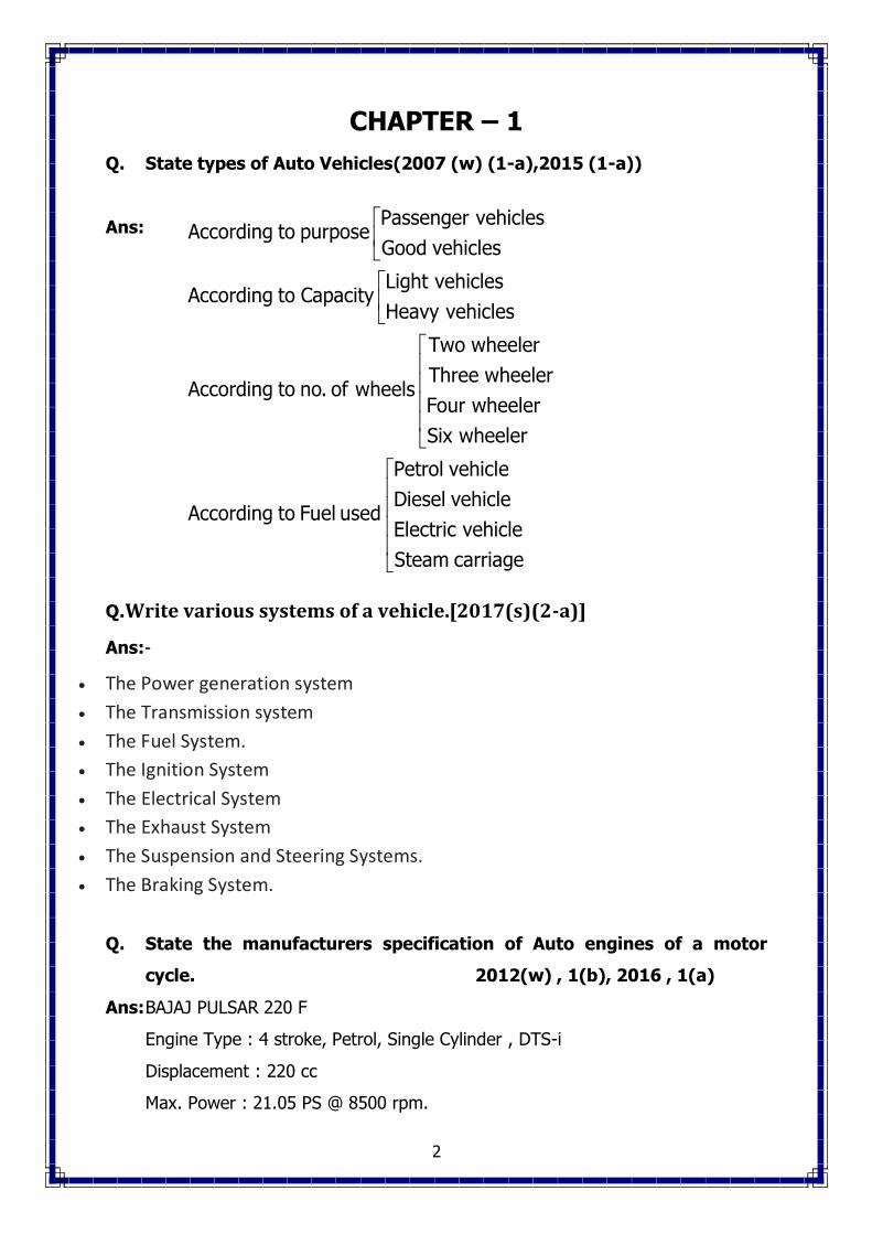
Q. With neat sketch describe the construction and working of a
conventional type differential with advantage & limitations. [2013(s)
Ans: Differential is device which is provided at the rear wheel of the vehicle
to provide the relative motion between the two real wheel at the time of taking
turn.
Construction :-
Differential is a part of rear axle housing assembly which consists of
bevel pinion, crown gear, sum gear and planet gear. The sum gear are
mounted on the inner end of each rear axle. A differential cage is assembled on
the left axle. A crown gear is attached to the case, so that the age rotates with
the crown gear. The crown gear is driven by bevel pinion. But both the crown

8
wheel and cage are free on the left rear axle. The cage supports two planet
pinions on a shaft which mesh with the two sum gears.
Working:-
When the vehicle moves in a straight line, the crown wheel, differential
cage, planet pinion and sum gears all turn as a unit without any relative
motion. When the vehicle takes a turn the planet pinions rotate on their axis to
permit the outer wheel to rotate at a faster rate then the inner wheel.
Q. Classify Clutches [2014, 4-b]
Ans: Different types of clutches are as follows :
1. Friction clutch:
a. Single plate clutch
b. Multi plate clutch
i. Wet ii. Dry
c. Cone clutch
i. External ii. Internal
2. Centrifugal clutch
3. Semi-centrifugal clutch
4. Conical spring clutch or Diaphragm clutch:
a. Tapered finger type b. Crown spring type
5. Positive clutch – Dog and spline clutch
6. Hydraulic clutch
7. Electro-magnetic clutch
8. Vacuum clutch
9. Over running clutch or free-wheel unit.
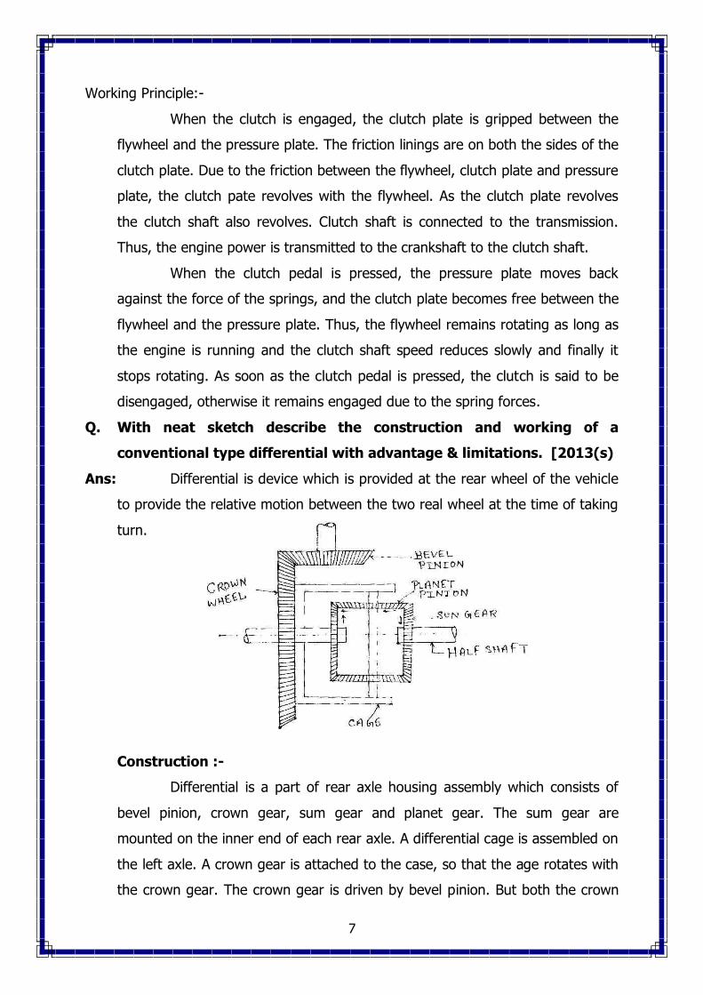
Q. Explain working of multi plate clutch with neat sketch [2016, 2-b]
Ans: Multi plate Clutch:-
Multi plate clutch consists of a number of clutch plates, instead of only
one clutch plate as in the case of single clutch. As the number of clutch plates
are increased, the friction surface also increase. The increased number of
friction surfaces obviously increases the capacity of the clutch to transmit
9
torque. The plates are alternately fitted to the engine shaft and gear box shaft.
They are firmly pressed by strong coil springs and assembled in a drum. Each
of the alternate plate slides in grooves on the flywheel and the other slides on
splines on the pressure plate. Thus, each alternate plate has inner and outer
splines.
The multi plate clutch works in the same way as the single plate clutch,
by operating the clutch pedal. The multi plate clutches are used in heavy
commercial vehicles, racing cars and motor cycles for transmitting high torque.
The multi plate clutches may be dry or wet. When the clutch is
operated in an oil bath, it is called a wet clutch. When the clutch is operated
dry, it is called dry clutch. The wet clutch are generally used in conjunction
with, or as a part of the automatic transmission.
10
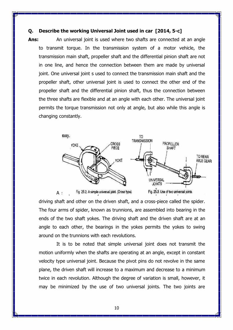
Q. Describe the working Universal Joint used in car [2014, 5-c]
Ans: An universal joint is used where two shafts are connected at an angle
to transmit torque. In the transmission system of a motor vehicle, the
transmission main shaft, propeller shaft and the differential pinion shaft are not
in one line, and hence the connection between them are made by universal
joint. One universal joint s used to connect the transmission main shaft and the
propeller shaft, other universal joint is used to connect the other end of the
propeller shaft and the differential pinion shaft, thus the connection between
the three shafts are flexible and at an angle with each other. The universal joint
permits the torque transmission not only at angle, but also while this angle is
changing constantly.
A simple universal joint consists of two Y-shaped yokes, one on the
driving shaft and other on the driven shaft, and a cross-piece called the spider.
The four arms of spider, known as trunnions, are assembled into bearing in the
ends of the two shaft yokes. The driving shaft and the driven shaft are at an
angle to each other, the bearings in the yokes permits the yokes to swing
around on the trunnions with each revolutions.
It is to be noted that simple universal joint does not transmit the
motion uniformly when the shafts are operating at an angle, except in constant
velocity type universal joint. Because the pivot pins do not revolve in the same
plane, the driven shaft will increase to a maximum and decrease to a minimum
twice in each revolution. Although the degree of variation is small, however, it
may be minimized by the use of two universal joints. The two joints are

11
arranged so that the non-uniform rotation of each joint tends to neutralize that
of the other, as shown in fig.
Q. Write different types of Universal Joints.
Ans: The universal joints may be of three types as follows :
1. Cross type or spider and two-yoke type.
2. Ball and turnnion type
3. Constant velocity type.
Q. What is the need of gear box in automobile. [2013, 4-b]
Ans: Purpose of Transmission :
The purpose of the transmission is to provide high torque at the time
of starting, hill climbing, accelerating and pulling a load. When a vehicle is
starting from rest, hill climbing, accelerating and meeting other resistances,
high torque (tractive effort) is required at the driving wheels. Hence a device
must be provided to permit the engine crankshaft to revolve a relatively high
speed, while the wheels turn at slower speeds. This is obtained by a set of
gears called a transmission or gear set. The gear set is enclosed in a metal box
called a gear box. The vehicle speed is also changed with the help of the
transmission keeping the engine speed same with certain limit.
CHAPTER:3
Q. With neat sketch explain the construction and working principle of
(i) Hydraulic braking system
(ii) Air – Assisted hydraulic braking system [2017(s)(3-c)2012
(s), 2009 (s)]
Ans:
12
Construction:-
It is operated by hydraulic pressure. The system consists of a master
cylinder, four wheel cylinder and brake lines. The system is filled with brake
fluid.
Working Principle:-
When the brake pedal is pressed the brake fluid inside the master
cylinder is pressurized and that pressure is transmitted to the wheel cylinder
through brake lines. The wheel cylinder is connected with two pistons which
expand outwards, thus expanding the brake shoe, so the brakes are applied.
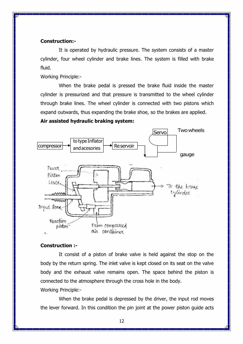
Air assisted hydraulic braking system:
Construction :-
It consist of a piston of brake valve is held against the stop on the
body by the return spring. The inlet valve is kept closed on its seat on the valve
body and the exhaust valve remains open. The space behind the piston is
connected to the atmosphere through the cross hole in the body.
Working Principle:-
When the brake pedal is depressed by the driver, the input rod moves
the lever forward. In this condition the pin joint at the power piston guide acts
compressorto type Inflator
andacesories Reservoir
Servo Twowheels
gauge
13
as a fulcrum the movement of the level moves the reaction piston and the
exhaust passage is closed.
Further movement of the input rod opens the inlet valve and air
pressure is admitted into the space behind the piston through the cross hole on
the body. This air pressure forces the power piston to move and this effort is
transmitted to the master cylinder through the output rod. The force acting on
the master cylinder thus creates the hydraulic pressure required for the
application of brakes.
Somewhere brakes are applied on the wheels to stop the vehicle.
Before applying the brakes, the acceleration is released to stop the fuel supply
thus the engine develops no more power to run the vehicle, and then the
brakes are applied which stop the rolling of the wheels on the road and hence
the vehicle is stopped. Clutch is also disengaged which disconnects the engine
from the transmission system. Thus, when the vehicle is standing, the engine is
still running at idling.
Q. Need of braking system in automobile. [2017(s)(3-a)2013, 6-a]
Ans: There are two distinct functions of the brakes:
1. To stop or slow down the vehicle in the shortest possible distance in
emergencies.
2. To control vehicle to be retained when descending a hill.
The first function calls for the brakes which can apply large braking
torques to the brake drums, while the second calls for brakes that an dissipate
large quantities of heat without large temperature rises.
Q. State various types of braking system. [2017(s)(3-b)2014, 6-b]
Ans: The automobile brakes are classified according to the different bases, as
follows:
1. With respect to application :
(a) Foot brake (b) Hand brake
2. With respect to the number of wheels :
(a) Two-wheel brakes (b) Four-wheel brakes
3. With respect to the method of braking contact :

14
(a) Internal expanding brakes (b) External contracting brakes
4. With respect to the method of applying the braking force :
(a) Single acting brakes (b) Double acting brakes
5. With respect to the brake gear :
(a) Mechanical brakes (b) Power brakes
6. With respect to power transmission :
(a) Vacuum brakes (b) Air brakes
(c) Hydraulic brakes (d) Hydrostatic brakes
(e) Electric brakes
7. With respect to power transmission :
(a) Direct acting brakes (b) Geared brakes
8. With respect to power unit :
(a) Cylinder brakes (b) Diaphragm brakes
Q. What is Vacuum brake [2016, 3-a]
Ans: In the air brakes the force of brake application is because of the
difference of pressures on the opposite sides of the diaphragm. One side of the
piston of diaphragm is exposed to the higher pressure while the other to the
atmospheric pressure. In fact, it is the potential difference which is utilized to
create the braking effect. Similar type of effect can be obtained if one side of
the piston or diaphragm is exposed to the atmospheric pressure while the other
side to a pressure below the atmospheric pressure. The pressure below
atmospheric is obtained by exhausting air from it. This is the principle of
vacuum brakes.
Q. What are the materials used in brake lining [2015, 7-a]
Ans: The brake linings are either of solid woven type of moulded type. The
asbestos base non-metallic linings have an average co-efficient of friction of 0.4
upto about 260oC. Their maximum temperature resistance is about 350oC. Zinc
wire lining have better resistance to wear than the non-metallic type. Also zinc
services to conduct some heat away from the working surface. Moulded type
linings are prepared directly from the mix which contains asbestos fibres,

15
together with resin powders and fillers. These linings have good wear
resistance. Their maximum temperature resistance is about 450oC. The average
co-efficient of friction if 0.4
Q. Explain of master cylinder with neat sketch. [2014, 5-c, 2015, 7-b]
Ans: The master cylinder is the heart of the hydraulic brake system. It
consists of two main chambers – the fluid to supply to the brake system, and
the compression chamber in which the piston operates. The reservoir supplies
fluid to the brake system through two parts. The larger port is called the filler
or intake part and is connected to the hollow portion of the piston between the
primary and secondary ups which act as piston seals. The smaller port is called
relief, bypass or compensating port which connects the reservoir directly with
the cylinder and lines when the piston is in the released position. The reservoir
is vented to the atmosphere so that the atmospheric pressure causes the flow
through the filler port. The vent is placed in the filler cap. The boot covers the
push rod and the end of the cylinder to keep it free from foreign matter.
When the brake pedal is depressed, the master cylinder piston moves
forward to force the liquid under pressure into the system. The relief port is
sealed out of the system. The liquid pressure is conducted to the wheel
cylinders, where it forces the wheel cylinder pistons outwards. These pistons
force the brake shoes out against the brake drums.

16
When brake pedal is released, the return spring quickly forces the
master cylinder piston back against the piston stop. Because the fluid in the
lines returns rather slowly, a vacuum tends to form in the cylinder in front of
the piston. This causes the primary cup to collapse to allow the liquid to flow
from the reservoir through the filler port past the piston to fill the vacuum.
When the pedal is in “off” position, the liquid may flow from the reservoir
through the relief port in the master cylinder, supply lines, and wheel cylinders
to make up for any fluid that may be lost or to compensate for shrinkage
cooling of the liquid. In this way, a complete column of liquid is always
maintained between the master cylinder piston and wheel cylinder pistons.
Q. Describe working of mechanical brake [2016, 3-b]
Ans: In a motor vehicle, the wheel is attached to an auxiliary wheel called
drum. The brake shoes are made to contact this drum. In most designs, two
shoes are used with each drum to form a complete brake mechanism at each
wheel. The brake shoes have brake linings on their outer surfaces. Each brake
shoe is hinged at one end by an anchor pin, the other end is operated by some
means so that the brake shoe expands outwards – the brake linings come into
contact with the drum. Retracting spring keeps the brakes shoes into position
when the brakes are not applied. The drum encloses the entire mechanism to
keep out dust and moisture. The wheel-attaching bolts on the drum are used to
contact wheel and drum. The braking plate completes the brake enclosure,
holds the assembly to the car axle, and acts at the base for fastening the brake
shoes and operating mechanisms. The shoes are generally mounted to rub
against the inside surface of the drum to form an internal expanding brake.

17
When the brake pedal is pressed, then cam turns by means of brake
linkage. When the cam turns, the shoes expands outwards against the drum. A
toggle lever is also used for the same purpose, as shown in fig. The brake
linings rub against be drum and thus stop its motion. The entire mechanical
linkage between the brake pedal and the shoes operates to transmit pedal
force to the brake shoes and to multiple that force through leverage to produce
effective braking forces against the drum.
CHAPTER : 04
Q. Define hot and cold plug. [2012 (s), 2011 (s), 2009(s), ]
Ans: According to the operating temperature the spark plugs are classified
as hot and cold plugs. The hot plug has a longer path of heat dissipation
thereby running at higher temperature than the old ply. A hot plug is generally
used in medium duty, low speed and cold operating conditions while the cold
plug is used in heavy duty, high speed engines where high temperatures are
encountered. It has experienced that a hotter plug gives better performance in
burning of the depositors inside the chamber.
Q. Draw and explain the wiring diagram of lighting circuit of an
automobile. [ 2017(s)(4-c)2012 (s), 2008 (s), 2016, 4-c, 2015, 6-c]
Ans:

18
All the electrical components provided on the vehicle have supply from
the battery as well as from the dynamo. Therefore each component needs two
paths, one for supply and the other for returning the current to the battery.
There are two methods of wiring, one is called double pole system, in which a
pair of wires is led to every component and the other is earth return system in
which the current is led to the component through a wire and returned through
the chassis frame of the vehicle.
Referring to the figure in the earth returned single pole wiring system,
the limited wire is needed for supplying the current and other terminal of the
component is earthed nearby. Therefore second system is very cheaper and
remains fairly complex and a colored cable system is used to assist in
identification. In this system positive terminal of the battery is usually earthed
instead of the negative one. In vehicle for warning lights a switch is provided
which operates mechanically by means of brake pedal. Sometimes it is also
incorporated in the hydraulic system and operated by hydraulic pressure, when
the brake pedal is depressed.
Q. Draw the line diagram of a horn consist of an auto electric system
with functional detail [2011 (s), 2008(s)]
Ans:

19
An electric horn consists of an electro magnet, an armature connected
with a flexible diaphragm and a tone disc. A strip is provided with the armature
to disconnect the breaker points.
The working principle is that when the horn button is pressed, The
battery high current passes around the solenoid, thereby magneitising the
laminated cone . thus attracting the laminated core thus attracting the
armature. This movement of the armature disconnects the points thereby
collapsing the magnetic field and returning the armature to its original position
under which re-contacting the points. This cycle remains continue thereby
vibrating the diaphragm and producing required tone by means of the toned
dsc.
Q. Briefly explain the cutout circuit with wiring diagram. [2010,2008
(s)]
Referring to figure the system consists of an electromagnet connected in the
generator circuit by means of series and shunt windings as shown. When the
generator develops sufficient pressure to charge the battery then the magnet
attracts an armature against a spring and thereby closing the circuit between the

20
generator and the battery and which will so open the circuit when the battery
pressure becomes greater than that developed in the generator.
Q. Specify a Spark Plug [2013, 4-a]
Ans: SPARK PLUG DATA
Type M12-13/225
Thread (metric) M14 × 1.25
Eletrode gap. 0.7 mm.
MICO SPARK PLUG RECOMMENDATION CHART
Vehicle Recommended Plug Gap mm
DODGE/FORGO 14 mm W 95 T3 0.6
1960 onward 14 mm head M 145 T3 0.6
18 mm head M 145 Z1 0.6
HINDUSTAN Ten
Landmaster W 145 RI 0.6
Ambassador (side valve engine)
Ambassador Mh II W 160 Z2 0.6
Baby Hindustan W 175 T2 0.6
HINDUSTAN BEDFORD
500 cu. in W 145 T3 0.6
230 cu. In (Chev) W 169 Z2 0.6
JEEP W 145 T3 0.7
NISHAN Jeep W 175 T2 0.6
NISHAN Truck W 175 T2 0.6
PREMIER Padmini W 175 ZI 0.6
PREMIER
Poineer
14mm W 145 T3 0.6
18 mm W 145 TI 0.6
STANDARD
Gazel and Herald W 160 Z2 0.6

21
STANDARD 1 Ton Truck W 145 ZI 0.6
Q. State Function of Spark Plug [2016, 4-a]
Ans: Spark Plug is a device to produce electric spark to ignite the
compressed air-fuel mixture inside the cylinder. The spark plug is screwed in
the top of the cylinder so that its electrodes projects in the combustion
chamber.
Construction. A spark plug consists of mainly three parts.
1. Centre electrode or insulated electrode.
2. Ground electrode or outer electrode.
3. Insulation separating the two electrodes.
Q. State the common ignition troubles and remedies [2017(s)(4-
b)2016, 4-b]
Ans: Causes and remedies
1. Battery discharged – Change battery.
2. Battery defective – Test and replace if necessary.
3. Battery cable(s) defective or undersize for given duty – Replace cable(s).
4. Battery cable connection loose, corroded or poorly fitted – Repair as
required.
5. Battery installed with reverse polarity – Switch battery cable hook up to
terminals.
6. Starter motor not the right one – Install proper starter motor.
7. Starter motor defective – Repair or replace.
8. Starter motor solenoid or switch defective – Repair or replace solenoid or
switch.
9. Starter motor improperly grounded – clean and or secure starter
mounting.
10. Starter motor pinion binding against flywheel teeth – Repair as required.
11. Flywheel teeth flattened – Replace flywheel or flywheel ring gear.
12. Neutral safety switch improperly adjusted or defective – Adjust or replace
safety switch.

22
13. Ignition switch defective (key start systems) – Replace switch.
14. Wiring between ignition switch and solenoid defective – Repair or replace
wires.
15. Ignition timing advanced too far at cranking speed – Adjust ignition
timing.
16. Motor oil or transmission oil (manual shift transmission) too thick –
Replace oil, thin with lighter or allow to warm.
CHAPTER : 5
Q. Explain with neat sketch the working principle of telescopic shock
Absorber.
Ans: Main parts
1. Chasis eye
2. Head
3. Piston rod grand
4. Inner cylinder
5. Piston cylinder
6. Procting cover
7. Reservoir
8. Axle eye
9. Foot valve
10. Inner ring of holes
11. Inner ring of holes
12. Outer ring of holes
Construction :-
It consist of an inner fitted with head at the open mouth. The head is
also screwed into the outer reservoir. Which is fixed to the eye by means of
which the reservoir is screw to the axle. The piston is screwed to the piston rod
which is fixed to the another eye. By which it is secured to the frame. The outer
part such as piston rod and reservoir are covered with the proactive cover
which is fixed with the eye and the rod.

23
Working :-
i. The inner cylinder is completely filled with fluid and the reserivor is half
filled.
ii. When the axle eye is moved upward the fluid must be displaced from the
bottom side to the top side of the piston.
iii. Under this condition the fluid will pass through the outer ring of the holes
by opening the valve disc.
iv. In this condition when the upper portion of the cylinder is filled fully or has
less space then the fluid will also be displaced though the inner ring of
holes of the foot valve and the level of the fluid in the reservoir will rise.
v. Similarly when the axle eye is moved down ward then the fluid will be
displaced from top side to the bottom side of the piston.
vi. Under this condition the fluid will pass through the inner ring of the holes
by opening the valve disc.
vii. The vacuum of the inner cylinder is filled by the fluid displacement of
reservoir.
Q. State Specification of a tyre [2017(s)(5-a)2016, 5-a, 2015, 3-a]
Ans: TYRE SIZE
Every tyre is marked with its size. Let us see what is the meaning of this
marking. If a tyre is marking with
8.25 × 20 × 10 PR.
It means:
1. The width or thickness of tyre from shoulder to shoulder is 8.25”
2. Diameter of the bead circle, which fits on the rim, is 20”
3. PR means ply rating 10 PR means the tyre consists of 10 plies. Scooter
tyres consists of 1 to 4 plies, car tyres 4 to 6 plies, light truck tyres 6 to 10
plies and truck tyres 10 to 22 plies. The number of plies makes the tyre
hard to resist heavy load. But the hard tyre does not absorb road shocks.

24
Q. What are the common causes of tyre wear[2017(s)(5-b)]
Ans: Causes of Tyre wear
1. Incorrect inflation
2. Incorrect castor, camber, or to –in
3. excessive braking or violent acceleration
4. Worn steering mechanism.
5. Wrong king pins
6. Out of balance wheel.
7. Misalignment
8. Over-loading
9. Wrong loading.
10. Defective brakes
11. Toe out incorrect on turn.
12. Bleeding of air in tyre
13. Careless driving
14. Unequal tyres.
15. Incorrect rotation of tyres.
Causes of irregular tyre wear
Fault Causes
1. Local rapid wear Oval or eccentric brake drums, or a local increase in tyre stiffness
2. Wear on one shoulder more Excessive wheel chamber The other misalignment
3. Heel and toe wear on individual Road slip in one direction only. Studs.
4. One half of the tread circumference Unbalancing, in special causes, More worn than the other half it may be due to maintaining a
uniform and high speed

25
Q. Explain with neat sketch the constructional features of rear axle used
in Indian car. [2013, 5 – c]
Ans: Depending upon the methods of supporting the rear axles and
mounting the real wheel, the rear axles are of three types.
1. Semi-floating axle.
2. Full floating axle.
3. Three quarter floating axle.
Misalignment
1. Semi-floating axle.
A semi-floating axle has a bearing located on the axle and inside the
axle casting. It has to support all the loads as listed above. Therefore, it needs
to be a larger size for the same torque output, than any other type. The inner
end of the axle is supported by the differential side gear. It is thus relieved of
the job of supporting the weight of the car by the axle housing. The outer end
has to support the weight of the car and take end thrust. The inner end of the
axle is splined to the differential side gear. The outer end is flanged so that the
wheel can be bolted directly to it. In some designs, the hub of the wheel is
keyed to the outer end of the axle. The vehicle load is transmitted to the axle
through the casing and the bearing, which causes the bending or shearing of
the axle. The semi-floating axle is the simplest and cheapest of all other types
and widely used on cars.
26
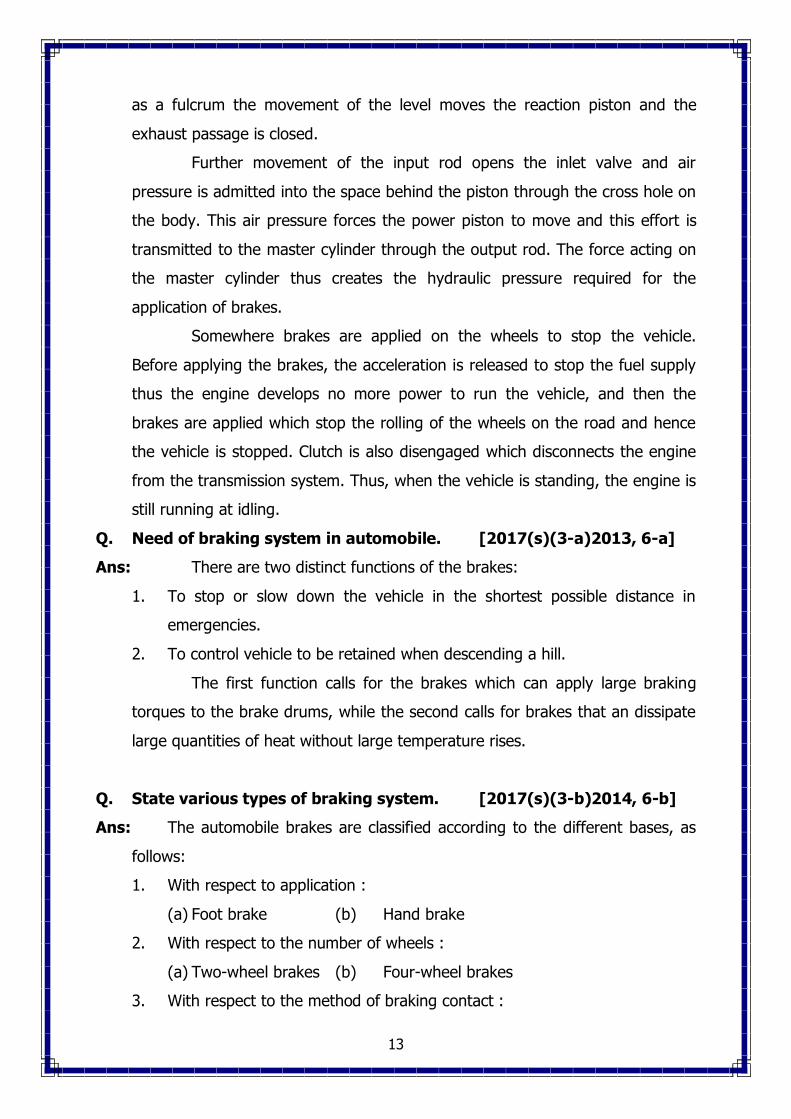
2. Full floating axle
A full floating axle has two deep-grove ball or taper roller bearings,
located between the axle casing and wheel hub. The outer of the axle is made
flanged to which the wheel hub is bolted. The axle is not supported by bearings
at either end, and its position is maintained by the way that it is supported at
both ends. Thus the axle is relieved of all strain caused by the weight of the
vehicle on end thrust. It transmits only the driving torque. For this reason, it is
called full floating. The axle may be removed from the housing without
disturbing the wheel by removing the nuts. An additional advantage of this
design is the ability to the vehicle even if it has a broken axle. This type of axle
is more expensive and heavier than the other axles. It is usually fitted on
commercial vehicles.
3. Three quarter floating axle.
A three quarter floating axle has a bearing located between the humb
and the axle casing. Thus the weight of the vehicle is transferred to the axle
casing and only the side thrust and driving torque are taken by the axle. The
axle is keyed rigidly to the hub, thus providing the driving connection and
maintaining the alignment of the wheel. The inner end of this axle has the
same construction as that of the semi-floating axle. Although the three quarter
floating axle is more reliable but it is not as simple as the semi-floating axle.

27
Q. Describe working of 4 speed gearbox with neat sketch [2017(s)(2-
c)2013,4-c]
Ans: 4-Speed Gear Box
Figure shows the layout of a 4-speed gear box using synchromesh
system in all the four forward speeds. Readers will note from the figure that the
clutch shaft drives the countershaft drive gear through main drive gear. The
first, second and third speed gears on the main shaft are in constant mesh with
their corresponding gears on the countershaft. The reverse idler gear and the
reverse sliding gear are not in mesh. In this position, the gear box is in neutral
since no power is transmitting to the mainshaft.

28
First Gear : Figure shows the layout of gears transmitting power in first gear.
This gear is obtained by shifting the dog clutch to the right thus engaging is
internal teeth with the external dog teeth of the first speed gear.
Second gear : Figure shows the layout of gears transmitting power in second
gear. To obtain this gear, first the 1-2 speed dog clutch is brought to neutral
and then moved to the left thereby engaging its internal teeth with the external
dog teeth of the second speed gear.
Third gear : Figure shows the layout of gears transmitting power in third
gear. In order to obtain this gear, first 1-2 speed dog clutch is shifted out of
mesh from second gear and brought to neutral position. The 3-4 speed dog
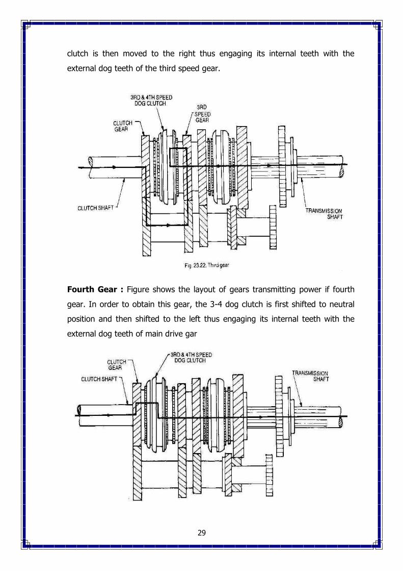
29
clutch is then moved to the right thus engaging its internal teeth with the
external dog teeth of the third speed gear.
Fourth Gear : Figure shows the layout of gears transmitting power if fourth
gear. In order to obtain this gear, the 3-4 dog clutch is first shifted to neutral
position and then shifted to the left thus engaging its internal teeth with the
external dog teeth of main drive gar

30
Reverse gear : Figure shows the layout of gears transmitting power in reverse
gear. This gear is obtained by first bringing the vehicle to rest position. The
gear box is then brought to neutral position. After this, the reverse sliding gear
is moved to the left thus engaging it with the reverse idler rear gear.
Q. Describe working of 3 speed constant mesh gear box with neat
sketch. [2015 , 5-b]
Ans: Figure shows the layout of a three-speed gear box with a synchromesh
system in its second and top gears. The housing, rotating parts with bearings
and the shifting mechanism constitute the gear box. The housing is generally
made of cast iron and bolted to the rear of the clutch housing. The housing
acts as a container for the oil in which the gears operate. The case cover
usually carries the shifting mechanism and it seals the gear box against water
and dirt. The dog clutch synchronizer assemblies and bearings constitute the
rotating parts. The flow of power during the various gear positions is discussed
below.

31
Neutral Position : figure shows the simplified diagram of a gear box
depicting the flow of power in the neutral position. In this position, the gears
inside the gear box simply rotate without effecting the main shaft of the gear
box. The power transmitted by the clutch simply rotates the main drive gear
and countershaft drive gear as well as the second speed gears on the main
shaft and countershaft since they rare constantly in mesh. The second speed
gear on the main shaft is loosely fitted and hence, does not drive the main
shaft. All the gears on the countershaft including the reverse gear, rotate,
without effecting the main shaft. The bold line depicts the power flow.

32
First Gear : Figure shows the simplified diagram of a gear box showing flow of
power in first gear. This position is obtained by sliding the first and reverse
gear to the left unit its teeth mesh with that of the countershaft first gear. In
this position, drive is given to the countershaft from the clutch and the main
shaft is driven by the first gear, which is splined to it.
Second Gear : Figure shows the simplified diagram of a gear box showing
flow of power in second gear. Before obtaining this position, the first gear is
slide out of mesh bringing the gear box in the neutral position. After this, the
dog clutch is moved to the right side making its internal teeth to mesh with the
external teeth of second speed gear. The dog clutch is splined with the main
shaft.

33
Third or top Gear : Figure shows the simplified diagram of a gear box
showing the flow of power in the third gear. This position is obtained by
shifting the dog clutch to the left till its internal teeth mesh with the external
teeth of the main drive gear. In this position, the main shaft is locked with the
clutch shaft, thus making a direct drive.
Reverse Gear : Figure shows the simplified diagram of a gear box showing
the flow of power in the reverse gear. Before obtaining this gear, the vehicle is
brought to rest and the gear box to its neutral position. After this, the first and
reverse gear is moved to the left till it meshes with the reverse idler. The
second speed gears revolve but transmit no power. In this position, the power
is transmitted through the reverse idler to the main shaft by the first reverse
gear which is splined to the main shaft, gears on the main shaft are in constant
mesh with the corresponding gears on the countershaft. The reverse idler gear
and the reverse sliding gears are not in mesh. In this position, the gear box is
in neutral since no power is transmitted to the main shaft.

34
Q. what are the components of transmission
system? Explain in brief.[2017(s)(2-b)]
Ans: The power developed inside the engine
cylinder is ultimately aimed to turn the wheels
so that the motor vehicle can move on the road.
The reciprocating motion of the piston turns a
crankshaft rotating the fly wheel through the
connecting rod. The circular motion of the
crankshaft is now to be transmitted to the real
wheels. It is transmitted through the clutch,
gearbox, universal joints, propeller shaft or drive
shaft, differential and axles extending to the
wheels. The application of engine power to the
driving wheels through all these parts is called
power transmission. The power transmission system is usually the same on all
modern passenger cars and trucks, but its arrangement may vary according to
the method of drive and type of the transmission units.
Figure shows the power transmission system of an automobile. The
motion of the crankshaft is transmitted through the clutch to the gear box or
transmission, which consists of a set of gears to change the speed. From gear
box, the motion is transmitted to the propeller shaft through the universal joint
and then to the differential through another universal joint. Universal joint is
used where the two rotating shafts are connected at an angle for power
transmission. Finally, the power is transmitted to the rear wheels through the
rear axles. The differential provides the relative motion to the two rear wheels
while the vehicle is taking a turn. Thus, the power developed inside the cylinder
is transmitted to the rear wheels through a system of transmission.
35
Q. Describe independent suspension system used in car. [2017(s)(5-
c)2016, 5-c]
Ans: Independent type front suspension.
Practically all passenger cars now use the independent type front
suspension system. In this system each front when can move up and down
freely without affecting or altering the movement of the other front wheel. The
front wheel is independently supported by a coil, torsion bar, or leaf spring. The
coil spring arrangement s the most common.
There are three types of coil spring independent front suspension
arrangements.
1. Coil spring is located between the upper and lower control arms and the
lower control arm has one point of attachment to the car frame. In this
arrangement, a strut or brake reaction rod, is used to prevent forward or
backward movement of the lower control arm. It is attached between the
outer end of the lower control arm, and the car frame.
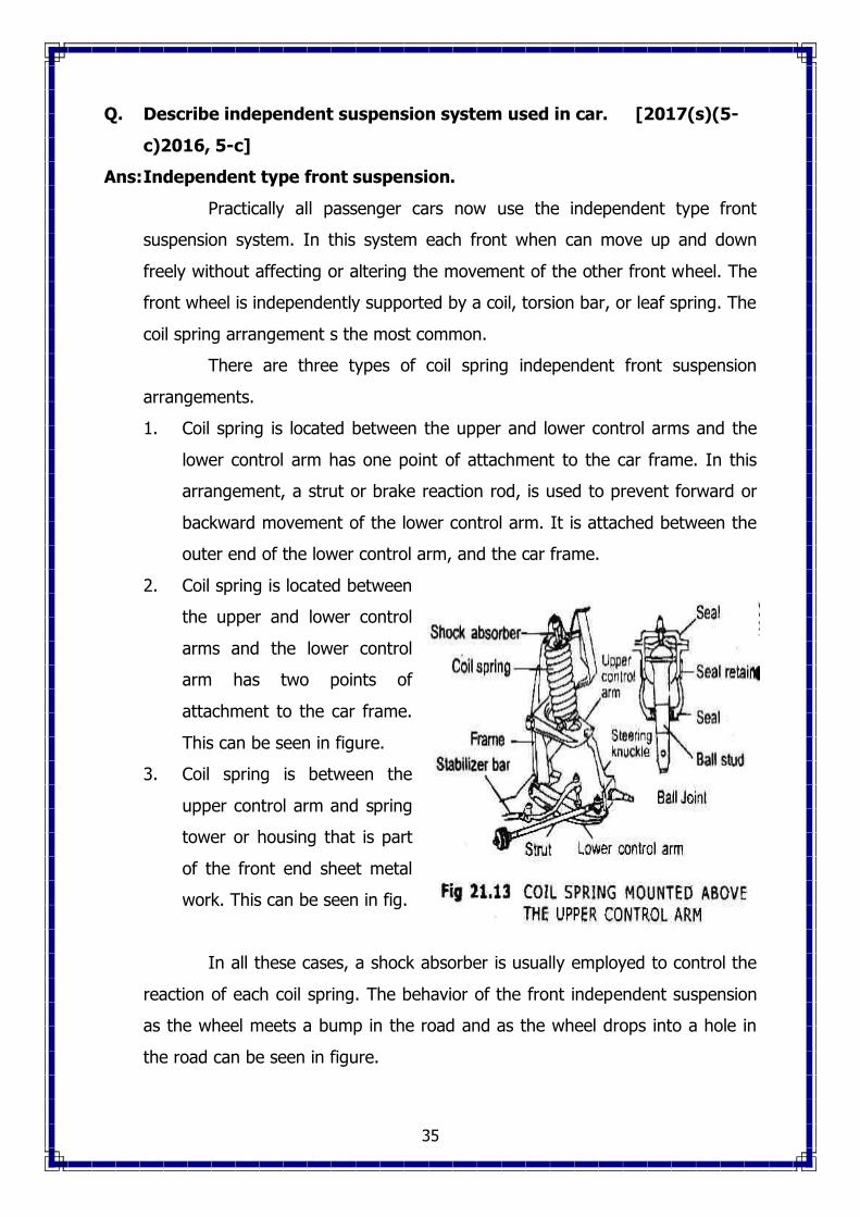
2. Coil spring is located between
the upper and lower control
arms and the lower control
arm has two points of
attachment to the car frame.
This can be seen in figure.
3. Coil spring is between the
upper control arm and spring
tower or housing that is part
of the front end sheet metal
work. This can be seen in fig.
In all these cases, a shock absorber is usually employed to control the
reaction of each coil spring. The behavior of the front independent suspension
as the wheel meets a bump in the road and as the wheel drops into a hole in
the road can be seen in figure.
36
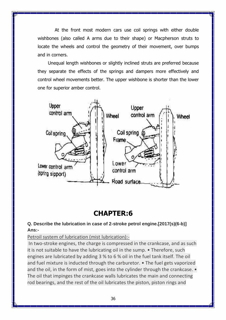
At the front most modern cars use coil springs with either double
wishbones (also called A arms due to their shape) or Macpherson struts to
locate the wheels and control the geometry of their movement, over bumps
and in corners.
Unequal length wishbones or slightly inclined struts are preferred because
they separate the effects of the springs and dampers more effectively and
control wheel movements better. The upper wishbone is shorter than the lower
one for superior amber control.
CHAPTER:6
Q. Describe the lubrication in case of 2-stroke petrol engine.[2017(s)(6-b)]
Ans:-
Petroil system of lubrication (mist lubrication):- In two-stroke engines, the charge is compressed in the crankcase, and as such it is not suitable to have the lubricating oil in the sump. • Therefore, such engines are lubricated by adding 3 % to 6 % oil in the fuel tank itself. The oil and fuel mixture is inducted through the carburetor. • The fuel gets vaporized and the oil, in the form of mist, goes into the cylinder through the crankcase. • The oil that impinges the crankcase walls lubricates the main and connecting rod bearings, and the rest of the oil lubricates the piston, piston rings and

37
cylinder. • The main advantage with this system lies in the simplicity and low cost as the system does not require any oil pump, filter etc.
Q. Describe the various lubrication system for a IC Engine [2008(w)]
Ans: Mostly pressure luibrication system is used I.C. Engine
Pressure lubrication :
As a splash lubricating system is not sufficient to lubricate efficiently all
part of the larger engines. There are a pressure lubricating system is provided.
Working:
the system consist of an oil pump which takes the oil form the sump
through the floating strainer and delivers it through a filter to oil gallery
Here the pressure of the oil usually ranges between 2 to 4 kg cm2.
The oil form the main gallery is goes to the main bearing form where
some of it after lubricating the main bearing falls back to sump.

38
Some is splashed to lubricate the cylinder walls and the remaining goes
through a hole to crank pin.
Form crank pin it goes to the connecting rod through a hole.
For lubricating camshaft and timing gears, the oil is led through a separate
oil line form one oil gallery
An oil pressure gauges at the instrument panel indicates the oil pressure in
the system.
Oil filters and strain in the system colour off the oil from the dust, metal
particles and other harmful particles.
Q. What are the type of cooling system and explain water cooling system
in details [ 2017(s)(6-c)2015, 3-b]
Ans: Methods of cooling
There are following four methods of engine cooling.
1. Air cooling
2. Water cooling
3. Liquid cooling
4. Steam cooling
Water cooling
In this method of cooling, water is circulated through water jackets
around each of the combustion chambers, cylinders, valve seat and valve
stems. The circulating water, when passes through the engine jackets in the
block and cylinder heat, takes heat of the combustion. When it passes through
the radiator, it is cooled by air drawn through the radiator by a fan and by air
flow developed by the forward motion of the vehicle. After passing through the
radiator, the water again goes in the engine jackets.
Systems of water cooling:
There are two systems of water cooling :
1. thermo siphon system : In this system of water cooling the circulation of
water is obtained due to the difference in densities of hot and cold regions
of the cooling water. There is no pump to circulate the water. The hot
water from the engine jacket being lighter, rises up in the horse pipe and
goes in the radiator from the top side. It is cooled there and hence goes
39
down at the bottom side of the radiator, from where it goes again in the
engine jackets. The system is quite simple and cheap, but the cooling is
rather slow. To maintain continuity of the water flow, the water must be
maintained up to a certain minimum level. If the water level falls down,
the circulation will discontinue and the cooling system will fail.
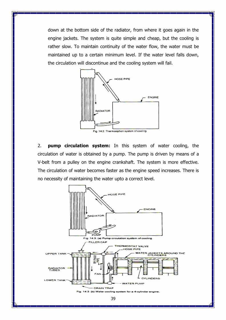
2. pump circulation system: In this system of water cooling, the
circulation of water is obtained by a pump. The pump is driven by means of a
V-belt from a pulley on the engine crankshaft. The system is more effective.
The circulation of water becomes faster as the engine speed increases. There is
no necessity of maintaining the water upto a correct level.

40
Q.What is the function of radiator.[2017(s)(6-a)]
Ans:- The radiator is responsible for preventing the engine from overheating. When the engine is in use, it produces a lot of friction and heat, and the radiator uses coolants to keep the engine running at a healthy temperature.
Q. Describe defects of cooling and their causes and remedies [2016,6-b]
Ans: Summary of cooling system Troubles:
Troubles Troubles
1. External leakage
2. Internal leakage
3. Water loss
4. Poor circulation
5. Corrosion
6. Overheating
7. Overcooling
1. Loose hose clips 2. Defective rubber hose. 3. Damaged radiator seams
4. Excessive wear in the water pump. 5. Loose core plugs 6. Damaged gaskets
7. Leaks in the heater connections or plug. 8. Leak at the water temperature gauge plug.
1. Defective cylinder head gasket. 2. Cracked cylinder wall.
3. Loose cylinder head bolt. 1. Boiling
2. External or internal leakage 3. Restricted radiator or inoperative thermostat.
1. Restriction in system. 2. Insufficient coolant.
3. Inoperative water pump. 4. Loose fan belt. 5. Inoperative thermostat.
1. Excessive impurity in the water. 2. Infrequent flushing and draining of the
system. 3. Incorrect anti-freeze mixtures.
1. Poor circulation due to any reason. 2. Dirty oil and sludge in the engine. 3. Radiator fins choked. 4. Incorrect ignition timing.
5. Incorrect valve timing. 6. Low oil level. 7. Tight engine
8. Engine oil too thick. 9. Clogged exhaust system. 10. Dragging brakes.
1. Defective thermostat. 2. Inaccurate temperature gauge.

41
Q. State the need of engine cooling [2016, 6-a, 2013, 7-a]
Ans: During the combustion of air fuel mixture enormous amount of heat is
produced inside the engine cylinder, and the temperature as high as 2500oC
may be reached by the burning gases. The temperature is so high that it will
break the lubricating film between the moving parts, weld the moving parts or
may cause any mechanical breakage of the engine parts. Hence this
temperature must be reduced by some means to such a value, about 200oC –
250oC, at which the engine may work efficiency. Too much cooling would,
however, lower thermal efficiency of the engine. Thus the purpose of the
cooling system is to keep the engine at its most efficient operating temperature
at all engine speeds and all driving conditions.
Q. Explain with neat sketch the Battery ignition system and magnato
Ignition system. [2017(s)(7-b)2008 (w), 2-c, 2010(s) Q-5, 2012 (s)
!-7]
Ans:
The figure shows battery ignition system for a four-cylinder engine. It
consists of a battery, ammeter, switch, ignition coil, condenser, contact
breaker, distributor and spark plug.

42
The primary ignition circuit starts at the battery and passes through
the switch, ammeter, primary winding, contact breaker points to the ground. A
condenser is also connected in parallel to the contact breaker points. One end
of the condenser is connected to the breaker arm and the other end is
grounded.
The secondary ignition circuit is not connected electrically to the
primary ignition circuit. It starts from the ground and passes through the
secondary winding distributors, spark plug to the ground.
The ignition coil steps up 6 or 12 volts from the battery to the high
tension voltage of about 20,000 to 30,000 volts required to jump the spark at
the spark plug gap, which ignites to combustible charge in the cylinder. The
rotor of the distributor revolves and distributes the current to the four
segments which in turn, send it to the spark plugs.
When the ignition switch is on, the current will flow from the battery
through the primary winding. It produces magnetic field in the coil. When the
contact points open, the magnetic field collapses and the movement of the
magnetic field induces current in the secondary winding coil.

43
Figure shows magneto ignition system for a four cylinder engine. It
consists of magneto instead of a battery. It produces and supplies current in
the primary winding. The remaining arrangement in this system is the same as
that in the battery ignition system. The magneto consists of a fixed armature
having primary and secondary windings and a rotating magnetic assembly
which is driven by the engine. When the magnets rotate, current flows in the
primary winding. The secondary winding gives high voltage current to the
distributor, which distributes it to the respective spark plug.
In a magneto, the magnetic field is produced by means of a permanent
magnet whereas in conventional generator , the magnetic field is produced by
passing some of the generated current through the field winding which
produces magnetic field.
The magneto may be either rotating armature type of rotating magnet
type. In rotating armature type magneto, the armature carrying the primary
and secondary windings and the condenser, rotate between the poles of a
stationary horse shoe magnet.
Q.Define carburettor.[2017(s)(7-a)]
Ans:- A carburettor is a device that mixes air and fuel for internal combustion
engines in the proper ratio for combustion.
Q. Describe the construction and working principle of solex carburetor
with neat sketch. [2008(s) Q-6, 2009 (s) , Q-4, 2011(s) Q-3]
Ans:

44
Solex carburetor is a down draught type carburetor . It consists of the
devices for starting, idling, normal running and acceleration.
Construction :
It consists of a starter valve in the form of a flat disc having holes of
different sizes. These holes connect the petrol jet and starter jet sides to the
passage which opens into the air horn just below the throttle valve. The starter
lever is operated by the driver from the dash board, which adjusts the position
of the starter valve so that either bigger or small holes come opposite the
passage.
Working Principle:-
At the time of starting, bigger holes connect the passage so that more
fuel may go to the engine. The throttle valve being closed, the whole of engine
suction is applied to the starting passage 1, so that the petrol from the float
chamber passage through the starter petrol jet and rises into passage 2, Some
of it comes out and mixes with the air entering through the air jet. This air fuel
mixtures is rich enough for starting for engine.
After the engine has started, the starter level is brought to the second
position, so that smaller holes connect the passage reducing the amount of
petrol. In this position the throttle valve is also partly open, so that the petrol is
also coming from the main jet. The reduced mixture supply from the starter
system, in this situation is, however, sufficient to keep the engine running.
When the engine reaches the normal running temperature, the starter is
brought to “off” position.
Q. Describe the working principle of fuel ignition system for multi
cylinder engine. [2017(s)(7-c)2008 (w) Q-6, 2013(w) 7-c]
Ans:

45
The fuel system of a diesel engine consists of the following :
1. Air cleaner
2. Fuel Tank
3. Fuel Filter
4. Injection Pump
5. Injector
6. Fuel lines for necessary connection
7. Fuel gauge.
The complete layout of diesel fuel system is clear from fig. The diesel
fuel is stored in a main fuel tank which consists of a fuel-level gauge and an
air-vented filter cap. In most of the vehicles this fuel tank is installed lower than
the engine level therefore a fuel-life pump is necessary in the system. The fuel
lift pump is generally of mechanical type which functions by means of vacume
of a diaphragm.
The usual system is omitted the lift pump and only it consists of a
diaphragm type feed pump operated by the injection pumps camshaft. The
feed pump draws fuel from the main tank through a preliminary filter thereby
obtaining the lean fuel. The feed pump delivers the fuel to a main filter which is
provided with a relief valve. The relief valve acts as a safeguard against
excessive pressure of the fuel and discharge the excessive fuel back to the
main tank.
In recent installations the preliminary filter is replaced by a plug filter
and the system consists of two fuel filters which are provided between the
deliver side of the feed pump and the inlet side of the injection pump. The
primary filter takes out the greater part and the secondary filter takes out the
finest particles of any dirt available in the fuel. Therefore, in this way the
complete fuel system includes the main fuel tank, filters, fuel lift pump, fuel
injection pump, injectors, low and high pressure pipe lines etc as shown in fig.
Q. How ignition takes place in petrol engine [2015, 4-a]
Ans: Petrol injection system is used in number of modern cars like Jaguar,
Benz 250 S.E. Whereas single carburetor is used to deliver air-fuel mixture into
multi-cylinder engine. It is likely that some of the cylinders may not get regular

46
supply of the mixture. The flow of mixture is restricted due to beds in its
passage. Also, the power output of an engine mainly depends upon its air
consumption, which cannot be increased beyond a certain limit with the use of
a simple carburetor, and hence the maximum output is not obtained. The use
of petrol injection system overcomes these difficulties. It ensures unrestricted
fuel supply and controls it at all times of the engine operation.
In petrol injection, every cylinder is provided with an injection nozzle
receiving the petrol from a pump. The petrol may be injected directly into the
cylinder or into the inlet manifold. If the petrol is injected into cylinder, it
should be timed as in the case of ordinary diesel engines. Petrol injection gives
both higher power and low specific fuel consumption. But it has some
disadvantages also like higher initial cost and maintenance cost, complicated
design and difficult in operation. However, the modern carburetor is a sample,
reliable and cheap device for normal operating condition.
Q. Explain multi point fuel injection system [2013, 7-c]
Ans: MULTI POINT FUEL INJECTION (MPFI)/ELECTRONIC FUEL INJECTION
(EFI)
Automobiles use one of two devices for supplying the air-fuel mixture
in correct ratio to the cylinders in all rpm ranges : a carburetor or an multi point
fuel injection electronic fuel injection system. Both of these measure the intake
air volume, which varies depending on the opening angle of the throttle valve
and the engine rpm, and they both supply a proper ratio of fuel and air to the
cylinders in accordance with the volume of intake air. The MPFI and EFI is the
same reference of the system. Because the construction of the carburetor is
relatively simple, it has been used almost exclusively on gasoline engines in the
past. However, in response to recent demands for cleaner exhaust emission,
more economical fuel consumption, improved drivability etc., the carburetor
now must be equipped with various compensating devices, making it a more
complex system.
In place of the carburetor, therefore, the MPFI system is used,
assuring the proper air-fuel ratio to the engine by electrically injecting fuel in
accordance with various driving conditions. The MPFI, however, calibrates the

47
fuel at optimum requirement of fuel as desired by engine. The fuel is controlled
not only by manual but so many other sensors. Carburetors atomize the fuel by
processes relying on the air speed being greater than the fuel speed at the fuel
nozzle. They also meter the fuel using the air flow as the independent variable.
Fuel injection differs in both respects. The fuel speed at the point of delivery is
greater than the air speed to atomize the fuel and the fuel is metered
proportionally to air flow but not by the air flow itself; rather a pump is used to
generate the pressure difference necessary to flow the fuel.
Fuel injection system can be classified as follows :
Single Point : One fuel injector
serves more than one cylinder.
Throttle body fuel injection is an
example. These systems are used only
on homogeneous charge engines.
Multiple Point:- One fuel injector per cylinder. These systems are always
used on diesel engines and direct-injection stratified charge engines.
Electronic:- The metering of the fuel by solenoid actuation.
Mechanical. The metering of the fuel by cam actuation.
Port. The fuel injector sprays into the air stream at the inlet port.
In-cylinder The fuel injector spray is directly into the cylinder.
Low pressure. Fuel is injected into gas at a pressure level on the order of the
intake pressure.
High pressure : Fuel is injected into the cylinder near the end of the
compression stroke and therefore into gas at a pressure level on the order of
the compression pressure.
Timed pulse : Each injection has a finite duration, controlling the duration’s
width is the dominant part of the metering scheme. The injection is then timed
48
to begin and end at specific times in the cycle. All in-cylinder injection systems
and some port fuel injection systems are timed.
Continuous of steady: The fuel is flowing through the injector through all
times in the engine cycle. In these systems the fuel is metered by controlling
the pressure upstream of the fuel injectors
Q. Explain fuel system in diesel engine [2015, 3-c]
Ans: Diesel Engine Fuel System :
The fuel system of a diesel engine consists of the following
1. Air cleaner
2. Fuel tank.
3. Fuel filter
4. Injection pump
5. Injector
6. Fuel lines for necessary connections.
7. Fuel gauge.
The main difference between the fuel system of a diesel engine and
that of a petrol engine is that the fuel system of a diesel engine consists of an
injector, instead of a carburetor, remaining items being the same.
In a diesel engine, only the air is sucked and compressed inside the
cylinder. At the end of compression stroke, the diesel oil is injected by an
injector in the compressed air, which ignites due to the heat of compression
and gives power impulse to the piston. The fuel pump delivers fuel at a
comparatively low pressure to the injector. Every cylinder is fitted with a
injector. The quantity of the fuel to be injected is controlled by the injector. If
less fuel is injected, less power will be developed and the engine will run
slowly.
With an effective compression ratio of 14 : 1, initial temperature of
60oC and assuming true adiabatic compression, the resulting temperature at
T.D.C. would be 675oC. these conditions would be approximately attained at
full load and full speed. This temperature of 575oC is more than sufficient to
ignite Diesel fuels, which have self-ignition temperatures in air at atmospheric
pressure ranging from 350oC to 450oC.

49
Fig. shows layout of fuel system for distributor type injection pump for
a four cylinder diesel engine. It is using the gravity fuel tank. In this
arrangement, the fuel tank must be at least one foot above the fuel filters and
injection pump. When the fuel cock is opened, the fuel flow direct to a hand
lever type of fuel priming pump, from which it then passes out to the inlet side
of the main fuel filter. The fuel after being filtered proceeds to the inlet side of
the fuel injection pump. From the injection pump, it flows under high pressure
in the four fuel feed pipes leading to the fuel injectors. Each injector has a leak-
off fuel pipe to carry off any back leakage fuel from the nozzle valve and fuide
members. This back-leakage fuel is returned to the fuel tank, together with any
back-leakage from the distributor injection pump unit.
Where gravity tank feed s not used in the system, a fuel feed pump is
used to supply the fuel to the filter and injection pump. The fuel feed pump is
usually operated by a special cam on ignition pump’s camshaft, so that both the
feed and injection pumps form a single unit.
Q. What is ignition timing [2014, 3-a]
Ans: Ignition timing:
In the explosion or constant volume cycle, the maximum useful work
can be realized with constant volume combustion and the maximum pressure
occurring near the top dead center.

50
In a actual engine, certain time interval exists between the instant of
ignition and the attainment of maximum pressure. This stipulates that the
charge must be ignited before TDC. This ensures the combustion of most of the
charge as the piston comes to TDC and begins to move towards BDC. The
crank angle at which spark occurs relative to the top dead centre is called
ignition timing.
Q. Describe fuel injector in detail [2014 , 7-c]
Ans: FUEL INJECTOR (OR ATOMISER)
The purpose of the fuel
injector is to inject a small volume
of fuel in a fine spray and to assist
in bringing each droplet into contact
with sufficient oxygen to give quick
and complete combustion.
Fig. shows C.A.V. fuel
injector. It consists of a needle
valve which is pressed on its seating
in the nozzle by a plunger or
spindle. A compression spring
controls the pressure upon the
plunger by which the needle valve
opens. A nozzle is attached to the
body of the injector by a cap nut.
The fuel enters the nozzle
through drillings in the injector
body. The fuel may pass from a
gallery down the sides of the lower
parts of the needle valve, or it may
enter an annular groove in the
nozzle and then pass through
drillings to a point just above the

51
nozzle seat. The body or the nozzle holder provides access for the fuel and an
outlet for the fuel that leaks into the area occupied by the spring.
Q. Define air fuel ratio and its importance [2015, 6-a, 2016, 7-a]
Ans: AIR FUEL RATIO
The carburetor must supply the air-fuel mixture of varying proportions
to suit the different operating requirements. The mixture must be rich for
starting and must be relatively lean for
idling and intermediate speeds. Figure
shows the air-fuel ratio for different
speeds of a car. For starting the air
fuel ratio is 9 : 1. It is a rich mixture.
For idling the ratio is 12 : 1. It is a
lean mixture. For intermediate speeds,
between 35 to 105 km/h, the mixture
further leans out 15 : 1 . But at higher speeds 120 to 150 km/h, with a wide
open throttle, the mixture is again enriched to about 13 : 1. For acceleration at
any speed the throttle is suddenly opened which causes a momentary
enrichment of the mixture. Two examples of acceleration are shown by dotted
lines on at 25 km/h and the other at 45 km/hr.
For different cars, the air fuel ratio also varies with speeds. The
mixture must be rich for initial start, because the engine and the carburetor are
cold, the fuel vaporizes very poorly. Thus extra amount of fuel is needed so
that enough will vaporize for starting. Similarly, by sudden opening of the
throttle for acceleration, air rushes suddenly. Hence extra fuel must come at
the same time. The carburetor must be designed to supply correct air-fuel
mixture for all the above operating conditions.
Q. Actual valve timing diagram for a two-stroke Cycle petrol engine.
Ans: In the valve timing diagram, as shown in fig. we see that the
expansion of the champ (after ignition) starts as the piston moves from EDC
towards BDC. First of all the exhaust port open before the piston reached BDC
and the burnt gases start leaving the cylinder. After a small fraction of the

52
crank revolution, the transfer port also opens and the fresh fuel – air mixture
enters into the engine cylinder. This is done as the fresh incoming charge helps
in pushing out the burnt gases. Now the piston reaches BDC and then starts
moving upwards. As the crank moves a little beyond BDC, first the transfer port
closes and then the exhaust port also closes. This is done to suck fresh charge
through the transfer port and to exhaust the burnt gases through the exhaust
port simultaneously. Now the charge is compressed with both ports closed, and
then ignitd with the help of a spark plug before the end of compression stroke.
This is done as the charge requires some time to ignite. By the time the piston
reaches TDC, the burnt gases (under high pressure and temperature) push the
piston downwards with full force and expansion of the burnt gases takes plac.
It may be noted that the exhaust and transfer ports open and close at equal
angles on either side of the BDC position.
o o
o o
o o
o o
TDC : Topdeadcentre
BDC :Bottomdeadcentre
EPO :Exhaustport opens(35 50 beforeBDC)
TPO : Transfer port opens (30 40 beforeBDC)
TPC : Transfer port closes (30 40 afterBDC)
EPC :Exhaustport opens (35 50 afterBDC)
IGN: Igniti
o oon(15 20 before TDC)
Related Documents


