Studies on polymer derived SiC based ceramics and ceramic matrix composites for high temperature applications Thesis submitted to Cochin University of Science and Technology in partial fulfilment of the requirements for the award of the degree of Doctor of Philosophy in Chemistry Under the Faculty of Science by Ganesh Babu T. Reg. No. 4941 Ceramic Matrix Products Division Analytical Spectroscopy and Ceramics Group Propellants, Polymers, Chemicals & Materials Entity Vikram Sarabhai Space Centre Indian Space Research Organisation Thiruvananthapuram, Kerala, India-695 022 December 2017

Welcome message from author
This document is posted to help you gain knowledge. Please leave a comment to let me know what you think about it! Share it to your friends and learn new things together.
Transcript
Studies on polymer derived SiC based ceramics
and ceramic matrix composites for high
temperature applications
Thesis submitted to
Cochin University of Science and Technology
in partial fulfilment of the requirements for
the award of the degree of
Doctor of Philosophy
in
Chemistry
Under the Faculty of Science
by
Ganesh Babu T.
Reg. No. 4941
Ceramic Matrix Products Division
Analytical Spectroscopy and Ceramics Group
Propellants, Polymers, Chemicals & Materials Entity
Vikram Sarabhai Space Centre
Indian Space Research Organisation
Thiruvananthapuram, Kerala, India-695 022
December 2017
Studies on polymer derived SiC based
ceramics and ceramic matrix composites
for high temperature applications
Ph. D. Thesis under the Faculty of Science,
Cochin University of Science and Technology Author:
GANESH BABU T.
Senior Research Fellow
Ceramic Matrix Products Division
Propellants, Polymers, Chemicals & Materials Entity
Vikram Sarabhai Space Centre
Thiruvananthapuram-695 022
E mail: [email protected]
Research Guide:
Dr. RENJITH DEVASIA
Scientist/Engineer-SF
Ceramic Matrix Products Division
Propellants, Polymers, Chemicals & Materials Entity
Vikram Sarabhai Space Centre
Thiruvananthapuram-695 022
E mail: [email protected]
Propellants, Polymers, Chemicals & Materials Entity
Vikram Sarabhai Space Centre
Thiruvananthapuram-695022, INDIA
December 2017

…..to, my parents
भारत सरकार अंतररक्ष विभाग
विक्रम साराभाई अंतररक्ष कें द्र
ततरुिनंतपुरम - 695 022, भारत
दूरभाष : 0471-2563870/3843
फैक्स : 0471-2564096
Government of India
Department of Space
Vikram Sarabhai Space Centre Thiruvananthapuram – 695 022, India
Telephone : 0471-2563870/3843
Fax : 0471-2564096
Email: [email protected]
भारतीय अन्तररक्ष अनुसन्धान संगठन Indian Space Research Organisation
01 August 2018
CERTIFICATE
This is to certify that the work embodied in the thesis entitled “Studies on
polymer derived SiC based ceramics and ceramic matrix composites for high
temperature applications”, submitted by Mr. Ganesh Babu T. in partial fulfilment
of the requirements for the degree of Doctor of Philosophy in Chemistry to Cochin
University of Science and Technology, is an authentic and bonafide record of the
original research work carried out by him, under my supervision at the Ceramic Matrix
Products Division (CMPD), Analytical Spectroscopy and Ceramics Group (ASCG),
Propellants, Polymers, Chemicals & Materials Entity (PCM), Vikram Sarabhai Space
Centre, Thiruvananthapuram. Further, the results embodied in this thesis, in full or in
part, have not been submitted previously for the award of any other degree in any
University/Institution. All the relevant corrections and modifications suggested by the
audience during the Pre-synopsis Seminar and recommended by the Doctoral
Committee have been incorporated in the thesis.
Dr. Renjith Devasia
Scientist ‘SF’
Ceramic Matrix Products Division
Analytical Spectroscopy and Ceramics Group
Propellants, Polymers, Chemicals & Materials Entity
(Research Guide)
DECLARATION
I hereby declare that the work presented in this thesis entitled “Studies on
polymer derived SiC based ceramics and ceramic matrix composites for high
temperature applications”, is the outcome of the original research work carried out
by me under the guidance of Dr. Renjith Devasia., Scientist-SF, Ceramic Matrix
Products Division (CMPD), Analytical Spectroscopy and Ceramics Group (ASCG),
Propellants, Polymers, Chemicals & Materials Entity (PCM), Vikram Sarabhai Space
Centre, Thiruvananthapuram. Further the results embodied in this thesis, in full or in
part, have not been included in any other thesis/dissertation submitted previously for
the award of any degree, diploma, associateship, or any other title, recognition from
any University/Institution.
Thiruvananthapuram Ganesh Babu T.
01 August 2018
i
ACKNOWLEDGEMENTS
This thesis is the end of the journey in obtaining my Ph.D. I am aware that, I have
not travelled in a vacuum. This thesis has been kept on track and been seen through to
completion with the support and encouragement of numerous people. At the end of my
thesis it is a pleasant task to express my sincere thanks to all those who contributed in
many ways to the success of this study and made it an unforgettable experience for me.
At the outset, I would like to express deepest gratitude to my supervisor, Dr.
Renjith Devasia. It has been an honor to be his first Ph.D. student. His expert guidance,
constant encouragement, intellectual support, constructive criticism, observations and
comments have helped me to remain focused on achieving my goal. His
conscientiousness personality will always be inspirational to me. I am greatly indebted to
him for all the efforts he has put in for the successful completion of this thesis. I extent
my gratitude to Dr. P. V. Prabhakaran, Head, Ceramic Matrix Products Division
(CMPD), for rendering all the facilities of the division and I would also like to thank him
for providing me with the opportunity to work with an excellent team of researchers.
I owe a very important debt to Dr. S. Packirisamy, Former, Deputy Director,
Propellants, Polymers, Chemicals and Materials (PCM) entity, VSSC. His words have
always inspired me and brought me to a higher level of thinking. His experimental and
philosophical approaches to problems will be dutifully remembered. Above all, he is a
gentleman personified, in true form and spirit, I consider it to be my good fortune to
have been associated with him.
I am thankful to the Chairman, Indian Space Research Organization (ISRO),
Director, Vikram Srabhai Space Centre (VSSC) and Deputy Director, Propellants,
Polymers, Chemicals and Materials (PCM) entity, VSSC for granting permission to carry
out the research work in VSSC, extending the necessary facilities and for the financial
support. My sincere thanks goes to Dr. C. P. Reghunadhan Nair, Former, Deputy
Director, PCM, Dr. Gouri C., Group Director, PSCG, Dr. Benny K George, Group
Director, ASCG, Dr. R. Rajeev, Head, ASD, Dr. Dona Mathew Head, PSCD, Dr. R. S.
Rajeev and Dr. K. S. Santhosh Kumar for their encouragement, suggestions, insightful
comments and analytical support. Special thanks to Dr. K. P. Vijayalakshmi, Head,
ii
TACS for her caring, suggestion, encouragement and conducting all my reviews in right
time. I extend my thankfulness to members of my Doctoral committee, Research
Committee, Academic and Seminar committee, Central level monitoring committee for
their perceptive comments and hard questions, which has helped me to establish the
overall direction of the research and to move forward with investigation in depth. I would
like to thank Dr. N. Manoj, Former Head, Department of Applied Chemistry, CUSAT,
Dr. Godfrey Louis, Former, Dean, Faculty of Science, CUSAT and Dr. Prathapachandra
Kurup, Dean, Faculty of Science, CUSAT for their support and dynamic contribution in
reviewing my research work.
I am extremely indebted to all CMPD members, without their support and help
this study would not have been completed. I would like to express my deep sense of
gratitude to Shri. P. Venuprasad and Shri. Anil Painuly for their support. My sincere
thanks to Dr. Deepa Devapal, Dr. K. J. Sreejith and Dr. R. Sreeja for their help, critical
suggestions and advices during the course of my work. I also wish to remember Dr.
K. J. Sreejith for his sincere help, fruitful discussions, strong support and keen interest in
my work, which helped me a lot in broadening my knowledge. I extend my gratitude to
Shri. Buragadda V. Rajasekhar, Shri. Shobhit Kumar and Shri. Anurag Kamal for their
support and friendship.
I am so lucky to have talented, helpful and caring research mates. I would like to
express the deepest appreciation to chettan Shri. V. Vipin Vijay for his endless support,
encouragement, advice, intellectual support, helpful criticism, fruitful discussion,
inspirational stories and for showing Magic. My sincere thanks to chechi Mrs. Sandhya
G. Nair for her support, advice, encouragement, love and for giving me a tasty homely
food. I extend my appreciation to Shri. M. Subramania Siva for his support, friendship
and for giving yummy sambar rice which I never forget in my life. Above all, I thank them
for the fun time we had together which I really enjoyed and it became an unforgettable
memory for me.
I would like to thank my CMPD colleagues Shri. M. P. Gopakumar, Shri. P. P.
Shyin, Shri. K. P. Sandeep Kumar, Shri. Kamalan Kirubhakaran, Dr. Arish, Dr. Sasi
Kala, Shri. R. Shinuraj, Shri. R. Dileep, Shri. Reenesh, Shri. H.M. Vaishnu Dev, Shri.
iii
Sarath, Shri. Shibin K Balan, Shri. P. D. Suresh, Mr. Allwyn, Shri. S. Santhanamari, Shri.
Marison, Mrs. S. Chithra, Mrs. Soumya, Ms. Shamily and Shri. Biru Das for their support
and friendship.
I am deeply grateful to all ASD members, Mrs. R. Sadhana, Mrs. Salu Jacob,
Shri. R. Parameswar, Shri. K. S. Abhilash, Dr. Deepthi L. Sivadas, Mrs. Deepthi
Thomas, Dr. Neeraj Naithani, Ms. Roopa Dimple, Mrs. N. Supriya, Mrs. S.
Buvaneshwari, Mrs. Bismi Basheer, Dr. Chinthalapalli Srinivas, Mrs. T. Jayalatha,
Mrs. R. Radhika, Shri. Rakesh Ranjan, Mrs. C. Suchitra, Shri. Pramod Bhaskar, Mrs.
A. Chitra, Mrs. Nisha Balachandran, Ms. C. Parvathy, Mrs. Rekha Krishnan, Mrs. P.
B. Soumyamol, Shri. Appala Raju Akula, Shri. Balakrishna Reddy Pillai, Shri. Manoj,
Shri. Augustus, Mrs. Vineetha, Mrs. M. V. Akhila and Mrs. Kasthoori for the analytical
support and friendship. I extend my gratitude to librarian and all the staff members of
the VSSC Library for their kind co-operation and timely help. Some of the results
described in this thesis would not have been obtained without a close collaboration with
few universities such as Sathyabhama University, Chennai, Cochin University of Science
and Technology, Cochin, National Institute of Science and Technology, Trivandrum and
Amirta University, Cochin, I acknowledge them for the analytical support.
I would like to thank all my research mates in PCM entity, Shri. A. P. Sanoop,
Shri. Ragin Ramadas, Mrs. Rinu Elizabeth Roy, Mrs. Rashmi and Mrs. S. Asha for their
friendship. Special thanks to Shri. Eapen Thomas, for his constant support,
encouragement and friendship throughout my research work. I acknowledge with thanks
to Shri. S. Ramakrishna for the friendship, research software and the great times we had
together. I would like to thank my roommates Shri. M. V. Vyshak for the support and
for impressive stories like Randamoozham and The Immortals of Meluha. I extent my
appreciation to Shri. T. Rijin for teaching me how to cook and for giving me delicious
food.
Last but not least, I owe a very important debt and high regards to my mom Mrs.
T. Malligeshwari and my dad Shri. M. Thiyagarajan, my sister Mrs. T. Bhuvaneshwari,
my brother-in-law Shri. P. Sathish Kumar, my nephew Shri. S. Jai Prasana and my
beloved friend Ms. Abha Bharti. I am so lucky to have such family, who was with me in
the ups and downs of my life with all support, prayers, love and encouragement which

iv
smoothly paved my path towards the successful completion of this research work. Besides
this, I bow my head to the people who has helped me knowingly and un-knowingly to
reach this milestone in my life.
Ganesh Babu T.
v
Table of Contents
Chapter 1
Introduction….………………………………………………….………….………1
1.1. Ceramic Matrix Composites (CMCs) .............................................................. 5
1.1.1. Classification of CMCs ..................................................................................... 6
1.2. Design and selection of constituents in CMCs ................................................. 7
1.2.1 Reinforcing Material ......................................................................................... 8
1.2.1.1 Silicon Carbide fiber as reinforcement ........................................................... 9
1.2.1.2 Carbon fiber as reinforcement ...................................................................... 10
1.2.2 Fiber/Matrix Interface .................................................................................... 16
1.2.2.1 Interphase concept in CMCs ........................................................................ 18
1.2.3 Matrix ............................................................................................................. 22
1.3. State of the art for the fabrication of CMCs ................................................... 23
1.3.1 Chemical Vapor Infiltration (CVI) technique ................................................ 24
1.3.2 Polymer Impregnation/Infiltration and Pyrolysis (PIP) technique ................ 28
1.3.3 Liquid Silicon Infiltration (LSI)/ Reactive Melt Infiltration (RMI) technique
31
1.3.4 The ceramic route .......................................................................................... 34
1.3.5 Reaction Bonded Silicon Carbide (RBSC) technique ................................... 34
1.4. The key issues with C/SiC composites ........................................................... 36
1.5. Concept of Self-healing matrix ....................................................................... 37
1.5.1 Methodologies to achieve self-healing property ............................................. 38
1.5.1.1 Boron containing interphase ......................................................................... 38
1.5.1.2 Boron containing ceramic additives .............................................................. 39
1.5.1.3 Boron containing ceramic matrix ................................................................. 39
1.6. Need for the modification of phenol-formaldehyde (PF) resin ..................... 41
1.7. Application of CMCs ..................................................................................... 43
1.7.1 Aerospace applications ................................................................................... 43
1.7.2 Non-aerospace applications ........................................................................... 43
T a b l e o f C o n t e n t s
vi
Scope and
Objective….….……………………………..…………………………….………45
Chapter 2 Materials and
Methods….…………………………………..………….……49
2.1. Materials ........................................................................................................ 53
2.2. Synthesis of preceramic polymers ................................................................. 54
2.2.1 Synthesis of BPF resin ................................................................................... 54
2.2.2 Synthesis of SPF resin.................................................................................... 55
2.2.3 Synthesis of BCTS resin ................................................................................ 57
2.3. Characterization of preceramic polymer ....................................................... 58
2.3.1. Gel permeation chromatography .................................................................. 58
2.3.2. Viscosity measurements ................................................................................. 58
2.3.3. Fourier Transform-Infra Red spectroscopy .................................................. 58
2.3.4. Nuclear Magnetic Resonance spectroscopy .................................................. 58
2.3.5. Thermogravimetric analysis ........................................................................... 59
2.3.6. Pyrolysis–gas chromatography–mass spectrometry ....................................... 59
2.4. Polymer to Ceramic conversion .................................................................... 59
2.4.1. Pyrolysis of BPF resin .................................................................................... 59
2.4.2. Pyrolysis of BPF resin with silicon as additive ............................................... 59
2.4.3. Pyrolysis of SPF resin .................................................................................... 60
2.4.4. Pyrolysis of BCTS resin ................................................................................ 60
2.5. Characterization of ceramics obtained from preceramic polymer ................ 60
2.5.1 X-Ray Diffraction analysis ............................................................................. 60
2.5.2 Raman spectroscopy ...................................................................................... 61
2.5.3 Scanning electron microscopy / Energy Dispersive X-ray analysis ............... 61
2.5.4 Felid emission Scanning electron microscopy / Energy Dispersive X-ray
analysis ........................................................................................................... 61
2.5.5 High-resolution Transmission electron microscopy analysis ........................ 62
2.5.6 Elemental Analysis......................................................................................... 62
2.5.7 Determination of ceramic residue ................................................................. 63
T a b l e o f c o n t e n t s
vii
2.6. Preparation of CMCs ..................................................................................... 64
2.6.1 Deposition of PyC interphase coating ............................................................ 64
2.6.2 Preparation of CMCs using slurry containing PF or BPF resin with silicon
powder as matrix precursor ............................................................................ 64
2.6.3 Preparation of CMCs using SPF resin as matrix precursor ........................... 65
2.6.4 BCTS as oxidation protection coating for CMCs .......................................... 66
2.7. Characterization of CMCs .............................................................................. 68
2.7.1 Bulk density and open porosity ..................................................................... 68
2.7.2 Evaluation of flexural strength ........................................................................ 68
2.7.3 Optical microscopy analysis ........................................................................... 69
2.7.4 Scanning Electron Microscopy analysis ......................................................... 69
2.7.5 Oxidation resistance test ................................................................................. 69
Chapter 3 Studies on boron modified phenol-formaldehyde (BPF) as
preceramic matrix resin for
CMCs……………………………………………………...71
Chapter 3.1 Synthesis, characterization and ceramic conversion studies of
BPF resins
………………………………………………………………………………………...75
3.1.1. Introduction .................................................................................................... 77
3.1.2. Experimental .................................................................................................. 77
3.1.2.1 Materials ......................................................................................................... 77
3.1.2.2 Synthesis of BPF resin .................................................................................... 77
3.1.2.3 Characterization ............................................................................................. 77
3.1.2.4 Polymer to ceramic conversion ...................................................................... 77
3.1.2.5 Fabrication of Cf/SiBOC composite .............................................................. 77
3.1.2.6 Oxidation tests ................................................................................................ 78
3.1.3. Results and Discussion ................................................................................... 78
3.1.3.1 Synthesis and characterization of BPF resin .................................................. 78
3.1.3.2 Pyrolysis of BPF at 1450°C ............................................................................ 80
T a b l e o f C o n t e n t s
viii
3.1.3.3 Pyrolysis of BPFSi at 1450°C ......................................................................... 86
3.1.3.3.1 XRD of BPFSi pyrolyzed at 1450°C ............................................................. 87
3.1.3.3.2 Oxidation behaviour and Microstructural of SiBOC ceramics .................... 88
3.1.3.4 Cf/SiBOC composite fabrication ................................................................... 91
3.1.3.4.1 Evaluation of flexural strength ....................................................................... 91
3.1.3.4.2 Oxidation of Cf/SiBOC composite and its microstructure ........................... 92
3.1.4. Conclusions ................................................................................................... 95
Chapter 3.2 Fabrication and characterization of CMCs using BPF as matrix
resin………..………………………………………………………………………………………...
97
3.2.1. Introduction ................................................................................................... 99
3.2.2. Experimental ................................................................................................. 99
3.2.2.1 Materials ........................................................................................................ 99
3.2.2.2 Synthesis of BPF resin ................................................................................... 99
3.2.2.3 Preparation of preceramic matrix precursors ................................................ 99
3.2.2.4 Fabrication of Cf/SiC composites ................................................................ 100
3.2.2.5 Fabrication of Cf/SiBOC composites .......................................................... 100
3.2.2.6 Fabrication of CMCs with PyC interphase .................................................. 100
3.2.2.7 Characterization ........................................................................................... 100
3.2.3. Results and Discussions ............................................................................... 101
3.2.3.1 Studies on optimization of F/M volume ratio in Cf/SiC composites ........... 101
3.2.3.2 Studies on effect of PyC interphase coating on flexural properties of CMCs
104
3.2.3.2.1 Without PyC interphase .............................................................................. 104
3.2.3.2.2 With PyC interphase ................................................................................... 106
3.2.4. Conclusions ................................................................................................. 108
Chapter 4 Studies on silazane modified phenol-formaldehyde (SPF) as
preceramic matrix resin for
CMCs…………………………………………………….111
T a b l e o f c o n t e n t s
ix
Chapter 4.1 Synthesis, characterization and ceramic conversion studies of
SPF resins
……………………………………………………………………………………….115
4.1.1. Introduction .................................................................................................. 117
4.1.2. Experimental ................................................................................................ 117
4.1.2.1 Materials ....................................................................................................... 117
4.1.2.2 Synthesis of SPF resin .................................................................................. 117
4.1.2.3 Characterization ........................................................................................... 118
4.1.2.4 Pyrolysis condition ....................................................................................... 118
4.1.3. Results and Discussion ................................................................................. 118
4.1.3.1 Synthesis and characterization of SPF resin ................................................. 118
4.1.3.2 Pyrolysis of SPF resin ................................................................................... 122
4.1.4. Conclusions .................................................................................................. 139
Chapter 4.2 Fabrication and characterization of CMCs using SPF as matrix
resin………..……………………………………………………………………….………………1
41
4.2.1. Introduction .................................................................................................. 143
4.2.2. Experimental ................................................................................................ 143
4.2.2.1 Materials ....................................................................................................... 143
4.2.2.2 Synthesis of SPF resins ................................................................................. 143
4.2.2.3 Fabrication of Cf/PyC/SiC-Si3N4 composites ................................................ 143
4.2.2.4 Characterization ........................................................................................... 143
4.2.3. Results and Discussion ................................................................................. 144
4.2.3.1 Studies on Cf/PyC/SiC-Si3N4 composite ....................................................... 144
4.2.3.1.1 Evaluation of flexural properties .................................................................. 145
4.2.4. Conclusions .................................................................................................. 149
Chapter 5 Studies on boron modified cyclotrisilazane (BCTS) resins as
oxidation resistance coating for
T a b l e o f C o n t e n t s
x
CMCs……………………………………………….151
Chapter 5.1 Synthesis, characterization and ceramic conversion studies of
BCTS resins
…………………………………………………………………………………….155
5.1.1. Introduction ................................................................................................. 157
5.1.2. Experimental ............................................................................................... 157
5.2.3.1 Materials ...................................................................................................... 157
5.2.3.2 Synthesis of BCTS resins ............................................................................ 157
5.2.3.3 Characterization ........................................................................................... 157
5.2.3.4 Polymer to Ceramic conversion .................................................................. 157
5.1.3. Results and Discussion ................................................................................ 157
5.1.3.1 Synthesis and characterization of BCTS resin ............................................ 157
5.1.3.2 Pyrolysis of BCTS resin .............................................................................. 167
5.1.4. Conclusions ................................................................................................. 176
Chapter 5.2 Fabrication of CMCs with improved oxidation stability using
BCTS as matrix resin
resin………..………..…………………………………………….179
5.2.1 Introduction ................................................................................................. 181
5.2.2 Experimental ............................................................................................... 181
5.2.2.1 Materials ...................................................................................................... 181
5.2.2.2 Synthesis of BCTS resin with the molar ratio of 1:5 ................................... 182
5.2.2.3 Fabrication of Cf/PyC/SiBOC-30 composites ............................................. 182
5.2.2.4 Fabrication of Cf/PyC/SiC-Si3N4-20 composites .......................................... 182
5.2.2.5 Infiltration of Cf/PyC/SiBOC-30 and Cf/PyC/SiC-Si3N4-20 composites with
BCTS15 resin .............................................................................................. 182
5.2.2.6 Oxidation tests ............................................................................................. 182
5.2.2.7 Characterization ........................................................................................... 182
5.2.3 Results and discussion ................................................................................. 182
T a b l e o f c o n t e n t s
xi
5.2.3.1 Evaluation of density and open porosity ...................................................... 182
5.2.3.2 Evaluation of flexural strength ...................................................................... 185
5.2.3.3 Evaluation of oxidation resistance ................................................................ 188
5.2.4 Conclusions .................................................................................................. 196
Chapter 6
Conclusions…………………….……………………………………………….199
Future
Perspectives………..…………………..…………………………………………….209
References……………………………………………………………………………………….2
11
List of
Publications……………………………………………………………………………225
Bio-
Data………..…………………………………………………………………………………227

xii
xiii
List of Figures
Figure 1.1 Basic components of CMCs ............................................................................ 8
Figure 1.2 Types of ceramic reinforcements .................................................................... 9
Figure 1.3 Flow chart for the fabrication of PAN based carbon fiber ............................ 12
Figure 1.4 (a) the carbon backbone chain structure of PAN and (b) the ladder structure
of PAN after stabilization ................................................................................................ 12
Figure 1.5 Flow chart for the fabrication of Pitch based carbon fiber ............................ 13
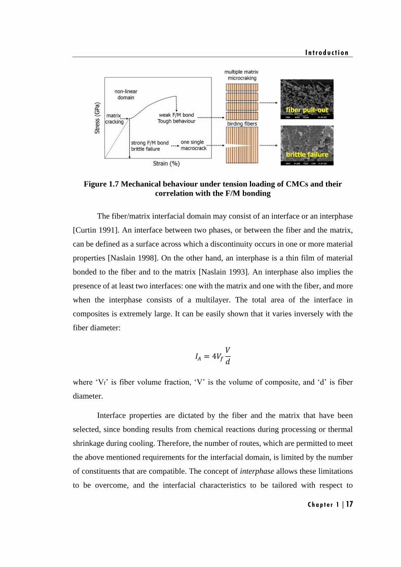
Figure 1.7 Mechanical behaviour under tension loading of CMCs and their correlation
with the F/M bonding ...................................................................................................... 17
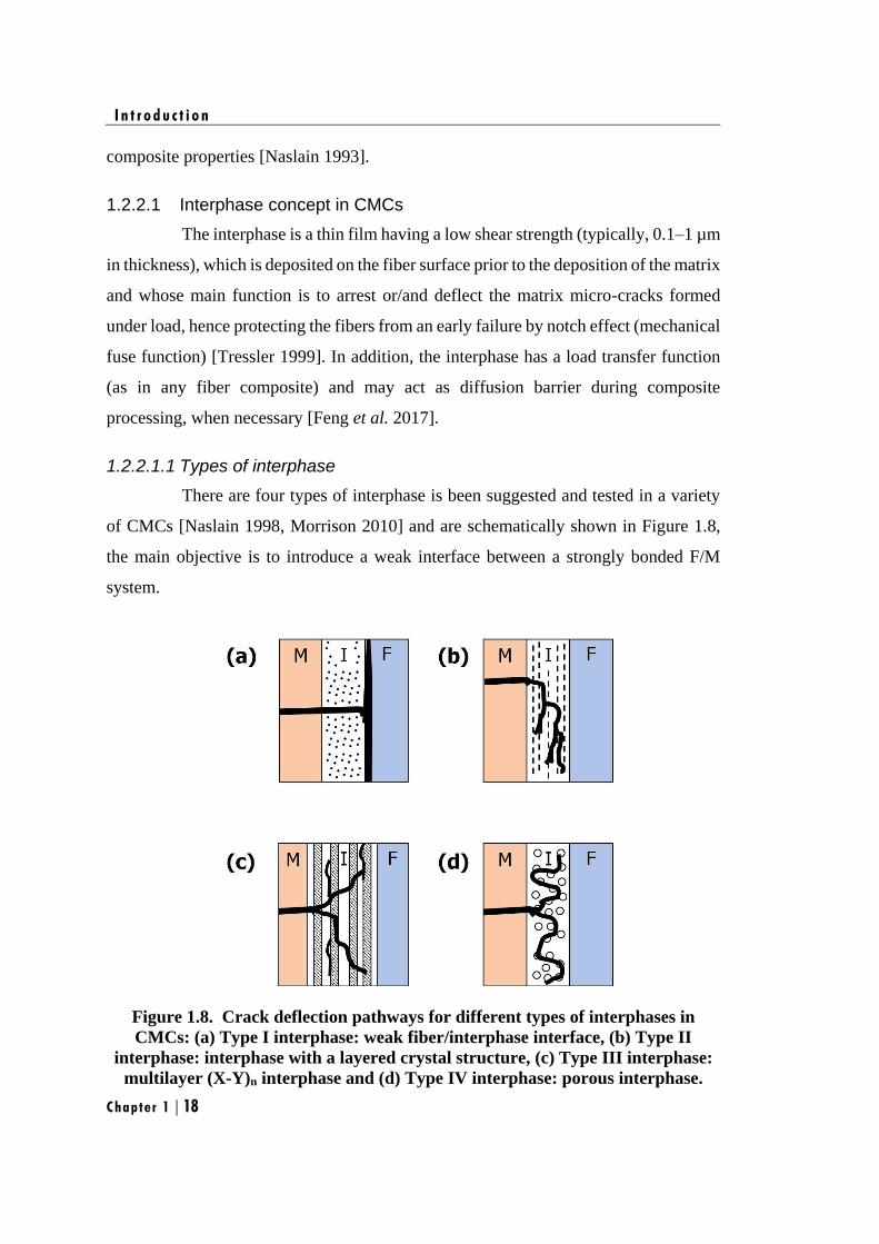
Figure 1.8. Crack deflection pathways for different types of interphases in CMCs: (a)
Type I interphase: weak fiber/interphase interface, (b) Type II interphase: interphase
with a layered crystal structure, (c) Type III interphase: multilayer (X-Y)n interphase and
(d) Type IV interphase: porous interphase. .................................................................... 18
Figure 1.9. Atomistic model of pyrocarbon (PyC) .......................................................... 21
Figure 1.10 Schematic overview of the different methods used for manufacturing of
CMCs…………………………………………………………………………………………………………………..
23
Figure 1.11 Chemical Vapor Infiltration (CVI) reactor .................................................. 24
Figure 1.12 Densification of matrix in CMCs via CVI technique ................................... 25
Figure 1.13. Schematic view of CVI process................................................................... 26
Figure 1.14. Steps of polymer infiltration and pyrolysis process .................................... 29
Figure 1.15 Polymer infiltration and pyrolysis process ................................................... 29
Figure 1.16 Steps involved in LSI process ...................................................................... 31
Figure 1.17. Schematic overview of the manufacture of C/SiC materials via LSI .......... 32
Figure 1.18 Schematic overview of the manufacture of C/SiC materials via RBSC……35
Figure 1.19 Schematic representation of Self-healing mechanism in CMCs .................. 38
Figure 1.20. Structure of phenolic resins ........................................................................ 41
Figure 2.1 Synthesis of BPF resin ................................................................................... 55
Figure 2.2 Synthesis of SPF resin .................................................................................... 56
Figure 2.3 Synthesis of BCTS resin ................................................................................ 58
Figure 2.4 Schematic view for the fabrication of CMCs using slurry containing PF or BPF
L i s t o f F i g u r e s
xiv
resin with silicon powder as matrix precursor via RBSC method .................................. 65
Figure 2.5 Schematic view for the fabrication of CMCs using SPF resin as matrix
precursor via PIP method .............................................................................................. 66
Figure 2.6 Schematic view for the vacuum infiltration of BCTS resin into CMCs ........ 67
Figure 3.1.1 Synthesis of BPF resin ............................................................................... 78
Figure 3.1.2 shows (a) FT-IR spectra of BPF resins (b) magnification in the range from
3800 to 2800 cm-1
and 1650 to 1250 cm-1
....................................................................... 79
Figure 3.1.3 XRD of B-C ceramics derived for BPF ..................................................... 80
Figure 3.1.4 Raman spectra of the B-C ceramics derived for BPF ................................ 82
Figure 3.1.5 Variation of ID/IG with interplanar distance (d002) of free carbon present in B-
C ceramics 83
Figure 3.1.6 presents a HRTEM micrograph of (a) BC-0, (c) BC-10, (f) BC-15 and (i)
BC-30 along with their corresponding selected area electron diffraction (SAED) and Fast
Fourier Transformer (FFT) patterns .............................................................................. 85
Figure 3.1.7 XRD of SiBOC mixed ceramics derived for BPFSi ................................. 88
Figure 3.1.8 Isothermal oxidation at 1000°C in air for 3 hr, showing (a) Weight change
(%) of oxidized SiBOC ceramic (b) Oxidation rate of SiBOC ceramic (c) SEM image of
the SiBOC ceramic before oxidation (d) SEM image of oxidized SiBOC ceramics at the
interval of 1hr, 2hr and 3hr. ........................................................................................... 89
Figure 3.1.9 (a) stress-strain-diagram of Cf/SiBOC from a flexural strength (b)
Comparison of average flexural strength of Cf/SiBOC along with its densities, (c) SEM
image of fractured surface of Cf/SiBOC-0, (d) SEM image of the top surface (plateau)
(blue) and side wall (orange) of carbon fibers, showing the thin polycrystalline SiC
product layer on the side wall, (e) and (f) shows the EDX for top surface (plateau) and
side wall of carbon fiber respectively. ............................................................................. 91
Figure 3.1.10 Isothermal oxidation at 1000°C, 1250°C and 1500°C in air for 3 hr, showing
(a) percentage weight change of Cf/SiBOC composite, (b) oxidation rate of Cf/SiBOC
composite, (c) The SEM image of the Cf/SiBOC composite before oxidation and (d) The
SEM image of the Cf/SiBOC composite after oxidation. ............................................... 94
Figure 3.2.1 (a) stress-strain-curves and (b) the average flexural strength of Cf/SiC-40/60,
Cf/SiC-50/50 and Cf/SiC-60/40 composites. ................................................................. 102
Figure 3.2.2 (a) Optical Image of lateral view on the development of cracks in a flexural
L i s t o f F i g u r e s
xv
specimen and (b) SEM image of the fractured surface of Cf/SiC-40/60, Cf/SiC-50/50 and
Cf/SiC-60/40 composites ............................................................................................... 103
Figure 3.2.3 (a) stress-strain-curves and (b) the average flexural strength of Cf/SiC-60/40,
Cf/SiBOC-10, Cf/SiBOC-15 and Cf/SiBOC-30 composites. ......................................... 105
Figure 3.2.4 (a) Optical image of lateral view on the development of cracks in a flexural
specimen and (b) SEM image on the fractured surface of Cf/SiC-60/40, Cf/SiBOC-10,
Cf/SiBOC-15 and Cf/SiBOC-30 composites. ................................................................ 105
Figure 3.2.5 (a) stress-strain-curves and (b) the average flexural strength of Cf/PyC/SiC-
60/40, Cf/PyC/SiBOC-10, Cf/PyC/SiBOC-15 and Cf/PyC/SiBOC-30 composites. ..... 107
Figure 3.2.6 (a) Optical image of lateral view on the development of cracks in a flexural
specimen and (b) SEM image on the fractured surface of Cf/PyC/SiC-60/40,
Cf/PyC/SiBOC-10, Cf/PyC/SiBOC-15 and Cf/PyC/SiBOC-30 composites. ................. 108
Figure 4.1.1. Synthesis of SPF resin .............................................................................. 119
Figure 4.1.2. FT-IR spectra of (a) CTS and PCTS resin and (b) PF resin and different
composition of SPF resins ............................................................................................ 119
Figure 4.1.3. 1
H NMR spectra of (a) PF, (b) PCTS and (c) SPF .................................. 120
Figure 4.1.4. 29
Si NMR spectra of (a) PCTS and (b) SPF ............................................ 121
Figure 4.1.5. Proposed ring opening mechanism for the formation of SPF resin ........ 122
Figure 4.1.6. XRD spectra of the pyrolyzed SPF resin (a) argon atmosphere at 1450°C
(b) nitrogen atmosphere at 1450°C and (c) argon atmosphere at 1650°C (d) nitrogen
atmosphere at 1650°C ................................................................................................... 123
Figure 4.1.7. Raman spectra of the pyrolyzed SPF resin (a) argon atmosphere at 1450°C
(b) nitrogen atmosphere at 1450°C and (c) argon atmosphere at 1650°C (d) nitrogen
atmosphere at 1650°C ................................................................................................... 125
Figure 4.1.8. Variation of size in carbon domains (La) with pyrolyzed SPF at (a) 1450°C
under argon atmosphere, (b) 1650°C under argon atmosphere, (c) 1450°C under nitrogen
atmosphere and (d) 1650°C under nitrogen atmosphere ............................................. 128
Figure 4.1.9. FESEM image of SPF pyrolyzed at 1450°C under argon atmosphere (a)
SPF-5, (b) SPF-10, (c) SPF-15, (d) SPF-20, (e) SPF-25 and (f) SPF-30 ........................ 130
Figure 4.1.10. FESEM image of SPF pyrolyzed under argon atmosphere at 1650°C (a)
SPF-5, (b) SPF-10, (c) SPF-15, (d) SPF-20, (e) SPF-25 and (f) SPF-30 ........................ 131
Figure 4.1.11. FESEM image, higher magnification FESEM image and corresponding
L i s t o f F i g u r e s
xvi
EDAX spectra of SiC nano-rods (a, b and c) under argon atmosphere and nano-crystal
decorated macro-porous cavity (d, e and f) under nitrogen atmosphere ..................... 132
Figure 4.1.12. FESEM image of SPF pyrolyzed at 1450°C under nitrogen atmosphere (a)
SPF-5, (b) SPF-10, (c) SPF-15, (d) SPF-20, (e) SPF-25 and (f) SPF-30 ........................ 133
Figure 4.1.13. FESEM image of SPF pyrolyzed at 1650°C under nitrogen atmosphere (a)
SPF-5, (b) SPF-10, (c) SPF-15, (d) SPF-20, (e) SPF-25 and (f) SPF-30 ........................ 133
Figure 4.1.14. Variation of surface porosity with pyrolyzed SPF (a) at 1450°C under argon
atmosphere, (b) at 1650°C under argon atmosphere, (c) at 1450°C under nitrogen
atmosphere and (d) at 1650°C under nitrogen atmosphere ......................................... 135
Figure 4.1.15. Mechanism for the formation (a) nano-rod structured ceramic under argon
atmosphere and (b) nano-crystal decorated macro-porous cavity ceramic under nitrogen
atmosphere 136
Figure 4.2.1 (a) Stress–strain-curves and (b) the average flexural strength of Cf/PyC/SiC-
Si3N4 composites ........................................................................................................... 145
Figure 5.1.2 GPC curve of CTS and different composition of BCTS resins .............. 159
Figure 5.1.3 FT-IR spectra of CTS and different composition of BCTS resins.......... 160
Figure 5.1.4 (a) 29
Si NMR spectra of CTS and BCTS15 resin and (b) 11
B NMR spectra of
BCTS15 resin ............................................................................................................... 162
Figure 5.1.5. Proposed ring opening mechanism for the formation of BCTS resin (a)
Self-condensation; (b) and (c) co-condensation ........................................................... 163
Figure 5.1.6 TG and its derivative curves of (a) CTS, (b) BCTS11, (c) BCTS13 and (d)
BCTS15……………………………………………………………………………………………………………..1
64
Figure 5.1.7 Schematic representation of highly cross-linked structure of BCTS ....... 165
Figure 5.1.8 Py-GC-MS spectra of BCTS15 sample in the temperature range of 25°C to
900°C…………………………………………………………………………………………………………………1
66
Figure 5.1.9 XRD spectra of the pyrolyzed BCTS resin (a) at 1450°C (b) at 1650°C . 167
Figure 5.1.10 SEM images of BCTS pyrolyzed at (a-c) 1450°C and (d-f) 1650°C ....... 170
Figure 5.1.11 HRTEM image of the BCTS resin pyrolyzed at 1450°C (a) BCTS11 (b)
BCTS13 and (c) BCTS15 along with their corresponding SAED pattern (a-1) BCTS11,
(b-1) BCTS13 and (c-1) BCTS15 ............................................................................. 173
L i s t o f F i g u r e s
xvii
Figure 5.1.12 HRTEM image of the BCTS resin pyrolyzed at 1650°C (a) BCTS11 (b)
BCTS13 and (c) BCTS15 along with their corresponding SAED pattern (a-1) BCTS11,
(b-1) BCTS13 and (c-1) BCTS15 .............................................................................. 174
Figure 5.1.13 HRTEM image of (a) BCTS15 pyrolyzed at 1650°C (b) magnified
HRTEM image of BCTS15 showing turbostatic layer of BN(C) ceramic ................... 175
Figure 5.1.14. Schematic representation for the conversion of h-BN to BN(C) on
increasing the pyrolyzed temperature from 1450°C to 1650°C in BCTS15 sample .... 176
Figure 5.2.1 SEM image of (a) Cf/PyC/SiBOC-30, (b) Cf/PyC/SiC-Si3N4-20 (c)
Cf/PyC/SiBOC-30/SiBCN15 and (d) Cf/PyC/SiC-Si3N4-20/SiBCN15 .......................... 184
Figure 5.2.2 Stress-strain-curves of CMCs before and after infiltration with BCTS
resin……………………………………………………………………………………………………………………
185
Figure 5.2.3 (a) Optical Image of lateral view on the development of cracks in a flexural
specimen and (b) SEM image of the fractured surface of CMCs before and after
infiltration
…………………………………………………………………………………………………………..1
87
Figure 5.2.4 Isothermal oxidation at 1000°C in air for 3h, showing (a) Percentage weight
loss of CMCs and (b) oxidation rate of CMCs ............................................................. 189
Figure 5.2.5 SEM image of oxidized CMCs at 1000°C in air for 3h ............................ 191
Figure 5.2.6 Isothermal oxidation at 1250°C in air for 3h, showing (a) Percentage weight
loss of CMCs and (b) oxidation rate of CMCs ............................................................. 192
Figure 5.2.7 SEM image of oxidized CMCs at 1000°C in air for 3h ............................ 193
Figure 5.2.8 Isothermal oxidation at 1500°C in air for 3h, showing (a) Percentage weight
loss of CMCs and (b) oxidation rate of CMCs ............................................................. 194
Figure 5.2.9 SEM image of oxidized CMCs at 1000°C in air for 3h ............................ 195

xix
List of Tables
Table 1.1 Some of the most commonly used oxide and non-oxide ceramic fiber and
matrices for high temperature applications ....................................................................... 6
Table 1.2 Some carbon fiber precursors and their yields .............................................. 11
Table 1.3 Types of carbon fiber reinforcement most commonly used for CMCs ........ 15
Table 1.4 Physical and mechanical characteristics of ceramic materials ........................ 22
Table 2.2 Properties of PF resin ..................................................................................... 53
Table 2.3 Different composition of BPF resin ............................................................... 54
Table 2.4 Different composition of SPF resin ............................................................... 57
Table 2.5 Different composition of BCTS resin with viscosity and molecular weight .. 57
Table 3.1.1 Parameters derived from Raman spectra and XRD of B-C ceramics......... 83
Table 3.1.2 Elemental Analysis for B-C ceramics obtained at 1450°C in argon
atmosphere…………………………………………………………………………………………………………..
84
Table 3.1.3 Elemental Analysis for SiBOC ceramics obtained at 1450°C in argon
atmosphere…………………………………………………………………………………………………………..
87
Table 3.2.1 Properties of the Preceramic matrix precursors ....................................... 101
Table 3.2.2 Properties of the Cf/SiC composites .......................................................... 101
Table 3.2.3 Properties of the CMCs with and without PyC interphase ....................... 104
Table 4.1.1 Parameters derived from Raman spectra for ceramics derived from PF and
SPF at 1450°C and 1650°C under argon atmosphere ................................................... 126
Table 4.1.2 Parameters derived from Raman spectra for ceramics derived from PF and
SPF at 1450°C and 1650°C under nitrogen atmosphere .............................................. 127
Table 4.1.3 Elemental composition of ceramics derived from SPF at 1450°C and 1650°C
under argon atmosphere ............................................................................................... 137
Table 4.1.4 Elemental composition of ceramics derived from SPF at 1450°C and 1650°C
under nitrogen atmosphere ........................................................................................... 138
Table 4.1.5 Ceramic yield of pyrolyzed SPF at 1450°C and 1650°C under argon and
nitrogen atmosphere ..................................................................................................... 139
Table 4.2.1 Different formulation of SPF resin ........................................................... 144

L i s t o f T a b l e s
xx
Table 4.2.2 Properties of the Cf/PyC/SiC-Si3N4composites ......................................... 144
Table 5.1.1 Different composition of BCTS resin with viscosity and molecular
weight…………………………………………………………………………………………………………………1
58
Table 5.1.2 Main peak assignment in FT-IR Spectrum of CTS, BCTS11, BCTS13 and
BCTS15 resin ............................................................................................................... 160
Table 5.1.3 TG and its derivative data of CTS, BCTS11, BCTS13 and BCTS15
resins………………………………………………………………………………………………………..………..1
64
Table 5.1.4 Elemental composition and ceramic yield of ceramics derived from BCTS
at 1450°C and 1650°C .................................................................................................. 171
Table 5.2.1 Properties of the CMCs derived from BPFSi and SPF resins ................. 181
Table 5.2.2 Properties of the Cf/PyC/SiBOC-30, Cf/PyC/SiC-Si3N4-20, Cf/PyC/SiBOC-
30/SiBCN15 and Cf/PyC/SiC-Si3N4-20/SiBCN15 composites ..................................... 183
Table 5.2.3 Elemental composition of the ceramic matrix ......................................... 186
xxi
Symbols and Abbreviations
β Full width at half maximum measured in radians
δ Chemical Shift
θ Bragg’s angle
λ Wavelength of X-ray radiation equal to 1.5406 Å
ρ Density
σf Flexural strength
wM Weight average molecular weight
nM Number average molecular weight
2D Two dimension
BC Boron-carbon containing ceramics
BCTS Boron modified cyclotrisilazane
BPF Boron modified phenol-formaldehyde
BPFSi Boron modified phenol formaldehyde resin blended with silicon
powder
CFRP Carbon fiber reinforced polymer matrix composites
CMC Ceramic matrix composite
CTS 1, 3, 5-trimethyl-1ˈ, 3ˈ, 5ˈ-trivinylcyclotrisilazane
CVI Chemical vapor infiltration
d Interplanar distance
D Average crystallite size
D-band Distorted carbon band
DCP Dicumyl peroxide
DMF N, N-dimethylformamide
EBC Environmental barrier coatings
EDX Energy Dispersive X-ray
Ef Flexural modulus
F/M Fiber/matrix
F-CVI Thermal gradient-forced flow-chemical vapor infiltration
FESEM Felid emission Scanning electron microscopy
FFT Fast Fourier Transformer
FTIR Fourier Transform-Infra Red
FWHM Full width at half maximum
G-band Graphitic carbon band
GPC Gel permeation chromatography
h-BN Hexagonal-boron nitride
HM High-modulus
HMTA Hexamethylenetetramine
HRTEM High-resolution Transmission electron microscopy
HT High-tensile
IA Area of the interface
ID Intensity ratio of the D-band
IF-CVI Isothermal-forced flow-chemical vapor infiltration
IG Intensity ratio of the G-band
IM Intermediate-modulus
L i s t o f S y m b o l s a n d A b b r e v i a t i o n s
xxii
k Coefficient, which is generally taken as 0.94
La Size of carbon domains along the six-fold ring plane
LSI Liquid silicon infiltration
m˳ Initial weight of ceramic or ceramic matrix composite
MTS Methyltrichlorosilane
NMR Nuclear Magnetic Resonance
PAN Polyacrylonitrile
PCTS Polycyclotrisilazane
P-CVI Pulsed flow-chemical vapor infiltration
PF Phenol-formaldehyde
PIP Polymer impregnation/infiltration and pyrolysis
pph Parts per hundred
PVC Polyvinylchloride
PyC Pyrocarbon
Py–GC–MS Pyrolysis–gas chromatography–mass spectrometry
RBSC Reaction bonded silicon carbide
RMI Reactive Melt Infiltration
SAED Selected area electron diffraction
SEM Scanning electron microscopy
SiBCN Silicon boron carbonitride
SiBOC Silicon boron oxycarbide
SiC Silicon carbide
SiCN Silicon carbonitride
SPF Silazane modified phenol formaldehyde
TBC Thermal barrier coatings
TGA Thermogravimetric analysis
TG-CVI Temperature gradient-chemical vapor infiltration
THF Tetrahydrofuran
UHM Ultra-high-modulus
V Volume of composite
Vf Fiber volume fraction
VLS Vapor-liquid-solid
VS Vapor-solid
VV Vapor-vapor
XRD X-Ray Diffraction
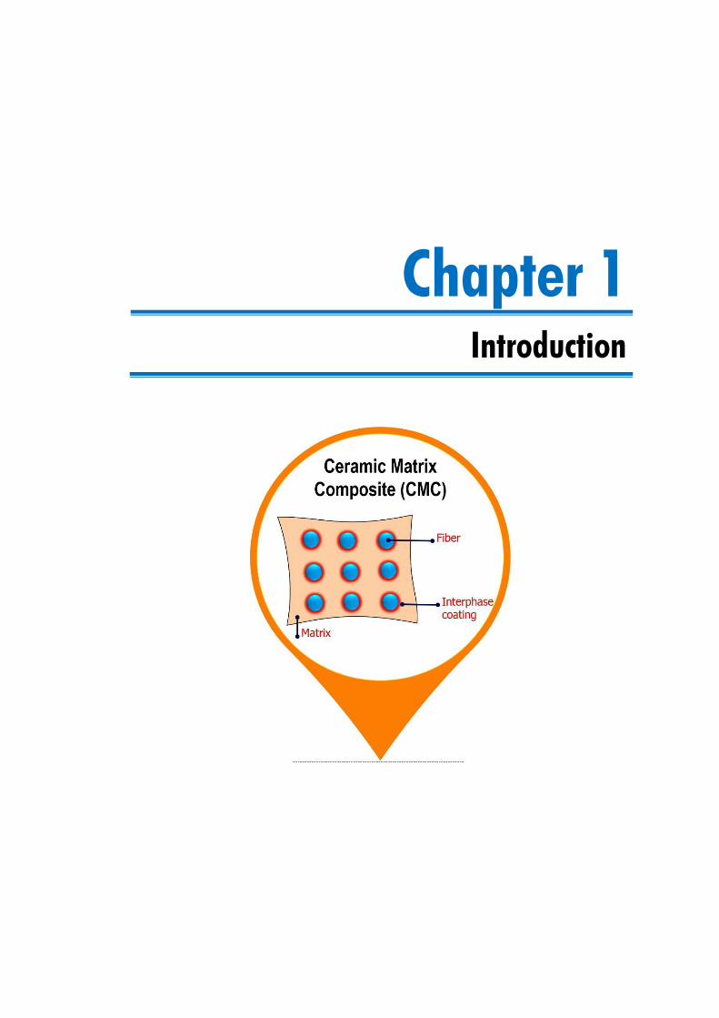
Chapter 1
Introduction

I n t r o d u c t i o n
C h a p t e r 1 | 3
This chapter gives a general introduction on CMCs such as,
• Design and selection of constituents in CMCs
• Processing techniques involved to fabricate CMCs
• Role of boron in the protection of CMCs
The introductory chapter concludes with the discussion on the scope and objective of
the present investigation

I n t r o d u c t i o n
C h a p t e r 1 | 4
I n t r o d u c t i o n
C h a p t e r 1 | 5
omposite materials have played vital role in development of aeronautic,
military and spatial industries [Abdalla et al. 2003, Peters 2013]. With years
of focused research, significant advancements have been made in terms of
quality and performance level of composite materials which has substantially widened
their applications [Mouritz et al. 2001, Dong-Xiao 2006, Gibson 2010, Gay 2014].
Today, sustainable development forms the main pre-occupations of governments and
industries. Towards this, different research programs have been launched, new
standards and measures have been placed with national and international scope to
mitigate the environmental impacts [Shanyi 2007]. Intensive researches are being
carried out aimed at the weight reduction of the structures by using composite materials,
for which more and more materials were extensively explored that can survive in the
extreme environments [Niihara 1991, Baldus et al. 1999, Cao et al. 2004]. Particularly,
composites made of carbon or ceramic fibers combined with carbon or ceramic matrix
called ceramic matrix composites (CMCs) are potential candidates for high-temperature
applications such as rocket nozzles, aeronautic jet engines, heat shields and aircraft
braking systems [Baldus et al. 1999, Cao et al. 2004, Naslain 2004]. They have the
advantage of retaining their thermo-mechanical properties even at very high
temperature, which highlights their usage for high-temperature applications [Schmidt
et al. 2004, Krenkel 2008]. However, the production cost and the materials used can
reach escalating prices depending on the targeted applications and the technologies
required for their production. Hence, development of these materials with competitive
and attractive methods gains tremendous significance for high-temperature application.
1.1. Ceramic Matrix Composites (CMCs)
Aeronautic, military and industrial applications require advanced materials that
can survive extreme environments. Recently, ceramics have attracted enormous
attention due to their superior properties, such as high-temperature stability, oxidation
and corrosion resistance, as well as enhanced thermo-mechanical properties compared
to that of metals and polymers [Baldus et al. 1999, Cao et al. 2004, Sanchez et al. 2013,
Kalpakjian et al. 2014]. Monolitic ceramics (SiC, B4C, Si3N4, SiB4), ceramic coatings
like thermal barrier coatings (TBC), environmental barrier coatings (EBC) and ceramic
C
I n t r o d u c t i o n
Chapter 1 | 6
matrix composites (CMCs) are some of the examples for high temperature ceramic
materials that can be classified as advanced materials [Miller 1997, Cao et al. 2004].
Although monolithic ceramics possess desirable properties such as low density, high
strength, high temperature resistance, chemical inertness, wear and erosion resistance,
they exhibit extremely brittle behavior under thermal and mechanical loading
conditions. In order to overcome this drawback, fiber-reinforcemented ceramics are
used to increase toughness of the ceramic materials and are termed as CMCs [Ohnabe
et al. 1999, Schmidt et al. 2004]. They received considerable attention for thermo-
structural applications due to their low density, high modulus and good thermal shock
resistance [Ohnabe et al. 1999]. CMCs represent the latest entry in the field of
composites. They are largely suitable for the high temperature applications such as
components in thrust providing parts of rocket or missile systems and thermal
protection systems of the nose cap in re-entry vehicles [Triantou et al. 2017, Triantou
et al. 2017].
1.1.1. Classification of CMCs
CMCs are broadly classified into two classes viz. oxide and non-oxide CMCs
[Sun et al. 2006]. Oxide CMCs consist of oxide fibers combined with oxide matrices,
while the non-oxide CMCs consist of non-oxide fibers combined with non-oxide
matrices. Some of the most commonly used oxide and non-oxide fibers and matrices
for high temperature applications are given in Table 1.1.
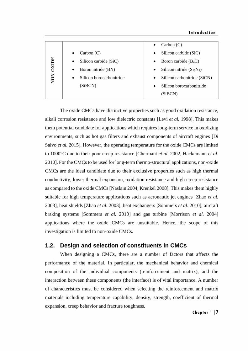
Table 1.1
Some of the most commonly used oxide and non-oxide ceramic fiber and matrices
for high temperature applications CMCs FIBER MATRIX
OX
IDE
• Alumina (α-Al2O3)
• Alumina silicate (Al2O3.SiO2)
• Alumina borosilicate
(Al2O3.SiO2.B2O3)
• Alumina zirconate (Al2O3.ZrO2)
• Zirconium silicate (ZrO2.SiO2)
• Alumina (α-Al2O3)
• Alumina silicate
(Al2O3.SiO2)
• Zriconia (ZrO2)
I n t r o d u c t i o n
C h a p t e r 1 | 7
NO
N-O
XID
E
• Carbon (C)
• Silicon carbide (SiC)
• Boron nitride (BN)
• Silicon borocarbonitride
(SiBCN)
• Carbon (C)
• Silicon carbide (SiC)
• Boron carbide (B4C)
• Silicon nitride (Si3N4)
• Silicon carbonitride (SiCN)
• Silicon borocarbonitride
(SiBCN)
The oxide CMCs have distinctive properties such as good oxidation resistance,
alkali corrosion resistance and low dielectric constants [Levi et al. 1998]. This makes
them potential candidate for applications which requires long-term service in oxidizing
environments, such as hot gas filters and exhaust components of aircraft engines [Di
Salvo et al. 2015]. However, the operating temperature for the oxide CMCs are limited
to 1000°C due to their poor creep resistance [Chermant et al. 2002, Hackemann et al.
2010]. For the CMCs to be used for long-term thermo-structural applications, non-oxide
CMCs are the ideal candidate due to their exclusive properties such as high thermal
conductivity, lower thermal expansion, oxidation resistance and high creep resistance
as compared to the oxide CMCs [Naslain 2004, Krenkel 2008]. This makes them highly
suitable for high temperature applications such as aeronautic jet engines [Zhao et al.
2003], heat shields [Zhao et al. 2003], heat exchangers [Sommers et al. 2010], aircraft
braking systems [Sommers et al. 2010] and gas turbine [Morrison et al. 2004]
applications where the oxide CMCs are unsuitable. Hence, the scope of this
investigation is limited to non-oxide CMCs.
1.2. Design and selection of constituents in CMCs
When designing a CMCs, there are a number of factors that affects the
performance of the material. In particular, the mechanical behavior and chemical
composition of the individual components (reinforcement and matrix), and the
interaction between these components (the interface) is of vital importance. A number
of characteristics must be considered when selecting the reinforcement and matrix
materials including temperature capability, density, strength, coefficient of thermal
expansion, creep behavior and fracture toughness.
I n t r o d u c t i o n
Chapter 1 | 8
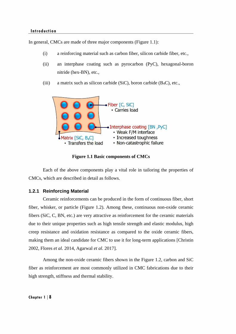
In general, CMCs are made of three major components (Figure 1.1):
(i) a reinforcing material such as carbon fiber, silicon carbide fiber, etc.,
(ii) an interphase coating such as pyrocarbon (PyC), hexagonal-boron
nitride (hex-BN), etc.,
(iii) a matrix such as silicon carbide (SiC), boron carbide (B4C), etc.,
Figure 1.1 Basic components of CMCs
Each of the above components play a vital role in tailoring the properties of
CMCs, which are described in detail as follows.
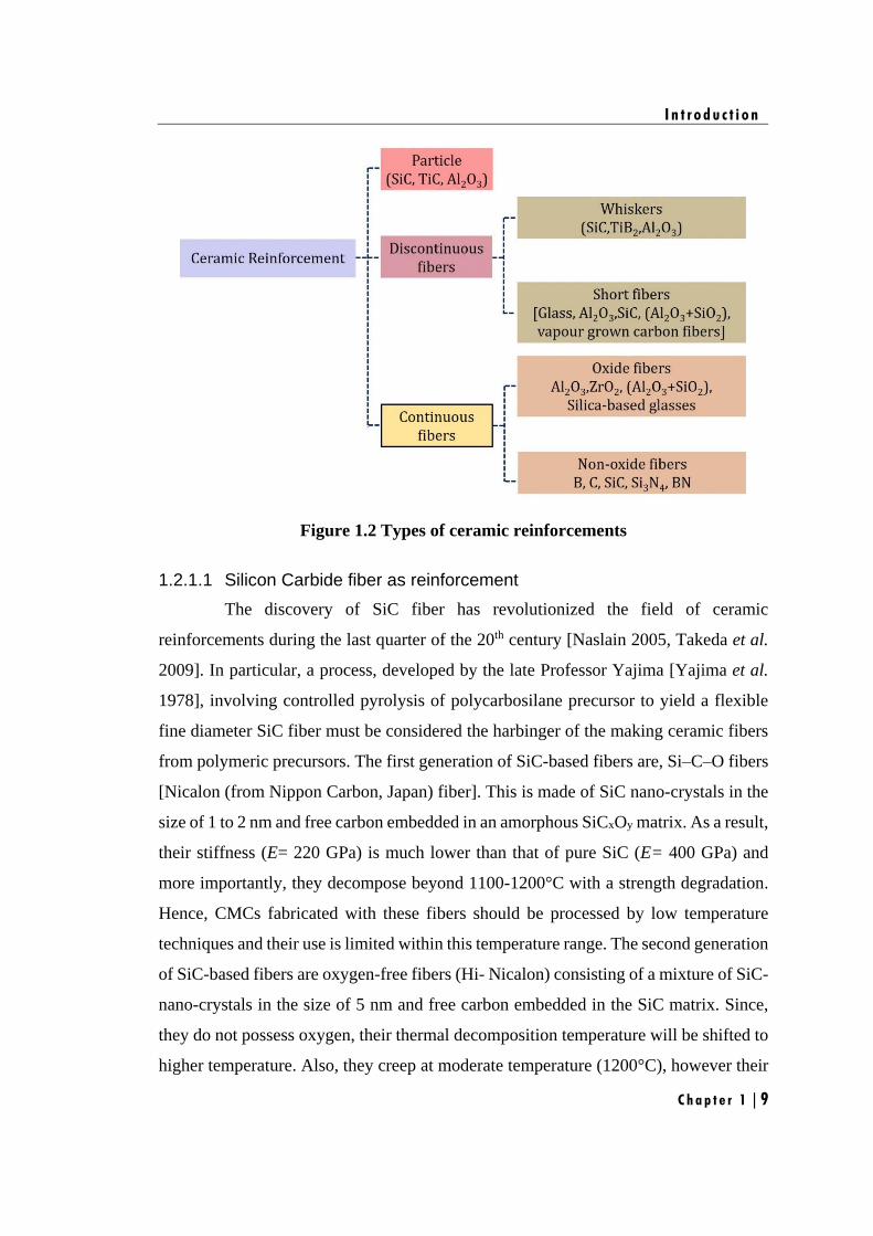
1.2.1 Reinforcing Material
Ceramic reinforcements can be produced in the form of continuous fiber, short
fiber, whisker, or particle (Figure 1.2). Among these, continuous non-oxide ceramic
fibers (SiC, C, BN, etc.) are very attractive as reinforcement for the ceramic materials
due to their unique properties such as high tensile strength and elastic modulus, high
creep resistance and oxidation resistance as compared to the oxide ceramic fibers,
making them an ideal candidate for CMC to use it for long-term applications [Christin
2002, Flores et al. 2014, Agarwal et al. 2017].
Among the non-oxide ceramic fibers shown in the Figure 1.2, carbon and SiC
fiber as reinforcement are most commonly utilized in CMC fabrications due to their
high strength, stiffness and thermal stability.
I n t r o d u c t i o n
C h a p t e r 1 | 9
Figure 1.2 Types of ceramic reinforcements
1.2.1.1 Silicon Carbide fiber as reinforcement
The discovery of SiC fiber has revolutionized the field of ceramic
reinforcements during the last quarter of the 20th century [Naslain 2005, Takeda et al.
2009]. In particular, a process, developed by the late Professor Yajima [Yajima et al.
1978], involving controlled pyrolysis of polycarbosilane precursor to yield a flexible
fine diameter SiC fiber must be considered the harbinger of the making ceramic fibers
from polymeric precursors. The first generation of SiC-based fibers are, Si–C–O fibers
[Nicalon (from Nippon Carbon, Japan) fiber]. This is made of SiC nano-crystals in the
size of 1 to 2 nm and free carbon embedded in an amorphous SiCxOy matrix. As a result,
their stiffness (E= 220 GPa) is much lower than that of pure SiC (E= 400 GPa) and
more importantly, they decompose beyond 1100-1200°C with a strength degradation.
Hence, CMCs fabricated with these fibers should be processed by low temperature
techniques and their use is limited within this temperature range. The second generation
of SiC-based fibers are oxygen-free fibers (Hi- Nicalon) consisting of a mixture of SiC-
nano-crystals in the size of 5 nm and free carbon embedded in the SiC matrix. Since,
they do not possess oxygen, their thermal decomposition temperature will be shifted to
higher temperature. Also, they creep at moderate temperature (1200°C), however their
I n t r o d u c t i o n
Chapter 1 | 10
creep resistance can be improved (1400°C) on subsequent heat treatment at 1400-
1600°C which stabilizes the fiber microstructure. The third generation of SiC-based
fibers are oxygen-free and quasi-stoichiometric in nature (Hi-Nicalon S, Tyranno SA
or Sylramic) and are prepared at very high temperature (1600 to 2000°C) with
crystallite size is in the range of 20 to 200 nm. The third generation of the SiC-based
fibers exhibit superior thermal stability as compared to the first and second generation
SiC fibers. There are other potential SiC-based fiber reinforcements, e.g. the amorphous
Si-B-C-N fibers but which are still at an experimental stage. In spite of the great
significance of SiC-based fibers in the field of CMCs, all these fibers are very stiff in
nature and has high crystallite size. This leads to poor weave-ability and difficulties in
fabricating the CMCs with complex shapes which limits their applicability. Also, most
of the SiC fibers are very expensive and their availability is less as compared to carbon
fibers.
In this regards, only carbon fiber has reached the stage in which they have been
used to reinforce different high-temperature CMC systems [Sambell et al. 1972,
Figueiredo et al. 2013, Gay 2014]. Although these fibers degrade in an oxidizing
atmosphere above 450°C, they are stable under non-oxidizing conditions up to
temperatures of 2800°C [Lamouroux et al. 1999]. Carbon fibers have unique properties
such as good mechanical and thermal properties at elevated temperature, low density
and moderate cost. In addition, the diameter of the carbon fiber is in the range of 7 µm
to 10 µm giving them good weaving ability and they can be used to produce nD-
preforms of complex shapes make it very popular in aerospace, civil engineering and
military applications [Chawla 1998, Krenkel et al. 2002].
1.2.1.2 Carbon fiber as reinforcement
Carbon fibers have been described as the fibers containing at least 90% carbon
obtained by the controlled pyrolysis of appropriate fibers [Fitzer 1987]. The carbon
atoms are bonded together in microscopic crystals that are more or less aligned parallel
to the long axis of the fiber [Peebles Jr 1995]. The crystal alignment makes the fiber
very strong for its size. Several thousand carbon fibers are twisted together to form a
yarn, which may be used by itself or woven into a fabric [Buckley et al. 1993]. Carbon
I n t r o d u c t i o n
C h a p t e r 1 | 11
fiber has many different weave patterns and can be combined with a ceramic materials
and wound or molded to form CMCs, such as carbon fibers reinforced silicon carbide
composite (C/SiC), to provide high strength-to-weight ratio materials [Camus et al.
1996, Su et al. 2004, Longbiao et al. 2013, Zhang et al. 2013].
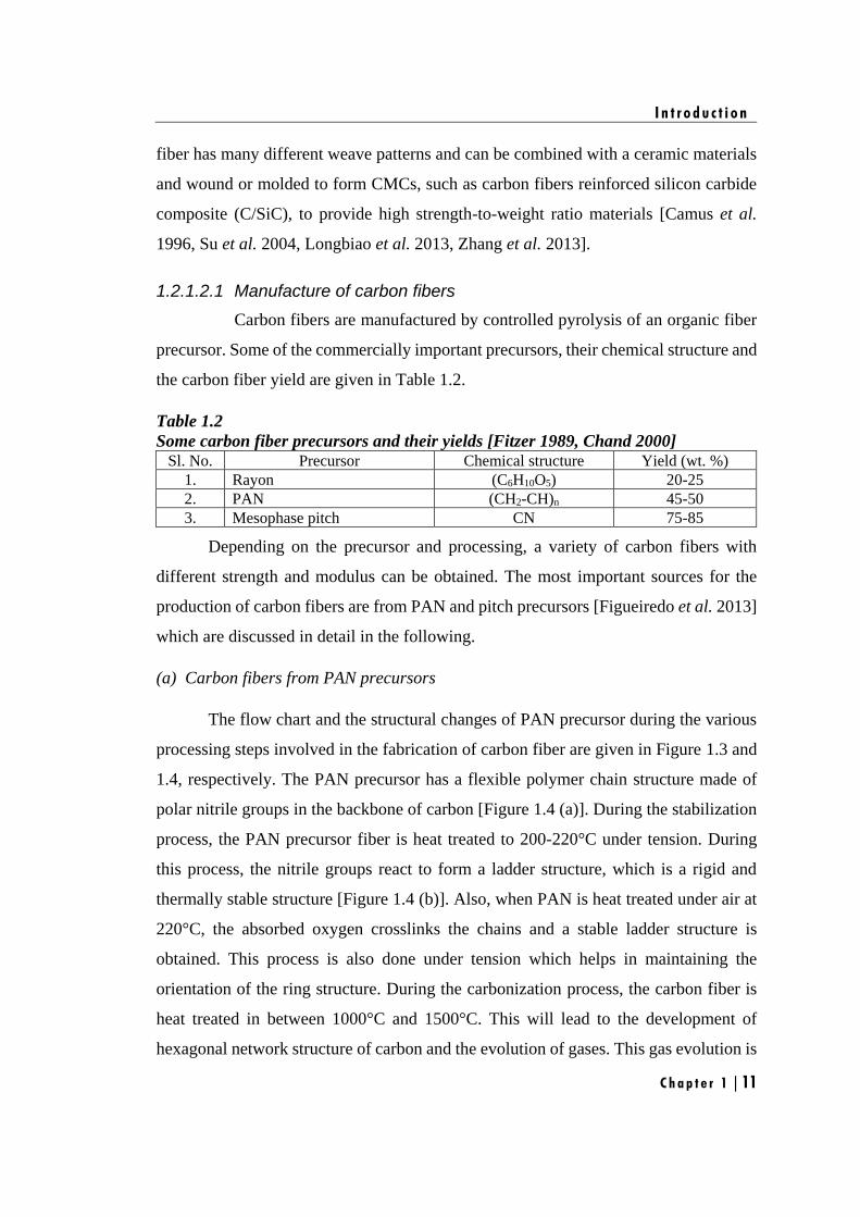
1.2.1.2.1 Manufacture of carbon fibers
Carbon fibers are manufactured by controlled pyrolysis of an organic fiber
precursor. Some of the commercially important precursors, their chemical structure and
the carbon fiber yield are given in Table 1.2.
Table 1.2
Some carbon fiber precursors and their yields [Fitzer 1989, Chand 2000] Sl. No. Precursor Chemical structure Yield (wt. %)
1. Rayon (C6H10O5) 20-25
2. PAN (CH2-CH)n 45-50
3. Mesophase pitch CN 75-85
Depending on the precursor and processing, a variety of carbon fibers with
different strength and modulus can be obtained. The most important sources for the
production of carbon fibers are from PAN and pitch precursors [Figueiredo et al. 2013]
which are discussed in detail in the following.
(a) Carbon fibers from PAN precursors
The flow chart and the structural changes of PAN precursor during the various
processing steps involved in the fabrication of carbon fiber are given in Figure 1.3 and
1.4, respectively. The PAN precursor has a flexible polymer chain structure made of
polar nitrile groups in the backbone of carbon [Figure 1.4 (a)]. During the stabilization
process, the PAN precursor fiber is heat treated to 200-220°C under tension. During
this process, the nitrile groups react to form a ladder structure, which is a rigid and
thermally stable structure [Figure 1.4 (b)]. Also, when PAN is heat treated under air at
220°C, the absorbed oxygen crosslinks the chains and a stable ladder structure is
obtained. This process is also done under tension which helps in maintaining the
orientation of the ring structure. During the carbonization process, the carbon fiber is
heat treated in between 1000°C and 1500°C. This will lead to the development of
hexagonal network structure of carbon and the evolution of gases. This gas evolution is
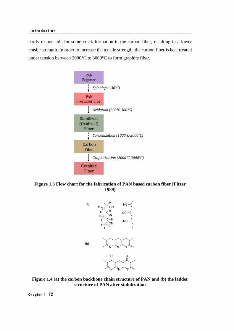
I n t r o d u c t i o n
Chapter 1 | 12
partly responsible for some crack formation in the carbon fiber, resulting in a lower
tensile strength. In order to increase the tensile strength, the carbon fiber is heat treated
under tension between 2000°C to 3000°C to form graphite fiber.
Figure 1.3 Flow chart for the fabrication of PAN based carbon fiber [Fitzer
1989]
Figure 1.4 (a) the carbon backbone chain structure of PAN and (b) the ladder
structure of PAN after stabilization
I n t r o d u c t i o n
C h a p t e r 1 | 13
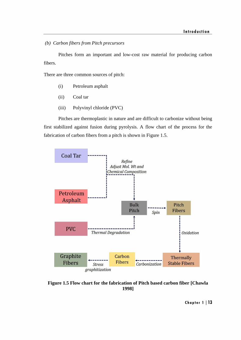
(b) Carbon fibers from Pitch precursors
Pitches form an important and low-cost raw material for producing carbon
fibers.
There are three common sources of pitch:
(i) Petroleum asphalt
(ii) Coal tar
(iii) Polyvinyl chloride (PVC)
Pitches are thermoplastic in nature and are difficult to carbonize without being
first stabilized against fusion during pyrolysis. A flow chart of the process for the
fabrication of carbon fibers from a pitch is shown in Figure 1.5.
Figure 1.5 Flow chart for the fabrication of Pitch based carbon fiber [Chawla
1998]
I n t r o d u c t i o n
Chapter 1 | 14
It involves the following steps:
(i) Fiberization, i.e. extrusion of a polymer melt or solution into a precursor
fiber.
(ii) Stabilization (oxidation or thermosetting) is done at relatively low
temperatures (200-450°C), usually in air. This renders the precursor
infusible during the subsequent high-temperature processing.
(iii) Carbonization is carried out under nitrogen atmosphere at the
temperature of 1000-2000°C. At the end of this step the fiber has 85-
99% of carbon content.
(iv) Graphitization is done under argon or nitrogen atmosphere at a
temperature greater than 2500°C. This step increases the carbon content
to more than 99% and imparts a very high degree of preferred orientation
to the fiber.
1.2.1.2.2 Classification of Carbon fibers
Based on modulus, strength, and final heat treatment temperature, carbon
fibers can be classified into the following three categories:
Based on properties of carbon fibers, they can be grouped into:
(i) Ultra-high-modulus (UHM) having modulus of >450 GPa
(ii) High-modulus (HM) having modulus between 350–450 GPa
(iii) Intermediate-modulus (IM) having modulus between 200–350 GPa
(iv) Low modulus and high-tensile (HT) having modulus of <100 Gpa;
tensile strength of >3.0 GPa
Based on precursor materials, carbon fibers are classified into:
(i) Polyacrylonitrile (PAN) based carbon fibers
(ii) Pitch based carbon fibers
(iii) Rayon based carbon fibers
I n t r o d u c t i o n
C h a p t e r 1 | 15
Based on final heat treatment temperature, carbon fibers are classified into:
(i) Type-I, high-heat-treatment carbon fibers (HTT), where final heat
treatment temperature should be above 2000°C and can be associated
with high-modulus type fiber.
(ii) Type-II, intermediate-heat-treatment carbon fibers (IHT), where final
heat treatment temperature should be around or above 1500°C and can
be associated with high-strength type fiber.
(iii) Type-III, low-heat-treatment carbon fibers, where final heat treatment
temperature not greater than 1000°C. These are low modulus and low
strength materials.
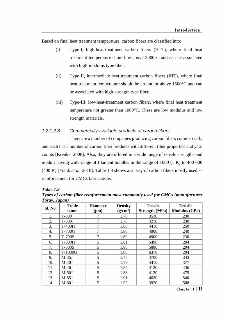
1.2.1.2.3 Commercially available products of carbon fibers
There are a number of companies producing carbon fibers commercially
and each has a number of carbon fiber products with different fiber properties and yarn
counts [Krenkel 2008]. Also, they are offered in a wide range of tensile strengths and
moduli having wide range of filament bundles in the range of 1000 (1 K) to 400 000
(400 K) [Frank et al. 2016]. Table 1.3 shows a survey of carbon fibers mostly used as
reinforcement for CMCs fabrications.
Table 1.3
Types of carbon fiber reinforcement most commonly used for CMCs (manufacturer
Toray, Japan)
Sl. No. Trade
name
Diameter
(µm)
Density
(g/cm3)
Tensile
Strength (MPa)
Tensile
Modulus (GPa)
1. T-300 7 1.76 3530 230
2. T-300J 7 1.78 4210 230
3. T-400H 7 1.80 4410 250
4. T-700G 7 1.80 4900 240
5. T-700S 7 1.80 4900 230
6. T-800H 5 1.81 5490 294
7. T-800S 5 1.80 5880 294
8. T-1000G 5 1.80 6370 294
9. M-35J 5 1.75 4700 343
10. M-40J 5 1.77 4410 377
11. M-46J 5 1.84 4120 436
12. M-50J 5 1.88 4120 475
13. M-55J 5 1.91 4020 540
14. M-60J 5 1.93 3920 588
I n t r o d u c t i o n
Chapter 1 | 16
Among the carbon fibers given in the Table 1.3, T-300 carbon fiber was selected
in this study due to its availability and moderate cost. T-300 carbon fiber are available
in four types of filament bundles such as 1K, 3K, 6K and 12K. It is to be noted that, on
increasing the number of filaments, the strength of fiber increases whereas wettability
of the matrix resin decreases and hence an optimum strength and wettability is desired
for the CMCs fabrications. This will lead to low coefficient of thermal expansion (CTE)
mismatch between the fiber and matrix. Hence, among the carbon fiber filaments (1K,
3K, 6K and 12K) T-300 3K was selected for the further investigations. In addition, the
diameter of the T-300 3K carbon fiber is of 7 µm making their weaving quite facile and
can be used to produce nD-preforms of complex shapes.
1.2.2 Fiber/Matrix Interface
The fiber/matrix interfacial domain is a decisive constituent of fiber reinforced
CMCs [Kerans et al. 1989]. Depending on the characteristics of the domain, the
composite will be either a brittle ceramic or a damage tolerant composite as shown in
Figure 1.7.
Thus, several requirements, which may seem to oppose to each other, have to
be met the requirements [Budiansky et al. 1986, Evans et al. 1989, Figueiredo et al.
2013, Rajan et al. 2014]:
(i) Fibers have to be bonded to the matrix, in order to ensure material
integrity and to obtain a continuous medium.
(ii) Fiber failures have to be prevented when the matrix cracks which is
achieved by crack deviation.
(iii) Once deviation of matrix cracks has occurred, the loads still have to be
transferred efficiently through the interfaces, so that a certain amount of
the applied load is still carried by the matrix.
(iv) Then, in aggressive environments, the fibers should not be exposed to
species conveyed by the matrix cracks.
Meeting all of above requirements will lead to high-performance composite materials.
I n t r o d u c t i o n
C h a p t e r 1 | 17
Figure 1.7 Mechanical behaviour under tension loading of CMCs and their
correlation with the F/M bonding
The fiber/matrix interfacial domain may consist of an interface or an interphase
[Curtin 1991]. An interface between two phases, or between the fiber and the matrix,
can be defined as a surface across which a discontinuity occurs in one or more material
properties [Naslain 1998]. On the other hand, an interphase is a thin film of material
bonded to the fiber and to the matrix [Naslain 1993]. An interphase also implies the
presence of at least two interfaces: one with the matrix and one with the fiber, and more
when the interphase consists of a multilayer. The total area of the interface in
composites is extremely large. It can be easily shown that it varies inversely with the
fiber diameter:
𝐼𝐴 = 4𝑉𝑓𝑉
𝑑
where ‘Vf’ is fiber volume fraction, ‘V’ is the volume of composite, and ‘d’ is fiber
diameter.
Interface properties are dictated by the fiber and the matrix that have been
selected, since bonding results from chemical reactions during processing or thermal
shrinkage during cooling. Therefore, the number of routes, which are permitted to meet
the above mentioned requirements for the interfacial domain, is limited by the number
of constituents that are compatible. The concept of interphase allows these limitations
to be overcome, and the interfacial characteristics to be tailored with respect to
I n t r o d u c t i o n
Chapter 1 | 18
composite properties [Naslain 1993].
1.2.2.1 Interphase concept in CMCs
The interphase is a thin film having a low shear strength (typically, 0.1–1 µm
in thickness), which is deposited on the fiber surface prior to the deposition of the matrix
and whose main function is to arrest or/and deflect the matrix micro-cracks formed
under load, hence protecting the fibers from an early failure by notch effect (mechanical
fuse function) [Tressler 1999]. In addition, the interphase has a load transfer function
(as in any fiber composite) and may act as diffusion barrier during composite
processing, when necessary [Feng et al. 2017].
1.2.2.1.1 Types of interphase
There are four types of interphase is been suggested and tested in a variety
of CMCs [Naslain 1998, Morrison 2010] and are schematically shown in Figure 1.8,
the main objective is to introduce a weak interface between a strongly bonded F/M
system.
Figure 1.8. Crack deflection pathways for different types of interphases in
CMCs: (a) Type I interphase: weak fiber/interphase interface, (b) Type II
interphase: interphase with a layered crystal structure, (c) Type III interphase:
multilayer (X-Y)n interphase and (d) Type IV interphase: porous interphase.
I n t r o d u c t i o n
C h a p t e r 1 | 19
a) Type I interphase
In type I interphases, a simple weak interface is introduced in the F/M interfacial
zone to act as mechanical fuse [Figure 1.8 (a)]. Examples of such weak interfaces are:
(i) Silica glass/anisotropic pyrocarbon (PyC) interface
(ii) Lanthanum phosphate LaPO4/ alumina interface.
b) Type II interphase
In type II interphases are most commonly employed interphase for the CMCs.
These interphase is made of a layered crystal structure, which are deposited parallel to
the fiber surface and provide a weak bond to the F/M interface [Figure 1.8 (b)].
Examples of such interphases are:
(i) Anisotropic turbostratic PyC
(ii) Hexagonal-boron nitride
(iii) Phyllosilicates, such as the fluorophlogopite mica, KMg3 (AlSi3)O10F2
(iv) Hexaluminates, such as hibonite CaAl2O19
c) Type III interphase
In type III interphases, the concept used in type II interphases is extended to the
micro- or nano-structure. These interphases consist of a stack of layers of different
nature [say, (X-Y)n], strongly bonded to the fiber surface, but with weak internal
interfaces which can be either the X/Y interfaces or even atomic planes if one of the
layers, say X, has a layered crystal structure, as for the type II interphase [Figure 1.8
(c)]. With respect to the latter, type III interphases can be widely tailored, the adjustable
parameters being the nature of X and Y, the number of X -Y sequences, n, and the
thicknesses of X and Y layers in the sequence. As an example, layer X can act as
mechanical fuse and layer Y as diffusion barrier. At least two interphases of this type
have been extensively studied:
(i) The dual BN-SiC (n=1) interphases used in silica based glass-CMCs
I n t r o d u c t i o n
Chapter 1 | 20
(ii) The (PyC-SiC)n multilayer interphases (with typically, 1 , n , 10) used
in SiC/SiC composites.
d) Type IV interphase
In type IV interphases, the interphase is a layer of a porous material [Figure 1.8
(d)]. Examples of such interphases are:
(i) Porous alumina (or) zirconia layers in alumina fiber/alumina matrix
composites.
One simple way to form such porous oxides is first to deposit a carbon/oxide
mixture on the fibre surface, then to embed the coated fibres in the matrix and finally,
to burn out the carbon of the interphase. Other approaches have been proposed to
weaken the F/M bonding in CMCs but have not been applied yet to real composites or
have not yielded improved mechanical properties or/and lifetimes.
Although different types of interphase concepts have been suggested as shown
above, it has been postulated that the best interphase materials might be those with a
layered crystal structure on the fiber surface, such as pyrocarbon (PyC), hexagonal
boron nitride (h-BN), can transfer load and protect fiber effectively [Carrère et al. 2000,
Naslain et al. 2004].
BN interphase
The h-BN interphase coating is deposited via chemical vapor infiltration (CVI)
technique using BCl3 and NH3 as precursor at 850°C for 4h under nitrogen atmosphere
[Naslain et al. 1991]. There are many reports available on the utilization of BN as
interphase coating for the CMC fabrication and have resulted in very good thermo-
mechanical properties [Kerans et al. 2002, Kiser et al. 2016]. However, the use of h-
BN as an interphase material raises several difficulties. Firstly, the most common
gaseous precursor of BN, i.e., BF3-NH3-Ar or BCl3-NH3-H2 are corrosive and
hygroscopic. Hence, their use in CVI may damage carbon fibers and introduce, at their
surface, oxygen-containing species yielding low fiber/interphase bonding. Further, BN
when deposited from BCl3-NH3-H2 under CVI conditions, i.e., at low temperature (900-
1000°C) and low pressure (a few KPa) with an excess of NH3 is amorphous (or poorly
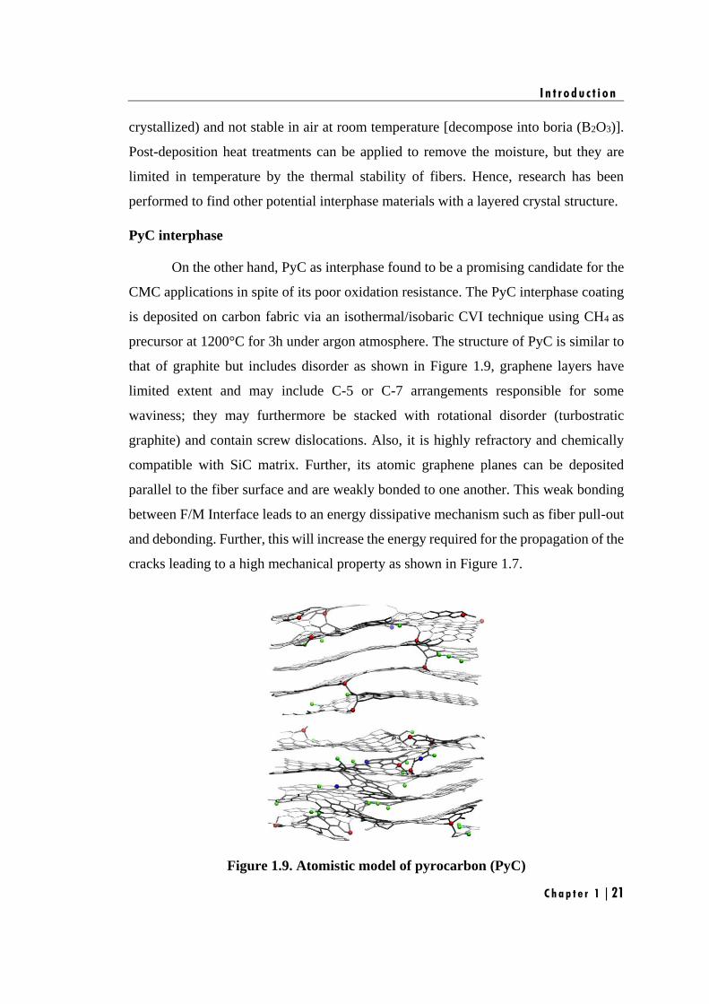
I n t r o d u c t i o n
C h a p t e r 1 | 21
crystallized) and not stable in air at room temperature [decompose into boria (B2O3)].
Post-deposition heat treatments can be applied to remove the moisture, but they are
limited in temperature by the thermal stability of fibers. Hence, research has been
performed to find other potential interphase materials with a layered crystal structure.
PyC interphase
On the other hand, PyC as interphase found to be a promising candidate for the
CMC applications in spite of its poor oxidation resistance. The PyC interphase coating
is deposited on carbon fabric via an isothermal/isobaric CVI technique using CH4 as
precursor at 1200°C for 3h under argon atmosphere. The structure of PyC is similar to
that of graphite but includes disorder as shown in Figure 1.9, graphene layers have
limited extent and may include C-5 or C-7 arrangements responsible for some
waviness; they may furthermore be stacked with rotational disorder (turbostratic
graphite) and contain screw dislocations. Also, it is highly refractory and chemically
compatible with SiC matrix. Further, its atomic graphene planes can be deposited
parallel to the fiber surface and are weakly bonded to one another. This weak bonding
between F/M Interface leads to an energy dissipative mechanism such as fiber pull-out
and debonding. Further, this will increase the energy required for the propagation of the
cracks leading to a high mechanical property as shown in Figure 1.7.
Figure 1.9. Atomistic model of pyrocarbon (PyC)
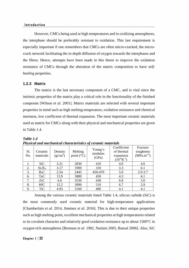
I n t r o d u c t i o n
Chapter 1 | 22
However, CMCs being used at high temperatures and in oxidizing atmospheres,
the interphase should be preferably resistant to oxidation. This last requirement is
especially important if one remembers that CMCs are often micro-cracked, the micro-
crack network facilitating the in-depth diffusion of oxygen towards the interphases and
the fibres. Hence, attempts have been made in this thesis to improve the oxidation
resistance of CMCs through the alteration of the matrix composition to have self-
healing properties.
1.2.3 Matrix
The matrix is the last necessary component of a CMC, and is vital since the
intrinsic properties of the matrix play a critical role in the functionality of the finished
composite [Wilson et al. 2001]. Matrix materials are selected with several important
properties in mind such as high melting temperature, oxidation resistance and chemical
inertness, low coefficient of thermal expansion. The most important ceramic materials
used as matrix for CMCs along with their physical and mechanical properties are given
in Table 1.4.
Table 1.4
Physical and mechanical characteristics of ceramic materials
Sl.
No.
Ceramic
materials
Density
(g/cm3)
Melting
point (°C)
Young’s
modulus
(GPa)
Coefficient
of thermal
expansion
(10-6K-1)
Fracture
toughness
(MPa.m1/2)
1. SiC 3.21 2830 410 4.0 4.6
2. Si3N4 3.17 1900 310 3.3 6.1
3. B4C 2.54 2445 450-470 5.0 2.9-3.7
6. TaC 13.9 3880 450 4.3 4.1
7. ZrC 6.6 3530 430 6.8 3.0
8. HfC 12.2 3890 510 6.7 2.9
9. TiC 4.93 3160 400 4.1 4.1
Among the various ceramic materials listed Table 1.4, silicon carbide (SiC) is
the most commonly used ceramic material for high-temperature applications
[Chamberlain et al. 2014, Jiménez et al. 2016]. This is due to their unique properties
such as high melting point, excellent mechanical properties at high temperatures related
to its covalent character and relatively good oxidation resistance up to about 1500°C in
oxygen-rich atmospheres [Brennan et al. 1982, Naslain 2005, Bansal 2006]. Also, SiC
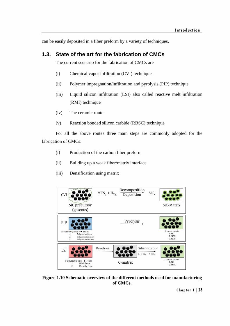
I n t r o d u c t i o n
C h a p t e r 1 | 23
can be easily deposited in a fiber preform by a variety of techniques.
1.3. State of the art for the fabrication of CMCs
The current scenario for the fabrication of CMCs are
(i) Chemical vapor infiltration (CVI) technique
(ii) Polymer impregnation/infiltration and pyrolysis (PIP) technique
(iii) Liquid silicon infiltration (LSI) also called reactive melt infiltration
(RMI) technique
(iv) The ceramic route
(v) Reaction bonded silicon carbide (RBSC) technique
For all the above routes three main steps are commonly adopted for the
fabrication of CMCs:
(i) Production of the carbon fiber preform
(ii) Building up a weak fiber/matrix interface
(iii) Densification using matrix
Figure 1.10 Schematic overview of the different methods used for manufacturing
of CMCs.
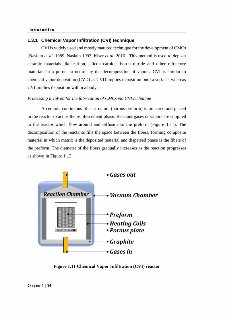
I n t r o d u c t i o n
Chapter 1 | 24
1.3.1 Chemical Vapor Infiltration (CVI) technique
CVI is widely used and mostly matured technique for the development of CMCs
[Naslain et al. 1989, Naslain 1993, Kiser et al. 2016]. This method is used to deposit
ceramic materials like carbon, silicon carbide, boron nitride and other refractory
materials in a porous structure by the decomposition of vapors. CVI is similar to
chemical vapor deposition (CVD) as CVD implies deposition onto a surface, whereas
CVI implies deposition within a body.
Processing involved for the fabrication of CMCs via CVI technique
A ceramic continuous fiber structure (porous preform) is prepared and placed
in the reactor to act as the reinforcement phase. Reactant gases or vapors are supplied
to the reactor which flow around and diffuse into the preform (Figure 1.11). The
decomposition of the reactants fills the space between the fibers, forming composite
material in which matrix is the deposited material and dispersed phase is the fibers of
the preform. The diameter of the fibers gradually increases as the reaction progresses
as shown in Figure 1.12.
Figure 1.11 Chemical Vapor Infiltration (CVI) reactor
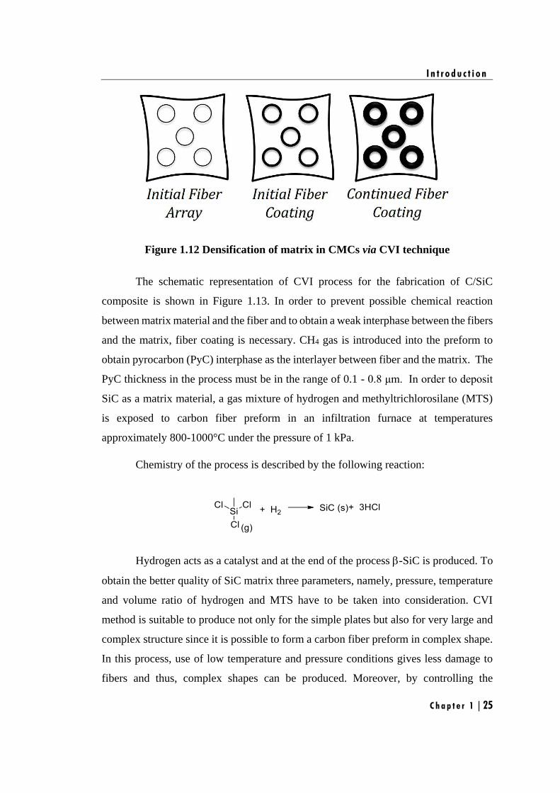
I n t r o d u c t i o n
C h a p t e r 1 | 25
Figure 1.12 Densification of matrix in CMCs via CVI technique
The schematic representation of CVI process for the fabrication of C/SiC
composite is shown in Figure 1.13. In order to prevent possible chemical reaction
between matrix material and the fiber and to obtain a weak interphase between the fibers
and the matrix, fiber coating is necessary. CH4 gas is introduced into the preform to
obtain pyrocarbon (PyC) interphase as the interlayer between fiber and the matrix. The
PyC thickness in the process must be in the range of 0.1 - 0.8 μm. In order to deposit
SiC as a matrix material, a gas mixture of hydrogen and methyltrichlorosilane (MTS)
is exposed to carbon fiber preform in an infiltration furnace at temperatures
approximately 800-1000°C under the pressure of 1 kPa.
Chemistry of the process is described by the following reaction:
Hydrogen acts as a catalyst and at the end of the process -SiC is produced. To
obtain the better quality of SiC matrix three parameters, namely, pressure, temperature
and volume ratio of hydrogen and MTS have to be taken into consideration. CVI
method is suitable to produce not only for the simple plates but also for very large and
complex structure since it is possible to form a carbon fiber preform in complex shape.
In this process, use of low temperature and pressure conditions gives less damage to
fibers and thus, complex shapes can be produced. Moreover, by controlling the

I n t r o d u c t i o n
Chapter 1 | 26
composition of the gases, pure and uniform fine grained SiC matrix which directly
affects the mechanical properties of the composite can be obtained.
Figure 1.13. Schematic view of CVI process
Different types of CVI processes:
(i) Isothermal/isobaric CVI process: The reactant gas is supplied to the
preform at a uniform temperature and pressure. It is a very slow process
as it has a low rate of diffusion.
(ii) Temperature gradient (TG-CVI): In this process the vapor diffuses
initially to the hotter surface of the preform and then to the cooler
surface. The temperature difference enhances the gas diffusivity. The
vapors decompose mostly in the hot inner surface as the rate of the
chemical reaction increases with increase in temperature. Due to the
prevention from early closure of the surface pores, this method allows
I n t r o d u c t i o n
C h a p t e r 1 | 27
better densification of the ceramic matrix.
(iii) Isothermal-forced flow (IF-CVI): In this process, vapors are forced into
the uniformly heated preform. The rate of the deposition is increased by
the increase in infiltration of the forced reactant gas.
(iv) Thermal gradient-forced flow (F-CVI): This process is the combination
of the both TG-CVI and IF-CVI processes which enhances the
infiltration of the vapors. This process also reduces the densification
time. Temperature difference in preform is achieved by heating the
above region while the bottom region is cooled. Forced flows are
determined by the difference in the pressure of the entering and exhaust
gases.
(v) Pulsed flow (P-CVI): In this process, the surrounding gas pressure
changes rapidly. The pressure changes repeatedly during each cycle.
Each cycle consists of the evacuation of the reactor vessel followed by
its filling with the reactant gas.
Advantages
(i) Low residual stress due to low infiltration temperature
(ii) Large, complex shape product can be produced in a near-net shape
(iii) Enhanced mechanical properties, corrosion resistance and thermal shock
resistance
(iv) Various matrices can be fabricated
(v) Very low fiber damage
Disadvantages
(i) Matrix deposition rate is very low
(ii) Time consuming process
(iii) Residual porosity is very high (10-15%)
(iv) High capital and production costs
I n t r o d u c t i o n
Chapter 1 | 28
1.3.2 Polymer Impregnation/Infiltration and Pyrolysis (PIP) technique
Polymer impregnation/infiltration and pyrolysis (PIP) process can be defined as
the conversion of the preceramic precursor into ceramic matrix via pyrolysis. The main
advantage of this route is flexibility of selection of preceramic resins to obtain different
types of CMCs [Jones et al. 1999, Riedel et al. 2006, Lee et al. 2008]. The important
criteria for the preceramic resin to be used as matrix resin for the fabrication of CMCs
through PIP route is,
(a) The preceramic resin should wet the fibers and should have low enough
viscosity to flow in the pore network between the fiber filaments.
(b) Upon pyrolyzing preceramic resin should yield a high ceramic yield.
The most commonly used preceramic polymers are as follows,
(i) Silicon containing preceramic polymers such as polysilane,
polycarbosilane and polysiloxane
(ii) Silicon and nitrogen containing preceramic polymers such as
polysilazane, perhydridopolysilazane and polycarbosilazane
(iii) Silicon and boron containing preceramic polymers such as
polyborosilane and polyborosiloxane
(iv) Silicon, boron and nitrogen containing preceramic polymers such as
polyborosilazane
All the above mentioned resins can be used as preceramic matrix resin for the
fabrication of CMCs through PIP route which is unique advantage of this route. After
selection of the preceramic resin, PIP process contains four different steps (Figure
1.14):
(i) Deposition of fiber coating by CVI technique (Section 1.2.2.1),
(ii) Manufacture of CFRP preform,
(iii) Pyrolysis of the CFRP preform,
(iv) Densification via repeated polymer infiltration and pyrolysis
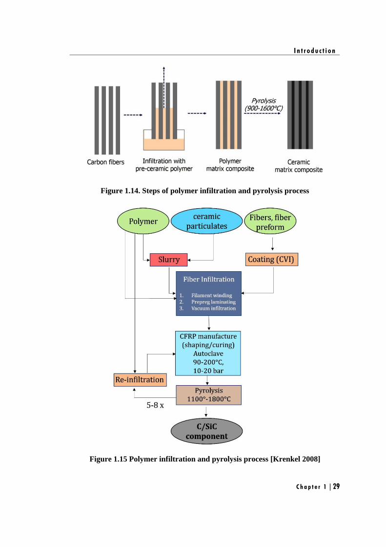
I n t r o d u c t i o n
C h a p t e r 1 | 29
Figure 1.14. Steps of polymer infiltration and pyrolysis process
Figure 1.15 Polymer infiltration and pyrolysis process [Krenkel 2008]
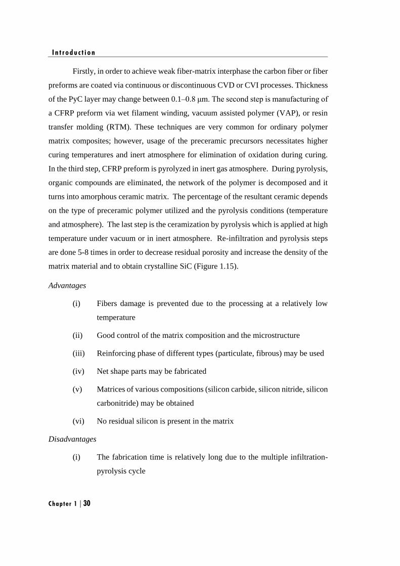
I n t r o d u c t i o n
Chapter 1 | 30
Firstly, in order to achieve weak fiber-matrix interphase the carbon fiber or fiber
preforms are coated via continuous or discontinuous CVD or CVI processes. Thickness
of the PyC layer may change between 0.1–0.8 μm. The second step is manufacturing of
a CFRP preform via wet filament winding, vacuum assisted polymer (VAP), or resin
transfer molding (RTM). These techniques are very common for ordinary polymer
matrix composites; however, usage of the preceramic precursors necessitates higher
curing temperatures and inert atmosphere for elimination of oxidation during curing.
In the third step, CFRP preform is pyrolyzed in inert gas atmosphere. During pyrolysis,
organic compounds are eliminated, the network of the polymer is decomposed and it
turns into amorphous ceramic matrix. The percentage of the resultant ceramic depends
on the type of preceramic polymer utilized and the pyrolysis conditions (temperature
and atmosphere). The last step is the ceramization by pyrolysis which is applied at high
temperature under vacuum or in inert atmosphere. Re-infiltration and pyrolysis steps
are done 5-8 times in order to decrease residual porosity and increase the density of the
matrix material and to obtain crystalline SiC (Figure 1.15).
Advantages
(i) Fibers damage is prevented due to the processing at a relatively low
temperature
(ii) Good control of the matrix composition and the microstructure
(iii) Reinforcing phase of different types (particulate, fibrous) may be used
(iv) Net shape parts may be fabricated
(v) Matrices of various compositions (silicon carbide, silicon nitride, silicon
carbonitride) may be obtained
(vi) No residual silicon is present in the matrix
Disadvantages
(i) The fabrication time is relatively long due to the multiple infiltration-
pyrolysis cycle
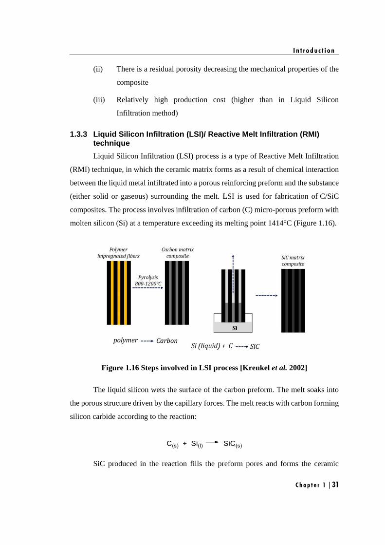
I n t r o d u c t i o n
C h a p t e r 1 | 31
(ii) There is a residual porosity decreasing the mechanical properties of the
composite
(iii) Relatively high production cost (higher than in Liquid Silicon
Infiltration method)
1.3.3 Liquid Silicon Infiltration (LSI)/ Reactive Melt Infiltration (RMI) technique
Liquid Silicon Infiltration (LSI) process is a type of Reactive Melt Infiltration
(RMI) technique, in which the ceramic matrix forms as a result of chemical interaction
between the liquid metal infiltrated into a porous reinforcing preform and the substance
(either solid or gaseous) surrounding the melt. LSI is used for fabrication of C/SiC
composites. The process involves infiltration of carbon (C) micro-porous preform with
molten silicon (Si) at a temperature exceeding its melting point 1414°C (Figure 1.16).
Figure 1.16 Steps involved in LSI process [Krenkel et al. 2002]
The liquid silicon wets the surface of the carbon preform. The melt soaks into
the porous structure driven by the capillary forces. The melt reacts with carbon forming
silicon carbide according to the reaction:
SiC produced in the reaction fills the preform pores and forms the ceramic
I n t r o d u c t i o n
Chapter 1 | 32
matrix. Since the molar volume of SiC is less than the sum of the molar volumes of
silicon and carbon by 23%, the soaking of liquid silicon continues in course of the
formation of silicon carbide. The initial pore volume fraction providing complete
conversion of carbon into silicon carbide is 0.562. If the initial pore volume fraction is
lower than 0.562 the infiltration results in entrapping residual free silicon. Commonly
at least 5% of residual free silicon is left in SiC matrix. The porous carbon is synthesized
by pyrolysis of a polymerized resin. The most commonly used polymer is phenol-
formaldehyde resin [Odeshi et al. 2006].
Figure 1.17. Schematic overview of the manufacture of C/SiC materials via LSI
[Krenkel et al. 2005]
I n t r o d u c t i o n
C h a p t e r 1 | 33
LSI process
Processing of C/C-SiC composites via LSI contains three main steps (Figure
1.17),
(i) Production of carbon fiber reinforced polymer matrix composites
(CFRP)
(ii) Pyrolysis of CFRP to C/C preform
(iii) Liquid silicon infiltration of C/C preform
Composites manufactured by LSI contain lower amount of porosities which
results in higher shear strength and thermal conductivity. It is a near net shaping process
and its main advantage is its in-situ joining capability and the possibility of
manufacturing large and complex shape components with the help of near net shaping.
Moreover, this process has lower component fabrication time and thus, manufacturing
cost is reduced considerably compared to other manufacturing techniques.
Advantages
(i) Low cost
(ii) Short production time
(iii) Very low residual porosity
(iv) High thermal conductivity
(v) High electrical conductivity
(vi) Complex and near-net shapes may be fabricated
Disadvantages
(i) High temperature of molten silicon may cause a damage of the fibers
(ii) Residual silicon is present in the carbide matrix
(iii) Lower mechanical properties of the resulting composite: strength,
modulus of elasticity
I n t r o d u c t i o n
Chapter 1 | 34
1.3.4 The ceramic route
In the ceramic route, the matrix precursor is a slurry, i.e. a stable suspension of
a β-SiC powder in a liquid which also contains sintering additives and a fugitive binder.
The reinforcement is impregnated with the slurry and wound on a drum, yielding a 1D-
prepreg-type intermediate product [Rosso 2006]. After drying, the layers are stacked in
the die of a unidirectional press and the composite sintered at high temperature under
pressure.
Disadvantages
(i) The sintering of SiC powder is very difficult and requires very high
temperatures, even in the presence of sintering aids.
(ii) Since, it is performed here under pressure (to achieve low residual
porosity), the combined effect of high temperature and high pressure
was considered for a long time as a source of too severe fiber
degradation and this route more or less disregarded.
1.3.5 Reaction Bonded Silicon Carbide (RBSC) technique
In comparison to CVI, PIP and ceramic route, the LSI process is relatively
economical [Krenkel 2009]. However, in this process, reaction of liquid silicon with
carbon is not restricted to the carbon of the matrix, but it also reacts with the carbon
fiber leading to poor mechanical properties [Odeshi et al. 2006, Magnant et al. 2012].
To overcome the disadvantages of LSI technique, while retaining the cost
advantage, fine silicon powder was added to the polymeric precursor. Before silicon-
carbon reaction occurs, silicon and carbon are distributed homogeneously within the
matrix and hence the reaction is restricted mainly to the matrix. This method has been
termed as ‘Reaction Bonded Silicon Carbide method’ (RBSC) which is modified LSI
route [Magnant et al. 2012].
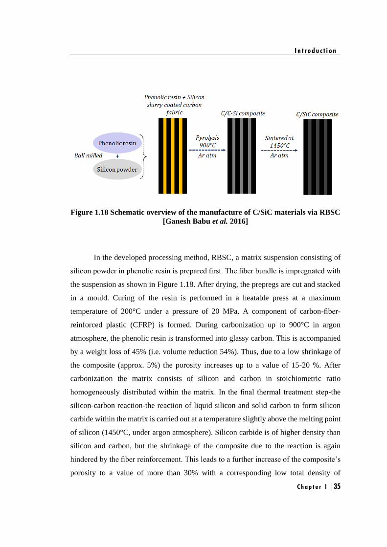
I n t r o d u c t i o n
C h a p t e r 1 | 35
Figure 1.18 Schematic overview of the manufacture of C/SiC materials via RBSC
[Ganesh Babu et al. 2016]
In the developed processing method, RBSC, a matrix suspension consisting of
silicon powder in phenolic resin is prepared first. The fiber bundle is impregnated with
the suspension as shown in Figure 1.18. After drying, the prepregs are cut and stacked
in a mould. Curing of the resin is performed in a heatable press at a maximum
temperature of 200°C under a pressure of 20 MPa. A component of carbon-fiber-
reinforced plastic (CFRP) is formed. During carbonization up to 900°C in argon
atmosphere, the phenolic resin is transformed into glassy carbon. This is accompanied
by a weight loss of 45% (i.e. volume reduction 54%). Thus, due to a low shrinkage of
the composite (approx. 5%) the porosity increases up to a value of 15-20 %. After
carbonization the matrix consists of silicon and carbon in stoichiometric ratio
homogeneously distributed within the matrix. In the final thermal treatment step-the
silicon-carbon reaction-the reaction of liquid silicon and solid carbon to form silicon
carbide within the matrix is carried out at a temperature slightly above the melting point
of silicon (1450°C, under argon atmosphere). Silicon carbide is of higher density than
silicon and carbon, but the shrinkage of the composite due to the reaction is again
hindered by the fiber reinforcement. This leads to a further increase of the composite’s
porosity to a value of more than 30% with a corresponding low total density of
I n t r o d u c t i o n
Chapter 1 | 36
approximately 1.5 g/cm3. The final product of carbon-fiber-reinforced silicon carbide
(C/SiC) is achieved.
1.4. The key issues with C/SiC composites
The important properties for the CMCs are,
(i) It should have good mechanical properties that can be retained even at
high temperature (>1200°C)
(ii) It should possess good oxidation resistance.
The mechanical property can be improved through a proper design of the F/M
interface arresting and deflecting cracks formed under load in the brittle matrix and
preventing the catastrophic failure of the CMCs. This crack deflection is controlled via
the deposition of a thin layer of a compliant material with a low shear strength, on the
fiber surface, referred to as the interphase as explained in Section 1.2.2.1 which acts as
a mechanical fuse.
However, in terms of oxidation resistance, the interphase coating used for the
CMCs should be preferably resistant to the oxidation [Naslain 2004]. Further, it is
observed that when SiC is used as a matrix in either C/SiC or SiC/SiC composites, SiC
undergoes multiple micro-cracking when loaded in tension beyond a relatively low
stress level (100-200 MPa). These micro-cracks, facilitate the in-depth diffusion of
oxygen towards the oxidation-prone interphases and the fibers, when the composite is
exposed to an oxidizing atmosphere at medium or high temperatures [Ruggles-Wrenn
et al. 2013, Al Nasiri et al. 2016]. Hence, for the long-term applications, the objective
of CMCs is to engineer or tailor the SiC-matrix in order to impede or at least to slow
down oxygen diffusion in the material and to increase its durability in corrosive
environments. Towards this, self-healing matrix plays a vital role in the protection of
CMCs from oxidizing environment [Low 2014, Luan et al. 2016].
I n t r o d u c t i o n
C h a p t e r 1 | 37
1.5. Concept of Self-healing matrix
For long-term high temperature applications, CMCs has to be highly engineered
in order to improve their oxidation resistance, particularly at the level of the interphase
and the matrix. In this field, boron-bearing species are reported to be highly efficient
[Naslain et al. 2004, Ganesh Babu et al. 2016, Bertrand et al. 2017]. They can form
fluid oxide phases (B2O3 or –Si-O-B-C- multi phase) over a broad temperature range
(600–1200°C) when heated in an oxidizing atmosphere as shown in eqns. (1.1) to (1.5)
[Ganesh Babu et al. 2016].
These B-bearing species, if introduced in the interphase or ceramic matrix of
non-oxide CMCs or as fillers, could be used to design self-healing materials which form
fluid oxide phases during oxidation to fill cracks. This will slow down the in-depth
diffusion of oxygen imparting self-healing properties as shown in Figure 1.19 to
improve the lifetimes of the CMCs [Tong et al. 2008].
Despite many relevant studies regarding the role of substitutional boron in
protection of CMCs [Quemard et al. 2007, Cluzel et al. 2009], controversy still remains,
and many more experimental results must be discussed. Indeed, different approaches
have been used to produce B-doped carbon materials. Although each study used
different materials and experimental conditions, the final goal for each was to improve
the oxidation stability by introduction of boron into system.
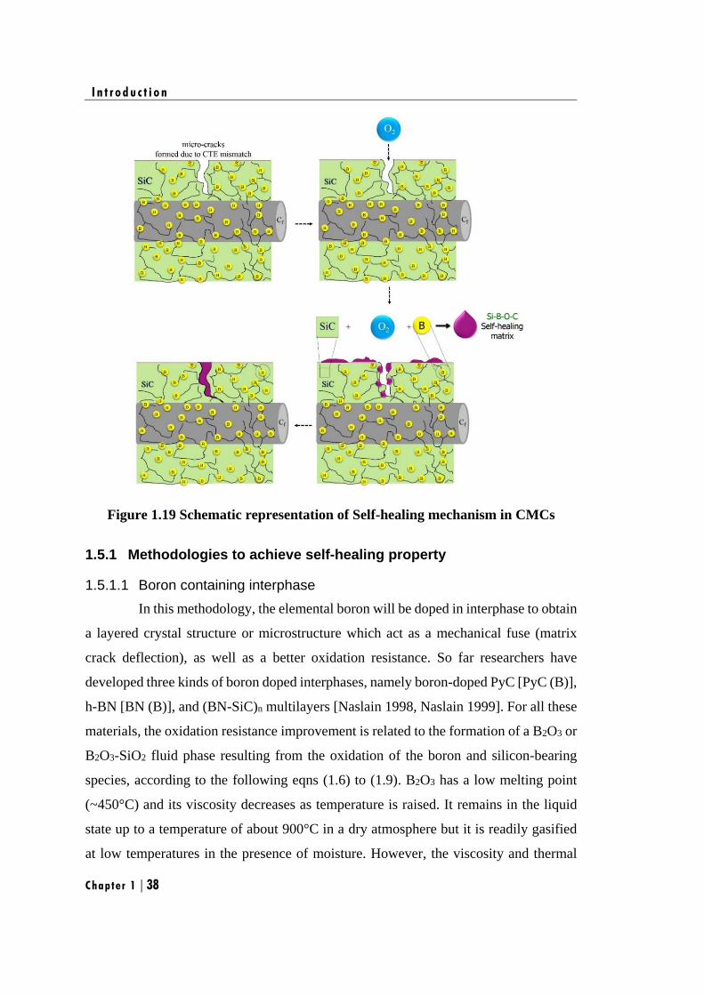
I n t r o d u c t i o n
Chapter 1 | 38
Figure 1.19 Schematic representation of Self-healing mechanism in CMCs
1.5.1 Methodologies to achieve self-healing property
1.5.1.1 Boron containing interphase
In this methodology, the elemental boron will be doped in interphase to obtain
a layered crystal structure or microstructure which act as a mechanical fuse (matrix
crack deflection), as well as a better oxidation resistance. So far researchers have
developed three kinds of boron doped interphases, namely boron-doped PyC [PyC (B)],
h-BN [BN (B)], and (BN-SiC)n multilayers [Naslain 1998, Naslain 1999]. For all these
materials, the oxidation resistance improvement is related to the formation of a B2O3 or
B2O3-SiO2 fluid phase resulting from the oxidation of the boron and silicon-bearing
species, according to the following eqns (1.6) to (1.9). B2O3 has a low melting point
(~450°C) and its viscosity decreases as temperature is raised. It remains in the liquid
state up to a temperature of about 900°C in a dry atmosphere but it is readily gasified
at low temperatures in the presence of moisture. However, the viscosity and thermal
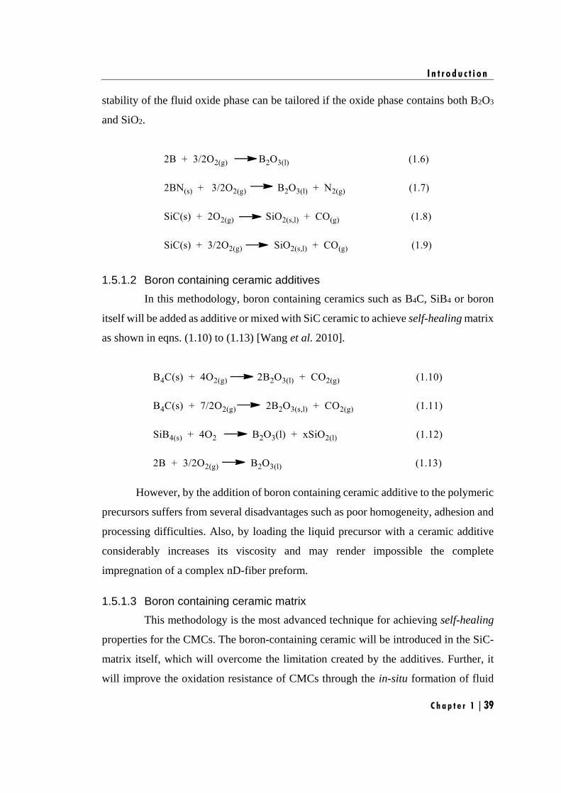
I n t r o d u c t i o n
C h a p t e r 1 | 39
stability of the fluid oxide phase can be tailored if the oxide phase contains both B2O3
and SiO2.
1.5.1.2 Boron containing ceramic additives
In this methodology, boron containing ceramics such as B4C, SiB4 or boron
itself will be added as additive or mixed with SiC ceramic to achieve self-healing matrix
as shown in eqns. (1.10) to (1.13) [Wang et al. 2010].
However, by the addition of boron containing ceramic additive to the polymeric
precursors suffers from several disadvantages such as poor homogeneity, adhesion and
processing difficulties. Also, by loading the liquid precursor with a ceramic additive
considerably increases its viscosity and may render impossible the complete
impregnation of a complex nD-fiber preform.
1.5.1.3 Boron containing ceramic matrix
This methodology is the most advanced technique for achieving self-healing
properties for the CMCs. The boron-containing ceramic will be introduced in the SiC-
matrix itself, which will overcome the limitation created by the additives. Further, it
will improve the oxidation resistance of CMCs through the in-situ formation of fluid
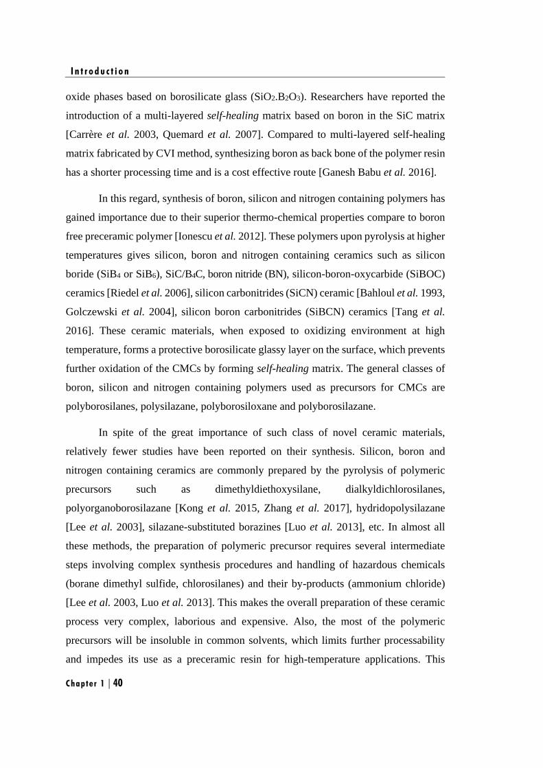
I n t r o d u c t i o n
Chapter 1 | 40
oxide phases based on borosilicate glass (SiO2.B2O3). Researchers have reported the
introduction of a multi-layered self-healing matrix based on boron in the SiC matrix
[Carrère et al. 2003, Quemard et al. 2007]. Compared to multi-layered self-healing
matrix fabricated by CVI method, synthesizing boron as back bone of the polymer resin
has a shorter processing time and is a cost effective route [Ganesh Babu et al. 2016].
In this regard, synthesis of boron, silicon and nitrogen containing polymers has
gained importance due to their superior thermo-chemical properties compare to boron
free preceramic polymer [Ionescu et al. 2012]. These polymers upon pyrolysis at higher
temperatures gives silicon, boron and nitrogen containing ceramics such as silicon
boride (SiB4 or SiB6), SiC/B4C, boron nitride (BN), silicon-boron-oxycarbide (SiBOC)
ceramics [Riedel et al. 2006], silicon carbonitrides (SiCN) ceramic [Bahloul et al. 1993,
Golczewski et al. 2004], silicon boron carbonitrides (SiBCN) ceramics [Tang et al.
2016]. These ceramic materials, when exposed to oxidizing environment at high
temperature, forms a protective borosilicate glassy layer on the surface, which prevents
further oxidation of the CMCs by forming self-healing matrix. The general classes of
boron, silicon and nitrogen containing polymers used as precursors for CMCs are
polyborosilanes, polysilazane, polyborosiloxane and polyborosilazane.
In spite of the great importance of such class of novel ceramic materials,
relatively fewer studies have been reported on their synthesis. Silicon, boron and
nitrogen containing ceramics are commonly prepared by the pyrolysis of polymeric
precursors such as dimethyldiethoxysilane, dialkyldichlorosilanes,
polyorganoborosilazane [Kong et al. 2015, Zhang et al. 2017], hydridopolysilazane
[Lee et al. 2003], silazane-substituted borazines [Luo et al. 2013], etc. In almost all
these methods, the preparation of polymeric precursor requires several intermediate
steps involving complex synthesis procedures and handling of hazardous chemicals
(borane dimethyl sulfide, chlorosilanes) and their by-products (ammonium chloride)
[Lee et al. 2003, Luo et al. 2013]. This makes the overall preparation of these ceramic
process very complex, laborious and expensive. Also, the most of the polymeric
precursors will be insoluble in common solvents, which limits further processability
and impedes its use as a preceramic resin for high-temperature applications. This
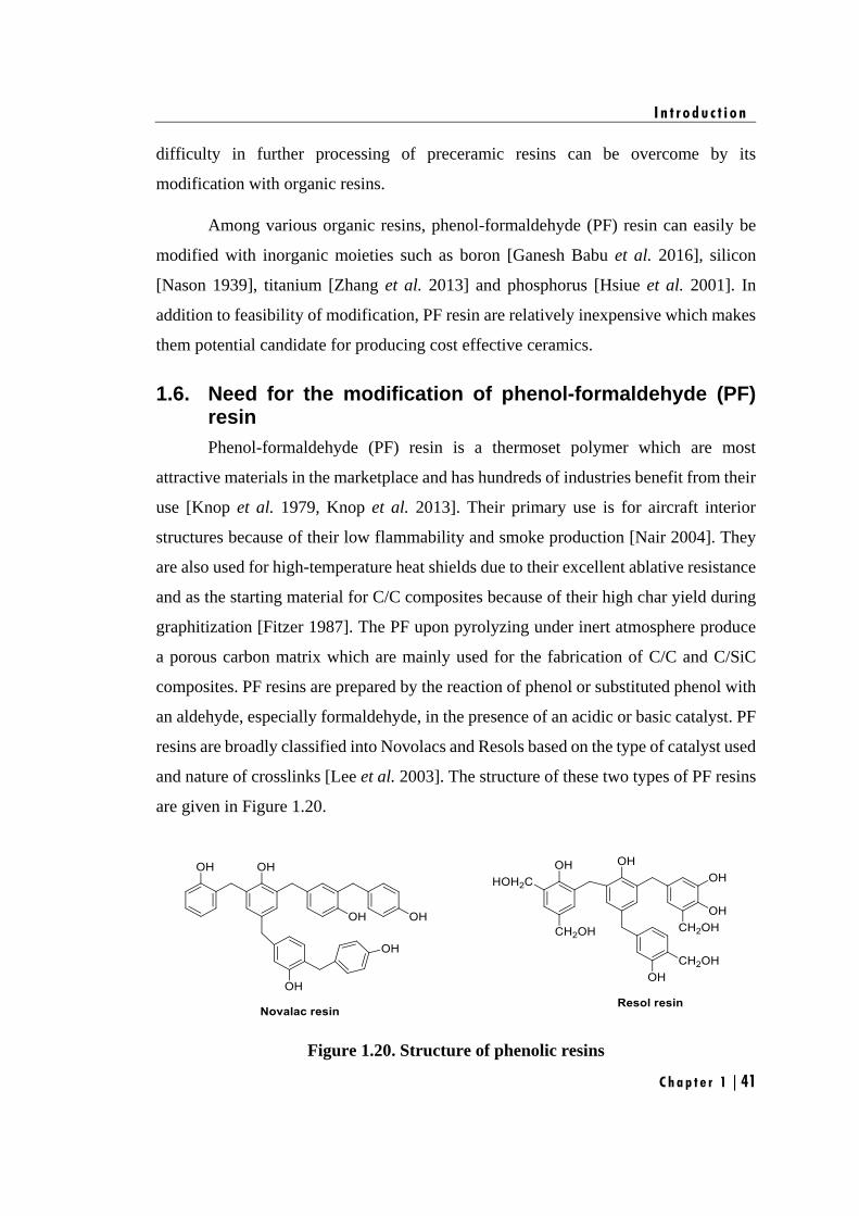
I n t r o d u c t i o n
C h a p t e r 1 | 41
difficulty in further processing of preceramic resins can be overcome by its
modification with organic resins.
Among various organic resins, phenol-formaldehyde (PF) resin can easily be
modified with inorganic moieties such as boron [Ganesh Babu et al. 2016], silicon
[Nason 1939], titanium [Zhang et al. 2013] and phosphorus [Hsiue et al. 2001]. In
addition to feasibility of modification, PF resin are relatively inexpensive which makes
them potential candidate for producing cost effective ceramics.
1.6. Need for the modification of phenol-formaldehyde (PF) resin
Phenol-formaldehyde (PF) resin is a thermoset polymer which are most
attractive materials in the marketplace and has hundreds of industries benefit from their
use [Knop et al. 1979, Knop et al. 2013]. Their primary use is for aircraft interior
structures because of their low flammability and smoke production [Nair 2004]. They
are also used for high-temperature heat shields due to their excellent ablative resistance
and as the starting material for C/C composites because of their high char yield during
graphitization [Fitzer 1987]. The PF upon pyrolyzing under inert atmosphere produce
a porous carbon matrix which are mainly used for the fabrication of C/C and C/SiC
composites. PF resins are prepared by the reaction of phenol or substituted phenol with
an aldehyde, especially formaldehyde, in the presence of an acidic or basic catalyst. PF
resins are broadly classified into Novolacs and Resols based on the type of catalyst used
and nature of crosslinks [Lee et al. 2003]. The structure of these two types of PF resins
are given in Figure 1.20.
Figure 1.20. Structure of phenolic resins
I n t r o d u c t i o n
Chapter 1 | 42
a. Novolac resin
Novolac resins are synthesized from a monomer feed with excess phenol in the
presence of an acid catalyst. The final novolac resin is unable to react further without
the addition of a crosslinking agent like hexamethylenetetramine (HMTA). Novolac
resins are amorphous thermoplastics, which are solid at room temperature and soften
and flow in the temperature range 65-105°C. The number average molecular weight of
a standard phenol novolac resin is between 250°C and 900°C. Novolac resins are
soluble in polar organic solvents (e.g., alcohols, acetone), but not in water.
b. Resol resin
A base (alkaline) catalyst and, usually but not necessarily, a molar excess of
formaldehyde is used to make resole resins. When an excess of formaldehyde is used,
sufficient number of methylol and dibenzyl ether groups remain reactive to complete
the polymerization and cure the resin without incorporation of a curing agent. The
typical number average molecular weight of a resol resin is between 200 and 450. The
commonly used alkaline catalysts are NaOH, Ca(OH)2, and Ba(OH)2.
Resol resin can easily be modified with inorganic moieties such as boron,
silicon, titanium and phosphorus as compared to that of novalac resin [Chiang et al.
2004, Kawamoto et al. 2010, Zhang et al. 2013]. This is due to the presence of free
methylol groups in resol resin which helps in feasibility of the modification. These
modified resins are widely used in the process of polymer infiltration and pyrolysis
technique to prepare refractory carbide modified carbon/carbon composites (C/C).
However, similar to the disadvantages associated with other polymeric materials, the
application of PF resin at high temperatures is restricted due to its thermal degradation
above 200°C [Li et al. 2016]. For the development of advanced ceramics based on
modification of preceramic resin with organic resin such as PF, it is particularly
attractive to utilize the best properties of each component to develop new materials with
tailor made properties. Hence, attempts were made in this thesis to synthesize phenol
formaldehyde resin modified with boron, silicon and nitrogen which are expected to be
potential preceramic matrix resin for CMCs to achieve improved oxidation resistance
I n t r o d u c t i o n
C h a p t e r 1 | 43
property.
1.7. Application of CMCs
It is convenient to divide the general applications of CMCs in terms of aerospace
and non-aerospace applications. In the aerospace area, performance is the foremost
consideration while in the non-aerospace fields cost effectiveness is the prime
consideration.
1.7.1 Aerospace applications
Aerospace applications, in general, demand high thrust-to-weight ratios, faster
cruising speeds, increased altitudes and improved flight performance [Naslain et al.
2004]. These goals translate into material requirements involving increased strength-
to-density, stiffness-to-density and improved damage tolerance all at significantly
higher temperatures. High-temperature structural composites represent a key
technology for advanced aerospace systems [Triantou et al. 2017]. CMCs potentially
offer higher specific mechanical properties which can be utilized in a variety of high-
temperature aerospace applications. SiC coated C/C composites are used as a thermal
protection material in the Ceramic Matrix Products Division of Vikram Sarabhai Space
Centre, Indian Space Research Organization (ISRO). C/SiC composites are candidate
materials for a variety of space plan programs in ISRO. Besides the space plane, other
applications for CMCs include a variety of high speed airplane, various defense related
projects such as Advanced Tactical Fighter (ATF), many existing fighters, missiles,
hypersonic flights, hard armor and turbine engines [Halbig et al. 2013, Kalaiyarasan et
al. 2016, Kiser et al. 2016, Luo et al. 2017].
1.7.2 Non-aerospace applications
Among the non-aerospace applications of CMCs, engine components at high
temperatures and in corrosive environments [Low 2014], cutting tool inserts [Liu et al.
2014], wear resistant parts [Wang et al. 2017], nozzles [Halbig et al. 2013] and exhaust
ducts [Hynes et al. 2016], energy related applications such as heat exchanger tubes
[Zhou et al. 2013], etc. are the prime areas. For such applications, the components can
range from simple to complex and tend to be smaller in size. Thus, it is not surprising

I n t r o d u c t i o n
Chapter 1 | 44
that for applications related to wear, cutting tool inserts, and heat engines, there are
commercially available dense, wear-resistant, particle- and whisker-reinforced ceramic
matrix composites.
C h a p t e r 1 | 45
Scope and objectives
he survey of pertinent literature reveals that, the field of CMCs have been
intriguing technologists for diverse high temperature applications such as
rocket nozzles, aeronautic jet engines, heat shields and aircraft braking
systems. There has been concerted developments and innovations reported in this field
over the last two decades. The search for more and more advanced materials that can
survive the extreme environments clearly shows the ever rising interest and un-tapped
potential of this field for further technological advancement of CMCs. However, the
production cost and the materials used can reach escalating price depending on the
targeted applications and the technologies required for their production which continues
to be a major obstacle to widespread application of CMCs. Hence, development of
these materials with competitive and attractive methods gains tremendous significance
for high-temperature application.
The main objective of this study is to develop new class of cost effective
preceramic polymer to employ it as matrix resin for CMCs to achieve self-healing
properties and to investigate its effect on mechanical properties. Covering these aspects,
the research work is divided into the following chapters.
Chapter-1 gives a general introduction on CMCs, design and selection of constituents
in CMCs, processing techniques involved to fabricate CMCs and the role of boron in
protection of CMCs for the long-term aerospace applications.
Chapter-2 provides the details on materials, experimental procedures and the analytical
techniques used in the present study.
Chapter-3 deals with the investigation of boron modified phenol-formaldehyde (BPF)
resins as preceramic matrix resin for CMCs. This chapter comprises of two parts;
• In the first part, synthesis, characterization and ceramic conversion
studies of BPF resins are discussed in detail. The aim of the work is to
evaluate BPF as a potential self-healing matrix resin for the fabrication
of CMC.
T
S c o p e a n d O b j e c t i v e s
C h a p t e r 1 | 46
• In the second part, CMCs are fabricated using BPF resin blended with
elemental silicon as preceramic matrix resin, PyC as interphase and 2D
carbon fabric as reinforcement. The study focusses on the optimization
of fiber/matrix (F/M) volume ratio and the influence of PyC interphase
coating on the flexural properties of CMCs.
In Chapter-3, silicon is added as additive to the preceramic polymer and used as matrix
resin for CMCs. In Chapter-4, attempt was made to incorporate silicon as back bone of
preceramic polymer and used as matrix resin for CMCs. This work has been divided
into two parts;
• In the first part, synthesis, characterization and ceramic conversion
studies of silazane modified phenol-formaldehyde (SPF) resins are
discussed in detail. The principle objective of the study is to select an
appropriate pyrolysis condition (pyrolysis) to achieve desired ceramic in
high yield (>60 wt. %).
• In the second part, CMCs are fabricated using SPF as matrix resin via
polymer impregnation and pyrolysis (PIP) techniques. The study
focusses on the investigation of fracture behavior and failure mechanism
of the obtained CMCs.
In Chapter-4, the work was focused on the improvement of mechanical properties of
the CMCs derived from SPF. However, for the long-term use superior oxidation
resistance of CMCs are highly desired. Hence, in Chapter-5, synthesis of single source
preceramic matrix resins containing silicon, boron and nitrogen are attempted to get
SiBCN based ceramics. This work has been divided into two parts;
• In the first part, synthesis, characterization and ceramic conversion
studies of boron modified cyclotrisilazane (BCTS) resins are discussed
in detail. The principle objective of this work is to assess BCTS resin as
potential preceramic resin and to attain oxide free SiBCN ceramic.
• In the second part, CMCs derived from BPF and SPF resins were
screened based on the mechanical properties and were infiltrated with
S c o p e a n d O b j e c t i v e s
C h a p t e r 1 | 47
BCTS resin to achieve cost-effective CMCs with improved oxidation
resistance property.
Chapter-6 summarizes the findings of the present investigation together with
concluding remarks and scope for future work.

S c o p e a n d O b j e c t i v e s
C h a p t e r 1 | 48
Chapter 2
Materials and Methods

M a t e r i a l s a n d M e t h o d s
C h a p t e r 2 | 51
• This chapter provides the details on the materials and experimental procedure
for the synthesis and ceramic conversion process of preceramic polymers.
• Analytical techniques used for the characterization of the preceramic polymers
and the ceramic materials.
• Procedure for the fabrication of CMCs and the evaluation of mechanical and
oxidation resistance properties of the CMCs.

M a t e r i a l s a n d M e t h o d s
Chapter 2 | 52
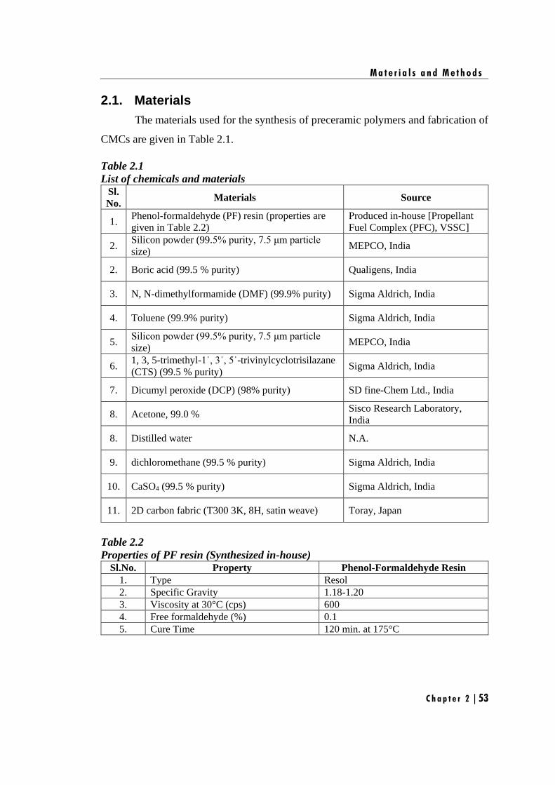
M a t e r i a l s a n d M e t h o d s
C h a p t e r 2 | 53
2.1. Materials
The materials used for the synthesis of preceramic polymers and fabrication of
CMCs are given in Table 2.1.
Table 2.1
List of chemicals and materials Sl.
No. Materials Source
1. Phenol-formaldehyde (PF) resin (properties are
given in Table 2.2)
Produced in-house [Propellant
Fuel Complex (PFC), VSSC]
2. Silicon powder (99.5% purity, 7.5 μm particle
size) MEPCO, India
2. Boric acid (99.5 % purity) Qualigens, India
3. N, N-dimethylformamide (DMF) (99.9% purity) Sigma Aldrich, India
4. Toluene (99.9% purity) Sigma Aldrich, India
5. Silicon powder (99.5% purity, 7.5 μm particle
size) MEPCO, India
6. 1, 3, 5-trimethyl-1ˈ, 3ˈ, 5ˈ-trivinylcyclotrisilazane
(CTS) (99.5 % purity) Sigma Aldrich, India
7. Dicumyl peroxide (DCP) (98% purity) SD fine-Chem Ltd., India
8. Acetone, 99.0 % Sisco Research Laboratory,
India
8. Distilled water N.A.
9. dichloromethane (99.5 % purity) Sigma Aldrich, India
10. CaSO4 (99.5 % purity) Sigma Aldrich, India
11. 2D carbon fabric (T300 3K, 8H, satin weave) Toray, Japan
Table 2.2
Properties of PF resin (Synthesized in-house) Sl.No. Property Phenol-Formaldehyde Resin
1. Type Resol
2. Specific Gravity 1.18-1.20
3. Viscosity at 30°C (cps) 600
4. Free formaldehyde (%) 0.1
5. Cure Time 120 min. at 175°C
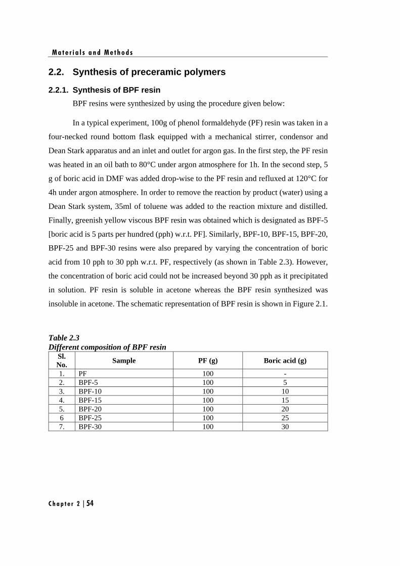
M a t e r i a l s a n d M e t h o d s
C h a p t e r 2 | 54
2.2. Synthesis of preceramic polymers
2.2.1. Synthesis of BPF resin
BPF resins were synthesized by using the procedure given below:
In a typical experiment, 100g of phenol formaldehyde (PF) resin was taken in a
four-necked round bottom flask equipped with a mechanical stirrer, condensor and
Dean Stark apparatus and an inlet and outlet for argon gas. In the first step, the PF resin
was heated in an oil bath to 80°C under argon atmosphere for 1h. In the second step, 5
g of boric acid in DMF was added drop-wise to the PF resin and refluxed at 120°C for
4h under argon atmosphere. In order to remove the reaction by product (water) using a
Dean Stark system, 35ml of toluene was added to the reaction mixture and distilled.
Finally, greenish yellow viscous BPF resin was obtained which is designated as BPF-5
[boric acid is 5 parts per hundred (pph) w.r.t. PF]. Similarly, BPF-10, BPF-15, BPF-20,
BPF-25 and BPF-30 resins were also prepared by varying the concentration of boric
acid from 10 pph to 30 pph w.r.t. PF, respectively (as shown in Table 2.3). However,
the concentration of boric acid could not be increased beyond 30 pph as it precipitated
in solution. PF resin is soluble in acetone whereas the BPF resin synthesized was
insoluble in acetone. The schematic representation of BPF resin is shown in Figure 2.1.
Table 2.3
Different composition of BPF resin Sl.
No. Sample PF (g) Boric acid (g)
1. PF 100 -
2. BPF-5 100 5
3. BPF-10 100 10
4. BPF-15 100 15
5. BPF-20 100 20
6 BPF-25 100 25
7. BPF-30 100 30
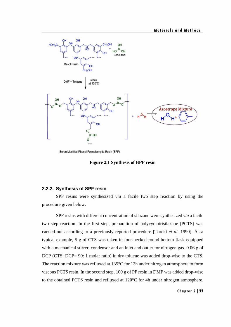
M a t e r i a l s a n d M e t h o d s
C h a p t e r 2 | 55
Figure 2.1 Synthesis of BPF resin
2.2.2. Synthesis of SPF resin
SPF resins were synthesized via a facile two step reaction by using the
procedure given below:
SPF resins with different concentration of silazane were synthesized via a facile
two step reaction. In the first step, preparation of polycyclotrisilazane (PCTS) was
carried out according to a previously reported procedure [Toreki et al. 1990]. As a
typical example, 5 g of CTS was taken in four-necked round bottom flask equipped
with a mechanical stirrer, condensor and an inlet and outlet for nitrogen gas. 0.06 g of
DCP (CTS: DCP= 90: 1 molar ratio) in dry toluene was added drop-wise to the CTS.
The reaction mixture was refluxed at 135°C for 12h under nitrogen atmosphere to form
viscous PCTS resin. In the second step, 100 g of PF resin in DMF was added drop-wise
to the obtained PCTS resin and refluxed at 120°C for 4h under nitrogen atmosphere.
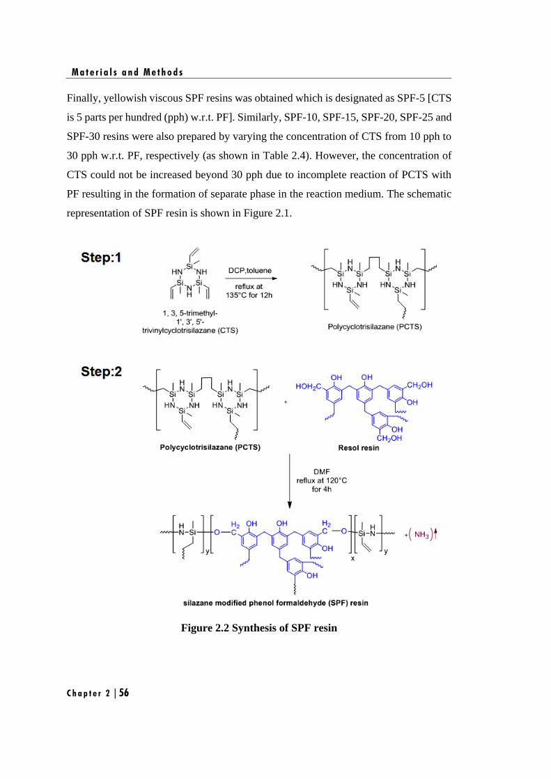
M a t e r i a l s a n d M e t h o d s
C h a p t e r 2 | 56
Finally, yellowish viscous SPF resins was obtained which is designated as SPF-5 [CTS
is 5 parts per hundred (pph) w.r.t. PF]. Similarly, SPF-10, SPF-15, SPF-20, SPF-25 and
SPF-30 resins were also prepared by varying the concentration of CTS from 10 pph to
30 pph w.r.t. PF, respectively (as shown in Table 2.4). However, the concentration of
CTS could not be increased beyond 30 pph due to incomplete reaction of PCTS with
PF resulting in the formation of separate phase in the reaction medium. The schematic
representation of SPF resin is shown in Figure 2.1.
Figure 2.2 Synthesis of SPF resin
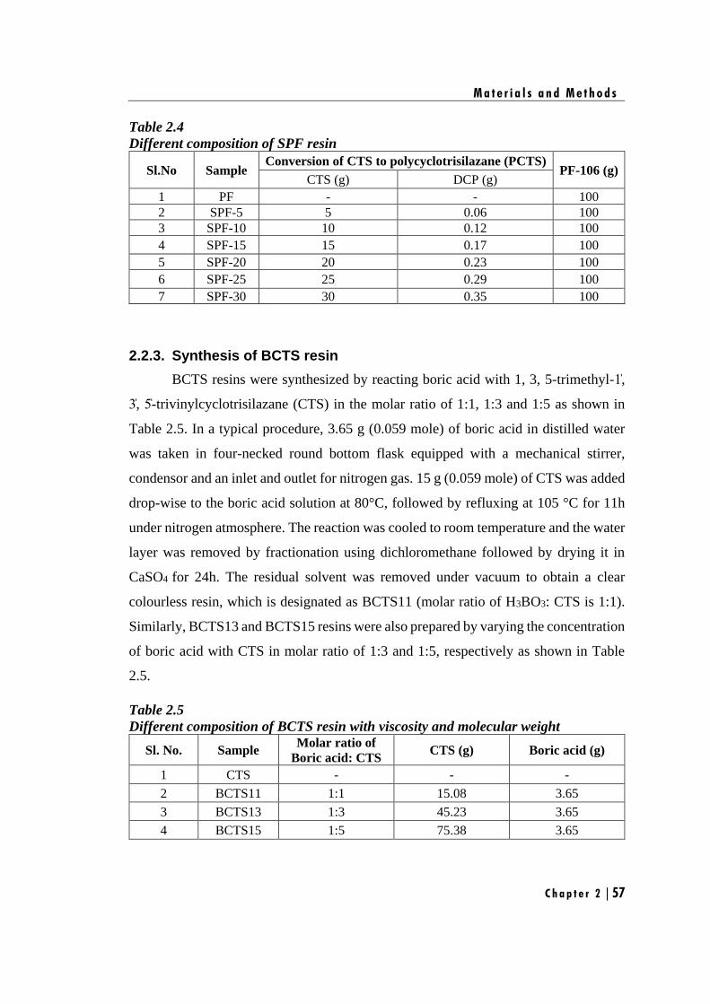
M a t e r i a l s a n d M e t h o d s
C h a p t e r 2 | 57
Table 2.4
Different composition of SPF resin
Sl.No Sample Conversion of CTS to polycyclotrisilazane (PCTS)
PF-106 (g) CTS (g) DCP (g)
1 PF - - 100
2 SPF-5 5 0.06 100
3 SPF-10 10 0.12 100
4 SPF-15 15 0.17 100
5 SPF-20 20 0.23 100
6 SPF-25 25 0.29 100
7 SPF-30 30 0.35 100
2.2.3. Synthesis of BCTS resin
BCTS resins were synthesized by reacting boric acid with 1, 3, 5-trimethyl-1̍,
3̍, 5̍-trivinylcyclotrisilazane (CTS) in the molar ratio of 1:1, 1:3 and 1:5 as shown in
Table 2.5. In a typical procedure, 3.65 g (0.059 mole) of boric acid in distilled water
was taken in four-necked round bottom flask equipped with a mechanical stirrer,
condensor and an inlet and outlet for nitrogen gas. 15 g (0.059 mole) of CTS was added
drop-wise to the boric acid solution at 80°C, followed by refluxing at 105 °C for 11h
under nitrogen atmosphere. The reaction was cooled to room temperature and the water
layer was removed by fractionation using dichloromethane followed by drying it in
CaSO4 for 24h. The residual solvent was removed under vacuum to obtain a clear
colourless resin, which is designated as BCTS11 (molar ratio of H3BO3: CTS is 1:1).
Similarly, BCTS13 and BCTS15 resins were also prepared by varying the concentration
of boric acid with CTS in molar ratio of 1:3 and 1:5, respectively as shown in Table
2.5.
Table 2.5
Different composition of BCTS resin with viscosity and molecular weight
Sl. No. Sample Molar ratio of
Boric acid: CTS CTS (g) Boric acid (g)
1 CTS - - -
2 BCTS11 1:1 15.08 3.65
3 BCTS13 1:3 45.23 3.65
4 BCTS15 1:5 75.38 3.65
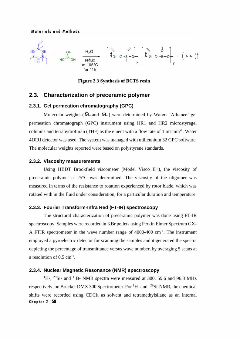
M a t e r i a l s a n d M e t h o d s
C h a p t e r 2 | 58
Figure 2.3 Synthesis of BCTS resin
2.3. Characterization of preceramic polymer
2.3.1. Gel permeation chromatography (GPC)
Molecular weights ( wM and nM ) were determined by Waters ‘Alliance’ gel
permeation chromatograph (GPC) instrument using HR1 and HR2 microstyragel
columns and tetrahydrofuran (THF) as the eluent with a flow rate of 1 mLmin-1. Water
410RI detector was used. The system was managed with millennium 32 GPC software.
The molecular weights reported were based on polystyrene standards.
2.3.2. Viscosity measurements
Using HBDT Brookfield viscometer (Model Visco II+), the viscosity of
preceramic polymer at 25°C was determined. The viscosity of the oligomer was
measured in terms of the resistance to rotation experienced by rotor blade, which was
rotated with in the fluid under consideration, for a particular duration and temperature.
2.3.3. Fourier Transform-Infra Red (FT-IR) spectroscopy
The structural characterization of preceramic polymer was done using FT-IR
spectroscopy. Samples were recorded in KBr pellets using Perkin Elmer Spectrum GX-
A FTIR spectrometer in the wave number range of 4000-400 cm-1. The instrument
employed a pyroelectric detector for scanning the samples and it generated the spectra
depicting the percentage of transmittance versus wave number, by averaging 5 scans at
a resolution of 0.5 cm-1.
2.3.4. Nuclear Magnetic Resonance (NMR) spectroscopy
1H-, 29Si- and 11B- NMR spectra were measured at 300, 59.6 and 96.3 MHz
respectively, on Brucker DMX 300 Spectrometer. For 1H- and 29Si-NMR, the chemical
shifts were recorded using CDCl3 as solvent and tetramethylsilane as an internal
M a t e r i a l s a n d M e t h o d s
C h a p t e r 2 | 59
standard. In the case of 11B-NMR spectra, deuterated THF was used as solvent and the
chemical shifts were reported with respect to an external standard viz., borontrifluoride
etherate.
2.3.5. Thermogravimetric analysis (TGA)
Thermogravimetric analysis (TGA) of preceramic polymers were performed on
TA Instruments SDT 2960 at a heating rate of 10°C min-1 under nitrogen atmosphere
over a temperature range of 25°C to 1200°C.
2.3.6. Pyrolysis–gas chromatography–mass spectrometry (Py–GC–MS)
Pyrolysis-gas chromatography-mass spectrometry (Py–GC–MS) studies were
conducted using a Thermo Electron Trace Ultra GC directly coupled to a Thermo
Electron Polaris Q (Quadruple ion trap) mass spectrometer and SGE pyrolyzer
(Pyrojector II, SGE Analytical Science Pty Ltd, Ringwood, Victoria, Australia).
2.4. Polymer to Ceramic conversion
2.4.1. Pyrolysis of BPF resin
The synthesized BPF resins (Table 2.3) were cured at 175°C for 2 h in air oven.
15 g of the cured BPF was taken in alumina crucible and pyrolyzed at 1450°C under
argon atmosphere at a heating rate of 3°C/min and gas flow rate of 50 mL/min. The
furnace temperature was maintained at 1450°C for 3 h and then it was cooled to room
temperature at a heating rate of 3°C/min to obtain boron and carbon (BC) containing
ceramics.
2.4.2. Pyrolysis of BPF resin with silicon as additive
The synthesized BPF resin (Table 2.3) was blended with stoichiometric amount
of silicon powder (designated as BPFSi) with respect to carbon obtained at 1450°C
during pyrolysis of PF, i.e. ratio of Si: C = 2.33:1. The mixture was ball milled for 120
min to obtain uniform slurry, followed by curing at 175°C. 15 g of cured mix was taken
in alumina crucible and sintered at 1450°C under argon atmosphere at a heating rate of
3°C/min and gas flow rate of 50 mL/min. The furnace temperature was maintained at
1450°C for 3 h and then it was cooled to room temperature at a heating rate of 3°C/min
M a t e r i a l s a n d M e t h o d s
C h a p t e r 2 | 60
to obtain silicon, carbon and boron-containing ceramics (designated as SiBOC).
2.4.3. Pyrolysis of SPF resin
The synthesized SPF resins (Table 2.4) were cured at 200°C for 2 h under
vacuum oven. 15 g of the cured SPF was taken in alumina crucible and pyrolyzed at
1450°C and 1650°C separately under argon and nitrogen atmosphere. Ceramic
conversion studies were carried out by heating the sample at a rate of 3°C/min and
maintained at pyrolysis temperature (1450°C or 1650°C) for 3 h. The furnace was then
cooled back to room temperature at a rate of 3°C/min. Both the heating and cooling
process were carried out under argon or nitrogen atmosphere at a flow rate of 50
mL/min.
2.4.4. Pyrolysis of BCTS resin
The synthesized BCTS resins (Table 2.5) were cured at 200°C for 2 h under
vacuum oven. 15 g of the cured BCTS was taken in alumina crucible and pyrolyzed at
1450°C and 1650°C under nitrogen atmosphere. Ceramic conversion studies were
carried out by heating the sample at a rate of 3°C min-1 and maintained at pyrolysis
temperature (1450°C or 1650°C) for 3 h. The furnace was then cooled back to room
temperature at a rate of 3°C min-1. Both the heating and cooling process were carried
out under nitrogen atmosphere at a flow rate of 50 mL/min.
2.5. Characterization of ceramics obtained from preceramic polymer
2.5.1 X-Ray Diffraction (XRD) analysis
The structural evolution of ceramics was studied using X-ray diffraction (XRD)
analysis. The sample were recorded on a Bruker D8 discover using Cu-Kα radiation
(40 kV, 40 mA; step scan of 0.051, counting time of 5 s/step and 1.5460 A°). The
crystallite size of ceramics was calculated from the line broadening of diffraction peak
using Scherrer equation.
D= cos
k
(2.1)
M a t e r i a l s a n d M e t h o d s
C h a p t e r 2 | 61
where D is the average crystallite size, k is the coefficient, which is generally taken as
0.94, λ is the wavelength of X-ray radiation equal to 1.5406 Å, β is full width at half
maximum (FWHM) measured in radians, and θ is the Bragg’s angle.
2.5.2 Raman spectroscopy
The nature of free carbon in the ceramics was understood using Raman spectra
recorded with WITec alpha 300R confocal Raman microscope using frequency doubled
Nd: YAF laser of excitation wavelength 532 nm. The parameters such as variations in
position and intensity of D and G band were derived using Gaussian curve fitting of the
Raman bands. The intensity ratio of the D and G bands (ID/IG) were used to calculate
the cluster size (La) of the free carbon using the formula reported by Ferrari and
Robertson [Ferrari et al. 2004].
(2.2)
where La is the size of carbon domains along the six-fold ring plane, and Cˈ is a
coefficient that depends on the excitation wavelength (λ) of the laser. The value of Cˈ
of the wavelength of 532 nm of the Nd: YAG laser used here is 0.6195 nm.
2.5.3 Scanning electron microscopy (SEM) / Energy Dispersive X-ray (EDX) analysis
The morphological features were analyzed using scanning electron microscopy
(SEM) analysis. The analysis was done using JEOL Model JSM - 6390LV. This
instrument has a resolution of 3 nm at an accelerating voltage of 20 KV and ultimate
vacuum of 10-7 Torr. The specimen surface was made electrically conductive by coating
a thin layer of gold by the plasma vapor deposition in a Fine Coat Ion Sputterer JF-
1100. For EDX analysis, an OXFORD INCA system was used.
2.5.4 Felid emission Scanning electron microscopy (FESEM) / Energy Dispersive X-ray (EDX) analysis
In order to obtain high-resolution and magnified image the ceramic sample,
D
G
2'( ) La
IC
I=
M a t e r i a l s a n d M e t h o d s
C h a p t e r 2 | 62
Field Emission Scanning Electron Microscopy (FESEM) was carried out. The ceramic
samples were imaged using a Carl Zeiss, Supra 55, FESEM instrument. SUPRA 55 FE-
SEM is an ultra-high resolution FESEM based on the unique GEMINI Technology. It
provided excellent imaging properties combined with analytical capabilities. This
instrument has a resolution of 1 nm at an accelerating voltage of 30 KV and ultimate
vacuum of 10-7 Torr. The sample surface was made electrically conductive by coating
a thin layer of gold by the plasma vapor deposition in a Fine Coat Ion Sputterer JF-
1100. For EDX analysis, an OXFORD INCA system was used.
2.5.5 High-resolution Transmission electron microscopy (HRTEM) analysis
High-resolution transmission electron microscope analysis was used to study
the crystal structure and topographical features such as shape/dimensions of the surface
structures present in the ceramic sample. The samples were recorded using Technai 30
G2, S-TWIN instrument. For this samples were prepared by finely powdering the
ceramics into sub-micron sizes and dispersing these in acetone to form a uniform slurry.
A drop of the slurry was transferred to a carbon-film coated TEM grid.
2.5.6 Elemental Analysis
2.5.6.1 Estimation of silicon
Silicon content of the ceramic were determined by gravimetric analysis
[1966]. The silicon containing ceramic sample was converted to its sodium salt by
sodium carbonate fusion. The extract was dehydrated with perchloric acid, ignited, and
then volatilized after adding hydrofluoric acid. The residue obtained was ignited and
weighed. The loss in weight represents the quantity of silica formed. Percentage of
silicon in the sample is then estimated as:
Weight of silica in grams 28.08 100Silicon (%) =
Weight of the ceramic sample in grams 60.08
2.5.6.2 Estimation of boron
Boron content of ceramic sample was also determined by volumetric analysis
M a t e r i a l s a n d M e t h o d s
C h a p t e r 2 | 63
[1966]. About 1 to 2 g of the sample and 5 g of anhydrous sodium carbonate were taken
in a platinum crucible and heated in a furnace to 1000°C. The melt was dissolved in
water followed by digestion. The solution was filtered through a filter paper. The pH of
the filtrate was adjusted to 3.5 with dilute sulphuric acid and heated for some time to
remove any carbonic acid formed. The filtrate was titrated against standard sodium
hydroxide solution. Mannitol solution was added and the titration was continued till
mannitol borate equivalent point (near pH = 8.1) was reached. Boron percentage in the
sample is then estimated as:
Volume of NaOH Normality of NaOH 10.8 100Boron (%)=
Weight of the ceramic sample in grams
2.5.6.3 Estimation of carbon and nitrogen
The percentage of carbon and nitrogen present in ceramic samples were
determined using a Perkin Elmer Elemental Analyzer (Model PE 2400). The analyzer
was based on the Flash dynamic catalytic combustion of samples into simple gases. The
system used a steady state wave-front chromatographic approach to separate the
mixture of gases. The separated gases were detected as a function of thermal
conductivity.
2.5.6.4 Estimation of oxygen
The oxygen content in the ceramic samples was analyzed by LECO TC 436
O-H-N analyzer. The ceramic powder was fused in a graphite crucible in Helium
atmosphere and the liberated oxygen is reacted with carbon from the crucible to form
CO2, which was estimated by a non-dispersive infra-red detector (NDIR).
2.5.7 Determination of ceramic residue
The ceramic residue was experimentally determined as shown below
M a t e r i a l s a n d M e t h o d s
C h a p t e r 2 | 64
Weight of the ceramic obtained at 1450°C or 1650°C in grams x 100Ceramic residue (%)=
Weight of the cured preceramic polymer in grams
2.6. Preparation of ceramic matrix composites (CMCs)
In the present investigation, CMCs were fabricated using 2D carbon fabric
(Toray, T300 3K, 8H, satin weave) as reinforcement, PyC as an interphase, two
different matrix resin namely, slurry of PF or BPF resin with silicon powder and SPF
resin as matrix precursors and BCTS resin as oxidation protection coating.
2.6.1 Deposition of PyC interphase coating
The PyC interphase coating of thickness 0.2-0.5 µm was deposited on carbon
fabric via an isothermal/isobaric CVI technique using CH4 as precursor at 1200°C for
3hr under argon atmosphere.
2.6.2 Preparation of CMCs using slurry containing PF or BPF resin with silicon powder as matrix precursor
CMCs were fabricated from carbon fabric (Toray, T300 3K, 8H, satin weave)
as reinforcement and slurry containing PF or BPF resin with silicon powder as matrix
resin via RBSC technique (Figure 2.4).
In the typical experiment, carbon fabric was cut into square pieces of 200×200
mm2 size and the slurry was applied on to the pieces. The coated fabric pieces were
dried at 80°C for 1 h and stacked in 0°/90° fiber orientation to form the desired thickness
of the preform. The whole assembly was covered with Teflon sheet and kept in a steel
mold. The mold was then placed in a hydraulic press and was cured at 175°C in a
programmed heating as given in Table 2.6. The precursor composite was then allowed
to cool to room temperature and removed from the hydraulic press. The cured preforms
were pyrolyzed at 900°C followed by sintering at 1450°C (slightly above the melting
point of silicon) in a programmed heating rate as given in Table 2.6 under argon
atmosphere at a flow rate of 50 mL/min. Thus obtained CMCs were machined to
evaluate the flexural and oxidation resistance properties.
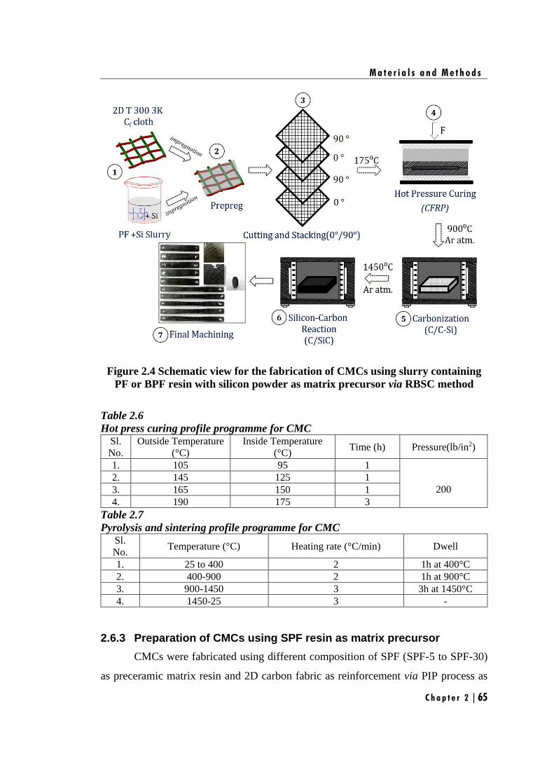
M a t e r i a l s a n d M e t h o d s
C h a p t e r 2 | 65
Figure 2.4 Schematic view for the fabrication of CMCs using slurry containing
PF or BPF resin with silicon powder as matrix precursor via RBSC method
Table 2.6
Hot press curing profile programme for CMC Sl.
No.
Outside Temperature
(°C)
Inside Temperature
(°C) Time (h) Pressure(lb/in2)
1. 105 95 1
200
2. 145 125 1
3. 165 150 1
4. 190 175 3
Table 2.7
Pyrolysis and sintering profile programme for CMC Sl.
No. Temperature (°C) Heating rate (°C/min) Dwell
1. 25 to 400 2 1h at 400°C
2. 400-900 2 1h at 900°C
3. 900-1450 3 3h at 1450°C
4. 1450-25 3 -
2.6.3 Preparation of CMCs using SPF resin as matrix precursor
CMCs were fabricated using different composition of SPF (SPF-5 to SPF-30)
as preceramic matrix resin and 2D carbon fabric as reinforcement via PIP process as
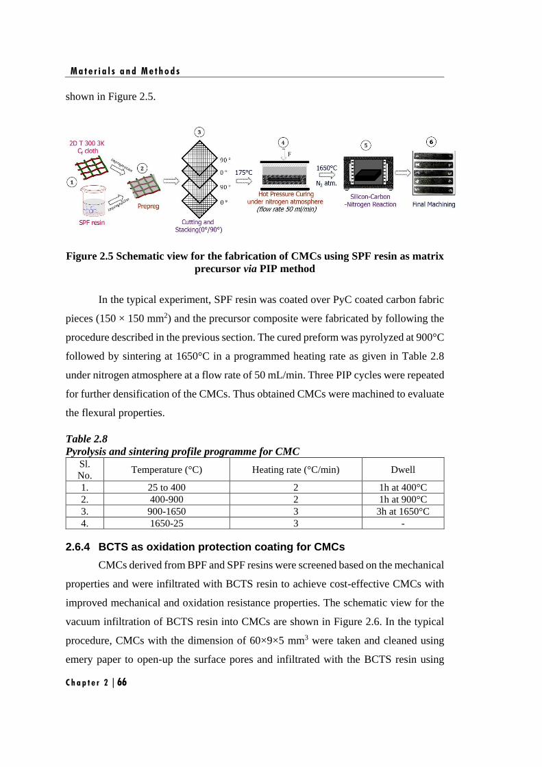
M a t e r i a l s a n d M e t h o d s
C h a p t e r 2 | 66
shown in Figure 2.5.
Figure 2.5 Schematic view for the fabrication of CMCs using SPF resin as matrix
precursor via PIP method
In the typical experiment, SPF resin was coated over PyC coated carbon fabric
pieces (150 × 150 mm2) and the precursor composite were fabricated by following the
procedure described in the previous section. The cured preform was pyrolyzed at 900°C
followed by sintering at 1650°C in a programmed heating rate as given in Table 2.8
under nitrogen atmosphere at a flow rate of 50 mL/min. Three PIP cycles were repeated
for further densification of the CMCs. Thus obtained CMCs were machined to evaluate
the flexural properties.
Table 2.8
Pyrolysis and sintering profile programme for CMC Sl.
No. Temperature (°C) Heating rate (°C/min) Dwell
1. 25 to 400 2 1h at 400°C
2. 400-900 2 1h at 900°C
3. 900-1650 3 3h at 1650°C
4. 1650-25 3 -
2.6.4 BCTS as oxidation protection coating for CMCs
CMCs derived from BPF and SPF resins were screened based on the mechanical
properties and were infiltrated with BCTS resin to achieve cost-effective CMCs with
improved mechanical and oxidation resistance properties. The schematic view for the
vacuum infiltration of BCTS resin into CMCs are shown in Figure 2.6. In the typical
procedure, CMCs with the dimension of 60×9×5 mm3 were taken and cleaned using
emery paper to open-up the surface pores and infiltrated with the BCTS resin using
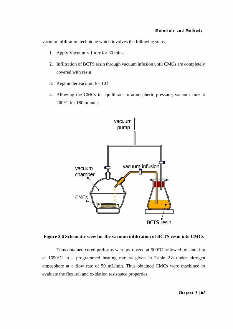
M a t e r i a l s a n d M e t h o d s
C h a p t e r 2 | 67
vacuum infiltration technique which involves the following steps,
1. Apply Vacuum < 1 torr for 30 mins
2. Infiltration of BCTS resin through vacuum infusion until CMCs are completely
covered with resin
3. Kept under vacuum for 10 h
4. Allowing the CMCs to equilibrate to atmospheric pressure; vacuum cure at
200°C for 180 minutes
Figure 2.6 Schematic view for the vacuum infiltration of BCTS resin into CMCs
Thus obtained cured preforms were pyrolyzed at 900°C followed by sintering
at 1650°C in a programmed heating rate as given in Table 2.8 under nitrogen
atmosphere at a flow rate of 50 mL/min. Thus obtained CMCs were machined to
evaluate the flexural and oxidation resistance properties.
M a t e r i a l s a n d M e t h o d s
C h a p t e r 2 | 68
2.7. Characterization of CMCs
2.7.1 Bulk density and open porosity
The bulk density and open porosity of the composites were measured by
Archimedes method using distilled water as per ASTM C 20 [Kumar Mandal 2010].
3Bulk density = g/cmD
W S− (2.3)
( )
Open porosity = 100( )
W D
W S
−
− (2.4)
where, ‘W’ is saturated weight of the CMC, ‘D’ is the dry weight of the CMC and ‘S’
is suspended weight of the CMC
2.7.2 Evaluation of flexural strength
The flexural strength and modulus of the composites were measured by three-
point-bending test at room temperature on a universal testing machine (INSTRON-
5569) as per ASTM C 1341 [C1341 2013]. The dimension of the test sample was
60×9×5 mm3. The span length, L is 30 mm, and the crosshead speed is 0.5 mm/min.
Flexural strength (σf) and flexural modulus (Ef) are calculated with the following
equations:
2
3
2f
PL
BH = (2.5)
3
3 4
f
PLE
BH f
=
(2.6)
where P is the maximum load, ∆P/∆f is the slope of the straight line in the load–
deflection curve recorded during the test. All the flexural strength and modulus are the
average values from five sample tests.
M a t e r i a l s a n d M e t h o d s
C h a p t e r 2 | 69
2.7.3 Optical microscopy analysis
After three-point-bending test, the crack propagation on the fractured surface of
the CMCs was observed by an optical microscope. The fractured surface of the CMCs
samples was recorded on Olympus BX51M optical microscopic instrument.
2.7.4 Scanning Electron Microscopy (SEM) analysis
The fracture surface of the composites was observed using a SEM technique as
described in Section 2.5.3.
2.7.5 Oxidation resistance test
Isothermal oxidation of ceramics and the ceramic matrix composites were done
in a raising hearth furnace (Fitzer Instruments India Pvt. Ltd). The ceramic samples
were oxidized isothermally at three different temperatures 1000°C, 1250°C and 1500°C
in a raising hearth furnace at an air flow rate of 100 cm3/ min for 3hr with 30 mins
interval. The change in weight was calculated using the formula
(2.7)
where, m˳ is the initial ceramic weight at time, t = 0 and m that at time, t) and the
oxidation rate was calculated using the formula,
(2.8)
( )0
0 0
m mΔm100
m m
−=
( )0m moxidation rate
t
−=

M a t e r i a l s a n d M e t h o d s
Chapter 2 | 70
Chapter 3
Studies on boron modified phenol-
formaldehyde (BPF) as preceramic
matrix resin for CMCs

C h a p t e r 3 | 73
s discussed in Chapter 1, Section 1.4, the C/SiC composites are highly prone
to oxidation in oxidizing environment. To enhance the application regime
of C/SiC composite, the oxidation resistance of the composites have to be improved. In
this regard, boron-bearing species are reported to be highly efficient. They can form
fluid oxide phases (B2O3 or Si–B–O ternary phase) during oxidation to fill cracks which
in turn slows down the in-depth diffusion of oxygen imparting self-healing properties.
There are many methodologies to achieve self-healing properties for CMCs which are
explained in Chapter 1, Section 1.5. It has been concluded that, compared to other
methodologies, incorporating boron as back bone of the matrix resin has shorter
processing time and is cost effective. To the best of our knowledge, there are no
available reports on boron modified phenol formaldehyde (BPF) based preceramic
precursor.
This chapter deals with the investigation of boron modified phenol-
formaldehyde (BPF) resins as potential preceramic matrix resin for CMCs. This work
has been divided into two parts;
• In the first part, synthesis, characterization and ceramic conversion
studies of BPF resins are discussed in detail.
• In the second part, CMCs are fabricated using BPF as preceramic matrix
resin. This study focused on the optimization of fiber/matrix (F/M)
volume ratio and the influence of PyC interphase coating on the flexural
properties of CMCs.
A

C h a p t e r 3 | 74
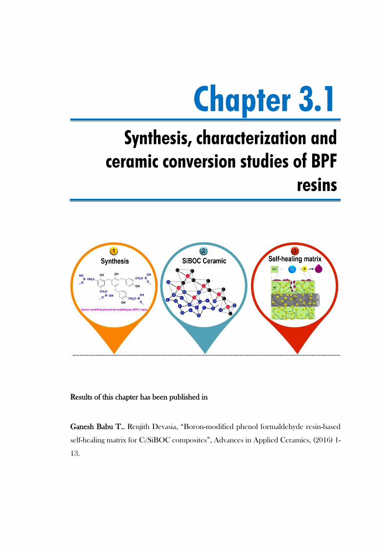
Chapter 3.1
Synthesis, characterization and
ceramic conversion studies of BPF
resins
Results of this chapter has been published in
Ganesh Babu T., Renjith Devasia, “Boron-modified phenol formaldehyde resin-based
self-healing matrix for Cf/SiBOC composites”, Advances in Applied Ceramics, (2016) 1-
13.


S y n t h e s i s , c h a r a c t e r i z a t i o n a n d c e r a m i c c o n v e r s i o n s t u d i e s o f B P F r e s i n s
C h a p t e r 3 . 1 | 77
3.1.1. Introduction
This chapter reports synthesis and ceramic conversion of boron modified
phenol formaldehyde (BPF) resins, with the aim to use it as preceramic matrix resin for
CMCs. This preceramic polymer was synthesized by reacting varying concentrations
of boric acid with phenol formaldehyde resin and the polymer to ceramic
transformation were carried out at 1450°C under argon atmosphere, with and without
silicon as reactive additive. The obtained ceramic phases, morphology and elemental
composition were thoroughly investigated through XRD, SEM and HRTEM
techniques. The objective of this study was to evaluate BPF resin as a potential self-
healing matrix resin for CMCs. Hence, CMCs are fabricated using BPF as matrix resin
via RBSC technique. The microstructures, mechanical properties as well as oxidation
behaviour of CMCs are thoroughly investigated.
3.1.2. Experimental
3.1.2.1 Materials
Details of the chemicals and materials are given in Chapter 2, Section 2.1.
3.1.2.2 Synthesis of BPF resin
The procedure for the synthesis of BPF resins are given in Chapter 2, Section
2.2.1.
3.1.2.3 Characterization
Characterization methods employed include FT-IR, XRD, Raman
spectroscopy, HRTEM, SEM, elemental analysis, three-point-bending test and
oxidation resistance test. The detailed procedures of all these characterizations are
given in Chapter 2, Section 2.5 and 2.7.
3.1.2.4 Polymer to ceramic conversion
The detailed procedure for the polymer to ceramic conversion process of
BPF and BPFSi are given in Chapter 2, Section 2.4.1 and 2.4.2.
3.1.2.5 Fabrication of Cf/SiBOC composite
Cf/SiBOC composite were fabricated from 2D carbon fabric as
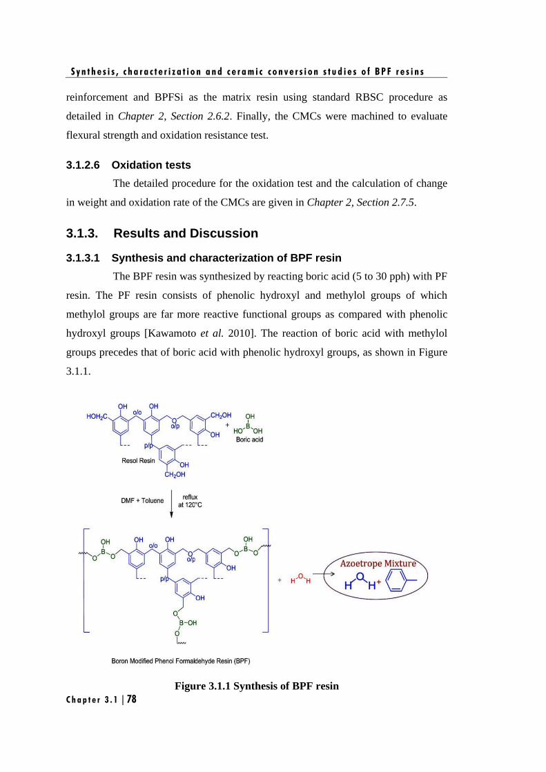
S y n t h e s i s , c h a r a c t e r i z a t i o n a n d c e r a m i c c o n v e r s i o n s t u d i e s o f B P F r e s i n s
C h a p t e r 3 . 1 | 78
reinforcement and BPFSi as the matrix resin using standard RBSC procedure as
detailed in Chapter 2, Section 2.6.2. Finally, the CMCs were machined to evaluate
flexural strength and oxidation resistance test.
3.1.2.6 Oxidation tests
The detailed procedure for the oxidation test and the calculation of change
in weight and oxidation rate of the CMCs are given in Chapter 2, Section 2.7.5.
3.1.3. Results and Discussion
3.1.3.1 Synthesis and characterization of BPF resin
The BPF resin was synthesized by reacting boric acid (5 to 30 pph) with PF
resin. The PF resin consists of phenolic hydroxyl and methylol groups of which
methylol groups are far more reactive functional groups as compared with phenolic
hydroxyl groups [Kawamoto et al. 2010]. The reaction of boric acid with methylol
groups precedes that of boric acid with phenolic hydroxyl groups, as shown in Figure
3.1.1.
Figure 3.1.1 Synthesis of BPF resin
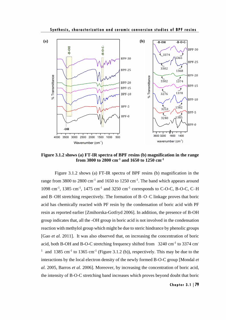
S y n t h e s i s , c h a r a c t e r i z a t i o n a n d c e r a m i c c o n v e r s i o n s t u d i e s o f B P F r e s i n s
C h a p t e r 3 . 1 | 79
Figure 3.1.2 shows (a) FT-IR spectra of BPF resins (b) magnification in the range
from 3800 to 2800 cm-1 and 1650 to 1250 cm-1
Figure 3.1.2 shows (a) FT-IR spectra of BPF resins (b) magnification in the
range from 3800 to 2800 cm-1 and 1650 to 1250 cm-1. The band which appears around
1098 cm-1, 1385 cm-1, 1475 cm-1 and 3250 cm-1 corresponds to C-O-C, B-O-C, C–H
and B–OH stretching respectively. The formation of B–O–C linkage proves that boric
acid has chemically reacted with PF resin by the condensation of boric acid with PF
resin as reported earlier [Zmihorska-Gotfryd 2006]. In addition, the presence of B-OH
group indicates that, all the -OH group in boric acid is not involved in the condensation
reaction with methylol group which might be due to steric hindrance by phenolic groups
[Gao et al. 2011]. It was also observed that, on increasing the concentration of boric
acid, both B-OH and B-O-C stretching frequency shifted from 3240 cm-1 to 3374 cm-
1 and 1385 cm-1 to 1365 cm-1 (Figure 3.1.2 (b)), respectively. This may be due to the
interactions by the local electron density of the newly formed B-O-C group [Mondal et
al. 2005, Barros et al. 2006]. Moreover, by increasing the concentration of boric acid,
the intensity of B-O-C stretching band increases which proves beyond doubt that boric
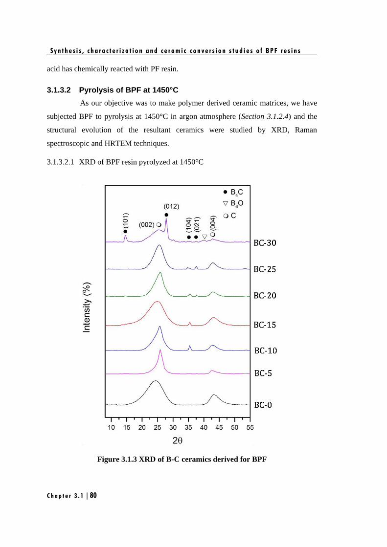
S y n t h e s i s , c h a r a c t e r i z a t i o n a n d c e r a m i c c o n v e r s i o n s t u d i e s o f B P F r e s i n s
C h a p t e r 3 . 1 | 80
acid has chemically reacted with PF resin.
3.1.3.2 Pyrolysis of BPF at 1450°C
As our objective was to make polymer derived ceramic matrices, we have
subjected BPF to pyrolysis at 1450°C in argon atmosphere (Section 3.1.2.4) and the
structural evolution of the resultant ceramics were studied by XRD, Raman
spectroscopic and HRTEM techniques.
3.1.3.2.1 XRD of BPF resin pyrolyzed at 1450°C
Figure 3.1.3 XRD of B-C ceramics derived for BPF
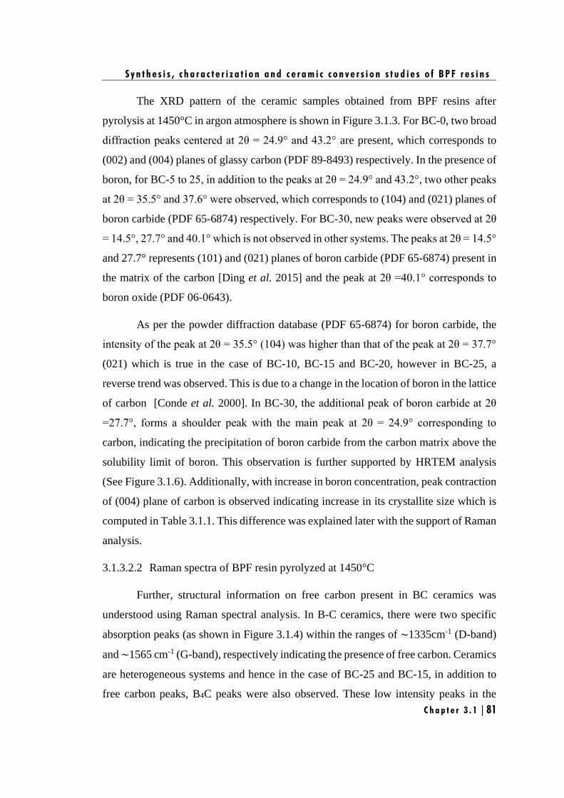
S y n t h e s i s , c h a r a c t e r i z a t i o n a n d c e r a m i c c o n v e r s i o n s t u d i e s o f B P F r e s i n s
C h a p t e r 3 . 1 | 81
The XRD pattern of the ceramic samples obtained from BPF resins after
pyrolysis at 1450°C in argon atmosphere is shown in Figure 3.1.3. For BC-0, two broad
diffraction peaks centered at 2θ = 24.9° and 43.2° are present, which corresponds to
(002) and (004) planes of glassy carbon (PDF 89-8493) respectively. In the presence of
boron, for BC-5 to 25, in addition to the peaks at 2θ = 24.9° and 43.2°, two other peaks
at 2θ = 35.5° and 37.6° were observed, which corresponds to (104) and (021) planes of
boron carbide (PDF 65-6874) respectively. For BC-30, new peaks were observed at 2θ
= 14.5°, 27.7° and 40.1° which is not observed in other systems. The peaks at 2θ = 14.5°
and 27.7° represents (101) and (021) planes of boron carbide (PDF 65-6874) present in
the matrix of the carbon [Ding et al. 2015] and the peak at 2θ =40.1° corresponds to
boron oxide (PDF 06-0643).
As per the powder diffraction database (PDF 65-6874) for boron carbide, the
intensity of the peak at 2θ = 35.5° (104) was higher than that of the peak at 2θ = 37.7°
(021) which is true in the case of BC-10, BC-15 and BC-20, however in BC-25, a
reverse trend was observed. This is due to a change in the location of boron in the lattice
of carbon [Conde et al. 2000]. In BC-30, the additional peak of boron carbide at 2θ
=27.7°, forms a shoulder peak with the main peak at 2θ = 24.9° corresponding to
carbon, indicating the precipitation of boron carbide from the carbon matrix above the
solubility limit of boron. This observation is further supported by HRTEM analysis
(See Figure 3.1.6). Additionally, with increase in boron concentration, peak contraction
of (004) plane of carbon is observed indicating increase in its crystallite size which is
computed in Table 3.1.1. This difference was explained later with the support of Raman
analysis.
3.1.3.2.2 Raman spectra of BPF resin pyrolyzed at 1450°C
Further, structural information on free carbon present in BC ceramics was
understood using Raman spectral analysis. In B-C ceramics, there were two specific
absorption peaks (as shown in Figure 3.1.4) within the ranges of ∼1335cm-1 (D-band)
and ∼1565 cm-1 (G-band), respectively indicating the presence of free carbon. Ceramics
are heterogeneous systems and hence in the case of BC-25 and BC-15, in addition to
free carbon peaks, B4C peaks were also observed. These low intensity peaks in the
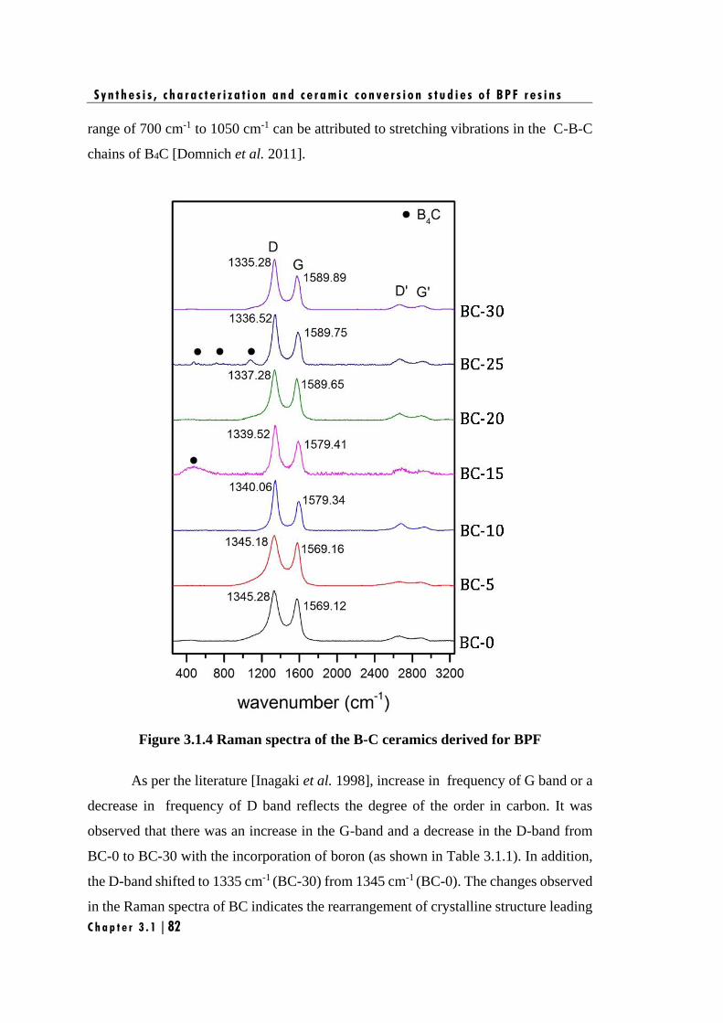
S y n t h e s i s , c h a r a c t e r i z a t i o n a n d c e r a m i c c o n v e r s i o n s t u d i e s o f B P F r e s i n s
C h a p t e r 3 . 1 | 82
range of 700 cm-1 to 1050 cm-1 can be attributed to stretching vibrations in the C-B-C
chains of B4C [Domnich et al. 2011].
Figure 3.1.4 Raman spectra of the B-C ceramics derived for BPF
As per the literature [Inagaki et al. 1998], increase in frequency of G band or a
decrease in frequency of D band reflects the degree of the order in carbon. It was
observed that there was an increase in the G-band and a decrease in the D-band from
BC-0 to BC-30 with the incorporation of boron (as shown in Table 3.1.1). In addition,
the D-band shifted to 1335 cm-1 (BC-30) from 1345 cm-1 (BC-0). The changes observed
in the Raman spectra of BC indicates the rearrangement of crystalline structure leading
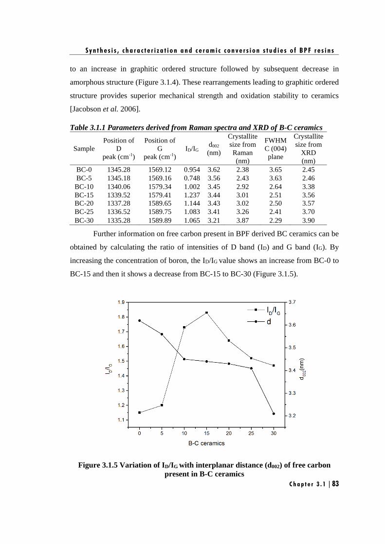
S y n t h e s i s , c h a r a c t e r i z a t i o n a n d c e r a m i c c o n v e r s i o n s t u d i e s o f B P F r e s i n s
C h a p t e r 3 . 1 | 83
to an increase in graphitic ordered structure followed by subsequent decrease in
amorphous structure (Figure 3.1.4). These rearrangements leading to graphitic ordered
structure provides superior mechanical strength and oxidation stability to ceramics
[Jacobson et al. 2006].
Table 3.1.1 Parameters derived from Raman spectra and XRD of B-C ceramics
Sample
Position of
D
peak (cm-1)
Position of
G
peak (cm-1)
ID/IG d002
(nm)
Crystallite
size from
Raman
(nm)
FWHM
C (004)
plane
Crystallite
size from
XRD
(nm)
BC-0 1345.28 1569.12 0.954 3.62 2.38 3.65 2.45
BC-5 1345.18 1569.16 0.748 3.56 2.43 3.63 2.46
BC-10 1340.06 1579.34 1.002 3.45 2.92 2.64 3.38
BC-15 1339.52 1579.41 1.237 3.44 3.01 2.51 3.56
BC-20 1337.28 1589.65 1.144 3.43 3.02 2.50 3.57
BC-25 1336.52 1589.75 1.083 3.41 3.26 2.41 3.70
BC-30 1335.28 1589.89 1.065 3.21 3.87 2.29 3.90
Further information on free carbon present in BPF derived BC ceramics can be
obtained by calculating the ratio of intensities of D band (ID) and G band (IG). By
increasing the concentration of boron, the ID/IG value shows an increase from BC-0 to
BC-15 and then it shows a decrease from BC-15 to BC-30 (Figure 3.1.5).
Figure 3.1.5 Variation of ID/IG with interplanar distance (d002) of free carbon
present in B-C ceramics
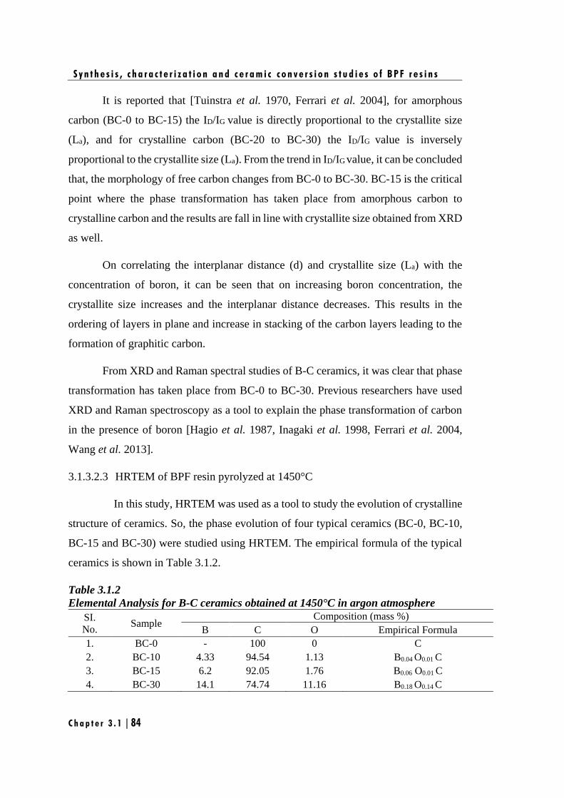
S y n t h e s i s , c h a r a c t e r i z a t i o n a n d c e r a m i c c o n v e r s i o n s t u d i e s o f B P F r e s i n s
C h a p t e r 3 . 1 | 84
It is reported that [Tuinstra et al. 1970, Ferrari et al. 2004], for amorphous
carbon (BC-0 to BC-15) the ID/IG value is directly proportional to the crystallite size
(La), and for crystalline carbon (BC-20 to BC-30) the ID/IG value is inversely
proportional to the crystallite size (La). From the trend in ID/IG value, it can be concluded
that, the morphology of free carbon changes from BC-0 to BC-30. BC-15 is the critical
point where the phase transformation has taken place from amorphous carbon to
crystalline carbon and the results are fall in line with crystallite size obtained from XRD
as well.
On correlating the interplanar distance (d) and crystallite size (La) with the
concentration of boron, it can be seen that on increasing boron concentration, the
crystallite size increases and the interplanar distance decreases. This results in the
ordering of layers in plane and increase in stacking of the carbon layers leading to the
formation of graphitic carbon.
From XRD and Raman spectral studies of B-C ceramics, it was clear that phase
transformation has taken place from BC-0 to BC-30. Previous researchers have used
XRD and Raman spectroscopy as a tool to explain the phase transformation of carbon
in the presence of boron [Hagio et al. 1987, Inagaki et al. 1998, Ferrari et al. 2004,
Wang et al. 2013].
3.1.3.2.3 HRTEM of BPF resin pyrolyzed at 1450°C
In this study, HRTEM was used as a tool to study the evolution of crystalline
structure of ceramics. So, the phase evolution of four typical ceramics (BC-0, BC-10,
BC-15 and BC-30) were studied using HRTEM. The empirical formula of the typical
ceramics is shown in Table 3.1.2.
Table 3.1.2
Elemental Analysis for B-C ceramics obtained at 1450°C in argon atmosphere
SI.
No. Sample
Composition (mass %)
B C O Empirical Formula
1. BC-0 - 100 0 C
2. BC-10 4.33 94.54 1.13 B0.04 O0.01 C
3. BC-15 6.2 92.05 1.76 B0.06 O0.01 C
4. BC-30 14.1 74.74 11.16 B0.18 O0.14 C
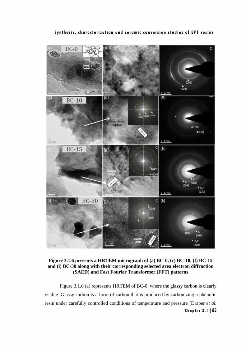
S y n t h e s i s , c h a r a c t e r i z a t i o n a n d c e r a m i c c o n v e r s i o n s t u d i e s o f B P F r e s i n s
C h a p t e r 3 . 1 | 85
Figure 3.1.6 presents a HRTEM micrograph of (a) BC-0, (c) BC-10, (f) BC-15
and (i) BC-30 along with their corresponding selected area electron diffraction
(SAED) and Fast Fourier Transformer (FFT) patterns
Figure 3.1.6 (a) represents HRTEM of BC-0, where the glassy carbon is clearly
visible. Glassy carbon is a form of carbon that is produced by carbonizing a phenolic
resin under carefully controlled conditions of temperature and pressure [Draper et al.
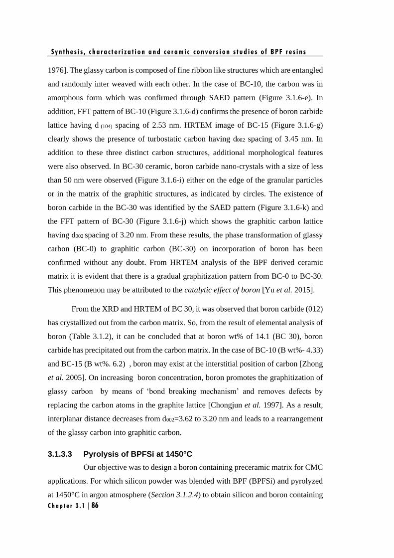
S y n t h e s i s , c h a r a c t e r i z a t i o n a n d c e r a m i c c o n v e r s i o n s t u d i e s o f B P F r e s i n s
C h a p t e r 3 . 1 | 86
1976]. The glassy carbon is composed of fine ribbon like structures which are entangled
and randomly inter weaved with each other. In the case of BC-10, the carbon was in
amorphous form which was confirmed through SAED pattern (Figure 3.1.6-e). In
addition, FFT pattern of BC-10 (Figure 3.1.6-d) confirms the presence of boron carbide
lattice having d (104) spacing of 2.53 nm. HRTEM image of BC-15 (Figure 3.1.6-g)
clearly shows the presence of turbostatic carbon having d002 spacing of 3.45 nm. In
addition to these three distinct carbon structures, additional morphological features
were also observed. In BC-30 ceramic, boron carbide nano-crystals with a size of less
than 50 nm were observed (Figure 3.1.6-i) either on the edge of the granular particles
or in the matrix of the graphitic structures, as indicated by circles. The existence of
boron carbide in the BC-30 was identified by the SAED pattern (Figure 3.1.6-k) and
the FFT pattern of BC-30 (Figure 3.1.6-j) which shows the graphitic carbon lattice
having d002 spacing of 3.20 nm. From these results, the phase transformation of glassy
carbon (BC-0) to graphitic carbon (BC-30) on incorporation of boron has been
confirmed without any doubt. From HRTEM analysis of the BPF derived ceramic
matrix it is evident that there is a gradual graphitization pattern from BC-0 to BC-30.
This phenomenon may be attributed to the catalytic effect of boron [Yu et al. 2015].
From the XRD and HRTEM of BC 30, it was observed that boron carbide (012)
has crystallized out from the carbon matrix. So, from the result of elemental analysis of
boron (Table 3.1.2), it can be concluded that at boron wt% of 14.1 (BC 30), boron
carbide has precipitated out from the carbon matrix. In the case of BC-10 (B wt%- 4.33)
and BC-15 (B wt%. 6.2) , boron may exist at the interstitial position of carbon [Zhong
et al. 2005]. On increasing boron concentration, boron promotes the graphitization of
glassy carbon by means of ‘bond breaking mechanism’ and removes defects by
replacing the carbon atoms in the graphite lattice [Chongjun et al. 1997]. As a result,
interplanar distance decreases from d002=3.62 to 3.20 nm and leads to a rearrangement
of the glassy carbon into graphitic carbon.
3.1.3.3 Pyrolysis of BPFSi at 1450°C
Our objective was to design a boron containing preceramic matrix for CMC
applications. For which silicon powder was blended with BPF (BPFSi) and pyrolyzed
at 1450°C in argon atmosphere (Section 3.1.2.4) to obtain silicon and boron containing
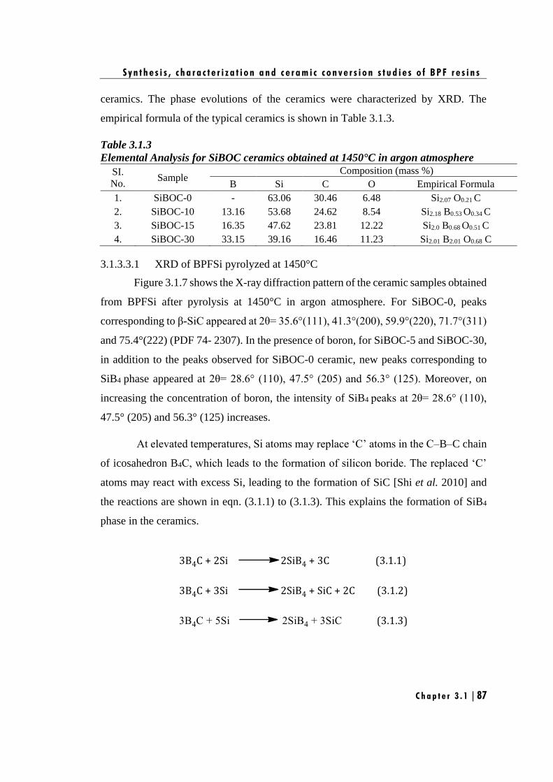
S y n t h e s i s , c h a r a c t e r i z a t i o n a n d c e r a m i c c o n v e r s i o n s t u d i e s o f B P F r e s i n s
C h a p t e r 3 . 1 | 87
ceramics. The phase evolutions of the ceramics were characterized by XRD. The
empirical formula of the typical ceramics is shown in Table 3.1.3.
Table 3.1.3
Elemental Analysis for SiBOC ceramics obtained at 1450°C in argon atmosphere
SI.
No. Sample
Composition (mass %)
B Si C O Empirical Formula
1. SiBOC-0 - 63.06 30.46 6.48 Si2.07 O0.21 C
2. SiBOC-10 13.16 53.68 24.62 8.54 Si2.18 B0.53 O0.34 C
3. SiBOC-15 16.35 47.62 23.81 12.22 Si2.0 B0.68 O0.51 C
4. SiBOC-30 33.15 39.16 16.46 11.23 Si2.01 B2.01 O0.68 C
3.1.3.3.1 XRD of BPFSi pyrolyzed at 1450°C
Figure 3.1.7 shows the X-ray diffraction pattern of the ceramic samples obtained
from BPFSi after pyrolysis at 1450°C in argon atmosphere. For SiBOC-0, peaks
corresponding to β-SiC appeared at 2θ= 35.6°(111), 41.3°(200), 59.9°(220), 71.7°(311)
and 75.4°(222) (PDF 74- 2307). In the presence of boron, for SiBOC-5 and SiBOC-30,
in addition to the peaks observed for SiBOC-0 ceramic, new peaks corresponding to
SiB4 phase appeared at 2θ= 28.6° (110), 47.5° (205) and 56.3° (125). Moreover, on
increasing the concentration of boron, the intensity of SiB4 peaks at 2θ= 28.6° (110),
47.5° (205) and 56.3° (125) increases.
At elevated temperatures, Si atoms may replace ‘C’ atoms in the C–B–C chain
of icosahedron B4C, which leads to the formation of silicon boride. The replaced ‘C’
atoms may react with excess Si, leading to the formation of SiC [Shi et al. 2010] and
the reactions are shown in eqn. (3.1.1) to (3.1.3). This explains the formation of SiB4
phase in the ceramics.
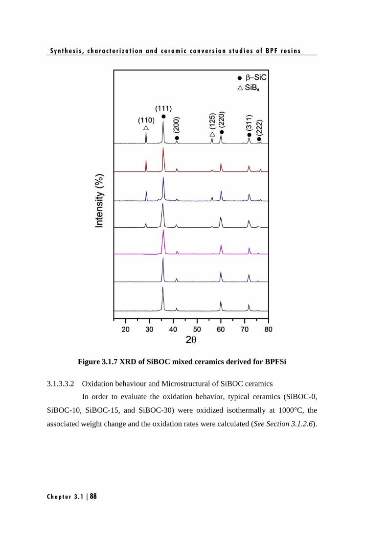
S y n t h e s i s , c h a r a c t e r i z a t i o n a n d c e r a m i c c o n v e r s i o n s t u d i e s o f B P F r e s i n s
C h a p t e r 3 . 1 | 88
Figure 3.1.7 XRD of SiBOC mixed ceramics derived for BPFSi
3.1.3.3.2 Oxidation behaviour and Microstructural of SiBOC ceramics
In order to evaluate the oxidation behavior, typical ceramics (SiBOC-0,
SiBOC-10, SiBOC-15, and SiBOC-30) were oxidized isothermally at 1000°C, the
associated weight change and the oxidation rates were calculated (See Section 3.1.2.6).
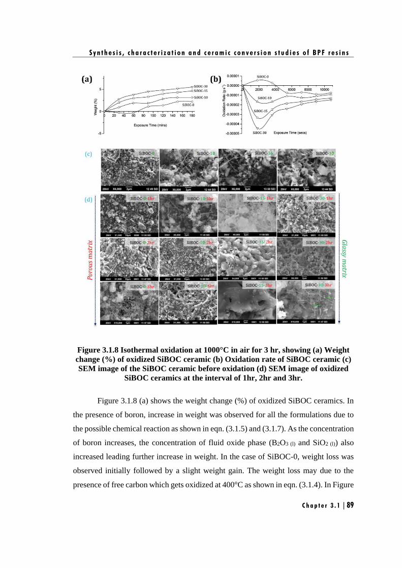
S y n t h e s i s , c h a r a c t e r i z a t i o n a n d c e r a m i c c o n v e r s i o n s t u d i e s o f B P F r e s i n s
C h a p t e r 3 . 1 | 89
Figure 3.1.8 Isothermal oxidation at 1000°C in air for 3 hr, showing (a) Weight
change (%) of oxidized SiBOC ceramic (b) Oxidation rate of SiBOC ceramic (c)
SEM image of the SiBOC ceramic before oxidation (d) SEM image of oxidized
SiBOC ceramics at the interval of 1hr, 2hr and 3hr.
Figure 3.1.8 (a) shows the weight change (%) of oxidized SiBOC ceramics. In
the presence of boron, increase in weight was observed for all the formulations due to
the possible chemical reaction as shown in eqn. (3.1.5) and (3.1.7). As the concentration
of boron increases, the concentration of fluid oxide phase (B2O3 (l) and SiO2 (l)) also
increased leading further increase in weight. In the case of SiBOC-0, weight loss was
observed initially followed by a slight weight gain. The weight loss may due to the
presence of free carbon which gets oxidized at 400°C as shown in eqn. (3.1.4). In Figure
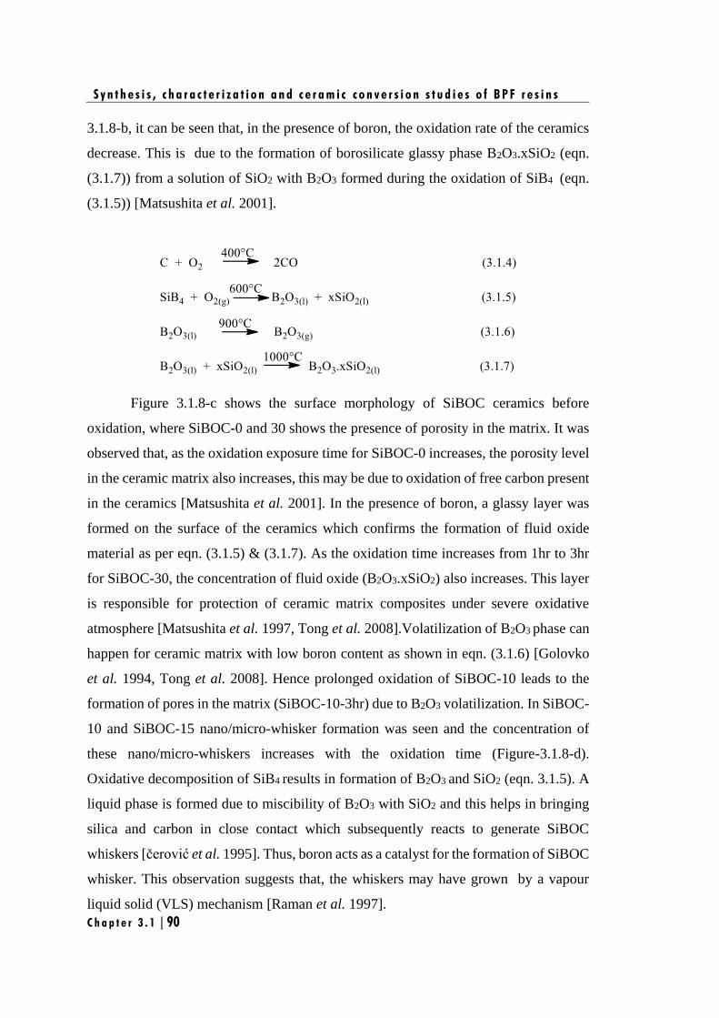
S y n t h e s i s , c h a r a c t e r i z a t i o n a n d c e r a m i c c o n v e r s i o n s t u d i e s o f B P F r e s i n s
C h a p t e r 3 . 1 | 90
3.1.8-b, it can be seen that, in the presence of boron, the oxidation rate of the ceramics
decrease. This is due to the formation of borosilicate glassy phase B2O3.xSiO2 (eqn.
(3.1.7)) from a solution of SiO2 with B2O3 formed during the oxidation of SiB4 (eqn.
(3.1.5)) [Matsushita et al. 2001].
Figure 3.1.8-c shows the surface morphology of SiBOC ceramics before
oxidation, where SiBOC-0 and 30 shows the presence of porosity in the matrix. It was
observed that, as the oxidation exposure time for SiBOC-0 increases, the porosity level
in the ceramic matrix also increases, this may be due to oxidation of free carbon present
in the ceramics [Matsushita et al. 2001]. In the presence of boron, a glassy layer was
formed on the surface of the ceramics which confirms the formation of fluid oxide
material as per eqn. (3.1.5) & (3.1.7). As the oxidation time increases from 1hr to 3hr
for SiBOC-30, the concentration of fluid oxide (B2O3.xSiO2) also increases. This layer
is responsible for protection of ceramic matrix composites under severe oxidative
atmosphere [Matsushita et al. 1997, Tong et al. 2008].Volatilization of B2O3 phase can
happen for ceramic matrix with low boron content as shown in eqn. (3.1.6) [Golovko
et al. 1994, Tong et al. 2008]. Hence prolonged oxidation of SiBOC-10 leads to the
formation of pores in the matrix (SiBOC-10-3hr) due to B2O3 volatilization. In SiBOC-
10 and SiBOC-15 nano/micro-whisker formation was seen and the concentration of
these nano/micro-whiskers increases with the oxidation time (Figure-3.1.8-d).
Oxidative decomposition of SiB4 results in formation of B2O3 and SiO2 (eqn. 3.1.5). A
liquid phase is formed due to miscibility of B2O3 with SiO2 and this helps in bringing
silica and carbon in close contact which subsequently reacts to generate SiBOC
whiskers [čerović et al. 1995]. Thus, boron acts as a catalyst for the formation of SiBOC
whisker. This observation suggests that, the whiskers may have grown by a vapour
liquid solid (VLS) mechanism [Raman et al. 1997].
S y n t h e s i s , c h a r a c t e r i z a t i o n a n d c e r a m i c c o n v e r s i o n s t u d i e s o f B P F r e s i n s
C h a p t e r 3 . 1 | 91
3.1.3.4 Cf/SiBOC composite fabrication
Our studies proved that SiBOC obtained from BPFSi shows self-healing
behaviour and so it was of interest to use it as preceramic matrix resin for the fabrication
of carbon fiber reinforced ceramic matrix composite (Cf/SiBOC). CMCs were
fabricated using BPFSi-0, 10, 15 and 30 (Section 3.1.2.5) and preliminary mechanical
properties were evaluated.
3.1.3.4.1 Evaluation of flexural strength
Figure 3.1.9 (a) stress-strain-diagram of Cf/SiBOC from a flexural strength (b)
Comparison of average flexural strength of Cf/SiBOC along with its densities, (c)
SEM image of fractured surface of Cf/SiBOC-0, (d) SEM image of the top surface
(plateau) (blue) and side wall (orange) of carbon fibers, showing the thin
polycrystalline SiC product layer on the side wall, (e) and (f) shows the EDX for
top surface (plateau) and side wall of carbon fiber respectively.
Figure 3.1.9 (a) shows the typical stress-strain-curves for the flexural strengths
of the CMCs. Figure 3.1.9 (b) shows the average flexural strength for carbon fiber
reinforced with different matrix composition (Cf/SiBOC-0, Cf/SiBOC-10, Cf/SiBOC-
15 and Cf/SiBOC-30). It is expected that BPFSi as matrix resin will improve the
mechanical strength due to the formation of β-SiC and SiB4 ceramics. However, it is
S y n t h e s i s , c h a r a c t e r i z a t i o n a n d c e r a m i c c o n v e r s i o n s t u d i e s o f B P F r e s i n s
C h a p t e r 3 . 1 | 92
observed that the improvement is marginal i.e., maximum flexural strength obtained for
Cf/SiBOC-30 was only 46±1.6 MPa (ρ=2.2 g/cm3) [Figure-3.1.9 (b)]. The major reason
for the low mechanical properties is that, SiBOC matrix is very brittle and hence crack
reaches the saturation point very fast and fiber fails in a brittle manner. The brittle
failure of the composite was observed in the SEM image (Figure 3.1.9 (c)) which clearly
shows lack of fiber pull out, indicating strong fiber-matrix bonding in the absence of an
interphase coating [Buet et al. 2014]. Another reason can be that, the presence of
elemental silicon (melting point ~1390-1410°C) and oxygen in the matrix can react
with carbon fiber causing a reduction in strength of the fiber which has been proved
with spot-EDX analysis (Figure-3.1.9 (d, e and f)). The EDX was recorded for the top
surface (plateau) of the fractured carbon fiber (Figure 3.1.9 (e)) and the carbon fiber
side walls (Figure 3.1.9 (f)) of Cf/SiBOC-0 composite. It reveals that, the side wall of
the carbon fiber is enriched with silicon 22.57 wt% as compared to 6.05 wt% on the top
surface (plateau) of carbon fiber. The morphology of the carbon fiber side walls (Figure
3.1.9 (d)) clearly indicated that, it has been damaged by reacting with elemental silicon
to form thin polycrystalline SiC layer which has led to reduction in the flexural strength
of the Cf/SiBOC composites. This phenomenon may not exist in the presence of an
interphase coated carbon fiber (such as PyC or h-BN) which is reported to help in crack
deflection and acts as a diffusion barrier [Naslain et al. 2004].
3.1.3.4.2 Oxidation of Cf/SiBOC composite and its microstructure
Cf/SiBOC composites were oxidized isothermally at three different
temperatures 1000°C, 1250°C and 1500°C in raising hearth furnace at the flow rate of
air 100 cm3/ min for 3hr with 30 mins intervals. The weight change and oxidation rate
were calculated. Figure 3.1.10 (a) and 3.1.10 (b) shows the percentage weight change
and oxidation rate of Cf/SiBOC composite respectively. The weight loss was observed
for the entire composite (Figure 3.1.10 (a)) and it increases with exposure time,
indicating that oxygen has diffused into the Cf/SiBOC composite, resulting in the
oxidation of the carbon phase (eqn. (3.1.8)). The weight loss is most predominant in the
case of Cf/SiBOC-0 composite. Obviously, the increase of exposure time has led to the
acceleration of the oxidation rate (Figure 3.1.10 (b)). Theoretically the formation of
B2O3 and SiO2 in the case of boron incorporated composite could lead to increase in
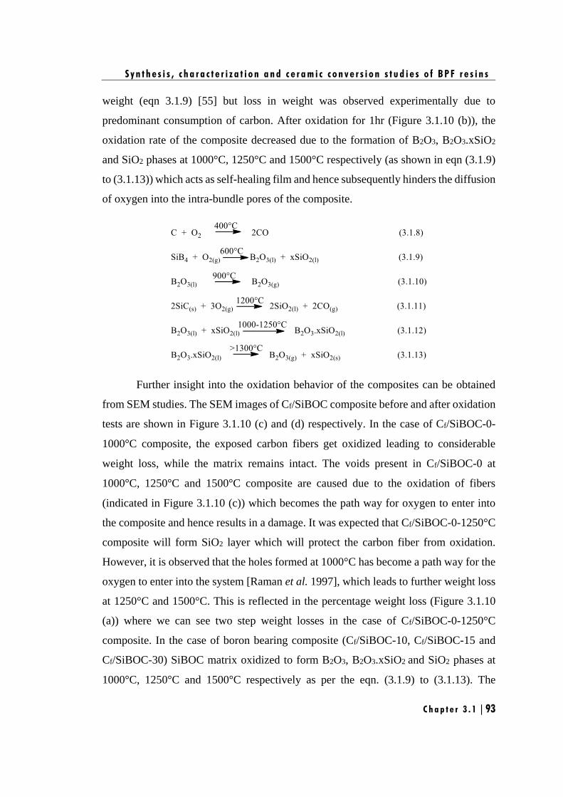
S y n t h e s i s , c h a r a c t e r i z a t i o n a n d c e r a m i c c o n v e r s i o n s t u d i e s o f B P F r e s i n s
C h a p t e r 3 . 1 | 93
weight (eqn 3.1.9) [55] but loss in weight was observed experimentally due to
predominant consumption of carbon. After oxidation for 1hr (Figure 3.1.10 (b)), the
oxidation rate of the composite decreased due to the formation of B2O3, B2O3.xSiO2
and SiO2 phases at 1000°C, 1250°C and 1500°C respectively (as shown in eqn (3.1.9)
to (3.1.13)) which acts as self-healing film and hence subsequently hinders the diffusion
of oxygen into the intra-bundle pores of the composite.
Further insight into the oxidation behavior of the composites can be obtained
from SEM studies. The SEM images of Cf/SiBOC composite before and after oxidation
tests are shown in Figure 3.1.10 (c) and (d) respectively. In the case of Cf/SiBOC-0-
1000°C composite, the exposed carbon fibers get oxidized leading to considerable
weight loss, while the matrix remains intact. The voids present in Cf/SiBOC-0 at
1000°C, 1250°C and 1500°C composite are caused due to the oxidation of fibers
(indicated in Figure 3.1.10 (c)) which becomes the path way for oxygen to enter into
the composite and hence results in a damage. It was expected that Cf/SiBOC-0-1250°C
composite will form SiO2 layer which will protect the carbon fiber from oxidation.
However, it is observed that the holes formed at 1000°C has become a path way for the
oxygen to enter into the system [Raman et al. 1997], which leads to further weight loss
at 1250°C and 1500°C. This is reflected in the percentage weight loss (Figure 3.1.10
(a)) where we can see two step weight losses in the case of Cf/SiBOC-0-1250°C
composite. In the case of boron bearing composite (Cf/SiBOC-10, Cf/SiBOC-15 and
Cf/SiBOC-30) SiBOC matrix oxidized to form B2O3, B2O3.xSiO2 and SiO2 phases at
1000°C, 1250°C and 1500°C respectively as per the eqn. (3.1.9) to (3.1.13). The

S y n t h e s i s , c h a r a c t e r i z a t i o n a n d c e r a m i c c o n v e r s i o n s t u d i e s o f B P F r e s i n s
C h a p t e r 3 . 1 | 94
formation of these phases led to the healing of micro-crack in the SiBOC matrix and
protected the carbon fiber from oxidation. Increasing the concentration of boron further
increased the self-healing properties of Cf/SiBOC composite.
Figure 3.1.10 Isothermal oxidation at 1000°C, 1250°C and 1500°C in air for 3 hr,
showing (a) percentage weight change of Cf/SiBOC composite, (b) oxidation rate
of Cf/SiBOC composite, (c) The SEM image of the Cf/SiBOC composite before
oxidation and (d) The SEM image of the Cf/SiBOC composite after oxidation.
S y n t h e s i s , c h a r a c t e r i z a t i o n a n d c e r a m i c c o n v e r s i o n s t u d i e s o f B P F r e s i n s
C h a p t e r 3 . 1 | 95
From the above results, it is proved that boron incorporated i.e., Cf/SiBOC-10,
15 and 30 ceramic composites displayed better oxidation resistance compared to a
Cf/SiBOC-0 due to the existence of SiB4 ceramics. However, in order to improve the
oxidation as well as the reusability of the Cf/SiBOC composite materials a suitable
interphase coating on the fiber has to be employed in addition to a self-healing matrix.
3.1.4. Conclusions
The current work was aimed at developing a cost effective Cf/SiBOC
composite using BPFSi as matrix resin and 2D carbon fabric as reinforcement by RBSC
method. The study leads to following conclusions
(i) Boron is incorporated in the back bone of phenol formaldehyde resin
which is the carbonaceous precursor for the formation of reaction-
bonded SiBOC mixed ceramics.
(ii) Raman and HRTEM analysis revealed the morphology of free carbon in
B-C ceramics which supports the transformation of glassy carbon (BPF-
0) to graphitic carbon (BPF-30).
(iii) Isothermal oxidation of SiBOC mixed ceramics at 1000°C leads to the
formation of SiO2-B2O3 phase proving boron bearing ceramics are more
efficient at relatively low temperatures (500–1000°C) to protect CMCs.
(iv) Flexural strength of Cf/SiBOC composites showed marginal
improvements maximum of 46±1.6 MPa was achieved in the case
Cf/SiBOC-30.
(v) Fractured surface of Cf/SiBOC-0 composite was observed using SEM
which showed brittle failure with no fiber pull out and this is attributed
to the strong fiber-matrix bonding in the composite.
(vi) Energy dispersive X-rays (EDX) of Cf/SiBOC-0 composite shows that,
the side wall of the carbon fiber is enriched with silicon 22.57 wt% as
compared to 6.05 wt% on top surface (plateau) of carbon fiber. This
clearly indicated that it has been damaged by reacting with elemental
S y n t h e s i s , c h a r a c t e r i z a t i o n a n d c e r a m i c c o n v e r s i o n s t u d i e s o f B P F r e s i n s
C h a p t e r 3 . 1 | 96
silicon leading to reduction in the flexural strength of the Cf/SiBOC
composites.
(vii) Evaluation of oxidation resistance for Cf/SiBOC composites at various
temperatures (1000°C, 1250°C and 1500°C) proved the formation of
borosilicate glass at relatively low temperature which is responsible for
self-healing property of CMCs.
(viii) Significance of interphase coating on the flexural strength has to be
understood and hence will be studied in detail in next Chapter.
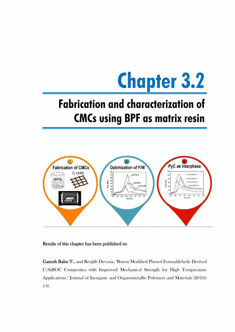
Chapter 3.2
Fabrication and characterization of
CMCs using BPF as matrix resin
Results of this chapter has been published in:
Ganesh Babu T., and Renjith Devasia, "Boron Modified Phenol Formaldehyde Derived
Cf/SiBOC Composites with Improved Mechanical Strength for High Temperature
Applications." Journal of Inorganic and Organometallic Polymers and Materials (2016):
1-9.


F a b r i c a t i o n a n d c h a r a c t e r i z a t i o n o f C M C s u s i n g B P F a s m a t r i x r e s i n
Chapter 3 .2 | 99
3.2.1. Introduction
Chapter 3.1, has demonstrated that the boron modified Cf/SiBOC composites
exhibit improved oxidation resistance compared to Cf/SiC composite by the formation
of self-healing matrix. However, the flexural strength of Cf/SiBOC composites shows
only marginal improvement (46±1.6 MPa) as compared to Cf/SiC composite (42±2.2
MPa) and it was attributed to the damage of carbon fiber on reaction with elemental
silicon. This study imparts the significance of interphase coating and optimization of
F/M volume ratio on the improvement of flexural strength. Also to enhance the
application regime of Cf/SiBOC composites, the fracture behavior and mechanism
should be investigated in detail.
Hence, in this chapter, the study focuses on the optimization of F/M volume
ratio and the influence of PyC interphase coating on the flexural properties of Cf/SiBOC
derived from BPF resin via RBSC method. At the same time, the flexural properties of
Cf/SiBOC are compared with Cf/SiC composite derived from PF resin. Finally, the
fracture behavior and mechanism of Cf/SiBOC and Cf/PyC/SiBOC composites are
discussed based on the characterization of the fracture surface and its microstructure.
3.2.2. Experimental
3.2.2.1 Materials
Details of the chemicals and materials are detailed in Chapter 2, Section 2.1.
3.2.2.2 Synthesis of BPF resin
The procedure for the synthesis of BPF resins are detailed in Chapter 2,
Section 2.2.1.
3.2.2.3 Preparation of preceramic matrix precursors
The procedure for the preparation of preceramic matrix precursors are given
in Chapter 2, Section 2.4.2. The typical properties of the preceramic precursors are
shown in Table 3.2.1.
F a b r i c a t i o n a n d c h a r a c t e r i z a t i o n o f C M C s u s i n g B P F a s m a t r i x r e s i n
Chapter 3 .2 | 100
3.2.2.4 Fabrication of Cf/SiC composites
In order to optimize the F/M volume ratio and to understand its effect on the
flexural properties of the composites, three types of Cf/SiC composites were fabricated
by varying the F/M volume ratio viz. 40/60, 50/50 and 60/40 using PFSi as matrix and
2D carbon fabric as reinforcement via standard RBSC techniques as described in
Chapter 2, Section 2.6.2. Their CMCs were designated as Cf/SiC-40/60, Cf/SiC-50/50
and Cf/SiC-60/40. Finally, these composites were machined to evaluate flexural
properties.
3.2.2.5 Fabrication of Cf/SiBOC composites
Cf/SiBOC composites were fabricated using BPFSi-10, BPFSi-15 and
BPFSi-30 as matrix resin and 2D carbon fabric as reinforcement through RBSC method
as described in Chapter 2, Section 2.6.2. The composites thus obtained are named as
Cf/SiBOC-10, Cf/SiBOC-15 and Cf/SiBOC-30. Finally, these composites were
machined to evaluate flexural properties.
3.2.2.6 Fabrication of CMCs with PyC interphase
To study the effect of PyC interphase coating on the flexural properties of
the composites. CMCs with PyC interphase were fabricated as described in Chapter 2,
Section 2.6.1, followed by densification with the above mentioned matrices via RBSC
method and are denoted as Cf/PyC/SiBOC-10, Cf/PyC/SiBOC-15 and Cf/PyC/SiBOC-
30. Finally, the obtained composites were machined to evaluate the flexural properties.
The flexural properties were compared with Cf/PyC/SiC composite derived from PFSi
also.
3.2.2.7 Characterization
Characterization methods employed include density and open porosity
measurements, three-point-bending test, optical microscopy analysis and SEM
analysis. The detailed procedures of all these characterizations are given in Chapter 2,
Section 2.5 and 2.7.
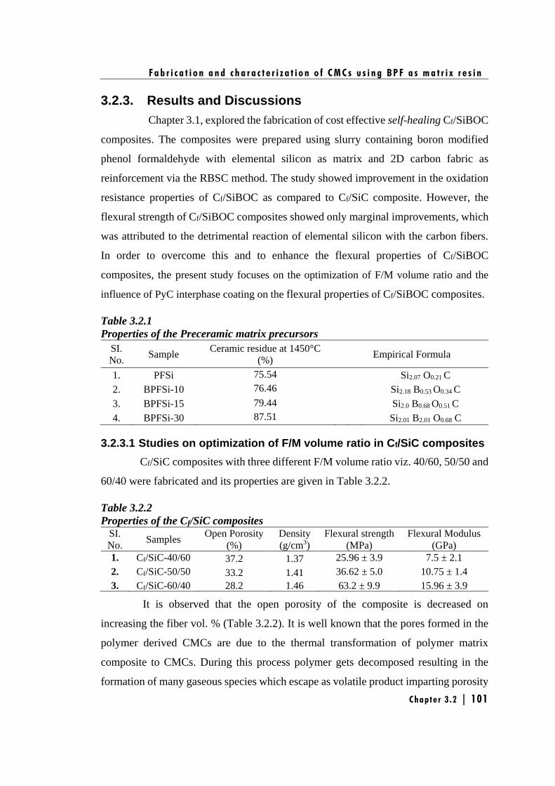
F a b r i c a t i o n a n d c h a r a c t e r i z a t i o n o f C M C s u s i n g B P F a s m a t r i x r e s i n
Chapter 3 .2 | 101
3.2.3. Results and Discussions
Chapter 3.1, explored the fabrication of cost effective self-healing Cf/SiBOC
composites. The composites were prepared using slurry containing boron modified
phenol formaldehyde with elemental silicon as matrix and 2D carbon fabric as
reinforcement via the RBSC method. The study showed improvement in the oxidation
resistance properties of Cf/SiBOC as compared to Cf/SiC composite. However, the
flexural strength of Cf/SiBOC composites showed only marginal improvements, which
was attributed to the detrimental reaction of elemental silicon with the carbon fibers.
In order to overcome this and to enhance the flexural properties of Cf/SiBOC
composites, the present study focuses on the optimization of F/M volume ratio and the
influence of PyC interphase coating on the flexural properties of Cf/SiBOC composites.
Table 3.2.1
Properties of the Preceramic matrix precursors
SI.
No. Sample
Ceramic residue at 1450°C
(%) Empirical Formula
1. PFSi 75.54 Si2.07 O0.21 C
2. BPFSi-10 76.46 Si2.18 B0.53 O0.34 C
3. BPFSi-15 79.44 Si2.0 B0.68 O0.51 C
4. BPFSi-30 87.51 Si2.01 B2.01 O0.68 C
3.2.3.1 Studies on optimization of F/M volume ratio in Cf/SiC composites
Cf/SiC composites with three different F/M volume ratio viz. 40/60, 50/50 and
60/40 were fabricated and its properties are given in Table 3.2.2.
Table 3.2.2
Properties of the Cf/SiC composites SI.
No. Samples
Open Porosity
(%)
Density
(g/cm3)
Flexural strength
(MPa)
Flexural Modulus
(GPa)
1. Cf/SiC-40/60 37.2 1.37 25.96 ± 3.9 7.5 ± 2.1
2. Cf/SiC-50/50 33.2 1.41 36.62 ± 5.0 10.75 ± 1.4
3. Cf/SiC-60/40 28.2 1.46 63.2 ± 9.9 15.96 ± 3.9
It is observed that the open porosity of the composite is decreased on
increasing the fiber vol. % (Table 3.2.2). It is well known that the pores formed in the
polymer derived CMCs are due to the thermal transformation of polymer matrix
composite to CMCs. During this process polymer gets decomposed resulting in the
formation of many gaseous species which escape as volatile product imparting porosity
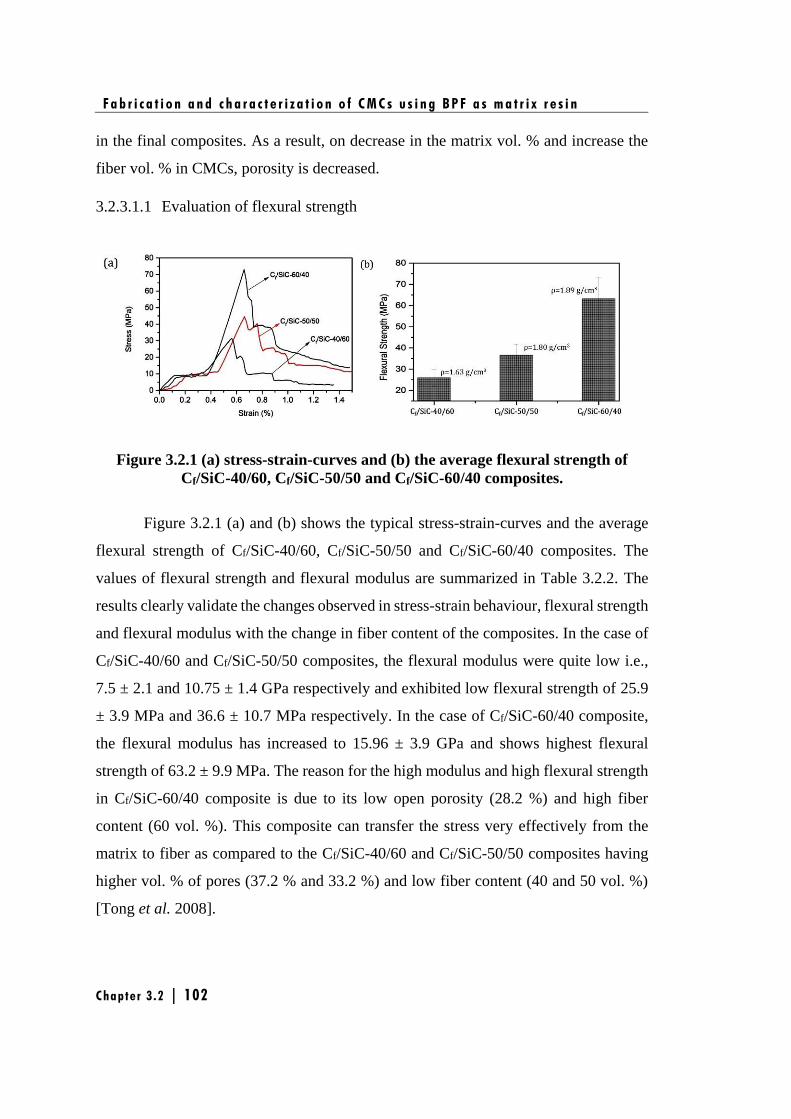
F a b r i c a t i o n a n d c h a r a c t e r i z a t i o n o f C M C s u s i n g B P F a s m a t r i x r e s i n
Chapter 3 .2 | 102
in the final composites. As a result, on decrease in the matrix vol. % and increase the
fiber vol. % in CMCs, porosity is decreased.
3.2.3.1.1 Evaluation of flexural strength
Figure 3.2.1 (a) stress-strain-curves and (b) the average flexural strength of
Cf/SiC-40/60, Cf/SiC-50/50 and Cf/SiC-60/40 composites.
Figure 3.2.1 (a) and (b) shows the typical stress-strain-curves and the average
flexural strength of Cf/SiC-40/60, Cf/SiC-50/50 and Cf/SiC-60/40 composites. The
values of flexural strength and flexural modulus are summarized in Table 3.2.2. The
results clearly validate the changes observed in stress-strain behaviour, flexural strength
and flexural modulus with the change in fiber content of the composites. In the case of
Cf/SiC-40/60 and Cf/SiC-50/50 composites, the flexural modulus were quite low i.e.,
7.5 ± 2.1 and 10.75 ± 1.4 GPa respectively and exhibited low flexural strength of 25.9
± 3.9 MPa and 36.6 ± 10.7 MPa respectively. In the case of Cf/SiC-60/40 composite,
the flexural modulus has increased to 15.96 ± 3.9 GPa and shows highest flexural
strength of 63.2 ± 9.9 MPa. The reason for the high modulus and high flexural strength
in Cf/SiC-60/40 composite is due to its low open porosity (28.2 %) and high fiber
content (60 vol. %). This composite can transfer the stress very effectively from the
matrix to fiber as compared to the Cf/SiC-40/60 and Cf/SiC-50/50 composites having
higher vol. % of pores (37.2 % and 33.2 %) and low fiber content (40 and 50 vol. %)
[Tong et al. 2008].
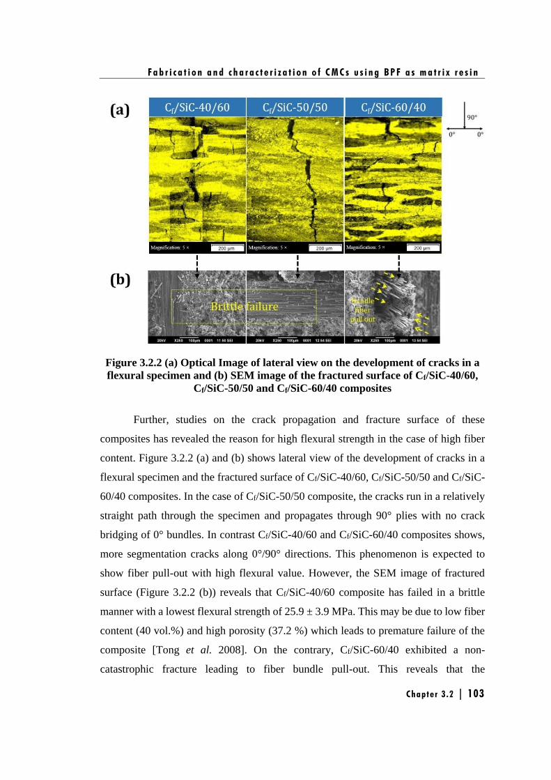
F a b r i c a t i o n a n d c h a r a c t e r i z a t i o n o f C M C s u s i n g B P F a s m a t r i x r e s i n
Chapter 3 .2 | 103
Figure 3.2.2 (a) Optical Image of lateral view on the development of cracks in a
flexural specimen and (b) SEM image of the fractured surface of Cf/SiC-40/60,
Cf/SiC-50/50 and Cf/SiC-60/40 composites
Further, studies on the crack propagation and fracture surface of these
composites has revealed the reason for high flexural strength in the case of high fiber
content. Figure 3.2.2 (a) and (b) shows lateral view of the development of cracks in a
flexural specimen and the fractured surface of Cf/SiC-40/60, Cf/SiC-50/50 and Cf/SiC-
60/40 composites. In the case of Cf/SiC-50/50 composite, the cracks run in a relatively
straight path through the specimen and propagates through 90° plies with no crack
bridging of 0° bundles. In contrast Cf/SiC-40/60 and Cf/SiC-60/40 composites shows,
more segmentation cracks along 0°/90° directions. This phenomenon is expected to
show fiber pull-out with high flexural value. However, the SEM image of fractured
surface (Figure 3.2.2 (b)) reveals that Cf/SiC-40/60 composite has failed in a brittle
manner with a lowest flexural strength of 25.9 ± 3.9 MPa. This may be due to low fiber
content (40 vol.%) and high porosity (37.2 %) which leads to premature failure of the
composite [Tong et al. 2008]. On the contrary, Cf/SiC-60/40 exhibited a non-
catastrophic fracture leading to fiber bundle pull-out. This reveals that the
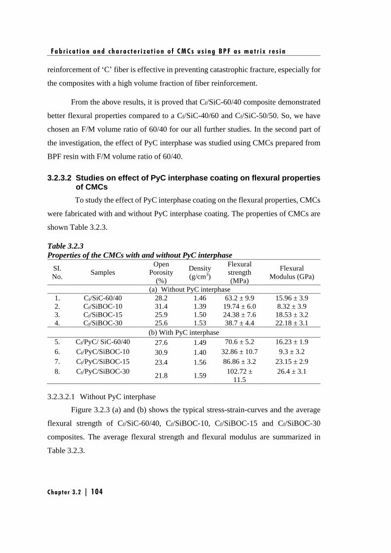
F a b r i c a t i o n a n d c h a r a c t e r i z a t i o n o f C M C s u s i n g B P F a s m a t r i x r e s i n
Chapter 3 .2 | 104
reinforcement of ‘C’ fiber is effective in preventing catastrophic fracture, especially for
the composites with a high volume fraction of fiber reinforcement.
From the above results, it is proved that Cf/SiC-60/40 composite demonstrated
better flexural properties compared to a Cf/SiC-40/60 and Cf/SiC-50/50. So, we have
chosen an F/M volume ratio of 60/40 for our all further studies. In the second part of
the investigation, the effect of PyC interphase was studied using CMCs prepared from
BPF resin with F/M volume ratio of 60/40.
3.2.3.2 Studies on effect of PyC interphase coating on flexural properties of CMCs
To study the effect of PyC interphase coating on the flexural properties, CMCs
were fabricated with and without PyC interphase coating. The properties of CMCs are
shown Table 3.2.3.
Table 3.2.3
Properties of the CMCs with and without PyC interphase
SI.
No. Samples
Open
Porosity
(%)
Density
(g/cm3)
Flexural
strength
(MPa)
Flexural
Modulus (GPa)
(a) Without PyC interphase
1. Cf/SiC-60/40 28.2 1.46 63.2 ± 9.9 15.96 ± 3.9
2. Cf/SiBOC-10 31.4 1.39 19.74 ± 6.0 8.32 ± 3.9
3. Cf/SiBOC-15 25.9 1.50 24.38 ± 7.6 18.53 ± 3.2
4. Cf/SiBOC-30 25.6 1.53 38.7 ± 4.4 22.18 ± 3.1
(b) With PyC interphase
5. Cf/PyC/ SiC-60/40 27.6 1.49 70.6 ± 5.2 16.23 ± 1.9
6. Cf/PyC/SiBOC-10 30.9 1.40 32.86 ± 10.7 9.3 ± 3.2
7. Cf/PyC/SiBOC-15 23.4 1.56 86.86 ± 3.2 23.15 ± 2.9
8. Cf/PyC/SiBOC-30 21.8 1.59
102.72 ±
11.5
26.4 ± 3.1
3.2.3.2.1 Without PyC interphase
Figure 3.2.3 (a) and (b) shows the typical stress-strain-curves and the average
flexural strength of Cf/SiC-60/40, Cf/SiBOC-10, Cf/SiBOC-15 and Cf/SiBOC-30
composites. The average flexural strength and flexural modulus are summarized in
Table 3.2.3.
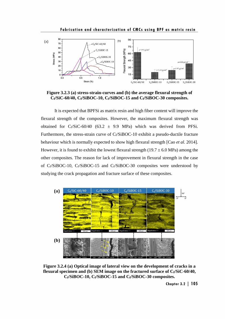
F a b r i c a t i o n a n d c h a r a c t e r i z a t i o n o f C M C s u s i n g B P F a s m a t r i x r e s i n
Chapter 3 .2 | 105
Figure 3.2.3 (a) stress-strain-curves and (b) the average flexural strength of
Cf/SiC-60/40, Cf/SiBOC-10, Cf/SiBOC-15 and Cf/SiBOC-30 composites.
It is expected that BPFSi as matrix resin and high fiber content will improve the
flexural strength of the composites. However, the maximum flexural strength was
obtained for Cf/SiC-60/40 (63.2 ± 9.9 MPa) which was derived from PFSi.
Furthermore, the stress-strain curve of Cf/SiBOC-10 exhibit a pseudo-ductile fracture
behaviour which is normally expected to show high flexural strength [Cao et al. 2014].
However, it is found to exhibit the lowest flexural strength (19.7 ± 6.0 MPa) among the
other composites. The reason for lack of improvement in flexural strength in the case
of Cf/SiBOC-10, Cf/SiBOC-15 and Cf/SiBOC-30 composites were understood by
studying the crack propagation and fracture surface of these composites.
Figure 3.2.4 (a) Optical image of lateral view on the development of cracks in a
flexural specimen and (b) SEM image on the fractured surface of Cf/SiC-60/40,
Cf/SiBOC-10, Cf/SiBOC-15 and Cf/SiBOC-30 composites.
F a b r i c a t i o n a n d c h a r a c t e r i z a t i o n o f C M C s u s i n g B P F a s m a t r i x r e s i n
Chapter 3 .2 | 106
Figure 3.2.4 (a) and (b) shows lateral view of the development of cracks in a
flexural specimen and the fractured surface of Cf/SiC-60/40, Cf/SiBOC-10, Cf/SiBOC-
15 and Cf/SiBOC-30 composites. In the case of Cf/SiC-60/40, Cf/SiBOC-15 and
Cf/SiBOC-30 composites, though the development of cracks exhibits similar
phenomenon (Figure 3.2.4 (a)), i.e., cracks run in a relatively straight path through the
specimen with some segmentation cracks, but its fracture surface was not same (Figure
3.2.4 (b)). The fracture surface of Cf/SiC-60/40 composite shows fiber pull out
phenomenon in contrast to Cf/SiBOC-15 and Cf/SiBOC-30 composites which have
shown no fiber pull out. This results in a catastrophic failure which has been reflected
in their flexural properties as well (Table 3.2.3). The major reason behind the
catastrophic failure was that, SiBOC as matrix leads to a strong bonding in F/M
interface and hence crack reaches the saturation point very fast and fiber fails in a brittle
manner. The brittle failure of the composite was observed in the fractured surface of
SEM image (Figure 3.2.4 (b)) which clearly shows the lack of fiber pull out, indicating
the strong bonding in F/M interface. Another reason can be that, during the fabrication
of CMCs using RBSC technique, carbon fiber gets attacked by the elemental silicon.
This will lead to reduction in the flexural properties which was proved in the previous
chapter (Chapter 3.1). On contrast, the crack propagation and fracture surface behaviour
of Cf/SiBOC-10 composite shows more segmentation cracks along 0°/90° directions
and leads to partial delamination of the composite. The delamination has occurred
between fiber and the matrix, as indicated by arrows (Figure 3.2.4 (b)) which says that
F/M interface is too low in this composite. This is due to the structurally weak points
like high property of pores (31.4 %) or cracks in the matrix which may lead to a
premature failure of the composite and has resulted in lowering of flexural strength
(19.7 ± 6.0 MPa) among other composites.
3.2.3.2.2 With PyC interphase
As our main objective was to overcome the above mentioned problems and
to enhance the flexural properties of Cf/SiBOC composites, a thin layer of PyC
interphase coating was deposited on the carbon fiber using CVI followed by
densification of the composite using RBSC method.
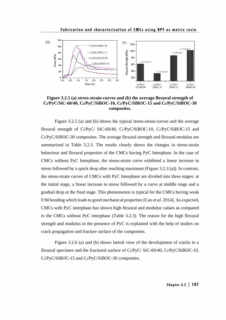
F a b r i c a t i o n a n d c h a r a c t e r i z a t i o n o f C M C s u s i n g B P F a s m a t r i x r e s i n
Chapter 3 .2 | 107
Figure 3.2.5 (a) stress-strain-curves and (b) the average flexural strength of
Cf/PyC/SiC-60/40, Cf/PyC/SiBOC-10, Cf/PyC/SiBOC-15 and Cf/PyC/SiBOC-30
composites.
Figure 3.2.5 (a) and (b) shows the typical stress-strain-curves and the average
flexural strength of Cf/PyC/ SiC-60/40, Cf/PyC/SiBOC-10, Cf/PyC/SiBOC-15 and
Cf/PyC/SiBOC-30 composites. The average flexural strength and flexural modulus are
summarized in Table 3.2.3. The results clearly shows the changes in stress-strain
behaviour and flexural properties of the CMCs having PyC Interphase. In the case of
CMCs without PyC Interphase, the stress-strain curve exhibited a linear increase in
stress followed by a quick drop after reaching maximum (Figure 3.2.3 (a)). In contrast,
the stress-strain curves of CMCs with PyC Interphase are divided into three stages: at
the initial stage, a linear increase in stress followed by a curve at middle stage and a
gradual drop at the final stage. This phenomenon is typical for the CMCs having weak
F/M bonding which leads to good mechanical properties [Cao et al. 2014]. As expected,
CMCs with PyC interphase has shown high flexural and modulus values as compared
to the CMCs without PyC interphase (Table 3.2.3). The reason for the high flexural
strength and modulus in the presence of PyC is explained with the help of studies on
crack propagation and fracture surface of the composites.
Figure 3.2.6 (a) and (b) shows lateral view of the development of cracks in a
flexural specimen and the fractured surface of Cf/PyC/ SiC-60/40, Cf/PyC/SiBOC-10,
Cf/PyC/SiBOC-15 and Cf/PyC/SiBOC-30 composites.
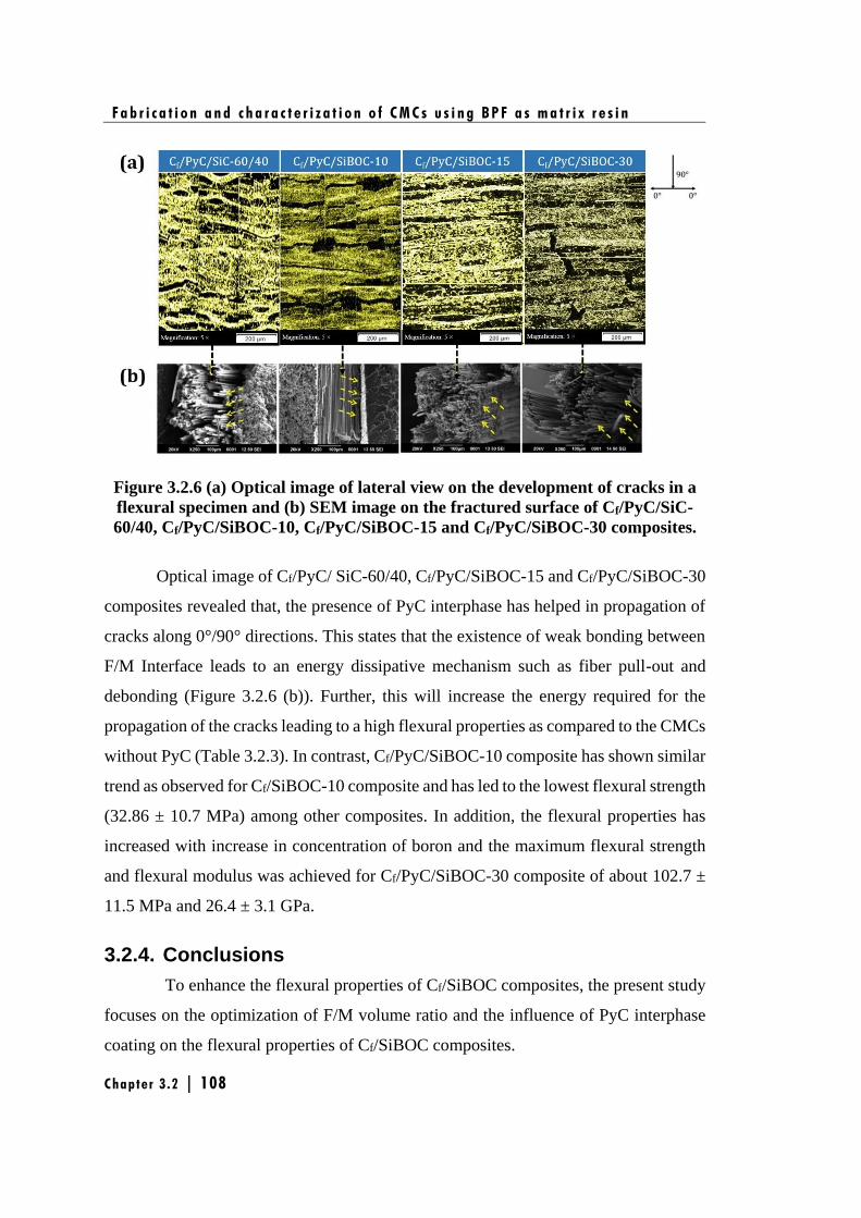
F a b r i c a t i o n a n d c h a r a c t e r i z a t i o n o f C M C s u s i n g B P F a s m a t r i x r e s i n
Chapter 3 .2 | 108
Figure 3.2.6 (a) Optical image of lateral view on the development of cracks in a
flexural specimen and (b) SEM image on the fractured surface of Cf/PyC/SiC-
60/40, Cf/PyC/SiBOC-10, Cf/PyC/SiBOC-15 and Cf/PyC/SiBOC-30 composites.
Optical image of Cf/PyC/ SiC-60/40, Cf/PyC/SiBOC-15 and Cf/PyC/SiBOC-30
composites revealed that, the presence of PyC interphase has helped in propagation of
cracks along 0°/90° directions. This states that the existence of weak bonding between
F/M Interface leads to an energy dissipative mechanism such as fiber pull-out and
debonding (Figure 3.2.6 (b)). Further, this will increase the energy required for the
propagation of the cracks leading to a high flexural properties as compared to the CMCs
without PyC (Table 3.2.3). In contrast, Cf/PyC/SiBOC-10 composite has shown similar
trend as observed for Cf/SiBOC-10 composite and has led to the lowest flexural strength
(32.86 ± 10.7 MPa) among other composites. In addition, the flexural properties has
increased with increase in concentration of boron and the maximum flexural strength
and flexural modulus was achieved for Cf/PyC/SiBOC-30 composite of about 102.7 ±
11.5 MPa and 26.4 ± 3.1 GPa.
3.2.4. Conclusions
To enhance the flexural properties of Cf/SiBOC composites, the present study
focuses on the optimization of F/M volume ratio and the influence of PyC interphase
coating on the flexural properties of Cf/SiBOC composites.
F a b r i c a t i o n a n d c h a r a c t e r i z a t i o n o f C M C s u s i n g B P F a s m a t r i x r e s i n
Chapter 3 .2 | 109
To understand the effect of F/M volume ratio on the flexural properties of the
composites, three types of Cf/SiC composites were fabricated by varying the F/M
volume ratio viz. 40/60, 50/50 and 60/40 using PFSi as matrix precursor. The results
show that, the flexural strength has increased from 25 ± 3.9 MPa (fiber content-40%)
to 63 ± 9.9 MPa (fiber content-60%) on increasing the fiber vol. %. Additionally,
Cf/SiC-40/60 and Cf/SiC-50/50 composites has failed in a brittle manner while Cf/SiC-
60/40 composite exhibited a non-catastrophic fracture leading to fiber bundle pull-out.
This reveals that the reinforcement of ‘C’ fiber is effective in preventing catastrophic
fracture, especially for the composites with a high volume fraction of fiber
reinforcement.
In the second part of investigation, CMCs were prepared with and without PyC
interphase using BPFSi as matrix. The study proves that, PyC as interphase in the
CMCs has played an important role in the load-carrying capability of the final
composite. CMCs with PyC interphase shows an improvement in flexural strength from
32.86 ± 10.7 MPa (Cf/PyC/SiBOC-10) to 102±11.5 MPa (Cf/PyC/SiBOC-30) while
CMCs without interphase has shown no trend in improvement of flexural properties
and the maximum flexural strength obtained was 38±4.4 MPa (Cf/SiBOC-30). Further,
the fractography of CMCs without interphase shows no fiber pull-out, indicating a
strong fiber-matrix bonding. CMCs with PyC interphase coating shows fiber pull-out
phenomenon and hence fails in a ductile manner. The study has proved the importance
of optimization of F/M volume ratio and the need of PyC interphase coating to fabricate
CMCs with better mechanical properties.
F a b r i c a t i o n a n d c h a r a c t e r i z a t i o n o f C M C s u s i n g B P F a s m a t r i x r e s i n
Chapter 3 .2 | 110
Chapter 4
Studies on silazane modified phenol-
formaldehyde (SPF) as preceramic
matrix resin for CMCs


n the previous chapter, it was understood that carbon fiber has been damaged by
reacting with molten silicon to form thin polycrystalline SiC layer which has led
to a reduction in the flexural property of the CMCs. So, in this chapter, silicon as
additive was avoided and we have incorporated in the back bone of PF resin to prevent
the silicon attack of carbon fiber to achieve improved mechanical properties of the
CMCs. In this regard, PF modified with silazane is expected to result in an advanced
preceramic resin for CMCs. As explained in Chapter 1, Section 1.5.1.3 and 1.6, many
reports are available on PF resin based preceramic matrix resin, of which
organometallic polymers, such as polysiloxane [Najafi et al. 2015, Noparvar-Qarebagh
et al. 2016] and polyborosiloxane [Li et al. 2016], were widely studied for improving
the thermo-structural properties of high-performance materials. To the best of our
knowledge, there are no available reports on silazane modified phenol formaldehyde
(SPF) based preceramic resin.
Hence, this chapter deals with the investigation of SPF as a potential preceramic
matrix resin for CMCs. This work has been divided into two parts;
• In the first part, synthesis, characterization and ceramic conversion studies of
SPF resin is discussed in detail.
• In the second part, CMCs are fabricated using SPF as matrix resin via polymer
impregnation and pyrolysis (PIP) techniques.
I


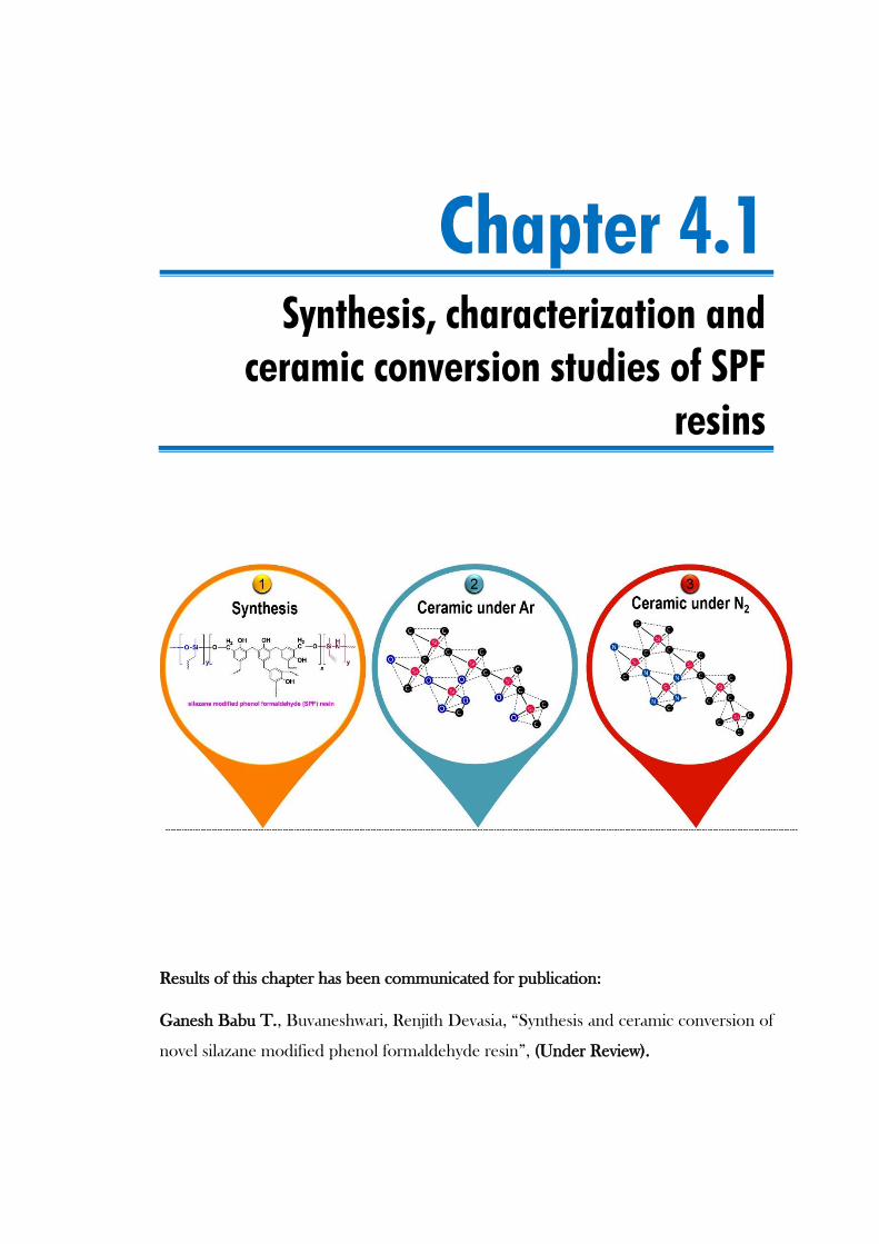
Chapter 4.1
Synthesis, characterization and
ceramic conversion studies of SPF
resins
Results of this chapter has been communicated for publication:
Ganesh Babu T., Buvaneshwari, Renjith Devasia, “Synthesis and ceramic conversion of
novel silazane modified phenol formaldehyde resin”, (Under Review).

S y n t h e s i s , c h a r a c t e r i z a t i o n a n d c e r a m i c c o n v e r s i o n s t u d i e s o f S P F r e s i n s
C h a p t e r 4 . 1 | 117
4.1.1. Introduction
This chapter reports synthesis and ceramic conversion of a novel preceramic
polymer system based on SPF resins. This resins were synthesized by reacting varying
amounts of 1, 3, 5-trimethyl-1ˈ, 3ˈ, 5ˈ-trivinylcyclotrisilazane (CTS) with phenol
formaldehyde (PF) resin. The conversion of preceramic resin to ceramics with high
yield (>60 wt. %) and tailor-ability to obtain the desired ceramics are important criteria
for the preceramic matrix resin. These criteria are highly dependent on the molecular
structure and the pyrolysis conditions (temperature and atmosphere) of the preceramic
resin, which significantly alters their properties for high-temperature applications
[Bahloul et al. 1993, Bahloul et al. 1993]. Furthermore, the aim of this chapter is to
employ SPF as matrix resin for CMCs. In this regard, the most commonly employed
pyrolysis gas atmospheres are argon and nitrogen. Though, ammonia is another
suggested pyrolysis atmosphere, the degradation of the reinforcement like carbon fiber
is quite feasible under corrosive ammonia atmosphere [Chawla 1998] which may result
in the deterioration of the CMCs strength, making ammonia atmosphere highly
unsuitable for CMCs. Hence, this study was carried out under argon and nitrogen
atmosphere for the final intended application and to select the most suitable pyrolysis
condition to achieve the desired ceramics in high yield. The effect of pyrolysis
conditions on ceramic yield, structural evolution and preceramic crystallization
behavior was thoroughly investigated through XRD, Raman and FESEM techniques.
The objective of this study is to assess the potential of SPF as a preceramic resin for
CMCs and selection of an appropriate pyrolysis condition in order to achieve desired
ceramic in high yield (>60 wt. %).
4.1.2. Experimental
4.1.2.1. Materials
Details of the chemicals are described in Chapter 2, Section 2.1.
4.1.2.2 Synthesis of SPF resin
The procedure for the synthesis of SPF resins are given in Chapter 2, Section
2.2.2.
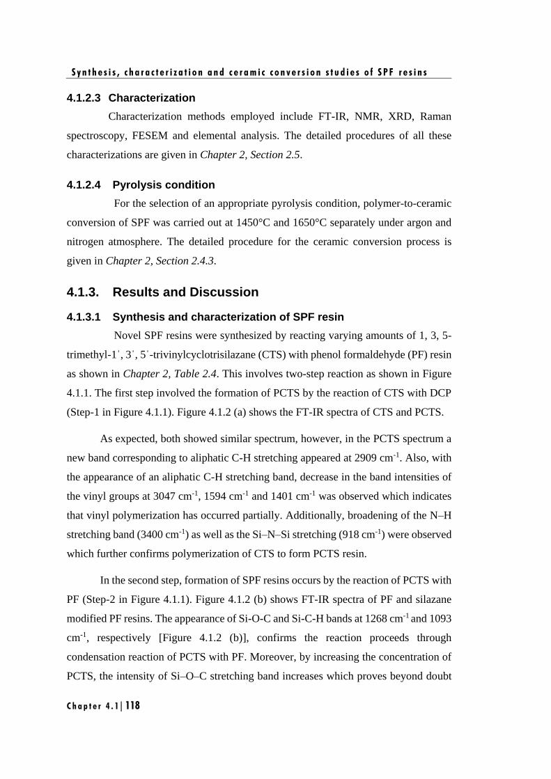
S y n t h e s i s , c h a r a c t e r i z a t i o n a n d c e r a m i c c o n v e r s i o n s t u d i e s o f S P F r e s i n s
C h a p t e r 4 . 1 | 118
4.1.2.3 Characterization
Characterization methods employed include FT-IR, NMR, XRD, Raman
spectroscopy, FESEM and elemental analysis. The detailed procedures of all these
characterizations are given in Chapter 2, Section 2.5.
4.1.2.4 Pyrolysis condition
For the selection of an appropriate pyrolysis condition, polymer-to-ceramic
conversion of SPF was carried out at 1450°C and 1650°C separately under argon and
nitrogen atmosphere. The detailed procedure for the ceramic conversion process is
given in Chapter 2, Section 2.4.3.
4.1.3. Results and Discussion
4.1.3.1 Synthesis and characterization of SPF resin
Novel SPF resins were synthesized by reacting varying amounts of 1, 3, 5-
trimethyl-1ˈ, 3ˈ, 5ˈ-trivinylcyclotrisilazane (CTS) with phenol formaldehyde (PF) resin
as shown in Chapter 2, Table 2.4. This involves two-step reaction as shown in Figure
4.1.1. The first step involved the formation of PCTS by the reaction of CTS with DCP
(Step-1 in Figure 4.1.1). Figure 4.1.2 (a) shows the FT-IR spectra of CTS and PCTS.
As expected, both showed similar spectrum, however, in the PCTS spectrum a
new band corresponding to aliphatic C-H stretching appeared at 2909 cm-1. Also, with
the appearance of an aliphatic C-H stretching band, decrease in the band intensities of
the vinyl groups at 3047 cm-1, 1594 cm-1 and 1401 cm-1 was observed which indicates
that vinyl polymerization has occurred partially. Additionally, broadening of the N–H
stretching band (3400 cm-1) as well as the Si–N–Si stretching (918 cm-1) were observed
which further confirms polymerization of CTS to form PCTS resin.
In the second step, formation of SPF resins occurs by the reaction of PCTS with
PF (Step-2 in Figure 4.1.1). Figure 4.1.2 (b) shows FT-IR spectra of PF and silazane
modified PF resins. The appearance of Si-O-C and Si-C-H bands at 1268 cm-1 and 1093
cm-1, respectively [Figure 4.1.2 (b)], confirms the reaction proceeds through
condensation reaction of PCTS with PF. Moreover, by increasing the concentration of
PCTS, the intensity of Si–O–C stretching band increases which proves beyond doubt
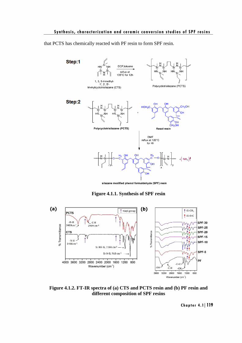
S y n t h e s i s , c h a r a c t e r i z a t i o n a n d c e r a m i c c o n v e r s i o n s t u d i e s o f S P F r e s i n s
C h a p t e r 4 . 1 | 119
that PCTS has chemically reacted with PF resin to form SPF resin.
Figure 4.1.1. Synthesis of SPF resin
Figure 4.1.2. FT-IR spectra of (a) CTS and PCTS resin and (b) PF resin and
different composition of SPF resins
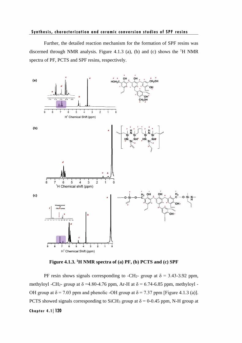
S y n t h e s i s , c h a r a c t e r i z a t i o n a n d c e r a m i c c o n v e r s i o n s t u d i e s o f S P F r e s i n s
C h a p t e r 4 . 1 | 120
Further, the detailed reaction mechanism for the formation of SPF resins was
discerned through NMR analysis. Figure 4.1.3 (a), (b) and (c) shows the 1H NMR
spectra of PF, PCTS and SPF resins, respectively.
Figure 4.1.3. 1H NMR spectra of (a) PF, (b) PCTS and (c) SPF
PF resin shows signals corresponding to -CH2- group at δ = 3.43-3.92 ppm,
methyloyl -CH2- group at δ =4.80-4.76 ppm, Ar-H at δ = 6.74-6.85 ppm, methyloyl -
OH group at δ = 7.03 ppm and phenolic -OH group at δ = 7.37 ppm [Figure 4.1.3 (a)].
PCTS showed signals corresponding to SiCH3 group at δ = 0-0.45 ppm, N-H group at
S y n t h e s i s , c h a r a c t e r i z a t i o n a n d c e r a m i c c o n v e r s i o n s t u d i e s o f S P F r e s i n s
C h a p t e r 4 . 1 | 121
δ = 0.62 ppm, -CH2-group at δ = 1.3 ppm and -CH2=CH- at δ = 5.71–6.28 ppm [Figure
4.1.3 (b)]. SPF resin 1H NMR showed characteristic signals of both PCTS and PF, with
the disappearance of methyloyl -OH group at δ = 7.03 ppm and N-H group at δ = 0.62
ppm [Figure 4.1.3 (c)]. This confirms the reaction of PCTS with methylol -OH groups
of PF which precedes over phenolic -OH groups of PF, with evolution of ammonia as
shown in Figure 4.1.1.
The validation of reaction mechanism was further done through 29Si NMR
studies. Figure 4.1.4 (a) and (b) shows 29Si NMR spectra of PCTS and SPF.
Figure 4.1.4. 29Si NMR spectra of (a) PCTS and (b) SPF
PCTS showed SiC2N2 signal at δ = -14.90 ppm, whereas in SPF no signal for
SiC2N2 was observed. However, two new peaks at δ = -32.55 ppm and δ = -35.02 ppm
were observed for SPF, which corresponds to SiC2NO and SiC2O2, respectively. The
formation of SiC2NO and SiC2O2 indicates that, the reaction of PCTS with PF proceeds
through a ring opening mechanism as shown in Figure 4.1.5.
The ring opening proceeds via condensation of one Si-NH-Si linkage of PCTS
with two methyloyl -OH groups of PF which occurs in two steps. In the first step, the
electrophilic attack of the hydrogen atoms of the methyloyl -OH group of PF on the
nitrogen atoms of the silazane occurs to form a four centered labile complex. Formation
of one Si-O-C linkage and one Si-NH2 group occurs by the splitting of Si-N bond in the
complex. In the second step, the formed Si-NH2 group undergoes further reaction with
methyloyl -OH group of PF forming another Si-O-C linkage with the evolution of NH3
gas. This results in a more stable and less strained linear structured SPF resin.
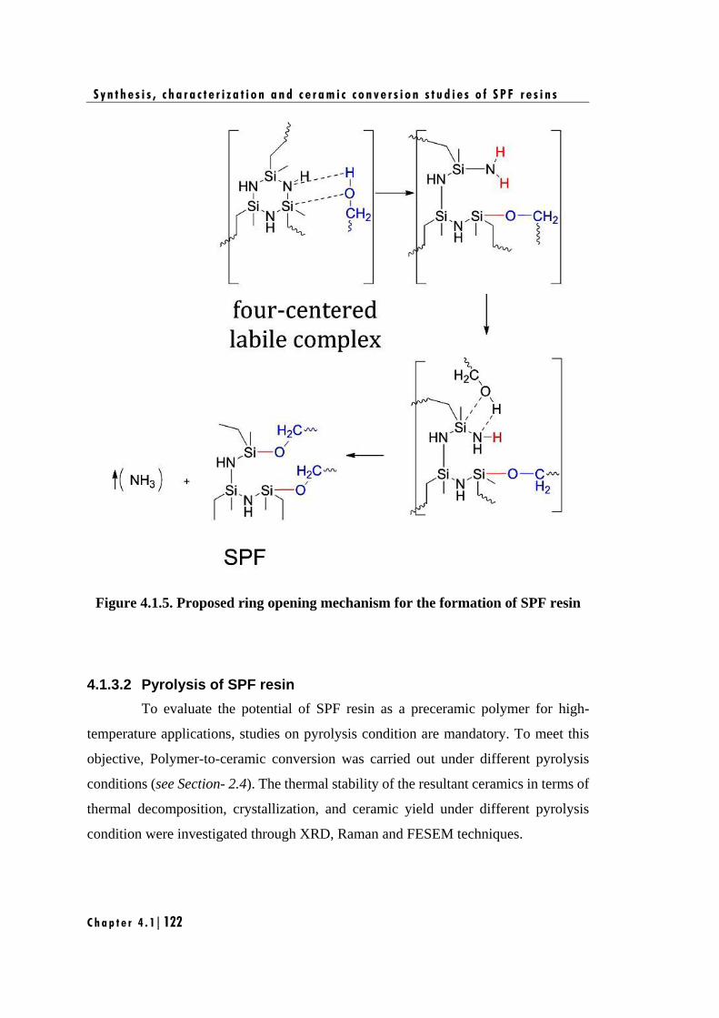
S y n t h e s i s , c h a r a c t e r i z a t i o n a n d c e r a m i c c o n v e r s i o n s t u d i e s o f S P F r e s i n s
C h a p t e r 4 . 1 | 122
Figure 4.1.5. Proposed ring opening mechanism for the formation of SPF resin
4.1.3.2 Pyrolysis of SPF resin
To evaluate the potential of SPF resin as a preceramic polymer for high-
temperature applications, studies on pyrolysis condition are mandatory. To meet this
objective, Polymer-to-ceramic conversion was carried out under different pyrolysis
conditions (see Section- 2.4). The thermal stability of the resultant ceramics in terms of
thermal decomposition, crystallization, and ceramic yield under different pyrolysis
condition were investigated through XRD, Raman and FESEM techniques.
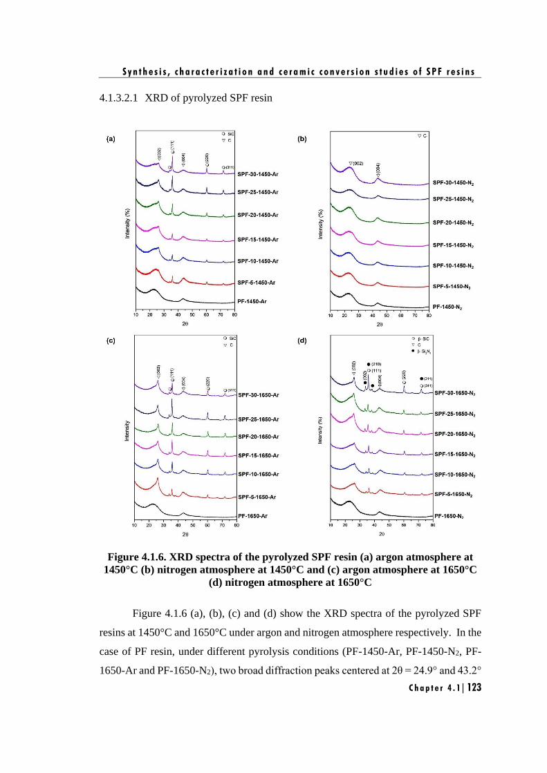
S y n t h e s i s , c h a r a c t e r i z a t i o n a n d c e r a m i c c o n v e r s i o n s t u d i e s o f S P F r e s i n s
C h a p t e r 4 . 1 | 123
4.1.3.2.1 XRD of pyrolyzed SPF resin
Figure 4.1.6. XRD spectra of the pyrolyzed SPF resin (a) argon atmosphere at
1450°C (b) nitrogen atmosphere at 1450°C and (c) argon atmosphere at 1650°C
(d) nitrogen atmosphere at 1650°C
Figure 4.1.6 (a), (b), (c) and (d) show the XRD spectra of the pyrolyzed SPF
resins at 1450°C and 1650°C under argon and nitrogen atmosphere respectively. In the
case of PF resin, under different pyrolysis conditions (PF-1450-Ar, PF-1450-N2, PF-
1650-Ar and PF-1650-N2), two broad diffraction peaks centered at 2θ = 24.9° and 43.2°
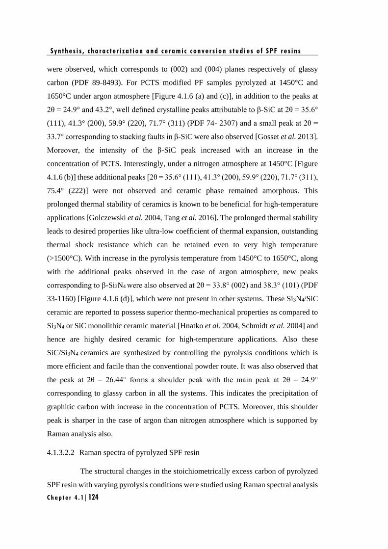
S y n t h e s i s , c h a r a c t e r i z a t i o n a n d c e r a m i c c o n v e r s i o n s t u d i e s o f S P F r e s i n s
C h a p t e r 4 . 1 | 124
were observed, which corresponds to (002) and (004) planes respectively of glassy
carbon (PDF 89-8493). For PCTS modified PF samples pyrolyzed at 1450°C and
1650°C under argon atmosphere [Figure 4.1.6 (a) and (c)], in addition to the peaks at
2θ = 24.9° and 43.2°, well defined crystalline peaks attributable to β-SiC at 2θ = 35.6°
(111), 41.3° (200), 59.9° (220), 71.7° (311) (PDF 74- 2307) and a small peak at 2θ =
33.7° corresponding to stacking faults in β-SiC were also observed [Gosset et al. 2013].
Moreover, the intensity of the β-SiC peak increased with an increase in the
concentration of PCTS. Interestingly, under a nitrogen atmosphere at 1450°C [Figure
4.1.6 (b)] these additional peaks [2θ = 35.6° (111), 41.3° (200), 59.9° (220), 71.7° (311),
75.4° (222)] were not observed and ceramic phase remained amorphous. This
prolonged thermal stability of ceramics is known to be beneficial for high-temperature
applications [Golczewski et al. 2004, Tang et al. 2016]. The prolonged thermal stability
leads to desired properties like ultra-low coefficient of thermal expansion, outstanding
thermal shock resistance which can be retained even to very high temperature
(>1500°C). With increase in the pyrolysis temperature from 1450°C to 1650°C, along
with the additional peaks observed in the case of argon atmosphere, new peaks
corresponding to β-Si3N4 were also observed at 2θ = 33.8° (002) and 38.3° (101) (PDF
33-1160) [Figure 4.1.6 (d)], which were not present in other systems. These Si3N4/SiC
ceramic are reported to possess superior thermo-mechanical properties as compared to
Si3N4 or SiC monolithic ceramic material [Hnatko et al. 2004, Schmidt et al. 2004] and
hence are highly desired ceramic for high-temperature applications. Also these
SiC/Si3N4 ceramics are synthesized by controlling the pyrolysis conditions which is
more efficient and facile than the conventional powder route. It was also observed that
the peak at 2θ = 26.44° forms a shoulder peak with the main peak at 2θ = 24.9°
corresponding to glassy carbon in all the systems. This indicates the precipitation of
graphitic carbon with increase in the concentration of PCTS. Moreover, this shoulder
peak is sharper in the case of argon than nitrogen atmosphere which is supported by
Raman analysis also.
4.1.3.2.2 Raman spectra of pyrolyzed SPF resin
The structural changes in the stoichiometrically excess carbon of pyrolyzed
SPF resin with varying pyrolysis conditions were studied using Raman spectral analysis
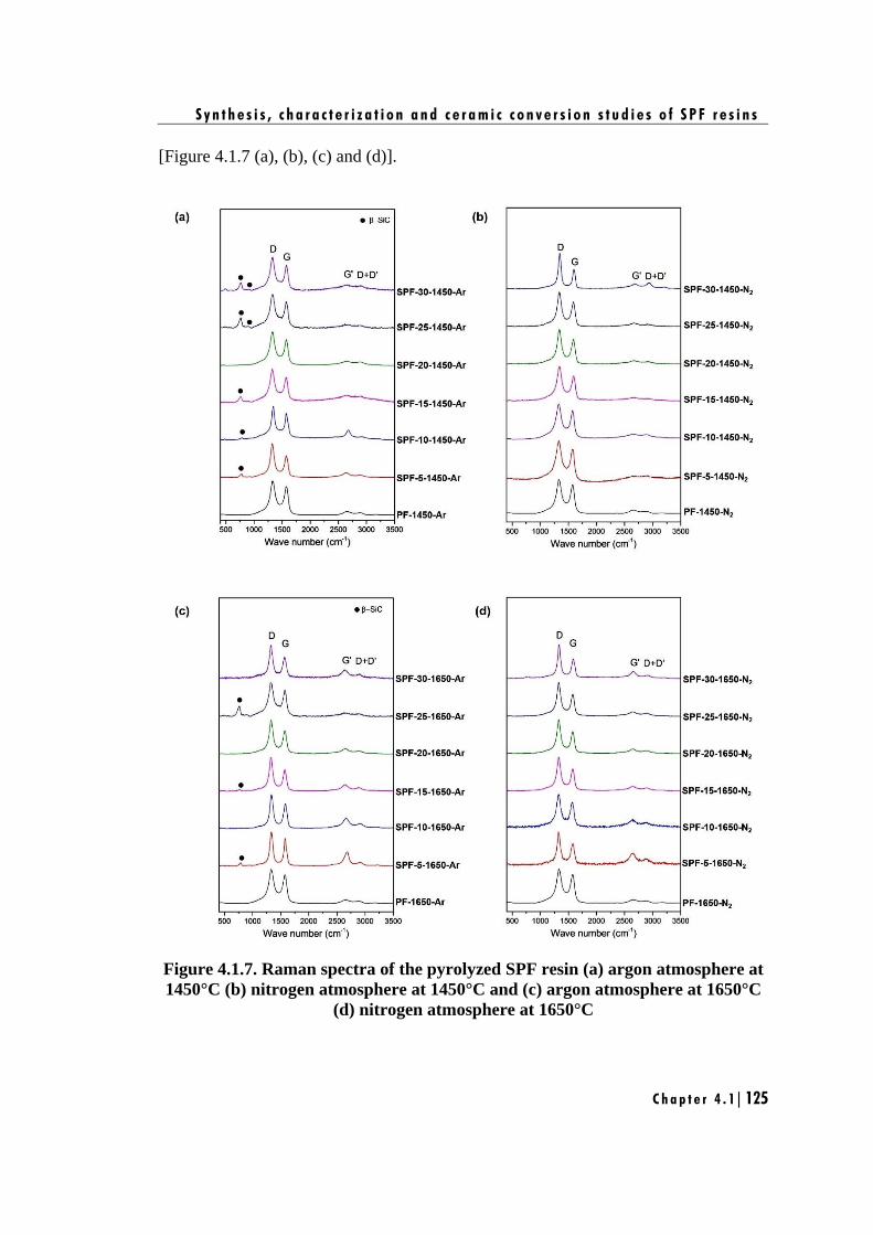
S y n t h e s i s , c h a r a c t e r i z a t i o n a n d c e r a m i c c o n v e r s i o n s t u d i e s o f S P F r e s i n s
C h a p t e r 4 . 1 | 125
[Figure 4.1.7 (a), (b), (c) and (d)].
Figure 4.1.7. Raman spectra of the pyrolyzed SPF resin (a) argon atmosphere at
1450°C (b) nitrogen atmosphere at 1450°C and (c) argon atmosphere at 1650°C
(d) nitrogen atmosphere at 1650°C

S y n t h e s i s , c h a r a c t e r i z a t i o n a n d c e r a m i c c o n v e r s i o n s t u d i e s o f S P F r e s i n s
C h a p t e r 4 . 1 | 126
All the samples exhibited similar Raman spectra showing, disorder induced D
and Gˈ bands (overtone of D band) at ~1330 cm-1 and 2630 cm-1, G band due to in-
plane bond stretching of sp2 carbon at ~1575 cm-1 and combinational D+Dˈ band at
~2900 cm-1. In addition to these peaks, some minor peaks corresponding to cubic 3C-
SiC phases at 798 cm-1 and 930 cm-1 were also observed in some spectra [Figure 4.1.7
(a) and (c)]. Variations in position and intensity of D and G band, with changes in the
structural organization of carbon phase in ceramics have been well reported [Traßl et
al. 2000, Trassl et al. 2002, Trassl et al. 2002, Mera et al. 2010]. Hence, by evaluating
these parameters, the effect of pyrolysis conditions on the structural organization of
carbon phase can be thoroughly investigated. These parameters were derived using
Gaussian curve fitting of the Raman bands and are listed in Table 4.1.1 and Table 4.1.2.
Table 4.1.1
Parameters derived from Raman spectra for ceramics derived from PF and SPF at
1450°C and 1650°C under argon atmosphere
Samples
Argon atmosphere
at 1450°C at 1650°C
D peak
position
G peak
position ID/IG La
(nm)
D peak
position
G peak
position ID/IG La
(nm) (cm-1) (cm-1) (cm-1) (cm-1)
PF 1343 1571 1.32 1.45 1340 1572 1.35 1.47
SPF-5 1335 1572 1.30 1.44 1337 1564 1.29 1.44
SPF-10 1333 1572 1.27 1.43 1332 1571 1.28 1.43
SPF-15 1330 1573 1.23 1.40 1330 1571 1.36 1.48
SPF-20 1329 1574 1.19 1.38 1329 1574 1.44 1.52
SPF -25 1325 1575 1.33 1.46 1326 1577 1.53 1.57
SPF -30 1322 1575 1.56 1.58 1324 1584 1.59 1.60
The intensity ratio of the D and G bands (ID/IG) can be also be used to calculate
excess carbon cluster size using the formula reported by Ferrari and Robertson [Ferrari
et al. 2004]
D
G
2'( ) L (4.1.1)a
IC
I=
Where, La is the size of carbon domains along the six-fold ring plane and Cˈ is
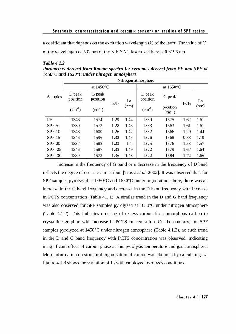
S y n t h e s i s , c h a r a c t e r i z a t i o n a n d c e r a m i c c o n v e r s i o n s t u d i e s o f S P F r e s i n s
C h a p t e r 4 . 1 | 127
a coefficient that depends on the excitation wavelength (λ) of the laser. The value of Cˈ
of the wavelength of 532 nm of the Nd: YAG laser used here is 0.6195 nm.
Table 4.1.2
Parameters derived from Raman spectra for ceramics derived from PF and SPF at
1450°C and 1650°C under nitrogen atmosphere
Samples
Nitrogen atmosphere
at 1450°C at 1650°C
D peak
position
G peak
position ID/IG
La
(nm)
D peak
position G peak
ID/IG La
(nm) (cm-1) (cm-1) (cm-1)
position
(cm-1)
PF 1346 1574 1.29 1.44 1339 1575 1.62 1.61
SPF-5 1330 1573 1.28 1.43 1333 1563 1.61 1.61
SPF-10 1348 1600 1.26 1.42 1332 1566 1.29 1.44
SPF-15 1346 1596 1.32 1.45 1326 1568 0.88 1.19
SPF-20 1337 1588 1.23 1.4 1325 1576 1.53 1.57
SPF -25 1346 1587 1.38 1.49 1322 1579 1.67 1.64
SPF -30 1330 1573 1.36 1.48 1322 1584 1.72 1.66
Increase in the frequency of G band or a decrease in the frequency of D band
reflects the degree of orderness in carbon [Trassl et al. 2002]. It was observed that, for
SPF samples pyrolyzed at 1450°C and 1650°C under argon atmosphere, there was an
increase in the G band frequency and decrease in the D band frequency with increase
in PCTS concentration (Table 4.1.1). A similar trend in the D and G band frequency
was also observed for SPF samples pyrolyzed at 1650°C under nitrogen atmosphere
(Table 4.1.2). This indicates ordering of excess carbon from amorphous carbon to
crystalline graphite with increase in PCTS concentration. On the contrary, for SPF
samples pyrolyzed at 1450°C under nitrogen atmosphere (Table 4.1.2), no such trend
in the D and G band frequency with PCTS concentration was observed, indicating
insignificant effect of carbon phase at this pyrolysis temperature and gas atmosphere.
More information on structural organization of carbon was obtained by calculating La.
Figure 4.1.8 shows the variation of La with employed pyrolysis conditions.
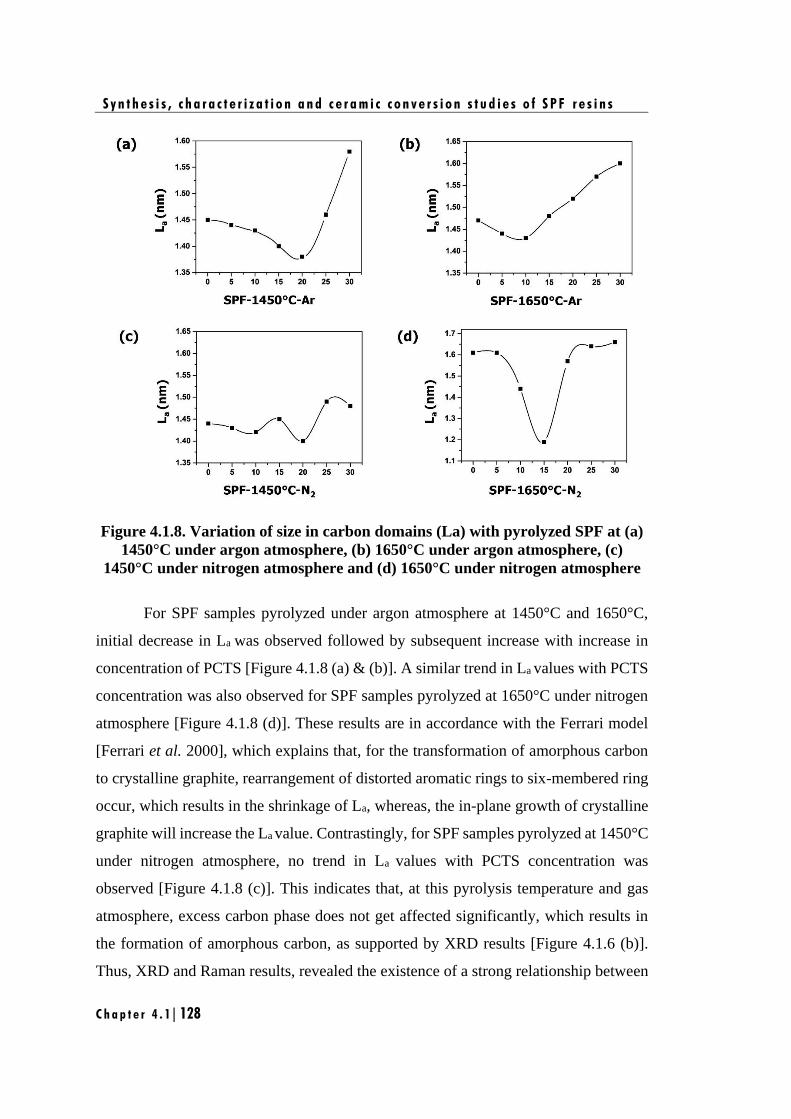
S y n t h e s i s , c h a r a c t e r i z a t i o n a n d c e r a m i c c o n v e r s i o n s t u d i e s o f S P F r e s i n s
C h a p t e r 4 . 1 | 128
Figure 4.1.8. Variation of size in carbon domains (La) with pyrolyzed SPF at (a)
1450°C under argon atmosphere, (b) 1650°C under argon atmosphere, (c)
1450°C under nitrogen atmosphere and (d) 1650°C under nitrogen atmosphere
For SPF samples pyrolyzed under argon atmosphere at 1450°C and 1650°C,
initial decrease in La was observed followed by subsequent increase with increase in
concentration of PCTS [Figure 4.1.8 (a) & (b)]. A similar trend in La values with PCTS
concentration was also observed for SPF samples pyrolyzed at 1650°C under nitrogen
atmosphere [Figure 4.1.8 (d)]. These results are in accordance with the Ferrari model
[Ferrari et al. 2000], which explains that, for the transformation of amorphous carbon
to crystalline graphite, rearrangement of distorted aromatic rings to six-membered ring
occur, which results in the shrinkage of La, whereas, the in-plane growth of crystalline
graphite will increase the La value. Contrastingly, for SPF samples pyrolyzed at 1450°C
under nitrogen atmosphere, no trend in La values with PCTS concentration was
observed [Figure 4.1.8 (c)]. This indicates that, at this pyrolysis temperature and gas
atmosphere, excess carbon phase does not get affected significantly, which results in
the formation of amorphous carbon, as supported by XRD results [Figure 4.1.6 (b)].
Thus, XRD and Raman results, revealed the existence of a strong relationship between
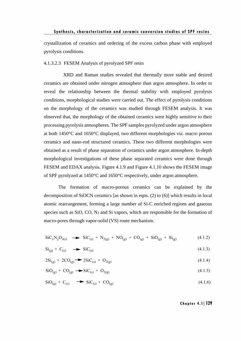
S y n t h e s i s , c h a r a c t e r i z a t i o n a n d c e r a m i c c o n v e r s i o n s t u d i e s o f S P F r e s i n s
C h a p t e r 4 . 1 | 129
crystallization of ceramics and ordering of the excess carbon phase with employed
pyrolysis conditions.
4.1.3.2.3 FESEM Analysis of pyrolyzed SPF resin
XRD and Raman studies revealed that thermally more stable and desired
ceramics are obtained under nitrogen atmosphere than argon atmosphere. In order to
reveal the relationship between the thermal stability with employed pyrolysis
conditions, morphological studies were carried out. The effect of pyrolysis conditions
on the morphology of the ceramics was studied through FESEM analysis. It was
observed that, the morphology of the obtained ceramics were highly sensitive to their
processing pyrolysis atmospheres. The SPF samples pyrolyzed under argon atmosphere
at both 1450°C and 1650°C displayed, two different morphologies viz. macro porous
ceramics and nano-rod structured ceramics. These two different morphologies were
obtained as a result of phase separation of ceramics under argon atmosphere. In-depth
morphological investigations of these phase separated ceramics were done through
FESEM and EDAX analysis. Figure 4.1.9 and Figure 4.1.10 shows the FESEM image
of SPF pyrolyzed at 1450°C and 1650°C respectively, under argon atmosphere.
The formation of macro-porous ceramics can be explained by the
decomposition of SiOCN ceramics [as shown in eqns. (2) to (6)] which results in local
atomic rearrangement, forming a large number of Si-C enriched regions and gaseous
species such as SiO, CO, N2 and Si vapors, which are responsible for the formation of
macro-pores through vapor-solid (VS) route mechanism.
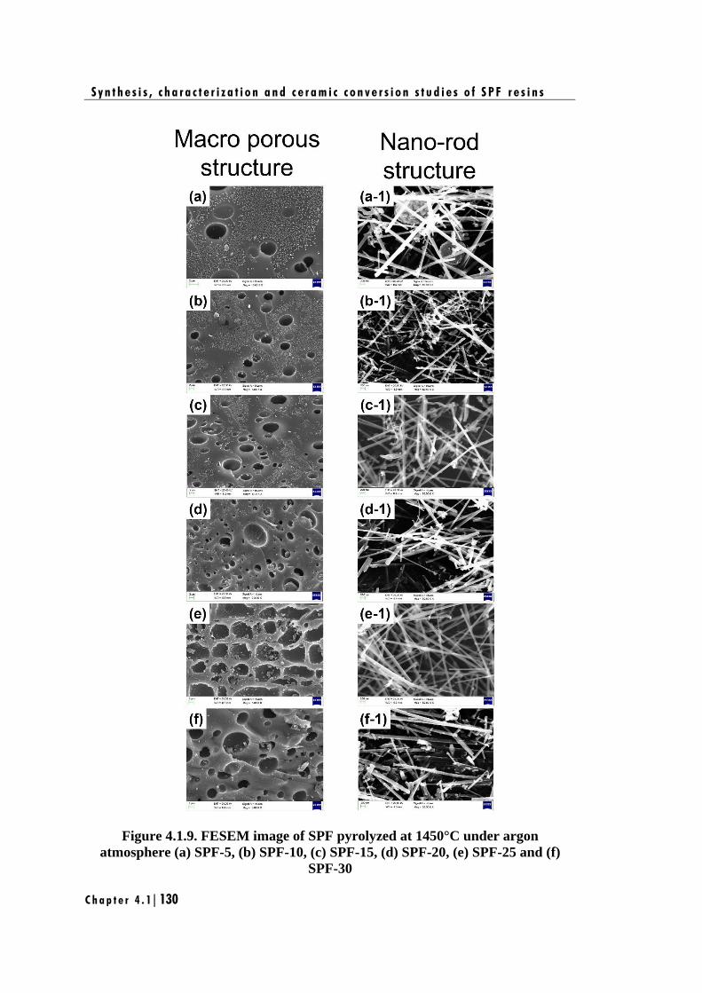
S y n t h e s i s , c h a r a c t e r i z a t i o n a n d c e r a m i c c o n v e r s i o n s t u d i e s o f S P F r e s i n s
C h a p t e r 4 . 1 | 130
Figure 4.1.9. FESEM image of SPF pyrolyzed at 1450°C under argon
atmosphere (a) SPF-5, (b) SPF-10, (c) SPF-15, (d) SPF-20, (e) SPF-25 and (f)
SPF-30
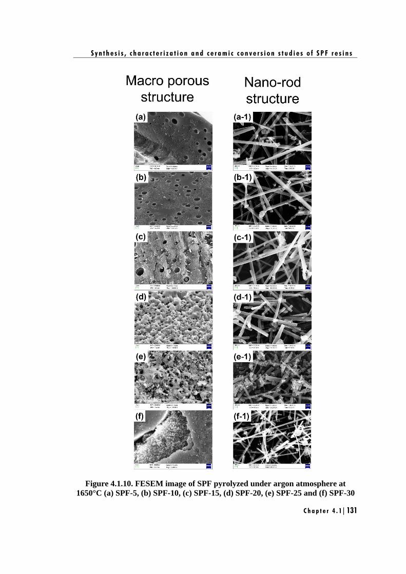
S y n t h e s i s , c h a r a c t e r i z a t i o n a n d c e r a m i c c o n v e r s i o n s t u d i e s o f S P F r e s i n s
C h a p t e r 4 . 1 | 131
Figure 4.1.10. FESEM image of SPF pyrolyzed under argon atmosphere at
1650°C (a) SPF-5, (b) SPF-10, (c) SPF-15, (d) SPF-20, (e) SPF-25 and (f) SPF-30
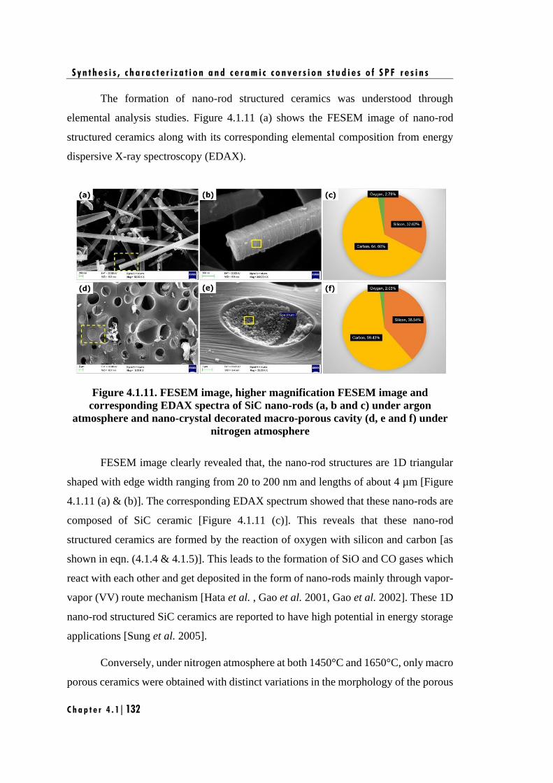
S y n t h e s i s , c h a r a c t e r i z a t i o n a n d c e r a m i c c o n v e r s i o n s t u d i e s o f S P F r e s i n s
C h a p t e r 4 . 1 | 132
The formation of nano-rod structured ceramics was understood through
elemental analysis studies. Figure 4.1.11 (a) shows the FESEM image of nano-rod
structured ceramics along with its corresponding elemental composition from energy
dispersive X-ray spectroscopy (EDAX).
Figure 4.1.11. FESEM image, higher magnification FESEM image and
corresponding EDAX spectra of SiC nano-rods (a, b and c) under argon
atmosphere and nano-crystal decorated macro-porous cavity (d, e and f) under
nitrogen atmosphere
FESEM image clearly revealed that, the nano-rod structures are 1D triangular
shaped with edge width ranging from 20 to 200 nm and lengths of about 4 µm [Figure
4.1.11 (a) & (b)]. The corresponding EDAX spectrum showed that these nano-rods are
composed of SiC ceramic [Figure 4.1.11 (c)]. This reveals that these nano-rod
structured ceramics are formed by the reaction of oxygen with silicon and carbon [as
shown in eqn. (4.1.4 & 4.1.5)]. This leads to the formation of SiO and CO gases which
react with each other and get deposited in the form of nano-rods mainly through vapor-
vapor (VV) route mechanism [Hata et al. , Gao et al. 2001, Gao et al. 2002]. These 1D
nano-rod structured SiC ceramics are reported to have high potential in energy storage
applications [Sung et al. 2005].
Conversely, under nitrogen atmosphere at both 1450°C and 1650°C, only macro
porous ceramics were obtained with distinct variations in the morphology of the porous
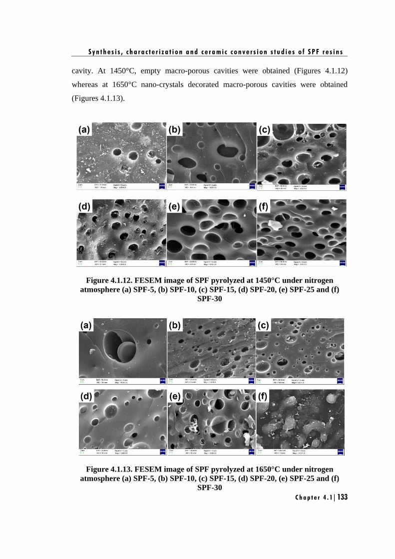
S y n t h e s i s , c h a r a c t e r i z a t i o n a n d c e r a m i c c o n v e r s i o n s t u d i e s o f S P F r e s i n s
C h a p t e r 4 . 1 | 133
cavity. At 1450°C, empty macro-porous cavities were obtained (Figures 4.1.12)
whereas at 1650°C nano-crystals decorated macro-porous cavities were obtained
(Figures 4.1.13).
Figure 4.1.12. FESEM image of SPF pyrolyzed at 1450°C under nitrogen
atmosphere (a) SPF-5, (b) SPF-10, (c) SPF-15, (d) SPF-20, (e) SPF-25 and (f)
SPF-30
Figure 4.1.13. FESEM image of SPF pyrolyzed at 1650°C under nitrogen
atmosphere (a) SPF-5, (b) SPF-10, (c) SPF-15, (d) SPF-20, (e) SPF-25 and (f)
SPF-30
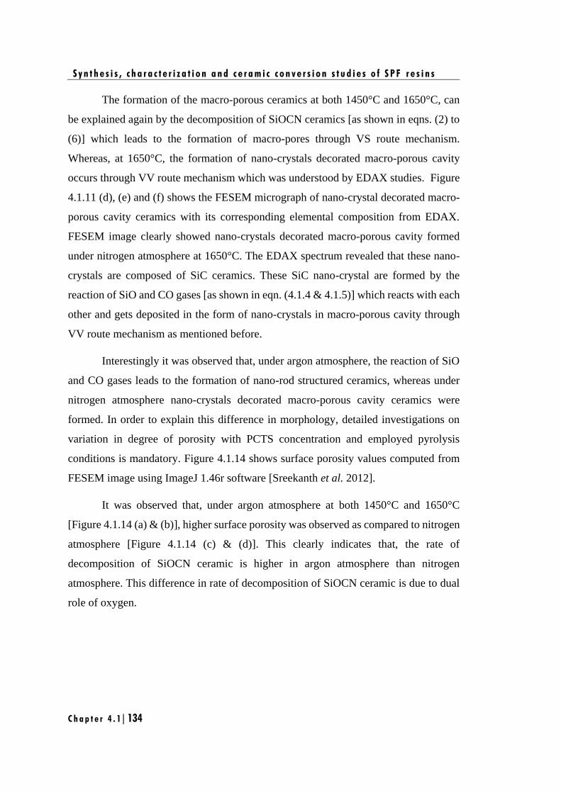
S y n t h e s i s , c h a r a c t e r i z a t i o n a n d c e r a m i c c o n v e r s i o n s t u d i e s o f S P F r e s i n s
C h a p t e r 4 . 1 | 134
The formation of the macro-porous ceramics at both 1450°C and 1650°C, can
be explained again by the decomposition of SiOCN ceramics [as shown in eqns. (2) to
(6)] which leads to the formation of macro-pores through VS route mechanism.
Whereas, at 1650°C, the formation of nano-crystals decorated macro-porous cavity
occurs through VV route mechanism which was understood by EDAX studies. Figure
4.1.11 (d), (e) and (f) shows the FESEM micrograph of nano-crystal decorated macro-
porous cavity ceramics with its corresponding elemental composition from EDAX.
FESEM image clearly showed nano-crystals decorated macro-porous cavity formed
under nitrogen atmosphere at 1650°C. The EDAX spectrum revealed that these nano-
crystals are composed of SiC ceramics. These SiC nano-crystal are formed by the
reaction of SiO and CO gases [as shown in eqn. (4.1.4 & 4.1.5)] which reacts with each
other and gets deposited in the form of nano-crystals in macro-porous cavity through
VV route mechanism as mentioned before.
Interestingly it was observed that, under argon atmosphere, the reaction of SiO
and CO gases leads to the formation of nano-rod structured ceramics, whereas under
nitrogen atmosphere nano-crystals decorated macro-porous cavity ceramics were
formed. In order to explain this difference in morphology, detailed investigations on
variation in degree of porosity with PCTS concentration and employed pyrolysis
conditions is mandatory. Figure 4.1.14 shows surface porosity values computed from
FESEM image using ImageJ 1.46r software [Sreekanth et al. 2012].
It was observed that, under argon atmosphere at both 1450°C and 1650°C
[Figure 4.1.14 (a) & (b)], higher surface porosity was observed as compared to nitrogen
atmosphere [Figure 4.1.14 (c) & (d)]. This clearly indicates that, the rate of
decomposition of SiOCN ceramic is higher in argon atmosphere than nitrogen
atmosphere. This difference in rate of decomposition of SiOCN ceramic is due to dual
role of oxygen.
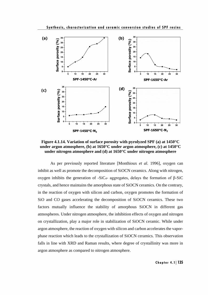
S y n t h e s i s , c h a r a c t e r i z a t i o n a n d c e r a m i c c o n v e r s i o n s t u d i e s o f S P F r e s i n s
C h a p t e r 4 . 1 | 135
Figure 4.1.14. Variation of surface porosity with pyrolyzed SPF (a) at 1450°C
under argon atmosphere, (b) at 1650°C under argon atmosphere, (c) at 1450°C
under nitrogen atmosphere and (d) at 1650°C under nitrogen atmosphere
As per previously reported literature [Monthioux et al. 1996], oxygen can
inhibit as well as promote the decomposition of SiOCN ceramics. Along with nitrogen,
oxygen inhibits the generation of -SiC4- aggregates, delays the formation of β-SiC
crystals, and hence maintains the amorphous state of SiOCN ceramics. On the contrary,
in the reaction of oxygen with silicon and carbon, oxygen promotes the formation of
SiO and CO gases accelerating the decomposition of SiOCN ceramics. These two
factors mutually influence the stability of amorphous SiOCN in different gas
atmospheres. Under nitrogen atmosphere, the inhibition effects of oxygen and nitrogen
on crystallization, play a major role in stabilization of SiOCN ceramic. While under
argon atmosphere, the reaction of oxygen with silicon and carbon accelerates the vapor-
phase reaction which leads to the crystallization of SiOCN ceramics. This observation
falls in line with XRD and Raman results, where degree of crystallinity was more in
argon atmosphere as compared to nitrogen atmosphere.
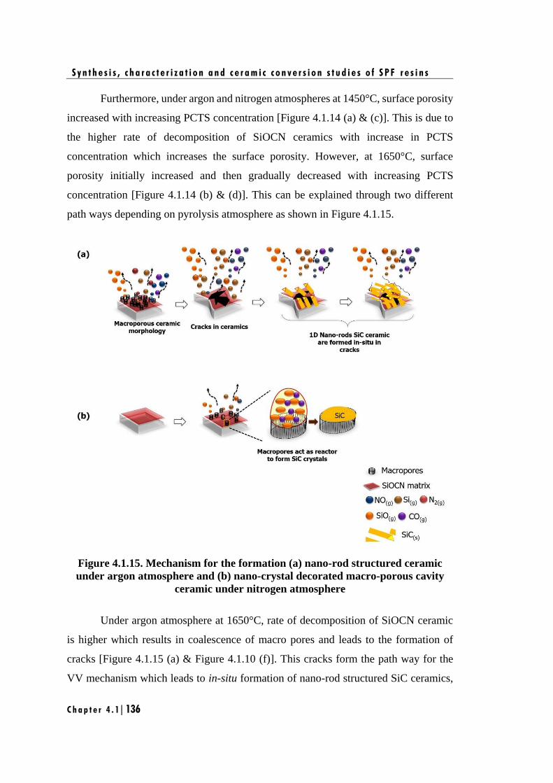
S y n t h e s i s , c h a r a c t e r i z a t i o n a n d c e r a m i c c o n v e r s i o n s t u d i e s o f S P F r e s i n s
C h a p t e r 4 . 1 | 136
Furthermore, under argon and nitrogen atmospheres at 1450°C, surface porosity
increased with increasing PCTS concentration [Figure 4.1.14 (a) & (c)]. This is due to
the higher rate of decomposition of SiOCN ceramics with increase in PCTS
concentration which increases the surface porosity. However, at 1650°C, surface
porosity initially increased and then gradually decreased with increasing PCTS
concentration [Figure 4.1.14 (b) & (d)]. This can be explained through two different
path ways depending on pyrolysis atmosphere as shown in Figure 4.1.15.
Figure 4.1.15. Mechanism for the formation (a) nano-rod structured ceramic
under argon atmosphere and (b) nano-crystal decorated macro-porous cavity
ceramic under nitrogen atmosphere
Under argon atmosphere at 1650°C, rate of decomposition of SiOCN ceramic
is higher which results in coalescence of macro pores and leads to the formation of
cracks [Figure 4.1.15 (a) & Figure 4.1.10 (f)]. This cracks form the path way for the
VV mechanism which leads to in-situ formation of nano-rod structured SiC ceramics,
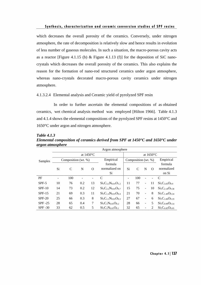
S y n t h e s i s , c h a r a c t e r i z a t i o n a n d c e r a m i c c o n v e r s i o n s t u d i e s o f S P F r e s i n s
C h a p t e r 4 . 1 | 137
which decreases the overall porosity of the ceramics. Conversely, under nitrogen
atmosphere, the rate of decomposition is relatively slow and hence results in evolution
of less number of gaseous molecules. In such a situation, the macro-porous cavity acts
as a reactor [Figure 4.1.15 (b) & Figure 4.1.13 (f)] for the deposition of SiC nano-
crystals which decreases the overall porosity of the ceramics. This also explains the
reason for the formation of nano-rod structured ceramics under argon atmosphere,
whereas nano-crystals decorated macro-porous cavity ceramics under nitrogen
atmosphere.
4.1.3.2.4 Elemental analysis and Ceramic yield of pyrolyzed SPF resin
In order to further ascertain the elemental compositions of as obtained
ceramics, wet chemical analysis method was employed [Hilton 1966]. Table 4.1.3
and 4.1.4 shows the elemental compositions of the pyrolyzed SPF resins at 1450°C and
1650°C under argon and nitrogen atmosphere.
Table 4.1.3
Elemental composition of ceramics derived from SPF at 1450°C and 1650°C under
argon atmosphere
Samples
Argon atmosphere
at 1450°C at 1650°C
Composition (wt. %) Empirical
formula
normalized on
Si
Composition (wt. %) Empirical
formula
normalized
on Si
Si C N O Si C N O
PF - 100 - - C - 100 - - C
SPF-5 10 76 0.2 13 Si1C3.3N0.01O1.2 11 77 - 11 Si1C3.05O0.9
SPF-10 14 73 0.2 12 Si1C2.2N0.01O0.7 15 75 - 10 Si1C2.14O0.58
SPF-15 21 69 0.3 11 Si1C1.4N0.01O0.4 21 70 - 8 Si1C1.40O0.34
SPF-20 25 66 0.3 8 Si1C1.1N0.01O0.3 27 67 - 6 Si1C1.06O0.19
SPF -25 28 65 0.4 7 Si1C1N0.01O0.2 28 66 - 5 Si1C0.99O0.14
SPF -30 33 62 0.5 5 Si1C1N0.01O0.1 32 65 - 2 Si1C0.85O0.05
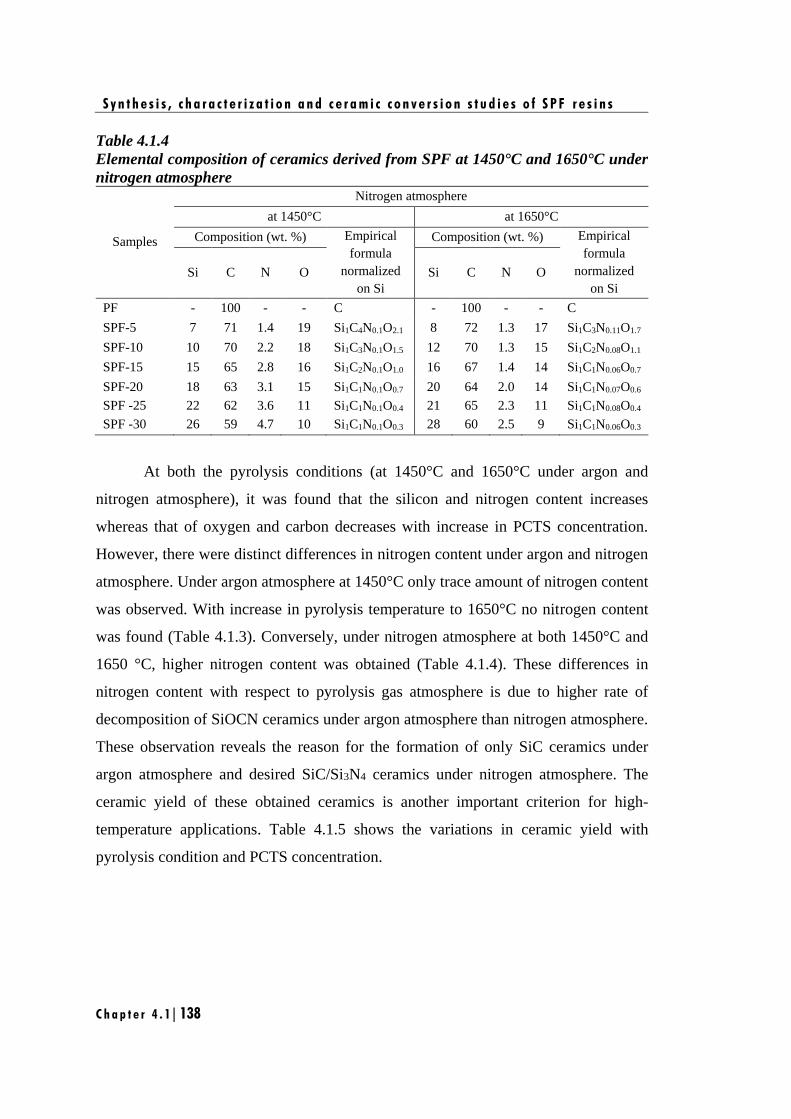
S y n t h e s i s , c h a r a c t e r i z a t i o n a n d c e r a m i c c o n v e r s i o n s t u d i e s o f S P F r e s i n s
C h a p t e r 4 . 1 | 138
Table 4.1.4
Elemental composition of ceramics derived from SPF at 1450°C and 1650°C under
nitrogen atmosphere
Samples
Nitrogen atmosphere
at 1450°C at 1650°C
Composition (wt. %) Empirical
formula
normalized
on Si
Composition (wt. %) Empirical
formula
normalized
on Si
Si C N O Si C N O
PF - 100 - - C - 100 - - C
SPF-5 7 71 1.4 19 Si1C4N0.1O2.1 8 72 1.3 17 Si1C3N0.11O1.7
SPF-10 10 70 2.2 18 Si1C3N0.1O1.5 12 70 1.3 15 Si1C2N0.08O1.1
SPF-15 15 65 2.8 16 Si1C2N0.1O1.0 16 67 1.4 14 Si1C1N0.06O0.7
SPF-20 18 63 3.1 15 Si1C1N0.1O0.7 20 64 2.0 14 Si1C1N0.07O0.6
SPF -25 22 62 3.6 11 Si1C1N0.1O0.4 21 65 2.3 11 Si1C1N0.08O0.4
SPF -30 26 59 4.7 10 Si1C1N0.1O0.3 28 60 2.5 9 Si1C1N0.06O0.3
At both the pyrolysis conditions (at 1450°C and 1650°C under argon and
nitrogen atmosphere), it was found that the silicon and nitrogen content increases
whereas that of oxygen and carbon decreases with increase in PCTS concentration.
However, there were distinct differences in nitrogen content under argon and nitrogen
atmosphere. Under argon atmosphere at 1450°C only trace amount of nitrogen content
was observed. With increase in pyrolysis temperature to 1650°C no nitrogen content
was found (Table 4.1.3). Conversely, under nitrogen atmosphere at both 1450°C and
1650 °C, higher nitrogen content was obtained (Table 4.1.4). These differences in
nitrogen content with respect to pyrolysis gas atmosphere is due to higher rate of
decomposition of SiOCN ceramics under argon atmosphere than nitrogen atmosphere.
These observation reveals the reason for the formation of only SiC ceramics under
argon atmosphere and desired SiC/Si3N4 ceramics under nitrogen atmosphere. The
ceramic yield of these obtained ceramics is another important criterion for high-
temperature applications. Table 4.1.5 shows the variations in ceramic yield with
pyrolysis condition and PCTS concentration.
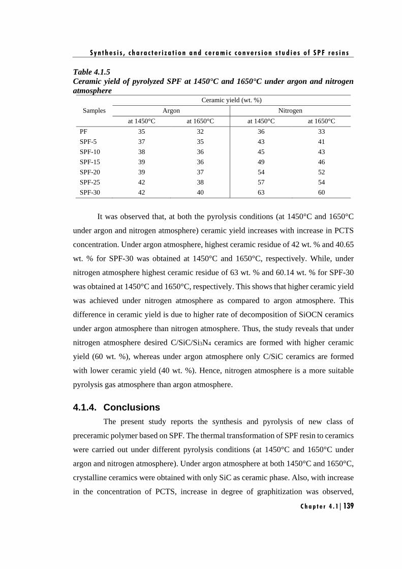
S y n t h e s i s , c h a r a c t e r i z a t i o n a n d c e r a m i c c o n v e r s i o n s t u d i e s o f S P F r e s i n s
C h a p t e r 4 . 1 | 139
Table 4.1.5
Ceramic yield of pyrolyzed SPF at 1450°C and 1650°C under argon and nitrogen
atmosphere
Samples
Ceramic yield (wt. %)
Argon Nitrogen
at 1450°C at 1650°C at 1450°C at 1650°C
PF 35 32 36 33
SPF-5 37 35 43 41
SPF-10 38 36 45 43
SPF-15 39 36 49 46
SPF-20 39 37 54 52
SPF-25 42 38 57 54
SPF-30 42 40 63 60
It was observed that, at both the pyrolysis conditions (at 1450°C and 1650°C
under argon and nitrogen atmosphere) ceramic yield increases with increase in PCTS
concentration. Under argon atmosphere, highest ceramic residue of 42 wt. % and 40.65
wt. % for SPF-30 was obtained at 1450°C and 1650°C, respectively. While, under
nitrogen atmosphere highest ceramic residue of 63 wt. % and 60.14 wt. % for SPF-30
was obtained at 1450°C and 1650°C, respectively. This shows that higher ceramic yield
was achieved under nitrogen atmosphere as compared to argon atmosphere. This
difference in ceramic yield is due to higher rate of decomposition of SiOCN ceramics
under argon atmosphere than nitrogen atmosphere. Thus, the study reveals that under
nitrogen atmosphere desired C/SiC/Si3N4 ceramics are formed with higher ceramic
yield (60 wt. %), whereas under argon atmosphere only C/SiC ceramics are formed
with lower ceramic yield (40 wt. %). Hence, nitrogen atmosphere is a more suitable
pyrolysis gas atmosphere than argon atmosphere.
4.1.4. Conclusions
The present study reports the synthesis and pyrolysis of new class of
preceramic polymer based on SPF. The thermal transformation of SPF resin to ceramics
were carried out under different pyrolysis conditions (at 1450°C and 1650°C under
argon and nitrogen atmosphere). Under argon atmosphere at both 1450°C and 1650°C,
crystalline ceramics were obtained with only SiC as ceramic phase. Also, with increase
in the concentration of PCTS, increase in degree of graphitization was observed,
S y n t h e s i s , c h a r a c t e r i z a t i o n a n d c e r a m i c c o n v e r s i o n s t u d i e s o f S P F r e s i n s
C h a p t e r 4 . 1 | 140
indicating significant structural rearrangement of excess carbon.
Under nitrogen atmosphere at 1450°C, amorphous ceramics were obtained with
no structural re-organization of carbon. While, at 1650°C crystalline SiC and Si3N4
ceramic phases were obtained. Also, graphitization of excess carbon from amorphous
carbon to crystalline graphite occurs, showing structural re-organization of excess
carbon. Moreover, under nitrogen atmosphere at both 1450°C and 1650°C, only macro-
porous ceramics were formed. In contrast to nitrogen atmosphere, in argon atmosphere
at both 1450°C and 1650°C, additional 1D, triangular shaped, nano-rod structured
ceramics along with macro-porous structure were formed. EDAX analysis revealed that
these nano-rods are composed of SiC formed through VV route mechanism.
This study demonstrates SPF as a new class of preceramic polymer for high-
temperature applications. The study also reveals that nitrogen atmosphere is a more
suitable pyrolysis gas atmosphere than argon atmosphere for preparation of desired
C/SiC/Si3N4 ceramics with higher ceramic yield. Moreover, the work also represents
an interesting and efficient route for synthesis of C/SiC/Si3N4 ceramics by controlling
the pyrolysis conditions which is way more facile than the conventional powder route.
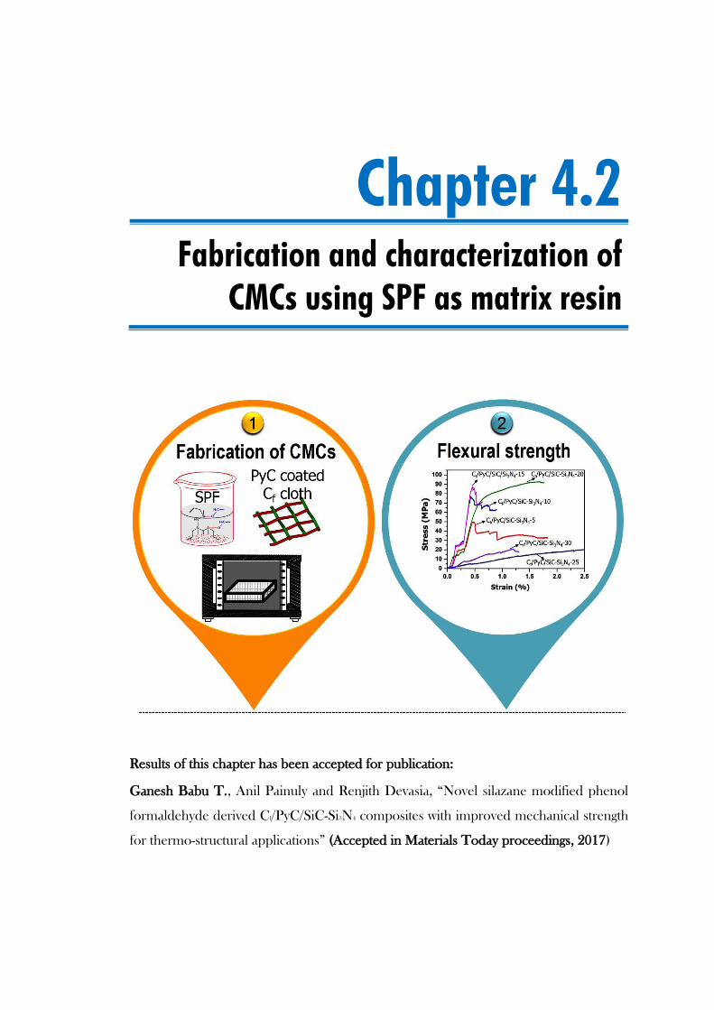
Chapter 4.2
Fabrication and characterization of
CMCs using SPF as matrix resin
Results of this chapter has been accepted for publication:
Ganesh Babu T., Anil Painuly and Renjith Devasia, “Novel silazane modified phenol
formaldehyde derived Cf/PyC/SiC-Si3N4 composites with improved mechanical strength
for thermo-structural applications” (Accepted in Materials Today proceedings, 2017)

F a b r i c a t i o n a n d c h a r a c t e r i z a t i o n o f C M C s u s i n g S P F a s m a t r i x r e s i n
C h a p t e r 4 . 2 | 143
4.2.1. Introduction
Chapter 3.2, established the importance of varying F/M volume ratio and the
need of PyC interphase coating to fabricate CMCs with better mechanical properties.
Chapter 4.1, demonstrated SPF resins as a new class of preceramic polymer for the
synthesis of SiCN based ceramics and revealed nitrogen atmosphere as a more suitable
pyrolysis gas atmosphere than argon atmosphere for the preparation of desired SiC-
Si3N4 ceramics with higher ceramic yield.
Hence, in this chapter, CMCs are fabricated having F/M volume ratio of 60/40,
PyC as interphase coating and SPF as matrix resin via PIP process. The objective of the
work is to assess the potential of SPF as a preceramic matrix resin for CMC applications
and to select the most suitable formulation of SPF resin based on the mechanical
properties of the composites.
4.2.2. Experimental
4.2.2.1 Materials
Details of the chemicals and materials are detailed in Chapter 2, Section 2.1.
Synthesis of SPF resins
The procedure for the synthesis of SPF resins are detailed in Chapter 2,
Section 2.2.2.
4.2.2.2 Fabrication of Cf/PyC/SiC-Si3N4 composites
In order to establish SPF as potential candidate for preceramic matrix resin to
achieve improved flexural properties of the composites, CMCs were fabricated as
described in Chapter 2, Section 2.6.3. The obtained composites were finally machined
to evaluate the flexural properties.
4.2.2.3 Characterization
Characterization methods employed include density and open porosity
measurements, three-point-bending test, optical microscopy analysis and SEM
analysis. The detailed procedures of all these characterizations are given in Chapter 2,
Section 2.5 and 2.7.
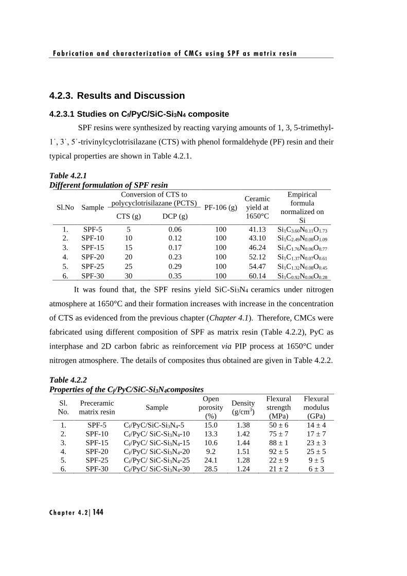
F a b r i c a t i o n a n d c h a r a c t e r i z a t i o n o f C M C s u s i n g S P F a s m a t r i x r e s i n
C h a p t e r 4 . 2 | 144
4.2.3. Results and Discussion
4.2.3.1 Studies on Cf/PyC/SiC-Si3N4 composite
SPF resins were synthesized by reacting varying amounts of 1, 3, 5-trimethyl-
1ˈ, 3ˈ, 5ˈ-trivinylcyclotrisilazane (CTS) with phenol formaldehyde (PF) resin and their
typical properties are shown in Table 4.2.1.
Table 4.2.1
Different formulation of SPF resin
Sl.No Sample
Conversion of CTS to
polycyclotrisilazane (PCTS) PF-106 (g)
Ceramic
yield at
1650°C
Empirical
formula
normalized on
Si CTS (g) DCP (g)
1. SPF-5 5 0.06 100 41.13 Si1C3.60N0.11O1.73
2. SPF-10 10 0.12 100 43.10 Si1C2.49N0.08O1.09
3. SPF-15 15 0.17 100 46.24 Si1C1.76N0.06O0.77
4. SPF-20 20 0.23 100 52.12 Si1C1.37N0.07O0.61
5. SPF-25 25 0.29 100 54.47 Si1C1.32N0.08O0.45
6. SPF-30 30 0.35 100 60.14 Si1C0.92N0.06O0.28
It was found that, the SPF resins yield SiC-Si3N4 ceramics under nitrogen
atmosphere at 1650°C and their formation increases with increase in the concentration
of CTS as evidenced from the previous chapter (Chapter 4.1). Therefore, CMCs were
fabricated using different composition of SPF as matrix resin (Table 4.2.2), PyC as
interphase and 2D carbon fabric as reinforcement via PIP process at 1650°C under
nitrogen atmosphere. The details of composites thus obtained are given in Table 4.2.2.
Table 4.2.2
Properties of the Cf/PyC/SiC-Si3N4composites
Sl.
No.
Preceramic
matrix resin Sample
Open
porosity
(%)
Density
(g/cm3)
Flexural
strength
(MPa)
Flexural
modulus
(GPa)
1. SPF-5 Cf/PyC/SiC-Si3N4-5 15.0 1.38 50 ± 6 14 ± 4
2. SPF-10 Cf/PyC/ SiC-Si3N4-10 13.3 1.42 75 ± 7 17 ± 7
3. SPF-15 Cf/PyC/ SiC-Si3N4-15 10.6 1.44 88 ± 1 23 ± 3
4. SPF-20 Cf/PyC/ SiC-Si3N4-20 9.2 1.51 92 ± 5 25 ± 5
5. SPF-25 Cf/PyC/ SiC-Si3N4-25 24.1 1.28 22 ± 9 9 ± 5
6. SPF-30 Cf/PyC/ SiC-Si3N4-30 28.5 1.24 21 ± 2 6 ± 3
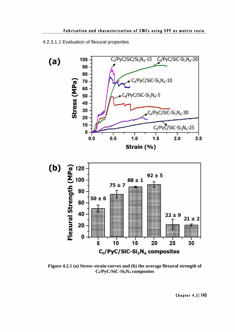
F a b r i c a t i o n a n d c h a r a c t e r i z a t i o n o f C M C s u s i n g S P F a s m a t r i x r e s i n
C h a p t e r 4 . 2 | 145
4.2.3.1.1 Evaluation of flexural properties
Figure 4.2.1 (a) Stress–strain-curves and (b) the average flexural strength of
Cf/PyC/SiC-Si3N4 composites
F a b r i c a t i o n a n d c h a r a c t e r i z a t i o n o f C M C s u s i n g S P F a s m a t r i x r e s i n
C h a p t e r 4 . 2 | 146
The stress-strain-curves and the average flexural strength of Cf/PyC/SiC-Si3N4
composites are shown in Figure 4.2.1 (a) and (b), respectively. The obtained properties
are summarized in Table 4.2.2. The changes in the SPF composition significantly
affects the mechanical properties as shown by the changes observed in stress-strain
behavior, flexural strength and flexural modulus. It is to be noted that, the composition
of SiC-Si3N4 ceramics increases with increase in the concentration of CTS i.e., from
SPF-5 to SPF-30 the concentration of SiC-Si3N4 ceramics gradually increases. Hence,
it is expected that on increase in SiC-Si3N4 ceramic content and the presence of PyC as
interphase will improve the flexural properties of the composites. Surprisingly, it was
observed that, from Cf/PyC/SiC-Si3N4-5 to Cf/PyC/SiC-Si3N4-20 the flexural properties
have gradually increased with increase in SiC-Si3N4 ceramic content (Table 4.2.2) and
a maximum flexural strength of 92 ± 5 MPa was achieved for Cf/PyC/SiC-Si3N4-20
composite. However, a sudden drop in flexural properties was observed in the case of
Cf/PyC/SiC-Si3N4-25 and Cf/PyC/SiC-Si3N4-30 composites (Table 4.2.2). These
variations in flexural properties of Cf/PyC/SiC-Si3N4 composites were further
understood from the stress-strain-curves which exhibited two types of fracture behavior
[Figure 4.2.1 (a)].
In the first type, the stress-strain-curves of composites showed three distinctive
stages. At the first stage, a linear increase in stress is observed followed by a curve at
second stage and a gradual drop at the final stage. This phenomenon was observed for
Cf/PyC/SiC-Si3N4-5, Cf/PyC/SiC-Si3N4-10 and Cf/PyC/SiC-Si3N4-15 composites as a
result of weak bonding between the F/M interfaces [Babu et al. 2016]. As a result, the
flexural properties increase with increase in SiC-Si3N4 ceramic content of the
composites. In the second type, the stress-strain-curves exhibits a pseudo-ductile
fracture behavior, which is observed in the case of Cf/PyC/SiC-Si3N4-20, Cf/PyC/SiC-
Si3N4-25 and Cf/PyC/SiC-Si3N4-30 composites. This phenomenon is normally expected
to show high flexural properties [Lamouroux et al. 1994] which is true only in the case
of Cf/PyC/SiC-Si3N4-20 composite where the highest flexural strength of 92 ± 5 MPa
and modulus of 25 ± 5 was observed. Whereas, Cf/PyC/SiC-Si3N4-25 and Cf/PyC/SiC-
Si3N4-30 are found to have the lowest flexural strength of 22 ± 9 MPa and 21 ± 2 MPa
F a b r i c a t i o n a n d c h a r a c t e r i z a t i o n o f C M C s u s i n g S P F a s m a t r i x r e s i n
C h a p t e r 4 . 2 | 147
respectively, and modulus of 9 ± 5 GPa and 6 ± 3 GPa, respectively. With increase in
SiC-Si3N4 composition for Cf/PyC/SiC-Si3N4composites the lack of improvement in
flexural properties were understood by studying the propagation of crack and fracture
surface of the composites.
The lateral view of the propagation of cracks in a flexural specimen and SEM
image of the fractured surface of Cf/PyC/SiC-Si3N4 composites are shown in Figure
4.2.2 (a) and (b), respectively. The lateral view image of Cf/PyC/SiC-Si3N4 composites
for all the composition of SPF showed the importance of PyC interphase coating on the
carbon fiber which helps in crack propagation along 0°/90° directions [Curtin 1991].
This suggests subsistence of a weak bonding between F/M Interface leading to fiber
pull-out and debonding through energy dissipative mechanism [Figure 4.2.2 (b)] [Rizvi
et al. 2016] resulting in superior flexural properties. This was true in the case of
Cf/PyC/SiC-Si3N4-5 to Cf/PyC/SiC-Si3N4-20 composites leading to increase in flexural
properties.
On the contrary, the propagation of cracks and fracture surface behavior of
Cf/PyC/SiC-Si3N4-25 and Cf/PyC/SiC-Si3N4-30 composites shows a partial
delamination, in spite of the crack propagation along 0°/90° directions. This is due to
the presence of very weak interface between F/M as indicated by arrows [Figure 4.2.2
(b)]. Hence, the structurally weak points like high propensity of cracks or pores in the
matrix may lead to a premature failure of the composite and results in inferior flexural
properties among other composites. It is to be noted that for achieving superior
mechanical properties of CMCs, higher density and lower porosity are highly desirable
[Naslain 2004]. A gradual increase in density and decrease in open porosity was
observed for Cf/PyC/SiC-Si3N4-5 to Cf/PyC/SiC-Si3N4-20 composites, resulting in
increase in flexural properties (Table 4.2.2). On contrary, for Cf/PyC/SiC-Si3N4-25 and
Cf/PyC/SiC-Si3N4-30 composites, lowest density and highest open porosity was
observed (Table 4.2.2) which resulted in lowest flexural properties among other
composites. This explains the reason for highest flexural properties in the case of
Cf/PyC/SiC-Si3N4-20 composite and lowest flexural properties in the case of
Cf/PyC/SiC-Si3N4-30 composite. The study establishes SPF-20 as the most suitable
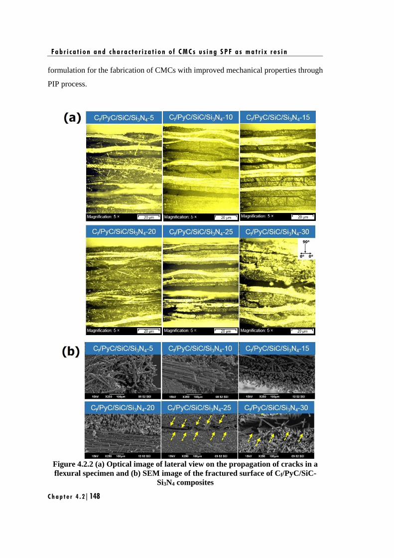
F a b r i c a t i o n a n d c h a r a c t e r i z a t i o n o f C M C s u s i n g S P F a s m a t r i x r e s i n
C h a p t e r 4 . 2 | 148
formulation for the fabrication of CMCs with improved mechanical properties through
PIP process.
Figure 4.2.2 (a) Optical image of lateral view on the propagation of cracks in a
flexural specimen and (b) SEM image of the fractured surface of Cf/PyC/SiC-
Si3N4 composites
F a b r i c a t i o n a n d c h a r a c t e r i z a t i o n o f C M C s u s i n g S P F a s m a t r i x r e s i n
C h a p t e r 4 . 2 | 149
4.2.4. Conclusions
The present study focuses on the fabrication of Cf/PyC/SiC-Si3N4 composites
using different composition of SPF (SPF-5 to 30) as preceramic matrix resin, PyC as
interphase and 2D carbon fabric as reinforcement. The PyC interphase was deposited
via chemical vapor infiltration (CVI) technique on the carbon fabric reinforcement and
densified with matrix via polymer impregnation and pyrolysis (PIP) process. For
Cf/PyC/SiC-Si3N4-5 to Cf/PyC/SiC-Si3N4-20 composites, gradual increase in flexural
strength of 50 ± 6 MPa to 92 ± 5 MPa was obtained. On contrary, for Cf/PyC/SiC-
Si3N4-25 and Cf/PyC/SiC-Si3N4-30, a sudden drop in flexural strength to 22 ± 9 and 21
± 2 respectively, was obtained. The fractography study shows that, for Cf/PyC/SiC-
Si3N4-5 to Cf/PyC/SiC-Si3N4-20 composites fiber pull-out phenomenon was observed
and hence failed in a ductile manner, while Cf/PyC/SiC-Si3N4-25 and Cf/PyC/SiC-
Si3N4-30 composites shows a partial delamination between F/M interface and hence,
leads to premature failure of the composite. This unusual behavior of Cf/PyC/SiC-
Si3N4-25 and Cf/PyC/SiC-Si3N4-30 composites is due to structurally weak points like
high propensity of cracks or pores in the matrix compared to the other composites. This
study establishes silazane modified phenol formaldehyde as a potential preceramic
matrix resin for the fabrication of Cf/PyC/SiC-Si3N4 composites to achieve improved
mechanical properties for thermo-structural applications. This study also demonstrated
that, high density and low porosity of Cf/PyC/SiC-Si3N4 composites are highly essential
for achieving high mechanical properties for CMCs.

F a b r i c a t i o n a n d c h a r a c t e r i z a t i o n o f C M C s u s i n g S P F a s m a t r i x r e s i n
C h a p t e r 4 . 2 | 150
Chapter 5
Studies on boron modified
cyclotrisilazane (BCTS) resins as
oxidation resistance coating for CMCs

n the previous chapter, SiCN based CMCs were fabricated to achieve improved
mechanical properties. However, for long-term service, these composites has to
be finely engineered to improve their oxidation resistance, particularly at the level
of the interphase and the matrix. Hence, to have improved oxidation resistance of the
matrix, synthesis of single source preceramic matrix resins containing silicon, boron
and nitrogen was synthesized to obtain SiBCN based ceramics. As explained in Chapter
1, Section 1.5.1.3, SiBCN ceramics are commonly prepared by the pyrolysis of boron
modified silazane polymer precursors such as polyorganoborosilazane [Kong et al.
2015, Zhang et al. 2017], hydridopolysilazane [Lee et al. 2003], silazane-substituted
borazines [Luo et al. 2013], etc. In almost all these methods, the preparation of
polymeric precursor requires several intermediate steps involving complex synthesis
procedures and handling of hazardous chemicals (borane dimethyl sulfide,
chlorosilanes) and their by-products (ammonium chloride) [Lee et al. 2003, Luo et al.
2013]. This makes the overall preparation of SiBCN ceramic process very complex,
laborious and expensive.
In this chapter, a novel, facile and low-cost synthetic route for preparing SiBCN
ceramics via pyrolysis of boron modified cyclotrisilazane (BCTS) is reported. This
work has been divided into two parts;
• Synthesis, characterization and ceramic conversion studies of BCTS resins are
discussed in detail.
• In the second part, CMCs derived from BPF and SPF resins were screened based
on the mechanical properties and were infiltrated with BCTS resin via vacuum
infiltration technique.
I

Chapter 5.1
Synthesis, characterization and
ceramic conversion studies of BCTS
resins
Results of this chapter has been communicated for publication:
Ganesh Babu T., Renjith Devasia, “Novel, facile and low-cost synthetic route for
SiBCN ceramics from boron modified cyclotrisilazane”.

S y n t h e s i s , c h a r a c t e r i z a t i o n a n d c e r a m i c c o n v e r s i o n s t u d i e s o f B C T S r e s i n s
C h a p t e r 5 . 1 | 157
5.1.1. Introduction
In this chapter, we report for the first time, synthesis and thermal
transformation of BCTS and its ceramic conversion to oxide free SiBCN ceramics. To
the best of our knowledge, there are no available reports on the phase evolution of
SiBCN ceramics from boron modified cyclotrisilazane. Polymer to ceramic conversion
of BCTS was carried out at 1450°C and 1650°C under nitrogen atmosphere. The
morphology of the obtained ceramic phases and their elemental composition were
thoroughly investigated through XRD, SEM and HRTEM techniques. The objective of
this work is to assess BCTS resin as potential preceramic resin and to attain oxide free
SiBCN ceramic.
5.1.2. Experimental
5.1.2.1. Materials
Details of the chemicals are given in Chapter 2, Section 2.1.
5.1.2.2. Synthesis of boron modified cyclotrisilazane (BCTS) resins
The procedure for the synthesis of BCTS resins are detailed in Chapter 2,
Section 2.2.3.
5.1.2.3. Characterization
Characterization methods employed include GPC, FT-IR, NMR, TGA, Py-
GC-MS, XRD, SEM, HRTEM and elemental analysis. The detailed procedures of all
these characterizations are given in Chapter 2, Section 2.5.
5.1.2.4. Polymer to Ceramic conversion
Ceramic conversion studies were carried out at 1450°C or 1650°C under
nitrogen atmosphere. The detailed procedure of the process is given in Chapter 2,
Section 2.4.4.
5.1.3. Results and Discussion
5.1.3.1 Synthesis and characterization of BCTS resin
Boron modified cyclotrisilazane (BCTS) resins were synthesised by reacting
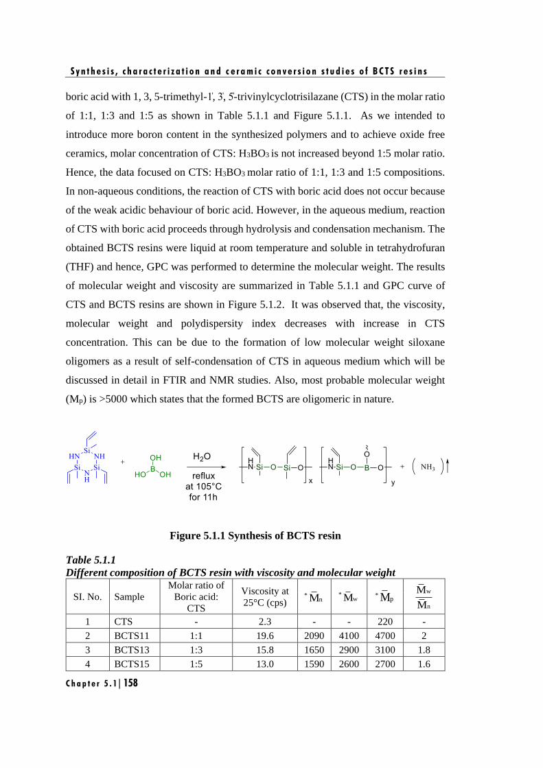
S y n t h e s i s , c h a r a c t e r i z a t i o n a n d c e r a m i c c o n v e r s i o n s t u d i e s o f B C T S r e s i n s
C h a p t e r 5 . 1 | 158
boric acid with 1, 3, 5-trimethyl-1̍, 3̍, 5̍-trivinylcyclotrisilazane (CTS) in the molar ratio
of 1:1, 1:3 and 1:5 as shown in Table 5.1.1 and Figure 5.1.1. As we intended to
introduce more boron content in the synthesized polymers and to achieve oxide free
ceramics, molar concentration of CTS: H3BO3 is not increased beyond 1:5 molar ratio.
Hence, the data focused on CTS: H3BO3 molar ratio of 1:1, 1:3 and 1:5 compositions.
In non-aqueous conditions, the reaction of CTS with boric acid does not occur because
of the weak acidic behaviour of boric acid. However, in the aqueous medium, reaction
of CTS with boric acid proceeds through hydrolysis and condensation mechanism. The
obtained BCTS resins were liquid at room temperature and soluble in tetrahydrofuran
(THF) and hence, GPC was performed to determine the molecular weight. The results
of molecular weight and viscosity are summarized in Table 5.1.1 and GPC curve of
CTS and BCTS resins are shown in Figure 5.1.2. It was observed that, the viscosity,
molecular weight and polydispersity index decreases with increase in CTS
concentration. This can be due to the formation of low molecular weight siloxane
oligomers as a result of self-condensation of CTS in aqueous medium which will be
discussed in detail in FTIR and NMR studies. Also, most probable molecular weight
(Mp) is >5000 which states that the formed BCTS are oligomeric in nature.
Figure 5.1.1 Synthesis of BCTS resin
Table 5.1.1
Different composition of BCTS resin with viscosity and molecular weight
SI. No. Sample
Molar ratio of
Boric acid:
CTS
Viscosity at
25°C (cps) *
nM *
wM *pM
w
n
M
M
1 CTS - 2.3 - - 220 -
2 BCTS11 1:1 19.6 2090 4100 4700 2
3 BCTS13 1:3 15.8 1650 2900 3100 1.8
4 BCTS15 1:5 13.0 1590 2600 2700 1.6
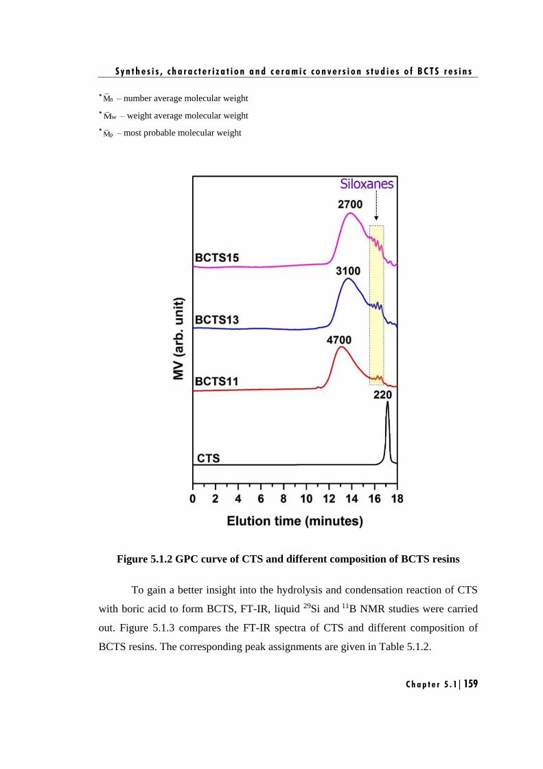
S y n t h e s i s , c h a r a c t e r i z a t i o n a n d c e r a m i c c o n v e r s i o n s t u d i e s o f B C T S r e s i n s
C h a p t e r 5 . 1 | 159
*nM – number average molecular weight
*wM – weight average molecular weight
*pM – most probable molecular weight
Figure 5.1.2 GPC curve of CTS and different composition of BCTS resins
To gain a better insight into the hydrolysis and condensation reaction of CTS
with boric acid to form BCTS, FT-IR, liquid 29Si and 11B NMR studies were carried
out. Figure 5.1.3 compares the FT-IR spectra of CTS and different composition of
BCTS resins. The corresponding peak assignments are given in Table 5.1.2.
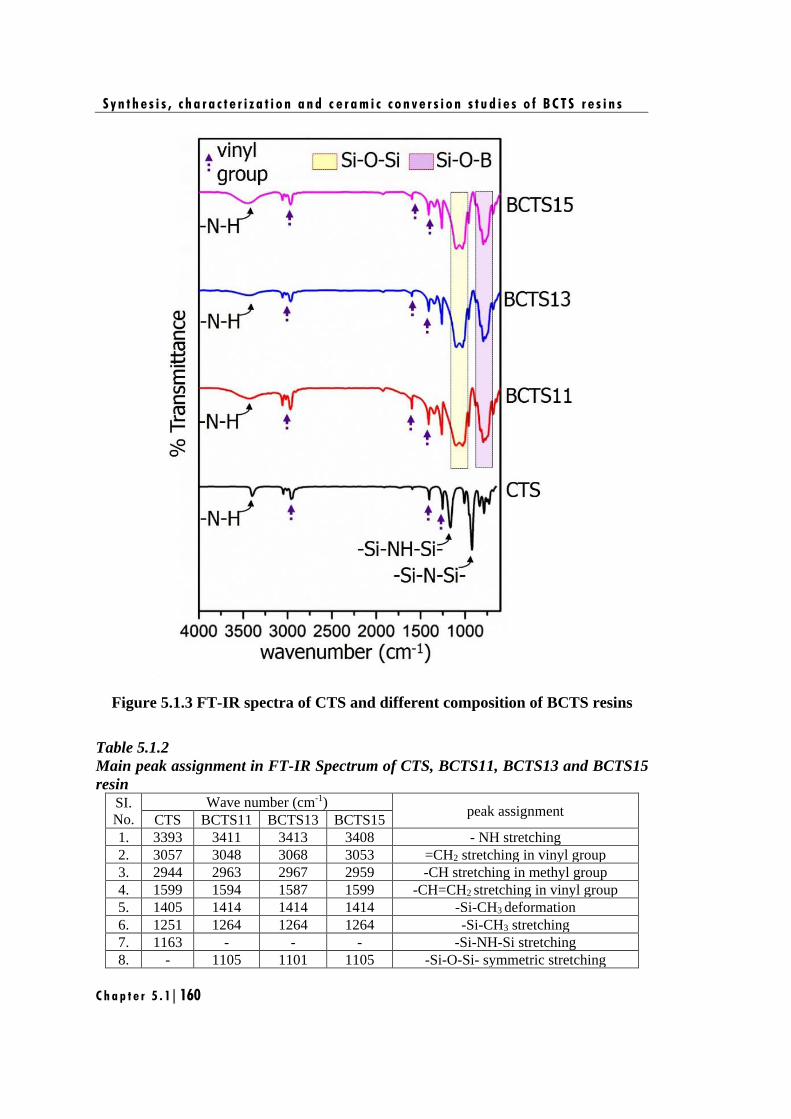
S y n t h e s i s , c h a r a c t e r i z a t i o n a n d c e r a m i c c o n v e r s i o n s t u d i e s o f B C T S r e s i n s
C h a p t e r 5 . 1 | 160
Figure 5.1.3 FT-IR spectra of CTS and different composition of BCTS resins
Table 5.1.2
Main peak assignment in FT-IR Spectrum of CTS, BCTS11, BCTS13 and BCTS15
resin
SI.
No.
Wave number (cm-1) peak assignment
CTS BCTS11 BCTS13 BCTS15
1. 3393 3411 3413 3408 - NH stretching
2. 3057 3048 3068 3053 =CH2 stretching in vinyl group
3. 2944 2963 2967 2959 -CH stretching in methyl group
4. 1599 1594 1587 1599 -CH=CH2 stretching in vinyl group
5. 1405 1414 1414 1414 -Si-CH3 deformation
6. 1251 1264 1264 1264 -Si-CH3 stretching
7. 1163 - - - -Si-NH-Si stretching
8. - 1105 1101 1105 -Si-O-Si- symmetric stretching
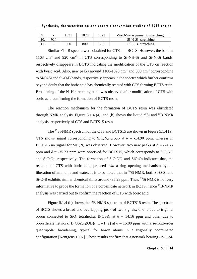
S y n t h e s i s , c h a r a c t e r i z a t i o n a n d c e r a m i c c o n v e r s i o n s t u d i e s o f B C T S r e s i n s
C h a p t e r 5 . 1 | 161
9. - 1031 1020 1023 -Si-O-Si- asymmetric stretching
10. 920 - - - -Si-N-Si- stretching
11. - 800 800 802 -Si-O-B- stretching
Similar FT-IR spectra were obtained for CTS and BCTS. However, the band at
1163 cm-1 and 920 cm-1 in CTS corresponding to Si-NH-Si and Si-N-Si bands,
respectively disappears in BCTS indicating the modification of the CTS on reaction
with boric acid. Also, new peaks around 1100-1020 cm-1 and 800 cm-1 corresponding
to Si-O-Si and Si-O-B bands, respectively appears in the spectra which further confirms
beyond doubt that the boric acid has chemically reacted with CTS forming BCTS resin.
Broadening of the N–H stretching band was observed after modification of CTS with
boric acid confirming the formation of BCTS resin.
The reaction mechanism for the formation of BCTS resin was elucidated
through NMR analysis. Figure 5.1.4 (a), and (b) shows the liquid 29Si and 11B NMR
analysis, respectively of CTS and BCTS15 resin.
The 29Si-NMR spectrum of the CTS and BCTS15 are shown in Figure 5.1.4 (a).
CTS shows signal corresponding to SiC2N2 group at δ = -14.90 ppm, whereas in
BCTS15 no signal for SiC2N2 was observed. However, two new peaks at δ = -24.77
ppm and δ = -35.23 ppm were observed for BCTS15, which corresponds to SiC2NO
and SiC2O2, respectively. The formation of SiC2NO and SiC2O2 indicates that, the
reaction of CTS with boric acid, proceeds via a ring opening mechanism by the
liberation of ammonia and water. It is to be noted that in 29Si NMR, both Si-O-Si and
Si-O-B exhibits similar chemical shifts around -35.23 ppm. Thus, 29Si NMR is not very
informative to probe the formation of a borosilicate network in BCTS, hence 11B-NMR
analysis was carried out to confirm the reaction of CTS with boric acid.
Figure 5.1.4 (b) shows the 11B-NMR spectrum of BCTS15 resin. The spectrum
of BCTS shows a broad and overlapping peak of two signals; one is due to trigonal
boron connected to SiO4 tetrahedra, B(OSi)3 at δ = 14.16 ppm and other due to
borosilicate network, B(OSi)3-x(OB)x (x =1, 2) at δ = 15.88 ppm with a second-order
quadrupolar broadening, typical for boron atoms in a trigonally coordinated
configuration [Kentgens 1997]. These results confirm that a network bearing -B-O-Si-
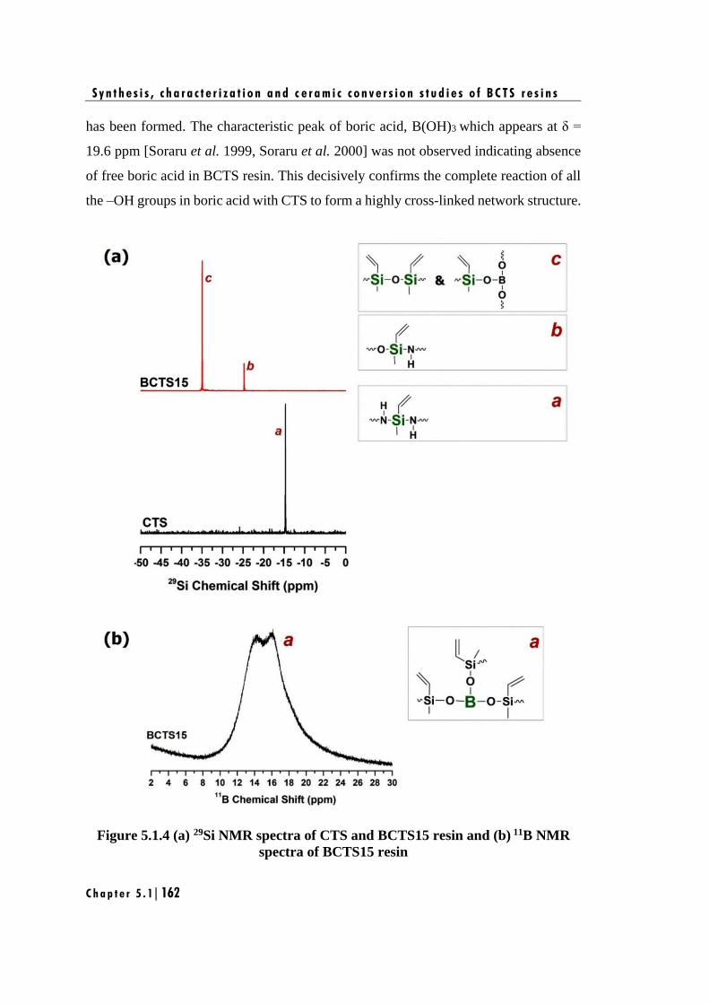
S y n t h e s i s , c h a r a c t e r i z a t i o n a n d c e r a m i c c o n v e r s i o n s t u d i e s o f B C T S r e s i n s
C h a p t e r 5 . 1 | 162
has been formed. The characteristic peak of boric acid, B(OH)3 which appears at δ =
19.6 ppm [Soraru et al. 1999, Soraru et al. 2000] was not observed indicating absence
of free boric acid in BCTS resin. This decisively confirms the complete reaction of all
the –OH groups in boric acid with CTS to form a highly cross-linked network structure.
Figure 5.1.4 (a) 29Si NMR spectra of CTS and BCTS15 resin and (b) 11B NMR
spectra of BCTS15 resin
S y n t h e s i s , c h a r a c t e r i z a t i o n a n d c e r a m i c c o n v e r s i o n s t u d i e s o f B C T S r e s i n s
C h a p t e r 5 . 1 | 163
From the FT-IR, 29Si and 11B NMR results, it can be inferred that the reaction
of boric acid with CTS in aqueous medium proceeds via self-condensation of CTS and
co-condensation of CTS with boric acid to form Si-O-Si and Si-O-B linkage,
respectively. The self-condensation and co-condensation reaction will lead to liberation
of ammonia and water by ring opening mechanism as shown in Figure 5.1.5. This
results in a more stable and less strained linear structured BCTS resin containing a
mixture of -Si-O-Si-, -HN-Si-O- and -Si-O-B- linkages.
Figure 5.1.5. Proposed ring opening mechanism for the formation of BCTS resin
(a) Self-condensation; (b) and (c) co-condensation
The thermal decomposition behavior of the CTS and BCTS resins were
investigated through TGA analysis. Figure 5.1.6 shows the TG and its derivative curves
of CTS and BCTS resins from 25°C to 1200°C under nitrogen atmosphere. The
parameters derived from TG and its derivative curves are summarized in Table 5.1.3.
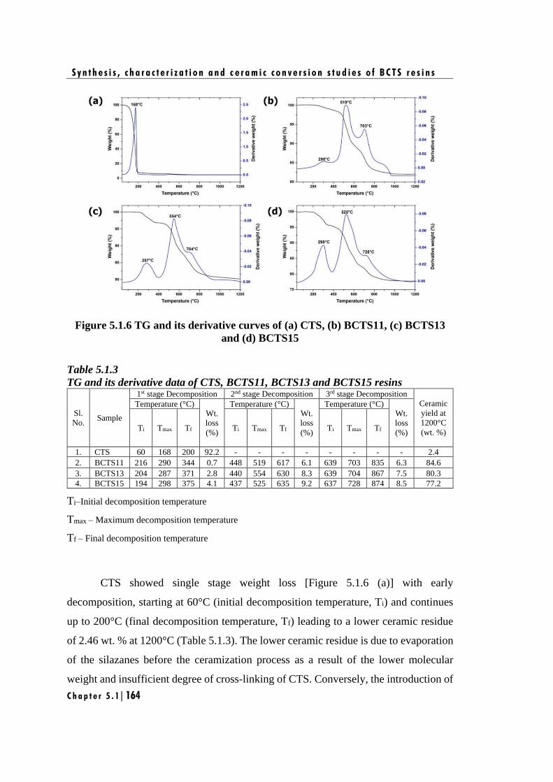
S y n t h e s i s , c h a r a c t e r i z a t i o n a n d c e r a m i c c o n v e r s i o n s t u d i e s o f B C T S r e s i n s
C h a p t e r 5 . 1 | 164
Figure 5.1.6 TG and its derivative curves of (a) CTS, (b) BCTS11, (c) BCTS13
and (d) BCTS15
Table 5.1.3
TG and its derivative data of CTS, BCTS11, BCTS13 and BCTS15 resins
Sl.
No. Sample
1st stage Decomposition 2nd stage Decomposition 3rd stage Decomposition
Ceramic
yield at
1200°C
(wt. %)
Temperature (°C) Wt.
loss
(%)
Temperature (°C) Wt.
loss
(%)
Temperature (°C) Wt.
loss
(%) Ti Tmax Tf Ti Tmax Tf Ti Tmax Tf
1. CTS 60 168 200 92.2 - - - - - - - - 2.4
2. BCTS11 216 290 344 0.7 448 519 617 6.1 639 703 835 6.3 84.6
3. BCTS13 204 287 371 2.8 440 554 630 8.3 639 704 867 7.5 80.3
4. BCTS15 194 298 375 4.1 437 525 635 9.2 637 728 874 8.5 77.2
Ti–Initial decomposition temperature
Tmax – Maximum decomposition temperature
Tf – Final decomposition temperature
CTS showed single stage weight loss [Figure 5.1.6 (a)] with early
decomposition, starting at 60°C (initial decomposition temperature, Ti) and continues
up to 200°C (final decomposition temperature, Tf) leading to a lower ceramic residue
of 2.46 wt. % at 1200°C (Table 5.1.3). The lower ceramic residue is due to evaporation
of the silazanes before the ceramization process as a result of the lower molecular
weight and insufficient degree of cross-linking of CTS. Conversely, the introduction of
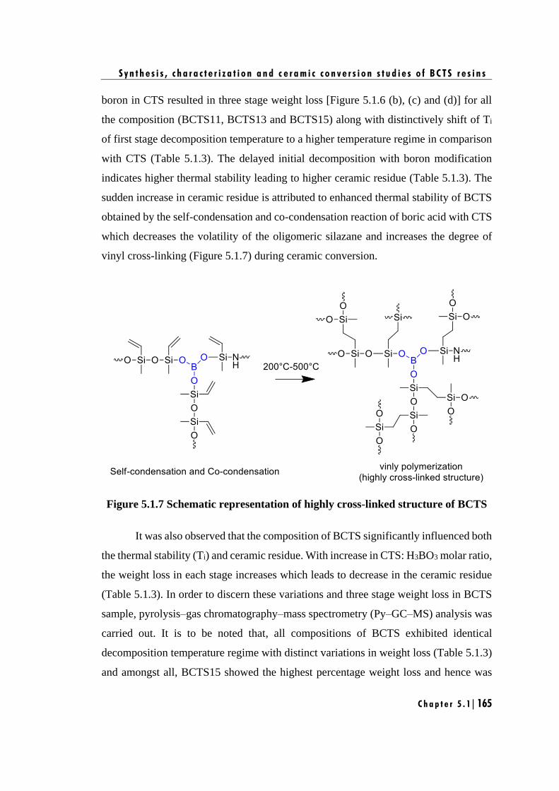
S y n t h e s i s , c h a r a c t e r i z a t i o n a n d c e r a m i c c o n v e r s i o n s t u d i e s o f B C T S r e s i n s
C h a p t e r 5 . 1 | 165
boron in CTS resulted in three stage weight loss [Figure 5.1.6 (b), (c) and (d)] for all
the composition (BCTS11, BCTS13 and BCTS15) along with distinctively shift of Ti
of first stage decomposition temperature to a higher temperature regime in comparison
with CTS (Table 5.1.3). The delayed initial decomposition with boron modification
indicates higher thermal stability leading to higher ceramic residue (Table 5.1.3). The
sudden increase in ceramic residue is attributed to enhanced thermal stability of BCTS
obtained by the self-condensation and co-condensation reaction of boric acid with CTS
which decreases the volatility of the oligomeric silazane and increases the degree of
vinyl cross-linking (Figure 5.1.7) during ceramic conversion.
Figure 5.1.7 Schematic representation of highly cross-linked structure of BCTS
It was also observed that the composition of BCTS significantly influenced both
the thermal stability (Ti) and ceramic residue. With increase in CTS: H3BO3 molar ratio,
the weight loss in each stage increases which leads to decrease in the ceramic residue
(Table 5.1.3). In order to discern these variations and three stage weight loss in BCTS
sample, pyrolysis–gas chromatography–mass spectrometry (Py–GC–MS) analysis was
carried out. It is to be noted that, all compositions of BCTS exhibited identical
decomposition temperature regime with distinct variations in weight loss (Table 5.1.3)
and amongst all, BCTS15 showed the highest percentage weight loss and hence was
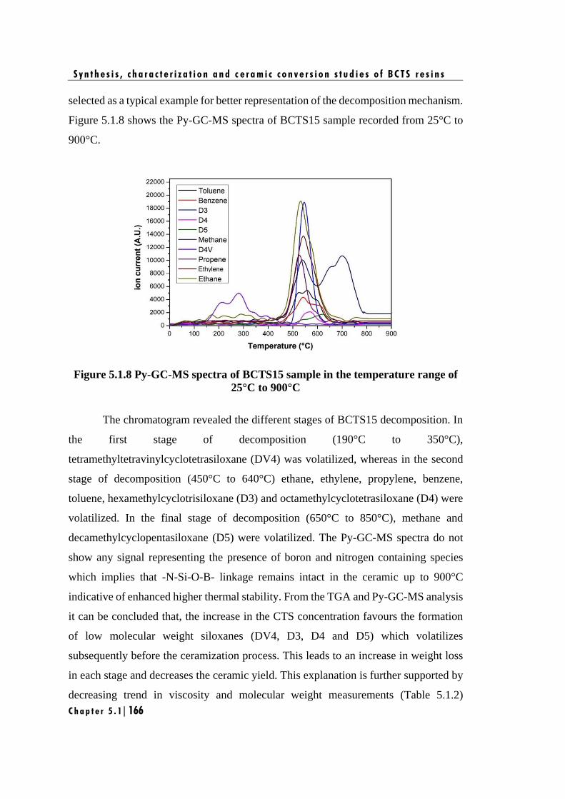
S y n t h e s i s , c h a r a c t e r i z a t i o n a n d c e r a m i c c o n v e r s i o n s t u d i e s o f B C T S r e s i n s
C h a p t e r 5 . 1 | 166
selected as a typical example for better representation of the decomposition mechanism.
Figure 5.1.8 shows the Py-GC-MS spectra of BCTS15 sample recorded from 25°C to
900°C.
Figure 5.1.8 Py-GC-MS spectra of BCTS15 sample in the temperature range of
25°C to 900°C
The chromatogram revealed the different stages of BCTS15 decomposition. In
the first stage of decomposition (190°C to 350°C),
tetramethyltetravinylcyclotetrasiloxane (DV4) was volatilized, whereas in the second
stage of decomposition (450°C to 640°C) ethane, ethylene, propylene, benzene,
toluene, hexamethylcyclotrisiloxane (D3) and octamethylcyclotetrasiloxane (D4) were
volatilized. In the final stage of decomposition (650°C to 850°C), methane and
decamethylcyclopentasiloxane (D5) were volatilized. The Py-GC-MS spectra do not
show any signal representing the presence of boron and nitrogen containing species
which implies that -N-Si-O-B- linkage remains intact in the ceramic up to 900°C
indicative of enhanced higher thermal stability. From the TGA and Py-GC-MS analysis
it can be concluded that, the increase in the CTS concentration favours the formation
of low molecular weight siloxanes (DV4, D3, D4 and D5) which volatilizes
subsequently before the ceramization process. This leads to an increase in weight loss
in each stage and decreases the ceramic yield. This explanation is further supported by
decreasing trend in viscosity and molecular weight measurements (Table 5.1.2)
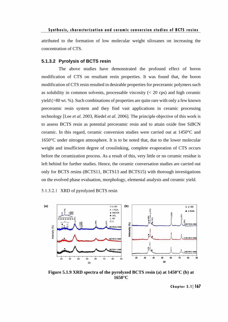
S y n t h e s i s , c h a r a c t e r i z a t i o n a n d c e r a m i c c o n v e r s i o n s t u d i e s o f B C T S r e s i n s
C h a p t e r 5 . 1 | 167
attributed to the formation of low molecular weight siloxanes on increasing the
concentration of CTS.
5.1.3.2 Pyrolysis of BCTS resin
The above studies have demonstrated the profound effect of boron
modification of CTS on resultant resin properties. It was found that, the boron
modification of CTS resin resulted in desirable properties for preceramic polymers such
as solubility in common solvents, processable viscosity (< 20 cps) and high ceramic
yield (>80 wt. %). Such combinations of properties are quite rare with only a few known
preceramic resin system and they find vast applications in ceramic processing
technology [Lee et al. 2003, Riedel et al. 2006]. The principle objective of this work is
to assess BCTS resin as potential preceramic resin and to attain oxide free SiBCN
ceramic. In this regard, ceramic conversion studies were carried out at 1450°C and
1650°C under nitrogen atmosphere. It is to be noted that, due to the lower molecular
weight and insufficient degree of crosslinking, complete evaporation of CTS occurs
before the ceramization process. As a result of this, very little or no ceramic residue is
left behind for further studies. Hence, the ceramic conversation studies are carried out
only for BCTS resins (BCTS11, BCTS13 and BCTS15) with thorough investigations
on the evolved phase evaluation, morphology, elemental analysis and ceramic yield.
XRD of pyrolyzed BCTS resin
Figure 5.1.9 XRD spectra of the pyrolyzed BCTS resin (a) at 1450°C (b) at
1650°C
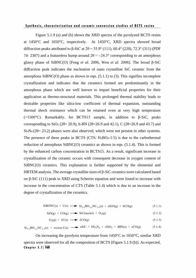
S y n t h e s i s , c h a r a c t e r i z a t i o n a n d c e r a m i c c o n v e r s i o n s t u d i e s o f B C T S r e s i n s
C h a p t e r 5 . 1 | 168
Figure 5.1.9 (a) and (b) shows the XRD spectra of the pyrolyzed BCTS resins
at 1450°C and 1650°C, respectively. At 1450°C, XRD spectra showed broad
diffraction peaks attributed to β-SiC at 2θ = 35.9° (111), 60.4° (220), 72.3° (311) (PDF
74- 2307) and a featureless hump around 2θ = ~24.3° corresponding to an amorphous
glassy phase of SiBNC(O) [Feng et al. 2006, Wen et al. 2006]. The broad β-SiC
diffraction peak indicates the nucleation of nano crystalline SiC ceramic from the
amorphous SiBNC(O) phase as shown in eqn. (5.1.1) to (3). This signifies incomplete
crystallization and indicates that the ceramics formed are predominantly in the
amorphous phase which are well known to impart beneficial properties for their
application as thermo-structural materials. This prolonged thermal stability leads to
desirable properties like ultra-low coefficient of thermal expansion, outstanding
thermal shock resistance which can be retained even at very high temperature
(>1500°C). Remarkably, for BCTS15 sample, in addition to β-SiC, peaks
corresponding to SiO2 (2θ= 20.9), h-BN (2θ=26.9 and 42.1), C (2θ=26.9 and 43.7) and
Si3N4 (2θ= 23.2) phases were also observed, which were not present in other systems.
The presence of these peaks in BCTS (CTS: H3BO3-1:5) is due to the carbothermal
reduction of amorphous SiBNC(O) ceramics as shown in eqn. (5.1.4). This is formed
by the enhanced carbon concentration in BCTS15. As a result, significant increase in
crystallization of the ceramic occurs with consequent decrease in oxygen content of
SiBNC(O) ceramics. This explanation is further supported by the elemental and
HRTEM analysis. The average crystallite sizes of β-SiC ceramics were calculated based
on β-SiC (111) peak in XRD using Scherrer equation and were found to increase with
increase in the concentration of CTS (Table 5.1.4) which is due to an increase in the
degree of crystallization of the ceramics.
On increasing the pyrolysis temperature from 1450°C to 1650°C, similar XRD
spectra were observed for all the composition of BCTS [Figure 5.1.9 (b)]. As expected,
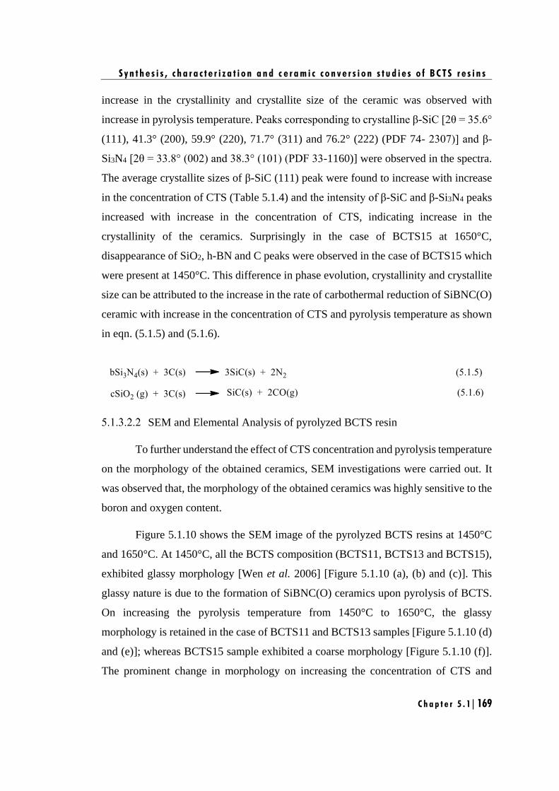
S y n t h e s i s , c h a r a c t e r i z a t i o n a n d c e r a m i c c o n v e r s i o n s t u d i e s o f B C T S r e s i n s
C h a p t e r 5 . 1 | 169
increase in the crystallinity and crystallite size of the ceramic was observed with
increase in pyrolysis temperature. Peaks corresponding to crystalline β-SiC [2θ = 35.6°
(111), 41.3° (200), 59.9° (220), 71.7° (311) and 76.2° (222) (PDF 74- 2307)] and β-
Si3N4 [2θ = 33.8° (002) and 38.3° (101) (PDF 33-1160)] were observed in the spectra.
The average crystallite sizes of β-SiC (111) peak were found to increase with increase
in the concentration of CTS (Table 5.1.4) and the intensity of β-SiC and β-Si3N4 peaks
increased with increase in the concentration of CTS, indicating increase in the
crystallinity of the ceramics. Surprisingly in the case of BCTS15 at 1650°C,
disappearance of SiO2, h-BN and C peaks were observed in the case of BCTS15 which
were present at 1450°C. This difference in phase evolution, crystallinity and crystallite
size can be attributed to the increase in the rate of carbothermal reduction of SiBNC(O)
ceramic with increase in the concentration of CTS and pyrolysis temperature as shown
in eqn. (5.1.5) and (5.1.6).
SEM and Elemental Analysis of pyrolyzed BCTS resin
To further understand the effect of CTS concentration and pyrolysis temperature
on the morphology of the obtained ceramics, SEM investigations were carried out. It
was observed that, the morphology of the obtained ceramics was highly sensitive to the
boron and oxygen content.
Figure 5.1.10 shows the SEM image of the pyrolyzed BCTS resins at 1450°C
and 1650°C. At 1450°C, all the BCTS composition (BCTS11, BCTS13 and BCTS15),
exhibited glassy morphology [Wen et al. 2006] [Figure 5.1.10 (a), (b) and (c)]. This
glassy nature is due to the formation of SiBNC(O) ceramics upon pyrolysis of BCTS.
On increasing the pyrolysis temperature from 1450°C to 1650°C, the glassy
morphology is retained in the case of BCTS11 and BCTS13 samples [Figure 5.1.10 (d)
and (e)]; whereas BCTS15 sample exhibited a coarse morphology [Figure 5.1.10 (f)].
The prominent change in morphology on increasing the concentration of CTS and
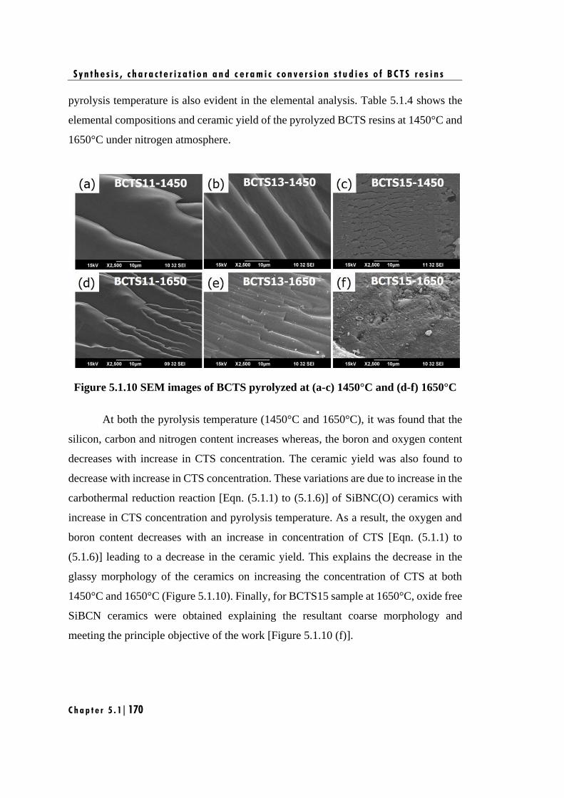
S y n t h e s i s , c h a r a c t e r i z a t i o n a n d c e r a m i c c o n v e r s i o n s t u d i e s o f B C T S r e s i n s
C h a p t e r 5 . 1 | 170
pyrolysis temperature is also evident in the elemental analysis. Table 5.1.4 shows the
elemental compositions and ceramic yield of the pyrolyzed BCTS resins at 1450°C and
1650°C under nitrogen atmosphere.
Figure 5.1.10 SEM images of BCTS pyrolyzed at (a-c) 1450°C and (d-f) 1650°C
At both the pyrolysis temperature (1450°C and 1650°C), it was found that the
silicon, carbon and nitrogen content increases whereas, the boron and oxygen content
decreases with increase in CTS concentration. The ceramic yield was also found to
decrease with increase in CTS concentration. These variations are due to increase in the
carbothermal reduction reaction [Eqn. (5.1.1) to (5.1.6)] of SiBNC(O) ceramics with
increase in CTS concentration and pyrolysis temperature. As a result, the oxygen and
boron content decreases with an increase in concentration of CTS [Eqn. (5.1.1) to
(5.1.6)] leading to a decrease in the ceramic yield. This explains the decrease in the
glassy morphology of the ceramics on increasing the concentration of CTS at both
1450°C and 1650°C (Figure 5.1.10). Finally, for BCTS15 sample at 1650°C, oxide free
SiBCN ceramics were obtained explaining the resultant coarse morphology and
meeting the principle objective of the work [Figure 5.1.10 (f)].
S y n t h e s i s , c h a r a c t e r i z a t i o n a n d c e r a m i c c o n v e r s i o n s t u d i e s o f B C T S r e s i n s
C h a p t e r 5 . 1 | 171
Table 5.1.4 Elemental composition and ceramic yield of ceramics derived from BCTS
at 1450°C and 1650°C
SI.
No. Samples Si B O N C
Empirical formula
normalized on Si
Ceramic
yield
(wt. %)
Crystallite
size from
XRD (nm)
Crystallite
size from
HRTEM
(nm)
(a) at 1450°C
1. BCTS11-
1450 48 11 17 4 20 SiB0.56O0.62N0.16C0.94 76 2.1 2.2±0.4
2. BCTS13-
1450 51 6 14 7 22 SiB0.30O0.46N0.26C1.01 75 3.2 3.3±0.2
3. BCTS15-
1450 56 4 7 6 27 SiB0.18O0.21N0.24C1.12 70 4.9 4.6±0.5
(b) at 1650°C
4. BCTS11-
1650 57 8 12 2 21 SiB0.34O0.38N0.08C0.86 74 7.2 7.5±0.2
5. BCTS13-
1650 61 5 5 4 25 SiB0.19O0.15N0.12C0.95 69 8.8 8.5±0.5
6. BCTS15-
1650 65 3 - 5 27 SiB0.09N0.15C0.98 65 9.3 9.6±0.7
HRTEM of pyrolyzed BCTS resin
To further discern the changes observed in the crystalline structure and the
morphology of the ceramics in atomic level with respect to both CTS concentration and
pyrolysis temperature, HRTEM studies were carried out. Figure 5.1.11 and 5.1.12
shows the HRTEM images of the pyrolyzed BCTS resins at 1450°C and 1650°C,
respectively along with their corresponding selected area electron diffraction (SAED)
patterns.
At 1450°C, for all the compositions of BCTS (BCTS11, BCTS13 and BCTS15),
very fine nano ceramic particles embedded in an amorphous ceramic matrix was
observed with a distinct variation in their arrangement (Figure 5.1.11). It was observed
that in the case of BCTS11 and BCTS13 samples, uniformly distributed nano ceramic
particles were obtained [Figure 5.1.11 (a & b)]; whereas, in the case of BCTS15 sample,
several nano ceramic particles coalesce to form nano ceramic clusters [Figure 5.1.11
(c)]. The corresponding SAED patterns displays a broad and diffused diffraction ring
with lattice spacing measurements matching that of β-SiC (d111= 0.25 nm)
corroborating with the XRD results. This conclusively shows that the nano ceramic
particles and nano ceramic clusters are composed of β-SiC ceramic phase embedded in
amorphous SiBNC(O) ceramic matrix. The diameters of the embedded β-SiC particles
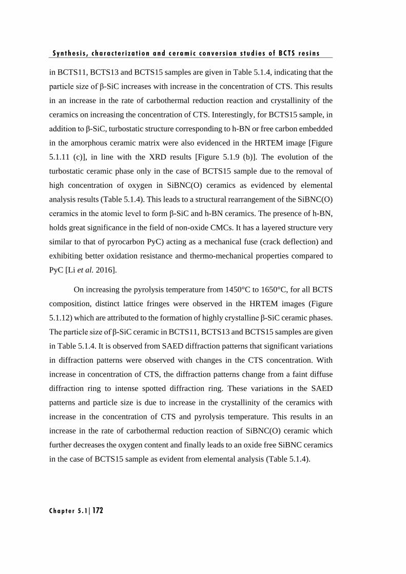
S y n t h e s i s , c h a r a c t e r i z a t i o n a n d c e r a m i c c o n v e r s i o n s t u d i e s o f B C T S r e s i n s
C h a p t e r 5 . 1 | 172
in BCTS11, BCTS13 and BCTS15 samples are given in Table 5.1.4, indicating that the
particle size of β-SiC increases with increase in the concentration of CTS. This results
in an increase in the rate of carbothermal reduction reaction and crystallinity of the
ceramics on increasing the concentration of CTS. Interestingly, for BCTS15 sample, in
addition to β-SiC, turbostatic structure corresponding to h-BN or free carbon embedded
in the amorphous ceramic matrix were also evidenced in the HRTEM image [Figure
5.1.11 (c)], in line with the XRD results [Figure 5.1.9 (b)]. The evolution of the
turbostatic ceramic phase only in the case of BCTS15 sample due to the removal of
high concentration of oxygen in SiBNC(O) ceramics as evidenced by elemental
analysis results (Table 5.1.4). This leads to a structural rearrangement of the SiBNC(O)
ceramics in the atomic level to form β-SiC and h-BN ceramics. The presence of h-BN,
holds great significance in the field of non-oxide CMCs. It has a layered structure very
similar to that of pyrocarbon PyC) acting as a mechanical fuse (crack deflection) and
exhibiting better oxidation resistance and thermo-mechanical properties compared to
PyC [Li et al. 2016].
On increasing the pyrolysis temperature from 1450°C to 1650°C, for all BCTS
composition, distinct lattice fringes were observed in the HRTEM images (Figure
5.1.12) which are attributed to the formation of highly crystalline β-SiC ceramic phases.
The particle size of β-SiC ceramic in BCTS11, BCTS13 and BCTS15 samples are given
in Table 5.1.4. It is observed from SAED diffraction patterns that significant variations
in diffraction patterns were observed with changes in the CTS concentration. With
increase in concentration of CTS, the diffraction patterns change from a faint diffuse
diffraction ring to intense spotted diffraction ring. These variations in the SAED
patterns and particle size is due to increase in the crystallinity of the ceramics with
increase in the concentration of CTS and pyrolysis temperature. This results in an
increase in the rate of carbothermal reduction reaction of SiBNC(O) ceramic which
further decreases the oxygen content and finally leads to an oxide free SiBNC ceramics
in the case of BCTS15 sample as evident from elemental analysis (Table 5.1.4).
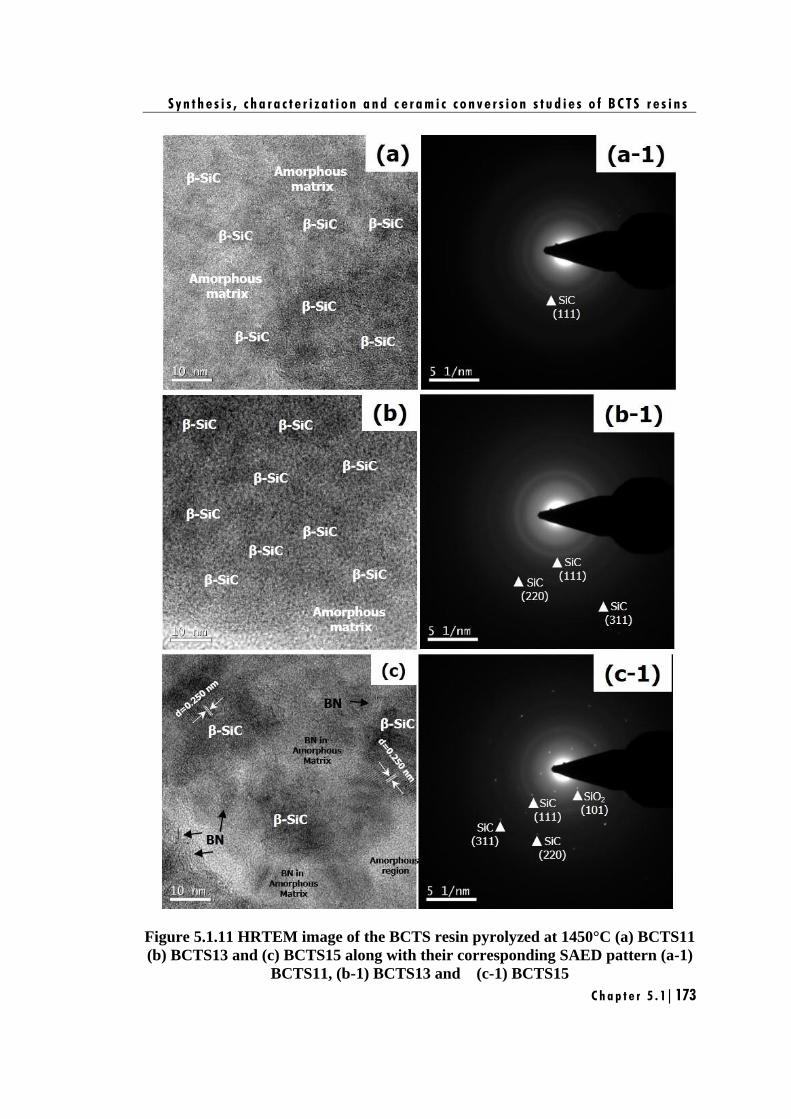
S y n t h e s i s , c h a r a c t e r i z a t i o n a n d c e r a m i c c o n v e r s i o n s t u d i e s o f B C T S r e s i n s
C h a p t e r 5 . 1 | 173
Figure 5.1.11 HRTEM image of the BCTS resin pyrolyzed at 1450°C (a) BCTS11
(b) BCTS13 and (c) BCTS15 along with their corresponding SAED pattern (a-1)
BCTS11, (b-1) BCTS13 and (c-1) BCTS15
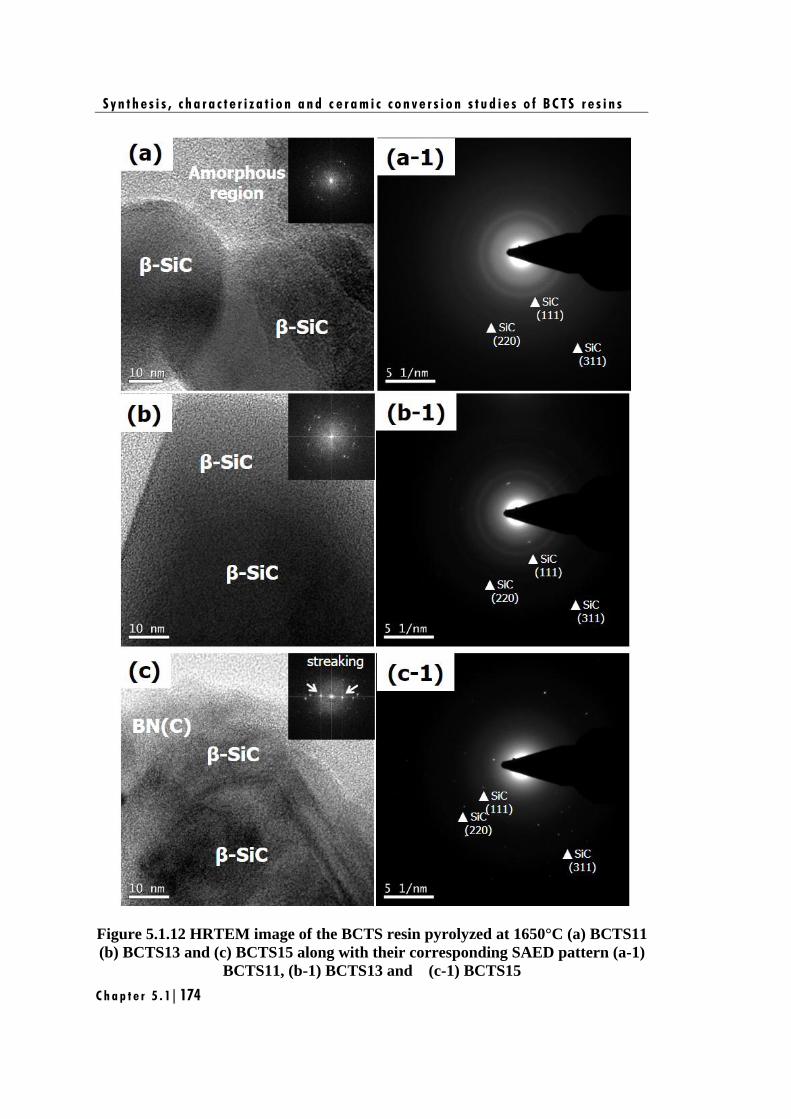
S y n t h e s i s , c h a r a c t e r i z a t i o n a n d c e r a m i c c o n v e r s i o n s t u d i e s o f B C T S r e s i n s
C h a p t e r 5 . 1 | 174
Figure 5.1.12 HRTEM image of the BCTS resin pyrolyzed at 1650°C (a) BCTS11
(b) BCTS13 and (c) BCTS15 along with their corresponding SAED pattern (a-1)
BCTS11, (b-1) BCTS13 and (c-1) BCTS15
S y n t h e s i s , c h a r a c t e r i z a t i o n a n d c e r a m i c c o n v e r s i o n s t u d i e s o f B C T S r e s i n s
C h a p t e r 5 . 1 | 175
Another interesting observation was found in the case of BCTS15 sample i.e.,
the presence of turbostatic structure of BN(C) phase. From the XRD results of BCTS15
sample pyrolyzed at 1450°C, formation of β-SiC, h-BN, C and β-Si3N4 ceramics were
evidenced [Figure 5.1.9 (a)]. However, upon increasing the pyrolysis temperature to
1650°C, XRD spectra showed peaks corresponding to β-SiC and β-Si3N4 peaks [Figure
5.1.9 (b)]. Nevertheless, the magnified HRTEM image of BCTS15 sample pyrolyzed
at 1650°C [Figure 5.1.13 (b)], clearly showed the turbostatic layer of BN(C) ceramic
around β-SiC crystallites.
The major reason behind the formation of BN(C) phase only in the case of
BCTS15 at 1650°C was due to formation of oxide free SiBCN ceramics which results
in structural rearrangement of ceramics in an atomic level. In particular, boron atom in
h-BN ceramic can be easily replaced by the free carbon atom present in the ceramics
by means of bond-breaking mechanism [Li et al. 2016] as shown in Figure 5.1.14. As
a result, crystalline h-BN ceramic will be converted to BN(C) phase which is
amorphous in nature. This explains the absence of BN(C) phase in the XRD spectrum
of BCTS15 at 1650°C.
Figure 5.1.13 HRTEM image of (a) BCTS15 pyrolyzed at 1650°C (b) magnified
HRTEM image of BCTS15 showing turbostatic layer of BN(C) ceramic
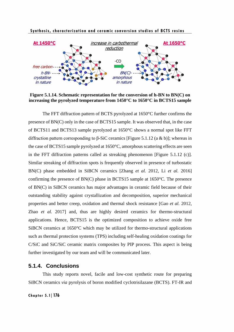
S y n t h e s i s , c h a r a c t e r i z a t i o n a n d c e r a m i c c o n v e r s i o n s t u d i e s o f B C T S r e s i n s
C h a p t e r 5 . 1 | 176
Figure 5.1.14. Schematic representation for the conversion of h-BN to BN(C) on
increasing the pyrolyzed temperature from 1450°C to 1650°C in BCTS15 sample
The FFT diffraction pattern of BCTS pyrolyzed at 1650°C further confirms the
presence of BN(C) only in the case of BCTS15 sample. It was observed that, in the case
of BCTS11 and BCTS13 sample pyrolyzed at 1650°C shows a normal spot like FFT
diffraction pattern corresponding to β-SiC ceramics [Figure 5.1.12 (a & b)]; whereas in
the case of BCTS15 sample pyrolyzed at 1650°C, amorphous scattering effects are seen
in the FFT diffraction patterns called as streaking phenomenon [Figure 5.1.12 (c)].
Similar streaking of diffraction spots is frequently observed in presence of turbostatic
BN(C) phase embedded in SiBCN ceramics [Zhang et al. 2012, Li et al. 2016]
confirming the presence of BN(C) phase in BCTS15 sample at 1650°C. The presence
of BN(C) in SiBCN ceramics has major advantages in ceramic field because of their
outstanding stability against crystallization and decomposition, superior mechanical
properties and better creep, oxidation and thermal shock resistance [Gao et al. 2012,
Zhao et al. 2017] and, thus are highly desired ceramics for thermo-structural
applications. Hence, BCTS15 is the optimized composition to achieve oxide free
SiBCN ceramics at 1650°C which may be utilized for thermo-structural applications
such as thermal protection systems (TPS) including self-healing oxidation coatings for
C/SiC and SiC/SiC ceramic matrix composites by PIP process. This aspect is being
further investigated by our team and will be communicated later.
5.1.4. Conclusions
This study reports novel, facile and low-cost synthetic route for preparing
SiBCN ceramics via pyrolysis of boron modified cyclotrisilazane (BCTS). FT-IR and
S y n t h e s i s , c h a r a c t e r i z a t i o n a n d c e r a m i c c o n v e r s i o n s t u d i e s o f B C T S r e s i n s
C h a p t e r 5 . 1 | 177
NMR investigation revealed the formation of BCTS via self and co-condensation
reaction mechanism. This resulted in desirable properties for preceramic polymers such
as solubility in common solvents, processable viscosity (< 20 cps) and high ceramic
yield (>80 wt. %). The thermal transformation of BCTS resin to ceramics were carried
out at 1450°C and 1650°C under nitrogen atmosphere. At 1450°C for all composition
of BCTS, nano-crystallite β-SiC ceramics embedded in amorphous SiBNC(O) ceramics
were formed and increases with increase in CTS concentration. However, for BCTS15,
in addition to nano-crystallite β-SiC ceramics, SiO2, h-BN, C and Si3N4 ceramics were
also formed. The morphological studies revealed that the obtained ceramics are glassy
in nature and it decrease with increase in the concentration of CTS.
At 1650°C, for all the composition of BCTS crystallinity and crystallite size of
the ceramic increases with pyrolysis temperature and results in β-SiC and β-Si3N4 as
ceramic phases. Moreover, additional turbostatic BN(C) layer was obtained with
BCTS15. The morphological study showed retention of the glassy morphology in the
case of BCTS11 and BCTS13 samples, whereas, the BCTS15 sample exhibited coarse
morphology.
The observed changes in ceramic phases and morphology with pyrolysis
temperature is attributed to increase in carbothermal reduction of SiBNC(O) ceramic
which result in decrease in oxygen content with increase in CTS concentration leading
to the formation of oxide free SiBCN ceramics for BCTS15 sample at 1650°C. This
study demonstrates BCTS15 as the suitable preceramic polymer to attain oxide free
SiBCN ceramics. This novel class of preceramic polymer opens up a new way for the
fabrication of high temperature thermal protection systems (TPS) including self-healing
oxidation coatings for C/SiC and SiC/SiC ceramic matrix composites by PIP process.
S y n t h e s i s , c h a r a c t e r i z a t i o n a n d c e r a m i c c o n v e r s i o n s t u d i e s o f B C T S r e s i n s
C h a p t e r 5 . 1 | 178
Chapter 5.2
Fabrication of CMCs with improved
oxidation stability using BCTS as
matrix resin

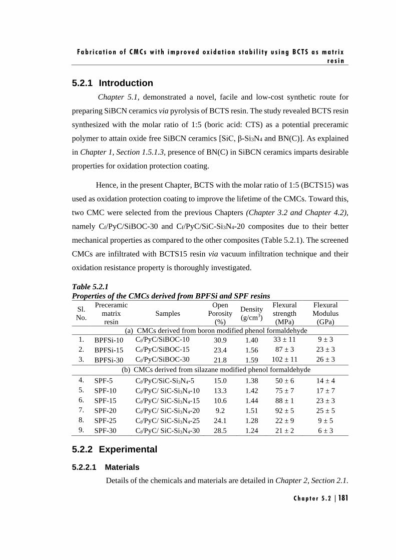
F a b r i c a t i o n o f C M C s w i t h i m p r o v e d o x i d a t i o n s t a b i l i t y u s i n g B C T S a s m a t r i x
r e s i n
C h a p t e r 5 . 2 | 181
5.2.1 Introduction
Chapter 5.1, demonstrated a novel, facile and low-cost synthetic route for
preparing SiBCN ceramics via pyrolysis of BCTS resin. The study revealed BCTS resin
synthesized with the molar ratio of 1:5 (boric acid: CTS) as a potential preceramic
polymer to attain oxide free SiBCN ceramics [SiC, β-Si3N4 and BN(C)]. As explained
in Chapter 1, Section 1.5.1.3, presence of BN(C) in SiBCN ceramics imparts desirable
properties for oxidation protection coating.
Hence, in the present Chapter, BCTS with the molar ratio of 1:5 (BCTS15) was
used as oxidation protection coating to improve the lifetime of the CMCs. Toward this,
two CMC were selected from the previous Chapters (Chapter 3.2 and Chapter 4.2),
namely Cf/PyC/SiBOC-30 and Cf/PyC/SiC-Si3N4-20 composites due to their better
mechanical properties as compared to the other composites (Table 5.2.1). The screened
CMCs are infiltrated with BCTS15 resin via vacuum infiltration technique and their
oxidation resistance property is thoroughly investigated.
Table 5.2.1
Properties of the CMCs derived from BPFSi and SPF resins
Sl.
No.
Preceramic
matrix
resin
Samples
Open
Porosity
(%)
Density
(g/cm3)
Flexural
strength
(MPa)
Flexural
Modulus
(GPa)
(a) CMCs derived from boron modified phenol formaldehyde
1. BPFSi-10 Cf/PyC/SiBOC-10 30.9 1.40 33 ± 11 9 ± 3
2. BPFSi-15 Cf/PyC/SiBOC-15 23.4 1.56 87 ± 3 23 ± 3
3. BPFSi-30 Cf/PyC/SiBOC-30 21.8 1.59 102 ± 11 26 ± 3
(b) CMCs derived from silazane modified phenol formaldehyde
4. SPF-5 Cf/PyC/SiC-Si3N4-5 15.0 1.38 50 ± 6 14 ± 4
5. SPF-10 Cf/PyC/ SiC-Si3N4-10 13.3 1.42 75 ± 7 17 ± 7
6. SPF-15 Cf/PyC/ SiC-Si3N4-15 10.6 1.44 88 ± 1 23 ± 3
7. SPF-20 Cf/PyC/ SiC-Si3N4-20 9.2 1.51 92 ± 5 25 ± 5
8. SPF-25 Cf/PyC/ SiC-Si3N4-25 24.1 1.28 22 ± 9 9 ± 5
9. SPF-30 Cf/PyC/ SiC-Si3N4-30 28.5 1.24 21 ± 2 6 ± 3
5.2.2 Experimental
5.2.2.1 Materials
Details of the chemicals and materials are detailed in Chapter 2, Section 2.1.
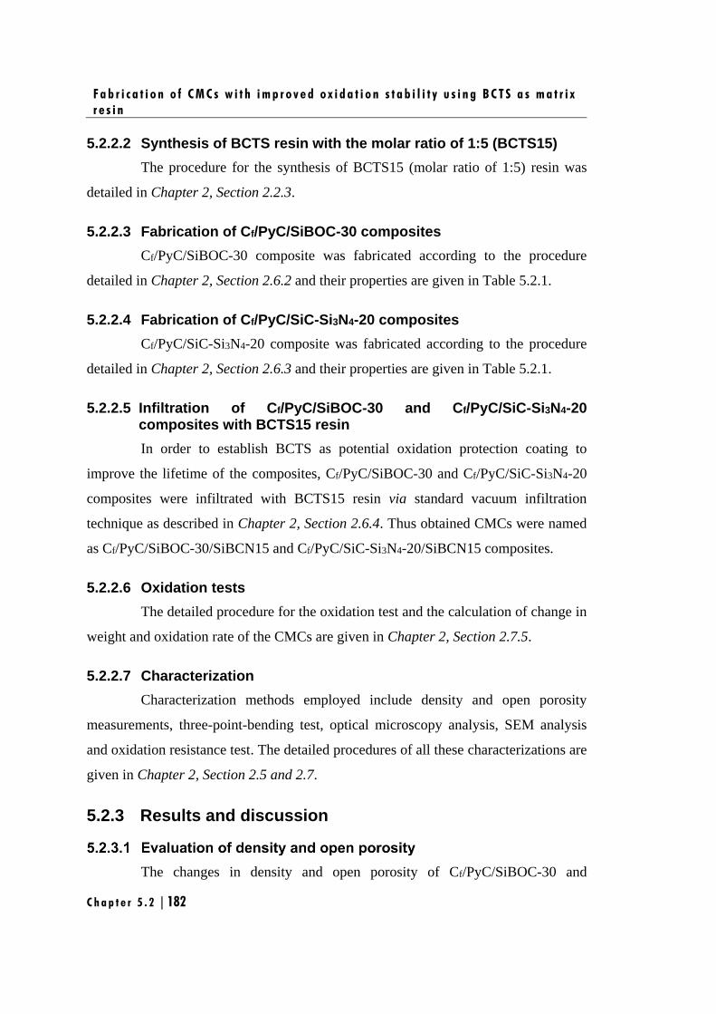
F a b r i c a t i o n o f C M C s w i t h i m p r o v e d o x i d a t i o n s t a b i l i t y u s i n g B C T S a s m a t r i x
r e s i n
C h a p t e r 5 . 2 | 182
5.2.2.2 Synthesis of BCTS resin with the molar ratio of 1:5 (BCTS15)
The procedure for the synthesis of BCTS15 (molar ratio of 1:5) resin was
detailed in Chapter 2, Section 2.2.3.
5.2.2.3 Fabrication of Cf/PyC/SiBOC-30 composites
Cf/PyC/SiBOC-30 composite was fabricated according to the procedure
detailed in Chapter 2, Section 2.6.2 and their properties are given in Table 5.2.1.
5.2.2.4 Fabrication of Cf/PyC/SiC-Si3N4-20 composites
Cf/PyC/SiC-Si3N4-20 composite was fabricated according to the procedure
detailed in Chapter 2, Section 2.6.3 and their properties are given in Table 5.2.1.
5.2.2.5 Infiltration of Cf/PyC/SiBOC-30 and Cf/PyC/SiC-Si3N4-20 composites with BCTS15 resin
In order to establish BCTS as potential oxidation protection coating to
improve the lifetime of the composites, Cf/PyC/SiBOC-30 and Cf/PyC/SiC-Si3N4-20
composites were infiltrated with BCTS15 resin via standard vacuum infiltration
technique as described in Chapter 2, Section 2.6.4. Thus obtained CMCs were named
as Cf/PyC/SiBOC-30/SiBCN15 and Cf/PyC/SiC-Si3N4-20/SiBCN15 composites.
5.2.2.6 Oxidation tests
The detailed procedure for the oxidation test and the calculation of change in
weight and oxidation rate of the CMCs are given in Chapter 2, Section 2.7.5.
5.2.2.7 Characterization
Characterization methods employed include density and open porosity
measurements, three-point-bending test, optical microscopy analysis, SEM analysis
and oxidation resistance test. The detailed procedures of all these characterizations are
given in Chapter 2, Section 2.5 and 2.7.
5.2.3 Results and discussion
The changes in density and open porosity of Cf/PyC/SiBOC-30 and
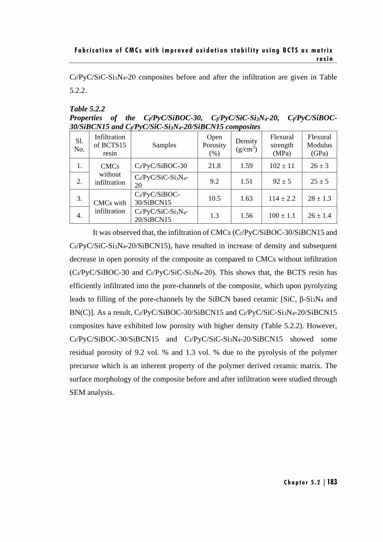
F a b r i c a t i o n o f C M C s w i t h i m p r o v e d o x i d a t i o n s t a b i l i t y u s i n g B C T S a s m a t r i x
r e s i n
C h a p t e r 5 . 2 | 183
Cf/PyC/SiC-Si3N4-20 composites before and after the infiltration are given in Table
5.2.2.
Table 5.2.2
Properties of the Cf/PyC/SiBOC-30, Cf/PyC/SiC-Si3N4-20, Cf/PyC/SiBOC-
30/SiBCN15 and Cf/PyC/SiC-Si3N4-20/SiBCN15 composites
Sl.
No.
Infiltration
of BCTS15
resin
Samples
Open
Porosity
(%)
Density
(g/cm3)
Flexural
strength
(MPa)
Flexural
Modulus
(GPa)
1. CMCs
without
infiltration
Cf/PyC/SiBOC-30 21.8 1.59 102 ± 11 26 ± 3
2. Cf/PyC/SiC-Si3N4-
20 9.2 1.51 92 ± 5 25 ± 5
3. CMCs with
infiltration
Cf/PyC/SiBOC-
30/SiBCN15 10.5 1.63 114 ± 2.2 28 ± 1.3
4. Cf/PyC/SiC-Si3N4-
20/SiBCN15 1.3 1.56 100 ± 1.1 26 ± 1.4
It was observed that, the infiltration of CMCs (Cf/PyC/SiBOC-30/SiBCN15 and
Cf/PyC/SiC-Si3N4-20/SiBCN15), have resulted in increase of density and subsequent
decrease in open porosity of the composite as compared to CMCs without infiltration
(Cf/PyC/SiBOC-30 and Cf/PyC/SiC-Si3N4-20). This shows that, the BCTS resin has
efficiently infiltrated into the pore-channels of the composite, which upon pyrolyzing
leads to filling of the pore-channels by the SiBCN based ceramic [SiC, β-Si3N4 and
BN(C)]. As a result, Cf/PyC/SiBOC-30/SiBCN15 and Cf/PyC/SiC-Si3N4-20/SiBCN15
composites have exhibited low porosity with higher density (Table 5.2.2). However,
Cf/PyC/SiBOC-30/SiBCN15 and Cf/PyC/SiC-Si3N4-20/SiBCN15 showed some
residual porosity of 9.2 vol. % and 1.3 vol. % due to the pyrolysis of the polymer
precursor which is an inherent property of the polymer derived ceramic matrix. The
surface morphology of the composite before and after infiltration were studied through
SEM analysis.
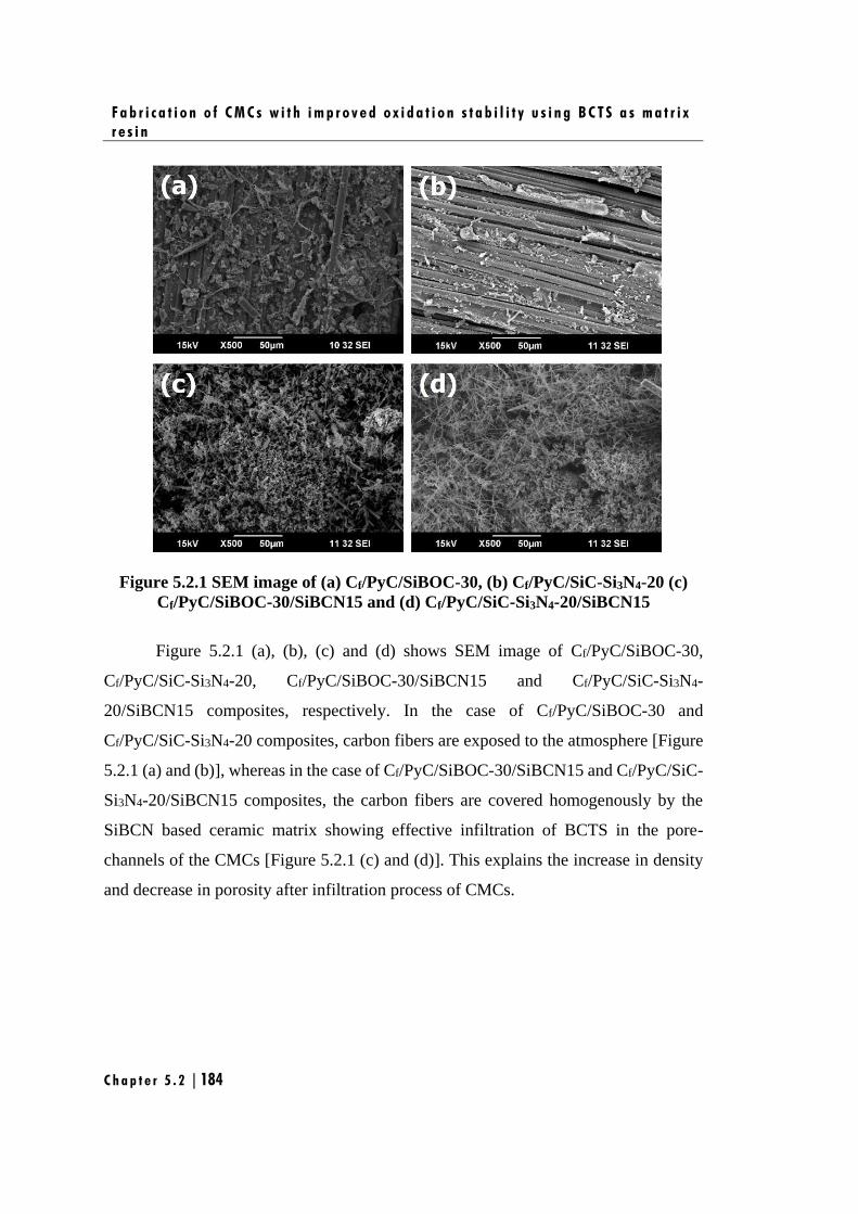
F a b r i c a t i o n o f C M C s w i t h i m p r o v e d o x i d a t i o n s t a b i l i t y u s i n g B C T S a s m a t r i x
r e s i n
C h a p t e r 5 . 2 | 184
Figure 5.2.1 SEM image of (a) Cf/PyC/SiBOC-30, (b) Cf/PyC/SiC-Si3N4-20 (c)
Cf/PyC/SiBOC-30/SiBCN15 and (d) Cf/PyC/SiC-Si3N4-20/SiBCN15
Figure 5.2.1 (a), (b), (c) and (d) shows SEM image of Cf/PyC/SiBOC-30,
Cf/PyC/SiC-Si3N4-20, Cf/PyC/SiBOC-30/SiBCN15 and Cf/PyC/SiC-Si3N4-
20/SiBCN15 composites, respectively. In the case of Cf/PyC/SiBOC-30 and
Cf/PyC/SiC-Si3N4-20 composites, carbon fibers are exposed to the atmosphere [Figure
5.2.1 (a) and (b)], whereas in the case of Cf/PyC/SiBOC-30/SiBCN15 and Cf/PyC/SiC-
Si3N4-20/SiBCN15 composites, the carbon fibers are covered homogenously by the
SiBCN based ceramic matrix showing effective infiltration of BCTS in the pore-
channels of the CMCs [Figure 5.2.1 (c) and (d)]. This explains the increase in density
and decrease in porosity after infiltration process of CMCs.
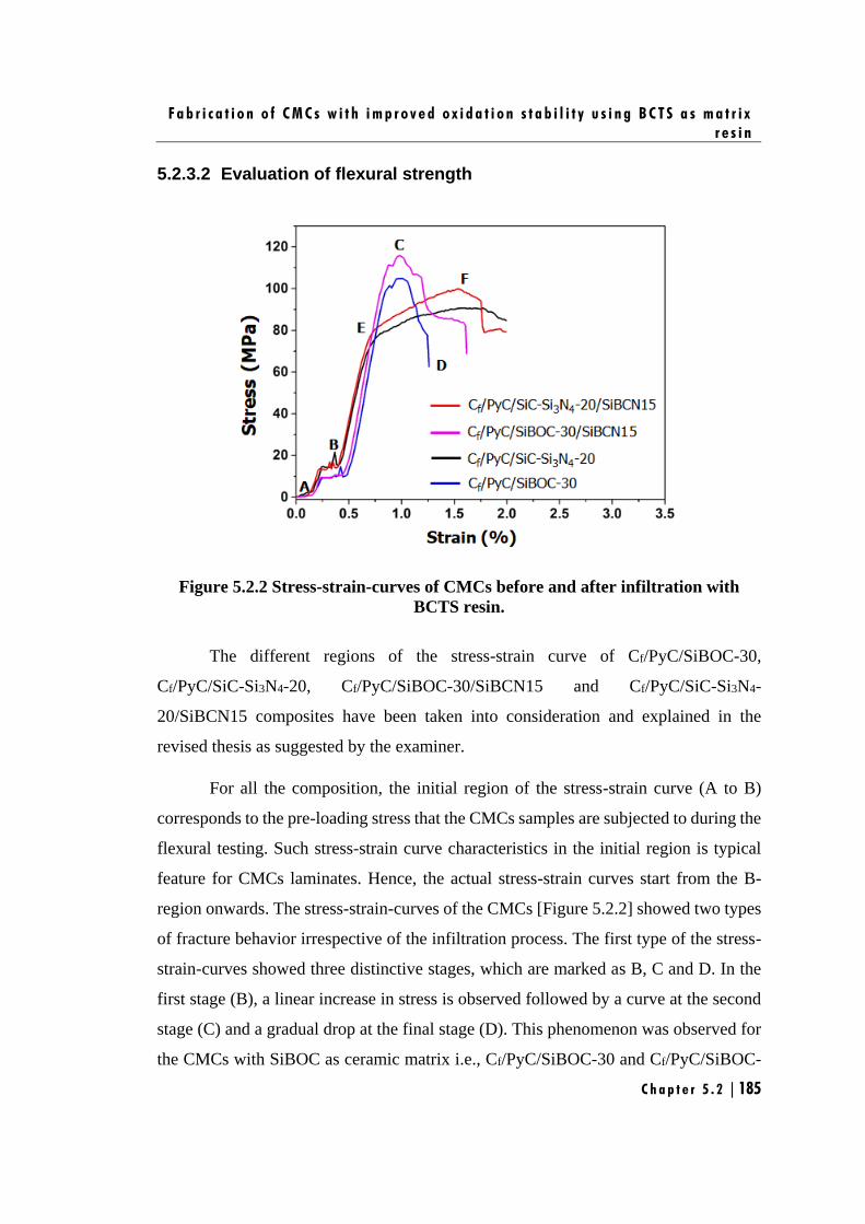
F a b r i c a t i o n o f C M C s w i t h i m p r o v e d o x i d a t i o n s t a b i l i t y u s i n g B C T S a s m a t r i x
r e s i n
C h a p t e r 5 . 2 | 185
5.2.3.2 Evaluation of flexural strength
Figure 5.2.2 Stress-strain-curves of CMCs before and after infiltration with
BCTS resin.
The different regions of the stress-strain curve of Cf/PyC/SiBOC-30,
Cf/PyC/SiC-Si3N4-20, Cf/PyC/SiBOC-30/SiBCN15 and Cf/PyC/SiC-Si3N4-
20/SiBCN15 composites have been taken into consideration and explained in the
revised thesis as suggested by the examiner.
For all the composition, the initial region of the stress-strain curve (A to B)
corresponds to the pre-loading stress that the CMCs samples are subjected to during the
flexural testing. Such stress-strain curve characteristics in the initial region is typical
feature for CMCs laminates. Hence, the actual stress-strain curves start from the B-
region onwards. The stress-strain-curves of the CMCs [Figure 5.2.2] showed two types
of fracture behavior irrespective of the infiltration process. The first type of the stress-
strain-curves showed three distinctive stages, which are marked as B, C and D. In the
first stage (B), a linear increase in stress is observed followed by a curve at the second
stage (C) and a gradual drop at the final stage (D). This phenomenon was observed for
the CMCs with SiBOC as ceramic matrix i.e., Cf/PyC/SiBOC-30 and Cf/PyC/SiBOC-
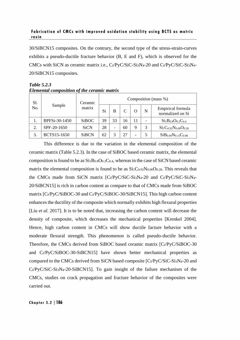
F a b r i c a t i o n o f C M C s w i t h i m p r o v e d o x i d a t i o n s t a b i l i t y u s i n g B C T S a s m a t r i x
r e s i n
C h a p t e r 5 . 2 | 186
30/SiBCN15 composites. On the contrary, the second type of the stress-strain-curves
exhibits a pseudo-ductile fracture behavior (B, E and F), which is observed for the
CMCs with SiCN as ceramic matrix i.e., Cf/PyC/SiC-Si3N4-20 and Cf/PyC/SiC-Si3N4-
20/SiBCN15 composites.
Table 5.2.3
Elemental composition of the ceramic matrix
Sl.
No. Sample
Ceramic
matrix
Composition (mass %)
Si B C O N Empirical formula
normalized on Si
1. BPFSi-30-1450 SiBOC 39 33 16 11 - Si1B0.8O0.2C0.4
2. SPF-20-1650 SiCN 28 - 60 9 3 Si1C0.92N0.06O0.28
3. BCTS15-1650 SiBCN 62 3 27 - 5 SiB0.09N0.15C0.98
This difference is due to the variation in the elemental composition of the
ceramic matrix (Table 5.2.3). In the case of SiBOC based ceramic matrix, the elemental
composition is found to be as Si1B0.8O0.2C0.4, whereas in the case of SiCN based ceramic
matrix the elemental composition is found to be as Si1C0.92N0.06O0.28. This reveals that
the CMCs made from SiCN matrix [Cf/PyC/SiC-Si3N4-20 and Cf/PyC/SiC-Si3N4-
20/SiBCN15] is rich in carbon content as compare to that of CMCs made from SiBOC
matrix [Cf/PyC/SiBOC-30 and Cf/PyC/SiBOC-30/SiBCN15]. This high carbon content
enhances the ductility of the composite which normally exhibits high flexural properties
[Liu et al. 2017]. It is to be noted that, increasing the carbon content will decrease the
density of composite, which decreases the mechanical properties [Krenkel 2004].
Hence, high carbon content in CMCs will show ductile facture behavior with a
moderate flexural strength. This phenomenon is called pseudo-ductile behavior.
Therefore, the CMCs derived from SiBOC based ceramic matrix [Cf/PyC/SiBOC-30
and Cf/PyC/SiBOC-30-SiBCN15] have shown better mechanical properties as
compared to the CMCs derived from SiCN based composite [Cf/PyC/SiC-Si3N4-20 and
Cf/PyC/SiC-Si3N4-20-SiBCN15]. To gain insight of the failure mechanism of the
CMCs, studies on crack propagation and fracture behavior of the composites were
carried out.
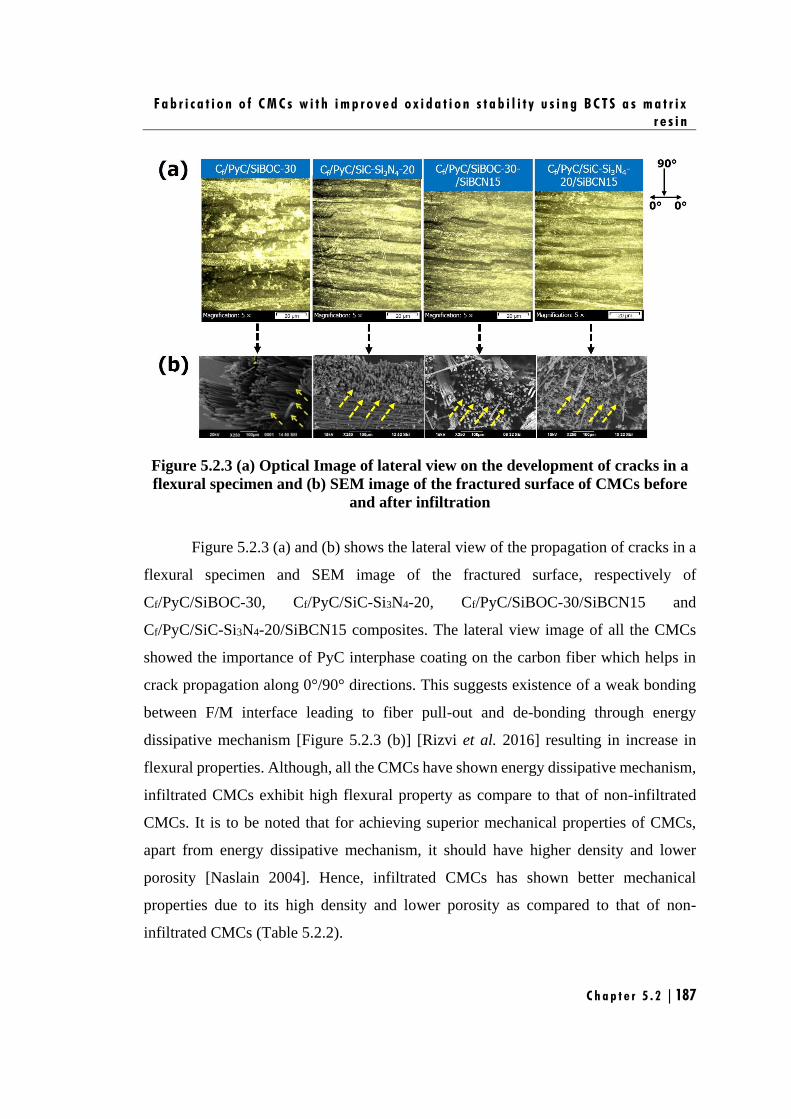
F a b r i c a t i o n o f C M C s w i t h i m p r o v e d o x i d a t i o n s t a b i l i t y u s i n g B C T S a s m a t r i x
r e s i n
C h a p t e r 5 . 2 | 187
Figure 5.2.3 (a) Optical Image of lateral view on the development of cracks in a
flexural specimen and (b) SEM image of the fractured surface of CMCs before
and after infiltration
Figure 5.2.3 (a) and (b) shows the lateral view of the propagation of cracks in a
flexural specimen and SEM image of the fractured surface, respectively of
Cf/PyC/SiBOC-30, Cf/PyC/SiC-Si3N4-20, Cf/PyC/SiBOC-30/SiBCN15 and
Cf/PyC/SiC-Si3N4-20/SiBCN15 composites. The lateral view image of all the CMCs
showed the importance of PyC interphase coating on the carbon fiber which helps in
crack propagation along 0°/90° directions. This suggests existence of a weak bonding
between F/M interface leading to fiber pull-out and de-bonding through energy
dissipative mechanism [Figure 5.2.3 (b)] [Rizvi et al. 2016] resulting in increase in
flexural properties. Although, all the CMCs have shown energy dissipative mechanism,
infiltrated CMCs exhibit high flexural property as compare to that of non-infiltrated
CMCs. It is to be noted that for achieving superior mechanical properties of CMCs,
apart from energy dissipative mechanism, it should have higher density and lower
porosity [Naslain 2004]. Hence, infiltrated CMCs has shown better mechanical
properties due to its high density and lower porosity as compared to that of non-
infiltrated CMCs (Table 5.2.2).
F a b r i c a t i o n o f C M C s w i t h i m p r o v e d o x i d a t i o n s t a b i l i t y u s i n g B C T S a s m a t r i x
r e s i n
C h a p t e r 5 . 2 | 188
5.2.3.3 Evaluation of oxidation resistance
As the objective of the work is to establish BCTS as potential oxidation
resistance coating to improve the lifetime of the CMCs, Cf/PyC/SiBOC-30 and
Cf/PyC/SiC-Si3N4-20 composites were infiltrated with BCTS and evaluated their
oxidation resistance property was evaluated. Both the CMCs before infiltration
(Cf/PyC/SiBOC-30 and Cf/PyC/SiC-Si3N4-20) and after infiltration (Cf/PyC/SiBOC-
30-SiBCN15 and Cf/PyC/SiC-Si3N4-20-SiBCN15) is subjected to isothermal oxidation
at three different temperatures 1000°C, 1250°C and 1500°C in raising hearth furnace at
the flow rate of air 100 cm3/min for 3h with 30 mins intervals. The weight change and
oxidation rate were calculated as given in Chapter 2, Section 2.7.5.
Figure 5.2.4 (a) and (b) shows the percentage weight loss and oxidation rate of
the oxidized CMCs, respectively at 1000°C. In the case of CMCs before infiltration,
Cf/PyC/SiBOC-30 composite, shows a small weight loss of 12 %, whereas Cf/PyC/SiC-
Si3N4-20 composite shows a huge weight loss of 80 % [Figure 5.2.4 (a)]. The
insignificant weight loss in Cf/PyC/SiBOC-30 composite is attributed to the presence
of boron in the matrix, which form a borosilicate glassy phase [B2O3.xSiO2] during the
oxidation of CMCs as per the eqn. 5.2.2 and 5.2.4.
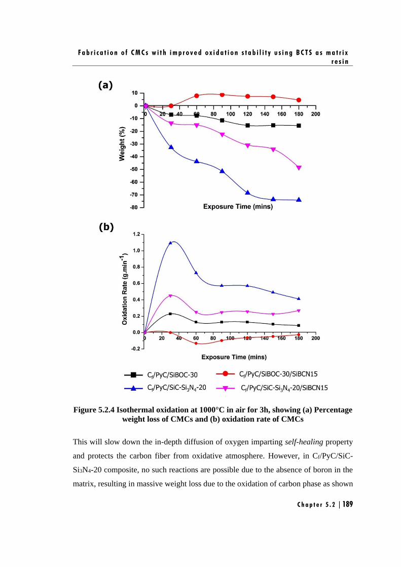
F a b r i c a t i o n o f C M C s w i t h i m p r o v e d o x i d a t i o n s t a b i l i t y u s i n g B C T S a s m a t r i x
r e s i n
C h a p t e r 5 . 2 | 189
Figure 5.2.4 Isothermal oxidation at 1000°C in air for 3h, showing (a) Percentage
weight loss of CMCs and (b) oxidation rate of CMCs
This will slow down the in-depth diffusion of oxygen imparting self-healing property
and protects the carbon fiber from oxidative atmosphere. However, in Cf/PyC/SiC-
Si3N4-20 composite, no such reactions are possible due to the absence of boron in the
matrix, resulting in massive weight loss due to the oxidation of carbon phase as shown
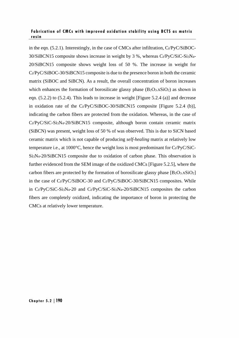
F a b r i c a t i o n o f C M C s w i t h i m p r o v e d o x i d a t i o n s t a b i l i t y u s i n g B C T S a s m a t r i x
r e s i n
C h a p t e r 5 . 2 | 190
in the eqn. (5.2.1). Interestingly, in the case of CMCs after infiltration, Cf/PyC/SiBOC-
30/SiBCN15 composite shows increase in weight by 3 %, whereas Cf/PyC/SiC-Si3N4-
20/SiBCN15 composite shows weight loss of 50 %. The increase in weight for
Cf/PyC/SiBOC-30/SiBCN15 composite is due to the presence boron in both the ceramic
matrix (SiBOC and SiBCN). As a result, the overall concentration of boron increases
which enhances the formation of borosilicate glassy phase (B2O3.xSiO2) as shown in
eqn. (5.2.2) to (5.2.4). This leads to increase in weight [Figure 5.2.4 (a)] and decrease
in oxidation rate of the Cf/PyC/SiBOC-30/SiBCN15 composite [Figure 5.2.4 (b)],
indicating the carbon fibers are protected from the oxidation. Whereas, in the case of
Cf/PyC/SiC-Si3N4-20/SiBCN15 composite, although boron contain ceramic matrix
(SiBCN) was present, weight loss of 50 % of was observed. This is due to SiCN based
ceramic matrix which is not capable of producing self-healing matrix at relatively low
temperature i.e., at 1000°C, hence the weight loss is most predominant for Cf/PyC/SiC-
Si3N4-20/SiBCN15 composite due to oxidation of carbon phase. This observation is
further evidenced from the SEM image of the oxidized CMCs [Figure 5.2.5], where the
carbon fibers are protected by the formation of borosilicate glassy phase [B2O3.xSiO2]
in the case of Cf/PyC/SiBOC-30 and Cf/PyC/SiBOC-30/SiBCN15 composites. While
in Cf/PyC/SiC-Si3N4-20 and Cf/PyC/SiC-Si3N4-20/SiBCN15 composites the carbon
fibers are completely oxidized, indicating the importance of boron in protecting the
CMCs at relatively lower temperature.
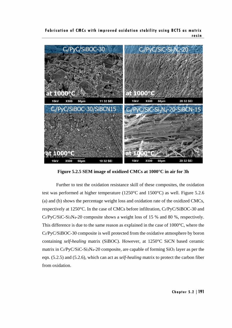
F a b r i c a t i o n o f C M C s w i t h i m p r o v e d o x i d a t i o n s t a b i l i t y u s i n g B C T S a s m a t r i x
r e s i n
C h a p t e r 5 . 2 | 191
Figure 5.2.5 SEM image of oxidized CMCs at 1000°C in air for 3h
Further to test the oxidation resistance skill of these composites, the oxidation
test was performed at higher temperature (1250°C and 1500°C) as well. Figure 5.2.6
(a) and (b) shows the percentage weight loss and oxidation rate of the oxidized CMCs,
respectively at 1250°C. In the case of CMCs before infiltration, Cf/PyC/SiBOC-30 and
Cf/PyC/SiC-Si3N4-20 composite shows a weight loss of 15 % and 80 %, respectively.
This difference is due to the same reason as explained in the case of 1000°C, where the
Cf/PyC/SiBOC-30 composite is well protected from the oxidative atmosphere by boron
containing self-healing matrix (SiBOC). However, at 1250°C SiCN based ceramic
matrix in Cf/PyC/SiC-Si3N4-20 composite, are capable of forming SiO2 layer as per the
eqn. (5.2.5) and (5.2.6), which can act as self-healing matrix to protect the carbon fiber
from oxidation.
F a b r i c a t i o n o f C M C s w i t h i m p r o v e d o x i d a t i o n s t a b i l i t y u s i n g B C T S a s m a t r i x
r e s i n
C h a p t e r 5 . 2 | 192
Figure 5.2.6 Isothermal oxidation at 1250°C in air for 3h, showing (a) Percentage
weight loss of CMCs and (b) oxidation rate of CMCs
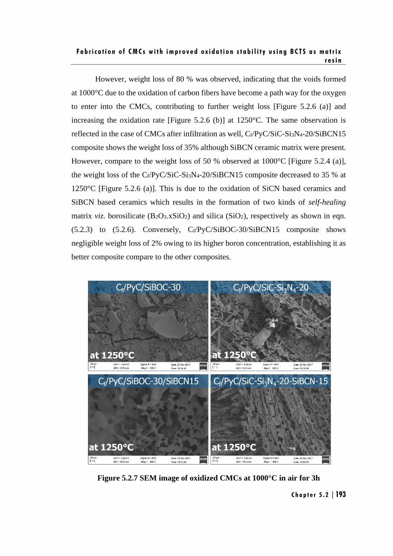
F a b r i c a t i o n o f C M C s w i t h i m p r o v e d o x i d a t i o n s t a b i l i t y u s i n g B C T S a s m a t r i x
r e s i n
C h a p t e r 5 . 2 | 193
However, weight loss of 80 % was observed, indicating that the voids formed
at 1000°C due to the oxidation of carbon fibers have become a path way for the oxygen
to enter into the CMCs, contributing to further weight loss [Figure 5.2.6 (a)] and
increasing the oxidation rate [Figure 5.2.6 (b)] at 1250°C. The same observation is
reflected in the case of CMCs after infiltration as well, Cf/PyC/SiC-Si3N4-20/SiBCN15
composite shows the weight loss of 35% although SiBCN ceramic matrix were present.
However, compare to the weight loss of 50 % observed at 1000°C [Figure 5.2.4 (a)],
the weight loss of the Cf/PyC/SiC-Si3N4-20/SiBCN15 composite decreased to 35 % at
1250°C [Figure 5.2.6 (a)]. This is due to the oxidation of SiCN based ceramics and
SiBCN based ceramics which results in the formation of two kinds of self-healing
matrix viz. borosilicate (B2O3.xSiO2) and silica (SiO2), respectively as shown in eqn.
(5.2.3) to (5.2.6). Conversely, Cf/PyC/SiBOC-30/SiBCN15 composite shows
negligible weight loss of 2% owing to its higher boron concentration, establishing it as
better composite compare to the other composites.
Figure 5.2.7 SEM image of oxidized CMCs at 1000°C in air for 3h
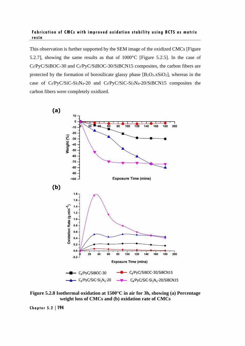
F a b r i c a t i o n o f C M C s w i t h i m p r o v e d o x i d a t i o n s t a b i l i t y u s i n g B C T S a s m a t r i x
r e s i n
C h a p t e r 5 . 2 | 194
This observation is further supported by the SEM image of the oxidized CMCs [Figure
5.2.7], showing the same results as that of 1000°C [Figure 5.2.5]. In the case of
Cf/PyC/SiBOC-30 and Cf/PyC/SiBOC-30/SiBCN15 composites, the carbon fibers are
protected by the formation of borosilicate glassy phase [B2O3.xSiO2], whereas in the
case of Cf/PyC/SiC-Si3N4-20 and Cf/PyC/SiC-Si3N4-20/SiBCN15 composites the
carbon fibers were completely oxidized.
Figure 5.2.8 Isothermal oxidation at 1500°C in air for 3h, showing (a) Percentage
weight loss of CMCs and (b) oxidation rate of CMCs
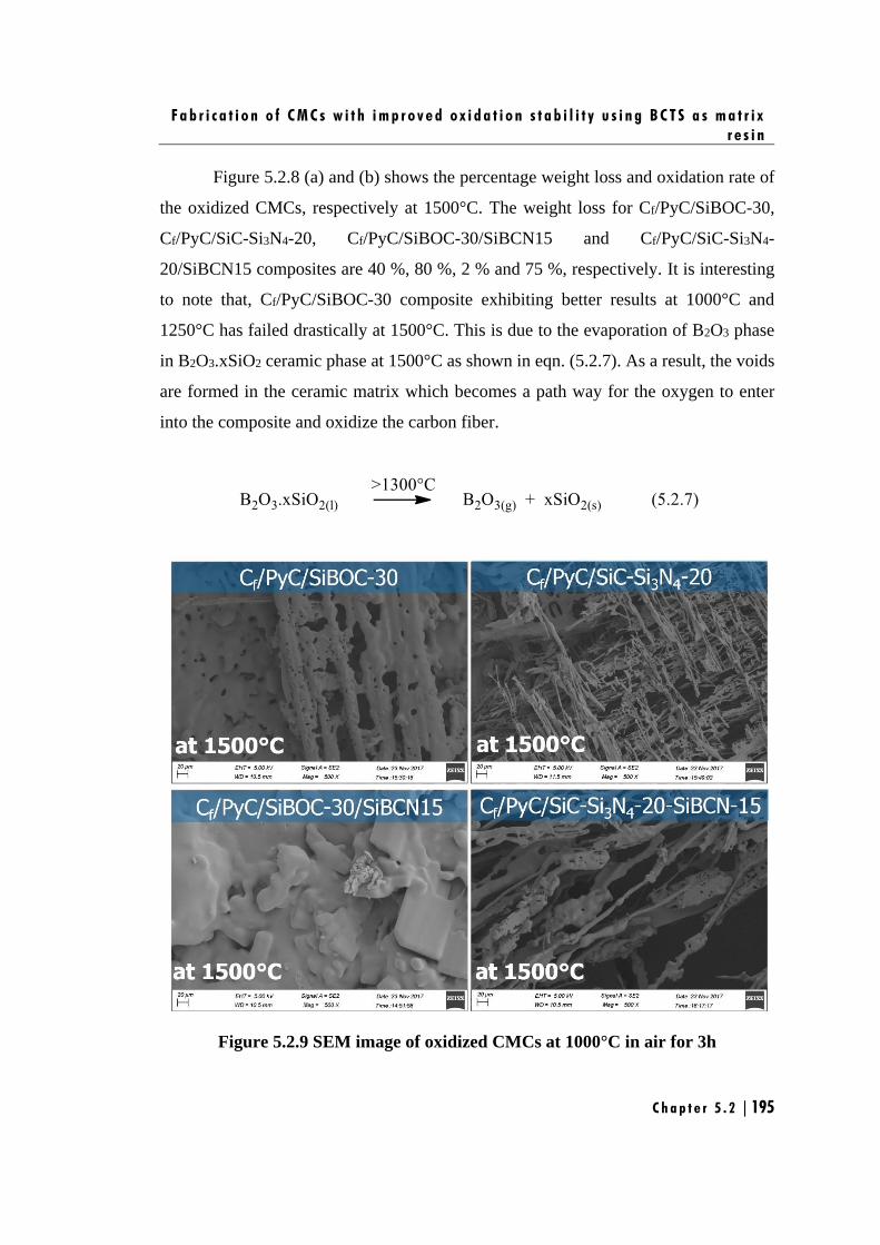
F a b r i c a t i o n o f C M C s w i t h i m p r o v e d o x i d a t i o n s t a b i l i t y u s i n g B C T S a s m a t r i x
r e s i n
C h a p t e r 5 . 2 | 195
Figure 5.2.8 (a) and (b) shows the percentage weight loss and oxidation rate of
the oxidized CMCs, respectively at 1500°C. The weight loss for Cf/PyC/SiBOC-30,
Cf/PyC/SiC-Si3N4-20, Cf/PyC/SiBOC-30/SiBCN15 and Cf/PyC/SiC-Si3N4-
20/SiBCN15 composites are 40 %, 80 %, 2 % and 75 %, respectively. It is interesting
to note that, Cf/PyC/SiBOC-30 composite exhibiting better results at 1000°C and
1250°C has failed drastically at 1500°C. This is due to the evaporation of B2O3 phase
in B2O3.xSiO2 ceramic phase at 1500°C as shown in eqn. (5.2.7). As a result, the voids
are formed in the ceramic matrix which becomes a path way for the oxygen to enter
into the composite and oxidize the carbon fiber.
Figure 5.2.9 SEM image of oxidized CMCs at 1000°C in air for 3h
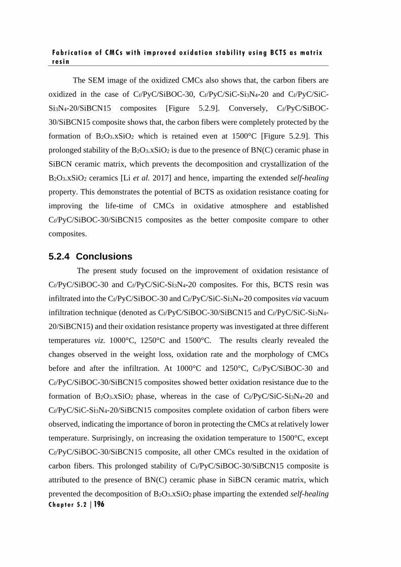
F a b r i c a t i o n o f C M C s w i t h i m p r o v e d o x i d a t i o n s t a b i l i t y u s i n g B C T S a s m a t r i x
r e s i n
C h a p t e r 5 . 2 | 196
The SEM image of the oxidized CMCs also shows that, the carbon fibers are
oxidized in the case of Cf/PyC/SiBOC-30, Cf/PyC/SiC-Si3N4-20 and Cf/PyC/SiC-
Si3N4-20/SiBCN15 composites [Figure 5.2.9]. Conversely, Cf/PyC/SiBOC-
30/SiBCN15 composite shows that, the carbon fibers were completely protected by the
formation of B2O3.xSiO2 which is retained even at 1500°C [Figure 5.2.9]. This
prolonged stability of the B2O3.xSiO2 is due to the presence of BN(C) ceramic phase in
SiBCN ceramic matrix, which prevents the decomposition and crystallization of the
B2O3.xSiO2 ceramics [Li et al. 2017] and hence, imparting the extended self-healing
property. This demonstrates the potential of BCTS as oxidation resistance coating for
improving the life-time of CMCs in oxidative atmosphere and established
Cf/PyC/SiBOC-30/SiBCN15 composites as the better composite compare to other
composites.
5.2.4 Conclusions
The present study focused on the improvement of oxidation resistance of
Cf/PyC/SiBOC-30 and Cf/PyC/SiC-Si3N4-20 composites. For this, BCTS resin was
infiltrated into the Cf/PyC/SiBOC-30 and Cf/PyC/SiC-Si3N4-20 composites via vacuum
infiltration technique (denoted as Cf/PyC/SiBOC-30/SiBCN15 and Cf/PyC/SiC-Si3N4-
20/SiBCN15) and their oxidation resistance property was investigated at three different
temperatures viz. 1000°C, 1250°C and 1500°C. The results clearly revealed the
changes observed in the weight loss, oxidation rate and the morphology of CMCs
before and after the infiltration. At 1000°C and 1250°C, Cf/PyC/SiBOC-30 and
Cf/PyC/SiBOC-30/SiBCN15 composites showed better oxidation resistance due to the
formation of B2O3.xSiO2 phase, whereas in the case of Cf/PyC/SiC-Si3N4-20 and
Cf/PyC/SiC-Si3N4-20/SiBCN15 composites complete oxidation of carbon fibers were
observed, indicating the importance of boron in protecting the CMCs at relatively lower
temperature. Surprisingly, on increasing the oxidation temperature to 1500°C, except
Cf/PyC/SiBOC-30/SiBCN15 composite, all other CMCs resulted in the oxidation of
carbon fibers. This prolonged stability of Cf/PyC/SiBOC-30/SiBCN15 composite is
attributed to the presence of BN(C) ceramic phase in SiBCN ceramic matrix, which
prevented the decomposition of B2O3.xSiO2 phase imparting the extended self-healing
F a b r i c a t i o n o f C M C s w i t h i m p r o v e d o x i d a t i o n s t a b i l i t y u s i n g B C T S a s m a t r i x
r e s i n
C h a p t e r 5 . 2 | 197
property. This demonstrated the potential of BCTS as oxidation resistance coating for
improving the life-time of CMCs in oxidative atmosphere and established
Cf/PyC/SiBOC-30/SiBCN15 composites as the better composite compare to other
composites. This study opens up a new way for the fabrication of cost-effective CMCs
with improved mechanical and oxidation resistance properties for the long-term
thermo-structural applications.
F a b r i c a t i o n o f C M C s w i t h i m p r o v e d o x i d a t i o n s t a b i l i t y u s i n g B C T S a s m a t r i x
r e s i n
C h a p t e r 5 . 2 | 198
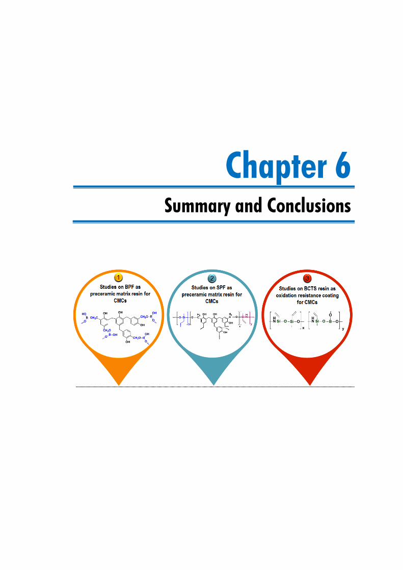
Chapter 6
Summary and Conclusions

S u m m a r y a n d C o n c l u s i o n s
C h a p t e r 6 | 201
This chapter summarizes the findings of the present investigation together with
concluding remarks and scope for future work.

S u m m a r y a n d C o n c l u s i o n s
C h a p t e r 6 | 202
S u m m a r y a n d C o n c l u s i o n s
C h a p t e r 6 | 203
his research was aimed at developing a new class of cost effective preceramic
matrix resins for CMCs with self-healing properties and to investigate their
effect on the mechanical properties. Covering these aspects, the work was
divided into the following chapters:
(i) Studies on boron modified phenol-formaldehyde (BPF) as preceramic
matrix resin for CMCs
(ii) Studies on silazane modified phenol-formaldehyde (SPF) as preceramic
matrix resin for CMCs
(iii) Studies on boron modified cyclotrisilazane (BCTS) resin as oxidation
resistance coating for CMCs
The most important findings and conclusions of the present investigation are given
below:
Studies on BPF as preceramic matrix resin for CMCs
This chapter is comprised of two parts;
➢ In the first part, synthesis, characterization and ceramic conversion of BPF resins were
investigated. BPF resins were synthesized by reacting various amount of boric acid [5,
10, 15, 20, 25 and 30 pph w.r.t PF] with PF resin. The concentration of boric acid could
not be increased beyond 30 pph as it precipitated in the reaction medium. FTIR studies
revealed that, boric acid has chemically reacted with PF resin to form BPF resin via
condensation reaction mechanism. The ceramic conversion of BPF resins were carried
out at 1450°C under argon atmosphere, with and without elemental silicon as reactive
additive. The structural evolution of the resultant ceramics were investigated using
XRD, Raman and HRTEM techniques. XRD studies of the ceramics revealed that, in
the case of BPF resin, without silicon additive, carbon and B4C ceramic phases were
obtained; whereas, in the case of BPF resin with silicon additive, SiC and SiB4 ceramic
phases were obtained. This difference is attributed to the reaction of ‘Si’ atoms with
‘C’ atoms in the C–B–C chain of B4C icosahedron, leading to SiC and SiB4 ceramic
phases. The nature of free carbon in the ceramics derived from BPF resins were
T
S u m m a r y a n d C o n c l u s i o n s
C h a p t e r 6 | 204
understood using Raman and HRTEM analysis. In the case of PF resin, free carbon was
found to exist as fine ribbon like structures corresponding to glassy carbon; whereas,
on incorporating boron to PF resin, the structure of free carbon has transformed from
glassy carbon to graphitic carbon following the sequence:
glassy carbon [PF] → amorphous carbon [BPF-10 (boric acid 10 pph w.r.t. PF)] →
turbostatic carbon [BPF-15 (boric acid 15 pph w.r.t. PF)] → graphitic carbon [BPF-30
(boric acid 30 pph w.r.t. PF)].
This sequential transformation of carbon through various intermediate phases were
attributed to the catalytic effect of boron. Hence, among various compositions of BPF
resins, BPF-10, BPF-15 and BPF-30 were chosen for further studies.
The objective of the second part of the study was to assess BPF resin as a self-
healing matrix resin for CMC. In this regard, CMCs were fabricated using 2D carbon
fabric as reinforcement and a slurry containing BPF with silicon (BPFSi) as matrix
resin. The CMCs thus obtained were evaluated for the flexural strength and oxidation
resistance properties. The obtained properties were compared with CMC derived from
a slurry containing PF with silicon (PFSi) as matrix resin. The flexural strength of
BPFSi derived CMCs showed a marginal improvement (46 ± 1.6 MPa) as compared to
PFSi derived CMCs (42 ± 2.2 MPa). This was attributed to the damage of carbon fiber
on reaction with molten silicon to form a thin polycrystalline SiC layer. The evaluation
of oxidation resistance properties for CMCs demonstrated improved oxidation
resistance of BPFSi derived CMCs in comparison to PFSi derived CMCs. This was due
to the formation of a borosilicate glassy layer on BPFSi derived CMCs which slowed
down the in-depth diffusion of oxygen, imparting self-healing property for CMCs. This
study demonstrated BPF as a potential self-healing matrix resin for CMCs. The next
section focuses on the attempts made to improve the mechanical properties of the
CMCs.
➢ The mechanical properties of CMCs are greatly influenced by the proper design of
Fiber/Matrix (F/M) interface. In this section, an attempt was made to study the effect
of F/M volume ratio and the influence of interphase coating on the flexural properties
S u m m a r y a n d C o n c l u s i o n s
C h a p t e r 6 | 205
of the CMCs. To understand the effect of F/M volume ratio on the flexural properties
of the composites, three types of CMCs were fabricated using PFSi as matrix resin,
varying the F/M volume ratio viz. 40/60, 50/50 and 60/40 (wt.%). The percentage of
fiber content could not be increased beyond 60 vol. % due to delamination of the
composite. The results revealed increase in the flexural strength from 25 ± 3.9 MPa
(F/M-40/60) to 63 ± 9.9 MPa (F/M-60/40) on increasing the fiber vol. %. Additionally,
CMCs having F/M volume ratio of 40/60 and 50/50 had failed in a brittle manner while
CMC having F/M volume ratio of 60/40 exhibited a ductile fracture leading to fiber
bundle pull-out. This revealed that increasing the ‘C’ fiber vol. % was effective in
preventing catastrophic fracture. Hence, F/M volume ratio of 60/40 was chosen for all
further studies.
To investigate the significance of an interphase coating, CMCs were fabricated
using F/M volume ratio of 60/40, PyC as interphase coating (thickness 0.2-0.5 μm) and
different composition of BPFSi (BPFSi-10, BPFSi-15, BPFSi-20 and BPFSi-30) as
preceramic matrix resin. The CMCs thus obtained were evaluated for the flexural
properties. The obtained properties were compared with CMC fabricated without an
interphase. CMCs with PyC interphase showed improvement in flexural strength from
32.86 ± 10.7 MPa (BPFSi-10 derived CMCs) to 102 ± 11.5 MPa (BPFSi-30 derived
CMCs), while CMCs without interphase showed no improvement in flexural properties
and exhibited maximum flexural strength of 38 ± 4.4 MPa (BPFSi-30 derived CMCs).
The fractograph of CMCs without interphase showed no fiber pull-out, indicating a
strong fiber-matrix bonding; while CMCs with PyC interphase coating exhibited fiber
pull-out phenomenon and hence failed in a ductile manner. The study demonstrated the
importance of optimization of F/M volume ratio and the necessity of an interphase
coating to fabricate CMCs with better mechanical properties. However, the limitation
created by the silicon as additive still persists. Hence, an attempt was made in the next
chapter, to incorporate silicon as back bone of PF resin and investigate it as preceramic
matrix resin for CMCs.
S u m m a r y a n d C o n c l u s i o n s
C h a p t e r 6 | 206
Studies on SPF as preceramic matrix resin for CMCs
This chapter is comprised of two parts;
➢ In the first part, synthesis, characterization and ceramic conversion of SPF resins were
investigated. SPF resins were synthesized by reacting varying amounts of CTS [5, 10,
15, 20, 25 and 30 pph w.r.t PF] with PF resin. The concentration of CTS could not be
increased beyond 30 pph due to incomplete reaction of CTS with PF resulting in the
formation of separate phase in the reaction medium. FTIR and NMR analysis revealed
that, CTS chemically reacted with PF resin to form SPF resin via ring opening
mechanism. To evaluate the potential of SPF as a preceramic matrix resin, studies on
pyrolysis condition are mandatory. To meet this objective, ceramic conversion studies
were carried out at 1450°C and 1650°C under argon and nitrogen atmosphere. The
structural evolution of the resultant ceramics were investigated through XRD, Raman
and FESEM techniques. Under argon atmosphere both at 1450°C and 1650°C, SPF
yield SiC ceramic phases only. While, at 1450°C under nitrogen atmosphere,
amorphous ceramics were obtained and at 1650°C, crystalline SiC and Si3N4 ceramic
phases were obtained. Moreover, under nitrogen atmosphere both at 1450°C and
1650°C, only macro-porous ceramics were formed. Surprisingly, under argon
atmosphere both at 1450°C and 1650°C, additional 1D, triangular shaped, nano-rod
structured ceramics along with macro-porous structure were formed. EDX analysis
revealed that, these nano-rods are composed of SiC ceramics and are formed through
vapor-vapor mechanism. This study demonstrated SPF as a new class of preceramic
polymer and revealed that nitrogen atmosphere was more suitable as a pyrolysis gas
atmosphere than argon for preparation of SiC/Si3N4 ceramics with enhanced ceramic
yield.
➢ In the second part of the investigation, CMCs were fabricated using F/M volume ratio
of 60/40, PyC as interphase coating and different composition of SPF (SPF-5 to 30) as
preceramic matrix resin via polymer infiltration and pyrolysis (PIP) process. For
Cf/PyC/SiC-Si3N4-5 (SPF-5 derived CMCs) to Cf/PyC/SiC-Si3N4-20 (SPF-20 derived
CMCs) composites, gradual increase in flexural strength of 50 ± 6 MPa to 92 ± 5 MPa
was obtained. On the contrary, for Cf/PyC/SiC-Si3N4-25 (SPF-25 derived CMCs) and
S u m m a r y a n d C o n c l u s i o n s
C h a p t e r 6 | 207
Cf/PyC/SiC-Si3N4-30 (SPF-30 derived CMCs), a sudden drop in flexural strength to 22
± 9 MPa and 21 ± 2 MPa respectively, was obtained. The fractograph of CMCs showed
fiber pull-out phenomenon for Cf/PyC/SiC-Si3N4-5 to Cf/PyC/SiC-Si3N4-20 composites
and hence failed in a ductile manner. In the case of Cf/PyC/SiC-Si3N4-25 and
Cf/PyC/SiC-Si3N4-30 composites, partial delamination between F/M interface was
observed which led to premature failure of the composite. This unusual behavior of
Cf/PyC/SiC-Si3N4-25 and Cf/PyC/SiC-Si3N4-30 composites was attributed to
structurally weak points like high propensity of cracks or pores in the matrix compared
to the other composites. This study demonstrated that, high density and low porosity of
Cf/PyC/SiC-Si3N4 composites are highly suitable for achieving high mechanical
properties for CMCs. The study established SPF-20 as the most suitable formulation
for the fabrication of CMCs with improved mechanical properties by PIP process.
Studies on BCTS resin as oxidation resistance coating for CMCs
In the previous chapter, SPF based CMCs were fabricated to achieve improved
mechanical properties. However, for the long-term service life, these composites have
to be highly engineered in order to improve their oxidation resistance and self-healing
behaviour. Hence, to have improved oxidation resistance as well, synthesis of a single
source preceramic matrix resin containing silicon, boron and nitrogen was attempted to
get SiBCN based ceramics.
This chapter is comprised of two parts;
➢ In the first part, studies on synthesis, characterization and ceramic conversion of BCTS
resins were carried out. BCTS resins were synthesized by reacting boric acid with CTS
in the molar ratio of 1:1, 1:3 and 1:5. FT-IR and NMR investigations revealed the
formation of BCTS via self and co-condensation reaction mechanism. This resulted in
optimum properties for preceramic polymers such as solubility in common solvents,
processable viscosity (< 20 cps) and high ceramic yield (>80 wt. %). The polymer to
ceramic conversion was carried out at 1450°C and 1650°C under nitrogen atmosphere.
The study revealed that changes in CTS concentration and pyrolysis temperatures
significantly affected the evolution of ceramic phases, morphology and elemental
S u m m a r y a n d C o n c l u s i o n s
C h a p t e r 6 | 208
composition which were thoroughly investigated through XRD, SEM and HRTEM
techniques. The increase in the CTS concentration and pyrolysis temperature resulted
in an increase of carbothermal reduction of SiBNC(O) ceramic. As a result, BCTS with
the molar ratio of 1:1 and BCTS with the molar ratio of 1:3 led to the formation of β-
SiC, β-Si3N4 and oxide ceramic phases. In the case of BCTS with the molar ratio of 1:5,
oxide free β-SiC, β-Si3N4 and turbostatic BN(C) ceramics were obtained. In this study,
we report the synthesis of a new, low viscous preceramic polymer with high ceramic
yield (>80 wt. %). BCTS with the molar ratio of 1:5 was demonstrated as a suitable
preceramic polymer to attain oxide free SiBCN ceramics.
➢ In the second part of the investigation, BCTS with the molar ratio of 1:5 (BCTS15) was
used as an oxidation protection coating to improve the lifetime of the CMCs. Towards
this, two CMC were selected from the previous chapters, namely Cf/PyC/SiBOC-30
(BPFSi-30 derived CMCs) and Cf/PyC/SiC-Si3N4-20 (SPF-20 derived CMCs)
composites due to their better mechanical properties as compared to the other
composites. These CMCs were infiltrated with BCTS15 resin via vacuum infiltration
technique (denoted as Cf/PyC/SiBOC-30/SiBCN15 and Cf/PyC/SiC-Si3N4-
20/SiBCN15) and their oxidation resistance property was investigated at three different
temperatures viz. 1000°C, 1250°C and 1500°C. The results clearly revealed significant
changes in the weight loss, oxidation rate and the morphology of CMCs before and
after the infiltration. At 1000°C and 1250°C, Cf/PyC/SiBOC-30 and Cf/PyC/SiBOC-
30/SiBCN15 composites showed better oxidation resistance due to the formation of
B2O3.xSiO2 phase; whereas, in the case of Cf/PyC/SiC-Si3N4-20 and Cf/PyC/SiC-Si3N4-
20/SiBCN15 composites complete oxidation of carbon fibers were observed, indicating
the importance of boron in protecting the CMCs at relatively lower temperature.
Surprisingly, on increasing the oxidation temperature to 1500°C, except
Cf/PyC/SiBOC-30/SiBCN15 composite, all other CMCs resulted in the oxidation of
carbon fibers. This prolonged stability of Cf/PyC/SiBOC-30/SiBCN15 composite is
attributed to the presence of BN(C) ceramic phase in SiBCN ceramic matrix, which
prevented the decomposition of B2O3.xSiO2 phase imparting the extended self-healing
property. The study demonstrated the capability of BCTS as oxidation protection
S u m m a r y a n d C o n c l u s i o n s
C h a p t e r 6 | 209
coating for improving the life-time of CMCs in an oxidative atmosphere.
To summarize,
(i) A new class of cost effective preceramic polymers based on phenol-
formaldehyde resin and single source preceramic polymer resin
containing silicon, boron, carbon and nitrogen was developed.
(ii) The preceramic polymers showed optimum properties such as solubility
in common solvents, good processablity and moderately high ceramic
residue (> 60 wt.%).
(iii) The preceramic polymers as matrix resin for CMCs showed moderate
mechanical properties with excellent self-healing properties.
Future Perspectives
Based on the present results, the future perspectives of this research work are:
(i) The present study showed moderate mechanical properties. Further,
investigation can be extended on the improvement of their mechanical
properties by fabricating CMCs with high strength (T300J) and high
modulus (M40J) carbon fibers as reinforcement.
(ii) The present study showed high temperature (1500°C) applicability of
developed ceramics. Further, investigations can be extended on the
improvement of their operating temperature (>2000°C) through
chemical modification of the preceramic polymer with metal [Ti, Zr, Hf,
etc.,] alkoxides to form ultra-high temperature ceramics.
(iii) Investigation of the SPF derived SiCN and BCTS derived SiBCN
ceramics as potential electrode active materials for energy storage
applications.

S u m m a r y a n d C o n c l u s i o n s
C h a p t e r 6 | 210
211
References
(1966). "Encyclopedia of industrial chemical analysis. Vol. 1, General Techniques A-
E. Edited by F. D. Snell and C. L. Hilton. Interscience Publishers, a div. of John Wiley
& Sons., Inc., 605 Third Ave., New York, N. Y. 10016, 1966. xv + 763 pp. 18.5 × 26
cm. Price $35.00 per copy with subscription. $45.00 per single copy." Journal of
Pharmaceutical Sciences, 55(9): 993-994.
Abdalla M. O., Ludwick A. and Mitchell T. (2003). "Boron-modified phenolic resins
for high performance applications." Polymer, 44(24): 7353-7359.
Agarwal B. D., Broutman L. J. and Chandrashekhara K. (2017). Analysis and
performance of fiber composites, John Wiley & Sons.
Al Nasiri N., Patra N., Ni N., Jayaseelan D. D. and Lee W. E. (2016). "Oxidation
behaviour of SiC/SiC ceramic matrix composites in air." Journal of the European
Ceramic Society, 36(14): 3293-3302.
Babu T. G. and Devasia R. (2016). "Boron Modified Phenol Formaldehyde Derived
Cf/SiBOC Composites with Improved Mechanical Strength for High Temperature
Applications." Journal of Inorganic and Organometallic Polymers and Materials,
26(4): 764-772.
Bahloul D., Pereira M. and Goursat P. (1993). "Preparation of silicon carbonitrides
from an organosilicon polymer: II, thermal behavior at high temperatures under argon."
Journal of the American Ceramic Society, 76(5): 1163-1168.
Bahloul D., Pereira M., Goursat P., Yive N. and Corriu R. J. (1993). "Preparation of
Silicon Carbonitrides from an Organosilicon Polymer: I, Thermal Decomposition of the
Cross‐linked Polysilazane." Journal of the American Ceramic Society, 76(5): 1156-
1162.
Baldus P., Jansen M. and Sporn D. (1999). "Ceramic fibers for matrix composites in
high-temperature engine applications." Science, 285(5428): 699-703.
Bansal N. P. (2006). Handbook of ceramic composites, Springer Science & Business
Media.
Barros P. M., Yoshida I. V. P. and Schiavon M. A. (2006). "Boron-containing poly
(vinyl alcohol) as a ceramic precursor." Journal of non-crystalline solids, 352(32):
3444-3450.
Bertrand R., Henne J.-F., Camus G. and Rebillat F. (2017). "Influence of the Cooling
Temperature on the Mechanical Behavior of an Oxidized Self-Healing Ceramic Matrix
Composite." Oxidation of Metals, 88(3-4): 237-246.
Brennan J. J. and Prewo K. M. (1982). "Silicon carbide fibre reinforced glass-ceramic
matrix composites exhibiting high strength and toughness." Journal of Materials
Science, 17(8): 2371-2383.
Buckley J. D. and Edie D. D. (1993). Carbon-carbon materials and composites,
William Andrew.
Budiansky B., Hutchinson J. W. and Evans A. G. (1986). "Matrix fracture in fiber-
R e f e r e n c e s
212
reinforced ceramics." Journal of the Mechanics and Physics of Solids, 34(2): 167-189.
Buet E., Sauder C., Sornin D., Poissonnet S., Rouzaud J.-N. and Vix-Guterl C. (2014).
"Influence of surface fibre properties and textural organization of a pyrocarbon
interphase on the interfacial shear stress of SiC/SiC minicomposites reinforced with Hi-
Nicalon S and Tyranno SA3 fibres." Journal of the European Ceramic Society, 34(2):
179-188.
C1341 A. (2013). "Standard Test Method for Flexural Properties of Continuous Fiber-
Reinforced Advanced Ceramic Composites, ASTM International, West
Conshohocken, PA, 2013." www.astm.org.
Camus G., Guillaumat L. and Baste S. (1996). "Development of damage in a 2D woven
C/SiC composite under mechanical loading: I. Mechanical characterization."
Composites Science and Technology, 56(12): 1363-1372.
Cao X., Vassen R. and Stoever D. (2004). "Ceramic materials for thermal barrier
coatings." Journal of the European Ceramic Society, 24(1): 1-10.
Cao X., Yin X., Fan X., Cheng L. and Zhang L. (2014). "Effect of PyC interphase
thickness on mechanical behaviors of SiBC matrix modified C/SiC composites
fabricated by reactive melt infiltration." Carbon, 77: 886-895.
Carrère N., Martin E. and Lamon J. (2000). "The influence of the interphase and
associated interfaces on the deflection of matrix cracks in ceramic matrix composites."
Composites Part A: Applied Science and Manufacturing, 31(11): 1179-1190.
Carrère P. and Lamon J. (2003). "Creep behaviour of a SiC/Si-BC composite with a
self-healing multilayered matrix." Journal of the European Ceramic Society, 23(7):
1105-1114.
čerović L. S., Milonjić S. and Bibić N. (1995). "Influence of boric acid concentration
on silicon carbide morphology." Journal of materials science letters, 14(15): 1052-
1054.
Chamberlain A. L. and Lazur A. J. (2014). Sic based ceramic matrix composites with
layered matrices and methods for producing sic based ceramic matrix composites with
layered matrices, Google Patents.
Chand S. (2000). "Review carbon fibers for composites." Journal of Materials Science,
35(6): 1303-1313.
Chawla K. K. (1998). Ceramic matrix composites. Composite Materials, Springer: 212-
251.
Chermant J., Boitier G., Darzens S., Farizy G., Vicens J. and Sangleboeuf J.-C. (2002).
"The creep mechanism of ceramic matrix composites at low temperature and stress, by
a material science approach." Journal of the European Ceramic Society, 22(14): 2443-
2460.
Chiang C.-L. and Ma C.-C. M. (2004). "Synthesis, characterization, thermal properties
and flame retardance of novel phenolic resin/silica nanocomposites." Polymer
Degradation and Stability, 83(2): 207-214.
213
Chongjun L., Boxin M., Xiaoxu H. and Zhibiao H. (1997). "The Catalytic
Graphitization Effects of B_4C in C/C Composites [J]." AEROSPACE MATERIALS &
TECHNOLOGY, 5: 007.
Christin F. (2002). "Design, fabrication, and application of thermostructural composites
(TSC) like C/C, C/SiC, and SiC/SiC composites." Advanced engineering materials,
4(12): 903-912.
Cluzel C., Baranger E., Ladevèze P. and Mouret A. (2009). "Mechanical behaviour and
lifetime modelling of self-healing ceramic-matrix composites subjected to
thermomechanical loading in air." Composites Part A: Applied Science and
Manufacturing, 40(8): 976-984.
Conde O., Silvestre A. and Oliveira J. (2000). "Influence of carbon content on the
crystallographic structure of boron carbide films." Surface and Coatings Technology,
125(1): 141-146.
Curtin W. A. (1991). "Theory of mechanical properties of ceramic‐matrix composites."
Journal of the American Ceramic Society, 74(11): 2837-2845.
Di Salvo D., Sackett E., Johnston R., Thompson D., Andrews P. and Bache M. (2015).
"Mechanical characterisation of a fibre reinforced oxide/oxide ceramic matrix
composite." Journal of the European Ceramic Society, 35(16): 4513-4520.
Ding J., Huang Z., Qin Y., Luo H. and Mao J. (2015). The effect of boron incorporation
on the thermo-oxidative stability of phenol-formaldehyde resin and its pyrolyzate
phase. 2015 International Conference on Materials, Environmental and Biological
Engineering, Atlantis Press.
Domnich V., Reynaud S., Haber R. A. and Chhowalla M. (2011). "Boron carbide:
structure, properties, and stability under stress." Journal of the American Ceramic
Society, 94(11): 3605-3628.
Dong-Xiao H. (2006). "Review of the Application of Advanced Composite in Aviation
and Aerospace [J]." Hi-Tech Fiber & Application, 2: 002.
Draper A. B. and Owusu Y. A. (1976). Role of Carbonaceous Materials at the Mold-
metal Interface: Final Report Submitted to American Foundrymen's Society,
Pennsylvania State University, College of Engineering.
Evans A. G. and Marshall D. B. (1989). "Overview no. 85 The mechanical behavior of
ceramic matrix composites." Acta Metallurgica, 37(10): 2567-2583.
Feng L., Guangwu W. and Zhaoxiang H. (2006). "Thermal Stability and Crystallization
Process of SiBONC Ceramics Derived from Polymeric Precursors." Rare Metal
Materials and Engineering, 35: 228.
Feng L., Li K., Xue B., Fu Q. and Zhang L. (2017). "Optimizing matrix and fiber/matrix
interface to achieve combination of strength, ductility and toughness in carbon
nanotube-reinforced carbon/carbon composites." Materials & Design, 113: 9-16.
Ferrari A. C. and Robertson J. (2000). "Interpretation of Raman spectra of disordered
and amorphous carbon." Physical review B, 61(20): 14095.
Ferrari A. C. and Robertson J. (2004). "Raman spectroscopy of amorphous,
R e f e r e n c e s
214
nanostructured, diamond–like carbon, and nanodiamond." Philosophical Transactions
of the Royal Society of London A: Mathematical, Physical and Engineering Sciences,
362(1824): 2477-2512.
Ferrari A. C. and Robertson J. (2004). "Raman spectroscopy of amorphous,
nanostructured, diamond–like carbon, and nanodiamond." Philosophical Transactions
of the Royal Society of London. Series A: Mathematical, Physical and Engineering
Sciences, 362(1824): 2477-2512.
Figueiredo J. L., Bernardo C., Baker R. and Hüttinger K. (2013). Carbon fibers
filaments and composites, Springer Science & Business Media.
Fitzer E. (1987). "The future of carbon-carbon composites." Carbon, 25(2): 163-190.
Fitzer E. (1989). "Pan-based carbon fibers—present state and trend of the technology
from the viewpoint of possibilities and limits to influence and to control the fiber
properties by the process parameters." Carbon, 27(5): 621-645.
Flores O., Bordia R. K., Nestler D., Krenkel W. and Motz G. (2014). "Ceramic fibers
based on SiC and SiCN systems: Current research, development, and commercial
status." Advanced Engineering Materials, 16(6): 621-636.
Frank E., Ingildeev D. and Buchmeiser M. (2016). "High-performance PAN-based
carbon fibers and their performance requirements." Structure and Properties of High-
Performance Fibers: 7.
Ganesh Babu T. and Devasia R. (2016). "Boron-modified phenol formaldehyde resin-
based self-healing matrix for Cf/SiBOC composites." Advances in Applied Ceramics,
115(8): 457-469.
Ganesh Babu T. and Devasia R. (2016). "Boron-modified phenol formaldehyde resin-
based self-healing matrix for Cf/SiBOC composites." Advances in Applied Ceramics:
1-13.
Gao J. G., Lin H. J. and Ma Y. Y. (2011). Systhesis, Curing and Thermal Propertied of
Boron-Containing o-Cresol-Formaldehyde Resin. Advanced Materials Research, Trans
Tech Publ.
Gao Y., Bando Y., Kurashima K. and Sato T. (2001). "The microstructural analysis of
SiC nanorods synthesized through carbothermal reduction." Scripta materialia, 44(8):
1941-1944.
Gao Y., Bando Y., Kurashima K. and Sato T. (2002). "SiC nanorods prepared from SiO
and activated carbon." Journal of materials science, 37(10): 2023-2029.
Gao Y., Mera G., Nguyen H., Morita K., Kleebe H.-J. and Riedel R. (2012). "Processing
route dramatically influencing the nanostructure of carbon-rich SiCN and SiBCN
polymer-derived ceramics. Part I: Low temperature thermal transformation." Journal
of the European Ceramic Society, 32(9): 1857-1866.
Gay D. (2014). Composite materials: design and applications, CRC press.
Gibson R. F. (2010). "A review of recent research on mechanics of multifunctional
composite materials and structures." Composite structures, 92(12): 2793-2810.
215
Golczewski J. A. and Aldinger F. (2004). "Thermodynamic modeling of amorphous
Si–C–N ceramics derived from polymer precursors." Journal of non-crystalline solids,
347(1): 204-210.
Golovko É., Makarenko G., Voitovich R. and Fedorus V. (1994). "Oxidation of boron
silicide and materials based on it." Powder Metallurgy and Metal Ceramics, 32(11-12):
917-920.
Gosset D., Colin C., Jankowiak A., Vandenberghe T. and Lochet N. (2013). "X‐ray
Diffraction Study of the Effect of High‐Temperature Heat Treatment on the
Microstructural Stability of Third‐Generation SiC Fibers." Journal of the American
Ceramic Society, 96(5): 1622-1628.
Hackemann S., Flucht F. and Braue W. (2010). "Creep investigations of alumina-based
all-oxide ceramic matrix composites." Composites Part A: Applied Science and
Manufacturing, 41(12): 1768-1776.
Hagio T., Nakamizo M. and Kobayashi K. (1987). "Thermal conductivities and Raman
spectra of boron-doped carbon materials." Carbon, 25(5): 637-639.
Halbig M. C., Jaskowiak M. H., Kiser J. D. and Zhu D. (2013). Evaluation of ceramic
matrix composite technology for aircraft turbine engine applications. 51st AIAA
Aerospace Sciences Meeting including the New Horizons Forum and Aerospace
Exposition.
Hata T., Bonnamy S., Bronsveld P., Castro V., Fujisawa M., Kikuchi H. and Imamura
Y. "SiC Nanorods grown on SiC coated Wood Charcoal."
Hilton F. D. S. a. C. L. (1966). "Encyclopedia of industrial chemical analysis. Vol. 1,
General Techniques A-E. Edited by F. D. Snell and C. L. Hilton. Interscience
Publishers, a div. of John Wiley & Sons., Inc., 605 Third Ave., New York, N. Y. 10016,
1966. xv + 763 pp. 18.5 × 26 cm. Price $35.00 per copy with subscription. $45.00 per
single copy." Journal of Pharmaceutical Sciences, 55(9): 993-994.
Hnatko M., Galusek D. and Šajgalı́k P. (2004). "Low-cost preparation of Si 3 N 4–SiC
micro/nano composites by in-situ carbothermal reduction of silica in silicon nitride
matrix." Journal of the European Ceramic Society, 24(2): 189-195.
Hsiue G. H., Shiao S. J., Wei H. F., Kuo W. J. and Sha Y. A. (2001). "Novel
phosphorus‐containing dicyclopentadiene‐modified phenolic resins for flame‐retardancy applications." Journal of applied polymer science, 79(2): 342-349.
Hynes J. T., Hynes B. J., Jackson T. B. and Hon W. (2016). Polymer matrix-ceramic
matrix hybrid composites for high thermal applications, Google Patents.
Inagaki M., Tachikawa H., Nakahashi T., Konno H. and Hishiyama Y. (1998). "The
chemical bonding state of nitrogen in kapton-derived carbon film and its effect on the
graphitization process." Carbon, 36(7): 1021-1025.
Ionescu E., Kleebe H.-J. and Riedel R. (2012). "Silicon-containing polymer-derived
ceramic nanocomposites (PDC-NCs): preparative approaches and properties."
Chemical Society Reviews, 41(15): 5032-5052.
Jacobson N. S. and Curry D. M. (2006). "Oxidation microstructure studies of reinforced
R e f e r e n c e s
216
carbon/carbon." Carbon, 44(7): 1142-1150.
Jiménez C., Mergia K., Lagos M., Yialouris P., Agote I., Liedtke V., Messoloras S.,
Panayiotatos Y., Padovano E. and Badini C. (2016). "Joining of ceramic matrix
composites to high temperature ceramics for thermal protection systems." Journal of
the European Ceramic Society, 36(3): 443-449.
Jones R., Szweda A. and Petrak D. (1999). "Polymer derived ceramic matrix
composites." Composites Part A: Applied Science and Manufacturing, 30(4): 569-575.
Kalaiyarasan A., Ramesh P. and Paramasivam P. (2016). "Study of Advanced
Composite Materials in Aerospace Application."
Kalpakjian S. and Schmid S. R. (2014). Manufacturing engineering and technology,
Pearson Upper Saddle River, NJ, USA.
Kawamoto A. M., Pardini L. C., Diniz M. F., Lourenço V. L. and Takahashi M. F. K.
(2010). "Synthesis of a boron modified phenolic resin." Journal of Aerospace
Technology and Management, 2(2): 169-182.
Kentgens A. (1997). "A practical guide to solid-state NMR of half-integer quadrupolar
nuclei with some applications to disordered systems." Geoderma, 80(3-4): 271-306.
Kerans R. J., Hay R. S., Pagano N. J. and Parthasarathy T. (1989). "The role of the
fiber-matrix interface in ceramic composites." American Ceramic Society Bulletin,
68(2): 429-442.
Kerans R. J., Hay R. S., Parthasarathy T. A. and Cinibulk M. K. (2002). "Interface
Design for Oxidation‐Resistant Ceramic Composites." Journal of the American
Ceramic Society, 85(11): 2599-2632.
Kiser J. D., Grady J. E., Bhatt R. T., Wiesner V. L. and Zhu D. (2016). "Overview of
CMC (Ceramic Matrix Composite) Research at the NASA Glenn Research Center."
Knop A. and Pilato L. A. (2013). Phenolic resins: chemistry, applications and
performance, Springer Science & Business Media.
Knop A. and Scheib W. (1979). Chemistry and application of phenolic resins, Springer.
Kong J., Wang M., Zou J. and An L. (2015). "Soluble and meltable hyperbranched
polyborosilazanes toward high-temperature stable SiBCN ceramics." ACS applied
materials & interfaces, 7(12): 6733-6744.
Krenkel W. (2004). "Carbon Fiber Reinforced CMC for High‐Performance Structures."
International Journal of applied ceramic technology, 1(2): 188-200.
Krenkel W. (2008). Ceramic matrix composites: fiber reinforced ceramics and their
applications, John Wiley & Sons.
Krenkel W. (2009). Cost effective processing of CMC composites by melt infiltration
(LSI-process). Ceramic Engineering and Science Proceedings.
Krenkel W. and Berndt F. (2005). "C/C–SiC composites for space applications and
advanced friction systems." Materials Science and Engineering: A, 412(1): 177-181.
Krenkel W., Heidenreich B. and Renz R. (2002). "C/C‐SiC Composites for Advanced
217
Friction Systems." Advanced Engineering Materials, 4(7): 427-436.
Kumar Mandal A. (2010). Standard Test Method for Apparent Porosity, Water
Absorption, Apparent Specific Gravity and Bulk Density of Burned Refractory Brick
and Shapes by Boiling Water, ASTM C 20–92.
Lamouroux F., Bertrand S., Pailler R., Naslain R. and Cataldi M. (1999). "Oxidation-
resistant carbon-fiber-reinforced ceramic-matrix composites." Composites science and
technology, 59(7): 1073-1085.
Lamouroux F., Steen M. and Valles J. (1994). "Uniaxial tensile and creep behaviour of
an alumina fibre-reinforced ceramic matrix composite: I. Experimental study." Journal
of the European Ceramic Society, 14(6): 529-537.
Lee J. and Baney R. (2003). Process for SiBCN based preceramic polymers and
products derivable therefrom, Google Patents.
Lee S. H., Weinmann M. and Aldinger F. (2008). "Processing and properties of C/Si–
B–C–N fiber–reinforced ceramic matrix composites prepared by precursor
impregnation and pyrolysis." Acta Materialia, 56(7): 1529-1538.
Lee Y. K., Kim D. J., Kim H. J., Hwang T. S., Rafailovich M. and Sokolov J. (2003).
"Activation energy and curing behavior of resol‐and novolac‐type phenolic resins by
differential scanning calorimetry and thermogravimetric analysis." Journal of applied
polymer science, 89(10): 2589-2596.
Levi C. G., Yang J. Y., Dalgleish B. J., Zok F. W. and Evans A. G. (1998). "Processing
and Performance of an All‐Oxide Ceramic Composite." Journal of the American
Ceramic Society, 81(8): 2077-2086.
Li C., Ma Z., Zhang X., Fan H. and Wan J. (2016). "Silicone-modified phenolic resin:
Relationships between molecular structure and curing behavior." Thermochimica Acta,
639: 53-65.
Li D., Yang Z., Jia D., Duan X., Wang S., Zhu Q., Miao Y., Rao J. and Zhou Y. (2017).
"Effects of boron addition on the high temperature oxidation resistance of dense
sSiBCN monoliths at 1500° C." Corrosion Science.
Li D., Yang Z., Jia D., Wu D., Zhu Q., Liang B., Wang S. and Zhou Y. (2016).
"Microstructure, oxidation and thermal shock resistance of graphene reinforced SiBCN
ceramics." Ceramics International, 42(3): 4429-4444.
Li S., Chen F., Zhang B., Luo Z., Li H. and Zhao T. (2016). "Structure and improved
thermal stability of phenolic resin containing silicon and boron elements." Polymer
degradation and stability.
Liu C., Lin Y., Zhou Z. and Li K.-Y. (2017). "Dual phase amorphous carbon ceramic
achieves theoretical strength limit and large plasticity." Carbon, 122: 276-280.
Liu J., Li J. and Xu C. (2014). "Interaction of the cutting tools and the ceramic-
reinforced metal matrix composites during micro-machining: a review." CIRP Journal
of Manufacturing Science and Technology, 7(2): 55-70.
Longbiao L., Yingdong S. and Youchao S. (2013). "Estimate interface shear stress of
unidirectional C/SiC ceramic matrix composites from hysteresis loops." Applied
R e f e r e n c e s
218
Composite Materials, 20(4): 693-707.
Low I.-M. (2014). Advances in ceramic matrix composites, Woodhead Publishing.
Luan X. g., Liu Y., Yang W., Peng Y., Zhang L. and Cheng L. (2016). "Stressed
oxidation behaviors of 2D C/SiC-BC x composite under wet oxygen atmosphere."
Journal of the European Ceramic Society, 36(11): 2673-2678.
Luo L., Ge M. and Zhang W. (2013). "Pyrolysis synthesis of Si–B–C–N ceramics and
their thermal stability." Ceramics International, 39(7): 7903-7909.
Luo L., Wang Y., Liu L., Zhao X., Lu Y. and Wang G. (2017). "Carbon fiber reinforced
silicon carbide composite-based sharp leading edges in high enthalpy plasma flows."
Composites Part B: Engineering.
Magnant J., Maillé L., Pailler R., Ichard J.-C., Guette A., Rebillat F. and Philippe E.
(2012). "Carbon fiber/reaction-bonded carbide matrix for composite materials–
manufacture and characterization." Journal of the European Ceramic Society, 32(16):
4497-4505.
Matsushita J.-I. and Sawada Y. (1997). "Oxidation resistance of silicon tetra boride
powder." Nippon Seramikkusu Kyokai Gakujutsu Ronbunshi(Journal of the Ceramic
Society of Japan)(Japan), 105(1226): 922-924.
Matsushita J. and Komarneni S. (2001). "High temperature oxidation of silicon
hexaboride ceramics." Materials research bulletin, 36(5): 1083-1089.
Mera G., Tamayo A., Nguyen H., Sen S. and Riedel R. (2010). "Nanodomain Structure
of Carbon‐Rich Silicon Carbonitride Polymer‐Derived Ceramics." Journal of the
American Ceramic Society, 93(4): 1169-1175.
Miller R. A. (1997). "Thermal barrier coatings for aircraft engines: history and
directions." Journal of thermal spray technology, 6(1): 35-42.
Mondal S. and Banthia A. K. (2005). "Low-temperature synthetic route for boron
carbide." Journal of the European Ceramic Society, 25(2): 287-291.
Monthioux M. and Delverdier O. (1996). "Thermal behavior of (organosilicon)
polymer-derived ceramics. V: Main facts and trends." Journal of the European Ceramic
Society, 16(7): 721-737.
Morrison J. (2010). Method for forming interphase layers in ceramic matrix
composites, Google Patents.
Morrison J. A., Campbell C., Merrill G. B., Lane J. E., Thompson D. G., Albrecht H.
A. and Shteyman Y. P. (2004). Ceramic matrix composite gas turbine vane, Google
Patents.
Mouritz A., Gellert E., Burchill P. and Challis K. (2001). "Review of advanced
composite structures for naval ships and submarines." Composite structures, 53(1): 21-
42.
Nair C. R. (2004). "Advances in addition-cure phenolic resins." Progress in Polymer
Science, 29(5): 401-498.
219
Najafi A., Golestani-Fard F. and Rezaie H. (2015). "Improvement of SiC nanopowder
synthesis by sol–gel method via TEOS/resin phenolic precursors." Journal of Sol-Gel
Science and Technology, 75(2): 255-263.
Naslain R. (1993). "Fibre-matrix interphases and interfaces in ceramic matrix
composites processed by CVI." Composite Interfaces, 1(3): 253-286.
Naslain R. (1999). "Materials design and processing of high temperature ceramic
matrix composites: state of the art and future trends." Advanced composite materials,
8(1): 3-16.
Naslain R. (2004). "Design, preparation and properties of non-oxide CMCs for
application in engines and nuclear reactors: an overview." Composites Science and
Technology, 64(2): 155-170.
Naslain R., Dugne O., Guette A., Sevely J., Brosse C. R., Rocher J. P. and Cotteret J.
(1991). "Boron Nitride Interphase in Ceramic‐Matrix Composites." Journal of the
American Ceramic Society, 74(10): 2482-2488.
Naslain R., Guette A., Rebillat F., Pailler R., Langlais F. and Bourrat X. (2004). "Boron-
bearing species in ceramic matrix composites for long-term aerospace applications."
Journal of Solid State Chemistry, 177(2): 449-456.
Naslain R., Langlais F. and Fedou R. (1989). "The CVI-processing of ceramic matrix
composites." Le Journal de Physique Colloques, 50(C5): C5-191-C195-207.
Naslain R. R. (1998). "The design of the fibre-matrix interfacial zone in ceramic matrix
composites." Composites Part A: Applied Science and Manufacturing, 29(9): 1145-
1155.
Naslain R. R. (2005). "SiC‐Matrix Composites: Nonbrittle Ceramics for Thermo‐Structural Application." International Journal of Applied Ceramic Technology, 2(2):
75-84.
Nason H. K. (1939). Silicon modified phenolic resins and process for producing same,
Google Patents.
Niihara K. (1991). "New design concept of structural ceramics." Journal of the Ceramic
Society of Japan, 99(1154): 974-982.
Noparvar-Qarebagh A., Roghani-Mamaqani H. and Salami-Kalajahi M. (2016).
"Novolac phenolic resin and graphene aerogel organic-inorganic nanohybrids: High
carbon yields by resin modification and its incorporation into aerogel network."
Polymer degradation and stability, 124: 1-14.
Odeshi A., Mucha H. and Wielage B. (2006). "Manufacture and characterisation of a
low cost carbon fibre reinforced C/SiC dual matrix composite." Carbon, 44(10): 1994-
2001.
Ohnabe H., Masaki S., Onozuka M., Miyahara K. and Sasa T. (1999). "Potential
application of ceramic matrix composites to aero-engine components." Composites
Part A: Applied Science and Manufacturing, 30(4): 489-496.
Peebles Jr L. (1995). "Carbon fibers, formation, structure and properties." CRC Press,
Inc, 2000 Corporate Blvd, NW, Boca Raton, FL 33431, USA, 1995. 224.
R e f e r e n c e s
220
Peters S. T. (2013). Handbook of composites, Springer Science & Business Media.
Quemard L., Rebillat F., Guette A., Tawil H. and Louchet-Pouillerie C. (2007). "Self-
healing mechanisms of a SiC fiber reinforced multi-layered ceramic matrix composite
in high pressure steam environments." Journal of the European Ceramic Society, 27(4):
2085-2094.
Rajan V. P. and Zok F. W. (2014). "Matrix cracking of fiber-reinforced ceramic
composites in shear." Journal of the Mechanics and Physics of Solids, 73: 3-21.
Raman V., Parashar V. and Bahl O. (1997). "Influence of boric acid on the synthesis of
silicon carbide whiskers from rice husks and polyacrylonitrile." Journal of materials
science letters, 16(15): 1252-1254.
Riedel R., Mera G., Hauser R. and Klonczynski A. (2006). "Silicon-based polymer-
derived ceramics: synthesis properties and applications-a review dedicated to Prof. Dr.
Fritz Aldinger on the occasion of his 65th birthday." Journal of the Ceramic Society of
Japan (日本セラミックス協会学術論文誌), 114(1330): 425-444.
Rizvi R., Anwer A., Fernie G., Dutta T. and Naguib H. (2016). "Multifunctional
Textured Surfaces with Enhanced Friction and Hydrophobic Behaviors Produced by
Fiber Debonding and Pullout." ACS Applied Materials & Interfaces, 8(43): 29818-
29826.
Rosso M. (2006). "Ceramic and metal matrix composites: Routes and properties."
Journal of Materials Processing Technology, 175(1): 364-375.
Ruggles-Wrenn M. and Jones T. (2013). "Tension–compression fatigue of a SiC/SiC
ceramic matrix composite at 1200° C in air and in steam." International Journal of
Fatigue, 47: 154-160.
Sambell R., Bowen D. and Phillips D. (1972). "Carbon fibre composites with ceramic
and glass matrices." Journal of Materials Science, 7(6): 663-675.
Sanchez J. E. R., Riccione M. A. and Glispin J. C. (2013). Attaching ceramic matrix
composite to high temperature gas turbine structure, Google Patents.
Schmidt H., Borchardt G., Müller A. and Bill J. (2004). "Formation kinetics of
crystalline Si3N4/SiC composites from amorphous Si–C–N ceramics." Journal of Non-
Crystalline Solids, 341(1–3): 133-140.
Schmidt S., Beyer S., Knabe H., Immich H., Meistring R. and Gessler A. (2004).
"Advanced ceramic matrix composite materials for current and future propulsion
technology applications." Acta Astronautica, 55(3): 409-420.
Shanyi D. (2007). "Advanced composite materials and aerospace engineering [J]." Acta
Materiae Compositae Sinica, 1: 000.
Shi F., Yin X., Fan X., Cheng L. and Zhang L. (2010). "A new route to fabricate SiB 4
modified C/SiC composites." Journal of the European Ceramic Society, 30(9): 1955-
1962.
Sommers A., Wang Q., Han X., T'Joen C., Park Y. and Jacobi A. (2010). "Ceramics
and ceramic matrix composites for heat exchangers in advanced thermal systems—A
221
review." Applied Thermal Engineering, 30(11): 1277-1291.
Soraru G. D., Babonneau F., Gervais C. and Dallabona N. (2000). "Hybrid RSiO1.
5/B2O3 gels from modified silicon alkoxides and boric acid." Journal of sol-gel science
and technology, 18(1): 11-19.
Soraru G. D., Dallabona N., Gervais C. and Babonneau F. (1999). "Organically
Modified SiO2− B2O3 Gels Displaying a High Content of Borosiloxane (B− O− Si⋮) Bonds." Chemistry of materials, 11(4): 910-919.
Sreekanth D., Rameshbabu N. and Venkateswarlu K. (2012). "Effect of various
additives on morphology and corrosion behavior of ceramic coatings developed on
AZ31 magnesium alloy by plasma electrolytic oxidation." Ceramics International,
38(6): 4607-4615.
Su J.-m., Cui H., SU Z.-a., GUO C., LI R.-z., LI Y.-d. and ZHOU S.-j. (2004).
"RESEARCH OF 4D C/C COMPOSITE MATERIAL THROAT INSERT BY MIX
WEAVED WITH CARBON FIBRE AND AXIAL CARBON ROD." Carbon, 1: 002.
Sun J., Deemer C., Ellingson W. and Wheeler J. (2006). "NDT technologies for ceramic
matrix composites: Oxide and nonoxide." Materials evaluation, 64(1): 52-60.
Sung I. K., Christian, Mitchell M., Kim D. P. and Kenis P. J. A. (2005). "Tailored
Macroporous SiCN and SiC Structures for High-Temperature Fuel Reforming."
Advanced Functional Materials, 15(8): 1336-1342.
Takeda M., Sakamoto J., Saeki A., Imai Y. and Ichikawa H. (2009). High performance
silicon carbide fiber Hi-Nicalon for ceramic matrix composites. 19th Annual
Conference on Composites, Advanced Ceramics, Materials, and Structures-A: Ceramic
Engineering and Science Proceedings, Volume 16, John Wiley & Sons.
Tang B., Zhang Y., Hu S. and Feng B. (2016). "A dense amorphous SiBCN (O) ceramic
prepared by simultaneous pyrolysis of organics and inorganics." Ceramics
International, 42(4): 5238-5244.
Tong C., Cheng L., Yin X., Zhang L. and Xu Y. (2008). "Oxidation behavior of 2D
C/SiC composite modified by SiB 4 particles in inter-bundle pores." Composites
Science and Technology, 68(3): 602-607.
Toreki W., Batich C. D., Sacks M. D. and Morrone A. A. (1990). Synthesis and
applications of a vinylsilazane preceramic polymer. 14th Annual Conference on
Composites and Advanced Ceramic Materials, Part 2 of 2: Ceramic Engineering and
Science Proceedings, Volume 11, Issue 9/10, Wiley Online Library.
Trassl S., Kleebe H. J., Störmer H., Motz G., Rössler E. and Ziegler G. (2002).
"Characterization of the Free‐Carbon Phase in Si‐C‐N Ceramics: Part II, Comparison
of Different Polysilazane Precursors." Journal of the American Ceramic Society, 85(5):
1268-1274.
Trassl S., Motz G., Rössler E. and Ziegler G. (2002). "Characterization of the Free‐Carbon Phase in Precursor‐Derived Si‐C‐N Ceramics: I, Spectroscopic Methods."
Journal of the American Ceramic Society, 85(1): 239-244.
Traßl S., Suttor D., Motz G., Rössler E. and Ziegler G. (2000). "Structural
R e f e r e n c e s
222
characterisation of silicon carbonitride ceramics derived from polymeric precursors."
Journal of the European Ceramic Society, 20(2): 215-225.
Tressler R. E. (1999). "Recent developments in fibers and interphases for high
temperature ceramic matrix composites." Composites Part A: Applied Science and
Manufacturing, 30(4): 429-437.
Triantou K., Mergia K., Perez B., Florez S., Stefan A., Ban C., Pelin G., Ionescu G.,
Zuber C. and Fischer W. (2017). "Thermal shock performance of carbon-bonded carbon
fiber composite and ceramic matrix composite joints for thermal protection re-entry
applications." Composites Part B: Engineering, 111: 270-278.
Triantou K., Perez B., Marinou A., Florez S., Mergia K., Vekinis G., Barcena J.,
Rotärmel W., Zuber C. and de Montbrun À. (2017). "Performance of cork and ceramic
matrix composite joints for re-entry thermal protection structures." Composites Part B:
Engineering, 108: 270-278.
Tuinstra F. and Koenig J. L. (1970). "Raman spectrum of graphite." The Journal of
Chemical Physics, 53(3): 1126-1130.
Wang H., Guo Q., Yang J., Liu Z., Zhao Y., Li J., Feng Z. and Liu L. (2013).
"Microstructural evolution and oxidation resistance of polyacrylonitrile-based carbon
fibers doped with boron by the decomposition of B4C." Carbon, 56(0): 296-308.
Wang L., Cheng J., Qiao Z., Yang J. and Liu W. (2017). "Tribological behaviors of in
situ TiB 2 ceramic reinforced TiAl-based composites under sea water environment."
Ceramics International, 43(5): 4314-4323.
Wang Z., Dong S., He P., Gao L., Zhou H., Yang J. and Jiang D. (2010). "Fabrication
of carbon fiber reinforced ceramic matrix composites with improved oxidation
resistance using boron as active filler." Journal of the European Ceramic Society, 30(3):
787-792.
Wen G., Li F. and Song L. (2006). "Structural characterization and mechanical
properties of SiBONC ceramics derived from polymeric precursors." Materials Science
and Engineering: A, 432(1): 40-46.
Wilson D., Withers J., Safadi B., Kowbel W., Loutfy R., Schetanov B., Kablov E.,
Scheglova T., Ulyanova T. and Titova L. (2001). "High temperature ceramic matrix
composites."
Yajima S., Hayashi J. and Omori M. (1978). Silicon carbide fibers having a high
strength and a method for producing said fibers, Google Patents.
Yu J., Ma X., Song Q., Zhao Y., Cao J. and Chen X. (2015). "The effect of B4C on the
properties of graphite foam prepared by template method." Materials Research
Innovations, 19(S5): S5-118-S115-122.
Zhang C., Han K., Liu Y., Mou S., Chang X., Zhang H., Ni J. and Yu M. (2017). "A
novel high yield polyborosilazane precursor for SiBNC ceramic fibers." Ceramics
International.
Zhang C., Zhang Y., Zhao D., Hu H. and Zhang Z. (2013). "Mechanism of ablation of
223
3D C/ZrC–SiC composite under an oxyacetylene flame." Corrosion Science, 68: 168-
175.
Zhang P., Jia D., Yang Z., Duan X. and Zhou Y. (2012). "Progress of a novel non-oxide
Si-BCN ceramic and its matrix composites." Journal of Advanced Ceramics, 1(3): 157-
178.
Zhang Y., Shen S. and Liu Y. (2013). "The effect of titanium incorporation on the
thermal stability of phenol-formaldehyde resin and its carbonization microstructure."
Polymer degradation and stability, 98(2): 514-518.
Zhao H., Chen L., Luan X., Zhang X., Yun J. and Xu T. (2017). "Synthesis, pyrolysis
of a novel liquid SiBCN ceramic precursor and its application in ceramic matrix
composites." Journal of the European Ceramic Society, 37(4): 1321-1329.
Zhao J.-C. and Westbrook J. H. (2003). "Ultrahigh-temperature materials for jet
engines." MRS bulletin, 28(9): 622-630.
Zhong D., Sano H., Zheng G.-B. and Uchiyama Y. (2005). "Graphitization behavior of
the boron-containing carbon film derived from polyimide." 長崎大学工学部研究報告, 35(64): 63-67.
Zhou M., Lin T., Huang F., Zhong Y., Wang Z., Tang Y., Bi H., Wan D. and Lin J.
(2013). "Highly conductive porous graphene/ceramic composites for heat transfer and
thermal energy storage." Advanced Functional Materials, 23(18): 2263-2269.
Zmihorska-Gotfryd A. (2006). "Phenol-formaldehyde resols modified by boric acid."
Polimery,(5): 386-388.

R e f e r e n c e s
224
225
List of Publications a) Publications in International Journals
1. Ganesh Babu T., Renjith Devasia "Boron-modified phenol formaldehyde resin-
based self-healing matrix for Cf/SiBOC composites." Advances in Applied
Ceramics (2016): 1-13.
2. Ganesh Babu T., Renjith Devasia "Boron Modified Phenol Formaldehyde
Derived Cf/SiBOC Composites with Improved Mechanical Strength for High
Temperature Applications." Journal of Inorganic and Organometallic Polymers
and Materials (2016): 1-9.
3. Ganesh Babu T., Anil Painuly, Renjith Devasia “Novel silazane modified phenol
formaldehyde derived Cf/PyC/SiC-Si3N4 composites with improved mechanical
strength for thermo-structural applications” [paper accepted in Material Today
Proceedings, 2017].
4. Ganesh Babu T., Bhuvaneswari S, Renjith Devasia “Synthesis and ceramic
conversion of novel silazane modified phenol formaldehyde resin” [Under
Review].
5. Ganesh Babu T., Renjith Devasia, “Novel, facile and low-cost synthetic route for
SiBCN ceramics from boron modified cyclotrisilazane” [communicated].
6. Sandha G. Nair, K.J. Sreejith, S. Packrisamy, Ganesh Babu T., “Polymer derived
PyC interphase coating for C/SiBOC composites”. Material Chemistry and
Physics 204 (2018) 179-186.
b) Papers presented in conferences and seminars
1. Poster presentation on “Novel silazane modified phenol formaldehyde derived
Cf/PyC/SiC-Si3N4 composites with improved mechanical strength for thermo-
structural applications”, International Conference on Advances in Materials and
Manufacturing Applications [IConAMMA 2017], Amrita University, August 17-
19 2017, Bangalore, India.
2. Oral presentation on “Boron Modified Phenol Formaldehyde derived Cf/SiBOC
composites with improved mechanical strength for high temperature
applications” at material research society of India-2016, IIST, Trivandrum, India.
3. Oral presentation on “Investigation on Boron Modified Phenol Formaldehyde
Resin as Ceramic Precursors for Cf/SiC composites” at International Conference
on Ceramic & Advanced Materials for Energy and Environment, December 14-
17 2015, Bangalore, India.
4. Poster presentation on “Self-healing Si-B-C ceramics from boron modified
phenolic resin for high temperature applications” presented at National
conference on Recent Trends in Materials Science and Technology. Dated: 28-
30th July 2014, IIST, Trivandrum, India.

L i s t o f P u b l i c a t i o n s
226
227
BIO-DATA
Ganesh Babu T.
Senior Research Fellow
Ceramic Matrix Products Division,
Propellants, Polymers, Chemicals &
Materials Entity,
Vikram Sarabhai Space Centre,
Indian Space Research Organisation,
Thiruvananthapuram 695 022
Kerala, India.
+91-9710235276
+91-8157902274
I. Personal Information:
Father’s name : Thiyagarajan M.
Birth Date : 15th
September 1988
Gender : Male
Marital Status : Single
Languages Known : Tamil, Telugu, Malayalam and English
Nationality : Indian
II. Education:
Bachelor of Chemistry : University of Madras, Chennai, Tamilnadu, India
2009, 1st
class (76.00 %) with Distinction
Master of Chemistry : Anna University, Chennai, Tamilnadu, India
2011, 1st
class (CGPA 8.4/10).
Ph.D. in Chemistry : Cochin University of Science and Technology,
Cochin, Kerala, India, 2013- Cont.,
Thesis titled “Studies on polymer derived SiC
based ceramics and ceramic matrix composites
for high temperature applications”.
III. Research Interests:
• Polymer derived ceramics
• High temperature and Ultra high temperature ceramic materials
B i o - D a t a
228
• Ceramic matrix composites
• High temperature oxidation resistant coatings
• Porous ceramic materials
• Ceramic materials for energy storage applications
• Organic Inorganic hybrid materials
• Super-hydrophobic materials
IV. Research Experience:
• 2013- Cont. : ISRO Research Fellow,
Vikram Sarabhai Space Centre,
Thiruvananthapuram, Kerala, India.
• 2011-2013 : Junior Executive in R&D,
Susira Industries,
Chennai, Tamilnadu, India.
• 2011 : M.Sc., Project
Titled “Development of organic-inorganic hybrid
membrane” Anna University, Chennai,
Tamilnadu, India
V. Fellowship:
• Indian Space Research Organisation Fellowship for Ph. D. research
(2013-Cont.).
VI. Research publications and Conferences
a) Publications in International Journals
1. Ganesh Babu T., Renjith Devasia "Boron-modified phenol formaldehyde
resin-based self-healing matrix for Cf/SiBOC composites." Advances in
Applied Ceramics (2016): 1-13.
2. Ganesh Babu T., Renjith Devasia "Boron Modified Phenol
Formaldehyde Derived Cf/SiBOC Composites with Improved
Mechanical Strength for High Temperature Applications." Journal of
Inorganic and Organometallic Polymers and Materials (2016): 1-9.
3. Ganesh Babu T., Anil Painuly, Renjith Devasia “Novel silazane modified
phenol formaldehyde derived Cf/PyC/SiC-Si3N4 composites with
improved mechanical strength for thermo-structural applications” [paper
accepted in Material Today Proceedings, 2017].
4. Ganesh Babu T., Bhuvaneswari S, Renjith Devasia “Synthesis and
ceramic conversion of novel silazane modified phenol formaldehyde
resin” [Under Review].
5. Ganesh Babu T., Renjith Devasia, “Novel, facile and low-cost synthetic
route for SiBCN ceramics from boron modified cyclotrisilazane”
[Communicated].
B i o - D a t a
229
6. Sandha G. Nair, K.J. Sreejith, S. Packrisamy, Ganesh Babu T., “Polymer
derived PyC interphase coating for C/SiBOC composites”. Material
Chemistry and Physics 204 (2018) 179-186.
b) Papers presented in conferences and seminars
1. Poster presentation on “Novel silazane modified phenol formaldehyde
derived Cf/PyC/SiC-Si3N4 composites with improved mechanical strength
for thermo-structural applications”, International Conference on
Advances in Materials and Manufacturing Applications [IConAMMA
2017], Amrita University, August 17-19 2017, Bangalore, India.
2. Oral presentation on “Boron Modified Phenol Formaldehyde derived
Cf/SiBOC composites with improved mechanical strength for high
temperature applications” at material research society of India-2016,
IIST, Trivandrum, India.
3. Oral presentation on “Investigation on Boron Modified Phenol
Formaldehyde Resin as Ceramic Precursors for Cf/SiC composites” at
International Conference on Ceramic & Advanced Materials for Energy
and Environment, December 14-17 2015, Bangalore, India.
4. Poster presentation on “Self-healing Si-B-C ceramics from boron
modified phenolic resin for high temperature applications” presented at
National conference on Recent Trends in Materials Science and
Technology. Dated: 28-30th July 2014, IIST, Trivandrum, India.
This bio-data is a true and accurate declaration of my activities and accomplishments. I
certify that the information furnished in this bio-data is true to the best of my knowledge
and belief.
Place: Thiruvananthapuram, Kerala Ganesh Babu T.
Related Documents