169 VI National Conference on Wind Engineering 2012, Dec. 14-15 STUDIES OF DRAG ON SQUARE CYLINDER WITH UPSTREAM ROD IN STAGGERED ARRANGEMENT Akshoy Ranjan Paul 1* , Ramakant Pandey 1 , Aman Jindal 2 , Prakhar kant Tiwari 2 , Anuj Jain 1 1 Department of Applied Mechanics, 2 Department of Mechanical Engg, Motilal Nehru National Institute of Technology, Allahabad-211004, India. * Corresponding author’s e-mail: [email protected], Tel: +91-532-2271212 ABSTRACT Aerodynamic characteristics of a square cylinder with an upstream rod in a staggered arrangement are studied in the present paper. The numerical analysis is carried out on a commercially available CFD code based on the finite volume technique, solving the Realizable k- equations. The numerical investigation shows that in tandem arrangement, reduction of drag on cylinder occurs as a result of increase in rear suction pressure. As the staggered angle between cylinder and rod is introduced, a greater decrease in shield and disturbance effects overcomes the small changes in side forces, hence effects the drag force over the cylinder. Keywords: Square cylinder, upstream rod, static pressure coefficient, drag reduction 1 INTRODUCTION The flow past a cylinder is one of the most studied phenomenon of aerodynamics because of its simple geometry as well as the logical structure of its vortices. The studies were led on one hand by academic interests and on the other are relevant to many engineering applications like cross-flow heat exchangers, automobiles, architectural structures, such as buildings, bridge decks, and monuments, etc. A cylindrical body induces various instantaneous unsteady effects like flow-separation, reattachment bubble, shear- layer instability, vortex shedding when flow pasts over it, resulting in a large value of drag coefficient. In many engineering applications, it is desirable to minimize this Drag coefficient, C D . Some effective methods have been Proposed to reduce the drag of bluff bodies by controlling the boundary layer or the separation shear layer (Roshko 1954; Berman 1978; Igarashi 1982; Sakamoto; Prasad and Williamson 1997), mostly focusing on the circular cylinder. Lesage and Gartshore (1987) proposed a method to control the boundary layer and the separated shear layer of the bluff body by setting up a small rod upstream of a rectangular cylinder with a section width/height ratio of 5. The shear layer separated from the leading edge of the cylinder reattaches on the side face close to the leading edge and the separation bubble becomes small, moreover, the enhancement of heat transfer was achieved. Furthermore, Igarashi (1997) applied this method to the flow around a square cylinder, as the spacing between the rod and the square cylinder is varied, two major flow modes, characterized by the behavior of the rod wake, were observed. In the first mode known as the Cavity-flow mode, the gap between the rod and the cylinder is small and no vortex shedding from the rod is observed. In the second mode known as Wake- impingement mode both the rod and the square cylinder have shedding vortices for a large spacing ratio, and the wake behind the rod impinges on the upward side of the square cylinder. Between these two modes, the value of the drag coefficient is drastically changed, which is the so-called jump phenomenon. The spacing, where the jump phenomenon appears, is defined as critical length L c . In the range of 0.1 ≤ d/D ≤ 0.2 (here, d is the diameter of the control rod and D is the width of the square cylinder), the drag of the square cylinder decreases by about 70% in cavity flow mode and 50% in wake impinge mode. Most of the work until recently is focused on tandem arrangement, and no attempt has been made to investigate staggered arrangement, which is more common in practical applications. Bouak and Lemay ( 2000) carried out experiments method in a staggered arrangement. For d=0.125D and the staggered angle of α=6, the drag of the circular cylinder is reduced compared to the case for α=0, while the side Force coefficient increased from 0 (in tandem) to 0.67 at the staggered angle of α=6. Wang et al. ( 2004) also investigated the effects of the incidence of the approaching flow on the passive control method. When the spacing L (the center to center distance of the rod and the circular cylinder) is less than the critical value

Welcome message from author
This document is posted to help you gain knowledge. Please leave a comment to let me know what you think about it! Share it to your friends and learn new things together.
Transcript
169
VI National Conference on Wind Engineering 2012, Dec. 14-15
STUDIES OF DRAG ON SQUARE CYLINDER WITH UPSTREAM ROD IN
STAGGERED ARRANGEMENT
Akshoy Ranjan Paul1*
, Ramakant Pandey1, Aman Jindal
2, Prakhar kant Tiwari
2, Anuj Jain
1
1Department of Applied Mechanics,
2Department of Mechanical Engg,
Motilal Nehru National Institute of Technology, Allahabad-211004, India. *Corresponding author’s e-mail: [email protected], Tel: +91-532-2271212
ABSTRACT
Aerodynamic characteristics of a square cylinder with an upstream rod in a staggered arrangement are studied in the present paper. The numerical analysis is carried out on a commercially available CFD code
based on the finite volume technique, solving the Realizable k- equations. The numerical investigation shows that in tandem arrangement, reduction of drag on cylinder occurs as a result of increase in rear suction pressure. As the staggered angle between cylinder and rod is introduced, a greater decrease in shield and disturbance effects overcomes the small changes in side forces, hence effects the drag force over the cylinder.
Keywords: Square cylinder, upstream rod, static pressure coefficient, drag reduction
1 INTRODUCTION
The flow past a cylinder is one of the most studied phenomenon of aerodynamics because of its simple geometry as well as the logical structure of its vortices. The studies were led on one hand by academic interests and on the other are relevant to many engineering applications like cross-flow heat exchangers, automobiles, architectural structures, such as buildings, bridge decks, and monuments, etc. A cylindrical body induces various instantaneous unsteady effects like flow-separation, reattachment bubble, shear-layer instability, vortex shedding when flow pasts over it, resulting in a large value of drag coefficient. In many engineering applications, it is desirable to minimize this Drag coefficient, CD. Some effective methods have been Proposed to reduce the drag of bluff bodies by controlling the boundary layer or the separation shear layer (Roshko 1954; Berman 1978; Igarashi 1982; Sakamoto; Prasad and Williamson 1997), mostly focusing on the circular cylinder. Lesage and Gartshore (1987) proposed a method to control the boundary layer and the separated shear layer of the bluff body by setting up a small rod upstream of a rectangular cylinder with a section width/height ratio of 5. The shear layer separated from the leading edge of the cylinder reattaches on the side face close to the leading edge and the separation bubble becomes small, moreover, the enhancement of heat transfer was achieved. Furthermore, Igarashi (1997) applied this method to the flow around a square cylinder, as the spacing between the rod and the square cylinder is varied, two major flow modes, characterized by the behavior of the rod wake, were observed. In the first mode known as the Cavity-flow mode, the gap between the rod and the cylinder is small and no vortex shedding from the rod is observed. In the second mode known as Wake-impingement mode both the rod and the square cylinder have shedding vortices for a large spacing ratio, and the wake behind the rod impinges on the upward side of the square cylinder. Between these two modes, the value of the drag coefficient is drastically changed, which is the so-called jump phenomenon. The spacing, where the jump phenomenon appears, is defined as critical length Lc. In the range of 0.1 ≤ d/D ≤ 0.2 (here, d is the diameter of the control rod and D is the width of the square cylinder), the drag of the square cylinder decreases by about 70% in cavity flow mode and 50% in wake impinge mode. Most of the work until recently is focused on tandem arrangement, and no attempt has been made to investigate staggered arrangement, which is more common in practical applications. Bouak and Lemay (2000) carried out experiments method in a staggered arrangement. For d=0.125D and the staggered angle of α=6, the drag of the circular cylinder is reduced compared to the case for α=0, while the side Force coefficient increased from 0 (in tandem) to 0.67 at the staggered angle of α=6. Wang et al. (2004) also investigated the effects of the incidence of the approaching flow on the passive control method. When the spacing L (the center to center distance of the rod and the circular cylinder) is less than the critical value
170
VI National Conference on Wind Engineering 2012, Dec. 14-15
Lc, the drag of the circular cylinder can be reduced for α<10, but it steadily increases with the staggered angle at L>Lc. On the other hand, the side force of the circular cylinder can even exceed the drag coefficient of a single cylinder at some staggered angles. In all cases, the resultant force of the circular cylinder is larger than the base line case for α=0.
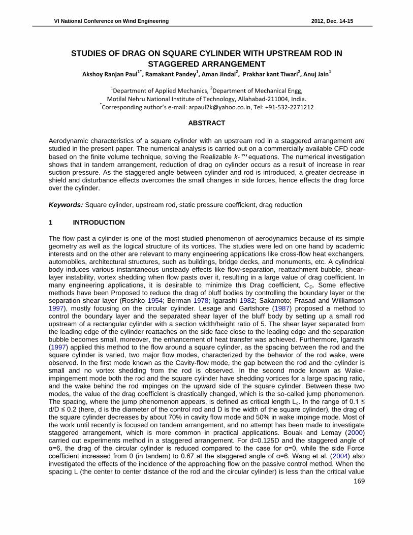
The present paper is concerned with the computational study of drag reduction on a square cylinder using an upstream rod in staggered arrangement and the characteristics of the flow field around the square cylinder when two upstream rods are used. The staggered angle α is varied from 0° to 45°, upstream rods diameters are taken as d/D=0.1,0.167,0.267,0.5, d is the diameter of upstream rod, this allowed the normalized spacing ratio L/D (L is defined as the center to center distance of the rod and square cylinder) to be adjusted from 1.5 to 4.0. 2 NUMERICAL STUDY 2.1 Computational Setup Geometry modeling and meshing is performed on commercially available software Gambit 6.3 and ANSYS FLUENT 6.3 is used for solving the governing equations. The detailed view of computational domain is shown in Figure1, where D is the dimension of square cylinder i.e.60 mm. The present configuration yielded an aspect ratio of 16.7, a blockage ratio of about 4% and turbulent intensity as 0.04.
Figure1: Geometry of Computational domain
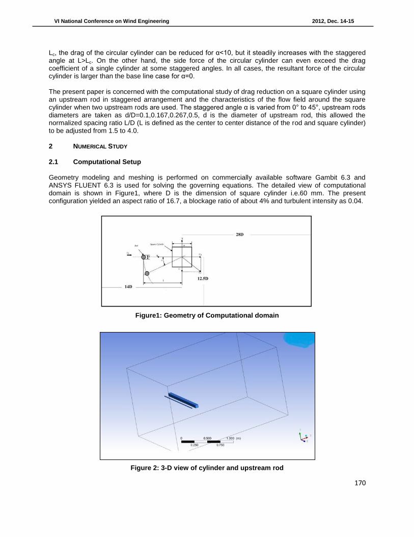
Figure 2: 3-D view of cylinder and upstream rod
171
VI National Conference on Wind Engineering 2012, Dec. 14-15
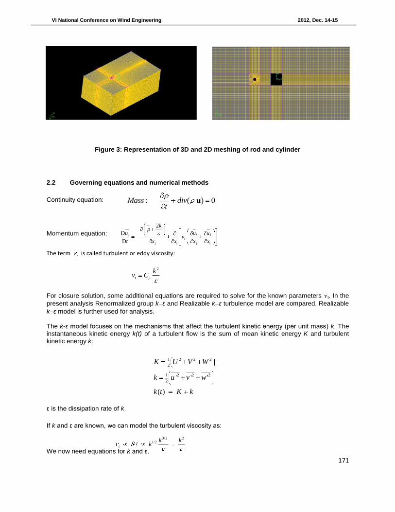
Figure 3: Representation of 3D and 2D meshing of rod and cylinder
2.2 Governing equations and numerical methods
Continuity equation:
Momentum equation:
The term t is called turbulent or eddy viscosity:
For closure solution, some additional equations are required to solve for the known parameters t. In the
present analysis Renormalized group k ε and Realizable k ε turbulence model are compared. Realizable
k ε model is further used for analysis.
The k-ε model focuses on the mechanisms that affect the turbulent kinetic energy (per unit mass) k. The instantaneous kinetic energy k(t) of a turbulent flow is the sum of mean kinetic energy K and turbulent kinetic energy k:
ε is the dissipation rate of k.
If k and ε are known, we can model the turbulent viscosity as:
We now need equations for k and ε.
i jit
j i j i
2
D
D
kp
u u uv
t x x x x
2
t
kv C
1 2 2 2
2
1 2 2 2
2' ' '
( )
K U V W
k u v w
k t K k
3/2 21/2
t
k kk
: ( ) 0Mass divt
u
172
VI National Conference on Wind Engineering 2012, Dec. 14-15
Model equation for k
The equation for k contains additional turbulent fluctuation terms that are unknown. Again using the Boussinesq assumption, these fluctuation terms can be linked to the mean flow. The following (simplified) model equation for k is commonly used.
The Prandtl number σk connects the diffusivity of k to the eddy viscosity. Typically a value of 1.0 is used. Model equation for ε A model equation for ε is derived by multiplying the k equation by (ε/k) and introducing model constants. The following (simplified) model equation for ε is commonly used.
Typically values for the model constants C1ε and C2ε of 1.44 and 1.92 are used. Model equation for ε Calculating the Reynolds stresses from k and ε
The turbulent viscosity is calculated from:
The Reynolds stresses are then calculated as follows:
The (2/3)ρkδij term ensures that the normal stresses sum to k. Note that the k-ε model leads to all normal stresses being equal, which is usually inaccurate. prandtl number σε connects the diffusivity of ε to the eddy viscosity. Typically a value of 1.30 is used.
Realizable k- ε equations
• Distinctions from standard k- model: – Alternative formulation for turbulent viscosity:
where is now variable.
( )( ) 2 .t
t ij ij
k
kdiv k div grad k E E
tU
2
1 2
( )( ) 2 .t
t ij ijdiv div grad C E E Ct k k
U
2
0.09t
kC C
2 2' ' 2
3 3
1 0
jii j t ij t ij ij
j i
ij ij
UUu u k E k
x x
if i j and if i j
2
t
kC *
1
o s
CU k
A A
173
VI National Conference on Wind Engineering 2012, Dec. 14-15
• (A0, As, and U* are functions of velocity gradients). • Ensures positivity of normal stresses:
• Ensures Schwarz’s inequality:
– New transport equation for dissipation rate, :
Realizable k- ε Cμ equations
• Eddy viscosity computed from. Realizable k- ε positivity of normal stresses
• Boussinesq viscosity relation:
• Normal component:
• Normal stress will be negative if:
An implicit solution scheme is used in combination with an algebraic multigrid method to achieve faster convergence. In view of flow having directionality upwind scheme has been employed for all the equation with the second order discretization to achieve higher accuracy. Further, a pressure velocity correction is used since velocity and pressure are a function of each other and a transport equation exclusively for pressure does not exists, they have to be coupled to each other to solve them accurately. This pressure velocity coupling is established by pressure velocity correction using Semi-Implicit Method for Pressure Linked Equation (SIMPLE) algorithm. It employs iterative prediction-correction to predict the velocity field and correct the pressure field. 2.3 Boundary conditions
• Velocity inlet is taken at inlet boundary condition and zero gauge pressure used at outlet.
• Characterize turbulence at inlets and outlets (potential backflow),k- Model requires:
b
j
t
j
Gck
ck
cScxxDt
D31
2
21
2
iu 0
2 2 2
i j i j(u u ) u u
2
t *
0
1,
s
kC C
U kA A
*
ij ij ij ijU S S
1
0
14.04, 6 cos , cos 6
3sA A W
,ij ji ki
ij ij
S S SW S S S
S
2
t ij t
2 - ;
3
jii j
j i
uu ku u k C
x x
22 2
2 3
k Uu k C
x
1 3.7
3
k U
x C
174
VI National Conference on Wind Engineering 2012, Dec. 14-15
23
( )2
avik U l
3/2
3/4 kC
L
Where, L – turbulent length scale I – turbulent intensity = 0.16 (Re)
-1/8
• Turbulence intensity and turbulent viscosity ratio, for external flows: • No slip boundary condition is specified at the wall.
2.4 Flow visualization
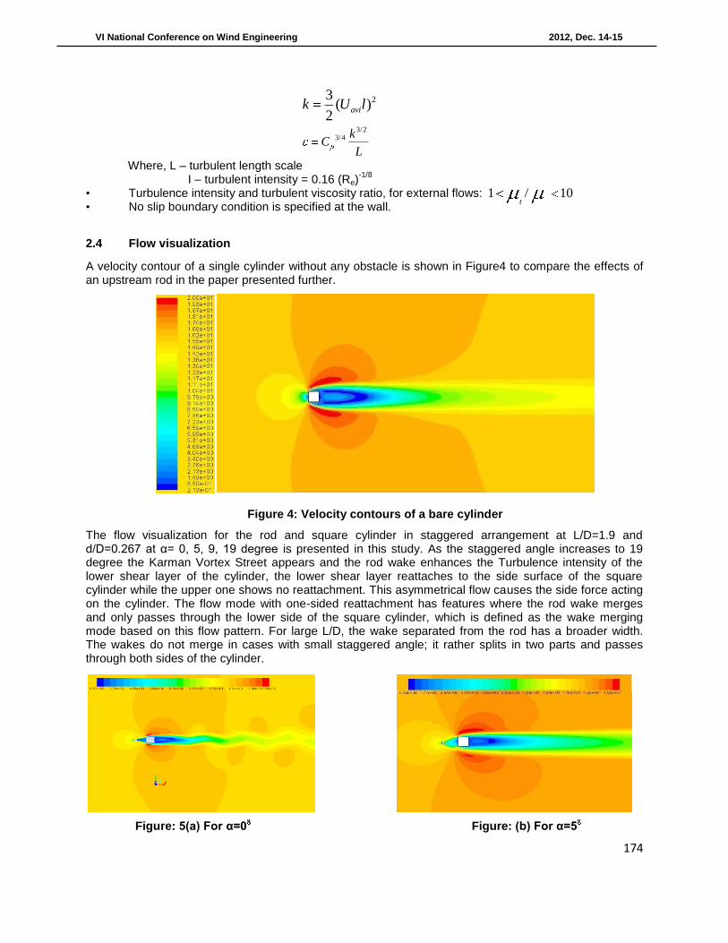
A velocity contour of a single cylinder without any obstacle is shown in Figure4 to compare the effects of an upstream rod in the paper presented further.
Figure 4: Velocity contours of a bare cylinder
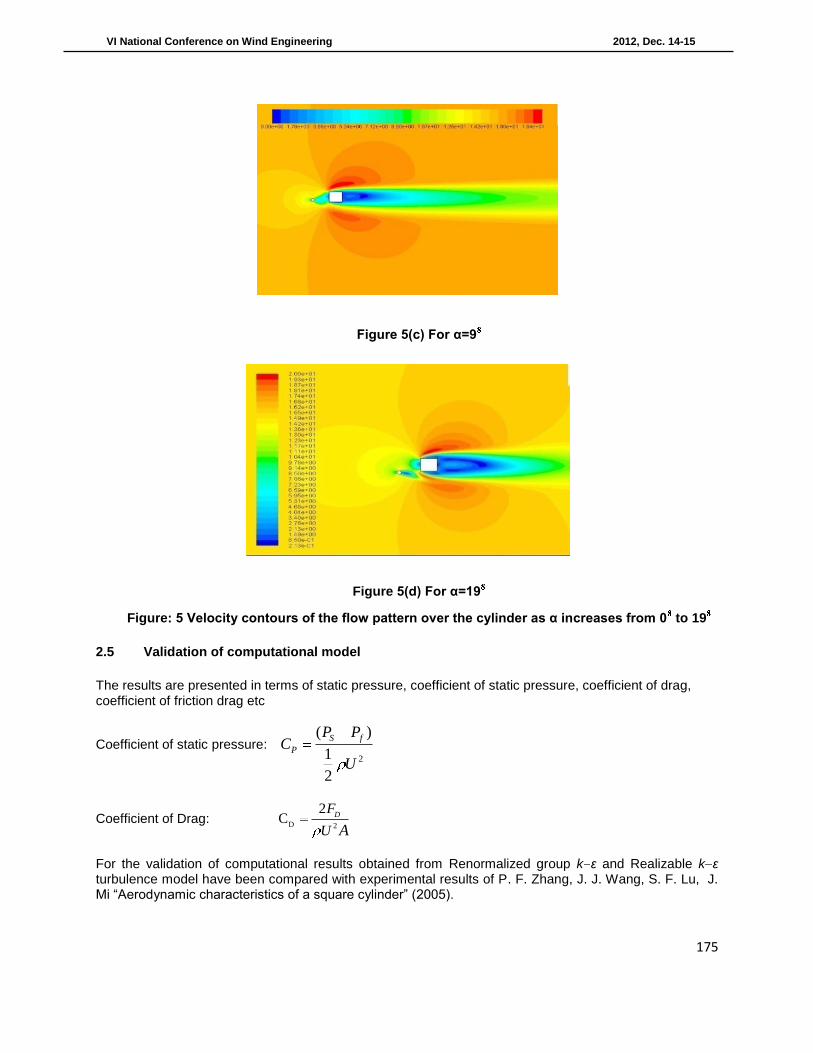
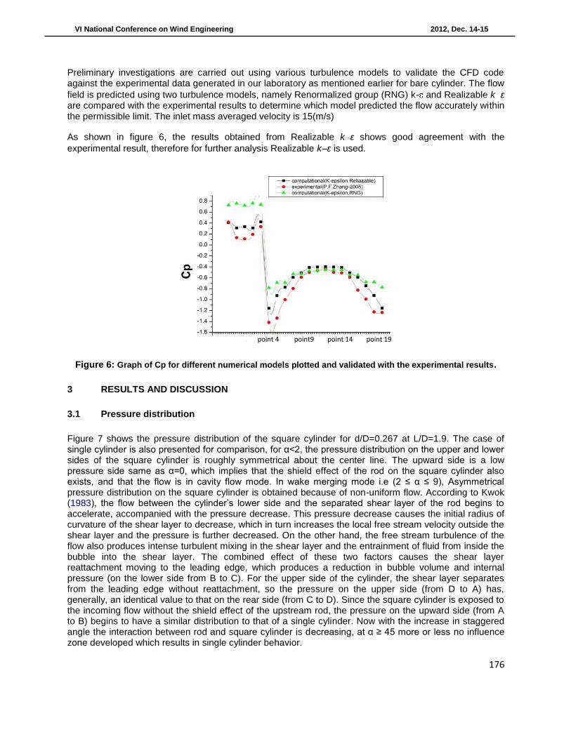
The flow visualization for the rod and square cylinder in staggered arrangement at L/D=1.9 and d/D=0.267 at α= 0, 5, 9, 19 degree is presented in this study. As the staggered angle increases to 19 degree the Karman Vortex Street appears and the rod wake enhances the Turbulence intensity of the lower shear layer of the cylinder, the lower shear layer reattaches to the side surface of the square cylinder while the upper one shows no reattachment. This asymmetrical flow causes the side force acting on the cylinder. The flow mode with one-sided reattachment has features where the rod wake merges and only passes through the lower side of the square cylinder, which is defined as the wake merging mode based on this flow pattern. For large L/D, the wake separated from the rod has a broader width. The wakes do not merge in cases with small staggered angle; it rather splits in two parts and passes through both sides of the cylinder.
Figure: 5(a) For α=0 Figure: (b) For α=5
1 / 10t
175
VI National Conference on Wind Engineering 2012, Dec. 14-15
Figure 5(c) For α=9
Figure 5(d) For α=19
Figure: 5 Velocity contours of the flow pattern over the cylinder as α increases from 0 to 19
2.5 Validation of computational model
The results are presented in terms of static pressure, coefficient of static pressure, coefficient of drag, coefficient of friction drag etc
Coefficient of static pressure: 2
( )
1
2
S f
P
P PC
U
Coefficient of Drag: D 2
2C D
F
U A
For the validation of computational results obtained from Renormalized group k ε and Realizable k ε turbulence model have been compared with experimental results of P. F. Zhang, J. J. Wang, S. F. Lu, J. Mi “Aerodynamic characteristics of a square cylinder” (2005).
176
VI National Conference on Wind Engineering 2012, Dec. 14-15
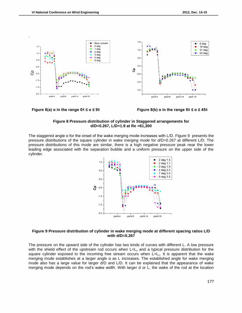
Preliminary investigations are carried out using various turbulence models to validate the CFD code against the experimental data generated in our laboratory as mentioned earlier for bare cylinder. The flow
field is predicted using two turbulence models, namely Renormalized group (RNG) k- and Realizable k ε are compared with the experimental results to determine which model predicted the flow accurately within the permissible limit. The inlet mass averaged velocity is 15(m/s)
As shown in figure 6, the results obtained from Realizable k ε shows good agreement with the
experimental result, therefore for further analysis Realizable k ε is used.
Figure 6: Graph of Cp for different numerical models plotted and validated with the experimental results.
3 RESULTS AND DISCUSSION
3.1 Pressure distribution
Figure 7 shows the pressure distribution of the square cylinder for d/D=0.267 at L/D=1.9. The case of single cylinder is also presented for comparison, for α<2, the pressure distribution on the upper and lower sides of the square cylinder is roughly symmetrical about the center line. The upward side is a low pressure side same as α=0, which implies that the shield effect of the rod on the square cylinder also exists, and that the flow is in cavity flow mode. In wake merging mode i.e (2 ≤ α ≤ 9), Asymmetrical pressure distribution on the square cylinder is obtained because of non-uniform flow. According to Kwok (1983), the flow between the cylinder’s lower side and the separated shear layer of the rod begins to accelerate, accompanied with the pressure decrease. This pressure decrease causes the initial radius of curvature of the shear layer to decrease, which in turn increases the local free stream velocity outside the shear layer and the pressure is further decreased. On the other hand, the free stream turbulence of the flow also produces intense turbulent mixing in the shear layer and the entrainment of fluid from inside the bubble into the shear layer. The combined effect of these two factors causes the shear layer reattachment moving to the leading edge, which produces a reduction in bubble volume and internal pressure (on the lower side from B to C). For the upper side of the cylinder, the shear layer separates from the leading edge without reattachment, so the pressure on the upper side (from D to A) has, generally, an identical value to that on the rear side (from C to D). Since the square cylinder is exposed to the incoming flow without the shield effect of the upstream rod, the pressure on the upward side (from A to B) begins to have a similar distribution to that of a single cylinder. Now with the increase in staggered angle the interaction between rod and square cylinder is decreasing, at α ≥ 45 more or less no influence zone developed which results in single cylinder behavior.
point 4 point9 point 14 point 19
177
VI National Conference on Wind Engineering 2012, Dec. 14-15
.
Figure 8(a) α in the range 0 ≤ α ≤ 9 Figure 8(b) α in the range 9 ≤ α ≤ 45
Figure 8 Pressure distribution of cylinder in Staggered arrangements for d/D=0.267, L/D=1.9 at Re =61,300
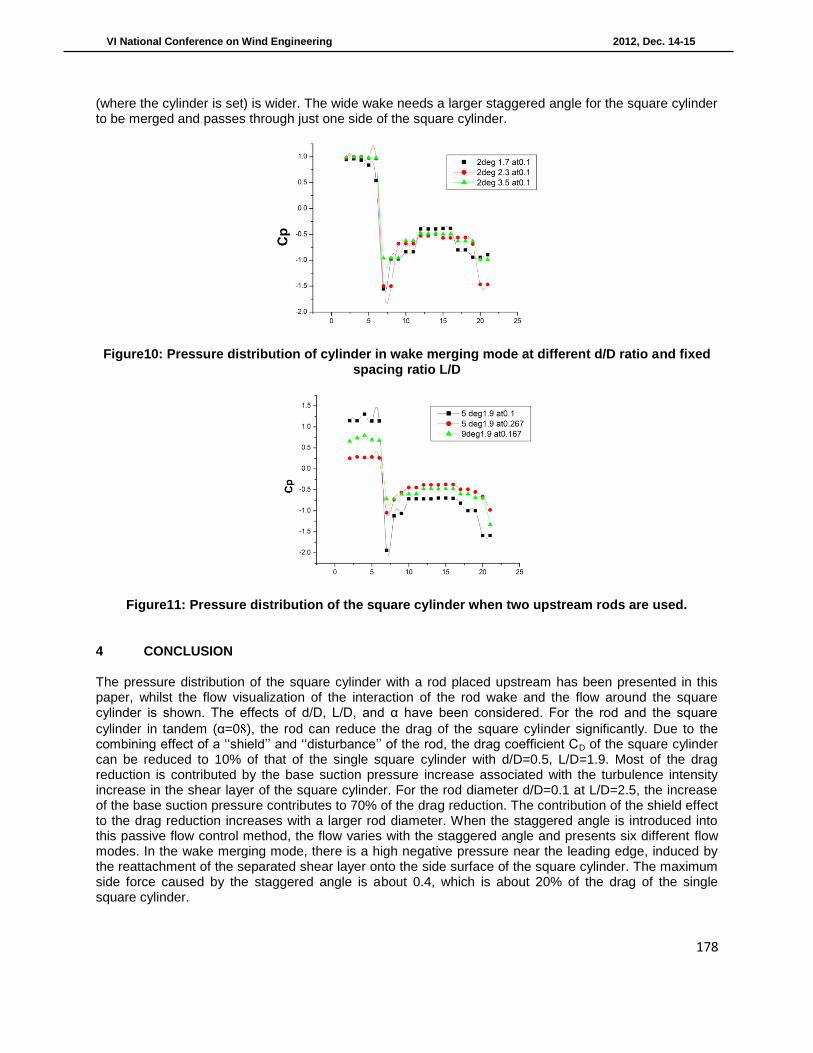
The staggered angle α for the onset of the wake merging mode increases with L/D. Figure 9 presents the pressure distributions of the square cylinder in wake merging mode for d/D=0.267 at different L/D. The pressure distributions of this mode are similar, there is a high negative pressure peak near the lower leading edge associated with the separation bubble and a uniform pressure on the upper side of the cylinder.
Figure 9 Pressure distribution of cylinder in wake merging mode at different spacing ratios L/D
with d/D=0.267
The pressure on the upward side of the cylinder has two kinds of curves with different L. A low pressure with the shield effect of the upstream rod occurs when L<Lc and a typical pressure distribution for the square cylinder exposed to the incoming free stream occurs when L>Lc. It is apparent that the wake merging mode establishes at a larger angle α as L increases. The established angle for wake merging mode also has a large value for larger d/D and L/D. It can be explained that the appearance of wake merging mode depends on the rod’s wake width. With larger d or L, the wake of the rod at the location
178
VI National Conference on Wind Engineering 2012, Dec. 14-15
(where the cylinder is set) is wider. The wide wake needs a larger staggered angle for the square cylinder to be merged and passes through just one side of the square cylinder.
Figure10: Pressure distribution of cylinder in wake merging mode at different d/D ratio and fixed spacing ratio L/D
Figure11: Pressure distribution of the square cylinder when two upstream rods are used.
4 CONCLUSION
The pressure distribution of the square cylinder with a rod placed upstream has been presented in this paper, whilst the flow visualization of the interaction of the rod wake and the flow around the square cylinder is shown. The effects of d/D, L/D, and α have been considered. For the rod and the square
cylinder in tandem (α=0 ), the rod can reduce the drag of the square cylinder significantly. Due to the combining effect of a ‘‘shield’’ and ‘‘disturbance’’ of the rod, the drag coefficient CD of the square cylinder can be reduced to 10% of that of the single square cylinder with d/D=0.5, L/D=1.9. Most of the drag reduction is contributed by the base suction pressure increase associated with the turbulence intensity increase in the shear layer of the square cylinder. For the rod diameter d/D=0.1 at L/D=2.5, the increase of the base suction pressure contributes to 70% of the drag reduction. The contribution of the shield effect to the drag reduction increases with a larger rod diameter. When the staggered angle is introduced into this passive flow control method, the flow varies with the staggered angle and presents six different flow modes. In the wake merging mode, there is a high negative pressure near the leading edge, induced by the reattachment of the separated shear layer onto the side surface of the square cylinder. The maximum side force caused by the staggered angle is about 0.4, which is about 20% of the drag of the single square cylinder.
179
VI National Conference on Wind Engineering 2012, Dec. 14-15
REFERENCES
[1] Roshko,1960, “Experiments on the flow past a circular cylinder at very high Reynolds number”, pp 345-356
[2] Bearman PW 1965, “Investigation of the flow behind a two-dimensional model with a blunt trailing edge and fitted with splitter plates”, Journal of Fluid Mech. Vol. 21 pp.241–255.
[3] Bearman PW, Obasaju ED 1982, “An experimental study of pressure fluctuation on fixed and oscillating square-section cylinder”, J Fluid Mech. Vol.119 pp. 297–321.
[4] Lesage F, Gartshore IS 1987, “A method of reducing drag and fluctuating side force on bluff bodies”, Journal of Wind Engg.vol.2, pp. 229–245.
[5] Sakamoto and Haniu 1994, “Optimum suppression of fluid forces acting on a circular cylinder”, ASME Journal of Fluids Eng. Vol.116, pp. 221–227.
[6] Williamson and Prasad, 1997, “A method for the reduction of bluff body drag” Journal of Wind Engineering and Industrial Aerodynamics, vol. 69- 71, pp.155 167.
[7] Tamura, t,1998, “Numerical prediction of unsteady pressures on a square cylinder with various corner shapes”, Journal of Wind Engineering and Industrial Aerodynamics, pp- 531-542.
[8] T. Tamura, 1998, “Numerical prediction of unsteady pressures on a square cylinder with various corner shapes” Journal of Wind Engineering and Industrial Aerodynamics vol. 74-76, pp. 531-542.
[9] Lemay and Bouak, 1997, “Passive control of the aerodynamic forces acting on a circular cylinder” Experimental thermal and fluid sciences, vol.16, Pages 112-121.
[10] Igarashi, T., 1997,” Drag reduction of a square prism by flow control using a small rod”, Journal of Wind Engineering and Industrial Aerodynamics, vol. 67, pp-141-153.
[11] Liu, Chia-Hung, 2002, “Observations of hysteresis in flow around two square cylinders in a tandem arrangement” Journal of Wind Engineering and Industrial Aerodynamics, vol. 90, pp. 1019–1050
[12] Igarashi, T., “Drag reduction of flat plate normal to airstream by flow control using a rod”, Journal of Wind Engineering and Industrial Aerodynamics, vol. 90, page. 359–376, 2002
[13] Tsutsui, T. 2002, “Drag reduction of a circular cylinder in an air-stream”, Journal of Wind Engineering and Industrial Aerodynamics, vol. 90, page. 527–541
[14] P. F. Zhang, J. J. Wang, 2005, “Aerodynamic characteristics of a square cylinder with a rod in a staggered arrangement”, Experiments in Fluids, vol.38, pp 494–502.
[15] J. J. Wang, P. F. Zhang in, 2006, “Drag Reduction of a Circular Cylinder Using an Upstream Rod Flow”, Turbulence and Combustion, vol.76, pp.-83–101.
[16] S.C. Yen, K.C. San, 2007, “Interactions of tandem square cylinders at low Reynolds numbers”, Experimental Thermal and Fluid Science, vol. 32, pp-927–938
[17] Moon Kyoung Kim, Dong Keon Kim, 2008, “Measurements of the flow fields around two square cylinders in a tandem arrangement”, Journal of Mechanical Science and Technology, vol. 22, pp- 397-407.
Related Documents