Structure-aware Stylization of Mountainous Terrains Julian Kratt 1 Ferdinand Eisenkeil 2 Marc Spicker 1 Yunhai Wang 3 Daniel Weiskopf 4 Oliver Deussen 1 1 University of Konstanz, Germany 2 IABG mbH, Germany 3 School of Computer Science and Technology, Shandong University, China 4 University of Stuttgart, Germany (a) (b) (c) Figure 1: Our method takes an input terrain geometry and texture (a); based on geometric features such as crest lines, smoothing is applied and streamlines are computed in a structure-aware distribution (b), hatching styles are computed to create the final illustration (c). Abstract We present a method for the stylization of mountainous terrains that allows creating abstract representations in different ren- dering styles. Our method consists of two major components: structure-aware terrain filtering and streamline-based hatching. For a given input terrain we compute different Levels-of-Detail (LoD) according to a crest line oriented importance measure and then filter each LoD accordingly. We generate flow fields for each LoD and compute streamlines to direct the production of hatching lines. The combination of crest and silhouette lines with streamline-based hatching allows us to create a variety of styles in different Levels-of-Detail. We evaluate our method using several terrains and demonstrate the effectiveness of our method by composing a number of different illustration styles. Categories and Subject Descriptors (according to ACM CCS): I.3.3 [Computer Graphics]: Picture/Image Generation—Line and curve generation I.3.3 [Computer Graphics]: Picture/Image Generation—Viewing algorithms I.3.5 [Computer Graphics]: Com- putational Geometry and Object Modeling—Curve, surface, solid, and object representations 1. Introduction Terrain illustrations are needed for a wide variety of applications ranging from map production to geo-visualization and geographic information systems, interactive computer games [Döl07], flight and driving simulators and planning systems for navigational tasks. Simplified methods might feed head-mounted displays when only the most important features of a terrain should be shown [FHT08]. Mountainous terrains are special types of terrain, they have a fractal structure and are subject of strong pluvial and fluvial erosion with corresponding flow patterns forming valleys and ridges. This is why artists used streamline-like illustrations to depict mountain areas from early on (Figure 2). In traditional Chinese paintings this form of rendering is widely used [Sir56]. We combine state-of-the- art streamline placement techniques with Levels-of-Detail (LoD) heightmap smoothing approaches as well as modern real-time ren- dering methods to generate images that have a similar appearance as real artistic terrain sketches. The goal of our work is to provide landscape and terrain renderings that a artist would draw as well as the possibility to navigate through an artistic looking 3D environ- ment. Our representation highlights characteristic features such as ridges and valleys and combines them with hatches produced from streamline-based placement methods. Unlike previous meth- ods [BSD ∗ 04, WS06] we use the streamlines not just directly, but as guiding paths for different kinds of hatches. The line style of these hatches is determined by the underlying terrain type (snow, Konstanzer Online-Publikations-System (KOPS) URL: http://nbn-resolving.de/urn:nbn:de:bsz:352-2-12vyko29oy5b89 Erschienen in: VMV 2017 : Vision, Modeling and Visualization ; Proceedings / Fellner, Dieter (Hrsg.). - Goslar : Eurographics Association, 2017. - S. 17-28. - ISBN 978-3-03868-049-9 https://dx.doi.org/10.2312/vmv.20171255

Welcome message from author
This document is posted to help you gain knowledge. Please leave a comment to let me know what you think about it! Share it to your friends and learn new things together.
Transcript
Structure-aware Stylization of Mountainous Terrains
Julian Kratt1 Ferdinand Eisenkeil2 Marc Spicker1 Yunhai Wang3 Daniel Weiskopf4 Oliver Deussen1
1University of Konstanz, Germany2IABG mbH, Germany
3 School of Computer Science and Technology, Shandong University, China4University of Stuttgart, Germany
(a) (b) (c)
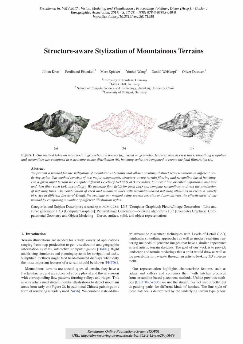
Figure 1: Our method takes an input terrain geometry and texture (a); based on geometric features such as crest lines, smoothing is appliedand streamlines are computed in a structure-aware distribution (b), hatching styles are computed to create the final illustration (c).
AbstractWe present a method for the stylization of mountainous terrains that allows creating abstract representations in different ren-dering styles. Our method consists of two major components: structure-aware terrain filtering and streamline-based hatching.For a given input terrain we compute different Levels-of-Detail (LoD) according to a crest line oriented importance measureand then filter each LoD accordingly. We generate flow fields for each LoD and compute streamlines to direct the productionof hatching lines. The combination of crest and silhouette lines with streamline-based hatching allows us to create a varietyof styles in different Levels-of-Detail. We evaluate our method using several terrains and demonstrate the effectiveness of ourmethod by composing a number of different illustration styles.
Categories and Subject Descriptors (according to ACM CCS): I.3.3 [Computer Graphics]: Picture/Image Generation—Line and
curve generation I.3.3 [Computer Graphics]: Picture/Image Generation—Viewing algorithms I.3.5 [Computer Graphics]: Com-
putational Geometry and Object Modeling—Curve, surface, solid, and object representations
1. Introduction
Terrain illustrations are needed for a wide variety of applications
ranging from map production to geo-visualization and geographic
information systems, interactive computer games [Döl07], flight
and driving simulators and planning systems for navigational tasks.
Simplified methods might feed head-mounted displays when only
the most important features of a terrain should be shown [FHT08].
Mountainous terrains are special types of terrain, they have a
fractal structure and are subject of strong pluvial and fluvial erosion
with corresponding flow patterns forming valleys and ridges. This
is why artists used streamline-like illustrations to depict mountain
areas from early on (Figure 2). In traditional Chinese paintings this
form of rendering is widely used [Sir56]. We combine state-of-the-
art streamline placement techniques with Levels-of-Detail (LoD)
heightmap smoothing approaches as well as modern real-time ren-
dering methods to generate images that have a similar appearance
as real artistic terrain sketches. The goal of our work is to provide
landscape and terrain renderings that a artist would draw as well as
the possibility to navigate through an artistic looking 3D environ-
ment.
Our representation highlights characteristic features such as
ridges and valleys and combines them with hatches produced
from streamline-based placement methods. Unlike previous meth-
ods [BSD∗04, WS06] we use the streamlines not just directly, but
as guiding paths for different kinds of hatches. The line style of
these hatches is determined by the underlying terrain type (snow,
Konstanzer Online-Publikations-System (KOPS) URL: http://nbn-resolving.de/urn:nbn:de:bsz:352-2-12vyko29oy5b89
Erschienen in: VMV 2017 : Vision, Modeling and Visualization ; Proceedings / Fellner, Dieter (Hrsg.). - Goslar : Eurographics Association, 2017. - S. 17-28. - ISBN 978-3-03868-049-9
https://dx.doi.org/10.2312/vmv.20171255
rocks, forest, etc.) and the overall style of the intended illustration.
Figure 1 shows an input terrain with crest lines and the resulting
terrain illustration.
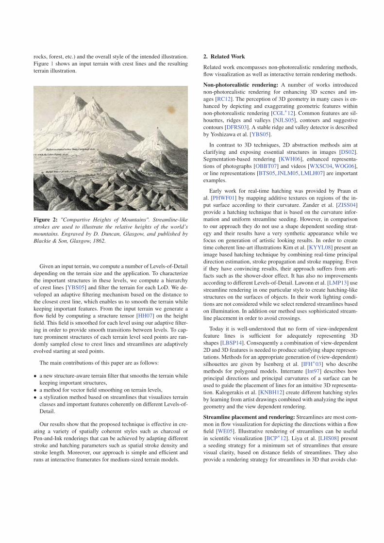
Figure 2: "Compartive Heights of Mountains". Streamline-likestrokes are used to illustrate the relative heights of the world’smountains. Engraved by D. Duncan, Glasgow, and published byBlackie & Son, Glasgow, 1862.
Given an input terrain, we compute a number of Levels-of-Detail
depending on the terrain size and the application. To characterize
the important structures in these levels, we compute a hierarchy
of crest lines [YBS05] and filter the terrain for each LoD. We de-
veloped an adaptive filtering mechanism based on the distance to
the closest crest line, which enables us to smooth the terrain while
keeping important features. From the input terrain we generate a
flow field by computing a structure tensor [HH07] on the height
field. This field is smoothed for each level using our adaptive filter-
ing in order to provide smooth transitions between levels. To cap-
ture prominent structures of each terrain level seed points are ran-
domly sampled close to crest lines and streamlines are adaptively
evolved starting at seed points.
The main contributions of this paper are as follows:
• a new structure-aware terrain filter that smooths the terrain while
keeping important structures,
• a method for vector field smoothing on terrain levels,
• a stylization method based on streamlines that visualizes terrain
classes and important features coherently on different Levels-of-
Detail.
Our results show that the proposed technique is effective in cre-
ating a variety of spatially coherent styles such as charcoal or
Pen-and-Ink renderings that can be achieved by adapting different
stroke and hatching parameters such as spatial stroke density and
stroke length. Moreover, our approach is simple and efficient and
runs at interactive framerates for medium-sized terrain models.
2. Related Work
Related work encompasses non-photorealistic rendering methods,
flow visualization as well as interactive terrain rendering methods.
Non-photorealistic rendering: A number of works introduced
non-photorealistic rendering for enhancing 3D scenes and im-
ages [RC12]. The perception of 3D geometry in many cases is en-
hanced by depicting and exaggerating geometric features within
non-photorealistic rendering [CGL∗12]. Common features are sil-
houettes, ridges and valleys [NJLS05], contours and suggestive
contours [DFRS03]. A stable ridge and valley detector is described
by Yoshizawa et al. [YBS05].
In contrast to 3D techniques, 2D abstraction methods aim at
clarifying and exposing essential structures in images [DS02].
Segmentation-based rendering [KWH06], enhanced representa-
tions of photographs [OBBT07] and videos [WXSC04, WOG06],
or line representations [BTS05, JNLM05, LMLH07] are important
examples.
Early work for real-time hatching was provided by Praun et
al. [PHWF01] by mapping additive textures on regions of the in-
put surface according to their curvature. Zander et al. [ZISS04]
provide a hatching technique that is based on the curvature infor-
mation and uniform streamline seeding. However, in comparison
to our approach they do not use a shape dependent seeding strat-
egy and their results have a very synthetic appearance while we
focus on generation of artistic looking results. In order to create
time coherent line-art illustrations Kim et al. [KYYL08] present an
image based hatching technique by combining real-time principal
direction estimation, stroke propagation and stroke mapping. Even
if they have convincing results, their approach suffers from arti-
facts such as the shower-door effect. It has also no improvements
according to different Levels-of-Detail. Lawonn et al. [LMP13] use
streamline rendering in one particular style to create hatching-like
structures on the surfaces of objects. In their work lighting condi-
tions are not considered while we select rendered streamlines based
on illumination. In addition our method uses sophisticated stream-
line placement in order to avoid crossings.
Today it is well-understood that no form of view-independent
feature lines is sufficient for adequately representing 3D
shapes [LBSP14]. Consequently a combination of view-dependent
2D and 3D features is needed to produce satisfying shape represen-
tations. Methods for an appropriate generation of (view-dependent)
silhouettes are given by Isenberg et al. [IFH∗03] who describe
methods for polygonal models. Interrante [Int97] describes how
principal directions and principal curvatures of a surface can be
used to guide the placement of lines for an intuitive 3D representa-
tion. Kalogerakis et al. [KNBH12] create different hatching styles
by learning from artist drawings combined with analyzing the input
geometry and the view dependent rendering.
Streamline placement and rendering: Streamlines are most com-
mon in flow visualization for depicting the directions within a flow
field [WE05]. Illustrative rendering of streamlines can be useful
in scientific visualization [BCP∗12]. Liya et al. [LHS08] present
a seeding strategy for a minimum set of streamlines that ensure
visual clarity, based on distance fields of streamlines. They also
provide a rendering strategy for streamlines in 3D that avoids clut-

tering by minimizing overlapping and intersections [LwS07]. Xu
et al. [XLS10] present a seeding algorithm in areas with high en-
tropy and additional seeding in areas where the conditional entropy
is high. Inspired by this work, we place more streamlines around
crest lines to capture the local structure near salient regions.
Our method requires smoothing of flow fields, since we want to
visually abstract distant parts of our terrains. We were inspired by
noise reduction of diffusion tensor images [DGA05]. Since in our
case the flow field is generated by the gradient of a height map,
smoothing can be done by interpolating the gradient at the vertex
positions of the map [MMMY97]. However, this results in artifacts,
so more sophisticated methods have been provided [HAM11]. To
avoid inconsistencies by interpolation or approximation of the in-
put, we directly smooth the given vector field.
Mesh smoothing with shape preservation: Feature driven
smoothing within subdivision methods was done by Amresh and
Farin [AFR02] as well as by Li and Ma [LM09]. Isenberg et
al. [IHK03] provide a GPU implementation for achieving interac-
tive frame rates by using the view-direction as a hint where sub-
division has to be applied. These methods have in common that
they produce additional geometry. In contrast, we want to sim-
plify the geometry in our Levels-of-Detail and thus need differ-
ent methods that allow this. Also image processing techniques can
be applied to the corresponding height field image in the con-
text of terrain smoothing and simplification. Previous work on
edge-preserving smoothing (e.g. bilateral [TM98] or Laplacian fil-
ter [PHK11]) can be used to remove small details in the height field
image while maintaining important features of the terrain. These
methods, however, are designed to preserve edges in an image and
thus may produce unwanted sharp creases in the terrain. Tasdizen
and Whitaker [TW03] developed a feature preserving smoothing
approach based on a variational generalization of anisotropic dif-
fusion. Their methods is computational expensive. Moreover, in
contrast to our approach, a hierarchical production of different
Levels-of-Detail representations can not be achieved. Desbrun et
al. [DMSB00] also use anisotropic diffusion to denoise gray-scale
images such as terrain height fields.
Terrain rendering: Terrain rendering covers a variety of methods
ranging from the generation of artistic panorama maps towards re-
alistic rendering [BST09]. Kennelly and Kimerling describe NPR
techniques for terrain rendering in a cartographic context [KK06].
Mower [Mow09] extracts silhouettes, creases and slope lines from
digital elevation models to create Pen-and-Ink landscape illustra-
tions. The work most relevant for our approach is proposed by
Buchin et al. [BSD∗04] and by Way and Shih [WS06]. Buchin
et al. create terrain illustrations by using light intensities on the
terrain surface for creating stroke-based renderings. Strokes start
at uniformly sampled points within the terrain and flow downhill,
the selection of strokes to be rendered is based on light variation.
In contrast to them, our work combines state-of-the-art streamline
placement with rendering of crest lines and furthermore uses the
streamlines as guiding paths for our hatching lines to create differ-
ent kinds of strokes.
Way and Shih [WS06] provide an approach that uses streamlines
to represent terrains inspired by Chinese landscape paintings. Their
approach, however, is limited to streamlines that are generated for
each triangle in the terrain mesh. Moreover, the resulting stream-
lines are textured with a fixed type of Chinese drawing style. In our
work we extend their approach by modifying our streamline-based
hatches according to the terrain type. We also use lighting infor-
mation for streamline rendering and a more sophisticated stream-
line placement as well as an adaptive stroke parametrization that
allows us to render different drawing styles. In addition, we apply
the method proposed by Whelan et al. [WV03] to enhance our ter-
rain renderings with silhouettes from depth images. Mat and Vis-
valingam [MV02] provide an evaluation that shows that silhouettes
are important for terrain rendering. A fast approach for such ren-
derings with a GPU implementation is given by Mower [Mow14].
Levels-of-Detail approaches for terrain rendering: Since ter-
rains typically contain huge amount of data, Levels-of-Detail ap-
proaches have to be introduced. Hoppe [Hop96] provides a method
to represent terrains using progressive meshes that enables view-
ers to smoothly change Levels-of-Detail based on the camera posi-
tion. Cignoni et al. [CGG∗03] introduce the BDAM technique, that
simplifies terrain meshes by optimizing their triangulation. Another
approach is to recursively subdivide triangle meshes using longest-
edge bisection for a view-dependent refinement, following smooth
blending of geometry using geomorphing [LP02]. Losasso and
Hoppe [LH04] use geometry clipmaps to provide visual continu-
ity by caching terrain data in a set of nested regular grids. The grids
are incrementally refilled as the viewpoint changes. An in-depth
overview and comparison of general Level-of-Detail techniques for
geometric surfaces is provided by Luebke et al. [LWC∗02].
3. Overview
Input for our system are synthetic fractal terrains as well as real-
world terrains obtained from earth observation techniques such as
airborne LiDAR [Axe99]. We use the corresponding height and tex-
ture information since we modify our rendering style according to
the underlying type of ground. Figure 3 gives a brief overview over
the whole processing pipeline from offline preprocessing steps up
to real-time rendering.
Terrain Model
Level-of-Detail Generation Rendering
Stylized Terrain
- Crest-oriented Filtering- Flow Field Generation- Streamline Placement
- Streamline Selection- Stroke Generation
Figure 3: System Overview. In a preprocessing step we producedifferent Levels-of-Detail for a given input terrain. Here, we usecrest-oriented filtering to smooth the terrain levels. A flow field isgenerated for each level and streamlines are placed. In the render-ing step, streamlines are selected based on the LoD and strokes aregenerated depending on the underlying terrain type to produce astylized model.
Crest-oriented Filtering: In preparation for view-dependent ren-
dering we create four Levels-of-Detail. This number is heuristically
determined and can be changed by the user. To obtain the different
levels we detect crest lines on the input terrain by using the method
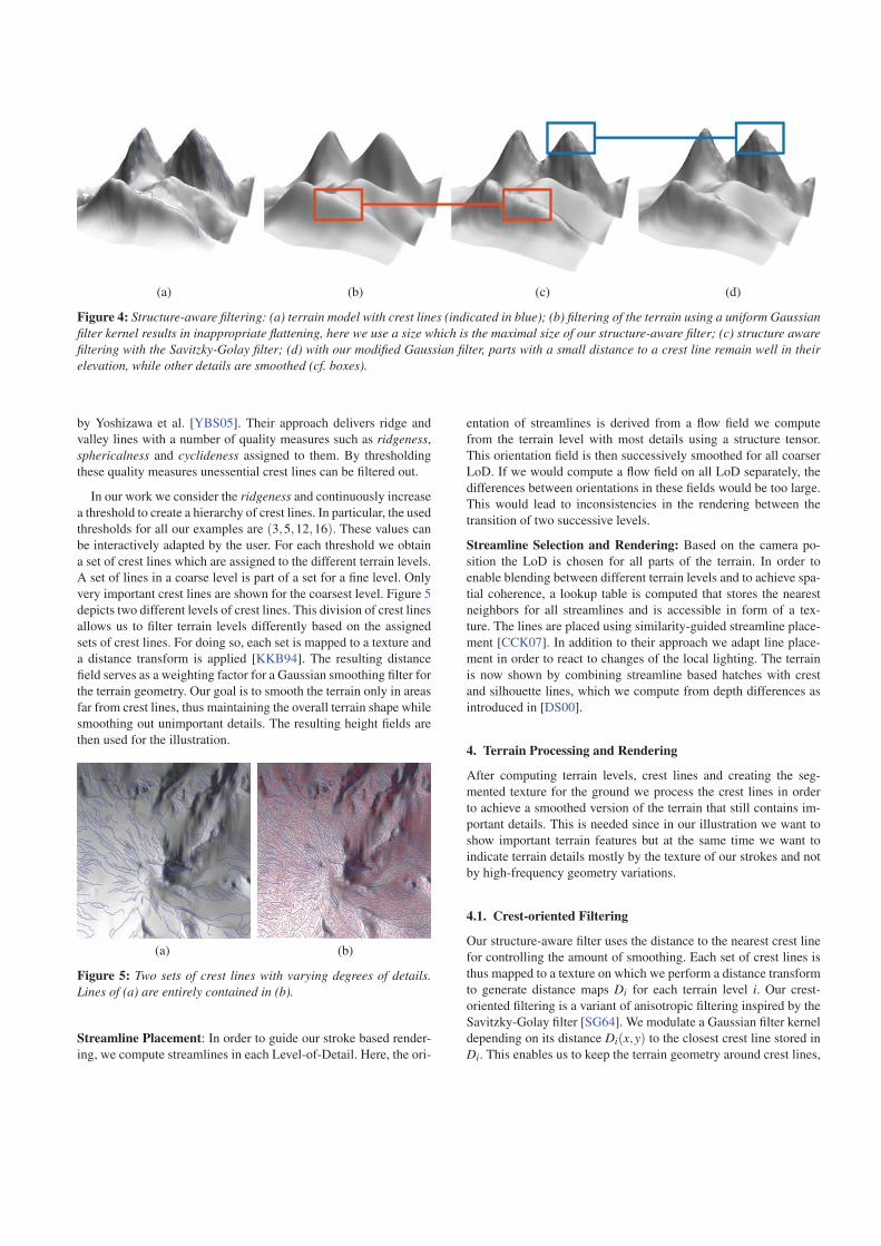
(a) (b) (c) (d)
Figure 4: Structure-aware filtering: (a) terrain model with crest lines (indicated in blue); (b) filtering of the terrain using a uniform Gaussianfilter kernel results in inappropriate flattening, here we use a size which is the maximal size of our structure-aware filter; (c) structure awarefiltering with the Savitzky-Golay filter; (d) with our modified Gaussian filter, parts with a small distance to a crest line remain well in theirelevation, while other details are smoothed (cf. boxes).
by Yoshizawa et al. [YBS05]. Their approach delivers ridge and
valley lines with a number of quality measures such as ridgeness,
sphericalness and cyclideness assigned to them. By thresholding
these quality measures unessential crest lines can be filtered out.
In our work we consider the ridgeness and continuously increase
a threshold to create a hierarchy of crest lines. In particular, the used
thresholds for all our examples are (3,5,12,16). These values can
be interactively adapted by the user. For each threshold we obtain
a set of crest lines which are assigned to the different terrain levels.
A set of lines in a coarse level is part of a set for a fine level. Only
very important crest lines are shown for the coarsest level. Figure 5
depicts two different levels of crest lines. This division of crest lines
allows us to filter terrain levels differently based on the assigned
sets of crest lines. For doing so, each set is mapped to a texture and
a distance transform is applied [KKB94]. The resulting distance
field serves as a weighting factor for a Gaussian smoothing filter for
the terrain geometry. Our goal is to smooth the terrain only in areas
far from crest lines, thus maintaining the overall terrain shape while
smoothing out unimportant details. The resulting height fields are
then used for the illustration.
(a) (b)
Figure 5: Two sets of crest lines with varying degrees of details.Lines of (a) are entirely contained in (b).
Streamline Placement: In order to guide our stroke based render-
ing, we compute streamlines in each Level-of-Detail. Here, the ori-
entation of streamlines is derived from a flow field we compute
from the terrain level with most details using a structure tensor.
This orientation field is then successively smoothed for all coarser
LoD. If we would compute a flow field on all LoD separately, the
differences between orientations in these fields would be too large.
This would lead to inconsistencies in the rendering between the
transition of two successive levels.
Streamline Selection and Rendering: Based on the camera po-
sition the LoD is chosen for all parts of the terrain. In order to
enable blending between different terrain levels and to achieve spa-
tial coherence, a lookup table is computed that stores the nearest
neighbors for all streamlines and is accessible in form of a tex-
ture. The lines are placed using similarity-guided streamline place-
ment [CCK07]. In addition to their approach we adapt line place-
ment in order to react to changes of the local lighting. The terrain
is now shown by combining streamline based hatches with crest
and silhouette lines, which we compute from depth differences as
introduced in [DS00].
4. Terrain Processing and Rendering
After computing terrain levels, crest lines and creating the seg-
mented texture for the ground we process the crest lines in order
to achieve a smoothed version of the terrain that still contains im-
portant details. This is needed since in our illustration we want to
show important terrain features but at the same time we want to
indicate terrain details mostly by the texture of our strokes and not
by high-frequency geometry variations.
4.1. Crest-oriented Filtering
Our structure-aware filter uses the distance to the nearest crest line
for controlling the amount of smoothing. Each set of crest lines is
thus mapped to a texture on which we perform a distance transform
to generate distance maps Di for each terrain level i. Our crest-
oriented filtering is a variant of anisotropic filtering inspired by the
Savitzky-Golay filter [SG64]. We modulate a Gaussian filter kernel
depending on its distance Di(x,y) to the closest crest line stored in
Di. This enables us to keep the terrain geometry around crest lines,
(especially its elevation) while smoothing unimportant details far
away from these lines. This is done for each level.
Gi(x,y) =1
2π2e−
x2+y2
2·σ2 , (1)
with the standard deviation σ computed by:
σ = min(
rmax,ωeDi(x,y)−1). (2)
The strength of the filter is controlled by ω which we heuristically
set to ω = 5, rmax = 20 for a typical terrain resolution of 256×256
height values. Figure 4 shows the effect of different filters applied
to the terrain mesh. As the uniform Gaussian kernel smooths even
important features, the Savitzky-Golay filter (Figure 4(c)) preserves
prominent structures better but also flattens the terrain in important
feature positions. In contrast our modulated filter applied in Fig-
ure 4(d) keeps the elevation and local area around crest lines.
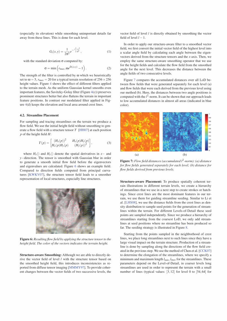
4.2. Streamline Placement
For sampling and tracing streamlines on the terrain we produce a
flow field. We use the initial height field without smoothing to gen-
erate a flow field with a structure tensor T [HH07] at each position
p of the height field H:
T (p) =[
(Hx(p))2 Hx(p)Hy(p)Hx(p)Hy(p) (Hy(p))2
], (3)
where Hx() and Hy() denote the spatial derivatives in x− and
y−direction. The tensor is smoothed with Gaussian blur in order
to generate a smooth initial flow field before the eigenvectors
and eigenvalues are calculated. Figure 6 shows an example field.
Compared to direction fields computed from principal curva-
tures [KWKV07], the structure tensor field leads to a smoother
representation of local structures, especially line structures.
Figure 6: Resulting flow field by applying the structure tensor to theheight field. The color of the vectors indicates the terrain height.
Structure-aware Smoothing: Although we are able to directly de-
rive the vector field of level l with the structure tensor based on
the smoothed height field, this introduces inconsistencies as re-
ported from diffuse tensor imaging [MMMY97]. To provide coher-
ent changes between the vector fields of two successive levels, the
vector field of level l is directly obtained by smoothing the vector
field of level l −1.
In order to apply our structure-aware filter to a smoothed vector
field, we first convert the initial vector field of the highest level into
a scalar angle field by calculating each angle between the eigen-
vectors derived from the structure tensors and the x-axis. Then, we
employ the same structure-aware smoothing operator that we use
for the height fields and calculate the flow field from the smoothed
angle for the next level. This decreases the distance between the
angle fields of two consecutive levels.
Figure 7 compares the accumulated distances over all LoD be-
tween flow fields that were generated separately for each level (a)
and flow fields that were each derived from the previous level using
our method (b). Here, the distances between two angle positions is
computed with the l2-norm. It can be shown that our approach leads
to low accumulated distances in almost all areas (indicated in blue
color).
(a) (b)
Figure 7: Flow field distances (accumulated l2-norm): (a) distancefor flow fields generated separately for each level; (b) distance forflow fields derived from previous levels.
Structure-aware Placement: To produce spatially coherent ter-
rain illustrations in different terrain levels, we create a hierarchy
of streamlines that we use in a next step to create strokes or hatch-
ings. Since crest lines are the most dominant features in our ter-
rain, we use them for guiding streamline seeding. Similar to Li et
al. [LHS08], we use the distance fields from the crest lines as den-
sity distribution to sample seed points for the generation of stream-
lines within the terrain. For different Levels-of-Detail these seed
points are sampled independently. Since we produce a hierarchy of
streamlines starting from the coarsest LoD, we only add stream-
lines at seed positions where no streamline has been produced so
far. The seeding strategy is illustrated in Figure 8.
Starting from the points sampled in the neighborhood of crest
lines, we place long streamlines next to such lines since they have a
large visual impact on the terrain structure. Production of a stream-
line is done by sampling along the directions of the flow field cre-
ated in the previous step. We use the method of Chen et al. [CCK07]
to determine the elongation of the streamlines, where we specify a
minimum and maximum length lmin, lmax for the streamlines. These
parameters depend on the Level-of-Detail, in coarser levels long
streamlines are used in order to represent the terrain with a small
number of lines (typical values: [3,12] for level 0 to [54,64] for
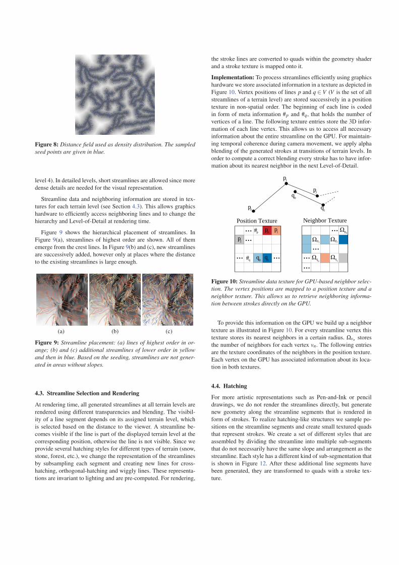
Figure 8: Distance field used as density distribution. The sampledseed points are given in blue.
level 4). In detailed levels, short streamlines are allowed since more
dense details are needed for the visual representation.
Streamline data and neighboring information are stored in tex-
tures for each terrain level (see Section 4.3). This allows graphics
hardware to efficiently access neighboring lines and to change the
hierarchy and Level-of-Detail at rendering time.
Figure 9 shows the hierarchical placement of streamlines. In
Figure 9(a), streamlines of highest order are shown. All of them
emerge from the crest lines. In Figure 9(b) and (c), new streamlines
are successively added, however only at places where the distance
to the existing streamlines is large enough.
(a) (b) (c)
Figure 9: Streamline placement: (a) lines of highest order in or-ange; (b) and (c) additional streamlines of lower order in yellowand then in blue. Based on the seeding, streamlines are not gener-ated in areas without slopes.
4.3. Streamline Selection and Rendering
At rendering time, all generated streamlines at all terrain levels are
rendered using different transparencies and blending. The visibil-
ity of a line segment depends on its assigned terrain level, which
is selected based on the distance to the viewer. A streamline be-
comes visible if the line is part of the displayed terrain level at the
corresponding position, otherwise the line is not visible. Since we
provide several hatching styles for different types of terrain (snow,
stone, forest, etc.), we change the representation of the streamlines
by subsampling each segment and creating new lines for cross-
hatching, orthogonal-hatching and wiggly lines. These representa-
tions are invariant to lighting and are pre-computed. For rendering,
the stroke lines are converted to quads within the geometry shader
and a stroke texture is mapped onto it.
Implementation: To process streamlines efficiently using graphics
hardware we store associated information in a texture as depicted in
Figure 10. Vertex positions of lines p and q ∈ V (V is the set of all
streamlines of a terrain level) are stored successively in a position
texture in non-spatial order. The beginning of each line is coded
in form of meta information #p and #q, that holds the number of
vertices of a line. The following texture entries store the 3D infor-
mation of each line vertex. This allows us to access all necessary
information about the entire streamline on the GPU. For maintain-
ing temporal coherence during camera movement, we apply alpha
blending of the generated strokes at transitions of terrain levels. In
order to compute a correct blending every stroke has to have infor-
mation about its nearest neighbor in the next Level-of-Detail.
Position Texture Neighbor Texture... #p
... ...#q
... p
p0
p1
p2q0
q1
...
...
......
p0 p1
p2
q0q1
0
p1 p2
q0
q1
Figure 10: Streamline data texture for GPU-based neighbor selec-tion. The vertex positions are mapped to a position texture and aneighbor texture. This allows us to retrieve neighboring informa-tion between strokes directly on the GPU.
To provide this information on the GPU we build up a neighbor
texture as illustrated in Figure 10. For every streamline vertex this
texture stores its nearest neighbors in a certain radius. Ωvn stores
the number of neighbors for each vertex vn. The following entries
are the texture coordinates of the neighbors in the position texture.
Each vertex on the GPU has associated information about its loca-
tion in both textures.
4.4. Hatching
For more artistic representations such as Pen-and-Ink or pencil
drawings, we do not render the streamlines directly, but generate
new geometry along the streamline segments that is rendered in
form of strokes. To realize hatching-like structures we sample po-
sitions on the streamline segments and create small textured quads
that represent strokes. We create a set of different styles that are
assembled by dividing the streamline into multiple sub-segments
that do not necessarily have the same slope and arrangement as the
streamline. Each style has a different kind of sub-segmentation that
is shown in Figure 12. After these additional line segments have
been generated, they are transformed to quads with a stroke tex-
ture.
(a) (b)
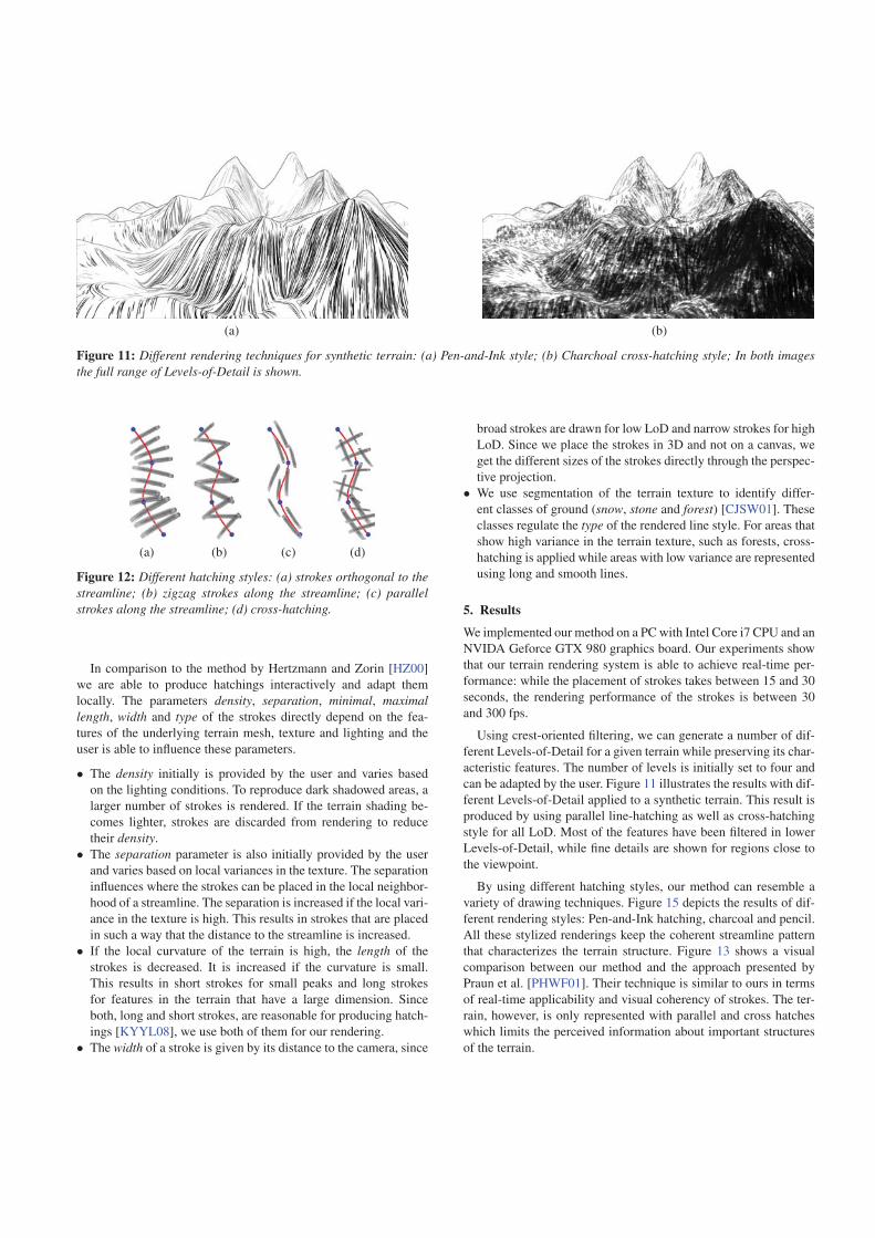
Figure 11: Different rendering techniques for synthetic terrain: (a) Pen-and-Ink style; (b) Charchoal cross-hatching style; In both imagesthe full range of Levels-of-Detail is shown.
(a) (b) (c) (d)
Figure 12: Different hatching styles: (a) strokes orthogonal to thestreamline; (b) zigzag strokes along the streamline; (c) parallelstrokes along the streamline; (d) cross-hatching.
In comparison to the method by Hertzmann and Zorin [HZ00]
we are able to produce hatchings interactively and adapt them
locally. The parameters density, separation, minimal, maximallength, width and type of the strokes directly depend on the fea-
tures of the underlying terrain mesh, texture and lighting and the
user is able to influence these parameters.
• The density initially is provided by the user and varies based
on the lighting conditions. To reproduce dark shadowed areas, a
larger number of strokes is rendered. If the terrain shading be-
comes lighter, strokes are discarded from rendering to reduce
their density.
• The separation parameter is also initially provided by the user
and varies based on local variances in the texture. The separation
influences where the strokes can be placed in the local neighbor-
hood of a streamline. The separation is increased if the local vari-
ance in the texture is high. This results in strokes that are placed
in such a way that the distance to the streamline is increased.
• If the local curvature of the terrain is high, the length of the
strokes is decreased. It is increased if the curvature is small.
This results in short strokes for small peaks and long strokes
for features in the terrain that have a large dimension. Since
both, long and short strokes, are reasonable for producing hatch-
ings [KYYL08], we use both of them for our rendering.
• The width of a stroke is given by its distance to the camera, since
broad strokes are drawn for low LoD and narrow strokes for high
LoD. Since we place the strokes in 3D and not on a canvas, we
get the different sizes of the strokes directly through the perspec-
tive projection.
• We use segmentation of the terrain texture to identify differ-
ent classes of ground (snow, stone and forest) [CJSW01]. These
classes regulate the type of the rendered line style. For areas that
show high variance in the terrain texture, such as forests, cross-
hatching is applied while areas with low variance are represented
using long and smooth lines.
5. Results
We implemented our method on a PC with Intel Core i7 CPU and an
NVIDA Geforce GTX 980 graphics board. Our experiments show
that our terrain rendering system is able to achieve real-time per-
formance: while the placement of strokes takes between 15 and 30
seconds, the rendering performance of the strokes is between 30
and 300 fps.
Using crest-oriented filtering, we can generate a number of dif-
ferent Levels-of-Detail for a given terrain while preserving its char-
acteristic features. The number of levels is initially set to four and
can be adapted by the user. Figure 11 illustrates the results with dif-
ferent Levels-of-Detail applied to a synthetic terrain. This result is
produced by using parallel line-hatching as well as cross-hatching
style for all LoD. Most of the features have been filtered in lower
Levels-of-Detail, while fine details are shown for regions close to
the viewpoint.
By using different hatching styles, our method can resemble a
variety of drawing techniques. Figure 15 depicts the results of dif-
ferent rendering styles: Pen-and-Ink hatching, charcoal and pencil.
All these stylized renderings keep the coherent streamline pattern
that characterizes the terrain structure. Figure 13 shows a visual
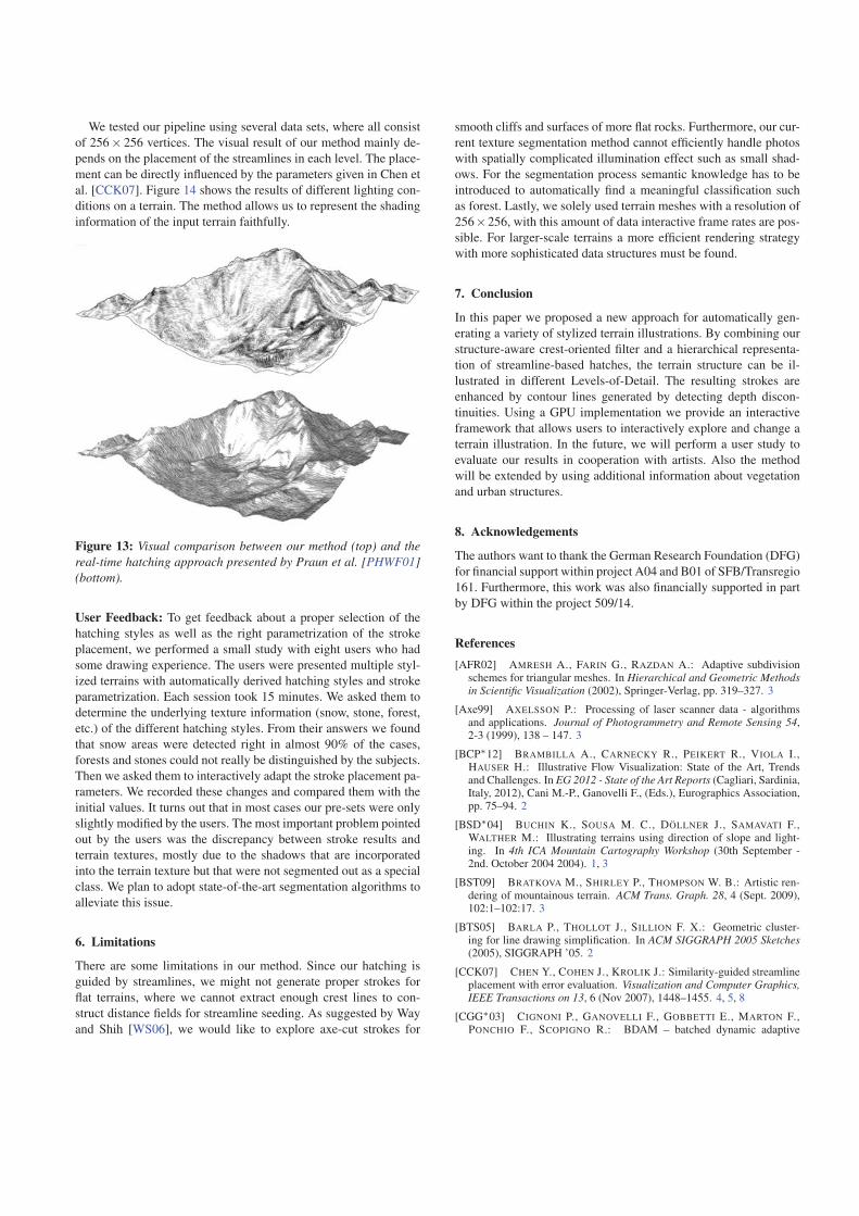
comparison between our method and the approach presented by
Praun et al. [PHWF01]. Their technique is similar to ours in terms
of real-time applicability and visual coherency of strokes. The ter-
rain, however, is only represented with parallel and cross hatches
which limits the perceived information about important structures
of the terrain.
We tested our pipeline using several data sets, where all consist
of 256× 256 vertices. The visual result of our method mainly de-
pends on the placement of the streamlines in each level. The place-
ment can be directly influenced by the parameters given in Chen et
al. [CCK07]. Figure 14 shows the results of different lighting con-
ditions on a terrain. The method allows us to represent the shading
information of the input terrain faithfully.
Figure 13: Visual comparison between our method (top) and thereal-time hatching approach presented by Praun et al. [PHWF01](bottom).
User Feedback: To get feedback about a proper selection of the
hatching styles as well as the right parametrization of the stroke
placement, we performed a small study with eight users who had
some drawing experience. The users were presented multiple styl-
ized terrains with automatically derived hatching styles and stroke
parametrization. Each session took 15 minutes. We asked them to
determine the underlying texture information (snow, stone, forest,
etc.) of the different hatching styles. From their answers we found
that snow areas were detected right in almost 90% of the cases,
forests and stones could not really be distinguished by the subjects.
Then we asked them to interactively adapt the stroke placement pa-
rameters. We recorded these changes and compared them with the
initial values. It turns out that in most cases our pre-sets were only
slightly modified by the users. The most important problem pointed
out by the users was the discrepancy between stroke results and
terrain textures, mostly due to the shadows that are incorporated
into the terrain texture but that were not segmented out as a special
class. We plan to adopt state-of-the-art segmentation algorithms to
alleviate this issue.
6. Limitations
There are some limitations in our method. Since our hatching is
guided by streamlines, we might not generate proper strokes for
flat terrains, where we cannot extract enough crest lines to con-
struct distance fields for streamline seeding. As suggested by Way
and Shih [WS06], we would like to explore axe-cut strokes for
smooth cliffs and surfaces of more flat rocks. Furthermore, our cur-
rent texture segmentation method cannot efficiently handle photos
with spatially complicated illumination effect such as small shad-
ows. For the segmentation process semantic knowledge has to be
introduced to automatically find a meaningful classification such
as forest. Lastly, we solely used terrain meshes with a resolution of
256×256, with this amount of data interactive frame rates are pos-
sible. For larger-scale terrains a more efficient rendering strategy
with more sophisticated data structures must be found.
7. Conclusion
In this paper we proposed a new approach for automatically gen-
erating a variety of stylized terrain illustrations. By combining our
structure-aware crest-oriented filter and a hierarchical representa-
tion of streamline-based hatches, the terrain structure can be il-
lustrated in different Levels-of-Detail. The resulting strokes are
enhanced by contour lines generated by detecting depth discon-
tinuities. Using a GPU implementation we provide an interactive
framework that allows users to interactively explore and change a
terrain illustration. In the future, we will perform a user study to
evaluate our results in cooperation with artists. Also the method
will be extended by using additional information about vegetation
and urban structures.
8. Acknowledgements
The authors want to thank the German Research Foundation (DFG)
for financial support within project A04 and B01 of SFB/Transregio
161. Furthermore, this work was also financially supported in part
by DFG within the project 509/14.
References[AFR02] AMRESH A., FARIN G., RAZDAN A.: Adaptive subdivision
schemes for triangular meshes. In Hierarchical and Geometric Methodsin Scientific Visualization (2002), Springer-Verlag, pp. 319–327. 3
[Axe99] AXELSSON P.: Processing of laser scanner data - algorithmsand applications. Journal of Photogrammetry and Remote Sensing 54,2-3 (1999), 138 – 147. 3
[BCP∗12] BRAMBILLA A., CARNECKY R., PEIKERT R., VIOLA I.,HAUSER H.: Illustrative Flow Visualization: State of the Art, Trendsand Challenges. In EG 2012 - State of the Art Reports (Cagliari, Sardinia,Italy, 2012), Cani M.-P., Ganovelli F., (Eds.), Eurographics Association,pp. 75–94. 2
[BSD∗04] BUCHIN K., SOUSA M. C., DÖLLNER J., SAMAVATI F.,WALTHER M.: Illustrating terrains using direction of slope and light-ing. In 4th ICA Mountain Cartography Workshop (30th September -2nd. October 2004 2004). 1, 3
[BST09] BRATKOVA M., SHIRLEY P., THOMPSON W. B.: Artistic ren-dering of mountainous terrain. ACM Trans. Graph. 28, 4 (Sept. 2009),102:1–102:17. 3
[BTS05] BARLA P., THOLLOT J., SILLION F. X.: Geometric cluster-ing for line drawing simplification. In ACM SIGGRAPH 2005 Sketches(2005), SIGGRAPH ’05. 2
[CCK07] CHEN Y., COHEN J., KROLIK J.: Similarity-guided streamlineplacement with error evaluation. Visualization and Computer Graphics,IEEE Transactions on 13, 6 (Nov 2007), 1448–1455. 4, 5, 8
[CGG∗03] CIGNONI P., GANOVELLI F., GOBBETTI E., MARTON F.,PONCHIO F., SCOPIGNO R.: BDAM – batched dynamic adaptive
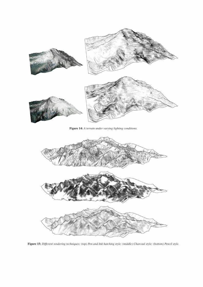
Figure 14: A terrain under varying lighting conditions.
Figure 15: Different rendering techniques: (top) Pen-and-Ink hatching style; (middle) Charcoal style; (bottom) Pencil style.
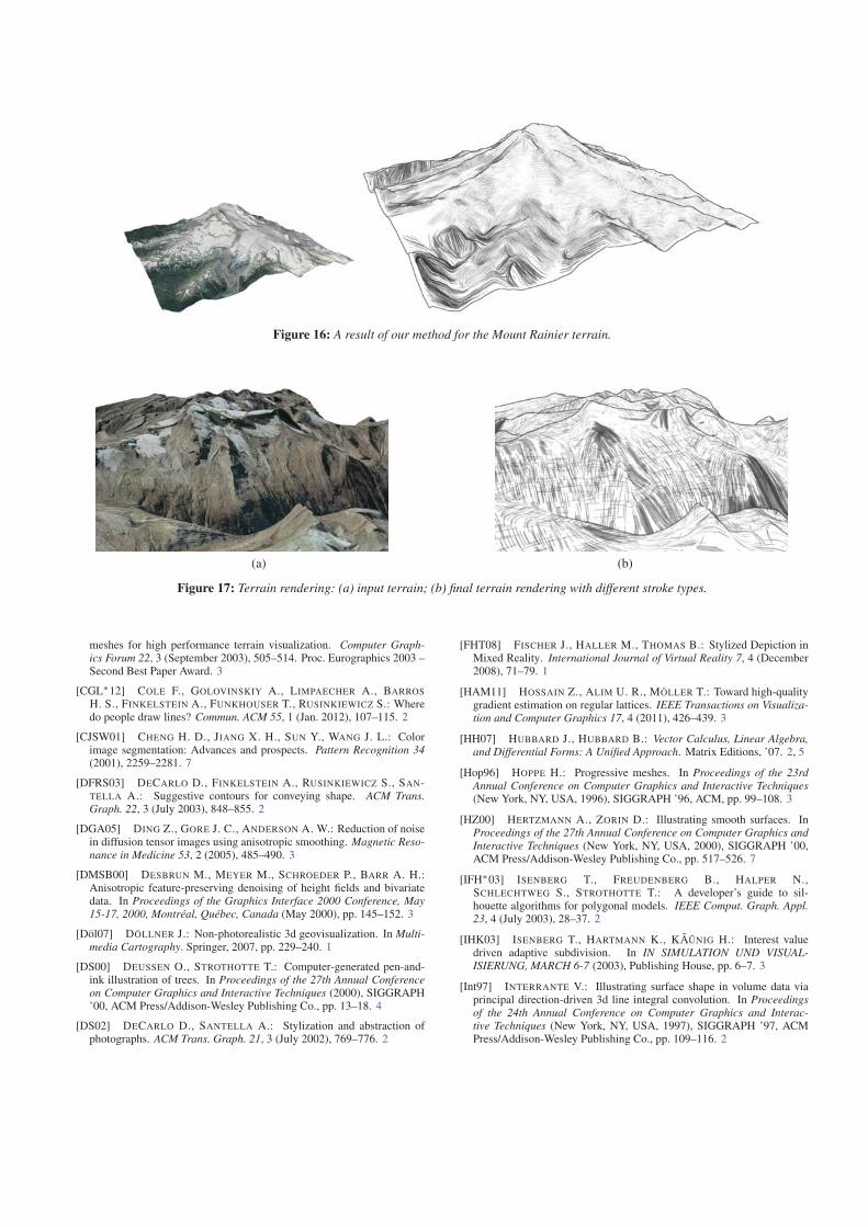
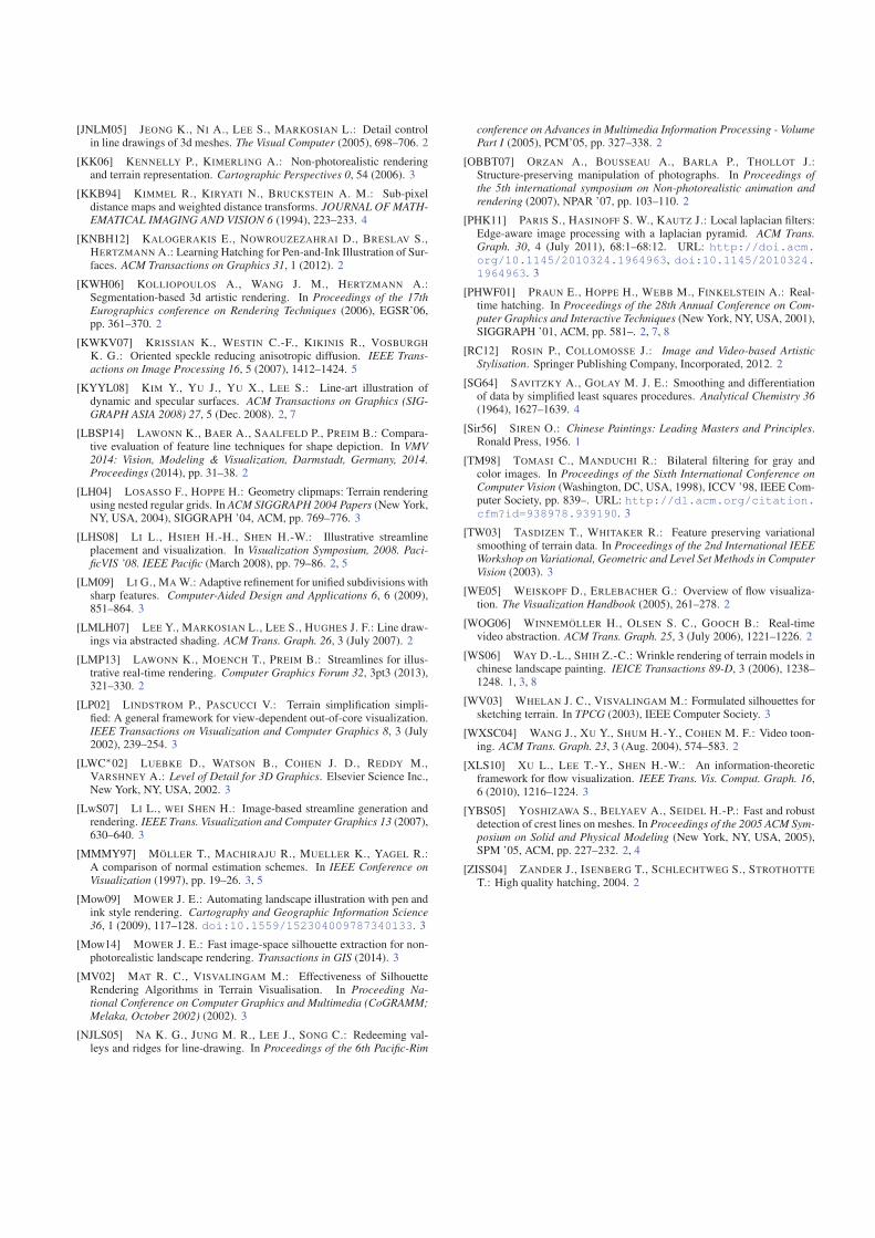
Figure 16: A result of our method for the Mount Rainier terrain.
(a) (b)
Figure 17: Terrain rendering: (a) input terrain; (b) final terrain rendering with different stroke types.
meshes for high performance terrain visualization. Computer Graph-ics Forum 22, 3 (September 2003), 505–514. Proc. Eurographics 2003 –Second Best Paper Award. 3
[CGL∗12] COLE F., GOLOVINSKIY A., LIMPAECHER A., BARROS
H. S., FINKELSTEIN A., FUNKHOUSER T., RUSINKIEWICZ S.: Wheredo people draw lines? Commun. ACM 55, 1 (Jan. 2012), 107–115. 2
[CJSW01] CHENG H. D., JIANG X. H., SUN Y., WANG J. L.: Colorimage segmentation: Advances and prospects. Pattern Recognition 34(2001), 2259–2281. 7
[DFRS03] DECARLO D., FINKELSTEIN A., RUSINKIEWICZ S., SAN-TELLA A.: Suggestive contours for conveying shape. ACM Trans.Graph. 22, 3 (July 2003), 848–855. 2
[DGA05] DING Z., GORE J. C., ANDERSON A. W.: Reduction of noisein diffusion tensor images using anisotropic smoothing. Magnetic Reso-nance in Medicine 53, 2 (2005), 485–490. 3
[DMSB00] DESBRUN M., MEYER M., SCHROEDER P., BARR A. H.:Anisotropic feature-preserving denoising of height fields and bivariatedata. In Proceedings of the Graphics Interface 2000 Conference, May15-17, 2000, Montréal, Québec, Canada (May 2000), pp. 145–152. 3
[Döl07] DÖLLNER J.: Non-photorealistic 3d geovisualization. In Multi-media Cartography. Springer, 2007, pp. 229–240. 1
[DS00] DEUSSEN O., STROTHOTTE T.: Computer-generated pen-and-ink illustration of trees. In Proceedings of the 27th Annual Conferenceon Computer Graphics and Interactive Techniques (2000), SIGGRAPH’00, ACM Press/Addison-Wesley Publishing Co., pp. 13–18. 4
[DS02] DECARLO D., SANTELLA A.: Stylization and abstraction ofphotographs. ACM Trans. Graph. 21, 3 (July 2002), 769–776. 2
[FHT08] FISCHER J., HALLER M., THOMAS B.: Stylized Depiction inMixed Reality. International Journal of Virtual Reality 7, 4 (December2008), 71–79. 1
[HAM11] HOSSAIN Z., ALIM U. R., MÖLLER T.: Toward high-qualitygradient estimation on regular lattices. IEEE Transactions on Visualiza-tion and Computer Graphics 17, 4 (2011), 426–439. 3
[HH07] HUBBARD J., HUBBARD B.: Vector Calculus, Linear Algebra,and Differential Forms: A Unified Approach. Matrix Editions, ’07. 2, 5
[Hop96] HOPPE H.: Progressive meshes. In Proceedings of the 23rdAnnual Conference on Computer Graphics and Interactive Techniques(New York, NY, USA, 1996), SIGGRAPH ’96, ACM, pp. 99–108. 3
[HZ00] HERTZMANN A., ZORIN D.: Illustrating smooth surfaces. InProceedings of the 27th Annual Conference on Computer Graphics andInteractive Techniques (New York, NY, USA, 2000), SIGGRAPH ’00,ACM Press/Addison-Wesley Publishing Co., pp. 517–526. 7
[IFH∗03] ISENBERG T., FREUDENBERG B., HALPER N.,SCHLECHTWEG S., STROTHOTTE T.: A developer’s guide to sil-houette algorithms for polygonal models. IEEE Comput. Graph. Appl.23, 4 (July 2003), 28–37. 2
[IHK03] ISENBERG T., HARTMANN K., KÃUNIG H.: Interest valuedriven adaptive subdivision. In IN SIMULATION UND VISUAL-ISIERUNG, MARCH 6-7 (2003), Publishing House, pp. 6–7. 3
[Int97] INTERRANTE V.: Illustrating surface shape in volume data viaprincipal direction-driven 3d line integral convolution. In Proceedingsof the 24th Annual Conference on Computer Graphics and Interac-tive Techniques (New York, NY, USA, 1997), SIGGRAPH ’97, ACMPress/Addison-Wesley Publishing Co., pp. 109–116. 2
[JNLM05] JEONG K., NI A., LEE S., MARKOSIAN L.: Detail controlin line drawings of 3d meshes. The Visual Computer (2005), 698–706. 2
[KK06] KENNELLY P., KIMERLING A.: Non-photorealistic renderingand terrain representation. Cartographic Perspectives 0, 54 (2006). 3
[KKB94] KIMMEL R., KIRYATI N., BRUCKSTEIN A. M.: Sub-pixeldistance maps and weighted distance transforms. JOURNAL OF MATH-EMATICAL IMAGING AND VISION 6 (1994), 223–233. 4
[KNBH12] KALOGERAKIS E., NOWROUZEZAHRAI D., BRESLAV S.,HERTZMANN A.: Learning Hatching for Pen-and-Ink Illustration of Sur-faces. ACM Transactions on Graphics 31, 1 (2012). 2
[KWH06] KOLLIOPOULOS A., WANG J. M., HERTZMANN A.:Segmentation-based 3d artistic rendering. In Proceedings of the 17thEurographics conference on Rendering Techniques (2006), EGSR’06,pp. 361–370. 2
[KWKV07] KRISSIAN K., WESTIN C.-F., KIKINIS R., VOSBURGH
K. G.: Oriented speckle reducing anisotropic diffusion. IEEE Trans-actions on Image Processing 16, 5 (2007), 1412–1424. 5
[KYYL08] KIM Y., YU J., YU X., LEE S.: Line-art illustration ofdynamic and specular surfaces. ACM Transactions on Graphics (SIG-GRAPH ASIA 2008) 27, 5 (Dec. 2008). 2, 7
[LBSP14] LAWONN K., BAER A., SAALFELD P., PREIM B.: Compara-tive evaluation of feature line techniques for shape depiction. In VMV2014: Vision, Modeling & Visualization, Darmstadt, Germany, 2014.Proceedings (2014), pp. 31–38. 2
[LH04] LOSASSO F., HOPPE H.: Geometry clipmaps: Terrain renderingusing nested regular grids. In ACM SIGGRAPH 2004 Papers (New York,NY, USA, 2004), SIGGRAPH ’04, ACM, pp. 769–776. 3
[LHS08] LI L., HSIEH H.-H., SHEN H.-W.: Illustrative streamlineplacement and visualization. In Visualization Symposium, 2008. Paci-ficVIS ’08. IEEE Pacific (March 2008), pp. 79–86. 2, 5
[LM09] LI G., MA W.: Adaptive refinement for unified subdivisions withsharp features. Computer-Aided Design and Applications 6, 6 (2009),851–864. 3
[LMLH07] LEE Y., MARKOSIAN L., LEE S., HUGHES J. F.: Line draw-ings via abstracted shading. ACM Trans. Graph. 26, 3 (July 2007). 2
[LMP13] LAWONN K., MOENCH T., PREIM B.: Streamlines for illus-trative real-time rendering. Computer Graphics Forum 32, 3pt3 (2013),321–330. 2
[LP02] LINDSTROM P., PASCUCCI V.: Terrain simplification simpli-fied: A general framework for view-dependent out-of-core visualization.IEEE Transactions on Visualization and Computer Graphics 8, 3 (July2002), 239–254. 3
[LWC∗02] LUEBKE D., WATSON B., COHEN J. D., REDDY M.,VARSHNEY A.: Level of Detail for 3D Graphics. Elsevier Science Inc.,New York, NY, USA, 2002. 3
[LwS07] LI L., WEI SHEN H.: Image-based streamline generation andrendering. IEEE Trans. Visualization and Computer Graphics 13 (2007),630–640. 3
[MMMY97] MÖLLER T., MACHIRAJU R., MUELLER K., YAGEL R.:A comparison of normal estimation schemes. In IEEE Conference onVisualization (1997), pp. 19–26. 3, 5
[Mow09] MOWER J. E.: Automating landscape illustration with pen andink style rendering. Cartography and Geographic Information Science36, 1 (2009), 117–128. doi:10.1559/152304009787340133. 3
[Mow14] MOWER J. E.: Fast image-space silhouette extraction for non-photorealistic landscape rendering. Transactions in GIS (2014). 3
[MV02] MAT R. C., VISVALINGAM M.: Effectiveness of SilhouetteRendering Algorithms in Terrain Visualisation. In Proceeding Na-tional Conference on Computer Graphics and Multimedia (CoGRAMM;Melaka, October 2002) (2002). 3
[NJLS05] NA K. G., JUNG M. R., LEE J., SONG C.: Redeeming val-leys and ridges for line-drawing. In Proceedings of the 6th Pacific-Rim
conference on Advances in Multimedia Information Processing - VolumePart I (2005), PCM’05, pp. 327–338. 2
[OBBT07] ORZAN A., BOUSSEAU A., BARLA P., THOLLOT J.:Structure-preserving manipulation of photographs. In Proceedings ofthe 5th international symposium on Non-photorealistic animation andrendering (2007), NPAR ’07, pp. 103–110. 2
[PHK11] PARIS S., HASINOFF S. W., KAUTZ J.: Local laplacian filters:Edge-aware image processing with a laplacian pyramid. ACM Trans.Graph. 30, 4 (July 2011), 68:1–68:12. URL: http://doi.acm.org/10.1145/2010324.1964963, doi:10.1145/2010324.1964963. 3
[PHWF01] PRAUN E., HOPPE H., WEBB M., FINKELSTEIN A.: Real-time hatching. In Proceedings of the 28th Annual Conference on Com-puter Graphics and Interactive Techniques (New York, NY, USA, 2001),SIGGRAPH ’01, ACM, pp. 581–. 2, 7, 8
[RC12] ROSIN P., COLLOMOSSE J.: Image and Video-based ArtisticStylisation. Springer Publishing Company, Incorporated, 2012. 2
[SG64] SAVITZKY A., GOLAY M. J. E.: Smoothing and differentiationof data by simplified least squares procedures. Analytical Chemistry 36(1964), 1627–1639. 4
[Sir56] SIREN O.: Chinese Paintings: Leading Masters and Principles.Ronald Press, 1956. 1
[TM98] TOMASI C., MANDUCHI R.: Bilateral filtering for gray andcolor images. In Proceedings of the Sixth International Conference onComputer Vision (Washington, DC, USA, 1998), ICCV ’98, IEEE Com-puter Society, pp. 839–. URL: http://dl.acm.org/citation.cfm?id=938978.939190. 3
[TW03] TASDIZEN T., WHITAKER R.: Feature preserving variationalsmoothing of terrain data. In Proceedings of the 2nd International IEEEWorkshop on Variational, Geometric and Level Set Methods in ComputerVision (2003). 3
[WE05] WEISKOPF D., ERLEBACHER G.: Overview of flow visualiza-tion. The Visualization Handbook (2005), 261–278. 2
[WOG06] WINNEMÖLLER H., OLSEN S. C., GOOCH B.: Real-timevideo abstraction. ACM Trans. Graph. 25, 3 (July 2006), 1221–1226. 2
[WS06] WAY D.-L., SHIH Z.-C.: Wrinkle rendering of terrain models inchinese landscape painting. IEICE Transactions 89-D, 3 (2006), 1238–1248. 1, 3, 8
[WV03] WHELAN J. C., VISVALINGAM M.: Formulated silhouettes forsketching terrain. In TPCG (2003), IEEE Computer Society. 3
[WXSC04] WANG J., XU Y., SHUM H.-Y., COHEN M. F.: Video toon-ing. ACM Trans. Graph. 23, 3 (Aug. 2004), 574–583. 2
[XLS10] XU L., LEE T.-Y., SHEN H.-W.: An information-theoreticframework for flow visualization. IEEE Trans. Vis. Comput. Graph. 16,6 (2010), 1216–1224. 3
[YBS05] YOSHIZAWA S., BELYAEV A., SEIDEL H.-P.: Fast and robustdetection of crest lines on meshes. In Proceedings of the 2005 ACM Sym-posium on Solid and Physical Modeling (New York, NY, USA, 2005),SPM ’05, ACM, pp. 227–232. 2, 4
[ZISS04] ZANDER J., ISENBERG T., SCHLECHTWEG S., STROTHOTTE
T.: High quality hatching, 2004. 2
Related Documents