Journal of Magnetism and Magnetic Materials 294 (2005) e57–e62 Structure and magnetic properties of nanoparticles encapsulated in carbon shells M. Leonowicz a, , M. Woz´niak a , Y.M. Shulga b , V.E. Muradyan b , Z. Liu c , H.A. Davies c , W. Kaszuwara a , J. Grabski d a Faculty of Materials Science and Engineering, NanoCentre, Warsaw University of Technology, Poland b Institute of Problems of Chemical Physics RAS, Chernogolovka, Russian Federation c Department of Engineering Materials, University of Sheffield, UK d Faculty of Physics, Warsaw University of Technology, Poland Available online 18 April 2005 Abstract Ni 2 Y and Nd–Fe–Nb–B catalysts were used for the processing of nanoparticles by arc discharge between graphite electrodes. The products were collected from the cathode (deposit and collar) and reactor walls (soot). The ferromagnetic nanoparticles have size in the range of 10–50 nm and are encapsulated in carbon shells. The chemical composition, structure and magnetic properties of the nanoparticles have been studied. For the Ni 2 Y catalyst we found that the arc discharge results in decomposition of the intermetallic Ni 2 Y phase and formation of Ni nanoparticles encapsulated in carbon shells in the collar and soot, whereas yttrium oxide was found in the deposit. For the Nd–Fe–Nb–B catalysts the magnetic properties depend on the collection place and erosion rate. Fe and Fe–Nd–Nb nanoparticles were found in the soot and deposit, respectively. r 2005 Elsevier B.V. All rights reserved. PACS: 61.46.+w; 68.37.Lp; 75.75.+a Keywords: Ferromagnetic materials; Ferromagnets—nanoscale; Rare-earth transition metal alloys It is well established that arc discharge between graphite electrodes containing catalyst leads to the formation of various geometrical and crystallo- graphic forms such as nanotubes, ribbons, en- capsulates, onions, fibres, etc (e.g. [1,2]). Appropriate choice of the processing variables and application of particular catalysts allow controlled synthesis of such materials. Carbon nanostructures have recently attracted consider- able scientific attention due to their unique physical and mechanical properties. Such nanos- tructures, depending on their properties, may have ARTICLE IN PRESS www.elsevier.com/locate/jmmm 0304-8853/$ - see front matter r 2005 Elsevier B.V. All rights reserved. doi:10.1016/j.jmmm.2005.03.054 Corresponding author. Tel.: +48 22 660 84 50; fax: +48 22 660 84 50. E-mail address: [email protected] (M. Leonowicz).

Welcome message from author
This document is posted to help you gain knowledge. Please leave a comment to let me know what you think about it! Share it to your friends and learn new things together.
Transcript
ARTICLE IN PRESS
Journal of Magnetism and Magnetic Materials 294 (2005) e57–e62
0304-8853/$
doi:10.1016
�Corresp
fax: +48 22
E-mail a
www.elsevier.com/locate/jmmm
Structure and magnetic properties of nanoparticlesencapsulated in carbon shells
M. Leonowicza,�, M. Wozniaka, Y.M. Shulgab, V.E. Muradyanb, Z. Liuc,H.A. Daviesc, W. Kaszuwaraa, J. Grabskid
aFaculty of Materials Science and Engineering, NanoCentre, Warsaw University of Technology, PolandbInstitute of Problems of Chemical Physics RAS, Chernogolovka, Russian Federation
cDepartment of Engineering Materials, University of Sheffield, UKdFaculty of Physics, Warsaw University of Technology, Poland
Available online 18 April 2005
Abstract
Ni2Y and Nd–Fe–Nb–B catalysts were used for the processing of nanoparticles by arc discharge between graphite
electrodes. The products were collected from the cathode (deposit and collar) and reactor walls (soot). The
ferromagnetic nanoparticles have size in the range of 10–50 nm and are encapsulated in carbon shells. The chemical
composition, structure and magnetic properties of the nanoparticles have been studied. For the Ni2Y catalyst we found
that the arc discharge results in decomposition of the intermetallic Ni2Y phase and formation of Ni nanoparticles
encapsulated in carbon shells in the collar and soot, whereas yttrium oxide was found in the deposit. For the
Nd–Fe–Nb–B catalysts the magnetic properties depend on the collection place and erosion rate. Fe and Fe–Nd–Nb
nanoparticles were found in the soot and deposit, respectively.
r 2005 Elsevier B.V. All rights reserved.
PACS: 61.46.+w; 68.37.Lp; 75.75.+a
Keywords: Ferromagnetic materials; Ferromagnets—nanoscale; Rare-earth transition metal alloys
It is well established that arc discharge betweengraphite electrodes containing catalyst leads to theformation of various geometrical and crystallo-graphic forms such as nanotubes, ribbons, en-
- see front matter r 2005 Elsevier B.V. All rights reserve
/j.jmmm.2005.03.054
onding author. Tel.: +48 22 660 84 50;
660 84 50.
ddress: [email protected] (M. Leonowicz).
capsulates, onions, fibres, etc (e.g. [1,2]).Appropriate choice of the processing variablesand application of particular catalysts allowcontrolled synthesis of such materials. Carbonnanostructures have recently attracted consider-able scientific attention due to their uniquephysical and mechanical properties. Such nanos-tructures, depending on their properties, may have
d.
ARTICLE IN PRESS
M. Leonowicz et al. / Journal of Magnetism and Magnetic Materials 294 (2005) e57–e62e58
a number of potential applications, e.g. in opticaldevices, information storage and composite mate-rials. So far, several authors reported the proces-sing of elementary nanoparticles of ferromagneticmetals, Fe, Co, Ni (e.g. [3,4]). However, very lessinformation is available on more complex parti-culates such as Nd–Fe–B [5,6]. Unique magneticproperties result from size-dependent phenomenain magnetic nanoparticles. Another importantaspect of this method is that the carbon shell caneffectively protect the pyrophoric nanoparticlesfrom oxidation.
In the current research we have studied themagnetic properties and structure of the encapsu-lates, which are formed on the cathode and in thewall soot for Ni2Y and Nd–Fe–Nb–B catalysts.
The experimental method applied in this study iscommonly used for the processing of fullerenesand carbon nanotubes. The cathode was made ofbulk graphite. A hollow graphite rod, filled withthe catalyst, was used as the anode. The dischargewas performed in a helium gas atmosphere(650 hPa). The discharge current and voltagevaried depending on the process, between75–90 A and 28–30 V, respectively. The distancebetween the electrodes was kept constant ataround 2 mm. For the Nd–Fe–Nb–B catalyststhe erosion rate was varied in the range0.25–1.45 g/min. Three types of discharge productswere analysed: (a) soot—collected from the cham-ber walls, (b) collar—accumulated around thecathode and (c) deposit—accumulated on the face
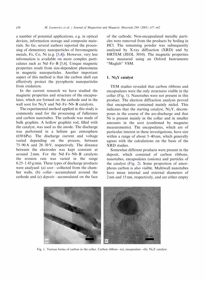
Fig. 1. Various forms of carbon in the collar. Carbo
of the cathode. Non-encapsulated metallic parti-cles were removed from the products by boiling inHCl. The remaining powder was subsequentlyanalysed by X-ray diffraction (XRD) and byHRTEM (JEOL 3010). The magnetic propertieswere measured using an Oxford Instruments‘‘Maglab’’ VSM.
1. Ni2Y catalyst
TEM studies revealed that carbon ribbons andencapsulates were the only structures visible in thecollar (Fig. 1). Nanotubes were not present in thisproduct. The electron diffraction analysis provedthat encapsulates contained mainly nickel. Thisindicates that the starting catalyst, Ni2Y, decom-poses in the course of the arc-discharge and thatNi is present mainly in the collar and in smalleramounts in the soot (confirmed by magneticmeasurements). The encapsulates, which are ofparticular interest in these investigations, have sizewithin a range of about 5–40 nm, which generallyagrees with the calculations on the basis of theXRD studies.
Somewhat different products were present in thedeposit, which consisted of carbon ribbons,nanotubes, encapsulates (onions) and particles ofthe catalyst (Fig. 2). Some proportion of amor-phous carbon is also visible. Multiwall nanotubeshave mean internal and external diameters of2 nm and 15 nm, respectively, and are either empty
n ribbon—(a), encapsulate—(b). Ni2Y catalyst.
ARTICLE IN PRESS
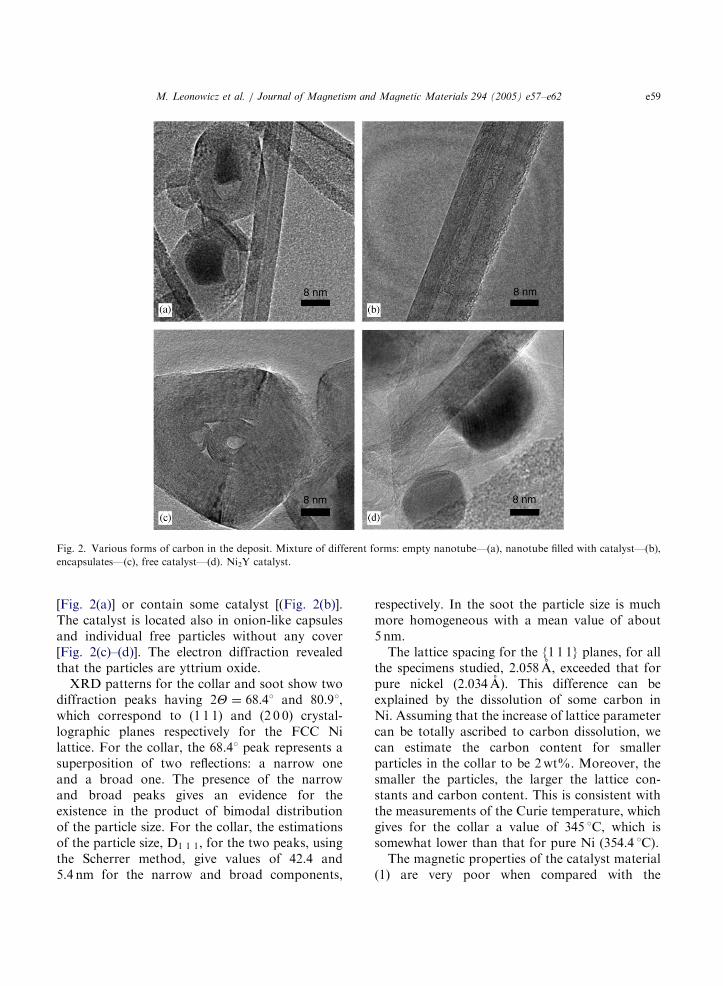
Fig. 2. Various forms of carbon in the deposit. Mixture of different forms: empty nanotube—(a), nanotube filled with catalyst—(b),
encapsulates—(c), free catalyst—(d). Ni2Y catalyst.
M. Leonowicz et al. / Journal of Magnetism and Magnetic Materials 294 (2005) e57–e62 e59
[Fig. 2(a)] or contain some catalyst [(Fig. 2(b)].The catalyst is located also in onion-like capsulesand individual free particles without any cover[Fig. 2(c)–(d)]. The electron diffraction revealedthat the particles are yttrium oxide.
XRD patterns for the collar and soot show twodiffraction peaks having 2Y ¼ 68:41 and 80.91,which correspond to (1 1 1) and (2 0 0) crystal-lographic planes respectively for the FCC Nilattice. For the collar, the 68.41 peak represents asuperposition of two reflections: a narrow oneand a broad one. The presence of the narrowand broad peaks gives an evidence for theexistence in the product of bimodal distributionof the particle size. For the collar, the estimationsof the particle size, D1 1 1, for the two peaks, usingthe Scherrer method, give values of 42.4 and5.4 nm for the narrow and broad components,
respectively. In the soot the particle size is muchmore homogeneous with a mean value of about5 nm.
The lattice spacing for the {1 1 1} planes, for allthe specimens studied, 2.058 A, exceeded that forpure nickel (2.034 A). This difference can beexplained by the dissolution of some carbon inNi. Assuming that the increase of lattice parametercan be totally ascribed to carbon dissolution, wecan estimate the carbon content for smallerparticles in the collar to be 2 wt%. Moreover, thesmaller the particles, the larger the lattice con-stants and carbon content. This is consistent withthe measurements of the Curie temperature, whichgives for the collar a value of 345 1C, which issomewhat lower than that for pure Ni (354.4 1C).
The magnetic properties of the catalyst material(1) are very poor when compared with the
ARTICLE IN PRESS
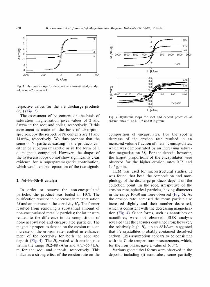
3
2
1
0
-1
-2
-3
-800 -400 0 800400
H, kA/m
σ em
u/g
1
3
2
Fig. 3. Hysteresis loops for the specimens investigated; catalyst
�1, soot �2, collar �3.
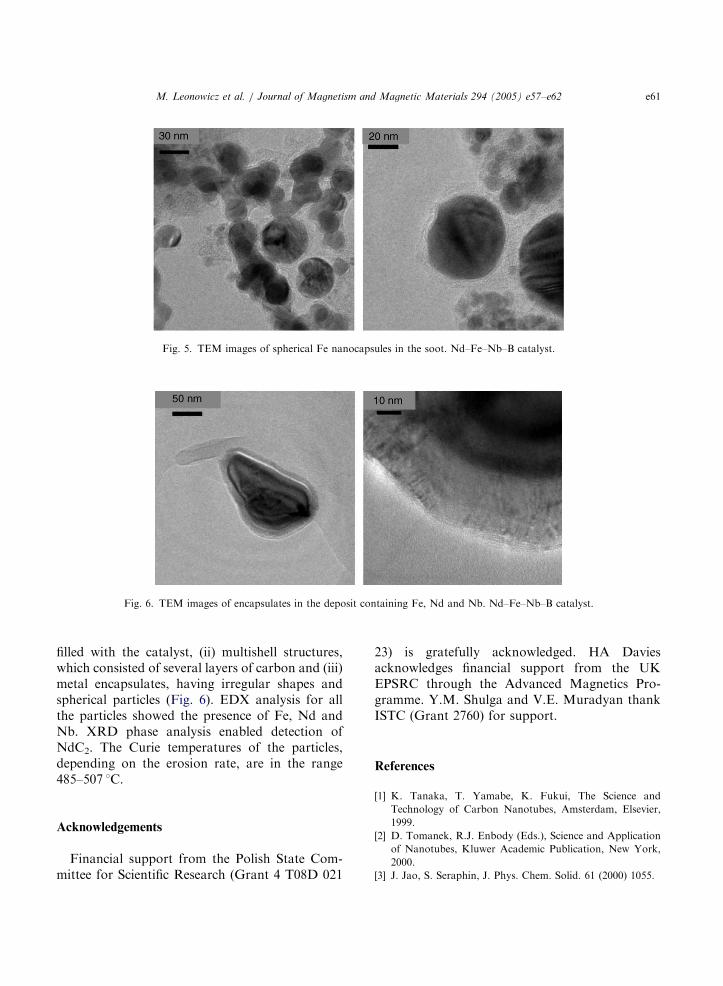
6
4
2
0
-2
-4
-6
-2000 -1500 -1000 -500 0 500 1000 1500 2000
0.25
0.75
1.45
0.25
0.75
1.45
M [e
mu/
g]M
[em
u/g]
H [kA/m]
H [kA/m]
0.50.40.30.20.1
0
-0.2-0.1
-0.3-0.4-0.5
-1600 -1100 -600 0 400 900 1400
Soot
Deposit
Fig. 4. Hysteresis loops for soot and deposit processed at
erosion rates of 1.45, 0.75 and 0.25 g/min.
M. Leonowicz et al. / Journal of Magnetism and Magnetic Materials 294 (2005) e57–e62e60
respective values for the arc discharge products(2,3) (Fig. 3).
The assessment of Ni content on the basis ofsaturation magnetisation gives values of 2 and8 wt% in the soot and collar, respectively. If thisassessment is made on the basis of absorptionspectroscopy the respective Ni contents are 11 and14 wt%, respectively. We thus propose that thesome of Ni particles existing in the products caneither be superparamagnetic or in the form of adiamagnetic compound. However, the shapes ofthe hysteresis loops do not show significantly clearevidence for a superparamagnetic contribution,which would enable separation of the two signals.
2. Nd–Fe–Nb–B catalyst
In order to remove the non-encapsulatedparticles, the product was boiled in HCl. Thepurification resulted in a decrease in magnetisationM and an increase in the coercivity Hc. The formerresulted from removing a substantial amount ofnon-encapsulated metallic particles; the latter wererelated to the difference in the compositions ofnon-encapsulated and encapsulated particles. Themagnetic properties depend on the erosion rate; anincrease of the erosion rate resulted in enhance-ment of the coercivity for both the soot anddeposit (Fig. 4). The Hc varied with erosion ratewithin the range 18.2–88 kA/m and 47.7–56.4 kA/m for the soot and deposit, respectively. Thisindicates a strong effect of the erosion rate on the
composition of encapsulates. For the soot adecrease of the erosion rate resulted in anincreased volume fraction of metallic encapsulates,which was demonstrated by an increasing satura-tion magnetisation Ms. For the deposit, however,the largest proportions of the encapsulates wereobserved for the higher erosion rates 0.75 and1.45 g/min.
TEM was used for microstructural studies. Itwas found that both the composition and mor-phology of the discharge products depend on thecollection point. In the soot, irrespective of theerosion rate, spherical particles, having diametersin the range 10–50 nm were observed (Fig. 5). Asthe erosion rate increased the mean particle sizeincreased slightly and their number decreased,which is consistent with the decreasing magnetisa-tion (Fig. 4). Other forms, such as nanotubes ornanofibres, were not observed. EDX analysisrevealed that the capsules contained iron; however,the relatively high Hc, up to 88 kA/m, suggestedthat Fe crystallites probably contained dissolvedcarbon. This assumption appears to be consistentwith the Curie temperature measurements, which,for the iron phase, gave a value of 670 1C.
Various geometrical forms were observed in thedeposit, including (i) nanotubes, some partially
ARTICLE IN PRESS
Fig. 6. TEM images of encapsulates in the deposit containing Fe, Nd and Nb. Nd–Fe–Nb–B catalyst.
Fig. 5. TEM images of spherical Fe nanocapsules in the soot. Nd–Fe–Nb–B catalyst.
M. Leonowicz et al. / Journal of Magnetism and Magnetic Materials 294 (2005) e57–e62 e61
filled with the catalyst, (ii) multishell structures,which consisted of several layers of carbon and (iii)metal encapsulates, having irregular shapes andspherical particles (Fig. 6). EDX analysis for allthe particles showed the presence of Fe, Nd andNb. XRD phase analysis enabled detection ofNdC2. The Curie temperatures of the particles,depending on the erosion rate, are in the range485–507 1C.
Acknowledgements
Financial support from the Polish State Com-mittee for Scientific Research (Grant 4 T08D 021
23) is gratefully acknowledged. HA Daviesacknowledges financial support from the UKEPSRC through the Advanced Magnetics Pro-gramme. Y.M. Shulga and V.E. Muradyan thankISTC (Grant 2760) for support.
References
[1] K. Tanaka, T. Yamabe, K. Fukui, The Science and
Technology of Carbon Nanotubes, Amsterdam, Elsevier,
1999.
[2] D. Tomanek, R.J. Enbody (Eds.), Science and Application
of Nanotubes, Kluwer Academic Publication, New York,
2000.
[3] J. Jao, S. Seraphin, J. Phys. Chem. Solid. 61 (2000) 1055.

ARTICLE IN PRESS
M. Leonowicz et al. / Journal of Magnetism and Magnetic Materials 294 (2005) e57–e62e62
[4] M. Leonowicz, Y. Shulga, M. Wozniak, Wei Xie, in: T.N.
Veziroglu, et al. (Eds.), Hydrogen Materials Science and
Chemistry of Carbon Nanomaterials, Proceedings NATO
Advanced Research Workshop, Sudak, Crimea, Ukraine,
September 14–20, 2003, Kluwer Academic Publication, New
York, 2004, pp. 193.
[5] M. Bystrzejewski, A. Huczko, H. Lange, P. Baranowski, J.
Kozubowski, M. Wozniak, M. Leonowicz, W. Kaszuwara,
Proceedings EMRS-2003, 14–19 September 2003, Warsaw,
Poland, pp. 200.
[6] C.T. Kuo, C.H. Lin, A.Y. Lo, Diamond Relat. Mater. 12
(2003) 799.
Related Documents