Structural Technical Report 1 Structural Concept / Structural Existing Conditions Report PricewaterhouseCoopers Oslo, Norway James Wilson Structural Option AE 481W Senior Thesis The Pennsylvania State University Faculty Consultant: Professor M. Kevin Parfitt

Welcome message from author
This document is posted to help you gain knowledge. Please leave a comment to let me know what you think about it! Share it to your friends and learn new things together.
Transcript
Structural Technical Report 1 Structural Concept / Structural Existing Conditions Report
PricewaterhouseCoopers Oslo, Norway
James Wilson Structural Option
AE 481W Senior Thesis The Pennsylvania State University
Faculty Consultant: Professor M. Kevin Parfitt

Technical Report 1 PricewaterhouseCoopers James Wilson - Structural Option Oslo, Norway Advisor: Prof. M. Kevin Parfitt 9/29/08
1
Table of Contents
Executive Summary ........................................................................................................2 1. Structural Discussion .....................................................................................................3
1.1 Introduction .................................................................................................................. 3 1.2 Floor and Roof System of the Superstructure .............................................................. 4 1.3 Superstructure Columns ................................................................................................ 5 1.4 Lateral System ............................................................................................................... 6 1.5 Substructure ................................................................................................................... 7 1.6 Foundation ..................................................................................................................... 7 1.7 The Grand Entrance ....................................................................................................... 8
2. Design Codes...................................................................................................................9 2.1 Norwegian Standards Used in Original Design ............................................................ 9 2.2 Codes and Reference Standards used in Senior Thesis .............................................. 10
3. Materials .......................................................................................................................11 3.1 Steel ............................................................................................................................ 11 3.2 Concrete ..................................................................................................................... 12
4. Gravity and Lateral Loads ..........................................................................................13 4.1 Dead ........................................................................................................................... 13 4.2 Live ............................................................................................................................. 14 4.3 Wind ............................................................................................................................ 15 4.4 Seismic ........................................................................................................................ 16
5. Spot Checks ..................................................................................................................18 5.1 Beam ........................................................................................................................... 18 5.2 Column ....................................................................................................................... 18
Appendix ...........................................................................................................................19 A1 Wind Loads ............................................................................................................... 19 A2 Seismic Loads ............................................................................................................. 22 A3 Snow Loads ................................................................................................................ 26 A4 Beam Spot Check ....................................................................................................... 27 A5 Column Spot Check .................................................................................................... 32

Technical Report 1 PricewaterhouseCoopers James Wilson - Structural Option Oslo, Norway Advisor: Prof. M. Kevin Parfitt 9/29/08
2
Executive Summary
The purpose of this report is to assess the existing conditions of the PricewaterhouseCoopers building and to gain an understanding of the procedures used in its structural design. It encompasses a structural discussion, code overview, material summary, determination of design loads and spot checks. The design codes used by the structural engineer to determine loads on the structure are Norwegian Standards. As the Eurocodes will be implemented across Europe within the next couple of years, this technical report makes an attempt to follow the Eurocodes when possible. However, with limited guidance on procedures alternative codes have additionally been used. Lateral loads have been determined in accordance with ASCE 07 and spot checks follow LRFD provisions.
An effort has been made to summarize the properties of the materials used in the building as well as their designations in accordance with various standards.
The gravity loads on the structure were found to be directly in accordance with the Eurocodes. Lateral loads were calculated to be greater than those determined by design engineer and needs further review. Reasons for the discrepancies could be differences in design codes, reference location and assumptions as well as errors in manual calculation.
A spot check of one column and one beam indicates the members of the structure are adequate to carry design loads. The reason for the calculated member capacities being considerably larger than the loads is most likely due to simplifying assumptions made in calculations.
Technical Report 1 PricewaterhouseCoopers James Wilson - Structural Option Oslo, Norway Advisor: Prof. M. Kevin Parfitt 9/29/08
3
1 - Structural Discussion
1.1 Introduction
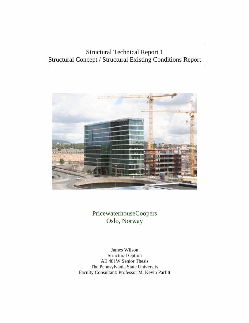
The superstructure of the PricewaterhouseCoopers (PwC) building consists of concrete plank decking on steel frame with cast in place concrete cores. Along the exterior of the building the concrete planks typically rest on HSQ profile beams, while along the interior they rest on steel angles connected to the concrete core. The exterior steel beams are supported by circular steel columns filled with reinforced concrete. A grand opening at the center of the facade is allowed through the use of three steel trusses. To provide lateral resistance there are concrete cores located centrally in each leg of the building. The cores are integrated into substructure which is comprised of cast in place concrete. The foundation uses steel and concrete piles driven between 30 and 40m to bedrock.
Figure 1. Building Section
Figure 2. Typical framing plan for floors 1 – 4
N
E
S
W
Technical Report 1 PricewaterhouseCoopers James Wilson - Structural Option Oslo, Norway Advisor: Prof. M. Kevin Parfitt 9/29/08
4
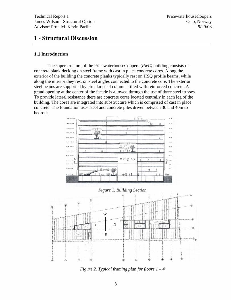
1.2 Floor and Roof System of the Superstructure The floor and roof system of the superstructure is precast hollow core concrete plank on steel framing. The concrete planks are HD265’s and have approximate section dimensions of 1.2m x 0.3m (figure 3). Spans range from 5m to 10m and are run in the East-West direction. Due to the buildings shape, edges of some of the planks are cut at an angle.
Figure 3: HD 265 element
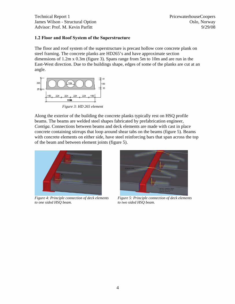
Along the exterior of the building the concrete planks typically rest on HSQ profile beams. The beams are welded steel shapes fabricated by prefabrication engineer, Contiga. Connections between beams and deck elements are made with cast in place concrete containing stirrups that loop around shear tabs on the beams (figure 5). Beams with concrete elements on either side, have steel reinforcing bars that span across the top of the beam and between element joints (figure 5).
Figure 4: Principle connection of deck elements Figure 5: Principle connection of deck elements to one sided HSQ beam. to two sided HSQ beam.
Technical Report 1 PricewaterhouseCoopers James Wilson - Structural Option Oslo, Norway Advisor: Prof. M. Kevin Parfitt 9/29/08
5
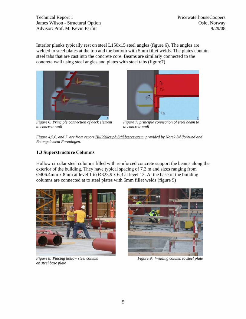
Interior planks typically rest on steel L150x15 steel angles (figure 6). The angles are welded to steel plates at the top and the bottom with 5mm fillet welds. The plates contain steel tabs that are cast into the concrete core. Beams are similarly connected to the concrete wall using steel angles and plates with steel tabs (figure7)
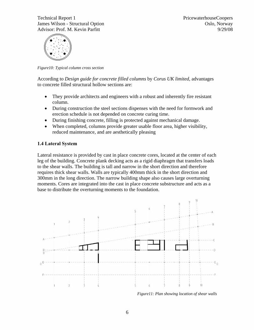
Figure 6: Principle connection of deck element Figure 7: principle connection of steel beam to to concrete wall to concrete wall Figure 4,5,6, and 7 are from report Hulldeker på Stål bæresystem provided by Norsk Stålforbund and Betongelement Foreningen. 1.3 Superstructure Columns Hollow circular steel columns filled with reinforced concrete support the beams along the exterior of the building. They have typical spacing of 7.2 m and sizes ranging from Ø406.4mm x 8mm at level 1 to Ø323.9 x 6.3 at level 12. At the base of the building columns are connected at to steel plates with 6mm fillet welds (figure 9)
Figure 8: Placing hollow steel column Figure 9: Welding column to steel plate on steel base plate
Technical Report 1 PricewaterhouseCoopers James Wilson - Structural Option Oslo, Norway Advisor: Prof. M. Kevin Parfitt 9/29/08
6
Figure10: Typical column cross section According to Design guide for concrete filled columns by Corus UK limited, advantages to concrete filled structural hollow sections are:
• They provide architects and engineers with a robust and inherently fire resistant
column. • During construction the steel sections dispenses with the need for formwork and
erection schedule is not depended on concrete curing time. • During finishing concrete, filling is protected against mechanical damage. • When completed, columns provide greater usable floor area, higher visibility,
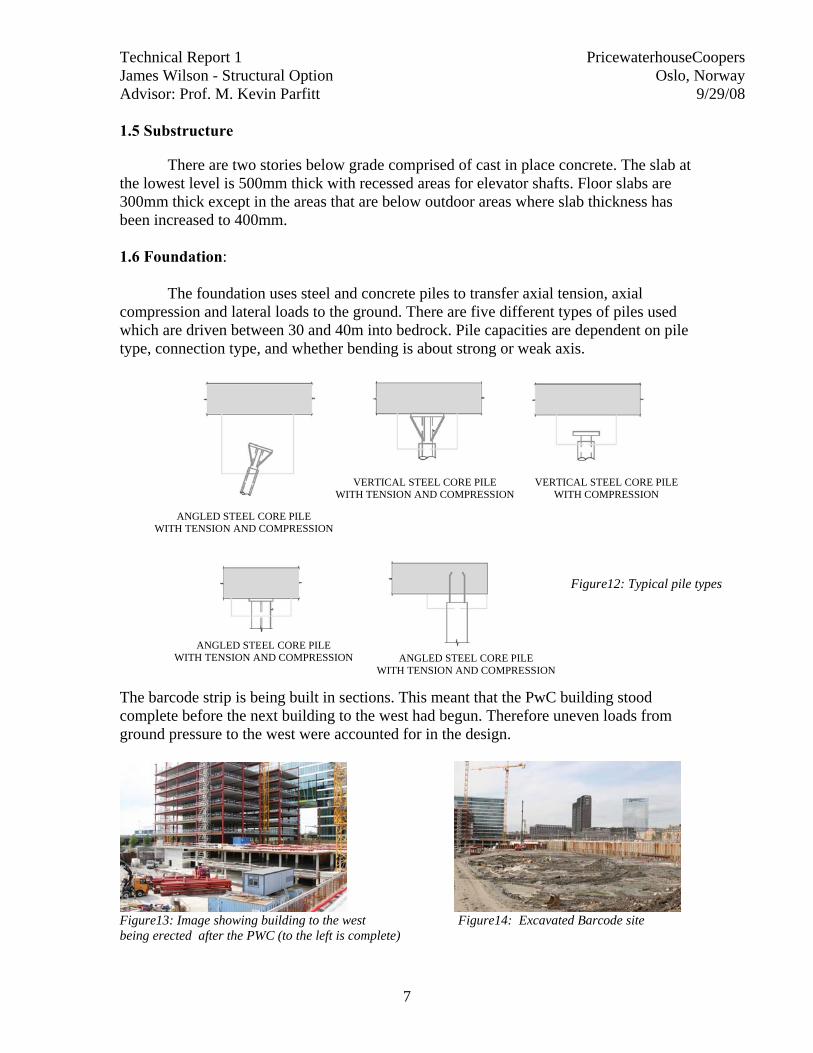
reduced maintenance, and are aesthetically pleasing 1.4 Lateral System Lateral resistance is provided by cast in place concrete cores, located at the center of each leg of the building. Concrete plank decking acts as a rigid diaphragm that transfers loads to the shear walls. The building is tall and narrow in the short direction and therefore requires thick shear walls. Walls are typically 400mm thick in the short direction and 300mm in the long direction. The narrow building shape also causes large overturning moments. Cores are integrated into the cast in place concrete substructure and acts as a base to distribute the overturning moments to the foundation.
Figure11: Plan showing location of shear walls
Technical Report 1 PricewaterhouseCoopers James Wilson - Structural Option Oslo, Norway Advisor: Prof. M. Kevin Parfitt 9/29/08
7
1.5 Substructure
There are two stories below grade comprised of cast in place concrete. The slab at the lowest level is 500mm thick with recessed areas for elevator shafts. Floor slabs are 300mm thick except in the areas that are below outdoor areas where slab thickness has been increased to 400mm. 1.6 Foundation:
The foundation uses steel and concrete piles to transfer axial tension, axial compression and lateral loads to the ground. There are five different types of piles used which are driven between 30 and 40m into bedrock. Pile capacities are dependent on pile type, connection type, and whether bending is about strong or weak axis.
The barcode strip is being built in sections. This meant that the PwC building stood complete before the next building to the west had begun. Therefore uneven loads from ground pressure to the west were accounted for in the design.
Figure13: Image showing building to the west Figure14: Excavated Barcode site being erected after the PWC (to the left is complete)
ANGLED STEEL CORE PILE WITH TENSION AND COMPRESSION
ANGLED STEEL CORE PILE WITH TENSION AND COMPRESSION ANGLED STEEL CORE PILE
WITH TENSION AND COMPRESSION
VERTICAL STEEL CORE PILE WITH COMPRESSION
VERTICAL STEEL CORE PILE WITH TENSION AND COMPRESSION
Figure12: Typical pile types
Technical Report 1 PricewaterhouseCoopers James Wilson - Structural Option Oslo, Norway Advisor: Prof. M. Kevin Parfitt 9/29/08
8
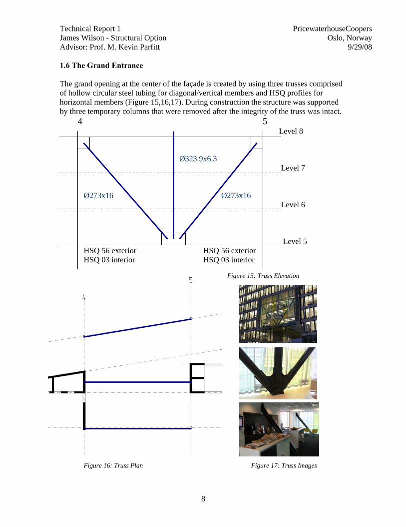
1.6 The Grand Entrance The grand opening at the center of the façade is created by using three trusses comprised of hollow circular steel tubing for diagonal/vertical members and HSQ profiles for horizontal members (Figure 15,16,17). During construction the structure was supported by three temporary columns that were removed after the integrity of the truss was intact.
4 5 Level 8
Ø323.9x6.3 Level 7
Ø273x16 Ø273x16 Level 6 Level 5 HSQ 56 exterior HSQ 56 exterior HSQ 03 interior HSQ 03 interior
Figure 15: Truss Elevation
Figure 16: Truss Plan Figure 17: Truss Images
Technical Report 1 PricewaterhouseCoopers James Wilson - Structural Option Oslo, Norway Advisor: Prof. M. Kevin Parfitt 9/29/08
9
2 - Design codes
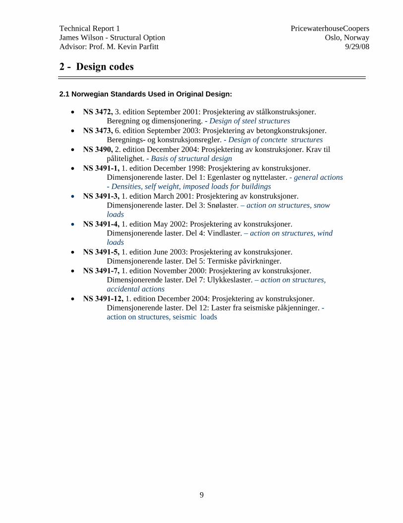
2.1 Norwegian Standards Used in Original Design:
• NS 3472, 3. edition September 2001: Prosjektering av stålkonstruksjoner. Beregning og dimensjonering. - Design of steel structures
• NS 3473, 6. edition September 2003: Prosjektering av betongkonstruksjoner. Beregnings- og konstruksjonsregler. - Design of conctete structures
• NS 3490, 2. edition December 2004: Prosjektering av konstruksjoner. Krav til pålitelighet. - Basis of structural design
• NS 3491-1, 1. edition December 1998: Prosjektering av konstruksjoner. Dimensjonerende laster. Del 1: Egenlaster og nyttelaster. - general actions - Densities, self weight, imposed loads for buildings
• NS 3491-3, 1. edition March 2001: Prosjektering av konstruksjoner. Dimensjonerende laster. Del 3: Snølaster. – action on structures, snow loads
• NS 3491-4, 1. edition May 2002: Prosjektering av konstruksjoner. Dimensjonerende laster. Del 4: Vindlaster. – action on structures, wind loads
• NS 3491-5, 1. edition June 2003: Prosjektering av konstruksjoner. Dimensjonerende laster. Del 5: Termiske påvirkninger.
• NS 3491-7, 1. edition November 2000: Prosjektering av konstruksjoner. Dimensjonerende laster. Del 7: Ulykkeslaster. – action on structures, accidental actions
• NS 3491-12, 1. edition December 2004: Prosjektering av konstruksjoner. Dimensjonerende laster. Del 12: Laster fra seismiske påkjenninger. - action on structures, seismic loads
Technical Report 1 PricewaterhouseCoopers James Wilson - Structural Option Oslo, Norway Advisor: Prof. M. Kevin Parfitt 9/29/08
10
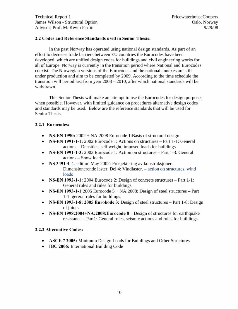
2.2 Codes and Reference Standards used in Senior Thesis:
In the past Norway has operated using national design standards. As part of an effort to decrease trade barriers between EU countries the Eurocodes have been developed, which are unified design codes for buildings and civil engineering works for all of Europe. Norway is currently in the transition period where National and Eurocodes coexist. The Norwegian versions of the Eurocodes and the national annexes are still under production and aim to be completed by 2009. According to the time schedule the transition will period last from year 2008 – 2010, after which national standards will be withdrawn.
This Senior Thesis will make an attempt to use the Eurocodes for design purposes
when possible. However, with limited guidance on procedures alternative design codes and standards may be used. Below are the reference standards that will be used for Senior Thesis. 2.2.1 Eurocodes:
• NS-EN 1990: 2002 + NA:2008 Eurocode 1:Basis of structural design • NS-EN 1991-1-1: 2002 Eurocode 1: Actions on structures – Part 1-1: General
actions – Densities, self weight, imposed loads for buildings • NS-EN 1991-1-3: 2003 Eurocode 1: Action on structures – Part 1-3: General
actions – Snow loads • NS 3491-4, 1. edition May 2002: Prosjektering av konstruksjoner.
Dimensjonerende laster. Del 4: Vindlaster. – action on structures, wind loads
• NS-EN 1992-1-1: 2004 Eurocode 2: Design of concrete structures – Part 1-1: General rules and rules for buildings
• NS-EN 1993-1-1:2005 Eurocode 5 + NA:2008: Design of steel structures – Part 1-1: gereral rules for buildings.
• NS-EN 1993-1-8: 2005 Eurokode 3: Design of steel structures – Part 1-8: Design of joints
• NS-EN 1998:2004+NA:2008:Eurocode 8 – Design of structures for earthquake resistance – Part1: General rules, seismic actions and rules for buildings.
2.2.2 Alternative Codes:
• ASCE 7 2005: Minimum Design Loads for Buildings and Other Structures • IBC 2006: International Building Code
Technical Report 1 PricewaterhouseCoopers James Wilson - Structural Option Oslo, Norway Advisor: Prof. M. Kevin Parfitt 9/29/08
11
3 - Materials
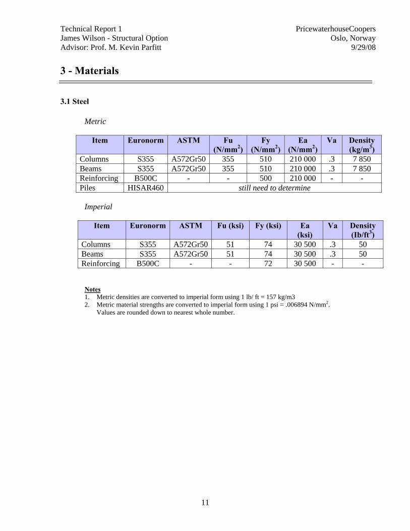
3.1 Steel
Metric
Item Euronorm ASTM Fu (N/mm2)
Fy (N/mm2)
Ea (N/mm2)
Va Density (kg/m3)
Columns S355 A572Gr50 355 510 210 000 .3 7 850 Beams S355 A572Gr50 355 510 210 000 .3 7 850 Reinforcing B500C - - 500 210 000 - - Piles HISAR460 still need to determine
Imperial
Item Euronorm ASTM Fu (ksi) Fy (ksi) Ea
(ksi) Va Density
(Ib/ft3) Columns S355 A572Gr50 51 74 30 500 .3 50 Beams S355 A572Gr50 51 74 30 500 .3 50 Reinforcing B500C - - 72 30 500 - -
Notes 1. Metric densities are converted to imperial form using 1 lb/ ft = 157 kg/m3 2. Metric material strengths are converted to imperial form using 1 psi = .006894 N/mm2.
Values are rounded down to nearest whole number.
Technical Report 1 PricewaterhouseCoopers James Wilson - Structural Option Oslo, Norway Advisor: Prof. M. Kevin Parfitt 9/29/08
12
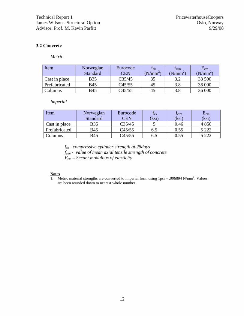
3.2 Concrete
Metric
Item Norwegian Standard
Eurocode CEN
fck (N/mm2)
fctm (N/mm2)
Ecm (N/mm2)
Cast in place B35 C35/45 35 3.2 33 500 Prefabricated B45 C45/55 45 3.8 36 000 Columns B45 C45/55 45 3.8 36 000
Imperial
Item Norwegian
Standard Eurocode
CEN fck
(ksi) fctm (ksi)
Ecm (ksi)
Cast in place B35 C35/45 5 0.46 4 850 Prefabricated B45 C45/55 6.5 0.55 5 222 Columns B45 C45/55 6.5 0.55 5 222
fck - compressive cylinder strength at 28days fctm - value of mean axial tensile strength of concrete Ecm – Secant modulous of elasticity
Notes 1. Metric material strengths are converted to imperial form using 1psi = .006894 N/mm2. Values
are been rounded down to nearest whole number.
Technical Report 1 PricewaterhouseCoopers James Wilson - Structural Option Oslo, Norway Advisor: Prof. M. Kevin Parfitt 9/29/08
13
4 Gravity and Lateral Loads
4.1 Dead Loads
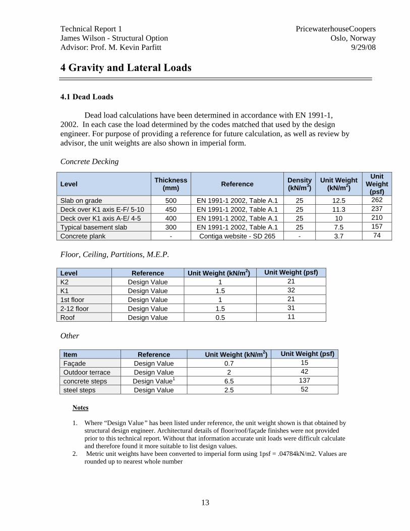
Dead load calculations have been determined in accordance with EN 1991-1, 2002. In each case the load determined by the codes matched that used by the design engineer. For purpose of providing a reference for future calculation, as well as review by advisor, the unit weights are also shown in imperial form. Concrete Decking
Floor, Ceiling, Partitions, M.E.P. Level Reference Unit Weight (kN/m2) Unit Weight (psf) K2 Design Value 1 21 K1 Design Value 1.5 32 1st floor Design Value 1 21 2-12 floor Design Value 1.5 31 Roof Design Value 0.5 11 Other Item Reference Unit Weight (kN/m2) Unit Weight (psf)Façade Design Value 0.7 15 Outdoor terrace Design Value 2 42 concrete steps Design Value1 6.5 137 steel steps Design Value 2.5 52
Notes
1. Where “Design Value” has been listed under reference, the unit weight shown is that obtained by
structural design engineer. Architectural details of floor/roof/façade finishes were not provided prior to this technical report. Without that information accurate unit loads were difficult calculate and therefore found it more suitable to list design values.
2. Metric unit weights have been converted to imperial form using 1psf = .04784kN/m2. Values are rounded up to nearest whole number
Level Thickness (mm) Reference Density
(kN/m3) Unit Weight
(kN/m2) Unit
Weight (psf)
Slab on grade 500 EN 1991-1 2002, Table A.1 25 12.5 262 Deck over K1 axis E-F/ 5-10 450 EN 1991-1 2002, Table A.1 25 11.3 237 Deck over K1 axis A-E/ 4-5 400 EN 1991-1 2002, Table A.1 25 10 210 Typical basement slab 300 EN 1991-1 2002, Table A.1 25 7.5 157 Concrete plank - Contiga website - SD 265 - 3.7 74

Technical Report 1 PricewaterhouseCoopers James Wilson - Structural Option Oslo, Norway Advisor: Prof. M. Kevin Parfitt 9/29/08
14
4.2 Live Loads
Live load calculations have been determined according to the EN 1991-1, 2002 and NS-EN 1991-1-3, 2003 In each case the load determined by the codes matched that used by the design engineer.
Imposed Floor Loads
Snow Loads
Notes 1. Where “Design Value” has been listed under reference, the value shown is that obtained by
structural design engineer. Architectural details of floor/roof/façade finishes were not obtained prior this technical report. Without that information accurate unit loads could not be calculated and therefore it was more suitable to list design values.
2. Metric unit weights have been converted to imperial form using 1psf = .04784kN/m2. Values are been rounded up to nearest whole number
Area Reference Category Unit
Weight (kN/m2)
Concentrated Load (kN)
Unit Weight
(psf) Office spaces EN 1991-1 2002, Table NA.6.2 B 2 2 42 Cafeteria EN 1991-1 2002, Table NA.6.2 C1 3 4 63 Outdoor terrace EN 1991-1 2002, Table NA.6.2 C1 3 4 63 Auditorium EN 1991-1 2002, Table NA.6.2 C2 4 4 84 Corridors EN 1991-1 2002, Table NA.6.2 C3 5 4 105 Technical Rooms Design Value1 - 5 4 105 Archives (stationary) Design Value1 - 7 4 147 Archives (On rollers) Design Value1 - 12 4 251 Outdoor "under opening" Design Value1 - 20 105 418 Outdoor Design Value1 - 20 190 418
Snow Load NS-EN 1991-1-3: 2003 - 2.8 - 60
Technical Report 1 PricewaterhouseCoopers James Wilson - Structural Option Oslo, Norway Advisor: Prof. M. Kevin Parfitt 9/29/08
15
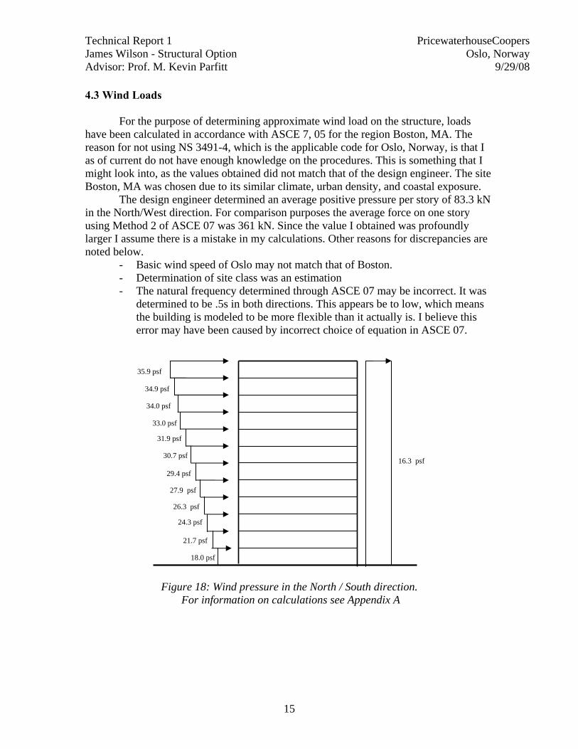
4.3 Wind Loads For the purpose of determining approximate wind load on the structure, loads have been calculated in accordance with ASCE 7, 05 for the region Boston, MA. The reason for not using NS 3491-4, which is the applicable code for Oslo, Norway, is that I as of current do not have enough knowledge on the procedures. This is something that I might look into, as the values obtained did not match that of the design engineer. The site Boston, MA was chosen due to its similar climate, urban density, and coastal exposure.
The design engineer determined an average positive pressure per story of 83.3 kN in the North/West direction. For comparison purposes the average force on one story using Method 2 of ASCE 07 was 361 kN. Since the value I obtained was profoundly larger I assume there is a mistake in my calculations. Other reasons for discrepancies are noted below.
- Basic wind speed of Oslo may not match that of Boston. - Determination of site class was an estimation - The natural frequency determined through ASCE 07 may be incorrect. It was
determined to be .5s in both directions. This appears be to low, which means the building is modeled to be more flexible than it actually is. I believe this error may have been caused by incorrect choice of equation in ASCE 07.
Figure 18: Wind pressure in the North / South direction. For information on calculations see Appendix A
18.0 psf
21.7 psf
24.3 psf
26.3 psf
29.4 psf
30.7 psf
31.9 psf
33.0 psf
34.0 psf
34.9 psf
35.9 psf
27.9 psf
16.3 psf
Technical Report 1 PricewaterhouseCoopers James Wilson - Structural Option Oslo, Norway Advisor: Prof. M. Kevin Parfitt 9/29/08
16
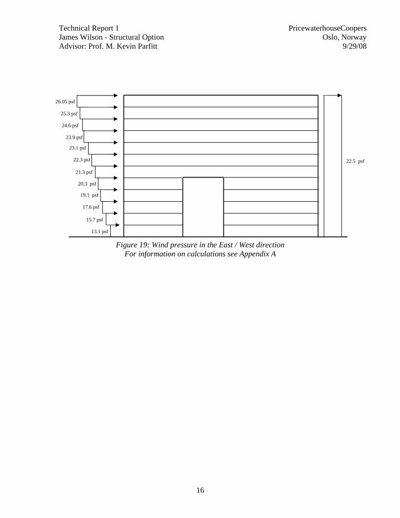
Figure 19: Wind pressure in the East / West direction For information on calculations see Appendix A
13.1 psf
15.7 psf
17.6 psf
19.1 psf
21.3 psf
22.3 psf
23.1 psf
23.9 psf
24.6 psf
25.3 psf
26.05 psf
20.3 psf
22.5 psf
Technical Report 1 PricewaterhouseCoopers James Wilson - Structural Option Oslo, Norway Advisor: Prof. M. Kevin Parfitt 9/29/08
17
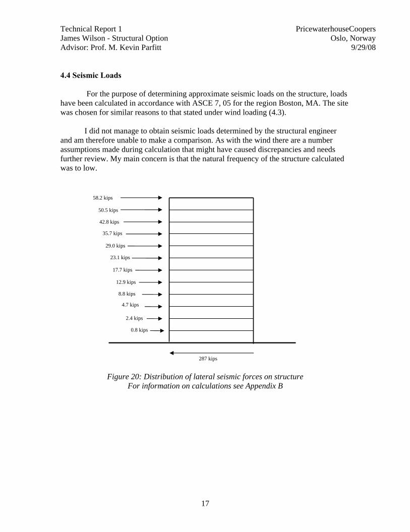
4.4 Seismic Loads
For the purpose of determining approximate seismic loads on the structure, loads have been calculated in accordance with ASCE 7, 05 for the region Boston, MA. The site was chosen for similar reasons to that stated under wind loading (4.3).
I did not manage to obtain seismic loads determined by the structural engineer
and am therefore unable to make a comparison. As with the wind there are a number assumptions made during calculation that might have caused discrepancies and needs further review. My main concern is that the natural frequency of the structure calculated was to low.
Figure 20: Distribution of lateral seismic forces on structure For information on calculations see Appendix B
0.8 kips
2.4 kips
4.7 kips
8.8 kips
17.7 kips
23.1 kips
29.0 kips
35.7 kips
42.8 kips
50.5 kips
58.2 kips
12.9 kips
287 kips
Technical Report 1 PricewaterhouseCoopers James Wilson - Structural Option Oslo, Norway Advisor: Prof. M. Kevin Parfitt 9/29/08
18
5 Spot Checks
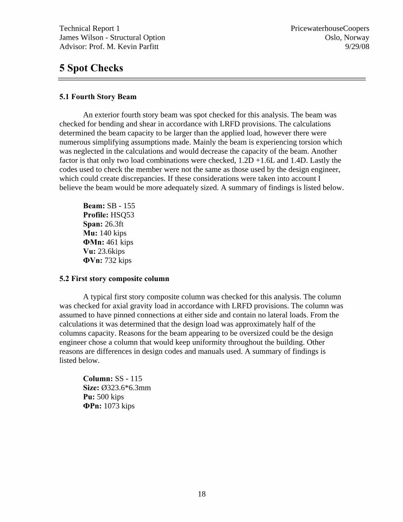
5.1 Fourth Story Beam An exterior fourth story beam was spot checked for this analysis. The beam was checked for bending and shear in accordance with LRFD provisions. The calculations determined the beam capacity to be larger than the applied load, however there were numerous simplifying assumptions made. Mainly the beam is experiencing torsion which was neglected in the calculations and would decrease the capacity of the beam. Another factor is that only two load combinations were checked, 1.2D +1.6L and 1.4D. Lastly the codes used to check the member were not the same as those used by the design engineer, which could create discrepancies. If these considerations were taken into account I believe the beam would be more adequately sized. A summary of findings is listed below.
Beam: SB - 155 Profile: HSQ53 Span: 26.3ft Mu: 140 kips ФMn: 461 kips Vu: 23.6kips ФVn: 732 kips
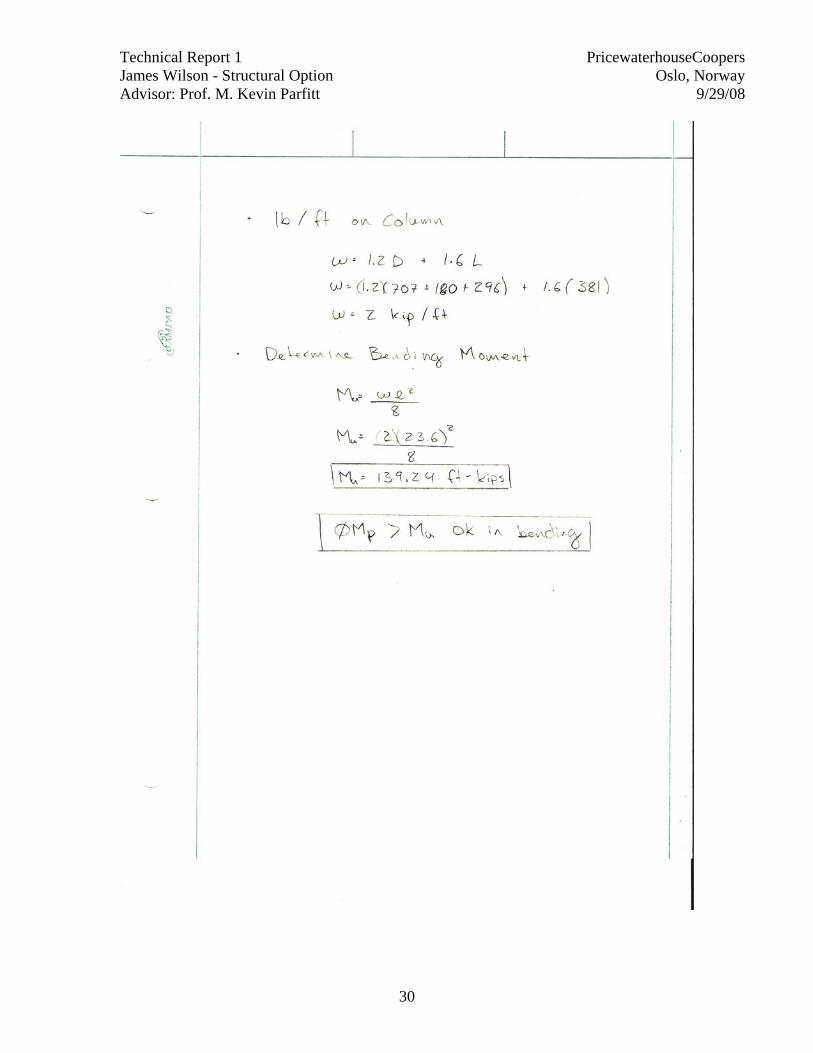
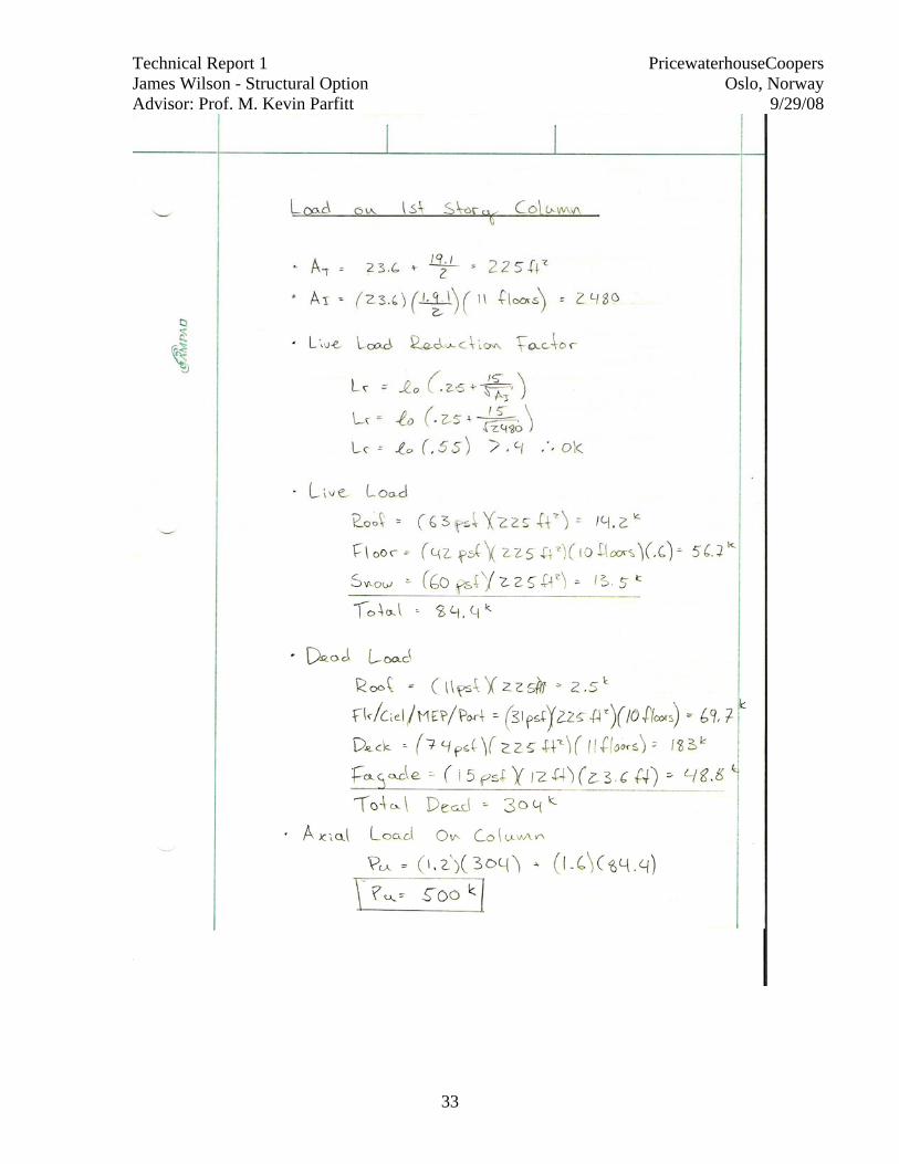
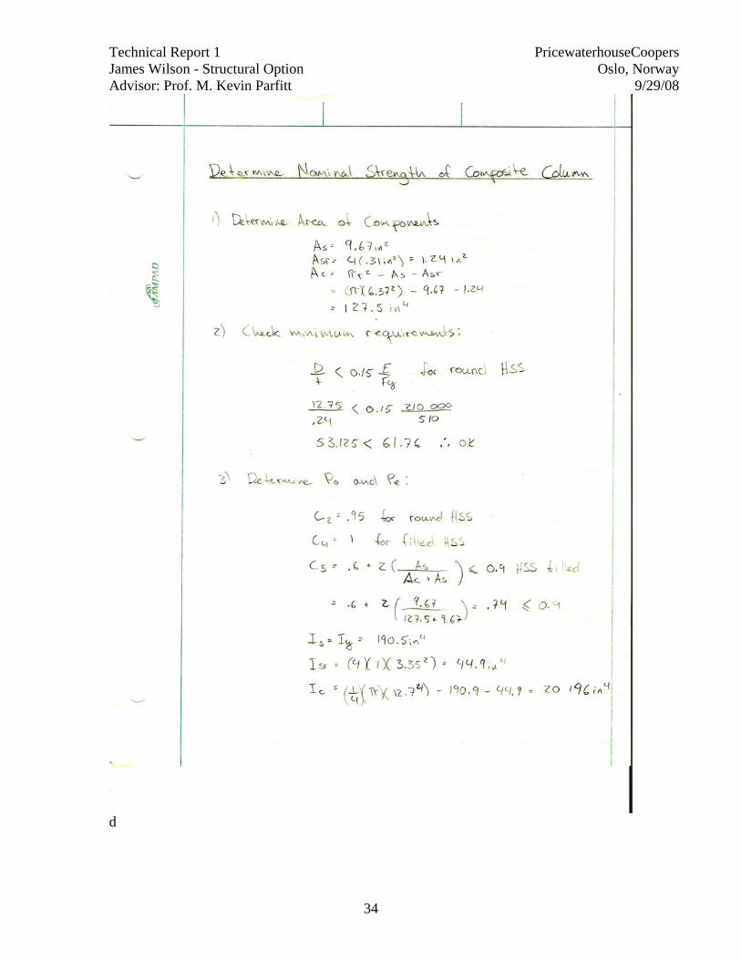
5.2 First story composite column A typical first story composite column was checked for this analysis. The column was checked for axial gravity load in accordance with LRFD provisions. The column was assumed to have pinned connections at either side and contain no lateral loads. From the calculations it was determined that the design load was approximately half of the columns capacity. Reasons for the beam appearing to be oversized could be the design engineer chose a column that would keep uniformity throughout the building. Other reasons are differences in design codes and manuals used. A summary of findings is listed below.
Column: SS - 115 Size: Ø323.6*6.3mm Pu: 500 kips ФPn: 1073 kips
Technical Report 1 PricewaterhouseCoopers James Wilson - Structural Option Oslo, Norway Advisor: Prof. M. Kevin Parfitt 9/29/08
19
Appendix
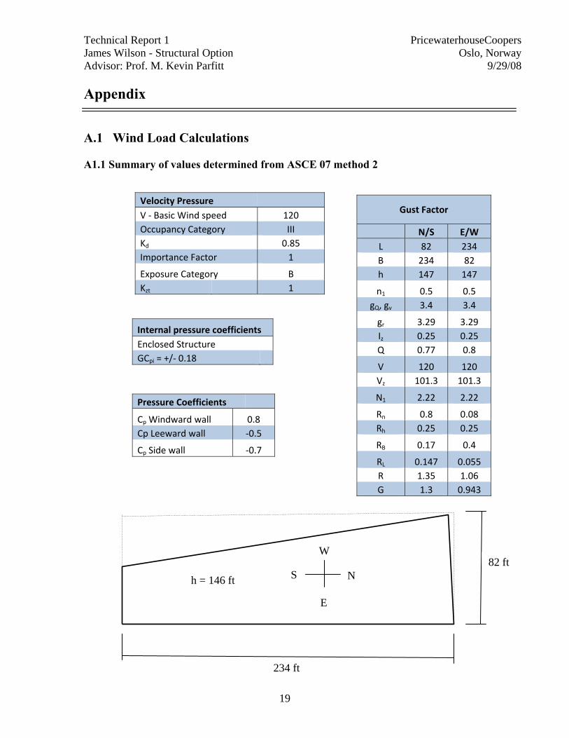
A.1 Wind Load Calculations A1.1 Summary of values determined from ASCE 07 method 2
Velocity Pressure V ‐ Basic Wind speed 120 Occupancy Category III Kd 0.85 Importance Factor 1
Exposure Category B Kzt 1
Gust Factor
N/S E/W L 82 234 B 234 82 h 147 147
n1 0.5 0.5 gQ, gv 3.4 3.4
gr 3.29 3.29 Iz 0.25 0.25 Q 0.77 0.8
V 120 120 Vz 101.3 101.3
N1 2.22 2.22
Rn 0.8 0.08 Rh 0.25 0.25
RB 0.17 0.4
RL 0.147 0.055 R 1.35 1.06 G 1.3 0.943
Internal pressure coefficients Enclosed Structure GCpi = +/‐ 0.18
Pressure Coefficients
Cp Windward wall 0.8 Cp Leeward wall ‐0.5
Cp Side wall ‐0.7
82 ft
234 ft
N S
E
W
h = 146 ft
Technical Report 1 PricewaterhouseCoopers James Wilson - Structural Option Oslo, Norway Advisor: Prof. M. Kevin Parfitt 9/29/08
20
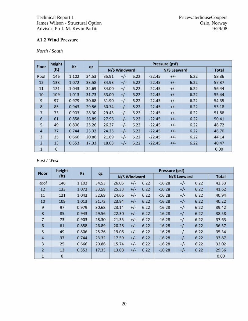
A1.2 Wind Pressure North / South
East / West
Floor height (ft)
Kz qz Pressure (psf)
N/S Windward N/S Leeward Total Roof 146 1.102 34.53 35.91 +/‐ 6.22 ‐22.45 +/‐ 6.22 58.36 12 133 1.072 33.58 34.93 +/‐ 6.22 ‐22.45 +/‐ 6.22 57.37 11 121 1.043 32.69 34.00 +/‐ 6.22 ‐22.45 +/‐ 6.22 56.44 10 109 1.013 31.73 33.00 +/‐ 6.22 ‐22.45 +/‐ 6.22 55.44 9 97 0.979 30.68 31.90 +/‐ 6.22 ‐22.45 +/‐ 6.22 54.35 8 85 0.943 29.56 30.74 +/‐ 6.22 ‐22.45 +/‐ 6.22 53.18 7 73 0.903 28.30 29.43 +/‐ 6.22 ‐22.45 +/‐ 6.22 51.88 6 61 0.858 26.89 27.96 +/‐ 6.22 ‐22.45 +/‐ 6.22 50.41 5 49 0.806 25.26 26.27 +/‐ 6.22 ‐22.45 +/‐ 6.22 48.72 4 37 0.744 23.32 24.25 +/‐ 6.22 ‐22.45 +/‐ 6.22 46.70 3 25 0.666 20.86 21.69 +/‐ 6.22 ‐22.45 +/‐ 6.22 44.14 2 13 0.553 17.33 18.03 +/‐ 6.22 ‐22.45 +/‐ 6.22 40.47 1 0 0.00
Floor height (ft)
Kz qz Pressure (psf)
N/S Windward N/S Leeward Total
Roof 146 1.102 34.53 26.05 +/‐ 6.22 ‐16.28 +/‐ 6.22 42.33 12 133 1.072 33.58 25.33 +/‐ 6.22 ‐16.28 +/‐ 6.22 41.62 11 121 1.043 32.69 24.66 +/‐ 6.22 ‐16.28 +/‐ 6.22 40.94 10 109 1.013 31.73 23.94 +/‐ 6.22 ‐16.28 +/‐ 6.22 40.22 9 97 0.979 30.68 23.14 +/‐ 6.22 ‐16.28 +/‐ 6.22 39.42 8 85 0.943 29.56 22.30 +/‐ 6.22 ‐16.28 +/‐ 6.22 38.58 7 73 0.903 28.30 21.35 +/‐ 6.22 ‐16.28 +/‐ 6.22 37.63 6 61 0.858 26.89 20.28 +/‐ 6.22 ‐16.28 +/‐ 6.22 36.57 5 49 0.806 25.26 19.06 +/‐ 6.22 ‐16.28 +/‐ 6.22 35.34 4 37 0.744 23.32 17.59 +/‐ 6.22 ‐16.28 +/‐ 6.22 33.87 3 25 0.666 20.86 15.74 +/‐ 6.22 ‐16.28 +/‐ 6.22 32.02 2 13 0.553 17.33 13.08 +/‐ 6.22 ‐16.28 +/‐ 6.22 29.36 1 0 0.00
Technical Report 1 PricewaterhouseCoopers James Wilson - Structural Option Oslo, Norway Advisor: Prof. M. Kevin Parfitt 9/29/08
21
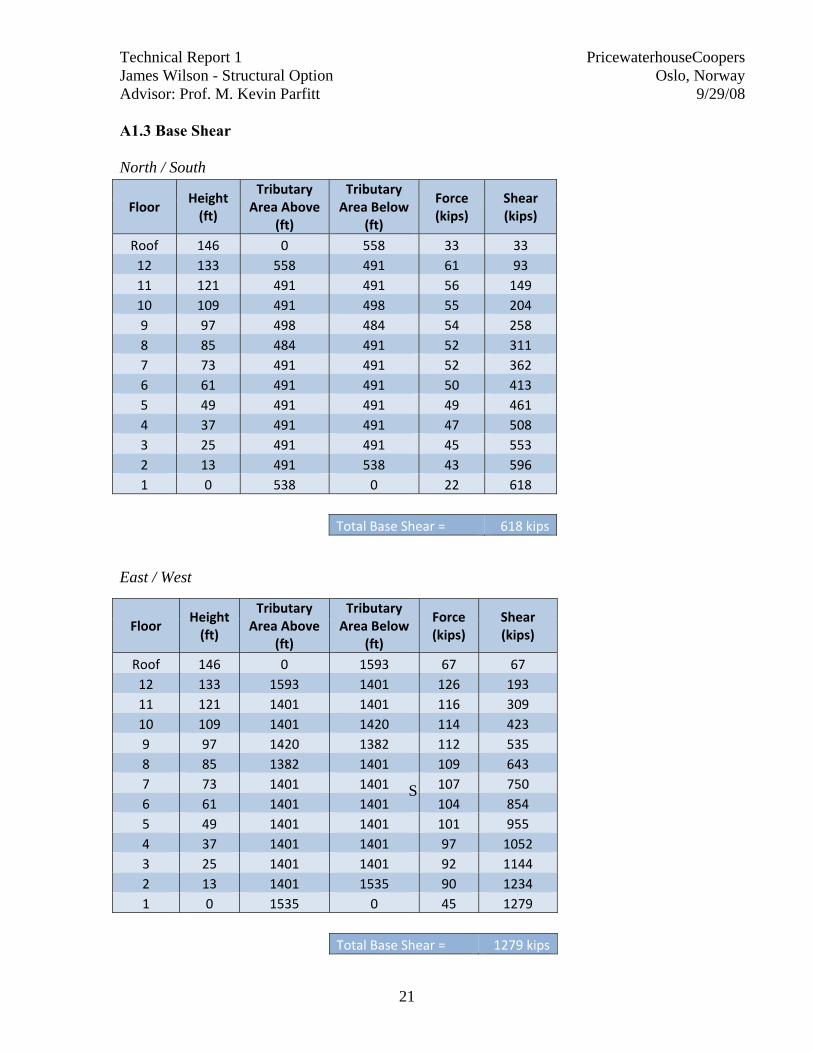
A1.3 Base Shear North / South
East / West
Floor Height (ft)
Tributary Area Above
(ft)
Tributary Area Below
(ft)
Force (kips)
Shear (kips)
Roof 146 0 558 33 33 12 133 558 491 61 93 11 121 491 491 56 149 10 109 491 498 55 204 9 97 498 484 54 258 8 85 484 491 52 311 7 73 491 491 52 362 6 61 491 491 50 413 5 49 491 491 49 461 4 37 491 491 47 508 3 25 491 491 45 553 2 13 491 538 43 596 1 0 538 0 22 618
Total Base Shear = 618 kips
Floor Height (ft)
Tributary Area Above
(ft)
Tributary Area Below
(ft)
Force (kips)
Shear (kips)
Roof 146 0 1593 67 67 12 133 1593 1401 126 193 11 121 1401 1401 116 309 10 109 1401 1420 114 423 9 97 1420 1382 112 535 8 85 1382 1401 109 643 7 73 1401 1401 107 750 6 61 1401 1401 104 854 5 49 1401 1401 101 955 4 37 1401 1401 97 1052 3 25 1401 1401 92 1144 2 13 1401 1535 90 1234 1 0 1535 0 45 1279
Total Base Shear = 1279 kips
S
Technical Report 1 PricewaterhouseCoopers James Wilson - Structural Option Oslo, Norway Advisor: Prof. M. Kevin Parfitt 9/29/08
22
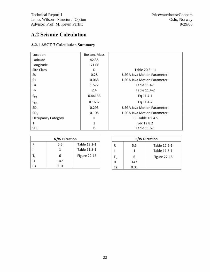
A.2 Seismic Calculation A.2.1 ASCE 7 Calculation Summary Location Boston, Mass Latitude 42.35 Longitude ‐71.06 Site Class D Table 20.3 – 1 Ss 0.28 USGA Java Motion Parameter: S1 0.068 USGA Java Motion Parameter: Fa 1.577 Table 11.4‐1 Fv 2.4 Table 11.4‐2
SMS 0.44156 Eq 11.4‐1
SM1 0.1632 Eq 11.4‐2
SDs 0.293 USGA Java Motion Parameter: SD1 0.108 USGA Java Motion Parameter: Occupancy Category II IBC Table 1604.5 T 2 Sec 12.8.2 SDC B Table 11.6‐1
N/W Direction
R 5.5 Table 12.2‐1 I 1 Table 11.5‐1
TL 6 Figure 22‐15 H 147 Cs 0.01
E/W Direction
R 5.5 Table 12.2‐1 I 1 Table 11.5‐1
TL 6 Figure 22‐15 H 147 Cs 0.01

Technical Report 1 PricewaterhouseCoopers James Wilson - Structural Option Oslo, Norway Advisor: Prof. M. Kevin Parfitt 9/29/08
23
Story wx (kips) hx k wxhx^k Cvx Fx (kips) Vx(kips) Roof 2402 146 1.75 14811132 0.20 58.2
12 2473 133 1.75 12856810 0.18 50.5 58 11 2473 121 1.75 10898144 0.15 42.8 109 10 2473 109 1.75 9079848 0.12 35.7 152 9 2473 97 1.75 7383724 0.10 29.0 187 8 2473 85 1.75 5879786 0.08 23.1 216 7 2473 73 1.75 4507279 0.06 17.7 239 6 2473 61 1.75 3294083 0.05 12.9 257 5 2471 49 1.75 2244895 0.03 8.8 270 4 2165 37 1.75 1205323 0.02 4.7 279 3 2165 25 1.75 609009 0.01 2.4 284 2 2165 13 1.75 195804 0.00 0.8 286 1 0 0 1.75 0 0.00 0 287
Totals 28682 NA NA 72965837 286.8 287 V = Cs*W 286.81844

Technical Report 1 PricewaterhouseCoopers James Wilson - Structural Option Oslo, Norway Advisor: Prof. M. Kevin Parfitt 9/29/08
24
A2.2 Total Building Dead Load Floor
Level Tributary Area
(ft2)
Deck + Super Imposed (psf)
Beam + Connections (psf)
Dead Load (kips)
Roof 14391 127 11 1986 12 14391 105 11 1669 11 14391 105 11 1669 10 14391 105 11 1669 9 14391 105 11 1669 8 14391 105 11 1669 7 14391 105 11 1669 6 14391 105 11 1669 5 14391 105 11 1669 4 11756 105 11 1364 3 11756 105 11 1364 2 11756 105 11 1364 1 0 0 0 0
Façade
Story Perimiter
(ft) Trib. Height
(ft) Wall Load
(psf) Wall load (kips)
Roof 581 6 15 52.29 12 581 12 15 104.58 11 581 12 15 104.58 10 581 12 15 104.58 9 581 12 15 104.58 8 581 12 15 104.58 7 581 12 15 104.58 6 581 12 15 104.58 5 587 12 15 105.66 4 587 12 15 105.66 3 587 12 15 105.66 2 587 12 15 105.66 1 587 6 15 52.83
Technical Report 1 PricewaterhouseCoopers James Wilson - Structural Option Oslo, Norway Advisor: Prof. M. Kevin Parfitt 9/29/08
25
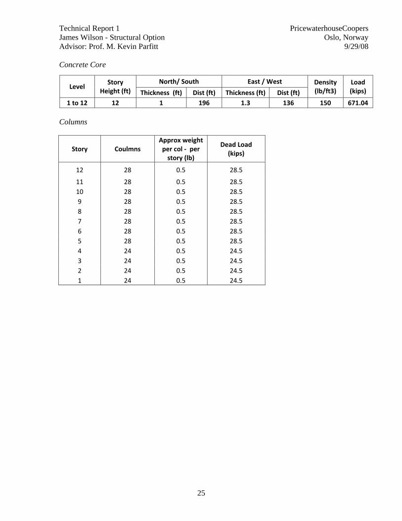
Concrete Core
Columns
Story Coulmns Approx weight per col ‐ per story (lb)
Dead Load (kips)
12 28 0.5 28.5
11 28 0.5 28.5 10 28 0.5 28.5 9 28 0.5 28.5 8 28 0.5 28.5 7 28 0.5 28.5 6 28 0.5 28.5 5 28 0.5 28.5 4 24 0.5 24.5 3 24 0.5 24.5 2 24 0.5 24.5 1 24 0.5 24.5
Level Story
Height (ft) North/ South East / West Density
(lb/ft3) Load (kips) Thickness (ft) Dist (ft) Thickness (ft) Dist (ft)
1 to 12 12 1 196 1.3 136 150 671.04
Technical Report 1 PricewaterhouseCoopers James Wilson - Structural Option Oslo, Norway Advisor: Prof. M. Kevin Parfitt 9/29/08
26
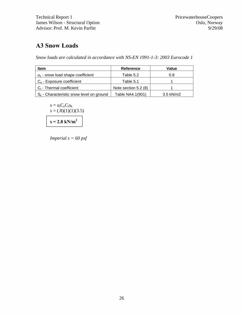
A3 Snow Loads Snow loads are calculated in accordance with NS-EN 1991-1-3: 2003 Eurocode 1 Item Reference Value u1 - snow load shape coefficient Table 5.2 0.8 Ce - Exposure coefficient Table 5.1 1 Ct - Thermal coefficient Note section 5.2 (8) 1 Sk - Characteristic snow level on ground Table NA4.1(901) 3.5 kN/m2
s = uiCeCtsk s = (.8)(1)(1)(3.5)
s = 2.8 kN/m2
Imperial s = 60 psf

Technical Report 1 PricewaterhouseCoopers James Wilson - Structural Option Oslo, Norway Advisor: Prof. M. Kevin Parfitt 9/29/08
27
A4 Beam Spot Check

Technical Report 1 PricewaterhouseCoopers James Wilson - Structural Option Oslo, Norway Advisor: Prof. M. Kevin Parfitt 9/29/08
28

Technical Report 1 PricewaterhouseCoopers James Wilson - Structural Option Oslo, Norway Advisor: Prof. M. Kevin Parfitt 9/29/08
29
Technical Report 1 PricewaterhouseCoopers James Wilson - Structural Option Oslo, Norway Advisor: Prof. M. Kevin Parfitt 9/29/08
30

Technical Report 1 PricewaterhouseCoopers James Wilson - Structural Option Oslo, Norway Advisor: Prof. M. Kevin Parfitt 9/29/08
31

Technical Report 1 PricewaterhouseCoopers James Wilson - Structural Option Oslo, Norway Advisor: Prof. M. Kevin Parfitt 9/29/08
32
A5 Column Spot Check
Technical Report 1 PricewaterhouseCoopers James Wilson - Structural Option Oslo, Norway Advisor: Prof. M. Kevin Parfitt 9/29/08
33
Technical Report 1 PricewaterhouseCoopers James Wilson - Structural Option Oslo, Norway Advisor: Prof. M. Kevin Parfitt 9/29/08
34
d

Technical Report 1 PricewaterhouseCoopers James Wilson - Structural Option Oslo, Norway Advisor: Prof. M. Kevin Parfitt 9/29/08
35
Related Documents