Welcome message from author
This document is posted to help you gain knowledge. Please leave a comment to let me know what you think about it! Share it to your friends and learn new things together.
Transcript
Structural Steelwork:Design to Limit State Theory
Third edition
Dennis LamSchool of Civil EngineeringThe University of Leeds, Leeds, UK
Thien-Cheong AngSchool of Civil and Environmental EngineeringNanyang Technological University, Singapore
Sing-Ping ChiewSchool of Civil and Environmental EngineeringNanyang Technological University, Singapore
AMSTERDAM • BOSTON • HEIDELBERG • LONDON • NEW YORK • OXFORDPARIS • SAN DEIGO • SAN FRANCISCO • SINGAPORE • SYDNEY • TOKYO
kmkosipil.blogspot.com
Elsevier Butterworth-HeinemannLinacre House, Jordan Hill, Oxford OX2 8DP200 Wheeler Road, Burlington, MA 01803
First published 1987Reprinted 1988 (with corrections), 1990, 1991Second edition 1992Reprinted 1993 (twice), 1994, 1995, 1997, 1998, 1999, 2001, 2002Third edition 2004
Copyright © 1987, 1992, 2004, Elsevier Ltd. All rights reserved
No part of this publication may be reproduced in any material form(including photocopying or storing in any medium by electronicmeans and whether or not transiently or incidentally to some otheruse of this publication) without the written permission of thecopyright holder except in accordance with the provisions of theCopyright, Designs and Patents Act 1988 or under the terms of alicence issued by the Copyright Licensing Agency Ltd, 90Tottenham Court Road, London, England W1T 4LP. Applicationsfor the copyright holder’s written permission to reproduce any partof this publication should be addressed to the publisher.
Permissions may be sought directly from Elsevier’s Science andTechnology RightsDepartment in Oxford, UK: phone: (+44) (0) 1865 843830;fax: (+44) (0) 1865 853333; e-mail: [email protected] may also complete your request on-line via the Elsevierhomepage (http://www.elsevier.com), by selecting ‘CustomerSupport’ and then ‘Obtaining Permissions’.
Cover Image: Swiss Re Building – 30 St Mary Axe – The Gherkin.Photo with kind permission from Grant Smith Photographer
British Library Cataloguing in Publication DataLam, Dennis
Structural steelwork : design to limit state theory. – 3rd ed.1. Steel, Structural 2. Building, Iron and steelI. Title II. Ang, Paul III. Chiew, Sing-Ping624.1′821
ISBN 0 7506 59122
Library of Congress Cataloguing in Publication DataA catalogue record for this book is available from the Library of Congress
ISBN 0 7506 59122
For information on all Butterworth-Heinemann publicationsvisit our website at www.bh.com
Typeset by Newgen Imaging Systems (P) Ltd, Chennai, IndiaPrinted and bound in Great Britain
Contents
Preface to the third edition viPreface to the second edition viiPreface to the first edition viii
Chapter 1 INTRODUCTION 1
1.1 Steel structures 11.2 Structural elements 11.3 Structural design 41.4 Design methods 41.5 Design calculations and computing 61.6 Detailing 7
Chapter 2 LIMIT STATE DESIGN 8
2.1 Limit state design principles 82.2 Limit states for steel design 82.3 Working and factored loads 92.4 Stability limit states 112.5 Structural integrity 112.6 Serviceability limit state deflection 122.7 Design strength of materials 132.8 Design methods for buildings 14
Chapter 3 MATERIALS 15
3.1 Structural steel properties 153.2 Design considerations 153.3 Steel sections 183.4 Section properties 21
Chapter 4 BEAMS 24
4.1 Types and uses 244.2 Beam loads 254.3 Classification of beam cross-sections 264.4 Bending stresses and moment capacity 284.5 Lateral torsional buckling 34
4.6 Shear in beams 404.7 Deflection of beams 424.8 Beam connections 424.9 Examples of beam design 474.10 Compound beams 564.11 Crane beams 624.12 Purlins 774.13 Sheeting rails 85
Chapter 5 PLATE GIRDERS 94
5.1 Design considerations 945.2 Behaviour of a plate girder 975.3 Design to BS 5950: Part 1 1015.4 Design of a plate girder 1125.5 Design utilizing tension field action 120
Chapter 6 TENSION MEMBERS 131
6.1 Uses, types and design considerations 1316.2 End connections 1326.3 Structural behaviour of tension members 1346.4 Design of tension members 1396.5 Design examples 141
Chapter 7 COMPRESSION MEMBERS 144
7.1 Types and uses 1447.2 Loads on compression members 1467.3 Classification of cross-sections 1487.4 Axially loaded compression members 1487.5 Beam columns 1657.6 Eccentrically loaded columns in buildings 1737.7 Cased columns subjected to axial load and moment 1827.8 Side column for a single-storey industrial building 1847.9 Crane columns 1947.10 Column bases 204
Chapter 8 TRUSSES AND BRACING 210
8.1 Trusses—types, uses and truss members 2108.2 Loads on trusses 2108.3 Analysis of trusses 2128.4 Design of truss members 2148.5 Truss connections 2188.6 Design of a roof truss for an industrial building 2208.7 Bracing 233
Chapter 9 PORTAL FRAMES 246
9.1 Design and construction 2469.2 Elastic design 2489.3 Plastic design 2599.4 In-plane stability 2649.5 Restraints and member stability 2679.6 Serviceability check for eaves deflection 2709.7 Design of joints 2719.8 Design example of a portal frame 2749.9 Further reading for portal design 282
Chapter 10 CONNECTIONS 284
10.1 Types of connections 28410.2 Non-preloaded bolts 28410.3 Preloaded bolts 30110.4 Welded connections 30610.5 Further considerations in design of connections 318
Chapter 11 WORKSHOP STEELWORK DESIGN EXAMPLE 325
11.1 Introduction 32511.2 Basic design loads 32511.3 Computer analysis data 32711.4 Results of computer analysis 33011.5 Structural design of members 33411.6 Steelwork detailing 337
Chapter 12 STEELWORK DETAILING 338
12.1 Drawings 33812.2 General recommendations 33912.3 Steel sections 34012.4 Grids and marking plans 34112.5 Bolts 34312.6 Welds 34412.7 Beams 34712.8 Plate girders 34712.9 Columns and bases 34812.10 Trusses and lattice girders 34912.11 Computer-aided drafting 350
References 352Index 353
Preface to the third edition
This is the third edition of the Structural Steelwork: Design to Limit State Theoryby T.J. MacGinley and T.C. Ang, which proved to be very popular with both stu-dents and practising engineers. The change of authorship was forced upon by thedeceased of Mr T.J. MacGinley. All the chapters have been updated and rearrangedto comply with the latest revision of the BS 5950-1:2000 Structural use of steel-work in building - Part 1: Code of practice for design rolled and welded sections, itmay be used as a stand-alone text or in conjunction with BS 5950. The book con-tains detailed explanation of the principles underlying steel design and is intendedfor students reading for civil and/or structural engineering degrees in universit-ies. It should be useful to final year students involved in design projects and alsosufficiently practical for practising engineers and architects who require an intro-duction to the latest revision of BS 5950. Every topic is illustrated with fullyworked examples and problems are also provided for practice.
D.L.
Preface to the second edition
The book has been updated to comply with
BS 5950: Part I: 1990Structural Use of Steelwork in BuildingCode of Practice for Design in Simple and Continuous Construction:Hot Rolled Sections
A new chapter on portal design has been added to round out its contents. This typeof structure is in constant demand for warehouses, factories and for many otherpurposes and is the most common single-storey building in use. The inclusion ofthis material introduces the reader to elastic and plastic rigid frame design, memberstability problems and design of moment-transmitting joints.
T.J.M.T.C.A.
Preface to the first edition
The purpose of this book is to show basic steel design to the new limit state codeBS 5950. It has been written primarily for undergraduates who will now startlearning steel design to the new code, and will also be of use to recent graduatesand designers wishing to update their knowledge.
The book covers design of elements and joints in steel construction to the simpledesign method; its scheme is the same as that used in the previous book by theprincipal author, Structural Steelwork Calculations and Detailing, Butterworths,1973. Design theory with some of the background to the code procedures is givenand separate elements and a complete building frame are designed to show the useof the code.
The application of microcomputers in the design process is discussed and thelistings for some programs are given. Recommendations for detailing are includedwith a mention of computer-aided drafting (CAD).
T.J.M.T.C.A.
1
Introduction
1.1 Steel structures
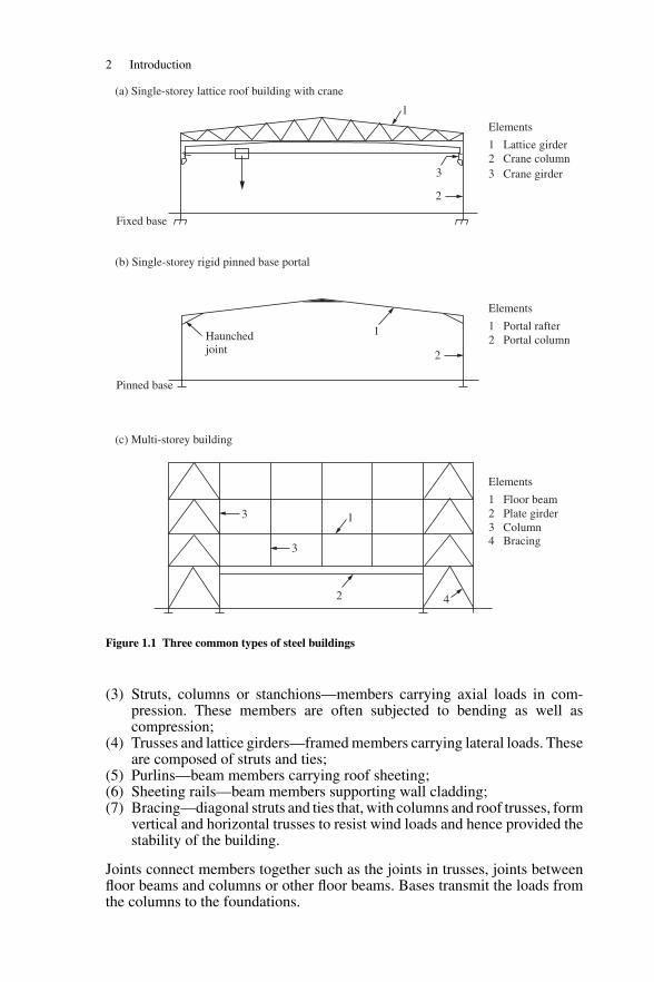
Steel frame buildings consist of a skeletal framework which carries all theloads to which the building is subjected. The sections through three commontypes of buildings are shown in Figure 1.1. These are:
(1) single-storey lattice roof building;(2) single-storey portal frame building;(3) medium-rise braced multi-storey building.
These three types cover many of the uses of steel frame buildings such asfactories, warehouses, offices, flats, schools, etc. A design for the lattice roofbuilding (Figure 1.1(a)) is given and the design of the elements for the bracedmulti-storey building (Figure 1.1(c)) is also included. Design of portal frameis described separately in Chapter 9.
The building frame is made up of separate elements—the beams, columns,trusses and bracing—listed beside each section in Figure 1.1. These must bejoined together and the building attached to the foundations. Elements arediscussed more fully in Section 1.2.
Buildings are three dimensional and only the sectional frame has been shownin Figure 1.1. These frames must be propped and braced laterally so that theyremain in position and carry the loads without buckling out of the plane ofthe section. Structural framing plans are shown in Figures 1.2 and 1.3 for thebuilding types illustrated in Figures 1.1(a) and 1.1(c).
Various methods for analysis and design have been developed over the years.In Figure 1.1, the single-storey structure in (a) and the multi-storey building in(c) are designed by the simple design method, while the portal frame in (b) isdesigned by the continuous design method. All design is based on the newlyrevised limit state design code BS 5950-1: 2000: Part 1. Design theories arediscussed briefly in Section 1.4 and design methods are set out in detail inChapter 2.
1.2 Structural elements
As mentioned above, steel buildings are composed of distinct elements:
(1) Beams and girders—members carrying lateral loads in bending and shear;(2) Ties—members carrying axial loads in tension;
1
2 Introduction
1
1
1
Haunchedjoint
2
2
2 4
3
3
3
(a) Single-storey lattice roof building with crane
(b) Single-storey rigid pinned base portal
(c) Multi-storey building
Elements
1 Lattice girder2 Crane column3 Crane girder
Fixed base
Pinned base
Elements
1 Portal rafter2 Portal column
Elements
1 Floor beam2 Plate girder3 Column4 Bracing
Figure 1.1 Three common types of steel buildings
(3) Struts, columns or stanchions—members carrying axial loads in com-pression. These members are often subjected to bending as well ascompression;
(4) Trusses and lattice girders—framed members carrying lateral loads. Theseare composed of struts and ties;
(5) Purlins—beam members carrying roof sheeting;(6) Sheeting rails—beam members supporting wall cladding;(7) Bracing—diagonal struts and ties that, with columns and roof trusses, form
vertical and horizontal trusses to resist wind loads and hence provided thestability of the building.
Joints connect members together such as the joints in trusses, joints betweenfloor beams and columns or other floor beams. Bases transmit the loads fromthe columns to the foundations.
Structural elements 3
96
3
5
348
3
7
102 1 4
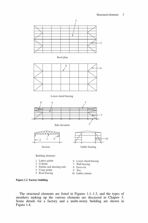
Building elements
1 Lattice girder2 Column3 Purlins and sheeting rails4 Crane girder5 Roof bracing
6 Lower chord bracing 7 Wall bracing 8 Eaves tie 9 Ties 10 Gable column
Roof plan
Lower chord bracing
Side elevation
Section Gable framing
Figure 1.2 Factory building
The structural elements are listed in Figures 1.1–1.3, and the types ofmembers making up the various elements are discussed in Chapter 3.Some details for a factory and a multi-storey building are shown inFigure 1.4.
4 Introduction
2 2
4
4
2
23
4
1
43
I
I I I I
I I
I I I I I I
I I I I I I I
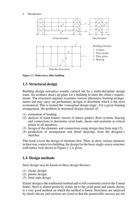
End elevation Front elevation
Plan first floor level
Building elements
1 Column2 Floor beams 3 Plate girder 4 Bracing
Figure 1.3 Multi-storey office building
1.3 Structural design
Building design nowadays usually carried out by a multi-discipline designteam. An architect draws up plans for a building to meet the client’s require-ments. The structural engineer examines various alternative framing arrange-ments and may carry out preliminary designs to determine which is the mosteconomical. This is termed the ‘conceptual design stage’. For a given framingarrangement, the problem in structural design consists of:
(1) estimation of loading;(2) analysis of main frames, trusses or lattice girders, floor systems, bracing
and connections to determine axial loads, shears and moments at criticalpoints in all members;
(3) design of the elements and connections using design data from step (2);(4) production of arrangement and detail drawings from the designer’s
sketches.
This book covers the design of elements first. Then, to show various elementsin their true context in a building, the design for the basic single-storey structurewith lattice roof shown in Figure 1.2 is given.
1.4 Design methods
Steel design may be based on three design theories:
(1) elastic design;(2) plastic design;(3) limit state design.
Elastic design is the traditional method and is still commonly used in the UnitedStates. Steel is almost perfectly elastic up to the yield point and elastic theoryis a very good method on which the method is based. Structures are analysedby elastic theory and sections are sized so that the permissible stresses are not
Design methods 5
++
++
+ +
+ +
+ +
+ +
columnbase
columnbase
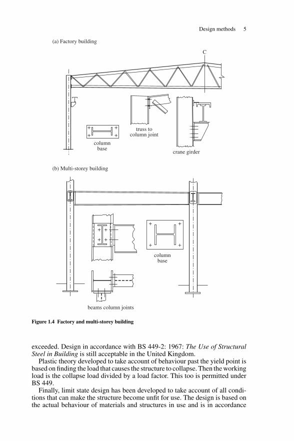
(a) Factory building
(b) Multi-storey building
truss tocolumn joint
crane girder
beams column joints
C
Figure 1.4 Factory and multi-storey building
exceeded. Design in accordance with BS 449-2: 1967: The Use of StructuralSteel in Building is still acceptable in the United Kingdom.
Plastic theory developed to take account of behaviour past the yield point isbased on finding the load that causes the structure to collapse. Then the workingload is the collapse load divided by a load factor. This too is permitted underBS 449.
Finally, limit state design has been developed to take account of all condi-tions that can make the structure become unfit for use. The design is based onthe actual behaviour of materials and structures in use and is in accordance
6 Introduction
with BS 5950: The Structural Use of Steelwork in Building; Part 1—Code ofPractice for Design—Rolled and Welded Sections.
The code requirements relevant to the worked problems are noted and dis-cussed. The complete code should be obtained and read in conjunction withthis book.
The aim of structural design is to produce a safe and economical structurethat fulfils its required purpose. Theoretical knowledge of structural analysismust be combined with knowledge of design principles and theory and theconstraints given in the standard to give a safe design. A thorough knowledgeof properties of materials, methods of fabrication and erection is essential forthe experienced designer. The learner must start with the basics and graduallybuild up experience through doing coursework exercises in conjunction witha study of design principles and theory.
British Standards are drawn up by panels of experts from the professionalinstitutions, and include engineers from educational and research institu-tions, consulting engineers, government authorities and the fabrication andconstruction industries. The standards give the design methods, factors ofsafety, design loads, design strengths, deflection limits and safe constructionpractices.
As well as the main design standard for steelwork in buildings, BS 5950-1:2000: Part 1, reference must be made to other relevant standards, including:
(1) BS EN 10020: 2000. This gives definition and classification of grades ofsteel.
(2) BS EN 10029: 1991 (plates); BS EN 10025: 1993 (sections); BS EN 10210-1: 1994 (hot finished hollow sections); BS EN 10219-1: 1997 (cold formedhollow sections). This gives the mechanical properties for the various typesof steel sections.
(3) BS 6399-1: 1996 Part 1, Code of Practice for Dead and Imposed Loads.(4) BS 6399-2: 1997 Part 2, Code of Practice for Wind Loads.(5) BS 6399-3: 1998 Part 1, Code of Practice for Imposed Roof Loads.
Representative loading may be taken for element design. Wind loading dependson the complete building and must be estimated using the wind code.
1.5 Design calculations and computing
Calculations are needed in the design process to determine the loading on thestructure, carry out the analysis and design the elements and joints, and mustbe set out clearly in a standard form. Design sketches to illustrate and amplifythe calculations are an integral part of the procedure and are used to producethe detail drawings.
Computing now forms an increasingly larger part of design work, and allroutine calculations can be readily carried out on a PC. The use of the computerspeeds up calculation and enables alternative sections to be checked, givingthe designer a wider choice than would be possible with manual working.However, it is most important that students understand the design principlesinvolved before using computer programs.
It is through doing exercises that the student consolidates the design theorygiven in lectures. Problems are given at the end of most chapters.
Detailing 7
1.6 Detailing
Chapter 12 deals with the detailing of structural steelwork. In the earlierchapters, sketches are made in design problems to show building arrange-ments, loading on frames, trusses, members, connections and other featurespertinent to the design. It is often necessary to make a sketch showing thearrangement of a joint before the design can be carried out. At the end of theproblem, sketches are made to show basic design information such as sectionsize, span, plate sizes, drilling, welding, etc. These sketches are used to producethe working drawings.
The general arrangement drawing and marking plans give the informationfor erection. The detailed drawings show all the particulars for fabrication ofthe elements. The designer must know the conventions for making steelworkdrawings, such as the scales to be used, the methods for specifying mem-bers, plates, bolts, welding, etc. He/she must be able to draw standard jointdetails and must also have a knowledge of methods of fabrication and erection.AutoCAD is becoming generally available and the student should be given anappreciation of their use.
2
Limit state design
2.1 Limit state design principles
The central concepts of limit state design are as follows:
(1) All the separate conditions that make the structure unfit for use are takeninto account. These are the separate limit states.
(2) The design is based on the actual behaviour of materials and performanceof structures and members in service.
(3) Ideally, design should be based on statistical methods with a small prob-ability of the structure reaching a limit state.
The three concepts are examined in more detail below.Requirement (1) means that the structure should not overturn under applied
loads and its members and joints should be strong enough to carry the forcesto which they are subjected. In addition, other conditions such as excessivedeflection of beams or unacceptable vibration, though not in fact causing col-lapse, should not make the structure unfit for use.
In concept (2), the strengths are calculated using plastic theory and post-buckling behaviour is taken into account. The effect of imperfections on designstrength is also included. It is recognized that calculations cannot be made inall cases to ensure that limit states are not reached. In cases such as brittlefracture, good practice must be followed to ensure that damage or failure doesnot occur.
Concept (3) implies recognition of the fact that loads and material strengthsvary, approximations are used in design and imperfections in fabrication anderection affect the strength in service. All these factors can only be realisticallyassessed in statistical terms. However, it is not yet possible to adopt a completeprobability basis for design, and the method adopted is to ensure safety by usingsuitable factors. Partial factors of safety are introduced to take account of allthe uncertainties in loads, materials strengths, etc. mentioned above. These arediscussed more fully below.
2.2 Limit states for steel design
The limit states for which steelwork is to be designed are set out in Section 2of BS 5950-1: 2000. These are as follows.
8
Working and factored loads 9
2.2.1 Ultimate limit states
The ultimate limit states include the following:
(1) strength (including general yielding, rupture, buckling and transformationinto a mechanism);
(2) stability against overturning and sway;(3) fracture due to fatigue;(4) brittle fracture.
When the ultimate limit states are exceeded, the whole structure or part of itcollapses.
2.2.2 Serviceability limit states
The serviceability limit states consist of the following:
(5) deflection;(6) vibration (for example, wind-induced oscillation);(7) repairable damage due to fatigue;(8) corrosion and durability.
The serviceability limit states, when exceeded, make the structure or part of itunfit for normal use but do not indicate that collapse has occurred.
All relevant limit states should be considered, but usually it will be appro-priate to design on the basis of strength and stability at ultimate loading andthen check that deflection is not excessive under serviceability loading. Somerecommendations regarding the other limit states will be noted when appro-priate, but detailed treatment of these topics is outside the scope of this book.
2.3 Working and factored loads
2.3.1 Working loads
The working loads (also known as the specified, characteristic or nominalloads) are the actual loads the structure is designed to carry. These are normallythought of as the maximum loads which will not be exceeded during the life ofthe structure. In statistical terms, characteristic loads have a 95 per cent probab-ility of not being exceeded. The main loads on buildings may be classified as:
(1) Dead loads: These are due to the weights of floor slabs, roofs, walls,ceilings, partitions, finishes, services and self-weight of steel. When sizesare known, dead loads can be calculated from weights of materials orfrom the manufacturer’s literature. However, at the start of a design, sizesare not known accurately and dead loads must often be estimated fromexperience. The values used should be checked when the final design iscomplete. For examples on element design, representative loading has beenchosen, but for the building design examples actual loads from BS 6399:Part 1 are used.
(2) Imposed loads: These take account of the loads caused by people, furniture,equipment, stock, etc. on the floors of buildings and snow on roofs. Thevalues of the floor loads used depend on the use of the building. Imposedloads are given in BS 6399: Part 1 and snow load is given in BS 6399:Part 3.
10 Limit state design
(3) Wind loads: These loads depend on the location and building size. Windloads are given in BS 6399: Part 2.
∗Calculation of wind loads is given in
the examples on building design.(4) Dynamic loads: These are caused mainly by cranes. An allowance is made
for impact by increasing the static vertical loads and the inertia effectsare taken into account by applying a proportion of the vertical loads ashorizontal loads. Dynamic loads from cranes are given in BS 6399: Part 1.Design examples show how these loads are calculated and applied to cranegirders and columns.
Other loads on the structures are caused by waves, ice, seismic effects, etc. andthese are outside the scope of this book.
2.3.2 Factored loads for the ultimate limit states
In accordance with Section 2.4.1 of BS 5950-1: 2000, factored loads are usedin design calculations for strength and stability.
Factored load = working or nominal load × relevant partial load factor, γf
The partial load factor takes account of:
(1) the unfavourable deviation of loads from their nominal values; and(2) the reduced probability that various loads will all be at their nominal value
simultaneously.
It also allows for the uncertainties in the behaviour of materials and of thestructure as opposed to those assumed in design.
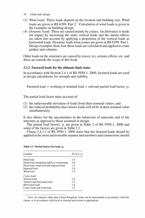
The partial load factors, γf are given in Table 2 of BS 5950-1: 2000 andsome of the factors are given in Table 2.1.
Clause 2.4.1.1 of BS 5950-1: 2000 states that the factored loads should beapplied in the most unfavourable manner and members and connections should
Table 2.1 Partial factors for load, γf
Loading Factors γf
Dead load 1.4Dead load restraining uplift or overturning 1.0Dead load, wind load and imposed load 1.2Imposed load 1.6Wind load 1.4
Crane loadsVertical load 1.6Vertical and horizontal load 1.4Horizontal load 1.6Crane loads and wind load 1.2
∗Note: In countries other than United Kingdom, loads can be determined in accordance with this
clause, or in accordance with local or national provisions as appropriate.
Structural integrity 11
not fail under these load conditions. Brief comments are given on some of theload combinations:
(1) The main load for design of most members and structures is dead plusimposed load.
(2) In light roof structures uplift and load reversal occurs and tall structuresmust be checked for overturning. The load combination of dead plus windload is used in these cases with a load factor of 1.0 for dead and 1.4 forwind load.
(3) It is improbable that wind and imposed loads will simultaneously reachtheir maximum values and load factors are reduced accordingly.
(4) It is also unlikely that the impact and surge load from cranes will reachmaximum values together and so the load factors are reduced. Again, whenwind is considered with crane loads the factors are further reduced.
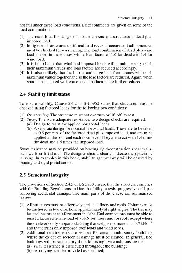
2.4 Stability limit states
To ensure stability, Clause 2.4.2 of BS 5950 states that structures must bechecked using factored loads for the following two conditions:
(1) Overturning: The structure must not overturn or lift off its seat.(2) Sway: To ensure adequate resistance, two design checks are required:
(a) Design to resist the applied horizontal loads.(b) A separate design for notional horizontal loads. These are to be taken
as 0.5 per cent of the factored dead plus imposed load, and are to beapplied at the roof and each floor level. They are to act with 1.4 timesthe dead and 1.6 times the imposed load.
Sway resistance may be provided by bracing rigid-construction shear walls,stair wells or lift shafts. The designer should clearly indicate the system heis using. In examples in this book, stability against sway will be ensured bybracing and rigid portal action.
2.5 Structural integrity
The provisions of Section 2.4.5 of BS 5950 ensure that the structure complieswith the Building Regulations and has the ability to resist progressive collapsefollowing accidental damage. The main parts of the clause are summarizedbelow:
(1) All structures must be effectively tied at all floors and roofs. Columns mustbe anchored in two directions approximately at right angles. The ties maybe steel beams or reinforcement in slabs. End connections must be able toresist a factored tensile load of 75 kN for floors and for roofs except wherethe steelwork only supports cladding that weighs not more than 0.7 kN/m2
and that carries only imposed roof loads and wind loads.(2) Additional requirements are set out for certain multi-storey buildings
where the extent of accidental damage must be limited. In general, tiedbuildings will be satisfactory if the following five conditions are met:(a) sway resistance is distributed throughout the building;(b) extra tying is to be provided as specified;
12 Limit state design
(c) column splices are designed to resist a specified tensile force;(d) any beam carrying a column is checked as set out in (3) below; and(e) precast floor units are tied and anchored.
(3) Where required in (2) the above damage must be localized by checkingto see if at any storey any single column or beam carrying a column maybe removed without causing more than a limited amount of damage. Ifthe removal of a member causes more than the permissible limit, it mustbe designed as a key element. These critical members are designed foraccidental loads set out in the Building Regulations.
The complete section in the code and the Building Regulations should beconsulted.
2.6 Serviceability limit state deflection
Deflection is the main serviceability limit state that must be considered indesign. The limit state of vibration is outside the scope of this book and fatiguewas briefly discussed in Section 2.2.1 and, again, is not covered in detail. Theprotection for steel to prevent the limit state of corrosion being reached wasmentioned in Section 2.2.4.
BS 5950-1: 2000 states in Clause 2.5.1 that deflection under serviceabilityloads of a building or part should not impair the strength or efficiency of thestructure or its components or cause damage to the finishings. The service-ability loads used are the unfactored imposed loads except in the followingcases:
(1) Dead + imposed + wind. Apply 80 per cent of the imposed and wind load.(2) Crane surge + wind. The greater effect of either only is considered.
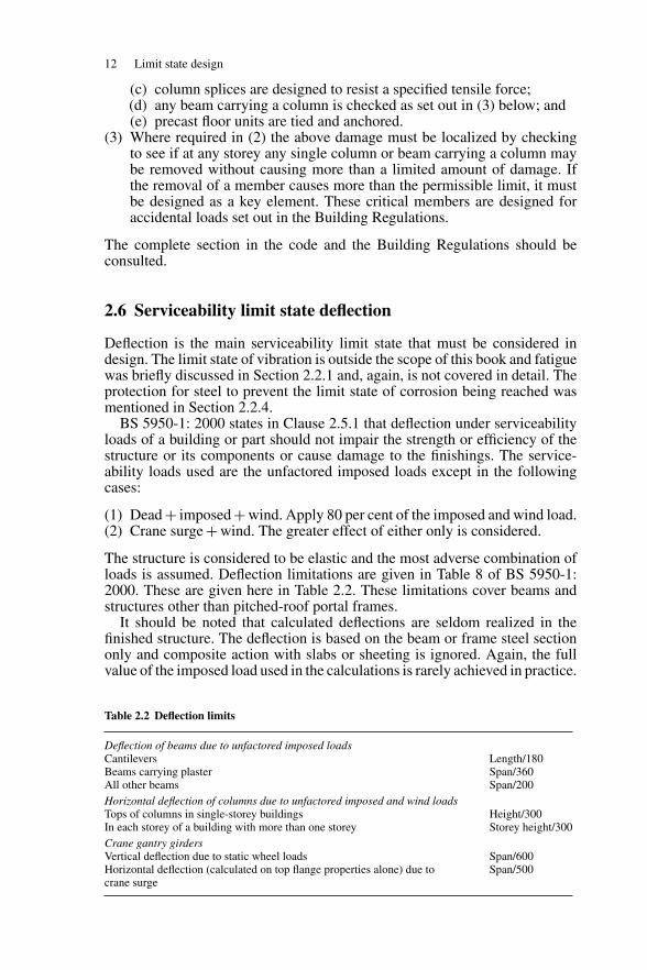
The structure is considered to be elastic and the most adverse combination ofloads is assumed. Deflection limitations are given in Table 8 of BS 5950-1:2000. These are given here in Table 2.2. These limitations cover beams andstructures other than pitched-roof portal frames.
It should be noted that calculated deflections are seldom realized in thefinished structure. The deflection is based on the beam or frame steel sectiononly and composite action with slabs or sheeting is ignored. Again, the fullvalue of the imposed load used in the calculations is rarely achieved in practice.
Table 2.2 Deflection limits
Deflection of beams due to unfactored imposed loadsCantilevers Length/180Beams carrying plaster Span/360All other beams Span/200Horizontal deflection of columns due to unfactored imposed and wind loadsTops of columns in single-storey buildings Height/300In each storey of a building with more than one storey Storey height/300Crane gantry girdersVertical deflection due to static wheel loads Span/600Horizontal deflection (calculated on top flange properties alone) due tocrane surge
Span/500
Design methods for buildings 13
2.7 Design strength of materials
The design strengths for steel complying with BS 5950-2 are given inSection 3.1.1 of BS 5950-1: 2000. Note that the material strength factor γm,part of the overall safety factor in limit state design, is taken as 1.0 in the code.The design strength may be taken as
py = 1.0 Ys but not greater than Us/1.2
where Ys is the minimum yield strength, ReH and Us the minimum ultimatetensile strength, Rm.
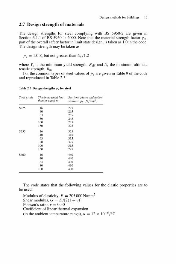
For the common types of steel values of py are given in Table 9 of the codeand reproduced in Table 2.3.
Table 2.3 Design strengths py for steel
Steel grade Thickness (mm) lessthan or equal to
Sections, plates and hollowsections, py (N/mm2)
S275 16 27540 26563 25580 245
100 235150 225
S355 16 35540 34563 33580 325
100 315150 295
S460 16 46040 44063 43080 410
100 400
The code states that the following values for the elastic properties are tobe used:
Modulus of elasticity, E = 205 000 N/mm2
Shear modulus, G = E/[2(1 + v)]Poisson’s ratio, v = 0.30Coefficient of linear thermal expansion(in the ambient temperature range), α = 12 × 10−6/◦C
14 Limit state design
2.8 Design methods for buildings
The design of buildings must be carried out in accordance with one of themethods given in Clause 2.1.2 of BS 5950-1: 2000. The design methods areas follows:
(1) Simple design: In this method, the connections between members areassumed not to develop moments adversely affecting either the membersor structure as a whole. The structure is assumed to be pin jointed foranalysis. Bracing or shear walls are necessary to provide resistance tohorizontal loading.
(2) Continuous design: The connections are assumed to be capable of develop-ing the strength and/or stiffness required by an analysis assuming full con-tinuity. The analysis may be made using either elastic or plastic methods.
(3) Semi-continuous design: This method may be used where the joints havesome degree of strength and stiffness, but insufficient to develop full con-tinuity. Either elastic or plastic analysis may be used. The moment capacity,rotational stiffness and rotation capacity of the joints should be based onexperimental evidence. This may permit some limited plasticity, providedthat the capacity of the bolts or welds is not the failure criterion. On thisbasis, the design should satisfy the strength, stiffness and in-plane stabil-ity requirements of all parts of the structure when partial continuity at thejoints is taken into account in determining the moments and forces in themembers.
(4) Experimental verification: The code states that where the design of a struc-ture or element by calculation in accordance with any of the above methodsis not practicable, the strength and stiffness may be confirmed by loadingtests. The test procedure is set out in Section 7 of the code.
In practice, structures are designed to either the simple or continuous meth-ods of design. Semi-continuous design has never found general favour withdesigners. Examples in this book are generally of the simple method of design.
3
Materials
3.1 Structural steel properties
Structural steel products are manufactured to conform to new specificationsgiven in BS 5950 Part 2: 2001. The previously used specification for weldablestructural steels, BS 4360: 1990 has been replaced by a series of Euronormspecifications for technical delivery requirements, dimensions and tolerancessuch as BS EN10025, BS EN10029, BS EN10051, BS EN10113, BS EN10137,BS EN10155, BS EN10163, BS EN10210, BS EN10219 and others.
Steel is composed of about 98 per cent of iron with the main alloyingelements carbon, silicon and manganese. Copper and chromium are added toproduce the weather-resistant steels that do not require corrosion protection.Structural steel is basically produced in three strength grades S275, S355 andS460. The important design properties are strength, ductility, impact resistanceand weldability.
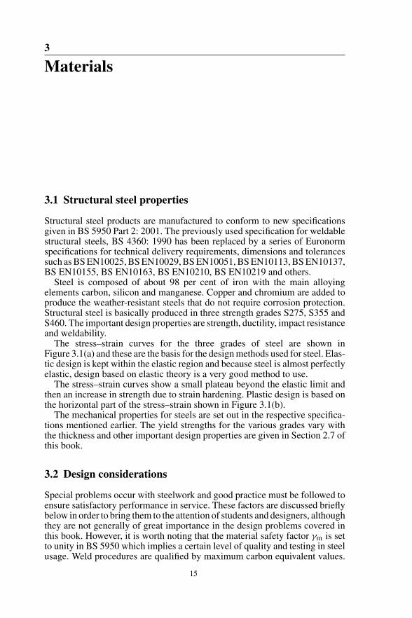
The stress–strain curves for the three grades of steel are shown inFigure 3.1(a) and these are the basis for the design methods used for steel. Elas-tic design is kept within the elastic region and because steel is almost perfectlyelastic, design based on elastic theory is a very good method to use.
The stress–strain curves show a small plateau beyond the elastic limit andthen an increase in strength due to strain hardening. Plastic design is based onthe horizontal part of the stress–strain shown in Figure 3.1(b).
The mechanical properties for steels are set out in the respective specifica-tions mentioned earlier. The yield strengths for the various grades vary withthe thickness and other important design properties are given in Section 2.7 ofthis book.
3.2 Design considerations
Special problems occur with steelwork and good practice must be followed toensure satisfactory performance in service. These factors are discussed brieflybelow in order to bring them to the attention of students and designers, althoughthey are not generally of great importance in the design problems covered inthis book. However, it is worth noting that the material safety factor γm is setto unity in BS 5950 which implies a certain level of quality and testing in steelusage. Weld procedures are qualified by maximum carbon equivalent values.
15
16 Materials
Strain
Thickness �16 mm
00.1 0.2 0.3 0.4
460
(a) Stress–strain diagrams for structural steels
355275
S460
S355
S275
Stre
ss N
/mm
2
Plastic range
00.1
Strain
0.2
Yieldstress
Elasticrange
Stre
ss N
/mm
2
(b) Stress–strain diagram for plastic design
Figure 3.1 Stress–strain diagrams for structural steels
Attention to weldability should be given when dealing with special, thick andhigher grade steel to avoid hydrogen induced cracking. Reader can refer toBS EN10229: 1998 for more information if necessary.
3.2.1 Fatigue
Fatigue failure can occur in members or structures subjected to fluctuatingloads such as crane girders, bridges and offshore structures. Failure occursthrough initiation and propagation of a crack that starts at a fault or structuraldiscontinuity and the failure load may be well below its static value.
Welded connections have the greatest effect on the fatigue strength of steelstructures. Tests show that butt welds give the best performance in servicewhile continuous fillet welds are much superior to intermittent fillet welds.Bolted connections do not reduce the strength under fatigue loading. To helpavoid fatigue failure, detail should be such that stress concentrations and abruptchanges of section are avoided in regions of tensile stress. Cases where fatiguecould occur are noted in this book, and for further information the reader shouldconsult reference (1).
Design considerations 17
3.2.2 Brittle fracture
Structural steel is ductile at temperatures above 10◦C but it becomes morebrittle as the temperature falls, and fracture can occur at low stresses below0◦C. The Charpy impact test is used to determine the resistance of steel tobrittle fracture. In this test, a small specimen is broken by a hammer and theenergy or toughness to cause failure at a given test temperature is measured.
In design, brittle fracture should be avoided by using steel quality gradewith adequate impact toughness. Quality steels are designated JR, J0, J2, K2and so forth in order of increasing resistance to brittle fracture. The Charpyimpact fracture toughness is specified for the various steel quality grades: forexample, Grade S275 J0 steel is to have a minimum fracture toughness of 27 Jat a test temperature of 0◦C.
In addition to taking care in the selection of steel grade to be used, it is alsonecessary to pay special attention to the design details to reduce the likeli-hood of brittle fracture. Thin plates are more resistant than thick ones. Abruptchanges of section and stress concentration should be avoided. Fillets weldsshould not be laid down across tension flanges and intermittent welding shouldnot be used.
Cases where brittle fracture may occur in design of structural elementsare noted in this book. For further information, the reader should consultreference (2).
3.2.3 Fire protection
Structural steelwork performs badly in fires, with the strength decreasing withincrease in temperature. At 550◦C, the yield stress has fallen to approximately0.7 of its value at normal temperatures; that is, it has reached its working stressand failure occurs under working loads.
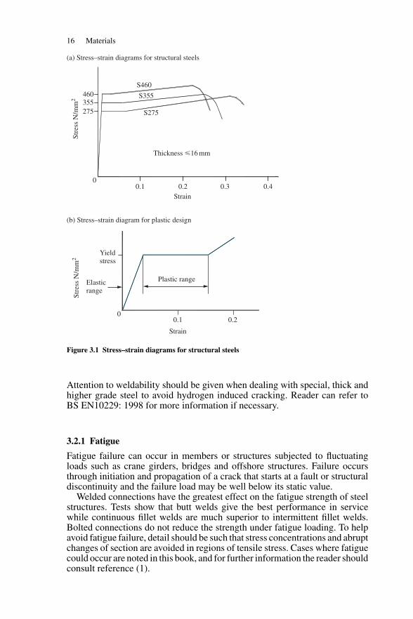
The statutory requirements for fire protection are usually set out clearly in theapproved documents from the local Building Regulations (3) or Fire SafetyAuthority. These lay down the fire-resistance period that any load-bearingelement in a given building must have, and also give the fire-resistance periodsfor different types of fire protection. Fire protection can be provided by encas-ing the member in concrete, fire board or cementitious fibre materials. The maintypes of fire protection for columns and beams are shown in Figure 3.2. Morerecently, intumescent paint is being used especially for exposed steelwork.
Solid casing Profile casingHollow casing
Figure 3.2 Fire protections for columns and beams
18 Materials
All multi-storey steel buildings require fire protection. Single-storey factorybuildings normally do not require fire protection for the steel frame. Furtherinformation is given in reference (4).
3.2.4 Corrosion protection
Exposed steelwork can be severely affected by corrosion in the atmosphere,particularly if pollutants are present, and it is necessary to provide surfaceprotection in all cases. The type of protection depends on the surface conditionsand length of life required.
The main types of protective coatings are:
(1) Metallic coatings: Either a sprayed-on in line coating of aluminium or zincis used or the member is coated by hot-dipping it in a bath of molten zincin the galvanizing process.
(2) Painting: where various systems are used. One common system consists ofusing a primer of zinc chromate followed by finishing coats of micaceousiron oxide. Plastic and bituminous paints are used in special cases.
The single most important factor in achieving a sound corrosion-protectioncoating is surface preparation. Steel is covered with mill scale when it coolsafter rolling, and this must be removed before the protection is applied, other-wise the scale can subsequently loosen and break the film. Blast cleaningmakes the best preparation prior to painting. Acid pickling is used in the gal-vanizing process. Other methods of corrosion protection which can also beconsidered are sacrificial allowance, sherardizing, concrete encasement andcathodic protection.
Careful attention to design detail is also required (for example, upturnedchannels that form a cavity where water can collect should be avoided) andaccess for future maintenance should also be provided. For further informationthe reader should consult BS EN ISO12944 Parts 1-8: 1998—Corrosion Pro-tection of Steel Structures by Protective Paint Systems and BS EN ISO14713:1999—Protection against Corrosion of Iron and Steel in Structures, Zinc andAluminium Coatings.
3.3 Steel sections
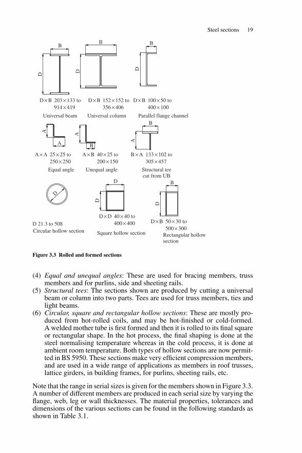
3.3.1 Rolled and formed sections
Rolled and formed sections are produced in steel mills from steel blooms, beamblanks or coils by passing them through a series of rollers. The main sectionsare shown on Figure 3.3 and their principal properties and uses are discussedbriefly below:
(1) Universal beams: These are very efficient sections for resisting bendingmoment about the major axis.
(2) Universal columns: These are sections produced primarily to resist axialload with a high radius of gyration about the minor axis to prevent bucklingin that plane.
(3) Channels: These are used for beams, bracing members, truss members andin compound members.
Steel sections 19
D × B 203 × 133 to914 × 419
A × A 25 × 25 to250 × 250
D × D 40 × 40 toD 21.3 to 508Circular hollow section
Equal angle
Universal beam Universal column Parallel flange channel
Unequal angle Structural teecut from UB
Rectangular hollowsection
Square hollow section
400 × 400 D × B 50 × 30 to500 × 300
B × A 133 × 102 to305 × 457
A × B 40 × 25 to200 × 150
D × B 100 × 50 to400 × 100
D × B 152 × 152 to356 × 406
DA A
D
D
A
B
A B
D B
B
D D
B B
D
Figure 3.3 Rolled and formed sections
(4) Equal and unequal angles: These are used for bracing members, trussmembers and for purlins, side and sheeting rails.
(5) Structural tees: The sections shown are produced by cutting a universalbeam or column into two parts. Tees are used for truss members, ties andlight beams.
(6) Circular, square and rectangular hollow sections: These are mostly pro-duced from hot-rolled coils, and may be hot-finished or cold-formed.A welded mother tube is first formed and then it is rolled to its final squareor rectangular shape. In the hot process, the final shaping is done at thesteel normalising temperature whereas in the cold process, it is done atambient room temperature. Both types of hollow sections are now permit-ted in BS 5950. These sections make very efficient compression members,and are used in a wide range of applications as members in roof trusses,lattice girders, in building frames, for purlins, sheeting rails, etc.
Note that the range in serial sizes is given for the members shown in Figure 3.3.A number of different members are produced in each serial size by varying theflange, web, leg or wall thicknesses. The material properties, tolerances anddimensions of the various sections can be found in the following standards asshown in Table 3.1.
20 Materials
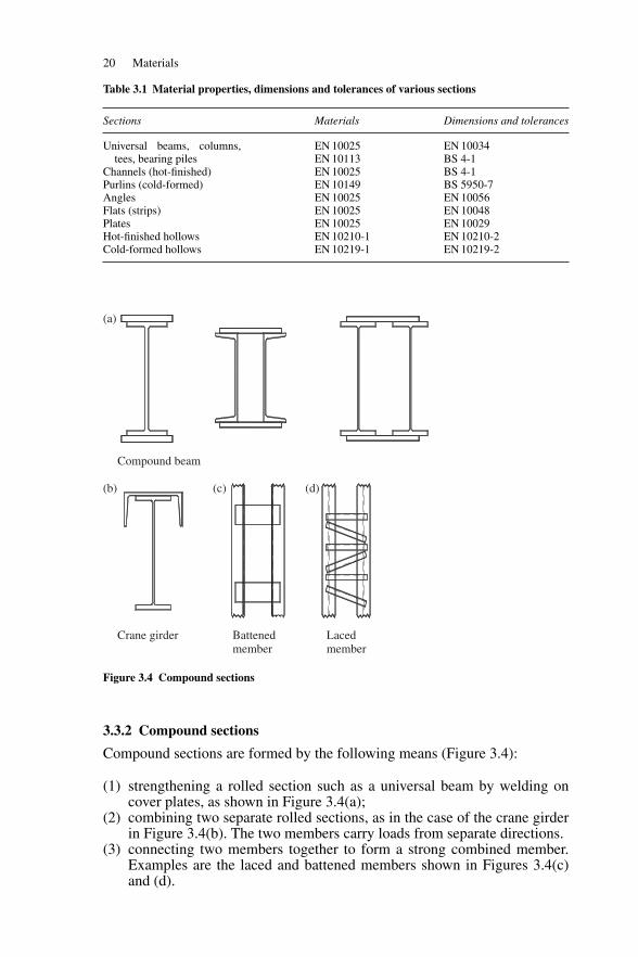
Table 3.1 Material properties, dimensions and tolerances of various sections
Sections Materials Dimensions and tolerances
Universal beams, columns,tees, bearing piles
EN 10025 EN 10034EN 10113 BS 4-1
Channels (hot-finished) EN 10025 BS 4-1Purlins (cold-formed) EN 10149 BS 5950-7Angles EN 10025 EN 10056Flats (strips) EN 10025 EN 10048Plates EN 10025 EN 10029Hot-finished hollows EN 10210-1 EN 10210-2Cold-formed hollows EN 10219-1 EN 10219-2
Compound beam
Crane girder Battenedmember
Lacedmember
(a)
(b) (c) (d)
Figure 3.4 Compound sections
3.3.2 Compound sections
Compound sections are formed by the following means (Figure 3.4):
(1) strengthening a rolled section such as a universal beam by welding oncover plates, as shown in Figure 3.4(a);
(2) combining two separate rolled sections, as in the case of the crane girderin Figure 3.4(b). The two members carry loads from separate directions.
(3) connecting two members together to form a strong combined member.Examples are the laced and battened members shown in Figures 3.4(c)and (d).
Section properties 21
Plate girderBox girder Box column
Built-upsection
Figure 3.5 Built-up sections
Zed section Lipped channelSigma section
Figure 3.6 Cold-rolled sections
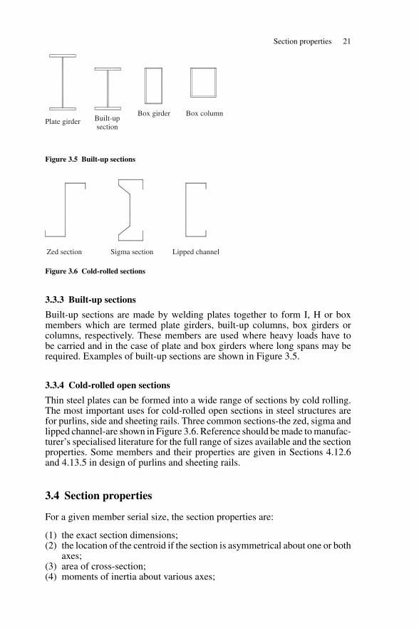
3.3.3 Built-up sections
Built-up sections are made by welding plates together to form I, H or boxmembers which are termed plate girders, built-up columns, box girders orcolumns, respectively. These members are used where heavy loads have tobe carried and in the case of plate and box girders where long spans may berequired. Examples of built-up sections are shown in Figure 3.5.
3.3.4 Cold-rolled open sections
Thin steel plates can be formed into a wide range of sections by cold rolling.The most important uses for cold-rolled open sections in steel structures arefor purlins, side and sheeting rails. Three common sections-the zed, sigma andlipped channel-are shown in Figure 3.6. Reference should be made to manufac-turer’s specialised literature for the full range of sizes available and the sectionproperties. Some members and their properties are given in Sections 4.12.6and 4.13.5 in design of purlins and sheeting rails.
3.4 Section properties
For a given member serial size, the section properties are:
(1) the exact section dimensions;(2) the location of the centroid if the section is asymmetrical about one or both
axes;(3) area of cross-section;(4) moments of inertia about various axes;
22 Materials
(5) radii of gyration about various axes;(6) moduli of section for various axes, both elastic and plastic.
The section properties for hot rolled and formed sections are also listed in SCIPublication 202: Steelwork Design Guide to BS 5950: Part 1: 2000, Volume1 Section Properties and Member Capacities, 6th edition with amendments,The Steel Construction Institute, United Kingdom.
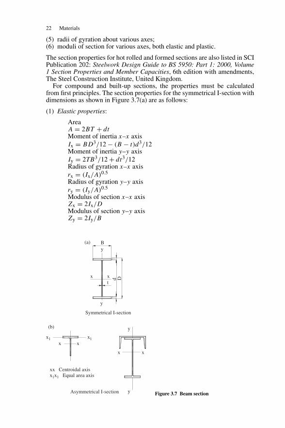
For compound and built-up sections, the properties must be calculatedfrom first principles. The section properties for the symmetrical I-section withdimensions as shown in Figure 3.7(a) are as follows:
(1) Elastic properties:
AreaA = 2BT + dtMoment of inertia x–x axisIx = BD3/12 − (B − t)d3/12Moment of inertia y–y axisIy = 2TB3/12 + dt3/12Radius of gyration x–x axisrx = (Ix/A)0.5
Radius of gyration y–y axisry = (Iy/A)0.5
Modulus of section x–x axisZx = 2Ix/DModulus of section y–y axisZy = 2Iy/B
Symmetrical I-section
Asymmetrical I-section
(a)
x
x x
xx Centroidal axisx1x1 Equal area axis
x x
x1 x1
xt
y
y
y
By
(b)
Dd
Figure 3.7 Beam section
Section properties 23
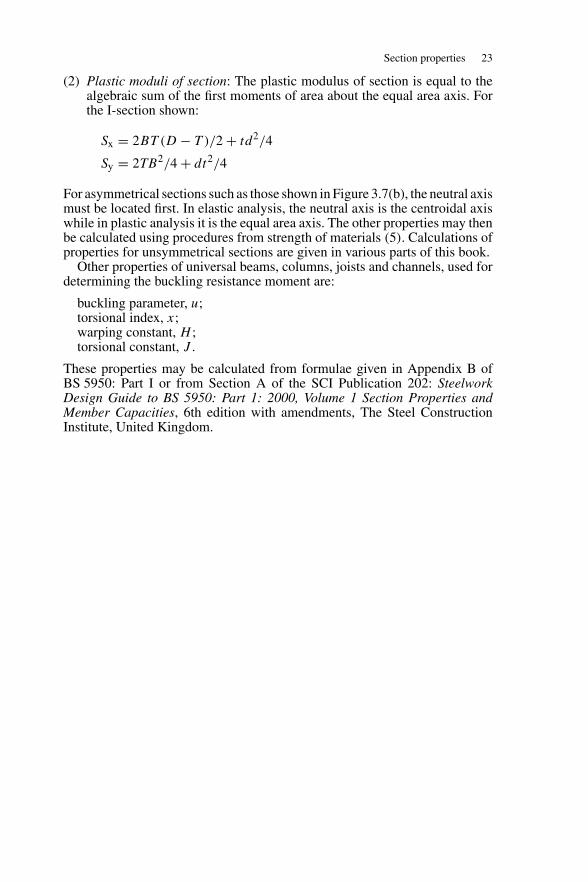
(2) Plastic moduli of section: The plastic modulus of section is equal to thealgebraic sum of the first moments of area about the equal area axis. Forthe I-section shown:
Sx = 2BT (D − T )/2 + td2/4
Sy = 2TB2/4 + dt2/4
For asymmetrical sections such as those shown in Figure 3.7(b), the neutral axismust be located first. In elastic analysis, the neutral axis is the centroidal axiswhile in plastic analysis it is the equal area axis. The other properties may thenbe calculated using procedures from strength of materials (5). Calculations ofproperties for unsymmetrical sections are given in various parts of this book.
Other properties of universal beams, columns, joists and channels, used fordetermining the buckling resistance moment are:
buckling parameter, u;torsional index, x;warping constant, H ;torsional constant, J .
These properties may be calculated from formulae given in Appendix B ofBS 5950: Part I or from Section A of the SCI Publication 202: SteelworkDesign Guide to BS 5950: Part 1: 2000, Volume 1 Section Properties andMember Capacities, 6th edition with amendments, The Steel ConstructionInstitute, United Kingdom.
4
Beams
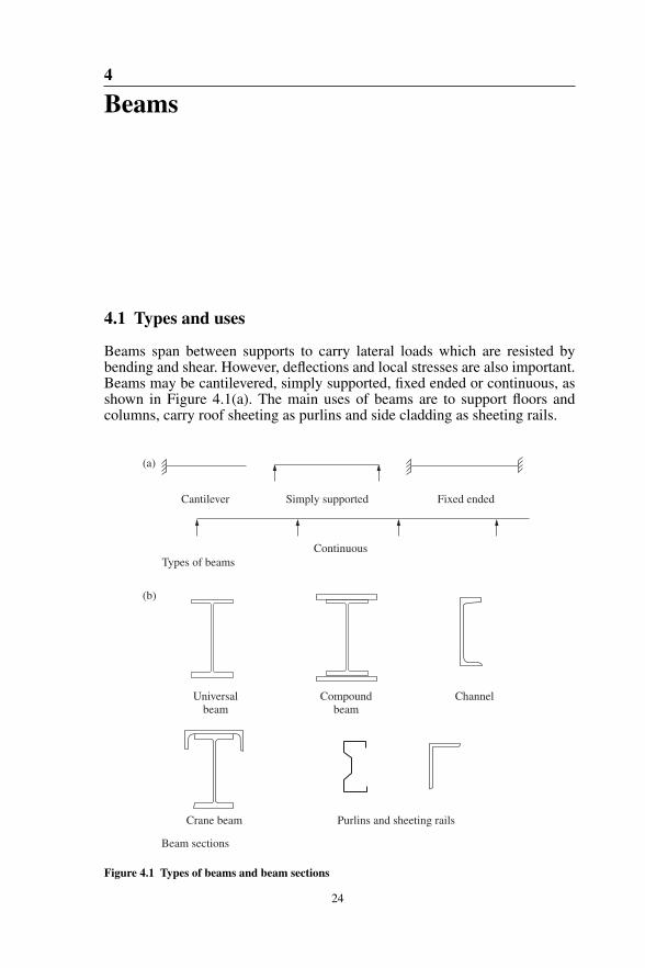
4.1 Types and uses
Beams span between supports to carry lateral loads which are resisted bybending and shear. However, deflections and local stresses are also important.Beams may be cantilevered, simply supported, fixed ended or continuous, asshown in Figure 4.1(a). The main uses of beams are to support floors andcolumns, carry roof sheeting as purlins and side cladding as sheeting rails.
Cantilever Simply supported
ContinuousTypes of beams
Beam sections
(a)
(b)
Universalbeam
Compoundbeam
Channel
Crane beam Purlins and sheeting rails
Fixed ended
Figure 4.1 Types of beams and beam sections
24
Beam loads 25
Bending moment diagram
Bending moment diagram
Cover plates
Simply supported beam
Fixed ended beam
Haunched ends
Figure 4.2 Non-uniform beam
Any section may serve as a beam, and common beam sections are shown inFigure 4.1(b). Some comments on the different sections are given:
(1) The universal beam where the material is concentrated in the flanges is themost efficient section to resist uniaxial bending.
(2) The universal column may be used where the depth is limited, but it is lessefficient.
(3) The compound beam consisting of a universal beam and flange plates isused where the depth is limited and the universal beam itself is not strongenough to carry the load.
(4) The crane beam consists of a universal beam and channel. It is because thebeam needs to resist bending in both horizontal and vertical directions.
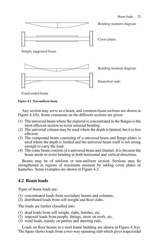
Beams may be of uniform or non-uniform section. Sections may bestrengthened in regions of maximum moment by adding cover plates orhaunches. Some examples are shown in Figure 4.2.
4.2 Beam loads
Types of beam loads are:
(1) concentrated loads from secondary beams and columns;(2) distributed loads from self-weight and floor slabs.
The loads are further classified into:
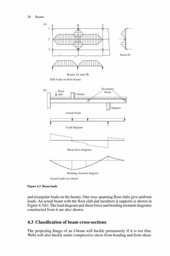
(1) dead loads from self weight, slabs, finishes, etc.(2) imposed loads from people, fittings, snow on roofs, etc.(3) wind loads, mainly on purlins and sheeting rails.
Loads on floor beams in a steel frame building are shown in Figure 4.3(a).The figure shows loads from a two-way spanning slab which gives trapezoidal
26 Beams
1A B C
2
3
Beam B1
Beams 2A and 2B
Slab loads on floor beams
Actual loads on a beam
Secondarybeam
Support
Floorslab
Actual beam
Load diagram
Shear force diagram
Bending moment diagram
(a)
(b)Column
Figure 4.3 Beam loads
and triangular loads on the beams. One-way spanning floor slabs give uniformloads. An actual beam with the floor slab and members it supports is shown inFigure 4.3(b). The load diagram and shear force and bending moment diagramsconstructed from it are also shown.
4.3 Classification of beam cross-sections
The projecting flange of an I-beam will buckle prematurely if it is too thin.Webs will also buckle under compressive stress from bending and from shear.
Classification of beam cross-sections 27
This problem is discussed in more detail in Section 5.2 in Chapter 5 (see alsoreference (6)).
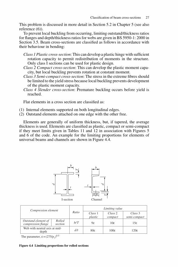
To prevent local buckling from occurring, limiting outstand/thickness ratiosfor flanges and depth/thickness ratios for webs are given in BS 5950-1: 2000 inSection 3.5. Beam cross-sections are classified as follows in accordance withtheir behaviour in bending:
Class 1 Plastic cross-section: This can develop a plastic hinge with sufficientrotation capacity to permit redistribution of moments in the structure.Only class I sections can be used for plastic design.
Class 2 Compact cross-section: This can develop the plastic moment capa-city, but local buckling prevents rotation at constant moment.
Class 3 Semi-compact cross-section: The stress in the extreme fibres shouldbe limited to the yield stress because local buckling prevents developmentof the plastic moment capacity.
Class 4 Slender cross-section: Premature buckling occurs before yield isreached.
Flat elements in a cross section are classified as:
(1) Internal elements supported on both longitudinal edges.(2) Outstand elements attached on one edge with the other free.
Elements are generally of uniform thickness, but, if tapered, the averagethickness is used. Elements are classified as plastic, compact or semi-compactif they meet limits given in Tables 11 and 12 in association with Figures 5and 6 of the code. An example for the limiting proportions for elements ofuniversal beams and channels are shown in Figure 4.4.
Limiting valueCompression element
Ratio Class 1plastic
Class 2compact
Class 3semi-compact
Outstand element ofcompression flange
Rolledsection b/ T 9ε 10ε 15ε
Web with neutral axis at mid-depth d/t 80ε 100ε 120ε
The parameter, ε = (275/py)0.5
b
tt
b
d
n n T
T
d
I-section Channel
Figure 4.4 Limiting proportions for rolled sections
28 Beams
4.4 Bending stresses and moment capacity
Both elastic and plastic theories are discussed here. Short or restrained beamsare considered in this section. Plastic properties are used for plastic and com-pact sections and elastic properties for semi-compact sections to determinemoment capacities. For slender sections, only effective elastic properties areused.
4.4.1 Elastic theory
(1) Uniaxial bending
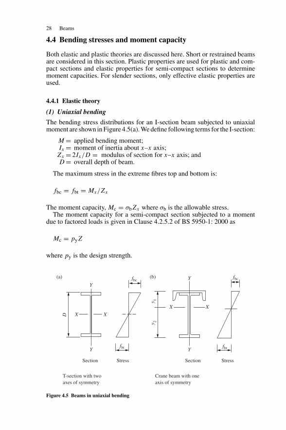
The bending stress distributions for an I-section beam subjected to uniaxialmoment are shown in Figure 4.5(a). We define following terms for the I-section:
M = applied bending moment;Ix = moment of inertia about x–x axis;Zx = 2Ix/D = modulus of section for x–x axis; andD = overall depth of beam.
The maximum stress in the extreme fibres top and bottom is:
fbc = fbt = Mx/Zx
The moment capacity, Mc = σbZx where σb is the allowable stress.The moment capacity for a semi-compact section subjected to a moment
due to factored loads is given in Clause 4.2.5.2 of BS 5950-1: 2000 as
Mc = pyZ
where py is the design strength.
Section Stress
T-section with twoaxes of symmetry
Crane beam with oneaxis of symmetry
Section Stress
X X
X X
Y
Y Y
Y
fbt fbt
fbcfbc
y 1y 2
D
(a) (b)
Figure 4.5 Beams in uniaxial bending
Bending stresses and moment capacity 29
For the asymmetrical crane beam section shown in Figure 4.5(b), the addi-tional terms require definition:
Z1 = Ix/y1 = modulus of section for top flange,Z2 = Ix/y2 = modulus of section for bottom flange,y1, y2 = distance from centroid to top and bottom fibres.
The bending stresses are:
Top fibre in compression fbc = Mx/Z1Bottom fibre in tension fbt = Mx/Z2
The moment capacity controlled by the stress in the bottom flange is
Mc = pyZ2
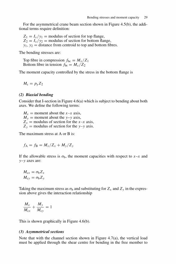
(2) Biaxial bending
Consider that I-section in Figure 4.6(a) which is subject to bending about bothaxes. We define the following terms:
Mx = moment about the x–x axis,My = moment about the y–y axis,Zx = modulus of section for the x–x axis,Zy = modulus of section for the y–y axis.
The maximum stress at A or B is:
fA = fB = Mx/Zx + My/Zy
If the allowable stress is σb, the moment capacities with respect to x–x andy–y axes are:
Mcx = σbZx
Mcy = σbZy
Taking the maximum stress as σb and substituting for Zx and Zy in the expres-sion above gives the interaction relationship
Mx
Mcx+ My
Mcy= 1
This is shown graphically in Figure 4.6(b).
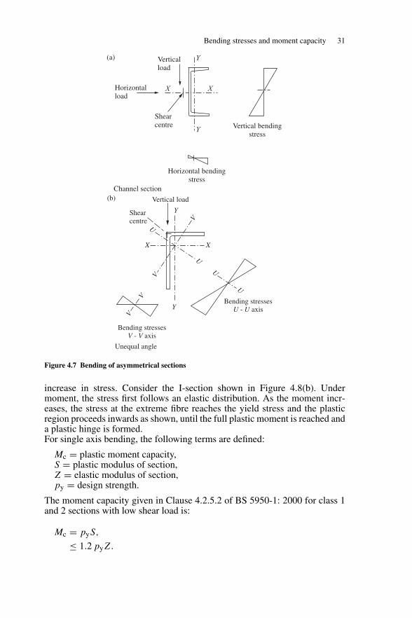
(3) Asymmetrical sections
Note that with the channel section shown in Figure 4.7(a), the vertical loadmust be applied through the shear centre for bending in the free member to
30 Beams
X X X X
Compression
Tension
Vertical load
BY
Y
Horizontalload
My
Y
Y
A
Mx
Zx
Mx Mx
My
Compression
Horizontal bending stresses
Bending stresses
Vertical bending stresses
Tension
My
Zy
1.0
1.0
Interaction diagram
My
Mcy
Mx
Mcx
(b)
(a)
My
Zy
MxZx
Figure 4.6 Biaxial bending
take place about the x–x axis, otherwise twisting and biaxial bending occurs.However, a horizontal load applied through the centroid causes bending aboutthe y–y axis only.
For an asymmetrical section such as the unequal angle shown inFigure 4.7(b), bending takes place about the principal axes u–u and v–v inthe free member when the load is applied through the shear centre. When theangle is used as a purlin, the cladding restrains the member so that it bendsabout the x–x axis.
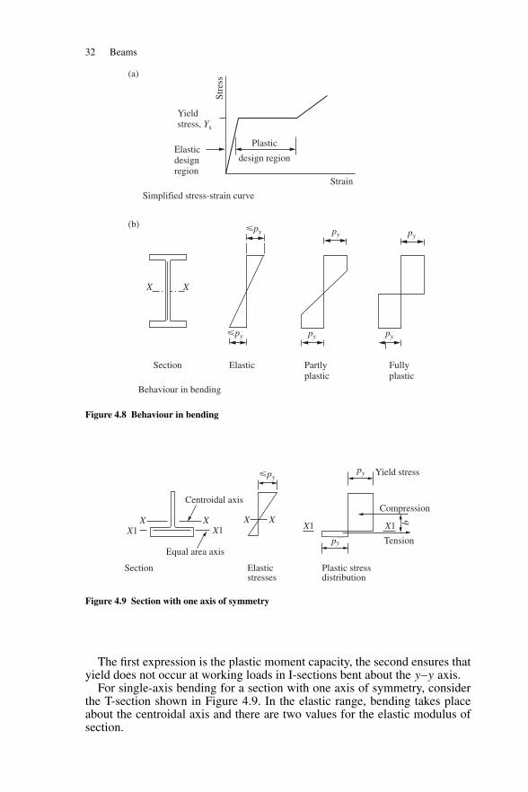
4.4.2 Plastic theory
(1) Uniaxial bending
The stress–strain curve for steel on which plastic theory is based is shown inFigure 4.8(a). In the plastic region after yield, the strain increases without
Bending stresses and moment capacity 31
Y
Y
XX
Horizontal bendingstress
Channel section
Shearcentre
Horizontalload
Verticalload
Vertical bendingstress
(a)
Bending stressesV - V axis
Bending stressesU - U axis
Unequal angle
U
U
U
U
V
V
V
V
XX
Y
Y
Shearcentre
Vertical load(b)
Figure 4.7 Bending of asymmetrical sections
increase in stress. Consider the I-section shown in Figure 4.8(b). Undermoment, the stress first follows an elastic distribution. As the moment incr-eases, the stress at the extreme fibre reaches the yield stress and the plasticregion proceeds inwards as shown, until the full plastic moment is reached anda plastic hinge is formed.For single axis bending, the following terms are defined:
Mc = plastic moment capacity,S = plastic modulus of section,Z = elastic modulus of section,py = design strength.
The moment capacity given in Clause 4.2.5.2 of BS 5950-1: 2000 for class 1and 2 sections with low shear load is:
Mc = pyS,
≤ 1.2 pyZ.
32 Beams
Strain
Yieldstress, Ys
Elasticdesignregion
Plastic
design region
�py
�py
py
py py
py
X X
Section Elastic Partlyplastic
Fullyplastic
(a)
(b)St
ress
Simplified stress-strain curve
Behaviour in bending
Figure 4.8 Behaviour in bending
Centroidal axis
X X X XX1 X1
py
py
X1 X1
Equal area axis
b
Yield stress
Compression
Tension
Plastic stressdistribution
Elasticstresses
Section
�py
Figure 4.9 Section with one axis of symmetry
The first expression is the plastic moment capacity, the second ensures thatyield does not occur at working loads in I-sections bent about the y–y axis.
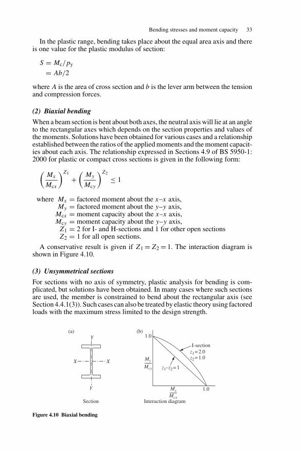
For single-axis bending for a section with one axis of symmetry, considerthe T-section shown in Figure 4.9. In the elastic range, bending takes placeabout the centroidal axis and there are two values for the elastic modulus ofsection.
Bending stresses and moment capacity 33
In the plastic range, bending takes place about the equal area axis and thereis one value for the plastic modulus of section:
S = Mc/py
= Ab/2
where A is the area of cross section and b is the lever arm between the tensionand compression forces.
(2) Biaxial bending
When a beam section is bent about both axes, the neutral axis will lie at an angleto the rectangular axes which depends on the section properties and values ofthe moments. Solutions have been obtained for various cases and a relationshipestablished between the ratios of the applied moments and the moment capacit-ies about each axis. The relationship expressed in Sections 4.9 of BS 5950-1:2000 for plastic or compact cross sections is given in the following form:(
Mx
Mcx
)Z1
+(
My
Mcy
)Z2
≤ 1
where Mx = factored moment about the x–x axis,My = factored moment about the y–y axis,
Mcx = moment capacity about the x–x axis,Mcy = moment capacity about the y–y axis,Z1 = 2 for I- and H-sections and 1 for other open sectionsZ2 = 1 for all open sections.
A conservative result is given if Z1 = Z2 = 1. The interaction diagram isshown in Figure 4.10.
(3) Unsymmetrical sections
For sections with no axis of symmetry, plastic analysis for bending is com-plicated, but solutions have been obtained. In many cases where such sectionsare used, the member is constrained to bend about the rectangular axis (seeSection 4.4.1(3)). Such cases can also be treated by elastic theory using factoredloads with the maximum stress limited to the design strength.
X
Y
Y
Xz1–z2 = 1
z1 = 2.0z2 = 1.0
I-section
My
Mcy
1.0
1.0Mx
Mcx
(a) (b)
Section Interaction diagram
Figure 4.10 Biaxial bending
34 Beams
4.5 Lateral torsional buckling
4.5.1 General considerations
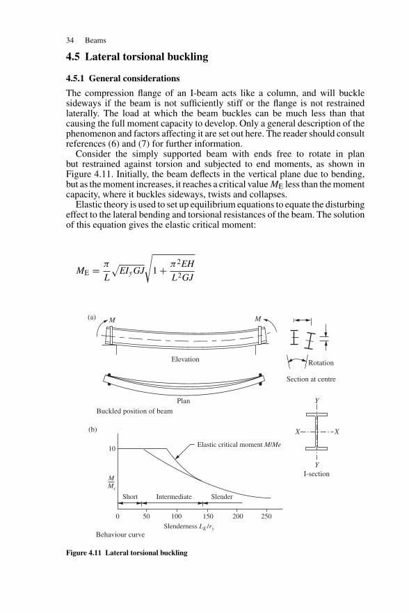
The compression flange of an I-beam acts like a column, and will bucklesideways if the beam is not sufficiently stiff or the flange is not restrainedlaterally. The load at which the beam buckles can be much less than thatcausing the full moment capacity to develop. Only a general description of thephenomenon and factors affecting it are set out here. The reader should consultreferences (6) and (7) for further information.
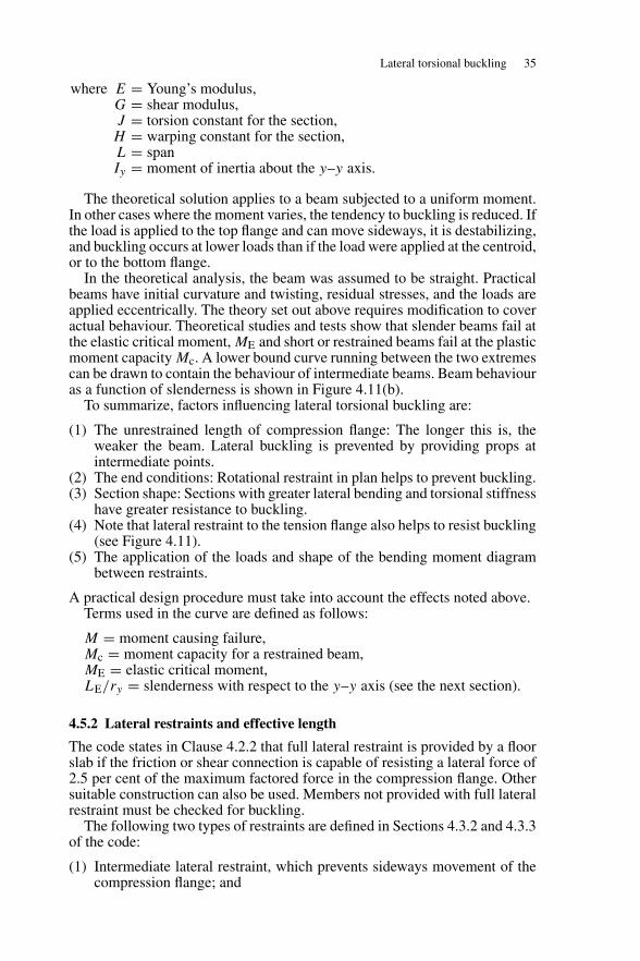
Consider the simply supported beam with ends free to rotate in planbut restrained against torsion and subjected to end moments, as shown inFigure 4.11. Initially, the beam deflects in the vertical plane due to bending,but as the moment increases, it reaches a critical value ME less than the momentcapacity, where it buckles sideways, twists and collapses.
Elastic theory is used to set up equilibrium equations to equate the disturbingeffect to the lateral bending and torsional resistances of the beam. The solutionof this equation gives the elastic critical moment:
ME = π
L
√EIyGJ
√1 + π2EH
L2GJ
500
Short
M
10
Mc
Intermediate Slender
Elastic critical moment M/Me
100
Slenderness LE /ry
150 200 250
Y
Y
X X
Rotation
MM
Elevation
Section at centre
I-section
(a)
(b)
PlanBuckled position of beam
Behaviour curve
Figure 4.11 Lateral torsional buckling
Lateral torsional buckling 35
where E = Young’s modulus,G = shear modulus,J = torsion constant for the section,H = warping constant for the section,L = spanIy = moment of inertia about the y–y axis.
The theoretical solution applies to a beam subjected to a uniform moment.In other cases where the moment varies, the tendency to buckling is reduced. Ifthe load is applied to the top flange and can move sideways, it is destabilizing,and buckling occurs at lower loads than if the load were applied at the centroid,or to the bottom flange.
In the theoretical analysis, the beam was assumed to be straight. Practicalbeams have initial curvature and twisting, residual stresses, and the loads areapplied eccentrically. The theory set out above requires modification to coveractual behaviour. Theoretical studies and tests show that slender beams fail atthe elastic critical moment, ME and short or restrained beams fail at the plasticmoment capacity Mc. A lower bound curve running between the two extremescan be drawn to contain the behaviour of intermediate beams. Beam behaviouras a function of slenderness is shown in Figure 4.11(b).
To summarize, factors influencing lateral torsional buckling are:
(1) The unrestrained length of compression flange: The longer this is, theweaker the beam. Lateral buckling is prevented by providing props atintermediate points.
(2) The end conditions: Rotational restraint in plan helps to prevent buckling.(3) Section shape: Sections with greater lateral bending and torsional stiffness
have greater resistance to buckling.(4) Note that lateral restraint to the tension flange also helps to resist buckling
(see Figure 4.11).(5) The application of the loads and shape of the bending moment diagram
between restraints.
A practical design procedure must take into account the effects noted above.Terms used in the curve are defined as follows:
M = moment causing failure,Mc = moment capacity for a restrained beam,ME = elastic critical moment,LE/ry = slenderness with respect to the y–y axis (see the next section).
4.5.2 Lateral restraints and effective length
The code states in Clause 4.2.2 that full lateral restraint is provided by a floorslab if the friction or shear connection is capable of resisting a lateral force of2.5 per cent of the maximum factored force in the compression flange. Othersuitable construction can also be used. Members not provided with full lateralrestraint must be checked for buckling.
The following two types of restraints are defined in Sections 4.3.2 and 4.3.3of the code:
(1) Intermediate lateral restraint, which prevents sideways movement of thecompression flange; and
36 Beams
Open l 2 l 4
LE
=l 2
LE
=0.
714
Fullyrestrained
(b)
(a)
Slab
Torsional restraintfree to rotate in plan
Fixed ends
Effective lengths
l1LE = l1
Floor slab providesfull lateral restraint
Secondary beam provideslateral restraint
Lateral and torsional restraint
Torsional restraintfree to rotate in plan
l3LE = l3
Figure 4.12 Restraints and effective lengths
(2) Torsional restraint, which prevents movement of one flange relative tothe other.
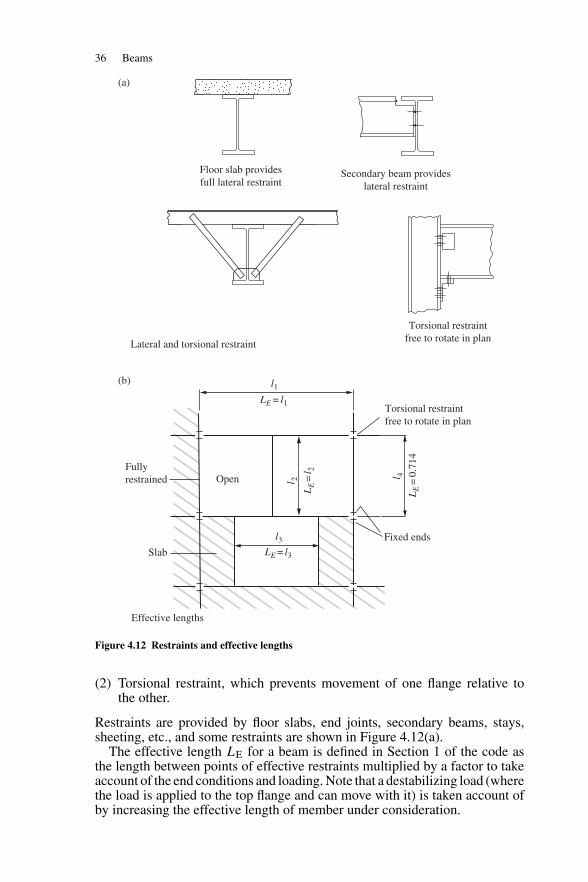
Restraints are provided by floor slabs, end joints, secondary beams, stays,sheeting, etc., and some restraints are shown in Figure 4.12(a).
The effective length LE for a beam is defined in Section 1 of the code asthe length between points of effective restraints multiplied by a factor to takeaccount of the end conditions and loading. Note that a destabilizing load (wherethe load is applied to the top flange and can move with it) is taken account ofby increasing the effective length of member under consideration.
Lateral torsional buckling 37
Table 4.1 Effective length LE–Beams
Support conditions Loading conditions
Normal Destabilizing
Beam partial torsionally unrestrained 1.2LLT + 2D 1.4LLT + 2D
Compression flange laterally unrestrainedBoth flanges free to rotate on plan
Beam torsionally restrained 1.0LLT 1.2LLTCompression flange laterally restrainedCompression flange only free to rotate on plan
Beam torsionally restrained 0.7LLT 0.85LLTBoth flanges NOT free to rotate on plan
LLT = length of beam between restraints.D = depth of beam.
The effective length for beams is discussed in Section 4.3.5 of BS 5950-1:2000. When the beam is restrained at the ends only, that is, without intermediaterestraint, the effective length should be obtained from Table 13 in the code.Some values from this table are given in Table 4.1.
Where the beam is restrained at intervals by other members the effectivelength LE may be taken as L, the distance between restraints. Some effectivelengths for floor beams are shown in Figure 4.12(b).
4.5.3 Code design procedure
(1) General procedure
The general procedure for checking the resistance to lateral torsional bucklingis out lined in Section 4.3.6 of BS 5950-1: 2000:
(1) Resistance to lateral-torsional buckling need not be checked separately(and the buckling resistance moment Mb may be taken as equal to therelevant moment capacity Mc) in the following cases:
bending about the minor axis;CHS, square RHS or circular or square solid bars;RHS, unless LE/ry exceeds the limiting value given in Table 15 of
BS 5950-1: 2000 for the relevant value of D/B;I, H, channel or box sections, if λLT does not exceed λL0,
Otherwise, for members subject to bending about their major axis, refer-ence should be made as follows:
Mx ≤ Mb/mLT and Mx ≤ Mcx
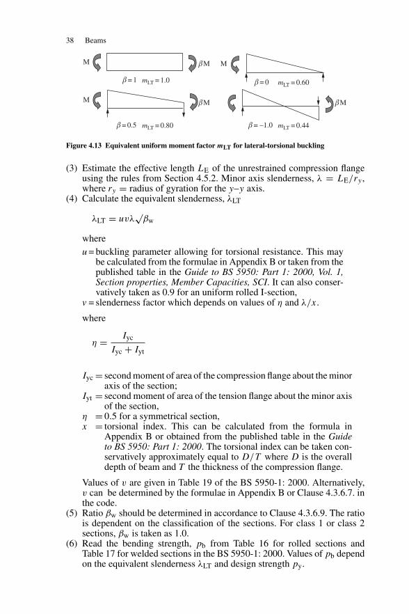
(2) Calculate the equivalent uniform moment factor mLT:The value of the equivalent uniform moment factor mLT which depend onthe ratio and direction of the major axis moment. For the normal loadingcondition, the equivalent uniform moment factor for lateral-torsional buck-ling should be obtained from Table 18 of BS 5950-1: 2000. For destabil-izing loading condition, mLT should be taken as 1.0. Values for somecommon load cases are shown in Figure 4.13.
38 Beams
M
M
βM
mLT = 1.0β = 1
mLT = 0.80β = 0.5 mLT = 0.44β = –1.0
mLT = 0.60β = 0
βM βM
M
Figure 4.13 Equivalent uniform moment factor mLT for lateral-torsional buckling
(3) Estimate the effective length LE of the unrestrained compression flangeusing the rules from Section 4.5.2. Minor axis slenderness, λ = LE/ry ,where ry = radius of gyration for the y–y axis.
(4) Calculate the equivalent slenderness, λLT
λLT = uvλ√
βw
whereu = buckling parameter allowing for torsional resistance. This may
be calculated from the formulae in Appendix B or taken from thepublished table in the Guide to BS 5950: Part 1: 2000, Vol. 1,Section properties, Member Capacities, SCI. It can also conser-vatively taken as 0.9 for an uniform rolled I-section,
v = slenderness factor which depends on values of η and λ/x.
where
η = Iyc
Iyc + Iyt
Iyc = second moment of area of the compression flange about the minoraxis of the section;
Iyt = second moment of area of the tension flange about the minor axisof the section,
η = 0.5 for a symmetrical section,x = torsional index. This can be calculated from the formula in
Appendix B or obtained from the published table in the Guideto BS 5950: Part 1: 2000. The torsional index can be taken con-servatively approximately equal to D/T where D is the overalldepth of beam and T the thickness of the compression flange.
Values of v are given in Table 19 of the BS 5950-1: 2000. Alternatively,v can be determined by the formulae in Appendix B or Clause 4.3.6.7. inthe code.
(5) Ratio βw should be determined in accordance to Clause 4.3.6.9. The ratiois dependent on the classification of the sections. For class 1 or class 2sections, βw is taken as 1.0.
(6) Read the bending strength, pb from Table 16 for rolled sections andTable 17 for welded sections in the BS 5950-1: 2000. Values of pb dependon the equivalent slenderness λLT and design strength py.
Lateral torsional buckling 39
(7) Calculate the buckling resistance moment.for class 1 plastic or class 2 compact cross-sections:
Mb = pbSx.
for class 3 semi-compact cross-sections:
Mb = pbZx; or alternatively, Mb = pbSx,eff
for class 4 slender cross-sections:
Mb = pbZx,eff .
where
pb is the bending strength;Sx is the plastic modulus about the major axis;Sx,eff is the effective plastic modulus about the major axis;Zx is the section modulus about the major axis;Zx,eff is the effective section modulus about the major axis.
(2) Conservative approach for equal flanged rolled sections
The code gives a conservative approach for equal flanged rolled sections inSection 4.3.7. The buckling resistance moment Mb of a plain rolled I, H or chan-nel section with equal flanges may be determined using the bending strength,pb obtained from Table 20 for the relevant values of (βw)0.5LE/ry and D/Tas follows:
for a class 1 plastic or class 2 compact cross-section:
Mb = pbSx
for a class 3 semi-compact cross-section:
Mb = pbZx
4.5.4 Biaxial bending
Lateral torsional buckling affects the moment capacity with respect to themajor axis only of I-section beams. When the section is bent about only theminor axis, it will reach the moment capacity given in Section 4.4.2(1).
Where biaxial bending occurs, BS 5950-1: 2000 specifies in Section 4.9 thatthe following simplified interaction expressions must be satisfied for plastic orcompact sections:
(1) Cross-section capacity check at point of maximum combined moments:
Mx
Mcx+ My
Mcy≤ 1
This design check was discussed in Section 4.4.2(2) above.
40 Beams
(2) Member buckling check at the centre of the beam:
mxMx
pyZx
+ myMy
pyZy
≤ 1
mLTMLT
Mb+ myMy
pyZy
≤ 1
where
Mb is the buckling resistance moment,MLT is the maximum major axis moment in the segment length L
governing Mb;Mx is the maximum major axis moment in the segment length Lx ;My is the maximum minor axis moment in the segment length Ly ;Zx is the section modulus about the major axis;Zy is the section modulus about the minor axis.
The equivalent uniform moment factors mLT, mx and my should be obtainedfrom Clause 4.8.3.3.4 of BS 5950-1: 2000.
More exact expressions are given in the code. Biaxial bending is discussedmore fully in Chapter 7 of this book.
4.6 Shear in beams
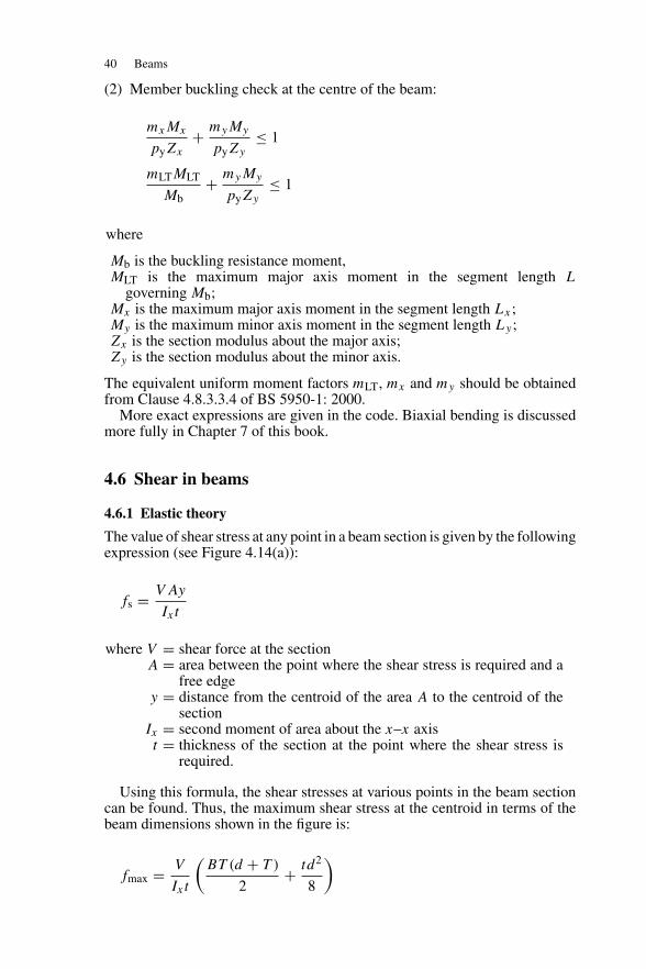
4.6.1 Elastic theory
The value of shear stress at any point in a beam section is given by the followingexpression (see Figure 4.14(a)):
fs = V Ay
Ixt
where V = shear force at the sectionA = area between the point where the shear stress is required and a
free edgey = distance from the centroid of the area A to the centroid of the
sectionIx = second moment of area about the x–x axist = thickness of the section at the point where the shear stress is
required.
Using this formula, the shear stresses at various points in the beam sectioncan be found. Thus, the maximum shear stress at the centroid in terms of thebeam dimensions shown in the figure is:
fmax = V
Ixt
(BT (d + T )
2+ td2
8
)
Shear in beams 41
X
B
Elastic shear stress distribution
Rolled beamShear areas
T-section
(a)
(b)
(c)
X
t
t
D
D
dT
T
d
t
X X
Shearstress Net bending stress
YieldstressSection
Plastic theory-shear and moment
Yeildstress
Maximumstress
Figure 4.14 Shear in beams
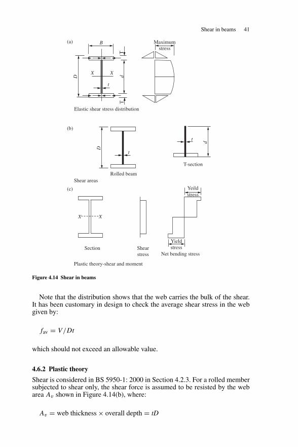
Note that the distribution shows that the web carries the bulk of the shear.It has been customary in design to check the average shear stress in the webgiven by:
fav = V/Dt
which should not exceed an allowable value.
4.6.2 Plastic theory
Shear is considered in BS 5950-1: 2000 in Section 4.2.3. For a rolled membersubjected to shear only, the shear force is assumed to be resisted by the webarea Av shown in Figure 4.14(b), where:
Av = web thickness × overall depth = tD
42 Beams
For the T section shown in the figure:
Av = 0.9Ao
where Ao is the area of the rectilinear element which has the largest dimensionin the direction parallel to the shear force and equal to td.
The shear area may be stressed to the yield stress in shear, that is, to 1/√
3of the yield stress in tension. The capacity is given in the code as:
Pv = 0.6pyAv
If the ratio d/t exceeds 70ε for a rolled section, or 62ε for a welded section,the web should be checked for shear buckling in accordance with Clause 4.4.5in BS 5950-1: 2000.
If moment as well as shear occurs at the section, the web is assumed to resistall the shear while the flanges are stressed to yield by bending. The sectionanalysis is based on the shear stress and bending stress distributions shownin Figure 4.14(c). The web is at yield under the combined bending and shearstresses and von Mises’ criterion is adopted for failure in the web. The shearreduces the moment capacity, but the reduction is small for all but high valuesof shear force. The analysis for shear and bending is given in reference (8).
BS 5950-1: 2000 gives the following expression in Section 4.2.5.3 forthe moment capacity for plastic or compact sections in the presence of highshear load.
When the average shear force F , is less than 0.6 of the shear capacity Pv ,no reduction in moment capacity is required. When Fv is greater than 0.6 Pv ,the reduced moment capacity for class 1 or class 2 cross-sections is given by:
Mc = py(S − ρSv)
where Sv = tD2/4 for a rolled section with equal flangesρ = [2(Fv/Pv) − 1]2.
4.7 Deflection of beams
The deflection limits for beams specified in Section 2.5.1 of BS 5950-1: 2000were set in Section 2.6 of this book. The serviceability loads are the unfactoredimposed loads.
Deflection formulae are given in design manuals. Deflections for somecommon load cases for simply supported beams together with the maximummoments are given in Figure 4.15. For general load cases deflections can becalculated by the moment area method. (see references (9) and (10).)
4.8 Beam connections
End connections to columns and other beams form an essential part of beamdesign. Checks for local failure are required at supports and points whereconcentrated loads are applied.
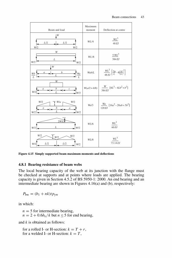
Beam connections 43
Beam and loadMaximummoment Deflection at centre
W
W
W
W
a
a b c
bL
W/2
W/2
WbL
W/2
W/2
L /2L /2
L
WaL
W/2W/2
W/2 W/2W/a
W/2 W/2
2W/L
W/2 W/2
WL/8
WL/6
Wa/3
W(a/2 + b/8)
Wab/L
WL /8
WL /4WL3
48 EI
W/2W/2 W/2
W/2L/2L/2W/2
a b aL
L
WL3
48 EI
5 WL3
384 EI
–
Wa
120 EI
WL3
60 EI
WL3
73.14 EI
[16a2 – 20ab + 5b2]
W
384 EI[8L3 – 4Lb2 + b3]
L
3aL
aL4
3
Figure 4.15 Simply supported beam maximum moments and deflections
4.8.1 Bearing resistance of beam webs
The local bearing capacity of the web at its junction with the flange mustbe checked at supports and at points where loads are applied. The bearingcapacity is given in Section 4.5.2 of BS 5950-1: 2000. An end bearing and anintermediate bearing are shown in Figures 4.16(a) and (b), respectively:
Pbw = (b1 + nk)tpyw
in which:
n = 5 for intermediate bearing,n = 2 + 0.6be/k but n ≤ 5 for end bearing,
and k is obtained as follows:
for a rolled I- or H-section: k = T + r ,for a welded I- or H-section: k = T ,
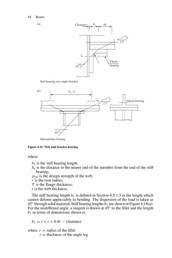
44 Beams
Clearance
End bearing on a angle bracket
Intermediate bearing
(a)
(b)
nkb1
b1 – 5
z
2.51
2.51 Check bearing
Checkbearing45°
z
r
45°
Figure 4.16 Web and bracket bearing
where
b1 is the stiff bearing length,be is the distance to the nearer end of the member from the end of the stiff
bearing;pyw is the design strength of the web;r is the root radius;T is the flange thickness:t is the web thickness.
The stiff bearing length b1 is defined in Section 4.5.1.3 as the length whichcannot deform appreciably in bending. The dispersion of the load is taken as45◦ through solid material. Stiff bearing lengths b1 are shown in Figure 4.16(a).For the unstiffened angle, a tangent is drawn at 45◦ to the fillet and the lengthb1 in terms of dimensions shown is:
b1 = t + t + 0.8r − clearance
where r = radius of the fillett = thickness of the angle leg
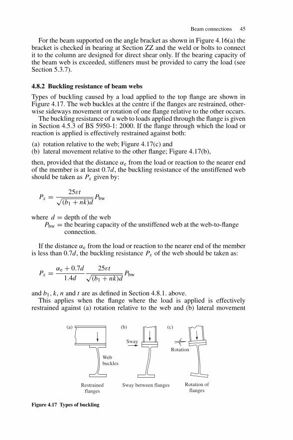
Beam connections 45
For the beam supported on the angle bracket as shown in Figure 4.16(a) thebracket is checked in bearing at Section ZZ and the weld or bolts to connectit to the column are designed for direct shear only. If the bearing capacity ofthe beam web is exceeded, stiffeners must be provided to carry the load (seeSection 5.3.7).
4.8.2 Buckling resistance of beam webs
Types of buckling caused by a load applied to the top flange are shown inFigure 4.17. The web buckles at the centre if the flanges are restrained, other-wise sideways movement or rotation of one flange relative to the other occurs.
The buckling resistance of a web to loads applied through the flange is givenin Section 4.5.3 of BS 5950-1: 2000. If the flange through which the load orreaction is applied is effectively restrained against both:
(a) rotation relative to the web; Figure 4.17(c) and(b) lateral movement relative to the other flange; Figure 4.17(b),
then, provided that the distance αe from the load or reaction to the nearer endof the member is at least 0.7d, the buckling resistance of the unstiffened webshould be taken as Px given by:
Px = 25εt√(b1 + nk)d
Pbw
where d = depth of the webPbw = the bearing capacity of the unstiffened web at the web-to-flange
connection.
If the distance αe from the load or reaction to the nearer end of the memberis less than 0.7d, the buckling resistance Px of the web should be taken as:
Px = αe + 0.7d
1.4d
25εt√(b1 + nk)d
Pbw
and b1, k, n and t are as defined in Section 4.8.1. above.This applies when the flange where the load is applied is effectively
restrained against (a) rotation relative to the web and (b) lateral movement
Webbuckles
Rotation
Sway
Restrainedflanges
Sway between flanges Rotation offlanges
(a) (b) (c)
Figure 4.17 Types of buckling
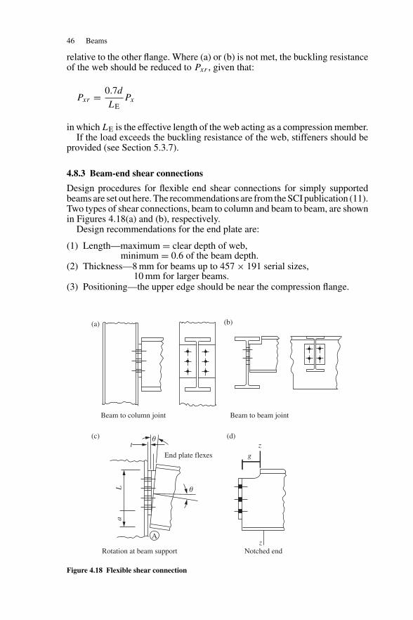
46 Beams
relative to the other flange. Where (a) or (b) is not met, the buckling resistanceof the web should be reduced to Pxr , given that:
Pxr = 0.7d
LEPx
in which LE is the effective length of the web acting as a compression member.If the load exceeds the buckling resistance of the web, stiffeners should be
provided (see Section 5.3.7).
4.8.3 Beam-end shear connections
Design procedures for flexible end shear connections for simply supportedbeams are set out here. The recommendations are from the SCI publication (11).Two types of shear connections, beam to column and beam to beam, are shownin Figures 4.18(a) and (b), respectively.
Design recommendations for the end plate are:
(1) Length—maximum = clear depth of web,minimum = 0.6 of the beam depth.
(2) Thickness—8 mm for beams up to 457 × 191 serial sizes,10 mm for larger beams.
(3) Positioning—the upper edge should be near the compression flange.
Beam to column joint Beam to beam joint
θ
θ
t
A
End plate flexes
aL
g
z
Rotation at beam support Notched endz
(a) (b)
(c) (d)
Figure 4.18 Flexible shear connection
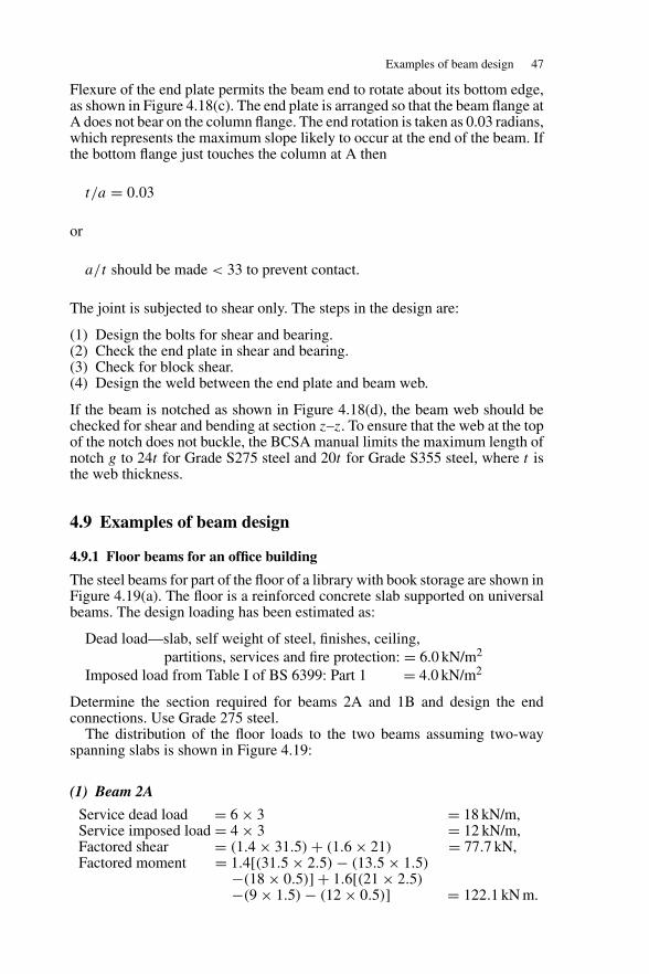
Examples of beam design 47
Flexure of the end plate permits the beam end to rotate about its bottom edge,as shown in Figure 4.18(c). The end plate is arranged so that the beam flange atA does not bear on the column flange. The end rotation is taken as 0.03 radians,which represents the maximum slope likely to occur at the end of the beam. Ifthe bottom flange just touches the column at A then
t/a = 0.03
or
a/t should be made < 33 to prevent contact.
The joint is subjected to shear only. The steps in the design are:
(1) Design the bolts for shear and bearing.(2) Check the end plate in shear and bearing.(3) Check for block shear.(4) Design the weld between the end plate and beam web.
If the beam is notched as shown in Figure 4.18(d), the beam web should bechecked for shear and bending at section z–z. To ensure that the web at the topof the notch does not buckle, the BCSA manual limits the maximum length ofnotch g to 24t for Grade S275 steel and 20t for Grade S355 steel, where t isthe web thickness.
4.9 Examples of beam design
4.9.1 Floor beams for an office building
The steel beams for part of the floor of a library with book storage are shown inFigure 4.19(a). The floor is a reinforced concrete slab supported on universalbeams. The design loading has been estimated as:
Dead load—slab, self weight of steel, finishes, ceiling,partitions, services and fire protection: = 6.0 kN/m2
Imposed load from Table I of BS 6399: Part 1 = 4.0 kN/m2
Determine the section required for beams 2A and 1B and design the endconnections. Use Grade 275 steel.
The distribution of the floor loads to the two beams assuming two-wayspanning slabs is shown in Figure 4.19:
(1) Beam 2A
Service dead load = 6 × 3 = 18 kN/m,Service imposed load = 4 × 3 = 12 kN/m,Factored shear = (1.4 × 31.5) + (1.6 × 21) = 77.7 kN,Factored moment = 1.4[(31.5 × 2.5) − (13.5 × 1.5)
−(18 × 0.5)] + 1.6[(21 × 2.5)−(9 × 1.5) − (12 × 0.5)] = 122.1 kN m.
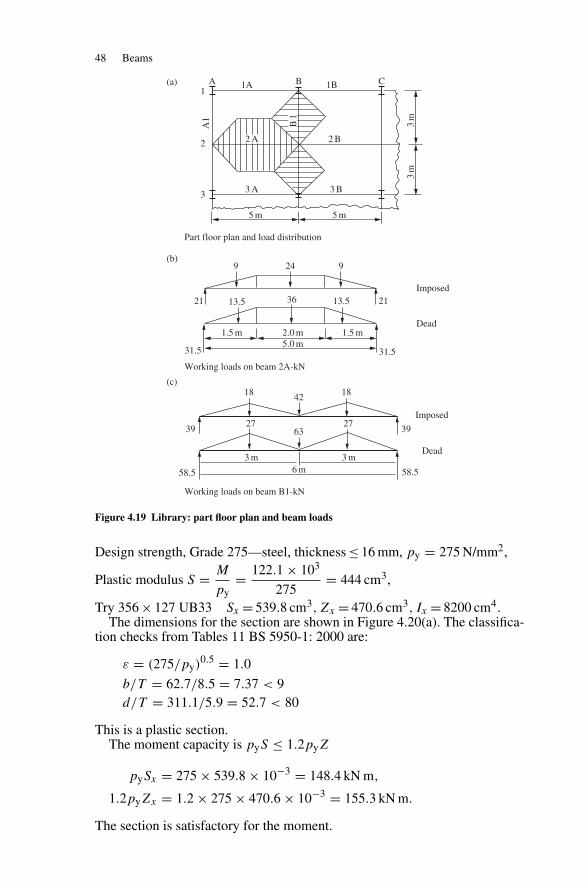
48 Beams
3m
3m
A 1A
A1
1B
2 B
3 B
1
2
3 3 A
5 m
Part floor plan and load distribution
5 m
B C
21
31.5
1.5 m 2.0 m
3 m3 m6 m
5.0 m31.5
Working loads on beam 2A-kN
Working loads on beam B1-kN
1.5 m
2113.53613.5
Imposed
Imposed
Dead
Dead
9 24 9
18 18
272739
58.5 58.5
3963
42
(a)
(b)
(c)
2 A
B1
Figure 4.19 Library: part floor plan and beam loads
Design strength, Grade 275—steel, thickness ≤ 16 mm, py = 275 N/mm2,
Plastic modulus S = M
py= 122.1 × 10³
275= 444 cm3,
Try 356 × 127 UB33 Sx = 539.8 cm3, Zx = 470.6 cm3, Ix = 8200 cm4.The dimensions for the section are shown in Figure 4.20(a). The classifica-
tion checks from Tables 11 BS 5950-1: 2000 are:
ε = (275/py)0.5 = 1.0
b/T = 62.7/8.5 = 7.37 < 9d/T = 311.1/5.9 = 52.7 < 80
This is a plastic section.The moment capacity is pyS ≤ 1.2pyZ
pySx = 275 × 539.8 × 10−3 = 148.4 kN m,
1.2pyZx = 1.2 × 275 × 470.6 × 10−3 = 155.3 kN m.
The section is satisfactory for the moment.
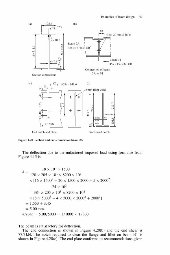
Examples of beam design 49
125.4b = 62.7
r = 10.2Beam 2A356 × 127 × 33 UB
Beam B1457 × 152 × 60 UB
t = 5.9
82
77.7 kN
8
3040
135
215
245.
2
213.
710
4.8
318.
573
.3
40a
=10
3.5
�24t = 141.6
6 mm fillet weld
Equalareaaxis
Centroidalaxis
Section dimensions
End notch and plate Section of notch
Connection of beam2A to B1
D=
348.
5T
=8.
5
d=
311.
182
4 no. 20 mm � bolts
(a) (b)
(c) (d)
Figure 4.20 Section and end-connection beam 2A
The deflection due to the unfactored imposed load using formulae fromFigure 4.15 is:
δ = 18 × 103 × 1500
120 × 205 × 103 × 8200 × 104
× [16 × 15002 + 20 × 1500 × 2000 + 5 × 20002]+ 24 × 103
384 × 205 × 103 × 8200 × 104
× [8 × 50003 − 4 × 5000 × 20002 + 20003]= 1.553 + 3.45= 5.00 mm.
δ/span = 5.00/5000 = 1/1000 < 1/360.
The beam is satisfactory for deflection.The end connection is shown in Figure 4.20(b) and the end shear is
77.7 kN. The notch required to clear the flange and fillet on beam B1 isshown in Figure 4.20(c). The end plate conforms to recommendations given
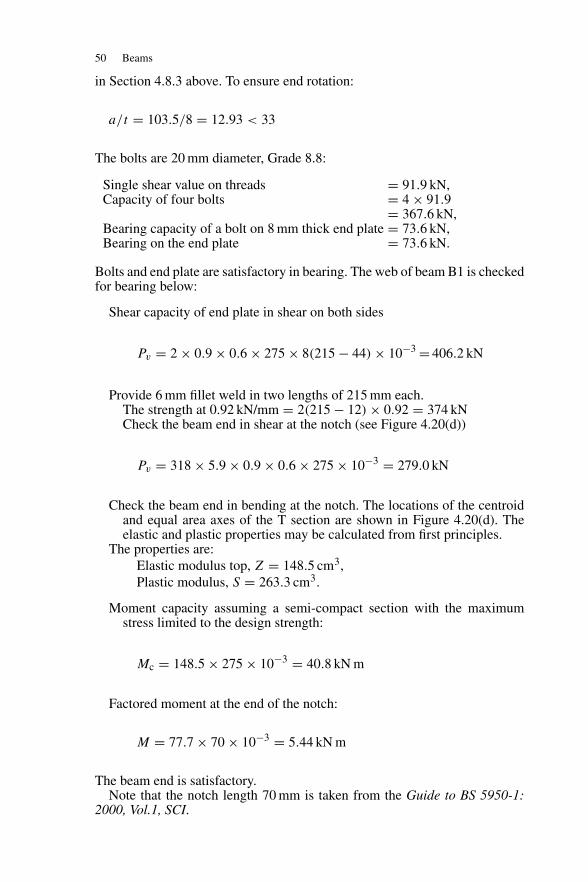
50 Beams
in Section 4.8.3 above. To ensure end rotation:
a/t = 103.5/8 = 12.93 < 33
The bolts are 20 mm diameter, Grade 8.8:
Single shear value on threads = 91.9 kN,Capacity of four bolts = 4 × 91.9
= 367.6 kN,Bearing capacity of a bolt on 8 mm thick end plate = 73.6 kN,Bearing on the end plate = 73.6 kN.
Bolts and end plate are satisfactory in bearing. The web of beam B1 is checkedfor bearing below:
Shear capacity of end plate in shear on both sides
Pv = 2 × 0.9 × 0.6 × 275 × 8(215 − 44) × 10−3 = 406.2 kN
Provide 6 mm fillet weld in two lengths of 215 mm each.The strength at 0.92 kN/mm = 2(215 − 12) × 0.92 = 374 kNCheck the beam end in shear at the notch (see Figure 4.20(d))
Pv = 318 × 5.9 × 0.9 × 0.6 × 275 × 10−3 = 279.0 kN
Check the beam end in bending at the notch. The locations of the centroidand equal area axes of the T section are shown in Figure 4.20(d). Theelastic and plastic properties may be calculated from first principles.
The properties are:Elastic modulus top, Z = 148.5 cm3,Plastic modulus, S = 263.3 cm3.
Moment capacity assuming a semi-compact section with the maximumstress limited to the design strength:
Mc = 148.5 × 275 × 10−3 = 40.8 kN m
Factored moment at the end of the notch:
M = 77.7 × 70 × 10−3 = 5.44 kN m
The beam end is satisfactory.Note that the notch length 70 mm is taken from the Guide to BS 5950-1:
2000, Vol.1, SCI.
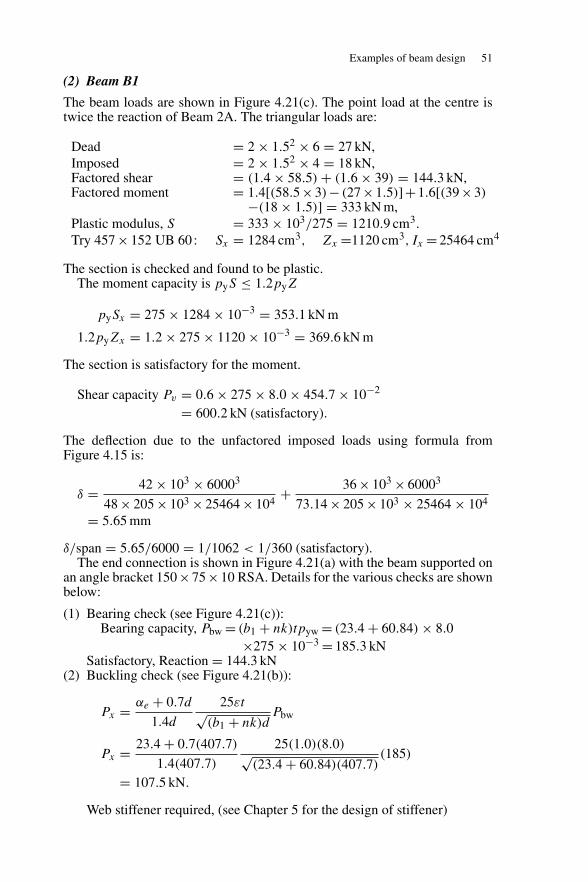
Examples of beam design 51
(2) Beam B1
The beam loads are shown in Figure 4.21(c). The point load at the centre istwice the reaction of Beam 2A. The triangular loads are:
Dead = 2 × 1.52 × 6 = 27 kN,Imposed = 2 × 1.52 × 4 = 18 kN,Factored shear = (1.4 × 58.5) + (1.6 × 39) = 144.3 kN,Factored moment = 1.4[(58.5×3)− (27×1.5)]+1.6[(39×3)
−(18 × 1.5)] = 333 kN m,Plastic modulus, S = 333 × 103/275 = 1210.9 cm3.Try 457 × 152 UB 60 : Sx = 1284 cm3, Zx =1120 cm3, Ix = 25464 cm4
The section is checked and found to be plastic.The moment capacity is pyS ≤ 1.2pyZ
pySx = 275 × 1284 × 10−3 = 353.1 kN m
1.2pyZx = 1.2 × 275 × 1120 × 10−3 = 369.6 kN m
The section is satisfactory for the moment.
Shear capacity Pv = 0.6 × 275 × 8.0 × 454.7 × 10−2
= 600.2 kN (satisfactory).
The deflection due to the unfactored imposed loads using formula fromFigure 4.15 is:
δ = 42 × 103 × 60003
48 × 205 × 103 × 25464 × 104+ 36 × 103 × 60003
73.14 × 205 × 103 × 25464 × 104
= 5.65 mm
δ/span = 5.65/6000 = 1/1062 < 1/360 (satisfactory).The end connection is shown in Figure 4.21(a) with the beam supported on
an angle bracket 150 ×75×10 RSA. Details for the various checks are shownbelow:
(1) Bearing check (see Figure 4.21(c)):Bearing capacity, Pbw = (b1 + nk)tpyw = (23.4 + 60.84) × 8.0
×275 × 10−3 = 185.3 kNSatisfactory, Reaction = 144.3 kN
(2) Buckling check (see Figure 4.21(b)):
Px = αe + 0.7d
1.4d
25εt√(b1 + nk)d
Pbw
Px = 23.4 + 0.7(407.7)
1.4(407.7)
25(1.0)(8.0)√(23.4 + 60.84)(407.7)
(185)
= 107.5 kN.
Web stiffener required, (see Chapter 5 for the design of stiffener)
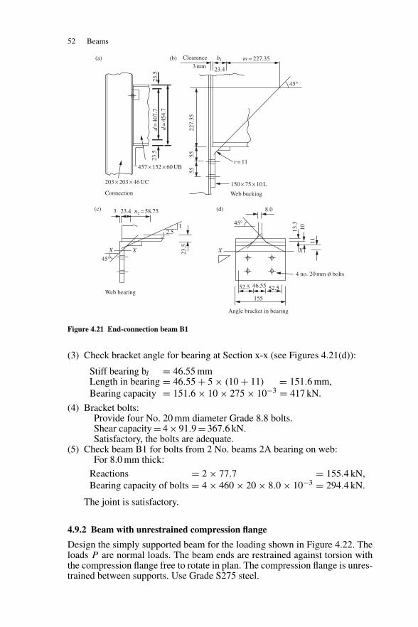
52 Beams
8.03 23.4
2.51
45°
n2 = 58.75
52.5 46.55 52.5
155
X XX X
13.3
10
11
45°
4 no. 20 mm ø bolts
23.5
23.5
d=
407.
723
.5
d=
454.
7457 × 152 × 60 UB
203 × 203 × 46 UC
Connection
Web bearing
Angle bracket in bearing
(a)
(d)(c)
227.
3555
55
r = 11
150 × 75 × 10 L
Web bucking
3 mm
Clearance m = 227.35b1
23.4
45°
(b)
Figure 4.21 End-connection beam B1
(3) Check bracket angle for bearing at Section x-x (see Figures 4.21(d)):
Stiff bearing bl = 46.55 mmLength in bearing = 46.55 + 5 × (10 + 11) = 151.6 mm,Bearing capacity = 151.6 × 10 × 275 × 10−3 = 417 kN.
(4) Bracket bolts:Provide four No. 20 mm diameter Grade 8.8 bolts.Shear capacity = 4 × 91.9 = 367.6 kN.Satisfactory, the bolts are adequate.
(5) Check beam B1 for bolts from 2 No. beams 2A bearing on web:For 8.0 mm thick:
Reactions = 2 × 77.7 = 155.4 kN,Bearing capacity of bolts = 4 × 460 × 20 × 8.0 × 10−3 = 294.4 kN.
The joint is satisfactory.
4.9.2 Beam with unrestrained compression flange
Design the simply supported beam for the loading shown in Figure 4.22. Theloads P are normal loads. The beam ends are restrained against torsion withthe compression flange free to rotate in plan. The compression flange is unres-trained between supports. Use Grade S275 steel.
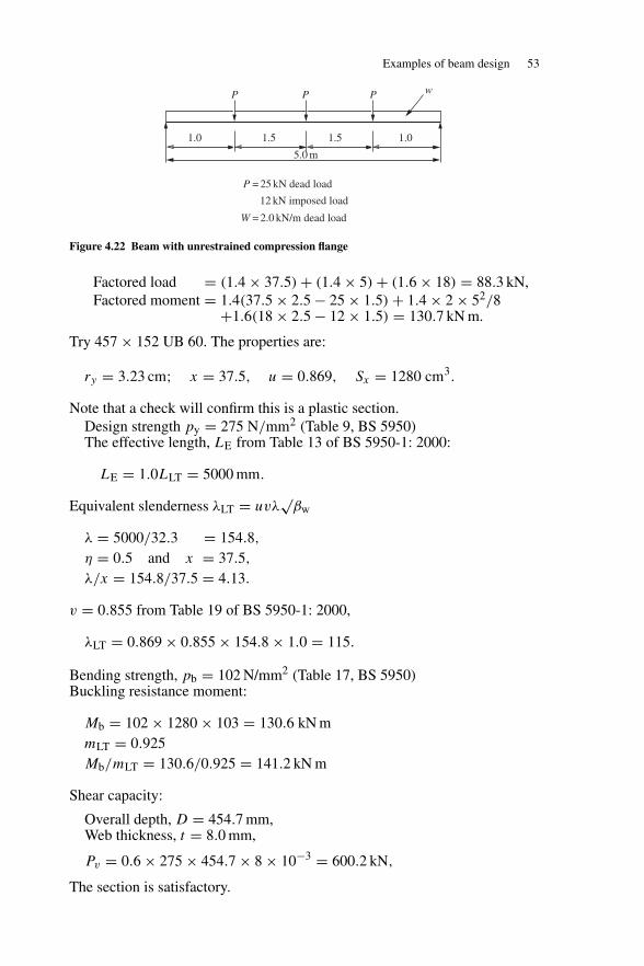
Examples of beam design 53
P
1.0 1.5
5.0 m
P
W
= 25 kN dead load
12 kN imposed load
= 2.0 kN/m dead load
1.5 1.0
P P w
Figure 4.22 Beam with unrestrained compression flange
Factored load = (1.4 × 37.5) + (1.4 × 5) + (1.6 × 18) = 88.3 kN,Factored moment = 1.4(37.5 × 2.5 − 25 × 1.5) + 1.4 × 2 × 52/8
+1.6(18 × 2.5 − 12 × 1.5) = 130.7 kN m.
Try 457 × 152 UB 60. The properties are:
ry = 3.23 cm; x = 37.5, u = 0.869, Sx = 1280 cm3.
Note that a check will confirm this is a plastic section.Design strength py = 275 N/mm2 (Table 9, BS 5950)The effective length, LE from Table 13 of BS 5950-1: 2000:
LE = 1.0LLT = 5000 mm.
Equivalent slenderness λLT = uvλ√
βw
λ = 5000/32.3 = 154.8,
η = 0.5 and x = 37.5,
λ/x = 154.8/37.5 = 4.13.
v = 0.855 from Table 19 of BS 5950-1: 2000,
λLT = 0.869 × 0.855 × 154.8 × 1.0 = 115.
Bending strength, pb = 102 N/mm2 (Table 17, BS 5950)Buckling resistance moment:
Mb = 102 × 1280 × 103 = 130.6 kN mmLT = 0.925Mb/mLT = 130.6/0.925 = 141.2 kN m
Shear capacity:
Overall depth, D = 454.7 mm,Web thickness, t = 8.0 mm,
Pv = 0.6 × 275 × 454.7 × 8 × 10−3 = 600.2 kN,
The section is satisfactory.
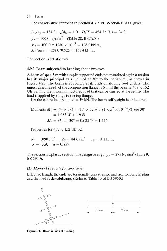
54 Beams
The conservative approach in Section 4.3.7. of BS 5950-1: 2000 gives:
LE/ry = 154.8√
βw = 1.0 D/T = 454.7/13.3 = 34.2,
pb = 100.0 N/mm2—(Table 20, BS 5950),
Mb = 100.0 × 1280 × 10−3 = 128.0 kN m,
Mb/mLT = 128.0/0.925 = 138.4 kN m.
The section is satisfactory.
4.9.3 Beam subjected to bending about two axes
A beam of span 5 m with simply supported ends not restrained against torsionhas its major principal axis inclined at 30◦ to the horizontal, as shown inFigure 4.23. The beam is supported at its ends on sloping roof girders. Theunrestrained length of the compression flange is 5 m. If the beam is 457 × 152UB 52, find the maximum factored load that can be carried at the centre. Theload is applied by slings to the top flange.
Let the centre factored load = W kN. The beam self weight is unfactored.
Moments Mx = [W × 5/4 + (1.4 × 52 × 9.81 × 52 × 10−3)/8] cos 30◦= 1.083 W + 1.933
My = Mx tan 30◦ = 0.625 W + 1.116.
Properties for 457 × 152 UB 52:
Sx = 1090 cm3, Zy = 84.6 cm3, ry = 3.11 cm,
x = 43.9, u = 0.859.
The section is a plastic section. The design strength py = 275 N/mm2 (Table 9,BS 5950).
(1) Moment capacity for x–x axis
Effective length: the ends are torsionally unrestrained and free to rotate in planand the load is destabilizing. (Refer to Table 13 of BS 5950.)
30° Y
X
X
Y
2.5 m 2.5 m
Figure 4.23 Beam in biaxial bending
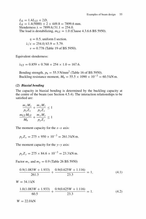
Examples of beam design 55
LE = 1.4LLT + 2D,LE = 1.4(5000) + 2 × 449.8 = 7899.6 mm.Slenderness λ = 7899.6/31.1 = 254.0.The load is destabilizing, mLT = 1.0 (Clause 4.3.6.6 BS 5950).
η = 0.5, uniform I section.λ/x = 254.0/43.9 = 5.79.
v = 0.778 (Table 19 of BS 5950).
Equivalent slenderness:
λLT = 0.859 × 0.768 × 254 × 1.0 = 167.6.
Bending strength, pb = 55.5 N/mm2 (Table 16 of BS 5950).Buckling resistance moment, Mb = 55.5 × 1090 × 10−3 = 60.5 kN m.
(2) Biaxial bending
The capacity in biaxial bending is determined by the buckling capacity atthe centre of the beam (see Section 4.5.4). The interaction relationships to besatisfied are:
mxMx
pyZx
+ myMy
pyZy
≤ 1
mLTMLT
Mb+ myMy
pyZy
≤ 1
The moment capacity for the x–x axis:
pyZx = 275 × 950 × 10−3 = 261.3 kN m.
The moment capacity for the y–y axis:
pyZy = 275 × 84.6 × 10−3 = 23.3 kN m.
Factor mx and my = 0.9 (Table 26 BS 5950)
0.9(1.083W + 1.933)
261.3+ 0.9(0.625W + 1.116)
23.3= 1, (4.1)
W = 34.1 kN
1.0(1.083W + 1.933)
60.5+ 0.9(0.625W + 1.116)
23.3= 1. (4.2)
W = 22.0 kN
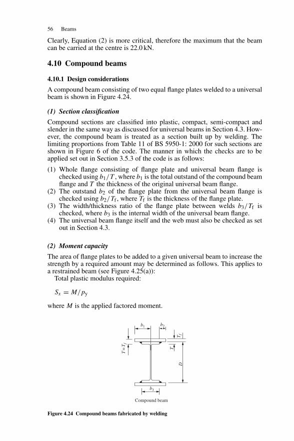
56 Beams
Clearly, Equation (2) is more critical, therefore the maximum that the beamcan be carried at the centre is 22.0 kN.
4.10 Compound beams
4.10.1 Design considerations
A compound beam consisting of two equal flange plates welded to a universalbeam is shown in Figure 4.24.
(1) Section classification
Compound sections are classified into plastic, compact, semi-compact andslender in the same way as discussed for universal beams in Section 4.3. How-ever, the compound beam is treated as a section built up by welding. Thelimiting proportions from Table 11 of BS 5950-1: 2000 for such sections areshown in Figure 6 of the code. The manner in which the checks are to beapplied set out in Section 3.5.3 of the code is as follows:
(1) Whole flange consisting of flange plate and universal beam flange ischecked using b1/T , where b1 is the total outstand of the compound beamflange and T the thickness of the original universal beam flange.
(2) The outstand b2 of the flange plate from the universal beam flange ischecked using b2/Tf , where Tf is the thickness of the flange plate.
(3) The width/thickness ratio of the flange plate between welds b3/Tf ischecked, where b3 is the internal width of the universal beam flange.
(4) The universal beam flange itself and the web must also be checked as setout in Section 4.3.
(2) Moment capacity
The area of flange plates to be added to a given universal beam to increase thestrength by a required amount may be determined as follows. This applies toa restrained beam (see Figure 4.25(a)):
Total plastic modulus required:
Sx = M/py
where M is the applied factored moment.
b3
D
T=
Tf
Tf
T
b2b1
Compound beam
Figure 4.24 Compound beams fabricated by welding
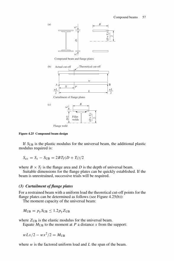
Compound beams 57
Filletwelds
B
A
Actual cut-off
Compound beam and flange plates
Curtailment of flange plates
Flange weld
Theoretical cut-off
wLX P
w
L
B(a)
(b)
(c)
B
2(D
+T
f)
D/2
Tf
2
Tf
Tf
D
wL2
(D+
Tf)
2
Figure 4.25 Compound beam design
If SUB is the plastic modulus for the universal beam, the additional plasticmodulus required is:
Sax = Sx − SUB = 2BTf(D + Tf)/2
where B × Tf is the flange area and D is the depth of universal beam.Suitable dimensions for the flange plates can be quickly established. If the
beam is unrestrained, successive trials will be required.
(3) Curtailment of flange plates
For a restrained beam with a uniform load the theoretical cut-off points for theflange plates can be determined as follows (see Figure 4.25(b)):
The moment capacity of the universal beam:
MUB = pySUB ≤ 1.2pyZUB
where ZUB is the elastic modulus for the universal beam.Equate MUB to the moment at P a distance x from the support:
wLx/2 − wx2/2 = MUB
where w is the factored uniform load and L the span of the beam.
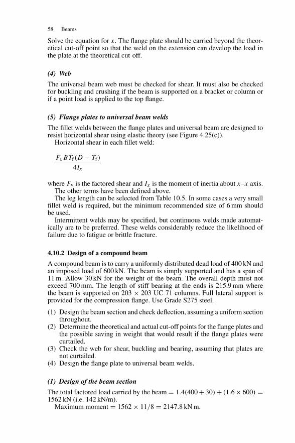
58 Beams
Solve the equation for x. The flange plate should be carried beyond the theor-etical cut-off point so that the weld on the extension can develop the load inthe plate at the theoretical cut-off.
(4) Web
The universal beam web must be checked for shear. It must also be checkedfor buckling and crushing if the beam is supported on a bracket or column orif a point load is applied to the top flange.
(5) Flange plates to universal beam welds
The fillet welds between the flange plates and universal beam are designed toresist horizontal shear using elastic theory (see Figure 4.25(c)).
Horizontal shear in each fillet weld:
FvBTf(D − Tf)
4Ix
where Fv is the factored shear and Ix is the moment of inertia about x–x axis.The other terms have been defined above.The leg length can be selected from Table 10.5. In some cases a very small
fillet weld is required, but the minimum recommended size of 6 mm shouldbe used.
Intermittent welds may be specified, but continuous welds made automat-ically are to be preferred. These welds considerably reduce the likelihood offailure due to fatigue or brittle fracture.
4.10.2 Design of a compound beam
A compound beam is to carry a uniformly distributed dead load of 400 kN andan imposed load of 600 kN. The beam is simply supported and has a span of11 m. Allow 30 kN for the weight of the beam. The overall depth must notexceed 700 mm. The length of stiff bearing at the ends is 215.9 mm wherethe beam is supported on 203 × 203 UC 71 columns. Full lateral support isprovided for the compression flange. Use Grade S275 steel.
(1) Design the beam section and check deflection, assuming a uniform sectionthroughout.
(2) Determine the theoretical and actual cut-off points for the flange plates andthe possible saving in weight that would result if the flange plates werecurtailed.
(3) Check the web for shear, buckling and bearing, assuming that plates arenot curtailed.
(4) Design the flange plate to universal beam welds.
(1) Design of the beam section
The total factored load carried by the beam = 1.4(400 + 30) + (1.6 × 600) =1562 kN (i.e. 142 kN/m).
Maximum moment = 1562 × 11/8 = 2147.8 kN m.
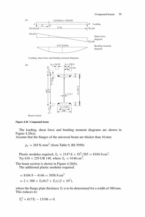
Compound beams 59
b2 = 34.95
2147.8 kNm
142 kN/m = 1562 kN
11 mA
(b)
(a)
X PB
781 kN
Loading
781 kN
781 kN
781 kN
Shear forcediagram
Bending momentdiagram
Loading, shear force and bending moment diagrams
Beam section
b3 = 230.1
Tf=
25T
f=25
T=
22.1
667
617
d=
547.
259
.959
.9
b1 = 150.0
b = 115.05
t = 13.1
300
Figure 4.26 Compound beam
The loading, shear force and bending moment diagrams are shown inFigure 4.26(a).Assume that the flanges of the universal beam are thicker than 16 mm:
py = 265 N/mm2 (from Table 9, BS 5950)
Plastic modulus required, Sx = 2147.8 × 103/265 = 8104.9 cm3.Try 610 × 229 UB 140, where Sx = 4146 cm3.
The beam section is shown in Figure 4.26(b).The additional plastic modulus required:
= 8104.9 − 4146 = 3958.9 cm3
= 2 × 300 × Tf(617 + Tf)/(2 × 103),
where the flange plate thickness Tf is to be determined for a width of 300 mm.This reduces to:
T 2f + 617Tf − 13196 = 0.
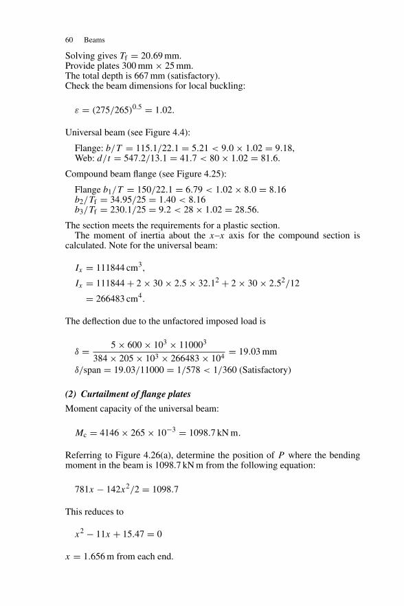
60 Beams
Solving gives Tf = 20.69 mm.Provide plates 300 mm × 25 mm.The total depth is 667 mm (satisfactory).Check the beam dimensions for local buckling:
ε = (275/265)0.5 = 1.02.
Universal beam (see Figure 4.4):
Flange: b/T = 115.1/22.1 = 5.21 < 9.0 × 1.02 = 9.18,Web: d/t = 547.2/13.1 = 41.7 < 80 × 1.02 = 81.6.
Compound beam flange (see Figure 4.25):
Flange b1/T = 150/22.1 = 6.79 < 1.02 × 8.0 = 8.16b2/Tf = 34.95/25 = 1.40 < 8.16b3/Tf = 230.1/25 = 9.2 < 28 × 1.02 = 28.56.
The section meets the requirements for a plastic section.The moment of inertia about the x–x axis for the compound section is
calculated. Note for the universal beam:
Ix = 111844 cm3,
Ix = 111844 + 2 × 30 × 2.5 × 32.12 + 2 × 30 × 2.52/12
= 266483 cm4.
The deflection due to the unfactored imposed load is
δ = 5 × 600 × 103 × 110003
384 × 205 × 103 × 266483 × 104= 19.03 mm
δ/span = 19.03/11000 = 1/578 < 1/360 (Satisfactory)
(2) Curtailment of flange plates
Moment capacity of the universal beam:
Mc = 4146 × 265 × 10−3 = 1098.7 kN m.
Referring to Figure 4.26(a), determine the position of P where the bendingmoment in the beam is 1098.7 kN m from the following equation:
781x − 142x2/2 = 1098.7
This reduces to
x2 − 11x + 15.47 = 0
x = 1.656 m from each end.
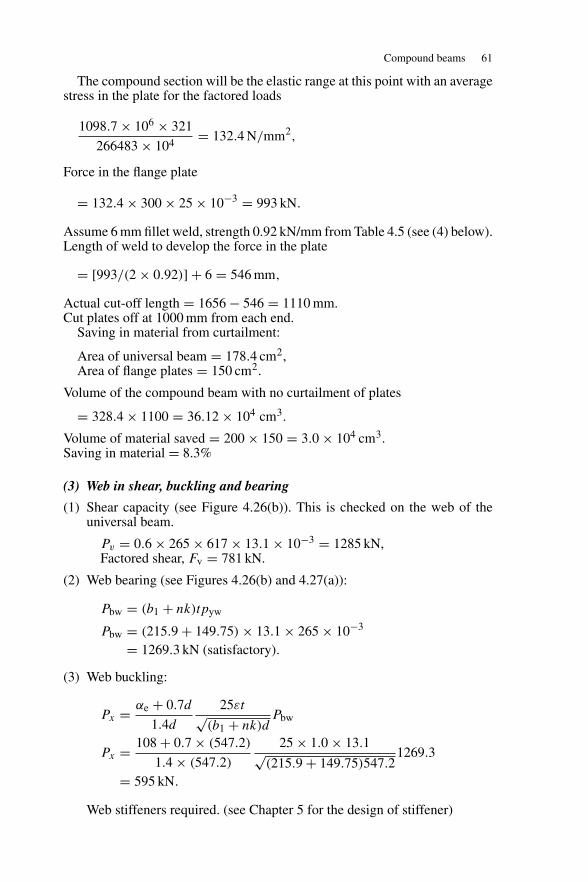
Compound beams 61
The compound section will be the elastic range at this point with an averagestress in the plate for the factored loads
1098.7 × 106 × 321
266483 × 104= 132.4 N/mm2,
Force in the flange plate
= 132.4 × 300 × 25 × 10−3 = 993 kN.
Assume 6 mm fillet weld, strength 0.92 kN/mm from Table 4.5 (see (4) below).Length of weld to develop the force in the plate
= [993/(2 × 0.92)] + 6 = 546 mm,
Actual cut-off length = 1656 − 546 = 1110 mm.Cut plates off at 1000 mm from each end.
Saving in material from curtailment:
Area of universal beam = 178.4 cm2,Area of flange plates = 150 cm2.
Volume of the compound beam with no curtailment of plates
= 328.4 × 1100 = 36.12 × 104 cm3.
Volume of material saved = 200 × 150 = 3.0 × 104 cm3.Saving in material = 8.3%
(3) Web in shear, buckling and bearing
(1) Shear capacity (see Figure 4.26(b)). This is checked on the web of theuniversal beam.
Pv = 0.6 × 265 × 617 × 13.1 × 10−3 = 1285 kN,Factored shear, Fv = 781 kN.
(2) Web bearing (see Figures 4.26(b) and 4.27(a)):
Pbw = (b1 + nk)tpyw
Pbw = (215.9 + 149.75) × 13.1 × 265 × 10−3
= 1269.3 kN (satisfactory).
(3) Web buckling:
Px = αe + 0.7d
1.4d
25εt√(b1 + nk)d
Pbw
Px = 108 + 0.7 × (547.2)
1.4 × (547.2)
25 × 1.0 × 13.1√(215.9 + 149.75)547.2
1269.3
= 595 kN.
Web stiffeners required. (see Chapter 5 for the design of stiffener)
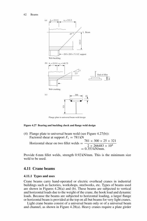
62 Beams
b1 = 215.9 n2 = 149.75
b1 = 215.9 n1 = 333.5
333.
5
45°
End of fillet
Web crushing
Web buckling
(a)
(b)
(c)
2.5
1
203 × 203 × 71 UC support
300
25
321
59.7
Flange plate to universal beam weld design
L Beam
Figure 4.27 Bearing and buckling check and flange weld design
(4) Flange plate to universal beam weld (see Figure 4.27(b)):Factored shear at support Fv = 781 kN
Horizontal shear on two fillet welds = 781 × 300 × 25 × 321
2 × 266483 × 104
= 0.353 kN/mm.
Provide 6 mm fillet welds, strength 0.92 kN/mm. This is the minimum sizeweld to be used.
4.11 Crane beams
4.11.1 Types and uses
Crane beams carry hand-operated or electric overhead cranes in industrialbuildings such as factories, workshops, steelworks, etc. Types of beams usedare shown in Figures 4.28(a) and (b). These beams are subjected to verticaland horizontal loads due to the weight of the crane, the hook load and dynamicloads. Because the beams are subjected to horizontal loading, a larger flangeor horizontal beam is provided at the top on all but beams for very light cranes.
Light crane beams consist of a universal beam only or of a universal beamand channel, as shown in Figure 4.28(a). Heavy cranes require a plate girder
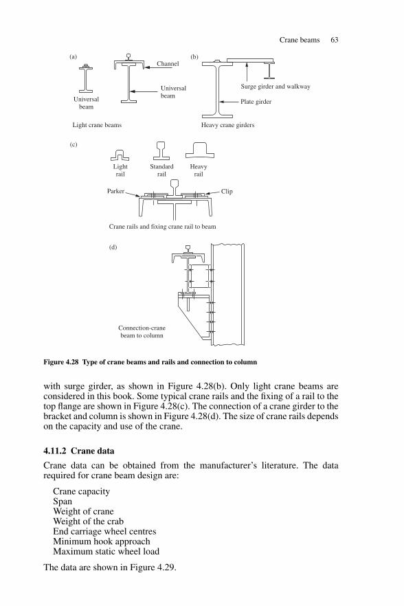
Crane beams 63
Channel(a) (b)
(c)
(d)
Surge girder and walkway
Plate girder
Heavyrail
Standardrail
Lightrail
Parker Clip
UniversalbeamUniversal
beam
Light crane beams
Crane rails and fixing crane rail to beam
Connection-cranebeam to column
Heavy crane girders
Figure 4.28 Type of crane beams and rails and connection to column
with surge girder, as shown in Figure 4.28(b). Only light crane beams areconsidered in this book. Some typical crane rails and the fixing of a rail to thetop flange are shown in Figure 4.28(c). The connection of a crane girder to thebracket and column is shown in Figure 4.28(d). The size of crane rails dependson the capacity and use of the crane.
4.11.2 Crane data
Crane data can be obtained from the manufacturer’s literature. The datarequired for crane beam design are:
Crane capacitySpanWeight of craneWeight of the crabEnd carriage wheel centresMinimum hook approachMaximum static wheel load
The data are shown in Figure 4.29.
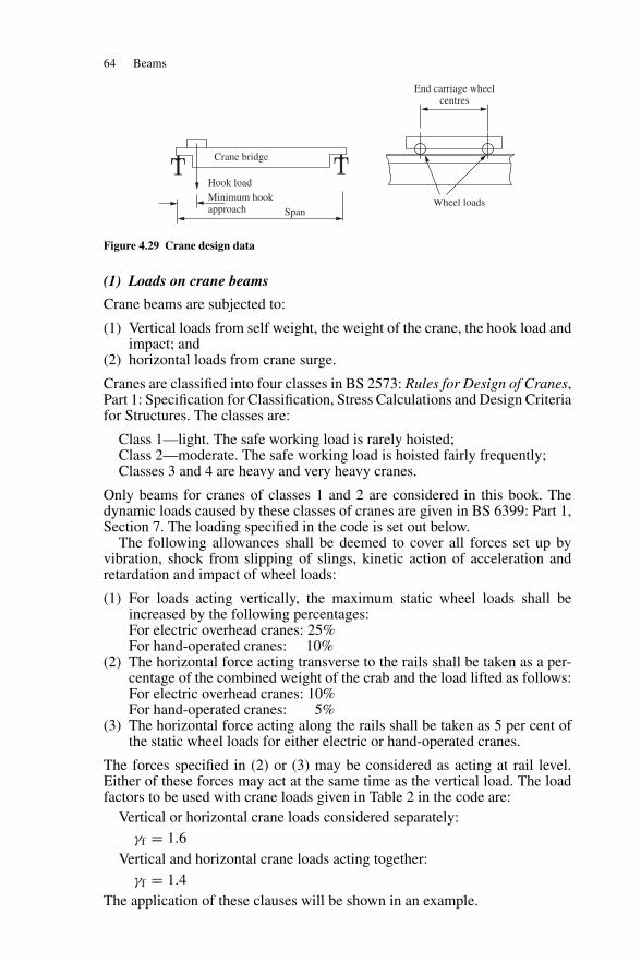
64 Beams
Crane bridge
Hook load
Minimum hook approach Span
End carriage wheelcentres
Wheel loads
Figure 4.29 Crane design data
(1) Loads on crane beams
Crane beams are subjected to:
(1) Vertical loads from self weight, the weight of the crane, the hook load andimpact; and
(2) horizontal loads from crane surge.
Cranes are classified into four classes in BS 2573: Rules for Design of Cranes,Part 1: Specification for Classification, Stress Calculations and Design Criteriafor Structures. The classes are:
Class 1—light. The safe working load is rarely hoisted;Class 2—moderate. The safe working load is hoisted fairly frequently;Classes 3 and 4 are heavy and very heavy cranes.
Only beams for cranes of classes 1 and 2 are considered in this book. Thedynamic loads caused by these classes of cranes are given in BS 6399: Part 1,Section 7. The loading specified in the code is set out below.
The following allowances shall be deemed to cover all forces set up byvibration, shock from slipping of slings, kinetic action of acceleration andretardation and impact of wheel loads:
(1) For loads acting vertically, the maximum static wheel loads shall beincreased by the following percentages:For electric overhead cranes: 25%For hand-operated cranes: 10%
(2) The horizontal force acting transverse to the rails shall be taken as a per-centage of the combined weight of the crab and the load lifted as follows:For electric overhead cranes: 10%For hand-operated cranes: 5%
(3) The horizontal force acting along the rails shall be taken as 5 per cent ofthe static wheel loads for either electric or hand-operated cranes.
The forces specified in (2) or (3) may be considered as acting at rail level.Either of these forces may act at the same time as the vertical load. The loadfactors to be used with crane loads given in Table 2 in the code are:
Vertical or horizontal crane loads considered separately:γf = 1.6
Vertical and horizontal crane loads acting together:γf = 1.4
The application of these clauses will be shown in an example.
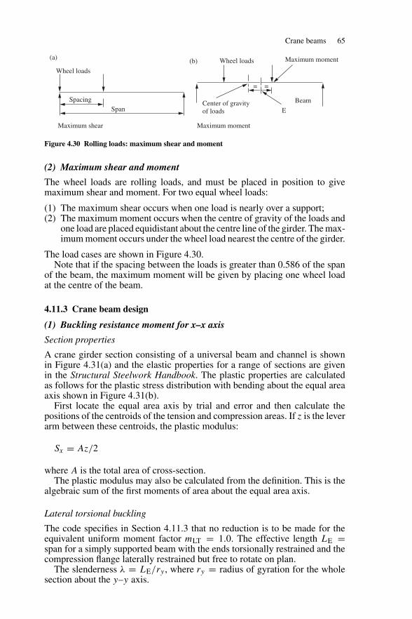
Crane beams 65
ECenter of gravityof loads
Wheel loads
Wheel loads
(a) (b)
Spacing
Maximum shear
Span
Maximum moment
Maximum moment
= =
Beam
Figure 4.30 Rolling loads: maximum shear and moment
(2) Maximum shear and moment
The wheel loads are rolling loads, and must be placed in position to givemaximum shear and moment. For two equal wheel loads:
(1) The maximum shear occurs when one load is nearly over a support;(2) The maximum moment occurs when the centre of gravity of the loads and
one load are placed equidistant about the centre line of the girder. The max-imum moment occurs under the wheel load nearest the centre of the girder.
The load cases are shown in Figure 4.30.Note that if the spacing between the loads is greater than 0.586 of the span
of the beam, the maximum moment will be given by placing one wheel loadat the centre of the beam.
4.11.3 Crane beam design
(1) Buckling resistance moment for x–x axis
Section properties
A crane girder section consisting of a universal beam and channel is shownin Figure 4.31(a) and the elastic properties for a range of sections are givenin the Structural Steelwork Handbook. The plastic properties are calculatedas follows for the plastic stress distribution with bending about the equal areaaxis shown in Figure 4.31(b).
First locate the equal area axis by trial and error and then calculate thepositions of the centroids of the tension and compression areas. If z is the leverarm between these centroids, the plastic modulus:
Sx = Az/2
where A is the total area of cross-section.The plastic modulus may also be calculated from the definition. This is the
algebraic sum of the first moments of area about the equal area axis.
Lateral torsional buckling
The code specifies in Section 4.11.3 that no reduction is to be made for theequivalent uniform moment factor mLT = 1.0. The effective length LE =span for a simply supported beam with the ends torsionally restrained and thecompression flange laterally restrained but free to rotate on plan.
The slenderness λ = LE/ry , where ry = radius of gyration for the wholesection about the y–y axis.
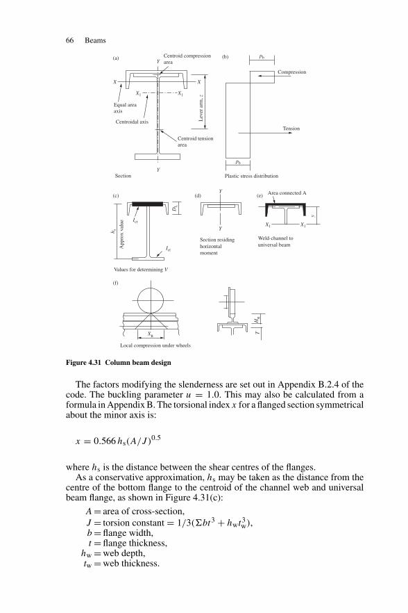
66 Beams
Centroid compressionarea
Centroid tensionarea
Equal areaaxis
Centroidal axis
X1
X
(a) (b)
(c)
(f)
(d) (e)
X
Y
Y
X1
Section
Ict
DL
Ict
Plastic stress distribution
Tension
Lev
er a
rm, z
Compression
pb
pb
App
rox
valu
e
h s
Y Area connected A
X1 X1Y
y
T
Section residinghorizontalmoment
Weld-channel touniversal beam
XR
HR
Local compression under wheels
Values for determining V
. .
Figure 4.31 Column beam design
The factors modifying the slenderness are set out in Appendix B.2.4 of thecode. The buckling parameter u = 1.0. This may also be calculated from aformula in Appendix B. The torsional index x for a flanged section symmetricalabout the minor axis is:
x = 0.566 hs(A/J )0.5
where hs is the distance between the shear centres of the flanges.As a conservative approximation, hs may be taken as the distance from the
centre of the bottom flange to the centroid of the channel web and universalbeam flange, as shown in Figure 4.31(c):
A = area of cross-section,J = torsion constant = 1/3(�bt3 + hwt3
w),b = flange width,t = flange thickness,
hw = web depth,tw = web thickness.
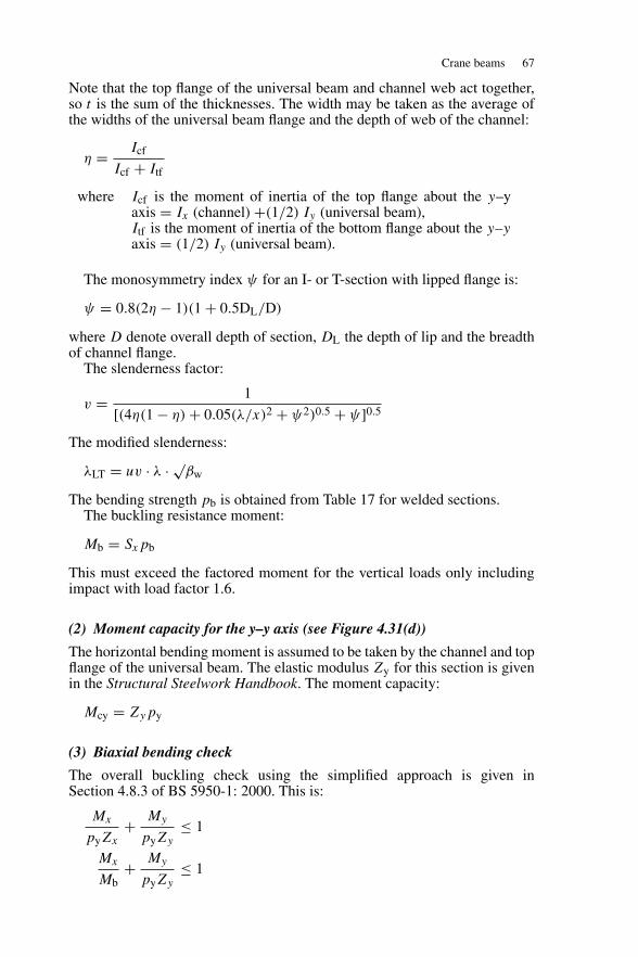
Crane beams 67
Note that the top flange of the universal beam and channel web act together,so t is the sum of the thicknesses. The width may be taken as the average ofthe widths of the universal beam flange and the depth of web of the channel:
η = Icf
Icf + Itf
where Icf is the moment of inertia of the top flange about the y–yaxis = Ix (channel) +(1/2) Iy (universal beam),Itf is the moment of inertia of the bottom flange about the y–yaxis = (1/2) Iy (universal beam).
The monosymmetry index ψ for an I- or T-section with lipped flange is:
ψ = 0.8(2η − 1)(1 + 0.5DL/D)
where D denote overall depth of section, DL the depth of lip and the breadthof channel flange.
The slenderness factor:
v = 1
[(4η(1 − η) + 0.05(λ/x)2 + ψ2)0.5 + ψ]0.5
The modified slenderness:
λLT = uv · λ · √βw
The bending strength pb is obtained from Table 17 for welded sections.The buckling resistance moment:
Mb = Sxpb
This must exceed the factored moment for the vertical loads only includingimpact with load factor 1.6.
(2) Moment capacity for the y–y axis (see Figure 4.31(d))
The horizontal bending moment is assumed to be taken by the channel and topflange of the universal beam. The elastic modulus Zy for this section is givenin the Structural Steelwork Handbook. The moment capacity:
Mcy = Zypy
(3) Biaxial bending check
The overall buckling check using the simplified approach is given inSection 4.8.3 of BS 5950-1: 2000. This is:
Mx
pyZx
+ My
pyZy
≤ 1
Mx
Mb+ My
pyZy
≤ 1
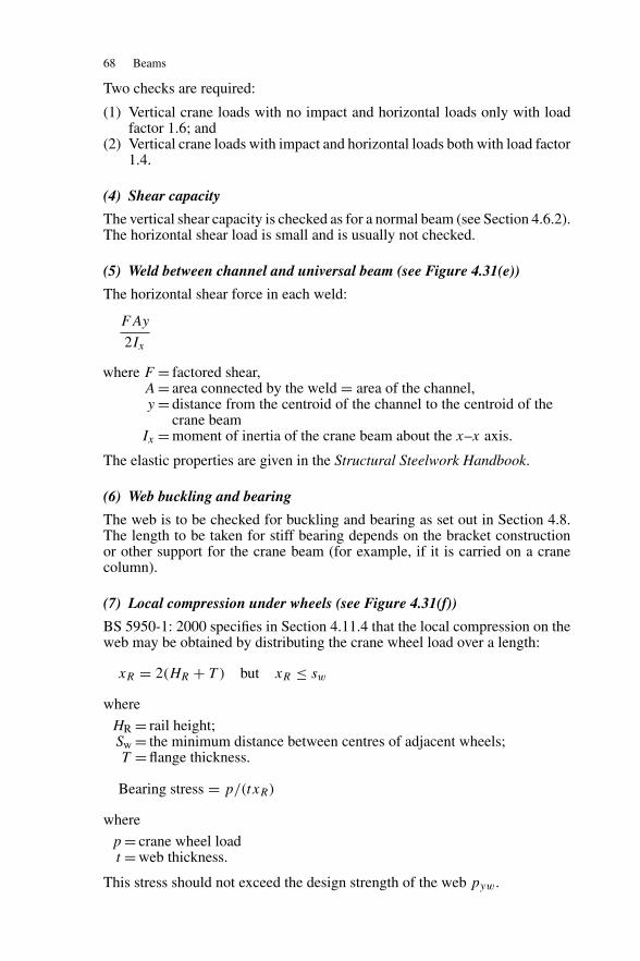
68 Beams
Two checks are required:
(1) Vertical crane loads with no impact and horizontal loads only with loadfactor 1.6; and
(2) Vertical crane loads with impact and horizontal loads both with load factor1.4.
(4) Shear capacity
The vertical shear capacity is checked as for a normal beam (see Section 4.6.2).The horizontal shear load is small and is usually not checked.
(5) Weld between channel and universal beam (see Figure 4.31(e))
The horizontal shear force in each weld:
FAy
2Ix
where F = factored shear,A = area connected by the weld = area of the channel,y = distance from the centroid of the channel to the centroid of the
crane beamIx = moment of inertia of the crane beam about the x–x axis.
The elastic properties are given in the Structural Steelwork Handbook.
(6) Web buckling and bearing
The web is to be checked for buckling and bearing as set out in Section 4.8.The length to be taken for stiff bearing depends on the bracket constructionor other support for the crane beam (for example, if it is carried on a cranecolumn).
(7) Local compression under wheels (see Figure 4.31(f))
BS 5950-1: 2000 specifies in Section 4.11.4 that the local compression on theweb may be obtained by distributing the crane wheel load over a length:
xR = 2(HR + T ) but xR ≤ sw
where
HR = rail height;Sw = the minimum distance between centres of adjacent wheels;T = flange thickness.
Bearing stress = p/(txR)
where
p = crane wheel loadt = web thickness.
This stress should not exceed the design strength of the web pyw.
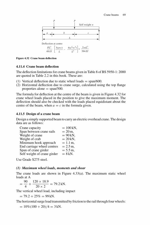
Crane beams 69
a b c
L
P
Deflection at centre
PL3
48 EI
P
Self weight w
5 wL3
384 EI3(a+c) 4(a3+c3)
L L3+–
Figure 4.32 Crane beam deflection
4.11.4 Crane beam deflection
The deflection limitations for crane beams given in Table 8 of BS 5950-1: 2000are quoted in Table 2.2 in this book. These are:
(1) Vertical deflection due to static wheel loads = span/600.(2) Horizontal deflection due to crane surge, calculated using the top flange
properties alone = span/500.
The formula for deflection at the centre of the beam is given in Figure 4.32 forcrane wheel loads placed in the position to give the maximum moment. Thedeflection should also be checked with the loads placed equidistant about thecentre of the beam, when a = c in the formula given.
4.11.5 Design of a crane beam
Design a simply supported beam to carry an electric overhead crane. The designdata are as follows:
Crane capacity = 100 kN,Span between crane rails = 20 m,Weight of crane = 90 kN,Weight of crab = 20 kN,Minimum hook approach = 1.1 m,End carriage wheel centres = 2.5 m,Span of crane girder = 5.5 m,Self weight of crane girder = 8 kN.
Use Grade S275 steel.
(1) Maximum wheel loads, moments and shear
The crane loads are shown in Figure 4.33(a). The maximum static wheelloads at A
= 90
4+ 120 × 18.9
20 × 2= 79.2 kN.
The vertical wheel load, including impact
= 79.2 + 25% = 99 kN.
The horizontal surge load transmitted by friction to the rail through four wheels:
= 10%(100 + 20)/4 = 3 kN.
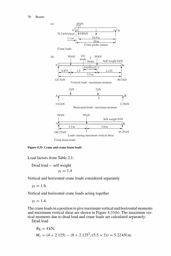
70 Beams
2.125
Self weight 8 kN
20 m18.9 m1.1 m
79.2 kN/wheel
c
99 kN99 kN
20 kN
100 kNB
Crane girder centresCrane loads
Crane beam loads
3.62 kN 2.38 kN
AC
B
A
A
125.5 kN 80.5 kN
B
3 kN
Horizontal loads – maximun moment
Loads causing maximum vertical shear
Vertical loads – maximum moment
99 kN 99 kN
2.5 m 3.0 m
0.625
CGloads £
beam
0.625
5.5 m2.5
(a)
(b)
0.875
3 kN
Self weight 8 kN
A
160.75 kN 45.25 kN
B
Figure 4.33 Crane and crane beam loads
Load factors from Table 2.1:
Dead load − self weightγf = 1.4
Vertical and horizontal crane loads considered separately
γf = 1.6,
Vertical and horizontal crane loads acting together
γf = 1.4.
The crane loads in a position to give maximum vertical and horizontal momentsand maximum vertical shear are shown in Figure 4.33(b). The maximum ver-tical moments due to dead load and crane loads are calculated separately:
Dead load
RB = 4 kN,
Mc = (4 × 2.125) − (8 × 2.1252/(5.5 × 2)) = 5.22 kN m.
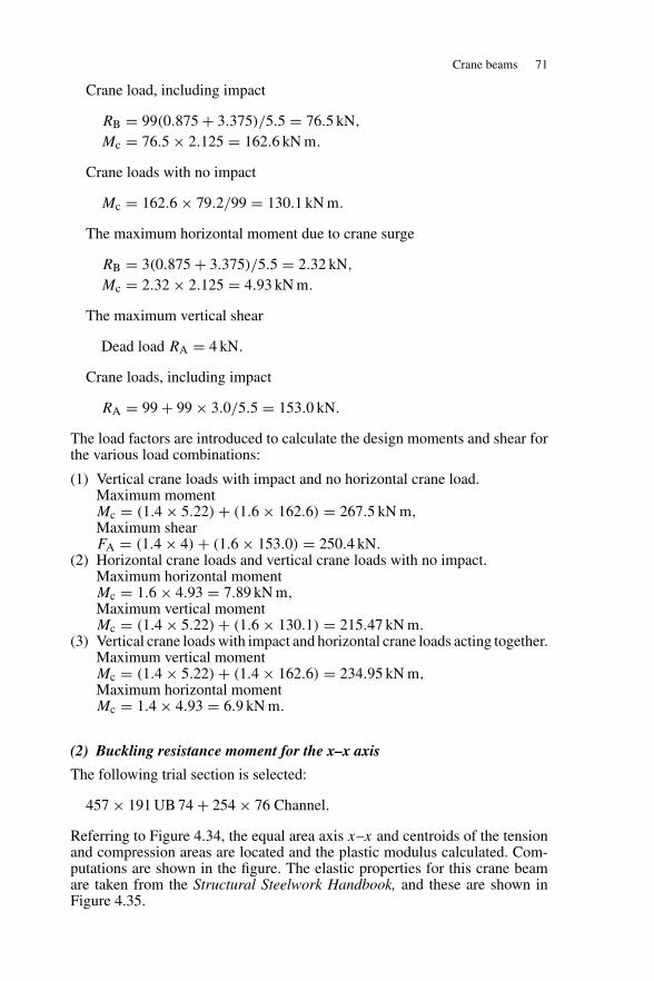
Crane beams 71
Crane load, including impact
RB = 99(0.875 + 3.375)/5.5 = 76.5 kN,
Mc = 76.5 × 2.125 = 162.6 kN m.
Crane loads with no impact
Mc = 162.6 × 79.2/99 = 130.1 kN m.
The maximum horizontal moment due to crane surge
RB = 3(0.875 + 3.375)/5.5 = 2.32 kN,
Mc = 2.32 × 2.125 = 4.93 kN m.
The maximum vertical shear
Dead load RA = 4 kN.
Crane loads, including impact
RA = 99 + 99 × 3.0/5.5 = 153.0 kN.
The load factors are introduced to calculate the design moments and shear forthe various load combinations:
(1) Vertical crane loads with impact and no horizontal crane load.Maximum momentMc = (1.4 × 5.22) + (1.6 × 162.6) = 267.5 kN m,Maximum shearFA = (1.4 × 4) + (1.6 × 153.0) = 250.4 kN.
(2) Horizontal crane loads and vertical crane loads with no impact.Maximum horizontal momentMc = 1.6 × 4.93 = 7.89 kN m,Maximum vertical momentMc = (1.4 × 5.22) + (1.6 × 130.1) = 215.47 kN m.
(3) Vertical crane loads with impact and horizontal crane loads acting together.Maximum vertical momentMc = (1.4 × 5.22) + (1.4 × 162.6) = 234.95 kN m,Maximum horizontal momentMc = 1.4 × 4.93 = 6.9 kN m.
(2) Buckling resistance moment for the x–x axis
The following trial section is selected:
457 × 191 UB 74 + 254 × 76 Channel.
Referring to Figure 4.34, the equal area axis x–x and centroids of the tensionand compression areas are located and the plastic modulus calculated. Com-putations are shown in the figure. The elastic properties for this crane beamare taken from the Structural Steelwork Handbook, and these are shown inFigure 4.35.
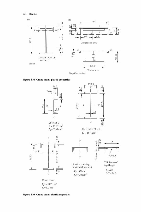
72 Beams
X
(a) (b)
X
X X
XX
9.1
21
190.5
Tension area
Section
Simplified section
Compression area
42
1
254
3
43.6
114
5 8.1
zy 1
17.8
131
2.89
465.
3
–
y
66.2
139
9.09
–
y 1
125.
6
9.99
–457 × 191 × 74 UB 254 × 76 C
10.9
Figure 4.34 Crane beam: plastic properties
X X
Y
Y
XX
457.
274
.5
407.
924
.65
10.5
2
Dis
tanc
e to
cen
troi
d
24.6
5
X X
YY
Y
Y
176.
7
465.
3
10.5
27.
25
76.2
20.0
8.1
254 × 76 C
457 × 191 × 74 UBA = 36.03 cm2
IX = 3367 cm4
IY = 1671 cm4
b
Area A
T = A/bD/T = 24.5
9.1
190.5
Y
Y
10.9
254
IY = 4202cm4ZY = 331cm3
h Z=
447.
53
Crane beam
Section resistinghorizontal moment
Thickness of top flange
IX = 45983 cm4
IY = 6.2 cm
Figure 4.35 Crane beam: elastic properties
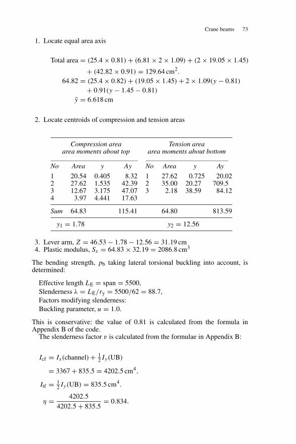
Crane beams 73
1. Locate equal area axis
Total area = (25.4 × 0.81) + (6.81 × 2 × 1.09) + (2 × 19.05 × 1.45)
+ (42.82 × 0.91) = 129.64 cm2.
64.82 = (25.4 × 0.82) + (19.05 × 1.45) + 2 × 1.09(y − 0.81)
+ 0.91(y − 1.45 − 0.81)
y = 6.618 cm
2. Locate centroids of compression and tension areas
Compression area Tension areaarea moments about top area moments about bottom
No Area y Ay No Area y Ay
1 20.54 0.405 8.32 1 27.62 0.725 20.022 27.62 1.535 42.39 2 35.00 20.27 709.53 12.67 3.175 47.07 3 2.18 38.59 84.124 3.97 4.441 17.63
Sum 64.83 115.41 64.80 813.59
y1 = 1.78 y2 = 12.56
3. Lever arm, Z = 46.53 − 1.78 − 12.56 = 31.19 cm4. Plastic modulus, Sx = 64.83 × 32.19 = 2086.8 cm3
The bending strength, pb taking lateral torsional buckling into account, isdetermined:
Effective length LE = span = 5500,Slenderness λ = LE/ry = 5500/62 = 88.7,Factors modifying slenderness:Buckling parameter, u = 1.0.
This is conservative: the value of 0.81 is calculated from the formula inAppendix B of the code.
The slenderness factor v is calculated from the formulae in Appendix B:
Icf = Ix(channel) + 12Iy(UB)
= 3367 + 835.5 = 4202.5 cm4,
Itf = 12Iy(UB) = 835.5 cm4.
η = 4202.5
4202.5 + 835.5= 0.834.
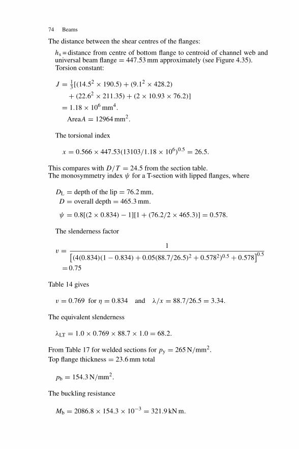
74 Beams
The distance between the shear centres of the flanges:
hs = distance from centre of bottom flange to centroid of channel web anduniversal beam flange = 447.53 mm approximately (see Figure 4.35).Torsion constant:
J = 13 [(14.52 × 190.5) + (9.12 × 428.2)
+ (22.62 × 211.35) + (2 × 10.93 × 76.2)]= 1.18 × 106 mm4.
AreaA = 12964 mm2.
The torsional index
x = 0.566 × 447.53(13103/1.18 × 106)0.5 = 26.5.
This compares with D/T = 24.5 from the section table.The monosymmetry index ψ for a T-section with lipped flanges, where
DL = depth of the lip = 76.2 mm,
D = overall depth = 465.3 mm.
ψ = 0.8[(2 × 0.834) − 1][1 + (76.2/2 × 465.3)] = 0.578.
The slenderness factor
v = 1[(4(0.834)(1 − 0.834) + 0.05(88.7/26.5)2 + 0.5782)0.5 + 0.578
]0.5
= 0.75
Table 14 gives
v = 0.769 for η = 0.834 and λ/x = 88.7/26.5 = 3.34.
The equivalent slenderness
λLT = 1.0 × 0.769 × 88.7 × 1.0 = 68.2.
From Table 17 for welded sections for py = 265 N/mm2.Top flange thickness = 23.6 mm total
pb = 154.3 N/mm2.
The buckling resistance
Mb = 2086.8 × 154.3 × 10−3 = 321.9 kN m.
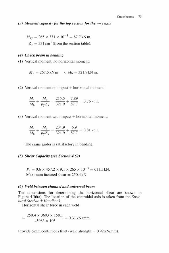
Crane beams 75
(3) Moment capacity for the top section for the y–y axis
Mcy = 265 × 331 × 10−3 = 87.7 kN m,
Zy = 331 cm3 (from the section table).
(4) Check beam in bending
(1) Vertical moment, no horizontal moment:
Mx = 267.5 kN m < Mb = 321.9 kN m.
(2) Vertical moment no impact + horizontal moment:
Mx
Mb+ My
pyZy
= 215.5
321.9+ 7.89
87.7= 0.76 < 1.
(3) Vertical moment with impact + horizontal moment:
Mx
Mb+ My
pyZy
= 234.9
321.9+ 6.9
87.7= 0.81 < 1.
The crane girder is satisfactory in bending.
(5) Shear Capacity (see Section 4.62)
Pv = 0.6 × 457.2 × 9.1 × 265 × 10−3 = 611.5 kN,
Maximum factored shear = 250.4 kN.
(6) Weld between channel and universal beam
The dimensions for determining the horizontal shear are shown inFigure 4.36(a). The location of the centroidal axis is taken from the Struc-tural Steelwork Handbook.
Horizontal shear force in each weld
= 250.4 × 3603 × 158.1
45983 × 104= 0.31 kN/mm.
Provide 6 mm continuous fillet (weld strength = 0.92 kN/mm).
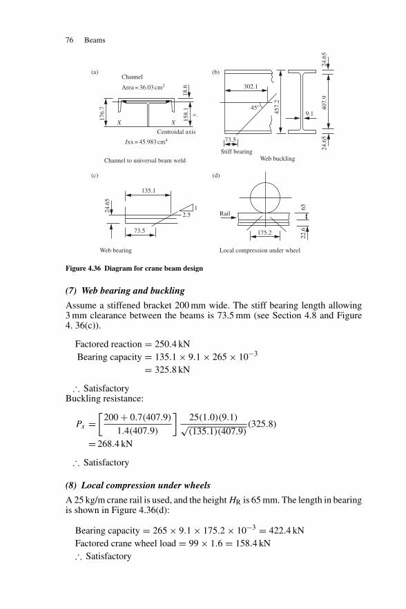
76 Beams
X
Channel
Ixx = 45.983 cm4
Stiff bearingWeb buckling
Area = 36.03 cm2
X
Centroidal axis
Channel to universal beam weld
Web bearing Local compression under wheel
457.
2
24.6
5
18.6
158.
1
176.
7
y
24.6
540
7.9
9.145°
302.1
73.5
135.1
73.5
2.51
Rail
175.2
24.6
5
6522
.6
(a)
(c) (d)
(b)
Figure 4.36 Diagram for crane beam design
(7) Web bearing and buckling
Assume a stiffened bracket 200 mm wide. The stiff bearing length allowing3 mm clearance between the beams is 73.5 mm (see Section 4.8 and Figure4. 36(c)).
Factored reaction = 250.4 kNBearing capacity = 135.1 × 9.1 × 265 × 10−3
= 325.8 kN
∴ SatisfactoryBuckling resistance:
Px =[
200 + 0.7(407.9)
1.4(407.9)
]25(1.0)(9.1)√(135.1)(407.9)
(325.8)
= 268.4 kN
∴ Satisfactory
(8) Local compression under wheels
A 25 kg/m crane rail is used, and the height HR is 65 mm. The length in bearingis shown in Figure 4.36(d):
Bearing capacity = 265 × 9.1 × 175.2 × 10−3 = 422.4 kNFactored crane wheel load = 99 × 1.6 = 158.4 kN∴ Satisfactory
Purlins 77
(9) Deflection
The vertical deflection due to the static wheel load must not exceed:
Span/600 = 5500/600 = 9.17 mm.
See Figures 4.32 and 4.33. The horizontal deflection due to crane surge mustnot exceed:
Span/500 = 5500/500 = 11 mm.
The vertical deflection at the centre with the loads in position for maximummoment is
δ = 79.2 × 103 × 55003
48 × 205000 × 45983 × 104
(3(875 + 2125)
5500− 4(8753 + 21253)
55003
)
+ 5 × 8000 × 55003
384 × 205000 × 45983 × 104= 4.03 + 0.18 = 4.21 mm
If the loads are placed equidistant about the centre line of beam, a = c is1500 mm:
δ = 4.29 + 0.18 = 4.47 mm.
This gives the maximum deflection.The horizontal deflection due to the surge loads
= 4.29 × 3 × 45983
79.2 × 4202.5= 1.77 mm.
The crane girder is satisfactory with respect to deflection.
4.12 Purlins
4.12.1 Types and uses
The purlin is a beam and it supports roof decking on flat roofs or cladding onsloping roofs on industrial buildings.
Members used for purlins are shown in Figure 4.37. These are cold-rolledsections, angles, channels joists and structural hollow sections. Cold-rolledsections are now used on most industrial buildings.
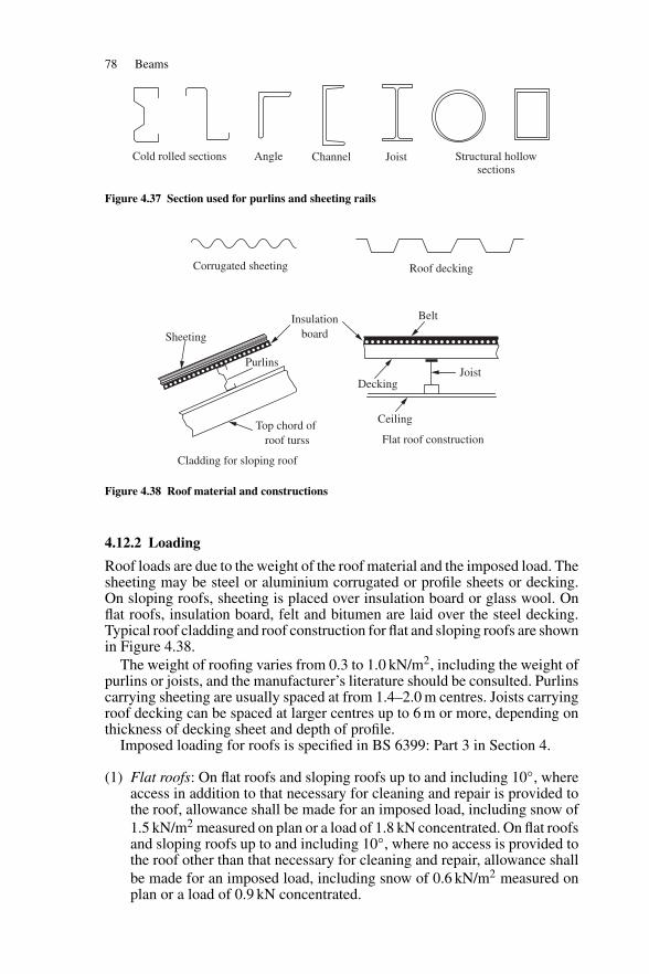
78 Beams
Cold rolled sections Angle Channel Joist Structural hollowsections
Figure 4.37 Section used for purlins and sheeting rails
Sheeting
Corrugated sheeting
Cladding for sloping roof
Flat roof construction
Roof decking
Purlins
Ceiling
DeckingJoist
Belt
Top chord of roof turss
Insulationboard
Figure 4.38 Roof material and constructions
4.12.2 Loading
Roof loads are due to the weight of the roof material and the imposed load. Thesheeting may be steel or aluminium corrugated or profile sheets or decking.On sloping roofs, sheeting is placed over insulation board or glass wool. Onflat roofs, insulation board, felt and bitumen are laid over the steel decking.Typical roof cladding and roof construction for flat and sloping roofs are shownin Figure 4.38.
The weight of roofing varies from 0.3 to 1.0 kN/m2, including the weight ofpurlins or joists, and the manufacturer’s literature should be consulted. Purlinscarrying sheeting are usually spaced at from 1.4–2.0 m centres. Joists carryingroof decking can be spaced at larger centres up to 6 m or more, depending onthickness of decking sheet and depth of profile.
Imposed loading for roofs is specified in BS 6399: Part 3 in Section 4.
(1) Flat roofs: On flat roofs and sloping roofs up to and including 10◦, whereaccess in addition to that necessary for cleaning and repair is provided tothe roof, allowance shall be made for an imposed load, including snow of1.5 kN/m2 measured on plan or a load of 1.8 kN concentrated. On flat roofsand sloping roofs up to and including 10◦, where no access is provided tothe roof other than that necessary for cleaning and repair, allowance shallbe made for an imposed load, including snow of 0.6 kN/m2 measured onplan or a load of 0.9 kN concentrated.
Purlins 79
(2) Sloping roofs: On roofs with a slope greater than 10◦ and with no accessprovided to the roof other than that necessary for cleaning and repair thefollowing imposed loads, including snow, shall be allowed for:(a) For a roof slope of 30◦ or less, 0.6 kN/m2 measured on plan or a vertical
load of 0.9 kN concentrated;(b) For a roof slope of 60◦ or more, no allowance is necessary. For roof
slopes between 30◦ and 60◦, a uniformly distributed load of 0.6[(60−α)/30] kN/m2 measured on plan where α is the roof slope.
Wind loads are generally upward, or cause suction on all but steeply slop-ing roofs. In some instances, the design may be controlled by the dead-windload cases. Wind loads are estimated in accordance with BS 6399 Part 2. Thecalculation of wind loads on a roof is given in Chapter 8 of this book.
4.12.3 Purlins for a flat roof
These members are designed as beams with the decking providing full lateralrestraint to the top flange. If the ceiling is directly connected to the bottomflange the deflection due to imposed load may need to be limited to span/360,in accordance with Table 8 of BS 5950-1: 2000. In other cases the code statesin Section 4.12.2 that the deflection should be limited to suit the characteristicsof the cladding system.
4.12.4 Purlins for a sloping roof
Consider a purlin on a sloping roof as shown in Figure 4.39(a). The load on aninterior purlin is from a width of roof equal to the purlin spacing S. The loadis made up of dead and imposed load acting vertically downwards.
A conservative method of design is to neglect the in-plane strength of theroof, resolve the load normal and tangential to the roof surface and designthe purlin for moments about the x–x and y–y axes (see Figure 4.39(c)). Ifa section such as a channel is used where the strength about the y–y axis ismuch less than that about the x–x axis, a system of sag rods to support thepurlin about the weak axis may be introduced, as shown in Figure 4.39(b). Thepurlin is then designed as a simply supported beam for bending about the x–xaxis and a continuous beam for bending about the y–y axis.
A more realistic and economic design results if the in-plane strength of thecladding is taken into account. The purlin is designed for bending about thex–x axis with the whole vertical load assumed to cause moment.
An angle purlin bent at the full plastic moment about the x–x axis is shownin Figure 4.39(d). Note that the internal resultant forces act at the centroids ofthe tension and compression areas. These forces cause a secondary momentabout the y–y axis. It is assumed in design that the sheeting absorbs thismoment.
BS 5950-1: 2000 gives the classification for angles in Table 11, wherelimiting width/thickness ratios are given for legs. The sheeting restrains theangle member so that bending take place about the x–x axis. The unsupporteddownward leg is in tension in simply supported purlins, but it would be incompression under uplift from wind load or near the supports in continuouspurlins.
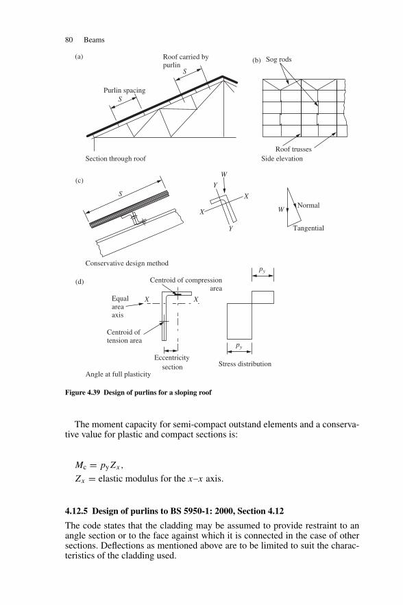
80 Beams
S
(a) (b)
(c)
(d) Centroid of compressionarea
Equalareaaxis
Centroid of tension area
Eccentricitysection Stress distribution
py
py
Y
Y
X
X X
X
W
Purlin spacing
Section through roof
Conservative design method
Angle at full plasticity
Side elevation
Roof carried bypurlin
Sog rods
Roof trusses
NormalW
Tangential
S
S
Figure 4.39 Design of purlins for a sloping roof
The moment capacity for semi-compact outstand elements and a conserva-tive value for plastic and compact sections is:
Mc = pyZx,
Zx = elastic modulus for the x–x axis.
4.12.5 Design of purlins to BS 5950-1: 2000, Section 4.12
The code states that the cladding may be assumed to provide restraint to anangle section or to the face against which it is connected in the case of othersections. Deflections as mentioned above are to be limited to suit the charac-teristics of the cladding used.
Purlins 81
The empirical design method is set out in Section 4.12.4 of the code, andthe general requirements are:
(1) The member should be of steel to a minimum of grade S275.(2) Unfactored loads are used in the design;(3) The span is not to exceed 6.5 m centre to centre of main supports;(4) If the purlin spans one bay it must be connected by two fasteners at each
end;(5) If the purlins are continuous over two or more bays with staggered joints
in adjacent lines, at least one end of any single-bay member should beconnected by not less than two fasteners.
The rules for empirical design of angle purlins are:
(1) The roof slope should not exceed 30◦.(2) The load should be substantially uniformly distributed. Not more than 10
per cent of the total load should be due to other types of load;(3) The elastic modulus about the axis parallel to the plane of cladding should
not be less than the larger value of Wp/1800 cm3 or WqL/2250 cm3, whereWp is the total unfactored load on one span (kN) due to dead and imposedload and Wq is the total unfactored load on one span (kN) due to deadminus wind load and L is the span (mm).
(4) Dimension D perpendicular to the plane of the cladding is not to be lessthan L/45. Dimension B parallel to the plane of the cladding is not to beless than L/60.
The code notes that where sag rods are provided the sag rod spacing may beused to determine B only.
4.12.6 Cold-rolled purlins
Cold-rolled purlins are almost exclusively adopted for industrial buildings.The design is to conform to BS 5950: Part 5, Code of Practice for Design ofCold Formed Sections. Detailed design of these sections is outside the scope ofthis book.
The purlin section for a given roof may be selected from manufacturer’sdata. Ward Building Components Ltd has kindly given permission for some oftheir design data to be reproduced in this book. This firm produces completesystems for purlins and cladding rails based on their cold-formed multibeamsection. Full information including fixing methods and accessories is given intheir Technical Handbook (12). In addition, they have produced the multibeamdesign software system for optimum design for their purlins and side rails.
The multibeam cold-formed section and ultimate loads for double-span pur-lins for a limited range of purlins are shown in Table 4.2. Notes for use of thetable are:
(1) The loads tables show the ultimate loads that can be applied. The sectionself-weight has not been deducted. Loadings have also been tabulated thatwill produce the noted deflection ratio.
(2) The loads given are based on lateral restraint being provided to the topflange by the cladding,
(3) The values given are also the ultimate uplift load due to wind uplift.
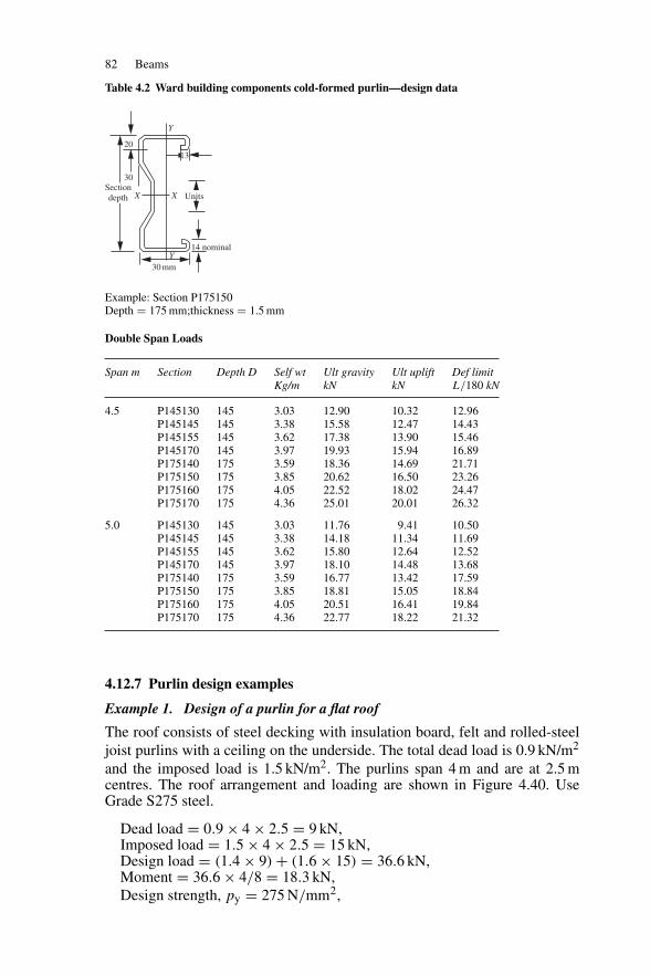
82 Beams
Table 4.2 Ward building components cold-formed purlin—design data
Y
X
20
30
30 mm
13
14 nominal
X
Y
UnitsSectiondepth
Example: Section P175150Depth = 175 mm;thickness = 1.5 mm
Double Span Loads
Span m Section Depth D Self wt Ult gravity Ult uplift Def limitKg/m kN kN L/180 kN
4.5 P145130 145 3.03 12.90 10.32 12.96P145145 145 3.38 15.58 12.47 14.43P145155 145 3.62 17.38 13.90 15.46P145170 145 3.97 19.93 15.94 16.89P175140 175 3.59 18.36 14.69 21.71P175150 175 3.85 20.62 16.50 23.26P175160 175 4.05 22.52 18.02 24.47P175170 175 4.36 25.01 20.01 26.32
5.0 P145130 145 3.03 11.76 9.41 10.50P145145 145 3.38 14.18 11.34 11.69P145155 145 3.62 15.80 12.64 12.52P145170 145 3.97 18.10 14.48 13.68P175140 175 3.59 16.77 13.42 17.59P175150 175 3.85 18.81 15.05 18.84P175160 175 4.05 20.51 16.41 19.84P175170 175 4.36 22.77 18.22 21.32
4.12.7 Purlin design examples
Example 1. Design of a purlin for a flat roof
The roof consists of steel decking with insulation board, felt and rolled-steeljoist purlins with a ceiling on the underside. The total dead load is 0.9 kN/m2
and the imposed load is 1.5 kN/m2. The purlins span 4 m and are at 2.5 mcentres. The roof arrangement and loading are shown in Figure 4.40. UseGrade S275 steel.
Dead load = 0.9 × 4 × 2.5 = 9 kN,Imposed load = 1.5 × 4 × 2.5 = 15 kN,Design load = (1.4 × 9) + (1.6 × 15) = 36.6 kN,Moment = 36.6 × 4/8 = 18.3 kN,Design strength, py = 275 N/mm2,
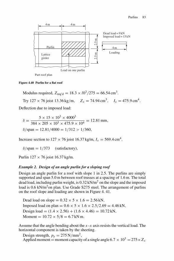
Purlins 83
4 m 4 m
4 m
Loading
Dead load = 9 kNImposed load = 15 kN
2.5
m2.
5m
Purlin
Part roof plan
Load on one purlin
Latticegirder
Figure 4.40 Purlin for a flat roof
Modulus required, Zreq′d = 18.3 × l03/275 = 66.54 cm3.
Try 127 × 76 joist 13.36 kg/m, Zx = 74.94 cm3, Ix = 475.9 cm4.
Deflection due to imposed load:
δ = 5 × 15 × 103 × 40003
384 × 205 × 103 × 475.9 × 104= 12.81 mm,
δ/span = 12.81/4000 = 1/312 > 1/360,
Increase section to 127 × 76 joist 16.37 kg/m, Ix = 569.4 cm4.
δ/span = 1/373 (satisfactory),
Purlin 127 × 76 joist 16.37 kg/m.
Example 2. Design of an angle purlin for a sloping roof
Design an angle purlin for a roof with slope 1 in 2.5. The purlins are simplysupported and span 5.0 m between roof trusses at a spacing of 1.6 m. The totaldead load, including purlin weight, is 0.32 kN/m2 on the slope and the imposedload is 0.6 kN/m2on plan. Use Grade S275 steel. The arrangement of purlinson the roof slope and loading are shown in Figure 4. 41.
Dead load on slope = 0.32 × 5 × 1.6 = 2.56 kN,
Imposed load on plan = 0.6 × 5 × 1.6 × 2.5/2.69 = 4.46 kN,
Design load = (1.4 × 2.56) + (1.6 × 4.46) = 10.72 kN,
Moment = 10.72 × 5/8 = 6.7 kN m.
Assume that the angle bending about the x–x axis resists the vertical load. Thehorizontal component is taken by the sheeting.
Design strength, py = 275 N/mm2,Applied moment = moment capacity of a single angle 6.7 × 103 = 275×Zx
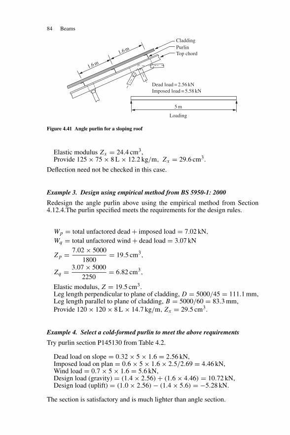
84 Beams
Cladding
1.6 m
1.6 m
Dead load = 2.56 kNImposed load = 5.58 kN
5 m
Loading
PurlinTop chord
Figure 4.41 Angle purlin for a sloping roof
Elastic modulus Zx = 24.4 cm3,Provide 125 × 75 × 8 L × 12.2 kg/m, Zx = 29.6 cm3.
Deflection need not be checked in this case.
Example 3. Design using empirical method from BS 5950-1: 2000
Redesign the angle purlin above using the empirical method from Section4.12.4.The purlin specified meets the requirements for the design rules.
Wp = total unfactored dead + imposed load = 7.02 kN,
Wq = total unfactored wind + dead load = 3.07 kN
Zp = 7.02 × 5000
1800= 19.5 cm3,
Zq = 3.07 × 5000
2250= 6.82 cm3,
Elastic modulus, Z = 19.5 cm3.Leg length perpendicular to plane of cladding, D = 5000/45 = 111.1 mm,Leg length parallel to plane of cladding, B = 5000/60 = 83.3 mm,Provide 120 × 120 × 8 L × 14.7 kg/m, Zx = 29.5 cm3.
Example 4. Select a cold-formed purlin to meet the above requirements
Try purlin section P145130 from Table 4.2.
Dead load on slope = 0.32 × 5 × 1.6 = 2.56 kN,Imposed load on plan = 0.6 × 5 × 1.6 × 2.5/2.69 = 4.46 kN,Wind load = 0.7 × 5 × 1.6 = 5.6 kN,Design load (gravity) = (1.4 × 2.56) + (1.6 × 4.46) = 10.72 kN,Design load (uplift) = (1.0 × 2.56) − (1.4 × 5.6) = −5.28 kN.
The section is satisfactory and is much lighter than angle section.
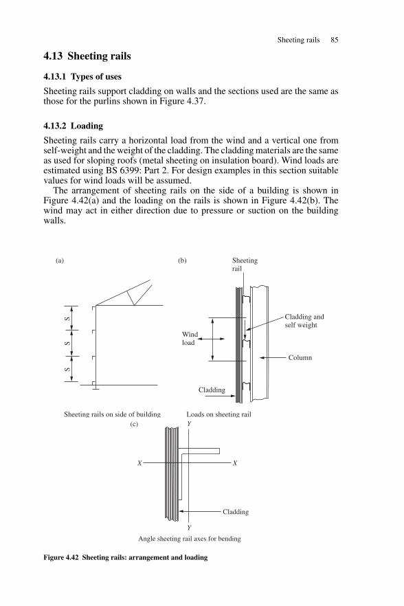
Sheeting rails 85
4.13 Sheeting rails
4.13.1 Types of uses
Sheeting rails support cladding on walls and the sections used are the same asthose for the purlins shown in Figure 4.37.
4.13.2 Loading
Sheeting rails carry a horizontal load from the wind and a vertical one fromself-weight and the weight of the cladding. The cladding materials are the sameas used for sloping roofs (metal sheeting on insulation board). Wind loads areestimated using BS 6399: Part 2. For design examples in this section suitablevalues for wind loads will be assumed.
The arrangement of sheeting rails on the side of a building is shown inFigure 4.42(a) and the loading on the rails is shown in Figure 4.42(b). Thewind may act in either direction due to pressure or suction on the buildingwalls.
SS
S
Windload
Sheetingrail
Cladding andself weight
Column
Cladding
(b)(a)
Loads on sheeting railSheeting rails on side of buildingY
Y
XX
Cladding
(c)
Angle sheeting rail axes for bending
Figure 4.42 Sheeting rails: arrangement and loading
86 Beams
4.13.3 Design of angle sheeting rail
Sheeting rails may be designed as beams bending about two axes. It is assumedfor angle sheeting rails that the sheeting restrains the member and bendingtakes place about the vertical and horizontal axes. Eccentricity of the verticalloading (shown in Figure 4.42(b)) is not taken into account.
The sheeting rail is fully supported on the downward leg. The outstandleg for simply supported sheeting rails is in compression from dead load andtension or compression from wind load.
The moment capacity is (see Section 4.12.4):
Mc = pyZ
where Z is the elastic modulus for the appropriate axis.For biaxial bending:
mxMx
pyZx
+ myMy
pyZy
≤ 1,
mLTMLT
Mb+ myMy
pyZy
≤ 1.
4.13.4 Design of angle sheeting rails to BS 5950-1: 2000
The general requirements from Section 4.12.4.1 of the code set out for purlinsin Section 4.12.4 above must be satisfied. Empirical rules for design of sheetingrails are given in Section 4.12.4.3 of the BS 5950. These state that:
(1) The loading should generally be due to wind load and weight of cladding.Not more than 10 per cent should be due to other loads or due to loads notuniformly distributed.
(2) The elastic moduli for the two axes of the sheeting rail from Table 28 inthe code should not be less than the following values for an angle (seeFigure 4.42(c):(a) y–y axis—parallel to plane of the cladding:
Z1 > W1L1/2250 cm3,
where W1 = unfactored load on one rail acting perpendicular to theplane of the cladding in kN. (This is the wind load.)
L1 = span in millimetres, centre to centre of columns.
(b) x–x axis—perpendicular to the plane of the cladding:
Z2 > W2L2/1200 cm3,
where W2 = unfactored load on one railing acting parallel to theplane of the cladding in kN. (This is the weight of thecladding and rail.)
L2 = span centre to centre of columns or spacing of sag rodswhere these are provided and properly supported.
(3) The dimensions of the angle should not be less than the following:D—perpendicular to the cladding < L1/45,B—parallel to the cladding < L2/60.L1 and L2 were defined above.
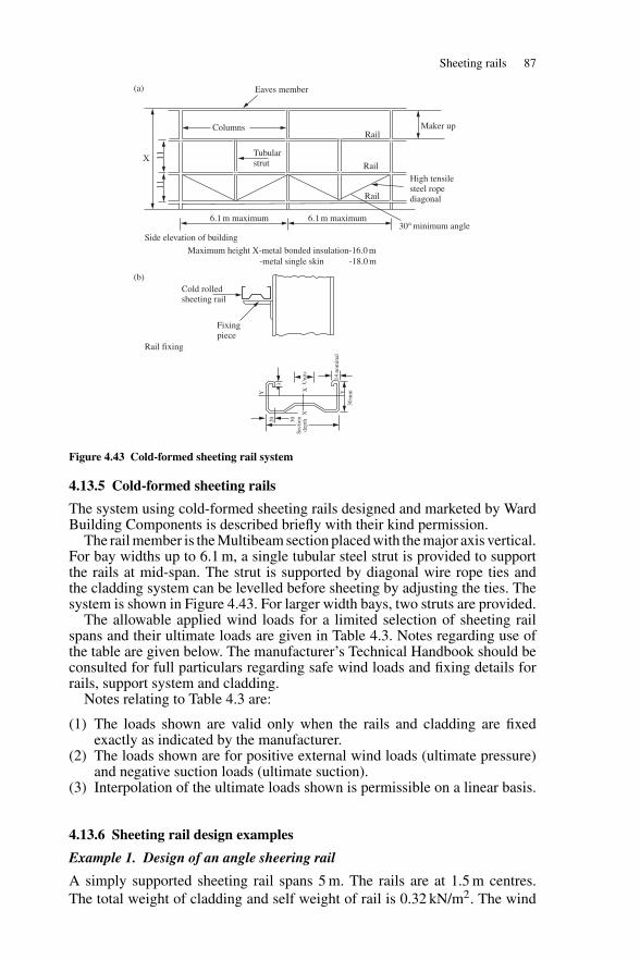
Sheeting rails 87
(a)
(b)
Eaves member
X 1111
Columns
6.1 m maximum
Cold rolledsheeting rail
Fixingpiece
Maximum height X-metal bonded insulation-16.0 m-metal single skin -18.0 m
6.1 m maximum
Tubularstrut
RailMaker up
30° minimum angleSide elevation of building
Rail fixing
Rail
Rail
High tensilesteel ropediagonal
Y
X
20 30
30m
m
13
14 n
omin
al
X Y
Uni
tsSe
ctio
nde
pth
Figure 4.43 Cold-formed sheeting rail system
4.13.5 Cold-formed sheeting rails
The system using cold-formed sheeting rails designed and marketed by WardBuilding Components is described briefly with their kind permission.
The rail member is the Multibeam section placed with the major axis vertical.For bay widths up to 6.1 m, a single tubular steel strut is provided to supportthe rails at mid-span. The strut is supported by diagonal wire rope ties andthe cladding system can be levelled before sheeting by adjusting the ties. Thesystem is shown in Figure 4.43. For larger width bays, two struts are provided.
The allowable applied wind loads for a limited selection of sheeting railspans and their ultimate loads are given in Table 4.3. Notes regarding use ofthe table are given below. The manufacturer’s Technical Handbook should beconsulted for full particulars regarding safe wind loads and fixing details forrails, support system and cladding.
Notes relating to Table 4.3 are:
(1) The loads shown are valid only when the rails and cladding are fixedexactly as indicated by the manufacturer.
(2) The loads shown are for positive external wind loads (ultimate pressure)and negative suction loads (ultimate suction).
(3) Interpolation of the ultimate loads shown is permissible on a linear basis.
4.13.6 Sheeting rail design examples
Example 1. Design of an angle sheering rail
A simply supported sheeting rail spans 5 m. The rails are at 1.5 m centres.The total weight of cladding and self weight of rail is 0.32 kN/m2. The wind
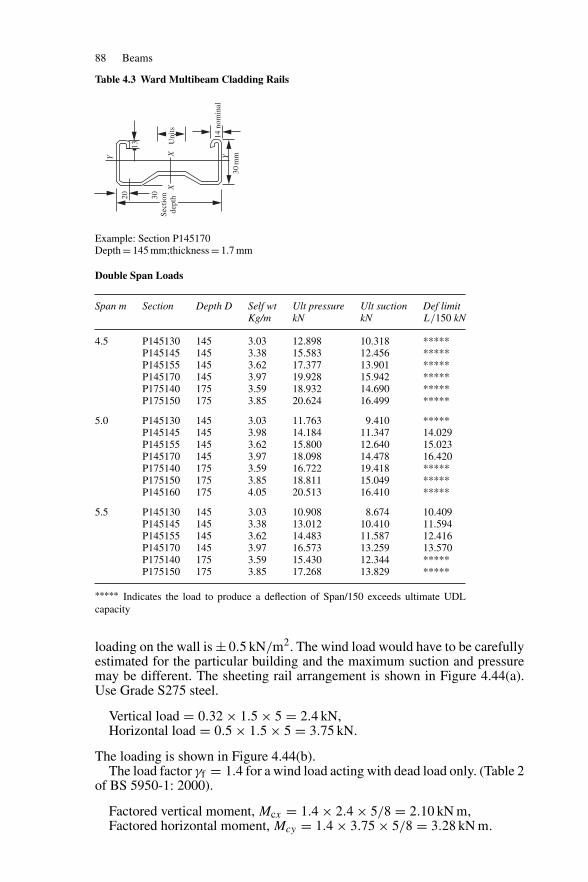
88 Beams
Table 4.3 Ward Multibeam Cladding Rails
Y
X
20 30
30m
m
13
14 n
omin
al
X Y
Uni
tsSe
ctio
nde
pth
Example: Section P145170Depth = 145 mm;thickness = 1.7 mm
Double Span Loads
Span m Section Depth D Self wt Ult pressure Ult suction Def limitKg/m kN kN L/150 kN
4.5 P145130 145 3.03 12.898 10.318 *****P145145 145 3.38 15.583 12.456 *****P145155 145 3.62 17.377 13.901 *****P145170 145 3.97 19.928 15.942 *****P175140 175 3.59 18.932 14.690 *****P175150 175 3.85 20.624 16.499 *****
5.0 P145130 145 3.03 11.763 9.410 *****P145145 145 3.98 14.184 11.347 14.029P145155 145 3.62 15.800 12.640 15.023P145170 145 3.97 18.098 14.478 16.420P175140 175 3.59 16.722 19.418 *****P175150 175 3.85 18.811 15.049 *****P145160 175 4.05 20.513 16.410 *****
5.5 P145130 145 3.03 10.908 8.674 10.409P145145 145 3.38 13.012 10.410 11.594P145155 145 3.62 14.483 11.587 12.416P145170 145 3.97 16.573 13.259 13.570P175140 175 3.59 15.430 12.344 *****P175150 175 3.85 17.268 13.829 *****
∗∗∗∗∗ Indicates the load to produce a deflection of Span/150 exceeds ultimate UDLcapacity
loading on the wall is ± 0.5 kN/m2. The wind load would have to be carefullyestimated for the particular building and the maximum suction and pressuremay be different. The sheeting rail arrangement is shown in Figure 4.44(a).Use Grade S275 steel.
Vertical load = 0.32 × 1.5 × 5 = 2.4 kN,Horizontal load = 0.5 × 1.5 × 5 = 3.75 kN.
The loading is shown in Figure 4.44(b).The load factor γf = 1.4 for a wind load acting with dead load only. (Table 2
of BS 5950-1: 2000).
Factored vertical moment, Mcx = 1.4 × 2.4 × 5/8 = 2.10 kN m,Factored horizontal moment, Mcy = 1.4 × 3.75 × 5/8 = 3.28 kN m.
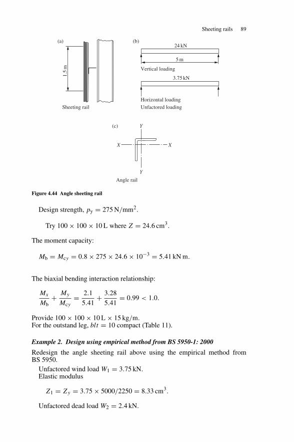
Sheeting rails 89
1.5
m5 m
24 kN
3.75 kN
Y
Y
X X
(a)
Sheeting rail Unfactored loading
Angle rail
Vertical loading
Horizontal loading
(b)
(c)
Figure 4.44 Angle sheeting rail
Design strength, py = 275 N/mm2.
Try 100 × 100 × 10 L where Z = 24.6 cm3.
The moment capacity:
Mb = Mcy = 0.8 × 275 × 24.6 × 10−3 = 5.41 kN m.
The biaxial bending interaction relationship:
Mx
Mb+ My
Mcy= 2.1
5.41+ 3.28
5.41= 0.99 < 1.0.
Provide 100 × 100 × 10 L × 15 kg/m.For the outstand leg, blt = 10 compact (Table 11).
Example 2. Design using empirical method from BS 5950-1: 2000
Redesign the angle sheeting rail above using the empirical method fromBS 5950.
Unfactored wind load W1 = 3.75 kN.Elastic modulus
Z1 = Zy = 3.75 × 5000/2250 = 8.33 cm3.
Unfactored dead load W2 = 2.4 kN.
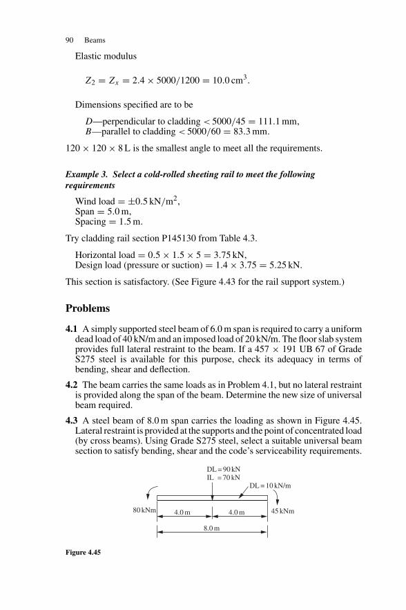
90 Beams
Elastic modulus
Z2 = Zx = 2.4 × 5000/1200 = 10.0 cm3.
Dimensions specified are to be
D—perpendicular to cladding < 5000/45 = 111.1 mm,B—parallel to cladding < 5000/60 = 83.3 mm.
120 × 120 × 8 L is the smallest angle to meet all the requirements.
Example 3. Select a cold-rolled sheeting rail to meet the followingrequirements
Wind load = ±0.5 kN/m2,Span = 5.0 m,Spacing = 1.5 m.
Try cladding rail section P145130 from Table 4.3.
Horizontal load = 0.5 × 1.5 × 5 = 3.75 kN,Design load (pressure or suction) = 1.4 × 3.75 = 5.25 kN.
This section is satisfactory. (See Figure 4.43 for the rail support system.)
Problems
4.1 A simply supported steel beam of 6.0 m span is required to carry a uniformdead load of 40 kN/m and an imposed load of 20 kN/m. The floor slab systemprovides full lateral restraint to the beam. If a 457 × 191 UB 67 of GradeS275 steel is available for this purpose, check its adequacy in terms ofbending, shear and deflection.
4.2 The beam carries the same loads as in Problem 4.1, but no lateral restraintis provided along the span of the beam. Determine the new size of universalbeam required.
4.3 A steel beam of 8.0 m span carries the loading as shown in Figure 4.45.Lateral restraint is provided at the supports and the point of concentrated load(by cross beams). Using Grade S275 steel, select a suitable universal beamsection to satisfy bending, shear and the code’s serviceability requirements.
DL = 90 kN IL = 70 kN
DL = 10 kN/m
45 kNm80 kNm 4.0 m 4.0 m
8.0 m
Figure 4.45
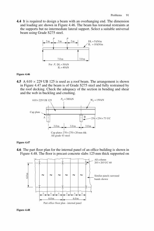
Problems 91
4.4 It is required to design a beam with an overhanging end. The dimensionand loading are shown in Figure 4.46. The beam has torsional restraints atthe supports but no intermediate lateral support. Select a suitable universalbeam using Grade S275 steel.
P2 m 3 m 2 m
DL = 50 kN IL = 40 kN
7.0 m 3.0 m
P
For P,
DL = 5 kN/m IL = 10 kN/m
Figure 4.46
4.5 A 610 × 229 UB 125 is used as a roof beam. The arrangement is shownin Figure 4.47 and the beam is of Grade S275 steel and fully restrained bythe roof decking. Check the adequacy of the section in bending and shearand the web in buckling and crushing.
610 × 229 UB 125 PU = 300 kN
BA
Cap plate
3.0 m 3.0 m
Cap plates 270 × 270 × 20 mm thk All grade 43 steel
3.0 m
WU = 150 kN
254 × 254 × 73 UC
Figure 4.47
4.6 The part floor plan for the internal panel of an office building is shown inFigure 4.48. The floor is precast concrete slabs 125 mm thick supported on
Similar panels surroundbands shown
6.0 m6.0 m
= = = = = =
Part office floor plan – internal panel
6.0
m
All column203 × 203 UC 60
Figure 4.48
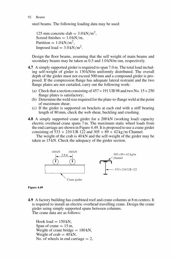
92 Beams
steel beams. The following loading data may be used:
125 mm concrete slab = 3.0 kN/m2,Screed finishes = 1.0 kN/m,Partition = 1.0 kN/m2,Imposed load = 3.0 kN/m2.
Design the floor beams, assuming that the self weight of main beams andsecondary beams may be taken as 0.5 and 1.0 kN/m run, respectively.
4.7 A simply supported girder is required to span 7.0 m. The total load includ-ing self-weight of girder is 130 kN/m uniformly distributed. The overalldepth of the girder must not exceed 500 mm and a compound girder is pro-posed. If the compression flange has adequate lateral restraint and the twoflange plates are not curtailed, carry out the following work:
(a) Check that a section consisting of 457×191 UB 98 and two No. 15×250flange plates is satisfactory;
(b) Determine the weld size required for the plate-to-flange weld at the pointof maximum shear;
(c) If the girder is supported on brackets at each end with a stiff bearinglength of 80 mm, check the web shear, buckling and crushing.
4.8 A simply supported crane girder for a 200 kN (working load) capacityelectric overhead crane spans 7 m. The maximum static wheel loads fromthe end carriage are shown in Figure 4.49. It is proposed to use a crane girderconsisting of 533 × 210 UB 122 and 305 × 89 × 42 kg/m Channel.
The weight of the crab is 40 kN and the self-weight of the girder may betaken as 15 kN. Check the adequacy of the girder section.
160 kN 160 kN305 × 89 × 42 kg/mchannel
533 × 210 UB 122
2.8 m
Crane girder
Figure 4.49
4.9 A factory building has combined roof and crane columns at 8 m centres. Itis required to install an electric overhead travelling crane. Design the cranegirder using simply supported spans between columns.The crane data are as follows:
Hook load = 150 kN,Span of crane = 15 m,Weight of crane bridge = 180 kN,Weight of crab = 40 kN,No. of wheels in end carriage = 2,
Problems 93
Wheels centres in end carriage = 3 m,Minimum hook approach = 1 m.
4.10 Select a suitable size for a simply supported cold-rolled purlin. The purlinspan is 5.0 m and the spacing is 1.8 m. The total dead load and imposed loadon plan are 0.22 and 0.6 kN/m2, respectively. Use Table 4.2 in the design.Redesign the purlin using the rules from BS 5950-1: 2000.
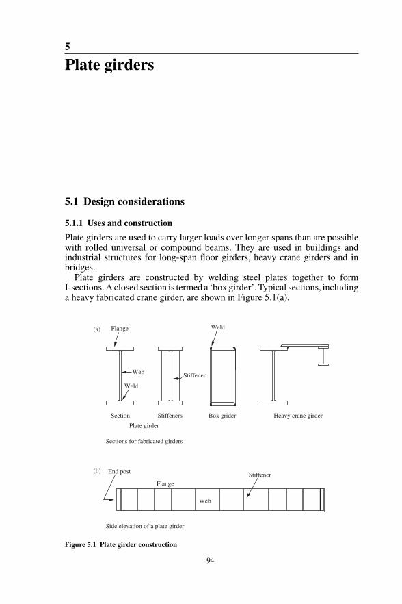
5
Plate girders
5.1 Design considerations
5.1.1 Uses and construction
Plate girders are used to carry larger loads over longer spans than are possiblewith rolled universal or compound beams. They are used in buildings andindustrial structures for long-span floor girders, heavy crane girders and inbridges.
Plate girders are constructed by welding steel plates together to formI-sections. A closed section is termed a ‘box girder’. Typical sections, includinga heavy fabricated crane girder, are shown in Figure 5.1(a).
Flange(a)
(b)
Web
Weld
Stiffener
Stiffeners
StiffenerEnd post
Flange
Web
Section
Plate girder
Sections for fabricated girders
Side elevation of a plate girder
Box grider Heavy crane girder
Weld
Figure 5.1 Plate girder construction
94
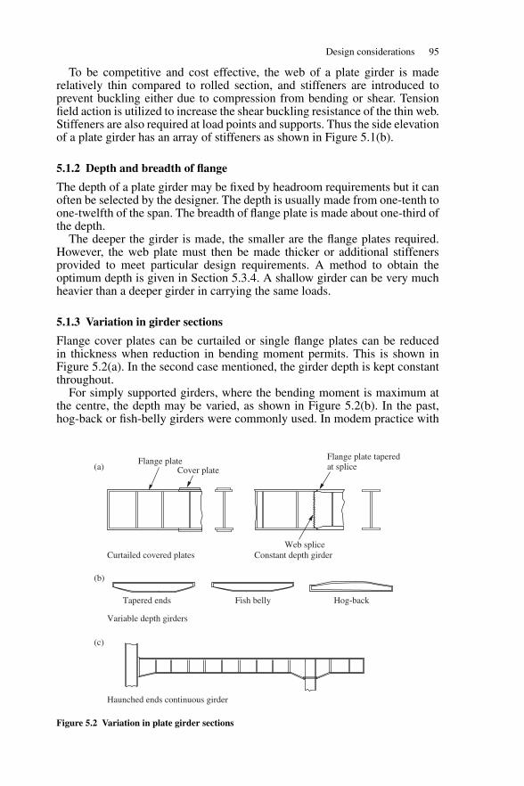
Design considerations 95
To be competitive and cost effective, the web of a plate girder is maderelatively thin compared to rolled section, and stiffeners are introduced toprevent buckling either due to compression from bending or shear. Tensionfield action is utilized to increase the shear buckling resistance of the thin web.Stiffeners are also required at load points and supports. Thus the side elevationof a plate girder has an array of stiffeners as shown in Figure 5.1(b).
5.1.2 Depth and breadth of flange
The depth of a plate girder may be fixed by headroom requirements but it canoften be selected by the designer. The depth is usually made from one-tenth toone-twelfth of the span. The breadth of flange plate is made about one-third ofthe depth.
The deeper the girder is made, the smaller are the flange plates required.However, the web plate must then be made thicker or additional stiffenersprovided to meet particular design requirements. A method to obtain theoptimum depth is given in Section 5.3.4. A shallow girder can be very muchheavier than a deeper girder in carrying the same loads.
5.1.3 Variation in girder sections
Flange cover plates can be curtailed or single flange plates can be reducedin thickness when reduction in bending moment permits. This is shown inFigure 5.2(a). In the second case mentioned, the girder depth is kept constantthroughout.
For simply supported girders, where the bending moment is maximum atthe centre, the depth may be varied, as shown in Figure 5.2(b). In the past,hog-back or fish-belly girders were commonly used. In modem practice with
Curtailed covered plates
Variable depth girders
Haunched ends continuous girder
Tapered ends Fish belly Hog-back
Constant depth girder
Flange plate taperedat splice
Web splice
Cover plateFlange plate
(a)
(b)
(c)
Figure 5.2 Variation in plate girder sections
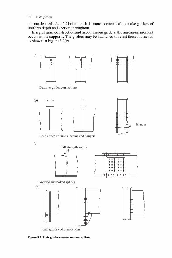
96 Plate girders
automatic methods of fabrication, it is more economical to make girders ofuniform depth and section throughout.
In rigid frame construction and in continuous girders, the maximum momentoccurs at the supports. The girders may be haunched to resist these moments,as shown in Figure 5.2(c).
(a)
Beam to girder connections
Loads from columns, beams and hangers
Welded and bolted splices
(b)
(c)Full strength welds
Hanger
Plate girder end connections
(d)
Figure 5.3 Plate girder connections and splices
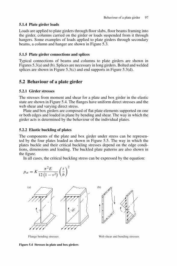
Behaviour of a plate girder 97
5.1.4 Plate girder loads
Loads are applied to plate girders through floor slabs, floor beams framing intothe girder, columns carried on the girder or loads suspended from it throughhangers. Some examples of loads applied to plate girders through secondarybeams, a column and hanger are shown in Figure 5.3.
5.1.5 Plate girder connections and splices
Typical connections of beams and columns to plate girders are shown inFigures 5.3(a) and (b). Splices are necessary in long girders. Bolted and weldedsplices are shown in Figure 5.3(c) and end supports in Figure 5.3(d).
5.2 Behaviour of a plate girder
5.2.1 Girder stresses
The stresses from moment and shear for a plate and box girder in the elasticstate are shown in Figure 5.4. The flanges have uniform direct stresses and theweb shear and varying direct stress.
Plate and box girders are composed of flat plate elements supported on oneor both edges and loaded in plane by bending and shear. The way in which thegirder acts is determined by the behaviour of the individual plates.
5.2.2 Elastic buckling of plates
The components of the plate and box girder under stress can be represen-ted by the four plates loaded as shown in Figure 5.5. The way in which theplates buckle and their critical buckling stresses depend on the edge condi-tions, dimensions and loading. The buckled plate patterns are also shown inthe figure.
In all cases, the critical buckling stress can be expressed by the equation:
pcr = Kπ2E
12(1 − ν2
) (t
b
)2
(a)
Flange bending stresses Web shear and bending stresses
(b)
Figure 5.4 Stresses in plate and box girders
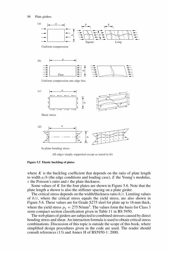
98 Plate girders
a
b
(a)
(b)
(c)
(d)
a
a
a
Free
bb
b
b
Square
Uniform compression
Uniform compression-one edge free
Shear stress
In plane bending stress
All edges simply supported except as noted in (b)
Long
b
b
Figure 5.5 Elastic buckling of plates
where K is the buckling coefficient that depends on the ratio of plate lengthto width a/b (the edge conditions and loading case), E the Young’s modulus,ν the Poisson’s ratio and t the plate thickness.
Some values of K for the four plates are shown in Figure 5.6. Note that theplate length a shown is also the stiffener spacing on a plate girder.
The critical stress depends on the width/thickness ratio b/t . Limiting valuesof b/t , where the critical stress equals the yield stress, are also shown inFigure 5.6. These values are for Grade S275 steel for plate up to 16 mm thick,where the yield stress py = 275 N/mm2. The values form the basis for Class 3semi-compact section classification given in Table 11 in BS 5950.
The web plates of girders are subjected to combined stresses caused by directbending stress and shear. An interaction formula is used to obtain critical stresscombinations. Discussion of this topic is outside the scope of this book, wheresimplified design procedures given in the code are used. The reader shouldconsult references (13) and Annex H of BS5950-1: 2000.
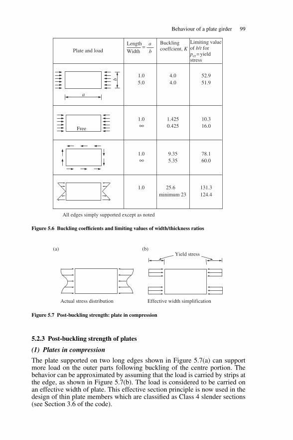
Behaviour of a plate girder 99
Free
a
b
Plate and load
Bucklingcoeffcient, K
Limiting valueof b/t forpcr= yieldstress
1.05.0
1.4250.425
10.316.0
1.0∞
∞
All edges simply supported except as noted
1.0 131.3124.4
25.6minimum 23
9.355.35
78.160.0
1.0
4.04.0
52.951.9
Length a
Width b=
Figure 5.6 Buckling coefficients and limiting values of width/thickness ratios
Yield stress(a)
Actual stress distribution Effective width simplification
(b)
Figure 5.7 Post-buckling strength: plate in compression
5.2.3 Post-buckling strength of plates
(1) Plates in compression
The plate supported on two long edges shown in Figure 5.7(a) can supportmore load on the outer parts following buckling of the centre portion. Thebehavior can be approximated by assuming that the load is carried by strips atthe edge, as shown in Figure 5.7(b). The load is considered to be carried onan effective width of plate. This effective section principle is now used in thedesign of thin plate members which are classified as Class 4 slender sections(see Section 3.6 of the code).
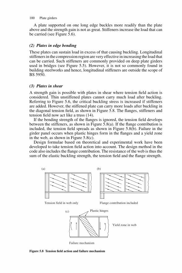
100 Plate girders
A plate supported on one long edge buckles more readily than the plateabove and the strength gain is not as great. Stiffeners increase the load that canbe carried (see Figure 5.6).
(2) Plates in edge bending
These plates can sustain load in excess of that causing buckling. Longitudinalstiffeners in the compression region are very effective in increasing the load thatcan be carried. Such stiffeners are commonly provided on deep plate girdersused in bridges (see Figure 5.5). However, it is not so commonly found inbuilding steelworks and hence, longitudinal stiffeners are outside the scope ofBS 5950.
(3) Plates in shear
A strength gain is possible with plates in shear where tension field action isconsidered. Thin unstiffened plates cannot carry much load after buckling.Referring to Figure 5.6, the critical buckling stress is increased if stiffenersare added. However, the stiffened plate can carry more loads after buckling inthe diagonal tension field, as shown in Figure 5.8. The flanges, stiffeners andtension field now act like a truss (14).
If the bending strength of the flanges is ignored, the tension field developsbetween the stiffeners, as shown in Figure 5.8(a). If the flange contribution isincluded, the tension field spreads as shown in Figure 5.8(b). Failure in thegirder panel occurs when plastic hinges form in the flanges and a yield zonein the web, as shown in Figure 5.8(c).
Design formulae based on theoretical and experimental work have beendeveloped to take tension field action into account. The design method in thecode also includes the flange contribution. The resistance of the web is thus thesum of the elastic buckling strength, the tension field and the flange strength.
(a) (b)
(c) Plastic hinges
Yield zone in web
Failure mechanism
Tension field in web only Flange contribution included
Figure 5.8 Tension field action and failure mechanism
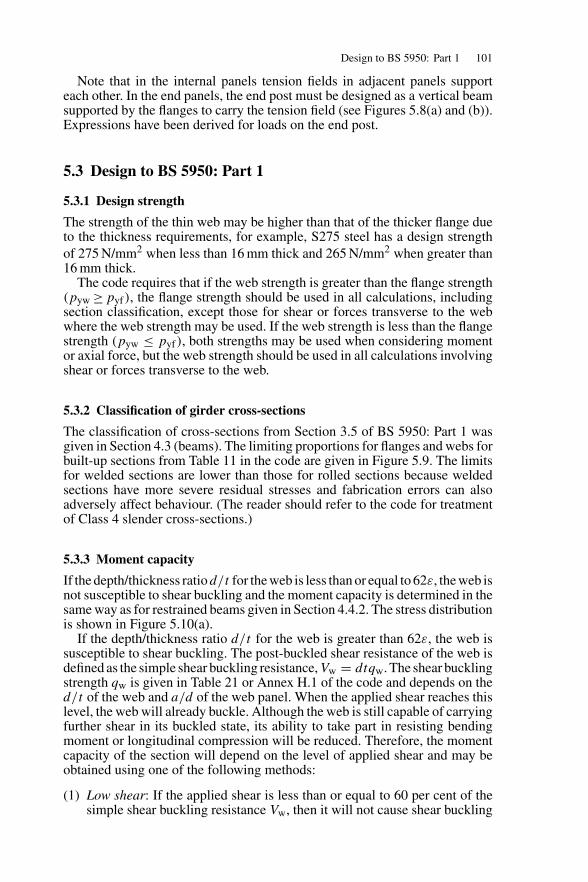
Design to BS 5950: Part 1 101
Note that in the internal panels tension fields in adjacent panels supporteach other. In the end panels, the end post must be designed as a vertical beamsupported by the flanges to carry the tension field (see Figures 5.8(a) and (b)).Expressions have been derived for loads on the end post.
5.3 Design to BS 5950: Part 1
5.3.1 Design strength
The strength of the thin web may be higher than that of the thicker flange dueto the thickness requirements, for example, S275 steel has a design strengthof 275 N/mm2 when less than 16 mm thick and 265 N/mm2 when greater than16 mm thick.
The code requires that if the web strength is greater than the flange strength(pyw ≥ pyf), the flange strength should be used in all calculations, includingsection classification, except those for shear or forces transverse to the webwhere the web strength may be used. If the web strength is less than the flangestrength (pyw ≤ pyf), both strengths may be used when considering momentor axial force, but the web strength should be used in all calculations involvingshear or forces transverse to the web.
5.3.2 Classification of girder cross-sections
The classification of cross-sections from Section 3.5 of BS 5950: Part 1 wasgiven in Section 4.3 (beams). The limiting proportions for flanges and webs forbuilt-up sections from Table 11 in the code are given in Figure 5.9. The limitsfor welded sections are lower than those for rolled sections because weldedsections have more severe residual stresses and fabrication errors can alsoadversely affect behaviour. (The reader should refer to the code for treatmentof Class 4 slender cross-sections.)
5.3.3 Moment capacity
If the depth/thickness ratiod/t for the web is less than or equal to 62ε, the web isnot susceptible to shear buckling and the moment capacity is determined in thesame way as for restrained beams given in Section 4.4.2. The stress distributionis shown in Figure 5.10(a).
If the depth/thickness ratio d/t for the web is greater than 62ε, the web issusceptible to shear buckling. The post-buckled shear resistance of the web isdefined as the simple shear buckling resistance,Vw = dtqw. The shear bucklingstrength qw is given in Table 21 or Annex H.1 of the code and depends on thed/t of the web and a/d of the web panel. When the applied shear reaches thislevel, the web will already buckle. Although the web is still capable of carryingfurther shear in its buckled state, its ability to take part in resisting bendingmoment or longitudinal compression will be reduced. Therefore, the momentcapacity of the section will depend on the level of applied shear and may beobtained using one of the following methods:
(1) Low shear: If the applied shear is less than or equal to 60 per cent of thesimple shear buckling resistance Vw, then it will not cause shear buckling
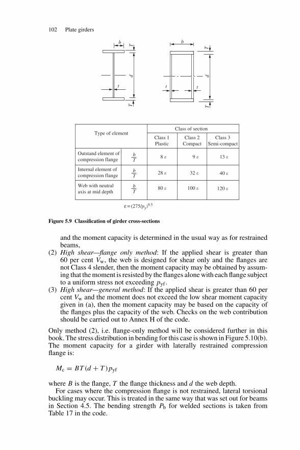
102 Plate girders
d dT
T
TT
t
b b
t t
Type of element
Outstand element ofcompression flange
bT
8 �
Class 1 Plastic
Class 2Compact
Class of section
Class 3Semi-compact
28 �
80 � 100 �
32 �
9 � 13 �
40 �
120 �
Internal element ofcompression flange
Web with neutralaxis at mid depth
ε = (275/py)0.5
bT
bT
Figure 5.9 Classification of girder cross-sections
and the moment capacity is determined in the usual way as for restrainedbeams,
(2) High shear—flange only method: If the applied shear is greater than60 per cent Vw, the web is designed for shear only and the flanges arenot Class 4 slender, then the moment capacity may be obtained by assum-ing that the moment is resisted by the flanges alone with each flange subjectto a uniform stress not exceeding pyf .
(3) High shear—general method: If the applied shear is greater than 60 percent Vw and the moment does not exceed the low shear moment capacitygiven in (a), then the moment capacity may be based on the capacity ofthe flanges plus the capacity of the web. Checks on the web contributionshould be carried out to Annex H of the code.
Only method (2), i.e. flange-only method will be considered further in thisbook. The stress distribution in bending for this case is shown in Figure 5.10(b).The moment capacity for a girder with laterally restrained compressionflange is:
Mc = BT (d + T )pyf
where B is the flange, T the flange thickness and d the web depth.For cases where the compression flange is not restrained, lateral torsional
buckling may occur. This is treated in the same way that was set out for beamsin Section 4.5. The bending strength Pb for welded sections is taken fromTable 17 in the code.
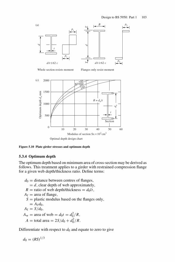
Design to BS 5950: Part 1 103
t
py
B
py
d dT
Td/t ≤ 62 �
(a)
(c) 2000
1500
1000
500
010 20
Modulus of section Sx × 103 cm3
30 40 50 60
Opt
imum
dep
th d
om
m
d/t ≥ 62 �
Whole section resists moment Flanges only resist moment
Optimal depth design chart
py
py
R= 250
200
150
t
Section
d o
R = do/t
Figure 5.10 Plate girder stresses and optimum depth
5.3.4 Optimum depth
The optimum depth based on minimum area of cross-section may be derived asfollows. This treatment applies to a girder with restrained compression flangefor a given web depth/thickness ratio. Define terms:
d0 = distance between centres of flanges,= d, clear depth of web approximately,
R = ratio of web depth/thickness = d0lt,
Af = area of flange,S = plastic modulus based on the flanges only,
= Afd0,
Af = S/d0,
Aw = area of web = d0t = d20/R,
A = total area = 2S/d0 + d20/R.
Differentiate with respect to d0 and equate to zero to give
d0 = (RS)1/3
104 Plate girders
Curves drawn for depth d0 against plastic modulus S for values of R of 150,200 and 250 are shown in Figure 5.10(b). For the required value of
S = M/pyf
the optimum depth d0 can be read from the chart for a given value of R, whereM is the applied moment.
5.3.5 Shear buckling resistance and web design
(1) Minimum thickness of web
This is given in Section 4.4.3 of BS 5950: Part 1. The following two conditionsmust be satisfied for webs with intermediate transverse stiffeners:
(i) Serviceability to prevent damage in handling:
Stiffener spacing a > d: t ≥ d/250
Stiffener spacing a ≤ d: t ≥ (d/250)(a/d)0.5
(ii) To avoid the flange buckling into the web. This type of failure has beenobserved in girders with thin webs:13
Stiffener spacing a > 1.5d: t ≥ (d/250)(pyf/345)
Stiffener spacing a ≤ 1.5d: t ≥ (d/250)(pyf/455)0.5
where d is the depth of web, t the thickness of web and pyf the designstrength of compression flange.
(2) Design for shear buckling resistance
The shear buckling resistance of the thin webs with d/t > 62ε is coveredin Section 4.4.5 of BS 5950: Part 1 and applies to webs carrying shear only.Those that are used to carry bending moment and/or axial load in addition toshear should be designed to Annex H of the code. Thin webs with intermediatestiffeners may be designed either using the simplified or more exact method.
In the simplified method, it is assumed that the flanges play no part inresisting the shear. The shear buckling resistance Vb of the thin web withintermediate transverse stiffeners should be based on the simple shear bucklingresistance Vw as given in Section 4.4.5.2 of the code as:
Vb = Vw = dtqw
where qw is the post-buckled shear buckling strength assuming tension fieldaction and is given in Tables 21 or Annex H.1 of the code. Unlike the oldcode, the critical shear buckling resistance before utilizing tension field actionVcr is now expressed as equation in Cl.4.4.5.4 or Annex H.2 of the code (seeequations given in Section 5.3.7(4)).
The more exact method assumes that the flanges can play a part in resistingthe shear. The stress in the flange due to axial load and/or bending moment aswell as the strength of the flange must therefore be considered.
If the flange is fully stressed (ff = pyf) then the shear buckling resistanceis the same as for the simplified method.
Design to BS 5950: Part 1 105
If the flanges are not fully stressed (ff ≤ pyf), the shear buckling resistancemay be increased to:
Vb = Vw + Vf but Vb ≤ Pv
and Vf , the flange-dependent shear buckling resistance is given by:
Vf =Pv (d/a)
⌊1 − (
ff/pyf)2
⌋1 + 0.15
(Mpw/Mpf
)where, ff is the mean longitudinal stress in the flange due to moment,M/(d0BT ),Mpf the plastic moment capacity of the flange,pyfBT 2/4,Mpw theplastic moment capacity of the web, pywtd2/4, pyf the design strength of theflange and M the applied moment.
The dimensions B, T , t, d and d0 defined above are shown in Figure 5.10.
5.3.6 Stiffener design
Two main types of stiffeners used in plate girders are:
(1) Intermediate transverse web stiffeners: These divide the web into panelsand prevent the web from buckling due to shear. They also have to resistdirect forces from tension field action and possibly external loads actingas well.
(2) Load carrying and bearing stiffeners: These are required at all points wheresubstantial external loads are applied through the flange and at supports toprevent local buckling and crushing of the web.
The stiffeners at the supports are also termed ‘end posts’. The design of theend posts to provide end anchorage for tension field action to develop in theend panel is dealt with in Section 5.3.9. Note that other special-purpose webstiffeners are defined in BS 5950: Part 1 in Section 4.5.1.1. Only the typesmentioned above will be discussed in this book.
5.3.7 Intermediate transverse web stiffeners
Transverse stiffeners may be placed on either one or both sides of the web, asshown in Figure 5.11. Flats are the most common stiffener section used. Therequirements and design procedure are set out in Section 4.4.6 of BS 5950:Part 1. Only stiffeners not subjected to any external loads or moments areconsidered here. The code should be consulted for design of stiffeners subjectedto external loads or moments. The design process is:
(1) Spacing
This depends on:
(i) minimum web thickness (see Section 5.3.5(1));(ii) web shear buckling resistance required. The closer the spacing is, the
greater the shear buckling resistance (see Section 5.3.5(2)).

106 Plate girders
t
4t
ts
Out
stan
db s
Elevation Section
Sectional plan
Stiffened detail
Figure 5.11 intermediate transverse web stiffeners
(2) Outstand
This is given in Section 4.5.1.2 of the code. The outstand should notexceed 19tsε (see Figure 5.11), where ts is the thickness of stiffener andε equals (275/py)
0.5.When the outstand is between 13tsε and 19tsε, the design is to be based on
a core effective section with an outstand of 13tsε.
(3) Minimum stiffness
Transverse stiffeners not subjected to any external loads or moments shouldhave a second moment of inertia Is about the centerline of the web not lessthan Is given by:
for a/d ≥ √2 : Is = 0.75dt3
min
for a/d <√
2 : Is = 1.5(d/a)2dt3min
where a is the actual stiffener spacing, d the depth of web and tmin the minimumrequired web thickness for actual stiffener spacing a.
Note that additional stiffness for external loading are stipulated inSection 4.4.6.5 of the code is required where stiffeners are subject to lat-eral loads or to moments due to eccentricity of transverse loads relativeto the web. No increase is needed where transverse loads are in line withthe web.
Design to BS 5950: Part 1 107
(4) Buckling resistance
This check is only required for intermediate stiffeners in webs when tensionfield action is utilized. The stiffener should be checked for buckling for a force:
Fq = V − Vcr < Pq
where V is the maximum shear in the web panel adjacent to the stiffener,Vcr the critical shear buckling resistance of the same web panel given by thefollowing:
if Vw = Pv Vcr = Pvif Pv > Vw > 0.72Pv Vcr = (9Vw − 2Pv)/7if Vw ≤ 0.72Pv Vcr = (Vw/0.9)2/Pv
where Pv is the shear capacity of the web panel = 0.6Pydt and Pq the bucklingresistance of the intermediate web stiffener (see Section 6.3.8).
(5) Connection to web of intermediate stiffeners
The connection between each plate and the web is to be designed for a shearof not less than:
t2/(5bs) (kN/mm)
where t is the web thickness (mm) and bs the outstand of the stiffener (mm).The code states that intermediate stiffeners that are not subject to external
forces or moments may be cut-off at about 4t above the tension flange. Thestiffeners should extend to the compression flange but need not be connectedto it (see Figure 5.11).
5.3.8 Load carrying and bearing stiffeners
Load carrying and bearing stiffeners are required to prevent local bucklingand crushing of the web due to concentrated loads applied through the flangewhen the web itself cannot support the load. The capacity of the web alonein buckling and bearing was discussed in the earlier chapter in Sections 5.8.1and 5.8.2, respectively.
The design procedure for these stiffeners is set out in Section 4.5 of BS 5950:Part 1. The process is as follows:
(1) Outstand
This is the same as set out for intermediate stiffeners in Section 5.3.7 (2).
(2) Buckling resistance of stiffeners
This is set out in Section 4.5.3.3 of BS 5950: Part 1 (see Figure 5.12(a)). Thestiffener is designed as a ‘cruciform’ strut of cross-sectional area As at thecentre of the girder where As is the area of stiffener plus 15 times the webthickness on either side of the centre line of the stiffener (= 2bsts + 30t2
where bs the density stiffener outstand, ts the stiffener thickness and t the webthickness).
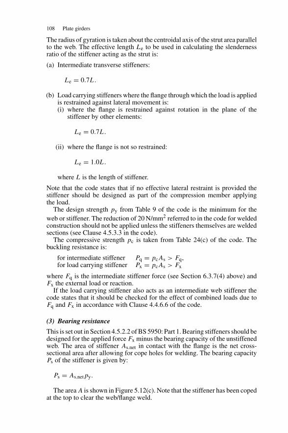
108 Plate girders
The radius of gyration is taken about the centroidal axis of the strut area parallelto the web. The effective length Le to be used in calculating the slendernessratio of the stiffener acting as the strut is:
(a) Intermediate transverse stiffeners:
Le = 0.7L.
(b) Load carrying stiffeners where the flange through which the load is appliedis restrained against lateral movement is:(i) where the flange is restrained against rotation in the plane of the
stiffener by other elements:
Le = 0.7L.
(ii) where the flange is not so restrained:
Le = 1.0L.
where L is the length of stiffener.
Note that the code states that if no effective lateral restraint is provided thestiffener should be designed as part of the compression member applyingthe load.
The design strength py from Table 9 of the code is the minimum for theweb or stiffener. The reduction of 20 N/mm2 referred to in the code for weldedconstruction should not be applied unless the stiffeners themselves are weldedsections (see Clause 4.5.3.3 in the code).
The compressive strength pc is taken from Table 24(c) of the code. Thebuckling resistance is:
for intermediate stiffener Pq = pcAs > Fq,for load carrying stiffener Px = pcAs > Fx
where Fq is the intermediate stiffener force (see Section 6.3.7(4) above) andFx the external load or reaction.
If the load carrying stiffener also acts as an intermediate web stiffener thecode states that it should be checked for the effect of combined loads due toFq and Fx in accordance with Clause 4.4.6.6 of the code.
(3) Bearing resistance
This is set out in Section 4.5.2.2 of BS 5950: Part 1. Bearing stiffeners should bedesigned for the applied force Fx minus the bearing capacity of the unstiffenedweb. The area of stiffener As.net in contact with the flange is the net cross-sectional area after allowing for cope holes for welding. The bearing capacityPs of the stiffener is given by:
Ps = As.netpy.
The area A is shown in Figure 5.12(c). Note that the stiffener has been copedat the top to clear the web/flange weld.
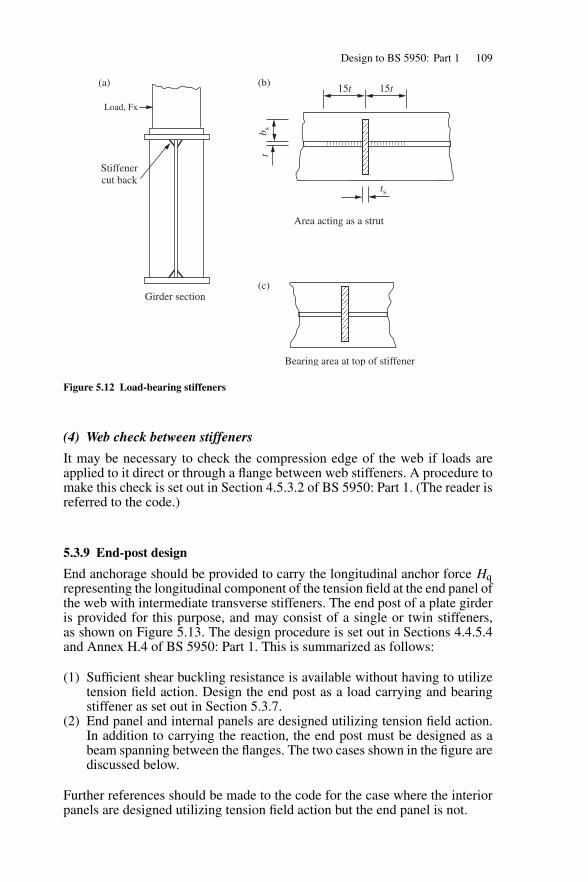
Design to BS 5950: Part 1 109
Load, Fx
(a) (b)
(c)
b st
Stiffenercut back
ts
15t 15t
Area acting as a strut
Bearing area at top of stiffener
Girder section
Figure 5.12 Load-bearing stiffeners
(4) Web check between stiffeners
It may be necessary to check the compression edge of the web if loads areapplied to it direct or through a flange between web stiffeners. A procedure tomake this check is set out in Section 4.5.3.2 of BS 5950: Part 1. (The reader isreferred to the code.)
5.3.9 End-post design
End anchorage should be provided to carry the longitudinal anchor force Hqrepresenting the longitudinal component of the tension field at the end panel ofthe web with intermediate transverse stiffeners. The end post of a plate girderis provided for this purpose, and may consist of a single or twin stiffeners,as shown on Figure 5.13. The design procedure is set out in Sections 4.4.5.4and Annex H.4 of BS 5950: Part 1. This is summarized as follows:
(1) Sufficient shear buckling resistance is available without having to utilizetension field action. Design the end post as a load carrying and bearingstiffener as set out in Section 5.3.7.
(2) End panel and internal panels are designed utilizing tension field action.In addition to carrying the reaction, the end post must be designed as abeam spanning between the flanges. The two cases shown in the figure arediscussed below.
Further references should be made to the code for the case where the interiorpanels are designed utilizing tension field action but the end panel is not.
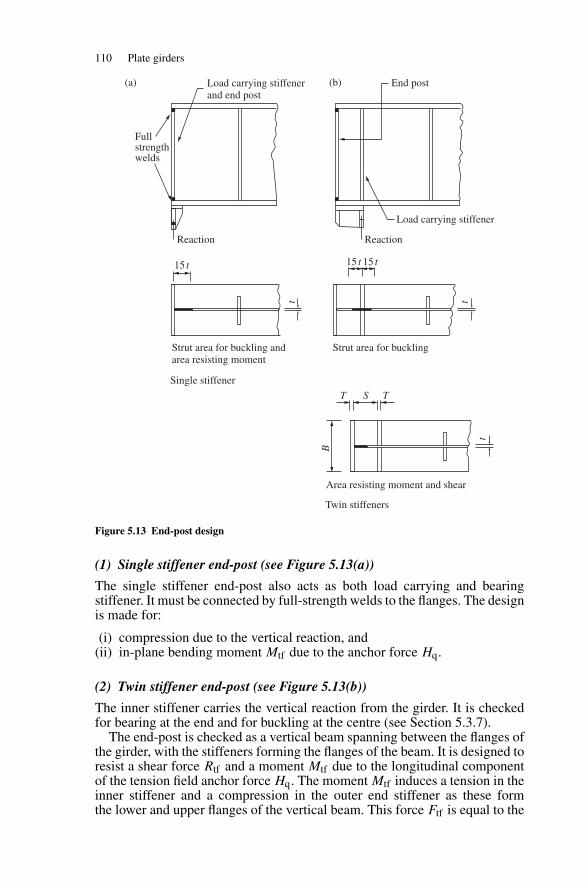
110 Plate girders
Load carrying stiffenerand end post
Load carrying stiffener
End post
Fullstrengthwelds
Reaction
15 t 15 t 15 t
Reaction
T TS
Strut area for buckling andarea resisting moment
Area resisting moment and shear
Strut area for buckling
Single stiffener
B
t
t
t
Twin stiffeners
(a) (b)
Figure 5.13 End-post design
(1) Single stiffener end-post (see Figure 5.13(a))
The single stiffener end-post also acts as both load carrying and bearingstiffener. It must be connected by full-strength welds to the flanges. The designis made for:
(i) compression due to the vertical reaction, and(ii) in-plane bending moment Mtf due to the anchor force Hq.
(2) Twin stiffener end-post (see Figure 5.13(b))
The inner stiffener carries the vertical reaction from the girder. It is checkedfor bearing at the end and for buckling at the centre (see Section 5.3.7).
The end-post is checked as a vertical beam spanning between the flanges ofthe girder, with the stiffeners forming the flanges of the beam. It is designed toresist a shear force Rtf and a moment Mtf due to the longitudinal componentof the tension field anchor force Hq. The moment Mtf induces a tension in theinner stiffener and a compression in the outer end stiffener as these formthe lower and upper flanges of the vertical beam. This force Ftf is equal to the
Design to BS 5950: Part 1 111
moment divided by the ‘depth S’ of the vertical beam. Thus, the stiffener mustalso be designed to resist this force, plus any force arising from the reactionof the plate girder.The expressions to derive the shear, moment and compressive force given inthe code are:
Shear Rtf = 0.75HqMoment Mtf = 0.15HqdForce Ftf = Mtf/S
The anchor force Hq from the tension field:
(i) if the web is fully loaded in shear (Fv ≥ Vw)
Hq = 0.5dtpy(1 − Vcr/Pv)0.5
(ii) if the web is not fully loaded in shear (Fv < Vw)
Hq = 0.5dtpy
[Fv − Vcr
Vw − Vcr
](1 − Vcr/Pv)
0.5
where, d is the depth of the web, Fv the maximum shear force, Pv theshear capacity, t the web thickness, Vcr the critical shear buckling resist-ance and Vw the simple shear buckling resistance.
The shear capacity of the end-post is:
Pv = 0.6pySt
where S is the length of web between stiffeners and t the web thickness. Theshear capacity Pv must exceed the shear from the tension field Rtf .
The moment capacity of the end-post at the centre of the girder, assumingthat the flanges resist the whole moment, is:
Mcx = pyBT (S + T )
where B is the stiffener width and T the stiffener thickness. Note that propor-tions should be selected so that the plates selected are Class 3 semi-compact asa minimum requirement. The moment capacity Mcx must exceed the momentdue to tension field action Mtf .
The welds between the stiffener and web must be designed to carry thereaction and the shear from the end-post beam action.
The application of the design procedure is given in the example inSection 6.4.
5.3.10 Flange to web welds
Fillet welds are used for the flange to web welds (see Figure 5.14). The weldsare designed for the horizontal shear per weld:
= FAy/2Ix
where F is the applied shear, A the area of flange, y the distance of the centroidof A from the centroid of the girder and Ix the moment of inertia of the girderabout the x–x axis.
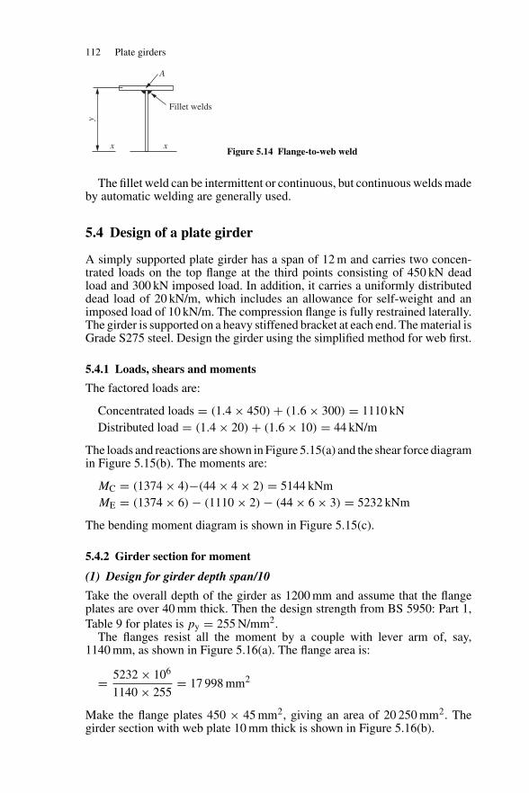
112 Plate girders
y
x x
A
Fillet welds
Figure 5.14 Flange-to-web weld
The fillet weld can be intermittent or continuous, but continuous welds madeby automatic welding are generally used.
5.4 Design of a plate girder
A simply supported plate girder has a span of 12 m and carries two concen-trated loads on the top flange at the third points consisting of 450 kN deadload and 300 kN imposed load. In addition, it carries a uniformly distributeddead load of 20 kN/m, which includes an allowance for self-weight and animposed load of 10 kN/m. The compression flange is fully restrained laterally.The girder is supported on a heavy stiffened bracket at each end. The material isGrade S275 steel. Design the girder using the simplified method for web first.
5.4.1 Loads, shears and moments
The factored loads are:
Concentrated loads = (1.4 × 450) + (1.6 × 300) = 1110 kNDistributed load = (1.4 × 20) + (1.6 × 10) = 44 kN/m
The loads and reactions are shown in Figure 5.15(a) and the shear force diagramin Figure 5.15(b). The moments are:
MC = (1374 × 4)−(44 × 4 × 2) = 5144 kNmME = (1374 × 6) − (1110 × 2) − (44 × 6 × 3) = 5232 kNm
The bending moment diagram is shown in Figure 5.15(c).
5.4.2 Girder section for moment
(1) Design for girder depth span/10
Take the overall depth of the girder as 1200 mm and assume that the flangeplates are over 40 mm thick. Then the design strength from BS 5950: Part 1,Table 9 for plates is py = 255 N/mm2.
The flanges resist all the moment by a couple with lever arm of, say,1140 mm, as shown in Figure 5.16(a). The flange area is:
= 5232 × 106
1140 × 255= 17 998 mm2
Make the flange plates 450 × 45 mm2, giving an area of 20 250 mm2. Thegirder section with web plate 10 mm thick is shown in Figure 5.16(b).
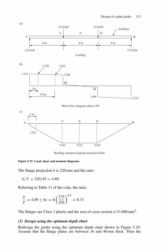
Design of a plate girder 113
AC
1110 kN 1110 kN44 kN/m
4 m
1374 kN
1 374
1374 kN
4 m
1 330 1242
1198
1198 1374
88
1 m
3.0 m
88
Loading
4 m
E DB
Shear force diagram shears-kN
Bending moment diagram moments-kNm
A C
1352
51445144 5232
E D B
1 m
(a)
(b)
(c)
Figure 5.15 Load, shear and moment diagrams
The flange projection b is 220 mm and the ratio:
b/T = 220/45 = 4.89.
Referring to Table 11 of the code, the ratio:
b
T= 4.89 ≤ 8ε = 8
(275
255
)0.5
= 8.31
The flanges are Class 1 plastic and the area of cross section is 51 600 mm2.
(2) Design using the optimum depth chart
Redesign the girder using the optimum depth chart shown in Figure 5.10.Assume that the flange plates are between 16 and 40 mm thick. Then the
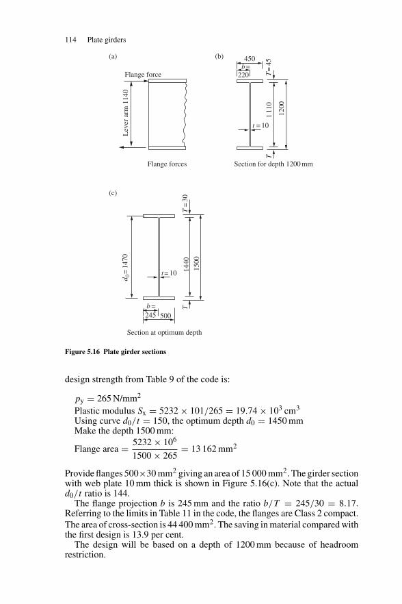
114 Plate girders
Flange forces
Flange force
Lev
er a
rm 1
140
450
220b=
T=
45T
t = 10
1200
111
0
Section for depth 1200 mm
500245b =
t= 10
T=
30T
1500
d 0=
1470
1440
Section at optimum depth
(a)
(c)
(b)
Figure 5.16 Plate girder sections
design strength from Table 9 of the code is:
py = 265 N/mm2
Plastic modulus Sx = 5232 × 101/265 = 19.74 × 103 cm3
Using curve d0/t = 150, the optimum depth d0 = 1450 mmMake the depth 1500 mm:
Flange area = 5232 × 106
1500 × 265= 13 162 mm2
Provide flanges 500×30 mm2 giving an area of 15 000 mm2. The girder sectionwith web plate 10 mm thick is shown in Figure 5.16(c). Note that the actuald0/t ratio is 144.
The flange projection b is 245 mm and the ratio b/T = 245/30 = 8.17.Referring to the limits in Table 11 in the code, the flanges are Class 2 compact.The area of cross-section is 44 400 mm2. The saving in material compared withthe first design is 13.9 per cent.
The design will be based on a depth of 1200 mm because of headroomrestriction.
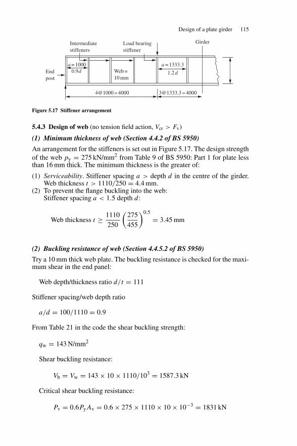
Design of a plate girder 115
Intermediatestiffeners
Endpost
a = 1000 a = 1333.3
[email protected] = 40004@1000 = 4000
0.9d 1.2 dWeb =10 mm
Load bearingstiffener
Girder
Figure 5.17 Stiffener arrangement
5.4.3 Design of web (no tension field action, Vcr > Fv)
(1) Minimum thickness of web (Section 4.4.2 of BS 5950)
An arrangement for the stiffeners is set out in Figure 5.17. The design strengthof the web py = 275 kN/mm2 from Table 9 of BS 5950: Part 1 for plate lessthan 16 mm thick. The minimum thickness is the greater of:
(1) Serviceability. Stiffener spacing a > depth d in the centre of the girder.Web thickness t > 1110/250 = 4.4 mm.
(2) To prevent the flange buckling into the web:Stiffener spacing a < 1.5 depth d:
Web thickness t ≥ 1110
250
(275
455
)0.5
= 3.45 mm
(2) Buckling resistance of web (Section 4.4.5.2 of BS 5950)
Try a 10 mm thick web plate. The buckling resistance is checked for the maxi-mum shear in the end panel:
Web depth/thickness ratio d/t = 111
Stiffener spacing/web depth ratio
a/d = 100/1110 = 0.9
From Table 21 in the code the shear buckling strength:
qw = 143 N/mm2
Shear buckling resistance:
Vb = Vw = 143 × 10 × 1110/103 = 1587.3 kN
Critical shear buckling resistance:
Pv = 0.6PyAv = 0.6 × 275 × 1110 × 10 × 10−3 = 1831 kN
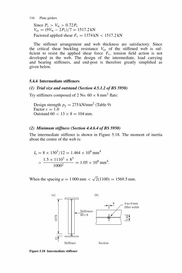
116 Plate girders
Since Pv > Vw > 0.72PvVcr = (9Vw − 2Pv)/7 = 1517.2 kNFactored applied shear Fv = 1374 kN < 1517.2 kN
The stiffener arrangement and web thickness are satisfactory. Sincethe critical shear buckling resistance Vcr of the stiffened web is suf-ficient to resist the applied shear force Fv, tension field action is notdeveloped in the web. The design of the intermediate, load carryingand bearing stiffeners, and end-post is therefore greatly simplified asgiven below.
5.4.4 Intermediate stiffeners
(1) Trial size and outstand (Section 4.5.1.2 of BS 5950)
Try stiffeners composed of 2 No. 60 × 8 mm2 flats:
Design strength py = 275 kN/mm2 (Table 9)Factor ε = 1.0Outstand 60 < 13 × 8 = 104 mm.
(2) Minimum stiffness (Section 4.4.6.4 of BS 5950)
The intermediate stiffener is shown in Figure 5.18. The moment of inertiaabout the centre of the web is:
Is = 8 × 1303/12 = 1.464 × 106 mm4
>1.5 × 11103 × 83
10002= 1.05 × 106 mm4.
When the spacing a = 1 000 mm <√
2(1100) = 1569.5 mm.
Stiffener
1078
32
Stiffeners60 × 8
4 no.6 mmfillet welds
130
8
Section
(a) (b)
Figure 5.18 Intermediate stiffener
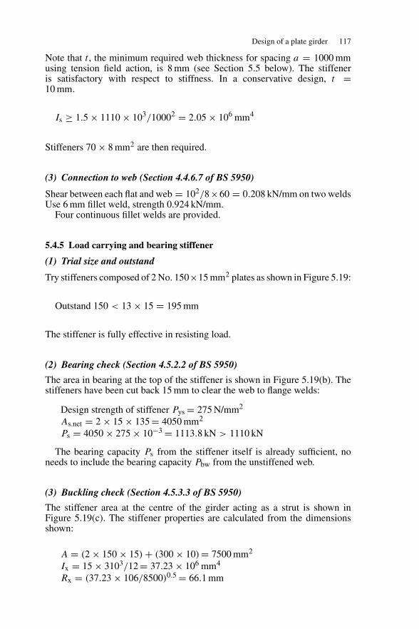
Design of a plate girder 117
Note that t , the minimum required web thickness for spacing a = 1000 mmusing tension field action, is 8 mm (see Section 5.5 below). The stiffeneris satisfactory with respect to stiffness. In a conservative design, t =10 mm.
Is ≥ 1.5 × 1110 × 103/10002 = 2.05 × 106 mm4
Stiffeners 70 × 8 mm2 are then required.
(3) Connection to web (Section 4.4.6.7 of BS 5950)
Shear between each flat and web = 102/8×60 = 0.208 kN/mm on two weldsUse 6 mm fillet weld, strength 0.924 kN/mm.
Four continuous fillet welds are provided.
5.4.5 Load carrying and bearing stiffener
(1) Trial size and outstand
Try stiffeners composed of 2 No. 150×15 mm2 plates as shown in Figure 5.19:
Outstand 150 < 13 × 15 = 195 mm
The stiffener is fully effective in resisting load.
(2) Bearing check (Section 4.5.2.2 of BS 5950)
The area in bearing at the top of the stiffener is shown in Figure 5.19(b). Thestiffeners have been cut back 15 mm to clear the web to flange welds:
Design strength of stiffener Pys = 275 N/mm2
As.net = 2 × 15 × 135 = 4050 mm2
Ps = 4050 × 275 × 10−3 = 1113.8 kN > 1110 kN
The bearing capacity Ps from the stiffener itself is already sufficient, noneeds to include the bearing capacity Pbw from the unstiffened web.
(3) Buckling check (Section 4.5.3.3 of BS 5950)
The stiffener area at the centre of the girder acting as a strut is shown inFigure 5.19(c). The stiffener properties are calculated from the dimensionsshown:
A = (2 × 150 × 15) + (300 × 10) = 7500 mm2
Ix = 15 × 3103/12 = 37.23 × 106 mm4
Rx = (37.23 × 10⁶/8500)0.5 = 66.1 mm
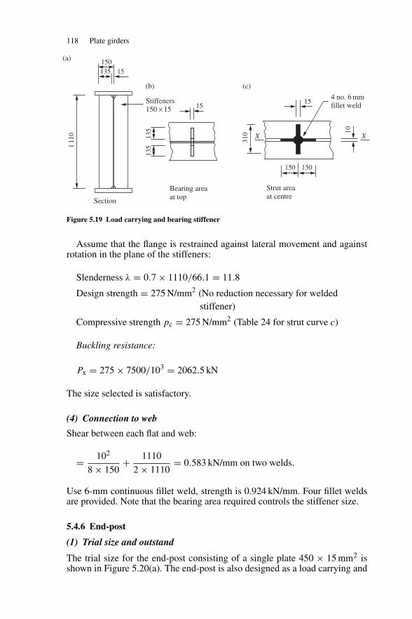
118 Plate girders
Section
111
0
Stiffeners150 × 15
15150135
Bearing areaat top
15
135
135
310
Strut areaat centre
X X
15
150 150
10
4 no. 6 mmfillet weld
(a)
(b) (c)
Figure 5.19 Load carrying and bearing stiffener
Assume that the flange is restrained against lateral movement and againstrotation in the plane of the stiffeners:
Slenderness λ = 0.7 × 1110/66.1 = 11.8
Design strength = 275 N/mm2 (No reduction necessary for weldedstiffener)
Compressive strength pc = 275 N/mm2 (Table 24 for strut curve c)
Buckling resistance:
Px = 275 × 7500/103 = 2062.5 kN
The size selected is satisfactory.
(4) Connection to web
Shear between each flat and web:
= 102
8 × 150+ 1110
2 × 1110= 0.583 kN/mm on two welds.
Use 6-mm continuous fillet weld, strength is 0.924 kN/mm. Four fillet weldsare provided. Note that the bearing area required controls the stiffener size.
5.4.6 End-post
(1) Trial size and outstand
The trial size for the end-post consisting of a single plate 450 × 15 mm2 isshown in Figure 5.20(a). The end-post is also designed as a load carrying and
Design of a plate girder 119
15
450
Bearing areaat bottom
111
0
Section1374 kN
End reaction
192.5
150
X X
2 no. 6 mmfillet weld
10
Cor
e 40
0
7.5
Strut areaat centre
(a) (b) (c) (d)
Figure 5.20 End-post
bearing stiffener because no tension field action is necessary in the end panel,no anchorage and hence no anchor force is developed.
Outstand = 220 mm > 13 × 15 = 195 mm
< 19 × 15 = 285 mm
Base design on a stiffener core 400 mm × 15 mm
Design strength = 275 N/mm2 (Table 9)
(2) Bearing check
The bearing area is shown in Figure 5.20(c):
As.net = 15 × 400 = 6000 mm2
Ps = 6000 × 275 × 10−3 = 1650 kN > 1374 kN (satisfactory)
(3) Buckling check
The area at the centre line acting as a strut is shown in Figure 5.20(d):
A = (400 × 15) + (142.5 × 10) = 7425 mm2
Ix = 15 × 4003/12 = 80 × 106 mm4
rx = (80.0 × 10⁶/7925)0.5 = 100.4λ = 0.7 × 1110/100.4 = 7.7pc = 275 N/mm2 (Table 24 for strut curve c)Px = 275 × 7425/103 = 2041.9 kNLoad carried = 1374 kN
The size is satisfactory.
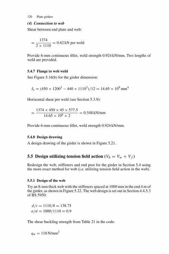
120 Plate girders
(4) Connection to web
Shear between end plate and web:
= 1374
2 × 1110= 0.62 kN per weld
Provide 6-mm continuous fillet, weld strength 0.924 kN/mm. Two lengths ofweld are provided.
5.4.7 Flange to web weld
See Figure 5.16(b) for the girder dimension:
Ix = (450 × 12003 − 440 × 11103)/12 = 14.65 × 109 mm4
Horizontal shear per weld (see Section 5.3.9):
= 1374 × 450 × 45 × 577.5
14.65 × 109 × 2= 0.548 kN/mm
Provide 6-mm continuous fillet, weld strength 0.924 kN/mm.
5.4.8 Design drawing
A design drawing of the girder is shown in Figure 5.21.
5.5 Design utilizing tension field action (Vb = Vw + Vf )
Redesign the web, stiffeners and end post for the girder in Section 5.4 usingthe more exact method for web (i.e. utilizing tension field action in the web).
5.5.1 Design of the web
Try an 8-mm thick web with the stiffeners spaced at 1000 mm in the end 4 m ofthe girder, as shown in Figure 5.22. The web design is set out in Section 4.4.5.3of BS 5950:
d/t = 1110/8 = 138.75a/d = 1000/1110 = 0.9
The shear buckling strength from Table 21 in the code:
qw = 118 N/mm2
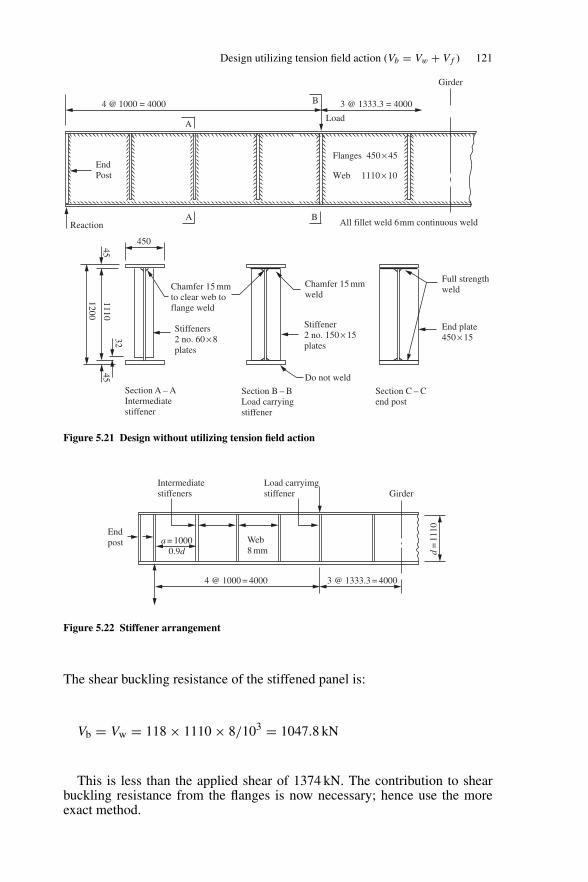
Design utilizing tension field action (Vb = Vw + Vf ) 121
4 @ 1000 = 4000 3 @ 1333.3 = 4000
A
A B
EndPost
Reaction All fillet weld 6mm continuous weld
B
Load
Flanges 450 × 45
Web 1110 × 10
Girder
Section A – AIntermediatestiffener
450
1110
1200
4545
32
Stiffeners2 no. 60 × 8plates
Chamfer 15 mmweld
Full strengthweld
End plate450 × 15
Do not weld
Stiffener2 no. 150 × 15plates
Chamfer 15 mmto clear web toflange weld
Section B – BLoad carrying stiffener
Section C – Cend post
Figure 5.21 Design without utilizing tension field action
Intermediatestiffeners
Endpost a = 1000
0.9dWeb8 mm
Load carryimgstiffener Girder
d=
1110
3 @ 1333.3 = 40004 @ 1000 = 4000
Figure 5.22 Stiffener arrangement
The shear buckling resistance of the stiffened panel is:
Vb = Vw = 118 × 1110 × 8/103 = 1047.8 kN
This is less than the applied shear of 1374 kN. The contribution to shearbuckling resistance from the flanges is now necessary; hence use the moreexact method.
122 Plate girders
Vb = Vw + Vf but Vb ≤ Pv
The plastic moment capacity of the flange where the design strength of theflange pyf = 255 N/mm2:
Mpf = 255 × 450 × 452
4 × 106= 58.1 kNm
The plastic moment capacity of the web where the design strength of the webpyw = 275 N/mm2:
Mpw = 275 × 8 × 11102
4 × 106= 677.6 kNm
The maximum moment in the end panel is 1352 kNm (see Figure 5.15(c)). Themean longitudinal stress in the flange due to moment:
ff = 1352 × 106
1155 × 45 × 450= 57.8 N/mm2
Pv = 0.6PyAv = 0.6 × 275 × 8 × 1110 × 10−3 = 1465.2 kN
Since the flanges are not fully stressed (ff < Pyf), Vb = Vw +Vf but Vb ≤ Pv.The flange-dependent shear buckling resistance:
Vf =Pv (d/a)
[1 − (
ff/pyf)2
]1 + 0.15
(Mpw/Mpf
)= 1465.2(1100/1000)
[1 − (57.8/255)2
]1 + 0.15(677.6/58.1)
= 556.1 kN
The total shear buckling resistance:
Vb = 1047.8 + 556.1 = 1603.9 ≤ 1465.2 kN
This exceeds the applied shear of 1374 kN (hence, satisfactory).
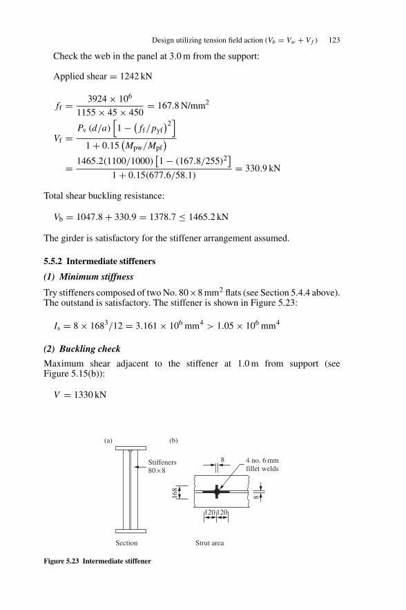
Design utilizing tension field action (Vb = Vw + Vf ) 123
Check the web in the panel at 3.0 m from the support:
Applied shear = 1242 kN
ff = 3924 × 106
1155 × 45 × 450= 167.8 N/mm2
Vf =Pv (d/a)
[1 − (
ff/pyf)2
]1 + 0.15
(Mpw/Mpf
)= 1465.2(1100/1000)
[1 − (167.8/255)2
]1 + 0.15(677.6/58.1)
= 330.9 kN
Total shear buckling resistance:
Vb = 1047.8 + 330.9 = 1378.7 ≤ 1465.2 kN
The girder is satisfactory for the stiffener arrangement assumed.
5.5.2 Intermediate stiffeners
(1) Minimum stiffness
Try stiffeners composed of two No. 80×8 mm2 flats (see Section 5.4.4 above).The outstand is satisfactory. The stiffener is shown in Figure 5.23:
Is = 8 × 1683/12 = 3.161 × 106 mm4 > 1.05 × 106 mm4
(2) Buckling check
Maximum shear adjacent to the stiffener at 1.0 m from support (seeFigure 5.15(b)):
V = 1330 kN
8 4 no. 6 mmfillet welds
8168
120
Stiffeners80 × 8
Section
(a) (b)
120
Strut area
Figure 5.23 Intermediate stiffener
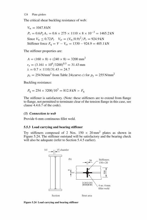
124 Plate girders
The critical shear buckling resistance of web:
Vw = 1047.8 kN
Pv = 0.6PyAv = 0.6 × 275 × 1110 × 8 × 10−3 = 1465.2 kN
Since Vw ≤ 0.72Pv Vcr = (Vw/0.9)2/Pv = 924.9 kNStiffener force Fq = V − Vcr = 1330 − 924.9 = 405.1 kN
The stiffener properties are:
A = (160 × 8) + (240 × 8) = 3200 mm2
rx = (3.161 × 10⁶/3200)0.5 = 31.43 mmλ = 0.7 × 1110/31.43 = 24.7
pc = 254 N/mm2 from Table 24(curve c) for py = 255 N/mm2
Buckling resistance:
Pq = 254 × 3200/103 = 812.8 kN > Fq
The stiffener is satisfactory. (Note: these stiffeners are to extend from flangeto flange, not permitted to terminate clear of the tension flange in this case, seeclause 4.4.6.7 of the code).
(3) Connection to web
Provide 6-mm continuous fillet weld.
5.5.3 Load carrying and bearing stiffener
Try stiffeners composed of 2 Nos. 150 × 20 mm2 plates as shown inFigure 5.24. The stiffener outstand will be satisfactory and the bearing checkwill also be adequate (refer to Section 5.4.5 earlier).
Stiffeners150 × 20
4 no. 6 mmfillet weld
20
15 chamfer(a)
(b)
8
120 120
308
Section Strut area
Figure 5.24 Load carrying and bearing stiffener
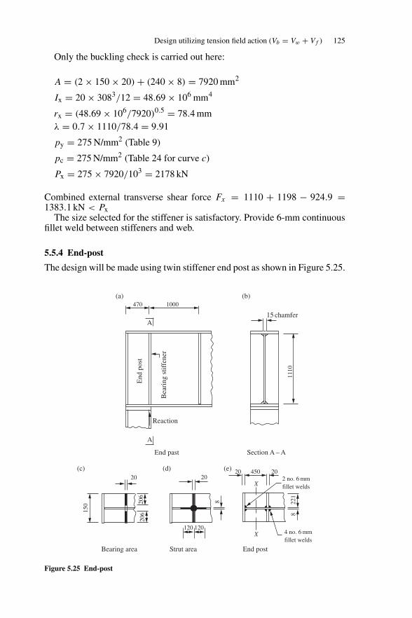
Design utilizing tension field action (Vb = Vw + Vf ) 125
Only the buckling check is carried out here:
A = (2 × 150 × 20) + (240 × 8) = 7920 mm2
Ix = 20 × 3083/12 = 48.69 × 106 mm4
rx = (48.69 × 10⁶/7920)0.5 = 78.4 mmλ = 0.7 × 1110/78.4 = 9.91
py = 275 N/mm2 (Table 9)
pc = 275 N/mm2 (Table 24 for curve c)
Px = 275 × 7920/103 = 2178 kN
Combined external transverse shear force Fx = 1110 + 1198 − 924.9 =1383.1 kN < Px
The size selected for the stiffener is satisfactory. Provide 6-mm continuousfillet weld between stiffeners and web.
5.5.4 End-post
The design will be made using twin stiffener end post as shown in Figure 5.25.
Bea
ring
stif
fene
r
End
pos
t
Reaction
A
470 1000
A
1110
15 chamfer
20 20
221
8
8206
20615
0
2 no. 6 mmfillet welds
4 no. 6 mmfillet welds
X
X
4502020
120 120
End past
Bearing area Strut area End post
Section A – A
(a) (b)
(c) (d) (e)
Figure 5.25 End-post
126 Plate girders
(1) Bearing check
The reaction is carried on the inner stiffener. The stiffener ends are chamferedto clear the web to flange welds and the bearing area is shown in Figure 5.25(c).
pys = 265 N/mm2 (Table 9)
As.net = 2 × 20 × 206 = 8240 mm2
Ps = 265 × 8240 = 2183.6 kN > 1374 kN
Note that outstand = 221 mm < 13 × 20
(275
265
)0.5
= 264.9 mm
The full area of the stiffener is effective and the stiffener is satisfactory forbearing.
(2) Buckling check
The area at the centre line of the bearing stiffener acting as a strut is shown inFigure 5.25(d):
A = (2 × 20 × 221) + (2 × 120 × 8)= 10760 mm2
Ix = 20 × 4503/12= 151.87 × 106 mm4
rx = (151.87 × 10⁶/10760)0.5= 118.8 mmλ = 0.7 × 1110/118.8= 6.54
pc = 265 N/mm2 (Table 27 curve c)
Px = 265 × 10760/103= 2851 kN
This exceeds the reaction of 1374 kN. Therefore satisfactory.
(3) Shear and moment from the tension field anchor force
Refer to Section 4.4.5.4 and Annex H.4 of BS 5950.
d/t = 138.75 and a/d = 0.9
From Table 21, shear buckling strength qw = 118 N/mm2.The simple shear buckling resistance Vw = 118 × 1110 × 8/103 =
1047.8 kNApplied shear force in the end panel: Fv = 1374 kN
Since Fv > Vw, the web is fully loaded in shear and the tension fieldlongitudinal anchor force Hq cannot be reduced. This anchor force is:
Hq = 0.5 dtpy(1 − Vcr/Pv)0.5
= 0.5 × 1100 × 8 × 275 × 10−3{1 − (924.9/1465.2)}0.5
= 734.8 kN
Design utilizing tension field action (Vb = Vw + Vf ) 127
Shear from the tension field force:
Rtf = 0.75 Hq = 551.1 kN
Moment in the end-post:
Mtf = 0.15 × 734.8 × 1110
103= 121.2 kNm
(4) Shear capacity of end-post
The end-post is shown in Figure 5.25(e). The web 450 × 8 mm2 resists shear(see Table 11 of code for limiting proportions for webs):
d/t = 450/8 = 56.25 < 80ε
The section is Class 1 Plastic
Shear capacity, Pv = 0.6 × 275 × 450 × 8/103 = 594 kN
The end-post is satisfactory with respect to shear.
(5) Moment capacity
Referring to Figure 5.25(e), the flange proportions are:
b/T = 221/20 = 11.05
Design strength py = 265 N/mm2 (Table 9 in the code).From Table 11, b/T < 13ε = 13.2. The flanges are Class 3 semi-compact.
Moment capacity check at the centre of the girder:
Mcx = 265 × 450 × 20 × 470/106 = 1120.9 kNm.
This exceeds the moment from tension field action of 121.1 kNm.
(6) Additional stiffener force due to moment
The moment Mtf induces additional compressive force Ftf in the inner stiffenerwhich must be checked for (see Section H.4.3 of the code).
Ftf = Mtf/ae where ae is the centre-to-centre of the twin stiffeners.
Ftf = 121.1 × 10³/470 = 257.7 kN
The inner twin stiffener is still satisfactory for bearing and buckling with thisadditional force (see Section 6.5.4 (1) and (2)).
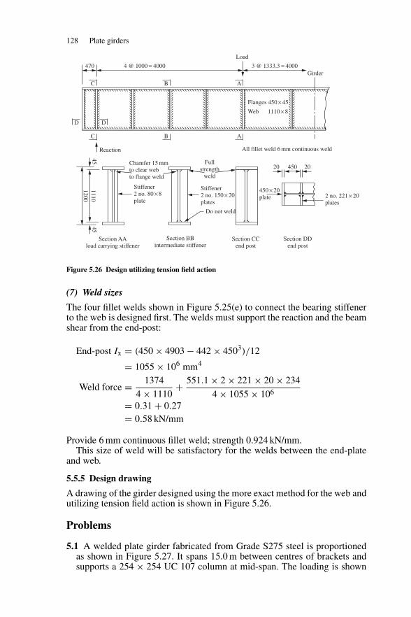
128 Plate girders
4 @ 1000 = 4000 3 @ 1333.3 = 4000470
Load
Girder
Flanges 450 × 45
Web 1110 × 8
C
D D
C B A
B A
Reaction All fillet weld 6 mm continuous weld
Chamfer 15 mmto clear webto flange weld
Stiffener2 no. 80 × 8plate
Fullstrength
weld
Stiffener2 no. 150 × 20plates
Do not weld
20 450 20
450 × 20plate 2 no. 221 × 20
plates
4545
11101200
Section AAload carrying stiffener
Section BBintermediate stiffener
Section CCend post
Section DDend post
Figure 5.26 Design utilizing tension field action
(7) Weld sizes
The four fillet welds shown in Figure 5.25(e) to connect the bearing stiffenerto the web is designed first. The welds must support the reaction and the beamshear from the end-post:
End-post Ix = (450 × 4903 − 442 × 4503)/12
= 1055 × 106 mm4
Weld force = 1374
4 × 1110+ 551.1 × 2 × 221 × 20 × 234
4 × 1055 × 106
= 0.31 + 0.27= 0.58 kN/mm
Provide 6 mm continuous fillet weld; strength 0.924 kN/mm.This size of weld will be satisfactory for the welds between the end-plate
and web.
5.5.5 Design drawing
A drawing of the girder designed using the more exact method for the web andutilizing tension field action is shown in Figure 5.26.
Problems
5.1 A welded plate girder fabricated from Grade S275 steel is proportionedas shown in Figure 5.27. It spans 15.0 m between centres of brackets andsupports a 254 × 254 UC 107 column at mid-span. The loading is shown
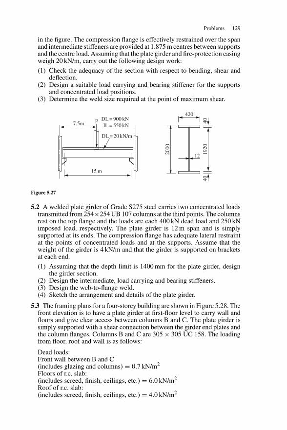
Problems 129
in the figure. The compression flange is effectively restrained over the spanand intermediate stiffeners are provided at 1.875 m centres between supportsand the centre load. Assuming that the plate girder and fire-protection casingweigh 20 kN/m, carry out the following design work:
(1) Check the adequacy of the section with respect to bending, shear anddeflection.
(2) Design a suitable load carrying and bearing stiffener for the supportsand concentrated load positions.
(3) Determine the weld size required at the point of maximum shear.
7.5m P DL = 900 kN IL = 550 kN
DL = 20 kN/m
15 m20
00
420
12 1920
4040
Figure 5.27
5.2 A welded plate girder of Grade S275 steel carries two concentrated loadstransmitted from 254×254 UB 107 columns at the third points. The columnsrest on the top flange and the loads are each 400 kN dead load and 250 kNimposed load, respectively. The plate girder is 12 m span and is simplysupported at its ends. The compression flange has adequate lateral restraintat the points of concentrated loads and at the supports. Assume that theweight of the girder is 4 kN/m and that the girder is supported on bracketsat each end.
(1) Assuming that the depth limit is 1400 mm for the plate girder, designthe girder section.
(2) Design the intermediate, load carrying and bearing stiffeners.(3) Design the web-to-flange weld.(4) Sketch the arrangement and details of the plate girder.
5.3 The framing plans for a four-storey building are shown in Figure 5.28. Thefront elevation is to have a plate girder at first-floor level to carry wall andfloors and give clear access between columns B and C. The plate girder issimply supported with a shear connection between the girder end plates andthe column flanges. Columns B and C are 305 × 305 UC 158. The loadingfrom floor, roof and wall is as follows:
Dead loads:Front wall between B and C(includes glazing and columns) = 0.7 kN/m2
Floors of r.c. slab:(includes screed, finish, ceilings, etc.) = 6.0 kN/m2
Roof of r.c. slab:(includes screed, finish, ceilings, etc.) = 4.0 kN/m2
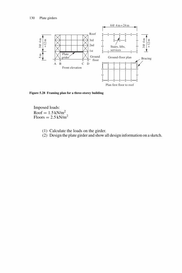
130 Plate girders
3@ 4
m
=12
m
5m
A B C D
Plategrider
Roof
3rd
2nd
1st
Ground floor
Front elevation
6@ 4 m = 24 m
Stairs, lifts,services
3@ 4
m
=12
m
Ground-floor plan Bracing
Plan first floor to roof
Figure 5.28 Framing plan for a three-storey building
Imposed loads:Roof = 1.5 kN/m2
Floors = 2.5 kN/m2
(1) Calculate the loads on the girder.(2) Design the plate girder and show all design information on a sketch.
6
Tension members
6.1 Uses, types and design considerations
6.1.1 Uses and types
A tension member transmits a direct axial pull between two points in astructural frame. A rope supporting a load or cables in a suspension bridgeare obvious examples. In building frames, tension members occur as:
(1) tension chords and internal ties in trusses;(2) tension bracing members;(3) hangers supporting floor beams.
Examples of these members are shown in Figure 6.1.The main sections used for tension members are:
(1) open sections such as angles, channels, tees, joists, universal beams andcolumns;
(2) closed sections. Circular, square and rectangular hollow sections;(3) compound and built-up sections. Double angles and double channels are
common compound sections used in trusses. Built-up sections are used inbridge trusses.
Round bars, flats and cables can also be used for tension members where thereis no reversal of load. These elements as well as single angles are used incross bracing, where the tension diagonal only is effective in carrying a load,as shown in Figure 6.1(d). Common tension member sections are shown inFigure 6.2.
6.1.2 Design considerations
Theoretically, the tension member is the most efficient structural element, butits efficiency may be seriously affected by the following factors:
(1) The end connections. For example, bolt holes reduce the member section.(2) The member may be subject to reversal of load, in which case it is liable
to buckle because a tension member is more slender than a compressionmember.
131
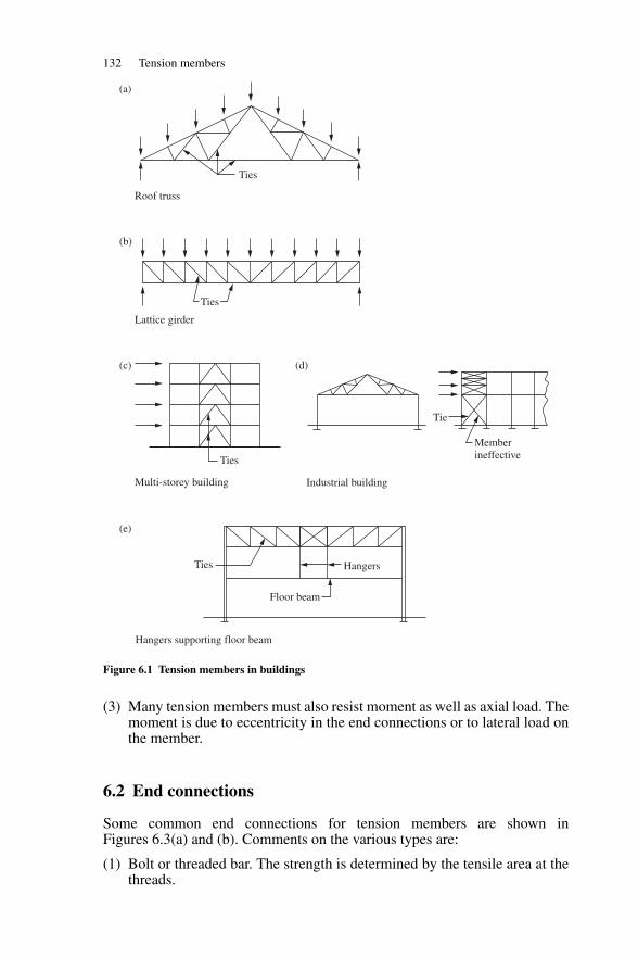
132 Tension members
Ties
Ties
Ties
Tie
Memberineffective
Ties Hangers
Floor beam
Roof truss
(a)
(b)
(c)
(e)
(d)
Lattice girder
Multi-storey building Industrial building
Hangers supporting floor beam
Figure 6.1 Tension members in buildings
(3) Many tension members must also resist moment as well as axial load. Themoment is due to eccentricity in the end connections or to lateral load onthe member.
6.2 End connections
Some common end connections for tension members are shown inFigures 6.3(a) and (b). Comments on the various types are:
(1) Bolt or threaded bar. The strength is determined by the tensile area at thethreads.
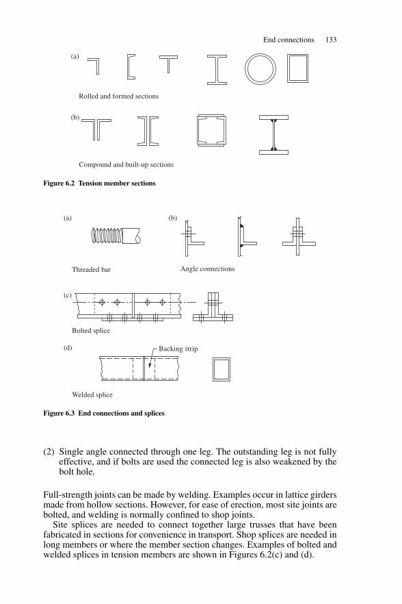
End connections 133
Rolled and formed sections
Compound and built-up sections
(a)
(b)
Figure 6.2 Tension member sections
Backing strip
Threaded bar Angle connections
Bolted splice
Welded splice
(a) (b)
(c)
(d)
Figure 6.3 End connections and splices
(2) Single angle connected through one leg. The outstanding leg is not fullyeffective, and if bolts are used the connected leg is also weakened by thebolt hole.
Full-strength joints can be made by welding. Examples occur in lattice girdersmade from hollow sections. However, for ease of erection, most site joints arebolted, and welding is normally confined to shop joints.
Site splices are needed to connect together large trusses that have beenfabricated in sections for convenience in transport. Shop splices are needed inlong members or where the member section changes. Examples of bolted andwelded splices in tension members are shown in Figures 6.2(c) and (d).
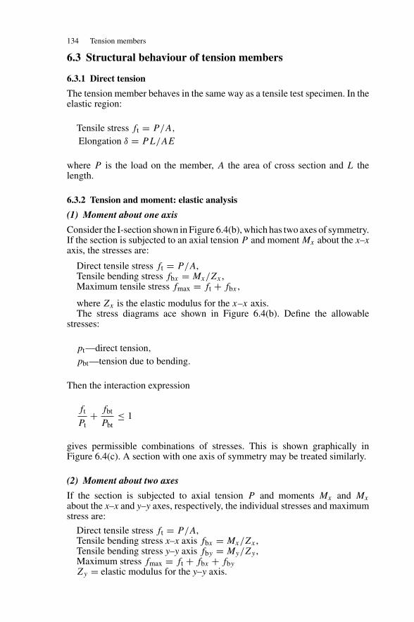
134 Tension members
6.3 Structural behaviour of tension members
6.3.1 Direct tension
The tension member behaves in the same way as a tensile test specimen. In theelastic region:
Tensile stress ft = P/A,
Elongation δ = PL/AE
where P is the load on the member, A the area of cross section and L thelength.
6.3.2 Tension and moment: elastic analysis
(1) Moment about one axis
Consider the I-section shown in Figure 6.4(b), which has two axes of symmetry.If the section is subjected to an axial tension P and moment Mx about the x–xaxis, the stresses are:
Direct tensile stress ft = P/A,Tensile bending stress fbx = Mx/Zx ,Maximum tensile stress fmax = ft + fbx ,
where Zx is the elastic modulus for the x–x axis.The stress diagrams ace shown in Figure 6.4(b). Define the allowable
stresses:
pt—direct tension,
pbt—tension due to bending.
Then the interaction expression
ft
Pt+ fbt
Pbt≤ 1
gives permissible combinations of stresses. This is shown graphically inFigure 6.4(c). A section with one axis of symmetry may be treated similarly.
(2) Moment about two axes
If the section is subjected to axial tension P and moments Mx and Mx
about the x–x and y–y axes, respectively, the individual stresses and maximumstress are:
Direct tensile stress ft = P/A,Tensile bending stress x–x axis fbx = Mx/Zx ,Tensile bending stress y–y axis fby = My/Zy ,Maximum stress fmax = ft + fbx + fby
Zy = elastic modulus for the y–y axis.
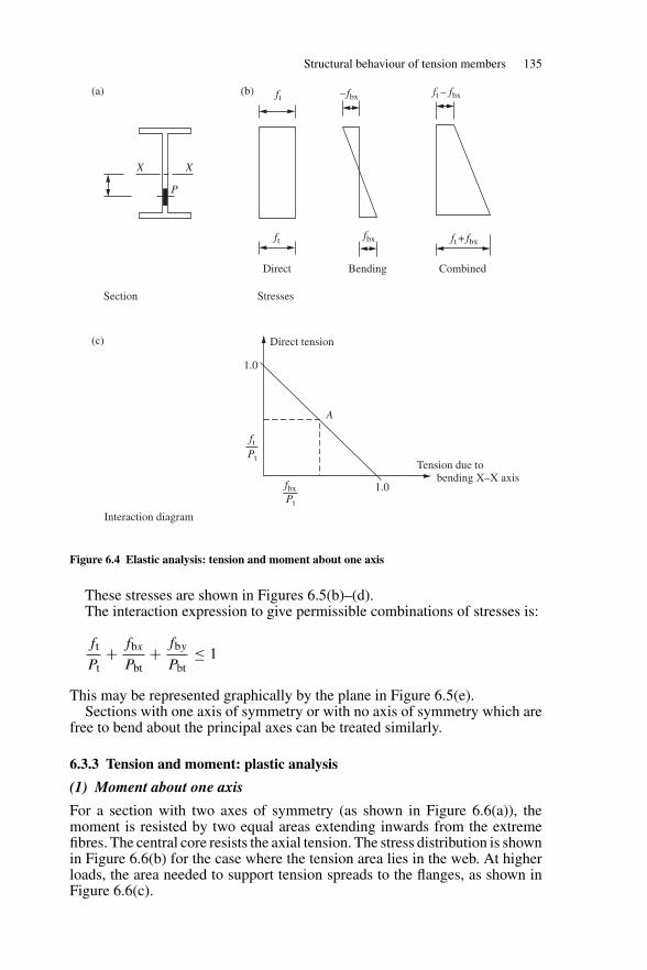
Structural behaviour of tension members 135
X X
P
ft
ft
– fbx
fbx
ft – fbx
ft + fbx
Direct tension
1.0
A
1.0
Tension due to bending X–X axis
ftPt
fbxPt
Section Stresses
Interaction diagram
(a)
(c)
(b)
Direct Bending Combined
Figure 6.4 Elastic analysis: tension and moment about one axis
These stresses are shown in Figures 6.5(b)–(d).The interaction expression to give permissible combinations of stresses is:
ft
Pt+ fbx
Pbt+ fby
Pbt≤ 1
This may be represented graphically by the plane in Figure 6.5(e).Sections with one axis of symmetry or with no axis of symmetry which are
free to bend about the principal axes can be treated similarly.
6.3.3 Tension and moment: plastic analysis
(1) Moment about one axis
For a section with two axes of symmetry (as shown in Figure 6.6(a)), themoment is resisted by two equal areas extending inwards from the extremefibres. The central core resists the axial tension. The stress distribution is shownin Figure 6.6(b) for the case where the tension area lies in the web. At higherloads, the area needed to support tension spreads to the flanges, as shown inFigure 6.6(c).
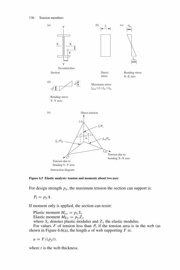
136 Tension members
X X
P
Y
Y ft –fbx
fbx
–fby
f by
Section
Eccentricities
Maximum stressfmax = ft + fbx + fby
Direct tension
1.0
fby /Pbtfbx/Pbt
ft /Pt
Tension due tobending Y–Y axis
Tension due tobending X–X axis
A
1.0
1.0
Directstress
Bending stressX–X axis
Bending stressY–Y axis
Interaction diagram
(a)
(d)
(e)
(b) (c)
Figure 6.5 Elastic analysis: tension and moments about two axes
For design strength py, the maximum tension the section can support is:
Pt = pyA.
If moment only is applied, the section can resist:
Plastic moment Mcx = pySx
Elastic moment MEx = pyZx
where Sx denotes plastic modulus and Zx the elastic modulus.For values F of tension less than Pt if the tension area is in the web (as
shown in Figure 6.6(a), the length a of web supporting F is:
a = F/(pyt).
where t is the web thickness.
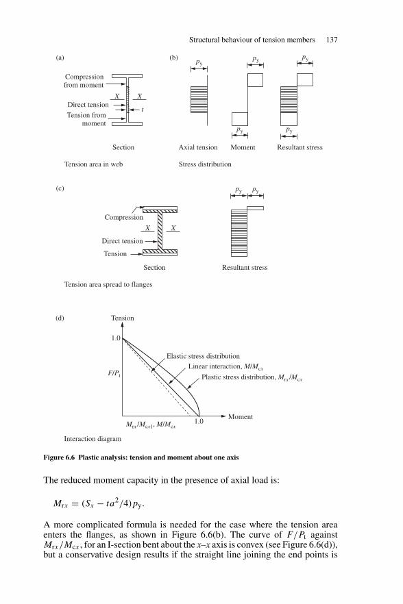
Structural behaviour of tension members 137
Tension
Tension
X X
X X
t
Section Axial tension Moment Resultant stress
Direct tension
Compression
Compressionfrom moment
Direct tension
Tension frommoment
Section Resultant stress
1.0
1.0Moment
Tension area spread to flanges
Tension area in web Stress distribution
Interaction diagram
Plastic stress distribution, Mrx /Mcx
Linear interaction, M/Mcx
Elastic stress distribution
F/Pt
Mrx /Mcx1, M/Mcx
py
pypy py
py py
py
(a)
(c)
(d)
(b)
Figure 6.6 Plastic analysis: tension and moment about one axis
The reduced moment capacity in the presence of axial load is:
Mrx = (Sx − ta2/4)py.
A more complicated formula is needed for the case where the tension areaenters the flanges, as shown in Figure 6.6(b). The curve of F/Pt againstMrx/Mcx , for an I-section bent about the x–x axis is convex (see Figure 6.6(d)),but a conservative design results if the straight line joining the end points is
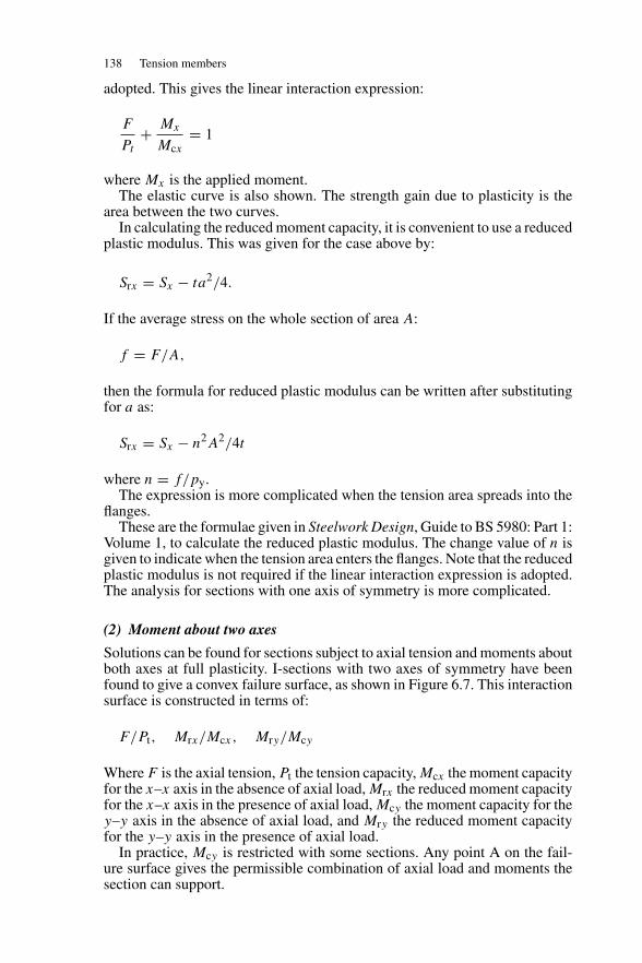
138 Tension members
adopted. This gives the linear interaction expression:
F
Pt
+ Mx
Mcx= 1
where Mx is the applied moment.The elastic curve is also shown. The strength gain due to plasticity is the
area between the two curves.In calculating the reduced moment capacity, it is convenient to use a reduced
plastic modulus. This was given for the case above by:
Srx = Sx − ta2/4.
If the average stress on the whole section of area A:
f = F/A,
then the formula for reduced plastic modulus can be written after substitutingfor a as:
Srx = Sx − n2A2/4t
where n = f/py.The expression is more complicated when the tension area spreads into the
flanges.These are the formulae given in Steelwork Design, Guide to BS 5980: Part 1:
Volume 1, to calculate the reduced plastic modulus. The change value of n isgiven to indicate when the tension area enters the flanges. Note that the reducedplastic modulus is not required if the linear interaction expression is adopted.The analysis for sections with one axis of symmetry is more complicated.
(2) Moment about two axes
Solutions can be found for sections subject to axial tension and moments aboutboth axes at full plasticity. I-sections with two axes of symmetry have beenfound to give a convex failure surface, as shown in Figure 6.7. This interactionsurface is constructed in terms of:
F/Pt, Mrx/Mcx, Mry/Mcy
Where F is the axial tension, Pt the tension capacity, Mcx the moment capacityfor the x–x axis in the absence of axial load, Mrx the reduced moment capacityfor the x–x axis in the presence of axial load, Mcy the moment capacity for they–y axis in the absence of axial load, and Mry the reduced moment capacityfor the y–y axis in the presence of axial load.
In practice, Mcy is restricted with some sections. Any point A on the fail-ure surface gives the permissible combination of axial load and moments thesection can support.
Design of tension members 139
Mry
1.0
Tension
Moment Y–Y axis
Interaction diagram
Moment X–X axis
Plane for linearinteraction expression
1.0
1.0
Mcy
My
Mcy
MxMcx
Mrx
Mcx
F
A
Pt
Figure 6.7 Plastic analysis: tension and moment about two axes
A plane may be drawn through the terminal points on the failure surface. Thiscan be used to give a simplified and conservative linear interaction expression:
Ft
Pt+ Mx
Mcx+ My
Mcy= 1
where Mx is the applied moment about the x–x axis and My the appliedmoment about the y–y axis.
6.4 Design of tension members
6.4.1 Axially loaded tension members
The tension capacity is given in Section 4.6.1 of BS 5950: Part 1. This is:
Pt = Aepy
where Ae is the effective area of the section defined in Sections 3.4.3, 4.6.2and 4.6.3 of the code.
From Section 3.4.3, the effective area of each element of a member isgiven by:
Ae = Ke× net area where holes occur ≤ gross areaKe = 1.2 for Grade S275 and 1.1 for S355 steel(Net area = gross area less holes.)
Tests show that holes do not reduce the capacity of a member in tensionprovided that the ratio of net area to gross area is greater than the ratio ofyield strength to ultimate strength.
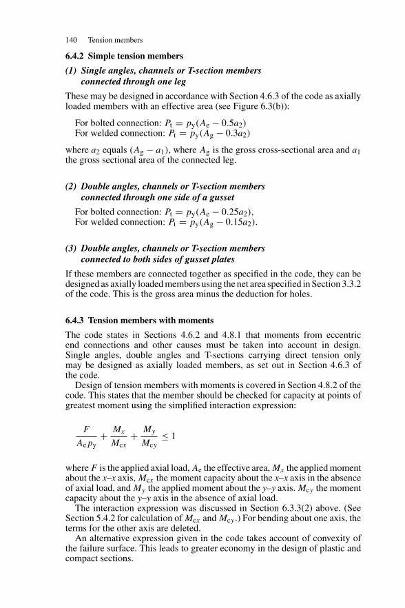
140 Tension members
6.4.2 Simple tension members
(1) Single angles, channels or T-section membersconnected through one leg
These may be designed in accordance with Section 4.6.3 of the code as axiallyloaded members with an effective area (see Figure 6.3(b)):
For bolted connection: Pt = py(Ae − 0.5a2)For welded connection: Pt = py(Ag − 0.3a2)
where a2 equals (Ag − a1), where Ag is the gross cross-sectional area and a1the gross sectional area of the connected leg.
(2) Double angles, channels or T-section membersconnected through one side of a gusset
For bolted connection: Pt = py(Ae − 0.25a2),For welded connection: Pt = py(Ag − 0.15a2).
(3) Double angles, channels or T-section membersconnected to both sides of gusset plates
If these members are connected together as specified in the code, they can bedesigned as axially loaded members using the net area specified in Section 3.3.2of the code. This is the gross area minus the deduction for holes.
6.4.3 Tension members with moments
The code states in Sections 4.6.2 and 4.8.1 that moments from eccentricend connections and other causes must be taken into account in design.Single angles, double angles and T-sections carrying direct tension onlymay be designed as axially loaded members, as set out in Section 4.6.3 ofthe code.
Design of tension members with moments is covered in Section 4.8.2 of thecode. This states that the member should be checked for capacity at points ofgreatest moment using the simplified interaction expression:
F
Aepy+ Mx
Mcx+ My
Mcy≤ 1
where F is the applied axial load, Ae the effective area, Mx the applied momentabout the x–x axis, Mcx the moment capacity about the x–x axis in the absenceof axial load, and My the applied moment about the y–y axis. Mcy the momentcapacity about the y–y axis in the absence of axial load.
The interaction expression was discussed in Section 6.3.3(2) above. (SeeSection 5.4.2 for calculation of Mcx and Mcy .) For bending about one axis, theterms for the other axis are deleted.
An alternative expression given in the code takes account of convexity ofthe failure surface. This leads to greater economy in the design of plastic andcompact sections.
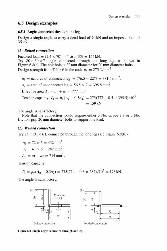
Design examples 141
6.5 Design examples
6.5.1 Angle connected through one leg
Design a single angle to carry a dead load of 70 kN and an imposed load of35 kN.
(1) Bolted connection
Factored load = (1.4 × 70) + (1.6 × 35) = 154 kN.Try 80 × 60 × 7 angle connected through the long leg, as shown inFigure 6.8(a). The bolt hole is 22 mm diameter for 20 mm diameter bolts.Design strength from Table 6 in the code py = 275 N/mm2
a1 = net area of connected leg = (76.5 − 22)7 = 381.5 mm2,
a2 = area of unconnected leg = 56.5 × 7 = 395.5 mm2,
Effective area Ae = a1 + a2 = 777 mm2.
Tension capacity: Pt = py(Ae − 0.5a2) = 275(777 − 0.5 × 395.5)/103
= 159 kN.
The angle is satisfactory.Note that the connection would require either 3 No. Grade 8.8 or 3 No.
friction-grip 20 mm diameter bolts to support the load.
(2) Welded connection
Try 75 × 50 × 6 L connected through the long leg (see Figure 6.8(b)):
a1 = 72 × 6 = 432 mm2,
a2 = 47 × 6 = 282 mm2,
Ag = a1 + a2 = 714 mm2.
Tension capacity:
Pt = py(Ag − 0.3a2) = 275(714 − 0.3 × 282)/103 = 173 kN.
The angle is satisfactory.
60 56.5
3.5
3.5 3376.5
22 φ hole
72
7580
Bolted connection Welded connection
50 47
(a) (b)
Figure 6.8 Single angle connected through one leg
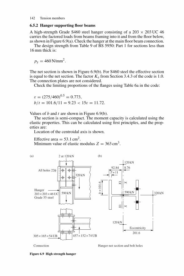
142 Tension members
6.5.2 Hanger supporting floor beams
A high-strength Grade S460 steel hanger consisting of a 203 × 203 UC 46carries the factored loads from beams framing into it and from the floor below,as shown in Figure 6.9(a). Check the hanger at the main floor beam connection.
The design strength from Table 9 of BS 5950: Part 1 for sections less than16 mm thick is:
py = 460 N/mm2.
The net section is shown in Figure 6.9(b). For S460 steel the effective sectionis equal to the net section. The factor Ke from Section 3.4.3 of the code is 1.0.The connection plates are not considered.
Check the limiting proportions of the flanges using Table 6a in the code:
ε = (275/460)0.5 = 0.773,
b/t = 101.6/11 = 9.23 < 15ε = 11.72.
Values of b and t are shown in Figure 6.9(b).The section is semi-compact. The moment capacity is calculated using the
elastic properties. This can be calculated using first principles, and the prop-erties are:
Location of the centroidal axis is shown.
Effective area = 53.1 cm2.Minimum value of elastic modulus Z = 363 cm3.
2 at 120 kN
120 kN
120 kN
Connection Hanger-net section and bolt holes
Eccentricity
590 kN
201.6
320 kN
92.84 8.76
T = 11
b=
101.
6 X1
X1
XX
590 kN
320 kN
Hanger203 × 203 × 46 UC
305 × 165 × 54 UB 457 × 152 × 74 UB
Grade 55 steel
All holes 22φ
(a) (b)
Figure 6.9 High strength hanger
Problems 143
The moment capacity for the major axis:
Mcx = 363 × 460/103 = 166.9 kN m.
The applied axial load:
F = (2 × 120) + 590 + 320 = 1150 kN m.
The applied moment about the x1–x1 axis:
Mx = (320 × 0.21) + (2 × 120 + 590)0.0088 = 74.5 kN m.
Substitute into the interaction expression:
F
Aepy+ Mx
Mcx= 1150 × 10
53.1 × 450+ 74.5
166.9= 0.92 < 1.
The hanger is satisfactory.
Problems
6.1 A tie member in a roof truss is subjected to an ultimate tension of 1000 kN.Design this member using Grade S275 steel and an equal angle section.
6.2 A tension member in Grade S275 steel consists of 2 No. 150×100×8 mmunequal angles placed back to back. At the connection, two rows of 2 No.22 mm diameter holes are drilled through the longer legs of the angles.Determine the ultimate tensile load that can be carried by the member.
6.3 A tension member from a heavy truss is subjected to an ultimate axialload and bending moment of 2000 kN and 500 kN m, respectively. Design asuitable universal beam section in Grade S275 steel. Assume that the grosssection will resist the load and moment.
6.4 A tie member in a certain steel structure is subjected to tension and biaxialbending. The ultimate tensile load was found to be 3000 kN while the ulti-mate moments about the major and minor axes were 160 kN m and 90 kN m,respectively. Check whether a 305 × 305 UC 158 in Grade S275 steel isadequate. Assume that the gross section resists the loads and moments.
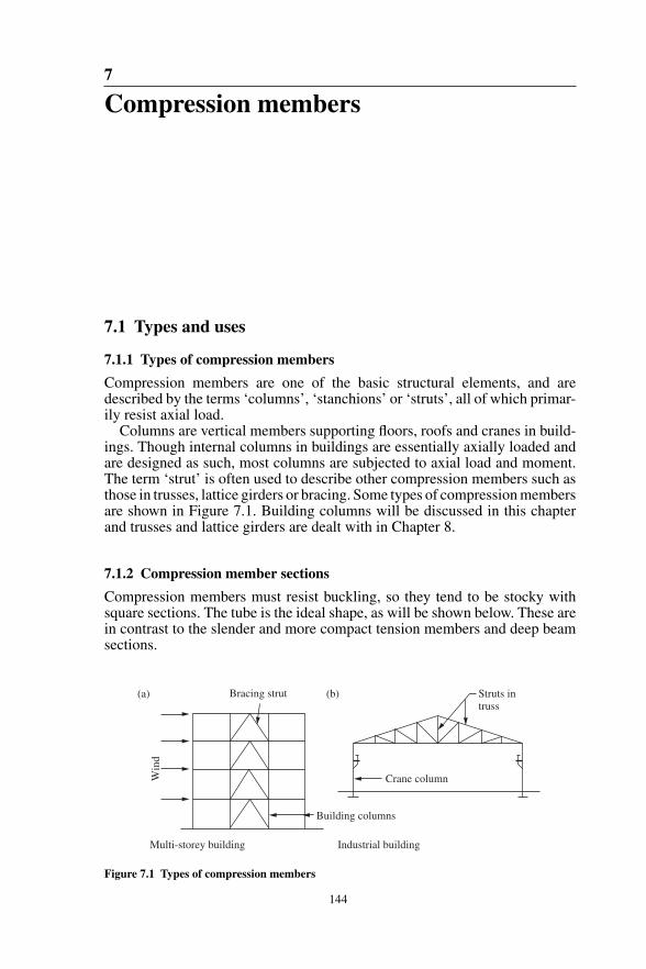
7
Compression members
7.1 Types and uses
7.1.1 Types of compression members
Compression members are one of the basic structural elements, and aredescribed by the terms ‘columns’, ‘stanchions’ or ‘struts’, all of which primar-ily resist axial load.
Columns are vertical members supporting floors, roofs and cranes in build-ings. Though internal columns in buildings are essentially axially loaded andare designed as such, most columns are subjected to axial load and moment.The term ‘strut’ is often used to describe other compression members such asthose in trusses, lattice girders or bracing. Some types of compression membersare shown in Figure 7.1. Building columns will be discussed in this chapterand trusses and lattice girders are dealt with in Chapter 8.
7.1.2 Compression member sections
Compression members must resist buckling, so they tend to be stocky withsquare sections. The tube is the ideal shape, as will be shown below. These arein contrast to the slender and more compact tension members and deep beamsections.
Bracing strut
Multi-storey building Industrial building
Crane column
Struts intruss
Building columns
Win
d
(a) (b)
Figure 7.1 Types of compression members
144
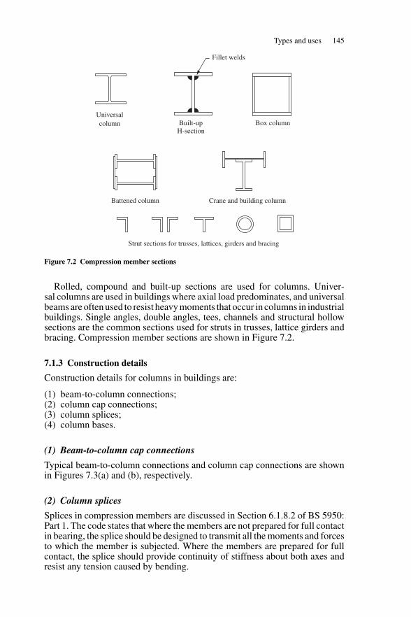
Types and uses 145
Fillet welds
Universalcolumn Built-up
H-sectionBox column
Battened column Crane and building column
Strut sections for trusses, lattices, girders and bracing
Figure 7.2 Compression member sections
Rolled, compound and built-up sections are used for columns. Univer-sal columns are used in buildings where axial load predominates, and universalbeams are often used to resist heavy moments that occur in columns in industrialbuildings. Single angles, double angles, tees, channels and structural hollowsections are the common sections used for struts in trusses, lattice girders andbracing. Compression member sections are shown in Figure 7.2.
7.1.3 Construction details
Construction details for columns in buildings are:
(1) beam-to-column connections;(2) column cap connections;(3) column splices;(4) column bases.
(1) Beam-to-column cap connections
Typical beam-to-column connections and column cap connections are shownin Figures 7.3(a) and (b), respectively.
(2) Column splices
Splices in compression members are discussed in Section 6.1.8.2 of BS 5950:Part 1. The code states that where the members are not prepared for full contactin bearing, the splice should be designed to transmit all the moments and forcesto which the member is subjected. Where the members are prepared for fullcontact, the splice should provide continuity of stiffness about both axes andresist any tension caused by bending.
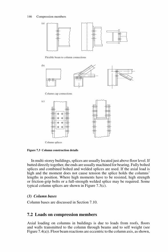
146 Compression members
Flexible beam to column connections
Column cap connections
Column splices
(a)
(b)
(c)
Figure 7.3 Column construction details
In multi-storey buildings, splices are usually located just above floor level. Ifbutted directly together, the ends are usually machined for bearing. Fully boltedsplices and combined bolted and welded splices are used. If the axial load ishigh and the moment does not cause tension the splice holds the columns’lengths in position. Where high moments have to be resisted, high strengthor friction-grip bolts or a full-strength welded splice may be required. Sometypical column splices are shown in Figure 7.3(c).
(3) Column bases
Column bases are discussed in Section 7.10.
7.2 Loads on compression members
Axial loading on columns in buildings is due to loads from roofs, floorsand walls transmitted to the column through beams and to self weight (seeFigure 7.4(a)). Floor beam reactions are eccentric to the column axis, as shown,
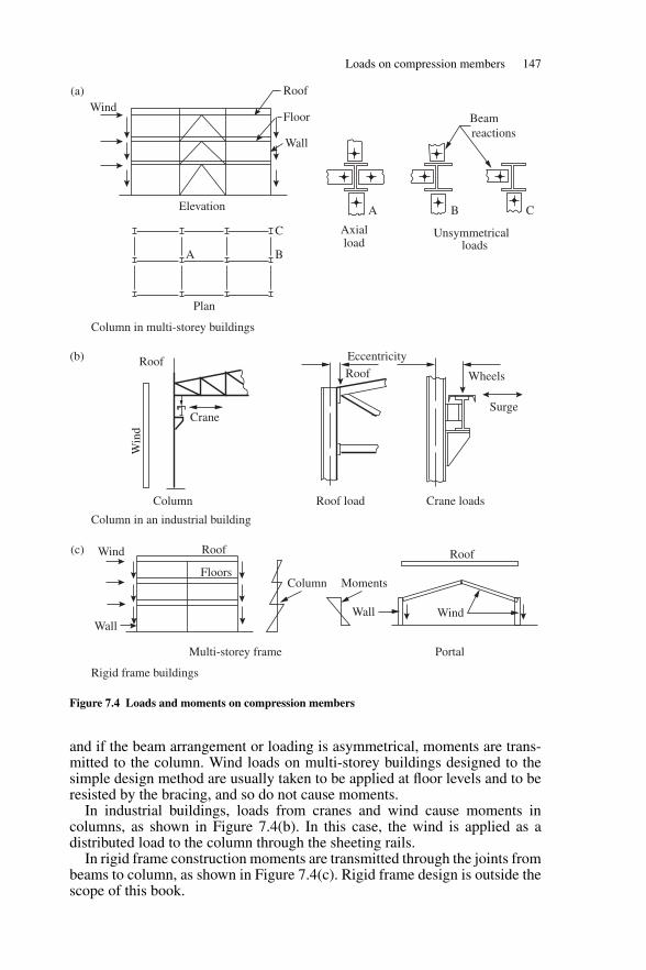
Loads on compression members 147
WindRoof
Floor
Wall
Elevation
Axialload
Plan
Crane
Eccentricity
Column
Win
d
RoofRoof
Roof
WindWallWall
Wind Roof
FloorsMomentsColumn
Wheels
Surge
Multi-storey frame
Rigid frame buildings
Column in an industrial building
Column in multi-storey buildings
Portal
Crane loadsRoof load
Unsymmetricalloads
A
A B
C
B
Beamreactions
C
(a)
(b)
(c)
Figure 7.4 Loads and moments on compression members
and if the beam arrangement or loading is asymmetrical, moments are trans-mitted to the column. Wind loads on multi-storey buildings designed to thesimple design method are usually taken to be applied at floor levels and to beresisted by the bracing, and so do not cause moments.
In industrial buildings, loads from cranes and wind cause moments incolumns, as shown in Figure 7.4(b). In this case, the wind is applied as adistributed load to the column through the sheeting rails.
In rigid frame construction moments are transmitted through the joints frombeams to column, as shown in Figure 7.4(c). Rigid frame design is outside thescope of this book.
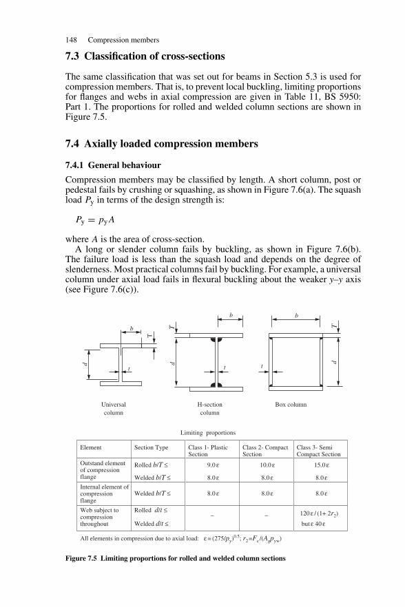
148 Compression members
7.3 Classification of cross-sections
The same classification that was set out for beams in Section 5.3 is used forcompression members. That is, to prevent local buckling, limiting proportionsfor flanges and webs in axial compression are given in Table 11, BS 5950:Part 1. The proportions for rolled and welded column sections are shown inFigure 7.5.
7.4 Axially loaded compression members
7.4.1 General behaviour
Compression members may be classified by length. A short column, post orpedestal fails by crushing or squashing, as shown in Figure 7.6(a). The squashload Py in terms of the design strength is:
Py = pyA
where A is the area of cross-section.A long or slender column fails by buckling, as shown in Figure 7.6(b).
The failure load is less than the squash load and depends on the degree ofslenderness. Most practical columns fail by buckling. For example, a universalcolumn under axial load fails in flexural buckling about the weaker y–y axis(see Figure 7.6(c)).
Limiting proportions
Element Section Type Class 1- PlasticSection
Class 2- CompactSection
Class 3- SemiCompact Section
Outstand element of compression flange
Rolled b/T ≤
Welded b/T ≤
9.0 ε
8.0 ε
10.0 ε
8.0 ε
15.0 ε
8.0 εInternal element ofcompressionflange
Welded b/T ≤ 8.0 ε 8.0 ε 8.0 ε
Web subject tocompressionthroughout
Rolled d/t ≤
Welded d/t ≤
_ _ 120 ε / (1+ 2r2)
but ε 40 ε
All elements in compression due to axial load: ε = (275/py)0.5; r2=Fc /(Agpyw)
d
T
T T
d db
b b
t t t
Universal column
Box columnH-sectioncolumn
Figure 7.5 Limiting proportions for rolled and welded column sections
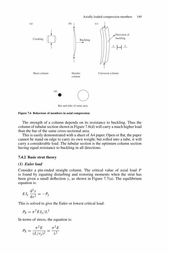
Axially loaded compression members 149
Crushing Buckling
Short column
Direction ofbuckling
Slendercolumn
Universal column
Bar and tube of same area
x x
(a)
(d)
(b) (c)
Figure 7.6 Behaviour of members in axial compression
The strength of a column depends on its resistance to buckling. Thus thecolumn of tubular section shown in Figure 7.6(d) will carry a much higher loadthan the bar of the same cross-sectional area.
This is easily demonstrated with a sheet of A4 paper. Open or flat, the papercannot be stand on edge to carry its own weight; but rolled into a tube, it willcarry a considerable load. The tubular section is the optimum column sectionhaving equal resistance to buckling in all directions.
7.4.2 Basic strut theory
(1) Euler load
Consider a pin-ended straight column. The critical value of axial load Pis found by equating disturbing and restoring moments when the strut hasbeen given a small deflection y, as shown in Figure 7.7(a). The equilibriumequation is:
EIyd2y
dx2= −Py
This is solved to give the Euler or lowest critical load:
PE = π2EIy/L2
In terms of stress, the equation is:
PE = π2E
(L/ry)2= π2E
λ2
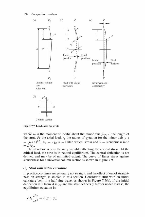
150 Compression members
PE
PE P
hY
Y
XX
P
P P
A
x x
Initialposition
Initially straightstruteuler load
Strut with initialcurvature
Column section
Strut with endeccentricity
Finalposition
Initialposition
Finalposition
xy
y y
y0r
L
L CC
(a)
(d)
(b) (c)
Figure 7.7 Load cases for struts
where Iy is the moment of inertia about the minor axis y–y, L the length ofthe strut, PP the axial load, ry the radius of gyration for the minor axis y–y= (Iy/A)0.5, pE = PE/A = Euler critical stress and λ = slenderness ratio= L/ry.
The slenderness λ is the only variable affecting the critical stress. At thecritical load, the strut is in neutral equilibrium. The central deflection is notdefined and may be of unlimited extent. The curve of Euler stress againstslenderness for a universal column section is shown in Figure 7.9.
(2) Strut with initial curvature
In practice, columns are generally not straight, and the effect of out of straight-ness on strength is studied in this section. Consider a strut with an initialcurvature bent in a half sine wave, as shown in Figure 7.7(b). If the initialdeflection at x from A is y0 and the strut deflects y further under load P , theequilibrium equation is:
EIyd2y
dx2= P(y + y0)
Axially loaded compression members 151
where deflection y = sin(πx/L). If δ0 is the initial deflection at the centre andδ the additional deflection caused by P , then it can be shown by solving theequilibrium equation that:
δ = δ0
(PE/P ) − 1
The maximum stress at the centre of the strut is given by:
Pmax = P
A+ P(δ0 + δ)h
IY
where h is shown in Figure 7.7(d).In the above equation,
pmax = py = design strength,pc = P/A = average stress,pE = PE/A = Euler stress,Iy = Ar2
y = moment of inertia about the y–y axis,A = area of cross-section,ry = radius of gyration for the y–y axis,h = half the flange breath.
The equation for maximum stress can be written:
py = pc + pc
{1 + 1
(pE/pc) − 1
}δ0h
r2y
Put
η = δ0h/r2y
and rearrange to give:
(pE − pc)(py − pc) = ηpEpc
The value of pc the limiting strength at which the maximum stress equals thedesign strength, can be found by solving this equation and η is the Perry factor.This is to redefined in terms of slenderness. (See Section 7.4.3 (2) below. Thedesign strength curve is also discussed in that section.)
(3) Eccentrically loaded strut
Most struts are eccentrically loaded, and the effect of this on strut strength isexamined here. A strut with end eccentricities e is shown in Figure 7.7(c). Ify is deflection from the initially straight strut the equilibrium equation is:
EIyd2y
dx2= −p(e + y)
This can be solved to give the secant formula for limiting stress.
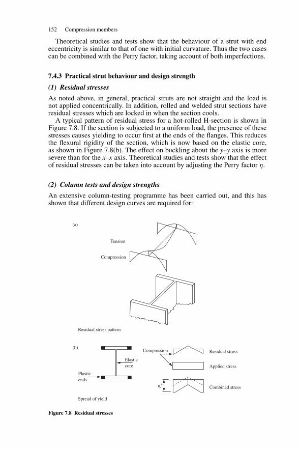
152 Compression members
Theoretical studies and tests show that the behaviour of a strut with endeccentricity is similar to that of one with initial curvature. Thus the two casescan be combined with the Perry factor, taking account of both imperfections.
7.4.3 Practical strut behaviour and design strength
(1) Residual stresses
As noted above, in general, practical struts are not straight and the load isnot applied concentrically. In addition, rolled and welded strut sections haveresidual stresses which are locked in when the section cools.
A typical pattern of residual stress for a hot-rolled H-section is shown inFigure 7.8. If the section is subjected to a uniform load, the presence of thesestresses causes yielding to occur first at the ends of the flanges. This reducesthe flexural rigidity of the section, which is now based on the elastic core,as shown in Figure 7.8(b). The effect on buckling about the y–y axis is moresevere than for the x–x axis. Theoretical studies and tests show that the effectof residual stresses can be taken into account by adjusting the Perry factor η.
(2) Column tests and design strengths
An extensive column-testing programme has been carried out, and this hasshown that different design curves are required for:
Tension
Compression
Compression
Elasticcore
Plasticends
Residual stress
Applied stress
Combined stress
Residual stress pattern
Spread of yield
Py
(a)
(b)
Figure 7.8 Residual stresses
Axially loaded compression members 153
(1) different column sections;(2) the same section buckling about different axes;(3) sections with different thicknesses of metal.
For example, H-sections have high residual compressive stresses at the ends ofthe flanges, and these affect the column strength if buckling takes place aboutthe minor axis.
The total effect of the imperfections discussed above (initial curvature, endeccentricity and residual stresses on strength) are combined into the Perryconstant η. This is adjusted to make the equation for limiting stress pc a lowerbound to the test results.
The constant η is defined by:
η = 0.001 a(λ − λ0)
λ = 0.2 (π2E/py)0.5
The value λ0 gives the limit to the plateau over which the design strength pycontrols the strut load.
The Robertson constant a is assigned different values to give the differentdesign curves. For H-sections buckling about the minor axis, a has the value 5.5to give design curve (c) (Table 24(c)).
A strut table selection is given in Table 23 in BS 4950: Part 1. For example,for rolled and welded H sections with metal thicknesses up to 40 mm, thefollowing design curves are used:
(1) buckling about the major axis x–x curve (b) (Table 24(b));(2) buckling about the minor axis y–y curve (c) (Table 24(c)).
The compressive strength is given by the smaller root of the equation that wasderived above for a strut with initial curvature. This is:
(pE − pc)(py − pc) = ηpEpc
pc = pEpy
(φ + φ2 − pEpy)0.5
φ = [py + (η + l)pE]/2
The curves for Euler stress pE and limiting stress or compressive strength pcfor a rolled H-section column buckling about the minor axis are shown in
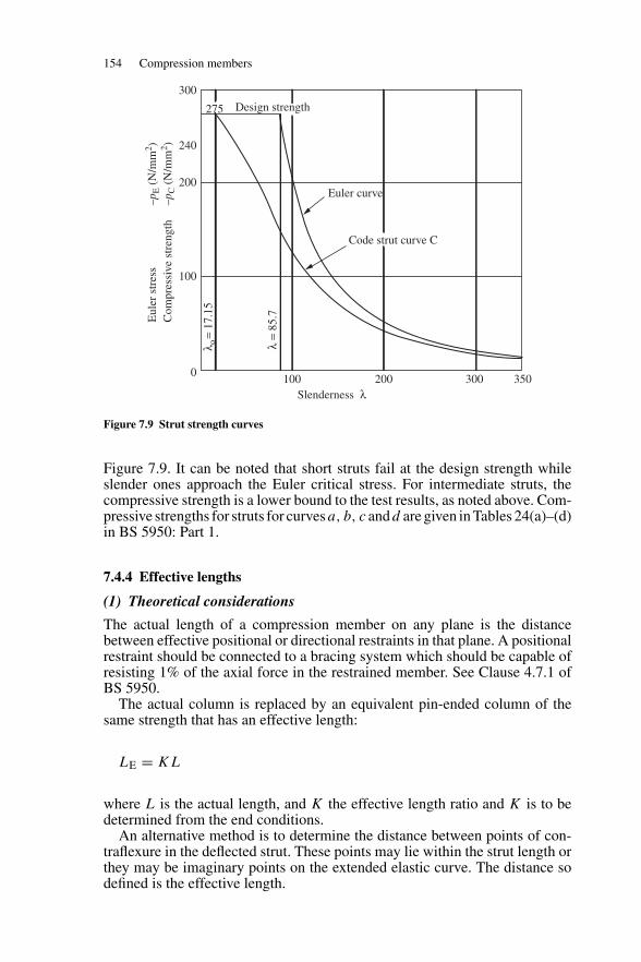
154 Compression members
Eul
er s
tres
s –p
E (
N/m
m2 )
Com
pres
sive
str
engt
h –p
C (
N/m
m2 )
300
240
200
100
0100 200
Slenderness λ
λ =
85.7
λ o=
17.1
5
300 350
275 Design strength
Euler curve
Code strut curve C
Figure 7.9 Strut strength curves
Figure 7.9. It can be noted that short struts fail at the design strength whileslender ones approach the Euler critical stress. For intermediate struts, thecompressive strength is a lower bound to the test results, as noted above. Com-pressive strengths for struts for curvesa, b, c andd are given in Tables 24(a)–(d)in BS 5950: Part 1.
7.4.4 Effective lengths
(1) Theoretical considerations
The actual length of a compression member on any plane is the distancebetween effective positional or directional restraints in that plane. A positionalrestraint should be connected to a bracing system which should be capable ofresisting 1% of the axial force in the restrained member. See Clause 4.7.1 ofBS 5950.
The actual column is replaced by an equivalent pin-ended column of thesame strength that has an effective length:
LE = KL
where L is the actual length, and K the effective length ratio and K is to bedetermined from the end conditions.
An alternative method is to determine the distance between points of con-traflexure in the deflected strut. These points may lie within the strut length orthey may be imaginary points on the extended elastic curve. The distance sodefined is the effective length.
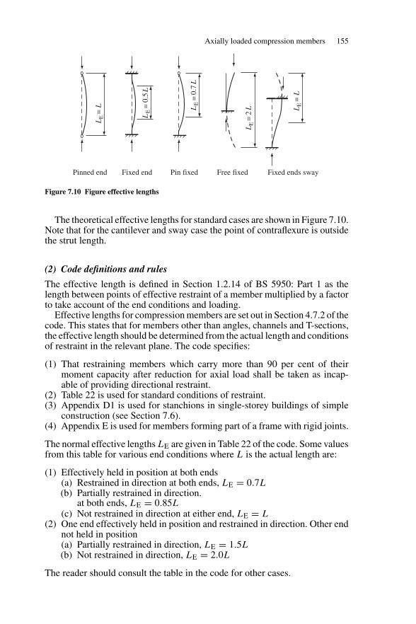
Axially loaded compression members 155
Pinned end Fixed end Pin fixed Free fixed Fixed ends sway
LE
=L
LE
=L
LE
=0.
5L
LE
=0.
7L
LE
=2
L
Figure 7.10 Figure effective lengths
The theoretical effective lengths for standard cases are shown in Figure 7.10.Note that for the cantilever and sway case the point of contraflexure is outsidethe strut length.
(2) Code definitions and rules
The effective length is defined in Section 1.2.14 of BS 5950: Part 1 as thelength between points of effective restraint of a member multiplied by a factorto take account of the end conditions and loading.
Effective lengths for compression members are set out in Section 4.7.2 of thecode. This states that for members other than angles, channels and T-sections,the effective length should be determined from the actual length and conditionsof restraint in the relevant plane. The code specifies:
(1) That restraining members which carry more than 90 per cent of theirmoment capacity after reduction for axial load shall be taken as incap-able of providing directional restraint.
(2) Table 22 is used for standard conditions of restraint.(3) Appendix D1 is used for stanchions in single-storey buildings of simple
construction (see Section 7.6).(4) Appendix E is used for members forming part of a frame with rigid joints.
The normal effective lengths LE are given in Table 22 of the code. Some valuesfrom this table for various end conditions where L is the actual length are:
(1) Effectively held in position at both ends(a) Restrained in direction at both ends, LE = 0.7L(b) Partially restrained in direction.
at both ends, LE = 0.85L(c) Not restrained in direction at either end, LE = L
(2) One end effectively held in position and restrained in direction. Other endnot held in position(a) Partially restrained in direction, LE = 1.5L(b) Not restrained in direction, LE = 2.0L
The reader should consult the table in the code for other cases.
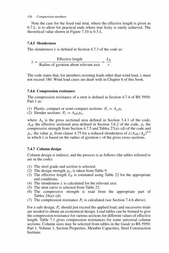
156 Compression members
Note the case for the fixed end strut, where the effective length is given as0.7 L, is to allow for practical ends where true fixity is rarely achieved. Thetheoretical value shown in Figure 7.10 is 0.5 L.
7.4.5 Slenderness
The slenderness λ is defined in Section 4.7.3 of the code as:
λ = Effective length
Radius of gyration about relevant axis= LE
r
The code states that, for members resisting loads other than wind load, λ mustnot exceed 180. Wind load cases are dealt with in Chapter 8 of this book.
7.4.6 Compression resistance
The compression resistance of a strut is defined in Section 4.7.4 of BS 5950:Part 1 as:
(1) Plastic, compact or semi-compact sections: Pc = Agpc(2) Slender sections: Pc = Aeffpcs
where Ag is the gross sectional area defined in Section 3.4.1 of the code,Aeff the effective sectional area defined in Section 3.6.2 of the code, pc thecompressive strength from Section 4.7.5 and Tables 27(a)–(d) of the code andpcs the value pc from clause 4.75 for a reduced slenderness of λ(Aeff/Ag)
0.5
in which λ is based on the radius of gyration r of the gross cross-sections.
7.4.7 Column design
Column design is indirect, and the process is as follows (the tables referred toare in the code):
(1) The steel grade and section is selected.(2) The design strength py, is taken from Table 9.(3) The effective length LE is estimated using Table 22 for the appropriate
end conditions.(4) The slenderness λ is calculated for the relevant axis.(5) The strut curve is selected from Table 23.(6) The compressive strength is read from the appropriate part of
Tables 24(a)–(d).(7) The compression resistance Pc is calculated (see Section 7.4.6 above).
For a safe design, Pc should just exceed the applied load, and successive trialsare needed to obtain an economical design. Load tables can be formed to givethe compression resistance for various sections for different values of effectivelength. Table 7.1 gives compression resistances for some universal columnsections. Column sizes may be selected from tables in the Guide to BS 5950:Part 1, Volume 1, Section Properties, Member Capacities, Steel ConstructionInstitute.
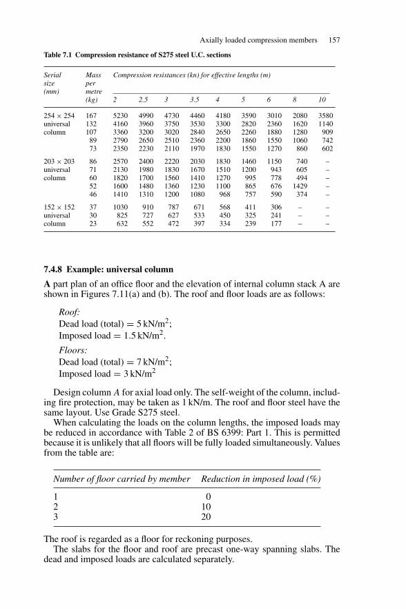
Axially loaded compression members 157
Table 7.1 Compression resistance of S275 steel U.C. sections
Serial Mass Compression resistances (kn) for effective lengths (m)size per(mm) metre
(kg) 2 2.5 3 3.5 4 5 6 8 10
254 × 254 167 5230 4990 4730 4460 4180 3590 3010 2080 3580universal 132 4160 3960 3750 3530 3300 2820 2360 1620 1140column 107 3360 3200 3020 2840 2650 2260 1880 1280 909
89 2790 2650 2510 2360 2200 1860 1550 1060 74273 2350 2230 2110 1970 1830 1550 1270 860 602
203 × 203 86 2570 2400 2220 2030 1830 1460 1150 740 –universal 71 2130 1980 1830 1670 1510 1200 943 605 –column 60 1820 1700 1560 1410 1270 995 778 494 –
52 1600 1480 1360 1230 1100 865 676 1429 –46 1410 1310 1200 1080 968 757 590 374 –
152 × 152 37 1030 910 787 671 568 411 306 – –universal 30 825 727 627 533 450 325 241 – –column 23 632 552 472 397 334 239 177 – –
7.4.8 Example: universal column
A part plan of an office floor and the elevation of internal column stack A areshown in Figures 7.11(a) and (b). The roof and floor loads are as follows:
Roof:Dead load (total) = 5 kN/m2;Imposed load = 1.5 kN/m2.
Floors:Dead load (total) = 7 kN/m2;Imposed load = 3 kN/m2
Design column A for axial load only. The self-weight of the column, includ-ing fire protection, may be taken as 1 kN/m. The roof and floor steel have thesame layout. Use Grade S275 steel.
When calculating the loads on the column lengths, the imposed loads maybe reduced in accordance with Table 2 of BS 6399: Part 1. This is permittedbecause it is unlikely that all floors will be fully loaded simultaneously. Valuesfrom the table are:
Number of floor carried by member Reduction in imposed load (%)
1 02 103 20
The roof is regarded as a floor for reckoning purposes.The slabs for the floor and roof are precast one-way spanning slabs. The
dead and imposed loads are calculated separately.
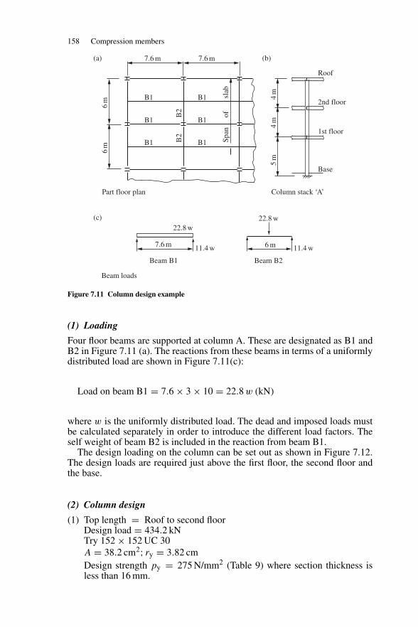
158 Compression members
Base
1st floor
2nd floor
Roof
7.6 m7.6 m
6m
6m
4m
5m
4m
B1B1
B1B1
B2
B2
ofsl
abSp
an
B1
Part floor plan Column stack ‘A’
Beam loads
Beam B1 Beam B2
7.6 m
B1
6 m
22.8 w22.8 w
11.4 w 11.4 w
(a)
(c)
(b)
Figure 7.11 Column design example
(1) Loading
Four floor beams are supported at column A. These are designated as B1 andB2 in Figure 7.11 (a). The reactions from these beams in terms of a uniformlydistributed load are shown in Figure 7.11(c):
Load on beam B1 = 7.6 × 3 × 10 = 22.8 w (kN)
where w is the uniformly distributed load. The dead and imposed loads mustbe calculated separately in order to introduce the different load factors. Theself weight of beam B2 is included in the reaction from beam B1.
The design loading on the column can be set out as shown in Figure 7.12.The design loads are required just above the first floor, the second floor andthe base.
(2) Column design
(1) Top length = Roof to second floorDesign load = 434.2 kNTry 152 × 152 UC 30A = 38.2 cm2; ry = 3.82 cmDesign strength py = 275 N/mm2 (Table 9) where section thickness isless than 16 mm.
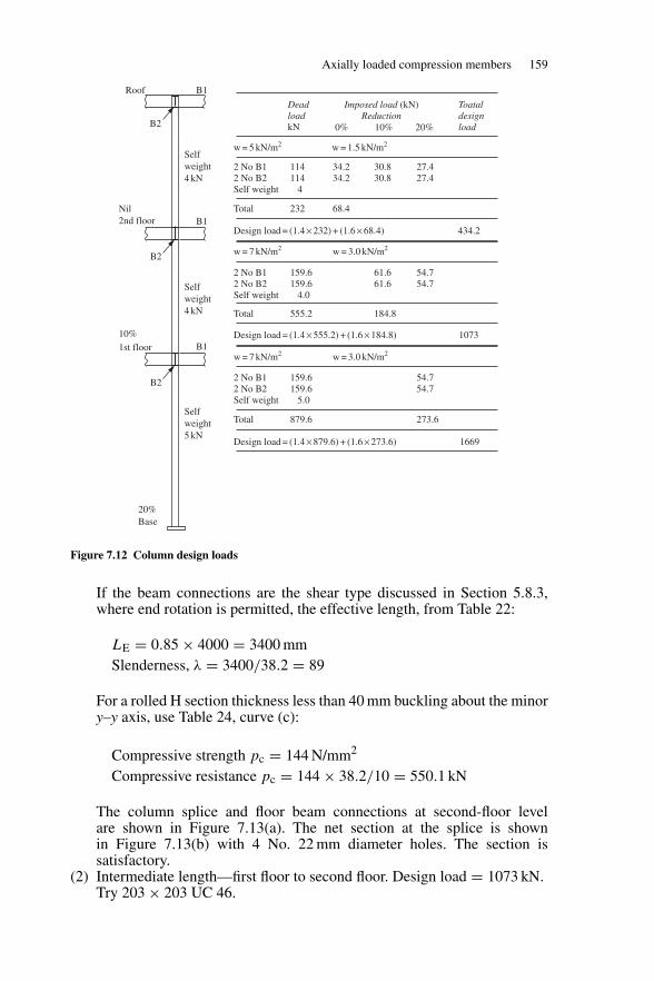
Axially loaded compression members 159
Roof B1
B1
B1
B2
B2
B2
Selfweight4 kN
Selfweight4 kN
Nil2nd floor
20%Base
10%1st floor
Selfweight5 kN
DeadloadkN
w = 5 kN/m2
2 No B1 114 34.2 30.8 27.42 No B2 114 34.2 30.8 27.4Self weight 4
2 No B1 159.6 61.6 54.72 No B2 159.6 61.6 54.7Self weight 4.0
2 No B1 159.6 54.72 No B2 159.6 54.7Self weight 5.0
Total 879.6 273.6
Total 555.2 184.8
Design load = (1.4 × 555.2) + (1.6 × 184.8) 1073
Design load = (1.4 × 879.6) + (1.6 × 273.6) 1669
Total 232 68.4
Design load = (1.4 × 232) + (1.6 × 68.4) 434.2
w = 7 kN/m2 w = 3.0 kN/m2
w = 7 kN/m2 w = 3.0 kN/m2
w = 1.5 kN/m2
Toataldesignload
Imposed load (kN)Reduction
0% 10% 20%
Figure 7.12 Column design loads
If the beam connections are the shear type discussed in Section 5.8.3,where end rotation is permitted, the effective length, from Table 22:
LE = 0.85 × 4000 = 3400 mmSlenderness, λ = 3400/38.2 = 89
For a rolled H section thickness less than 40 mm buckling about the minory–y axis, use Table 24, curve (c):
Compressive strength pc = 144 N/mm2
Compressive resistance pc = 144 × 38.2/10 = 550.1 kN
The column splice and floor beam connections at second-floor levelare shown in Figure 7.13(a). The net section at the splice is shownin Figure 7.13(b) with 4 No. 22 mm diameter holes. The section issatisfactory.
(2) Intermediate length—first floor to second floor. Design load = 1073 kN.Try 203 × 203 UC 46.
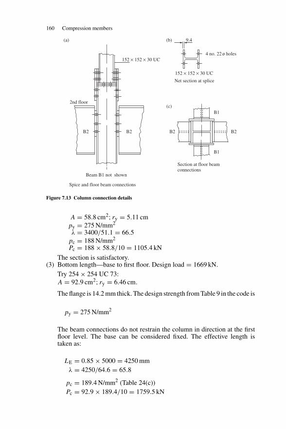
160 Compression members
B1
B1
B2B2B2B2
2nd floor
Beam B1 not shown
Section at floor beam connections
Spice and floor beam connections
152 × 152 × 30 UC
152 × 152 × 30 UC
Net section at splice
4 no. 22 ø holes
9.4(a) (b)
(c)
Figure 7.13 Column connection details
A = 58.8 cm2; ry = 5.11 cmpy = 275 N/mm2
λ = 3400/51.1 = 66.5pc = 188 N/mm2
Pc = 188 × 58.8/10 = 1105.4 kN
The section is satisfactory.(3) Bottom length—base to first floor. Design load = 1669 kN.
Try 254 × 254 UC 73:A = 92.9 cm2; ry = 6.46 cm.
The flange is 14.2 mm thick. The design strength from Table 9 in the code is
py = 275 N/mm2
The beam connections do not restrain the column in direction at the firstfloor level. The base can be considered fixed. The effective length istaken as:
LE = 0.85 × 5000 = 4250 mmλ = 4250/64.6 = 65.8
pc = 189.4 N/mm2 (Table 24(c))Pc = 92.9 × 189.4/10 = 1759.5 kN
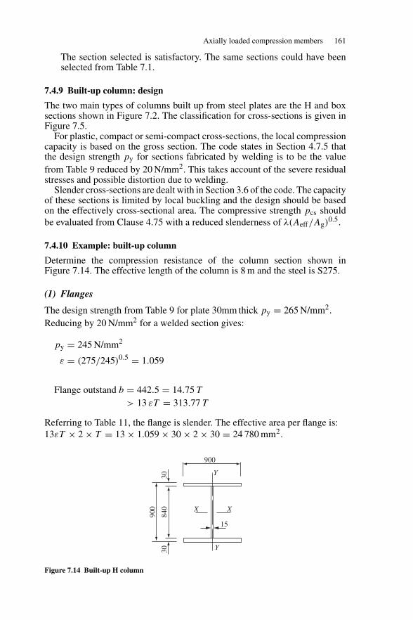
Axially loaded compression members 161
The section selected is satisfactory. The same sections could have beenselected from Table 7.1.
7.4.9 Built-up column: design
The two main types of columns built up from steel plates are the H and boxsections shown in Figure 7.2. The classification for cross-sections is given inFigure 7.5.
For plastic, compact or semi-compact cross-sections, the local compressioncapacity is based on the gross section. The code states in Section 4.7.5 thatthe design strength py for sections fabricated by welding is to be the valuefrom Table 9 reduced by 20 N/mm2. This takes account of the severe residualstresses and possible distortion due to welding.
Slender cross-sections are dealt with in Section 3.6 of the code. The capacityof these sections is limited by local buckling and the design should be basedon the effectively cross-sectional area. The compressive strength pcs shouldbe evaluated from Clause 4.75 with a reduced slenderness of λ(Aeff/Ag)
0.5.
7.4.10 Example: built-up column
Determine the compression resistance of the column section shown inFigure 7.14. The effective length of the column is 8 m and the steel is S275.
(1) Flanges
The design strength from Table 9 for plate 30mm thick py = 265 N/mm2.Reducing by 20 N/mm2 for a welded section gives:
py = 245 N/mm2
ε = (275/245)0.5 = 1.059
Flange outstand b = 442.5 = 14.75 T
> 13 εT = 313.77 T
Referring to Table 11, the flange is slender. The effective area per flange is:13εT × 2 × T = 13 × 1.059 × 30 × 2 × 30 = 24 780 mm2.
Y
Y
900
900
840
3030
XX
15
Figure 7.14 Built-up H column
162 Compression members
(2) Web
This is an internal element in axial compression.
py = 275 − 20 = 255 N/mm2
ε = (275/255)0.5 = 1.038
The effective area of the web is taken as 20εt from each end, hence for theweb effective area is 20 × 1.038 × 15 × 2 × 15 = 9342 mm2
(3) Properties of the gross section and effective section
Gross area = (2 × 30 × 900) + (840 × 15) = 66 600 mm2
Iy = (60 × 9003/12) + (neglect web) = 3.645 × 109 mm4;ry = [3.645 × 10⁹/6.66 × 104]0.5 = 233.9 mm;λ = 8000/233.9 = 34.2.
Effective sectional area = 2 × 24 780 + 9342 = 58 902 mm2.
(4) Compressive resistance of the column
The compressive strength of the column pc is obtained with py of 245 N/mm2
and reduced slenderness of
λ(Aeff/Ag)0.5 = 34.2 × (58 902/66 600)0.5 = 32.2.
From Table 24c, pc is 225 N/mm2,
Pc = pcAeff = 225 × 58 902/1000 = 13 253 kN.
This is compared with the strength of 12 300 kN calculated from the previousversion of the code. Note that the new procedure is much easier.
7.4.11 Cased columns: design
(1) General requirements
Solid concrete casing acts as fire protection for steel columns and the casingassists in carrying the load and preventing the column from buckling aboutthe weak axis. Regulations governing design are set out in Section 4.14 of BS5950: Part 1.
The column must meet the following general requirements:
(1) The steel section is either a single-rolled or fabricated I- or H-section withequal flanges. Channels and compound sections can also be used. (Referto the code for requirements.)
(2) The steel section is not to exceed 1000 × 500 mm2. The dimension1000 mm is in the direction of the web.
(3) Primary structural connections should be made to the steel section.
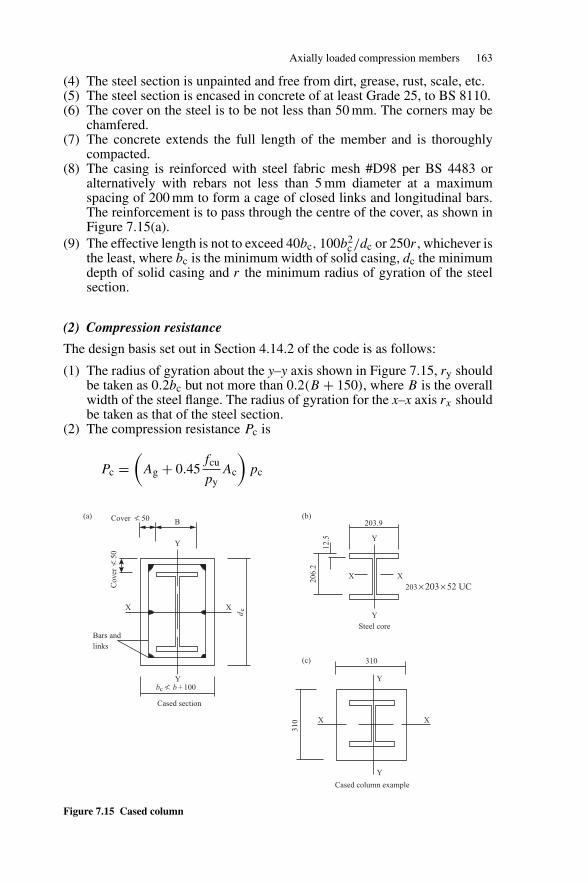
Axially loaded compression members 163
(4) The steel section is unpainted and free from dirt, grease, rust, scale, etc.(5) The steel section is encased in concrete of at least Grade 25, to BS 8110.(6) The cover on the steel is to be not less than 50 mm. The corners may be
chamfered.(7) The concrete extends the full length of the member and is thoroughly
compacted.(8) The casing is reinforced with steel fabric mesh #D98 per BS 4483 or
alternatively with rebars not less than 5 mm diameter at a maximumspacing of 200 mm to form a cage of closed links and longitudinal bars.The reinforcement is to pass through the centre of the cover, as shown inFigure 7.15(a).
(9) The effective length is not to exceed 40bc, 100b2c/dc or 250r , whichever is
the least, where bc is the minimum width of solid casing, dc the minimumdepth of solid casing and r the minimum radius of gyration of the steelsection.
(2) Compression resistance
The design basis set out in Section 4.14.2 of the code is as follows:
(1) The radius of gyration about the y–y axis shown in Figure 7.15, ry shouldbe taken as 0.2bc but not more than 0.2(B + 150), where B is the overallwidth of the steel flange. The radius of gyration for the x–x axis rx shouldbe taken as that of the steel section.
(2) The compression resistance Pc is
Pc =(
Ag + 0.45fcu
pyAc
)pc
Cover � 50
Cov
er�
50
Y
Ybc � b + 100
B
X
dcX
Bars andlinks
Cased section
Cased column example
310 X X
Y
Y
310
Steel core
203.9
Y
Y
X
203 × 203 × 52 UCX
12.5
206.
2
(a) (b)
(c)
Figure 7.15 Cased column
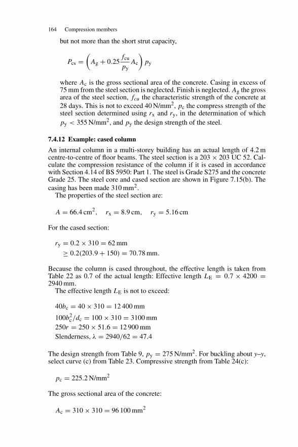
164 Compression members
but not more than the short strut capacity,
Pcs =(
Ag + 0.25fcu
pyAc
)py
where Ac is the gross sectional area of the concrete. Casing in excess of75 mm from the steel section is neglected. Finish is neglected. Ag the grossarea of the steel section, fcu the characteristic strength of the concrete at28 days. This is not to exceed 40 N/mm2, pc the compress strength of thesteel section determined using rx and ry, in the determination of whichpy < 355 N/mm2, and py the design strength of the steel.
7.4.12 Example: cased column
An internal column in a multi-storey building has an actual length of 4.2 mcentre-to-centre of floor beams. The steel section is a 203 × 203 UC 52. Cal-culate the compression resistance of the column if it is cased in accordancewith Section 4.14 of BS 5950: Part 1. The steel is Grade S275 and the concreteGrade 25. The steel core and cased section are shown in Figure 7.15(b). Thecasing has been made 310 mm2.
The properties of the steel section are:
A = 66.4 cm2, rx = 8.9 cm, ry = 5.16 cm
For the cased section:
ry = 0.2 × 310 = 62 mm
≥ 0.2(203.9 + 150) = 70.78 mm.
Because the column is cased throughout, the effective length is taken fromTable 22 as 0.7 of the actual length: Effective length LE = 0.7 × 4200 =2940 mm.
The effective length LE is not to exceed:
40bc = 40 × 310 = 12 400 mm
100b2c/dc = 100 × 310 = 3100 mm
250r = 250 × 51.6 = 12 900 mmSlenderness, λ = 2940/62 = 47.4
The design strength from Table 9, py = 275 N/mm2. For buckling about y–y,select curve (c) from Table 23. Compressive strength from Table 24(c):
pc = 225.2 N/mm2
The gross sectional area of the concrete:
Ac = 310 × 310 = 96 100 mm2
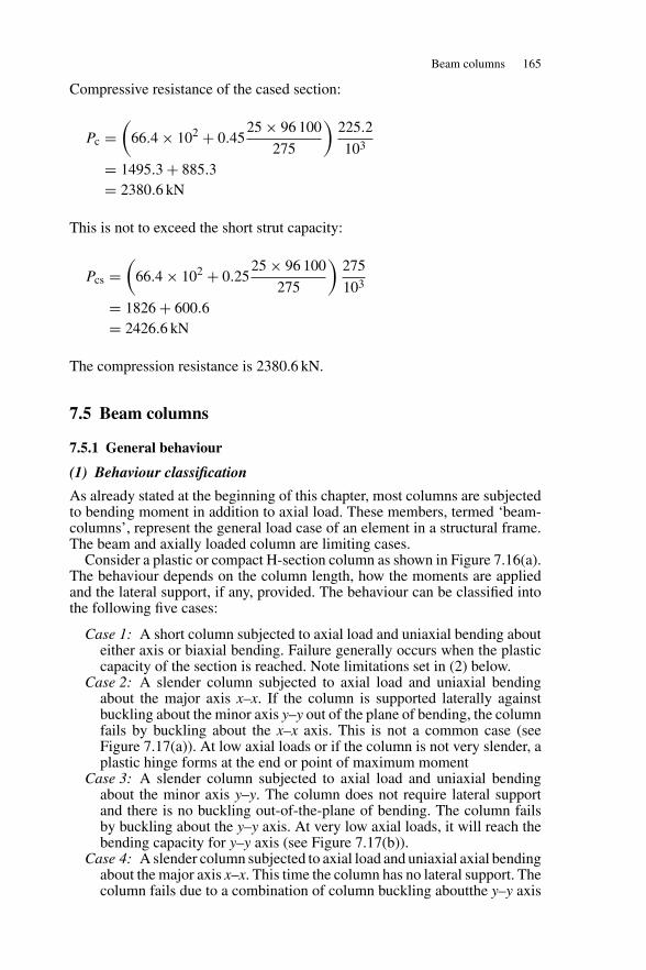
Beam columns 165
Compressive resistance of the cased section:
Pc =(
66.4 × 10² + 0.4525 × 96 100
275
)225.2
103
= 1495.3 + 885.3= 2380.6 kN
This is not to exceed the short strut capacity:
Pcs =(
66.4 × 10² + 0.2525 × 96 100
275
)275
103
= 1826 + 600.6= 2426.6 kN
The compression resistance is 2380.6 kN.
7.5 Beam columns
7.5.1 General behaviour
(1) Behaviour classification
As already stated at the beginning of this chapter, most columns are subjectedto bending moment in addition to axial load. These members, termed ‘beam-columns’, represent the general load case of an element in a structural frame.The beam and axially loaded column are limiting cases.
Consider a plastic or compact H-section column as shown in Figure 7.16(a).The behaviour depends on the column length, how the moments are appliedand the lateral support, if any, provided. The behaviour can be classified intothe following five cases:
Case 1: A short column subjected to axial load and uniaxial bending abouteither axis or biaxial bending. Failure generally occurs when the plasticcapacity of the section is reached. Note limitations set in (2) below.
Case 2: A slender column subjected to axial load and uniaxial bendingabout the major axis x–x. If the column is supported laterally againstbuckling about the minor axis y–y out of the plane of bending, the columnfails by buckling about the x–x axis. This is not a common case (seeFigure 7.17(a)). At low axial loads or if the column is not very slender, aplastic hinge forms at the end or point of maximum moment
Case 3: A slender column subjected to axial load and uniaxial bendingabout the minor axis y–y. The column does not require lateral supportand there is no buckling out-of-the-plane of bending. The column failsby buckling about the y–y axis. At very low axial loads, it will reach thebending capacity for y–y axis (see Figure 7.17(b)).
Case 4: A slender column subjected to axial load and uniaxial axial bendingabout the major axis x–x. This time the column has no lateral support. Thecolumn fails due to a combination of column buckling aboutthe y–y axis
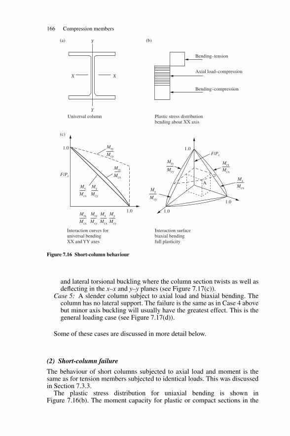
166 Compression members
Y
Y
XX
Universal column
(a) (b)
(c)
Interaction curves foruniversal bending XX and YY axes
Interaction surface biaxial bending full plasticity
Plastic stress distributionbending about XX axis
1.0
1.0
1.01.0
A
Bending–tension
Axial load–compression
Bending–compression
1.0
F/Pc
F/Pc
Mx
Mcx
My
Mcy
Mcy
Mcy
Mcy Mcx
MrxMry
My
Mcx
Mx
Mry
Mrx
Mrx Mry Mx My
Mcx Mcy Mcx Mcy
Mcx
Figure 7.16 Short-column behaviour
and lateral torsional buckling where the column section twists as well asdeflecting in the x–x and y–y planes (see Figure 7.17(c)).
Case 5: A slender column subject to axial load and biaxial bending. Thecolumn has no lateral support. The failure is the same as in Case 4 abovebut minor axis buckling will usually have the greatest effect. This is thegeneral loading case (see Figure 7.17(d)).
Some of these cases are discussed in more detail below.
(2) Short-column failure
The behaviour of short columns subjected to axial load and moment is thesame as for tension members subjected to identical loads. This was discussedin Section 7.3.3.
The plastic stress distribution for uniaxial bending is shown inFigure 7.16(b). The moment capacity for plastic or compact sections in the
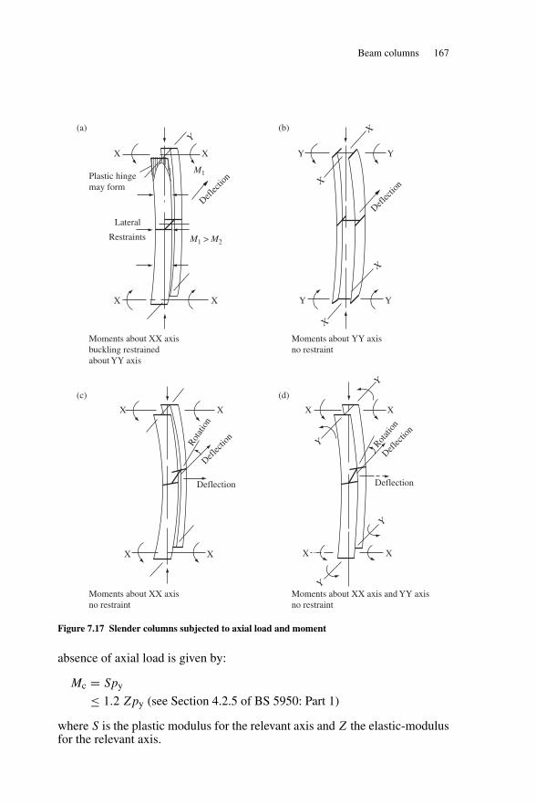
Beam columns 167
X
XX
X X
Rotat
ion
Deflec
tion
Deflection
X X
X
Y
Y
Y
Y
YX
X
X
X
Rotati
on
Deflection
Deflec
tion
Deflec
tion
Deflec
tion
Lateral
Restraints M1 > M2
M1Plastic hingemay form
YYXX
X X Y Y
Moments about XX axis buckling restrained about YY axis
Moments about XX axis no restraint
Moments about XX axis and YY axis no restraint
Moments about YY axis no restraint
(a) (b)
(c) (d)
Figure 7.17 Slender columns subjected to axial load and moment
absence of axial load is given by:
Mc = Spy
≤ 1.2 Zpy (see Section 4.2.5 of BS 5950: Part 1)
where S is the plastic modulus for the relevant axis and Z the elastic-modulusfor the relevant axis.
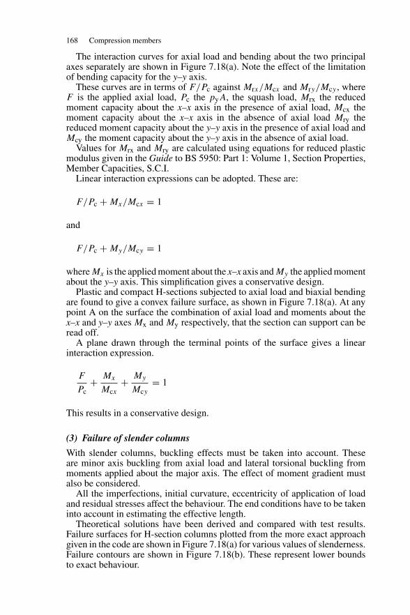
168 Compression members
The interaction curves for axial load and bending about the two principalaxes separately are shown in Figure 7.18(a). Note the effect of the limitationof bending capacity for the y–y axis.
These curves are in terms of F/Pc against Mrx/Mcx and Mry/Mcy , whereF is the applied axial load, Pc the pyA, the squash load, Mrx the reducedmoment capacity about the x–x axis in the presence of axial load, Mcx themoment capacity about the x–x axis in the absence of axial load Mry thereduced moment capacity about the y–y axis in the presence of axial load andMcy the moment capacity about the y–y axis in the absence of axial load.
Values for Mrx and Mry are calculated using equations for reduced plasticmodulus given in the Guide to BS 5950: Part 1: Volume 1, Section Properties,Member Capacities, S.C.I.
Linear interaction expressions can be adopted. These are:
F/Pc + Mx/Mcx = 1
and
F/Pc + My/Mcy = 1
where Mx is the applied moment about the x–x axis and My the applied momentabout the y–y axis. This simplification gives a conservative design.
Plastic and compact H-sections subjected to axial load and biaxial bendingare found to give a convex failure surface, as shown in Figure 7.18(a). At anypoint A on the surface the combination of axial load and moments about thex–x and y–y axes Mx and My respectively, that the section can support can beread off.
A plane drawn through the terminal points of the surface gives a linearinteraction expression.
F
Pc+ Mx
Mcx+ My
Mcy= 1
This results in a conservative design.
(3) Failure of slender columns
With slender columns, buckling effects must be taken into account. Theseare minor axis buckling from axial load and lateral torsional buckling frommoments applied about the major axis. The effect of moment gradient mustalso be considered.
All the imperfections, initial curvature, eccentricity of application of loadand residual stresses affect the behaviour. The end conditions have to be takeninto account in estimating the effective length.
Theoretical solutions have been derived and compared with test results.Failure surfaces for H-section columns plotted from the more exact approachgiven in the code are shown in Figure 7.18(a) for various values of slenderness.Failure contours are shown in Figure 7.18(b). These represent lower boundsto exact behaviour.
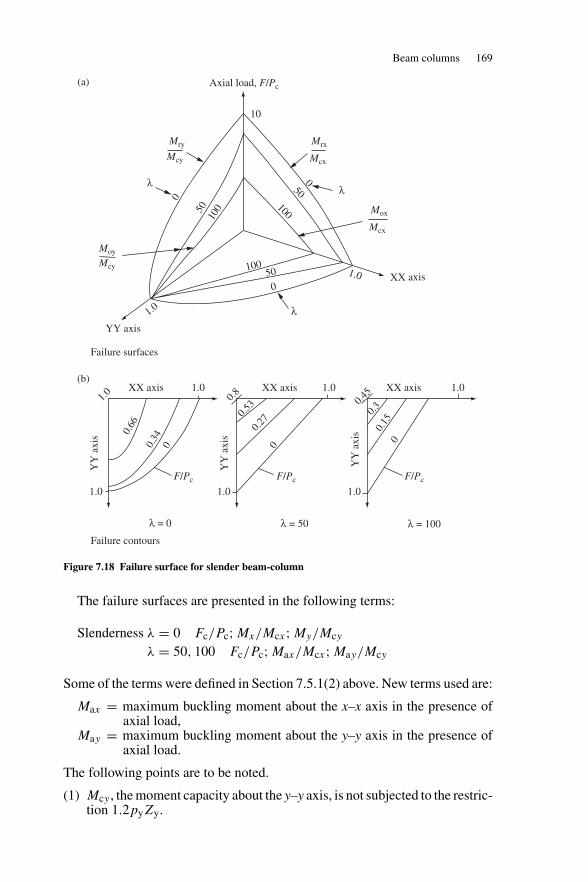
Beam columns 169
Failure surfaces
Failure contours
1.0 1.0 1.0
F/PcF/PcF/Pc
1.0 0.8
0.53 0.4
5
0.3
0.15
0
0.27
0
0.66
0.34
0
1.0XX axis XX axis XX axis
YY
axi
s
YY axis
1.0
10050
0
YY
axi
s
YY
axi
s
λ = 0 λ = 50
λ
λ = 100
1.0 1.0
10050
0
10
Mry Mrx
Mcy Mcx
Mox
XX axis
Mcx
Moy
Mcy
0
5010
0
λ
1.0
Axial load, F/Pc(a)
(b)
λ
Figure 7.18 Failure surface for slender beam-column
The failure surfaces are presented in the following terms:
Slenderness λ = 0 Fc/Pc; Mx/Mcx; My/Mcy
λ = 50, 100 Fc/Pc; Max/Mcx; May/Mcy
Some of the terms were defined in Section 7.5.1(2) above. New terms used are:
Max = maximum buckling moment about the x–x axis in the presence ofaxial load,
May = maximum buckling moment about the y–y axis in the presence ofaxial load.
The following points are to be noted.
(1) Mcy , the moment capacity about the y–y axis, is not subjected to the restric-tion 1.2pyZy.
170 Compression members
(2) At zero axial load, slenderness does not affect the bending strength of anH section about the y–y axis.
(3) At high values of slenderness the buckling resistance moment Mb aboutthe x–x axis controls the moment capacity for bending about that axis.
(4) As the slenderness increases, the failure curves in the F/Pc, y–y-axis planechange from convex to concave, showing the increasing dominance ofminor axis buckling.
For design purposes, the results are presented in the form of an interactionexpression, and this is discussed in the next section.
7.5.2 Code design procedure
The code design procedure for compression members with moments is set outin Section 4.8.3 of BS 5950: Part 1. This requires the following two checks tobe carried out:
(1) cross-section capacity check and(2) member buckling check.
In each case, two procedures are given. These are a simplified approach and amore exact one. Only the simplified approach will be used in design examplesin this book.
(1) Cross-section capacity check
The member should be checked at the point of greatest bending moment andaxial load. This is usually at the end, but it could be within the column heightif lateral loads are also applied. The capacity is controlled by yielding or localbuckling. (Local buckling was considered in Section 7.3.)
Except for Class 4 members, with the simplified approach, the interactionrelationship for Classes 1, 2 and 3 members given in Section 4.8.3.2 of thecode is:
Fc
Agpy+ Mx
Mcx+ My
Mcy≤ 1
where F is the applied axial load, Ag the gross cross-sectional area, Mx theapplied moment about the major axis x–x, Mcx the moment capacity aboutthe major axis x–x in the absence of axial load, My the applied moment aboutthe minor axis y–y, and Mcy the moment capacity about the minor axis y–yin the absence of axial load.
Alternatively, a more rigorous interaction relationship for plastic and com-pact sections given in the code can also be used. This is based on the convexfailure surface discussed above and gives greater economy in design.
For Class 4 members, the interaction relationship is:
Fc
Aeffpy+ Mx
Mcx+ My
Mcy≤ 1
where the additional term Aeff is the effective cross-sectional area defined bythe code under Clause 3.6.
Beam columns 171
(2) Member buckling resistance
Under Clause 4.8.3.3.1 of the code, for simplified method, the buckling resist-ance of a member may be verified by checking the following relationships sothat both are satisfied:
Fc
Agpc+ mxMx
Mb+ myMy
pyZy
≤ 1
and
Fc
Agpcy+ mLTMLT
Mb+ myMy
pyZy
≤ 1
where Fc = axial compressive loadm = equivalent uniform moment factor (x or y axis) from Table 18
of the code,Mb = buckling resistance moment capacity about the major axis
x–x,MLT = the maximum major axis moment in the segment length L
governing Mb,Mx = the maximum major axis moment in the segment length Lx
govering pcx ,My = the maximum minor axis moment in the segment length Ly
govering pcy ,pc = the smaller of pcx and pcy ,pcy = the compression resistance, considering buckling about the
minor axis only,Zy = elastic modulus of section for the minor axis y–y,Zy = elastic modulus of section for the minor axis y–y.
The value for Mb is determined using the methods set out in Section 5.5of this book (dealing with lateral torsional buckling of beams). A more exactapproach is also given in the code. This uses the convex failure surfaces dis-cussed above.
7.5.3 Example of beam column design
A braced column 4.5 m long is subjected to the factored end loads and momentsabout the x–x axis, as shown in Figure 7.19(a). The column is held in posi-tion but only partially restrained in direction at the ends. Check that a 203 ×203 UC 52 in Grade 43 steel is adequate.
(1) Column-section classification
Design strength from Table 9 py = 275 N/mm2
Factor ε = (275/py)0.5 = 1.0
(see Figure 7.19(b))Flange b/T = 101.95/12.5 = 8.156 < 9.0Web d/t = 160.8/8.0 = 20.1 < 40
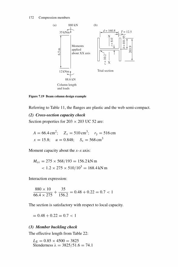
172 Compression members
6.5
m
35 kNm
12 kNm
88.6 kN
Momentsappliedabout XX axis
880 kN(a) (b)
Trial section
d = 160.8 T = 12.5X
Xr =
10.
2
t = 8
.0
203.
9b=
101.
95
Column length and loads
Figure 7.19 Beam column design example
Referring to Table 11, the flanges are plastic and the web semi-compact.
(2) Cross-section capacity check
Section properties for 203 × 203 UC 52 are:
A = 66.4 cm2; Zx = 510 cm3; ry = 516 cm
x = 15.8; u = 0.848; Sx = 568 cm3
Moment capacity about the x–x axis:
Mcx = 275 × 568/193 = 156.2 kN m
< 1.2 × 275 × 510/103 = 168.4 kN m
Interaction expression:
880 × 10
66.4 × 275+ 35
156.2= 0.48 + 0.22 = 0.7 < 1
The section is satisfactory with respect to local capacity.
= 0.48 + 0.22 = 0.7 < 1
(3) Member buckling check
The effective length from Table 22:
LE = 0.85 × 4500 = 3825Slenderness λ = 3825/51.6 = 74.1
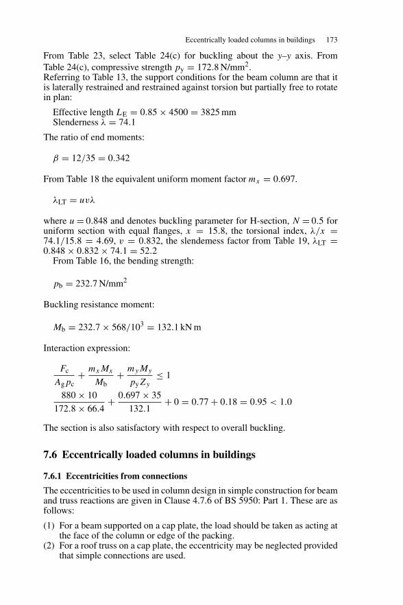
Eccentrically loaded columns in buildings 173
From Table 23, select Table 24(c) for buckling about the y–y axis. FromTable 24(c), compressive strength py = 172.8 N/mm2.Referring to Table 13, the support conditions for the beam column are that itis laterally restrained and restrained against torsion but partially free to rotatein plan:
Effective length LE = 0.85 × 4500 = 3825 mmSlenderness λ = 74.1
The ratio of end moments:
β = 12/35 = 0.342
From Table 18 the equivalent uniform moment factor mx = 0.697.
λLT = uvλ
where u = 0.848 and denotes buckling parameter for H-section, N = 0.5 foruniform section with equal flanges, x = 15.8, the torsional index, λ/x =74.1/15.8 = 4.69, v = 0.832, the slendemess factor from Table 19, λLT =0.848 × 0.832 × 74.1 = 52.2
From Table 16, the bending strength:
pb = 232.7 N/mm2
Buckling resistance moment:
Mb = 232.7 × 568/103 = 132.1 kN m
Interaction expression:
Fc
Agpc+ mxMx
Mb+ myMy
pyZy
≤ 1
880 × 10
172.8 × 66.4+ 0.697 × 35
132.1+ 0 = 0.77 + 0.18 = 0.95 < 1.0
The section is also satisfactory with respect to overall buckling.
7.6 Eccentrically loaded columns in buildings
7.6.1 Eccentricities from connections
The eccentricities to be used in column design in simple construction for beamand truss reactions are given in Clause 4.7.6 of BS 5950: Part 1. These are asfollows:
(1) For a beam supported on a cap plate, the load should be taken as acting atthe face of the column or edge of the packing.
(2) For a roof truss on a cap plate, the eccentricity may be neglected providedthat simple connections are used.
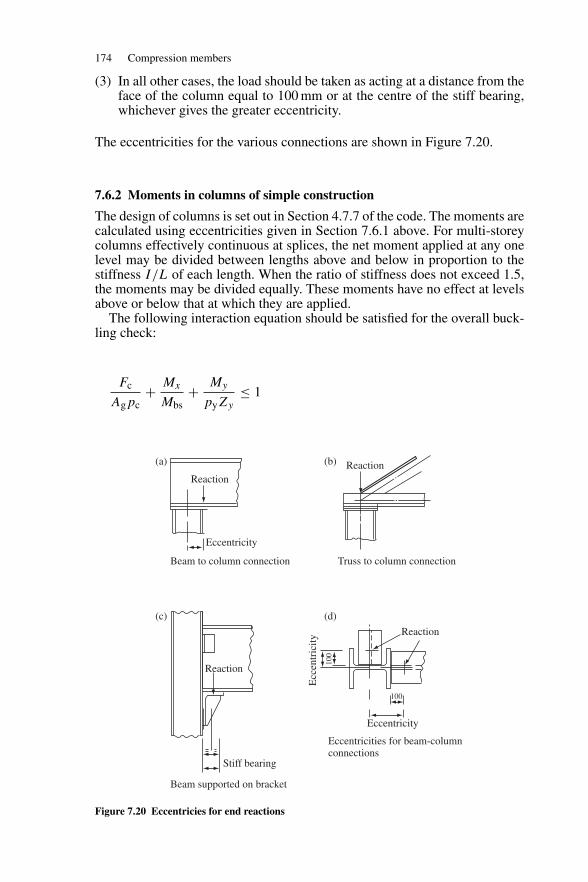
174 Compression members
(3) In all other cases, the load should be taken as acting at a distance from theface of the column equal to 100 mm or at the centre of the stiff bearing,whichever gives the greater eccentricity.
The eccentricities for the various connections are shown in Figure 7.20.
7.6.2 Moments in columns of simple construction
The design of columns is set out in Section 4.7.7 of the code. The moments arecalculated using eccentricities given in Section 7.6.1 above. For multi-storeycolumns effectively continuous at splices, the net moment applied at any onelevel may be divided between lengths above and below in proportion to thestiffness I/L of each length. When the ratio of stiffness does not exceed 1.5,the moments may be divided equally. These moments have no effect at levelsabove or below that at which they are applied.
The following interaction equation should be satisfied for the overall buck-ling check:
Fc
Agpc+ Mx
Mbs+ My
pyZy
≤ 1
Reaction
Eccentricity
Reaction(a) (b)
(c) (d)
Beam to column connection
Beam supported on bracket
Truss to column connection
Eccentricities for beam-column connections
Reaction
Stiff bearing
Eccentricity
Reaction
100
Ecc
entr
icity
100
Figure 7.20 Eccentricies for end reactions
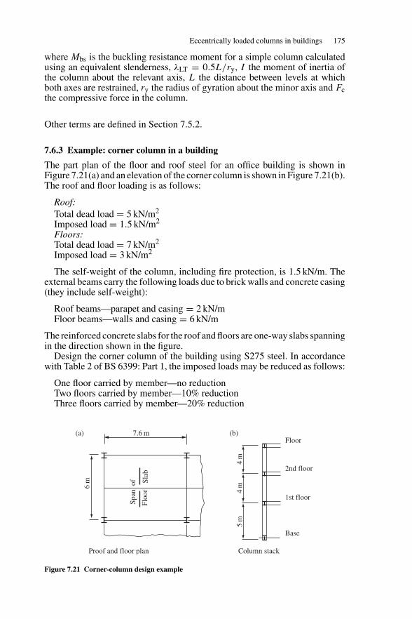
Eccentrically loaded columns in buildings 175
where Mbs is the buckling resistance moment for a simple column calculatedusing an equivalent slenderness, λLT = 0.5L/ry, I the moment of inertia ofthe column about the relevant axis, L the distance between levels at whichboth axes are restrained, ry the radius of gyration about the minor axis and Fcthe compressive force in the column.
Other terms are defined in Section 7.5.2.
7.6.3 Example: corner column in a building
The part plan of the floor and roof steel for an office building is shown inFigure 7.21(a) and an elevation of the corner column is shown in Figure 7.21(b).The roof and floor loading is as follows:
Roof:Total dead load = 5 kN/m2
Imposed load = 1.5 kN/m2
Floors:Total dead load = 7 kN/m2
Imposed load = 3 kN/m2
The self-weight of the column, including fire protection, is 1.5 kN/m. Theexternal beams carry the following loads due to brick walls and concrete casing(they include self-weight):
Roof beams—parapet and casing = 2 kN/mFloor beams—walls and casing = 6 kN/m
The reinforced concrete slabs for the roof and floors are one-way slabs spanningin the direction shown in the figure.
Design the corner column of the building using S275 steel. In accordancewith Table 2 of BS 6399: Part 1, the imposed loads may be reduced as follows:
One floor carried by member—no reductionTwo floors carried by member—10% reductionThree floors carried by member—20% reduction
Span
of
Floo
rSl
ab
7.6 m(a) (b)
Column stack
Floor
2nd floor
1st floor
Base
5m
4m
4m
6m
Proof and floor plan
Figure 7.21 Corner-column design example
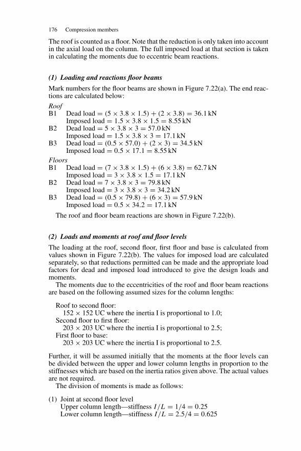
176 Compression members
The roof is counted as a floor. Note that the reduction is only taken into accountin the axial load on the column. The full imposed load at that section is takenin calculating the moments due to eccentric beam reactions.
(1) Loading and reactions floor beams
Mark numbers for the floor beams are shown in Figure 7.22(a). The end reac-tions are calculated below:
RoofB1 Dead load = (5 × 3.8 × 1.5) + (2 × 3.8) = 36.1 kN
Imposed load = 1.5 × 3.8 × 1.5 = 8.55 kNB2 Dead load = 5 × 3.8 × 3 = 57.0 kN
Imposed load = 1.5 × 3.8 × 3 = 17.1 kNB3 Dead load = (0.5 × 57.0) + (2 × 3) = 34.5 kN
Imposed load = 0.5 × 17.1 = 8.55 kNFloorsB1 Dead load = (7 × 3.8 × 1.5) + (6 × 3.8) = 62.7 kN
Imposed load = 3 × 3.8 × 1.5 = 17.1 kNB2 Dead load = 7 × 3.8 × 3 = 79.8 kN
Imposed load = 3 × 3.8 × 3 = 34.2 kNB3 Dead load = (0.5 × 79.8) + (6 × 3) = 57.9 kN
Imposed load = 0.5 × 34.2 = 17.1 kN
The roof and floor beam reactions are shown in Figure 7.22(b).
(2) Loads and moments at roof and floor levels
The loading at the roof, second floor, first floor and base is calculated fromvalues shown in Figure 7.22(b). The values for imposed load are calculatedseparately, so that reductions permitted can be made and the appropriate loadfactors for dead and imposed load introduced to give the design loads andmoments.
The moments due to the eccentricities of the roof and floor beam reactionsare based on the following assumed sizes for the column lengths:
Roof to second floor:152 × 152 UC where the inertia I is proportional to 1.0;
Second floor to first floor:203 × 203 UC where the inertia I is proportional to 2.5;
First floor to base:203 × 203 UC where the inertia I is proportional to 2.5.
Further, it will be assumed initially that the moments at the floor levels canbe divided between the upper and lower column lengths in proportion to thestiffnesses which are based on the inertia ratios given above. The actual valuesare not required.
The division of moments is made as follows:
(1) Joint at second floor levelUpper column length—stiffness I/L = 1/4 = 0.25Lower column length—stiffness I/L = 2.5/4 = 0.625
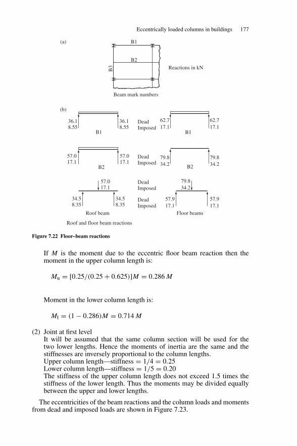
Eccentrically loaded columns in buildings 177
B2
B1
Beam mark numbers
B1(a)
(b)B
3
57.017.1
34.58.35
34.58.35
57.017.1
B2
Roof beam Floor beams
79.834.2
B2
B1
62.717.1
79.834.2
79.834.2
57.917.1
57.917.1
62.717.1
Reactions in kN
57.017.1
36.18.55
36.18.55
Roof and floor beam reactions
DeadImposed
DeadImposed
DeadImposed
DeadImposed
Figure 7.22 Floor–beam reactions
If M is the moment due to the eccentric floor beam reaction then themoment in the upper column length is:
Mu = [0.25/(0.25 + 0.625)]M = 0.286 M
Moment in the lower column length is:
Ml = (1 − 0.286)M = 0.714 M
(2) Joint at first levelIt will be assumed that the same column section will be used for thetwo lower lengths. Hence the moments of inertia are the same and thestiffnesses are inversely proportional to the column lengths.Upper column length—stiffness = 1/4 = 0.25Lower column length—stiffness = 1/5 = 0.20The stiffness of the upper column length does not exceed 1.5 times thestiffness of the lower length. Thus the moments may be divided equallybetween the upper and lower lengths.
The eccentricities of the beam reactions and the column loads and momentsfrom dead and imposed loads are shown in Figure 7.23.
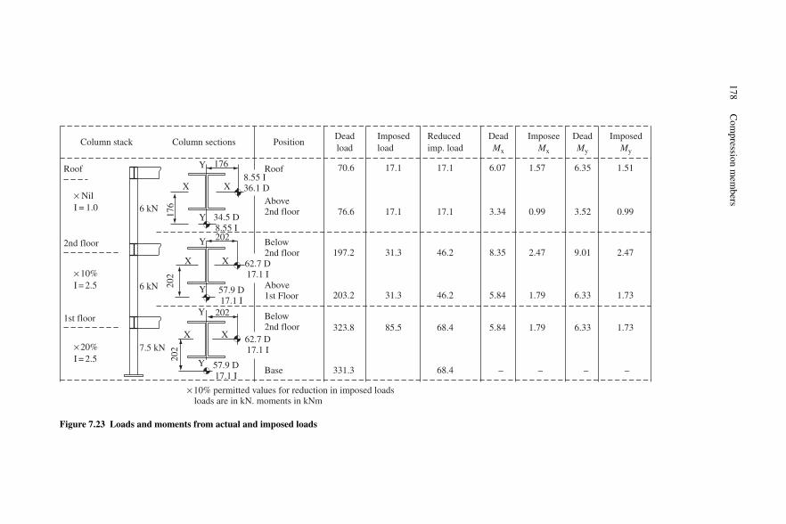
178C
ompression
mem
bers
Column stack Column sections PositionDeadload
Imposedload
Reducedimp. load
DeadMx
ImposeeMx
DeadMy
ImposedMy
Roof
× NilI = 1.0
Roof
Above2nd floor
Below2nd floor
Above1st Floor
Below2nd floor
Base 331.3
323.8
203.2
197.2
76.6
70.6
68.4
68.4
46.2
46.2
17.1
17.1
–
1.73
1.73
2.47
0.99
1.51
–
6.33
6.33
9.01
3.52
6.35
–
1.79
1.79
2.47
0.99
1.57
–
5.84
5.84
8.35
3.34
6.07
85.5
31.3
31.3
17.1
17.1
2nd floor
× 10%I = 2.5
× 20%I = 2.5
7.5 kNX
Y
Y
Y
Y
Y
X X
X
6 kN
6 kN
176
202
202
1st floor
X X
Y 176
8.55 I36.1 D
202
202
57.9 D17.1 I
62.7 D17.1 I
62.7 D17.1 I
57.9 D17.1 I
34.5 D 8.55 I
× 10% permitted values for reduction in imposed loads loads are in kN. moments in kNm
Figure 7.23 Loads and moments from actual and imposed loads
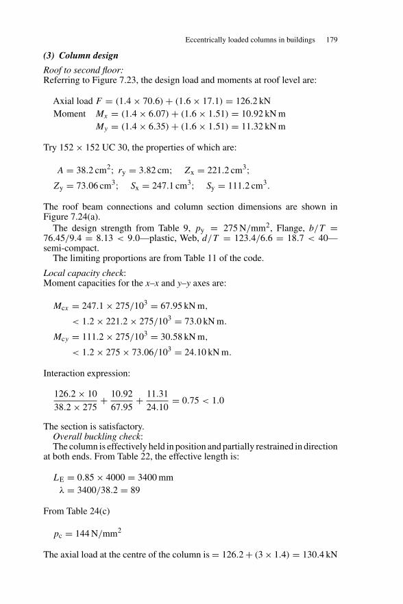
Eccentrically loaded columns in buildings 179
(3) Column design
Roof to second floor:Referring to Figure 7.23, the design load and moments at roof level are:
Axial load F = (1.4 × 70.6) + (1.6 × 17.1) = 126.2 kNMoment Mx = (1.4 × 6.07) + (1.6 × 1.51) = 10.92 kN m
My = (1.4 × 6.35) + (1.6 × 1.51) = 11.32 kN m
Try 152 × 152 UC 30, the properties of which are:
A = 38.2 cm2; ry = 3.82 cm; Zx = 221.2 cm3;Zy = 73.06 cm3; Sx = 247.1 cm3; Sy = 111.2 cm3.
The roof beam connections and column section dimensions are shown inFigure 7.24(a).
The design strength from Table 9, py = 275 N/mm2, Flange, b/T =76.45/9.4 = 8.13 < 9.0—plastic, Web, d/T = 123.4/6.6 = 18.7 < 40—semi-compact.
The limiting proportions are from Table 11 of the code.
Local capacity check:Moment capacities for the x–x and y–y axes are:
Mcx = 247.1 × 275/103 = 67.95 kN m,
< 1.2 × 221.2 × 275/103 = 73.0 kN m.
Mcy = 111.2 × 275/103 = 30.58 kN m,
< 1.2 × 275 × 73.06/103 = 24.10 kN m.
Interaction expression:
126.2 × 10
38.2 × 275+ 10.92
67.95+ 11.31
24.10= 0.75 < 1.0
The section is satisfactory.Overall buckling check:The column is effectively held in position and partially restrained in direction
at both ends. From Table 22, the effective length is:
LE = 0.85 × 4000 = 3400 mmλ = 3400/38.2 = 89
From Table 24(c)
pc = 144 N/mm2
The axial load at the centre of the column is = 126.2 + (3 × 1.4) = 130.4 kN
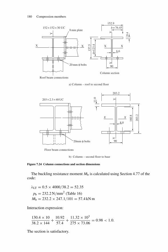
180 Compression members
X X
YY
d=12
3.4
157.
5
152.9
b = 76.45
X
6.6
90
203.2
X X
8.0
90
9.4
X
Y
YY
160.
8
203.
2
11.0
Floor beam connections
b) Column – second floor to base
20mm φ bolts
20 mm φ bolts
Column section
8 mm plate
203 × 2.3 × 48 UC
a) Column – roof to second floor
Roof beam connections
152 × 152 × 30 UC
Figure 7.24 Column connections and section dimensions
The buckling resistance moment Mb is calculated using Section 4.77 of thecode:
λLT = 0.5 × 4000/38.2 = 52.35
pb = 232.2 N/mm2 (Table 16)Mb = 232.2 × 247.1/101 = 57.4 kN m
Interaction expression:
130.4 × 10
38.2 × 144+ 10.92
57.4+ 11.32 × 10³
275 × 73.06= 0.98 < 1.0.
The section is satisfactory.
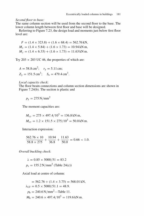
Eccentrically loaded columns in buildings 181
Second floor to base:The same column section will be used from the second floor to the base. Thelower column length between first floor and base will be designed.
Referring to Figure 7.23, the design load and moments just below first floorlevel are:
F = (1.4 × 323.8) + (1.6 × 68.4) = 562.76 kN,
Mx = (1.4 × 5.84) + (1.6 × 1.73) = 10.94 kN m,
My = (1.4 × 6.33) + (1.6 × 1.73) = 11.63 kN m.
Try 203 × 203 UC 46, the properties of which are:
A = 58.8 cm2; ry = 5.11 cm;Zy = 151.5 cm3; Sx = 479.4 cm3.
Local capacity check:The floor beam connections and column section dimensions are shown inFigure 7.24(b). The section is plastic and
py = 275 N/mm2
The moment capacities are:
Mcy = 275 × 497.4/103 = 136.8 kN m,
Mcy = 1.2 × 151.5 × 275/103 = 50.0 kN m.
Interaction expression:
562.76 × 10
58.8 × 275+ 10.94
36.8+ 11.63
50.0= 0.66 < 1.0.
Overall buckling check:
λ = 0.85 × 5000/51 = 83.2
pc = 155.2 N/mm2 (Table 24(c))
Axial load at centre of column:
= 562.76 + (1.4 × 3.75) = 568.01 kN,
λLT = 0.5 × 5000/51.1 = 48.9.
pb = 240.6 N/mm2—Table 11.
Mb = 240.6 × 497.4/103 = 119.6 kN m.
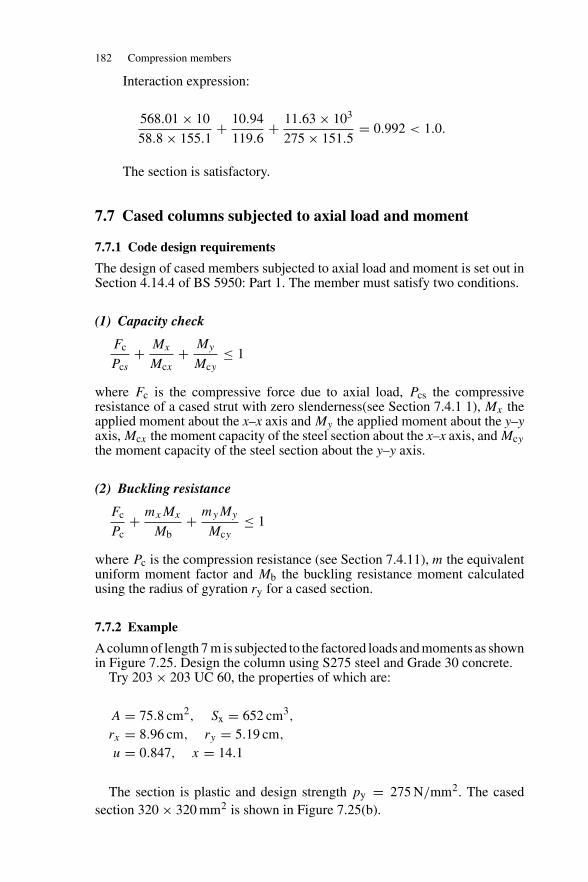
182 Compression members
Interaction expression:
568.01 × 10
58.8 × 155.1+ 10.94
119.6+ 11.63 × 10³
275 × 151.5= 0.992 < 1.0.
The section is satisfactory.
7.7 Cased columns subjected to axial load and moment
7.7.1 Code design requirements
The design of cased members subjected to axial load and moment is set out inSection 4.14.4 of BS 5950: Part 1. The member must satisfy two conditions.
(1) Capacity check
Fc
Pcs+ Mx
Mcx+ My
Mcy≤ 1
where Fc is the compressive force due to axial load, Pcs the compressiveresistance of a cased strut with zero slenderness(see Section 7.4.1 1), Mx theapplied moment about the x–x axis and My the applied moment about the y–yaxis, Mcx the moment capacity of the steel section about the x–x axis, and Mcythe moment capacity of the steel section about the y–y axis.
(2) Buckling resistance
Fc
Pc+ mxMx
Mb+ myMy
Mcy≤ 1
where Pc is the compression resistance (see Section 7.4.11), m the equivalentuniform moment factor and Mb the buckling resistance moment calculatedusing the radius of gyration ry for a cased section.
7.7.2 Example
A column of length 7 m is subjected to the factored loads and moments as shownin Figure 7.25. Design the column using S275 steel and Grade 30 concrete.
Try 203 × 203 UC 60, the properties of which are:
A = 75.8 cm2, Sx = 652 cm3,
rx = 8.96 cm, ry = 5.19 cm,
u = 0.847, x = 14.1
The section is plastic and design strength py = 275 N/mm2. The casedsection 320 × 320 mm2 is shown in Figure 7.25(b).
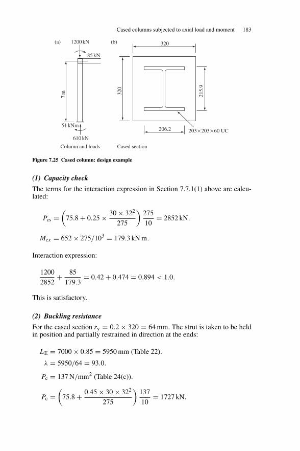
Cased columns subjected to axial load and moment 183
51 kNm
610 kN
Column and loads Cased section
7m
85 kN
1200 kN(a) (b)
206.2 203 × 203 × 60 UC
320
215.
9
320
Figure 7.25 Cased column: design example
(1) Capacity check
The terms for the interaction expression in Section 7.7.1(1) above are calcu-lated:
Pcs =(
75.8 + 0.25 × 30 × 322
275
)275
10= 2852 kN.
Mcx = 652 × 275/103 = 179.3 kN m.
Interaction expression:
1200
2852+ 85
179.3= 0.42 + 0.474 = 0.894 < 1.0.
This is satisfactory.
(2) Buckling resistance
For the cased section ry = 0.2 × 320 = 64 mm. The strut is taken to be heldin position and partially restrained in direction at the ends:
LE = 7000 × 0.85 = 5950 mm (Table 22).
λ = 5950/64 = 93.0.
Pc = 137 N/mm2 (Table 24(c)).
Pc =(
75.8 + 0.45 × 30 × 322
275
)137
10= 1727 kN.
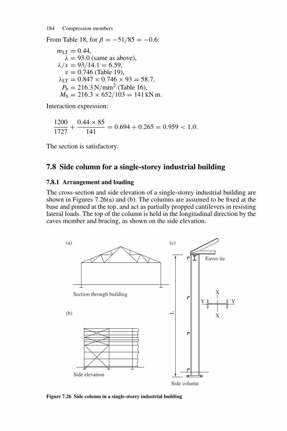
184 Compression members
From Table 18, for β = −51/85 = −0.6:
mLT = 0.44,λ = 93.0 (same as above),
λ/x = 93/14.1 = 6.59,v = 0.746 (Table 19),
λLT = 0.847 × 0.746 × 93 = 58.7,Pb = 216.3 N/mm2 (Table 16),Mb = 216.3 × 652/103 = 141 kN m.
Interaction expression:
1200
1727+ 0.44 × 85
141= 0.694 + 0.265 = 0.959 < 1.0.
The section is satisfactory.
7.8 Side column for a single-storey industrial building
7.8.1 Arrangement and loading
The cross-section and side elevation of a single-storey industrial building areshown in Figures 7.26(a) and (b). The columns are assumed to be fixed at thebase and pinned at the top, and act as partially propped cantilevers in resistinglateral loads. The top of the column is held in the longitudinal direction by thecaves member and bracing, as shown on the side elevation.
Section through building
(a) (c)
(b)
Side elevation
Side column
X
X
Eaves tie
L
Y Y
Figure 7.26 Side column in a single-storey industrial building
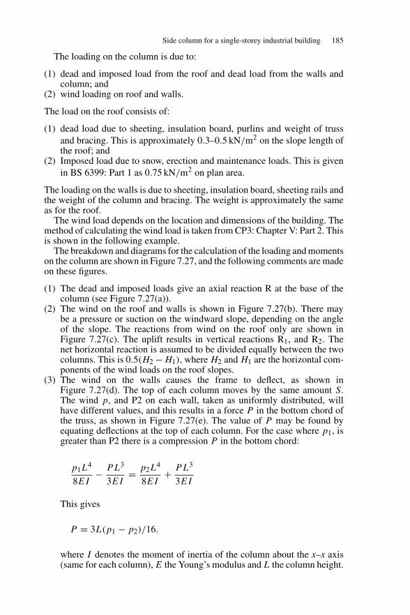
Side column for a single-storey industrial building 185
The loading on the column is due to:
(1) dead and imposed load from the roof and dead load from the walls andcolumn; and
(2) wind loading on roof and walls.
The load on the roof consists of:
(1) dead load due to sheeting, insulation board, purlins and weight of trussand bracing. This is approximately 0.3–0.5 kN/m2 on the slope length ofthe roof; and
(2) Imposed load due to snow, erection and maintenance loads. This is givenin BS 6399: Part 1 as 0.75 kN/m2 on plan area.
The loading on the walls is due to sheeting, insulation board, sheeting rails andthe weight of the column and bracing. The weight is approximately the sameas for the roof.
The wind load depends on the location and dimensions of the building. Themethod of calculating the wind load is taken from CP3: Chapter V: Part 2. Thisis shown in the following example.
The breakdown and diagrams for the calculation of the loading and momentson the column are shown in Figure 7.27, and the following comments are madeon these figures.
(1) The dead and imposed loads give an axial reaction R at the base of thecolumn (see Figure 7.27(a)).
(2) The wind on the roof and walls is shown in Figure 7.27(b). There maybe a pressure or suction on the windward slope, depending on the angleof the slope. The reactions from wind on the roof only are shown inFigure 7.27(c). The uplift results in vertical reactions R1, and R2. Thenet horizontal reaction is assumed to be divided equally between the twocolumns. This is 0.5(H2 − H1), where H2 and H1 are the horizontal com-ponents of the wind loads on the roof slopes.
(3) The wind on the walls causes the frame to deflect, as shown inFigure 7.27(d). The top of each column moves by the same amount S.The wind p, and P2 on each wall, taken as uniformly distributed, willhave different values, and this results in a force P in the bottom chord ofthe truss, as shown in Figure 7.27(e). The value of P may be found byequating deflections at the top of each column. For the case where p1, isgreater than P2 there is a compression P in the bottom chord:
p1L4
8EI− PL3
3EI= p2L
4
8EI+ PL3
3EI
This gives
P = 3L(p1 − p2)/16.
where I denotes the moment of inertia of the column about the x–x axis(same for each column), E the Young’s modulus and L the column height.
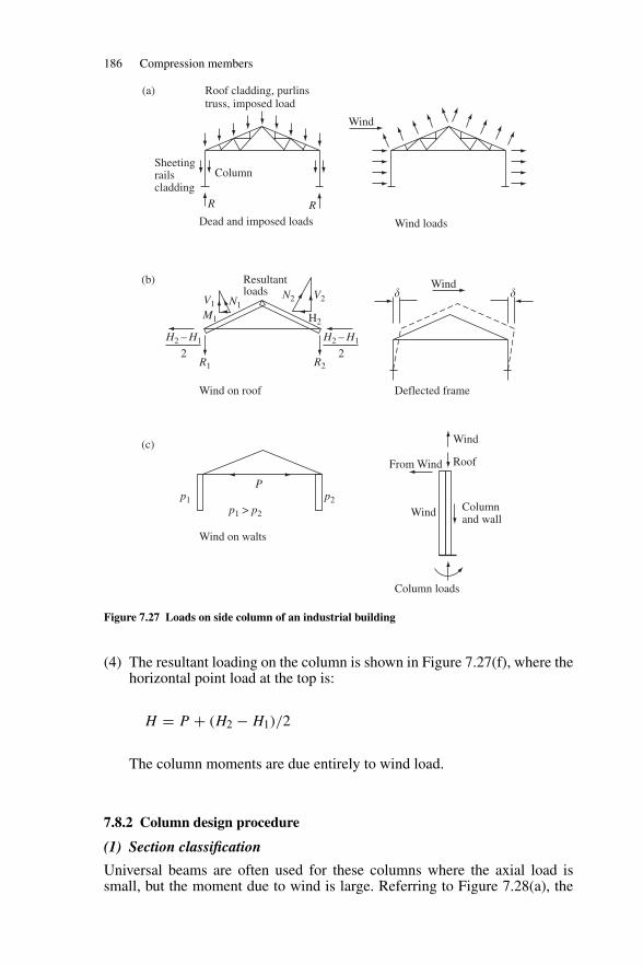
186 Compression members
Wind
WindN2
H2
V2
Resultantloads
V1 N1M1
H2 – H1
2
H2 – H1
2R1 R2
Wind on roof
Sheetingrailscladding
Column
R
Dead and imposed loads
Roof cladding, purlinstruss, imposed load
(b)
(c)
(a)
Wind loads
R
Deflected frame
� �
P
p1 > p2
Wind on walts
p2p1Columnand wall
Roof
Wind
From Wind
Wind
Column loads
Figure 7.27 Loads on side column of an industrial building
(4) The resultant loading on the column is shown in Figure 7.27(f), where thehorizontal point load at the top is:
H = P + (H2 − H1)/2
The column moments are due entirely to wind load.
7.8.2 Column design procedure
(1) Section classification
Universal beams are often used for these columns where the axial load issmall, but the moment due to wind is large. Referring to Figure 7.28(a), the
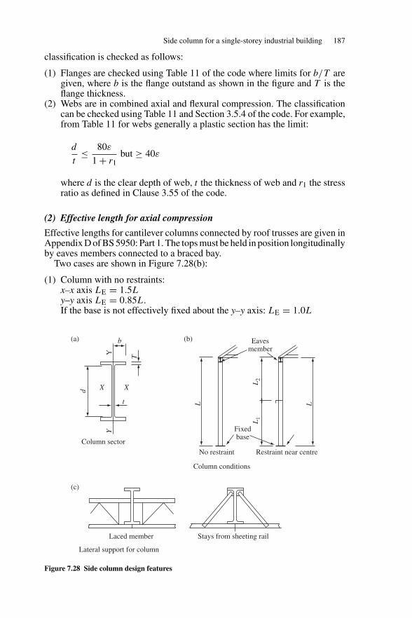
Side column for a single-storey industrial building 187
classification is checked as follows:
(1) Flanges are checked using Table 11 of the code where limits for b/T aregiven, where b is the flange outstand as shown in the figure and T is theflange thickness.
(2) Webs are in combined axial and flexural compression. The classificationcan be checked using Table 11 and Section 3.5.4 of the code. For example,from Table 11 for webs generally a plastic section has the limit:
d
t≤ 80ε
1 + r1but ≥ 40ε
where d is the clear depth of web, t the thickness of web and r1 the stressratio as defined in Clause 3.55 of the code.
(2) Effective length for axial compression
Effective lengths for cantilever columns connected by roof trusses are given inAppendix D of BS 5950: Part 1. The tops must be held in position longitudinallyby eaves members connected to a braced bay.
Two cases are shown in Figure 7.28(b):
(1) Column with no restraints:x–x axis LE = 1.5Ly–y axis LE = 0.85L.If the base is not effectively fixed about the y–y axis: LE = 1.0L
t
Xd
Y
X
b
TY
Fixedbase
Eavesmember
(b)(a)
(c)
No restraint
Column conditions
Lateral support for column
Column sector
Laced member Stays from sheeting rail
Restraint near centre
L
L2
L1
L
Figure 7.28 Side column design features
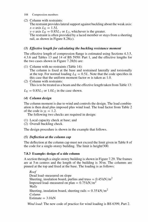
188 Compression members
(2) Column with restraints:The restraint provides lateral support against buckling about the weak axis:x–x axis LE = 1.5Ly–y axis LE = 0.85L1 or L2, whichever is the greater.The restraint is often provided by a laced member or stays from a sheetingrail, as shown in Figure 8.28(c).
(3) Effective length for calculating the buckling resistance moment
The effective length of compression flange is estimated using Sections 4.3.5,4.3.6 and Tables 13 and 14 of BS 5950: Part 1, and the effective lengths forthe two cases shown in Figure 7.28(b) are:
(1) Column with no restraints (Table 14):The column is fixed at the base and restrained laterally and torsionallyat the top. For normal loading LE = 0.5L. Note that the code specifies inthis case that the uniform moment factor m is taken as 1.0.
(2) Column with restraints:This is to be treated as a beam and the effective length taken from Table 13:
LE = 0.85L1 or 1.0L2 in the case shown.
(4) Column design
The column moment is due to wind and controls the design. The load combin-ation is then dead plus imposed plus wind load. The load factor from Table 2of the code is γf = 1.2.
The following two checks are required in design:
(1) Local capacity check at base; and(2) Overall buckling check.
The design procedure is shown in the example that follows.
(5) Deflection at the column cap
The deflection at the column cap must not exceed the limit given in Table 8 ofthe code for a single-storey building. The limit is height/300.
7.8.3 Example: design of a side column
A section through a single-storey building is shown in Figure 7.29. The framesare at 5 m centres and the length of the building is 30 m. The columns arepinned at the top and fixed at the base. The loading is as follows:
RoofDead load–measured on slopeSheeting, insulation board, purlins and truss = 0.45 kN/m2
Imposed load–measured on plan = 0.75 kN/m2
WallsSheeting, insulation board, sheeting rails = 0.35 kN/m2
ColumnEstimate = 3.0 kN
Wind load: The new code of practice for wind loading is BS 6399, Part 2.
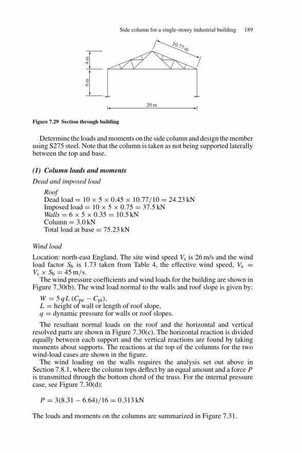
Side column for a single-storey industrial building 189
10.77 m
20 m
6m
4m
Figure 7.29 Section through building
Determine the loads and moments on the side column and design the memberusing S275 steel. Note that the column is taken as not being supported laterallybetween the top and base.
(1) Column loads and moments
Dead and imposed load
RoofDead load = 10 × 5 × 0.45 × 10.77/10 = 24.23 kNImposed load = 10 × 5 × 0.75 = 37.5 kNWalls = 6 × 5 × 0.35 = 10.5 kNColumn = 3.0 kNTotal load at base = 75.23 kN
Wind load
Location: north-east England. The site wind speed Vs is 26 m/s and the windload factor Sb is 1.73 taken from Table 4, the effective wind speed, Ve =Vs × Sb = 45 m/s.
The wind pressure coefficients and wind loads for the building are shown inFigure 7.30(b). The wind load normal to the walls and roof slope is given by:
W = 5 qL (Cpe − Cpi),L = height of wall or length of roof slope,q = dynamic pressure for walls or roof slopes.
The resultant normal loads on the roof and the horizontal and verticalresolved parts are shown in Figure 7.30(c). The horizontal reaction is dividedequally between each support and the vertical reactions are found by takingmoments about supports. The reactions at the top of the columns for the twowind-load cases are shown in the figure.
The wind loading on the walls requires the analysis set out above inSection 7.8.1, where the column tops deflect by an equal amount and a force Pis transmitted through the bottom chord of the truss. For the internal pressurecase, see Figure 7.30(d):
P = 3(8.31 − 6.64)/16 = 0.313 kN
The loads and moments on the columns are summarized in Figure 7.31.
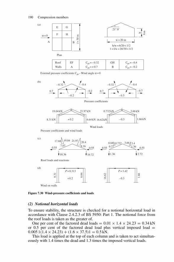
190 Compression members
E(a)
(b)
(c)
(d)
F
A B
G
H
l=30
m
6mh
α = 0
21° 8�
w = 20 m
h/w = 6/20 < 1/2 1 < l/w = 20/30 < 1/2
Plan
Roof
Walls
EF
A B
GHCpe = – 0.32
Cpe = + 0.7
Cpe = –0.4
Cpe = –0.2
External pressure coefficients Cpe – Wind angle α = 0
– 0.32 – 0.4
– 0.2
– 0.20.7
– 0.32 – 0.4
– 0.3
– 0.70.7
–0.3+ 0.2
Pressure coefficients
19.04 kN 21.97 kN
8.31 kN 6.64 kN
0.732 kN
16.62 kN
Wind loads
1.66 kN
3.66 kN
Pressure coefficients and wind loads
17.68 21.97 20.4
0.55 0.55 0.550.557.07
18.36 19.72
8.16
19.040.680.27
0.732 3.66 3.41.36
1.36 2.72
Roof loads and reactions
Wind on walls
P = 0.313
+0.2
8.31
6.64
P = 3.42
–0.316.6
2
1.66
Figure 7.30 Wind-pressure coefficients and loads
(2) Notional horizontal loads
To ensure stability, the structure is checked for a notional horizontal load inaccordance with Clause 2.4.2.3 of BS 5950: Part 1. The notional force fromthe roof loads is taken as the greater of.
One per cent of the factored dead loads = 0.01 × 1.4 × 24.23 = 0.34 kNor 0.5 per cent of the factored dead load plus vertical imposed load =0.005 1(1.4 × 24.23) + (1.6 × 37.5)1 = 0.5 kN.
This load is applied at the top of each column and is taken to act simultan-eously with 1.4 times the dead and 1.3 times the imposed vertical loads.
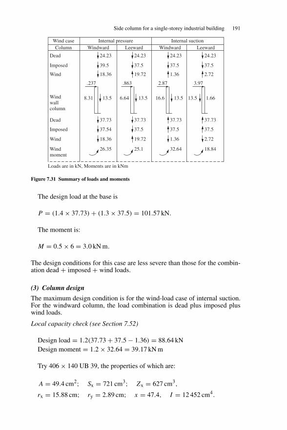
Side column for a single-storey industrial building 191
24.23
39.5
18.36
37.73
37.54
18.36
26.35
Wind caseColumn
Dead
Imposed
Wind
Windwallcolumn
Dead
Imposed
Wind
Windmoment
Internal pressureWindward Leeward
Internal suctionWindward Leeward
.237
8.31 13.5
.863
6.64 13.5
2.87
16.6 13.5
3.97
13.5 1.66
24.23
37.5
19.72
37.73
37.5
19.72
25.1
Loads are in kN, Moments are in kNm
24.23
37.5
1.36
37.73
37.5
1.36
32.64
24.23
37.5
2.72
37.73
37.5
2.72
18.84
Figure 7.31 Summary of loads and moments
The design load at the base is
P = (1.4 × 37.73) + (1.3 × 37.5) = 101.57 kN.
The moment is:
M = 0.5 × 6 = 3.0 kN m.
The design conditions for this case are less severe than those for the combin-ation dead + imposed + wind loads.
(3) Column design
The maximum design condition is for the wind-load case of internal suction.For the windward column, the load combination is dead plus imposed pluswind loads.
Local capacity check (see Section 7.52)
Design load = 1.2(37.73 + 37.5 − 1.36) = 88.64 kNDesign moment = 1.2 × 32.64 = 39.17 kN m
Try 406 × 140 UB 39, the properties of which are:
A = 49.4 cm2; Sx = 721 cm3; Zx = 627 cm3,
rx = 15.88 cm; ry = 2.89 cm; x = 47.4, I = 12 452 cm4.
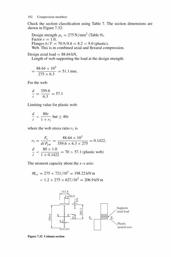
192 Compression members
Check the section classification using Table 7. The section dimensions areshown in Figure 7.32:
Design strength py = 275 N/mm2 (Table 9),Factor ε = 1.0,Flanges b/T = 70.9/8.6 = 8.2 < 9.0 (plastic),Web. This is in combined axial and flexural compression.
Design axial load = 88.64 kN,Length of web supporting the load at the design strength:
= 88.64 × 10³
275 × 6.3= 51.1 mm,
For the web:
d
t= 359.6
6.3= 57.1
Limiting value for plastic web:
d
t<
80ε
1 + r1but ≥ 40ε
where the web stress ratio r1 is
r1 = Fc
dtPyw= 88.64 × 10³
359.6 × 6.3 × 275= 0.1422,
d
t<
80 × 1.0
1 + 0.1422= 70 > 57.1 (plastic web)
The moment capacity about the x–x axis:
Mcx = 275 × 721/103 = 198.22 kN m
< 1.2 × 275 × 627/103 = 206.9 kN m
141.8
b = 70.9
359.
6
6.3
51.1 20
5.3
8.6
Supportsaxial load
Plasticneutral axis
X1X1XX
Figure 7.32 Column section
Side column for a single-storey industrial building 193
Interaction expression:
88.64 × 10
49.4 × 275+ 39.17
198.22= 0.27 < 1.0
The section is satisfactory.
(4) Overall buckling check
Compressive strength:
λx = 1.5 × 6000/158.5 = 56.78,
λy = 0.85 × 6000/28.9 = 176.47 < 180,
Pc = 52.1 N mm2 (Table 24(c)).
Buckling resistance moment:
LE = 0.5 × 6000 = 3000 (Table 14),λ = 3000/28.9 = 103.8.
Use the conservative approach in Section 4.3.7.7 of the code:
Pb = 146.8 N/mm2 from Table 20 forλ = 103.8 and x = 47.4,
Mb = 146.8 × 721/103 = 105.8 kN m.
Interaction expression:
88.64 × 10
49.4 × 52.1− 39.17
105.8= 0.35 + 0.37 = 0.71 < 1.0
The section is satisfactory. The slenderness exceeds 180 for the next lightestsection.Deflection at column cap:For the internal suction case:
δ = 16.62 × 103 × 60003
8 × 205 × 103 × 12 452 × 104− 2.87 × 103 × 60003
3 × 205 × 103 × 12 452 × 104
= 17.57 − 8.09 = 9.48 mm.
δ/height = 9.48/6000 = 1/632 < 1/300 (Table 8).The column is satisfactory with respect to deflection.
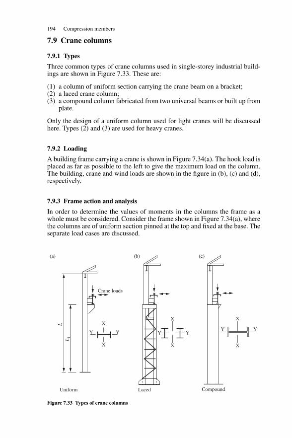
194 Compression members
7.9 Crane columns
7.9.1 Types
Three common types of crane columns used in single-storey industrial build-ings are shown in Figure 7.33. These are:
(1) a column of uniform section carrying the crane beam on a bracket;(2) a laced crane column;(3) a compound column fabricated from two universal beams or built up from
plate.
Only the design of a uniform column used for light cranes will be discussedhere. Types (2) and (3) are used for heavy cranes.
7.9.2 Loading
A building frame carrying a crane is shown in Figure 7.34(a). The hook load isplaced as far as possible to the left to give the maximum load on the column.The building, crane and wind loads are shown in the figure in (b), (c) and (d),respectively.
7.9.3 Frame action and analysis
In order to determine the values of moments in the columns the frame as awhole must be considered. Consider the frame shown in Figure 7.34(a), wherethe columns are of uniform section pinned at the top and fixed at the base. Theseparate load cases are discussed.
LL
1
XX X
XXX
YY YY Y
Y
Crane loads
Uniform
(a) (b) (c)
CompoundLaced
Figure 7.33 Types of crane columns
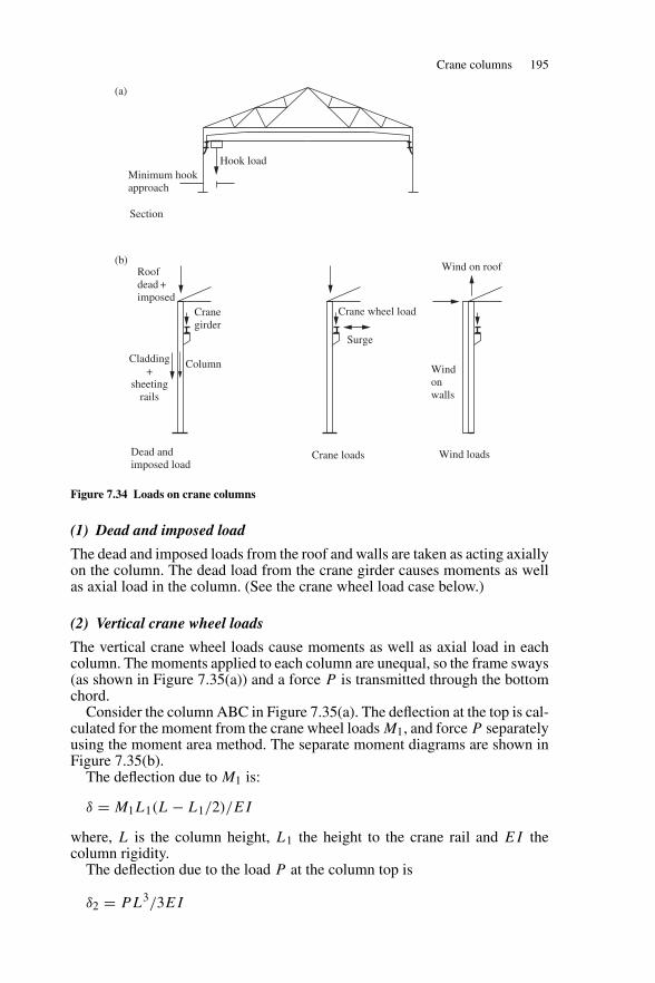
Crane columns 195
Hook loadMinimum hookapproach
(a)
(b)Roofdead +imposed
Cranegirder
ColumnCladding+
sheetingrails
Crane wheel load
Surge
Wind on roof
Windonwalls
Dead andimposed load
Crane loads Wind loads
Section
Figure 7.34 Loads on crane columns
(1) Dead and imposed load
The dead and imposed loads from the roof and walls are taken as acting axiallyon the column. The dead load from the crane girder causes moments as wellas axial load in the column. (See the crane wheel load case below.)
(2) Vertical crane wheel loads
The vertical crane wheel loads cause moments as well as axial load in eachcolumn. The moments applied to each column are unequal, so the frame sways(as shown in Figure 7.35(a)) and a force P is transmitted through the bottomchord.
Consider the column ABC in Figure 7.35(a). The deflection at the top is cal-culated for the moment from the crane wheel loads M1, and force P separatelyusing the moment area method. The separate moment diagrams are shown inFigure 7.35(b).
The deflection due to M1 is:
δ = M1L1(L − L1/2)/EI
where, L is the column height, L1 the height to the crane rail and EI thecolumn rigidity.
The deflection due to the load P at the column top is
δ2 = PL3/3EI
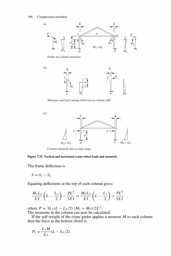
196 Compression members
P
MA A
δ δ
δ1
δ
AMA= SL1
δ
λ
δ2
M1 M1
M1
Moments and load causing deflection in column ABC
M1
S
MF = SL1F
S
A
FC
PL
B
C
M2 M2
MB
B E
C
(a)
(b)
(c)
D
M1 > M2
L L1
LL
1 2–
L1
P
F
P
Frame are column moments
Column moments due to crane surge
Figure 7.35 Vertical and horizontal crane-wheel loads and moments
The frame deflection is
δ = δ1 − δ2
Equating deflections at the top of each column gives:
M1L1
EI
(L − L1
2
)− PL3
3EI= M2L1
EI
(L − L1
2
)+ PL3
3EI
where P = 3L1(L − L1/2) (M1 + M2)/2L3.The moments in the column can now be calculated.
If the self-weight of the crane girder applies a moment M to each columnthen the force in the bottom chord is:
P1 = L1M
L3(L − L1/2).
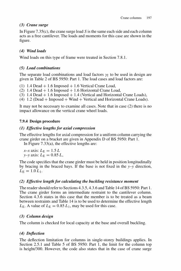
Crane columns 197
(3) Crane surge
In Figure 7.35(c), the crane surge load S is the same each side and each columnacts as a free cantilever. The loads and moments for this case are shown in thefigure.
(4) Wind loads
Wind loads on this type of frame were treated in Section 7.8.1.
(5) Load combinations
The separate load combinations and load factors γf to be used in design aregiven in Table 2 of BS 5950: Part 1. The load cases and load factors are:
(1) 1.4 Dead + 1.6 Imposed + 1.6 Vertical Crane Load,(2) 1.4 Dead + 1.6 Imposed + 1.6 Horizontal Crane Load,(3) 1.4 Dead + 1.6 Imposed + 1.4 (Vertical and Horizontal Crane Loads),(4) 1.2 (Dead + Imposed + Wind + Vertical and Horizontal Crane Loads).
It may not be necessary to examine all cases. Note that in case (2) there is noimpact allowance on the vertical crane wheel loads.
7.9.4 Design procedure
(1) Effective lengths for axial compression
The effective lengths for axial compression for a uniform column carrying thecrane girder on a bracket are given in Appendix D of BS 5950: Part 1.
In Figure 7.33(a), the effective lengths are:
x–x axis: LE = 1.5 Ly–y axis: LE = 0.85 L,
The code specifies that the crane girder must be held in position longitudinallyby bracing in the braced bays. If the base is not fixed in the y–y direction,LE = 1.0 L1.
(2) Effective length for calculating the buckling resistance moment
The reader should refer to Sections 4.3.5, 4.3.6 and Table 14 of BS 5950: Part 1.The crane girder forms an intermediate restraint to the cantilever column.Section 4.3.6 states in this case that the member is to be treated as a beambetween restraints and Table 14 is to be used to determine the effective lengthLE. A value of LE = 0.85 L1, may be used for this case.
(3) Column design
The column is checked for local capacity at the base and overall buckling.
(4) Deflection
The deflection limitation for columns in single-storey buildings applies. InSection 2.5.1 and Table 5 of BS 5950: Part 1, the limit for the column topis height/300. However, the code also states that in the case of crane surge
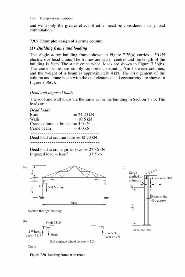
198 Compression members
and wind only the greater effect of either need be considered in any loadcombination.
7.9.5 Example: design of a crane column
(1) Building frame and loading
The single-storey building frame shown in Figure 7.36(a) carries a 50 kNelectric overhead crane. The frames are at 5 m centres and the length of thebuilding is 30 m. The static crane wheel loads are shown in Figure 7.36(b).The crane beams are simply supported, spanning 5 m between columns,and the weight of a beam is approximately 4 kN. The arrangement of thecolumn and crane beam with the end clearance and eccentricity are shown inFigure 7.36(c).
Dead and imposed loads
The roof and wall loads are the same as for the building in Section 7.8.3. Theloads are:
Dead loadsRoof = 24.23 kNWalls = 10.5 kNCrane column + bracket = 4.0 kNCrane beam = 4.0 kN--- - - - - - - - - - - - - - - - - - - - - - - - - - - - - - - - - -Dead load at column base = 42.73 kN--- - - - - - - - - - - - - - - - - - - - - - - - - - - - - - - - - -
Dead load at crane girder level = 27.86 kNImposed load − Roof = 37.5 kN
20 m
50 kN crane
(a) (c)
(b)
4m
4.5
m1.
5
2 Wheelseach 45 kN
Crab 75 kN
50 kN 2 Wheelseach 18 kN
End carriage wheel centres = 2.5m
Surgeapplied tocolumn
Clearance 200
Eccentricity450 approx.
4.5
m40
0
Section through building
Crane
Crane column
Figure 7.36 Building frame with crane
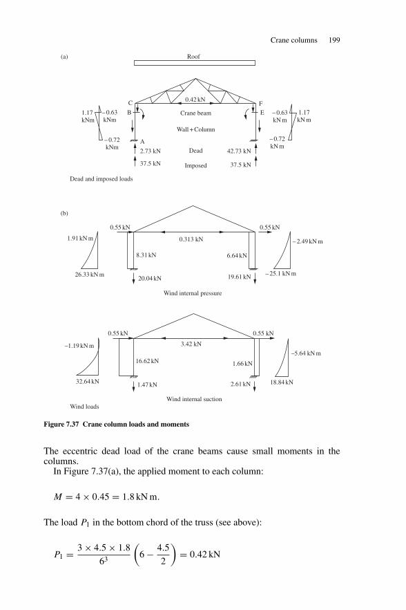
Crane columns 199
0.42 kN
A
B
C
EF
Crane beam
Wall + Column
Dead2.73 kN
37.5 kN
42.73 kN
37.5 kNImposed
–1.19 kN m
32.64 kN
0.55 kN 0.55 kN
16.62 kN
1.47 kN
3.42 kN
1.66 kN
2.61 kN
1.91 kN m
26.33 kN m
0.55 kN 0.55 kN
8.31 kN
20.04 kN
0.313 kN
6.64 kN
19.61 kN
– 2.49 kN m
– 25.1 kN m
Roof(a)
(b)
1.17kNm
– 0.63kNm
– 0.72kNm
– 0.63kN m
1.17kN m
– 0.72kN m
18.84 kN
–5.64 kN m
Dead and imposed loads
Wind internal pressure
Wind internal suctionWind loads
Figure 7.37 Crane column loads and moments
The eccentric dead load of the crane beams cause small moments in thecolumns.
In Figure 7.37(a), the applied moment to each column:
M = 4 × 0.45 = 1.8 kN m.
The load P1 in the bottom chord of the truss (see above):
P1 = 3 × 4.5 × 1.8
63
(6 − 4.5
2
)= 0.42 kN
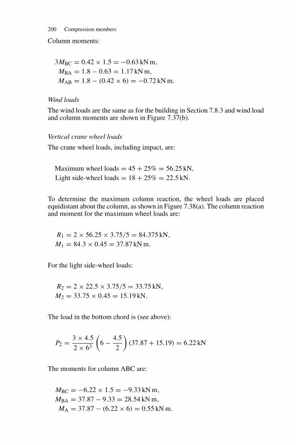
200 Compression members
Column moments:
3MBC = 0.42 × 1.5 = −0.63 kN m,
MBA = 1.8 − 0.63 = 1.17 kN m,
MAB = 1.8 − (0.42 × 6) = −0.72 kN m.
Wind loads
The wind loads are the same as for the building in Section 7.8.3 and wind loadand column moments are shown in Figure 7.37(b).
Vertical crane wheel loads
The crane wheel loads, including impact, are:
Maximum wheel loads = 45 + 25% = 56.25 kN,
Light side-wheel loads = 18 + 25% = 22.5 kN.
To determine the maximum column reaction, the wheel loads are placedequidistant about the column, as shown in Figure 7.38(a). The column reactionand moment for the maximum wheel loads are:
R1 = 2 × 56.25 × 3.75/5 = 84.375 kN,
M1 = 84.3 × 0.45 = 37.87 kN m.
For the light side-wheel loads:
R2 = 2 × 22.5 × 3.75/5 = 33.75 kN,
M2 = 33.75 × 0.45 = 15.19 kN.
The load in the bottom chord is (see above):
P2 = 3 × 4.5
2 × 63
(6 − 4.5
2
)(37.87 + 15.19) = 6.22 kN
The moments for column ABC are:
MBC = −6.22 × 1.5 = −9.33 kN m,
MBA = 37.87 − 9.33 = 28.54 kN m,
MA = 37.87 − (6.22 × 6) = 0.55 kN m.
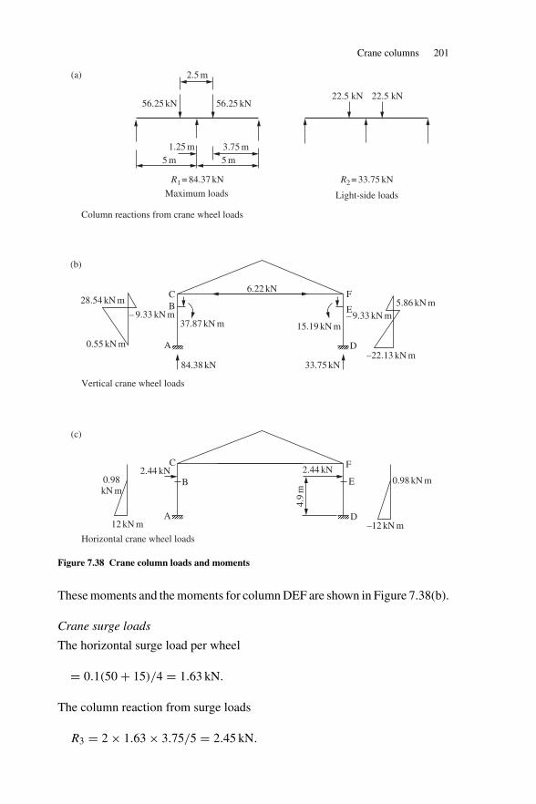
Crane columns 201
2.5 m
56.25 kN22.5 kN 22.5 kN
56.25 kN
1.25 m
R1 = 84.37 kN R2 = 33.75 kN
3.75 m5 m 5 m
28.54 kN m 5.86 kN m
–22.13 kN m0.55 kN m
– 9.33 kN m – 9.33 kN m
CB
A
6.22 kN
37.87 kN m 15.19 kN m
33.75 kN84.38 kN
D
F
E
F
E0.98kN m
C2.44 kN
A
2.44 kN
D
0.98 kN m
–12 kN m12 kN m
4.9
m
B
Maximum loads Light-side loads
Column reactions from crane wheel loads
Vertical crane wheel loads
Horizontal crane wheel loads
(a)
(b)
(c)
Figure 7.38 Crane column loads and moments
These moments and the moments for column DEF are shown in Figure 7.38(b).
Crane surge loads
The horizontal surge load per wheel
= 0.1(50 + 15)/4 = 1.63 kN.
The column reaction from surge loads
R3 = 2 × 1.63 × 3.75/5 = 2.45 kN.
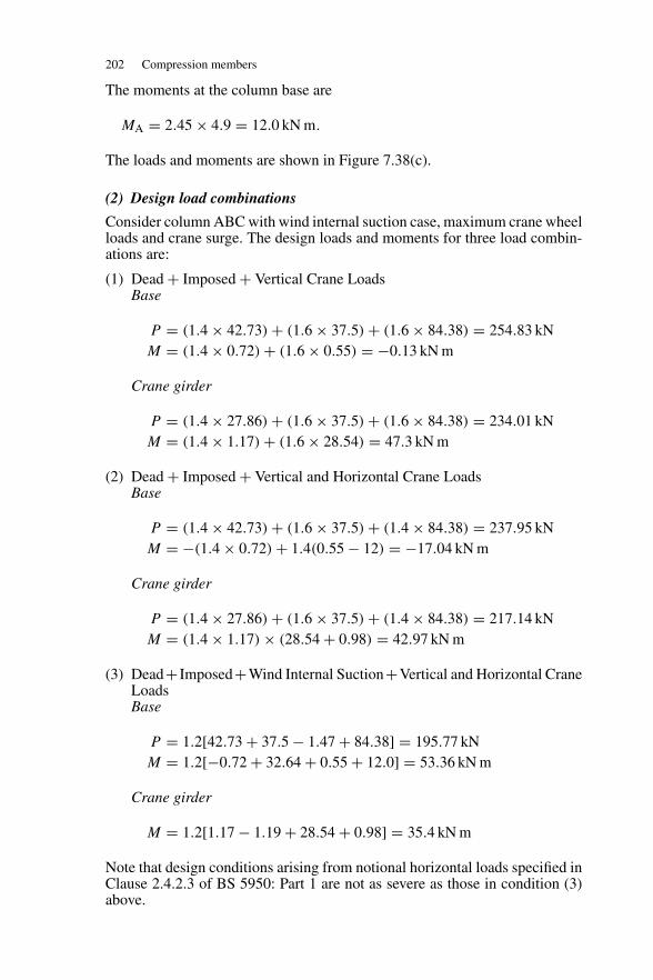
202 Compression members
The moments at the column base are
MA = 2.45 × 4.9 = 12.0 kN m.
The loads and moments are shown in Figure 7.38(c).
(2) Design load combinations
Consider column ABC with wind internal suction case, maximum crane wheelloads and crane surge. The design loads and moments for three load combin-ations are:
(1) Dead + Imposed + Vertical Crane LoadsBase
P = (1.4 × 42.73) + (1.6 × 37.5) + (1.6 × 84.38) = 254.83 kNM = (1.4 × 0.72) + (1.6 × 0.55) = −0.13 kN m
Crane girder
P = (1.4 × 27.86) + (1.6 × 37.5) + (1.6 × 84.38) = 234.01 kNM = (1.4 × 1.17) + (1.6 × 28.54) = 47.3 kN m
(2) Dead + Imposed + Vertical and Horizontal Crane LoadsBase
P = (1.4 × 42.73) + (1.6 × 37.5) + (1.4 × 84.38) = 237.95 kNM = −(1.4 × 0.72) + 1.4(0.55 − 12) = −17.04 kN m
Crane girder
P = (1.4 × 27.86) + (1.6 × 37.5) + (1.4 × 84.38) = 217.14 kNM = (1.4 × 1.17) × (28.54 + 0.98) = 42.97 kN m
(3) Dead+ Imposed+Wind Internal Suction+Vertical and Horizontal CraneLoadsBase
P = 1.2[42.73 + 37.5 − 1.47 + 84.38] = 195.77 kNM = 1.2[−0.72 + 32.64 + 0.55 + 12.0] = 53.36 kN m
Crane girder
M = 1.2[1.17 − 1.19 + 28.54 + 0.98] = 35.4 kN m
Note that design conditions arising from notional horizontal loads specified inClause 2.4.2.3 of BS 5950: Part 1 are not as severe as those in condition (3)above.
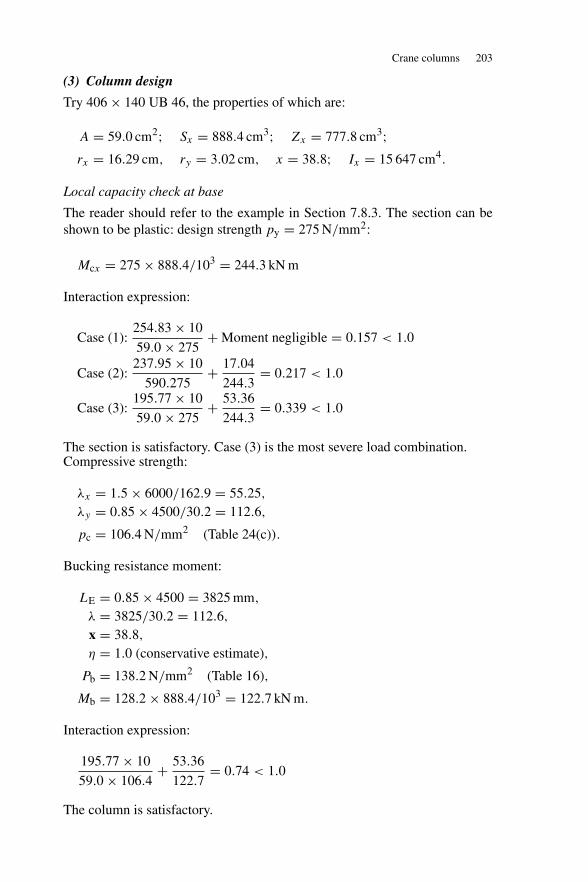
Crane columns 203
(3) Column design
Try 406 × 140 UB 46, the properties of which are:
A = 59.0 cm2; Sx = 888.4 cm3; Zx = 777.8 cm3;rx = 16.29 cm, ry = 3.02 cm, x = 38.8; Ix = 15 647 cm4.
Local capacity check at base
The reader should refer to the example in Section 7.8.3. The section can beshown to be plastic: design strength py = 275 N/mm2:
Mcx = 275 × 888.4/103 = 244.3 kN m
Interaction expression:
Case (1):254.83 × 10
59.0 × 275+ Moment negligible = 0.157 < 1.0
Case (2):237.95 × 10
590.275+ 17.04
244.3= 0.217 < 1.0
Case (3):195.77 × 10
59.0 × 275+ 53.36
244.3= 0.339 < 1.0
The section is satisfactory. Case (3) is the most severe load combination.Compressive strength:
λx = 1.5 × 6000/162.9 = 55.25,
λy = 0.85 × 4500/30.2 = 112.6,
pc = 106.4 N/mm2 (Table 24(c)).
Bucking resistance moment:
LE = 0.85 × 4500 = 3825 mm,
λ = 3825/30.2 = 112.6,
x = 38.8,
η = 1.0 (conservative estimate),
Pb = 138.2 N/mm2 (Table 16),
Mb = 128.2 × 888.4/103 = 122.7 kN m.
Interaction expression:
195.77 × 10
59.0 × 106.4+ 53.36
122.7= 0.74 < 1.0
The column is satisfactory.
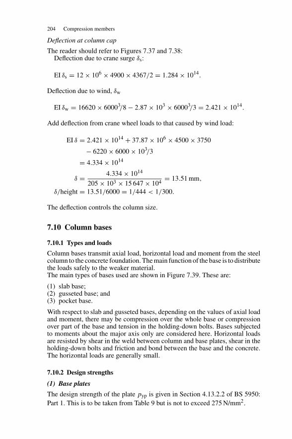
204 Compression members
Deflection at column cap
The reader should refer to Figures 7.37 and 7.38:Deflection due to crane surge δs:
EI δs = 12 × 106 × 4900 × 4367/2 = 1.284 × 10¹⁴.
Deflection due to wind, δw
EI δw = 16620 × 60003/8 − 2.87 × 103 × 60003/3 = 2.421 × 10¹⁴.
Add deflection from crane wheel loads to that caused by wind load:
EI δ = 2.421 × 10¹⁴ + 37.87 × 106 × 4500 × 3750
− 6220 × 6000 × 103/3
= 4.334 × 10¹⁴
δ = 4.334 × 10¹⁴
205 × 103 × 15 647 × 104= 13.51 mm,
δ/height = 13.51/6000 = 1/444 < 1/300.
The deflection controls the column size.
7.10 Column bases
7.10.1 Types and loads
Column bases transmit axial load, horizontal load and moment from the steelcolumn to the concrete foundation. The main function of the base is to distributethe loads safely to the weaker material.The main types of bases used are shown in Figure 7.39. These are:
(1) slab base;(2) gusseted base; and(3) pocket base.
With respect to slab and gusseted bases, depending on the values of axial loadand moment, there may be compression over the whole base or compressionover part of the base and tension in the holding-down bolts. Bases subjectedto moments about the major axis only are considered here. Horizontal loadsare resisted by shear in the weld between column and base plates, shear in theholding-down bolts and friction and bond between the base and the concrete.The horizontal loads are generally small.
7.10.2 Design strengths
(1) Base plates
The design strength of the plate pyp is given in Section 4.13.2.2 of BS 5950:Part 1. This is to be taken from Table 9 but is not to exceed 275 N/mm2.
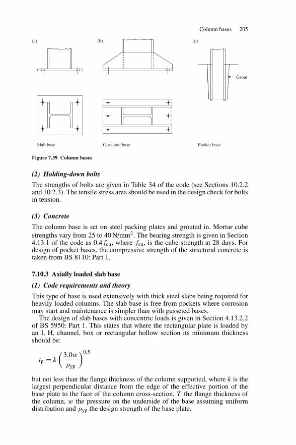
Column bases 205
Slab base Gusseted base Pocket base
Grout
(a) (b) (c)
Figure 7.39 Column bases
(2) Holding-down bolts
The strengths of bolts are given in Table 34 of the code (see Sections 10.2.2and 10.2.3). The tensile stress area should be used in the design check for boltsin tension.
(3) Concrete
The column base is set on steel packing plates and grouted in. Mortar cubestrengths vary from 25 to 40 N/mm2. The bearing strength is given in Section4.13.1 of the code as 0.4fcu, where fcu, is the cube strength at 28 days. Fordesign of pocket bases, the compressive strength of the structural concrete istaken from BS 8110: Part 1.
7.10.3 Axially loaded slab base
(1) Code requirements and theory
This type of base is used extensively with thick steel slabs being required forheavily loaded columns. The slab base is free from pockets where corrosionmay start and maintenance is simpler than with gusseted bases.
The design of slab bases with concentric loads is given in Section 4.13.2.2of BS 5950: Part 1. This states that where the rectangular plate is loaded byan I, H, channel, box or rectangular hollow section its minimum thicknessshould be:
tp = k
(3.0w
pyp
)0.5
but not less than the flange thickness of the column supported, where k is thelargest perpendicular distance from the edge of the effective portion of thebase plate to the face of the column cross-section, T the flange thickness ofthe column, w the pressure on the underside of the base assuming uniformdistribution and pyp the design strength of the base plate.

206 Compression members
Y
X
1 mm
1 mm
Stripsection
Y
A
X
a
bw
N/m
m2
wN/mm2
1m
m
Figure 7.40 Column base plate moments
(2) Weld: column to slab
The code states in Section 4.13.3 that where the slab and column end are intight contact the load is transmitted in direct bearing. The surfaces in contactwould be machined in this case. The weld only holds the base slab in position.Where the surfaces are not suitable to transmit the load in direct bearing theweld must be designed to transmit the load.
7.10.4 Axially loaded slab base: example
A column consisting of a 305 × 305 UC 198 carries an axial dead load of1600 kN and an imposed load of 800 kN. Adopting a square slab, determinethe size and thickness required. The cube strength of the concrete grout is25 N/mm2. Use Grade S275 steel.
Design load = (1.4 × 1600) + (1.6 × 800) = 3520 kN.
Effective area method
Required area of base plate, Areg = Fc/0.6fcu
= 3520 × 103/(0.6 × 25) = 234 667 mm2
Provide 600 × 600 mm2 square base plate:
The area provided, Aprovide = 360 000 mm2 > Areg.
The arrangement of the column on the base plate is shown in Figure 7.41, fromthis the effective area is:
Aeff = (D + 2c)(B + 2c) − (D − 2c − 2T )(B − t)
= (DB + 2Bc + 2Dc + 4c2)
− (DB − 2Bc − 2BT − DT − Dt + 2tc + 2T t)
= 4c2 + (2D + 4B − 2t)c + (2BT + Dt − 2T t)
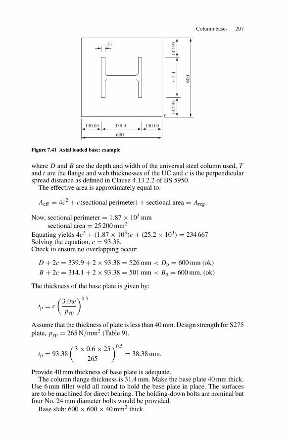
Column bases 207
31
130.05 339.9 130.05
Y
142.
9531
4.1
600
142.
95
600
Figure 7.41 Axial loaded base: example
where D and B are the depth and width of the universal steel column used, Tand t are the flange and web thicknesses of the UC and c is the perpendicularspread distance as defined in Clause 4.13.2.2 of BS 5950.
The effective area is approximately equal to:
Aeff = 4c2 + c(sectional perimeter) + sectional area = Areg.
Now, sectional perimeter = 1.87 × 10³ mmsectional area = 25 200 mm2
Equating yields 4c2 + (1.87 × 10³)c + (25.2 × 10³) = 234 667Solving the equation, c = 93.38.Check to ensure no overlapping occur:
D + 2c = 339.9 + 2 × 93.38 = 526 mm < Dp = 600 mm (ok)
B + 2c = 314.1 + 2 × 93.38 = 501 mm < Bp = 600 mm. (ok)
The thickness of the base plate is given by:
tp = c
(3.0w
pyp
)0.5
Assume that the thickness of plate is less than 40 mm. Design strength for S275plate, pyp = 265 N/mm2 (Table 9).
tp = 93.38
(3 × 0.6 × 25
265
)0.5
= 38.38 mm.
Provide 40 mm thickness of base plate is adequate.The column flange thickness is 31.4 mm. Make the base plate 40 mm thick.
Use 6 mm fillet weld all round to hold the base plate in place. The surfacesare to be machined for direct bearing. The holding-down bolts are nominal butfour No. 24 mm diameter bolts would be provided.
Base slab: 600 × 600 × 40 mm3 thick.
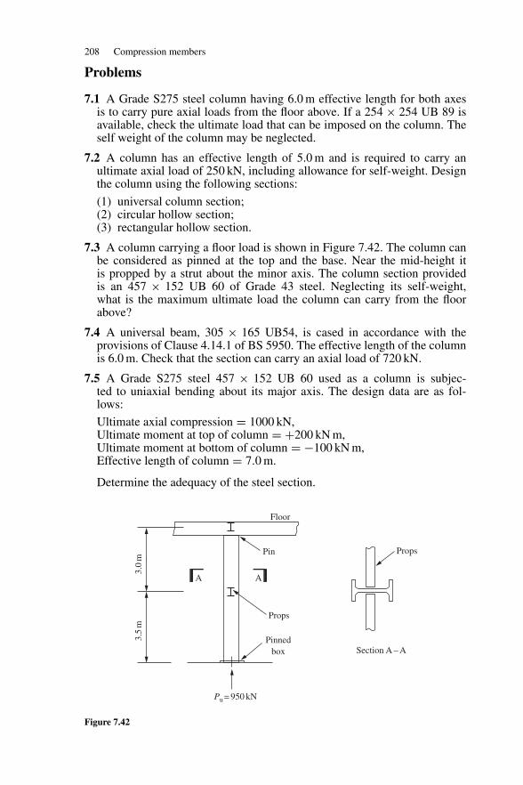
208 Compression members
Problems
7.1 A Grade S275 steel column having 6.0 m effective length for both axesis to carry pure axial loads from the floor above. If a 254 × 254 UB 89 isavailable, check the ultimate load that can be imposed on the column. Theself weight of the column may be neglected.
7.2 A column has an effective length of 5.0 m and is required to carry anultimate axial load of 250 kN, including allowance for self-weight. Designthe column using the following sections:
(1) universal column section;(2) circular hollow section;(3) rectangular hollow section.
7.3 A column carrying a floor load is shown in Figure 7.42. The column canbe considered as pinned at the top and the base. Near the mid-height itis propped by a strut about the minor axis. The column section providedis an 457 × 152 UB 60 of Grade 43 steel. Neglecting its self-weight,what is the maximum ultimate load the column can carry from the floorabove?
7.4 A universal beam, 305 × 165 UB54, is cased in accordance with theprovisions of Clause 4.14.1 of BS 5950. The effective length of the columnis 6.0 m. Check that the section can carry an axial load of 720 kN.
7.5 A Grade S275 steel 457 × 152 UB 60 used as a column is subjec-ted to uniaxial bending about its major axis. The design data are as fol-lows:
Ultimate axial compression = 1000 kN,Ultimate moment at top of column = +200 kN m,Ultimate moment at bottom of column = −100 kN m,Effective length of column = 7.0 m.
Determine the adequacy of the steel section.
A
Pin
Floor
3.0
m3.
5m
A
Props
Pinnedbox Section A – A
Pu = 950 kN
Props
Figure 7.42
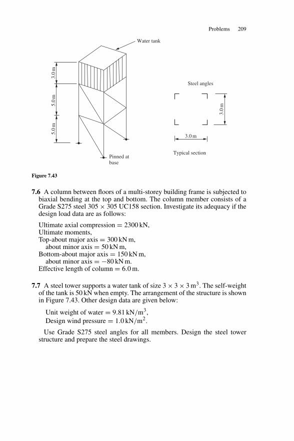
Problems 209
Steel angles
Water tank
Typical sectionPinned atbase
3.0 m
5.0
m5.
0m
3.0
m
3.0
m
Figure 7.43
7.6 A column between floors of a multi-storey building frame is subjected tobiaxial bending at the top and bottom. The column member consists of aGrade S275 steel 305 × 305 UC158 section. Investigate its adequacy if thedesign load data are as follows:
Ultimate axial compression = 2300 kN,Ultimate moments,Top-about major axis = 300 kN m,
about minor axis = 50 kN m,Bottom-about major axis = 150 kN m,
about minor axis = −80 kN m.Effective length of column = 6.0 m.
7.7 A steel tower supports a water tank of size 3 × 3 × 3 m3. The self-weightof the tank is 50 kN when empty. The arrangement of the structure is shownin Figure 7.43. Other design data are given below:
Unit weight of water = 9.81 kN/m3,Design wind pressure = 1.0 kN/m2.
Use Grade S275 steel angles for all members. Design the steel towerstructure and prepare the steel drawings.
8
Trusses and bracing
8.1 Trusses—types, uses and truss members
8.1.1 Types and uses of trusses
Trusses and lattice girders are framed elements resisting in-plane loading byaxial forces in either tension or compression in the individual members. Theyare beam elements, but their use gives a large weight saving when comparedwith a universal beam designed for the same conditions.
The main uses for trusses and lattice girders in buildings are to supportroofs and floors and carry wind loads. Pitched trusses are used for roofs whileparallel chord lattice girders carry flat roofs or floors.
Some typical trusses and lattice girders are shown in Figure 8.1(a). Trussesin buildings are used for spans of about 10–50 m. The spacing is usually about5–8 m. The panel length may be made to suit the sheeting or decking used andthe purlin spacing adopted. Purlins need not be located at the nodes but thisintroduces bending into the chord. The panel spacing is usually 1.5–4 m.
8.1.2 Truss members
Truss and lattice girder members are shown in Figure 8.1(b). The most commonmembers used are single and double angles, tees, channels and the structuralhollow sections. I and H and compound and built-up members are used inheavy trusses.
8.2 Loads on trusses
The main types of loads on trusses are dead, imposed and wind loads. Theseare shown in Figure 8.1(a).
8.2.1 Dead loads
The dead load is due to sheeting or decking, insulation, felt, ceiling if provided,weight of purlins and self weight. This load may range from 0.3 to 1.0 kN/m2.Typical values are used in the worked examples here.
210
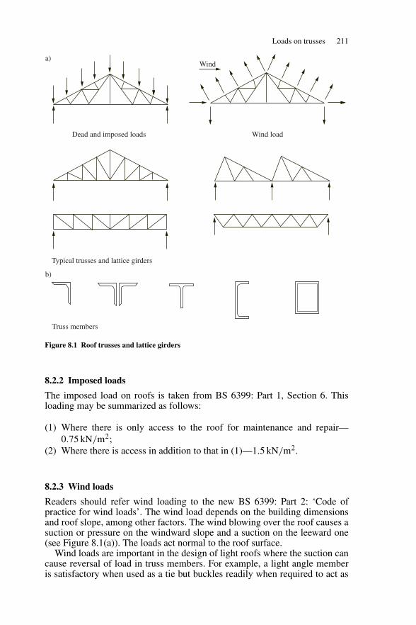
Loads on trusses 211
Wind
Dead and imposed loads Wind load
Typical trusses and lattice girders
Truss members
b)
a)
Figure 8.1 Roof trusses and lattice girders
8.2.2 Imposed loads
The imposed load on roofs is taken from BS 6399: Part 1, Section 6. Thisloading may be summarized as follows:
(1) Where there is only access to the roof for maintenance and repair—0.75 kN/m2;
(2) Where there is access in addition to that in (1)—1.5 kN/m2.
8.2.3 Wind loads
Readers should refer wind loading to the new BS 6399: Part 2: ‘Code ofpractice for wind loads’. The wind load depends on the building dimensionsand roof slope, among other factors. The wind blowing over the roof causes asuction or pressure on the windward slope and a suction on the leeward one(see Figure 8.1(a)). The loads act normal to the roof surface.
Wind loads are important in the design of light roofs where the suction cancause reversal of load in truss members. For example, a light angle memberis satisfactory when used as a tie but buckles readily when required to act as
212 Trusses and bracing
a strut. In the case of flat roofs with heavy decking, the wind uplift will not begreater than the dead load, and it need not be considered in the design.
8.2.4 Application of loads
The loading is applied to the truss through the purlins. The value depends onthe roof area supported by the purlin. The purlin load may be at a node point, asshown in Figure 8.1(a), or between nodes, as discussed in Section 8.3.3 below.The weight of the truss is included in the purlin point loads.
8.3 Analysis of trusses
8.3.1 Statically determinate trusses
Trusses may be simply supported or continuous, statically determinate orredundant and pin jointed or rigid jointed. However, the most commonly usedtruss or lattice girder is single span, simply supported and statically determi-nate. The joints are assumed to be pinned, though, as will be seen in actualconstruction, continuous members are used for the chords. This assumptionfor truss analysis is stated in Section 4.10 of BS 5950: Part 1.
A pin-jointed truss is statically determinate when:
m = 2j − 3
where m denotes the number of members and j the number of joints.
8.3.2 Load applied at the nodes of the truss
When the purlins are located at the node points the following manual methodsof analysis are used:
(1) Force diagram—This is the quickest method for pitched roof trusses.(2) Joint resolution—This is the best method for a parallel chord lattice girder.(3) Method of sections—This method is useful where it is necessary to find
the force in only a few members.
The force diagram method is used for the analysis of the truss in Section 8.6.An example of use of the method of sections would be for a light lattice girderwhere only the force in the maximum loaded member would be found. Themember is designed for this force and made uniform throughout.
A matrix analysis program can be used for truss analysis. In Chapter 11, theroof truss for an industrial building is analysed using a computer program.
8.3.3 Loads not applied at the nodes of the truss
The case where the purlins are not located at the nodes of the truss is shownin Figure 8.2(a). In this case the analysis is made in two parts:
(1) The total load is distributed to the nodes as shown in Figure 8.2(b). Thetruss is analysed to give the axial loads in the members.
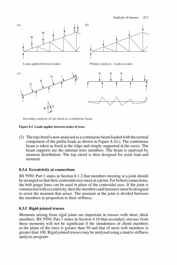
Analysis of trusses 213
NN
WN
NN N N
WW
Loads applied between nodes
Secondary analysis of top chord as a continuous beam
Primary analysis – loads at nodes
(a) (b)
(c)
Figure 8.2 Loads applies between nodes of truss
(2) The top chord is now analysed as a continuous beam loaded with the normalcomponent of the purlin loads as shown in Figure 8.2(c). The continuousbeam is taken as fixed at the ridge and simply supported at the eaves. Thebeam supports are the internal truss members. The beam is analysed bymoment distribution. The top chord is then designed for axial load andmoment.
8.3.4 Eccentricity at connections
BS 5950: Part 1 states in Section 6.1.2 that members meeting at a joint shouldbe arranged so that their centroidal axes meet at a point. For bolted connections,the bolt gauge lines can be used in place of the centroidal axes. If the joint isconstructed with eccentricity, then the members and fasteners must be designedto resist the moment that arises. The moment at the joint is divided betweenthe members in proportion to their stiffness.
8.3.5 Rigid-jointed trusses
Moments arising from rigid joints are important in trusses with short, thickmembers. BS 5950: Part 1 states in Section 4.10 that secondary stresses fromthese moments will not be significant if the slenderness of chord membersin the plane of the truss is greater than 50 and that of most web members isgreater than 100. Rigid jointed trusses may be analysed using a matrix stiffnessanalysis program.
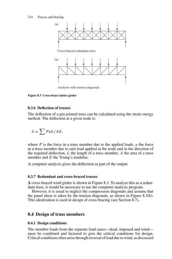
214 Trusses and bracing
Cross braced redundant truss
Analysis with tension diagonals
(a)
(b)
Figure 8.3 Cross-brace lattice girder
8.3.6 Deflection of trusses
The deflection of a pin-jointed truss can be calculated using the strain energymethod. The deflection at a given node is:
δ =∑
PuL/AE,
where P is the force in a truss member due to the applied loads, u the forcein a truss member due to unit load applied at the node and in the direction ofthe required deflection, L the length of a truss member, A the area of a trussmember and E the Young’s modulus.
A computer analysis gives the deflection as part of the output.
8.3.7 Redundant and cross-braced trusses
A cross-braced wind girder is shown in Figure 8.3. To analyse this as a redun-dant truss, it would be necessary to use the computer analysis program.
However, it is usual to neglect the compression diagonals and assume thatthe panel shear is taken by the tension diagonals, as shown in Figure 8.3(b).This idealization is used in design of cross bracing (see Section 8.7).
8.4 Design of truss members
8.4.1 Design conditions
The member loads from the separate load cases—dead, imposed and wind—must be combined and factored to give the critical conditions for design.Critical conditions often arise through reversal of load due to wind, as discussed
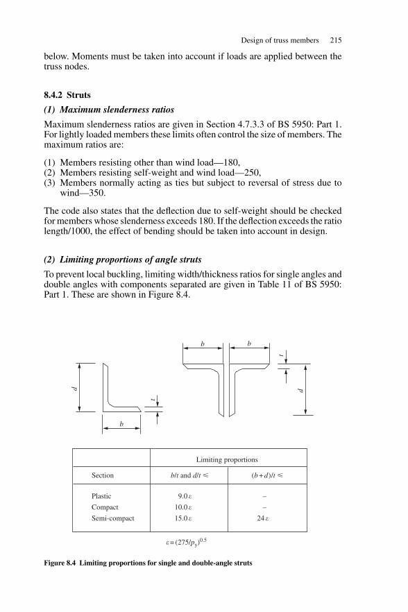
Design of truss members 215
below. Moments must be taken into account if loads are applied between thetruss nodes.
8.4.2 Struts
(1) Maximum slenderness ratios
Maximum slenderness ratios are given in Section 4.7.3.3 of BS 5950: Part 1.For lightly loaded members these limits often control the size of members. Themaximum ratios are:
(1) Members resisting other than wind load—180,(2) Members resisting self-weight and wind load—250,(3) Members normally acting as ties but subject to reversal of stress due to
wind—350.
The code also states that the deflection due to self-weight should be checkedfor members whose slenderness exceeds 180. If the deflection exceeds the ratiolength/1000, the effect of bending should be taken into account in design.
(2) Limiting proportions of angle struts
To prevent local buckling, limiting width/thickness ratios for single angles anddouble angles with components separated are given in Table 11 of BS 5950:Part 1. These are shown in Figure 8.4.
d
b
b b
t
t
d
Limiting proportions
Section
Plastic
Compact
Semi-compact
9.0 �
10.0 �
15.0 �
–
–
24 �
b/t and d/t � (b + d)/t �
� = (275/py)0.5
Figure 8.4 Limiting proportions for single and double-angle struts
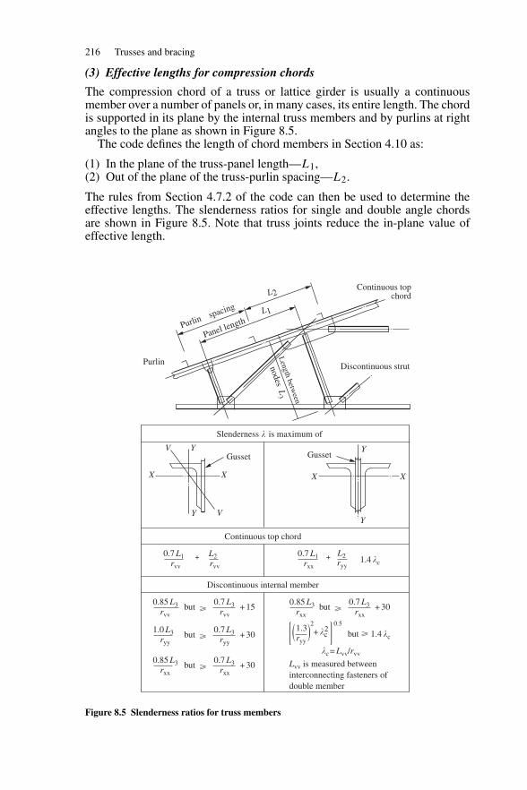
216 Trusses and bracing
(3) Effective lengths for compression chords
The compression chord of a truss or lattice girder is usually a continuousmember over a number of panels or, in many cases, its entire length. The chordis supported in its plane by the internal truss members and by purlins at rightangles to the plane as shown in Figure 8.5.
The code defines the length of chord members in Section 4.10 as:
(1) In the plane of the truss-panel length—L1,(2) Out of the plane of the truss-purlin spacing—L2.
The rules from Section 4.7.2 of the code can then be used to determine theeffective lengths. The slenderness ratios for single and double angle chordsare shown in Figure 8.5. Note that truss joints reduce the in-plane value ofeffective length.
Purlinspacing
Panel length
L2
L1
Purlin Discontinuous strut
Length betw
een
nodesL
3
Continuous topchord
Slenderness � is maximum of
V
V
Y
Y
XX
Gusset
Continuous top chord
Discontinuous internal member
0.85 L3
GussetY
Y
XX
0.7 L1rvv
0.85 L3rvv
0.7 L3rvv rxx
L2rvv
0.7 L1rxx
L2ryy
1.4 �c
+ �c2
�c = Lvv/rvv
+ 15but �0.7 L3
rxx+ 30
Lvv is measured betweeninterconnecting fasteners ofdouble member
but � 1.4 �c
but �
1.0 L3ryy
0.7 L3ryy
+ 30but �
0.85 L3rxx
0.7 L3rxx
+ 30but �
1.3ryy
2 0.5
+ +
Figure 8.5 Slenderness ratios for truss members
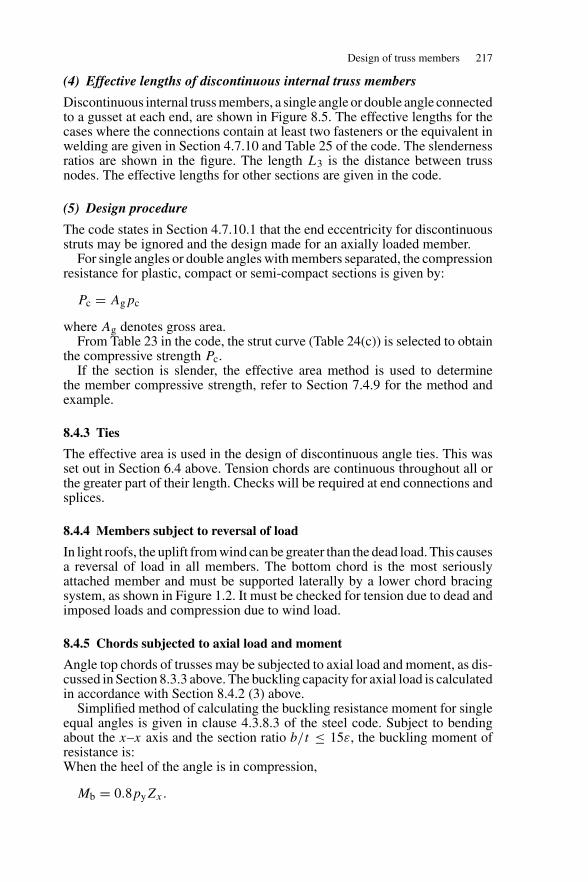
Design of truss members 217
(4) Effective lengths of discontinuous internal truss members
Discontinuous internal truss members, a single angle or double angle connectedto a gusset at each end, are shown in Figure 8.5. The effective lengths for thecases where the connections contain at least two fasteners or the equivalent inwelding are given in Section 4.7.10 and Table 25 of the code. The slendernessratios are shown in the figure. The length L3 is the distance between trussnodes. The effective lengths for other sections are given in the code.
(5) Design procedure
The code states in Section 4.7.10.1 that the end eccentricity for discontinuousstruts may be ignored and the design made for an axially loaded member.
For single angles or double angles with members separated, the compressionresistance for plastic, compact or semi-compact sections is given by:
Pc = Agpc
where Ag denotes gross area.From Table 23 in the code, the strut curve (Table 24(c)) is selected to obtain
the compressive strength Pc.If the section is slender, the effective area method is used to determine
the member compressive strength, refer to Section 7.4.9 for the method andexample.
8.4.3 Ties
The effective area is used in the design of discontinuous angle ties. This wasset out in Section 6.4 above. Tension chords are continuous throughout all orthe greater part of their length. Checks will be required at end connections andsplices.
8.4.4 Members subject to reversal of load
In light roofs, the uplift from wind can be greater than the dead load. This causesa reversal of load in all members. The bottom chord is the most seriouslyattached member and must be supported laterally by a lower chord bracingsystem, as shown in Figure 1.2. It must be checked for tension due to dead andimposed loads and compression due to wind load.
8.4.5 Chords subjected to axial load and moment
Angle top chords of trusses may be subjected to axial load and moment, as dis-cussed in Section 8.3.3 above. The buckling capacity for axial load is calculatedin accordance with Section 8.4.2 (3) above.
Simplified method of calculating the buckling resistance moment for singleequal angles is given in clause 4.3.8.3 of the steel code. Subject to bendingabout the x–x axis and the section ratio b/t ≤ 15ε, the buckling moment ofresistance is:When the heel of the angle is in compression,
Mb = 0.8pyZx.
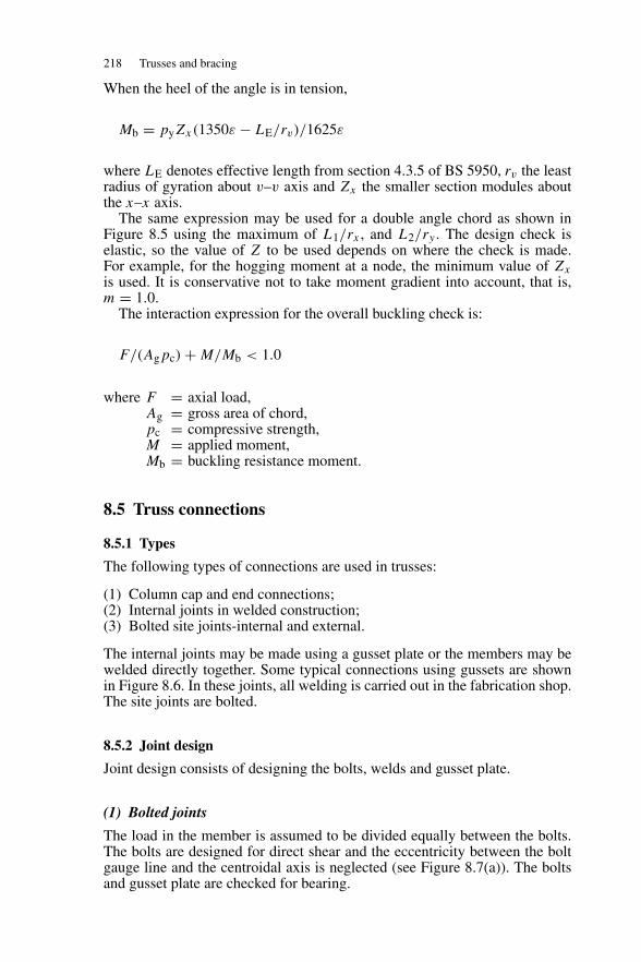
218 Trusses and bracing
When the heel of the angle is in tension,
Mb = pyZx(1350ε − LE/rv)/1625ε
where LE denotes effective length from section 4.3.5 of BS 5950, rv the leastradius of gyration about v–v axis and Zx the smaller section modules aboutthe x–x axis.
The same expression may be used for a double angle chord as shown inFigure 8.5 using the maximum of L1/rx , and L2/ry . The design check iselastic, so the value of Z to be used depends on where the check is made.For example, for the hogging moment at a node, the minimum value of Zx
is used. It is conservative not to take moment gradient into account, that is,m = 1.0.
The interaction expression for the overall buckling check is:
F/(Agpc) + M/Mb < 1.0
where F = axial load,Ag = gross area of chord,pc = compressive strength,M = applied moment,Mb = buckling resistance moment.
8.5 Truss connections
8.5.1 Types
The following types of connections are used in trusses:
(1) Column cap and end connections;(2) Internal joints in welded construction;(3) Bolted site joints-internal and external.
The internal joints may be made using a gusset plate or the members may bewelded directly together. Some typical connections using gussets are shownin Figure 8.6. In these joints, all welding is carried out in the fabrication shop.The site joints are bolted.
8.5.2 Joint design
Joint design consists of designing the bolts, welds and gusset plate.
(1) Bolted joints
The load in the member is assumed to be divided equally between the bolts.The bolts are designed for direct shear and the eccentricity between the boltgauge line and the centroidal axis is neglected (see Figure 8.7(a)). The boltsand gusset plate are checked for bearing.
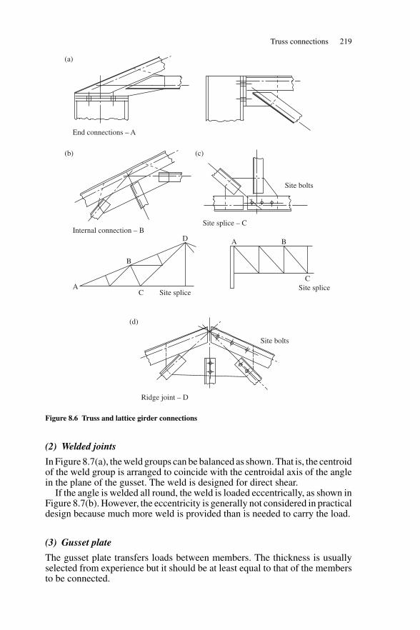
Truss connections 219
End connections – A
Internal connection – B
Site bolts
Site splice – C
Ridge joint – D
A
B
C Site splice
D A B
CSite splice
Site bolts
(a)
(b) (c)
(d)
Figure 8.6 Truss and lattice girder connections
(2) Welded joints
In Figure 8.7(a), the weld groups can be balanced as shown. That is, the centroidof the weld group is arranged to coincide with the centroidal axis of the anglein the plane of the gusset. The weld is designed for direct shear.
If the angle is welded all round, the weld is loaded eccentrically, as shown inFigure 8.7(b). However, the eccentricity is generally not considered in practicaldesign because much more weld is provided than is needed to carry the load.
(3) Gusset plate
The gusset plate transfers loads between members. The thickness is usuallyselected from experience but it should be at least equal to that of the membersto be connected.
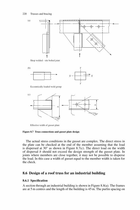
220 Trusses and bracing
Shop welded - site bolted joint
Eccentrically loaded weld group
Effective width of gusset plate
X X
Y
Y
30°
30°
b
b
(a)
(b)
(c)
Figure 8.7 Truss connections and gusset plate design
The actual stress conditions in the gusset are complex. The direct stress inthe plate can be checked at the end of the member assuming that the loadis dispersed at 30◦ as shown in Figure 8.7(c). The direct load on the widthof dispersal b should not exceed the design strength of the gusset plate. Injoints where members are close together, it may not be possible to dispersethe load. In this case a width of gusset equal to the member width is taken forthe check.
8.6 Design of a roof truss for an industrial building
8.6.1 Specification
A section through an industrial building is shown in Figure 8.8(a). The framesare at 5 m centres and the length of the building is 45 m. The purlin spacing on
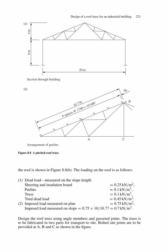
Design of a roof truss for an industrial building 221
20 m
Section through building
10 770
6 spaces @ 1780 = 10 680
6m
4m
A C
B
90
Arrangement of purlins
(a)
(b)
Figure 8.8 A pitched-roof truss
the roof is shown in Figure 8.8(b). The loading on the roof is as follows:
(1) Dead load—measured on the slope lengthSheeting and insulation board = 0.25 kN/m2,Purlins = 0.1 kN/m2,Truss = 0.1 kN/m2,Total dead load = 0.45 kN/m2.
(2) Imposed load measured on plan = 0.75 kN/m2,Imposed load measured on slope = 0.75 × 10/10.77 = 0.7 kN/m2.
Design the roof truss using angle members and gusseted joints. The truss isto be fabricated in two parts for transport to site. Bolted site joints are to beprovided at A, B and C as shown in the figure.
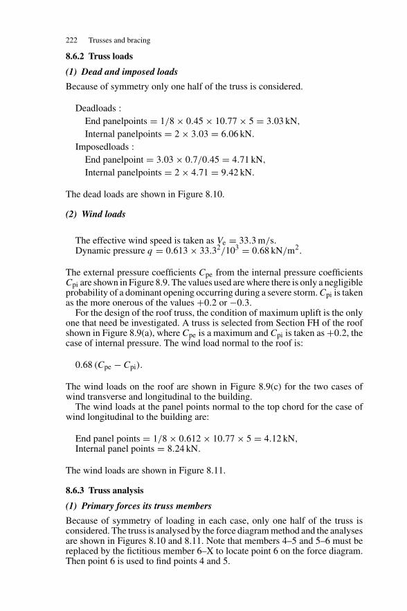
222 Trusses and bracing
8.6.2 Truss loads
(1) Dead and imposed loads
Because of symmetry only one half of the truss is considered.
Deadloads :End panelpoints = 1/8 × 0.45 × 10.77 × 5 = 3.03 kN,
Internal panelpoints = 2 × 3.03 = 6.06 kN.
Imposedloads :End panelpoint = 3.03 × 0.7/0.45 = 4.71 kN,
Internal panelpoints = 2 × 4.71 = 9.42 kN.
The dead loads are shown in Figure 8.10.
(2) Wind loads
The effective wind speed is taken as Ve = 33.3 m/s.Dynamic pressure q = 0.613 × 33.32/103 = 0.68 kN/m2.
The external pressure coefficients Cpe from the internal pressure coefficientsCpi are shown in Figure 8.9. The values used are where there is only a negligibleprobability of a dominant opening occurring during a severe storm. Cpi is takenas the more onerous of the values +0.2 or −0.3.
For the design of the roof truss, the condition of maximum uplift is the onlyone that need be investigated. A truss is selected from Section FH of the roofshown in Figure 8.9(a), where Cpe is a maximum and Cpi is taken as +0.2, thecase of internal pressure. The wind load normal to the roof is:
0.68 (Cpe − Cpi).
The wind loads on the roof are shown in Figure 8.9(c) for the two cases ofwind transverse and longitudinal to the building.
The wind loads at the panel points normal to the top chord for the case ofwind longitudinal to the building are:
End panel points = 1/8 × 0.612 × 10.77 × 5 = 4.12 kN,Internal panel points = 8.24 kN.
The wind loads are shown in Figure 8.11.
8.6.3 Truss analysis
(1) Primary forces its truss members
Because of symmetry of loading in each case, only one half of the truss isconsidered. The truss is analysed by the force diagram method and the analysesare shown in Figures 8.10 and 8.11. Note that members 4–5 and 5–6 must bereplaced by the fictitious member 6–X to locate point 6 on the force diagram.Then point 6 is used to find points 4 and 5.
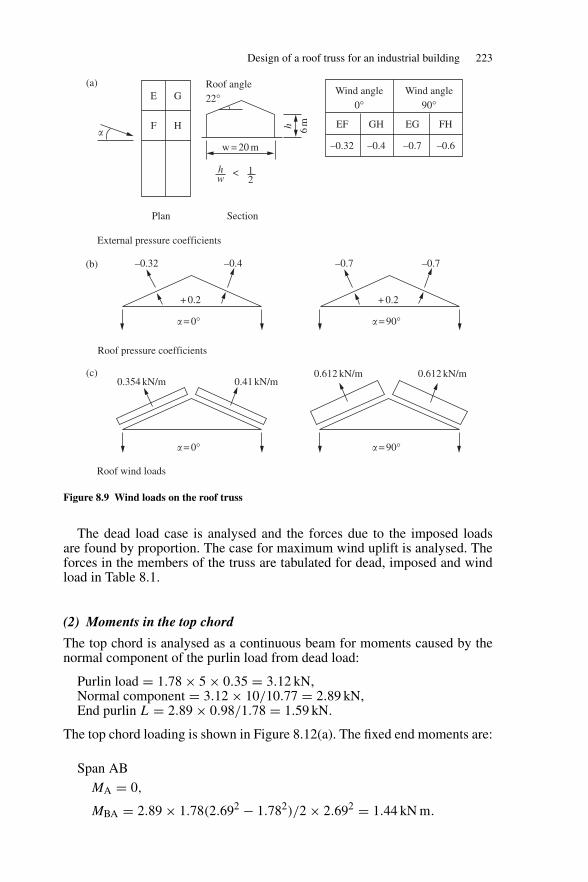
Design of a roof truss for an industrial building 223
w = 20 m
hw
Roof angle22°
12
<
h 6m
E
Plan Section
G
F H
Wind angle0°
Wind angle90°
EF
–0.32 –0.4 –0.7 –0.6
GH EG FH
External pressure coefficients
Roof pressure coefficients
0.354 kN/m 0.41 kN/m0.612 kN/m 0.612 kN/m
Roof wind loads
–0.32 –0.4
+ 0.2
� = 0°
–0.7 –0.7
+ 0.2
� = 90°
� = 0° � = 90°
�
(a)
(b)
(c)
Figure 8.9 Wind loads on the roof truss
The dead load case is analysed and the forces due to the imposed loadsare found by proportion. The case for maximum wind uplift is analysed. Theforces in the members of the truss are tabulated for dead, imposed and windload in Table 8.1.
(2) Moments in the top chord
The top chord is analysed as a continuous beam for moments caused by thenormal component of the purlin load from dead load:
Purlin load = 1.78 × 5 × 0.35 = 3.12 kN,Normal component = 3.12 × 10/10.77 = 2.89 kN,End purlin L = 2.89 × 0.98/1.78 = 1.59 kN.
The top chord loading is shown in Figure 8.12(a). The fixed end moments are:
Span ABMA = 0,
MBA = 2.89 × 1.78(2.692 − 1.782)/2 × 2.692 = 1.44 kN m.
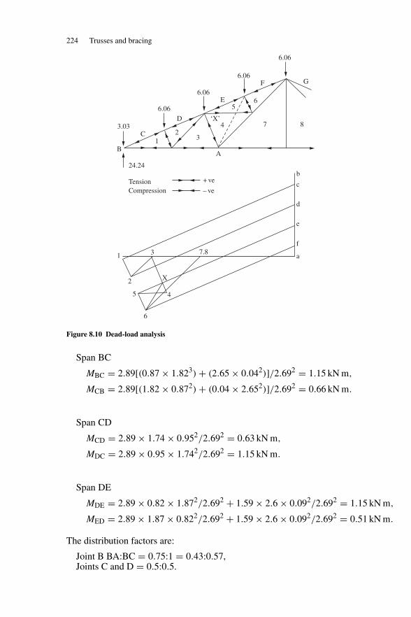
224 Trusses and bracing
b
c
d
e
f
a7.83
24.24
TensionCompression
1
2
5
6
X
4
+ ve
– ve
BA
7 8
6
F
E
D
C
G
3.03
6.06
6.06
12
3
4‘X’
5
6.06
6.06
Figure 8.10 Dead-load analysis
Span BC
MBC = 2.89[(0.87 × 1.823) + (2.65 × 0.042)]/2.692 = 1.15 kN m,
MCB = 2.89[(1.82 × 0.872) + (0.04 × 2.652)]/2.692 = 0.66 kN m.
Span CD
MCD = 2.89 × 1.74 × 0.952/2.692 = 0.63 kN m,
MDC = 2.89 × 0.95 × 1.742/2.692 = 1.15 kN m.
Span DE
MDE = 2.89 × 0.82 × 1.872/2.692 + 1.59 × 2.6 × 0.092/2.692 = 1.15 kN m,
MED = 2.89 × 1.87 × 0.822/2.692 + 1.59 × 2.6 × 0.092/2.692 = 0.51 kN m.
The distribution factors are:
Joint B BA:BC = 0.75:1 = 0.43:0.57,Joints C and D = 0.5:0.5.
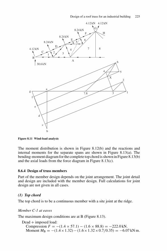
Design of a roof truss for an industrial building 225
4
X
3
2
1
5
6
7.8
ag
f
30.6 kN
e
d
c
b
BA
7 8
6
H
E
F
D
C
G
8.24 kN
8.24 kN
4.12 kN
8.24 kN
4.12 kN 4.12 kN
12 3
4
X 5
Figure 8.11 Wind-load analysis
The moment distribution is shown in Figure 8.12(b) and the reactions andinternal moments for the separate spans are shown in Figure 8.13(a). Thebending-moment diagram for the complete top chord is shown in Figure 8.13(b)and the axial loads from the force diagram in Figure 8.13(c).
8.6.4 Design of truss members
Part of the member design depends on the joint arrangement. The joint detailand design are included with the member design. Full calculations for jointdesign are not given in all cases.
(1) Top chord
The top chord is to be a continuous member with a site joint at the ridge.
Member C-1 at eaves
The maximum design conditions are at B (Figure 8.13).
Dead + imposed load:Compression F = −(1.4 × 57.1) − (1.6 × 88.8) = −222.0 kN.Moment MB = −(1.4×1.32)− (1.6×1.32×0.7/0.35) = −6.07 kN m.
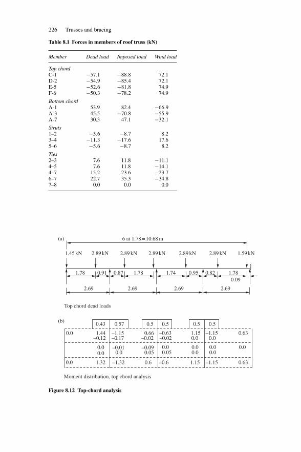
226 Trusses and bracing
Table 8.1 Forces in members of roof truss (kN)
Member Dead load Imposed load Wind load
Top chordC-1 −57.1 −88.8 72.1D-2 −54.9 −85.4 72.1E-5 −52.6 −81.8 74.9F-6 −50.3 −78.2 74.9
Bottom chordA-1 53.9 82.4 −66.9A-3 45.5 −70.8 −55.9A-7 30.3 47.1 −32.1
Struts1–2 −5.6 −8.7 8.23–4 −11.3 −17.6 17.65–6 −5.6 −8.7 8.2
Ties2–3 7.6 11.8 −11.14–5 7.6 11.8 −14.14–7 15.2 23.6 −23.76–7 22.7 35.3 −34.87–8 0.0 0.0 0.0
6 at 1.78 = 10.68 m
1.45 kN
1.78
2.69 2.69 2.69
Top chord dead loads
2.69
0.91 0.87 1.78 1.74 0.95 0.82 1.780.09
2.89 kN 2.89 kN 2.89 kN 2.89 kN 2.89 kN 1.59 kN
Moment distribution, top chord analysis
0.43
0.0 1.44
0.00.0
–0.12–1.15–0.17
0.66–0.02 –0.02
–0.63
0.00.05
0.00.0
0.0 0.00.0
0.01.15
0.0–1.15 0.63
–1.151.15–0.60.60.0 –1.321.32 0.63
–0.090.05
–0.010.0
0.57 0.5 0.5 0.5 0.5
(a)
(b)
Figure 8.12 Top-chord analysis
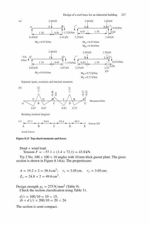
Design of a roof truss for an industrial building 227
2.89 kN
MF = 0.87 kNm
1.78 0.91
2.41 kN0.49 kN
–1.32 kNm
A F B
2.89 kN
– 0.6kNm
MJ = 0.83 kNm
1.74 0.95
2.07 kN
Separate spans, reactions and internal moments
0.82 kN
–1.15 kNm
C J D
2.89 kN 1.59 kN
MK = 0.72 kNm
ML = 0.37 kNm
0.82 1.780.09
2.23kN
2.25 kN
0.63 kNm
K L E
2.89 kN
0.6 kNm
2.89 kN
MG = 0.67 kNm
MH = 0.46 kNm
0.87 1.78
3.49 kN2.29 kN
0.04
G H C
Bending moment diagram
Axial forces
A B C D EMoment kNm
F G H J K L
0.87 0.67 0.83
–1.3
2
–1.1
5
–0.4
6–0
.6
–0.3
7–0
.63
0.72
–57.1
A B C D E
–54.9 –52.6 –50.3Forces kN
(a)
(b)
(c)
Figure 8.13 Top-chord moments and forces
Dead + wind load:Tension F = −57.1 + (1.4 × 72.1) = 43.8 kN.
Try 2 No. 100 × 100 × 10 angles with 10 mm thick gusset plate. The grosssection is shown in Figure 8.14(a). The propertiesare:
A = 19.2 × 2 = 38.4 cm2; rx = 3.05 cm, ry = 3.05 cm;Zx = 24.8 × 2 = 49.6 cm3.
Design strength py = 275 N/mm2 (Table 9).Check the section classification using Table 11.
d/t = 100/10 = 10 < 15,(b + d )/t × 200/10 = 20 < 24.
The section is semi-compact.
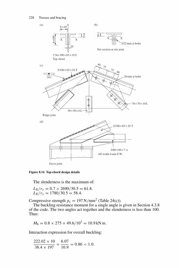
228 Trusses and bracing
b = 65
Y
Y
X X
10
33.6
d=
100
2 No.100 × 65 × 10Top chord
2/100 × 65 × 10
Ridge joint
All welds 6 mm F.W.
2/80 × 60 × 7
2/100 × 65 × 10
Eaves joint
50 × 50 × 6 L
70 × 70 × 10 L
20 mm � bolts
4075
75 40
Net section at site joint
30.1
2/22 mm � holes
XX
(a)
(c)
(d)
(b)
Figure 8.14 Top-chord design details
The slenderness is the maximum of:
LE/rx = 0.7 × 2690/30.5 = 61.8.LE/ry = 1780/30.5 = 58.4.
Compressive strength pc = 197 N/mm2 (Table 24(c)).The buckling resistance moment for a single angle is given in Section 4.3.8
of the code. The two angles act together and the slenderness is less than 100.Thus:
Mb = 0.8 × 275 × 49.6/103 = 10.9 kN m.
Interaction expression for overall buckling:
222.02 × 10
38.4 × 197+ 6.07
10.9= 0.86 < 1.0.
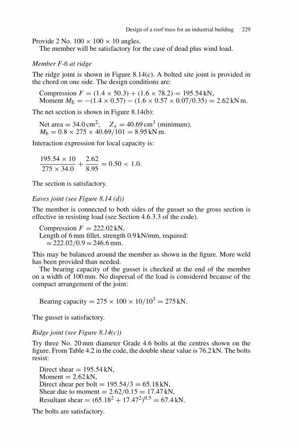
Design of a roof truss for an industrial building 229
Provide 2 No. 100 × 100 × 10 angles.The member will be satisfactory for the case of dead plus wind load.
Member F-6 at ridge
The ridge joint is shown in Figure 8.14(c). A bolted site joint is provided inthe chord on one side. The design conditions are:
Compression F = (1.4 × 50.3) + (1.6 × 78.2) = 195.54 kN,Moment ME = −(1.4 × 0.57) − (1.6 × 0.57 × 0.07/0.35) = 2.62 kN m.
The net section is shown in Figure 8.14(b):
Net area = 34.0 cm2; Zx = 40.69 cm3 (minimum).Mb = 0.8 × 275 × 40.69/101 = 8.95 kN m.
Interaction expression for local capacity is:
195.54 × 10
275 × 34.0+ 2.62
8.95= 0.50 < 1.0.
The section is satisfactory.
Eaves joint (see Figure 8.14 (d))
The member is connected to both sides of the gusset so the gross section iseffective in resisting load (see Section 4.6.3.3 of the code).
Compression F = 222.02 kN,Length of 6 mm fillet, strength 0.9 kN/mm, required:
= 222.02/0.9 = 246.6 mm.
This may be balanced around the member as shown in the figure. More weldhas been provided than needed.
The bearing capacity of the gusset is checked at the end of the memberon a width of 100 mm. No dispersal of the load is considered because of thecompact arrangement of the joint:
Bearing capacity = 275 × 100 × 10/103 = 275 kN.
The gusset is satisfactory.
Ridge joint (see Figure 8.14(c))
Try three No. 20 mm diameter Grade 4.6 bolts at the centres shown on thefigure. From Table 4.2 in the code, the double shear value is 76.2 kN. The boltsresist:
Direct shear = 195.54 kN,Moment = 2.62 kN,Direct shear per bolt = 195.54/3 = 65.18 kN,Shear due to moment = 2.62/0.15 = 17.47 kN,Resultant shear = (65.182 + 17.472)0.5 = 67.4 kN.
The bolts are satisfactory.
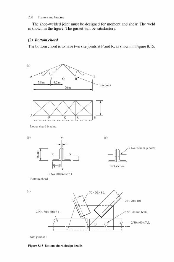
230 Trusses and bracing
The shop-welded joint must be designed for moment and shear. The weldis shown in the figure. The gusset will be satisfactory.
(2) Bottom chord
The bottom chord is to have two site joints at P and R, as shown in Figure 8.15.
20 m
5.8 m
AP Q R
B
Site joint4.2 m
Lower chard bracing
PA
Q R B
X X
b = 60
d=
80
Y
Y
2 No. 80 × 60 × 7
Bottom chord
10
Net section
2 No. 22 mm � holes
70 × 70 × 8 L
2/80 × 60 × 7
2 No. 20 mm bolts
70 × 70 × 10 L
2 No. 80 × 60 × 7
Site joint at P
(a)
(b)
(d)
(c)
Figure 8.15 Bottom-chord design details
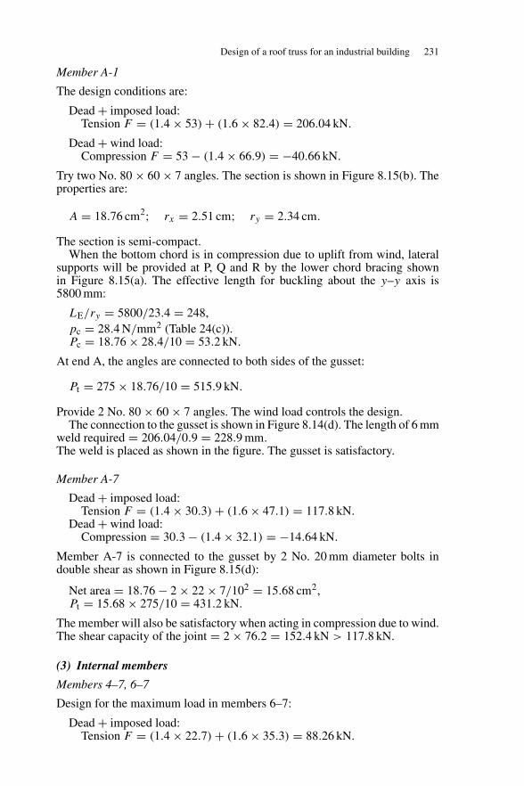
Design of a roof truss for an industrial building 231
Member A-1
The design conditions are:
Dead + imposed load:Tension F = (1.4 × 53) + (1.6 × 82.4) = 206.04 kN.
Dead + wind load:Compression F = 53 − (1.4 × 66.9) = −40.66 kN.
Try two No. 80 × 60 × 7 angles. The section is shown in Figure 8.15(b). Theproperties are:
A = 18.76 cm2; rx = 2.51 cm; ry = 2.34 cm.
The section is semi-compact.When the bottom chord is in compression due to uplift from wind, lateral
supports will be provided at P, Q and R by the lower chord bracing shownin Figure 8.15(a). The effective length for buckling about the y–y axis is5800 mm:
LE/ry = 5800/23.4 = 248,pc = 28.4 N/mm2 (Table 24(c)).Pc = 18.76 × 28.4/10 = 53.2 kN.
At end A, the angles are connected to both sides of the gusset:
Pt = 275 × 18.76/10 = 515.9 kN.
Provide 2 No. 80 × 60 × 7 angles. The wind load controls the design.The connection to the gusset is shown in Figure 8.14(d). The length of 6 mm
weld required = 206.04/0.9 = 228.9 mm.The weld is placed as shown in the figure. The gusset is satisfactory.
Member A-7
Dead + imposed load:Tension F = (1.4 × 30.3) + (1.6 × 47.1) = 117.8 kN.
Dead + wind load:Compression = 30.3 − (1.4 × 32.1) = −14.64 kN.
Member A-7 is connected to the gusset by 2 No. 20 mm diameter bolts indouble shear as shown in Figure 8.15(d):
Net area = 18.76 − 2 × 22 × 7/102 = 15.68 cm2,Pt = 15.68 × 275/10 = 431.2 kN.
The member will also be satisfactory when acting in compression due to wind.The shear capacity of the joint = 2 × 76.2 = 152.4 kN > 117.8 kN.
(3) Internal members
Members 4–7, 6–7
Design for the maximum load in members 6–7:
Dead + imposed load:Tension F = (1.4 × 22.7) + (1.6 × 35.3) = 88.26 kN.
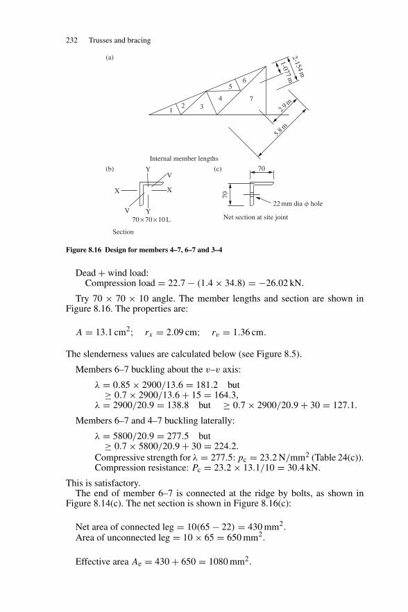
232 Trusses and bracing
12 3
4
56
7
1-077m
2-154m
2.9m
5.8m
Internal member lengths
X
YV
X
YV
70 × 70 × 10 L
Section
Net section at site joint
70
22 mm dia � hole
70
(a)
(b) (c)
Figure 8.16 Design for members 4–7, 6–7 and 3–4
Dead + wind load:Compression load = 22.7 − (1.4 × 34.8) = −26.02 kN.
Try 70 × 70 × 10 angle. The member lengths and section are shown inFigure 8.16. The properties are:
A = 13.1 cm2; rx = 2.09 cm; rv = 1.36 cm.
The slenderness values are calculated below (see Figure 8.5).
Members 6–7 buckling about the v–v axis:
λ = 0.85 × 2900/13.6 = 181.2 but≥ 0.7 × 2900/13.6 + 15 = 164.3,
λ = 2900/20.9 = 138.8 but ≥ 0.7 × 2900/20.9 + 30 = 127.1.
Members 6–7 and 4–7 buckling laterally:
λ = 5800/20.9 = 277.5 but≥ 0.7 × 5800/20.9 + 30 = 224.2.
Compressive strength for λ = 277.5: pc = 23.2 N/mm2 (Table 24(c)).Compression resistance: Pc = 23.2 × 13.1/10 = 30.4 kN.
This is satisfactory.The end of member 6–7 is connected at the ridge by bolts, as shown in
Figure 8.14(c). The net section is shown in Figure 8.16(c):
Net area of connected leg = 10(65 − 22) = 430 mm2.Area of unconnected leg = 10 × 65 = 650 mm2.
Effective area Ae = 430 + 650 = 1080 mm2.
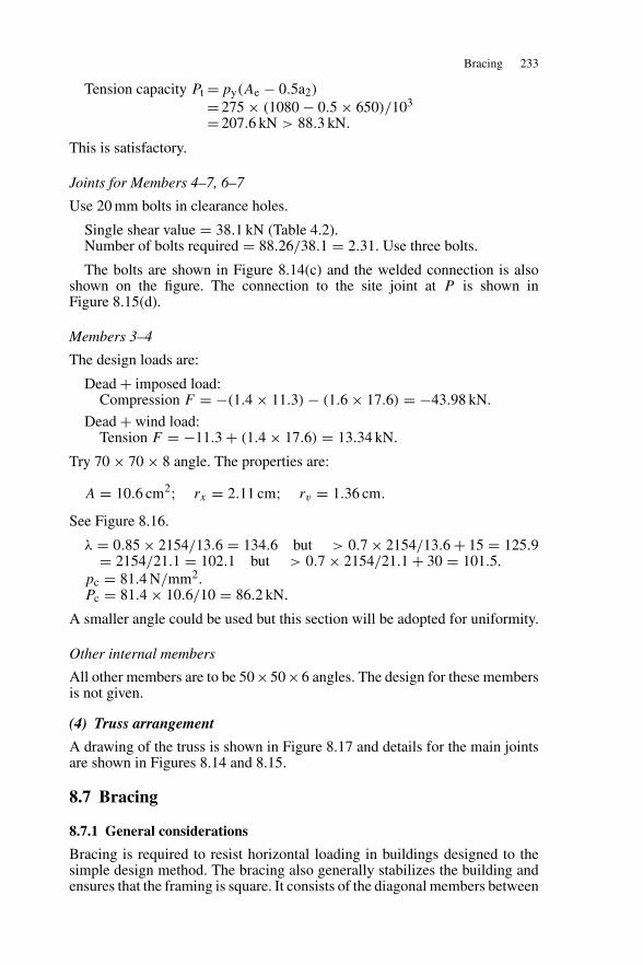
Bracing 233
Tension capacity Pt = py(Ae − 0.5a2)
= 275 × (1080 − 0.5 × 650)/103
= 207.6 kN > 88.3 kN.
This is satisfactory.
Joints for Members 4–7, 6–7
Use 20 mm bolts in clearance holes.
Single shear value = 38.1 kN (Table 4.2).Number of bolts required = 88.26/38.1 = 2.31. Use three bolts.
The bolts are shown in Figure 8.14(c) and the welded connection is alsoshown on the figure. The connection to the site joint at P is shown inFigure 8.15(d).
Members 3–4
The design loads are:
Dead + imposed load:Compression F = −(1.4 × 11.3) − (1.6 × 17.6) = −43.98 kN.
Dead + wind load:Tension F = −11.3 + (1.4 × 17.6) = 13.34 kN.
Try 70 × 70 × 8 angle. The properties are:
A = 10.6 cm2; rx = 2.11 cm; rv = 1.36 cm.
See Figure 8.16.
λ = 0.85 × 2154/13.6 = 134.6 but > 0.7 × 2154/13.6 + 15 = 125.9= 2154/21.1 = 102.1 but > 0.7 × 2154/21.1 + 30 = 101.5.
pc = 81.4 N/mm2.Pc = 81.4 × 10.6/10 = 86.2 kN.
A smaller angle could be used but this section will be adopted for uniformity.
Other internal members
All other members are to be 50×50×6 angles. The design for these membersis not given.
(4) Truss arrangement
A drawing of the truss is shown in Figure 8.17 and details for the main jointsare shown in Figures 8.14 and 8.15.
8.7 Bracing
8.7.1 General considerations
Bracing is required to resist horizontal loading in buildings designed to thesimple design method. The bracing also generally stabilizes the building andensures that the framing is square. It consists of the diagonal members between
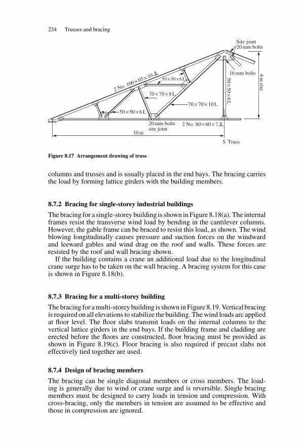
234 Trusses and bracing
50 × 50 × 6 L
10 m
20 mm boltssite joint
2 No. 80 × 60 × 7
2 No. 100 × 65 × 10
70 × 70 × 10 L
70 × 70 × 8 L
50 × 50 × 6 L
Truss$
4m
rise
16 mm bolts50×50×
6L
Site joint20 mm bolts
Figure 8.17 Arrangement drawing of truss
columns and trusses and is usually placed in the end bays. The bracing carriesthe load by forming lattice girders with the building members.
8.7.2 Bracing for single-storey industrial buildings
The bracing for a single-storey building is shown in Figure 8.18(a). The internalframes resist the transverse wind load by bending in the cantilever columns.However, the gable frame can be braced to resist this load, as shown. The windblowing longitudinally causes pressure and suction forces on the windwardand leeward gables and wind drag on the roof and walls. These forces areresisted by the roof and wall bracing shown.
If the building contains a crane an additional load due to the longitudinalcrane surge has to be taken on the wall bracing. A bracing system for this caseis shown in Figure 8.18(b).
8.7.3 Bracing for a multi-storey building
The bracing for a multi-storey building is shown in Figure 8.19. Vertical bracingis required on all elevations to stabilize the building. The wind loads arc appliedat floor level. The floor slabs transmit loads on the internal columns to thevertical lattice girders in the end bays. If the building frame and cladding areerected before the floors are constructed, floor bracing must be provided asshown in Figure 8.19(c). Floor bracing is also required if precast slabs noteffectively tied together are used.
8.7.4 Design of bracing members
The bracing can be single diagonal members or cross members. The load-ing is generally due to wind or crane surge and is reversible. Single bracingmembers must be designed to carry loads in tension and compression. Withcross-bracing, only the members in tension are assumed to be effective andthose in compression are ignored.
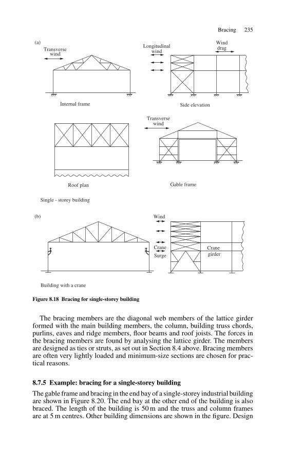
Bracing 235
Internal frame
Transversewind
Longitudinalwind
Transversewind
Winddrag
Side elevation
Roof plan Gable frame
Single - storey building
Wind
Crane
Surge
Cranegirder
Building with a crane
(a)
(b)
Figure 8.18 Bracing for single-storey building
The bracing members are the diagonal web members of the lattice girderformed with the main building members, the column, building truss chords,purlins, eaves and ridge members, floor beams and roof joists. The forces inthe bracing members are found by analysing the lattice girder. The membersare designed as ties or struts, as set out in Section 8.4 above. Bracing membersare often very lightly loaded and minimum-size sections are chosen for prac-tical reasons.
8.7.5 Example: bracing for a single-storey building
The gable frame and bracing in the end bay of a single-storey industrial buildingare shown in Figure 8.20. The end bay at the other end of the building is alsobraced. The length of the building is 50 m and the truss and column framesare at 5 m centres. Other building dimensions are shown in the figure. Design
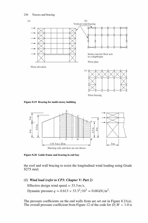
236 Trusses and bracing
Floor elevation
Vertical wind bracing
Insitu concrete floor actsas a diaphragm
Floor plan
Floor bracing
(b)
(c)
(a)
Figure 8.19 Bracing for multi-storey building
F D
E
C
A
B
Sheeting rails and door are not shown
6m
4m
9.5
m
4 @ 5 m = 20 m
6.5
m
8m
5 m
Figure 8.20 Gable frame and bracing in end bay
the roof and wall bracing to resist the longitudinal wind loading using GradeS275 steel.
(1) Wind load (refer to CP3: Chapter V: Part 2)
Effective design wind speed = 33.3 m/s,
Dynamic pressure q = 0.613 × 33.32/103 = 0.68 kN/m2.
The pressure coefficients on the end walls from are set out in Figure 8.21(a).The overall pressure coefficient from Figure 12 of the code for D/H < 1.0 is
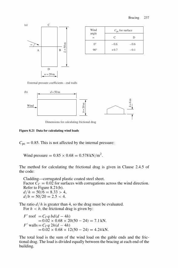
Bracing 237
A
w = 20 m
D
C
B L=
50m∝
Windangle
∝
0°
90°
– 0.6
+ 0.7
– 0.6
– 0.1
DC
Cpe for surface
External pressure coefficients - end walls
d = 50 m
Wind
Dimensions for calculating frictional drag
b=
20m
h=
6m
(a)
(b)
Figure 8.21 Data for calculating wind loads
Cpe = 0.85. This is not affected by the internal pressure:
Wind pressure = 0.85 × 0.68 = 0.578 kN/m2.
The method for calculating the frictional drag is given in Clause 2.4.5 ofthe code:
Cladding—corrugated plastic coated steel sheet.Factor Cf ′ = 0.02 for surfaces with corrugations across the wind direction.Refer to Figure 8.21(b).d/h = 50/6 = 8.33 > 4,d/b = 50/20 = 2.5 < 4.
The ratio d/h is greater than 4, so the drag must be evaluated.For h < b, the frictional drag is given by:
F ′ roof = Cf ′q bd(d − 4h)= 0.02 × 0.68 × 20(50 − 24) = 7.1 kN.
F ′ walls = Cf ′q 2h(d − 4h)= 0.02 × 0.68 × 12(50 − 24) = 4.24 kN.
The total load is the sum of the wind load on the gable ends and the fric-tional drag. The load is divided equally between the bracing at each end of thebuilding.
238 Trusses and bracing
(2) Loads on bracing (see Figure 9.20)
Point E
Load from the wind on the end gable column EF= 9.5 × 5 × 0.5 × 0.578 = 13.73 kN,
Reaction at E, top of the column = 6.86 kN,Load at E from wind drag on the roof
= 0.5 × 7.1 × 0.25 = 0.9 kN,Total load at E = 7.76 kN.
Point C
Load from the wind on the end gable column CD= 8 × 5 × 0.5 × 0.578 = 11.56 kN,
Reaction at C, top of the column = 5.78 kN,Load C from wind drag on the roof = 0.9 kN,Total load at C = 6.68 kN.
Point A
Load from the wind on building column AB= 2.5 × 6.5 × 0.5 × 0.578 = 4.69 kN,
Reaction at A, top of the column = 2.35 kN,Load at A from wind drag on roof and wall
= (0.125 × 7.1 × 0.5) + (0.5 × 4.24 × 0.25) = 0.97 kN,Total load at A = 3.32 kN.
(3) Roof bracing
The loading on the lattice girder formed by the bracing and roof members andthe forces in the bracing members are shown in Figure 8.22(a). Note that themembers of the cross bracing in compression have not been shown. Forcesare transmitted through the purlins in this case. The maximum loaded memberis AH:
Design load = 1.4 × 15.5 = 20.62 kN.Try 50 × 50 × 6 angle with 2 No. 16 mm diameter Grade 4.6 bolts in the
end connections.Bolt capacity = 2 × 25.1 = 50.2 kN (Table 4.2).Referring to Figure 8.22(a):
Net area Ae = (47 − 18)6 + 282 = 456 mm2,Unconnected area a2 = 282 mm2.
Tension capacity Pt = py(Ae − 0.5a2)
= 275 × (456 − 0.5 × 282)/103 = 86.6 kN.Make all the members the same section.
(4) Wall bracing
The load on the wall bracing and the force in the bracing member are shownin Figure 8.22(b).
Design load = 1.4 × 21.7 = 30.4 kN.Provide 50 × 50 × 6 angle.
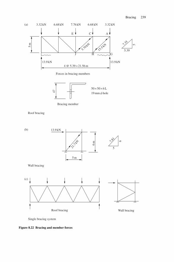
Bracing 239
5m
3.32 kN 6.68 kN 7.76 kN 6.68 kN 3.32 kN
13.9 kN
13.9 kN
13.9 kN
7.35
5.39
5
GHJ
E C A
5.70 kN
15.5kN
Forces in bracing members
4 @ 5.39 = 21.56 m
47
Bracing member
50 × 50 × 6 L
19 mm � hole
Roof bracing
6m
5 m
Wall bracing
21.7
kN 7.81
6
5
Roof bracing
Single bracing system
Wall bracing
(a)
(b)
(c)
Figure 8.22 Bracing and member forces
240 Trusses and bracing
(5) Further considerations
Design for load on one gable
In a long building, the bracing should be designed for the maximum load atone end. This is the external pressure and internal suction on the gable plusone half of the frictional drag on the roof and ’walls. In this case, if the designis made on this basis:
Roof bracing: Design load in AH = 25.1 kN,Wall bracing: Design load = 39.2 kN.
The 50 × 50 × 6 angles will be satisfactory.
Single bracing system
In the above analysis, cross bracing is provided and the purlins form part ofthe bracing lattice girder. This arrangement is satisfactory when angle purlinsare used. However, if cold-rolled purlins are used the bracing system shouldbe independent of the purlins. A suitable system is shown in Figure 8.22(c),where the roof-bracing members support the gable columns. Circular hollowsections are often used for the bracing members.
8.7.6 Example: bracing for a multi-storey building
The framing plans for an office building are shown in Figure 8.23. The floorsand roof are cast in situ reinforced concrete slabs which transmit the wind loadfrom the internal columns to the end bracing. Design the wind bracing usingGrade S275 steel.
(1) Wind loads
The data for the wind loading are:
The site in country with closest distance to sea upwind 2 km, at the first floorthe height above ground of 5 m, take:Effective design wind speed, Ve = 26 m/s.
Table 4 of BS 6399 part 2, the value of Sb for difference height:First floor H = 5 m Sb = 1.62,Second floor H = 10 m Sb = 1.78,Roof H = 15 m Sb = 1.85.
The design wind speeds and dynamic pressures are:
First floor Ve = 26.0 m/s.q = 0.613 × 26.0/103 = 0.42 kN/m2.
Second floor Ve = 26.0 × (1.78/1.62) = 28.5 m/s.q = 0.49 kN/m2.
Roof level Ve = 26.0 × (1.85/1.62) = 29.6 m/s.q = 0.54 kN/m2.
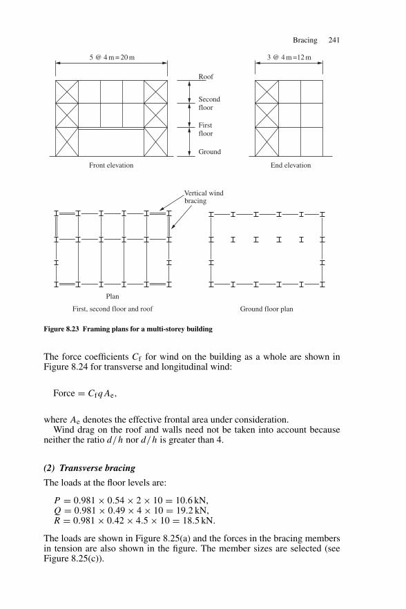
Bracing 241
5 @ 4 m = 20 m 3 @ 4 m =12 m
Roof
Ground
Secondfloor
Firstfloor
Vertical windbracing
Front elevation End elevation
Plan
First, second floor and roof Ground floor plan
Figure 8.23 Framing plans for a multi-storey building
The force coefficients Cf for wind on the building as a whole are shown inFigure 8.24 for transverse and longitudinal wind:
Force = CfqAe,
where Ae denotes the effective frontal area under consideration.Wind drag on the roof and walls need not be taken into account because
neither the ratio d/h nor d/h is greater than 4.
(2) Transverse bracing
The loads at the floor levels are:
P = 0.981 × 0.54 × 2 × 10 = 10.6 kN,Q = 0.981 × 0.49 × 4 × 10 = 19.2 kN,R = 0.981 × 0.42 × 4.5 × 10 = 18.5 kN.
The loads are shown in Figure 8.25(a) and the forces in the bracing membersin tension are also shown in the figure. The member sizes are selected (seeFigure 8.25(c)).
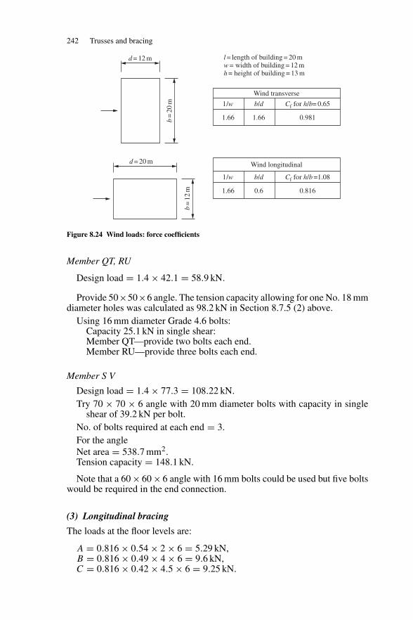
242 Trusses and bracing
Wind transverse
l /w b/d Cf for h/b= 0.65
1.66 1.66 0.981
l = length of building = 20 mw = width of building = 12 mh = height of building = 13 m
Wind longitudinal
l /w b/d Cf for h/b =1.08
1.66 0.6 0.816
d = 12 m
d = 20 mb
=20
m
b=
12m
Figure 8.24 Wind loads: force coefficients
Member QT, RU
Design load = 1.4 × 42.1 = 58.9 kN.
Provide 50×50×6 angle. The tension capacity allowing for one No. 18 mmdiameter holes was calculated as 98.2 kN in Section 8.7.5 (2) above.
Using 16 mm diameter Grade 4.6 bolts:Capacity 25.1 kN in single shear:Member QT—provide two bolts each end.Member RU—provide three bolts each end.
Member S V
Design load = 1.4 × 77.3 = 108.22 kN.Try 70 × 70 × 6 angle with 20 mm diameter bolts with capacity in single
shear of 39.2 kN per bolt.No. of bolts required at each end = 3.For the angleNet area = 538.7 mm2.Tension capacity = 148.1 kN.
Note that a 60 × 60 × 6 angle with 16 mm bolts could be used but five boltswould be required in the end connection.
(3) Longitudinal bracing
The loads at the floor levels are:
A = 0.816 × 0.54 × 2 × 6 = 5.29 kN,B = 0.816 × 0.49 × 4 × 6 = 9.6 kN,C = 0.816 × 0.42 × 4.5 × 6 = 9.25 kN.
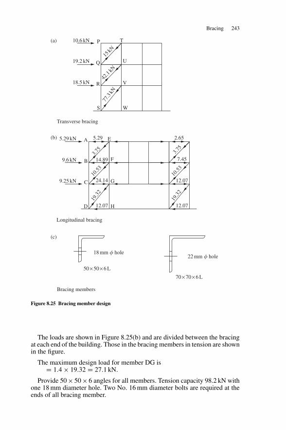
Bracing 243
10.6 kN
15kN
42.1
kN
77.3
kN
19.2 kN
18.5 kN
P
Q
R
S
T
U
V
W
5.29 kN 5.29 2.65
14.89
24.14
12.07 12.07
12.07
7.453.7
5
10.53
19.3
2
3.75
10.53
19.3
2
9.6 kN
9.25 kN
A
B
C
D
E
F
G
H
50 × 50 × 6 L
70 × 70 × 6 L
18 mm � hole22 mm � hole
Transverse bracing
Longitudinal bracing
Bracing members
(a)
(b)
(c)
Figure 8.25 Bracing member design
The loads are shown in Figure 8.25(b) and are divided between the bracingat each end of the building. Those in the bracing members in tension are shownin the figure.
The maximum design load for member DG is= 1.4 × 19.32 = 27.1 kN.
Provide 50 × 50 × 6 angles for all members. Tension capacity 98.2 kN withone 18 mm diameter hole. Two No. 16 mm diameter bolts are required at theends of all bracing member.
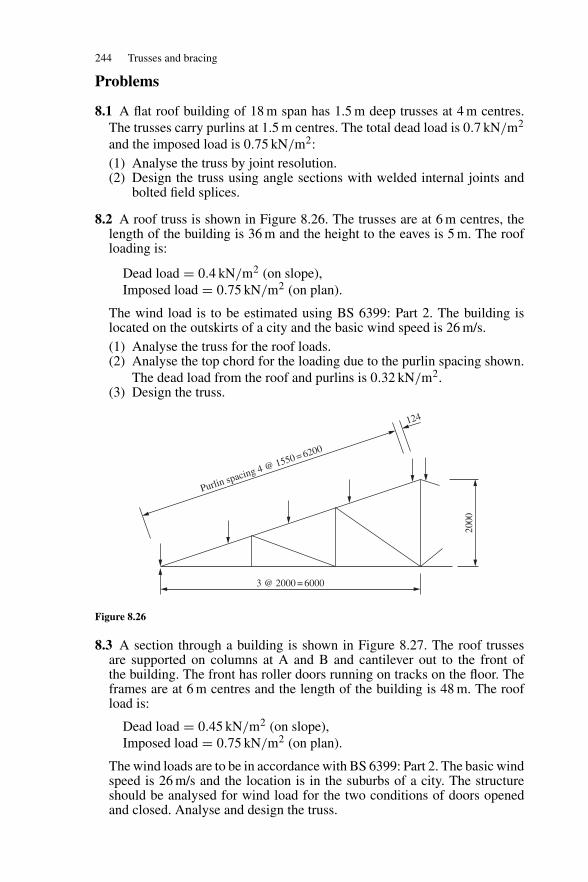
244 Trusses and bracing
Problems
8.1 A flat roof building of 18 m span has 1.5 m deep trusses at 4 m centres.The trusses carry purlins at 1.5 m centres. The total dead load is 0.7 kN/m2
and the imposed load is 0.75 kN/m2:(1) Analyse the truss by joint resolution.(2) Design the truss using angle sections with welded internal joints and
bolted field splices.
8.2 A roof truss is shown in Figure 8.26. The trusses are at 6 m centres, thelength of the building is 36 m and the height to the eaves is 5 m. The roofloading is:
Dead load = 0.4 kN/m2 (on slope),Imposed load = 0.75 kN/m2 (on plan).
The wind load is to be estimated using BS 6399: Part 2. The building islocated on the outskirts of a city and the basic wind speed is 26 m/s.(1) Analyse the truss for the roof loads.(2) Analyse the top chord for the loading due to the purlin spacing shown.
The dead load from the roof and purlins is 0.32 kN/m2.(3) Design the truss.
Purlin spacing 4 @ 1550 = 6200
124
3 @ 2000 = 6000
2000
Figure 8.26
8.3 A section through a building is shown in Figure 8.27. The roof trussesare supported on columns at A and B and cantilever out to the front ofthe building. The front has roller doors running on tracks on the floor. Theframes are at 6 m centres and the length of the building is 48 m. The roofload is:
Dead load = 0.45 kN/m2 (on slope),Imposed load = 0.75 kN/m2 (on plan).
The wind loads are to be in accordance with BS 6399: Part 2. The basic windspeed is 26 m/s and the location is in the suburbs of a city. The structureshould be analysed for wind load for the two conditions of doors openedand closed. Analyse and design the truss.
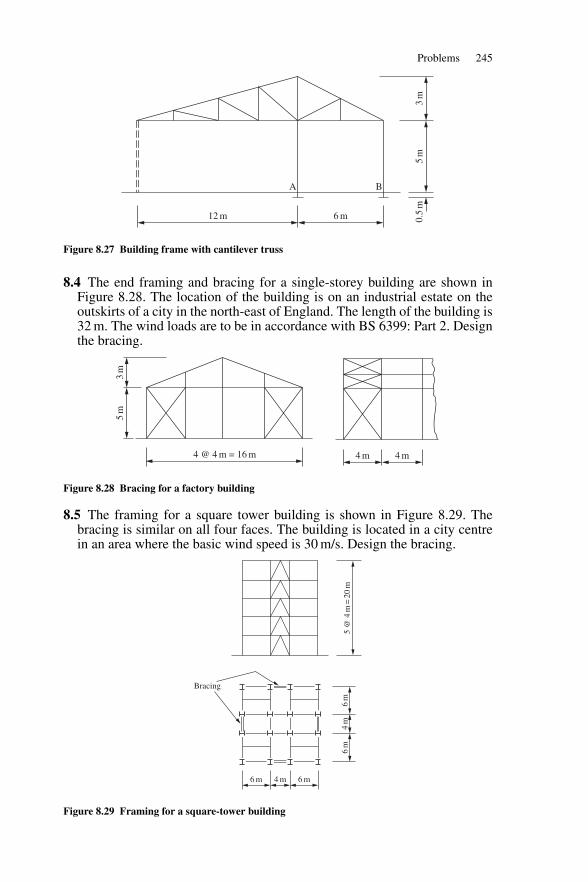
Problems 245
A B
3m
5m
0.5
m
12 m 6 m
Figure 8.27 Building frame with cantilever truss
8.4 The end framing and bracing for a single-storey building are shown inFigure 8.28. The location of the building is on an industrial estate on theoutskirts of a city in the north-east of England. The length of the building is32 m. The wind loads are to be in accordance with BS 6399: Part 2. Designthe bracing.
4 @ 4 m = 16 m
3m
5m
4 m 4 m
Figure 8.28 Bracing for a factory building
8.5 The framing for a square tower building is shown in Figure 8.29. Thebracing is similar on all four faces. The building is located in a city centrein an area where the basic wind speed is 30 m/s. Design the bracing.
6 m 4 m 6 m
6m
4m
6m
Bracing
5 @
4m
=20
m
Figure 8.29 Framing for a square-tower building
9
Portal frames
9.1 Design and construction
9.1.1 Portal type and structural action
The single-storey clear-span building is in constant demand for warehouses,factories and many other purposes. The clear internal appearance makes itmuch more appealing than a trussed roof building and it also requires lessmaintenance and heating. The portal may be of three-pinned, pinned-base orfixed-base construction as shown in Figure 9.1(a). The pinned-base portal isthe most common type adopted because of the greater economy in foundationdesign over the fixed-base type.
In plane, the portal resists the following loads by rigid frame action (seeFigure 9.1(b)):
(a) dead and imposed loads acting vertically;(b) wind causing horizontal loads on the walls and generally uplift loads on
the roof slopes.
In the longitudinal direction, the building is of simple design and diagonalbracing is provided in the end bays to provide stability and resist wind load onthe gable ends and wind friction on sides and roof (see Figure 9.1(d)).
9.1.2 Construction
The main features in modern portal construction shown in Figure 9.1(c) are:
(a) Columns—uniform universal beam section;(b) Rafters—universal beams with haunches usually of sections 30–40%
lighter than the columns;(c) Eaves and ridge connections—site-bolted joints using grade 8.8 bolts
where the haunched ends of the rafters provide the necessary lever arm fordesign. Local joint stiffening is required;
(d) Base—nominally pinned with two or four holding down bolts;(e) Purlins and sheeting rails—cold-formed sections spaced at not greater
than 1.75–2 m centres;(f ) Stays from purlins and rails—these provide lateral support to the inside
flange of portal frame members;
246
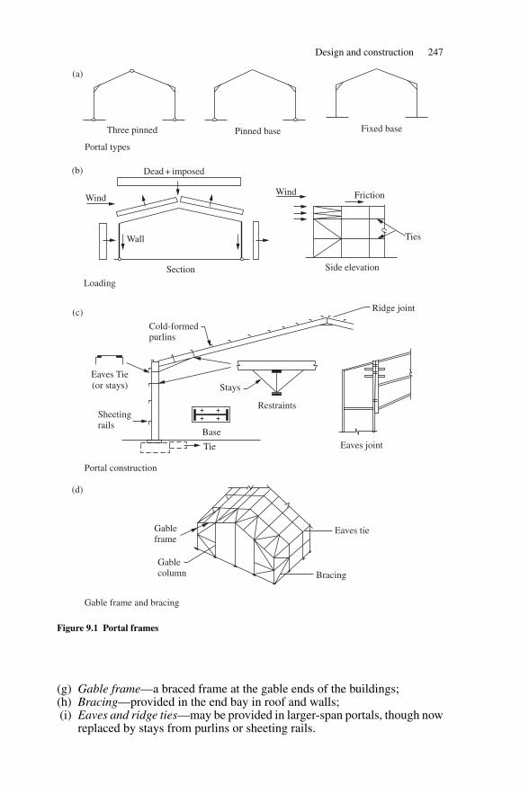
Design and construction 247
Dead + imposed
Wind
Wall
Wind Friction
Ties
Cold-formedpurlins
Ridge joint
(or stays)
Sheetingrails
Stays
Tie
Gableframe
Gablecolumn
Eaves tie
Bracing
Three pinned Pinned base Fixed base
Portal types
Section Side elevation
Loading
Eaves Tie
Restraints
BaseEaves joint
Portal construction
Gable frame and bracing
(a)
(b)
(c)
(d)
Figure 9.1 Portal frames
(g) Gable frame—a braced frame at the gable ends of the buildings;(h) Bracing—provided in the end bay in roof and walls;(i) Eaves and ridge ties—may be provided in larger-span portals, though now
replaced by stays from purlins or sheeting rails.
248 Portal frames
9.1.3 Foundations
The pinned-base portal is generally adopted because it is difficult to ensurefixity without piling and it is more economical to construct. It is also advant-ageous to provide a tie through the ground slab to resist horizontal thrust dueto dead and imposed load as shown in Figure 9.1(c).
9.1.4 Design outline
The code states that either elastic or plastic design may be used. Plastic designgives the more economical solution and is almost universally adopted. Thedesign process for the portal consists of:
(a) analysis—elastic or plastic;(b) design of members taking into account of flexural and lateral torsional
buckling with provision of restraints to limit out-of-plane buckling;(c) sway stability check in the plane of the portal;(d) joint design with provision of stiffeners to ensure all parts are capable of
transmitting design actions;(e) serviceability check for deflection at eaves and apex.
Procedures for elastic and plastic design are set out in BS 5950-1: 2000 andare discussed below.
9.2 Elastic design
9.2.1 Code provision
The provisions from BS 5950-1: 2000 are summarized as follows:
(a) Clause 5.2.2: analysis is made using factored loads.(b) Clause 5.4.1: the capacity and buckling resistance of members are to be
checked using Section 4 of the code.(c) Clause 5.5.2: the stability of the frame should be checked using
Section 2.4.2 of the code. This states that, in load combination 1, thenotional horizontal loads of 0.5% of the factored dead + imposed loadshould be applied. These loads are applied at eaves level and act with1.4× dead load +1.6× imposed load. They are not to be combined withwind loads. In load combinations 2 and 3, the horizontal component ofthe factored wind load should not be taken as less than 1% of the factoreddead load applied horizontally.
9.2.2 Portal analysis
The most convenient manual method of analysis is to use formulae from theSteel Designers Manual (see Further reading at the end of this chapter). Ageneral load case can be broken down into separate cases for which solutionsare given and then these results are recombined. Computer analysis is the mostconvenient method to use, particularly for wind loads and load combinations.The output gives design actions and deflections.
The critical load combination for design is 1.4× dead load +1.6× imposedload. The wind loads mainly cause uplift and the moments are generally in theopposite direction to those caused by the dead and imposed loads. The bending
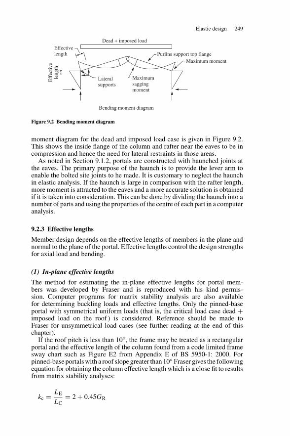
Elastic design 249
Dead + imposed loadEffectivelength
Eff
ectiv
ele
ngth
Lateralsupports
Maximumsaggingmoment
Purlins support top flangeMaximum moment
Bending moment diagram
Figure 9.2 Bending moment diagram
moment diagram for the dead and imposed load case is given in Figure 9.2.This shows the inside flange of the column and rafter near the eaves to be incompression and hence the need for lateral restraints in those areas.
As noted in Section 9.1.2, portals are constructed with haunched joints atthe eaves. The primary purpose of the haunch is to provide the lever arm toenable the bolted site joints to he made. It is customary to neglect the haunchin elastic analysis. If the haunch is large in comparison with the rafter length,more moment is attracted to the eaves and a more accurate solution is obtainedif it is taken into consideration. This can be done by dividing the haunch into anumber of parts and using the properties of the centre of each part in a computeranalysis.
9.2.3 Effective lengths
Member design depends on the effective lengths of members in the plane andnormal to the plane of the portal. Effective lengths control the design strengthsfor axial load and bending.
(1) In-plane effective lengths
The method for estimating the in-plane effective lengths for portal mem-bers was developed by Fraser and is reproduced with his kind permis-sion. Computer programs for matrix stability analysis are also availablefor determining buckling loads and effective lengths. Only the pinned-baseportal with symmetrical uniform loads (that is, the critical load case dead +imposed load on the roof ) is considered. Reference should be made toFraser for unsymmetrical load cases (see further reading at the end of thischapter).
If the roof pitch is less than 10◦, the frame may be treated as a rectangularportal and the effective length of the column found from a code limited framesway chart such as Figure E2 from Appendix E of BS 5950-1: 2000. Forpinned-base portals with a roof slope greater than 10◦ Fraser gives the followingequation for obtaining the column effective length which is a close fit to resultsfrom matrix stability analyses:
kc = LE
LC= 2 + 0.45GR
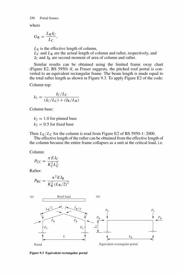
250 Portal frames
where
GR = LRIC
LC,
LE is the effective length of column,LC and LR are the actual length of column and rafter, respectively, andIC and IR are second moment of area of column and rafter.
Similar results can be obtained using the limited frame sway chart(Figure E2, BS 5950) if, as Fraser suggests, the pitched roof portal is con-verted to an equivalent rectangular frame. The beam length is made equal tothe total rafter length as shown in Figure 9.3. To apply Figure E2 of the code:
Column top:
k1 = IC/LC
(IC/LC) + (IR/LR)
Column base:
k2 = 1.0 for pinned basek2 = 0.5 for fixed base
Then LE/LC for the column is read from Figure E2 of BS 5950-1: 2000.The effective length of the rafter can be obtained from the effective length of
the column because the entire frame collapses as a unit at the critical load, i.e.
Column:
PCC = πEIC
K2CL2
C
Rafter:
PRC = π2EIR
K2R (LR/2)2
PR
PC PC
PC PC
LRL
LC
PR
PR PR
Roof load
LR/ 2 LR / 2
Portal Equivalent rectangular portal
(a) (b)
Figure 9.3 Equivalent rectangular portal
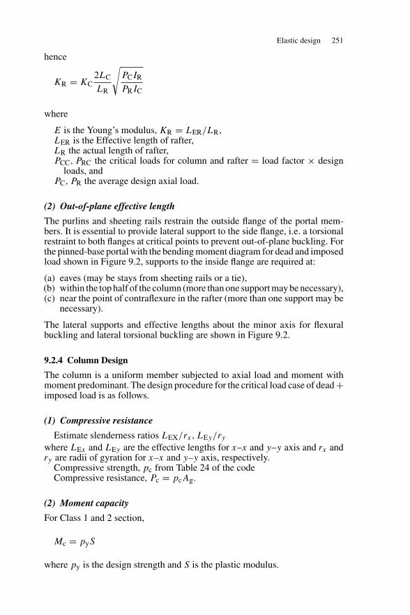
Elastic design 251
hence
KR = KC2LC
LR
√PCIR
PRIC
where
E is the Young’s modulus, KR = LER/LR,LER is the Effective length of rafter,LR the actual length of rafter,PCC, PRC the critical loads for column and rafter = load factor × design
loads, andPC, PR the average design axial load.
(2) Out-of-plane effective length
The purlins and sheeting rails restrain the outside flange of the portal mem-bers. It is essential to provide lateral support to the side flange, i.e. a torsionalrestraint to both flanges at critical points to prevent out-of-plane buckling. Forthe pinned-base portal with the bending moment diagram for dead and imposedload shown in Figure 9.2, supports to the inside flange are required at:
(a) eaves (may be stays from sheeting rails or a tie),(b) within the top half of the column (more than one support may be necessary),(c) near the point of contraflexure in the rafter (more than one support may be
necessary).
The lateral supports and effective lengths about the minor axis for flexuralbuckling and lateral torsional buckling are shown in Figure 9.2.
9.2.4 Column Design
The column is a uniform member subjected to axial load and moment withmoment predominant. The design procedure for the critical load case of dead +imposed load is as follows.
(1) Compressive resistance
Estimate slenderness ratios LEX/rx, LEy/rywhere LEx and LEy are the effective lengths for x–x and y–y axis and rx andry are radii of gyration for x–x and y–y axis, respectively.
Compressive strength, pc from Table 24 of the codeCompressive resistance, Pc = pcAg.
(2) Moment capacity
For Class 1 and 2 section,
Mc = pyS
where py is the design strength and S is the plastic modulus.
252 Portal frames
(3) Buckling resistance moment
The bending moment diagram and effective length are shown in Figure 9.2.Calculate the equivalent slenderness, λLT
λLT = uvλ√
βw
where
v is from Table 19 of the BS 5950-1: 2000,u from section table, λ = LE/ry and βw = 1.0 for class 1 and 2 section.
Bending strength, pb from Table 16 of the code
Buckling resistance moment, Mb = pbS.
(4) Interaction expressions
Cross-section capacity
Fc
Agpy
+ mxMx
Mcx≤ 1
Member buckling resistance
Fc
Pc+ mxMx
pyZx
≤ 1
Fc
Pcy+ mLTMLT
Mb≤ 1
9.2.5 Rafter design
The rafter is a member haunched at both ends with the moment distributionshown in Figure 9.2. The portion near the eaves has compression on the inside.Beyond the point of contraflexure, the inside flange is in tension and is stable.The top flange is fully restrained by the purlins.
If the haunch length is small, it may conservatively be neglected andthe design made for the maximum moment at the eaves. A torsionalrestraint is provided at the first or second purlin point away from theeaves and the design is made in the same way as for the column. Rafterdesign taking the haunch into account is considered under plastic design inSection 9.3.
9.2.6 Example: Elastic design of a portal frame
(1) Specification
The pinned-base portal for an industrial building is shown in Figure 9.4(a). Theportals are at 5 m centres and the length of the building is 40 m. The buildingload are:
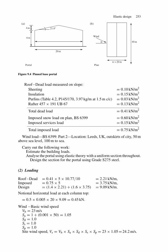
Elastic design 253
4 m
6 m
40 m
20 m
Wind
w = 20 mPlanPortal
α
21.8°
(a) (b)
Figure 9.4 Pinned base portal
Roof−Dead load measured on slope:Sheeting = 0.10 kN/m2
Insulation = 0.15 kN/m2
Purlins (Table 4.2, P145/170, 3.97 kg/m at 1.5 m c/c) = 0.03 kN/m2
Rafter 457 × 191 UB 67 = 0.13 kN/m2
Total dead load = 0.41 kN/m2
Imposed snow load on plan, BS 6399 = 0.60 kN/m2
Imposed services load = 0.15 kN/m2
Total imposed load = 0.75 kN/m2
Wind load—BS 6399: Part 2—Location: Leeds, UK, outskirts of city, 50 mabove sea level, 100 m to sea.
Carry out the following work:Estimate the building loads.Analyse the portal using elastic theory with a uniform section throughout.
Design the section for the portal using Grade S275 steel.
(2) Loading
Roof−Dead = 0.41 × 5 × 10.77/10 = 2.21 kN/m,Imposed = 0.75 × 5 = 3.75 kN/m,Design = (1.4 × 2.21) + (1.6 × 3.75) = 9.09 kN/m.
Notional horizontal load at each column top:
= 0.5 × 0.005 × 20 × 9.09 = 0.45 kN.
Wind −Basic wind speedVb = 23 m/sSa = 1 + (0.001 × 50) = 1.05Sd = 1.0Ss = 1.0Sp = 1.0Site wind speed, Vs = Vb × Sa × Sd × Ss × Sp = 23 × 1.05 = 24.2 m/s.
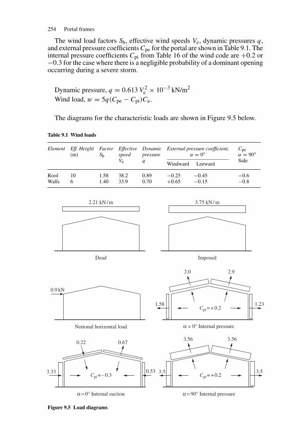
254 Portal frames
The wind load factors Sb, effective wind speeds Ve, dynamic pressures q,and external pressure coefficients Cpe for the portal are shown in Table 9.1. Theinternal pressure coefficients Cpi from Table 16 of the wind code are +0.2 or−0.3 for the case where there is a negligible probability of a dominant openingoccurring during a severe storm.
Dynamic pressure, q = 0.613 V 2e × 10−3 kN/m2
Wind load, w = 5q(Cpe − Cpi)Ca.
The diagrams for the characteristic loads are shown in Figure 9.5 below.
Table 9.1 Wind loads
Element Eff. Heiglit(m)
FactorSb
EffectivespeedVe
Dynamicpressureq
External pressure coefficient,α = 0◦
Windward Leeward
Cpeα = 90◦Side
Roof 10 1.58 38.2 0.89 −0.25 −0.45 −0.6Walls 6 1.40 33.9 0.70 +0.65 −0.15 −0.8
2.21 kN / m 3.75 kN / m
Dead Imposed
0.9 kN
2.0 2.9
1.58 1.23
3.5
Notional horizontal load α = 0° Internal pressure
0.22 0.67
3.33 0.53 3.5
α = 0° Internal suction α = 90° Internal pressure
3.56 3.56
Cpi = + 0.2
Cpi = – 0.3 Cpi = + 0.2
Figure 9.5 Load diagrams
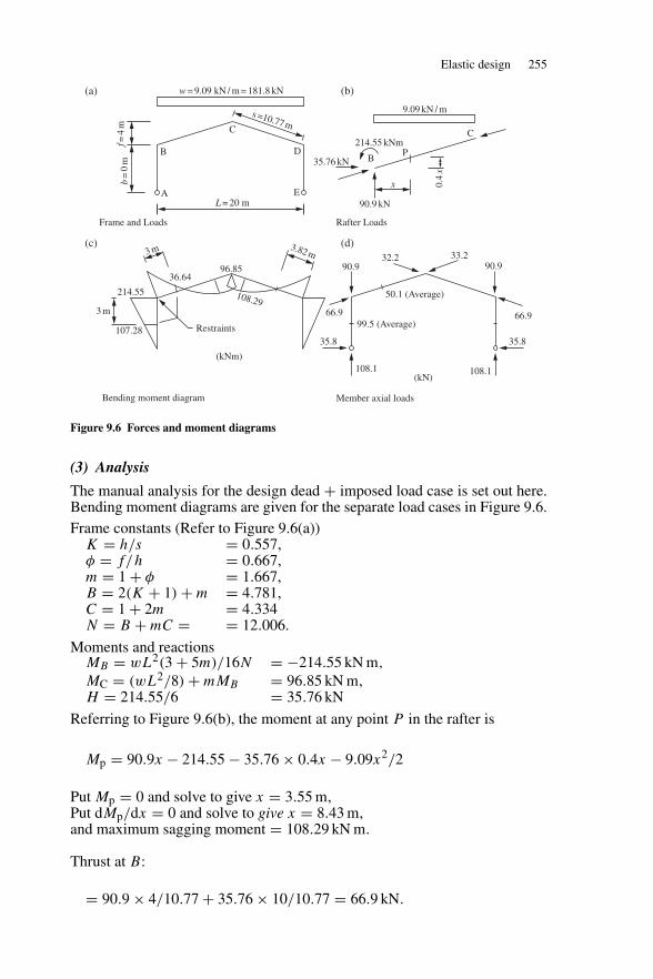
Elastic design 255
w = 9.09 kN / m = 181.8 kN
A
B
C
L = 20 m
D
E
9.09 kN / m
35.76 kN
214.55 kNm
B
x
90.9 kN
P
C
0.4
x
214.55
36.6496.85
3.82 m
108.29
Restraints107.28
(kNm)
66.9 66.9
35.8 35.8
50.1 (Average)
99.5 (Average)
90.9 90.932.2 33.2
108.1 108.1(kN)
3 m
f=4
mb
=0
ms =10.77 m
3 m
(a)
(c)
(b)
(d)
Frame and Loads
Bending moment diagram
Rafter Loads
Member axial loads
Figure 9.6 Forces and moment diagrams
(3) Analysis
The manual analysis for the design dead + imposed load case is set out here.Bending moment diagrams are given for the separate load cases in Figure 9.6.Frame constants (Refer to Figure 9.6(a))
K = h/s = 0.557,φ = f/h = 0.667,m = 1 + φ = 1.667,B = 2(K + 1) + m = 4.781,C = 1 + 2m = 4.334N = B + mC = = 12.006.
Moments and reactionsMB = wL2(3 + 5m)/16N = −214.55 kN m,
MC = (wL2/8) + mMB = 96.85 kN m,H = 214.55/6 = 35.76 kN
Referring to Figure 9.6(b), the moment at any point P in the rafter is
Mp = 90.9x − 214.55 − 35.76 × 0.4x − 9.09x2/2
Put Mp = 0 and solve to give x = 3.55 m,Put dMp/dx = 0 and solve to give x = 8.43 m,and maximum sagging moment = 108.29 kN m.
Thrust at B:
= 90.9 × 4/10.77 + 35.76 × 10/10.77 = 66.9 kN.
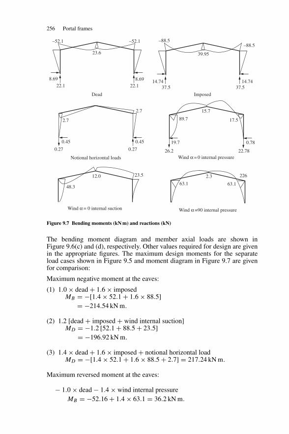
256 Portal frames
–52.1 –52.1
23.6
8.69 8.6922.1
2.7
2.7
0.45 0.45
0.27
48.3
12.0 23.5
0.27
22.1
–88.5–88.5
39.95
14.74 14.7437.5 37.5
Dead
Notional horizontal loads Wind α = 0 internal pressure
Wind α =90 internal pressureWind α = 0 internal suction
Imposed
26.2 22.78
19.7
89.7
15.7
17.5
0.78
63.1
2.3 226
63.1
Figure 9.7 Bending moments (kN m) and reactions (kN)
The bending moment diagram and member axial loads are shown inFigure 9.6(c) and (d), respectively. Other values required for design are givenin the appropriate figures. The maximum design moments for the separateload cases shown in Figure 9.5 and moment diagram in Figure 9.7 are givenfor comparison:
Maximum negative moment at the eaves:
(1) 1.0 × dead + 1.6 × imposedMB = −[1.4 × 52.1 + 1.6 × 88.5]
= −214.54 kN m.
(2) 1.2 [dead + imposed + wind internal suction]MD = −1.2 [52.1 + 88.5 + 23.5]
= −196.92 kN m.
(3) 1.4 × dead + 1.6 × imposed + notional horizontal loadMD = −[1.4 × 52.1 + 1.6 × 88.5 + 2.7] = 217.24 kN m.
Maximum reversed moment at the eaves:
− 1.0 × dead − 1.4 × wind internal pressureMB = −52.16 + 1.4 × 63.1 = 36.2 kN m.
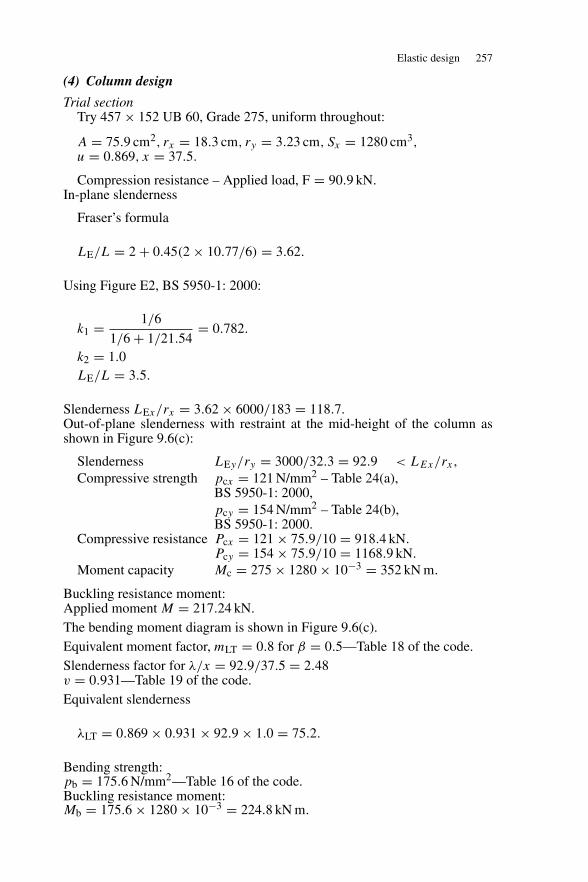
Elastic design 257
(4) Column design
Trial sectionTry 457 × 152 UB 60, Grade 275, uniform throughout:
A = 75.9 cm2, rx = 18.3 cm, ry = 3.23 cm, Sx = 1280 cm3,u = 0.869, x = 37.5.
Compression resistance – Applied load, F = 90.9 kN.In-plane slenderness
Fraser’s formula
LE/L = 2 + 0.45(2 × 10.77/6) = 3.62.
Using Figure E2, BS 5950-1: 2000:
k1 = 1/6
1/6 + 1/21.54= 0.782.
k2 = 1.0LE/L = 3.5.
Slenderness LEx/rx = 3.62 × 6000/183 = 118.7.Out-of-plane slenderness with restraint at the mid-height of the column asshown in Figure 9.6(c):
Slenderness LEy/ry = 3000/32.3 = 92.9 < LEx/rx ,Compressive strength pcx = 121 N/mm2 – Table 24(a),
BS 5950-1: 2000,pcy = 154 N/mm2 – Table 24(b),BS 5950-1: 2000.
Compressive resistance Pcx = 121 × 75.9/10 = 918.4 kN.Pcy = 154 × 75.9/10 = 1168.9 kN.
Moment capacity Mc = 275 × 1280 × 10−3 = 352 kN m.
Buckling resistance moment:Applied moment M = 217.24 kN.The bending moment diagram is shown in Figure 9.6(c).Equivalent moment factor, mLT = 0.8 for β = 0.5—Table 18 of the code.Slenderness factor for λ/x = 92.9/37.5 = 2.48v = 0.931—Table 19 of the code.Equivalent slenderness
λLT = 0.869 × 0.931 × 92.9 × 1.0 = 75.2.
Bending strength:pb = 175.6 N/mm2—Table 16 of the code.Buckling resistance moment:Mb = 175.6 × 1280 × 10−3 = 224.8 kN m.
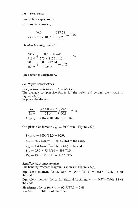
258 Portal frames
Interaction expressions
Cross-section capacity
90.9
275 × 75.9 × 10−1+ 217.24
352= 0.66
Member buckling capacity
90.9
918.4+ 0.6 × 217.24
275 × 1120 × 10−3= 0.52
90.9
1168.9+ 0.8 × 217.24
224.8= 0.85
The section is satisfactory.
(5) Rafter design check
Compression resistance, F = 66.9 kN.The average compressive forces for the rafter and column are shown inFigure 9.6(d).In-plane slenderness
LE
LR/2= 3.62 × 2 × 6
21.54
√99.5
50.1= 2.84.
LEx/rx = 2.84 × 10770/183 = 167.
Out-plane slenderness: LEy = 3000 mm—Figure 9.6(c)
LEy/ry = 3000/32.3 = 92.9.
pcx = 65.7 N/mm2—Table 24(a) of the code,
pcy = 154 N/mm2—Table 24(b) of the code,Pcx = 65.7 × 75.9/10 = 498.7 kN,
Pcy = 154 × 75.9/10 = 1168.9 kN.
Buckling resistance momentThe bending moment diagram is shown in Figure 9.6(c).
Equivalent moment factor, mLT = 0.67 for β = 0.17—Table 18 ofthe code.Equivalent moment factor for flexural buckling, m = 0.37—Table 18 ofthe code.
Slenderness factor for λ/x = 92.9/37.5 = 2.48.v = 0.931—Table 19 of the code.
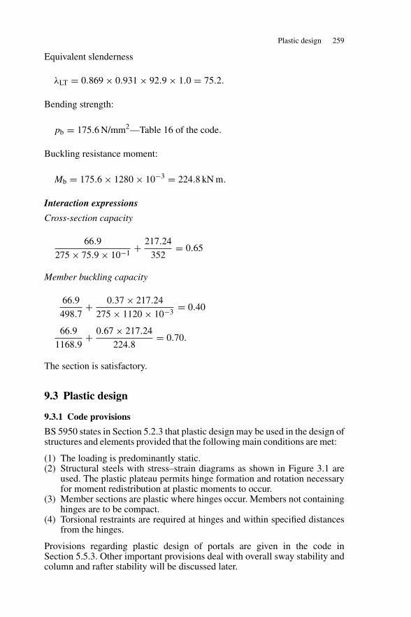
Plastic design 259
Equivalent slenderness
λLT = 0.869 × 0.931 × 92.9 × 1.0 = 75.2.
Bending strength:
pb = 175.6 N/mm2—Table 16 of the code.
Buckling resistance moment:
Mb = 175.6 × 1280 × 10−3 = 224.8 kN m.
Interaction expressions
Cross-section capacity
66.9
275 × 75.9 × 10−1+ 217.24
352= 0.65
Member buckling capacity
66.9
498.7+ 0.37 × 217.24
275 × 1120 × 10−3= 0.40
66.9
1168.9+ 0.67 × 217.24
224.8= 0.70.
The section is satisfactory.
9.3 Plastic design
9.3.1 Code provisions
BS 5950 states in Section 5.2.3 that plastic design may be used in the design ofstructures and elements provided that the following main conditions are met:
(1) The loading is predominantly static.(2) Structural steels with stress–strain diagrams as shown in Figure 3.1 are
used. The plastic plateau permits hinge formation and rotation necessaryfor moment redistribution at plastic moments to occur.
(3) Member sections are plastic where hinges occur. Members not containinghinges are to be compact.
(4) Torsional restraints are required at hinges and within specified distancesfrom the hinges.
Provisions regarding plastic design of portals are given in the code inSection 5.5.3. Other important provisions deal with overall sway stability andcolumn and rafter stability will be discussed later.
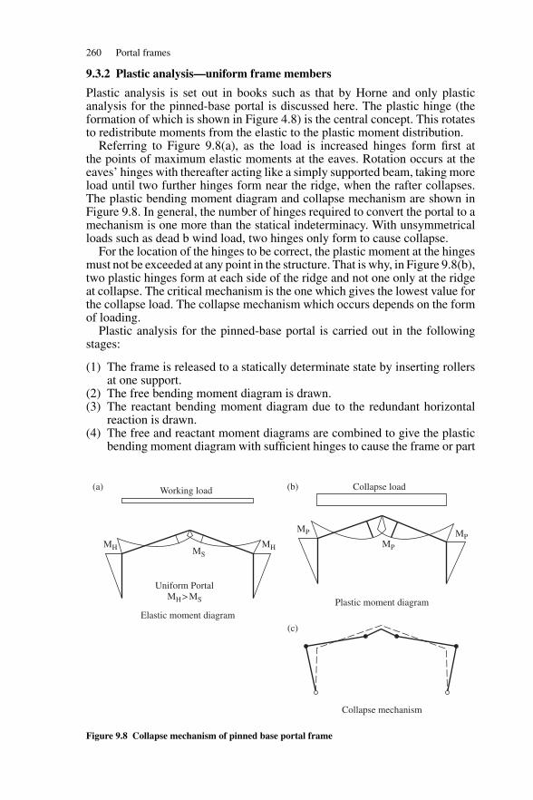
260 Portal frames
9.3.2 Plastic analysis—uniform frame members
Plastic analysis is set out in books such as that by Horne and only plasticanalysis for the pinned-base portal is discussed here. The plastic hinge (theformation of which is shown in Figure 4.8) is the central concept. This rotatesto redistribute moments from the elastic to the plastic moment distribution.
Referring to Figure 9.8(a), as the load is increased hinges form first atthe points of maximum elastic moments at the eaves. Rotation occurs at theeaves’ hinges with thereafter acting like a simply supported beam, taking moreload until two further hinges form near the ridge, when the rafter collapses.The plastic bending moment diagram and collapse mechanism are shown inFigure 9.8. In general, the number of hinges required to convert the portal to amechanism is one more than the statical indeterminacy. With unsymmetricalloads such as dead b wind load, two hinges only form to cause collapse.
For the location of the hinges to be correct, the plastic moment at the hingesmust not be exceeded at any point in the structure. That is why, in Figure 9.8(b),two plastic hinges form at each side of the ridge and not one only at the ridgeat collapse. The critical mechanism is the one which gives the lowest value forthe collapse load. The collapse mechanism which occurs depends on the formof loading.
Plastic analysis for the pinned-base portal is carried out in the followingstages:
(1) The frame is released to a statically determinate state by inserting rollersat one support.
(2) The free bending moment diagram is drawn.(3) The reactant bending moment diagram due to the redundant horizontal
reaction is drawn.(4) The free and reactant moment diagrams are combined to give the plastic
bending moment diagram with sufficient hinges to cause the frame or part
Working load Collapse load
Uniform Portal MH > MS
MH MH
MP MPMPMS
Elastic moment diagramPlastic moment diagram
Collapse mechanism
(a) (b)
(c)
Figure 9.8 Collapse mechanism of pinned base portal frame
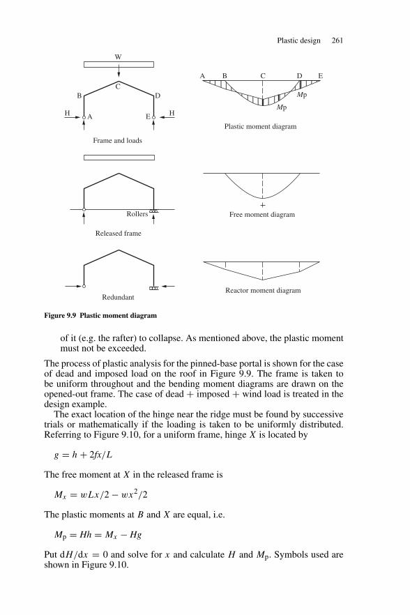
Plastic design 261
W
A
BC
D
EH H
A B C D E
Mp
Mp
Rollers
Frame and loads
Plastic moment diagram
Released frame
Free moment diagram
RedundantReactor moment diagram
Figure 9.9 Plastic moment diagram
of it (e.g. the rafter) to collapse. As mentioned above, the plastic momentmust not be exceeded.
The process of plastic analysis for the pinned-base portal is shown for the caseof dead and imposed load on the roof in Figure 9.9. The frame is taken tobe uniform throughout and the bending moment diagrams are drawn on theopened-out frame. The case of dead + imposed + wind load is treated in thedesign example.
The exact location of the hinge near the ridge must be found by successivetrials or mathematically if the loading is taken to be uniformly distributed.Referring to Figure 9.10, for a uniform frame, hinge X is located by
g = h + 2fx/L
The free moment at X in the released frame is
Mx = wLx/2 − wx2/2
The plastic moments at B and X are equal, i.e.
Mp = Hh = Mx − Hg
Put dH/dx = 0 and solve for x and calculate H and Mp. Symbols used areshown in Figure 9.10.
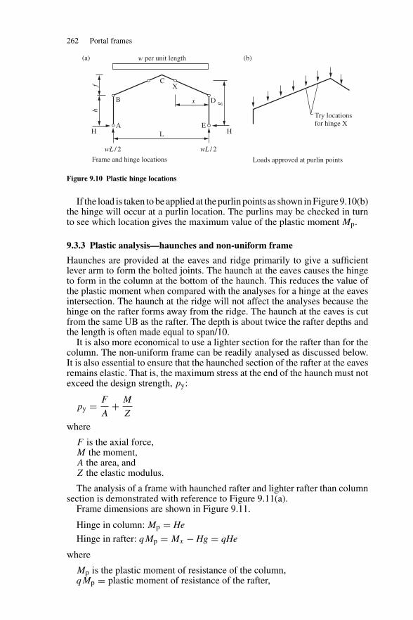
262 Portal frames
Try locationsfor hinge X
w per unit length
A
B
CX
x
E
D
LH H
hf
g
wL / 2 wL / 2
Frame and hinge locations Loads approved at purlin points
(a) (b)
Figure 9.10 Plastic hinge locations
If the load is taken to be applied at the purlin points as shown in Figure 9.10(b)the hinge will occur at a purlin location. The purlins may be checked in turnto see which location gives the maximum value of the plastic moment Mp.
9.3.3 Plastic analysis—haunches and non-uniform frame
Haunches are provided at the eaves and ridge primarily to give a sufficientlever arm to form the bolted joints. The haunch at the eaves causes the hingeto form in the column at the bottom of the haunch. This reduces the value ofthe plastic moment when compared with the analyses for a hinge at the eavesintersection. The haunch at the ridge will not affect the analyses because thehinge on the rafter forms away from the ridge. The haunch at the eaves is cutfrom the same UB as the rafter. The depth is about twice the rafter depths andthe length is often made equal to span/10.
It is also more economical to use a lighter section for the rafter than for thecolumn. The non-uniform frame can be readily analysed as discussed below.It is also essential to ensure that the haunched section of the rafter at the eavesremains elastic. That is, the maximum stress at the end of the haunch must notexceed the design strength, py:
py = F
A+ M
Z
where
F is the axial force,M the moment,A the area, andZ the elastic modulus.
The analysis of a frame with haunched rafter and lighter rafter than columnsection is demonstrated with reference to Figure 9.11(a).
Frame dimensions are shown in Figure 9.11.
Hinge in column: Mp = He
Hinge in rafter: qMp = Mx − Hg = qHe
where
Mp is the plastic moment of resistance of the column,qMp = plastic moment of resistance of the rafter,
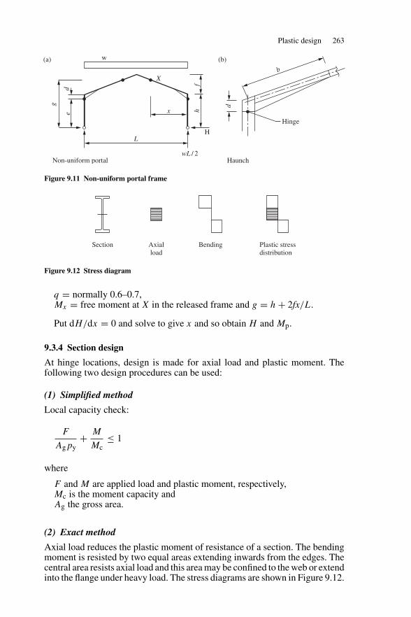
Plastic design 263
g
d
h
d
f
e
Xb
x
Hinge
w
LH
wL / 2Non-uniform portal Haunch
(a) (b)
Figure 9.11 Non-uniform portal frame
Section Axialload
Bending Plastic stressdistribution
Figure 9.12 Stress diagram
q = normally 0.6–0.7,Mx = free moment at X in the released frame and g = h + 2fx/L.
Put dH/dx = 0 and solve to give x and so obtain H and Mp.
9.3.4 Section design
At hinge locations, design is made for axial load and plastic moment. Thefollowing two design procedures can be used:
(1) Simplified method
Local capacity check:
F
Agpy+ M
Mc≤ 1
where
F and M are applied load and plastic moment, respectively,Mc is the moment capacity andAg the gross area.
(2) Exact method
Axial load reduces the plastic moment of resistance of a section. The bendingmoment is resisted by two equal areas extending inwards from the edges. Thecentral area resists axial load and this area may be confined to the web or extendinto the flange under heavy load. The stress diagrams are shown in Figure 9.12.
264 Portal frames
The formulae for calculating the reduced plastic moduli of sections subjectedto axial load and moment are given in Steelwork Design to BS 5950, Volume Iand the calculation procedure is as follows:
n = F/Agpy
where
F is the applied axial loadAg the gross area.
Change values of n are given for each section. For lower values of n, theneutral axis lies in the web and the reduced plastic modulus:
Sr = k1 − k2n2
where values of k1 and k2 are given in the Steelwork Design to BS 5950,Volume I. A formula is also given for upper values of n. Reduced momentcapacity, Mr = Srpy > M , applied moment.
9.4 In-plane stability
The in-plane stability of a portal frame should be checked under each load com-bination. Section 5.5.4, BS 5950-1: 2000 gives three procedures for checkingthe overall sway stability of a portal:
(a) Sway-check method given in Section 5.5.4.2. in the code.(b) Amplified moments method given in Section 5.5.4.4. in the code.(c) Second-order analysis given in Section 5.5.4.5. in the code.
These ensure that the elastic buckling load is not reached and that the effectsof additional moments due to deflection of the portal are taken into account.
9.4.1 Sway-check method
The sway-check method may be used to verify the in-plane stability of portalframes in which each bay satisfies the following conditions:
(a) span, L does not exceed five times the mean height h of the columns;(b) height, hr of the apex above the tops of the columns does not exceed
0.25 times the span, L.
(1) Limiting horizontal deflection at eaves
For gravity loads (load combination 1), the horizontal deflection calculated bylinear elastic analysis at the top of the columns due to the notional horizontalloads without any allowance for the stiffening effects of cladding should notexceed h/1000, where h is the column height. The notional loads are 0.5% ofthe factored roof dead and imposed loads applied at the column tops.
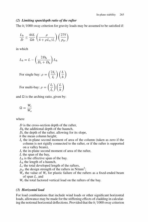
In-plane stability 265
(2) Limiting span/depth ratio of the rafter
The h/1000 sway criterion for gravity loads may be assumed to be satisfied if:
Lb
D≤ 44L
�h
(ρ
4 + ρLr/L
) (275
pyr
)
in which
Lb = L −(
2Dh
Ds + Dh
)Lh
For single bay: ρ =(
2Ic
Ir
) (L
h
)
For multi-bay: ρ =(
Ic
Ir
) (L
h
)
and � is the arching ratio, given by:
� = Wr
Wo
where
D is the cross-section depth of the rafter,Dh the additional depth of the haunch,Ds the depth of the rafter, allowing for its slope,h the mean column height;Ic the in-plane second moment of area of the column (taken as zero if the
column is not rigidly connected to the rafter, or if the rafter is supportedon a valley beam),
Ir the in-plane second moment of area of the rafter,L the span of the bay,Lb is the effective span of the bay.Lh the length of a haunch,Lr the total developed length of the rafters,pyr the design strength of the rafters in N/mm2;Wo the value of Wr for plastic failure of the rafters as a fixed-ended beam
of span L, andWr the total factored vertical load on the rafters of the bay.
(3) Horizontal load
For load combinations that include wind loads or other significant horizontalloads, allowance may be made for the stiffening effects of cladding in calculat-ing the notional horizontal deflections. Provided that the h/1000 sway criterion
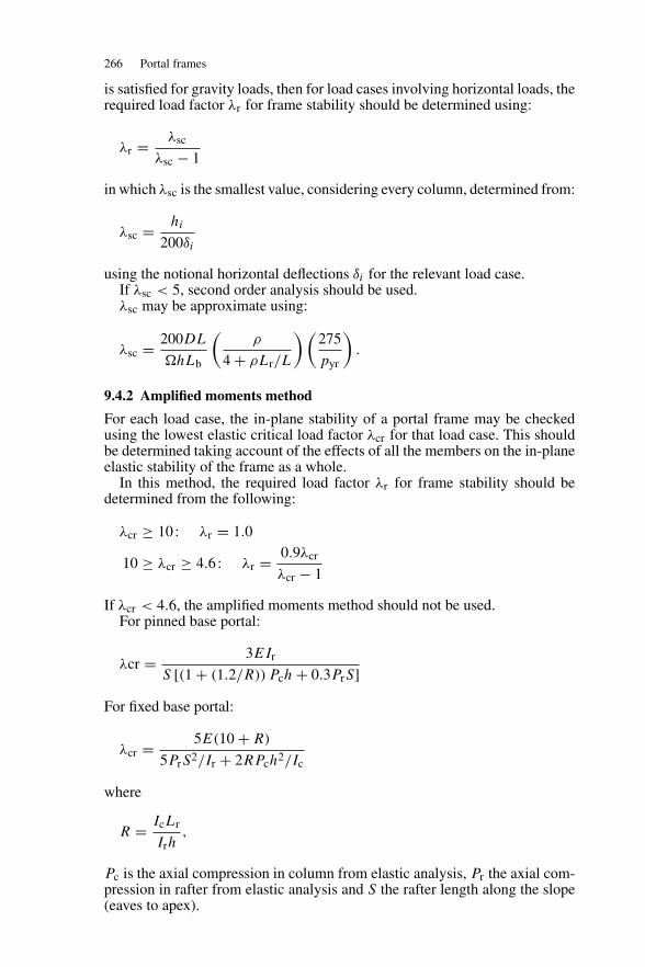
266 Portal frames
is satisfied for gravity loads, then for load cases involving horizontal loads, therequired load factor λr for frame stability should be determined using:
λr = λsc
λsc − 1
in which λsc is the smallest value, considering every column, determined from:
λsc = hi
200δi
using the notional horizontal deflections δi for the relevant load case.If λsc < 5, second order analysis should be used.λsc may be approximate using:
λsc = 200DL
�hLb
(ρ
4 + ρLr/L
) (275
pyr
).
9.4.2 Amplified moments method
For each load case, the in-plane stability of a portal frame may be checkedusing the lowest elastic critical load factor λcr for that load case. This shouldbe determined taking account of the effects of all the members on the in-planeelastic stability of the frame as a whole.
In this method, the required load factor λr for frame stability should bedetermined from the following:
λcr ≥ 10 : λr = 1.0
10 ≥ λcr ≥ 4.6 : λr = 0.9λcr
λcr − 1
If λcr < 4.6, the amplified moments method should not be used.For pinned base portal:
λcr = 3EIr
S [(1 + (1.2/R)) Pch + 0.3PrS]
For fixed base portal:
λcr = 5E(10 + R)
5PrS2/Ir + 2RPch2/Ic
where
R = IcLr
Irh,
Pc is the axial compression in column from elastic analysis, Pr the axial com-pression in rafter from elastic analysis and S the rafter length along the slope(eaves to apex).
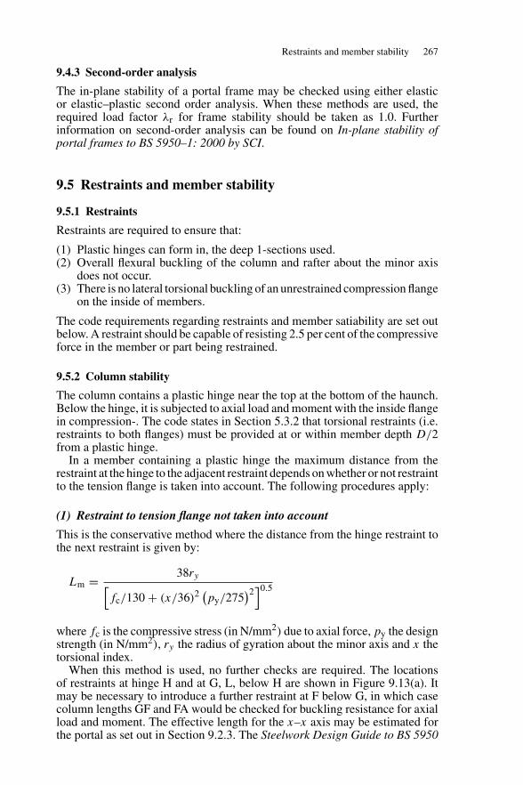
Restraints and member stability 267
9.4.3 Second-order analysis
The in-plane stability of a portal frame may be checked using either elasticor elastic–plastic second order analysis. When these methods are used, therequired load factor λr for frame stability should be taken as 1.0. Furtherinformation on second-order analysis can be found on In-plane stability ofportal frames to BS 5950–1: 2000 by SCI.
9.5 Restraints and member stability
9.5.1 Restraints
Restraints are required to ensure that:
(1) Plastic hinges can form in, the deep 1-sections used.(2) Overall flexural buckling of the column and rafter about the minor axis
does not occur.(3) There is no lateral torsional buckling of an unrestrained compression flange
on the inside of members.
The code requirements regarding restraints and member satiability are set outbelow. A restraint should be capable of resisting 2.5 per cent of the compressiveforce in the member or part being restrained.
9.5.2 Column stability
The column contains a plastic hinge near the top at the bottom of the haunch.Below the hinge, it is subjected to axial load and moment with the inside flangein compression-. The code states in Section 5.3.2 that torsional restraints (i.e.restraints to both flanges) must be provided at or within member depth D/2from a plastic hinge.
In a member containing a plastic hinge the maximum distance from therestraint at the hinge to the adjacent restraint depends on whether or not restraintto the tension flange is taken into account. The following procedures apply:
(1) Restraint to tension flange not taken into account
This is the conservative method where the distance from the hinge restraint tothe next restraint is given by:
Lm = 38ry[fc/130 + (x/36)2 (
py/275)2
]0.5
where fc is the compressive stress (in N/mm2) due to axial force, py the designstrength (in N/mm2), ry the radius of gyration about the minor axis and x thetorsional index.
When this method is used, no further checks are required. The locationsof restraints at hinge H and at G, L, below H are shown in Figure 9.13(a). Itmay be necessary to introduce a further restraint at F below G, in which casecolumn lengths GF and FA would be checked for buckling resistance for axialload and moment. The effective length for the x–x axis may be estimated forthe portal as set out in Section 9.2.3. The Steelwork Design Guide to BS 5950
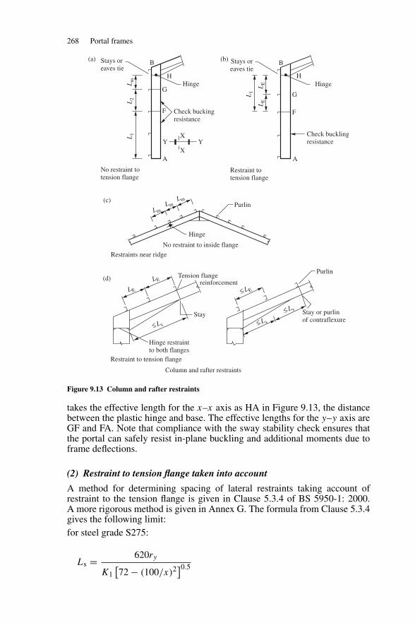
268 Portal frames
B
HHinge
Check buckingresistance
G
F
A
Y YX
X
L1
L2
Lm
L1
LE
LE
B
HHinge
G
F
Check bucklingresistance
A
Hinge
No restraint to inside flange
PurlinLm
LE
≤ L s
LE
≤ LE
≤ L s
≤ L s
LmLm
Tension flangereinforcement
Hinge restraintto both flanges
Stay Stay or purlinof contraflexure
Purlin
Restraints near ridge
Restraint to tension flange
Column and rafter restraints
(c)
(a) (b)
(d)
Stays oreaves tie
No restraint totension flange
Stays oreaves tie
Restraint totension flange
Figure 9.13 Column and rafter restraints
takes the effective length for the x–x axis as HA in Figure 9.13, the distancebetween the plastic hinge and base. The effective lengths for the y–y axis areGF and FA. Note that compliance with the sway stability check ensures thatthe portal can safely resist in-plane buckling and additional moments due toframe deflections.
(2) Restraint to tension flange taken into account
A method for determining spacing of lateral restraints taking account ofrestraint to the tension flange is given in Clause 5.3.4 of BS 5950-1: 2000.A more rigorous method is given in Annex G. The formula from Clause 5.3.4gives the following limit:for steel grade S275:
Ls = 620ry
K1[72 − (100/x)2]0.5
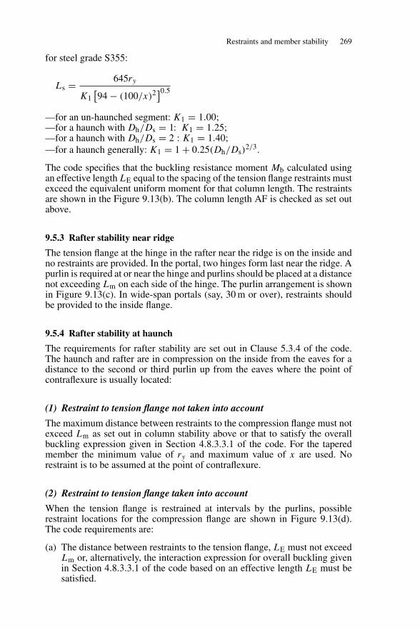
Restraints and member stability 269
for steel grade S355:
Ls = 645ry
K1[94 − (100/x)2]0.5
—for an un-haunched segment: K1 = 1.00;—for a haunch with Dh/Ds = 1: K1 = 1.25;—for a haunch with Dh/Ds = 2 : K1 = 1.40;—for a haunch generally: K1 = 1 + 0.25(Dh/Ds)
2/3.
The code specifies that the buckling resistance moment Mb calculated usingan effective length LE equal to the spacing of the tension flange restraints mustexceed the equivalent uniform moment for that column length. The restraintsare shown in the Figure 9.13(b). The column length AF is checked as set outabove.
9.5.3 Rafter stability near ridge
The tension flange at the hinge in the rafter near the ridge is on the inside andno restraints are provided. In the portal, two hinges form last near the ridge. Apurlin is required at or near the hinge and purlins should be placed at a distancenot exceeding Lm on each side of the hinge. The purlin arrangement is shownin Figure 9.13(c). In wide-span portals (say, 30 m or over), restraints shouldbe provided to the inside flange.
9.5.4 Rafter stability at haunch
The requirements for rafter stability are set out in Clause 5.3.4 of the code.The haunch and rafter are in compression on the inside from the eaves for adistance to the second or third purlin up from the eaves where the point ofcontraflexure is usually located:
(1) Restraint to tension flange not taken into account
The maximum distance between restraints to the compression flange must notexceed Lm as set out in column stability above or that to satisfy the overallbuckling expression given in Section 4.8.3.3.1 of the code. For the taperedmember the minimum value of ry and maximum value of x are used. Norestraint is to be assumed at the point of contraflexure.
(2) Restraint to tension flange taken into account
When the tension flange is restrained at intervals by the purlins, possiblerestraint locations for the compression flange are shown in Figure 9.13(d).The code requirements are:
(a) The distance between restraints to the tension flange, LE must not exceedLm or, alternatively, the interaction expression for overall buckling givenin Section 4.8.3.3.1 of the code based on an effective length LE must besatisfied.
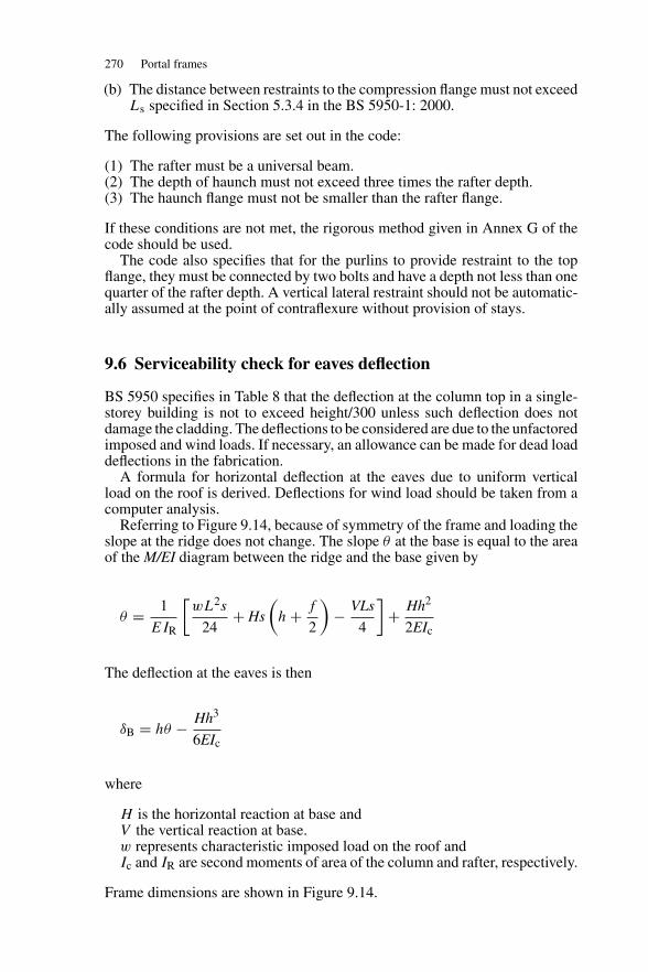
270 Portal frames
(b) The distance between restraints to the compression flange must not exceedLs specified in Section 5.3.4 in the BS 5950-1: 2000.
The following provisions are set out in the code:
(1) The rafter must be a universal beam.(2) The depth of haunch must not exceed three times the rafter depth.(3) The haunch flange must not be smaller than the rafter flange.
If these conditions are not met, the rigorous method given in Annex G of thecode should be used.
The code also specifies that for the purlins to provide restraint to the topflange, they must be connected by two bolts and have a depth not less than onequarter of the rafter depth. A vertical lateral restraint should not be automatic-ally assumed at the point of contraflexure without provision of stays.
9.6 Serviceability check for eaves deflection
BS 5950 specifies in Table 8 that the deflection at the column top in a single-storey building is not to exceed height/300 unless such deflection does notdamage the cladding. The deflections to be considered are due to the unfactoredimposed and wind loads. If necessary, an allowance can be made for dead loaddeflections in the fabrication.
A formula for horizontal deflection at the eaves due to uniform verticalload on the roof is derived. Deflections for wind load should be taken from acomputer analysis.
Referring to Figure 9.14, because of symmetry of the frame and loading theslope at the ridge does not change. The slope θ at the base is equal to the areaof the M/EI diagram between the ridge and the base given by
θ = 1
EIR
[wL2s
24+ Hs
(h + f
2
)− VLs
4
]+ Hh2
2EIc
The deflection at the eaves is then
δB = hθ − Hh3
6EIc
where
H is the horizontal reaction at base andV the vertical reaction at base.w represents characteristic imposed load on the roof andIc and IR are second moments of area of the column and rafter, respectively.
Frame dimensions are shown in Figure 9.14.
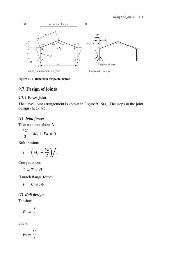
Design of joints 271
B D
EAH
hf
VL
IR
IC
Ch�s
Tangent of base
w per unit length
�B�B
�
Loading and moment diagram Deflected structure
(a) (b)
Figure 9.14 Deflection for portal frame
9.7 Design of joints
9.7.1 Eaves joint
The eaves joint arrangement is shown in Figure 9.15(a). The steps in the jointdesign check are:
(1) Joint forces
Take moment about X:
Vd
2− Mp + T a = 0
Bolt tension:
T =(
Mp − Vd
2
)/a
Compression:
C = T + H
Haunch flange force:
F = C sec φ
(2) Bolt design
Tension:
FT = T
4,
Shear:
FS = V
8.
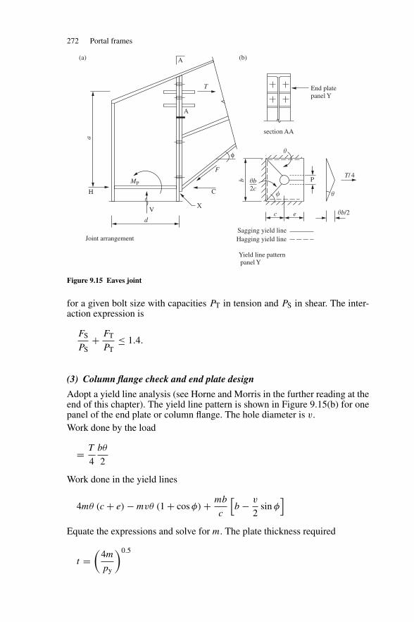
272 Portal frames
a
H
A
A
V
d
X
C
F
MP
End platepanel Y
b PT/ 4
�
c e �b/2
Sagging yield lineHagging yield line
T
φ �
�b2c
Joint arrangement
Yield line pattern panel Y
section AA
�
(a) (b)
Figure 9.15 Eaves joint
for a given bolt size with capacities PT in tension and PS in shear. The inter-action expression is
FS
PS+ FT
PT≤ 1.4.
(3) Column flange check and end plate design
Adopt a yield line analysis (see Horne and Morris in the further reading at theend of this chapter). The yield line pattern is shown in Figure 9.15(b) for onepanel of the end plate or column flange. The hole diameter is v.Work done by the load
= T
4
bθ
2
Work done in the yield lines
4mθ (c + e) − mvθ (1 + cos φ) + mb
c
[b − v
2sin φ
]Equate the expressions and solve for m. The plate thickness required
t =(
4m
py
)0.5
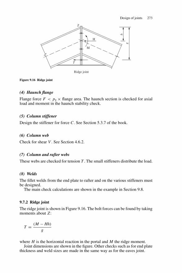
Design of joints 273
Z
H
M
h
g
T
Ridge joint
Figure 9.16 Ridge joint
(4) Haunch flange
Flange force F < py × flange area. The haunch section is checked for axialload and moment in the haunch stability check.
(5) Column stiffener
Design the stiffener for force C. See Section 5.3.7 of the book.
(6) Column web
Check for shear V . See Section 4.6.2.
(7) Column and rafter webs
These webs are checked for tension T . The small stiffeners distribute the load.
(8) Welds
The fillet welds from the end plate to rafter and on the various stiffeners mustbe designed.
The main check calculations are shown in the example in Section 9.8.
9.7.2 Ridge joint
The ridge joint is shown in Figure 9.16. The bolt forces can be found by takingmoments about Z:
T = (M − Hh)
g
where H is the horizontal reaction in the portal and M the ridge moment.Joint dimensions are shown in the figure. Other checks such as for end plate
thickness and weld sizes are made in the same way as for the eaves joint.
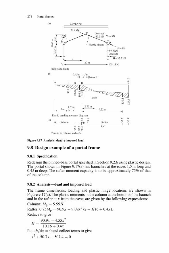
274 Portal frames
9.09 kN / m
30.4 kN
5.55
m4
m
1.5 m
0.45
m B D
C
V
x
Average47.3 kN 90.9 kN
Plastic hinges64.2 kN
99.5 kNAverage
H = 32.7 kN
20 m108.1 kN
H
0.45 m 1.5 mhaunch
A F G H B
kNm
96.1
148.
8
161.
219
6.8
136.
1
127.
545
4.5
3 m1.55 m 2.72 m
9.22 m
A Column
95.1
92.2
90.9
Ratter 35.2
30.4
kN
64.2
B 59.5
Frame and loads
(a)
(b)
(c)
Plastic rending moment diagram
Thrusts in column and rafter
Figure 9.17 Analysis: dead + imposed load
9.8 Design example of a portal frame
9.8.1 Specification
Redesign the pinned-base portal specified in Section 9.2.6 using plastic design.The portal shown in Figure 9.17(a) has haunches at the eaves 1.5 m long and0.45 m deep. The rafter moment capacity is to be approximately 75% of thatof the column.
9.8.2 Analysis—dead and imposed load
The frame dimensions, loading and plastic hinge locations are shown inFigure 9.17(a). The plastic moments in the column at the bottom of the haunchand in the rafter at x from the eaves are given by the following expressions:Column: Mp = 5.55H .Rafter: 0.75Mp = 90.9x − 9.09x2/2 − H(6 + 0.4x).Reduce to give
H = 90.9x − 4.55x2
10.16 + 0.4x
Put dh/dx = 0 and collect terms to give
x2 + 50.7x − 507.4 = 0
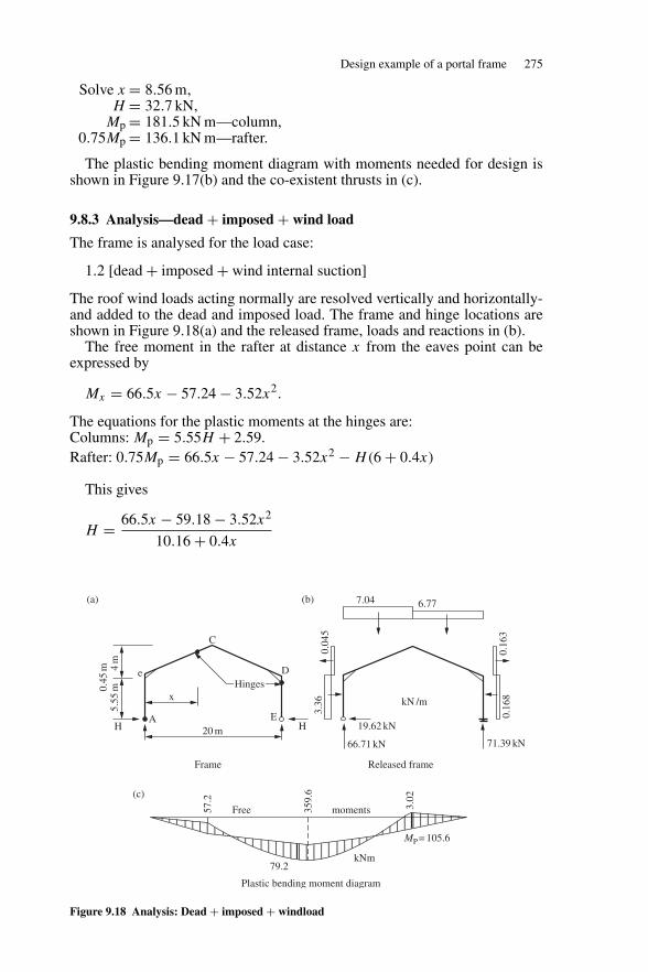
Design example of a portal frame 275
Solve x = 8.56 m,H = 32.7 kN,
Mp = 181.5 kN m—column,0.75Mp = 136.1 kN m—rafter.
The plastic bending moment diagram with moments needed for design isshown in Figure 9.17(b) and the co-existent thrusts in (c).
9.8.3 Analysis—dead + imposed + wind load
The frame is analysed for the load case:
1.2 [dead + imposed + wind internal suction]
The roof wind loads acting normally are resolved vertically and horizontally-and added to the dead and imposed load. The frame and hinge locations areshown in Figure 9.18(a) and the released frame, loads and reactions in (b).
The free moment in the rafter at distance x from the eaves point can beexpressed by
Mx = 66.5x − 57.24 − 3.52x2.
The equations for the plastic moments at the hinges are:Columns: Mp = 5.55H + 2.59.Rafter: 0.75Mp = 66.5x − 57.24 − 3.52x2 − H(6 + 0.4x)
This gives
H = 66.5x − 59.18 − 3.52x2
10.16 + 0.4x
20 mA
C
D
EH
5.55
m0.45
m 4m
e
H
x
7.04 6.77
0.04
53.
36 kN /m
19.62 kN
66.71 kN
0.16
30.
168
71.39 kN
Free moments57.2
359.
6
3.02
79.2kNm
MP = 105.6
Hinges
Frame Released frame
Plastic bending moment diagram
(a) (b)
(c)
Figure 9.18 Analysis: Dead + imposed + windload
276 Portal frames
Put dh/dx = 0 and solve to give x = 8.39 m.
H = 18.6 kN,
Mp = 105.1 kN.
The plastic bending moment diagram is shown in Figure 9.18(c). The momentsare less than for the dead + imposed load case.
9.8.4 Column design
The design actions at the column hinge are
Mp = 181.8 kN m,
F = 92.2 kN,
Sx = 181.8 × 10³/275 = 661.1 cm3.
Try 406 × 140 UB 46
Sx = 888 cm3, A = 59 cm2, rx = 16.3 cm, ry = 3.02 cm,
u = 0.87, x = 38.8, Ix = 15 600 cm4.
n = 92.2 × 10/(59 × 275) = 0.056 < 0.444.
Reduced plastic modulus:
Srx = 888 − 1260n2 = 883.9 cm3.
The section is satisfactory.
9.8.5 Rafter section
The design actions at the rafter hinge are:
Mp = 136.1 kN m
F = 35.2 kN,
S = 136.1 × 10³/275 = 494.9 cm3.
Try 356 × 127 UB 39
Sx = 654 cm3, A = 49.4 cm2, rx = 14.3 cm, ry = 2.69 cm,
Zx = 572 cm3, Ix = 10 100 cm4, x = 34.3.
n = 35.5 × 10/(49.4 × 275) = 0.026 < 0.437,
Srx = 654 0.43 = 653.6 cm3.
The section is satisfactory.
Check that the rafter section at the end of the haunch remains elastic underfactored loads. The actions are
M = 96.9 kN m,
F = 59.5 kN
Maximum stress = 59.5 × 10
49.4+ 96.9 × 10³
572= 181.4 N/mm2.
This is less than py = 275 N/mm2. The section remains elastic.
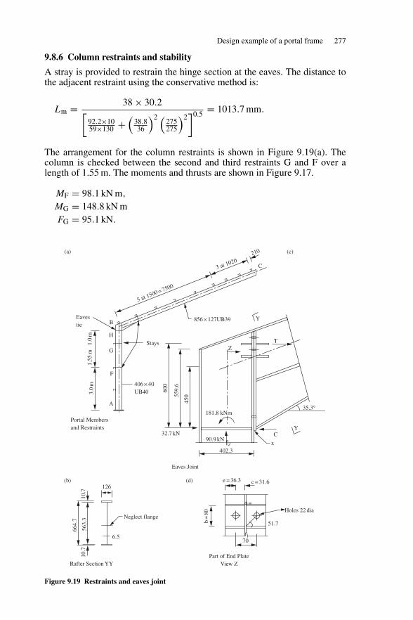
Design example of a portal frame 277
9.8.6 Column restraints and stability
A stray is provided to restrain the hinge section at the eaves. The distance tothe adjacent restraint using the conservative method is:
Lm = 38 × 30.2[92.2×1059×130 +
(38.836
)2 (275275
)2]0.5
= 1013.7 mm.
The arrangement for the column restraints is shown in Figure 9.19(a). Thecolumn is checked between the second and third restraints G and F over alength of 1.55 m. The moments and thrusts are shown in Figure 9.17.
MF = 98.1 kN m,
MG = 148.8 kN mFG = 95.1 kN.
φ =
Eavestie B
H
G
F
A
Stays
1.55
m1.
0m
3.0
m 406 × 40UB40
856 × 127UB39
5 at 1500 = 7500
3 at 1020210
C
600
559.
6
450
Z
181.8 kNm
90.9 kNx
35.3°
C
402.3
32.7 kN
664.
7
563.
310
.710
.7
126
Neglect flange
6.5
e = 36.3 c = 31.6
b=
80
51.7
Holes 22 dia
70
Y
T
Portal Membersand Restraints
Eaves Joint
Rafter Section YYPart of End Plate
View Z
Y
(a) (c)
(b) (d)
Figure 9.19 Restraints and eaves joint
278 Portal frames
The effective lengths and slenderness ratios are
kc =[
2 + 0.45 × 21.54 × 15600
6 × 10100
]= 4.49
LEX/rx = 4.49 × 6000/163 = 165.3.Note that the Steelwork Design Guide to BS 5950 would use LEX/rx =5550/163 = 34 in this check
LEy/ry = 1550/30.2 = 51.3,pcx = 66.7 N/mm2—Table 24(a) in the code,pcy = 235.5 N/mm2—Table 24(b) in the code,Pcx = 66.7 × 59/10 = 393.5 kN,Pcx = 235.5 × 59/10 = 1389.5 kN,β = 0, m = 0.6—Table 26 in the code, andβ = 98.1/148.8 = 0.66, mLT = 0.86—Table 18 in the code,λ/x = 56.3/38.8 = 1.45, v = 0.972—Table 19 in the code,λLT = 0.87 × 0.972 × 56.3 × 1.0 = 47.6,pb = 243.8 N/mm2—Table 16 in the code, andMb = 243.8 × 888 × 10−3 = 216.5 kN m.
Member buckling capacity:
95.1
393.5+ 0.6 × 196.2
275 × 778 × 10−3= 0.79
95.1
1389.5+ 0.86 × 148.8
216.5= 0.66
Satisfactory.
Note that the in-plane stability or sway stability is checked by the codeprocedure in (8) below.
9.8.7 Rafter restraints and stability
The rafter section at the caves is shown in Figure 9.19(b). The centre flange isneglected and the section properties are calculated to give
A =64.9 cm2,
Sx =1353 cm3,
rx =2.35 cm.
x =hs
[BcTc+BtTt +dt
BcT 3c +BtT
3t +dt3
]0.5
—Annex B2.4.1 in the BS 5590-1: 2000.
x =59.4
[12.6 × 1.07+12.6 × 1.07+58.33×0.65
12.6×1.073+12.6×1.073+58.33×0.653
]0.5
=69.9.
Design example of a portal frame 279
The rafter stability is checked taking account of restraint to the tension flangeusing Clause 5.3.4 in the code.
Depth of haunch/depth of rafter = 380.6/337 = 1.13
K1 = 1 + 0.25(1.13)2/3 = 1.27
Ls = 620 × 23.5
1.27[72 − (100/69.9)2]0.5
= 1372 mm.
Provide stays at 1372 mm for the haunch.
Check overall buckling in accordance with Clause 4.8.3.3.1 using an effectivelength LE of 1372 mm for the haunch:
LEy/ry = 1372/23.5 = 58.4,
λ/x = 58.4/69.9 = 0.84, v = 0.993—Table 19 in the code,u = 1.0,
λLT = 1.0 × 0.993 × 58.4 × 1.0 = 58.0.
The smallest value of ry and the largest value of x have been used.
At the large end of the haunch, at the eaves, consider as a welded section:
F = 64.2 kN from Figure 9.17,Mx = 196.2 kN m from Figure 9.17,pb = 187 N/mm2 from Table 17 of the code,pc = 204 N/mm2 from Table 24(c) of the code, andMb = 187 × 1353 × 10−3 = 253.0 kN m.
Interaction expression
64.2 × 10
213.4 × 69.4+ 196.2
253= 0.82.
At the small end of the haunch, consider as a rolled section 356×127 UB 39 forwhich A = 49.4 cm2, Sx = 654 cm3. The actions at the end of the haunch are:
F = 59.5 kN. See section (5) above.Mx = 96.9 kN m,pb = 203.9 N/mm2 from Table 16 of the code,pc = 213.4 N/mm2 from Table 27(b) of the code andMb = 203.9 × 654 × 10−3 = 133.4 kN m.
280 Portal frames
Interaction expression
59.5 × 10
213.4 × 49.4+ 96.9
133.4= 0.79
The haunch is satisfactory.
If restraint to the tension flange is not considered:
At the large end of the haunch,
Lm = 38 × 23.5[64.2×1064.9×130 +
(68.636
)2 (275275
)2]0.5
= 463.8 mm.
At the small end of the haunch,
Lm = 38 × 26.9[35.2×1049.4×130 +
(35.336
)2 (275275
)2]0.5
= 1030.5 mm.
An additional purlin must be located at, say, 450 mm from the eaves with staysto the compression flange.
At the hinge location near the ridge the purlins will be spaced at 1020 mmas shown in Figure 9.19(a).
9.8.8 Sway stability
Using sway-check method in section 9.4.1, L/h < 5; hr < 0.25L, use limitingspan/depth of rafter ratio. The haunch depth 604.7 mm (Figure 9.19(b)) is lessthan twice the rafter depth, the effective span Lb = 20 m:
ρ =(
2 × 15600
10100
) (20
6
)= 10.29.
Mp = 654 × 275 × 10−3 = 179.9 kN m—rafter,
= WoL/16.
Wo = 143.9 kN.
� = 9.09 × 20/143.9 = 1.26
L
D= 20000
352.8= 56.7 ≤ 44 × 20
1.26 × 6
(10.29
4 + 10.29 × 21.54/20
) (275
275
)= 79.4.
Satisfactory.
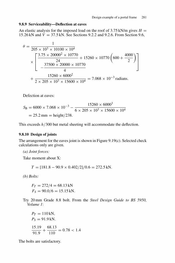
Design example of a portal frame 281
9.8.9 Serviceability—Deflection at eaves
An elastic analysis for the imposed load on the roof of 3.75 kN/m gives H =15.26 kN and V = 37.5 kN. See Sections 9.2.2 and 9.2.6. From Section 9.6,
θ = 1
205 × 103 × 10100 × 104
×⎡⎢⎣
3.75 × 200002 × 10770
24+ 15260 × 10770
(600 + 4000
2
)−37500 × 20000 × 10770
4
⎤⎥⎦
+ 15260 × 60002
2 × 205 × 103 × 15600 × 104= 7.068 × 10⁻³ radians.
Defection at eaves:
SB = 6000 × 7.068 × 10−3 − 15260 × 60003
6 × 205 × 103 × 15600 × 104
= 25.2 mm = height/238.
This exceeds h/300 but metal sheeting will accommodate the deflection.
9.8.10 Design of joints
The arrangement for the eaves joint is shown in Figure 9.19(c). Selected checkcalculations only are given.
(a) Joint forces:
Take moment about X:
T = [181.8 − 90.9 × 0.402/2]/0.6 = 272.5 kN.
(b) Bolts:
FT = 272/4 = 68.13 kNFS = 90.0/6 = 15.15 kN.
Try 20 mm Grade 8.8 bolt. From the Steel Design Guide to BS 5950,Volume 1:
PT = 110 kN,
PS = 91.9 kN.
15.19
91.9+ 68.13
110= 0.78 < 1.4
The bolts are satisfactory.
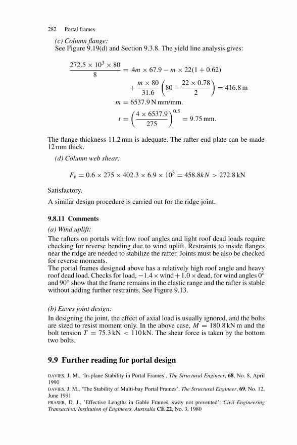
282 Portal frames
(c) Column flange:See Figure 9.19(d) and Section 9.3.8. The yield line analysis gives:
272.5 × 103 × 80
8= 4m × 67.9 − m × 22(1 + 0.62)
+ m × 80
31.6
(80 − 22 × 0.78
2
)= 416.8 m
m = 6537.9 N mm/mm.
t =(
4 × 6537.9
275
)0.5
= 9.75 mm.
The flange thickness 11.2 mm is adequate. The rafter end plate can be made12 mm thick.
(d) Column web shear:
Fv = 0.6 × 275 × 402.3 × 6.9 × 103 = 458.8kN > 272.8 kN
Satisfactory.
A similar design procedure is carried out for the ridge joint.
9.8.11 Comments
(a) Wind uplift:The rafters on portals with low roof angles and light roof dead loads requirechecking for reverse bending due to wind uplift. Restraints to inside flangesnear the ridge are needed to stabilize the rafter. Joints must be also be checkedfor reverse moments.The portal frames designed above has a relatively high roof angle and heavyroof dead load. Checks for load, −1.4×wind+1.0×dead, for wind angles 0◦and 90◦ show that the frame remains in the elastic range and the rafter is stablewithout adding further restraints. See Figure 9.13.
(b) Eaves joint design:In designing the joint, the effect of axial load is usually ignored, and the boltsare sized to resist moment only. In the above case, M = 180.8 kN m and thebolt tension T = 75.3 kN < 110 kN. The shear force is taken by the bottomtwo bolts.
9.9 Further reading for portal design
davies, J. M., ‘In-plane Stability in Portal Frames’, The Structural Engineer, 68, No. 8, April1990davies, J. M., ‘The Stability of Multi-bay Portal Frames’, The Structural Engineer, 69, No. 12,June 1991fraser, D. J., ’Effective Lengths in Gable Frames, sway not prevented’: Civil EngineeringTransaction, Institution of Engineers, Australia CE 22, No. 3, 1980

Further reading for portal design 283
fraser, D. J., ‘Stability of Pitched Roof Frames’: Civil Engineering Transaction, Institution ofEngineers, Australia CE 28, No. 1, 1986horne, M. R. and merchant, W., ‘The stability of frames’, Oxford, Fergamon Press, 1965horne, M. R., ‘Plastic Theory of Structures’, Nelson, London, 1971horne, M. R. and morris, L. J., ‘Plastic Design of Low Rise Frames’, Collins, London, 1981In-plane Stability of Portal Frames to BS5950-1: 2000, The Steel Construction Institute, AscotSteel Designer’s Manual, The Steel Construction Institute, Blackwell Science.Steelwork Design Guide to BS5950-1: Volume 1, Section Properties and Member Capacities,The Steel Construction Institute, Ascot 2000.
10
Connections
10.1 Types of connections
Connections are needed to join:
(a) members together in trusses and lattice girders;(b) plates together to form built-up members;(c) beams to beams, beams, trusses, bracing, etc. to columns in structural
frames, and(d) columns to foundations.
Some of these typical connections are shown in Figure 10.1. Basic connec-tions are considered in this chapter and end connections for beams and columnbases are treated in the chapters on beams and columns, respectively.
Connections may be made by:
• bolting – non-preloaded bolts in standard clearance or oversize holes;– preloaded or friction-grip bolt; and
• welding – fillet and butt welds.
10.2 Non-preloaded bolts
10.2.1 Bolts, nuts and washers
The ISO metric ‘black’ hexagon head ordinary non-preloaded bolt shown inFigure 10.2 with nut and washer is the most commonly used structural fastenerin the industry. The bolts, in the three common strength grades given below, arespecified in BS 4190: 2001. The specification for ISO metric ‘precision’ non-preloaded hexagon bolts and nuts, which are manufactured to tighter dimen-sional tolerances, are given in BS 3692: 2001. Mechanical properties of thebolts are specified in BS EN ISO898: Part 1: 1999.
Strength grade Yield stress (N/mm2) Tensile stress (N/mm2)
4.6 240 4008.8 640 800
10.9 900 1000
284
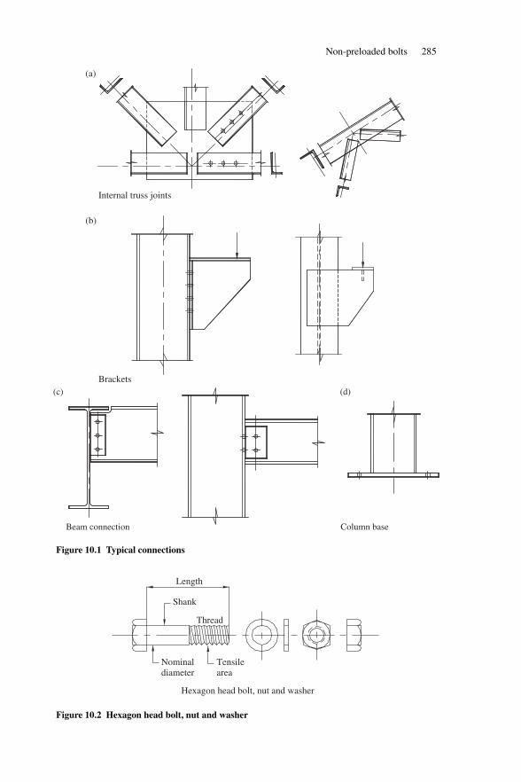
Non-preloaded bolts 285
(a)
(b)
Internal truss joints
Brackets(c)
Beam connection Column base
(d)
Figure 10.1 Typical connections
Tensilearea
Thread
Shank
Length
Nominaldiameter
Hexagon head bolt, nut and washer
Figure 10.2 Hexagon head bolt, nut and washer
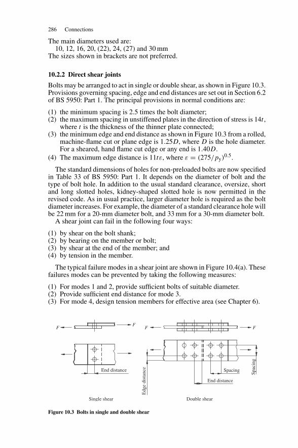
286 Connections
The main diameters used are:10, 12, 16, 20, (22), 24, (27) and 30 mm
The sizes shown in brackets are not preferred.
10.2.2 Direct shear joints
Bolts may be arranged to act in single or double shear, as shown in Figure 10.3.Provisions governing spacing, edge and end distances are set out in Section 6.2of BS 5950: Part 1. The principal provisions in normal conditions are:
(1) the minimum spacing is 2.5 times the bolt diameter;(2) the maximum spacing in unstiffened plates in the direction of stress is 14t ,
where t is the thickness of the thinner plate connected;(3) the minimum edge and end distance as shown in Figure 10.3 from a rolled,
machine-flame cut or plane edge is 1.25D, where D is the hole diameter.For a sheared, hand flame cut edge or any end is 1.40D.
(4) The maximum edge distance is 11tε, where ε = (275/py)0.5.
The standard dimensions of holes for non-preloaded bolts are now specifiedin Table 33 of BS 5950: Part 1. It depends on the diameter of bolt and thetype of bolt hole. In addition to the usual standard clearance, oversize, shortand long slotted holes, kidney-shaped slotted hole is now permitted in therevised code. As in usual practice, larger diameter hole is required as the boltdiameter increases. For example, the diameter of a standard clearance hole willbe 22 mm for a 20-mm diameter bolt, and 33 mm for a 30-mm diameter bolt.
A shear joint can fail in the following four ways:
(1) by shear on the bolt shank;(2) by bearing on the member or bolt;(3) by shear at the end of the member; and(4) by tension in the member.
The typical failure modes in a shear joint are shown in Figure 10.4(a). Thesefailures modes can be prevented by taking the following measures:
(1) For modes 1 and 2, provide sufficient bolts of suitable diameter.(2) Provide sufficient end distance for mode 3.(3) For mode 4, design tension members for effective area (see Chapter 6).
End distance
End distance
Spacing
Spac
ing
Double shear
Edg
e di
stan
ce
Single shear
FF
F F
Figure 10.3 Bolts in single and double shear
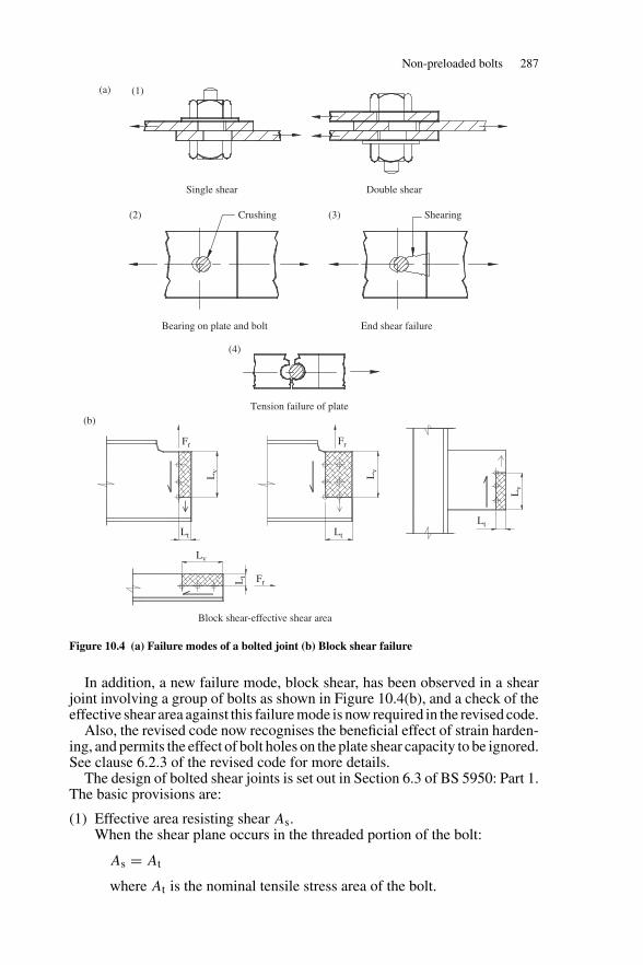
Non-preloaded bolts 287
Single shear
(1)(a)
Double shear
Crushing(2) (3)
(4)
Bearing on plate and bolt End shear failure
Tension failure of plate
Shearing
Fr
Fr
Fr
Lt
Block shear-effective shear area
Lt
Lt
Lt
Lv
Lv
Lv
Lv
(b)
Figure 10.4 (a) Failure modes of a bolted joint (b) Block shear failure
In addition, a new failure mode, block shear, has been observed in a shearjoint involving a group of bolts as shown in Figure 10.4(b), and a check of theeffective shear area against this failure mode is now required in the revised code.
Also, the revised code now recognises the beneficial effect of strain harden-ing, and permits the effect of bolt holes on the plate shear capacity to be ignored.See clause 6.2.3 of the revised code for more details.
The design of bolted shear joints is set out in Section 6.3 of BS 5950: Part 1.The basic provisions are:
(1) Effective area resisting shear As.When the shear plane occurs in the threaded portion of the bolt:
As = At
where At is the nominal tensile stress area of the bolt.
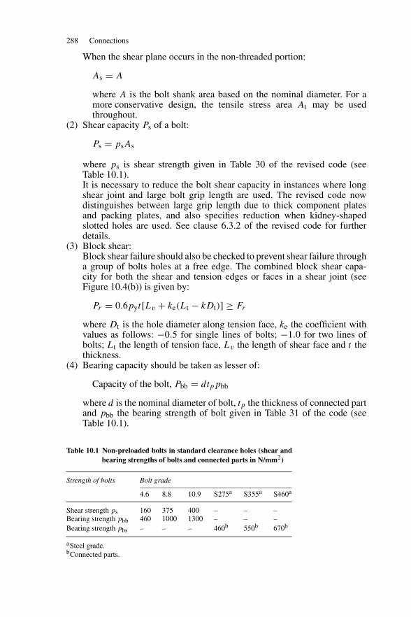
288 Connections
When the shear plane occurs in the non-threaded portion:
As = A
where A is the bolt shank area based on the nominal diameter. For amore conservative design, the tensile stress area At may be usedthroughout.
(2) Shear capacity Ps of a bolt:
Ps = psAs
where ps is shear strength given in Table 30 of the revised code (seeTable 10.1).It is necessary to reduce the bolt shear capacity in instances where longshear joint and large bolt grip length are used. The revised code nowdistinguishes between large grip length due to thick component platesand packing plates, and also specifies reduction when kidney-shapedslotted holes are used. See clause 6.3.2 of the revised code for furtherdetails.
(3) Block shear:Block shear failure should also be checked to prevent shear failure througha group of bolts holes at a free edge. The combined block shear capa-city for both the shear and tension edges or faces in a shear joint (seeFigure 10.4(b)) is given by:
Pr = 0.6pyt[Lv + ke(Lt − kDt)] ≥ Fr
where Dt is the hole diameter along tension face, ke the coefficient withvalues as follows: −0.5 for single lines of bolts; −1.0 for two lines ofbolts; Lt the length of tension face, Lv the length of shear face and t thethickness.
(4) Bearing capacity should be taken as lesser of:
Capacity of the bolt, Pbb = dtppbb
where d is the nominal diameter of bolt, tp the thickness of connected partand pbb the bearing strength of bolt given in Table 31 of the code (seeTable 10.1).
Table 10.1 Non-preloaded bolts in standard clearance holes (shear andbearing strengths of bolts and connected parts in N/mm2)
Strength of bolts Bolt grade
4.6 8.8 10.9 S275a S355a S460a
Shear strength ps 160 375 400 – – –Bearing strength pbb 460 1000 1300 – – –Bearing strength pbs – – – 460b 550b 670b
aSteel grade.bConnected parts.
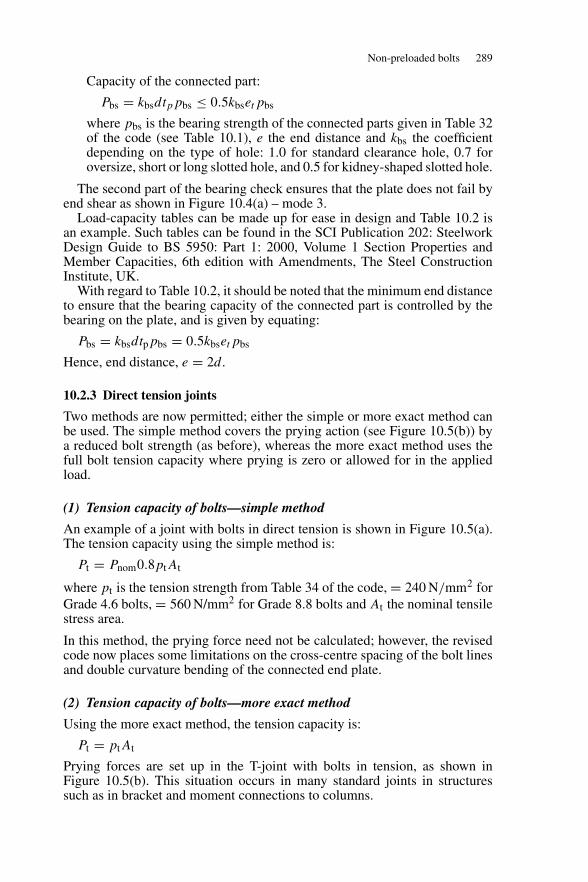
Non-preloaded bolts 289
Capacity of the connected part:
Pbs = kbsdtppbs ≤ 0.5kbsetpbs
where pbs is the bearing strength of the connected parts given in Table 32of the code (see Table 10.1), e the end distance and kbs the coefficientdepending on the type of hole: 1.0 for standard clearance hole, 0.7 foroversize, short or long slotted hole, and 0.5 for kidney-shaped slotted hole.
The second part of the bearing check ensures that the plate does not fail byend shear as shown in Figure 10.4(a) – mode 3.
Load-capacity tables can be made up for ease in design and Table 10.2 isan example. Such tables can be found in the SCI Publication 202: SteelworkDesign Guide to BS 5950: Part 1: 2000, Volume 1 Section Properties andMember Capacities, 6th edition with Amendments, The Steel ConstructionInstitute, UK.
With regard to Table 10.2, it should be noted that the minimum end distanceto ensure that the bearing capacity of the connected part is controlled by thebearing on the plate, and is given by equating:
Pbs = kbsdtppbs = 0.5kbsetpbs
Hence, end distance, e = 2d.
10.2.3 Direct tension joints
Two methods are now permitted; either the simple or more exact method canbe used. The simple method covers the prying action (see Figure 10.5(b)) bya reduced bolt strength (as before), whereas the more exact method uses thefull bolt tension capacity where prying is zero or allowed for in the appliedload.
(1) Tension capacity of bolts—simple method
An example of a joint with bolts in direct tension is shown in Figure 10.5(a).The tension capacity using the simple method is:
Pt = Pnom0.8ptAt
where pt is the tension strength from Table 34 of the code, = 240 N/mm2 forGrade 4.6 bolts, = 560 N/mm2 for Grade 8.8 bolts and At the nominal tensilestress area.
In this method, the prying force need not be calculated; however, the revisedcode now places some limitations on the cross-centre spacing of the bolt linesand double curvature bending of the connected end plate.
(2) Tension capacity of bolts—more exact method
Using the more exact method, the tension capacity is:
Pt = ptAt
Prying forces are set up in the T-joint with bolts in tension, as shown inFigure 10.5(b). This situation occurs in many standard joints in structuressuch as in bracket and moment connections to columns.
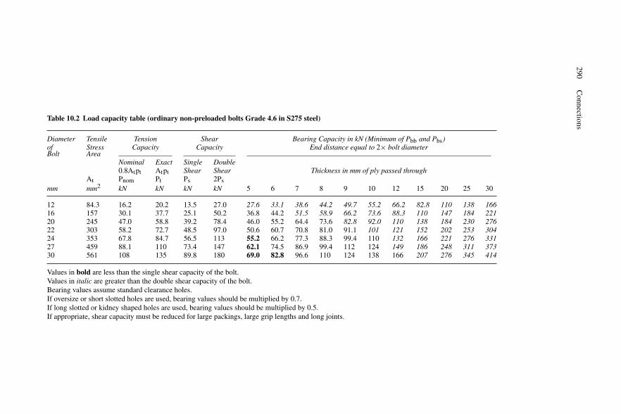
290C
onnections
Table 10.2 Load capacity table (ordinary non-preloaded bolts Grade 4.6 in S275 steel)
Diameter Tensile Tension Shear Bearing Capacity in kN (Minimum of Pbb and Pbs)of Stress Capacity Capacity End distance equal to 2× bolt diameterBolt Area
Nominal Exact Single Double0.8Atpt Atpt Shear Shear Thickness in mm of ply passed through
At Pnom Pt Ps 2Psmm mm2 kN kN kN kN 5 6 7 8 9 10 12 15 20 25 30
12 84.3 16.2 20.2 13.5 27.0 27.6 33.1 38.6 44.2 49.7 55.2 66.2 82.8 110 138 16616 157 30.1 37.7 25.1 50.2 36.8 44.2 51.5 58.9 66.2 73.6 88.3 110 147 184 22120 245 47.0 58.8 39.2 78.4 46.0 55.2 64.4 73.6 82.8 92.0 110 138 184 230 27622 303 58.2 72.7 48.5 97.0 50.6 60.7 70.8 81.0 91.1 101 121 152 202 253 30424 353 67.8 84.7 56.5 113 55.2 66.2 77.3 88.3 99.4 110 132 166 221 276 33127 459 88.1 110 73.4 147 62.1 74.5 86.9 99.4 112 124 149 186 248 311 37330 561 108 135 89.8 180 69.0 82.8 96.6 110 124 138 166 207 276 345 414
Values in bold are less than the single shear capacity of the bolt.Values in italic are greater than the double shear capacity of the bolt.Bearing values assume standard clearance holes.If oversize or short slotted holes are used, bearing values should be multiplied by 0.7.If long slotted or kidney shaped holes are used, bearing values should be multiplied by 0.5.If appropriate, shear capacity must be reduced for large packings, large grip lengths and long joints.
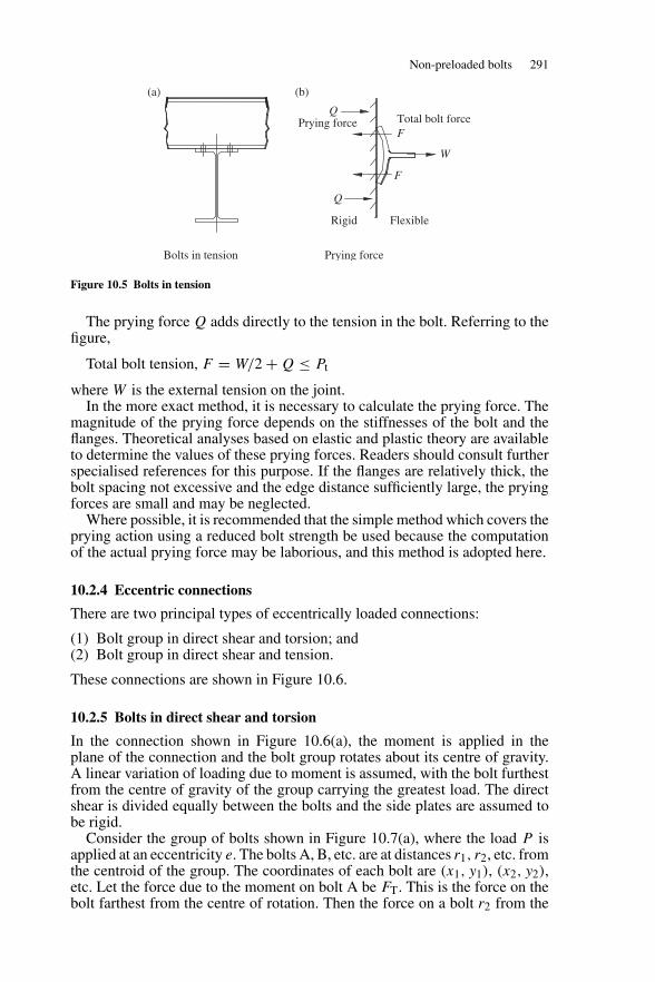
Non-preloaded bolts 291
Rigid Flexible
Q
F
FTotal bolt forcePrying force
Prying force
(b)(a)
Bolts in tension
W
Q
Figure 10.5 Bolts in tension
The prying force Q adds directly to the tension in the bolt. Referring to thefigure,
Total bolt tension, F = W/2 + Q ≤ Pt
where W is the external tension on the joint.In the more exact method, it is necessary to calculate the prying force. The
magnitude of the prying force depends on the stiffnesses of the bolt and theflanges. Theoretical analyses based on elastic and plastic theory are availableto determine the values of these prying forces. Readers should consult furtherspecialised references for this purpose. If the flanges are relatively thick, thebolt spacing not excessive and the edge distance sufficiently large, the pryingforces are small and may be neglected.
Where possible, it is recommended that the simple method which covers theprying action using a reduced bolt strength be used because the computationof the actual prying force may be laborious, and this method is adopted here.
10.2.4 Eccentric connections
There are two principal types of eccentrically loaded connections:
(1) Bolt group in direct shear and torsion; and(2) Bolt group in direct shear and tension.
These connections are shown in Figure 10.6.
10.2.5 Bolts in direct shear and torsion
In the connection shown in Figure 10.6(a), the moment is applied in theplane of the connection and the bolt group rotates about its centre of gravity.A linear variation of loading due to moment is assumed, with the bolt furthestfrom the centre of gravity of the group carrying the greatest load. The directshear is divided equally between the bolts and the side plates are assumed tobe rigid.
Consider the group of bolts shown in Figure 10.7(a), where the load P isapplied at an eccentricity e. The bolts A, B, etc. are at distances r1, r2, etc. fromthe centroid of the group. The coordinates of each bolt are (x1, y1), (x2, y2),etc. Let the force due to the moment on bolt A be FT. This is the force on thebolt farthest from the centre of rotation. Then the force on a bolt r2 from the
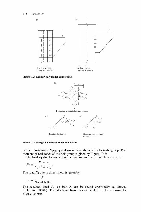
292 Connections
Bolts in direct shear and torsion
Bolts in direct shear and tension
(b)(a)
Figure 10.6 Eccentrically loaded connections
Bolt group in direct shear and torsion
(a)
(b) (c)
Resultant load on bolt
Fs
FsFT
FT
FT
FT
Y
Y
XX
A
B
C
x
e
–x
–yy
FT
FT r2/r1
FT r2/r1
r2
r1
FT
FR
FT
cos�
FT sin �
Resolved parts of loads on bolt
��
� �
Figure 10.7 Bolt group in direct shear and torsion
centre of rotation is FTr2/r1 and so on for all the other bolts in the group. Themoment of resistance of the bolt group is given by Figure 10.7:
The load FT due to moment on the maximum loaded bolt A is given by
FT = P · e · r1∑x2 + ∑
y2
The load FS due to direct shear is given by
FS = P
No. of boltsThe resultant load FR on bolt A can be found graphically, as shownin Figure 10.7(b). The algebraic formula can be derived by referring toFigure 10.7(c).
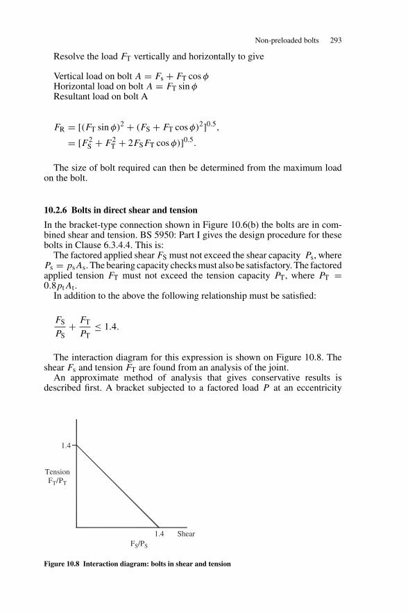
Non-preloaded bolts 293
Resolve the load FT vertically and horizontally to give
Vertical load on bolt A = Fs + FT cos φHorizontal load on bolt A = FT sin φResultant load on bolt A
FR = [(FT sin φ)2 + (FS + FT cos φ)2]0.5,
= [F 2S + F 2
T + 2FSFT cos φ)]0.5.
The size of bolt required can then be determined from the maximum loadon the bolt.
10.2.6 Bolts in direct shear and tension
In the bracket-type connection shown in Figure 10.6(b) the bolts are in com-bined shear and tension. BS 5950: Part I gives the design procedure for thesebolts in Clause 6.3.4.4. This is:
The factored applied shear FS must not exceed the shear capacity Ps, wherePs = psAs. The bearing capacity checks must also be satisfactory. The factoredapplied tension FT must not exceed the tension capacity PT, where PT =0.8ptAt .
In addition to the above the following relationship must be satisfied:
FS
PS+ FT
PT≤ 1.4.
The interaction diagram for this expression is shown on Figure 10.8. Theshear Fs and tension FT are found from an analysis of the joint.
An approximate method of analysis that gives conservative results isdescribed first. A bracket subjected to a factored load P at an eccentricity
FS/PS
1.4
1.4
Shear
TensionFT/PT
Figure 10.8 Interaction diagram: bolts in shear and tension
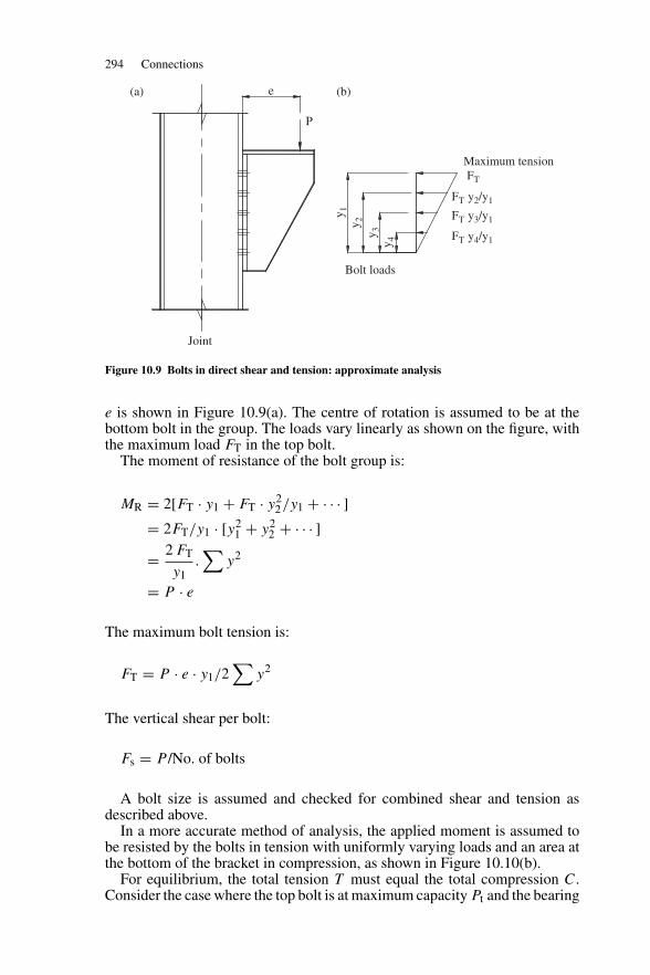
294 Connections
y 1y 2
y 3y 4
e(a) (b)
P
Bolt loads
Joint
FT y2/y1
FT
Maximum tension
FT y3/y1
FT y4/y1
Figure 10.9 Bolts in direct shear and tension: approximate analysis
e is shown in Figure 10.9(a). The centre of rotation is assumed to be at thebottom bolt in the group. The loads vary linearly as shown on the figure, withthe maximum load FT in the top bolt.
The moment of resistance of the bolt group is:
MR = 2[FT · y1 + FT · y22/y1 + · · · ]
= 2FT/y1 · [y21 + y2
2 + · · · ]= 2 FT
y1.∑
y2
= P · e
The maximum bolt tension is:
FT = P · e · y1/2∑
y2
The vertical shear per bolt:
Fs = P /No. of bolts
A bolt size is assumed and checked for combined shear and tension asdescribed above.
In a more accurate method of analysis, the applied moment is assumed tobe resisted by the bolts in tension with uniformly varying loads and an area atthe bottom of the bracket in compression, as shown in Figure 10.10(b).
For equilibrium, the total tension T must equal the total compression C.Consider the case where the top bolt is at maximum capacity Pt and the bearing
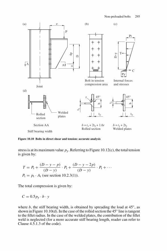
Non-preloaded bolts 295
A A
Joint
Bolt in tension compression area
Internal forces and stresses
a4p D
Py
Pt
C
T
P
e(a) (b) (c)
D–y
Rolledsection
Weldedplates
Section AA b = t1 + 2t2Welded plates
b = t1 + 2t2 + 1.6rRolled section
Stiff bearing width
(d)
t2 t2
45° 45°r
t 1
t 1b b
Figure 10.10 Bolts in direct shear and tension: accurate analysis
stress is at its maximum value py. Referring to Figure 10.12(c), the total tensionis given by:
T = Pt + (D − y − p)
(D − y)· Pt + (D − y − 2p)
(D − y)· Pt + · · ·
Pt = pt · At (see section 10.2.3(1)).
The total compression is given by:
C = 0.5py · b · y
where b, the stiff bearing width, is obtained by spreading the load at 45◦, asshown in Figure 10.10(d). In the case of the rolled section the 45◦ line is tangentto the fillet radius. In the case of the welded plates, the contribution of the filletweld is neglected (for a more accurate stiff bearing length, reader can refer toClause 4.5.1.3 of the code).
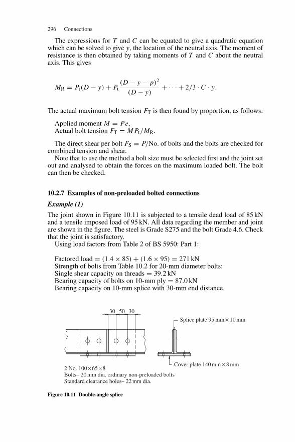
296 Connections
The expressions for T and C can be equated to give a quadratic equationwhich can be solved to give y, the location of the neutral axis. The moment ofresistance is then obtained by taking moments of T and C about the neutralaxis. This gives
MR = Pt(D − y) + Pt(D − y − p)2
(D − y)+ · · · + 2/3 · C · y.
The actual maximum bolt tension FT is then found by proportion, as follows:
Applied moment M = Pe,Actual bolt tension FT = MPt/MR.
The direct shear per bolt FS = P/No. of bolts and the bolts are checked forcombined tension and shear.
Note that to use the method a bolt size must be selected first and the joint setout and analysed to obtain the forces on the maximum loaded bolt. The boltcan then be checked.
10.2.7 Examples of non-preloaded bolted connections
Example (1)
The joint shown in Figure 10.11 is subjected to a tensile dead load of 85 kNand a tensile imposed load of 95 kN. All data regarding the member and jointare shown in the figure. The steel is Grade S275 and the bolt Grade 4.6. Checkthat the joint is satisfactory.
Using load factors from Table 2 of BS 5950: Part 1:
Factored load = (1.4 × 85) + (1.6 × 95) = 271 kNStrength of bolts from Table 10.2 for 20-mm diameter bolts:Single shear capacity on threads = 39.2 kNBearing capacity of bolts on 10-mm ply = 87.0 kNBearing capacity on 10-mm splice with 30-mm end distance.
30
2 No. 100 × 65 × 8Bolts– 20 mm dia. ordinary non-preloaded bolts Standard clearance holes– 22 mm dia.
50 30
Cover plate 140 mm × 8 mm
Splice plate 95 mm × 10 mm
Figure 10.11 Double-angle splice
Non-preloaded bolts 297
Bearing strength pbs = 460 N/mm2 from Table 10.1:
Pbs = 1/2 × 30 × l0 × 460/103 = 69 kN
Bolt capacity-two bolts are in double shear and four in single.
Shear = (4 × 39.2) + (2 × 39.2) + 69 = 304.2 kN
Note that the capacity of the end bolt bearing on the 10 mm splice plate iscontrolled by the end distance (BS 5950: Part 1, Clause 6.3.3.3).
Strength of the angles. Gross area = 12.7 cm2 per angle.
The angles are connected through both legs. Clause 4.6.3.3 of BS 5950:Part 1 states that the net area defined in Clause 3.3.2 is to be used in design.The standard clearance holes are 22-mm diameter:
Net area = 2(1270 − 2 × 22 × 8) = 1836 mm2.Design strength py = 275 N/mm2 (Table 9 of code).Capacity Pt = 275 × 1836/103 = 504.9 kN.Splice plate and cover plate (see Clauses 3.3.3 of the code and Section 7.4.1
of this book):Effective area = 1.2[(95 − 22)10 + (140 − 44)8] = 1798 mm2
<gross area = 2070 mm2.Capacity Pt = 275 × 1798/103 = 494.3 kN.
The splice is adequate to resist the applied load. By inspection, block shearfailure is also not critical for this splice joint.
Example (2)
Check that the bracket shown in Figure 10.12 is adequate. All data requiredare given in the figure.
Factored Load = (1.4 × 60) + (1.6 × 80) = 212 kN
Moment M = (212 × 525)/103 = 111.3 kN m
Bolt group∑
x2 = 12 × 2502 = 750 × 103∑y2 = 4(352 + 1052 + 1752) = 171.5 × 10³∑
x2 +∑
y2 = 921.5 × 10³
cos φ = 250/305.16 = 0.819
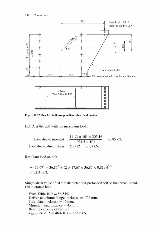
298 Connections
57.9
45
= 3
50
35
105 17
5
5 sp
aces
at 7
0
57.9250
2 Nos. 254 × 254 × 89 UC
250
525 Dead load = 60kN Imposed load = 80kN
15 mm bracket plate
All non-preloaded bolts 24mm diameter
�
r 1= 305.16
Figure 10.12 Bracket: bolt group in direct shear and torsion
Bolt A is the bolt with the maximum load:
Load due to moment = 111.3 × 103 × 305.16
921.5 × 103= 36.85 kN,
Load due to direct shear = 212/12 = 17.67 kN.
Resultant load on bolt
= [17.672 + 36.852 + (2 × 17.67 × 36.85 × 0.819)]0.5
= 52.31 kN.
Single-shear value of 24 mm diameter non-preloaded bolt on the thread, stand-ard tolerance hole:
From Table 10.2 = 56.5 kN,Universal column flange thickness = 17.3 mm,Side-plate thickness = 15 mm,Minimum end distance = 45 mm,Bearing capacity of the boltPbb = 24 × 15 × 460/103 = 165.6 kN,
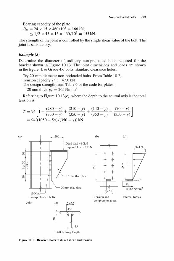
Non-preloaded bolts 299
Bearing capacity of the platePbs = 24 × 15 × 460/103 = 166 kN,
≤ 1/2 × 45 × 15 × 460/103 = 155 kN.
The strength of the joint is controlled by the single shear value of the bolt. Thejoint is satisfactory.
Example (3)
Determine the diameter of ordinary non-preloaded bolts required for thebracket shown in Figure 10.13. The joint dimensions and loads are shownin the figure. Use Grade 4.6 bolts, standard clearance holes.
Try 20-mm diameter non-preloaded bolts. From Table 10.2,Tension capacity PT = 47.0 kNThe design strength from Table 6 of the code for plates:
20 mm thick py = 265 N/mm2
Referring to Figure 10.13(c), where the depth to the neutral axis is the totaltension is:
T = 94
[1 + (280 − y)
(350 − y)+ (210 − y)
(350 − y)+ (140 − y)
(350 − y)+ (70 − y)
(350 − y)
]= 94[(1050 − 5y)/(350 − y)] kN
200(a) (b) (c)
10 Nos. non-preloaded bolts
Joint
Internal forcesTension and compression areas
Stiff bearing length
b = 55(d)
15
45°
20 mm thk. plate
94 kN
= 265 N/mm2
15 mm thk. plateC
T
py
D–y
Dead load = 80kN Imposed load = 75 kN
7070
4 at
70
=28
0
20
350
b = 55
Figure 10.13 Bracket: bolts in direct shear and tension
300 Connections
The width of stiff bearing is shown in Figure 10.13(d):
b = 15 + 2 × 20 = 55 mm.
The total compression in terms of y is given by:
C = 12 × 265 × 55y/103 = 7.29 kN.
Equate T and C and rearrange terms to give the quadratic equation:
7.29y2 − 3028y + 100 170 = 0.
Solve to give
y = 36.25 mm.
The moment of resistance is:
MR = 94
103
((350 − 36.5) + (280 − 36.5)2
(350 − 36.25)+ (210 − 36.5)2
(350 − 36.25)
+ (140 − 36.5)2
(350 − 36.25)+ (70 − 36.5)2
(350 − 36.25)
)+ 7.29 × 36.52 × 2
3 × 103
= 67.17 kN m.
Factored load = (1.4 × 80) + (1.6 × 75) = 232 kN,Factored moment = 232 × 200/103 = 46.4 kN m,Actual tension in top boltsFT = 46.4 × 47.0/67.17 = 32.5 kN,Direct shear per bolt = 232/10 = 23.2 kN,Shear capacity on threads PS = 39.2 kN,Tension capacity PT = 47.0 kN.
Combined shear and tension:
FS
PS+ FT
PT= 23.2
39.2+ 32.5
47.0= 1.28 < 1.4.
Therefore 20-mm diameter bolts are satisfactory.The reader can redesign the bolts using the approximate method. Note that
only the bolts have been designed. The welds and bracket plates must bedesigned and the column checked for the bracket forces. These considerationsare dealt with in Section 10.4.5.
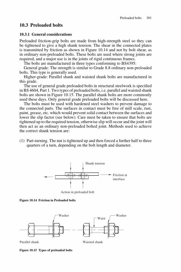
Preloaded bolts 301
10.3 Preloaded bolts
10.3.1 General considerations
Preloaded friction-grip bolts are made from high-strength steel so they canbe tightened to give a high shank tension. The shear in the connected platesis transmitted by friction as shown in Figure 10.14 and not by bolt shear, asin ordinary non-preloaded bolts. These bolts are used where strong joints arerequired, and a major use is in the joints of rigid continuous frames.
The bolts are manufactured in three types conforming to BS4395:General grade: The strength is similar to Grade 8.8 ordinary non-preloaded
bolts. This type is generally used.Higher-grade: Parallel shank and waisted shank bolts are manufactured in
this grade.The use of general grade preloaded bolts in structural steelwork is specified
in BS 4604, Part 1. Two types of preloaded bolts, i.e. parallel and waisted shankbolts are shown in Figure 10.15. The parallel shank bolts are more commonlyused these days. Only general grade preloaded bolts will be discussed here.
The bolts must be used with hardened steel washers to prevent damage tothe connected parts. The surfaces in contact must be free of mill scale, rust,paint, grease, etc. which would prevent solid contact between the surfaces andlower the slip factor (see below). Care must be taken to ensure that bolts aretightened up to the required tension, otherwise slip will occur and the joint willthen act as an ordinary non-preloaded bolted joint. Methods used to achievethe correct shank tension are:
(1) Part-turning. The nut is tightened up and then forced a further half to threequarters of a turn, depending on the bolt length and diameter.
Shank tension
Friction atinterface
Action in preloaded bolt
Figure 10.14 Friction in Preloaded bolts
Parallel shank Waisted shank
Washer WasherWaist
Figure 10.15 Types of preloaded bolts
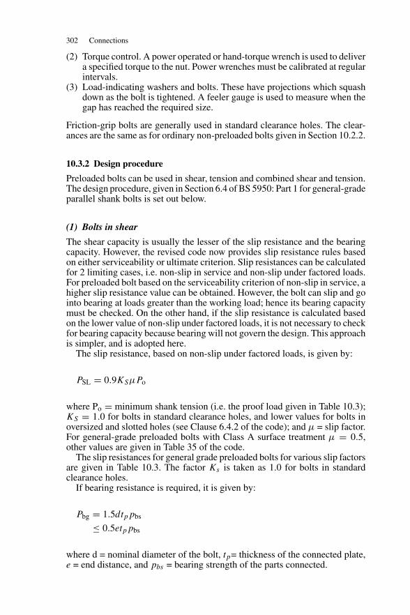
302 Connections
(2) Torque control. A power operated or hand-torque wrench is used to delivera specified torque to the nut. Power wrenches must be calibrated at regularintervals.
(3) Load-indicating washers and bolts. These have projections which squashdown as the bolt is tightened. A feeler gauge is used to measure when thegap has reached the required size.
Friction-grip bolts are generally used in standard clearance holes. The clear-ances are the same as for ordinary non-preloaded bolts given in Section 10.2.2.
10.3.2 Design procedure
Preloaded bolts can be used in shear, tension and combined shear and tension.The design procedure, given in Section 6.4 of BS 5950: Part 1 for general-gradeparallel shank bolts is set out below.
(1) Bolts in shear
The shear capacity is usually the lesser of the slip resistance and the bearingcapacity. However, the revised code now provides slip resistance rules basedon either serviceability or ultimate criterion. Slip resistances can be calculatedfor 2 limiting cases, i.e. non-slip in service and non-slip under factored loads.For preloaded bolt based on the serviceability criterion of non-slip in service, ahigher slip resistance value can be obtained. However, the bolt can slip and gointo bearing at loads greater than the working load; hence its bearing capacitymust be checked. On the other hand, if the slip resistance is calculated basedon the lower value of non-slip under factored loads, it is not necessary to checkfor bearing capacity because bearing will not govern the design. This approachis simpler, and is adopted here.
The slip resistance, based on non-slip under factored loads, is given by:
PSL = 0.9KSμPo
where Po = minimum shank tension (i.e. the proof load given in Table 10.3);KS = 1.0 for bolts in standard clearance holes, and lower values for bolts inoversized and slotted holes (see Clause 6.4.2 of the code); and μ = slip factor.For general-grade preloaded bolts with Class A surface treatment μ = 0.5,other values are given in Table 35 of the code.
The slip resistances for general grade preloaded bolts for various slip factorsare given in Table 10.3. The factor Ks is taken as 1.0 for bolts in standardclearance holes.
If bearing resistance is required, it is given by:
Pbg = 1.5dtppbs
≤ 0.5etppbs
where d = nominal diameter of the bolt, tp= thickness of the connected plate,e = end distance, and pbs = bearing strength of the parts connected.
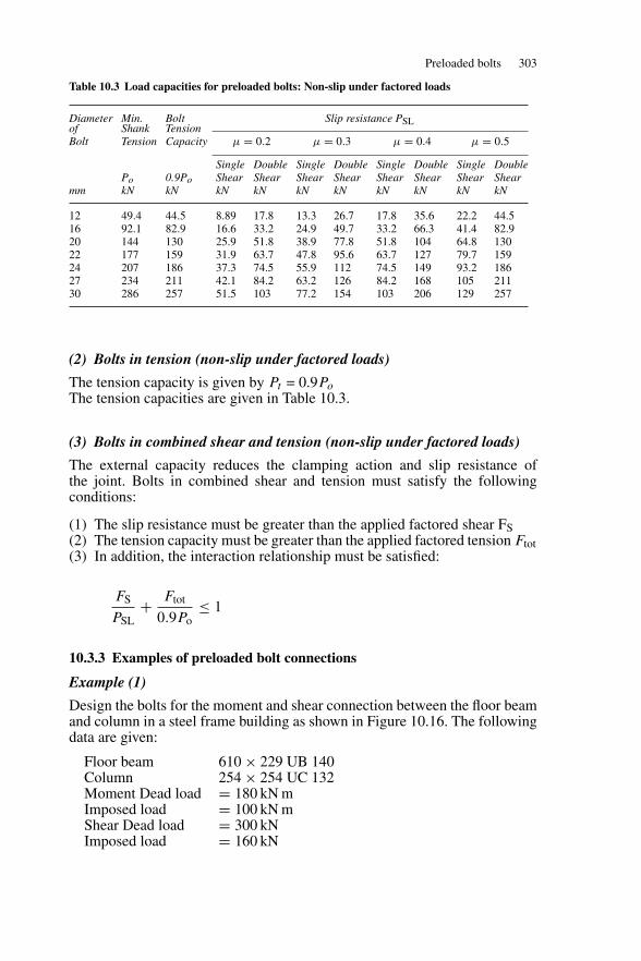
Preloaded bolts 303
Table 10.3 Load capacities for preloaded bolts: Non-slip under factored loads
Diameter Min. Bolt Slip resistance PSLof Shank TensionBolt Tension Capacity μ = 0.2 μ = 0.3 μ = 0.4 μ = 0.5
Single Double Single Double Single Double Single DoublePo 0.9Po Shear Shear Shear Shear Shear Shear Shear Shear
mm kN kN kN kN kN kN kN kN kN kN
12 49.4 44.5 8.89 17.8 13.3 26.7 17.8 35.6 22.2 44.516 92.1 82.9 16.6 33.2 24.9 49.7 33.2 66.3 41.4 82.920 144 130 25.9 51.8 38.9 77.8 51.8 104 64.8 13022 177 159 31.9 63.7 47.8 95.6 63.7 127 79.7 15924 207 186 37.3 74.5 55.9 112 74.5 149 93.2 18627 234 211 42.1 84.2 63.2 126 84.2 168 105 21130 286 257 51.5 103 77.2 154 103 206 129 257
(2) Bolts in tension (non-slip under factored loads)
The tension capacity is given by Pt = 0.9Po
The tension capacities are given in Table 10.3.
(3) Bolts in combined shear and tension (non-slip under factored loads)
The external capacity reduces the clamping action and slip resistance ofthe joint. Bolts in combined shear and tension must satisfy the followingconditions:
(1) The slip resistance must be greater than the applied factored shear FS(2) The tension capacity must be greater than the applied factored tension Ftot(3) In addition, the interaction relationship must be satisfied:
FS
PSL+ Ftot
0.9Po≤ 1
10.3.3 Examples of preloaded bolt connections
Example (1)
Design the bolts for the moment and shear connection between the floor beamand column in a steel frame building as shown in Figure 10.16. The followingdata are given:
Floor beam 610 × 229 UB 140Column 254 × 254 UC 132Moment Dead load = 180 kN mImposed load = 100 kN mShear Dead load = 300 kNImposed load = 160 kN
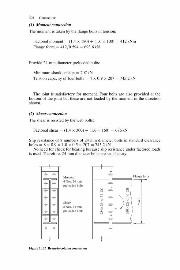
304 Connections
(1) Moment connection
The moment is taken by the flange bolts in tension:
Factored moment = (1.4 × 180) + (1.6 × 100) = 412 kNmFlange force = 412/0.594 = 693.6 kN
Provide 24-mm diameter preloaded bolts:
Minimum shank tension = 207 kNTension capacity of four bolts = 4 × 0.9 × 207 = 745.2 kN
The joint is satisfactory for moment. Four bolts are also provided at thebottom of the joint but these are not loaded by the moment in the directionshown.
(2) Shear connection
The shear is resisted by the web bolts:
Factored shear = (1.4 × 300) + (1.6 × 160) = 676 kN
Slip resistance of 8 numbers of 24 mm diameter bolts in standard clearanceholes = 8 × 0.9 × 1.0 × 0.5 × 207 = 745.2 kN
No need for check for bearing because slip resistance under factored loadsis used. Therefore, 24-mm diameter bolts are satisfactory.
Moment4 Nos. 24 mm preloaded bolts
Shear8 Nos. 24 mm preloaded bolts
Flange force
610
×22
9×
140
UB
594.
9
254
×25
4×
132
UC
Figure 10.16 Beam-to-column connection
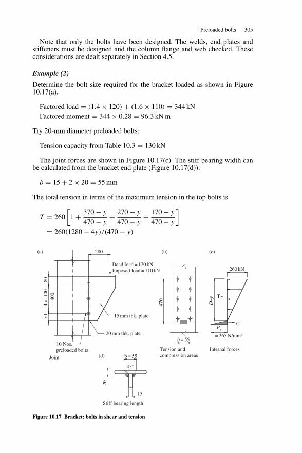
Preloaded bolts 305
Note that only the bolts have been designed. The welds, end plates andstiffeners must be designed and the column flange and web checked. Theseconsiderations are dealt separately in Section 4.5.
Example (2)
Determine the bolt size required for the bracket loaded as shown in Figure10.17(a).
Factored load = (1.4 × 120) + (1.6 × 110) = 344 kNFactored moment = 344 × 0.28 = 96.3 kN m
Try 20-mm diameter preloaded bolts:
Tension capacity from Table 10.3 = 130 kN
The joint forces are shown in Figure 10.17(c). The stiff bearing width canbe calculated from the bracket end plate (Figure 10.17(d)):
b = 15 + 2 × 20 = 55 mm
The total tension in terms of the maximum tension in the top bolts is
T = 260
[1 + 370 − y
470 − y+ 270 − y
470 − y+ 170 − y
470 − y
]= 260(1280 − 4y)/(470 − y)
Tension and compression areas
Internal forces
Joint
Stiff bearing length
b = 55
15
45°
20
280(a) (b)
(d)
(c)
20 mm thk. plate
260 kN
= 265 N/mm2
15 mm thk. plate
C
T
Py
D–y
Dead load = 120 kN Imposed load = 110 kN
7080
4 at
100
=40
0
470
10 Nos. preloaded bolts
b = 55
Figure 10.17 Bracket: bolts in shear and tension
306 Connections
The design strength from Table 9of the code for plates 20 mm thick, py = 265N/mm2
The total compression is given by:
C = 1/2 × 265 × 55y/103
Equate T and C and rearrange to give:
y2 − 631.9y + 51832 = 0
Solving gives y = 96.87 mmThe moment of resistance is
MR = 260
102
((470 − 96.87) + (370 − 96.87)2
(470 − 96.87)+ (270 − 96.87)2
(470 − 96.87)
+ (170 − 96.87)2
(470 − 96.87)2
)+ 7.29 × 96.872 × 2
3 × 103
= 173.07 + 45.61= 218.68 kNm
The actual maximum tension in the top bolts (assuming no prying force) is:
Ftot = 96.3 × 130/218.68 = 57.2 kN
The slip resistance from Table 10.3 for slip factor of 0.5, PSL= 68.4 kN
Applied shear per bolt FS = 344/10 = 34 kN.
FS
PSL+ Ftot
0.9Po= 34
68.4+ 57.2
0.9 × 144= 0.94 < 1.0
Interaction criteria:Therefore 20-mm diameter bolts are satisfactory.
10.4 Welded connections
10.4.1 Welding
Welding is the process of joining metal parts by fusing them and filling inwith molten metal from the electrode. The method is used extensively to joinparts and members, attach cleats, stiffeners, end plates, etc. and to fabricatecomplete elements such as plate girders. Welding produces neat, strong andmore efficient joints than are possible with bolting. However, it should becarried out under close supervision, and this is possible in the fabrication shop.Site joints are usually bolted. Though site welding can be done it is costly, anddefects are more likely to occur.
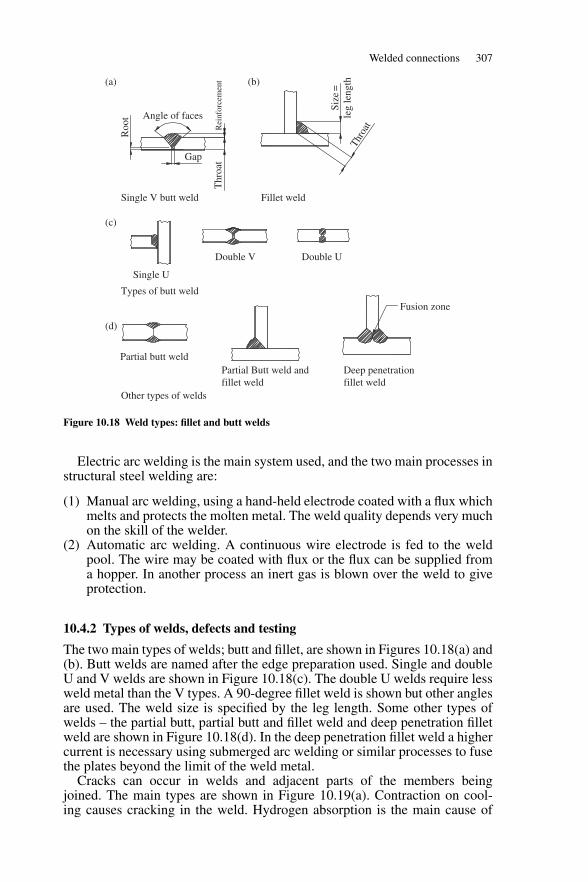
Welded connections 307
Single V butt weld
Double V
Types of butt weld
Other types of welds
Partial butt weldPartial Butt weld and fillet weld
Deep penetration fillet weld
Fusion zone
Double U
Single U
Gap
Rei
nfor
cem
ent
Thr
oat
Fillet weld
Size
=
leg
leng
thTh
roat
Angle of facesR
oot
(a) (b)
(c)
(d)
Figure 10.18 Weld types: fillet and butt welds
Electric arc welding is the main system used, and the two main processes instructural steel welding are:
(1) Manual arc welding, using a hand-held electrode coated with a flux whichmelts and protects the molten metal. The weld quality depends very muchon the skill of the welder.
(2) Automatic arc welding. A continuous wire electrode is fed to the weldpool. The wire may be coated with flux or the flux can be supplied froma hopper. In another process an inert gas is blown over the weld to giveprotection.
10.4.2 Types of welds, defects and testing
The two main types of welds; butt and fillet, are shown in Figures 10.18(a) and(b). Butt welds are named after the edge preparation used. Single and doubleU and V welds are shown in Figure 10.18(c). The double U welds require lessweld metal than the V types. A 90-degree fillet weld is shown but other anglesare used. The weld size is specified by the leg length. Some other types ofwelds – the partial butt, partial butt and fillet weld and deep penetration filletweld are shown in Figure 10.18(d). In the deep penetration fillet weld a highercurrent is necessary using submerged arc welding or similar processes to fusethe plates beyond the limit of the weld metal.
Cracks can occur in welds and adjacent parts of the members beingjoined. The main types are shown in Figure 10.19(a). Contraction on cool-ing causes cracking in the weld. Hydrogen absorption is the main cause of
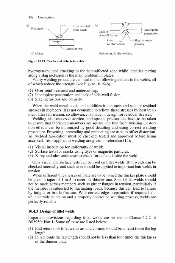
308 Connections
Hot crack(a) (b)
Lamellar tear
Cracking Defects and faulty welding
Heat affected zone crack
Lack of sidewall fusion
Incompletepenetration
Slag inclusion parasity
Overreinforcement
Figure 10.19 Cracks and defects in welds
hydrogen-induced cracking in the heat-affected zone while lamellar tearingalong a slag inclusion is the main problem in plates.
Faulty welding procedure can lead to the following defects in the welds, allof which reduce the strength (see Figure 10.19(b)):
(1) Over-reinforcement and undercutting;(2) Incomplete penetration and lack of side-wall fusion;(3) Slag inclusions and porosity.
When the weld metal cools and solidifies it contracts and sets up residualstresses in members. It is not economic to relieve these stresses by heat treat-ment after fabrication, so allowance is made in design for residual stresses.
Welding also causes distortion, and special precautions have to be takento ensure that fabricated members are square and free from twisting. Distor-tion effects can be minimized by good detailing and using correct weldingprocedure. Presetting, pretending and preheating are used to offset distortion.All welded fabrication must be checked, tested and approved before beingaccepted. Tests applied to welding are given in reference (15):
(1) Visual inspection for uniformity of weld;(2) Surface tests for cracks using dyes or magnetic particles;(3) X-ray and ultrasonic tests to check for defects inside the weld.
Only visual and surface tests can be used on fillet welds. Butt welds can bechecked internally, and such tests should be applied to important butt welds intension.
When different thicknesses of plate are to be joined the thicker plate shouldbe given a taper of 1 in 5 to meet the thinner one. Small fillet welds shouldnot be made across members such as girder flanges in tension, particularly ifthe member is subjected to fluctuating loads, because this can lead to failureby fatigue or brittle fracture. With correct edge preparation if required, fit-up, electrode selection and a properly controlled welding process, welds areperfectly reliable.
10.4.3 Design of fillet welds
Important provisions regarding fillet welds are set out in Clause 6.7.2 ofBS5950: Part 1. Some of these are listed below:
(1) End returns for fillet welds around corners should be at least twice the leglength.
(2) In lap joints the lap length should not be less than four times the thicknessof the thinner plate.
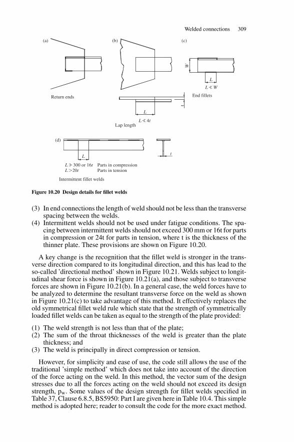
Welded connections 309
Return ends
(a)
(d)
(b) (c)
Intermittent fillet welds
End fillets
Lap length
L
L � 300 or 16t Parts in compressionL 20t Parts in tension
L W
L 4t
L
Lt
tW
Figure 10.20 Design details for fillet welds
(3) In end connections the length of weld should not be less than the transversespacing between the welds.
(4) Intermittent welds should not be used under fatigue conditions. The spa-cing between intermittent welds should not exceed 300 mm or 16t for partsin compression or 24t for parts in tension, where t is the thickness of thethinner plate. These provisions are shown on Figure 10.20.
A key change is the recognition that the fillet weld is stronger in the trans-verse direction compared to its longitudinal direction, and this has lead to theso-called ’directional method’ shown in Figure 10.21. Welds subject to longit-udinal shear force is shown in Figure 10.21(a), and those subject to transverseforces are shown in Figure 10.21(b). In a general case, the weld forces have tobe analyzed to determine the resultant transverse force on the weld as shownin Figure 10.21(c) to take advantage of this method. It effectively replaces theold symmetrical fillet weld rule which state that the strength of symmetricallyloaded fillet welds can be taken as equal to the strength of the plate provided:
(1) The weld strength is not less than that of the plate;(2) The sum of the throat thicknesses of the weld is greater than the plate
thickness; and(3) The weld is principally in direct compression or tension.
However, for simplicity and ease of use, the code still allows the use of thetraditional ’simple method’ which does not take into account of the directionof the force acting on the weld. In this method, the vector sum of the designstresses due to all the forces acting on the weld should not exceed its designstrength, pw. Some values of the design strength for fillet welds specified inTable 37, Clause 6.8.5, BS5950: Part I are given here in Table 10.4. This simplemethod is adopted here; reader to consult the code for the more exact method.
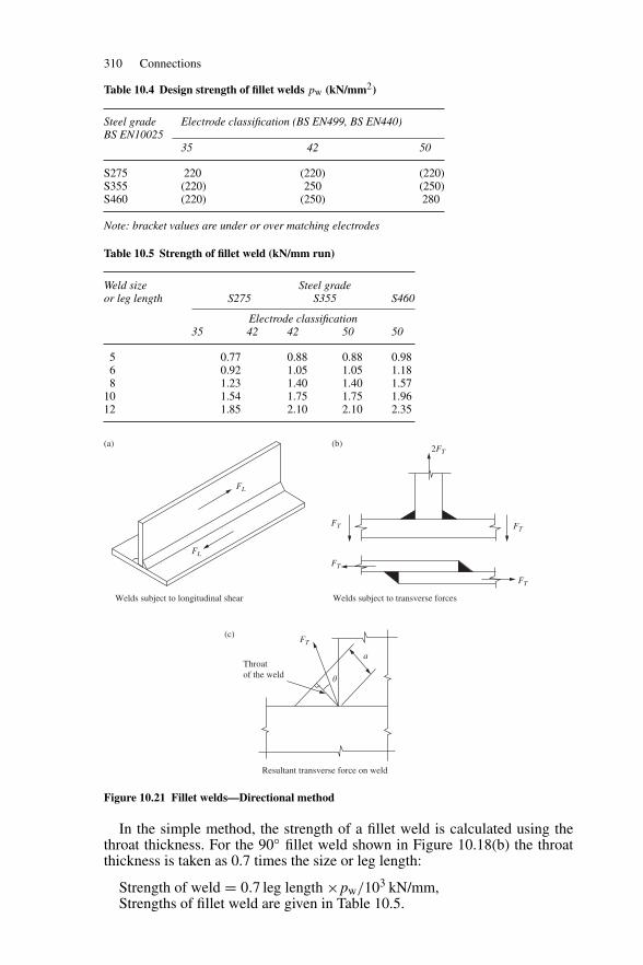
310 Connections
Table 10.4 Design strength of fillet welds pw (kN/mm2)
Steel grade Electrode classification (BS EN499, BS EN440)BS EN10025
35 42 50
S275 220 (220) (220)S355 (220) 250 (250)S460 (220) (250) 280
Note: bracket values are under or over matching electrodes
Table 10.5 Strength of fillet weld (kN/mm run)
Weld size Steel gradeor leg length S275 S355 S460
Electrode classification35 42 42 50 50
5 0.77 0.88 0.88 0.986 0.92 1.05 1.05 1.188 1.23 1.40 1.40 1.57
10 1.54 1.75 1.75 1.9612 1.85 2.10 2.10 2.35
Throatof the weld
FT
FT
FL
FL
2FT
FT
FT
FT
a
�
Resultant transverse force on weld
Welds subject to transverse forces Welds subject to longitudinal shear
(a) (b)
(c)
Figure 10.21 Fillet welds—Directional method
In the simple method, the strength of a fillet weld is calculated using thethroat thickness. For the 90◦ fillet weld shown in Figure 10.18(b) the throatthickness is taken as 0.7 times the size or leg length:
Strength of weld = 0.7 leg length ×pw/103 kN/mm,Strengths of fillet weld are given in Table 10.5.
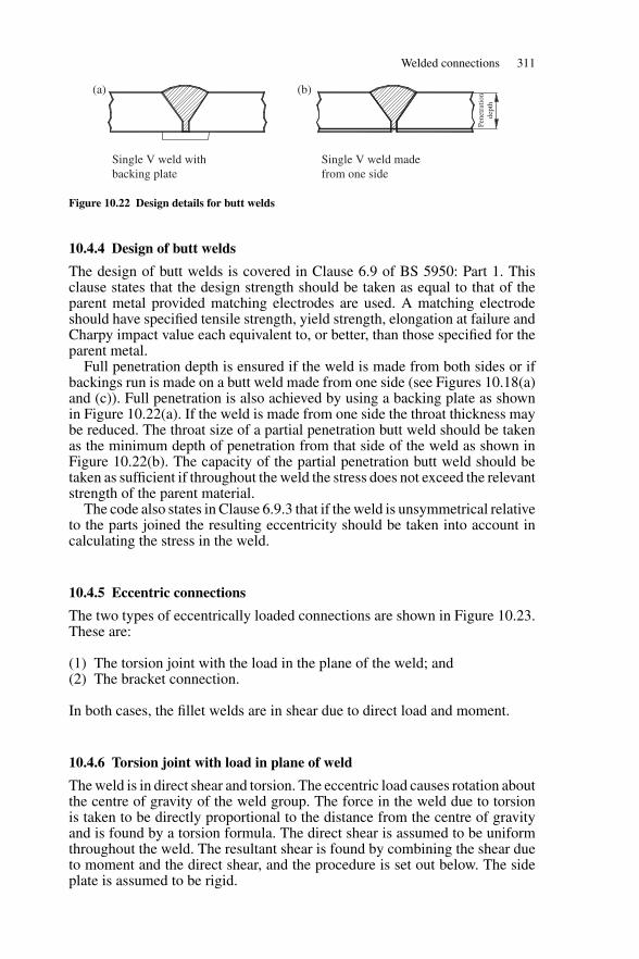
Welded connections 311
Single V weld with backing plate
Single V weld made from one side
(a) (b)
Pene
trat
ion
dept
h
Figure 10.22 Design details for butt welds
10.4.4 Design of butt welds
The design of butt welds is covered in Clause 6.9 of BS 5950: Part 1. Thisclause states that the design strength should be taken as equal to that of theparent metal provided matching electrodes are used. A matching electrodeshould have specified tensile strength, yield strength, elongation at failure andCharpy impact value each equivalent to, or better, than those specified for theparent metal.
Full penetration depth is ensured if the weld is made from both sides or ifbackings run is made on a butt weld made from one side (see Figures 10.18(a)and (c)). Full penetration is also achieved by using a backing plate as shownin Figure 10.22(a). If the weld is made from one side the throat thickness maybe reduced. The throat size of a partial penetration butt weld should be takenas the minimum depth of penetration from that side of the weld as shown inFigure 10.22(b). The capacity of the partial penetration butt weld should betaken as sufficient if throughout the weld the stress does not exceed the relevantstrength of the parent material.
The code also states in Clause 6.9.3 that if the weld is unsymmetrical relativeto the parts joined the resulting eccentricity should be taken into account incalculating the stress in the weld.
10.4.5 Eccentric connections
The two types of eccentrically loaded connections are shown in Figure 10.23.These are:
(1) The torsion joint with the load in the plane of the weld; and(2) The bracket connection.
In both cases, the fillet welds are in shear due to direct load and moment.
10.4.6 Torsion joint with load in plane of weld
The weld is in direct shear and torsion. The eccentric load causes rotation aboutthe centre of gravity of the weld group. The force in the weld due to torsionis taken to be directly proportional to the distance from the centre of gravityand is found by a torsion formula. The direct shear is assumed to be uniformthroughout the weld. The resultant shear is found by combining the shear dueto moment and the direct shear, and the procedure is set out below. The sideplate is assumed to be rigid.
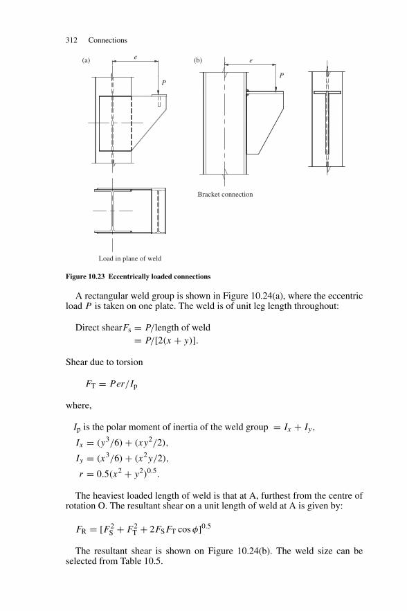
312 Connections
Bracket connection
Load in plane of weld
e
P
e(b)(a)
P
Figure 10.23 Eccentrically loaded connections
A rectangular weld group is shown in Figure 10.24(a), where the eccentricload P is taken on one plate. The weld is of unit leg length throughout:
Direct shearFs = P/length of weld= P/[2(x + y)].
Shear due to torsion
FT = Per/Ip
where,
Ip is the polar moment of inertia of the weld group = Ix + Iy,
Ix = (y3/6) + (xy2/2),
Iy = (x3/6) + (x2y/2),
r = 0.5(x2 + y2)0.5.
The heaviest loaded length of weld is that at A, furthest from the centre ofrotation O. The resultant shear on a unit length of weld at A is given by:
FR = [F 2S + F 2
T + 2FSFT cos φ]0.5
The resultant shear is shown on Figure 10.24(b). The weld size can beselected from Table 10.5.
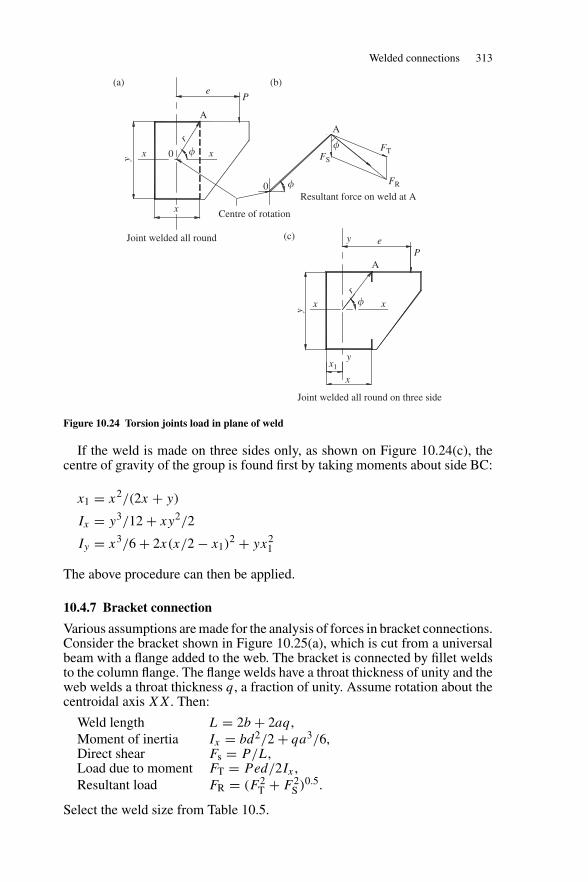
Welded connections 313
Joint welded all round on three side
Resultant force on weld at A
Joint welded all round
Centre of rotation
x1y
y e
e
x x
x x
(a) (b)
(c)
A
FS
FT
FR
AA
P
P
0
0
�
�
��
r
r
x
x
y
y
Figure 10.24 Torsion joints load in plane of weld
If the weld is made on three sides only, as shown on Figure 10.24(c), thecentre of gravity of the group is found first by taking moments about side BC:
x1 = x2/(2x + y)
Ix = y3/12 + xy2/2
Iy = x3/6 + 2x(x/2 − x1)2 + yx2
1
The above procedure can then be applied.
10.4.7 Bracket connection
Various assumptions are made for the analysis of forces in bracket connections.Consider the bracket shown in Figure 10.25(a), which is cut from a universalbeam with a flange added to the web. The bracket is connected by fillet weldsto the column flange. The flange welds have a throat thickness of unity and theweb welds a throat thickness q, a fraction of unity. Assume rotation about thecentroidal axis XX. Then:
Weld length L = 2b + 2aq,Moment of inertia Ix = bd2/2 + qa3/6,Direct shear Fs = P/L,Load due to moment FT = Ped/2Ix ,Resultant load FR = (F 2
T + F 2S )0.5.
Select the weld size from Table 10.5.
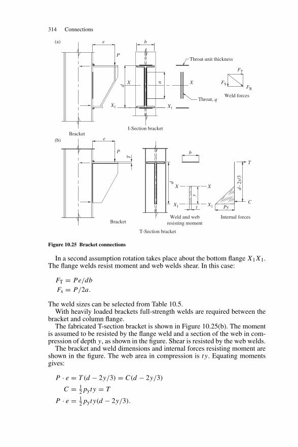
314 Connections
Bracket
Bracket
I-Section bracket
T-Section bracket
Weld and web resisting moment
Internal forces
Throat unit thickness
Weld forcesThroat, q
FS
FT
FR
X
P
P
T
d
b
e
e b(a)
(b)
X1
X1 X1
X X
PyC
t
T
d–2y
/3
y
X1
a
d
X
Figure 10.25 Bracket connections
In a second assumption rotation takes place about the bottom flange X1X1.The flange welds resist moment and web welds shear. In this case:
FT = Pe/db
Fs = P/2a.
The weld sizes can be selected from Table 10.5.With heavily loaded brackets full-strength welds are required between the
bracket and column flange.The fabricated T-section bracket is shown in Figure 10.25(b). The moment
is assumed to be resisted by the flange weld and a section of the web in com-pression of depth y, as shown in the figure. Shear is resisted by the web welds.
The bracket and weld dimensions and internal forces resisting moment areshown in the figure. The web area in compression is ty. Equating momentsgives:
P · e = T (d − 2y/3) = C(d − 2y/3)
C = 12pyty = T
P · e = 12pyty(d − 2y/3).
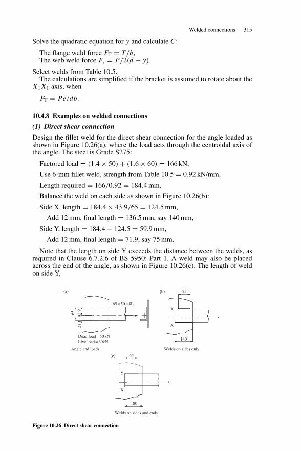
Welded connections 315
Solve the quadratic equation for y and calculate C:
The flange weld force FT = T/b,The web weld force Fs = P/2(d − y).
Select welds from Table 10.5.The calculations are simplified if the bracket is assumed to rotate about the
X1X1 axis, when
FT = Pe/db.
10.4.8 Examples on welded connections
(1) Direct shear connection
Design the fillet weld for the direct shear connection for the angle loaded asshown in Figure 10.26(a), where the load acts through the centroidal axis ofthe angle. The steel is Grade S275:
Factored load = (1.4 × 50) + (1.6 × 60) = 166 kN,
Use 6-mm fillet weld, strength from Table 10.5 = 0.92 kN/mm,
Length required = 166/0.92 = 184.4 mm,
Balance the weld on each side as shown in Figure 10.26(b):
Side X, length = 184.4 × 43.9/65 = 124.5 mm,
Add 12 mm, final length = 136.5 mm, say 140 mm,
Side Y, length = 184.4 − 124.5 = 59.9 mm,
Add 12 mm, final length = 71.9, say 75 mm.
Note that the length on side Y exceeds the distance between the welds, asrequired in Clause 6.7.2.6 of BS 5950: Part 1. A weld may also be placedacross the end of the angle, as shown in Figure 10.26(c). The length of weldon side Y,
Welds on sides and ends
Angle and loads
Dead load = 50 kN Live load = 60kN
65 × 50 × 8L
Welds on sides only
140
X
65
21.1
43
.9
Y
75(a) (b)
(c)
180
X
Y
65
Figure 10.26 Direct shear connection
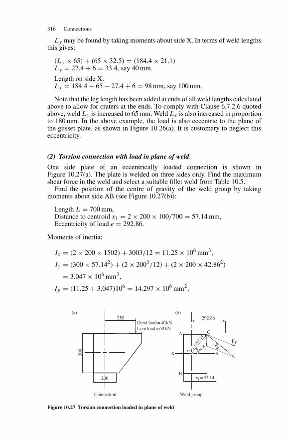
316 Connections
Ly may be found by taking moments about side X. In terms of weld lengthsthis gives:
(Ly × 65) + (65 × 32.5) = (184.4 × 21.1)Ly = 27.4 + 6 = 33.4, say 40 mm.
Length on side X:Lx = 184.4 − 65 − 27.4 + 6 = 98 mm, say 100 mm.
Note that the leg length has been added at ends of all weld lengths calculatedabove to allow for craters at the ends. To comply with Clause 6.7.2.6 quotedabove, weld Ly is increased to 65 mm. Weld Lx is also increased in proportionto 180 mm. In the above example, the load is also eccentric to the plane ofthe gusset plate, as shown in Figure 10.26(a). It is customary to neglect thiseccentricity.
(2) Torsion connection with load in plane of weld
One side plate of an eccentrically loaded connection is shown inFigure 10.27(a). The plate is welded on three sides only. Find the maximumshear force in the weld and select a suitable fillet weld from Table 10.5.
Find the position of the centre of gravity of the weld group by takingmoments about side AB (see Figure 10.27(b)):
Length L = 700 mm,Distance to centroid x1 = 2 × 200 × 100/700 = 57.14 mm,Eccentricity of load e = 292.86.
Moments of inertia:
Ix = (2 × 200 × 1502) + 3003/12 = 11.25 × 106 mm3,
Iy = (300 × 57.142) + (2 × 2003/12) + (2 × 200 × 42.862)
= 3.047 × 106 mm3,
Ip = (11.25 + 3.047)106 = 14.297 × 106 mm2,
Connection Weld group
250(a) (b)
�
292.86
300
200
Dead load = 40 kN Live load = 60 kN
B
A
o r=20
7.14
C
X X
x1 = 57.14
Fs
FTFR
Figure 10.27 Torsion connection loaded in plane of weld
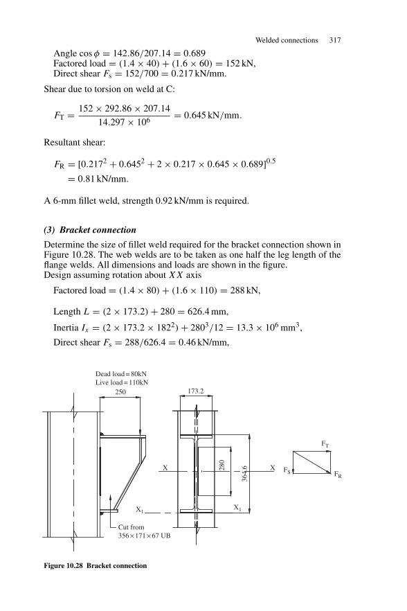
Welded connections 317
Angle cos φ = 142.86/207.14 = 0.689Factored load = (1.4 × 40) + (1.6 × 60) = 152 kN,Direct shear Fs = 152/700 = 0.217 kN/mm.
Shear due to torsion on weld at C:
FT = 152 × 292.86 × 207.14
14.297 × 106= 0.645 kN/mm.
Resultant shear:
FR = [0.2172 + 0.6452 + 2 × 0.217 × 0.645 × 0.689]0.5
= 0.81 kN/mm.
A 6-mm fillet weld, strength 0.92 kN/mm is required.
(3) Bracket connection
Determine the size of fillet weld required for the bracket connection shown inFigure 10.28. The web welds are to be taken as one half the leg length of theflange welds. All dimensions and loads are shown in the figure.Design assuming rotation about XX axis
Factored load = (1.4 × 80) + (1.6 × 110) = 288 kN,
Length L = (2 × 173.2) + 280 = 626.4 mm,
Inertia Ix = (2 × 173.2 × 1822) + 2803/12 = 13.3 × 106 mm3,
Direct shear Fs = 288/626.4 = 0.46 kN/mm,
Cut from 356 × 171 × 67 UB
X1
280
364.
6
X1
X X FS FR
FT
173.2250
Dead load = 80kN Live load = 110kN
Figure 10.28 Bracket connection
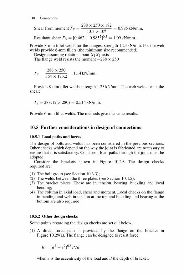
318 Connections
Shear from moment FT = 288 × 250 × 182
13.3 × 106= 0.985 kN/mm,
Resultant shear FR = [0.462 + 0.9852]0.5 = 1.09 kN/mm.
Provide 8-mm fillet welds for the flanges, strength 1.23 kN/mm. For the webwelds provide 6-mm fillets (the minimum size recommended).
Design assuming rotation about X1X1 axisThe flange weld resists the moment −288 × 250
FT = 288 × 250
364 × 173.2= 1.14 kN/mm.
Provide 8-mm fillet welds, strength 1.23 kN/mm. The web welds resist theshear:
Fs = 288/(2 × 280) = 0.514 kN/mm.
Provide 6-mm fillet welds. The methods give the same results.
10.5 Further considerations in design of connections
10.5.1 Load paths and forces
The design of bolts and welds has been considered in the previous sections.Other checks which depend on the way the joint is fabricated are necessary toensure that it is satisfactory. Consistent load paths through the joint must beadopted.
Consider the brackets shown in Figure 10.29. The design checksrequired are:
(1) The bolt group (see Section 10.3.3);(2) The welds between the three plates (see Section 10.4.5);(3) The bracket plates. These are in tension, bearing, buckling and local
bending;(4) The column in axial load, shear and moment. Local checks on the flange
in bending and web in tension at the top and buckling and bearing at thebottom are also required.
10.5.2 Other design checks
Some points regarding the design checks are set out below.
(1) A direct force path is provided by the flange on the bracket inFigure 10.29(a). The flange can be designed to resist force
R = (d2 + e2)0.5P/d
when e is the eccentricity of the load and d the depth of bracket.
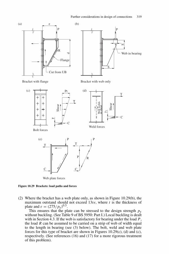
Further considerations in design of connections 319
e(a) (b)
(c) (d)
(e)
P
R
S
Flange
Cut from UB
Bracket with flange
Bolt forcesWeld forces
Web plate forces
Pt
T
TT
T
C
C C
P
P P
R
C
Bracket with web only
Web in bearingd
y
Shea
r
Shea
r
y 1Web
wel
ds
in s
hear
S
P
Figure 10.29 Brackets: load paths and forces
(2) Where the bracket has a web plate only, as shown in Figure 10.29(b), themaximum outstand should not exceed 13te, where t is the thickness ofplate and ε = (275/py)
0.5.This ensures that the plate can be stressed to the design strength py
without buckling. (See Table 9 of BS 5950: Part I.) Local buckling is dealtwith in Section 4.3. If the web is satisfactory for bearing under the load P ,the load R can be assumed to be carried on a strip of web of width equalto the length in bearing (see (3) below). The bolt, weld and web plateforces for this type of bracket are shown in Figures 10.29(c), (d) and (c),respectively. (See references (16) and (17) for a more rigorous treatmentof this problem).
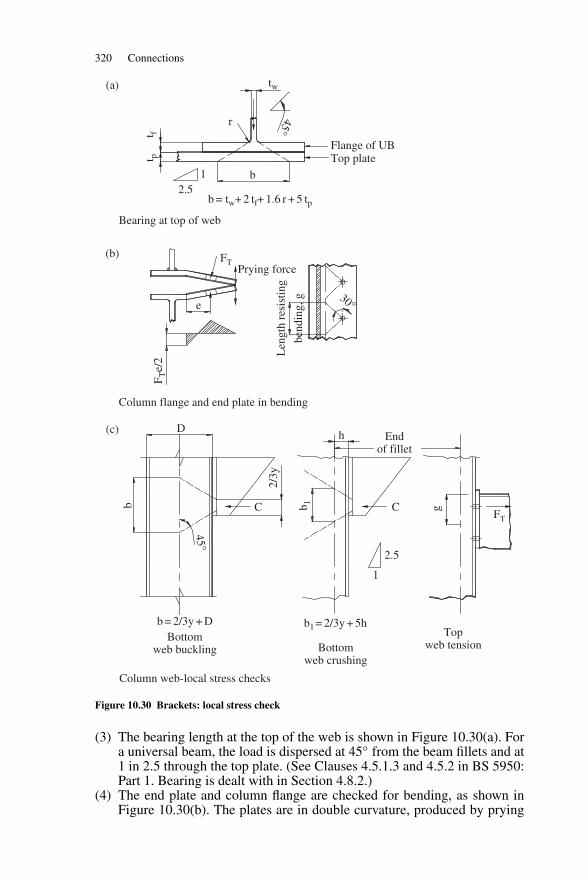
320 Connections
tw
b = tw+ 2 tf+ 1.6 r + 5 tp
Bearing at top of web
t ft p
r
12.5
b
FTPrying force
Column flange and end plate in bending
Len
gth
resi
stin
g
bend
ing,
g
Flange of UBTop plate
45°e
30°
F Te/
2
D
b C C
45°
2/3y
b = 2/3y + D b1 = 2/3y + 5hBottom
web buckling Bottomweb crushing
Topweb tension
b 1 gh
2.5
FT
Endof fillet
1
Column web-local stress checks
(a)
(b)
(c)
Figure 10.30 Brackets: local stress check
(3) The bearing length at the top of the web is shown in Figure 10.30(a). Fora universal beam, the load is dispersed at 45◦ from the beam fillets and at1 in 2.5 through the top plate. (See Clauses 4.5.1.3 and 4.5.2 in BS 5950:Part 1. Bearing is dealt with in Section 4.8.2.)
(4) The end plate and column flange are checked for bending, as shown inFigure 10.30(b). The plates are in double curvature, produced by prying
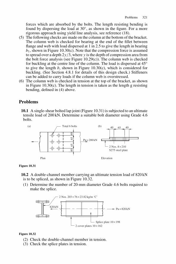
Problems 321
forces which are absorbed by the bolts. The length resisting bending isfound by dispersing the load at 30◦, as shown in the figure. For a morerigorous approach using yield line analysis, see reference (18).
(5) The following checks are made on the column at the bottom of the bracket.The column web is checked for bearing at the end of the fillet betweenflange and web with load dispersed at 1 in 2.5 to give the length in bearingb1, shown in Figure 10.30(c). Note that the compression force is assumedto spread over a depth 2y/3, where y is the depth of compression area fromthe bolt force analysis (see Figure 10.29(c)). The column web is checkedfor buckling at the centre line of the column. The load is dispersed at 45◦to give the length b, shown in Figure 10.30(c), which is considered forbuckling. (See Section 4.8.1 for details of this design check.) Stiffenerscan be added to carry loads if the column web is overstressed.
(6) The column web is checked in tension at the top of the bracket, as shownin Figure 10.30(c). The length in tension is taken as the length g resistingbending, defined in (4) above.
Problems
10.1 A single-shear bolted lap joint (Figure 10.31) is subjected to an ultimatetensile load of 200 kN. Determine a suitable bolt diameter using Grade 4.6bolts.
Total 6 bolts(a) (b)
4040
65
40 4065
65 Pu = 200 kN
2 Nos. 8 × 210
Plan Elevation
S275 steel plate
Figure 10.31
10.2 A double-channel member carrying an ultimate tension load of 820 kNis to be spliced, as shown in Figure 10.32.(1) Determine the number of 20-mm diameter Grade 4.6 bolts required to
make the splice.
2 Nos. 203 × 76 × 23.82 kg/m ‘C’
820 kNPu = 820 kN
Splice plate 10 × 1982 cover plates 10 × 162
Figure 10.32
(2) Check the double-channel member in tension.(3) Check the splice plates in tension.
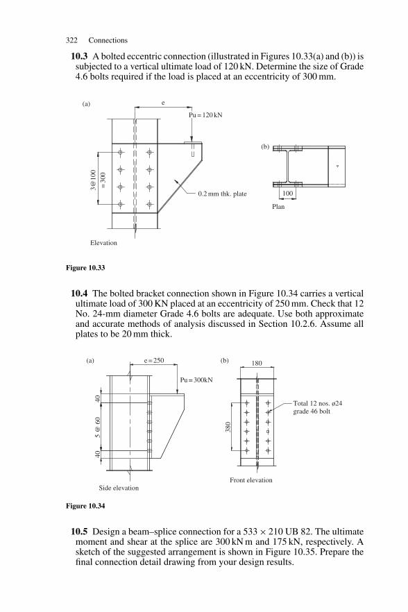
322 Connections
10.3 A bolted eccentric connection (illustrated in Figures 10.33(a) and (b)) issubjected to a vertical ultimate load of 120 kN. Determine the size of Grade4.6 bolts required if the load is placed at an eccentricity of 300 mm.
e
Pu = 120 kN
0.2 mm thk. plate
3@10
0=
300
100
Plan
Elevation
(a)
(b)
Figure 10.33
10.4 The bolted bracket connection shown in Figure 10.34 carries a verticalultimate load of 300 KN placed at an eccentricity of 250 mm. Check that 12No. 24-mm diameter Grade 4.6 bolts are adequate. Use both approximateand accurate methods of analysis discussed in Section 10.2.6. Assume allplates to be 20 mm thick.
e = 250(a) (b) 180
380
4040
5 @
60
Pu = 300kN
Side elevationFront elevation
Total 12 nos. ø24grade 46 bolt
Figure 10.34
10.5 Design a beam–splice connection for a 533 × 210 UB 82. The ultimatemoment and shear at the splice are 300 kN m and 175 kN, respectively. Asketch of the suggested arrangement is shown in Figure 10.35. Prepare thefinal connection detail drawing from your design results.
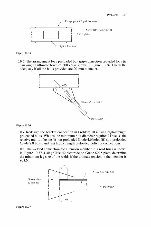
Problems 323
Splice location
2 web plates
Flange plate (Top & bottom)
533 × 210 × 82 kg/m UB
Figure 10.35
10.6 The arrangement for a preloaded bolt grip-connection provided for a tiecarrying an ultimate force of 300 kN is shown in Figure 10.36. Check theadequacy if all the bolts provided are 20-mm diameter.
Pu = 300kN
2 Nos. 75 × 50 × 8
45
Figure 10.36
10.7 Redesign the bracket connection in Problem 10.4 using high-strengthpreloaded bolts. What is the minimum bolt diameter required? Discuss therelative merits of using (i) non-preloaded Grade 4.6 bolts, (ii) non-preloadedGrade 8.8 bolts, and (iii) high strength preloaded bolts for connections.
10.8 The welded connection for a tension member in a roof truss is shownin Figure 10.37. Using Class 42 electrode on Grade S275 plate, determinethe minimum leg size of the welds if the ultimate tension in the member is90 kN.
2 Nos. 65 × 50 × 6
65
Pu = 90 kN
20
Gusset plate 12 mm thk
Figure 10.37
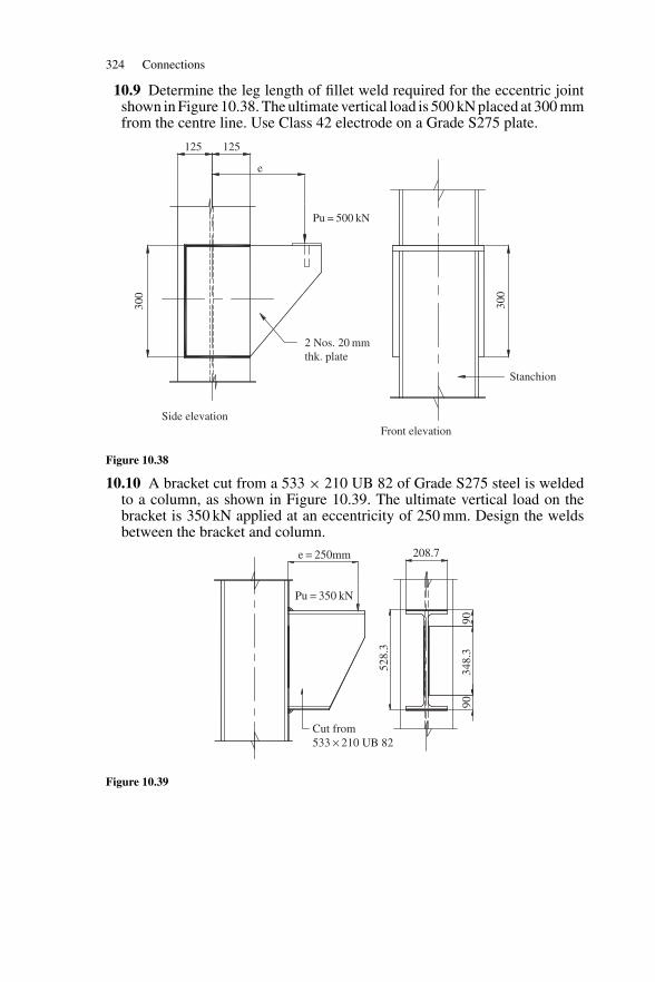
324 Connections
10.9 Determine the leg length of fillet weld required for the eccentric jointshown in Figure 10.38. The ultimate vertical load is 500 kN placed at 300 mmfrom the centre line. Use Class 42 electrode on a Grade S275 plate.
2 Nos. 20 mm thk. plate
Stanchion
Front elevationSide elevation
300
300
Pu = 500 kN
125 125
e
Figure 10.38
10.10 A bracket cut from a 533 × 210 UB 82 of Grade S275 steel is weldedto a column, as shown in Figure 10.39. The ultimate vertical load on thebracket is 350 kN applied at an eccentricity of 250 mm. Design the weldsbetween the bracket and column.
Cut from 533 × 210 UB 82
e = 250mm 208.7
Pu = 350 kN
9090
348.
3
528.
3
Figure 10.39
11
Workshop steelwork design example
11.1 Introduction
An example giving the design of the steel frame for a workshop is presentedhere and illustrates the following steps in the design process:
(1) Preliminary considerations and estimation of loads for the various loadcases;
(2) Computer analysis for the structural frame;(3) Design of the truss and crane column;(4) Sketches of the steelwork details.
The framing plans for the workshop with overhead crane are shown inFigure 11.1. The frames are spaced at 6.0 m centres and the overall lengthof building is 48.0 m. The crane span is 19.1 m and the capacity is 50 kN.
Design the structure using Grade S275 steel. Structural steel angle sectionsare used for the roof truss and universal beams for the columns.
Computer analysis is used because plane frame programs are now generallyavailable for use on microcomputers. (The reader can consult references 16and 22 for particulars of the matrix stiffness method analysis. The plane framemanual for the particular software package used should also be consulted.)
A manual method of analysis could also be used and the procedure is asfollows:
(1) The roof truss is taken to be simply supported for analysis.(2) The columns are analysed for crane and wind loads assuming portal action
with no change of slope at the column top. The portal action introducesforces into the chords of the truss which should be added to the forces in(1) for design.
The reader should consult references (9) and (20) for further particulars of themanual method of analysis.
11.2 Basic design loads
Details of sheeting and purlins used are given below:
Sheeting: Cellactite 11/3 corrugated sheeting, type 800 thickness 0.8 mm.Dead load = 0.1 kN/m2. The loads and estimated self-weight on
325
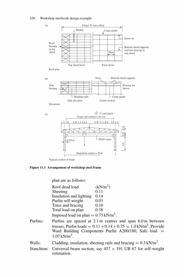
326 Workshop steelwork design example
Roofbracingin topchord
8 bays @ 6 m = 48 m(a)
(b)
(c)
Purlins Crane girder
Eaves tie
Top chord level Eaves level
Truss Bottom chord supports
Bracing notshown
Sidebracing
Sheeting rails Crane girder
Roof plan
Side elevation Centre sectionElevations
3° roof pitchCrane rail centres = 19.1 m
Bottom chord supportstied into bracing intop chordTruss
1.3 1.31.
01.
55.
51.6
0.45 m 50 kN crane
Stanchion centres = 20 m
Typical section of frame
1.64 @ 2.1 = 8.4 4 @ 2.1 = 8.4
Figure 11.1 Arrangement of workshop steel frame
plan are as follows:
Roof dead load (kN/m2)Sheeting 0.11Insulation and lighting 0.14Purlin self weight 0.03Truss and bracing 0.10Total load on plan 0.38Imposed load on plan = 0.75 kN/m2.
Purlins: Purlins are spaced at 2.1 m centres and span 6.0 m betweentrusses, Purlin loads = 0.11+0.14+0.75 = 1.0 kN/m2, ProvideWard Building Components Purlin A200/180, Safe load =1.07 kN/m2.
Walls: Cladding, insulation, sheeting rails and bracing = 0.3 kN/m2.Stanchion: Universal beam section, say 457 × 191 UB 67 for self-weight
estimation.
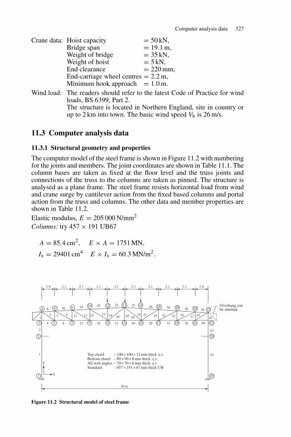
Computer analysis data 327
Crane data: Hoist capacity = 50 kN,Bridge span = 19.1 m,Weight of bridge = 35 kN,Weight of hoist = 5 kN,End clearance = 220 mm,End-carriage wheel centres = 2.2 m,Minimum hook approach = 1.0 m.
Wind load: The readers should refer to the latest Code of Practice for windloads, BS 6399, Part 2.The structure is located in Northern England, site in country orup to 2 km into town. The basic wind speed Vb is 26 m/s.
11.3 Computer analysis data
11.3.1 Structural geometry and properties
The computer model of the steel frame is shown in Figure 11.2 with numberingfor the joints and members. The joint coordinates are shown in Table 11.1. Thecolumn bases are taken as fixed at the floor level and the truss joints andconnections of the truss to the columns are taken as pinned. The structure isanalysed as a plane frame. The steel frame resists horizontal load from windand crane surge by cantilever action from the fixed based columns and portalaction from the truss and columns. The other data and member properties areshown in Table 11.2.Elastic modulus, E = 205 000 N/mm2
Columns: try 457 × 191 UB67
A = 85.4 cm2, E × A = 1751 MN,
Ix = 29401 cm4 E × Ix = 60.3 MN/m2.
Top chordBottom chordAll web anglesStandard
––––
100 × 100 × 12 mm thick �s90 × 90 × 8 mm thick �s70 × 70 × 6 mm thick �s457 × 191 × 67 mm thick UB
1.6
4
3
2
1
5 7 9 11 11a 15 17 19 21 23
25
24
6 6 10 12 1413 16 18 20 22
4
2
35 7 9 11 13 15 17 19 20 45 24
25 27 29 31 33 35 37 3941
42
431
6
8
10
12
14
16
18
21
22
44
20 m
y
x
23
28
26
32
30
36
36
40
Overhang canbe omitted.38
2.1 2.1 2.1 2.1 2.1 2.1 2.1 2.1 1.6
Figure 11.2 Structural model of steel frame
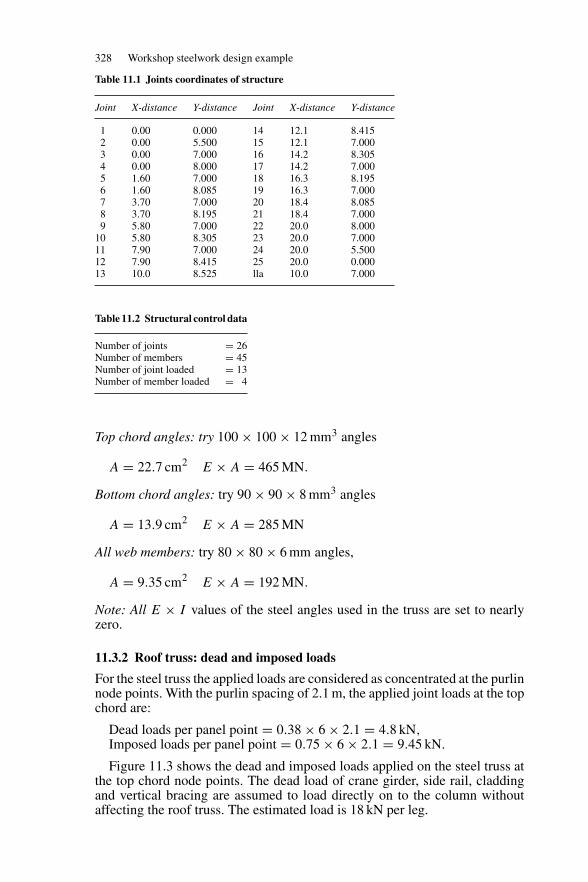
328 Workshop steelwork design example
Table 11.1 Joints coordinates of structure
Joint X-distance Y-distance Joint X-distance Y-distance
1 0.00 0.000 14 12.1 8.4152 0.00 5.500 15 12.1 7.0003 0.00 7.000 16 14.2 8.3054 0.00 8.000 17 14.2 7.0005 1.60 7.000 18 16.3 8.1956 1.60 8.085 19 16.3 7.0007 3.70 7.000 20 18.4 8.0858 3.70 8.195 21 18.4 7.0009 5.80 7.000 22 20.0 8.000
10 5.80 8.305 23 20.0 7.00011 7.90 7.000 24 20.0 5.50012 7.90 8.415 25 20.0 0.00013 10.0 8.525 lla 10.0 7.000
Table 11.2 Structural control data
Number of joints = 26Number of members = 45Number of joint loaded = 13Number of member loaded = 4
Top chord angles: try 100 × 100 × 12 mm3 angles
A = 22.7 cm2 E × A = 465 MN.
Bottom chord angles: try 90 × 90 × 8 mm3 angles
A = 13.9 cm2 E × A = 285 MN
All web members: try 80 × 80 × 6 mm angles,
A = 9.35 cm2 E × A = 192 MN.
Note: All E × I values of the steel angles used in the truss are set to nearlyzero.
11.3.2 Roof truss: dead and imposed loads
For the steel truss the applied loads are considered as concentrated at the purlinnode points. With the purlin spacing of 2.1 m, the applied joint loads at the topchord are:
Dead loads per panel point = 0.38 × 6 × 2.1 = 4.8 kN,Imposed loads per panel point = 0.75 × 6 × 2.1 = 9.45 kN.
Figure 11.3 shows the dead and imposed loads applied on the steel truss atthe top chord node points. The dead load of crane girder, side rail, claddingand vertical bracing are assumed to load directly on to the column withoutaffecting the roof truss. The estimated load is 18 kN per leg.
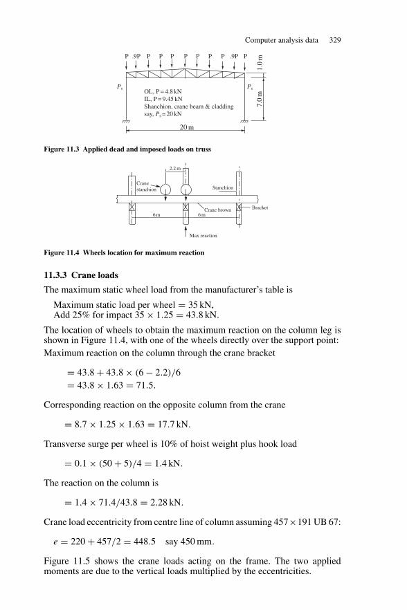
Computer analysis data 329
P .9P .9PP
Ps Ps
P
OL, P = 4.8 kNIL, P = 9.45 kNShanchion, crane beam & claddingsay, Ps = 20 kN
P P P P P P
20 m
7.0
m1.
0m
Figure 11.3 Applied dead and imposed loads on truss
Cranestanchion
Crane brown
Max reaction
Bracket
Stanchion
2.2 m
6 m 6 m
Figure 11.4 Wheels location for maximum reaction
11.3.3 Crane loads
The maximum static wheel load from the manufacturer’s table is
Maximum static load per wheel = 35 kN,Add 25% for impact 35 × 1.25 = 43.8 kN.
The location of wheels to obtain the maximum reaction on the column leg isshown in Figure 11.4, with one of the wheels directly over the support point:Maximum reaction on the column through the crane bracket
= 43.8 + 43.8 × (6 − 2.2)/6= 43.8 × 1.63 = 71.5.
Corresponding reaction on the opposite column from the crane
= 8.7 × 1.25 × 1.63 = 17.7 kN.
Transverse surge per wheel is 10% of hoist weight plus hook load
= 0.1 × (50 + 5)/4 = 1.4 kN.
The reaction on the column is
= 1.4 × 71.4/43.8 = 2.28 kN.
Crane load eccentricity from centre line of column assuming 457×191 UB 67:
e = 220 + 457/2 = 448.5 say 450 mm.
Figure 11.5 shows the crane loads acting on the frame. The two appliedmoments are due to the vertical loads multiplied by the eccentricities.
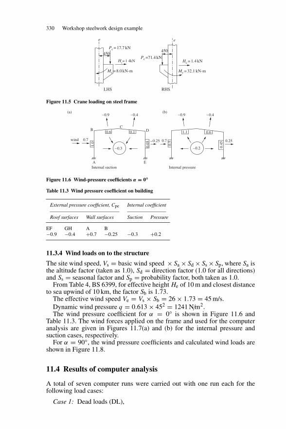
330 Workshop steelwork design example
e e
Pc = 17.7 kN
Hc= 1 4kN Hc = 1.4 kNPc =71.4 kN
Mc = 8.0 kN-m Mc = 32.1 kN-m
450450
LHS RHS
Figure 11.5 Crane loading on steel frame
–0.9(a) (b)
–0.4 –0.9 –0.4
BC
D0.6
0.7wind –0.25
–0.2–0.3
Internal suction Internal pressure
0.25
0.450.
5
1.0
0.05
0.1
0.7
1.1 0.6
A E
Figure 11.6 Wind-pressure coefficients α = 0◦
Table 11.3 Wind pressure coefficient on building
External pressure coefficient, Cpe Internal coefficient
Roof surfaces Wall surfaces Suction Pressure
EF GH A B−0.9 −0.4 +0.7 −0.25 −0.3 +0.2
11.3.4 Wind loads on to the structure
The site wind speed, Vs = basic wind speed ×Sa ×Sd ×Ss ×Sp, where Sa isthe altitude factor (taken as 1.0), Sd = direction factor (1.0 for all directions)and Ss = seasonal factor and Sp = probability factor, both taken as 1.0.
From Table 4, BS 6399, for effective height He of 10 m and closest distanceto sea upwind of 10 km, the factor Sb is 1.73.
The effective wind speed Ve = Vs × Sb = 26 × 1.73 = 45 m/s.Dynamic wind pressure q = 0.613 × 452 = 1241 N/m2.The wind pressure coefficient for α = 0◦ is shown in Figure 11.6 and
Table 11.3. The wind forces applied on the frame and used for the computeranalysis are given in Figures 11.7(a) and (b) for the internal pressure andsuction cases, respectively.
For α = 90◦, the wind pressure coefficients and calculated wind loads areshown in Figure 11.8.
11.4 Results of computer analysis
A total of seven computer runs were carried out with one run each for thefollowing load cases:
Case 1: Dead loads (DL),
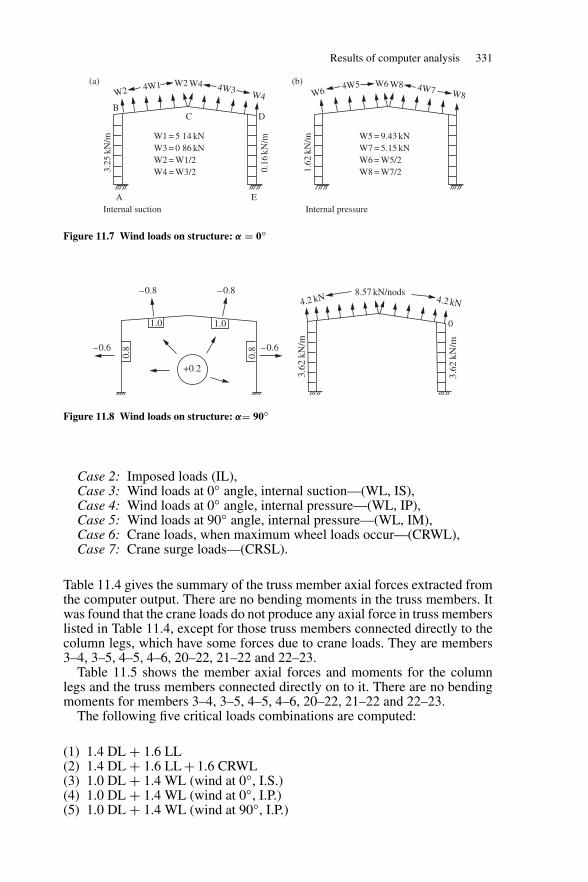
Results of computer analysis 331
W2W24W1 W4 4W3 W4 W6
W64W5 W8 4W7 W8
C
W1 = 5 14 kN W3 = 0 86 kN W2 = W1/2 W4 = W3/2
Internal suction Internal pressure
W5 = 9.43 kN W7 = 5.15 kN W6 = W5/2 W8 = W7/2
A E
BD
0.16
kN/m
3.25
kN/m
1.62
kN/m
(b)(a)
Figure 11.7 Wind loads on structure: α = 0◦
1.0
+0.2
0.8
0.8
1.0
–0.8
–0.6 –0.6
–0.84.2 kN 4.2 kN
8.57 kN/nods
0
3.62
kN/m
3.62
kN/m
Figure 11.8 Wind loads on structure: α= 90◦
Case 2: Imposed loads (IL),Case 3: Wind loads at 0◦ angle, internal suction—(WL, IS),Case 4: Wind loads at 0◦ angle, internal pressure—(WL, IP),Case 5: Wind loads at 90◦ angle, internal pressure—(WL, IM),Case 6: Crane loads, when maximum wheel loads occur—(CRWL),Case 7: Crane surge loads—(CRSL).
Table 11.4 gives the summary of the truss member axial forces extracted fromthe computer output. There are no bending moments in the truss members. Itwas found that the crane loads do not produce any axial force in truss memberslisted in Table 11.4, except for those truss members connected directly to thecolumn legs, which have some forces due to crane loads. They are members3–4, 3–5, 4–5, 4–6, 20–22, 21–22 and 22–23.
Table 11.5 shows the member axial forces and moments for the columnlegs and the truss members connected directly on to it. There are no bendingmoments for members 3–4, 3–5, 4–5, 4–6, 20–22, 21–22 and 22–23.
The following five critical loads combinations are computed:
(1) 1.4 DL + 1.6 LL(2) 1.4 DL + 1.6 LL + 1.6 CRWL(3) 1.0 DL + 1.4 WL (wind at 0◦, I.S.)(4) 1.0 DL + 1.4 WL (wind at 0◦, I.P.)(5) 1.0 DL + 1.4 WL (wind at 90◦, I.P.)
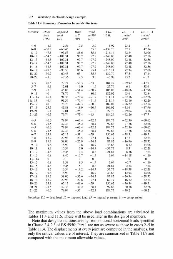
332 Workshop steelwork design example
Table 11.4 Summary of member force (kN) for truss
Member Deadload(DL)
Imposedload(IL)
Windat T(IP)
Windat 90*(IP)
1.4 DL +1.6 IL
DL + 1.4x windat 0◦,
DL + 1.4x windat 90◦
4–6 −1.3 −2.56 17.5 3.0 −5.92 23.2 −1.36–8 −30.7 −60.45 63 55.6 −139.70 57.5 47.148–10 −47.5 −93.53 85.6 85.4 −216.14 72.34 72.06
10–12 −54.5 −107.31 90.7 97.9 −248.00 72.48 82.5612–13 −54.5 −107.31 90.7 −97.9 −248.00 72.48 82.5613–14 −54.5 −107.31 90.7 97.9 −248.00 72.48 82.5614–16 −54.5 −107.31 90.7 97.9 −248.00 72.48 82.5616–18 −47.5 −93.53 85.6 85.4 −216.14 72.34 72.0618–20 −30.7 −60.45 63 55.6 −139.70 57.5 47.1420–22 −1.3 −2.56 17.5 3.0 −5.92 23.2 −1.3
3–5 40.5 79.74 −50.3 −63 184.29 −29.92 −47.75–7 6.1 12.01 −6.0 −1.6 27.76 6.1 −38.67–9 23.3 45.88 −51.4 −50.9 106.02 −48.66 −47.969–11 40 78.76 −74 −80.6 182.02 −63.6 −72.84
11–11a 46.4 91.36 −70.4 −91.9 211.14 −52.16 −82.2611a–15 46.4 91.36 −70.4 −91.9 211.14 −52.16 −82.26
15–17 40 78.76 −47.3 −80.6 182.02 −26.22 −72.8417–19 23.3 45.88 −18.9 −50.9 106.02 −3.16 −47.9619–21 6.1 12.01 −25.1 −1.6 27.76 −29.04 3.8621–23 40.5 79.74 −73.4 −63 184.29 −62.26 −47.7
4–5 40.6 79.94 −66.4 −72.3 184.75 −52.36 −60.625–6 −21.5 −42.33 35.2 38.4 −97.83 27.78 32.264–5 40.6 79.94 −66.4 −72.3 184.75 −52.36 −60.625–6 −21.5 −42.33 35.2 38.4 −97.83 27.78 32.266–7 33.1 65.17 −51 −59 150.62 −38.3 −49.57–8 −15.2 −29.93 23.5 27.1 −69.17 17.7 22.748–9 19.3 38.00 −25.9 −34.3 87.82 −16.96 −28.729–10 −9.6 −18.90 12.8 16.9 −43.68 8.32 14.06
10–11 8.3 16.34 6.0 −14.7 −37.77 8.3 −12.2811–12 −4.8 −9.45 9.4 8.6 −21.84 8.36 7.2411–13 0.8 9.45 −10.7 −1.4 3.64 −14.18 −1.1613–11a 0 0 0 0 0 1.0 013–15 0.8 1.58 8.5 −1.4 3.64 −2.7 −1.1614–15 −4.8 −9.45 5.1 8.6 21.84 2.34 7.2415–16 8.3 16.34 −19.2 −14.7 37.77 −18.58 −12.2816–17 −9.6 −18.90 16.1 16.9 −43.68 12.94 14.0617–18 19.3 38.00 −32.6 −34.3 87.82 −26.34 −28.7218–19 −15.2 −29.93 22.8 27.1 −69.17 16.72 22.7419–20 33.1 65.17 −49.6 −59 150.62 −36.34 −49.520–21 −21.5 −42.33 30.2 38.4 −97.83 20.78 32.2621–22 40.6 79.94 −57 −72.3 184.75 −39.2 −60.2
Notation: DL = dead load, IL = imposed load, IP = internal pressure, (–) = compression
The maximum values from the above load combinations are tabulated inTables 11.4 and 11.6. These will be used later in the design of members.
Note that design conditions arising from notional horizontal loads specifiedin Clause 2.4.2.3 of BS 5950: Part 1 are not as severe as those in cases 2–5 inTable 11.4. The displacements at every joint are computed in the analyses, butonly the critical values are of interest. They are summarized in Table 11.7 andcompared with the maximum allowable values.
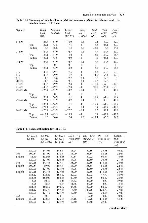
Results of computer analysis 333
Table 11.5 Summary of member forces (kN) and moments (kN m) for columns and trussmember connected to them
Member Deadload(DL)
Imposedload (IL)
Craneload(CRWL)
Craneload(CRSL)
Windat 0◦(IS)
Windat 0◦(IP)
Windat 90◦(IP)
1–2(M) −26.4 −51.9 −16.9 0.4 9.4 40.9 42.7Top −22.1 −43.5 −7.1 −4 6.5 −24.1 −47.7Bottom 18.6 36.6 11.3 8.6 −35.1 8.3 54.1
2–3(M) −26.4 −51.9 −0.7 0.4 8.8 38.5 40.7Top −33.1 −64.9 4.2 4 −3.5 −38.9 −58.4Bottom −22.1 −43.5 0.9 −4 6.5 −24.1 −47.7
3–4(M) −26.4 −51.9 −0.7 −0.4 8.8 38.5 40.7Top 0 0 0 0 0 0 4Bottom −33.1 −64.9 4.2 4 3.5 −38.9 −58.4
3–5 −40.5 −79.7 7.5 4 13.2 50.3 634–5 40.6 79.9 −1.7 −1 −14.5 −66.4 −72.34–6 −1.3 −2.6 −2.7 −3.1 −8.8 17.5 320–22 −1.3 −2.6 9.1 3.1 −7.2 17.5 321–22 40.6 79.9 2.4 1 −10.1 −57 −72.321–23 −40.5 −79.7 −7.8 −4 25.5 −73.4 −6322–23(M) −26.4 −51.9 −0.7 −0.4 5 30.8 40.7
Top 0.0 0 0 0 0 0 0Bottom −33.1 −64.9 1.1 4 −17.9 −61.9 −58.4
23–24(M) −26.4 −51.9 −0.7 −0.4 5 30.8 40.7
Top −33.1 −64.9 1.1 4 −17.9 −61.9 −58.4Bottom −22.1 −43.5 16 0.4 6.9 −42.7 −47.2
24–25(M) −26.4 −51.9 −72.2 −0.4 5.2 32.1 42.7
Top −412.1 −43.5 −15.9 −4 6.9 −42.7 −47.7Bottom 18.6 36.6 2.4 8.6 −17.4 63.6 54.2
Table 11.6 Load combination for Table 11.5
1.4 DL +1.6 DL
1.4 DL +1.6 LL +1.6 CRWL
1.4 DL +1.6 LL +1.4 TCL
DL + 1.4x
Wind at 0◦(IS)
DL + 1.4x
Wind at 0◦(IP)
DL + 1.4Wind at 90◦(IP)
1.2(DL +TCL +Wind at 0◦(IS)
−120.00 −147.04 −146.4 −13.24 30.86 33.38 −40.20Top −100.54 −111.90 −118.3 −13.00 −55.84 −88.88 −32.04Bottom 84.60 102.68 116.68 −30.54 30.22 94.34 4.08
−120.00 −121.00 −120.48 −14.08 27.50 30.58 −21.48Top −150.18 −143.46 −137.1 −38.00 −87.56 −114.86 −34.08Bottom −100.54 −99.00 −105.5 −13.00 −55.84 −88.88 −22.44
−120.00 −121.00 −121.76 −14.08 27.50 30.58 −22.44Bottom −150.18 −143.46 −137.06 −38.00 −87.56 −114.86 −34.08
−184.22 −172.22 −165.82 −22.02 29.92 47.70 −18.96184.68 182.00 −180.36 20.30 −52.36 −60.62 28.08−5.98 −10.30 −15.26 −13.62 23.20 2.90 −19.08−5.98 8.58 13.54 −11.38 23.20 2.90 4.44184.68 188.52 190.12 26.46 −39.20 −60.62 40.68
−184.22 −196.70 −197.34 −4.80 −143.26 −128.70 −27.84−120.00 −121.12 −121.76 −19.40 16.72 30.58 −27.00
Top 0 0 0 0 0.00 0.00 0.00Bottom −150.18 −132.58 −126.18 −58.16 −119.76 −114.86 −43.20
−120.00 −121.10 −121.76 −19.40 30.58 −27.00
(contd. overleaf)
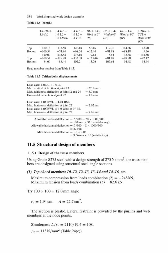
334 Workshop steelwork design example
Table 11.6 (contd.)
1.4 DL +1.6 DL
1.4 DL +1.6 LL +1.6 CRWL
1.4 DL +1.6 LL +1.4 TCL
DL + 1.4x
Wind at 0◦(IS)
DL + 1.4x
Wind at 0◦(IP)
DL + 1.4Wind at 90◦(IP)
1.2(DL +TCL +Wind at 0◦(IS)
Top −150.18 −132.58 −126.18 −56.16 119.76 −114.86 −43.20Bottom −100.54 −74.94 −68.54 −12.44 −81.88 −88.18 5.76
−120.00 −235.52 −236.16 −19.12 18.54 33.38 −112.56Top −100.54 −125.98 −132.38 −12.44@ −81.88 −88.88 −42.12Bottom 84.60 88.44 102.2 −5.76 107.64 94.48 14.64
Read member number from Table 11.5.
Table 11.7 Critical joint displacements
Load case: 1.0 DL + 1.0 LLMax. vertical deflection at joint 13 = 32.1 mmMax. horizontal deflection at joints 2 and 24 = 3.7 mmHorizontal deflection at joint 22 = 1.8 mm
Load case: 1.0 CRWL + 1.0 CRSLMax. horizontal deflection at joint 22 = 2.62 mmLoad case: 1.0 CRWL = 1.0 Wind at 0◦ I.S.Max. horizontal deflection at joint 22 = 7.86 mm
Allowable vertical deflection = L/200 = 20 × 1000/200= 100 mm > 32.1 (satisfactory).
Allowable horizontal deflection = L/300 − 8 × 1000/300= 27 mm
Max. horizontal deflection = 1.8 + 7.86= 9.66 mm < 16 (satisfactory).
11.5 Structural design of members
11.5.1 Design of the truss members
Using Grade S275 steel with a design strength of 275 N/mm2, the truss mem-bers are designed using structural steel angle sections.
(1) Top chord members 10–12, 12–13, 13–14 and 14–16, etc.
Maximum compression from loads combination (2) = −248 kN,Maximum tension from loads combination (5) = 82.6 kN.
Try 100 × 100 × 12.0 mm angle
rv = 1.94 cm, A = 22.7 cm2.
The section is plastic. Lateral restraint is provided by the purlins and webmembers at the node points.
Slenderness L/rv = 2110/19.4 = 108,
pc = 113 N/mm2 (Table 24(c)).
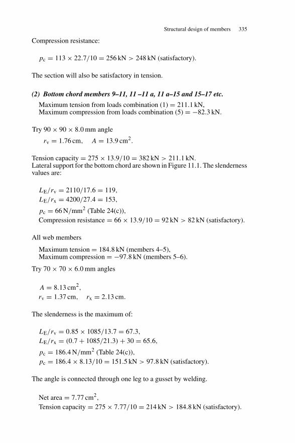
Structural design of members 335
Compression resistance:
pc = 113 × 22.7/10 = 256 kN > 248 kN (satisfactory).
The section will also be satisfactory in tension.
(2) Bottom chord members 9–11, 11 –11 a, 11 a–15 and 15–17 etc.
Maximum tension from loads combination (1) = 211.1 kN,Maximum compression from loads combination (5) = −82.3 kN.
Try 90 × 90 × 8.0 mm angle
rv = 1.76 cm, A = 13.9 cm2.
Tension capacity = 275 × 13.9/10 = 382 kN > 211.1 kN.Lateral support for the bottom chord are shown in Figure 11.1. The slendernessvalues are:
LE/rv = 2110/17.6 = 119,
LE/rx = 4200/27.4 = 153,
pc = 66 N/mm2 (Table 24(c)),Compression resistance = 66 × 13.9/10 = 92 kN > 82 kN (satisfactory).
All web members
Maximum tension = 184.8 kN (members 4–5),Maximum compression = −97.8 kN (members 5–6).
Try 70 × 70 × 6.0 mm angles
A = 8.13 cm2,
rv = 1.37 cm, rx = 2.13 cm.
The slenderness is the maximum of:
LE/rv = 0.85 × 1085/13.7 = 67.3,
LE/rx = (0.7 + 1085/21.3) + 30 = 65.6,
pc = 186.4 N/mm2 (Table 24(c)),pc = 186.4 × 8.13/10 = 151.5 kN > 97.8 kN (satisfactory).
The angle is connected through one leg to a gusset by welding.
Net area = 7.77 cm2,
Tension capacity = 275 × 7.77/10 = 214 kN > 184.8 kN (satisfactory).
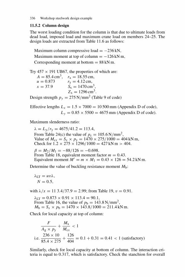
336 Workshop steelwork design example
11.5.2 Column design
The worst loading condition for the column is that due to ultimate loads fromdead load, imposed load and maximum crane load on members 24–25. Thedesign loads are extracted from Table 11.6 as follows:
Maximum column compressive load = −236 kN,
Maximum moment at top of column = −126 kN m,
Corresponding moment at bottom = 88 kN m.
Try 457 × 191 UB67, the properties of which are:A = 85.4 cm3, rx = 18.55 cm,u = 0.873 ry = 4.12 cm,x = 37.9 Sx = 1470 cm3,
Zx = 1296 cm3.Design strength py = 275 N/mm2 (Table 9 of code)
Effective lengths Lx = 1.5 × 7000 = 10 500 mm (Appendix D of code),Ly = 0.85 × 5500 = 4675 mm (Appendix D of code).
Maximum slenderness ratio:
λ = Ly/ry = 4675/41.2 = 113.4,From Table 24(c) the value of pc = 105.6 N/mm2,Value of Mcx = Sx × py = 1470 × 275/1000 = 404 kN m,Check for 1.2 × 275 × 1296/1000 = 427 kN m > 404.
β = M2/M1 = −88/126 = −0.698.From Table 18, equivalent moment factor m = 0.43.Equivalent moment M ′ = m × M1 = 0.43 × 126 = 54.2 kN m.
Determine the value of buckling resistance moment Mb:
λLT = uvλ,
N = 0.5,
with λ/x = 11 3.4/37.9 = 2.99; from Table 19, v = 0.91.
λLT = 0.873 × 0.91 × 113.4 = 90.1,From Table 16, the value of pb = 143.8 N/mm2,Mb = Sx × pb = 1470 × 143.8/1000 = 211.4 kN m.
Check for local capacity at top of column:
F
Ag × py+ Mx
Mcx< 1
i.e.236 × 10
85.4 × 275+ 126
404= 0.1 + 0.31 = 0.41 < 1 (satisfactory)
Similarly, check for local capacity at bottom of column. The interaction cri-teria is equal to 0.317, which is satisfactory. Check the stanchion for overall
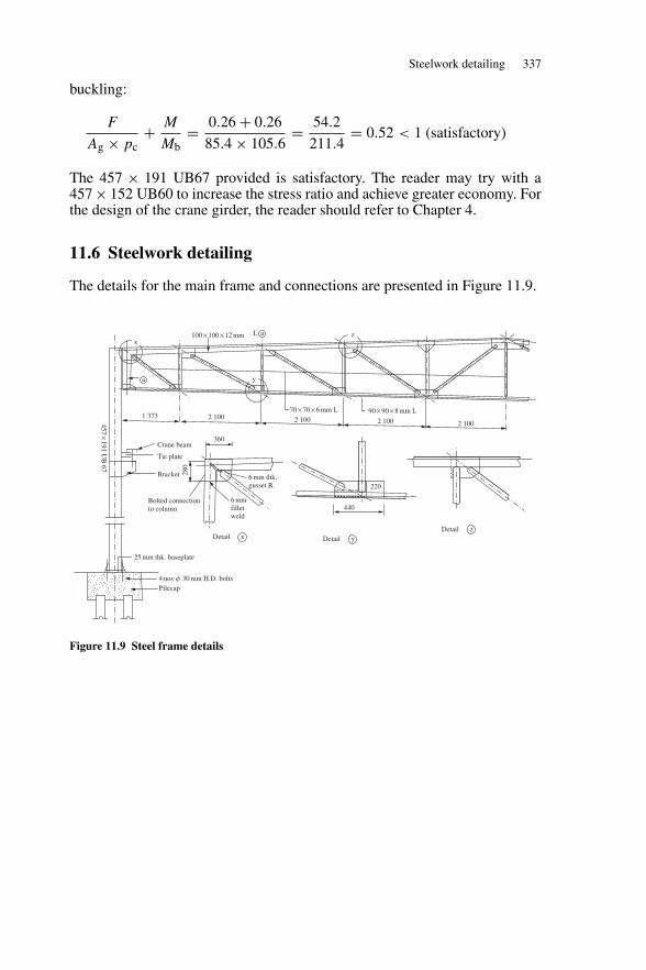
Steelwork detailing 337
buckling:
F
Ag × pc+ M
Mb= 0.26 + 0.26
85.4 × 105.6= 54.2
211.4= 0.52 < 1 (satisfactory)
The 457 × 191 UB67 provided is satisfactory. The reader may try with a457 × 152 UB60 to increase the stress ratio and achieve greater economy. Forthe design of the crane girder, the reader should refer to Chapter 4.
11.6 Steelwork detailing
The details for the main frame and connections are presented in Figure 11.9.
100 × 100 × 12 mm
70 × 70 × 6 mm L 90 × 90 × 8 mm L1 373
a
aL
2 100 2 100 2 100
220
440
25 mm thk. baseplate
4 nos � 30 mm H.D. bolts
Bolted connection to column
6 mmfilletweld
6 mm thk.gusset R.
360
280
457×191 U
B 67
Crane beam
Tie plate
Bracket
Pilecap
Detail z
2 100
Detail yDetail x
x
y
z
Figure 11.9 Steel frame details
12
Steelwork detailing
12.1 Drawings
Drawings are the means by which the requirements of architects and engineersare communicated to the fabricators and erectors, and must be presented in anacceptable way. Detailing is given for selected structural elements.
Drawings are needed to show the layout and to describe and specify therequirements of a building. They show the location, general arrangement anddetails for fabrication and erection. They are also used for estimating quantitiesand cost and for making material lists for ordering materials.
Sufficient information must be given on the designer’s sketches for thedraughtsman to make up the arrangement and detail drawings. A classificationof drawings is set out below:
Site or location plans. These show the location of the building in relation toother buildings, site boundaries, streets, roads, etc.
General arrangement. This consists of plans, elevations and sections to setout the function of the building. These show locations and leading dimen-sions for offices, rooms, work areas, machinery, cranes, doors, services,etc. Materials and finishes are specified.
Marking plans. These are the framing plans for the steel-frame buildingshowing the location and mark numbers for all steel members in the roof,floors and various elevations.
Foundation plans. These show the setting out for the column bases andholding-down bolts and should be read in conjunction with detail draw-ings of the foundations.
Sheeting plans. These show the arrangement of sheeting and cladding onbuilding.
Key plan. If the work is set out on various drawings, a key plan may beprovided to show the portion of work covered by the particular drawing.
Detail drawings. These show the details of structural members and give allinformation regarding materials, sizes, welding, drilling, etc. for fabric-ation. The mark number of the detail refers to the number on the mark-ing plan.
Detail drawings and marking plans will be dealt with here.
338
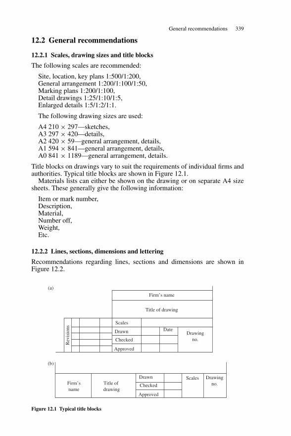
General recommendations 339
12.2 General recommendations
12.2.1 Scales, drawing sizes and title blocks
The following scales are recommended:
Site, location, key plans 1:500/1:200,General arrangement 1:200/1:100/1:50,Marking plans 1:200/1:100,Detail drawings 1:25/1:10/1:5,Enlarged details 1:5/1:2/1:1.
The following drawing sizes are used:
A4 210 × 297—sketches,A3 297 × 420—details,A2 420 × 59—general arrangement, details,A1 594 × 841—general arrangement, details,A0 841 × 1189—general arrangement, details.
Title blocks on drawings vary to suit the requirements of individual firms andauthorities. Typical title blocks are shown in Figure 12.1.
Materials lists can either be shown on the drawing or on separate A4 sizesheets. These generally give the following information:
Item or mark number,Description,Material,Number off,Weight,Etc.
12.2.2 Lines, sections, dimensions and lettering
Recommendations regarding lines, sections and dimensions are shown inFigure 12.2.
Firm’s name
Title of drawing
Scales
Scales
Drawn
Checked
DateDrawing
no.
Drawingno.
Approved
Drawn
Checked
Approved
Firm’sname
Title of drawing
Rev
isio
ns
(a)
(b)
Figure 12.1 Typical title blocks
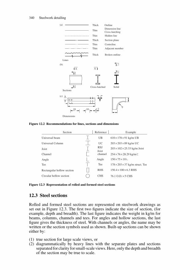
340 Steelwork detailing
Thick
Thick
Thick
Lines
A AB
B
B
B
Cross-hatchedSections
Dimensions
Solid
ThinDimension lineCross-hatching
Thin Hidden line
Section plane
Centreline
Adjacent member
Broken outline
Thin
Thin
Outline
18 10 2
(a)
(b)
(c)
Figure 12.2 Recommendations for lines, sections and dimensions
Section
Universal beam UB 610 × 178 × 91 kg/m UB
Universal Column
Joist
Channel
Angle
Tee
Rectangular hollow section
Circular hollow section
UCRSJJoistchannel
Angle
Tee
RHS
CHS
203 × 203 × 89 kg/m UC
203 × 102 × 25.33 kg/m Joist
254 × 76 × 28.29 kg/m
150 × 75 × 10
150.4 × 100 × 6.3 RHS
76.1 O.D. × 5 CHS
178 × 203 × 37 kg/m struct. Tee
Reference Example
Figure 12.3 Representation of rolled and formed steel sections
12.3 Steel sections
Rolled and formed steel sections are represented on steelwork drawings asset out in Figure 12.3. The first two figures indicate the size of section, (forexample, depth and breadth). The last figure indicates the weight in kg/m forbeams, columns, channels and tees. For angles and hollow sections, the lastfigure gives the thickness of steel. With channels or angles, the name may bewritten or the section symbols used as shown. Built-up sections can be showneither by:
(1) true section for large scale views, or(2) diagrammatically by heavy lines with the separate plates and sections
separated for clarity for small-scale views. Here, only the depth and breadthof the section may be true to scale.
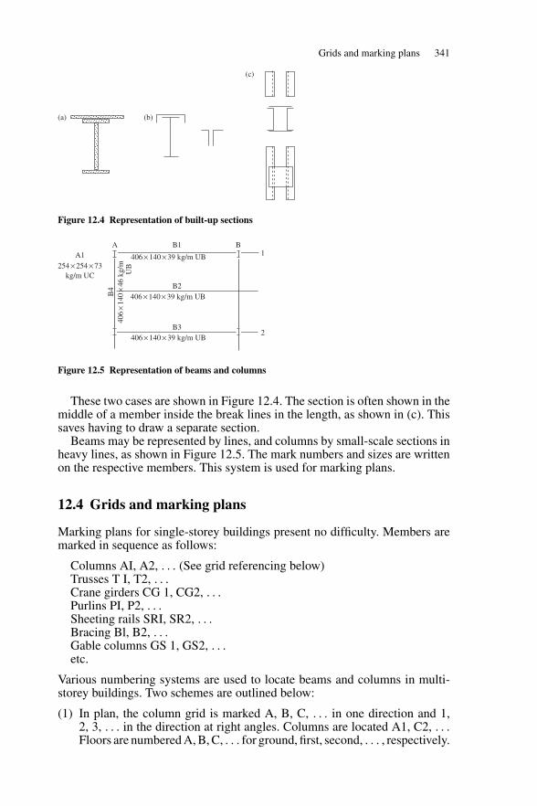
Grids and marking plans 341
(a) (b)
(c)
Figure 12.4 Representation of built-up sections
A B1 B
B2
2
1
B3
B4
406 × 140 × 39 kg/m UB
406 × 140 × 39 kg/m UB
406 × 140 × 39 kg/m UBA1254 × 254 × 73
kg/m UC
406
×14
0×
46 k
g/m
UB
Figure 12.5 Representation of beams and columns
These two cases are shown in Figure 12.4. The section is often shown in themiddle of a member inside the break lines in the length, as shown in (c). Thissaves having to draw a separate section.
Beams may be represented by lines, and columns by small-scale sections inheavy lines, as shown in Figure 12.5. The mark numbers and sizes are writtenon the respective members. This system is used for marking plans.
12.4 Grids and marking plans
Marking plans for single-storey buildings present no difficulty. Members aremarked in sequence as follows:
Columns AI, A2, . . . (See grid referencing below)Trusses T I, T2, . . .Crane girders CG 1, CG2, . . .Purlins PI, P2, . . .Sheeting rails SRI, SR2, . . .Bracing Bl, B2, . . .Gable columns GS 1, GS2, . . .etc.
Various numbering systems are used to locate beams and columns in multi-storey buildings. Two schemes are outlined below:
(1) In plan, the column grid is marked A, B, C, . . . in one direction and 1,2, 3, . . . in the direction at right angles. Columns are located A1, C2, . . .Floors are numbered A, B, C, . . . for ground, first, second, . . . , respectively.
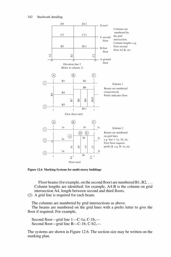
342 Steelwork detailing
B3
B7
B8
B9
B10
B1
B4
B5
B2Scheme 1
Beams are numberedconsecutivelyPrefix indicates floor
Scheme 2
Beams are numberedon grid linese.g. line 1–1a, 1b, etc.First floor requiresprefix B. e.g. B–1a, etc.
B6
B11
A
1
2
B C
I I I
III
a1
b1 d4 c4 c1
1a
2a
3a
b3 C3
1b 1c
2c
3c
4b
3b
A
D E1
2
4
3
B
First–floor steel
Floor steel
C
A2
B2
C2
D5
C5
B5
D11D-roof
Columns are numbered bythe gridintersection.Column lengths, e.g.First-secondfloor A2-B, etc.
C-second floor
B-first floor
A-ground floorElevation line 2
(Refer to scheme 1)
C11
B11
Figure 12.6 Marking Systems for multi-storey buildings
Floor beams (for example, on the second floor) are numbered B1, B2, . . .Column lengths are identified: for example, A4-B is the column on gridintersection A4, length between second and third floors.
(2) A grid line is required for each beam.
The columns are numbered by grid intersections as above.The beams are numbered on the grid lines with a prefix letter to give the
floor if required. For example,
Second floor—grid line 1—C-1a, C-1b,—Second floor—grid line B—C-1b, C-b2,—
The systems are shown in Figure 12.6. The section size may be written on themarking plan.
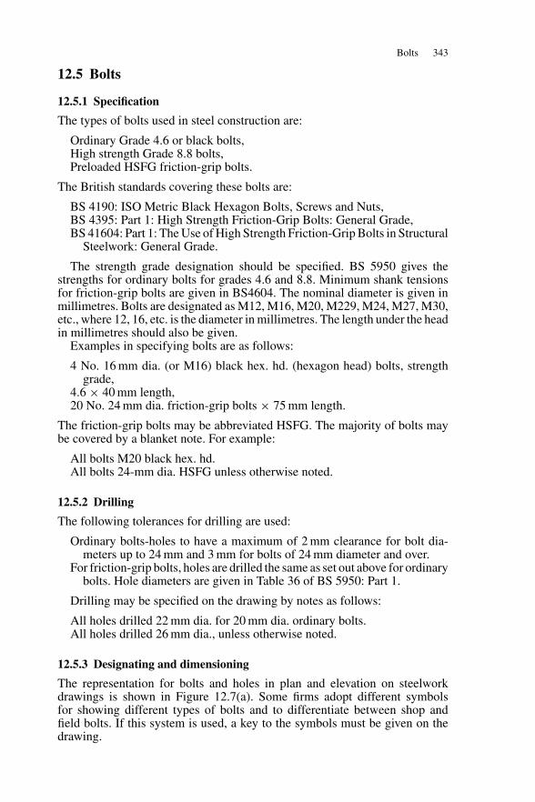
Bolts 343
12.5 Bolts
12.5.1 Specification
The types of bolts used in steel construction are:
Ordinary Grade 4.6 or black bolts,High strength Grade 8.8 bolts,Preloaded HSFG friction-grip bolts.
The British standards covering these bolts are:
BS 4190: ISO Metric Black Hexagon Bolts, Screws and Nuts,BS 4395: Part 1: High Strength Friction-Grip Bolts: General Grade,BS 41604: Part 1: The Use of High Strength Friction-Grip Bolts in Structural
Steelwork: General Grade.
The strength grade designation should be specified. BS 5950 gives thestrengths for ordinary bolts for grades 4.6 and 8.8. Minimum shank tensionsfor friction-grip bolts are given in BS4604. The nominal diameter is given inmillimetres. Bolts are designated as M12, M16, M20, M229, M24, M27, M30,etc., where 12, 16, etc. is the diameter in millimetres. The length under the headin millimetres should also be given.
Examples in specifying bolts are as follows:
4 No. 16 mm dia. (or M16) black hex. hd. (hexagon head) bolts, strengthgrade,
4.6 × 40 mm length,20 No. 24 mm dia. friction-grip bolts × 75 mm length.
The friction-grip bolts may be abbreviated HSFG. The majority of bolts maybe covered by a blanket note. For example:
All bolts M20 black hex. hd.All bolts 24-mm dia. HSFG unless otherwise noted.
12.5.2 Drilling
The following tolerances for drilling are used:
Ordinary bolts-holes to have a maximum of 2 mm clearance for bolt dia-meters up to 24 mm and 3 mm for bolts of 24 mm diameter and over.
For friction-grip bolts, holes are drilled the same as set out above for ordinarybolts. Hole diameters are given in Table 36 of BS 5950: Part 1.
Drilling may be specified on the drawing by notes as follows:
All holes drilled 22 mm dia. for 20 mm dia. ordinary bolts.All holes drilled 26 mm dia., unless otherwise noted.
12.5.3 Designating and dimensioning
The representation for bolts and holes in plan and elevation on steelworkdrawings is shown in Figure 12.7(a). Some firms adopt different symbolsfor showing different types of bolts and to differentiate between shop andfield bolts. If this system is used, a key to the symbols must be given on thedrawing.
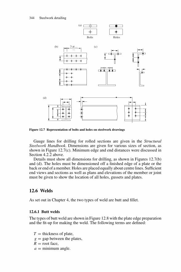
344 Steelwork detailing
Bolts
(b) (c)
(d)
Holes
(a)
3 at ......
Figure 12.7 Representation of bolts and holes on steelwork drawings
Gauge lines for drilling for rolled sections are given in the StructuralSteelwork Handbook. Dimensions are given for various sizes of section, asshown in Figure 12.7(c). Minimum edge and end distances were discussed inSection 4.2.2 above.
Details must show all dimensions for drilling, as shown in Figures 12.7(b)and (d). The holes must be dimensioned off a finished edge of a plate or theback or end of a member. Holes are placed equally about centre lines. Sufficientend views and sections as well as plans and elevations of the member or jointmust be given to show the location of all holes, gussets and plates.
12.6 Welds
As set out in Chapter 4, the two types of weld are butt and fillet.
12.6.1 Butt welds
The types of butt weld are shown in Figure 12.8 with the plate edge preparationand the fit-up for making the weld. The following terms are defined:
T = thickness of plate,g = gap between the plates,R = root face,a = minimum angle.
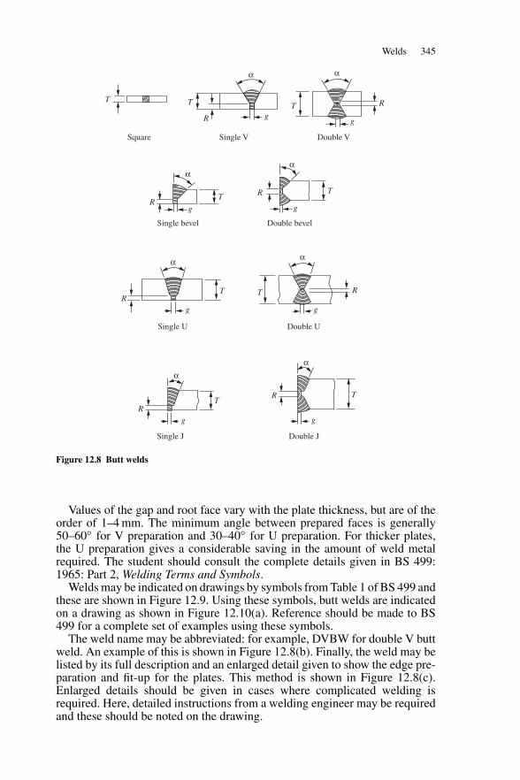
Welds 345
Square
Single bevel
Single U
Single J Double J
Double U
Double bevel
Single V
R
RR
R
R
R
R
RT
TT
TT
TT
TT
αα
αα
αα
αα
g
g
g
gg
g
g
g
Double V
Figure 12.8 Butt welds
Values of the gap and root face vary with the plate thickness, but are of theorder of 1–4 mm. The minimum angle between prepared faces is generally50–60◦ for V preparation and 30–40◦ for U preparation. For thicker plates,the U preparation gives a considerable saving in the amount of weld metalrequired. The student should consult the complete details given in BS 499:1965: Part 2, Welding Terms and Symbols.
Welds may be indicated on drawings by symbols from Table 1 of BS 499 andthese are shown in Figure 12.9. Using these symbols, butt welds are indicatedon a drawing as shown in Figure 12.10(a). Reference should be made to BS499 for a complete set of examples using these symbols.
The weld name may be abbreviated: for example, DVBW for double V buttweld. An example of this is shown in Figure 12.8(b). Finally, the weld may belisted by its full description and an enlarged detail given to show the edge pre-paration and fit-up for the plates. This method is shown in Figure 12.8(c).Enlarged details should be given in cases where complicated welding isrequired. Here, detailed instructions from a welding engineer may be requiredand these should be noted on the drawing.
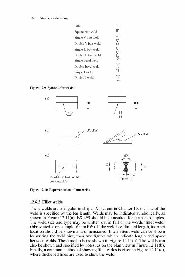
346 Steelwork detailing
Fillet
Square butt weld
Single V butt weld
Single U butt weld
Single bevel weld
Single J weld
Double V butt weld
Double U butt weld
Double bevel weld
Double J weld
Figure 12.9 Symbols for welds
(a)
(b)
(c)
DVBWSVBW
30
Double V butt weldsee detail A
2
60°
2Detail A
Figure 12.10 Representation of butt welds
12.6.2 Fillet welds
These welds are triangular in shape. As set out in Chapter 10, the size of theweld is specified by the leg length. Welds may be indicated symbolically, asshown in Figure 12.11(a). BS 499 should be consulted for further examples.The weld size and type may be written out in full or the words ‘fillet weld’abbreviated, (for example, 6 mm FW). If the weld is of limited length, its exactlocation should be shown and dimensioned. Intermittent weld can be shownby writing the weld size, then two figures which indicate length and spacebetween welds. These methods are shown in Figure 12.11(b). The welds canalso be shown and specified by notes, as on the plan view in Figure 12.11(b).Finally, a common method of showing fillet welds is given in Figure 12.11(c),where thickened lines are used to show the weld.
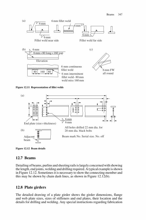
Beams 347
6 mm FWall round
6 mm continuousfillet weld6 mm intermittentfillet weld - 80 mm weld miss 160 mm
Elevation
6 mm
(a)
(b) (c)
6 mmFillet weld near side Fillet weld far side
6 mm fillet weld6 mm
6 mm
6 mm
6 mm × 80 long × 160 gap
80 160 80
Figure 12.11 Representation of fillet welds
End plate (size × thickness)
Adjacentbeam
6 mm6 mm
All holes drilled 22 mm dia. for20 mm dia. black bolts
Beam mark No. Serial size. No. off
(a)
(b)
Figure 12.12 Beam details
12.7 Beams
Detailing of beams, purlins and sheeting rails is largely concerned with showingthe length, end joints, welding and drilling required. A typical example is shownin Figure 12.12. Sometimes it is necessary to show the connecting member andthis may be shown by chain dash lines, as shown in Figure 12.12(b).
12.8 Plate girders
The detailed drawing of a plate girder shows the girder dimensions, flangeand web plate sizes, sizes of stiffeners and end plates, their location and thedetails for drilling and welding. Any special instructions regarding fabrication
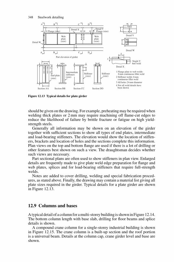
348 Steelwork detailing
A B C D
A B
End plate(size)
Section AA Section BB Section CC Section DD
Part elevation of girder
C D
Detail W
Flange (size)
Webplate(size)
Webplate(size)
Detail X Detail V
Detail V
1 Flange plate to web welds- 8 mm continuous fillet weld2 Stiffener welds–6 mm continuous fillet weld3 All holes 24 mm diameter4 Not all weld details have been shown
Stiffener(size)
Stiffener(size)
Intermediatestiffeners(size)
Single Vbutt weld
5
1
Flange (size)
Detail W
Detail X
Figure 12.13 Typical details for plate girder
should be given on the drawing. For example, preheating may be required whenwelding thick plates or 2 mm may require machining off flame-cut edges toreduce the likelihood of failure by brittle fracture or fatigue on high yield-strength steels.
Generally all information may be shown on an elevation of the girdertogether with sufficient sections to show all types of end plates, intermediateand load-bearing stiffeners. The elevation would show the location of stiffen-ers, brackets and location of holes and the sections complete this information.Plan views on the top and bottom flange are used if there is a lot of drilling orother features best shown on such a view. The draughtsman decides whethersuch views are necessary.
Part sectional plans are often used to show stiffeners in plan view. Enlargeddetails are frequently made to give plate weld edge preparation for flange andweb plates, splices and for load-bearing stiffeners that require full-strengthwelds.
Notes are added to cover drilling, welding and special fabrication proced-ures, as stated above. Finally, the drawing may contain a material list giving allplate sizes required in the girder. Typical details for a plate girder are shownin Figure 12.13.
12.9 Columns and bases
A typical detail of a column for a multi-storey building is shown in Figure 12.14.The bottom column length with base slab, drilling for floor beams and splicedetails is shown.
A compound crane column for a single-storey industrial building is shownin Figure 12.15. The crane column is a built-up section and the roof portionis a universal beam. Details at the column cap, crane girder level and base areshown.
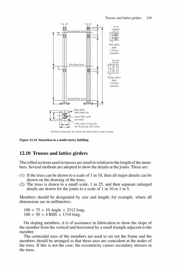
Trusses and lattice girders 349
First-floor level
Ground-floor level
Base-plate600 × 600 × 50
8 mm fillet weldall round
4 No. holes 32 mm dia.for 30 mm dia. H.D. bolts
All holes 22 mm dia. for 20 mm dia. black bolts except as noted
Second-floor level
Web spliceplate
2 off perstanchion
Flange spliceplate
2-off perstanction
Figure 12.14 Stanchion in a multi-storey building
12.10 Trusses and lattice girders
The rolled sections used in trusses are small in relation to the length of the mem-bers. Several methods are adopted to show the details at the joints. These are:
(1) If the truss can be drawn to a scale of 1 in 10, then all major details can beshown on the drawing of the truss.
(2) The truss is drawn to a small scale, 1 in 25, and then separate enlargeddetails are drawn for the joints to a scale of 1 in 10 or 1 in 5.
Members should be designated by size and length; for example, where alldimensions are in millimetres:
100 × 75 × 10 Angle × 2312 long,100 × 50 × 4 RHS × 1310 long.
On sloping members, it is of assistance in fabrication to show the slope ofthe member from the vertical and horizontal by a small triangle adjacent to themember.
The centroidal axes of the members are used to set out the frame and themembers should be arranged so that these axes are coincident at the nodes ofthe truss. If this is not the case, the eccentricity causes secondary stresses inthe truss.
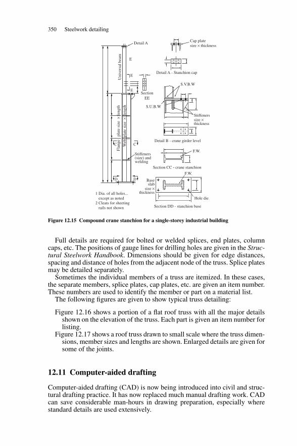
350 Steelwork detailing
Detail A
E
E
E
Detail A - Stanchion cap
Cap platesize × thickness
S.V.B.W
S.U.B.W
Stiffenerssize ×thickness
Stiffeners (size) andwelding
Flan
ge
plat
e si
ze×
leng
th
Web
pla
te s
ize
× l
engt
h
CC
D Baseslab
size ×thickness
F.W.
F.W.
Hole die
Section DD - stanchion base
1 Dia. of all holes... except as noted2 Cleats for sheeting rails not shown
D
Detail B - crane girder level
Section CC - crane stanchion
SectionEE
Uni
vers
al b
eam
Figure 12.15 Compound crane stanchion for a single-storey industrial building
Full details are required for bolted or welded splices, end plates, columncaps, etc. The positions of gauge lines for drilling holes are given in the Struc-tural Steelwork Handbook. Dimensions should be given for edge distances,spacing and distance of holes from the adjacent node of the truss. Splice platesmay be detailed separately.
Sometimes the individual members of a truss are itemized. In these cases,the separate members, splice plates, cap plates, etc. are given an item number.These numbers are used to identify the member or part on a material list.
The following figures are given to show typical truss detailing:
Figure 12.16 shows a portion of a flat roof truss with all the major detailsshown on the elevation of the truss. Each part is given an item number forlisting.
Figure 12.17 shows a roof truss drawn to small scale where the truss dimen-sions, member sizes and lengths are shown. Enlarged details are given forsome of the joints.
12.11 Computer-aided drafting
Computer-aided drafting (CAD) is now being introduced into civil and struc-tural drafting practice. It has now replaced much manual drafting work. CADcan save considerable man-hours in drawing preparation, especially wherestandard details are used extensively.
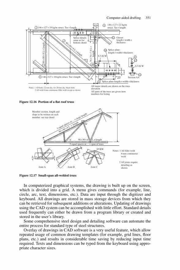
Computer-aided drafting 351
1
3
6
10
6
12
11Section AA
Splice plate-length × width × thickness
All major details are shown on the trusselevationAll parts of the truss are given itemnumbers for listing
11
AA
12
146 × 127 × 19 kg/m struct. Tee × length
146 × 127 × 16 kg/m struct. Tee × length5
Notes: 1 All holes 22 mm dia. for 20 mm dia. black bolts 2 All weld 6 mm continuous fillet weld except as shown
146 × 127 × 22 kg/mstruct. Tee × length
Splice detailssame as forbottom chord
S.V.B.W
S.V.B.W
Splice plate-length × width × thickness
Gussetlength × width ×thickness80×80× 8 L× length
4
76×
76×
7.8
L×
leng
th
80×
80×
8 L
× le
ngth
7
Figure 12.16 Portion of a flat roof truss
SVBW
Joint A Joint B Joint C
Member section, length andslope to be written on eachmember. see top chord
Notes: 1 All fillet weld 6 mm continuous weld
2 All joints require detailing as shown
3 equal spaces at…
= slope length
90 × 90 × 8 L × length
90 × 90 × 6 L = length
5 equal spaces at… = span of truss
‘C’
‘B’
‘A’
Figure 12.17 Small-span all-welded truss
In computerized graphical systems, the drawing is built up on the screen,which is divided into a grid. A menu gives commands (for example, line,circle, arc, text, dimensions, etc.). Data are input through the digitizer andkeyboard. All drawings are stored in mass storage devices from which theycan be retrieved for subsequent additions or alterations. Updating of drawingsusing the CAD system can be accomplished with little effort. Standard detailsused frequently can either be drawn from a program library or created andstored in the user’s library.
Some comprehensive steel design and detailing software can automate theentire process for standard type of steel structures.
Overlay of drawings in CAD software is a very useful feature, which allowrepeated usage of common drawing templates (for example, grid lines, floorplans, etc.) and results in considerable time saving by reducing input timerequired. Texts and dimensions can be typed from the keyboard using appro-priate character sizes.
References
1 richards, k.g., Fatigue Strength of Welded Structures, The Welding Institute, Cambridge, 19692 boyd, g.m., Brittle Fracture in Steel Structures, Butterworths, London, 19703 Building Regulations and Associated Approved Documents B, HMSO, London, 20004 Fire Protection of Structural Steel in building (Third Edition), ASFPCM, 20025 case, j. and chiler, a.h., Strength of Materials, Edward Arnold, London, 19646 trahair, n.s., bradford, m.a. and nethercot, d.a., The Behaviour and Design of Steel Structures
to BS5950, Spon Press, 20017 nethercot, d.a. and lawson, r.m., Lateral Stability of Steel Beams and Columns – Common
Cases of Restraint, Steel Construction Institute, 19928 horne, m.r., Plastic Theory of Structures, Pergamon Press, Oxford, 19799 Steel Designers Manual, Steel Construction Institute and Blackwell Science, 2003
10 ghali, a. and neville, a.m., Structural Analysis, Chapman and Hall, London, 198911 Joints in Steel Construction: Simple Connections, SCI & BCSA, 200212 ward buildings components, Multibeam Products, Ward Buildings Components Ltd, 200213 timoshenko, s.p. and gere, j.m., Theory of Elastic Stability, McGraw-Hill, New York, 196114 porter, d.m., rockey, k.c. and evans, h.r., The Collapse Behaviour of Plate Girders Loaded in
Shear, The Structural Engineer, August 197515 pratt, j.l., Introduction to the Welding of Structural Steelwork, Steel Construction Institute, 198916 holmes, m. and martin, l.h., Analysis and Design of Structural Connections—Reinforced Con-
crete and Steel, Ellis Horwood, London, 198317 salmon, c.g. et al., Laboratory Investigation on Unstiffened Triangular Bracket Plates, ASCE
Structural Division, April 196418 horne, m.r. and morris, l.j., Plastic Design of Low Rise Frames, Collins, London, 198119 coates, r.c., coutie, m.g. and kong, f.k., Structural Analysis, Spon E & FN, 199820 southcombe, c., Design of Structural Steelwork: Lattice Framed Industrial Buildings, Steel Con-
struction Institute, 1993
Index
Acid pickling, 18Angles
equal and unequal, 19purlin, 30, 79–80, 84sheeting rails, 85
design of, 86–7, 89–90tension members, 140
Angle struts, limiting proportions, 215AutoCAD, 7Axial compression, behaviour of members in
149
Base platesdesign, 204–5thickness, 205, 207
BCSA publication Manual on Connections,46–7
Beam columns, 165–73behaviour classification, 165buckling check 169–70, 172–3buckling resistance, 171design, example of, 171–3code design procedure, 170–1failure of slender columns, 168general behaviour, 165local capacity check, 170moment capacity, 166short column check, 166
Beam connections, 42–7bearing resistance of beam webs, 42–4buckling resistance of beam webs, 44–6end shear connections, 46–7
Beam designexamples of, 47–56subjected to bending about two axes, 54–6with unrestrained compression flange,
52–4Beams, 24, 28, 34
bending stresses and moment capacity,28–33
classification of cross-sections, 26–7deflection limits for, 42elastic theory, 28–30lateral torsional buckling, 34–40loads, 25–6non-uniform, 25
plastic theory, 30–3types and uses, 24–5
Bearingresistance of beam webs, 42–4stiffeners, 107–9, 117–18, 124web buckling and, 68, 76
Bendingasymmetrical sections, 29biaxial bending, 29
in elastic theory, 29in lateral torsional buckling, 39plastic theory, 33
edge plate, 100stresses and moment capacity for beams,
28–33uniaxial bending
elastic theory, 28–9plastic theory, 30–3
Blast cleaning, 18Bolted joints,
in direct shear, 287–91and tension, 292–5and torsion, 290–2
direct tensions, 291–2Bolts, 284, 342
non-preloaded, 284–300eccentric connections, 291examples of, 296general considerations, 301–2types of, 284
preloaded, 301–6design procedure, 302–3examples of, 304–7
specification, 342–3Box girder, 94Bracing, 233–43
general considerations, 233–4members, design of, 234for multi-storey building, 234
example, 240–3for single-storey industrial buildings, 234
example, 235–40Buckling
beam check 169–70overall, 172–3
353
354 Index
Buckling (continued)lateral torsional
biaxial bending, 39code design procedure, 37–9general considerations, 34–5lateral restraints and effective length,
35–7resistance of beam webs, 44–6resistance moment, 23, 37, 39–40, 53, 55,
65, 67, 71, 170–1, 173, 175, 180,182, 188, 193, 197, 203, 217–18,228, 252, 257–9, 269
shear, 104web, 68, 76
BS 2573: Rules for Design of Cranes, 64BS 499: 1965: Part 2, Welding Terms and
Symbols, 345BS 5950: The Structural Use of Steelwork in
Building; Part 1—Code of Practice forDesign, 6, 39, 101–12, 148, 155, 164,202, 205, 213, 292, 296, 309, 332
depth/thickness ratios for webs, 27design
classification of girder cross-sections,101
end-post design, 109flange to web welds, 111growth, 101intermediate transverse web stiffeners,
105–7load carrying and bearing stiffeners,
107–9moment capacity, 101–3optimum depth, 103–4shear buckling resistance of thin webs,
104stiffener design, 105
Guide 156, 168, 379BS 5950: Part 5, Code of Practice for Design
of Cold Formed Sections, 81BS 6399-1: 1996 Part 1, Code of Practice for
Dead and Imposed Loads, 6BS 6399-2: 1997 Part 2, Code of Practice for
Wind Loads, 6, 327BS 6399-3: 1998 Part 1, Code of Practice for
Imposed Roof Loads, 6BS EN ISO14713: 1999—Protection against
Corrosion of Iron and Steel inStructures, Zinc and AluminiumCoatings, 18
Building regulations, 11–12, 17Buildings
columns in 145–6corner in, 175–82eccentrically loaded, 173–82
common types of steel buildings, 2
design methods for, 13–14factory, 3industrial, design of, 220–33multi-storey 2,
bracing for 234office, floor beams for, 47–52single-storey industrial building, 349
bracing for, 234side column for, 184–93
steel frame, 1Built-up columns
cross-section classification, 21design, 21example, 21
Cap plates, 348Cased columns
buckling resistance, 182–3capacity check, 182–3compression resistance, 163example, 164, 182–3subjected to axial load and moment, 182–4
Charpy impact test, 17Code design procedure
cased columns subjected to axial load andmoment, 182–4
conservative approach for equal flangedrolled sections, 39
general procedure, 37–9Code of Practice for Design, 6, 39, 101–12,
148, 155, 164, 202, 205, 213, 292, 296,309, 332
classification of girder cross-sections, 101of cold formed sections, 81for dead and imposed loads, 6depth/thickness ratios for webs, 27end-post design, 109flange to web welds, 111growth, 101hot rolled section, 22for imposed roof loads, 6intermediate transverse web stiffeners,
105–7load carrying and bearing stiffeners, 107–9moment capacity, 101–3optimum depth, 103–4shear buckling resistance of thin
webs, 104steel design, 8stiffener design, 105weldable structural steel, 15for wind loads, 6, 326
Column bases, 204–8gusseted, 204pocket 204slab 204
Index 355
Columnsbeam, 165–73built-up, 161–2construction details, 145–6card, 164–5design, 336–7eccentrically loaded, 173–82moments in simple construction, 174tests and design strengths, 152
universal, 157–61Compound beams, 56–62
buckling and bearing, 58, 61curtailment of flange plates, 57design of, 57–8
considerations, 56–8eccentrically loaded,flange plates to universal beam welds, 58moment capacity, 56section classification, 56in shear, buckling and bearing, 61–2web, 58
Compound crane stanchion for single-storeyindustrial building, 349
Compression members, 144, 154, 174, 182cased columns subjected to axial load and
moment, code design requirements,182–4
classification of cross-sections, 148column bases, 204–8
type and loads, 204crane columns, 197
design procedure, 197eccentrically loaded columns in buildings,
173–82moments in columns of simple
construction, 174–5example, corner column in a building,
175–82general behaviour, 148, 165–70loads on, 146–7side column for single-storey industrial
building, 184–93types and uses, 144–6
Compression members, axially loaded,148–65
basic strut theory, 149–52built-up column design, 161cased columns design, 162–4code definitions and rules, 155column design, 156compression resistance, 156cross-section classification, 148effective length, 154–6examples
built-up column, 161–2
card column, 164–5universal column, 157–61
loads, 146–8practical strut behaviour and design
strength, 152–4slenderness, 156sections, 144–5types and uses, 144–6
Compression members, beam columns,165–73
code design procedure, 170–1column base
axially loaded slab base, 205–8design strengths, 204–5types and loads, 204
crane column, 194–204example of design of, 198–204
design, example of, 171–3Compressive strength, 153–4Computer programs for matrix stability
analysis, 249Computer-aided drafting, (CAD), 349Connections,
beam to column, 46bracket, 51–2, 58, 62, 68, 112, 194, 197–8,
293–4design consideration in load paths and
forces, 318–19eccentric, 311–12friction-grip bolts, 342–3non-preloaded bolts, 284–300other design checks, 319–21preloaded bolts, 301–6types, 218, 284typical, 284–5welded joints, 219
ConstantPerry, 151–3Robertson, 153
Corner columns, design example, 175Crane
data, 63, 327loads for steel workshop, 329surge, 197surge loads, 201, 331wheel loads, 64, 68–9, 195–8, 200, 202,
204, 331Crane beams, 62–77
biaxial bending check, 67buckling resistance moment, 65deflection, 68–9design of, 65–8, 69–77elastic properties, 72loads, 64, 329maximum wheel loads, 331plastic properties, 65, 72
356 Index
Crane beams (continued)shear capacity, 68, 75types and uses, 62–3
Crane columnsframe action and analysis, 194–7loading, 194types, 194
Deflectionof beams, 42at column cap, 188, 193, 195of crane beams, 68–9of crane columns, 197limits, 12portals, 281serviceability limit state deflection, 12of trusses, 214
Designcalculations and computing, 6and construction, portal type and
structural action, 246continuous, 14drawing, 128limit state, 4–5, 8methods, 4–6
for buildings, 13–14of plate girder, 112–20preliminary, 325semi-continuous, 14simple, 14strength of materials, 13structural, 334of tension members, 139–41utilizing tension field action, 123, 125–8of web, 115–16
Design considerationsbrittle fracture, 8–9corrosion protection, 15, 18fatigue, 9fire protection, 17–18
Detailing of structural steelwork, 7, 338beams, 346bolts, 342
specification, 342–3columns and bases, 347computer-aided drafting, (CAD), 349–50designating and dimensioning, 343drawings, 338drilling, 343general recommendations, 339
lines, sections, dimensions andlettering, 339
grids and marking plans, 341–2plate girders, 346–7steel sections, 340
trusses and lattice girders, 348–9welds, 344–6
Direct tension, 134Drawings
classification, 338general recommendations, 339
Dynamic loads, 10
Eccentrically loaded columns in buildings,173–82
Edge bending plates, 100Effective lengths
for beams, 36–7for cased columns, 163code definitions and rules, 155for columns, 168, 172–3, 179, 187for compression chords, 216for crane columns, 197lateral restraints and, 35–7of portal members, 249table for beams, 37
Elastic designcode provision, 248portal analysis, 248rafter design, 252
Elastic theoryasymmetrical sections, 29for beams, 28–30
biaxial bending, 29uniaxial bending, 28–9
End connections, 132–3End-post design, 110Equivalent slenderness, 53, 55, 74, 175, 252,
257, 259Equivalent uniform moment, 37–8, 40, 65,
171, 173, 182, 269Euler stress, 150–1Experimental verification, 14
Factored loads, 9for ultimate limit states, 10
Factory building, 3Fire Safety authority, 17Floor beams for office building, 47–52Fraser’s formula, 249–50, 257Friction grip bolts
action in, 301types of, 301see also preloaded bolts
Girder cross-section, classification, 101
Hog-back (fish-belly) girders, 95Holding down bolts
design strength, 205, 207, 246tension in bolts, example, 204
Index 357
Hollow sections, circular, square andrectangular, 19
Imposed loads, 9Index
monosymmetry, 67torsional, 38
In-plane stability, sway-check method, 264–5
Joints in portalseaves, 271–3ridge, 273
Lateral torsional buckling, 35, 39biaxial bending, 39code design procedure, 37–9general considerations, 34–5lateral restraints and effective length, 35–7
Lattice girders, 210Limit states
design principles, 8serviceability, 9for steel design, 8ultimate, 9
Load factors, 10–11, 64, 69, 71, 158, 176,197, 254, 296
Loadsanalysis, 275–6application on trusses, 212dead, 9, 185, 210, 275–6dynamic, 10factored, 10imposed, 9, 185, 211, 275–6notional horizontal, 248serviceability, 12wind, 10, 85, 185, 211, 275–6working, 9, 17
Materials, 15–16brittle fracture, 17compound sections, 20corrosion protection, 18design considerations, 15fatigue, 16fire protection, 17properties, tolerances and dimensions of
various sections, 20section properties, 21–3steel sections, 18–21structural steel properties, 15
Metallic coatings, 18Modulus
of elasticity, 13of section in plastic analysis, 23of shear, 13
Nuts, 284
Painting, 18Pinned base portal, 253
plastic analysis for, 260Plans
foundation, 338key, 338marking, 338sheeting, 338site or locations, 338
Plastic analysisof beams, 30–3design code provisions, 259–64moduli of section, 23moment diagram, 261tension and moment about two axes, 139
Plastic theoryof beams
biaxial bending, 33uniaxial bending, 30–3
unsymmetrical sections, 33Plate girders, 94, 120
behaviour of, 97, 99post-buckling strength of plates, 99–101
connections and splices, 97elastic buckling of plates, 97–8loads, 96stresses, 97types of stiffeners used in, 105uses and construction, 94–5
Plate girders, designconsiderations, 94–7
depth and breadth of flange, 95variation in girder sections, 95–6
drawing, 120flange to web weld, 120utilizing tension field action, 120–8web design of, 120
Pocket bases, 204–5Portal frame design
analysis, example of dead and imposedload, 273–4
and construction, 246–8examples, 273–82of joints, 271–3outline, 248plastic design, 259–64of rafter restraints and stability, 266–70,
278–80at haunch, 269near ridge, 269
second-order analysis, 266Portal frames, 246, 248
amplified moments method, 266column design, 251–2
358 Index
Portal frames (continued)column stability, 267–9construction, 246–7effective lengths, 249–51elastic design, 248–59foundations, 248in-plane stability, 264–6plastic analysis
haunches and non-uniform frame,262–4
uniform frame members, 260–2serviceability check for eaves deflection,
270Protective coatings, types of, 18Purlins, 77–84, 210
angle, for sloping roof, 79cold-rolled, 81design to BS5950-1:2000, 79–81design examples, 82–4for flat roof, 79loading, 78for sloping roof, 79in steel workshop, 341, 346types and uses, 77–84
Quality steels, 17
Rolled and welded sections, 6Roof
bracings, 238, 240flat, 78loadings, 78materials and constructions, 78purlins, 77–80
Roof trussanalysis, 222–5for industrial building, design of, 220–33
specification, 220–1loads, 222
Serviceability limit state deflection, 12Shear
buckling resistance and web design, 104plates in, 100reduced moment capacity, 42stresses, 42web area, 41
Shear in beams, 40–2elastic theory, 40plastic theory, 41–2
Sheeting rails, 85–90arrangement, 85cold-formed, 87design
of angle, 86examples, 87–90
loading, 85types of uses, 85
Side columnsarrangement and loading, 184–6column design procedure, 186–8example, design of, 188–94local capacity check, 188overall buckling check, 188for single-storey industrial building
184–88Slab base, 204Slenderness
axially loaded beam column, 156factor, 38, 67factors modifying, 65limiting, 168modified, 67ratio, 67, 108, 150, 215–17, 251, 278, 336unstiffened web, 45
Splice plates, 348Stability
limit states, 11for portals, 264–6
Steel buildings, common types of, 2Steel frame buildings, 1Steel sections, 340
asymmetrical, 29–31built-up sections, 21classification for, 18–21cold-rolled open sections, 21rolled and formed sections, 18–20stress-strain diagrams, 16unsymmetrical, 33
Steel structures, 1Steelwork Design Guide to BS 5950, 22–3,
138Steelwork, detailing, 338
beams, 346bolts, 342
specification, 342–3columns and bases, 347computer-aided drafting, (CAD), 349–50designating and dimensioning, 343drawings, 338drilling, 343general recommendations, 339
lines, sections, dimensions andlettering, 339
grids and marking plans, 341–2plate girders, 346–7steel sections, 340trusses and lattice girders, 348–9welds, 344–6
Stiffenersarrangement, 115bearing resistance of, 108
Index 359
buckling resistance of, 105design, 105, 107intermediate transverse web, 105–7load carrying and bearing, 107–9end-post design, 109–11
single, 110twin, 110–11
minimum stiffness 106spacing, 104web check between, 109
Strengthcompressive, 152factor, 13of material for design, 13for steel in design, 13
Stressesbeams bending, 28–33plate girder, 97reduction factor, 108residual, 152, 168shear, 40–2tension and moment, 134
Structural design, 4Structural elements, 1Structural integrity, 11Structural Steelwork Handbook, 65Struts
angle, limiting proportions, 215basic theory in axially loaded compression
members, 149–52eccentrically loaded, 151Euler load, 149with initial curvature, 150, 153practical behaviour and design strength,
152–4Sway, 11
resistance, 11
Tees, structural, 19Tension field action
design utilizing 123, 125, 128end-post, 125–8plate girders, 120–8stiffeners, 123–4for web under shear, 120
Tension members, 131axially loaded, 139design examples, 141–3end connections, 132–3hanger supporting floor beams, 142–3with moments, 140simple, 140structural behaviour of, 134uses, types and design considerations,
131–2Tension and moment
elastic analysis, 134–5plastic analysis, 135–9
Ties,effective area, 217
Torsion joint, 312–13Torsional constant, 23Torsional index, 23Torsional restraint, 35, 91, 251Trusses
analysis of, 212–14eccentricity at connections, 213rigid-jointed trusses, 213
and bracing, 210chord subjected to axial load and moment,
217–18connections, 218–20
joint design, 218–20types, 218
dead and imposed loads, 222deflection of, 214for industrial building, 220–34loads, 210–12
applied at nodes of, 212not applied at nodes of, 212
members, design of, 214–15, 225–33members subject to reversal of load, 217redundant and cross-braced, 214statically determinate, 212struts, 215–17types and uses, 210
Universal beam web, 58Universal beams, 18Universal columns, 18
von Mises’ criterion, 42
Washers, 284Web
bearing resistance, 42buckling and bearing, 68, 76buckling resistance, 44
Welded connections, 307–18bracket connection, 314–15design of butt welds, 310–11design of fillet welds, 309–10eccentric connections, 312examples on, 315–18torsion joint with load in plane of weld,
312–13Welding
automatic arc, 307electric arc, 307manual arc, 307
360 Index
Weldsbutt, 344–5cracks and defects in, 307–9design, 309–11design strength, 309–11fillet, 309–10, 345–6sizes, 128symbols, 345testing, 307–9type of, 307–9
Wind loads, 10, 25, 85–6, 147, 185, 188,197, 200, 229, 254, 275, 330
analysis, 225data, 236–7force coefficient, 189, 242on roof truss, 210–11, 222on steel frame, 327
Wind pressurecoefficients, 189–90dynamic, 330on roof and walls, 189
Working loads, 9Workshop steelwork
computer analysis, results of, 330–4structural design of members, 334–7
design of the truss members, 334–6Workshop steel work example, 325,
327basic design loads, 325–7computer analysis data, 327–30
crane loads, 329roof truss, dead and imposed
loads, 328structural geometry and properties,
327–8wind loads on to the structure, 330
steelwork detailing, 337structural design of members, 336
column design, 336–7
Young’s modulus, 251
kmkosipil.blogspot.com
Related Documents


![Untitled-1 [] · 2018. 11. 6. · SANS 10162 — Structural Steelwork SANS 10162 Part 2 — Limit States design of Cold Formed Structural Steelwork SANS 14713 — Protection against](https://static.cupdf.com/doc/110x72/60bfca9edf84f3163d3d55fb/untitled-1-2018-11-6-sans-10162-a-structural-steelwork-sans-10162-part.jpg)