EAD 200005-00-0103 December 2014 STRUCTURAL STEEL PILES WITH HOLLOW SECTIONS AND RIGID SPLICES ©2015

Welcome message from author
This document is posted to help you gain knowledge. Please leave a comment to let me know what you think about it! Share it to your friends and learn new things together.
Transcript

EAD 200005-00-0103
December 2014
STRUCTURAL STEEL PILES WITH HOLLOW SECTIONS AND RIGID
SPLICES
©2015

European Assessment Document EAD 200005-00-0103, 2014-12 final 2/17
©EOTA 2015
The reference title and language for this EAD is English. The applicable rules of copyright refer to the document elaborated in and published by EOTA.
This European Assessment Document (EAD) has been developed taking into account up-to-date technical and scientific knowledge at the time of issue and is published in accordance with the relevant provisions of Regulation (EU) No 305/2011 as a basis for the preparation and issuing of European Technical Assessments (ETA).
Reference of this EAD is published in the Official Journal of the European Union (OJEU) 2015/C 226/05.

EAD European Assessment Document EAD 200005-00-0103, 2014-12 final 3/17
©EOTA 2015
Conten ts
1 Scope of the EAD............................................................................................................................4
1.1 Description of the construction product 4
1.2 Information on the intended use(s) of the construction product 51.2.1 Intended use(s).......................................................................................................................51.2.2 Working life/Durability.............................................................................................................5
2 Essential characteristics and relevant assessment methods and criteria ...............................6
2.1 Essential characteristics of the product 6
2.2 Assessment methods and criteria for the performance of the product in relation to essentialcharacteristics of the product 6
2.2.1 Bending resistance and bending stiffness..............................................................................72.2.2 Tension resistance .................................................................................................................72.2.3 Compression resistance.........................................................................................................72.2.4 Robustness of pile joints ........................................................................................................72.2.5 Material properties and dimensional tolerances.....................................................................82.2.6 Resistance to corrosion..........................................................................................................82.2.7 Reaction to fire .......................................................................................................................8
3 Assessment and verification of constancy of performance ......................................................9
3.1 System(s) of assessment and verification of constancy of performance 9
3.2 Tasks of the manufacturer 9
3.3 Tasks of the notified body 9
4 Reference documents ................................................................................................................. 11
Annex A Components of the steel piles ......................................................................................... 12
Annex B Chemical composition and mechanical properties of steels ....................................... 13
Annex C Tolerances on shape and mass ....................................................................................... 15
Annex D Compression and tensile tests of pile joints .................................................................. 16

EAD European Assessment Document EAD 200005-00-0103, 2014-12 final 4/17
©EOTA 2015
1 SCOPE OF THE EAD
1.1 Description of the construction product
Steel piles consist of a hollow section structural steel pipe. It may also include mechanical joints (e.g.external or internal friction splice or threaded splice) or welded joint, a pile tip (e.g. bottom and rock shoeor bottom plate), a bearing plate or other additional accessories. Product is illustrated in the Annex A.
Hollow section steel pipe is made of structural steel. Outside diameters of the piles are according tostandard 10219-2 Annex C. Steel grades used in pile pipes are either according to the standard EN10219or alternatively steels S440J2H, S440MH, S550J2H or S550MH. Chemical and mechanical properties ofS440J2H, S440MH, S550J2H or S550MH steel grades are presented in the Annex B.
Bearing plate can be with or without holes, and it consists of steel plate and plate concentrator. Steelgrades used in bearing plates are according to the standards EN10219 and EN 10025.
External splice is outside of pile pipe locating pile joint where connection is based on friction. Steel gradesused in external splice are either according to the standard EN10219 or alternatively steels S440J2H,S440MH, S550J2H or S550MH.
Internal splice is inside of pile locating pile joint where connection is based on friction. Steel grades usedin internal splice are according to the standards EN 10294-1, EN 10297-1 and EN 10025.
Threaded splice is pile joint with or without sleeve where connection is based on threads. Steel gradesused in threaded sleeve splice are according to the standards EN 10219, EN 10294-1, EN 10297-1 oralternatively steels S440J2H, S440MH, S550J2H or S550MH.
Bottom and rock shoe is pile tip which is fastened to the lower end of the pile by welding or mechanicallywith friction and conical surface. Pile tip can also have expander head which make shaft groutingpossible. The installation procedures of the shaft grouted pile and grouting materials are not part of theETA. The procedure and the material of the grouting should be done according to EN 14199 and EN12699. Rock shoe is additionally equipped with a dowel made of structural or special steel. Steel gradesused in bottom and rock shoes are according to the standards EN 10025, EN 10294-1, EN 10297-1 andEN 10083.
The product is not covered by a harmonised European standard (hEN).
Concerning product packaging, transport, storage, maintenance, replacement and repair it is theresponsibility of the manufacturer to undertake the appropriate measures and to advise his clients on thetransport, storage, maintenance, replacement and repair of the product as he considers necessary.
It is assumed that the product will be installed according to the manuf s or (in absenceof such instructions) according to the usual practice of the building professionals.
European Assessment Document shall be considered for the determination of the performance anddetailed in the ETA.
The installation and execution of piles shall be in accordance with EN 1993-5 (chapter 8), EN 14199, EN1536 and EN 12699 as far as national regulations admit it.
Steel pipe piles are dimensioned in accordance with valid European (CEN) norms and standards and/ornational regulations and guidelines.

EAD European Assessment Document EAD 200005-00-0103, 2014-12 final 5/17
©EOTA 2015
1.2 Information on the intended use(s) of the construction product
1.2.1 Intended use(s)
The products are used as the foundation piles in all kind of structures where the pile foundations areneeded e.g. buildings, bridges, harbours or other traffic structures. The piles are designed generally as anend bearing pile but designing as a shaft bearing pile is also possible. Products can be also used as apart of retaining wall according to EN 12063. The piles are designed for loading by axial forces orhorizontal forces or combined loads. In the designing of tension piles the requirements for pile splicespresented on chapter 2.2.1 to 2.2.4 have to take into account. If the pile is under considerable cyclicalstress they must be taken into account separately.
1.2.2 Working life/Durability
The assessment methods included or referred to in this EAD have been written based on thet to take into account a working life of the structural steel piles for the intended use
of 100 years when installed in the works (depending of chosen material thickness and environmentalconditions which are defined in Eurocode EN 1993-5 paragraph 4.4). These provisions are based uponthe current state of the art and the available knowledge and experience.
When assessing the product the intended use as foreseen by the manufacturer shall be taken intoaccount. The real working life may be, in normal use conditions, considerably longer without major
degradation affecting the basic requirements for works1.
The indications given as to the working life of the construction product cannot be interpreted as aguarantee neither given by the product manufacturer or his representative nor by EOTA when draftingthis EAD nor by the Technical Assessment Body issuing an ETA based on this EAD, but are regardedonly as a means for expressing the expected economically reasonable working life of the product.
1 The real working life of a product incorporated in a specific works depends on the environmental conditions to which that
works is subject, as well as on the particular conditions of the design, execution, use and maintenance of that works.
Therefore, it cannot be excluded that in certain cases the real working life of the product may also be shorter than referred to
above.
EAD European Assessment Document EAD 200005-00-0103, 2014-12 final 6/17
©EOTA 2015
2 ESSENTIAL CHARACTERISTICS AND RELEVANT ASSESSMENTMETHODS AND CRITERIA
2.1 Essential characteristics of the product
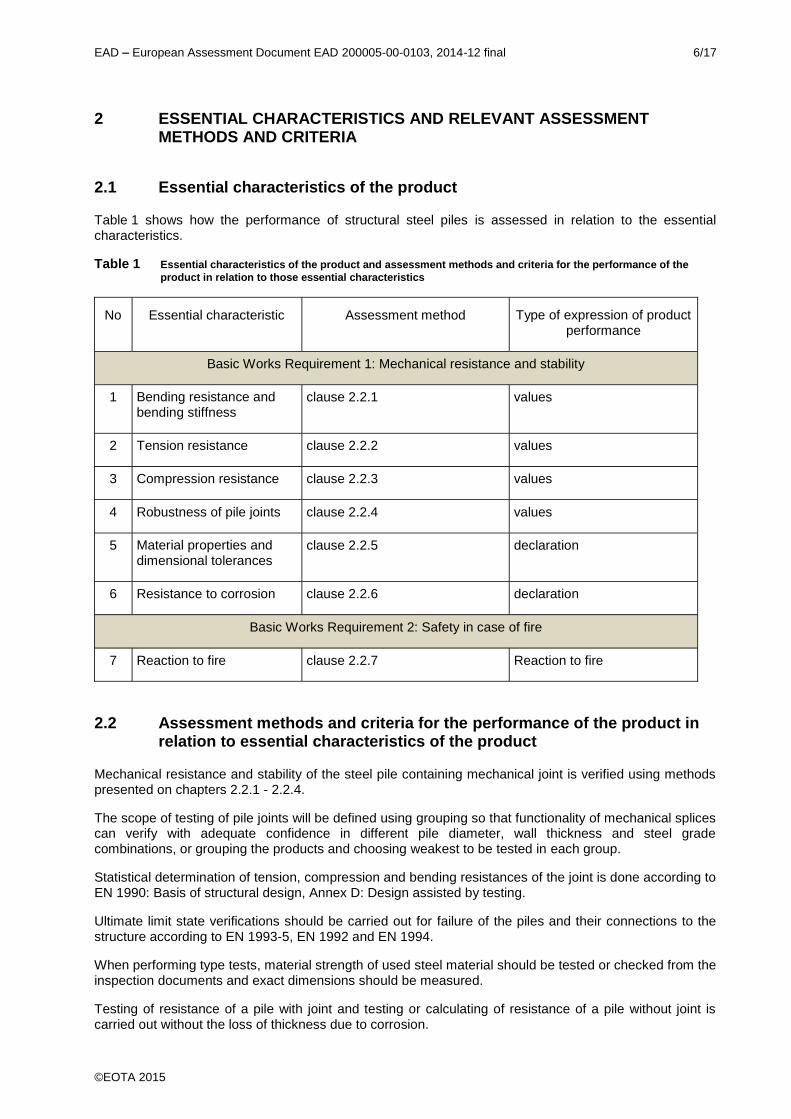
Table 1 shows how the performance of structural steel piles is assessed in relation to the essentialcharacteristics.
Table 1 Essential characteristics of the product and assessment methods and criteria for the performance of the
product in relation to those essential characteristics
No Essential characteristic Assessment method Type of expression of productperformance
Basic Works Requirement 1: Mechanical resistance and stability
1 Bending resistance andbending stiffness
clause 2.2.1 values
2 Tension resistance clause 2.2.2 values
3 Compression resistance clause 2.2.3 values
4 Robustness of pile joints clause 2.2.4 values
5 Material properties anddimensional tolerances
clause 2.2.5 declaration
6 Resistance to corrosion clause 2.2.6 declaration
Basic Works Requirement 2: Safety in case of fire
7 Reaction to fire clause 2.2.7 Reaction to fire
2.2 Assessment methods and criteria for the performance of the product inrelation to essential characteristics of the product
Mechanical resistance and stability of the steel pile containing mechanical joint is verified using methodspresented on chapters 2.2.1 - 2.2.4.
The scope of testing of pile joints will be defined using grouping so that functionality of mechanical splicescan verify with adequate confidence in different pile diameter, wall thickness and steel gradecombinations, or grouping the products and choosing weakest to be tested in each group.
Statistical determination of tension, compression and bending resistances of the joint is done according toEN 1990: Basis of structural design, Annex D: Design assisted by testing.
Ultimate limit state verifications should be carried out for failure of the piles and their connections to thestructure according to EN 1993-5, EN 1992 and EN 1994.
When performing type tests, material strength of used steel material should be tested or checked from theinspection documents and exact dimensions should be measured.
Testing of resistance of a pile with joint and testing or calculating of resistance of a pile without joint iscarried out without the loss of thickness due to corrosion.

EAD European Assessment Document EAD 200005-00-0103, 2014-12 final 7/17
©EOTA 2015
2.2.1 Bending resistance and bending stiffness
2.2.1.1 Method of verification
Testing shall be conducted according to the method described in the Annex A, point A 1.5 of the standardEN 12794. Location of loading and measuring points can vary according to pile size.
2.2.1.2 Method of assessing
Bending stiffness of the pile with pile joint shall be at least 0,75 x of the bending stiffness of the similarpile without pile joint in moment range 0,3 0,8 x M. Reference value for bending stiffness of the pilewithout joint can be tested by the same test method or calculated according to EN 1993-5.
Bending resistance of the pile with pile joint shall be at the same level as bending resistance of the similarpile without joint.
2.2.2 Tension resistance
2.2.2.1 Method of verification
Testing shall be conducted according to the method described in the Annex D.
2.2.2.2 Method of assessing
Tension resistance of the pile with joint shall be at least 15 % of the tension resistance of the similar pilewithout joint.
2.2.3 Compression resistance
2.2.3.1 Method of verification
Testing shall be conducted according to the method described in the Annex D.
Test is not necessary if pile pipes to be jointed are supported on each other in the whole cross sectionarea and pile joint meets the criteria presented in the chapters 2.2.1, 2.2.2 and 2.2.4.
2.2.3.2 Method of assessing
Compression resistance of the pile with pile joint shall be at least in the same level as compressionresistance of the similar pile without joint.
2.2.4 Robustness of pile joints
2.2.4.1 Method of verification
Robustness of pile joints for a driven pile shall be tested by an impact test. The impact test shall be donebefore bending, tension and compression tests of the joined pile. Impact test is done according toprinciples in Annex A of EN 12794.
Robustness of pile joints for drilled pile shall be tested by a tightening test. Tightening of the pile joint isdone according to the instructions of the manufacturer before bending, tension and compression tests ofthe joined pile.
2.2.4.2 Method of assessing
Joined driven pile shall pass the following test sequence:
Amount of impacts is at least 200, if the mass of ram is at least 20 times higher than the meter-mass ofthe pile. Amount of impacts is at least 2000, if the mass of ram is less than 20 times higher than themeter-mass of the pile.
Stress level in the test shall be at least 0,5 × yield strength of the pile pipe.

EAD European Assessment Document EAD 200005-00-0103, 2014-12 final 8/17
©EOTA 2015
The measurement of stress level shall be done according to the standard ASTM D 4945, Standard testmethod for High-Strain Dynamic Testing of Piles.
Required tightening moment for drilled pile in tightening test will be defined by the manufacturer.
Resistance of the pile can be seen adequate if the pile and pile joint perform as it is planned in impact ortightening test.
2.2.5 Material properties and dimensional tolerances
2.2.5.1 Method of verification
Manufacturing and testing of the pile pipe material shall be conducted according to the standard EN10219. Testing of the pile component material shall be conducted according to the relevant standarddescribed in the chapter 1.1. Testing shall be done by material manufacturer.
The dimensions and shape shall be declared and measured. Measurement and target values of allrelevant dimensions and the tolerances of them shall be declared in the FPC documentation of themanufacturer. Measurement shall be done in a purposeful way that guarantees that the product is fit forthe intended use.
2.2.5.2 Method of assessing
Material properties of pile pipe are according to the standard EN 10219 or Annex B of this EAD. Materialproperties of the pile components are according to the relevant standard described in the chapter 1.1 oraccording to Annex B. Material properties shall be checked from the material certificates. For pile pipematerial, material certificate 3.1 is required according to the standard EN 10204.
Tolerances of the pile pipe and external friction splice pipe are given in Annex C. The pipe tolerances thatare not mentioned in Annex C are according to EN 10219-2. Tolerances of the pile components areaccording to EN 22768-1 (tolerance class Medium), if FPC documentation does not give additionalinformation.
The measurement method of dimensional tolerances shall be evaluated. ETA shall contain the main
dimensions.
2.2.6 Resistance to corrosion
2.2.6.1 Method of verification
According to the standard EN 1993-5 paragraph 4.4.
2.2.6.2 Method of assessing
According to the standard EN 1993-5 paragraph 4.4 depending on the installation environmentaggressiveness and designed material thicknesses.
In the case of piles without concrete filling possible internal corrosion should take into account sealing ofthe pile and possible entering of soil and water to the pile.
2.2.7 Reaction to fire
The structural steel piles are considered to satisfy the requirements for performance class A1 of thecharacteristic reaction to fire in accordance with the EC Decision 96/603/EC (as amended) without theneed for testing on the basis of it fulfilling the conditions set out in that Decision and its intended usebeing covered by that Decision.
Therefore the performance of the products are A1.

EAD European Assessment Document EAD 200005-00-0103, 2014-12 final 9/17
©EOTA 2015
3 ASSESSMENT AND VERIFICATION OF CONSTANCY OF PERFORMANCE
3.1 System(s) of assessment and verification of constancy of performance
For the products covered by this EAD the applicable European legal act is: 1999/94/EC.
The system to be applied is: 2+
3.2 Tasks of the manufacturer
The cornerstones of the actions to be undertaken by the manufacturer of the products in the process ofassessment and verification of constancy of performance are laid down in Table 2.
Table 2 Control plan for the manufacturer; cornerstones
No Subject/type of control Test or controlmethod
Criteria,if any
Minimumnumber
ofsamples
Minimumfrequency of
control
Factory production control (FPC)
1 Incoming raw materials Material certificates orproduct certificates,dimensions checking
Every delivery orevery melting
2 Dimensions Essential dimensionsinfluencing on theperformance
According to theprescribedcontrol plan
3 Handling of non-conformingproducts
According to writtenprocedure
Every shift
3.3 Tasks of the notified body
The cornerstones of the actions to be undertaken by the notified body in the process of assessment andverification of constancy of performance for structural steel piles are laid down in Table 3.

EAD European Assessment Document EAD 200005-00-0103, 2014-12 final 10/17
©EOTA 2015
Table 3 Control plan for the notified body; cornerstones
No Subject/type of control Test orcontrolmethod
Criteria,if any
Minimumnumber
ofsamples
Minimumfrequency of
control
Initial inspection of the manufacturing plant and of factory production control
1 The notified body shall ascertain that, in accordance with the prescribed control plan, thefactory, in particular the staff and equipment, and the factory quality control, are suitable toensure a continuous and orderly manufacturing of pile with the specifications given in qualitycontrol agreement.
Continuous surveillance, assessment and evaluation of factory production control
2 The notified body shall visit the factory at least once a year for routine inspections. It shall verifythat the system of factory quality control and the specified manufacturing processes aremaintained, taking account of the prescribed control plan.

EAD European Assessment Document EAD 200005-00-0103, 2014-12 final 11/17
©EOTA 2015
4 REFERENCE DOCUMENTS
As far as no edition date is given in the list of standards thereafter, the standard in its current version atthe time of issuing the European Technical Assessment, is of relevance.
EN 1990
EN 1992
EN 1993-5
EN 1994
Eurocode Basis of structural design
Eurocode 2 Design of concrete structures
Eurocode 3 Design of steel structures. Part 5: Piling
Eurocode 4 Design of composite steel and concrete structures
EN 10204 Material certificates of metallic materials
EN 12794 Precast concrete products. Foundation piles
EN 12699 Execution of special geotechnical work. Displacement piles
EN 14199 Execution of special geotechnical works. Micropiles
EN 1536
EN 12063
Execution of special geotechnical work. Bored piles
Execution of special geotechnical work. Sheet-pile walls
EN 22768-1 General tolerances. Part 1: Tolerances for linear and angular
dimensions without individual tolerance indicators
EN 10219-1 Cold formed welded structural hollow sections of non-alloy and fine
grain steels. Part 1: Technical delivery conditions
EN 10219-2 Cold formed welded structural hollow sections of non-alloy and fine
grain steels. Part 2: Tolerances, dimensions and sectional properties
EN 10025 -1 Hot rolled products of structural steels Part 1: General technical delivery
conditions
EN 10083-1 Steels for quenching and tempering Part 1: General technical delivery
conditions
EN 10294-1 Hollow bars for machining. Technical delivery conditions. Part 1: Non
alloy and alloy steels
EN 10297-1 Seamless circular steel tubes for mechanical and general engineering
purposes. Technical delivery conditions. Part 1: Non-alloy and alloy
steel tubes

EAD European Assessment Document EAD 200005-00-0103, 2014-12 final 12/17
©EOTA 2015
ANNEX A COMPONENTS OF THE STEEL PILES
Components of the steel piles
Drilled pile
Bearing plate
Threaded splice
welded joint
or
Driven pile
External splice
Bearing plate
internal splice
Bottom plate
rock shoe
or
or
welded joint
or
Drilling system components attached to thelower end of the pile according to theinstructions of drilling system manufacturer.

EAD European Assessment Document EAD 200005-00-0103, 2014-12 final 13/17
©EOTA 2015
ANNEX B CHEMICAL COMPOSITION AND MECHANICAL PROPERTIESOF STEELS
Table 1. Chemical composition 20 mm
Steel grade Type of
deoxidationa
% by mass, maximum
C Si Mn P S Nb
S440J2H FF 0,18 0,50 1,70 0,025 0,020 -
S550J2H FF 0,16 0,50 2,20 0,030 0,030 -
a The deoxidation method is designated as follows:
FF: Fully killed steel containing nitrogen binding elements in amounts sufficient to bind available nitrogen (e.g. min. 0,020 % total Al or 0,015% soluble Al).b The maximum value for nitrogen does not apply if the chemical composition shows a minimum total Al content of 0,020 % with a minimumAl/N ratio of 2:1, or if sufficient other N-binding elements are present. The N-binding elements shall be recorded in the Inspection Document.
Table 2. Mechanical properties of non-alloy steel hollow sections in thicknesses 20 mm
Steel grade Minimum yield
strength ReH
MPa
Tensile strength Rm
MPa
Minimumelongation Aa
%
Minimum impact energyKVb
J
Specified thickness
mm
Specified thickness
mm
Specified thickness
mm
at test temperature of
-20°C 0 °C 20 °C
S440J2H 440 490-630 17 27 - -
S550J2H 550 605-760 14 27 -
a For pile sizes D/T < 15 (circular) the minimum elongation is reduced by 2b For impact properties for reduced section test pieces see 6.7.2. EN 10219-1
Table 3. Chemical composition - 20 mm, feedstock condition Ma
Steel grade Type of
deoxidationb
Classification
c
% by mass
C
max.
Si
max.
Mn
max.
P
max.
S
max.
Nb
max.
V
max.
Altotald
min.
Ti
max.
Ni
max.
Moe
max.
N
max.
S440MH GF SS 0,16 0,50 1,70 0,025 0,020 0,050 0,12 0,020 0,050 0,30 0,20 0,025
S550MH GF SS 0,14 0,50 2,00 0,025 0,020 0,050 0,12 0,020 0,050 0,30 0,20 0,025
a See 6.3. EN 10219-1
b The deoxidation method is designated as follows:
GF = Fully killed steel containing nitrogen binding elements in amounts sufficient to bind the available nitrogen and having a fine grained structure.
c SS = special steel.
d If sufficient N-binding elements are present, the minimum total Al content does not apply.
e The total sum of Cr, Cu and Mo shall not be higher than 0,60 %.

EAD European Assessment Document EAD 200005-00-0103, 2014-12 final 14/17
©EOTA 2015
20 mm Feedstock material condition M
Steel grade Minimum yield
strength ReH
MPa
Tensile strength Rm
MPa
Minimumelongation Aa
%
Minimum impact energyKVb
J
Specified thickness
mm
Specified thickness
mm
Specified thickness
mm
at test temperature of
-50°C -20 °C
S440MH 440 490-630 17 - 40c
S550MH 550 605-760 14 - 40c
a For pile sizes D/T < 15 (circular) the minimum elongation is reduced by 2
b For impact properties for reduced section test pieces see 6.7.2. EN 10219-1
c This value corresponds to 27 J at -30 °C (see EN 1993-1-1).
Table 5. Maximum carbon equivalent value (CEV) based on cast analysis a
Steel grade 20 mm
%
S440J2H 0,45
S550J2H 0,47
S440MH 0,42
S550MH 0,45
a See 6.6.2 EN 10219-1, Option 1.2.

EAD European Assessment Document EAD 200005-00-0103, 2014-12 final 15/17
©EOTA 2015
ANNEX C TOLERANCES ON SHAPE AND MASS
Table 1. Tolerances on shape and mass, pile pipe
Characteristic Circular hollow section
Outside diameter (D)*
D > 350 mm ± 1%
Thickness (T) For D 406,4 mm:
T 5 mm ± 10 %
T > 5 mm ± 0,5 mm
For D > 406,4 mm:
± 10 % with a maximum of ± 2 mm
Out-of-roundness (O)
D > 350 mm ± 2%
Straightness (e) 0,20 % of total length
Mass per unit length (M) ± 6 % on individual delivered lengths
*The diameter (D) shall be measured by circumference tape at the discretion of the manufacturer.
Table 2, Tolerances on shape and mass, sleeve pipe (friction joint)
Characteristic Circular hollow section
Inside diameter (D)*
D > 150 mm ± 0,3 %
Thickness (T) For D 406,4 mm:
T 5 mm ± 10 %
T > 5 mm ± 0,5 mm
For D > 406,4 mm:
± 10 % with a maximum of ± 2 mm
Out-of-roundness (O)
D > 150 mm ± 1 %
Straightness (e) 0,20 % of total length
Mass per unit length (M) ± 6 % on individual delivered lengths
Length of individual sleeve (L) ± 5 mm
*The diameter (D) shall be measured by circumference tape at the discretion of the manufacturer.

EAD European Assessment Document EAD 200005-00-0103, 2014-12 final 16/17
©EOTA 2015
ANNEX D COMPRESSION AND TENSILE TESTS OF PILE JOINTS
Compression and tensile resistance of pile joints are tested according to test arrangements presented inFigures 1 and 2. Characteristic compression and tensile capacity of the joint must fulfil the requirementspresented in 2.2.2 and 2.2.3 after the jointinstructions.
Compression test
Each test specimen must include the entire joint section connecting two pile elements. The minimum
D (D = outside diameter of the pile element, Fig. 1).
The specimen is compressed with central axial load (N) applied on the pile segments (Fig. 1).
Fig. 1 Loading arrangements of compression test of pile joints.
During the tests the relative displacement of the specimen (minimum two displacement sensors at theopposite sides of the joint, Fig. 1), the applied compressive force (N) and the ultimate failure mechanismof the specimen are recorded.
N
>2D
D
EAD European Assessment Document EAD 200005-00-0103, 2014-12 final 17/17
©EOTA 2015
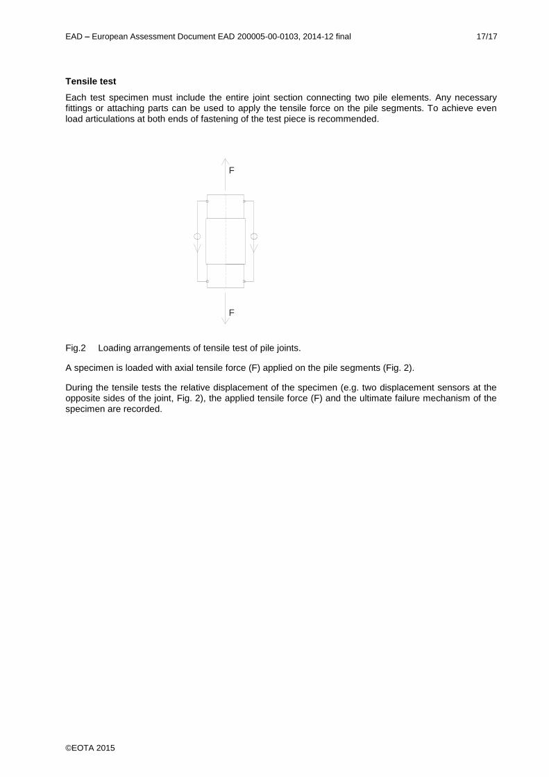
Tensile test
Each test specimen must include the entire joint section connecting two pile elements. Any necessaryfittings or attaching parts can be used to apply the tensile force on the pile segments. To achieve evenload articulations at both ends of fastening of the test piece is recommended.
Fig.2 Loading arrangements of tensile test of pile joints.
A specimen is loaded with axial tensile force (F) applied on the pile segments (Fig. 2).
During the tensile tests the relative displacement of the specimen (e.g. two displacement sensors at theopposite sides of the joint, Fig. 2), the applied tensile force (F) and the ultimate failure mechanism of thespecimen are recorded.
F/2
F/2
Related Documents