Top Banner
Structural Performance of FRP in Fire Structural Performance of FRP in Fire Mark F. Green Queen’s University at Kingston Leverhulme Visiting Professor 8 April 2014 Steel in Fire Forum 1
34

Structural Performance of FRP in Firefire-research.group.shef.ac.uk/steelinfire/downloads/MG_2014.pdf · Figure 3‐33 Flames are visible at cracks in the U‐wrap location, Beam‐B

Apr 13, 2018

Download

Documents

tranthien
Welcome message from author
This document is posted to help you gain knowledge. Please leave a comment to let me know what you think about it! Share it to your friends and learn new things together.
Transcript
Page 1: Structural Performance of FRP in Firefire-research.group.shef.ac.uk/steelinfire/downloads/MG_2014.pdf · Figure 3‐33 Flames are visible at cracks in the U‐wrap location, Beam‐B

Structural Performance of FRP in FireStructural Performance of FRP in Fire

Mark F. GreenQueen’s University at KingstonLeverhulme Visiting Professor

8 April 2014Steel in Fire Forum

1

Page 2: Structural Performance of FRP in Firefire-research.group.shef.ac.uk/steelinfire/downloads/MG_2014.pdf · Figure 3‐33 Flames are visible at cracks in the U‐wrap location, Beam‐B

Outline

• FRP and High Temperature• FRP Material Tests • Recent Full-Scale Tests on Beams • Modelling – Different Fire Scenarios• Design Approaches

2

Page 3: Structural Performance of FRP in Firefire-research.group.shef.ac.uk/steelinfire/downloads/MG_2014.pdf · Figure 3‐33 Flames are visible at cracks in the U‐wrap location, Beam‐B

Deterioration of structures

New construction

Cost Environment

FRP

Strengthening Rehabilitation

Existing Technology

New technologies

FRP

Use in buildingsFire concern 

Introduction

• Fire design criteria must be satisfied in buildings

• Little research has been performed to date

3

Page 4: Structural Performance of FRP in Firefire-research.group.shef.ac.uk/steelinfire/downloads/MG_2014.pdf · Figure 3‐33 Flames are visible at cracks in the U‐wrap location, Beam‐B

4

Glass fibreroving

Carbon fibre roving

Unidirectional glass FRP bar

Carbon FRP prestressing

tendon

Aramid FRP grid

Examples of FRP

High strength fibres in a polymer matrix

Page 5: Structural Performance of FRP in Firefire-research.group.shef.ac.uk/steelinfire/downloads/MG_2014.pdf · Figure 3‐33 Flames are visible at cracks in the U‐wrap location, Beam‐B

Material Tests

• Tensile strength• FRP to FRP bond• FRP to concrete bond• Steady-state temperature tests• Transient temperature tests• Tests up to 200 degrees C

5

Page 6: Structural Performance of FRP in Firefire-research.group.shef.ac.uk/steelinfire/downloads/MG_2014.pdf · Figure 3‐33 Flames are visible at cracks in the U‐wrap location, Beam‐B

6

Page 7: Structural Performance of FRP in Firefire-research.group.shef.ac.uk/steelinfire/downloads/MG_2014.pdf · Figure 3‐33 Flames are visible at cracks in the U‐wrap location, Beam‐B

Some tensile test results (Tyfo GFRP)

7T e m p e ra tu re (C )

( )

0 5 0 1 0 0 1 5 0 2 0 0 2 5 0

Nor

mal

ized

Ten

sile

Stre

ngth

0 .0

0 .5

1 .0

1 .5

T g = 7 5 CP R = 0 .4 6k m = 0 .0 8 8 2

T cen tra l = 4 7 CR = 0 .9 5R 2 = 0 .9 0

Page 8: Structural Performance of FRP in Firefire-research.group.shef.ac.uk/steelinfire/downloads/MG_2014.pdf · Figure 3‐33 Flames are visible at cracks in the U‐wrap location, Beam‐B

Steady State Proposed Model

0.02.04.06.08.0

10.012.014.016.0

0 50 100 150 200

Stre

ngth

(kN

)

Temperature (°C)

Proposed Model

~ 35°C

95% confidence interval

w is 0.018

8

Page 9: Structural Performance of FRP in Firefire-research.group.shef.ac.uk/steelinfire/downloads/MG_2014.pdf · Figure 3‐33 Flames are visible at cracks in the U‐wrap location, Beam‐B

Full-Scale Tests

9

Page 10: Structural Performance of FRP in Firefire-research.group.shef.ac.uk/steelinfire/downloads/MG_2014.pdf · Figure 3‐33 Flames are visible at cracks in the U‐wrap location, Beam‐B

• Span 3.8 m• FRP materials

– Sika CarboDur S812– SikaWrap Hex103– Tyfo CFRP, GFRP– MBrace

• Insulation– Sikacrete®-213 – Tyfo VG system– Other cementitious system

Fire Tests, T-beams

10

1220mm

150mm250mm CFR

P Insulation

Page 11: Structural Performance of FRP in Firefire-research.group.shef.ac.uk/steelinfire/downloads/MG_2014.pdf · Figure 3‐33 Flames are visible at cracks in the U‐wrap location, Beam‐B

Floor Test Furnace at NRC

11

Page 12: Structural Performance of FRP in Firefire-research.group.shef.ac.uk/steelinfire/downloads/MG_2014.pdf · Figure 3‐33 Flames are visible at cracks in the U‐wrap location, Beam‐B

12

Page 13: Structural Performance of FRP in Firefire-research.group.shef.ac.uk/steelinfire/downloads/MG_2014.pdf · Figure 3‐33 Flames are visible at cracks in the U‐wrap location, Beam‐B

Figure  3‐33 Flames are visible at cracks in the U‐wrap location, Beam‐B after 1 hour and 53 minutes of fire exposure. 13

Page 14: Structural Performance of FRP in Firefire-research.group.shef.ac.uk/steelinfire/downloads/MG_2014.pdf · Figure 3‐33 Flames are visible at cracks in the U‐wrap location, Beam‐B

Figure  3‐36 T‐beams after fire test in the loading frame.14

Page 15: Structural Performance of FRP in Firefire-research.group.shef.ac.uk/steelinfire/downloads/MG_2014.pdf · Figure 3‐33 Flames are visible at cracks in the U‐wrap location, Beam‐B

Figure  3‐34 Cracks at  insulation surface after fire test Beam‐B 15

Page 16: Structural Performance of FRP in Firefire-research.group.shef.ac.uk/steelinfire/downloads/MG_2014.pdf · Figure 3‐33 Flames are visible at cracks in the U‐wrap location, Beam‐B

0

200

400

600

800

1000

1200

0 60 120 180 240 300

Furnace temp.

Insulation Surface

FRP/Concrete

FRP Surface

Time (min)

Tem

pera

ture

(˚C)

Beam-B SikaWrap® Hex 103C 40 mm of Sikacrete®-213F

16

Page 17: Structural Performance of FRP in Firefire-research.group.shef.ac.uk/steelinfire/downloads/MG_2014.pdf · Figure 3‐33 Flames are visible at cracks in the U‐wrap location, Beam‐B

0

20

40

60

80

100

120

140

160

Tyfo 25 mm VG Tyfo 40 mm VG MBrace 30 mmCem

MBrace 30 mmCem

Carbodur 40mm Cem

SikaWrap 40mm Cem

Tyfo 15 mm VG Tyfo 20 mm VG

Stre

ngth

(kN

.m)

Summary of T-Beam Tests (CSA S806)

17

Strengthened Design Resista

Test Load

Maximum Test Load

Maximum Test Loa

Test Load

Page 18: Structural Performance of FRP in Firefire-research.group.shef.ac.uk/steelinfire/downloads/MG_2014.pdf · Figure 3‐33 Flames are visible at cracks in the U‐wrap location, Beam‐B

Numerical Modelling

18

Page 19: Structural Performance of FRP in Firefire-research.group.shef.ac.uk/steelinfire/downloads/MG_2014.pdf · Figure 3‐33 Flames are visible at cracks in the U‐wrap location, Beam‐B

Heat Transfer 

19

Radiation

Convection

)( 44pfcf TTq

)( pcc TThq

.

Page 20: Structural Performance of FRP in Firefire-research.group.shef.ac.uk/steelinfire/downloads/MG_2014.pdf · Figure 3‐33 Flames are visible at cracks in the U‐wrap location, Beam‐B

Heat Transfer FV Model

• Nonlinear Finite Volume code• Explicit formulation• 2D• In MATLAB environment• Accounts for variation in

– Thermal properties– Moisture content

20

Page 21: Structural Performance of FRP in Firefire-research.group.shef.ac.uk/steelinfire/downloads/MG_2014.pdf · Figure 3‐33 Flames are visible at cracks in the U‐wrap location, Beam‐B

T-beam Temp. Predictionsunexposed surface centreline cover of 155 mm

longitudinal steel FRP-concrete interface

21

Page 22: Structural Performance of FRP in Firefire-research.group.shef.ac.uk/steelinfire/downloads/MG_2014.pdf · Figure 3‐33 Flames are visible at cracks in the U‐wrap location, Beam‐B

Structural Model

• Beam theory– Bernoulli hypothesis (plane sections remain plane)– Iterative solution– Includes Transient Creep

22

Page 23: Structural Performance of FRP in Firefire-research.group.shef.ac.uk/steelinfire/downloads/MG_2014.pdf · Figure 3‐33 Flames are visible at cracks in the U‐wrap location, Beam‐B

Deflection simulation T‐beam No Axial Restraint

23

Page 24: Structural Performance of FRP in Firefire-research.group.shef.ac.uk/steelinfire/downloads/MG_2014.pdf · Figure 3‐33 Flames are visible at cracks in the U‐wrap location, Beam‐B

Deflection Prediction including Axial Force

0

5

10

15

20

25

30

‐60 0 60 120 180 240 300

Defle

ction (m

m)

Time(min)

Model Axial=100‐0Model Axial=100‐100Model Axial=100‐200Model Axial=100‐300Beam_A_Test

24

Page 25: Structural Performance of FRP in Firefire-research.group.shef.ac.uk/steelinfire/downloads/MG_2014.pdf · Figure 3‐33 Flames are visible at cracks in the U‐wrap location, Beam‐B

Different Fire Scenarios

(Lie 1992)

250 10.

. 3 1 . 1 4 1 C600 .

  √ / Fire I 0.01 30 0.0Fire II 0.05 30 0.0Fire III 0.10 30 0.0Fire IV 0.10 100  1.0 

25

Page 26: Structural Performance of FRP in Firefire-research.group.shef.ac.uk/steelinfire/downloads/MG_2014.pdf · Figure 3‐33 Flames are visible at cracks in the U‐wrap location, Beam‐B

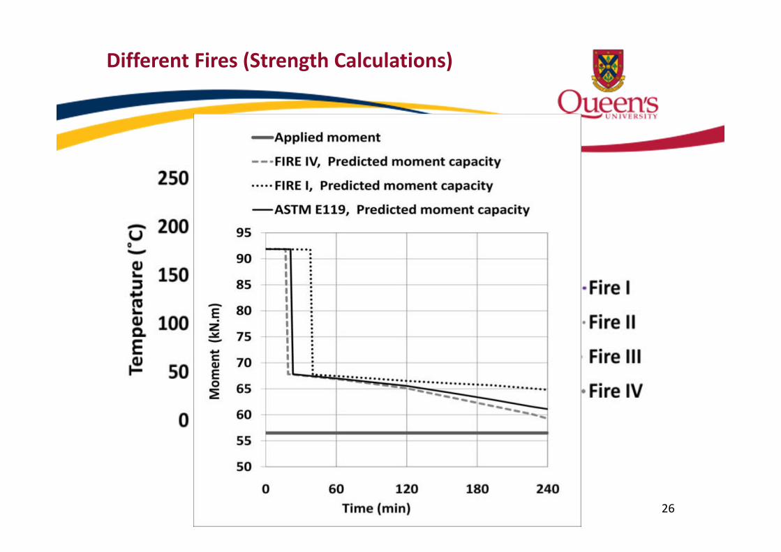
Different Fires (Strength Calculations)

• T‐beam‐A&B • 40 mm Sikacrete ‐213F insulationLongitudinal steel temperature 

26

Page 27: Structural Performance of FRP in Firefire-research.group.shef.ac.uk/steelinfire/downloads/MG_2014.pdf · Figure 3‐33 Flames are visible at cracks in the U‐wrap location, Beam‐B

Different Fire Structural Response

• T-Beam-C• 13 mm of WR-AFP insulation• Load 24.1 kN/m

0

200

400

600

800

0 60 120 180 240 300

Tempe

rature (°C)

Time(min)

Steel Temp. Fire ISteel Temp. Fire IISteel Temp. Fire IIISteel Temp. Fire IVSteel Temp. E119

0

50

100

150

200

0 60 120 180 240 300

Deflection (m

m)

Time(min)

Deflection Fire IDeflection Fire IIDeflection Fire IIIDeflection Fire IVDeflection E119

27

Page 28: Structural Performance of FRP in Firefire-research.group.shef.ac.uk/steelinfire/downloads/MG_2014.pdf · Figure 3‐33 Flames are visible at cracks in the U‐wrap location, Beam‐B

Design for Fire Safety

Page 29: Structural Performance of FRP in Firefire-research.group.shef.ac.uk/steelinfire/downloads/MG_2014.pdf · Figure 3‐33 Flames are visible at cracks in the U‐wrap location, Beam‐B

Philosophy for Fire‐Safety

Temp.(ºC)Load

Time

Initial Service Life Retrofitted Life

Strength

Service Load

Fire Event (hrs)0            1            2            3           4 

1000

100

Retrofit

Fire Event Onset

Construction

Page 30: Structural Performance of FRP in Firefire-research.group.shef.ac.uk/steelinfire/downloads/MG_2014.pdf · Figure 3‐33 Flames are visible at cracks in the U‐wrap location, Beam‐B

Conceptual design approach

Fire resistance

Flame spreadprotectionAm

ount

of S

treng

then

ing

Protect FRP Itself

Page 31: Structural Performance of FRP in Firefire-research.group.shef.ac.uk/steelinfire/downloads/MG_2014.pdf · Figure 3‐33 Flames are visible at cracks in the U‐wrap location, Beam‐B

Conceptual Model – Slabs(40 mm clear cover)

CAUTION – very preliminary – Not for use in design!!

Page 32: Structural Performance of FRP in Firefire-research.group.shef.ac.uk/steelinfire/downloads/MG_2014.pdf · Figure 3‐33 Flames are visible at cracks in the U‐wrap location, Beam‐B

Steel Structures?

• Structural steel can also be strengthened with FRP

• Fire performance has not been investigated• Strategies for fire protection could be similar to

that of concrete– Role of intumescent paints?– Spray-applied insulation

32Photos courtesy of Prof. Amir Fam

Page 33: Structural Performance of FRP in Firefire-research.group.shef.ac.uk/steelinfire/downloads/MG_2014.pdf · Figure 3‐33 Flames are visible at cracks in the U‐wrap location, Beam‐B

Conclusions

• All members achieved 4 hour fire ratings– FRP reached its glass transition temperature fairly quickly– Structural contribution of FRP unknown– Insulation provided protection to concrete and steel

• Predictions of numerical models were consistent with experimental observations

• Conceptual design model shows promise

Page 34: Structural Performance of FRP in Firefire-research.group.shef.ac.uk/steelinfire/downloads/MG_2014.pdf · Figure 3‐33 Flames are visible at cracks in the U‐wrap location, Beam‐B

Acknowledgements

• Students and Post-docs: Duncan Cree, Luke Bisby, Brea Williams, Masoud Adelzadeh, Ershad Chowdhury, Rob Eedson, Kevin Hollingshead, Greg Shier

• NRC collaborators: Noureddine Benichou, Hossein Mostafaei, Venkatesh Kodur

• Technical staff at NRC and Queen’s• ISIS Canada, NSERC, NRC-IRAP• Industry sponsors: Fyfe/Fibrwrap, Sika, BASF• Leverhulme Trust

34