STRUCTURAL MECHANIC AND AEROELASTIC APPROACH FOR DESIGN AND SIMULATION OF CFRP FAN BLADES N. Forsthofer, German Aerospace Center (DLR), Stuttgart, Germany C. Reiber, German Aerospace Center (DLR), Göttingen, Germany ABSTRACT Since the development of CRISP, a counter rotating integrated shrouded propfan, within a MTU-DLR cooperative project between 1985 and 2000, major advances have been made in various areas of engine development and fan technology. Therefore DLR launched a successive project CRISPmulti in 2010, redesigning the existing blades to increase the level of aerodynamic efficiency, lower the noise emissions and reduce the overall weight. The improvements are made possible by using the method of multidisciplinary optimization involving the DLR Institutes of Propulsion Technology, Aeroelastics and Structures and Design, together with the DLR facility Systemhaus Technik. This paper focuses on the structural mechanics and aeroelastic aspects in design and simulation for a counter rotating fan stage with blades made from carbon fiber reinforced PEEK. With the use of the thermoplastic resin PEEK, a new approach for the manufacturing of fan blades was used. Different from the so called “onion skin configuration” of CRISP the layers of the CRISPmulti blades are stacked up to a flat plate and are reshaped using a hot press. Afterwards the final blade geometry is obtained through a milling process. The material testing program to identify the important material parameters for this approach is specified and adjusted to suit the highly sophisticated simulation techniques. Based on the material properties, the structural mechanic approach for the calculation of the static and dynamic behavior is presented. The aeroelastic simulation validates the forced response and flutter behavior of the CFRP fan blades. The presented design strategy has been successfully completed and undergone a critical design review to prove mechanical and aeroelastic feasibility regarding a planned rig test. NOMENCLATURE ACARE Advisory Council for Aeronautics Research in Europe CFD Computational Fluid Dynamics CF/PEEK Carbon-Fiber-Reinforced PEEK CFRP Carbon-Fiber-Reinforced-Plastic CLT Complete Laminate Theory CRISP Counter Rotating Integrated Shrouded Propfan DLR Deutsches Zentrum für Luft- und Raumfahrt (German Aerospace Center) EF Eigenfrequency EO Engine Order FEM Finite Element Method GOM Gesellschaft für optische Messtechnik HCF High Cycle Fatigue LCF Low Cycle Fatigue M2VP Multistage two-shaft compressor test facility MTU Motoren- und Turbinen-Union (MTU Aero Engines) OP Operating Point PEEK Polyether Ether Ketone R Rotor RPM Revolutions Per Minute TRACE Turbomachinery Research and Computational Environment 1. INTRODUCTION CRISPmulti is a DLR project for the multidisciplinary development and testing of a highly efficient counter- rotating fan stage for the next generation of aircraft engines with a very high bypass ratio. Counter rotating rotors represent a fan stage concept that offers the greatest promise to reduce fuel consumption. This will contribute significantly to the cost-effectiveness and environmental friendliness of next generation aircraft engines, and is in line with the Advisory Council for Aeronautics Research in Europe (ACARE) Vision 2020 project. The main goals of the design are: • A cycle and engine concept for an engine with an extremely high bypass ratio • Development of blade shapes for maximum aerodynamic effectiveness, lower noise emissions and weight reduction • Use of an innovative and highly automated CFRP rotor blade manufacturing technology and therefore reduced cost and industrial usability • Use of the latest measurement techniques to test the prototype on a modern compressor test stand The multidisciplinary design of the counter-rotating fan stage takes into account aerodynamic, aeroelastic, structural and manufacturing aspects and is described in detail in [1 and 2]. Simultaneous pursuit of sometimes contradictory design goals is enabled by the use of

Welcome message from author
This document is posted to help you gain knowledge. Please leave a comment to let me know what you think about it! Share it to your friends and learn new things together.
Transcript

STRUCTURAL MECHANIC AND AEROELASTIC APPROACH FOR DESIGN AND SIMULATION OF CFRP FAN BLADES
N. Forsthofer, German Aerospace Center (DLR), Stuttgart, Germany
C. Reiber, German Aerospace Center (DLR), Göttingen, Germany
ABSTRACT
Since the development of CRISP, a counter rotating integrated shrouded propfan, within a MTU-DLR cooperative project between 1985 and 2000, major advances have been made in various areas of engine development and fan technology. Therefore DLR launched a successive project CRISPmulti in 2010, redesigning the existing blades to increase the level of aerodynamic efficiency, lower the noise emissions and reduce the overall weight. The improvements are made possible by using the method of multidisciplinary optimization involving the DLR Institutes of Propulsion Technology, Aeroelastics and Structures and Design, together with the DLR facility Systemhaus Technik. This paper focuses on the structural mechanics and aeroelastic aspects in design and simulation for a counter rotating fan stage with blades made from carbon fiber reinforced PEEK. With the use of the thermoplastic resin PEEK, a new approach for the manufacturing of fan blades was used. Different from the so called “onion skin configuration” of CRISP the layers of the CRISPmulti blades are stacked up to a flat plate and are reshaped using a hot press. Afterwards the final blade geometry is obtained through a milling process. The material testing program to identify the important material parameters for this approach is specified and adjusted to suit the highly sophisticated simulation techniques. Based on the material properties, the structural mechanic approach for the calculation of the static and dynamic behavior is presented. The aeroelastic simulation validates the forced response and flutter behavior of the CFRP fan blades. The presented design strategy has been successfully completed and undergone a critical design review to prove mechanical and aeroelastic feasibility regarding a planned rig test.
NOMENCLATURE ACARE Advisory Council for Aeronautics
Research in Europe CFD Computational Fluid Dynamics CF/PEEK Carbon-Fiber-Reinforced PEEK CFRP Carbon-Fiber-Reinforced-Plastic CLT Complete Laminate Theory CRISP Counter Rotating Integrated Shrouded Propfan DLR Deutsches Zentrum für Luft- und
Raumfahrt (German Aerospace Center) EF Eigenfrequency EO Engine Order FEM Finite Element Method GOM Gesellschaft für optische Messtechnik HCF High Cycle Fatigue LCF Low Cycle Fatigue M2VP Multistage two-shaft compressor test
facility MTU Motoren- und Turbinen-Union (MTU Aero Engines) OP Operating Point PEEK Polyether Ether Ketone R Rotor RPM Revolutions Per Minute TRACE Turbomachinery Research and Computational Environment
1. INTRODUCTION CRISPmulti is a DLR project for the multidisciplinary development and testing of a highly efficient counter-rotating fan stage for the next generation of aircraft engines with a very high bypass ratio. Counter rotating rotors represent a fan stage concept that offers the greatest promise to reduce fuel consumption. This will contribute significantly to the cost-effectiveness and environmental friendliness of next generation aircraft engines, and is in line with the Advisory Council for Aeronautics Research in Europe (ACARE) Vision 2020 project. The main goals of the design are:
• A cycle and engine concept for an engine with an extremely high bypass ratio
• Development of blade shapes for maximum aerodynamic effectiveness, lower noise emissions and weight reduction
• Use of an innovative and highly automated CFRP rotor blade manufacturing technology and therefore reduced cost and industrial usability
• Use of the latest measurement techniques to test the prototype on a modern compressor test stand
The multidisciplinary design of the counter-rotating fan stage takes into account aerodynamic, aeroelastic, structural and manufacturing aspects and is described in detail in [1 and 2]. Simultaneous pursuit of sometimes contradictory design goals is enabled by the use of
multidisciplinary optimization methods that use DLR’s own evolutionary optimization algorithm AutoOpti.
To manufacture the rotor blades, a process developed within the Department of Design and Manufacture Technologies was used to produce thermoplastic fiber composite components. In doing so, ‘organosheets’ that can be produced automatically, are manufactured, re-shaped near to net shape in a hot press and subsequently milled into complex three-dimensional components with multiple curved surfaces. The thermoplastic material used, CF-PEEK, underwent an extensive test program to provide highly precise material parameters for the structural and aeroelastic calculations and to demonstrate the strength needed to withstand the high static and dynamic loads on the rotor blades.
The design objectives will be tested experimentally on DLR’s modern Multistage Two Shaft Compressor Test Facility (M2VP).
2. MATERIAL TESTING Main goal for the manufacturing process was the possibility for automated manufacturing. Starting points are flat rectangular plates, so called “organosheets” made from a thermoplastic resin PEEK. The plates are reshaped in the hot press along the middle surface of the later blade. To reduce stresses injected by the reshaping process a symmetric layup with in itself symmetric packages of eight layers was chosen and the reformed plates are tempered. Finally the blade geometry is retrieved through a milling process. The manufacturing process is shown exemplary in figure 1.
Figure 1: Manufacturing Process
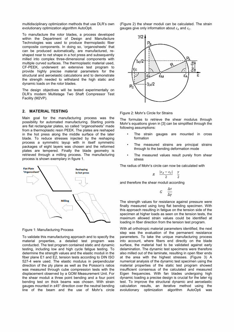
To validate this manufacturing approach and to specify the material properties, a detailed test program was conducted. The test program contained static and dynamic testing, including low and high cycle fatigue testing. To determine the strength values and the elastic moduli in the fiber plane E1 and E2, tension tests according to DIN ISO 527-4 were used. The elastic modulus in perpendicular direction of the ply plane as well as the Poisson’s ratios was measured through cube compression tests with the displacement observed by a GOM Measurement Unit. For the shear moduli a three point bending and a four point bending test on thick beams was chosen. With strain gauges mounted in ±45° direction over the neutral bending line of the beam and the use of Mohr’s circle
(Figure 2) the shear moduli can be calculated. The strain gauges give only information about 𝜀𝜀𝐴𝐴 and 𝜀𝜀𝐶𝐶 .
Figure 2: Mohr’s Circle for Strains
The formulas to retrieve the shear modulus through Mohr’s equations given in [3] can be simplified through the following assumptions:
• The strain gauges are mounted in cross formation
• The measured strains are principal strains through to the bending deformation mode
• The measured values result purely from shear stress
The radius of Mohr’s circle can now be calculated with
𝑅𝑅 =|𝜀𝜀𝐴𝐴 − 𝜀𝜀𝐶𝐶|
2 =𝛾𝛾2
and therefore the shear moduli according
𝐺𝐺 =∆𝜏𝜏∆𝛾𝛾
The strength values for resistance against pressure were finally measured using long flat bending specimen. With this approach resulting in fatigue on the tension side of the specimen at higher loads as seen on the tension tests, the maximum allowed strain values could be identified at loading in fiber direction from the tension test program.
With all orthotropic material parameters identified, the next step was the evaluation of the permanent resistance parameters. To take the unique manufacturing process into account, where fibers end directly on the blade surface, the material had to be validated against early delamination. The dynamic test specimens were therefore also milled out of the laminate, resulting in open fiber ends at the area with the highest stresses. (Figure 3) A numerical analysis of the dynamic test specimen using the material properties of the static test program showed insufficient consensus of the calculated and measured Eigen frequencies. With fan blades undergoing high dynamic loading a precise design is crucial for the later rig test. To improve the structural dynamic and aeroelastic calculation results, an iterative method using the evolutionary optimization algorithm AutoOpti was

Figure 3: Dynamic test specimen
developed. To reduce the free parameters during the iteration a layup was built using the complete laminate theory (CLT) and therefore enabling the assumption of transversal isotropy. The used fabric was modelled according to [4] and [5] with two unidirectional plies regarding the warp to fill ratio through the thickness ratio.
The resulting stiffness matrix needs to be converted into the compliance matrix by
𝑆𝑆 = 𝐶𝐶−1
with the following form
from which the laminate stiffness parameters can be extracted. With the transversal isotropy of the ply, the following assumptions can be made:
𝐸𝐸2 = 𝐸𝐸3
and
𝐺𝐺23 = 𝐺𝐺13
The most important parameters regarding the Eigen frequencies for thin parts are 𝐸𝐸1, 𝐸𝐸2 and 𝐺𝐺 12 of the unidirectional layer and were therefore chosen as free parameters during the iteration. The missing ply stiffness parameters were calculated from the static test program with CLT and adjusted with literature values for CF PEEK. With this setup and AutoOpti an optimization was performed aiming for the best consensus between calculated and measured Eigen frequencies according to the scheme given in figure 4. The use of an anisotropic material leads to four different shaker test specimen with the laminate oriented either horizontal or vertical and in two different directions in the ply plane. The convergence criterion was formulated for the maximum deviation of the first Eigen frequency between the measured and calculated test specimen being less than 5% in every direction. After the iteration converged the resulting
Figure 4: Material Model Optimization Process
material properties achieved very good comparison as well for the Eigen frequencies as also for the different measured stiffness properties from the static test program. A comparison for the most crucial material stiffness parameters is shown in figure 5. With all calculated stiffness values below the measured values, a conservative approach is given. With the static and dynamic stiffness and strength values determined, the simulations could be conducted.
Figure 5: Comparison of Stiffness properties
3. STATIC ANALYSIS For the finite element analysis a detailed model was build, including the mounting parts up to the disc segment. The simulation was conducted with the solver PERMAS. For the static calculations the pressure field and the rotational force were taken into account. With temperature increase of only 30K over the fan stage, the influence of thermal expansion could be neglected being only 0.06mm for rotor one. For both rotors, a so called hot-to-cold transformation to retrieve the undeformed ‘cold’ blade shape was
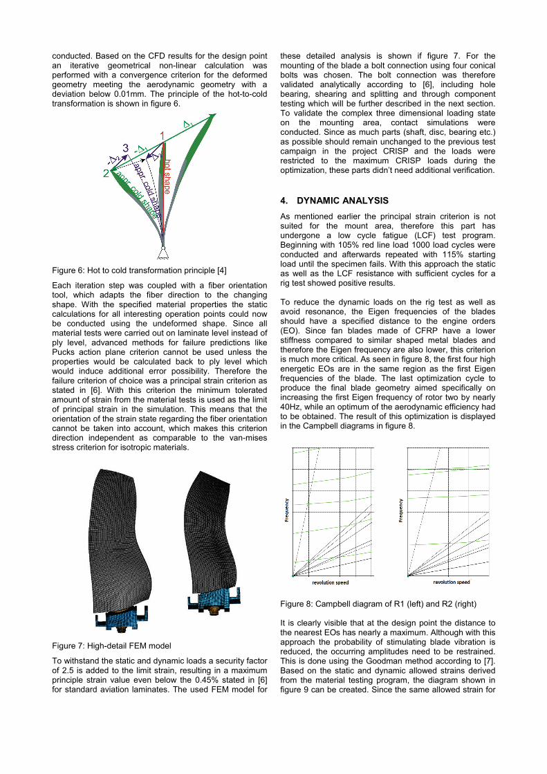
conducted. Based on the CFD results for the design point an iterative geometrical non-linear calculation was performed with a convergence criterion for the deformed geometry meeting the aerodynamic geometry with a deviation below 0.01mm. The principle of the hot-to-cold transformation is shown in figure 6.
Figure 6: Hot to cold transformation principle [4]
Each iteration step was coupled with a fiber orientation tool, which adapts the fiber direction to the changing shape. With the specified material properties the static calculations for all interesting operation points could now be conducted using the undeformed shape. Since all material tests were carried out on laminate level instead of ply level, advanced methods for failure predictions like Pucks action plane criterion cannot be used unless the properties would be calculated back to ply level which would induce additional error possibility. Therefore the failure criterion of choice was a principal strain criterion as stated in [6]. With this criterion the minimum tolerated amount of strain from the material tests is used as the limit of principal strain in the simulation. This means that the orientation of the strain state regarding the fiber orientation cannot be taken into account, which makes this criterion direction independent as comparable to the van-mises stress criterion for isotropic materials.
Figure 7: High-detail FEM model
To withstand the static and dynamic loads a security factor of 2.5 is added to the limit strain, resulting in a maximum principle strain value even below the 0.45% stated in [6] for standard aviation laminates. The used FEM model for
these detailed analysis is shown if figure 7. For the mounting of the blade a bolt connection using four conical bolts was chosen. The bolt connection was therefore validated analytically according to [6], including hole bearing, shearing and splitting and through component testing which will be further described in the next section. To validate the complex three dimensional loading state on the mounting area, contact simulations were conducted. Since as much parts (shaft, disc, bearing etc.) as possible should remain unchanged to the previous test campaign in the project CRISP and the loads were restricted to the maximum CRISP loads during the optimization, these parts didn’t need additional verification.
4. DYNAMIC ANALYSIS As mentioned earlier the principal strain criterion is not suited for the mount area, therefore this part has undergone a low cycle fatigue (LCF) test program. Beginning with 105% red line load 1000 load cycles were conducted and afterwards repeated with 115% starting load until the specimen fails. With this approach the static as well as the LCF resistance with sufficient cycles for a rig test showed positive results. To reduce the dynamic loads on the rig test as well as avoid resonance, the Eigen frequencies of the blades should have a specified distance to the engine orders (EO). Since fan blades made of CFRP have a lower stiffness compared to similar shaped metal blades and therefore the Eigen frequency are also lower, this criterion is much more critical. As seen in figure 8, the first four high energetic EOs are in the same region as the first Eigen frequencies of the blade. The last optimization cycle to produce the final blade geometry aimed specifically on increasing the first Eigen frequency of rotor two by nearly 40Hz, while an optimum of the aerodynamic efficiency had to be obtained. The result of this optimization is displayed in the Campbell diagrams in figure 8.
Figure 8: Campbell diagram of R1 (left) and R2 (right) It is clearly visible that at the design point the distance to the nearest EOs has nearly a maximum. Although with this approach the probability of stimulating blade vibration is reduced, the occurring amplitudes need to be restrained. This is done using the Goodman method according to [7]. Based on the static and dynamic allowed strains derived from the material testing program, the diagram shown in figure 9 can be created. Since the same allowed strain for

tension and compression is used and dynamic loads are alternating loads, the Goodman diagram can be simplified using only one quadrant and therefore absolute strain
Figure 9: Goodman Diagram values. The main idea behind this method is linking static loads with dynamic loads to derive maximum allowed loading combinations. With high static loads occurring only low dynamic loads can be resisted and vice versa. This analysis is done for all operating points over the rpm range and different pressure fields. Therefore software was developed to identify the most critical load combinations and the associated nodes in the model. To take the accuracy for the dynamic measurement into account, the Goodman line needs to be lowered for two σ for the excitation limits and to 40% for the forced response limits. Based on the numerical modal analysis the calculated amplitude of the relevant modes can be addressed to a certain static/dynamic strain combination. When this data is applied to the Goodman diagram, the allowed amplitude for every mode is specified and set as a limit. To control the amplitudes on the rig test, strain gauges are mounted on the blades enabling the test engineer to abort the test if the specified amplitude limits will be exceeded.
5. AEROELASTIC BEHAVIOR The estimation of the aeroelastic behavior is not included in the optimization chain but it is very important for the safety of the test rig. The analysis contains the prediction of the flutter stability and of the system behavior for forced response. The occurring oscillation amplitudes are used to estimate the blade loadings. On the basis of the general equation of motion and if structural damping is neglected, the development of the oscillation amplitude can be described by the aerodynamic damping. Based on the energy method by Carta [8] the aeroelastic damping can be calculated by the deformation and unsteady pressure which occur during the oscillation on the blade surface. Depending on the phase lag between these two quantities the aeroelastic work can have an exciting or a damping effect on the oscillation. Figure 10 shows the distribution of the local aerodynamic excitation over the blade surfaces for suction and pressure side in which the
green areas have a damping and the red areas have an exciting effect. Integrating the local aerodynamic excitation over the surface provides the global aerodynamic damping in which the sign is adapted in a way that a positive value describes a damping and a negative sign describes an exciting effect. The calculation of the unsteady flow field does not consider the coupling effect between structural mechanic and aerodynamic behavior of the system. The aeroelastic analysis take place in two separated consecutive steps. In the first part the natural oscillation of the rotor and in the second the unsteady pressure on the blade surface were be determined.
Fig 10: Local excitation on the blade If there is no mistuning and no structural dynamic interaction between the blades, the natural oscillation of the rotor can be described as a combination of the natural oscillation of one blade and an inter-blade phase angle. Therefore the natural oscillation of one blade has been calculated considering the blade prestress loadings during the operation using a nonlinear numerical modal analysis. The inter-blade phase angle describes the constant phase lag between the oscillation of two adjacent blades which inter-blade phase angles are possible can be determined directly by the number of blades of the belonging rotor. The unsteady flow field was simulated by mapping the rotor oscillation (blade natural oscillation + inter-blade phase angle) on the CFD-mesh. The vibration of the blade and the unsteady flow field are dependent on the operating conditions of the turbomachinery. The aerodynamic damping is a function of the blade natural oscillation, the inter-blade phase angle and the operating conditions. Thus the aeroelastic behavior should be determined for the entire operating conditions of the turbomachinery. The compressor map of the CRISP II fan is shown in figure 11. For the estimation of the flutter stability, the aerodynamic damping due to the oscillation of the rotor in the flow field should be calculated. The TRACE [9] linearized Navier-Stokes three dimensional flow solver was used to simulate the unsteady flow field due to very low vibration amplitudes. All relevant Eigen modes of the blade and all inter-blade phase angles have to be considered because it is not possible to estimate which rotor natural oscillation will occur. The rotor natural oscillation with the lowest value for aerodynamic damping is critical and used to estimate the flutter stability. Only the first three Eigen modes are relevant because their reduced frequencies are in a range in which flutter can occur. Figure 12 shows the
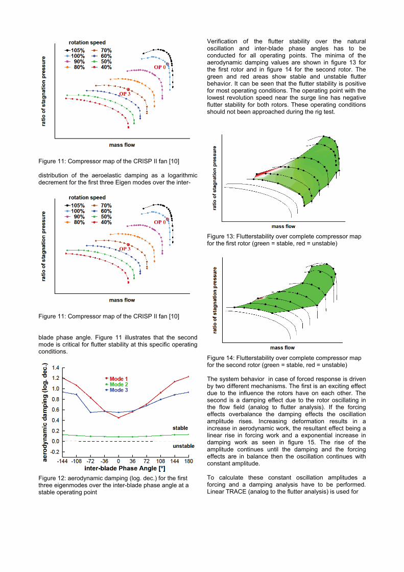
Figure 11: Compressor map of the CRISP II fan [10] distribution of the aeroelastic damping as a logarithmic decrement for the first three Eigen modes over the inter-
Figure 11: Compressor map of the CRISP II fan [10] blade phase angle. Figure 11 illustrates that the second mode is critical for flutter stability at this specific operating conditions.
Figure 12: aerodynamic damping (log. dec.) for the first three eigenmodes over the inter-blade phase angle at a stable operating point
Verification of the flutter stability over the natural oscillation and inter-blade phase angles has to be conducted for all operating points. The minima of the aerodynamic damping values are shown in figure 13 for the first rotor and in figure 14 for the second rotor. The green and red areas show stable and unstable flutter behavior. It can be seen that the flutter stability is positive for most operating conditions. The operating point with the lowest revolution speed near the surge line has negative flutter stability for both rotors. These operating conditions should not been approached during the rig test.
Figure 13: Flutterstability over complete compressor map for the first rotor (green = stable, red = unstable)
Figure 14: Flutterstability over complete compressor map for the second rotor (green = stable, red = unstable) The system behavior in case of forced response is driven by two different mechanisms. The first is an exciting effect due to the influence the rotors have on each other. The second is a damping effect due to the rotor oscillating in the flow field (analog to flutter analysis). If the forcing effects overbalance the damping effects the oscillation amplitude rises. Increasing deformation results in a increase in aerodynamic work, the resultant effect being a linear rise in forcing work and a exponential increase in damping work as seen in figure 15. The rise of the amplitude continues until the damping and the forcing effects are in balance then the oscillation continues with constant amplitude. To calculate these constant oscillation amplitudes a forcing and a damping analysis have to be performed. Linear TRACE (analog to the flutter analysis) is used for
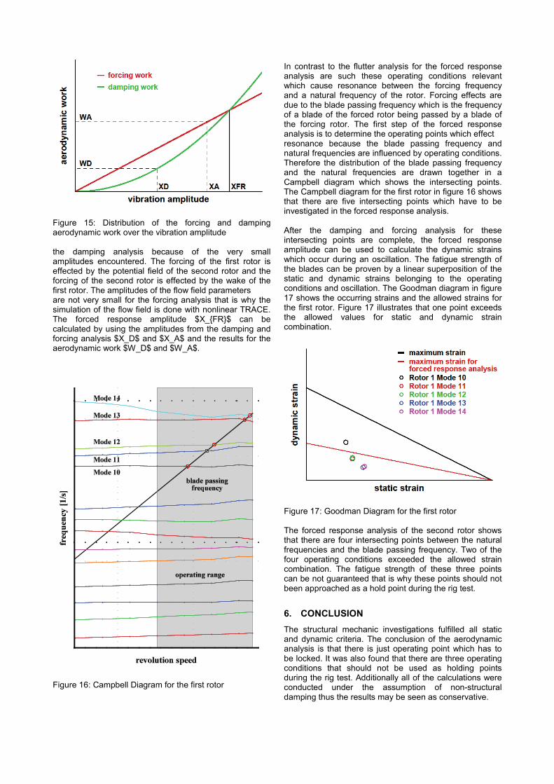
Figure 15: Distribution of the forcing and damping aerodynamic work over the vibration amplitude the damping analysis because of the very small amplitudes encountered. The forcing of the first rotor is effected by the potential field of the second rotor and the forcing of the second rotor is effected by the wake of the first rotor. The amplitudes of the flow field parameters are not very small for the forcing analysis that is why the simulation of the flow field is done with nonlinear TRACE. The forced response amplitude $X_{FR}$ can be calculated by using the amplitudes from the damping and forcing analysis $X_D$ and $X_A$ and the results for the aerodynamic work $W_D$ and $W_A$.
Figure 16: Campbell Diagram for the first rotor
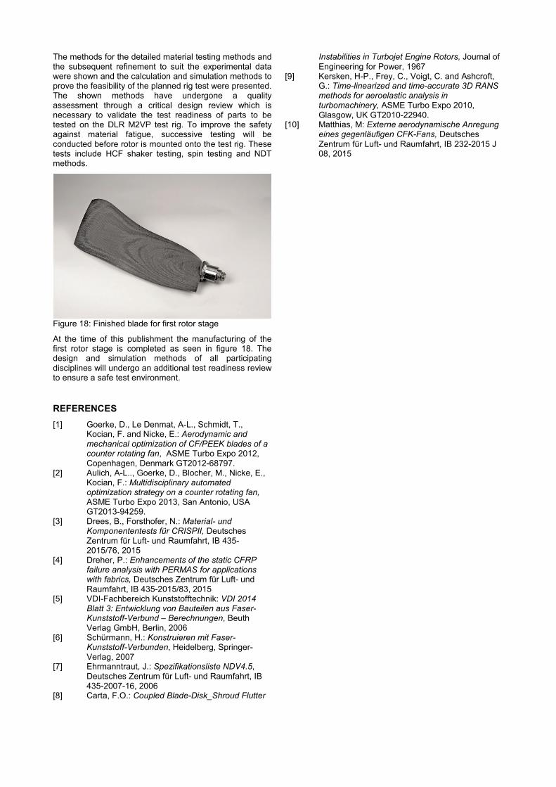
In contrast to the flutter analysis for the forced response analysis are such these operating conditions relevant which cause resonance between the forcing frequency and a natural frequency of the rotor. Forcing effects are due to the blade passing frequency which is the frequency of a blade of the forced rotor being passed by a blade of the forcing rotor. The first step of the forced response analysis is to determine the operating points which effect resonance because the blade passing frequency and natural frequencies are influenced by operating conditions. Therefore the distribution of the blade passing frequency and the natural frequencies are drawn together in a Campbell diagram which shows the intersecting points. The Campbell diagram for the first rotor in figure 16 shows that there are five intersecting points which have to be investigated in the forced response analysis. After the damping and forcing analysis for these intersecting points are complete, the forced response amplitude can be used to calculate the dynamic strains which occur during an oscillation. The fatigue strength of the blades can be proven by a linear superposition of the static and dynamic strains belonging to the operating conditions and oscillation. The Goodman diagram in figure 17 shows the occurring strains and the allowed strains for the first rotor. Figure 17 illustrates that one point exceeds the allowed values for static and dynamic strain combination.
Figure 17: Goodman Diagram for the first rotor The forced response analysis of the second rotor shows that there are four intersecting points between the natural frequencies and the blade passing frequency. Two of the four operating conditions exceeded the allowed strain combination. The fatigue strength of these three points can be not guaranteed that is why these points should not been approached as a hold point during the rig test.
6. CONCLUSION The structural mechanic investigations fulfilled all static and dynamic criteria. The conclusion of the aerodynamic analysis is that there is just operating point which has to be locked. It was also found that there are three operating conditions that should not be used as holding points during the rig test. Additionally all of the calculations were conducted under the assumption of non-structural damping thus the results may be seen as conservative.
The methods for the detailed material testing methods and the subsequent refinement to suit the experimental data were shown and the calculation and simulation methods to prove the feasibility of the planned rig test were presented. The shown methods have undergone a quality assessment through a critical design review which is necessary to validate the test readiness of parts to be tested on the DLR M2VP test rig. To improve the safety against material fatigue, successive testing will be conducted before rotor is mounted onto the test rig. These tests include HCF shaker testing, spin testing and NDT methods.
Figure 18: Finished blade for first rotor stage
At the time of this publishment the manufacturing of the first rotor stage is completed as seen in figure 18. The design and simulation methods of all participating disciplines will undergo an additional test readiness review to ensure a safe test environment.
REFERENCES [1] Goerke, D., Le Denmat, A-L., Schmidt, T.,
Kocian, F. and Nicke, E.: Aerodynamic and mechanical optimization of CF/PEEK blades of a counter rotating fan, ASME Turbo Expo 2012, Copenhagen, Denmark GT2012-68797.
[2] Aulich, A-L.., Goerke, D., Blocher, M., Nicke, E., Kocian, F.: Multidisciplinary automated optimization strategy on a counter rotating fan, ASME Turbo Expo 2013, San Antonio, USA GT2013-94259.
[3] Drees, B., Forsthofer, N.: Material- und Komponententests für CRISPII, Deutsches Zentrum für Luft- und Raumfahrt, IB 435-2015/76, 2015
[4] Dreher, P.: Enhancements of the static CFRP failure analysis with PERMAS for applications with fabrics, Deutsches Zentrum für Luft- und Raumfahrt, IB 435-2015/83, 2015
[5] VDI-Fachbereich Kunststofftechnik: VDI 2014 Blatt 3: Entwicklung von Bauteilen aus Faser-Kunststoff-Verbund – Berechnungen, Beuth Verlag GmbH, Berlin, 2006
[6] Schürmann, H.: Konstruieren mit Faser-Kunststoff-Verbunden, Heidelberg, Springer-Verlag, 2007
[7] Ehrmanntraut, J.: Spezifikationsliste NDV4.5, Deutsches Zentrum für Luft- und Raumfahrt, IB 435-2007-16, 2006
[8] Carta, F.O.: Coupled Blade-Disk_Shroud Flutter
Instabilities in Turbojet Engine Rotors, Journal of Engineering for Power, 1967
[9] Kersken, H-P., Frey, C., Voigt, C. and Ashcroft, G.: Time-linearized and time-accurate 3D RANS methods for aeroelastic analysis in turbomachinery, ASME Turbo Expo 2010, Glasgow, UK GT2010-22940.
[10] Matthias, M: Externe aerodynamische Anregung eines gegenläufigen CFK-Fans, Deutsches Zentrum für Luft- und Raumfahrt, IB 232-2015 J 08, 2015
Related Documents