Structural Integrity Performance of Additively Manufactured Titanium Alloys Professor Xiang Zhang Centre for Manufacturing & Materials Engineering Royal Aeronautical Society Structures and Materials Conference “New Materials, Structures and Manufacturing Methods for Aerospace Use” AMRC Sheffield, 5th April 2017

Welcome message from author
This document is posted to help you gain knowledge. Please leave a comment to let me know what you think about it! Share it to your friends and learn new things together.
Transcript
Structural Integrity Performance of Additively Manufactured Titanium Alloys
Professor Xiang Zhang
Centre for Manufacturing & Materials Engineering
Royal Aeronautical Society Structures and Materials Conference “New Materials, Structures and Manufacturing Methods
for Aerospace Use”
AMRC Sheffield, 5th April 2017
Acknowledgements
Coventry University
Dr A Khadar Syed Professor Mike Fitzpatrick Xueyuan Wang, Romali Biswal
CollaboratorsProfessor SW Williams (Cranfield University)Dr F Martina, Dr J Ding (Cranfield University)Dr J Zhang (Beihang University, China)M Zhang (Nanyang Technological University, Singapore)
SponsorsAirbusWAAMMat programmeLRF/NSIRC
2

Outline
- IntroductionAdditive manufacturing of titanium alloys
Durability & damage tolerance requirements
AM titanium projects at Coventry University
- Fatigue & Fracture ResponsesChallenges to AM structural integrity
High cycle fatigue
Fracture toughness
Fatigue crack growth behaviour
- Summary
3

Metal AM Processes
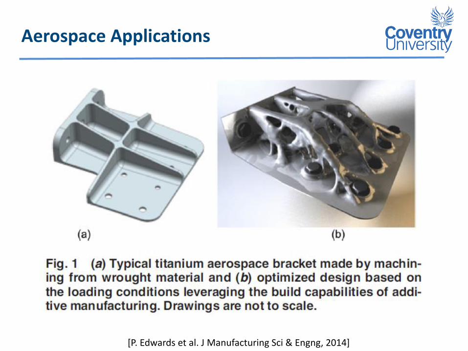
Aerospace Applications
[P. Edwards et al. J Manufacturing Sci & Engng, 2014]

Aerospace Applications
WAAM can build much larger parts and at faster deposition rate
Ti-6Al-4V wing spar built for BAE Systems, top view (courtesy BAE Systems; PAWWAAM process)
Ti-6Al-4V external landing gear assembly (PAWWAAM process)
[Source: baesystems.com: ‘Growing knowledge, growing parts: innovative 3D printing process reveals potential for aerospace industry’; 2014. http://www.baesystems.com/article/BAES_163742/growingknowledge-growing-parts.]
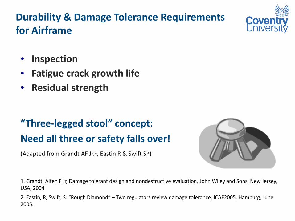
Durability & Damage Tolerance Requirements for Airframe
• Inspection
• Fatigue crack growth life
• Residual strength
“Three-legged stool” concept:
Need all three or safety falls over!
(Adapted from Grandt AF Jr.1, Eastin R & Swift S 2)
1. Grandt, Alten F Jr, Damage tolerant design and nondestructive evaluation, John Wiley and Sons, New Jersey, USA, 2004
2. Eastin, R, Swift, S. “Rough Diamond” – Two regulators review damage tolerance, ICAF2005, Hamburg, June 2005.
Manufacturing & Materials Engineering (Research Centre)
Core themes: Processes, Materials & Products
Research Groups
Functional materials, Future manufacturing, Metrology
Laser Engineering, Materials mechanics & measurement
Structural Integrity, Welding & joining
Structural Integrity Key Research Themes
Additive manufactured metallics (structural integrity focus)
Advanced modelling & experimentation methods
Non-destructive evaluation techniques
Residual stress engineering (e.g. laser shock peening)
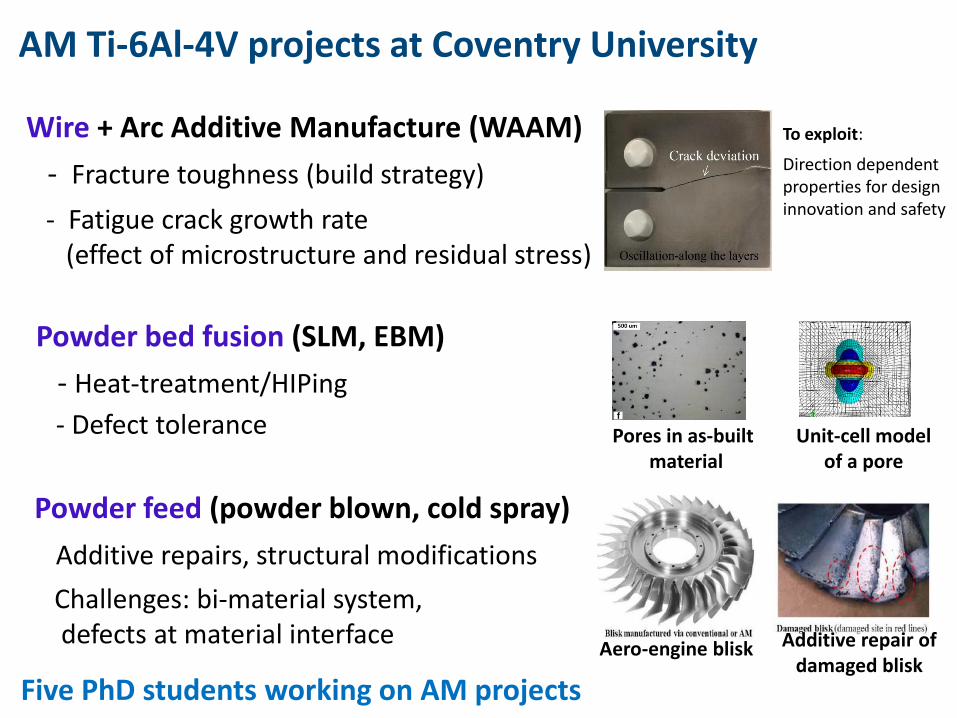
AM Ti-6Al-4V projects at Coventry University
Wire + Arc Additive Manufacture (WAAM)
- Fracture toughness (build strategy)
- Fatigue crack growth rate (effect of microstructure and residual stress)
Powder bed fusion (SLM, EBM)
- Heat-treatment/HIPing
- Defect tolerance
Powder feed (powder blown, cold spray)
Additive repairs, structural modifications
Challenges: bi-material system, defects at material interface
Aero-engine blisk Additive repair of damaged blisk
Pores in as-built material
Unit-cell model of a pore
To exploit:
Direction dependent properties for design innovation and safety
Five PhD students working on AM projects

Outline
- IntroductionAdditive manufacturing of titanium alloys
Durability & damage tolerance requirements
AM titanium projects at Coventry University
- Fatigue & Fracture ResponsesChallenges to AM structural integrity
High cycle fatigue
Fracture toughness
Fatigue crack growth behaviour
- Summary
10
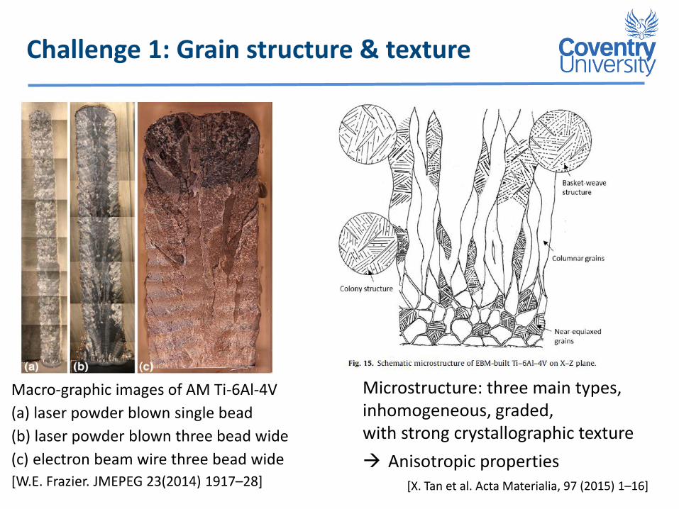
Challenge 1: Grain structure & texture
Microstructure: three main types, inhomogeneous, graded, with strong crystallographic texture
Anisotropic properties[X. Tan et al. Acta Materialia, 97 (2015) 1–16]
Macro-graphic images of AM Ti-6Al-4V
(a) laser powder blown single bead
(b) laser powder blown three bead wide
(c) electron beam wire three bead wide
[W.E. Frazier. JMEPEG 23(2014) 1917–28]

Challenge 2: Residual Stresses
WAAM Ti-6Al-4V Produced by Cranfield University
Cut & CMM measurement
Displacement profile Input into FE model
-400
-200
0
200
400
600
800
0 20 40 60 80 100 120 140Stre
ss (
MP
a)
Distance from base plate (mm)
SubstrateWAAM build “Wall”
1D stress plot(average in mid thickness)
2D stress map(FEA)
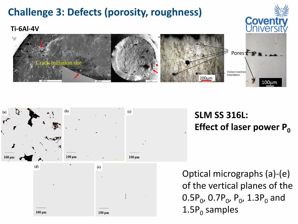
Challenge 3: Defects (porosity, roughness)
Ti-6Al-4V
Crack initiation site
Pores
Optical micrographs (a)-(e) of the vertical planes of the 0.5P0, 0.7P0, P0, 1.3P0 and 1.5P0 samples
SLM SS 316L: Effect of laser power P0

Challenge 4: Property dependency on Process methods and parameters
Properties depend on AM build methods, build strategies, process parameters, and post-AM treatments, such as:
Heat treatment: for residual stress relief (necessary for SLM)
Hot Isostatic Pressure (HIP): to close porosities
Laser shock peening: to introduce compressive residual stress
Large variations in material performance, especially under fatigue loads
No “handbook” of AM metal mechanical properties

Outline
- IntroductionAdditive manufacturing of titanium alloys
Durability & damage tolerance requirements
AM titanium projects at Coventry University
- Fatigue & Fracture ResponsesChallenges to AM structural integrity
High cycle fatigue
Fracture toughness
Fatigue crack growth behaviour
- Summary
15
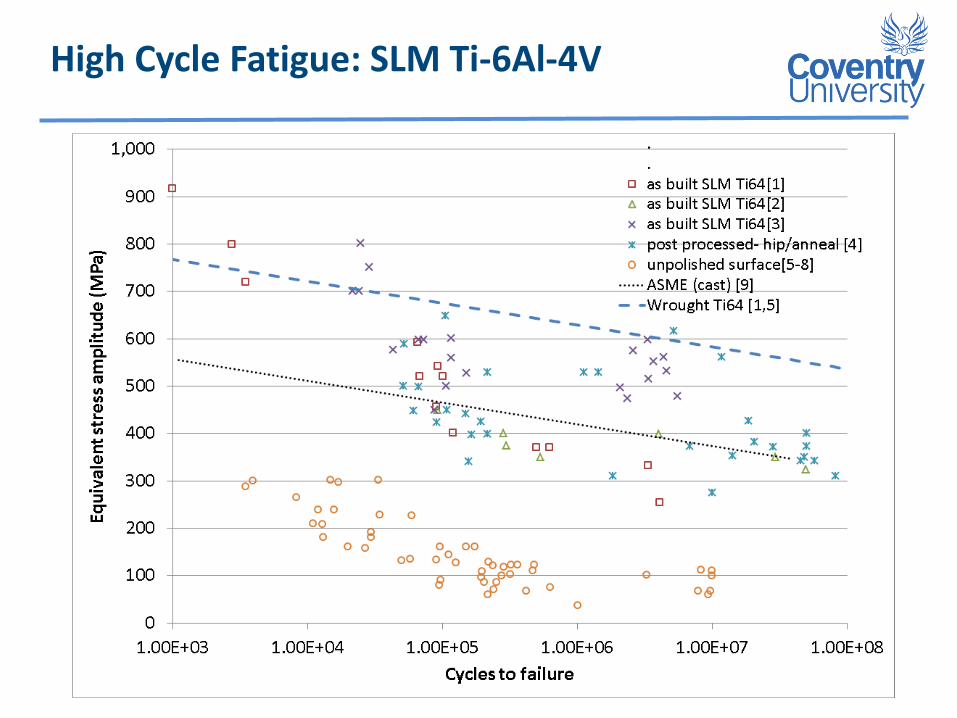
High Cycle Fatigue: SLM Ti-6Al-4V
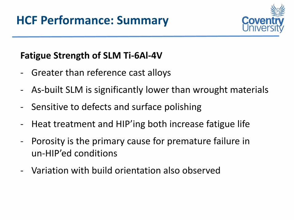
HCF Performance: Summary
Fatigue Strength of SLM Ti-6Al-4V
- Greater than reference cast alloys
- As-built SLM is significantly lower than wrought materials
- Sensitive to defects and surface polishing
- Heat treatment and HIP’ing both increase fatigue life
- Porosity is the primary cause for premature failure in un-HIP’ed conditions
- Variation with build orientation also observed

Fracture Toughness: AM vs. Wrought Ti-6-4
Zhang X, Martina F, Ding J, Wang X, Williams S. Fracture toughness and fatigue crack growth rate properties in wire + arc additive manufactured Ti-6Al-4V, Fatigue & Fracture of Eng Mater & Struct. Nov 2016
Plane strain condition(22 mm thick), with
2 x build orientations2 x oxygen content
Fracture Toughness: Summary
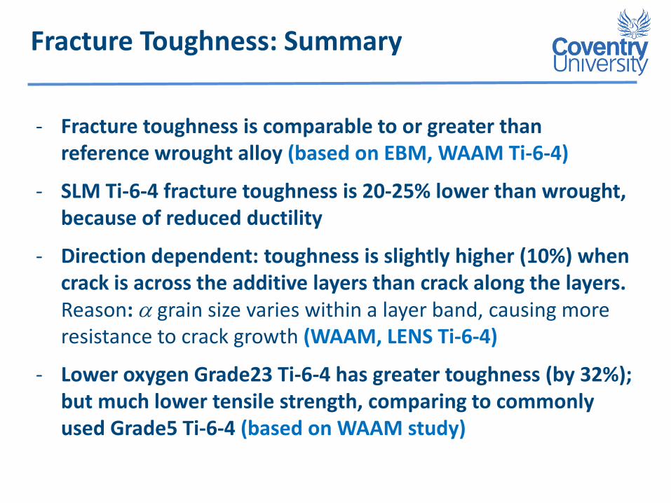
- Fracture toughness is comparable to or greater than reference wrought alloy (based on EBM, WAAM Ti-6-4)
- SLM Ti-6-4 fracture toughness is 20-25% lower than wrought, because of reduced ductility
- Direction dependent: toughness is slightly higher (10%) when crack is across the additive layers than crack along the layers.Reason: a grain size varies within a layer band, causing more resistance to crack growth (WAAM, LENS Ti-6-4)
- Lower oxygen Grade23 Ti-6-4 has greater toughness (by 32%); but much lower tensile strength, comparing to commonly used Grade5 Ti-6-4 (based on WAAM study)

FCGR: WAAM Ti-6Al-4V
Crack along layers Crack across layers
Tested at R = 0.1. Source: Zhang X, Martina F, Ding J, Wang X, Williams S. Fracture toughness and fatigue crack growth rate properties in wire + arc additive manufactured Ti-6Al-4V, Fatigue & Fracture of Eng Mater & Struct. Nov 2016
Fatigue crack growth rate is
between two ref. alloys ofconventional process
isotropic when DK > 20
direction dependent DK < 20
slower for crack across layers owing to microstructure effect when crack is smaller (next slide)
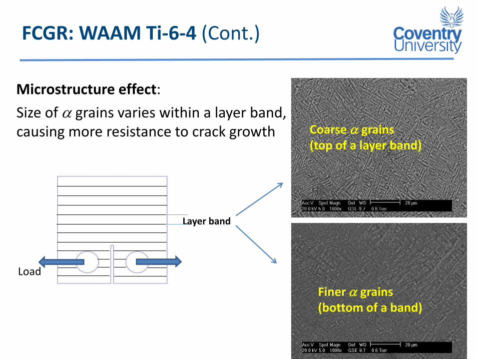
FCGR: WAAM Ti-6-4 (Cont.)
Microstructure effect:
Size of a grains varies within a layer band, causing more resistance to crack growth Coarse a grains
(top of a layer band)
Finer a grains (bottom of a band)
Layer band
Load

FCGR: SLM Ti-6Al-4V
Tested at R = 0.1. Source: S. Leuders et al. Int J Fatigue 48(2013) 300-307
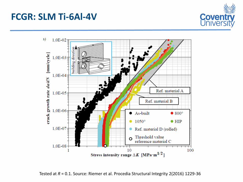
FCGR: SLM Ti-6Al-4V
Tested at R = 0.1. Source: Riemer et al. Procedia Structural Integrity 2(2016) 1229-36
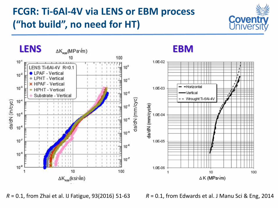
FCGR: Ti-6Al-4V via LENS or EBM process (“hot build”, no need for HT)
R = 0.1, from Edwards et al. J Manu Sci & Eng, 2014R = 0.1, from Zhai et al. IJ Fatigue, 93(2016) 51-63
EBMLENS
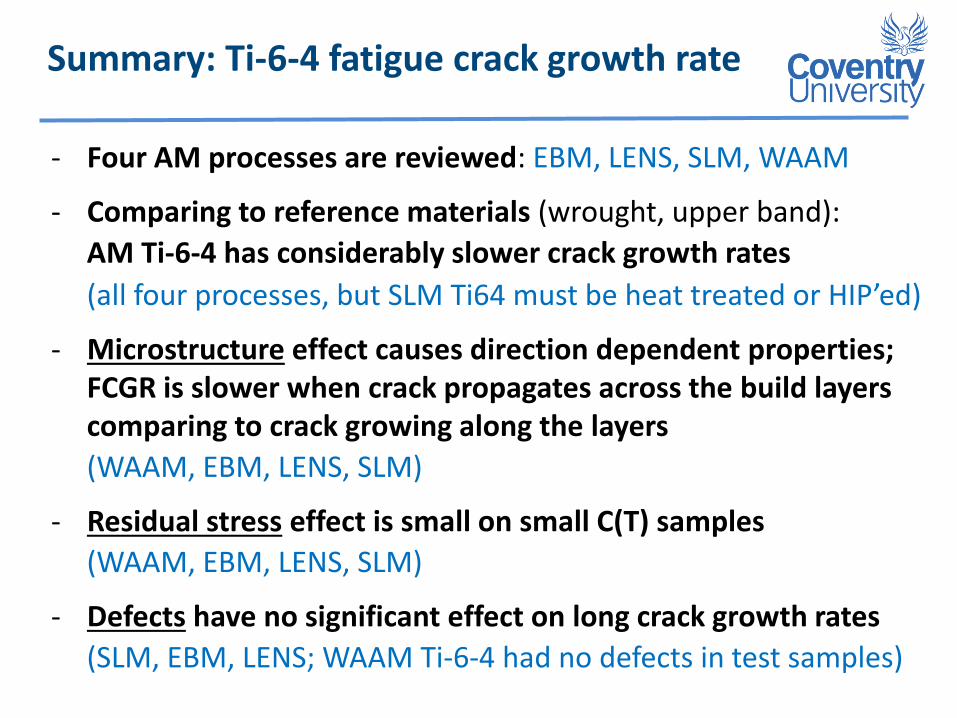
Summary: Ti-6-4 fatigue crack growth rate
- Four AM processes are reviewed: EBM, LENS, SLM, WAAM
- Comparing to reference materials (wrought, upper band):
AM Ti-6-4 has considerably slower crack growth rates
(all four processes, but SLM Ti64 must be heat treated or HIP’ed)
- Microstructure effect causes direction dependent properties;FCGR is slower when crack propagates across the build layers comparing to crack growing along the layers
(WAAM, EBM, LENS, SLM)
- Residual stress effect is small on small C(T) samples
(WAAM, EBM, LENS, SLM)
- Defects have no significant effect on long crack growth rates
(SLM, EBM, LENS; WAAM Ti-6-4 had no defects in test samples)

Conclusions
For additively manufactured Ti-6Al-4V (via EBM, LENS, WAAM, and SLM + heat treatment),
- Fracture toughness is comparable to or greater than wrought materials.
- Fatigue crack growth rate is slower than wrought alloys.
- High Cycle Fatigue strength is highly sensitive to defects.
- For damage tolerant design (based on fatigue crack growth life), current AM processes are viable manufacturing processes.
- For durability design (safe life principle), control of defects is a key challenge.
- Build speed is a challenge for AM to be adopted for larger parts.

Life Prediction Methods (current)
Fatigue crack growth rate “law”
n
effRKCdN
da),(D
Reff
Residual stress contribution (FEA)
DK
Applied load, geometry (FEA)
C, n
Material property (obtained by coupon tests)
Microstructure effect reflected?

Micro-mechanical models (under development)
Microstructural effect on crack growth rate (upper left)1
Microstructure models, e.g.
Crystal plasticity
Peri-dynamics (lower left)2
In-situ XCT, DIC, etc.
Defects behaviour in fatigue
[1] S Lu, R Bao, K Wang et al. Mater. Sci & Eng A. 690(2017) 378-386
[2] S Silling, A Askari, Peridynamics models, SES 51st Annual Technical Meeting, Purdue University, 2014

Overview: Additive Manufacture Projects (Aerospace)
Modelling & Characterisation
Airbus Experimentation &
Characterisation
SLM Ti-6Al-4V
EBM Ti-6Al-4V
EBAM Ti-6Al-4V
Structural Integrity
Process /Alloy Work Sponsors
Heat treatment effect on properties
Residual stresses
Highlights
LRF Defect tolerance (impact on safety)
LRF / Rolls-Royce
Powder blown Ti-6Al-4V
Repair high value Parts
Structure modification
SLM Ti-6Al-4V
WAAM Ti-6-4
WAAM AA 2139
Fatigue & Fracture
Join AM part to conventional material
WAAMMat Consortium: BAE Systems, Bombardier, Universities
Design application
unit-cell modelLarge pores
Explore: Direction dependent properties for design innovation and safety
Contour method
Aero-engine blisk Additive repair
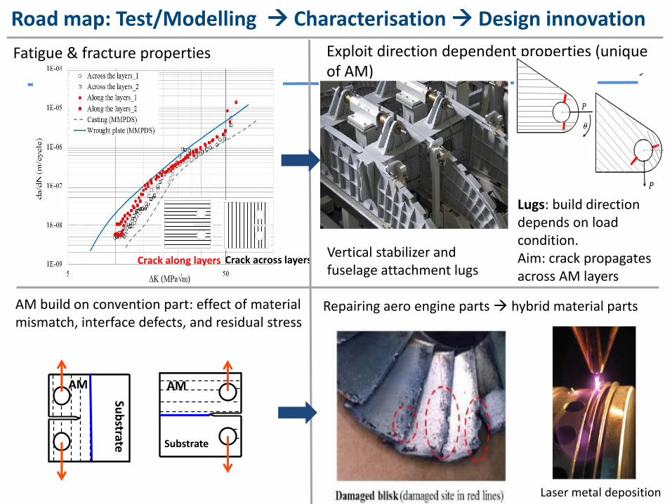
Road map
Crack along layers Crack across layers
Fatigue & fracture properties Exploit direction dependent properties (unique of AM)
Repairing aero engine parts hybrid material parts
Road map: Test/Modelling Characterisation Design innovation
Vertical stabilizer and fuselage attachment lugs
Lugs: build direction depends on load condition.Aim: crack propagates across AM layers
Laser metal deposition
AM build on convention part: effect of material mismatch, interface defects, and residual stress
AM AM
Substrate
Sub
strate
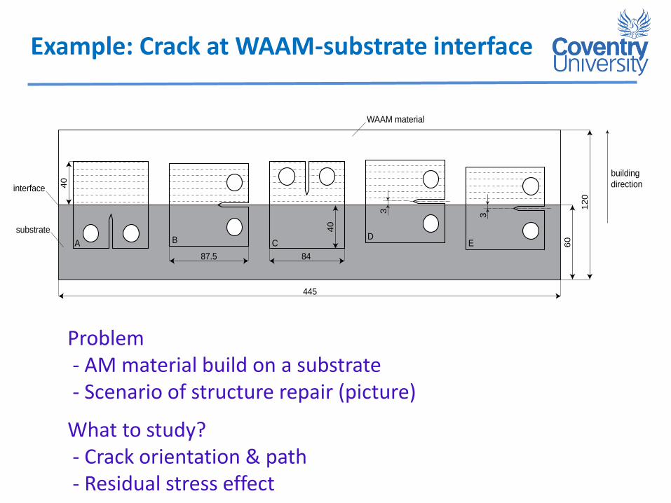
Example: Crack at WAAM-substrate interface
substrate
building
direction40
87.5 84
60
12
0
445
40
3
3
WAAM material
interface
A B CD
E
Problem- AM material build on a substrate- Scenario of structure repair (picture)
What to study?- Crack orientation & path - Residual stress effect

2. Residual stress engineering/control/mitegation
In-house robot-arm X-ray diffractometer (XRD) Heavy users of neutron/XRD world-wide
Undisturbed body containing residual stress; Sever body into 2 parts
Measure surface profilesApply deformation contour in FE model
Map of residual stress on surface where severed
Incremental hole drilling & Contour methods are complementary to the diffraction methods, as AM metals have inhomogeneous microstructure and potentially strong, varying crystallographic texture.
Related Documents