Structural Engineering and Mechanics, Vol. 49, No. 5 (2014) 645-660 DOI: http://dx.doi.org/10.12989/sem.2014.49.5.645 645 Copyright © 2014 Techno-Press, Ltd. http://www.techno-press.org/?journal=sem&subpage=8 ISSN: 1225-4568 (Print), 1598-6217 (Online) SPIF-A: on the development of a new concept of incremental forming machine R.J. Alves de Sousa , J.A.F. Ferreira, J.B. Sá de Farias, J.N.D. Torrão, D.G. Afonso and M.A.B.E Martins TEMA: Centre for Mechanical Technology and Automation, Department of Mechanical Engineering, University of Aveiro, Campus de Santiago, 3810-183 Aveiro, Portugal (Received April 3, 2013, Revised December 28, 2013, Accepted February 1, 2014) Abstract. This paper presents the design and project of an innovative concept for a Single Point Incremental Forming (SPIF) Machine. Nowadays, equipment currently available for conducting SPIF result mostly from the adaptation of conventional CNC machine tools that results in a limited range of applications in terms of materials and geometries. There is also a limited market supply of equipment dedicated to Incremental Sheet Forming (ISF), that are costly considering low batches, making it unattractive for industry. Other factors impairing a quicker spread of SPIF are large forming times and poor geometrical accuracy of parts. The following sections will depict the development of a new equipment, designed to overcome some of the limitations of machines currently used, allowing the development of a sounding basis for further studies on the particular features of this process. The equipment here described possesses six- degrees-of freedom for the tool, for the sake of improved flexibility in terms of achievable tool-paths and an extra stiffness provided by a parallel kinematics scheme. A brief state of the art about the existing SPIF machines is provided to support the project’s guidelines. Keywords: parallel kinematics; single point incremental forming; machine design; Stewart platform 1. Introduction Exception made to dedicated Single Point Incremental Forming (SPIF) machines like the ones developed by Amino Corporation (Amino et al. 2002) or by Julian Allwood’s group at Cambridge University (Allwood et al. 2005), most of Incremental Sheet Forming (ISF) experimental research is being nowadays carried out using adapted CNC milling machines or serial kinematics robots. Many examples can be found in a set of works developed by Duflou et al. (2005), as well as Shim and Park (2001), Fratini et al. (2004), Filice et al. (2002), Cerretti et al. (2004), and Ambrogio et al. (2005) to name just a few research groups. Generally, all 3-axis machine tools controlled by CNC are adequate to perform SPIF, due to their considerable stiffness and large productivity rate. Toolpath is processed through CAD/CAM software by converting a CAD file (e.g., STL, IGES, STEP) STL file containing geometric information. The sheet to be formed is clamped to the forming table, which, in addition can have Corresponding author, Professor, E-mail: [email protected]

Welcome message from author
This document is posted to help you gain knowledge. Please leave a comment to let me know what you think about it! Share it to your friends and learn new things together.
Transcript
Structural Engineering and Mechanics, Vol. 49, No. 5 (2014) 645-660 DOI: http://dx.doi.org/10.12989/sem.2014.49.5.645 645
Copyright © 2014 Techno-Press, Ltd. http://www.techno-press.org/?journal=sem&subpage=8 ISSN: 1225-4568 (Print), 1598-6217 (Online)
SPIF-A: on the development of a new concept of incremental forming machine
R.J. Alves de Sousa, J.A.F. Ferreira, J.B. Sá de Farias, J.N.D. Torrão, D.G. Afonso and M.A.B.E Martins
TEMA: Centre for Mechanical Technology and Automation, Department of Mechanical Engineering,
University of Aveiro, Campus de Santiago, 3810-183 Aveiro, Portugal
(Received April 3, 2013, Revised December 28, 2013, Accepted February 1, 2014)
Abstract. This paper presents the design and project of an innovative concept for a Single Point Incremental Forming (SPIF) Machine. Nowadays, equipment currently available for conducting SPIF result mostly from the adaptation of conventional CNC machine tools that results in a limited range of applications in terms of materials and geometries. There is also a limited market supply of equipment dedicated to Incremental Sheet Forming (ISF), that are costly considering low batches, making it unattractive for industry. Other factors impairing a quicker spread of SPIF are large forming times and poor geometrical accuracy of parts. The following sections will depict the development of a new equipment, designed to overcome some of the limitations of machines currently used, allowing the development of a sounding basis for further studies on the particular features of this process. The equipment here described possesses six-degrees-of freedom for the tool, for the sake of improved flexibility in terms of achievable tool-paths and an extra stiffness provided by a parallel kinematics scheme. A brief state of the art about the existing SPIF machines is provided to support the project’s guidelines.
Keywords: parallel kinematics; single point incremental forming; machine design; Stewart platform 1. Introduction
Exception made to dedicated Single Point Incremental Forming (SPIF) machines like the ones
developed by Amino Corporation (Amino et al. 2002) or by Julian Allwood’s group at Cambridge University (Allwood et al. 2005), most of Incremental Sheet Forming (ISF) experimental research is being nowadays carried out using adapted CNC milling machines or serial kinematics robots. Many examples can be found in a set of works developed by Duflou et al. (2005), as well as Shim and Park (2001), Fratini et al. (2004), Filice et al. (2002), Cerretti et al. (2004), and Ambrogio et al. (2005) to name just a few research groups.
Generally, all 3-axis machine tools controlled by CNC are adequate to perform SPIF, due to their considerable stiffness and large productivity rate. Toolpath is processed through CAD/CAM software by converting a CAD file (e.g., STL, IGES, STEP) STL file containing geometric information. The sheet to be formed is clamped to the forming table, which, in addition can have
Corresponding author, Professor, E-mail: [email protected]
R.J. Alves de Sousa et al.
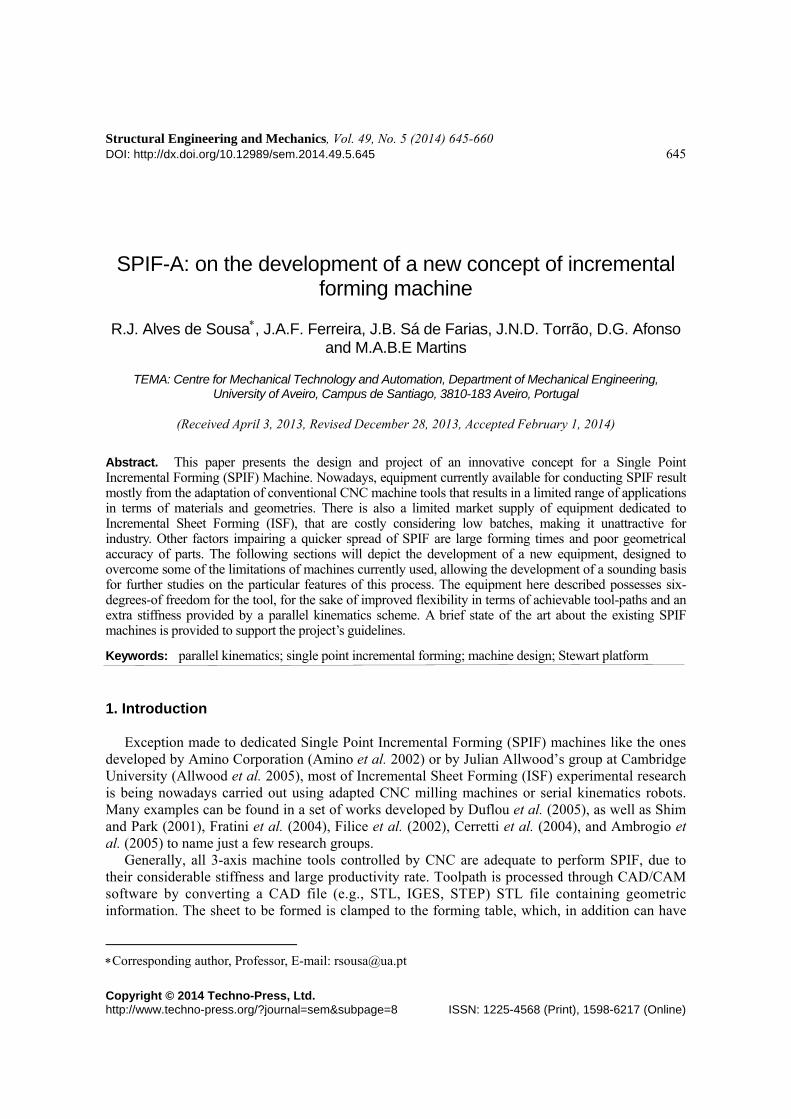
Fig. 1 Equipment for performing ISF. From left to right: adapted milling machine (Ambrogio et al. 2005, Amino purpose built machine, and serial manipulator (Strano 2005)
translational motion on the three main axes X, Y and Z. Milling machines are available in several configurations differing in volume, feed rate, maximum loads, stiffness and cost.
As an alternative to adapted machine tools, several authors have implemented the use of robotic serial manipulators to perform SPIF. This solution becomes attractive due to its high flexibility given six axes mobility, allowing the most convenient punch positioning at the surface sheet metal. It also makes possible the combination of multiple stages of production in a single manufacturing cell using a single robot (Schafer and Schraft 2004, Meier et al. 2005, Lamminen et al. 2005). The ISF process with robotic arms is performed in a very similar way to the one described for milling machines: a 3D CAD model of the part is sliced into horizontal layers in the CAM software and converted into tool paths of the punch. Fig. 1 illustrates examples of state-of-the-art equipment used to perform SPIF.
In both cases, the adaptation is straightforward. Special care must be given to the tool holder, as it must be reinforced in order to support larger lateral forces. The table must be redesigned to include a clamping frame for the sheet. Tool path algorithms can be planned similarly as in cutting operations, but the SPIF process may induce large dimensional deviations, demanding correction algorithms as presented for instance by Meier et al. (2005). In fact, it has been largely demonstrated over the literature through experiments, that tool-paths coming from metal cutting-oriented software yield large dimensional errors in final produced parts due to sheet’s continuous springback. For this reason, this is one of the most demanding topics in ISF research.
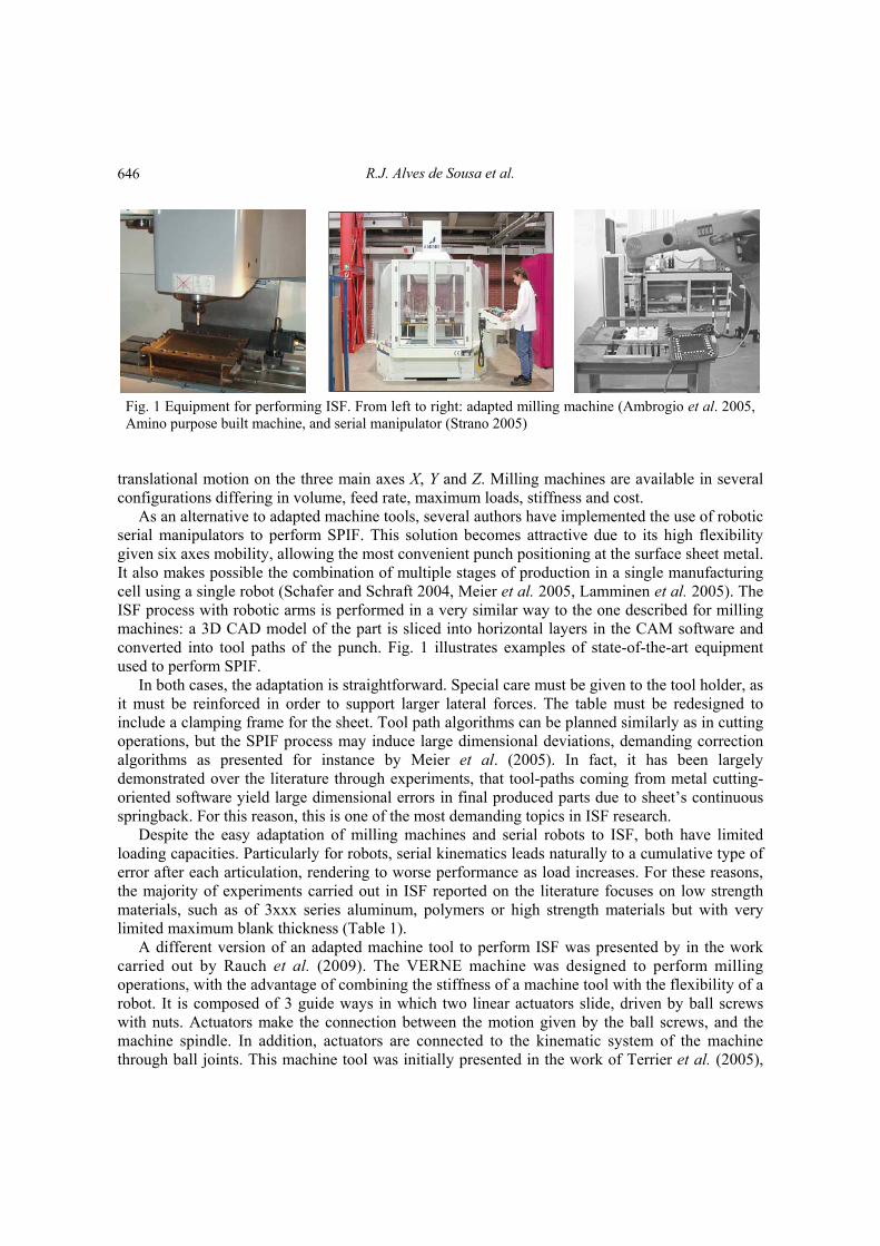
Despite the easy adaptation of milling machines and serial robots to ISF, both have limited loading capacities. Particularly for robots, serial kinematics leads naturally to a cumulative type of error after each articulation, rendering to worse performance as load increases. For these reasons, the majority of experiments carried out in ISF reported on the literature focuses on low strength materials, such as of 3xxx series aluminum, polymers or high strength materials but with very limited maximum blank thickness (Table 1).
A different version of an adapted machine tool to perform ISF was presented by in the work carried out by Rauch et al. (2009). The VERNE machine was designed to perform milling operations, with the advantage of combining the stiffness of a machine tool with the flexibility of a robot. It is composed of 3 guide ways in which two linear actuators slide, driven by ball screws with nuts. Actuators make the connection between the motion given by the ball screws, and the machine spindle. In addition, actuators are connected to the kinematic system of the machine through ball joints. This machine tool was initially presented in the work of Terrier et al. (2005),
646
SPIF-A: on the development of a new concept of incremental forming machine
Table 1 Materials generally used in SPIF
Author Material Thickness
[mm] Yield Strength
[MPa] UTS
[MPa] Duflou et al. (2005) AA-3003 O 0,85-1,5 41 130 Jeswiet et al. (2005) AA-3003 O 0,93-2,1 41 130
Ham and Jeswiet (2007)
AA-5754 AA-6451 AA-5182
0,8-1,5
106 117 130
247 N.A. N.A.
Micari et al. (2007) AA 1050-O 1,2 35 110
Jackson et al. (2008) Polypropylene+stainless steel
Polypropylene+aluminum
1,2-13 14,5-21 14,5-21
N.A. N.A.
Aerens et al. (2009)
AA 1050 O
1,06-1,2
35 110 AA-3003 O 41 130
DC04 140 N.A. AISI 304 O 241 600 AA 3003 0,85-1,5 41 103 AA 5754 1,0-1,5 106 247
DC01 0,5-1,15 N.A 357 AISI 304 O 0,4-0,8 241 600
65Cr2 0,5 N.A N.A. Franzena et al. (2009) PVC 3 37-45 N.A.
Table 2 State of the art for the equipment used to perform ISF
Author Equipment
Allwood et al. (2005) Purpose built machine Ambrogio et al. (2005) Adapted machine tool
Amino et al. (2002) Purpose built machine Arghi et al. (2009) Adapted machine tool
Dejardin et al. (2010) Adapted machine tool Duflou et al. (2007) Adapted machine tool Duflou et al. (2007) 6 axis serial robot Filice et al. (2002) Adapted machine tool
Hussain & Gao (2007) Adapted machine tool Jeswiet et al. (2002) Adapted machine tool
Kopac and Kampus (2005) Adapted machine tool Meier et al. (2005) 6 axis serial robot
Strano (2005) Adapted machine tool
as an innovative five-axis machine tool. Unfortunately, no information is available about the load capacity of VERNE machine.
A summary on several works found in literature and respective equipment used to conduct SPIF is given on Table 2. Amino Corporation currently markets a range of machines for the incremental sheet metal forming with enough accuracy to reproduce parts or functional prototypes from just a CAD file. However, it demands the use of a partial die, in opposition to what is
647
R.J. Alves de Sousa et al.
Table 3 Requirements for SPIF-A’s design (Marabuto et al. 2011)
Kinematic system Parallel with 6 dof
Punch/sheet interaction Passive or un-driven tool Admissible loads:
- axial, compressive - bending, lateral
13kN 6,5kN
Work area 500×500mm2
Vertical travel 400 mm
expected in SPIF processes. The Cambridge ISF Machine is a prototype designed by Allwood et al. (2005) to perform SPIF operations, endowed of a 3 axis translational motion. As it is fitted with a very large tapered spindle, it provides a very restricted positioning flexibility of the punch, in addition with a reduced accessibility to the work piece.
1.2 Motivation and guidelines for this project Create a stiff, flexible and cost-effective SPIF machine is the motivation for this work. In a
previous research work (Marabuto et al. 2011), it was carried out a discussion on the advantages and drawbacks of many design solutions for an incremental forming machine. This project was driven by the need of forming harder materials and with higher thicknesses, which demands larger admissible forming loads. As an innovative prototype, the so SPIF-A (with A standing for Aveiro) was designed intending to extend the process’ range of application and reproduce case studies presented in literature. Hence, it was targeted to achieve a work area of at least 500 by 500 mm, and a vertical travel of at least 400 mm. The justification for the chosen enlarged work enveloped is to guarantee the possibility of producing not only academic benchmark pieces, but also real industrial components. Nevertheless, the final machine prototype contemplates the possibility to modify the forming table size or to provide it with an additional translational motion.
The discussion carried out lead to the choice of a Stewart platform (parallel kinematics), with six independent degrees of freedom driven by hydraulic actuators, providing improved stiffness and precision at large forming forces. The possibility of simultaneous translational and rotational motions confers the potential to propose alternative tool paths to the punch, positioning it in order to reduce the amount of lateral forces during the process.
Besides the development of a kinematic system with six degrees of freedom, it was necessary to construct an appropriate spindle to house the punch and uphold the loads generated during the process, and a machine frame to ensure all necessary relative positioning of machine’s components. Bearing these requirements in mind, the project started from the guidelines stated in Marabuto et al. 2011, with the key decisions defined in Table 3.
The interaction mechanism implemented in this project was also subjected to careful analysis, since there is a widespread use of punches with spindle rotation for incremental forming operations. However, this interaction mechanism was only chosen when forming was carried out on adapted machine tools, that already include by basic construction rotational spindle, which is a fundamental feature to machining. Durante et al. (2009) also conducted experimental work on this subject to determine the influence of tool rotation speed on the forming forces and surface finish of parts obtained by ISF. Some conclusions point out that spindle speed is a detrimental parameter for this technological process in terms of surface quality (although some formability can be gained
648
SPIF-A: on the development of a new concept of incremental forming machine
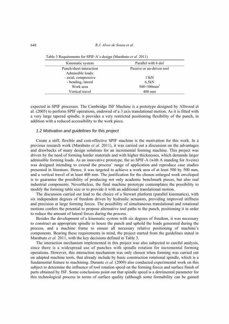
Fig. 2 Interaction mechanism selected for SPIF-A
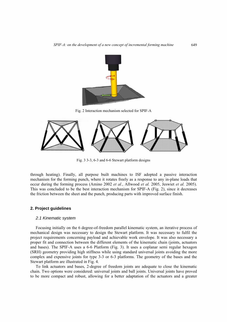
Fig. 3 3-3, 6-3 and 6-6 Stewart platform designs
through heating). Finally, all purpose built machines to ISF adopted a passive interaction mechanism for the forming punch, where it rotates freely as a response to any in-plane loads that occur during the forming process (Amino 2002 et al., Allwood et al. 2005, Jeswiet et al. 2005). This was concluded to be the best interaction mechanism for SPIF-A (Fig. 2), since it decreases the friction between the sheet and the punch, producing parts with improved surface finish. 2. Project guidelines
2.1 Kinematic system Focusing initially on the 6 degree-of-freedom parallel kinematic system, an iterative process of
mechanical design was necessary to design the Stewart platform. It was necessary to fulfil the project requirements concerning payload and achievable work envelope. It was also necessary a proper fit and connection between the different elements of the kinematic chain (joints, actuators and bases). The SPIF-A uses a 6-6 Platform (Fig. 3). It uses a coplanar semi regular hexagon (SRH) geometry providing high stiffness while using standard universal joints avoiding the more complex and expensive joints for type 3-3 or 6-3 platforms. The geometry of the bases and the Stewart platform are illustrated in Fig. 4.
To link actuators and bases, 2-degree of freedom joints are adequate to close the kinematic chain. Two options were considered: universal joints and ball joints. Universal joints have proved to be more compact and robust, allowing for a better adaptation of the actuators and a greater
649
R.J. Alves de Sousa et al.
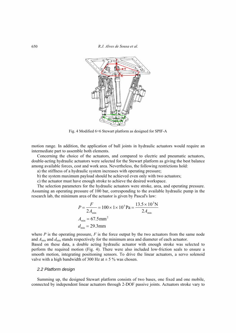
Fig. 4 Modified 6×6 Stewart platform as designed for SPIF-A
motion range. In addition, the application of ball joints in hydraulic actuators would require an intermediate part to assemble both elements.
Concerning the choice of the actuators, and compared to electric and pneumatic actuators, double-acting hydraulic actuators were selected for the Stewart platform as giving the best balance among available forces, cost and work area. Nevertheless, the following restrictions hold:
a) the stiffness of a hydraulic system increases with operating pressure; b) the system maximum payload should be achieved even only with two actuators; c) the actuator must have enough stroke to achieve the desired workspace. The selection parameters for the hydraulic actuators were stroke, area, and operating pressure.
Assuming an operating pressure of 100 bar, corresponding to the available hydraulic pump in the research lab, the minimum area of the actuator is given by Pascal's law:
P F
2Amin
100 1105 Pa 13.5 103N
2Amin
Amin 67.5mm2
dmin 29.3mm
where P is the operating pressure, F is the force output by the two actuators from the same node and Amin and dmin stands respectively for the minimum area and diameter of each actuator. Based on these data, a double acting hydraulic actuator with enough stroke was selected to perform the required motion (Fig. 4). There were also included low-friction seals to ensure a smooth motion, integrating positioning sensors. To drive the linear actuators, a servo solenoid valve with a high bandwidth of 300 Hz at ± 5 % was chosen.
2.2 Platform design Summing up, the designed Stewart platform consists of two bases, one fixed and one mobile,
connected by independent linear actuators through 2-DOF passive joints. Actuators stroke vary to
650
SPIF-A: on the development of a new concept of incremental forming machine
Fig. 4 Hydraulic actuator selected for SPIF-A, by Parker Hannifin Company
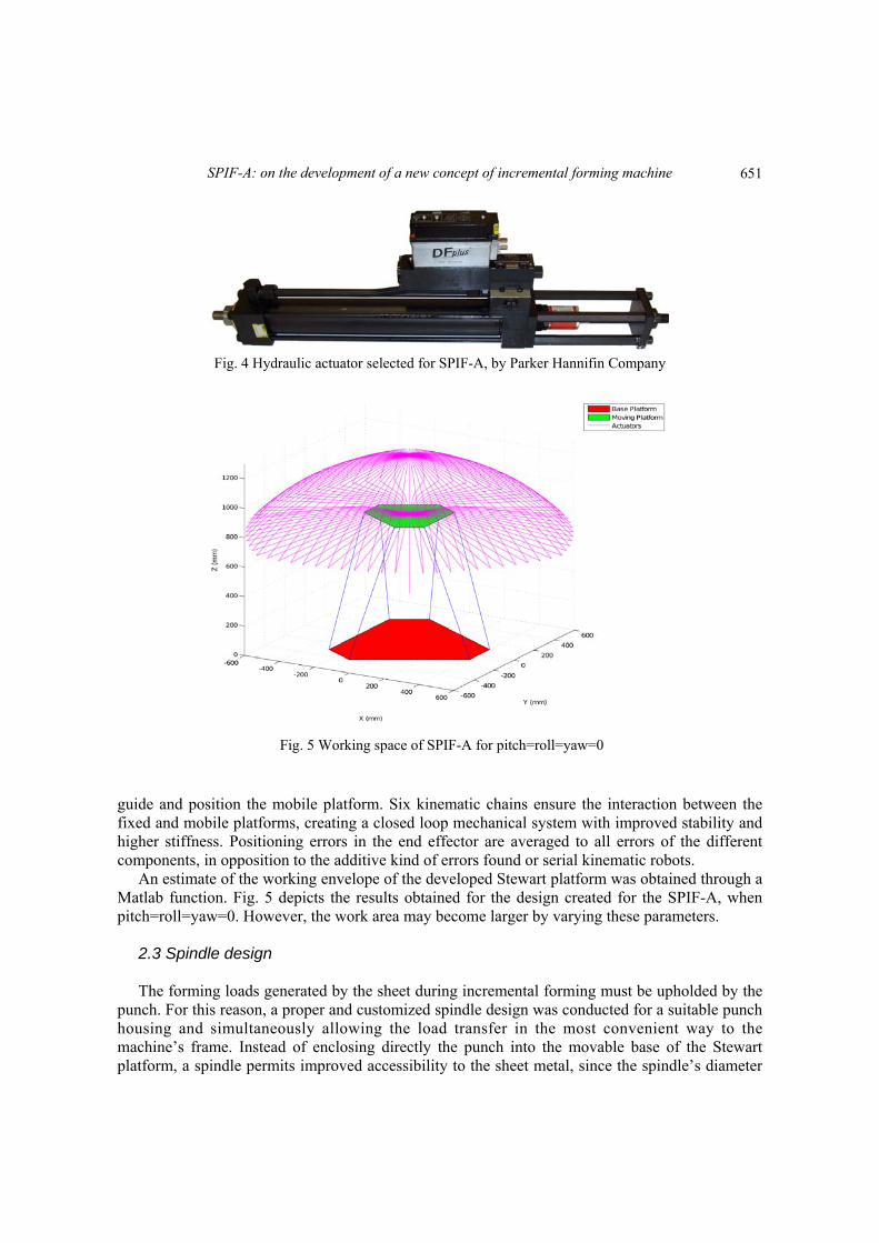
Fig. 5 Working space of SPIF-A for pitch=roll=yaw=0
guide and position the mobile platform. Six kinematic chains ensure the interaction between the fixed and mobile platforms, creating a closed loop mechanical system with improved stability and higher stiffness. Positioning errors in the end effector are averaged to all errors of the different components, in opposition to the additive kind of errors found or serial kinematic robots.
An estimate of the working envelope of the developed Stewart platform was obtained through a Matlab function. Fig. 5 depicts the results obtained for the design created for the SPIF-A, when pitch=roll=yaw=0. However, the work area may become larger by varying these parameters.
2.3 Spindle design The forming loads generated by the sheet during incremental forming must be upholded by the
punch. For this reason, a proper and customized spindle design was conducted for a suitable punch housing and simultaneously allowing the load transfer in the most convenient way to the machine’s frame. Instead of enclosing directly the punch into the movable base of the Stewart platform, a spindle permits improved accessibility to the sheet metal, since the spindle’s diameter
651
R.J. Alves de Sousa et al.
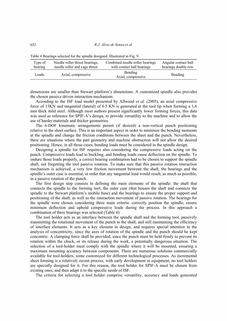
Table 4 Bearings selected for the spindle designed. Illustrated in Fig. 9
Type of bearing
Needle roller thrust bearings, needle roller and cage thrust
Combined needle roller bearings with contact ball bearings
Angular contact ball bearings double row
Loads Axial, compressive Bending
Axial, compressive Bending
dimensions are smaller than Stewart platform’s dimensions. A customized spindle also provides the chosen passive driven interaction mechanism.
According to the ISF load model presented by Allwood et al. (2005), an axial compressive force of 13KN and tangential (lateral) of 6.5 KN is generated at the tool tip when forming a 1,6 mm thick mild steel. Although most authors present significantly lower forming forces, this data was used as reference for SPIF-A’s design, to provide versatility to the machine and to allow the use of harder materials and thicker geometries.
The 6-DOF kinematic arrangements permit (if desired) a non-vertical punch positioning relative to the sheet surface. This is an important aspect in order to minimize the bending moments at the spindle and change the friction conditions between the sheet and the punch. Nevertheless, there are situations where the part geometry and machine obstruction will not allow the desired positioning. Hence, in all those cases, bending loads must be considered in the spindle design.
Designing a spindle for ISF requires also considering the compressive loads acting on the punch. Compressive loads lead to buckling, and bending loads cause deflection on the spindle. To endure those loads properly, a correct bearing combination had to be chosen to support the spindle shaft, not forgetting the tool passive rotation. To make sure that this passive rotation interaction mechanism is achieved, a very low friction movement between the shaft, the bearings and the spindle’s outer case is essential, in order that any tangential load would result, as much as possible, in a passive rotation of the punch.
The first design step consists in defining the main elements of the spindle: the shaft that connects the spindle to the forming tool, the outer case (that houses the shaft and connects the spindle to the Stewart platform’s mobile base) and the bearings to ensure the proper support and positioning of the shaft, as well as the interaction movement of passive rotation. The bearings for the spindle were chosen considering three main criteria: correctly position the spindle, ensure minimum deflection and uphold compressive loads during the process. In this approach a combination of three bearings was selected (Table 4):
The tool holder acts as an interface between the spindle shaft and the forming tool, passively transmitting the rotational movement of the punch to the shaft, and still maintaining the efficiency of interface elements. It acts as a key element in design, and requires special attention in the analysis of concentricity, since the axes of rotation of the spindle and the punch should be kept concentric. A clamping force shall be provided, since the punch must be held firmly to prevent its rotation within the chuck, or its release during the work, a potentially dangerous situation. The selection of a tool-holder must comply with the spindle where it will be mounted, ensuring a maximum mounting accuracy between components. There are numerous solutions commercially available for tool-holders, some customized for different technological processes. As incremental sheet forming is a relatively recent process, with early development in equipment, no tool holders are specially designed for it. For this reason, the tool holder for SPIF-A must be chosen from existing ones, and then adapt it to the specific needs of ISF.
The criteria for selecting a tool holder comprise versatility, accuracy and loads generated
652
SPIF-A: on the development of a new concept of incremental forming machine
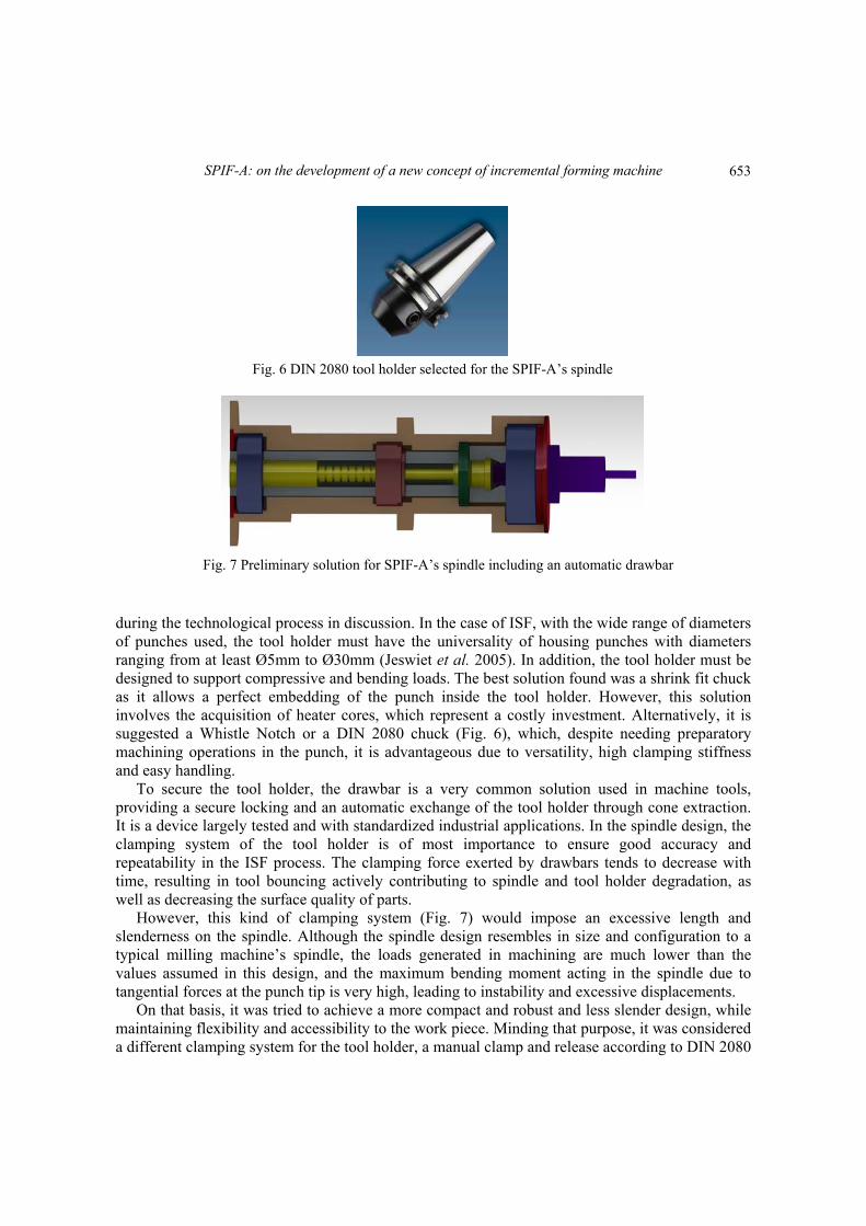
Fig. 6 DIN 2080 tool holder selected for the SPIF-A’s spindle
Fig. 7 Preliminary solution for SPIF-A’s spindle including an automatic drawbar
during the technological process in discussion. In the case of ISF, with the wide range of diameters of punches used, the tool holder must have the universality of housing punches with diameters ranging from at least Ø5mm to Ø30mm (Jeswiet et al. 2005). In addition, the tool holder must be designed to support compressive and bending loads. The best solution found was a shrink fit chuck as it allows a perfect embedding of the punch inside the tool holder. However, this solution involves the acquisition of heater cores, which represent a costly investment. Alternatively, it is suggested a Whistle Notch or a DIN 2080 chuck (Fig. 6), which, despite needing preparatory machining operations in the punch, it is advantageous due to versatility, high clamping stiffness and easy handling.
To secure the tool holder, the drawbar is a very common solution used in machine tools, providing a secure locking and an automatic exchange of the tool holder through cone extraction. It is a device largely tested and with standardized industrial applications. In the spindle design, the clamping system of the tool holder is of most importance to ensure good accuracy and repeatability in the ISF process. The clamping force exerted by drawbars tends to decrease with time, resulting in tool bouncing actively contributing to spindle and tool holder degradation, as well as decreasing the surface quality of parts.
However, this kind of clamping system (Fig. 7) would impose an excessive length and slenderness on the spindle. Although the spindle design resembles in size and configuration to a typical milling machine’s spindle, the loads generated in machining are much lower than the values assumed in this design, and the maximum bending moment acting in the spindle due to tangential forces at the punch tip is very high, leading to instability and excessive displacements.
On that basis, it was tried to achieve a more compact and robust and less slender design, while maintaining flexibility and accessibility to the work piece. Minding that purpose, it was considered a different clamping system for the tool holder, a manual clamp and release according to DIN 2080
653
R.J. Alves de Sousa et al.
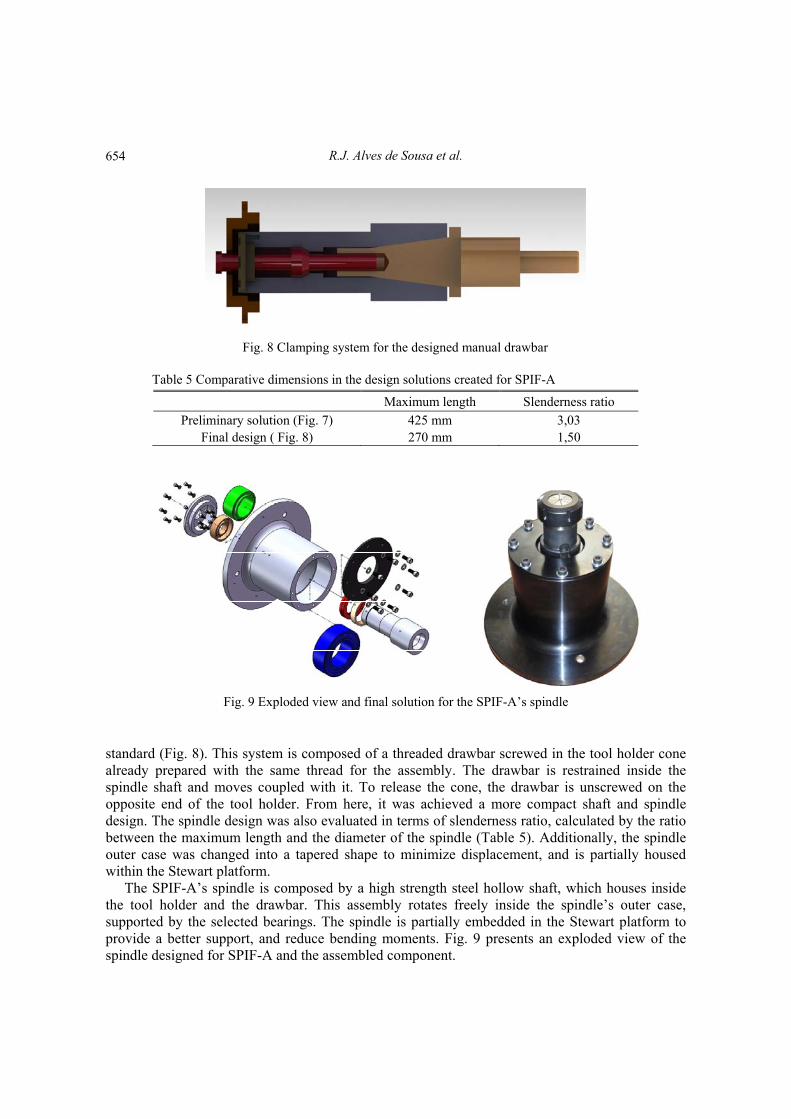
Fig. 8 Clamping system for the designed manual drawbar
Table 5 Comparative dimensions in the design solutions created for SPIF-A
Maximum length Slenderness ratio
Preliminary solution (Fig. 7) 425 mm 3,03 Final design ( Fig. 8) 270 mm 1,50
Fig. 9 Exploded view and final solution for the SPIF-A’s spindle
standard (Fig. 8). This system is composed of a threaded drawbar screwed in the tool holder cone already prepared with the same thread for the assembly. The drawbar is restrained inside the spindle shaft and moves coupled with it. To release the cone, the drawbar is unscrewed on the opposite end of the tool holder. From here, it was achieved a more compact shaft and spindle design. The spindle design was also evaluated in terms of slenderness ratio, calculated by the ratio between the maximum length and the diameter of the spindle (Table 5). Additionally, the spindle outer case was changed into a tapered shape to minimize displacement, and is partially housed within the Stewart platform.
The SPIF-A’s spindle is composed by a high strength steel hollow shaft, which houses inside the tool holder and the drawbar. This assembly rotates freely inside the spindle’s outer case, supported by the selected bearings. The spindle is partially embedded in the Stewart platform to provide a better support, and reduce bending moments. Fig. 9 presents an exploded view of the spindle designed for SPIF-A and the assembled component.
654
SPIF-A: on the development of a new concept of incremental forming machine
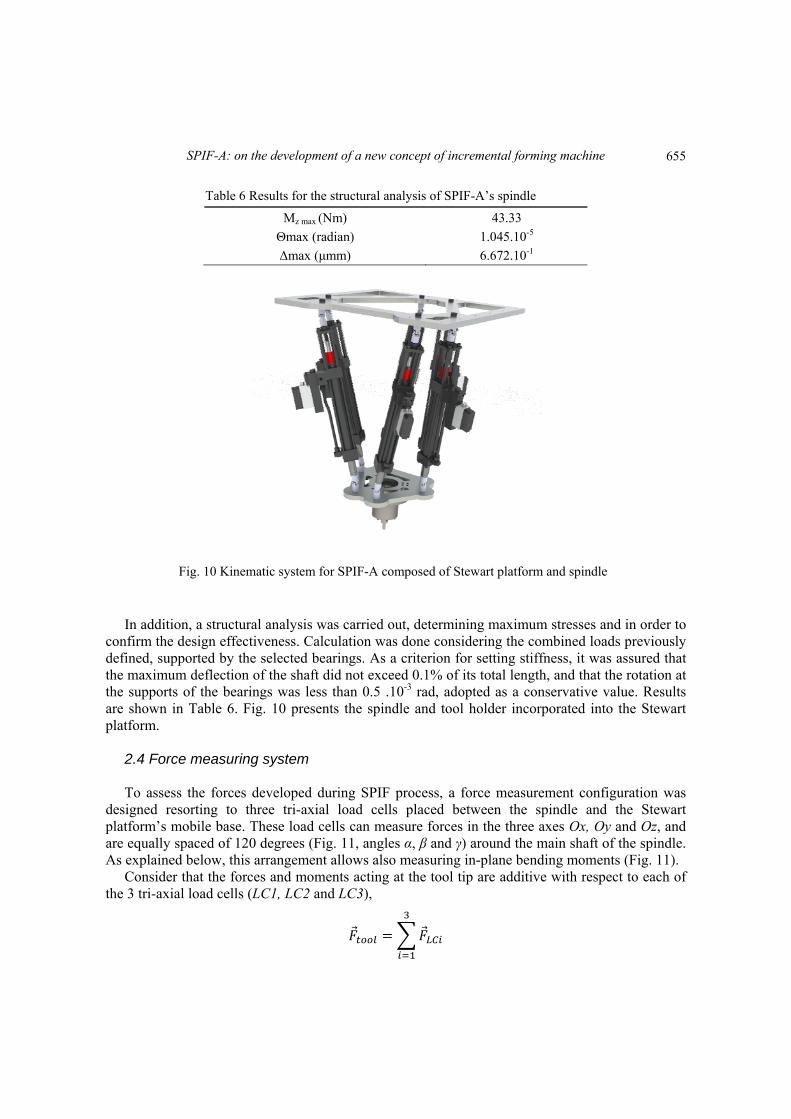
Table 6 Results for the structural analysis of SPIF-A’s spindle
Mz max (Nm) 43.33
Θmax (radian) 1.045.10-5
Δmax (μmm) 6.672.10-1
Fig. 10 Kinematic system for SPIF-A composed of Stewart platform and spindle
In addition, a structural analysis was carried out, determining maximum stresses and in order to
confirm the design effectiveness. Calculation was done considering the combined loads previously defined, supported by the selected bearings. As a criterion for setting stiffness, it was assured that the maximum deflection of the shaft did not exceed 0.1% of its total length, and that the rotation at the supports of the bearings was less than 0.5 .10-3 rad, adopted as a conservative value. Results are shown in Table 6. Fig. 10 presents the spindle and tool holder incorporated into the Stewart platform.
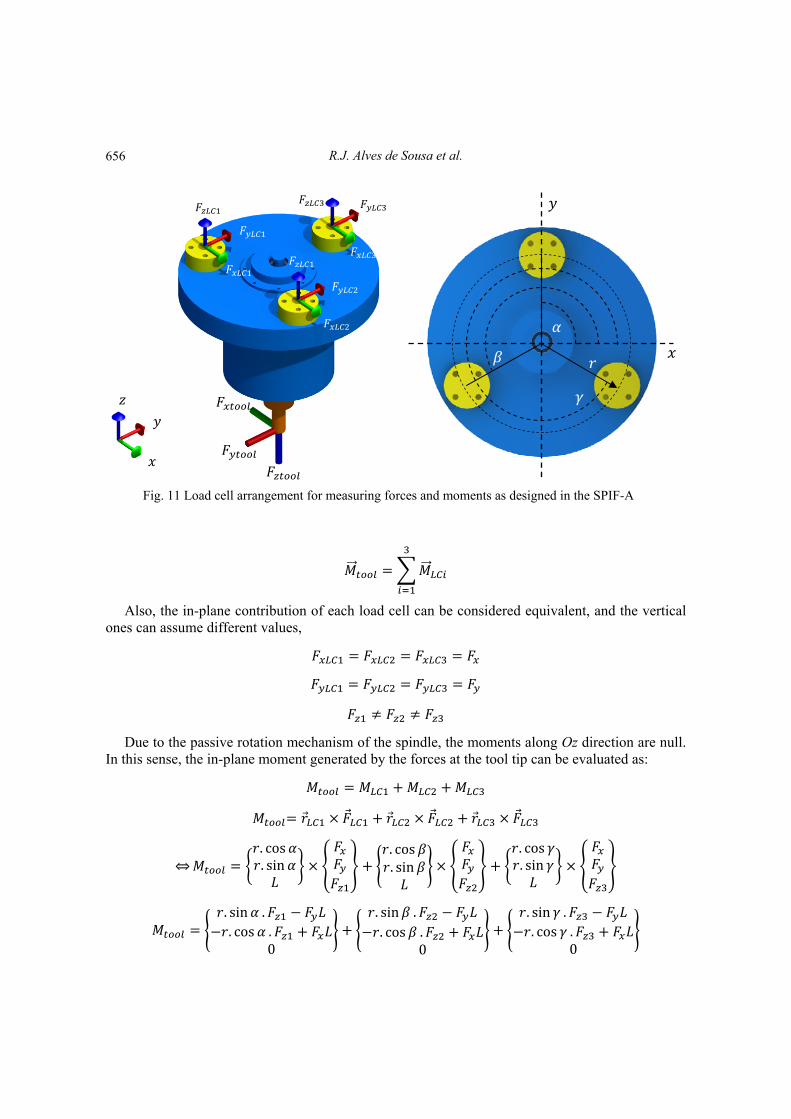
2.4 Force measuring system To assess the forces developed during SPIF process, a force measurement configuration was
designed resorting to three tri-axial load cells placed between the spindle and the Stewart platform’s mobile base. These load cells can measure forces in the three axes Ox, Oy and Oz, and are equally spaced of 120 degrees (Fig. 11, angles α, β and γ) around the main shaft of the spindle. As explained below, this arrangement allows also measuring in-plane bending moments (Fig. 11).
Consider that the forces and moments acting at the tool tip are additive with respect to each of the 3 tri-axial load cells (LC1, LC2 and LC3),
655
R.J. Alves de Sousa et al.
Fig. 11 Load cell arrangement for measuring forces and moments as designed in the SPIF-A
Also, the in-plane contribution of each load cell can be considered equivalent, and the vertical ones can assume different values,
Due to the passive rotation mechanism of the spindle, the moments along Oz direction are null. In this sense, the in-plane moment generated by the forces at the tool tip can be evaluated as:
⇔. cos. sin
. cos. sin
. cos. sin
. sin .. cos .
0
. sin .. cos .
0
. sin .. cos .
0
656
SPIF-A: on the development of a new concept of incremental forming machine
. sin . . sin . . sin . 3. cos . . cos . . cos . 3
0
where r is the distance between the spindle center and the load cell center.
2.5 Machine structure Once defined the kinematic system for the machine, the machine’s frame was designed to
properly accommodate forming forces and ensure accurate relative positioning of all machine’s parts. The frame geometry must allow the implementation of all necessary movements, strokes, working area, modular setting-up of the part to be produced, tool exchange and maintenance. Deflections must be kept at the lowest values possible, ensuring the stability and accuracy of the machine with the lowest wear rate of all parts. Particularly for SPIF-A’s, the effect of dynamic loads is negligible due to low inertia of the tools and low operating speeds.
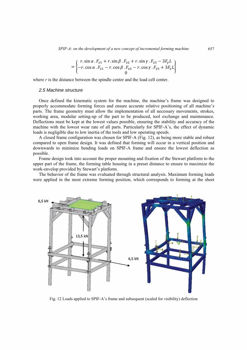
A closed frame configuration was chosen for SPIF-A (Fig. 12), as being more stable and robust compared to open frame design. It was defined that forming will occur in a vertical position and downwards to minimize bending loads on SPIF-A frame and ensure the lowest deflection as possible.
Frame design took into account the proper mounting and fixation of the Stewart platform to the upper part of the frame, the forming table housing in a preset distance to ensure to maximize the work-envelop provided by Stewart’s platform.
The behavior of the frame was evaluated through structural analysis. Maximum forming loads were applied in the most extreme forming position, which corresponds to forming at the sheet
Fig. 12 Loads applied to SPIF-A’s frame and subsequent (scaled for visibility) deflection
657
R.J. Alves de Sousa et al.
Table 7 Results for the frame’s design
Parameter Obtained Admissible
Deflection (mm/m) 0,694 1,2
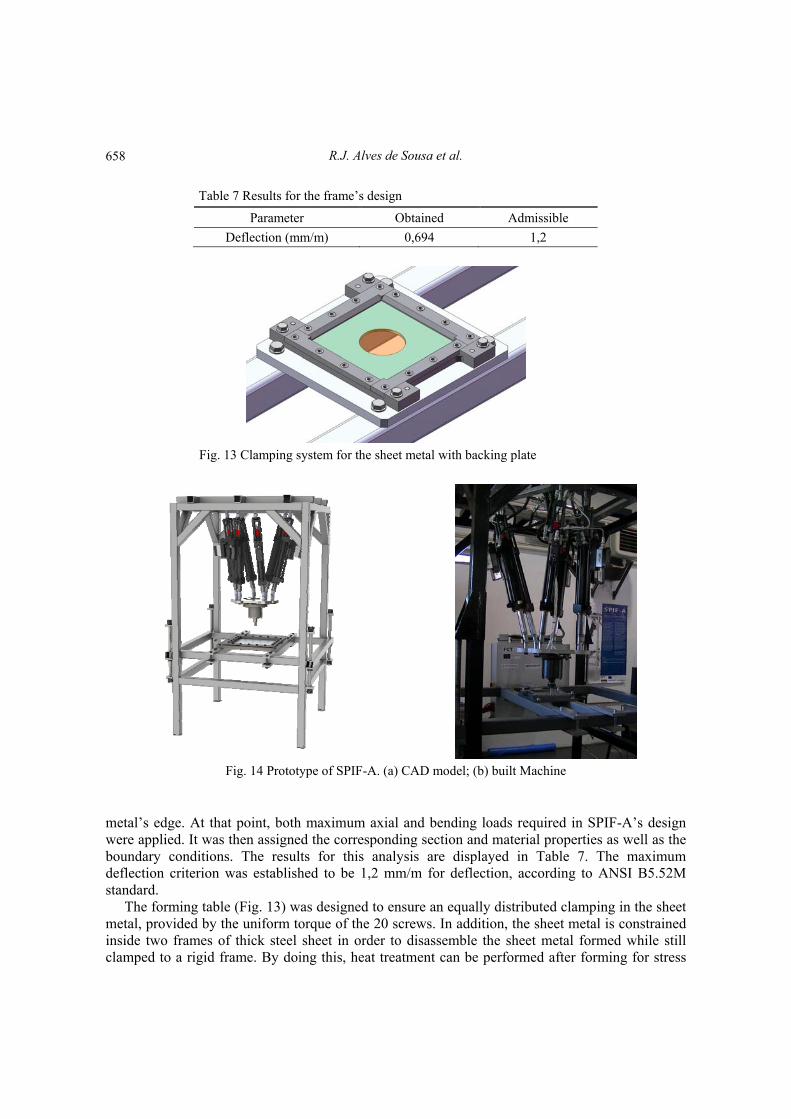
Fig. 13 Clamping system for the sheet metal with backing plate
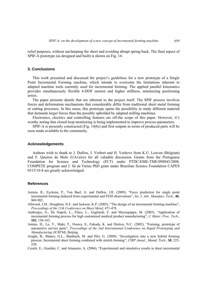
Fig. 14 Prototype of SPIF-A. (a) CAD model; (b) built Machine
metal’s edge. At that point, both maximum axial and bending loads required in SPIF-A’s design were applied. It was then assigned the corresponding section and material properties as well as the boundary conditions. The results for this analysis are displayed in Table 7. The maximum deflection criterion was established to be 1,2 mm/m for deflection, according to ANSI B5.52M standard.
The forming table (Fig. 13) was designed to ensure an equally distributed clamping in the sheet metal, provided by the uniform torque of the 20 screws. In addition, the sheet metal is constrained inside two frames of thick steel sheet in order to disassemble the sheet metal formed while still clamped to a rigid frame. By doing this, heat treatment can be performed after forming for stress
658
SPIF-A: on the development of a new concept of incremental forming machine
relief purposes, without unclamping the sheet and avoiding abrupt spring-back. The final aspect of SPIF-A prototype (as designed and built) is shown on Fig. 14. 3. Conclusions
This work presented and discussed the project’s guidelines for a new prototype of a Single Point Incremental Forming machine, which intends to overcome the limitations inherent to adapted machine tools currently used for incremental forming. The applied parallel kinematics provides simultaneously flexible 6-DOF motion and higher stiffness, minimizing positioning errors.
The paper presents details that are inherent to the project itself. The SPIF process involves forces and deformation mechanisms that considerably differ from traditional sheet metal forming or cutting processes. In this sense, this prototype opens the possibility to study different material that demands larger forces than the possibly upholded by adapted milling machines.
Electronics, electrics and controlling features are off-the scope of this paper. However, it’s worthy noting that closed loop monitoring is being implemented to improve process parameters.
SPIF-A is presently constructed (Fig. 14(b)) and first outputs in terms of produced parts will be soon made available to the community. Acknowledgements
Authors wish to thank to J. Duflou, J. Verbert and H. Verhove from K.U. Leuven (Belgium) and F. Queiros de Melo (UAveiro) for all valuable discussion. Grants from the Portuguese Foundation for Science and Technology (FCT) under PTDC/EME-TME/098845/2008, COMPETE program and J. Sá de Farias PhD grant under Brazilian Science Foundation CAPES 0515/10-8 are greatly acknowledged. References
Aerens, R., Eyckens, P., Van Bael, A. and Duflou, J.R. (2009), “Force prediction for single point
incremental forming deduced from experimental and FEM observations”, Int. J. Adv. Manufact. Tech., 46, 969-982.
Allwood, J.M., Houghton, N.E. and Jackson, K.P. (2005), “The design of an incremental forming machine”, Proceedings of the 11th Conference on Sheet Metal, 471-478.
Ambrogio, G., De Napoli, L., Filice, L., Gagliardi, F. and Muzzupappa, M. (2005), “Application of incremental forming process for high customized medical product manufacturing”, J. Mater. Proc. Tech., 162, 156-162.
Amino, H., Lu, Y., Maki, T., Osawa, S., Fukuda, K. and Dieless, N.C. (2002), “Forming, prototype of automotive service parts”, Proceedings of the 2nd International Conference on Rapid Prototyping and Manufacturing (ICRPM), Beijing.
Araghi, B., Manco, G.L., Bambach, M. and Hirt, G. (2009), “Investigation into a new hybrid forming process: Incremental sheet forming combined with stretch forming”, CIRP Annal., Manuf. Tech., 58, 225-228.
Ceretti, E., Giardini, C. and Attanasio, A. (2004), “Experimental and simulative results in sheet incremental
659
R.J. Alves de Sousa et al.
forming on CNC machines”, J. Mater. Proc. Tech., 152, 176-184. Dejardin, S., Thibaud, S., Gelin, J.C. and Michel, G. (2010), “Experimental investigations and numerical
analysis for improving knowledge of incremental sheet forming process for sheet metal parts”, J. Mater. Proc. Tech., 210, 363-369.
Duflou, J.R., Callebaut, B., Verbert, J. and De Baerdemaeker, H. (2007), “Laser assisted incremental forming: formability and accuracy improvement”, Ann. CIRP, 56, 273-276.
Duflou, J.R., Szekeres, A. and VanHerck, A. (2005), “Force measurements for single point incremental forming and experimental study”, J. Adv. Mater. Res., 6-8, 441-448.
Duflou, J.R., Tunçkol, Y., Szekeres, A. and Vanherck, P. (2007), “Experimental study on force measurements for single point incremental forming”, J. Mater. Proc. Tech., 189, 65-72.
Durante, M., Formisano, A., Langella, A. and Minutolo, F. (2009), “The influence of tool rotation on an Incremental Forming Process”, J. Mater. Proc. Tech., 209, 4621-4626.
Filice, L., Fratini, L. and Micari, F. (2002), “Analysis of material formability in incremental forming”, Annal. CIRP, 51, 199-202.
Franzena, V., Kwiatkowskia, L., Martins, P. and Tekkayaa, A. (2009), “Single point incremental forming of PVC”, J.Mater. Proc. Tech., 209, 462-469.
Fratini, L., Ambrogio, G., Di Lorenzo, R., Filice, L. and Micari, F. (2004), “Influence of mechanical properties of the sheet material on formability in single point incremental forming”, J. Mater. Proc. Tech., 153-154, 501-507.
Ham, M. and Jeswiet, J. (2007), “Forming limit curves in single point incremental forming”, Annal. CIRP, 56, 277-280.
Hussain, G. and Gao, L. (2007), “A novel method to test the thinning limits of sheet metals in negative incremental forming”, Int. J. Mach. Tool. Manuf., 47, 419-435.
Jackson, K., Allwood, J. and Landert, M. (2008), “Incremental forming of sandwich panels”, J. Mater. Proc. Tech., 204, 290-303.
Jeswiet, J., Hagan, E. and Szekeres, A. (2002), “Forming parameters for incremental forming of aluminium alloy sheet metal”, Proc. Int. Conf. Mech. Eng., Part B: Eng. Manuf., 216, 1367-1371.
Jeswiet, J., Micari, F., Hirt, G., Bramley, A., Duflou, J. and Allwood, J. (2005), “Asymmetric single point incremental forming of sheet metal”, CIRP Annal. Manuf. Tech., 54(2), 88-114.
Kopac, J. and Kampus, Z. (2005), “Incremental sheet metal forming on CNC milling machine-tool”, J. Mater. Proc. Tech., 162-163, 622-628.
Lamminen, L., Tuominen, T. and Kivivuori, S. (2005), “Incremental sheet forming with an industrial robot- forming limits and their effects on component design”, Proceedings of 3rd International Conference on Advanced Materials Processing (ICAMP-3), Finland.
Matlab User’s Help Guide, Mathworks Corporation. Meier, H., Dewald, O. and Zhang, J. (2005), Development of a Robot-Based Sheet Metal Forming Process”,
Steel Research, Issue, Dusseldorf. Micari, F., Ambrogio, G. and Filice, L. (2007), “Shape and dimensional accuracy in Single Point
Incremental Forming: State of the art and future trends”, J. Mater. Proc. Tech., 191, 390-395. Rauch, M., Hascoet, J., Hamann, J. and Plenel, Y. (2009), “Tool path programming optimization for
incremental sheet forming applications”, Comput. Aid. Des., 41, 877- 885. Marabuto, S.R., Afonso, D., Ferreira, J.A.F., Melo, F.Q. and Alves de Sousa, R.J. (2011), “Finding the best
machine for SPIF operations: A brief discussion”, Key Eng. Mater., 473, 861-868. Schafer, T. and Schraft, R.D. (2004), “Incremental sheet forming by industrial robots using a hammering
tool”, 10thEuropean Forum on Rapid Prototyping, Association Francais de Prototypage Rapid - AFPR. Shim, M. and Park, J. (2001), “The formability of aluminum sheet in incremental forming”, J. Mater. Proc.
Tech., 113, 654-658. Strano, M. (2005), “Technological representation of forming limits for negative incremental forming of Thin
aluminum sheets”, J. Manuf. Proc., 7, 122-129. Terrier, M, Gimenez, M. and Hascoet, J.Y. (2005), “VERNE - a five-axis parallel kinematics milling
machine”, Proc. Inst. Mech. Eng., Part B: J. Eng. Manuf., 219, 327-336.
660
Related Documents