Technological University of the Philippines Taguig Campus Bachelor of Science in Civil Engineering STRUCTURAL CAD STEEL STRUCTURAL DETAILING INTRODUCTION In construction, anything composed of parts is called a structure. To design, manufacture and put the various parts together to form a complete structure, structural drawings must be prepared. Draftsmen are tasked to prepare two types of drawings: 1. Engineering Drawings are used to provide an overall picture of a job. a) Location of structural components like columns, beams and girders b) Basic dimensions c) Typical sections & notes 2. Shop Drawings are much more detailed. a) Connection details b) Fabrication details c) Bill of materials Engineering and Shop Drawings may be combined into one set to form Working Drawings. STRUCTURAL STEELWORK IN GENERAL Structural Steel is produced in rolling mills in standard shapes as shown below:

Structural Detailing Intro
Dec 13, 2015
Structural Detailing Intro
Welcome message from author
This document is posted to help you gain knowledge. Please leave a comment to let me know what you think about it! Share it to your friends and learn new things together.
Transcript
Technological University of the Philippines
Taguig Campus
Bachelor of Science in Civil Engineering
STRUCTURAL CAD
STEEL STRUCTURAL DETAILING
INTRODUCTION
In construction, anything composed of parts is called a structure. To design, manufacture and put
the various parts together to form a complete structure, structural drawings must be prepared.
Draftsmen are tasked to prepare two types of drawings:
1. Engineering Drawings are used to provide an overall picture of a job.
a) Location of structural components like columns, beams and girders
b) Basic dimensions
c) Typical sections & notes
2. Shop Drawings are much more detailed.
a) Connection details
b) Fabrication details
c) Bill of materials
Engineering and Shop Drawings may be combined into one set to form Working Drawings.
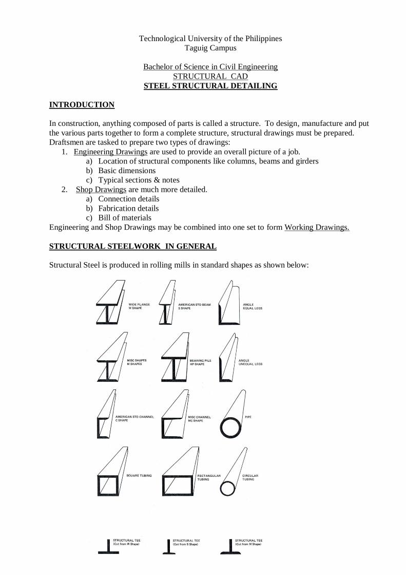
STRUCTURAL STEELWORK IN GENERAL
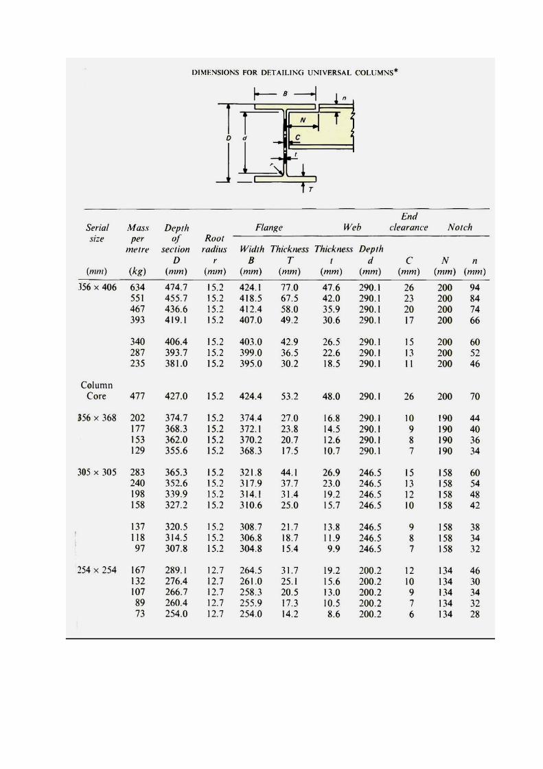
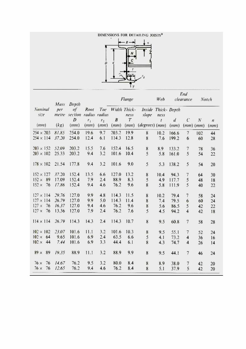
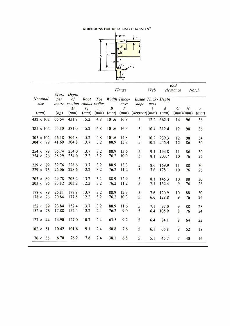
Structural Steel is produced in rolling mills in standard shapes as shown below:
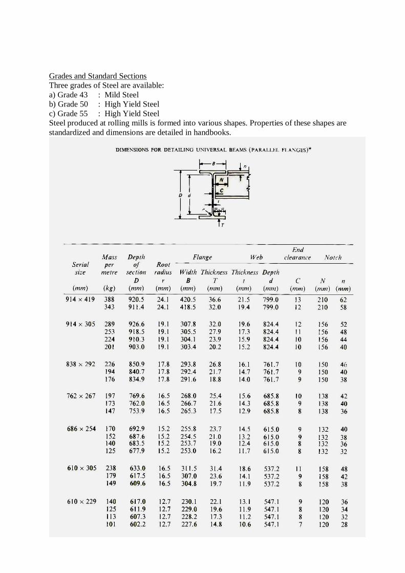
Grades and Standard Sections
Three grades of Steel are available:
a) Grade 43 : Mild Steel
b) Grade 50 : High Yield Steel
c) Grade 55 : High Yield Steel
Steel produced at rolling mills is formed into various shapes. Properties of these shapes are
standardized and dimensions are detailed in handbooks.
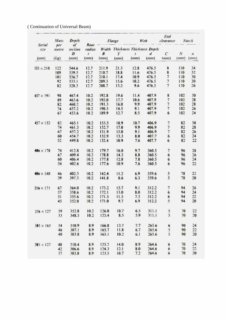
( Continuation of Universal Beam)
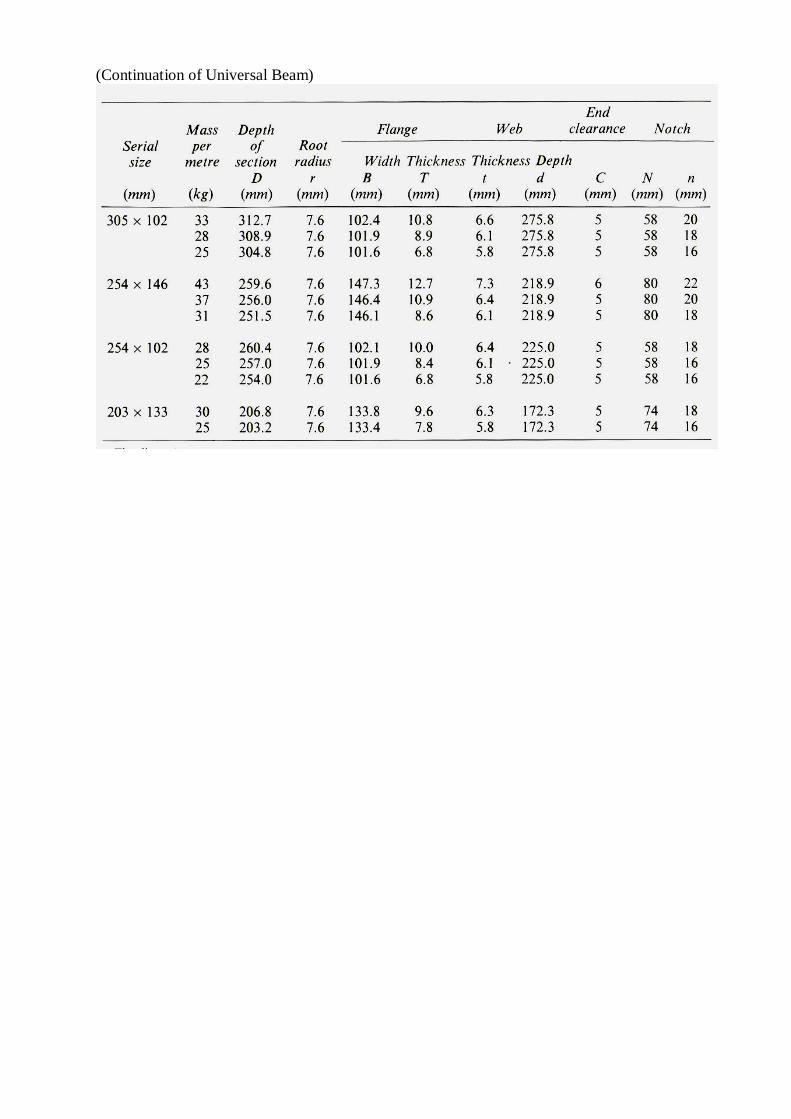
(Continuation of Universal Beam)
STEEL STRUCTURAL DETAILING
PRACTICAL EXERCISE No. 1
STRUCTURAL SHAPES
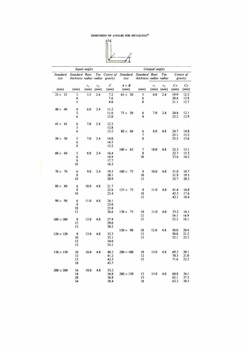
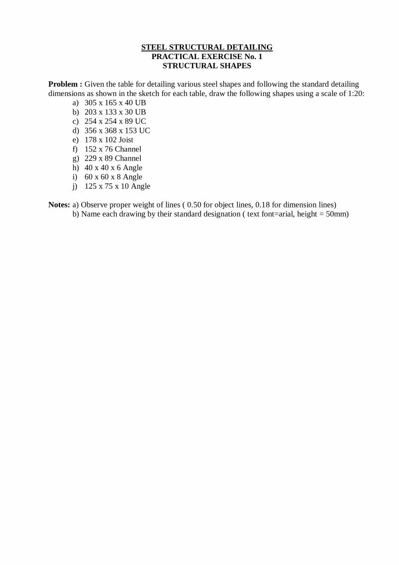
Problem : Given the table for detailing various steel shapes and following the standard detailing
dimensions as shown in the sketch for each table, draw the following shapes using a scale of 1:20:
a) 305 x 165 x 40 UB
b) 203 x 133 x 30 UB
c) 254 x 254 x 89 UC
d) 356 x 368 x 153 UC
e) 178 x 102 Joist
f) 152 x 76 Channel
g) 229 x 89 Channel
h) 40 x 40 x 6 Angle
i) 60 x 60 x 8 Angle
j) 125 x 75 x 10 Angle
Notes: a) Observe proper weight of lines ( 0.50 for object lines, 0.18 for dimension lines)
b) Name each drawing by their standard designation ( text font=arial, height = 50mm)
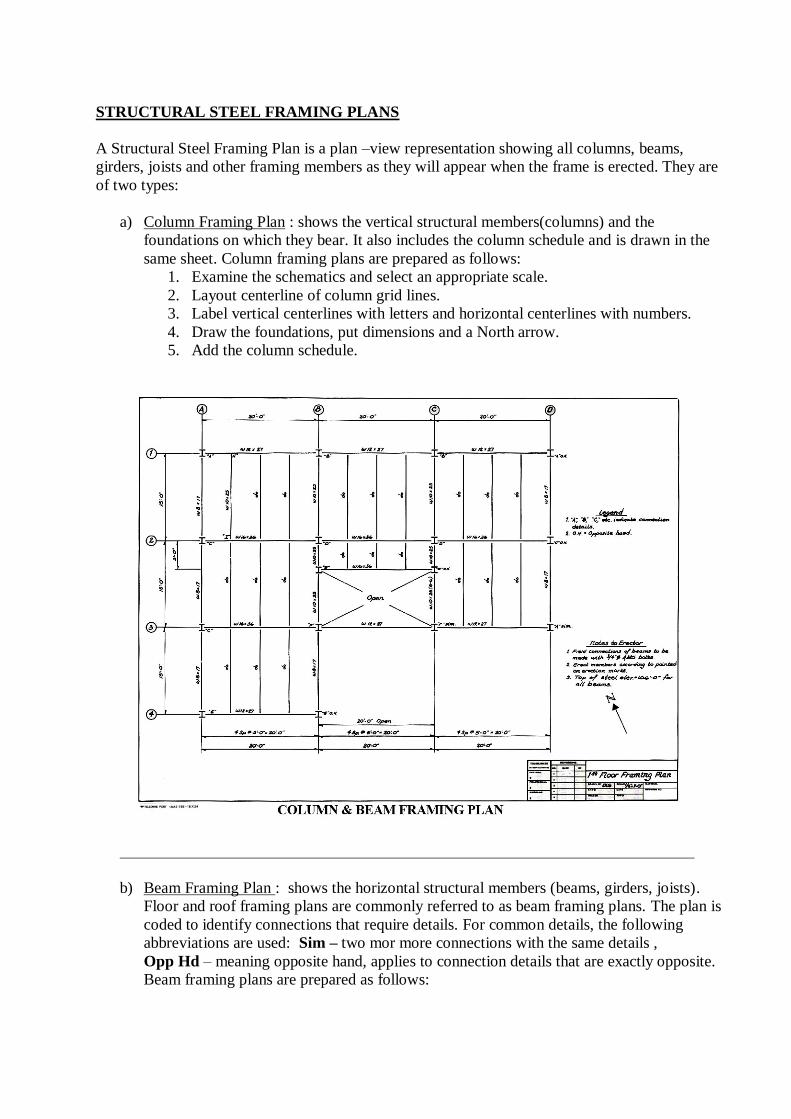
STRUCTURAL STEEL FRAMING PLANS
A Structural Steel Framing Plan is a plan –view representation showing all columns, beams,
girders, joists and other framing members as they will appear when the frame is erected. They are
of two types:
a) Column Framing Plan : shows the vertical structural members(columns) and the
foundations on which they bear. It also includes the column schedule and is drawn in the
same sheet. Column framing plans are prepared as follows:
1. Examine the schematics and select an appropriate scale.
2. Layout centerline of column grid lines.
3. Label vertical centerlines with letters and horizontal centerlines with numbers.
4. Draw the foundations, put dimensions and a North arrow.
5. Add the column schedule.
b) Beam Framing Plan : shows the horizontal structural members (beams, girders, joists).
Floor and roof framing plans are commonly referred to as beam framing plans. The plan is
coded to identify connections that require details. For common details, the following
abbreviations are used: Sim – two mor more connections with the same details ,
Opp Hd – meaning opposite hand, applies to connection details that are exactly opposite.
Beam framing plans are prepared as follows:

1. Examine the schematics and select an appropriate scale.
2. Layout column grid lines and draw columns.
3. Label vertical centerlines with letters and horizontal centerlines with numbers.
4. Draw all horizontal members(beams, girders and joists) and label each member
with the proper shape designation.
5. Label the top of steel elevation for each beam or indicate on the drawing as a note.
6. Complete the plan by adding dimensions, notes, connection detail designations and
a North arrow.
Related Documents