CHAP. 16, DIV. I 1601 1605.2.1 1997 UNIFORM BUILDING CODE 2–1 Volume 2 Chapters 1 through 15 are printed in Volume 1 of the Uniform Building Code. Chapter 16 STRUCTURAL DESIGN REQUIREMENTS NOTE: This chapter has been revised in its entirety. Division I—GENERAL DESIGN REQUIREMENTS SECTION 1601 — SCOPE This chapter prescribes general design requirements applicable to all structures regulated by this code. CHAP. 16, DIV. I SECTION 1602 — DEFINITIONS The following terms are defined for use in this code: ALLOWABLE STRESS DESIGN is a method of proportion- ing structural elements such that computed stresses produced in the elements by the allowable stress load combinations do not exceed specified allowable stress (also called working stress design). BALCONY, EXTERIOR, is an exterior floor system project- ing from a structure and supported by that structure, with no addi- tional independent supports. DEAD LOADS consist of the weight of all materials and fixed equipment incorporated into the building or other structure. DECK is an exterior floor system supported on at least two opposing sides by an adjoining structure and/or posts, piers, or other independent supports. FACTORED LOAD is the product of a load specified in Sec- tions 1606 through 1611 and a load factor. See Section 1612.2 for combinations of factored loads. LIMIT STATE is a condition in which a structure or compo- nent is judged either to be no longer useful for its intended function (serviceability limit state) or to be unsafe (strength limit state). LIVE LOADS are those loads produced by the use and occu- pancy of the building or other structure and do not include dead load, construction load, or environmental loads such as wind load, snow load, rain load, earthquake load or flood load. LOAD AND RESISTANCE FACTOR DESIGN (LRFD) is a method of proportioning structural elements using load and resist- ance factors such that no applicable limit state is reached when the structure is subjected to all appropriate load combinations. The term “LRFD” is used in the design of steel and wood structures. STRENGTH DESIGN is a method of proportioning structural elements such that the computed forces produced in the elements by the factored load combinations do not exceed the factored ele- ment strength. The term “strength design” is used in the design of concrete and masonry structures. SECTION 1603 — NOTATIONS D = dead load. E = earthquake load set forth in Section 1630.1. E m = estimated maximum earthquake force that can be devel- oped in the structure as set forth in Section 1630.1.1. F = load due to fluids. H = load due to lateral pressure of soil and water in soil. L = live load, except roof live load, including any permitted live load reduction. L r = roof live load, including any permitted live load reduction. P = ponding load. S = snow load. T = self-straining force and effects arising from contraction or expansion resulting from temperature change, shrink- age, moisture change, creep in component materials, movement due to differential settlement, or combina- tions thereof. W = load due to wind pressure. SECTION 1604 — STANDARDS The standards listed below are recognized standards (see Section 3504). 1. Wind Design. 1.1 ASCE 7, Chapter 6, Minimum Design Loads for Buildings and Other Structures 1.2 ANSI EIA/TIA 222-E, Structural Standards for Steel Antenna Towers and Antenna Supporting Structures 1.3 ANSI/NAAMM FP1001, Guide Specifications for the Design Loads of Metal Flagpoles SECTION 1605 — DESIGN 1605.1 General. Buildings and other structures and all portions thereof shall be designed and constructed to sustain, within the limitations specified in this code, all loads set forth in Chapter 16 and elsewhere in this code, combined in accordance with Section 1612. Design shall be in accordance with Strength Design, Load and Resistance Factor Design or Allowable Stress Design meth- ods, as permitted by the applicable materials chapters. EXCEPTION: Unless otherwise required by the building official, buildings or portions thereof that are constructed in accordance with the conventional light-framing requirements specified in Chapter 23 of this code shall be deemed to meet the requirements of this section. 1605.2 Rationality. Any system or method of construction to be used shall be based on a rational analysis in accordance with well- established principles of mechanics. Such analysis shall result in a system that provides a complete load path capable of transferring all loads and forces from their point of origin to the load-resisting elements. The analysis shall include, but not be limited to, the pro- visions of Sections 1605.2.1 through 1605.2.3. 1605.2.1 Distribution of horizontal shear. The total lateral force shall be distributed to the various vertical elements of the lateral-force-resisting system in proportion to their rigidities con- sidering the rigidity of the horizontal bracing system or dia- phragm. Rigid elements that are assumed not to be part of the lateral-force-resisting system may be incorporated into buildings, provided that their effect on the action of the system is considered and provided for in the design.

Welcome message from author
This document is posted to help you gain knowledge. Please leave a comment to let me know what you think about it! Share it to your friends and learn new things together.
Transcript
CHAP. 16, DIV. I1601
1605.2.1
1997 UNIFORM BUILDING CODE
2–1
Volume 2Chapters 1 through 15 are printed in Volume 1 of the Uniform Building Code.
Chapter 16
STRUCTURAL DESIGN REQUIREMENTSNOTE: This chapter has been revised in its entirety.
Division I—GENERAL DESIGN REQUIREMENTS
SECTION 1601 — SCOPE
This chapter prescribes general design requirements applicable toall structures regulated by this code.CHAP. 16, DIV. I
SECTION 1602 — DEFINITIONS
The following terms are defined for use in this code:
ALLOWABLE STRESS DESIGN is a method of proportion-ing structural elements such that computed stresses produced inthe elements by the allowable stress load combinations do notexceed specified allowable stress (also called working stressdesign).
BALCONY, EXTERIOR, is an exterior floor system project-ing from a structure and supported by that structure, with no addi-tional independent supports.
DEAD LOADS consist of the weight of all materials and fixedequipment incorporated into the building or other structure.
DECK is an exterior floor system supported on at least twoopposing sides by an adjoining structure and/or posts, piers, orother independent supports.
FACTORED LOAD is the product of a load specified in Sec-tions 1606 through 1611 and a load factor. See Section 1612.2 forcombinations of factored loads.
LIMIT STATE is a condition in which a structure or compo-nent is judged either to be no longer useful for its intended function(serviceability limit state) or to be unsafe (strength limit state).
LIVE LOADS are those loads produced by the use and occu-pancy of the building or other structure and do not include deadload, construction load, or environmental loads such as wind load,snow load, rain load, earthquake load or flood load.
LOAD AND RESISTANCE FACTOR DESIGN (LRFD) is amethod of proportioning structural elements using load and resist-ance factors such that no applicable limit state is reached when thestructure is subjected to all appropriate load combinations. Theterm “LRFD” is used in the design of steel and wood structures.
STRENGTH DESIGN is a method of proportioning structuralelements such that the computed forces produced in the elementsby the factored load combinations do not exceed the factored ele-ment strength. The term “strength design” is used in the design ofconcrete and masonry structures.
SECTION 1603 — NOTATIONS
D = dead load.E = earthquake load set forth in Section 1630.1.
Em = estimated maximum earthquake force that can be devel-oped in the structure as set forth in Section 1630.1.1.
F = load due to fluids.H = load due to lateral pressure of soil and water in soil.
L = live load, except roof live load, including any permittedlive load reduction.
Lr = roof live load, including any permitted live loadreduction.
P = ponding load.S = snow load.T = self-straining force and effects arising from contraction
or expansion resulting from temperature change, shrink-age, moisture change, creep in component materials,movement due to differential settlement, or combina-tions thereof.
W = load due to wind pressure.
SECTION 1604 — STANDARDS
The standards listed below are recognized standards (see Section3504).
1. Wind Design.
1.1 ASCE 7, Chapter 6, Minimum Design Loads forBuildings and Other Structures
1.2 ANSI EIA/TIA 222-E, Structural Standards for SteelAntenna Towers and Antenna Supporting Structures
1.3 ANSI/NAAMM FP1001, Guide Specifications forthe Design Loads of Metal Flagpoles
SECTION 1605 — DESIGN
1605.1 General.Buildings and other structures and all portionsthereof shall be designed and constructed to sustain, within thelimitations specified in this code, all loads set forth in Chapter 16and elsewhere in this code, combined in accordance with Section1612. Design shall be in accordance with Strength Design, Loadand Resistance Factor Design or Allowable Stress Design meth-ods, as permitted by the applicable materials chapters.
EXCEPTION: Unless otherwise required by the building official,buildings or portions thereof that are constructed in accordance withthe conventional light-framing requirements specified in Chapter 23 ofthis code shall be deemed to meet the requirements of this section.
1605.2 Rationality. Any system or method of construction to beused shall be based on a rational analysis in accordance with well-established principles of mechanics. Such analysis shall result in asystem that provides a complete load path capable of transferringall loads and forces from their point of origin to the load-resistingelements. The analysis shall include, but not be limited to, the pro-visions of Sections 1605.2.1 through 1605.2.3.
1605.2.1 Distribution of horizontal shear. The total lateralforce shall be distributed to the various vertical elements of thelateral-force-resisting system in proportion to their rigidities con-sidering the rigidity of the horizontal bracing system or dia-phragm. Rigid elements that are assumed not to be part of thelateral-force-resisting system may be incorporated into buildings,provided that their effect on the action of the system is consideredand provided for in the design.
CHAP. 16, DIV. I1605.2.11607.4.2
1997 UNIFORM BUILDING CODE
2–2
Provision shall be made for the increased forces induced onresisting elements of the structural system resulting from torsiondue to eccentricity between the center of application of the lateralforces and the center of rigidity of the lateral-force-resisting sys-tem. For accidental torsion requirements for seismic design, seeSection 1630.6.
1605.2.2 Stability against overturning. Every structure shall bedesigned to resist the overturning effects caused by the lateralforces specified in this chapter. See Section 1611.6 for retainingwalls, Section 1615 for wind and Section 1626 for seismic.
1605.2.3 Anchorage. Anchorage of the roof to walls and col-umns, and of walls and columns to foundations, shall be providedto resist the uplift and sliding forces that result from the applica-tion of the prescribed forces.
Concrete and masonry walls shall be anchored to all floors,roofs and other structural elements that provide lateral support forthe wall. Such anchorage shall provide a positive direct connec-tion capable of resisting the horizontal forces specified in thischapter but not less than the minimum forces in Section 1611.4. Inaddition, in Seismic Zones 3 and 4, diaphragm to wall anchorageusing embedded straps shall have the straps attached to or hookedaround the reinforcing steel or otherwise terminated so as to effec-tively transfer forces to the reinforcing steel. Walls shall bedesigned to resist bending between anchors where the anchorspacing exceeds 4 feet (1219 mm). Required anchors in masonrywalls of hollow units or cavity walls shall be embedded in a rein-forced grouted structural element of the wall. See Sections 1632,1633.2.8 and 1633.2.9 for earthquake design requirements.
1605.3 Erection of Structural Framing. Walls and structuralframing shall be erected true and plumb in accordance with thedesign.
SECTION 1606 — DEAD LOADS
1606.1 General.Dead loads shall be as defined in Section 1602and this section.
1606.2 Partition Loads. Floors in office buildings and otherbuildings where partition locations are subject to change shall bedesigned to support, in addition to all other loads, a uniformly dis-tributed dead load equal to 20 pounds per square foot (psf) (0.96kN/m2) of floor area.
EXCEPTION: Access floor systems shall be designed to support,in addition to all other loads, a uniformly distributed dead load not lessthan 10 psf (0.48 kN/m2) of floor area.
SECTION 1607 — LIVE LOADS
1607.1 General.Live loads shall be the maximum loadsexpected by the intended use or occupancy but in no case shall beless than the loads required by this section.
1607.2 Critical Distribution of Live Loads. Where structuralmembers are arranged to create continuity, members shall bedesigned using the loading conditions, which would cause maxi-mum shear and bending moments. This requirement may be satis-fied in accordance with the provisions of Section 1607.3.2 or1607.4.2, where applicable.
1607.3 Floor Live Loads.
1607.3.1 General.Floors shall be designed for the unit liveloads as set forth in Table 16-A. These loads shall be taken as theminimum live loads in pounds per square foot of horizontal pro-jection to be used in the design of buildings for the occupancies
listed, and loads at least equal shall be assumed for uses not listedin this section but that create or accommodate similar loadings.
Where it can be determined in designing floors that the actuallive load will be greater than the value shown in Table 16-A, theactual live load shall be used in the design of such buildings or por-tions thereof. Special provisions shall be made for machine andapparatus loads.
1607.3.2 Distribution of uniform floor loads. Where uniformfloor loads are involved, consideration may be limited to full deadload on all spans in combination with full live load on adjacentspans and alternate spans.
1607.3.3 Concentrated loads. Provision shall be made indesigning floors for a concentrated load, L, as set forth in Table16-A placed upon any space 21/2 feet (762 mm) square, whereverthis load upon an otherwise unloaded floor would produce stressesgreater than those caused by the uniform load required therefor.
Provision shall be made in areas where vehicles are used orstored for concentrated loads, L, consisting of two or more loadsspaced 5 feet (1524 mm) nominally on center without uniform liveloads. Each load shall be 40 percent of the gross weight of themaximum-size vehicle to be accommodated. Parking garages forthe storage of private or pleasure-type motor vehicles with norepair or refueling shall have a floor system designed for a concen-trated load of not less than 2,000 pounds (8.9 kN) acting on an areaof 20 square inches (12 903 mm2) without uniform live loads. Thecondition of concentrated or uniform live load, combined inaccordance with Section 1612.2 or 1612.3 as appropriate, produc-ing the greatest stresses shall govern.
1607.3.4 Special loads.Provision shall be made for the specialvertical and lateral loads as set forth in Table 16-B.
1607.3.5 Live loads posted.The live loads for which each flooror portion thereof of a commercial or industrial building is or hasbeen designed shall have such design live loads conspicuouslyposted by the owner in that part of each story in which they apply,using durable metal signs, and it shall be unlawful to remove ordeface such notices. The occupant of the building shall be respon-sible for keeping the actual load below the allowable limits.
1607.4 Roof Live Loads.
1607.4.1 General.Roofs shall be designed for the unit liveloads, Lr, set forth in Table 16-C. The live loads shall be assumedto act vertically upon the area projected on a horizontal plane.
1607.4.2 Distribution of loads. Where uniform roof loads areinvolved in the design of structural members arranged to createcontinuity, consideration may be limited to full dead loads on allspans in combination with full roof live loads on adjacent spansand on alternate spans.
EXCEPTION: Alternate span loading need not be consideredwhere the uniform roof live load is 20 psf (0.96 kN/m2) or more orwhere load combinations, including snow load, result in larger mem-bers or connections.
For those conditions where light-gage metal preformed struc-tural sheets serve as the support and finish of roofs, roof structuralmembers arranged to create continuity shall be considered ade-quate if designed for full dead loads on all spans in combinationwith the most critical one of the following superimposed loads:
1. Snow load in accordance with Section 1614.
2. The uniform roof live load, Lr, set forth in Table 16-C on allspans.
3. A concentrated gravity load, Lr, of 2,000 pounds (8.9 kN)placed on any span supporting a tributary area greater than 200square feet (18.58 m2) to create maximum stresses in the member,
CHAP. 16, DIV. I1607.4.2
1611.51997 UNIFORM BUILDING CODE
2–3
whenever this loading creates greater stresses than those causedby the uniform live load. The concentrated load shall be placed onthe member over a length of 21/2 feet (762 mm) along the span.The concentrated load need not be applied to more than one spansimultaneously.
4. Water accumulation as prescribed in Section 1611.7.
1607.4.3 Unbalanced loading. Unbalanced loads shall be usedwhere such loading will result in larger members or connections.Trusses and arches shall be designed to resist the stresses causedby unit live loads on one half of the span if such loading results inreverse stresses, or stresses greater in any portion than the stressesproduced by the required unit live load on the entire span. Forroofs whose structures are composed of a stressed shell, framed orsolid, wherein stresses caused by any point loading are distributedthroughout the area of the shell, the requirements for unbalancedunit live load design may be reduced 50 percent.
1607.4.4 Special roof loads. Roofs to be used for special pur-poses shall be designed for appropriate loads as approved by thebuilding official.
Greenhouse roof bars, purlins and rafters shall be designed tocarry a 100-pound-minimum (444.8 N) concentrated load, Lr, inaddition to the uniform live load.
1607.5 Reduction of Live Loads. The design live load deter-mined using the unit live loads as set forth in Table 16-A for floorsand Table 16-C, Method 2, for roofs may be reduced on any mem-ber supporting more than 150 square feet (13.94 m2), includingflat slabs, except for floors in places of public assembly and forlive loads greater than 100 psf (4.79 kN/m2), in accordance withthe following formula:
R = r (A – 150) (7-1)
For SI:R = r (A – 13.94)
The reduction shall not exceed 40 percent for members receiv-ing load from one level only, 60 percent for other members or R, asdetermined by the following formula:
R = 23.1 (1 + D/L) (7-2)
WHERE:A = area of floor or roof supported by the member, square
feet (m2).
D = dead load per square foot (m2) of area supported by themember.
L = unit live load per square foot (m2) of area supported bythe member.
R = reduction in percentage.
r = rate of reduction equal to 0.08 percent for floors. SeeTable 16-C for roofs.
For storage loads exceeding 100 psf (4.79 kN/m2), no reductionshall be made, except that design live loads on columns may bereduced 20 percent.
The live load reduction shall not exceed 40 percent in garagesfor the storage of private pleasure cars having a capacity of notmore than nine passengers per vehicle.
1607.6 Alternate Floor Live Load Reduction. As an alternateto Formula (7-1), the unit live loads set forth in Table 16-A may bereduced in accordance with Formula (7-3) on any member, includ-ing flat slabs, having an influence area of 400 square feet (37.2 m2)or more.
L � Lo�0.25� 15AI
� � (7-3)
For SI:
L � Lo�0.25� 4.57� 1AI
� ��WHERE:
AI = influence area, in square feet (m2). The influence area AIis four times the tributary area for a column, two timesthe tributary area for a beam, equal to the panel area for atwo-way slab, and equal to the product of the span andthe full flange width for a precast T-beam.
L = reduced design live load per square foot (m2) of areasupported by the member.
Lo = unreduced design live load per square foot (m2) of areasupported by the member (Table 16-A).
The reduced live load shall not be less than 50 percent of the unitlive load Lo for members receiving load from one level only, norless than 40 percent of the unit live load Lo for other members.
SECTION 1608 — SNOW LOADS
Snow loads shall be determined in accordance with Chapter 16,Division II.
SECTION 1609 — WIND LOADS
Wind loads shall be determined in accordance with Chapter 16,Division III.
SECTION 1610 — EARTHQUAKE LOADS
Earthquake loads shall be determined in accordance with Chapter16, Division IV.
SECTION 1611 — OTHER MINIMUM LOADS
1611.1 General.In addition to the other design loads specifiedin this chapter, structures shall be designed to resist the loads spe-cified in this section and the special loads set forth in Table 16-B.
1611.2 Other Loads.Buildings and other structures and por-tions thereof shall be designed to resist all loads due to applicablefluid pressures, F, lateral soil pressures, H, ponding loads, P, andself-straining forces, T. See Section 1611.7 for ponding loads forroofs.
1611.3 Impact Loads. Impact loads shall be included in thedesign of any structure where impact loads occur.
1611.4 Anchorage of Concrete and Masonry Walls. Concreteand masonry walls shall be anchored as required by Section1605.2.3. Such anchorage shall be capable of resisting the loadcombinations of Section 1612.2 or 1612.3 using the greater of thewind or earthquake loads required by this chapter or a minimumhorizontal force of 280 pounds per linear foot (4.09 kN/m) of wall,substituted for E.
1611.5 Interior Wall Loads. Interior walls, permanent partitionsand temporary partitions that exceed 6 feet (1829 mm) in heightshall be designed to resist all loads to which they are subjected butnot less than a load, L, of 5 psf (0.24 kN/m2) applied perpendicu-lar to the walls. The 5 psf (0.24 kN/m2) load need not be appliedsimultaneously with wind or seismic loads. The deflection of such
CHAP. 16, DIV. I1611.51612.3.2
1997 UNIFORM BUILDING CODE
2–4
walls under a load of 5 psf (0.24 kN/m2) shall not exceed 1/240 ofthe span for walls with brittle finishes and 1/120 of the span forwalls with flexible finishes. See Table 16-O for earthquake designrequirements where such requirements are more restrictive.
EXCEPTION: Flexible, folding or portable partitions are notrequired to meet the load and deflection criteria but must be anchoredto the supporting structure to meet the provisions of this code.
1611.6 Retaining Walls. Retaining walls shall be designed toresist loads due to the lateral pressure of retained material inaccordance with accepted engineering practice. Walls retainingdrained soil, where the surface of the retained soil is level, shall bedesigned for a load, H, equivalent to that exerted by a fluid weigh-ing not less than 30 psf per foot of depth (4.71 kN/m2/m) and hav-ing a depth equal to that of the retained soil. Any surcharge shall bein addition to the equivalent fluid pressure.
Retaining walls shall be designed to resist sliding by at least1.5 times the lateral force and overturning by at least 1.5 times theoverturning moment, using allowable stress design loads.
1611.7 Water Accumulation. All roofs shall be designed withsufficient slope or camber to ensure adequate drainage after thelong-term deflection from dead load or shall be designed to resistponding load, P, combined in accordance with Section 1612.2 or1612.3. Ponding load shall include water accumulation from anysource, including snow, due to deflection. See Section 1506 andTable 16-C, Footnote 3, for drainage slope. See Section 1615 fordeflection criteria.
1611.8 Hydrostatic Uplift. All foundations, slabs and otherfootings subjected to water pressure shall be designed to resist auniformly distributed uplift load, F, equal to the full hydrostaticpressure.
1611.9 Flood-resistant Construction.For flood-resistant con-struction requirements, where specifically adopted, see AppendixChapter 31, Division I.
1611.10 Heliport and Helistop Landing Areas.In addition toother design requirements of this chapter, heliport and helistoplanding or touchdown areas shall be designed for the followingloads, combined in accordance with Section 1612.2 or 1612.3:
1. Dead load plus actual weight of the helicopter.
2. Dead load plus a single concentrated impact load, L, cover-ing 1 square foot (0.093 m2) of 0.75 times the fully loaded weightof the helicopter if it is equipped with hydraulic-type shockabsorbers, or 1.5 times the fully loaded weight of the helicopter ifit is equipped with a rigid or skid-type landing gear.
3. The dead load plus a uniform live load, L, of 100 psf (4.8 kN/m2). The required live load may be reduced in accordance withSection 1607.5 or 1607.6.
1611.11 Prefabricated Construction.
1611.11.1 Connections. Every device used to connect pre-fabricated assemblies shall be designed as required by this codeand shall be capable of developing the strength of the membersconnected, except in the case of members forming part of a struc-tural frame designed as specified in this chapter. Connections shallbe capable of withstanding uplift forces as specified in thischapter.
1611.11.2 Pipes and conduit. In structural design, due allowanceshall be made for any material to be removed for the installation ofpipes, conduits or other equipment.
1611.11.3 Tests and inspections. See Section 1704 for require-ments for tests and inspections of prefabricated construction.
SECTION 1612 — COMBINATIONS OF LOADS
1612.1 General.Buildings and other structures and all portionsthereof shall be designed to resist the load combinations specifiedin Section 1612.2 or 1612.3 and, where required by Chapter 16,Division IV, or Chapters 18 through 23, the special seismic loadcombinations of Section 1612.4.
The most critical effect can occur when one or more of the con-tributing loads are not acting. All applicable loads shall be consid-ered, including both earthquake and wind, in accordance with thespecified load combinations.
1612.2 Load Combinations Using Strength Design or Loadand Resistance Factor Design.
1612.2.1 Basic load combinations. Where Load and ResistanceFactor Design (Strength Design) is used, structures and all por-tions thereof shall resist the most critical effects from the follow-ing combinations of factored loads:
1.4D (12-1)1.2D + 1.6L + 0.5 (Lr or S) (12-2)
1.2D + 1.6 (Lr or S) + (f1L or 0.8W) (12-3)1.2D + 1.3W + f1L + 0.5 (Lr or S) (12-4)
1.2D + 1.0E + (f1L + f2S) (12-5)
0.9D � (1.0E or 1.3W) (12-6)WHERE:
f1 = 1.0 for floors in places of public assembly, for live loadsin excess of 100 psf (4.9 kN/m2), and for garage liveload.
= 0.5 for other live loads.f2 = 0.7 for roof configurations (such as saw tooth) that do
not shed snow off the structure.= 0.2 for other roof configurations.
EXCEPTIONS: 1. Factored load combinations for concrete perSection 1909.2 where load combinations do not include seismic forces.
2. Factored load combinations of this section multiplied by 1.1 forconcrete and masonry where load combinations include seismicforces.
3. Where other factored load combinations are specifically requiredby the provisions of this code.
1612.2.2 Other loads. Where F, H, P or T are to be considered indesign, each applicable load shall be added to the above combina-tions factored as follows: 1.3F, 1.6H, 1.2P and 1.2T.
1612.3 Load Combinations Using Allowable Stress Design.
1612.3.1 Basic load combinations. Where allowable stressdesign (working stress design) is used, structures and all portionsthereof shall resist the most critical effects resulting from the fol-lowing combinations of loads:
D (12-7)D + L + (Lr or S) (12-8)
D � �W or E1.4� (12-9)
0.9D � E1.4
(12-10)
D � 0.75�L � (Lr or S) � �W or E1.4�� (12-11)
No increase in allowable stresses shall be used with these loadcombinations except as specifically permitted elsewhere in thiscode.
1612.3.2 Alternate basic load combinations. In lieu of the basicload combinations specified in Section 1612.3.1, structures and
CHAP. 16, DIV. I1612.3.2
16131997 UNIFORM BUILDING CODE
2–5
portions thereof shall be permitted to be designed for the most crit-ical effects resulting from the following load combinations. Whenusing these alternate basic load combinations, a one-third increaseshall be permitted in allowable stresses for all combinationsincluding W or E.
D � L � (Lr or S) (12-12)
D � L � �W or E1.4� (12-13)
D � L � W� S2
(12-14)
D � L � S� W2
(12-15)
D � L � S � E1.4
(12-16)
0.9D � E1.4
(12-16-1)
EXCEPTIONS: 1. Crane hook loads need not be combined withroof live load or with more than three fourths of the snow load or onehalf of the wind load.
2. Design snow loads of 30 psf (1.44 kN/m2) or less need not be com-bined with seismic loads. Where design snow loads exceed 30 psf (1.44kN/m2), the design snow load shall be included with seismic loads, butmay be reduced up to 75 percent where consideration of siting, config-uration and load duration warrant when approved by the building offi-cial.
1612.3.3 Other loads. Where F, H, P or T are to be considered indesign, each applicable load shall be added to the combinationsspecified in Sections 1612.3.1 and 1612.3.2. When using the alter-
nate load combinations specified in Section 1612.3.2, a one-thirdincrease shall be permitted in allowable stresses for all combina-tions including W or E.
1612.4 Special Seismic Load Combinations. For both Allow-able Stress Design and Strength Design, the following special loadcombinations for seismic design shall be used as specificallyrequired by Chapter 16, Division IV, or by Chapters 18 through 23:
1.2D � f1L � 1.0Em (12-17)
0.9D � 1.0Em (12-18)
WHERE:f1 = 1.0 for floors in places of public assembly, for live loads
in excess of 100 psf (4.79 kN/m2), and for garage liveload.
= 0.5 for other live loads.
SECTION 1613 — DEFLECTION
The deflection of any structural member shall not exceed the val-ues set forth in Table 16-D, based on the factors set forth in Table16-E. The deflection criteria representing the most restrictive con-dition shall apply. Deflection criteria for materials not specifiedshall be developed in a manner consistent with the provisions ofthis section. See Section 1611.7 for camber requirements. Spantables for light wood-frame construction as specified in Chapter23, Division VII, shall conform to the design criteria containedtherein. For concrete, see Section 1909.5.2.6; for aluminum, seeSection 2003; for glazing framing, see Section 2404.2.
CHAP. 16, DIV. II16141614
1997 UNIFORM BUILDING CODE
2–6
Division II—SNOW LOADS
SECTION 1614 — SNOW LOADS
Buildings and other structures and all portions thereof that are sub-ject to snow loading shall be designed to resist the snow loads, asdetermined by the building official, in accordance with the loadcombinations set forth in Section 1612.2 or 1612.3.
Potential unbalanced accumulation of snow at valleys, para-pets, roof structures and offsets in roofs of uneven configurationshall be considered.
Snow loads in excess of 20 psf (0.96 kN/m2) may be reduced foreach degree of pitch over 20 degrees by Rs as determined by theformula: CHAP. 16, DIV. II
Rs � S40
� 12
(14-1)
For SI: Rs � S40
� 0.024
WHERE:Rs = snow load reduction in pounds per square foot (kN/m2)
per degree of pitch over 20 degrees.
S = total snow load in pounds per square foot (kN/m2).
For alternate design procedure, where specifically adopted, seeAppendix Chapter 16, Division I.
CHAP. 16, DIV. III1615
1621.31997 UNIFORM BUILDING CODE
2–7
Division III—WIND DESIGN
SECTION 1615 — GENERAL
Every building or structure and every portion thereof shall be de-signed and constructed to resist the wind effects determined in ac-cordance with the requirements of this division. Wind shall beassumed to come from any horizontal direction. No reduction inwind pressure shall be taken for the shielding effect of adjacentstructures.
Structures sensitive to dynamic effects, such as buildings with aheight-to-width ratio greater than five, structures sensitive towind-excited oscillations, such as vortex shedding or icing, andbuildings over 400 feet (121.9 m) in height, shall be, and any struc-ture may be, designed in accordance with approved nationalstandards. CHAP. 16, DIV. III
The provisions of this section do not apply to building and foun-dation systems in those areas subject to scour and water pressureby wind and wave action. Buildings and foundations subject tosuch loads shall be designed in accordance with approved nationalstandards.
SECTION 1616 — DEFINITIONS
The following definitions apply only to this division:
BASIC WIND SPEED is the fastest-mile wind speed asso-ciated with an annual probability of 0.02 measured at a point33 feet (10 000 mm) above the ground for an area having exposurecategory C.
EXPOSURE B has terrain with buildings, forest or surface ir-regularities, covering at least 20 percent of the ground level areaextending 1 mile (1.61 km) or more from the site.
EXPOSURE C has terrain that is flat and generally open, ex-tending 1/2 mile (0.81 km) or more from the site in any full quad-rant.
EXPOSURE D represents the most severe exposure in areaswith basic wind speeds of 80 miles per hour (mph) (129 km/h) orgreater and has terrain that is flat and unobstructed facing large bo-dies of water over 1 mile (1.61 km) or more in width relative to anyquadrant of the building site. Exposure D extends inland from theshoreline 1/4 mile (0.40 km) or 10 times the building height,whichever is greater.
FASTEST-MILE WIND SPEED is the wind speed obtainedfrom wind velocity maps prepared by the National Oceanographicand Atmospheric Administration and is the highest sustained av-erage wind speed based on the time required for a mile-long sam-ple of air to pass a fixed point.
OPENINGS are apertures or holes in the exterior wall bound-ary of the structure. All windows or doors or other openings shallbe considered as openings unless such openings and their framesare specifically detailed and designed to resist the loads on ele-ments and components in accordance with the provisions of thissection.
PARTIALLY ENCLOSED STRUCTURE OR STORY is astructure or story that has more than 15 percent of any windwardprojected area open and the area of opening on all other projectedareas is less than half of that on the windward projection.
SPECIAL WIND REGION is an area where local records andterrain features indicate 50-year fastest-mile basic wind speed ishigher than shown in Figure 16-1.
UNENCLOSED STRUCTURE OR STORY is a structurethat has 85 percent or more openings on all sides.
SECTION 1617 — SYMBOLS AND NOTATIONS
The following symbols and notations apply to the provisions ofthis division:
Ce = combined height, exposure and gust factor coefficient asgiven in Table 16-G.
Cq = pressure coefficient for the structure or portion of struc-ture under consideration as given in Table 16-H.
Iw = importance factor as set forth in Table 16-K.P = design wind pressure.qs = wind stagnation pressure at the standard height of 33 feet
(10 000 mm) as set forth in Table 16-F.
SECTION 1618 — BASIC WIND SPEED
The minimum basic wind speed at any site shall not be less thanthat shown in Figure 16-1. For those areas designated in Figure16-1 as special wind regions and other areas where local records orterrain indicate higher 50-year (mean recurrence interval) fastest-mile wind speeds, these higher values shall be the minimum basicwind speeds.
SECTION 1619 — EXPOSURE
An exposure shall be assigned at each site for which a building orstructure is to be designed.
SECTION 1620 — DESIGN WIND PRESSURES
Design wind pressures for buildings and structures and elementstherein shall be determined for any height in accordance with thefollowing formula:
P = Ce Cq qs Iw (20-1)
SECTION 1621 — PRIMARY FRAMES AND SYSTEMS
1621.1 General.The primary frames or load-resisting system ofevery structure shall be designed for the pressures calculated us-ing Formula (20-1) and the pressure coefficients, Cq, of eitherMethod 1 or Method 2. In addition, design of the overall structureand its primary load-resisting system shall conform to Section1605.
The base overturning moment for the entire structure, or for anyone of its individual primary lateral-resisting elements, shall notexceed two thirds of the dead-load-resisting moment. For an entirestructure with a height-to-width ratio of 0.5 or less in the wind di-rection and a maximum height of 60 feet (18 290 mm), the combi-nation of the effects of uplift and overturning may be reduced byone third. The weight of earth superimposed over footings may beused to calculate the dead-load-resisting moment.
1621.2 Method 1 (Normal Force Method).Method 1 shall beused for the design of gabled rigid frames and may be used for anystructure. In the Normal Force Method, the wind pressures shall beassumed to act simultaneously normal to all exterior surfaces. Forpressures on roofs and leeward walls, Ce shall be evaluated at themean roof height.
1621.3 Method 2 (Projected Area Method).Method 2 may beused for any structure less than 200 feet (60 960 mm) in height ex-cept those using gabled rigid frames. This method may be used instability determinations for any structure less than 200 feet(60 960 mm) high. In the Projected Area Method, horizontal pres-sures shall be assumed to act upon the full vertical projected area
CHAP. 16, DIV. III1621.31625
1997 UNIFORM BUILDING CODE
2–8
of the structure, and the vertical pressures shall be assumed to actsimultaneously upon the full horizontal projected area.
SECTION 1622 — ELEMENTS AND COMPONENTS OFSTRUCTURES
Design wind pressures for each element or component of a struc-ture shall be determined from Formula (20-1) and Cq values fromTable 16-H, and shall be applied perpendicular to the surface. Foroutward acting forces the value of Ce shall be obtained from Table16-G based on the mean roof height and applied for the entireheight of the structure. Each element or component shall be de-signed for the more severe of the following loadings:
1. The pressures determined using Cq values for elements andcomponents acting over the entire tributary area of the element.
2. The pressures determined using Cq values for local areas atdiscontinuities such as corners, ridges and eaves. These local pres-sures shall be applied over a distance from a discontinuity of10 feet (3048 mm) or 0.1 times the least width of the structure,whichever is less.
The wind pressures from Sections 1621 and 1622 need not becombined.
SECTION 1623 — OPEN-FRAME TOWERS
Radio towers and other towers of trussed construction shall be de-signed and constructed to withstand wind pressures specified inthis section, multiplied by the shape factors set forth in Table16-H.
SECTION 1624 — MISCELLANEOUS STRUCTURES
Greenhouses, lath houses, agricultural buildings or fences 12 feet(3658 mm) or less in height shall be designed in accordance withChapter 16, Division III. However, three fourths of qs, but not lessthan 10 psf (0.48 kN/m2), may be substituted for qs in Formula(20-1). Pressures on local areas at discontinuities need not be con-sidered.
SECTION 1625 — OCCUPANCY CATEGORIES
For the purpose of wind-resistant design, each structure shall beplaced in one of the occupancy categories listed in Table 16-K.Table 16-K lists importance factors, Iw, for each category.
CHAP. 16, DIV. IV16261627
1997 UNIFORM BUILDING CODE
2–9
Division IV—EARTHQUAKE DESIGN
SECTION 1626 — GENERAL
1626.1 Purpose. The purpose of the earthquake provisions hereinis primarily to safeguard against major structural failures and lossof life, not to limit damage or maintain function.
1626.2 Minimum Seismic Design.Structures and portionsthereof shall, as a minimum, be designed and constructed to resistthe effects of seismic ground motions as provided in this division.
1626.3 Seismic and Wind Design.When the code-prescribedwind design produces greater effects, the wind design shall gov-ern, but detailing requirements and limitations prescribed in thissection and referenced sections shall be followed.
SECTION 1627 — DEFINITIONS
For the purposes of this division, certain terms are defined as fol-lows: CHAP. 16, DIV. IV
BASE is the level at which the earthquake motions are consid-ered to be imparted to the structure or the level at which the struc-ture as a dynamic vibrator is supported.
BASE SHEAR, V, is the total design lateral force or shear at thebase of a structure.
BEARING WALL SYSTEM is a structural system without acomplete vertical load-carrying space frame. See Section1629.6.2.
BOUNDARY ELEMENT is an element at edges of openingsor at perimeters of shear walls or diaphragms.
BRACED FRAME is an essentially vertical truss system of theconcentric or eccentric type that is provided to resist lateral forces.
BUILDING FRAME SYSTEM is an essentially completespace frame that provides support for gravity loads. See Section1629.6.3.
CANTILEVERED COLUMN ELEMENT is a column ele-ment in a lateral-force-resisting system that cantilevers from afixed base and has minimal moment capacity at the top, with lat-eral forces applied essentially at the top.
COLLECTOR is a member or element provided to transfer lat-eral forces from a portion of a structure to vertical elements of thelateral-force-resisting system.
COMPONENT is a part or element of an architectural, electri-cal, mechanical or structural system.
COMPONENT, EQUIPMENT, is a mechanical or electricalcomponent or element that is part of a mechanical and/or electricalsystem.
COMPONENT, FLEXIBLE, is a component, including itsattachments, having a fundamental period greater than 0.06 sec-ond.
COMPONENT, RIGID, is a component, including its attach-ments, having a fundamental period less than or equal to 0.06 sec-ond.
CONCENTRICALLY BRACED FRAME is a braced framein which the members are subjected primarily to axial forces.
DESIGN BASIS GROUND MOTION is that ground motionthat has a 10 percent chance of being exceeded in 50 years as deter-mined by a site-specific hazard analysis or may be determinedfrom a hazard map. A suite of ground motion time histories withdynamic properties representative of the site characteristics shall
be used to represent this ground motion. The dynamic effects ofthe Design Basis Ground Motion may be represented by theDesign Response Spectrum. See Section 1631.2.
DESIGN RESPONSE SPECTRUM is an elastic responsespectrum for 5 percent equivalent viscous damping used to repre-sent the dynamic effects of the Design Basis Ground Motion forthe design of structures in accordance with Sections 1630 and1631. This response spectrum may be either a site-specific spec-trum based on geologic, tectonic, seismological and soil charac-teristics associated with a specific site or may be a spectrumconstructed in accordance with the spectral shape in Figure 16-3using the site-specific values of Ca and Cv and multiplied by theacceleration of gravity, 386.4 in./sec.2 (9.815 m/sec.2). See Sec-tion 1631.2.
DESIGN SEISMIC FORCE is the minimum total strength de-sign base shear, factored and distributed in accordance with Sec-tion 1630.
DIAPHRAGM is a horizontal or nearly horizontal system act-ing to transmit lateral forces to the vertical-resisting elements. Theterm “diaphragm” includes horizontal bracing systems.
DIAPHRAGM or SHEAR WALL CHORD is the boundaryelement of a diaphragm or shear wall that is assumed to take axialstresses analogous to the flanges of a beam.
DIAPHRAGM STRUT (drag strut, tie, collector) is the ele-ment of a diaphragm parallel to the applied load that collects andtransfers diaphragm shear to the vertical-resisting elements or dis-tributes loads within the diaphragm. Such members may take axialtension or compression.
DRIFT. See “story drift.”
DUAL SYSTEM is a combination of moment-resisting framesand shear walls or braced frames designed in accordance with thecriteria of Section 1629.6.5.
ECCENTRICALLY BRACED FRAME (EBF) is a steel-braced frame designed in conformance with Section 2213.10.
ELASTIC RESPONSE PARAMETERS are forces anddeformations determined from an elastic dynamic analysis usingan unreduced ground motion representation, in accordance withSection 1630.
ESSENTIAL FACILITIES are those structures that are nec-essary for emergency operations subsequent to a natural disaster.
FLEXIBLE ELEMENT or system is one whose deformationunder lateral load is significantly larger than adjoining parts of thesystem. Limiting ratios for defining specific flexible elements areset forth in Section 1630.6.
HORIZONTAL BRACING SYSTEM is a horizontal trusssystem that serves the same function as a diaphragm.
INTERMEDIATE MOMENT-RESISTING FRAME(IMRF) is a concrete frame designed in accordance with Section1921.8.
LATERAL-FORCE-RESISTING SYSTEM is that part ofthe structural system designed to resist the Design Seismic Forces.
MOMENT-RESISTING FRAME is a frame in which mem-bers and joints are capable of resisting forces primarily by flexure.
MOMENT-RESISTING WALL FRAME (MRWF) is amasonry wall frame especially detailed to provide ductile behav-ior and designed in conformance with Section 2108.2.5.
ORDINARY BRACED FRAME (OBF) is a steel-bracedframe designed in accordance with the provisions of Section
CHAP. 16, DIV. IV16271628
1997 UNIFORM BUILDING CODE
2–10
2213.8 or 2214.6, or concrete-braced frame designed in accord-ance with Section 1921.
ORDINARY MOMENT-RESISTING FRAME (OMRF) isa moment-resisting frame not meeting special detailing require-ments for ductile behavior.
ORTHOGONAL EFFECTS are the earthquake load effectson structural elements common to the lateral-force-resisting sys-tems along two orthogonal axes.
OVERSTRENGTH is a characteristic of structures where theactual strength is larger than the design strength. The degree ofoverstrength is material- and system-dependent.
P� EFFECT is the secondary effect on shears, axial forces andmoments of frame members induced by the vertical loads actingon the laterally displaced building system.
SHEAR WALL is a wall designed to resist lateral forces paral-lel to the plane of the wall (sometimes referred to as vertical dia-phragm or structural wall).
SHEAR WALL-FRAME INTERACTIVE SYSTEM usescombinations of shear walls and frames designed to resist lateralforces in proportion to their relative rigidities, considering inter-action between shear walls and frames on all levels.
SOFT STORY is one in which the lateral stiffness is less than70 percent of the stiffness of the story above. See Table 16-L.
SPACE FRAME is a three-dimensional structural system,without bearing walls, composed of members interconnected soas to function as a complete self-contained unit with or without theaid of horizontal diaphragms or floor-bracing systems.
SPECIAL CONCENTRICALLY BRACED FRAME(SCBF) is a steel-braced frame designed in conformance with theprovisions of Section 2213.9.
SPECIAL MOMENT-RESISTING FRAME (SMRF) is amoment-resisting frame specially detailed to provide ductilebehavior and comply with the requirements given in Chapter 19or 22.
SPECIAL TRUSS MOMENT FRAME (STMF) is amoment-resisting frame specially detailed to provide ductilebehavior and comply with the provisions of Section 2213.11.
STORY is the space between levels. Story x is the story belowLevel x.
STORY DRIFT is the lateral displacement of one level relativeto the level above or below.
STORY DRIFT RATIO is the story drift divided by the storyheight.
STORY SHEAR, Vx, is the summation of design lateral forcesabove the story under consideration.
STRENGTH is the capacity of an element or a member to resistfactored load as specified in Chapters 16, 18, 19, 21 and 22.
STRUCTURE is an assemblage of framing members designedto support gravity loads and resist lateral forces. Structures may becategorized as building structures or nonbuilding structures.
SUBDIAPHRAGM is a portion of a larger wood diaphragmdesigned to anchor and transfer local forces to primary diaphragmstruts and the main diaphragm.
VERTICAL LOAD-CARRYING FRAME is a space framedesigned to carry vertical gravity loads.
WALL ANCHORAGE SYSTEM is the system of elementsanchoring the wall to the diaphragm and those elements within thediaphragm required to develop the anchorage forces, including
subdiaphragms and continuous ties, as specified in Sections1633.2.8 and 1633.2.9.
WEAK STORY is one in which the story strength is less than80 percent of the story above. See Table 16-L.
SECTION 1628 — SYMBOLS AND NOTATIONS
The following symbols and notations apply to the provisions ofthis division:
AB = ground floor area of structure in square feet (m2) toinclude area covered by all overhangs and projec-tions.
Ac = the combined effective area, in square feet (m2), ofthe shear walls in the first story of the structure.
Ae = the minimum cross-sectional area in any horizontalplane in the first story, in square feet (m2) of a shearwall.
Ax = the torsional amplification factor at Level x.ap = numerical coefficient specified in Section 1632 and
set forth in Table 16-O.Ca = seismic coefficient, as set forth in Table 16-Q.Ct = numerical coefficient given in Section 1630.2.2.Cv = seismic coefficient, as set forth in Table 16-R.D = dead load on a structural element.
De = the length, in feet (m), of a shear wall in the first storyin the direction parallel to the applied forces.
E, Eh,Em, Ev = earthquake loads set forth in Section 1630.1.Fi , Fn,
Fx = Design Seismic Force applied to Level i, n or x,respectively.
Fp = Design Seismic Forces on a part of the structure.Fpx = Design Seismic Force on a diaphragm.Ft = that portion of the base shear, V, considered concen-
trated at the top of the structure in addition to Fn.fi = lateral force at Level i for use in Formula (30-10).g = acceleration due to gravity.
hi , hn,hx = height in feet (m) above the base to Level i, n or x,
respectively.I = importance factor given in Table 16-K.
Ip = importance factor specified in Table 16-K.L = live load on a structural element.
Level i = level of the structure referred to by the subscript i.“ i = 1” designates the first level above the base.
Level n = that level that is uppermost in the main portion of thestructure.
Level x = that level that is under design consideration. “x = 1”designates the first level above the base.
M = maximum moment magnitude.Na = near-source factor used in the determination of Ca in
Seismic Zone 4 related to both the proximity of thebuilding or structure to known faults with magnitudesand slip rates as set forth in Tables 16-S and 16-U.
Nv = near-source factor used in the determination of Cv inSeismic Zone 4 related to both the proximity of thebuilding or structure to known faults with magnitudesand slip rates as set forth in Tables 16-T and 16-U.
CHAP. 16, DIV. IV1628
1629.5.11997 UNIFORM BUILDING CODE
2–11
PI = plasticity index of soil determined in accordance withapproved national standards.
R = numerical coefficient representative of the inherentoverstrength and global ductility capacity of lateral-force-resisting systems, as set forth in Table 16-N or16-P.
r = a ratio used in determining �. See Section 1630.1.SA, SB,SC, SD,SE, SF = soil profile types as set forth in Table 16-J.
T = elastic fundamental period of vibration, in seconds,of the structure in the direction under consideration.
V = the total design lateral force or shear at the base givenby Formula (30-5), (30-6), (30-7) or (30-11).
Vx = the design story shear in Story x.W = the total seismic dead load defined in Section
1630.1.1.wi , wx = that portion of W located at or assigned to Level i or x,
respectively.Wp = the weight of an element or component.wpx = the weight of the diaphragm and the element tributary
thereto at Level x, including applicable portions ofother loads defined in Section 1630.1.1.
Z = seismic zone factor as given in Table 16-I.�M = Maximum Inelastic Response Displacement, which
is the total drift or total story drift that occurs when thestructure is subjected to the Design Basis GroundMotion, including estimated elastic and inelasticcontributions to the total deformation defined in Sec-tion 1630.9.
�S = Design Level Response Displacement, which is thetotal drift or total story drift that occurs when thestructure is subjected to the design seismic forces.
�i = horizontal displacement at Level i relative to the basedue to applied lateral forces, f, for use in Formula(30-10).
ρ = Redundancy/Reliability Factor given by Formula(30-3).
�o = Seismic Force Amplification Factor, which isrequired to account for structural overstrength and setforth in Table 16-N.
SECTION 1629 — CRITERIA SELECTION
1629.1 Basis for Design.The procedures and the limitations forthe design of structures shall be determined considering seismiczoning, site characteristics, occupancy, configuration, structuralsystem and height in accordance with this section. Structures shallbe designed with adequate strength to withstand the lateral dis-placements induced by the Design Basis Ground Motion, consid-ering the inelastic response of the structure and the inherentredundancy, overstrength and ductility of the lateral-force-resisting system. The minimum design strength shall be based onthe Design Seismic Forces determined in accordance with thestatic lateral force procedure of Section 1630, except as modifiedby Section 1631.5.4. Where strength design is used, the load com-binations of Section 1612.2 shall apply. Where Allowable StressDesign is used, the load combinations of Section 1612.3 shallapply. Allowable Stress Design may be used to evaluate sliding oroverturning at the soil-structure interface regardless of the designapproach used in the design of the structure, provided load com-
binations of Section 1612.3 are utilized. One- and two-familydwellings in Seismic Zone 1 need not conform to the provisions ofthis section.
1629.2 Occupancy Categories. For purposes of earthquake-resistant design, each structure shall be placed in one of the occu-pancy categories listed in Table 16-K. Table 16-K assigns impor-tance factors, I and Ip, and structural observation requirements foreach category.
1629.3 Site Geology and Soil Characteristics.Each site shallbe assigned a soil profile type based on properly substantiatedgeotechnical data using the site categorization procedure set forthin Division V, Section 1636 and Table 16-J.
EXCEPTION: When the soil properties are not known in sufficientdetail to determine the soil profile type, Type SD shall be used. Soil Pro-file Type SE or SF need not be assumed unless the building officialdetermines that Type SE or SF may be present at the site or in the eventthat Type SE or SF is established by geotechnical data.
1629.3.1 Soil profile type. Soil Profile Types SA, SB, SC, SD andSE are defined in Table 16-J and Soil Profile Type SF is defined assoils requiring site-specific evaluation as follows:
1. Soils vulnerable to potential failure or collapse under seis-mic loading, such as liquefiable soils, quick and highly sensitiveclays, and collapsible weakly cemented soils.
2. Peats and/or highly organic clays, where the thickness ofpeat or highly organic clay exceeds 10 feet (3048 mm).
3. Very high plasticity clays with a plasticity index, PI > 75,where the depth of clay exceeds 25 feet (7620 mm).
4. Very thick soft/medium stiff clays, where the depth of clayexceeds 120 feet (36 576 mm).
1629.4 Site Seismic Hazard Characteristics. Seismic hazardcharacteristics for the site shall be established based on the seis-mic zone and proximity of the site to active seismic sources, sitesoil profile characteristics and the structure’s importance factor.
1629.4.1 Seismic zone. Each site shall be assigned a seismic zonein accordance with Figure 16-2. Each structure shall be assigned aseismic zone factor Z, in accordance with Table 16-I.
1629.4.2 Seismic Zone 4 near-source factor. In Seismic Zone 4,each site shall be assigned a near-source factor in accordance withTable 16-S and the Seismic Source Type set forth in Table 16-U.The value of Na used to determine Ca need not exceed 1.1 forstructures complying with all the following conditions:
1. The soil profile type is SA, SB, SC or SD.
2. ρ = 1.0.
3. Except in single-story structures, Group R, Division 3 andGroup U, Division 1 Occupancies, moment frame systems desig-nated as part of the lateral-force-resisting system shall be specialmoment-resisting frames.
4. The exceptions to Section 2213.7.5 shall not apply, exceptfor columns in one-story buildings or columns at the top story ofmultistory buildings.
5. None of the following structural irregularities is present:Type 1, 4 or 5 of Table 16-L, and Type 1 or 4 of Table 16-M.
1629.4.3 Seismic response coefficients. Each structure shall beassigned a seismic coefficient, Ca, in accordance with Table 16-Qand a seismic coefficient, Cv, in accordance with Table 16-R.
1629.5 Configuration Requirements.
1629.5.1 General.Each structure shall be designated as beingstructurally regular or irregular in accordance with Sections1629.5.2 and 1629.5.3.
CHAP. 16, DIV. IV1629.5.21629.9.2
1997 UNIFORM BUILDING CODE
2–12
1629.5.2 Regular structures.Regular structures have no sig-nificant physical discontinuities in plan or vertical configurationor in their lateral-force-resisting systems such as the irregular fea-tures described in Section 1629.5.3.
1629.5.3 Irregular structures.
1. Irregular structures have significant physical discontinuitiesin configuration or in their lateral-force-resisting systems. Irregu-lar features include, but are not limited to, those described inTables 16-L and 16-M. All structures in Seismic Zone 1 and Occu-pancy Categories 4 and 5 in Seismic Zone 2 need to be evaluatedonly for vertical irregularities of Type 5 (Table 16-L) and horizon-tal irregularities of Type 1 (Table 16-M).
2. Structures having any of the features listed in Table 16-L shallbe designated as if having a vertical irregularity.
EXCEPTION: Where no story drift ratio under design lateralforces is greater than 1.3 times the story drift ratio of the story above,the structure may be deemed to not have the structural irregularities ofType 1 or 2 in Table 16-L. The story drift ratio for the top two storiesneed not be considered. The story drifts for this determination may becalculated neglecting torsional effects.
3. Structures having any of the features listed in Table 16-Mshall be designated as having a plan irregularity.
1629.6 Structural Systems.
1629.6.1 General.Structural systems shall be classified as oneof the types listed in Table 16-N and defined in this section.
1629.6.2 Bearing wall system.A structural system without acomplete vertical load-carrying space frame. Bearing walls orbracing systems provide support for all or most gravity loads. Re-sistance to lateral load is provided by shear walls or braced frames.
1629.6.3 Building frame system.A structural system with anessentially complete space frame providing support for gravityloads. Resistance to lateral load is provided by shear walls orbraced frames.
1629.6.4 Moment-resisting frame system.A structural systemwith an essentially complete space frame providing support forgravity loads. Moment-resisting frames provide resistance to lat-eral load primarily by flexural action of members.
1629.6.5 Dual system.A structural system with the followingfeatures:
1. An essentially complete space frame that provides supportfor gravity loads.
2. Resistance to lateral load is provided by shear walls or bracedframes and moment-resisting frames (SMRF, IMRF, MMRWF orsteel OMRF). The moment-resisting frames shall be designed toindependently resist at least 25 percent of the design base shear.
3. The two systems shall be designed to resist the total designbase shear in proportion to their relative rigidities considering theinteraction of the dual system at all levels.
1629.6.6 Cantilevered column system.A structural systemrelying on cantilevered column elements for lateral resistance.
1629.6.7 Undefined structural system.A structural system notlisted in Table 16-N.
1629.6.8 Nonbuilding structural system.A structural systemconforming to Section 1634.
1629.7 Height Limits. Height limits for the various structuralsystems in Seismic Zones 3 and 4 are given in Table 16-N.
EXCEPTION: Regular structures may exceed these limits by notmore than 50 percent for unoccupied structures, which are not accessi-ble to the general public.
1629.8 Selection of Lateral-force Procedure.
1629.8.1 General.Any structure may be, and certain structuresdefined below shall be, designed using the dynamic lateral-forceprocedures of Section 1631.
1629.8.2 Simplified static.The simplified static lateral-forceprocedure set forth in Section 1630.2.3 may be used for the fol-lowing structures of Occupancy Category 4 or 5:
1. Buildings of any occupancy (including single-family dwell-ings) not more than three stories in height excluding basements,that use light-frame construction.
2. Other buildings not more than two stories in height exclud-ing basements.
1629.8.3 Static. The static lateral force procedure of Section1630 may be used for the following structures:
1. All structures, regular or irregular, in Seismic Zone 1 and inOccupancy Categories 4 and 5 in Seismic Zone 2.
2. Regular structures under 240 feet (73 152 mm) in heightwith lateral force resistance provided by systems listed in Table16-N, except where Section 1629.8.4, Item 4, applies.
3. Irregular structures not more than five stories or 65 feet(19 812 mm) in height.
4. Structures having a flexible upper portion supported on arigid lower portion where both portions of the structure consid-ered separately can be classified as being regular, the averagestory stiffness of the lower portion is at least 10 times the averagestory stiffness of the upper portion and the period of the entirestructure is not greater than 1.1 times the period of the upper por-tion considered as a separate structure fixed at the base.
1629.8.4 Dynamic.The dynamic lateral-force procedure ofSection 1631 shall be used for all other structures, including thefollowing:
1. Structures 240 feet (73 152 mm) or more in height, except aspermitted by Section 1629.8.3, Item 1.
2. Structures having a stiffness, weight or geometric vertical ir-regularity of Type 1, 2 or 3, as defined in Table 16-L, or structureshaving irregular features not described in Table 16-L or 16-M, ex-cept as permitted by Section 1630.4.2.
3. Structures over five stories or 65 feet (19 812 mm) in heightin Seismic Zones 3 and 4 not having the same structural systemthroughout their height except as permitted by Section 1630.4.2.
4. Structures, regular or irregular, located on Soil Profile TypeSF, that have a period greater than 0.7 second. The analysis shallinclude the effects of the soils at the site and shall conform to Sec-tion 1631.2, Item 4.
1629.9 System Limitations.
1629.9.1 Discontinuity.Structures with a discontinuity in ca-pacity, vertical irregularity Type 5 as defined in Table 16-L, shallnot be over two stories or 30 feet (9144 mm) in height where theweak story has a calculated strength of less than 65 percent of thestory above.
EXCEPTION: Where the weak story is capable of resisting a totallateral seismic force of �o times the design force prescribed in Section1630.
1629.9.2 Undefined structural systems.For undefined struc-tural systems not listed in Table 16-N, the coefficient R shall besubstantiated by approved cyclic test data and analyses. The fol-lowing items shall be addressed when establishing R:
CHAP. 16, DIV. IV1629.9.21630.1.2
1997 UNIFORM BUILDING CODE
2–13
1. Dynamic response characteristics,
2. Lateral force resistance,
3. Overstrength and strain hardening or softening,
4. Strength and stiffness degradation,
5. Energy dissipation characteristics,
6. System ductility, and
7. Redundancy.
1629.9.3 Irregular features. All structures having irregularfeatures described in Table 16-L or 16-M shall be designed to meetthe additional requirements of those sections referenced in thetables.
1629.10 Alternative Procedures.
1629.10.1 General.Alternative lateral-force procedures usingrational analyses based on well-established principles of mechan-ics may be used in lieu of those prescribed in these provisions.
1629.10.2 Seismic isolation.Seismic isolation, energy dissipa-tion and damping systems may be used in the design of structureswhen approved by the building official and when special detailingis used to provide results equivalent to those obtained by the use ofconventional structural systems. For alternate design procedureson seismic isolation systems, refer to Appendix Chapter 16, Divi-sion III, Earthquake Regulations for Seismic-isolated Structures.
SECTION 1630 — MINIMUM DESIGN LATERALFORCES AND RELATED EFFECTS
1630.1 Earthquake Loads and Modeling Requirements.
1630.1.1 Earthquake loads. Structures shall be designed forground motion producing structural response and seismic forcesin any horizontal direction. The following earthquake loads shallbe used in the load combinations set forth in Section 1612:
E = ρ Eh + Ev (30-1)
Em = �oEh (30-2)
WHERE:E = the earthquake load on an element of the structure result-
ing from the combination of the horizontal component,Eh, and the vertical component, Ev.
Eh = the earthquake load due to the base shear, V, as set forthin Section 1630.2 or the design lateral force, Fp, as setforth in Section 1632.
Em = the estimated maximum earthquake force that can bedeveloped in the structure as set forth in Section1630.1.1.
Ev = the load effect resulting from the vertical component ofthe earthquake ground motion and is equal to an additionof 0.5CaID to the dead load effect, D, for StrengthDesign, and may be taken as zero for Allowable StressDesign.
�o = the seismic force amplification factor that is required toaccount for structural overstrength, as set forth in Sec-tion 1630.3.1.
� = Reliability/Redundancy Factor as given by the follow-ing formula:
� � 2 � 20rmax AB
� (30-3)
For SI: � � 2 � 6.1rmax AB
�
WHERE:rmax = the maximum element-story shear ratio. For a given di-
rection of loading, the element-story shear ratio is the ra-tio of the design story shear in the most heavily loadedsingle element divided by the total design story shear.For any given Story Level i, the element-story shear ra-tio is denoted as ri . The maximum element-story shearratio rmax is defined as the largest of the element storyshear ratios, ri , which occurs in any of the story levels ator below the two-thirds height level of the building.
For braced frames, the value of ri is equal to the maximum hori-zontal force component in a single brace element divided by thetotal story shear.
For moment frames, ri shall be taken as the maximum of thesum of the shears in any two adjacent columns in a moment framebay divided by the story shear. For columns common to two bayswith moment-resisting connections on opposite sides at Level i inthe direction under consideration, 70 percent of the shear in thatcolumn may be used in the column shear summation.
For shear walls, ri shall be taken as the maximum value of theproduct of the wall shear multiplied by 10/lw (For SI: 3.05/lw) anddivided by the total story shear, where lw is the length of the wall infeet (m).
For dual systems, ri shall be taken as the maximum value of ri asdefined above considering all lateral-load-resisting elements. Thelateral loads shall be distributed to elements based on relative ri-gidities considering the interaction of the dual system. For dualsystems, the value of � need not exceed 80 percent of the value cal-culated above.
� shall not be taken less than 1.0 and need not be greater than1.5, and AB is the ground floor area of the structure in square feet(m2). For special moment-resisting frames, except when used indual systems, � shall not exceed 1.25. The number of bays of spe-cial moment-resisting frames shall be increased to reduce r, suchthat � is less than or equal to 1.25.
EXCEPTION: AB may be taken as the average floor area in theupper setback portion of the building where a larger base area exists atthe ground floor.
When calculating drift, or when the structure is located in Seis-mic Zone 0, 1 or 2, ρ shall be taken equal to 1.
The ground motion producing lateral response and design seis-mic forces may be assumed to act nonconcurrently in the directionof each principal axis of the structure, except as required by Sec-tion 1633.1.
Seismic dead load, W, is the total dead load and applicable por-tions of other loads listed below.
1. In storage and warehouse occupancies, a minimum of 25percent of the floor live load shall be applicable.
2. Where a partition load is used in the floor design, a load ofnot less than 10 psf (0.48 kN/m2) shall be included.
3. Design snow loads of 30 psf (1.44 kN/m2) or less need not beincluded. Where design snow loads exceed 30 psf (1.44 kN/m2),the design snow load shall be included, but may be reduced up to75 percent where consideration of siting, configuration and loadduration warrant when approved by the building official.
4. Total weight of permanent equipment shall be included.
1630.1.2 Modeling requirements. The mathematical model ofthe physical structure shall include all elements of the lateral-force-resisting system. The model shall also include the stiffness
CHAP. 16, DIV. IV1630.1.21630.3.2
1997 UNIFORM BUILDING CODE
2–14
and strength of elements, which are significant to the distributionof forces, and shall represent the spatial distribution of the massand stiffness of the structure. In addition, the model shall complywith the following:
1. Stiffness properties of reinforced concrete and masonry ele-ments shall consider the effects of cracked sections.
2. For steel moment frame systems, the contribution of panelzone deformations to overall story drift shall be included.
1630.1.3P� effects. The resulting member forces and momentsand the story drifts induced by P� effects shall be considered inthe evaluation of overall structural frame stability and shall beevaluated using the forces producing the displacements of �S. P�need not be considered when the ratio of secondary moment to pri-mary moment does not exceed 0.10; the ratio may be evaluated forany story as the product of the total dead, floor live and snow load,as required in Section 1612, above the story times the seismic driftin that story divided by the product of the seismic shear in thatstory times the height of that story. In Seismic Zones 3 and 4, P�need not be considered when the story drift ratio does not exceed0.02/R.
1630.2 Static Force Procedure.
1630.2.1 Design base shear.The total design base shear in agiven direction shall be determined from the following formula:
V �Cv IR T
W (30-4)
The total design base shear need not exceed the following:
V �2.5 Ca I
RW (30-5)
The total design base shear shall not be less than the following:
V � 0.11 Ca I W (30-6)
In addition, for Seismic Zone 4, the total base shear shall alsonot be less than the following:
V �0.8 ZNv I
RW (30-7)
1630.2.2 Structure period.The value of T shall be determinedfrom one of the following methods:
1. Method A: For all buildings, the value T may be approxi-mated from the following formula:
T � Ct (hn)3�4 (30-8)
WHERE:Ct = 0.035 (0.0853) for steel moment-resisting frames.Ct = 0.030 (0.0731) for reinforced concrete moment-resist-
ing frames and eccentrically braced frames.Ct = 0.020 (0.0488) for all other buildings.
Alternatively, the value of Ct for structures with concrete or ma-
sonry shear walls may be taken as 0.1/Ac� (For SI: 0.0743� Ac
�for Ac in m2).
The value of Ac shall be determined from the following for-mula:
Ac � �Ae �0.2 � (De�hn)2� (30-9)
The value of De/hn used in Formula (30-9) shall not exceed 0.9.
2. Method B: The fundamental period T may be calculated us-ing the structural properties and deformational characteristics ofthe resisting elements in a properly substantiated analysis. Theanalysis shall be in accordance with the requirements of Section1630.1.2. The value of T from Method B shall not exceed a value30 percent greater than the value of T obtained from Method A inSeismic Zone 4, and 40 percent in Seismic Zones 1, 2 and 3.
The fundamental period T may be computed by using the fol-lowing formula:
T � 2� �n
i�1
wi �i2� � �g
n
i�1
fi �i�� (30-10)
The values of fi represent any lateral force distributed approxi-mately in accordance with the principles of Formulas (30-13),(30-14) and (30-15) or any other rational distribution. The elasticdeflections, δi , shall be calculated using the applied lateralforces, fi .
1630.2.3 Simplified design base shear.
1630.2.3.1 General. Structures conforming to the requirementsof Section 1629.8.2 may be designed using this procedure.
1630.2.3.2 Base shear. The total design base shear in a givendirection shall be determined from the following formula:
V �3.0 Ca
RW (30-11)
where the value of Ca shall be based on Table 16-Q for the soil pro-file type. When the soil properties are not known in sufficientdetail to determine the soil profile type, Type SD shall be used inSeismic Zones 3 and 4, and Type SE shall be used in Seismic Zones1, 2A and 2B. In Seismic Zone 4, the Near-Source Factor, Na, neednot be greater than 1.3 if none of the following structural irregular-ities are present: Type 1, 4 or 5 of Table 16-L, or Type 1 or 4 ofTable 16-M.
1630.2.3.3 Vertical distribution. The forces at each level shallbe calculated using the following formula:
Fx �3.0 Ca
Rwi (30-12)
where the value of Ca shall be determined in Section 1630.2.3.2.
1630.2.3.4 Applicability. Sections 1630.1.2, 1630.1.3, 1630.2.1,1630.2.2, 1630.5, 1630.9, 1630.10 and 1631 shall not apply whenusing the simplified procedure.
EXCEPTION: For buildings with relatively flexible structuralsystems, the building official may require consideration of P� effectsand drift in accordance with Sections 1630.1.3, 1630.9 and 1630.10. �sshall be prepared using design seismic forces from Section 1630.2.3.2.
Where used, �M shall be taken equal to 0.01 times the storyheight of all stories. In Section 1633.2.9, Formula (33-1) shall read
Fpx = 3.0 Ca
Rwpx and need not exceed 1.0 Ca wpx, but shall not be
less than 0.5 Ca wpx. R and �o shall be taken from Table 16-N.
1630.3 Determination of Seismic Factors.
1630.3.1 Determination of �o. For specific elements of thestructure, as specifically identified in this code, the minimumdesign strength shall be the product of the seismic force over-strength factor �o and the design seismic forces set forth in Sec-tion 1630. For both Allowable Stress Design and Strength Design,the Seismic Force Overstrength Factor, �o, shall be taken fromTable 16-N.
1630.3.2 Determination of R. The notation R shall be taken fromTable 16-N.
CHAP. 16, DIV. IV1630.4
1630.8.11997 UNIFORM BUILDING CODE
2–15
1630.4 Combinations of Structural Systems.
1630.4.1 General.Where combinations of structural systemsare incorporated into the same structure, the requirements of thissection shall be satisfied.
1630.4.2 Vertical combinations.The value of R used in the de-sign of any story shall be less than or equal to the value of R used inthe given direction for the story above.
EXCEPTION: This requirement need not be applied to a storywhere the dead weight above that story is less than 10 percent of thetotal dead weight of the structure.
Structures may be designed using the procedures of this sectionunder the following conditions:
1. The entire structure is designed using the lowest R of thelateral-force-resisting systems used, or
2. The following two-stage static analysis procedures may beused for structures conforming to Section 1629.8.3, Item 4.
2.1 The flexible upper portion shall be designed as a sepa-rate structure, supported laterally by the rigid lowerportion, using the appropriate values of R and �.
2.2 The rigid lower portion shall be designed as a separatestructure using the appropriate values of R and �. Thereactions from the upper portion shall be those deter-mined from the analysis of the upper portion amplifiedby the ratio of the (R/�) of the upper portion over (R/�)of the lower portion.
1630.4.3 Combinations along different axes.In SeismicZones 3 and 4 where a structure has a bearing wall system in onlyone direction, the value of R used for design in the orthogonal di-rection shall not be greater than that used for the bearing wall sys-tem.
Any combination of bearing wall systems, building frame sys-tems, dual systems or moment-resisting frame systems may beused to resist seismic forces in structures less than 160 feet (48 768mm) in height. Only combinations of dual systems and specialmoment-resisting frames shall be used to resist seismic forces instructures exceeding 160 feet (48 768 mm) in height in SeismicZones 3 and 4.
1630.4.4 Combinations along the same axis.For other thandual systems and shear wall-frame interactive systems in SeismicZones 0 and 1, where a combination of different structural systemsis utilized to resist lateral forces in the same direction, the value ofR used for design in that direction shall not be greater than the leastvalue for any of the systems utilized in that same direction.
1630.5 Vertical Distribution of Force. The total force shall bedistributed over the height of the structure in conformance withFormulas (30-13), (30-14) and (30-15) in the absence of a morerigorous procedure.
V � Ft � �n
i�1
Fi (30-13)
The concentrated force Ft at the top, which is in addition to Fn,shall be determined from the formula:
Ft � 0.07 T V (30-14)
The value of T used for the purpose of calculating Ft shall be theperiod that corresponds with the design base shear as computedusing Formula (30-4). Ft need not exceed 0.25V and may be con-sidered as zero where T is 0.7 second or less. The remaining por-
tion of the base shear shall be distributed over the height of thestructure, including Level n, according to the following formula:
Fx �(V � Ft ) wx hx
�n
i�1
wi hi
(30-15)
At each level designated as x, the force Fx shall be applied overthe area of the building in accordance with the mass distribution atthat level. Structural displacements and design seismic forcesshall be calculated as the effect of forces Fx and Ft applied at theappropriate levels above the base.
1630.6 Horizontal Distribution of Shear. The design storyshear, Vx, in any story is the sum of the forces Ft and Fx above thatstory. Vx shall be distributed to the various elements of the verticallateral-force-resisting system in proportion to their rigidities, con-sidering the rigidity of the diaphragm. See Section 1633.2.4 forrigid elements that are not intended to be part of the lateral-force-resisting systems.
Where diaphragms are not flexible, the mass at each level shallbe assumed to be displaced from the calculated center of mass ineach direction a distance equal to 5 percent of the building dimen-sion at that level perpendicular to the direction of the force underconsideration. The effect of this displacement on the story sheardistribution shall be considered.
Diaphragms shall be considered flexible for the purposes of dis-tribution of story shear and torsional moment when the maximumlateral deformation of the diaphragm is more than two times theaverage story drift of the associated story. This may be determinedby comparing the computed midpoint in-plane deflection of thediaphragm itself under lateral load with the story drift of adjoiningvertical-resisting elements under equivalent tributary lateral load.
1630.7 Horizontal Torsional Moments.Provisions shall bemade for the increased shears resulting from horizontal torsionwhere diaphragms are not flexible. The most severe load combi-nation for each element shall be considered for design.
The torsional design moment at a given story shall be the mo-ment resulting from eccentricities between applied design lateralforces at levels above that story and the vertical-resisting elementsin that story plus an accidental torsion.
The accidental torsional moment shall be determined by assum-ing the mass is displaced as required by Section 1630.6.
Where torsional irregularity exists, as defined in Table 16-M,the effects shall be accounted for by increasing the accidental tor-sion at each level by an amplification factor, Ax, determined fromthe following formula:
Ax � � �max
1.2�avg�
2
(30-16)
WHERE:δavg = the average of the displacements at the extreme points of
the structure at Level x.δmax = the maximum displacement at Level x.
The value of Ax need not exceed 3.0.
1630.8 Overturning.
1630.8.1 General.Every structure shall be designed to resist theoverturning effects caused by earthquake forces specified in Sec-tion 1630.5. At any level, the overturning moments to be resistedshall be determined using those seismic forces (Ft and Fx) that acton levels above the level under consideration. At any level, the in-
CHAP. 16, DIV. IV1630.8.11631.1
1997 UNIFORM BUILDING CODE
2–16
cremental changes of the design overturning moment shall be dis-tributed to the various resisting elements in the manner prescribedin Section 1630.6. Overturning effects on every element shall becarried down to the foundation. See Sections 1612 and 1633 forcombining gravity and seismic forces.
1630.8.2 Elements supporting discontinuous systems.
1630.8.2.1 General. Where any portion of the lateral-load-resisting system is discontinuous, such as for vertical irregularityType 4 in Table 16-L or plan irregularity Type 4 in Table 16-M,concrete, masonry, steel and wood elements supporting such dis-continuous systems shall have the design strength to resist thecombination loads resulting from the special seismic load com-binations of Section 1612.4.
EXCEPTIONS: 1. The quantity Em in Section 1612.4 need notexceed the maximum force that can be transferred to the element by thelateral-force-resisting system.
2. Concrete slabs supporting light-frame wood shear wall systemsor light-frame steel and wood structural panel shear wall systems.
For Allowable Stress Design, the design strength may be deter-mined using an allowable stress increase of 1.7 and a resistancefactor, �, of 1.0. This increase shall not be combined with the one-third stress increase permitted by Section 1612.3, but may be com-bined with the duration of load increase permitted in Chapter 23,Division III.
1630.8.2.2 Detailing requirements in Seismic Zones 3 and 4.In Seismic Zones 3 and 4, elements supporting discontinuous sys-tems shall meet the following detailing or member limitations:
1. Reinforced concrete elements designed primarily as axial-load members shall comply with Section 1921.4.4.5.
2. Reinforced concrete elements designed primarily as flexuralmembers and supporting other than light-frame wood shear wallsystems or light-frame steel and wood structural panel shear wallsystems shall comply with Sections 1921.3.2 and 1921.3.3.Strength computations for portions of slabs designed as support-ing elements shall include only those portions of the slab that com-ply with the requirements of these sections.
3. Masonry elements designed primarily as axial-load carryingmembers shall comply with Sections 2106.1.12.4, Item 1, and2108.2.6.2.6.
4. Masonry elements designed primarily as flexural membersshall comply with Section 2108.2.6.2.5.
5. Steel elements designed primarily as axial-load membersshall comply with Sections 2213.5.2 and 2213.5.3.
6. Steel elements designed primarily as flexural members ortrusses shall have bracing for both top and bottom beam flanges orchords at the location of the support of the discontinuous systemand shall comply with the requirements of Section 2213.7.1.3.
7. Wood elements designed primarily as flexural members shallbe provided with lateral bracing or solid blocking at each end ofthe element and at the connection location(s) of the discontinuoussystem.
1630.8.3 At foundation. See Sections 1629.1 and 1809.4 foroverturning moments to be resisted at the foundation soil inter-face.
1630.9 Drift. Drift or horizontal displacements of the structureshall be computed where required by this code. For both Allow-able Stress Design and Strength Design, the Maximum InelasticResponse Displacement, �M, of the structure caused by theDesign Basis Ground Motion shall be determined in accordancewith this section. The drifts corresponding to the design seismic
forces of Section 1630.2.1, �S, shall be determined in accordancewith Section 1630.9.1. To determine �M, these drifts shall beamplified in accordance with Section 1630.9.2.
1630.9.1 Determination of �S. A static, elastic analysis of thelateral force-resisting system shall be prepared using the designseismic forces from Section 1630.2.1. Alternatively, dynamicanalysis may be performed in accordance with Section 1631.Where Allowable Stress Design is used and where drift is beingcomputed, the load combinations of Section 1612.2 shall be used.The mathematical model shall comply with Section 1630.1.2. Theresulting deformations, denoted as �S, shall be determined at allcritical locations in the structure. Calculated drift shall includetranslational and torsional deflections.
1630.9.2 Determination of �M. The Maximum InelasticResponse Displacement, �M, shall be computed as follows:
�M � 0.7 R�S (30-17)
EXCEPTION: Alternatively, �M may be computed by nonlineartime history analysis in accordance with Section 1631.6.
The analysis used to determine the Maximum InelasticResponse Displacement �M shall consider P� effects.
1630.10 Story Drift Limitation.
1630.10.1 General.Story drifts shall be computed using theMaximum Inelastic Response Displacement, �M.
1630.10.2 Calculated.Calculated story drift using �M shall notexceed 0.025 times the story height for structures having a funda-mental period of less than 0.7 second. For structures having a fun-damental period of 0.7 second or greater, the calculated story driftshall not exceed 0.020 times the story height.
EXCEPTIONS: 1. These drift limits may be exceeded when it isdemonstrated that greater drift can be tolerated by both structural ele-ments and nonstructural elements that could affect life safety. The driftused in this assessment shall be based upon the Maximum InelasticResponse Displacement, �M.
2. There shall be no drift limit in single-story steel-framed structuresclassified as Groups B, F and S Occupancies or Group H, Division 4or 5 Occupancies. In Groups B, F and S Occupancies, the primary useshall be limited to storage, factories or workshops. Minor accessoryuses shall be allowed in accordance with the provisions of Section 302.Structures on which this exception is used shall not have equipment at-tached to the structural frame or shall have such equipment detailed toaccommodate the additional drift. Walls that are laterally supported bythe steel frame shall be designed to accommodate the drift in accor-dance with Section 1633.2.4.
1630.10.3 Limitations. The design lateral forces used to deter-mine the calculated drift may disregard the limitations of Formula(30-6) and may be based on the period determined from Formula(30-10) neglecting the 30 or 40 percent limitations of Section1630.2.2, Item 2.
1630.11 Vertical Component.The following requirements ap-ply in Seismic Zones 3 and 4 only. Horizontal cantilever compo-nents shall be designed for a net upward force of 0.7CaIWp.
In addition to all other applicable load combinations, horizontalprestressed components shall be designed using not more than 50percent of the dead load for the gravity load, alone or in combina-tion with the lateral force effects.
SECTION 1631 — DYNAMIC ANALYSISPROCEDURES
1631.1 General.Dynamic analyses procedures, when used,shall conform to the criteria established in this section. The analy-sis shall be based on an appropriate ground motion representationand shall be performed using accepted principles of dynamics.
CHAP. 16, DIV. IV1631.1
1631.5.71997 UNIFORM BUILDING CODE
2–17
Structures that are designed in accordance with this section shallcomply with all other applicable requirements of these provisions.
1631.2 Ground Motion. The ground motion representationshall, as a minimum, be one having a 10-percent probability of be-ing exceeded in 50 years, shall not be reduced by the quantity Rand may be one of the following:
1. An elastic design response spectrum constructed in accord-ance with Figure 16-3, using the values of Ca and Cv consistentwith the specific site. The design acceleration ordinates shall bemultiplied by the acceleration of gravity, 386.4 in./sec.2 (9.815m/sec.2).
2. A site-specific elastic design response spectrum based on thegeologic, tectonic, seismologic and soil characteristics associatedwith the specific site. The spectrum shall be developed for a damp-ing ratio of 0.05, unless a different value is shown to be consistentwith the anticipated structural behavior at the intensity of shakingestablished for the site.
3. Ground motion time histories developed for the specific siteshall be representative of actual earthquake motions. Responsespectra from time histories, either individually or in combination,shall approximate the site design spectrum conforming to Section1631.2, Item 2.
4. For structures on Soil Profile Type SF, the following require-ments shall apply when required by Section 1629.8.4, Item 4:
4.1 The ground motion representation shall be developed inaccordance with Items 2 and 3.
4.2 Possible amplification of building response due to theeffects of soil-structure interaction and lengthening ofbuilding period caused by inelastic behavior shall beconsidered.
5. The vertical component of ground motion may be defined byscaling corresponding horizontal accelerations by a factor of two-thirds. Alternative factors may be used when substantiated by site-specific data. Where the Near Source Factor, Na, is greater than1.0, site-specific vertical response spectra shall be used in lieu ofthe factor of two-thirds.
1631.3 Mathematical Model.A mathematical model of thephysical structure shall represent the spatial distribution of themass and stiffness of the structure to an extent that is adequate forthe calculation of the significant features of its dynamic response.A three-dimensional model shall be used for the dynamic analysisof structures with highly irregular plan configurations such asthose having a plan irregularity defined in Table 16-M and havinga rigid or semirigid diaphragm. The stiffness properties used in theanalysis and general mathematical modeling shall be in accord-ance with Section 1630.1.2.
1631.4 Description of Analysis Procedures.
1631.4.1 Response spectrum analysis.An elastic dynamicanalysis of a structure utilizing the peak dynamic response of allmodes having a significant contribution to total structural re-sponse. Peak modal responses are calculated using the ordinatesof the appropriate response spectrum curve which correspond tothe modal periods. Maximum modal contributions are combinedin a statistical manner to obtain an approximate total structural re-sponse.
1631.4.2 Time-history analysis.An analysis of the dynamic re-sponse of a structure at each increment of time when the base issubjected to a specific ground motion time history.
1631.5 Response Spectrum Analysis.
1631.5.1 Response spectrum representation and interpreta-tion of results. The ground motion representation shall be inaccordance with Section 1631.2. The corresponding responseparameters, including forces, moments and displacements, shallbe denoted as Elastic Response Parameters. Elastic ResponseParameters may be reduced in accordance with Section 1631.5.4.
1631.5.2 Number of modes.The requirement of Section1631.4.1 that all significant modes be included may be satisfied bydemonstrating that for the modes considered, at least 90 percent ofthe participating mass of the structure is included in the calcula-tion of response for each principal horizontal direction.
1631.5.3 Combining modes.The peak member forces, dis-placements, story forces, story shears and base reactions for eachmode shall be combined by recognized methods. When three-dimensional models are used for analysis, modal interaction ef-fects shall be considered when combining modal maxima.
1631.5.4 Reduction of Elastic Response Parameters for de-sign. Elastic Response Parameters may be reduced for purposesof design in accordance with the following items, with the limita-tion that in no case shall the Elastic Response Parameters be re-duced such that the corresponding design base shear is less thanthe Elastic Response Base Shear divided by the value of R.
1. For all regular structures where the ground motion represen-tation complies with Section 1631.2, Item 1, Elastic ResponseParameters may be reduced such that the corresponding designbase shear is not less than 90 percent of the base shear determinedin accordance with Section 1630.2.
2. For all regular structures where the ground motion represen-tation complies with Section 1631.2, Item 2, Elastic ResponseParameters may be reduced such that the corresponding designbase shear is not less than 80 percent of the base shear determinedin accordance with Section 1630.2.
3. For all irregular structures, regardless of the ground motionrepresentation, Elastic Response Parameters may be reduced suchthat the corresponding design base shear is not less than 100 per-cent of the base shear determined in accordance with Section1630.2.
The corresponding reduced design seismic forces shall be usedfor design in accordance with Section 1612.
1631.5.5 Directional effects.Directional effects for horizontalground motion shall conform to the requirements of Section1630.1. The effects of vertical ground motions on horizontal can-tilevers and prestressed elements shall be considered in accord-ance with Section 1630.11. Alternately, vertical seismic responsemay be determined by dynamic response methods; in no case shallthe response used for design be less than that obtained by the staticmethod.
1631.5.6 Torsion.The analysis shall account for torsional ef-fects, including accidental torsional effects as prescribed in Sec-tion 1630.7. Where three-dimensional models are used foranalysis, effects of accidental torsion shall be accounted for by ap-propriate adjustments in the model such as adjustment of mass lo-cations, or by equivalent static procedures such as provided inSection 1630.6.
1631.5.7 Dual systems.Where the lateral forces are resisted bya dual system as defined in Section 1629.6.5, the combined systemshall be capable of resisting the base shear determined in accord-ance with this section. The moment-resisting frame shall conformto Section 1629.6.5, Item 2, and may be analyzed using either theprocedures of Section 1630.5 or those of Section 1631.5.
CHAP. 16, DIV. IV1631.61632.2
1997 UNIFORM BUILDING CODE
2–18
1631.6 Time-history Analysis.
1631.6.1 Time history.Time-history analysis shall be per-formed with pairs of appropriate horizontal ground-motion time-history components that shall be selected and scaled from not lessthan three recorded events. Appropriate time histories shall havemagnitudes, fault distances and source mechanisms that are con-sistent with those that control the design-basis earthquake (ormaximum capable earthquake). Where three appropriate recordedground-motion time-history pairs are not available, appropriatesimulated ground-motion time-history pairs may be used to makeup the total number required. For each pair of horizontal ground-motion components, the square root of the sum of the squares(SRSS) of the 5 percent-damped site-specific spectrum of thescaled horizontal components shall be constructed. The motionsshall be scaled such that the average value of the SRSS spectradoes not fall below 1.4 times the 5 percent-damped spectrum ofthe design-basis earthquake for periods from 0.2T second to1.5T seconds. Each pair of time histories shall be applied simulta-neously to the model considering torsional effects.
The parameter of interest shall be calculated for each time-history analysis. If three time-history analyses are performed, thenthe maximum response of the parameter of interest shall be usedfor design. If seven or more time-history analyses are performed,then the average value of the response parameter of interest maybe used for design.
1631.6.2 Elastic time-history analysis. Elastic time historyshall conform to Sections 1631.1, 1631.2, 1631.3, 1631.5.2,1631.5.4, 1631.5.5, 1631.5.6, 1631.5.7 and 1631.6.1. Responseparameters from elastic time-history analysis shall be denoted asElastic Response Parameters. All elements shall be designedusing Strength Design. Elastic Response Parameters may bescaled in accordance with Section 1631.5.4.
1631.6.3 Nonlinear time-history analysis.
1631.6.3.1 Nonlinear time history. Nonlinear time-historyanalysis shall meet the requirements of Section 1629.10, and timehistories shall be developed and results determined in accordancewith the requirements of Section 1631.6.1. Capacities and charac-teristics of nonlinear elements shall be modeled consistent withtest data or substantiated analysis, considering the ImportanceFactor. The maximum inelastic response displacement shall notbe reduced and shall comply with Section 1630.10.
1631.6.3.2 Design review. When nonlinear time-history analysisis used to justify a structural design, a design review of the lateral-force-resisting system shall be performed by an independent engi-neering team, including persons licensed in the appropriatedisciplines and experienced in seismic analysis methods. Thelateral-force-resisting system design review shall include, but notbe limited to, the following:
1. Reviewing the development of site-specific spectra andground-motion time histories.
2. Reviewing the preliminary design of the lateral-force-resist-ing system.
3. Reviewing the final design of the lateral-force-resisting sys-tem and all supporting analyses.
The engineer of record shall submit with the plans and calcula-tions a statement by all members of the engineering team doing thereview stating that the above review has been performed.
SECTION 1632 — LATERAL FORCE ON ELEMENTSOF STRUCTURES, NONSTRUCTURAL COMPONENTSAND EQUIPMENT SUPPORTED BY STRUCTURES
1632.1 General.Elements of structures and their attachments,permanent nonstructural components and their attachments, andthe attachments for permanent equipment supported by a structureshall be designed to resist the total design seismic forces pre-scribed in Section 1632.2. Attachments for floor- or roof-mountedequipment weighing less than 400 pounds (181 kg), and furnitureneed not be designed.
Attachments shall include anchorages and required bracing.Friction resulting from gravity loads shall not be considered toprovide resistance to seismic forces.
When the structural failure of the lateral-force-resisting sys-tems of nonrigid equipment would cause a life hazard, such sys-tems shall be designed to resist the seismic forces prescribed inSection 1632.2.
When permissible design strengths and other acceptance crite-ria are not contained in or referenced by this code, such criteriashall be obtained from approved national standards subject to theapproval of the building official.
1632.2 Design for Total Lateral Force.The total design lateralseismic force, Fp, shall be determined from the following formula:
Fp � 4.0Ca Ip Wp (32-1)
Alternatively, Fp may be calculated using the following for-mula:
Fp �ap Ca Ip
Rp� 1 � 3
hx
hr� Wp (32-2)
Except that:
Fp shall not be less than 0.7CaIpWp andneed not be more than 4CaIpWp (32-3)
WHERE:hx is the element or component attachment elevation with
respect to grade. hx shall not be taken less than 0.0.
hr is the structure roof elevation with respect to grade.
ap is the in-structure Component Amplification Factor that var-ies from 1.0 to 2.5.
A value for ap shall be selected from Table 16-O. Alternatively,this factor may be determined based on the dynamic properties orempirical data of the component and the structure that supports it.The value shall not be taken less than 1.0.
Rp is the Component Response Modification Factor that shallbe taken from Table 16-O, except that Rp for anchorages shallequal 1.5 for shallow expansion anchor bolts, shallow chemicalanchors or shallow cast-in-place anchors. Shallow anchors arethose with an embedment length-to-diameter ratio of less than 8.When anchorage is constructed of nonductile materials, or by useof adhesive, Rp shall equal 1.0.
The design lateral forces determined using Formula (32-1) or(32-2) shall be distributed in proportion to the mass distribution ofthe element or component.
Forces determined using Formula (32-1) or (32-2) shall be usedto design members and connections that transfer these forces tothe seismic-resisting systems. Members and connection designshall use the load combinations and factors specified in Section1612.2 or 1612.3. The Reliability/Redundancy Factor, ρ, may betaken equal to 1.0.
For applicable forces and Component Response ModificationFactors in connectors for exterior panels and diaphragms, refer toSections 1633.2.4, 1633.2.8 and 1633.2.9.
CHAP. 16, DIV. IV1632.2
1633.2.4.21997 UNIFORM BUILDING CODE
2–19
Forces shall be applied in the horizontal directions, which resultin the most critical loadings for design.
1632.3 Specifying Lateral Forces.Design specifications forequipment shall either specify the design lateral forces prescribedherein or reference these provisions.
1632.4 Relative Motion of Equipment Attachments.Forequipment in Categories 1 and 2 buildings as defined in Table16-K, the lateral-force design shall consider the effects of relativemotion of the points of attachment to the structure, using the driftbased upon �M.
1632.5 Alternative Designs.Where an approved nationalstandard or approved physical test data provide a basis for theearthquake-resistant design of a particular type of equipment orother nonstructural component, such a standard or data may be ac-cepted as a basis for design of the items with the following limita-tions:
1. These provisions shall provide minimum values for the de-sign of the anchorage and the members and connections that trans-fer the forces to the seismic-resisting system.
2. The force, Fp, and the overturning moment used in the designof the nonstructural component shall not be less than 80 percent ofthe values that would be obtained using these provisions.
SECTION 1633 — DETAILED SYSTEMS DESIGNREQUIREMENTS
1633.1 General.All structural framing systems shall complywith the requirements of Section 1629. Only the elements of thedesignated seismic-force-resisting system shall be used to resistdesign forces. The individual components shall be designed to re-sist the prescribed design seismic forces acting on them. The com-ponents shall also comply with the specific requirements for thematerial contained in Chapters 19 through 23. In addition, suchframing systems and components shall comply with the detailedsystem design requirements contained in Section 1633.
All building components in Seismic Zones 2, 3 and 4 shall bedesigned to resist the effects of the seismic forces prescribed here-in and the effects of gravity loadings from dead, floor live andsnow loads.
Consideration shall be given to design for uplift effects causedby seismic loads.
In Seismic Zones 2, 3 and 4, provision shall be made for the ef-fects of earthquake forces acting in a direction other than the prin-cipal axes in each of the following circumstances:
The structure has plan irregularity Type 5 as given in Table16-M.
The structure has plan irregularity Type 1 as given in Table16-M for both major axes.
A column of a structure forms part of two or more intersectinglateral-force-resisting systems.
EXCEPTION: If the axial load in the column due to seismic forcesacting in either direction is less than 20 percent of the column axial loadcapacity.
The requirement that orthogonal effects be considered may besatisfied by designing such elements for 100 percent of the pre-scribed design seismic forces in one direction plus 30 percent ofthe prescribed design seismic forces in the perpendicular direc-tion. The combination requiring the greater component strengthshall be used for design. Alternatively, the effects of the two ortho-gonal directions may be combined on a square root of the sum ofthe squares (SRSS) basis. When the SRSS method of combining
directional effects is used, each term computed shall be assignedthe sign that will result in the most conservative result.
1633.2 Structural Framing Systems.
1633.2.1 General.Four types of general building framing sys-tems defined in Section 1629.6 are recognized in these provisionsand shown in Table 16-N. Each type is subdivided by the types ofvertical elements used to resist lateral seismic forces. Specialframing requirements are given in this section and in Chapters 19through 23.
1633.2.2 Detailing for combinations of systems.For compo-nents common to different structural systems, the more restrictivedetailing requirements shall be used.
1633.2.3 Connections.Connections that resist design seismicforces shall be designed and detailed on the drawings.
1633.2.4 Deformation compatibility. All structural framingelements and their connections, not required by design to be partof the lateral-force-resisting system, shall be designed and/ordetailed to be adequate to maintain support of design dead pluslive loads when subjected to the expected deformations caused byseismic forces. P� effects on such elements shall be considered.Expected deformations shall be determined as the greater of theMaximum Inelastic Response Displacement, �M, considering P�effects determined in accordance with Section 1630.9.2 or thedeformation induced by a story drift of 0.0025 times the storyheight. When computing expected deformations, the stiffeningeffect of those elements not part of the lateral-force-resisting sys-tem shall be neglected.
For elements not part of the lateral-force-resisting system, theforces induced by the expected deformation may be considered asultimate or factored forces. When computing the forces inducedby expected deformations, the restraining effect of adjoining rigidstructures and nonstructural elements shall be considered and arational value of member and restraint stiffness shall be used.Inelastic deformations of members and connections may be con-sidered in the evaluation, provided the assumed calculated capaci-ties are consistent with member and connection design anddetailing.
For concrete and masonry elements that are part of the lateral-force-resisting system, the assumed flexural and shear stiffnessproperties shall not exceed one half of the gross section propertiesunless a rational cracked-section analysis is performed. Addi-tional deformations that may result from foundation flexibilityand diaphragm deflections shall be considered. For concrete ele-ments not part of the lateral-force-resisting system, see Section1921.7.
1633.2.4.1 Adjoining rigid elements. Moment-resisting framesand shear walls may be enclosed by or adjoined by more rigid ele-ments, provided it can be shown that the participation or failure ofthe more rigid elements will not impair the vertical and lateral-load-resisting ability of the gravity load and lateral-force-resistingsystems. The effects of adjoining rigid elements shall be consid-ered when assessing whether a structure shall be designated regu-lar or irregular in Section 1629.5.1.
1633.2.4.2 Exterior elements.Exterior nonbearing, nonshearwall panels or elements that are attached to or enclose the exteriorshall be designed to resist the forces per Formula (32-1) or (32–2)and shall accommodate movements of the structure based on �Mand temperature changes. Such elements shall be supported bymeans of cast-in-place concrete or by mechanical connections andfasteners in accordance with the following provisions:
1. Connections and panel joints shall allow for a relative move-ment between stories of not less than two times story drift caused
CHAP. 16, DIV. IV1633.2.4.21633.2.9
1997 UNIFORM BUILDING CODE
2–20
by wind, the calculated story drift based on �M or 1/2 inch (12.7mm), whichever is greater.
2. Connections to permit movement in the plane of the panelfor story drift shall be sliding connections using slotted or oversizeholes, connections that permit movement by bending of steel, orother connections providing equivalent sliding and ductility ca-pacity.
3. Bodies of connections shall have sufficient ductility and ro-tation capacity to preclude fracture of the concrete or brittle fail-ures at or near welds.
4. The body of the connection shall be designed for the forcedetermined by Formula (32-2), where Rp = 3.0 and ap = 1.0.
5. All fasteners in the connecting system, such as bolts, inserts,welds and dowels, shall be designed for the forces determined byFormula (32-2), where Rp = 1.0 and ap = 1.0.
6. Fasteners embedded in concrete shall be attached to, orhooked around, reinforcing steel or otherwise terminated to effec-tively transfer forces to the reinforcing steel.
1633.2.5 Ties and continuity.All parts of a structure shall beinterconnected and the connections shall be capable of transmit-ting the seismic force induced by the parts being connected. As aminimum, any smaller portion of the building shall be tied to theremainder of the building with elements having at least a strengthto resist 0.5 CaI times the weight of the smaller portion.
A positive connection for resisting a horizontal force acting par-allel to the member shall be provided for each beam, girder ortruss. This force shall not be less than 0.5 CaI times the dead pluslive load.
1633.2.6 Collector elements.Collector elements shall be pro-vided that are capable of transferring the seismic forces originat-ing in other portions of the structure to the element providing theresistance to those forces.
Collector elements, splices and their connections to resistingelements shall resist the forces determined in accordance withFormula (33-1). In addition, collector elements, splices, and theirconnections to resisting elements shall have the design strength toresist the combined loads resulting from the special seismic loadof Section 1612.4.
EXCEPTION: In structures, or portions thereof, braced entirely bylight-frame wood shear walls or light-frame steel and wood structuralpanel shear wall systems, collector elements, splices and connectionsto resisting elements need only be designed to resist forces in accord-ance with Formula (33-1).
The quantity EM need not exceed the maximum force that canbe transferred to the collector by the diaphragm and other ele-ments of the lateral-force-resisting system. For Allowable StressDesign, the design strength may be determined using an allowablestress increase of 1.7 and a resistance factor, �, of 1.0. This in-crease shall not be combined with the one-third stress increasepermitted by Section 1612.3, but may be combined with the dura-tion of load increase permitted in Division III of Chapter 23.
1633.2.7 Concrete frames.Concrete frames required by designto be part of the lateral-force-resisting system shall conform to thefollowing:
1. In Seismic Zones 3 and 4 they shall be special moment-resisting frames.
2. In Seismic Zone 2 they shall, as a minimum, be intermediatemoment-resisting frames.
1633.2.8 Anchorage of concrete or masonry walls.Concreteor masonry walls shall be anchored to all floors and roofs that pro-vide out-of-plane lateral support of the wall. The anchorage shall
provide a positive direct connection between the wall and floor orroof construction capable of resisting the larger of the horizontalforces specified in this section and Sections 1611.4 and 1632. Inaddition, in Seismic Zones 3 and 4, diaphragm to wall anchorageusing embedded straps shall have the straps attached to or hookedaround the reinforcing steel or otherwise terminated to effectivelytransfer forces to the reinforcing steel. Requirements for develop-ing anchorage forces in diaphragms are given in Section 1633.2.9.Diaphragm deformation shall be considered in the design of thesupported walls.
1633.2.8.1 Out-of-plane wall anchorage to flexible dia-phragms. This section shall apply in Seismic Zones 3 and 4where flexible diaphragms, as defined in Section 1630.6, providelateral support for walls.
1. Elements of the wall anchorage system shall be designed forthe forces specified in Section 1632 where Rp = 3.0 and ap = 1.5.
In Seismic Zone 4, the value of Fp used for the design of the ele-ments of the wall anchorage system shall not be less than 420pounds per lineal foot (6.1 kN per lineal meter) of wall substitutedfor E.
See Section 1611.4 for minimum design forces in other seismiczones.
2. When elements of the wall anchorage system are not loadedconcentrically or are not perpendicular to the wall, the systemshall be designed to resist all components of the forces induced bythe eccentricity.
3. When pilasters are present in the wall, the anchorage force atthe pilasters shall be calculated considering the additional loadtransferred from the wall panels to the pilasters. However, theminimum anchorage force at a floor or roof shall be that specifiedin Section 1633.2.8.1, Item 1.
4. The strength design forces for steel elements of the wall an-chorage system shall be 1.4 times the forces otherwise required bythis section.
5. The strength design forces for wood elements of the wallanchorage system shall be 0.85 times the force otherwise requiredby this section and these wood elements shall have a minimumactual net thickness of 21/2 inches (63.5 mm).
1633.2.9 Diaphragms.1. The deflection in the plane of the diaphragm shall not exceed
the permissible deflection of the attached elements. Permissibledeflection shall be that deflection that will permit the attached ele-ment to maintain its structural integrity under the individual load-ing and continue to support the prescribed loads.
2. Floor and roof diaphragms shall be designed to resist theforces determined in accordance with the following formula:
Fpx �
Ft � �n
i � x
Fi
�n
i � x
wi
wpx (33-1)
The force Fpx determined from Formula (33-1) need not exceed1.0CaIwpx, but shall not be less than 0.5CaIwpx.
When the diaphragm is required to transfer design seismicforces from the vertical-resisting elements above the diaphragmto other vertical-resisting elements below the diaphragm due tooffset in the placement of the elements or to changes in stiffness inthe vertical elements, these forces shall be added to those deter-mined from Formula (33-1).
3. Design seismic forces for flexible diaphragms providing lat-eral supports for walls or frames of masonry or concrete shall be
CHAP. 16, DIV. IV1633.2.9
1634.41997 UNIFORM BUILDING CODE
2–21
determined using Formula (33-1) based on the load determined inaccordance with Section 1630.2 using a R not exceeding 4.
4. Diaphragms supporting concrete or masonry walls shallhave continuous ties or struts between diaphragm chords to dis-tribute the anchorage forces specified in Section 1633.2.8. Addedchords of subdiaphragms may be used to form subdiaphragms totransmit the anchorage forces to the main continuous crossties.The maximum length-to-width ratio of the wood structural sub-diaphragm shall be 21/2:1.
5. Where wood diaphragms are used to laterally support con-crete or masonry walls, the anchorage shall conform to Section1633.2.8. In Seismic Zones 2, 3 and 4, anchorage shall not be ac-complished by use of toenails or nails subject to withdrawal, woodledgers or framing shall not be used in cross-grain bending orcross-grain tension, and the continuous ties required by Item 4shall be in addition to the diaphragm sheathing.
6. Connections of diaphragms to the vertical elements in struc-tures in Seismic Zones 3 and 4, having a plan irregularity of Type1, 2, 3 or 4 in Table 16-M, shall be designed without consideringeither the one-third increase or the duration of load increase con-sidered in allowable stresses for elements resisting earthquakeforces.
7. In structures in Seismic Zones 3 and 4 having a plan irregu-larity of Type 2 in Table 16-M, diaphragm chords and drag mem-bers shall be designed considering independent movement of theprojecting wings of the structure. Each of these diaphragm ele-ments shall be designed for the more severe of the following twoassumptions:
Motion of the projecting wings in the same direction.Motion of the projecting wings in opposing directions.
EXCEPTION: This requirement may be deemed satisfied if theprocedures of Section 1631 in conjunction with a three-dimensionalmodel have been used to determine the lateral seismic forces fordesign.
1633.2.10 Framing below the base.The strength and stiffnessof the framing between the base and the foundation shall not beless than that of the superstructure. The special detailing require-ments of Chapters 19 and 22, as appropriate, shall apply to col-umns supporting discontinuous lateral-force-resisting elementsand to SMRF, IMRF, EBF, STMF and MMRWF system elementsbelow the base, which are required to transmit the forces resultingfrom lateral loads to the foundation.
1633.2.11 Building separations.All structures shall be sepa-rated from adjoining structures. Separations shall allow for thedisplacement �M. Adjacent buildings on the same property shallbe separated by at least �MT where
�MT � (�M1)2 � (�M2)
2� (33-2)
and �M1 and �M2 are the displacements of the adjacent buildings.
When a structure adjoins a property line not common to a publicway, that structure shall also be set back from the property line byat least the displacement �M of that structure.
EXCEPTION: Smaller separations or property line setbacks maybe permitted when justified by rational analyses based on maximumexpected ground motions.
SECTION 1634 — NONBUILDING STRUCTURES
1634.1 General.
1634.1.1 Scope.Nonbuilding structures include all self-supporting structures other than buildings that carry gravity loadsand resist the effects of earthquakes. Nonbuilding structures shall
be designed to provide the strength required to resist the displace-ments induced by the minimum lateral forces specified in this sec-tion. Design shall conform to the applicable provisions of othersections as modified by the provisions contained in Section 1634.
1634.1.2 Criteria. The minimum design seismic forces pre-scribed in this section are at a level that produce displacements in afixed base, elastic model of the structure, comparable to thoseexpected of the real structure when responding to the Design BasisGround Motion. Reductions in these forces using the coefficient Ris permitted where the design of nonbuilding structures providessufficient strength and ductility, consistent with the provisionsspecified herein for buildings, to resist the effects of seismicground motions as represented by these design forces.
When applicable, design strengths and other detailed designcriteria shall be obtained from other sections or their referencedstandards. The design of nonbuilding structures shall use the loadcombinations or factors specified in Section 1612.2 or 1612.3. Fornonbuilding structures designed using Section 1634.3, 1634.4 or1634.5, the Reliability/Redundancy Factor, ρ, may be taken as 1.0.
When applicable design strengths and other design criteria arenot contained in or referenced by this code, such criteria shall beobtained from approved national standards.
1634.1.3 Weight W. The weight, W, for nonbuilding structuresshall include all dead loads as defined for buildings in Section1630.1.1. For purposes of calculating design seismic forces innonbuilding structures, W shall also include all normal operatingcontents for items such as tanks, vessels, bins and piping.
1634.1.4 Period.The fundamental period of the structure shallbe determined by rational methods such as by using Method B inSection 1630.2.2.
1634.1.5 Drift. The drift limitations of Section 1630.10 need notapply to nonbuilding structures. Drift limitations shall be estab-lished for structural or nonstructural elements whose failurewould cause life hazards. P∆ effects shall be considered for struc-tures whose calculated drifts exceed the values in Section1630.1.3.
1634.1.6 Interaction effects.In Seismic Zones 3 and 4, struc-tures that support flexible nonstructural elements whose com-bined weight exceeds 25 percent of the weight of the structureshall be designed considering interaction effects between thestructure and the supported elements.
1634.2 Lateral Force. Lateral-force procedures for non-building structures with structural systems similar to buildings(those with structural systems which are listed in Table 16-N) shallbe selected in accordance with the provisions of Section 1629.
EXCEPTION: Intermediate moment-resisting frames (IMRF)may be used in Seismic Zones 3 and 4 for nonbuilding structures inOccupancy Categories 3 and 4 if (1) the structure is less than 50 feet(15 240 mm) in height and (2) the value R used in reducing calculatedmember forces and moments does not exceed 2.8.
1634.3 Rigid Structures. Rigid structures (those with period Tless than 0.06 second) and their anchorages shall be designed forthe lateral force obtained from Formula (34-1).
V � 0.7Ca IW (34-1)
The force V shall be distributed according to the distribution ofmass and shall be assumed to act in any horizontal direction.
1634.4 Tanks with Supported Bottoms.Flat bottom tanks orother tanks with supported bottoms, founded at or below grade,shall be designed to resist the seismic forces calculated using theprocedures in Section 1634 for rigid structures considering the en-tire weight of the tank and its contents. Alternatively, such tanks
CHAP. 16, DIV. IV1634.41635
1997 UNIFORM BUILDING CODE
2–22
may be designed using one of the two procedures described be-low:
1. A response spectrum analysis that includes consideration ofthe actual ground motion anticipated at the site and the inertial ef-fects of the contained fluid.
2. A design basis prescribed for the particular type of tank by anapproved national standard, provided that the seismic zones andoccupancy categories shall be in conformance with the provisionsof Sections 1629.4 and 1629.2, respectively.
1634.5 Other Nonbuilding Structures. Nonbuilding struc-tures that are not covered by Sections 1634.3 and 1634.4 shall bedesigned to resist design seismic forces not less than those deter-mined in accordance with the provisions in Section 1630 with thefollowing additions and exceptions:
1. The factors R and �o shall be as set forth in Table 16-P. Thetotal design base shear determined in accordance with Section1630.2 shall not be less than the following:
V � 0.56CaIW (34-2)
Additionally, for Seismic Zone 4, the total base shear shall alsonot be less than the following:
V �1.6 ZNv I
RW (34-3)
2. The vertical distribution of the design seismic forces instructures covered by this section may be determined by using theprovisions of Section 1630.5 or by using the procedures of Section1631.
EXCEPTION: For irregular structures assigned to OccupancyCategories 1 and 2 that cannot be modeled as a single mass, the proce-dures of Section 1631 shall be used.
3. Where an approved national standard provides a basis for theearthquake-resistant design of a particular type of nonbuildingstructure covered by this section, such a standard may be used,subject to the limitations in this section:
The seismic zones and occupancy categories shall be in confor-mance with the provisions of Sections 1629.4 and 1629.2, respec-tively.
The values for total lateral force and total base overturning mo-ment used in design shall not be less than 80 percent of the valuesthat would be obtained using these provisions.
SECTION 1635 — EARTHQUAKE-RECORDINGINSTRUMENTATIONS
For earthquake-recording instrumentations, see Appendix Chap-ter 16, Division II.
CHAP. 16, DIV. V1636
1636.2.61997 UNIFORM BUILDING CODE
2–23
Division V—SOIL PROFILE TYPES
SECTION 1636 — SITE CATEGORIZATIONPROCEDURE
1636.1 Scope. This division describes the procedure for deter-mining Soil Profile Types SA through SF in accordance with Table16-J. CHAP. 16, DIV. V
1636.2 Definitions. Soil profile types are defined as follows:
SA Hard rock with measured shear wave velocity, vs > 5,000ft./sec. (1500 m/s).
SB Rock with 2,500 ft./sec. < vs � 5,000 ft./sec. (760 m/s <vs � 1500 m/s).
SC Very dense soil and soft rock with 1,200 ft./sec. < vs �2,500 ft./sec. (360 m/s vs � 760 m/s) or with eitherN > 50 or su � 2,000 psf (100 kPa).
SD Stiff soil with 600 ft./sec. � vs � 1,200 ft./sec. (180 m/s� vs � 360 m/s) or with 15 � N � 50 or 1,000 psf � su
� 2,000 psf (50 kPa � su � 100 kPa).
SE A soil profile with vs < 600 ft./sec. (180 m/s) or any pro-file with more than 10 ft. (3048 mm) of soft clay definedas soil with PI > 20, wmc � 40 percent and su < 500 psf(25 kPa).
SF Soils requiring site-specific evaluation:
1. Soils vulnerable to potential failure or collapse under seis-mic loading such as liquefiable soils, quick and highly sensitiveclays, collapsible weakly cemented soils.
2. Peats and/or highly organic clays [H > 10 ft. (3048 mm) ofpeat and/or highly organic clay where H = thickness of soil].
3. Very high plasticity clays [H > 25 ft. (7620 mm) with PI >75].
4. Very thick soft/medium stiff clays [H > 120 ft. (36 580mm)].
EXCEPTION: When the soil properties are not known in sufficientdetail to determine the soil profile type, Type SD shall be used. Soil Pro-file Type SE need not be assumed unless the building official deter-mines that Soil Profile Type SE may be present at the site or in the eventthat Type SE is established by geotechnical data.
The criteria set forth in the definition for Soil Profile Type SFrequiring site-specific evaluation shall be considered. If the sitecorresponds to this criteria, the site shall be classified as Soil Pro-file Type SF and a site-specific evaluation shall be conducted.
1636.2.1 vs, Average shear wave velocity. vs shall be deter-mined in accordance with the following formula:
vs �
�n
i�1
di
�n
i�1
divsi
(36-1)
WHERE:
di = thickness of Layer i in feet (m).
vsi = shear wave velocity in Layer i in ft./sec. (m/sec).
1636.2.2N, average field standard penetration resistance andNCH, average standard penetration resistance for cohesionlesssoil layers. N and NCH shall be determined in accordance with thefollowing formula:
N �
�n
i�1
di
�n
i�1
diNi
(36-2)
and
NCH �ds
�n
i�1
diNi
(36-3)
WHERE:di = thickness of Layer i in feet (mm).ds = the total thickness of cohesionless soil layers in the top
100 feet (30 480 mm).Ni = the standard penetration resistance of soil layer in
accordance with approved nationally recognized stand-ards.
1636.2.3 su, Average undrained shear strength. su shall bedetermined in accordance with the following formula:
su �dc
�n
i�1
diSui
(36-4)
WHERE:dc = the total thickness (100 – ds) of cohesive soil layers in the
top 100 feet (30 480 mm).Sui = the undrained shear strength in accordance with
approved nationally recognized standards, not to exceed5,000 psf (250 kPa).
1636.2.4 Soft clay profile, SE. The existence of a total thicknessof soft clay greater than 10 feet (3048 mm) shall be investigatedwhere a soft clay layer is defined by su < 500 psf (24 kPa), wmc �40 percent and PI > 20. If these criteria are met, the site shall beclassified as Soil Profile Type SE.
1636.2.5 Soil profiles SC, SD and SE. Sites with Soil ProfileTypes SC, SD and SE shall be classified by using one of the follow-ing three methods with vs, N and su computed in all cases as speci-fied in Section 1636.2.
1. vs for the top 100 feet (30 480 mm) (vs method).
2. N for the top 100 feet (30 480 mm) (N method).
3. NCH for cohesionless soil layers (PI < 20) in the top 100 feet(30 480 mm) and average su for cohesive soil layers (PI > 20) inthe top 100 feet (30 480 mm) (su method).
1636.2.6 Rock profiles, SA and SB. The shear wave velocity forrock, Soil Profile Type SB, shall be either measured on site or esti-mated by a geotechnical engineer, engineering geologist orseismologist for competent rock with moderate fracturing andweathering. Softer and more highly fractured and weathered rockshall either be measured on site for shear wave velocity or classi-fied as Soil Profile Type SC.
The hard rock, Soil Profile Type SA, category shall be supportedby shear wave velocity measurement either on site or on profilesof the same rock type in the same formation with an equal orgreater degree of weathering and fracturing. Where hard rock con-ditions are known to be continuous to a depth of 100 feet (30 480mm), surficial shear wave velocity measurements may be extrap-olated to assess vs. The rock categories, Soil Profile Types SA and

CHAP. 16, DIV. V1636.2.61636.2.6
1997 UNIFORM BUILDING CODE
2–24
SB, shall not be used if there is more than 10 feet (3048 mm) of soilbetween the rock surface and the bottom of the spread footing ormat foundation.
The definitions presented herein shall apply to the upper 100feet (30 480 mm) of the site profile. Profiles containing distinctlydifferent soil layers shall be subdivided into those layers desig-nated by a number from 1 to n at the bottom, where there are a totalof n distinct layers in the upper 100 feet (30 480 mm). The symboli then refers to any one of the layers between 1 and n.
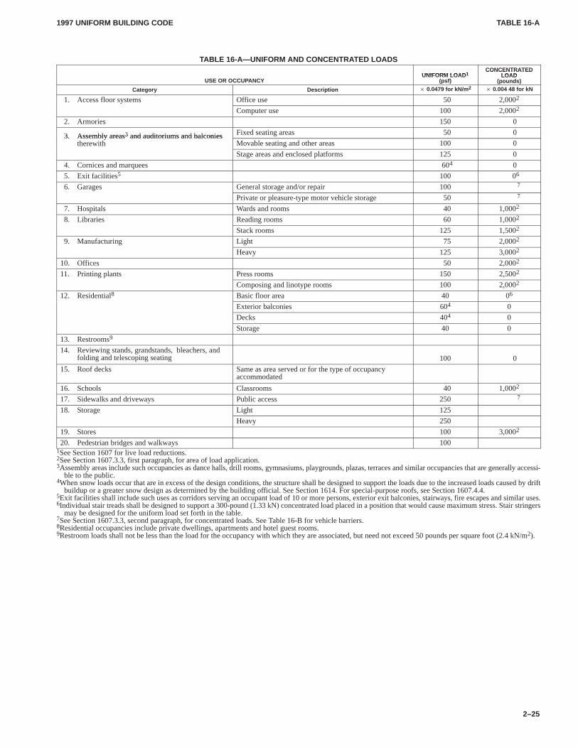
TABLE 16-ATABLE 16-A
1997 UNIFORM BUILDING CODE
2–25
TABLE 16-A—UNIFORM AND CONCENTRATED LOADS
UNIFORM LOAD1CONCENTRATED
LOADUSE OR OCCUPANCY
UNIFORM LOAD1
(psf)
CONCENTRATEDLOAD
(pounds)
Category Description � 0.0479 for kN/m 2� 0.004 48 for kN
1. Access floor systems Office use 50 2,0002
Computer use 100 2,0002
2. Armories 150 0
3. Assembly areas3 and auditoriums and balconies Fixed seating areas 50 03. Assembly areas3 and auditoriums and balconiestherewith Movable seating and other areas 100 0
Stage areas and enclosed platforms 125 0
4. Cornices and marquees 604 0
5. Exit facilities5 100 06
6. Garages General storage and/or repair 100 7
Private or pleasure-type motor vehicle storage 50 7
7. Hospitals Wards and rooms 40 1,0002
8. Libraries Reading rooms 60 1,0002
Stack rooms 125 1,5002
9. Manufacturing Light 75 2,0002
Heavy 125 3,0002
10. Offices 50 2,0002
11. Printing plants Press rooms 150 2,5002
Composing and linotype rooms 100 2,0002
12. Residential8 Basic floor area 40 06
Exterior balconies 604 0
Decks 404 0
Storage 40 0
13. Restrooms9
14. Reviewing stands, grandstands, bleachers, andfolding and telescoping seating 100 0
15. Roof decks Same as area served or for the type of occupancyaccommodated
16. Schools Classrooms 40 1,0002
17. Sidewalks and driveways Public access 250 7
18. Storage Light 125
Heavy 250
19. Stores 100 3,0002
20. Pedestrian bridges and walkways 1001See Section 1607 for live load reductions.2See Section 1607.3.3, first paragraph, for area of load application.3Assembly areas include such occupancies as dance halls, drill rooms, gymnasiums, playgrounds, plazas, terraces and similar occupancies that are generally accessi-
ble to the public.4When snow loads occur that are in excess of the design conditions, the structure shall be designed to support the loads due to the increased loads caused by drift
buildup or a greater snow design as determined by the building official. See Section 1614. For special-purpose roofs, see Section 1607.4.4.5Exit facilities shall include such uses as corridors serving an occupant load of 10 or more persons, exterior exit balconies, stairways, fire escapes and similar uses.6Individual stair treads shall be designed to support a 300-pound (1.33 kN) concentrated load placed in a position that would cause maximum stress. Stair stringers
may be designed for the uniform load set forth in the table.7See Section 1607.3.3, second paragraph, for concentrated loads. See Table 16-B for vehicle barriers.8Residential occupancies include private dwellings, apartments and hotel guest rooms.9Restroom loads shall not be less than the load for the occupancy with which they are associated, but need not exceed 50 pounds per square foot (2.4 kN/m2).
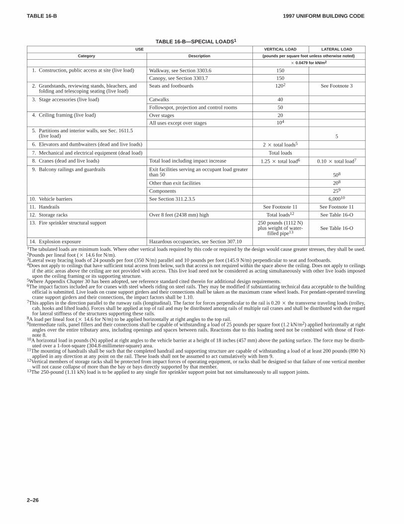
TABLE 16-BTABLE 16-B
1997 UNIFORM BUILDING CODE
2–26
TABLE 16-B—SPECIAL LOADS 1
USE VERTICAL LOAD LATERAL LOAD
Category Description (pounds per square foot unless otherwise noted)
� 0.0479 for kN/m 2
1. Construction, public access at site (live load) Walkway, see Section 3303.6 150, p ( )
Canopy, see Section 3303.7 150
2. Grandstands, reviewing stands, bleachers, andfolding and telescoping seating (live load)
Seats and footboards 1202 See Footnote 3
3. Stage accessories (live load) Catwalks 40
Followspot, projection and control rooms 50
4. Ceiling framing (live load) Over stages 20g g ( )
All uses except over stages 104
5. Partitions and interior walls, see Sec. 1611.5(live load) 5
6. Elevators and dumbwaiters (dead and live loads) 2 � total loads5
7. Mechanical and electrical equipment (dead load) Total loads
8. Cranes (dead and live loads) Total load including impact increase 1.25 � total load6 0.10 � total load7
9. Balcony railings and guardrails Exit facilities serving an occupant load greaterthan 50 508
Other than exit facilities 208
Components 259
10. Vehicle barriers See Section 311.2.3.5 6,00010
11. Handrails See Footnote 11 See Footnote 11
12. Storage racks Over 8 feet (2438 mm) high Total loads12 See Table 16-O
13. Fire sprinkler structural support 250 pounds (1112 N)plus weight of water-
filled pipe13See Table 16-O
14. Explosion exposure Hazardous occupancies, see Section 307.101The tabulated loads are minimum loads. Where other vertical loads required by this code or required by the design would cause greater stresses, they shall be used.2Pounds per lineal foot (� 14.6 for N/m).3Lateral sway bracing loads of 24 pounds per foot (350 N/m) parallel and 10 pounds per foot (145.9 N/m) perpendicular to seat and footboards.4Does not apply to ceilings that have sufficient total access from below, such that access is not required within the space above the ceiling. Does not apply to ceilings
if the attic areas above the ceiling are not provided with access. This live load need not be considered as acting simultaneously with other live loads imposedupon the ceiling framing or its supporting structure.
5Where Appendix Chapter 30 has been adopted, see reference standard cited therein for additional design requirements.6The impact factors included are for cranes with steel wheels riding on steel rails. They may be modified if substantiating technical data acceptable to the building
official is submitted. Live loads on crane support girders and their connections shall be taken as the maximum crane wheel loads. For pendant-operated travelingcrane support girders and their connections, the impact factors shall be 1.10.
7This applies in the direction parallel to the runway rails (longitudinal). The factor for forces perpendicular to the rail is 0.20 � the transverse traveling loads (trolley,cab, hooks and lifted loads). Forces shall be applied at top of rail and may be distributed among rails of multiple rail cranes and shall be distributed with due regardfor lateral stiffness of the structures supporting these rails.
8A load per lineal foot (� 14.6 for N/m) to be applied horizontally at right angles to the top rail.9Intermediate rails, panel fillers and their connections shall be capable of withstanding a load of 25 pounds per square foot (1.2 kN/m2) applied horizontally at right
angles over the entire tributary area, including openings and spaces between rails. Reactions due to this loading need not be combined with those of Foot-note 8.
10A horizontal load in pounds (N) applied at right angles to the vehicle barrier at a height of 18 inches (457 mm) above the parking surface. The force may be distrib-uted over a 1-foot-square (304.8-millimeter-square) area.
11The mounting of handrails shall be such that the completed handrail and supporting structure are capable of withstanding a load of at least 200 pounds (890 N)applied in any direction at any point on the rail. These loads shall not be assumed to act cumulatively with Item 9.
12Vertical members of storage racks shall be protected from impact forces of operating equipment, or racks shall be designed so that failure of one vertical memberwill not cause collapse of more than the bay or bays directly supported by that member.
13The 250-pound (1.11 kN) load is to be applied to any single fire sprinkler support point but not simultaneously to all support joints.
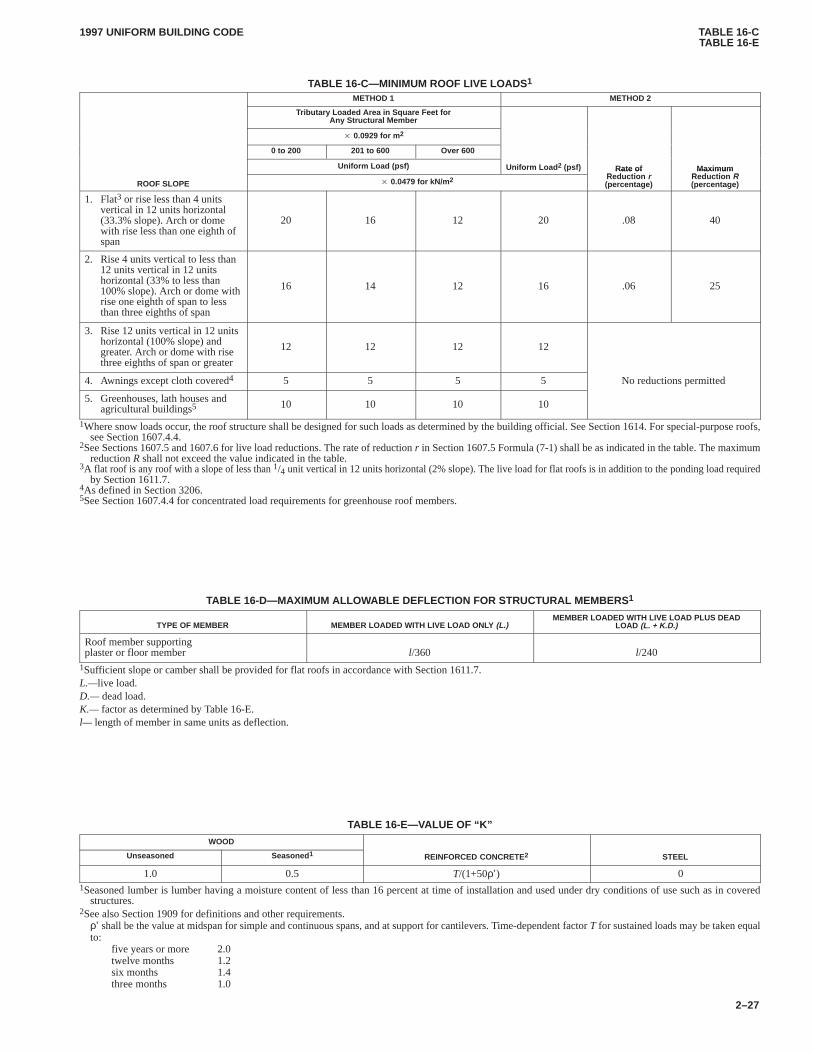
TABLE 16-CTABLE 16-E
1997 UNIFORM BUILDING CODE
2–27
TABLE 16-C—MINIMUM ROOF LIVE LOADS 1
METHOD 1 METHOD 2
Tributary Loaded Area in Square Feet forAny Structural Member
� 0.0929 for m 2
0 to 200 201 to 600 Over 600
Uniform Load (psf) Uniform Load 2 (psf) Rate ofR d ti
MaximumR d ti R
ROOF SLOPE � 0.0479 for kN/m 2
Rate ofReduction r(percentage)
Maxim umReduction R(percentage)
1. Flat3 or rise less than 4 unitsvertical in 12 units horizontal(33.3% slope). Arch or domewith rise less than one eighth ofspan
20 16 12 20 .08 40
2. Rise 4 units vertical to less than12 units vertical in 12 unitshorizontal (33% to less than100% slope). Arch or dome withrise one eighth of span to lessthan three eighths of span
16 14 12 16 .06 25
3. Rise 12 units vertical in 12 unitshorizontal (100% slope) andgreater. Arch or dome with risethree eighths of span or greater
12 12 12 12
4. Awnings except cloth covered4 5 5 5 5 No reductions permitted
5. Greenhouses, lath houses andagricultural buildings5 10 10 10 10
1Where snow loads occur, the roof structure shall be designed for such loads as determined by the building official. See Section 1614. For special-purpose roofs,see Section 1607.4.4.
2See Sections 1607.5 and 1607.6 for live load reductions. The rate of reduction r in Section 1607.5 Formula (7-1) shall be as indicated in the table. The maximumreduction R shall not exceed the value indicated in the table.
3A flat roof is any roof with a slope of less than 1/4 unit vertical in 12 units horizontal (2% slope). The live load for flat roofs is in addition to the ponding load requiredby Section 1611.7.
4As defined in Section 3206.5See Section 1607.4.4 for concentrated load requirements for greenhouse roof members.
TABLE 16-D—MAXIMUM ALLOW ABLE DEFLECTION FOR STRUCTURAL MEMBERS 1
TYPE OF MEMBER MEMBER LOADED WITH LIVE LOAD ONL Y (L.)MEMBER LOADED WITH LIVE LOAD PLUS DEAD
LOAD (L. + K.D.)
Roof member supportingplaster or floor member l/360 l/240
1Sufficient slope or camber shall be provided for flat roofs in accordance with Section 1611.7.L.—live load.D.— dead load.K.— factor as determined by Table 16-E.l— length of member in same units as deflection.
TABLE 16-E—VALUE OF “K”
WOOD
Unseasoned Seasoned 1 REINFORCED CONCRETE2 STEEL
1.0 0.5 T/(1+50ρ’) 01Seasoned lumber is lumber having a moisture content of less than 16 percent at time of installation and used under dry conditions of use such as in covered
structures.2See also Section 1909 for definitions and other requirements.
ρ’ shall be the value at midspan for simple and continuous spans, and at support for cantilevers. Time-dependent factor T for sustained loads may be taken equalto:
five years or more 2.0twelve months 1.2six months 1.4three months 1.0
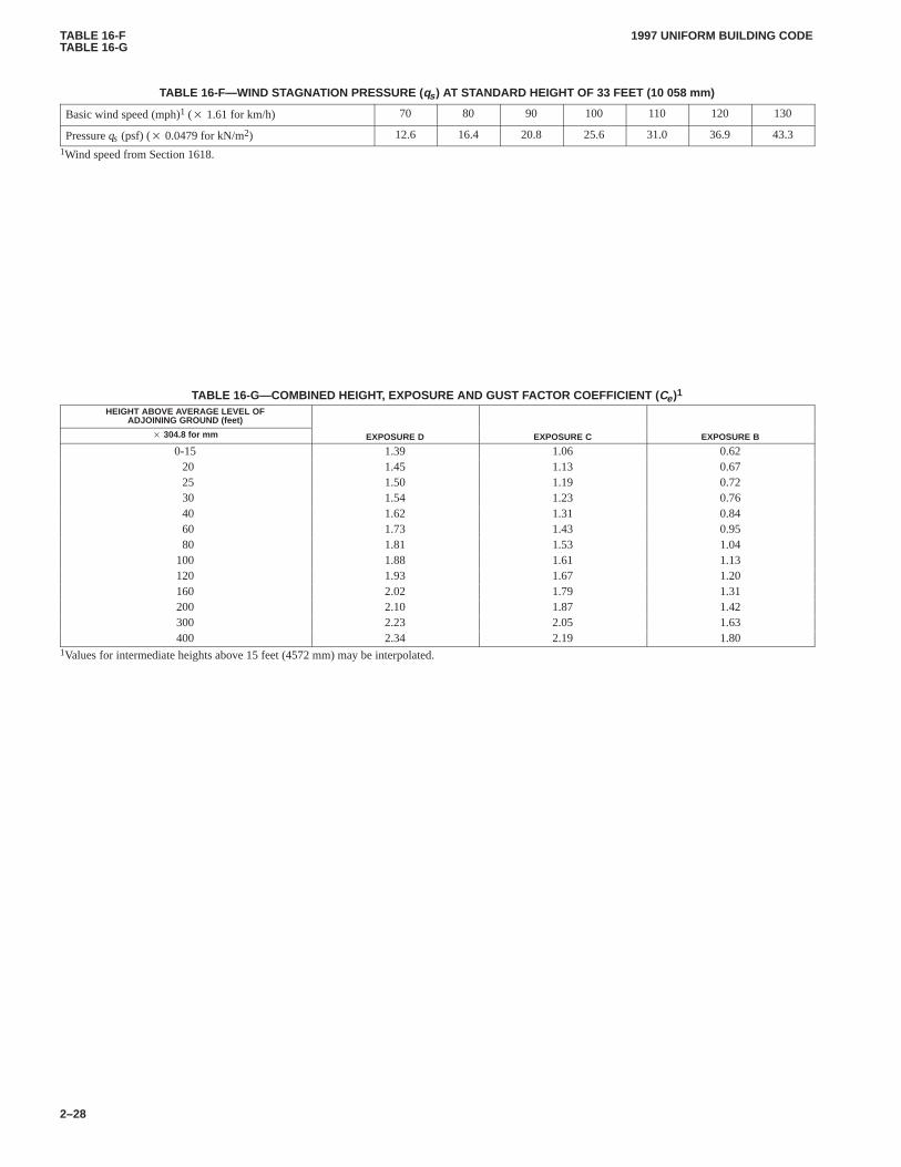
TABLE 16-FTABLE 16-G
1997 UNIFORM BUILDING CODE
2–28
TABLE 16-F—WIND STAGNATION PRESSURE (qs ) AT STANDARD HEIGHT OF 33 FEET (10 058 mm)
Basic wind speed (mph)1 (� 1.61 for km/h) 70 80 90 100 110 120 130
Pressure qs (psf) (� 0.0479 for kN/m2) 12.6 16.4 20.8 25.6 31.0 36.9 43.3
1Wind speed from Section 1618.
TABLE 16-G—COMBINED HEIGHT, EXPOSURE AND GUST FACTOR COEFFICIENT (Ce)1
HEIGHT ABOVE AVERAGE LEVEL OFADJOINING GROUND (feet)
� 304.8 for mm EXPOSURE D EXPOSURE C EXPOSURE B
0-15 1.39 1.06 0.6220 1.45 1.13 0.6725 1.50 1.19 0.7230 1.54 1.23 0.7640 1.62 1.31 0.8460 1.73 1.43 0.9580 1.81 1.53 1.04
100 1.88 1.61 1.13120 1.93 1.67 1.20160 2.02 1.79 1.31200 2.10 1.87 1.42300 2.23 2.05 1.63400 2.34 2.19 1.80
1Values for intermediate heights above 15 feet (4572 mm) may be interpolated.
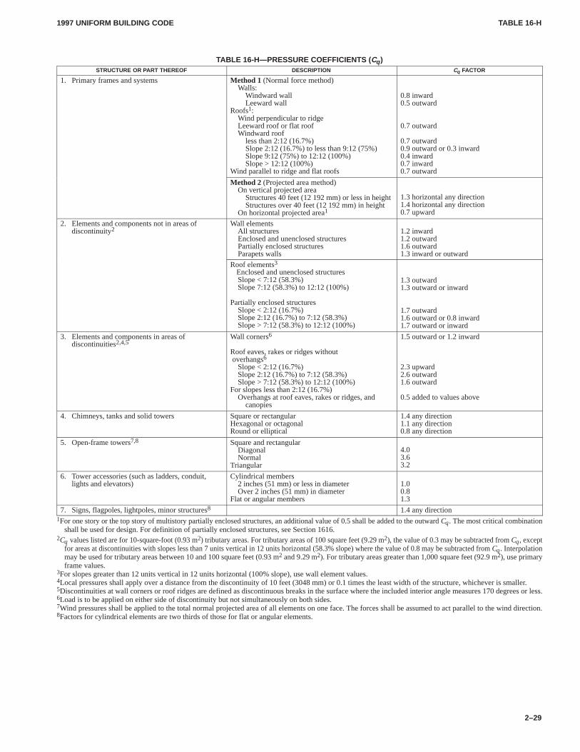
TABLE 16-HTABLE 16-H
1997 UNIFORM BUILDING CODE
2–29
TABLE 16-H—PRESSURE COEFFICIENTS ( Cq )STRUCTURE OR PART THEREOF DESCRIPTION Cq FACTOR
1. Primary frames and systems Method 1 (Normal force method)Walls:
Windward wallLeeward wall
Roofs1:Wind perpendicular to ridgeLeeward roof or flat roofWindward roof
less than 2:12 (16.7%)Slope 2:12 (16.7%) to less than 9:12 (75%)Slope 9:12 (75%) to 12:12 (100%)Slope > 12:12 (100%)
Wind parallel to ridge and flat roofs
0.8 inward0.5 outward
0.7 outward
0.7 outward0.9 outward or 0.3 inward0.4 inward0.7 inward0.7 outward
Method 2 (Projected area method)On vertical projected area
Structures 40 feet (12 192 mm) or less in heightStructures over 40 feet (12 192 mm) in height
On horizontal projected area1
1.3 horizontal any direction1.4 horizontal any direction0.7 upward
2. Elements and components not in areas ofdiscontinuity2
Wall elementsAll structuresEnclosed and unenclosed structuresPartially enclosed structuresParapets walls
1.2 inward1.2 outward1.6 outward1.3 inward or outward
Roof elements3Enclosed and unenclosed structuresSlope < 7:12 (58.3%)Slope 7:12 (58.3%) to 12:12 (100%)
Partially enclosed structuresSlope < 2:12 (16.7%)Slope 2:12 (16.7%) to 7:12 (58.3%)Slope > 7:12 (58.3%) to 12:12 (100%)
1.3 outward1.3 outward or inward
1.7 outward1.6 outward or 0.8 inward1.7 outward or inward
3. Elements and components in areas ofdiscontinuities2,4,5
Wall corners6
Roof eaves, rakes or ridges without overhangs6
Slope < 2:12 (16.7%)Slope 2:12 (16.7%) to 7:12 (58.3%)Slope > 7:12 (58.3%) to 12:12 (100%)
For slopes less than 2:12 (16.7%)Overhangs at roof eaves, rakes or ridges, and
canopies
1.5 outward or 1.2 inward
2.3 upward2.6 outward1.6 outward
0.5 added to values above
4. Chimneys, tanks and solid towers Square or rectangularHexagonal or octagonalRound or elliptical
1.4 any direction1.1 any direction0.8 any direction
5. Open-frame towers7,8 Square and rectangularDiagonalNormal
Triangular
4.03.63.2
6. Tower accessories (such as ladders, conduit,lights and elevators)
Cylindrical members2 inches (51 mm) or less in diameterOver 2 inches (51 mm) in diameter
Flat or angular members
1.00.81.3
7. Signs, flagpoles, lightpoles, minor structures8 1.4 any direction1For one story or the top story of multistory partially enclosed structures, an additional value of 0.5 shall be added to the outward Cq. The most critical combination
shall be used for design. For definition of partially enclosed structures, see Section 1616.2Cq values listed are for 10-square-foot (0.93 m2) tributary areas. For tributary areas of 100 square feet (9.29 m2), the value of 0.3 may be subtracted from Cq, except
for areas at discontinuities with slopes less than 7 units vertical in 12 units horizontal (58.3% slope) where the value of 0.8 may be subtracted from Cq. Interpolationmay be used for tributary areas between 10 and 100 square feet (0.93 m2 and 9.29 m2). For tributary areas greater than 1,000 square feet (92.9 m2), use primaryframe values.
3For slopes greater than 12 units vertical in 12 units horizontal (100% slope), use wall element values.4Local pressures shall apply over a distance from the discontinuity of 10 feet (3048 mm) or 0.1 times the least width of the structure, whichever is smaller.5Discontinuities at wall corners or roof ridges are defined as discontinuous breaks in the surface where the included interior angle measures 170 degrees or less.6Load is to be applied on either side of discontinuity but not simultaneously on both sides.7Wind pressures shall be applied to the total normal projected area of all elements on one face. The forces shall be assumed to act parallel to the wind direction.8Factors for cylindrical elements are two thirds of those for flat or angular elements.
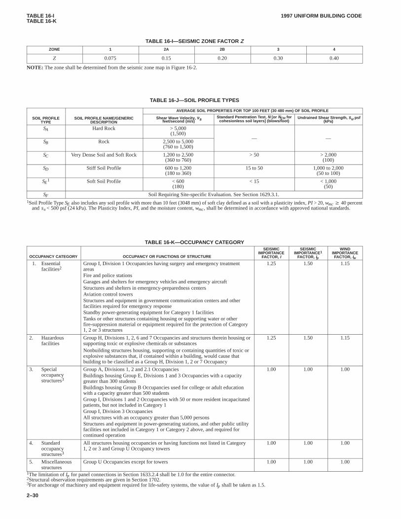
TABLE 16-ITABLE 16-K
1997 UNIFORM BUILDING CODE
2–30
TABLE 16-I—SEISMIC ZONE FACTOR ZZONE 1 2A 2B 3 4
Z 0.075 0.15 0.20 0.30 0.40
NOTE: The zone shall be determined from the seismic zone map in Figure 16-2.
TABLE 16-J—SOIL PROFILE TYPES
AVERAGE SOIL PROPERTIES FOR TOP 100 FEET (30 480 mm) OF SOIL PROFILE
SOIL PROFILETYPE
SOIL PROFILE NAME/GENERICDESCRIPTION feet/second (m/s)
Shear Wave Velocit y, vs Standard Penetration T est, N [or NCH forcohesionless soil layers] (blows/foot) (kPa)
Undrained Shear Strength , su psf
SA Hard Rock > 5,000(1,500)
SB Rock 2,500 to 5,000(760 to 1,500)
— —
SC Very Dense Soil and Soft Rock 1,200 to 2,500(360 to 760)
> 50 > 2,000(100)
SD Stiff Soil Profile 600 to 1,200(180 to 360)
15 to 50 1,000 to 2,000(50 to 100)
SE1 Soft Soil Profile < 600
(180)< 15 < 1,000
(50)
SF Soil Requiring Site-specific Evaluation. See Section 1629.3.1.1Soil Profile Type SE also includes any soil profile with more than 10 feet (3048 mm) of soft clay defined as a soil with a plasticity index, PI > 20, wmc � 40 percent
and su < 500 psf (24 kPa). The Plasticity Index, PI, and the moisture content, wmc, shall be determined in accordance with approved national standards.
TABLE 16-K—OCCUPANCY CATEGORY
OCCUPANCY CATEGORY OCCUPANCY OR FUNCTIONS OF STRUCTURE
SEISMICIMPORTANCE
FACTOR, I
SEISMICIMPORTANCE1
FACTOR, Ip
WINDIMPORTANCEFACTOR, Iw
1. Essentialfacilities2
Group I, Division 1 Occupancies having surgery and emergency treatmentareasFire and police stationsGarages and shelters for emergency vehicles and emergency aircraftStructures and shelters in emergency-preparedness centersAviation control towersStructures and equipment in government communication centers and otherfacilities required for emergency responseStandby power-generating equipment for Category 1 facilitiesTanks or other structures containing housing or supporting water or otherfire-suppression material or equipment required for the protection of Category1, 2 or 3 structures
1.25 1.50 1.15
2. Hazardousfacilities
Group H, Divisions 1, 2, 6 and 7 Occupancies and structures therein housing orsupporting toxic or explosive chemicals or substancesNonbuilding structures housing, supporting or containing quantities of toxic orexplosive substances that, if contained within a building, would cause thatbuilding to be classified as a Group H, Division 1, 2 or 7 Occupancy
1.25 1.50 1.15
3. Specialoccupancystructures3
Group A, Divisions 1, 2 and 2.1 OccupanciesBuildings housing Group E, Divisions 1 and 3 Occupancies with a capacitygreater than 300 studentsBuildings housing Group B Occupancies used for college or adult educationwith a capacity greater than 500 studentsGroup I, Divisions 1 and 2 Occupancies with 50 or more resident incapacitatedpatients, but not included in Category 1Group I, Division 3 OccupanciesAll structures with an occupancy greater than 5,000 personsStructures and equipment in power-generating stations, and other public utilityfacilities not included in Category 1 or Category 2 above, and required forcontinued operation
1.00 1.00 1.00
4. Standardoccupancystructures3
All structures housing occupancies or having functions not listed in Category1, 2 or 3 and Group U Occupancy towers
1.00 1.00 1.00
5. Miscellaneousstructures
Group U Occupancies except for towers 1.00 1.00 1.00
1The limitation of Ip for panel connections in Section 1633.2.4 shall be 1.0 for the entire connector.2Structural observation requirements are given in Section 1702.3For anchorage of machinery and equipment required for life-safety systems, the value of Ip shall be taken as 1.5.
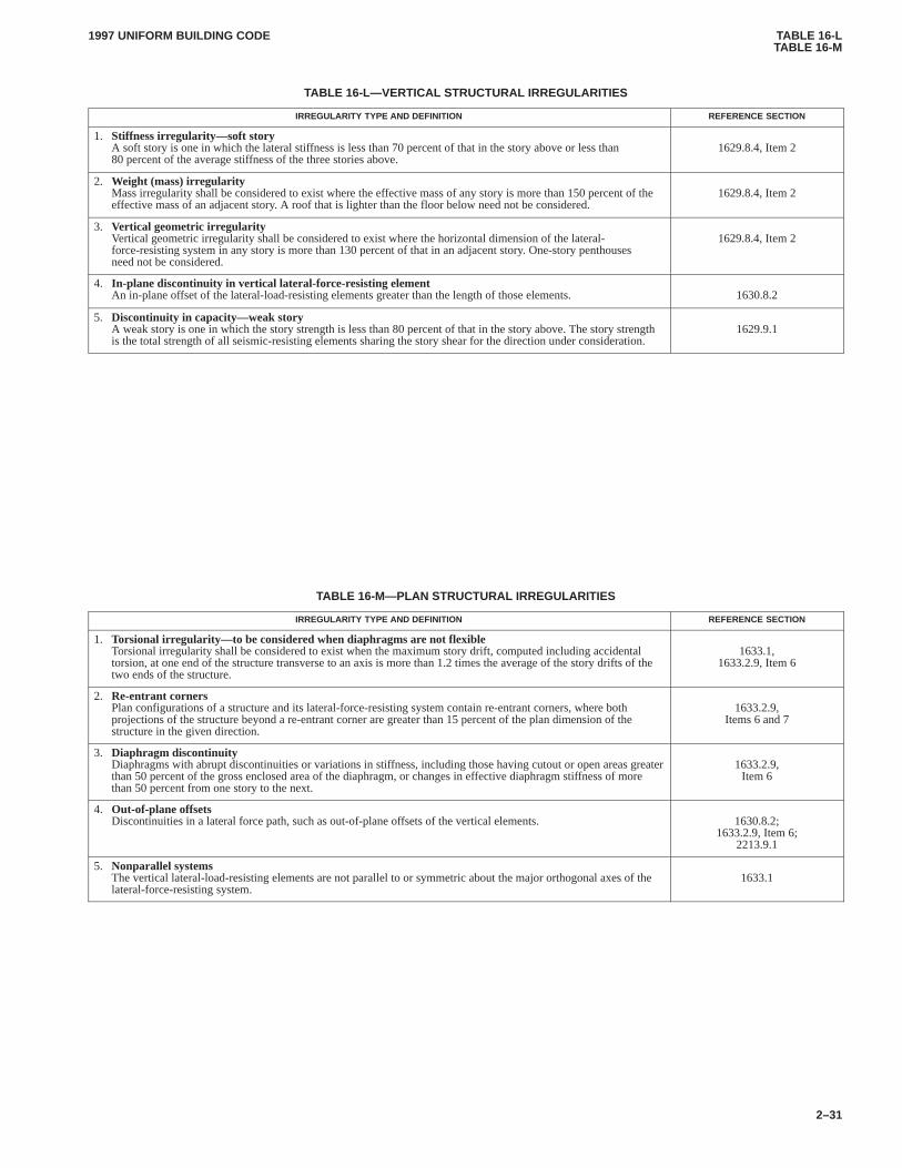
TABLE 16-LTABLE 16-M
1997 UNIFORM BUILDING CODE
2–31
TABLE 16-L—VERTICAL STRUCTURAL IRREGULARITIES
IRREGULARITY TYPE AND DEFINITION REFERENCE SECTION
1. Stiffness irregularity—soft storyA soft story is one in which the lateral stiffness is less than 70 percent of that in the story above or less than80 percent of the average stiffness of the three stories above.
1629.8.4, Item 2
2. Weight (mass) irregularityMass irregularity shall be considered to exist where the effective mass of any story is more than 150 percent of theeffective mass of an adjacent story. A roof that is lighter than the floor below need not be considered.
1629.8.4, Item 2
3. Vertical geometric irregularityVertical geometric irregularity shall be considered to exist where the horizontal dimension of the lateral-force-resisting system in any story is more than 130 percent of that in an adjacent story. One-story penthousesneed not be considered.
1629.8.4, Item 2
4. In-plane discontinuity in vertical lateral-force-r esisting elementAn in-plane offset of the lateral-load-resisting elements greater than the length of those elements. 1630.8.2
5. Discontinuity in capacity—weak storyA weak story is one in which the story strength is less than 80 percent of that in the story above. The story strengthis the total strength of all seismic-resisting elements sharing the story shear for the direction under consideration.
1629.9.1
TABLE 16-M—PLAN STRUCTURAL IRREGULARITIES
IRREGULARITY TYPE AND DEFINITION REFERENCE SECTION
1. Torsional irregularity—to be considered when diaphragms are not flexibleTorsional irregularity shall be considered to exist when the maximum story drift, computed including accidentaltorsion, at one end of the structure transverse to an axis is more than 1.2 times the average of the story drifts of thetwo ends of the structure.
1633.1,1633.2.9, Item 6
2. Re-entrant cornersPlan configurations of a structure and its lateral-force-resisting system contain re-entrant corners, where bothprojections of the structure beyond a re-entrant corner are greater than 15 percent of the plan dimension of thestructure in the given direction.
1633.2.9,Items 6 and 7
3. Diaphragm discontinuityDiaphragms with abrupt discontinuities or variations in stiffness, including those having cutout or open areas greaterthan 50 percent of the gross enclosed area of the diaphragm, or changes in effective diaphragm stiffness of morethan 50 percent from one story to the next.
1633.2.9,Item 6
4. Out-of-plane offsetsDiscontinuities in a lateral force path, such as out-of-plane offsets of the vertical elements. 1630.8.2;
1633.2.9, Item 6;2213.9.1
5. Nonparallel systemsThe vertical lateral-load-resisting elements are not parallel to or symmetric about the major orthogonal axes of thelateral-force-resisting system.
1633.1
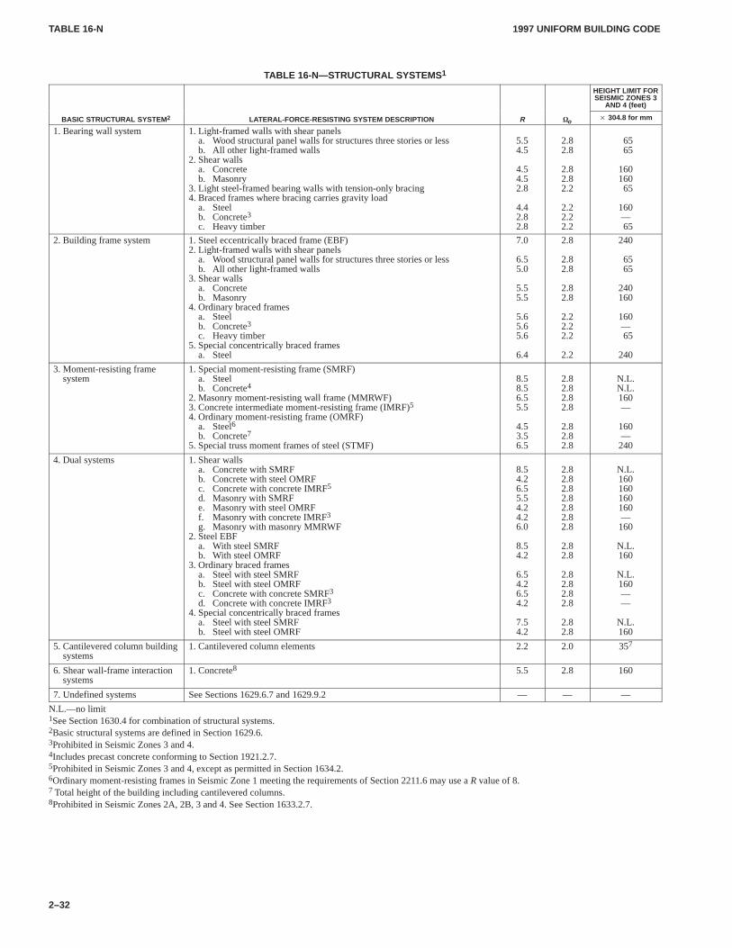
TABLE 16-NTABLE 16-N
1997 UNIFORM BUILDING CODE
2–32
TABLE 16-N—STRUCTURAL SYSTEMS 1
HEIGHT LIMIT FORSEISMIC ZONES 3
AND 4 (feet)
BASIC STRUCTURAL SYSTEM 2 LATERAL-FORCE-RESISTING SYSTEM DESCRIPTION R �o � 304.8 for mm
1. Bearing wall system 1. Light-framed walls with shear panelsa. Wood structural panel walls for structures three stories or lessb. All other light-framed walls
2. Shear wallsa. Concreteb. Masonry
3. Light steel-framed bearing walls with tension-only bracing4. Braced frames where bracing carries gravity load
a. Steelb. Concrete3c. Heavy timber
5.54.5
4.54.52.8
4.42.82.8
2.82.8
2.82.82.2
2.22.22.2
6565
16016065
160—65
2. Building frame system 1. Steel eccentrically braced frame (EBF)2. Light-framed walls with shear panels
a. Wood structural panel walls for structures three stories or lessb. All other light-framed walls
3. Shear wallsa. Concreteb. Masonry
4. Ordinary braced framesa. Steelb. Concrete3c. Heavy timber
5. Special concentrically braced framesa. Steel
7.0
6.55.0
5.55.5
5.65.65.6
6.4
2.8
2.82.8
2.82.8
2.22.22.2
2.2
240
6565
240160
160—65
240
3. Moment-resisting framesystem
1. Special moment-resisting frame (SMRF)a. Steelb. Concrete4
2. Masonry moment-resisting wall frame (MMRWF)3. Concrete intermediate moment-resisting frame (IMRF)5
4. Ordinary moment-resisting frame (OMRF)a. Steel6b. Concrete7
5. Special truss moment frames of steel (STMF)
8.58.56.55.5
4.53.56.5
2.82.82.82.8
2.82.82.8
N.L.N.L.160—
160—240
4. Dual systems 1. Shear wallsa. Concrete with SMRFb. Concrete with steel OMRFc. Concrete with concrete IMRF5
d. Masonry with SMRFe. Masonry with steel OMRFf. Masonry with concrete IMRF3g. Masonry with masonry MMRWF
2. Steel EBFa. With steel SMRFb. With steel OMRF
3. Ordinary braced framesa. Steel with steel SMRFb. Steel with steel OMRFc. Concrete with concrete SMRF3
d. Concrete with concrete IMRF3
4. Special concentrically braced framesa. Steel with steel SMRFb. Steel with steel OMRF
8.54.26.55.54.24.26.0
8.54.2
6.54.26.54.2
7.54.2
2.82.82.82.82.82.82.8
2.82.8
2.82.82.82.8
2.82.8
N.L.160160160160—160
N.L.160
N.L.160——
N.L.160
5. Cantilevered column buildingsystems
1. Cantilevered column elements 2.2 2.0 357
6. Shear wall-frame interactionsystems
1. Concrete8 5.5 2.8 160
7. Undefined systems See Sections 1629.6.7 and 1629.9.2 — — —
N.L.—no limit1See Section 1630.4 for combination of structural systems.2Basic structural systems are defined in Section 1629.6.3Prohibited in Seismic Zones 3 and 4.4Includes precast concrete conforming to Section 1921.2.7.5Prohibited in Seismic Zones 3 and 4, except as permitted in Section 1634.2.6Ordinary moment-resisting frames in Seismic Zone 1 meeting the requirements of Section 2211.6 may use a R value of 8.7 Total height of the building including cantilevered columns.8Prohibited in Seismic Zones 2A, 2B, 3 and 4. See Section 1633.2.7.
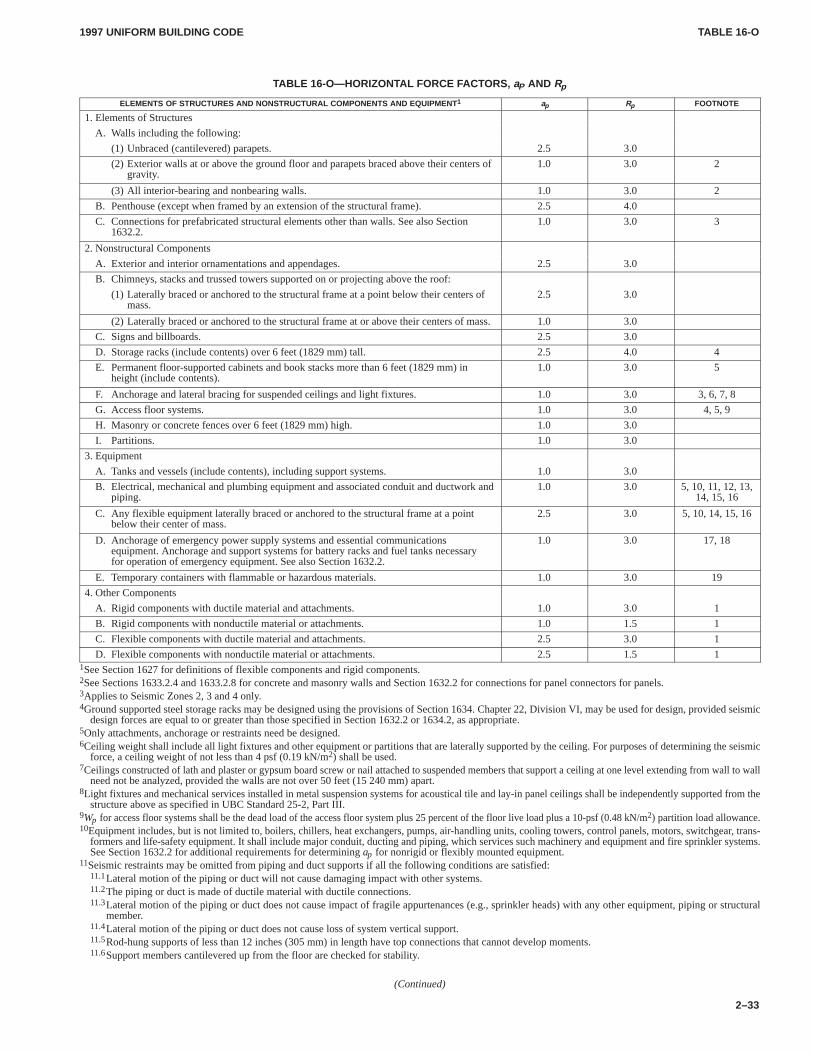
TABLE 16-OTABLE 16-O
1997 UNIFORM BUILDING CODE
2–33
TABLE 16-O—HORIZONTAL FORCE FACTORS, aP AND Rp
ELEMENTS OF STRUCTURES AND NONSTRUCTURAL COMPONENTS AND EQUIPMENT 1 ap Rp FOOTNOTE
1. Elements of Structures
A. Walls including the following:
(1) Unbraced (cantilevered) parapets. 2.5 3.0
(2) Exterior walls at or above the ground floor and parapets braced above their centers ofgravity.
1.0 3.0 2
(3) All interior-bearing and nonbearing walls. 1.0 3.0 2
B. Penthouse (except when framed by an extension of the structural frame). 2.5 4.0
C. Connections for prefabricated structural elements other than walls. See also Section1632.2.
1.0 3.0 3
2. Nonstructural Components
A. Exterior and interior ornamentations and appendages. 2.5 3.0
B. Chimneys, stacks and trussed towers supported on or projecting above the roof:
(1) Laterally braced or anchored to the structural frame at a point below their centers ofmass.
2.5 3.0
(2) Laterally braced or anchored to the structural frame at or above their centers of mass. 1.0 3.0
C. Signs and billboards. 2.5 3.0
D. Storage racks (include contents) over 6 feet (1829 mm) tall. 2.5 4.0 4
E. Permanent floor-supported cabinets and book stacks more than 6 feet (1829 mm) inheight (include contents).
1.0 3.0 5
F. Anchorage and lateral bracing for suspended ceilings and light fixtures. 1.0 3.0 3, 6, 7, 8
G. Access floor systems. 1.0 3.0 4, 5, 9
H. Masonry or concrete fences over 6 feet (1829 mm) high. 1.0 3.0
I. Partitions. 1.0 3.0
3. Equipment
A. Tanks and vessels (include contents), including support systems. 1.0 3.0
B. Electrical, mechanical and plumbing equipment and associated conduit and ductwork andpiping.
1.0 3.0 5, 10, 11, 12, 13,14, 15, 16
C. Any flexible equipment laterally braced or anchored to the structural frame at a pointbelow their center of mass.
2.5 3.0 5, 10, 14, 15, 16
D. Anchorage of emergency power supply systems and essential communicationsequipment. Anchorage and support systems for battery racks and fuel tanks necessary for operation of emergency equipment. See also Section 1632.2.
1.0 3.0 17, 18
E. Temporary containers with flammable or hazardous materials. 1.0 3.0 19
4. Other Components
A. Rigid components with ductile material and attachments. 1.0 3.0 1
B. Rigid components with nonductile material or attachments. 1.0 1.5 1
C. Flexible components with ductile material and attachments. 2.5 3.0 1
D. Flexible components with nonductile material or attachments. 2.5 1.5 11See Section 1627 for definitions of flexible components and rigid components.2See Sections 1633.2.4 and 1633.2.8 for concrete and masonry walls and Section 1632.2 for connections for panel connectors for panels.3Applies to Seismic Zones 2, 3 and 4 only.4Ground supported steel storage racks may be designed using the provisions of Section 1634. Chapter 22, Division VI, may be used for design, provided seismic
design forces are equal to or greater than those specified in Section 1632.2 or 1634.2, as appropriate.5Only attachments, anchorage or restraints need be designed.6Ceiling weight shall include all light fixtures and other equipment or partitions that are laterally supported by the ceiling. For purposes of determining the seismic
force, a ceiling weight of not less than 4 psf (0.19 kN/m2) shall be used.7Ceilings constructed of lath and plaster or gypsum board screw or nail attached to suspended members that support a ceiling at one level extending from wall to wall
need not be analyzed, provided the walls are not over 50 feet (15 240 mm) apart.8Light fixtures and mechanical services installed in metal suspension systems for acoustical tile and lay-in panel ceilings shall be independently supported from the
structure above as specified in UBC Standard 25-2, Part III.9Wp for access floor systems shall be the dead load of the access floor system plus 25 percent of the floor live load plus a 10-psf (0.48 kN/m2) partition load allowance.10Equipment includes, but is not limited to, boilers, chillers, heat exchangers, pumps, air-handling units, cooling towers, control panels, motors, switchgear, trans-
formers and life-safety equipment. It shall include major conduit, ducting and piping, which services such machinery and equipment and fire sprinkler systems.See Section 1632.2 for additional requirements for determining ap for nonrigid or flexibly mounted equipment.
11Seismic restraints may be omitted from piping and duct supports if all the following conditions are satisfied:11.1Lateral motion of the piping or duct will not cause damaging impact with other systems.11.2The piping or duct is made of ductile material with ductile connections.11.3Lateral motion of the piping or duct does not cause impact of fragile appurtenances (e.g., sprinkler heads) with any other equipment, piping or structural
member.11.4Lateral motion of the piping or duct does not cause loss of system vertical support.11.5Rod-hung supports of less than 12 inches (305 mm) in length have top connections that cannot develop moments.11.6Support members cantilevered up from the floor are checked for stability.
(Continued)
TABLE 16-OTABLE 16-Q
1997 UNIFORM BUILDING CODE
2–34
FOOTNOTES TO TABLE 16-O—(Continued)12Seismic restraints may be omitted from electrical raceways, such as cable trays, conduit and bus ducts, if all the following conditions are satisfied:
12.1Lateral motion of the raceway will not cause damaging impact with other systems.12.2Lateral motion of the raceway does not cause loss of system vertical support.12.3Rod-hung supports of less than 12 inches (305 mm) in length have top connections that cannot develop moments.12.4Support members cantilevered up from the floor are checked for stability.
13Piping, ducts and electrical raceways, which must be functional following an earthquake, spanning between different buildings or structural systems shall besufficiently flexible to withstand relative motion of support points assuming out-of-phase motions.
14Vibration isolators supporting equipment shall be designed for lateral loads or restrained from displacing laterally by other means. Restraint shall also be provided,which limits vertical displacement, such that lateral restraints do not become disengaged. ap and Rp for equipment supported on vibration isolators shall be takenas 2.5 and 1.5, respectively, except that if the isolation mounting frame is supported by shallow or expansion anchors, the design forces for the anchors calculatedby Formula (32-1), (32-2) or (32-3) shall be additionally multiplied by a factor of 2.0.
15Equipment anchorage shall not be designed such that lateral loads are resisted by gravity friction (e.g., friction clips).16Expansion anchors, which are required to resist seismic loads in tension, shall not be used where operational vibrating loads are present.17Movement of components within electrical cabinets, rack- and skid-mounted equipment and portions of skid-mounted electromechanical equipment that may
cause damage to other components by displacing, shall be restricted by attachment to anchored equipment or support frames.18Batteries on racks shall be restrained against movement in all directions due to earthquake forces.19Seismic restraints may include straps, chains, bolts, barriers or other mechanisms that prevent sliding, falling and breach of containment of flammable and toxic
materials. Friction forces may not be used to resist lateral loads in these restraints unless positive uplift restraint is provided which ensures that the friction forcesact continuously.
TABLE 16-P—R AND �o FACTORS FOR NONBUILDING STRUCTURES
STRUCTURE TYPE R �o
1. Vessels, including tanks and pressurized spheres, on braced or unbraced legs. 2.2 2.0
2. Cast-in-place concrete silos and chimneys having walls continuous to the foundations. 3.6 2.0
3. Distributed mass cantilever structures such as stacks, chimneys, silos and skirt-supported vertical vessels. 2.9 2.0
4. Trussed towers (freestanding or guyed), guyed stacks and chimneys. 2.9 2.0
5. Cantilevered column-type structures. 2.2 2.0
6. Cooling towers. 3.6 2.0
7. Bins and hoppers on braced or unbraced legs. 2.9 2.0
8. Storage racks. 3.6 2.0
9. Signs and billboards. 3.6 2.0
10. Amusement structures and monuments. 2.2 2.0
11. All other self-supporting structures not otherwise covered. 2.9 2.0
TABLE 16-Q—SEISMIC COEFFICIENT Ca
SEISMIC ZONE FACTOR, Z
SOIL PROFILE TYPE Z = 0.075 Z = 0.15 Z = 0.2 Z = 0.3 Z = 0.4
SA 0.06 0.12 0.16 0.24 0.32Na
SB 0.08 0.15 0.20 0.30 0.40Na
SC 0.09 0.18 0.24 0.33 0.40Na
SD 0.12 0.22 0.28 0.36 0.44Na
SE 0.19 0.30 0.34 0.36 0.36Na
SF See Footnote 11Site-specific geotechnical investigation and dynamic site response analysis shall be performed to determine seismic coefficients for Soil Profile Type SF.
TABLE 16-RTABLE 16-U
1997 UNIFORM BUILDING CODE
2–35
TABLE 16-R—SEISMIC COEFFICIENT Cv
SEISMIC ZONE FACTOR, Z
SOIL PROFILE TYPE Z = 0.075 Z = 0.15 Z = 0.2 Z = 0.3 Z = 0.4
SA 0.06 0.12 0.16 0.24 0.32Nv
SB 0.08 0.15 0.20 0.30 0.40Nv
SC 0.13 0.25 0.32 0.45 0.56Nv
SD 0.18 0.32 0.40 0.54 0.64Nv
SE 0.26 0.50 0.64 0.84 0.96Nv
SF See Footnote 11Site-specific geotechnical investigation and dynamic site response analysis shall be performed to determine seismic coefficients for Soil Profile Type SF.
TABLE 16-S—NEAR-SOURCE FACTOR Na1
CLOSEST DISTANCE TO KNOWN SEISMIC SOURCE 2,3
SEISMIC SOURCE TYPE � 2 km 5 km � 10 km
A 1.5 1.2 1.0
B 1.3 1.0 1.0
C 1.0 1.0 1.01The Near-Source Factor may be based on the linear interpolation of values for distances other than those shown in the table.2The location and type of seismic sources to be used for design shall be established based on approved geotechnical data (e.g., most recent mapping of active faults by
the United States Geological Survey or the California Division of Mines and Geology).3The closest distance to seismic source shall be taken as the minimum distance between the site and the area described by the vertical projection of the source on the
surface (i.e., surface projection of fault plane). The surface projection need not include portions of the source at depths of 10 km or greater. The largest value of theNear-Source Factor considering all sources shall be used for design.
TABLE 16-T—NEAR-SOURCE FACTOR Nv1
CLOSEST DISTANCE TO KNOWN SEISMIC SOURCE 2,3
SEISMIC SOURCE TYPE � 2 km 5 km 10 km � 15 km
A 2.0 1.6 1.2 1.0
B 1.6 1.2 1.0 1.0
C 1.0 1.0 1.0 1.01The Near-Source Factor may be based on the linear interpolation of values for distances other than those shown in the table.2The location and type of seismic sources to be used for design shall be established based on approved geotechnical data (e.g., most recent mapping of active faults by
the United States Geological Survey or the California Division of Mines and Geology).3The closest distance to seismic source shall be taken as the minimum distance between the site and the area described by the vertical projection of the source on the
surface (i.e., surface projection of fault plane). The surface projection need not include portions of the source at depths of 10 km or greater. The largest value of theNear-Source Factor considering all sources shall be used for design.
TABLE 16-U—SEISMIC SOURCE TYPE1
SEISMICSEISMIC SOURCE DEFINITION2
SEISMICSOURCE TYPE SEISMIC SOURCE DESCRIPTION Maximum Moment Magnitude, M Slip Rate, SR (mm/year)
A Faults that are capable of producing large magnitude events and thathave a high rate of seismic activity
M � 7.0 SR � 5
B All faults other than Types A and C M � 7.0M � 7.0M � 6.5
SR � 5SR � 2SR � 2
C Faults that are not capable of producing large magnitude earthquakesand that have a relatively low rate of seismic activity
M < 6.5 SR � 2
1Subduction sources shall be evaluated on a site-specific basis.2Both maximum moment magnitude and slip rate conditions must be satisfied concurrently when determining the seismic source type.
FIGURE 16-1FIGURE 16-1
1997 UNIFORM BUILDING CODE
2–36
110110
70
100
110
90
110
8090
100
90
9090
80
70
110
100
90
8070
100 90 8070
7080
80
70 80
100
110
110
110
NOTES:1. LINEAR INTERPOLATION BETWEEN WIND SPEED CONTOURS IS ACCEPTABLE.2. CAUTION IN USE OF WIND SPEED CONTOURS IN MOUNTAINOUS REGIONS OF ALASKA IS ADVISED.3. WIND SPEED FOR HAWAII IS 80, PUERTO RICO IS 95 AND THE VIRGIN ISLANDS IS 110.4. WIND SPEED MAY BE ASSUMED TO BE CONSTANT BETWEEN THE COASTLINE AND THE NEAREST INLAND CONTOUR.
BASIC WIND SPEED 70 mph SPECIAL WIND REGION
Aleutian Islands
70
8070 90
80
7070
90
110
7080
100 90
70
80
ALASKA100 2000
52° 52°
180°176° E 176° W
180°176° E 176° W
56°
64°
68°
110°100° 105°
168° 136°144°152°
100°
160°
52°
60°
168° 152°160°176°
95° 90° 85° 80° 75°
25°
30°
35°
40°
45°
40°
45°
35°
30°
25°
110°115°120°125° 105° 100° 95° 90° 85° 80° 75° 70° 65°
FIGURE 16-1—MINIMUM BASIC WIND SPEEDS IN MILES PER HOUR (� 1.61 for km/h)
FIGURE 16-2FIGURE 16-2
1997 UNIFORM BUILDING CODE
2–37
4
30 100 300
MILES
200
4
PUERTO RICO
GUAM
33
2A
ALASKA
ALEUTIANISLANDS
1
1
1
1
1
1
1
2A3
3
3
3
3
3
4
4
4
4
0
0
0
0
0
2A
2B
2B
2A 2B
2B
2B
2A
2B
2B
2B
1
1
3
0
1
2A
2A
2A
1
0
4
1
4
OAHUMAUI
HAWAII
KAUAI
3
TUTUILA3
3
0
3
2B
1
FIGURE 16-2—SEISMIC ZONE MAP OF THE UNITED STATESFor areas outside of the United States, see Appendix Chapter 16.
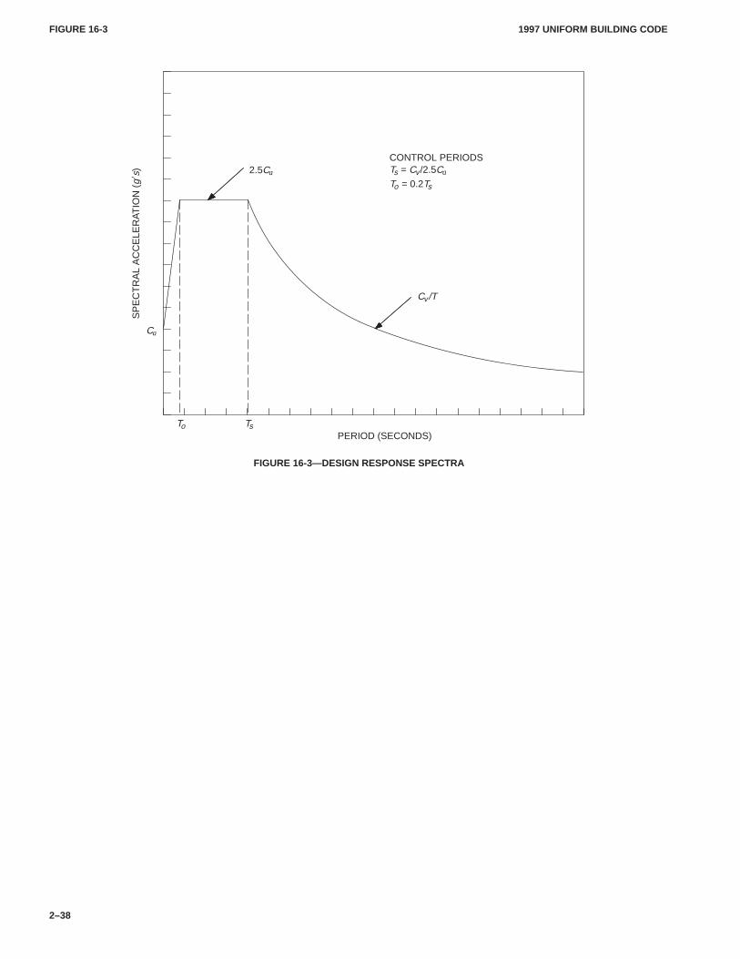
FIGURE 16-3FIGURE 16-3
1997 UNIFORM BUILDING CODE
2–38
2.5Ca
SP
EC
TR
AL
AC
CE
LER
AT
ION
(g�
s)
Cv/T
Ca
To Ts
CONTROL PERIODSTs = Cv/2.5Ca
To = 0.2Ts
PERIOD (SECONDS)
FIGURE 16-3—DESIGN RESPONSE SPECTRA
17011701.5
1997 UNIFORM BUILDING CODE
2–39
Chapter 17
STRUCTURAL TESTS AND INSPECTIONS
SECTION 1701 — SPECIAL INSPECTIONS
1701.1 General.In addition to the inspections required by Sec-tion 108, the owner or the engineer or architect of record acting asthe owner’s agent shall employ one or more special inspectorswho shall provide inspections during construction on the types ofwork listed under Section 1701.5.
EXCEPTION: The building official may waive the requirementfor the employment of a special inspector if the construction is of aminor nature.
1701.2 Special Inspector. The special inspector shall be a quali-fied person who shall demonstrate competence, to the satisfactionof the building official, for inspection of the particular type of con-struction or operation requiring special inspection.
1701.3 Duties and Responsibilities of the Special Inspec-tor. The special inspector shall observe the work assigned forconformance to the approved design drawings and specifications.
The special inspector shall furnish inspection reports to thebuilding official, the engineer or architect of record, and other des-ignated persons. All discrepancies shall be brought to the immedi-ate attention of the contractor for correction, then, if uncorrected,to the proper design authority and to the building official.
The special inspector shall submit a final signed report statingwhether the work requiring special inspection was, to the best ofthe inspector’s knowledge, in conformance to the approved plansand specifications and the applicable workmanship provisions ofthis code.
1701.4 Standards of Quality.The standards listed below la-beled a “UBC Standard” are also listed in Chapter 35, Part II, andare part of this code. The other standards listed below are recog-nized standards. (See Sections 3503 and 3504.)
1. Concrete.
ASTM C 94, Ready-mixed Concrete
2. Connections.
Specification for Structural Joints Using ASTM A 325 or A 490Bolts-Load and Resistance Factor Design, Research Council ofStructural Connections, Section 1701.5, Item 6.
Specification for Structural Joints Using ASTM A 325 or A 490Bolts-Allowable Stress Design, Research Council of StructuralConnections, Section 1701.5, Item 6.
3. Spray-applied Fire-resistive Materials.
UBC Standard 7-6, Thickness and Density Determination forSpray-applied Fire-resistive Materials
1701.5 Types of Work.Except as provided in Section 1701.1,the types of work listed below shall be inspected by a special in-spector.
1. Concrete. During the taking of test specimens and placing ofreinforced concrete. See Item 12 for shotcrete.
EXCEPTIONS: 1. Concrete for foundations conforming to mini-mum requirements of Table 18-I-C or for Group R, Division 3 or GroupU, Division 1 Occupancies, provided the building official finds that aspecial hazard does not exist.
2. For foundation concrete, other than cast-in-place drilled piles orcaissons, where the structural design is based on an f ’c no greater than2,500 pounds per square inch (psi) (17.2 MPa).
3. Nonstructural slabs on grade, including prestressed slabs ongrade when effective prestress in concrete is less than 150 psi (1.03MPa).
4. Site work concrete fully supported on earth and concrete whereno special hazard exists.
2. Bolts installed in concrete. Prior to and during the place-ment of concrete around bolts when stress increases permitted byFootnote 5 of Table 19-D or Section 1923 are utilized.
3. Special moment-resisting concrete frame. For momentframes resisting design seismic load in structures within SeismicZones 3 and 4, the special inspector shall provide reports to theperson responsible for the structural design and shall provide con-tinuous inspection of the placement of the reinforcement and con-crete.
4. Reinforcing steel and prestressing steel tendons.
4.1 During all stressing and grouting of tendons in pre-stressed concrete.
4.2 During placing of reinforcing steel and prestressing ten-dons for all concrete required to have special inspectionby Item 1.
EXCEPTION: The special inspector need not be present continu-ously during placing of reinforcing steel and prestressing tendons, pro-vided the special inspector has inspected for conformance to theapproved plans prior to the closing of forms or the delivery of concreteto the jobsite.
5. Structural welding.
5.1 General. During the welding of any member or connec-tion that is designed to resist loads and forces requiredby this code.
EXCEPTIONS: 1. Welding done in an approved fabricator’s shopin accordance with Section 1701.7.
2. The special inspector need not be continuously present duringwelding of the following items, provided the materials, qualificationsof welding procedures and welders are verified prior to the start ofwork; periodic inspections are made of work in progress; and a visualinspection of all welds is made prior to completion or prior to shipmentof shop welding:
2.1 Single-pass fillet welds not exceeding 5/16 inch (7.9 mm) insize.
2.2 Floor and roof deck welding.2.3 Welded studs when used for structural diaphragm or com-
posite systems.2.4 Welded sheet steel for cold-formed steel framing members
such as studs and joists.2.5 Welding of stairs and railing systems.
5.2 Special moment-resisting steel frames. During thewelding of special moment-resisting steel frames. Inaddition to Item 5.1 requirements, nondestructive test-ing as required by Section 1703 of this code.
5.3 Welding of reinforcing steel. During the welding ofreinforcing steel.
EXCEPTION: The special inspector need not be continuouslypresent during the welding of ASTM A 706 reinforcing steel not largerthan No. 5 bars used for embedments, provided the materials, qualifi-cations of welding procedures and welders are verified prior to the startof work; periodic inspections are made of work in progress; and avisual inspection of all welds is made prior to completion or prior toshipment of shop welding.
6. High-strength bolting. The inspection of high-strengthA 325 and A 490 bolts shall be in accordance with approved
1701.51702
1997 UNIFORM BUILDING CODE
2–40
nationally recognized standards and the requirements of this sec-tion.
While the work is in progress, the special inspector shall deter-mine that the requirements for bolts, nuts, washers and paint;bolted parts; and installation and tightening in such standards aremet. Such inspections may be performed on a periodic basis inaccordance with the requirements of Section 1701.6. The specialinspector shall observe the calibration procedures when such pro-cedures are required by the plans or specifications and shall moni-tor the installation of bolts to determine that all plies of connectedmaterials have been drawn together and that the selected proce-dure is properly used to tighten all bolts.
7. Structural masonry.
7.1 For masonry, other than fully grouted open-end hollow-unit masonry, during preparation and taking of anyrequired prisms or test specimens, placing of allmasonry units, placement of reinforcement, inspectionof grout space, immediately prior to closing of clean-outs, and during all grouting operations.
EXCEPTION: For hollow-unit masonry where the f ′m is no morethan 1,500 psi (10.34 MPa) for concrete units or 2,600 psi (17.93 MPa)for clay units, special inspection may be performed as required for fullygrouted open-end hollow-unit masonry specified in Item 7.2.
7.2 For fully grouted open-end hollow-unit masonry duringpreparation and taking of any required prisms or testspecimens, at the start of laying units, after the place-ment of reinforcing steel, grout space prior to eachgrouting operation, and during all grouting operations.
EXCEPTION: Special inspection as required in Items 7.1 and 7.2need not be provided when design stresses have been adjusted as speci-fied in Chapter 21 to permit noncontinuous inspection.
8. Reinforced gypsum concrete. When cast-in-place Class Bgypsum concrete is being mixed and placed.
9. Insulating concrete fill. During the application of insulatingconcrete fill when used as part of a structural system.
EXCEPTION: The special inspections may be limited to an initialinspection to check the deck surface and placement of reinforcing. Thespecial inspector shall supervise the preparation of compression testspecimens during this initial inspection.
10. Spray-applied fire-resistive materials. As required byUBC Standard 7-6.
11. Piling, drilled piers and caissons. During driving and test-ing of piles and construction of cast-in-place drilled piles or cais-sons. See Items l and 4 for concrete and reinforcing steelinspection.
12. Shotcrete. During the taking of test specimens and placingof all shotcrete and as required by Sections 1924.10 and 1924.11.
EXCEPTION: Shotcrete work fully supported on earth, minor re-pairs and when, in the opinion of the building official, no special hazardexists.
13. Special grading, excavation and filling. Duringearth-work excavations, grading and filling operations inspectionto satisfy requirements of Chapter 18 and Appendix Chapter 33.
14. Smoke-control system.
14.1 During erection of ductwork and prior to conceal-ment for the purposes of leakage testing and record-ing of device location.
14.2 Prior to occupancy and after sufficient completionfor the purposes of pressure difference testing, flow
measurements, and detection and control verifica-tion.
15. Special cases. Work that, in the opinion of the building offi-cial, involves unusual hazards or conditions.
1701.6 Continuous and Periodic Special Inspection.
1701.6.1 Continuous special inspection.Continuous specialinspection means that the special inspector is on the site at alltimes observing the work requiring special inspection.
1701.6.2 Periodic special inspection.Some inspections may bemade on a periodic basis and satisfy the requirements of continu-ous inspection, provided this periodic scheduled inspection is per-formed as outlined in the project plans and specifications andapproved by the building official.
1701.7 Approved Fabricators. Special inspections required bythis section and elsewhere in this code are not required where thework is done on the premises of a fabricator registered and ap-proved by the building official to perform such work without spe-cial inspection. The certificate of registration shall be subject torevocation by the building official if it is found that any work donepursuant to the approval is in violation of this code. The approvedfabricator shall submit a certificate of compliance that the workwas performed in accordance with the approved plans and specifi-cations to the building official and to the engineer or architect ofrecord. The approved fabricator’s qualifications shall be contin-gent on compliance with the following:
1. The fabricator has developed and submitted a detailed fabri-cation procedural manual reflecting key quality control proce-dures that will provide a basis for inspection control ofworkmanship and the fabricator plant.
2. Verification of the fabricator’s quality control capabilities,plant and personnel as outlined in the fabrication procedural man-ual shall be by an approved inspection or quality control agency.
3. Periodic plant inspections shall be conducted by an ap-proved inspection or quality control agency to monitor the effec-tiveness of the quality control program.
4. It shall be the responsibility of the inspection or quality con-trol agency to notify the approving authority in writing of anychange to the procedural manual. Any fabricator approval may berevoked for just cause. Reapproval of the fabricator shall be con-tingent on compliance with quality control procedures during thepast year.
SECTION 1702 — STRUCTURAL OBSERVATION
Structural observation shall be provided in Seismic Zone 3 or 4when one of the following conditions exists:
1. The structure is defined in Table 16-K as Occupancy Cate-gory 1, 2 or 3,
2. The structure is required to comply with Section 403,
3. The structure is in Seismic Zone 4, Na as set forth in Table16-S is greater than one, and a lateral design is required for the en-tire structure,
EXCEPTION: One- and two-story Group R, Division 3 andGroup U Occupancies and one- and two-story Groups B, F, M and SOccupancies.
4. When so designated by the architect or engineer of record, or
5. When such observation is specifically required by the build-ing official.
The owner shall employ the engineer or architect responsiblefor the structural design, or another engineer or architect desig-
17021704.6.5
1997 UNIFORM BUILDING CODE
2–41
nated by the engineer or architect responsible for the structural de-sign, to perform structural observation as defined in Section 220.Observed deficiencies shall be reported in writing to the owner’srepresentative, special inspector, contractor and the building offi-cial. The structural observer shall submit to the building official awritten statement that the site visits have been made and identify-ing any reported deficiencies that, to the best of the structural ob-server’s knowledge, have not been resolved.
SECTION 1703 — NONDESTRUCTIVE TESTING
In Seismic Zones 3 and 4, welded, fully restrained connectionsbetween the primary members of ordinary moment frames andspecial moment-resisting frames shall be tested by nondestructivemethods for compliance with approved standards and job specifi-cations. This testing shall be a part of the special inspection re-quirements of Section 1701.5. A program for this testing shall beestablished by the person responsible for structural design and asshown on plans and specifications.
As a minimum, this program shall include the following:
1. All complete penetration groove welds contained in jointsand splices shall be tested 100 percent either by ultrasonic testingor by radiography.
EXCEPTIONS: 1. When approved, the nondestructive testingrate for an individual welder or welding operator may be reduced to25 percent, provided the reject rate is demonstrated to be 5 percent orless of the welds tested for the welder or welding operator. A samplingof at least 40 completed welds for a job shall be made for such reductionevaluation. Reject rate is defined as the number of welds containing re-jectable defects divided by the number of welds completed. Forevaluating the reject rate of continuous welds over 3 feet (914 mm) inlength where the effective throat thickness is 1 inch (25 mm) or less,each 12-inch increment (305 mm) or fraction thereof shall be consid-ered as one weld. For evaluating the reject rate on continuous weldsover 3 feet (914 mm) in length where the effective throat thickness isgreater than 1 inch (25 mm), each 6 inches (152 mm) of length or frac-tion thereof shall be considered one weld.
2. For complete penetration groove welds on materials less than5/16 inch (7.9 mm) thick, nondestructive testing is not required; for thiswelding, continuous inspection is required.
3. When approved by the building official and outlined in the proj-ect plans and specifications, this nondestructive ultrasonic testing maybe performed in the shop of an approved fabricator utilizing qualifiedtest techniques in the employment of the fabricator.
2. Partial penetration groove welds when used in columnsplices shall be tested either by ultrasonic testing or radiographywhen required by the plans and specifications. For partial penetra-tion groove welds when used in column splices, with an effectivethroat less than 3/4 inch (19.1 mm) thick, nondestructive testing isnot required; for this welding, continuous special inspection isrequired.
3. Base metal thicker than 11/2 inches (38 mm), when subjectedto through-thickness weld shrinkage strains, shall be ultrasoni-cally inspected for discontinuities directly behind such welds afterjoint completion.
Any material discontinuities shall be accepted or rejected on thebasis of the defect rating in accordance with the (larger reflector)criteria of approved national standards.
SECTION 1704 — PREFABRICATED CONSTRUCTION
1704.1 General.
1704.1.1 Purpose.The purpose of this section is to regulate ma-terials and establish methods of safe construction where any struc-ture or portion thereof is wholly or partially prefabricated.
1704.1.2 Scope.Unless otherwise specifically stated in this sec-tion, all prefabricated construction and all materials used thereinshall conform to all the requirements of this code. (See Section104.2.8.)
1704.1.3 Definition.
PREFABRICATED ASSEMBLY is a structural unit, the inte-gral parts of which have been built up or assembled prior to incor-poration in the building.
1704.2 Tests of Materials. Every approval of a material not spe-cifically mentioned in this code shall incorporate as a proviso thekind and number of tests to be made during prefabrication.
1704.3 Tests of Assemblies.The building official may requirespecial tests to be made on assemblies to determine their durabil-ity and weather resistance.
1704.4 Connections.See Section 1611.11.1 for design require-ments of connections for prefabricated assemblies.
1704.5 Pipes and Conduits.See Section 1611.11.2 for designrequirements for removal of material for pipes, conduit and otherequipment.
1704.6 Certificate and Inspection.
1704.6.1 Materials. Materials and the assembly thereof shall beinspected to determine compliance with this code. Every materialshall be graded, marked or labeled where required elsewhere inthis code.
1704.6.2 Certificate. A certificate of approval shall be fur-nished with every prefabricated assembly, except where the as-sembly is readily accessible to inspection at the site. Thecertificate of approval shall certify that the assembly in questionhas been inspected and meets all the requirements of this code.When mechanical equipment is installed so that it cannot be in-spected at the site, the certificate of approval shall certify that suchequipment complies with the laws applying thereto.
1704.6.3 Certifying agency.To be acceptable under this code,every certificate of approval shall be made by an approved agency.
1704.6.4 Field erection. Placement of prefabricated assembliesat the building site shall be inspected by the building official to de-termine compliance with this code.
1704.6.5 Continuous inspection. If continuous inspection is re-quired for certain materials where construction takes place on thesite, it shall also be required where the same materials are used inprefabricated construction.
EXCEPTION: Continuous inspection will not be required duringprefabrication if the approved agency certifies to the construction andfurnishes evidence of compliance.
CHAP. 18, DIV. I1801
1804.71997 UNIFORM BUILDING CODE
2–43
Chapter 18
FOUNDATIONS AND RETAINING WALLSDivision I—GENERAL
SECTION 1801 — SCOPE
1801.1 General.This chapter sets forth requirements for exca-vation and fills for any building or structure and for foundationsand retaining structures.
Reference is made to Appendix Chapter 33 for requirementsgoverning excavation, grading and earthwork construction, in-cluding fills and embankments. CHAP. 18, DIV. I
1801.2 Standards of Quality.The standards listed below la-beled a “UBC Standard” are also listed in Chapter 35, Part II, andare part of this code.
1. Testing.
1.1 UBC Standard 18-1, Soils Classification
1.2 UBC Standard 18-2, Expansion Index Test
SECTION 1802 — QUALITY AND DESIGN
The quality and design of materials used structurally in excava-tions, footings and foundations shall conform to the requirementsspecified in Chapters 16, 19, 21, 22 and 23.
Excavations and fills shall comply with Chapter 33.
Allowable bearing pressures, allowable stresses and design for-mulas provided in this chapter shall be used with the allowablestress design load combinations specified in Section 1612.3.
SECTION 1803 — SOIL CLASSIFICATION—EXPANSIVE SOIL
1803.1 General.For the purposes of this chapter, the definitionand classification of soil materials for use in Table 18-I-A shall beaccording to UBC Standard 18-1.
1803.2 Expansive Soil.When the expansive characteristics of asoil are to be determined, the procedures shall be in accordancewith UBC Standard 18-2 and the soil shall be classified accordingto Table 18-I-B. Foundations for structures resting on soils with anexpansion index greater than 20, as determined by UBC Standard18-2, shall require special design consideration. If the soil expan-sion index varies with depth, the variation is to be included in theengineering analysis of the expansive soil effect upon the struc-ture.
SECTION 1804 — FOUNDATION INVESTIGATION
1804.1 General.The classification of the soil at each buildingsite shall be determined when required by the building official.The building official may require that this determination be madeby an engineer or architect licensed by the state to practice as such.
1804.2 Investigation.The classification shall be based on ob-servation and any necessary tests of the materials disclosed byborings or excavations made in appropriate locations. Additionalstudies may be necessary to evaluate soil strength, the effect ofmoisture variation on soil-bearing capacity, compressibility,liquefaction and expansiveness.
In Seismic Zones 3 and 4, when required by the building offi-cial, the potential for seismically induced soil liquefaction and soilinstability shall be evaluated as described in Section 1804.5.
EXCEPTIONS: 1. The building official may waive this evaluationupon receipt of written opinion of a qualified geotechnical engineer orgeologist that liquefaction is not probable.
2. A detached, single-story dwelling of Group R, Division 3 Occu-pancy with or without attached garages.
3. Group U, Division 1 Occupancies.4. Fences.
1804.3 Reports.The soil classification and design-bearing ca-pacity shall be shown on the plans, unless the foundation con-forms to Table 18-I-C. The building official may requiresubmission of a written report of the investigation, which shall in-clude, but need not be limited to, the following information:
1. A plot showing the location of all test borings and/or excava-tions.
2. Descriptions and classifications of the materials encoun-tered.
3. Elevation of the water table, if encountered.
4. Recommendations for foundation type and design criteria,including bearing capacity, provisions to mitigate the effects ofexpansive soils, provisions to mitigate the effects of liquefactionand soil strength, and the effects of adjacent loads.
5. Expected total and differential settlement.
1804.4 Expansive Soils.When expansive soils are present, thebuilding official may require that special provisions be made inthe foundation design and construction to safeguard against dam-age due to this expansiveness. The building official may require aspecial investigation and report to provide these design and con-struction criteria.
1804.5 Liquefaction Potential and Soil Strength Loss.Whenrequired by Section 1804.2, the potential for soil liquefaction andsoil strength loss during earthquakes shall be evaluated during thegeotechnical investigation. The geotechnical report shall assesspotential consequences of any liquefaction and soil strength loss,including estimation of differential settlement, lateral movementor reduction in foundation soil-bearing capacity, and discuss miti-gating measures. Such measures shall be given consideration inthe design of the building and may include, but are not limited to,ground stabilization, selection of appropriate foundation type anddepths, selection of appropriate structural systems to accommo-date anticipated displacements, or any combination of these mea-sures.
The potential for liquefaction and soil strength loss shall be eva-luated for a site peak ground acceleration that, as a minimum, con-forms to the probability of exceedance specified in Section1631.2. Peak ground acceleration may be determined based on asite-specific study taking into account soil amplification effects.In the absence of such a study, peak ground acceleration may beassumed equal to the seismic zone factor in Table 16-I.
1804.6 Adjacent Loads.Where footings are placed at varyingelevations, the effect of adjacent loads shall be included in thefoundation design.
1804.7 Drainage.Provisions shall be made for the control anddrainage of surface water around buildings. (See also Section1806.5.5.)
CHAP. 18, DIV. I18051806.6.1
1997 UNIFORM BUILDING CODE
2–44
SECTION 1805 — ALLOWABLE FOUNDATION ANDLATERAL PRESSURES
The allowable foundation and lateral pressures shall not exceedthe values set forth in Table 18-I-A unless data to substantiate theuse of higher values are submitted. Table 18-I-A may be used fordesign of foundations on rock or nonexpansive soil for Type IIOne-hour, Type II-N and Type V buildings that do not exceedthree stories in height or for structures that have continuous foot-ings having a load of less than 2,000 pounds per lineal foot (29.2kN/m) and isolated footings with loads of less than 50,000 pounds(222.4 kN).
Allowable bearing pressures provided in Table 18-I-A shall beused with the allowable stress design load combinations specifiedin Section 1612.3.
SECTION 1806 — FOOTINGS
1806.1 General.Footings and foundations shall be constructedof masonry, concrete or treated wood in conformance with Divi-sion II and shall extend below the frost line. Footings of concreteand masonry shall be of solid material. Foundations supportingwood shall extend at least 6 inches (152 mm) above the adjacentfinish grade. Footings shall have a minimum depth as indicated inTable 18-I-C, unless another depth is recommended by a founda-tion investigation.
The provisions of this section do not apply to building and foun-dation systems in those areas subject to scour and water pressureby wind and wave action. Buildings and foundations subject tosuch loads shall be designed in accordance with approved nationalstandards. See Section 3302 for subsoil preparation and woodform removal.
1806.2 Footing Design.Except for special provisions of Sec-tion 1808 covering the design of piles, all portions of footings shallbe designed in accordance with the structural provisions of thiscode and shall be designed to minimize differential settlementwhen necessary and the effects of expansive soils when present.
Slab-on-grade and mat-type footings for buildings located onexpansive soils may be designed in accordance with the provi-sions of Division III or such other engineering design based ongeotechnical recommendation as approved by the building offi-cial.
1806.3 Bearing Walls.Bearing walls shall be supported on ma-sonry or concrete foundations or piles or other approved founda-tion system that shall be of sufficient size to support all loads.Where a design is not provided, the minimum foundation require-ments for stud bearing walls shall be as set forth in Table 18-I-C,unless expansive soils of a severity to cause differential move-ment are known to exist.
EXCEPTIONS: 1. A one-story wood- or metal-frame building notused for human occupancy and not over 400 square feet (37.2 m2) infloor area may be constructed with walls supported on a wood founda-tion plate when approved by the building official.
2. The support of buildings by posts embedded in earth shall be de-signed as specified in Section 1806.8. Wood posts or poles embeddedin earth shall be pressure treated with an approved preservative. Steelposts or poles shall be protected as specified in Section 1807.9.
1806.4 Stepped Foundations.Foundations for all buildingswhere the surface of the ground slopes more than 1 unit vertical in10 units horizontal (10% slope) shall be level or shall be stepped sothat both top and bottom of such foundation are level.
1806.5 Footings on or Adjacent to Slopes.
1806.5.1 Scope.The placement of buildings and structures on oradjacent to slopes steeper than 1 unit vertical in 3 units horizontal(33.3% slope) shall be in accordance with this section.
1806.5.2 Building clearance from ascending slopes.In gener-al, buildings below slopes shall be set a sufficient distance fromthe slope to provide protection from slope drainage, erosion andshallow failures. Except as provided for in Section 1806.5.6 andFigure 18-I-1, the following criteria will be assumed to providethis protection. Where the existing slope is steeper than 1 unit ver-tical in 1 unit horizontal (100% slope), the toe of the slope shall beassumed to be at the intersection of a horizontal plane drawn fromthe top of the foundation and a plane drawn tangent to the slope atan angle of 45 degrees to the horizontal. Where a retaining wall isconstructed at the toe of the slope, the height of the slope shall bemeasured from the top of the wall to the top of the slope.
1806.5.3 Footing setback from descending slope surface.Footing on or adjacent to slope surfaces shall be founded in firmmaterial with an embedment and setback from the slope surfacesufficient to provide vertical and lateral support for the footingwithout detrimental settlement. Except as provided for in Section1806.5.6 and Figure 18-I-1, the following setback is deemed ade-quate to meet the criteria. Where the slope is steeper than 1 unitvertical in 1 unit horizontal (100% slope), the required setbackshall be measured from an imaginary plane 45 degrees to the hori-zontal, projected upward from the toe of the slope.
1806.5.4 Pools.The setback between pools regulated by thiscode and slopes shall be equal to one half the building footing set-back distance required by this section. That portion of the poolwall within a horizontal distance of 7 feet (2134 mm) from the topof the slope shall be capable of supporting the water in the poolwithout soil support.
1806.5.5 Foundation elevation.On graded sites, the top of anyexterior foundation shall extend above the elevation of the streetgutter at point of discharge or the inlet of an approved drainage de-vice a minimum of 12 inches (305 mm) plus 2 percent. The build-ing official may approve alternate elevations, provided it can bedemonstrated that required drainage to the point of discharge andaway from the structure is provided at all locations on the site.
1806.5.6 Alternate setback and clearance.The building offi-cial may approve alternate setbacks and clearances. The buildingofficial may require an investigation and recommendation of aqualified engineer to demonstrate that the intent of this section hasbeen satisfied. Such an investigation shall include considerationof material, height of slope, slope gradient, load intensity and ero-sion characteristics of slope material.
1806.6 Foundation Plates or Sills.Wood plates or sills shall bebolted to the foundation or foundation wall. Steel bolts with aminimum nominal diameter of 1/2 inch (12.7 mm) shall be used inSeismic Zones 0 through 3. Steel bolts with a minimum nominaldiameter of 5/8 inch (16 mm) shall be used in Seismic Zone 4.Bolts shall be embedded at least 7 inches (178 mm) into the con-crete or masonry and shall be spaced not more than 6 feet (1829mm) apart. There shall be a minimum of two bolts per piece withone bolt located not more than 12 inches (305 mm) or less thanseven bolt diameters from each end of the piece. A properly sizednut and washer shall be tightened on each bolt to the plate. Foun-dation plates and sills shall be the kind of wood specified inSection 2306.4.
1806.6.1 Additional requirements in Seismic Zones 3 and 4.The following additional requirements shall apply in SeismicZones 3 and 4.
CHAP. 18, DIV. I1806.6.1
1807.21997 UNIFORM BUILDING CODE
2–45
1. Sill bolt diameter and spacing for three-story raised woodfloor buildings shall be specifically designed.
2. Plate washers a minimum of 2 inch by 2 inch by 3/16 inch (51mm by 51 mm by 4.8 mm) thick shall be used on each bolt.
1806.7 Seismic Zones 3 and 4.In Seismic Zones 3 and 4, hori-zontal reinforcement in accordance with Sections 1806.7.1 and1806.7.2 shall be placed in continuous foundations to minimizedifferential settlement. Foundation reinforcement shall be pro-vided with cover in accordance with Section 1907.7.1.
1806.7.1 Foundations with stemwalls.Foundations with stem-walls shall be provided with a minimum of one No. 4 bar at the topof the wall and one No. 4 bar at the bottom of the footing.
1806.7.2 Slabs–on–ground with turned–down footings.Slabs–on–ground with turned-down footings shall have a mini-mum of one No. 4 bar at the top and bottom.
EXCEPTION: For slabs-on-ground cast monolithically with afooting, one No. 5 bar may be located at either the top or bottom.
1806.8 Designs Employing Lateral Bearing.
1806.8.1 General.Construction employing posts or poles ascolumns embedded in earth or embedded in concrete footings inthe earth may be used to resist both axial and lateral loads. Thedepth to resist lateral loads shall be determined by means of thedesign criteria established herein or other methods approved bythe building official.
1806.8.2 Design criteria.
1806.8.2.1 Nonconstrained.The following formula may beused in determining the depth of embedment required to resist lat-eral loads where no constraint is provided at the ground surface,such as rigid floor or rigid ground surface pavement.
d � A2�1 � 1 � 4.36h
A� � (6-1)
WHERE:
A = 2.34PS1b
b = diameter of round post or footing or diagonal dimensionof square post or footing, feet (m).
d = depth of embedment in earth in feet (m) but not over12 feet (3658 mm) for purpose of computing lateral pres-sure.
h = distance in feet (m) from ground surface to point ofapplication of ‘‘P.”
P = applied lateral force in pounds (kN).
S1 = allowable lateral soil-bearing pressure as set forth inTable 18-I-A based on a depth of one third the depth ofembedment (kPa).
S3 = allowable lateral soil-bearing pressure as set forth inTable 18-I-A based on a depth equal to the depth ofembedment (kPa).
1806.8.2.2 Constrained.The following formula may be used todetermine the depth of embedment required to resist lateral loadswhere constraint is provided at the ground surface, such as a rigidfloor or pavement.
d2 � 4.25PhS3b
(6-2)
1806.8.2.3 Vertical load.The resistance to vertical loads is de-termined by the allowable soil-bearing pressure set forth in Table18-I-A.
1806.8.3 Backfill. The backfill in the annular space around col-umns not embedded in poured footings shall be by one of the fol-lowing methods:
1. Backfill shall be of concrete with an ultimate strength of2,000 pounds per square inch (13.79 MPa) at 28 days. The holeshall not be less than 4 inches (102 mm) larger than the diameter ofthe column at its bottom or 4 inches (102 mm) larger than the diag-onal dimension of a square or rectangular column.
2. Backfill shall be of clean sand. The sand shall be thoroughlycompacted by tamping in layers not more than 8 inches (203 mm)in depth.
1806.8.4 Limitations. The design procedure outlined in thissection shall be subject to the following limitations:
The frictional resistance for retaining walls and slabs on siltsand clays shall be limited to one half of the normal force imposedon the soil by the weight of the footing or slab.
Posts embedded in earth shall not be used to provide lateral sup-port for structural or nonstructural materials such as plaster, ma-sonry or concrete unless bracing is provided that develops thelimited deflection required.
1806.9 Grillage Footings.When grillage footings of structuralsteel shapes are used on soils, they shall be completely embeddedin concrete with at least 6 inches (152 mm) on the bottom and atleast 4 inches (102 mm) at all other points.
1806.10 Bleacher Footings.Footings for open-air seating faci-lities shall comply with Chapter 18.
EXCEPTIONS: Temporary open-air portable bleachers as de-fined in Section 1008.2 may be supported upon wood sills or steelplates placed directly upon the ground surface, provided soil pressuredoes not exceed 1,200 pounds per square foot (57.5 kPa).
SECTION 1807 — PILES — GENERALREQUIREMENTS
1807.1 General.Pile foundations shall be designed and in-stalled on the basis of a foundation investigation as defined in Sec-tion 1804 where required by the building official.
The investigation and report provisions of Section 1804 shall beexpanded to include, but not be limited to, the following:
1. Recommended pile types and installed capacities.
2. Driving criteria.
3. Installation procedures.
4. Field inspection and reporting procedures (to include proce-dures for verification of the installed bearing capacity where re-quired).
5. Pile load test requirements.
The use of piles not specifically mentioned in this chapter shallbe permitted, subject to the approval of the building official uponsubmission of acceptable test data, calculations or other informa-tion relating to the properties and load-carrying capacities of suchpiles.
1807.2 Interconnection. Individual pile caps and caissons ofevery structure subjected to seismic forces shall be interconnectedby ties. Such ties shall be capable of resisting, in tension or com-pression, a minimum horizontal force equal to 10 percent of thelarger column vertical load.
CHAP. 18, DIV. I1807.21808.3.2
1997 UNIFORM BUILDING CODE
2–46
EXCEPTION: Other approved methods may be used where it canbe demonstrated that equivalent restraint can be provided.
1807.3 Determination of Allowable Loads.The allowable ax-ial and lateral loads on piles shall be determined by an approvedformula, by load tests or by a foundation investigation.
1807.4 Static Load Tests.When the allowable axial load of asingle pile is determined by a load test, one of the following meth-ods shall be used:
Method 1. It shall not exceed 50 percent of the yield point undertest load. The yield point shall be defined as that point at which anincrease in load produces a disproportionate increase in settle-ment.
Method 2. It shall not exceed one half of the load which causes anet settlement, after deducting rebound, of 0.01 inch per ton(0.000565 mm/N) of test load which has been applied for a periodof at least 24 hours.
Method 3. It shall not exceed one half of that load under which,during a 40-hour period of continuous load application, no addi-tional settlement takes place.
1807.5 Column Action. All piles standing unbraced in air, wa-ter or material not capable of lateral support, shall conform withthe applicable column formula as specified in this code. Such pilesdriven into firm ground may be considered fixed and laterally sup-ported at 5 feet (1524 mm) below the ground surface and in softmaterial at 10 feet (3048 mm) below the ground surface unlessotherwise prescribed by the building official after a foundation in-vestigation by an approved agency.
1807.6 Group Action. Consideration shall be given to the re-duction of allowable pile load when piles are placed in groups.Where soil conditions make such load reductions advisable ornecessary, the allowable axial load determined for a single pileshall be reduced by any rational method or formula approved bythe building official.
1807.7 Piles in Subsiding Areas.Where piles are driventhrough subsiding fills or other subsiding strata and derive supportfrom underlying firmer materials, consideration shall be given tothe downward frictional forces which may be imposed on the pilesby the subsiding upper strata.
Where the influence of subsiding fills is considered as imposingloads on the pile, the allowable stresses specified in this chaptermay be increased if satisfactory substantiating data are submitted.
1807.8 Jetting. Jetting shall not be used except where and asspecifically permitted by the building official. When used, jettingshall be carried out in such a manner that the carrying capacity ofexisting piles and structures shall not be impaired. After with-drawal of the jet, piles shall be driven down until the required re-sistance is obtained.
1807.9 Protection of Pile Materials.Where the boring recordsof site conditions indicate possible deleterious action on pile ma-terials because of soil constituents, changing water levels or otherfactors, such materials shall be adequately protected by methodsor processes approved by the building official. The effectivenessof such methods or processes for the particular purpose shall havebeen thoroughly established by satisfactory service records orother evidence which demonstrates the effectiveness of such pro-tective measures.
1807.10 Allowable Loads.The allowable loads based on soilconditions shall be established in accordance with Section 1807.
EXCEPTION: Any uncased cast-in-place pile may be assumed todevelop a frictional resistance equal to one sixth of the bearing value
of the soil material at minimum depth as set forth in Table 18-I-A butnot to exceed 500 pounds per square foot (24 kPa) unless a greatervalue is allowed by the building official after a soil investigation as spe-cified in Section 1804 is submitted. Frictional resistance and bearingresistance shall not be assumed to act simultaneously unless recom-mended after a foundation investigation as specified in Section 1804.
1807.11 Use of Higher Allowable Pile Stresses.Allowablecompressive stresses greater than those specified in Section 1808shall be permitted when substantiating data justifying such higherstresses are submitted to and approved by the building official.Such substantiating data shall include a foundation investigationincluding a report in accordance with Section 1807.1 by a soils en-gineer defined as a civil engineer experienced and knowledgeablein the practice of soils engineering.
SECTION 1808 — SPECIFIC PILE REQUIREMENTS
1808.1 Round Wood Piles.
1808.1.1 Material. Except where untreated piles are permitted,wood piles shall be pressure treated. Untreated piles may be usedonly when it has been established that the cutoff will be belowlowest groundwater level assumed to exist during the life of thestructure.
1808.1.2 Allowable stresses.The allowable unit stresses forround wood piles shall not exceed those set forth in Chapter 23,Division III, Part I.
The allowable values listed in Chapter 23, Division III, Part I,for compression parallel to the grain at extreme fiber in bendingare based on load sharing as occurs in a pile cluster. For pileswhich support their own specific load, a safety factor of 1.25 shallbe applied to compression parallel to the grain values and 1.30 toextreme fiber in bending values.
1808.2 Uncased Cast-in-place Concrete Piles.
1808.2.1 Material. Concrete piles cast in place against earth indrilled or bored holes shall be made in such a manner as to ensurethe exclusion of any foreign matter and to secure a full-sized shaft.The length of such pile shall be limited to not more than 30 timesthe average diameter. Concrete shall have a specified compressivestrength f ′c of not less than 2,500 psi (17.24 MPa).
EXCEPTION: The length of pile may exceed 30 times the diame-ter provided the design and installation of the pile foundation is in ac-cordance with an approved investigation report.
1808.2.2 Allowable stresses.The allowable compressive stressin the concrete shall not exceed 0.33f ′c. The allowable compres-sive stress of reinforcement shall not exceed 34 percent of theyield strength of the steel or 25,500 psi (175.7 MPa).
1808.3 Metal-cased Concrete Piles.
1808.3.1 Material. Concrete used in metal-cased concrete pilesshall have a specified compressive strength f ′c of not less than2,500 psi (17.24 MPa).
1808.3.2 Installation. Every metal casing for a concrete pileshall have a sealed tip with a diameter of not less than 8 inches(203 mm).
Concrete piles cast in place in metal shells shall have shellsdriven for their full length in contact with the surrounding soil andleft permanently in place. The shells shall be sufficiently strong toresist collapse and sufficiently watertight to exclude water andforeign material during the placing of concrete.
Piles shall be driven in such order and with such spacing as toensure against distortion of or injury to piles already in place. Nopile shall be driven within four and one-half average pile diame-
CHAP. 18, DIV. I1808.3.21808.7.2
1997 UNIFORM BUILDING CODE
2–47
ters of a pile filled with concrete less than 24 hours old unless ap-proved by the building official.
1808.3.3 Allowable stresses.Allowable stresses shall not ex-ceed the values specified in Section 1808.2.2, except that the al-lowable concrete stress may be increased to a maximum value of0.40f ′c for that portion of the pile meeting the following condi-tions:
1. The thickness of the metal casing is not less than 0.068 inch(1.73 mm) (No. 14 carbon sheet steel gage).
2. The casing is seamless or is provided with seams of equalstrength and is of a configuration that will provide confinement tothe cast-in-place concrete.
3. The specified compressive strength f ′c shall not exceed5,000 psi (34.47 MPa) and the ratio of steel minimum specifiedyield strength fy to concrete specified compressive strength f ′cshall not be less than 6.
4. The pile diameter is not greater than 16 inches (406 mm).
1808.4 Precast Concrete Piles.
1808.4.1 Materials. Precast concrete piles shall have a speci-fied compressive strength f ′c of not less than 3,000 psi (20.68MPa), and shall develop a compressive strength of not less than3,000 psi (20.68 MPa) before driving.
1808.4.2 Reinforcement ties.The longitudinal reinforcementin driven precast concrete piles shall be laterally tied with steel tiesor wire spirals. Ties and spirals shall not be spaced more than 3 in-ches (76 mm) apart, center to center, for a distance of 2 feet (610mm) from the ends and not more than 8 inches (203 mm) else-where. The gage of ties and spirals shall be as follows:
For piles having a diameter of 16 inches (406 mm) or less, wireshall not be smaller than 0.22 inch (5.6 mm) (No. 5 B.W. gage).
For piles having a diameter of more than 16 inches (406 mm)and less than 20 inches (508 mm), wire shall not be smaller than0.238 inch (6.0 mm) (No. 4 B.W. gage).
For piles having a diameter of 20 inches (508 mm) and larger,wire shall not be smaller than 1/4 inch (6.4 mm) round or 0.259inch (6.6 mm) (No. 3 B.W. gage).
1808.4.3 Allowable stresses.Precast concrete piling shall bedesigned to resist stresses induced by handling and driving as wellas by loads. The allowable stresses shall not exceed the values spe-cified in Section 1808.2.2.
1808.5 Precast Prestressed Concrete Piles (Pretensioned).
1808.5.1 Materials. Precast prestressed concrete piles shallhave a specified compressive strength f ′c of not less than 5,000 psi(34.48 MPa) and shall develop a compressive strength of not lessthan 4,000 psi (27.58 MPa) before driving.
1808.5.2 Reinforcement.The longitudinal reinforcement shallbe high-tensile seven-wire strand. Longitudinal reinforcementshall be laterally tied with steel ties or wire spirals.
Ties or spiral reinforcement shall not be spaced more than 3 in-ches (76 mm) apart, center to center, for a distance of 2 feet (610mm) from the ends and not more than 8 inches (203 mm) else-where.
At each end of the pile, the first five ties or spirals shall bespaced 1 inch (25 mm) center to center.
For piles having a diameter of 24 inches (610 mm) or less, wireshall not be smaller than 0.22 inch (5.6 mm) (No. 5 B.W. gage).For piles having a diameter greater than 24 inches (610 mm) but
less than 36 inches (914 mm), wire shall not be smaller than 0.238inch (6.0 mm) (No. 4 B.W. gage). For piles having a diametergreater than 36 inches (914 mm), wire shall not be smaller than1/4 inch (6.4 mm) round or 0.259 inch (6.6 mm) (No. 3 B.W. gage).
1808.5.3 Allowable stresses.Precast prestressed piling shall bedesigned to resist stresses induced by handling and driving as wellas by loads. The effective prestress in the pile shall not be less than400 psi (2.76 MPa) for piles up to 30 feet (9144 mm) in length, 550psi (3.79 MPa) for piles up to 50 feet (15 240 mm) in length, and700 psi (4.83 MPa) for piles greater than 50 feet (15 240 mm) inlength.
The compressive stress in the concrete due to externally appliedload shall not exceed:
fc � 0.33f �c � 0.27fpc
WHERE:fpc = effective prestress stress on the gross section.
Effective prestress shall be based on an assumed loss of 30,000psi (206.85 MPa) in the prestressing steel. The allowable stress inthe prestressing steel shall not exceed the values specified in Sec-tion 1918.
1808.6 Structural Steel Piles.
1808.6.1 Material. Structural steel piles, steel pipe piles andfully welded steel piles fabricated from plates shall conform toUBC Standard 22-1 and be identified in accordance with Section2202.2.
1808.6.2 Allowable stresses.The allowable axial stresses shallnot exceed 0.35 of the minimum specified yield strength Fy or12,600 psi (86.88 MPa), whichever is less.
EXCEPTION: When justified in accordance with Section 1807.11,the allowable axial stress may be increased above 12,600 psi (86.88MPa) and 0.35Fy, but shall not exceed 0.5Fy.
1808.6.3 Minimum dimensions.Sections of driven H-pilesshall comply with the following:
1. The flange projection shall not exceed 14 times the mini-mum thickness of metal in either the flange or the web, and theflange widths shall not be less than 80 percent of the depth of thesection.
2. The nominal depth in the direction of the web shall not beless than 8 inches (203 mm).
3. Flanges and webs shall have a minimum nominal thicknessof 3/8 inch (9.5 mm).
Sections of driven pipe piles shall have an outside diameter ofnot less than 10 inches (254 mm) and a minimum thickness of notless than 1/4 inch (6.4 mm).
1808.7 Concrete-filled Steel Pipe Piles.
1808.7.1 Material. The concrete-filled steel pipe piles shallconform to UBC Standard 22-1 and shall be identified in accord-ance with Section 2202.2. The concrete-filled steel pipe piles shallhave a specified compressive strength f ′c of not less than 2,500 psi(17.24 MPa).
1808.7.2 Allowable stresses.The allowable axial stresses shallnot exceed 0.35 of the minimum specified yield strength Fy of thesteel plus 0.33 of the specified compressive strength f ′c of con-crete, provided Fy shall not be assumed greater than 36,000 psi(248.22 MPa) for computational purposes.
EXCEPTION: When justified in accordance with Section2807.11, the allowable stresses may be increased to 0.50 Fy.
CHAP. 18, DIV. I1808.7.31809.5.2.3
1997 UNIFORM BUILDING CODE
2–48
1808.7.3 Minimum dimensions.Driven piles of uniform sec-tion shall have a nominal outside diameter of not less than 8 inches(203 mm).
SECTION 1809 — FOUNDATION CONSTRUCTION—SEISMIC ZONES 3 AND 4
1809.1 General.In Seismic Zones 3 and 4 the further require-ments of this section shall apply to the design and construction offoundations, foundation components and the connection of super-structure elements thereto.
1809.2 Soil Capacity.The foundation shall be capable of trans-mitting the design base shear and overturning forces prescribed inSection 1630 from the structure into the supporting soil. Theshort-term dynamic nature of the loads may be taken into accountin establishing the soil properties.
1809.3 Superstructure-to-Foundation Connection.The con-nection of superstructure elements to the foundation shall be ade-quate to transmit to the foundation the forces for which theelements were required to be designed.
1809.4 Foundation-Soil Interface.For regular buildings, theforce Ft as provided in Section 1630.5 may be omitted when deter-mining the overturning moment to be resisted at thefoundation-soil interface.
1809.5 Special Requirements for Piles and Caissons.
1809.5.1 General.Piles, caissons and caps shall be designed ac-cording to the provisions of Section 1603, including the effects oflateral displacements. Special detailing requirements as describedin Section 1809.5.2 shall apply for a length of piles equal to 120percent of the flexural length. Flexural length shall be consideredas a length of pile from the first point of zero lateral deflection tothe underside of the pile cap or grade beam.
1809.5.2 Steel piles, nonprestressed concrete piles and pre-stressed concrete piles.
1809.5.2.1 Steel piles.Piles shall conform to width-thicknessratios of stiffened, unstiffened and tubular compression elementsas shown in Chapter 22, Division VIII.
1809.5.2.2 Nonprestressed concrete piles.Piles shall havetransverse reinforcement meeting the requirements of Section1921.4.
EXCEPTION: Transverse reinforcement need not exceed theamount determined by Formula (21-2) in Section 1921.4.4.1 for spiralor circular hoop reinforcement or by Formula (21-4) in Section1921.4.4.1 for rectangular hoop reinforcement.
1809.5.2.3 Prestressed concrete piles.Piles shall have a mini-mum volumetric ratio of spiral reinforcement no less than 0.021for 14-inch (356 mm) square and smaller piles, and 0.012 for24-inch (610 mm) square and larger piles unless a smaller valuecan be justified by rational analysis. Interpolation may be used be-tween the specified ratios for intermediate sizes.
�
CHAP. 18, DIV. ITABLE 18-I-ATABLE 18-I-C
1997 UNIFORM BUILDING CODE
2–49
TABLE 18-I-A—ALLOWABLE FOUNDATION AND LATERAL PRESSURE
ALLOWABLELATERAL BEARINGLBS /SQ /FT /FT OF
LATERAL SLIDING 4ALLOWABLEFOUNDATION
PRESSURE (psf) 2
LATERAL BEARINGLBS./SQ./FT./FT. OF
DEPTH BELOWNATURAL GRADE 3
Resistance(psf) 6
CLASS OF MATERIALS 1 � 0.0479 for kPa� 0.157 for kPa
per meter Coefficient 5� 0.0479for kPa
1. Massive crystalline bedrock 4,000 1,200 0.70
2. Sedimentary and foliated rock 2,000 400 0.35
3. Sandy gravel and/or gravel (GW and GP) 2,000 200 0.35
4. Sand, silty sand, clayey sand, silty gravel and clayey gravel (SW, SP, SM, SC, GMand GC) 1,500 150 0.25
5. Clay, sandy clay, silty clay and clayey silt (CL, ML, MH and CH) 1,0007 100 1301For soil classifications OL, OH and PT (i.e., organic clays and peat), a foundation investigation shall be required.2All values of allowable foundation pressure are for footings having a minimum width of 12 inches (305 mm) and a minimum depth of 12 inches (305 mm) into
natural grade. Except as in Footnote 7, an increase of 20 percent shall be allowed for each additional foot (305 mm) of width or depth to a maximum value ofthree times the designated value. Additionally, an increase of one third shall be permitted when considering load combinations, including wind or earthquakeloads, as permitted by Section 1612.3.2.
3May be increased the amount of the designated value for each additional foot (305 mm) of depth to a maximum of 15 times the designated value. Isolated polesfor uses such as flagpoles or signs and poles used to support buildings that are not adversely affected by a 1/2-inch (12.7 mm) motion at ground surface due toshort-term lateral loads may be designed using lateral bearing values equal to two times the tabulated values.
4Lateral bearing and lateral sliding resistance may be combined.5Coefficient to be multiplied by the dead load.6Lateral sliding resistance value to be multiplied by the contact area. In no case shall the lateral sliding resistance exceed one half the dead load.7No increase for width is allowed.
TABLE 18-I-B—CLASSIFICATION OF EXPANSIVE SOIL
EXPANSION INDEX POTENTIAL EXPANSION
0-20 Very low
21-50 Low
51-90 Medium
91-130 High
Above 130 Very high
TABLE 18-I-C—FOUNDATIONS FOR STUD BEARING WALLS—MINIMUM REQUIREMENTS 1,2,3
THICKNESS OF FOUNDATION WALL(inches)
WIDTH OF FOOTING THICKNESS OF DEPTH BELOW UNDISTURBED� 25.4 for mm
WIDTH OF FOOTING(inches)
THICKNESS OFFOOTING (inches)
DEPTH BELOW UNDISTURBEDGROUND SURFACE (inches)
NUMBER OF FLOORS SUPPORTEDBY THE FOUNDATION4 Concrete
UnitMasonry � 25.4 for mm
1 6 6 12 6 12
2 8 8 15 7 18
3 10 10 18 8 241Where unusual conditions or frost conditions are found, footings and foundations shall be as required in Section 1806.1.2The ground under the floor may be excavated to the elevation of the top of the footing.3Interior stud bearing walls may be supported by isolated footings. The footing width and length shall be twice the width shown in this table and the footings shall
be spaced not more than 6 feet (1829 mm) on center.4Foundations may support a roof in addition to the stipulated number of floors. Foundations supporting roofs only shall be as required for supporting one floor.
�
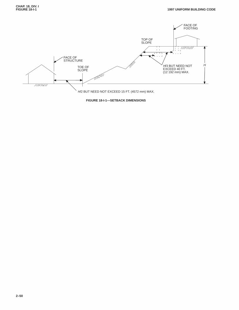
CHAP. 18, DIV. IFIGURE 18-I-1FIGURE 18-I-1
1997 UNIFORM BUILDING CODE
2–50
FACE OFSTRUCTURE
TOE OFSLOPE
TOP OFSLOPE
FACE OFFOOTING
H/3 BUT NEED NOTEXCEED 40 FT.(12 192 mm) MAX.
H
H/2 BUT NEED NOT EXCEED 15 FT. (4572 mm) MAX.
FIGURE 18-I-1—SETBACK DIMENSIONS
CHAP. 18, DIV. II1810
1812.11997 UNIFORM BUILDING CODE
2–51
Division II—DESIGN STANDARD FOR TREATED WOOD FOUNDATION SYSTEM
Based on National Forest Products Association, Technical Report No. 7
SECTION 1810 — SCOPE
The basic design and construction requirements for treated woodfoundation systems are set forth in this division. Included are cri-teria for materials, preservative treatment, soil characteristics, en-vironmental control, design loads and structural design.
SECTION 1811 — MATERIALS
1811.1 Lumber. Lumber shall be of a species and grade forwhich allowable unit stresses are set forth in Chapter 23, DivisionIII, Part I, and shall bear the grade mark of, or have a certificate ofinspection issued by, an approved lumber grading or inspectionbureau or agency.
1811.2 Plywood.All plywood shall be bonded with exteriorglue and be grade marked indicating conformance with UBCStandard 23-2 and shall bear the grade mark of an approved ply-wood inspection agency. CHAP. 18, DIV. II
1811.3 Fasteners in Preservative-treated Wood.Fasteners inpreservative-treated wood shall be approved silicon bronze orcopper, stainless steel or hot-dipped zinc-coated steel. Siliconbronze, copper and stainless steel fasteners are acceptable for allground contact and moisture situations. Hot-dipped zinc-coatednails may be used for basement and crawl space wall constructionwhere polyethylene sheeting is applied to the below-grade portionof the exterior wall and for wood basement floor construction,provided the polyethylene sheeting is placed in accordance withSection 1812.4. In addition, crawl space construction shall be lo-cated in soils having good drainage, such as GW, GP, SW, SP, GMand SM types. Other types of steel or metal fasteners shall be per-mitted only if adequate comparative tests for corrosion resistance,including the effects associated with the wood treating chemicals,indicate an equal or better performance. Zinc-coated fastenersshall be coated after manufacture to their final form, includingpointing, heating, threading or twisting, as applicable. Electro-galvanized nails or staples and hot-dipped zinc-coated staplesshall not be used.
Framing anchors shall be of hot-dipped zinc-coated A-446Grade A sheet steel conforming to UBC Standard 22-1.
1811.4 Gravel, Sand or Crushed Stone for FootingsFill. Gravel shall be washed and well graded. The maximum sizestone shall not exceed 3/4 inch (19 mm). Gravel shall be free fromorganic, clayey or silty soils.
Sand shall be coarse, not smaller than 1/16-inch (1.6 mm) grainsand shall be free from organic, clayey or silty soils.
Crushed stone shall have a maximum size of 1/2 inch (12.7 mm).
1811.5 Polyethylene Sheeting.Polyethylene sheeting shallconform to requirements approved by the building official.
1811.6 Sealants. The materials used to attach the polyethylenesheets to each other or to the plywood shall be capable of adheringto those materials to form a continuous seal.
The material used for caulking joints in plywood sheathingshall be capable of adhering to the wood to provide a moisture sealunder the conditions of temperature and moisture content at whichit will be applied and used.
1811.7 Preservative Treatment.All lumber and plywood re-quired to be preservative treated shall be pressure treated and bearthe FDN grade mark. After treatment, each piece of lumber and
plywood shall be dried to a moisture content not exceeding 19 per-cent. Each piece of treated lumber and plywood shall bear an ap-proved quality mark or that of an approved inspection agencywhich maintains continuing supervision, testing and inspectionover the quality of the product, and shall be identified.
Where FDN lumber is cut or drilled after treatment, the cut sur-face shall be field treated with the following preservatives by re-peated brushing, dipping or soaking until the wood absorbs nomore preservative: ammoniacal copper arsenate (ACA), chro-mated copper arsenate (CCA), fluor chrome arsenate phenol(FCAP), acid copper chromate (ACC), or copper napthenate.
Copper napthenate shall be prepared with a solvent conformingto AWPA Standard P5. The preservative concentration shallcontain a minimum of 2 percent copper metal. Preparations madeby manufacturers of preservatives can also be used.
Waterborne preservatives ACA and CCA, Types A, B and C,shall have a minimum concentration of 3 percent in solution.Waterborne preservatives FCAP and ACC may be used for fieldtreatment of material originally treated with CCA and ACA wa-terborne preservatives and the concentration of FCAP or ACCshall be a minimum of 5 percent in solution.
All lumber and plywood used in exterior foundation walls (ex-cept the upper top plate), all interior-bearing wall framing andsheathing posts or other wood supports used in crawl spaces; allsleepers, joists, blocking and plywood subflooring used in base-ment floors; and all other plates, framing and sheathing in theground or in direct contact with concrete shall be preservativetreated. Where a significant portion of a bottom story wall is aboveadjacent ground level, such as when a building is situated on slop-ing terrain, the portion of wall to be considered as foundation wallshall be based on good engineering practice. Some members insuch a wall may not require preservative treatment, such as win-dow or door headers or the top plate. As a minimum, all exteriorwall framing lumber and plywood sheathing less than 6 inches(152 mm) above finished grade shall be preservative treated.
1811.8 Soil Characteristics.Soils are defined herein in accord-ance with the Unified Soil Classification System (see UBC Stand-ard 18-1). Design properties are provided in Table 18-I-A or by aqualified soils engineer who, by approval of the building official,may assign other values based on soil tests or local experience.
Backfill of CH type (inorganic clays of high plasticity) or othertypes of expansive soils shall not be compacted dry. Backfill withMH soil types (inorganic silts, micaceous or diatomaceous finesandy or silty soils, elastic silts) shall be well compacted to preventsurface water infiltration.
Organic soils, OL, OH and Pt are unsatisfactory for foundationsunless specifically approved by the building official after a quali-fied soils engineer advises on the design of the entire soil-structural system.
SECTION 1812 — DRAINAGE AND MOISTURECONTROL
1812.1 General.The following sections present requirementsto achieve dry and energy-efficient below-grade habitable spacethat is located above the permanent water table. Floors located be-low the permanent water table are not permitted unless specialmoisture control measures are designed by persons qualified inaccordance with the authority having jurisdiction. (See Section1804.7.)
CHAP. 18, DIV. II1812.21814.4
1997 UNIFORM BUILDING CODE
2–52
1812.2 Area Drainage.Adjacent ground surface shall be slopedaway from the structure with a gradient of at least 1/2 inch (12.7mm) per foot for a distance of 6 feet (1829 mm) or more. Provi-sions shall be made for drainage to prevent accumulation of sur-face water.
1812.3 Subgrade Drainage.A porous layer of gravel, crushedstone or sand shall be placed to a minimum thickness of 4 inches(102 mm) under basement floor slabs and all wall footings. Forbasement construction in MH and CH type soils, the porous layerunder footings and slab shall be at least 6 inches (152 mm) thick.
Where there is basement space below grade, a sump shall beprovided to drain the porous layer unless the foundation is in-stalled in GW-, GP-, SW-, SP-, GM- and SM-type soils. The sumpshall be at least 24-inch (610 mm) diameter or 20-inch (508 mm)square, shall extend at least 24 inches (610 mm) below the bottomof the basement floor slab and shall be capable of positive gravityor mechanical drainage to remove any accumulated water.
1812.4 Sheeting and Caulking.Polyethylene sheeting of 6-mil(0.153 mm) thickness shall be applied over the porous layer. Aconcrete slab shall be poured over the sheeting or a wood base-ment floor system shall be constructed on the sheeting. Wherewood floors are used, the polyethylene sheeting shall be placedover wood sleepers supporting the floor joists. Sheeting shouldnot extend beneath the wood footing plate.
In basement construction, joints between plywood panels in thefoundation walls shall be sealed full length with caulking com-pound. Any unbacked panel joints shall be caulked at the time thepanels are fastened to the framing.
Six-mil-thick (0.153 mm) polyethylene sheeting shall beapplied over the below-grade portion of exterior basement wallsprior to backfilling, except in GW-, GP-, SW-, SP-, GM- and SM-type soils. Joints in the polyethylene sheeting shall be lapped 6 in-ches (152 mm) and bonded with a sealant. The top edge of thepolyethylene sheeting shall be bonded with a sealant to the ply-wood sheeting. A treated lumber or plywood strip shall be at-tached to the wall to cover the top edge of the polyethylenesheeting. The wood strip shall extend at least 2 inches (51 mm)above and 5 inches (127 mm) below finish grade level to protectthe polyethylene from exposure to light and from mechanicaldamage at or near grade. The joint between the strip and the wallshall be caulked full length prior to fastening the strip to the wall.Alternatively, asbestos-cement board, brick, stucco or other cov-ering appropriate to the architectural treatment may be used inplace of the wood strip. The polyethylene sheeting shall extenddown to the bottom of the wood footing plate, but shall not overlapor extend into the gravel footing.
1812.5 Perimeter Drainage Control.The space between theside of a basement excavation and the exterior of a basement wallshall be backfilled for half the height of the excavation with thesame material used for footings, except that for basements locatedin GW-, GP-, SW-, SP-, GM- and SM-type soils, or other sites thatare well drained and acceptable to the authority havingjurisdiction, the granular fill need not exceed a height of 1 foot(305 mm) above the footing. The top of this granular fill outsidebasement foundation walls and footings shall be covered withstrips of 6-mil-thick (0.153 mm) polyethylene sheeting or Type 30felt, with adjacent strips lapped to provide for water seepage whilepreventing excessive infiltration of fine soils. Perforated sheetingor other filter membrane may also be used to control infiltration offines.
1812.6 Alternate Drainage System.If a continuous concretefooting rather than a composite wood and gravel footing is used
with the wood foundation in basement construction, the concreteshall be placed over a 4-inch-thick (102 mm) layer of gravel,crushed stone or sand that is arranged to allow drainage of waterfrom the granular backfill outside the footing to the porous layerunder the slab. Alternately, drainage across the concrete footingshall be provided by transverse pipes or drain tiles embedded inthe concrete every 6 linear feet (1829 mm) around the foundation.
1812.7 Insulation. Where insulation is applied between studs inexterior basement walls but the insulation is not flush with the ex-terior wall sheathing and does not extend down to the bottomplate, blocking shall be installed between the studs at the lowerend of the insulation to prevent convection currents.
SECTION 1813 — DESIGN LOADS
1813.1 General.All parts of the wood foundation system shallbe designed and constructed to provide safe support for allanticipated loads within the stress limits specified by this code.Design loads shall not be less than those specified in Chapter 16.
Design loads shall include downward forces acting on the wallfrom dead loads and roof and floor live loads, plus the lateral pres-sure from soil. Where applicable, the foundation also shall be de-signed to resist wind, earthquake and other static or dynamicforces. The foundation system shall be designed for the most se-vere distribution, concentration or combination of design loadsdeemed proper to act on the structure simultaneously.
1813.2 Soil Loads.Lateral pressure of the soil on the wall shallbe considered in accordance with Section 1611.6.
SECTION 1814 — STRUCTURAL DESIGN
1814.1 General.Structural design of wood foundations shall bein accordance with established structural engineering and wooddesign practices as set forth in Chapter 23.
1814.2 Allowable Stresses.Allowable unit stresses for lumberand plywood shall be as provided in Section 2304. Design stressesfor framing lumber shall be based on use under dry conditions (19percent maximum moisture content), except that stresses for foot-ing plates and crawl space framing shall be based on use under wetconditions. Design stresses for plywood sheathing shall be basedon use under damp (moisture content 16 percent or more) condi-tions.
1814.3 Allowable Loads on Fastenings.Allowable loads forsteel nails and framing anchors shall be in accordance withSection 2318. Allowable loads for stainless steel Type 304 or 316,silicon bronze or copper nails shall be developed on a comparablebasis to loads allowed for common steel nails. Allowable loads forstainless steel Type 304 or 316, silicon bronze or copper staples orother fasteners shall be in accordance with good engineeringpractice.
1814.4 Footing Design.The treated wood foundation systemsincorporate a composite footing consisting of a wood footing plateand a layer of gravel, coarse sand or crushed stone. The wood foot-ing plate distributes the axial design load from the framed wall tothe gravel layer which in turn distributes it to the supporting soil.
Soil-bearing pressure under the gravel, sand or crushed stonefootings shall not exceed the allowable soil bearing values fromTable 18-I-A except as permitted by Section 1805.
Footing plate width shall be determined by allowable bearingpressure between the footing plate and the granular part of thefooting. Gravel, sand or crushed stone under the footing plate shallbe compacted to provide an allowable bearing capacity of 3,000
CHAP. 18, DIV. II1814.41814.8
1997 UNIFORM BUILDING CODE
2–53
psf (144 kPa) when required by the design, otherwise an allowablebearing capacity of 2,000 psf (96 kPa) shall be assumed.
When the footing plate is wider than the bottom wall plate, thetension stress perpendicular to grain induced in the bottom face ofthe footing plate shall not exceed one third the allowable unit shearstress for the footing plate. Use of plywood strips to reinforce thelumber footing plate is acceptable.
Thickness and width of the granular footing shall be determinedby allowable bearing pressure between the gravel, sand or crushedstone and the supporting soil, assuming the downward load fromthe wood footing plate is distributed outward through the gravel,sand or crushed stone footing at an angle of 30 degrees from verti-cal at each edge of the footing plate. Additionally, the gravel, sandor crushed stone footing shall have a width not less than twice thewidth and a thickness not less than three-quarters the width of thewood footing plate and shall be confined laterally by backfill,granular fill, undisturbed soil, the foundation wall or other equiva-lent means.
The bottom of the wood footing plate shall not be above themaximum depth of frost penetration unless the gravel, sand orcrushed stone footing extends to the maximum depth of frostpenetration and is either connected to positive mechanical or grav-ity drainage, at or below the frost line, or is installed in GW-, GP-,SW-, SP-, GM- and SM-type soils where the permanent watertable is below the frost line. A granular footing connected to a pos-itively drained sump (see Section 1812.3) by a trench filled withgravel, sand or crushed stone, or by an acceptable pipe connection,shall be considered to be drained to the level of the bottom of thesump or the bottom of the connecting trench or pipe, whichever ishigher.
Where the bottom of the wood footing plate of a crawl spacewall is not below the frost line, the top of the gravel, sand orcrushed stone outside the wall shall be covered as required in Sec-tion 1812.5 for basement construction to prevent excessiveinfiltration of fine soils.
Where a wood footing plate is close to finished grade, such aswhen a deep granular footing is used to reach the frost line, thegranular footing shall be protected against surface erosion ormechanical disturbance.
Posts and piers and their footings in basements or crawl spacesshall be in accordance with Sections 1806 and 2306.
Footings under posts or piers may be of treated wood, treatedwood and gravel, precast concrete or other approved material.
1814.5 Foundation Wall Design.Foundation wall studs shallbe designed for stresses due to combined bending moment and ax-ial loading resulting from lateral soil pressure and downward liveand dead loads on the foundation wall, and for shear stresses due tolateral soil pressure. Top and bottom wall plates shall be designedfor bearing of the studs on the plates. Joints in footing plate andupper top plate shall be staggered at least one stud space fromjoints in the adjacent plate to provide continuity between wall pan-els. Framing at openings in wall and floor systems and at other
points of concentrated loads shall be designed with adequate ca-pacity for the concentrated loads.
Plywood wall sheathing shall be designed for the shear andbending moment between studs due to soil pressures.
Joints, fastenings and connections in the wood foundation sys-tem shall be adequate to transfer all vertical and horizontal forcesto the footing or to the applicable floor system. Connections at thetop of the foundation wall shall be designed to transfer lateral soilload into the floor assembly. Lateral load at the bottom of abasement wall shall be transferred to the basement floor throughbearing of the studs against the floor. Lateral load at the bottom ofa crawl space wall shall be resisted by the soil inside the footing.
Foundation walls subject to racking loads due to earthquake,wind or differential soil pressure forces shall be designed withadequate shear strength to resist the most severe racking load orcombination of loads, but earthquake and wind forces shall not beassumed to act simultaneously. Where a bottom wall plate of1-inch (25 mm) nominal thickness has been used, the bottom ofthe wall shall be considered an unsupported panel edge whendetermining shear resistance of the wall.
1814.6 Interior Load-bearing Walls. Interior load-bearingwalls in basements or crawl spaces shall be designed to carry theapplicable dead and live loads in accordance with standardengineering practice and the requirements of this code.
1814.7 Basement Floor Design.Concrete slab basement floorsshall be designed in accordance with requirements of this code butshall not be less than 31/2 inches (89 mm) in thickness.
Wood basement floors shall be designed to withstand axialforces and bending moments resulting from lateral soil pressuresat the base of the exterior foundation walls and floor and live anddead loads. Floor framing shall be designed to meet joist deflec-tion requirements of this code.
Unless special provision is made to resist sliding caused by un-balanced lateral soil loads, wood basement floors shall be limitedto applications where the differential depth of fill on opposing ex-terior foundation walls is 2 feet (610 mm) or less.
Joists in wood basement floors shall bear tightly against the nar-row face of studs in the foundation wall or directly against a bandjoist that bears on the studs. Plywood subfloor shall be continuousoverlapped joists or over butt joints between in-line joists. Wherejoists are parallel to the wall, sufficient blocking shall be providedbetween joists to transfer lateral forces from the base of the wallinto the floor system.
Where required, resistance to uplift or restraint against bucklingshall be provided by interior-bearing walls or appropriatelydesigned stub walls anchored in the supporting soil below.
Sleepers, joists, blocking and plywood subflooring used inbasement floors shall meet the treatment requirements of Section1811.7.
1814.8 Uplift or Overturning. Design of the structure for upliftor overturning shall be in accordance with the requirements of thiscode.
CHAP. 18, DIV. III1814.81815.7
1997 UNIFORM BUILDING CODE
2–54
Division III—DESIGN STANDARD FOR DESIGN OF SLAB-ON-GROUND FOUNDATIONS TORESIST THE EFFECTS OF EXPANSIVE SOILS AND COMPRESSIBLE SOILS
SECTION 1815 — DESIGN OF SLAB-ON-GROUNDFOUNDATIONS [BASED ON DESIGN OF SLAB-ON-GROUND FOUNDATIONS OF THE WIREREINFORCEMENT INSTITUTE, INC. (AUGUST, 1981)]
1815.1 Scope.This section covers a procedure for the design ofslab-on-ground foundations to resist the effects of expansive soilsin accordance with Division I. Use of this section shall be limitedto buildings three stories or less in height in which gravity loadsare transmitted to the foundation primarily by means of bearingwalls constructed of masonry, wood or steel studs, and with orwithout masonry veneer. CHAP. 18, DIV. III
1815.2 Symbols and Notations.
1-c = soil/climatic rating factor. See Figure 18-III-8.
As = area of steel reinforcing (square inch per foot) (mm2 perm) in slab. See Figure 18-III-1.
Co = overconsolidation coefficient. See Figure 18-III-2.
Cs = soil slope coefficient. See Figure 18-III-3.
Cw = climatic rating. See Figure 18-III-4.
Ec = creep modulus of elasticity of concrete.
fy = yield strength of reinforcing.
Ic = cracked moment of inertia of cross section.
kl = length modification factor-long direction. See Figure18-III-5.
ks = length modification factor-short direction. See Figure18-III-5.
L = total length of slab in prime direction.
L� = total length of slab (width) perpendicular to L.
Lc = design cantilever length (l ck)—See Figures 18-III-5 and18-III-6.
l c = cantilever length as soil function.
Ml = design moment in long direction.
Ms = design moment in short direction.
PI = plasticity index.
S = maximum spacing of beams. See Figure 18-III-7.
V = design shear force (total).
w = weight per square foot (N/m2) of building and slab.
qu = unconfined compressive strength of soil.
∆ = deflection of slab, inch (mm).
1815.3 Foundation Investigation.A foundation investigationof the site shall be conducted in accordance with the provisions ofSection 1804.
1815.4 Design Procedure.
1815.4.1 Loads.The foundation shall be designed for a uni-formly distributed load which shall be determined by dividing theactual dead and live loads for which the superstructure is de-signed, plus the dead and live loads contributed by the foundation,by the area of the foundation.
EXCEPTIONS: 1. For one-story metal and wood stud buildings,with or without masonry veneer, and when the design floor live loadis 50 pounds per square foot (2.4 kN/m2) or less, a uniformly distrib-uted load of 200 pounds per square foot (9.6 kN/m2) may be assumedin lieu of calculating the effects of specific dead and live loads.
2. Those conditions where concentrated loads are of such magnitudethat they must be considered are not covered by this section.
1815.4.2 Determining the effective plasticity index.Theeffective plasticity index to be used in the design shall bedetermined in accordance with the following procedures:
1. The plasticity index shall be determined for the upper 15 feet(4572 mm) of the soil layers and where the plasticity index variesbetween layers shall be weighted in accordance with the proce-dures outlined in Figure 18-III-9.
2. Where the natural ground slopes, the plasticity index shall beincreased by the factor Cs determined in accordance with Figure18-III-3.
3. Where the unconfined compressive strength of the founda-tion materials exceeds 6,000 pounds per square foot (287.4 kPa),the plasticity index shall be modified by the factor Co determinedin accordance with Figure 18-III-2. Where the unconfined com-pressive strength of the foundation materials is less than 6,000pounds per square foot (287.4 kPa), the plasticity index may bemodified by the factor Co determined in accordance with Figure18-III-2.
The value of the effective plasticity index is that determinedfrom the following equation:
Effective plasticity index = weighted plasticity index × Cs × Co
Other factors that are capable of modifying the plasticity indexsuch as fineness of soil particles and the moisture condition at thetime of construction shall be considered.
1815.5 Beam Spacing and Location. Reinforced concretebeams shall be provided around the perimeter of the slab, and inte-rior beams shall be placed at spacings not to exceed that deter-mined from Figure 18-III-7. Slabs of irregular shape shall bedivided into rectangles (which may overlap) so that the resultingoverall boundary of the rectangles is coincident with that of theslab perimeter. See Figure 18-III-10.
1815.6 Beam Design.The following formulas shall be used tocalculate the moment, shear and deflections, and are based on theassumption that the zone of seasonal moisture changes under theperimeter of the slab is such that the beams resist loads as a canti-lever of length Lc:
M �w L� (Lc)2
2
V � wL�Lc
� �w L� (Lc)4
4 Ec Ic
The calculations shall be performed for both the long and shortdirections. Deflection shall not exceed Lc/480.
1815.7 Slab Reinforcing.The minimum slab thickness shall be4 inches (102 mm), and the maximum spacing of reinforcing barsshall be 18 inches (457 mm). The amount of reinforcing shall bedetermined in accordance with Figure 18-III-1. Slab reinforcingshall be placed in both directions at the specified amounts andspacing.
1815
CHAP. 18, DIV. III1816
1816.21997 UNIFORM BUILDING CODE
2–55
SECTION 1816 — DESIGN OF POSTTENSIONEDSLABS ON GROUND (BASED ON DESIGNSPECIFICATION OF THE POSTTENSIONINGINSTITUTE)
1816.1 Scope.This section covers a procedure for the design ofslab-on-ground foundations to resist the effects of expansive soilsin accordance with Division I. Use of this section shall be limitedto buildings three stories or less in height in which gravity loadsare transmitted to the foundation primarily by means of bearingwalls constructed of masonry, wood or steel studs, and with orwithout masonry veneer.
1816.2 List of Symbols and Notations.
A = area of gross concrete cross section, in.2 (mm2).Ab = bearing area beneath a tendon anchor, in.2 (mm2).
A�b = maximum area of the portion of the supporting surfacethat is geometrically similar to and concentric with theloaded area, in.2 (mm2).
Abm = total area of beam concrete, in.2 (mm2).AC = activity ratio of clay.Ao = coefficient in Formula (16-13-1).
Aps = area of prestressing steel in.2 (mm2).Asl = total area of slab concrete, in.2 (mm2).B = constant used in Formula (16-13-1).b = width of an individual stiffening beam, in. (mm).
Bw = assumed slab width (used in Section 1816.4.12), in.(mm).
C = constant used in Formula (16-13-1).c = distance between CGC and extreme cross-section fibers,
in. (mm).CEAC= cation exchange activity.CGC = geometric centroid of gross concrete section.CGS = center of gravity of prestressing force.
Cp = coefficient in Formula (16-35) for slab stress due topartition load—function of ks.
C∆ = coefficient used to establish allowable differentialdeflection (see Table 18-III-GG).
e = eccentricity of posttensioning force (perpendicular dis-tance between the CGS and the CGC), in. (mm).
Ec = long-term or creep modulus of elasticity of concrete, psi(MPa).
EI = expansion index (see Table 18-I-B and UBC Standard18-2).
em = edge moisture variation distance, ft. (m).en = base of natural (Naperian) logarithms.Es = modulus of elasticity of the soil, psi (MPa).
f = applied flexural concrete stress (tension or compres-sion), psi (MPa).
fB = section modulus factor for bottom fiber.fbp = allowable bearing stress under tendon anchorages, psi
(MPa).fc = allowable concrete compressive stress, psi (MPa).
f �c = 28-day concrete compressive strength, psi (MPa).f �ci = concrete compressive strength at time of stressing ten-
dons, psi (MPa).fcr = concrete modulus of rupture, flexural tension stress
which produces first cracking, psi (MPa).fe = effective prestress force, lbs. (N).
fp = minimum average residual prestress compressive stress,psi (MPa).
fpi = allowable tendon stress immediately after stressing, psi(MPa).
fpj = allowable tendon stress due to tendon jacking force, psi(MPa).
fpu = specified maximum tendon tensile stress, psi (MPa).fT = section modulus factor for top fiber.ft = allowable concrete flexural tension stress, psi (MPa).g = moment of inertia factor.H = thickness of a uniform thickness foundation, in. (mm).h = total depth of stiffening beam, measured from top sur-
face of slab to bottom of beam (formerly d, changed forconsistency with ACI-318), in. (mm).
I = gross concrete moment of inertia, in.4 (mm4).k = depth-to-neutral axis ratio; also abbreviation for “kips”
(kN).ks = soil subgrade modulus, pci (N/mm3).L = total slab length (or total length of design rectangle) in
the direction being considered (short or long), perpen-dicular to W, ft. (m).
LL = long length of the design rectangle, ft. (m).LS = short length of the design rectangle, ft. (m).
M L = maximum applied service load moment in the longdirection (causing bending stresses on the short crosssection) from either center lift or edge lift swelling con-dition, ft.-kips/ft. (kN·m/m).
Mmax = maximum moment in slab under load-bearing partition,ft.-kips/ft. (kN·m/m).
MS = maximum applied service load moment in the shortdirection (causing bending stresses on the long crosssection) from either center lift or edge lift swelling con-dition, ft.-kips/ft. (kN·m/m).
n = number of stiffening beams in a cross section ofwidth W.
P = a uniform unfactored service line load (P) acting alongthe entire length of the perimeter stiffening beams repre-senting the weight of the exterior building material andthat portion of the superstructure dead and live loads thatframe into the exterior wall. P does not include any por-tion of the foundation concrete, lbs./ft. (N/m).
Pe = effective prestress force after losses due to elastic short-ening, creep and shrinkage of concrete, and steel relax-ation, kips (kN).
PI = plasticity index.Pi = prestress force immediately after stressing and anchor-
ing tendons, kips (kN).Pr = resultant prestress force after all losses (including those
due to subgrade friction), kips (kN).qallow = allowable soil-bearing pressure, psf (N/m2).
qu = unconfined compressive strength of the soil, psf (N/m2).S = interior stiffening beam spacing, ft. If beam spacings
vary, the average spacing may be used if the ratiobetween the largest and smallest spacing does notexceed 1.5. If the ratio between the largest and smallestspacing exceeds 1.5, use S = 0.85x (largest spacing).
Sb = section modulus with respect to bottom fiber, in.3
(mm3).
�
�
�
CHAP. 18, DIV. III1816.21816.4.3.1
1997 UNIFORM BUILDING CODE
2–56
SG = prestress loss due to subgrade friction, kips (kN).
ST = section modulus with respect to top fiber, in.3 (mm3).t = slab thickness in a ribbed (stiffened) foundation, in.
(mm).V = controlling service load shear force, larger of VS or VL,
kips/ft. (kN/m).v = service load shear stress, psi (MPa).
vc = allowable concrete shear stress, psi (MPa).VL = maximum service load shear force in the long direction
from either center lift or edge lift swelling condition,kips/ft. (kN/m).
VS = maximum service load shear force in the short directionfrom either center lift or edge lift swelling condition,kips/ft. (kN/m).
W = foundation width (or width of design rectangle) in thedirection being considered (short or long), perpendicu-lar to L, ft. (m).
Wslab = foundation weight, lbs. (kg).ym = maximum differential soil movement or swell, in. (mm).α = slope of tangent to tendon, radians.β = relative stiffness length, approximate distance from
edge of slab to point of maximum moment, ft. (m).∆ = expected service load differential deflection of slab, in-
cluding correction for prestressing, in. (mm) (∆ = ∆o �∆p).
∆allow = allowable differential deflection of slab, in. (mm).
∆o = expected service load differential deflection of slab(without deflection caused by prestressing), in. (mm).
∆p = deflection caused by prestressing, in. (mm).µ = coefficient of friction between slab and subgrade.
1816.3 Foundation Investigation. A foundation investigationof the site shall be conducted in accordance with the provisions ofSection 1804.
1816.4 Structural Design Procedure for Slabs on ExpansiveSoils.
1816.4.1 General.This procedure can be used for slabs withstiffening beams (ribbed foundations) or uniform thicknessfoundations. To design a uniform thickness foundation, thedesigner must first design a ribbed foundation that satisfies allrequirements of the design procedure for ribbed foundations. Thefully conformant ribbed foundation is then converted to an equiv-alent uniform thickness foundation.
The design procedure for posttensioned foundations con-structed over expansive clays should include the following steps,with the pertinent sections shown in parentheses:
1. Assemble all the known design data (Section 1816.4.2).
2. Divide an irregular foundation plan into overlapping rectan-gles and design each rectangular section separately (Figure18-III-11).
3. Assume a trial section for a ribbed foundation in both the longand short directions of the design rectangle (Section 1816.4.3).
4. Calculate the applied service moment the section will beexpected to experience in each direction for either the center lift oredge lift condition (Section 1816.4.7).
5. Determine the flexural concrete stresses caused by theapplied service moments and compare to the allowable flexuralconcrete stresses (Sections 1816.4.4 and 1816.4.7).
6. Determine the expected differential deflections and comparewith the allowable differential deflections (Section 1816.4.9).
7. Calculate the applied service shear force and shear stress inthe assumed sections and compare the applied shear stress with theallowable shear stress (Section 1816.4.10).
8. Convert the ribbed foundation to an equivalent uniformthickness foundation, if desired (Section 1816.4.11).
9. Repeat Steps 4 through 8 for the opposite swelling condition.
10. Check the design for the first swelling condition to ascertainif adjustments are necessary to compensate for any designchanges resulting from the second design swelling conditionaddressed in Step 9.
11. Check the effect of slab-subgrade friction to ensure a resid-ual compressive stress of 50 psi (0.35 MPa) at the center of eachdesign rectangle in both directions. Adjust posttensioning force, ifnecessary (Section 1816.4.6).
12. Calculate stresses due to any heavy concentrated loads onthe slab and provide special load transfer details when necessary(Section 1816.4.12).
1816.4.2 Required design data. The soils and structural proper-ties needed for design are as follows:
1. Soils properties.
1.1 Allowable soil-bearing pressure, qallow, in poundsper square foot (newtons per square meter).
1.2 Edge moisture variation distance, em, in feet (meters)1.3 Differential soil movement, ym, in inches (millime-
ters).1.4 Slab-subgrade friction coefficient, µ.
2. Structural data and materials properties.
2.1 Slab length, L, in feet (meters) (both directions).2.2 Perimeter loading, P, in pounds per foot (newtons per
meter).2.3 Average stiffening beam spacing, S, in feet (meters)
(both directions).2.4 Beam depth, h, in inches (millimeters).2.5 Compressive strength of the concrete, f �c, in pounds
per square inch (MPa).2.6 Allowable flexural tensile stress in the concrete, ft, in
pounds per square inch (MPa).2.7 Allowable compressive stress in the concrete, fc, in
pounds per square inch (MPa).2.8 Type, grade and strength of the prestressing steel.2.9 Prestress losses in kips per inch (kN per mm).
1816.4.3 Trial section assumptions.
1816.4.3.1 Assume beam depth and spacing. An initial esti-mate of the depth of the stiffening beam can be obtained from solv-ing either Formula (16-21) or Formula (16-22) for the beam depthyielding the maximum allowable differential deflection. The pro-cedure is as follows:
1. Determine the maximum distance over which the allowabledifferential deflection will occur, L or 6β, whichever is smaller. Asa first approximation, use β = 8 feet (2.44 m).
2. Select the allowable differential deflection ∆allow:
2.1 Center lift (assume C∆ = 360):
�allow �12(L or 6�)
C�
�12(L or 6�)
360(16-1)
For SI: 1 inch = 25.4 mm.
�
�
CHAP. 18, DIV. III1816.4.3.1
1816.4.71997 UNIFORM BUILDING CODE
2–57
2.2 Edge lift (assume C∆ = 720):
�allow �12(L or 6�)
C�
�12(L or 6�)
720(16-2)
For SI: 1 inch = 25.4 mm.
Alternatively, C∆ may be selected from Table 18-III-GG, whichpresents sample C∆ values for various types of superstructures.
3. Assume a beam spacing, S, and solve for beam depth, h:
3.1 Center lift (from Formula 16-20):
h1.214 �(ymL)0.205(S)1.059(P)0.523(em)1.296
380�allow(16-3-1)
h � �(ymL)0.205(S)1.059(P)0.523(em)1.296
380�allow
�0.824
(16-3-2)
For SI: 1 inch = 25.4 mm.
3.2 Edge lift (from Formula 16-21):
h0.85 �(L)0.35(S)0.88(em)0.74(ym)0.76
15.9�allow(P)0.01 (16-4-1)
h � �(L)0.35(S)0.88(em)0.74(ym)0.76
15.9�allow(P)0.01�
1.176
(16-4-2)
For SI: 1 inch = 25.4 mm.
Select the larger h from Formula (16-3-2) or (16-4-2). In theanalysis procedure, the beam depth h must be the same for allbeams in both directions. If different beam depths are selected forthe actual structure (such as a deeper edge beam), the analysisshall be based on the smallest beam depth actually used.
1816.4.3.2 Determine section properties. The moment of iner-tia, section modulus, and cross-sectional area of the slabs andbeams, and eccentricity of the prestressing force shall be calcu-lated for the trial beam depth determined above in accordancewith normal structural engineering procedures.
1816.4.4 Allowable stresses.
The following allowable stresses are recommended:
1. Allowable concrete flexural tensile stress:
ft � 6 f c� (16-5)
For SI: ft � 0.5 f c�
2. Allowable concrete flexural compressive stress:
fc � 0.45f c (16-6)
3. Allowable concrete bearing stress at anchorages.
3.1 At service load:
fbp � 0.6f cAb
Ab� � f c (16-7)
3.2 At transfer:
fbp � 0.8f ci
Ab
Ab� 0.2� � 1.25f ci (16-8)
4. Allowable concrete shear stress:
vc � 1.7 f c� � 0.2fp (16-9)
For SI: vc � 0.14 f c� � 0.2fp
5. Allowable stresses in prestressing steel.
5.1 Allowable stress due to tendon jacking force:
fpj � 0.8fpu � 0.94fpy (16-10)
5.2 Allowable stress immediately after prestress trans-fer:
fpi � 0.7fpu (16-11)
1816.4.5 Prestress losses. Loss of prestress due to friction, elas-tic shortening, creep and shrinkage of the concrete, and steelrelaxation shall be calculated in accordance with Section 1918.6.
1816.4.6 Slab-subgrade friction. The effective prestressingforce in posttensioned slabs-on-ground is further reduced by thefrictional resistance to movement of the slab on the subgrade dur-ing stressing as well as the frictional resistance to dimensionalchanges due to concrete shrinkage, creep and temperature varia-tions. The resultant prestress force, Pr , is the difference betweenthe effective prestress force and the losses due to subgrade fric-tion:
Pr � Pe � SG (16-12-1)
For SI: 1 pound = 4.45 kN.
where SG can be conservatively taken as:
SG �Wslab
2000� (16-12-2)
For SI: 1 pound = 4.45 kN.
The largest amount of prestress loss due to slab-subgrade fric-tion occurs in the center regions of the slab. The greatest structuralrequirement for prestress force, however, is at the location of themaximum moment, which occurs at approximately one β-lengthinward from the edge of the slab. For normal construction prac-tices, the value of the coefficient of friction µ should be taken as0.75 for slabs on polyethylene and 1.00 for slabs cast directly on asand base.
The maximum spacing of tendons shall not exceed that whichwould produce a minimum average effective prestress compres-sion of 50 psi (0.35 MPa) after allowance for slab-subgrade fric-tion.
1816.4.7 Maximum applied service moments. The maximummoment will vary, depending on the swelling mode and the slabdirection being designed. For design rectangles with a ratio oflong side to short side less than 1.1, the formulas for ML [Formulas(16-13-1) and (16-15)] shall be used for moments in both direc-tions.
1. Center lift moment.1.1 Long direction:
ML � Ao�B(em)1.238 � C� (16-13-1)
For SI: 1 ft.·kips/ft. = 4.45 kN·m/m.
WHERE:
Ao � 1727
�(L)0.013(S)0.306(h)0.688(P)0.534(ym)0.193� (16-13-2)
CHAP. 18, DIV. III1816.4.71816.4.9.5
1997 UNIFORM BUILDING CODE
2–58
and for:
0 � em � 5 B � 1, C � 0 (16-13-3)
em � 5 B � ym � 13 � 1.0 (16-13-4)
C � �8 �P � 613
255��4 � ym
3� � 0 (16-13-5)
1.2 Short direction.
For LL/LS � 1.1:
MS � �58 � em
60� ML (16-14)
For SI: 1 ft.·kips/ft. = 4.45 kN·m/m.
For LL/LS < 1.1:
MS � ML
2. Edge lift moment.
2.1 Long direction:
ML �(S)0.10(hem)0.78(ym)0.66
7.2(L)0.0065(P)0.04(16-15)
For SI: 1 ft.·kips/ft. = 4.45 kN·m/m.
2.2 Short direction.
For LL/LS � 1.1:
MS � h0.35�19 � em
57.75�ML (16-16)
For SI: 1 ft.·kips/ft. = 4.45 kN·m/m.
For LL/LS < 1.1:
MS � ML
Concrete flexural stresses produced by the applied servicemoments shall be calculated with the following formula:
f �PreA
�ML,S
St,b�
PreSt,b
(16-17)
For SI: 1 pound per square inch = 0.0069 MPa.
The applied concrete flexural stresses f shall not exceed ft in ten-sion and fc in compression.
1816.4.8 Cracked section considerations. This design method
limits concrete flexural tensile stresses to 6 f �c� (For SI:
0.5 f �c� ). Since the modulus of rupture of concrete is commonly
taken as fcr � 7.5 f �c� (For SI: fcr � 0.625 f �c
� ), slabs designedwith this method will theoretically have no flexural cracking.Some cracking from restraint to slab shortening is inevitable inposttensioned slabs on ground, as it is in elevated posttensionedconcrete members. Nevertheless, the limitation of flexural tensilestresses to a value less than the modulus of rupture justifies the useof the gross concrete cross section for calculating all section prop-erties. This is consistent with standard practices in elevated post-tensioned concrete members.
1816.4.9 Differential deflections. Allowable and expected dif-ferential deflections may be calculated from the formulas pre-sented in the following sections.
1816.4.9.1 Relative stiffness length. β may be calculated as fol-lows:
� � 112
EcIEs
4� (16-18)
For SI: � � 11000
EcIEs
4�If the creep modulus of elasticity of the concrete Ec is not
known, it can be closely approximated by using half of the normalor early life concrete modulus of elasticity. If the modulus of elas-ticity of the clay soil Es is not known, use 1,000 psi (6.89 MPa). I inFormula (16-18) is the gross moment of inertia for the entire slabcross section of width W, in the appropriate direction (short orlong).
1816.4.9.2 Differential deflection distance. The differentialdeflection may not occur over the entire length of the slab, particu-larly if the slab is longer than approximately 50 feet (15.24 m).Thus, the effective distance for determining the allowable differ-ential deflection is the smaller of the two distances, L or 6β, bothexpressed in feet (meters).
1816.4.9.3 Allowable differential deflection, ∆allow (in inches)(mm).
1. Center lift or edge lift:
�allow �12(L or 6�)
C�
(16-19)
For SI: �allow �1000(L or 6�)
C�
The coefficient C∆ is a function of the type of superstructurematerial and the swelling condition (center or edge lift). Samplevalues of C∆ for both swelling conditions and various superstruc-ture materials are shown in Table 18-III-GG.
1816.4.9.4 Expected differential deflection without prestress-ing, ∆o (in inches) (mm):
1. Center lift:
�o �(ymL)0.205(S)1.059(P)0.523(em)1.296
380(h)1.214 (16-20)
For SI: 1 inch = 25.4 mm.
2. Edge lift:
�o �(L)0.35(S)0.88(em)0.74(ym)0.76
15.9(h)0.85(P)0.01 (16-21)
For SI: 1 inch = 25.4 mm.
1816.4.9.5 Deflection caused by prestressing, ∆p (in inches)(mm). Additional slab deflection is produced by prestressing ifthe prestressing force at the slab edge is applied at any point otherthan the CGC. The deflection caused by prestressing can beapproximated with reasonable accuracy by assuming it is pro-duced by a concentrated moment of Pee applied at the end of a can-tilever with a span length of β. The deflection is:
�p �Pee�2
2EcI (16-22)
For SI: 1 inch = 25.4 mm.
If the tendon CGS is higher than the concrete CGC (a typicalcondition), ∆p increases the edge lift deflection and decreases the
CHAP. 18, DIV. III1816.4.9.51816.4.12
1997 UNIFORM BUILDING CODE
2–59
center lift deflection. Deflection caused by prestressing is nor-mally small and can justifiably be ignored in the design of mostposttensioned slabs on ground.
1816.4.9.6 Compare expected to allowable differential deflec-tion. If the expected differential deflection as calculated by eitherFormula (16-20) or (16-21), adjusted for the effect of prestressing,exceeds that determined from Formula (16-19) for the appropriateswelling condition, the assumed section must be stiffened.
1816.4.10 Shear.
1816.4.10.1 Applied service load shear. Expected values ofservice shear forces in kips per foot (kN per meter) of width of slaband stresses in kips per square inch (kN per square millimeter)shall be calculated from the following formulas:
1. Center lift.
1.2 Long direction shear:
VL �1
1940�(L)0.09(S)0.71(h)0.43(P)0.44(ym)0.16(em)0.93� (16-23)
For SI: 1 kips/ft. = 14.59 kN/m.
1.1 Short direction shear:
Vs �1
1350�(L)0.19(S)0.45(h)0.20(P)0.54(ym)0.04(em)0.97� (16-24)
For SI: 1 kips/ft. = 14.59 kN/m.
2. Edge lift (for both directions):
VS or VL �(L)0.07(h)0.4(P)0.03(em)0.16(ym)0.67
3.0(S)0.015 (16-25)
For SI: 1 kips/ft. = 14.59 kN/m.
1816.4.10.2 Applied service load shear stress, v. Only thebeams are considered in calculating the cross-sectional arearesisting shear force in a ribbed slab:
1. Ribbed foundations:
v � VWnhb
(16-26)
For SI: 1 pound per square inch = 0.0069 MPa.
2. Uniform thickness foundations:
v � V12H
(16-27)
For SI: 1 pound per square inch = 0.0069 MPa.
1816.4.10.3 Compare v to vc. If v exceeds vc, shear reinforce-ment in accordance with ACI 318-95 shall be provided. Possiblealternatives to shear reinforcement include:
1. Increasing the beam depth,
2. Increasing the beam width,
3. Increasing the number of beams (decrease the beam spacing).
1816.4.11 Uniform thickness conversion. Once the ribbedfoundation has been designed to satisfy moment, shear and differ-ential deflection requirements, it may be converted to an equiva-lent uniform thickness foundation with thickness H, if desired. Toconvert a ribbed slab of width, W (ft.) (m) and moment of inertia,I (in.4) (mm4) to a uniform thickness foundation of width, W (ft.)(m) and depth, H (ft.) (m), use the following formula:
I �(12W)H3
12(16-28)
Solve for H:
H � IW
3� (16-29)
For SI: H � 12I1000W
3�1816.4.12 Calculation of stress in slabs due to load-bearingpartitions . The formula for the allowable tensile stress in a slabbeneath a bearing partition may be derived from beam-on-elasticfoundation theory. The maximum moment directly under a pointload P in such a beam is:
Mmax � –P�4
(16-30)
For SI: 1 ft.·kips/ft. = 4.45 kN·m/m.WHERE:
� � �4EcIksBw�
0.25
� St,b (16-31)
For SI: 1 ft.·kips/ft. = 4.45 kN·m/m.
with Ec = 1,500,000 psi (10 341 MPa) and ks = 4 pci (0.001N/mm3):
IBw
�Bwt3
12Bw� t3
12
� � �4(1, 500, 000)t3
4(12)�
0.25
� 18.8t0.75 (16-32)
therefore:
Mmax � � 18.8Pt0.75
4� � 4.7Pt0.75 (16-33)
For SI: 1 ft.·kips/ft. = 4.45 kN·m/m.The formula for applied tensile stress ft is:
ft �Pr
A�
MmaxcI
(16-34)
For SI: 1 pound per square inch = 0.0069 MPa.
and since:
Ic �
Bwt3
12�2
t� �
Bwt2
6� 12t2
6� 2t2
the applied tensile stress is:
f �Pr
A� 4.7Pt0.75
2t2 �Pr
A� Cp
Pt1.25 (16-35)
For SI: 1 pound per square inch = 0.0069 MPa.For uniform thickness foundations substitute H for t in Formu-
las (16-32), (16-33) and (16-35). The value of Cp depends on theassumed value of the subgrade modulus ks. The following tableillustrates the variation in Cp for different values of ks:
TYPE OF SUBGRADEks , lb./in. 3
(0.00027 for N/mm 3) Cp
Lightly compacted, highplastic compressible soil
4 2.35
Compacted, low plastic soil 40 1.34
Stiff, compacted, selectgranular or stabilized fill
400 0.74
If the allowable tensile stress is exceeded by the results of theabove analysis, a thicker slab section should be used under theloaded area, or a stiffening beam should be placed directly beneaththe concentrated line load.
CHAP. 18, DIV. III18171818
1997 UNIFORM BUILDING CODE
2–60
SECTION 1817 — APPENDIX A (A PROCEDURE FORESTIMATION OF THE AMOUNT OF CLIMATECONTROLLED DIFFERENTIAL MOVEMENT OFEXPANSIVE SOILS)
In general, the amount of differential movement to be expected ina given expansive soil should be based on recommendationssupplied by a registered geotechnical engineer. The geotechnicalengineer may use various soil testing procedures to provide a basisfor these recommendations. A procedure developed in partthrough the PTI-sponsored research project at Texas A & M Uni-versity that may be used by geotechnical engineers (in conjunc-tion with accumulated experience with local soils conditions) asan aid for estimation of expected differential movements ofexpansive soils is presented in this appendix. This procedure isapplicable only in those cases where site conditions have beencorrected so that soil moisture conditions are controlled by theclimate alone.
The information necessary to determine the differential move-ment using the procedure in this appendix is the type and amountof clay, the depth to constant or equilibrium suction, the edgemoisture variation distance, the magnitude of the equilibrium suc-tion, and the field moisture velocity. With this information eitherknown or estimated, differential movements may be selected fromTables 18-III-A to 18-III-O for the center lift condition, or Tables18-III-P to 18-III-DD for the edge lift condition.
Procedures for determining or estimating the necessary items ofsoil information are as follows:
1. Select a Thornthwaite Moisture Index from Figure 18-III-14or 18-III-15. Alternatively, extreme annual values of the Thorn-thwaite Index may be calculated for a given site using Thorn-thwaite’s procedures.
2. Obtain an estimate of the edge moisture variation distance,em, for both edge lift and center lift loading conditions from Figure18-III-14.
3. Determine the percent of clay in the soil and the predominantclay mineral. The predominant type of clay can be determined byperforming the following tests and calculations and by using Fig-ure 18-III-15.
3.1 Determine the plastic limit (PL) and the plasticity index(PI) of the soil.
3.2 Determine the percentage of clay sizes in the materialpassing the U.S. No. 200 (75 µm) sieve (HydrometerTest).
3.3 Calculate the activity ratio of the soil:
Ac = PI(Percent passing U.S. No. 200[75 �m] sieve � 0.002mm)
(1)
3.4 Calculate the Cation Exchange Activity. A discussionof procedures for determining Cation Exchange Capac-ity for use in calculating Cation Exchange Activity ispresented in Appendix B.
CEAC = PI1.17
(Percent passing U.S. No. 200[75 �m] sieve � 0.002mm)
(2)
3.5 Enter Figure 18-III-15 with the Ac and CEAC. The soiltype is determined by the intersection of the two entries.Note that the same mineral type is obtained from Figure18-III-15 for a significant range of values of Ac andCEAC. This indicates that the determination of the
mineral type is relatively insensitive to the precision bywhich the Atterberg Limits and other soil parametershave been determined. In the case of doubt as to the pre-dominant mineral type, the clay may be conservativelyclassified as montmorillonite.
4. Depth to constant soil suction can be estimated as the depthbelow which the ratio of water content to plastic limit is constant.At times it will be the depth to an inert material, an unweatheredshale, or to a high water table. Constant soil suction can be esti-mated with reasonable accuracy from Figure 18-III-16 if it is notactually determined in the laboratory; however, for most practicalapplications, the design soil suction value will seldom exceed amagnitude of pF 3.6.
5. Moisture velocity can be approximated by using a velocityequal to one half of the Thornthwaite Moisture Index [expressedin inches/year (mm/year)] for the construction site, converted toinches/month. To allow for extreme local variations in moisturevelocity, this value shall not be assumed to be less than 0.5in./month (12.7 mm/month), and the maximum moisture velocityshall be 0.7 in./month (17.8 mm/month).
6. Using values of edge moisture distance variation, em, per-cent clay, predominant clay mineral (kaolinite, illite, or montmo-rillonite), depth to constant suction, soil suction, pF, and velocityof moisture flow determined in steps 1 through 5 above, enter theappropriate tables, Tables 18-III-A to 18-III-O for center lift andTables 18-III-P to 18-III-DD for edge lift, and find the correspond-ing soil differential movements, ym. The values of swell presentedin the tables were obtained from a computer program based on thepermeability of clays and the total potential of the soil water.
SECTION 1818 — APPENDIX B (SIMPLIFIEDPROCEDURES FOR DETERMINING CATIONEXCHANGE CAPACITY AND CATION EXCHANGEACTIVITY)
Simplified Procedure for Determining CationExchange Capacity Using a Spectrophotometer
The Cation Exchange Capacity of soil samples may be determinedby comparative means in the standard spectrophotometer device.This method of determining the Cation Exchange Capacity is usedby the U.S. Soil Conservation Service. Data obtained by thismethod should be comparable with data for similar soils that havebeen measured by the U.S. Conservation Service. This simplifiedprocedure is:
1. Place 10 grams of clay soil in a beaker and 100 ml of neutral1 N ammonium acetate (NH4AC) is added. This solution is al-lowed to stand overnight.
2. Filter the solution of Step 1 by washing through filter paperwith 50 ml of NH4AC.
3. Wash the material retained on the filter paper of Step 2 withtwo 150 ml washings of isopropyl alcohol, using suction. The iso-propyl alcohol wash fluid should be added in increments of ap-proximately 25 ml and the sample allowed to drain well betweenadditions.
4. Transfer the soil and filter paper to a 800-ml flask. Add50 ml MgCI2 solution and allow to set at least 30 minutes, but pref-erably 24 hours.
5. Under suction, filter the fluid resulting from Step 4.
6. Normally, the solution of MgCI2 must be diluted before it isplaced in the spectrophotometer in Step 10. The dilution will varyfrom one piece of equipment to the next. The calculations given atthe end of this section assume that 200 ml of distilled water have
CHAP. 18, DIV. III1818
1819.31997 UNIFORM BUILDING CODE
2–61
been used to dilute l ml of the MgCI2 solution. The 200-to-1 dilu-tion is fairly typical.
7. Prepare a standard curve by using 10 µg of nitrogen (in theNH4 form) per ml of a standard solution in a 50 ml volumetricflask. Adjust the volume to approximately 25 ml, add 1 ml of10 percent tartrate solution, and shake. Add 2 ml of Nessler’s ali-quot with rapid mixing. Add sufficient distilled water to bring thetotal volume to 50 ml. Allow color to develop for 30 minutes.
8. Repeat Step 7 for 1.0, 2.0, 4.0, and 8.0 ml aliquots of stand-ard solution.
9. Insert the standard solution resulting from Steps 7 and 8into the spectrophotometer. Record readings and plot the results toconstruct a standard curve. (The spectrophotometer is calibratedbeforehand with distilled water.)
10. Extract 2.0 ml of sample aliquot from Step 6 and add 25 mlof distilled water in a 50 ml volumetric flask. Add 1 ml of 10 per-cent tartrate and shake. Add 2 ml of Nessler’s aliquot with rapidmixing. Add sufficient distilled water to bring the total volume to50 ml. Let the solution stand for 30 minutes and then insert into thespectrophotometer and record the transparency reading.
11. Typical calculations:
Weight of dry soil = 10.64 gramsSpectrophotometer = 81 percent
= 24.5 �g/g from standard curveConversion:
24.5�g2 ml�aliquot
� 200 ml1 ml
� 50 ml10.64�g
� 11, 000��mg
�
114 mg�meq
� 100 g � 82.2 meq�100g
Equation for Cation Exchange Capacity
A 1979 study at Texas Tech University resulted in the followingproposed modifications to the Pearring and Holt equations forClay Activity, Cation Exchange Capacity, and Cation ExchangeActivity:
Clay Activity Ac = PI% Clay
Cation Exchange Capacity:
CEC = (PL)1.17
Cation Exchange Activity:
CEAC =(PL)1.17
% Clay
Symbols and Notations
PI = plasticity index.
PL = plastic limit.
% Clay = % Passing U.S. No. 200 sieve (75 µm) � 0.002 mm.
Comparison of Methods of Determining CationExchange Capacity in Predominant Clay Mineral
A comparison of values of Cation Exchange Capacity usingatomic absorption and spectrophotometer techniques is presentedin Table 18-III-EE.
Comparison of clay mineral determination between atomic ab-sorption of the correlation equations presented above is presentedin Table 18-III-FF and Figure 18-III-17.
SECTION 1819 — DESIGN OF POSTTENSIONEDSLABS ON COMPRESSIBLE SOILS (BASED ONDESIGN SPECIFICATIONS OF THE POSTTENSIONINGINSTITUTE)
1819.1 General. The design procedure for foundations on com-pressible soils is similar to the structural design procedure in Sec-tion 1816.4, except that different equations are used and theprimary bending deformation is usually similar to the edge liftloading case.
1819.2 List of Symbols and Notations.
Mcs = applied service moment in slab on compressible soil,ft.-kips/ft. (kN·m/m).
Mns = moment occurring in the “no swell” condition, ft.-kips/ft. (kN·m/m).
Vcs = maximum service load shear force in slab on compress-ible soil, kips/ft. (kN/m).
Vns = service load shear force in the “no swell” condition,kips/ft. (kN/m).
∆cs = differential deflection in a slab on compressible soil, in.(mm).
∆ns = differential deflection in the “no swell” condition, in.(mm).
δ = expected settlement, reported by the geotechnical engi-neer occurring in compressible soil due to the total loadexpressed as a uniform load, in. (mm).
1819.3 Slabs-on-ground Constructed on Compressible Soils.Design of slabs constructed on compressible soils can be done in amanner similar to that of the edge lift condition for slabs on expan-sive soils. Compressible soils are normally assumed to haveallowable values of soil-bearing capacity, qallow, equal to or lessthan 1,500 pounds per square foot (71.9 kN/m2). Special designequations are necessary for this problem due to the expected in situelastic property differences between compressible soils and thestiffer expansive soils. These formulas are:
1. Moment.
1.1 Long direction:
McsL� � �
�nsL
�0.5
MnsL(19-1)
1.2 Short direction:
McsS� �970 – h
880� McsL
(19-2)
For SI: ����� �������� �
�����������
�
WHERE:
MnsL�
(h)1.35(S)0.36
80(L)0.12(P)0.10 (19-3)
For SI: 1ft.·kip
ft.� 4 448 031kN·m
m
�nsL�
(L)1.28(S)0.80
133(h)0.28(P)0.62 (19-4)
For SI: 1 inch = 25.4 mm.
2. Differential deflection:
�cs� �e[1.78�0.103(h)�1.65x10�3(P)�3.95x10�7(P)2]n (19-5)
CHAP. 18, DIV. III1819.31819.3
1997 UNIFORM BUILDING CODE
2–62
3. Shear.3.1 Long direction:
VcsL� � �
�nsL
�0.30
VnsL(19-6)
WHERE:
VnsL�
(h)0.90(PS)0.30
550(L)0.10 (19-7)
For SI: 1kipft.
� 2100kNm
3.2 Short direction:
VcsS� �116� h
94�VcsL
(19-8)
For SI: VcsS� �2946.4� h
2387.6� VcsL
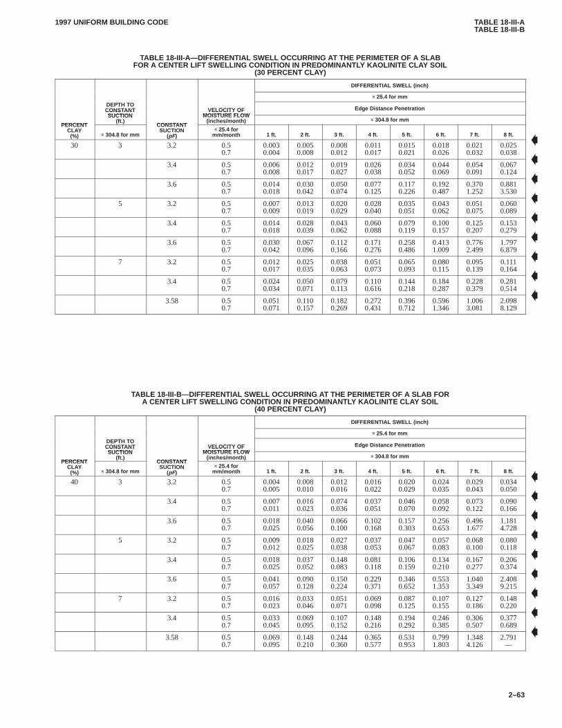
TABLE 18-III-ATABLE 18-III-B
1997 UNIFORM BUILDING CODE
2–63
TABLE 18-III-A—DIFFERENTIAL SWELL OCCURRING A T THE PERIMETER OF A SLABFOR A CENTER LIFT SWELLING CONDITION IN PREDOMINANTLY KAOLINITE CLA Y SOIL
(30 PERCENT CLAY)
DIFFERENTIAL SWELL (inch)
× 25.4 for mmDEPTH TOCONSTANTSUCTION
VELOCITY OFMOISTURE FLOW
Edge Distance Penetration
PERCENT
CONSTANTSUCTION
(ft.)CONSTANT
VELOCITY OFMOISTURE FLOW
(inches/month) × 304.8 for mmPERCENT
CLAY(%) × 304.8 for mm
CONSTANTSUCTION
(pF)× 25.4 for
mm/month 1 ft. 2 ft. 3 ft. 4 ft. 5 ft. 6 ft. 7 ft. 8 ft.
30 3 3.2 0.50.7
0.0030.004
0.0050.008
0.0080.012
0.0110.017
0.0150.021
0.0180.026
0.0210.032
0.0250.038
3.4 0.50.7
0.0060.008
0.0120.017
0.0190.027
0.0260.038
0.0340.052
0.0440.069
0.0540.091
0.0670.124
3.6 0.50.7
0.0140.018
0.0300.042
0.0500.074
0.0770.125
0.1170.226
0.1920.487
0.3701.252
0.8813.530
5 3.2 0.50.7
0.0070.009
0.0130.019
0.0200.029
0.0280.040
0.0350.051
0.0430.062
0.0510.075
0.0600.089
3.4 0.50.7
0.0140.018
0.0280.039
0.0430.062
0.0600.088
0.0790.119
0.1000.157
0.1250.207
0.1530.279
3.6 0.50.7
0.0300.042
0.0670.096
0.1120.166
0.1710.276
0.2580.486
0.4131.009
0.7762.499
1.7976.879
7 3.2 0.50.7
0.0120.017
0.0250.035
0.0380.063
0.0510.073
0.0650.093
0.0800.115
0.0950.139
0.1110.164
3.4 0.50.7
0.0240.034
0.0500.071
0.0790.113
0.1100.616
0.1440.218
0.1840.287
0.2280.379
0.2810.514
3.58 0.50.7
0.0510.071
0.1100.157
0.1820.269
0.2720.431
0.3960.712
0.5961.346
1.0063.081
2.0988.129
TABLE 18-III-B—DIFFERENTIAL SWELL OCCURRING A T THE PERIMETER OF A SLAB FORA CENTER LIFT SWELLING CONDITION IN PREDOMINANTLY KAOLINITE CLA Y SOIL
(40 PERCENT CLAY)
DIFFERENTIAL SWELL (inch)
× 25.4 for mmDEPTH TOCONSTANTSUCTION
VELOCITY OFMOISTURE FLOW
Edge Distance Penetration
PERCENT
CONSTANTSUCTION
(ft.)CONSTANT
VELOCITY OFMOISTURE FLOW
(inches/month) × 304.8 for mmPERCENT
CLAY(%) × 304.8 for mm
CONSTANTSUCTION
(pF)× 25.4 for
mm/month 1 ft. 2 ft. 3 ft. 4 ft. 5 ft. 6 ft. 7 ft. 8 ft.
40 3 3.2 0.50.7
0.0040.005
0.0080.010
0.0120.016
0.0160.022
0.0200.029
0.0240.035
0.0290.043
0.0340.050
3.4 0.50.7
0.0070.011
0.0160.023
0.0740.036
0.0370.051
0.0460.070
0.0580.092
0.0730.122
0.0900.166
3.6 0.50.7
0.0180.025
0.0400.056
0.0660.100
0.1020.168
0.1570.303
0.2560.653
0.4961.677
1.1814.728
5 3.2 0.50.7
0.0090.012
0.0180.025
0.0270.038
0.0370.053
0.0470.067
0.0570.083
0.0680.100
0.0800.118
3.4 0.50.7
0.0180.025
0.0370.052
0.1480.083
0.0810.118
0.1060.159
0.1340.210
0.1670.277
0.2060.374
3.6 0.50.7
0.0410.057
0.0900.128
0.1500.224
0.2290.371
0.3460.652
0.5531.353
1.0403.349
2.4089.215
7 3.2 0.50.7
0.0160.023
0.0330.046
0.0510.071
0.0690.098
0.0870.125
0.1070.155
0.1270.186
0.1480.220
3.4 0.50.7
0.0330.045
0.0690.095
0.1070.152
0.1480.216
0.1940.292
0.2460.385
0.3060.507
0.3770.689
3.58 0.50.7
0.0690.095
0.1480.210
0.2440.360
0.3650.577
0.5310.953
0.7991.803
1.3484.126
2.791—
�
�
�
�
�
�
�
�
�
�
�
�
�
�
�
�
�
�
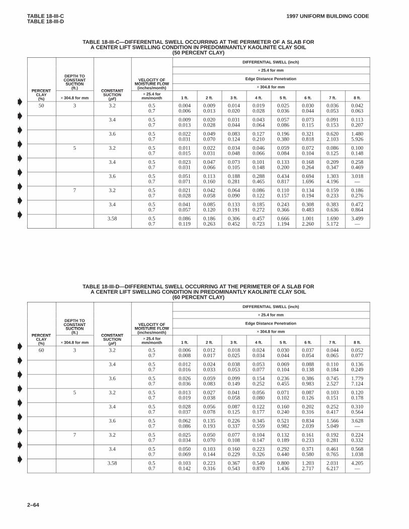
TABLE 18-III-CTABLE 18-III-D
1997 UNIFORM BUILDING CODE
2–64
TABLE 18-III-C—DIFFERENTIAL SWELL OCCURRING A T THE PERIMETER OF A SLAB FORA CENTER LIFT SWELLING CONDITION IN PREDOMINANTLY KAOLINITE CLA Y SOIL
(50 PERCENT CLAY)
DIFFERENTIAL SWELL (inch)
× 25.4 for mmDEPTH TOCONSTANTSUCTION
VELOCITY OFMOISTURE FLOW
Edge Distance Penetration
PERCENT
CONSTANTSUCTION
(ft.)CONSTANT
VELOCITY OFMOISTURE FLOW
(inches/month) × 304.8 for mmPERCENT
CLAY(%) × 304.8 for mm
CONSTANTSUCTION
(pF)× 25.4 for
mm/month 1 ft. 2 ft. 3 ft. 4 ft. 5 ft. 6 ft. 7 ft. 8 ft.
50 3 3.2 0.50.7
0.0040.006
0.0090.013
0.0140.020
0.0190.028
0.0250.036
0.0300.044
0.0360.053
0.0420.063
3.4 0.50.7
0.0090.013
0.0200.028
0.0310.044
0.0430.064
0.0570.086
0.0730.115
0.0910.153
0.1130.207
3.6 0.50.7
0.0220.031
0.0490.070
0.0830.124
0.1270.210
0.1960.380
0.3210.818
0.6202.103
1.4805.926
5 3.2 0.50.7
0.0110.015
0.0220.031
0.0340.048
0.0460.066
0.0590.084
0.0720.104
0.0860.125
0.1000.148
3.4 0.50.7
0.0230.031
0.0470.066
0.0730.105
0.1010.148
0.1330.200
0.1680.264
0.2090.347
0.2580.469
3.6 0.50.7
0.0510.071
0.1130.160
0.1880.281
0.2880.465
0.4340.817
0.6941.696
1.3034.196
3.018—
7 3.2 0.50.7
0.0210.028
0.0420.058
0.0640.090
0.0860.122
0.1100.157
0.1340.194
0.1590.233
0.1860.276
3.4 0.50.7
0.0410.057
0.0850.120
0.1330.191
0.1850.272
0.2430.366
0.3080.483
0.3830.636
0.4720.864
3.58 0.50.7
0.0860.119
0.1860.263
0.3060.452
0.4570.723
0.6661.194
1.0012.260
1.6905.172
3.499—
TABLE 18-III-D—DIFFERENTIAL SWELL OCCURRING A T THE PERIMETER OF A SLAB FORA CENTER LIFT SWELLING CONDITION IN PREDOMINANTLY KAOLINITE CLA Y SOIL
(60 PERCENT CLAY)
DIFFERENTIAL SWELL (inch)
× 25.4 for mmDEPTH TOCONSTANTSUCTION
VELOCITY OFMOISTURE FLOW
Edge Distance Penetration
PERCENT
CONSTANTSUCTION
(ft.)CONSTANT
VELOCITY OFMOISTURE FLOW
(inches/month) × 304.8 for mmPERCENT
CLAY(%) × 304.8 for mm
CONSTANTSUCTION
(pF)× 25.4 for
mm/month 1 ft. 2 ft. 3 ft. 4 ft. 5 ft. 6 ft. 7 ft. 8 ft.
60 3 3.2 0.50.7
0.0060.008
0.0120.017
0.0180.025
0.0240.034
0.0300.044
0.0370.054
0.0440.065
0.0520.077
3.4 0.50.7
0.0120.016
0.0240.033
0.0380.053
0.0530.077
0.0690.104
0.0880.138
0.1100.184
0.1360.249
3.6 0.50.7
0.0260.036
0.0590.083
0.0990.149
0.1540.252
0.2360.455
0.3860.983
0.7452.527
1.7797.124
5 3.2 0.50.7
0.0130.019
0.0270.038
0.0410.058
0.0560.080
0.0710.102
0.0870.126
0.1030.151
0.1200.178
3.4 0.50.7
0.0280.037
0.0560.078
0.0870.125
0.1220.177
0.1600.240
0.2020.316
0.2520.417
0.3100.564
3.6 0.50.7
0.0620.086
0.1350.193
0.2260.337
0.3450.559
0.5210.982
0.8342.039
1.5665.049
3.628—
7 3.2 0.50.7
0.0250.034
0.0500.070
0.0770.108
0.1040.147
0.1320.189
0.1610.233
0.1920.281
0.2240.332
3.4 0.50.7
0.0500.069
0.1030.144
0.1600.229
0.2230.326
0.2920.440
0.3710.580
0.4610.765
0.5681.038
3.58 0.50.7
0.1030.142
0.2230.316
0.3670.543
0.5490.870
0.8001.436
1.2032.717
2.0316.217
4.205—
�
�
�
�
�
�
�
�
�
�
�
�
�
�
�
�
�
�
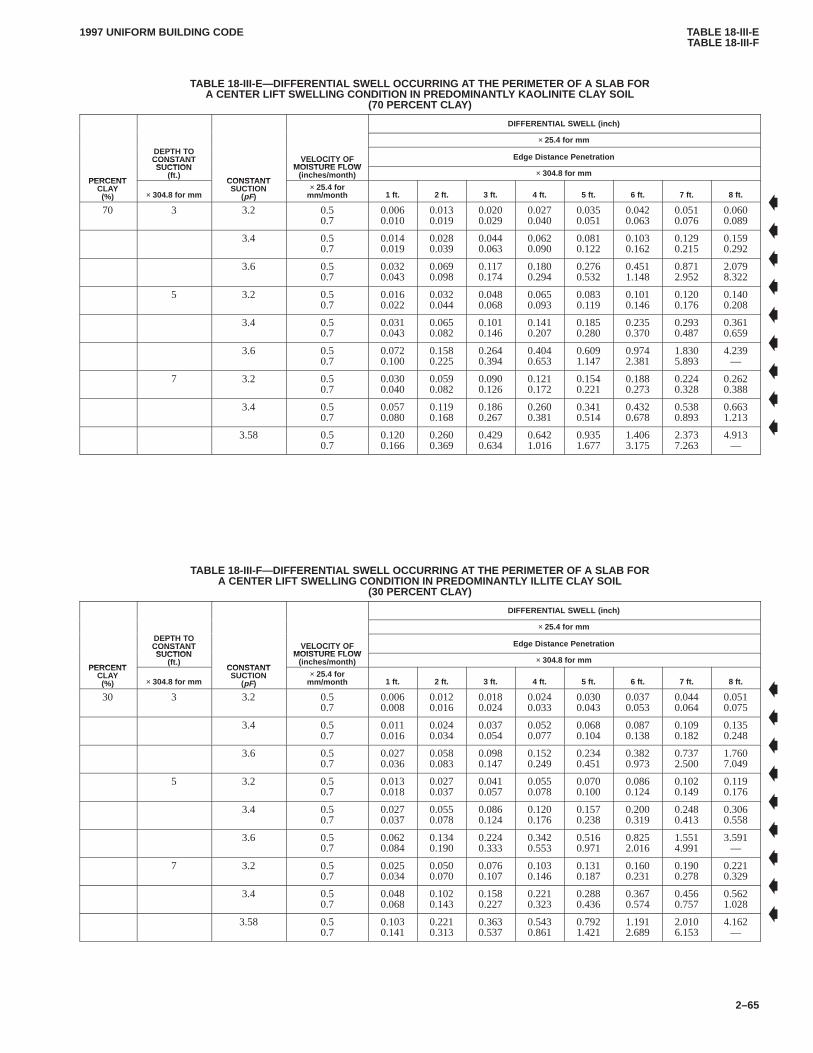
TABLE 18-III-ETABLE 18-III-F
1997 UNIFORM BUILDING CODE
2–65
TABLE 18-III-E—DIFFERENTIAL SWELL OCCURRING A T THE PERIMETER OF A SLAB FORA CENTER LIFT SWELLING CONDITION IN PREDOMINANTLY KAOLINITE CLA Y SOIL
(70 PERCENT CLAY)
DIFFERENTIAL SWELL (inch)
× 25.4 for mmDEPTH TOCONSTANTSUCTION
VELOCITY OFMOISTURE FLOW
Edge Distance Penetration
PERCENT
CONSTANTSUCTION
(ft.)CONSTANT
VELOCITY OFMOISTURE FLOW
(inches/month) × 304.8 for mmPERCENT
CLAY(%) × 304.8 for mm
CONSTANTSUCTION
(pF)× 25.4 for
mm/month 1 ft. 2 ft. 3 ft. 4 ft. 5 ft. 6 ft. 7 ft. 8 ft.
70 3 3.2 0.50.7
0.0060.010
0.0130.019
0.0200.029
0.0270.040
0.0350.051
0.0420.063
0.0510.076
0.0600.089
3.4 0.50.7
0.0140.019
0.0280.039
0.0440.063
0.0620.090
0.0810.122
0.1030.162
0.1290.215
0.1590.292
3.6 0.50.7
0.0320.043
0.0690.098
0.1170.174
0.1800.294
0.2760.532
0.4511.148
0.8712.952
2.0798.322
5 3.2 0.50.7
0.0160.022
0.0320.044
0.0480.068
0.0650.093
0.0830.119
0.1010.146
0.1200.176
0.1400.208
3.4 0.50.7
0.0310.043
0.0650.082
0.1010.146
0.1410.207
0.1850.280
0.2350.370
0.2930.487
0.3610.659
3.6 0.50.7
0.0720.100
0.1580.225
0.2640.394
0.4040.653
0.6091.147
0.9742.381
1.8305.893
4.239—
7 3.2 0.50.7
0.0300.040
0.0590.082
0.0900.126
0.1210.172
0.1540.221
0.1880.273
0.2240.328
0.2620.388
3.4 0.50.7
0.0570.080
0.1190.168
0.1860.267
0.2600.381
0.3410.514
0.4320.678
0.5380.893
0.6631.213
3.58 0.50.7
0.1200.166
0.2600.369
0.4290.634
0.6421.016
0.9351.677
1.4063.175
2.3737.263
4.913—
TABLE 18-III-F—DIFFERENTIAL SWELL OCCURRING AT THE PERIMETER OF A SLAB FORA CENTER LIFT SWELLING CONDITION IN PREDOMINANTL Y ILLITE CLAY SOIL
(30 PERCENT CLAY)
DIFFERENTIAL SWELL (inch)
× 25.4 for mmDEPTH TOCONSTANTSUCTION
VELOCITY OFMOISTURE FLOW
Edge Distance Penetration
PERCENT
CONSTANTSUCTION
(ft.)CONSTANT
VELOCITY OFMOISTURE FLOW
(inches/month) × 304.8 for mmPERCENT
CLAY(%) × 304.8 for mm
CONSTANTSUCTION
(pF)× 25.4 for
mm/month 1 ft. 2 ft. 3 ft. 4 ft. 5 ft. 6 ft. 7 ft. 8 ft.
30 3 3.2 0.50.7
0.0060.008
0.0120.016
0.0180.024
0.0240.033
0.0300.043
0.0370.053
0.0440.064
0.0510.075
3.4 0.50.7
0.0110.016
0.0240.034
0.0370.054
0.0520.077
0.0680.104
0.0870.138
0.1090.182
0.1350.248
3.6 0.50.7
0.0270.036
0.0580.083
0.0980.147
0.1520.249
0.2340.451
0.3820.973
0.7372.500
1.7607.049
5 3.2 0.50.7
0.0130.018
0.0270.037
0.0410.057
0.0550.078
0.0700.100
0.0860.124
0.1020.149
0.1190.176
3.4 0.50.7
0.0270.037
0.0550.078
0.0860.124
0.1200.176
0.1570.238
0.2000.319
0.2480.413
0.3060.558
3.6 0.50.7
0.0620.084
0.1340.190
0.2240.333
0.3420.553
0.5160.971
0.8252.016
1.5514.991
3.591—
7 3.2 0.50.7
0.0250.034
0.0500.070
0.0760.107
0.1030.146
0.1310.187
0.1600.231
0.1900.278
0.2210.329
3.4 0.50.7
0.0480.068
0.1020.143
0.1580.227
0.2210.323
0.2880.436
0.3670.574
0.4560.757
0.5621.028
3.58 0.50.7
0.1030.141
0.2210.313
0.3630.537
0.5430.861
0.7921.421
1.1912.689
2.0106.153
4.162—
�
�
�
�
�
�
�
�
�
�
�
�
�
�
�
�
�
�

TABLE 18-III-GTABLE 18-III-H
1997 UNIFORM BUILDING CODE
2–66
TABLE 18-III-G—DIFFERENTIAL SWELL OCCURRING A T THE PERIMETER OF A SLAB FORA CENTER LIFT SWELLING CONDITION IN PREDOMINANTL Y ILLITE CLAY SOIL
(40 PERCENT CLAY)
DIFFERENTIAL SWELL (inch)
× 25.4 for mmDEPTH TOCONSTANTSUCTION
VELOCITY OFMOISTURE FLOW
Edge Distance Penetration
PERCENT
CONSTANTSUCTION
(ft.)CONSTANT
VELOCITY OFMOISTURE FLOW
(inches/month) × 304.8 for mmPERCENT
CLAY(%) × 304.8 for mm
CONSTANTSUCTION
(pF)× 25.4 for
mm/month 1 ft. 2 ft. 3 ft. 4 ft. 5 ft. 6 ft. 7 ft. 8 ft.
40 3 3.2 0.50.7
0.0080.011
0.0160.023
0.0250.035
0.0340.048
0.0430.062
0.0520.076
0.0630.092
0.0730.109
3.4 0.50.7
0.0170.023
0.0340.048
0.0540.077
0.0750.110
0.0990.149
0.1260.198
0.1570.263
0.1940.357
3.6 0.50.7
0.0390.053
0.0850.120
0.1420.213
0.2200.360
0.3380.651
0.5521.405
1.0653.611
2.542—
5 3.2 0.50.7
0.0190.026
0.0390.054
0.0590.083
0.0800.113
0.1010.145
0.1240.179
0.1470.215
0.1720.254
3.4 0.50.7
0.0390.053
0.0800.112
0.1240.178
0.1730.254
0.2270.343
0.2880.452
0.3580.596
0.4420.805
3.6 0.50.7
0.0890.122
0.1940.275
0.3230.482
0.4940.799
0.7451.403
1.1922.912
2.2397.207
5.184—
7 3.2 0.50.7
0.0350.049
0.0720.100
0.1090.154
0.1480.210
0.1880.270
0.2300.330
0.2740.401
0.3200.474
3.4 0.50.7
0.0700.098
0.1460.207
0.2280.328
0.3180.466
0.4170.629
0.5280.829
0.6571.093
0.8111.484
3.58 0.50.7
0.1470.203
0.3180.451
0.5240.775
0.7841.242
1.1432.051
1.7193.883
2.9028.882
6.008—
TABLE 18-III-H—DIFFERENTIAL SWELL OCCURRING A T THE PERIMETER OF A SLAB FORA CENTER LIFT SWELLING CONDITION IN PREDOMINANTL Y ILLITE CLAY SOIL
(50 PERCENT CLAY)
DIFFERENTIAL SWELL (inch)
× 25.4 for mmDEPTH TOCONSTANTSUCTION
VELOCITY OFMOISTURE FLOW
Edge Distance Penetration
PERCENT
CONSTANTSUCTION
(ft.)CONSTANT
VELOCITY OFMOISTURE FLOW
(inches/month) × 304.8 for mmPERCENT
CLAY(%) × 304.8 for mm
CONSTANTSUCTION
(pF)× 25.4 for
mm/month 1 ft. 2 ft. 3 ft. 4 ft. 5 ft. 6 ft. 7 ft. 8 ft.
50 3 3.2 0.50.7
0.0100.014
0.0210.030
0.0330.046
0.0420.063
0.0560.081
0.0690.099
0.0820.120
0.0960.142
3.4 0.50.7
0.0220.030
0.0450.063
0.0700.101
0.0980.144
0.1290.196
0.1640.260
0.2050.344
0.2540.467
3.6 0.50.7
0.0500.069
0.1110.156
0.1850.278
0.2870.470
0.4410.851
0.7211.836
1.3914.720
3.322—
5 3.2 0.50.7
0.0250.035
0.0510.071
0.0770.110
0.1040.148
0.1330.190
0.1620.235
0.1930.282
0.2250.333
3.4 0.50.7
0.0510.070
0.1040.147
0.1630.233
0.2270.332
0.2980.449
0.3770.592
0.4690.779
0.5791.054
3.6 0.50.7
0.1160.159
0.2530.359
0.4230.629
0.6461.043
0.9741.834
1.5583.807
2.9279.422
6.778—
7 3.2 0.50.7
0.0460.064
0.0940.131
0.1430.201
0.1930.275
0.2460.353
0.3010.436
0.3580.524
0.4180.620
3.4 0.50.7
0.0920.129
0.1920.271
0.2990.429
0.4160.610
0.5460.823
0.6921.085
0.8601.429
1.0611.940
3.58 0.50.7
0.1930.265
0.4170.590
0.6851.013
1.0261.624
1.4952.682
2.2485.075
3.795—
7.856—
�
�
�
�
�
�
�
�
�
�
�
�
�
�
�
�
�
�
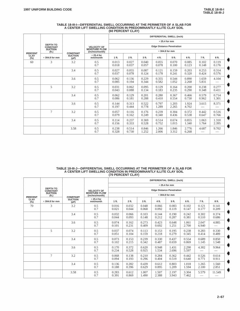
TABLE 18-III-ITABLE 18-III-J
1997 UNIFORM BUILDING CODE
2–67
TABLE 18-III-I—DIFFERENTIAL SWELL OCCURRING AT THE PERIMETER OF A SLAB FORA CENTER LIFT SWELLING CONDITION IN PREDOMINANTL Y ILLITE CLAY SOIL
(60 PERCENT CLAY)
DIFFERENTIAL SWELL (inch)
× 25.4 for mmDEPTH TOCONSTANTSUCTION
VELOCITY OFMOISTURE FLOW
Edge Distance Penetration
PERCENT
CONSTANTSUCTION
(ft.)CONSTANT
VELOCITY OFMOISTURE FLOW
(inches/month) × 304.8 for mmPERCENT
CLAY(%) × 304.8 for mm
CONSTANTSUCTION
(pF)× 25.4 for
mm/month 1 ft. 2 ft. 3 ft. 4 ft. 5 ft. 6 ft. 7 ft. 8 ft.
60 3 3.2 0.50.7
0.0130.018
0.0270.037
0.0400.057
0.0550.078
0.0700.100
0.0850.123
0.1020.148
0.1190.176
3.4 0.50.7
0.0270.037
0.0550.078
0.0870.124
0.1210.178
0.1590.241
0.2030.320
0.2530.424
0.3140.576
3.6 0.50.7
0.0620.085
0.1360.194
0.2290.344
0.3550.582
0.5441.052
0.8902.268
1.6595.831
4.104—
5 3.2 0.50.7
0.0310.043
0.0620.088
0.0950.134
0.1290.183
0.1640.235
0.2000.290
0.2380.348
0.2770.411
3.4 0.50.7
0.0620.086
0.1290.181
0.2010.288
0.2800.410
0.3670.554
0.4660.730
0.5790.962
0.7141.301
3.6 0.50.7
0.1440.197
0.3130.444
0.5220.778
0.7971.289
1.2032.265
1.9244.702
3.615—
8.371—
7 3.2 0.50.7
0.0570.079
0.1160.162
0.1760.249
0.2390.340
0.3040.436
0.3720.538
0.4420.647
0.5160.766
3.4 0.50.7
0.1140.156
0.2370.333
0.3690.528
0.5140.752
0.6741.015
0.8551.340
1.0631.764
1.3102.395
3.58 0.50.7
0.2380.328
0.5140.730
0.8461.252
1.2662.006
1.8463.312
2.7766.268
4.687—
9.702—
TABLE 18-III-J—DIFFERENTIAL SWELL OCCURRING AT THE PERIMETER OF A SLAB FORA CENTER LIFT SWELLING CONDITION IN PREDOMINANTL Y ILLITE CLAY SOIL
(70 PERCENT CLAY)
DIFFERENTIAL SWELL (inch)
× 25.4 for mmDEPTH TOCONSTANTSUCTION
VELOCITY OFMOISTURE FLOW
Edge Distance Penetration
PERCENT
CONSTANTSUCTION
(ft.)CONSTANT
VELOCITY OFMOISTURE FLOW
(inches/month) × 304.8 for mmPERCENT
CLAY(%) × 304.8 for mm
CONSTANTSUCTION
(pF)× 25.4 for
mm/month 1 ft. 2 ft. 3 ft. 4 ft. 5 ft. 6 ft. 7 ft. 8 ft.
70 3 3.2 0.50.7
0.0160.021
0.0320.044
0.0480.068
0.0660.092
0.0830.119
0.1020.147
0.1210.177
0.1410.209
3.4 0.50.7
0.0320.044
0.0660.093
0.1030.148
0.1440.212
0.1900.287
0.2420.381
0.3020.510
0.3740.686
3.6 0.50.7
0.0740.101
0.1620.231
0.2730.409
0.4230.692
0.6481.251
1.0612.700
2.0476.940
4.885—
5 3.2 0.50.7
0.0370.051
0.0740.104
0.1130.159
0.1530.218
0.1950.279
0.2380.345
0.2830.414
0.3300.489
3.4 0.50.7
0.0730.102
0.1530.215
0.2390.342
0.3300.487
0.4370.659
0.5540.869
0.6891.145
0.8501.548
3.6 0.50.7
0.1700.234
0.3720.528
0.6200.925
0.9481.534
1.4312.696
2.2905.597
4.302—
9.964—
7 3.2 0.50.7
0.0680.094
0.1380.193
0.2100.296
0.2840.404
0.3620.519
0.4420.640
0.5260.771
0.6140.911
3.4 0.50.7
0.1360.188
0.2820.396
0.4390.629
0.6120.895
0.8031.209
1.0181.594
1.2652.100
1.5602.851
3.58 0.50.7
0.2830.391
0.6120.869
1.0071.490
1.5072.388
2.1973.943
3.3047.462
5.579—
11.549—
�
�
�
�
�
�
�
�
�
�
�
�
�
�
�
�
�
�
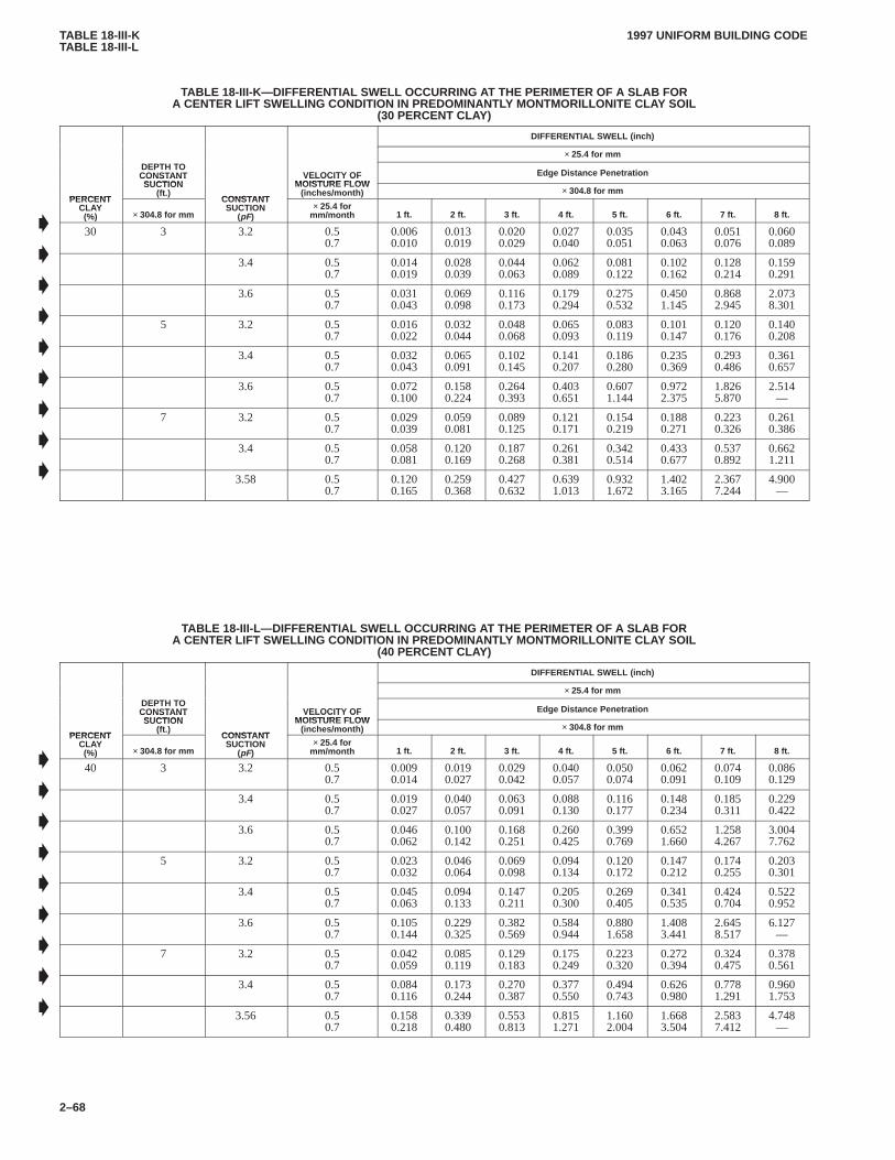
TABLE 18-III-KTABLE 18-III-L
1997 UNIFORM BUILDING CODE
2–68
TABLE 18-III-K—DIFFERENTIAL SWELL OCCURRING A T THE PERIMETER OF A SLAB FORA CENTER LIFT SWELLING CONDITION IN PREDOMINANTL Y MONTMORILLONITE CLAY SOIL
(30 PERCENT CLAY)
DIFFERENTIAL SWELL (inch)
× 25.4 for mmDEPTH TOCONSTANTSUCTION
VELOCITY OFMOISTURE FLOW
Edge Distance Penetration
PERCENT
CONSTANTSUCTION
(ft.)CONSTANT
VELOCITY OFMOISTURE FLOW
(inches/month) × 304.8 for mmPERCENT
CLAY(%) × 304.8 for mm
CONSTANTSUCTION
(pF)× 25.4 for
mm/month 1 ft. 2 ft. 3 ft. 4 ft. 5 ft. 6 ft. 7 ft. 8 ft.
30 3 3.2 0.50.7
0.0060.010
0.0130.019
0.0200.029
0.0270.040
0.0350.051
0.0430.063
0.0510.076
0.0600.089
3.4 0.50.7
0.0140.019
0.0280.039
0.0440.063
0.0620.089
0.0810.122
0.1020.162
0.1280.214
0.1590.291
3.6 0.50.7
0.0310.043
0.0690.098
0.1160.173
0.1790.294
0.2750.532
0.4501.145
0.8682.945
2.0738.301
5 3.2 0.50.7
0.0160.022
0.0320.044
0.0480.068
0.0650.093
0.0830.119
0.1010.147
0.1200.176
0.1400.208
3.4 0.50.7
0.0320.043
0.0650.091
0.1020.145
0.1410.207
0.1860.280
0.2350.369
0.2930.486
0.3610.657
3.6 0.50.7
0.0720.100
0.1580.224
0.2640.393
0.4030.651
0.6071.144
0.9722.375
1.8265.870
2.514—
7 3.2 0.50.7
0.0290.039
0.0590.081
0.0890.125
0.1210.171
0.1540.219
0.1880.271
0.2230.326
0.2610.386
3.4 0.50.7
0.0580.081
0.1200.169
0.1870.268
0.2610.381
0.3420.514
0.4330.677
0.5370.892
0.6621.211
3.58 0.50.7
0.1200.165
0.2590.368
0.4270.632
0.6391.013
0.9321.672
1.4023.165
2.3677.244
4.900—
TABLE 18-III-L—DIFFERENTIAL SWELL OCCURRING AT THE PERIMETER OF A SLAB FORA CENTER LIFT SWELLING CONDITION IN PREDOMINANTL Y MONTMORILLONITE CLAY SOIL
(40 PERCENT CLAY)
DIFFERENTIAL SWELL (inch)
× 25.4 for mmDEPTH TOCONSTANTSUCTION
VELOCITY OFMOISTURE FLOW
Edge Distance Penetration
PERCENT
CONSTANTSUCTION
(ft.)CONSTANT
VELOCITY OFMOISTURE FLOW
(inches/month) × 304.8 for mmPERCENT
CLAY(%) × 304.8 for mm
CONSTANTSUCTION
(pF)× 25.4 for
mm/month 1 ft. 2 ft. 3 ft. 4 ft. 5 ft. 6 ft. 7 ft. 8 ft.
40 3 3.2 0.50.7
0.0090.014
0.0190.027
0.0290.042
0.0400.057
0.0500.074
0.0620.091
0.0740.109
0.0860.129
3.4 0.50.7
0.0190.027
0.0400.057
0.0630.091
0.0880.130
0.1160.177
0.1480.234
0.1850.311
0.2290.422
3.6 0.50.7
0.0460.062
0.1000.142
0.1680.251
0.2600.425
0.3990.769
0.6521.660
1.2584.267
3.0047.762
5 3.2 0.50.7
0.0230.032
0.0460.064
0.0690.098
0.0940.134
0.1200.172
0.1470.212
0.1740.255
0.2030.301
3.4 0.50.7
0.0450.063
0.0940.133
0.1470.211
0.2050.300
0.2690.405
0.3410.535
0.4240.704
0.5220.952
3.6 0.50.7
0.1050.144
0.2290.325
0.3820.569
0.5840.944
0.8801.658
1.4083.441
2.6458.517
6.127—
7 3.2 0.50.7
0.0420.059
0.0850.119
0.1290.183
0.1750.249
0.2230.320
0.2720.394
0.3240.475
0.3780.561
3.4 0.50.7
0.0840.116
0.1730.244
0.2700.387
0.3770.550
0.4940.743
0.6260.980
0.7781.291
0.9601.753
3.56 0.50.7
0.1580.218
0.3390.480
0.5530.813
0.8151.271
1.1602.004
1.6683.504
2.5837.412
4.748—
�
�
�
�
�
�
�
�
�
�
�
�
�
�
�
�
�
�
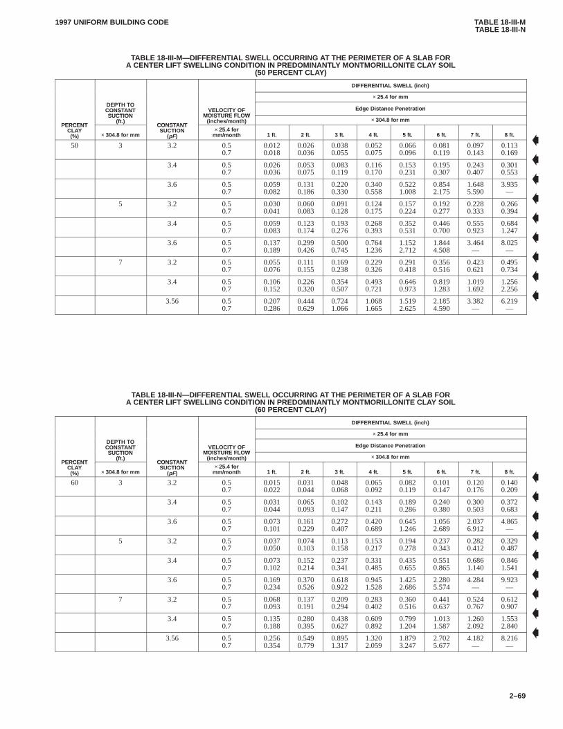
TABLE 18-III-MTABLE 18-III-N
1997 UNIFORM BUILDING CODE
2–69
TABLE 18-III-M—DIFFERENTIAL SWELL OCCURRING AT THE PERIMETER OF A SLAB FORA CENTER LIFT SWELLING CONDITION IN PREDOMINANTL Y MONTMORILLONITE CLAY SOIL
(50 PERCENT CLAY)
DIFFERENTIAL SWELL (inch)
× 25.4 for mmDEPTH TOCONSTANTSUCTION
VELOCITY OFMOISTURE FLOW
Edge Distance Penetration
PERCENT
CONSTANTSUCTION
(ft.)CONSTANT
VELOCITY OFMOISTURE FLOW
(inches/month) × 304.8 for mmPERCENT
CLAY(%) × 304.8 for mm
CONSTANTSUCTION
(pF)× 25.4 for
mm/month 1 ft. 2 ft. 3 ft. 4 ft. 5 ft. 6 ft. 7 ft. 8 ft.
50 3 3.2 0.50.7
0.0120.018
0.0260.036
0.0380.055
0.0520.075
0.0660.096
0.0810.119
0.0970.143
0.1130.169
3.4 0.50.7
0.0260.036
0.0530.075
0.0830.119
0.1160.170
0.1530.231
0.1950.307
0.2430.407
0.3010.553
3.6 0.50.7
0.0590.082
0.1310.186
0.2200.330
0.3400.558
0.5221.008
0.8542.175
1.6485.590
3.935—
5 3.2 0.50.7
0.0300.041
0.0600.083
0.0910.128
0.1240.175
0.1570.224
0.1920.277
0.2280.333
0.2660.394
3.4 0.50.7
0.0590.083
0.1230.174
0.1930.276
0.2680.393
0.3520.531
0.4460.700
0.5550.923
0.6841.247
3.6 0.50.7
0.1370.189
0.2990.426
0.5000.745
0.7641.236
1.1522.712
1.8444.508
3.464—
8.025—
7 3.2 0.50.7
0.0550.076
0.1110.155
0.1690.238
0.2290.326
0.2910.418
0.3560.516
0.4230.621
0.4950.734
3.4 0.50.7
0.1060.152
0.2260.320
0.3540.507
0.4930.721
0.6460.973
0.8191.283
1.0191.692
1.2562.256
3.56 0.50.7
0.2070.286
0.4440.629
0.7241.066
1.0681.665
1.5192.625
2.1854.590
3.382—
6.219—
TABLE 18-III-N—DIFFERENTIAL SWELL OCCURRING A T THE PERIMETER OF A SLAB FORA CENTER LIFT SWELLING CONDITION IN PREDOMINANTL Y MONTMORILLONITE CLAY SOIL
(60 PERCENT CLAY)
DIFFERENTIAL SWELL (inch)
× 25.4 for mmDEPTH TOCONSTANTSUCTION
VELOCITY OFMOISTURE FLOW
Edge Distance Penetration
PERCENT
CONSTANTSUCTION
(ft.)CONSTANT
VELOCITY OFMOISTURE FLOW
(inches/month) × 304.8 for mmPERCENT
CLAY(%) × 304.8 for mm
CONSTANTSUCTION
(pF)× 25.4 for
mm/month 1 ft. 2 ft. 3 ft. 4 ft. 5 ft. 6 ft. 7 ft. 8 ft.
60 3 3.2 0.50.7
0.0150.022
0.0310.044
0.0480.068
0.0650.092
0.0820.119
0.1010.147
0.1200.176
0.1400.209
3.4 0.50.7
0.0310.044
0.0650.093
0.1020.147
0.1430.211
0.1890.286
0.2400.380
0.3000.503
0.3720.683
3.6 0.50.7
0.0730.101
0.1610.229
0.2720.407
0.4200.689
0.6451.246
1.0562.689
2.0376.912
4.865—
5 3.2 0.50.7
0.0370.050
0.0740.103
0.1130.158
0.1530.217
0.1940.278
0.2370.343
0.2820.412
0.3290.487
3.4 0.50.7
0.0730.102
0.1520.214
0.2370.341
0.3310.485
0.4350.655
0.5510.865
0.6861.140
0.8461.541
3.6 0.50.7
0.1690.234
0.3700.526
0.6180.922
0.9451.528
1.4252.686
2.2805.574
4.284—
9.923—
7 3.2 0.50.7
0.0680.093
0.1370.191
0.2090.294
0.2830.402
0.3600.516
0.4410.637
0.5240.767
0.6120.907
3.4 0.50.7
0.1350.188
0.2800.395
0.4380.627
0.6090.892
0.7991.204
1.0131.587
1.2602.092
1.5532.840
3.56 0.50.7
0.2560.354
0.5490.779
0.8951.317
1.3202.059
1.8793.247
2.7025.677
4.182—
8.216—
�
�
�
�
�
�
�
�
�
�
�
�
�
�
�
�
�
�
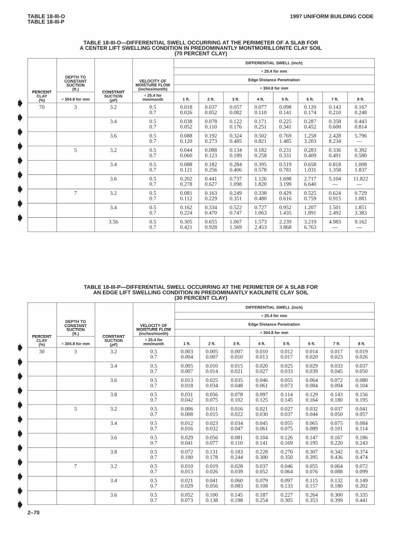
TABLE 18-III-OTABLE 18-III-P
1997 UNIFORM BUILDING CODE
2–70
TABLE 18-III-O—DIFFERENTIAL SWELL OCCURRING A T THE PERIMETER OF A SLAB FORA CENTER LIFT SWELLING CONDITION IN PREDOMINANTL Y MONTMORILLONITE CLAY SOIL
(70 PERCENT CLAY)
DIFFERENTIAL SWELL (inch)
× 25.4 for mmDEPTH TOCONSTANTSUCTION
VELOCITY OFMOISTURE FLOW
Edge Distance Penetration
PERCENT
CONSTANTSUCTION
(ft.)CONSTANT
VELOCITY OFMOISTURE FLOW
(inches/month) × 304.8 for mmPERCENT
CLAY(%) × 304.8 for mm
CONSTANTSUCTION
(pF)× 25.4 for
mm/month 1 ft. 2 ft. 3 ft. 4 ft. 5 ft. 6 ft. 7 ft. 8 ft.
70 3 3.2 0.50.7
0.0180.026
0.0370.052
0.0570.082
0.0770.110
0.0980.141
0.1200.174
0.1430.210
0.1670.248
3.4 0.50.7
0.0380.052
0.0780.110
0.1220.176
0.1710.251
0.2250.341
0.2870.452
0.3580.600
0.4430.814
3.6 0.50.7
0.0880.120
0.1920.273
0.3240.485
0.5020.821
0.7691.485
1.2583.203
2.4288.234
5.796—
5 3.2 0.50.7
0.0440.060
0.0880.123
0.1340.189
0.1820.258
0.2310.331
0.2830.409
0.3360.491
0.3920.580
3.4 0.50.7
0.0880.121
0.1820.256
0.2840.406
0.3950.578
0.5190.781
0.6581.031
0.8181.358
1.0081.837
3.6 0.50.7
0.2020.278
0.4410.627
0.7371.098
1.1261.820
1.6983.199
2.7176.640
5.104—
11.822—
7 3.2 0.50.7
0.0810.112
0.1630.229
0.2490.351
0.3380.480
0.4290.616
0.5250.759
0.6240.915
0.7291.081
3.4 0.50.7
0.1620.224
0.3340.470
0.5220.747
0.7271.063
0.9521.435
1.2071.891
1.5012.492
1.8513.383
3.56 0.50.7
0.3050.421
0.6550.928
1.0671.569
1.5732.453
2.2393.868
3.2196.763
4.983—
9.162—
TABLE 18-III-P—DIFFERENTIAL SWELL OCCURRING AT THE PERIMETER OF A SLAB FORAN EDGE LIFT SWELLING CONDITION IN PREDOMINANTLY KAOLINITE CLA Y SOIL
(30 PERCENT CLAY)
DIFFERENTIAL SWELL (inch)
× 25.4 for mmDEPTH TOCONSTANTSUCTION
VELOCITY OFMOISTURE FLOW
Edge Distance Penetration
PERCENT
CONSTANTSUCTION
(ft.)CONSTANT
VELOCITY OFMOISTURE FLOW
(inches/month) × 304.8 for mmPERCENT
CLAY(%) × 304.8 for mm
CONSTANTSUCTION
(pF)× 25.4 for
mm/month 1 ft. 2 ft. 3 ft. 4 ft. 5 ft. 6 ft. 7 ft. 8 ft.
30 3 3.2 0.50.7
0.0030.004
0.0050.007
0.0070.010
0.0100.013
0.0120.017
0.0140.020
0.0170.023
0.0190.026
3.4 0.50.7
0.0050.007
0.0100.014
0.0150.021
0.0200.027
0.0250.033
0.0290.039
0.0330.045
0.0370.050
3.6 0.50.7
0.0130.018
0.0250.034
0.0350.048
0.0460.061
0.0550.073
0.0640.084
0.0720.094
0.0800.104
3.8 0.50.7
0.0310.042
0.0560.075
0.0780.102
0.0970.125
0.1140.145
0.1290.164
0.1430.180
0.1560.195
5 3.2 0.50.7
0.0060.008
0.0110.015
0.0160.022
0.0210.030
0.0270.037
0.0320.044
0.0370.050
0.0410.057
3.4 0.50.7
0.0120.016
0.0230.032
0.0340.047
0.0450.061
0.0550.075
0.0650.089
0.0750.101
0.0840.114
3.6 0.50.7
0.0290.041
0.0560.077
0.0810.110
0.1040.141
0.1260.169
0.1470.195
0.1670.220
0.1860.243
3.8 0.50.7
0.0720.100
0.1310.178
0.1830.244
0.2280.300
0.2700.350
0.3070.395
0.3420.436
0.3740.474
7 3.2 0.50.7
0.0100.013
0.0190.026
0.0280.039
0.0370.052
0.0460.064
0.0550.076
0.0640.088
0.0720.099
3.4 0.50.7
0.0210.029
0.0410.056
0.0600.083
0.0790.108
0.0970.133
0.1150.157
0.1320.180
0.1490.202
3.6 0.50.7
0.0520.073
0.1000.138
0.1450.198
0.1870.254
0.2270.305
0.2640.353
0.3000.399
0.3350.441
�
�
�
�
�
�
�
�
�
�
�
�
�
�
�
�
�
�
�
�
�

TABLE 18-III-QTABLE 18-III-R
1997 UNIFORM BUILDING CODE
2–71
TABLE 18-III-Q—DIFFERENTIAL SWELL OCCURRING A T THE PERIMETER OF A SLAB FORAN EDGE LIFT SWELLING CONDITION IN PREDOMINANTLY KAOLINITE CLA Y SOIL
(40 PERCENT CLAY)
DIFFERENTIAL SWELL (inch)
× 25.4 for mmDEPTH TOCONSTANTSUCTION
VELOCITY OFMOISTURE FLOW
Edge Distance Penetration
PERCENT
CONSTANTSUCTION
(ft.)CONSTANT
VELOCITY OFMOISTURE FLOW
(inches/month) × 304.8 for mmPERCENT
CLAY(%) × 304.8 for mm
CONSTANTSUCTION
(pF)× 25.4 for
mm/month 1 ft. 2 ft. 3 ft. 4 ft. 5 ft. 6 ft. 7 ft. 8 ft.
40 3 3.2 0.50.7
0.0030.006
0.0070.009
0.0100.014
0.0130.018
0.0160.022
0.0190.026
0.0220.030
0.0250.034
3.4 0.50.7
0.0070.010
0.0140.019
0.0200.028
0.0270.037
0.0330.045
0.0390.052
0.0450.060
0.0500.067
3.6 0.50.7
0.0170.024
0.0330.045
0.0470.064
0.0610.081
0.0740.098
0.0860.112
0.0970.126
0.1080.139
3.8 0.50.7
0.0410.056
0.0750.100
0.1040.136
0.1290.167
0.1520.195
0.1730.219
0.1920.241
0.2090.261
5 3.2 0.50.7
0.0070.010
0.0150.020
0.0220.030
0.0290.040
0.0350.049
0.0420.058
0.0490.067
0.0560.076
3.4 0.50.7
0.0160.022
0.0310.043
0.0460.063
0.0600.082
0.0740.101
0.0870.119
0.1000.136
0.1130.152
3.6 0.50.7
0.0390.064
0.0750.103
0.1080.147
0.1400.188
0.1690.226
0.1970.261
0.2230.295
0.2490.326
3.8 0.50.7
0.0960.134
0.1760.239
0.2450.326
0.3060.402
0.3610.469
0.4110.529
0.4580.584
0.5010.634
7 3.2 0.50.7
0.0130.018
0.0250.035
0.0380.052
0.0500.069
0.0620.085
0.0740.102
0.0850.117
0.0970.133
3.4 0.50.7
0.0280.039
0.0540.076
0.0800.111
0.1050.145
0.1300.178
0.1540.210
0.1770.241
0.2000.271
3.6 0.50.7
0.0690.098
0.1340.185
0.1940.266
0.2500.340
0.3040.409
0.3540.473
0.4020.534
0.4480.591
TABLE 18-III-R—DIFFERENTIAL SWELL OCCURRING A T THE PERIMETER OF A SLAB FORAN EDGE LIFT SWELLING CONDITION IN PREDOMINANTLY KAOLINITE CLA Y SOIL
(50 PERCENT CLAY)
DIFFERENTIAL SWELL (inch)
× 25.4 for mmDEPTH TOCONSTANTSUCTION
VELOCITY OFMOISTURE FLOW
Edge Distance Penetration
PERCENT
CONSTANTSUCTION
(ft.)CONSTANT
VELOCITY OFMOISTURE FLOW
(inches/month) × 304.8 for mmPERCENT
CLAY(%) × 304.8 for mm
CONSTANTSUCTION
(pF)× 25.4 for
mm/month 1 ft. 2 ft. 3 ft. 4 ft. 5 ft. 6 ft. 7 ft. 8 ft.
50 3 3.2 0.50.7
0.0040.006
0.0080.012
0.0120.017
0.0160.023
0.0200.028
0.0240.033
0.0280.038
0.0320.043
3.4 0.50.7
0.0090.012
0.0170.024
0.0260.035
0.0340.046
0.0410.056
0.0490.066
0.0560.075
0.0630.084
3.6 0.50.7
0.0220.030
0.0420.056
0.0590.080
0.0760.102
0.0920.122
0.1070.141
0.1210.158
0.1350.175
3.8 0.50.7
0.0520.071
0.0940.126
0.1300.171
0.1620.210
0.1910.244
0.2170.275
0.2400.302
0.2620.328
5 3.2 0.50.7
0.0090.013
0.0180.025
0.0270.038
0.0360.050
0.0440.062
0.0530.073
0.0610.084
0.0700.096
3.4 0.50.7
0.0200.028
0.0390.054
0.0570.079
0.0750.103
0.0920.126
0.1090.149
0.1260.170
0.1420.191
3.6 0.50.7
0.0490.068
0.0940.129
0.1360.185
0.1750.236
0.2120.283
0.2470.328
0.2800.369
0.3120.408
3.8 0.50.7
0.1200.168
0.2200.299
0.3070.409
0.3840.504
0.4530.588
0.5160.663
0.5740.732
0.6280.795
7 3.2 0.50.7
0.0160.022
0.0320.044
0.0470.066
0.0620.087
0.0770.107
0.0920.127
0.1070.147
0.1210.167
3.4 0.50.7
0.0350.048
0.0680.095
0.1000.139
0.1320.182
0.1630.223
0.1930.263
0.2220.302
0.2500.339
3.6 0.50.7
0.0870.122
0.1680.232
0.2430.333
0.3140.426
0.3810.512
0.4440.593
0.5040.669
0.5620.741
�
�
�
�
�
�
�
�
�
�
�
�
�
�
�
�
�
�
�
�
�
�
�
�

TABLE 18-III-STABLE 18-III-T
1997 UNIFORM BUILDING CODE
2–72
TABLE 18-III-S—DIFFERENTIAL SWELL OCCURRING A T THE PERIMETER OF A SLAB FORAN EDGE LIFT SWELLING CONDITION IN PREDOMINANTLY KAOLINITE CLA Y SOIL
(60 PERCENT CLAY)
DIFFERENTIAL SWELL (inch)
× 25.4 for mmDEPTH TOCONSTANTSUCTION
VELOCITY OFMOISTURE FLOW
Edge Distance Penetration
PERCENT
CONSTANTSUCTION
(ft.)CONSTANT
VELOCITY OFMOISTURE FLOW
(inches/month) × 304.8 for mmPERCENT
CLAY(%) × 304.8 for mm
CONSTANTSUCTION
(pF)× 25.4 for
mm/month 1 ft. 2 ft. 3 ft. 4 ft. 5 ft. 6 ft. 7 ft. 8 ft.
60 3 3.2 0.50.7
0.0050.007
0.0100.014
0.0150.021
0.0200.027
0.0240.033
0.0290.040
0.0330.046
0.0380.052
3.4 0.50.7
0.0110.015
0.0210.029
0.0310.042
0.0400.055
0.0490.067
0.0580.079
0.0670.090
0.0760.101
3.6 0.50.7
0.0260.036
0.0500.068
0.0710.097
0.0920.123
0.1110.147
0.1290.169
0.1460.190
0.1620.210
3.8 0.50.7
0.0620.085
0.1130.151
0.1570.205
0.1950.252
0.2290.293
0.2600.330
0.2890.363
0.3150.394
5 3.2 0.50.7
0.0110.015
0.0220.031
0.0330.045
0.0430.060
0.0530.074
0.0640.088
0.0740.101
0.0840.115
3.4 0.50.7
0.0240.033
0.0460.065
0.0690.095
0.0900.124
0.1110.152
0.1310.179
0.1510.205
0.1700.230
3.6 0.50.7
0.0590.082
0.1130.155
0.1630.222
0.2100.284
0.2550.341
0.2970.394
0.3370.444
0.3750.491
3.8 0.50.7
0.1440.201
0.2650.360
0.3690.492
0.4610.606
0.5440.707
0.6200.798
0.6900.880
0.7540.956
7 3.2 0.50.7
0.0190.027
0.0380.053
0.0570.079
0.0750.104
0.0930.129
0.1110.153
0.1280.177
0.1460.201
3.4 0.50.7
0.0420.058
0.0820.114
0.1210.167
0.1590.219
0.1960.268
0.2320.316
0.2670.363
0.3010.408
3.6 0.50.7
0.1050.147
0.2010.279
0.2920.400
0.3770.512
0.4570.616
0.5340.713
0.6060.804
0.6750.891
TABLE 18-III-T—DIFFERENTIAL SWELL OCCURRING AT THE PERIMETER OF A SLAB FORAN EDGE LIFT SWELLING CONDITION IN PREDOMINANTLY KAOLINITE CLA Y SOIL
(70 PERCENT CLAY)
DIFFERENTIAL SWELL (inch)
× 25.4 for mmDEPTH TOCONSTANTSUCTION
VELOCITY OFMOISTURE FLOW
Edge Distance Penetration
PERCENT
CONSTANTSUCTION
(ft.)CONSTANT
VELOCITY OFMOISTURE FLOW
(inches/month) × 304.8 for mmPERCENT
CLAY(%) × 304.8 for mm
CONSTANTSUCTION
(pF)× 25.4 for
mm/month 1 ft. 2 ft. 3 ft. 4 ft. 5 ft. 6 ft. 7 ft. 8 ft.
70 3 3.2 0.50.7
0.0060.008
0.0120.016
0.0170.024
0.0230.032
0.0280.039
0.0340.046
0.0390.054
0.0440.061
3.4 0.50.7
0.0120.017
0.0240.034
0.0360.049
0.0470.064
0.0580.079
0.0680.092
0.0780.106
0.0880.118
3.6 0.50.7
0.0300.042
0.0580.079
0.0840.113
0.1070.143
0.1300.172
0.1510.198
0.1700.222
0.1890.245
3.8 0.50.7
0.0720.099
0.1320.176
0.1830.240
0.2280.295
0.2680.343
0.3040.386
0.3380.425
0.3690.460
5 3.2 0.50.7
0.0130.018
0.0260.036
0.0380.053
0.0500.070
0.0620.086
0.0740.103
0.0860.119
0.0980.134
3.4 0.50.7
0.0280.039
0.0540.075
0.0800.111
0.1050.145
0.1300.177
0.1530.209
0.1760.239
0.1990.268
3.6 0.50.7
0.0680.096
0.1320.181
0.1910.259
0.2460.331
0.2980.398
0.3470.460
0.3930.518
0.4380.574
3.8 0.50.7
0.1690.235
0.3090.420
0.4310.575
0.5390.708
0.6360.826
0.7240.932
0.8061.028
0.8811.117
7 3.2 0.50.7
0.0220.031
0.0440.062
0.0660.092
0.0870.121
0.1090.150
0.1290.179
0.1500.207
0.1700.234
3.4 0.50.7
0.0480.068
0.0950.133
0.1410.195
0.1850.256
0.2280.314
0.2700.370
0.3110.424
0.3510.476
3.6 0.50.7
0.1220.172
0.2350.326
0.3410.468
0.4410.598
0.5340.719
0.6230.833
0.7080.940
0.7891.041
�
�
�
�
�
�
�
�
�
�
�
�
�
�
�
�
�
�
�
�
�
�
�
�
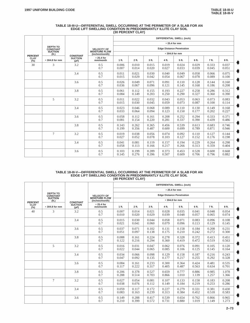
TABLE 18-III-UTABLE 18-III-V
1997 UNIFORM BUILDING CODE
2–73
TABLE 18-III-U—DIFFERENTIAL SWELL OCCURRING AT THE PERIMETER OF A SLAB FOR ANEDGE LIFT SWELLING CONDITION IN PREDOMINANTL Y ILLITE CLAY SOIL
(30 PERCENT CLAY)
DIFFERENTIAL SWELL (inch)
× 25.4 for mmDEPTH TOCONSTANTSUCTION
VELOCITY OFMOISTURE FLOW
Edge Distance Penetration
PERCENT
CONSTANTSUCTION
(ft.)CONSTANT
VELOCITY OFMOISTURE FLOW
(inches/month) × 304.8 for mmPERCENT
CLAY(%) × 304.8 for mm
CONSTANTSUCTION
(pF)× 25.4 for
mm/month 1 ft. 2 ft. 3 ft. 4 ft. 5 ft. 6 ft. 7 ft. 8 ft.
30 3 3.2 0.50.7
0.0060.007
0.0100.014
0.0150.020
0.0190.027
0.0240.033
0.0290.039
0.3330.045
0.0370.051
3.4 0.50.7
0.0110.015
0.0210.029
0.0300.042
0.0400.054
0.0490.067
0.0580.078
0.0660.089
0.0750.100
3.6 0.50.7
0.0260.036
0.0490.067
0.0710.096
0.0910.121
0.1100.145
0.1280.168
0.1440.186
0.1600.208
3.8 0.50.7
0.0610.084
0.1120.149
0.1550.203
0.1930.250
0.2270.290
0.2580.327
0.2860.360
0.3120.390
5 3.2 0.50.7
0.0110.015
0.0220.030
0.0320.045
0.0430.059
0.0530.073
0.0630.087
0.0730.100
0.0830.114
3.4 0.50.7
0.0230.033
0.0460.064
0.0680.094
0.0890.123
0.1100.150
0.1300.177
0.1490.202
0.1680.227
3.6 0.50.7
0.0580.081
0.1120.154
0.1610.220
0.2080.281
0.2520.337
0.2940.390
0.3330.439
0.3710.486
3.8 0.50.7
0.1430.199
0.2620.356
0.3650.487
0.4560.600
0.5390.699
0.6130.789
0.6830.871
0.7460.946
7 3.2 0.50.7
0.0190.027
0.0380.052
0.0560.078
0.0740.103
0.0920.127
0.1100.152
0.1270.176
0.1440.198
3.4 0.50.7
0.0410.058
0.0810.113
0.1190.166
0.1570.217
0.1940.266
0.2290.313
0.2640.359
0.2980.404
3.6 0.50.7
0.1030.145
0.1990.276
0.2890.396
0.3730.507
0.4530.609
0.5280.706
0.6000.796
0.6680.882
TABLE 18-III-V—DIFFERENTIAL SWELL OCCURRING AT THE PERIMETER OF A SLAB FOR ANEDGE LIFT SWELLING CONDITION IN PREDOMINANTL Y ILLITE CLAY SOIL
(40 PERCENT CLAY)
DIFFERENTIAL SWELL (inch)
× 25.4 for mmDEPTH TOCONSTANTSUCTION
VELOCITY OFMOISTURE FLOW
Edge Distance Penetration
PERCENT
CONSTANTSUCTION
(ft.)CONSTANT
VELOCITY OFMOISTURE FLOW
(inches/month) × 304.8 for mmPERCENT
CLAY(%) × 304.8 for mm
CONSTANTSUCTION
(pF)× 25.4 for
mm/month 1 ft. 2 ft. 3 ft. 4 ft. 5 ft. 6 ft. 7 ft. 8 ft.
40 3 3.2 0.50.7
0.0070.010
0.0140.020
0.0210.029
0.0280.039
0.0350.048
0.0410.057
0.0480.065
0.0540.074
3.4 0.50.7
0.0150.021
0.0300.041
0.0440.060
0.0580.079
0.0710.096
0.0830.113
0.0960.129
0.1080.145
3.6 0.50.7
0.0370.051
0.0710.097
0.1020.138
0.1310.175
0.1580.210
0.1840.242
0.2080.272
0.2310.300
3.8 0.50.7
0.0880.122
0.1610.216
0.2240.294
0.2780.360
0.3280.419
0.3720.472
0.4130.519
0.4510.563
5 3.2 0.50.7
0.0160.022
0.0310.044
0.0470.065
0.0620.085
0.0760.106
0.0910.125
0.1050.145
0.1200.164
3.4 0.50.7
0.0340.047
0.0660.092
0.0980.135
0.1290.177
0.1580.217
0.1870.255
0.2160.292
0.2430.328
3.6 0.50.7
0.0840.117
0.1610.222
0.2330.317
0.3000.405
0.3640.487
0.4240.563
0.4810.634
0.5350.701
3.8 0.50.7
0.2060.288
0.3780.514
0.5270.703
0.6590.866
0.7771.010
0.8861.139
0.9851.257
1.0781.366
7 3.2 0.50.7
0.0270.038
0.0540.076
0.0810.112
0.1070.149
0.1330.184
0.1580.219
0.1830.253
0.2080.286
3.4 0.50.7
0.0590.083
0.1170.163
0.1720.239
0.2270.313
0.2790.384
0.3310.452
0.3810.518
0.4300.583
3.6 0.50.7
0.1490.210
0.2880.399
0.4170.572
0.5390.731
0.6540.880
0.7621.019
0.8661.149
0.9651.273
�
�
�
�
�
�
�
�
�
�
�
�
�
�
�
�
�
�
�
�
�
�
�
�
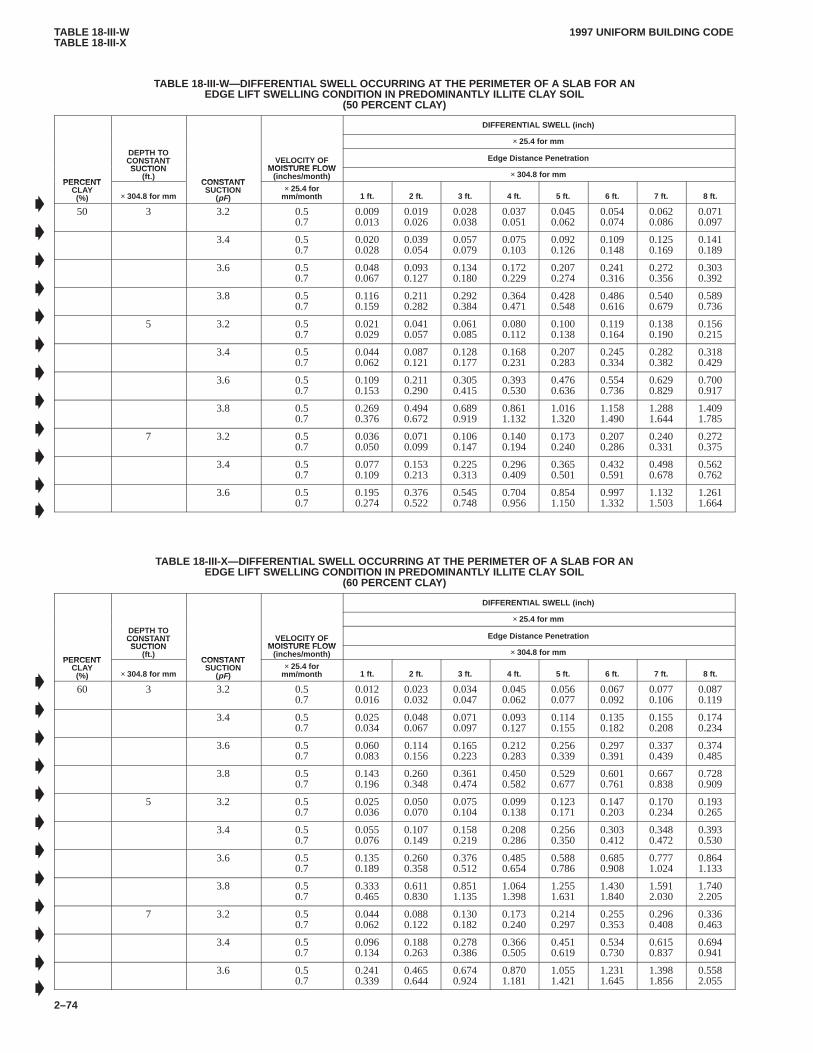
TABLE 18-III-WTABLE 18-III-X
1997 UNIFORM BUILDING CODE
2–74
TABLE 18-III-W—DIFFERENTIAL SWELL OCCURRING AT THE PERIMETER OF A SLAB FOR ANEDGE LIFT SWELLING CONDITION IN PREDOMINANTL Y ILLITE CLAY SOIL
(50 PERCENT CLAY)
DIFFERENTIAL SWELL (inch)
× 25.4 for mmDEPTH TOCONSTANTSUCTION
VELOCITY OFMOISTURE FLOW
Edge Distance Penetration
PERCENT
CONSTANTSUCTION
(ft.)CONSTANT
VELOCITY OFMOISTURE FLOW
(inches/month) × 304.8 for mmPERCENT
CLAY(%) × 304.8 for mm
CONSTANTSUCTION
(pF)× 25.4 for
mm/month 1 ft. 2 ft. 3 ft. 4 ft. 5 ft. 6 ft. 7 ft. 8 ft.
50 3 3.2 0.50.7
0.0090.013
0.0190.026
0.0280.038
0.0370.051
0.0450.062
0.0540.074
0.0620.086
0.0710.097
3.4 0.50.7
0.0200.028
0.0390.054
0.0570.079
0.0750.103
0.0920.126
0.1090.148
0.1250.169
0.1410.189
3.6 0.50.7
0.0480.067
0.0930.127
0.1340.180
0.1720.229
0.2070.274
0.2410.316
0.2720.356
0.3030.392
3.8 0.50.7
0.1160.159
0.2110.282
0.2920.384
0.3640.471
0.4280.548
0.4860.616
0.5400.679
0.5890.736
5 3.2 0.50.7
0.0210.029
0.0410.057
0.0610.085
0.0800.112
0.1000.138
0.1190.164
0.1380.190
0.1560.215
3.4 0.50.7
0.0440.062
0.0870.121
0.1280.177
0.1680.231
0.2070.283
0.2450.334
0.2820.382
0.3180.429
3.6 0.50.7
0.1090.153
0.2110.290
0.3050.415
0.3930.530
0.4760.636
0.5540.736
0.6290.829
0.7000.917
3.8 0.50.7
0.2690.376
0.4940.672
0.6890.919
0.8611.132
1.0161.320
1.1581.490
1.2881.644
1.4091.785
7 3.2 0.50.7
0.0360.050
0.0710.099
0.1060.147
0.1400.194
0.1730.240
0.2070.286
0.2400.331
0.2720.375
3.4 0.50.7
0.0770.109
0.1530.213
0.2250.313
0.2960.409
0.3650.501
0.4320.591
0.4980.678
0.5620.762
3.6 0.50.7
0.1950.274
0.3760.522
0.5450.748
0.7040.956
0.8541.150
0.9971.332
1.1321.503
1.2611.664
TABLE 18-III-X—DIFFERENTIAL SWELL OCCURRING AT THE PERIMETER OF A SLAB FOR ANEDGE LIFT SWELLING CONDITION IN PREDOMINANTL Y ILLITE CLAY SOIL
(60 PERCENT CLAY)
DIFFERENTIAL SWELL (inch)
× 25.4 for mmDEPTH TOCONSTANTSUCTION
VELOCITY OFMOISTURE FLOW
Edge Distance Penetration
PERCENT
CONSTANTSUCTION
(ft.)CONSTANT
VELOCITY OFMOISTURE FLOW
(inches/month) × 304.8 for mmPERCENT
CLAY(%) × 304.8 for mm
CONSTANTSUCTION
(pF)× 25.4 for
mm/month 1 ft. 2 ft. 3 ft. 4 ft. 5 ft. 6 ft. 7 ft. 8 ft.
60 3 3.2 0.50.7
0.0120.016
0.0230.032
0.0340.047
0.0450.062
0.0560.077
0.0670.092
0.0770.106
0.0870.119
3.4 0.50.7
0.0250.034
0.0480.067
0.0710.097
0.0930.127
0.1140.155
0.1350.182
0.1550.208
0.1740.234
3.6 0.50.7
0.0600.083
0.1140.156
0.1650.223
0.2120.283
0.2560.339
0.2970.391
0.3370.439
0.3740.485
3.8 0.50.7
0.1430.196
0.2600.348
0.3610.474
0.4500.582
0.5290.677
0.6010.761
0.6670.838
0.7280.909
5 3.2 0.50.7
0.0250.036
0.0500.070
0.0750.104
0.0990.138
0.1230.171
0.1470.203
0.1700.234
0.1930.265
3.4 0.50.7
0.0550.076
0.1070.149
0.1580.219
0.2080.286
0.2560.350
0.3030.412
0.3480.472
0.3930.530
3.6 0.50.7
0.1350.189
0.2600.358
0.3760.512
0.4850.654
0.5880.786
0.6850.908
0.7771.024
0.8641.133
3.8 0.50.7
0.3330.465
0.6110.830
0.8511.135
1.0641.398
1.2551.631
1.4301.840
1.5912.030
1.7402.205
7 3.2 0.50.7
0.0440.062
0.0880.122
0.1300.182
0.1730.240
0.2140.297
0.2550.353
0.2960.408
0.3360.463
3.4 0.50.7
0.0960.134
0.1880.263
0.2780.386
0.3660.505
0.4510.619
0.5340.730
0.6150.837
0.6940.941
3.6 0.50.7
0.2410.339
0.4650.644
0.6740.924
0.8701.181
1.0551.421
1.2311.645
1.3981.856
0.5582.055
�
�
�
�
�
�
�
�
�
�
�
�
�
�
�
�
�
�
�
�
�
�
�
�
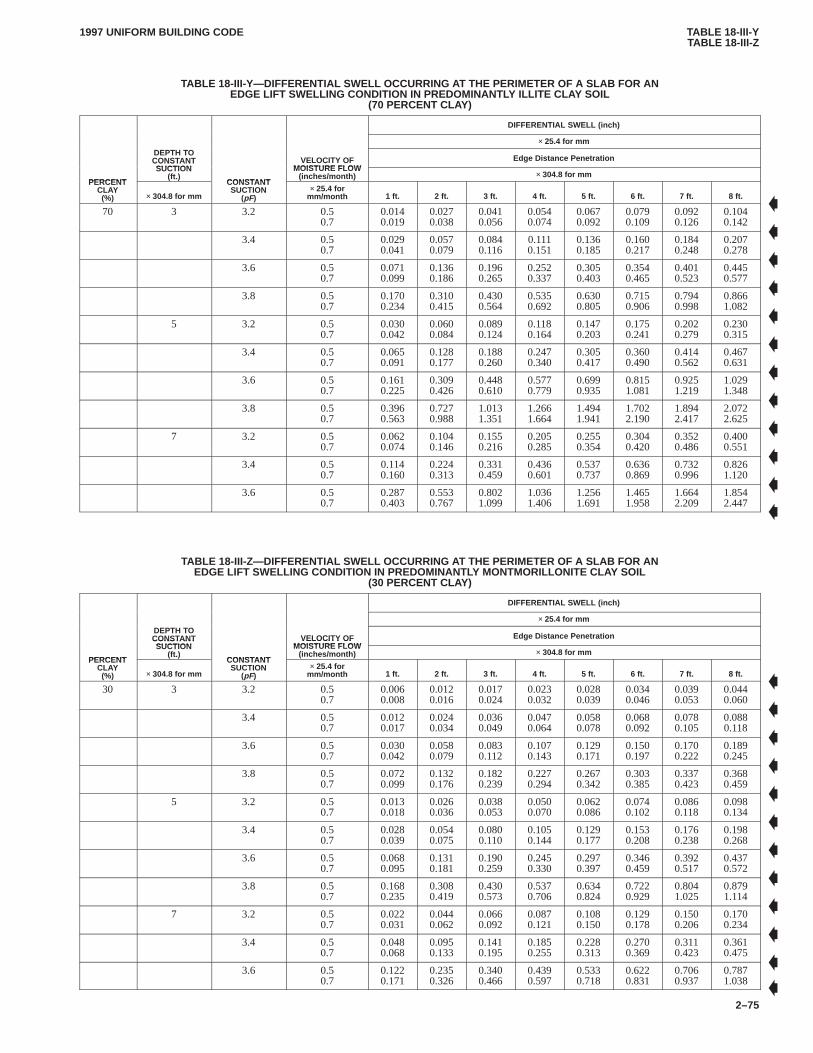
TABLE 18-III-YTABLE 18-III-Z
1997 UNIFORM BUILDING CODE
2–75
TABLE 18-III-Y—DIFFERENTIAL SWELL OCCURRING AT THE PERIMETER OF A SLAB FOR ANEDGE LIFT SWELLING CONDITION IN PREDOMINANTL Y ILLITE CLAY SOIL
(70 PERCENT CLAY)
DIFFERENTIAL SWELL (inch)
× 25.4 for mmDEPTH TOCONSTANTSUCTION
VELOCITY OFMOISTURE FLOW
Edge Distance Penetration
PERCENT
CONSTANTSUCTION
(ft.)CONSTANT
VELOCITY OFMOISTURE FLOW
(inches/month) × 304.8 for mmPERCENT
CLAY(%) × 304.8 for mm
CONSTANTSUCTION
(pF)× 25.4 for
mm/month 1 ft. 2 ft. 3 ft. 4 ft. 5 ft. 6 ft. 7 ft. 8 ft.
70 3 3.2 0.50.7
0.0140.019
0.0270.038
0.0410.056
0.0540.074
0.0670.092
0.0790.109
0.0920.126
0.1040.142
3.4 0.50.7
0.0290.041
0.0570.079
0.0840.116
0.1110.151
0.1360.185
0.1600.217
0.1840.248
0.2070.278
3.6 0.50.7
0.0710.099
0.1360.186
0.1960.265
0.2520.337
0.3050.403
0.3540.465
0.4010.523
0.4450.577
3.8 0.50.7
0.1700.234
0.3100.415
0.4300.564
0.5350.692
0.6300.805
0.7150.906
0.7940.998
0.8661.082
5 3.2 0.50.7
0.0300.042
0.0600.084
0.0890.124
0.1180.164
0.1470.203
0.1750.241
0.2020.279
0.2300.315
3.4 0.50.7
0.0650.091
0.1280.177
0.1880.260
0.2470.340
0.3050.417
0.3600.490
0.4140.562
0.4670.631
3.6 0.50.7
0.1610.225
0.3090.426
0.4480.610
0.5770.779
0.6990.935
0.8151.081
0.9251.219
1.0291.348
3.8 0.50.7
0.3960.563
0.7270.988
1.0131.351
1.2661.664
1.4941.941
1.7022.190
1.8942.417
2.0722.625
7 3.2 0.50.7
0.0620.074
0.1040.146
0.1550.216
0.2050.285
0.2550.354
0.3040.420
0.3520.486
0.4000.551
3.4 0.50.7
0.1140.160
0.2240.313
0.3310.459
0.4360.601
0.5370.737
0.6360.869
0.7320.996
0.8261.120
3.6 0.50.7
0.2870.403
0.5530.767
0.8021.099
1.0361.406
1.2561.691
1.4651.958
1.6642.209
1.8542.447
TABLE 18-III-Z—DIFFERENTIAL SWELL OCCURRING AT THE PERIMETER OF A SLAB FOR ANEDGE LIFT SWELLING CONDITION IN PREDOMINANTL Y MONTMORILLONITE CLAY SOIL
(30 PERCENT CLAY)
DIFFERENTIAL SWELL (inch)
× 25.4 for mmDEPTH TOCONSTANTSUCTION
VELOCITY OFMOISTURE FLOW
Edge Distance Penetration
PERCENT
CONSTANTSUCTION
(ft.)CONSTANT
VELOCITY OFMOISTURE FLOW
(inches/month) × 304.8 for mmPERCENT
CLAY(%) × 304.8 for mm
CONSTANTSUCTION
(pF)× 25.4 for
mm/month 1 ft. 2 ft. 3 ft. 4 ft. 5 ft. 6 ft. 7 ft. 8 ft.
30 3 3.2 0.50.7
0.0060.008
0.0120.016
0.0170.024
0.0230.032
0.0280.039
0.0340.046
0.0390.053
0.0440.060
3.4 0.50.7
0.0120.017
0.0240.034
0.0360.049
0.0470.064
0.0580.078
0.0680.092
0.0780.105
0.0880.118
3.6 0.50.7
0.0300.042
0.0580.079
0.0830.112
0.1070.143
0.1290.171
0.1500.197
0.1700.222
0.1890.245
3.8 0.50.7
0.0720.099
0.1320.176
0.1820.239
0.2270.294
0.2670.342
0.3030.385
0.3370.423
0.3680.459
5 3.2 0.50.7
0.0130.018
0.0260.036
0.0380.053
0.0500.070
0.0620.086
0.0740.102
0.0860.118
0.0980.134
3.4 0.50.7
0.0280.039
0.0540.075
0.0800.110
0.1050.144
0.1290.177
0.1530.208
0.1760.238
0.1980.268
3.6 0.50.7
0.0680.095
0.1310.181
0.1900.259
0.2450.330
0.2970.397
0.3460.459
0.3920.517
0.4370.572
3.8 0.50.7
0.1680.235
0.3080.419
0.4300.573
0.5370.706
0.6340.824
0.7220.929
0.8041.025
0.8791.114
7 3.2 0.50.7
0.0220.031
0.0440.062
0.0660.092
0.0870.121
0.1080.150
0.1290.178
0.1500.206
0.1700.234
3.4 0.50.7
0.0480.068
0.0950.133
0.1410.195
0.1850.255
0.2280.313
0.2700.369
0.3110.423
0.3610.475
3.6 0.50.7
0.1220.171
0.2350.326
0.3400.466
0.4390.597
0.5330.718
0.6220.831
0.7060.937
0.7871.038
�
�
�
�
�
�
�
�
�
�
�
�
�
�
�
�
�
�
�
�
�
�
�
�
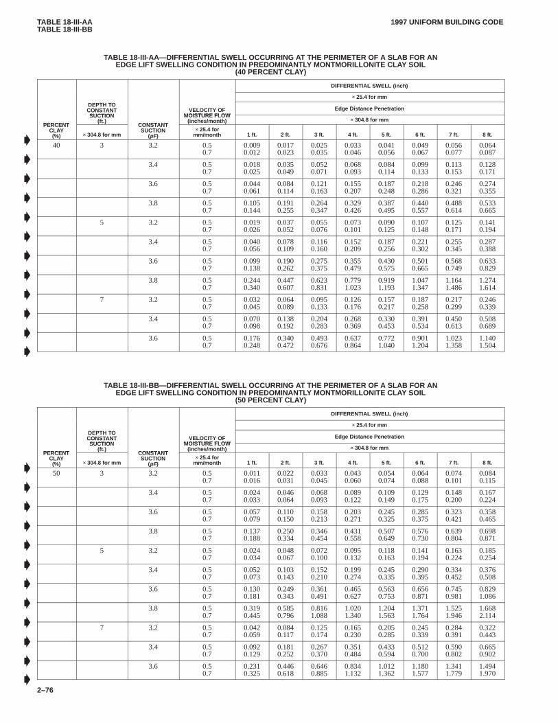
TABLE 18-III-AATABLE 18-III-BB
1997 UNIFORM BUILDING CODE
2–76
TABLE 18-III-AA—DIFFERENTIAL SWELL OCCURRING A T THE PERIMETER OF A SLAB FOR ANEDGE LIFT SWELLING CONDITION IN PREDOMINANTL Y MONTMORILLONITE CLAY SOIL
(40 PERCENT CLAY)
DIFFERENTIAL SWELL (inch)
× 25.4 for mmDEPTH TOCONSTANTSUCTION
VELOCITY OFMOISTURE FLOW
Edge Distance Penetration
PERCENT
CONSTANTSUCTION
(ft.)CONSTANT
VELOCITY OFMOISTURE FLOW
(inches/month) × 304.8 for mmPERCENT
CLAY(%) × 304.8 for mm
CONSTANTSUCTION
(pF)× 25.4 for
mm/month 1 ft. 2 ft. 3 ft. 4 ft. 5 ft. 6 ft. 7 ft. 8 ft.
40 3 3.2 0.50.7
0.0090.012
0.0170.023
0.0250.035
0.0330.046
0.0410.056
0.0490.067
0.0560.077
0.0640.087
3.4 0.50.7
0.0180.025
0.0350.049
0.0520.071
0.0680.093
0.0840.114
0.0990.133
0.1130.153
0.1280.171
3.6 0.50.7
0.0440.061
0.0840.114
0.1210.163
0.1550.207
0.1870.248
0.2180.286
0.2460.321
0.2740.355
3.8 0.50.7
0.1050.144
0.1910.255
0.2640.347
0.3290.426
0.3870.495
0.4400.557
0.4880.614
0.5330.665
5 3.2 0.50.7
0.0190.026
0.0370.052
0.0550.076
0.0730.101
0.0900.125
0.1070.148
0.1250.171
0.1410.194
3.4 0.50.7
0.0400.056
0.0780.109
0.1160.160
0.1520.209
0.1870.256
0.2210.302
0.2550.345
0.2870.388
3.6 0.50.7
0.0990.138
0.1900.262
0.2750.375
0.3550.479
0.4300.575
0.5010.665
0.5680.749
0.6330.829
3.8 0.50.7
0.2440.340
0.4470.607
0.6230.831
0.7791.023
0.9191.193
1.0471.347
1.1641.486
1.2741.614
7 3.2 0.50.7
0.0320.045
0.0640.089
0.0950.133
0.1260.176
0.1570.217
0.1870.258
0.2170.299
0.2460.339
3.4 0.50.7
0.0700.098
0.1380.192
0.2040.283
0.2680.369
0.3300.453
0.3910.534
0.4500.613
0.5080.689
3.6 0.50.7
0.1760.248
0.3400.472
0.4930.676
0.6370.864
0.7721.040
0.9011.204
1.0231.358
1.1401.504
TABLE 18-III-BB—DIFFERENTIAL SWELL OCCURRING AT THE PERIMETER OF A SLAB FOR ANEDGE LIFT SWELLING CONDITION IN PREDOMINANTL Y MONTMORILLONITE CLAY SOIL
(50 PERCENT CLAY)
DIFFERENTIAL SWELL (inch)
× 25.4 for mmDEPTH TOCONSTANTSUCTION
VELOCITY OFMOISTURE FLOW
Edge Distance Penetration
PERCENT
CONSTANTSUCTION
(ft.)CONSTANT
VELOCITY OFMOISTURE FLOW
(inches/month) × 304.8 for mmPERCENT
CLAY(%) × 304.8 for mm
CONSTANTSUCTION
(pF)× 25.4 for
mm/month 1 ft. 2 ft. 3 ft. 4 ft. 5 ft. 6 ft. 7 ft. 8 ft.
50 3 3.2 0.50.7
0.0110.016
0.0220.031
0.0330.045
0.0430.060
0.0540.074
0.0640.088
0.0740.101
0.0840.115
3.4 0.50.7
0.0240.033
0.0460.064
0.0680.093
0.0890.122
0.1090.149
0.1290.175
0.1480.200
0.1670.224
3.6 0.50.7
0.0570.079
0.1100.150
0.1580.213
0.2030.271
0.2450.325
0.2850.375
0.3230.421
0.3580.465
3.8 0.50.7
0.1370.188
0.2500.334
0.3460.454
0.4310.558
0.5070.649
0.5760.730
0.6390.804
0.6980.871
5 3.2 0.50.7
0.0240.034
0.0480.067
0.0720.100
0.0950.132
0.1180.163
0.1410.194
0.1630.224
0.1850.254
3.4 0.50.7
0.0520.073
0.1030.143
0.1520.210
0.1990.274
0.2450.335
0.2900.395
0.3340.452
0.3760.508
3.6 0.50.7
0.1300.181
0.2490.343
0.3610.491
0.4650.627
0.5630.753
0.6560.871
0.7450.981
0.8291.086
3.8 0.50.7
0.3190.445
0.5850.796
0.8161.088
1.0201.340
1.2041.563
1.3711.764
1.5251.946
1.6682.114
7 3.2 0.50.7
0.0420.059
0.0840.117
0.1250.174
0.1650.230
0.2050.285
0.2450.339
0.2840.391
0.3220.443
3.4 0.50.7
0.0920.129
0.1810.252
0.2670.370
0.3510.484
0.4330.594
0.5120.700
0.5900.802
0.6650.902
3.6 0.50.7
0.2310.325
0.4460.618
0.6460.885
0.8341.132
1.0121.362
1.1801.577
1.3411.779
1.4941.970
�
�
�
�
�
�
�
�
�
�
�
�
�
�
�
�
�
�
�
�
�
�
�
�

TABLE 18-III-CCTABLE 18-III-DD
1997 UNIFORM BUILDING CODE
2–77
TABLE 18-III-CC—DIFFERENTIAL SWELL OCCURRING A T THE PERIMETER OF A SLAB FOR ANEDGE LIFT SWELLING CONDITION IN PREDOMINANTL Y MONTMORILLONITE CLAY SOIL
(60 PERCENT CLAY)
DIFFERENTIAL SWELL (inch)
× 25.4 for mmDEPTH TOCONSTANTSUCTION
VELOCITY OFMOISTURE FLOW
Edge Distance Penetration
PERCENT
CONSTANTSUCTION
(ft.)CONSTANT
VELOCITY OFMOISTURE FLOW
(inches/month) × 304.8 for mmPERCENT
CLAY(%) × 304.8 for mm
CONSTANTSUCTION
(pF)× 25.4 for
mm/month 1 ft. 2 ft. 3 ft. 4 ft. 5 ft. 6 ft. 7 ft. 8 ft.
60 3 3.2 0.50.7
0.0140.019
0.0270.038
0.0410.056
0.0540.074
0.0660.091
0.0790.109
0.0910.125
0.1040.142
3.4 0.50.7
0.0290.041
0.0570.079
0.0840.116
0.1100.151
0.1350.184
0.1600.216
0.1830.247
0.2060.277
3.6 0.50.7
0.0710.098
0.1360.186
0.1950.264
0.2510.336
0.3030.402
0.3520.463
0.3990.521
0.4330.575
3.8 0.50.7
0.1690.233
0.3090.413
0.4280.562
0.5330.690
0.6270.802
0.7120.903
0.7900.994
0.8631.077
5 3.2 0.50.7
0.0300.042
0.0600.083
0.0900.124
0.1180.163
0.1460.202
0.1740.240
0.2020.278
0.2290.314
3.4 0.50.7
0.0650.090
0.1270.177
0.1880.259
0.2460.339
0.3030.415
0.3590.488
0.4130.559
0.4650.628
3.6 0.50.7
0.1600.224
0.3080.425
0.4460.607
0.5750.775
0.6970.931
0.8121.077
0.9211.214
1.0251.343
3.8 0.50.7
0.3950.551
0.7240.984
1.0091.345
1.2611.657
1.4881.933
1.6952.181
1.8862.407
2.0632.614
7 3.2 0.50.7
0.0520.073
0.1040.145
0.1550.215
0.2050.284
0.2540.352
0.3030.419
0.3510.484
0.3980.548
3.4 0.50.7
0.1130.159
0.2230.311
0.3300.458
0.4340.598
0.5350.734
0.6330.865
0.7290.992
0.8231.115
3.6 0.50.7
0.2860.402
0.5510.764
0.7991.095
1.0311.400
1.2511.684
1.4591.950
1.6582.200
1.8472.437
TABLE 18-III-DD—DIFFERENTIAL SWELL OCCURRING AT THE PERIMETER OF A SLAB FOR ANEDGE LIFT SWELLING CONDITION IN PREDOMINANTL Y MONTMORILLONITE CLAY SOIL
(70 PERCENT CLAY)
DIFFERENTIAL SWELL (inch)
× 25.4 for mmDEPTH TOCONSTANTSUCTION
VELOCITY OFMOISTURE FLOW
Edge Distance Penetration
PERCENT
CONSTANTSUCTION
(ft.)CONSTANT
VELOCITY OFMOISTURE FLOW
(inches/month) × 304.8 for mmPERCENT
CLAY(%) × 304.8 for mm
CONSTANTSUCTION
(pF)× 25.4 for
mm/month 1 ft. 2 ft. 3 ft. 4 ft. 5 ft. 6 ft. 7 ft. 8 ft.
70 3 3.2 0.50.7
0.0160.023
0.0320.045
0.0480.067
0.0640.088
0.0790.109
0.0940.129
0.1090.149
0.1230.169
3.4 0.50.7
0.0350.048
0.0680.094
0.1000.138
0.1310.179
0.1610.219
0.1900.258
0.2190.294
0.2460.330
3.6 0.50.7
0.0840.117
0.1620.221
0.2330.314
0.2990.400
0.3610.479
0.4200.552
0.4750.620
0.5280.684
3.8 0.50.7
0.2020.277
0.3680.492
0.5100.669
0.6350.822
0.7470.955
0.8491.075
0.9421.184
1.0281.284
5 3.2 0.50.7
0.0360.050
0.0710.099
0.1060.147
0.1400.195
0.1740.241
0.2070.286
0.2400.331
0.2730.374
3.4 0.50.7
0.0770.108
0.1510.210
0.2230.309
0.2930.403
0.3610.494
0.4270.582
0.4920.666
0.5540.748
3.6 0.50.7
0.1910.267
0.3670.506
0.5310.724
0.6850.924
0.8301.110
0.9671.283
1.0971.446
1.2211.600
3.8 0.50.7
0.4700.656
0.8621.172
1.2621.603
1.5021.974
1.7732.303
2.0202.598
2.2472.867
2.4583.114
7 3.2 0.50.7
0.0620.087
0.1240.173
0.1840.256
0.2440.339
0.3030.419
0.3610.499
0.4180.577
0.4750.653
3.4 0.50.7
0.1350.189
0.2660.371
0.3930.545
0.5170.713
0.6370.875
0.7541.031
0.8691.182
0.9801.329
3.6 0.50.7
0.3410.479
0.6560.910
0.9511.304
1.2291.668
1.4902.006
1.7392.323
1.9752.621
2.2002.903
�
�
�
�
�
�
�
�
�
�
�
�
�
�
�
�
�
�
�
�
�
�
�
�
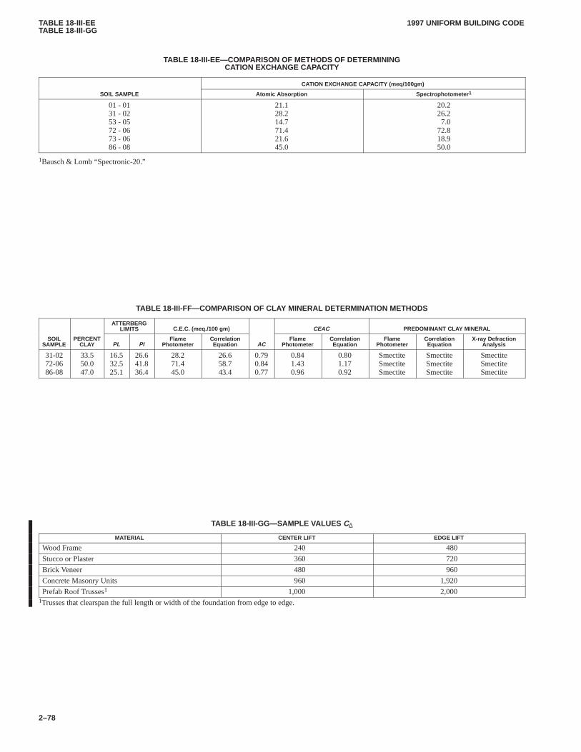
TABLE 18-III-EETABLE 18-III-GG
1997 UNIFORM BUILDING CODE
2–78
TABLE 18-III-EE—COMPARISON OF METHODS OF DETERMININGCATION EXCHANGE CAPACITY
CATION EXCHANGE CAPACITY (meq/100gm)
SOIL SAMPLE Atomic Absorption Spectrophotometer 1
01 - 0131 - 0253 - 0572 - 0673 - 0686 - 08
21.128.214.771.421.645.0
20.226.27.0
72.818.950.0
1Bausch & Lomb “Spectronic-20.”
TABLE 18-III-FF—COMPARISON OF CLAY MINERAL DETERMINATION METHODS
ATTERBERGLIMITS C.E.C. (meq./100 gm) CEAC PREDOMINANT CLAY MINERAL
SOILSAMPLE
PERCENTCLAY PL PI
FlamePhotometer
CorrelationEquation AC
FlamePhotometer
CorrelationEquation
FlamePhotometer
CorrelationEquation
X-ray DefractionAnalysis
31-0272-0686-08
33.550.047.0
16.532.525.1
26.641.836.4
28.271.445.0
26.658.743.4
0.790.840.77
0.841.430.96
0.801.170.92
SmectiteSmectiteSmectite
SmectiteSmectiteSmectite
SmectiteSmectiteSmectite
TABLE 18-III-GG—SAMPLE VALUES C∆
MATERIAL CENTER LIFT EDGE LIFT
Wood Frame 240 480
Stucco or Plaster 360 720
Brick Veneer 480 960
Concrete Masonry Units 960 1,920
Prefab Roof Trusses1 1,000 2,0001Trusses that clearspan the full length or width of the foundation from edge to edge.
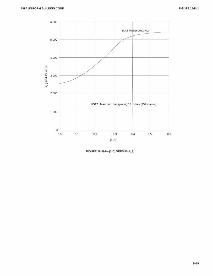
FIGURE 18-III-1FIGURE 18-III-1
1997 UNIFORM BUILDING CODE
2–79
0.1 0.2 0.3 0.4 0.5 0.6
NOTE: Maximum bar spacing 18 inches (457 mm) o.c.
SLAB REINFORCING
6,000
5,000
4,000
3,000
2,000
1,000
00.0
(1-C)
A sf y
(×
4.45
for
N)
FIGURE 18-III-1—(1-C) VERSUS As fy
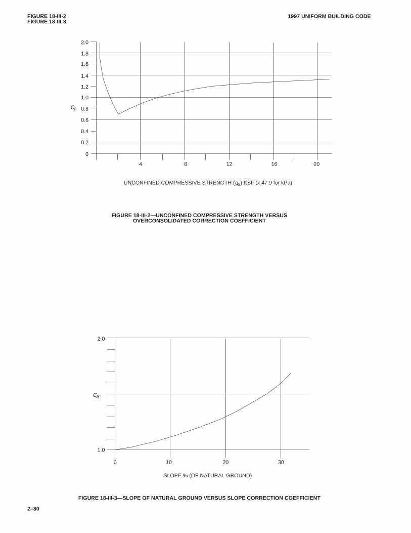
FIGURE 18-III-2FIGURE 18-III-3
1997 UNIFORM BUILDING CODE
2–80
UNCONFINED COMPRESSIVE STRENGTH (qu) KSF (x 47.9 for kPa)
4 8 12 16 20
2.0
Co
1.8
1.6
1.4
1.2
1.0
0.8
0.6
0.4
0.2
0
FIGURE 18-III-2—UNCONFINED COMPRESSIVE STRENGTH VERSUSOVERCONSOLIDATED CORRECTION COEFFICIENT
SLOPE % (OF NATURAL GROUND)
0 10 20 30
CS
2.0
1.0
FIGURE 18-III-3—SLOPE OF NATURAL GROUND VERSUS SLOPE CORRECTION COEFFICIENT
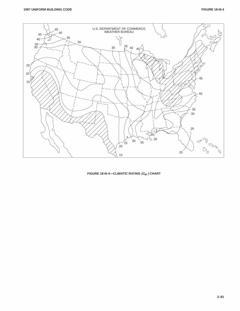
FIGURE 18-III-4FIGURE 18-III-4
1997 UNIFORM BUILDING CODE
2–81
U.S. DEPARTMENT OF COMMERCEWEATHER BUREAU
15
2025
30 3530
35
25
25
3035
40
45
403530 45
30
3035
35
4045
40
45
25
20
15
FIGURE 18-III-4—CLIMATIC RATING (CW ) CHART
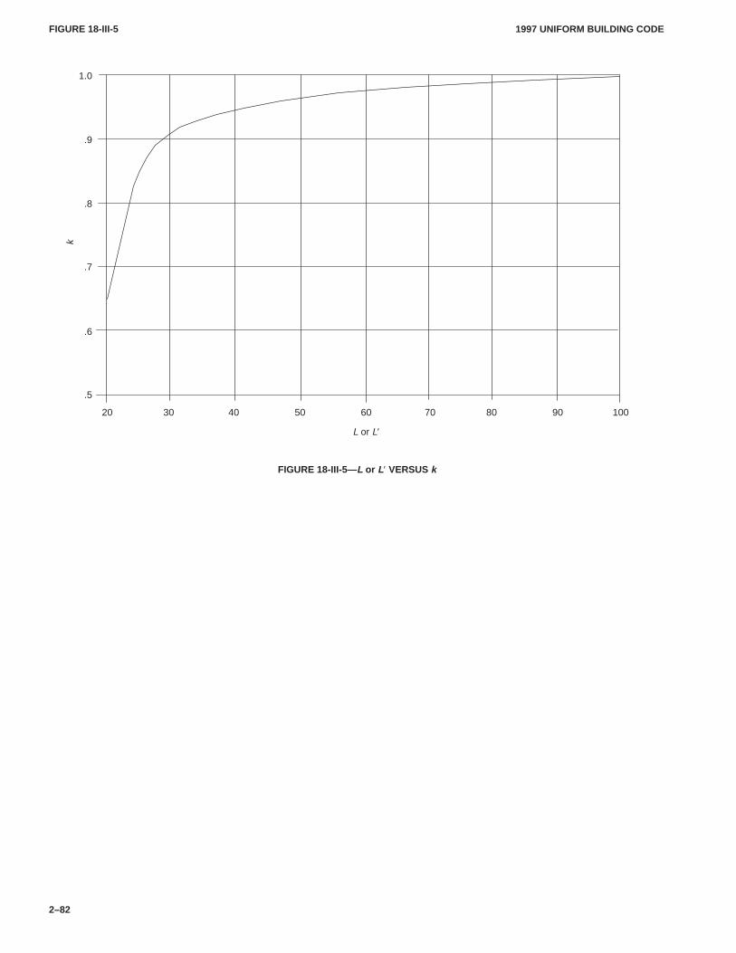
FIGURE 18-III-5FIGURE 18-III-5
1997 UNIFORM BUILDING CODE
2–82
20 30 40 50 60 70 80 90 100
1.0
.9
.8
.7
.6
.5
L or L′
k
FIGURE 18-III-5—L or L′ VERSUS k
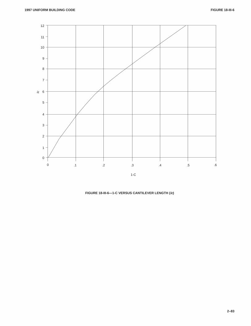
FIGURE 18-III-6FIGURE 18-III-6
1997 UNIFORM BUILDING CODE
2–83
.1
1-C
.2 .3 .4 .5 .60
12
11
10
9
8
7
6
5
4
3
2
1
0
Ic
FIGURE 18-III-6—1-C VERSUS CANTILEVER LENGTH ( lc)
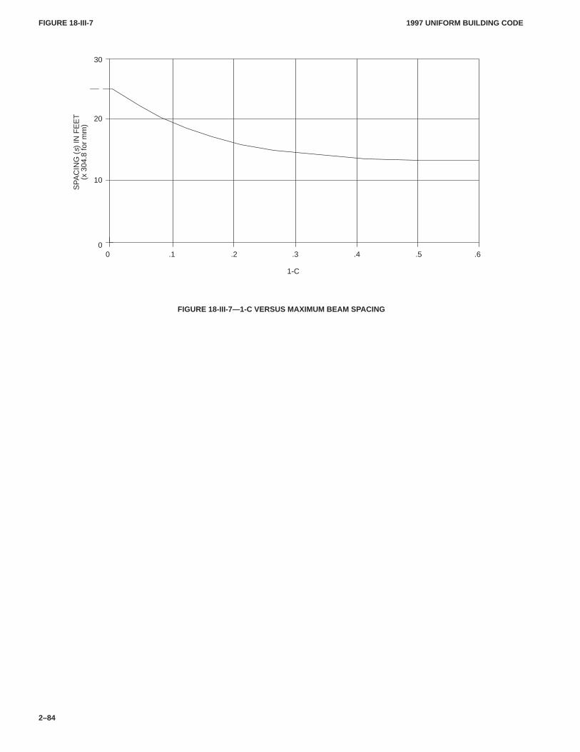
FIGURE 18-III-7FIGURE 18-III-7
1997 UNIFORM BUILDING CODE
2–84
.1
1-C
.2 .3 .4 .5 .6
20
SP
AC
ING
(s)
IN F
EE
T(x
304
.8 fo
r m
m)
30
10
00
FIGURE 18-III-7—1-C VERSUS MAXIMUM BEAM SPACING
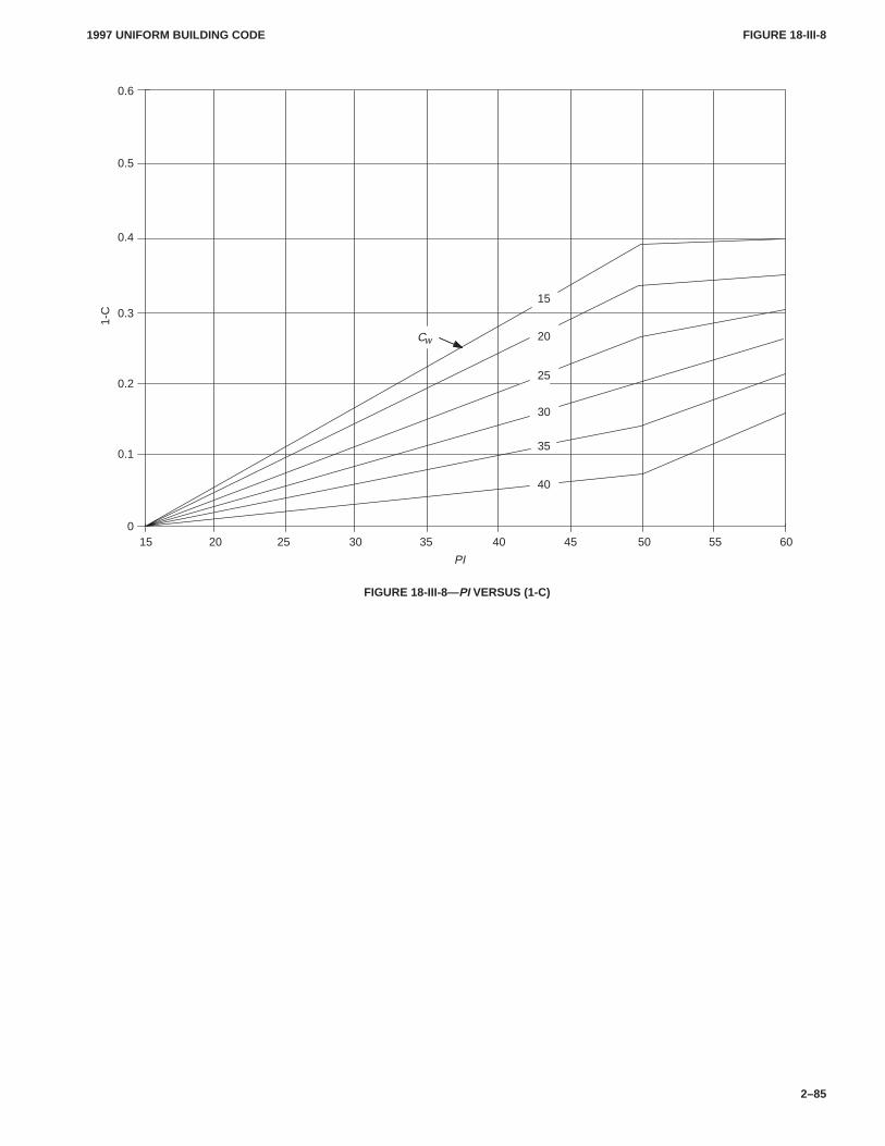
FIGURE 18-III-8FIGURE 18-III-8
1997 UNIFORM BUILDING CODE
2–85
15 20 25 30 35 40 45 50 55 60
0.5
Cw
40
35
30
25
20
15
PI
1-C
0.6
0.4
0.3
0.2
0.1
0
FIGURE 18-III-8—PI VERSUS (1-C)
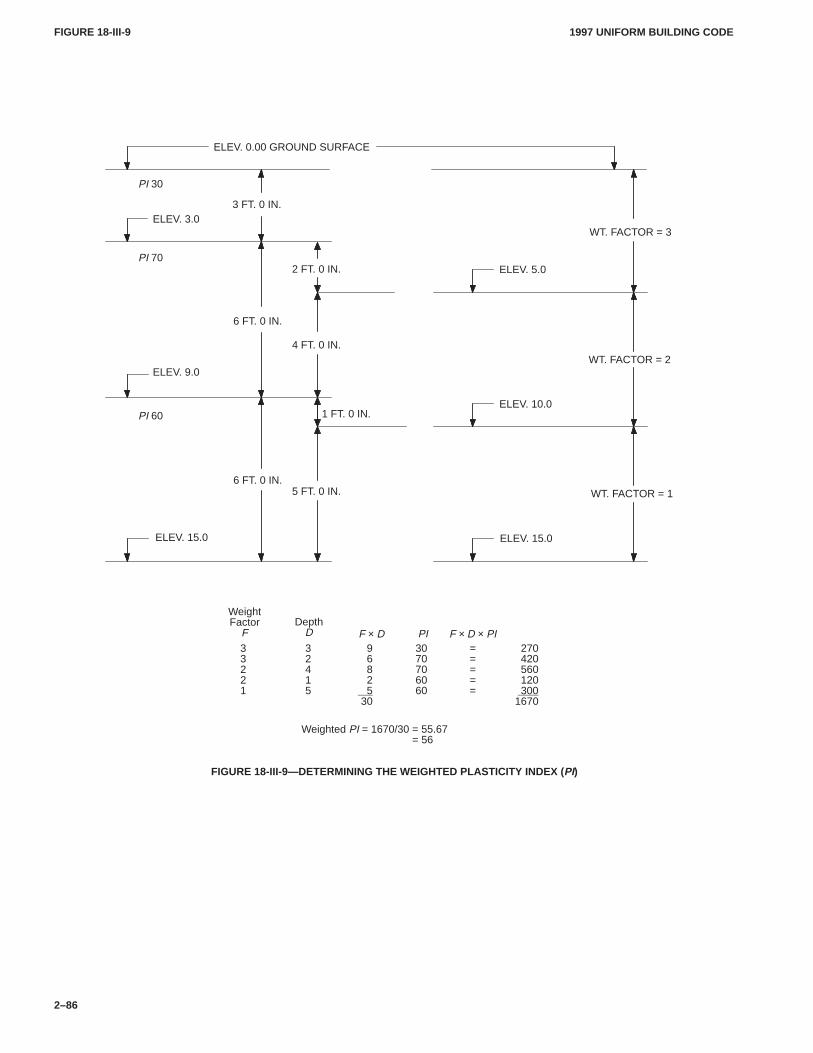
FIGURE 18-III-9FIGURE 18-III-9
1997 UNIFORM BUILDING CODE
2–86
33221
32415
9682
530
3070706060
=====
270420560120
3001670
Weighted PI = 1670/30 = 55.67= 56.67
PI 60
PI 70
PI 30
ELEV. 3.0
ELEV. 15.0
ELEV. 9.0
ELEV. 0.00 GROUND SURFACE
WT. FACTOR = 3
WT. FACTOR = 2
WT. FACTOR = 1
ELEV. 5.0
ELEV. 15.0
ELEV. 10.0
3 FT. 0 IN.
6 FT. 0 IN.
4 FT. 0 IN.
5 FT. 0 IN.
2 FT. 0 IN.
1 FT. 0 IN.
WeightFactor
FDepth
D F × D PI F × D × PI
6 FT. 0 IN.
FIGURE 18-III-9—DETERMINING THE WEIGHTED PLASTICITY INDEX (PI)
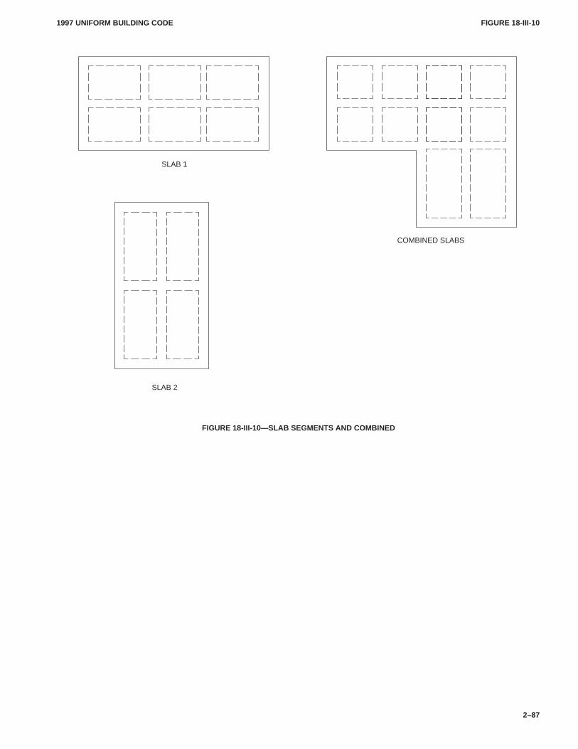
FIGURE 18-III-10FIGURE 18-III-10
1997 UNIFORM BUILDING CODE
2–87
SLAB 1
SLAB 2
COMBINED SLABS
FIGURE 18-III-10—SLAB SEGMENTS AND COMBINED
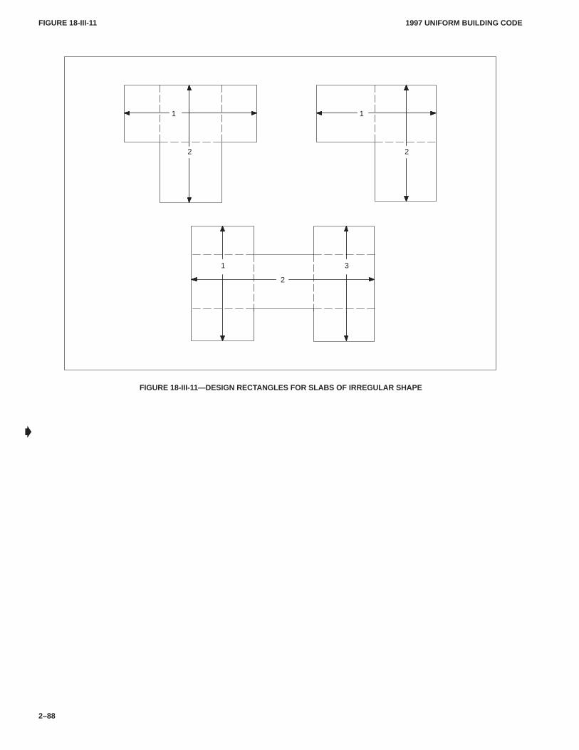
FIGURE 18-III-11FIGURE 18-III-11
1997 UNIFORM BUILDING CODE
2–88
2
11
2
2
1 3
FIGURE 18-III-11—DESIGN RECTANGLES FOR SLABS OF IRREGULAR SHAPE
�
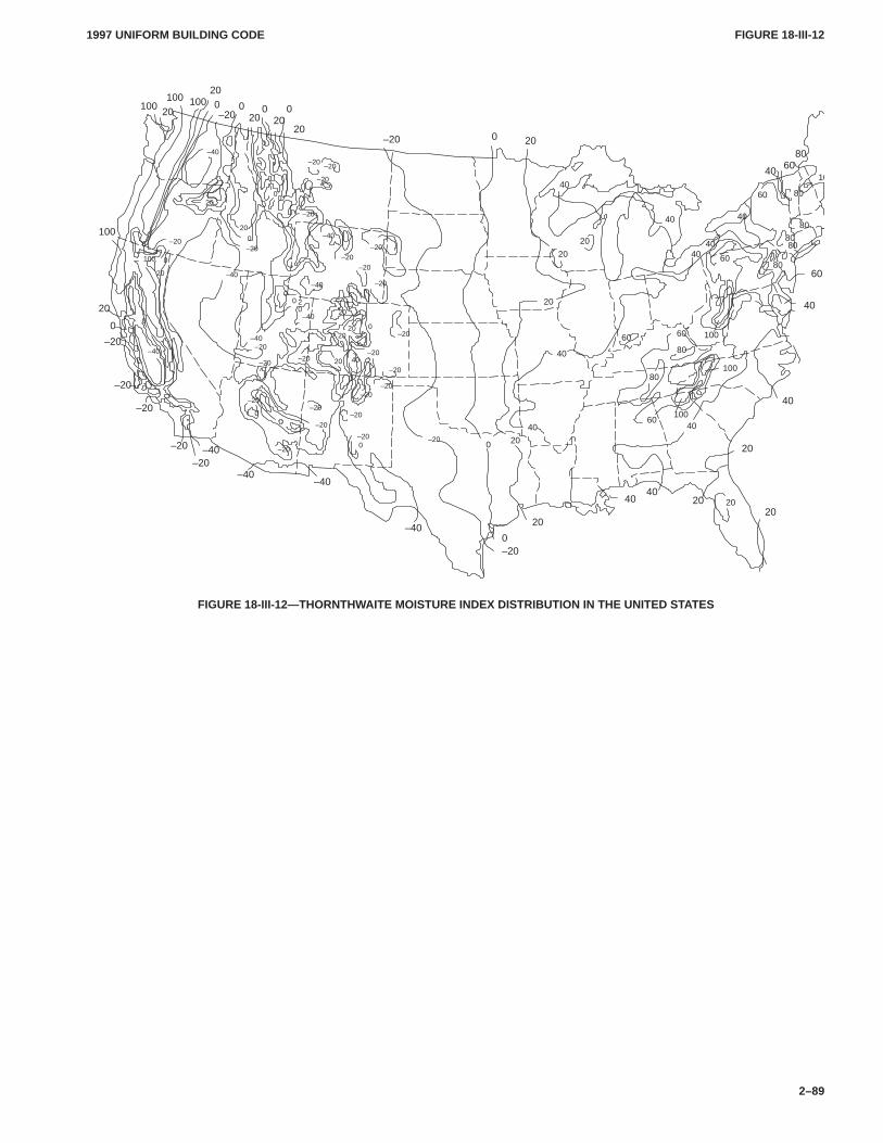
FIGURE 18-III-12FIGURE 18-III-12
1997 UNIFORM BUILDING CODE
2–89
–20
20
–40
–40
–40
–40 20
–20
–20
–20
–20
–20
20
0
100
0
–2020
20200 0 020
200
20–20
100100
100
40
806040
40
20
2020
4040
20
20
40
40
40
0
40
20
4060
80
80
100
40
10
40
40
60
60
100
–20
–20
–20–20
–20
–20
–20–20
20
–40
–40
–40
–40
–40
20
–20–20
20
20
0
00
40
–20
–20
–20
–20
00
–20
–20
0
20
0–40
0
20
–40
0
100
0
–20
–20
–20
0
–200
–20
–20
0
20 020
–20
–20
–20
20
60 60 100
8080
8060
80
80
FIGURE 18-III-12—THORNTHWAITE MOISTURE INDEX DISTRIBUTION IN THE UNITED STATES
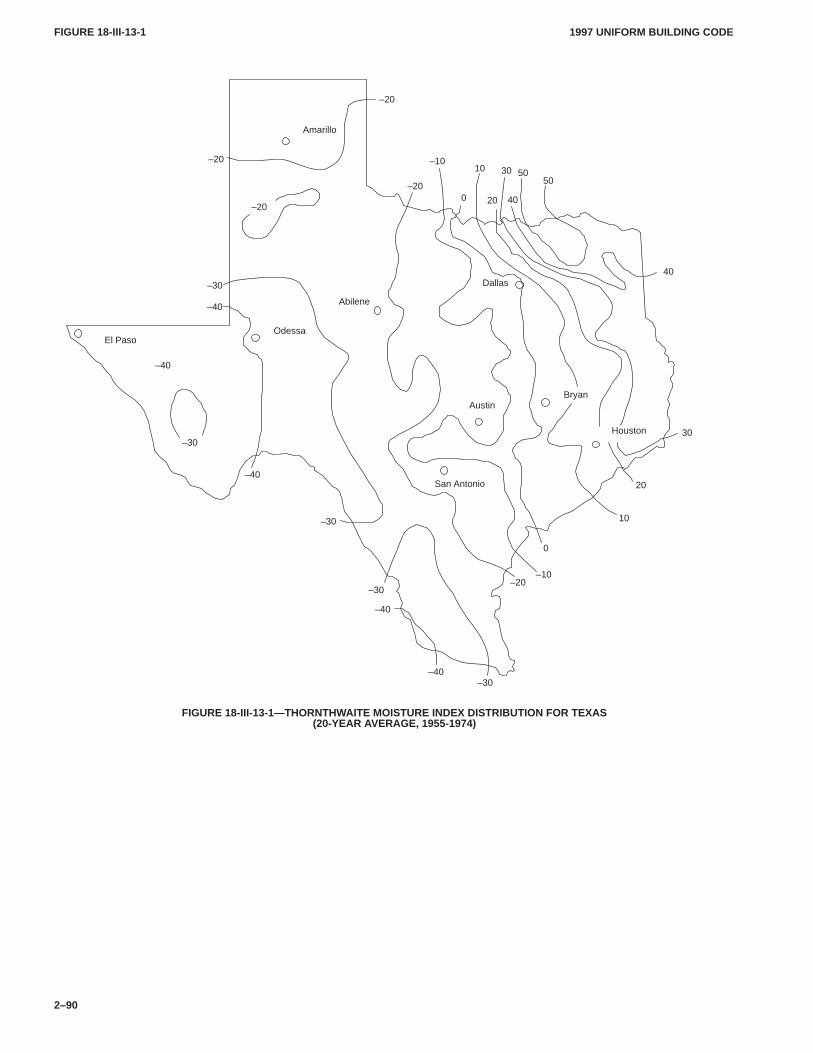
FIGURE 18-III-13-1FIGURE 18-III-13-1
1997 UNIFORM BUILDING CODE
2–90
–30
San Antonio
El PasoOdessa
Dallas
Houston
BryanAustin
Abilene
Amarillo
–40
–40
–40
–40
–30
–30
20
10
0
–10–20
–30
–30
–40
–20
0
–10
–20
–20
10 30 5050
20 40
30
40
–20
FIGURE 18-III-13-1—THORNTHWAITE MOISTURE INDEX DISTRIBUTION FOR TEXAS(20-YEAR AVERAGE, 1955-1974)
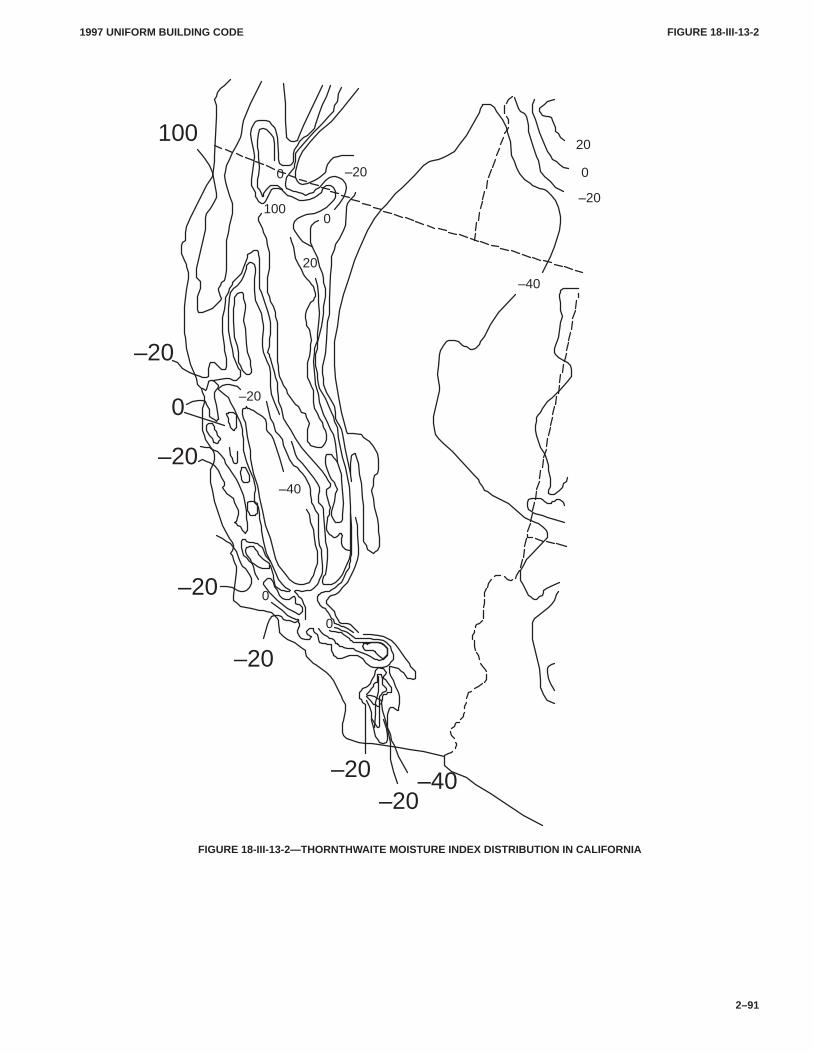
FIGURE 18-III-13-2FIGURE 18-III-13-2
1997 UNIFORM BUILDING CODE
2–91
0
–20
–20
–20–40
0
–20
–20
–20
0
20
0
–20
0
0
100
–20
–40
100
20
–20
–40
FIGURE 18-III-13-2—THORNTHWAITE MOISTURE INDEX DISTRIBUTION IN CALIFORNIA
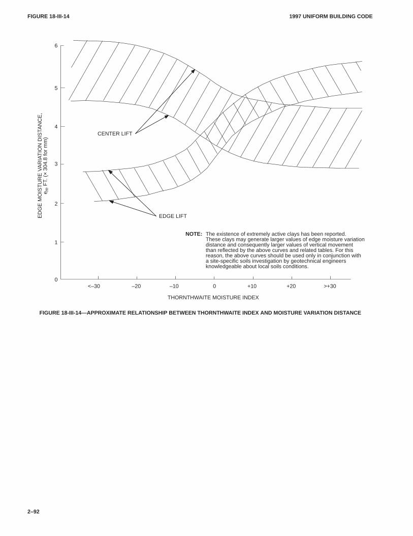
FIGURE 18-III-14FIGURE 18-III-14
1997 UNIFORM BUILDING CODE
2–92
<–30
THORNTHWAITE MOISTURE INDEX
NOTE: The existence of extremely active clays has been reported.These clays may generate larger values of edge moisture variationdistance and consequently larger values of vertical movementthan reflected by the above curves and related tables. For thisreason, the above curves should be used only in conjunction witha site-specific soils investigation by geotechnical engineersknowledgeable about local soils conditions.
–20 –10 0 +10 +20 >+30
6
EDGE LIFT
CENTER LIFT
5
4
3
2
1
0
ED
GE
MO
IST
UR
E V
AR
IAT
ION
DIS
TAN
CE
,e m
FT.
(×
304.
8 fo
r m
m)
FIGURE 18-III-14—APPROXIMATE RELATIONSHIP BETWEEN THORNTHWAITE INDEX AND MOISTURE VARIATION DISTANCE
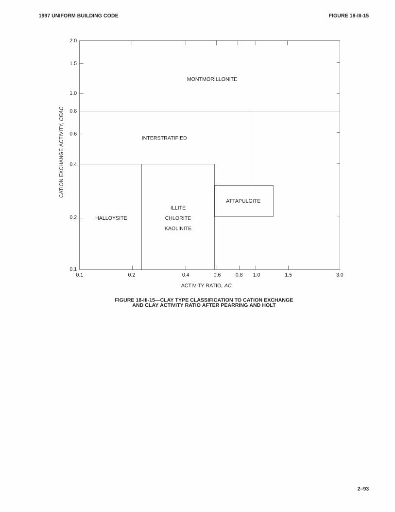
FIGURE 18-III-15FIGURE 18-III-15
1997 UNIFORM BUILDING CODE
2–93
0.1 0.2 0.4 0.6 0.8 1.0 1.5 3.0
2.0
INTERSTRATIFIED
ATTAPULGITEILLITE
CHLORITE
KAOLINITE
HALLOYSITE
MONTMORILLONITE
ACTIVITY RATIO, AC
CA
TIO
N E
XC
HA
NG
E A
CT
IVIT
Y, C
EA
C1.5
1.0
0.8
0.6
0.2
0.1
0.4
FIGURE 18-III-15—CLAY TYPE CLASSIFICATION T O CATION EXCHANGEAND CLAY ACTIVITY RATIO AFTER PEARRING AND HOL T
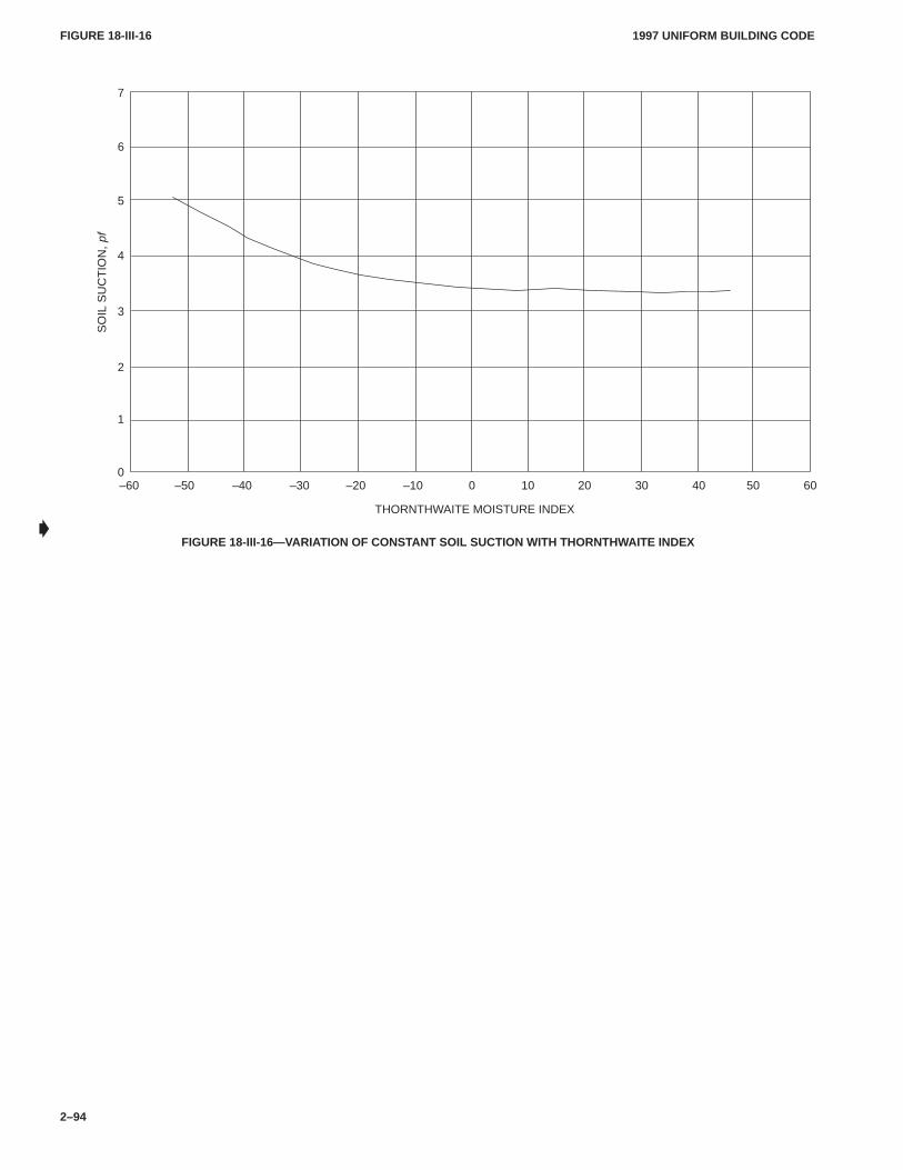
FIGURE 18-III-16FIGURE 18-III-16
1997 UNIFORM BUILDING CODE
2–94
–60 –50 –40 –30 –20 –10 0 10 20 30 40 50 60
THORNTHWAITE MOISTURE INDEX
7
6
5
4
3
2
1
0
SO
IL S
UC
TIO
N, p
f
FIGURE 18-III-16—VARIATION OF CONSTANT SOIL SUCTION WITH THORNTHWAITE INDEX�
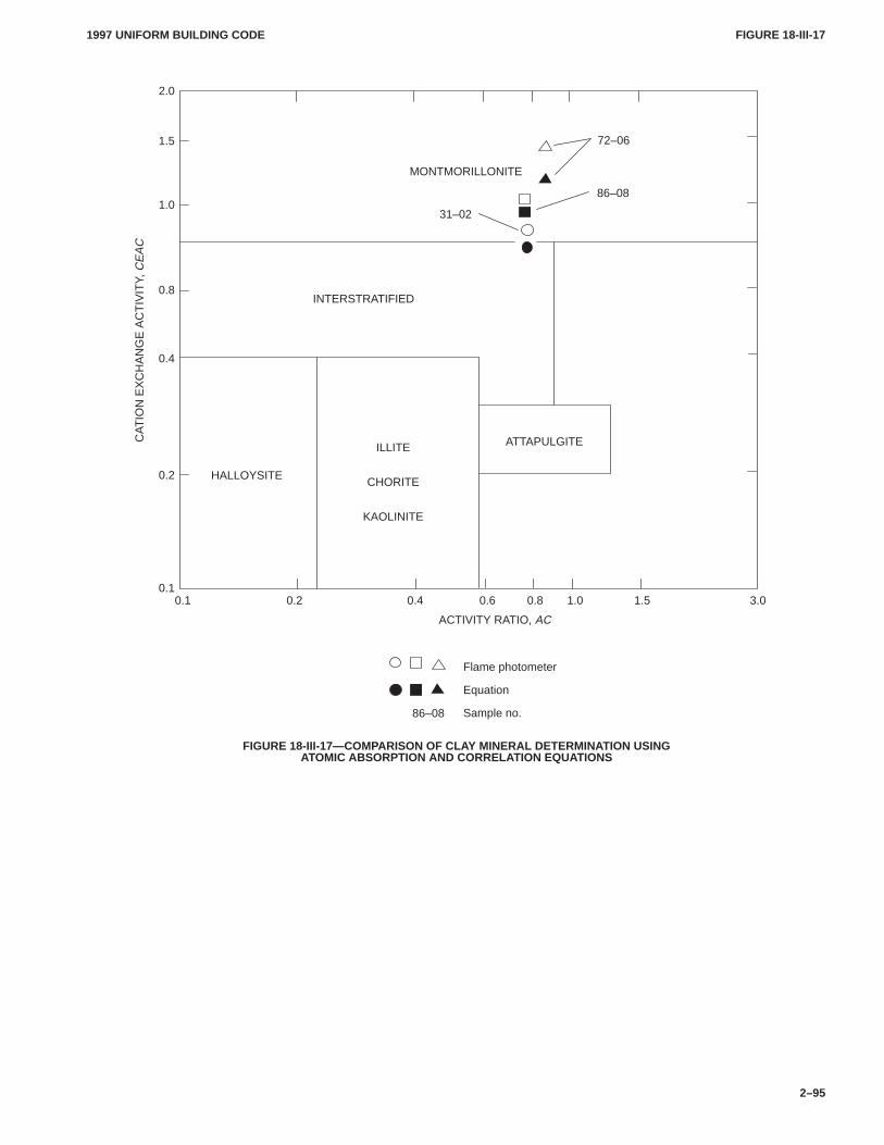
FIGURE 18-III-17FIGURE 18-III-17
1997 UNIFORM BUILDING CODE
2–95
0.1 0.2 0.4 0.6 0.8 1.0 1.5 3.0
2.0
INTERSTRATIFIED
ATTAPULGITEILLITE
CHORITE
KAOLINITE
HALLOYSITE
MONTMORILLONITE
31–02
86–08
72–06
Flame photometer
Equation
Sample no.86–08
ACTIVITY RATIO, AC
CA
TIO
N E
XC
HA
NG
E A
CT
IVIT
Y, C
EA
C1.5
1.0
0.8
0.4
0.2
0.1
FIGURE 18-III-17—COMPARISON OF CLAY MINERAL DETERMINATION USINGATOMIC ABSORPTION AND CORRELATION EQUATIONS
1997 UNIFORM BUILDING CODE STANDARD 18-1
3–327
UNIFORM BUILDING CODE STANDARD 18-1
SOILS CLASSIFICATIONBased on Standard Method D 2487-69 of the American Society for Testing and Materials.
Extracted, with permission, from the Annual Book of ASTM Standards, copyright American Society forTesting and Materials, 100 Barr Harbor Drive, West Conshohocken, P A 19428
See Sections 1801.2 and 1803.1, Uniform Building Code
SECTION 18.101 — SCOPE
This standard describes a system for classifying mineral and or-ganomineral soils for engineering purposes based on laboratorydetermination of particle-size characteristics, liquid limit andplasticity index.
SECTION 18.102 — APPARATUS
Apparatus of an approved type shall be used to perform the fol-lowing tests and procedures: Preparation of soil samples, liquidlimit test, plastic limit test and particle-size analysis.
SECTION 18.103 — SAMPLING
Sampling shall be conducted in accordance with approved meth-ods for soil investigation and sampling by auger borings, for Pene-tration Test and Split-barrel Sampling of Soils, and forThin-walled Tube Sampling of Soils.
The sample shall be carefully identified as to origin by a boringnumber and sample number in conjunction with a job number, ageologic stratum, a pedologic horizon or a location descriptionwith respect to a permanent monument, a grid system or a stationnumber and offset with respect to a stated center line.
The sample should also be described in accordance with an ap-proved visual-manual procedure. (A soil which is composed pri-marily of undecayed or partially decayed organic matter and has afibrous texture, dark brown to black color, and organic odorshould be designated as a highly organic soil, PT, and not sub-jected to the classification procedures described hereafter.)
SECTION 18.104 — TEST SAMPLE
Test samples shall represent that portion of the field sample finerthan the 3-inch (76 mm) sieve and shall be obtained as follows:
Air dry the field sample; weigh the field sample; and separatethe field sample into two fractions on a 3-inch (76 mm) sieve.Weigh the fraction retained on the 3-inch (76 mm) sieve. Computethe percentage of plus 3-inch (76 mm) material in the field sampleand note this percentage as auxiliary information. Thoroughlymix the fraction passing the 3-inch (76 mm) sieve and select testsamples.
SECTION 18.105 — PRELIMINARY CLASSIFICATIONPROCEDURE
Procedure for the determination of percentage finer than the No.200 (75 µm) sieve is as follows:
1. From the material passing the 3-inch (76 mm) sieve, select atest sample and determine the percentage of the test sample finerthan the No. 200 (75 µm) sieve. (This step may be omitted if thesoil can obviously be classified as fine-grained by visual inspec-tion.)
2. Classify the soil as coarse-grained if more than 50 percent ofthe test sample is retained on the No. 200 (75 µm) sieve.
3. Classify the soil as fine-grained if 50 percent or more of thetest sample passes the No. 200 (75 µm) sieve.
SECTION 18.106 — PROCEDURE FORCLASSIFICATION OF COARSE-GRAINED SOILS(MORE THAN 50 PERCENT RETAINED)
Select test samples from the material passing the 3-inch (76 mm)sieve for the determination of particle-size characteristics, liquidlimit and plasticity index. Determine the cumulative particle-sizedistribution of the fraction coarser than the No. 200 (75 µm) sieve.
Classify the sample as gravel, G, if 50 percent or more of thecoarse fraction [plus No. 200 (75 µm) sieve] is retained on the No.4 (4.75 mm) sieve. Classify the sample as sand, S, if more than 50percent of the coarse fraction [plus No. 200 (75 µm) sieve] passesthe No. 4 (75 mm) sieve.
If less than 5 percent of the test sample passed the No. 200 (75µm) sieve, compute the coefficient of uniformity, Cu, and coeffi-cient of curvature, Cz, as given in Formulas 18-1-1 and 18-1-2:
Cu �D60
D10(18-1-1)
Cz �(D30)2
D10� D60(18-1-2)
in which D10, D30 and D60 are the particle size diameters corre-sponding respectively to 10, 30 and 60 percent passing on the cu-mulative particle size distribution curve.
Classify the sample as well-graded gravel, GW, or well-gradedsand, SW, if Cu is greater than 4 for gravel and 6 for sand, and Cz isbetween 1 and 3. Classify the sample as poorly graded gravel, GP,or poorly graded sand, SP, if either the Cu or the Cz criteria forwell-graded soils are not satisfied.
If more than 12 percent of the test sample passed the No. 200 (75µm) sieve, determine the liquid limit and the plasticity index of aportion of the test sample passing the No. 40 (425 µm) sieve in ac-cordance with approved methods.
Classify the sample as silty gravel, GM, or silty sand, SM, if theresults of the limits tests show that the fines are silty, that is, theplot of the liquid limit versus plasticity index falls below the “A”line (see Plasticity Table 18-1-A) or the plasticity index is lessthan 4.
Classify the sample as clayey gravel, GC, or clayey sand, SC, ifthe fines are clayey, that is, the plot of liquid limit versus plasticityindex falls above the “A” line and the plasticity index is greaterthan 7.
If the fines are intermediate between silt and clay, that is, theplot of liquid limit versus plasticity index falls on or practically onthe “A” line or falls above the “A” line but the plasticity index is inthe range of 4 to 7, the soil should be given a borderline classifica-tion, such as GM-GC or SM-SC.
If 5 to 12 percent of the test sample passed the No. 200 (75 µm)sieve, the soil should be given a borderline classification based onboth its gradation and limit test characteristics, such as GW-GC orSP-SM. (In doubtful cases the rule is to favor the less plastic clas-
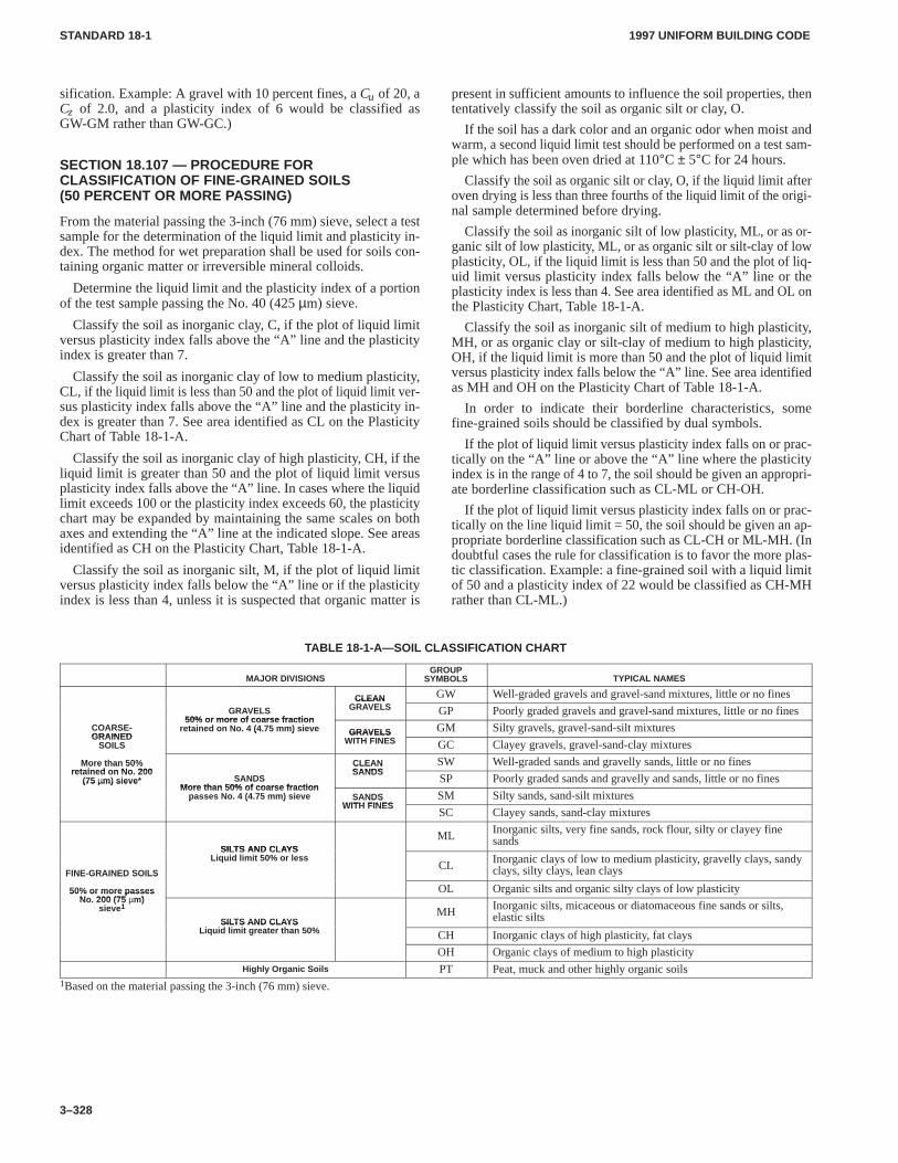
1997 UNIFORM BUILDING CODESTANDARD 18-1
3–328
sification. Example: A gravel with 10 percent fines, a Cu of 20, aCz of 2.0, and a plasticity index of 6 would be classified asGW-GM rather than GW-GC.)
SECTION 18.107 — PROCEDURE FORCLASSIFICATION OF FINE-GRAINED SOILS(50 PERCENT OR MORE PASSING)
From the material passing the 3-inch (76 mm) sieve, select a testsample for the determination of the liquid limit and plasticity in-dex. The method for wet preparation shall be used for soils con-taining organic matter or irreversible mineral colloids.
Determine the liquid limit and the plasticity index of a portionof the test sample passing the No. 40 (425 µm) sieve.
Classify the soil as inorganic clay, C, if the plot of liquid limitversus plasticity index falls above the “A” line and the plasticityindex is greater than 7.
Classify the soil as inorganic clay of low to medium plasticity,CL, if the liquid limit is less than 50 and the plot of liquid limit ver-sus plasticity index falls above the “A” line and the plasticity in-dex is greater than 7. See area identified as CL on the PlasticityChart of Table 18-1-A.
Classify the soil as inorganic clay of high plasticity, CH, if theliquid limit is greater than 50 and the plot of liquid limit versusplasticity index falls above the “A” line. In cases where the liquidlimit exceeds 100 or the plasticity index exceeds 60, the plasticitychart may be expanded by maintaining the same scales on bothaxes and extending the “A” line at the indicated slope. See areasidentified as CH on the Plasticity Chart, Table 18-1-A.
Classify the soil as inorganic silt, M, if the plot of liquid limitversus plasticity index falls below the “A” line or if the plasticityindex is less than 4, unless it is suspected that organic matter is
present in sufficient amounts to influence the soil properties, thententatively classify the soil as organic silt or clay, O.
If the soil has a dark color and an organic odor when moist andwarm, a second liquid limit test should be performed on a test sam-ple which has been oven dried at 110°C ± 5°C for 24 hours.
Classify the soil as organic silt or clay, O, if the liquid limit afteroven drying is less than three fourths of the liquid limit of the origi-nal sample determined before drying.
Classify the soil as inorganic silt of low plasticity, ML, or as or-ganic silt of low plasticity, ML, or as organic silt or silt-clay of lowplasticity, OL, if the liquid limit is less than 50 and the plot of liq-uid limit versus plasticity index falls below the “A” line or theplasticity index is less than 4. See area identified as ML and OL onthe Plasticity Chart, Table 18-1-A.
Classify the soil as inorganic silt of medium to high plasticity,MH, or as organic clay or silt-clay of medium to high plasticity,OH, if the liquid limit is more than 50 and the plot of liquid limitversus plasticity index falls below the “A” line. See area identifiedas MH and OH on the Plasticity Chart of Table 18-1-A.
In order to indicate their borderline characteristics, somefine-grained soils should be classified by dual symbols.
If the plot of liquid limit versus plasticity index falls on or prac-tically on the “A” line or above the “A” line where the plasticityindex is in the range of 4 to 7, the soil should be given an appropri-ate borderline classification such as CL-ML or CH-OH.
If the plot of liquid limit versus plasticity index falls on or prac-tically on the line liquid limit = 50, the soil should be given an ap-propriate borderline classification such as CL-CH or ML-MH. (Indoubtful cases the rule for classification is to favor the more plas-tic classification. Example: a fine-grained soil with a liquid limitof 50 and a plasticity index of 22 would be classified as CH-MHrather than CL-ML.)
TABLE 18-1-A—SOIL CLASSIFICA TION CHART
MAJOR DIVISIONSGROUP
SYMBOLS TYPICAL NAMES
CLEAN GW Well-graded gravels and gravel-sand mixtures, little or no finesGRAVELS
50% or more of coarse fraction
CLEANGRAVELS GP Poorly graded gravels and gravel-sand mixtures, little or no fines
COARSE-GRAINED
50% or more of coarse fractionretained on No. 4 (4.75 mm) sieve GRAVELS GM Silty gravels, gravel-sand-silt mixtures
GRAINEDSOILS
( ) GRAVELSWITH FINES GC Clayey gravels, gravel-sand-clay mixtures
More than 50%retained on No 200
CLEANSANDS
SW Well-graded sands and gravelly sands, little or no finesMore than 50%retained on No. 200
(75 µm) sieve* SANDSMore than 50% of coarse fraction
CLEANSANDS
SP Poorly graded sands and gravelly and sands, little or no fines(75 µm) sieveMore than 50% of coarse fraction
passes No. 4 (4.75 mm) sieve SANDSWITH FINES
SM Silty sands, sand-silt mixturesp ( ) SANDSWITH FINES
SC Clayey sands, sand-clay mixtures
SILTS AND CLAYSML Inorganic silts, very fine sands, rock flour, silty or clayey fine
sands
FINE-GRAINED SOILS
SILTS AND CLAYSLiquid limit 50% or less
CL Inorganic clays of low to medium plasticity, gravelly clays, sandyclays, silty clays, lean claysFINE GRAINED SOILS
50% or more passesNo 200 (75 m)
OL Organic silts and organic silty clays of low plasticity50% or more passesNo. 200 (75 µm)
sieve 1
SILTS AND CLAYSLi id li i h 50%
MH Inorganic silts, micaceous or diatomaceous fine sands or silts,elastic siltsSILTS AND CLAYS
Liquid limit greater than 50% CH Inorganic clays of high plasticity, fat clays
OH Organic clays of medium to high plasticityHighly Organic Soils PT Peat, muck and other highly organic soils
1Based on the material passing the 3-inch (76 mm) sieve.
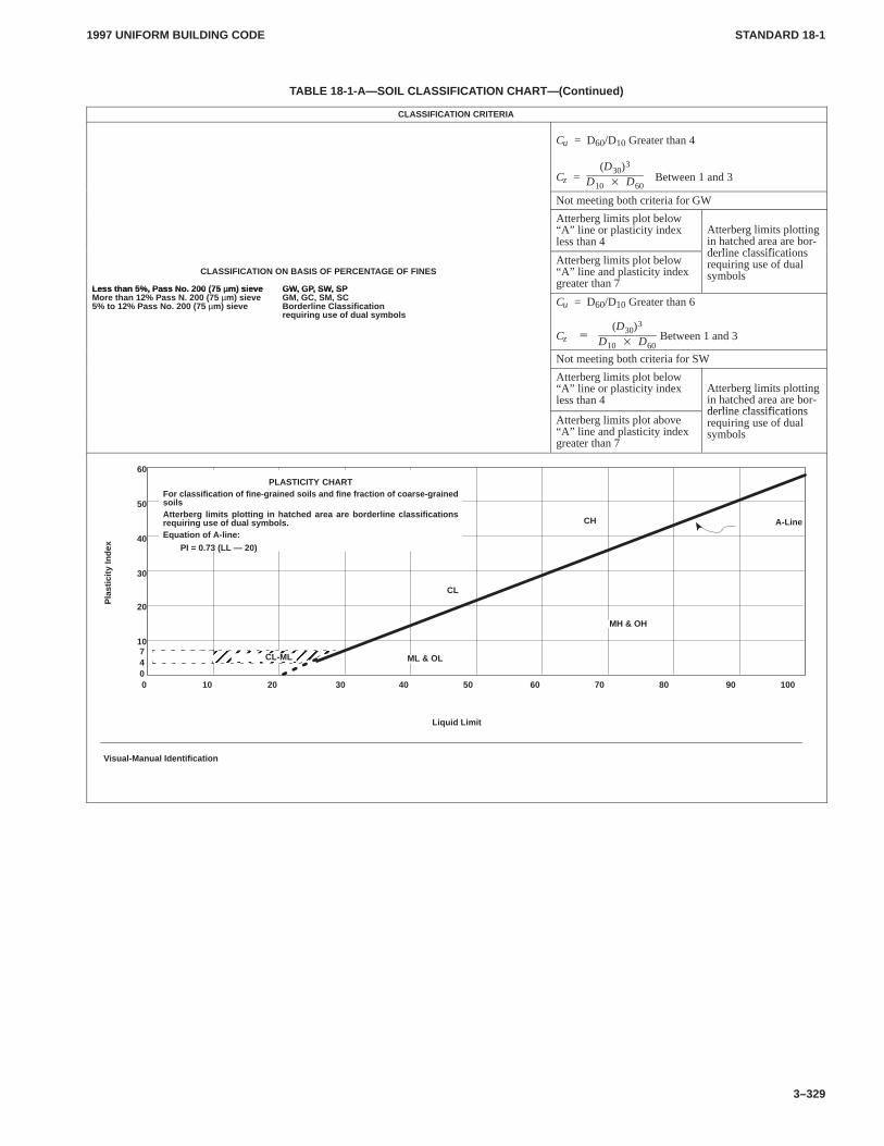
1997 UNIFORM BUILDING CODE STANDARD 18-1
3–329
TABLE 18-1-A—SOIL CLASSIFICA TION CHART—(Continued)
CLASSIFICATION CRITERIA
Cu = D60/D10 Greater than 4
Cz = Between 1 and 3(D30)
3
D10 � D60
Not meeting both criteria for GW
Atterberg limits plot below“A” line or plasticity indexless than 4
Atterberg limits plottingin hatched area are bor-derline classifications
CLASSIFICATION ON BASIS OF PERCENTAGE OF FINES
Less than 5% , Pass No. 200 (75 µm) sieve GW, GP, SW, SP
Atterberg limits plot below“A” line and plasticity indexgreater than 7
derline classificationsrequiring use of dualsymbols
Less than 5%, Pass No. 200 (75 µm) sieve GW, GP, SW, SPMore than 12% Pass N. 200 (75 µm) sieve GM, GC, SM, SC5% to 12% Pass No. 200 (75 µm) sieve Borderline Classification
requiring use of dual symbolsCu = D60/D10 Greater than 6
Cz Between 1 and 3�
(D30)3
D10 � D60
Not meeting both criteria for SW
Atterberg limits plot below“A” line or plasticity indexless than 4
Atterberg limits plottingin hatched area are bor-derline classifications
Atterberg limits plot above“A” line and plasticity indexgreater than 7
derline classificationsrequiring use of dualsymbols
A-Line
ÉÉÉÉÉÉÉÉÉÉ0 10 20 30 40 50 60 70 80 90 100
60
50
40
30
20
10740
CL-MLÉÉÉÉ ML & OL
MH & OH
CL
CH
Liquid Limit
PLASTICITY CHARTFor classification of fine-grained soils and fine fraction of coarse-grainedsoilsAtterberg limits plotting in hatched area are borderline classificationsrequiring use of dual symbols.Equation of A-line:
PI = 0.73 (LL — 20)
Pla
stic
ity In
dex
Visual-Manual Identification
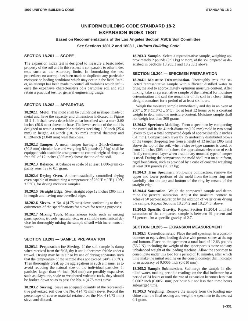
1997 UNIFORM BUILDING CODE STANDARD 18-2
3–331
UNIFORM BUILDING CODE STANDARD 18-2
EXPANSION INDEX TESTBased on Recommendations of the Los Angeles Section ASCE Soil Committee
See Sections 1801.2 and 1803.1, Uniform Building Code
SECTION 18.201 — SCOPE
The expansion index test is designed to measure a basic indexproperty of the soil and in this respect is comparable to other indextests such as the Atterberg limits. In formulating the testprocedures no attempt has been made to duplicate any particularmoisture or loading conditions which may occur in the field. Rath-er, an attempt has been made to control all variables which influ-ence the expansive characteristics of a particular soil and stillretain a practical test for general engineering usage.
SECTION 18.202 — APPARATUS
18.202.1 Mold. The mold shall be cylindrical in shape, made ofmetal and have the capacity and dimensions indicated in Figure18-2-1. It shall have a detachable collar inscribed with a mark 2.00inches (50.8 mm) above the base. The lower section of the mold isdesigned to retain a removable stainless steel ring 1.00 inch (25.4mm) in height, 4.01-inch (101.85 mm) internal diameter and0.120-inch (3.048 mm) wall thickness.
18.202.2 Tamper.A metal tamper having a 2-inch-diameter(50.8 mm) circular face and weighing 5.5 pounds (2.5 kg) shall beequipped with a suitable arrangement to control height of drop to afree fall of 12 inches (305 mm) above the top of the soil.
18.202.3 Balance.A balance or scale of at least 1,000-gram ca-pacity sensitive to 0.1 gram.
18.202.4 Drying Oven.A thermostatically controlled dryingoven capable of maintaining a temperature of 230°F ± 9°F (110°C± 5°C), for drying moisture samples.
18.202.5 Straight Edge. Steel straight edge 12 inches (305 mm)in length and having one bevelled edge.
18.202.6 Sieves.A No. 4 (4.75 mm) sieve conforming to the re-quirements of the specifications for sieves for testing purposes.
18.202.7 Mixing Tools.Miscellaneous tools such as mixingpans, spoons, trowels, spatula, etc., or a suitable mechanical de-vice for thoroughly mixing the sample of soil with increments ofwater.
SECTION 18.203 — SAMPLE PREPARATION
18.203.1 Preparation for Sieving.If the soil sample is dampwhen received from the field, dry it until it becomes friable under atrowel. Drying may be in air or by use of drying apparatus suchthat the temperature of the sample does not exceed 140°F (60°C).Then thoroughly break up the aggregations in such a manner as toavoid reducing the natural size of the individual particles. Ifparticles larger than 1/4 inch (6.4 mm) are possibly expansive,such as claystone, shale or weathered volcanic rock, they shouldbe broken down so as to pass the No. 4 (4.75 mm) sieve.
18.203.2 Sieving.Sieve an adequate quantity of the representa-tive pulverized soil over the No. 4 (4.75 mm) sieve. Record thepercentage of coarse material retained on the No. 4 (4.75 mm)sieve and discard.
18.203.3 Sample.Select a representative sample, weighing ap-proximately 2 pounds (0.91 kg) or more, of the soil prepared as de-scribed in Sections 18.203.1 and 18.203.2 above.
SECTION 18.204 — SPECIMEN PREPARATION
18.204.1 Moisture Determination.Thoroughly mix the se-lected representative sample with sufficient distilled water tobring the soil to approximately optimum moisture content. Aftermixing, take a representative sample of the material for moisturedetermination and seal the remainder of the soil in a close-fittingairtight container for a period of at least six hours.
Weigh the moisture sample immediately and dry in an oven at230° ± 9°F (110°C ± 5°C), for at least 12 hours or to a constantweight to determine the moisture content. Moisture sample shallnot weigh less than 300 grams.
18.204.2 Specimen Molding.Form a specimen by compactingthe cured soil in the 4-inch-diameter (102 mm) mold in two equallayers to give a total compacted depth of approximately 2 inches(51 mm). Compact each layer by 15 uniformly distributed blowsof the tamper dropping free from a height of 12 inches (305 mm)above the top of the soil, when a sleeve-type rammer is used, orfrom 12 inches (305 mm) above the approximate elevation of eachfinally compacted layer when a stationary mounted type of tamperis used. During the compaction the mold shall rest on a uniform,rigid foundation, such as provided by a cube of concrete weighingat least 200 pounds (90.72 kg).
18.204.3 Trim Specimen.Following compaction, remove theupper and lower portions of the mold from the inner ring andcarefully trim the top and bottom of the ring by means of thestraight edge.
18.204.4 Saturation.Weigh the compacted sample and deter-mine the percent saturation. Adjust the moisture content toachieve 50 percent saturation by the addition of water or air dryingthe sample. Repeat Sections 18.204.2 and 18.204.3 above.
18.204.5 Specific Gravity.Repeat Section 18.204.4 until thesaturation of the compacted sample is between 49 percent and51 percent for a specific gravity of 2.7.
SECTION 18.205 — EXPANSION MEASUREMENT
18.205.1 Consolidometer.Place the soil specimen in a consoli-dometer or equivalent loading device with porous stones at the topand bottom. Place on the specimen a total load of 12.63 pounds(56.2 N), including the weight of the upper porous stone and anyunbalanced weight of the loading machine. Allow the specimen toconsolidate under this load for a period of 10 minutes, after whichtime make the initial reading on the consolidometer dial indicatorto an accuracy of 0.0005 inch (0.010 mm).
18.205.2 Sample Submersion.Submerge the sample in dis-tilled water, making periodic readings on the dial indicator for aperiod of 24 hours or until the rate of expansion becomes less than0.0002 inch (0.0051 mm) per hour but not less than three hourssubmerged time.
18.205.3 Weighing.Remove the sample from the loading ma-chine after the final reading and weigh the specimen to the nearest0.1 gram.
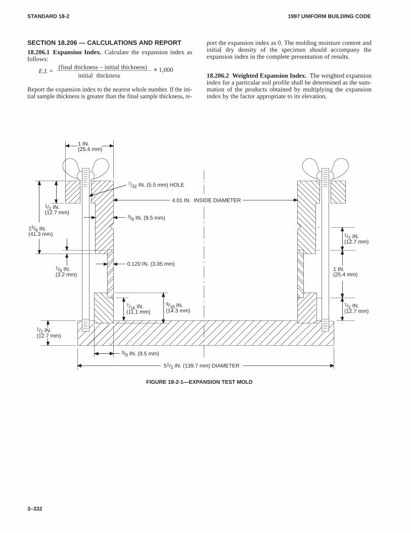
1997 UNIFORM BUILDING CODESTANDARD 18-2
3–332
SECTION 18.206 — CALCULATIONS AND REPORT18.206.1 Expansion Index.Calculate the expansion index asfollows:
(final thickness – initial thickness)initial thickness
E.I. = × 1,000
Report the expansion index to the nearest whole number. If the ini-tial sample thickness is greater than the final sample thickness, re-
port the expansion index as 0. The molding moisture content andinitial dry density of the specimen should accompany theexpansion index in the complete presentation of results.
18.206.2 Weighted Expansion Index. The weighted expansionindex for a particular soil profile shall be determined as the sum-mation of the products obtained by multiplying the expansionindex by the factor appropriate to its elevation.
51/2 IN. (139.7 mm) DIAMETER
9/16 IN.(14.3 mm)
3/8 IN. (9.5 mm)
7/32 IN. (5.5 mm) HOLE
0.120 IN. (3.05 mm)
7/16 IN.(11.1 mm)
1 IN.(25.4 mm)
4.01 IN. INSIDE DIAMETER
15/8 IN.(41.3 mm)
1/8 IN.(3.2 mm)
1/2 IN.(12.7 mm)
1/2 IN.(12.7 mm)
3/8 IN. (9.5 mm)
1/2 IN.(12.7 mm)
1/2 IN.(12.7 mm)
1 IN.(25.4 mm)
FIGURE 18-2-1—EXPANSION TEST MOLD
CHAP. 19, DIV. I1900
1900.4.61997 UNIFORM BUILDING CODE
2–97
Chapter 19
CONCRETENOTE: This is a new division.
Division I — GENERAL
SECTION 1900 — GENERAL
1900.1 Scope. The design of concrete structures of cast-in-placeor precast construction, plain, reinforced or prestressed shall con-form to the rules and principles specified in this chapter.
1900.2 General Requirements. All concrete structures shall bedesigned and constructed in accordance with the requirements ofDivision II and the additional requirements contained in Section1900.4 of this division.
1900.3 Design Methods. The design of concrete structures shallbe in accordance with one of the following methods.
1900.3.1 Strength design (load and resistance factor design).The design of concrete structures using the strength designmethod shall be in accordance with the requirements of DivisionII. CHAP. 19, DIV. I
1900.3.2 Allowable stress design. The design of concrete struc-tures using the Allowable Stress Design Method shall be inaccordance with the requirements of Division VI, Section 1926.
1900.4 Additional Design and Construction Requirements.
1900.4.1 Anchorage. Anchorage of bolts and headed studanchors to concrete shall be in accordance with Division III.
1900.4.2 Shotcrete. In addition to the requirements of DivisionII, design and construction of shotcrete structures shall meet therequirements of Division IV.
1900.4.3 Reinforced gypsum concrete. Reinforced gypsumconcrete shall be in accordance with Division V.
1900.4.4 Minimum slab thickness. The minimum thickness ofconcrete floor slabs supported directly on the ground shall not beless than 31/2 inches (89 mm).
1900.4.5 Unified design provisions for reinforced and pre-stressed concrete flexural and compression members.It shallbe permitted to use the alternate flexural and axial load design pro-visions in accordance with Division VII, Section 1927.
1900.4.6 Alternative load-factor combination and strength-reduction factors. It shall be permitted to use the alternative load-factor and strength-reduction factors in accordance with DivisionVIII, Section 1928.
CHAP. 19, DIV. II1900.4.61902
1997 UNIFORM BUILDING CODE
2–98
Division II
Copyright � by the American Concrete Institute and reproduced with their consent. All rights reserved.
The contents of this division are patterned after, and in generalconformity with, the provisions of Building Code Requirementsfor Reinforced Concrete (ACI 318-95) and commentary—ACI318 R-95. For additional background information and researchdata, see the referenced American Concrete Institute (ACI) publi-cation. CHAP. 19, DIV. II
To make reference to the ACI commentary easier for users ofthe code, the section designations of this division have been madesimilar to those found in ACI 318. The first two digits of a sectionnumber indicates this chapter number and the balance matches theACI chapter and section designation wherever possible. Italics areused in this chapter to indicate where the Uniform Building Codediffers substantively from the ACI standard.
SECTION 1901 — SCOPE1901.0
The design of structures in concrete of cast-in-place or precastconstruction, plain, reinforced or prestressed, shall conform to therules and principles specified in this chapter.
SECTION 1902 — DEFINITIONS1902.0
The following terms are defined for general use in this code. Spe-cialized definitions appear in individual sections.
ADMIXTURE is material other than water, aggregate, or hy-draulic cement used as an ingredient of concrete and added to con-crete before or during its mixing to modify its properties.
AGGREGATE is granular material, such as sand, gravel,crushed stone and iron blast-furnace slag, and when used with acementing medium forms a hydraulic cement concrete or mortar.
AGGREGATE, LIGHTWEIGHT, is aggregate with a dry,loose weight of 70 pounds per cubic foot (pcf) (1120 kg/m3) orless.
AIR-DRY WEIGHT is the unit weight of a lightweight concretespecimen cured for seven days with neither loss nor gain of mois-ture at 60�F to 80�F (15.6�C to 26.7�C) and dried for 21 days in50 � 7 percent relative humidity at 73.4�F � 2�F (23.0�C �1.1�C).
ANCHORAGE in posttensioning is a device used to anchortendons to concrete member; in pretensioning, a device used to an-chor tendons during hardening of concrete.
BONDED TENDON is a prestressing tendon that is bonded toconcrete either directly or through grouting.
CEMENTITIOUS MATERIALS are materials as specifiedin Section 1903 which have cementing value when used in con-crete either by themselves, such as portland cement, blended hy-draulic cements and expansive cement, or such materials incombination with fly ash, raw or other calcined natural pozzolans,silica fume, or ground granulated blast-furnace slag.
COLUMN is a member with a ratio of height-to-least-lateraldimension of 3 or greater used primarily to support axial compres-sive load.
COMPOSITE CONCRETE FLEXURAL MEMBERS areconcrete flexural members of precast and cast-in-place concreteelements or both constructed in separate placements but so inter-connected that all elements respond to loads as a unit.
COMPRESSION-CONTROLLED SECTION is a crosssection in which the net tensile strain in the extreme tension steelat nominal strength is less than or equal to the compression-controlled strain limit.
COMPRESSION-CONTROLLED STRAIN LIMIT is thenet tensile strain at balanced strain conditions. (See SectionB1910.3.2.)
CONCRETE is a mixture of portland cement or any other hy-draulic cement, fine aggregate, coarse aggregate and water, withor without admixtures.
CONCRETE, SPECIFIED COMPRESSIVE STRENGTHOF (f ′c), is the compressive strength of concrete used in designand evaluated in accordance with provisions of Section 1905, ex-pressed in pounds per square inch (psi) (MPa). Whenever thequantity f ′c is under a radical sign, square root of numerical valueonly is intended, and result has units of psi (MPa).
CONCRETE, STRUCTURAL LIGHTWEIGHT, is con-crete containing lightweight aggregate having an air-dry unitweight as determined by definition above, not exceeding 115 pcf(1840 kg/m3). In this code, a lightweight concrete without naturalsand is termed ‘‘all-lightweight concrete’’ and lightweight con-crete in which all fine aggregate consists of normal-weight sand istermed “sand-lightweight concrete.’’
CONTRACTION JOINT is a formed, sawed, or tooledgroove in a concrete structure to create a weakened plane and reg-ulate the location of cracking resulting from the dimensionalchange of different parts of the structure.
CURVATURE FRICTION is friction resulting from bends orcurves in the specified prestressing tendon profile.
DEFORMED REINFORCEMENT is deformed reinforcingbars, bar and rod mats, deformed wire, welded smooth wire fabricand welded deformed wire fabric.
DEVELOPMENT LENGTH is the length of embedded rein-forcement required to develop the design strength of reinforce-ment at a critical section. See Section 1909.3.3.
EFFECTIVE DEPTH OF SECTION (d) is the distance mea-sured from extreme compression fiber to centroid of tension rein-forcement.
EFFECTIVE PRESTRESS is the stress remaining in pre-stressing tendons after all losses have occurred, excluding effectsof dead load and superimposed load.
EMBEDMENT LENGTH is the length of embedded rein-forcement provided beyond a critical section.
EXTREME TENSION STEEL is the reinforcement (pre-stressed or nonprestressed) that is the farthest from the extremecompression fiber.
ISOLATION JOINT is a separation between adjoining partsof a concrete structure, usually a vertical plane, at a designed loca-tion such as to interfere least with performance of the structure, yetsuch as to allow relative movement in three directions and avoidformation of cracks elsewhere in the concrete and through whichall or part of the bonded reinforcement is interrupted.
JACKING FORCE is the temporary force exerted by devicethat introduces tension into prestressing tendons in prestressedconcrete.
LOAD, DEAD, is the dead weight supported by a member, asdefined by Section 1602 (without load factors).
�
19011901
CHAP. 19, DIV. II1902
1903.21997 UNIFORM BUILDING CODE
2–99
LOAD, FACTORED, is the load, multiplied by appropriateload factors, used to proportion members by the strength designmethod of this code. See Sections 1908.1.1 and 1909.2.
LOAD, LIVE, is the live load specified by Section 1602 (with-out load factors).
LOAD, SERVICE, is the live and dead loads (without loadfactors).
MODULUS OF ELASTICITY is the ratio of normal stress tocorresponding strain for tensile or compressive stresses belowproportional limit of material. See Section 1908.5.
NET TENSILE STRAIN is the tensile strain at nominalstrength exclusive of strains due to effective prestress, creep,shrinkage and temperature.
PEDESTAL is an upright compression member with a ratio ofunsupported height to average least lateral dimension of 3 or less.
PLAIN CONCRETE is structural concrete with no reinforce-ment or with less reinforcement than the minimum amount speci-fied for reinforced concrete.
PLAIN REINFORCEMENT is reinforcement that does notconform to definition of deformed reinforcement.
POSTTENSIONING is a method of prestressing in which ten-dons are tensioned after concrete has hardened.
PRECAST CONCRETE is a structural concrete element castin other than its final position in the structure.
PRESTRESSED CONCRETE is structural concrete in whichinternal stresses have been introduced to reduce potential tensilestresses in concrete resulting from loads.
PRETENSIONING is a method of prestressing in which ten-dons are tensioned before concrete is placed.
REINFORCED CONCRETE is structural concrete rein-forced with no less than the minimum amounts of prestressing ten-dons or nonprestressed reinforcement specified in this code.
REINFORCEMENT is material that conforms to Section1903.5.1, excluding prestressing tendons unless specifically in-cluded.
RESHORES are shores placed snugly under a concrete slab orother structural member after the original forms and shores havebeen removed from a larger area, thus requiring the new slab orstructural member to deflect and support its own weight and exist-ing construction loads applied prior to the installation of thereshores.
SHORES are vertical or inclined support members designed tocarry the weight of the formwork, concrete and construction loadsabove.
SPAN LENGTH. See Section 1908.7.
SPIRAL REINFORCEMENT is continuously wound rein-forcement in the form of a cylindrical helix.
SPLITTING TENSILE STRENGTH (fct) is the tensilestrength of concrete. See Section 1905.1.4.
STIRRUP is reinforcement used to resist shear and torsionstresses in a structural member; typically bars, wires, or weldedwire fabric (smooth or deformed) bent into L, U or rectangularshapes and located perpendicular to or at an angle to longitudinalreinforcement. (The term “stirrups’’ is usually applied to lateralreinforcement in flexural members and the term ‘‘ties’’ to those incompression members.) See “tie.”
STRENGTH, DESIGN, is the nominal strength multiplied bya strength-reduction factor φ. See Section 1909.3.
STRENGTH, NOMINAL, is the strength of a member orcross section calculated in accordance with provisions and as-sumptions of the strength design method of this code before appli-cation of any strength-reduction factors. See Section 1909.3.1.
STRENGTH, REQUIRED, is the strength of a member orcross section required to resist factored loads or related internalmoments and forces in such combinations as are stipulated in thiscode. See Section 1909.1.1.
STRESS is the intensity of force per unit area.
STRUCTURAL CONCRETE is all concrete used for struc-tural purposes, including plain and reinforced concrete.
TENDON is a steel element such as wire, cable, bar, rod orstrand, or a bundle of such elements, used to impart prestress toconcrete.
TENSION-CONTROLLED SECTION is a cross section inwhich the net tensile strain in the extreme tension steel at nominalstrength is greater than or equal to 0.005.
TIE is a loop of reinforcing bar or wire enclosing longitudinalreinforcement. A continuously wound bar or wire in the form of acircle, rectangle or other polygon shape without re-entrant cornersis acceptable. See “stirrup.”
TRANSFER is the act of transferring stress in prestressing ten-dons from jacks or pretensioning bed to concrete member.
WALL is a member, usually vertical, used to enclose or sepa-rate spaces.
WOBBLE FRICTION in prestressed concrete, is frictioncaused by unintended deviation of prestressing sheath or ductfrom its specified profile.
YIELD STRENGTH is the specified minimum yield strengthor yield point of reinforcement in psi.
SECTION 1903 — SPECIFICATIONS FOR TESTS ANDMATERIALS
1903.0 Notation.
fy = specified yield strength of nonprestressed reinforce-ment, psi (MPa).
1903.1 Tests of Materials.
1903.1.1The building official may require the testing of any ma-terials used in concrete construction to determine if materials areof quality specified.
1903.1.2Tests of materials and of concrete shall be made by anapproved agency and at no expense to the jurisdiction. Such testsshall be made in accordance with the standards listed in Section1903.
1903.1.3A complete record of tests of materials and of concreteshall be available for inspection during progress of work and fortwo years after completion of the project, and shall be preservedby the inspecting engineer or architect for that purpose.
1903.1.4 Material and test standards.The standards listed inthis chapter labeled a “UBC Standard” are also listed in Chapter35, Part II, and are part of this code. The other standards listed inthis chapter are recognized standards. (See Sections 3503 and3504.)
1903.2 Cement.
1. ASTM C 845, Expansive Hydraulic Cement
2. ASTM C 150, Portland Cement
3. ASTM C 595 or ASTM C 1157, Blended Hydraulic Cements
CHAP. 19, DIV. II1903.31903.5.4.2
1997 UNIFORM BUILDING CODE
2–100
1903.3 Aggregates.
1903.3.1 Recognized standards.
1. ASTM C 33, Concrete Aggregates
2. ASTM C 330, Lightweight Aggregates for Structural Con-crete
3. ASTM C 332, Lightweight Aggregates for Insulating Con-crete
4. ASTM C 144, Aggregate for Masonry Mortar
5. Aggregates failing to meet the above specifications butwhich have been shown by special test or actual service to produceconcrete of adequate strength and durability may be used whereauthorized by the building official.
1903.3.2The nominal maximum size of coarse aggregate shallnot be larger than:
1. One fifth the narrowest dimension between sides of forms,or
2. One third the depth of slabs, or
3. Three fourths the minimum clear spacing between individ-ual reinforcing bars or wires, bundles of bars, or prestress-ing tendons or ducts.
These limitations may be waived if, in the judgment of thebuilding official, workability and methods of consolidation aresuch that concrete can be placed without honeycomb or voids.
1903.4 Water.
1903.4.1Water used in mixing concrete shall be clean and freefrom injurious amounts of oils, acids, alkalis, salts, organic mate-rials or other substances deleterious to concrete or reinforcement.
1903.4.2Mixing water for prestressed concrete or for concretethat will contain aluminum embedments, including that portion ofmixing water contributed in the form of free moisture on aggre-gates, shall not contain deleterious amounts of chloride ions. SeeSection 1904.4.1.
1903.4.3Nonpotable water shall not be used in concrete unlessthe following are satisfied:
1903.4.3.1Selection of concrete proportions shall be based onconcrete mixes using water from the same source.
1903.4.3.2Mortar test cubes made with nonpotable mixing watershall have seven-day and 28-day strengths equal to at least 90 per-cent of strengths of similar specimens made with potable water.Strength test comparison shall be made on mortars, identical ex-cept for the mixing water, prepared and tested in accordance withASTM C 109 (Compressive Strength of Hydraulic Cement Mor-tars).
1903.5 Steel Reinforcement.
1903.5.1Reinforcement shall be deformed reinforcement, ex-cept that plain reinforcement may be used for spirals or tendons,and reinforcement consisting of structural steel, steel pipe or steeltubing may be used as specified in this chapter.
1903.5.2Welding of reinforcing bars shall conform to approvednationally recognized standards. Type and location of weldedsplices and other required welding of reinforcing bars shall be in-dicated on the design drawings or in the project specifications.ASTM reinforcing bar specifications, except for A 706, shall besupplemented to require a report of material properties necessaryto conform to requirements in UBC Standard 19-1.
1903.5.3 Deformed reinforcements.
1903.5.3.1ASTM A 615, A 616, A 617, A 706, A 767 and A 775,Reinforcing Bars for Concrete.
1903.5.3.2Deformed reinforcing bars with a specified yieldstrength fy exceeding 60,000 psi (413.7 MPa) may be used, provi-dedfy shall be the stress corresponding to a strain of 0.35 percentand the bars otherwise conform to approved national standards,see ASTM A 615, A 616, A 617, A 706, A 767 and A 775. See Sec-tion 1909.4.
1903.5.3.3ASTM A 184, Fabricated Deformed Steel Bar Mats.For reinforced bars used in bar mats, see ASTM A 615, A 616, A617, A 706, A 767 or A 775.
1903.5.3.4ASTM A 496, Steel Wire, Deformed, for ConcreteReinforcement.
For deformed wire for concrete reinforcement, see ASTM A496, except that wire shall not be smaller than size D4, and for wirewith a specified yield strength fy exceeding 60,000 psi (413.7MPa), fy shall be the stress corresponding to a strain of 0.35 per-cent, if the yield strength specified in design exceeds 60,000 psi(413.7 MPa).
1903.5.3.5ASTM A 185, Steel Welded Wire, Fabric, Plain forConcrete Reinforcement.
For welded plain wire fabric for concrete reinforcement, seeASTM 185, except that for wire with a specified yield strength fyexceeding 60,000 psi (413.7 MPa), fy shall be the stress corre-sponding to a strain of 0.35 percent, if the yield strength specifiedin design exceeds 60,000 psi (413.7 MPa). Welded intersectionsshall not be spaced farther apart than 12 inches (305 mm) in direc-tion of calculated stress, except for wire fabric used as stirrups inaccordance with Section 1912.14.
1903.5.3.6ASTM A 497, Welded Deformed Steel Wire Fabricfor Concrete Reinforcement.
For welded deformed wire fabric for concrete reinforcement,see ASTM A 497, except that for wire with a specified yieldstrength fy exceeding 60,000 psi (413.7 MPa), fy shall be the stresscorresponding to a strain of 0.35 percent, if the yield strength spe-cified in design exceeds 60,000 psi (413.7 MPa). Welded intersec-tions shall not be spaced farther apart than 16 inches (406 mm) indirection of calculated stress, except for wire fabric used as stir-rups in accordance with Section 1912.13.2.
1903.5.3.7Deformed reinforcing bars may be galvanized orepoxy coated. For zinc or epoxy-coated reinforcement, see ASTMA 615, A 616, A 617, A 706, A 767 and A 775 and ASTM A 934(Epoxy-Coated Steel Reinforcing Bars).
1903.5.3.8Epoxy-coated wires and welded wire fabric shallcomply with ASTM A 884 (Standard Specification for Epoxy-Coated Steel Wire and Welded Wire Fabric for Reinforcement).Epoxy-coated wires shall conform to Section 1903.5.3.4 andepoxy-coated welded wire fabric shall conform to Section1903.5.3.5 or 1903.5.3.6.
1903.5.4 Plain reinforcement.
1903.5.4.1Plain bars for spiral reinforcement shall conform toapproved national standards, see ASTM A 615, A 616 and A 617.
1903.5.4.2For plain wire for spiral reinforcement, see ASTM A82 except that for wire with a specified yield strength fy exceeding60,000 psi (413.7 MPa), fy shall be the stress corresponding to astrain of 0.35 percent, if the yield strength specified in designexceeds 60,000 psi (413.7 MPa).
CHAP. 19, DIV. II1903.5.51904.2.2
1997 UNIFORM BUILDING CODE
2–101
1903.5.5 Prestressing tendons.
1903.5.5.11. ASTM A 416, Uncoated Seven-wire Stress-relieved Steel Strand for Prestressed Concrete
2. ASTM A 421, Uncoated Stress-relieved Wire for Pre-stressed Concrete
3. ASTM A 722, Uncoated High-strength Steel Bar for Pre-stressing Concrete
1903.5.5.2Wire, strands and bars not specifically listed in ASTMA 416, A 421 and A 722 may be used, provided they conform tominimum requirements of these specifications and do not haveproperties that make them less satisfactory than those listed.
1903.5.6 Structural steel, steel pipe or tubing.
1903.5.6.1For structural steel used with reinforcing bars in com-posite compression members meeting requirements of Section1910.16.7 or 1910.16.8, see ASTM A 36, A 242, A 572 and A 588.
1903.5.6.2For steel pipe or tubing for composite compressionmembers composed of a steel-encased concrete core meeting re-quirements of Section 1910.16.4, see ASTM A 53, A 500 andA 501.
1903.5.7UBC Standard 19-1, Welding Reinforcing Steel, MetalInserts and Connections in Reinforced Concrete Construction
1903.6 Admixtures.
1903.6.1Admixtures to be used in concrete shall be subject toprior approval by the building official.
1903.6.2An admixture shall be shown capable of maintaining es-sentially the same composition and performance throughout thework as the product used in establishing concrete proportions inaccordance with Section 1905.2.
1903.6.3Calcium chloride or admixtures containing chloridefrom other than impurities from admixture ingredients shall not beused in prestressed concrete, in concrete containing embeddedaluminum, or in concrete cast against stay-in-place galvanizedsteel forms. See Sections 1904.3.2 and 1904.4.1.
1903.6.4ASTM C 260, Air-entraining Admixtures for Concrete
1903.6.5ASTM C 494 and C 1017, Chemical Admixtures forConcrete
1903.6.6ASTM C 618, Fly Ash and Raw or Calcined NaturalPozzolans for Use as Admixtures in Portland Cement Concrete
1903.6.7ASTM C 989, Ground-iron Blast-furnace Slag for Use inConcrete and Mortars
1903.6.8Admixtures used in concrete containing ASTM C 845expansive cements shall be compatible with the cement and pro-duce no deleterious effects.
1903.6.9Silica fume used as an admixture shall conform toASTM C 1240 (Silica Fume for Use in Hydraulic Cement Con-crete and Mortar).
1903.7 Storage of Materials.
1903.7.1Cementitious materials and aggregate shall be stored insuch manner as to prevent deterioration or intrusion of foreignmatter.
1903.7.2Any material that has deteriorated or has been contami-nated shall not be used for concrete.
1903.8 Concrete Testing.
1. ASTM C 192, Making and Curing Concrete Test Specimensin the Laboratory
2. ASTM C 31, Making and Curing Concrete Test Specimensin the Field
3. ASTM C 42, Obtaining and Testing Drilled Cores andSawed Beams of Concrete
4. ASTM C 39, Compressive Strength of Cylindrical ConcreteSpecimens
5. ASTM C 172, Sampling Freshly Mixed Concrete
6. ASTM C 496, Splitting Tensile Strength of Cylindrical Con-crete Specimens
7. ASTM C 1218, Water-Soluble Chloride in Mortar and Con-crete
1903.9 Concrete Mix.
1. ASTM C 94, Ready-mixed Concrete
2. ASTM C 685, Concrete Made by Volumetric Batching andContinuous Mixing
3. UBC Standard 19-2, Mill-mixed Gypsum Concrete andPoured Gypsum Roof Diaphragms
4. ASTM C 109, Compressive Strength of Hydraulic CementMortars
5. ASTM C 567, Unit Weight of Structural Lightweight Con-crete
1903.10 Welding. The welding of reinforcing steel, metal insertsand connections in reinforced concrete construction shall con-form to UBC Standard 19-1.
1903.11 Glass Fiber Reinforced Concrete.RecommendedPractice for Glass Fiber Reinforced Concrete Panels, Manual 128.
SECTION 1904 — DURABILITY REQUIREMENTS
1904.0 Notation.
f ′c = specified compressive strength of concrete, psi (MPa).
1904.1 Water-Cementitious Materials Ratio.
1904.1.1The water-cementitious materials ratios specified inTables 19-A-2 and 19-A-4 shall be calculated using the weight ofcement meeting ASTM C 150, C 595 or C 845 plus the weight offly ash and other pozzolans meeting ASTM C 618, slag meetingASTM C 989, and silica fume meeting ASTM C 1240, if any,except that when concrete is exposed to deicing chemicals, Sec-tion 1904.2.3 further limits the amount of fly ash, pozzolans, silicafume, slag or the combination of these materials.
1904.2 Freezing and Thawing Exposures.
1904.2.1Normal-weight and lightweight concrete exposed tofreezing and thawing or deicing chemicals shall be air entrainedwith air content indicated in Table 19-A-1. Tolerance on air con-tent as delivered shall be � 1.5 percent. For specified compres-sive strength f ′c greater than 5,000 psi (34.47 MPa), reduction ofair content indicated in Table 19-A-1 by 1.0 percent shall be per-mitted.
1904.2.2Concrete that will be subjected to the exposures given inTable 19-A-2 shall conform to the corresponding maximumwater-cementitious materials ratios and minimum specified con-crete compressive strength requirements of that table. In addition,concrete that will be exposed to deicing chemicals shall conformto the limitations of Section 1904.2.3.
CHAP. 19, DIV. II1904.2.31905.3.2.2
1997 UNIFORM BUILDING CODE
2–102
1904.2.3For concrete exposed to deicing chemicals, the maxi-mum weight of fly ash, other pozzolans, silica fume or slag that isincluded in the concrete shall not exceed the percentages of the to-tal weight of cementitious materials given in Table 19-A-3.
1904.3 Sulfate Exposure.
1904.3.1Concrete to be exposed to sulfate-containing solutionsor soils shall conform to the requirements of Table 19-A-4 or shallbe concrete made with a cement that provides sulfate resistanceand that has a maximum water-cementitious materials ratio andminimum compressive strength set forth in Table 19-A-4.
1904.3.2Calcium chloride as an admixture shall not be used inconcrete to be exposed to severe or very severe sulfate-containingsolutions, as defined in Table 19-A-4.
1904.4 Corrosion Protection of Reinforcement.
1904.4.1For corrosion protection of reinforcement in concrete,maximum water soluble chloride ion concentrations in hardenedconcrete at ages from 28 to 42 days contributed from the ingredi-ents, including water, aggregates, cementitious materials and ad-mixtures shall not exceed the limits of Table 19-A-5. When testingis performed to determine water soluble chloride ion content, testprocedures shall conform to ASTM C 1218.
1904.4.2 If concrete with reinforcement will be exposed to chlo-rides from deicing chemicals, salt, salt water, brackish water, seawater or spray from these sources, requirements of Table 19-A-2for water-cementitious materials ratio and concrete strength andthe minimum concrete cover requirements of Section 1907.7 shallbe satisfied. In addition, see Section 1918.14 for unbonded pre-stressed tendons.
SECTION 1905 — CONCRETE QUALITY, MIXING ANDPLACING
1905.0 Notations.
f ′c = specified compressive strength of concrete, psi (MPa).f ′cr = required average compressive strength of concrete used
as the basis for selection of concrete proportions, psi(MPa).
fct = average splitting tensile strength of lightweight aggre-gate concrete, psi (MPa).
s = standard deviation, psi (MPa).
1905.1 General.
1905.1.1Concrete shall be proportioned to provide an averagecompressive strength as prescribed in Section 1905.3.2, as well assatisfy the durability criteria of Section 1904. Concrete shall beproduced to minimize frequency of strengths below f ′c as pre-scribed in Section 1905.6.2.3.
1905.1.2Requirements for f ′c shall be based on tests of cylindersmade and tested as prescribed in Section 1905.6.2.
1905.1.3Unless otherwise specified, f ′c shall be based on 28-daytests. If other than 28 days, test age for f ′c shall be as indicated indesign drawings or specifications.
Design drawings shall show specified compressive strength ofconcrete f ′c for which each part of structure is designed.
1905.1.4Where design criteria in Sections 1909.5.2.3, 1911.2;and 1912.2.4, provide for use of a splitting tensile strength valueof concrete, laboratory tests shall be made to establish value of fctcorresponding to specified values of f ′c.
1905.1.5Splitting tensile strength tests shall not be used as a basisfor field acceptance of concrete.
1905.2 Selection of Concrete Proportions.
1905.2.1Proportions of materials for concrete shall be estab-lished to provide:
1. Workability and consistency to permit concrete to be workedreadily into forms and around reinforcement under conditions ofplacement to be employed without segregation or excessivebleeding.
2. Resistance to special exposures as required by Section 1904.
3. Conformance with strength test requirements of Section1905.6.
1905.2.2Where different materials are to be used for differentportions of proposed work, each combination shall be evaluated.
1905.2.3Concrete proportions, including water-cementitiousmaterials ratio, shall be established on the basis of field experienceand/or trial mixtures with materials to be employed (see Section1905.3), except as permitted in Section 1905.4 or required by Sec-tion 1904.
1905.3 Proportioning on the Basis of Field Experience andTrial Mixtures.
1905.3.1 Standard deviation.
1905.3.1.1Where a concrete production facility has test records,a standard deviation shall be established. Test records from whicha standard deviation is calculated:
1. Must represent materials, quality control procedures andconditions similar to those expected, and changes in materials andproportions within the test records shall not have been more re-stricted than those for proposed work.
2. Must represent concrete produced to meet a specifiedstrength or strengths f ′c within 1,000 psi (6.89 MPa) of that speci-fied for proposed work.
3. Must consist of at least 30 consecutive tests or two groups ofconsecutive tests totaling at least 30 tests as defined in Section1905.6.1.4, except as provided in Section 1905.3.1.2.
1905.3.1.2Where a concrete production facility does not havetest records meeting requirements of Section 1905.3.1.1, but doeshave a record based on 15 to 29 consecutive tests, a standard devi-ation may be established as the product of the calculated standarddeviation and the modification factor of Table 19-A-6. To be ac-ceptable, the test record must meet the requirements of Section1905.3.1.1, Items 1 and 2, and represent only a single record ofconsecutive tests that span a period of not less than 45 calendardays.
1905.3.2 Required average strength.
1905.3.2.1Required average compressive strength f ′cr used asthe basis for selection of concrete proportions shall be the larger ofFormula (5-1) or (5-2) using a standard deviation calculated in ac-cordance with Section 1905.3.1.1 or 1905.3.1.2.
f �cr � f �c � 1.34s (5-1)
or
f �cr � f �c � 2.33s � 500 (5-2)
For SI: f �cr � f �c � 2.33s � 3.45
1905.3.2.2When a concrete production facility does not havefield strength test records for calculation of standard deviationmeeting requirements of Section 1905.3.1.1 or 1905.3.1.2, re-quired average strength f ′cr shall be determined from Table 19-B
�
CHAP. 19, DIV. II1905.3.2.21905.6.3.4
1997 UNIFORM BUILDING CODE
2–103
and documentation of average strength shall be in accordancewith requirements of Section 1905.3.3.
1905.3.3 Documentation of average strength.Documentationthat proposed concrete proportions will produce an average com-pressive strength equal to or greater than required average com-pressive strength (see Section 1905.3.2) shall consist of a fieldstrength test record, several strength test records, or trial mixtures.
1905.3.3.1When test records are used to demonstrate that pro-posed concrete proportions will produce the required averagestrength f ′cr (see Section 1905.3.2), such records shall representmaterials and conditions similar to those expected. Changes inmaterials, conditions and proportions within the test records shallnot have been more restricted than those for proposed work. Forthe purpose of documenting average strength potential, test rec-ords consisting of less than 30 but not less than 10 consecutivetests may be used, provided test records encompass a period oftime not less than 45 days. Required concrete proportions may beestablished by interpolation between the strengths and propor-tions of two or more test records each of which meets other re-quirements of this section.
1905.3.3.2When an acceptable record of field test results is notavailable, concrete proportions established from trial mixturesmeeting the following restrictions shall be permitted:
1. Combination of materials shall be those for proposed work.
2. Trial mixtures having proportions and consistencies re-quired for proposed work shall be made using at least threedifferent water-cementitious materials ratios or cementi-tious materials contents that will produce a range ofstrengths encompassing the required average strength f ′cr.
3. Trial mixture shall be designed to produce a slump with-in � 0.75 inch (� 19 mm) of maximum permitted, and forair-entrained concrete, within � 0.5 percent of maximumallowable air content.
4. For each water-cementitious materials ratio or cementitiousmaterials content, at least three test cylinders for each testage shall be made and cured. Cylinders shall be tested at 28days or at test age designated for determination of f ′c.
5. From results of cylinder tests, a curve shall be plotted show-ing relationship between water-cementitious materials ra-tio or cementitious materials content and compressivestrength at designated test age.
6. Maximum water-cementitious materials ratio or minimumcementitious materials content for concrete to be used inproposed work shall be that shown by the curve to producethe average strength required by Section 1905.3.2, unless alower water-cementitious materials ratio or higher strengthis required by Section 1904.
1905.4 Proportioning without Field Experience or Trial Mix-tures.
1905.4.1 If data required by Section 1905.3 are not available,concrete proportions shall be based upon other experience orinformation, if approved by the building official. The requiredaverage compressive strength f �cr of concrete produced withmaterials similar to those proposed for use shall be at least 1,200psi (8.3 MPa) greater than the specified compressive strength, f �c.This alternative shall not be used for specified compressivestrength greater than 4,000 psi (27.58 MPa).
1905.4.2Concrete proportioned by Section 1905.4 shall conformto the durability requirements of Section 1904 and to compressivestrength test criteria of Section 1905.6.
1905.5 Average Strength Reduction.As data become avail-able during construction, it shall be permitted to reduce theamount by which f ′cr must exceed the specified value of f ′c, pro-vided:
1. Thirty or more test results are available and average of testresults exceeds that required by Section 1905.3.2.1, using a stand-ard deviation calculated in accordance with Section 1905.3.1.1, or
2. Fifteen to 29 test results are available and average of test re-sults exceeds that required by Section 1905.3.2.1, using a standarddeviation calculated in accordance with Section 1905.3.1.2, and
3. Special exposure requirements of Section 1904 are met.
1905.6 Evaluation and Acceptance of Concrete.
1905.6.1 Frequency of testing.
1905.6.1.1Samples for strength tests of each class of concreteplaced each day shall be taken not less than once a day, or not lessthan once for each 150 cubic yards (115 m3) of concrete, or not lessthan once for each 5,000 square feet (465 m2) of surface area forslabs or walls.
1905.6.1.2On a given project, if the total volume of concrete issuch that the frequency of testing required by Section 1905.6.1.1would provide less than five strength tests for a given class of con-crete, tests shall be made from at least five randomly selectedbatches or from each batch if fewer than five batches are used.
1905.6.1.3When total quantity of a given class of concrete is lessthan 50 cubic yards (38 m3), strength tests are not required whenevidence of satisfactory strength is submitted to and approved bythe building official.
1905.6.1.4A strength test shall be the average of the strengths oftwo cylinders made from the same sample of concrete and tested at28 days or at test age designated for determination of f ′c.
1905.6.2 Laboratory-cured specimens.
1905.6.2.1Samples for strength tests shall be taken.
1905.6.2.2Cylinders for strength tests shall be molded and labo-ratory cured and tested.
1905.6.2.3Strength level of an individual class of concrete shallbe considered satisfactory if both the following requirements aremet:
1. Every arithmetic average of any three consecutive strengthtests equals or exceeds f ′c.
2. No individual strength test (average of two cylinders) fallsbelow f ′c by more than 500 psi (3.45 MPa).
1905.6.2.4If either of the requirements of Section 1905.6.2.3 arenot met, steps shall be taken to increase the average of subsequentstrength test results. Requirements of Section 1905.6.4 shall beobserved if the requirement of Item 2 of Section 1905.6.2.3 is notmet.
1905.6.3 Field-cured specimens.
1905.6.3.1If required by the building official, results of strengthtests of cylinders cured under field conditions shall be provided.
1905.6.3.2Field-cured cylinders shall be cured under fieldconditions, in accordance with Section 1903.8.
1905.6.3.3Field-cured test cylinders shall be molded at the sametime and from the same samples as laboratory-cured test cylin-ders.
1905.6.3.4Procedures for protecting and curing concrete shall beimproved when strength of field-cured cylinders at test age desig-�
CHAP. 19, DIV. II1905.6.3.41905.11.1
1997 UNIFORM BUILDING CODE
2–104
nated for determination of f ′c is less than 85 percent of that of com-panion laboratory-cured cylinders. The 85 percent limitation shallnot apply if field-cured strength exceeds f ′c by more than 500 psi(3.45 MPa).
1905.6.4 Investigation of low-strength test results.
1905.6.4.1If any strength test (see Section 1905.6.1.4) of labora-tory-cured cylinders falls below specified values of f ′c by morethan 500 psi (3.45 MPa) (see Section 1905.6.2.3, Item 2) or if testsof field-cured cylinders indicate deficiencies in protection andcuring (see Section 1905.6.3.4), steps shall be taken to ensure thatload-carrying capacity of the structure is not jeopardized.
1905.6.4.2If the likelihood of low-strength concrete is con-firmed and calculations indicate that load-carrying capacity is sig-nificantly reduced, tests of cores drilled from the area in questionshall be permitted. In such case, three cores shall be taken for eachstrength test more than 500 psi (3.45 MPa) below specified valueof f ′c.
1905.6.4.3If concrete in the structure will be dry under serviceconditions, cores shall be air dried [temperatures 60�F to 80�F(15.6�C to 26.7�C), relative humidity less than 60 percent] forseven days before test and shall be tested dry. If concrete in thestructure will be more than superficially wet under service condi-tions, cores shall be immersed in water for at least 40 hours and betested wet.
1905.6.4.4Concrete in an area represented by core tests shall beconsidered structurally adequate if the average of three cores isequal to at least 85 percent of f ′c and if no single core is less than75 percent of f ′c. Additional testing of cores extracted from loca-tions represented by erratic core strength results shall be per-mitted.
1905.6.4.5If criteria of Section 1905.6.4.4 are not met, and ifstructural adequacy remains in doubt, the responsible authorityshall be permitted to order a strength evaluation in accordancewith Section 1920 for the questionable portion of the structure, ortake other appropriate action.
1905.7 Preparation of Equipment and Place of Deposit.
1905.7.1Preparation before concrete placement shall include thefollowing:
1. All equipment for mixing and transporting concrete shall beclean.
2. All debris and ice shall be removed from spaces to be occu-pied by concrete.
3. Forms shall be properly coated.
4. Masonry filler units that will be in contact with concreteshall be well drenched.
5. Reinforcement shall be thoroughly clean of ice or other dele-terious coatings.
6. Water shall be removed from place of deposit before con-crete is placed unless a tremie is to be used or unless otherwise per-mitted by the building official.
7. All laitance and other unsound material shall be removed be-fore additional concrete is placed against hardened concrete.
1905.8 Mixing.
1905.8.1All concrete shall be mixed until there is a uniform dis-tribution of materials and shall be discharged completely beforemixer is recharged.
1905.8.2Ready-mixed concrete shall be mixed and delivered inaccordance with requirements of ASTM C 94 (Ready-Mixed Con-crete) or ASTM C 685 (Concrete Made by Volumetric Batchingand Continuous Mixing).
1905.8.3Job-mixed concrete shall be mixed in accordance withthe following:
1. Mixing shall be done in a batch mixer of an approved type.
2. Mixer shall be rotated at a speed recommended by the man-ufacturer.
3. Mixing shall be continued for at least 11/2 minutes after allmaterials are in the drum, unless a shorter time is shown to be satis-factory by the mixing uniformity tests of ASTM C 94 (Ready-Mixed Concrete).
4. Materials handling, batching and mixing shall conform toapplicable provisions of ASTM C 94 (Ready-Mixed Concrete).
5. A detailed record shall be kept to identify:
5.1 Number of batches produced;
5.2 Proportions of materials used;
5.3 Approximate location of final deposit in structure;
5.4 Time and date of mixing and placing.
1905.9 Conveying.
1905.9.1Concrete shall be conveyed from mixer to place of finaldeposit by methods that will prevent separation or loss of materi-als.
1905.9.2Conveying equipment shall be capable of providing asupply of concrete at site of placement without separation of in-gredients and without interruptions sufficient to permit loss ofplasticity between successive increments.
1905.10 Depositing.
1905.10.1Concrete shall be deposited as nearly as practicable inits final position to avoid segregation due to rehandling or flow-ing.
1905.10.2Concreting shall be carried on at such a rate that con-crete is at all times plastic and flows readily into spaces betweenreinforcement.
1905.10.3Concrete that has partially hardened or been contami-nated by foreign materials shall not be deposited in the structure.
1905.10.4Retempered concrete or concrete that has been re-mixed after initial set shall not be used unless approved by thebuilding official.
1905.10.5After concreting is started, it shall be carried on as acontinuous operation until placing of a panel or section, as definedby its boundaries or predetermined joints, is completed, except aspermitted or prohibited by Section 1906.4.
1905.10.6Top surfaces of vertically formed lifts shall be general-ly level.
1905.10.7When construction joints are required, joints shall bemade in accordance with Section 1906.4.
1905.10.8All concrete shall be thoroughly consolidated by suit-able means during placement and shall be thoroughly workedaround reinforcement and embedded fixtures and into corners offorms.
1905.11 Curing.
1905.11.1Concrete (other than high-early-strength) shall bemaintained above 50�F (10.0�C) and in a moist condition for at
CHAP. 19, DIV. II1905.11.11906.3.5
1997 UNIFORM BUILDING CODE
2–105
least the first seven days after placement, except when cured in ac-cordance with Section 1905.11.3.
1905.11.2High-early-strength concrete shall be maintainedabove 50�F (10.0�C) and in a moist condition for at least the firstthree days, except when cured in accordance with Section1905.11.3.
1905.11.3 Accelerated curing.
1905.11.3.1Curing by high-pressure steam, steam at atmospher-ic pressure, heat and moisture or other accepted processes, may beemployed to accelerate strength gain and reduce time of curing.
1905.11.3.2Accelerated curing shall provide a compressivestrength of the concrete at the load stage considered at least equalto required design strength at that load stage.
1905.11.3.3Curing process shall be such as to produce concretewith a durability at least equivalent to the curing method of Sec-tion 1905.11.1 or 1905.11.2.
1905.11.3.4When required by the building official, supplemen-tary strength tests in accordance with Section 1905.6.3 shall beperformed to assure that curing is satisfactory.
1905.12 Cold Weather Requirements.
1905.12.1Adequate equipment shall be provided for heatingconcrete materials and protecting concrete during freezing ornear-freezing weather.
1905.12.2All concrete materials and all reinforcement, forms,fillers and ground with which concrete is to come in contact shallbe free from frost.
1905.12.3Frozen materials or materials containing ice shall notbe used.
1905.13 Hot Weather Requirements.During hot weather,proper attention shall be given to ingredients, production meth-ods, handling, placing, protection and curing to prevent excessiveconcrete temperatures or water evaporation that may impair re-quired strength or serviceability of the member or structure.
SECTION 1906 — FORMWORK, EMBEDDED PIPESAND CONSTRUCTION JOINTS
1906.1 Design of Formwork.
1906.1.1Forms shall result in a final structure that conforms toshapes, lines and dimensions of the members as required by thedesign drawings and specifications.
1906.1.2Forms shall be substantial and sufficiently tight to pre-vent leakage of mortar.
1906.1.3Forms shall be properly braced or tied together to main-tain position and shape.
1906.1.4Forms and their supports shall be designed so as not todamage previously placed structure.
1906.1.5Design of formwork shall include consideration of thefollowing factors:
1. Rate and method of placing concrete.
2. Construction loads, including vertical, horizontal and im-pact loads.
3. Special form requirements for construction of shells, foldedplates, domes, architectural concrete or similar types of elements.
1906.1.6Forms for prestressed concrete members shall be de-signed and constructed to permit movement of the member with-out damage during application of prestressing force.
1906.2 Removal of Forms, Shores and Reshoring.
1906.2.1 Removal of forms. Forms shall be removed in such amanner as not to impair safety and serviceability of the structure.Concrete to be exposed by form removal shall have sufficientstrength not to be damaged by removal operation.
1906.2.2 Removal of shores and reshoring. The provisions ofSection 1906.2.2.1 through 1906.2.2.3 shall apply to slabs andbeams except where cast on the ground.
1906.2.2.1Before starting construction, the contractor shalldevelop a procedure and schedule for removal of shores andinstallation of reshores and for calculating the loads transferred tothe structure during the process.
1. The structural analysis and concrete strength data used inplanning and implementing form removal and shoring shall befurnished by the contractor to the building official when sorequested.
2. Construction loads shall not be supported on, or any shoringremoved from, any part of the structure under construction exceptwhen that portion of the structure in combination with remainingforming and shoring system has sufficient strength to supportsafely its weight and loads placed thereon.
3. Sufficient strength shall be demonstrated by structural anal-ysis considering proposed loads, strength of forming and shoringsystem and concrete strength data. Concrete strength data may bebased on tests of field-cured cylinders or, when approved by thebuilding official, on other procedures to evaluate concretestrength.
1906.2.2.2Construction loads exceeding the combination ofsuperimposed dead load plus specified live load shall not be sup-ported on any unshored portion of the structure under construc-tion, unless analysis indicates adequate strength to support suchadditional loads.
1906.2.2.3Form supports for prestressed concrete members shallnot be removed until sufficient prestressing has been applied toenable prestressed members to carry their dead load and antici-pated construction loads.
1906.3 Conduits and Pipes Embedded in Concrete.
1906.3.1Conduits, pipes and sleeves of any material not harmfulto concrete and within limitations of this subsection may be em-bedded in concrete with approval of the building official, providedthey are not considered to replace structurally the displaced con-crete.
1906.3.2Conduits and pipes of aluminum shall not be embeddedin structural concrete unless effectively coated or covered to pre-vent aluminum-concrete reaction or electrolytic action betweenaluminum and steel.
1906.3.3Conduits, pipes and sleeves passing through a slab, wallor beam shall not impair significantly the strength of the construc-tion.
1906.3.4Conduits and pipes, with their fittings, embedded with-in a column shall not displace more than 4 percent of the area ofcross section on which strength is calculated or which is requiredfor fire protection.
1906.3.5Except when plans for conduits and pipes are approvedby the building official, conduits and pipes embedded within aslab, wall or beam (other than those merely passing through) shallsatisfy the following:
�
CHAP. 19, DIV. II1906.3.5.11907.4.3
1997 UNIFORM BUILDING CODE
2–106
1906.3.5.1They shall not be larger in outside dimension than onethird the overall thickness of slab, wall or beam in which they areembedded.
1906.3.5.2They shall be spaced not closer than three diametersor widths on center.
1906.3.5.3They shall not impair significantly the strength of theconstruction.
1906.3.6Conduits, pipes and sleeves may be considered as re-placing structurally in compression the displaced concrete, pro-vided:
1906.3.6.1They are not exposed to rusting or other deterioration.
1906.3.6.2They are of uncoated or galvanized iron or steel notthinner than standard Schedule 40 steel pipe.
1906.3.6.3They have a nominal inside diameter not over 2 inches(51 mm) and are spaced not less than three diameters on centers.
1906.3.7Pipes and fittings shall be designed to resist effects ofthe material, pressure and temperature to which they will be sub-jected.
1906.3.8No liquid, gas or vapor, except water not exceeding90�F (32.2�C) or 50 psi (0.34 MPa) pressure, shall be placed in thepipes until the concrete has attained its design strength.
1906.3.9 In solid slabs, piping, unless it is used for radiant heatingor snow melting, shall be placed between top and bottom rein-forcement.
1906.3.10Concrete cover for pipes, conduit and fittings shall notbe less than 11/2 inches (38 mm) for concrete exposed to earth orweather, or less than 3/4 inch (19 mm) for concrete not exposed toweather or in contact with ground.
1906.3.11Reinforcement with an area not less than 0.002 timesthe area of concrete section shall be provided normal to the piping.
1906.3.12Piping and conduit shall be so fabricated and installedthat cutting, bending or displacement of reinforcement from itsproper location will not be required.
1906.4 Construction Joints.
1906.4.1Surface of concrete construction joints shall be cleanedand laitance removed.
1906.4.2 Immediately before new concrete is placed, all con-struction joints shall be wetted and standing water removed.
1906.4.3Construction joints shall be so made and located as notto impair the strength of the structure. Provision shall be made fortransfer of shear and other forces through construction joints. SeeSection 1911.7.9.
1906.4.4Construction joints in floors shall be located within themiddle third of spans of slabs, beams and girders. Joints in girdersshall be offset a minimum distance of two times the width of inter-secting beams.
1906.4.5Beams, girders or slabs supported by columns or wallsshall not be cast or erected until concrete in the vertical supportmembers is no longer plastic.
1906.4.6Beams, girders, haunches, drop panels and capitalsshall be placed monolithically as part of a slab system, unlessotherwise shown in design drawings or specifications.
SECTION 1907 — DETAILS OF REINFORCEMENT
1907.0 Notations.
d = distance from extreme compression fiber to centroid oftension reinforcement, inches (mm).
db = nominal diameter of bar, wire or prestressing strand, in-ches (mm).
fy = specified yield strength of nonprestressed reinforce-ment, psi (MPa).
ld = development length, inches (mm). See Section 1912.
1907.1 Standard Hooks.‘‘Standard hook’’ as used in this codeis one of the following:
1907.1.1One-hundred-eighty-degree bend plus 4db extension,but not less than 21/2 inches (64 mm) at free end of bar.
1907.1.2Ninety-degree bend plus 12db extension at free end ofbar.
1907.1.3For stirrup and tie hooks:
1. No. 5 bar and smaller, 90-degree bend plus 6db extension atfree end of bar, or
2. No. 6, No. 7 and No. 8 bar, 90-degree bend, plus 12db exten-sion at free end of bar, or
3. No. 8 bar and smaller, 135-degree bend plus 6db extensionat free end of bar.
4. For stirrups and tie hooks in Seismic Zones 3 and 4, refer tothe hoop and crosstie provisions of Section 1921.1.
1907.2 Minimum Bend Diameters.
1907.2.1Diameter of bend measured on the inside of the bar, oth-er than for stirrups and ties in sizes No. 3 through No. 5, shall notbe less than the values in Table 19-B.
1907.2.2 Inside diameter of bends for stirrups and ties shall not beless than 4db for No. 5 bar and smaller. For bars larger than No. 5,diameter of bend shall be in accordance with Table 19-B.
1907.2.3 Inside diameter of bends in welded wire fabric (plain ordeformed) for stirrups and ties shall not be less than 4db for de-formed wire larger than D6 and 2db for all other wires. Bends withinside diameter of less than 8db shall not be less than 4db fromnearest welded intersection.
1907.3 Bending.
1907.3.1All reinforcement shall be bent cold, unless otherwisepermitted by the building official.
1907.3.2Reinforcement partially embedded in concrete shall notbe field bent, except as shown on the design drawings or permittedby the building official.
1907.4 Surface Conditions of Reinforcement.
1907.4.1At the time concrete is placed, reinforcement shall befree from mud, oil or other nonmetallic coatings that decreasebond. Epoxy coatings of bars in accordance with Section1903.5.3.7 shall be permitted.
1907.4.2Reinforcement, except prestressing tendons, with rust,mill scale or a combination of both, shall be considered satisfacto-ry, provided the minimum dimensions (including height of defor-mations) and weight of a hand-wire-brushed test specimen are notless than applicable specification requirements.
1907.4.3Prestressing tendons shall be clean and free of oil, dirt,scale, pitting and excessive rust. A light oxide shall be permitted.
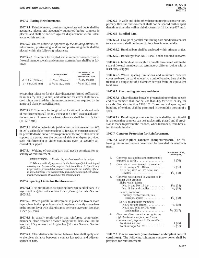
CHAP. 19, DIV. II1907.5
1907.7.21997 UNIFORM BUILDING CODE
2–107
1907.5 Placing Reinforcement.
1907.5.1Reinforcement, prestressing tendons and ducts shall beaccurately placed and adequately supported before concrete isplaced, and shall be secured against displacement within toler-ances of this section.
1907.5.2Unless otherwise approved by the building official, re-inforcement, prestressing tendons and prestressing ducts shall beplaced within the following tolerances:
1907.5.2.1Tolerance for depth d, and minimum concrete cover inflexural members, walls and compression members shall be as fol-lows:
TOLERANCE ONd
TOLERANCE ONMINIMUM
CONCRETE COVER
d � 8 in. (203 mm) � 3/8 in. (9.5 mm) – 3/8 in. (9.5 mm)
d > 8 in. (203 mm) � 1/2 in. (12.7 mm) – 1/2 in. (12.7 mm)
except that tolerance for the clear distance to formed soffits shallbe minus 1/4 inch (6.4 mm) and tolerance for cover shall not ex-ceed minus one third the minimum concrete cover required by theapproved plans or specifications.
1907.5.2.2Tolerance for longitudinal location of bends and endsof reinforcement shall be � 2 inches (� 51 mm) except at discon-tinuous ends of members where tolerance shall be � 1/2 inch(� 12.7 mm).
1907.5.3Welded wire fabric (with wire size not greater than W5or D5) used in slabs not exceeding 10 feet (3048 mm) in span shallbe permitted to be curved from a point near the top of slab over thesupport to a point near the bottom of slab at midspan, providedsuch reinforcement is either continuous over, or securely an-chored at, support.
1907.5.4Welding of crossing bars shall not be permitted for as-sembly of reinforcement.
EXCEPTIONS: 1. Reinforcing steel not required by design.
2. When specifically approved by the building official, welding ofcrossing bars for assembly purposes in Seismic Zones 0, 1 and 2 maybe permitted, provided that data are submitted to the building officialto show that there is no detrimental effect on the action of the structuralmember as a result of welding of the crossing bars.
1907.6 Spacing Limits for Reinforcement.
1907.6.1The minimum clear spacing between parallel bars in alayer shall be db but not less than 1 inch (25 mm). See also Section1903.3.2.
1907.6.2Where parallel reinforcement is placed in two or morelayers, bars in the upper layers shall be placed directly above barsin the bottom layer with clear distance between layers not less than1 inch (25 mm).
1907.6.3 In spirally reinforced or tied reinforced compressionmembers, clear distance between longitudinal bars shall not beless than 1.5db or less than 11/2 inches (38 mm). See also Section1903.3.2.
1907.6.4Clear distance limitation between bars shall apply alsoto the clear distance between a contact lap splice and adjacentsplices or bars.
1907.6.5 In walls and slabs other than concrete joist construction,primary flexural reinforcement shall not be spaced farther apartthan three times the wall or slab thickness, or 18 inches (457 mm).
1907.6.6 Bundled bars.
1907.6.6.1Groups of parallel reinforcing bars bundled in contactto act as a unit shall be limited to four bars in one bundle.
1907.6.6.2Bundled bars shall be enclosed within stirrups or ties.
1907.6.6.3Bars larger than No. 11 shall not be bundled in beams.
1907.6.6.4Individual bars within a bundle terminated within thespan of flexural members shall terminate at different points with atleast 40db stagger.
1907.6.6.5Where spacing limitations and minimum concretecover are based on bar diameter db, a unit of bundled bars shall betreated as a single bar of a diameter derived from the equivalenttotal area.
1907.6.7 Prestressing tendons and ducts.
1907.6.7.1Clear distance between pretensioning tendons at eachend of a member shall not be less than 4db for wire, or 3db forstrands. See also Section 1903.3.2. Closer vertical spacing andbundling of tendons shall be permitted in the middle portion of aspan.
1907.6.7.2Bundling of posttensioning ducts shall be permitted ifit is shown that concrete can be satisfactorily placed and if provi-sion is made to prevent the tendons, when tensioned, from break-ing through the duct.
1907.7 Concrete Protection for Reinforcement.
1907.7.1 Cast-in-place concrete (nonprestressed).The fol-lowing minimum concrete cover shall be provided for reinforce-ment:
MINIMUM COVER,inches (mm)
1. Concrete cast against and permanentlyexposed to earth . . . . . . . . . . . . . . . . . . . 3 (76)
2. Concrete exposed to earth or weather:No. 6 through No. 18 bar . . . . . . . . . . No. 5 bar, W31 or D31 wire, and
smaller . . . . . . . . . . . . . . . . . . . . . .
2 (51)
11/2 (38)3. Concrete not exposed to weather or in
contact with ground:Slabs, walls, joists:
No. 14 and No. 18 bar . . . . . . . . . . No. 11 bar and smaller . . . . . . . . . .
11/2 (38)3/4 (19)
Beams, columns:Primary reinforcement, ties,
stirrups, spirals . . . . . . . . . . . . . . 11/2 (38)Shells, folded plate members:
No. 6 bar and larger . . . . . . . . . . . . No. 5 bar, W31 or D31 wire,
and smaller . . . . . . . . . . . . . . . . .
3/4 (19)
1/2 (12.7)4. Concrete tilt-up panels cast against a
rigid horizontal surface, such as aconcrete slab, exposed to the weather:
No. 8 and smaller. . . . . . . . . . . . . . . . No. 9 through No. 18. . . . . . . . . . . . .
1 (25)2 (51)
1907.7.2 Precast concrete (manufactured under plant controlconditions). The following minimum concrete cover shall beprovided for reinforcement:
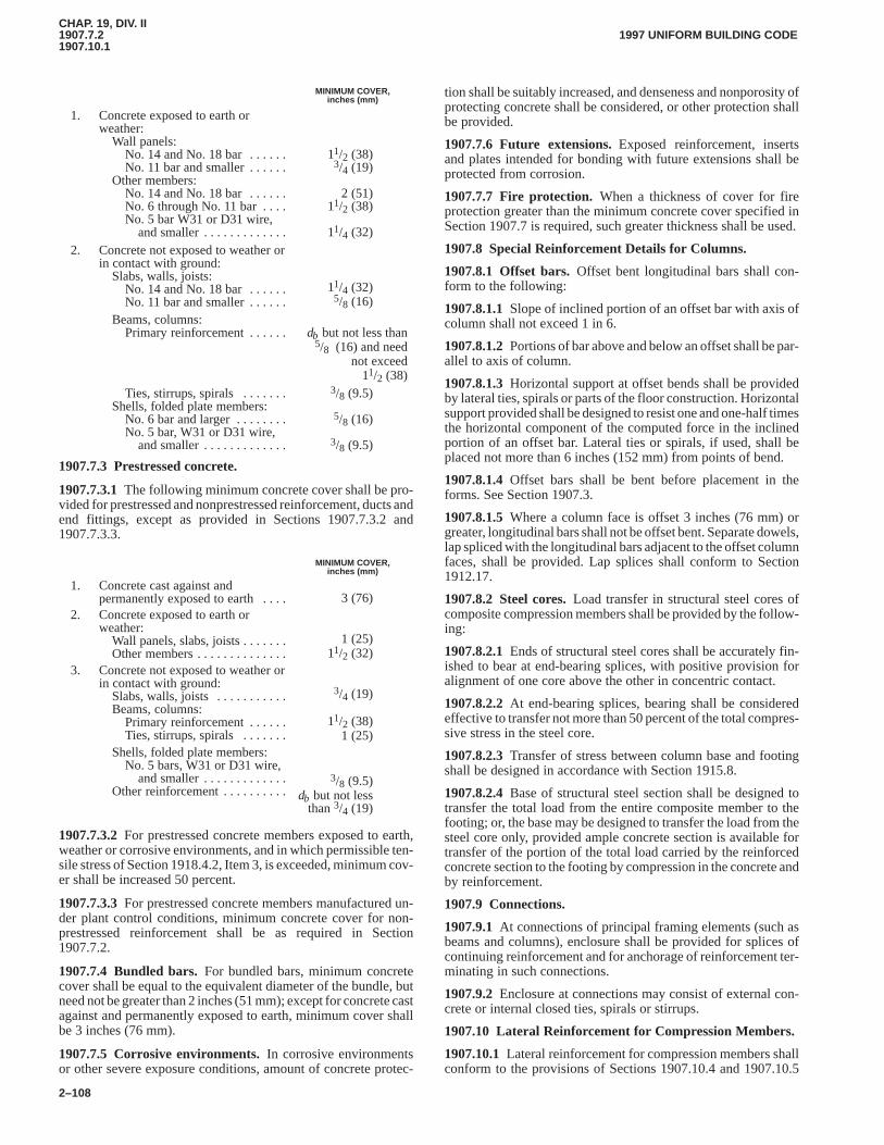
CHAP. 19, DIV. II1907.7.21907.10.1
1997 UNIFORM BUILDING CODE
2–108
MINIMUM COVER,inches (mm)
1. Concrete exposed to earth orweather:
Wall panels:No. 14 and No. 18 bar . . . . . . No. 11 bar and smaller . . . . . .
Other members:No. 14 and No. 18 bar . . . . . . No. 6 through No. 11 bar . . . . No. 5 bar W31 or D31 wire,
and smaller . . . . . . . . . . . . .
11/2 (38)3/4 (19)
2 (51)11/2 (38)
11/4 (32)2. Concrete not exposed to weather or
in contact with ground:Slabs, walls, joists:
No. 14 and No. 18 bar . . . . . . No. 11 bar and smaller . . . . . .
11/4 (32)5/8 (16)
Beams, columns:Primary reinforcement . . . . . . db but not less than
5/8 (16) and neednot exceed
11/2 (38)Ties, stirrups, spirals . . . . . . .
Shells, folded plate members:No. 6 bar and larger . . . . . . . . No. 5 bar, W31 or D31 wire,
and smaller . . . . . . . . . . . . .
3/8 (9.5)
5/8 (16)
3/8 (9.5)
1907.7.3 Prestressed concrete.
1907.7.3.1The following minimum concrete cover shall be pro-vided for prestressed and nonprestressed reinforcement, ducts andend fittings, except as provided in Sections 1907.7.3.2 and1907.7.3.3.
MINIMUM COVER,inches (mm)
1. Concrete cast against andpermanently exposed to earth . . . . 3 (76)
2. Concrete exposed to earth orweather:
Wall panels, slabs, joists . . . . . . . Other members . . . . . . . . . . . . . .
1 (25)
11/2 (32)3. Concrete not exposed to weather or
in contact with ground:Slabs, walls, joists . . . . . . . . . . . Beams, columns:
Primary reinforcement . . . . . . Ties, stirrups, spirals . . . . . . .
3/4 (19)
11/2 (38)1 (25)
Shells, folded plate members:No. 5 bars, W31 or D31 wire,
and smaller . . . . . . . . . . . . . Other reinforcement . . . . . . . . . .
3/8 (9.5)db but not less
than 3/4 (19)
1907.7.3.2For prestressed concrete members exposed to earth,weather or corrosive environments, and in which permissible ten-sile stress of Section 1918.4.2, Item 3, is exceeded, minimum cov-er shall be increased 50 percent.
1907.7.3.3For prestressed concrete members manufactured un-der plant control conditions, minimum concrete cover for non-prestressed reinforcement shall be as required in Section1907.7.2.
1907.7.4 Bundled bars.For bundled bars, minimum concretecover shall be equal to the equivalent diameter of the bundle, butneed not be greater than 2 inches (51 mm); except for concrete castagainst and permanently exposed to earth, minimum cover shallbe 3 inches (76 mm).
1907.7.5 Corrosive environments.In corrosive environmentsor other severe exposure conditions, amount of concrete protec-
tion shall be suitably increased, and denseness and nonporosity ofprotecting concrete shall be considered, or other protection shallbe provided.
1907.7.6 Future extensions.Exposed reinforcement, insertsand plates intended for bonding with future extensions shall beprotected from corrosion.
1907.7.7 Fire protection.When a thickness of cover for fireprotection greater than the minimum concrete cover specified inSection 1907.7 is required, such greater thickness shall be used.
1907.8 Special Reinforcement Details for Columns.
1907.8.1 Offset bars.Offset bent longitudinal bars shall con-form to the following:
1907.8.1.1Slope of inclined portion of an offset bar with axis ofcolumn shall not exceed 1 in 6.
1907.8.1.2Portions of bar above and below an offset shall be par-allel to axis of column.
1907.8.1.3Horizontal support at offset bends shall be providedby lateral ties, spirals or parts of the floor construction. Horizontalsupport provided shall be designed to resist one and one-half timesthe horizontal component of the computed force in the inclinedportion of an offset bar. Lateral ties or spirals, if used, shall beplaced not more than 6 inches (152 mm) from points of bend.
1907.8.1.4Offset bars shall be bent before placement in theforms. See Section 1907.3.
1907.8.1.5Where a column face is offset 3 inches (76 mm) orgreater, longitudinal bars shall not be offset bent. Separate dowels,lap spliced with the longitudinal bars adjacent to the offset columnfaces, shall be provided. Lap splices shall conform to Section1912.17.
1907.8.2 Steel cores.Load transfer in structural steel cores ofcomposite compression members shall be provided by the follow-ing:
1907.8.2.1Ends of structural steel cores shall be accurately fin-ished to bear at end-bearing splices, with positive provision foralignment of one core above the other in concentric contact.
1907.8.2.2At end-bearing splices, bearing shall be consideredeffective to transfer not more than 50 percent of the total compres-sive stress in the steel core.
1907.8.2.3Transfer of stress between column base and footingshall be designed in accordance with Section 1915.8.
1907.8.2.4Base of structural steel section shall be designed totransfer the total load from the entire composite member to thefooting; or, the base may be designed to transfer the load from thesteel core only, provided ample concrete section is available fortransfer of the portion of the total load carried by the reinforcedconcrete section to the footing by compression in the concrete andby reinforcement.
1907.9 Connections.
1907.9.1At connections of principal framing elements (such asbeams and columns), enclosure shall be provided for splices ofcontinuing reinforcement and for anchorage of reinforcement ter-minating in such connections.
1907.9.2Enclosure at connections may consist of external con-crete or internal closed ties, spirals or stirrups.
1907.10 Lateral Reinforcement for Compression Members.
1907.10.1Lateral reinforcement for compression members shallconform to the provisions of Sections 1907.10.4 and 1907.10.5
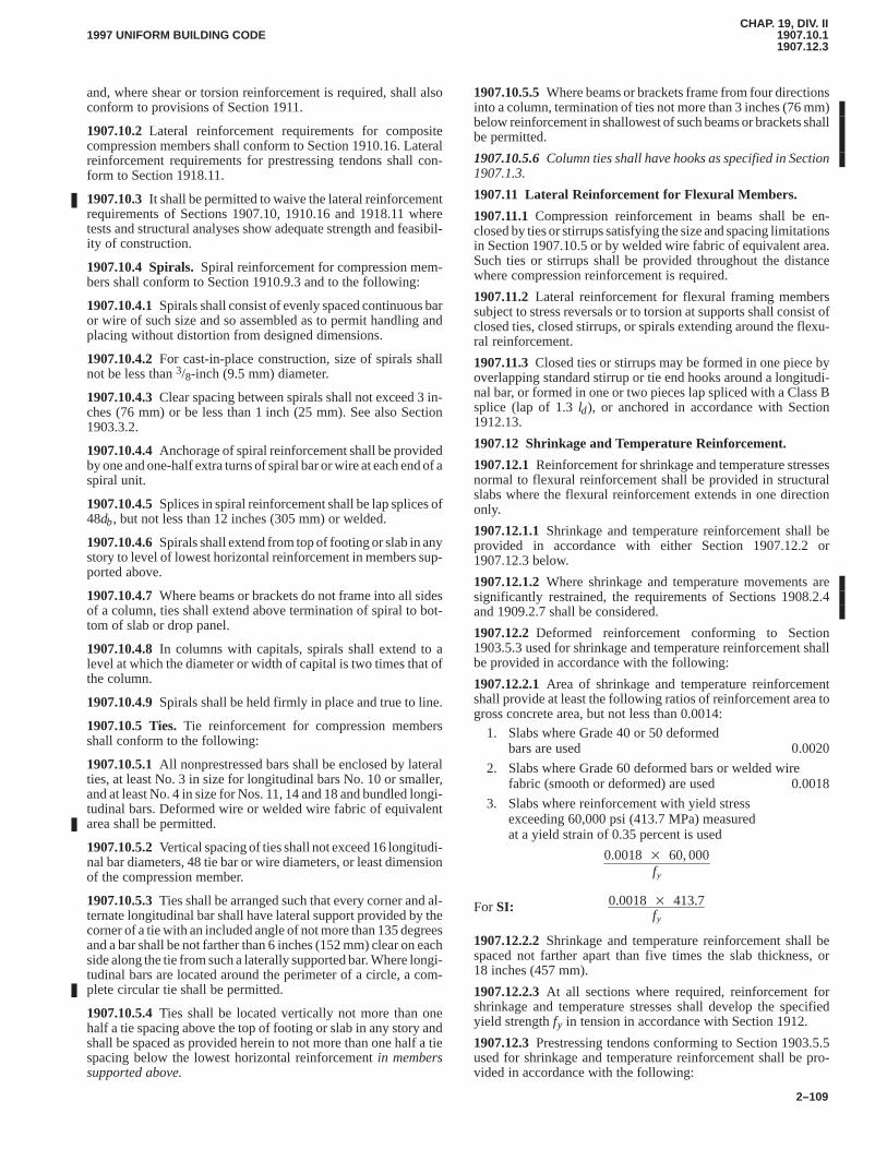
CHAP. 19, DIV. II1907.10.11907.12.3
1997 UNIFORM BUILDING CODE
2–109
and, where shear or torsion reinforcement is required, shall alsoconform to provisions of Section 1911.
1907.10.2Lateral reinforcement requirements for compositecompression members shall conform to Section 1910.16. Lateralreinforcement requirements for prestressing tendons shall con-form to Section 1918.11.
1907.10.3It shall be permitted to waive the lateral reinforcementrequirements of Sections 1907.10, 1910.16 and 1918.11 wheretests and structural analyses show adequate strength and feasibil-ity of construction.
1907.10.4 Spirals.Spiral reinforcement for compression mem-bers shall conform to Section 1910.9.3 and to the following:
1907.10.4.1Spirals shall consist of evenly spaced continuous baror wire of such size and so assembled as to permit handling andplacing without distortion from designed dimensions.
1907.10.4.2For cast-in-place construction, size of spirals shallnot be less than 3/8-inch (9.5 mm) diameter.
1907.10.4.3Clear spacing between spirals shall not exceed 3 in-ches (76 mm) or be less than 1 inch (25 mm). See also Section1903.3.2.
1907.10.4.4Anchorage of spiral reinforcement shall be providedby one and one-half extra turns of spiral bar or wire at each end of aspiral unit.
1907.10.4.5Splices in spiral reinforcement shall be lap splices of48db, but not less than 12 inches (305 mm) or welded.
1907.10.4.6Spirals shall extend from top of footing or slab in anystory to level of lowest horizontal reinforcement in members sup-ported above.
1907.10.4.7Where beams or brackets do not frame into all sidesof a column, ties shall extend above termination of spiral to bot-tom of slab or drop panel.
1907.10.4.8In columns with capitals, spirals shall extend to alevel at which the diameter or width of capital is two times that ofthe column.
1907.10.4.9Spirals shall be held firmly in place and true to line.
1907.10.5 Ties.Tie reinforcement for compression membersshall conform to the following:
1907.10.5.1All nonprestressed bars shall be enclosed by lateralties, at least No. 3 in size for longitudinal bars No. 10 or smaller,and at least No. 4 in size for Nos. 11, 14 and 18 and bundled longi-tudinal bars. Deformed wire or welded wire fabric of equivalentarea shall be permitted.
1907.10.5.2Vertical spacing of ties shall not exceed 16 longitudi-nal bar diameters, 48 tie bar or wire diameters, or least dimensionof the compression member.
1907.10.5.3Ties shall be arranged such that every corner and al-ternate longitudinal bar shall have lateral support provided by thecorner of a tie with an included angle of not more than 135 degreesand a bar shall be not farther than 6 inches (152 mm) clear on eachside along the tie from such a laterally supported bar. Where longi-tudinal bars are located around the perimeter of a circle, a com-plete circular tie shall be permitted.
1907.10.5.4Ties shall be located vertically not more than onehalf a tie spacing above the top of footing or slab in any story andshall be spaced as provided herein to not more than one half a tiespacing below the lowest horizontal reinforcement in memberssupported above.
1907.10.5.5Where beams or brackets frame from four directionsinto a column, termination of ties not more than 3 inches (76 mm)below reinforcement in shallowest of such beams or brackets shallbe permitted.
1907.10.5.6Column ties shall have hooks as specified in Section1907.1.3.
1907.11 Lateral Reinforcement for Flexural Members.
1907.11.1Compression reinforcement in beams shall be en-closed by ties or stirrups satisfying the size and spacing limitationsin Section 1907.10.5 or by welded wire fabric of equivalent area.Such ties or stirrups shall be provided throughout the distancewhere compression reinforcement is required.
1907.11.2Lateral reinforcement for flexural framing memberssubject to stress reversals or to torsion at supports shall consist ofclosed ties, closed stirrups, or spirals extending around the flexu-ral reinforcement.
1907.11.3Closed ties or stirrups may be formed in one piece byoverlapping standard stirrup or tie end hooks around a longitudi-nal bar, or formed in one or two pieces lap spliced with a Class Bsplice (lap of 1.3 ld), or anchored in accordance with Section1912.13.
1907.12 Shrinkage and Temperature Reinforcement.
1907.12.1Reinforcement for shrinkage and temperature stressesnormal to flexural reinforcement shall be provided in structuralslabs where the flexural reinforcement extends in one directiononly.
1907.12.1.1Shrinkage and temperature reinforcement shall beprovided in accordance with either Section 1907.12.2 or1907.12.3 below.
1907.12.1.2Where shrinkage and temperature movements aresignificantly restrained, the requirements of Sections 1908.2.4and 1909.2.7 shall be considered.
1907.12.2Deformed reinforcement conforming to Section1903.5.3 used for shrinkage and temperature reinforcement shallbe provided in accordance with the following:
1907.12.2.1Area of shrinkage and temperature reinforcementshall provide at least the following ratios of reinforcement area togross concrete area, but not less than 0.0014:
1. Slabs where Grade 40 or 50 deformedbars are used 0.0020
2. Slabs where Grade 60 deformed bars or welded wirefabric (smooth or deformed) are used 0.0018
3. Slabs where reinforcement with yield stressexceeding 60,000 psi (413.7 MPa) measuredat a yield strain of 0.35 percent is used
0.0018� 60, 000fy
For SI: 0.0018� 413.7fy
1907.12.2.2Shrinkage and temperature reinforcement shall bespaced not farther apart than five times the slab thickness, or18 inches (457 mm).
1907.12.2.3At all sections where required, reinforcement forshrinkage and temperature stresses shall develop the specifiedyield strength fy in tension in accordance with Section 1912.
1907.12.3Prestressing tendons conforming to Section 1903.5.5used for shrinkage and temperature reinforcement shall be pro-vided in accordance with the following:
CHAP. 19, DIV. II1907.12.3.11908.3.3
1997 UNIFORM BUILDING CODE
2–110
1907.12.3.1Tendons shall be proportioned to provide a mini-mum average compressive stress of 100 psi (0.69 MPa) on grossconcrete area using effective prestress, after losses, in accordancewith Section 1918.6.
1907.12.3.2Spacing of prestressed tendons shall not exceed6 feet (1829 mm).
1907.12.3.3When the spacing of prestressed tendons exceeds54 inches (1372 mm), additional bonded shrinkage and tempera-ture reinforcement conforming with Section 1907.12.2 shall beprovided between the tendons at slab edges extending from theslab edge for a distance equal to the tendon spacing.
1907.13 Requirements for Structural Integrity.
1907.13.1In the detailing of reinforcement and connections,members of a structure shall be effectively tied together toimprove integrity of the overall structure.
1907.13.2For cast-in-place construction, the following shallconstitute minimum requirements:
1907.13.2.1In joist construction, at least one bottom bar shall becontinuous or shall be spliced over the support with a Class A ten-sion splice and at noncontinuous supports be terminated with astandard hook.
1907.13.2.2Beams at the perimeter of the structure shall have atleast one sixth of the tension reinforcement required for negativemoment at the support and one-quarter of the positive momentreinforcement required at midspan made continuous around theperimeter and tied with closed stirrups or stirrups anchored aroundthe negative moment reinforcement with a hook having a bend ofat least 135 degrees. Stirrups need not be extended through anyjoints. When splices are needed, the required continuity shall beprovided with top reinforcement spliced at midspan and bottomreinforcement spliced at or near the support with Class A tensionsplices.
1907.13.2.3In other than perimeter beams, when closed stirrupsare not provided, at least one-quarter of the positive moment rein-forcement required at midspan shall be continuous or shall bespliced over the support with a Class A tension splice and at non-continuous supports be terminated with a standard hook.
1907.13.2.4For two-way slab construction, see Section1913.3.8.5.
1907.13.3For precast concrete construction, tension ties shall beprovided in the transverse, longitudinal, and vertical directionsand around the perimeter of the structure to effectively tie ele-ments together. The provisions of Section 1916.5 shall apply.
1907.13.4For lift-slab construction, see Sections 1913.3.8.6 and1918.12.6.
SECTION 1908 — ANALYSIS AND DESIGN
1908.0 Notations.
As = area of nonprestressed tension reinforcement, square in-ches (mm2).
A′s = area of compression reinforcement, square inches(mm2).
b = width of compression face of member, inches (mm).d = distance from extreme compression fiber to centroid of
tension reinforcement, inches (mm).Ec = modulus of elasticity of concrete, pounds per square
inch (MPa). See Section 1908.5.1.
Es = modulus of elasticity of reinforcement, pounds persquare inch (MPa). See Sections 1908.2 and 1908.5.3.
f ′c = specified compressive strength of concrete, pounds persquare inch (MPa).
fy = specified yield strength of nonprestressed reinforce-ment, pounds per square inch (MPa).
ln = clear span for positive moment or shear and average ofadjacent clear spans for negative moment.
Vc = nominal shear strength provided by concrete.wc = unit weight of concrete, pounds per cubic foot (kg/m3).wu = factored load per unit length of beam or per unit area of
slab.β1 = factor defined in Section 1910.2.7.3.εt = net tensile strain in extreme tension steel at nominal
strength.ρ = ratio of nonprestressed tension reinforcement.
= As/bd.ρ′ = ratio of nonprestressed compression reinforcement.
= A′s/bd.ρb = reinforcement ratio producing balanced strain condi-
tions. See Section 1910.3.2.φ = strength-reduction factor. See Section 1909.3.
1908.1 Design Methods.
1908.1.1 In design of structural concrete, members shall be pro-portioned for adequate strength in accordance with provisions ofthis code, using load factors and strength-reduction factors φ spe-cified in Section 1909.
1908.1.2Nonprestressed reinforced concrete members shall bepermitted to be designed using the provisions of Section 1926.
1908.1.3Design of reinforced concrete using Section 1927 shallbe permitted.
1908.2 Loading.
1908.2.1Design provisions of this code are based on the assump-tion that structures shall be designed to resist all applicable loads.
1908.2.2Service loads shall be in accordance with Chapter 16with appropriate live load reductions as permitted therein.
1908.2.3 In design for wind and earthquake loads, integral struc-tural parts shall be designed to resist the total lateral loads.
1908.2.4Consideration shall be given to effects of forces due toprestressing, crane loads, vibration, impact, shrinkage, tempera-ture changes, creep, expansion of shrinkage-compensating con-crete and unequal settlement of supports.
1908.3 Methods of Analysis.
1908.3.1All members of frames or continuous construction shallbe designed for the maximum effects of factored loads as deter-mined by the theory of elastic analysis, except as modified by Sec-tion 1908.4. It is permitted to simplify the design by using theassumptions specified in Sections 1908.6 through 1908.9.
1908.3.2Except for prestressed concrete, approximate methodsof frame analysis may be used for buildings of usual types of con-struction, spans and story heights.
1908.3.3As an alternate to frame analysis, the following approx-imate moments and shears shall be permitted to be used in designof continuous beams and one-way slabs (slabs reinforced to resistflexural stresses in only one direction), provided:
1. There are two or more spans,
CHAP. 19, DIV. II1908.3.31908.9.2
1997 UNIFORM BUILDING CODE
2–111
2. Spans are approximately equal, with the larger of two adja-cent spans not greater than the shorter by more than 20 percent,
3. Loads are uniformly distributed, and
4. Unit live load does not exceed three times unit dead load, and
5. Members are prismatic.
Positive moment:
End spans
Discontinuous end unrestrained wuln2/11. . . . . . . . . . . . Discontinuous end integral with support wuln2/14. . . . .
Interior spans wuln2/16. . . . . . . . . . . . . . . . . . . . . . . . . . . .
Negative moment at exterior face of first interior support
Two spans wuln2/9. . . . . . . . . . . . . . . . . . . . . . . . . . . . . . . . More than two spans wuln2/10. . . . . . . . . . . . . . . . . . . . . .
Negative moment at other faces ofinterior supports wuln2/11. . . . . . . . . . . . . . . . . . . . . . . . . .
Negative moment at face of all supports for:
Slabs with spans not exceeding 10 feet (3048 mm),and beams where ratio of sum of column stiffnessesto beam stiffness exceeds eight at each end ofthe span wuln2/12. . . . . . . . . . . . . . . . . . . . . . . . . . . . . . . . .
Negative moment at interior face of exterior support formembers built integrally with supports:
Where support is a spandrel beam wuln2/24. . . . . . . . . . . . Where support is a column wuln2/16. . . . . . . . . . . . . . . . . .
Shear in end members at face of firstinterior support 1.15 wuln/2. . . . . . . . . . . . . . . . . . . . . . . . .
Shear at face of all other supports wuln/2. . . . . . . . . . . . . . .
1908.4 Redistribution of Negative Moments in ContinuousNonprestressed Flexural Members.
1908.4.1Except where approximate values for moments areused, it is permitted to increase or decrease negative moments cal-culated by elastic theory at supports of continuous flexural mem-bers for any assumed loading arrangement by not more than
20�1�
ρ � ρ�
ρb
� percent
1908.4.2The modified negative moments shall be used for calcu-lating moments at sections within the spans.
1908.4.3Redistribution of negative moments shall be made onlywhen the section, at which moment is reduced, is so designed thatρ or ρ – ρ′ is not greater than 0.50 ρb, where
ρb �
0.85�1 f �cfy
87, 00087, 000� fy
(8-1)
For SI: ρb �
0.85�1 f �cfy
600600 � fy
1908.4.4For criteria on moment redistribution for prestressedconcrete members, see Section 1918.
1908.5 Modulus of Elasticity.
1908.5.1Modulus of elasticity Ec for concrete shall be permitted
to be taken as w 1.5c 33 f �c� (in psi) [For SI: w 1.5
c 0.043 f �c� (inMPA)] for values of wc between 90 pcf and 155 pcf (1440 kg/m3
and 2420 kg/m3). For normal-weight concrete, Ec shall be per-
mitted to be taken as 57,000f �c� (ForSI: 4730 f �c� ).
1908.5.2 Modulus of elasticity Es for nonprestressed reinforce-ment shall be permitted to be taken as 29,000,000 psi (200 000MPa).
1908.5.3Modulus of elasticity Es for prestressing tendons shallbe determined by tests or supplied by the manufacturer.
1908.6 Stiffness.
1908.6.1Use of any set of reasonable assumptions shall be per-mitted for computing relative flexural and torsional stiffnesses ofcolumns, walls, floors and roof systems. The assumptions adoptedshall be consistent throughout analysis.
1908.6.2Effect of haunches shall be considered both in deter-mining moments and in design of members.
1908.7 Span Length.
1908.7.1Span length of members not built integrally with sup-ports shall be considered the clear span plus depth of member, butneed not exceed distance between centers of supports.
1908.7.2 In analysis of frames or continuous construction for de-termination of moments, span length shall be taken as the distancecenter to center of supports.
1908.7.3For beams built integrally with supports, design on thebasis of moments at faces of support shall be permitted.
1908.7.4 It shall be permitted to analyze solid or ribbed slabs builtintegrally with supports, with clear spans not more than 10 feet(3048 mm), as continuous slabs on knife edge supports with spansequal to the clear spans of the slab and width of beams otherwiseneglected.
1908.8 Columns.
1908.8.1Columns shall be designed to resist the axial forcesfrom factored loads on all floors or roof and the maximum mo-ment from factored loads on a single adjacent span of the floor orroof under consideration. Loading condition giving the maximumratio of moment to axial load shall also be considered.
1908.8.2 In frames or continuous construction, considerationshall be given to the effect of unbalanced floor or roof loads onboth exterior and interior columns and of eccentric loading due toother causes.
1908.8.3 In computing gravity load moments in columns, it shallbe permitted to assume far ends of columns built integrally withthe structure to be fixed.
1908.8.4Resistance to moments at any floor or roof level shall beprovided by distributing the moment between columns immedi-ately above and below the given floor in proportion to the relativecolumn stiffnesses and conditions of restraint.
1908.9 Arrangement of Live Load.
1908.9.1 It is permissible to assume that:
1. the live load is applied only to the floor or roof under consid-eration, and
2. the far ends of columns built integrally with the structure areconsidered to be fixed.
1908.9.2 It is permitted to assume that the arrangement of liveload is limited to combinations of:
1. Factored dead load on all spans with full-factored live loadon two adjacent spans, and
CHAP. 19, DIV. II1908.9.21909.0
1997 UNIFORM BUILDING CODE
2–112
2. Factored dead load on all spans with full-factored live loadon alternate spans.
1908.10 T-beam Construction.
1908.10.1In T-beam construction, the flange and web shall bebuilt integrally or otherwise effectively bonded together.
1908.10.2Width of slab effective as a T-beam flange shall not ex-ceed one fourth the span length of the beam, and the effectiveoverhanging slab width on each side of the web shall not exceed:
1. Eight times the slab thickness, or
2. One half the clear distance to the next web.
1908.10.3For beams with a slab on one side only, the effectiveoverhanging flange width shall not exceed:
1. One twelfth the span length of the beam,
2. Six times the slab thickness, or
3. One half the clear distance to the next web.
1908.10.4Isolated beams, in which the T-shape is used to providea flange for additional compression area, shall have a flange thick-ness not less than one half the width of web and an effective flangewidth not more than four times the width of web.
1908.10.5Where primary flexural reinforcement in a slab that isconsidered as a T-beam flange (excluding joist construction) isparallel to the beam, reinforcement perpendicular to the beamshall be provided in the top of the slab in accordance with the fol-lowing:
1908.10.5.1Transverse reinforcement shall be designed to carrythe factored load on the overhanging slab width assumed to act as acantilever. For isolated beams, the full width of overhangingflange shall be considered. For other T-beams, only the effectiveoverhanging slab width need be considered.
1908.10.5.2Transverse reinforcement shall be spaced not fartherapart than five times the slab thickness or 18 inches (457 mm).
1908.11 Joist Construction.
1908.11.1 Joist construction consists of a monolithic combinationof regularly spaced ribs and a top slab arranged to span in one di-rection or two orthogonal directions.
1908.11.2Ribs shall not be less than 4 inches (102 mm) in widthand shall have a depth of not more than three and one-half timesthe minimum width of rib.
1908.11.3Clear spacing between ribs shall not exceed 30 inches(762 mm).
1908.11.4Joist construction not meeting the limitations of thepreceding two paragraphs shall be designed as slabs and beams.
1908.11.5When permanent burned clay or concrete tile fillers ofmaterial having a unit compressive strength at least equal to that ofthe specified strength of concrete in the joists are used:
1908.11.5.1For shear and negative-moment strength computa-tions, it shall be permitted to include the vertical shells of fillers incontact with ribs. Other portions of fillers shall not be included instrength computations.
1908.11.5.2Slab thickness over permanent fillers shall not beless than one twelfth the clear distance between ribs nor less than11/2 inches (38 mm).
1908.11.5.3In one-way joists, reinforcement normal to the ribsshall be provided in the slab as required by Section 1907.12.
1908.11.6When removable forms or fillers not complying withSection 1908.11.5 are used:
1908.11.6.1Slab thickness shall not be less than one twelfth theclear distance between ribs, or less than 2 inches (51 mm).
1908.11.6.2Reinforcement normal to the ribs shall be providedin the slab as required for flexure, considering load concentra-tions, if any, but not less than required by Section 1907.12.
1908.11.7Where conduits or pipes as permitted by Section1906.3 are embedded within the slab, slab thickness shall be atleast 1 inch (25 mm) greater than the total overall depth of the con-duits or pipes at any point. Conduits or pipes shall not impair sig-nificantly the strength of the construction.
1908.11.8For joist construction, contribution of concrete toshear strength Vc is permitted to be 10 percent more than that spe-cified in Section 1911. It shall be permitted to increase shearstrength using shear reinforcement or by widening the ends of theribs.
1908.12 Separate Floor Finish.
1908.12.1A floor finish shall not be included as part of a structur-al member unless placed monolithically with the floor slab or de-signed in accordance with requirements of Section 1917.
1908.12.2It shall be permitted to consider all concrete floor fi-nishes may be considered as part of required cover or total thick-ness for nonstructural considerations.
SECTION 1909 — STRENGTH AND SERVICEABILITYREQUIREMENTS
1909.0 Notations.Ag = gross area of section, square inches (mm2).A′s = area of compression reinforcement, square inches
(mm2).b = width of compression face of member, inches (mm).c = distance from extreme compression fiber to neutral axis
in inches (mm).D = dead loads, or related internal moments and forces.d = distance from extreme compression fiber to centroid of
tension reinforcement, inches (mm).d′ = distance from extreme compression fiber to centroid of
compression reinforcement, inches (mm).ds = distance from extreme tension fiber to centroid of ten-
sion reinforcement, inches (mm).dt = distance from extreme compression fiber to extreme
tension steel, inches (mm).E = load effects of earthquake, or related internal moments
and forces.Ec = modulus of elasticity of concrete, pounds per square
inch (MPa). See Section 1908.1.F = loads due to weight and pressures of fluids with well-
defined densities and controllable maximum heights, orrelated internal moments and forces.
f ′c = specified compressive strength of concrete, pounds persquare inch (MPa).
f �c� = square root of specified compressive strength of con-
crete, pounds per square inch (MPa).fct = average splitting tensile strength of lightweight aggre-
gate concrete, pounds per square inch (MPa).fr = modulus of rupture of concrete, pounds per square inch
(MPa).
CHAP. 19, DIV. II1909.0
1909.3.1.11997 UNIFORM BUILDING CODE
2–113
fy = specified yield strength of nonprestressed reinforce-ment, pounds per square inch (MPa).
H = loads due to weight and pressure of soil, water in soil, orother materials, or related internal moments and forces.
h = overall thickness of member, inches (mm).Icr = moment of inertia of cracked section transformed to
concrete.Ie = effective moment of inertia for computation of deflec-
tion.Ig = moment of inertia of gross concrete section about cen-
troidal axis, neglecting reinforcement.L = live loads, or related internal moments and forces.l = span length of beam or one-way slab, as defined in Sec-
tion 1908.7; clear projection of cantilever, inches (mm).ln = length of clear span in long direction of two-way con-
struction, measured face to face of supports in slabswithout beams and face to face of beams or other sup-ports in other cases.
Ma = maximum moment in member at stage deflection iscomputed.
Mcr = cracking moment. See Formula (9-8).Pb = nominal axial load strength at balanced strain condi-
tions. See Section 1910.3.2.Pn = nominal axial load strength at given eccentricity.T = cumulative effects of temperature, creep, shrinkage, dif-
ferential settlement and shrinkage compensating con-crete.
U = required strength to resist factored loads or related inter-nal moments and forces.
W = wind load, or related internal moments and forces.wc = weight of concrete, pounds per cubic foot (kg/m3).yt = distance from centroidal axis of gross section, neglect-
ing reinforcement, to extreme fiber in tension. α = ratio of flexural stiffness of beam section to flexural
stiffness of a width of slab bounded laterally by centerline of adjacent panel (if any) on each side of beam. SeeSection 1913.
αm = average value of α for all beams on edges of a panel.β = ratio of clear spans in long-to-short direction of two-way
slabs.ξ = time-dependent factor for sustained load. See Section
1909.5.2.5.εt = net tensile strain in extreme tension steel at nominal
strength.λ = multiplier for additional long-time deflection as defined
in Section 1909.5.2.5.ρ = ratio of nonprestressed tension reinforcement, As/bd.ρ′ = reinforcement ratio for nonprestressed compression re-
inforcement, A′g/bd.
ρb = reinforcement ratio producing balanced strain condi-tions. See Section B1910.3.2.
φ = strength-reduction factor. See Section 1909.3.
1909.1 General.
1909.1.1Structures and structural members shall be designed tohave design strengths at all sections at least equal to the requiredstrengths calculated for the factored loads and forces in such com-binations as are stipulated in this code.
1909.1.2Members also shall meet all other requirements of thiscode to ensure adequate performance at service load levels.
1909.2 Required Strength.
1909.2.1Required strength U to resist dead load D and live load Lshall be at least equal to
U � 1.4D � 1.7L (9-1)
1909.2.2 If resistance to structural effects of a specified wind loadW are included in design, the following combinations of D, L andW shall be investigated to determine the greatest required strengthU
U � 0.75 (1.4D � 1.7L � 1.7W) (9-2)where load combinations shall include both full value and zerovalue of L to determine the more severe condition, and
U � 0.9D � 1.3W (9-3)but for any combination of D, L and W, required strength U shallnot be less than Formula (9-1).
1909.2.3 If resistance to specified earthquake loads or forces Eare included in design, load combinations of Section 1612.2.1shall apply.
1909.2.4 If resistance to earth pressure H is included in design,required strength U shall be at least equal to
U � 1.4D � 1.7L � 1.7H (9-4)except that where D or L reduces the effect of H, 0.9D shall be sub-stituted for 1.4D and zero value of L shall be used to determine thegreatest required strength U. For any combination of D, L and H,required strength U shall not be less than Formula (9-1).
1909.2.5 If resistance to loadings due to weight and pressure offluids with well-defined densities and controllable maximumheights F is included in design, such loading shall have a load fac-tor of 1.4 and be added to all loading combinations that includelive load.
1909.2.6 If resistance to impact effects is taken into account indesign, such effects shall be included with live load L.
1909.2.7Where structural effects T of differential settlement,creep, shrinkage, expansion of shrinkage-compensating concreteor temperature change may be significant in design, requiredstrength U shall be at least equal to
U � 0.75 (1.4D � 1.4T � 1.7L) (9-5)but required strength U shall not be less than
U � 1.4 (D � T) (9-6)Estimations of differential settlement, creep, shrinkage, expan-sion of shrinkage-compensating concrete or temperature changeshall be based on a realistic assessment of such effects occurring inservice.
1909.3 Design Strength.
1909.3.1Design strength provided by a member, its connectionto other members and its cross sections, in terms of flexure, axialload, shear and tension, shall be taken as the nominal strength cal-culated in accordance with requirements and assumptions of thiscode, multiplied by a strength-reduction factor φ in Sections1909.3.2 and 1909.3.4.
1909.3.1.1If the structural framing includes primary members ofother materials proportioned to satisfy the load-factor combina-tions of Section 1928.1.2, it shall be permitted to proportion theconcrete members using the set of strength-reduction factors, �,listed in Section 1928.1.1 and the load-factor combinations inSection 1928.1.2.
CHAP. 19, DIV. II1909.3.21909.5.3.1
1997 UNIFORM BUILDING CODE
2–114
1909.3.2Strength-reduction factor φ shall be as follows:
1909.3.2.1Flexure, without axial load 0.90. . . . . . . . . . . . . . .
1909.3.2.2Axial load and axial load with flexure. (For axial loadwith flexure, both axial load and moment nominal strength shallbe multiplied by appropriate single value of φ.)
Axial tension and axial tension with flexure 0.90. . . . . . . . .
Axial compression and axial compression with flexure:
Members with spiral reinforcement conforming toSection 1910.9.3 0.75. . . . . . . . . . . . . . . . . . . . . . . . . . . . . .
Other reinforced members 0.70. . . . . . . . . . . . . . . . . . . . . . .
except that for low values of axial compression, φ shall be per-mitted to be increased in accordance with the following:
For members in which fy does not exceed 60,000 psi (413.7MPa), with symmetric reinforcement, and with (h – d′ – ds)/h notless than 0.70, φ shall be permitted to be increased linearly to 0.90as φPn decreases from 0.10 f ′c Ag to zero.
For other reinforced members, φ shall be permitted to be in-creased linearly to 0.90 as φPn decreases from 0.10 f ′c Ag or φPb,whichever is smaller, to zero.
1909.3.2.3Shear and torsion (See also Section 1909.3.4 for shearwalls and frames in Seismic Zones 3 and 4) 0.85. . . . . . . . . . .
1909.3.2.4Bearing on concrete (See also Section1918.13) 0.70. . . . . . . . . . . . . . . . . . . . . . . . . . . . . . . . . . . . . . .
1909.3.3Development lengths specified in Section 1912 do notrequire a φ factor.
1909.3.4 In Seismic Zones 3 and 4, strength-reduction factors φshall be as given above except for the following:
1909.3.4.1The shear strength-reduction factor shall be 0.6 forthe design of walls, topping slabs used as diaphragms over precastconcrete members and structural framing members, with theexception of joints, if their nominal shear strength is less than theshear corresponding to development of their nominal flexuralstrength. The nominal flexural strength shall be determined corre-sponding to the most critical factored axial loads including earth-quake effects. The shear strength reduction factor for joints shallbe 0.85.
1909.3.4.2Reinforcement used for diaphragm chords or collec-tors placed in topping slabs over precast concrete members shallbe designed using a strength-reduction factor of 0.6.
1909.3.5Strength reduction factor � for flexure compression,shear and bearing of structural plain concrete in Section 1922 shallbe 0.65.
1909.4 Design Strength for Reinforcement.Designs shall notbe based on a yield strength of reinforcement fy in excess of 80,000psi (551.6 MPa), except for prestressing tendons.
1909.5 Control of Deflections.
1909.5.1Reinforced concrete members subject to flexure shallbe designed to have adequate stiffness to limit deflections or anydeformations that affect strength or serviceability of a structureadversely.
1909.5.2 One-way construction (nonprestressed).
1909.5.2.1Minimum thickness stipulated in Table 19-C-1 shallapply for one-way construction not supporting or attached to par-titions or other construction likely to be damaged by large deflec-
tions, unless computation of deflection indicates a lesser thicknessmay be used without adverse effects.
1909.5.2.2Where deflections are to be computed, deflectionsthat occur immediately on application of load shall be computedby usual methods or formulas for elastic deflections, consideringeffects of cracking and reinforcement on member stiffness.
1909.5.2.3Unless stiffness values are obtained by a more com-prehensive analysis, immediate deflection shall be computed withthe modulus of elasticity Ec for concrete as specified in Section1908.5.1 (normal-weight or lightweight concrete) and with the ef-fective moment of inertia as follows, but not greater than Ig.
I e � �Mcr
Ma�
3
Ig � �1 � �Mcr
Ma�
3
�I cr (9-7)
WHERE:
Mcr �
fr I g
yt(9-8)
and for normal-weight concrete
fr � 7.5 f �c� (9-9)
For SI: fr � 0.62 f �c�
When lightweight aggregate concrete is used, one of the followingmodifications shall apply:
1. When fct is specified and concrete is proportioned in ac-cordance with Section 1905.2, fr shall be modified by sub-
stituting fct/6.7 (For SI: 1.8fct) for f �c� , but the value of
fct/6.7 (For SI: 1.8fct) shall not exceed f �c� .
2. When fct is not specified, fr shall be multiplied by 0.75 for‘‘all-lightweight’’ concrete, and 0.85 for “sand-light-weight’’ concrete. Linear interpolation shall be permitted tobe used when partial sand replacement is used.
1909.5.2.4For continuous members, effective moment of inertiashall be permitted to be taken as the average of values obtainedfrom Formula (9-7) for the critical positive and negative momentsections. For prismatic members, effective moment of inertia shallbe permitted to be taken as the value obtained from Formula (9-7)at midspan for simple and continuous spans, and at support forcantilevers.
1909.5.2.5Unless values are obtained by a more comprehensiveanalysis, additional longtime deflection resulting from creep andshrinkage of flexural members (normal-weight or lightweightconcrete) shall be determined by multiplying the immediate de-flection caused by the sustained load considered, by the factor
� ��
1 � 50ρ� (9-10)
where ρ′ shall be the value at midspan for simple and continuousspans, and at support for cantilevers. It is permitted to assume thetime-dependent factor for sustained loads to be equal to
Five years or more 2.012 months 1.4Six months 1.2Three months 1.0
1909.5.2.6Deflection computed in accordance with this sectionshall not exceed limits stipulated in Table 19-C-2.
1909.5.3 Two-way construction (nonprestressed).
1909.5.3.1This section shall govern the minimum thickness ofslabs or other two-way construction designed in accordance with
CHAP. 19, DIV. II1909.5.3.1
1910.01997 UNIFORM BUILDING CODE
2–115
the provisions of Section 1913 and conforming with the re-quirements of Section 1913.6.1.2. The thickness of slabs withoutinterior beams spanning between the supports on all sides shallsatisfy the requirements of Section 1909.5.3.2 or 1909.5.3.4.Thickness of slabs with beams spanning between the supports onall sides shall satisfy the requirements of Section 1909.5.3.3 or1909.5.3.4.
1909.5.3.2For slabs without interior beams spanning betweenthe supports and having a ratio of long to short span not greaterthan 2, the minimum thickness shall be in accordance with the pro-visions of Table 19-C-3 and shall not be less than the followingvalues:
1. Slabs without drop panels as defined inSections 1913.3.7.1 and 1913.3.7.2 5 inches (127 mm). .
2. Slabs with drop panels as defined inSections 1913.3.7.1 and 1913.3.7.2 4 inches (102 mm). .
1909.5.3.3For slabs with beams spanning between the supportson all sides, the minimum thickness shall be as follows:
1. For αm equal to or less than 0.2, the provisions of Section1909.5.3.2 shall apply.
2. For αm greater than 0.2 but not greater than 2.0, the thick-ness shall not be less than
h �
l n�0.8�fy
200,000�
36� 5�(�m� 0.2)(9-11)
For SI: h �
l n�0.8�fy
1370�
36� 5�(�m� 0.2)
but not less than 5 inches (127 mm).
3. For αm greater than 2.0, the thickness shall not be less than
h �
l n�0.8�fy
200,000�
36� 9�(9-12)
For SI: h �
l n�0.8�fy
1370�
36� 9�
but not less than 3.5 inches (89 mm).
4. At discontinuous edges, an edge beam shall be providedwith a stiffness ratio α not less than 0.80; or the minimumthickness required by Formula (9-11) or (9-12) shall be in-creased by at least 10 percent in the panel with a discontinu-ous edge.
1909.5.3.4Slab thickness less than the minimum thickness re-quired by Sections 1909.5.3.1, 1909.5.3.2 and 1909.5.3.3 shall bepermitted to be used if shown by computation that the deflectionwill not exceed the limits stipulated in Table 19-C-2. Deflectionsshall be computed taking into account size and shape of the panel,conditions of support, and nature of restraints at the panel edges.The modulus of elasticity of concrete Ec shall be as specified inSection 1908.5.1. The effective moment of inertia shall be thatgiven by Formula (9-7); other values shall be permitted to be usedif they result in computed deflections in reasonable agreementwith the results of comprehensive tests. Additional long-term de-flection shall be computed in accordance with Section 1909.5.2.5.
1909.5.4 Prestressed concrete construction.
1909.5.4.1For flexural members designed in accordance withprovisions of Section 1918, immediate deflection shall be com-puted by usual methods or formulas for elastic deflections, and themoment of inertia of the gross concrete section shall be permittedto be used for uncracked sections.
1909.5.4.2Additional long-time deflection of prestressed con-crete members shall be computed taking into account stresses inconcrete and steel under sustained load and including effects ofcreep and shrinkage of concrete and relaxation of steel.
1909.5.4.3Deflection computed in accordance with this sectionshall not exceed limits stipulated in Table 19-C-2.
1909.5.5 Composite construction.
1909.5.5.1 Shored construction.If composite flexural mem-bers are supported during construction so that, after removal oftemporary supports, dead load is resisted by the full compositesection, it shall be permitted to consider the composite memberequivalent to a monolithically cast member for computation of de-flection. For nonprestressed members, the portion of the memberin compression shall determine whether values in Table 19-C-1for normal-weight or lightweight concrete shall apply. If deflec-tion is computed, account shall be taken of curvatures resultingfrom differential shrinkage of precast and cast-in-place compo-nents, and of axial creep effects in a prestressed concrete member.
1909.5.5.2 Unshored construction.If the thickness of a non-prestressed precast flexural member meets the requirements ofTable 19-C-1, deflection need not be computed. If the thickness ofa nonprestressed composite member meets the requirements ofTable 19-C-1, it is not required to compute deflection occurringafter the member becomes composite, but the long-time deflec-tion of the precast member shall be investigated for magnitude andduration of load prior to beginning of effective composite action.
1909.5.5.3Deflection computed in accordance with this sectionshall not exceed limits stipulated in Table 19-C-2.
SECTION 1910 — FLEXURE AND AXIAL LOADS
1910.0 Notations.
A = effective tension area of concrete surrounding the flexu-ral tension reinforcement and having the same centroidas that reinforcement, divided by the number of bars orwires, square inches (mm2). When the flexural rein-forcement consists of different bar or wire sizes, thenumber of bars or wires shall be computed as the totalarea of reinforcement divided by the area of the largestbar or wire used.
Ac = area of core of spirally reinforced compression membermeasured to outside diameter of spiral, square inches(mm2).
Ag = gross area of section, square inches (mm2).As = area of nonprestressed tension reinforcement, square in-
ches (mm2).As,min= minimum amount of flexural reinforcement, inches
squared (mm2). See Section 1910.5.Ask = area of skin reinforcement per unit height in one side
face, square inches per foot (mm2/m).Ast = total area of longitudinal reinforcement (bars or steel
shapes), square inches (mm2).At = area of structural steel shape, pipe or tubing in a compos-
ite section, square inches (mm2).
CHAP. 19, DIV. II1910.01910.0
1997 UNIFORM BUILDING CODE
2–116
A1 = loaded area.
A2 = the area of the lower base of the largest frustum of a pyra-mid, cone, or tapered wedge contained wholly within thesupport and having for its upper base the loaded area,and having side slopes of 1 unit vertical in 2 units hori-zontal (50% slope).
a = depth of equivalent rectangular stress block as defined inSection 1910.2.7.1.
b = width of compression face of member, inches (mm).
bw = web width, inches (mm).
Cm = a factor relating actual moment diagram to an equivalentuniform moment diagram.
c = distance from extreme compression fiber to neutral axis,inches (mm).
d = distance from extreme compression fiber to centroid oftension reinforcement, inches (mm).
dc = thickness of concrete cover measured from extreme ten-sion fiber to center of bar or wire located closest thereto,inches (mm).
dt = distance from extreme compression fiber to extremetension steel, inches (mm).
Ec = modulus of elasticity of concrete, pounds per squareinch (MPa). See Section 1908.5.1.
Es = modulus of elasticity of reinforcement, pounds persquare inch (MPa). See Sections 1908.5.2 and 1908.5.3.
EI = flexural stiffness of compression member. See Formula(10-9).
f ′c = specified compressive strength of concrete, pounds persquare inch (MPa).
fs = calculated stress in reinforcement at service loads, kipsper square inch (MPa).
fy = specified yield strength of nonprestressed reinforce-ment, pounds per square inch (MPa).
h = overall dimension of member in direction of action con-sidered, inches (mm).
Ig = moment of inertia of gross concrete section about cen-troidal axis, neglecting reinforcement.
Ise = moment of inertia of reinforcement about centroidalaxis of member cross section.
It = moment of inertia of structural steel shape, pipe or tub-ing about centroidal axis of composite member crosssection.
k = effective length factor for compression members.
lc = length of a compression member in a frame, measuredfrom center to center of the joints in the frame.
lu = unsupported length of compression member.
Mc = factored moment to be used for design of compressionmember.
Ms = moment due to loads causing appreciable sway.
Mu = factored moment at section.
M1 = smaller factored end moment on a compression member,positive if member is bent in single curvature, negative ifbent in double curvature.
M1ns = factored end moment on a compression member at theend at which M1 acts, due to loads that cause no appre-ciable sidesway, calculated using a first-order elasticframe analysis.
M1s = factored end moment on compression members at theend at which M1 acts, due to loads that cause appreciablesidesway, calculated using a first-order elastic frameanalysis.
M2 = larger factored end moment on compression member,always positive.
M2,min= minimum value of M2.M2ns = factored end moment on compression member at the end
at which M2 acts, due to loads that cause no appreciablesidesway, calculated using a first-order elastic frameanalysis.
M2s = factored end moment on compression member at the endat which M2 acts, due to loads that cause appreciablesidesway, calculated using a first-order elastic frameanalysis.
Pb = nominal axial load strength at balanced strain condi-tions. See Section 1910.3.2.
Pc = critical load. See Formula (10-9).Pn = nominal axial load strength at given eccentricity.Po = nominal axial load strength at zero eccentricity.
Pu = factored axial load at given eccentricity � φPn.Q = stability index for a story. See Section 1910.11.4.r = radius of gyration of cross section of a compression
member.Vu = factored horizontal shear in a story.
z = quantity limiting distribution of flexural reinforcement.See Section 1910.6.
β1 = factor defined in Section 1910.2.7.3.�d = (a) for nonsway frames, �d is the ratio of the maximum
factored axial dead load to the total factored axial load.= (b) for sway frames, except as required in Item 3, �d is
the ratio of the maximum factored sustained shearwithin a story to the total factored shear in that story.
= (c) for stability checks of sway frames carried out inaccordance with Section 1910.13.6, �d is the ratio of themaximum factored sustained axial load to the total fac-tored axial load.
∆o = relative lateral deflection between the top and bottom ofa story due to Vu, computed using a first-order elasticframe analysis and stiffness values satisfying Section1910.11.1.
δns = moment magnification factor for frames braced againstsidesway to reflect effects of member curvature betweenends of compression members.
δs = moment magnification factor for frames not bracedagainst sidesway to reflect lateral drift resulting fromlateral and gravity loads.
�t = net tensile strain in extreme tension steel at nominalstrength.
ρ = ratio of nonprestressed tension reinforcement.= As/bd.
ρb = reinforcement ratio producing balanced strain condi-tions. See Section 1910.3.2.
ρs = ratio of volume of spiral reinforcement to total volumeof core (out-to-out of spirals) of a spirally reinforcedcompression member.
φ = strength-reduction factor. See Section 1909.3.�k = stiffness reduction factor.
CHAP. 19, DIV. II1910.1
1910.6.11997 UNIFORM BUILDING CODE
2–117
1910.1 Scope.Provisions of Section 1910 shall apply for designof members subject to flexure or axial loads or to combined flex-ure and axial loads.
1910.2 Design Assumptions.
1910.2.1Strength design of members for flexure and axial loadsshall be based on assumptions given in the following items and onsatisfaction of applicable conditions of equilibrium and compati-bility of strains.
1910.2.2Strain in reinforcement and concrete shall be assumeddirectly proportional to the distance from the neutral axis, except,for deep flexural members with overall depth-to-clear-span ratiosgreater than two fifths for continuous spans and four fifths for sim-ple spans, a nonlinear distribution of strain shall be considered.See Section 1910.7.
1910.2.3Maximum usable strain at extreme concrete compres-sion fiber shall be assumed equal to 0.003.
1910.2.4Stress in reinforcement below specified yield strength fyfor grade of reinforcement used shall be taken as Es times steelstrain. For strains greater than that corresponding to fy, stress inreinforcement shall be considered independent of strain and equalto fy.
1910.2.5Tensile strength of concrete shall be neglected in axialand flexural calculations of reinforced concrete, except wheremeeting requirements of Section 1918.4.
1910.2.6Relationship between concrete compressive stress dis-tribution and concrete strain shall be assumed to be rectangular,trapezoidal, parabolic or any other shape that results in predictionof strength in substantial agreement with results of comprehensivetests.
1910.2.7Requirements of Section 1910.2.6 may be consideredsatisfied by an equivalent rectangular concrete stress distributiondefined by the following:
1910.2.7.1Concrete stress of 0.85f ′c shall be assumed uniformlydistributed over an equivalent compression zone bounded byedges of the cross section and a straight line located parallel to theneutral axis at a distance a = β1c from the fiber of maximum com-pressive strain.
1910.2.7.2Distance c from fiber of maximum strain to the neutralaxis shall be measured in a direction perpendicular to the axis.
1910.2.7.3Factor β1 shall be taken as 0.85 for concrete strengthsf ′c up to and including 4,000 psi (27.58 MPa). For strengths above4,000 psi (27.58 MPa), β1 shall be reduced continuously at a rateof 0.05 for each 1,000 psi (6.89 MPa) of strength in excess of 4,000psi (27.58 MPa), but β1 shall not be taken less than 0.65.
1910.3 General Principles and Requirements.
1910.3.1Design of cross section subject to flexure or axial loadsor to combined flexure and axial loads shall be based on stress andstrain compatibility using assumptions in Section 1910.2.
1910.3.2Balanced strain conditions exist at a cross section whentension reinforcement reaches the strain corresponding to its spe-cified yield strength fy just as concrete in compression reaches itsassumed ultimate strain of 0.003.
1910.3.3For flexural members, and for members subject to com-bined flexure and compressive axial load when the design axialload strength φPn is less than the smaller of 0.10 f ′c Ag or φPb, theratio of reinforcement ρ provided shall not exceed 0.75 of the ratioρb that would produce balanced strain conditions for the section
under flexure without axial load. For members with compressionreinforcement, the portion of ρb equalized by compression rein-forcement need not be reduced by the 0.75 factor.
1910.3.4Use of compression reinforcement shall be permitted inconjunction with additional tension reinforcement to increase thestrength of flexural members.
1910.3.5Design axial load strength φPn of compression mem-bers shall not be taken greater than the following:
1910.3.5.1For nonprestressed members with spiral reinforce-ment conforming to Section 1907.10.4 or composite membersconforming to Section 1910.16:
��n(max.) � 0.85�[0.85f �c (Ag � Ast) � fyAst] (10-1)
1910.3.5.2For nonprestressed members with tie reinforcementconforming to Section 1907.10.5:
��n(max.) � 0.80�[0.85f �c (Ag � Ast) � fyAst] (10-2)
1910.3.5.3For prestressed members, design axial load strengthφPn shall not be taken greater than 0.85 (for members with spiralreinforcement) or 0.80 (for members with tie reinforcement) ofthe design axial load strength at zero eccentricity φPo.
1910.3.6Members subject to compressive axial load shall be de-signed for the maximum moment that can accompany the axialload. The factored axial load Pu at given eccentricity shall not ex-ceed that given in Section 1910.3.5. The maximum factored mo-ment Mu shall be magnified for slenderness effects in accordancewith Section 1910.10.
1910.4 Distance between Lateral Supports of Flexural Mem-bers.
1910.4.1Spacing of lateral supports for a beam shall not exceed50 times the least width b of compression flange or face.
1910.4.2Effects of lateral eccentricity of load shall be taken intoaccount in determining spacing of lateral supports.
1910.5 Minimum Reinforcement of Flexural Members.
1910.5.1At every section of a flexural member where tensilereinforcement is required by analysis, except as provided in Sec-tions 1910.5.2, 1910.5.3 and 1910.5.4, the area As provided shallnot be less than that given by:
As,min �
3 f �c�
fybwd and not less than
200bwdfy
(10-3)
1910.5.2For a statically determinate T-section with flange in ten-sion, the area As,min shall be equal to or greater than the smallervalue given either by:
As,min �
6 f �c�
fybwd (10-4)
or Formula (10-3) with bw set equal to the width of the flange.
1910.5.3The requirements of Sections 1910.5.1 and 1910.5.2need not be applied if at every section the area of tensile reinforce-ment provided is at least one-third greater than that required byanalysis.
1910.5.4For structural slabs and footings of uniform thickness,the minimum area of tensile reinforcement in the direction of spanshall be the same as that required by Section 1907.12. Maximumspacing of this reinforcement shall not exceed the lesser of threetimes the thickness and 18 inches (457 mm).
1910.6 Distribution of Flexural Reinforcement in Beams andOne-way Slabs.
1910.6.1The rules for distribution of flexural reinforcement tocontrol flexural cracking in beams and in one-way slabs (slabs re-
CHAP. 19, DIV. II1910.6.11910.11.1
1997 UNIFORM BUILDING CODE
2–118
inforced to resist flexural stresses in only one direction) are as fol-lows:
1910.6.2Distribution of flexural reinforcement in two-way slabsshall be as required by Section 1913.3.
1910.6.3Flexural tension reinforcement shall be well distributedwithin maximum flexural tension zones of a member cross sectionas required by Section 1910.6.4.
1910.6.4When design yield strength fy for tension reinforcementexceeds 40,000 psi (275.8 MPa), cross sections of maximum posi-tive and negative moment shall be so proportioned that the quanti-ty z given by:
z � fs dcA3� (10-5)
does not exceed 175 kips per inch (30.6 MN/m) for interior expo-sure and 145 kips per inch (25.4 MN/m) for exterior exposure.Calculated stress in reinforcement at service load fs (kips persquare inch) (MPa) shall be computed as the moment divided bythe product of steel area and internal moment arm. Alternatively, itshall be permitted to take fs as 60 percent of specified yieldstrength fy.
1910.6.5Provisions of Section 1910.6.4 may not be sufficient forstructures subject to very aggressive exposure or designed to bewatertight. For such structures, special investigations and precau-tions are required.
1910.6.6Where flanges of T-beam construction are in tension,part of the flexural tension reinforcement shall be distributed overan effective flange width as defined in Section 1908.10, or a widthequal to one tenth the span, whichever is smaller. If the effectiveflange width exceeds one tenth the span, some longitudinal rein-forcement shall be provided in the outer portions of the flange.
1910.6.7 If the effective depth d of a beam or joist exceeds36 inches (914 mm), longitudinal skin reinforcement shall be uni-formly distributed along both side faces of the member for a dis-tance d/2 nearest the flexural tension reinforcement. The area ofskin reinforcement, Ask, per foot (per mm) of height on each sideface shall be � 0.012 (d – 30) [For SI: � 0.012 (d – 762)]. Themaximum spacing of the skin reinforcement shall not exceed thelesser of d/6 and 12 inches (305 mm). It shall be permitted to in-clude such reinforcement in strength computations if a strain com-patibility analysis is made to determine stresses in the individualbars or wires. The total area of longitudinal skin reinforcement inboth faces need not exceed one half of the required flexural tensilereinforcement.
1910.7 Deep Flexural Members.
1910.7.1Flexural members with overall depth-to-clear-span ra-tios greater than two fifths for continuous spans, or four fifths forsimple spans, shall be designed as deep flexural members, takinginto account nonlinear distribution of strain and lateral buckling.
1910.7.2Shear strength of deep flexural members shall be in ac-cordance with Section 1911.8.
1910.7.3Minimum flexural tension reinforcement shall conformto Section 1910.5.
1910.7.4Minimum horizontal and vertical reinforcement in theside faces of deep flexural members shall be the greater of the re-quirements of Sections 1911.8.8 and 1911.8.9 or Sections1914.3.2 and 1914.3.3.
1910.8 Design Dimensions for Compression Members.
1910.8.1 Isolated compression member with multiple spi-rals. Outer limits of the effective cross section of a compressionmember with two or more interlocking spirals shall be taken at adistance outside the extreme limits of the spirals equal to the mini-mum concrete cover required by Section 1907.7.
1910.8.2 Compression member built monolithically withwall. Outer limits of the effective cross section of a spirally rein-forced or tied reinforced compression member built monolithical-ly with a concrete wall or pier shall be taken not greater than11/2 inches (38 mm) outside the spiral or tie reinforcement.
1910.8.3As an alternate to using the full gross area for design of acompressive member with a square, octagonal or other shapedcross section, it shall be permitted to use a circular section with adiameter equal to the least lateral dimension of the actual shape.
1910.8.4 Limits of section.For a compression member with across section larger than required by considerations of loading, itshall be permitted to base the minimum reinforcement and designstrength on a reduced effective area Ag not less than one half thetotal area. This provision shall not apply in Seismic Zones 3 and 4.
1910.9 Limits for Reinforcement of Compression Members.
1910.9.1Area of longitudinal reinforcement for noncompositecompression members shall not be less than 0.01 or more than0.08 times gross area Ag of section.
1910.9.2Minimum number of longitudinal bars in compressionmembers shall be four for bars within rectangular or circular ties,three for bars within triangular ties, and six for bars enclosed byspirals conforming to the following ratio:
1910.9.3Ratio of spiral reinforcement ρs shall not be less than thevalue given by
ρs � 0.45�Ag
Ac� 1�
f �cfy
(10-6)
where fy is the specified yield strength of spiral reinforcement butnot more than 60,000 psi (413.7 MPa).
1910.10 Slenderness Effects in Compression Members.
1910.10.1Except as allowed in Section 1910.10.2, the design ofcompression members, restraining beams and other supportingmembers shall be based on the factored forces and moments froma second order analysis considering materials nonlinearity andcracking, as well as the effects of member curvature and lateraldrift, duration of loads, shrinkage and creep, and interaction withthe supporting foundation. The dimensions of each member crosssection used in the analysis shall be within 10 percent of thedimensions of the members shown on the design drawings and theanalysis shall be repeated. The analysis procedure shall have beenshown to result in prediction of strength in substantial agreementwith the results of comprehensive tests of columns in staticallyindeterminate reinforced concrete structures.
1910.10.2As an alternate of the procedure prescribed in Section1910.10.1, it shall be permitted to base the design of compressionmembers, restraining beams, and other supporting members onaxial forces and moments from the analyses described in Section1910.11.
1910.11 Magnified Moments—General.
1910.11.1The factored axial forces, Pu, the factored moments,M1 and M2, at the ends of the column and, where required, therelative lateral story deflections, ∆o, shall be computed using anelastic first-order frame analysis with the section properties de-
�
CHAP. 19, DIV. II1910.11.11910.13.3
1997 UNIFORM BUILDING CODE
2–119
termined taking into account the influence of axial loads, the pres-ence of cracked regions along the length of the member and effectsof duration of loads. Alternatively, it shall be permitted to use thefollowing properties for the members in the structure:
1. Modulus of elasticity = Ec from Section 1908.5.1.
2. Moment of inertia:
Beams 0.35 IgColumns 0.70 IgWalls—Uncracked 0.70 Ig
—Cracked 0.35 IgFlat plates and flat slabs 0.25 Ig
3. Area 1.0 Ag
The moments of inertia shall be divided by (1 + ßd) when:
1. sustained lateral loads act, or for
2. stability checks made in accordance with Section 1910.13.6.
1910.11.2It shall be permitted to take the radius of gyration, r,equal to 0.30 times the overall dimension of the direction stabilityis being considered for rectangular compression members and0.25 times the diameter for circular compression members. Forother shapes, it shall be permitted to compute the radius of gyra-tion for the gross concrete section.
1910.11.3 Unsupported length of compression members.
1910.11.3.1The unsupported length lu of a compression membershall be taken as the clear distance between floor slabs, beams orother members capable of providing lateral support in the direc-tion being considered.
1910.11.3.2Where column capitals or haunches are present, theunsupported length shall be measured to the lower extremity of thecapital or haunch in the plane considered.
1910.11.4Columns and stories in structures shall be designatedas nonsway or sway columns or stories. The design of columns innonsway frames or stories shall be based on Section 1910.12. Thedesign of columns in sway frames or stories shall be based on Sec-tion 1910.13.
1910.11.4.1It shall be permitted to assume a column in a struc-ture is nonsway if the increase in column end moments due tosecond-order effects does not exceed 5 percent of the first-orderend moments.
1910.11.4.2It also shall be permitted to assume a story within astructure is nonsway if:
Q �
�Pu�o
Vulc is less than or equal to 0.05, (10-7)
where ΣPu and Vu are the total vertical load and the story shear,respectively, in the story in question and ∆o is the first-order rela-tive deflection between the top and bottom of that story due to Vu.
1910.11.5Where an individual compression member in theframe has a slenderness, klu/r, of more than 100, Section1910.10.1 shall be used to compute the forces and moments in theframe.
1910.11.6For compression members subject to bending aboutboth principal axes, the moment about each axis shall be magni-fied separately based on the conditions of restraint correspondingto that axis.
1910.12 Magnified Moments—Nonsway Frames.
1910.12.1For compression members in nonsway frames, theeffective length factor k shall be taken as 1.0, unless analysisshows that a lower value is justified. The calculation of k shall bebased on the E and I values used in Section 1910.11.1.
1910.12.2In nonsway frames, it shall be permitted to ignore slen-derness effect for compression members which satisfy:
klur � 34 � 12 (M1�M2) (10-8)
where M1/M2 is not taken less than –0.5. The term M1/M2 is posi-tive if the column is bent in single curvature.
1910.12.3Compression members shall be designed for the fac-tored axial load, Pu, and the moment amplified for the effects ofmember curvature, Mc, as follows:
Mc � �ns M2 (10-9)
WHERE:
�ns�Cm
1�Pu
0.75Pc
� 1.0 (10-10)
Pc ��2EI(klu)2 (10-11)
EI shall be taken as
EI �
(0.2EcIg � EsIse)
1 � �d
(10-12)
or
EI �
0.40Ec Ig
1 � �d(10-13)
1910.12.3.1For members without transverse loads between sup-ports, Cm shall be taken as
Cm � 0.6 � 0.4M1
M2� 0.4 (10-14)
where M1/M2 is positive if the column is bent in single curvature.For members with transverse loads between supports, Cm shall betaken as 1.0.
1910.12.3.2The factored moment M2 in Formula (10-9) shall notbe taken less than
M2,min � Pu (0.6 � 0.03h) (10-15)
about each axis separately, where 0.6 and h are in inches. Formembers for which M2,min exceeds M2, the value of Cm in For-mula (10-14) shall either be taken equal to 1.0, or shall be based onthe ratio of the computed end moments M1 and M2.
1910.13 Magnified Moments—Sway Frames.
1910.13.1For compression members not braced against side-sway, the effective length factor k shall be determined using E andI values in accordance with Section 1910.11.1 and shall be greaterthan 1.0.
1910.13.2For compression members not braced against side-sway, effects of slenderness may be neglected when klu/r is lessthan 22.
1910.13.3The moments M1 and M2 at the ends of an individualcompression member shall be taken as
M1 � M1ns � �sM1s (10-16)�
CHAP. 19, DIV. II1910.13.31910.16.7
1997 UNIFORM BUILDING CODE
2–120
M2 � M2ns � �sM2s (10-17)
where δsMs and δsM2s shall be computed according to Section1910.13.4.
1910.13.4 Calculation of δsMs.
1910.13.4.1The magnified sway moments δsMs shall be taken asthe column end moments calculated using a second-order elasticanalysis based on the member stiffnesses given in Section1910.11.1.
1910.13.4.2Alternatively, it shall be permitted to calculate δsMsas
�sMs �Ms
1 – Q� Ms (10-18)
If δs calculated in this way exceeds 1.5, δsMs shall be calculatedusing Section 1910.13.4.1 or 1910.13.4.3.
1910.13.4.3Alternatively, it shall be permitted to calculate themagnified sway moment δsMs as
�sMs �Ms
1��Pu
0.75�Pc
� Ms (10-19)
where �Pu is the summation for all the vertical loads in a story and�Pc is the summation for all sway resisting columns in a story, Pcis calculated using Formula (10-11) using k from Section1910.13.1 and EI from Formula (10-12) or (10-13).
1910.13.5If an individual compression member has
l ur �
35Pu
f �cAg�
(10-20)
it shall be designed for the factored axial load, Pu, and the moment,Mc, calculated using Section 1910.12.3 in which M1 and M2 arecomputed in accordance with Section 1910.13.3, �d as defined forthe load combination under consideration and k as defined in Sec-tion 1910.12.1.
1910.13.6In addition to load cases involving lateral loads, thestrength and stability of the structure as a whole under factoredgravity loads shall be considered.
1. When δsMs is computed from Section 1910.13.4.1, the ratioof second-order lateral deflections to first-order lateral deflectionsfor 1.4 dead load and 1.7 live load plus lateral load applied to thestructure shall not exceed 2.5.
2. When δsMs is computed according to Section 1910.13.4.2,the value of Q computed using ΣPu for 1.4 dead load plus 1.7 liveload shall not exceed 0.60.
3. When δsMs is computed from Section 1910.13.4.3, δs com-puted using ΣPu and ΣPc corresponding to the factored dead andlive loads shall be positive and shall not exceed 2.5.
In cases 1, 2 and 3 above, �d shall be taken as the ratio of themaximum factored sustained axial load to the total factored axialload.
1910.13.7In sway frames, flexural members shall be designedfor the total magnified end moments of the compression membersat the joint.
1910.14 Axially Loaded Members Supporting Slab Sys-tem. Axially loaded members supporting slab system includedwithin the scope of Section 1913.1 shall be designed as providedin Section 1910 and in accordance with the additional require-ments of Section 1913.
1910.15 Transmission of Column Loads through Floor Sys-tem. When the specified compressive strength of concrete in acolumn is greater than 1.4 times that specified for a floor system,transmission of load through the floor system shall be provided byone of the following:
1910.15.1Concrete of strength specified for the column shall beplaced in the floor at the column location. Top surface of the col-umn concrete shall extend 2 feet (610 mm) into the slab from faceof column. Column concrete shall be well integrated with floorconcrete, and shall be placed in accordance with Sections1906.4.5 and 1906.4.6.
1910.15.2Strength of a column through a floor system shall bebased on the lower value of concrete strength with vertical dowelsand spirals as required.
1910.15.3For columns laterally supported on four sides bybeams of approximately equal depth or by slabs, strength of thecolumn may be based on an assumed concrete strength in the col-umn joint equal to 75 percent of column concrete strength plus 35percent of floor concrete strength.
1910.16 Composite Compression Members.
1910.16.1Composite compression members shall include allsuch members reinforced longitudinally with structural steelshapes, pipe or tubing with or without longitudinal bars.
1910.16.2Strength of a composite member shall be computed forthe same limiting conditions applicable to ordinary reinforcedconcrete members.
1910.16.3Any axial load strength assigned to concrete of a com-posite member shall be transferred to the concrete by members orbrackets in direct bearing on the composite member concrete.
1910.16.4All axial load strength not assigned to concrete of acomposite member shall be developed by direct connection to thestructural steel shape, pipe or tube.
1910.16.5For evaluation of slenderness effects, radius of gyra-tion of a composite section shall not be greater than the value giv-en by:
r �
(Ec Ig�5) � Es I t
(Ec Ag�5) � Es At
� (10-21)
and, as an alternative to a more accurate calculation, EI in Formula(10-11) shall be taken either as Formula (10-12) or
EI �
EcIg�51 � �d
� EsIt (10-22)
1910.16.6 Structural steel-encased concrete core.
1910.16.6.1For a composite member with concrete core encasedby structural steel, thickness of the steel encasement shall not beless than
bfy
3Es� , for each face of widthb
nor
hfy
8Es� , for circular sections of diameterh
1910.16.6.2Longitudinal bars located within the encased con-crete core shall be permitted to be used in computing At and It.
1910.16.7 Spiral reinforcement around structural steelcore. A composite member with spirally reinforced concretearound a structural steel core shall conform to the following:
CHAP. 19, DIV. II1910.16.7.1
1911.01997 UNIFORM BUILDING CODE
2–121
1910.16.7.1Specified compressive strength of concrete f ′c shallnot be less than 2,500 psi (17.24 MPa).
1910.16.7.2Design yield strength of structural steel core shall bethe specified minimum yield strength for grade of structural steelused but not to exceed 50,000 psi (344.7 MPa).
1910.16.7.3Spiral reinforcement shall conform to Section1910.9.3.
1910.16.7.4Longitudinal bars located within the spiral shall notbe less than 0.01 or more than 0.08 times net area of concrete sec-tion.
1910.16.7.5Longitudinal bars located within the spiral shall bepermitted to be used in computing At and It.
1910.16.8 Tie reinforcement around structural steel core.Acomposite member with laterally tied concrete around a structuralsteel core shall conform to the following:
1910.16.8.1Specified compressive strength of concrete f ′c shallnot be less than 2,500 psi (17.24 MPa).
1910.16.8.2Design yield strength of structural steel core shall bethe specified minimum yield strength for grade of structural steelused but not to exceed 50,000 psi (344.7 MPa).
1910.16.8.3Lateral ties shall extend completely around thestructural steel core.
1910.16.8.4Lateral ties shall have a diameter not less than1/50 times the greatest side dimension of composite member, ex-cept that ties shall not be smaller than No. 3 and are not required tobe larger than No. 5. Welded wire fabric of equivalent area shall bepermitted.
1910.16.8.5Vertical spacing of lateral ties shall not exceed16 longitudinal bar diameters, 48 tie bar diameters, or one halftimes the least side dimension of the composite member.
1910.16.8.6Longitudinal bars located within the ties shall not beless than 0.01 or more than 0.08 times net area of concrete section.
1910.16.8.7A longitudinal bar shall be located at every corner ofa rectangular cross section, with other longitudinal bars spaced notfarther apart than one half the least side dimension of the compos-ite member.
1910.16.8.8Longitudinal bars located within the ties shall bepermitted to be used in computing At for strength but not in com-puting It for evaluation of slenderness effects.
1910.17 Bearing Strength.
1910.17.1Design bearing strength on concrete shall not exceed φ(0.85f ′c A1), except when the supporting surface is wider on allsides than the loaded area, design bearing strength on the loaded
area shall be permitted to be multiplied by A2�A1� , but not more
than 2.
1910.17.2Section 1910.17 does not apply to posttensioning an-chorages.
SECTION 1911 — SHEAR AND TORSION
1911.0 Notations.
Ac = area of concrete section resisting shear transfer, squareinches (mm2).
Acp = area enclosed by outside perimeter of concrete cross sec-tion, inches squared (mm2). See Section 1911.6.1.
Af = area of reinforcement in bracket or corbel resisting fac-tored moment [Vu a + Nuc (h–d)], square inches (mm2).
Ag = gross area of section, square inches (mm2).Ah = area of shear reinforcement parallel to flexural tension
reinforcement, square inches (mm2).Al = total area of longitudinal reinforcement to resist torsion,
square inches (mm2).An = area of reinforcement in bracket or corbel resisting ten-
sile force Nuc, square inches (mm2).Ao = gross area enclosed by shear flow, inches squared
(mm2).Aoh = area enclosed by centerline of the outermost closed
transverse torsional reinforcement, inches squared(mm2).
Aps = area of prestressed reinforcement in tension zone,square inches (mm2).
As = area of nonprestressed tension reinforcement, square in-ches (mm2).
At = area of one leg of a closed stirrup resisting torsion withina distance s, square inches (mm2).
Av = area of shear reinforcement within a distance s, or area ofshear reinforcement perpendicular to flexural tensionreinforcement within a distance s for deep flexural mem-bers, square inches (mm2).
Avf = area of shear-friction reinforcement, square inches(mm2).
Avh = area of shear reinforcement parallel to flexural tensionreinforcement within a distance s2, square inches(mm2).
a = shear span, distance between concentrated load and faceof supports.
b = width of compression face of member, inches (mm).bo = perimeter of critical section for slabs and footings, in-
ches (mm).bt = width of that part of cross section containing the closed
stirrups resisting torsion.bw = web width, or diameter of circular section, inches (mm).b1 = width of the critical section defined in Section
1911.12.6.1 measured in the direction of the span forwhich moments are determined, inches (mm).
b2 = width of the critical section defined in Section1911.12.6.1 measured in the direction perpendicular tob1, inches (mm).
c1 = size of rectangular or equivalent rectangular column,capital or bracket measured in the direction of the spanfor which moments are being determined, inches (mm).
c2 = size of rectangular or equivalent rectangular column,capital or bracket measured transverse to the direction ofthe span for which moments are being determined, in-ches (mm).
d = distance from extreme compression fiber to centroid oflongitudinal tension reinforcement, but need not be lessthan 0.80h for prestressed members, inches (mm). (Forcircular sections, d need not be less than the distancefrom extreme compression fiber to centroid of tensionreinforcement in opposite half of member.)
f ′c = specified compressive strength of concrete, pounds persquare inch (MPa).
= square root of specified compressive strength of con-crete, pounds per square inch (MPa).
�
f �c�
CHAP. 19, DIV. II1911.01911.1.1
1997 UNIFORM BUILDING CODE
2–122
fct = average splitting tensile strength of lightweight aggre-gate concrete, pounds per square inch (MPa).
fd = stress due to unfactored dead load, at extreme fiber ofsection where tensile stress is caused by externallyapplied loads, pounds per square inch (MPa).
fpc = compressive stress in concrete (after allowance for allprestress losses) at centroid of cross section resisting ex-ternally applied loads or at junction of web and flangewhen the centroid lies within the flange, pounds persquare inch (MPa). (In a composite member, fpc is resul-tant compressive stress at centroid of composite section,or at junction of web and flange when the centroid lieswithin the flange, due to both prestress and moments re-sisted by precast member acting alone.)
fpe = compressive stress in concrete due to effective prestressforces only (after allowance for all prestress losses) atextreme fiber of section where tensile stress is caused byexternally applied loads, pounds per square inch (MPa).
fpu = specified tensile strength of prestressing tendons,pounds per square inch (MPa).
fy = specified yield strength of nonprestressed reinforce-ment, pounds per square inch (MPa).
fyl = yield strength of longitudinal torsional reinforcement.
fyv = yield strength of closed transverse torsional reinforce-ment.
h = overall thickness of member, inches (mm).hv = total depth of shearhead cross section, inches (mm).
hw = total height of wall from base to top, inches (mm).
I = moment of inertia of section resisting externally appliedfactored loads.
ln = clear span measured face to face of supports.lv = length of shearhead arm from centroid of concentrated
load or reaction, inches (mm).
lw = horizontal length of wall, inches (mm).
Mcr = moment causing flexural cracking at section due to ex-ternally applied loads. See Section 1911.4.2.1.
Mm = modified moment.Mmax = maximum factored moment at section due to externally
applied loads.
Mp = required plastic moment strength of shearhead cross sec-tion.
Mu = factored moment at section.
Mv = moment resistance contributed by shearhead reinforce-ment.
Nu = factored axial load normal to cross section occurring si-multaneously with Vu; to be taken as positive for com-pression, negative for tension, and to include effects oftension due to creep and shrinkage.
Nuc = factored tensile force applied at top of bracket or corbelacting simultaneously with Vu to be taken as positive fortension.
Pcp = outside perimeter of the concrete cross section, inches(mm).
Ph = perimeter of centerline of outermost closed transversetorsional reinforcement, inches (mm).
s = spacing of shear or torsion reinforcement in directionparallel to longitudinal reinforcement, inches (mm).
s1 = spacing of vertical reinforcement in wall, inches (mm).
s2 = spacing of shear or torsion reinforcement in directionperpendicular to longitudinal reinforcement—or spac-ing of horizontal reinforcement in wall, inches (mm).
Tn = nominal torsional moment strength.Tu = factored torsional moment at section.
t = thickness of a wall of a hollow section, inches (mm).Vc = nominal shear strength provided by concrete.Vci = nominal shear strength provided by concrete when diag-
onal cracking results from combined shear and moment.Vcw = nominal shear strength provided by concrete when diag-
onal cracking results from excessive principal tensilestress in web.
Vd = shear force at section due to unfactored dead load.Vi = factored shear force at section due to externally applied
loads occurring simultaneously with Mmax.Vn = nominal shear strength.Vp = vertical component of effective prestress force at sec-
tion.Vs = nominal shear strength provided by shear reinforce-
ment.Vu = factored shear force at section.vn = nominal shear stress, pounds per square inch (MPa). See
Section 1911.12.6.2.yt = distance from centroidal axis of gross section, neglect-
ing reinforcement, to extreme fiber in tension.α = angle between included stirrups and longitudinal axis of
member.αf = angle between shear-friction reinforcement and shear
plane.αs = constant used to compute Vc in slabs and footings.αv = ratio of stiffness of shearhead arm to surrounding com-
posite slab section. See Section 1911.12.4.5.βc = ratio of long side to short side of concentrated load or
reaction area.βd = constant used to compute Vc in prestressed slabs.γ f = fraction of unbalanced moment transferred by flexure at
slab-column connection. See Section 1913.5.3.2.γv = fraction of unbalanced moment transferred by eccentric-
ity of shear at slab-column connections. See Section1911.12.6.1.
= 1 – γf.η = number of identical arms of shearhead.
µ = coefficient of friction. See Section 1911.7.4.3.λ = correction factor related to unit weight of concrete.ρ = ratio of nonprestressed tension reinforcement.
= As/bd.ρh = ratio of horizontal shear reinforcement area to gross con-
crete area of vertical section. ρn = ratio of vertical shear reinforcement area to gross con-
crete area of horizontal section.ρw = As/bwd.� = angle of compression diagonals in truss analogy for tor-
sion.φ = strength-reduction factor. See Section 1909.3.
1911.1 Shear Strength.
1911.1.1Design of cross sections subject to shear shall be basedon
��
�
�
�
CHAP. 19, DIV. II1911.1.11911.4.1
1997 UNIFORM BUILDING CODE
2–123
�Vn � Vu (11-1)
where Vu is factored shear force at section considered and Vn isnominal shear strength computed by
Vn � Vc � Vs (11-2)
where Vc is nominal shear strength provided by concrete in ac-cordance with Section 1911.3 or Section 1911.4, and Vs is nominalshear strength provided by shear reinforcement in accordancewith Section 1911.5.6.
1911.1.1.1In determining shear strength Vn, the effect of anyopenings in members shall be considered.
1911.1.1.2In determining shear strength Vc, whenever applica-ble, effects of axial tension due to creep and shrinkage in re-strained members shall be considered and effects of inclinedflexural compression in variable-depth members shall be per-mitted to be included.
1911.1.2The values of f �c� used in Section 1911 shall not exceed100 psi (0.69 MPa).
EXCEPTION: Values of f �c� greater than 100 psi (0.69 MPa) isallowed in computing Vc, V ci and Vcw for reinforced or prestressedconcrete beams and concrete joist construction having minimum webreinforcement equal to f ′c/5,000 (f ′c/34.47) times, but not more thanthree times the amounts required by Sections 1911.5.5.3, 1911.5.5.4and 1911.6.5.2.
1911.1.3Computations of maximum factored shear force Vu atsupports in accordance with Section 1911.1.3.1 or 1911.1.3.2shall be permitted when both of the following two conditions aresatisfied:
1. Support reaction, in direction of applied shear, introducescompression into the end regions of member, and
2. No concentrated load occurs between face of support and lo-cation of critical section defined in this section.
1911.1.3.1For nonprestressed members, sections located lessthan a distance d from face of support shall be permitted to be de-signed for the same shear Vu as that computed at a distance d.
1911.1.3.2For prestressed members, sections located less than adistance h/2 from face of support shall be permitted to be designedfor the same shear Vu as that computed at a distance h/2.
1911.1.4For deep flexural members, brackets and corbels, wallsand slabs and footings, the special provisions of Sections 1911.8through 1911.12 shall apply.
1911.2 Lightweight Concrete.
1911.2.1Provisions for shear strength Vc apply to normal-weightconcrete. When lightweight aggregate concrete is used, one of thefollowing modifications shall apply:
1911.2.1.1When fct is specified and concrete is proportioned inaccordance with Section 1905.2, provisions for Vc shall be modi-
fied by substituting fct/6.7 (For SI: 1.8 f �c� ) for f �c� , but the value
of fct/6.7 (For SI: 1.8 f �c� ) shall not exceed f �c� .
1911.2.1.2When fct is not specified, all values of f �c� affectingVc, Tc and Mcr shall be multiplied by 0.75 for all-lightweight con-crete and 0.85 for sand-lightweight concrete. Linear interpolationshall be permitted when partial sand replacement is used.
1911.3 Shear Strength Provided by Concrete for Nonpre-stressed Members.
1911.3.1Shear strength Vc shall be computed by provisions ofSections 1911.3.1.1 through 1911.3.1.3 unless a more detailedcalculation is made in accordance with Section 1911.3.2.
1911.3.1.1For members subject to shear and flexure only,
Vc � 2 f �c� bwd (11-3)
For SI: Vc � 0.166 f �c� bwd
1911.3.1.2For members subject to axial compression,
Vc � 2 �1 �Nu
2, 000Ag� f �c� bwd (11-4)
For SI: Vc � 0.166�1 � 0.073Nu
Ag� f �c� bwd
Quantity Nu/Ag shall be expressed in psi (MPa).
1911.3.1.3For members subject to significant axial tension,shear reinforcement shall be designed to carry total shear, unless amore detailed analysis is made using Section 1911.3.2.3.
1911.3.2Shear strength Vc shall be permitted to be computed bythe more detailed calculation of Sections 1911.3.2.1 through1911.3.2.3.
1911.3.2.1For members subject to shear and flexure only,
Vc � �1.9 f �c� � 2, 500ρwVudMu� bwd (11-5)
For SI: Vc � �0.158 f �c� � 17.1ρwVudMu� bwd
but not greater than 3.5f �c� bwd (ForSI: 0.29 f �c� bwd). QuantityVud/Mu shall not be taken greater than 1.0 in computing Vc by For-mula (11-5), where Mu is factored moment occurring simulta-neously with Vu at section considered.
1911.3.2.2For members subject to axial compression, it shall bepermitted to compute Vc using Formula (11-5) with Mm substi-tuted for Mu and Vud/Mu not then limited to 1.0, where
Mm � Mu � Nu(4h� d)
8(11-6)
However, Vc shall not be taken greater than
Vc � 3.5 f �c� bwd 1 �Nu
500Ag� (11-7)
For SI: Vc � 0.29 f �c� bwd 1 � 0.29Nu
Ag�
Quantity Nu/Ag shall be expressed in psi (MPa). When Mm as com-puted by Formula (11-6) is negative, Vc shall be computed by For-mula (11-7).
1911.3.2.3 For members subject to significant axial tension,
Vc � 2 �1 �Nu
500Ag� f �c� bw (11-8)
For SI: Vc � 0.166�1 � 0.29Nu
Ag� f �c� bwd
but not less than zero, where Nu is negative for tension. QuantityNu/Ag shall be expressed in psi (MPa).
1911.4 Shear Strength Provided by Concrete for PrestressedMembers.
1911.4.1For members with effective prestress force not less than40 percent of the tensile strength of flexural reinforcement, unless
�
CHAP. 19, DIV. II1911.4.11911.5.5.2
1997 UNIFORM BUILDING CODE
2–124
a more detailed calculation is made in accordance with Section1911.4.2.
Vc � �0.6 f �c� � 700VudMu� bwd (11-9)
For SI: Vc � �0.05 f �c� � 4.8VudMu� bwd
but Vc need not be taken less than 2f �c� bwd (For SI:
0.166 f �c� bwd) nor shall Vc be taken greater than 5f �c� bwd (For
SI: 0.42 f �c� bwd) or the value given in Section 1911.4.3 or1911.4.4. The quantity Vud/Mu shall not be taken greater than 1.0,where Mu is factored moment occurring simultaneously with Vu atsection considered. When applying Formula (11-9), d in the termVud/Mu shall be the distance from extreme compression fiber tocentroid of prestressed reinforcement.
1911.4.2Shear strength Vc shall be permitted to be computed inaccordance with Sections 1911.4.2.1 and 1911.4.2.2 where Vcshall be the lesser of Vci or Vcw.
1911.4.2.1Shear strength Vci shall be computed by
Vci � 0.6 f �c� bwd � Vd �Vi Mcr
Mmax(11-10)
For SI: Vci � 0.05 f �c� bwd � Vd �Vi Mcr
Mmax
but Vci need not be taken less than 1.7f �c� bwd (0.14 f �c� bwd),where
Mcr � (l�yt) (6 f �c� � fpe� fd) (11-11)
For SI: Mcr � (l�yt) (0.5 f �c� � fpe� fd)
and values of Mmax and Vi shall be computed from the load combi-nation causing maximum moment to occur at the section.
1911.4.2.2Shear strength Vcw shall be computed by
Vcw � (3.5 f �c� � 0.3fpc) bwd � VP (11-12)
For SI: Vcw � (0.29 f �c� � 0.3fpc) bwd � VP
Alternatively, Vcw may be computed as the shear force corre-sponding to dead load plus live load that results in a principal ten-
sile stress of 4f �c� (ForSI: 0.33 f �c� ) at centroidal axis ofmember, or at intersection of flange and web when centroidal axisis in the flange. In composite members, principal tensile stressshall be computed using the cross section that resists live load.
1911.4.2.3In Formulas (11-10) and (11-12), d shall be the dis-tance from extreme compression fiber to centroid of prestressedreinforcement or 0.8h, whichever is greater.
1911.4.3 In a pretensioned member in which the section at a dis-tance h/2 from face of support is closer to end of member than thetransfer length of the prestressing tendons, the reduced prestressshall be considered when computing Vcw. This value of Vcw shallalso be taken as the maximum limit for Formula (11-9). Prestressforce may be assumed to vary linearly from zero at end of tendonto a maximum at a distance from end of tendon equal to the trans-fer length, assumed to be 50 diameters for strand and 100 diame-ters for single wire.
1911.4.4 In a pretensioned member where bonding of some ten-dons does not extend to end of member, a reduced prestress shallbe considered when computing Vc in accordance with Section1911.4.1 or 1911.4.2. Value of Vcw calculated using the reducedprestress shall also be taken as the maximum limit for Formula
(11-9). Prestress force due to tendons for which bonding does notextend to end of member may be assumed to vary linearly fromzero at the point at which bonding commences to a maximum at adistance from this point equal to the transfer length, assumed to be50 diameters for strand and 100 diameters for single wire.
1911.5 Shear Strength Provided by Shear Reinforcement.
1911.5.1 Types of shear reinforcement.
1911.5.1.1Shear reinforcement consisting of the following shallbe permitted:
1. Stirrups perpendicular to axis of member.
2. Welded wire fabric with wires located perpendicular to axisof member.
1911.5.1.2For nonprestressed members, shear reinforcementshall be permitted to also consist of:
1. Stirrups making an angle of 45 degrees or more with longi-tudinal tension reinforcement.
2. Longitudinal reinforcement with bent portion making anangle of 30 degrees or more with the longitudinal tensionreinforcement.
3. Combination of stirrups and bent longitudinal reinforce-ment.
4. Spirals.
1911.5.2Design yield strength of shear reinforcement shall notexceed 60,000 psi (413.7 MPa), except that the design yieldstrength of welded deformed wire fabric shall not exceed 80,000psi (551.6 MPa).
1911.5.3Stirrups and other bars or wires used as shear reinforce-ment shall extend to a distance d from extreme compression fiberand shall be anchored at both ends according to Section 1912.13 todevelop the design yield strength of reinforcement.
1911.5.4 Spacing limits for shear reinforcement.
1911.5.4.1Spacing of shear reinforcement placed perpendicularto axis of member shall not exceed d/2 in nonprestressed membersand (3/4)h in prestressed members or 24 inches (610 mm).
1911.5.4.2Inclined stirrups and bent longitudinal reinforcementshall be so spaced that every 45-degree line, extending toward thereaction from middepth of member d/2 to longitudinal tension re-inforcement, shall be crossed by at least one line of shear rein-forcement.
1911.5.4.3When Vs exceeds 4f �c� bwd (ForSI: 0.33 f �c� bwd),maximum spacings given in the paragraphs above shall be re-duced by one half.
1911.5.5 Minimum shear reinforcement.
1911.5.5.1A minimum area of shear reinforcement shall be pro-vided in all reinforced concrete flexural members (prestressed andnonprestressed) where factored shear force Vu exceeds one halfthe shear strength provided by concrete φVc, except:
1. Slabs and footings.
2. Concrete joist construction defined by Section 1908.11.
3. Beams with total depth not greater than 10 inches (254mm), two and one half times thickness of flange or one halfthe width of web, whichever is greater.
1911.5.5.2Minimum shear reinforcement requirements of Sec-tion 1911.5.5.1 shall be waived if shown by test that required nom-inal flexural and shear strengths can be developed when shear
CHAP. 19, DIV. II1911.5.5.21911.6.2.5
1997 UNIFORM BUILDING CODE
2–125
reinforcement is omitted. Such tests shall simulate effects of dif-ferential settlement, creep, shrinkage and temperature change,based on a realistic assessment of such effects occurring in serv-ice.
1911.5.5.3Where shear reinforcement is required by Section1911.5.5.1 or for strength and where Section 1911.6.1 allows tor-sion to be neglected, the minimum area of shear reinforcement forprestressed (except as provided in Section 1911.5.5.4) and non-prestressed members shall be computed by:
Av � 50bwsfy
(11-13)
For SI: Av � 0.34bwsfy
where bw and s are in inches.
1911.5.5.4For prestressed members with effective prestressforce not less than 40 percent of the tensile strength of flexural re-inforcement, the area of shear reinforcement shall not be less thanthe smaller Av, computed by Formula (11-13) or (11-14).
Av �
Aps
80fpu
fy
sd
dbw
� (11-14)
1911.5.6 Design of shear reinforcement.
1911.5.6.1Where factored shear force Vu exceeds shear strengthφVc, shear reinforcement shall be provided to satisfy Formulas(11-1) and (11-2), where shear strength Vs shall be computed in ac-cordance with Sections 1911.5.6.2 through 1911.5.6.8.
1911.5.6.2When shear reinforcement perpendicular to axis ofmember is used,
Vs �
Avf yds (11-15-1)
where Av is the area of shear reinforcement within a distance s.
For circular columns, the area used to compute Vc shall be 0.8Ag. The shear strength Vs provided by the circular transverse rein-forcing shall be computed by
Vs �
� Ab fyhD�
2 s(11-15-2)
where Ab is the area of the hoop or spiral bar of yield strength fyhwith pitch s and hoop diameter D�.
1911.5.6.3When inclined stirrups are used as shear reinforce-ment,
Vs �
Avf y (sin � � cos �)ds
(11-16)
1911.5.6.4When shear reinforcement consists of a single bar or asingle group of parallel bars, all bent up at the same distance fromthe support,
Vs � Avf y sin � (11-17)
but not greater than 3f �c� bwd (ForSI: 0.25 f �c� bwd).
1911.5.6.5When shear reinforcement consists of a series of par-allel bent-up bars or groups of parallel bent-up bars at differentdistances from the support, shear strength Vs shall be computed byFormula (11-16).
1911.5.6.6Only the center three fourths of the inclined portion ofany longitudinal bent bar shall be considered effective for shearreinforcement.
1911.5.6.7Where more than one type of shear reinforcement isused to reinforce the same portion of a member, shear strength Vsshall be computed as the sum of the Vs values computed for thevarious types.
1911.5.6.8Shear strength Vs shall not be taken greater than
8 f �c� bwd (ForSI: 0.66 f �c� bwd).
1911.6 Design for Torsion.
1911.6.1 It shall be permitted to neglect torsion effects when thefactored torsional moment Tu is less than:
1. for nonprestressed members:
� f �c� �
A2cp
Pcp�
2. for prestressed members:
� f �c� �
A2cp
Pcp� 1 �
fpc
4 f �c�
�
For members cast monolithically with a slab, the overhangingflange width used in computing Acp and Pcp shall conform to Sec-tion 1913.2.4.
1911.6.2 Calculation of factored torsional moment Tu.
1911.6.2.1If the factored torsional moment Tu in a member isrequired to maintain equilibrium and exceeds the minimum valuegiven in Section 1911.6.1, the member shall be designed to carrythat torsional moment in accordance with Sections 1911.6.3through 1911.6.6.
1911.6.2.2In a statically indeterminate structure where reductionof the torsional moment in a member can occur due to redistribu-tion of internal forces upon cracking, the maximum factored tor-sional moment Tu shall be permitted to be reduced to
1. for nonprestressed members, at the sections described inSection 1911.6.2.4:
�4 f �c� �
A2cp
Pcp�
2. for prestressed members, at the sections described in Section1911.6.2.5:
�4 f �c� �
A2cp
Pcp� 1 �
fpc
4 f �c�
�
In such a case, the correspondingly redistributed bendingmoments and shears in the adjoining members shall be used in thedesign of those members.
1911.6.2.3Unless determined by a more exact analysis, it shall bepermitted to take the torsional loading from a slab as uniformlydistributed along the member.
1911.6.2.4In nonprestressed members, sections located less thana distance d from the face of a support shall be designed for not lessthan the torsion Tu computed at a distance d. If a concentratedtorque occurs within this distance, the critical section for designshall be at the face of the support.
1911.6.2.5In prestressed members, sections located less than adistance h/2 from the face of a support shall be designed for notless than the torsion Tu computed at a distance h/2. If a concen-trated torque occurs within this distance, the critical section fordesign shall be at the face of the support.
�
CHAP. 19, DIV. II1911.6.31911.6.6.1
1997 UNIFORM BUILDING CODE
2–126
1911.6.3 Torsional moment strength.
1911.6.3.1The cross-sectional dimensions shall be such that:
1. for solid sections:
� Vu
bwd�
2
�� Tuph
1.7A2oh
�2
� � � �Vc
bwd� 8 f �c
� � (11-18)
2. for hollow sections:
� Vu
bwd�� � Tuph
1.7A2oh
�� � � �Vc
bwd� 8 f �c
� � (11-19)
1911.6.3.2If the wall thickness varies around the perimeter of ahollow section, Formula (11-19) shall be evaluated at the locationwhere the left-hand side of Formula (11-19) is a maximum.
1911.6.3.3If the wall thickness is less than Aoh/ph, the secondterm in Formula (11-19) shall be taken as:
� Tu
1.7Aoht�
where t is the thickness of the wall of the hollow section at thelocation where the stresses are being checked.
1911.6.3.4Design yield strength of nonprestressed torsion re-inforcement shall not exceed 60,000 psi (413.7 MPa).
1911.6.3.5The reinforcement required for torsion shall be deter-mined from:
�Tn � Tu (11-20)
1911.6.3.6The transverse reinforcement for torsion shall bedesigned using:
Tn �
2AoAt fvv
s cot� (11-21)
where Ao shall be determined by analysis except that it shall bepermitted to take Ao equal to 0.85Aoh; θ shall not be taken smallerthan 30 degrees nor larger than 60 degrees. It shall be permitted totake � equal to:
1. 45 degrees for nonprestressed members or members withless prestress than in Item 2 below,
2. 37.5 degrees for prestressed members with an effective pre-stress force not less than 40 percent of the tensile strength of thelongitudinal reinforcement.
1911.6.3.7The additional longitudinal reinforcement requiredfor torsion shall not be less than:
Al �Ats ph �
fyv
fyl� cot2� (11-22)
where θ shall be the same value used in Formula (11-21) and At/sshall be taken as the amount computed from Formula (11-21) notmodified in accordance with Section 1911.6.5.2 or 1911.6.5.3.
1911.6.3.8Reinforcement required for torsion shall be added tothat required for the shear, moment and axial force that act in com-bination with the torsion. The most restrictive requirements forreinforcement spacing and placement must be met.
1911.6.3.9It shall be permitted to reduce the area of longitudinaltorsion reinforcement in the flexural compression zone by anamount equal to Mu/(0.9dfyl), where Mu is the factored moment
acting at the section in combination with Tu, except that the rein-forcement provided shall not be less than that required by Section1911.6.5.3 or 1911.6.6.2.
1911.6.3.10In prestressed beams:
1. The total longitudinal reinforcement including tendons ateach section shall resist the factored bending moment at that sec-tion plus an additional concentric longitudinal tensile force equalto Al fyl, based on the factored torsion at that section, and
2. The spacing of the longitudinal reinforcement including ten-dons shall satisfy the requirements in Section 1911.6.6.2.
1911.6.3.11In prestressed beams, it shall be permitted to reducethe area of longitudinal torsional reinforcement on the side of themember in compression due to flexure below that required by Sec-tion 1911.6.3.10 in accordance with Section 1911.6.3.9.
1911.6.4 Details of torsional reinforcement.
1911.6.4.1Torsion reinforcement shall consist of longitudinalbars or tendons and one or more of the following:
1. Closed stirrups or closed ties, perpendicular to the axis of themember, or
2. A closed cage of welded wire fabric with transverse wiresperpendicular to the axis of the member, or
3. In nonprestressed beams, spiral reinforcement.
1911.6.4.2Transverse torsional reinforcement shall be anchoredby one of the following:
1. A 135-degree standard hook around a longitudinal bar, or
2. According to Section 1912.13.2.1, 1912.13.2.2 or1912.13.2.3 in regions where the concrete surrounding theanchorage is restrained against spalling by a flange or slab or simi-lar member.
1911.6.4.3Longitudinal torsion reinforcement shall be devel-oped at both ends.
1911.6.4.4For hollow sections in torsion, the distance measuredfrom the centerline of the transverse torsional reinforcement to theinside face of the wall of a hollow section shall not be less than0.5Aoh/ph.
1911.6.5 Minimum torsion reinforcement.
1911.6.5.1A minimum area of torsion reinforcement shall beprovided in all regions where the factored torsional moment Tuexceeds the values specified in Section 1911.6.1.
1911.6.5.2Where torsional reinforcement is required by Section1911.6.5.1, the minimum area of transverse closed stirrups shallbe computed by:
(Av � 2At ) �50bws
fyv(11-23)
1911.6.5.3Where torsional reinforcement is required by Section1911.6.5.1, the minimum total area of longitudinal torsional rein-forcement shall be computed by:
Al,min �
5 f�c� Acp
fvl� �At
s� ph
fyv
fyl(11-24)
where At/s shall not be taken less than 25bw/fyv.
1911.6.6 Spacing of torsion reinforcement.
1911.6.6.1The spacing of transverse torsion reinforcement shallnot exceed the smaller of ph/8 or 12 inches (305 mm).
CHAP. 19, DIV. II1911.6.6.2
1911.8.61997 UNIFORM BUILDING CODE
2–127
1911.6.6.2The longitudinal reinforcement required for torsionshall be distributed around the perimeter of the closed stirrupswith a maximum spacing of 12 inches (305 mm). The longitudinalbars or tendons shall be inside the stirrups. There shall be at leastone longitudinal bar or tendon in each corner of the stirrups. Barsshall have a diameter at least 1/24 of the stirrup spacing but not lessthan a No. 3 bar.
1911.6.6.3Torsion reinforcement shall be provided for a distanceof at least (bt + d) beyond the point theoretically required.
1911.7 Shear-friction.
1911.7.1The following provisions shall be applied where it is ap-propriate to consider shear transfer across a given plane, such as anexisting or potential crack, an interface between dissimilar materi-als, or an interface between two concretes cast at different times.
1911.7.2Design of cross sections subject to shear transfer as de-scribed in Section 1911.7 shall be based on Formula (11-1) whereVn is calculated in accordance with provisions of Section 1911.7.3or 1911.7.4.
1911.7.3A crack shall be assumed to occur along the shear planeconsidered. Required area of shear-friction reinforcement Avfacross the shear plane may be designed using either Section1911.7.4 or any other shear transfer design methods that result inprediction of strength in substantial agreement with results ofcomprehensive tests.
1911.7.3.1Provisions of Sections 1911.7.5 through 1911.7.10shall apply for all calculations of shear transfer strength.
1911.7.4 Shear-friction design methods.
1911.7.4.1When shear-friction reinforcement is perpendicularto shear plane, shear strength Vn shall be computed by
Vn � Avf fy� (11-25)
where µ is coefficient of friction in accordance with Section1911.7.4.3.
1911.7.4.2When shear-friction reinforcement is inclined to shearplane such that the shear force produces tension in shear-frictionreinforcement, shear strength Vn shall be computed by
Vn � Avf fy (� sin �1 � cos �1) (11-26)
where α1 is angle between shear-friction reinforcement andshear plane.
1911.7.4.3Coefficient of friction µ in Formula (11-25) and For-mula (11-26) shall be
Concrete placed monolithically 1.4λ
Concrete placed against hardened concrete with surface intentionally roughened as specifiedin Section 1911.7.9 1.0λ
Concrete placed against hardened concrete notintentionally roughened 0.6λ
Concrete anchored to as-rolled structural steelby headed studs or by reinforcing bars(see Section 1911.7.10) 0.7λ
where λ = 1.0 for normal-weight concrete, 0.85 forsand-lightweight concrete and 0.75 for all-lightweight con-
crete. Linear interpolation shall be permitted when partialsand replacement is used.
1911.7.5Shear strength Vn shall not be taken greater than0.2f ′cAc or 800 Ac in pounds (5.5 Ac in newtons), where Ac is areaof concrete section resisting shear transfer.
1911.7.6Design yield strength of shear-friction reinforcementshall not exceed 60,000 psi (413.7 MPa).
1911.7.7Net tension across shear plane shall be resisted by addi-tional reinforcement. Permanent net compression across shearplane shall be permitted to be taken as additive to the force in theshear-friction reinforcement Avf fy when calculating required Avf.
1911.7.8Shear-friction reinforcement shall be appropriatelyplaced along the shear plane and shall be anchored to develop thespecified yield strength on both sides by embedment, hooks orwelding to special devices.
1911.7.9For the purpose of Section 1911.7, when concrete isplaced against previously hardened concrete, the interface forshear transfer shall be clean and free of laitance. If µ is assumedequal to 1.0λ, interface shall be roughened to a full amplitude ofapproximately 1/4 inch (6.4 mm).
1911.7.10When shear is transferred between as-rolled steel andconcrete using headed studs or welded reinforcing bars, steel shallbe clean and free of paint.
1911.8 Special Provisions for Deep Flexural Members.
1911.8.1Provisions of this section shall apply for members withln/d less than 5 that are loaded on one face and supported on theopposite face so that the compression struts can develop betweenthe loads and the supports. See also Section 1912.10.6.
1911.8.2The design of simple supported deep flexural membersfor shear shall be based on Formulas (11-1) and (11-2), whereshear strength Vc shall be in accordance with Section 1911.8.6 or1911.8.7, and shear strength Vs shall be in accordance with Sec-tion 1911.8.8.
1911.8.3The design of continuous deep flexural members forshear shall be based on Sections 1911.1 through 1911.5 with Sec-tion 1911.8.5 substituted for Section 1911.1.3, or on methods sat-isfying equilibrium and strength requirements. In either case, thedesign shall also satisfy Sections 1911.8.4, 1911.8.9 and1911.8.10.
1911.8.4Shear strength Vn for deep flexural members shall not be
taken greater than 8f �c� bwd (For SI: 0.66 f �c� bwd) when ln/d isless than 2. When ln/d is between 2 and 5,
Vn �23�10 �
l n
d� f �c� bwd (11-27)
For SI: Vn � 0.055�10 �l n
d� f �c� bwd
1911.8.5Critical section for shear measured from face of supportshall be taken at a distance 0.15ln for uniformly loaded beams and0.50a for beams with concentrated loads, but not greater than d.
1911.8.6Unless a more detailed calculation is made in accord-ance with Section 1911.8.7.
Vc � 2 f �c� bwd (11-28)
For SI: Vc � 0.166 f �c� bwd
CHAP. 19, DIV. II1911.8.71911.10.6
1997 UNIFORM BUILDING CODE
2–128
1911.8.7Shear strength Vc shall be permitted to be computed by
Vc � �3.5 � 2.5Mu
Vud�
�1.9 f c� � 2, 500ρwVudMu� bwd (11-29)
For SI:
Vc � �3.5 � 2.5Mu
Vud� �0.16 f c� � 17.2ρw
VudMu� bwd
except that the term
�3.5 � 2.5Mu
Vud�
shall not exceed 2.5, and Vc shall not be taken greater than
6 f c� bwd (For SI: 0.5 f c� bwd). Mu is factored moment occurringsimultaneously with Vu at the critical section defined in Section1911.8.5.
1911.8.8Where factored shear force Vu exceeds shear strengthφVc, shear reinforcement shall be provided to satisfy Formulas(11-1) and (11-2), where shear strength Vs shall be computed by
Vs � �Avs �
1 �lnd
12� �
Avhs2�11 �
lnd
12�� fy d (11-30)
where Av is area of shear reinforcement perpendicular to flex-ural tension reinforcement within a distance s, and Avh is area ofshear reinforcement parallel to flexural reinforcement within adistance s2.
1911.8.9Area of shear reinforcement Av shall not be less than0.0015 bws, and s shall not exceed d/5 or 18 inches (457 mm).
1911.8.10Area of horizontal shear reinforcement Avh shall not beless than 0.0025 bws2, and s2 shall not exceed d/3 or 18 inches (457mm).
1911.8.11Shear reinforcement required at the critical section de-fined in Section 1911.8.5 shall be used throughout the span.
1911.9 Special Provisions for Brackets and Corbels.
1911.9.1The following provisions apply to brackets and corbelswith a shear span-to-depth ratio a/d not greater than unity, and sub-ject to a horizontal tensile force Nuc not larger than Vu. Distance dshall be measured at face of support.
1911.9.2Depth at outside edge of bearing area shall not be lessthan 0.5d.
1911.9.3Section at face of support shall be designed to resist si-multaneously a shear Vu, a moment [Vua + Nuc (h – d)], and a hori-zontal tensile force Nuc.
1911.9.3.1In all design calculations in accordance with Section1911.9, strength-reduction factor φ shall be taken equal to 0.85.
1911.9.3.2Design of shear-friction reinforcement Avf to resistshear Vu shall be in accordance with Section 1911.7.
1911.9.3.2.1For normal-weight concrete, shear strength Vn shallnot be taken greater than 0.2f ′cbwd nor 800 bwd in pounds (5.5 bwdin newtons).
1911.9.3.2.2For all lightweight or sand-lightweight concrete,shear strength Vn shall not be taken greater than (0.2 – 0.07 a/d)f ′cbwd or (800 – 280 a/d) bwd in pounds [(5.5 – 1.9 a/d) bwd innewtons].
1911.9.3.3Reinforcement Af to resist moment [Vua + Nuc (h–d)]shall be computed in accordance with Sections 1910.2 and 1910.3.
1911.9.3.4Reinforcement An to resist tensile force Nuc shall bedetermined from Nuc � φAnfy. Tensile force Nuc shall not be takenless than 0.2 Vu unless special provisions are made to avoid tensileforces. Tensile force Nuc shall be regarded as a live load even whentension results from creep, shrinkage or temperature change.
1911.9.3.5Area of primary tension reinforcement As shall bemade equal to the greater of (Af + An) or (2Avf/3 + An).
1911.9.4Closed stirrups or ties parallel to As, with a total area Annot less than 0.5 (As–An), shall be uniformly distributed within twothirds of the effective depth adjacent to As.
1911.9.5Ratio ρ = As/bd shall not be less than 0.04 (f ′c/fy).
1911.9.6At front face of bracket or corbel, primary tension rein-forcement As shall be anchored by one of the following: (1) by astructural weld to a transverse bar of at least equal size; weld to bedesigned to develop specified yield strength fy of As bars; (2) bybending primary tension bars As back to form a horizontal loop; or(3) by some other means of positive anchorage.
1911.9.7Bearing area of load on bracket or corbel shall not proj-ect beyond straight portion of primary tension bar As, or projectbeyond interior face of transverse anchor bar (if one is provided).
1911.10 Special Provisions for Walls.
1911.10.1Design for shear forces perpendicular to face of wallshall be in accordance with provisions for slabs in Section1911.12. Design for horizontal shear forces in plane of wall shallbe in accordance with Section 1911.10.2 through 1911.10.8.
1911.10.2Design of horizontal section for shear in plane of wallshall be based on Formulas (11-1) and (11-2), where shear strengthVc shall be in accordance with Section 1911.10.5 or 1911.10.6 andshear strength Vs shall be in accordance with Section 1911.10.9.
1911.10.3Shear strength Vn at any horizontal section for shear in
plane of wall shall not be taken greater than 10f c� hd (For SI:0.83 f c� hd).
1911.10.4For design for horizontal shear forces in plane of wall,d shall be taken equal to 0.8 lw. A larger value of d, equal to thedistance from extreme compression fiber to center of force of allreinforcement in tension shall be permitted to be used when deter-mined by a strain compatibility analysis.
1911.10.5Unless a more detailed calculation is made in accor-dance with Section 1911.10.6, shear strength Vc shall not be taken
greater than 2f c� hd (For SI: 0.166 f c� hd) for walls subject toNu in compression, or Vc shall not be taken greater than the valuegiven in Section 1911.3.2.3 for walls subject to Nu in tension.
1911.10.6Shear strength Vc shall be permitted to be computed byFormulas (11-31) and (11-32), where Vc shall be the lesser of For-mula (11-31) or (11-32).
Vc � 3.3 f c� hd �Nud4lw
(11-31)
For SI: Vc � 0.27 f c� hd �Nud4lw
or
Vc ��
�0.6 f c� �
lw�1.25 f c� � 0.2Nulwh�
MuVu
�lw2
�hd (11-32)
CHAP. 19, DIV. II1911.10.6
1911.12.2.21997 UNIFORM BUILDING CODE
2–129
For SI: Vc ���
0.05 f �c� �
lw�0.10 f �c� � 0.2Nulwh�
MuVu
�lw2
�
�hd
where Nu is negative for tension. When (Mu/Vu – lw/2) is negative,Formula (11-32) shall not apply.
1911.10.7Sections located closer to wall base than a distance lw/2or one half the wall height, whichever is less, shall be permitted tobe designed for the same Vc as that computed at a distance lw/2 orone half the height.
1911.10.8When factored shear force Vu is less than φVc/2, rein-forcement shall be provided in accordance with Section 1911.10.9or in accordance with Section 1914. When Vu exceeds φVc/2, wallreinforcement for resisting shear shall be provided in accordancewith Section 1911.10.9.
1911.10.9 Design of shear reinforcement for walls.
1911.10.9.1Where factored shear force Vu exceeds shearstrength φVc, horizontal shear reinforcement shall be provided tosatisfy Formulas (11-1) and (11-2), where shear strength Vs shallbe computed by
Vs �
Av fyds2
(11-33)
where Av is area of horizontal shear reinforcement within a dis-tance s2 and distance d is in accordance with Section 1911.10.4.Vertical shear reinforcement shall be provided in accordance withSection 1911.10.9.4.
1911.10.9.2Ratio ρh of horizontal shear reinforcement area togross concrete area of vertical section shall not be less than0.0025.
1911.10.9.3Spacing of horizontal shear reinforcement s2 shallnot exceed lw/5, 3h or 18 inches (457 mm).
1911.10.9.4Ratio ρn of vertical shear reinforcement area to grossconcrete area of horizontal section shall not be less than
ρn � 0.0025� 0.5�2.5 �hw
lw� (ρh � 0.0025) (11-34)
or 0.0025, but need not be greater than the required horizontalshear reinforcement.
1911.10.9.5Spacing of vertical shear reinforcement s1 shall notexceed lw/3, 3h or 18 inches (457 mm).
1911.11 Transfer of Moments to Columns.
1911.11.1When gravity load, wind, earthquake or other lateralforces cause transfer of moment at connections of framing ele-ments to columns, the shear resulting from moment transfer shallbe considered in the design of lateral reinforcement in the col-umns.
1911.11.2Except for connections not part of a primary seismicload-resisting system that are restrained on four sides by beams orslabs of approximately equal depth, connections shall have lateralreinforcement not less than that required by Formula (11-13) with-in the column for a depth not less than that of the deepest connec-tion of framing elements to the columns. See also Section 1907.9.
1911.12 Special Provisions for Slabs and Footings.
1911.12.1The shear strength of slabs and footings in the vicinityof columns, concentrated loads or reactions is governed by themore severe of two conditions:
1911.12.1.1Beam action where each critical section to be inves-tigated extends in a plane across the entire width. For beam actionthe slab or footing shall be designed in accordance with Sections1911.1 through 1911.5.
1911.12.1.2Two-way action where each of the critical sections tobe investigated shall be located so that its perimeter, bo, is a mini-mum, but need not approach closer than d/2 to:
1. Edges or corners of columns, concentrated loads or reactionareas, or
2. Changes in slab thickness such as edges of capitals or droppanels.
For two-way action, the slab of footing shall be designed in ac-cordance with Sections 1911.12.2 through 1911.12.6.
1911.12.1.3For square or rectangular columns, concentratedloads or reactions areas, the critical sections with four straightsides shall be permitted.
1911.12.2The design of a slab or footing for two-way action isbased on Formulas (11-1) and (11-2). Vc shall be computed in ac-cordance with Section 1911.12.2.1, 1911.12.2.2 or 1911.12.3.1.Vs shall be computed in accordance with Section 1911.12.3. Forslabs with shear heads, Vn shall be in accordance with Section1911.12.4. When moment is transferred between a slab and a col-umn, Section 1911.12.6 shall apply.
1911.12.2.1For nonprestressed slabs and footings, Vc shall be thesmallest of:
1. Vc � �2 �4�c
� f �c� bod (11-35)
For SI: Vc � 0.083�2 �4�c
� f �c� bod
where βc is the ratio of long side to short side of the column,concentrated load or reaction area
2. Vc � ��sdbo
� 2� f �c� bod (11-36)
For SI: Vc � 0.083��sdbo
� 2� f �c� bod
where αs is 40 for interior columns, 30 for edge columnsand 20 for corner columns, and
3. Vc � 4 f �c� bod (11-37)
For SI: Vc � 0.33 f �c� bod
1911.12.2.2At columns of two-way prestressed slabs and foot-ings that meet the requirements of Section 1918.9.3:
Vc � (�p f �c� � 0.3fpc) bod � Vp (11-38)
For SI: Vc � (0.083�p f �c� � 0.3fpc) bod � Vp
where βp is the smaller of 3.5 or (αsd/bo + 1.5), αs is 40 for interiorcolumns, 30 for edge columns and 20 for corner columns, bo is pe-rimeter of critical section defined in Section 1911.12.1.2, fpc is theaverage value of fpc for the two directions, and Vp is the verticalcomponent of all effective prestress forces crossing the criticalsection. Vc shall be permitted to be computed by Formula (11-38)if the following are satisfied; otherwise, Section 1911.12.2.1 shallapply:
1. No portion of the column cross section shall be closer to thediscontinuous edge than four times the slab thickness, and
�
CHAP. 19, DIV. II1911.12.2.21911.12.6.3
1997 UNIFORM BUILDING CODE
2–130
2. f ′c in Formula (11-38) shall not be taken greater than 5,000psi (34.47 MPa), and
3. fpc in each direction shall not be less than 125 psi (0.86MPa), or be taken greater than 500 psi (3.45 MPa).
1911.12.3Shear reinforcement consisting of bars or wires shallbe permitted in slabs and footings in accordance with the follow-ing:
1911.12.3.1Vn shall be computed by Formula (11-2), where Vc
shall not be taken greater than 2f c� bod (For SI: 0.166 f c� bod),and the required area of shear reinforcement Av and Vs shall be cal-culated in accordance with Section 1911.5 and anchored in ac-cordance with Section 1912.13.
1911.12.3.2Vn shall not be taken greater than 6f c� bod (For SI:0.50 f c� bod).
1911.12.4Shear reinforcement consisting of steel I- or channel-shaped sections (shearheads) shall be permitted in slabs. The pro-visions of Sections 1911.12.4.1 through 1911.12.4.9 shall applywhere shear due to gravity load is transferred at interior columnsupports. Where moment is transferred to columns, Section1911.12.6.3 shall apply.
1911.12.4.1Each shearhead shall consist of steel shapes fabri-cated by welding with a full penetration weld into identical arms atright angles. Shearhead arms shall not be interrupted within thecolumn section.
1911.12.4.2A shearhead shall not be deeper than 70 times theweb thickness of the steel shape.
1911.12.4.3The ends of each shearhead arm shall be permitted tobe cut at angles not less than 30 degrees with the horizontal, pro-vided the plastic moment strength of the remaining tapered sec-tion is adequate to resist the shear force attributed to the arm of theshearhead.
1911.12.4.4All compression flanges of steel shapes shall be lo-cated within 0.3d of compression surface of slab.
1911.12.4.5The ratio αv between the stiffness of each shearheadarm and that of the surrounding composite cracked slab section ofwidth (c2 + d) shall not be less than 0.15.
1911.12.4.6The plastic moment strength Mp required for eacharm of the shearhead shall be computed by
�Mp �Vu
2��hv � �v �l v �
c1
2�� (11-39)
where φ is the strength-reduction factor for flexure, η is the num-ber of arms, and lv is the minimum length of each shearhead armrequired to comply with requirements of Section 1911.12.4.7 and1911.12.4.8.
1911.12.4.7The critical slab section for shear shall be perpendic-ular to the plane of the slab and shall cross each shearhead arm atthree fourths the distance [lv – (c1 /2)] from the column face to theend of the shearhead arm. The critical section shall be located sothat its perimeter bois a minimum, but need not be closer than theperimeter defined in Section 1911.12.1.2, Item 1.
1911.12.4.8Vn shall not be taken greater than 4f c� bod (For SI:0.33 f c� bod), on the critical section defined in Section1911.12.4.7. When shearhead reinforcement is provided, Vn shall
not be taken greater than 7f c� bod (For SI: 0.58 f c� bod), on thecritical section defined in Section 1911.12.1.2, Item 1.
1911.12.4.9The moment resistance Mv contributed to each slabcolumn strip computed by a shearhead shall not be taken greaterthan
Mv ���vVu
2��l v �
c1
2� (11-40)
where φ is the strength-reduction factor for flexure, η is the num-ber of arms, and lv is the length of each shearhead arm actually pro-vided. However, Mv shall not be taken larger than the smaller of:
1. Thirty percent of the total factored moment required foreach slab column strip,
2. The change in column strip moment over the length lv,
3. The value of Mp computed by Formula (11-39).
1911.12.4.10When unbalanced moments are considered, theshearhead must have adequate anchorage to transmit Mp to col-umn.
1911.12.5 Opening in slabs.When openings in slabs are locatedat a distance less than 10 times the slab thickness from a concen-trated load or reaction area, or when openings in flat slabs are lo-cated within column strips as defined in Section 1913, the criticalslab sections for shear defined in Section 1911.12.1.2 and Section1911.12.4.7 shall be modified as follows:
1911.12.5.1For slabs without shearheads, that part of the perime-ter of the critical section that is enclosed by straight lines project-ing from the centroid of the column, concentrated load or reactionarea and tangent to the boundaries of the openings shall be consid-ered ineffective.
1911.12.5.2For slabs with shearheads, the ineffective portion ofthe perimeter shall be one half of that defined in Section1911.12.5.1.
1911.12.6 Transfer of moment in slab-column connections.
1911.12.6.1When gravity load, wind, earthquake or other lateralforces cause transfer of unbalanced moment, Mu, between a slaband a column, a fraction γ fMu of the unbalanced moment shall betransferred by flexure in accordance with Section 1913.5.3. Theremainder of the unbalanced moment given by γv Mu shall be con-sidered to be transferred by eccentricity of shear about the cen-troid of the critical section defined in Section 1911.12.1.2 where:
�v � (1 � �f) (11-41)
1911.12.6.2The shear stress resulting from moment transfer byeccentricity of shear shall be assumed to vary linearly about thecentroid of the critical sections defined in Section 1911.12.1.2.The maximum shear stress due to the factored shear force and mo-ment shall not exceed φvn:
For members without shear reinforcement:
�vn � �Vc�(bod) (11-42)
where Vc is as defined in Section 1911.12.2.1 and 1911.12.2.2.For members with shear reinforcement other than shearheads:
�vn � �(Vc � Vs)�(bod) (11-43)
where Vc and Vs are defined in Section 1911.12.3. If shear rein-forcement is provided, the design shall take into account the varia-tion of shear stress around the column.
1911.12.6.3When shear reinforcement consisting of steel I- orchannel-shaped sections (shearheads) is provided, the sum of theshear stresses due to vertical load acting on the critical section de-fined by Section 1911.12.4.7 and the shear stresses resulting frommoment transferred by eccentricity of shear about the centroid of
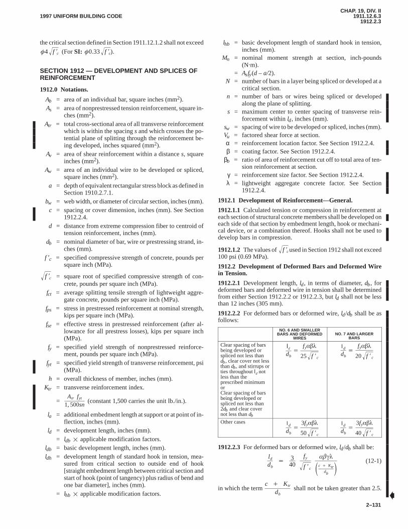
CHAP. 19, DIV. II1911.12.6.3
1912.2.31997 UNIFORM BUILDING CODE
2–131
the critical section defined in Section 1911.12.1.2 shall not exceed
�4 f �c� (For SI: �0.33 f �c� ).
SECTION 1912 — DEVELOPMENT AND SPLICES OFREINFORCEMENT
1912.0 Notations.
Ab = area of an individual bar, square inches (mm2).As = area of nonprestressed tension reinforcement, square in-
ches (mm2).Atr = total cross-sectional area of all transverse reinforcement
which is within the spacing s and which crosses the po-tential plane of splitting through the reinforcement be-ing developed, inches squared (mm2).
Av = area of shear reinforcement within a distance s, squareinches (mm2).
Aw = area of an individual wire to be developed or spliced,square inches (mm2).
a = depth of equivalent rectangular stress block as defined inSection 1910.2.7.1.
bw = web width, or diameter of circular section, inches (mm).c = spacing or cover dimension, inches (mm). See Section
1912.2.4.d = distance from extreme compression fiber to centroid of
tension reinforcement, inches (mm).db = nominal diameter of bar, wire or prestressing strand, in-
ches (mm).f ′c = specified compressive strength of concrete, pounds per
square inch (MPa).
f �c� = square root of specified compressive strength of con-crete, pounds per square inch (MPa).
fct = average splitting tensile strength of lightweight aggre-gate concrete, pounds per square inch (MPa).
fps = stress in prestressed reinforcement at nominal strength,kips per square inch (MPa).
fse = effective stress in prestressed reinforcement (after al-lowance for all prestress losses), kips per square inch(MPa).
fy = specified yield strength of nonprestressed reinforce-ment, pounds per square inch (MPa).
fyt = specified yield strength of transverse reinforcement, psi(MPa).
h = overall thickness of member, inches (mm).Ktr = transverse reinforcement index.
=Atr fyt
1, 500sn(constant 1,500 carries the unit lb./in.).
la = additional embedment length at support or at point of in-flection, inches (mm).
ld = development length, inches (mm). = ldb � applicable modification factors.
ldb = basic development length, inches (mm).ldh = development length of standard hook in tension, mea-
sured from critical section to outside end of hook[straight embedment length between critical section andstart of hook (point of tangency) plus radius of bend andone bar diameter], inches (mm).
= lhb � applicable modification factors.
lhb = basic development length of standard hook in tension,inches (mm).
Mn = nominal moment strength at section, inch-pounds(N�m).
= Asfy(d – a/2).N = number of bars in a layer being spliced or developed at a
critical section.n = number of bars or wires being spliced or developed
along the plane of splitting.s = maximum center to center spacing of transverse rein-
forcement within ld, inches (mm).sw = spacing of wire to be developed or spliced, inches (mm).Vu = factored shear force at section.α = reinforcement location factor. See Section 1912.2.4.β = coating factor. See Section 1912.2.4.
βb = ratio of area of reinforcement cut off to total area of ten-sion reinforcement at section.
γ = reinforcement size factor. See Section 1912.2.4.λ = lightweight aggregate concrete factor. See Section
1912.2.4.
1912.1 Development of Reinforcement—General.
1912.1.1 Calculated tension or compression in reinforcement ateach section of structural concrete members shall be developed oneach side of that section by embedment length, hook or mechani-cal device, or a combination thereof. Hooks shall not be used todevelop bars in compression.
1912.1.2 The values of f �c� used in Section 1912 shall not exceed100 psi (0.69 MPa).
1912.2 Development of Deformed Bars and Deformed Wirein Tension.
1912.2.1 Development length, ld, in terms of diameter, db, fordeformed bars and deformed wire in tension shall be determinedfrom either Section 1912.2.2 or 1912.2.3, but ld shall not be lessthan 12 inches (305 mm).
1912.2.2 For deformed bars or deformed wire, ld/db shall be asfollows:
NO. 6 AND SMALLERBARS AND DEFORMED
WIRESNO. 7 AND LARGER
BARS
Clear spacing of barsbeing developed orspliced not less thandb, clear cover not lessthan db, and stirrups orties throughout ld notless than theprescribed minimumorClear spacing of barsbeing developed orspliced not less than2db and clear covernot less than db
ld
db�
fy���
25 f �c�
ld
db�
fy���
20 f �c�
Other cases ld
db�
3fy���
50 f �c�
ld
db�
3fy���
40 f �c�
1912.2.3 For deformed bars or deformed wire, ld/db shall be:
l d
db�
340
fy
f �c�
����
�c � Ktr
db�
(12-1)
in which the term c � Ktr
dbshall not be taken greater than 2.5.
�
CHAP. 19, DIV. II1912.2.41912.5.4
1997 UNIFORM BUILDING CODE
2–132
1912.2.4The factors for use in the expressions for developmentof deformed bars and deformed wires in tension in Sections1912.0 through 1912.19 are as follows:
α = reinforcement location factor
Horizontal reinforcement so placed that more than 12 inches(305 mm) of fresh concrete is cast in the member below thedevelopment length or splice 1.3. . . . . . . . . . . . . . . . . . . . . . .
Other reinforcement 1.0. . . . . . . . . . . . . . . . . . . . . . . . . . . . .
β = coating factor
Epoxy-coated bars or wires with cover less than 3db, orclear spacing less than 6db 1.5. . . . . . . . . . . . . . . . . . . . . . . . . .
All other epoxy-coated bars or wires 1.2. . . . . . . . . . . . . . . .
Uncoated reinforcement 1.0. . . . . . . . . . . . . . . . . . . . . . . . . .
However, the product αβ need not be taken greater than 1.7.
γ = reinforcement size factor
No. 6 and smaller bars and deformed wires 0.8. . . . . . . . . . .
No. 7 and larger bars 1.0. . . . . . . . . . . . . . . . . . . . . . . . . . . .
λ = lightweight aggregate concrete factor.
When lightweight aggregate concrete is used 1.3. . . . . . . . .
However, when fct is specified, λ shall be permitted to be
taken as 6.7 f �c�fct� but not less than 1.0. . . . . . . . . . . . . . . . . .
when normal weight concrete is used 1.0. . . . . . . . . . . . . . .
c = spacing or cover dimension, inches (mm).
Use the smaller of either the distance from the center of the barto the nearest concrete surface or one-half the center-to-centerspacing of the bars being developed.
Ktr = transverse reinforcement index
�
Atr fyt
1, 500sn
WHERE:
Atr = total cross-sectional area of all transverse reinforcementwhich is within the spacing s and which crosses thepotential plane of splitting through the reinforcementbeing developed, inches squared (mm2).
fyt = specified yield strength of transverse reinforcement,inches squared (mm2).
s = maximum spacing of transverse reinforcement withinld, center-to-center, inches (mm).
n = number of bars or wires being developed along the planeof splitting.
It shall be permitted to use Ktr = 0 as a design simplificationeven if transverse reinforcement is present.
1912.2.5 Excess reinforcement. Reduction in developmentlength shall be permitted where reinforcement in a flexural mem-ber is in excess of that required by analysis except where anchor-age or development for fy is specifically required or thereinforcement is designed under provisions of Section1921.2.1.4 [(As required)/(As provided)]. . . . . . . . . . . . . . . . . . .
1912.3 Development of Deformed Bars in Compression.
1912.3.1Development length ld, in inches, for deformed bars incompression shall be computed as the product of the basic devel-opment length ldb and applicable modification factors as definedin this section, but ld shall not be less than 8 inches (203 mm).
1912.3.2Basic development length ldb shall be . 0.02db fy� f �c�
(For SI: 0.24db fy� f �c� )
but not less than 0.0003dbfy . . . . . . . . . . . . . . . . . . . . . . . . . . . . (For SI: 0.044 dbfy)
1912.3.3Basic development length ldb shall be permitted to bemultiplied by applicable factors for:
1912.3.3.1 Excess reinforcement.Reinforcement in excess ofthat required by analysis (As required)/(As provided). . . . . . .
1912.3.3.2 Spirals and ties.Reinforcement enclosed withinspiral reinforcement not less than 1/4-inch (6.4 mm) diameter andnot more than 4-inch (102 mm) pitch or within No. 4 ties in confor-mance with Section 1907.10.5 and spaced not more than 4 inches(102 mm) on center 0.75. . . . . . . . . . . . . . . . . . . . . . . . . . . . . .
1912.4 Development of Bundled Bars.
1912.4.1Development length of individual bars within a bundle,in tension or compression, shall be that for the individual bar, in-creased 20 percent for 3-bar bundle, and 33 percent for 4-barbundle.
1912.4.2For determining the appropriate factors in Section1912.2, a unit of bundled bars shall be treated as a single bar of adiameter derived from the equivalent total area.
1912.5 Development of Standard Hooks in Tension.
1912.5.1Development length ldh in inches (mm) for deformedbars in tension terminating in a standard hook shall be computedas the product of the basic development length lhb of Section1912.5.2 and the applicable modification factor or factors of Sec-tion 1912.5.3, but ldh shall not be less than 8db or less than 6 inches(152 mm).
1912.5.2Basic development length lhb for a hooked bar with fyequal to 60,000 psi (413.7 MPa) shall be 1, 200db� f �c� . . . . .
(For SI: 99.7db� f �c� )
1912.5.3Basic development length lhb shall be multiplied byapplicable factor or factors for:
1912.5.3.1 Bar yield strength.Bars with fy other than 60,000psi (413.7 MPa) fy/60,000. . . . . . . . . . . . . . . . . . . . . . . . . . . . . .
(For SI: fy/413.7)
1912.5.3.2 Concrete cover.For No. 11 bar and smaller, sidecover (normal to plane of the hook) not less than 21/2 inches(64 mm), and for 90-degree hook, cover on bar extension beyondhook not less than 2 inches (51 mm) 0.7. . . . . . . . . . . . . . . . .
1912.5.3.3 Ties or stirrups.For No. 11 bar and smaller, hookenclosed vertically or horizontally within ties or stirrup tiesspaced along the full development length ldh not greater than 3db,where db is diameter of hooked bar 0.8. . . . . . . . . . . . . . . . . . .
1912.5.3.4 Excessive reinforcement.Where anchorage or de-velopment for fy is not specifically required, reinforcement in ex-cess of that required by analysis [(As required)/(As provided)].
1912.5.3.5 Lightweight aggregate concrete 1.3. . . . . . . . . . .
1912.5.3.6 Epoxy-coated reinforcement. Hooked bars withepoxy coating 1.2. . . . . . . . . . . . . . . . . . . . . . . . . . . . . . . . . . . .
1912.5.4For bars being developed by a standard hook at discon-tinuous ends of members with side cover and top (or bottom) cov-er over hook less than 21/2 inches (64 mm), hooked bar shall beenclosed within ties or stirrups spaced along the full developmentlength ldh not greater than 3db, where db is diameter of hooked bar.For this case, factor of Section 1912.5.3.3 shall not apply.
CHAP. 19, DIV. II1912.5.5
1912.10.61997 UNIFORM BUILDING CODE
2–133
1912.5.5Hooks shall not be considered effective in developingbars in compression.
1912.6 Mechanical Anchorage.
1912.6.1Any mechanical device capable of developing thestrength of reinforcement without damage to concrete may beused as anchorage.
1912.6.2Test results showing adequacy of such mechanical de-vices shall be presented to the building official.
1912.6.3Development of reinforcement shall be permitted toconsist of a combination of mechanical anchorage plus additionalembedment length of reinforcement between the point of maxi-mum bar stress and the mechanical anchorage.
1912.7 Development of Welded Deformed Wire Fabric inTension.
1912.7.1Development length ld, in inches (mm), of welded de-formed wire fabric measured from the point of critical section tothe end of wire shall be computed as the product of the develop-ment length ld, from Section 1912.2.2 or 1912.2.3 times a wirefabric factor from Section 1912.7.2 or 1912.7.3. It shall be per-mitted to reduce the development length in accordance with1912.2.5 when applicable, but ld shall not be less than 8 inches(203 mm) except in computation of lap splices by Section1912.18. When using the wire fabric factor from Section 1912.7.2,it shall be permitted to use an epoxy-coating factor � of 1.0 forepoxy-coated welded wire fabric in Sections 1912.2.2 and1912.2.3.
1912.7.2For welded deformed wire fabric with at least one crosswire within the development length and not less than 2 inches (51mm) from the point of the critical section, the wire fabric factorshall be the greater of:
�fy � 35, 000
fy�
or
�5dbsw�
but need not be taken greater than 1.
1912.7.3For welded deformed wire fabric with no cross wireswithin the development length or with a single cross wire less than2 inches (51 mm) from the point of the critical section, the wirefabric factor shall be taken as 1, and the development length shallbe determined as for deformed wire.
1912.7.4When any plain wires are present in the deformed wirefabric in the direction of the development length, the fabric shallbe developed in accordance with Section 1912.8.
1912.8 Development of Welded Plain Wire Fabric in Tension.Yield strength of welded plain wire fabric shall be considereddeveloped by embedment of two cross wires with the closer crosswire not less than 2 inches (51 mm) from the point of the criticalsection. However, the development length ld, in inches (mm),measured from the point of the critical section to the outermostcross wire shall not be less than
0.27Awsw� fy
f �c�� �
For SI: 3.3Awsw� fy
f �c�� �
except that when reinforcement provided is in excess of thatrequired, this length may be reduced in accordance with Section1912.2.5. ld shall not be less than 6 inches (152 mm) except incomputation of lap splices by Section 1912.19.
1912.9 Development of Prestressing Strand.
1912.9.1Three- or seven-wire pretensioning strand shall bebonded beyond the critical section for a development length, in in-ches (mm), not less than
�fps �23
fse� db�
For SI: 0.145�fps �23
fse� db
†Expression in parentheses used as a constant without units.
where db is strand diameter in inches (mm), and fps and fse are ex-pressed in kips per square inch (MPa).
1912.9.2Limiting the investigation to cross sections nearest eachend of the member that are required to develop full design strengthunder specified factored loads shall be permitted.
1912.9.3Where bonding of a strand does not extend to end ofmember, and design includes tension at service load in precom-pressed tensile zone as permitted by Section 1918.4.2, develop-ment length specified in Section 1912.9.1 shall be doubled.
1912.10 Development of Flexural Reinforcement—General.
1912.10.1Development of tension reinforcement by bendingacross the web to be anchored or made continuous with reinforce-ment on the opposite face of member shall be permitted.
1912.10.2Critical sections for development of reinforcement inflexural members are at points of maximum stress and at pointswithin the span where adjacent reinforcement terminates or isbent. Provisions of Section 1912.11.3 must be satisfied.
1912.10.3Reinforcement shall extend beyond the point at whichit is no longer required to resist flexure for a distance equal to theeffective depth of member or 12db, whichever is greater, except atsupports of simple spans and at free end of cantilevers.
1912.10.4Continuing reinforcement shall have an embedmentlength not less than the development length ld beyond the pointwhere bent or terminated tension reinforcement is no longer re-quired to resist flexure.
1912.10.5Flexural reinforcement shall not be terminated in atension zone unless one of the following conditions is satisfied:
1912.10.5.1Shear at the cutoff point does not exceed two thirdsthat permitted, including shear strength of shear reinforcementprovided.
1912.10.5.2Stirrup area in excess of that required for shear andtorsion is provided along each terminated bar or wire over a dis-tance from the termination point equal to three fourths the effec-tive depth of member. Excess stirrup area Av shall not be less than60bws/fy (For SI: 0.41bws�fy). Spacing s shall not exceed d/8βbwhere βb is the ratio of area of reinforcement cut off to total area oftension reinforcement at the section.
1912.10.5.3For No. 11 bar and smaller, continuing reinforce-ment provides double the area required for flexure at the cutoffpoint and shear does not exceed three fourths that permitted.
1912.10.6Adequate anchorage shall be provided for tension re-inforcement in flexural members where reinforcement stress is
CHAP. 19, DIV. II1912.10.61912.14.2.2
1997 UNIFORM BUILDING CODE
2–134
not directly proportional to moment, such as sloped, stepped or ta-pered footings, brackets, deep flexural members, or members inwhich tension reinforcement is not parallel to compression face.See Sections 1912.11.4 and 1912.12.4 for deep flexural members.
1912.11 Development of Positive Moment Reinforcement.
1912.11.1At least one third the positive moment reinforcementin simple members and one fourth the positive moment reinforce-ment in continuous members shall extend along the same face ofmember into the support. In beams, such reinforcement shall ex-tend into the support at least 6 inches (152 mm).
1912.11.2When a flexural member is part of a primary lateral-load-resisting system, positive moment reinforcement required tobe extended into the support by Section 1912.11.1 shall be an-chored to develop the specified yield strength fy in tension at theface of support.
1912.11.3At simple supports and at points of inflection, positivemoment tension reinforcement shall be limited to a diameter suchthat ld computed for fy by Section 1912.2 satisfies Formula (12-2),except Formula (12-2) need not be satisfied for reinforcement ter-minating beyond center line of simple supports by a standard hookor a mechanical anchorage at least equivalent to a standard hook.
l d �Mn
Vu� l a (12-2)
WHERE:la = at a support shall be the embedment length beyond cen-
ter of support.
la = at a point of inflection shall be limited to the effectivedepth of member or 12db, whichever is greater.
Mn = nominal strength assuming all reinforcement at the sec-tion to be stressed to the specified yield strength fy.
Vu = factored shear force at the section.
An increase of 30 percent in the value of Mn/Vu shall be per-mitted when the ends of reinforcement are confined by a compres-sive reaction.
1912.11.4At simple supports of deep flexural members, positivemoment tension reinforcement shall be anchored to develop thespecified yield strength fy in tension at the face of support. At inte-rior supports of deep flexural members, positive moment tensionreinforcement shall be continuous or be spliced with that of theadjacent spans.
1912.12 Development of Negative Moment Reinforcement.
1912.12.1Negative moment reinforcement in a continuous, re-strained or cantilever member, or in any member of a rigid frame,shall be anchored in or through the supporting member by embed-ment length, hooks or mechanical anchorage.
1912.12.2Negative moment reinforcement shall have an embed-ment length into the span as required by Sections 1912.1 and1912.10, Item 3.
1912.12.3At least one third the total tension reinforcement pro-vided for negative moment at a support shall have an embedmentlength beyond the point of inflection not less than effective depthof member, 12db, or 1/16 the clear span, whichever is greater.
1912.12.4At interior supports of deep flexural members, nega-tive moment tension reinforcement shall be continuous with thatof the adjacent spans.
1912.13 Development of Web Reinforcement.
1912.13.1Web reinforcement shall be carried as close to com-pression and tension surfaces of member as cover requirementsand proximity of other reinforcement will permit.
1912.13.2Ends of single leg, simple U- or multiple U-stirrupsshall be anchored by one of the following means:
1912.13.2.1For No. 5 bar and D31 wire, and smaller, and for Nos.6, 7 and 8 bars with fy of 40,000 psi (275.8 MPa) or less, a standardstirrup hook around longitudinal reinforcement.
1912.13.2.2For Nos. 6, 7 and 8 stirrups with fy greater than40,000 psi (275.8 MPa), a standard stirrup hook around a longitu-dinal bar plus an embedment between midheight of the memberand the outside end of the hook equal to or greater than 0.014
dbfy / f �c� (For SI: 0.169db fy� f �c� ).
1912.13.2.3For each leg of welded smooth wire fabric formingsimple U-stirrups, either:
1. Two longitudinal wires spaced at a 2-inch (51 mm) spacingalong the member at the top of the U.
2. One longitudinal wire located not more than d/4 from thecompression face and a second wire closer to the compres-sion face and spaced not less than 2 inches (51 mm) from thefirst wire. The second wire shall be permitted to be locatedon the stirrup leg beyond a bend, or on a bend with an insidediameter of bend not less than 8db.
1912.13.2.4For each end of a single-leg stirrup of welded plainor deformed wire fabric, two longitudinal wires at a minimumspacing of 2 inches (51 mm) and with the inner wire at least thegreater of d/4 or 2 inches (51 mm) from middepth of member d/2.Outer longitudinal wire at tension face shall not be farther from theface than the portion of primary flexural reinforcement closest tothe face.
1912.13.2.5In joist construction as defined in Section 1908.11,for No. 4 bar and D20 wire and smaller, a standard hook.
1912.13.3Between anchored ends, each bend in the continuousportion of a simple U-stirrup or multiple U-stirrups shall enclose alongitudinal bar.
1912.13.4Longitudinal bars bent to act as shear reinforcement, ifextended into a region of tension, shall be continuous with longi-tudinal reinforcement and, if extended into a region of compres-sion, shall be anchored beyond middepth d/2 as specified fordevelopment length in Section 1912.2 for that part of fy required tosatisfy Formula (11-19).
1912.13.5Pairs of U-stirrups or ties so placed as to form a closedunit shall be considered properly spliced when lengths of laps are1.3ld. In members at least 18 inches (457 mm) deep, such spliceswith Abfy not more than 9,000 pounds (40 000 N) per leg may beconsidered adequate if stirrup legs extend the full available depthof member.
1912.14 Splices of Reinforcement.
1912.14.1Splices of reinforcement shall be made only as re-quired or permitted on design drawings or in specifications, or asauthorized by the building official.
1912.14.2 Lap splices.
1912.14.2.1Lap splices shall not be used for bars larger than No.11, except as provided in Sections 1912.16.2 and 1915.8.2.3.
1912.14.2.2Lap splices of bars in a bundle shall be based on thelap splice length required for individual bars within the bundle,
CHAP. 19, DIV. II1912.14.2.21912.17.2.4
1997 UNIFORM BUILDING CODE
2–135
increased in accordance with Section 1912.4. Individual barsplices within a bundle shall not overlap. Entire bundles shall notbe lap spliced.
1912.14.2.3Bars spliced by noncontact lap splices in flexuralmembers shall not be spaced transversely farther apart than onefifth the required lap splice length, or 6 inches (152 mm).
1912.14.3 Welded splices and mechanical connections.
1912.14.3.1Welded splices and other mechanical connectionsmay be used.
1912.14.3.2Except as provided in this code, all welding shallconform to UBC Standard 19-1.
1912.14.3.3A full-welded splice shall develop at least 125 per-cent of specified yield strength, fy, of the bar.
1912.14.3.4A full mechanical connection shall develop in ten-sion or compression, as required, at least 125 percent of specifiedyield strength fy of the bar.
1912.14.3.5Welded splices and mechanical connections notmeeting requirements of Section 1912.14.3.3 or 1912.14.3.4 areallowed only for No. 5 bars and smaller and in accordance withSection 1912.15.4.
1912.14.3.6Welded splices and mechanical connections shallmaintain the clearance and coverage requirements of Sections1907.6 and 1907.7.
1912.15 Splices of Deformed Bars and Deformed Wire in Ten-sion.
1912.15.1Minimum length of lap for tension lap splices shall beas required for Class A or B splice, but not less than 12 inches (305mm), where:
Class A splice 1.0ld. . . . . . . . . . . . . . . . . . . . . . . . . . . . . . . .
Class B splice 1.3ld. . . . . . . . . . . . . . . . . . . . . . . . . . . . . . . .
where ld is the tensile development length for the specified yieldstrength fy in accordance with Section 1912.2 without the modifi-cation factor of Section 1912.2.5.
1912.15.2Lap splices of deformed bars and deformed wire intension shall be Class B splices except that Class A splices may beused when (1) the area of reinforcement provided is at least twicethat required by analysis over the entire length of the splice, and(2) one half or less of the total reinforcement is spliced within therequired lap length.
1912.15.3Welded splices or mechanical connections used wherearea of reinforcement provided is less than twice that required byanalysis shall meet requirements of Section 1912.14.3.3 and1912.14.3.4.
1912.15.4Welded splices or mechanical connections not meet-ing the requirements of Section 1912.14.3.3 or 1912.14.3.4 areallowed for No. 5 bars and smaller when the area of reinforcementprovided is at least twice that required by analysis, and the follow-ing requirements are met:
1912.15.4.1Splices shall be staggered at least 24 inches (610mm) and in such manner as to develop at every section at leasttwice the calculated tensile force at that section but not less than20,000 psi (137.9 MPa) for total area of reinforcement provided.
1912.15.4.2In computing tensile forces developed at each sec-tion, rate the spliced reinforcement at the specified splice strength.Unspliced reinforcement shall be rated at that fraction of fy de-fined by the ratio of the shorter actual development length to ld re-quired to develop the specified yield strength fy.
1912.15.4.3Mechanical connections need not be staggered asrequired by Section 1912.15.4.1 or 1912.15.5 provided the clear-ance and coverage requirements of Sections 1907.6 and 1907.7are maintained and, at 90 percent of the yield stress, the strainmeasured over the full length of the connector does not exceed 50percent of the strain of an unspliced bar when the maximum com-puted design load stress does not exceed 50 percent of the yieldstress.
1912.15.5Splices in ‘‘tension tie members’’ shall be made with afull-welded splice or full mechanical connection in accordancewith Section 1912.14.3.3 and 1912.14.3.4, and splices in adjacentbar shall be staggered at least 30 inches (762 mm).
1912.16 Splices of Deformed Bars in Compression.
1912.16.1Compression lap splice length shall be 0.0005 fydb(For SI: 0.073 fydb) for fy of 60,000 psi (413.7 MPa) or less, or(0.0009 fy – 24) db [For SI: (0.13 fy – 24) db] for fy greater than60,000 psi (413.7 MPa), but not less than 12 inches (305 mm). Forf ′c less than 3,000 psi (20.68 MPa), length of lap shall be increasedby one third.
1912.16.2When bars of different size are lap spliced in compres-sion, splice length shall be the larger of: development length oflarger bar, or splice length of smaller bar. Lap splices of No. 14 andNo. 18 bars to No. 11 and smaller bars shall be permitted.
1912.16.3Welded splices or mechanical connections used incompression shall meet requirements of Sections 1912.14.3.3 and1912.14.3.4.
1912.16.4 End-bearing splices.
1912.16.4.1In bars required for compression only, transmissionof compressive stress by bearing of square cut ends held in con-centric contact by a suitable device shall be permitted.
1912.16.4.2Bar ends shall terminate in flat surfaces within 11/2degrees of a right angle to the axis of the bars and shall be fittedwithin 3 degrees of full bearing after assembly.
1912.16.4.3End-bearing splices shall be used only in memberscontaining closed ties, closed stirrups or spirals.
1912.17 Special Splice Requirements for Columns.
1912.17.1Lap splices, butt welded splices, mechanical connec-tions or end-bearing splices shall be used with the limitations ofSections 1912.17.2 through 1912.17.4. A splice shall satisfy re-quirements for all load combinations for the column.
1912.17.2 Lap splices in columns.
1912.17.2.1Where the bar stress due to factored loads is com-pressive, lap splices shall conform to Sections 1912.16.1 and1912.16.2, and where applicable, to Section 1912.17.2.4 or1912.17.2.5.
1912.17.2.2Where the bar stress due to factored loads is tensileand does not exceed 0.5fy in tension, lap splices shall be Class Btension lap splices if more than one half of the bars are spliced atany section, or Class A tension lap splices if one half or fewer ofthe bars are spliced at any section and alternate lap splices are stag-gered by ld.
1912.17.2.3Where the bar stress due to factored loads is greaterthan 0.5 fy in tension, lap splices shall be Class B tension lapsplices.
1912.17.2.4In tied reinforced compression members, where tiesthroughout the lap splice length have an effective area not lessthan 0.0015hs, lap splice length shall be permitted to be multipliedby 0.83, but lap length shall not be less than 12 inches (305 mm).
CHAP. 19, DIV. II1912.17.2.41913.0
1997 UNIFORM BUILDING CODE
2–136
Tie legs perpendicular to dimension h shall be used in determiningeffective area.
1912.17.2.5In spirally reinforced compression members, lapsplice length of bars within a spiral shall be permitted to be multi-plied by 0.75, but lap length shall not be less than 12 inches (305mm).
1912.17.3 Welded splices or mechanical connectors in co-lumns. Welded splices or mechanical connectors in columnsshall meet the requirements of Section 1912.14.3.3 or1912.14.3.4.
1912.17.4 End-bearing splices in columns.End-bearingsplices complying with Section 1912.16.4 shall be permitted to beused for column bars stressed in compression provided the splicesare staggered or additional bars are provided at splice locations.The continuing bars in each face of the column shall have a tensilestrength, based on the specified yield strength fy, not less than0.25fy times the area of the vertical reinforcement in that face.
1912.18 Splices of Welded Deformed Wire Fabric in Tension.
1912.18.1Minimum length of lap for lap splices of welded de-formed wire fabric measured between the ends of each fabric sheetshall not be less than 1.3ld or 8 inches (203 mm), and the overlapmeasured between outermost cross wires of each fabric sheet shallnot be less than 2 inches (51 mm), ld shall be the developmentlength for the specified yield strength fy in accordance with Sec-tion 1912.7.
1912.18.2Lap splices of welded deformed wire fabric, with nocross wires within the lap splice length, shall be determined as fordeformed wire.
1912.18.3When any plain wires are present in the deformed wirefabric in the direction of the lap splice or when deformed wire fab-ric is lap spliced to plain wire fabric, the fabric shall be lap splicedin accordance with Section 1912.19.
1912.19 Splices of Welded Plain Wire Fabric in Tension.Mi-nimum length of lap for lap splices of welded smooth wire fabricshall be in accordance with the following:
1912.19.1When area of reinforcement provided is less thantwice that required by analysis at splice location, length of overlapmeasured between outermost cross wires of each fabric sheet shallnot be less than one spacing of cross wires plus 2 inches (51 mm),or less than 1.5 ld, or 6 inches (152 mm), ld shall be the develop-ment length for the specified yield strength fy in accordance withSection 1912.8.
1912.19.2When area of reinforcement provided is at least twicethat required by analysis at splice location, length of overlap mea-sured between outermost cross wires of each fabric sheet shall notbe less than 1.5 ld, or 2 inches (51 mm), ld shall be the developmentlength for the specified yield strength fy in accordance with Sec-tion 1912.8.
SECTION 1913 — TWO-WAY SLAB SYSTEMS
1913.0 Notations.
b1 = width of the critical section defined in Section1911.12.1.2 measured in the direction of the span forwhich moments are determined, inches (mm).
b2 = width of the critical section defined in Section1911.12.1.2 measured in the direction perpendicular tob1, inches (mm).
C = cross-sectional constant to define torsional properties.
� �1 � 0.63 xy�
x3y3
The constant C for T- or L-sections shall be permitted tobe evaluated by dividing the section into separate rectan-gular parts and summing the values of C for each part.
c1 = size of rectangular or equivalent rectangular column,capital, or bracket measured in the direction of the spanfor which moments are being determined, inches (mm).
c2 = size of rectangular or equivalent rectangular column,capital or bracket measured transverse to the direction ofthe span for which moments are being determined, in-ches (mm).
Ecb = modulus of elasticity of beam concrete.Ecs = modulus of elasticity of slab concrete.
h = overall thickness of member, inches (mm).Ib = moment of inertia about centroidal axis of gross section
of beam as defined in Section 1913.3.Is = moment of inertia about centroidal axis of gross section
of slab.= h3/12 times width of slab defined in notations α and βt.
Kt = torsional stiffness of torsional member; moment per unitrotation.
ln = length of clear span in direction that moments are beingdetermined, measured face to face of supports.
l1 = length of span in direction that moments are being deter-mined, measured center to center of supports.
l2 = length of span transverse to l1, measured center to centerof supports. See also Sections 1913.6.2.3 and1913.6.2.4.
Mo = total factored static moment.Mu = factored moment at section.Vc = nominal shear strength provided by concrete. See Sec-
tion 1911.12.2.1.Vu = factored shear force at section.wd = factored dead load per unit area.wl = factored live load per unit area.wu = factored load per unit area.
x = shorter overall dimension of rectangular part of crosssection.
y = longer overall dimension of rectangular part of crosssection.
α = ratio of flexural stiffness of beam section to flexural stif-fness of a width of slab bounded laterally by center linesof adjacent panels (if any) on each side of the beam.
=EcbIb
EcsIs
α1 = α in direction of l1.α2 = α in direction of l2.βt = ratio of torsional stiffness of edge beam section to flexu-
ral stiffness of a width of slab equal to span length ofbeam, center to center of supports.
=EcbC2EcsIs
γf = fraction of unbalanced moment transferred by flexure atslab-column connections. See Section 1913.5.3.2.
γv = fraction of unbalanced moment transferred by eccentric-ity of shear at slab-column connections.
= 1 – γ f�
�
�
�
�
CHAP. 19, DIV. II1913.0
1913.4.11997 UNIFORM BUILDING CODE
2–137
ρ = ratio of nonprestressed tension reinforcement.
ρb = reinforcement ratio producing balanced strain condi-tions.
φ = strength reduction factor.
1913.1 Scope.
1913.1.1The provisions of this section shall apply for design ofslab systems reinforced for flexure in more than one direction,with or without beams between supports.
1913.1.2For a slab system supported by columns or walls, the di-mensions c1 and c2 and the clear span ln shall be based on an effec-tive support area defined by the intersection of the bottom surfaceof the slab, or the drop panel if there is one, with the largest rightcircular cone, right pyramid, or tapered wedge whose surfaces arelocated within the column and capital or bracket and are orientedno greater than 45 degrees to the axis of the column.
1913.1.3Solid slabs and slabs with recesses or pockets made bypermanent or removable fillers between ribs or joists in two direc-tions are included within the scope of this section.
1913.1.4Minimum thickness of slabs designed in accordancewith this section shall be as required by Section 1909.5.3.
1913.2 Definitions.
1913.2.1Column strip is a design strip with a width on each sideof a column center line equal to 0.25l2 or 0.25l1, whichever is less.Column strip includes beams, if any.
1913.2.2Middle strip is a design strip bounded by two columnstrips.
1913.2.3A panel is bounded by column, beam or wall centerlines on all sides.
1913.2.4For monolithic or fully composite construction, a beamincludes that portion of slab on each side of the beam extending adistance equal to the projection of the beam above or below theslab, whichever is greater, but not greater than four times the slabthickness.
1913.3 Slab Reinforcement.
1913.3.1Area of reinforcement in each direction for two-wayslab systems shall be determined from moments at critical sec-tions, but shall not be less than required by Section 1907.12.
1913.3.2Spacing of reinforcement at critical sections shall notexceed two times the slab thickness, except for portions of slabarea of cellular or ribbed construction. In the slab over cellularspaces, reinforcement shall be provided as required by Section1907.12.
1913.3.3Positive moment reinforcement perpendicular to a dis-continuous edge shall extend to the edge of slab and have embed-ment, straight or hooked, at least 6 inches (152 mm) in spandrelbeams, columns or walls.
1913.3.4Negative moment reinforcement perpendicular to a dis-continuous edge shall be bent, hooked or otherwise anchored, inspandrel beams, columns or walls, to be developed at face of sup-port according to provisions of Section 1912.
1913.3.5Where a slab is not supported by a spandrel beam orwall at a discontinuous edge or where a slab cantilevers beyondthe support, anchorage of reinforcement shall be permitted withinthe slab.
1913.3.6 In slabs with beams between supports with a value of αgreater than 1.0, special top and bottom slab reinforcement shallbe provided at exterior corners in accordance with the following:
1913.3.6.1The special reinforcement in both top and bottom ofslab shall be sufficient to resist a moment equal to the maximumpositive moment (per foot of width) (per meter of width) in theslab.
1913.3.6.2The moment shall be assumed to be about an axis per-pendicular to the diagonal from the corner in the top of the slab andperpendicular to the diagonal in the bottom of the slab.
1913.3.6.3The special reinforcement shall be provided for a dis-tance in each direction from the corner equal to one fifth the longerspan.
1913.3.6.4The special reinforcement shall be placed in a bandparallel to the diagonal in the top of the slab and a band perpendic-ular to the diagonal in the bottom of the slab. Alternatively, thespecial reinforcement shall be placed in two layers parallel to thesides of the slab in either the top or bottom of the slab.
1913.3.7Where a drop panel is used to reduce amount of negativemoment reinforcement over the column of a flat slab, size of droppanel shall be in accordance with the following:
1913.3.7.1Drop panel shall extend in each direction from centerline of support a distance not less than one sixth the span lengthmeasured from center to center of supports in that direction.
1913.3.7.2Projection of drop panel below the slab shall be atleast one fourth the slab thickness beyond the drop.
1913.3.7.3In computing required slab reinforcement, thicknessof drop panel below the slab shall not be assumed greater than onefourth the distance from edge of drop panel to edge of column orcolumn capital.
1913.3.8 Details of reinforcement in slabs without beams.
1913.3.8.1In addition to the other requirements of Section1913.3, reinforcement in slabs without beams shall have mini-mum extensions as prescribed in Figure 19-1.
1913.3.8.2Where adjacent spans are unequal, extension of nega-tive moment reinforcement beyond the face of support as pre-scribed in Figure 19-1 shall be based on requirements of longerspan.
1913.3.8.3Bent bars shall be permitted only when depth-span ra-tio permits use of bends 45 degrees or less.
1913.3.8.4For slabs in frames not braced against sidesway,lengths of reinforcement shall be determined by analysis but shallnot be less than those prescribed in Figure 19-1.
1913.3.8.5All bottom bars or wires within the column strip, ineach direction, shall be continuous or spliced with Class A spliceslocated as shown in Figure 19-1. At least two of the column stripbottom bars or wires in each direction shall pass within the columncore and shall be anchored at exterior supports.
1913.3.8.6In slabs with shearheads and in lift-slab construction,at least two bonded bottom bars or wires in each direction shallpass through the shearhead or lifting collar as close to the columnas practicable and be continuous or spliced with a Class A splice.At exterior columns, the reinforcement shall be anchored at theshearhead or lifting collar.
1913.4 Openings in Slab Systems.
1913.4.1Openings of any size shall be permitted in slab systemsif shown by analysis that the design strength is at least equal to the
CHAP. 19, DIV. II1913.4.11913.6.2.4
1997 UNIFORM BUILDING CODE
2–138
required strength considering Sections 1909.2 and 1909.3, andthat all serviceability conditions, including the specified limits ondeflections, are met.
1913.4.2 In lieu of special analysis as required by Section1913.4.1, openings shall be permitted in slab systems withoutbeams only in accordance with the following:
1913.4.2.1Openings of any size shall be permitted in the areacommon to intersecting middle strips, provided total amount of re-inforcement required for the panel without the opening is main-tained.
1913.4.2.2In the area common to intersecting column strips, notmore than one eighth the width of column strip in either span shallbe interrupted by openings. An amount of reinforcement equiva-lent to that interrupted by an opening shall be added on the sides ofthe opening.
1913.4.2.3In the area common to one column strip and onemiddle strip, not more than one fourth the reinforcement in eitherstrip shall be interrupted by openings. An amount of reinforce-ment equivalent to that interrupted by an opening shall be addedon the sides of the opening.
1913.4.2.4Shear requirements of Section 1911.12.5 shall be sa-tisfied.
1913.5 Design Procedures.
1913.5.1A slab system shall be designed by any procedure satis-fying conditions of equilibrium and geometric compatibility ifshown that the design strength at every section is at least equal tothe required strength considering Sections 1909.2 and 1909.3 andthat all serviceability conditions, including specified limits on de-flections, are met.
1913.5.1.1Design of a slab system for gravity loads including theslab and beams (if any) between supports and supporting columnsor walls forming orthogonal frames, by either the Direct DesignMethod of Section 1913.6 or the Equivalent Frame Method ofSection 1913.7, shall be permitted.
1913.5.1.2For lateral loads, analysis of unbraced frames shalltake into account effects of cracking and reinforcement on stif-fness of frame members.
1913.5.1.3Combining the results of the gravity load analysiswith the results of the lateral load analysis shall be permitted.
1913.5.2The slab and beams (if any) between supports shall beproportioned for factored moments prevailing at every section.
1913.5.3When gravity load, wind, earthquake or other lateralforces cause transfer of moment between slab and column, a frac-tion of the unbalanced moment shall be transferred by flexure inaccordance with Sections 1913.5.3.2 and 1913.5.3.3.
1913.5.3.1Fraction of unbalanced moment not transferred byflexure shall be transferred by eccentricity of shear in accordancewith Section 1911.12.6.
1913.5.3.2A fraction of the unbalanced moment given by γfMushall be considered to be transferred by flexure within an effectiveslab width between lines that are one and one-half slab or droppanel thickness (1.5h) outside opposite faces of the column or cap-ital, where Mu is the moment to be transferred and
�f �1
1 �2�3 b1�b2
�(13-1)
1913.5.3.3For unbalanced moments about an axis parallel to theedge at exterior supports, the value of γ f by Formula (13-1) shall
be permitted to be increased up to 1.0 provided that Vu at an edgesupport does not exceed 0.75�Vc or at a corner support does notexceed 0.5�Vc. For unbalanced moments at interior supports, andfor unbalanced moments about an axis transverse to the edge atexterior supports, the value of γ f in Formula (13-1) shall be per-mitted to be increased by up to 25 percent provided that Vu at thesupport does not exceed 0.4�Vc. The reinforcement ratio ρ, withinthe effective slab width defined in Section 1913.5.3.2, shall notexceed 0.375 ρb. No adjustments to γ f shall be permitted for pre-stressed slab systems.
1913.5.3.4Concentration of reinforcement over the column bycloser spacing or additional reinforcement shall be used to resistmoment on the effective slab width defined in Section 1913.5.3.2.
1913.5.4Design for transfer of load from slab to supporting col-umns or walls through shear and torsion shall be in accordancewith Sections 1911.0 through 1911.12.
1913.6 Direct Design Method.
1913.6.1 Limitations. Design of slab systems within the follow-ing limitations by the Direct Design Method shall be permitted:
1913.6.1.1There shall be a minimum of three continuous spansin each direction.
1913.6.1.2Panels shall be rectangular, with a ratio of longer toshorter span center-to-center supports within a panel not greaterthan 2.
1913.6.1.3Successive span lengths center-to-center supports ineach direction shall not differ by more than one third the longerspan.
1913.6.1.4Offset of columns by a maximum of 10 percent of thespan (in direction of offset) from either axis between center linesof successive columns shall be permitted.
1913.6.1.5All loads shall be due to gravity only and uniformlydistributed over an entire panel. Live load shall not exceed twotimes dead load.
1913.6.1.6For a panel with beams between supports on all sides,the relative stiffness of beams in two perpendicular directions
�1l22
�2l12 (13-2)
shall not be less than 0.2 or greater than 5.0.
1913.6.1.7Moment redistribution as permitted by Section1908.4 shall not be applied for slab systems designed by the directdesign method. See Section 1913.6.7.
1913.6.1.8Variations from the limitations of Section 1913.6.1shall be permitted if demonstrated by analysis that requirementsof Section 1913.5.1 are satisfied.
1913.6.2 Total factored static moment for a span.
1913.6.2.1Total factored static moment for a span shall be deter-mined in a strip bounded laterally by center line of panel on eachside of center line of supports.
1913.6.2.2Absolute sum of positive and average negative fac-tored moments in each direction shall not be less than
Mo �wul2l n
2
8(13-3)
1913.6.2.3Where the transverse span of panels on either side ofthe center line of supports varies, l2 in Formula (13-3) shall be tak-en as the average of adjacent transverse spans.
1913.6.2.4When the span adjacent and parallel to an edge is be-ing considered, the distance from edge to panel center line shall besubstituted for l2 in Formula (13-3).
CHAP. 19, DIV. II1913.6.2.51913.6.8.4
1997 UNIFORM BUILDING CODE
2–139
1913.6.2.5Clear span ln shall extend from face to face of col-umns, capitals, brackets or walls. Value of ln used in Formula(13-3) shall not be less than 0.65l1. Circular or regular polygon-shaped supports shall be treated as square supports with the samearea.
1913.6.3 Negative and positive factored moments.
1913.6.3.1Negative factored moments shall be located at face ofrectangular supports. Circular or regular polygon-shaped supportsshall be treated as square supports with the same area.
1913.6.3.2In an interior span, total static moment Mo shall bedistributed as follows:
Negative factored moment 0.65. . . . . . . . . . . . . . . . . . . . .
Positive factored moment 0.35. . . . . . . . . . . . . . . . . . . . . .
1913.6.3.3In an end span, total factored static moment Mo shallbe distributed as follows:
(1) (2) (3) (4) (5)
Slab withBeams
Slab without Beamsbetween Interior
Supports
ExteriorEdge
Unrestrained
Beamsbetween
AllSupports
WithoutEdgeBeam
WithEdgeBeam
ExteriorEdge FullyRestrained
Interior negativefactored moment 0.75 0.70 0.70 0.70 0.65
Positive factoredmoment 0.63 0.57 0.52 0.50 0.35
Exterior negativefactored moment 0 0.16 0.26 0.30 0.65
1913.6.3.4Negative moment sections shall be designed to resistthe larger of the two interior negative factored moments deter-mined for spans framing into a common support unless an analysisis made to distribute the unbalanced moment in accordance withstiffness of adjoining elements.
1913.6.3.5Edge beams or edges of slab shall be proportioned toresist in torsion their share of exterior negative factored moments.
1913.6.3.6The gravity load moment to be transferred betweenslab and edge column in accordance with Section 1913.5.3.1 shallbe 0.3M.
1913.6.4 Factored moments in column strips.
1913.6.4.1Column strips shall be proportioned to resist the fol-lowing percentage of interior negative factored moments:
l2 l1 0.5 1.0 2.0
(α1l2/l1) = 0 75 75 75
(α1l2/l1) � 1.0 90 75 45
Linear interpolations shall be made between values shown.
1913.6.4.2Column strips shall be proportioned to resist the fol-lowing percentage of exterior negative factored moments:
l2/l1 0.5 1.0 2.0
(α l /l ) 0βt = 0 100 100 100
(α1l2/l1) = 0βt � 2.5 75 75 75
(α1l2/l1) �βt = 0 100 100 100
(α1l2/l1) �1.0 βt � 2.5 90 75 45
Linear interpolations shall be made between values shown.
1913.6.4.3Where supports consist of columns or walls extendingfor a distance equal to or greater than three fourths the span lengthl2 used to compute Mo, negative moments shall be considered tobe uniformly distributed across l2.
1913.6.4.4Column strips shall be proportioned to resist the fol-lowing percentage of positive factored moments:
l2 l1 0.5 1.0 2.0
(α1l2/l1) = 0 60 60 60
(α1l2/l1) � 1.0 90 75 45
Linear interpolations shall be made between values shown:
1913.6.4.5For slabs with beams between supports, the slab por-tion of column strips shall be proportioned to resist that portion ofcolumn strip moments not resisted by beams.
1913.6.5 Factored moments in beams.
1913.6.5.1Beams between supports shall be proportioned to re-sist 85 percent of column strip moments if (α1l2/l1) is equal to orgreater than 1.0.
1913.6.5.2For values of (α1l2/l1) between 1.0 and zero, propor-tion of column strip moments resisted by beams shall be obtainedby linear interpolation between 85 and zero percent.
1913.6.5.3In addition to moments calculated for uniform loadsaccording to Sections 1913.6.2.2, 1913.6.5.1 and 1913.6.5.2,beams shall be proportioned to resist all moments caused by con-centrated or linear loads applied directly to beams, includingweight of projecting beam stem above or below the slab.
1913.6.6 Factored moments in middle strips.
1913.6.6.1That portion of negative and positive factored mo-ments not resisted by column strips shall be proportionately as-signed to corresponding half middle strips.
1913.6.6.2Each middle strip shall be proportioned to resist thesum of the moments assigned to its two half middle strips.
1913.6.6.3A middle strip adjacent to and parallel with an edgesupported by a wall shall be proportioned to resist twice the mo-ment assigned to the half middle strip corresponding to the firstrow of interior supports.
1913.6.7 Modification of factored moments.Modification ofnegative and positive factored moments by 10 percent shall bepermitted provided the total static moment for a panel in the direc-tion considered is not less than that required by Formula (13-3).
1913.6.8 Factored shear in slab systems with beams.
1913.6.8.1Beams with (α1l2/l1) equal to or greater than 1.0 shallbe proportioned to resist shear caused by factored loads on tribu-tary areas bounded by 45-degree lines drawn from the corners ofthe panels and the center lines of the adjacent panels parallel to thelong sides.
1913.6.8.2In proportioning of beams with (α1l2/l1) less than 1.0to resist shear, linear interpolation, assuming beams carry no loadat α1 = 0, shall be permitted.
1913.6.8.3In addition to shears calculated according to this sec-tion, beams shall be proportioned to resist shears caused by fac-tored loads applied directly on beams.
1913.6.8.4Computations of slab shear strength on the assump-tion that load is distributed to supporting beams in accordancewith Section 1913.6.8.1 or 1913.6.8.2 shall be permitted. Resist-ance to total shear occurring on a panel shall be provided.
CHAP. 19, DIV. II1913.6.8.51913.7.7.4
1997 UNIFORM BUILDING CODE
2–140
1913.6.8.5Shear strength shall satisfy requirements of Section1911.
1913.6.9 Factored moments in columns and walls.
1913.6.9.1Columns and walls built integrally with a slab systemshall resist moments caused by factored loads on the slab system.
1913.6.9.2At an interior support, supporting elements above andbelow the slab shall resist the moment specified by Formula (13-4)in direct proportion to their stiffnesses unless a general analysis ismade.
M � 0.07 [(wd � 0.5wl)l2l n2� w�d l�2(l�n)2] (13-4)
where w′d, l ′2 and l ′n refer to shorter span.
1913.7 Equivalent Frame Method.
1913.7.1Design of slab systems by the equivalent frame methodshall be based on assumptions given in Sections 1913.7.2 through1913.7.6, and all sections of slabs and supporting members shallbe proportioned for moments and shears thus obtained.
1913.7.1.1Where metal column capitals are used, it shall be per-mitted to take account of their contributions to stiffness and resis-tance to moment and to shear.
1913.7.1.2Neglecting the change in length of columns and slabsdue to direct stress, and deflections due to shear, shall be per-mitted.
1913.7.2 Equivalent frame.
1913.7.2.1The structure shall be considered to be made up ofequivalent frames on column lines taken longitudinally and trans-versely through the building.
1913.7.2.2Each frame shall consist of a row of columns or sup-ports and slab-beam strips, bounded laterally by the center line ofpanel on each side of the center line of columns or supports.
1913.7.2.3Columns or supports shall be assumed to be attachedto slab-beam strips by torsional members (Section 1913.7.5)transverse to the direction of the span for which moments are be-ing determined and extending to bounding lateral panel centerlines on each side of a column.
1913.7.2.4Frames adjacent and parallel to an edge shall bebounded by that edge and the center line of adjacent panel.
1913.7.2.5Analysis of each equivalent frame in its entirety shallbe permitted. Alternatively for gravity loading, a separate analysisof each floor or roof with far ends of columns considered fixedshall be permitted.
1913.7.2.6Where slab-beams are analyzed separately, deter-mination of moment at a given support assuming that the slab-beam is fixed at any support two panel distance therefrom shall bepermitted, provided the slab continues beyond that point.
1913.7.3 Slab-beams.
1913.7.3.1Determination of the moment of inertia of slab-beamsat any cross section outside of joints or column capitals using thegross area of concrete shall be permitted.
1913.7.3.2Variation in moment of inertia along axis ofslab-beams shall be taken into account.
1913.7.3.3Moment of inertia of slab-beams from center of col-umn to face of column, bracket or capital shall be assumed equal tothe moment of inertia of the slab-beam at face of column, bracketor capital divided by the quantity (1 – c2/l2)2 where c2 and l2 are
measured transverse to the direction of the span for which mo-ments are being determined.
1913.7.4 Columns.
1913.7.4.1Determination of the moment of inertia of columns atany cross section outside of joints or column capitals using thegross area of concrete shall be permitted.
1913.7.4.2Variation in moment of inertia along axis of columnsshall be taken into account.
1913.7.4.3Moment of inertia of columns from top to bottom ofthe slab-beam at a joint shall be assumed infinite.
1913.7.5 Torsional members.
1913.7.5.1Torsional members shall be assumed to have a con-stant cross section throughout their length consisting of the largestof:
1. A portion of slab having a width equal to that of the column,bracket or capital in the direction of the span for which momentsare being determined, or
2. For monolithic or fully composite construction, the portionof slab specified in A above plus that part of the transverse beamabove and below the slab, and
3. The transverse beam as defined in Section 1913.2.4.
1913.7.5.2Where beams frame into columns in the direction ofthe span for which moments are being determined, the torsionalstiffness shall be multiplied by the ratio of moment of inertia ofslab with such beam to moment of inertia of slab without suchbeam.
1913.7.6 Arrangement of live load.
1913.7.6.1When loading pattern is known, the equivalent frameshall be analyzed for that load.
1913.7.6.2When live load is variable but does not exceed three-quarters of the dead load, or the nature of live load is such that allpanels will be loaded simultaneously, it shall be permitted toassume that maximum factored moments occur at all sections withfull factored live load on entire slab system.
1913.7.6.3For loading conditions other than those defined inSection 1913.7.6.2, it shall be permitted to assume that maximumpositive factored moment near midspan of a panel occurs withthree-quarters of the full factored live load on the panel and onalternate panels; and it shall be permitted to assume that maximumnegative factored moment in the slab at a support occurs withthree-quarters of the full live load on adjacent panels only.
1913.7.6.4Factored moments shall not be taken less than thoseoccurring with full factored live load on all panels.
1913.7.7 Factored moments.
1913.7.7.1At interior supports, critical section for negative fac-tored moment (in both column and middle strips) shall be taken atface of rectilinear supports, but not greater than 0.175l1 from cen-ter of a column.
1913.7.7.2At exterior supports provided with brackets or capi-tals, critical section for negative factored moment in the span per-pendicular to an edge shall be taken at a distance from face ofsupporting element not greater than one half the projection ofbracket or capital beyond face of supporting element.
1913.7.7.3Circular or regular polygon-shaped supports shall betreated as square supports with the same area for location of criti-cal section for negative design moment.
1913.7.7.4When slab systems within limitations of Section1913.6.1 are analyzed by the Equivalent Frame Method, it shall be
�
�
CHAP. 19, DIV. II1913.7.7.4
1914.41997 UNIFORM BUILDING CODE
2–141
permitted to reduce the resulting computed moments in such pro-portion that the absolute sum of the positive and average negativemoments used in the design need not exceed the value obtainedfrom Formula (13-3).
1913.7.7.5Distribution of moments at critical sections across theslab-beam strip of each frame to column strips, beams and middlestrips as provided in Sections 1913.6.4, 1913.6.5 and 1913.6.6shall be permitted if the requirement of Section 1913.6.1.6 is satis-fied.
SECTION 1914 — WALLS
1914.0 Notations.
Ag = gross area of section, square inches (mm2).f ′c = specified compressive strength of concrete, pounds per
square inch (MPa).h = overall thickness of member, inches (mm).k = effective length factor.lc = vertical distance between supports, inches (mm).
Mcr = cracking moment 5 f �c� Ig�yt (For SI: 0.42 f �c� Ig�yt)for regular concrete.
Mn = nominal moment strength at section, inch-pound (N�m).Mu = factored moment at section, inch-pound (N�m). See Sec-
tion 1914.8.3.Pnw = nominal axial load strength of wall designed by Section
1914.4.Pu = factored axial load at midheight of wall, including tribu-
tary wall weight.ρ = ratio of nonprestressed tension reinforcement.
ρb = reinforcement ratio producing balanced strain condi-tions. See Formula (8-1).
φ = strength-reduction factor. See Section 1909.3.
1914.1 Scope.
1914.1.1Provisions of Section 1914 shall apply for design ofwalls subjected to axial load, with or without flexure.
1914.1.2Cantilever retaining walls are designed according toflexural design provisions of Section 1910 with minimum hori-zontal reinforcement according to Section 1914.3.3.
1914.2 General.
1914.2.1Walls shall be designed for eccentric loads and any lat-eral or other loads to which they are subjected.
1914.2.2Walls subject to axial loads shall be designed in accor-dance with Sections 1914.2, 1914.3 and either Section 1914.4 or1914.5.
1914.2.3Design for shear shall be in accordance with Section1911.10.
1914.2.4Unless demonstrated by a detailed analysis, horizontallength of wall to be considered as effective for each concentratedload shall not exceed center-to-center distance between loads, orwidth of bearing plus four times the wall thickness.
1914.2.5Compression members built integrally with walls shallconform to Section 1910.8.2.
1914.2.6Walls shall be anchored to intersecting elements such asfloors or roofs or to columns, pilasters, buttresses, and intersectingwalls and footings.
1914.2.7Quantity of reinforcement and limits of thickness re-quired by Sections 1914.3 and 1914.5 shall be permitted to bewaived where structural analysis shows adequate strength and sta-bility.
1914.2.8Transfer of force to footing at base of wall shall be in ac-cordance with Section 1915.8.
1914.3 Minimum Reinforcement.
1914.3.1Minimum vertical and horizontal reinforcement shallbe in accordance with Sections 1914.3.2 and 1914.3.3 unless agreater amount is required for shear by Sections 1911.10.8 and1911.10.9.
1914.3.2Minimum ratio of vertical reinforcement area to grossconcrete area shall be:
1. 0.0012 for deformed bars not larger than No. 5 with a speci-fied yield strength not less than 60,000 psi (413.7 MPa), or
2. 0.0015 for other deformed bars, or
3. 0.0012 for welded wire fabric (plain or deformed) not largerthan W31 or D31.
1914.3.3Minimum ratio of horizontal reinforcement area togross concrete area shall be:
1. 0.0020 for deformed bars not larger than No. 5 with a speci-fied yield strength not less than 60,000 psi (413.7 MPa), or
2. 0.0025 for other deformed bars, or
3. 0.0020 for welded wire fabric (plain or deformed) not largerthan W31 or D31.
1914.3.4Walls more than 10 inches (254 mm) thick, except base-ment walls, shall have reinforcement for each direction placed intwo layers parallel with faces of wall in accordance with the fol-lowing:
1. One layer consisting of not less than one half and not morethan two thirds of total reinforcement required for each directionshall be placed not less than 2 inches (51 mm) or more than onethird the thickness of wall from exterior surface.
2. The other layer, consisting of the balance of required re-inforcement in that direction, shall be placed not less than 3/4 inch(19 mm) or more than one third the thickness of wall from interiorsurface.
1914.3.5Vertical and horizontal reinforcement shall not bespaced farther apart than three times the wall thickness, nor18 inches (457 mm). Unless otherwise required by the engineer,the upper- and lowermost horizontal reinforcement shall beplaced within one half of the specified spacing at the top and bot-tom of the wall.
1914.3.6Vertical reinforcement need not be enclosed by lateralties if vertical reinforcement area is not greater than 0.01 timesgross concrete area, or where vertical reinforcement is not re-quired as compression reinforcement.
1914.3.7 In addition to the minimum reinforcement required bySection 1914.3.1, not less than two No. 5 bars shall be providedaround all window and door openings. Such bars shall be extendedto develop the bar beyond the corners of the openings but not lessthan 24 inches (610 mm).
1914.3.8The minimum requirements for horizontal and verticalsteel of Sections 1914.3.2 and 1914.3.3 may be interchanged forprecast panels which are not restrained along vertical edges to in-hibit temperature expansion or contraction.
1914.4 Walls Designed as Compression Members.Except asprovided in Section 1914.5, walls subject to axial load or com-
CHAP. 19, DIV. II1914.41915.2.2
1997 UNIFORM BUILDING CODE
2–142
bined flexure and axial load shall be designed as compressionmembers in accordance with provisions of Sections 1910.2,1910.3, 1910.10, 1910.11, 1910.12, 1910.13, 1910.14, 1910.17,1914.2 and 1914.3.
1914.5 Empirical Design Method.
1914.5.1Walls of solid rectangular cross section shall be per-mitted to be designed by the empirical provisions of Section1914.5 if resultant of all factored loads is located within themiddle third of the overall thickness of wall and all limits of Sec-tions 1914.2, 1914.3 and 1914.5 are satisfied.
1914.5.2Design axial load strength φPnw of a wall satisfying lim-itations of Section 1914.5.1 shall be computed by Formula (14-1)unless designed in accordance with Section 1914.4.
�Pnw � 0.55� f c Ag�1 � � klc32h
2
� (14-1)
where φ = 0.70 and effective length factor k shall be:
For walls braced top and bottom against lateral translation and
1. Restrained against rotation at one or both ends (top and/orbottom) 0.8
2. Unrestrained against rotation at both ends 1.0
For walls not braced against lateral translation 2.0
1914.5.3 Minimum thickness of walls designed by empiricaldesign method.
1914.5.3.1Thickness of bearing walls shall not be less than 1/25the supported height or length, whichever is shorter, or not lessthan 4 inches (102 mm).
1914.5.3.2Thickness of exterior basement walls and foundationwalls shall not be less than 71/2 inches (191 mm).
1914.6 Nonbearing Walls.
1914.6.1Thickness of nonbearing walls shall not be less than4 inches (102 mm), or not less than 1/30 the least distance betweenmembers that provide lateral support.
1914.7 Walls as Grade Beams.
1914.7.1Walls designed as grade beams shall have top and bot-tom reinforcement as required for moment in accordance withprovisions of Sections 1910.2 through 1910.7. Design for shearshall be in accordance with provisions of Section 1911.
1914.7.2Portions of grade beam walls exposed above grade shallalso meet requirements of Section 1914.3.
1914.8 Alternate Design Slender Walls.
1914.8.1When flexural tension controls design of walls, the re-quirements of Section 1910.10 may be satisfied by complying withthe limitations and procedures set forth in this section.
1914.8.2The following limitations apply when this section isemployed.
1. Vertical service load stress at the location of maximum mo-ment does not exceed 0.04 f′c.
2. The reinforcement ratio ρ does not exceed 0.6 ρb.
3. Sufficient reinforcement is provided so that the nominal mo-ment capacity times the φ factor is greater than Mcr.
4. Distribution of concentrated load does not exceed the widthof bearing plus a width increasing at a slope of 2 vertical to 1 hori-zontal down to the design flexural section.
1914.8.3The required factored moment, Mu at the midheightcross section for combined axial and lateral factored loads, in-cluding the P ∆ moments, shall be as set forth in Formula (14-2).
Mu � � Mn (14-2)
Unless a more comprehensive analysis is used, the P ∆ momentshall be calculated using the maximum potential deflection, ∆n, asdefined in Section 1914.8.4.
1914.8.4The midheight deflection ∆s, under service lateral andvertical loads (without load factors), shall be limited by the rela-tion
�s �l c
150(14-3)
Unless a more comprehensive analysis is used, the midheightdeflection shall be computed with the following formulas:
�s � �cr � �Ms � Mcr
Mn � Mcr (�n � �cr); for Ms � Mcr
(14-4)
�s �5Mslc
2
48EcIg; for Ms � Mcr (14-5)
WHERE:
Ase =Pu � Asfy
fy
Icr = nAse(d � c)2�
bc3
3Ms = the maximum moment in the wall resulting from the
application of the unfactored load combinations.
∆cr =5Mcr lc 2
48EcIg
∆n =5Mnlc
2
48EcIcr
SECTION 1915 — FOOTINGS
1915.0 Notations.
Ag = gross area of section, square inches (mm2).dp = diameter of pile at footing base.β = ratio of long side to short side of footing.
1915.1 Scope.
1915.1.1Provisions of this section shall apply for design of iso-lated footings and, where applicable, to combined footings andmats.
1915.1.2Additional requirements for design of combined foot-ings and mats are given in Section 1915.10.
1915.2 Loads and Reactions.
1915.2.1Footings shall be proportioned to resist the factoredloads and induced reactions, in accordance with the appropriatedesign requirements of this code and as provided in this section.
1915.2.2Base area of footing or number and arrangement of pilesshall be determined from the external forces and moments (trans-mitted by footing to soil or piles) and permissible soil pressure orpermissible pile capacity selected through principles of soil me-chanics. External forces and moments are those resulting from un-factored loads (D, L, W and E) specified in Chapter 16.
CHAP. 19, DIV. II1915.2.3
1915.8.2.21997 UNIFORM BUILDING CODE
2–143
1915.2.3For footings on piles, computations for moments andshears may be based on the assumption that the reaction from anypile is concentrated at pile center.
1915.2.4External forces and moments applied to footings shallbe transferred to supporting soil without exceeding permissiblesoil pressures.
1915.3 Footings Supporting Circular or Regular Polygon-shaped Columns or Pedestals.For location of critical sectionsfor moment, shear and development of reinforcement in footings,it shall be permitted to treat circular or regular polygon-shapedconcrete columns or pedestals as square members with the samearea.
1915.4 Moment in Footings.
1915.4.1External moment on any section of a footing shall be de-termined by passing a vertical plane through the footing and com-puting the moment of the forces acting over entire area of footingon one side of that vertical plane.
1915.4.2Maximum factored moment for an isolated footingshall be computed as prescribed in Section 1915.4.1 at critical sec-tions located as follows:
1. At face of column, pedestal or wall, for footings supporting aconcrete column, pedestal or wall.
2. Halfway between middle and edge of wall, for footings sup-porting a masonry wall.
3. Halfway between face of column and edge of steel base, forfootings supporting a column with steel base plates.
1915.4.3 In one-way footings, and two-way square footings, re-inforcement shall be distributed uniformly across entire width offooting.
1915.4.4 In two-way rectangular footings, reinforcement shall bedistributed as follows:
1915.4.4.1Reinforcement in long direction shall be distributeduniformly across entire width of footing.
1915.4.4.2For reinforcement in short direction, a portion of thetotal reinforcement given by Formula (15-1) shall be distributeduniformly over a band width (centered on center line of column orpedestal) equal to the length of short side of footing. Remainder ofreinforcement required in short direction shall be distributed uni-formly outside center band width of footing.
Reinforcement in band widthTotal reinforcement in short direction
�2
(� � 1)(15-1)
1915.5 Shear in Footings.
1915.5.1Shear strength in footings shall be in accordance withSection 1911.12.
1915.5.2Location of critical section for shear in accordance withSection 1911 shall be measured from face of column, pedestal orwall, for footings supporting a column, pedestal or wall. For foot-ings supporting a column or pedestal with steel base plates, thecritical section shall be measured from location defined in Section1915.4.2, Item 3.
1915.5.3Computation of shear on any section through a footingsupported on piles shall be in accordance with the following:
1915.5.3.1Entire reaction from any pile whose center is locateddp/2 or more outside the section shall be considered as producingshear on that section.
1915.5.3.2Reaction from any pile whose center is located dp/2 ormore inside the section shall be considered as producing no shearin that section.
1915.5.3.3For intermediate positions of pile center, the portionof the pile reaction to be considered as producing shear on the sec-tion shall be based on straight-line interpolation between full val-ue at dp/2 outside the section and zero value at dp/2 inside thesection.
1915.6 Development of Reinforcement in Footings.
1915.6.1Development of reinforcement in footings shall be inaccordance with Section 1912.
1915.6.2Calculated tension or compression in reinforcement ateach section shall be developed on each side of that section byembedment length, hooks (tension only), mechanical device orcombinations thereof.
1915.6.3Critical sections for development of reinforcementshall be assumed at the same locations as defined in Section1915.4.2 for maximum factored moment, and at all other verticalplanes where changes of section or reinforcement occur. See alsoSection 1912.10.6.
1915.7 Minimum Footing Depth. Depth of footing above bot-tom reinforcement shall not be less than 6 inches (152 mm) forfootings on soil, or not less than 12 inches (305 mm) for footingson piles.
1915.8 Transfer of Force at Base of Column, Wall or Rein-forced Pedestal.
1915.8.1Forces and moments at base of column, wall, or pedes-tal shall be transferred to supporting pedestal or footing by bearingon concrete and by reinforcement, dowels and mechanical con-nectors.
1915.8.1.1Bearing on concrete at contact surface between sup-ported and supporting member shall not exceed concrete bearingstrength for either surface as given by Section 1910.17.
1915.8.1.2Reinforcement, dowels or mechanical connectors be-tween supported and supporting members shall be adequate totransfer:
1. All compressive force that exceeds concrete bearingstrength of either member.
2. Any computed tensile force across interface.
In addition, reinforcement, dowels or mechanical connectorsshall satisfy Section 1915.8.2 or 1915.8.3.
1915.8.1.3If calculated moments are transferred to supportingpedestal or footing, reinforcement, dowels or mechanical connec-tors shall be adequate to satisfy Section 1912.17.
1915.8.1.4Lateral forces shall be transferred to supporting ped-estal or footing in accordance with shear-friction provisions ofSection 1911.7 or by other appropriate means.
1915.8.2 In cast-in-place construction, reinforcement required tosatisfy Section 1915.8.1 shall be provided either by extending lon-gitudinal bars into supporting pedestal or footing, or by dowels.
1915.8.2.1For cast-in-place columns and pedestals, area of rein-forcement across interface shall not be less than 0.005 times grossarea of supported member.
1915.8.2.2For cast-in-place walls, area of reinforcement acrossinterface shall not be less than minimum vertical reinforcementgiven in Section 1914.3.2.
CHAP. 19, DIV. II1915.8.2.31916.5.1.2
1997 UNIFORM BUILDING CODE
2–144
1915.8.2.3At footings, No. 14 and No. 18 longitudinal bars, incompression only, may be lap spliced with dowels to provide rein-forcement required to satisfy Section 1915.8.1. Dowels shall notbe larger than No. 11 bar and shall extend into supported member adistance not less than the development length of No. 14 or No. 18bars or the splice length of the dowels, whichever is greater, andinto the footing a distance not less than the development length ofthe dowels.
1915.8.2.4If a pinned or rocker connection is provided incast-in-place construction, connection shall conform to Sections1915.8.1 and 1915.8.3.
1915.8.3 In precast construction, reinforcement required to satis-fy Section 1915.8.1 may be provided by anchor bolts or suitablemechanical connectors.
1915.8.3.1Connection between precast columns or pedestalsand supporting members shall meet the requirements of Section1916.5.1.3, Item 1.
1915.8.3.2Connection between precast walls and supportingmembers shall meet the requirements of Section 1916.5.1.3, Items2 and 3.
EXCEPTION: In tilt-up construction, this connection may be to anadjacent floor slab. In no case shall the connection provided be lessthan that required by Section 1611.
1915.8.3.3Anchor bolts and mechanical connectors shall be de-signed to reach their design strength prior to anchorage failure orfailure of surrounding concrete.
1915.9 Sloped or Stepped Footings.
1915.9.1 In sloped or stepped footings, angle of slope or depthand location of steps shall be such that design requirements are sa-tisfied at every section.
1915.9.2Sloped or stepped footings designed as a unit shall beconstructed to assure action as a unit.
1915.10 Combined Footings and Mats.
1915.10.1Footings supporting more than one column, pedestalor wall (combined footings or mats) shall be proportioned to resistthe factored loads and induced reactions in accordance with ap-propriate design requirements of this code.
1915.10.2The direct design method of Section 1913 shall not beused for design of combined footings and mats.
1915.10.3Distribution of soil pressure under combined footingsand mats shall be consistent with properties of the soil and thestructure and with established principles of soil mechanics.
1915.11 Plain Concrete Pedestals and Footings. See Section1922.
SECTION 1916 — PRECAST CONCRETE
1916.0 Notations.
Ag = gross area of column, inches squared (mm2).
l = clear span, inches (mm).
1916.1 Scope.
1916.1.1All provisions of this code, not specifically excludedand not in conflict with the provisions of Section 1916, shall applyto structures incorporating precast concrete structural members.
1916.2 General.
1916.2.1Design of precast members and connections shallinclude loading and restraint conditions from initial fabrication toend use in the structure, including form removal, storage, trans-portation and erection.
1916.2.2When precast members are incorporated into a struc-tural system, the forces and deformations occurring in and adja-cent to connections shall be included in the design.
1916.2.3Tolerances for both precast members and interfacingmembers shall be specified. Design of precast members and con-nections shall include the effects of these tolerances.
1916.2.4 In addition to the requirements for drawings and speci-fications in Section 106.3.2, the following shall be included ineither the contract documents or shop drawings:
1. Details of reinforcement, inserts and lifting devices requiredto resist temporary loads from handling, storage, transportationand erection.
2. Required concrete strength at stated ages or stages ofconstruction.
1916.3 Distribution of Forces among Members.
1916.3.1Distribution of forces that are perpendicular to the planeof members shall be established by analysis or by test.
1916.3.2Where the system behavior requires in-plane forces tobe transferred between the members of a precast floor or wall sys-tem, the following shall apply:
1916.3.2.1In-plane force paths shall be continuous through bothconnections and members.
1916.3.2.2Where tension forces occur, a continuous path of steelor steel reinforcement shall be provided.
1916.4 Member Design.
1916.4.1 In one-way precast floor and roof slabs and in one-wayprecast, prestressed wall panels, all not wider than 12 feet (4 m),and where members are not mechanically connected to causerestraint in the transverse direction, the shrinkage and temperaturereinforcement requirements of Section 1907.12 in the directionnormal to the flexural reinforcement shall be permitted to bewaived. This waiver shall not apply to members which requirereinforcement to resist transverse flexural stresses.
1916.4.2For precast, nonprestressed walls the reinforcementshall be designed in accordance with the provisions of Section1910 or 1914 except that the area of horizontal and vertical rein-forcement shall each be not less than 0.001 times the gross cross-sectional area of the wall panel. Spacing of reinforcement shall notexceed five times the wall thickness or 30 inches (762 mm) forinterior walls or 18 inches (457 mm) for exterior walls.
1916.5 Structural Integrity.
1916.5.1Except where the provisions of Section 1916.5.2 gov-ern, the following minimum provisions for structural integrityshall apply to all precast concrete structures:
1916.5.1.1Longitudinal and transverse ties required by Section1907.13.3 shall connect members to a lateral-load-resisting sys-tem.
1916.5.1.2Where precast elements form floor or roof dia-phragms, the connections between diaphragm and those membersbeing laterally supported shall have a nominal tensile strengthcapable of resisting not less than 300 pounds per linear foot (630N/mm).
CHAP. 19, DIV. II1916.5.1.31916.10.2
1997 UNIFORM BUILDING CODE
2–145
1916.5.1.3Vertical tension tie requirements of Section 1907.13.3shall apply to all vertical structural members, except cladding, andshall be achieved by providing connections at horizontal joints inaccordance with the following:
1. Precast columns shall have a nominal strength in tension notless than 200 Ag in pounds (N). For columns with a larger crosssection than required by consideration of loading, a reduced effec-tive area Ag, based on cross section required but not less than one-half the total area, shall be permitted.
2. Precast wall panels shall have a minimum of two ties perpanel, with a nominal tensile strength not less than 10,000 pounds(44 500 N) per tie.
3. When design forces result in no tension at the base, the tiesrequired by Section 1916.5.1.3, Item 2, shall be permitted to beanchored into an appropriately reinforced concrete floor slab ongrade.
1916.5.1.4Connection details that rely solely on friction causedby gravity loads shall not be used.
1916.5.2For precast concrete bearing wall structures three ormore stories in height, the following minimum provisions shallapply:
1916.5.2.1Longitudinal and transverse ties shall be provided infloor and roof systems to provide a nominal strength of 1,500pounds per foot (315 N/mm) of width or length. Ties shall be pro-vided over interior wall supports and between members and exte-rior walls. Ties shall be positioned in or within 2 feet (610 mm) ofthe plane of the floor or roof system.
1916.5.2.2Longitudinal ties parallel to floor or roof slab spansshall be spaced not more than 10 feet (3048 mm) on centers. Provi-sions shall be made to transfer forces around openings.
1916.5.2.3Transverse ties perpendicular to floor or roof slabspans shall be spaced not greater than the bearing wall spacing.
1916.5.2.4Ties around the perimeter of each floor and roof,within 4 feet (1219 mm) of the edge, shall provide a nominalstrength in tension not less than 16,000 pounds (71 200 N).
1916.5.2.5Vertical tension ties shall be provided in all walls andshall be continuous over the height of the building. They shall pro-vide a nominal tensile strength not less than 3,000 pounds per hori-zontal foot (6300 N/mm) of wall. Not less than two ties shall beprovided for each precast panel.
1916.6 Connection and Bearing Design.
1916.6.1Forces shall be permitted to be transferred betweenmembers by grouted joints, shear keys, mechanical connectors,reinforcing steel connections, reinforced topping or a combina-tion of these means.
1916.6.1.1The adequacy of connections to transfer forcesbetween members shall be determined by analysis or by test.Where shear is the primary imposed loading, it shall be permittedto use the provisions of Section 1911.7 as applicable.
1916.6.1.2When designing a connection using materials withdifferent structural properties, their relative stiffnesses, strengthsand ductilities shall be considered.
1916.6.2Bearing for precast floor and roof members on simplesupports shall satisfy the following:
1916.6.2.1The allowable bearing stress at the contact surfacebetween supported and supporting members and between anyintermediate bearing elements shall not exceed the bearing
strength for either surface and the bearing element. Concrete bear-ing strength shall be as given in Section 1910.17.
1916.6.2.2Unless shown by test or analysis that performancewill not be impaired, the following minimum requirements shallbe met:
1. Each member and its supporting system shall have designdimensions selected so that, after consideration of tolerances, thedistance from the edge of the support to the end of the precastmember in the direction of the span is at least 1/180 of the clearspan, l, but not less than:
For solid or hollow-core slabs 2 inches (51 mm).. . . . . . . . . For beams or stemmed members 3 inches (76 mm).. . . . . . . 2. Bearing pads at unarmored edges shall be set back a mini-
mum of 1/2 inch (12.7 mm) from the face of the support, or at leastthe chamfer dimension at chamfered edges.
1916.6.2.3The requirements of Section 1912.11.1 shall not applyto the positive bending moment reinforcement for statically deter-minate precast members, but at least one-third of such reinforce-ment shall extend to the center of the bearing length.
1916.7 Items Embedded after Concrete Placement.
1916.7.1When approved by the engineer, embedded items (suchas dowels or inserts) that either protrude from the concrete orremain exposed for inspection shall be permitted to be embeddedwhile the concrete is in a plastic state provided that:
1916.7.1.1Embedded items are not required to be hooked or tiedto reinforcement within the concrete.
1916.7.1.2Embedded items are maintained in the correct posi-tion while the concrete remains plastic.
1916.7.1.3The concrete is properly consolidated around theembedded item.
1916.8 Marking and Identification.
1916.8.1Each precast member shall be marked to indicate itslocation and orientation in the structure and date of manufacture.
1916.8.2 Identification marks shall correspond to placing draw-ings.
1916.9 Handling.
1916.9.1Member design shall consider forces and distortionsduring curing, stripping, storage, transportation and erection sothat precast members are not overstressed or otherwise damaged.
1916.9.2Precast members and structures shall be adequatelysupported and braced during erection to ensure proper alignmentand structural integrity until permanent connections are com-pleted.
1916.10 Strength Evaluation of Precast Construction.
1916.10.1A precast element to be made composite with cast-in-place concrete shall be permitted to be tested in flexure as a precastelement alone in accordance with the following:
1916.10.1.1Test loads shall be applied only when calculationsindicate the isolated precast element will not be critical in com-pression or buckling.
1916.10.1.2The test load shall be that load which, when appliedto the precast member alone, induces the same total force in thetension reinforcement as would be induced by loading the com-posite member with the test load required by Section 1920.3.2.
1916.10.2The provisions of Sections 1920.5 shall be the basis foracceptance or rejection of the precast element.
CHAP. 19, DIV. II19171917.5.3
1997 UNIFORM BUILDING CODE
2–146
SECTION 1917 — COMPOSITE CONCRETEFLEXURAL MEMBERS
1917.0 Notations.
Ac = area of contact surface being investigated for horizontalshear, square inches (mm2).
Av = area of ties within a distance s, square inches (mm2).
bv = width of cross section at contact surface being investi-gated for horizontal shear.
d = distance from extreme compression fiber to centroid oftension reinforcement for entire composite section, in-ches (mm).
h = overall thickness of composite members, inches (mm).
s = spacing of ties measured along the longitudinal axis ofthe member, inches (mm).
Vnh = nominal horizontal shear strength.
Vu = factored shear force at section.
λ = correction factor related to unit weight of concrete.
ρv = ratio of tie reinforcement area to area of contact surface.
= Av/bvs
φ = strength-reduction factor. See Section 1909.3.
1917.1 Scope.
1917.1.1Provisions of this section shall apply for design of com-posite concrete flexural members defined as precast orcast-in-place concrete elements or both constructed in separateplacements but so interconnected that all elements respond toloads as a unit.
1917.1.2All provisions of this code shall apply to composite con-crete flexural members, except as specifically modified in thissection.
1917.2 General.
1917.2.1The use of an entire composite member or portionsthereof for resisting shear and moment shall be permitted.
1917.2.2 Individual elements shall be investigated for all criticalstages of loading.
1917.2.3 If the specified strength, unit weight or other propertiesof the various elements are different, properties of the individualelements or the most critical values shall be used in design.
1917.2.4 In strength computations of composite members, nodistinction shall be made between shored and unshored members.
1917.2.5All elements shall be designed to support all loads intro-duced prior to full development of design strength of compositemembers.
1917.2.6Reinforcement shall be provided as required to controlcracking and to prevent separation of individual elements of com-posite members.
1917.2.7Composite members shall meet requirements for con-trol of deflections in accordance with Section 1909.5.5.
1917.3 Shoring.When used, shoring shall not be removed untilsupported elements have developed design properties required tosupport all loads and limit deflections and cracking at time of shor-ing removal.
1917.4 Vertical Shear Strength.
1917.4.1When an entire composite member is assumed to resistvertical shear, design shall be in accordance with requirements ofSection 1911 as for a monolithically cast member of the samecross-sectional shape.
1917.4.2Shear reinforcement shall be fully anchored into inter-connected elements in accordance with Section 1912.13.
1917.4.3Extended and anchored shear reinforcement shall bepermitted to be included as ties for horizontal shear.
1917.5 Horizontal Shear Strength.
1917.5.1 In a composite member, full transfer of horizontal shearforces shall be assured at contact surfaces of interconnected ele-ments.
1917.5.1.1Full transfer of horizontal shear forces may be as-sumed when all of the following are satisfied:
1. Contact surfaces are clean, free of laitance, and intention-ally roughened to a full amplitude of approximately 1/4 inch(6.4 mm),
2. Minimum ties are provided in accordance with Section1917.6,
3. Web members are designed to resist total vertical shear, and
4. All shear reinforcement is fully anchored into all intercon-nected elements.
1917.5.1.2If all requirements of Section 1917.5.1.1 are not satis-fied, horizontal shear shall be investigated in accordance withSection 1917.5.2 or 1917.5.3.
1917.5.2Unless calculated in accordance with Section 1917.5.3,design of cross sections subject to horizontal shear shall be basedon
Vu � �Vnh (17-1)
where Vu is factored shear force at section considered and Vnh isnominal horizontal shear strength in accordance with the follow-ing:
1917.5.2.1When contact surfaces are clear, free of laitance andintentionally roughened, shear strength Vnh shall not be takengreater than 80bvd, in pounds (0.55 bvd, in newtons).
1917.5.2.2When minimum ties are provided in accordance withSection 1917.6 and contact surfaces are clean and free of laitance,but not intentionally roughened, shear strength Vnh shall not betaken greater than 80bvd, in pounds (0.55 bvd, in newtons).
1917.5.2.3When minimum ties are provided in accordance withSection 1917.6 and contact surfaces are clean, free of laitance, andintentionally roughened to a full amplitude of approximately1/4 inch (6.4 mm), shear strength Vnh shall be taken equal to (260 +0.6ρvfy)bvd in pounds [(1.79 + 0.6ρvfy)bvd, in newtons], but notgreater than 500 bvd in pounds (3.5 bvd, in newtons). Values for λin Section 1911.7.4.3 shall apply.
1917.5.2.4When factored shear force Vu at section consideredexceeds φ (500bvd) [For SI: φ (3.5bvd)], design for horizontalshear shall be in accordance with Section 1911.7.4.
1917.5.2.5When determining nominal horizontal shear strengthover prestressed concrete elements, d shall be as defined or 0.8h,whichever is greater.
1917.5.3As an alternative to Section 1917.5.2, horizontal shearshall be determined by computing the actual compressive or ten-
CHAP. 19, DIV. II1917.5.31918.1.3
1997 UNIFORM BUILDING CODE
2–147
sile force in any segment, and provisions shall be made to transferthat force as horizontal shear to the supporting element. The fac-tored horizontal shear force shall not exceed horizontal shearstrength φVnh as given in Sections 1917.5.2.1 through 1917.5.2.4where area of contact surface Ac shall be substituted for bvd.
1917.5.3.1When ties provided to resist horizontal shear are de-signed to satisfy Section 1917.5.3, the tie-area-to-tie-spacing ratioalong the member shall approximately reflect the distribution ofshear forces in the member.
1917.5.4When tension exists across any contact surface betweeninterconnected elements, shear transfer by contact may be as-sumed only when minimum ties are provided in accordance withSection 1917.6.
1917.6 Ties for Horizontal Shear.
1917.6.1When ties are provided to transfer horizontal shear, tiearea shall not be less than that required by Section 1911.5.5.3 andtie spacing shall not exceed four times the least dimension of sup-ported element, or 24 inches (610 mm).
1917.6.2Ties for horizontal shear may consist of single bars orwire, multiple leg stirrups or vertical legs of welded wire fabric(plain or deformed).
1917.6.3All ties shall be fully anchored into interconnected ele-ments in accordance with Section 1912.13.
SECTION 1918 — PRESTRESSED CONCRETE
1918.0 Notations.
A = area of that part of cross section between flexural tensionface and center of gravity of gross section, square inches(mm2).
Aps = area of prestressed reinforcement in tension zone,square inches (mm2).
As = area of nonprestressed tension reinforcement, square in-ches (mm2).
A′s = area of compression reinforcement, square inches(mm2).
b = width of compression face of member, inches (mm).D = dead loads or related internal moments and forces.d = distance from extreme compression fiber to centroid of
nonprestressed tension reinforcement, inches (mm).d′ = distance from extreme compression fiber to centroid of
compression reinforcement, inches (mm).dp = distance from extreme compression fiber to centroid of
prestressed reinforcement.e = base of Napierian logarithms.
f ′c = specified compressive strength of concrete, pounds persquare inch (MPa).
f �c� = square root of specified compressive strength of con-crete, pounds per square inch; or square root of compres-sive strength of concrete at time of initial prestress,pounds per square inch (MPa).
f ′ci = compressive strength of concrete at time of initial pre-stress, pounds per square inch (MPa).
fpc = average compressive stress in concrete due to effectiveprestress force only (after allowance for all prestresslosses), pounds per square inch (MPa).
fps = stress in prestressed reinforcement at nominal strength,pounds per square inch (MPa).
fpu = specified tensile strength of prestressing tendons,pounds per square inch (MPa).
fpy = specified yield strength of prestressing tendons, poundsper square inch (MPa).
fr = modulus of rupture of concrete, pounds per square inch(MPa).
fse = effective stress in prestressed reinforcement (after al-lowance for all prestress losses), pounds per square inch(MPa).
fy = specified yield strength of nonprestressed reinforce-ment, pounds per square inch (MPa).
h = overall dimension of member in direction of action con-sidered, inches (mm).
K = wobble friction coefficient per foot (per mm) of pre-stressing tendon.
L = live loads or related internal moments and forces.l = length of span of two-way flat plates in direction parallel
to that of the reinforcement being determined, inches(mm). See Formula (18-8).
lx = length of prestressing tendon element from jacking endto any point x, feet (mm). See Formulas (18-1) and(18-2).
Nc = tensile force in concrete due to unfactored dead load pluslive load (D + L).
Ps = prestressing tendon force at jacking end.Px = prestressing tendon force at any point x. α = total angular change of prestressing tendon profile in ra-
dians from tendon jacking end to any point x.β1 = factor defined in Section 1910.2.7.1.γp = factor for type of prestressing tendon.
= 0.55 for fpy/fpu not less than 0.80.= 0.40 for fpy/fpu not less than 0.85.= 0.28 for fpy/fpu not less than 0.90.
µ = curvature friction coefficient.ρ = ratio of nonprestressed tension reinforcement.
= As/bd.ρ′ = ratio of compression reinforcement.
= A′s/bd.ρp = ratio of prestressed reinforcement.
= Aps/bdp.φ = strength-reduction factor. See Section 1909.3.ω = ρfy/f ′c.ω′ = ρ′fy/f ′c.ωp = ρp fps/f ′c.
ωw, ωpw, ω′w= reinforcement indices for flanged sections computed as
for ω, ωp, and ω′ except that b shall be the web width,and reinforcement area shall be that required to developcompressive strength of web only.
1918.1 Scope.
1918.1.1Provisions of this section shall apply to members pre-stressed with wire, strands or bars conforming to provisions forprestressing tendons.
1918.1.2All provisions of this code not specifically excluded,and not in conflict with provisions of this section, shall apply toprestressed concrete.
1918.1.3The following provisions of this code shall not apply toprestressed concrete, except as specifically noted: Sections
CHAP. 19, DIV. II1918.1.31918.7.1
1997 UNIFORM BUILDING CODE
2–148
1907.6.5, 1908.4, 1908.10.2 through 1908.10.4, 1908.11,1910.3.2 and 1910.3.3, 1910.5, 1910.6, 1910.9.1, 1910.9.2, 1913,1914.3, 1914.5 and 1914.6.
1918.2 General.
1918.2.1Prestressed members shall meet the strength require-ments specified in this code.
1918.2.2Design of prestressed members shall be based onstrength and on behavior at service conditions at all load stagesthat may be critical during the life of the structure from the timeprestress is first applied.
1918.2.3Stress concentrations due to prestressing shall be con-sidered in design.
1918.2.4Provisions shall be made for effects on adjoining con-struction of elastic and plastic deformations, deflections, changesin length and rotations due to prestressing. Effects of temperatureand shrinkage shall also be included.
1918.2.5Possibility of buckling in a member between pointswhere concrete and prestressing tendons are in contact and ofbuckling in thin webs and flanges shall be considered.
1918.2.6 In computing section properties prior to bonding of pre-stressing tendons, effect of loss of area due to open ducts shall beconsidered.
1918.3 Design Assumptions.
1918.3.1Strength design of prestressed members for flexure andaxial loads shall be based on assumptions given in Section 1910.2,except Section 1910.2.4, shall apply only to reinforcement con-forming to Section 1903.5.3.
1918.3.2For investigation of stresses at transfer of prestress, atservice loads and at cracking loads, straight-line theory may beused with the following assumptions:
1918.3.2.1Strains vary linearly with depth through entire loadrange.
1918.3.2.2At cracked sections, concrete resists no tension.
1918.4 Permissible Stresses in Concrete—Flexural Mem-bers.
1918.4.1Stresses in concrete immediately after prestress transfer(before time-dependent prestress losses) shall not exceed the fol-lowing:
1. Extreme fiber stress in compression 0.60f ′c. . . . . . . . . . . .
2. Extreme fiber stress in tension except as
permitted in 3 f �ci�. . . . . . . . . . . . . . . . . . . . . . . . . . . . . . . . . . .
(For SI: 0.25 f �ci� )
3. Extreme fiber stress in tension at ends of simply supported
members 6 f �ci�. . . . . . . . . . . . . . . . . . . . . . . . . . . . . . . . . . . . . .
(For SI: 0.50 f �ci� )
Where computed tensile stresses exceed these values, bondedauxiliary reinforcement (nonprestressed or prestressed) shall beprovided in the tensile zone to resist the total tensile force in con-crete computed with the assumption of an uncracked section.
1918.4.2Stresses in concrete at service loads (after allowance forall prestress losses) shall not exceed the following:
1. Extreme fiber stress in compression due to prestress plussustained loads 0.45f ′c. . . . . . . . . . . . . . . . . . . . . . . . . . . . . . . . .
2. Extreme fiber stress in compression due to prestress plustotal load 0.60f �c. . . . . . . . . . . . . . . . . . . . . . . . . . . . . . . . . . . .
3. Extreme fiber stress in tension in precompressed tensile
zone 6 f �c�. . . . . . . . . . . . . . . . . . . . . . . . . . . . . . . . . . . . . . . . .
(For SI: 0.50 f �c� )
4. Extreme fiber stress in tension in precompressed tensilezone of members (except two-way slab systems) where analysisbased on transformed cracked sections and on bilinear mo-ment-deflection relationships show that immediate and long-timedeflections comply with requirements of Section 1909.5.4, andwhere cover requirements comply with
Section 1907.7.3.2 12f �c�. . . . . . . . . . . . . . . . . . . . . . . . . . . . .
(For SI: 1.0 f �c� )
1918.4.3Permissible stresses in concrete of Sections 1918.4.1and 1918.4.2 may be exceeded if shown by test or analysis thatperformance will not be impaired.
1918.5 Permissible Stress in Prestressing Tendons.
1918.5.1Tensile stress in prestressing tendons shall not exceedthe following:
1. Due to tendon jacking force 0.94fpy. . . . . . . . . . . . . . . . . but not greater than the lesser of 0.80 fpu and the maximum valuerecommended by manufacturer of prestressing tendons or anchor-ages.
2. Immediately after prestress transfer 0.82fpy. . . . . . . . . . . but not greater than 0.74fpu.
3. Posttensioning tendons, at anchorages and couplers, imme-diately after tendon anchorage 0.70fpu. . . . . . . . . . . . . . . . . . . .
1918.6 Loss of Prestress.
1918.6.1To determine effective prestress fse, allowance for thefollowing sources of loss of prestress shall be considered:
1. Anchorage seating loss.
2. Elastic shortening of concrete.
3. Creep of concrete.
4. Shrinkage of concrete.
5. Relaxation of tendon stress.
6. Friction loss due to intended or unintended curvature in post-tensioning tendons.
1918.6.2 Friction loss in posttensioning tendons.
1918.6.2.1Effect of friction loss in posttensioning tendons shallbe computed by
Ps � Pxe (Klx � ��) (18-1)When (Kl � µα) is not greater than 0.3, effect of friction loss shallbe permitted to be computed by
Ps � Px (1 � Klx � ��) (18-2)
1918.6.2.2Friction loss shall be based on experimentally deter-mined wobble K and curvature µ friction coefficients and shall beverified during tendon stressing operations.
1918.6.2.3Values of wobble and curvature coefficients used indesign shall be shown on design drawings.
1918.6.3Where loss of prestress in member may occur due toconnection of member to adjoining construction, such loss of pre-stress shall be allowed for in design.
1918.7 Flexural Strength.
1918.7.1Design moment strength of flexural members shall becomputed by the strength design methods of this chapter. For pre-
CHAP. 19, DIV. II1918.7.1
1918.9.4.11997 UNIFORM BUILDING CODE
2–149
stressing tendons, fps shall be substituted for fy in strength compu-tations.
1918.7.2As an alternative to a more accurate determination of fpsbased on strain compatibility, the following approximate values offps shall be used if fse is not less than 0.5 fpu.
1. For members with bonded prestressing tendons:
fps � fpu�1 �
�p
�1
�ρp
fpu
f c�
ddp
(� � �)�� (18-3)
If any compression reinforcement is taken into account whencalculating fps by Formula (18-3), the term
�ρp
fpu
f c�
ddp
(� � �)�
shall be taken not less than 0.17 and d′ shall be no greater than0.15 dp.
2. For members with unbonded prestressing tendons and with aspan-to-depth ratio of 35 or less:
fps � fse � 10, 000�f c
100ρp(18-4)
For SI: fps � fse � 69 �f c
100ρp
but fps in Formula (18-4) shall not be taken greater than fpy, or (fse +60,000) (For SI: fse + 413.7).
3. For members with unbonded prestressing tendons and with aspan-to-depth ratio greater than 35:
fps � fse � 10, 000�f c
300ρp(18-5)
For SI: fps � fse � 69 �f c
300ρp
but fps in Formula (18-5) shall not be taken greater than fpy, or (fse +30,000) (For SI: fse + 206.9).
1918.7.3Nonprestressed reinforcement conforming to Section1903.5.3, if used with prestressing tendons, shall be permitted tobe considered to contribute to the tensile force and to be includedin moment strength computations at a stress equal to the specifiedyield strength fy. Other nonprestressed reinforcement shall be per-mitted to be included in strength computations only if a straincompatibility analysis is made to determine stresses in such rein-forcement.
1918.8 Limits for Reinforcement of Flexural Members.
1918.8.1Ratio of prestressed and nonprestressed reinforcementused for computation of moment strength of a member, except asprovided in this section shall be such that �p, [�p � (d�dp)(� � �)], or [�pw � (d�dp) (�w � �w)] is not greater than0.36 β1.
1918.8.2When a reinforcement ratio in excess of that specified inthis section is provided, design moment strength shall not exceedthe moment strength based on the compression portion of the mo-ment couple.
1918.8.3Total amount of prestressed and nonprestressed rein-forcement shall be adequate to develop a factored load at least 1.2times the cracking load computed on the basis of the modulus ofrupture fr specified in Section 1909.5.2.3, except for flexural
members with shear and flexural strength at least twice that re-quired by Section 1909.2.
1918.9 Minimum Bonded Reinforcement.
1918.9.1A minimum area of bonded reinforcement shall be pro-vided in all flexural members with unbonded prestressing tendonsas required by Sections 1918.9.2 and 1918.9.3.
1918.9.2Except as provided in Section 1918.9.3, minimum areaof bonded reinforcement shall be computed by
As � 0.004A (18-6)
1918.9.2.1Bonded reinforcement required by Formula (18-6)shall be uniformly distributed over precompressed tensile zone asclose as practicable to extreme tension fiber.
1918.9.2.2Bonded reinforcement shall be required regardless ofservice load stress conditions.
One-way, unbonded, posttensioned slabs and beams shall bedesigned to carry the dead load of the slab or beam plus 25 percentof the unreduced superimposed live load by some method otherthan the primary unbonded posttensioned reinforcement. Designshall be based on the strength method of design with a load factorand capacity reduction factor of one. All reinforcement other thanthe primary unbonded reinforcement provided to meet other re-quirements of this section may be used in the design.
1918.9.2.3Maximum spacing limitations of Sections 1907.6.1and 1908.10.5.2, for bonded reinforcement in slabs are not appli-cable to spacing of bonded reinforcement in members with un-bonded tendons.
1918.9.3For two-way flat plates, defined as solid slabs of uni-form thickness, minimum area and distribution of bonded rein-forcement shall be as follows:
1918.9.3.1Bonded reinforcement shall not be required in posi-tive moment areas where computed tensile stress in concrete atservice load (after allowance for prestress losses) does not exceed
2 f c� (For SI: 0.166 f c� ).
1918.9.3.2In positive moment areas where computed tensile
stress in concrete at service load exceeds 2f c� (For SI:0.166 f c� ) minimum area of bonded reinforcement shall be com-puted by
As �Nc
0.5fy(18-7)
where design yield strength fy shall not exceed 60,000 pounds persquare inch (413.7 MPa). Bonded reinforcement shall be uniform-ly distributed over precompressed tensile zone as close as practi-cable to extreme tension fiber.
1918.9.3.3In negative moment areas at column supports, mini-mum area of bonded reinforcement in each direction shall be com-puted by
As � 0.00075hl (18-8)
where l is length of span in direction parallel to that of the rein-forcement being determined. Bonded reinforcement required byFormula (18-8) shall be distributed within a slab width betweenlines that are 1.5h outside opposite faces of the column support. Atleast four bars or wires shall be provided in each direction. Spac-ing of bonded reinforcement shall not exceed 12 inches (305 mm).
1918.9.4Minimum length of bonded reinforcement required bySections 1918.9.2 and 1918.9.3 shall be as follows:
1918.9.4.1In positive moment areas, minimum length of bondedreinforcement shall be one third the clear span length and centeredin positive moment area.
CHAP. 19, DIV. II1918.9.4.21918.13.3
1997 UNIFORM BUILDING CODE
2–150
1918.9.4.2In negative moment areas, bonded reinforcementshall extend one sixth the clear span on each side of support.
1918.9.4.3Where bonded reinforcement is provided for designmoment strength in accordance with Section 1918.7.3, or for ten-sile stress conditions in accordance with Section 1918.9.3.2, mini-mum length also shall conform to provisions of Section 1912.
1918.10 Statically Indeterminate Structures.
1918.10.1Frames and continuous construction of prestressedconcrete shall be designed for satisfactory performance at serviceload conditions and for adequate strength.
1918.10.2Performance at service load conditions shall be deter-mined by elastic analysis, considering reactions, moments,shears, and axial forces produced by prestressing, creep, shrink-age, temperature change, axial deformation, restraint of attachedstructural elements and foundation settlement.
1918.10.3Moments to be used to compute required strength shallbe the sum of the moments due to reactions induced by prestress-ing (with a load factor of 1.0) and the moments due to factoredloads. Adjustment of the sum of these moments shall be permittedas allowed in Section 1918.10.4.
1918.10.4 Redistribution of negative moments in continuousprestressed flexural members.
1918.10.4.1Where bonded reinforcement is provided at supportsin accordance with Section 1918.9.2, negative moments calcu-lated by elastic theory for any assumed loading arrangement shallbe permitted to be increased or decreased by not more than
20�1�
�p � (d�dp) (� � ��)0.36�1
� percent
1918.10.4.2The modified negative moments shall be used forcalculating moments at sections within spans for the same loadingarrangement.
1918.10.4.3Redistribution of negative moments shall be madeonly when the section at which moment is reduced is so designedthat �p, [�p � (d�dp) (� � ��)], or [�pw � (d�dp)(�w � ��w)], whichever is applicable, is not greater than 0.24β1.
1918.11 Compression Members—Combined Flexure andAxial Loads.
1918.11.1Prestressed concrete members subject to combinedflexure and axial load, with or without nonprestressed reinforce-ment, shall be proportioned by the strength design methods of thischapter for members without prestressing. Effects of prestress,creep, shrinkage and temperature change shall be included.
1918.11.2 Limits for reinforcement of prestressed compres-sion members.
1918.11.2.1Members with average prestress fpc less than 225 psi(1.55 MPa) shall have minimum reinforcement in accordancewith Sections 1907.10, 1910.9.1 and 1910.9.2 for columns, orSection 1914.3 for walls.
1918.11.2.2Except for walls, members with average prestress fpcequal to or greater than 225 psi (1.55 MPa) shall have all prestress-ing tendons enclosed by spirals or lateral ties in accordance withthe following:
1. Spirals shall conform to Section 1907.10.4.
2. Lateral ties shall be at least No. 3 in size or welded wire fab-ric of equivalent area, and spaced vertically not to exceed48 tie bar or wire diameters or least dimension of compres-sion member.
3. Ties shall be located vertically not more than half a tie spac-ing above top of footing or slab in any story, and shall bespaced as provided herein to not more than half a tie spacingbelow lowest horizontal reinforcement in members sup-ported above.
4. Where beams or brackets frame into all sides of a column, itshall be permitted to terminate ties not more than 3 inches(76 mm) below lowest reinforcement in such beams orbrackets.
1918.11.2.3For walls with average prestress fpc equal to orgreater than 225 pounds per square inch (1.55 MPa), minimumreinforcement required by Section 1914.3 may be waived wherestructural analysis shows adequate strength and stability.
1918.12 Slab Systems.
1918.12.1Factored moments and shears in prestressed slab sys-tems reinforced for flexure in more than one direction shall be de-termined in accordance with provisions of Section 1913.7,excluding Sections 1913.7.7.4 and 1913.7.7.5, or by more de-tailed design procedures.
1918.12.2Moment strength of prestressed slabs at every sectionshall be at least equal to the required strength considering Sections1909.2, 1909.3, 1918.10.3 and 1918.10.4. Shear strength of pre-stressed slabs at columns shall be at least equal to the requiredstrength considering Sections 1909.2, 1909.3, 1911.1, 1911.12.2and 1911.12.6.2.
1918.12.3At service load conditions, all serviceability limita-tions, including specified limits on deflections, shall be met, withappropriate consideration of the factors listed in Section1918.10.2.
1918.12.4For normal live loads and load uniformly distributed,spacing of prestressing tendons or groups of tendons in one direc-tion shall not exceed eight times the slab thickness, or 5 feet (1524mm). Spacing of tendons also shall provide a minimum averageprestress, after allowance for all prestress losses, of 125 psi (0.86MPa) on the slab section tributary to the tendon or tendon group. Aminimum of two tendons shall be provided in each directionthrough the critical shear section over columns. Special consider-ation of tendon spacing shall be provided for slabs with concen-trated loads.
1918.12.5In slabs with unbonded prestressing tendons, bondedreinforcement shall be provided in accordance with Sections1918.9.3 and 1918.9.4.
1918.12.6In lift slabs, bonded bottom reinforcement shall be de-tailed in accordance with the last paragraph of Section 1913.3.8.6.
1918.13 Tendon Anchorage Zones.
1918.13.1Reinforcement shall be provided where required intendon anchorage zones to resist bursting, splitting and spallingforces induced by tendon anchorages. Regions of abrupt change insection shall be adequately reinforced.
1918.13.2End blocks shall be provided where required for sup-port bearing or for distribution of concentrated prestressingforces.
1918.13.3Posttensioning anchorages and supporting concreteshall be designed to resist maximum jacking force for strength ofconcrete at time of prestressing.
CHAP. 19, DIV. II1918.13.4
1919.01997 UNIFORM BUILDING CODE
2–151
1918.13.4Posttensioning anchorage zones shall be designed todevelop the guaranteed ultimate tensile strength of prestressingtendons using a strength-reduction factor φ of 0.90 for concrete.
1918.14 Corrosion Protection for Unbonded PrestressingTendons.
1918.14.1Unbonded tendons shall be completely coated withsuitable material to ensure corrosion protection.
1918.14.2Tendon cover shall be continuous over entire length tobe unbonded, and shall prevent intrusion of cement paste or loss ofcoating materials during concrete placement.
1918.14.3Unbonded single strand tendons shall be protectedagainst corrosion.
1918.15 Posttensioning Ducts.
1918.15.1Ducts for grouted or unbonded tendons shall bemortar-tight and nonreactive with concrete, tendons or filler mate-rials.
1918.15.2Ducts for grouted single wire, strand or bar tendonsshall have an inside diameter at least 1/4 inch (6.4 mm) larger thantendon diameter.
1918.15.3Ducts for grouted multiple wire, strand or bar tendonsshall have an inside cross-sectional area at least two times the areaof tendons.
1918.15.4Ducts shall be maintained free of water if members tobe grouted are exposed to temperatures below freezing prior togrouting.
1918.16 Grout for Bonded Prestressing Tendons.
1918.16.1Grout shall consist of portland cement and water; orportland cement, sand and water.
1918.16.2Materials for grout shall conform to the following:
1918.16.2.1Portland cement shall conform to Section 1903.2.
1918.16.2.2Water shall conform to Section 1903.4.
1918.16.2.3The gradation of sand shall be permitted to be modi-fied as necessary to obtain satisfactory workability.
1918.16.2.4Admixtures conforming to Section 1903.6 andknown to have no injurious effects on grout, steel or concrete maybe used. Calcium chloride shall not be used.
1918.16.3 Selection of grout proportions.
1918.16.3.1Proportions of materials for grout shall be based oneither of the following:
1. Results of tests on fresh and hardened grout prior to begin-ning grouting operations, or
2. Prior documented experience with similar materials andequipment and under comparable field conditions.
1918.16.3.2Cement used in the work shall correspond to that onwhich selection of grout proportions was based.
1918.16.3.3Water content shall be the minimum necessary forproper pumping of grout; however, water-cementitous materialsratio shall not exceed 0.45 by weight.
1918.16.3.4Water shall not be added to increase grout flowabil-ity that has been decreased by delayed use of grout.
1918.16.4 Mixing and pumping grout.
1918.16.4.1Grout shall be mixed in equipment capable of con-tinuous mechanical mixing and agitation that will produce uni-form distribution of materials, passed through screens, andpumped in a manner that will completely fill tendon ducts.
1918.16.4.2Temperature of members at time of grouting shall beabove 35�F (1.7�C) and shall be maintained above 35�F (1.7�C)until field-cured 2-inch (51 mm) cubes of grout reach a minimumcompressive strength of 800 pounds per square inch (5.52 MPa).
1918.16.4.3Grout temperatures shall not be above 90�F(32.2�C) during mixing and pumping.
1918.17 Protection for Prestressing Tendons.Burning orwelding operations in vicinity of prestressing tendons shall becarefully performed so that tendons are not subject to excessivetemperatures, welding sparks or ground currents.
1918.18 Application and Measurement of Prestressing Force.
1918.18.1Prestressing force shall be determined by both of thefollowing methods:
1. Measurement of tendon elongation. Required elongationshall be determined from average load-elongation curves for theprestressing tendons used.
2. Observation of jacking force on a calibrated gauge or loadcell or by use of a calibrated dynamometer.
Cause of any difference in force determination between 1 and 2that exceeds 5 percent for pretensioned elements or 7 percent forpost-tensioned construction shall be ascertained and corrected.
1918.18.2Where transfer of force from bulkheads of pretension-ing bed to concrete is accomplished by flame cutting prestressingtendons, cutting points and cutting sequence shall be predeter-mined to avoid undesired temporary stresses.
1918.18.3Long lengths of exposed pretensioned strand shall becut near the member to minimize shock to concrete.
1918.18.4Total loss of prestress due to unreplaced broken ten-dons shall not exceed 2 percent of total prestress.
1918.19 Posttensioning Anchorages and Couplers.
1918.19.1Anchorages and couplers for bonded and unbondedprestressed tendons shall develop at least 95 percent of the speci-fied breaking strength of the tendons, when tested in an unbondedcondition, without exceeding anticipated set. For bonded tendons,anchorages and couplers shall be located so that 100 percent of thespecified breaking strength of the tendons shall be developed atcritical sections after tendons are bonded in the member.
1918.19.2Couplers shall be placed in areas approved by thebuilding official and enclosed in housing long enough to permitnecessary movements.
1918.19.3In unbonded construction subject to repetitive loads,special attention shall be given to the possibility of fatigue in an-chorages and couplers.
1918.19.4Anchorages, couplers and end fittings shall be perma-nently protected against corrosion.
SECTION 1919 — SHELLS AND FOLDED PLATES
1919.0 Notations.
Ec = modulus of elasticity of concrete, pounds per squareinch (MPa). See Section 1908.5.1.
CHAP. 19, DIV. II1919.01919.4.3
1997 UNIFORM BUILDING CODE
2–152
f ′c = specified compressive strength of concrete, pounds persquare inch (MPa).
f �c� = square root of specified compressive strength of con-crete, pounds per square inch (MPa).
fy = specified yield strength of nonprestressed reinforce-ment, pounds per square inch (MPa).
h = thickness of shell or folded plate, inches (mm).ld = development length, inches (mm).φ = strength-reduction factor. See Section 1909.3.
1919.1 Scope and Definitions.
1919.1.1Provisions of Section 1919 shall apply to thin-shell andfolded-plate concrete structures, including ribs and edge mem-bers.
1919.1.2All provisions of Chapter 19 not specifically excluded,and not in conflict with provisions of Section 1919, shall apply tothin-shell structures.
AUXILIARY MEMBERS are ribs or edge beams which serveto strengthen, stiffen and/or support the shell; usually, auxiliarymembers act jointly with the shell.
ELASTIC ANALYSIS is an analysis of deformations and in-ternal forces based on equilibrium, compatibility of strains and as-sumed elastic behavior and representing to suitableapproximation the three-dimensional action of the shell togetherwith its auxiliary members.
EXPERIMENTAL ANALYSIS is an analysis procedurebased on the measurement of deformations and/or strains of thestructure or its model; experimental analysis may be based on ei-ther elastic or inelastic behavior.
FOLDED PLATES are a special class of shell structuresformed by joining flat, thin slabs along their edges to create athree-dimensional spatial structure.
INELASTIC ANALYSIS is an analysis of deformations andinternal forces based on equilibrium, nonlinear stress-strain rela-tions for concrete and reinforcement, consideration of crackingand time-dependent effects and compatibility of strains. The anal-ysis shall represent a suitable approximation of the three-dimen-sional action of the shell together with its auxiliary members.
RIBBED SHELLS are spatial structures with material placedprimarily along certain preferred rib lines, with the area betweenthe ribs filled with thin slabs or left open.
THIN SHELLS are three-dimensional spatial structures madeup of one or more curved slabs or folded plates whose thicknessesare small compared to their other dimensions. Thin shells are char-acterized by their three-dimensional load-carrying behaviorwhich is determined by the geometry of their forms, by the mannerin which they are supported and by the nature of the applied load.
1919.2 Analysis and Design.
1919.2.1Elastic behavior shall be an accepted basis for determin-ing internal forces and displacements of thin shells. This behaviorshall be permitted to be established by computations based on ananalysis of the uncracked concrete structure in which the materialis assumed linearly elastic, homogeneous and isotropic. Poisson’sratio of concrete shall be permitted to be taken equal to zero.
1919.2.2 Inelastic analysis shall be permitted to be used where itcan be shown that such methods provide a safe basis for design.
1919.2.3Equilibrium checks of internal resistances and externalloads shall be made to ensure consistency of results.
1919.2.4Experimental or numerical analysis procedures shall bepermitted where it can be shown that such procedures provide asafe basis for design.
1919.2.5Approximate methods of analysis shall be permittedwhere it can be shown that such methods provide a safe basis fordesign.
1919.2.6 In prestressed shells, the analysis shall also consider be-havior under loads induced during prestressing, at cracking loadand at factored load. Where prestressing tendons are draped with-in a shell, design shall take into account force components on theshell resulting from the tendon profile not lying in one plane.
1919.2.7The thickness of a shell and its reinforcement shall beproportioned for the required strength and serviceability, using ei-ther the strength design method of Section 1908.1.1 or the alter-nate design method of Section 1926.
1919.2.8Shell instability shall be investigated and shown bydesign to be precluded.
1919.2.9Auxiliary members shall be designed according to theapplicable provisions of this code. It shall be permitted to assumethat a portion of the shell equal to the flange width, as specified inSection 1908.10, acts with the auxiliary member. In such portionsof the shell, the reinforcement perpendicular to the auxiliarymember shall be at least equal to that required for the flange of aT-beam by Section 1908.10.5.
1919.2.10Strength design of shell slabs for membrane and bend-ing forces shall be based on the distribution of stresses and strainsas determined from either an elastic or an inelastic analysis.
1919.2.11In a region where membrane cracking is predicted, thenominal compressive strength parallel to the cracks shall be takenas 0.4f�c.
1919.3 Design Strength of Materials.
1919.3.1Specified compressive strength of concrete f ′c at28 days shall not be less than 3,000 psi (20.69 MPa).
1919.3.2Specified yield strength of nonprestressed reinforce-ment fy shall not exceed 60,000 psi (413.7 MPa).
1919.4 Shell Reinforcement.
1919.4.1Shell reinforcement shall be provided to resist tensilestresses from internal membrane forces, to resist tension frombending and twisting moments, to control shrinkage and tempera-ture cracking and as special reinforcement as shell boundaries,load attachments and shell openings.
1919.4.2Tensile reinforcement shall be provided in two or moredirections and shall be proportioned such that its resistance in anydirection equals or exceeds the component of internal forces inthat direction.
Alternatively, reinforcement for the membrane forces in theslab shall be calculated as the reinforcement required to resistaxial tensile forces plus the tensile force due to shear frictionrequired to transfer shear across any cross section of the mem-brane. The assumed coefficient of friction shall not exceed 1.0where � = 1.0 for normal-weight concrete, 0.85 for sand-light-weight concrete, and 0.75 for all lightweight concrete. Linearinterpolation shall be permitted when partial sand replacement isused.
1919.4.3The area of shell reinforcement at any section as mea-sured in two orthogonal directions shall not be less than the slabshrinkage or temperature reinforcement required by Section1907.12.
CHAP. 19, DIV. II1919.4.41920.2.4
1997 UNIFORM BUILDING CODE
2–153
1919.4.4Reinforcement for shear and bending moments aboutaxes in the plane of the shell slab shall be calculated in accordancewith Sections 1910, 1911 and 1913.
1919.4.5The area of shell tension reinforcement shall be limitedso that the reinforcement will yield before either crushing of con-crete in compression or shell buckling can take place.
1919.4.6 In regions of high tension, membrane reinforcementshall, if practical, be placed in the general directions of the princi-pal tensile membrane forces. Where this is not practical, it shall bepermitted to place membrane reinforcement in two or more com-ponent directions.
1919.4.7 If the direction of reinforcement varies more than 10 de-grees from the direction of principal tensile membrane force, theamount of reinforcement shall be reviewed in relation to crackingat service loads.
1919.4.8Where the magnitude of the principal tensile membranestress within the shell varies greatly over the area of the shell sur-face, reinforcement resisting the total tension may be concen-trated in the regions of largest tensile stress where it can be shownthat this provides a safe basis for design. However, the ratio ofshell reinforcement in any portion of the tensile zone shall not beless than 0.0035 based on the overall thickness of the shell.
1919.4.9Reinforcement required to resist shell bending mo-ments shall be proportioned with due regard to the simultaneousaction of membrane axial forces at the same location. Where shellreinforcement is required in only one face to resist bending mo-ments, equal amounts shall be placed near both surfaces of theshell even though a reversal of bending moments is not indicatedby the analysis.
1919.4.10Shell reinforcement in any direction shall not bespaced farther apart than 18 inches (457 mm), or five times theshell thickness. Where the principal membrane tensile stress on
the gross concrete area due to factored loads exceeds 4� f �c� (For
SI: 0.33� f �c� ), reinforcement shall not be spaced farther apartthan three times the shell thickness.
1919.4.11Shell reinforcement at the junction of the shell andsupporting members or edge members shall be anchored in or ex-tended through such members in accordance with the require-ments of Section 1912, except that the minimum developmentlength shall be 1.2 d but not less than 18 inches (457 mm).
1919.4.12Splice development lengths of shell reinforcementshall be governed by the provisions of Section 1912, except thatthe minimum splice length of tension bars shall be 1.2 times thevalue required by Section 1912 but not less than 18 inches (457mm). The number of splices in principal tensile reinforcementshall be kept to a practical minimum. Where splices are necessary,they shall be staggered at least ld with not more than one third ofthe reinforcement spliced at any section.
1919.5 Construction.
1919.5.1When removal of formwork is based on a specific mo-dulus of elasticity of concrete because of stability or deflectionconsiderations, the value of the modulus of elasticity Ec shall bedetermined from flexural tests of field-cured beam specimens.The number of test specimens, the dimensions of test beam speci-mens and test procedures shall be specified.
1919.5.2The tolerances for the shape of the shell shall be speci-fied. If construction results in deviations from the shape greaterthan the specified tolerances, an analysis of the effect of the devi-
ations shall be made and any required remedial actions shall betaken to ensure safe behavior.
SECTION 1920 — STRENGTH EVALUATION OFEXISTING STRUCTURES
1920.0 Notations.D = dead loads, or related internal moments and forces.
f �c = specified compressive strength concrete, psi (MPa).h = overall thickness of member in direction of action con-
sidered, inches (mm).L = live loads or related internal moments and forces.lt = span of member under load test, inches (mm). (The
shorter span for two-way slab systems.) Span is thesmaller of (1) distance between centers of supports and(2) clear distance between supports plus thickness, h, ofmember, inches (mm). In Formula (20-1), span for a can-tilever shall be taken as twice the distance from supportto cantilever end, inches (mm).
∆max = measured maximum deflection, inches (mm), see For-mula (20-1).
∆r max= measured residual deflection, inches (mm), see Formu-las (20-2) and (20-3).
∆f max= maximum deflection measured during the second testrelative to the position of the structure at the beginningof the second test, inches (mm). See Formula (20-3).
1920.1 Strength Evaluation—General.
1920.1.1 If there is a doubt that a part or all of a structure meetsthe safety requirements of this code, a strength evaluation shall becarried out as required by the engineer or building official.
1920.1.2 If the effect of the strength deficiency is well understoodand if it is feasible to measure the dimensions and materials prop-erties required for analysis, analytical evaluations of strengthbased on those measurements shall suffice. Required data shall bedetermined in accordance with Section 1920.2.
1920.1.3 If the effect of the strength deficiency is not well under-stood or if it is not feasible to establish the required dimensionsand material properties by measurement, a load test shall berequired if the structure is to remain in service.
1920.1.4 If the doubt about safety of a part or all of a structureinvolves deterioration and if the observed response during theload test satisfies the acceptance criteria, the structure or part ofthe structure shall be permitted to remain in service for a specifiedtime period. If deemed necessary by the engineer, periodic reeval-uations shall be conducted.
1920.2 Determination of Required Dimensions and MaterialProperties.
1920.2.1Dimensions of the structural elements shall be estab-lished at critical sections.
1920.2.2Locations and sizes of the reinforcing bars, welded wirefabric or tendons shall be determined by measurement. It shall bepermitted to base reinforcement locations on available drawings ifspot checks are made confirming the information on the drawings.
1920.2.3 If required, concrete strength shall be based on results ofcylinder tests or tests of cores removed from the part of the struc-ture where the strength is in doubt. Concrete strength shall bedetermined as specified in Section 1905.6.4.
1920.2.4 If required, reinforcement or tendon strength shall bebased on tensile tests of representative samples of the material inthe structure in question.
�
CHAP. 19, DIV. II1920.2.51921.0
1997 UNIFORM BUILDING CODE
2–154
1920.2.5 If the required dimensions and material properties aredetermined through measurements and testing, and if calculationscan be made in accordance with Section 1920.1.2, it shall be per-mitted to increase the strength-reduction factor in Section 1909.3but the strength-reduction factor shall not be more than:
Flexure without axial load 1.0. . . . . . . . . . . . . . . . . . . . . . . . Axial tension and axial tension with flexure 1.0. . . . . . . . . . Axial compression and axial compression with flexure:
Members with spiral reinforcement conforming toSection 1910.9.3 0.9. . . . . . . . . . . . . . . . . . . . . . . . . . . . . . . . .
Other members 0.85. . . . . . . . . . . . . . . . . . . . . . . . . . . . . . . . Shear and/or torsion 0.9. . . . . . . . . . . . . . . . . . . . . . . . . . . . . Bearing on concrete 0.85. . . . . . . . . . . . . . . . . . . . . . . . . . . .
1920.3 Load Test Procedure.
1920.3.1 Load arrangement.The number and arrangement ofspans or panels loaded shall be selected to maximize the deflec-tion and stresses in the critical regions of the structural elements ofwhich strength is in doubt. More than one test load arrangementshall be used if a single arrangement will not simultaneously resultin maximum values of the effects (such as deflection, rotation orstress) necessary to demonstrate the adequacy of the structure.
1920.3.2 Load intensity. The total test load (including dead loadalready in place) shall not be less than 0.85 (1.4D + 1.7L). It shallbe permitted to reduce L in accordance with the requirements ofthis code.
1920.3.3A load test shall not be made until that portion of thestructure to be subject to load is at least 56 days old. If the owner ofthe structure, the contractor and all involved parties agree, it shallbe permitted to make the test at an earlier age.
1920.4 Loading Criteria.
1920.4.1The initial value for all applicable response measure-ments (such as deflection, rotation, strain, slip, crack widths) shallbe obtained not more than one hour before application of the firstload increment. Measurements shall be made at locations wheremaximum response is expected. Additional measurements shallbe made if required.
1920.4.2Test load shall be applied in not less than four approxi-mately equal increments.
1920.4.3Uniform test load shall be applied in a manner to ensureuniform distribution of the load transmitted to the structure or por-tion of the structure being tested. Arching of the applied load shallbe avoided.
1920.4.4A set of response measurements shall be made aftereach load increment is applied and after the total load has beenapplied on the structure for at least 24 hours.
1920.4.5Total test load shall be removed immediately after allresponse measurements defined in Section 1920.4.4 are made.
1920.4.6A set of final response measurements shall be made24 hours after the test load is removed.
1920.5 Acceptance Criteria.
1920.5.1The portion of the structure tested shall show no evi-dence of failure. Spalling and crushing of compressed concreteshall be considered an indication of failure.
1920.5.2Measured maximum deflections shall satisfy one of thefollowing conditions:
�max �
l2t
20, 000h(20-1)
�r max ��max
4(20-2)
If the measured maximum and residual deflections do not sat-isfy Formula (20-1) or (20-2), it shall be permitted to repeat theload test.
The repeated test shall be conducted not earlier than 72 hoursafter removal of the first test load. The portion of the structuretested in the repeat test shall be considered acceptable if deflectionrecovery satisfied the condition:
�r max �
�f max
5(20-3)
where ∆f max is the maximum deflection measured during the sec-ond test relative to the position of the structure at the beginning ofthe second test.
1920.5.3Structural members tested shall not have cracks indicat-ing the imminence of shear failure.
1920.5.4 In regions of structural members without transversereinforcement, appearance of structural cracks inclined to the lon-gitudinal axis and having a horizontal projection longer than thedepth of the member at mid-point of the crack shall be evaluated.
1920.5.5 In regions of anchorage and lap splices, the appearancealong the line of reinforcement of a series of short inclined cracksor horizontal cracks shall be evaluated.
1920.6 Provisions for Lower Load Rating.If the structure un-der investigation does not satisfy conditions or criteria of Section1920.1.2, 1920.5.2 or 1920.5.3, the structure may be permitted foruse at a lower load rating based on the results of the load test oranalysis, if approved by the building official.
1920.7 Safety.
1920.7.1Load tests shall be conducted in such a manner as to pro-vide for safety of life and structure during the test.
1920.7.2No safety measures shall interfere with load test proce-dures or affect results.
SECTION 1921 — REINFORCED CONCRETESTRUCTURES RESISTING FORCES INDUCED BYEARTHQUAKE MOTIONS
1921.0 Notations.
Ach = cross-sectional area of a structural member measuredout-to-out of transverse reinforcement, square inches(mm2).
Acp = area of concrete section, resisting shear, of an individualpier or horizontal wall segment, square inches (mm2).
Acv = net area of concrete section bounded by web thicknessand length of section in the direction of shear force con-sidered, square inches (mm2).
Ag = gross area of section, square inches (mm2).Aj = effective cross-sectional area within a joint (see Section
1921.5.3.1) in a plane parallel to plane of reinforcementgenerating shear in the joint. The joint depth shall be theoverall depth of the column. Where a beam frames into asupport of larger width, the effective width of the jointshall not exceed the smaller of:
1. beam width plus the joint depth2. twice the smaller perpendicular distance from the
CHAP. 19, DIV. II1921.01921.1
1997 UNIFORM BUILDING CODE
2–155
longitudinal axis of the beam to the column side. SeeSection 1921.5.3.1.
Ash = total cross-sectional area of transverse reinforcement(including crossties) within spacing, s, and perpendicu-lar to dimension, hc.
b = effective compressive flange width of a structural mem-ber, inches (mm).
bw = web width, or diameter of circular section, inches (mm).
d = effective depth of section.
db = bar diameter.
E = load effects of earthquake, or related internal momentsand forces.
f ′c = specified compressive strength of concrete, psi (MPa).
fy = specified yield strength of reinforcement, psi (MPa).
fyh = specified yield strength of transverse reinforcement, psi(MPa).
h = overall dimension of member in the direction of actionconsidered.
hc = cross-sectional dimension of a column core or shear wallboundary zone measured center-to-center of confiningreinforcement.
hw = height of entire wall (diaphragm) or of the segment ofwall (diaphragm) considered.
ld = development length for a straight bar.
ldh = development length for a bar with a standard hook as de-fined in Formula (21-5).
lo = minimum length, measured from joint face along axis ofstructural member, over which transverse reinforcementmust be provided, inches (mm).
lu = unsupported length of compression member (see Sec-tion 1910.11.3.1).
lw = length of entire wall (diaphragm) or of segment of wall(diaphragm) considered in direction of shear force.
Mpr = probable flexural strength of members, with or withoutaxial load, determined using the properties of the mem-ber at the joint faces assuming a tensile strength in thelongitudinal bars of at least 1.25 fy and a strength-reduction factor φ of 1.0.
Ms = portion of slab moment balanced by support moment.
s = spacing of transverse reinforcement measured along thelongitudinal axis of the structural member, inches (mm).
Se CONNECTION= moment, shear or axial force at connection cross section
other than the nonlinear action location correspondingto probable strength at the nonlinear action location,taking gravity load effects into consideration, per Sec-tion 1921.2.7.3.
Sn CONNECTION= nominal strength of connection cross section in flexural,
shear or axial action, per Section 1921.2.7.3.
so = maximum spacing of transverse reinforcement, inches(mm).
Vc = nominal shear strength provided by concrete.
Ve = design shear force determined from Section 1921.3.4.1or 1921.4.5.1.
Vn = nominal shear strength.
Vu = factored shear force at section.
αc = coefficient defining the relative contribution of concretestrength to wall strength.
ρ = ratio of nonprestressed tension reinforcement= As/bd.
ρg = ratio of total reinforcement area to cross-sectional areaof column.
ρn = ratio of distributed shear reinforcement on a plane per-pendicular to plane of Acv.
ρs = ratio of volume of spiral reinforcement to the core vol-ume confined by the spiral reinforcement (measuredout-to-out).
ρv = Asv/Acv; where Asv is the projection on Acv of area of dis-tributed shear reinforcement crossing the plane of Acv.
φ = strength-reduction factor.
�m = 0.7 R�s.�s = Design Level Response Displacement, which is the total
drift or total story drift that occurs when the structure issubjected to the design seismic forces.
� = Dynamic Amplification Factor from Sections 1921.2.7.3and 1921.2.7.4.
1921.1 Definitions. For the purposes of this section, certainterms are defined as follows:
BASE OF STRUCTURE is the level at which earthquakemotions are assumed to be imparted to a building. This level doesnot necessarily coincide with the ground level.
BOUNDARY ELEMENTS (or ZONES) are portions alongwall and diaphragm edges strengthened by longitudinal and trans-everse reinforcement. Boundary elements do not necessarilyrequire an increase in the thickness of the wall or diaphragm.Edges of openings within walls and diaphragms shall be providedwith boundary elements if required by Sections 1921.6.6.1 and1921.6.7.1.
COLLECTOR ELEMENTS are elements that serve to trans-mit the inertial forces with the diaphragms to members of the later-al-force-resisting systems.
CONFINED CORE is the area within the core defined by hc.
CONNECTION is an element that joins two precast membersor a precast member and a cast-in-place member.
COUPLING BEAMS are a horizontal element in plane withand connecting two shear walls.
CROSSTIE is a continuous reinforcing bar having a seismichook at one end and a hook of not less than 90 degrees with at leastsix diameters at the other end. The hooks shall engage peripherallongitudinal bars. The 90-degree hooks of two successive cross-ties engaging the same longitudinal bar shall be alternated end forend.
DESIGN LOAD COMBINATIONS are combinations of fac-tored loads and forces specified in Sections 1612.2.1 and 1909.2.
DEVELOPMENT LENGTH FOR A BAR WITH ASTANDARD HOOK is the shortest distance between the criticalsection (where the strength of the bar is to be developed) and a tan-gent to the outer edge of the 90-degree hook.
DRY CONNECTION is a connection used between precastmembers, which does not qualify as a wet connection.
FACTORED LOADS AND FORCES are the specified loadsand forces modified by the factors in Sections 1612.2.1 and1909.2.
HOOP is a closed tie or continuously wound tie. A closed tiecan be made up of several reinforcing elements, each having seis-
CHAP. 19, DIV. II1921.11921.2.1.7
1997 UNIFORM BUILDING CODE
2–156
mic hooks at both ends. A continuously wound tie shall have aseismic hook at both ends.
JOINT is the geometric volume common to intersecting mem-bers.
LATERAL-FORCE-RESISTING SYSTEM is that portionof the structure composed of members proportioned to resistforces related to earthquake effects.
LIGHTWEIGHT-AGGREGATE CONCRETE is all light-weight or sanded lightweight aggregate concrete made with light-weight aggregates conforming to Section 1903.3.
NONLINEAR ACTION LOCATION is the center of theregion of yielding in flexure, shear or axial action.
NONLINEAR ACTION REGION is the member length overwhich nonlinear action takes place. It shall be taken as extendinga distance of no less than h/2 on either side of the nonlinear actionlocation.
SEISMIC HOOK is a hook on a stirrup, hoop or crosstie hav-ing a bend not less than 135 degrees with a six-bar-diameter [butnot less than 3 inches (76 mm)], extension that engages the longi-tudinal reinforcement and projects into the interior of the stirrup orhoop.
SHELL CONCRETE is concrete outside the transverse rein-forcement confining the concrete.
SPECIFIED LATERAL FORCES are lateral forces corre-sponding to the appropriate distribution of the design base shearforce prescribed by the governing code for earthquake-resistantdesign.
STRONG CONNECTION is a connection that remains elastic,while the designated nonlinear action regions undergo inelasticresponse under the Design Basis Ground Motion.
STRUCTURAL DIAPHRAGMS are structural members,such as floor and roof slabs, which transmit inertial forces to later-al-force-resisting members.
STRUCTURAL TRUSSES are assemblages of reinforcedconcrete members subjected primarily to axial forces.
STRUT is an element of a structural diaphragm used to providecontinuity around an opening in the diaphragm.
TIE ELEMENTS are elements which serve to transmit inertiaforces and prevent separation of such building components asfootings and walls.
WALL PIER is a wall segment with a horizontal length-to-thickness ratio between 2.5 and 6, and whose clear height is atleast two times its horizontal length.
WET CONNECTION uses any of the splicing methods, perSection 1921.2.6.1 or 1921.3.2.3, to connect precast members anduses cast-in-place concrete or grout to fill the splicing closure.
1921.2 General Requirements.
1921.2.1 Scope.
1921.2.1.1Section 1921 contains special requirements for designand construction of reinforced concrete members of a structure forwhich the design forces, related to earthquake motions, have beendetermined on the basis of energy dissipation in the nonlinearrange of response.
1921.2.1.2The provisions of Sections 1901 through 1918 shallapply except as modified by the provisions of Section 1921.
1921.2.1.3In Seismic Zones 0 and 1, the provisions of Section1921 shall not apply.
In Seismic Zone 2, reinforced concrete frames resisting forcesinduced by earthquake motions shall be intermediate moment-re-sisting frames proportioned to satisfy only Section 1921.8 in addi-tion to the requirements of Sections 1901 through 1918. In SeismicZone 2, frame members which are not designated to be part of thelateral-force-resisting system shall conform to Section 1921.7.
1921.2.1.4In Seismic Zones 3 and 4, all reinforced concretestructural members that are part of the lateral-force-resisting sys-tem shall satisfy the requirements of Sections 1921.2 through1921.7, in addition to the requirements of Sections 1901 through1917.
1921.2.1.5A reinforced concrete structural system not satisfyingthe requirements of this section may be used if it is demonstratedby experimental evidence and analysis that the proposed systemwill have strength and toughness equal to or exceeding those pro-vided by a comparable monolithic reinforced concrete structuresatisfying this section.
1921.2.1.6Precast lateral-force-resisting systems shall satisfyeither of the following criteria:
1. Emulate the behavior of monolithic reinforced concreteconstruction and satisfy Section 1921.2.2.5, or
2. Rely on the unique properties of a structural system com-posed of interconnected precast elements and conform to Section1629.9.2.
1921.2.1.7In structures having precast gravity systems, thelateral-force-resisting system shall be one of the systems listed inTable 16-N and shall be well distributed using one of the followingmethods:
1. The lateral-force-resisting systems shall be spaced such thatthe span of the diaphragm or diaphragm segment between lateral-force-resisting systems shall be no more than three times the widthof the diaphragm or diaphragm segment.
Where the lateral-force-resisting system consists of moment-re-sisting frames, at least [(Nb/4) + 1] of the bays (rounded up to thenearest integer) along any frame line at any story shall be part ofthe lateral-force-resisting system, where Nb is the total number ofbays along that line at that story. This requirement applies to onlythe lower two thirds of the stories of buildings three stories ortaller.
2. All beam-to-column connections that are not part of thelateral-force-resisting system shall be designed in accordancewith the following:
Connection design force. The connection shall be designed todevelop strength M. M is the moment developed at the connectionwhen the frame is displaced by �s assuming fixity at the connec-tion and a beam flexural stiffness of no more than one-half of thegross section stiffness. M shall be sustained through a deforma-tion of �m.
Connection characteristics. The connection shall be permittedto resist moment in one direction only, positive or negative. Theconnection at the opposite end of the member shall resist momentwith same positive or negative sign. The connection shall be per-mitted to have zero flexural stiffness up to a frame displacement of�s.
In addition, complete calculations for the deformation compati-bility of the gravity load carrying system shall be made in accord-ance with Section 1633.2.4 using cracked section stiffnesses in thelateral-force-resisting system and the diaphragm.
Where gravity columns are not provided with lateral support onall sides, a positive connection shall be provided along eachunsupported direction parallel to a principal plan axis of thestructure. The connection shall be designed for a horizontal forceequal to 4 percent of the axial load strength (P0) of the column.
CHAP. 19, DIV. II1921.2.1.71921.2.7.1
1997 UNIFORM BUILDING CODE
2–157
The bearing length shall be 2 inches (51 mm) more than thatrequired for bearing strength.
1921.2.2 Analysis and proportioning of structural members.
1921.2.2.1The interaction of all structural and nonstructuralmembers which materially affect the linear and nonlinear re-sponse of the structure to earthquake motions shall be consideredin the analysis.
1921.2.2.2Rigid members assumed not to be a part of the lateral-force-resisting system shall be permitted, provided their effect onthe response of the system is considered and accommodated in thestructural design. Consequences of failure of structural and non-structural members which are not a part of the lateral-force-resist-ing system shall also be considered.
1921.2.2.3Structural members below base of structure requiredto transmit to the foundation forces resulting from earthquake ef-fects shall also comply with the requirements of Section 1921.
1921.2.2.4All structural members assumed not to be part of thelateral-force-resisting system shall conform to Section 1921.7.
1921.2.2.5Precast structural systems using frames and emulat-ing the behavior of monolithic reinforced concrete constructionshall satisfy either Section 1921.2.2.6 or 1921.2.2.7.
1921.2.2.6Precast structural systems, utilizing wet connections,shall comply with all the applicable requirements of monolithicconcrete construction for resisting seismic forces.
1921.2.2.7Precast structural systems not meeting Section1921.2.2.6 shall utilize strong connections resulting in nonlinearresponse away from connections. Design shall satisfy the require-ments of Section 1921.2.7 in addition to all the applicable require-ments of monolithic concrete construction for resisting seismicforces, except that provisions of Section 1921.3.1.2 shall apply tothe segments between nonlinear action locations.
1921.2.3 Strength-reduction factors.Strength-reduction fac-tors shall be as given in Section 1909.3.4.
1921.2.4 Concrete in members resisting earthquake-inducedforces.
1921.2.4.1Compressive strength f ′c shall not be less than 3,000psi (20.69 MPa).
EXCEPTION: Footings of buildings three stories or less may haveconcrete with f′c of not less than 2,500 psi (17.24 MPa).
1921.2.4.2Compressive strength of lightweight-aggregate con-crete used in design shall not exceed 4,000 psi (27.58 MPa). Light-weight aggregate concrete with higher design compressivestrength shall be permitted if demonstrated by experimental evi-dence that structural members made with that lightweight aggre-gate concrete provide strength and toughness equal to orexceeding those of comparable members made with nor-mal-weight aggregate concrete of the same strength. In no caseshall the compressive strength of lightweight concrete used in de-sign exceed 6,000 psi (41.37 MPa).
1921.2.5 Reinforcement in members resisting earthquake-in-duced forces.
1921.2.5.1Alloy A 706 reinforcement.Except as permitted inSections 1921.2.5.2 through 1921.2.5.5, reinforcement resistingearthquake-induced flexural and axial forces in frame membersand in wall boundary elements shall comply with low alloy A 706except as allowed in Section 1921.2.5.2.
1921.2.5.2 Billet steel A 615 reinforcement. Billet steel A 615Grades 40 and 60 reinforcement shall be permitted to be used inframe members and wall boundary elements if (1) the actual yieldstrength based on mill tests does not exceed the specified yieldstrength by more than 18,000 psi (124.1 MPa) [retests shall notexceed this value by more than an additional 3,000 psi (20.69MPa)], and (2) the ratio of the actual ultimate tensile stress to theactual yield strength is not less than 1.25.
1921.2.5.3The average prestress fpc, calculated for an areaequal to the member’s shortest cross-sectional dimension multi-plied by the perpendicular dimension, shall be the lesser of 350 psi(2.41 MPa) or f�c/12 at locations of nonlinear action, where pre-stressing tendons are used in members of frames.
1921.2.5.4For members in which prestressing tendons are usedtogether with mild reinforcement to resist earthquake-inducedforces, prestressing tendons shall not provide more than one-quarter of the strength for both positive and negative moments atthe joint face and shall extend through exterior joints and beanchored at the exterior face of the joint or beyond.
1921.2.5.5Shear strength provided by prestressing tendons shallnot be considered in design.
1921.2.6 Welded splices and mechanically connected rein-forcement.
1921.2.6.1Reinforcement resisting earthquake-induced flexuralor axial forces in frame members or in wall boundary membersshall be permitted to be spliced using welded splices or mechani-cal connectors conforming to Section 1912.14.3.3 or 1912.14.3.4.
Splice locations in frame members shall conform to Section1921.2.6.1.1 or 1921.2.6.1.2.
1921.2.6.1.1 Welded splices. In Seismic Zones 2, 3 and 4, weldedsplices on billet steel A 615 or low allow A 706 reinforcement shallnot be used within an anticipated plastic hinge region nor within adistance of one beam depth on either side of the plastic hinge re-gion or within a joint.
1921.2.6.1.2 Mechanical connection splices. Splices withmechanical connections shall be classified according to strengthcapacity as follows:
Type 1 splice. Mechanical connections meeting the require-ments of Sections 1912.14.3.4 and 1912.14.3.5.
Type 2 splice. Mechanical connections that develop in tensionthe lesser of 95 percent of the ultimate tensile strength or 160 per-cent of specified yield strength, fy, of the bar.
Mechanical connection splices shall be permitted to be locatedas follows:
Type 1 splice. In Seismic Zone 1, a Type 1 splice shall be per-mitted in any location within a member. In Seismic Zones 2, 3 and4, a Type 1 splice shall not be used within an anticipated plastichinge region or within a distance of one beam depth on either sideof the plastic hinge region or within a joint.
Type 2 splice. A Type 2 splice shall be permitted in any locationwithin a member.
1921.2.6.2Welding of stirrups, ties, inserts or other similar ele-ments to longitudinal reinforcement required by design shall notbe permitted.
1921.2.7 Emulation of monolithic construction using strongconnections. Members resisting earthquake-induced forces inprecast frames using strong connections shall satisfy the follow-ing:
1921.2.7.1 Location. Nonlinear action location shall be selectedso that there is a strong column/weak beam deformation mecha-
�
CHAP. 19, DIV. II1921.2.7.11921.3.4.2
1997 UNIFORM BUILDING CODE
2–158
nism under seismic effects. The nonlinear action location shall beno closer to the near face of strong connection than h/2. Forcolumn-to-footing connections, where nonlinear action mayoccur at the column base to complete the mechanism, the nonlin-ear action location shall be no closer to the near face of the con-nection than h/2.
1921.2.7.2 Anchorage and splices. Reinforcement in the nonlin-ear action region shall be fully developed outside both the strongconnection region and the nonlinear action region. Noncontinu-ous anchorage reinforcement of strong connection shall be fullydeveloped between the connection and the beginning of nonlinearaction region. Lap splices are prohibited within connections adja-cent to a joint.
1921.2.7.3 Design forces. Design strength of strong connectionsshall be based on
� Sn CONNECTION > � Se CONNECTION (21-1)
Dynamic amplification factor � shall be taken as 1.0.
1921.2.7.4 Column-to-column connection. The strength of suchconnections shall comply with Section 1921.2.7.3 with � taken as1.4. Where column-to-column connections occur, the columnsshall be provided with transverse reinforcement as specified inSections 1921.4.4.1 through 1921.4.4.3 over their full height if thefactored axial compressive force in these members, including seis-mic effects, exceeds Ag f �c/10.
EXCEPTION: Where column-to-column connection is locatedwithin the middle third of the column clear height, the following shallapply: (1) The design moment strength �Mn of the connection shall notbe less than 0.4 times the maximum Mpr for the column within the storyheight, and (2) the design shear strength �Vn of the connection shallnot be less than that determined per Section 1921.4.5.1.
1921.2.7.5 Column-face connection. Any strong connectionlocated outside the middle half of a beam span shall be a wet con-nection, unless a dry connection can be substantiated by approvedcyclic test results. Any mechanical connector located within sucha column-face strong connection shall develop in tension or com-pression, as required, at least 140 percent of specified yieldstrength, fy, of the bar.
1921.3 Flexural Members of Frames.
1921.3.1 Scope.Requirements of this section apply to framemembers (1) resisting earthquake-induced forces and (2) propor-tioned primarily to resist flexure. These frame members shall alsosatisfy the following conditions:
1921.3.1.1Factored axial compressive force on the member shallnot exceed (Ag f ′c/10).
1921.3.1.2Clear span for the members shall not be less than fourtimes its effective depth.
1921.3.1.3The width-to-depth ratio shall not be less than 0.3.
1921.3.1.4The width shall not be (1) less than 10 inches (254mm) and (2) more than the width of the supporting member (mea-sured on a plane perpendicular to the longitudinal axis of the flex-ural member) plus distances on each side of the supportingmember not exceeding three fourths of the depth of the flexuralmember.
1921.3.2 Longitudinal reinforcement.
1921.3.2.1At any section of a flexural member, except as pro-vided in Section 1910.5.3, for top as well as for bottom reinforce-ment, the amount of reinforcement shall not be less than that givenby Formula (10-3) but not less than 200 bwd/fy, (For SI: 1.38 bwd/
fy) and the reinforcement ratio, ρ, shall not exceed 0.025. At leasttwo bars shall be provided continuously, both top and bottom.
1921.3.2.2Positive-moment strength at joint face shall not beless than one half of the negative-moment strength provided atthat face of the joint. Neither the negative nor the positive-momentstrength at any section along member length shall be less than onefourth the maximum moment strength provided at face of eitherjoint.
1921.3.2.3Lap splices of flexural reinforcement shall be per-mitted only if hoop or spiral reinforcement is provided over the laplength. Maximum spacing of the transverse reinforcement enclos-ing the lapped bars shall not exceed d/4 or 4 inches (102 mm). Lapsplices shall not be used (1) within the joints, (2) within a distanceof twice the member depth from the face of joint, and (3) at loca-tions where analysis indicates flexural yielding caused by inelas-tic lateral displacements of the frame.
1921.3.2.4Welded splices and mechanical connections shallconform to Section 1921.2.6.1.
1921.3.3 Transverse reinforcement.
1921.3.3.1Hoops shall be provided in the following regions offrame members:
1. Over a length equal to twice the member depth measuredfrom the face of the supporting member toward midspan, at bothends of the flexural members.
2. Over lengths equal to twice the member depth on both sidesof a section where flexural yielding may occur in connection withinelastic lateral displacements of the frame.
1921.3.3.2The first hoop shall be located not more than 2 inches(51 mm) from the face of a supporting member. Maximum spac-ing of the hoops shall not exceed (1) d/4, (2) eight times the diame-ter of the smallest longitudinal bars, (3) 24 times the diameter ofthe hoop bars, and (4) 12 inches (305 mm).
1921.3.3.3Where hoops are required, longitudinal bars on theperimeter shall have lateral support conforming to Section1907.10.5.3.
1921.3.3.4Where hoops are not required, stirrups with seismichooks at both ends shall be spaced at a distance not more than d/2throughout the length of the member.
1921.3.3.5Stirrups or ties required to resist shear shall be hoopsover lengths of members as specified in Sections 1921.3.3,1921.4.4 and 1921.5.2.
1921.3.3.6Hoops in flexural members shall be permitted to bemade up of two pieces of reinforcement: a stirrup having seismichooks at both ends and closed by a crosstie. Consecutive crosstiesengaging the same longitudinal bar shall have their 90-degreehooks at opposite sides of the flexural member. If the longitudinalreinforcing bars secured by the crossties are confined by a slab ononly one side of the flexural frame member, the 90-degree hooksof the crossties shall all be placed on that side.
1921.3.4 Shear strength.
1921.3.4.1 Design forces.The design shear forces Ve shall bedetermined from consideration of the static forces on the portionof the member between faces of the joint. It shall be assumed thatmoments of opposite sign corresponding to probable strength Mpract at the joint faces and that the member is loaded with the tribu-tary gravity load along its span.
1921.3.4.2 Transverse reinforcement.Transverse reinforce-ment over the lengths identified in Section 1921.3.3.1 shall be pro-portioned to resist shear assuming Vc = 0 when both of thefollowing conditions occur:
CHAP. 19, DIV. II1921.3.4.21921.4.4.6
1997 UNIFORM BUILDING CODE
2–159
1. The earthquake-induced shear force calculated in accord-ance with Section 1921.3.4.1 represents one-half or more of themaximum required shear strength within those lengths.
2. The factored axial compressive force including earthquakeeffects is less than Agf �c/20.
1921.4 Frame Members Subjected to Bending and AxialLoad.
1921.4.1 Scope.The requirements of Section 1921.4 apply toframe members (1) resisting earthquake-induced forces and (2)having a factored axial force exceeding Agf ′c/10. These framemembers shall also satisfy the following conditions:
1921.4.1.1The shortest cross-sectional dimension, measured ona straight line passing through the geometric centroid, shall not beless than 12 inches (305 mm).
1921.4.1.2The ratio of the shortest cross-sectional dimension tothe perpendicular dimension shall not be less than 0.4.
1921.4.2 Minimum flexural strength of columns.
1921.4.2.1Flexural strength of any column proportioned to resista factored axial compressive force exceeding Agf ′c/10 shall satisfySection 1921.4.2.2 or 1921.4.2.3.
Lateral strength and stiffness of columns not satisfying Section1921.4.2.2 shall be ignored in determining the calculated strengthand stiffness of the structure but shall conform to Section 1921.7.
1921.4.2.2The flexural strengths of the columns shall satisfyFormula (21-1).
�Me � (6�5)�Mg (21-1)
WHERE:ΣMe = sum of moments, at the center of the joint, corresponding
to the design flexural strength of the columns framinginto that joint. Column flexural strength shall be calcu-lated for the factored axial force, consistent with the di-rection of the lateral forces considered, resulting in thelowest flexural strength.
ΣMg = sum of moments, at the center of the joint, correspondingto the design flexural strengths of the girders framinginto that joint.
Flexural strengths shall be summed such that the column mo-ments oppose the beam moments. Formula (21-1) shall be satis-fied for beam moments acting in both directions in the verticalplane of the frame considered.
1921.4.2.3If Section 1921.4.2.2 is not satisfied at a joint, col-umns supporting reactions from that joint shall be provided withtransverse reinforcement as specified in Section 1921.4.4 overtheir full height.
1921.4.3 Longitudinal reinforcement.
1921.4.3.1The reinforcement ratio ρg shall not be less than 0.01and shall not exceed 0.06.
1921.4.3.2Welded splices and mechanical connections shallconform to Section 1921.2.6.1. Lap splices shall be permitted onlywithin the center half of the member length and shall be propor-tioned as tension splices.
1921.4.4 Transverse reinforcement.
1921.4.4.1Transverse reinforcement as specified below shall beprovided unless a larger amount is required by Section 1921.4.5.
1. The volumetric ratio of spiral or circular hoop reinforce-ment, ρs, shall not be less than that indicated by Formula (21-2).
ρs � 0.12f �c�fyh (21-2)
and shall not be less than that required by Formula (10-6).
2. The total cross-sectional area of rectangular hoop reinforce-ment shall not be less than that given by Formulas (21-3) and(21-4).
Ash � 0.3 (shc f �c�fyh)�(Ag�Ach) � 1� (21-3)
Ash � 0.09 (shc f �c�fyh) (21-4)
3. Transverse reinforcement shall be provided by either singleor overlapping hoops. Crossties of the same bar size and spacingas the hoops shall be permitted to be used. Each end of the crosstieshall engage a peripheral longitudinal reinforcing bar. Consecu-tive crossties shall be alternated end for end along the longitudinalreinforcement.
4. If the design strength of member core satisfies the require-ment of the specified loading combinations including earthquakeeffect, Formulas (21-3) and (10-6) need not be satisfied.
5. Any area of a column which extends more than 4 inches (102mm) beyond the confined core shall have minimum reinforcementas required for nonseismic columns as specified in Section 1921.7.
6. Where the calculated point of contraflexure is not within themiddle half of the member clear height, provide transverse re-inforcement as specified in Sections 1921.4.4.1, Items 1 through 3,over the full height of the member.
1921.4.4.2Transverse reinforcement shall be spaced at distancesnot exceeding (1) one-quarter minimum member dimension and(2) 4 inches (102 mm). Anchor bolts set in the top of a column shallbe enclosed with ties as specified in Section 1921.4.4.8.
1921.4.4.3Crossties or legs of overlapping hoops shall not bespaced more than 14 inches (356 mm) on center in the directionperpendicular to the longitudinal axis of the structural member.
1921.4.4.4Transverse reinforcement in amount specified in Sec-tions 1921.4.4.1 through 1921.4.4.3 shall be provided over alength lo from each joint face and on both sides of any sectionwhere flexural yielding may occur in connection with inelastic lat-eral displacements of the frame. The length lo shall not be less than(1) the depth of the member at the joint face or at the section whereflexural yielding may occur, (2) one sixth of the clear span of themember, and (3) 18 inches (457 mm).
1921.4.4.5Columns supporting reactions from discontinued stiffmembers, such as walls, shall be provided with transverse re-inforcement as specified in Sections 1921.4.4.1 through1921.4.4.3 over their full height beneath the level at which the dis-continuity occurs if the factored axial compressive force in thesemembers, including earthquake effect, exceeds Agf ′c/10. Trans-verse reinforcement as specified in Sections 1921.4.4.1 through1921.4.4.3 shall extend into the discontinued member for at leastthe development length of the largest longitudinal reinforcementin the column in accordance with Section 1921.5.4. If the lowerend of the column terminates on a wall, transverse reinforcementas specified in Sections 1921.4.4.1 through 1921.4.4.3 shall ex-tend into the wall for at least the development length of the largestlongitudinal reinforcement in the column at the point of termina-tion. If the column terminates on a footing or mat, transverse rein-forcement as specified in Sections 1921.4.4.1 through 1921.4.4.3shall extend at least 12 inches (305 mm) into the footing or mat.
1921.4.4.6Where transverse reinforcement as specified in Sec-tions 1921.4.4.1 through 1921.4.4.3 is not provided throughoutthe full length of the column, the remainder of the column lengthshall contain spiral or hoop reinforcement with center-to-centerspacing not exceeding the smaller of six times the diameter of thelongitudinal column bars or 6 inches (152 mm).
CHAP. 19, DIV. II1921.4.4.71921.5.4.3
1997 UNIFORM BUILDING CODE
2–160
1921.4.4.7At any section where the design strength, φPn, of thecolumn is less than the sum of the shears Ve computed in accord-ance with Sections 1921.3.4.1 and 1921.4.5.1 for all the beamsframing into the column above the level under consideration,transverse reinforcement as specified in Sections 1921.4.4.1through 1921.4.4.3 shall be provided. For beams framing into op-posite sides of the column, the moment components may be as-sumed to be of opposite sign. For the determination of the designstrength, φPn, of the column, these moments may be assumed to re-sult from the deformation of the frame in any one principal axis.
1921.4.4.8 Ties at anchor bolts. Anchor bolts which are set in thetop of a column shall be provided with ties which enclose at leastfour vertical column bars. Such ties shall be in accordance withSection 1907.1.3, Item 3, shall be within 5 inches (127 mm) of thetop of the column, and shall consist of at least two No. 4 or threeNo. 3 bars.
1921.4.5 Shear strength requirements.
1921.4.5.1 Design forces.The design shear force Ve shall be de-termined from the consideration of the maximum forces that canbe generated at the faces of the joints at each end of the member.These joint forces shall be determined using the maximum prob-able moment strengths, Mpr, of the member associated with therange of factored axial loads on the member. The member shearneed not exceed those determined from joint strengths based onthe probable moment strength, Mpr, of the transverse membersframing in the joint. In no case shall Ve be less than the factoredshear determined by analysis of the structure.
1921.4.5.2Transverse reinforcement over the lengths lo, identi-fied in Section 1921.4.4.4, shall be proportioned to resist shearassuming Vc = 0 when both of the following conditions occur:
1. The earthquake-induced shear force calculated in accord-ance with Section 1921.4.5.1 represents one-half or more of themaximum required shear strength within those lengths.
2. The factored axial compressive force including earthquakeeffects is less than Agf �c/20.
1921.5 Joints of Frames.
1921.5.1 General requirements.
1921.5.1.1Forces in longitudinal beam reinforcement at the jointface shall be determined by assuming that the stress in the flexuraltensile reinforcement is 1.25 fy.
1921.5.1.2Strength of joint shall be governed by the appropriatestrength-reduction factors specified in Section 1909.3.
1921.5.1.3Beam longitudinal reinforcement terminated in a col-umn shall be extended to the far face of the confined column coreand anchored in tension according to Section 1921.5.4, and incompression according to Section 1912.
1921.5.1.4Where longitudinal beam reinforcement extendsthrough a beam-column joint, the column dimension parallel tothe beam reinforcement shall not be less than 20 times the diame-ter of the largest longitudinal bar for normal-weight concrete. Forlightweight concrete, the dimension shall not be less than 26 timesthe bar diameter.
1921.5.2 Transverse reinforcement.
1921.5.2.1Transverse hoop reinforcement as specified in Sec-tion 1921.4.4 shall be provided within the joint, unless the joint isconfined by structural members as specified in Section1921.5.2.2.
1921.5.2.2Within the depth of the shallowest framing member,transverse reinforcement equal to at least one half the amount re-quired by Section 1921.4.4.1 shall be provided where membersframe into all four sides of the joint and where each member widthis at least three fourths the column width. At these locations, thespacing specified in Section 1921.4.4.2 shall be permitted to beincreased to 6 inches (152 mm).
1921.5.2.3Transverse reinforcement as required by Section1921.4.4 shall be provided through the joint to provide confine-ment for longitudinal beam reinforcement outside the columncore if such confinement is not provided by a beam framing intothe joint.
1921.5.3 Shear strength.
1921.5.3.1The nominal shear strength of the joint shall not betaken greater than the forces specified below for normal-weightaggregate concrete.
For joints confined on all four faces 20f �c� Aj. . . . . . . . . . .
(For SI: 1.66 f �c� Aj)
For joints confined on three faces or on two
opposite faces 15f �c� Aj. . . . . . . . . . . . . . . . . . . . . . . . . . . . . . .
(For SI: 1.25 f �c� Aj)
For others 12 f �c� Aj. . . . . . . . . . . . . . . . . . . . . . . . . . . . . . . .
(For SI: 1.00 f �c� Aj)
A member that frames into a face is considered to provide con-finement to the joint if at least three fourths of the face of the jointis covered by the framing member. A joint is considered to be con-fined is such confining members frame into all faces of the joint.
1921.5.3.2For lightweight aggregate concrete, the nominal shearstrength of the joint shall not exceed three fourths of the limits fornormal-weight aggregate concrete.
1921.5.4 Development length for reinforcement in tension.
1921.5.4.1The development length, ldh, for a bar with a standard90-degree hook in normal-weight aggregate concrete shall not beless than 8db, 6 inches (152 mm), and the length required by For-mula (21-5).
l dh � fydb�65 f �c� (21-5)
For SI: l dh � fydb�5.4 f �c�
for bar sizes No. 3 through No. 11.
For lightweight aggregate concrete, the development length fora bar with a standard 90-degree hook shall not be less than 10db,7.5 inches (191 mm), and 1.25 times that required by Formula(21-5).
The 90-degree hook shall be located within the confined core ofa column or of a boundary member.
1921.5.4.2For bar sizes No. 3 through No. 11, the developmentlength, ld, for a straight bar shall not be less than (1) 2.5 times thelength required by Section 1921.5.4.1 if the depth of the concretecast in one lift beneath the bar does not exceed 12 inches (305mm), and (2) 3.5 times the length required by Section 1921.5.4.1if the depth of the concrete cast in one lift beneath the bar exceeds12 inches (305 mm).
1921.5.4.3Straight bars terminated at a joint shall pass throughthe confined core of a column or of a boundary member. Any por-tion of the straight embedment length not within the confined coreshall be increased by a factor of 1.6.
CHAP. 19, DIV. II1921.5.4.41921.6.6.4
1997 UNIFORM BUILDING CODE
2–161
1921.5.4.4If epoxy-coated reinforcement is used, the develop-ment lengths in Sections 1921.5.4.1 through Section 1921.5.4.3shall be multiplied by the applicable factor specified in Section1912.2.4 or 1912.5.3.6.
1921.6 Shear Walls, Diaphragms and Trusses.
1921.6.1 Scope.The requirements of this section apply to shearwalls and trusses serving as parts of the earthquake-force-resistingsystems as well as to diaphragms, struts, ties, chords and collectormembers which transmit forces induced by earthquake.
1921.6.2 Reinforcement.
1921.6.2.1The reinforcement ratio, ρv, for shear walls shall notbe less than 0.0025 along the longitudinal and transverse axes. If
the design shear force does not exceed Acv f �c� (For SI:
0.08Acv f �c� ) , the minimum reinforcement for shear walls shall
be in conformance with Section 1914.3. The minimum reinforce-ment ratio for structural diaphragms shall be in conformance withSection 1907.12. Reinforcement spacing each way in shear wallsand diaphragms shall not exceed 18 inches (457 mm). Reinforce-ment provided for shear strength shall be continuous and shall bedistributed across the shear plane.
1921.6.2.2At least two curtains of reinforcement shall be used ina wall if the in-plane factored shear force assigned to the wall ex-
ceeds 2Acv f �c� (For SI: 0.166Acv f �c� ).
When Vu in the plane of the wall exceeds Acv f �c� (For SI:
0.08Acv f �c� ) , horizontal reinforcement terminating at the edges
of shear walls shall have a standard hook engaging the edge rein-forcement, or the edge reinforcement shall be enclosed in “U”stirrups having the same size and spacing as, and spliced to, thehorizontal reinforcement.
1921.6.2.3Structural-truss elements, struts, ties and collectorelements with compressive stresses exceeding 0.2 f ′c shall havespecial transverse reinforcement, as specified in Section 1921.4.4,over the total length of the element. The special transverse rein-forcement may be discontinued at a section where the calculatedcompressive stress is less than 0.15 f ′c. Stresses shall be calculatedfor the factored forces using a linearly elastic model andgross-section properties of the elements considered.
1921.6.2.4All continuous reinforcement in shear walls, dia-phragms, trusses, struts, ties, chords and collector elements shallbe anchored or spliced in accordance with the provisions for rein-forcement in tension as specified in Section 1921.5.4.
1921.6.3 Design forces.The design shear force Vu shall be ob-tained from the lateral load analysis in accordance with the fac-tored loads and combinations specified in Section 1909.2 and asmodified in Section 1612.2.1.
1921.6.4 Diaphragms.See Sections 1921.6.11 and 1921.6.12.
1921.6.5 Shear strength.
1921.6.5.1Nominal shear strength of shear walls and dia-phragms shall be determined using either Section 1921.6.5.2 or1921.6.5.3.
1921.6.5.2Nominal shear strength, Vn, of shear walls and dia-phragms shall be assumed not to exceed the shear force calculatedfrom
Vn � Acv (2 f �c� � ρn fy) (21-6)
For SI: Vn � Acv (0.166 f �c� � ρn fy)
1921.6.5.3For walls (diaphragms) and wall (diaphragm) seg-ments having a ratio of (hw/lw) less than 2.0, nominal shearstrength of wall (diaphragm) shall be determined from Formula(21-7)
Vn � Acv (�c f �c� � ρn fy) (21-7)
For SI: Vn � Acv (0.08�c f �c� � ρn fy)
Where the coefficient αc varies linearly from 3.0 for hw/lw = 1.5 to2.0 for hw/lw = 2.0.
1921.6.5.4In Section 1921.6.5.3 above, the value of ratio (hw/lw)used for determining Vn for segments of a wall or diaphragm shallbe the largest of the ratios for the entire wall (diaphragm) and thesegment of wall (diaphragm) considered.
1921.6.5.5Walls (diaphragms) shall have distributed shear rein-forcement providing resistance in two orthogonal directions in theplane of the wall (diaphragm). If the ratio (hw/lw) does not exceed2.0, reinforcement ratio ρv shall not be less than reinforcement ra-tio ρn.
1921.6.5.6Nominal shear strength of all wall piers sharing a
common lateral force shall not be assumed to exceed 8Acv f �c�
(For SI: 0.66Acv f �c� ) where Acv is the total cross-sectional areaand the nominal shear strength of any one of the individual wall
piers shall not be assumed to exceed 10Acp f �c� (For SI:
0.83Acp f �c� ) where Acp represents the cross-sectional area of thepier considered.
1921.6.5.7Nominal shear strength of horizontal wall segments
shall not be assumed to exceed 10Acp f �c� (For SI: 0.83Acp f �c� )where Acp represents the cross-sectional area of a horizontal wallsegment.
1921.6.6 Design of shear walls for flexural and axial loads.
1921.6.6.1Shear walls and portions of shear walls subject tocombined flexural and axial loads shall be designed in accord-ance with Sections 1910.2 and 1910.3, except Section 1910.3.6and the nonlinear strain requirements of Section 1910.2.2 do notapply. The strength-reduction factor φ shall be in accordance withSection 1909.3.
1921.6.6.2The effective flange widths to be used in the design ofI-, L-, C- or T-shaped sections shall not be assumed to extend fur-ther from the face of the web than (1) one half the distance to anadjacent shear wall web, or (2) 15 percent of the total wall heightfor the flange in compression or 30 percent of the total wall heightfor the flange in tension, not to exceed the total projection of theflange.
1921.6.6.3Walls and portions of walls with Pu > 0.35Po shall notbe considered to contribute to the calculated strength of the struc-ture for resisting earthquake-induced forces. Such walls shallconform to the requirements of Section 1631.2, Item 4.
1921.6.6.4Shear wall boundary zone detail requirements as de-fined in Section 1921.6.6.6 need not be provided in shear walls orportions of shear walls meeting the following conditions:
1. Pu �0.10Agf ′c for geometrically symmetrical wall sectionsPu � 0.05Agf ′c for geometrically unsymmetrical wall sec-
tions
and either
2.Mu
Vu lw� 1.0
or
�
CHAP. 19, DIV. II1921.6.6.41921.6.6.6
1997 UNIFORM BUILDING CODE
2–162
3. Vu � 3Acv f �c� and
Mu
Vu lw� 3 (For SI: Vu � 0.25Acv f �c
� )
Shear walls and portions of shear walls not meeting the condi-tions of Section 1921.6.6.4 and having Pu < 0.35Po shall haveboundary zones at each end a distance varying linearly from0.25 lw to 0.15 lw for Pu varying from 0.35 Po to 0.15 Po. Theboundary zone shall have minimum length of 0.15 lw and shall bedetailed in accordance with Section 1921.6.6.6.
1921.6.6.5Alternatively, the requirements for boundary zones inshear walls or portions of shear walls not meeting the conditionsof Section 1921.6.6.4 may be based on determination of the com-pressive strain levels at edges when the wall or portion of wall issubjected to displacement levels resulting from the ground mo-tions specified in Section 1629.2 using cracked section propertiesand considering the response modification effects of possible non-linear behavior of the building.
Boundary zone detail requirements as defined in Section1921.6.6.6 shall be provided over those portions of the wall wherecompressive strains exceed 0.003. In no instance shall designs bepermitted in which compressive strains exceed εmax.
WHERE:
�max� 0.015 (21-8)
1. Using the displacement of Section 1921.6.6.5, determine thecurvature of the wall cross section at each location of potentialflexural yielding assuming the possible nonlinear response of thewall and its elements. Using a strain compatibility analysis of thewall cross section, determine the compressive strains resultingfrom these curvatures.
2. For shear walls in which the flexural limit state response isgoverned by yielding at the base of the wall, compressive strains atwall edges may be approximated as follows:
Determine the total curvature demand (�t) as given in Formula(21-9):
�t ��i
(hw � l p�2)l p� �y (21-9)
WHERE:c�u = neutral axis depth at P�u and M�n.lp = height of the plastic hinge above critical section and
which shall be established on the basis of substan-tiated test data or may be alternatively taken at 0.5lw.
P�u = 1.2D + 0.5L + Eh.
∆ E = elastic design displacement at the top of the wallusing gross section properties and code-specifiedseismic forces.
∆ i = inelastic deflection at top of wall.= ∆ t – ∆ y
∆ t = total deflection at the top of the wall equal to ∆M, us-ing cracked section properties, or may be taken as2∆M, using gross section properties.
∆ y = displacement at top of wall corresponding to yieldingof the tension reinforcement at critical section, ormay be taken as (M�n/ME)∆ E, where ME equals un-factored moment at critical section when top of wallis displaced ∆ E. M�n is nominal flexural strength ofcritical section at P�u.
φy = yield curvature which may be estimated as 0.003/lw.
If �t is less than or equal to 0.003/c�u, boundary zone details asdefined in Section 1921.6.6.6 are not required. If �t exceeds0.003/c�u, the compressive strains may be assumed to vary
linearly over the depth c�u and have maximum value equal to theproduct of c�u and �t.
1921.6.6.6 Shear wall boundary zone detail requirements.When required by Section 1921.6.6.1 through 1921.6.6.5, bound-ary zones shall meet the following:
1. Dimensional requirements.
1.1 All portions of the boundary zones shall have a thick-ness of lu/16 or greater.
1.2 Boundary zones shall extend vertically a distance equalto the development length of the largest vertical barwithin the boundary zone above the elevation where therequirements of Section 1921.6.6.4 or 1921.6.6.5 aremet.
Extensions below the base of the boundary zone shallconform to Section 1921.4.4.6.
EXCEPTION: The boundary zone reinforcement need not extendabove the base of the boundary zone a distance greater than the largerof lw or Mu/4Vu.
1.3 Boundary zones as determined by the requirements ofSection 1921.6.6.5 shall have a minimum length of18 inches (457 mm) at each end of the wall or portion ofwall.
1.4 In I-, L-, C- or T-shaped sections, the boundary zone ateach end shall include the effective flange width andshall extend at least 12 inches (305 mm) into the web.
2. Confinement reinforcement.
2.1 All vertical reinforcement within the boundary zoneshall be confined by hoops or cross ties producing anarea of steel not less than:
Ash � 0.09shc f �c�fyh (21-10)
2.2 Hoops and cross ties shall have a vertical spacing notgreater than the smaller of 6 inches (152 mm) or 6 diam-eters of the largest vertical bar within the boundaryzone.
2.3 The ratio of the length to the width of the hoops shall notexceed 3. All adjacent hoops shall be overlapping.
2.4 Cross ties or legs of overlapping hoops shall not bespaced further apart than 12 inches (305 mm) along thewall.
2.5 Alternate vertical bars shall be confined by the cornerof a hoop or cross tie.
3. Horizontal reinforcement.
3.1 All horizontal reinforcement terminating within aboundary zone shall be anchored in accordance withSection 1921.6.2.
3.2 Horizontal reinforcement shall not be lap spliced withinthe boundary zone.
4. Vertical reinforcement.
4.1 Vertical reinforcement shall be provided to satisfy alltension and compression requirements.
4.2 Area of reinforcement shall not be less than 0.005 timesthe area of boundary zone or less than two No. 5 bars ateach edge of boundary zone.
4.3 Lap splices of vertical reinforcement within the bound-ary zone shall be confined by hoops or cross ties. Spac-ing of hoops and cross ties confining lap-splicedreinforcement shall not exceed 4 inches (102 mm).
CHAP. 19, DIV. II1921.6.6.7
1921.7.11997 UNIFORM BUILDING CODE
2–163
1921.6.6.7Welded splices and mechanical connections of longi-tudinal reinforcement in the boundary zone shall conform to Sec-tion 1921.2.6.1.
1921.6.7 Boundaries of structural diaphragms.
1921.6.7.1Boundary elements of structural diaphragms shall beproportioned to resist the sum of the factored axial force acting inthe plane of the diaphragm and the force obtained from dividingthe factored moment at the section by the distance between theedges of the diaphragm at that section.
1921.6.7.2Splices of tensile reinforcement in the boundaries andcollector elements of all diaphragms shall develop the yieldstrength of the reinforcement. Welded splices and mechanicalconnections shall conform to Section 1921.2.7.1.
1921.6.7.3Reinforcement for chords and collectors at splicesand anchorage zones shall have a minimum spacing of three bardiameters, but not less than 11/2 inches (38 mm), and a minimumconcrete cover of two and one-half bar diameters, but not less than2 inches (51 mm), and shall have transverse reinforcement as spe-cified by Section 1911.5.5.3, except as required in Section1921.6.2.3.
1921.6.8 Construction joints.
1921.6.8.1All construction joints in walls and diaphragms shallconform to Section 1906.4, and contact surfaces shall be rough-ened as specified in Section 1911.7.9.
1921.6.9 Discontinuous walls.Columns supporting discontin-uous walls shall be reinforced in accordance with Section1921.4.4.5.
1921.6.10 Coupling beams.
1921.6.10.1For coupling beams with 1n/d � 4, the design shallconform to the requirements of Sections 1921.2 and 1921.3. Itshall be permitted to waive the requirements of Sections1921.3.1.3 and 1921.3.1.4 if it can be shown by analysis that lat-eral stability is adequate or if alternative means of maintaininglateral stability is provided.
1921.6.10.2Coupling beams with 1n/d < 4 shall be permitted tobe reinforced with two intersecting groups of symmetrical diago-nal bars. Coupling beams with 1n/d < 4 and with factored shearforce Vu exceeding 4f �c
� bwd (For SI: 0.33 f �c� bwd) shall be
reinforced with two intersecting groups of symmetrical diagonalbars. Each group shall consist of a minimum of four barsassembled in a core with a lateral dimension of each side not lessthan bw/2 or 4 inches (102 mm). The design shear strength, φVn, ofthese coupling beams shall be determined by:
φVn = 2φ fy sin α Ad � 10φ f �c� bwd (21-11)
For SI: φVn = 2φ fy sin α Ad � 0.83φ f �c� bwd
WHERE:α = the angle between the diagonal reinforcement and the
longitudinal axis.Avd = the total area of reinforcement of each group of diagonal
bars.φ = 0.85.
EXCEPTION: The design of coupling beams need not comply withthe requirements for diagonal reinforcement if it can be shown that fail-ure of the coupling beams will not impair the vertical load carryingcapacity of the structure, the egress from the structure, or the integrityof nonstructural components and connections. The analysis shall takeinto account the effects of the failure of the coupling beams on founda-tion rotation and overall system displacements. Design strength of cou-
pling beams assumed to be part of the seismic force resisting systemshall not be reduced below the values otherwise required.
1921.6.10.3Each group of diagonally placed bars shall beenclosed in transverse reinforcement conforming to Sections1921.4.4.1 through 1921.4.4.3. For the purpose of computing Ag,as per Formulas 10-6 and 21-3, the minimum cover, as specified inSection 1907.7, shall be assumed over each group of diagonallyplaced reinforcing bars.
1921.6.10.4Reinforcement parallel and transverse to the longi-tudinal axis shall be provided and, as a minimum, shall conform toSections 1910.5, 1911.8.9 and 1911.8.10.
1921.6.10.5Contribution of the diagonal reinforcement to nomi-nal flexural strength of the coupling beam shall be considered.
1921.6.11 Floor topping.A cast-in-place topping on a precastfloor system may serve as the diaphragm, provided thecast-in-place topping acting alone is proportioned and detailed toresist the design forces.
1921.6.12 Diaphragms. Diaphragms used to resist prescribedlateral forces shall comply with the following:
1. Thickness shall not be less than 2 inches (51 mm).
2. When mechanical connectors are used to transfer forcesbetween the diaphragm and the lateral system, the anchorageshall be adequate to develop 1.4 As fy, where As is the connector’scross-sectional area.
3. Collector and boundary elements in topping slabs placedover precast floor and roof elements shall not be less than 3 inches(76 mm) or 6 db thick, where db is the diameter of the largest rein-forcement in the topping slab.
4. Prestressing tendons shall not be used as primary reinforce-ment in boundaries and collector elements of structural dia-phragms. Precompression from unbonded tendons may be used toresist diaphragm forces.
1921.6.13 Wall piers.
1921.6.13.1Wall piers not designed as part of a special moment-resisting frame shall have transverse reinforcement designed tosatisfy the requirements in Section 1921.6.13.2.
EXCEPTIONS: 1. Wall piers that satisfy Section 1921.7.2. Wall piers along a wall line within a story where other shear wall
segments provide lateral support to the wall piers, and such segmentshave a total stiffness of at least six times the sum of the stiffnesses of allthe wall piers.
1921.6.13.2Transverse reinforcement shall be designed to resistthe shear forces determined from Sections 1921.4.5.1 and1921.3.4.2. When the axial compressive force, including earth-quake effects, is less than Ag f ′c /20, transverse reinforcement inwall piers may have standard hooks at each end in lieu of hoops.Spacing of transverse reinforcement shall not exceed 6 inches(152 mm). Transverse reinforcement shall be extended beyond thepier clear height for at least the development length of the largestlongitudinal reinforcement in the wall pier.
1921.6.13.3Wall segments with horizontal length-to-thicknessratio less than 21/2 shall be designed as columns.
1921.7 Frame Members Not Part of the Lateral-force-resist-ing System.
1921.7.1Frame members assumed not to contribute to lateralresistance shall be detailed according to Section 1921.7.2 or1921.7.3, depending on the magnitude of moments induced inthose members when subjected to �M . When induced momentsunder lateral displacements are not calculated, Section 1921.7.3shall apply.
CHAP. 19, DIV. II1921.7.21921.8.6.6
1997 UNIFORM BUILDING CODE
2–164
1921.7.2When the induced moments and shears under lateraldisplacements of Section 1921.7.1 combined with the factoredgravity moments and shear loads do not exceed the designmoment and shear strength of the frame member, the followingconditions shall be satisfied. For this purpose, the load combina-tions (1.4D + 1.4L) and 0.9D shall be used.
1921.7.2.1Members with factored gravity axial forces notexceeding (Agf �c/10), shall satisfy Section 1921.3.2.1. Stirrupsshall be placed at not more than d/2 throughout the length of themember.
1921.7.2.2Members with factored gravity axial forces exceed-ing (Agf �c/10), but not exceeding 0.3Po shall satisfy Sections1921.4.3, 1921.4.4.1, Item 3, and 1921.4.4.3. Design shearstrength shall not be less than the shear associated with the devel-opment of nominal moment strengths of the member at each endof the clear span. The maximum longitudinal spacing of ties shallbe so for the full column height. The spacing so shall not be morethan (1) 6 diameters of the smallest longitudinal bar enclosed, (2)16 tie-bar diameters, (3) one-half the least cross-sectional dimen-sion of the column and (4) 6 inches (152 mm).
1921.7.2.3Members with factored gravity axial forces exceed-ing 0.3Po shall satisfy Sections 1921.4.4 and 1921.4.5.
1921.7.3When the induced moments under lateral displace-ments of Section 1921.7.1 exceed the design moment strength ofthe frame member, or where induced moments are not calculated,the following conditions in Sections 1921.7.3.1 through1921.7.3.3 shall be satisfied.
1921.7.3.1Materials shall satisfy Sections 1921.2.4, 1921.2.5and 1921.2.6.
1921.7.3.2Members with factored gravity axial forces notexceeding (Agf �c/10) shall satisfy Sections 1921.3.2.1 and1921.3.4. Stirrups shall be placed at not more than d/2 throughoutthe length of the member.
1921.7.3.3Members with factored gravity axial forces exceed-ing (Agf �c/10) shall satisfy Sections 1921.4.4, 1921.4.5 and1921.5.2.1.
1921.7.4 Ties at anchor bolts. Anchor bolts set in the top of a col-umn shall be enclosed with ties as specified in Section 1921.4.4.8.
1921.8 Requirements for Frames in Seismic Zone 2.
1921.8.1 In Seismic Zone 2, structural frames proportioned to re-sist forces induced by earthquake motions shall satisfy the re-quirements of Section 1921.8 in addition to those of Sections 1901through 1918.
1921.8.2Reinforcement details in a frame member shall satisfySection 1921.8.4 if the factored compressive axial load for themember does not exceed (Agf ′c/10). If the factored compressiveaxial load is larger, frame reinforcement details shall satisfy Sec-tion 1921.8.5 unless the member has spiral reinforcement accord-ing to Formula (10-5). If a two-way slab system without beams istreated as part of a frame-resisting earthquake effect, reinforce-ment details in any span resisting moments caused by lateral forceshall satisfy Section 1921.8.6.
1921.8.3Design shear strength of beams, columns and two-wayslabs resisting earthquake effect shall not be less than either (1) thesum of the shear associated with development of nominal momentstrengths of the member at each restrained end of the clear spanand the shear calculated for gravity loads, or (2) the maximumshear obtained from design load combinations which include
earthquake effect E, with E assumed to be twice that prescribed inSection 1626.
1921.8.4 Beams.
1921.8.4.1The positive-moment strength at the face of the jointshall not be less than one third the negative-moment strength pro-vided at that face of the joint. Neither the negative- nor the posi-tive-moment strength at any section along the length of themember shall be less than one fifth the maximum momentstrength provided at the face of either joint.
1921.8.4.2At both ends of the member, stirrups shall be providedover lengths equal to twice the member depth measured from theface of the supporting member toward midspan. The first stirrupshall be located at not more than 2 inches (51 mm) from the face ofthe supporting member. Maximum stirrup spacing shall not ex-ceed (1) d/4, (2) eight times the diameter of the smallest longitudi-nal bar enclosed, (3) 24 times the diameter of the stirrup bar, and(4) 12 inches (305 mm).
1921.8.4.3Stirrups shall be placed at not more than d/2 through-out the length of the member.
1921.8.5 Columns.
1921.8.5.1Maximum tie spacing shall not exceed so over a lengthlo measured from the joint face. Spacing so shall not exceed (1)eight times the diameter of the smallest longitudinal bar enclosed,(2) 24 times the diameter of the tie bar, (3) one half of the smallestcross-sectional dimension of the frame member, and (4) 12 inches(305 mm). Length lo shall not be less than (1) one sixth of the clearspan of the member, (2) maximum cross-sectional dimension ofthe member, and (3) 18 inches (457 mm).
1921.8.5.2The first tie shall be located at not more than so/2 fromthe joint face.
1921.8.5.3Joint reinforcement shall conform to Section1911.11.2.
1921.8.5.4Tie spacing shall not exceed twice the spacings so.
1921.8.5.5Column lateral ties shall be as specified in Section1907.1.3. Anchor bolts set in the top of a column shall be enclosedwith ties as specified in Section 1921.4.4.8.
1921.8.6 Two-way slabs without beams.
1921.8.6.1Factored slab moment at support related to earth-quake effect shall be determined for load combinations defined byFormulas (9-2) and (9-3). All reinforcement provided to resist Ms,the portion of slab moment balanced by support moment, shall beplaced within the column strip defined in Section 1913.2.1.
1921.8.6.2The fraction, defined by Formula (13-1), of momentMs shall be resisted by reinforcement placed within the effectivewidth specified in Section 1913.5.2.
1921.8.6.3Not less than one half of the reinforcement in the col-umn strip at support shall be placed within the effective slab widthspecified in Section 1913.5.2.
1921.8.6.4Not less than one fourth of the top reinforcement at thesupport in the column strip shall be continuous throughout thespan.
1921.8.6.5Continuous bottom reinforcement in the column stripshall not be less than one third of the top reinforcement at the sup-port in the column strip.
1921.8.6.6Not less than one half of all bottom reinforcement atmidspan shall be continuous and shall develop its yield strength atface of support as defined in Section 1913.6.2.5.
CHAP. 19, DIV. II1921.8.6.7
1922.4.71997 UNIFORM BUILDING CODE
2–165
1921.8.6.7At discontinuous edges of the slab, all top and bottomreinforcement at support shall be developed at the face of supportas defined in Section 1913.6.2.5.
SECTION 1922 — STRUCTURAL PLAIN CONCRETE
1922.0 Notations.
Ag = gross area of section, inches squared (mm2).
A1 = loaded area, inches squared (mm2).
A2 = the area of the lower base of the largest frustum of a pyra-mid, cone or tapered wedge contained wholly within thesupport and having for its upper base the loaded area,and having side slopes of 1 unit vertical to 2 units hori-zontal, inches squared (mm2).
b = width of member, inches (mm).
bo = perimeter of critical section for shear in footings, inches(mm).
Bn = nominal bearing strength of loaded area.
f �c = specified compressive strength of concrete, psi (MPa).See Section 1905.
f �c� = square root of specified compressive strength of con-
crete, psi (MPa).
fct = average splitting tensile strength of lightweight aggre-gate concrete, psi (MPa). See Sections 1905.1.4 and1905.1.5.
h = overall thickness of member, inches (mm).
lc = vertical distance between supports, inches (mm).
Mn = nominal moment strength at section.
Mu = factored moment at section.
Pn = nominal strength of cross section subject to compres-sion.
Pnw = nominal axial load strength of wall designed by Section1922.6.5.
Pu = factored axial load at given eccentricity.
S = elastic section modulus of section.
Vn = nominal shear strength at section.
vu = shear stress due to factored shear force at section.
Vu = factored shear force at section.
�c = ratio of long side to short side of concentrated load orreaction area.
φ = strength reduction factor. See Section 1909.3.5.
1922.1 Scope.
1922.1.1This section provides minimum requirements fordesign and construction of structural plain concrete members(cast-in-place or precast) except as specified in Sections1922.1.1.1 and 1922.1.1.2.
EXCEPTION: The design is not required when the minimum foun-dation for stud walls is in accordance with Table 18-I-C.
1922.1.1.1Structural plain concrete basement walls shall beexempted from the requirements for special exposure conditionsof Section 1904.2.2.
1922.1.1.2Design and construction of soil-supported slabs, suchas sidewalks and slabs on grade shall not be regulated by this codeunless they transmit vertical loads from other parts of the structureto the soil.
1922.1.2For special structures, such as arches, underground util-ity structures, gravity walls, and shielding walls, provisions of thissection shall govern where applicable.
1922.2 Limitations.
1922.2.1Provisions of this section shall apply for design of struc-tural plain concrete members defined as either unreinforced orcontaining less reinforcement than the minimum amount speci-fied in this code for reinforced concrete.
1922.2.2Use of structural plain concrete shall be limited to (1)members that are continuously supported by soil or supported byother structural members capable of providing continuous verticalsupport, (2) members for which arch action provides compressionunder all conditions of loading, or (3) walls and pedestals. SeeSections 1922.6 and 1922.8. The use of structural plain concretecolumns is not permitted.
1922.2.3This section does not govern design and installation ofcast-in-place concrete piles and piers embedded in ground.
1922.2.4 Minimum strength. Specified compressive strength ofconcrete, f �c, used in structural plain concrete elements shall notbe less than 2,500 psi (17.2 MPa).
1922.2.5 Seismic Zones 2, 3 and 4. Plain concrete shall not beused in Seismic Zone 2, 3 or 4 except where specifically permittedby Section 1922.10.3.
1922.3 Joints.
1922.3.1Contraction or isolation joints shall be provided todivide structural plain concrete members into flexurally discon-tinuous elements. Size of each element shall be limited to controlbuildup of excessive internal stresses within each element causedby restraint to movements from creep, shrinkage and temperatureeffects.
1922.3.2 In determining the number and location of contractionor isolation joints, consideration shall be given to: influence of cli-matic conditions; selection and proportioning of materials; mix-ing, placing and curing of concrete; degree of restraint tomovement; stresses due to loads to which an element is subject;and construction techniques.
1922.4 Design Method.
1922.4.1Structural plain concrete members shall be designed foradequate strength in accordance with provisions of this chapter,using load factors and design strength.
1922.4.2Factored loads and forces shall be in such combinationsas specified in Section 1909.2.
1922.4.3Where required strength exceeds design strength, rein-forcement shall be provided and the member designed as a rein-forced concrete member in accordance with appropriate designrequirements of this chapter.
1922.4.4Strength design of structural plain concrete membersfor flexure and axial loads shall be based on a linear stress-strainrelationship in both tension and compression.
1922.4.5Tensile strength of concrete shall be permitted to beconsidered in design of plain concrete members when provisionsof Section 1922.3 have been followed.
1922.4.6No strength shall be assigned to steel reinforcement thatmay be present.
1922.4.7Tension shall not be transmitted through outside edges,construction joints, contraction joints or isolation joints of an indi-vidual plain concrete element. No flexural continuity due to ten-
�
CHAP. 19, DIV. II1922.4.71922.6.6.4
1997 UNIFORM BUILDING CODE
2–166
sion shall be assumed between adjacent structural plain concreteelements.
1922.4.8 In computing strength in flexure, combined flexure andaxial load, and shear, the gross cross section of a member shall beconsidered in design, except for concrete cast against soil, overallthickness h shall be taken as 2 inches (51 mm) less than actualthickness.
1922.5 Strength Design.
1922.5.1Design of cross sections subject to flexure shall bebased on
�Mn � Mu (22-1)
where Mu is factored moment and Mn is nominal momentstrength* computed by
Mn � 5 f �c S (22-2)
where S is the elastic section modulus of the cross section.
1922.5.2Design of cross sections subject to compression shall bebased on
�PN � Pu (22-3)
where Pu is factored load and Pn is nominal compression strengthcomputed by
Pn � 0.60f �c �1 � � l c
32h
2
� A1 (22-4)
where A1 is the loaded area.
1922.5.3Members subject to combined flexure and axial load incompression shall be proportioned such that on the compressionface:
Pu��Pn � Mu��Mn � 1 (22-5)
and on the tension face:
Mu�S – Pu�Ag � 5� f �c (22-6)
1922.5.4Design of rectangular cross sections subject to shear*
shall be based on
�Vn � Vu (22-7)
where Vu is factored shear and Vn is nominal shear strength com-puted by
Vn �43
f �c bh (22-8)
for beam action and by
Vn � �43�8
3�c� f �c boh � 2.66 f �c
boh (22-9)
for two-way action but not greater than 2.66 f �c boh.
1922.5.5Design of bearing areas subject to compression shall bebased on
�Bn � Pu (22-10)
where Pu is factored bearing load and Bn is the nominal bearingstrength of loaded area A1 computed by
Bn � 0.85f �cA1 (22-11)
except when the supporting surface is wider on all sides than theloaded area, design bearing strength on the loaded area shall be
multiplied by A2�A1 but not more than 2.
1922.6 Walls.
1922.6.1Structural plain concrete walls shall be continuouslysupported by soil, footings, foundation walls, grade beams orother structural members capable of providing continuous verticalsupport.
1922.6.2Structural plain concrete walls shall be designed forvertical, lateral and other loads to which they are subjected.
1922.6.3Structural plain concrete walls shall be designed for aneccentricity corresponding to the maximum moment that canaccompany the axial load but not less than 0.10h. If the resultant ofall factored loads is located within the middle third of the overallwall thickness, the design shall be in accordance with Section1922.5.3 or 1922.6.5. Otherwise, walls shall be designed inaccordance with Section 1922.5.3.
1922.6.4Design for shear shall be in accordance with Section1922.5.4.
1922.6.5 Empirical design method.
1922.6.5.1Structural plain concrete walls of solid rectangularcross section shall be permitted to be designed by Formula (22-13)if the resultant of all factored loads is located within the middlethird of the overall thickness of wall.
1922.6.5.2Design of walls subject to axial loads in compressionshall be based on
�Pnw � Pu (22-12)
where Pu is the factored axial load and Pnw is nominal axial loadstrength computed by
Pnw � 0.45f �cAg �1 � � l c
32h
2
� (22-13)
1922.6.6 Limitations.
1922.6.6.1Unless demonstrated by a detailed analysis, horizon-tal length of wall to be considered effective for each vertical con-centrated load shall not exceed center-to-center distance betweenloads, nor width of bearing plus four times the wall thickness.
1922.6.6.2Except as provided for in Section 1922.6.6.3, thick-ness of bearing walls shall not be less than 1/24 the unsupportedheight or length, whichever is shorter, nor less than 51/2 inches(140 mm).
1922.6.6.3Thickness of exterior basement walls and foundationwalls shall not be less than 71/2 inches (191 mm).
1922.6.6.4Walls shall be braced against lateral translation. SeeSections 1924.3 and 1922.4.7.
*Equations for nominal flexural and shear strengths apply for normal concrete; for lightweight aggregate concrete, one of the following modifications shall apply:1. When fct is specified and concrete is proportioned in accordance with Section 1905.2,fct/6.7 shall be substituted for f �c but the value of fct/6.7 shall not
exceed.2. When fct is not specified, the value for nominal flexural and shear shall be multiplied by 0.75 for “all-lightweight” concrete and by 0.85 for “sand-lightweight”
concrete. Linear interpolation is permitted when partial sand replacement is used.
CHAP. 19, DIV. II1922.6.6.51922.10.3
1997 UNIFORM BUILDING CODE
2–167
1922.6.6.5Not less than two No. 5 bars shall be provided aroundall window and door openings. Such bars shall extend at least24 inches (610 mm) beyond the corners of openings.
1922.7 Footings.
1922.7.1Structural plain concrete footings shall be designed forfactored loads and induced reactions in accordance with appropri-ate design requirements of this code and as provided in Sections1922.7.2 through 1922.7.8.
1922.7.2Base area of footing shall be determined from un-factored forces and moments transmitted by footing to soil andpermissible soil pressure selected through principles of soilmechanics.
1922.7.3Plain concrete shall not be used for footings on piles.
1922.7.4Thickness of structural plain concrete footings shall notbe less than 8 inches (203 mm). See Section 1922.4.8.
1922.7.5Maximum factored moment shall be computed at criti-cal sections located as follows:
1. At face of column, pedestal or wall for footing supporting aconcrete column, pedestal or wall.
2. Halfway between middle and edge of wall, for footing sup-porting a masonry wall.
3. Halfway between face of column and edge of steel baseplate, for footing supporting a column with steel base plate.
1922.7.6 Shear in plain concrete footing.
1922.7.6.1Maximum factored shear shall be computed inaccordance with Section 1922.7.6.2, with location of critical sec-tion measured from face of column, pedestal or wall for footingsupporting a column, pedestal or wall. For footing supporting acolumn with steel base plates, the critical section shall be mea-sured from location defined in Section 1922.7.5, Item 3.
1922.7.6.2Shear strength of structural plain concrete footings inthe vicinity of concentrated loads or reactions shall be governedby the more severe of two conditions:
1. Beam action for footing, with a critical section extending in aplane across the entire footing width and located at a distance hfrom face of concentrated load or reaction area. For this condition,the footing shall be designed in accordance with Formula (22-8).
2. Two-way action for footing, with a critical section perpendic-ular to plane of footing and located so that its perimeter bo is aminimum, but need not approach closer than h/2 to perimeter ofconcentrated load or reaction area. For this condition, the footingshall be designed in accordance with Formula (22-9).
1922.7.7Circular or regular polygon shaped concrete columns orpedestals shall be permitted to be treated as square members with
the same area for location of critical sections for moment andshear.
1922.7.8Factored bearing load on concrete at contact surfacebetween supporting and supported member shall not exceeddesign bearing strength for either surface as given in Section1922.5.5.
1922.8 Pedestals.
1922.8.1Plain concrete pedestals shall be designed for vertical,lateral and other loads to which they are subjected.
1922.8.2Ratio of unsupported height to average least lateraldimension of plain concrete pedestals shall not exceed 3.
1922.8.3Maximum factored axial load applied to plain concretepedestals shall not exceed design bearing strength given in Sec-tion 1922.5.5.
1922.9 Precast Members.
1922.9.1Design of precast plain concrete members shall con-sider all loading conditions from initial fabrication to completionof the structure, including form removal, storage, transportationand erection.
1922.9.2Limitations of Section 1922.2 apply to precast membersof plain concrete not only to the final condition but also duringfabrication, transportation and erection.
1922.9.3Precast members shall be connected securely to transferall lateral forces into a structural system capable of resisting suchforces.
1922.9.4Precast members shall be adequately braced and sup-ported during erection to ensure proper alignment and structuralintegrity until permanent connections are completed.
1922.10 Seismic Requirements for Plain Concrete.
1922.10.1 General. The design and construction of plain con-crete components that resist seismic forces shall conform to the re-quirements of Section 1922, except as modified by this section.
1922.10.2 Seismic Zones 0 and 1.Structural plain concretemembers located in Seismic Zones 0 and 1 shall be designed in ac-cordance with the provisions of Sections 1922.1 through 1922.9.
1922.10.3 Seismic Zones 2, 3 and 4.Structural plain concretemembers are not permitted in buildings located in Seismic Zones2, 3 and 4.
EXCEPTIONS: 1. Footings for buildings of Group R, Division 3 orGroup U, Division 1 Occupancy constructed in accordance with Table18-I-C.
2. Nonstructural slabs supported directly on the ground or by ap-proved structural systems.
�
CHAP. 19, DIV. III1922.10.31923.3.3
1997 UNIFORM BUILDING CODE
2–168
Division III—DESIGN STANDARD FOR ANCHORAGE TO CONCRETE
SECTION 1923 — ANCHORAGE TO CONCRETE
1923.1 Service Load Design.Bolts and headed stud anchorsshall be solidly cast in concrete and the service load shear and ten-sion shall not exceed the values set forth in Table 19-D.
For combined tension and shear:
(Ps�Pt)5�3� (Vs�Vt)5�3
� 1
WHERE: CHAP. 19, DIV. III
Ps = applied service tension load.Pt = Table 19-D service tension load.Vs = applied service shear load.Vt = Table 19-D service shear load.
1923.2 Strength Design.The factored loads on embedded an-chor bolts and headed studs shall not exceed the design strengthsdetermined by Section 1923.3.
In addition to the load factors in Section 1909.2, a multiplier of2 shall be used if special inspection is not provided, or of 1.3 if it isprovided. When anchors are embedded in the tension zone of amember, the load factors in Section 1909.2 shall have a multiplierof 3 if special inspection is not provided, or of 2 if it is provided.
1923.3 Strength of Anchors.
1923.3.1 General.The strength of headed bolts and headedstuds solidly cast in concrete shall be taken as the average of 10tests approved by the building official for each concrete strengthand anchor size. Alternatively, the strength of the anchor shall becalculated in accordance with Sections 1923.3.2 through1923.3.4. The bearing area of headed anchors shall be at least oneand one-half times the shank area.
1923.3.2 Design strength in tension.The design strength ofanchors in tension shall be the minimum of Pss or φ Pc where:
Pss = 0.9 Ab fut
and for an anchor group where the distance between anchors isless than twice their embedment length or for a single anchor oranchor group where the distance between anchors is equal to orgreater than twice their embedment length
φ Pc = φλ 4 Ap f �c�
For SI: φ Pc = 0.32 φλ Ap f �c�
WHERE:Ab = area [in square inches (mm2)] of anchor. Must be used
with the corresponding steel properties to determine theweakest part of the assembly in tension.
Ap = the effective area [in square inches (mm2)] of the projec-tion of an assumed concrete failure surface upon the sur-face from which the anchor protrudes. For a singleanchor or for an anchor group where the distancebetween anchors is equal to or greater than twice theirembedment length, the surface is assumed to be that of atruncated cone radiating at a 45-degree slope from thebearing edge of the anchor toward the surface fromwhich the anchor protrudes. The effective area is theprojection of the cone on this surface. For an anchorwhich is perpendicular to the surface from which it pro-trudes, the effective area is a circle.
For an anchor group where the distance betweenanchors is less than twice their embedment length, thefailure surface is assumed to be that of a truncated pyra-mid radiating at a 45-degree slope from the bearing
edge of the anchor group toward the surface from whichthe anchors protrudes. The effective area is the projec-tion of this truncated pyramid on this surface. In addi-tion, for thin sections with anchor groups, the failuresurface shall be assumed to follow the extension of thisslope through to the far side rather than be truncated,and the failure mode resulting in the lower value of φPcshall control.
db = anchor shank diameter.f �c = specified compression strength of concrete, which shall
not be taken as greater than 6,000 psi (41.37 MPa) fordesign.
fut = minimum specified tensile strength [in psi (MPa)] of theanchor. May be assumed to be 60,000 psi (413.7 MPa)for A 307 bolts or A 108 studs.
Pc = design tensile strength [in pounds (MPa)].Pu = required tensile strength from factored loads,
pounds (N).Vc = design shear strength [in pounds (MPa)].Vu = required shear strength from factored loads, pounds (N).λ = 1 for normal-weight concrete, 0.75 for “all lightweight”
concrete, and 0.85 for “sand-lightweight” concrete.φ = strength reduction factor
= 0.65.EXCEPTION: When the anchor is attached to or hooked around
reinforcing steel or otherwise terminated to effectively transfer forcesto the reinforcing steel that is designed to distribute forces and avertsudden local failure, φ may be taken as 0.85.
Where edge distance is less than embedment length, reduce φPcproportionately. For multiple edge distances less than embedmentlength, use multiple reductions.
1923.3.3 Design strength in shear.The design strength ofanchors in shear shall be the minimum of Vss or φ Vc where:
Vss = 0.75 Ab fut
and where loaded toward an edge greater than 10 diametersaway,
φ Vc = φ 800 Ab λ f �c�
For SI: φVc = 66.4 φAb λ f �c�
or where loaded toward an edge equal to or less than 10 diametersaway,
φVc = φ 2πde2 λ f �c
�
For SI: φ Vc = 0.166 φπde2 λ f �c
�
where de equals the edge distance from the anchor axis to the freeedge.
For groups of anchors, the concrete design shear strength shallbe taken as the smallest of:
1. The design strength of the weakest anchor times the numberof anchors,
2. The design strength of the row of anchors nearest the freeedge in the direction of shear times the number of rows or
3. The design strength of the row farthest from the free edge inthe direction of shear.
For shear loading toward an edge equal to or less than 10 diam-eters away, or tension or shear not toward an edge less than fivediameters away, reinforcing sufficient to carry the load shall beprovided to prevent failure of the concrete in tension. In no caseshall the edge distance be less than four diameters.
1923
�
�
�
CHAP. 19, DIV. III1923.3.41923.3.4
1997 UNIFORM BUILDING CODE
2–169
1923.3.4 Combined tension and shear.When tension and shearact simultaneously, all of the following shall be met:
1��Pu
Pc� � 1 1
��Vu
Vc� � 1
1���Pu
Pc�
5�3
��Vu
Vc�
5�3
� � 1 �Pu
Pss�
2
��Vu
Vss�
2
� 1
CHAP. 19, DIV. IV1923.3.41924.12
1997 UNIFORM BUILDING CODE
2–170
Division IV—DESIGN AND CONSTRUCTION STANDARD FOR SHOTCRETE
SECTION 1924 — SHOTCRETE
1924.1 General.Shotcrete shall be defined as mortar or con-crete pneumatically projected at high velocity onto a surface. Ex-cept as specified in this section, shotcrete shall conform to theregulations of this chapter for plain concrete or reinforced con-crete. CHAP. 19, DIV. IV
1924.2 Proportions and Materials.Shotcrete proportions shallbe selected that allow suitable placement procedures using the de-livery equipment selected and shall result in finished in-placehardened shotcrete meeting the strength requirements of this code.
1924.3 Aggregate.Coarse aggregate, if used, shall not exceed3/4 inch (19 mm).
1924.4 Reinforcement.The maximum size of reinforcementshall be No. 5 bars unless it can be demonstrated by preconstruc-tion tests that adequate encasement of larger bars can beachieved. When No. 5 or smaller bars are used, there shall be aminimum clearance between parallel reinforcement bars of 21/2inches (64 mm). When bars larger than No. 5 are permitted, thereshall be a minimum clearance between parallel bars equal to sixdiameters of the bars used. When two curtains of steel are pro-vided, the curtain nearest the nozzle shall have a minimum spac-ing equal to 12 bar diameters and the remaining curtain shall havea minimum spacing of six bar diameters.
EXCEPTION: Subject to the approval of the building official, re-duced clearances may be used where it can be demonstrated by precon-struction tests that adequate encasement of the bars used in the designcan be achieved.
Lap splices in reinforcing bars shall be by the noncontact lapsplice method with at least 2 inches (51 mm) clearance betweenbars. The building official may permit the use of contact lapsplices when necessary for the support of the reinforcing providedit can be demonstrated by means of preconstruction testing, thatadequate encasement of the bars at the splice can be achieved, andprovided that the splices are placed so that a line through the cen-ter of the two spliced bars is perpendicular to the surface of theshotcrete work.
Shotcrete shall not be applied to spirally tied columns.
1924.5 Preconstruction Tests.When required by the buildingofficial a test panel shall be shot, cured, cored or sawn, examinedand tested prior to commencement of the project. The sample pan-el shall be representative of the project and simulate job condi-tions as closely as possible. The panel thickness and reinforcingshall reproduce the thickest and most congested area specified inthe structural design. It shall be shot at the same angle, using thesame nozzleman and with the same concrete mix design that willbe used on the project.
1924.6 Rebound.Any rebound or accumulated loose aggregateshall be removed from the surfaces to be covered prior to placingthe initial or any succeeding layers of shotcrete. Rebound shall notbe reused as aggregate.
1924.7 Joints.Except where permitted herein, unfinished workshall not be allowed to stand for more than 30 minutes unless alledges are sloped to a thin edge. Before placing additional materi-al adjacent to previously applied work, sloping and square edgesshall be cleaned and wetted.
1924.8 Damage.In-place shotcrete which exhibits sags orsloughs, segregation, honeycombing, sand pockets or other ob-vious defects shall be removed and replaced. Shotcrete above sagsand sloughs shall be removed and replaced while still plastic.
1924.9 Curing. During the curing periods specified herein,shotcrete shall be maintained above 40�F (4.4�C) and in moist
condition. In initial curing, shotcrete shall be kept continuouslymoist for 24 hours after placement is complete. Final curing shallcontinue for seven days after shotcreting, for three days ifhigh-early-strength cement is used, or until the specified strengthis obtained. Final curing shall consist of a fog spray or an ap-proved moisture-retaining cover or membrane. In sections of adepth in excess of 12 inches (305 mm), final curing shall be thesame as that for initial curing.
1924.10 Strength Test.Strength test for shotcrete shall be madeby an approved agency on specimens which are representative ofwork and which have been water soaked for at least 24 hours priorto testing. When the maximum size aggregate is larger than3/8 inch (9.5 mm), specimens shall consist of not less than three3-inch-diameter (76 mm) cores or 3-inch (76 mm) cubes. When themaximum size aggregate is 3/8 inch (9.5 mm) or smaller, speci-mens shall consist of not less than three 2-inch-diameter (51 mm)cores or 2-inch (51 mm) cubes. Specimens shall be taken in ac-cordance with one of the following:
1. From the in-place work: taken at least once each shift or lessthan one for each 50 cubic yards (38.2 m3) of shotcrete; or
2. From test panels: made not less than once each shift or notless than one for each 50 cubic yards (38.2 m3) of shotcrete placed.When the maximum size aggregate is larger than 3/8 inch (9.5mm), the test panels shall have a minimum dimension of 18 inchesby 18 inches (457 mm by 457 mm). When the maximum size aggre-gate is 3/8 inch (9.5 mm) or smaller, the test panels shall have aminimum dimension of 12 inches by 12 inches (305 mm by 305mm). Panels shall be gunned in the same position as the work, dur-ing the course of the work and by nozzlepersons doing the work.The condition under which the panels are cured shall be the sameas the work.
The average of three cores from a single panel shall be equal toor exceed 0.85 f ′c with no single core less than 0.75 f′c. The aver-age of three cubes taken from a single panel must equal or exceedf ′c with no individual cube less than 0.88 f′c. To check testing ac-curacy, locations represented by erratic core strengths may be ret-ested.
1924.11 Inspections.
1924.11.1 During placement.When shotcrete is used for struc-tural members, a special inspector is required by Section 1701.5,Item 12. The special inspector shall provide continuous inspectionof the placement of the reinforcement and shotcreting and shallsubmit a statement indicating compliance with the plans and spec-ifications.
1924.11.2 Visual examination for structural soundness ofin-place shotcrete.Completed shotcrete work shall be checkedvisually for reinforcing bar embedment, voids, rock pockets, sandstreaks and similar deficiencies by examining a minimum of three3-inch (76 mm) cores taken from three areas chosen by the designengineer which represent the worst congestion of reinforcing barsoccurring in the project. Extra reinforcing bars may be added tononcongested areas and cores may be taken from these areas. Thecores shall be examined by the special inspector and a report sub-mitted to the building official prior to final approval of the shot-crete.
EXCEPTION: Shotcrete work fully supported on earth, minor re-pairs, and when, in the opinion of the building official, no special haz-ard exists.
1924.12 Equipment.The equipment used in preconstructiontesting shall be the same equipment used in the work requiringsuch testing, unless substitute equipment is approved by the build-ing official.
1924
CHAP. 19, DIV. V1924.121925.3
1997 UNIFORM BUILDING CODE
2–171
Division V—DESIGN STANDARD FOR REINFORCED GYPSUM CONCRETE
SECTION 1925 — REINFORCED GYPSUM CONCRETE
1925.1 General. Reinforced gypsum concrete shall conform toUBC Standard 19-2. CHAP. 19, DIV. V
Reinforced gypsum concrete shall develop the minimum ulti-mate compressive strength in pounds per square inch (MPa) setforth in Table 19-E when dried to constant weight, with tests madeon cylinders 2 inches (51 mm) in diameter and 4 inches (102 mm)long or on 2-inch (51 mm) cubes.
For special inspection, see Section 1701.
1925.2 Design.The minimum thickness of reinforced gypsumconcrete shall be 2 inches (51 mm) except the thickness may be re-duced to 11/2 inches (38 mm), provided all of the following condi-tions are satisfied:
1. The overall thickness, including the formboard, is not lessthan 2 inches (51 mm).
2. The clear span of the gypsum concrete between supportsdoes not exceed 2 feet 9 inches (838 mm).
3. Diaphragm action is not required.
4. The design live load does not exceed 40 pounds per squarefoot (195 kg/m2).
1925.3 Stresses. The maximum allowable unit working stressesin reinforced gypsum concrete shall not exceed the values set forthin Table 19-F except as specified in Chapter 16. Bolt values shallnot exceed those set forth in Table 19-G.
Allowable shear in poured-in-place reinforced gypsum con-crete diaphragms using standard hot-rolled bulb tee subpurlinsshall be determined by UBC Standard 19-2. (See Table 19-2-A inthe standard for values for commonly used roof systems.)
1925
CHAP. 19, DIV. VI1925.31926.3.2
1997 UNIFORM BUILDING CODE
2–172
Division VI—ALTERNATE DESIGN METHOD
SECTION 1926 — ALTERNATE DESIGN METHOD
1926.0 Notations.The following symbols and notations applyonly to the provisions of this section:
Ag = gross area of section, square inches (mm2).A1 = loaded area. CHAP. 19, DIV. VI
A2 = maximum area of the portion of the supporting surfacethat is geometrically similar to and concentric with theloaded area.
Av = area of shear reinforcement within a distance s, squareinches (mm2).
b = width of compression face of member, inches (mm).bo = perimeter of critical section for slabs and footings, in-
ches (mm).bw = web width, or diameter of circular section, inches (mm).d = distance from extreme compression fiber to centroid of
tension reinforcement, inches (mm).Ec = modulus of elasticity of concrete, psi (MPa). See Section
1908.5.1.Es = modulus of elasticity of reinforcement, psi (MPa). See
Section 1908.5.2.f ′c = specified compressive strength of concrete, psi (MPa).
See Section 1905.
f �c� = square root of specified compressive strength of con-crete, psi (MPa).
fct = average splitting tensile strength of lightweight aggre-gate concrete, psi (MPa). See Section 1905.1.4.
fs = permissible tensile stress in reinforcement, psi (MPa).fy = specified yield strength of reinforcement, psi (MPa).M = design moment.N = design axial load normal to cross section occurring si-
multaneously with V; to be taken as positive for com-pression, negative for tension and to include effects oftension due to creep and shrinkage.
n = modular ratio of elasticity.= Es/Ec.
s = spacing of shear reinforcement in direction parallel tolongitudinal reinforcement, inches (mm).
V = design shear force at section.v = design shear stress.
vc = permissible shear stress carried by concrete, psi (MPa).vh = permissible horizontal shear stress, psi (MPa). α = angle between inclined stirrups and longitudinal axis of
member. βc = ratio of long side to short side of concentrated load or
reaction area.ρ = ratio of tension reinforcement.
= As/bd.
φ = strength-reduction factor. See Section 1926.2.1.
1926.1 Scope.
1926.1.1Nonprestressed reinforced concrete members shall bepermitted to be designed using service loads (without load factors)and permissible service load stresses in accordance with provi-sions of this section.
1926.1.2For design of members not covered by this section, ap-propriate provisions of this code shall apply.
1926.1.3All applicable provisions of this code for nonpres-tressed concrete, except Section 1908.4, shall apply to membersdesigned by the alternate design method.
1926.1.4Flexural members shall meet requirements for deflec-tion control in Section 1909.5 and requirements of Sections1910.4 through 1910.7 of this code.
1926.2 General.
1926.2.1Load factors and strength-reduction factors φ shall betaken as unity for members designed by the alternate design meth-od.
1926.2.2 It shall be permitted to proportion members for 75 per-cent of capacities required by other parts of the section when con-sidering wind or earthquake forces combined with other loads,provided the resulting section is not less than that required for thecombination of dead and live load.
1926.2.3When dead load reduces effects of other loads, mem-bers shall be designed for 85 percent of dead load in combinationwith the other loads.
1926.3 Permissible Service Load Stresses.
1926.3.1Stresses in concrete shall not exceed the following:
1. Flexure.Extreme fiber stress in compression 0.45 f ′c. . . . . . . . . .
2. Shear.†Beams and one-way slabs and footings:Shear carried by concrete, vc 1.1 f �c�. . . . . . . . . . . . . . . .
(For SI: 0.09 f �c� )Maximum shear carried by
concrete plus shear reinforcement vc + 4.4 f �c�. . . . . . . (For SI: vc � 0.37 f �c� )
Joists.*Shear carried by concrete, vc 1.2 f �c�. . . . . . . . . . . . . .
(For SI: 0.10 f �c� )†For more detailed calculation of shear stress carried by concrete vc and shear
values for lightweight aggregate concrete, see Section 1926.7.4.*Designed in accordance with Section 1908.11.
Two-way slabs and footings:
Shear carried by concrete, vc‡ (1 + 2/βc) f �c�. . . . . . . . . .
[For SI: (1 � 2��c)0.08 f �c� ]
but not greater than 2f �c�. . . . . . . . . . . . . . . . . . . . . . . . .
(For SI: 0.166 f �c� )3. Bearing on loaded area** 0.3f �c. . . . . . . . . . . . . . . . . . . .
‡If shear reinforcement is provided, see Sections 1926.7.7.4 and 1926.7.7.5.**When the supporting surface is wider on all sides than the loaded area, per-
missible bearing stress on the loaded area shall be permitted to be increased
by A2�A1� but not more than 2. When the supporting surface is sloped or
stepped, A2 shall be permitted to be taken as the area of the lower base of thelargest frustum of a right pyramid or cone contained wholly within the sup-port and having for its upper base the loaded area and having side slopes of1 vertical to 2 horizontal.
1926.3.2Tensile stress in reinforcement fs shall not exceed thefollowing:
1. Grade 40 or Grade 50 reinforcement 20,000 psi. . . . . . . . (137.9 MPa)
1926
CHAP. 19, DIV. VI1926.3.2
1926.7.4.61997 UNIFORM BUILDING CODE
2–173
2. Grade 60 reinforcement or greater and welded wire fabric (smoothed or deformed) 24,000 psi. . . . . . . . . . . . . . . . . . . . . . . . . . . . .
(165.5 MPa)3. For flexural reinforcement, 3/8 inch (9.5 mm) or
less in diameter, in one-way slabs of not morethan 12-foot (3658 mm) span, but not greaterthan 30,000 psi (206.8 MPa) 0.50 fy. . . . . . . . . . . . . . . . .
1926.4 Development and Splices of Reinforcement.
1926.4.1Development and splices of reinforcement shall be asrequired in Section 1912.
1926.4.2 In satisfying requirements of Section 1912.11.3, Mnshall be taken as computed moment capacity assuming all positivemoment tension reinforcement at the section to be stressed to thepermissible tensile stress fs, and Vu shall be taken as unfactoredshear force at the section.
1926.5 Flexure.For investigation of stresses at service loads,straight-line theory (for flexure) shall be used with the followingassumptions:
1926.5.1Strains vary linearly as the distance from the neutralaxis, except for deep flexural members with overall depth-span ra-tios greater than 2:5 for continuous spans and 4:5 for simple spans,a nonlinear distribution of strain shall be considered. (See Section1910.7.)
1926.5.2Stress-strain relationship of concrete is a straight lineunder service loads within permissible service load stresses.
1926.5.3 In reinforced concrete members, concrete resists no ten-sion.
1926.5.4 It shall be permitted to take the modular ratio, n = Es/Ec,as the nearest whole number (but not less than 6). Except in calcu-lations for deflections, value of n for lightweight concrete shall beassumed to be the same as for normal-weight concrete of the samestrength.
1926.5.5 In doubly reinforced flexural members, an effectivemodular ratio of 2 Es/Ec shall be used to transform compressionreinforcement for stress computations. Compressive stress in suchreinforcement shall not exceed permissible tensile stress.
1926.6 Compression Members with or without Flexure.
1926.6.1Combined flexure and axial load capacity of compres-sion members shall be taken as 40 percent of that computed in ac-cordance with provisions in Section 1910.
1926.6.2Slenderness effects shall be included according to re-quirements of Sections 1910.10 and 1910.11. In Formulas (10-7)and (10-8), the term Pu shall be replaced by 2.5 times the designaxial load, and φ shall be taken equal to 1.0.
1926.6.3Walls shall be designed in accordance with Section1914 with flexure and axial load capacities taken as 40 percent ofthat computed using Section 1914. In Formula (14-1), φ shall betaken equal to 1.0.
1926.7 Shear and Torsion.
1926.7.1Design shear stress v shall be computed by:
v �V
bwd(26-1)
where V is design shear force at section considered.
1926.7.2When the reaction, in direction of applied shear, intro-duces compression into the end regions of a member, sections
located less than a distance d from face of support shall be per-mitted to be designed for the same shear v as that computed at adistance d.
1926.7.3Whenever applicable, effects of torsion, in accordancewith provisions of Section 1911, shall be added. Shear and tor-sional moment strengths provided by concrete and limiting maxi-mum strengths for torsion shall be taken as 55 percent of the valuesgiven in Section 1911.
1926.7.4 Shear stress carried by concrete.
1926.7.4.1For members subject to shear and flexure only, shear
stress carried by concrete vc shall not exceed 1.1f �c� (For SI:0.09 f �c� ) unless a more detailed calculation is made in accor-dance with Section 1926.7.4.4.
1926.7.4.2For members subject to axial compression, shear
stress carried by concrete vc shall not exceed 1.1f �c� (For SI:0.09 f �c� ) unless a more detailed calculation is made in accord-ance with Section 1926.7.4.5.
1926.7.4.3For members subject to significant axial tension,shear reinforcement shall be designed to carry total shear, unless amore detailed calculation is made using
vc � 1.1�1 � 0.004NAg� f �c� (26-2)
For SI: vc � 0.09�1 � 0.004NAg� f �c�
where N is negative for tension. Quantity N/Ag shall be expressedin psi (MPa).
1926.7.4.4For members subject to shear and flexure only, vc itshall be permitted to compute by
vc � f �c� � 1, 300ρwVdM
(26-3)
For SI: vc � 0.083 f �c� � 9 ρwVdM
but vc shall not exceed 1.9f �c� (For SI: 0.16 f �c� ). Quantity Vd/Mshall not be taken greater than 1.0 where M is design moment oc-curring simultaneously with V at section considered.
1926.7.4.5For members subject to axial compression, vc may becomputed by
vc � 1.1�1 � 0.0006 NAg� f �c� (26-4)
For SI: vc � 0.09�1 � 0.0006 NAg� f �c�
Quantity N/Ag shall be expressed in psi (MPa).
1926.7.4.6Shear stresses carried by concrete vc apply to nor-mal-weight concrete. When lightweight aggregate concrete isused, one of the following modifications shall apply:
1. When fct is specified and concrete is proportioned in accord-ance with Section 1904.2, fct/6.7 (For SI: 1.8 fct) shall be substi-
tuted for f �c� , but the value of fct/6.7 (For SI: 1.8 fct) shall not
exceed f �c� .
2. When fct is not specified, the value of f �c� (For SI:0.083 f �c� ) shall be multiplied by 0.75 for all-lightweight con-crete and by 0.85 for sand-lightweight concrete. Linear interpola-tion may be applied when partial sand replacement is used.
CHAP. 19, DIV. VI1926.7.4.71926.7.7.1.2
1997 UNIFORM BUILDING CODE
2–174
1926.7.4.7In determining shear stress by concrete vc, wheneverapplicable, effects of axial tension due to creep and shrinkage inrestrained members shall be included and it shall be permitted toinclude effects of inclined flexural compression in variable-depthmembers.
1926.7.5 Shear stress carried by shear reinforcement.
1926.7.5.1 Types of shear reinforcement.Shear reinforcementshall consist of the following:
1. Stirrups perpendicular to axis of member.
2. Welded wire fabric with wires located perpendicular to axisof member making an angle of 45 degrees or more with longitudi-nal tension reinforcement.
3. Longitudinal reinforcement with bent portion making anangle of 30 degrees or more with longitudinal tension reinforce-ment.
4. Combinations of stirrups and bent longitudinal reinforce-ment.
5. Spirals.
1926.7.5.2Design yield strength of shear reinforcement shall notexceed 60,000 psi (413.7 MPa).
1926.7.5.3Stirrups and other bars or wires used as shear re-inforcement shall extend to a distance d from extreme compres-sion fiber and shall be anchored at both ends according to Section1912.13 to develop design yield strength of reinforcement.
1926.7.5.4 Spacing limits for shear reinforcement.
1926.7.5.4.1Spacing of shear reinforcement placed perpendicu-lar to axis of member shall not exceed d/2 or 24 inches (610 mm).
1926.7.5.4.2Inclined stirrups and bent longitudinal reinforce-ment shall be so spaced that every 45-degree line, extending to-ward the reaction from middepth of member d/2 to longitudinaltension reinforcement, shall be crossed by at least one line of shearreinforcement.
1926.7.5.4.3When (v – vc) exceeds 2f �c� (For SI: 0.166 f �c� )maximum spacing given by this subsection shall be reduced byone half.
1926.7.5.5 Minimum shear reinforcement.
1926.7.5.5.1A minimum area of shear reinforcement shall beprovided in all reinforced concrete flexural members where de-sign shear stress v is greater than one half the permissible shearstress vc carried by concrete, except the following:
1. Slab and footings.
2. Concrete joist construction defined by Section 1908.11 ofthis code.
3. Beams with total depth not greater than 10 inches (254 mm),two and one-half times thickness of flange or one half the width ofweb, whichever is greater.
1926.7.5.5.2Minimum shear reinforcement requirements of thissection may be waived if shown by test that required ultimate flex-ural and shear strength can be developed when shear reinforce-ment is omitted.
1926.7.5.5.3Where shear reinforcement is required by this sub-section or by analysis, minimum area of shear reinforcement shallbe computed by
Av � 50bwsfy
(26-5)
For SI: Av � 0.34bwsfy
where bw and s are in inches (mm).
1926.7.5.6 Design of shear reinforcement.
1926.7.5.6.1Where design shear stress v exceeds shear stresscarried by concrete vc, shear reinforcement shall be provided inaccordance with this subsection.
1926.7.5.6.2When shear reinforcement perpendicular to axis ofmember is used,
Av �(v� vc)bws
fs(26-6)
1926.7.5.6.3When inclined stirrups are used as shear rein-forcement,
Av �(v� vc)bws
fs (sin � � cos �)(26-7)
1926.7.5.6.4When shear reinforcement consists of a single baror a single group of parallel bars, all bent up at the same dis-tance from the support,
Av �(v� vc)bwd
fs sin �(26-8)
where (v – vc) shall not exceed 1.6f �c� (For SI: 0.13 f �c� ).
1926.7.5.6.5When shear reinforcement consists of a series ofparallel bent-up bars or groups of parallel bent-up bars at differentdistances from the support, required area shall be computed byFormula (26-7).
1926.7.5.6.6Only the center three fourths of the inclined portionof any longitudinal bent bar shall be considered effective for shearreinforcement.
1926.7.5.6.7When more than one type of shear reinforcement isused to reinforce the same portion of a member, required area shallbe computed as the sum of the various types separately. In suchcomputations, vc shall be included only once.
1926.7.5.6.8Value of (v – vc) shall not exceed 4.4f �c� (For SI:0.37 f �c� ).
1926.7.6 Shear friction.Where it is appropriate to considershear transfer across a given plane such as an existing or potentialcrack, an interface between dissimilar materials, or an interfacebetween two concretes cast at different times, shear friction provi-sions of Section 1911.7 shall be permitted to be applied with limit-ing maximum stress for shear taken as 55 percent of that given inSection 1911.7.5. Permissible stress in shear friction reinforce-ment shall be that given in Section 1926.3.2.
1926.7.7 Special provisions for slabs and footings.
1926.7.7.1Shear capacity of slabs and footings in the vicinity ofconcentrated loads or reactions is governed by the more severe ofthe following two conditions:
1926.7.7.1.1Beam action for slab or footing with a critical sec-tion extending in a plane across the entire width and located at adistance d from face of concentrated load or reaction area. For thiscondition, the slab or footing shall be designed in accordance withSections 1926.7.1 through 1926.7.5.
1926.7.7.1.2Two-way action for slab or footing with a criticalsection perpendicular to plane of slab and located so that its perim-eter is a minimum but need not approach closer than d/2 to perime-ter of concentrated load or reaction area. For this condition, theslab or footing shall be designed in accordance with Sections1926.7.7.2 and 1926.7.7.3.
CHAP. 19, DIV. VI1926.7.7.2
1926.7.91997 UNIFORM BUILDING CODE
2–175
1926.7.7.2Design shear stress v shall be computed by
v �V
bod(26-9)
where V and bo shall be taken at the critical section defined in Sec-tion 1926.7.7.1.2.
1926.7.7.3Design shear stress v shall not exceed vc given by For-mula (26-10) unless shear reinforcement is provided.
vc � �1 �2�c
� f �c� (26-10)
For SI: vc � 0.083�1 �2�c
� f �c�
but vc shall not exceed 2f �c� (For SI: 0.166 f �c� ). βc is the ratioof long side to short side of concentrated load or reaction area.When lightweight aggregate concrete is used, the modifications ofSection 1926.7.4.6 shall apply.
1926.7.7.4If shear reinforcement consisting of bars or wiresis provided in accordance with Section 1911.12.3, vc shall not
exceed f �c� (For SI: 0.083 f �c� ), and v shall not exceed 3 f �c�
(For SI: 0.25 f �c� ).
1926.7.7.5If shear reinforcement consisting of steel I or channelshapes (shearheads) is provided in accordance with Section1911.12.4 of this code, v on the critical section defined in Section
1926.7.7.1.2 shall not exceed 3.5f �c� (For SI: 0.29 f �c� ) and v onthe critical section defined in Section 1911.12.4.7 shall not exceed
2 f �c� (For SI: 0.166 f �c� ). In Formulas (11-38) and (11-39), de-sign shear force V shall be multiplied by 2 and substituted for Vu.
1926.7.8 Special provisions for other members.For design ofdeep flexural members, brackets and corbels and walls, the specialprovisions of Section 1911 shall be used with shear strengths pro-vided by concrete and limiting maximum strengths for shear takenas 55 percent of the values given in Section 1911. In Section1911.10.6, the design axial load shall be multiplied by 1.2 if com-pression and 2.0 if tension and substituted for Nu.
1926.7.9 Composite concrete flexural members.For design ofcomposite concrete flexural members, permissible horizontalshear stress vh shall not exceed 55 percent of the horizontal shearstrengths given in Section 1917.5.2.
CHAP. 19, DIV. VII1926.7.91927
1997 UNIFORM BUILDING CODE
2–176
Division VII—UNIFIED DESIGN PROVISIONSNOTE: This is a new division.
SECTION 1927 — UNIFIED DESIGN PROVISIONS FORREINFORCED AND PRESTRESSED CONCRETEFLEXURAL AND COMPRESSION MEMBERS
B.1927.0 CHAP. 19, DIV. VII
B.1927.1 Scope. Design for flexure and axial load by provisionsof Section 1927.0 shall be permitted. When Section 1927.0 is usedin design, all numbered sections in Section 1927.0 shall be used inplace of the corresponding numbered sections in Sections 1908,1909, 1910 and 1918. If any section in Section 1927.0 is used, allsections in Section 1927.0 shall be substituted for the correspond-ing sections in Chapter 19.*
B.1908.4 Redistribution of Negative Moments in ContinuousFlexural Members.
B.1908.4.1Except where approximate values for moments areused, it shall be permitted to increase or decrease negativemoments calculated by elastic theory at supports of continuousflexural members for any assumed loading arrangement by notmore than 1,000 percent �t, with a maximum of 20 percent.
B.1908.4.2 The modified negative moments shall be used for cal-culating moments at sections within the spans.
B.1908.4.3 Redistribution of negative moments shall be madeonly when �t is equal to or greater than 0.0075 at the section atwhich moment is reduced.
B.1909.2 Required Strength.
B.1909.2.1 Required strength U to resist dead load D and live loadL shall be at least equal to
U = 1.4D + 1.7L (B.9-1)
B.1909.2.2 If resistance to structural effects of a specified windload W are included in design, the following combinations of D, Land W shall be investigated to determine the greatest requiredstrength U:
U = 0.75 (1.4D + 1.7L + 1.7W) (B.9-2)
where load combinations shall include both full value and zerovalue of L to determine the more severe condition, and
U = 0.9D + 1.3W (B.9-3)
but for any combination of D, L and W, required strength U shallnot be less than Formula (B.9-1).
B.1909.2.3 If resistance to specified earthquake loads or forces Eare included in design, load combinations of Section 1612.2.1shall apply.
B.1909.2.4 If resistance to earth pressure H is included in design,required strength U shall be at least equal to
U = 1.4D + 1.7L + 1.7H (B.9-4)
except that where D or L reduce the effect of H, 0.9D shall besubstituted for 1.4D and zero value of L shall be used to determine
the greatest required U. For any combination of D, L and H, re-quired strength U shall not be less than Formula (B.9-1).
B.1909.2.5 If resistance to loadings due to weight and pressure offluids with well-defined densities and controllable maximumheights F is included in design, such loading shall have a load fac-tor of 1.4, and be added to all loading combinations that includelive load.
B.1909.2.6 If resistance to impact effects is taken into account indesign, such effects shall be included with live load L.
B.1909.2.7 Where structural effects T of differential settlement,creep, shrinkage, expansion and shrinkage-compensating con-crete, or temperature change are significant in design, requiredstrength U shall be at least equal to
U = 0.75 (1.4D + 1.4T + 1.7L) (B.9-5)
but required strength U shall not be less than
U = 1.4 (D + T) (B.9-6)Estimations of differential settlement, creep, shrinkage, expan-
sion of shrinkage-compensating concrete, or temperature changeshall be based on a realistic assessment of such effects occurring inservice.
B.1909.3 Design Strength.
B.1909.3.1 Design strength provided by a member, its connec-tions to other members, and its cross sections, in terms of flexure,axial load, shear, and torsion, shall be taken as the nominalstrength calculated in accordance with requirements and assump-tions of this code, multiplied by a strength reduction factor φ.
B.1909.3.2 Strength reduction factor φ shall be as follows:
B.1909.3.2.1 Tension-controlled sections 0.90. . . . . . . . . . . . .
B.1909.3.2.2 Compression-controlled sections:
1. Members with spiral reinforcement conforming to Section 1910.9.3 0.75. . . . . . . . . . . . . . . . . . . . . . . . . . . . . .
2. Other reinforced members 0.70. . . . . . . . . . . . . . . . . . . . For sections in which the net tensile strain in the extreme ten-
sion steel at nominal strength is between the limits for compres-sion-controlled and tension-controlled sections, φ shall be linearlyincreased from that for compression-controlled sections to 0.90 asthe net tensile strain in the extreme tension steel at nominalstrength increases from the compression-controlled strain limit to0.005. Alternatively, it shall be permitted to take φ as that for com-pression-controlled sections.
B.1909.3.2.3 Shear and torsion 0.85. . . . . . . . . . . . . . . . . . . . . B.1909.3.2.4 Bearing on concrete. See alsoSection 1918.13. 0.70. . . . . . . . . . . . . . . . . . . . . . . . . . . . . . . .
B.1910.3.2 Balanced strain conditions exist at a cross sectionwhen tension reinforcement reaches the strain corresponding to itsspecified yield strength fy just as concrete in compression reachesits assumed strain limit of 0.003.
The compression-controlled strain limit is the net tensile strainin the reinforcement at balanced strain conditions. For prestressed
*When Section 1927.0 is used, each section of Section 1927.0 must be substituted for the corresponding section in Chapter 19. For instance, Section B.1908.4 issubstituted for Section 1908.4, etc., through Section B.1918.10.4 being substituted for Section 1918.10.4. The corresponding commentary sections should also besubstituted.
Section 1927.0 introduces substantial changes in design for flexure and axial loads to Chapter 19. Reinforcement limits, strength reduction factor and momentredistribution are affected. Designs using the provisions of Section 1927.0 satisfy Chapter 19, and are equally acceptable.
1927
CHAP. 19, DIV. VII19271927
1997 UNIFORM BUILDING CODE
2–177
sections, it shall be permitted to use the same compression-con-trolled strain limit as that for reinforcement with a design yieldstrength fy of 60,000 psi (413.7 MPa).
B.1910.3.3 Sections are compression-controlled when the net ten-sile strain in the extreme tension steel is equal to or less than thecompression-controlled strain limit at the time the concrete incompression reaches its assumed strain limit of 0.003. Sectionsare tension-controlled when the net tensile strain in the extremetension steel is equal to or greater than 0.005 just as the concrete incompression reaches its assumed strain limit of 0.003. Sectionswith net tensile strain in the extreme tension steel between thecompression-controlled strain limit and 0.005 constitute a transi-tion region between compression-controlled and tension-controlled sections.
B.1918.1.3 The following provisions of this code shall not applyto prestressed concrete, except as specifically noted: Sections1907.6.5, 1908.10.2, 1908.10.3, 1908.10.4, 1908.11, 1910.5,1910.6, 1910.9.1 and 1910.9.2; Section 1913; and Sections1914.3, 1914.5 and 1914.6.
B.1918.8 Limits for Reinforcement of Flexural Members.
B.1918.8.1 Prestressed concrete sections shall be classified astension-controlled and compression-controlled sections inaccordance with Section B.1910.3.3. The appropriate φ-factorsfrom Section B.1909.3.2 shall apply.
B.1918.8.2 Total amount of prestressed and nonprestressed re-inforcement shall be adequate to develop a factored load at least1.2 times the cracking load computed on the basis of the modulusof rupture specified in Section 1909.5.2.3, except for flexuralmembers with shear and flexural strength at least twice thatrequired by Section 1909.2.
B.1918.8.3 Part or all of the bonded reinforcement consisting ofbars or tendons shall be provided as close as practicable to theextreme tension fiber in all prestressed flexural members, exceptthat in members prestressed with unbonded tendons, the mini-mum bonded reinforcement consisting of bars or tendons shall beas required by Section 1918.9.
B.1918.10.4 Redistribution of negative moments in continu-ous prestressed flexural members.
B.1918.10.4.1 Where bonded reinforcement is provided at sup-ports in accordance with Section 1918.9.2, it shall be permitted toincrease or decrease negative moments calculated by elastictheory for any assumed loading, in accordance with SectionB.1908.4.
B.1918.10.4.2 The modified negative moments shall be used forcalculating moments at sections within spans for the same loadingarrangement.
CHAP. 19, DIV. VIII19271928.1.2.4
1997 UNIFORM BUILDING CODE
2–178
Division VIII—ALTERNATIVE LOAD-FACTOR COMBINATION AND STRENGTH REDUCTION FACTORSNOTE: This is a new division.
SECTION 1928 — ALTERNATIVE LOAD-FACTORCOMBINATION AND STRENGTH REDUCTIONFACTORS
1928.1 General. It shall be permitted to proportion concretestructural elements using the alternate load-factor combinationsin Section 1928.1.2 in conjunction with the alternate strengthreduction factors in Section 1928.1.1 if the structural framingincludes primary members of other materials proportioned to sat-isfy the alternate load-factor combinations in Section 1928.1.2.Loads shall be determined in accordance with Chapter 16 of thiscode. CHAP. 19, DIV. VIII
1928.1.1 Alternate strength reduction factors.
1928.1.1.1Flexure, without axial load 0.80. . . . . . . . . . . . . . . 1928.1.1.2Axial tension and axial tension with flexure 0.80. 1928.1.1.3Axial compression and axial compression withflexure
1. Members with spiral reinforcement conforming to Section 1910.9.3 0.70. . . . . . . . . . . . . . . . . . . . . . . . . . . . . .
2. Other reinforced members 0.65. . . . . . . . . . . . . . . . . . . .
except that for low values of axial compression, it shall be per-mitted to increase φ toward the value for flexure, 0.80, using thelinear interpolation provided in either Section 1909.3.2.2 orB.1909.3.2.2.
3. In Seismic Zones 3 and 4, members resisting earthquake forces without transverse reinforcementconforming to 21.4.4 0.50. . . . . . . . . . . . . . . . . . . . . . . . . . . . . 1928.1.1.4Shear and torsion 0.75. . . . . . . . . . . . . . . . . . . . . .
except that in Seismic Zones 3 and 4:
1. Shear in members resisting earthquake forces if the nominal shear strength of the member is less than the nominal shear corresponding to the development of the nominal flexural strength of the member 0.55. . . . . . . .
2. Shear in joints of building structures 0.80. . . . . . . . . . . . . 1928.1.1.5Bearing 0.65. . . . . . . . . . . . . . . . . . . . . . . . . . . . . . 1928.1.1.6Plain concrete 0.55. . . . . . . . . . . . . . . . . . . . . . . . .
1928.1.2 Alternate load-factor combinations.
1928.1.2.1 Symbols and notations.
D = dead load consisting of: (1) weight of the member, (2)weight of all materials of construction incorporated intothe building to be permanently supported by the mem-ber, including built-in partitions, and (3) weight of per-manent equipment.
E = earthquake load.F = loads due to fluids with well-defined pressures and max-
imum heights.H = loads due to the weight and lateral pressure of soil and
water in soil.L = live loads due to intended use and occupancy, including
loads due to movable objects and movable partitions andloads temporarily supported by the structure duringmaintenance. L includes any permissible reduction. Ifresistance to impact loads is taken into account indesign, such effects shall be included with the liveload L.
Lr = roof live loads.P = loads, forces and effects due to ponding.R = rain loads, except ponding.S = snow loads.T = self-straining forces and effects arising from contraction
or expansion resulting from temperature changes,shrinkage, moisture changes, creep in component mate-rials, movement due to differential settlement or com-binations thereof.
W = wind load.
1928.1.2.2 Combining loads using strength design.
1928.1.2.3 Basic combinations. When permitted by Section1928.1, structures, components and foundations shall be designedso that their design strength exceeds the effects of the factoredloads in the following combinations:
1. 1.4D
2. 1.2D + 1.6L + 0.5(Lr or S or R)
3. 1.2D + 1.6(Lr or S or R) + (0.5L or 0.8W)
4. 1.2D + 1.3W + 0.5L + 0.5(Lr or S or R)
5. 1.2D + 1.5E + (0.5L or 0.2S)
6. 0.9D – (1.3W or 1.5E)EXCEPTIONS: 1. The load factor on L in combinations 3, 4 and
5 shall equal 1.0 for garages, areas occupied and places of publicassembly, and all areas where the live load is greater than 100 lb./ft.2
(pounds-force per square foot) (4.79 kPa).2. Each relevant strength limit state shall be considered. The most
unfavorable effect may occur when one or more of the contributingloads are not acting.
1928.1.2.4 Other combinations. The structural effects of F, H, Por T shall be considered in design as the following factored loads:1.3F, 1.6H, 1.2P and 1.2T.
1928

TABLE 19-A-1TABLE 19-A-4
1997 UNIFORM BUILDING CODE
2–179
TABLE 19-A-1—T OTAL AIR CONTENT FOR FROST-RESISTANT CONCRETE
NOMINAL MAXIMUM AGGREGATE SIZE (inches) AIR CONTENT, PERCENTAGE
� 25.4 for mm Severe Exposure Moderate Exposure3/8 71/2 61/2 7 51/23/4 6 5
1 6 41/211/2 51/2 41/421 5 4
31 41/2 31/21These air contents apply to total mix, as for the preceding aggregate sizes. When testing this concrete, however, aggregate larger than 11/2 inches (38 mm) is re-
moved by hand picking or sieving, and air content is determined on the minus 11/2-inch (38 mm) fraction.
TABLE 19-A-2—REQUIREMENTS FOR SPECIAL EXPOSURE CONDITIONS
MAXIMUM WATER-CEMENTITIOUSMATERIALS RATIO BY WEIGHT
MINIMUM f’c , NORMAL-WEIGHT ANDLIGHTWEIGHT AGGREGATE
CONCRETE, psi
EXPOSURE CONDITIONMATERIALS RATIO, BY WEIGHT,
NORMAL-WEIGHT AGGREGATE CONCRETE � 0.00689 for MPa
Concrete intended to have low permeability when exposed to water 0.50 4,000
Concrete exposed to freezing and thawing in a moist condition or to deicingchemicals 0.45 4,500
For corrosion protection for reinforced concrete exposed to chlorides fromdeicing chemicals, salt, saltwater, brackish water, seawater or spray fromthese sources 0.40 5,000
TABLE 19-A-3—REQUIREMENTS FOR CONCRETE EXPOSED TO DEICING CHEMICALS
CEMENTITIOUS MATERIALS MAXIMUM PERCENT OF TOTAL CEMENTITIOUS MATERIALS BY WEIGHT 1
Fly ash or other pozzolans conforming to ASTM C 618 25
Slag conforming to ASTM C 989 50
Silica fume conforming to ASTM C 1240 10
Total of fly ash or other pozzolans, slag and silica fume 502
Total of fly ash or other pozzolans and silica fume 352
1The total cementitious materials also includes ASTM C 150, C 595 and C 845 cement.2Fly ash or other pozzolans and silica fume shall constitute no more than 25 and 10 percent, respectively, of the total weight of the cementitious materials.The maximum percentages above shall include:
1. Fly ash or other pozzolans present in Type IP or I(PM) blended cement in accordance with ASTM C 595.2. Slag used in the manufacture of a IS or I(SM) blended cement in accordance with ASTM C 595.3. Silica fume, ASTM C 1240, present in a blended cement.
TABLE 19-A-4—REQUIREMENTS FOR CONCRETE EXPOSED TO SULFATE-CONTAINING SOLUTIONS
WATER- SOLUBLESULFATE
(SO ) IN SOIL SULFATE (SO ) IN WATER
MAXIMUM WATER-CEMENTITIOUS MATERIALS
RATIO, BY WEIGHT,NORMAL WEIGHT
MINIMUM f’c ,NORMAL-WEIGHT AND
LIGHTWEIGHTAGGREGATE CONCRETE,
psi
SULFATE EXPOSURE (SO4) IN SOIL,
PERCENTAGE BY WEIGHTSULFATE (SO4) IN WATER,
ppm CEMENT TYPE
, ,NORMAL-WEIGHT
AGGREGATE CONCRETE1 � 0.00689 for MPa
Negligible 0.00-0.10 0-150 — — —
Moderate2 0.10-0.20 150-1,500 II, IP(MS), IS (MS) 0.50 4,000
Severe 0.20-2.00 1,500-10,000 V 0.45 4,500
Very severe Over 2.00 Over 10,000 V plus pozzolan3 0.45 4,500
1A lower water-cementitious materials ratio or higher strength may be required for low permeability or for protection against corrosion of embedded items or freez-ing and thawing (Table 19-A-2).
2Seawater.3Pozzolan that has been determined by test or service record to improve sulfate resistance when used in concrete containing Type V cement.
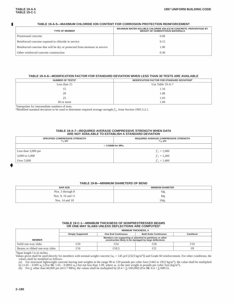
TABLE 19-A-5TABLE 19-C-1
1997 UNIFORM BUILDING CODE
2–180
TABLE 19-A-5—MAXIMUM CHLORIDE ION CONTENT FOR CORROSION PROTECTION REINFORCEMENT
TYPE OF MEMBERMAXIMUM WATER-SOLUBLE CHLORIDE ION (Cl) IN CONCRETE, PERCENTAGE BY
WEIGHT OF CEMENTITIOUS MATERIALS
Prestressed concrete 0.06
Reinforced concrete exposed to chloride in service 0.15
Reinforced concrete that will be dry or protected from moisture in service 1.00
Other reinforced concrete construction 0.30
TABLE 19-A-6—MODIFICATION FACTOR FOR STANDARD DEVIATION WHEN LESS THAN 30 TESTS ARE A VAILABLENUMBER OF TESTS1 MODIFICATION FACTOR FOR STANDARD DEVIATION 2
Less than 15
15
20
25
Use Table 19-A-7
1.16
1.08
1.0330 or more 1.00
1Interpolate for intermediate numbers of tests.2Modified standard deviation to be used to determine required average strength f’cr from Section 1905.3.2.1.
TABLE 19-A-7—REQUIRED AVERAGE COMPRESSIVE STRENGTH WHEN DATAARE NOT AVAILABLE TO EST ABLISH A ST ANDARD DEVIATION
SPECIFIED COMPRESSIVE STRENGTHf ’c psi
REQUIRED AVERAGE COMPRESSIVE STRENGTHf ’cr psi
� 0.00689 for MPa
Less than 3,000 psi f ’c + 1,000
3,000 to 5,000 f ’c + 1,200
Over 5,000 f ’c + 1,400
TABLE 19-B—MINIMUM DIAMETERS OF BENDBAR SIZE MINIMUM DIAMETER
Nos. 3 through 8 6db
Nos. 9, 10 and 11 8db
Nos. 14 and 18 10db
TABLE 19-C-1—MINIMUM THICKNESS OF NONPRESTRESSED BEAMSOR ONE-WAY SLABS UNLESS DEFLECTIONS ARE COMPUTED 1
MINIMUM THICKNESS, h
Simply Supported One End Continuous Both Ends Continuous Cantilever
MEMBERMembers not supporting or attached to partitions or other
construction likely to be damaged by large deflections
Solid one-way slabs l/20 l/24 l/28 l/10
Beams or ribbed one-way slabs l/16 l/18.5 l/21 l/81Span length l is in inches.Values given shall be used directly for members with normal-weight concrete [wc = 145 pcf (2323 kg/m3)] and Grade 60 reinforcement. For other conditions, the
values shall be modified as follows:(a) For structural lightweight concrete having unit weights in the range 90 to 120 pounds per cubic foot (1442 to 1922 kg/m3), the value shall be multipliedby (1.65 – 0.005 wc) (For SI: 1.65 – 0.0003 wc) but not less than 1.09, where wc is the unit weight in pounds per cubic foot (kg/m3).(b) For fy other than 60,000 psi (413.7 MPa), the values shall be multiplied by (0.4 + fy/100,000) (For SI: 0.4 + fy/689.5).
�
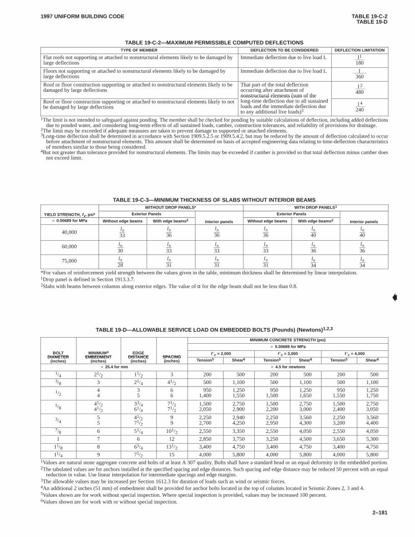
TABLE 19-C-2TABLE 19-D
1997 UNIFORM BUILDING CODE
2–181
TABLE 19-C-2—MAXIMUM PERMISSIBLE COMPUTED DEFLECTIONSTYPE OF MEMBER DEFLECTION TO BE CONSIDERED DEFLECTION LIMITATION
Flat roofs not supporting or attached to nonstructural elements likely to be damaged bylarge deflections
Immediate deflection due to live load L l1
180
Floors not supporting or attached to nonstructural elements likely to be damaged bylarge deflections
Immediate deflection due to live load L l360
Roof or floor construction supporting or attached to nonstructural elements likely to bedamaged by large deflections
That part of the total deflectionoccurring after attachment ofnonstructural elements (sum of the
l2
480
Roof or floor construction supporting or attached to nonstructural elements likely to notbe damaged by large deflections
nonstructural elements (sum of thelong-time deflection due to all sustainedloads and the immediate deflection dueto any additional live loads)3
l4
240
1The limit is not intended to safeguard against ponding. The member shall be checked for ponding by suitable calculations of deflection, including added deflectionsdue to ponded water, and considering long-term effects of all sustained loads, camber, construction tolerances, and reliability of provisions for drainage.
2The limit may be exceeded if adequate measures are taken to prevent damage to supported or attached elements.3Long-time deflection shall be determined in accordance with Section 1909.5.2.5 or 1909.5.4.2, but may be reduced by the amount of deflection calculated to occur
before attachment of nonstructural elements. This amount shall be determined on basis of accepted engineering data relating to time-deflection characteristicsof members similar to those being considered.
4But not greater than tolerance provided for nonstructural elements. The limits may be exceeded if camber is provided so that total deflection minus camber doesnot exceed limit.
TABLE 19-C-3—MINIMUM THICKNESS OF SLABS WITHOUT INTERIOR BEAMSWITHOUT DROP PANELS* WITH DROP PANELS 1
YIELD STRENGTH, f y, psi* Exterior Panels Exterior Panels
� 0.00689 for MPa Without edge beams With edge beams 2 Interior panels Without edge beams With edge beams 2 Interior panels
40,000l n33
l n36
l n36
l n36
l n40
l n40
60,000 l n30
l n33
l n33
l n33
l n36
l n36
75,000 l n28
l n31
l n31
l n31
l n34
l n34
*For values of reinforcement yield strength between the values given in the table, minimum thickness shall be determined by linear interpolation.1Drop panel is defined in Section 1913.3.7.2Slabs with beams between columns along exterior edges. The value of α for the edge beam shall not be less than 0.8.
TABLE 19-D—ALLOWABLE SER VICE LOAD ON EMBEDDED BOL TS (Pounds) (Newtons) 1,2,3
MINIMUM CONCRETE STRENGTH (psi)
� 0.00689 for MPa
BOLTDIAMETER
MINIMUM4
EMBEDMENTEDGE
DISTANCE SPACINGf ′c = 2,000 f ′c = 3,000 f ′c = 4,000
DIAMETER(inches)
EMBEDMENT(inches)
DISTANCE(inches)
SPACING(inches) Tension 5 Shear6 Tension 5 Shear6 Tension 5 Shear6
� 25.4 for mm � 4.5 for newtons
1/4 21/2 11/2 3 200 500 200 500 200 5003/8 3 21/4 41/2 500 1,100 500 1,100 500 1,100
1/244
35
66
9501,400
1,2501,550
9501,500
1,2501,650
9501,550
1,2501,750
5/841/241/2
33/461/4
71/271/2
1,5002,050
2,7502,900
1,5002,200
2,7503,000
1,5002,400
2,7503,050
3/455
41/271/2
99
2,2502,700
2,9404,250
2,2502,950
3,5604,300
2,2503,200
3,5604,400
7/8 6 51/4 101/2 2,550 3,350 2,550 4,050 2,550 4,050
1 7 6 12 2,850 3,750 3,250 4,500 3,650 5,300
11/8 8 63/4 131/2 3,400 4,750 3,400 4,750 3,400 4,750
11/4 9 71/2 15 4,000 5,800 4,000 5,800 4,000 5,8001Values are natural stone aggregate concrete and bolts of at least A 307 quality. Bolts shall have a standard head or an equal deformity in the embedded portion.2The tabulated values are for anchors installed at the specified spacing and edge distances. Such spacing and edge distance may be reduced 50 percent with an equal
reduction in value. Use linear interpolation for intermediate spacings and edge margins.3The allowable values may be increased per Section 1612.3 for duration of loads such as wind or seismic forces.4An additional 2 inches (51 mm) of embedment shall be provided for anchor bolts located in the top of columns located in Seismic Zones 2, 3 and 4.5Values shown are for work without special inspection. Where special inspection is provided, values may be increased 100 percent.6Values shown are for work with or without special inspection.
�
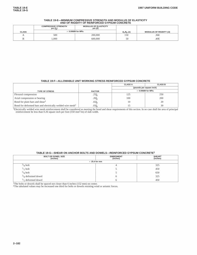
TABLE 19-ETABLE 19-G
1997 UNIFORM BUILDING CODE
2–182
TABLE 19-E—MINIMUM COMPRESSIVE STRENGTH AND MODULUS OF ELASTICITYAND OF RIGIDITY OF REINFORCED GYPSUM CONCRETE
COMPRESSIVE STRENGTHpsi ( fg )
MODULUS OF ELASTICITYpsi ( E)
CLASS � 0.00689 for MPa Es /Eg (n) MODULUS OF RIGIDITY (G)
A 500 200,000 150 .36E
B 1,000 600,000 50 .40E
TABLE 19-F—ALLOWABLE UNIT WORKING STRESS REINFORCED GYPSUM CONCRETECLASS A CLASS B
(pounds per square inch)
TYPE OF STRESS FACTOR � 0.00689 for MPa
Flexural compression .25fg 125 250
Axial compression or bearing .20fg 100 200
Bond for plain bars and shear1 .02fg 10 20
Bond for deformed bars and electrically welded wire mesh1 .03fg 15 301Electrically welded wire mesh reinforcement shall be considered as meeting the bond and shear requirements of this section. In no case shall the area of principal
reinforcement be less than 0.26 square inch per foot (550 mm2/m) of slab width.
TABLE 19-G—SHEAR ON ANCHOR BOL TS AND DOWELS—REINFORCED GYPSUM CONCRETE1
BOLT OR DOWEL SIZE(inches)
EMBEDMENT(inches)
SHEAR2
(inches)
� 25.4 for mm
3/8 bolt 4 3251/2 bolt 5 4505/8 bolt 5 6503/8 deformed dowel 6 3251/2 deformed dowel 6 450
1The bolts or dowels shall be spaced not closer than 6 inches (152 mm) on center.2The tabulated values may be increased one third for bolts or dowels resisting wind or seismic forces.
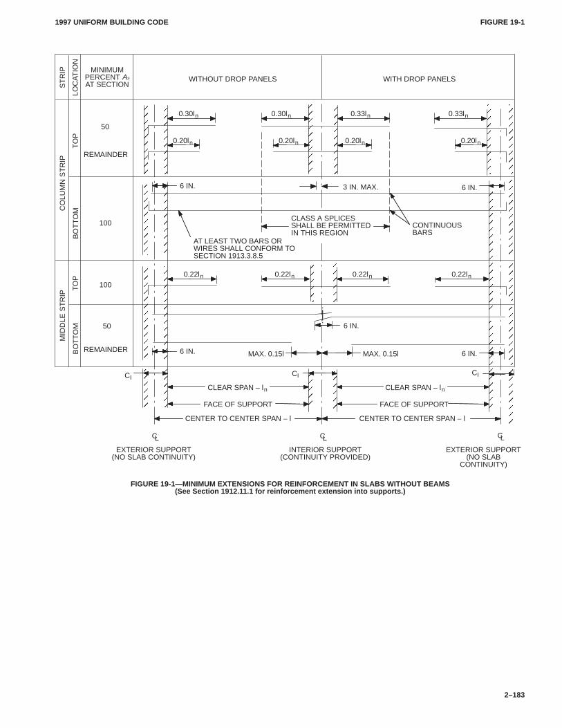
FIGURE 19-1FIGURE 19-1
1997 UNIFORM BUILDING CODE
2–183
ÎÎÎ
ÎÎÎ
ÎÎÎÎÎÎ
ÎÎÎ
ÎÎÎÎ
ÎÎÎÎÎÎ
ÎÎÎÎÎÎÎÎÎÎÎÎÎÎ
ÎÎÎÎÎÎÎÎ
ÎÎÎÎÎÎÎÎ
ÎÎÎÎ
ÎÎÎÎÎÎ
ÎÎÎÎÎÎ
ÎÎÎÎÎÎ
ÎÎÎÎÎÎÎÎÎÎÎÎÎÎ
ÎÎÎÎÎÎÎÎÎÎÎÎ
ÎÎÎÎÎÎ
3 IN. MAX.
EXTERIOR SUPPORT(NO SLAB CONTINUITY)
INTERIOR SUPPORT(CONTINUITY PROVIDED)
EXTERIOR SUPPORT(NO SLAB
CONTINUITY)
6 IN.
MAX. 0.15l
AT LEAST TWO BARS ORWIRES SHALL CONFORM TOSECTION 1913.3.8.5
50
100
100
50
REMAINDER
REMAINDER
WITHOUT DROP PANELS WITH DROP PANELSMINIMUM
PERCENT AS
AT SECTION
CENTER TO CENTER SPAN – l
FACE OF SUPPORT
CI
0.30ln
MID
DLE
ST
RIP
CL
CO
LUM
N S
TR
IP S
TR
IP
BO
TT
OM
LOC
AT
ION
TO
PB
OT
TO
MT
OP
0.30ln 0.33ln 0.33ln
0.20ln 0.20ln 0.20ln 0.20ln
ÎÎÎÎÎÎÎÎÎÎÎÎÎÎÎÎÎÎÎÎÎÎÎÎÎÎÎ
0.22ln 0.22ln0.22ln 0.22ln
CLEAR SPAN – ln
6 IN.
CI
CENTER TO CENTER SPAN – l
FACE OF SUPPORT
CLEAR SPAN – ln
CL CL
CI
MAX. 0.15l 6 IN.
CLASS A SPLICESSHALL BE PERMITTEDIN THIS REGION
CONTINUOUSBARS
6 IN. 6 IN.
FIGURE 19-1—MINIMUM EXTENSIONS FOR REINFORCEMENT IN SLABS WITHOUT BEAMS(See Section 1912.1 1.1 for reinforcement extension into supports.)
1997 UNIFORM BUILDING CODE STANDARD 19-1
3–333
UNIFORM BUILDING CODE STANDARD 19-1
WELDING REINFORCING STEEL, METAL INSERTS ANDCONNECTIONS IN REINFORCED CONCRETE CONSTRUCTION
See Sections 1903.5.2, 1903.10, and 1912.14,Uniform Building Code
SECTION 19.101 — ADOPTION OF AWS CODE
19.101.1Except for the limitations, deletions, modifications oramendments set forth in Section 19.102 of this standard, the weld-ing of concrete reinforcing steel for splices (prestressing steelexcepted), steel connection devices, inserts, anchors and anchor-age details, as well as any other welding required in reinforcedconcrete construction, shall be in accordance with the StructuralWelding Code—Reinforcing Steel, ANSI/AWS D1.4-92, pub-lished by the American Welding Society, Inc., Copyright 1992,550 North LeJeune Road, Miami, Florida 33135, as if set out atlength herein.
SECTION 19.102 — DELETIONS AND AMENDMENTS
19.102.1 General.The American Welding Society, Inc., codeadopted by Section 19.101 applies to all materials, processes,design, workmanship and testing of welding performed as a partof reinforced concrete construction, except as set forth in this sec-tion.
19.102.2 Deletions.The following sections and chapters aredeleted:
Section 1.6
Section 1.7
Section 3.7
Section 5.6.3
Chapter 7
19.102.3 Amendments
1. Sec. 1.2.1 is amended by changing the last sentence to read asfollows:
When reinforcing steel is welded to primary structural steelmembers, welding procedures, welder qualification require-ments and welding electrodes shall be in accordance withChapter 22, Divisions II, III and VI or VII, of this code andapproved national standards.
2. Sec. 1.2.3 is amended to read as follows:
1.2.3. All references to the need for approval shall be inter-preted to mean approval by the building official.
3. Sec. 1.2.4 is amended to read as follows:
1.2.4 When structural steel base metals make up the entireweld joint, the engineer may select the use of welding proce-dures and welder qualifications in accordance with Chapter22, Divisions II, III and VI or VII, of this code and approvednational standards to perform that weld, provided other rele-vant provisions of UBC Standard 19-1 are considered.
4. Sec. 1.3.3 is amended to read as follows:
1.3.3 Base metal, other than those previously listed, shall beone of the structural steels listed in Chapter 22, Divisions II,III and VI or VII, of this code.
5. Sec. 1.5 is amended to read as follows:
1.5 DefinitionsThe welding terms used in this code shall be interpreted
in accordance with the definitions given in Chapter 22, Divi-sions V, VIII and IX or X, of this code and approved nationalstandards.
6. Sec. 2.1 is amended to read as follows:
2.1 Base Metal Stresses. The allowable base metal stressesshall be those specified in this code for reinforced concreteconstruction.
�
1997 UNIFORM BUILDING CODE STANDARD 19-2
3–335
UNIFORM BUILDING CODE STANDARD 19-2
MILL-MIXED GYPSUM CONCRETE ANDPOURED GYPSUM ROOF DIAPHRAGMS
Based on Reports of Test Programs by S. B. Barnes and Associates dated February 1955, November 1956,January 1958, and February 1962, and Standard Specification C 317-70 of the American Society for Testing and
Materials. Extracted, with permission, from the Annual Book of ASTM Standards, copyright American Society forTesting and Materials, 100 Barr Harbor Drive, West Conshohocken, PA 19428
See Sections 1903.9 and 1925.3, Uniform Building Code
Part I—Mill-mixed Gypsum Concrete
SECTION 19.201 — SCOPE
This part covers mill-mixed gypsum concrete. Gypsum concretesupplied under this standard shall be mill-mixed gypsum con-crete, consisting essentially of calcined gypsum and suitable ag-gregate, requiring the addition of water only at the job. Gypsumconcrete is intended for use in construction of poured-in-placeroof decks or slabs. Two classes, based on the compressivestrength and density, are covered.
SECTION 19.202 — COMPOSITION
Gypsum concrete shall consist essentially of calcined gypsum andwood chips or wood shavings, proportioned to meet the applicablerequirements of this standard. Calcined gypsum used in the millmixed gypsum concrete shall conform to the requirements ofASTM C 28-76a. Wood chips or wood shavings shall be of drywood, uniform and clean in appearance, shall pass a 1-inch (25mm) sieve, and shall not be more than 1/16 inch (1.6 mm) in thick-ness.
SECTION 19.203 — TIME OF SETTING
Gypsum concrete shall not set in less than 20 minutes nor morethan 90 minutes.
SECTION 19.204 — COMPRESSIVE STRENGTH ANDDENSITY
Gypsum concrete shall have the following compressive strengthand density for the respective classes:
COMPRESSIVESTRENGTH
MINIMUM psi (MPa)
DENSITYPOUNDS PER CUBIC
FOOT (kg/m 3)
Class AClass B
500 (3.5)1,000 (6.9)
60 (960)—
SECTION 19.205 — METHODS OF TESTING
The physical properties of gypsum concrete shall be determined inaccordance with approved methods.
Part II—Poured-in-place Reinforced Gypsum Concrete
SECTION 19.206 — SCOPE
This part covers the design of poured-in-place reinforced gypsumconcrete roof decks when used as a horizontal diaphragm.
SECTION 19.207 — DESIGN
19.207.1 General.The gypsum roof diaphragm shall consist ofsub-purlins welded transversely to primary purlins. Formboard isthen placed on the flanges of the subpurlins. Wire mesh reinforce-ment is then placed over the subpurlins and formboard and lappedat least 4 inches (102 mm) or one mesh on ends and edges, which-ever is greater. Gypsum concrete meeting the requirements of PartI of this standard is then placed to a minimum thickness of 2 inches(51 mm) over the formboard and 5/8 inch (16 mm) over the subpur-lins and doweling elements. The bulb section or top flange of thesubpurlin shall be fully embedded in the gypsum concrete.
19.207.2 Diaphragm Shear.Shear in poured gypsum concretediaphragms shall be determined by the formula:
Q = .16fg t Cl + 1,000 (k1 d1 + k2 d2)
For SI: Q = 1.36fg t Cl + 17.86 (k1 d1 + k2 d2)
WHERE:
Cl = 1.0 for Class A gypsum; 1.5 for Class B gypsum.
d1 = diameter of mesh wires passing over subpurlins, in in-ches (mm), except hexagonal mesh.
d2 = diameter, in inches (mm), of mesh wires parallel to sub-purlins or of hexagonal wires.
fg = oven-dry compressive strength of gypsum in pounds persquare inch (MPa) as determined by tests conforming tothis standard.
k1 = number of mesh wires per foot (m) passing over subpur-lins.
k2 = number of mesh wires per foot (m) parallel to subpurlinsor .7 times the number of hexagonal wires. Note: k2 = 8.5(27.9) for 2-inch (51 mm) hexagonal mesh woven of No.19 gage galvanized wire with additional longitudinalNo. 16 gage galvanized wires spaced every 3 inches (76mm) across the width of the mesh.
Q = allowable shear on diaphragm in pounds per linear foot(kg/m), which includes a one-third increase forshort-time loading.
t = thickness of gypsum concrete between subpurlins, ininches (mm). For the purpose of computing diaphragmshear values, t shall not exceed 4 inches (102 mm).
The solution of the above equation for commonly used thick-ness and mesh types for each class of gypsum would give the val-ues set forth in Table 19-2-A.
19.207.3 Shear Transfer.Bolts, dowels or other approved ele-ments may be used to transfer diaphragm shears to perimeter orother structural members. Allowable bolt and dowel stresses shallcomply with Table 19-G and Section 1603 of this code.
�
1997 UNIFORM BUILDING CODESTANDARD 19-2
3–336
TABLE 19-2-A—ALLOWABLE SHEAR VALUES IN POUNDS PER FOOT USING BULB TEE SUBPURLINS 1
MESH TYPE2
CLASS OFGYPSUM
CONCRETE
CONCRETETHICKNESS
(inches)
4″ × 8″(102 mm × 203 mm)
No. 12-No. 14(Galvanized)
6″ × 6″(152 mm × 152 mm)
No. 10-No. 10Hexagonal 3
(Galvanized)
× 6.89 for kPa × 25.4 for mm × 14.59 for N/m
A(500 psi)
221/2
600640
700740
760800
B(1,000 psi)
221/2
9201,040
1,0201,140
1,0801,200
1The tabulated shear values are for short-time loads due to wind or earthquake forces and are not permitted a one-third increase for duration of load.2Mesh shall be lapped at least 4 inches (102 mm) or one mesh on ends and edges, whichever is greater.3Two-inch (51 mm) hexagonal mesh woven of No. 19 gage galvanized wire with additional longitudinal No. 16 gage galvanized wires spaced every 3 inches
(76 mm) across the width of the mesh.
�
CHAP. 20, DIV. I2001
2001.31997 UNIFORM BUILDING CODE
2–185
Chapter 20
LIGHTWEIGHT METALSDivision I—GENERAL
SECTION 2001 — MATERIAL STANDARDS ANDSYMBOLS
2001.1 General.The quality, design, fabrication and erection ofaluminum used structurally in buildings and structures shall con-form to the requirements of this chapter, to other applicable re-quirements of this code and to Division II.CHAP. 20, DIV. I
Allowable stresses and design formulas provided in this chaptershall be used with the allowable stress design load combinationsspecified in Section 1612.3.
2001.2 Alloys. The use of aluminum alloys and tempers otherthan those covered by this chapter and other lightweight metal al-loys are allowed for structural members and assemblies, providedstandards of performance not less than those required by this chap-ter are substantiated to the satisfaction of the building official.When required by the building official, certification that the alloysand tempers called for on the plans have been furnished shall beprovided.
2001.3 Symbols and Notations.The symbols and notationsused in this chapter are defined as follows:
A = area, square inches (mm2).Ac = area of compression element, square inches (mm2)
(compression flange plus one third of area of web be-tween compression flange and neutral axis).
Aw = area of cross section lying within 1.0 inch of a weld,square inches (mm2).
a1 = shorter dimension of rectangular panel, inches (mm).a2 = longer dimension of rectangular panel, inches (mm).ae = equivalent width of rectangular panel, inches (mm).
B, D, C= buckling formula constants, with following subscript:
c—compression in columnsp—compression in flat platest—compression in round tubestb—bending in round tubesb—bending in rectangular barss—shear in flat plates
b = width of sections, inches (mm).b/t = width-to-thickness ratio or rectangular element of a
cross section.c = distance from neutral axis to extreme fiber, inches (mm).D = diameter, inches (mm).d = depth of section or beam, inches (mm).E = compressive modulus of elasticity, kips per square inch
(ksi) (MPa).F = allowable stress, ksi (MPa).
Fa = allowable compressive stress for member considered asan axially loaded column, ksi (MPa).
Fb = allowable compressive stress for member considered asa beam, ksi (MPa).
Fbu = bearing ultimate strength, ksi (MPa).Fbuw = bearing ultimate strength within 1.0 inch (25.4 mm) of a
weld, ksi (MPa).Fby = bearing yield strength, ksi (MPa).
Fbyw = bearing yield strength within 1.0 inch (25.4 mm) of aweld, ksi (MPa).
Fc = allowable compressive stress, ksi (MPa).Fcy = compressive yield strength, ksi (MPa).
Fcyw = compressive yield strength across a butt weld [0.2 per-cent offset in 10-inch (254 mm) gage length], ksi (MPa).
Fec = π2E/ [nu(l/r)2], where l/r is slenderness ratio for memberconsidered as a column tending to fail in the plane of theapplied bending moments, ksi (MPa).
Fn = allowable stress for cross section 1.0 inch (25.4 mm) ormore from weld, ksi (MPa).
Fpw = allowable stress on cross section, part of whose area lieswithin 1.0 (25.4 mm) inch of a weld, ksi (MPa).
Fs = allowable shear stress for members subjected only totorsion or shear, ksi (MPa).
Fsu = shear ultimate strength, ksi (MPa).Fsuw = shear ultimate strength within 1.0 inch (25.4 mm) of a
weld, ksi (MPa).Fsy = shear yield strength, ksi (MPa).
Fsyw = shear yield strength within 1.0 inch (25.4 mm) of a weld,ksi (MPa).
Ftu = tensile ultimate strength, ksi (MPa).Ftuw = tensile ultimate strength across a butt weld, ksi (MPa).
Fty = tensile yield strength, ksi (MPa).Ftyw = tensile yield strength across a butt weld [0.2 percent off-
set in 10-inch (254 mm) gage length], ksi (MPa).Fy = either Fty or Fcy, whichever is smaller, ksi (MPa).
f = calculated stress, ksi (MPa).fa = average compressive stress on cross section of member
produced by axial compressive load, ksi (MPa).fb = maximum bending stress (compressive) caused by
transverse loads or end moments, ksi (MPa).fs = shear stress caused by torsion or transverse shear, ksi
(MPa).G = modulus of elasticity in shear, ksi (MPa).g = spacing of rivet or bolt holes perpendicular to direction
of load, inches (mm).h = clear height of shear web, inches (mm).I = moment of inertia, inches4 (mm4).
Ih = moment of inertia of horizontal stiffener, inches4 (mm4).Is = moment of inertia of transverse stiffener to resist shear
buckling, inches4 (mm4).Ix = moment of inertia of a beam about axis perpendicular to
web, inches4 (mm4).Iy = moment of inertia of a beam about axis parallel to web,
inches4 (mm4).Iyc = moment of inertia of compression element about axis
parallel to vertical web, inches4 (mm4).J = torsion constant, inches4 (mm4).
k1 = coefficient for determining slenderness limit S2 for sec-tions for which the allowable compressive stress isbased on crippling strength.
k2 = coefficient for determining allowable compressivestress in sections with slenderness ratio above S2 for
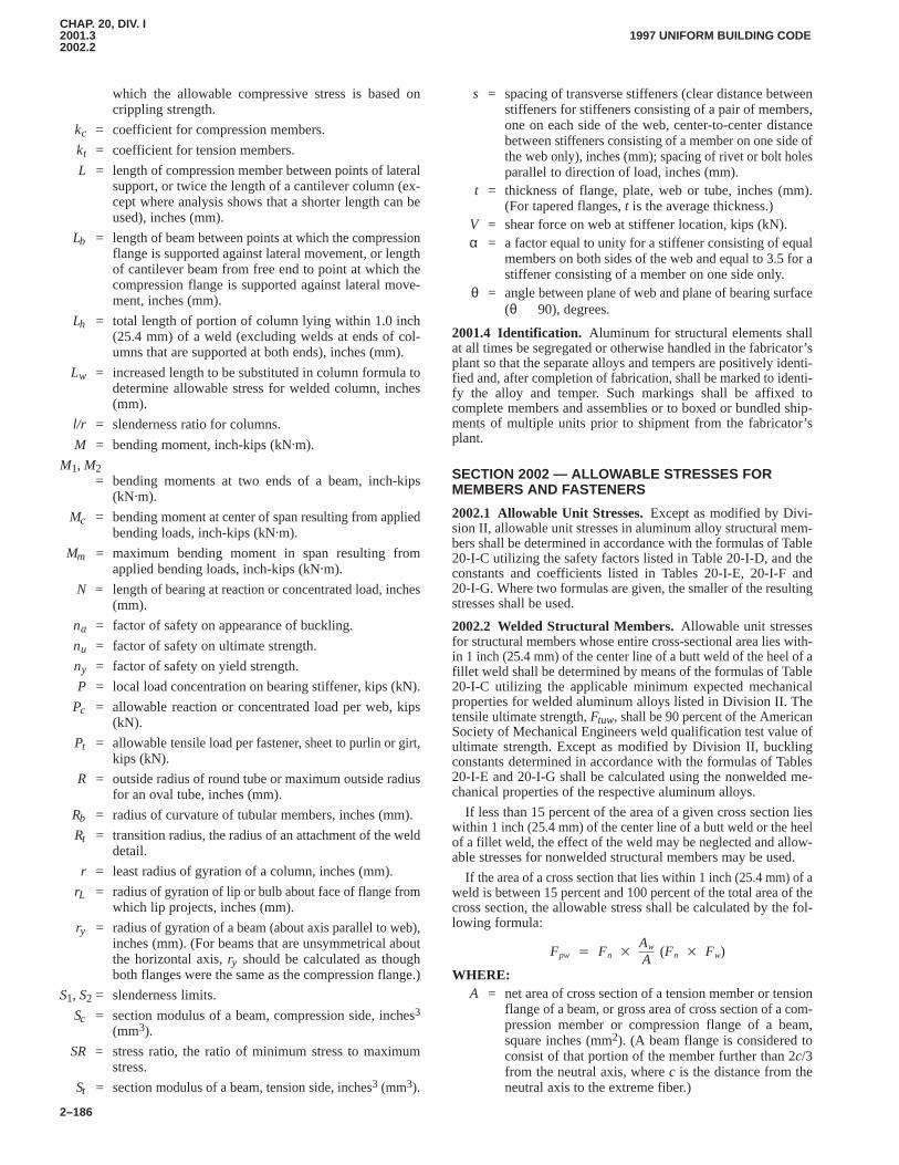
CHAP. 20, DIV. I2001.32002.2
1997 UNIFORM BUILDING CODE
2–186
which the allowable compressive stress is based oncrippling strength.
kc = coefficient for compression members.
kt = coefficient for tension members.
L = length of compression member between points of lateralsupport, or twice the length of a cantilever column (ex-cept where analysis shows that a shorter length can beused), inches (mm).
Lb = length of beam between points at which the compressionflange is supported against lateral movement, or lengthof cantilever beam from free end to point at which thecompression flange is supported against lateral move-ment, inches (mm).
Lh = total length of portion of column lying within 1.0 inch(25.4 mm) of a weld (excluding welds at ends of col-umns that are supported at both ends), inches (mm).
Lw = increased length to be substituted in column formula todetermine allowable stress for welded column, inches(mm).
l/r = slenderness ratio for columns.
M = bending moment, inch-kips (kN�m).
M1, M2= bending moments at two ends of a beam, inch-kips
(kN�m).
Mc = bending moment at center of span resulting from appliedbending loads, inch-kips (kN�m).
Mm = maximum bending moment in span resulting fromapplied bending loads, inch-kips (kN�m).
N = length of bearing at reaction or concentrated load, inches(mm).
na = factor of safety on appearance of buckling.
nu = factor of safety on ultimate strength.
ny = factor of safety on yield strength.
P = local load concentration on bearing stiffener, kips (kN).
Pc = allowable reaction or concentrated load per web, kips(kN).
Pt = allowable tensile load per fastener, sheet to purlin or girt,kips (kN).
R = outside radius of round tube or maximum outside radiusfor an oval tube, inches (mm).
Rb = radius of curvature of tubular members, inches (mm).
Rt = transition radius, the radius of an attachment of the welddetail.
r = least radius of gyration of a column, inches (mm).
rL = radius of gyration of lip or bulb about face of flange fromwhich lip projects, inches (mm).
ry = radius of gyration of a beam (about axis parallel to web),inches (mm). (For beams that are unsymmetrical aboutthe horizontal axis, ry should be calculated as thoughboth flanges were the same as the compression flange.)
S1, S2 = slenderness limits.
Sc = section modulus of a beam, compression side, inches3
(mm3).
SR = stress ratio, the ratio of minimum stress to maximumstress.
St = section modulus of a beam, tension side, inches3 (mm3).
s = spacing of transverse stiffeners (clear distance betweenstiffeners for stiffeners consisting of a pair of members,one on each side of the web, center-to-center distancebetween stiffeners consisting of a member on one side ofthe web only), inches (mm); spacing of rivet or bolt holesparallel to direction of load, inches (mm).
t = thickness of flange, plate, web or tube, inches (mm).(For tapered flanges, t is the average thickness.)
V = shear force on web at stiffener location, kips (kN).α = a factor equal to unity for a stiffener consisting of equal
members on both sides of the web and equal to 3.5 for astiffener consisting of a member on one side only.
θ = angle between plane of web and plane of bearing surface(θ � 90), degrees.
2001.4 Identification. Aluminum for structural elements shallat all times be segregated or otherwise handled in the fabricator’splant so that the separate alloys and tempers are positively identi-fied and, after completion of fabrication, shall be marked to identi-fy the alloy and temper. Such markings shall be affixed tocomplete members and assemblies or to boxed or bundled ship-ments of multiple units prior to shipment from the fabricator’splant.
SECTION 2002 — ALLOWABLE STRESSES FORMEMBERS AND FASTENERS
2002.1 Allowable Unit Stresses.Except as modified by Divi-sion II, allowable unit stresses in aluminum alloy structural mem-bers shall be determined in accordance with the formulas of Table20-I-C utilizing the safety factors listed in Table 20-I-D, and theconstants and coefficients listed in Tables 20-I-E, 20-I-F and20-I-G. Where two formulas are given, the smaller of the resultingstresses shall be used.
2002.2 Welded Structural Members.Allowable unit stressesfor structural members whose entire cross-sectional area lies with-in 1 inch (25.4 mm) of the center line of a butt weld of the heel of afillet weld shall be determined by means of the formulas of Table20-I-C utilizing the applicable minimum expected mechanicalproperties for welded aluminum alloys listed in Division II. Thetensile ultimate strength, Ftuw, shall be 90 percent of the AmericanSociety of Mechanical Engineers weld qualification test value ofultimate strength. Except as modified by Division II, bucklingconstants determined in accordance with the formulas of Tables20-I-E and 20-I-G shall be calculated using the nonwelded me-chanical properties of the respective aluminum alloys.
If less than 15 percent of the area of a given cross section lieswithin 1 inch (25.4 mm) of the center line of a butt weld or the heelof a fillet weld, the effect of the weld may be neglected and allow-able stresses for nonwelded structural members may be used.
If the area of a cross section that lies within 1 inch (25.4 mm) of aweld is between 15 percent and 100 percent of the total area of thecross section, the allowable stress shall be calculated by the fol-lowing formula:
Fpw � Fn �Aw
A(Fn � Fw)
WHERE:A = net area of cross section of a tension member or tension
flange of a beam, or gross area of cross section of a com-pression member or compression flange of a beam,square inches (mm2). (A beam flange is considered toconsist of that portion of the member further than 2c/3from the neutral axis, where c is the distance from theneutral axis to the extreme fiber.)
CHAP. 20, DIV. I2002.22004.7
1997 UNIFORM BUILDING CODE
2–187
Aw = area of cross section lying within 1.0 inch (25.4 mm) of aweld.
Fn = allowable stress for cross section 1.0 inch (25.4 mm) ormore from weld.
Fpw = allowable stress on cross section part of whose area lieswithin 1.0 inch (25.4 mm) of a weld.
Fw = allowable stress on cross section if entire area were to liewithin 1.0 inch (25.4 mm) of a weld.
For columns and beams with welds at locations other than attheir supported ends (not farther from the supports than 0.05 Lfrom the ends), and for cantilever columns and single web beamswith transverse welds at or near the supported end, the effect ofwelding on allowable stresses shall be determined in accordancewith the provisions of Division II.
2002.3 Rivets and Bolts. Allowable stresses in aluminum rivetsand bolts shall be as set forth in Table 20-I-A.
2002.4 Fillet Welds. Allowable shear stresses in fillet weldsshall be as set forth in Table 20-I-B.
SECTION 2003 — DESIGN
2003.1 Combined Stresses.Members subjected to combina-tions of compression and bending or shear, compression and bend-ing shall be proportioned in accordance with the provisions ofDivision II.
2003.2 Light Gage Members.Where the design of light gagestructural members is involved, the special provisions of DivisionII shall be applied.
2003.3 Structural Roofing and Siding.The live load deflec-tion of structural roofing and siding made of formed sheet shall notexceed 1/60 of the span length.
2003.4 Connections.The design of mechanical and weldedconnections shall be in accordance with this chapter and the provi-sions of Division II.
SECTION 2004 — FABRICATION AND ERECTION
2004.1 Cutting. Oxygen cutting of aluminum alloys shall not bepermitted.
2004.2 Fasteners.Bolts and other fasteners shall be aluminum,stainless steel or aluminized, hot-dip galvanized or electrogalva-nized steel. Double cadmium-plated AN steel bolts may also beused. Steel rivets shall not be used except where aluminum is to bejoined to steel or where corrosion resistance of the structure is nota requirement or where the structure is to be protected against cor-rosion.
2004.3 Dissimilar Materials. Where aluminum alloy parts arein contact with dissimilar metals, other than stainless, aluminizedor galvanized steel or absorbent building materials likely to becontinuously or intermittently wet, the faying surfaces shall bepainted or otherwise separated in accordance with Division II.
2004.4 Painting. Except as prescribed in Section 2004.3, paint-ing or coating of aluminum alloy parts shall be required only whencalled for on the plans.
2004.5 Welding. Aluminum parts shall be welded with an inertgas shielded arc or resistance welding process. No welding pro-cess that requires a welding flux shall be used. Filler alloys com-plying with the requirements of Division II shall be used.
2004.6 Welder Qualification. All welds of structural membersshall be performed by welders qualified in accordance with theprocedures of Division II.
2004.7 Erection. During erection, structural aluminum shall beadequately braced and fastened to resist dead, wind and erectionloads.
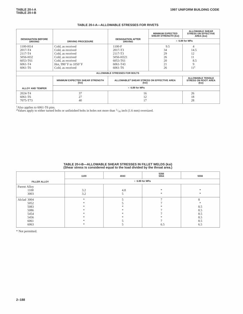
TABLE 20-I-ATABLE 20-I-B
1997 UNIFORM BUILDING CODE
2–188
TABLE 20-I-A—ALLOW ABLE STRESSES FOR RIVETS
DESIGNATION BEFORE DESIGNATION AFTER
MINIMUM EXPECTEDSHEAR STRENGTH (ksi)
ALLOWABLE SHEARSTRESS ON EFFECTIVE
AREA (ksi)DESIGNATION BEFORE
DRIVING DRIVING PROCEDUREDESIGNATION AFTER
DRIVING � 6.89 for MPa
1100-H142017-T42117-T45056-H326053-T616061-T46061-T6
Cold, as receivedCold, as receivedCold, as receivedCold, as receivedCold, as receivedHot, 990�F to 1050�FCold, as received
1100-F2017-T32117-T35056-H3216053-T616061-T436061-T6
9.5342926202126
414.512118.59
111
ALLOWABLE STRESSES FOR BOLTS
MINIMUM EXPECTED SHEAR STRENGTH(ksi)
ALLOWABLE 2 SHEAR STRESS ON EFFECTIVE AREA(ksi)
ALLOWABLE TENSILESTRESS ON ROOT AREA
(ksi)
ALLOY AND TEMPER � 6.89 for MPa
2024-T46061-T67075-T73
372740
161217
261828
1Also applies to 6061-T6 pins.2Values apply to either turned bolts or unfinished bolts in holes not more than 1/16 inch (1.6 mm) oversized.
TABLE 20-I-B—ALLOWABLE SHEAR STRESSES IN FILLET WELDS (ksi)(Shear stress is considered equal to the load divided by the throat area.)
1100 404353565554 5556
FILLER ALLOY � 6.89 for MPa
Parent Alloy11003003
3.23.2
4.85
**
**
Alclad 30045052508350865454545660616063
********
55****55
77*77*76.5
8*
8.58.58.58.58.56.5
* Not permitted.
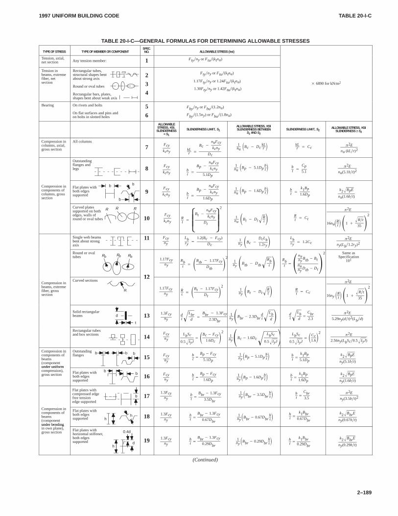
TABLE 20-I-CTABLE 20-I-C
1997 UNIFORM BUILDING CODE
2–189
TABLE 20-I-C—GENERAL FORMULAS FOR DETERMINING ALLOW ABLE STRESSES
TYPE OF STRESS TYPE OF MEMBER OR COMPONENTSPEC.NO. ALLOWABLE STRESS (ksi)
Tension, axial,net section Any tension member: 1 Fty�ny or Ftu�(ktnu)
Tension inbeams, extremefiber, netsection
Rectangular tubes,structural shapes bentabout strong axis
Round or oval tubes
Rectangular bars, plates, shapes bent about weak axis
2
3
4
Fty�ny or Ftu�(ktnu)
1.17Fty�ny or 1.24Ftu�(ktnu)
1.30Fty�ny or 1.42Ftu�(ktnu)� 6890 for kN/m2
Bearing On rivets and bolts
On flat surfaces and pins and on bolts in slotted holes
5
6
Fby�ny or Fbu�(1.2nu)
Fby�(1.5ny) or Fbu�(1.8nu)
ALLOWABLESTRESS, KSI,SLENDERNESS
< S1
SLENDERNESS LIMIT, S1ALLOWABLE STRESS, KSISLENDERNESS BETWEEN
S1 AND S2SLENDERNESS LIMIT, S2
ALLOWABLE STRESS, KSISLENDERNESS > S2
Compression incolumns, axial,gross section
All columns
7 Fcy
kcny kLr �
Bc �
nuFcy
kcnyDc
1nu�Bc � Dc
kLr �
kLr � Cc
�2E
nu (kL�r)2
Outstanding flanges andlegs 8 Fcy
kcnybt �
Bp �
nuFcy
kcny
5.1Dp
1nu�Bp � 5.1Dp
bt� b
t �
Cp
5.1�
2E
nu(5.1b�t)2
Compression incomponents ofcolumns, grosssection
Flat plates withboth edgessupported
b
b
b
9Fcy
kcny bt �
Bp �
nuFcy
kcny
1.6Dp
1nu�Bp � 1.6Dp
bt� b
t �
k1Bp
1.6Dp
k2 BpE�
nu(1.6b�t)
Curved platessupported on bothedges, walls ofround or oval tubes
R R R
10Fcy
kcnyRt �
Bt �
nuFcy
kcnyDt
�
�
2
1nu�Bt � Dt
Rt
� �Rt � Ct
�2E
16nu�Rt� �1 �
R�t�
35�
2
Single web beamsbent about strongaxis
11 Fcyny
Lbry
�
1.2(Bc � Fcy)
Dc1ny�Bc �
DcLb1.2ry�
Lbry
� 1.2Cc�
2E
ny(Lb�1.2ry)2
Round or ovaltubes RbRbRb
12
1.17Fcyny
Rbt � �
Btb � 1.17Fcy
Dtb�
21ny�Btb � Dtb
Rbt
� �Rbt ��
nuny
Btb� Bt
nuny
Dtb� Dt�
2 Same asSpecification
101
Compression inbeams, extremefiber, grosssection
Curved sections
R
12
1.17Fcyny
Rt � �
Bt � 1.17FcyDt
�2
1ny�Bt � Dt
Rt
� � Rt � Cc
�2E
16ny �Rt� �1 �
R�t�
35�
2
Solid rectangularbeams d
t
13 1.3Fcyny
dt
Lbrd
� �
Bbr � 1.3Fcy
2.3Dbr
1ny�Bbr � 2.3Dbr
dt
Lbd
� � dt
Lbd
� �
Cbr2.3
�2E
5.29ny(d�t)2(Lb�d)
Rectangular tubesand box sections 14
Fcyny
LbSc
0.5 IyJ�� �
Bc� Fcy1.6Dc
�2
1ny�Bc� 1.6Dc
LbSc
0.5 IyJ�� � LbSc
0.5 IyJ�� �
Cc1.6�
2�
2E
2.56ny(LbSc�0.5 IyJ� )
Compression incomponents ofbeams(componentunder uniform
Outstandingflanges b b b
15 Fcyny
bt �
Bp� Fcy
5.1Dp
1ny�Bp� 5.1Dp
bt� b
t �k1Bp
5.1Dp
k2 BpE�
ny(5.1b�t)under uniformcompression),gross section Flat plates with
both edgessupported
bb
16 Fcyny
bt �
Bp� Fcy1.6Dp
1ny�Bp� 1.6Dp
bt� b
t �k1Bp
1.6Dp
k2 BpE�
ny(1.6b�t)
b
Flat plates withcompressed edgefree tensionedge supported
171.3Fcy
nybt �
Bbr � 1.3Fcy
3.5Dbr
1ny�Bbr � 3.5Dbr
bt� b
t �Cbr3.5
�2E
ny(3.5b�t)2
Compression incomponents ofbeams(componentunder bending
Flat plates withboth edgessupported h
h 18 1.3Fcyny
ht �
Bbr � 1.3Fcy
0.67Dbr
1ny�Bbr � 0.67Dbr
ht�
ht �
k1Bbr0.67Dbr
k2 BbrE�
ny(0.67h�t)under bendingin own plane),gross section Flat plates with
horizontal stiffener,both edgessupported
0.4d
dh
19 1.3Fcyny
ht �
Bbr � 1.3Fcy
0.29Dbr
1ny�Bbr � 0.29Dbr
ht� h
t �k1Bbr
0.29Dbr
k2 BbrE�
ny(0.29h�t)
(Continued)
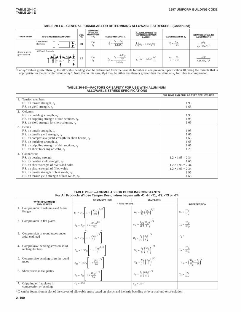
TABLE 20-I-CTABLE 20-I-E
1997 UNIFORM BUILDING CODE
2–190
TABLE 20-I-C—GENERAL FORMULAS FOR DETERMINING ALLOW ABLE STRESSES—(Continued)
TYPE OF STRESS TYPE OF MEMBER OR COMPONENTSPEC.NO.
ALLOWABLESTRESS, KSI,SLENDERNESS
< S1 SLENDERNESS LIMIT, S1
ALLOWABLE STRESS, KSISLENDERNESS BETWEEN
S1 AND S2 SLENDERNESS LIMIT, S2ALLOWABLE STRESS, KSISLENDERNESS > S2
Unstiffenedflat webs h 20
Fsyny
ht �
Bs� Fsy
1.25Ds1ny�Bs� 1.25Ds
ht
ht �
Cs1.25
�2E
ny(1.25h�t)2
Shear in webs,gross section
a2
Stiffened flat webs
a1
a1a221 Fsy
nyaet �
Bs�naFsy
ny
1.25Ds
1na�Bs� 1.25Ds
aet
aet �
Cs1.25
�2E
na(1.25ae�t)2
1For Rb/t values greater than S2, the allowable bending shall be determined from the formula for tubes in compression, Specification 10, using the formula that isappropriate for the particular value of Rb/t. Note that in this case, Rb/t may be either less than or greater than the value of S2 for tubes in compression.
TABLE 20-I-D—FACTORS OF SAFETY FOR USE WITH ALUMINUM ALLOWABLE STRESS SPECIFICA TIONS
BUILDING AND SIMILAR TYPE STRUCTURES
1. Tension membersF.S. on tensile strength, nuF.S. on yield strength, ny
1.951.65
2. ColumnsF.S. on buckling strength, nuF.S. on crippling strength of thin sections, nuF.S. on yield strength for short columns, ny
1.951.951.65
3. BeamsF.S. on tensile strength, nuF.S. on tensile yield strength, nyF.S. on compressive yield strength for short beams, nyF.S. on buckling strength, nyF.S. on crippling strength of thin sections, nyF.S. on shear buckling of webs, na
1.951.651.651.651.651.20
4. ConnectionsF.S. on bearing strengthF.S. on bearing yield strength, nyF.S. on shear strength of rivets and boltsF.S. on shear strength of fillet weldsF.S. on tensile strength of butt welds, nuF.S. on tensile yield strength of butt welds, ny
1.2 × 1.95 = 2.341.65
1.2 × 1.95 = 2.341.2 × 1.95 = 2.34
1.951.65
TABLE 20-I-E—FORMULAS FOR BUCKLING CONST ANTSFor All Products Whose T emper Designation begins with -O, -H, -T1, -T2, -T3 or -T4
TYPE OF MEMBERINTERCEPT (ksi) SLOPE (ksi)
TYPE OF MEMBERAND STRESS � 6.89 for MPa INTERSECTION
1. Compression in columns and beamflanges Bc � Fcy�1��
Fcy1000
1�2
� Dc �
Bc20�
6BcE
1�2Cc �
2Bc3Dc
2. Compression in flat platesBp � Fcy�1�
(Fcy)
7.6
1�3
� Dp �
Bp20�
6BpE
1�2
Cp �
2Bp3Dp
3. Compression in round tubes underaxial end load Bt � Fcy�1�
(Fcy)
5.8
1�5
� Dt �Bt3.7�
BtE
1�3Ct *
4. Compressive bending stress in solidrectangular bars Bb � 1.3Fcy�1�
(Fcy)
7
1�3
� Db �
Bb20�
6BbE
1�2
Cb �
2Bb3Db
5. Compressive bending stress in roundtubes Btb � 1.5Fy�1�
(Fy)
5.8
1�5
� Dtb �
Btb2.7�
BtbE
1�3
Ctb � �Btb� BtDtb� Dt
2
6. Shear stress in flat platesBs� Fsy�1�
(Fsy)
6.2
1�3
� Ds�Bs20�
6BsE
1�2
Cs�2Bs3Ds
7. Crippling of flat plates incompression or bending
k1 � 0.50 k2 � 2.04
*Ct can be found from a plot of the curves of allowable stress based on elastic and inelastic buckling or by a trial-and-error solution.
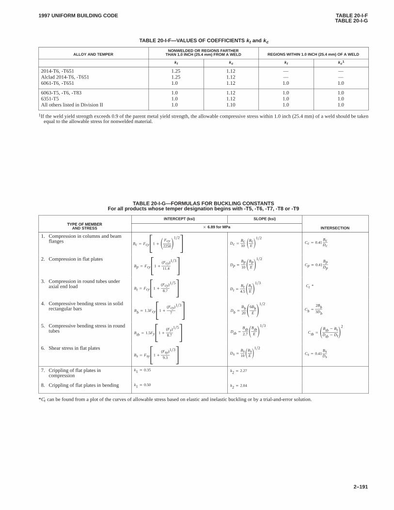
TABLE 20-I-FTABLE 20-I-G
1997 UNIFORM BUILDING CODE
2–191
TABLE 20-I-F—VALUES OF COEFFICIENTS kt and kc
ALLOY AND TEMPERNONWELDED OR REGIONS FARTHER
THAN 1.0 INCH (25.4 mm) FROM A WELD REGIONS WITHIN 1.0 INCH (25.4 mm) OF A WELD
k t k c k t k c 1
2014-T6, -T651Alclad 2014-T6, -T6516061-T6, -T651
1.251.251.0
1.121.121.12
——1.0
——1.0
6063-T5, -T6, -T836351-T5All others listed in Division II
1.01.01.0
1.121.121.10
1.01.01.0
1.01.01.0
1If the weld yield strength exceeds 0.9 of the parent metal yield strength, the allowable compressive stress within 1.0 inch (25.4 mm) of a weld should be takenequal to the allowable stress for nonwelded material.
TABLE 20-I-G—FORMULAS FOR BUCKLING CONST ANTSFor all products whose temper designation begins with -T5, -T6, -T7, -T8 or -T9
TYPE OF MEMBERINTERCEPT (ksi) SLOPE (ksi)
TYPE OF MEMBERAND STRESS � 6.89 for MPa INTERSECTION
1. Compression in columns and beamflanges Bc � Fcy�1��
Fcy
2250
1�2
� Dc �
Bc10�
BcE
1�2Cc � 0.41
BcDc
2. Compression in flat platesBp � Fcy�1�
(Fcy)
11.4
1�3
� Dp �
Bp10�
BpE
1�2
Cp � 0.41BpDp
3. Compression in round tubes underaxial end load Bt � Fcy�1�
(Fcy)
8.7
1�5
� Dt �Bt4.5�
BtE
1�3Ct *
4. Compressive bending stress in solidrectangular bars Bb � 1.3Fcy�1�
(Fcy)
7
1�3
� Db �
Bb20�
6BbE
1�2
Cb �
2Bb3Db
5. Compressive bending stress in roundtubes Btb � 1.5Fy�1�
(Fy)
8.7
1�5
� Dtb �
Btb2.7�
BtbE
1�3
Ctb � �Btb� BtDtb� Dt
2
6. Shear stress in flat platesBs� Fsy�1�
(Fsy)
9.3
1�3
� Ds�Bs10�
BsE
1�2
Cs� 0.41BsDs
7. Crippling of flat plates incompression
k1 � 0.35 k2 � 2.27
8. Crippling of flat plates in bending k1 � 0.50 k2 � 2.04
*Ct can be found from a plot of the curves of allowable stress based on elastic and inelastic buckling or by a trial-and-error solution.
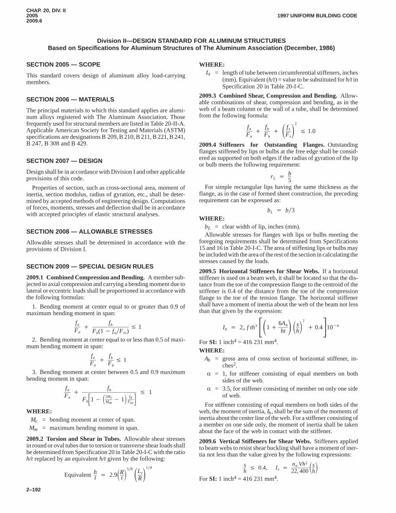
CHAP. 20, DIV. II20052009.6
1997 UNIFORM BUILDING CODE
2–192
Division II—DESIGN STANDARD FOR ALUMINUM STRUCTURESBased on Specifications for Aluminum Structures of The Aluminum Association (December, 1986)
SECTION 2005 — SCOPE
This standard covers design of aluminum alloy load-carryingmembers.CHAP. 20, DIV. II
SECTION 2006 — MATERIALS
The principal materials to which this standard applies are alumi-num alloys registered with The Aluminum Association. Thosefrequently used for structural members are listed in Table 20-II-A.Applicable American Society for Testing and Materials (ASTM)specifications are designations B 209, B 210, B 211, B 221, B 241,B 247, B 308 and B 429.
SECTION 2007 — DESIGN
Design shall be in accordance with Division I and other applicableprovisions of this code.
Properties of section, such as cross-sectional area, moment ofinertia, section modulus, radius of gyration, etc., shall be deter-mined by accepted methods of engineering design. Computationsof forces, moments, stresses and deflection shall be in accordancewith accepted principles of elastic structural analyses.
SECTION 2008 — ALLOWABLE STRESSES
Allowable stresses shall be determined in accordance with theprovisions of Division I.
SECTION 2009 — SPECIAL DESIGN RULES
2009.1 Combined Compression and Bending.A member sub-jected to axial compression and carrying a bending moment due tolateral or eccentric loads shall be proportioned in accordance withthe following formulas:
1. Bending moment at center equal to or greater than 0.9 ofmaximum bending moment in span:
fa
Fa�
fb
Fb(1� fa�Fec)� 1
2. Bending moment at center equal to or less than 0.5 of maxi-mum bending moment in span:
fa
Fa�
fb
Fb� 1
3. Bending moment at center between 0.5 and 0.9 maximumbending moment in span:
fa
Fa�
fb
Fb�1� �2McMm
� 1� faFec�� 1
WHERE:Mc = bending moment at center of span.Mm = maximum bending moment in span.
2009.2 Torsion and Shear in Tubes.Allowable shear stressesin round or oval tubes due to torsion or transverse shear loads shallbe determined from Specification 20 in Table 20-I-C with the ratioh/t replaced by an equivalent h/t given by the following:
Equivalentht � 2.9�Rt �5�8 �Lt
R�1�4
WHERE:Lt = length of tube between circumferential stiffeners, inches
(mm). Equivalent (h/t) = value to be substituted for h/t inSpecification 20 in Table 20-I-C.
2009.3 Combined Shear, Compression and Bending.Allow-able combinations of shear, compression and bending, as in theweb of a beam column or the wall of a tube, shall be determinedfrom the following formula:
fa
Fa�
fb
Fb� � fs
Fs�2
� 1.0
2009.4 Stiffeners for Outstanding Flanges.Outstandingflanges stiffened by lips or bulbs at the free edge shall be consid-ered as supported on both edges if the radius of gyration of the lipor bulb meets the following requirement:
rL � b5
For simple rectangular lips having the same thickness as theflange, as in the case of formed sheet construction, the precedingrequirement can be expressed as:
bL � b�3WHERE:
bL = clear width of lip, inches (mm).Allowable stresses for flanges with lips or bulbs meeting the
foregoing requirements shall be determined from Specifications15 and 16 in Table 20-I-C. The area of stiffening lips or bulbs maybe included with the area of the rest of the section in calculating thestresses caused by the loads.
2009.5 Horizontal Stiffeners for Shear Webs.If a horizontalstiffener is used on a beam web, it shall be located so that the dis-tance from the toe of the compression flange to the centroid of thestiffener is 0.4 of the distance from the toe of the compressionflange to the toe of the tension flange. The horizontal stiffenershall have a moment of inertia about the web of the beam not lessthan that given by the expression:
I h � 2�
f th3 ��1�6Ah
ht� �s
h�2
� 0.4�10�6
For SI: 1 inch4 = 416 231 mm4.WHERE:
Ah = gross area of cross section of horizontal stiffener, in-ches2.
� = 1, for stiffener consisting of equal members on bothsides of the web.
� = 3.5, for stiffener consisting of member on only one sideof web.
For stiffener consisting of equal members on both sides of theweb, the moment of inertia, Ih, shall be the sum of the moments ofinertia about the center line of the web. For a stiffener consisting ofa member on one side only, the moment of inertia shall be takenabout the face of the web in contact with the stiffener.
2009.6 Vertical Stiffeners for Shear Webs.Stiffeners appliedto beam webs to resist shear buckling shall have a moment of iner-tia not less than the value given by the following expressions:
sh
� 0.4, I s � na Vh2
22, 400�sh�
For SI: 1 inch4 = 416 231 mm4.
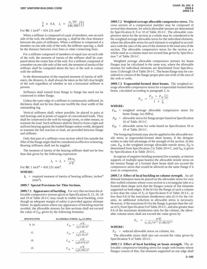
CHAP. 20, DIV. II2009.6
2009.7.51997 UNIFORM BUILDING CODE
2–193
sh
� 0.4, I s � na Vh2
140, 000�hs�
For SI: 1 inch4 = 416 231 mm4.
When a stiffener is composed of a pair of members, one on eachside of the web, the stiffener spacing, s, shall be the clear distancebetween the pairs of stiffeners. When a stiffener is composed of amember on one side only of the web, the stiffener spacing, s, shallbe the distance between rivet lines or other connecting lines.
For a stiffener composed of members of equal size on each sideof the web, the moment of inertia of the stiffener shall be com-puted about the center line of the web. For a stiffener composed ofa member on one side only of the web, the moment of inertia of thestiffener shall be computed about the face of the web in contactwith the stiffener.
In the determination of the required moment of inertia of stiff-eners, the distance, h, shall always be taken as the full clear heightof the web regardless of whether or not a horizontal stiffener ispresent.
Stiffeners shall extend from flange to flange but need not beconnected to either flange.
Unless the outer edge of a stiffener is continuously stiffened, itsthickness shall not be less than one twelfth the clear width of theoutstanding leg.
Vertical stiffeners shall, where possible, be placed in pairs atend bearings and at points of support of concentrated loads. Theyshall be connected to the web by enough rivets, or other means, totransmit the load. Such stiffeners shall be fitted to form a tight anduniform bearing against the loaded flanges unless welds, designedto transmit the full reaction or load, are provided between flangeand stiffener.
Only that part of a stiffener cross section which lies outside thefillet of the flange angle shall be considered as effective in bearing.Bearing stiffeners shall not be joggled.
The moment of inertia of the bearing stiffener shall not be lessthan that given by the following expression:
I b � I s � Ph2nu
�2E
For SI: 1 inch4 = 416 231 mm4.
WHERE:Ib = required moment of inertia of bearing stiffener, inches4
(mm4).
2009.7 Special Provisions for Thin Sections.
2009.7.1 Appearance of buckling.For very thin sections the al-lowable compressive stresses given in Specifications 9, 15, 16, 18and 19 of Table 20-I-C may result in visible local buckling, eventhough an adequate margin of safety is provided against ultimatefailure. In applications where any appearance of buckling must beavoided, the allowable stresses for thin sections shall not exceedthe value of Fab given by the following formulas:
SPECIFICATION ALLOWABLE STRESS, Fab ksi (MPa)
9, 16 Fab � �2E
na(1.6b�t)2
15 Fab � �2E
na(5.1b�t)2
18 Fab � �2E
na(0.67h�t)2
19 Fab � �2E
na(0.29h�t)2
2009.7.2 Weighted average allowable compressive stress. Thecross section of a compression member may be composed ofseveral thin elements, for which allowable stresses are determinedby Specification 8, 9 or 10 of Table 20-I-C. The allowable com-pressive stress for the section as a whole may be considered to bethe weighted average allowable stress for the individual elements,where the allowable stress for each element is weighted in accord-ance with the ratio of the area of the element to the total area of thesection. The allowable compressive stress for the section as awhole used as a column must not exceed that given by Specifica-tion 7 of Table 20-I-C.
Weighted average allowable compressive stresses for beamflanges may be calculated in the same way, where the allowablestresses for individual elements are determined from Specifica-tions 15 through 19 of Table 20-I-C. The beam flange may be con-sidered to consist of the flange proper plus one sixth of the area ofthe web or webs.
2009.7.3 Trapezoidal-formed sheet beams.The weighted av-erage allowable compressive stress for a trapezoidal-formed sheetbeam, calculated according to paragraph 2, is:
Fba �Fbf � Fbh
� h3b�
1 � h3b
WHERE:Fba = weighted average allowable compressive stress for
beam flange, ksi (MPa).Fbf = allowable stress for flange proper based on Specification
16 of Table 20-I-C.Fbh = allowable stress for webs based on Specification 18 or
19 of Table 20-I-C.
The foregoing formula may also be applied to the allowable ten-sile stress in trapezoidal-formed sheet beams, if the designerwishes to take full advantage of the strength of the section. In thiscase, Fba is the weighted average allowable tensile stress, Fbf isdetermined from Specification 2 in Table 20-I-C, and Fbh is givenby Specification 4 in Table 20-I-C.
In regions of negative bending moment (for example, at interiorsupports of multiple-span beams) the allowable tensile stress onthe tension flange of a formed sheet beam shall not exceed thecompressive stress that would be allowed on the same flange if itwere in compression.
2009.7.4 Effect of local buckling on column strength.An ad-ditional limitation must be placed on the allowable stress for verythin-walled columns whose cross section is a rectangular tube or aformed sheet shape such that the flanges consist of flat elementssupported on both edges. If the b/t for the flange of such a columnis less than the value of S2 in Specification 9 of Table 20-I-C, orless than 0.6 of the maximum slenderness ratio (L/r) for the col-umn, no additional reduction in allowable stress is necessary.However, if the maximum b/t for the flange is greater than the val-ue of S2 from Specification 9 of Table 20-I-C, and also greater than0.6 of the maximum slenderness ratio for the column, the allow-able column stress shall not exceed the value given by
Frc � �2E
nu (L�r)2�3 (1.6b�t)4�3
WHERE:Frc = reduced allowable stress on column, ksi.The allowable stress shall also not exceed the value given by
Specification 9 of Table 20-I-C.
2009.7.5 Effect of local buckling on beam strength.The al-lowable compressive bending stress for single web beams whoseflanges consist of thin, flat elements supported on one edge shall
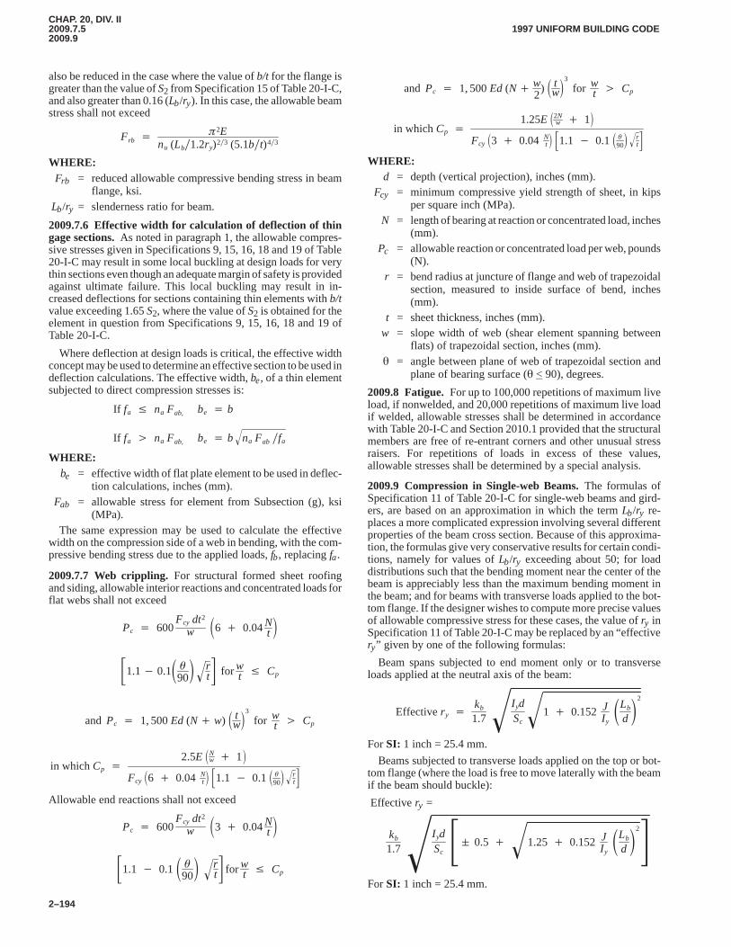
CHAP. 20, DIV. II2009.7.52009.9
1997 UNIFORM BUILDING CODE
2–194
also be reduced in the case where the value of b/t for the flange isgreater than the value of S2 from Specification 15 of Table 20-I-C,and also greater than 0.16 (Lb/ry). In this case, the allowable beamstress shall not exceed
Frb � �2E
nu (Lb�1.2ry)2�3 (5.1b�t)4�3
WHERE:Frb = reduced allowable compressive bending stress in beam
flange, ksi. Lb/ry = slenderness ratio for beam.
2009.7.6 Effective width for calculation of deflection of thingage sections.As noted in paragraph 1, the allowable compres-sive stresses given in Specifications 9, 15, 16, 18 and 19 of Table20-I-C may result in some local buckling at design loads for verythin sections even though an adequate margin of safety is providedagainst ultimate failure. This local buckling may result in in-creased deflections for sections containing thin elements with b/tvalue exceeding 1.65 S2, where the value of S2 is obtained for theelement in question from Specifications 9, 15, 16, 18 and 19 ofTable 20-I-C.
Where deflection at design loads is critical, the effective widthconcept may be used to determine an effective section to be used indeflection calculations. The effective width, be, of a thin elementsubjected to direct compression stresses is:
If fa � na Fab, be � b
If fa � na Fab, be � b na Fab �fa�
WHERE:be = effective width of flat plate element to be used in deflec-
tion calculations, inches (mm).Fab = allowable stress for element from Subsection (g), ksi
(MPa).The same expression may be used to calculate the effective
width on the compression side of a web in bending, with the com-pressive bending stress due to the applied loads, fb, replacing fa.
2009.7.7 Web crippling. For structural formed sheet roofingand siding, allowable interior reactions and concentrated loads forflat webs shall not exceed
Pc � 600Fcy dt2
w 6 � 0.04Nt
�1.1� 0.1 �90 r
t� � for w
t � Cp
and Pc � 1, 500Ed (N� w) tw
3
for wt � Cp
in which Cp �2.5E Nw � 1
Fcy 6 � 0.04 Nt �1.1 � 0.1 �90
rt
� �Allowable end reactions shall not exceed
Pc � 600Fcy dt2
w 3 � 0.04Nt
�1.1 � 0.1 �90 r
t� � for w
t � Cp
and Pc � 1, 500Ed (N� w2
) tw
3
for wt � Cp
in which Cp �1.25E 2N
w � 1
Fcy 3 � 0.04 Nt �1.1 � 0.1 �90
rt
� �WHERE:
d = depth (vertical projection), inches (mm).Fcy = minimum compressive yield strength of sheet, in kips
per square inch (MPa).N = length of bearing at reaction or concentrated load, inches
(mm).Pc = allowable reaction or concentrated load per web, pounds
(N).r = bend radius at juncture of flange and web of trapezoidal
section, measured to inside surface of bend, inches(mm).
t = sheet thickness, inches (mm).w = slope width of web (shear element spanning between
flats) of trapezoidal section, inches (mm).� = angle between plane of web of trapezoidal section and
plane of bearing surface (� < 90), degrees.
2009.8 Fatigue.For up to 100,000 repetitions of maximum liveload, if nonwelded, and 20,000 repetitions of maximum live loadif welded, allowable stresses shall be determined in accordancewith Table 20-I-C and Section 2010.1 provided that the structuralmembers are free of re-entrant corners and other unusual stressraisers. For repetitions of loads in excess of these values,allowable stresses shall be determined by a special analysis.
2009.9 Compression in Single-web Beams.The formulas ofSpecification 11 of Table 20-I-C for single-web beams and gird-ers, are based on an approximation in which the term Lb/ry re-places a more complicated expression involving several differentproperties of the beam cross section. Because of this approxima-tion, the formulas give very conservative results for certain condi-tions, namely for values of Lb/ry exceeding about 50; for loaddistributions such that the bending moment near the center of thebeam is appreciably less than the maximum bending moment inthe beam; and for beams with transverse loads applied to the bot-tom flange. If the designer wishes to compute more precise valuesof allowable compressive stress for these cases, the value of ry inSpecification 11 of Table 20-I-C may be replaced by an “effectivery” given by one of the following formulas:
Beam spans subjected to end moment only or to transverseloads applied at the neutral axis of the beam:
Effectivery �kb
1.7I ydSc
1 � 0.152 JIyLb
d2��
For SI: 1 inch = 25.4 mm.
Beams subjected to transverse loads applied on the top or bot-tom flange (where the load is free to move laterally with the beamif the beam should buckle):
Effective ry =
kb
1.7I ydSc�� 0.5 � 1.25 � 0.152 J
IyLb
d2� ��
For SI: 1 inch = 25.4 mm.
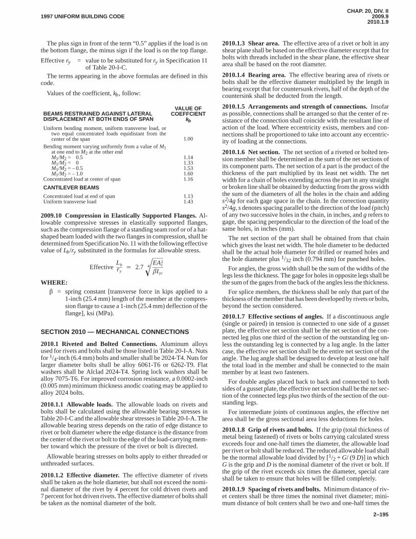
CHAP. 20, DIV. II2009.9
2010.1.91997 UNIFORM BUILDING CODE
2–195
The plus sign in front of the term “0.5” applies if the load is onthe bottom flange, the minus sign if the load is on the top flange.
Effective ry = value to be substituted for ry in Specification 11of Table 20-I-C.
The terms appearing in the above formulas are defined in thiscode.
Values of the coefficient, kb, follow:
BEAMS RESTRAINED AGAINST LATERALDISPLACEMENT AT BOTH ENDS OF SPAN
VALUE OFCOEFFCIENT
kb
Uniform bending moment, uniform transverse load, ortwo equal concentrated loads equidistant from thecenter of the span 1.00
Bending moment varying uniformly from a value of M1at one end to M2 at the other endM1/M2 = 0.5M1/M2 = 0M1/M2 = – 0.5M1/M2 = – 1.0
Concentrated load at center of span
1.141.331.531.601.16
CANTILEVER BEAMS
Concentrated load at end of spanUniform transverse load
1.131.43
2009.10 Compression in Elastically Supported Flanges. Al-lowable compressive stresses in elastically supported flanges,such as the compression flange of a standing seam roof or of a hat-shaped beam loaded with the two flanges in compression, shall bedetermined from Specification No. 11 with the following effectivevalue of Lb/ry substituted in the formulas for allowable stress.
EffectiveLbry
� 2.7EA2
c
�I yc
4�WHERE:
� = spring constant [transverse force in kips applied to a1-inch (25.4 mm) length of the member at the compres-sion flange to cause a 1-inch (25.4 mm) deflection of theflange], ksi (MPa).
SECTION 2010 — MECHANICAL CONNECTIONS
2010.1 Riveted and Bolted Connections.Aluminum alloysused for rivets and bolts shall be those listed in Table 20-I-A. Nutsfor 1/4-inch (6.4 mm) bolts and smaller shall be 2024-T4. Nuts forlarger diameter bolts shall be alloy 6061-T6 or 6262-T9. Flatwashers shall be Alclad 2024-T4. Spring lock washers shall bealloy 7075-T6. For improved corrosion resistance, a 0.0002-inch(0.005 mm) minimum thickness anodic coating may be applied toalloy 2024 bolts.
2010.1.1 Allowable loads.The allowable loads on rivets andbolts shall be calculated using the allowable bearing stresses inTable 20-I-C and the allowable shear stresses in Table 20-I-A. Theallowable bearing stress depends on the ratio of edge distance torivet or bolt diameter where the edge distance is the distance fromthe center of the rivet or bolt to the edge of the load-carrying mem-ber toward which the pressure of the rivet or bolt is directed.
Allowable bearing stresses on bolts apply to either threaded orunthreaded surfaces.
2010.1.2 Effective diameter.The effective diameter of rivetsshall be taken as the hole diameter, but shall not exceed the nomi-nal diameter of the rivet by 4 percent for cold driven rivets and7 percent for hot driven rivets. The effective diameter of bolts shallbe taken as the nominal diameter of the bolt.
2010.1.3 Shear area.The effective area of a rivet or bolt in anyshear plane shall be based on the effective diameter except that forbolts with threads included in the shear plane, the effective sheararea shall be based on the root diameter.
2010.1.4 Bearing area.The effective bearing area of rivets orbolts shall be the effective diameter multiplied by the length inbearing except that for countersunk rivets, half of the depth of thecountersink shall be deducted from the length.
2010.1.5 Arrangements and strength of connections.Insofaras possible, connections shall be arranged so that the center of re-sistance of the connection shall coincide with the resultant line ofaction of the load. Where eccentricity exists, members and con-nections shall be proportioned to take into account any eccentric-ity of loading at the connections.
2010.1.6 Net section.The net section of a riveted or bolted ten-sion member shall be determined as the sum of the net sections ofits component parts. The net section of a part is the product of thethickness of the part multiplied by its least net width. The netwidth for a chain of holes extending across the part in any straightor broken line shall be obtained by deducting from the gross widththe sum of the diameters of all the holes in the chain and addings2/4g for each gage space in the chain. In the correction quantitys2/4g, s denotes spacing parallel to the direction of the load (pitch)of any two successive holes in the chain, in inches, and g refers togage, the spacing perpendicular to the direction of the load of thesame holes, in inches (mm).
The net section of the part shall be obtained from that chainwhich gives the least net width. The hole diameter to be deductedshall be the actual hole diameter for drilled or reamed holes andthe hole diameter plus 1/32 inch (0.794 mm) for punched holes.
For angles, the gross width shall be the sum of the widths of thelegs less the thickness. The gage for holes in opposite legs shall bethe sum of the gages from the back of the angles less the thickness.
For splice members, the thickness shall be only that part of thethickness of the member that has been developed by rivets or bolts,beyond the section considered.
2010.1.7 Effective sections of angles.If a discontinuous angle(single or paired) in tension is connected to one side of a gussetplate, the effective net section shall be the net section of the con-nected leg plus one third of the section of the outstanding leg un-less the outstanding leg is connected by a lug angle. In the lattercase, the effective net section shall be the entire net section of theangle. The lug angle shall be designed to develop at least one halfthe total load in the member and shall be connected to the mainmember by at least two fasteners.
For double angles placed back to back and connected to bothsides of a gusset plate, the effective net section shall be the net sec-tion of the connected legs plus two thirds of the section of the out-standing legs.
For intermediate joints of continuous angles, the effective netarea shall be the gross sectional area less deductions for holes.
2010.1.8 Grip of rivets and bolts.If the grip (total thickness ofmetal being fastened) of rivets or bolts carrying calculated stressexceeds four and one-half times the diameter, the allowable loadper rivet or bolt shall be reduced. The reduced allowable load shallbe the normal allowable load divided by [1/2 + G/ (9 D)] in whichG is the grip and D is the nominal diameter of the rivet or bolt. Ifthe grip of the rivet exceeds six times the diameter, special careshall be taken to ensure that holes will be filled completely.
2010.1.9 Spacing of rivets and bolts.Minimum distance of riv-et centers shall be three times the nominal rivet diameter; mini-mum distance of bolt centers shall be two and one-half times the
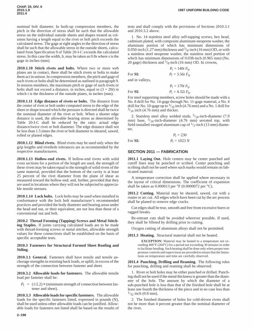
CHAP. 20, DIV. II2010.1.92011.4
1997 UNIFORM BUILDING CODE
2–196
nominal bolt diameter. In built-up compression members, thepitch in the direction of stress shall be such that the allowablestress on the individual outside sheets and shapes treated as col-umns having a length equal to the rivet or bolt pitch exceeds thecalculated stress. The gage at right angles to the direction of stressshall be such that the allowable stress in the outside sheets, calcu-lated from Specification 9 of Table 20-I-C exceeds the calculatedstress. In this case the width, b, may be taken as 0.8s where s is thegage in inches (mm).
2010.1.10 Stitch rivets and bolts.Where two or more webplates are in contact, there shall be stitch rivets or bolts to makethem act in unison. In compression members, the pitch and gage ofsuch rivets or bolts shall be determined as outlined in paragraph 9.In tension members, the maximum pitch or gage of such rivets orbolts shall not exceed a distance, in inches, equal to (3 + 20t) inwhich t is the thickness of the outside plates, in inches (mm).
2010.1.11 Edge distance of rivets or bolts.The distance fromthe center of rivet or bolt under computed stress to the edge of thesheet or shape toward which the pressure is directed shall be twicethe nominal diameter of the rivet or bolt. When a shorter edgedistance is used, the allowable bearing stress as determined byTable 20-I-C shall be reduced by the ratio: actual edgedistance/twice rivet or bolt diameter. The edge distance shall notbe less than 1.5 times the rivet or bolt diameter to sheared, sawed,rolled or planed edges.
2010.1.12 Blind rivets.Blind rivets may be used only when thegrip lengths and rivethole tolerances are as recommended by therespective manufacturers.
2010.1.13 Hollow-end rivets.If hollow-end rivets with solidcross sections for a portion of the length are used, the strength ofthese rivets may be taken equal to the strength of solid rivets of thesame material, provided that the bottom of the cavity is at least25 percent of the rivet diameter from the plane of shear asmeasured toward the hollow end; and, further, provided that theyare used in locations where they will not be subjected to apprecia-ble tensile stresses.
2010.1.14 Lock bolts.Lock bolts may be used when installed inconformance with the lock bolt manufacturer’s recommendedpractices and provided the body diameter and bearing areas underthe head and nut, or their equivalent, are not less than those of aconventional nut and bolt.
2010.2 Thread Forming (Tapping) Screws and Metal Stitch-ing Staples. If joints carrying calculated loads are to be madewith thread-forming screws or metal stitches, allowable strengthvalues for these connections shall be established on the basis ofspecific acceptable tests.
2010.3 Fasteners for Structural Formed Sheet Roofing andSiding.
2010.3.1 General.Fasteners shall have tensile and tensile an-chorage strengths in resisting back loads, or uplift, in excess of thestrength of the connection between fastener and sheet.
2010.3.2 Allowable loads for fasteners.The allowable tensileload per fastener shall be:
Pt = (1/2.2) × (minimum strength of connection between fas-tener and sheet).
2010.3.3 Allowable loads for specific fasteners.The allowableloads for the specific fasteners listed, expressed in pounds (N),shall be used unless other allowable loads can be justified. Allow-able loads for fasteners not listed shall be based on the results of
tests and shall comply with the provisions of Sections 2010.3.1and 2010.3.2 above.
1. No. 14 stainless steel alloy self-tapping screws, hex head,cadmium plated, with composite aluminum-neoprene washer, thealuminum portion of which has minimum dimensions of0.050-inch (1.27 mm) thickness and 5/8-inch (16 mm) OD, or witha stainless steel neoprene washer, the stainless steel portion ofwhich has minimum dimensions of 0.038-inch (0.965 mm) (No.20 gage) thickness and 5/8-inch (16 mm) OD. In crowns,
Pt = 140t Fty
For SI: Pt = 3.56t Fty
and in valleys,
Pt = 170t Fty
For SI: Pt = 4.32t Fty
For steel supporting members, screw holes should be made with aNo. 8 drill for No. 14-gage through No. 11-gage material, a No. 4drill for No. 10-gage up to 3/16 inch (4.76 mm) and a No. 1 drill for3/16 inch (4.76 mm) and thicker.
2. Stainless steel alloy welded studs, 5/16-inch-diameter (7.9mm) base, 3/16-inch-diameter (4.76 mm) serrated top, withfield-installed swaged aluminum cap of 1/2-inch (13 mm) diame-ter,
Pt = 230
For SI: Pt = 1023 N
SECTION 2011 — FABRICATION
2011.1 Laying Out. Hole centers may be center punched andcutoff lines may be punched or scribed. Center punching andscribing shall not be used where such marks would remain on fab-ricated material.
A temperature correction shall be applied where necessary inthe layout of critical dimensions. The coefficient of expansionshall be taken as 0.000013 per °F (0.0000072 per °C).
2011.2 Cutting. Material may be sheared, sawed, cut with arouter or arc cut. All edges which have been cut by the arc processshall be planed to remove edge cracks.
Cut edges shall be true, smooth and free from excessive burrs orragged breaks.
Re-entrant cuts shall be avoided wherever possible. If used,they shall be filleted by drilling prior to cutting.
Oxygen cutting of aluminum alloys shall not be permitted.
2011.3 Heating.Structural material shall not be heated.
EXCEPTION: Material may be heated to a temperature not ex-ceeding 400°F (204°C) for a period not exceeding 30 minutes in orderto facilitate bending. Such heating shall be done only when proper tem-perature controls and supervision are provided to ensure that the limita-tions on temperature and time are carefully observed.
2011.4 Punching, Drilling and Reaming.The following rulesfor punching, drilling and reaming shall be observed:
1. Rivet or bolt holes may be either punched or drilled. Punch-ing shall not be used if the metal thickness is greater than the diam-eter of the hole. The amount by which the diameter of asub-punched hole is less than that of the finished hole shall be atleast one fourth the thickness of the piece and in no case less than1/32 inch (0.8 mm).
2. The finished diameter of holes for cold-driven rivets shallnot be more than 4 percent greater than the nominal diameter ofthe rivet.
CHAP. 20, DIV. II2011.42012.2
1997 UNIFORM BUILDING CODE
2–197
3. The finished diameter of holes for hot-driven rivets shall notbe more than 7 percent greater than the nominal diameter of therivet.
4. The finished diameter of holes for bolts shall not be morethan 1/16 inch (1.6 mm) larger than the nominal bolt diameter.
5. If any holes must be enlarged to admit the rivets or bolts, theyshall be reamed. Poor matching of holes shall be cause for rejec-tion. Holes shall not be drifted in such a manner as to distort themetal. All chips lodged between contacting surfaces shall be re-moved before assembly.
2011.5 Riveting.
2011.5.1 Driven head.The driven head of aluminum alloy riv-ets shall be of the flat or the cone-point type with dimensions asfollows:
1. Flat heads shall have a diameter not less than 1.4 times thenominal rivet diameter and a height not less than 0.4 times thenominal rivet diameter.
2. Cone-point heads shall have a diameter not less than 1.4 timesthe nominal rivet diameter and a height to the apex of the cone notless than 0.65 times the nominal rivet diameter. The includedangle at the apex of the cone shall be approximately 127 degrees.
2011.5.2 Hole filling. Rivets shall fill holes completely. Rivetheads shall be concentric with the rivet holes and shall be in propercontact with the surface of the metal.
2011.5.3 Defective rivets.Defective rivets shall be removed bydrilling.
2011.6 Painting.
2011.6.1 General.Structures of the alloys covered by thesestandards are not ordinarily painted (with the exception of2014-T6 when exposed to corrosive environments). Surfacesshall be painted where:
1. The aluminum alloy parts are in contact with, or are fastenedto, steel members or other dissimilar materials.
2. The structures are to be exposed to extremely corrosive con-ditions, or for reason of appearance. Painting procedure is coveredin the following paragraphs and methods of cleaning andpreparation are found in Section 2011.7. (Treatment and paintingof the structure in accordance with United States MilitarySpecification MIL-T-704 is also acceptable.)
2011.6.2 Contact with dissimilar materials. Where the alumi-num alloy parts are in contact with, or are fastened to, steelmembers or other dissimilar materials, the aluminum shall be keptfrom direct contact with the steel or other dissimilar material bypainting as follows:
1. Aluminum surfaces to be placed in contact with steel shall begiven one coat of zinc chromate primer in accordance withFederal Specification TT-P-645 or the equivalent, or one coat of asuitable nonhardening joint compound capable of excludingmoisture from the joint during prolonged service. Where severecorrosion conditions are expected, additional protection can beobtained by applying the joint compound in addition to the zincchromate primer. Zinc chromate paint shall be allowed to dry hard(air dry 24 hours) before assembly of the parts. The steel surfacesto be placed in contact with aluminum shall be painted with goodquality priming paint, such as zinc chromate primer in accordancewith Federal Specification TT-P-645, followed by one coat ofpaint consisting of 2 pounds of aluminum paste pigment (ASTMSpecification D 96266, Type 2, Class B) per gallon (0.24 kg/L) ofvarnish meeting Federal Specification TT-V-81d, Type II, or the
equivalent. Stainless steel, or aluminized, hot-dip galvanized orelectrogalvanized steel placed in contact with aluminum need notbe painted.
2. When aluminum is in direct contact with wood, fiberboard orother porous material that may absorb water, an insulating barriershall be installed between the aluminum and the porous material.Such aluminum surfaces shall be given a heavy coat of alkali-resistant bituminous paint or other coating providing equivalentprotection before installation. Aluminum in contact with concreteor masonry shall be similarly protected in cases where moisture ispresent and corrodents can be entrapped between the surfaces.
3. Aluminum surfaces to be embedded in concrete ordinarilyneed not be painted, unless corrosive components are added to theconcrete or unless the concrete is subjected for extended periods toextremely corrosive conditions. In such cases, aluminum surfacesshall be given one coat of suitable quality paint, such as zincchromate primer conforming to Federal Specification TT-P-645or equivalent, or shall be wrapped with a suitable plastic tapeapplied in such a manner as to provide adequate protection at theoverlap.
4. Water that comes in contact with aluminum after first runningover a heavy metal such as copper may contain trace quantities ofthe dissimilar metal or its corrosion product, which will causecorrosion of the aluminum. Protection shall be obtained bypainting or plastic coating the dissimilar metal or by designing thestructure so that the drainage from the dissimilar metal is divertedaway from the aluminum.
2011.6.3 Overall painting. Structures of the alloys covered bythis standard are either not ordinarily painted for surfaceprotection (with the exception of 2014-T6 when exposed tocorrosive environments) or are made of prepainted aluminumcomponents. There may be applications where the structures areto be exposed to extremely corrosive conditions. In these casesoverall painting shall be specified.
2011.7 Cleaning and Treatment of Metal Surfaces.Prior tofield painting of structures, all surfaces to be painted shall becleaned immediately before painting by a method that will removeall dirt, oil, grease, chips and other foreign substances.
Exposed metal surfaces shall be cleaned with a suitablechemical cleaner such as a solution of phosphoric acid and organicsolvents meeting United States Military SpecificationMIL-M-10578. If the metal is more than 1/8 inch (3.2 mm) thick,sandblasting may be used.
SECTION 2012 — WELDED CONSTRUCTION
2012.1 Filler Wire. Verification shall be provided to show thatthe choice of filler metal for general purpose welding is appropri-ate.
2012.2 Columns and Single-web Beams with Welds at Loca-tions Other than Ends and Cantilever Columns andSingle-web Beams.The allowable stresses determined inaccordance with the provisions of Division I apply to memberssupported at both ends with welds at the ends only (not fartherfrom the supports than 0.05 L from the ends).
For columns with transverse welds at locations other than thesupports, cantilever columns with transverse welds at or near thesupported end and columns with longitudinal welds having Awequal to or greater than 15 percent of A, the effect of welding oncolumn strength shall be taken into account by using an increasedslenderness ratio, Lw/r, in the column formula, as follows:
If Lr � 250, 000
Fcyw� ;
Lwr � L
r
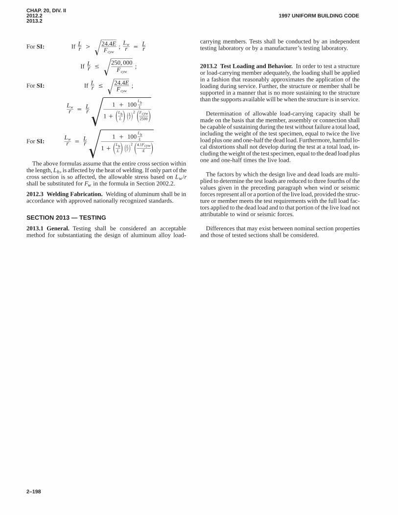
CHAP. 20, DIV. II2012.22013.2
1997 UNIFORM BUILDING CODE
2–198
For SI: If Lr � 24.4E
Fcyw� ;
Lwr � L
r
If Lr � 250, 000
Fcyw� ;
For SI: If Lr � 24.4E
Fcyw� ;
Lwr � L
r1 � 100
LhL
1� �LhL� �Lr�2 �Fcyw
2500��
For SI:Lwr � L
r1 � 100
LhL
1� �LhL� �Lr�2 �4.1Fcyw
E��
The above formulas assume that the entire cross section withinthe length, Lh, is affected by the heat of welding. If only part of thecross section is so affected, the allowable stress based on Lw/rshall be substituted for Fw in the formula in Section 2002.2.
2012.3 Welding Fabrication. Welding of aluminum shall be inaccordance with approved nationally recognized standards.
SECTION 2013 — TESTING
2013.1 General.Testing shall be considered an acceptablemethod for substantiating the design of aluminum alloy load-
carrying members. Tests shall be conducted by an independenttesting laboratory or by a manufacturer’s testing laboratory.
2013.2 Test Loading and Behavior.In order to test a structureor load-carrying member adequately, the loading shall be appliedin a fashion that reasonably approximates the application of theloading during service. Further, the structure or member shall besupported in a manner that is no more sustaining to the structurethan the supports available will be when the structure is in service.
Determination of allowable load-carrying capacity shall bemade on the basis that the member, assembly or connection shallbe capable of sustaining during the test without failure a total load,including the weight of the test specimen, equal to twice the liveload plus one and one-half the dead load. Furthermore, harmful lo-cal distortions shall not develop during the test at a total load, in-cluding the weight of the test specimen, equal to the dead load plusone and one-half times the live load.
The factors by which the design live and dead loads are multi-plied to determine the test loads are reduced to three fourths of thevalues given in the preceding paragraph when wind or seismicforces represent all or a portion of the live load, provided the struc-ture or member meets the test requirements with the full load fac-tors applied to the dead load and to that portion of the live load notattributable to wind or seismic forces.
Differences that may exist between nominal section propertiesand those of tested sections shall be considered.
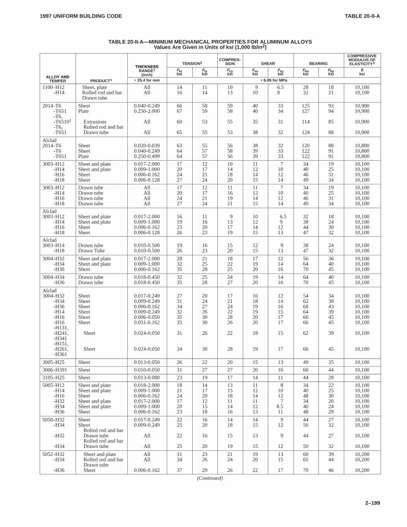
TABLE 20-II-ATABLE 20-II-A
1997 UNIFORM BUILDING CODE
2–199
TABLE 20-II-A—MINIMUM MECHANICAL PROPERTIES FOR ALUMINUM ALLOYSValues Are Given in Units of ksi (1,000 lb/in 2)
THICKNESSTENSION2
COMPRES-SION SHEAR BEARING
COMPRESSIVEMODULUS OFELASTICITY 3
ALLOY AND
THICKNESSRANGE1
(inch)Ftuksi
Ftyksi
Fcyksi
Fsuksi
Fsyksi
Fbuksi
Fbyksi
Eksi
ALLOY ANDTEMPER PRODUCT1 × 25.4 for mm × 6.89 for MPa
1100-H12-H14
Sheet, plateRolled rod and barDrawn tube
AllAll
1416
1114
1013
910
6.58
2832
1821
10,10010,100
2014-T6-T651-T6,-T65101-T6,-T651
SheetPlate
ExtrusionsRolled rod and barDrawn tube
0.040-0.2490.250-2.000
All
All
6667
60
65
5859
53
55
5958
55
53
4040
35
38
3334
31
32
125127
114
124
9394
85
88
10,90010,900
10,900
10,900
Alclad2014-T6
-T6-T651
SheetSheetPlate
0.020-0.0390.040-0.2490.250-0.499
636464
555757
565856
383939
323333
120122122
889191
10,80010,80010,800
3003-H12-H14-H16-H18
Sheet and plateSheet and plateSheetSheet
0.017-2.0000.009-1.0000.006-0.1620.006-0.128
17202427
12172124
10141820
11121415
7101214
34404649
19253134
10,10010,10010,10010,100
3003-H12-H14-H16-H18
Drawn tubeDrawn tubeDrawn tubeDrawn tube
AllAllAllAll
17202427
12172124
11161921
11121415
7101214
34404649
19253134
10,10010,10010,10010,100
Alclad3003-H12
-H14-H16-H18
Sheet and plateSheet and plateSheetSheet
0.017-2.0000.009-1.0000.006-0.1620.006-0.128
16192326
11162023
9131719
10121415
6.59
1213
32384447
18243032
10,10010,10010,10010,100
Alclad3003-H14
-H18Drawn tubeDrawn Tube
0.010-0.5000.010-0.500
1926
1623
1520
1215
913
3847
2432
10,10010,100
3004-H32-H34-H36
Sheet and plateSheet and plateSheet
0.017-2.0000.009-1.0000.006-0.162
283235
212528
182225
171920
121416
566470
364045
10,10010,10010,100
3004-H34-H36
Drawn tubeDrawn tube
0.018-0.4500.018-0.450
3235
2528
2427
1920
1416
6470
4045
10,10010,100
Alclad3004-H32
-H34-H36-H14-H16-H16-H131,-H241,-H341-H151,-H261,-H361
SheetSheetSheetSheetSheetSheet
Sheet
Sheet
0.017-0.2490.009-0.2490.006-0.1620.009-0.2490.006-0.0500.051-0.162
0.024-0.050
0.024-0.050
273134323535
31
34
202427263030
26
30
172124222826
22
28
161819192020
18
19
121416151717
15
17
546268646666
62
66
343843394545
39
45
10,10010,10010,10010,10010,10010,100
10,100
10,100
3005-H25 Sheet 0.013-0.050 26 22 20 15 13 49 35 10,100
3006-H391 Sheet 0.010-0.050 31 27 27 20 16 60 44 10,100
3105-H25 Sheet 0.013-0.080 23 19 17 14 11 44 28 10,100
5005-H12-H14-H16-H32-H34-H36
Sheet and plateSheet and plateSheetSheet and plateSheet and plateSheet
0.018-2.0000.009-1.0000.006-0.1620.017-2.0000.009-1.0000.006-0.162
182124172023
141720121518
131518111416
111214111213
810127
8.5 11
344048344048
222530202429
10,10010,10010,10010,10010,10010,100
5050-H32-H34
-H32
-H34
SheetSheet
Rolled rod and barDrawn tubeRolled rod and barDrawn tube
0.017-0.2490.009-0.249
All
All
2225
22
25
1620
16
20
1418
15
19
1415
13
15
912
9
12
4450
44
50
2732
27
32
10,10010,100
10,100
10,100
5052-H32-H34
-H36
Sheet and plateRolled rod and barDrawn tubeSheet
AllAll
0.006-0.162
3134
37
2326
29
2124
26
1920
22
1315
17
6065
70
3944
46
10,20010,200
10,200
(Continued)
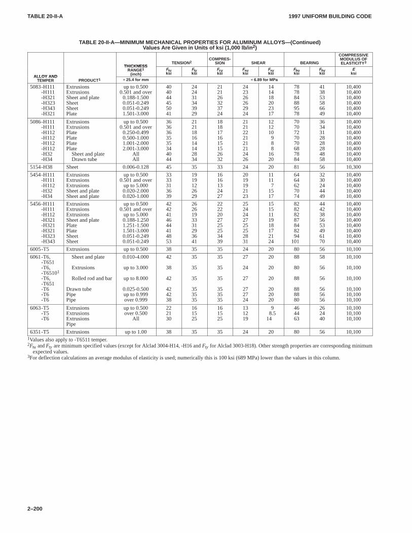
TABLE 20-II-ATABLE 20-II-A
1997 UNIFORM BUILDING CODE
2–200
TABLE 20-II-A—MINIMUM MECHANICAL PROPERTIES FOR ALUMINUM ALLOYS—(Continued)Values Are Given in Units of ksi (1,000 lb/in 2)
THICKNESSTENSION2
COMPRES-SION SHEAR BEARING
COMPRESSIVEMODULUS OFELASTICITY 3
ALLOY AND
THICKNESSRANGE1
(inch)Ftuksi
Ftyksi
Fcyksi
Fsuksi
Fsyksi
Fbuksi
Fbyksi
Eksi
ALLOY ANDTEMPER PRODUCT1 × 25.4 for mm × 6.89 for MPa
5083-H111-H111-H321-H323-H343-H321
ExtrusionsExtrusionsSheet and plateSheetSheetPlate
up to 0.5000.501 and over
0.188-1.5000.051-0.2490.051-0.2491.501-3.000
404044455041
242431343929
212126323724
242326262924
141418202317
787884889578
413853586649
10,40010,40010,40010,40010,40010,400
5086-H111-H111-H112-H112-H112-H112-H32-H34
ExtrusionsExtrusionsPlatePlatePlatePlate
Sheet and plateDrawn tube
up to 0.5000.501 and over
0.250-0.4990.500-1.0001.001-2.0002.001-3.000
AllAll
3636363535344044
2121181614142834
1818171615152632
2121222121212426
121210988
1620
7070727070687884
3634312828284858
10,40010,40010,40010,40010,40010,40010,40010,400
5154-H38 Sheet 0.006-0.128 45 35 33 24 20 81 56 10,300
5454-H111-H111-H112-H32-H34
ExtrusionsExtrusionsExtrusionsSheet and plateSheet and plate
up to 0.5000.501 and over
up to 5.0000.020-2.0000.020-1.000
3333313639
1919122629
1616132427
2019192123
11117
1517
6464627074
3230244449
10,40010,40010,40010,40010,400
5456-H111-H111-H112-H321-H321-H321-H323-H343
ExtrusionsExtrusionsExtrusionsSheet and platePlatePlateSheetSheet
up to 0.5000.501 and over
up to 5.0000.188-1.2501.251-1.5001.501-3.0000.051-0.2490.051-0.249
4242414644414853
2626193331293641
2222202725253439
2524242725252831
1515111918172124
82828287848294
101
4442385653496170
10,40010,40010,40010,40010,40010,40010,40010,400
6005-T5 Extrusions up to 0.500 38 35 35 24 20 80 56 10,100
6061-T6,-T651-T6,-T65101-T6,-T651-T6-T6-T6
Sheet and plate
Extrusions
Rolled rod and bar
Drawn tubePipePipe
0.010-4.000
up to 3.000
up to 8.000
0.025-0.500up to 0.999over 0.999
42
38
42
424238
35
35
35
353535
35
35
35
353535
27
24
27
272724
20
20
20
202020
88
80
88
888880
58
56
56
565656
10,100
10,100
10,100
10,10010,10010,100
6063-T5-T5-T6
ExtrusionsExtrusionsExtrusionsPipe
up to 0.500over 0.500
All
222130
161525
161525
131219
98.5
14
464463
262440
10,10010,10010,100
6351-T5 Extrusions up to 1.00 38 35 35 24 20 80 56 10,1001Values also apply to -T6511 temper.2Ftu and Fty are minimum specified values (except for Alclad 3004-H14, -H16 and Fty for Alclad 3003-H18). Other strength properties are corresponding minimum
expected values.3For deflection calculations an average modulus of elasticity is used; numerically this is 100 ksi (689 MPa) lower than the values in this column.
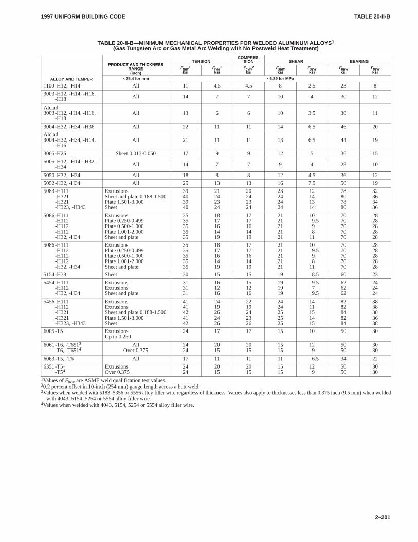
TABLE 20-II-BTABLE 20-II-B
1997 UNIFORM BUILDING CODE
2–201
TABLE 20-II-B—MINIMUM MECHANICAL PROPERTIES FOR WELDED ALUMINUM ALLOYS 1
(Gas Tungsten Arc or Gas Metal Arc W elding with No Postweld Heat T reatment)
PRODUCT AND THICKNESSTENSION
COMPRES-SION SHEAR BEARING
PRODUCT AND THICKNESSRANGE(inch)
Ftuw 1
ksiFtyw 2
ksiFcyw 2
ksiFsuwksi
Fsywksi
Fbuwksi
Fbywksi
ALLOY AND TEMPER × 25.4 for mm × 6.89 for MPa
1100-H12, -H14 All 11 4.5 4.5 8 2.5 23 8
3003-H12, -H14, -H16,-H18 All 14 7 7 10 4 30 12
Alclad3003-H12, -H14, -H16,
-H18All 13 6 6 10 3.5 30 11
3004-H32, -H34, -H36 All 22 11 11 14 6.5 46 20
Alclad3004-H32, -H34, -H14,
-H16All 21 11 11 13 6.5 44 19
3005-H25 Sheet 0.013-0.050 17 9 9 12 5 36 15
5005-H12, -H14, -H32,-H34 All 14 7 7 9 4 28 10
5050-H32, -H34 All 18 8 8 12 4.5 36 12
5052-H32, -H34 All 25 13 13 16 7.5 50 19
5083-H111-H321-H321-H323, -H343
ExtrusionsSheet and plate 0.188-1.500Plate 1.501-3.000Sheet
39403940
21242324
20242324
23242424
12141314
78807880
32363436
5086-H111-H112-H112-H112-H32, -H34
ExtrusionsPlate 0.250-0.499Plate 0.500-1.000Plate 1.001-2.000Sheet and plate
3535353535
1817161419
1717161419
2121212121
109.598
11
7070707070
2828282828
5086-H111-H112-H112-H112-H32, -H34
ExtrusionsPlate 0.250-0.499Plate 0.500-1.000Plate 1.001-2.000Sheet and plate
3535353535
1817161419
1717161419
2121212121
109.598
11
7070707070
2828282828
5154-H38 Sheet 30 15 15 19 8.5 60 23
5454-H111-H112-H32, -H34
ExtrusionsExtrusionsSheet and plate
313131
161216
151216
191919
9.579.5
626262
242424
5456-H111-H112-H321-H321-H323, -H343
ExtrusionsExtrusionsSheet and plate 0.188-1.500Plate 1.501-3.000Sheet
4141424142
2419262426
2219242326
2424252525
1411151415
8282848284
3838383638
6005-T5 ExtrusionsUp to 0.250
24 17 17 15 10 50 30
6061-T6, -T6513-T6, -T6514
AllOver 0.375
2424
2015
2015
1515
129
5050
3030
6063-T5, -T6 All 17 11 11 11 6.5 34 22
6351-T51-T54
ExtrusionsOver 0.375
2424
2015
2015
1515
129
5050
3030
1Values of Ftuw are ASME weld qualification test values.20.2 percent offset in 10-inch (254 mm) gauge length across a butt weld.3Values when welded with 5183, 5356 or 5556 alloy filler wire regardless of thickness. Values also apply to thicknesses less than 0.375 inch (9.5 mm) when welded
with 4043, 5154, 5254 or 5554 alloy filler wire.4Values when welded with 4043, 5154, 5254 or 5554 alloy filler wire.
21012101.3
1997 UNIFORM BUILDING CODE
2–203
Chapter 21
MASONRY
SECTION 2101 — GENERAL
2101.1 Scope.The materials, design, construction and qualityassurance of masonry shall be in accordance with this chapter.
2101.2 Design Methods.Masonry shall comply with the provi-sions of one of the following design methods in this chapter as wellas the requirements of Sections 2101 through 2105.
2101.2.1 Working stress design.Masonry designed by theworking stress design method shall comply with the provisions ofSections 2106 and 2107.
2101.2.2 Strength design.Masonry designed by the strengthdesign method shall comply with the provisions of Sections 2106and 2108.
2101.2.3 Empirical design.Masonry designed by the empiricaldesign method shall comply with the provisions of Sections2106.1 and 2109.
2101.2.4 Glass masonry.Glass masonry shall comply with theprovisions of Section 2110.
2101.3 Definitions. For the purpose of this chapter, certainterms are defined as follows:
AREAS:
Bedded Area is the area of the surface of a masonry unit whichis in contact with mortar in the plane of the joint.
Effective Area of Reinforcement is the cross-sectional area ofreinforcement multiplied by the cosine of the angle between thereinforcement and the direction for which effective area is to bedetermined.
Gross Area is the total cross-sectional area of a specified sec-tion.
Net Area is the gross cross-sectional area minus the area ofungrouted cores, notches, cells and unbedded areas. Net area is theactual surface area of a cross section of masonry.
Transformed Area is the equivalent area of one material to asecond based on the ratio of moduli of elasticity of the first mate-rial to the second.
BOND:
Adhesion Bond is the adhesion between masonry units andmortar or grout.
Reinforcing Bond is the adhesion between steel reinforcementand mortar or grout.
BOND BEAM is a horizontal grouted element within masonryin which reinforcement is embedded.
CELL is a void space having a gross cross-sectional areagreater than 11/2 square inches (967 mm2).
CLEANOUT is an opening to the bottom of a grout space ofsufficient size and spacing to allow the removal of debris.
COLLAR JOINT is the mortared or grouted space betweenwythes of masonry.
COLUMN, REINFORCED, is a vertical structural member inwhich both the reinforcement and masonry resist compression.
COLUMN, UNREINFORCED, is a vertical structural mem-ber whose horizontal dimension measured at right angles to thethickness does not exceed three times the thickness.
DIMENSIONS:
Actual Dimensions are the measured dimensions of a desig-nated item. The actual dimension shall not vary from the specifieddimension by more than the amount allowed in the appropriatestandard of quality in Section 2102.
Nominal Dimensions of masonry units are equal to its speci-fied dimensions plus the thickness of the joint with which the unitis laid.
Specified Dimensions are the dimensions specified for themanufacture or construction of masonry, masonry units, joints orany other component of a structure.
GROUT LIFT is an increment of grout height within the totalgrout pour.
GROUT POUR is the total height of masonry wall to begrouted prior to the erection of additional masonry. A grout pourwill consist of one or more grout lifts.
GROUTED MASONRY:
Grouted Hollow-unit Masonry is that form of groutedmasonry construction in which certain designated cells of hollowunits are continuously filled with grout.
Grouted Multiwythe Masonry is that form of groutedmasonry construction in which the space between the wythes issolidly or periodically filled with grout.
JOINTS:
Bed Joint is the mortar joint that is horizontal at the time themasonry units are placed.
Head Joint is the mortar joint having a vertical transverseplane.
MASONRY UNIT is brick, tile, stone, glass block or concreteblock conforming to the requirements specified in Section 2102.
Hollow-masonry Unit is a masonry unit whose net cross-sectional areas (solid area) in any plane parallel to the surface con-taining cores, cells or deep frogs is less than 75 percent of its grosscross-sectional area measured in the same plane.
Solid-masonry Unit is a masonry unit whose net cross-sectional area in any plane parallel to the surface containing thecores or cells is at least 75 percent of the gross cross-sectional areameasured in the same plane.
PRISM is an assemblage of masonry units and mortar with orwithout grout used as a test specimen for determining properties ofthe masonry.
REINFORCED MASONRY is that form of masonryconstruction in which reinforcement acting in conjunction withthe masonry is used to resist forces.
SHELL is the outer portion of a hollow masonry unit as placedin masonry.
WALLS
Bonded Wall is a masonry wall in which two or more wythesare bonded to act as a structural unit.
Cavity Wall is a wall containing continuous air space with aminimum width of 2 inches (51 mm) and a maximum width of
�
2101.32101.4
1997 UNIFORM BUILDING CODE
2–204
41/2 inches (114 mm) between wythes which are tied with metalties.
WALL TIE is a mechanical metal fastener which connectswythes of masonry to each other or to other materials.
WEB is an interior solid portion of a hollow-masonry unit asplaced in masonry.
WYTHE is the portion of a wall which is one masonry unit inthickness. A collar joint is not considered a wythe.
2101.4 Notations.
Ab = cross-sectional area of anchor bolt, square inches(mm2).
Ae = effective area of masonry, square inches (mm2).Ag = gross area of wall, square inches (mm2).Ajh = total area of special horizontal reinforcement through
wall frame joint, square inches (mm2).Amv = net area of masonry section bounded by wall thickness
and length of section in direction of shear force consid-ered, square inches (mm2).
Ap = area of tension (pullout) cone of embedded anchor boltprojected onto surface of masonry, square inches (mm2).
As = effective cross-sectional area of reinforcement in col-umn or flexural member, square inches (mm2).
Ase = effective area of reinforcement, square inches (mm2).Ash = total cross-sectional area of rectangular tie reinforce-
ment for confined core, square inches (mm2).Av = area of reinforcement required for shear reinforcement
perpendicular to longitudinal reinforcement, squareinches (mm2).
A�s = effective cross-sectional area of compression reinforce-ment in flexural member, square inches (mm2).
a = depth of equivalent rectangular stress block, inches(mm).
Bsn = nominal shear strength of anchor bolt, pounds (N).Bt = allowable tensile force on anchor bolt, pounds (N).
Btn = nominal tensile strength of anchor bolt, pounds (N).Bv = allowable shear force on anchor bolt, pounds (N).b = effective width of rectangular member or width of
flange for T and I sections, inches (mm).bsu = factored shear force supported by anchor bolt, pounds
(N).bt = computed tensile force on anchor bolt, pounds (N).
btu = factored tensile force supported by anchor bolt, pounds(N).
bv = computed shear force on anchor bolt, pounds (N).b� = width of web in T or I section, inches (mm).Cd = nominal shear strength coefficient as obtained from
Table 21-K.c = distance from neutral axis to extreme fiber, inches (mm).D = dead loads, or related internal moments and forces.d = distance from compression face of flexural member to
centroid of longitudinal tensile reinforcement, inches(mm).
db = diameter of reinforcing bar, inches (mm).dbb = diameter of largest beam longitudinal reinforcing bar
passing through, or anchored in, a joint, inches (mm).dbp = diameter of largest pier longitudinal reinforcing bar
passing through a joint, inches (mm).
E = load effects of earthquake, or related internal momentsand forces.
Em = modulus of elasticity of masonry, pounds per squareinch (MPa).
e = eccentricity of Puf, inches (mm).emu = maximum usable compressive strain of masonry.
F = loads due to weight and pressure of fluids or relatedmoments and forces.
Fa = allowable average axial compressive stress in columnsfor centroidally applied axial load only, pounds persquare inch (MPa).
Fb = allowable flexural compressive stress in members sub-jected to bending load only, pounds per square inch(MPa).
Fbr = allowable bearing stress in masonry, pounds per squareinch (MPa).
Fs = allowable stress in reinforcement, pounds per squareinch (MPa).
Fsc = allowable compressive stress in column reinforcement,pounds per square inch (MPa).
Ft = allowable flexural tensile stress in masonry, pounds persquare inch (MPa).
Fv = allowable shear stress in masonry, pounds per squareinch (MPa).
fa = computed axial compressive stress due to design axialload, pounds per square inch (MPa).
fb = computed flexural stress in extreme fiber due to designbending loads only, pounds per square inch (MPa).
fmd = computed compressive stress due to dead load only,pounds per square inch (MPa).
fr = modulus of rupture, pounds per square inch (MPa).fs = computed stress in reinforcement due to design loads,
pounds per square inch (MPa).fv = computed shear stress due to design load, pounds per
square inch (MPa).fy = tensile yield stress of reinforcement, pounds per square
inch (MPa).fyh = tensile yield stress of horizontal reinforcement, pounds
per square inch (MPa).f �g = specified compressive strength of grout at age of 28
days, pounds per square inch (MPa).f �m = specified compressive strength of masonry at age of 28
days, pounds per square inch (MPa).G = shear modulus of masonry, pounds per square inch
(MPa).H = loads due to weight and pressure of soil, water in soil or
related internal moments and forces.h = height of wall between points of support, inches (mm).
hb = beam depth, inches (mm).hc = cross-sectional dimension of grouted core measured
center to center of confining reinforcement, inches(mm).
hp = pier depth in plane of wall frame, inches (mm).h� = effective height of wall or column, inches (mm).I = moment of inertia about neutral axis of cross-sectional
area, inches4 (mm4).Ie = effective moment of inertia, inches4 (mm4).
Ig, Icr = gross, cracked moment of inertia of wall cross section,inches4 (mm4).
j = ratio or distance between centroid of flexural compres-sive forces and centroid of tensile forces of depth, d.
2101.42102.2
1997 UNIFORM BUILDING CODE
2–205
K = reinforcement cover or clear spacing, whichever is less,inches (mm).
k = ratio of depth of compressive stress in flexural memberto depth, d.
L = live loads, or related internal moments and forces.Lw = length of wall, inches (mm).
l = length of wall or segment, inches (mm).lb = embedment depth of anchor bolt, inches (mm).
lbe = anchor bolt edge distance, the least distance measuredfrom edge of masonry to surface of anchor bolt, inches(mm).
ld = required development length of reinforcement, inches(mm).
M = design moment, inch-pounds (N�mm).Ma = maximum moment in member at stage deflection is
computed, inch-pounds (N�mm).Mc = moment capacity of compression reinforcement in flex-
ural member about centroid of tensile force, inch-pounds (N�mm).
Mcr = nominal cracking moment strength in masonry, inch-pounds (N�mm).
Mm = moment of compressive force in masonry about centroidof tensile force in reinforcement, inch-pounds (N�mm).
Mn = nominal moment strength, inch-pounds (N�mm).Ms = moment of tensile force in reinforcement about centroid
of compressive force in masonry, inch-pounds (N�mm).Mser = service moment at midheight of panel, including P∆
effects, inch-pounds (N�mm).Mu = factored moment, inch-pounds (N�mm).
n = modular ratio.= Es/Em.
P = design axial load, pounds (N).Pa = allowable centroidal axial load for reinforced masonry
columns, pounds (N).Pb = nominal balanced design axial strength, pounds (N).Pf = load from tributary floor or roof area, pounds (N).Pn = nominal axial strength in masonry, pounds (N).Po = nominal axial load strength in masonry without flexure,
pounds (N).Pu = factored axial load, pounds (N).Puf = factored load from tributary floor or roof loads, pounds
(N).Puw = factored weight of wall tributary to section under con-
sideration, pounds (N).Pw = weight of wall tributary to section under consideration,
pounds (N).r = radius of gyration (based on specified unit dimensions or
Tables 21-H-1, 21-H-2 and 21-H-3), inches (mm).rb = ratio of area of reinforcing bars cut off to total area of
reinforcing bars at the section.S = section modulus, inches3 (mm3).s = spacing of stirrups or of bent bars in direction parallel to
that of main reinforcement, inches (mm).T = effects of temperature, creep, shrinkage and differential
settlement.t = effective thickness of wythe, wall or column, inches
(mm).
U = required strength to resist factored loads, or relatedinternal moments and forces.
u = bond stress per unit of surface area of reinforcing bar,pounds per square inch (MPa).
V = total design shear force, pounds (N).Vjh = total horizontal joint shear, pounds (N).Vm = nominal shear strength of masonry, pounds (N).Vn = nominal shear strength, pounds (N).Vs = nominal shear strength of shear reinforcement, pounds
(N).Vu = required shear strength in masonry, pounds (N).W = wind load, or related internal moments in forces.wu = factored distributed lateral load.∆ s = horizontal deflection at midheight under factored load,
inches (mm).∆ u = deflection due to factored loads, inches (mm).
ρ = ratio of area of flexural tensile reinforcement, As, to areabd.
ρb = reinforcement ratio producing balanced strain condi-tions.
ρn = ratio of distributed shear reinforcement on plane perpen-dicular to plane of Amv.
Σo = sum of perimeters of all longitudinal reinforcement,inches (mm).
f �m�
= square root of specified strength of masonry at the age of28 days, pounds per square inch (MPa).
φ = strength-reduction factor.
SECTION 2102 — MATERIAL STANDARDS
2102.1 Quality. Materials used in masonry shall conform to therequirements stated herein. If no requirements are specified in thissection for a material, quality shall be based on generally acceptedgood practice, subject to the approval of the building official.
Reclaimed or previously used masonry units shall meet theapplicable requirements as for new masonry units of the samematerial for their intended use.
2102.2 Standards of Quality.The standards listed belowlabeled a “UBC Standard” are also listed in Chapter 35, Part II, andare part of this code. The other standards listed below are recog-nized standards. See Sections 3503 and 3504.
1. Aggregates.
1.1 ASTM C 144, Aggregates for Masonry Mortar
1.2 ASTM C 404, Aggregates for Grout
2. Cement.
2.1 UBC Standard 21-11, Cement, Masonry. (Plasticcement conforming to the requirements of UBC Stand-ard 25-1 may be used in lieu of masonry cement when italso conforms to UBC Standard 21-11.)
2.2 ASTM C 150, Portland Cement
2.3 UBC Standard 21-14, Mortar Cement
3. Lime.
3.1 UBC Standard 21-12, Quicklime for Structural Pur-poses
3.2 UBC Standard 21-13, Hydrated Lime for Masonry Pur-poses. When Types N and NA hydrated lime are used in
2102.22103.4.1
1997 UNIFORM BUILDING CODE
2–206
masonry mortar, they shall comply with the provisionsof UBC Standard 21-15, Section 21.1506.7, excludingthe plasticity requirement.
4. Masonry units of clay or shale.
4.1 ASTM C 34, Structural Clay Load-bearing Wall Tile
4.2 ASTM C 56, Structural Clay Nonload-bearing Tile
4.3 UBC Standard 21-1, Section 21.101, Building Brick(solid units)
4.4 ASTM C 126, Ceramic Glazed Structural Clay FacingTile, Facing Brick and Solid Masonry Units. Load-bearing glazed brick shall conform to the weatheringand structural requirements of UBC Standard 21-1,Section 21.106, Facing Brick
4.5 UBC Standard 21-1, Section 21.106, Facing Brick(solid units)
4.6 UBC Standard 21-1, Section 21.107, Hollow Brick
4.7 ASTM C 67, Sampling and Testing Brick and Structur-al Clay Tile
4.8 ASTM C 212, Structural Clay Facing Tile
4.9 ASTM C 530, Structural Clay Non-LoadbearingScreen Tile
5. Masonry units of concrete.
5.1 UBC Standard 21-3, Concrete Building Brick
5.2 UBC Standard 21-4, Hollow and Solid Load-bearingConcrete Masonry Units
5.3 UBC Standard 21-5, Nonload-bearing ConcreteMasonry Units
5.4 ASTM C 140, Sampling and Testing Concrete MasonryUnits
5.5 ASTM C 426, Standard Test Method for Drying Shrink-age of Concrete Block
6. Masonry units of other materials.
6.1 Calcium silicate.
UBC Standard 21-2, Calcium Silicate Face Brick(Sand-lime Brick)
6.2 UBC Standard 21-9, Unburned Clay Masonry Unitsand Standard Methods of Sampling and Testing Un-burned Clay Masonry Units
6.3 ACI-704, Cast Stone
6.4 UBC Standard 21-17, Test Method for CompressiveStrength of Masonry Prisms
7. Connectors.
7.1 Wall ties and anchors made from steel wire shall con-form to UBC Standard 21-10, Part II, and other steelwall ties and anchors shall conform to A 36 in accord-ance with UBC Standard 22-1. Wall ties and anchorsmade from copper, brass or other nonferrous metal shallhave a minimum tensile yield strength of 30,000 psi(207 MPa).
7.2 All such items not fully embedded in mortar or groutshall either be corrosion resistant or shall be coated afterfabrication with copper, zinc or a metal having at leastequivalent corrosion-resistant properties.
8. Mortar.
8.1 UBC Standard 21-15, Mortar for Unit Masonry andReinforced Masonry other than Gypsum
8.2 UBC Standard 21-16, Field Tests Specimens for Mortar
8.3 UBC Standard 21-20, Standard Test Method for Flexu-ral Bond Strength of Mortar Cement
9. Grout.
9.1 UBC Standard 21-18, Method of Sampling and TestingGrout
9.2 UBC Standard 21-19, Grout for Masonry
10. Reinforcement.
10.1 UBC Standard 21-10, Part I, Joint Reinforcement forMasonry
10.2 ASTM A 615, A 616, A 617, A 706, A 767, and A 775,Deformed and Plain Billet-steel Bars, Rail-steelDeformed and Plain Bars, Axle-steel Deformed andPlain Bars, and Deformed Low-alloy Bars for Con-crete Reinforcement
10.3 UBC Standard 21-10, Part II, Cold-drawn Steel Wirefor Concrete Reinforcement
SECTION 2103 — MORTAR AND GROUT
2103.1 General.Mortar and grout shall comply with the provi-sions of this section. Special mortars, grouts or bonding systemsmay be used, subject to satisfactory evidence of their capabilitieswhen approved by the building official.
2103.2 Materials. Materials used as ingredients in mortar andgrout shall conform to the applicable requirements in Section2102. Cementitious materials for grout shall be one or both of thefollowing: lime and portland cement. Cementitious materials formortar shall be one or more of the following: lime, masonrycement, portland cement and mortar cement. Cementitious mate-rials or additives shall not contain epoxy resins and derivatives,phenols, asbestos fibers or fireclays.
Water used in mortar or grout shall be clean and free of deleteri-ous amounts of acid, alkalies or organic material or other harmfulsubstances.
2103.3 Mortar.
2103.3.1 General.Mortar shall consist of a mixture of cementi-tious materials and aggregate to which sufficient water andapproved additives, if any, have been added to achieve a workable,plastic consistency.
2103.3.2 Selecting proportions.Mortar with specified propor-tions of ingredients that differ from the mortar proportions ofTable 21-A may be approved for use when it is demonstrated bylaboratory or field experience that this mortar with the specifiedproportions of ingredients, when combined with the masonryunits to be used in the structure, will achieve the specified com-pressive strength f ′m. Water content shall be adjusted to provideproper workability under existing field conditions. When the pro-portion of ingredients is not specified, the proportions by mortartype shall be used as given in Table 21-A.
2103.4 Grout.
2103.4.1 General.Grout shall consist of a mixture of cementi-tious materials and aggregate to which water has been added suchthat the mixture will flow without segregation of the constituents.The specified compressive strength of grout, f �g, shall not be lessthan 2,000 psi (13.8 MPa).
�
2103.4.22104.3.5
1997 UNIFORM BUILDING CODE
2–207
2103.4.2 Selecting proportions.Water content shall beadjusted to provide proper workability and to enable proper place-ment under existing field conditions, without segregation. Groutshall be specified by one of the following methods:
1. Proportions of ingredients and any additives shall be basedon laboratory or field experience with the grout ingredients andthe masonry units to be used. The grout shall be specified by theproportion of its constituents in terms of parts by volume, or
2. Minimum compressive strength which will produce therequired prism strength, or
3. Proportions by grout type shall be used as given in Table21-B.
2103.5 Additives and Admixtures.
2103.5.1 General.Additives and admixtures to mortar or groutshall not be used unless approved by the building official.
2103.5.2 Antifreeze compounds.Antifreeze liquids, chloridesalts or other such substances shall not be used in mortar or grout.
2103.5.3 Air entrainment. Air-entraining substances shall notbe used in mortar or grout unless tests are conducted to determinecompliance with the requirements of this code.
2103.5.4 Colors.Only pure mineral oxide, carbon black or syn-thetic colors may be used. Carbon black shall be limited to a maxi-mum of 3 percent of the weight of the cement.
SECTION 2104 — CONSTRUCTION
2104.1 General.Masonry shall be constructed according to theprovisions of this section.
2104.2 Materials: Handling, Storage and Preparation.Allmaterials shall comply with applicable requirements of Section2102. Storage, handling and preparation at the site shall conformalso to the following:
1. Masonry materials shall be stored so that at the time of usethe materials are clean and structurally suitable for the intendeduse.
2. All metal reinforcement shall be free from loose rust andother coatings that would inhibit reinforcing bond.
3. At the time of laying, burned clay units and sand lime unitsshall have an initial rate of absorption not exceeding 0.035 ounceper square inch (1.6 L/m2) during a period of one minute. In theabsorption test, the surface of the unit shall be held 1/8 inch (3 mm)below the surface of the water.
4. Concrete masonry units shall not be wetted unless otherwiseapproved.
5. Materials shall be stored in a manner such that deteriorationor intrusion of foreign materials is prevented and that the materialwill be capable of meeting applicable requirements at the time ofmixing or placement.
6. The method of measuring materials for mortar and groutshall be such that proportions of the materials can be controlled.
7. Mortar or grout mixed at the jobsite shall be mixed for aperiod of time not less than three minutes or more than 10 minutesin a mechanical mixer with the amount of water required to pro-vide the desired workability. Hand mixing of small amounts ofmortar is permitted. Mortar may be retempered. Mortar or groutwhich has hardened or stiffened due to hydration of the cementshall not be used. In no case shall mortar be used two and one-halfhours, nor grout used one and one-half hours, after the initial mix-ing water has been added to the dry ingredients at the jobsite.
EXCEPTION: Dry mixes for mortar and grout which are blendedin the factory and mixed at the jobsite shall be mixed in mechanicalmixers until workable, but not to exceed 10 minute
2104.3 Cold-weather Construction.
2104.3.1 General.All materials shall be delivered in a usablecondition and stored to prevent wetting by capillary action, rainand snow.
The tops of all walls not enclosed or sheltered shall be coveredwith a strong weather-resistive material at the end of each day orshutdown.
Partially completed walls shall be covered at all times whenwork is not in progress. Covers shall be draped over the wall andextend a minimum of 2 feet (600 mm) down both sides and shall besecurely held in place, except when additional protection isrequired in Section 2104.3.4.
2104.3.2 Preparation. If ice or snow has inadvertently formedon a masonry bed, it shall be thawed by application of heat care-fully applied until top surface of the masonry is dry to the touch.
A section of masonry deemed frozen and damaged shall beremoved before continuing construction of that section.
2104.3.3 Construction.Masonry units shall be dry at time ofplacement. Wet or frozen masonry units shall not be laid.
Special requirements for various temperature ranges are as fol-lows:
1. Air temperature 40�F to 32�F (4.5�C to 0�C): Sand or mix-ing water shall be heated to produce mortar temperatures between40�F and 120�F (4.5�C and 49�C).
2. Air temperature 32�F to 25�F (0�C to –4�C): Sand and mix-ing water shall be heated to produce mortar temperatures between40�F and 120�F (4.5�C and 49�C). Maintain temperatures ofmortar on boards above freezing.
3. Air temperature 25�F to 20�F (–4�C to –7�C): Sand andmixing water shall be heated to produce mortar temperaturesbetween 40�F and 120�F (4.5�C and 49�C). Maintain mortartemperatures on boards above freezing. Salamanders or othersources of heat shall be used on both sides of walls under construc-tion. Windbreaks shall be employed when wind is in excess of15 miles per hour (24 km/h).
4. Air temperature 20�F (–7�C) and below: Sand and mixingwater shall be heated to produce mortar temperatures between40�F and 120�F (4.5�C and 49�C). Enclosure and auxiliary heatshall be provided to maintain air temperature above freezing.Temperature of units when laid shall not be less than 20�F (–7�C).
2104.3.4 Protection.When the mean daily air temperature is40�F to 32�F (4.5�C to 0�C), masonry shall be protected fromrain or snow for 24 hours by covering with a weather-resistivemembrane.
When the mean daily air temperature is 32�F to 25�F (0�C to–4�C), masonry shall be completely covered with a weather-resistive membrane for 24 hours.
When the mean daily air temperature is 25�F to 20�F (–4�C to–7�C), masonry shall be completely covered with insulating blan-kets or equally protected for 24 hours.
When the mean daily air temperature is 20�F (–7�C) or below,masonry temperature shall be maintained above freezing for24 hours by enclosure and supplementary heat, by electric heatingblankets, infrared heat lamps or other approved methods.
2104.3.5 Placing grout and protection of grouted masonry.When air temperatures fall below 40�F (4.5�C), grout mixingwater and aggregate shall be heated to produce grout temperaturesbetween 40�F and 120�F (4.5�C and 49�C).
2104.3.52104.8
1997 UNIFORM BUILDING CODE
2–208
Masonry to be grouted shall be maintained above freezing dur-ing grout placement and for at least 24 hours after placement.
When atmospheric temperatures fall below 20�F (–7�C),enclosures shall be provided around the masonry during groutplacement and for at least 24 hours after placement.
2104.4 Placing Masonry Units.
2104.4.1 Mortar. The mortar shall be sufficiently plastic andunits shall be placed with sufficient pressure to extrude mortarfrom the joint and produce a tight joint. Deep furrowing whichproduces voids shall not be used.
The initial bed joint thickness shall not be less than 1/4 inch(6 mm) or more than 1 inch (25 mm); subsequent bed joints shallnot be less than 1/4 inch (6 mm) or more than 5/8 inch (16 mm) inthickness.
2104.4.2 Surfaces.Surfaces to be in contact with mortar orgrout shall be clean and free of deleterious materials.
2104.4.3 Solid masonry units.Solid masonry units shall havefull head and bed joints.
2104.4.4 Hollow-masonry units.All head and bed joints shallbe filled solidly with mortar for a distance in from the face of theunit not less than the thickness of the shell.
Head joints of open-end units with beveled ends that are to befully grouted need not be mortared. The beveled ends shall form agrout key which permits grout within 5/8 inch (16 mm) of the faceof the unit. The units shall be tightly butted to prevent leakage ofgrout.
2104.5 Reinforcement Placing.Reinforcement details shallconform to the requirements of this chapter. Metal reinforcementshall be located in accordance with the plans and specifications.Reinforcement shall be secured against displacement prior togrouting by wire positioners or other suitable devices at intervalsnot exceeding 200 bar diameters.
Tolerances for the placement of reinforcement in walls andflexural elements shall be plus or minus 1/2 inch (12.7 mm) for dequal to 8 inches (200 mm) or less, � 1 inch (� 25 mm) for dequal to 24 inches (600 mm) or less but greater than 8 inches (200mm), and � 11/4 inches (32 mm) for d greater than 24 inches (600mm).
Tolerance for longitudinal location of reinforcement shall be �2 inches (51 mm).
2104.6 Grouted Masonry.
2104.6.1 General conditions.Grouted masonry shall beconstructed in such a manner that all elements of the masonry acttogether as a structural element.
Prior to grouting, the grout space shall be clean so that all spacesto be filled with grout do not contain mortar projections greaterthan 1/2 inch (12.7 mm), mortar droppings or other foreign mate-rial. Grout shall be placed so that all spaces designated to begrouted shall be filled with grout and the grout shall be confined tothose specific spaces.
Grout materials and water content shall be controlled to provideadequate fluidity for placement without segregation of the constit-uents, and shall be mixed thoroughly.
The grouting of any section of wall shall be completed in oneday with no interruptions greater than one hour.
Between grout pours, a horizontal construction joint shall beformed by stopping all wythes at the same elevation and with thegrout stopping a minimum of 11/2 inches (38 mm) below a mortar
joint, except at the top of the wall. Where bond beams occur, thegrout pour shall be stopped a minimum of 1/2 inch (12.7 mm) be-low the top of the masonry.
Size and height limitations of the grout space or cell shall not beless than shown in Table 21-C. Higher grout pours or smaller cav-ity widths or cell size than shown in Table 21-C may be used whenapproved, if it is demonstrated that grout spaces will be properlyfilled.
Cleanouts shall be provided for all grout pours over 5 feet (1524mm) in height.
Where required, cleanouts shall be provided in the bottomcourse at every vertical bar but shall not be spaced more than32 inches (813 mm) on center for solidly grouted masonry. Whencleanouts are required, they shall be sealed after inspection andbefore grouting.
Where cleanouts are not provided, special provisions must bemade to keep the bottom and sides of the grout spaces, as well asthe minimum total clear area as required by Table 21-C, clean andclear prior to grouting.
Units may be laid to the full height of the grout pour and groutshall be placed in a continuous pour in grout lifts not exceeding6 feet (1830 mm). When approved, grout lifts may be greater than6 feet (1830 mm) if it can be demonstrated the grout spaces can beproperly filled.
All cells and spaces containing reinforcement shall be filledwith grout.
2104.6.2 Construction requirements.Reinforcement shall beplaced prior to grouting. Bolts shall be accurately set with tem-plates or by approved equivalent means and held in place to pre-vent dislocation during grouting.
Segregation of the grout materials and damage to the masonryshall be avoided during the grouting process.
Grout shall be consolidated by mechanical vibration duringplacement before loss of plasticity in a manner to fill the groutspace. Grout pours greater than 12 inches (300 mm) in height shallbe reconsolidated by mechanical vibration to minimize voids dueto water loss. Grout pours 12 inches (300 mm) or less in heightshall be mechanically vibrated or puddled.
In one-story buildings having wood-frame exterior walls,foundations not over 24 inches (600 mm) high measured from thetop of the footing may be constructed of hollow-masonry unitslaid in running bond without mortared head joints. Any standardshape unit may be used, provided the masonry units permit hori-zontal flow of grout to adjacent units. Grout shall be solidlypoured to the full height in one lift and shall be puddled or mechan-ically vibrated.
In nonstructural elements which do not exceed 8 feet (2440mm) in height above the highest point of lateral support, includingfireplaces and residential chimneys, mortar of pouring consis-tency may be substituted for grout when the masonry isconstructed and grouted in pours of 12 inches (300 mm) or less inheight.
In multiwythe grouted masonry, vertical barriers of masonryshall be built across the grout space the entire height of the groutpour and spaced not more than 30 feet (9144 mm) horizontally.The grouting of any section of wall between barriers shall be com-pleted in one day with no interruption longer than one hour.
2104.7 Aluminum Equipment. Grout shall not be handled norpumped utilizing aluminum equipment unless it can be demon-strated with the materials and equipment to be used that there willbe no deleterious effect on the strength of the grout.
2104.8 Joint Reinforcement.Wire joint reinforcement used inthe design as principal reinforcement in hollow-unit construction
2104.82105.3.4
1997 UNIFORM BUILDING CODE
2–209
shall be continuous between supports unless splices are made bylapping:
1. Fifty-four wire diameters in a grouted cell, or
2. Seventy-five wire diameters in the mortared bed joint, or
3. In alternate bed joints of running bond masonry a distancenot less than 54 diameters plus twice the spacing of the bed joints,or
4. As required by calculation and specific location in areas ofminimum stress, such as points of inflection.
Side wires shall be deformed and shall conform to UBC Stand-ard 21-10, Part I, Joint Reinforcement for Masonry.
SECTION 2105 — QUALITY ASSURANCE
2105.1 General.Quality assurance shall be provided to ensurethat materials, construction and workmanship are in compliancewith the plans and specifications, and the applicable requirementsof this chapter. When required, inspection records shall be main-tained and made available to the building official.
2105.2 Scope.Quality assurance shall include, but is not limitedto, assurance that:
1. Masonry units, reinforcement, cement, lime, aggregate andall other materials meet the requirements of the applicable stand-ards of quality and that they are properly stored and prepared foruse.
2. Mortar and grout are properly mixed using specified propor-tions of ingredients. The method of measuring materials for mor-tar and grout shall be such that proportions of materials arecontrolled.
3. Construction details, procedures and workmanship are inaccordance with the plans and specifications.
4. Placement, splices and reinforcement sizes are in accord-ance with the provisions of this chapter and the plans and specifi-cations.
2105.3 Compliance with f ′m.
2105.3.1 General.Compliance with the requirements for thespecified compressive strength of masonry f ′m shall be in accord-ance with one of the sections in this subsection.
2105.3.2 Masonry prism testing.The compressive strength ofmasonry determined in accordance with UBC Standard 21-17 foreach set of prisms shall equal or exceed f ′m. Compressive strengthof prisms shall be based on tests at 28 days. Compressive strengthat seven days or three days may be used provided a relationshipbetween seven-day and three-day and 28-day strength has beenestablished for the project prior to the start of construction. Verifi-cation by masonry prism testing shall meet the following:
1. A set of five masonry prisms shall be built and tested inaccordance with UBC Standard 21-17 prior to the start ofconstruction. Materials used for the construction of the prismsshall be taken from those specified to be used in the project. Prismsshall be constructed under the observation of the engineer or spe-cial inspector or an approved agency and tested by an approvedagency.
2. When full allowable stresses are used in design, a set of threeprisms shall be built and tested during construction in accordancewith UBC Standard 21-17 for each 5,000 square feet (465 m2) ofwall area, but not less than one set of three masonry prisms for theproject.
3. When one half the allowable masonry stresses are used indesign, testing during construction is not required. A letter of cer-tification from the supplier of the materials used to verify the f ′m inaccordance with Section 2105.3.2, Item 1, shall be provided at thetime of, or prior to, delivery of the materials to the jobsite to ensurethe materials used in construction are representative of the materi-als used to construct the prisms prior to construction.
2105.3.3 Masonry prism test record.Compressive strengthverification by masonry prism test records shall meet the follow-ing:
1. A masonry prism test record approved by the building offi-cial of at least 30 masonry prisms which were built and tested inaccordance with UBC Standard 21-17. Prisms shall have beenconstructed under the observation of an engineer or specialinspector or an approved agency and shall have been tested by anapproved agency.
2. Masonry prisms shall be representative of the correspondingconstruction.
3. The average compressive strength of the test record shallequal or exceed 1.33 f ′m.
4. When full allowable stresses are used in design, a set of threemasonry prisms shall be built during construction in accordancewith UBC Standard 21-17 for each 5,000 square feet (465 m2) ofwall area, but not less than one set of three prisms for the project.
5. When one half the allowable masonry stresses are used indesign, field testing during construction is not required. A letter ofcertification from the supplier of the materials to the jobsite shallbe provided at the time of, or prior to, delivery of the materials toassure the materials used in construction are representative of thematerials used to develop the prism test record in accordance withSection 2105.3.3, Item 1.
2105.3.4 Unit strength method.Verification by the unitstrength method shall meet the following:
1. When full allowable stresses are used in design, units shallbe tested prior to construction and test units during constructionfor each 5,000 square feet (465 m2) of wall area for compressivestrength to show compliance with the compressive strengthrequired in Table 21-D; and
EXCEPTION: Prior to the start of construction, prism testing maybe used in lieu of testing the unit strength. During construction, prismtesting may also be used in lieu of testing the unit strength and the groutas required by Section 2105.3.4, Item 4.
2. When one half the allowable masonry stresses are used indesign, testing is not required for the units. A letter of certificationfrom the manufacturer of the units shall be provided at the time of,or prior to, delivery of the units to the jobsite to assure the unitscomply with the compressive strength required in Table 21-D; and
3. Mortar shall comply with the mortar type required in Table21-D; and
4. When full stresses are used in design for concrete masonry,grout shall be tested for each 5,000 square feet (465 m2) of wallarea, but not less than one test per project, to show compliancewith the compressive strength required in Table 21-D, Footnote 4.
5. When one half the allowable stresses are used in design forconcrete masonry, testing is not required for the grout. A letter ofcertification from the supplier of the grout shall be provided at thetime of, or prior to, delivery of the grout to the jobsite to assure thegrout complies with the compressive strength required in Table21-D, Footnote 4; or
6. When full allowable stresses are used in design for claymasonry, grout proportions shall be verified by the engineer orspecial inspector or an approved agency to conform with Table21-B.
2105.3.42106.1.8
1997 UNIFORM BUILDING CODE
2–210
7. When one half the allowable masonry stresses are used indesign for clay masonry, a letter of certification from the supplierof the grout shall be provided at the time of, or prior to, delivery ofthe grout to the jobsite to assure the grout conforms to the propor-tions of Table 21-B.
2105.3.5 Testing prisms from constructed masonry.Whenapproved by the building official, acceptance of masonry whichdoes not meet the requirements of Section 2105.3.2, 2105.3.3 or2105.3.4 shall be permitted to be based on tests of prisms cut fromthe masonry construction in accordance with the following:
1. A set of three masonry prisms that are at least 28 days oldshall be saw cut from the masonry for each 5,000 square feet (465m2) of the wall area that is in question but not less than one set ofthree masonry prisms for the project. The length, width and heightdimensions of the prisms shall comply with the requirements ofUBC Standard 21-17. Transporting, preparation and testing ofprisms shall be in accordance with UBC Standard 21-17.
2. The compressive strength of prisms shall be the value calcu-lated in accordance with UBC Standard 21-17, Section 21.1707.2,except that the net cross-sectional area of the prism shall be basedon the net mortar bedded area.
3. Compliance with the requirement for the specified compres-sive strength of masonry, f ′m, shall be considered satisfied pro-vided the modified compressive strength equals or exceeds thespecified f ′m. Additional testing of specimens cut from locationsin question shall be permitted.
2105.4 Mortar Testing. When required, mortar shall be testedin accordance with UBC Standard 21-16.
2105.5 Grout Testing. When required, grout shall be tested inaccordance with UBC Standard 21-18.
SECTION 2106 — GENERAL DESIGNREQUIREMENTS
2106.1 General.
2106.1.1 Scope.The design of masonry structures shall complywith the working stress design provisions of Section 2107, or thestrength design provisions of Section 2108 or the empirical designprovisions of Section 2109, and with the provisions of this section.Unless otherwise stated, all calculations shall be made using orbased on specified dimensions.
2106.1.2 Plans.Plans submitted for approval shall describe therequired design strengths of masonry materials and inspectionrequirements for which all parts of the structure were designed,and any load test requirements.
2106.1.3 Design loads.See Chapter 16 for design loads.
2106.1.4 Stack bond. In bearing and nonbearing walls, exceptveneer walls, if less than 75 percent of the units in any transversevertical plane lap the ends of the units below a distance less thanone half the height of the unit, or less than one fourth the length ofthe unit, the wall shall be considered laid in stack bond.
2106.1.5 Multiwythe walls.
2106.1.5.1 General.All wythes of multiwythe walls shall bebonded by grout or tied together by corrosion-resistant wall ties orjoint reinforcement conforming to the requirements of Section2102, and as set forth in this section.
2106.1.5.2 Wall ties in cavity wall construction.Wall ties shallbe of sufficient length to engage all wythes. The portion of the wallties within the wythe shall be completely embedded in mortar or
grout. The ends of the wall ties shall be bent to 90-degree angleswith an extension not less than 2 inches (51 mm) long. Wall tiesnot completely embedded in mortar or grout between wythes shallbe a single piece with each end engaged in each wythe.
There shall be at least one 3/16-inch-diameter (9.5 mm) wall tiefor each 41/2 square feet (0.42 m2) of wall area. For cavity walls inwhich the width of the cavity is greater than 3 inches (75 mm), butnot more than 41/2 inches (115 mm), at least one 3/16-inch-diame-ter (9.5 mm) wall tie for each 3 square feet (0.28 m2) of wall areashall be provided.
Ties in alternate courses shall be staggered. The maximum ver-tical distance between ties shall not exceed 24 inches (610 mm)and the maximum horizontal distance between ties shall notexceed 36 inches (914 mm).
Additional ties spaced not more than 36 inches (914 mm) apartshall be provided around openings within a distance of 12 inches(305 mm) from the edge of the opening.
Adjustable wall ties shall meet the following requirements:
1. One tie shall be provided for each 1.77 square feet (0.16 m2)of wall area. Horizontal and vertical spacing shall not exceed16 inches (406 mm). Maximum misalignment of bed joints fromone wythe to the other shall be 11/4 inches (32 mm).
2. Maximum clearance between the connecting parts of the tieshall be 1/16 inch (1.6 mm). When used, pintle ties shall have atleast two 3/16-inch-diameter (4.8 mm) pintle legs.
Wall ties of different size and spacing that provide equivalentstrength between wythes may be used.
2106.1.5.3 Wall ties for grouted multiwythe construc-tion. Wythes of multiwythe walls shall be bonded together withat least 3/16-inch-diameter (4.8 mm) steel wall tie for each 2 squarefeet (0.19 m2) of area. Wall ties of different size and spacing thatprovide equivalent strength between wythes may be used.
2106.1.5.4 Joint reinforcement.Prefabricated joint reinforce-ment for masonry walls shall have at least one cross wire of at leastNo. 9 gage steel for each 2 square feet (0.19 m2) of wall area. Thevertical spacing of the joint reinforcement shall not exceed 16 in-ches (406 mm). The longitudinal wires shall be thoroughlyembedded in the bed joint mortar. The joint reinforcement shallengage all wythes.
Where the space between tied wythes is solidly filled with groutor mortar, the allowable stresses and other provisions for masonrybonded walls shall apply. Where the space is not filled, tied wallsshall conform to the allowable stress, lateral support, thickness(excluding cavity), height and tie requirements for cavity walls.
2106.1.6 Vertical support. Structural members providing verti-cal support of masonry shall provide a bearing surface on whichthe initial bed joint shall not be less than 1/4 inch (6 mm) or morethan 1 inch (25 mm) in thickness and shall be of noncombustiblematerial, except where masonry is a nonstructural decorative fea-ture or wearing surface.
2106.1.7 Lateral support. Lateral support of masonry may beprovided by cross walls, columns, pilasters, counterforts or but-tresses where spanning horizontally or by floors, beams, girts orroofs where spanning vertically.
The clear distance between lateral supports of a beam shall notexceed 32 times the least width of the compression area.
2106.1.8 Protection of ties and joint reinforcement.A mini-mum of 5/8-inch (16 mm) mortar cover shall be provided betweenties or joint reinforcement and any exposed face. The thickness ofgrout or mortar between masonry units and joint reinforcementshall not be less than 1/4 inch (6 mm), except that 1/4 inch (6 mm)
2106.1.82106.1.12.4
1997 UNIFORM BUILDING CODE
2–211
or smaller diameter reinforcement or bolts may be placed in bedjoints which are at least twice the thickness of the reinforcement orbolts.
2106.1.9 Pipes and conduits embedded in masonry.Pipes orconduit shall not be embedded in any masonry in a manner thatwill reduce the capacity of the masonry to less than that necessaryfor required strength or required fire protection.
Placement of pipes or conduits in unfilled cores of hollow-unitmasonry shall not be considered as embedment.
EXCEPTIONS: 1. Rigid electric conduits may be embedded instructural masonry when their locations have been detailed on theapproved plan.
2. Any pipe or conduit may pass vertically or horizontally throughany masonry by means of a sleeve at least large enough to pass any hubor coupling on the pipeline. Such sleeves shall not be placed closer thanthree diameters, center to center, nor shall they unduly impair thestrength of construction.
2106.1.10 Load tests.When a load test is required, the memberor portion of the structure under consideration shall be subjectedto a superimposed load equal to twice the design live load plus onehalf of the dead load. This load shall be left in position for a periodof 24 hours before removal. If, during the test or upon removal ofthe load, the member or portion of the structure shows evidence offailure, such changes or modifications as are necessary to makethe structure adequate for the rated capacity shall be made; orwhere approved, a lower rating shall be established. A flexuralmember shall be considered to have passed the test if the maxi-mum deflection D at the end of the 24-hour period does not exceedthe value of Formulas (6-1) or (6-2) and the beams and slabs showa recovery of at least 75 percent of the observed deflection within24 hours after removal of the load.
D � l200
(6-1)
D � l 2
4, 000t(6-2)
2106.1.11 Reuse of masonry units.Masonry units may bereused when clean, whole and conforming to the other require-ments of this section. All structural properties of masonry ofreclaimed units shall be determined by approved test.
2106.1.12 Special provisions in areas of seismic risk.
2106.1.12.1 General.Masonry structures constructed in theseismic zones shown in Figure 16-2 shall be designed in accord-ance with the design requirements of this chapter and the specialprovisions for each seismic zone given in this section.
2106.1.12.2 Special provisions for Seismic Zones 0 and1. There are no special design and construction provisions in thissection for structures built in Seismic Zones 0 and 1.
2106.1.12.3 Special provisions for Seismic Zone 2.Masonrystructures in Seismic Zone 2 shall comply with the following spe-cial provisions:
1. Columns shall be reinforced as specified in Sections2106.3.6, 2106.3.7 and 2107.2.13.
2. Vertical wall reinforcement of at least 0.20 square inch (130mm2) in cross-sectional area shall be provided continuously fromsupport to support at each corner, at each side of each opening, atthe ends of walls and at maximum spacing of 4 feet (1219 mm)apart horizontally throughout walls.
3. Horizontal wall reinforcement not less than 0.2 square inch(130 mm2) in cross-sectional area shall be provided (1) at the bot-
tom and top of wall openings and shall extend not less than24 inches (610 mm) or less than 40 bar diameters past the opening,(2) continuously at structurally connected roof and floor levelsand at the top of walls, (3) at the bottom of walls or in the top offoundations when doweled in walls, and (4) at maximum spacingof 10 feet (3048 mm) unless uniformly distributed joint reinforce-ment is provided. Reinforcement at the top and bottom of open-ings when continuous in walls may be used in determining themaximum spacing specified in Item 1 of this paragraph.
4. Where stack bond is used, the minimum horizontal rein-forcement ratio shall be 0.0007bt. This ratio shall be satisfied byuniformly distributed joint reinforcement or by horizontal rein-forcement spaced not over 4 feet (1219 mm) and fully embeddedin grout or mortar.
5. The following materials shall not be used as part of the verti-cal or lateral load-resisting systems: Type O mortar, masonrycement, plastic cement, nonloadbearing masonry units and glassblock.
2106.1.12.4 Special provisions for Seismic Zones 3 and 4.Allmasonry structures built in Seismic Zones 3 and 4 shall bedesigned and constructed in accordance with requirements forSeismic Zone 2 and with the following additional requirementsand limitations:
EXCEPTION: One- and two-story masonry buildings of Group R,Division 3 and Group U Occupancies located in Seismic Zone 3 havingmasonry wall h�/t ratios not greater than 27 and using running bondconstruction when provisions of Section 2106.1.12.3 are met.
1. Column reinforcement ties. In columns that are stressed bytensile or compressive axial overturning forces from seismic load-ing, the spacing of column ties shall not exceed 8 inches (203 mm)for the full height of such columns. In all other columns, ties shallbe spaced a maximum of 8 inches (203 mm) in the tops and bot-toms of the columns for a distance of one sixth of the clear columnheight, 18 inches (457 mm), or the maximum column cross-sectional dimension, whichever is greater. Tie spacing for theremaining column height shall not exceed the lessor of 16 bardiameters, 48 tie diameters, the least column cross-sectionaldimension, or 18 inches (457 mm).
Column ties shall terminate with a minimum 135-degree hookwith extensions not less than six bar diameters or 4 inches (102mm). Such extensions shall engage the longitudinal column rein-forcement and project into the interior of the column. Hooks shallcomply with Section 2107.2.2.5, Item 3.
EXCEPTION: Where ties are placed in horizontal bed joints,hooks shall consist of a 90-degree bend having an inside radius of notless than four tie diameters plus an extension of 32 tie diameters.
2. Shear Walls.
2.1 Reinforcement. The portion of the reinforcementrequired to resist shear shall be uniformly distributedand shall be joint reinforcement, deformed bars or acombination thereof. The spacing of reinforcement ineach direction shall not exceed one half the length of theelement, nor one half the height of the element, nor48 inches (1219 mm).
Joint reinforcement used in exterior walls and consid-ered in the determination of the shear strength of themember shall be hot-dipped galvanized in accordancewith UBC Standard 21-10.
Reinforcement required to resist in-plane shear shall beterminated with a standard hook as defined in Section2107.2.2.5 or with an extension of proper embedmentlength beyond the reinforcement at the end of the wallsection. The hook or extension may be turned up, down
2106.1.12.42106.2.7
1997 UNIFORM BUILDING CODE
2–212
or horizontally. Provisions shall be made not to obstructgrout placement. Wall reinforcement terminating incolumns or beams shall be fully anchored into these ele-ments.
2.2 Bond. Multiwythe grouted masonry shear walls shallbe designed with consideration of the adhesion bondstrength between the grout and masonry units. Whenbond strengths are not known from previous tests, thebond strength shall be determined by tests.
2.3 Wall reinforcement. All walls shall be reinforcedwith both vertical and horizontal reinforcement. Thesum of the areas of horizontal and vertical reinforce-ment shall be at least 0.002 times the gross cross-sectional area of the wall, and the minimum area ofreinforcement in either direction shall not be less than0.0007 times the gross cross-sectional area of the wall.The minimum steel requirements for Seismic Zone 2 inSection 2106.1.12.3, Items 2 and 3, may be included inthe sum. The spacing of reinforcement shall not exceed4 feet (1219 mm). The diameter of reinforcement shallnot be less than 3/8 inch (9.5 mm) except that joint re-inforcement may be considered as a part or all of therequirement for minimum reinforcement. Reinforce-ment shall be continuous around wall corners andthrough intersections. Only reinforcement which iscontinuous in the wall or element shall be considered incomputing the minimum area of reinforcement. Re-inforcement with splices conforming to Section2107.2.2.6 shall be considered as continuous reinforce-ment.
2.4 Stack bond. Where stack bond is used, the minimumhorizontal reinforcement ratio shall be 0.0015bt.Where open-end units are used and grouted solid, theminimum horizontal reinforcement ratio shall be0.0007bt.
Reinforced hollow-unit stacked bond constructionwhich is part of the seismic-resisting system shall useopen-end units so that all head joints are made solid,shall use bond beam units to facilitate the flow of groutand shall be grouted solid.
3. Type N mortar. Type N mortar shall not be used as part ofthe vertical- or lateral-load-resisting system.
4. Concrete abutting structural masonry. Concrete abuttingstructural masonry, such as at starter courses or at wall intersec-tions not designed as true separation joints, shall be roughened to afull amplitude of 1/16 inch (1.6 mm) and shall be bonded to themasonry in accordance with the requirements of this chapter as ifit were masonry. Unless keys or proper reinforcement is provided,vertical joints as specified in Section 2106.1.4 shall be consideredto be stack bond and the reinforcement as required for stack bondshall extend through the joint and be anchored into the concrete.
2106.2 Working Stress Design and Strength Design Require-ments for Unreinforced and Reinforced Masonry.
2106.2.1 General.In addition to the requirements of Section2106.1, the design of masonry structures by the working stress de-sign method and strength design method shall comply with the re-quirements of this section. Additionally, the design of reinforcedmasonry structures by these design methods shall comply with therequirements of Section 2106.3.
2106.2.2 Specified compressive strength of masonry.Theallowable stresses for the design of masonry shall be based on avalue of f ′m selected for the construction.
Verification of the value of f ′m shall be based on compliancewith Section 2105.3. Unless otherwise specified, f ′m shall bebased on 28-day tests. If other than a 28-day test age is used, thevalue of f ′m shall be as indicated in design drawings or specifica-tions. Design drawings shall show the value of f ′m for which eachpart of the structure is designed.
2106.2.3 Effective thickness.
2106.2.3.1 Single-wythe walls.The effective thickness ofsingle-wythe walls of either solid or hollow units is the specifiedthickness of the wall.
2106.2.3.2 Multiwythe walls.The effective thickness of multi-wythe walls is the specified thickness of the wall if the spacebetween wythes is filled with mortar or grout. For walls with anopen space between wythes, the effective thickness shall be deter-mined as for cavity walls.
2106.2.3.3 Cavity walls.Where both wythes of a cavity wall areaxially loaded, each wythe shall be considered to act indepen-dently and the effective thickness of each wythe is as defined inSection 2106.2.3.1. Where only one wythe is axially loaded, theeffective thickness of the cavity wall is taken as the square root ofthe sum of the squares of the specified thicknesses of the wythes.
Where a cavity wall is composed of a single wythe and a multi-wythe, and both sides are axially loaded, each side of the cavitywall shall be considered to act independently and the effectivethickness of each side is as defined in Sections 2106.2.3.1 and2106.2.3.2. Where only one side is axially loaded, the effectivethickness of the cavity wall is the square root of the sum of thesquares of the specified thicknesses of the sides.
2106.2.3.4 Columns.The effective thickness for rectangularcolumns in the direction considered is the specified thickness. Theeffective thickness for nonrectangular columns is the thickness ofthe square column with the same moment of inertia about its axisas that about the axis considered in the actual column.
2106.2.4 Effective height.The effective height of columns andwalls shall be taken as the clear height of members laterally sup-ported at the top and bottom in a direction normal to the memberaxis considered. For members not supported at the top normal tothe axis considered, the effective height is twice the height of themember above the support. Effective height less than clear heightmay be used if justified.
2106.2.5 Effective area.The effective cross-sectional area shallbe based on the minimum bedded area of hollow units, or the grossarea of solid units plus any grouted area. Where hollow units areused with cells perpendicular to the direction of stress, the effec-tive area shall be the lesser of the minimum bedded area or theminimum cross-sectional area. Where bed joints are raked, theeffective area shall be correspondingly reduced. Effective areasfor cavity walls shall be that of the loaded wythes.
2106.2.6 Effective width of intersecting walls.Where a shearwall is anchored to an intersecting wall or walls, the width of theoverhanging flange formed by the intersected wall on either sideof the shear wall, which may be assumed working with the shearwall for purposes of flexural stiffness calculations, shall notexceed six times the thickness of the intersected wall. Limits of theeffective flange may be waived if justified. Only the effective areaof the wall parallel to the shear forces may be assumed to carryhorizontal shear.
2106.2.7 Distribution of concentrated vertical loads inwalls. The length of wall laid up in running bond which may be
2106.2.72106.3.4
1997 UNIFORM BUILDING CODE
2–213
considered capable of working at the maximum allowable com-pressive stress to resist vertical concentrated loads shall notexceed the center-to-center distance between such loads, nor thewidth of bearing area plus four times the wall thickness. Concen-trated vertical loads shall not be assumed to be distributed acrosscontinuous vertical mortar or control joints unless elementsdesigned to distribute the concentrated vertical loads areemployed.
2106.2.8 Loads on nonbearing walls.Masonry walls used asinterior partitions or as exterior surfaces of a building which do notcarry vertical loads imposed by other elements of the buildingshall be designed to carry their own weight plus any superimposedfinish and lateral forces. Bonding or anchorage of nonbearingwalls shall be adequate to support the walls and to transfer lateralforces to the supporting elements.
2106.2.9 Vertical deflection.Elements supporting masonryshall be designed so that their vertical deflection will not exceed1/600 of the clear span under total loads. Lintels shall bear on sup-porting masonry on each end such that allowable stresses in thesupporting masonry are not exceeded. A minimum bearing lengthof 4 inches (102 mm) shall be provided for lintels bearing on ma-sonry.
2106.2.10 Structural continuity. Intersecting structural ele-ments intended to act as a unit shall be anchored together to resistthe design forces.
2106.2.11 Walls intersecting with floors and roofs.Walls shallbe anchored to all floors, roofs or other elements which providelateral support for the wall. Where floors or roofs are designed totransmit horizontal forces to walls, the anchorage to such wallsshall be designed to resist the horizontal force.
2106.2.12 Modulus of elasticity of materials.
2106.2.12.1 Modulus of elasticity of masonry.The moduli formasonry may be estimated as provided below. Actual values,where required, shall be established by test. The modulus of elas-ticity of masonry shall be determined by the secant method inwhich the slope of the line for the modulus of elasticity is takenfrom 0.05 f ′m to a point on the curve at 0.33 f ′m. These values arenot to be reduced by one half as set forth in Section 2107.1.2.
Modulus of elasticity of clay or shale unit masonry.
Em = 750 f ′m, 3,000,000 psi (20.5 GPa) maximum (6-3)
Modulus of elasticity of concrete unit masonry.
Em = 750 f ′m, 3,000,000 psi (20.5 GPa) maximum (6-4)
2106.2.12.2 Modulus of elasticity of steel.
Es = 29,000,000 psi (200 GPa) (6-5)
2106.2.13 Shear modulus of masonry.
G = 0.4 Em (6-6)
2106.2.14 Placement of embedded anchor bolts.
2106.2.14.1 General.Placement requirements for plate anchorbolts, headed anchor bolts and bent bar anchor bolts shall be deter-mined in accordance with this subsection. Bent bar anchor boltsshall have a hook with a 90-degree bend with an inside diameter ofthree bolt diameters, plus an extension of one and one half boltdiameters at the free end. Plate anchor bolts shall have a platewelded to the shank to provide anchorage equivalent to headedanchor bolts.
The effective embedment depth l b for plate or headed anchorbolts shall be the length of embedment measured perpendicularfrom the surface of the masonry to the bearing surface of the plate
or head of the anchorage, and l b for bent bar anchors shall be thelength of embedment measured perpendicular from the surface ofthe masonry to the bearing surface of the bent end minus oneanchor bolt diameter. All bolts shall be grouted in place with atleast 1 inch (25 mm) of grout between the bolt and the masonry,except that 1/4-inch-diameter (6.4 mm) bolts may be placed in bedjoints which are at least 1/2 inch (12.7 mm) in thickness.
2106.2.14.2 Minimum edge distance.The minimum anchorbolt edge distance lbe measured from the edge of the masonry par-allel with the anchor bolt to the surface of the anchor bolt shall be11/2 inches (38 mm).
2106.2.14.3 Minimum embedment depth.The minimumembedment depth of anchor bolts lb shall be four bolt diametersbut not less than 2 inches (51 mm).
2106.2.14.4 Minimum spacing between bolts.The minimumcenter-to-center distance between anchor bolts shall be four boltdiameters.
2106.2.15 Flexural resistance of cavity walls.For computingthe flexural resistance of cavity walls, lateral loads perpendicularto the plane of the wall shall be distributed to the wythes accordingto their respective flexural rigidities.
2106.3 Working Stress Design and Strength Design Require-ments for Reinforced Masonry.
2106.3.1 General.In addition to the requirements of Sections2106.1 and 2106.2, the design of reinforced masonry structures bythe working stress design method or the strength design methodshall comply with the requirements of this section.
2106.3.2 Plain bars.The use of plain bars larger than 1/4 inch(6.4 mm) in diameter is not permitted.
2106.3.3 Spacing of longitudinal reinforcement.The cleardistance between parallel bars, except in columns, shall not be lessthan the nominal diameter of the bars or 1 inch (25 mm), exceptthat bars in a splice may be in contact. This clear distance require-ment applies to the clear distance between a contact splice andadjacent splices or bars.
The clear distance between the surface of a bar and any surfaceof a masonry unit shall not be less than 1/4 inch (6.4 mm) for finegrout and 1/2 inch (12.7 mm) for coarse grout. Cross webs of hol-low units may be used as support for horizontal reinforcement.
2106.3.4 Anchorage of flexural reinforcement.The tension orcompression in any bar at any section shall be developed on eachside of that section by the required development length. Thedevelopment length of the bar may be achieved by a combinationof an embedment length, anchorage or, for tension only, hooks.
Except at supports or at the free end of cantilevers, every rein-forcing bar shall be extended beyond the point at which it is nolonger needed to resist tensile stress for a distance equal to 12 bardiameters or the depth of the beam, whichever is greater. No flexu-ral bar shall be terminated in a tensile zone unless at least one ofthe following conditions is satisfied:
1. The shear is not over one half that permitted, includingallowance for shear reinforcement where provided.
2. Additional shear reinforcement in excess of that required isprovided each way from the cutoff a distance equal to the depth ofthe beam. The shear reinforcement spacing shall not exceed d/8rb.
3. The continuing bars provide double the area required forflexure at that point or double the perimeter required for reinforc-ing bond.
At least one third of the total reinforcement provided for nega-tive moment at the support shall be extended beyond the extreme
�
2106.3.42107.1.3.2
1997 UNIFORM BUILDING CODE
2–214
position of the point of inflection a distance sufficient to developone half the allowable stress in the bar, not less than 1/16 of theclear span, or the depth d of the member, whichever is greater.
Tensile reinforcement for negative moment in any span of acontinuous restrained or cantilever beam, or in any member of arigid frame, shall be adequately anchored by reinforcement bond,hooks or mechanical anchors in or through the supporting mem-ber.
At least one third of the required positive moment reinforce-ment in simple beams or at the freely supported end of continuousbeams shall extend along the same face of the beam into the sup-port at least 6 inches (153 mm). At least one fourth of the requiredpositive moment reinforcement at the continuous end of continu-ous beams shall extend along the same face of the beam into thesupport at least 6 inches (153 mm).
Compression reinforcement in flexural members shall beanchored by ties or stirrups not less than 1/4 inch (6.4 mm) in diam-eter, spaced not farther apart than 16 bar diameters or 48 tie diame-ters, whichever is less. Such ties or stirrups shall be usedthroughout the distance where compression reinforcement isrequired.
2106.3.5 Anchorage of shear reinforcement.Single, separatebars used as shear reinforcement shall be anchored at each end byone of the following methods:
1. Hooking tightly around the longitudinal reinforcementthrough 180 degrees.
2. Embedment above or below the mid-depth of the beam onthe compression side a distance sufficient to develop the stress inthe bar for plain or deformed bars.
3. By a standard hook, as defined in Section 2107.2.2.5, con-sidered as developing 7,500 psi (52 MPa), plus embedment suffi-cient to develop the remainder of the stress to which the bar issubjected. The effective embedded length shall not be assumed toexceed the distance between the mid-depth of the beam and thetangent of the hook.
The ends of bars forming a single U or multiple U stirrup shallbe anchored by one of the methods set forth in Items 1 through 3above or shall be bent through an angle of at least 90 degreestightly around a longitudinal reinforcing bar not less in diameterthan the stirrup bar, and shall project beyond the bend at least12 stirrup diameters.
The loops or closed ends of simple U or multiple U stirrups shallbe anchored by bending around the longitudinal reinforcementthrough an angle of at least 90 degrees and project beyond the endof the bend at least 12 stirrup diameters.
2106.3.6 Lateral ties.All longitudinal bars for columns shall beenclosed by lateral ties. Lateral support shall be provided to thelongitudinal bars by the corner of a complete tie having anincluded angle of not more than 135 degrees or by a standard hookat the end of a tie. The corner bars shall have such support providedby a complete tie enclosing the longitudinal bars. Alternate longi-tudinal bars shall have such lateral support provided by ties and nobar shall be farther than 6 inches (152 mm) from such laterallysupported bar.
Lateral ties and longitudinal bars shall be placed not less than11/2 inches (38 mm) and not more than 5 inches (127 mm) from thesurface of the column. Lateral ties may be placed against the lon-gitudinal bars or placed in the horizontal bed joints where therequirements of Section 2106.1.8 are met. Spacing of ties shall notexceed 16 longitudinal bar diameters, 48 tie diameters or the leastdimension of the column but not more than 18 inches (457 mm).
Ties shall be at least 1/4 inch (6.4 mm) in diameter for No. 7 orsmaller longitudinal bars and at least No. 3 for longitudinal barslarger than No. 7. Ties smaller than No. 3 may be used for longitu-dinal bars larger than No. 7, provided the total cross-sectional areaof such smaller ties crossing a longitudinal plane is equal to that ofthe larger ties at their required spacing.
2106.3.7 Column anchor bolt ties.Additional ties shall be pro-vided around anchor bolts which are set in the top of columns.Such ties shall engage at least four bolts or, alternately, at least fourvertical column bars or a combination of bolts and bars totaling atleast four. Such ties shall be located within the top 5 inches (127mm) of the column and shall provide a total of 0.4 square inch (260mm2) or more in cross-sectional area. The uppermost tie shall bewithin 2 inches (51 mm) of the top of the column.
2106.3.8 Effective width b of compression area.In computingflexural stresses in walls where reinforcement occurs, the effec-tive width assumed for running bond masonry shall not exceed sixtimes the nominal wall thickness or the center-to-center distancebetween reinforcement. Where stack bond is used, the effectivewidth shall not exceed three times the nominal wall thickness orthe center-to-center distance between reinforcement or the lengthof one unit, unless solid grouted open-end units are used.
SECTION 2107 — WORKING STRESS DESIGN OFMASONRY
2107.1 General.
2107.1.1 Scope.The design of masonry structures using work-ing stress design shall comply with the provisions of Section 2106and this section. Stresses in clay or concrete masonry under ser-vice loads shall not exceed the values given in this section.
2107.1.2 Allowable masonry stresses.When quality assuranceprovisions do not include requirements for special inspection asprescribed in Section 1701, the allowable stresses for masonry inSection 2107 shall be reduced by one half.
When one half allowable masonry stresses are used in SeismicZones 3 and 4, the value of f ′m from Table 21-D shall be limited toa maximum of 1,500 psi (10 MPa) for concrete masonry and 2,600psi (18 MPa) for clay masonry unless the value of f ′m is verified bytests in accordance with Section 2105.3.4, Items 1 and 4 or 6. Aletter of certification is not required.
When one half allowable masonry stresses are used for designin Seismic Zones 3 and 4, the value of f ′m shall be limited to 1,500psi (10 MPa) for concrete masonry and 2,600 psi (18 MPa) for claymasonry for Section 2105.3.2, Item 3, and Section 2105.3.3, Item5, unless the value of f ′m is verified during construction by the test-ing requirements of Section 2105.3.2, Item 2. A letter of certifica-tion is not required.
2107.1.3 Minimum dimensions for masonry structureslocated in Seismic Zones 3 and 4.Elements of masonry struc-tures located in Seismic Zones 3 and 4 shall be in accordance withthis section.
2107.1.3.1 Bearing walls.The nominal thickness of reinforcedmasonry bearing walls shall not be less than 6 inches (152 mm)except that nominal 4-inch-thick (102 mm) load-bearing rein-forced hollow-clay unit masonry walls may be used, provided netarea unit strength exceeds 8,000 psi (55 MPa), units are laid in run-ning bond, bar sizes do not exceed 1/2 inch (12.7 mm) with nomore than two bars or one splice in a cell, and joints are flush cut,concave or a protruding V section.
2107.1.3.2 Columns.The least nominal dimension of a rein-forced masonry column shall be 12 inches (305 mm) except that,
2107.1.3.22107.2.1
1997 UNIFORM BUILDING CODE
2–215
for working stress design, if the allowable stresses are reduced byone half, the minimum nominal dimension shall be 8 inches (203mm).
2107.1.4 Design assumptions.The working stress design pro-cedure is based on working stresses and linear stress-strain dis-tribution assumptions with all stresses in the elastic range asfollows:
1. Plane sections before bending remain plane after bending.
2. Stress is proportional to strain.
3. Masonry elements combine to form a homogenous member.
2107.1.5 Embedded anchor bolts.
2107.1.5.1 General.Allowable loads for plate anchor bolts,headed anchor bolts and bent bar anchor bolts shall be determinedin accordance with this section.
2107.1.5.2 Tension.Allowable loads in tension shall be thelesser value selected from Tables 21-E-1 and 21-E-2 or shall bedetermined from the lesser of Formula (7-1) or Formula (7-2).
Bt � 0.5Ap f �m� (7-1)
For SI: Bt � 0.042Ap f �m�
Bt � 0.2Ab fy (7-2)
The area Ap shall be the lesser of Formula (7-3) or Formula (7-4)and where the projected areas of adjacent anchor bolts overlap, Apof each anchor bolt shall be reduced by one half of the overlappingarea.
Ap � �l b2 (7-3)
Ap � �l be2 (7-4)
2107.1.5.3 Shear.Allowable loads in shear shall be the valueselected from Table 21-F or shall be determined from the lesser ofFormula (7-5) or Formula (7-6).
Bv � 350 f �mAb4� (7-5)
For SI: Bv � 1070 f �mAb4�
Bv � 0.12Ab fy (7-6)
Where the anchor bolt edge distance lbe in the direction of loadis less than 12 bolt diameters, the value of Bv in Formula (7-5) shallbe reduced by linear interpolation to zero at an lbe distance of 11/2inches (38 mm). Where adjacent anchors are spaced closer than8db, the allowable shear of the adjacent anchors determined byFormula (7-5) shall be reduced by linear interpolation to 0.75times the allowable shear value at a center-to-center spacing offour bolt diameters.
2107.1.5.4 Combined shear and tension.Anchor bolts sub-jected to combined shear and tension shall be designed in accord-ance with Formula (7-7).
bt
Bt�
bv
Bv� 1.0 (7-7)
2107.1.6 Compression in walls and columns.
2107.1.6.1 Walls, axial loads.Stresses due to compressiveforces applied at the centroid of wall may be computed by Formu-la (7-8) assuming uniform distribution over the effective area.
fa = P /Ae (7-8)
2107.1.6.2 Columns, axial loads.Stresses due to compressiveforces applied at the centroid of columns may be computed by
Formula (7-8) assuming uniform distribution over the effectivearea.
2107.1.6.3 Columns, bending or combined bending and axialloads. Stresses in columns due to combined bending and axialloads shall satisfy the requirements of Section 2107.2.7 wherefa/Fa is replaced by P/Pa. Columns subjected to bending shallmeet all applicable requirements for flexural design.
2107.1.7 Shear walls, design loads.When calculating shear ordiagonal tension stresses, shear walls which resist seismic forcesin Seismic Zones 3 and 4 shall be designed to resist 1.5 times theforces required by Section 1630.
2107.1.8 Design, composite construction.
2107.1.8.1 General.The requirements of this section governmultiwythe masonry in which at least one wythe has strength orcomposition characteristics different from the other wythe orwythes and is adequately bonded to act as a single structural ele-ment.
The following assumptions shall apply to the design of compos-ite masonry:
1. Analysis shall be based on elastic transformed section of thenet area.
2. The maximum computed stress in any portion of compositemasonry shall not exceed the allowable stress for the material ofthat portion.
2107.1.8.2 Determination of moduli of elasticity.The modu-lus of elasticity of each type of masonry in composite constructionshall be measured by tests if the modular ratio of the respectivetypes of masonry exceeds 2 to 1 as determined by Section2106.2.12.
2107.1.8.3 Structural continuity.
2107.1.8.3.1 Bonding of wythes.All wythes of compositemasonry elements shall be tied together as specified in Section2106.1.5.2 as a minimum requirement. Additional ties or the com-bination of grout and metal ties shall be provided to transfer thecalculated stress.
2107.1.8.3.2 Material properties.The effect of dimensionalchanges of the various materials and different boundary condi-tions of various wythes shall be included in the design.
2107.1.8.4 Design procedure, transformed sections.In thedesign of transformed sections, one material is chosen as the refer-ence material, and the other materials are transformed to an equiv-alent area of the reference material by multiplying the areas of theother materials by the respective ratios of the moduli of elasticityof the other materials to that of the reference material. Thicknessof the transformed area and its distance perpendicular to a givenbending axis remain unchanged. Effective height or length of theelement remains unchanged.
2107.1.9 Reuse of masonry units.The allowable workingstresses for reused masonry units shall not exceed 50 percent ofthose permitted for new masonry units of the same properties.
2107.2 Design of Reinforced Masonry.
2107.2.1 Scope.The requirements of this section are in additionto the requirements of Sections 2106 and 2107.1, and governmasonry in which reinforcement is used to resist forces.
Walls with openings used to resist lateral loads whose pier andbeam elements are within the dimensional limits of Section2108.2.6.1.2 may be designed in accordance with Section2108.2.6. Walls used to resist lateral loads not meeting the dimen-
2107.2.12107.2.8
1997 UNIFORM BUILDING CODE
2–216
sional limits of Section 2108.2.6.1.2 may be designed as walls inaccordance with this section or Section 2108.2.5.
2107.2.2 Reinforcement.
2107.2.2.1 Maximum reinforcement size.The maximum sizeof reinforcement shall be No. 11 bars. Maximum reinforcementarea in cells shall be 6 percent of the cell area without splices and12 percent of the cell area with splices.
2107.2.2.2 Cover.All reinforcing bars, except joint reinforce-ment, shall be completely embedded in mortar or grout and have aminimum cover, including the masonry unit, of at least3/4 inch (19 mm), 11/2 inches (38 mm) of cover when the masonryis exposed to weather and 2 inches (51 mm) of cover when the ma-sonry is exposed to soil.
2107.2.2.3 Development length.The required developmentlength ld for deformed bars or deformed wire shall be calculatedby:
ld = 0.002 db fs for bars in tension (7-9)
For SI: ld = 0.29 db fs for bars in tension
ld = 0.0015 db fs for bars in compression (7-10)
For SI: ld = 0.22 db fs for bars in compression
Development length for smooth bars shall be twice the lengthdetermined by Formula (7-9).
2107.2.2.4 Reinforcement bond stress. Bond stress u in rein-forcing bars shall not exceed the following:
Plain Bars 60 psi (413 kPa)Deformed Bars 200 psi (1378 kPa)Deformed Bars without Special Inspection 100 psi (689 kPa)
2107.2.2.5 Hooks.
1. The term “standard hook” shall mean one of the following:
1.1 A 180-degree turn plus extension of at least four bardiameters, but not less than 21/2 inches (63 mm) at freeend of bar.
1.2 A 90-degree turn plus extension of at least 12 bar diam-eters at free end of bar.
1.3 For stirrup and tie anchorage only, either a 90-degree ora 135-degree turn, plus an extension of at least six bardiameters, but not less than 21/2 inches (63 mm) at thefree end of the bar.
2. Inside diameter of bend of the bars, other than for stirrupsand ties, shall not be less than that set forth in Table 21-G.
3. Inside diameter of bend for No. 5 or smaller stirrups and tiesshall not be less than four bar diameters. Inside diameter of bendfor No. 5 or larger stirrups and ties shall not be less than that setforth in Table 21-G.
4. Hooks shall not be permitted in the tension portion of anybeam, except at the ends of simple or cantilever beams or at thefreely supported end of continuous or restrained beams.
5. Hooks shall not be assumed to carry a load which would pro-duce a tensile stress in the bar greater than 7,500 psi (52 MPa).
6. Hooks shall not be considered effective in adding to the com-pressive resistance of bars.
7. Any mechanical device capable of developing the strengthof the bar without damage to the masonry may be used in lieu of ahook. Data must be presented to show the adequacy of suchdevices.
2107.2.2.6 Splices.The amount of lap of lapped splices shall besufficient to transfer the allowable stress of the reinforcement asspecified in Sections 2106.3.4, 2107.2.2.3 and 2107.2.12. In nocase shall the length of the lapped splice be less than 30 bar diame-ters for compression or 40 bar diameters for tension.
Welded or mechanical connections shall develop 125 percent ofthe specified yield strength of the bar in tension.
EXCEPTION: For compression bars in columns that are not partof the seismic-resisting system and are not subject to flexure, only thecompressive strength need be developed.
When adjacent splices in grouted masonry are separated by3 inches (76 mm) or less, the required lap length shall be increased30 percent.
EXCEPTION: Where lap splices are staggered at least 24 bar di-ameters, no increase in lap length is required.
See Section 2107.2.12 for lap splice increases.
2107.2.3 Design assumptions.The following assumptions arein addition to those stated in Section 2107.1.4:
1. Masonry carries no tensile stress.
2. Reinforcement is completely surrounded by and bonded tomasonry material so that they work together as a homogenousmaterial within the range of allowable working stresses.
2107.2.4 Nonrectangular flexural elements.Flexural ele-ments of nonrectangular cross section shall be designed in accord-ance with the assumptions given in Sections 2107.1.4 and2107.2.3.
2107.2.5 Allowable axial compressive stress and force.Formembers other than reinforced masonry columns, the allowableaxial compressive stress Fa shall be determined as follows:
Fa � 0.25f �m�1� � h�140r2� for h��r � 99 (7-11)
Fa � 0.25f �m�70rh�2
for h��r � 99 (7-12)
For reinforced masonry columns, the allowable axial compres-sive force Pa shall be determined as follows:
Pa � [0.25f �mAe� 0.65AsFsc]�1�� h�140r2�
��� ���� � �� (7-13)
Pa � [0.25f �mAe� 0.65AsFsc]�70rh�2
��� ���� � �� (7-14)
2107.2.6 Allowable flexural compressive stress.The allow-able flexural compressive stress Fb is:
Fb = 0.33 f ′m, 2,000 psi (13.8 MPa) maximum (7-15)
2107.2.7 Combined compressive stresses, unity formula.Elements subjected to combined axial and flexural stresses shall
be designed in accordance with accepted principles of mechanicsor in accordance with Formula (7-16):
fa
Fa�
fb
Fb� 1 (7-16)
2107.2.8 Allowable shear stress in flexural members.Whereno shear reinforcement is provided, the allowable shear stress Fvin flexural members is:
Fv = 1.0 f �m , 50 psi maximum (7-17)
2107.2.82107.2.16
1997 UNIFORM BUILDING CODE
2–217
For SI: Fv = 0.083 f �m� , 345 kPa maximum
EXCEPTION: For a distance of 1/16 the clear span beyond thepoint of inflection, the maximum stress shall be 20 psi (140 kPa).
Where shear reinforcement designed to take entire shear forceis provided, the allowable shear stress Fv in flexural members is:
Fv = 3.0 f �m� , 150 psi maximum (7-18)
For SI: Fv = 0.25 f �m� , 1.0 MPa maximum
2107.2.9 Allowable shear stress in shear walls.Where in-plane flexural reinforcement is provided and masonry is used toresist all shear, the allowable shear stress Fv in shear walls is:
For M/Vd < 1,
Fv = 1/3 �4� MVd� f �m� ,
�80� 45 MVd� maximum (7-19)
For SI: Fv = 1/36 �4� MVd� f �m� , �80� 45 M
Vd� maximum
For M/Vd � 1, Fv = 1.0 f �m� , 35 psi maximum (7-20)
For SI: Fv = 1/12 f �m� , 240 kPa maximum
Where shear reinforcement designed to take all the shear is pro-vided, the allowable shear stress Fv in shear walls is:
For M/Vd < 1,
Fv = 1/2 �4� MVd� f �m� , �120� 45 M
Vd� maximum (7-21)
For SI: For M/Vd < 1,
Fv = 1/24 �4� MVd� f �m� , �120� 45 M
Vd� maximum
For M/Vd � 1, Fv = 1.5 f �m� , 75 psi maximum (7-22)
For SI: For M/Vd � 1, Fv = 0.12 f �m� , 520 kPa maximum
2107.2.10 Allowable bearing stress.When a member bears onthe full area of a masonry element, the allowable bearing stress Fbris:
Fbr = 0.26 f ′m (7-23)
When a member bears on one third or less of a masonry element,the allowable bearing stress Fbr is:
Fbr = 0.38 f ′m (7-24)
Formula (7-24) applies only when the least dimension betweenthe edges of the loaded and unloaded areas is a minimum of onefourth of the parallel side dimension of the loaded area. The allow-able bearing stress on a reasonably concentric area greater thanone third but less than the full area shall be interpolated betweenthe values of Formulas (7-23) and (7-24).
2107.2.11 Allowable stresses in reinforcement. The allowablestresses in reinforcement shall be as follows:
1. Tensile stress.
1.1 Deformed bars,
Fs = 0.5 fy, 24,000 psi (165 MPa) maximum (7-25)
1.2 Wire reinforcement,
Fs = 0.5 fy, 30,000 psi (207 MPa) maximum (7-26)
1.3 Ties, anchors and smooth bars,
Fs = 0.4 fy, 20,000 psi (138 MPa) maximum (7-27)
2. Compressive stress.
2.1 Deformed bars in columns,
Fsc = 0.4 fy, 24,000 psi (165 MPa) maximum (7-28)2.2 Deformed bars in flexural members,
Fs = 0.5 fy, 24,000 psi (165 MPa) maximum (7-29)2.3 Deformed bars in shear walls which are confined by lat-
eral ties throughout the distance where compression re-inforcement is required and where such lateral ties arenot less than 1/4 inch in diameter and spaced not fartherapart than 16 bar diameters or 48 tie diameters,
Fsc = 0.4 fy, 24,000 psi (165 MPa) maximum (7-30)
2107.2.12 Lap splice increases.In regions of moment wherethe design tensile stresses in the reinforcement are greater than80 percent of the allowable steel tensile stress Fs, the lap length ofsplices shall be increased not less than 50 percent of the minimumrequired length. Other equivalent means of stress transfer toaccomplish the same 50 percent increase may be used.
2107.2.13 Reinforcement for columns. Columns shall be pro-vided with reinforcement as specified in this section.
2107.2.13.1 Vertical reinforcement.The area of vertical rein-forcement shall not be less than 0.005 Ae and not more than 0.04Ae. At least four No. 3 bars shall be provided. The minimum cleardistance between parallel bars in columns shall be two and onehalf times the bar diameter.
2107.2.14 Compression in walls and columns.
2107.2.14.1 General.Stresses due to compressive forces inwalls and columns shall be calculated in accordance with Section2107.2.5.
2107.2.14.2 Walls, bending or combined bending and axialloads. Stresses in walls due to combined bending and axial loadsshall satisfy the requirements of Section 2107.2.7 where fa is givenby Formula (7-8). Walls subjected to bending with or without axialloads shall meet all applicable requirements for flexural design.
The design of walls with an h′/t ratio larger than 30 shall bebased on forces and moments determined from an analysis of thestructure. Such analysis shall consider the influence of axial loadsand variable moment of inertia on member stiffness and fixed-endmoments, effect of deflections on moments and forces and theeffects of duration of loads.
2107.2.15 Flexural design, rectangular flexural elements.Rectangular flexural elements shall be designed in accordancewith the following formulas or other methods based on theassumptions given in Sections 2107.1.4, 2107.2.3 and this section.
1. Compressive stress in the masonry:
fb � Mbd2�2
jk� (7-31)
2. Tensile stress in the longitudinal reinforcement:
fs � MAsjd
(7-32)
3. Design coefficients:
k � (nρ)2 � 2nρ� � nρ (7-33)or
k � 11 � fs
n fb
(7-34)
j � 1 � k3
(7-35)
2107.2.16 Bond of flexural reinforcement.In flexural mem-bers in which tensile reinforcement is parallel to the compressiveface, the bond stress shall be computed by the formula:
2107.2.162107.3.14
1997 UNIFORM BUILDING CODE
2–218
u � V�o jd
(7-36)
2107.2.17 Shear in flexural members and shear walls.Theshear stress in flexural members and shear walls shall be com-puted by:
fv � Vbjd
(7-37)
For members of T or I section, b� shall be substituted for b.Where fv as computed by Formula (7-37) exceeds the allowableshear stress in masonry, Fv, web reinforcement shall be providedand designed to carry the total shear force. Both vertical and hori-zontal shear stresses shall be considered.
The area required for shear reinforcement placed perpendicularto the longitudinal reinforcement shall be computed by:
Av � sVFsd
(7-38)
Where web reinforcement is required, it shall be so spaced thatevery 45-degree line extending from a point at d/2 of the beam tothe longitudinal tension bars shall be crossed by at least one line ofweb reinforcement.
2107.3 Design of Unreinforced Masonry.
2107.3.1 General.The requirements of this section governmasonry in which reinforcement is not used to resist design forcesand are in addition to the requirements of Sections 2106 and2107.1.
2107.3.2 Allowable axial compressive stress. The allowableaxial compressive stress Fa is:
Fa � 0.25f �m�1�� h�140r2� for h��r � 99 (7-39)
Fa � 0.25f �m �70rh�2
for h��r � 99 (7-40)
2107.3.3 Allowable flexural compressive stress. The allowableflexural compressive stress Fb is:
Fb = 0.33 f ′m, 2,000 psi (13.8 MPa) maximum (7-41)
2107.3.4 Combined compressive stresses, unity formula.Elements subjected to combined axial and flexural stresses shallbe designed in accordance with accepted principles of mechanicsor in accordance with the Formula (7-42):
fa
Fa�
fb
Fb� 1 (7-42)
2107.3.5 Allowable tensile stress.Resultant tensile stress dueto combined bending and axial load shall not exceed the allowableflexural tensile stress, Ft.
The allowable tensile stress for walls in flexure without tensilereinforcement using portland cement and hydrated lime, or usingmortar cement Type M or S mortar, shall not exceed the values inTable 21-I.
Values in Table 21-I for tension normal to head joints are forrunning bond; no tension is allowed across head joints in stackbond masonry. These values shall not be used for horizontal flexu-ral members.
2107.3.6 Allowable shear stress in flexural members. The al-lowable shear stress Fv in flexural members is:
Fv = 1.0 f �m , 50 psi maximum (7-43)
For SI: Fv = 0.083 f �m , 345 kPa maximum
EXCEPTION: For a distance of 1/16th the clear span beyond thepoint of inflection, the maximum stress shall be 20 psi (138 kPa).
2107.3.7 Allowable shear stress in shear walls. The allowableshear stress Fv in shear walls is as follows:
1. Clay units Fv = 0.3 f �m , 80 psi maximum (7-44)
For SI: Fv = 0.025 f �m , 551 kPa maximum
2. Concrete units with Type M or S mortar, Fv = 34 psi (234kPa) maximum.
3. Concrete units with Type N mortar, Fv = 23 psi (158 kPa)maximum.
4. The allowable shear stress in unreinforced masonry may beincreased by 0.2 fmd.
2107.3.8 Allowable bearing stress. When a member bears onthe full area of a masonry element, the allowable bearing stress Fbrshall be:
Fbr = 0.26 f ′m (7-45)
When a member bears on one-third or less of a masonry ele-ment, the allowable bearing stress Fbr shall be:
Fbr = 0.38 f ′m (7-46)
Formula (7-46) applies only when the least dimension betweenthe edges of the loaded and unloaded areas is a minimum of onefourth of the parallel side dimension of the loaded area. The allow-able bearing stress on a reasonably concentric area greater thanone third but less than the full area shall be interpolated betweenthe values of Formulas (7-45) and (7-46).
2107.3.9 Combined bending and axial loads, compressivestresses.Compressive stresses due to combined bending andaxial loads shall satisfy the requirements of Section 2107.3.4.
2107.3.10 Compression in walls and columns.Stresses due tocompressive forces in walls and columns shall be calculated inaccordance with Section 2107.2.5.
2107.3.11 Flexural design.Stresses due to flexure shall notexceed the values given in Sections 2107.1.2, 2107.3.3 and2107.3.5, where:
fb = Mc/I (7-47)
2107.3.12 Shear in flexural members and shear walls.Shearcalculations for flexural members and shear walls shall be basedon Formula (7-48).
fv = V / Ae (7-48)
2107.3.13 Corbels.The slope of corbelling (angle measuredfrom the horizontal to the face of the corbelled surface) of unrein-forced masonry shall not be less than 60 degrees.
The maximum horizontal projection of corbelling from theplane of the wall shall be such that allowable stresses are notexceeded.
2107.3.14 Stack bond.Masonry units laid in stack bond shallhave longitudinal reinforcement of at least 0.00027 times the ver-tical cross-sectional area of the wall placed horizontally in the bed
2107.3.142108.2.1.1
1997 UNIFORM BUILDING CODE
2–219
joints or in bond beams spaced vertically not more than 48 inches(1219 mm) apart.
SECTION 2108 — STRENGTH DESIGN OF MASONRY
2108.1 General.
2108.1.1 General provisions.The design of hollow-unit clayand concrete masonry structures using strength design shall com-ply with the provisions of Section 2106 and this section.
EXCEPTION: Two-wythe solid-unit masonry may be used underSections 2108.2.1 and 2108.2.4.
2108.1.2 Quality assurance provisions.Special inspectionduring construction shall be provided as set forth in Section1701.5, Item 7.
2108.1.3 Required strength.The required strength shall bedetermined in accordance with the factored load combinations ofSection 1612.2.
2108.1.4 Design strength.Design strength is the nominalstrength, multiplied by the strength-reduction factor, φ, as speci-fied in this section. Masonry members shall be proportioned suchthat the design strength exceeds the required strength.
2108.1.4.1 Beams, piers and columns.
2108.1.4.1.1 Flexure.Flexure with or without axial load, thevalue of φ shall be determined from Formula (8-1):
φ = 0.8 – Pu
Ae f �m(8-1)
and 0.60 � φ � 0.80
2108.1.4.1.2 Shear.Shear: φ = 0.60
2108.1.4.2 Wall design for out-of-plane loads.
2108.1.4.2.1 Walls with unfactored axial load of 0.04 f ′m orless. Flexure: φ = 0.80.
2108.1.4.2.2 Walls with unfactored axial load greater than0.04 f ′m. Axial load and axial load with flexure: φ = 0.80. Shear:φ = 0.60.
2108.1.4.3 Wall design for in-plane loads.
2108.1.4.3.1 Axial load.Axial load and axial load with flexure:φ = 0.65.
For walls with symmetrical reinforcement in which fy does notexceed 60,000 psi (413 MPa), the value of φ may be increased lin-early to 0.85 as the value of φ Pn decreases from 0.10 f ′m Ae or 0.25Pb to zero.
For solid grouted walls, the value of Pb may be calculated byFormula (8-2)
Pb = 0.85 f ′m bab (8-2)
WHERE:ab = 0.85d {emu / [emu + (fy / Es)]} (8-3)
2108.1.4.3.2 Shear.Shear: φ = 0.60.
The value of φ may be 0.80 for any shear wall when its nominalshear strength exceeds the shear corresponding to development ofits nominal flexural strength for the factored-load combination.
2108.1.4.4 Moment-resisting wall frames.
2108.1.4.4.1 Flexure with or without axial load. The value of φshall be as determined from Formula (8-4); however, the value ofφ shall not be less than 0.65 nor greater than 0.85.
� � 0.85� 2� Pu
Ae f �m� (8-4)
2108.1.4.4.2 Shear.Shear: φ = 0.80.
2108.1.4.5 Anchor.Anchor bolts: φ = 0.80.
2108.1.4.6 Reinforcement.
2108.1.4.6.1 Development.Development: φ = 0.80.
2108.1.4.6.2 Splices.Splices: φ = 0.80.
2108.1.5 Anchor bolts.
2108.1.5.1 Required strength.The required strength ofembedded anchor bolts shall be determined from factored loads asspecified in Section 2108.1.3.
2108.1.5.2 Nominal anchor bolt strength.The nominalstrength of anchor bolts times the strength-reduction factor shallequal or exceed the required strength.
The nominal tensile capacity of anchor bolts shall be deter-mined from the lesser of Formula (8-5) or (8-6).
Btn � 1.0Ap f �m� (8-5)
For SI: Btn � 0.084Ap f �m�
Btn � 0.4Abfy (8-6)
The area Ap shall be the lesser of Formula (8-7) or (8-8) andwhere the projected areas of adjacent anchor bolts overlap, thevalue of Ap of each anchor bolt shall be reduced by one half of theoverlapping area.
Ap = π lb2 (8-7)
Ap = π lbe2 (8-8)
The nominal shear capacity of anchor bolts shall be determinedfrom the lesser of Formula (8-9) or (8-10).
Bsn � 900 f �m Ab4� (8-9)
For SI: Bsn � 2750 f �m Ab4�
Bsn � 0.25Abfy (8-10)
Where the anchor bolt edge distance, lbe, in the direction of loadis less than 12 bolt diameters, the value of Btn in Formula (8-9)shall be reduced by linear interpolation to zero at an lbe distance of11/2 inches (38 mm). Where adjacent anchor bolts are spacedcloser than 8db, the nominal shear strength of the adjacent anchorsdetermined by Formula (8-9) shall be reduced by linear interpola-tion to 0.75 times the nominal shear strength at a center-to-centerspacing of four bolt diameters.
Anchor bolts subjected to combined shear and tension shall bedesigned in accordance with Formula (8-11).
btu
�Btn�
bsu
�Bsn� 1.0 (8-11)
2108.1.5.3 Anchor bolt placement.Anchor bolts shall beplaced so as to meet the edge distance, embedment depth andspacing requirements of Sections 2106.2.14.2, 2106.2.14.3 and2106.2.14.4.
2108.2 Reinforced Masonry.
2108.2.1 General.
2108.2.1.1 Scope. The requirements of this section are in addi-tion to the requirements of Sections 2106 and 2108.1 and governmasonry in which reinforcement is used to resist forces.
�
2108.2.1.22108.2.3.3
1997 UNIFORM BUILDING CODE
2–220
2108.2.1.2 Design assumptions.The following assumptionsapply:
Masonry carries no tensile stress greater than the modulus ofrupture.
Reinforcement is completely surrounded by and bonded tomasonry material so that they work together as a homogeneousmaterial.
Nominal strength of singly reinforced masonry wall cross sec-tions for combined flexure and axial load shall be based on appli-cable conditions of equilibrium and compatibility of strains.Strain in reinforcement and masonry walls shall be assumed to bedirectly proportional to the distance from the neutral axis.
Maximum usable strain, emu, at the extreme masonry compres-sion fiber shall:
1. Be 0.003 for the design of beams, piers, columns and walls.
2. Not exceed 0.003 for moment-resisting wall frames, unlesslateral reinforcement as defined in Section 2108.2.6.2.6 is uti-lized.
Strain in reinforcement and masonry shall be assumed to be di-rectly proportional to the distance from the neutral axis.
Stress in reinforcement below specified yield strength fy forgrade of reinforcement used shall be taken as Es times steel strain.For strains greater than that corresponding to fy, stress in reinforce-ment shall be considered independent of strain and equal to fy.
Tensile strength of masonry walls shall be neglected in flexuralcalculations of strength, except when computing requirements fordeflection.
Relationship between masonry compressive stress andmasonry strain may be assumed to be rectangular as defined by thefollowing:
Masonry stress of 0.85 f′m shall be assumed uniformly distrib-uted over an equivalent compression zone bounded by edges ofthe cross section and a straight line located parallel to the neutralaxis at a distance a = 0.85c from the fiber of maximum compres-sive strain. Distance c from fiber of maximum strain to the neutralaxis shall be measured in a direction perpendicular to that axis.
2108.2.2 Reinforcement requirements and details.
2108.2.2.1 Maximum reinforcement.The maximum size ofreinforcement shall be No. 9. The diameter of a bar shall notexceed one fourth the least dimension of a cell. No more than twobars shall be placed in a cell of a wall or a wall frame.
2108.2.2.2 Placement.The placement of reinforcement shallcomply with the following:
In columns and piers, the clear distance between vertical rein-forcing bars shall not be less than one and one-half times the nomi-nal bar diameter, nor less than 11/2 inches (38 mm).
2108.2.2.3 Cover.All reinforcing bars shall be completelyembedded in mortar or grout and shall have a cover of not less than11/2 inches (38 mm) nor less than 2.5 db.
2108.2.2.4 Standard hooks.A standard hook shall be one of thefollowing:
1. A 180-degree turn plus an extension of at least four bar diam-eters, but not less than 21/2 inches (63 mm) at the free end of thebar.
2. A 135-degree turn plus an extension of at least six bar diame-ters at the free end of the bar.
3. A 90-degree turn plus an extension of at least 12 bar diame-ters at the free end of the bar.
2108.2.2.5 Minimum bend diameter for reinforcingbars. Diameter of bend measured on the inside of a bar other thanfor stirrups and ties in sizes No. 3 through No. 5 shall not be lessthan the values in Table 21-G.
Inside diameter of bends for stirrups and ties shall not be lessthan 4db for No. 5 bars and smaller. For bars larger than No. 5,diameter of bend shall be in accordance with Table 21-G.
2108.2.2.6 Development.The calculated tension or compres-sion reinforcement shall be developed in accordance with the fol-lowing provisions:
The embedment length of reinforcement shall be determined byFormula (8-12).
ld = lde / φ (8-12)
WHERE:
l de�0.15db
2 fy
K f �m� � 52db (8-13)
For SI: l de�1.8db
2 fy
K f �m� � 52db
K shall not exceed 3db.
The minimum embedment length of reinforcement shall be12 inches (305 mm).
2108.2.2.7 Splices.Reinforcement splices shall comply withone of the following:
1. The minimum length of lap for bars shall be 12 inches (305mm) or the length determined by Formula (8-14).
ld = lde/ φ (8-14)
Bars spliced by noncontact lap splices shall be spaced trans-versely a distance not greater than one fifth the required length oflap or more than 8 inches (203 mm).
2. A welded splice shall have the bars butted and welded todevelop in tension 125 percent of the yield strength of the bar, fy.
3. Mechanical splices shall have the bars connected to developin tension or compression, as required, at least 125 percent of theyield strength of the bar, fy.
2108.2.3 Design of beams, piers and columns.
2108.2.3.1 General. The requirements of this section are for thedesign of masonry beams, piers and columns.
The value of f ′m shall not be less than 1,500 psi (10.3 MPa). Forcomputational purposes, the value of f ′m shall not exceed 4,000psi (27.6 MPa).
2108.2.3.2 Design assumptions.
Member design forces shall be based on an analysis whichconsiders the relative stiffness of structural members. The cal-culation of lateral stiffness shall include the contribution of allbeams, piers and columns.
The effects of cracking on member stiffness shall be considered.
The drift ratio of piers and columns shall satisfy the limits speci-fied in Chapter 16.
2108.2.3.3 Balanced reinforcement ratio for compressionlimit state. Calculation of the balanced reinforcement ratio, ρb,shall be based on the following assumptions:
1. The distribution of strain across the section shall be assumedto vary linearly from the maximum usable strain, emu, at theextreme compression fiber of the element, to a yield strain of fy/Esat the extreme tension fiber of the element.
�
2108.2.3.32108.2.3.10.1
1997 UNIFORM BUILDING CODE
2–221
2. Compression forces shall be in equilibrium with the sum oftension forces in the reinforcement and the maximum axial loadassociated with a loading combination 1.0D + 1.0L + (1.4E or1.3W).
3. The reinforcement shall be assumed to be uniformly distrib-uted over the depth of the element and the balanced reinforcementratio shall be calculated as the area of this reinforcement dividedby the net area of the element.
4. All longitudinal reinforcement shall be included in calculat-ing the balanced reinforcement ratio except that the contributionof compression reinforcement to resistance of compressive loadsshall not be considered.
2108.2.3.4 Required strength.Except as required by Sections2108.2.3.6 through 2108.2.3.12, the required strength shall be de-termined in accordance with Section 2108.1.3.
2108.2.3.5 Design strength.Design strength provided by beam,pier or column cross sections in terms of axial force, sheer and mo-ment shall be computed as the nominal strength multiplied by theapplicable strength-reduction factor, φ, specified in Section2108.1.4.
2108.2.3.6 Nominal strength.
2108.2.3.6.1 Nominal axial and flexural strength.The nomi-nal axial strength, Pn, and the nominal flexural strength, Mn, of across section shall be determined in accordance with the designassumptions of Section 2108.2.1.2 and 2108.2.3.2.
The maximum nominal axial compressive strength shall bedetermined in accordance with Formula (8-15).
Pn = 0.80[0.85f �m(Ae – As) + fyAs] (8-15)
2108.2.3.6.2 Nominal shear strength.The nominal shearstrength shall be determined in accordance with Formula (8-16).
Vn = Vm + Vs (8-16)
WHERE:
Vm � CdAe f �m� , 63CdAe maximum (8-17)
For SI: Vm � 0.083CdAe f �m� , 63CdAe maximum
andVs = Aeρn fy (8-18)
1. The nominal shear strength shall not exceed the value givenin Table 21-J.
2. The value of Vm shall be assumed to be zero within anyregion subjected to net tension factored loads.
3. The value of Vm shall be assumed to be 25 psi (172 kPa)where Mu is greater than 0.7 Mn. The required moment, Mu, forseismic design for comparison with the 0.7 Mn value of this sec-tion shall be based on an R of 2.
2108.2.3.7 Reinforcement.
1. Where transverse reinforcement is required, the maximumspacing shall not exceed one half the depth of the member nor48 inches (1219 mm).
2. Flexural reinforcement shall be uniformly distributedthroughout the depth of the element.
3. Flexural elements subjected to load reversals shall be sym-metrically reinforced.
4. The nominal moment strength at any section along a mem-ber shall not be less than one fourth of the maximum momentstrength.
5. The flexural reinforcement ratio, ρ, shall not exceed 0.5 ρb.
6. Lap splices shall comply with the provisions of Section2108.2.2.7.
7. Welded splices and mechanical splices which develop atleast 125 percent of the specified yield strength of a bar may beused for splicing the reinforcement. Not more than two longitudi-nal bars shall be spliced at a section. The distance between splicesof adjacent bars shall be at least 30 inches (762 mm) along the lon-gitudinal axis.
8. Specified yield strength of reinforcement shall not exceed60,000 psi (413 MPa). The actual yield strength based on mill testsshall not exceed 1.3 times the specified yield strength.
2108.2.3.8 Seismic design provisions.The lateral seismic loadresistance in any line or story level shall be provided by shearwalls or wall frames, or a combination of shear walls and wallframes. Shear walls and wall frames shall provide at least 80 per-cent of the lateral stiffness in any line or story level.
EXCEPTION: Where seismic loads are determined based on R notgreater than 2 and where all joints satisfy the provisions of Section2108.2.6.2.9, the piers may be used to provide seismic load resistance.
2108.2.3.9 Dimensional limits.Dimensions shall be in accord-ance with the following:
1. Beams.1.1 The nominal width of a beam shall not be less than 6 in-
ches (153 mm).
1.2 The clear distance between locations of lateral bracingof the compression side of the beam shall not exceed32 times the least width of the compression area.
1.3 The nominal depth of a beam shall not be less than 8 in-ches (203 mm).
2. Piers.2.1 The nominal width of a pier shall not be less than
6 inches (153 mm) and shall not exceed 16 inches (406mm).
2.2 The distance between lateral supports of a pier shall notexceed 30 times the nominal width of the piers except asprovided for in Section 2108.2.3.9, Item 2.3.
2.3 When the distance between lateral supports of a pierexceeds 30 times the nominal width of the pier, the pro-visions of Section 2108.2.4 shall be used for design.
2.4 The nominal length of a pier shall not be less than threetimes the nominal width of the pier. The nominal lengthof a pier shall not be greater than six times the nominalwidth of the pier. The clear height of a pier shall notexceed five times the nominal length of the pier.
EXCEPTION: The length of a pier may be equal to the width of thepier when the axial force at the location of maximum moment is lessthan 0.04 f �m Ag.
3. Columns.3.1 The nominal width of a column shall not be less than
12 inches (305 mm).
3.2 The distance between lateral supports of a column shallnot exceed 30 times the nominal width of the column.
3.3 The nominal length of a column shall not be less than12 inches (305 mm) and not greater than three times thenominal width of the column.
2108.2.3.10 Beams.
2108.2.3.10.1 Scope.Members designed primarily to resistflexure shall comply with the requirements of this section. The
2108.2.3.10.12108.2.4.5
1997 UNIFORM BUILDING CODE
2–222
factored axial compressive force on a beam shall not exceed 0.05Ae f �m.
2108.2.3.10.2 Longitudinal reinforcement.
1. The variation in the longitudinal reinforcing bars shall not begreater than one bar size. Not more than two bar sizes shall be usedin a beam.
2. The nominal flexural strength of a beam shall not be less than1.3 times the nominal cracking moment strength of the beam. Themodulus of rupture, fr, for this calculation shall be assumed to be235 psi (1.6 MPa).
2108.2.3.10.3 Transverse reinforcement.Transverse rein-forcement shall be provided where Vu exceeds Vm. Requiredshear, Vu, shall include the effects of drift. The value of Vu shall bebased on �M. When transverse shear reinforcement is required,the following provisions shall apply:
1. Shear reinforcement shall be a single bar with a 180-degreehook at each end.
2. Shear reinforcement shall be hooked around the longitudinalreinforcement.
3. The minimum transverse shear reinforcement ratio shall be0.0007.
4. The first transverse bar shall not be more than one fourth ofthe beam depth from the end of the beam.
2108.2.3.10.4 Construction.Beams shall be solid grouted.
2108.2.3.11 Piers.
2108.2.3.11.1 Scope.Piers proportioned to resist flexure andshear in conjunction with axial load shall comply with the require-ments of this section. The factored axial compression on the piersshall not exceed 0.3 Ae f �m.
2108.2.3.11.2 Longitudinal reinforcement.A pier subjected toin-plane stress reversals shall be longitudinally reinforced sym-metrically on both sides of the neutral axis of the pier.
1. One bar shall be provided in the end cells.
2. The minimum longitudinal reinforcement ratio shall be0.0007.
2108.2.3.11.3 Transverse reinforcement.Transverse rein-forcement shall be provided where Vu exceeds Vm. Requiredshear, Vu, shall include the effects of drift. The value of Vu shall bebased on �M. When transverse shear reinforcement is required,the following provisions shall apply:
1. Shear reinforcement shall be hooked around the extremelongitudinal bars with a 180-degree hook. Alternatively, at wallintersections, transverse reinforcement with a 90-degree standardhook around a vertical bar in the intersecting wall shall be per-mitted.
2. The minimum transverse reinforcement ratio shall be0.0015.
2108.2.3.12 Columns.
2108.2.3.12.1 Scope. Columns shall comply with the require-ments of this section.
2108.2.3.12.2 Longitudinal reinforcement.Longitudinal rein-forcement shall be a minimum of four bars, one in each corner ofthe column.
1. Maximum reinforcement area shall be 0.03 Ae.
2. Minimum reinforcement area shall be 0.005 Ae.
2108.2.3.12.3 Lateral ties.
1. Lateral ties shall be provided in accordance with Section2106.3.6.
2. Minimum lateral reinforcement area shall be 0.0018 Ag.
2108.2.3.12.4 Construction.Columns shall be solid grouted.
2108.2.4 Wall design for out-of-plane loads.
2108.2.4.1 General.The requirements of this section are for thedesign of walls for out-of-plane loads.
2108.2.4.2 Maximum reinforcement.The reinforcement ratioshall not exceed 0.5ρb.
2108.2.4.3 Moment and deflection calculations.All momentand deflection calculations in Section 2108.2.4 are based on sim-ple support conditions top and bottom. Other support and fixityconditions, moments and deflections shall be calculated usingestablished principles of mechanics.
2108.2.4.4 Walls with axial load of 0.04f ′m or less. The proce-dures set forth in this section, which consider the slenderness ofwalls by representing effects of axial forces and deflection in cal-culation of moments, shall be used when the vertical load stress atthe location of maximum moment does not exceed 0.04f ′m ascomputed by Formula (8-19). The value of f ′m shall not exceed6,000 psi (41.3 MPa).
Pw � Pf
Ag� 0.04f �m (8-19)
Walls shall have a minimum nominal thickness of 6 inches (153mm).
Required moment and axial force shall be determined at themidheight of the wall and shall be used for design. The factoredmoment, Mu, at the midheight of the wall shall be determined byFormula (8-20).
Mu �wu h2
8� Puf
e2� Pu �u
(8-20)
WHERE:∆u = deflection at midheight of wall due to factored loads
Pu = Puw + Puf (8-21)
The design strength for out-of-plane wall loading shall be deter-mined by Formula (8-22).
Mu � φ Mn (8-22)
WHERE:Mn = Ase fy (d – a/2) (8-23)
Ase = (As fy + Pu) / fy, effective area of steel (8-24)
a = (Pu + As fy) / 0.85 f ′m b, depth of stress blockdue to factored loads (8-25)
2108.2.4.5 Wall with axial load greater than 0.04f ′m. Theprocedures set forth in this section shall be used for the design ofmasonry walls when the vertical load stresses at the location ofmaximum moment exceed 0.04f ′m but are less than 0.2f ′m and theslenderness ratio h′/t does not exceed 30.
Design strength provided by the wall cross section in terms ofaxial force, shear and moment shall be computed as the nominalstrength multiplied by the applicable strength-reduction factor, φ,specified in Section 2108.1.4. Walls shall be proportioned suchthat the design strength exceeds the required strength.
The nominal shear strength shall be determined by Formula(8-26).
Vn � 2Amv f �m� (8-26)
2108.2.4.52108.2.6.1.2
1997 UNIFORM BUILDING CODE
2–223
For SI: Vn � 0.166Amv f �m�
2108.2.4.6 Deflection design.The midheight deflection, ∆s,under service lateral and vertical loads (without load factors) shallbe limited by the relation:
�s � 0.007h (8-27)
P∆ effects shall be included in deflection calculation. The mid-height deflection shall be computed with the following formula:
�s �5 Msh2
48 EmIgfor Mser � Mcr (8-28)
�s �5 Mcrh2
48 EmIg�
5 (Mser � Mcr)h2
48 EmIcrfor Mcr � Mser � Mn
(8-29)
The cracking moment strength of the wall shall be determinedfrom the formula:
Mcr = Sfr (8-30)
The modulus of rupture, fr, shall be as follows:
1. For fully grouted hollow-unit masonry,
fr � 4.0 f �m� , 235 psi maximum (8–31)
For SI: fr � 0.33 f �m� , 1.6 MPa maximum
2. For partially grouted hollow-unit masonry,
fr � 2.5 f �m� , 125 psi maximum (8-32)
For SI: fr � 0.21 f �m� , 861 kPa maximum
3. For two-wythe brick masonry,
fr � 2.0 f �m� , 125 psi maximum (8-33)
For SI: fr � 0.166 f �m� , 861 kPa maximum
2108.2.5 Wall design for in-plane loads.
2108.2.5.1 General.The requirements of this section are for thedesign of walls for in-plane loads.
The value of f ′m shall not be less than 1,500 psi (10.3 MPa) norgreater than 4,000 psi (27.6 MPa).
2108.2.5.2 Reinforcement.Reinforcement shall be in accord-ance with the following:
1. Minimum reinforcement shall be provided in accordancewith Section 2106.1.12.4, Item 2.3, for all seismic areas using thismethod of analysis.
2. When the shear wall failure mode is in flexure, the nominalflexural strength of the shear wall shall be at least 1.8 times thecracking moment strength of a fully grouted wall or 3.0 times thecracking moment strength of a partially grouted wall from For-mula (8-30).
3. The amount of vertical reinforcement shall not be less thanone half the horizontal reinforcement.
4. Spacing of horizontal reinforcement within the regiondefined in Section 2108.2.5.5, Item 3, shall not exceed three timesthe nominal wall thickness nor 24 inches (610 mm).
2108.2.5.3 Design strength.Design strength provided by theshear wall cross section in terms of axial force, shear and momentshall be computed as the nominal strength multiplied by the appli-cable strength-reduction factor, φ, specified in Section 2108.1.4.3.
2108.2.5.4 Axial strength.The nominal axial strength of theshear wall supporting axial loads only shall be calculated by For-mula (8-34).
Po � 0.85f �m (Ae � As) � fy As (8-34)Axial design strength provided by the shear wall cross section
shall satisfy Formula (8-35).
Pu � 0.80� Po (8-35)
2108.2.5.5 Shear strength.Shear strength shall be as follows:
1. The nominal shear strength shall be determined using eitherItem 2 or 3 below. Maximum nominal shear strength values aredetermined from Table 21-J.
2. The nominal shear strength of the shear wall shall be deter-mined from Formula (8-36), except as provided in Item 3 below
Vn = Vm + Vs (8-36)WHERE:
Vm � CdAmv f �m� (8-37)
For SI: Vm � 0.083CdAmv f �m�
and
Vs = Amv ρnfy (8-38)3. For a shear wall whose nominal shear strength exceeds the
shear corresponding to development of its nominal flexuralstrength, two shear regions exist.
For all cross sections within the region defined by the base of theshear wall and a plane at a distance Lw above the base of the shearwall, the nominal shear strength shall be determined from For-mula (8-39).
Vn = Amv ρnfy (8-39)The required shear strength for this region shall be calculated at
a distance Lw/2 above the base of the shear wall, but not to exceedone half story height.
For the other region, the nominal shear strength of the shear wallshall be determined from Formula (8-36).
2108.2.5.6 Boundary members.Boundary members shall be asfollows:
1. Boundary members shall be provided at the boundaries ofshear walls when the compressive strains in the wall exceed0.0015. The strain shall be determined using factored forces and Requal to 1.1.
2. The minimum length of the boundary member shall be threetimes the thickness of the wall, but shall include all areas where thecompressive strain per Section 2108.2.6.2.7 is greater than0.0015.
3. Lateral reinforcement shall be provided for the boundaryelements. The lateral reinforcement shall be a minimum of No. 3bars at a maximum of 8-inch (203 mm) spacing within the groutedcore or equivalent confinement which can develop an ultimatecompressive masonry strain of at least 0.006.
2108.2.6 Design of moment-resisting wall frames.
2108.2.6.1 General requirements.
2108.2.6.1.1 Scope.The requirements of this section are for thedesign of fully grouted moment-resisting wall frames constructedof reinforced open-end hollow-unit concrete or hollow-unit claymasonry.
2108.2.6.1.2 Dimensional limits.Dimensions shall be inaccordance with the following.
Beams. Clear span for the beam shall not be less than two timesits depth.
2108.2.6.1.22108.2.6.2.6
1997 UNIFORM BUILDING CODE
2–224
The nominal depth of the beam shall not be less than two units or16 inches (406 mm), whichever is greater. The nominal beamdepth to nominal beam width ratio shall not exceed 6.
The nominal width of the beam shall be the greater of 8 inches(203 mm) or 1/26 of the clear span between pier faces.
Piers. The nominal depth of piers shall not exceed 96 inches(2438 mm). Nominal depth shall not be less than two full units or32 inches (813 mm), whichever is greater.
The nominal width of piers shall not be less than the nominalwidth of the beam, nor less than 8 inches (203 mm) or 1/14 of theclear height between beam faces, whichever is greater.
The clear height-to-depth ratio of piers shall not exceed 5.
2108.2.6.1.3 Analysis.Member design forces shall be based onan analysis which considers the relative stiffness of pier and beammembers, including the stiffening influence of joints.
The calculation of beam moment capacity for the determinationof pier design shall include any contribution of floor slab rein-forcement.
The out-of-plane drift ratio of all piers shall satisfy the drift-ratio limits specified in Section 1630.10.2.
2108.2.6.2 Design procedure.
2108.2.6.2.1 Required strength.Except as required by Sec-tions 2108.2.6.2.7 and 2108.2.6.2.8, the required strength shall bedetermined in accordance with Section 2108.1.3.
2108.2.6.2.2 Design strength.Design strength provided byframe member cross sections in terms of axial force, shear andmoment shall be computed as the nominal strength multiplied bythe applicable strength-reduction factor, φ, specified in Section2108.1.4.4.
Members shall be proportioned such that the design strengthexceeds the required strength.
2108.2.6.2.3 Design assumptions for nominal strength.Thenominal strength of member cross sections shall be based onassumptions prescribed in Section 2108.2.1.2.
The value of f ′m shall not be less than 1,500 psi (10.3 MPa) orgreater than 4,000 psi (27.6 MPa).
2108.2.6.2.4 Reinforcement.The nominal moment strength atany section along a member shall not be less than one fourth of thehigher moment strength provided at the two ends of the member.
Lap splices shall be as defined in Section 2108.2.2.7. The centerof the lap splice shall be at the center of the member clear length.
Welded splices and mechanical connections conforming to Sec-tion 1912.14.3, Items 1 through 4, may be used for splicing thereinforcement at any section provided not more than alternate lon-gitudinal bars are spliced at a section, and the distance betweensplices of alternate bars is at least 24 inches (610 mm) along thelongitudinal axis.
Reinforcement shall not have a specified yield strength greaterthan 60,000 psi (413 MPa). The actual yield strength based on milltests shall not exceed the specified yield strength times 1.3.
2108.2.6.2.5 Flexural members (beams).Requirements of thissection apply to beams proportioned primarily to resist flexure asfollows:
The axial compressive force on beams due to factored loadsshall not exceed 0.10 An f ′m.
1. Longitudinal reinforcement. At any section of a beam,each masonry unit through the beam depth shall contain longitudi-nal reinforcement.
The variation in the longitudinal reinforcement area betweenunits at any section shall not be greater than 50 percent, exceptmultiple No. 4 bars shall not be greater than 100 percent of theminimum area of longitudinal reinforcement contained by anyone unit, except where splices occur.
Minimum reinforcement ratio calculated over the gross crosssection shall be 0.002.
Maximum reinforcement ratio calculated over the gross crosssection shall be 0.15f ′m / fy.
2. Transverse reinforcement. Transverse reinforcement shallbe hooked around top and bottom longitudinal bars with a stand-ard 180-degree hook, as defined in Section 2108.2.2.4, and shallbe single pieces.
Within an end region extending one beam depth from pier facesand at any region at which beam flexural yielding may occur dur-ing seismic or wind loading, maximum spacing of transverse rein-forcement shall not exceed one fourth the nominal depth of thebeam.
The maximum spacing of transverse reinforcement shall notexceed one half the nominal depth of the beam.
Minimum reinforcement ratio shall be 0.0015.
The first transverse bar shall not be more than 4 inches (102mm) from the face of the pier.
2108.2.6.2.6 Members subjected to axial force and flexure.
The requirements set forth in this subsection apply to piers pro-portioned to resist flexure in conjunction with axial loads.
1. Longitudinal reinforcement. A minimum of four longitu-dinal bars shall be provided at all sections of every pier.
Flexural reinforcement shall be distributed across the memberdepth. Variation in reinforcement area between reinforced cellsshall not exceed 50 percent.
Minimum reinforcement ratio calculated over the gross crosssection shall be 0.002.
Maximum reinforcement ratio calculated over the gross crosssection shall be 0.15f ′m / fy.
Maximum bar diameter shall be one eighth nominal width of thepier.
2. Transverse reinforcement. Transverse reinforcement shallbe hooked around the extreme longitudinal bars with standard180-degree hook as defined in Section 2108.2.2.4.
Within an end region extending one pier depth from the end ofthe beam, and at any region at which flexural yielding may occurduring seismic or wind loading, the maximum spacing of trans-verse reinforcement shall not exceed one fourth the nominal depthof the pier.
The maximum spacing of transverse reinforcement shall notexceed one half the nominal depth of the pier.
The minimum transverse reinforcement ratio shall be 0.0015.
3. Lateral reinforcement. Lateral reinforcement shall be pro-vided to confine the grouted core when compressive strains due toaxial and bending forces exceed 0.0015, corresponding to fac-tored forces with Rw equal to 1.5. The unconfined portion of thecross section with strain exceeding 0.0015 shall be neglected incomputing the nominal strength of the section.
The total cross-sectional area of rectangular tie reinforcementfor the confined core shall not be less than:
2108.2.6.2.62109.3
1997 UNIFORM BUILDING CODE
2–225
Ash = 0.09shc f ′m / fyh (8-40)
Alternatively, equivalent confinement which can develop anultimate compressive strain of at least 0.006 may be substitutedfor rectangular tie reinforcement.
2108.2.6.2.7 Pier design forces.Pier nominal moment strengthshall not be less than 1.6 times the pier moment corresponding tothe development of beam plastic hinges, except at the foundationlevel.
Pier axial load based on the development of beam plastic hingesin accordance with the paragraph above and including factoreddead and live loads shall not exceed 0.15 An f ′m.
The drift ratio of piers shall satisfy the limits specified in Chap-ter 16.
The effects of cracking on member stiffness shall be considered.
The base plastic hinge of the pier must form immediately adja-cent to the level of lateral support provided at the base or founda-tion.
2108.2.6.2.8 Shear design.
1. General. Beam and pier nominal shear strength shall not beless than 1.4 times the shears corresponding to the development ofbeam flexural yielding.
It shall be assumed in the calculation of member shear force thatmoments of opposite sign act at the joint faces and that the mem-ber is loaded with the tributary gravity load along its span.
2. Vertical member shear strength. The nominal shearstrength shall be determined from Formula (8-41):
Vn = Vm + Vs (8-41)
WHERE:
Vm � Cd Amv f �m� (8-42)
For SI: Vm � 0.083Cd Amv f �m�
and
Vs = Amv ρn fy (8-43)
The value of Vm shall be zero within an end region extendingone pier depth from beam faces and at any region where pier flexu-ral yielding may occur during seismic loading, and at piers sub-jected to net tension factored loads.
The nominal pier shear strength, Vn, shall not exceed the valuedetermined from Table 21-J.
3. Beam shear strength. The nominal shear strength shall bedetermined from Formula (8-44),
WHERE:
Vm � 1.2Amv f �m� (8-44)
For SI: Vm � 0.01Amv f �m�
The value of Vm shall be zero within an end region extendingone beam depth from pier faces and at any region at which beamflexural yielding may occur during seismic loading.
The nominal beam shear strength, Vn, shall be determined fromFormula (8-45).
Vn � 4 Amv f �m� (8-45)
For SI: Vn � 0.33Amv f �m�
2108.2.6.2.9 Joints.
1. General requirements. Where reinforcing bars extendthrough a joint, the joint dimensions shall be proportioned suchthat
hp � 4800dbb� f �g� (8-46)
For SI: hp � 400dbb� f �g�
and
hb � 1800dbp� f �g� (8-47)
For SI: hb � 150dbp� f �g�
The grout strength shall not exceed 5,000 psi (34.4 MPa) for thepurposes of Formulas (8-46) and (8-47).
Joint shear forces shall be calculated on the assumption that thestress in all flexural tension reinforcement of the beams at the pierfaces is 1.4 fy.
Strength of joint shall be governed by the appropriate strength-reduction factors specified in Section 2108.1.4.4.
Beam longitudinal reinforcement terminating in a pier shall beextended to the far face of the pier and anchored by a standard90- or 180-degree hook, as defined in Section 2108.2.2.4, bentback to the beam.
Pier longitudinal reinforcement terminating in a beam shall beextended to the far face of the beam and anchored by a standard90- or 180-degree hook, as defined in Section 2108.2.2.4, bentback to the beam.
2. Transverse reinforcement. Special horizontal joint shearreinforcement crossing a potential corner-to-corner diagonal jointshear crack, and anchored by standard hooks, as defined in Section2108.2.2.4, around the extreme pier reinforcing bars shall be pro-vided such that
Ajh = 0.5 Vjh / fy (8-48)Vertical shear forces may be considered to be carried by a com-
bination of masonry shear-resisting mechanisms and truss mecha-nisms involving intermediate pier reinforcing bars.
3. Shear strength. The nominal horizontal shear strength of
the joint shall not exceed 7f �m� (For SI: 0.58 f �m
� ) or 350 psi (2.4MPa), whichever is less.
SECTION 2109 — EMPIRICAL DESIGN OF MASONRY
2109.1 General.The design of masonry structures using empir-ical design located in those portions of Seismic Zones 0 and 1 asdefined in Part III of Chapter 16 where the basic wind speed is lessthan 80 miles per hour as defined in Part II of Chapter 16 shallcomply with the provisions of Section 2106 and this section, sub-ject to approval of the building official.
2109.2 Height. Buildings relying on masonry walls for lateralload resistance shall not exceed 35 feet (10 668 mm) in height.
2109.3 Lateral Stability. Where the structure depends onmasonry walls for lateral stability, shear walls shall be providedparallel to the direction of the lateral forces resisted.
Minimum nominal thickness of masonry shear walls shall be8 inches (203 mm).
In each direction in which shear walls are required for lateralstability, the minimum cumulative length of shear walls providedshall be 0.4 times the long dimension of the building. The cumula-tive length of shear walls shall not include openings.
�
2109.32109.7.4
1997 UNIFORM BUILDING CODE
2–226
The maximum spacing of shear walls shall not exceed the ratiolisted in Table 21-L.
2109.4 Compressive Stresses.
2109.4.1 General.Compressive stresses in masonry due to ver-tical dead loads plus live loads, excluding wind or seismic loads,shall be determined in accordance with Section 2109.4.3. Deadand live loads shall be in accordance with this code with permittedlive load reductions.
2109.4.2 Allowable stresses.The compressive stresses inmasonry shall not exceed the values set forth in Table 21-M. Theallowable stresses given in Table 21-M for the weakest combina-tion of the units and mortar used in any load wythe shall be used forall loaded wythes of multiwythe walls.
2109.4.3 Stress calculations.Stresses shall be calculated basedon specified rather than nominal dimensions. Calculated com-pressive stresses shall be determined by dividing the design loadby the gross cross-sectional area of the member. The area of open-ings, chases or recesses in walls shall not be included in the grosscross-sectional area of the wall.
2109.4.4 Anchor bolts.Bolt values shall not exceed those setforth in Table 21-N.
2109.5 Lateral Support. Masonry walls shall be laterally sup-ported in either the horizontal or vertical direction not exceedingthe intervals set forth in Table 21-O.
Lateral support shall be provided by cross walls, pilasters, but-tresses or structural framing members horizontally or by floors,roof or structural framing members vertically.
Except for parapet walls, the ratio of height to nominal thick-ness for cantilever walls shall not exceed 6 for solid masonry or4 for hollow masonry.
In computing the ratio for cavity walls, the value of thicknessshall be the sums of the nominal thickness of the inner and outerwythes of the masonry. In walls composed of different classes ofunits and mortars, the ratio of height or length to thickness shallnot exceed that allowed for the weakest of the combinations ofunits and mortar of which the member is composed.
2109.6 Minimum Thickness.
2109.6.1 General.The nominal thickness of masonry bearingwalls in buildings more than one story in height shall not be lessthan 8 inches (203 mm). Solid masonry walls in one-story build-ings may be of 6-inch nominal thickness when not over 9 feet(2743 mm) in height, provided that when gable construction isused, an additional 6 feet (1829 mm) is permitted to the peak of thegable.
EXCEPTION: The thickness of unreinforced grouted brickmasonry walls may be 2 inches (51 mm) less than required by this sec-tion, but in no case less than 6 inches (152 mm).
2109.6.2 Variation in thickness.Where a change in thicknessdue to minimum thickness occurs between floor levels, the greaterthickness shall be carried up to the higher floor level.
2109.6.3 Decrease in thickness.Where walls of masonry ofhollow units or masonry-bonded hollow walls are decreased inthickness, a course or courses of solid masonry shall beconstructed between the walls below and the thinner wall above,or special units or construction shall be used to transmit the loadsfrom face shells or wythes to the walls below.
2109.6.4 Parapets.Parapet walls shall be at least 8 inches (203mm) in thickness and their height shall not exceed three times theirthickness. The parapet wall shall not be thinner than the wall be-low.
2109.6.5 Foundation walls.Mortar used in masonry founda-tion walls shall be either Type M or S.
Where the height of unbalanced fill (height of finished gradeabove basement floor or inside grade) and the height of the wallbetween lateral support does not exceed 8 feet (2438 mm), andwhen the equivalent fluid weight of unbalanced fill does notexceed 30 pounds per cubic foot (480 kg/m2), the minimum thick-ness of foundation walls shall be as set forth in Table 21-P. Maxi-mum depths of unbalanced fill permitted in Table 21-P may beincreased with the approval of the building official when local soilconditions warrant such an increase.
Where the height of unbalanced fill, height between lateral sup-ports or equivalent fluid weight of unbalanced fill exceeds that setforth above, foundation walls shall be designed in accordancewith Chapter 18.
2109.7 Bond.
2109.7.1 General.The facing and backing of multiwythemasonry walls shall be bonded in accordance with this section.
2109.7.2 Masonry headers.Where the facing and backing ofsolid masonry construction are bonded by masonry headers, notless than 4 percent of the wall surface of each face shall be com-posed of headers extending not less than 3 inches (76 mm) into thebacking. The distance between adjacent full-length headers shallnot exceed 24 inches (610 mm) either vertically or horizontally. Inwalls in which a single header does not extend through the wall,headers from opposite sides shall overlap at least 3 inches (76mm), or headers from opposite sides shall be covered with anotherheader course overlapping the header below at least 3 inches (76mm).
Where two or more hollow units are used to make up the thick-ness of the wall, the stretcher courses shall be bonded at verticalintervals not exceeding 34 inches (864 mm) by lapping at least3 inches (76 mm) over the unit below, or by lapping at verticalintervals not exceeding 17 inches (432 mm) with units which areat least 50 percent greater in thickness than the units below.
2109.7.3 Wall ties.Where the facing and backing of masonrywalls are bonded with 3/16-inch-diameter (4.8 mm) wall ties ormetal ties of equivalent stiffness embedded in the horizontal mor-tar joints, there shall be at least one metal tie for each 41/2 squarefeet (0.42 m2) of wall area. Ties in alternate courses shall be stag-gered, the maximum vertical distance between ties shall notexceed 24 inches (610 mm), and the maximum horizontal distanceshall not exceed 36 inches (914 mm). Rods bent to rectangularshape shall be used with hollow-masonry units laid with the cellsvertical. In other walls, the ends of ties shall be bent to 90-degreeangles to provide hooks not less than 2 inches (51 mm) long. Addi-tional ties shall be provided at all openings, spaced not more than3 feet (914 mm) apart around the perimeter and within 12 inches(305 mm) of the opening.
The facing and backing of masonry walls may be bonded withprefabricated joint reinforcement. There shall be at least one crosswire serving as a tie for each 22/3 square feet (0.25 m2) of wallarea. The vertical spacing of the joint reinforcement shall notexceed 16 inches (406 mm). Cross wires of prefabricated jointreinforcement shall be at least No. 9 gage wire. The longitudinalwire shall be embedded in mortar.
2109.7.4 Longitudinal bond. In each wythe of masonry, headjoints in successive courses shall be offset at least one fourth of the
2109.7.42110.6
1997 UNIFORM BUILDING CODE
2–227
unit length or the walls shall be reinforced longitudinally asrequired in Section 2106.1.12.3, Item 4.
2109.8 Anchorage.
2109.8.1 Intersecting walls.Masonry walls depending on oneanother for lateral support shall be anchored or bonded at locationswhere they meet or intersect by one of the following methods:
1. Fifty percent of the units at the intersection shall be laid in anoverlapping pattern, with alternating units having a bearing of notless than 3 inches (76 mm) on the unit below.
2. Walls shall be anchored by steel connectors having a mini-mum section of 1/4 inch by 11/2 inches (6.4 mm by 38 mm) withends bent up at least 2 inches (51 mm), or with cross pins to formanchorage. Such anchors shall be at least 24 inches (610 mm) longand the maximum spacing shall be 4 feet (1219 mm) vertically.
3. Walls shall be anchored by joint reinforcement spaced at amaximum distance of 8 inches (203 mm) vertically. Longitudinalrods of such reinforcement shall be at least No. 9 gage and shallextend at least 30 inches (762 mm) in each direction at the inter-section.
4. Interior nonbearing walls may be anchored at their intersec-tion, at vertical spacing of not more than 16 inches (406 mm) withjoint reinforcement or 1/4-inch (6.4 mm) mesh galvanized hard-ware cloth.
5. Other metal ties, joint reinforcement or anchors may beused, provided they are spaced to provide equivalent area ofanchorage to that required by this section.
2109.8.2 Floor and roof anchorage.Floor and roof diaphragmsproviding lateral support to masonry walls shall be connected tothe masonry walls by one of the following methods:
1. Wood floor joists bearing on masonry walls shall beanchored to the wall by approved metal strap anchors at intervalsnot exceeding 6 feet (1829 mm). Joists parallel to the wall shall beanchored with metal straps spaced not more than 6 feet (1829 mm)on center extending over and under and secured to at least threejoists. Blocking shall be provided between joists at each strapanchor.
2. Steel floor joists shall be anchored to masonry walls withNo. 3 bars, or their equivalent, spaced not more than 6 feet (1829mm) on center. Where joists are parallel to the wall, anchors shallbe located at joist cross bridging.
3. Roof structures shall be anchored to masonry walls with1/2-inch-diameter (12.7 mm) bolts at 6 feet (1829 mm) on center ortheir equivalent. Bolts shall extend and be embedded at least15 inches (381 mm) into the masonry, or be hooked or welded tonot less than 0.2 square inch (129 mm2) of bond beam reinforce-ment placed not less than 6 inches (152 mm) from the top of thewall.
2109.8.3 Walls adjoining structural framing. Where walls aredependent on the structural frame for lateral support, they shall beanchored to the structural members with metal anchors or keyed tothe structural members. Metal anchors shall consist of 1/2-inch-diameter (12.7 mm) bolts spaced at a maximum of 4 feet (1219mm) on center and embedded at least 4 inches (102 mm) into themasonry, or their equivalent area.
2109.9 Unburned Clay Masonry.
2109.9.1 General.Masonry of stabilized unburned clay unitsshall not be used in any building more than one story in height. Theunsupported height of every wall of unburned clay units shall notbe more than 10 times the thickness of such walls. Bearing wallsshall in no case be less than 16 inches (406 mm) in thickness. All
footing walls which support masonry of unburned clay units shallextend to an elevation not less than 6 inches (152 mm) above theadjacent ground at all points.
2109.9.2 Bolts.Bolt values shall not exceed those set forth inTable 21-Q.
2109.10 Stone Masonry.
2109.10.1 General.Stone masonry is that form of constructionmade with natural or cast stone in which the units are laid and set inmortar with all joints filled.
2109.10.2 Construction.In ashlar masonry, bond stones uni-formly distributed shall be provided to the extent of not less than10 percent of the area of exposed facets. Rubble stone masonry24 inches (610 mm) or less in thickness shall have bond stoneswith a maximum spacing of 3 feet (914 mm) vertically and 3 feet(914 mm) horizontally and, if the masonry is of greater thicknessthan 24 inches (610 mm), shall have one bond stone for each6 square feet (0.56 m2) of wall surface on both sides.
2109.10.3 Minimum thickness.The thickness of stonemasonry bearing walls shall not be less than 16 inches (406 mm).
SECTION 2110 — GLASS MASONRY
2110.1 General.Masonry of glass blocks may be used in non-load-bearing exterior or interior walls and in openings whichmight otherwise be filled with windows, either isolated or in con-tinuous bands, provided the glass block panels have a minimumthickness of 3 inches (76 mm) at the mortar joint and the mortaredsurfaces of the blocks are treated for mortar bonding. Glass blockmay be solid or hollow and may contain inserts.
2110.2 Mortar Joints. Glass block shall be laid in Type S or Nmortar. Both vertical and horizontal mortar joints shall be at least1/4 inch (6 mm) and not more than 3/8 inch (9.5 mm) thick and shallbe completely filled. All mortar contact surfaces shall be treated toensure adhesion between mortar and glass.
2110.3 Lateral Support. Glass panels shall be laterally sup-ported along each end of the panel.
Lateral support shall be provided by panel anchors spaced notmore than 16 inches (406 mm) on center or by channels. The lat-eral support shall be capable of resisting the horizontal designforces determined in Chapter 16 or a minimum of 200 pounds perlineal foot (2920 N per linear meter) of wall, whichever is greater.The connection shall accommodate movement requirements ofSection 2110.6.
2110.4 Reinforcement.Glass block panels shall have joint rein-forcement spaced not more than 16 inches (406 mm) on center andlocated in the mortar bed joint extending the entire length of thepanel. A lapping of longitudinal wires for a minimum of 6 inches(152 mm) is required for joint reinforcement splices. Joint rein-forcement shall also be placed in the bed joint immediately belowand above openings in the panel. Joint reinforcement shall con-form to UBC Standard 21-10, Part I. Joint reinforcement in exte-rior panels shall be hot-dip galvanized in accordance with UBCStandard 21-10, Part I.
2110.5 Size of Panels.Glass block panels for exterior walls shallnot exceed 144 square feet (13.4 m2) of unsupported wall surfaceor 15 feet (4572 mm) in any dimension. For interior walls, glassblock panels shall not exceed 250 square feet (23.2 m2) of unsup-ported area or 25 feet (7620 mm) in any dimension.
2110.6 Expansion Joints.Glass block shall be provided withexpansion joints along the sides and top, and these joints shallhave sufficient thickness to accommodate displacements of the

2110.62111
1997 UNIFORM BUILDING CODE
2–228
supporting structure, but not less than 3/8 inch (9.5 mm). Expan-sion joints shall be entirely free of mortar and shall be filled withresilient material.
2110.7 Reuse of Units.Glass block units shall not be reusedafter being removed from an existing panel.
SECTION 2111 — CHIMNEYS, FIREPLACES ANDBARBECUES
Chimneys, flues, fireplaces and barbecues and their connectionscarrying products of combustion shall be designed, anchored, sup-ported and reinforced as set forth in Chapter 31 and any applicableprovisions of this chapter.
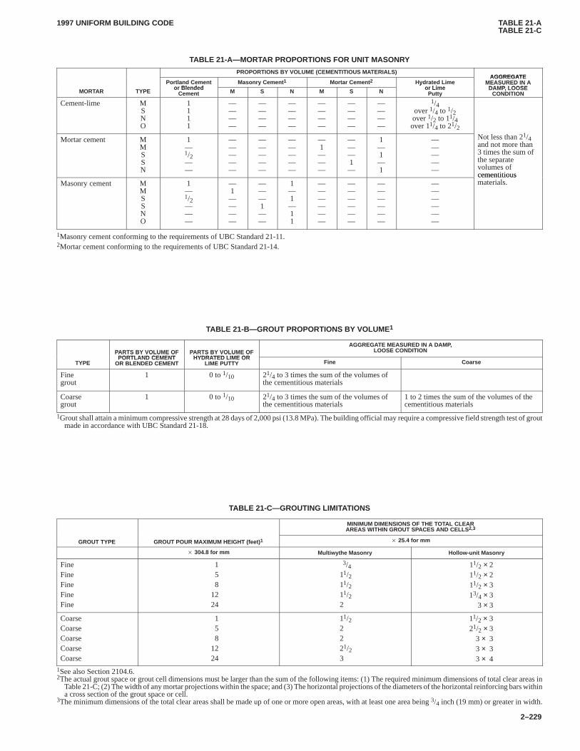
TABLE 21-ATABLE 21-C
1997 UNIFORM BUILDING CODE
2–229
TABLE 21-A—MORTAR PROPORTIONS FOR UNIT MASONRY
PROPORTIONS BY VOLUME (CEMENTITIOUS MATERIALS)AGGREGATE
Portland Cementor Blended
Masonry Cement 1 Mortar Cement 2 Hydrated Limeor Lime
AGGREGATEMEASURED IN A
DAMP LOOSEMORTAR TYPE
Portland Cementor Blended
Cement M S N M S N
Hydrated Limeor Lime
Putty
MEASURED IN ADAMP, LOOSE
CONDITION
Cement-lime MSNO
1111
————
————
————
————
————
————
1/4over 1/4 to 1/2over 1/2 to 11/4over 11/4 to 21/2
1Mortar cement M
MSSN
1—1/2——
—————
—————
—————
—1———
———1—
1—1—1
—————
Not less than 21/4and not more than3 times the sum ofthe separatevolumes ofcementitious
Masonry cement MMSSNO
1—1/2———
—1————
———1——
1—1—11
——————
——————
——————
——————
cementitiousmaterials.
1Masonry cement conforming to the requirements of UBC Standard 21-11.2Mortar cement conforming to the requirements of UBC Standard 21-14.
TABLE 21-B—GROUT PROPORTIONS BY VOLUME 1
PARTS BY VOLUME OFPORTLAND CEMENT
PARTS BY VOLUME OFHYDRATED LIME OR
AGGREGATE MEASURED IN A DAMP,LOOSE CONDITION
TYPE
PARTS BY VOLUME OFPORTLAND CEMENT
OR BLENDED CEMENT
PARTS BY VOLUME OFHYDRATED LIME OR
LIME PUTTY Fine Coarse
Finegrout
1 0 to 1/10 21/4 to 3 times the sum of the volumes ofthe cementitious materials
Coarsegrout
1 0 to 1/10 21/4 to 3 times the sum of the volumes ofthe cementitious materials
1 to 2 times the sum of the volumes of thecementitious materials
1Grout shall attain a minimum compressive strength at 28 days of 2,000 psi (13.8 MPa). The building official may require a compressive field strength test of groutmade in accordance with UBC Standard 21-18.
TABLE 21-C—GROUTING LIMITATIONS
MINIMUM DIMENSIONS OF THE TOTAL CLEARAREAS WITHIN GROUT SPACES AND CELLS 2,3
GROUT TYPE GROUT POUR MAXIMUM HEIGHT (feet) 1 � 25.4 for mm
� 304.8 for mm Multiwythe Masonry Hollow-unit Masonry
FineFineFineFineFine
158
1224
3/411/211/211/22
11/2 × 211/2 × 211/2 × 313/4 × 3
3 × 3
CoarseCoarseCoarseCoarseCoarse
158
1224
11/22221/23
11/2 × 321/2 × 3
3 × 33 × 33 × 4
1See also Section 2104.6.2The actual grout space or grout cell dimensions must be larger than the sum of the following items: (1) The required minimum dimensions of total clear areas in
Table 21-C; (2) The width of any mortar projections within the space; and (3) The horizontal projections of the diameters of the horizontal reinforcing bars withina cross section of the grout space or cell.
3The minimum dimensions of the total clear areas shall be made up of one or more open areas, with at least one area being 3/4 inch (19 mm) or greater in width.
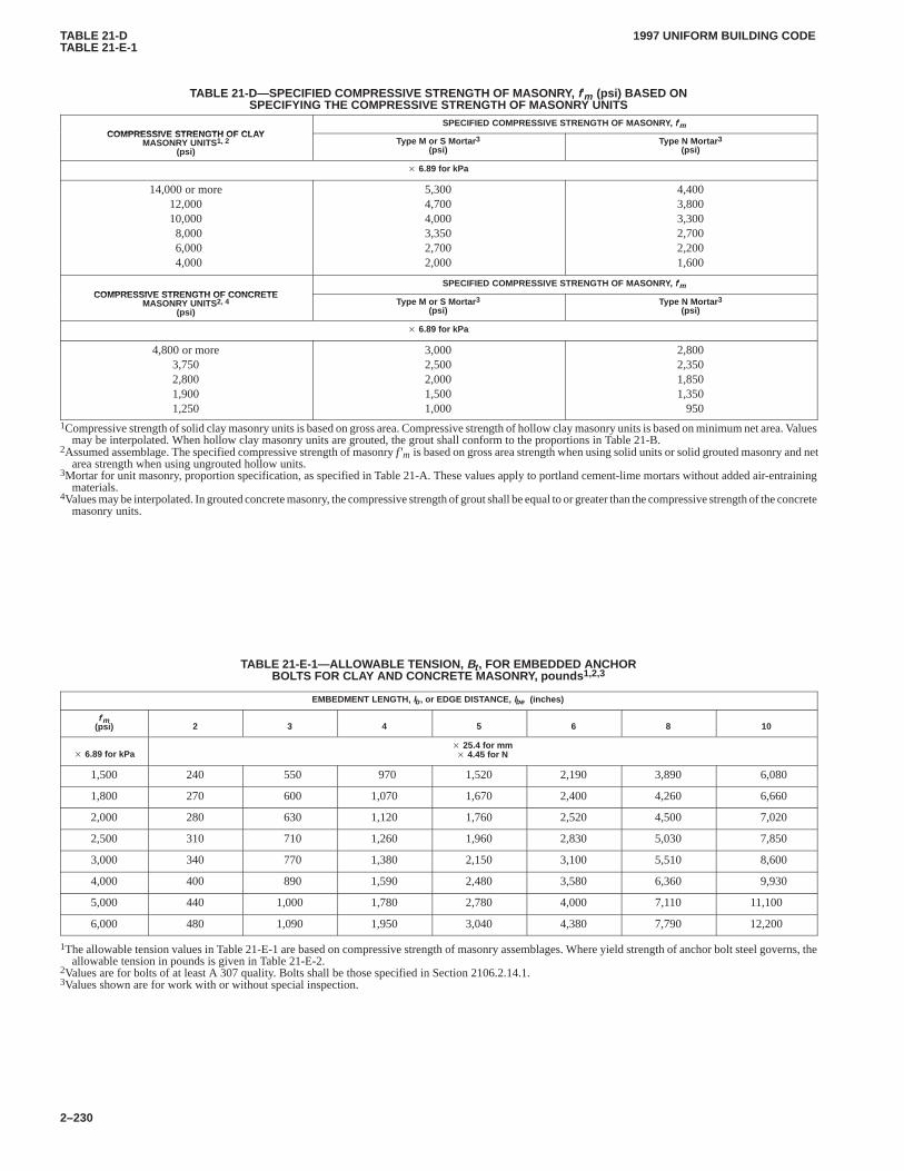
TABLE 21-DTABLE 21-E-1
1997 UNIFORM BUILDING CODE
2–230
TABLE 21-D—SPECIFIED COMPRESSIVE STRENGTH OF MASONRY, f′m (psi) BASED ONSPECIFYING THE COMPRESSIVE STRENGTH OF MASONRY UNITS
COMPRESSIVE STRENGTH OF CLAYSPECIFIED COMPRESSIVE STRENGTH OF MASONRY, f′m
COMPRESSIVE STRENGTH OF CLAYMASONRY UNITS1, 2
(psi)Type M or S Mortar 3
(psi)Type N Mortar 3
(psi)
� 6.89 for kPa
14,000 or more12,00010,0008,0006,0004,000
5,3004,7004,0003,3502,7002,000
4,4003,8003,3002,7002,2001,600
COMPRESSIVE STRENGTH OF CONCRETESPECIFIED COMPRESSIVE STRENGTH OF MASONRY, f′m
COMPRESSIVE STRENGTH OF CONCRETEMASONRY UNITS2, 4
(psi)Type M or S Mortar 3
(psi)Type N Mortar 3
(psi)
� 6.89 for kPa
4,800 or more3,7502,8001,9001,250
3,0002,5002,0001,5001,000
2,8002,3501,8501,350
9501Compressive strength of solid clay masonry units is based on gross area. Compressive strength of hollow clay masonry units is based on minimum net area. Values
may be interpolated. When hollow clay masonry units are grouted, the grout shall conform to the proportions in Table 21-B.2Assumed assemblage. The specified compressive strength of masonry f ′m is based on gross area strength when using solid units or solid grouted masonry and net
area strength when using ungrouted hollow units.3Mortar for unit masonry, proportion specification, as specified in Table 21-A. These values apply to portland cement-lime mortars without added air-entraining
materials.4Values may be interpolated. In grouted concrete masonry, the compressive strength of grout shall be equal to or greater than the compressive strength of the concrete
masonry units.
TABLE 21-E-1—ALLOWABLE TENSION, Bt , FOR EMBEDDED ANCHORBOLTS FOR CLAY AND CONCRETE MASONRY, pounds 1,2,3
EMBEDMENT LENGTH, lb , or EDGE DISTANCE, lbe (inches)
f′m(psi) 2 3 4 5 6 8 10
� 6.89 for kPa� 25.4 for mm� 4.45 for N
1,500 240 550 970 1,520 2,190 3,890 6,080
1,800 270 600 1,070 1,670 2,400 4,260 6,660
2,000 280 630 1,120 1,760 2,520 4,500 7,020
2,500 310 710 1,260 1,960 2,830 5,030 7,850
3,000 340 770 1,380 2,150 3,100 5,510 8,600
4,000 400 890 1,590 2,480 3,580 6,360 9,930
5,000 440 1,000 1,780 2,780 4,000 7,110 11,100
6,000 480 1,090 1,950 3,040 4,380 7,790 12,200
1The allowable tension values in Table 21-E-1 are based on compressive strength of masonry assemblages. Where yield strength of anchor bolt steel governs, theallowable tension in pounds is given in Table 21-E-2.
2Values are for bolts of at least A 307 quality. Bolts shall be those specified in Section 2106.2.14.1.3Values shown are for work with or without special inspection.
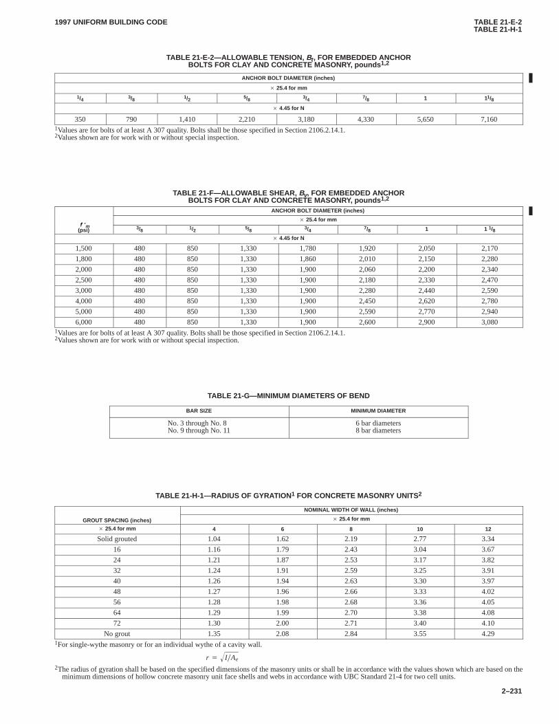
TABLE 21-E-2TABLE 21-H-1
1997 UNIFORM BUILDING CODE
2–231
TABLE 21-E-2—ALLOWABLE TENSION, Bt , FOR EMBEDDED ANCHORBOLTS FOR CLAY AND CONCRETE MASONRY, pounds 1,2
ANCHOR BOLT DIAMETER (inches)
� 25.4 for mm
1/4 3/8 1/2 5/8 3/4 7/8 1 11/8
� 4.45 for N
350 790 1,410 2,210 3,180 4,330 5,650 7,1601Values are for bolts of at least A 307 quality. Bolts shall be those specified in Section 2106.2.14.1.2Values shown are for work with or without special inspection.
TABLE 21-F—ALLOWABLE SHEAR, Bv, FOR EMBEDDED ANCHORBOLTS FOR CLAY AND CONCRETE MASONRY, pounds 1,2
ANCHOR BOLT DIAMETER (inches)
f ′� 25.4 for mm
f ′m(psi) 3/8 1/2 5/8 3/4 7/8 1 1 1/8
� 4.45 for N
1,500 480 850 1,330 1,780 1,920 2,050 2,170
1,800 480 850 1,330 1,860 2,010 2,150 2,280
2,000 480 850 1,330 1,900 2,060 2,200 2,340
2,500 480 850 1,330 1,900 2,180 2,330 2,470
3,000 480 850 1,330 1,900 2,280 2,440 2,590
4,000 480 850 1,330 1,900 2,450 2,620 2,780
5,000 480 850 1,330 1,900 2,590 2,770 2,940
6,000 480 850 1,330 1,900 2,600 2,900 3,0801Values are for bolts of at least A 307 quality. Bolts shall be those specified in Section 2106.2.14.1.2Values shown are for work with or without special inspection.
TABLE 21-G—MINIMUM DIAMETERS OF BEND
BAR SIZE MINIMUM DIAMETER
No. 3 through No. 8No. 9 through No. 11
6 bar diameters8 bar diameters
TABLE 21-H-1—RADIUS OF GYRATION 1 FOR CONCRETE MASONRY UNITS2
NOMINAL WIDTH OF WALL (inches)
GROUT SPACING (inches) � 25.4 for mm
� 25.4 for mm 4 6 8 10 12
Solid grouted 1.04 1.62 2.19 2.77 3.34
16 1.16 1.79 2.43 3.04 3.67
24 1.21 1.87 2.53 3.17 3.82
32 1.24 1.91 2.59 3.25 3.91
40 1.26 1.94 2.63 3.30 3.97
48 1.27 1.96 2.66 3.33 4.02
56 1.28 1.98 2.68 3.36 4.05
64 1.29 1.99 2.70 3.38 4.08
72 1.30 2.00 2.71 3.40 4.10
No grout 1.35 2.08 2.84 3.55 4.291For single-wythe masonry or for an individual wythe of a cavity wall.
r � I�Ae�
2The radius of gyration shall be based on the specified dimensions of the masonry units or shall be in accordance with the values shown which are based on theminimum dimensions of hollow concrete masonry unit face shells and webs in accordance with UBC Standard 21-4 for two cell units.
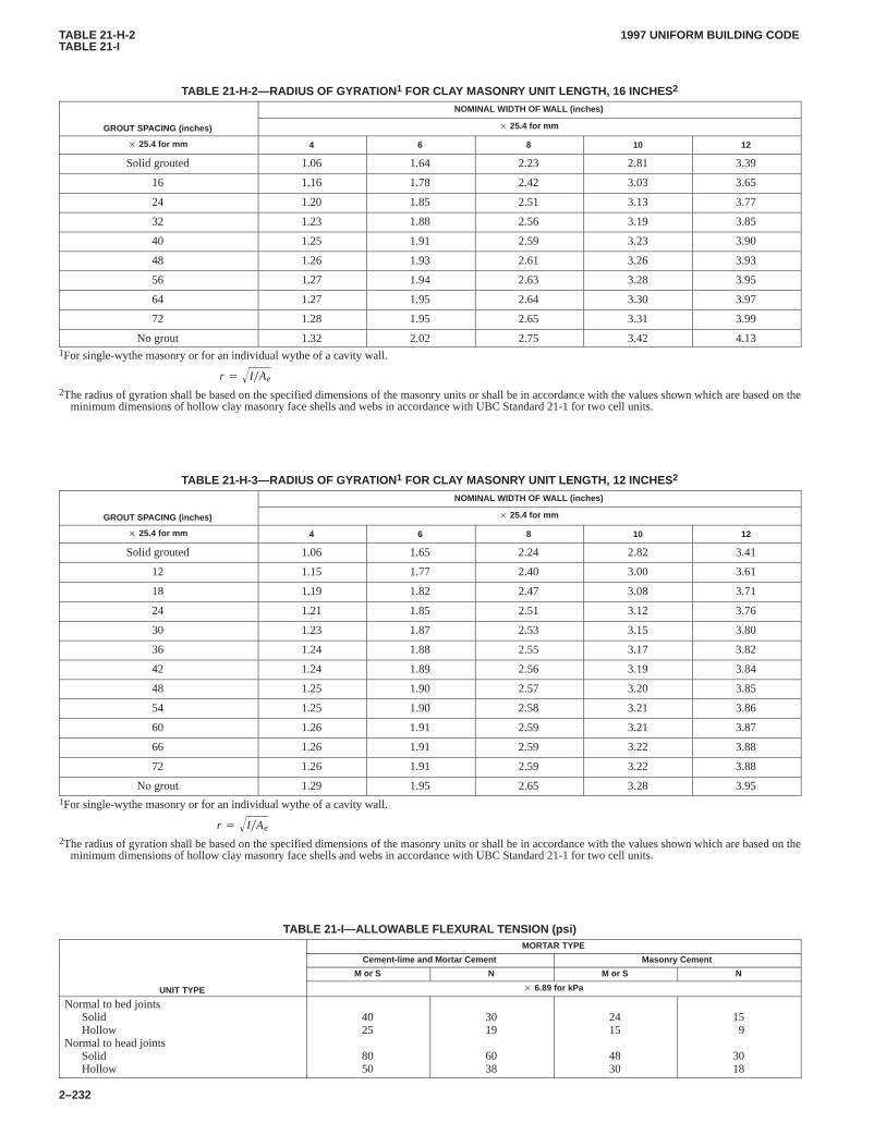
TABLE 21-H-2TABLE 21-I
1997 UNIFORM BUILDING CODE
2–232
TABLE 21-H-2—RADIUS OF GYRATION 1 FOR CLAY MASONRY UNIT LENGTH, 16 INCHES 2
NOMINAL WIDTH OF WALL (inches)
GROUT SPACING (inches) � 25.4 for mm
� 25.4 for mm 4 6 8 10 12
Solid grouted 1.06 1.64 2.23 2.81 3.39
16 1.16 1.78 2.42 3.03 3.65
24 1.20 1.85 2.51 3.13 3.77
32 1.23 1.88 2.56 3.19 3.85
40 1.25 1.91 2.59 3.23 3.90
48 1.26 1.93 2.61 3.26 3.93
56 1.27 1.94 2.63 3.28 3.95
64 1.27 1.95 2.64 3.30 3.97
72 1.28 1.95 2.65 3.31 3.99
No grout 1.32 2.02 2.75 3.42 4.131For single-wythe masonry or for an individual wythe of a cavity wall.
r � I�Ae�
2The radius of gyration shall be based on the specified dimensions of the masonry units or shall be in accordance with the values shown which are based on theminimum dimensions of hollow clay masonry face shells and webs in accordance with UBC Standard 21-1 for two cell units.
TABLE 21-H-3—RADIUS OF GYRATION 1 FOR CLAY MASONRY UNIT LENGTH, 12 INCHES 2
NOMINAL WIDTH OF WALL (inches)
GROUT SPACING (inches) � 25.4 for mm
� 25.4 for mm 4 6 8 10 12
Solid grouted 1.06 1.65 2.24 2.82 3.41
12 1.15 1.77 2.40 3.00 3.61
18 1.19 1.82 2.47 3.08 3.71
24 1.21 1.85 2.51 3.12 3.76
30 1.23 1.87 2.53 3.15 3.80
36 1.24 1.88 2.55 3.17 3.82
42 1.24 1.89 2.56 3.19 3.84
48 1.25 1.90 2.57 3.20 3.85
54 1.25 1.90 2.58 3.21 3.86
60 1.26 1.91 2.59 3.21 3.87
66 1.26 1.91 2.59 3.22 3.88
72 1.26 1.91 2.59 3.22 3.88
No grout 1.29 1.95 2.65 3.28 3.951For single-wythe masonry or for an individual wythe of a cavity wall.
r � I�Ae�
2The radius of gyration shall be based on the specified dimensions of the masonry units or shall be in accordance with the values shown which are based on theminimum dimensions of hollow clay masonry face shells and webs in accordance with UBC Standard 21-1 for two cell units.
TABLE 21-I—ALLOWABLE FLEXURAL TENSION (psi)MORTAR TYPE
Cement-lime and Mortar Cement Masonry Cement
M or S N M or S N
UNIT TYPE � 6.89 for kPa
Normal to bed jointsSolidHollow
Normal to head jointsSolidHollow
4025
8050
3019
6038
2415
4830
159
3018
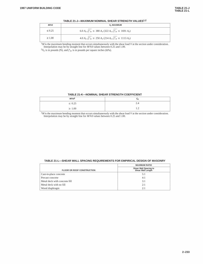
TABLE 21-JTABLE 21-L
1997 UNIFORM BUILDING CODE
2–233
TABLE 21-J—MAXIMUM NOMINAL SHEAR STRENGTH VALUES 1,2
M/Vd Vn MAXIMUM
≤ 0.25 6.0Ae f �m� � 380Ae (322Ae f �m� � 1691Ae)
≥ 1.00 4.0Ae f �m� � 250Ae (214Ae f �m� � 1113Ae)
1M is the maximum bending moment that occurs simultaneously with the shear load V at the section under consideration.Interpolation may be by straight line for M/Vd values between 0.25 and 1.00.
2Vn is in pounds (N), and f ′m is in pounds per square inches (kPa).
TABLE 21-K—NOMINAL SHEAR STRENGTH COEFFICIENTM/Vd1 Cd
� 0.25 2.4
� 1.00 1.2
1M is the maximum bending moment that occurs simultaneously with the shear load V at the section under consideration.Interpolation may be by straight line for M/Vd values between 0.25 and 1.00.
TABLE 21-L—SHEAR WALL SPACING REQUIREMENTS FOR EMPIRICAL DESIGN OF MASONRY
MAXIMUM RATIO
FLOOR OR ROOF CONSTRUCTIONShear Wall Spacing to
Shear Wall Length
Cast-in-place concrete 5:1Precast concrete 4:1Metal deck with concrete fill 3:1Metal deck with no fill 2:1Wood diaphragm 2:1
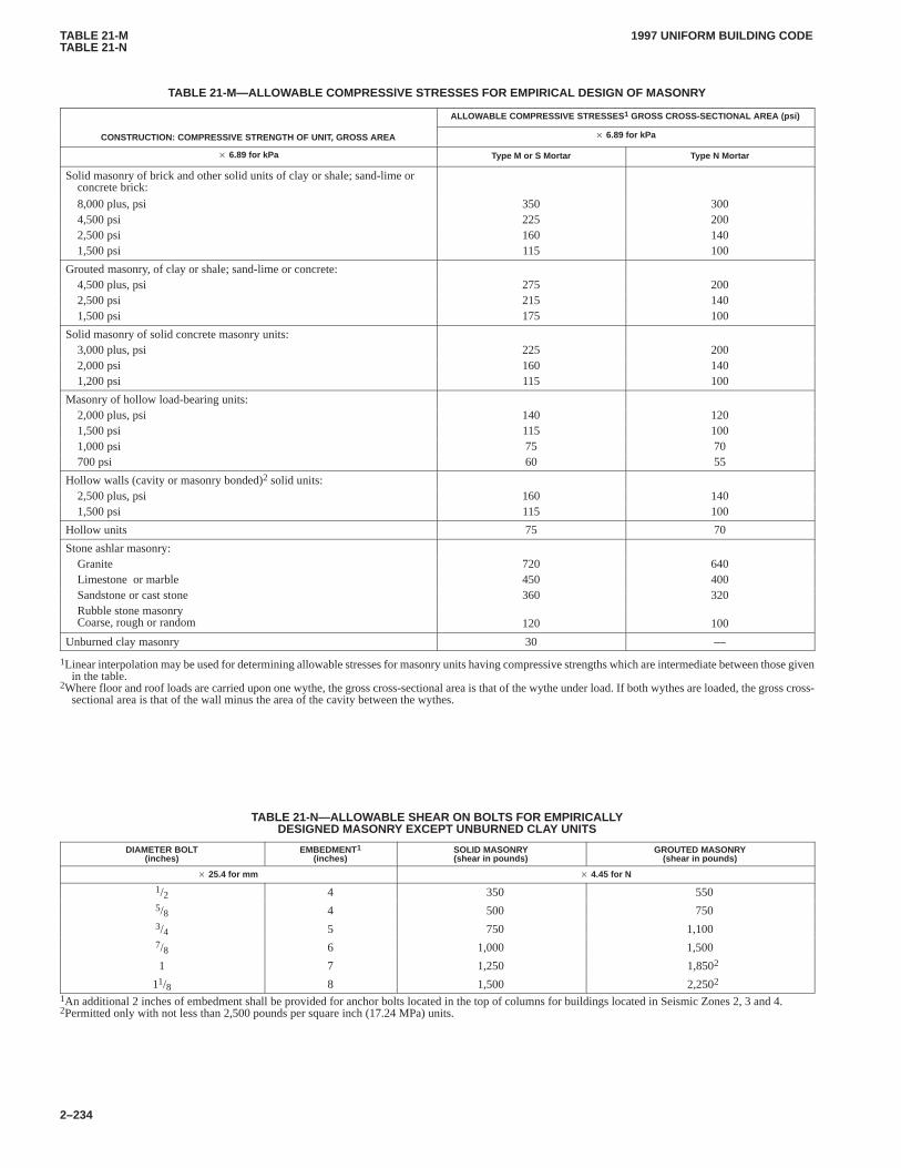
TABLE 21-MTABLE 21-N
1997 UNIFORM BUILDING CODE
2–234
TABLE 21-M—ALLOWABLE COMPRESSlVE STRESSES FOR EMPIRICAL DESIGN OF MASONRY
ALLOWABLE COMPRESSIVE STRESSES 1 GROSS CROSS-SECTIONAL AREA (psi)
CONSTRUCTION: COMPRESSIVE STRENGTH OF UNIT, GROSS AREA � 6.89 for kPa
� 6.89 for kPa Type M or S Mortar Type N Mortar
Solid masonry of brick and other solid units of clay or shale; sand-lime orconcrete brick:
8,000 plus, psi 350 3004,500 psi 225 2002,500 psi 160 1401,500 psi 115 100
Grouted masonry, of clay or shale; sand-lime or concrete:4,500 plus, psi 275 2002,500 psi 215 1401,500 psi 175 100
Solid masonry of solid concrete masonry units:3,000 plus, psi 225 2002,000 psi 160 1401,200 psi 115 100
Masonry of hollow load-bearing units:2,000 plus, psi 140 1201,500 psi 115 1001,000 psi 75 70700 psi 60 55
Hollow walls (cavity or masonry bonded)2 solid units:2,500 plus, psi 160 1401,500 psi 115 100
Hollow units 75 70
Stone ashlar masonry:Granite 720 640Limestone or marble 450 400Sandstone or cast stone 360 320Rubble stone masonry Coarse, rough or random 120 100
Unburned clay masonry 30 —
1Linear interpolation may be used for determining allowable stresses for masonry units having compressive strengths which are intermediate between those givenin the table.
2Where floor and roof loads are carried upon one wythe, the gross cross-sectional area is that of the wythe under load. If both wythes are loaded, the gross cross-sectional area is that of the wall minus the area of the cavity between the wythes.
TABLE 21-N—ALLOWABLE SHEAR ON BOLTS FOR EMPIRICALLYDESIGNED MASONRY EXCEPT UNBURNED CLAY UNITS
DIAMETER BOLT(inches)
EMBEDMENT1
(inches)SOLID MASONRY(shear in pounds)
GROUTED MASONRY(shear in pounds)
� 25.4 for mm � 4.45 for N
1/2 4 350 5505/8 4 500 7503/4 5 750 1,1007/8 6 1,000 1,500
1 7 1,250 1,8502
11/8 8 1,500 2,2502
1An additional 2 inches of embedment shall be provided for anchor bolts located in the top of columns for buildings located in Seismic Zones 2, 3 and 4.2Permitted only with not less than 2,500 pounds per square inch (17.24 MPa) units.
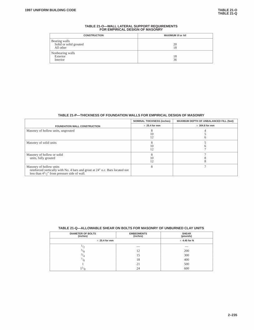
TABLE 21-OTABLE 21-Q
1997 UNIFORM BUILDING CODE
2–235
TABLE 21-O—WALL LATERAL SUPPORT REQUIREMENTSFOR EMPIRICAL DESIGN OF MASONRY
CONSTRUCTION MAXIMUM l/t or h/t
Bearing wallsSolid or solid groutedAll other
2018
Nonbearing wallsExteriorInterior
1836
TABLE 21-P—THlCKNESS OF FOUNDATION WALLS FOR EMPIRICAL DESIGN OF MASONRY
NOMINAL THICKNESS (inches) MAXIMUM DEPTH OF UNBALANCED FILL (feet)
FOUNDATION WALL CONSTRUCTION � 25.4 for mm � 304.8 for mm
Masonry of hollow units, ungrouted 81012
456
Masonry of solid units 81012
567
Masonry of hollow or solidunits, fully grouted
81012
788
Masonry of hollow unitsreinforced vertically with No. 4 bars and grout at 24″ o.c. Bars located notless than 41/2″ from pressure side of wall.
8 7
TABLE 21-Q—ALLOWABLE SHEAR ON BOLTS FOR MASONRY OF UNBURNED CLAY UNITS
DIAMETER OF BOLTS(inches)
EMBEDMENTS(inches)
SHEAR(pounds)
� 25.4 for mm � 4.45 for N
1/2 — —5/8 12 2003/4 15 3007/8 18 4001 21 500
11/8 24 600
1997 UNIFORM BUILDING CODE STANDARD 21-1
3–337
UNIFORM BUILDING CODE STANDARD 21-1
BUILDING BRICK, FACING BRICK AND HOLLOW BRICK(MADE FROM CLAY OR SHALE)
Based on Standard Specifications C 62-94a, C 216-92c, and C 652-94 of the American Society for Testing andMaterials. Extracted, with permission, from the Annual Book of ASTM Standards, copyright American Society for
Testing and Materials, 100 Barr Harbor Drive, West Conshohocken, P A 19428
See Section 2102.2, Item 4, Uniform Building Code
SECTION 21.101 — SCOPE
21.101.1 General.This standard covers brick made from clay orshale and subjected to heat treatment at elevated temperatures (fir-ing), and intended for use in brick masonry. In addition, this stand-ard covers dimension and distortion tolerances for facing brickand hollow brick to be used in masonry construction.
21.101.2 Definition.
BRICK is a solid clay masonry unit whose net cross-sectionalarea in any plane parallel to the surface containing the cores orcells is at least 75 percent of the gross cross-sectional area mea-sured in the same plane.
21.101.3 Grades.Three grades of brick are covered.
Grade SW. Brick intended for use where a high and uniform re-sistance to damage caused by cyclic freezing is desired and the ex-posure is such that the brick may be frozen when saturated withwater.
Grade MW. Brick intended for use where moderate resistanceto cyclic freezing damage is permissible or where brick may bedamp but not saturated with water when freezing occurs.
Grade NW. Brick with little resistance to cyclic freezing dam-age but which may be acceptable for applications protected fromwater absorption and freezing.
21.101.4 Grade Requirements for Face Exposure. The selec-tion of the grade of brick for face exposure of vertical or horizontalsurfaces shall conform to Table 21-1-A and Figure 21-1-1.
SECTION 21.102 — PHYSICAL PROPERTIES
21.102.1 Durability. The brick shall conform to the physical re-quirements for the grade specified, as prescribed in Table 21-1-B.
21.102.2 Substitution of Grades. Grades SW and MW may beused in lieu of Grade NW, and Grade SW in lieu of Grade MW.
21.102.3 Waiver of Saturation Coefficient. The saturation co-efficient shall be waived provided the average cold-water absorp-tion of a random sample of five bricks does not exceed 8 percent,no more than one brick of the sample exceeds 8 percent and itscold-water absorption must be less than 10 percent.
21.102.4 Freezing and Thawing.The requirements specifiedin this standard for water absorption (five-hour boiling) and satu-ration coefficient shall be waived, provided a sample of fivebricks, meeting all other requirements, complies with the follow-ing requirements when subjected to 50 cycles of the freez-ing-and-thawing test:
Grade SW No breakage and not greater than 0.5 per-cent loss in dry weight of any individualbrick.
Brick is not required to conform to the provisions of this section,and these do not apply unless the sample fails to conform to therequirements for absorption and saturation coefficient prescribed
in Table 21-1-B or the absorption requirements in Section21.102.3.
A particular lot or shipment shall be given the same grading as apreviously tested lot, without repeating the freezing-and-thawingtest, provided the brick is made by the same manufacturer fromsimilar raw materials and by the same method of forming; and pro-vided also that a sample of five bricks selected from the particularlot has an average and individual minimum strength not less than apreviously graded sample, and has average and individual maxi-mum water absorption and saturation coefficient not greater thanthose of the previously tested sample graded according to thefreezing-and-thawing test.
21.102.5 Waiver of Durability Requir ements. If brick is in-tended for use exposed to weather where the weathering index isless than 50 (see Figure 21-1-1), unless otherwise specified, therequirements given in Section 21.102.1 for water absorption (five-hour boiling) and for saturation coefficient shall be waived and aminimum average strength of 2,500 pounds per square inch(17 200 kPa) shall apply.
SECTION 21.103 — SIZE, CORING AND FROGGING
21.103.1 Tolerances on Dimensions.The maximum permissi-ble variation in dimensions of individual units shall not exceedthose given in Table 21-1-C.
21.103.2 Coring. The net cross-sectional area of cored brick inany plane parallel to the surface containing the cores or cells shallbe at least 75 percent of the gross cross-sectional area measured inthe same plane. No part of any hole shall be less than 3/4 inch (19.1mm) from any edge of the brick.
21.103.3 Frogging.One bearing face of each brick may have arecess or panel frog and deep frogs. The recess or panel frog shallnot exceed 3/8 inch (9.5 mm) in depth and no part of the recess orpanel frog shall be less than 3/4 inch (19.1 mm) from any edge ofthe brick. In brick containing deep frogs, frogs deeper than 3/8 inch(9.5 mm), any cross section through the deep frogs parallel to thesurface containing the deep frogs shall conform to the require-ments of Section 21.103.2.
SECTION 21.104 — VISUAL INSPECTION
21.104.1 General.The brick shall be free of defects, deficien-cies and surface treatments, including coatings, that would inter-fere with the proper setting of the brick or significantly impair thestrength or performance of the construction.
Minor indentations or surface cracks incidental to the usualmethod of manufacture, or the chipping resulting from the cus-tomary methods of handling in shipment and delivery should notbe deemed grounds for rejection.
SECTION 21.105 — SAMPLING AND TESTING
21.105.1 Sampling and Testing.Brick shall be sampled andtested in accordance with ASTM C 67.
1997 UNIFORM BUILDING CODESTANDARD 21-1
3–338
SECTION 21.106 — FACING BRICK
21.106.1 General.Facing brick shall be of Grade SW or MWand shall comply with the degree of mechanical perfection andsize variations specified in this section. Grade SW may be used inlieu of Grade MW.
21.106.2 Types.Three types of facing brick are covered:
Type FBS. Brick for general use in exposed exterior and interi-or masonry walls and partitions where greater variation in sizesare permitted than are specified for Type FBX.
Type FBX. Brick for general use in exposed exterior and interi-or masonry walls and partitions where a high degree of mechani-cal perfection and minimum permissible variation in size arerequired.
Type FBA. Brick manufactured and selected to produce char-acteristic architectural effects resulting from nonuniformity insize and texture of individual units.
When the type is not specified, the requirements for Type FBSshall govern.
21.106.3 Tolerances on Dimensions.The brick shall not departfrom the specified size to be used by more than the individual tol-erance for the type specified set forth in Table 21-1-D. Toleranceson dimensions for Type FBA shall be as specified by the purchas-er, but not more restrictive than Type FBS.
21.106.4 Warpage.Tolerances for distortion or warpage of faceor edges of indivi-dual brick from a plane surface and from astraight line, respectively, shall not exceed the maximum for thetype specified as set forth in Table 21-1-E. Tolerances on distor-tion for Type FBA shall be as specified by the purchaser.
21.106.5 Coring. Brick may be cored. The net cross-sectionalarea of cored brick in any plane parallel to the surface containingthe cores or cells shall be at least 75 percent of the gross cross-sectional area measured in the same plane. No part of any holeshall be less than 3/4 inch (19.1 mm) from any edge of the brick.
21.106.6 Frogging.One bearing face of each brick may have arecess or panel frog and deep frogs. The recess or panel frog shallnot exceed 3/8 inch (9.5 mm) in depth and no part of the recess orpanel frog shall be less than 3/4 inch (19.1 mm) from any edge ofthe brick. In brick containing deep frogs, frogs deeper than 3/8 inch(9.5 mm), any cross section through the deep frogs parallel to thesurface containing the deep frogs shall conform to the require-ments of Section 21.106.5.
21.106.7 Visual Inspection.In addition to the requirements ofSection 21.104, brick used in exposed wall construction shall havefaces which are free of cracks or other imperfections detractingfrom the appearance of the designated sample when viewed from adistance of 15 feet (4600 mm) for Type FBX and a distance of20 feet (6100 mm) for Types FBS and FBA.
SECTION 21.107 — HOLLOW BRICK
21.107.1 General.Hollow brick shall be of Grade SW or MWand comply with the physical requirements in Table 21-1-B andother requirements of this section. Grade SW may be used in lieuof Grade MW.
21.107.2 Definitions.
HOLLOW BRICK is a clay masonry unit whose net cross-sectional area (solid area) in any plane parallel to the surface, con-taining the cores, cells or deep frogs is less than 75 percent of itsgross cross-sectional area measured in the same plane.
CORES are void spaces having a gross cross-sectional areaequal to or less than 11/2 square inches (968 mm2).
CELLS are void spaces having a gross cross-sectional areagreater than 11/2 square inches (968 mm2).
21.107.3 Types.Four types of hollow brick are covered:
Type HBS. Hollow brick for general use in exposed exteriorand interior masonry walls and partitions greater variation in sizeare permitted than is specified for Type HBX.
Type HBX. Hollow brick for general use in exposed exteriorand interior masonry walls and partitions where a high degree ofmechanical perfection and minimum permissible variation in sizeare required.
Type HBA. Hollow brick manufactured and selected to pro-duce characteristic architectural effects resulting from nonunifor-mity in size and texture of the individual units.
Type HBB. Hollow brick for general use in masonry walls andpartitions where a particular color, texture, finish, uniformity, orlimits on cracks, warpage, or other imperfections detracting fromthe appearance are not a consideration.
When the type is not specified, the requirements for Type HBSshall govern.
21.107.4 Class.Two classes of hollow brick are covered:
Class H40V. Hollow brick intended for use where void areas orhollow spaces greater than 25 percent, but not greater than 40 per-cent, of the gross cross-sectional area of the unit measured in anyplane parallel to the surface containing the cores, cells or deepfrogs are desired. The void spaces, web thicknesses and shellthicknesses shall comply with the requirements of Sections21.107.5, 21.107.6 and 21.107.7.
Class H60V. Hollow brick intended for use where larger voidareas are desired. The sum of these void areas shall be greater than40 percent, but not greater than 60 percent, of the gross cross-sectional area of the unit measured in any plane parallel to the sur-face containing the cores, cells or deep frogs. The void spaces,web thicknesses and shell thicknesses shall comply with the re-quirements of Sections 21.107.5, 21.107.6 and 21.107.7 and to theminimum requirements of Table 21-1-F.
When the class is not specified, the requirements for ClassH40V shall govern.
21.107.5 Hollow Spaces.Core holes shall not be less than5/8 inch (15.9 mm) from any edge of the brick, except forcored-shell hollow brick. Cored-shell hollow brick shall have aminimum shell thickness of 11/2 inches (38 mm). Cores greaterthan 1 square inch (645 mm2) in cored shells shall not be less than1/2 inch (13 mm) from any edge. Cores not greater than 1 inchsquare (645 mm2) in shells cored not more than 35 percent shallnot be less than 3/8 inch (9.5 mm) from any edge.
Cells shall not be less than 3/4 inch (19.1 mm) from any edge ofthe brick except for double-shell hollow brick.
Double-shell hollow brick with inner and outer shells not lessthan 1/2 inch (13 mm) thick may not have cells greater than 5/8 inch(15.9 mm) in width or 5 inches (127 mm) in length between theinner and outer shell.
21.107.6 Webs.The thickness for webs between cells shall notbe less than 1/2 inch (13 mm), 3/8 inch (9.5 mm) between cells andcores or 1/4 inch (6 mm) between cores. The distance of voids fromunexposed edges, which are recessed not less than 1/2 inch (13mm), shall not be less than 1/2 inch (13 mm).
21.107.7 Frogging.One bearing face of each brick may have arecess or panel frog and deep frogs. The recess or panel frog shall
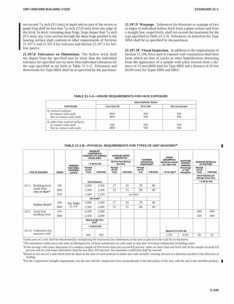
1997 UNIFORM BUILDING CODE STANDARD 21-1
3–339
not exceed 3/8 inch (9.5 mm) in depth and no part of the recess orpanel frog shall be less than 5/8 inch (15.9 mm) from any edge ofthe brick. In brick containing deep frogs, frogs deeper than 3/8 inch(9.5 mm), any cross section through the deep frogs parallel to thebearing surface shall conform to other requirements of Sections21.107.2 and 21.107.4 for void area and Section 21.107.5 for hol-low spaces.
21.107.8 Tolerances on Dimensions.The hollow brick shallnot depart from the specified size by more than the individualtolerance for specified size by more than individual tolerances forthe type specified as set forth in Table 21-1-G. Tolerances anddimensions for Type HBA shall be as specified by the purchaser.
21.107.9 Warpage.Tolerances for distortion or warpage of faceor edges of individual hollow brick from a plane surface and froma straight line, respectively, shall not exceed the maximum for thetype specified in Table 21-1-H. Tolerances on distortion for TypeHBA shall be as specified by the purchaser.
21.107.10 Visual Inspection. In addition to the requirements ofSection 21.104, brick used in exposed wall construction shall havefaces which are free of cracks or other imperfections detractingfrom the appearance of a sample wall when viewed from a dis-tance of 15 feet (4600 mm) for Type HBX and a distance of 20 feet(6100 mm) for Types HBS and HBA.
TABLE 21-1-A—GRADE REQUIREMENTS FOR FACE EXPOSURE
WEATHERING INDEX
EXPOSURE Less than 50 50 to 500 500 and greater
In vertical surfaces:In contact with earthNot in contact with earth
MWMW
SWSW
SWSW
In other than vertical surfaces:In contact with earthNot in contact with earth
SWMW
SWSW
SWSW
TABLE 21-1-B—PHYSICAL REQUIREMENTS FOR TYPES OF UNIT MASONR Y5
MINIMUM1COMPRESSIVE
STRENGTH PSI AVERAGEGROSS AREA
MAXIMUM WATERABSORPTION
I UWATERB PTI I TU E
I I U× 6.89 for kPa
By Five-hour Boiling(percent)
MAXIMUMSATURATIONCOEFFICIENT2
TEABSORPTION
Maximum Poundsper Cubic Foot
MOISTURECONTENTaximum
MINIMUM MODULUSOF RUPTURE
TYPE OF MASONRY GRADE
MINIMUMFACE SHELLTHICKNESS(inches)
Averageof FiveTests Individual
Averageof FiveTests Individual
Averageof FiveTest Individual × 16 for kg/m3
TE TMaximumPercentageof TotalAbsorption
Averageof FiveTests Individual
(brick flatwise) psiAverage Gross Area
(brick flatwise) × 6.89 for kPa
24-1. Building brickd f
SW 3,000 2,500 17 20 .78 .80gmade fromclay or shale3 MW 2,500 2,200 22 25 .88 .90clay or shale3
NW 1,500 1,250 no limit(net area)4
Hollow Brick3 SW See Table 3,000 2,500 17 20 .78 .80Hollow Brick3
MWSee Table
21-1-F 2,500 2,000 22 25 .88 .90
24-2. Sand-limeb ildi b i k
SW 4,500 3,500 600 400building brick MW 2,500 2,000 450 300
Based on Net Area(psi)4
× 6.89 for kPa
24-14. Unburned clayit
Based on % of Dry Wt.ymasonry units 300 250 2.5% 4.0% 50 35
1Gross area of a unit shall be determined by multiplying the horizontal face dimension of the unit as placed in the wall by its thickness.2The saturation coefficient is the ratio of absorption by 24-hour submersion in cold water to that after five-hour submersion in boiling water.3If the average cold-water absorption of a random sample of five bricks does not exceed 8.0 percent, when no more than one brick unit of the sample exceeds 8.0
percent and its cold-water absorption must be less than 10.0 percent, the saturation coefficient shall be waived.4Based on net area of a unit which shall be taken as the area of solid material in shells and webs actually carrying stresses in a direction parallel to the direction of
loading.5For the compressive strength requirements, test the unit with the compressive force perpendicular to the bed surface of the unit, with the unit in the stretcher position.
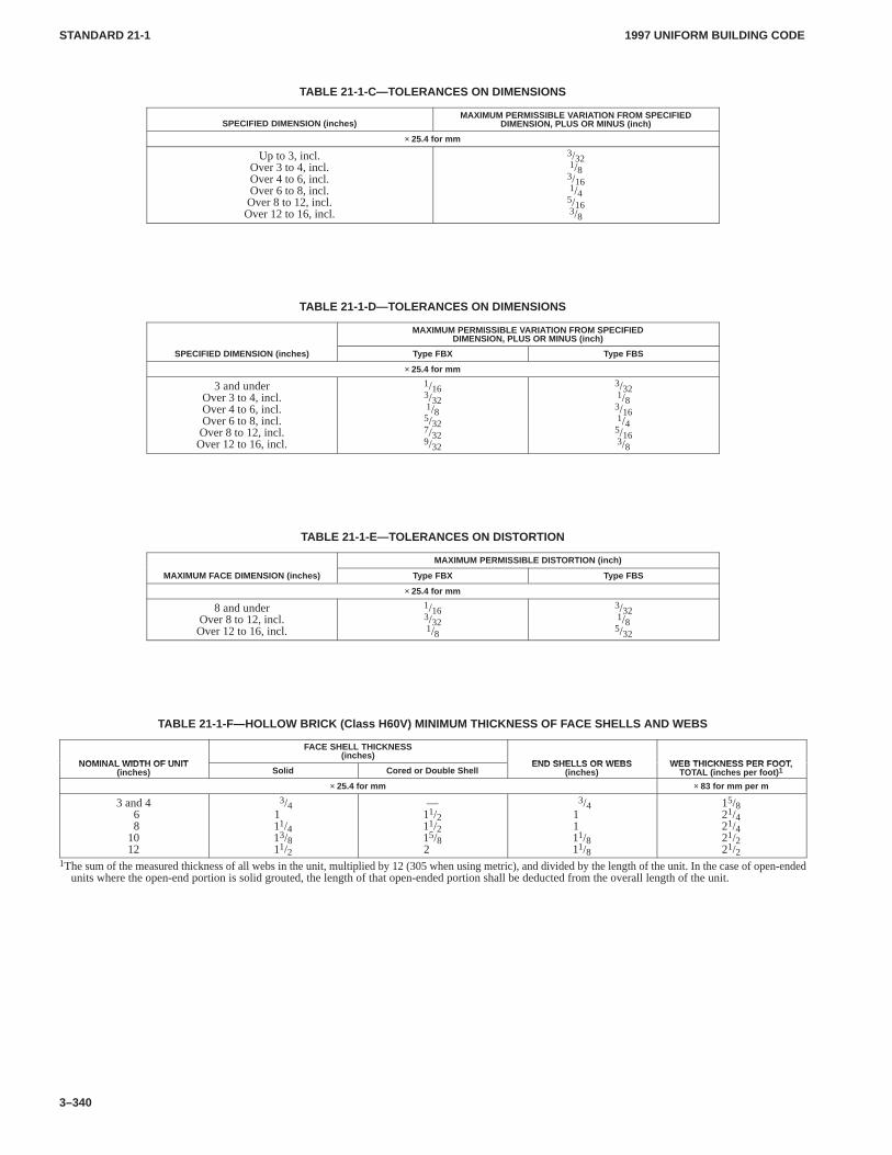
1997 UNIFORM BUILDING CODESTANDARD 21-1
3–340
TABLE 21-1-C—T OLERANCES ON DIMENSIONS
SPECIFIED DIMENSION (inches)MAXIMUM PERMISSIBLE VARIATION FROM SPECIFIED
DIMENSION, PLUS OR MINUS (inch)
× 25.4 for mm
Up to 3, incl.Over 3 to 4, incl.Over 4 to 6, incl.Over 6 to 8, incl.Over 8 to 12, incl.Over 12 to 16, incl.
3/321/83/161/45/163/8
TABLE 21-1-D—TOLERANCES ON DIMENSIONS
MAXIMUM PERMISSIBLE VARIATION FROM SPECIFIEDDIMENSION, PLUS OR MINUS (inch)
SPECIFIED DIMENSION (inches) Type FBX Type FBS
× 25.4 for mm
3 and underOver 3 to 4, incl.Over 4 to 6, incl.Over 6 to 8, incl.Over 8 to 12, incl.Over 12 to 16, incl.
1/163/321/85/327/329/32
3/321/83/161/45/163/8
TABLE 21-1-E—TOLERANCES ON DISTORTION
MAXIMUM PERMISSIBLE DIST ORTION (inch)
MAXIMUM FACE DIMENSION (inches) Type FBX Type FBS
× 25.4 for mm
8 and underOver 8 to 12, incl.Over 12 to 16, incl.
1/163/321/8
3/321/85/32
TABLE 21-1-F—HOLLOW BRICK (Class H60V) MINIMUM THICKNESS OF F ACE SHELLS AND WEBS
NOMINAL WIDTH OF UNIT
FACE SHELL THICKNESS(inches)
END SHELLS OR WEBS WEB THICKNESS PER FOOTNOMINAL WIDTH OF UNIT(inches) Solid Cored or Double Shell
END SHELLS OR WEBS(inches)
WEB THICKNESS PER FOOT,TOTAL (inches per foot) 1
× 25.4 for mm × 83 for mm per m
3 and 468
1012
3/4111/413/811/2
—11/211/215/82
3/41111/811/8
15/821/421/421/221/2
1The sum of the measured thickness of all webs in the unit, multiplied by 12 (305 when using metric), and divided by the length of the unit. In the case of open-endedunits where the open-end portion is solid grouted, the length of that open-ended portion shall be deducted from the overall length of the unit.
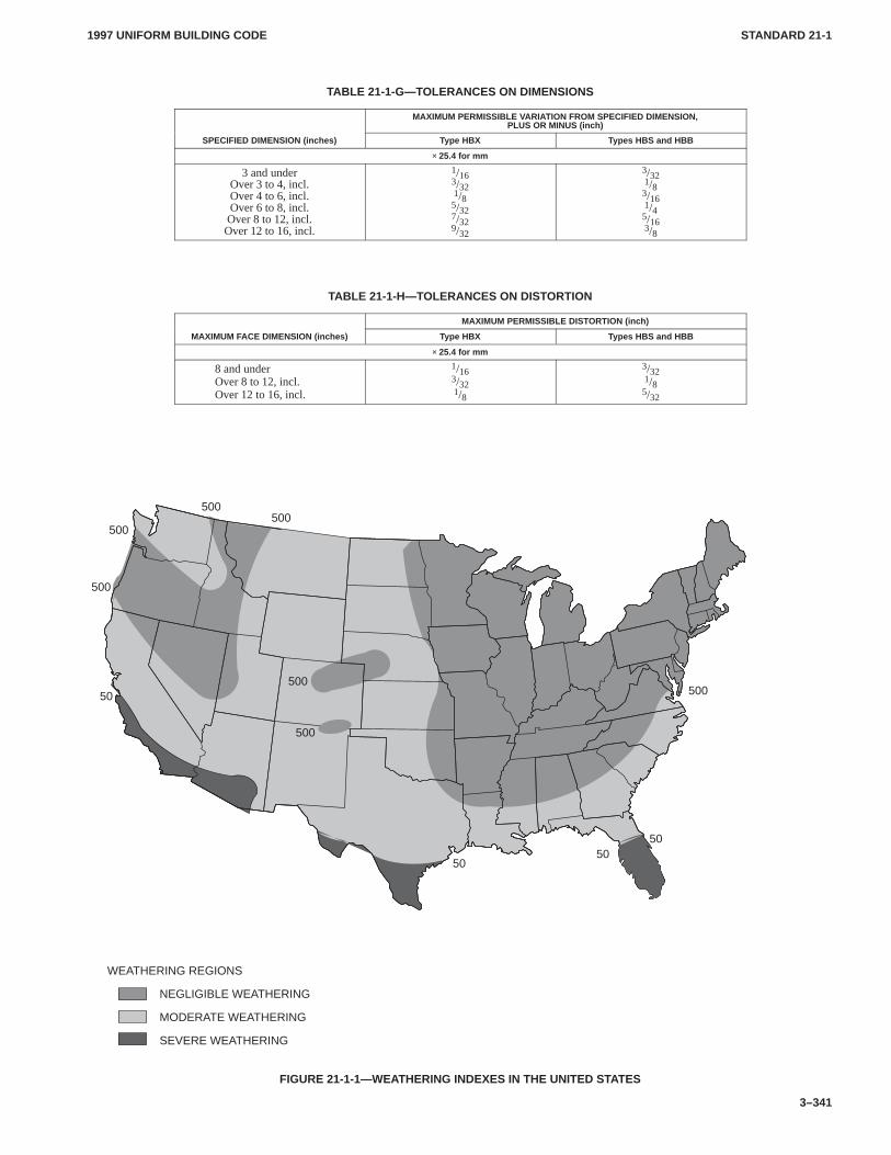
1997 UNIFORM BUILDING CODE STANDARD 21-1
3–341
TABLE 21-1-G—T OLERANCES ON DIMENSIONS
MAXIMUM PERMISSIBLE VARIATION FROM SPECIFIED DIMENSION,PLUS OR MINUS (inch)
SPECIFIED DIMENSION (inches) Type HBX Types HBS and HBB
× 25.4 for mm
3 and underOver 3 to 4, incl.Over 4 to 6, incl.Over 6 to 8, incl.Over 8 to 12, incl.Over 12 to 16, incl.
1/163/321/85/327/329/32
3/321/83/161/45/163/8
TABLE 21-1-H—TOLERANCES ON DISTORTION
MAXIMUM PERMISSIBLE DIST ORTION (inch)
MAXIMUM FACE DIMENSION (inches) Type HBX Types HBS and HBB
× 25.4 for mm
8 and underOver 8 to 12, incl.Over 12 to 16, incl.
1/163/321/8
3/321/85/32
WEATHERING REGIONS
NEGLIGIBLE WEATHERING
MODERATE WEATHERING
SEVERE WEATHERING
500500
500
500
50
5050
50
500500
500
FIGURE 21-1-1—WEATHERING INDEXES IN THE UNITED STATES
1997 UNIFORM BUILDING CODE STANDARD 21-2
3–343
UNIFORM BUILDING CODE STANDARD 21-2
CALCIUM SILICATE FACE BRICK(SAND-LIME BRICK)
Based on Standard Specification C 73-95 of the American Society for Testing and Materials.Extracted, with permission, from the Annual Book of ASTM Standards, copyright American Society for
Testing and Materials, 100 Barr Harbor Drive, West Conshohocken, P A 19428
See Section 2102.2, Item 6, Uniform Building Code
SECTION 21.201 — SCOPE
21.201.1 Grades.This standard covers brick made from sandand lime and intended for use in brick masonry. Two grades ofbrick are covered:
21.201.1.1 Grade SW. Brick intended for use where exposed totemperatures below freezing in the presence of moisture.
21.201.1.2 Grade MW.Brick intended for use where exposedto temperature below freezing but unlikely to be saturated withwater.
21.201.2 Definition. The term “brick” used in this standard shallmean brick or a solid sand-lime masonry unit.
SECTION 21.202 — PHYSICAL PROPERTIES
21.202.1 Durability. The brick shall conform to the physical re-quirements for the grade specified as prescribed in Table 21-2-A.
21.202.2 Substitution of Grades.Unless otherwise specified,brick of Grade SW shall be accepted in lieu of Grade MW.
SECTION 21.203 — SIZE
The size of the brick shall be as specified by the purchaser, and theaverage size of brick furnished shall approximate the size speci-fied in the invitation for bids.
No overall dimension (width, height and length) shall differ bymore than 1/8 inch (3.2 mm) from the specified standard dimen-sion. Standard dimensions of units are the manufacturer’s desig-nated dimensions.
SECTION 21.204 — VISUAL INSPECTION
Brick shall pass a visual inspection for soundness, compact struc-ture, reasonably uniform shape, and freedom from the following:cracks, warpage, large pebbles, balls of clay, or particles of limethat would affect the serviceability or strength of the brick.
SECTION 21.205 — METHODS OF SAMPLING ANDTESTING
The purchaser or the purchaser’s authorized representative shallbe accorded proper facilities to inspect and sample the units at theplace of manufacture from the lots ready for delivery. At least 10days should be allowed for completion of the tests.
Sample and test units in accordance with ASTM C 140.
TABLE 21-2-A—PHYSICAL REQUIREMENTS FOR SAND-LIME BUILDING BRICK
MINIMUM COMPRESSIVE STRENGTH PSIMINIMUM MODULUS OF RUPTURE
MINIMUM COMPRESSIVE STRENGTH PSIAVERAGE GROSS AREA Average of Five Tests Individual
Average of Five Tests Individual (Brick Flatwise) psi A verage Gross AreaWATER ABSORPTION
TYPE OF MASONRY GRADE � 6.89 for kPaWATER ABSORPTION
MAX. lb./ft. 3 (kg/m 3)
Sand-lime SW 4500 3500 600 400 10 (160)
Building brick MW 2500 2000 450 300 13 (208)
Gross area of a unit shall be determined by multiplying the horizontal face dimension of the unit as placed in the wall by its thickness.
1997 UNIFORM BUILDING CODE STANDARD 21-3
3–345
UNIFORM BUILDING CODE STANDARD 21-3
CONCRETE BUILDING BRICKBased on Standard Specification C 55-95 of the American Society for Testing and Materials.
Extracted, with permission, from the Annual Book of ASTM Standards, copyright American Society forTesting and Materials, 100 Barr Harbor Drive, West Conshohocken, P A 19428
See Section 2102.2, Item 5, Uniform Building Code
SECTION 21.301 — SCOPE
This standard covers concrete building brick and similar solidunits made from portland cement, water and suitable mineral ag-gregates with or without the inclusion of other materials.
SECTION 21.302 — CLASSIFICATION
21.302.1 Types.Two types of concrete brick in each of twogrades are covered, as follows:
21.302.1.1 Type I, moisture-controlled units.Concrete brickdesignated as Type I (Grades N-I and S-I) shall conform to all re-quirements of this standard, including the requirements of Table21-3-A.
21.302.1.2 Type II, nonmoisture-controlled units.Concretebrick designated as Type II (Grades N-II and S-II) shall conform toall requirements of this standard except the requirements of Table21-3-A.
21.302.2 Grades.Concrete brick manufactured in accordancewith this standard shall conform to two grades as follows:
21.302.2.1 Grade N. For use as architectural veneer and facingunits in exterior walls and for use where high strength and resis-tance to moisture penetration and severe frost action are desired.
21.302.2.2 Grade S.For general use where moderate strengthand resistance to frost action and moisture penetration arerequired.
SECTION 21.303 — MATERIALS
21.303.1 Cementitious Materials.Materials shall conform tothe following applicable standards:
1. Portland Cement—ASTM C 150 modified as follows:
Limitation on insoluble residue—1.5 percent.Limitation on air content of mortar,
Volume percent—22 percent maximum.Limitation on loss on ignition—7 percent maximum.Limestone with a minimum 85 percent calcium carbonate(CaCO3) content may be added to the cement, provided therequirements of ASTM C 150 as modified above are met.
2. Blended Cements—ASTM C 595.
3. Hydrated Lime, Type S—UBC Standard 21-13.
21.303.2 Other Constituents.Air-entraining agents, coloringpigments, integral water repellents, finely ground silica, etc., shallbe previously established as suitable for use in concrete or shall beshown by test or experience not to be detrimental to the durabilityof the concrete.
SECTION 21.304 — PHYSICAL REQUIREMENTS
At the time of delivery to the work site, the concrete brick shallconform to the physical requirements prescribed in Table 21-3-B.
At the time of delivery to the purchaser, the total linear dryingshrinkage of Type II units shall not exceed 0.065 percent whentested in accordance with ASTM C 426.
The moisture content of Type I concrete brick at the time of de-livery shall conform to the requirements prescribed in Table21-3-A.
SECTION 21.305 — DIMENSIONS AND PERMISSIBLEVARIATIONS
Overall dimensions (width, height, or length) shall not differ bymore than 1/8 inch (3.2 mm) from the specified standard dimen-sions.
NOTE: Standard dimensions of concrete brick are the manufactur-er’s designated dimensions. Nominal dimensions of modular-size con-crete brick are equal to the standard dimensions plus 3/8 inch (9.5 mm),the thickness of one standard mortar joint. Nominal dimensions of non-modular size concrete brick usually exceed the standard dimensions by1/8 inch to 1/4 inch (3.2 mm to 6.4 mm).
Variations in thickness of architectural units such as split-facedor slumped units will usually vary from the specified tolerances.
SECTION 21.306 — VISUAL INSPECTION
21.306.1 General.All concrete brick shall be sound and free ofcracks or other defects that would interfere with the proper placingof the unit or impair the strength or permanence of the construc-tion. Minor cracks incidental to the usual method of manufacture,or minor chipping resulting from customary methods of handlingin shipment and delivery, shall not be deemed grounds for rejec-tion.
21.306.2 Brick in Exposed Walls. Where concrete brick is to beused in exposed wall construction, the face or faces that are to beexposed shall be free of chips, cracks or other imperfections whenviewed from 20 feet (6100 mm), except that if not more than 5 per-cent of a shipment contains slight cracks or small chips not largerthan 1/2 inch (13 mm), this shall not be deemed grounds for rejec-tion.
SECTION 21.307 — METHODS OF SAMPLING ANDTESTING
The purchaser or authorized representative shall be accordedproper facilities to inspect and sample the concrete brick at theplace of manufacture from the lots ready for delivery. At least 10days shall be allowed for completion of the test.
Sample and test concrete brick in accordance with ASTM C 140and C 426, when applicable.
Total linear drying shrinkage shall be based on tests of concretebrick made with the same materials, concrete mix design,manufacturing process and curing method, conducted in accord-ance with ASTM C 426 not more than 24 months prior to delivery.
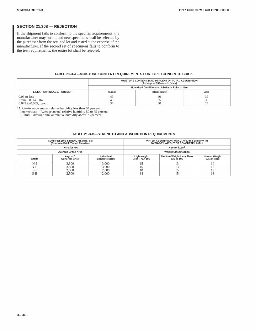
1997 UNIFORM BUILDING CODESTANDARD 21-3
3–346
SECTION 21.308 — REJECTION
If the shipment fails to conform to the specific requirements, themanufacturer may sort it, and new specimens shall be selected bythe purchaser from the retained lot and tested at the expense of themanufacturer. If the second set of specimens fails to conform tothe test requirements, the entire lot shall be rejected.
TABLE 21-3-A—MOISTURE CONTENT REQUIREMENTS FOR TYPE I CONCRETE BRICK
MOISTURE CONTENT, MAX. PERCENT OF TOTAL ABSORPTION(Average of 3 Concrete Brick)
Humidity 1 Conditions at Jobsite or Point of Use
LINEAR SHRINKAGE, PERCENT Humid Intermediate Arid
0.03 or lessFrom 0.03 to 0.0450.045 to 0.065, max.
454035
403530
353025
1Arid—Average annual relative humidity less than 50 percent.Intermediate—Average annual relative humidity 50 to 75 percent.Humid—Average annual relative humidity above 75 percent.
TABLE 21-3-B—STRENGTH AND ABSORPTION REQUIREMENTS
COMPRESSIVE STRENGTH, MIN., psi(Concrete Brick T ested Flatwise)
WATER ABSORPTION, MAX., (A vg. of 3 Brick) WITHOVEN-DRY WEIGHT OF CONCRETE Lb./Ft. 3
× 6.89 for kPa × 16 for kg/m 3
Average Gross Area Weight Classification
GradeAvg. of 3
Concrete BrickIndividual
Concrete BrickLightweight
Less Than 105Medium W eight Less Than
125 to 105Normal Weight
125 or More
N-IN-IIS-IS-II
3,5003,5002,5002,500
3,0003,0002,0002,000
15151818
13131515
10101313
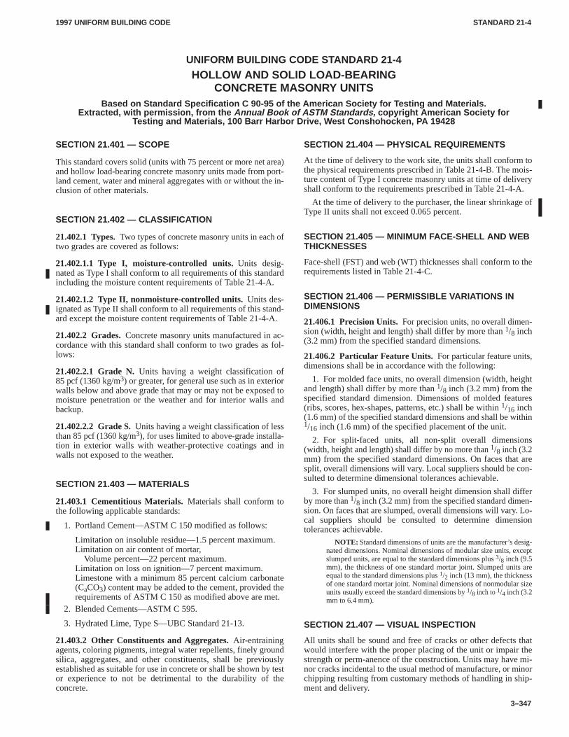
1997 UNIFORM BUILDING CODE STANDARD 21-4
3–347
UNIFORM BUILDING CODE STANDARD 21-4
HOLLOW AND SOLID LOAD-BEARINGCONCRETE MASONRY UNITS
Based on Standard Specification C 90-95 of the American Society for Testing and Materials.Extracted, with permission, from the Annual Book of ASTM Standards, copyright American Society for
Testing and Materials, 100 Barr Harbor Drive, West Conshohocken, P A 19428
SECTION 21.401 — SCOPE
This standard covers solid (units with 75 percent or more net area)and hollow load-bearing concrete masonry units made from port-land cement, water and mineral aggregates with or without the in-clusion of other materials.
SECTION 21.402 — CLASSIFICATION
21.402.1 Types.Two types of concrete masonry units in each oftwo grades are covered as follows:
21.402.1.1 Type I, moisture-controlled units.Units desig-nated as Type I shall conform to all requirements of this standardincluding the moisture content requirements of Table 21-4-A.
21.402.1.2 Type II, nonmoisture-controlled units.Units des-ignated as Type II shall conform to all requirements of this stand-ard except the moisture content requirements of Table 21-4-A.
21.402.2 Grades.Concrete masonry units manufactured in ac-cordance with this standard shall conform to two grades as fol-lows:
21.402.2.1 Grade N.Units having a weight classification of85 pcf (1360 kg/m3) or greater, for general use such as in exteriorwalls below and above grade that may or may not be exposed tomoisture penetration or the weather and for interior walls andbackup.
21.402.2.2 Grade S. Units having a weight classification of lessthan 85 pcf (1360 kg/m3), for uses limited to above-grade installa-tion in exterior walls with weather-protective coatings and inwalls not exposed to the weather.
SECTION 21.403 — MATERIALS
21.403.1 Cementitious Materials.Materials shall conform tothe following applicable standards:
1. Portland Cement—ASTM C 150 modified as follows:
Limitation on insoluble residue—1.5 percent maximum.Limitation on air content of mortar,
Volume percent—22 percent maximum.Limitation on loss on ignition—7 percent maximum.Limestone with a minimum 85 percent calcium carbonate(CaCO3) content may be added to the cement, provided therequirements of ASTM C 150 as modified above are met.
2. Blended Cements—ASTM C 595.
3. Hydrated Lime, Type S—UBC Standard 21-13.
21.403.2 Other Constituents and Aggregates.Air-entrainingagents, coloring pigments, integral water repellents, finely groundsilica, aggregates, and other constituents, shall be previouslyestablished as suitable for use in concrete or shall be shown by testor experience to not be detrimental to the durability of theconcrete.
SECTION 21.404 — PHYSICAL REQUIREMENTS
At the time of delivery to the work site, the units shall conform tothe physical requirements prescribed in Table 21-4-B. The mois-ture content of Type I concrete masonry units at time of deliveryshall conform to the requirements prescribed in Table 21-4-A.
At the time of delivery to the purchaser, the linear shrinkage ofType II units shall not exceed 0.065 percent.
SECTION 21.405 — MINIMUM FACE-SHELL AND WEBTHICKNESSES
Face-shell (FST) and web (WT) thicknesses shall conform to therequirements listed in Table 21-4-C.
SECTION 21.406 — PERMISSIBLE VARIATIONS INDIMENSIONS
21.406.1 Precision Units. For precision units, no overall dimen-sion (width, height and length) shall differ by more than 1/8 inch(3.2 mm) from the specified standard dimensions.
21.406.2 Particular Feature Units. For particular feature units,dimensions shall be in accordance with the following:
1. For molded face units, no overall dimension (width, heightand length) shall differ by more than 1/8 inch (3.2 mm) from thespecified standard dimension. Dimensions of molded features(ribs, scores, hex-shapes, patterns, etc.) shall be within 1/16 inch(1.6 mm) of the specified standard dimensions and shall be within1/16 inch (1.6 mm) of the specified placement of the unit.
2. For split-faced units, all non-split overall dimensions(width, height and length) shall differ by no more than 1/8 inch (3.2mm) from the specified standard dimensions. On faces that aresplit, overall dimensions will vary. Local suppliers should be con-sulted to determine dimensional tolerances achievable.
3. For slumped units, no overall height dimension shall differby more than 1/8 inch (3.2 mm) from the specified standard dimen-sion. On faces that are slumped, overall dimensions will vary. Lo-cal suppliers should be consulted to determine dimensiontolerances achievable.
NOTE: Standard dimensions of units are the manufacturer’s desig-nated dimensions. Nominal dimensions of modular size units, exceptslumped units, are equal to the standard dimensions plus 3/8 inch (9.5mm), the thickness of one standard mortar joint. Slumped units areequal to the standard dimensions plus 1/2 inch (13 mm), the thicknessof one standard mortar joint. Nominal dimensions of nonmodular sizeunits usually exceed the standard dimensions by 1/8 inch to 1/4 inch (3.2mm to 6.4 mm).
SECTION 21.407 — VISUAL INSPECTION
All units shall be sound and free of cracks or other defects thatwould interfere with the proper placing of the unit or impair thestrength or perm-anence of the construction. Units may have mi-nor cracks incidental to the usual method of manufacture, or minorchipping resulting from customary methods of handling in ship-ment and delivery.
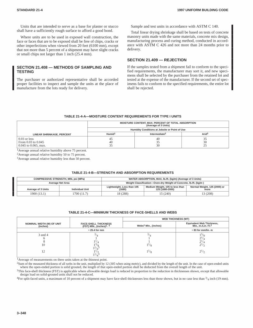
1997 UNIFORM BUILDING CODESTANDARD 21-4
3–348
Units that are intended to serve as a base for plaster or stuccoshall have a sufficiently rough surface to afford a good bond.
Where units are to be used in exposed wall construction, theface or faces that are to be exposed shall be free of chips, cracks orother imperfections when viewed from 20 feet (6100 mm), exceptthat not more than 5 percent of a shipment may have slight cracksor small chips not larger than 1 inch (25.4 mm).
SECTION 21.408 — METHODS OF SAMPLING ANDTESTING
The purchaser or authorized representative shall be accordedproper facilities to inspect and sample the units at the place ofmanufacture from the lots ready for delivery.
Sample and test units in accordance with ASTM C 140.
Total linear drying shrinkage shall be based on tests of concretemasonry units made with the same materials, concrete mix design,manufacturing process and curing method, conducted in accord-ance with ASTM C 426 and not more than 24 months prior todelivery.
SECTION 21.409 — REJECTION
If the samples tested from a shipment fail to conform to the speci-fied requirements, the manufacturer may sort it, and new speci-mens shall be selected by the purchaser from the retained lot andtested at the expense of the manufacturer. If the second set of spec-imens fails to conform to the specified requirements, the entire lotshall be rejected.
TABLE 21-4-A—MOISTURE CONTENT REQUIREMENTS FOR TYPE I UNITS
MOISTURE CONTENT, MAX. PERCENT OF TOTAL ABSORPTION(Average of 3 Units)
Humidity Conditions at Jobsite or Point of Use
LINEAR SHRINKAGE, PERCENT Humid 1 Intermediate 2 Arid 3
0.03 or lessFrom 0.03 to 0.0450.045 to 0.065, max.
454035
403530
353025
1Average annual relative humidity above 75 percent.2Average annual relative humidity 50 to 75 percent.3Average annual relative humidity less than 50 percent.
TABLE 21-4-B—STRENGTH AND ABSORPTION REQUIREMENTS
COMPRESSIVE STRENGTH, MIN, psi (MPa) WATER ABSORPTION, MAX, lb./ft. (kg/m) (Average of 3 Units)
Average Net Area Weight Classification—Oven-dry W eight of Concrete, lb./ft. (kg/m )
Average of 3 Units Individual UnitLightweight, Less than 105
(1680)Medium W eight, 105 to less than
125 (1680-2000)Normal W eight, 125 (2000) or
more
1900 (13.1) 1700 (11.7) 18 (288) 15 (240) 13 (208)
TABLE 21-4-C—MINIMUM THICKNESS OF FACE-SHELLS AND WEBS
WEB THICKNESS (WT)
NOMINAL WIDTH (W) OF UNIT(inches)
FACE-SHELL THICKNESS(FST) MIN., (inches) 1, 4 Webs1 Min., (inches)
Equivalent Web Thickness,Min., In./Lin. Ft. 2
× 25.4 for mm × 83 for mm/lin. m
3 and 468
10
12
3/41
11/413/811/43
11/211/43
3/411
11/8
11/8
15/821/421/421/2
21/2
1Average of measurements on three units taken at the thinnest point.2Sum of the measured thickness of all webs in the unit, multiplied by 12 (305 when using metric), and divided by the length of the unit. In the case of open-ended units
where the open-ended portion is solid grouted, the length of that open-ended portion shall be deducted from the overall length of the unit.3This face-shell thickness (FST) is applicable where allowable design load is reduced in proportion to the reduction in thicknesses shown, except that allowable
design load on solid-grouted units shall not be reduced.4For split-faced units, a maximum of 10 percent of a shipment may have face-shell thicknesses less than those shown, but in no case less than 3/4 inch (19 mm).
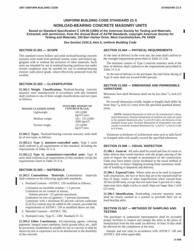
1997 UNIFORM BUILDING CODE STANDARD 21-5
3–349
UNIFORM BUILDING CODE STANDARD 21-5
NONLOAD-BEARING CONCRETE MASONRY UNITSBased on Standard Specification C 129-95 (1980) of the American Society for Testing and Materials.
Extracted, with permission, from the Annual Book of ASTM Standards, copyright American Society forTesting and Materials, 100 Barr Harbor Drive, West Conshohocken, P A 19428
See Section 2102.2, Item 5, Uniform Building Code
SECTION 21.501 — SCOPE
This standard covers hollow and solid nonload-bearing concretemasonry units made from portland cement, water, and mineral ag-gregates with or without the inclusion of other materials. Suchunits are intended for use in nonload-bearing partitions but undercertain conditions may be suitable for use in nonload-bearingexterior walls above grade, where effectively protected from theweather.
SECTION 21.502 — CLASSIFICATION
21.502.1 Weight Classifications.Nonload-bearing concretemasonry units manufactured in accordance with this standardshall conform to one of three weight classifications and two typesas follows:
WEIGHT CLASSIFICATIONOVEN-DRY WEIGHT OF
CONCRETE lb./cu.ft.
Lightweight 105 (1680kg/m3) max.
Medium weight 105 - 125 (1680 -2000 kg/m3)
Normal weight 125 (2000kg/m3) min.
21.502.2 Types.Nonload-bearing concrete masonry units shallbe of two types as follows:
21.502.2.1 Type I, moisture-controlled units.Type I unitsshall conform to all requirements of this standard, including therequirements of Table 21-5-A.
21.502.2.2 Type II, nonmoisture-controlled units.Type IIunits shall conform to all requirements of this standard, except therequirements listed in Table 21-5-A.
SECTION 21.503 — MATERIALS
21.503.1 Cementitious Materials.Cementitious materialsshall conform to the following applicable standards:
1. Portland Cement—ASTM C 150 modified as follows:
Limitation on insoluble residue—1.5 percent.Limitation on air content of mortar,
Volume percent—22 percent maximum.Limitation on loss on ignition—7 percent maximum.Limestone with a minimum 85 percent calcium carbonate(CaCO3) content may be added to the cement, provided therequirements of ASTM C 150 as modified above are met.
2. Blended Cements—ASTM C 595.
3. Hydrated Lime, Type S—UBC Standard 21-13.
21.503.2 Other Constituents.Air-entraining agents, coloringpigments, integral water repellents, finely ground silica, etc., shallbe previously established as suitable for use in concrete or shall beshown by test or experience not to be detrimental to the durabilityof the concrete.
SECTION 21.504 — PHYSICAL REQUIREMENTS
At the time of delivery to the work site, the units shall conform tothe strength requirements prescribed in Table 21-5-B.
The moisture content of Type I concrete masonry units at thetime of delivery shall conform to the requirements prescribed inTable 21-5-A.
At the time of delivery to the purchaser, the total linear drying ofType II units shall not exceed 0.065 percent.
SECTION 21.505 — DIMENSIONS AND PERMISSIBLEVARIATIONS
Minimum face-shell thickness shall not be less than 1/2 inch (13mm).
No overall dimension (width, height or length) shall differ bymore than 1/8 inch (3.2 mm) from the specified standard dimen-sions.
NOTE: Standard dimensions of units are the manufacturer’s desig-nated dimensions. Nominal dimensions of modular-size units are equalto the standard dimensions plus 3/8 inch (9.5 mm), the thickness of onestandard mortar joint. Nominal dimensions of nonmodular size unitsusually exceed the standard dimensions by 1/8 inch to 1/4 inch (3.2 mmto 6.4 mm).
Variations in thickness of architectural units such as split-facedor slumped units will usually exceed the specified tolerances.
SECTION 21.506 — VISUAL INSPECTION
21.506.1 General.All units shall be sound and free of cracks orother defects that would interfere with the proper placing of theunits or impair the strength or permanence of the construction.Units may have minor cracks incidental to the usual method ofmanufacture, or minor chipping resulting from customary meth-ods of handling in shipment and delivery.
21.506.2 Exposed Units. Where units are to be used in exposedwall construction, the face or faces that are to be exposed shall befree of chips, cracks or other imperfections when viewed from20 feet (6100 mm), except that not more than 5 percent of a ship-ment may have slight cracks or small chips not larger than 1 inch(25 mm).
21.506.3 Identification. Nonloading concrete masonry unitsshall be clearly marked in a manner to preclude their use asload-bearing units.
SECTION 21.507 — METHODS OF SAMPLING ANDTESTING
The purchaser or authorized representative shall be accordedproper facilities to inspect and sample the units at the place ofmanufacture from the lots ready for delivery. At least 10 days shallbe allowed for the completion of the tests.
Sample and test units in accordance with ASTM C 140 andASTM C 426 when applicable.
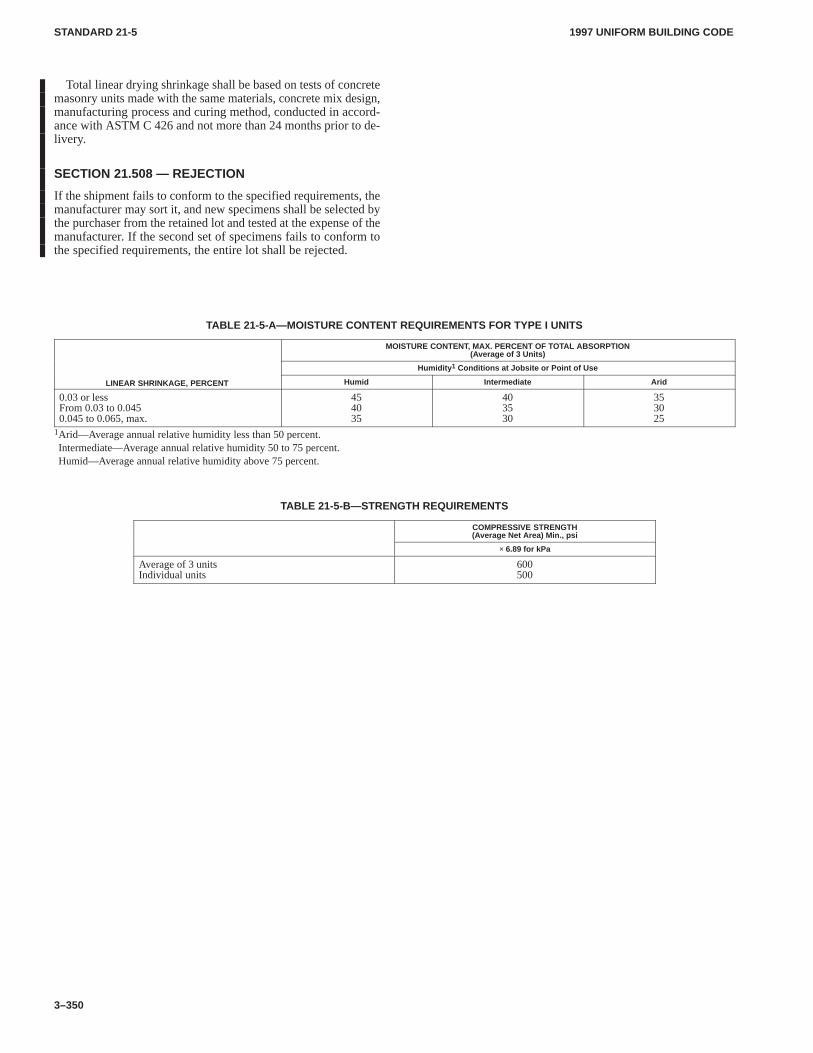
1997 UNIFORM BUILDING CODESTANDARD 21-5
3–350
Total linear drying shrinkage shall be based on tests of concretemasonry units made with the same materials, concrete mix design,manufacturing process and curing method, conducted in accord-ance with ASTM C 426 and not more than 24 months prior to de-livery.
SECTION 21.508 — REJECTION
If the shipment fails to conform to the specified requirements, themanufacturer may sort it, and new specimens shall be selected bythe purchaser from the retained lot and tested at the expense of themanufacturer. If the second set of specimens fails to conform tothe specified requirements, the entire lot shall be rejected.
TABLE 21-5-A—MOISTURE CONTENT REQUIREMENTS FOR TYPE I UNITS
MOISTURE CONTENT, MAX. PERCENT OF TOTAL ABSORPTION(Average of 3 Units)
Humidity 1 Conditions at Jobsite or Point of Use
LINEAR SHRINKAGE, PERCENT Humid Intermediate Arid
0.03 or lessFrom 0.03 to 0.0450.045 to 0.065, max.
454035
403530
353025
1Arid—Average annual relative humidity less than 50 percent.Intermediate—Average annual relative humidity 50 to 75 percent.Humid—Average annual relative humidity above 75 percent.
TABLE 21-5-B—STRENGTH REQUIREMENTS
COMPRESSIVE STRENGTH(Average Net Area) Min., psi
× 6.89 for kPa
Average of 3 unitsIndividual units
600500
1997 UNIFORM BUILDING CODE STANDARD 21-6
3–351
UNIFORM BUILDING CODE STANDARD 21-6
IN-PLACE MASONRY SHEAR TESTSTest Standard of the International Conference of Building Officials
See Appendix Chapter 1, Sections A106.3.3 and A107.2,Uniform Code for Building Conservation
SECTION 21.601 — SCOPE
This standard applies when the Uniform Code for Building Con-servation requires in-place testing of the quality of masonrymortar.
SECTION 21.602 — PREPARATION OF SAMPLE
The bed joints of the outer wythe of the masonry shall be tested inshear by laterally displacing a single brick relative to the adjacentbricks in the same wythe. The head joint opposite the loaded endof the test brick shall be carefully excavated and cleared. The brickadjacent to the loaded end of the test brick shall be carefully re-
moved by sawing or drilling and excavating to provide space for ahydraulic ram and steel loading blocks.
SECTION 21.603 — APPLICATION OF LOAD ANDDETERMINATION OF RESULTS
Steel blocks, the size of the end of the brick, shall be used on eachend of the ram to distribute the load to the brick. The blocks shallnot contact the mortar joints. The load shall be applied horizontal-ly, in the plane of the wythe, until either a crack can be seen or slipoccurs. The strength of the mortar shall be calculated by dividingthe load at the first cracking or movement of the test brick by thenominal gross area of the sum of the two bed joints.
1997 UNIFORM BUILDING CODE STANDARD 21-7
3–353
UNIFORM BUILDING CODE STANDARD 21-7
TESTS OF ANCHORS IN UNREINFORCED MASONRY WALLSTest Standard of the International Conference of Building Officials
See Appendix Chapter 1, Section A107.3 and A107.4,Uniform Code for Building Conservation
SECTION 21.701 — SCOPE
Shear and tension anchors in existing masonry construction shallbe tested in accordance with this standard when required by theUniform Code for Building Conservation.
SECTION 21.702 — DIRECT TENSION TESTING OFEXISTING ANCHORS AND NEW BOLTS
The test apparatus shall be supported by the masonry wall. Thedistance between the anchor and the test apparatus support shallnot be less than one half the wall thickness for existing anchors and75 percent of the embedment for new embedded bolts. Existingwall anchors shall be given a preload of 300 pounds (1335 N) priorto establishing a datum for recording elongation. The tension testload reported shall be recorded at 1/8 inch (3.2 mm) relative move-ment of the existing anchor and the adjacent masonry surface.New embedded tension bolts shall be subject to a direct tensionload of not less than 2.5 times the design load but not less than1,500 pounds (6672 N) for five minutes (10 percent deviation).
SECTION 21.703 — TORQUE TESTING OF NEWBOLTS
Bolts embedded in unreinforced masonry walls shall be testedusing a torque-calibrated wrench to the following minimumtorques:
1/2-inch-diameter (13 mm) bolts—40 foot pounds (54.2 N�m)5/8-inch-diameter (16 mm) bolts—50 foot pounds (67.8 N�m)3/4-inch-diameter (19 mm) bolts—60 foot pounds (81.3 N�m)
SECTION 21.704 — PREQUALIFICATION TEST FORBOLTS AND OTHER TYPES OF ANCHORS
This section is applicable when it is desired to use tension or shearvalues for anchors greater than those permitted by Table A-1-E ofthe Uniform Code for Building Conservation. The direct-tensiontest procedure set forth in Section 21.702 for existing anchors maybe used to determine the allowable tension values for newembedded or through bolts, except that no preload is required.Bolts shall be installed in the same manner and using the samematerials as will be used in the actual construction. A minimum offive tests for each bolt size and type shall be performed for eachclass of masonry in which they are proposed to be used. The allow-able tension values for such anchors shall be the lesser of the aver-age ultimate load divided by a factor of safety of 5.0 or the averageload of which 1/8 inch (3.2 mm) elongation occurs for each sizeand type of bolt and class of masonry.
Shear bolts may be similarly prequalified. The test procedureshall comply with ASTM E 488-90 or another approved proce-dure.
The allowable values determined in this manner may exceedthose set forth in Table A-1-E of the Uniform Code for BuildingConservation.
SECTION 21.705 — REPORTS
Results of all tests shall be reported. The report shall include thetest results as related to anchor size and type, orientation of load-ing, details of the anchor installation and embedment, wall thick-ness, and joist orientation.
1997 UNIFORM BUILDING CODE STANDARD 21-8
3–355
UNIFORM BUILDING CODE STANDARD 21-8
POINTING OF UNREINFORCED MASONRY WALLSConstruction Specification of the International Conference of Building Officials
See Appendix Chapter 1, Section A106.3.3.2,Uniform Code for Building Conservation
SECTION 21.801 — SCOPEPointing of deteriorated mortar joints when required by the Uni-form Code for Building Conservation shall be in accordance withthis standard.
SECTION 21.802 — JOINT PREPARATIONThe old or deteriorated mortar joint shall be cut out, by means of atoothing chisel or nonimpact power tool, to a uniform depth of3/4 inch (19 mm) until sound mortar is reached. Care shall be takennot to damage the brick edges. After cutting is complete, all loosematerial shall be removed with a brush, air or water stream.
SECTION 21.803 — MORTAR PREPARATIONThe mortar mix shall be Type N or Type S proportioned as re-quired by the construction specifications. The pointing mortar
shall be prehydrated by first thoroughly mixing all ingredients dryand then mixing again, adding only enough water to produce adamp unworkable mix which will retain its form when pressedinto a ball. The mortar shall be kept in a damp condition for oneand one-half hours; then sufficient water shall be added to bring itto a consistency that is somewhat drier than conventional masonrymortar.
SECTION 21.804 — PACKING
The joint into which the mortar is to be packed shall be damp butwithout freestanding water. The mortar shall be tightly packedinto the joint in layers not exceeding 1/4 inch (6.4 mm) in depthuntil it is filled; then it shall be tooled to a smooth surface to matchthe original profile.
1997 UNIFORM BUILDING CODE STANDARD 21-9
3–357
UNIFORM BUILDING CODE STANDARD 21-9
UNBURNED CLAY MASONRY UNITS AND STANDARDMETHODS OF SAMPLING AND TESTING UNBURNED
CLAY MASONRY UNITSTest Standard of the International Conference of Building Officials
See Section 2102.2, Item 6, Uniform Building Code
Part I—Unburned Clay Masonry
SECTION 21.901 — SCOPE
This standard covers unburned clay masonry units made from asuitable mixture of soil, clay and stabilizing agent, and intendedfor use in brick masonry.
SECTION 21.902 — COMPOSITION OF UNITS
21.902.1 Soil.The soil used shall contain not less than 25 per-cent and not more than 45 percent of material passing a No. 200mesh (75 µm) sieve. The soil shall contain sufficient clay to bindthe particles together, but shall contain not more than 0.2 percentof water-soluble salts.
21.902.2 Stabilizer.The stabilizing agent shall be emulsifiedasphalt. The stabilizing agent shall be uniformly mixed with thesoil in amounts sufficient to provide the required resistance to ab-sorption.
SECTION 21.903 — PHYSICAL REQUIREMENTS
The units shall conform to the physical requirements prescribed inTable 21-1-B of UBC Standard 21-1.
SECTION 21.904 — SHRINKAGE CRACKS
No units shall contain more than three shrinkage cracks, and noshrinkage crack shall exceed 3 inches (76 mm) in length or 1/8 inch(3.2 mm) in width.
Part II—Sampling and Testing ofUnburned Clay Masonry Units
SECTION 21.905 — SCOPE
These methods cover procedures for the sampling and testing ofunburned clay masonry units for compressive strength, modulusof rupture, absorption and moisture content.
Sampling
SECTION 21.906 — TEST SPECIMENS
For each of the tests prescribed in this standard, five sample unitsshall be selected at random from each lot of 5,000 units or fractionthereof.
SECTION 21.907 — IDENTIFICATION
Each specimen shall be marked so that it may be identified at anytime. Markings shall not cover more than 5 percent of the superfi-cial area of the specimen.
Compressive Strength
SECTION 21.908 — PROCEDURE
Five full-size specimens shall be tested for compressive strengthaccording to the following procedure:
1. Dry the specimens at a temperature of 85°F ± 15°F (29°C ±9°C) in an atmosphere having a relative humidity of not more than50 percent. Weigh the specimens at one-day intervals until con-stant weight is attained.
2. Test the specimens in the position in which the unburnedclay masonry unit is designed to be used, and bed on and cap with afelt pad not less than 1/8 inch (3.2 mm) nor more than 1/4 inch (6.4mm) in thickness.
3. The specimens may be suitably capped with calcined gyp-sum mortar or the bearing surfaces of the tile may be planed orrubbed smooth and true. When calcined gypsum is used for cap-ping, conduct the test after the capping has set and the specimenhas been dried to constant weight in accordance with Item 1 of thissection.
4. The loading head shall completely cover the bearing area ofthe specimen and the applied load shall be transmitted through aspherical bearing block of proper design. The speed of the movinghead of the testing machine shall not be more than 0.05 inch (1.27mm) per minute.
5. Calculate the average compressive strength of the speci-mens tested and report this as the compressive strength of theblock.
Modulus of Rupture
SECTION 21.909 — PROCEDURE
Five full-size specimens shall be tested for modulus of ruptureaccording to the following procedure:
1. Cured specimen shall be positioned on cylindrical supports2 inches (51 mm) in diameter, located 2 inches (51 mm) from eachend, and extending across the full width of the specimen.
2. A cylinder 2 inches (51 mm) in diameter shall be positionedon the specimen midway between and parallel to the cylindricalsupports.
3. Load shall be applied to the cylinder at the rate of 500 pounds(2224 N) per minute until failure occurs.
4. Calculate modulus of rupture from the formula
S = 3WL2Bd2
WHERE:B = width of specimen.d = thickness of specimen.L = distance between supports.S = modulus of rupture, psi (kPa).
W = load at failure.
1997 UNIFORM BUILDING CODESTANDARD 21-9
3–358
Absorption
SECTION 21.910 — PROCEDURE
A 4-inch (102 mm) cube cut from a sample unit shall be tested forabsorption according to the following procedure:
1. Dry specimen to a constant weight in a ventilated oven at212°F to 239°F (100°C to 115°C).
2. Place specimen on a constantly water-saturated porous sur-face for seven days. Weigh specimen.
3. Calculate absorption as a percentage of the initial dryweight.
Moisture Content
SECTION 21.911 — PROCEDURE
Five representative specimens shall be tested for moisture contentaccording to the following procedure:
1. Obtain weight of each specimen immediately upon receiv-ing.
2. Dry all specimens to constant weight in a ventilated oven at212°F to 239°F (100°C to 115°C) and obtain dry weight.
3. Calculate moisture content as a percentage of the initial dryweight.
1997 UNIFORM BUILDING CODE STANDARD 21-10
3–359
UNIFORM BUILDING CODE STANDARD 21-10
JOINT REINFORCEMENT FOR MASONRYSpecification Standard of the International Conference of Building Officials
See Sections 2102.2; 2104 and 2106.1.12.4, Item 2, Uniform Building Code
Part I—Joint Reinforcement for Masonry
SECTION 21.1001 — SCOPE
This standard covers joint reinforcement fabricated from cold-drawn steel wire for reinforcing masonry.
SECTION 21.1002 — DESCRIPTION
Joint reinforcement consists of deformed longitudinal wireswelded to cross wires (Figure 21-10-1) in sizes suitable for placingin mortar joints between masonry courses.
SECTION 21.1003 — CONFIGURATION AND SIZE OFLONGITUDINAL AND CROSS WIRES
21.1003.1 General.The distance between longitudinal wiresand the configuration of cross wires connecting the longitudinalwires shall conform to the design and the requirements of Figure21-10-1.
21.1003.2 Longitudinal Wires. The diameter of longitudinalwires shall not be less than 0.148 inch (3.76 mm) or more than onehalf the mortar joint thickness.
21.1003.3 Cross Wires.The diameter of cross wires shall not beless than (No. 9 gage) 0.148-inch (3.76 mm) diameter nor morethan the diameter of the longitudinal wires. Cross wires shall notproject beyond the outside longitudinal wires by more than1/8 inch (3.2 mm).
21.1003.4 Width. The width of joint reinforcement shall be theout-to-out distance between outside longitudinal wires. Variationin the width shall not exceed 1/8 inch (3.2 mm).
21.1003.5 Length.The length of pieces of joint reinforcementshall not vary more than 1/2 inch (13 mm) or 1.0 percent of the spe-cified length, whichever is less.
SECTION 21.1004 — MATERIAL REQUIREMENTS
21.1004.1 Tensile Properties.Wire of the finished product shallmeet the following requirements:
Tensile strength, minimum 75,000 psi (517 MPa)
Yield strength, minimum 60,000 psi (414 MPa)
Reduction of area, minimum 30 percent
For wire testing over 100,000 psi (689 MPa), the reduction ofarea shall not be less than 25 percent.
21.1004.2 Bend Properties.Wire shall not break or crack alongthe outside diameter of the bend when tested in accordance withSection 21.1008.
21.1004.3 Weld Shear Properties.The least weld shearstrength in pounds shall not be less than 25,000 (11.3 Mg) multi-plied by the specified area of the smaller wire in square inches.
SECTION 21.1005 — FABRICATION
Wire shall be fabricated and finished in a workmanlike manner,shall be free from injurious imperfections and shall conform tothis standard.
The wires shall be assembled by automatic machines or by othersuitable mechanical means which will assure accurate spacingand alignment of all members of the finished product.
Longitudinal and cross wires shall be securely connected atevery intersection by a process of electric-resistance welding.
Longitudinal wires shall be deformed. One set of four deforma-tions shall occur around the perimeter of the wire at a maximumspacing of 0.7 times the diameter of the wire but not less than eightsets per inch (25.4 mm) of length. The overall length of each defor-mation within the set shall be such that the summation of gaps be-tween the ends of the deformations shall not exceed 25 percent ofthe perimeter of the wire. The height or depth of the deformationsshall be 0.012 inch (0.305 mm) for 3/16 inch (4.76 mm) diameter orlarger wire, 0.011 (0.28 mm) for 0.162-inch (4.11 mm) diameterwire and 0.009 inch (0.23 mm) for 0.148-inch (3.76 mm) diameterwire.
SECTION 21.1006 — TENSION TESTS
Tension tests shall be made on individual wires cut from thefinished product across the welds.
Tension tests across a weld shall have the welded joint locatedapproximately at the center of the wire being tested.
Tensile strength shall be the average of four test values deter-mined by dividing the maximum test load by the specified cross-sectional area of the wire.
Reduction of area shall be determined by measuring the rup-tured section of a specimen which has been tested.
SECTION 21.1007 — WELD SHEAR STRENGTHTESTS
Test specimens shall be obtained from the finished product bycutting a section of wire which includes one weld.
Weld shear strength tests shall be conducted using a fixture ofsuch design as to prevent rotation of the cross wire. The cross wireshall be placed in the anvil of the testing device which is secured inthe tensile machine and the load then applied to the longitudinalwire.
Weld shear strength shall be the average test load in pounds offour tests.
SECTION 21.1008 — BEND TESTS
Test specimens shall be obtained from the finished product bycutting a section of wire without welds.
The test specimens shall be bent cold through 180 degreesaround a pin, the diameter of which is equal to the diameter of thespecimen.
The specimen shall not break nor shall there be visual cracks onthe outside diameter of the bend.
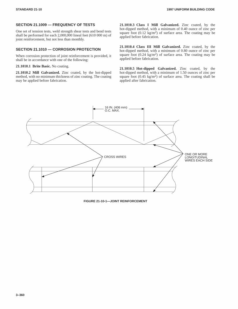
1997 UNIFORM BUILDING CODESTANDARD 21-10
3–360
SECTION 21.1009 — FREQUENCY OF TESTS
One set of tension tests, weld strength shear tests and bend testsshall be performed for each 2,000,000 lineal feet (610 000 m) ofjoint reinforcement, but not less than monthly.
SECTION 21.1010 — CORROSION PROTECTION
When corrosion protection of joint reinforcement is provided, itshall be in accordance with one of the following:
21.1010.1 Brite Basic. No coating.
21.1010.2 Mill Galvanized. Zinc coated, by the hot-dippedmethod, with no minimum thickness of zinc coating. The coatingmay be applied before fabrication.
21.1010.3 Class I Mill Galvanized. Zinc coated, by thehot-dipped method, with a minimum of 0.40 ounce of zinc persquare foot (0.12 kg/m2) of surface area. The coating may beapplied before fabrication.
21.1010.4 Class III Mill Galvanized. Zinc coated, by thehot-dipped method, with a minimum of 0.80 ounce of zinc persquare foot (0.24 kg/m2) of surface area. The coating may beapplied before fabrication.
21.1010.5 Hot-dipped Galvanized. Zinc coated, by thehot-dipped method, with a minimum of 1.50 ounces of zinc persquare foot (0.45 kg/m2) of surface area. The coating shall beapplied after fabrication.
ONE OR MORELONGITUDINALWIRES EACH SIDE
CROSS WIRES
16 IN. (406 mm)O.C. MAX.
FIGURE 21-10-1—JOINT REINFORCEMENT
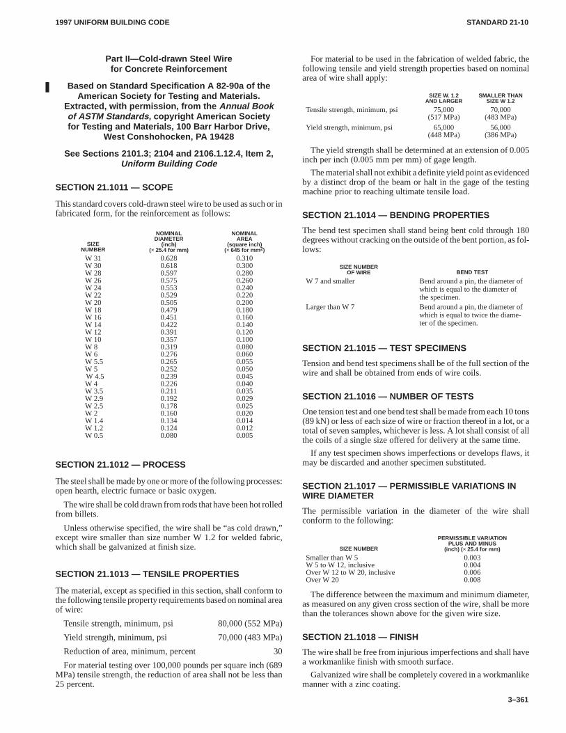
1997 UNIFORM BUILDING CODE STANDARD 21-10
3–361
Part II—Cold-drawn Steel Wirefor Concrete Reinforcement
Based on Standard Specification A 82-90a of theAmerican Society for Testing and Materials.
Extracted, with permission, from the Annual Bookof ASTM Standards, copyright American Societyfor Testing and Materials, 100 Barr Harbor Drive,
West Conshohocken, PA 19428
See Sections 2101.3; 2104 and 2106.1.12.4, Item 2,Uniform Building Code
SECTION 21.1011 — SCOPE
This standard covers cold-drawn steel wire to be used as such or infabricated form, for the reinforcement as follows:
SIZENUMBER
NOMINALDIAMETER
(inch)(× 25.4 for mm)
NOMINALAREA
(square inch)(× 645 for mm 2)
W 31W 30W 28W 26W 24W 22W 20W 18W 16W 14W 12W 10W 8W 6.W 5.5W 5.W 4.5W 4.W 3.5.W 2.9.W 2.5W 2.W 1.4.W 1.2.W 0.5
0.6280.6180.5970.5750.5530.5290.5050.4790.4510.4220.3910.3570.3190.2760.2650.2520.2390.2260.2110.1920.1780.1600.1340.1240.080
0.3100.3000.2800.2600.2400.2200.2000.1800.1600.1400.1200.1000.0800.0600.0550.0500.0450.0400.0350.0290.0250.0200.0140.0120.005
SECTION 21.1012 — PROCESS
The steel shall be made by one or more of the following processes:open hearth, electric furnace or basic oxygen.
The wire shall be cold drawn from rods that have been hot rolledfrom billets.
Unless otherwise specified, the wire shall be “as cold drawn,”except wire smaller than size number W 1.2 for welded fabric,which shall be galvanized at finish size.
SECTION 21.1013 — TENSILE PROPERTIES
The material, except as specified in this section, shall conform tothe following tensile property requirements based on nominal areaof wire:
Tensile strength, minimum, psi 80,000 (552 MPa)
Yield strength, minimum, psi 70,000 (483 MPa)
Reduction of area, minimum, percent 30
For material testing over 100,000 pounds per square inch (689MPa) tensile strength, the reduction of area shall not be less than25 percent.
For material to be used in the fabrication of welded fabric, thefollowing tensile and yield strength properties based on nominalarea of wire shall apply:
SIZE W. 1.2AND LARGER
SMALLER THANSIZE W 1.2
Tensile strength, minimum, psi 75,000(517 MPa)
70,000(483 MPa)
Yield strength, minimum, psi 65,000(448 MPa)
56,000(386 MPa)
The yield strength shall be determined at an extension of 0.005inch per inch (0.005 mm per mm) of gage length.
The material shall not exhibit a definite yield point as evidencedby a distinct drop of the beam or halt in the gage of the testingmachine prior to reaching ultimate tensile load.
SECTION 21.1014 — BENDING PROPERTIES
The bend test specimen shall stand being bent cold through 180degrees without cracking on the outside of the bent portion, as fol-lows:
SIZE NUMBEROF WIRE BEND TEST
W 7 and smaller Bend around a pin, the diameter ofwhich is equal to the diameter ofthe specimen.
Larger than W 7 Bend around a pin, the diameter ofwhich is equal to twice the diame-ter of the specimen.
SECTION 21.1015 — TEST SPECIMENS
Tension and bend test specimens shall be of the full section of thewire and shall be obtained from ends of wire coils.
SECTION 21.1016 — NUMBER OF TESTS
One tension test and one bend test shall be made from each 10 tons(89 kN) or less of each size of wire or fraction thereof in a lot, or atotal of seven samples, whichever is less. A lot shall consist of allthe coils of a single size offered for delivery at the same time.
If any test specimen shows imperfections or develops flaws, itmay be discarded and another specimen substituted.
SECTION 21.1017 — PERMISSIBLE VARIATIONS INWIRE DIAMETER
The permissible variation in the diameter of the wire shallconform to the following:
SIZE NUMBER
PERMISSIBLE VARIATIONPLUS AND MINUS
(inch) ( × 25.4 for mm)
Smaller than W 5W 5 to W 12, inclusiveOver W 12 to W 20, inclusiveOver W 20
0.0030.0040.0060.008
The difference between the maximum and minimum diameter,as measured on any given cross section of the wire, shall be morethan the tolerances shown above for the given wire size.
SECTION 21.1018 — FINISH
The wire shall be free from injurious imperfections and shall havea workmanlike finish with smooth surface.
Galvanized wire shall be completely covered in a workmanlikemanner with a zinc coating.
1997 UNIFORM BUILDING CODE STANDARD 21-11
3–363
UNIFORM BUILDING CODE STANDARD 21-11
CEMENT, MASONRYBased on Standard Specification C 91-93 of the American Society for Testing and Materials.
Extracted, with permission, from the Annual Book of ASTM Standards, copyright American Society forTesting and Materials, 100 Barr Harbor Drive, West Conshohocken, P A 19428
See Section 2102.2, Item 2 and Table 21-A, Uniform Building Code
SECTION 21.1101 — SCOPE
This standard covers three types of masonry cement for use inmasonry mortars.
SECTION 21.1102 — CLASSIFICATIONS
21.1102.1 General.Masonry cement complying with thisstandard shall be classified as one of the types set forth in thissection.
21.1102.2 Type N. Type N cement is for use as the cementitiousmaterial in the prep-aration of UBC Standard 21-15 Type N andType O mortars. It is for use in combination with portland orblended hydraulic cements in the preparation of Type S or Type Mmortars.
21.1102.3 Type S. Type S cement is for use as the cementitiousmaterial in the preparation of UBC Standard 21-15 Type S mortar.
21.1102.4 Type M. Type M cement is for use as the cementitiousmaterial in the preparation of UBC Standard 21-15 Type Mmortar.
SECTION 21.1103 — PHYSICAL REQUIREMENTS
Masonry cement shall conform to the requirements set forth inTable 21-11-A for its classifications.
SECTION 21.1104 — PACKAGE LABELING
Masonry cement packages shall carry a statement indicating thatthe product conforms to requirements of this standard and shall in-clude the brand, name of manufacturer, type of masonry cementand net weight of the package in pounds.
SECTION 21.1105 — CERTIFICATION
Certification shall be submitted upon request of the buildingofficial and shall certify compliance with the requirements of thisstandard.
SECTION 21.1106 — SAMPLING AND TESTING
Every 90 days, each masonry cement producer shall retain anapproved agency to obtain a random sample from a local point ofsupply in the market area served by the producer.
The agency shall test the masonry cement for compliance withthe physical requirements of Table 21-11-A.
Upon request of the building official, the producer shall furnish(at no cost) test results to the building official, architect, structuralengineer, general contractor and masonry contractor.
SECTION 21.1107 — TEMPERATURE AND HUMIDITY
The temperature of the air in the vicinity of the mixing slab and drymaterials, molds, base plates and mixing bowl shall be maintained
between 68°F and 81.5°F (20°C and 27.5°C). The temperature ofthe mixing water, moist cabinet or moist room, and water in thestorage tank shall not vary from 73.4°F (23°C) by more than 3°F(1.7°C).
The relative humidity of the laboratory air shall not be less than50 percent. The moist cabinet or moist room atmosphere shallhave a relative humidity of not less than 90 percent.
The moist cabinet or moist room shall conform to applicablestandards.
SECTION 21.1108 — FINENESS
The fineness of the cement shall be determined from the residueon the No. 325 (45 µm) sieve.
SECTION 21.1109 — NORMAL CONSISTENCY
Determine normal consistency by the Vicat apparatus.
SECTION 21.1110 — AUTOCLAVE EXPANSION
The autoclave expansion shall be determined. After molding,store the bars in the moist cabinet or room for 48 hours ± 30 min-utes before removal from the molds for measurement and test inthe autoclave. Calculate the difference in the lengths of the testspecimen before and after autoclaving to the nearest 0.01 percentof the effective gage length and report as the autoclave expansionof the masonry cement.
SECTION 21.1111 — TIME OF SETTING
The time of setting shall be determined by the Gillmore needlemethod.
SECTION 21.1112 — DENSITY
The density of the masonry cement shall be determined by usingkerosene as the liquid. Use the density so determined in the calcu-lation of the air content of the mortars.
SECTION 21.1113 — APPARATUS FOR MORTARTESTS
The apparatus for mortar tests shall be in accordance with applica-ble standards.
SECTION 21.1114 — BLENDED SAND
The sand shall be a blend of equal parts by weight of gradedstandard sand and Standard 20-30 sand.
SECTION 21.1115 — PREPARATION OF MORTAR
21.1115.1 Proportions for Mortar . Mortar for air entrainment,compressive strength and water-retention tests shall be propor-tioned to contain the weight of cement, in grams, equal to six times
1997 UNIFORM BUILDING CODESTANDARD 21-11
3–364
the printed bag weight in pounds (13.228 times the printed bagweight in kilograms) and 1,440 grams of sand. The sand shall con-sist of 720 grams of graded Ottawa sand and 720 grams of Stand-ard 20-30 sand. The quantity of water, measured in milliliters,shall be such as to produce a flow of 110 ± 5 as determined by theflow table.
21.1115.2 Mixing of Mortars. The mortar shall be mixed in ac-cordance with the applicable standards.
21.1115.3 Determination of Flow.The flow shall be deter-mined in accordance with applicable standards.
SECTION 21.1116 — AIR ENTRAINMENT
21.1116.1 Procedure.If the mortar has the correct flow, use aseparate portion of the mortar for the determination of entrainedair. Determine the mass of 400 ml of the mortar.
21.1116.2 Calculation.Calculate the air content of the mortarand report it to the nearest 0.1 percent as follows:
D = (W1 + W2 + Vw) [(W1/S1) + (W2/S2) + Vw]
A = 100 − (wm/4D)
WHERE:A = volume percent of entrained air.
D = density of air-free mortar, g/ml.
S1 = density of cement, g/ml.
S2 = density of standard sand, 2.65 g/ml.
Vw = milliliters-grams of water used.
Wm = mass of 400 ml.
W1 = mass of cement, g.
W2 = mass of sand, g.
SECTION 21.1117 — COMPRESSIVE STRENGTH
21.1117.1 Test Specimens.
21.1117.1.1 Molding.Immediately after determining the flowand the mass of 400 ml of mortar, return all the mortar to themixing bowl and remix for 15 seconds at the medium speed. Thenmold test specimens in accordance with applicable standards,except that elapsed time for mixing mortar, determining flow,determining air entrainment and starting the molding of cubesshall be within eight minutes.
21.1117.1.2 Storage.Store all test specimens immediately aftermolding in the molds on plane plates in a moist cabinet or moistroom for 48 to 52 hours, in such a manner that the upper surfacesshall be exposed to the moist air. Then remove the cubes from themolds and place in the moist cabinet or moist room for five days insuch a manner as to allow free circulation of air around at least fivefaces of the specimens. At the age of seven days, immerse thecubes for the 28-day tests in saturated lime water in storage tanksof noncorrodible materials.
21.1117.2 Procedure.Test the cube specimens immediately af-ter their removal from the moist cabinet or moist room for seven-day specimens, and immediately after their removal from storagewater for all other specimens. If more than one specimen at a timeis removed from the moist cabinet or moist room for seven-daytests, cover these cubes with a damp cloth until time of testing. Ifmore than one specimen at a time is removed from the storage wa-ter for testing, place these cubes in a pan of water at a temperature
of 73.4°F ± 3°F (23°C ± 1.7°C), and of sufficient depth to com-pletely immerse each cube until time of testing.
The remainder of the testing procedure shall conform to appli-cable standards.
SECTION 21.1118 — WATER RETENTION
21.1118.1 Apparatus. The water-retention test shall conform toapplicable standards.
21.1118.2 Procedure.Adjust the mercury relief column tomaintain a vacuum of 51 ± 3 mm as indicated by the manometer.Seat the perforated dish on the greased gasket or greased rim of thefunnel. Place a wetted filter paper in the bottom of the dish. Turnthe stopcock to apply the vacuum to the funnel and check the ap-paratus for leaks and to determine that the required vacuum is ob-tained. Then turn the stopcock to shut off the vacuum from thefunnel.
Mix the mortar to a flow of 110 ± 5 percent in accordance withapplicable standards. Immediately after making the flow test,return the mortar on the flow table to the mixing bowl and remixthe entire batch for 15 seconds at medium speed. Immediatelyafter remixing the mortar, fill the perforated dish with the mortarto slightly above the rim. Tamp the mortar 15 times with thetamper. Apply 10 of the tamping strokes at approximately uniformspacing adjacent to the rim of the dish and with the long axis of thetamping face held at right angles to the radius of the dish. Applythe remaining five tamping strokes at random points distributedover the central area of the dish. The tamping pressure shall be justsufficient to ensure filling of the dish. On completion of thetamping, the top of the mortar will extend slightly above the rim ofthe dish. Smooth off the mortar by drawing the flat side of thestraightedge (with the leading edge slightly raised) across the topof the dish. Then cut off the mortar to a plane surface flush with therim of the dish by drawing the straightedge with a sawing motionacross the top of the dish in two cutting strokes, starting each cutfrom near the center of the dish. If the mortar is pulled away fromthe side of the dish during the process of drawing the straightedgeacross the dish, gently press the mortar back into contact with theside of the dish using the tamper.
Turn the stopcock to apply the vacuum to the funnel. The timeelapsed from the start of mixing the cement and water to the timeof applying the vacuum shall not exceed eight minutes. After suc-tion for 60 seconds, quickly turn the stopcock to expose the funnelto atmospheric pressure. Immediately slide the perforated dish offfrom the funnel, touch it momentarily on a damp cloth to removedroplets of water, and set the dish on the table. Then, using thebowl scraper, plow and mix the mortar in the dish for 15 seconds.Upon completion of mixing, place the mortar in the flow mold anddetermine the flow. The entire operation shall be carried out with-out interruption and as quickly as possible, and shall be completedwithin an elapsed time of 11 minutes after the start of mixing thecement and water for the first flow determination. Both flow de-terminations shall be made in accordance with applicable stand-ards.
21.1118.3 Calculation.Calculate the water-retention value forthe mortar as follows:
Water-retention value = (A/B) × 100
WHERE:
A = flow after suction.
B = flow immediately after mixing.
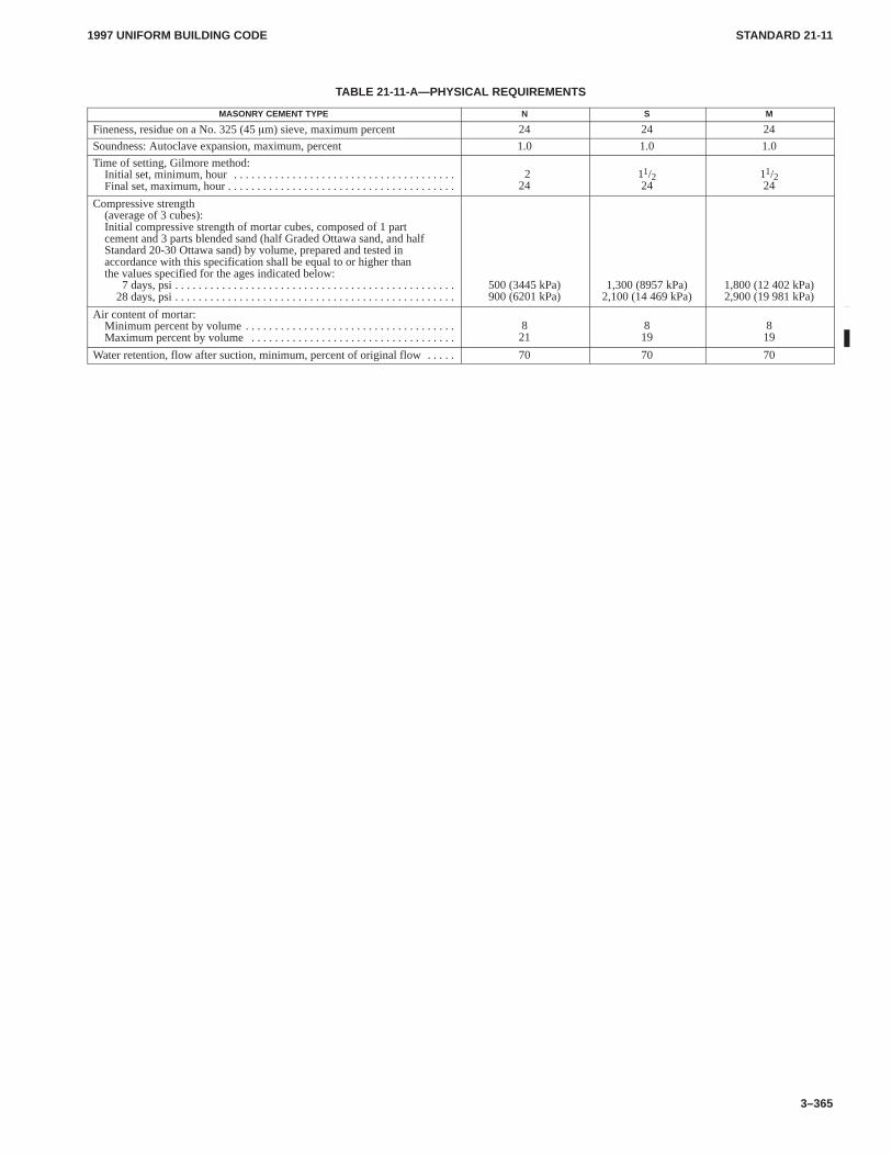
1997 UNIFORM BUILDING CODE STANDARD 21-11
3–365
TABLE 21-11-A—PHYSICAL REQUIREMENTS
MASONRY CEMENT TYPE N S M
Fineness, residue on a No. 325 (45 �m) sieve, maximum percent 24 24 24
Soundness: Autoclave expansion, maximum, percent 1.0 1.0 1.0
Time of setting, Gilmore method:Initial set, minimum, hour . . . . . . . . . . . . . . . . . . . . . . . . . . . . . . . . . . . . . . Final set, maximum, hour . . . . . . . . . . . . . . . . . . . . . . . . . . . . . . . . . . . . . . .
224
11/224
11/224
Compressive strength(average of 3 cubes):Initial compressive strength of mortar cubes, composed of 1 partcement and 3 parts blended sand (half Graded Ottawa sand, and halfStandard 20-30 Ottawa sand) by volume, prepared and tested inaccordance with this specification shall be equal to or higher thanthe values specified for the ages indicated below:
7 days, psi . . . . . . . . . . . . . . . . . . . . . . . . . . . . . . . . . . . . . . . . . . . . . . . . 28 days, psi . . . . . . . . . . . . . . . . . . . . . . . . . . . . . . . . . . . . . . . . . . . . . . . .
500 (3445 kPa)900 (6201 kPa)
1,300 (8957 kPa)2,100 (14 469 kPa)
1,800 (12 402 kPa)2,900 (19 981 kPa)
Air content of mortar:Minimum percent by volume . . . . . . . . . . . . . . . . . . . . . . . . . . . . . . . . . . . . Maximum percent by volume . . . . . . . . . . . . . . . . . . . . . . . . . . . . . . . . . . .
821
819
819
Water retention, flow after suction, minimum, percent of original flow . . . . . 70 70 70
1997 UNIFORM BUILDING CODE STANDARD 21-12
3–367
UNIFORM BUILDING CODE STANDARD 21-12
QUICKLIME FOR STRUCTURAL PURPOSESBased on Standard Specification C 5-79 (Reapproved 1992) of the American Society for Testing and Materials.
Extracted, with permission, from the Annual Book of ASTM Standards, copyright American Society forTesting and Materials, 100 Barr Harbor Drive, West Conshohocken, P A 19428
See Section 2102.2, Item 3, Uniform Building Code
SECTION 21.1201 — SCOPE
This standard covers all classes of quicklime, such as crushedlime, granular lime, ground lime, lump lime, pebble lime and pul-verized lime, used for structural purposes.
SECTION 21.1202 — GENERAL REQUIREMENTS
Quicklime shall be slaked and aged in accordance with the printeddirections of the manufacturer. The resulting lime putty shall bestored until cool.
SECTION 21.1203 — CHEMICAL COMPOSITION
The quicklime shall conform to the following requirements as tochemical composition, calculated to the nonvolatile basis:
CALCIUM MAGNESIUMLIME LIME
Calcium oxide, minimum, percent 75 —Magnesium oxide, minimum, percent — 20Calcium and magnesium oxides,
minimum, percent 95 95
Silica, alumina, and oxide of iron,maximum, percent 5 5
Carbon dioxide, maximum, percent:If sample is taken at the place of
manufacture 3 3If sample is taken at any other place 10 10
SECTION 21.1204 — RESIDUE
The quicklime shall not contain more than 15 percent by weight ofresidue.
SECTION 21.1205 — QUALITY CONTROL
Every 90 days, each lime producer shall retain an approvedagency to obtain a random sample from a local point of supply inthe market area served by the producer.
The agency shall test the lime for compliance with the physicalrequirements of Section 21.1204.
Upon request of the building official, the producer shall furnish(at no cost) test results to the building official, architect, structuralengineer, general contractor and masonry contractor.
1997 UNIFORM BUILDING CODE STANDARD 21-13
3–369
UNIFORM BUILDING CODE STANDARD 21-13
HYDRATED LIME FOR MASONRY PURPOSESBased on Standard Specification C 207-91 (Reapproved 1992) of the American Society for Testing and Materials.
Extracted, with permission, from the Annual Book of ASTM Standards, copyright American Society forTesting and Materials, 100 Barr Harbor Drive, West Conshohocken, P A 19428
See Section 2102.2, Item 3, Uniform Building Code
SECTION 21.1301 — SCOPE
This standard covers four types of hydrated lime. Types N and Sare suitable for use in mortar, in the scratch and brown coats of ce-ment plaster, for stucco, and for addition to portland-cement con-crete. Types NA and SA are air-entrained hydrated limes that aresuitable for use in any of the above uses where the inherent proper-ties of lime and air entrainment are desired. The four types of limesold under this specification shall be designated as follows:
Type N—Normal hydrated lime for masonry purposes.
Type S—Special hydrated lime for masonry purposes.
Type NA—Normal air-entraining hydrated lime for masonrypurposes.
Type SA—Special air-entraining hydrated lime for masonrypurposes.
NOTE: Type S, special hydrated lime, and Type SA, special air-entraining hydrated lime, are differentiated from Type N, normal hy-drated lime, and Type NA, normal air-entraining hydrated lime,principally by their ability to develop high, early plasticity and higherwater retentivity and by a limitation on their unhydrated oxide content.
SECTION 21.1302 — DEFINITION
HYDRATED LIME. The hydrated lime covered by Type N or Sin this standard shall contain no additives for the purpose of en-training air. The air content of cement-lime mortars made withType N or S shall not exceed 7 percent. Types NA and SA shallcontain an air-entraining additive as specified by Section 21.1305.The air content of cement-lime mortars made with Type NA or SAshall have a minimum of 7 percent and a maximum of 14 percent.
SECTION 21.1303 — ADDITIONS
Types NA and SA hydrated lime covered by this standard shallcontain additives for the purpose of entraining air.
SECTION 21.1304 — MANUFACTURER’S STATEMENT
Where required, the nature, amount and identity of the air-entrain-ing agent used and of any processing addition that may have beenused shall be provided, as well as test data showing compliance ofsuch air-entraining addition.
SECTION 21.1305 — CHEMICAL REQUIREMENTSCOMPOSITION
Hydrated lime for masonry purposes shall conform to therequirements as to chemical composition set forth in Table21-13-A.
SECTION 21.1306 — RESIDUE, POPPING ANDPITTING
The four types of hydrated lime for masonry purposes shallconform to one of the following requirements:
1. The residue retained on a No. 30 (600 µm) sieve shall not bemore than 0.5 percent, or
2. If the residue retained on a No. 30 (600 µm) sieve is over 0.5percent, the lime shall show no pops and pits when tested.
SECTION 21.1307 — PLASTICITY
The putty made from Type S, special hydrate, or Type SA, specialair-entraining hydrate, shall have a plasticity figure of not lessthan 200 within 30 minutes after mixing with water, when tested.
SECTION 21.1308 — WATER RETENTION
Hydrated lime mortar made with Type N, normal hydrated lime, orType NA, normal air-entraining hydrated lime, after suction for 60seconds, shall have a water-retention value of not less than 75 per-cent when tested in a standard mortar made from the dry hydrate orfrom putty made from the hydrate which has been soaked for aperiod of 16 to 24 hours.
Hydrated lime mortar made with Type S, special hydrated lime,or Type SA, special air-entraining hydrated lime, after suction for60 seconds, shall have a water-retention value of not less than 85percent when tested in a standard mortar made from the dryhydrate.
SECTION 21.1309 — SPECIAL MARKING
When Type NA or SA air-entraining hydrated lime is delivered inpackages, the type under this standard and the words “air-entrain-ing” shall be plainly indicated thereon or, in case of bulk ship-ments, so indicated on shipping notices.
SECTION 21.1310 — QUALITY CONTROL
Every 90 days, each lime producer shall retain an approvedagency to obtain a random sample from a local point of supply inthe market area served by the producer.
The agency shall test the lime for compliance with the physicalrequirements of Sections 21.1306, 21.1307 and 21.1308.
Upon request of the building official, the producer shall furnish(at no cost) test results to the building official, architect, structuralengineer, general contractor and masonry contractor.
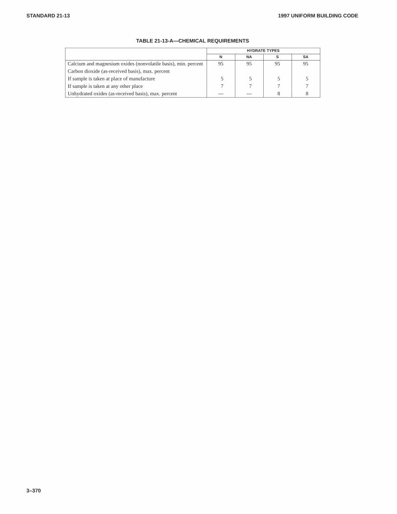
1997 UNIFORM BUILDING CODESTANDARD 21-13
3–370
TABLE 21-13-A—CHEMICAL REQUIREMENTS
HYDRATE TYPES
N NA S SA
Calcium and magnesium oxides (nonvolatile basis), min. percent 95 95 95 95
Carbon dioxide (as-received basis), max. percent
If sample is taken at place of manufacture 5 5 5 5
If sample is taken at any other place 7 7 7 7
Unhydrated oxides (as-received basis), max. percent — — 8 8
1997 UNIFORM BUILDING CODE STANDARD 21-14
3–371
UNIFORM BUILDING CODE STANDARD 21-14
MORTAR CEMENTTest Standard of the International Conference of Building Officials
See Section 2102.2, Item 2, Uniform Building Code
SECTION 21.1401 — SCOPE
This standard covers mortar cement for use in masonry mortars.
SECTION 21.1402 — CLASSIFICATIONS
There are three types of mortar cement:
1. Type N. For use as the cementitious material in the prepara-tion of UBC Standard 21-15 Type N and Type O mortars. For usein combination with portland or blended hydraulic cements in thepreparation of Type S or Type M mortars.
2. Type S. For use as the cementitious material in the prepara-tion of UBC Standard 21-15 Type S mortar.
3. Type M. For use as the cementitious material in the prepara-tion of UBC Standard 21-15 Type M mortar.
SECTION 21.1403 — PHYSICAL REQUIREMENTS
Mortar cement shall conform to the requirements set forth in Table21-14-A for its classifications.
SECTION 21.1404 — CONSTITUENT MATERIALS
Upon request of the building official, the constituent materialsshall be provided to the building official and engineer of record.
SECTION 21.1405 — RESTRICTED MATERIALS
Materials used in mortar cement shall conform to the require-ments set forth in Table 21-14-B.
SECTION 21.1406 — DELETERIOUS MATERIAL
Materials listed in Table 21-14-C shall not be used in mortar ce-ment.
SECTION 21.1407 — PACKAGE LABELING
Mortar cement packages shall carry a statement indicating that theproduct conforms to requirements of this standard and shall in-clude the brand, name of manufacturer, type of mortar cement andnet weight of the package in pounds.
SECTION 21.1408 — CERTIFICATION
Certification shall be submitted upon request of the buildingofficial and shall certify compliance with the requirements of thisstandard.
SECTION 21.1409 — SAMPLING AND TESTING
Every 90 days, each mortar cement producer shall retain anapproved agency to obtain a random sample from a local point ofsupply in the market area served by the producer.
The agency shall test the mortar cement for compliance with thephysical requirements of Table 21-14-A.
Upon request of the building official, the producer shall furnish(at no cost) test results to the building official, architect, structuralengineer, general contractor and masonry contractor.
SECTION 21.1410 — TEMPERATURE AND HUMIDITY
The temperature of the air in the vicinity of the mixing slab and drymaterials, molds, base plates and mixing bowl shall be maintainedbetween 68°F and 81.5°F (20°C and 27.5°C). The temperature ofthe mixing water, moist cabinet or moist room, and water in thestorage tank shall not vary from 73.4°F (23°C) by more than 3°F(1.7°C).
The relative humidity of the laboratory air shall not be less than50 percent. The moist cabinet or moist room atmosphere shallhave a relative humidity of not less than 90 percent.
The moist cabinet or moist room shall conform to applicablestandards.
SECTION 21.1411 — FINENESS
Determine the residue on the No. 325 (45 µm) sieve.
SECTION 21.1412 — NORMAL CONSISTENCY
Determine normal consistency by the Vicat apparatus.
SECTION 21.1413 — AUTOCLAVE EXPANSION
Determine autoclave expansion. After molding, store bars in themoist cabinet or room for 48 hours, plus or minus 30 minutes,before removal from the molds for measurement and test in theautoclave. Calculate the difference in length of the test specimenbefore and after autoclaving to the nearest 0.01 percent of theeffective gauge length and report as the autoclave expansion of themortar cement.
SECTION 21.1414 — TIME OF SETTING
Determine the time of setting by the Gillmore needle method.
SECTION 21.1415 — DENSITY
Determine the density of the mortar cement using kerosene as theliquid. Use the density so determined in the calculation of the aircontent of the mortars.
SECTION 21.1416 — APPARATUS FOR MORTARTESTS
Apparatus shall be in accordance with applicable standards.
SECTION 21.1417 — BLENDED SAND
The sand shall be a blend of equal parts by weight of gradedOttawa sand and Standard 20-30 Ottawa sand.
SECTION 21.1418 — PREPARATION OF MORTAR
21.1418.1 Proportions for Mortar. Mortar for air entrainment,compressive strength and water-retention tests shall be propor-
1997 UNIFORM BUILDING CODESTANDARD 21-14
3–372
tioned to contain the weight of cement, in grams, equal to six timesthe printed bag weight in pounds (13.228 times the printed bagweight in kilograms) and 1,440 grams of sand. The sand shall con-sist of 720 grams of graded Ottawa sand and 720 grams of Stand-ard 20-30 sand. The quantity of water, measured in milliliters,shall be such as to produce a flow of 110 ± 5 as determined by theflow table.
21.1418.2 Mixing of Mortars. Mix the mortar in accordancewith applicable standards.
21.1418.3 Determination of Flow.Determine the flow in ac-cordance with applicable standards.
SECTION 21.1419 — AIR ENTRAINMENT
21.1419.1 Procedure.If the mortar has the correct flow, use aseparate portion of the mortar for the determination of entrainedair. Determine the weight of 400 cm3 of mortar.
21.1419.2 Calculation.Calculate the air content of the mortarand report it to the nearest 0.1 percent as follows:
D = (W1 + W2 + Vw) / [(W1/S1) + (W2/S2) + Vw]
A = 100 − (Wm /4D)
WHERE:A = volume percent of entrained air.D = density of air-free mortar, g/cm3.S1 = density of cement, g/cm3.S2 = density of standard sand, 2.65 g/cm3.Vw = milliliters-grams of water used.Wm = mass of 400 ml of mortar, g.W1 = weight of cement, g.W2 = weight of sand, g.
SECTION 21.1420 — COMPRESSIVE STRENGTH OFTEST SPECIMENS
21.1420.1 Molding. Immediately after determining the flowand the weight of 400 cm3 or mortar, return all the mortar to themixing bowl and remix for 15 seconds at the medium speed. Thenmold test specimens in accordance with applicable standards,except that the elapsed time for mixing mortar, determining flow,determining air entrainment and starting the molding of cubesshall be within eight minutes.
21.1420.2 Storage.Store all test specimens immediately aftermolding in the molds on plane plates in a moist cabinet maintainedat a relative humidity of 90 percent or more for 48 to 52 hours insuch a manner that the upper surfaces shall be exposed to the moistair. Then remove the cubes from the molds and place in the moistcabinet for five days in such a manner as to allow free circulationof air around at least five faces of the specimens. At the age ofseven days, immerse the cubes for the 28-day tests in saturatedlime water in storage tanks of noncorrodible materials.
SECTION 21.1421 — PROCEDURE
Test the cube specimens immediately after their removal from themoist cabinet for seven-day specimens, and immediately aftertheir removal from storage water for all other specimens. If morethan one specimen at a time is removed from the moist closet forseven-day tests, cover these cubes with a damp cloth until time oftesting. If more than one specimen at a time is removed from thestorage water for testing, place these cubes in a pan of water at a
temperature of 73.4°F ± 3°F (23°C ± 1.7°C), and of sufficientdepth to completely immerse each cube until time of testing.
The remainder of the testing procedure shall conform to appli-cable standards.
SECTION 21.1422 — WATER RETENTION
21.1422.1 Water-retention Apparatus.For the water-reten-tion test, and apparatus essentially the same as that shown in Fig-ure 21-14-1 shall be used. This apparatus consists of a wateraspirator or other source of vacuum controlled by a mercury-reliefcolumn and connected by way of a three-way stopcock to a funnelupon which rests a perforated dish. The perforated dish shall bemade of metal not attacked by masonry mortar. The metal in thebase of the dish shall have a thickness of 1.7 to 1.9 mm and shallconform to the requirements given in Figure 21-14-1. The bore ofthe stopcock shall have a 4 mm plus or minus 0.5 mm diameter,and the connecting glass tubing shall have a minimum inside di-ameter of 4 mm. A mercury manometer, connected as shown inFigure 21-14-1, indicates the vacuum. The contact surface of thefunnel and perforated dish shall be plane and shall be lapped to en-sure intimate contact. An airtight seal shall be maintained betweenthe funnel and the dish during a test. This shall be accomplished byeither of the following procedures: (1) a synthetic (grease-resis-tant) rubber gasket may be permanently sealed to the top of thefunnel, using petrolatum or light grease to ensure a seal betweenthe funnel and dish, or (2) the top of the funnel may be lightlycoated with petrolatum or light grease to ensure a seal between thefunnel and dish. Care should be taken to ensure that none of theholes in the perforated dish are clogged from the grease. Hard-ened, very smooth, not rapid filter paper shall be used. It shall be ofsuch diameter that it will lie flat and completely cover the bottomof the dish.
A steel straightedge not less than 8 inches (203 mm) long andnot less than 1/16 inch (1.6 mm) nor more than 1/8-inch (3.2 mm)thickness shall be used.
Other apparatus required for the water-retention tests shall con-form to the applicable requirements of Section 21.1416.
21.1422.2 Procedure.Adjust the mercury-relief column tomaintain a vacuum of 50.8 mm as measured on the manometer.Seat the perforated dish on the greased gasket of the funnel. Placea wetted filter paper in the bottom of the dish. Turn the stopcock toapply the vacuum to the funnel and check the apparatus for leaksand to determine that the required vacuum is obtained. Then turnthe stopcock to shut off the vacuum from the funnel.
Mix the mortar to a flow of 110 plus or minus 5 percent inaccordance with applicable standards. Immediately after makingthe flow test, return the mortar on the flow table to the mixing bowland remix the entire batch for 15 seconds at medium speed.Immediately after remixing the mortar, fill the perforated dishwith the mortar to slightly above the rim. Tamp the mortar 15times with the tamper. Apply 10 of the tamping strokes atapproximately uniform spacing adjacent to the rim of the dish andwith the long axis of the tamping face held at right angles to theradius of the dish. Apply the remaining five tamping strokes atrandom points distributed over the central area of the dish. Thetamping pressure shall be just sufficient to ensure filling of thedish. On completion of the tamping, the top of the mortar shouldextend slightly above the rim of the dish. Smooth off the mortar bydrawing the flat side of the straightedge (with the leading edgeslightly raised) across the top of the dish. Then cut off the mortar toa plane surface flush with the rim of the dish by drawing thestraightedge with a sawing motion across the top of the dish in twocutting strokes, starting each cut from near the center of the dish. Ifthe mortar is pulled away from the side of the dish during the
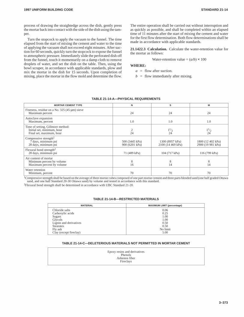
1997 UNIFORM BUILDING CODE STANDARD 21-14
3–373
process of drawing the straightedge across the dish, gently pressthe mortar back into contact with the side of the dish using the tam-per.
Turn the stopcock to apply the vacuum to the funnel. The timeelapsed from the start of mixing the cement and water to the timeof applying the vacuum shall not exceed eight minutes. After suc-tion for 60 seconds, quickly turn the stopcock to expose the funnelto atmospheric pressure. Immediately slide the perforated dish offfrom the funnel, touch it momentarily on a damp cloth to removedroplets of water, and set the dish on the table. Then, using thebowl scraper, in accordance with applicable standards, plow andmix the mortar in the dish for 15 seconds. Upon completion ofmixing, place the mortar in the flow mold and determine the flow.
The entire operation shall be carried out without interruption andas quickly as possible, and shall be completed within an elapsedtime of 11 minutes after the start of mixing the cement and waterfor the first flow determination. Both flow determinations shall bemade in accordance with applicable standards.
21.1422.3 Calculation.Calculate the water-retention value forthe mortar as follows:
Water-retention value = (a/b) × 100
WHERE:a = flow after suction.
b = flow immediately after mixing.
TABLE 21-14-A—PHYSICAL REQUIREMENTS
MORTAR CEMENT TYPE N S M
Fineness, residue on a No. 325 (45 µm) sieveMaximum percent 24 24 24
Autoclave expansionMaximum, percent 1.0 1.0 1.0
Time of setting, Gillmore method:Initial set, minimum, hourFinal set, maximum, hour
224
11/224
11/224
Compressive strength1
7 days, minimum psi28 days, minimum psi
500 (3445 kPa)900 (6201 kPa)
1300 (8957 kPa)2100 (14 469 kPa)
1800 (12 402 kPa)2900 (19 981 kPa)
Flexural bond strength228 days, minimum psi 71 (489 kPa) 104 (717 kPa) 116 (799 kPa)
Air content of mortarMinimum percent by volumeMaximum percent by volume
816
814
814
Water retentionMinimum, percent 70 70 70
1Compressive strength shall be based on the average of three mortar cubes composed of one part mortar cement and three parts blended sand (one half graded Ottawasand, and one half Standard 20-30 Ottawa sand) by volume and tested in accordance with this standard.
2Flexural bond strength shall be determined in accordance with UBC Standard 21-20.
TABLE 21-14-B—RESTRICTED MATERIALS
MATERIAL MAXIMUM LIMIT (percentage)
Chloride saltsCarboxylic acidsSugarsGlycolsLignin and derivativesStearatesFly ashClay (except fireclay)
0.060.251.001.000.500.50
No limit5.00
TABLE 21-14-C—DELETERIOUS MATERIALS NOT PERMITTED IN MORTAR CEMENT
Epoxy resins and derivativesPhenols
Asbestos fiberFireclays
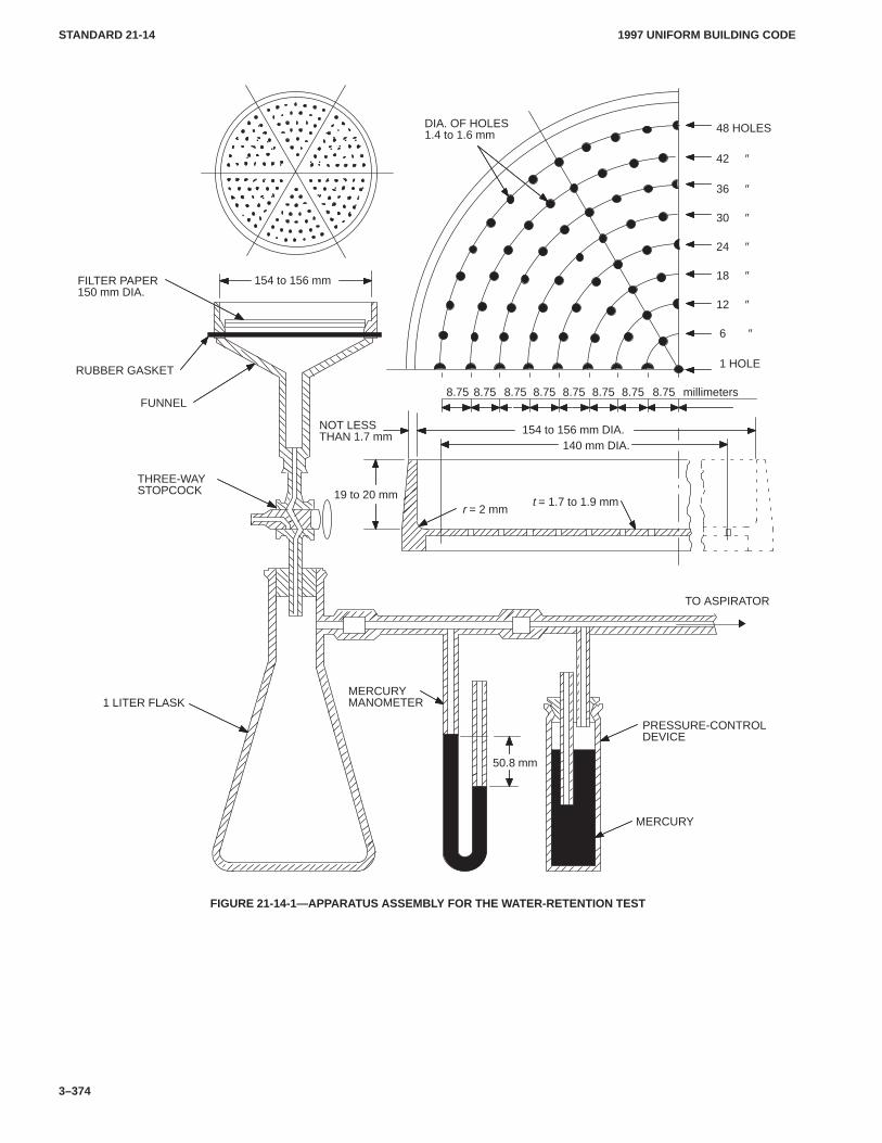
1997 UNIFORM BUILDING CODESTANDARD 21-14
3–374
r = 2 mm
THREE-WAYSTOPCOCK
1 LITER FLASKMERCURYMANOMETER
MERCURY
PRESSURE-CONTROLDEVICE
TO ASPIRATOR
48 HOLES
FUNNEL
RUBBER GASKET
FILTER PAPER150 mm DIA.
NOT LESSTHAN 1.7 mm
154 to 156 mm
154 to 156 mm DIA.140 mm DIA.
DIA. OF HOLES1.4 to 1.6 mm
42 ″
36 ″
30 ″
24 ″
18 ″
12 ″
6 ″
1 HOLE
8.75
t = 1.7 to 1.9 mm19 to 20 mm
50.8 mm
8.75 8.75 8.75 8.75 8.75 8.75 8.75 millimeters
FIGURE 21-14-1—APPARATUS ASSEMBLY FOR THE WATER-RETENTION TEST
1997 UNIFORM BUILDING CODE STANDARD 21-15
3–375
UNIFORM BUILDING CODE STANDARD 21-15
MORTAR FOR UNIT MASONRY AND REINFORCEDMASONRY OTHER THAN GYPSUM
Based on Standard Specification C 270-95 of the American Society for Testing and Materials.Extracted, with permission, from the Annual Book of ASTM Standards, copyright American Society for
Testing and Materials, 100 Barr Harbor Drive, West Conshohocken, P A 19428
See Section 2102.2, Item 8, Uniform Building Code
SECTION 21.1501 — SCOPE
These specifications cover the required properties of mortarsdetermined by laboratory tests for use in the construction ofreinforced brick masonry structures and unit masonry structures.Two alternative specifications are covered as follows:
21.1501.1 Property specifications.Property specifications arethose in which the acceptability of the mortar is based on theproperties of the ingredients (materials) and the properties (waterretention and compressive strength) of samples of the mortarmixed and tested in the laboratory.
21.1501.2 Proportion specifications.Proportion specifica-tions are those in which the acceptability of the mortar is based onthe properties of the ingredients (materials) and a definite compo-sition of the mortar consisting of fixed proportions of these ingre-dients.
Unless data are presented to show that the mortar meets the re-quirements of the physical property specifications, the proportionspecifications shall govern. For field tests of grout and mortars seeUBC Standard 21-16.
Property Specifications
SECTION 21.1502 — MATERIALS
21.1502.1 General.Materials used as ingredients in the mortarshall conform to the requirements specified in the pertinent UBCStandards.
21.1502.2 Cementitious Materials.Cementitious materialsshall conform to the following specifications:
1. Portland cement. Type I, IA, II, IIA, III or IIIA of ASTM C150.
2. Blended hydraulic cement. Type IS, IS-A, S, S-A, IP, IP-A,I(PM) or I(PM)-A of ASTM C 1157.
3. Plastic cement. Plastic cement conforming to the require-ments of UBC Standard 25-1 and UBC Standard 21-11, when usedin lieu of masonry cement.
4. Mortar cement. UBC Standard 21-14.
5. Masonry cements. UBC Standard 21-11.
6. Quicklime. UBC Standard 21-12.
7. Hydrated lime. UBC Standard 21-13.
21.1502.3 Water.Water shall be clean and free of deleteriousamounts of acids, alkalies or organic materials.
21.1502.4 Admixtures or Mortar Colors. Admixtures or mor-tar colors shall not be added to the mortar at the time of mixing un-less provided for in the contract specifications and, after thematerial is so added, the mortar shall conform to the requirementsof the property specifications.
Only pure mineral mortar colors shall be used.
21.1502.5 Antifreeze Compounds.No antifreeze liquid, saltsor other substances shall be used in the mortar to lower the freez-ing point.
21.1502.6 Storage of Materials.Cementitious materials andaggregates shall be stored in such a manner as to prevent deteriora-tion or intrusion of foreign material. Any material that has becomeunsuitable for good construction shall not be used.
SECTION 21.1503 — MIXING MORTAR
Mortar blended on the jobsite shall be mixed for a minimum peri-od of three minutes, with the amount of water required to producethe desired workability, in a drum-type batch mixer. Factory-dryblended mortar shall be mixed with water in a mechanical mixeruntil workable but not to exceed 10 minutes.
SECTION 21.1504 — MORTAR
21.1504.1 Mortar for Unit Masonry. Mortar conforming to theproportion specifications shall consist of a mixture of cementi-tious material and aggregate conforming to the requirements ofSection 21.1502, and the measurement and mixing requirementsof Section 21.1503, and shall be proportioned within the limitsgiven in Table 21-15-B for each mortar type specified.
21.1504.2 Mortar for Reinforced Masonry. In mortar used forreinforced masonry the following special requirements shall bemet: Sufficient water has been added to bring the mixture to a plas-tic state. The volume of aggregate in mortar shall be at least twoand one-fourth times but not more than three times the volume ofcementitious materials.
21.1504.3 Aggregate Ratio. The volume of damp, loose aggre-gate in mortar used in brick masonry shall be not less than two andone-fourth times or more than three times the total separate vol-umes of cementitious materials used.
21.1504.4 Water Retention. Mortar shall conform to the waterretention requirements of Table 21-15-A.
21.1504.5 Air Content. Mortar shall conform to the air contentrequirements of Table 21-15-A.
SECTION 21.1505 — COMPRESSIVE STRENGTH
The average compressive strength of three 2-inch (51 mm) cubesof mortar (before thinning) shall not be less than the strength givenin Table 21-15-A for the mortar type specified.
Proportion Specifications
SECTION 21.1506 — MATERIALS
21.1506.1 General.Materials used as ingredients in the mortarshall conform to the requirements of Section 21.1502 and to therequirements of this section.
21.1506.2 Portland Cement. Portland cement shall conform tothe requirements of ASTM C 150.
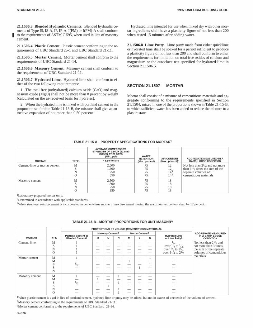
1997 UNIFORM BUILDING CODESTANDARD 21-15
3–376
21.1506.3 Blended Hydraulic Cements. Blended hydraulic ce-ments of Type IS, IS-A, IP, IP-A, I(PM) or I(PM)-A shall conformto the requirements of ASTM C 595, when used in lieu of masonrycement.
21.1506.4Plastic Cement. Plastic cement conforming to the re-quirements of UBC Standard 25-1 and UBC Standard 21-11.
21.1506.5 Mortar Cement. Mortar cement shall conform to therequirements of UBC Standard 21-14.
21.1506.6 Masonry Cement. Masonry cement shall conform tothe requirements of UBC Standard 21-11.
21.1506.7 Hydrated Lime.Hydrated lime shall conform to ei-ther of the two following requirements:
1. The total free (unhydrated) calcium oxide (CaO) and mag-nesium oxide (MgO) shall not be more than 8 percent by weight(calculated on the as-received basis for hydrates).
2. When the hydrated lime is mixed with portland cement in theproportion set forth in Table 21-15-B, the mixture shall give an au-toclave expansion of not more than 0.50 percent.
Hydrated lime intended for use when mixed dry with other mor-tar ingredients shall have a plasticity figure of not less than 200when tested 15 minutes after adding water.
21.1506.8 Lime Putty. Lime putty made from either quicklimeor hydrated lime shall be soaked for a period sufficient to producea plasticity figure of not less than 200 and shall conform to eitherthe requirements for limitation on total free oxides of calcium andmagnesium or the autoclave test specified for hydrated lime inSection 21.1506.5.
SECTION 21.1507 — MORTAR
Mortar shall consist of a mixture of cementitious materials and ag-gregate conforming to the requirements specified in Section21.1504, mixed in one of the proportions shown in Table 21-15-B,to which sufficient water has been added to reduce the mixture to aplastic state.
TABLE 21-15-A—PROPERTY SPECIFICATIONS FOR MORTAR1
AVERAGE COMPRESSIVESTRENGTH OF 2-INCH (51 mm)
CUBES AT 28 DAYS(Min., psi) WATER
RETENTION AIR CONTENT AGGREGATE MEASURED IN AMORTAR TYPE × 6.89 for kPa
WATERRETENTION
(Min., percent)AIR CONTENT
(Max., percent) 2AGGREGATE MEASURED IN A
DAMP, LOOSE CONDITION
Cement-lime or mortar cement MSNO
2,5001,800
750350
75757575
1212143
143
Not less than 21/4 and not morethan 31/2 times the sum of theseparate volumes ofcementitious materials
Masonry cement MSNO
2,5001,800
750350
75757575
18181818
1Laboratory-prepared mortar only.2Determined in accordance with applicable standards.3When structural reinforcement is incorporated in cement-lime mortar or mortar-cement mortar, the maximum air content shall be 12 percent.
TABLE 21-15-B—MORTAR PROPORTIONS FOR UNIT MASONRY
PROPORTIONS BY VOLUME (CEMENTITIOUS MATERIALS)
Portland Cement orMasonry Cement 2 Mortar Cement 3
Hydrated LimeAGGREGATE MEASURED
IN A DAMP LOOSEMORTAR TYPE
Portland Cement orBlended Cement 1 M S N M S N
Hydrated Limeor Lime Putty 1
AGGREGATE MEASUREDIN A DAMP, LOOSE
CONDITION
Cement-lime MSNO
1111
————
————
————
————
————
————
1/4over 1/4 to 1/2over 1/2 to 11/4over 11/4 to 21/2
Not less than 21/4 andnot more than 3 timesthe sum of the separatevolumes of cementitious
t i lMortar cement M
MSSN
1—1/2——
—————
—————
—————
—1———
———1—
1—1—1
—————
materials
Masonry cement MMSSNO
1—1/2———
—1————
———1——
1—1—11
——————
——————
——————
——————
1When plastic cement is used in lieu of portland cement, hydrated lime or putty may be added, but not in excess of one tenth of the volume of cement.2Masonry cement conforming to the requirements of UBC Standard 21-11.3Mortar cement conforming to the requirements of UBC Standard 21-14.
1997 UNIFORM BUILDING CODE STANDARD 21-16
3–377
UNIFORM BUILDING CODE STANDARD 21-16
FIELD TESTS SPECIMENS FOR MORTARTest Standard of the International Conference of Building Officials
See Section 2102.2, Item 8, Uniform Building Code
SECTION 21.1601 — FIELD COMPRESSIVE TESTSPECIMEN FOR MORTAR
Spread mortar on the masonry units 1/2 inch to 5/8 inch (13 mm to16 mm) thick, and allow to stand for one minute, then remove mor-tar and place in a 2-inch by 4-inch (51 mm by 102 mm) cylinder intwo layers, compressing the mortar into the cylinder using aflat-end stick or fingers. Lightly tap mold on opposite sides, leveloff and immediately cover molds and keep them damp until taken
to the laboratory. After 48 hours’ set, have the laboratory removemolds and place them in the fog room until tested in dampcondition.
SECTION 21.1602 — REQUIREMENTS
Each such mortar test specimen shall exhibit a minimum ultimatecompressive strength of 1,500 pounds per square inch (10 304kPa).
1997 UNIFORM BUILDING CODE STANDARD 21-17
3–379
UNIFORM BUILDING CODE STANDARD 21-17
TEST METHOD FOR COMPRESSIVESTRENGTH OF MASONRY PRISMS
Based on Standard Test Method E 447-92 of the American Society for Testing and Materials.Extracted, with permission, from the Annual Book of ASTM Standards, copyright American Society for
Testing and Materials, 100 Barr Harbor Drive, West Conshohocken, P A 19428
See Sections 2102.2, Item 6.4; 2105.3.2; and 2105.3.3, Uniform Building Code
SECTION 21.1701 — SCOPE
This standard covers procedures for masonry prism construction,testing and procedures for determining the compressive strengthof masonry.
SECTION 21.1702 — CONSTRUCTION OF PRISMS
Prisms shall be constructed on a flat, level base. Masonry unitsused in the prism shall be representative of the units used in thecorresponding construction. Each prism shall be built in anopened moisture-tight bag which is large enough to enclose andseal the completed prism. The orientation of units, where top andbottom cross sections vary due to taper of the cells, or where thearchitectural surface of either side of the unit varies, shall be thesame orientation as used in the corresponding construction.Prisms shall be a single wythe in thickness and laid up in stackbond (see Figure 21-17-1).
The length of masonry prisms may be reduced by saw cutting;however, prisms composed of regular shaped hollow units shallhave at least one complete cell with one full-width cross web oneither end. Prisms composed of irregular-shaped units shall be cutto obtain as symmetrical a cross section as possible. The minimumlength of saw-cut prisms shall be 4 inches (102 mm).
Masonry prisms shall be laid in a full mortar bed (mortar bedboth webs and face shells). Mortar shall be representative of thatused in the corresponding construction. Mortar joint thickness, thetooling of joints and the method of positioning and aligning unitsshall be representative of the corresponding construction.
Prisms shall be a minimum of two units in height, but the totalheight shall not be less than 1.3 times the least actual thickness ormore than 5.0 times the least actual thickness. Immediately fol-lowing the construction of the prism, the moisture-tight bag shallbe drawn around the prism and sealed.
Where the corresponding construction is to be solid grouted,prisms shall be solid grouted. Grout shall be representative of thatused in the corresponding construction. Grout shall be placed notless than one day nor more than two days following theconstruction of the prism. Grout consolidation shall be representa-tive of that used in the construction. Additional grout shall beplaced in the prism after reconsolidation and settlement due towater loss, but prior to the grout setting. Excess grout shall bescreeded off level with the top of the prism. Where open-end unitsare used, additional masonry units shall be used as forms toconfine the grout during placement. Masonry unit forms shall besufficiently braced to prevent displacement during grouting. Im-mediately following the grouting operation, the moisture-tightbag shall be drawn around the prism and resealed.
Where the corresponding construction is to be partially grouted,two sets of prisms shall be constructed; one set shall be groutedsolid and the other set shall not be grouted.
Where the corresponding construction is of multiwythe com-posite masonry, masonry prisms representative of each wytheshall be built and tested separately.
Prisms shall be left undisturbed for at least two days after con-struction.
SECTION 21.1703 — TRANSPORTING MASONRYPRISMS
Prior to transporting each prism, strap or clamp the prism togetherto prevent damage during handling and transportation. Secureprism to prevent jarring, bouncing or falling over duringtransporting.
SECTION 21.1704 — CURING
Prisms shall remain sealed in the moisture-tight bag until two daysprior to testing; the moisture-tight bag shall then be removed andcuring continued in laboratory air maintained at a temperature of75°F ± 15°F (24°C ± 8°C). Prisms shall be tested at 28 days afterconstructing the prism or at test age designated.
SECTION 21.1705 — PREPARATION FOR TESTING
21.1705.1 Capping the Prism. Cap top and bottom of the prismprior to testing with sulfur-filled capping or with high-strengthgypsum plaster capping (such as “Hydrostone” or “HyprocalWhite”). Sulfur-filled capping material shall be 40 to 60 percentby weight sulfur, the remainder being ground fireclay or othersuitable inert material passing a No. 100 (150 µm) sieve, with orwithout a plasticizer. Spread the capping material over a level sur-face which is plane within 0.003 inch (0.076 mm) in 16 inches(406 mm). Bring the surface to be capped into contact with thecapping paste; firmly press down the specimen, holding it so thatits axis is at right angles to the capping surfaces. The averagethickness of the cap shall not exceed 1/8 inch (3.2 mm). Allow capsto age at least two hours before testing.
21.1705.2 Measurement of the Prism. Measure the length andthickness of the prism to the nearest 0.01 inch (0.25 mm) by aver-aging three measurements taken at the center and quarter points ofthe height of the specimen. Measure the height of the prism,including caps, to the nearest 0.1 inch (2.54 mm).
SECTION 21.1706 — TEST PROCEDURE
21.1706.1 Test Apparatus.The test machine shall have an ac-curacy of plus or minus 1.0 percent over the load range. The upperbearing shall be spherically seated, hardened metal block firmlyattached at the center of the upper head of the machine. The centerof the sphere shall lie at the center of the surface held in its spheri-cal seat, but shall be free to turn in any direction, and its perimetershall have at least 1/4-inch (6.4 mm) clearance from the head toallow for specimens whose bearing surfaces are not exactlyparallel. The diameter of the bearing surface shall be at least5 inches (127 mm). A hardened metal bearing block may be usedbeneath the specimen to minimize wear of the lower platen of themachine. The bearing block surfaces intended for contact with thespecimen shall have a hardness not less than 60 HRC (620 HB).These surfaces shall not depart from plane surfaces by more than
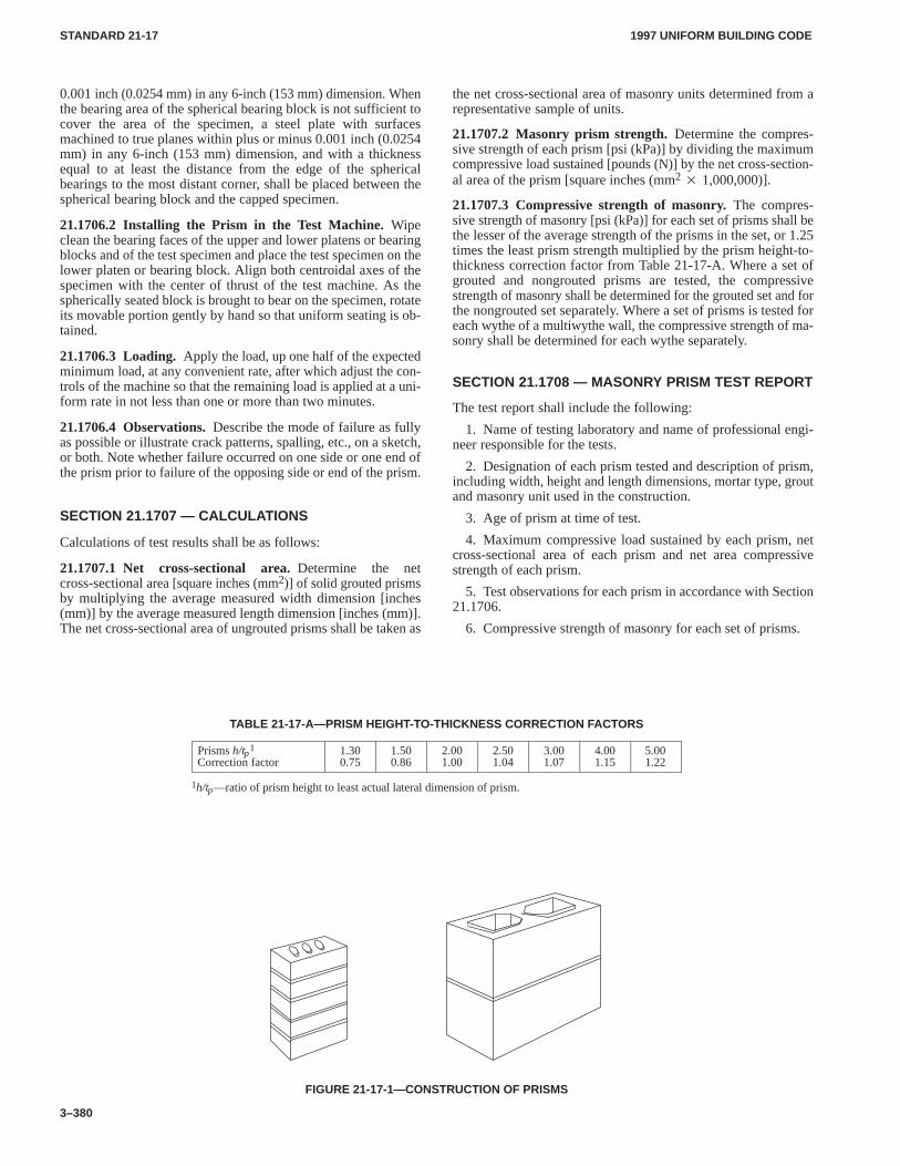
1997 UNIFORM BUILDING CODESTANDARD 21-17
3–380
0.001 inch (0.0254 mm) in any 6-inch (153 mm) dimension. Whenthe bearing area of the spherical bearing block is not sufficient tocover the area of the specimen, a steel plate with surfacesmachined to true planes within plus or minus 0.001 inch (0.0254mm) in any 6-inch (153 mm) dimension, and with a thicknessequal to at least the distance from the edge of the sphericalbearings to the most distant corner, shall be placed between thespherical bearing block and the capped specimen.
21.1706.2 Installing the Prism in the Test Machine.Wipeclean the bearing faces of the upper and lower platens or bearingblocks and of the test specimen and place the test specimen on thelower platen or bearing block. Align both centroidal axes of thespecimen with the center of thrust of the test machine. As thespherically seated block is brought to bear on the specimen, rotateits movable portion gently by hand so that uniform seating is ob-tained.
21.1706.3 Loading.Apply the load, up one half of the expectedminimum load, at any convenient rate, after which adjust the con-trols of the machine so that the remaining load is applied at a uni-form rate in not less than one or more than two minutes.
21.1706.4 Observations.Describe the mode of failure as fullyas possible or illustrate crack patterns, spalling, etc., on a sketch,or both. Note whether failure occurred on one side or one end ofthe prism prior to failure of the opposing side or end of the prism.
SECTION 21.1707 — CALCULATIONS
Calculations of test results shall be as follows:
21.1707.1 Net cross-sectional area.Determine the netcross-sectional area [square inches (mm2)] of solid grouted prismsby multiplying the average measured width dimension [inches(mm)] by the average measured length dimension [inches (mm)].The net cross-sectional area of ungrouted prisms shall be taken as
the net cross-sectional area of masonry units determined from arepresentative sample of units.
21.1707.2 Masonry prism strength.Determine the compres-sive strength of each prism [psi (kPa)] by dividing the maximumcompressive load sustained [pounds (N)] by the net cross-section-al area of the prism [square inches (mm2 � 1,000,000)].
21.1707.3 Compressive strength of masonry.The compres-sive strength of masonry [psi (kPa)] for each set of prisms shall bethe lesser of the average strength of the prisms in the set, or 1.25times the least prism strength multiplied by the prism height-to-thickness correction factor from Table 21-17-A. Where a set ofgrouted and nongrouted prisms are tested, the compressivestrength of masonry shall be determined for the grouted set and forthe nongrouted set separately. Where a set of prisms is tested foreach wythe of a multiwythe wall, the compressive strength of ma-sonry shall be determined for each wythe separately.
SECTION 21.1708 — MASONRY PRISM TEST REPORT
The test report shall include the following:
1. Name of testing laboratory and name of professional engi-neer responsible for the tests.
2. Designation of each prism tested and description of prism,including width, height and length dimensions, mortar type, groutand masonry unit used in the construction.
3. Age of prism at time of test.
4. Maximum compressive load sustained by each prism, netcross-sectional area of each prism and net area compressivestrength of each prism.
5. Test observations for each prism in accordance with Section21.1706.
6. Compressive strength of masonry for each set of prisms.
TABLE 21-17-A—PRISM HEIGHT-TO-THICKNESS CORRECTION FACTORS
Prisms h/tp1
Correction factor1.300.75
1.500.86
2.001.00
2.501.04
3.001.07
4.001.15
5.001.22
1h/tp—ratio of prism height to least actual lateral dimension of prism.
FIGURE 21-17-1—CONSTRUCTION OF PRISMS
1997 UNIFORM BUILDING CODE STANDARD 21-18
3–381
UNIFORM BUILDING CODE STANDARD 21-18
METHOD OF SAMPLING AND TESTING GROUTBased on Standard Method C 1019-89a (93) of the American Society for Testing and Materials.
Extracted, with permission, from the Annual Book of ASTM Standards, copyright American Society for Testingand Materials, 100 Barr Harbor Drive, West Conshohocken, P A 19428
See Section 2102.2, Item 9; and Table 21-B, Uniform Building Code
SECTION 21.1801 — SCOPE
This method covers procedures for both field and laboratorysampling and compression testing of grout used in masonryconstruction.
SECTION 21.1802 — APPARATUS
21.1802.1 Maximum-Minimum Thermometer.
21.1802.2 Straightedge.A steel straightedge not less than 6 in-ches (152.4 mm) long and not less than 1/16 inch (1.6 mm) in thick-ness.
21.1802.3 Tamping Rod.A nonabsorbent smooth rod, eitherround or square in cross section nominally 5/8 inch (15.9 mm) indimension with ends rounded to hemispherical tips of the same di-ameter. The rod shall be a minimum length of 12 inches (304.8mm).
21.1802.4 Wooden Blocks.Wooden squares with side dimen-sions equal to one-half the desired grout specimen height, within atolerance of 5 percent, and of sufficient quantity or thickness toyield the desired grout specimen height, as shown in Figures21-18-1 and 21-18-2.
Wooden blocks shall be soaked in limewater for 24 hours,sealed with varnish or wax, or covered with an impermeable mate-rial prior to use.
SECTION 21.1803 — SAMPLING
21.1803.1 Size of Sample.Grout samples to be used for slumpand compressive strength tests shall be a minimum of 1/2 ft.3(0.014 m3).
21.1803.2 Field Sample. Take grout samples as the grout is be-ing placed into the wall. Field samples may be taken at any timeexcept for the first and last 10 percent of the batch volume.
SECTION 21.1804 — TEST SPECIMEN AND SAMPLE
21.1804.1Each grout specimen shall be a square prism, nominal-ly 3 inches (76.2 mm) or larger on the sides and twice as high as itswidth. Dimensional tolerances shall be within 5 percent of thenominal width selected.
21.1804.2Three specimens constitute one sample.
SECTION 21.1805 — PROCEDURE
21.1805.1Select a level location where the molds can remain un-disturbed for 48 hours.
21.1805.2 Mold Construction.
21.1805.2.1The mold space should simulate the grout location inthe wall. If the grout is placed between two different types of ma-sonry units, both types should be used to construct the mold.
21.1805.2.2Form a square prism space, nominally 3 inches (76.2mm) or larger on each side and twice as high as its width, by stack-ing masonry units of the same type and moisture condition asthose being used in the construction. Place wooden blocks, cut toproper size and of the proper thickness or quantity, at the bottom ofthe space to achieve the necessary height of specimen. Toleranceon space and specimen dimensions shall be within 5 percent of thespecimen width. See Figures 21-18-1 and 21-18-2.
21.1805.2.3Line the masonry surfaces that will be in contactwith the grout specimen with a permeable material, such as papertowel, to prevent bond to the masonry units.
21.1805.3Measure and record the slump of the grout.
21.1805.4Fill the mold with grout in two layers. Rod each layer15 times with the tamping rod penetrating 1/2 inch (12.7 mm) intothe lower layer. Distribute the strokes uniformly over the crosssection of the mold.
21.1805.5Level the top surface of the specimen with a straight-edge and cover immediately with a damp absorbent material suchas cloth or paper towel. Keep the top surface of the sample dampby wetting the absorbent material and do not disturb the specimenfor 48 hours.
21.1805.6Protect the sample from freezing and variations intemperature. Store an indicating maximum-minimum thermome-ter with the sample and record the maximum and minimum tem-peratures experienced prior to the time the specimens are placed inthe moist room.
21.1805.7Remove the masonry units after 48 hours. Transportfield specimens to the laboratory, keeping the specimens dampand in a protective container.
21.1805.8Store in a moist room conforming to nationally recog-nized standards.
21.1805.9Cap the specimens in accordance with the applicablerequirements of UBC Standard 21-17.
21.1805.10Measure and record the width of each face at mid-height. Measure and record the height of each face at midwidth.Measure and record the amount out of plumb at midwidth of eachface.
21.1805.11Test the specimens in a damp condition in accordancewith applicable requirements of UBC Standard 21-17.
SECTION 21.1806 — CALCULATIONS
The report shall include the following:
1. Mix design.
2. Slump of the grout.
3. Type and number of units used to form mold for specimens.
4. Description of the specimens—dimensions, amount out ofplumb—in percent.
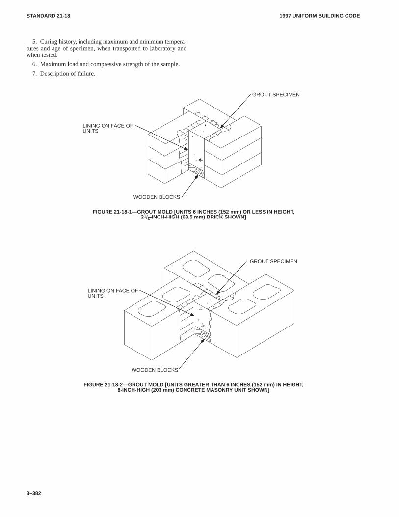
1997 UNIFORM BUILDING CODESTANDARD 21-18
3–382
5. Curing history, including maximum and minimum tempera-tures and age of specimen, when transported to laboratory andwhen tested.
6. Maximum load and compressive strength of the sample.
7. Description of failure.
LINING ON FACE OFUNITS
GROUT SPECIMEN
WOODEN BLOCKS
FIGURE 21-18-1—GROUT MOLD [UNITS 6 INCHES (152 mm) OR LESS IN HEIGHT ,21/2-INCH-HIGH (63.5 mm) BRICK SHOWN]
LINING ON FACE OFUNITS
GROUT SPECIMEN
WOODEN BLOCKS
FIGURE 21-18-2—GROUT MOLD [UNITS GREATER THAN 6 INCHES (152 mm) IN HEIGHT,8-INCH-HIGH (203 mm) CONCRETE MASONRY UNIT SHOWN]
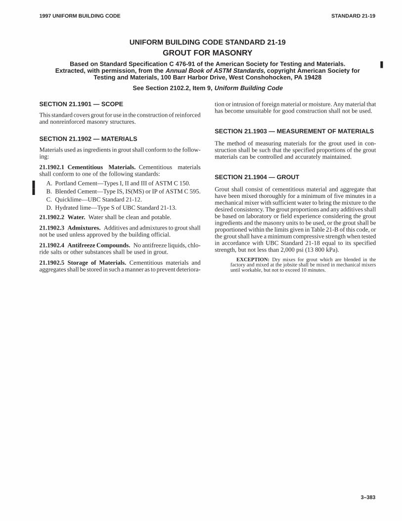
1997 UNIFORM BUILDING CODE STANDARD 21-19
3–383
UNIFORM BUILDING CODE STANDARD 21-19
GROUT FOR MASONRYBased on Standard Specification C 476-91 of the American Society for Testing and Materials.
Extracted, with permission, from the Annual Book of ASTM Standards, copyright American Society forTesting and Materials, 100 Barr Harbor Drive, West Conshohocken, PA 19428
See Section 2102.2, Item 9, Uniform Building Code
SECTION 21.1901 — SCOPE
This standard covers grout for use in the construction of reinforcedand nonreinforced masonry structures.
SECTION 21.1902 — MATERIALS
Materials used as ingredients in grout shall conform to the follow-ing:
21.1902.1 Cementitious Materials.Cementitious materialsshall conform to one of the following standards:
A. Portland Cement—Types I, II and III of ASTM C 150.B. Blended Cement—Type IS, IS(MS) or IP of ASTM C 595.C. Quicklime—UBC Standard 21-12.D. Hydrated lime—Type S of UBC Standard 21-13.
21.1902.2 Water.Water shall be clean and potable.
21.1902.3 Admixtures.Additives and admixtures to grout shallnot be used unless approved by the building official.
21.1902.4 Antifreeze Compounds.No antifreeze liquids, chlo-ride salts or other substances shall be used in grout.
21.1902.5 Storage of Materials.Cementitious materials andaggregates shall be stored in such a manner as to prevent deteriora-
tion or intrusion of foreign material or moisture. Any material thathas become unsuitable for good construction shall not be used.
SECTION 21.1903 — MEASUREMENT OF MATERIALS
The method of measuring materials for the grout used in con-struction shall be such that the specified proportions of the groutmaterials can be controlled and accurately maintained.
SECTION 21.1904 — GROUT
Grout shall consist of cementitious material and aggregate thathave been mixed thoroughly for a minimum of five minutes in amechanical mixer with sufficient water to bring the mixture to thedesired consistency. The grout proportions and any additives shallbe based on laboratory or field experience considering the groutingredients and the masonry units to be used, or the grout shall beproportioned within the limits given in Table 21-B of this code, orthe grout shall have a minimum compressive strength when testedin accordance with UBC Standard 21-18 equal to its specifiedstrength, but not less than 2,000 psi (13 800 kPa).
EXCEPTION: Dry mixes for grout which are blended in thefactory and mixed at the jobsite shall be mixed in mechanical mixersuntil workable, but not to exceed 10 minutes.
1997 UNIFORM BUILDING CODE STANDARD 21-20
3–385
UNIFORM BUILDING CODE STANDARD 21-20
STANDARD TEST METHOD FOR FLEXURALBOND STRENGTH OF MORTAR CEMENT
Test Standard of the International Conference of Building Officials
See Section 2102.2, Item 8, Uniform Building Code , andUBC Standard 21-14, Table 21-14-A
SECTION 21.2001 — SCOPE
This method covers the laboratory evaluation of the flexural bondstrength of a standardized mortar and a standardized masonry unit.
SECTION 21.2002 — APPARATUS
The test apparatus consists of a metal frame designed to support aprism as shown in Figures 21-20-1 and 21-20-2. The prism sup-port system shall be adjustable to support prisms ranging in heightfrom two to seven masonry units. The upper clamping bracket thatis clamped to the top masonry unit of the prism shall not come intocontact with the lower clamping bracket during the test. An align-ment jig, mortar template, and drop hammer as shown in Figures21-20-3, 21-20-4 and 21-20-5 are used in the fabrication of prismspecimens for testing.
SECTION 21.2003 — MATERIALS
21.2003.1Masonry units used shall be standard masonry unitsselected for the purpose of determining the flexural bond strengthproperties of mortar cement mortars. The standard unit shall be inaccordance with the following requirements:
1. Dimensions of units shall be 35/8 inches (92 mm) wide by21/4 inches (57 mm) high by 75/8 inches (194 mm) long within atolerance of plus or minus 1/8 inch (3.2 mm) and shall be 100 per-cent solid.
2. The unit material shall be concrete masonry manufacturedwith the following material proportions by volume:
One part portland cement to eight parts aggregate
3. Aggregate used in the manufacture of the unit shall be as fol-lows:
Bulk Specific GravityGradation
2.6 to 2.7Percent Retained by W eight
3/8-inch (9.5 mm) sieveNo. 4 (4.75 mm) sieveNo. 8 (2.36 mm) sieveNo. 16 (1.18 mm) sieveNo. 30 (600 µm) sieveNo. 50 (300 µm) sieveNo. 100 (150 µm) sievePan
00 to 5
20 to 3020 to 3015 to 255 to 155 to 105 to 10
4. Density of the unit shall be 125 to 135 pounds per cubic foot(2000 to 2160 kg/m3).
5. Unit shall be cured in a 100 percent relative humidity envi-ronment at 140°F ± 10°F (60°C ± 5.6°C) at atmospheric pressurefor 10 to 20 hours. Additional curing, under covered atmosphericconditions, shall continue for at least 28 days. Unit shall be loosestacked in the cube (separated by a 1/4-inch (6.4 mm) gap) to allowair to circulate during drying.
6. At the time of fabricating the prisms, units shall have a mois-ture content in the range of 25 percent to 35 percent.
7. Upon delivery units shall be stored in the laboratory at nor-mal temperature and humidity. Units shall not be wetted or surfacetreated prior to or during prism fabrication.
21.2003.2 Mortar. Mortar shall be prepared in accordance withthe following:
1. Mortar proportions shall be in accordance with Table21-20-A. The aggregate shall consist of a blend of one-half gradedOttawa sand and one-half Standard 20-30 Ottawa sand.
2. Mortar materials shall be mixed in a drum-type batch mixerfor five minutes.
3. Determine mortar flow in accordance with applicable stand-ards and adjust water until a flow of 125 ± 5 is achieved.
4. Determine mortar density, air content and initial cone pene-tration immediately after mixing the mortar in accordance withapplicable standards. Mortar shall not be used when cone penetra-tion is less than 80 percent of the initial cone penetration value.
SECTION 21.2004 — TEST SPECIMENS
21.2004.1 Number.Test specimens shall consist of one set ofsix prisms constructed with the mortar cement mortar. Each prismshall be six units in height.
21.2004.2 Prism Construction. (1) Each prism shall be built inan opened moisture-tight bag which is large enough to enclose andseal the completed prism. Set the first unit on a 1/2-inch (13 mm)plywood pallet in an alignment jig as shown in Figure 21-20-3.(2) Place the mortar template shown in Figure 21-20-4 on the unitsuch that the mortar bed depth prior to compaction is 1/2 inch (13mm). Place mortar in template and strike off excess mortar withstraight edge. (3) Remove template and immediately place thenext unit on the mortar bed in contact with the three alignmentbolts for that course using a bulls-eye level to assure uniform ini-tial contact of the unit surface and bed mortar. Carefully positiondrop hammer apparatus shown in Figure 21-20-5 on top of unitand drop its 4-pound (1.81 kg) weight, round end down, once froma height of 1.5 inches (38 mm). (4) Repeat (2) and (3) until theprisms are complete. (5) Joints shall be cut flush after the prism iscompletely built. Joints shall not be tooled. (6) One hour, ± 15minutes after completion of construction, place two masonry unitsof the type used to construct the prism upon the top course.(7) Identify all prisms using a water-resistant marker. (8) Drawand seal the moisture-tight bag around the prism. (9) All prismsshould be cured for 28 days. Two days prior to testing remove themoisture-tight bag and continue curing in the laboratory air,maintained at a temperature of 75°F ± 15°F (23.9°C ± 8.3°C), witha relative humidity between 30 to 70 percent.
SECTION 21.2005 — TEST PROCEDURE
Place the prism vertically in the support frame as shown in Figure21-20-1 and clamp firmly into a locked position using the lowerclamping bracket. Orient the prism so that the face of the joint in-tended to be subjected to flexural tension is on the same side of thespecimen as the clamping screws. The prism shall be positioned atthe required elevation that results in a single unit projecting abovethe lower clamping bracket. A soft bearing material (for example,polystyrene) at least 1/2-inch (13 mm) thick shall be placed be-tween the bottom of the prism and the adjustable prism base sup-port.
1997 UNIFORM BUILDING CODESTANDARD 21-20
3–386
Attach the upper clamping bracket to the top unit as shown inFigure 21-20-1. Tighten each clamping bolt using a torque notgreater than 20 inch-pounds (2.26 N�m).
Apply the load at a uniform rate so that the total load is appliedin not less than one minute or more than three minutes. Measureload to an accuracy of ± 2 percent with maximum error of fivepounds (22.2 N).
SECTION 21.2006 — CALCULATIONS
Calculate the modulus of rupture of each mortar joint as follows:
fr �6(PL� P1 L1)
bd2 �(P� P1)
bd
fr �6(PL� P1 L1)
1000bd2 �(P� P1)1000bd
For SI:
WHERE:b = average width of cross section of failure surface, inches
(mm).d = average thickness of cross section of failure surface,
inches (mm).fr = modulus of rupture, psi (kPa).L = distance from center of prism to loading point, inches
(mm).L1 = distance from center of prism to centroid of loading arm,
inches (mm).
P = maximum applied load, pounds (N).P1 = weight of loading arm, pounds (N).The flexural bond strength of mortar shall be determined as the
average modulus of rupture of 30 joints minus 1.28 times thestandard deviation of the sample which yields a value that a mortarjoint’s modulus of rupture will equal or exceed nine out of 10times.
SECTION 21.2007 — REPORT
The report shall include the manufacturer of the mortar cement be-ing evaluated, the source of manufacture, type of mortar cement,date of testing, laboratory name and laboratory personnel.
Report mortar density, air content, flow and cone penetrationtest data. Report the following data for the mortar cement mortarbeing evaluated:
PRISM TESTMODULUS OF RUPTURE
PRISMNO.
PRISMWEIGHT(lbs.)(kg)
JOINTNO.
TESTLOAD(lbs.)(N)
MOMENT(in.-lbs.)(N�m)
frpsi(kPa)
Meanpsi(kPa)
Std. Dev.psi1(kPa)
COV%
1 —
12345
—————
—————
—————
— — —
1Also, report the standard deviation for all six prisms (30 joints).
Report the flexural bond strength (determined in accordancewith Section 21.2006) of the mortar cement mortar.
TABLE 21-20-A—MORTAR PROPORTIONSBY VOLUME FOR EVALUATING FLEXURAL BOND
PROPORTIONS
MORTAR MORTAR CEMENT TYPE Mortar Cement Aggregate
Type NType SType M
NSM
111
333
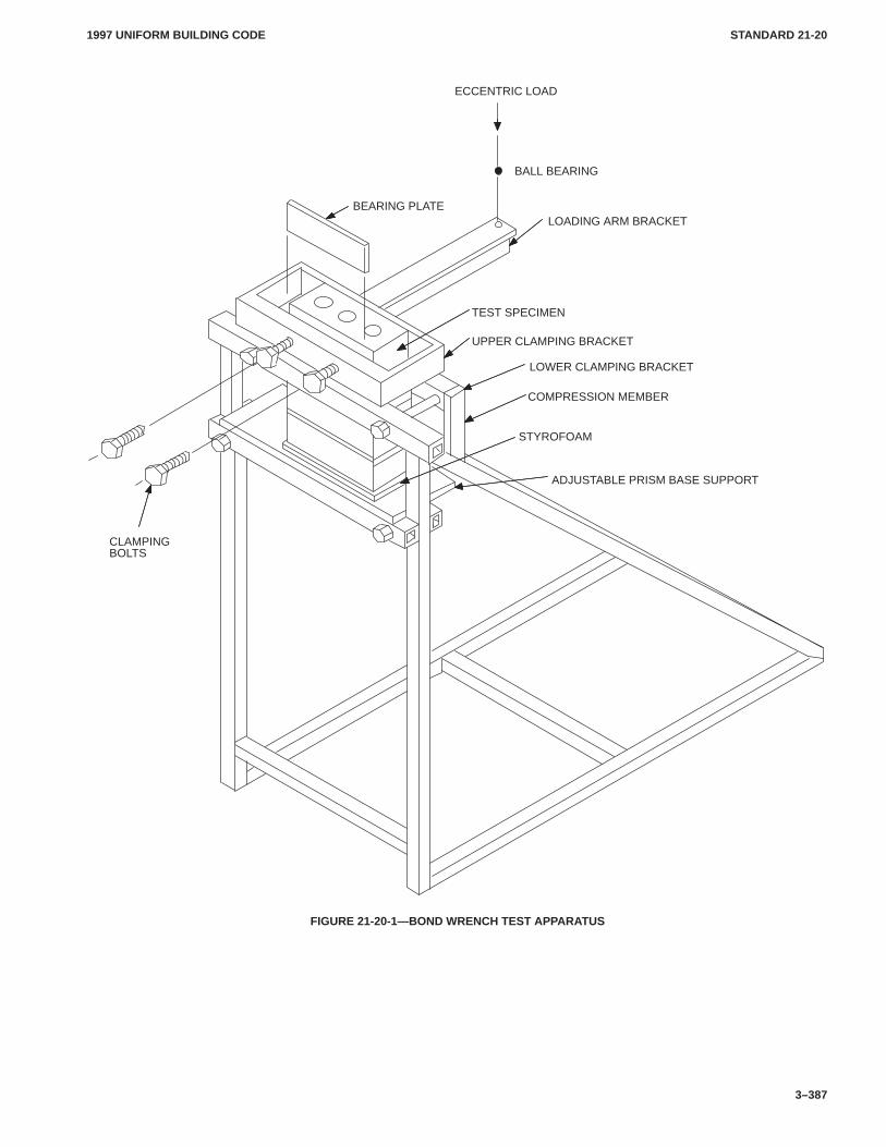
1997 UNIFORM BUILDING CODE STANDARD 21-20
3–387
BEARING PLATE
CLAMPINGBOLTS
ECCENTRIC LOAD
BALL BEARING
LOADING ARM BRACKET
TEST SPECIMEN
UPPER CLAMPING BRACKET
LOWER CLAMPING BRACKET
COMPRESSION MEMBER
STYROFOAM
ADJUSTABLE PRISM BASE SUPPORT
FIGURE 21-20-1—BOND WRENCH TEST APPARATUS
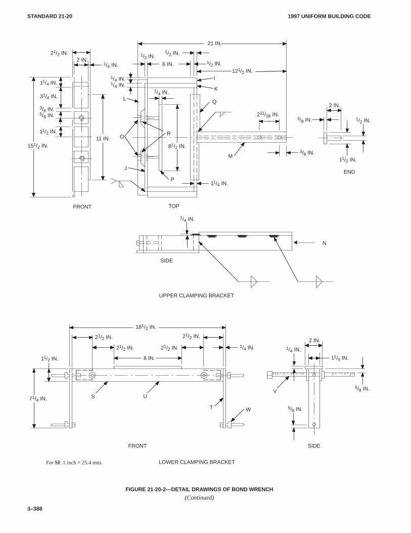
1997 UNIFORM BUILDING CODESTANDARD 21-20
3–388
21/2 IN.
LOWER CLAMPING BRACKET
FRONT SIDE
UPPER CLAMPING BRACKET
FRONT
SIDE
TOP
8 IN.
181/2 IN.
11/4 IN.
2 IN.
11/4 IN.
ENDJ
Q
K
L
M
P
N
O
I
R
21/2 IN.
211/16 IN.
1/4 IN.
1/4 IN.
2 IN.
3/8 IN.
1/2 IN.
3/8 IN.
121/2 IN.
21 IN.
1/2 IN.
6 IN.2 IN.
11/4 IN.
31/4 IN.
3/8 IN.
11/2 IN.
151/2 IN.
5/8 IN.
11 IN.
1/4 IN.1/4 IN.
81/2 IN.
1/2 IN.
1/2 IN.
11/2 IN.
1/4 IN.
21/2 IN.
21/2 IN. 1/4 IN.
5/8 IN.
1/4 IN.
5/8 IN.
21/2 IN.
71/4 IN.
11/2 IN.
WT
US
For SI: 1 inch = 25.4 mm.
V
FIGURE 21-20-2—DETAIL DRAWINGS OF BOND WRENCH
(Continued)
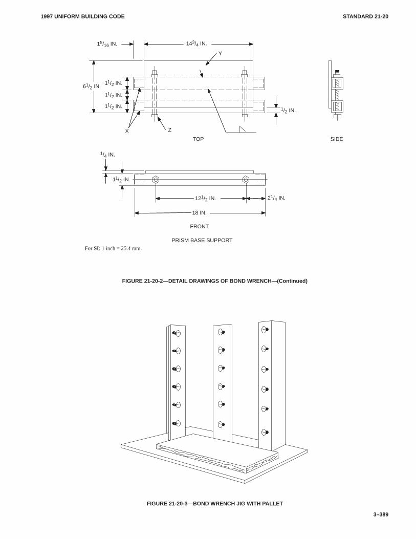
1997 UNIFORM BUILDING CODE STANDARD 21-20
3–389
ÎÎ
PRISM BASE SUPPORT
FRONT
For SI: 1 inch = 25.4 mm.
SIDETOP
121/2 IN. 21/4 IN.
18 IN.
1/2 IN.
X
Y
Z
143/4 IN.15/16 IN.
11/2 IN.
11/2 IN.
11/2 IN.61/2 IN.
1/4 IN.
11/2 IN.
FIGURE 21-20-2—DETAIL DRAWINGS OF BOND WRENCH—(Continued)
FIGURE 21-20-3—BOND WRENCH JIG WITH PALLET
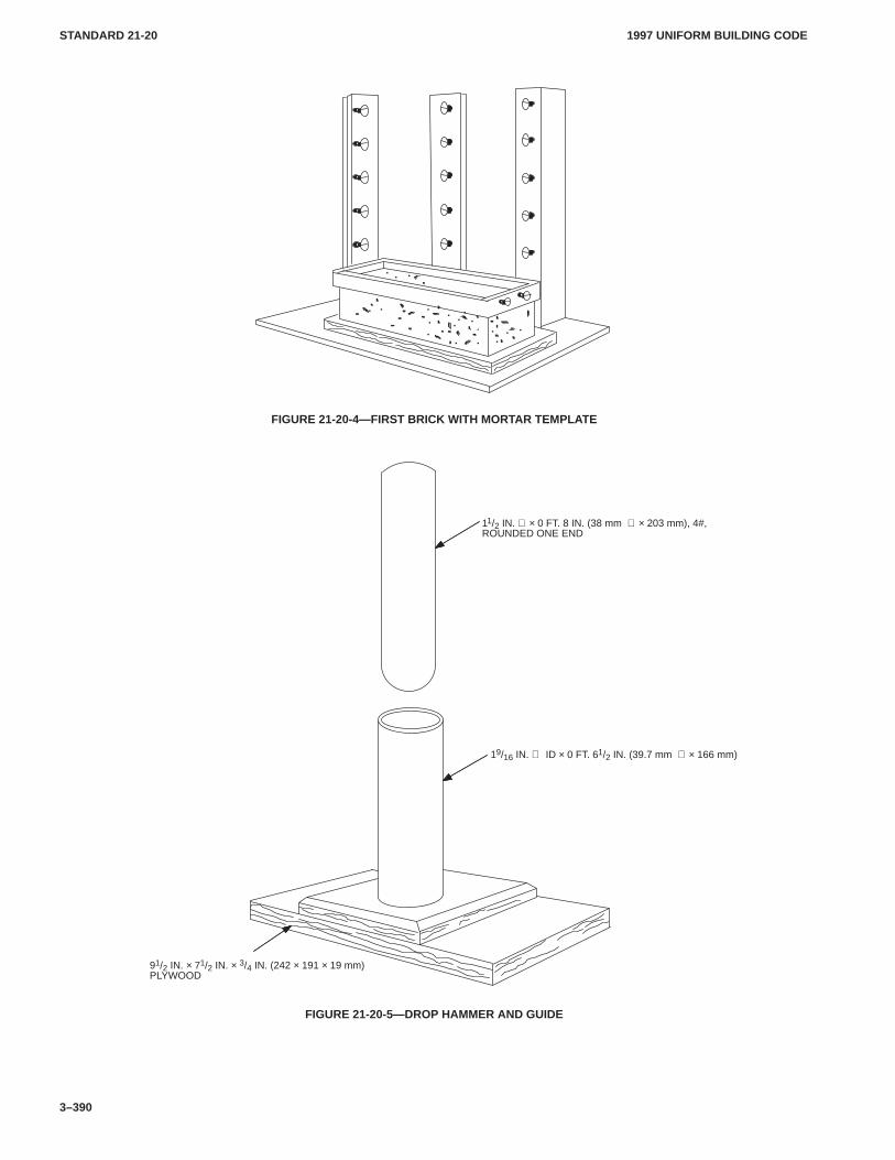
1997 UNIFORM BUILDING CODESTANDARD 21-20
3–390
FIGURE 21-20-4—FIRST BRICK WITH MORTAR TEMPLATE
91/2 IN. × 71/2 IN. × 3/4 IN. (242 × 191 × 19 mm)PLYWOOD
19/16 IN. ∅ ID × 0 FT. 61/2 IN. (39.7 mm ∅ × 166 mm)
11/2 IN. ∅ × 0 FT. 8 IN. (38 mm ∅ × 203 mm), 4#,ROUNDED ONE END
FIGURE 21-20-5—DROP HAMMER AND GUIDE
CHAP. 22, DIV. I2201
2205.31997 UNIFORM BUILDING CODE
2–237
Chapter 22
STEELDivision I—GENERAL
SECTION 2201 — SCOPE
The quality, testing and design of steel used structurally in build-ings or structures shall conform to the requirements specified inthis chapter.CHAP. 22, DIV. I
SECTION 2202 — STANDARDS OF QUALITY
The standards listed below labeled a “UBC Standard” are alsolisted in Chapter 35, Part II, and are part of this code. The otherstandards listed below are recognized standards. (See Sections3503 and 3504.)
2202.1 Material Standards.
UBC Standard 22-1, Material Specifications for Structural Steel
2202.2 Design Standards.
ANSI/ASCE 8, Specification for the Design of Cold-formedStainless Steel Structural Members, American Society of CivilEngineers
2202.3 Connectors.
ASTM A 502, Structural Rivet Steel
SECTION 2203 — MATERIAL IDENTIFICATION
2203.1 General.Steel furnished for structural load-carryingpurposes shall be properly identified for conformity to the orderedgrade in accordance with approved national standards, the provi-sions of this chapter and the appropriate UBC standards. Steelwhich is not readily identifiable as to grade from marking and testrecords shall be tested to determine conformity to such standards.
2203.2 Structural Steel.structural steel shall be identified bythe mill in accordance with approved national standards. Whensuch steel is furnished to a specified minimum yield point greaterthan 36,000 pounds per square inch (psi) (248 MPa), the AmericanSociety for Testing and Materials (ASTM) or other specificationdesignation shall be so indicated.
The fabricator shall maintain identity of the material and shallmaintain suitable procedures and records attesting that the speci-fied grade has been furnished in conformity with the applicablestandard. The fabricator’s identification mark system shall be es-tablished and on record prior to fabrication.
When structural steel is furnished to a specified minimum yieldpoint greater than 36,000 psi (248 MPa), the ASTM or other speci-fication designation shall be included near the erection mark oneach shipping assembly or important construction componentover any shop coat of paint prior to shipment from the fabricator’splant. Pieces of such steel which are to be cut to smaller sizes shall,before cutting, be legibly marked with the fabricator’s identifica-tion mark on each of the smaller-sized pieces to provide continuityof identification. When subject to fabrication operations, prior toassembling into members, which might obliterate paint marking,such as blast cleaning, galvanizing or heating for forming, suchpieces of steel shall be marked by steel die stamping or by a sub-stantial tag firmly attached.
Individual pieces of steel having a minimum specified yieldpoint in excess of 36,000 psi (248 MPa), which are received by thefabricator in a tagged bundle or lift or which have only the top
shape or plate in the bundle or lift marked by the mill shall bemarked by the fabricator prior to use in accordance with the fabri-cator’s established identification marking system.
2203.3 Cold-formed Carbon and Low-alloy Steel.Cold-for-med carbon and low-alloy steel used for structural purposes shallbe identified by the mill in accordance with approved nationalstandards. When such steel is furnished to a specified minimumyield point greater than 33,000 psi (228 MPa), the fabricator shallindicate the ASTM or other specification designation, by painting,decal, tagging or other suitable means, on each lift or bundle offabricated elements.
When cold-formed carbon and low-alloy steel used for structur-al purposes has a specified yield point equal to or greater than33,000 psi (228 MPa), which was obtained through additionaltreatment, the resulting minimum yield point shall be identified inaddition to the specification designation.
2203.4 Cold-formed Stainless Steel.Cold-formed stainlesssteel structural members designed in accordance with recognizedstandards shall be identified as to grade through mill test reports.(See reference to ANSI/ASCE 8 in Chapter 35.) A certificationshall be furnished that the chemical and mechanical properties ofthe material supplied equals or exceeds that considered in the de-sign. Each lift or bundle of fabricated elements shall be identifiedby painting, decal, tagging or other suitable means.
2203.5 Open-web Steel Joists.Open-web steel joists and simi-lar fabricated light steel load-carrying members shall be identifiedin accordance with Division II as to type, size and manufacturerby tagging or other suitable means at the time of manufacture orfabrication. Such identification shall be maintained continuouslyto the point of their installation in a structure.
SECTION 2204 — DESIGN METHODS
Design shall be by one of the following methods.
2204.1 Load and Resistance Factor Design. Steel design basedon load and resistance factor design methods shall resist the fac-tored load combinations of Section 1612.2 in accordance with theapplicable requirements of Section 2205. Seismic design of struc-tures, where required, shall comply with Division IV for struc-tures designed in accordance with Division II (LRFD).
2204.2 Allowable Stress Design. Steel design based on allow-able stress design methods shall resist the load combinations ofSection 1612.3 in accordance with the applicable requirements ofSection 2205. Seismic design of structures, where required, shallcomply with Division V for structures designed in accordancewith Division III (ASD).
SECTION 2205 — DESIGN AND CONSTRUCTIONPROVISIONS
2205.1 General. The following design standards shall apply.
2205.2 Structural Steel Construction. The design, fabricationand erection of structural steel shall be in accordance with therequirements of Division II for Load and Resistance FactorDesign or Division III for Allowable Stress Design.
2205.3 Seismic Design Provisions for Structural Steel. Steelstructural elements that resist seismic forces shall, in addition to
�
CHAP. 22, DIV. I2205.32205.11
1997 UNIFORM BUILDING CODE
2–238
the requirements of Section 2205.2, be designed in accordancewith Division IV or V.
2205.4 Cold-formed Steel Construction. The design of cold-formed carbon or low-alloy steel structural members shall be inaccordance with the requirements of Division VI for Load andResistance Factor Design or Division VII for Allowable StressDesign.
2205.5 Cold-formed Stainless Steel Construction. The designof cold-formed stainless steel structural members shall be inaccordance with approved national standards (see Section 2202).
2205.6 Design Provisions for Stud Wall Systems. Cold-formedsteel stud wall systems that serve as part of the lateral-force-resist-ing system shall, in addition to the requirements of Section 2205.4or 2205.5, be designed and constructed in accordance withDivision VIII.
2205.7 Open-web Steel Joists and Joist Girders. The design,manufacture and use of steel joist, K, LH, and KLH series and joistgirders shall be in accordance with Division IX.
2205.8 Steel Storage Racks. Steel storage racks may bedesigned in accordance with the provisions of Division X, exceptthat in Seismic Zones 3 and 4 wholesale and retail sales areas, theW used in the design of racks over 8 feet (2438 mm) in height shall
be equal to the weight of the rack structure and contents with noreductions.
2205.9 Steel Cables. Structural applications of steel cables forbuildings shall be in accordance with the provisions ofDivision XI.
2205.10 Welding. Welding procedures, welder qualificationrequirements and welding electrodes shall be in accordance withDivision II, III, VI or VII and approved national standards.
2205.11 Bolts. The use of high-strength A 325 and A 490 boltsshall be in accordance with the requirements of Divisions II andIII.
Anchor bolts shall be set accurately to the pattern and dimen-sions called for on the plans. The protrusion of the threaded endsthrough the connected material shall be sufficient to fully engagethe threads of the nuts, but shall not be greater than the length ofthreads on the bolts. Base plate holes for anchor bolts may be over-sized as follows:
Bolt Size, inches (mm) Hole Size, inches (mm)3/4 (19.1) 5/16 (7.9) oversized7/8 (22.2) 5/16 (7.9) oversized1 < 2 (25.4 < 50.8) 1/2 (12.7) oversized> 2 ( > 50.8) 1 (25.4) > bolt diameter
CHAP. 22, DIV. II2205.11
22071997 UNIFORM BUILDING CODE
2–239
Division II—DESIGN STANDARD FOR LOAD AND RESISTANCE FACTORDESIGN SPECIFICATION FOR STRUCTURAL STEEL BUILDINGS
American Institute of Steel Construction(December 1, 1993)
See Section 1602, Uniform Building Code
SECTION 2206 — ADOPTION
Except for the modifications as set forth in Section 2207 of thisdivision and the requirements of the Uniform Building Code, thedesign, fabrication, erection and quality control of structural steelshall be in accordance with the Load and Resistance FactorDesign Specifications for Structural Steel Buildings, December 1,1993, published by the American Institute of Steel Construction,1 East Wacker Drive, Suite 3100, Chicago, Illinois 60601, as if setout at length herein.CHAP. 22, DIV. II
SECTION 2207 — AMENDMENTS
The Load and Resistance Factory Design Specification for Struc-tural Steel Buildings (hereinafter referred to as LRFD) adoptedby this division applies to the design, fabrication, erection andquality control of structural steel, except as modified by thissection. Where other codes, standards or specifications arereferred to in LRFD they are considered as supplemental stand-
ards and only considered guidelines subject to the approval of thebuilding official.
1. Appendices. Appendices Sections B Design Requirements;E Columns and Other Compression Members; F Beams and OtherFlexural Members; G Plate Girders; H Members Under CombinedForces and Torsion; J Connections, Joints and Fasteners; andK Concentrated Forces, Ponding and Fatigue are specificallyadopted and made a part of this division.
2. Glossary. The glossary is specifically adopted and made apart of this division.
3. Sec. A4 is amended as follows:
The nominal loads shall be the minimum design loads requiredby the code, and the load combinations shall be as specified in Sec-tion A4.1, as amended.
4. Sec. A4.1 is amended as follows:
E: earthquake load
2206
�
Robert McCowan
CHAP. 22, DIV. III22072209
1997 UNIFORM BUILDING CODE
2–240
Division III—DESIGN STANDARD FOR SPECIFICATION FOR STRUCTURAL STEEL BUILDINGSALLOWABLE STRESS DESIGN AND PLASTIC DESIGN
SECTION 2208 — ADOPTION
Except for the modifications as set forth in Section 2209 of thisdivision and the requirements of the building code, the design,fabrication and erection of structural steel shall be in accordancewith the Specification for Structural Steel Buildings AllowableStress Design and Plastic Design, June 1, 1989, published by theAmerican Institute of Steel Construction, 1 East Wacker Drive,Suite 3100, Chicago, IL 60601, as if set out at length herein. Theadoption of the Specification for Structural Steel BuildingsAllowable Stress Design and Plastic Design hereinafter referredto as AISC-ASD shall include the following appendices: B5, F7and K4.CHAP. 22, DIV. III
Where other codes, standards or specifications are referred to inthis specification, they are to be considered as only an indicationof an acceptable method or material that can be used with theapproval of the building official.
SECTION 2209 — AMENDMENTS
The following amendments shall be made to the AISC ASD speci-fication, as adopted in Section 2208:
1. Sec. A4. Revise as follows:
The nominal loads shall be the minimum design loads requiredby the code.
2. Secs. A4.1, A4.4 and A4.5. Delete in their entirety withoutreplacement.
3. Replace Sec. A5.2 as follows:
Wind and Seismic Stresses. Allowable stresses may beincreased for load combinations, including wind and seismic, aspermitted by Section 1612.3.2. No increase in allowable stress ispermitted for Section 1612.3.1 load combinations.
2208
�
CHAP. 22, DIV. IV22092210
1997 UNIFORM BUILDING CODE
2–241
Division IV—SEISMIC PROVISIONS FOR STRUCTURAL STEEL BUILDINGS
Based on Seismic Provisions for Structural SteelBuildings, of the American Institute of Steel Construction
(June 15, 1992)
Section 2210 of this division contains the exceptions to the refer-enced specification. Section 2211 of this division, “Seismic Provi-sions for Structural Steel Buildings” is reproduced with per-mission of the publisher.CHAP. 22, DIV. IV
SECTION 2210 — AMENDMENTS
The American Institute of Steel Construction Specification tran-scribed in this division applies to the seismic design of structuralsteel members and is to be used in conjunction with Division II(LRFD). Where other codes, standards or specifications arereferred to in this division, they are to be considered as only anindication of an acceptable method or material that can be usedwith the approval of the building official.
1. Part I, Sec. 1. Revise as follows:
1. SCOPEThese special seismic requirements are to be applied in con-
junction with the building code and Chapter 22, Division II(AISC-LRFD) hereinafter referred to as the Specification. Theyare intended for the design and construction of structural steelmembers and connections in buildings for which the design forcesresulting from earthquake motions have been determined on thebasis of energy dissipation in the nonlinear range of response.
2. Part I, Sec. 2. Revise as follows:
2. REQUIREMENTS IN SEISMIC ZONES
2.1 Seismic Zone 0 and 1 and Zone 2 (I = 1.0).
Buildings in Seismic Zones 0 and 1 and buildings in SeismicZone 2 having an importance factor equal to 1.0 shall be designedin accordance with solely the Specification or in accordance withthe Specification and these provisions.
2.2 Seismic Zone 2 (I > 1.0).
Buildings in Seismic Zone 2 having an importance factor Igreater than 1.0 shall be designed in accordance with the Specifi-cation as modified by the additional provisions of this section.
2.2.a. Steel used in seismic-resisting systems shall be limited bythe provisions of Section 5.
2.2.b. Columns in seismic-resisting systems shall be designedin accordance with Section 6.
2.2.c. Ordinary Moment Frames (OMF) shall be designed inaccordance with the provisions of Section 7.
2.2.d. Special Moment Frames (SMF) are required to conformonly to the requirements of Sections 8.2, 8.7 and 8.8.
2.2.e. Braced framed systems shall conform to the requirementsof Section 9 or 10 when used alone or in combination with themoment frames of the seismic-resisting system.
2.3 Seismic Zones 3 and 4.
Buildings in Seismic Zones 3 and 4 shall be designed in accord-ance with the Specification as modified by the additional provi-sions of this section.
2.3.a. Steel used in seismic-resisting systems shall be limited bythe provisions of Section 5.
2.3.b. Columns in seismic-resisting systems shall be designedin accordance with Section 6.
2.3.c. Ordinary Moment Frames (OMF) shall be designed inaccordance with the provisions of Section 7.
2.3.d. Special Moment Frames (SMF) shall be designed inaccordance with the provisions of Section 8.
2.3.e. Braced framed systems shall conform to the requirementsof Section 9 (CBF) or 10 (EBF) when used alone or in combina-tion with the moment frames of the seismic-resisting system.
The use of K-bracing systems shall not be permitted as part ofthe seismic resisting system except as permitted by Section 9.5(Low Buildings).
2.3.f. A quality assurance plan shall be submitted to the regula-tory agency for the seismic-force-resisting system of the build-ing.
3. Part I, Sec. 3. Revise as follows:
3. LOADS, LOAD COMBINATIONS AND NOMINAL STRENGTHS
3.1 Loads and Load Combinations
The required strength of the structure and its elements shall bedetermined from the appropriate critical combination of factoredloads, as determined by the load combinations in accordance withSection 1612.2. Wherever load combinations 3-1 through 3-6 areused in these provisions, they shall be taken as combinations 12-1through 12-6 in Section 1612.2.1 of this code.
Orthogonal earthquake effects shall be included in the analysisunless noted specifically otherwise in Chapter 16.
Where required by these provisions, an amplified horizontalearthquake load of Ωo as defined in Section 1630.3.1 shall be ap-plied in load combinations 3-7 through 3-8 below.
The additional load combinations using the amplified horizon-tal earthquake are:
1.2 D � f1L � �o E
0.9 D � �o E
WHERE:f1 = 1.0 for floors in places of public assembly, for live loads
in excess of 100 pounds per square foot (4.79 kN/m2),and for garage live load.
= 0.5 for other live loads.
Where the amplified load is required, orthogonal effects are notrequired to be included.
3.2 Nominal Strengths
The nominal strengths shall be as provided in the Specification.
4. Sec. 5. Modify the second sentence by adding A 913 at theend of the sentence.
5. Sec. 6.1. Revise as follows:
2210
CHAP. 22, DIV. IV22102210
1997 UNIFORM BUILDING CODE
2–242
6.1 Column Strength
When Pu/φPn > 0.5, columns in seismic resisting frames, inaddition to complying with the Specification, shall be limited bythe following requirements.
6.1.a. The required axial compression strength shall be deter-mined from Load Combination 3-7.
6.1.b. The required axial tension strength shall be determinedfrom Load Combination 3-8.
6.1.c. The axial load combinations 3-7 and 3-8 are not requiredto exceed either of the following:
1. The maximum loads transferred to the column, consider-ing 1.25 times the design strength of the connecting beams orbrace elements of the structure.
2. The limit as determined by the foundation capacity to resistoverturning uplift.
6. Part I, Sec. 6.2.a. Delete.
7. Sec. 7.2.c.2. Revise as follows:
2. The connections have been demonstrated by cyclic tests tohave adequate rotation capacity at a design story drift ∆m, as de-fined in Section 1630.9.
8. Part I, Sec. 8. Revise as follows:
8.2.c. Connection Strength. Connection configurations utilizingwelds or high-strength bolts shall demonstrate, by approvedcyclic testing results or calculation, the ability to sustain inelasticrotation and to develop the strength criteria in Section 8.2.a con-sidering the expected value of yield strength and strain hardening.
8.2.d. Delete.
Sec. 8.4.b. Add the following to the end of the section:
The outside wall width thickness ratio of rectangular tubes used
for columns shall not exceed 110� Fy� (For SI: 0.65 E�Fy� ),
unless otherwise stiffened.
Sec. 8.7.b.1. Revise as follows:
1. The required column strength shall be determined as thelesser of:
a. The loads resulting from the application of Load Combina-tion No. 12.5 in Section 1612.2.1 except Ωo E shall be substi-tuted for E, or
b. 125 percent of the frame design strength based on eitherbeam or panel zone design strengths.
8.9 Add section as follows:
8.9 Moment Frame Drift Calculations.
Moment frame drift calculations shall include bending andshear contributions from the clear girder and column spans, col-umn axial deformation and the rotation and distortion of the panelzone.
8.9.a. Drift calculations may be based on column and girdercenter lines where either of the following conditions is met:
1. Where it can be demonstrated that drift so computed forframes of similar configuration is typically within 15 percent ofthat determined above, or
2. The nominal panel zone strength is equal to or greater than 0.8ΣMp of girders framing into the column flanges at the connection.
8.9.b. Column axial deformations may be neglected if they con-tribute less than 10 percent to the total drift.
9. Part I, Sec. 10.5. Add the following to the end of the sec-tion:
Intermediate bracing shall be provided at the top and bottomflanges of the link at intervals not exceeding 76� Fy� times the
beam flange width. Such intermediate bracing shall have a designstrength of 1.0 percent of the link flange nominal strength com-puted as Fybftf.
10. Part I. Add new requirements for Special ConcentricallyBraced Frames Requirements for Special ConcentricallyBraced Frames (SCBF) in Section 12:
Special CBFs shall be designed in accordance with the require-ments of Section 9 except as modified herein. The following mod-ifications shall apply to SCBFs and shall not modify therequirements for ordinary CBFs in Section 9.
a. Sec. 9.2.a. Revise as follows:
Slenderness: Bracing members shall have an L/r < 1, 000� Fy�
(For SI: 5.87 E�Fy� ).
b. Sec. 9.2.b. Revise as follows:
9.2.b. Compressive Design Strength. The design strength of abracing member in axial compression shall not exceed φcPn.
c. Sec. 9.2.d. Revise as follows:
9.2.d. Width-thickness Ratio. Width-thickness ratios of stiff-ened and unstiffened compression elements of braces shall com-ply with Section B5 of the Specification. Braces shall be compact(i.e., λ < λp). The width-thickness ratio of angle sections shall notexceed 52� Fy� . Circular sections shall have an outside diameter
to wall thickness ratio not exceeding 1, 300� Fy� ; rectangulartubes shall have an outside wall width-thickness ratio not exceed-ing 100� Fy� unless the circular section or tube walls are stiffened.
d. Sec. 9.2.e. Revise as follows:
9.2.e. Built-up Member Stitches. For all built-up braces, thespacing of stitches shall be uniform and not less than two stitchesshall be used:
1. For a brace in which stitches can be subjected to postbuck-ling shear, the spacing of the stitches shall be such that theslenderness ratio, L/r, of individual elements between thestitches does not exceed 0.4 times the governing slender-ness ratio of the built-up member. The total shear strengthof the stitches shall be at least equal to the tensile strengthof each element. Bolted stitches shall not be located withinthe middle one-fourth of the clear brace length.
2. For braces that can buckle without causing shear in thestitches, the spacing of the stitches shall be such that theslenderness ratio, L/r, of the individual elements betweenthe stitches does not exceed 0.75 times the governing slen-derness ratio of the built-up member.
e. Sec. 9.4.a. Revise as follows:
9.4.a. V and Inverted V Type Bracing. V braced and invertedV braced frames shall comply with the following:
1. A beam intersected by braces shall be continuous betweencolumns.
2. A beam intersected by braces shall be capable of supportingall tributary dead and live loads assuming the bracing is notpresent.
3. A beam intersected by braces shall be capable of resistingthe combination of load effects caused by the application ofthe load combinations in Section 2213.5.1, Items 1 and 2,
CHAP. 22, DIV. IV2210
2211.11997 UNIFORM BUILDING CODE
2–243
except that the term Qb shall be substituted for the term3 (Rw/8)PE where Qb = the maximum unbalanced loadeffect applied to the beam by the braces. This load effectshall be permitted to be calculated using a minimum Py forthe brace in tension and a maximum 0.3 φcPn for the bracein compression.
4. The top and bottom flanges of the beam at the point of inter-section of V braces shall be designed to support a lateralforce equal to 1.5 percent of the nominal beam flangestrength, Fybftf.
f. Sec. 9.4.b. Delete.
g. Sec. 9.5. Delete and substitute as follows:
9.5 Column.
9.5.a. Compactness. Columns used in SCBFs shall be compactaccording to Section B5 of the Specification. The outside wallwidth-thickness ratio of rectangular tube used for columns shallnot exceed 110� Fy� unless otherwise stiffened.
9.5.b. Splices. In addition to meeting the requirements of Section6.2, column splices in SBCFs also shall be designed to develop thenominal shear strength and 50 percent of the nominal momentstrength of the section. Splices shall not be located in the middleone-third of the column clear height.
11. Sec. 10.2.g. Revise as follows:
The link rotation angle is the plastic angle between the link and thebeam outside of the link determined at a design story drift, ∆m, asdefined in Section 1630.9.
12. Part II. Delete.
SECTION 2211 — ADOPTION
Reproduced with permission from American Institute of SteelConstruction, Inc., One East Wacker Drive, Suite 3100, Chicago,IL 60601-2001. Persons desiring to reprint in whole or in part anyportion of this specification must secure permission from theAmerican Institute of Steel Construction.
Seismic Provisions for Structural Steel BuildingsJune 15, 1992
2211.1 Table of Contents.
SYMBOLS
GLOSSARY
PART I—LOAD AND RESISTANCE FACTOR DESIGN(LRFD) SEISMIC PROVISIONS
1. SCOPE
2. SEISMIC PERFORMANCE CATEGORIES
3. LOADS, LOAD COMBINATIONS ANDNOMINAL STRENGTHS
4. STORY DRIFT
5. MATERIAL SPECIFICATIONS
6. COLUMN REQUIREMENTS1. Column Strength2. Column Splices
7. REQUIREMENTS FOR ORDINARYMOMENT FRAMES
1. Design Strength2. Joint Requirements
8. REQUIREMENTS FOR SPECIAL MOMENTFRAMES
1. Scope2. Beam-to-Column Joints3. Panel Zone of Beam-to Column Connection4. Beam and Column Limitations5. Continuity Plates6. Column-Beam Moment Ratio7. Beam-to-Column Connection Restraint8. Lateral Support of Beams
9. REQUIREMENTS FOR CONCENTRICALLYBRACED FRAMES
1. Scope2. Bracing Members3. Bracing Connections4. Special Bracing Configuration Requirements5. Low Buildings
10. REQUIREMENTS FOR ECCENTRICALLYBRACED FRAMES
1. Scope2. Links3. Link Stiffeners4. Link-to-Column Connections5. Lateral Support of Link6. Diagonal Brace and Beam Outside of Link7. Beam-to-Column Connections8. Required Column Strength
11. QUALITY ASSURANCE
PART II—ALLOWABLE STRESS DESIGN (ASD)ALTERNATIVE SEISMIC PROVISIONS
1. SCOPE
3. LOADS, LOAD COMBINATIONS ANDNOMINAL STRENGTHS
10. ECCENTRICALLY BRACED FRAMES (EBF)
COMMENTARY
PART I—LRFD PROVISIONS
1. SCOPE
2. SEISMIC PERFORMANCE CATEGORIES
3. LOADS, LOAD COMBINATIONS ANDNOMINAL STRENGTHS
4. STORY DRIFT
5. MATERIAL SPECIFICATIONS
6. COLUMN REQUIREMENTS1. Column Strength2. Column Splices
7. REQUIREMENTS FOR ORDINARYMOMENT FRAMES
1. Design Strength2. Joint Requirements
CHAP. 22, DIV. IV2211.12211.2
1997 UNIFORM BUILDING CODE
2–244
8. REQUIREMENTS FOR SPECIAL MOMENTFRAMES
1. Scope2. Beam-to-Column Joints3. Panel Zone of Beam-to-Column Connection4. Beam and Column Limitations5. Continuity Plates6. Column-Beam Moment Ratio7. Beam-to-Column Connection Restraint8. Lateral Support of Beams
9. REQUIREMENTS FOR CONCENTRICALLYBRACED FRAMES
1. Scope2. Bracing Members3. Bracing Connections4. Special Bracing Configuration Requirements5. Low Buildings
10. REQUIREMENTS FOR ECCENTRICALLYBRACED FRAMES
1. Scope2. Links3. Link Stiffeners4. Link-to-Column Connections5. Lateral Support of Link6. Diagonal Brace and Beam Outside of Link7. Beam-to-Column Connections8. Required Column Strength
11. QUALITY ASSURANCE
PART II—ALLOWABLE STRESS DESIGN (ASD)
ALTERNATIVE SEISMIC PROVISIONS
1. SCOPE
3., 7., 10. MODIFICATION OF PROVISIONS FOR ASD DESIGN
LIST OF REFERENCES
2211.2 Symbols.
The section numbers in parentheses after the definition of a sym-bol refers to the section where the symbol is first used.
Ae Effective net area, in.2 (9)Af Flange area of member, in.2 (6)Ag Gross area, in.2 (8)Ast Area of link stiffener, in.2 (10)Av Seismic coefficient representing the effective peak
velocity-related acceleration. (2)Aw Effective area of weld, in.2 (6)Aw Link web area, in.2 (10)Cs Response factor related to the fundamental period of the
building. (3)D Dead load due to the self-weight of the structure and the
permanent elements on the structure, kips. (3)E Earthquake load. (3)FBM Nominal strength of the base material to be welded,
ksi. (6)FEXX Classification strength of weld metal, ksi. (6)Fw Nominal strength of the weld electrode material, ksi. (6)
Fy Specified minimum yield strength of the type of steelbeing used, ksi. (8)
Fyb Fy of a beam, ksi. (8)Fyc Fy of a column, ksi. (6)H Average story height above and below a beam-to-
column connection, in. (8)L Live load due to occupancy and moveable equipment,
kips. (3)L Unbraced length of compression or bracing member,
in. (8)Lr Roof live load, kips. (3)Mn Nominal moment strength of a member or joint,
kip-in. (8)Mp Plastic bending moment, kip-in. (8)Mpa Plastic bending moment modified by axial load ratio,
kip-in. (10)Mu Required flexural strength on a member or joint,
kip-in. (8)PD Required axial strength on a column resulting from ap-
plication of dead load, D, kips. (6)PE Required axial strength on a column resulting from ap-
plication of the specified earthquake load, E, kips.PL Required axial strength on a column resulting from ap-
plication of live load, L, kips. (6)Pu Required axial strength on a column or a link, kips. (10)Pn Nominal axial strength of a column, kips. (6)Pu* Required axial strength on a brace, kips. (9)Puc Required axial strength on a column based on load com-
bination with seismic loads, kips. (8)Py Nominal yield axial strength of a member = FyAg,
kips. (10)R Response modification factor. (3)R� Load due to initial rainwater or ice exclusive of the pond-
ing contribution, kips. (Symbol R is used in the Specifi-cation). (3)
Rn Nominal strength of a member. (8)S Snow load, kips. (3)V Base shear due to earthquake load, kips. (3)Vn Nominal shear strength of a member, kips. (8)Vu Required shear strength on a member, kips. (8)Vp Nominal shear strength of an active link, kips. (10)Vpa Nominal shear strength of an active link modified by the
axial load magnitude, kips. (10)W Wind load, kips. (3)Wg Total weight of the building, kips. (3)Zb Plastic section modulus of a beam, in.3 (8)Zc Plastic section modulus of a column, in.3 (8)b Width of compression element, in. (Table 8-1)bf Flange width, in. (8)bcf Column flange width, in. (8)db Overall beam depth, in. (8)dc Overall column depth, in. (8)dz Overall panel zone depth between continuity plates,
in. (8)e EBF link length, in. (10)h Assumed web depth for stability, in. (Table 8-1)r Governing radius of gyration, in. (9)ry Radius of gyration about y axis, in. (8)tbf Thickness of beam flange, in. (8)
CHAP. 22, DIV. IV2211.22211.3
1997 UNIFORM BUILDING CODE
2–245
tcf Thickness of column flange, in. (8)tf Thickness of flange, in. (8)tp Thickness of panel zone including doubler plates, in. (8)tw Thickness of web, in. (8)tz Thickness of panel zone (doubler plates not necessarily
included), in. (8)wz Width of panel zone between column flanges, in. (8)α Fraction of member force transferred across a particular
net section. (9)ρ Ratio of required axial force Pu to required shear strength
Vu of a link. (10)k Slenderness parameter. (9)kp Limiting slenderness parameter for compact
element. (8)kr Limiting slenderness parameter for non-compact
element. (9)φ Resistance factor. (6,10)φb Resistance factor for beams. (6)φc Resistance factor for columns in compression. (6,10)φt Resistance factor for columns in tension. (6)φv Resistance factor for shear strength of panel zone of
beam-to-column connections. (8)φw Resistance factor for welds. (6)
2211.3 Glossary.
Beam. A structural member whose primary function is tocarry loads transverse to its longitudinal axis, usu-ally a horizontal member in a seismic frame system.
Braced Frame. An essentially vertical truss system of con-centric or eccentric type that resists lateral forces onthe structural system.
Concentrically Braced Frame (CBF). A braced frame inwhich all members of the bracing system are sub-jected primarily to axial forces. The CBF shall meetthe requirements of Sect. 9.
Connection. Combination of joints used to transmit forcesbetween two or more members. Categorized by thetype and amount of force transferred (moment,shear, end reaction).
Continuity Plates. Column stiffeners at top and bottom ofthe panel zone.
Design strength. Resistance (force, moment, stress, as ap-propriate) provided by element or connection; theproduct of the nominal strength and the resistancefactor.
Diagonal Bracing. Inclined structural members carryingprimarily axial load employed to enable a structuralframe to act as a truss to resist horizontal loads.
Dual System. A dual system is a structural system with thefollowing features:
� An essentially complete space frame whichprovides support for gravity loads.
� Resistance to lateral load is provided by momentresisting frames (SMF) or (OMF) which is capa-ble of resisting at least 25 percent of the baseshear and concrete or steel shear walls, steeleccentrically (EBF) or concentrically (CBF)braced frames.
� Each system shall be also designed to resist thetotal lateral load in proportion to its relative ri-gidity.
Eccentrically Braced Frame (EBF). A diagonal bracedframe in which at least one end of each bracingmember connects to a beam a short distance from abeam-to-column connection or from another beam-to-brace connection. The EBF shall meet the re-quirements of Sect. 10.
Essential Facilities. Those facilities defined as essential inthe applicable code under which the structure is de-signed. In the absence of such a code, see ASCE7-92.
Joint. Area where two or more ends, surfaces, or edges areattached. Categorized by type of fastener or weldused and method of force transfer.
K Braced Frame. A concentric braced frame (CBF) inwhich a pair of diagonal braces located on one sideof a column is connected to a single point within theclear column height.
Lateral Support Member. Member designed to inhibit lat-eral buckling or lateral-torsional buckling of pri-mary frame members.
Link. In EBF, the segment of a beam which extends fromcolumn to column, located between the end of a di-agonal brace and a column or between the ends oftwo diagonal braces of the EBF. The length of thelink is defined as the clear distance between the di-agonal brace and the column face or between theends of two diagonal braces.
Link Intermediate Web Stiffeners. Vertical web stiffenersplaced within the link.
Link Rotation Angle. The link rotation angle is the plasticangle between the link and the beam outside of thelink when the total story drift is E� / E times the driftderived using the specified base shear, V.
Link Shear Design Strength. The lesser of φVp or 2φMp/e,where φ = 0.9, Vp = 0.55Fydtw and e = the linklength except as modified by Sect. S9.2.f.
LRFD. (Load and Resistance Factor Design). A method ofproportioning structural components (members,connectors, connecting elements, and assem-blages) such that no applicable limit state is ex-ceeded when the structure is subjected to all designload combinations.
Moment Frame. A building frame system in which seismicshear forces are resisted by shear and flexure inmembers and joints of the frame.
Nominal loads. The magnitudes of the loads specified bythe applicable code.
Nominal strength. The capacity of a structure or componentto resist the effects of loads, as determined by com-putations using specified material strengths and di-mensions and formulas derived from acceptedprinciples of structural mechanics or by field testsor laboratory tests of scaled models, allowing formodeling effects, and differences between labora-tory and field conditions.
Ordinary Moment Frame (OMF). A moment frame systemwhich meets the requirements of Sect. 7.
CHAP. 22, DIV. IV2211.32211.4
1997 UNIFORM BUILDING CODE
2–246
P - Delta effect. Secondary effect of column axial loads andlateral deflection on the shears and moments inmembers.
Panel Zone. Area of beam-to column connection delineatedby beam and column flanges.
Required Strength. Load effect (force, moment, stress, asappropriate) acting on element of connection de-termined by structural analysis from the factoredloads (using most appropriate critical load com-binations).
Resistance Factor. A factor that accounts for unavoidabledeviations of the actual strength from the nominalvalue and the manner and consequences of failure.
Slip-Critical Joint. A bolted joint in which slip resistance ofthe connection is required.
Special Moment Frame (SMF). A moment frame systemwhich meets the requirements of Sect. 8.
Structural System. An assemblage of load carrying compo-nents which are joined together to provide regularinteraction or interdependence.
V Braced Frame. A concentrically braced frame (CBF) inwhich a pair of diagonal braces located either aboveor below a beam is connected to a single point with-in the clear beam span. Where the diagonal bracesare below the beam, the system is also referred to asan Inverted V Braced Frame.
X Braced Frame. A concentrically braced frame (CBF) inwhich a pair of diagonal braces crosses near mid-length of the braces.
Y Braced Frame. An eccentrically braced frame (EBF) inwhich the stem of the Y is the link of the EBF sys-tem.
2211.4 Part I—Load and Resistance Factor Design (LRFD).
1. SCOPE
These special seismic requirements are to be applied in con-junction with the AISC Load and Resistance Factor DesignSpecification for Structural Steel Buildings (LRFD), 1986;hereinafter referred to as the Specification. They are in-tended for the design and construction of structural steelmembers and connections in buildings for which the designforces resulting from earthquake motions have been deter-mined on the basis of energy dissipation in the non-linearrange of response.
Seismic provisions and the nominal loads for each SeismicPerformance Category, Seismic Hazard Exposure Group,or Seismic Zone shall be as specified by the applicable codeunder which the structure is designed or where no code ap-plies, as dictated by the conditions involved. In the absenceof a code, the Performance Categories, Seismic Hazard Ex-posure Groups, loads and load combinations shall be asgiven herein.
2. SEISMIC PERFORMANCE CATEGORIES
Seismic Performance Categories vary with the SeismicHazard Exposure Group shown in Table 2-1, the EffectivePeak Velocity Related Acceleration, Av, and the SeismicHazard Exposure Group shown in Table 2-2.
In addition to the general requirements assigned to the vari-ous Seismic Performance Categories in the applicable
building code for all types of construction, the following re-quirements apply to fabricated steel construction for build-ings and structures with similar structural characteristics.
2.1. Seismic Performance Categories A, B, and CBuildings assigned to Categories A, B, and C, except Cate-gory C in Seismic Hazard Exposure Group III where thevalue of Av � 0.10, shall be designed either in accordancewith solely the Specification or in accordance with theSpecification and these provisions.
TABLE 2-1
Seismic Hazard Exposure Groups
Group III Buildings having essential facilities that are necessary for post-earthquake recovery and requiring special requirements foraccess and functionality.
Group II Buildings that constitute a substantial public hazard because ofoccupancy or use.
Group I All buildings not classified in Groups II and III.
2.2. Seismic Performance Category CBuildings assigned to Category C in Seismic Hazard Expo-sure Group III where the value of Av � 0.10 shall be de-signed in accordance with the Specification as modified bythe additional provisions of this section.
2.2.a. Steel used in seismic resisting systems shall be lim-ited by the provisions of Sect. 5.
2.2.b. Columns in seismic resisting systems shall be de-signed in accordance with Sect. 6.
2.2.c. Ordinary Moment Frames (OMF) shall be designedin accordance with the provisions of Sect. 7.
2.2.d. Special Moment Frames (SMF) are required to con-form only to the requirements of Sects. 8.2, 8.7, and8.8.
2.2.e. Braced framed systems shall conform to the re-quirements of Sects. 9 or 10 when used alone or incombination with the moment frames of the seismicresisting system.
2.2.f. A quality assurance plan shall be submitted to theregulatory agency for the seismic force resistingsystem of the building.
2.3. Seismic Performance Categories D and EBuildings assigned to Categories D and E shall be designedin accordance with the Specification as modified by theadditional provisions of this section.
2.3.a. Steel used in seismic resisting systems shall be lim-ited by the provisions of Sect. 5.
2.3.b. Columns in seismic resisting systems shall be de-signed in accordance with Sect. 6.
2.3.c. Ordinary Moment Frames (OMF) shall be designedin accordance with the provisions of Sect. 7.
2.3.d. Special Moment Frames (SMF) shall be designedin accordance with the provisions of Sect. 8.
2.3.e. Braced framed systems shall conform to the re-quirements of Sects. 9. (CBF) or 10. (EBF) whenused alone or in combination with the momentframes of the seismic resisting system.
The use of K-bracing systems shall not be permittedas part of the seismic resisting system except as per-mitted by Sect. 9.5. (Low Buildings)
CHAP. 22, DIV. IV2211.42211.4
1997 UNIFORM BUILDING CODE
2–247
TABLE 2-2
Seismic Performance Categories
Seismic Hazard Exposure Group
Value of Av I II III
0.20 � Av0.15 � Av < 0.200.10 � Av < 0.150.05 � Av < 0.10
Av < 0.05
DCCBA
DDCBA
EDCCA
2.3.f. A quality assurance plan shall be submitted to theregulatory agency for the seismic force resistingsystem of the building.
3. LOADS, LOAD COMBINATIONS, AND NOMINALSTRENGTHS
3.1. Loads and Load Combinations
The following specified loads and their effects on the struc-ture shall be taken into account:
D: dead load due to the weight of the structural ele-ments and the permanent features on the structure.
L: live load due to occupancy and moveable equip-ment.
Lr : roof live load.
W: wind load.
S: snow load.
E: earthquake load (where the horizontal componentis derived from base shear Formula V = CsWg).
R�: load due to initial rainwater or ice exclusive of theponding contribution.
In the Formula V = CsWg for base shear:
Cs = Seismic design coefficient
Wg = Total weight of the building, see the applicablecode.
For the nominal loads as defined above, see the applicablecode.
The required strength of the structure and its elements shallbe determined from the appropriate critical combination offactored loads. The following Load Combinations and cor-responding load factors shall be investigated:
l.4D (3-1)
1.2D + 1.6L + 0.5(Lr or S or R′) (3-2)
1.2D + 1.6(Lr or S or R′) + (0.5L or 0.8W) (3-3)
1.2D + 1.3W + 0.5L + 0.5(Lr or S or R′) (3-4)
1.2D � 1.0E + 0.5L + 0.2S (3-5)
0.9D � (1.0E or 1.3W) (3-6)
Exception: The load factor on L in Load Combinations 3-3, 3-4, and3-5 shall equal 1.0 for garages, areas occupied as places of public as-sembly, and all areas where the live load is greater than 100 psf.
Other special load combinations are included with specificdesign requirements throughout these provisions.
Orthogonal earthquake effects shall be included in theanalysis unless noted specifically otherwise in the govern-ing building code.
Where required by these provisions, an amplified horizon-tal earthquake load of 0.4R × E (where the term 0.4R is
greater or equal to 1.0) shall be applied in lieu of the hori-zontal component of earthquake load E in the load com-binations above. The term R is the earthquake responsemodification coefficient contained in the applicable code.The additional load combinations using the amplified hori-zontal earthquake load are:
1.2D + 0.5L + 0.2S � 0.4R × E (3-7)
0.9D � 0.4R × E (3-8)Exception: The load factor on L in Load Combinations 3-7 shall
equal 1.0 for garages, areas occupied as places of public assembly andall areas where the live load is greater than 100 psf.
The term 0.4R in Load Combinations 3-7 and 3-8 shall begreater or equal to 1.0.
Where the amplified load is required, orthogonal effects arenot required to be included.
3.2. Nominal Strengths
The nominal strengths shall be as provided in the Specifica-tion.
4. STORY DRIFT
Story drift shall be calculated using the appropriate load ef-fects consistent with the structural system and the methodof analysis. Limits on story drift shall be in accordance withthe governing code and shall not impair the stability of thestructure.
5. MATERIAL SPECIFICATIONS
Steel used in seismic force resisting systems shall be aslisted in Sect. A3.1 of the Specification, except for build-ings over one story in height. The steel used in seismic re-sisting systems described in Sections 8, 9, and 10 shall belimited to the following ASTM Specifications: A36, A500(Grades B and C), A501, A572 (Grades 42 and 50), andA588. The steel used for base plates shall meet one of thepreceding ASTM Specifications or ASTM A283 Grade D.
6. COLUMN REQUIREMENTS
6.1. Column Strength
When Pu / φPn > 0.5, columns in seismic resisting frames, inaddition to complying with the Specification, shall be limit-ed by the following requirements:
6.1.a. Axial compression loads:
1.2PD + 0.5PL + 0.2PS + 0.4R × PE � φcPn (6-1)
where the term 0.4R is greater or equal to 1.0.Exception: The load factor on PL in Load Combination 6-1 shall
equal 1.0 for garages, areas occupied as places of public assembly, andall areas where the live load is greater than 100 psf.
6.1.b. Axial tension loads:
0.9PD – 0.4R × PE � φtPn (6-2)
where the term 0.4R is greater or equal to 1.0.
6.1.c. The axial Load Combinations 6-1 and 6-2 are notrequired to exceed either of the following:
1. The maximum loads transferred to the column,considering 1.25 times the design strengths ofthe connecting beam or brace elements of thestructure.
CHAP. 22, DIV. IV2211.42211.4
1997 UNIFORM BUILDING CODE
2–248
2. The limit as determined by the foundation ca-pacity to resist overturning uplift.
6.2. Column Splices
Column splices shall have a design strength to develop thecolumn axial loads given in Sect. 6.1.a, b, and c as well asthe Load Combinations 3-1 to 3-6.
6.2.a. In column splices using either complete or partialpenetration welded joints, beveled transitions arenot required when changes in thickness and widthof flanges and webs occur.
6.2.b. Splices using partial penetration welded joints shallnot be within 3 ft of the beam-to-column connec-tion. Column splices that are subject to net tensionforces shall comply with the more critical of the fol-lowing:
1. The design strength of partial penetrationwelded joints, the lesser of φwFwAw orφwFBMAw shall be at least 150 percent of the re-quired strength, where φw = 0.8 and Fw =0.6FEXX.
2. The design strength of welds shall not be lessthan 0.5FycAf, where Fyc is the yield strength ofthe column material and Af is the flange area ofthe smaller column connected.
7. REQUIREMENTS FOR ORDINARY MOMENTFRAMES (OMF)
7.1. Scope
Ordinary Moment Frames (OMF) shall have a designstrength as provided in the Specification to resist the LoadCombinations 3-1 through 3-6 as modified by the followingadded provisions:
7.2. Joint Requirements
All beam-to-column and column to beam connections inOMF which resist seismic forces shall meet one of the fol-lowing requirements:
7.2.a. FR (fully restrained) connections conforming withSect. 8.2, except that the required flexural strength,Mu, of a column-to-beam joint is not required to ex-ceed the nominal plastic flexural strength of theconnection.
7.2.b. FR connections with design strengths of the con-nections meeting the requirements of Sect. 7.1 us-ing the Load Combinations 3-7 and 3-8.
7.2.c. Either FR or PR (partially restrained) connectionsshall meet the following:
1. The design strengths of the members and con-nections meet the requirements of Sect. 7.1.
2. The connections have been demonstrated by cy-clic tests to have adequate rotation capacity at astory drift calculated at a horizontal load of0.4R × E, (where the term 0.4R is equal to orgreater than 1.0).
3. The additional drift due to PR connections shallbe considered in design.
FR and PR connections are described in detail inSect. A2 of the Specification.
8. REQUIREMENTS FOR SPECIAL MOMENTFRAMES (SMF)
8.1. Scope
Special Moment Frames (SMF) shall have a design strengthas provided in the Specification to resist the Load Combina-tions 3-1 through 3-6 as modified by the following addedprovisions:
8.2. Beam-to-Column Joints
8.2.a. The required flexural strength, Mu, of each beam-to-column joint shall be the lesser of the followingquantities:
l. The plastic bending moment, Mp, of the beam.
2. The moment resulting from the panel zone nom-inal shear strength, Vn, as determined usingEquation 8-1.
The joint is not required to develop either of thestrengths defined above if it is shown that underan amplified frame deformation produced byLoad Combinations 3-7 and 3-8, the designstrength of the members at the connection is ade-quate to support the vertical loads, and the re-quired lateral force resistance is provided byother means.
8.2.b. The required shear strength, Vu, of a beam-to-column joint shall be determined using the LoadCombination 1.2D + 0.5L + 0.2S plus the shear re-sulting from Mu, as defined in Sect. 8.2.a., on eachend of the beam. Alternatively, Vu shall be justifiedby a rational analysis. The required shear strength isnot required to exceed the shear resulting fromLoad Combination 3-7.
8.2.c. The design strength, φRn, of a beam-to-columnjoint shall be considered adequate to develop the re-quired flexural strength, Mu, of the beam if it con-forms to the following:
1. The beam flanges are welded to the column us-ing complete penetration welded joints.
2. The beam web joint has a design shear strengthφVn greater than the required shear, Vu, and con-forms to either:
a. Where the nominal flexural strength of the beam,Mn, considering only the flanges is greater than70 percent of the nominal flexural strength of theentire beam section [i.e., bftf (d � tf)Fyf�0.7Mp]; the web joint shall be made by meansof welding or slip-critical high strength bolting,or;
b. Where bftf(d � tf)Fyf < 0.7Mp, the web joint shallbe made by means of welding the web to the col-umn directly or through shear tabs. That weldingshall have a design strength of at least 20 percentof the nominal flexural strength of the beamweb. The required beam shear, Vu, shall be re-sisted by further welding or by slip-critical high-strength bolting or both.
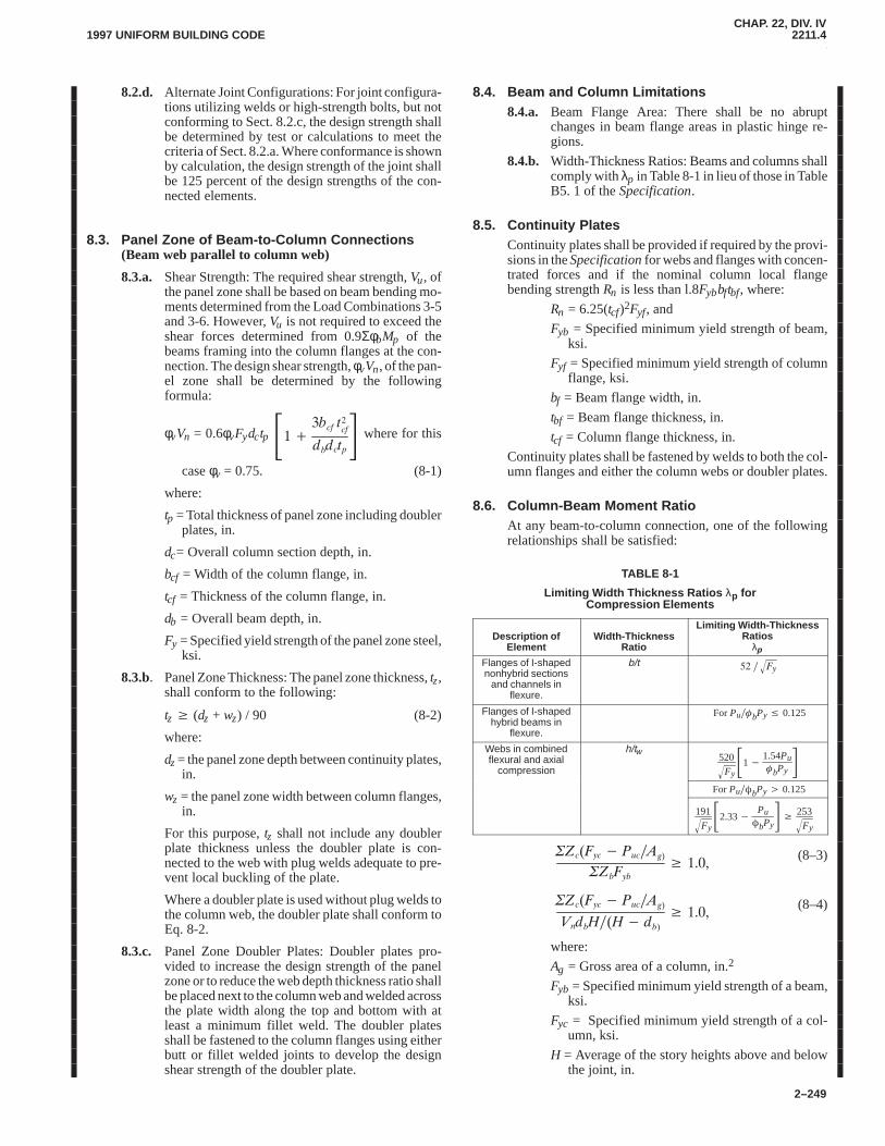
CHAP. 22, DIV. IV2211.42211.4
1997 UNIFORM BUILDING CODE
2–249
8.2.d. Alternate Joint Configurations: For joint configura-tions utilizing welds or high-strength bolts, but notconforming to Sect. 8.2.c, the design strength shallbe determined by test or calculations to meet thecriteria of Sect. 8.2.a. Where conformance is shownby calculation, the design strength of the joint shallbe 125 percent of the design strengths of the con-nected elements.
8.3. Panel Zone of Beam-to-Column Connections(Beam web parallel to column web)
8.3.a. Shear Strength: The required shear strength, Vu, ofthe panel zone shall be based on beam bending mo-ments determined from the Load Combinations 3-5and 3-6. However, Vu is not required to exceed theshear forces determined from 0.9ΣφbMp of thebeams framing into the column flanges at the con-nection. The design shear strength, φvVn, of the pan-el zone shall be determined by the followingformula:
φvVn = 0.6φvFydctp ������ ������ �� where for this
case φv = 0.75. (8-1)
where:
tp = Total thickness of panel zone including doublerplates, in.
dc= Overall column section depth, in.
bcf = Width of the column flange, in.
tcf = Thickness of the column flange, in.
db = Overall beam depth, in.
Fy = Specified yield strength of the panel zone steel,ksi.
8.3.b. Panel Zone Thickness: The panel zone thickness, tz,shall conform to the following:
tz � (dz + wz) / 90 (8-2)
where:
dz = the panel zone depth between continuity plates,in.
wz = the panel zone width between column flanges,in.
For this purpose, tz shall not include any doublerplate thickness unless the doubler plate is con-nected to the web with plug welds adequate to pre-vent local buckling of the plate.
Where a doubler plate is used without plug welds tothe column web, the doubler plate shall conform toEq. 8-2.
8.3.c. Panel Zone Doubler Plates: Doubler plates pro-vided to increase the design strength of the panelzone or to reduce the web depth thickness ratio shallbe placed next to the column web and welded acrossthe plate width along the top and bottom with atleast a minimum fillet weld. The doubler platesshall be fastened to the column flanges using eitherbutt or fillet welded joints to develop the designshear strength of the doubler plate.
8.4. Beam and Column Limitations8.4.a. Beam Flange Area: There shall be no abrupt
changes in beam flange areas in plastic hinge re-gions.
8.4.b. Width-Thickness Ratios: Beams and columns shallcomply with λp in Table 8-1 in lieu of those in TableB5. 1 of the Specification.
8.5. Continuity PlatesContinuity plates shall be provided if required by the provi-sions in the Specification for webs and flanges with concen-trated forces and if the nominal column local flangebending strength Rn is less than l.8Fybbftbf, where:
Rn = 6.25(tcf)2Fyf, and
Fyb = Specified minimum yield strength of beam,ksi.
Fyf = Specified minimum yield strength of columnflange, ksi.
bf = Beam flange width, in.
tbf = Beam flange thickness, in.
tcf = Column flange thickness, in.
Continuity plates shall be fastened by welds to both the col-umn flanges and either the column webs or doubler plates.
8.6. Column-Beam Moment RatioAt any beam-to-column connection, one of the followingrelationships shall be satisfied:
TABLE 8-1
Limiting Width Thickness Ratios λp forCompression Elements
Description ofElement
Width-ThicknessRatio
Limiting Width-ThicknessRatios
λp
Flanges of I-shapednonhybrid sections
and channels inflexure.
b/t ��� ���
Flanges of I-shapedhybrid beams in
flexure.
ForPu��bPy � 0.125
Webs in combinedflexural and axial
compression
h/tw520
Fy��1�
1.54Pu�bPy�
ForPu��bPy � 0.125
191
Fy��2.33�
Pu�bPy� � 253
Fy�
������� � ������
������
� ����(8–3)
������� � ������
��������� ���
� ����(8–4)
where:
Ag = Gross area of a column, in.2
Fyb = Specified minimum yield strength of a beam,ksi.
Fyc = Specified minimum yield strength of a col-umn, ksi.
H = Average of the story heights above and belowthe joint, in.
CHAP. 22, DIV. IV2211.42211.4
1997 UNIFORM BUILDING CODE
2–250
Puc = Required axial strength in the column (incompression) � 0
Vn = Nominal strength of the panel zone as deter-mined from Equation 8-1, ksi.
Zb = Plastic section modulus of a beam, in.3
Zc = Plastic section modulus of a column, in.3
db = Average overall depth of beams framing intothe connection, in.
These requirements do not apply in any of the followingcases, provided the columns conform to the requirements ofSect. 8.4:
8.6.a. Columns with Puc < 0.3FycAg.
8.6.b. Columns in any story that has a ratio of design shearstrength to design force 50 percent greater than thestory above.
8.6.c. Any column not included in the design to resist therequired seismic shears, but included in the designto resist axial overturning forces.
8.7. Beam-to-Column Connection Restraint
8.7.a. Restrained Connection:
1. Column flanges at a beam-to-column connec-tion require lateral support only at the level ofthe top flanges of the beams when a column isshown to remain elastic outside of the panelzone, using one of the following conditions:
a. Ratios calculated using Eqs. 8-3 or 8A aregreater than 1.25.
b. Column remains elastic when loaded with LoadCombination 3-7.
2. When a column cannot be shown to remain elas-tic outside of the panel zone, the following pro-visions apply:
a. The column flanges shall be laterally supportedat the levels of both top and bottom beamflanges.
b. Each column flange lateral support shall be de-signed for a required strength equal to 2.0 per-cent of the nominal beam flange strength(Fybftf).
c. Column flanges shall be laterally supported ei-ther directly, or indirectly, by means of the col-umn web or beam flanges.
8.7.b. Unrestrained Connections: A column containing abeam-to-column connection with no lateral supporttransverse to the seismic frame at the connectionshall be designed using the distance between adja-cent lateral supports as the column height for buck-ling transverse to the seismic frame and conform toSect. H of the Specification except that:
1. The required column strength shall be deter-mined from the Load Combination 3-5 where Eis the least of:
a. The amplified earthquake force 0.4R × E (wherethe term 0.4R shall be equal to or greater than1.0).
b. 125 percent of the frame design strength basedon either beam or panel zone design strengths.
2. The L/r for these columns shall not exceed 60.
3. The required column moment transverse to theseismic frame shall include that caused by thebeam flange force specified in Sect. 8.7.a.2.bplus the added second order moment due to theresulting column displacement in this direction.
8.8. Lateral Support of BeamsBoth flanges of beams shall be laterally supported directlyor indirectly. The unbraced length between lateral supportsshall not exceed 2,500 ry/Fy. In addition, lateral supportsshall be placed at concentrated loads where an analysis indi-cates a hinge will be formed during inelastic deformationsof the SMF.
9. REQUIREMENTS FOR CONCENTRICALLYBRACED (CBF) BUILDINGS
9.1. ScopeConcentrically Braced Frames (CBF) are braced systemswhose worklines essentially intersect at points. Minor ec-centricities, where the worklines intersect within the widthof the bracing members, are acceptable if accounted for inthe design. CBF shall have a design strength as provided inthe Specification to resist the Load Combinations 3-1through 3-6 as modified by the following added provisions:
9.2. Bracing Members9.2.a. Slenderness: Bracing members shall have an
�� �
���
�� �
except as permitted in Sect. 9.5.
9.2.b. Compressive Design Strength: The design strengthof a bracing member in axial compression shall notexceed 0.8φcPn.
9.2.c. Lateral Force Distribution: Along any line of brac-ing, braces shall be deployed in alternate directionssuch that, for either direction of force parallel to thebracing, at least 30 percent but no more than 70 per-cent of the total horizontal force shall be resisted bytension braces, unless the nominal strength, Pn, ofeach brace in compression is larger than the re-quired strength, Pu, resulting from the applicationof the Load Combinations 3-7 or 3-8. A line of brac-ing, for the purpose of this provision, is defined as asingle line or parallel lines whose plan offset is10 percent or less of the building dimension perpen-dicular to the line of bracing.
9.2.d. Width-Thickness Ratios: Width-thickness ratios ofstiffened and unstiffened compression elements inbraces shall comply with Sect. B5 in the Specifica-tion. Braces shall be compact or non-compact, butnot slender (i.e., λ < λr ). Circular sections shallhave an outside diameter to wall thickness ratio notexceeding 1,300/Fy, rectangular tubes shall have aflat-width to wall thickness not exceeding
���� ��� � unless the circular section or tube walls
are stiffened.
9.2.e. Built-up Member Stitches: For all built-up braces,the first bolted or welded stitch on each side of themidlength of a built up member shall be designed to
CHAP. 22, DIV. IV2211.42211.4
1997 UNIFORM BUILDING CODE
2–251
transmit a force equal to 50 percent of the nominalstrength of one element to the adjacent element.Not less than two stitches shall be equally spacedabout the member centerline.
9.3. Bracing Connections
9.3.a. Forces: The required strength of bracing joints (in-cluding beam-to-column joints if part of the bracingsystem) shall be the least of the following:
1. The design axial tension strength of the bracingmember.
2. The force in the brace resulting from the LoadCombinations 3-7 or 3-8.
3. The maximum force, indicated by an analysis,that is transferred to the brace by the system.
9.3.b. Net Area: In bolted brace joints, the minimum ratioof effective net section area to gross section areashall be limited by:
��
��
������� �����
(9–1)
where:
Ae = Effective net area as defined in Equation B3-1of the Specification.
Pu* = Required strength on the brace as determinedin Sect. 9.3.a.
Pn = Nominal tension strength as specified in Chap-ter D of the Specification.
φt = Special resistance factor for tension = 0.75.
α = Fraction of the member force from Sect. 9.3.athat is transferred across a particular net section.
9.3.c. Gusset Plates:
1. Where analysis indicates that braces buckle inthe plane of the gusset plates, the gusset andother parts of the connection shall have a designstrength equal to or greater than the in-planenominal bending strength of the brace.
2. Where the critical buckling strength is out-of-plane of the gusset plate, the brace shall termi-nate on the gusset a minimum of two times thegusset thickness from the theoretical line ofbending which is unrestrained by the column orbeam joints. The gusset plate shall have a re-quired compressive strength to resist the com-pressive design strength of the brace memberwithout local buckling of the gusset plate. Forbraces designed for axial load only, the bolts orwelds shall be designed to transmit the braceforces along the centroids of the brace elements.
9.4. Special Bracing Configuration Requirements
9.4.a. V and Inverted V Type Bracing:
1. The design strength of the brace members shallbe at least 1.5 times the required strength usingLoad Combinations 3-5 and 3-6.
2. The beam intersected by braces shall be continu-ous between columns.
3. A beam intersected by V braces shall be capableof supporting all tributary dead and live loads as-suming the bracing is not present.
4. The top and bottom flanges of the beam at thepoint of intersection of V braces shall be de-signed to support a lateral force equal to 1.5 per-cent of the nominal beam flange strength(Fybftf).
9.4.b. K bracing, where permitted:
1. The design strength of K brace members shall beat least 1.5 times the required strength usingLoad Combinations 3-5 and 3-6.
2. A column intersected by K braces shall be con-tinuous between beams.
3. A column intersected by K braces shall be capa-ble of supporting all dead and live loads assum-ing the bracing is not present.
4. Both flanges of the column at the point of inter-section of K braces shall be designed to supporta lateral force equal to 1.5 percent of the nominalcolumn flange strength (Fybftf).
9.5. Low Buildings
Braced frames not meeting the requirements of Sect. 9.2through 9.4 shall only be used in buildings not over two sto-ries and in roof structures if Load Combinations 3-7 and 3-8are used for determining the required strength of the mem-bers and connections.
10. REQUIREMENTS FOR ECCENTRICALLYBRACED FRAMES (EBF)
10.1. Scope
Eccentrically braced frames shall be designed so that underinelastic earthquake deformations, yielding will occur inthe links. The diagonal braces, the columns, and the beamsegments outside of the links shall be designed to remainelastic under the maximum forces that will be generated bythe fully yielded and strain hardened links, except wherepermitted by this section.
10.2. Links
10.2.a.Beams with links shall comply with the width-thickness ratios in Table 8-1.
10.2.b.The specified minimum yield stress of steel usedfor links shall not exceed Fy = 50 ksi.
10.2.c. The web of a link shall be single thickness withoutdoubler plate reinforcement and without openings.
10.2.d.Except as limited by Sect. 10.2.f., the requircd shearstrength of the link, Vu, shall not exceed the designshear strength of the link, φVn, where:
φVn = Link design shear strength of the link = thelesser of φVp or 2φMp / e, kips.
Vp = 0.6Fy(d�2tf)tw, kips.
φ = 0.9.
e = link length, in.
10.2.e. If the required axial strength, Pu, in a link is equal toor less than 0.15Py, where Py = AgFy, the effect of
CHAP. 22, DIV. IV2211.42211.4
1997 UNIFORM BUILDING CODE
2–252
axial force on the link design shear strength neednot be considered.
10.2.f. If the required axial strength, Pu, in a link exceeds0.15Py, the following additional limitations shall berequired:
1. The link design shear strength shall be the lesserof φVpa or 2φMpa / e, where:
��� � �� �� ���������
Mpa = 1.18 Mp [ 1 � (Pu / Py)]
φ = 0.9
2. The length of the link shall not exceed:
[1.15 � 0.5ρ(Aw/Ag)] 1.6 Mp / Vp for ρ(Aw/Ag) �0.3 and
l.6Mp / Vp for ρ(Aw /Ag) <0.3, where:
Aw = (d-2tf)twP = Pu/ / Vu
10.2.g.The link rotation angle is the plastic angle betweenthe link and the beam outside of the link when thetotal story drift is 0.4R times the drift determinedusing the specified base shear V. The term 0.4R shallbe equal to or greater than 1.0. Except as noted inSect. 10.4.d, the link rotation angle shall not exceedthe following values:
1. 0.09 radians for links of length 1.6Mp / Vp orless.
2. 0.03 radians for links of length 2.6Mp / Vp orgreater.
3. Linear interpolation shall be used for links oflength between 1.6Mp / Vp and 2.6Mp / Vp.
10.2.h. Alternatively, the top story of an EBF building hav-ing over five stories shall be a CBF.
10.3. Link Stiffeners
10.3.a.Full depth web stiffeners shall be provided on bothsides of the link web at the diagonal brace ends ofthe link. These stiffeners shall have a combinedwidth not less than (bf � 2tw) and a thickness notless than 0.75tw or 3/8-in., whichever is larger,where bf and tw are the link flange width and linkweb thickness, respectively.
10.3.b. Links shall be provided with intermediate web stiff-eners as follows:
1. Links of lengths 1.6Mp / Vp or less shall be pro-vided with intermediate web stiffeners spaced atintervals not exceeding (30tw � d/5) for a linkrotation angle of 0.09 radians or (52tw � d/5) forlink rotation angles of 0.03 radians or less. Lin-ear interpolation shall be used for values be-tween 0.03 and 0.09 radians.
2. Links of length greater than 2.6Mp / Vp and lessthan 5Mp / Vp shall be provided with intermedi-ate web stiffeners placed at a distance of 1.5bffrom each end of the link.
3. Links of length between 1.6Mp / Vp and2.6Mp/Vp shall be provided with intermediateweb stiffeners meeting the requirements of1 and 2 above.
4. No intermediate web stiffeners are required inlinks of lengths greater than 5Mp / Vp.
5. Intermediate link web stiffeners shall be fulldepth. For links less than 25 inches in depth,stiffeners are required on oniy one side of thelink web. The thickness of one-sided stiffenersshall not be less than tw or 3/8-in., whichever islarger, and the width shall be not less than(bf/2) � tw. For links 25 inches in depth orgreater, similar intermediate stiffeners are re-quired on both sides of the web.
10.3.c. Fillet welds connecting link stiffener to the link webshall have a design strength adequate to resist aforce of AstFy, in which Ast = area of the stiffener.The design strength of fillet welds fastening thestiffener to the flanges shall be adequate to resist aforce of AstFy / 4.
10.4. Link-to-Column ConnectionsWhere a link is connected to a column, the following addi-tional requirements shall be met:
10.4.a.The length of links connected to columns shall notexceed 1.6Mp / Vp unless it is demonstrated that thelink-to-column connection is adequate to developthe required inelastic rotation of the link.
10.4.b. The link flanges shall have complete penetrationwelded joints to the column. The joint of the linkweb to the column shall be welded. The requiredstrength of the welded joint shall be at least thenominal axial, shear, and flexural strengths of thelink web.
10.4.c. The need for continuity plates shall be determinedaccording to the requirements of Sect. 8.5.
10.4.d. Where the link is connected to the column web, thelink flanges shall have complete penetrationwelded joints to plates and the web joint shall bewelded. The required strength of the link web shallbe at least the nominal axial, shear, and flexuralstrength of the link web. The link rotation angleshall not exceed 0.015 radians for any link length.
10.5. Lateral Support of LinkLateral supports shall be provided at both the top and bot-tom flanges of link at the ends of the link. End lateral sup-ports of links shall have a design strength of 6 percent of thelink flange nominal strength computed as Fybftf.
10.6. Diagonal Brace and Beam Outside of Link10.6.a. The required combined axial and moment strength
of the diagonal brace shall be the axial forces andmoments generated by 1.25 times the nominalshear strength of the link as defined in Sect. 10.2.The design strengths of the diagonal brace, as deter-mined by Sect. H (including Appendix H) of theSpecification, shall exceed the required strengths asdefined above.
10.6.b. The required strength of the beam outside of the linkshall be the forces generated by at least 1.25 timesthe nominal shear strength of the link and shall beprovided with lateral support to maintain the stabil-ity of the beam. Lateral supports shall be providedat both top and bottom flanges of the beam and each
CHAP. 22, DIV. IV2211.42211.5
1997 UNIFORM BUILDING CODE
2–253
shall have a design strength to resist at least 1.5 per-cent of the beam flange nominal strength computedas Fybftf.
10.6.c. At the connection between the diagonal brace andthe beam at the link end of the brace, the intersec-tion of the brace and beam centerlines shall be at theend of the link or in the link. The beam shall not bespliced within or adjacent to the connection be-tween the beam and the brace.
10.6.d. The required strength of the diagonal brace-to-beamconnection at the link end of the brace shall be atleast the nominal strength of the brace. No part ofthis connection shall extend over the link length. Ifthe brace resists a portion of the link end moment,the connection shall be designed as Type FR (FullyRestrained).
10.6.e. The width-thickness ratio of brace shall satisfy λp ofTable B5.1 of the Specification.
10.7. Beam-to-Column Connections
Beam-to-column connections away from links are per-mitted to be designed as a pin in the plane of the web. Theconnection shall have a design strength to resist torsionabout the longitudinal axis of the beam based on two equaland opposite forces of at least 1.5 percent of the beam flangenominal strength computed as Fybftf acting laterally on thebeam flanges.
10.8. Required Column Strength
The required strength of columns shall be determined byLoad Combinations 3-5 and 3-6 except that the momentsand axial loads introduced into the column at the connectionof a link or brace shall not be less than those generated by1.25 times the nominal strength of the link.
11. QUALITY ASSURANCE
The general requirements and responsibilities for perfor-mance of a quality assurance plan shall be in accordancewith the requirements of the regulatory agency and specifi-cations by the design engineer.
The special inspections and special tests needed to establishthat the construction is in conformance with these provi-sions shall be included in a quality assurance plan.
The minimum special inspection and testing contained inthe quality assurance plan beyond that required by the Spec-ification shall be as follows:
Groove welded joints subjected to net tensile forces whichare part of the seismic force resisting systems of Sects. 8, 9,and 10 shall be tested 100 percent either by ultrasonic test-ing or by other approved equivalent methods conforming toAWS D1.1.
Exception: The nondestructive testing rate for an individual weldershall be reduced to 25 percent with the concurrence of the person re-sponsible for structural design, provided the reject rate is demonstratedto be 5 percent or less of the welds tested for the welder.
2211.5 Part II—Allowable Stress Design (ASD) Alternative.
As an alternative to the LRFD seismic design procedures for struc-tural steel design given in PART I, the design procedures in theSpecification for Structural Steel Buildings—Allowable StressDesign and Plastic Design, AISC 1989 are permitted as modified
by PART II of these provisions. When using ASD, the provisionsof PART I of these seismic provisions shall apply except the fol-lowing sections shall be substituted for, or added to, the appropri-ate sections as indicated:
1. SCOPE
Revise the first paragraph of Part I, Sect. 1 to read as follows:
These special requirements are to be applied in conjunctionwith the AISC Specification for Structural Steel Build-ings— Allowable Stress Design and Plastic Design herein-after referred to as Specification. They are intended for thedesign and construction of structural steel members andconnections in buildings for which the design forces result-ing from earthquake motions have been determined on thebasis of energy dissipation in the nonlinear range of re-sponse.
3. LOADS, LOAD COMBINATIONS AND NOMINALSTRENGTHS
Substitute the following for Section 3.2 in Part I:
3.2. Nominal Strengths
The nominal strengths of members shall be determined asfollows:
3.2.a. Replace Sect. A5.2 of the Specification to read:“The nominal strength of structural steel membersfor resisting seismic forces acting alone or in com-bination with dead and live loads shall be deter-mined by multiplying 1.7 times the allowablestresses in Sect. D, E, F, G, J, and K.”
3.2.b. Amend the first paragraph of Sect. N1 of the Speci-fication by deleting “or earthquake” and adding:“The nominal strength of members shall be deter-mined by the requirements contained herein. Ex-cept as modified by these rules, all pertinentprovisions of Chapters A through M shall govern.”
3.2.c. In Sect H1 of the Specification the definition of Fe′shall read as follows:
��� ����
���������
where:
lb = the actual length in the plane of bending.
rb = the corresponding radius of gyration.
K = the effective length factor in the plane of bend-ing.
Add the following section to Part I:
3.3. Design Strengths
3.3.a. The design strengths of structural steel membersand connections subjected to seismic forces in com-bination with other prescribed loads shall be deter-mined by converting allowable stresses intonominal strengths and multiplying such nominalstrengths by the resistance factors herein.
3.3.b. Resistance factors, φ, for use in Part II shall be asfollows:
Flexure φb = 0.90
CHAP. 22, DIV. IV2211.52211.5
1997 UNIFORM BUILDING CODE
2–254
Compression and axially loadedcomposite members φc = 0.85
Eyebars and pin connected members:
Shear of the effective area φsf = 0.75
Tension on net effective area φt = 0.75
Bearing on the project area of pin φt = 1.0
Tension members:
Yielding on gross section φt = 0.90
Fracture in the net section φt = 0.75
Shear φv = 0.90
Connections:
Base plates that develop the strengthof the members or structural systemsφ = 0.90
Welded connections that do notdevelop the strength of the memberor structural system, including connection of base plates andanchor bolts φ = 0.67
Partial Penetration welds in columnswhen subjected to tension stressesφ = 0.80
High strength bolts (A325 and A490)and rivets:Tensile strength φ = 0.75
Shear strength in hearing-type jointsφ = 0.65
Slip-critical joints φ = 1.0
A307 bolts:
Tensile strength φ = 0.75
Shear strength in bearing-type jointsφ = 0.60
Substitute the following for Section 7 in Part I in its entirety:
7. REQUIREMENTS FOR ORDINARY MOMENTFRAMES (OMF)
7.1. Scope
Ordinary Moment Frames (OMF) shall have a designstrength as provided in the Specification to resist the Load
Combinations 3-5 and 3-6 as modified by the followingadded provisions:
7.2. Joint Requirements
All beam-to-column and column to beam connections inOMF which resist seismic forces shall meet one of the fol-lowing requirements:
7.2.a. Type 1 connections conforming with Sect. 8.2, ex-cept that the required flexural strength, Mu, of acolumn-to-beam joint are not required to exceedthat required to develop the nominal plastic flexuralstrength of the connection.
7.2.b. Type 1 connections capable of inelastic deforma-tion and the design strengths of the connectionsmeeting the requirements of Sect. 7.1 using theLoad Combinations 3-7 and 3-8.
7.2.c. Either Type 1 or Type 3 connections are permittedprovided:
1. The design strengths of the members and con-nections meet the requirements of Sect. 7.1.
2. The connections have been demonstrated by cy-clic tests to have adequate rotation capacity at astory drift calculated at a horizontal load of0.4R × E (where the term 0.4R is equal to orgreater than 1.0).
3. The additional drift due to Type 3 connectionsshall be considered in design.
Type 1 and Type 3 connections are described in de-tail in Sect. A2 of the Specification.
Substitute the following in Sections 10.6.a and 10. 6.d in Part I:
10.6.a.Delete reference to Appendix H.
10.6.d.The last sentence shall read: “If the brace resists aportion of the link end moment as described above,the connection shall be designed as a Type 1 con-nection.”
CHAP. 22, DIV. V2211.5
2213.5.21997 UNIFORM BUILDING CODE
2–255
Division V—SEISMIC PROVISIONS FOR STRUCTURAL STEEL BUILDINGSFOR USE WITH ALLOWABLE STRESS DESIGN
SECTION 2212 — GENERAL
When the load combinations of Section 1612.3 for AllowableStress Design are used, structural steel buildings shall be designedin accordance with the provisions of Chapter 22, Division III(AISC-ASD), and this division where applicable.
SECTION 2213 — SEISMIC PROVISIONS FORSTRUCTURAL STEEL BUILDINGS IN SEISMICZONES 3 AND 4
2213.1 General.Design and construction of steel framing inlateral-force-resisting systems in Seismic Zones 3 and 4 shall con-form to the requirements of the code and to the requirements ofthis section.
2213.2 Definitions. CHAP. 22, DIV. V
ALLOWABLE STRESSES are prescribed in Divisons III andVII.
CHEVRON BRACING is that form of bracing where a pair ofbraces located either above or below a beam terminates at a singlepoint within the clear beam span.
CONNECTION is the group of elements that connect themember to the joint.
DIAGONAL BRACING is that form of bracing that diago-nally connects joints at different levels.
ECCENTRICALLY BRACED FRAME (EBF) is a diagonalbraced frame in which at least one end of each bracing memberconnects to a beam a short distance from a beam-to-column con-nection or from another beam-to-brace connection.
GIRDER is the horizontal member in a seismic frame. Thewords beam and girder may be used interchangeably.
JOINT is the entire assemblage at the intersections of the mem-bers.
K BRACING is that form of bracing where a pair of braces lo-cated on one side of a column terminates at a single point withinthe clear column height.
LINK BEAM is that part of a beam in an eccentrically bracedframe which is designed to yield in shear and/or bending so thatbuckling of the bracing members is prevented.
STRENGTH is the strength as prescribed in Section 2213.4.2.
V BRACING is that form of chevron bracing that intersects abeam from above and inverted V bracing is that form of chevronbracing that intersects a beam from below.
X BRACING is that form of bracing where a pair of diagonalbraces cross near midlength of the bracing members.
2213.3 Symbols and Notations.The symbols and notationsunique to this section are as follows:
Ms = flexural strength.PDL = axial dead load.PE = axial load on member due to earthquake.
PLL = axial live load.Psc = compressive axial strength of member.Pst = tensile axial strength of member.Vs = shear strength of member.Z = plastic section modulus.
2213.4 Materials.
2213.4.1 Quality. Structural steel used in lateral-force-resistingsystems shall conform to A 36, A 500, A 501, A 572 (Grades 42and 50), A 913 (Grades 50 and 65) and A 588. Structural steel con-forming to A 283 (Grade D) may be used for base plates and an-chor bolts.
EXCEPTION: Other steels permitted in this code may be used forthe following:
1. One-story buildings.
2. Light-framed wall systems in accordance with Division VIII.
2213.4.2 Member strength.Where this section requires thestrength of the member to be developed, the following shall beused:
StrengthMoment Ms = ZFy
Shear Vs = 0.55 FydtAxial compression Psc = 1.7 FaAAxial tension Pst = FyAConnectors
Full-penetration welds FyAPartial penetration welds 1.7 Fs
Bolts and fillet welds 1.7 Fs
Where Fs is the allowable stress value defined in the applicablechapter of Division III. For the purpose of determining member orconnection strengths, the allowable stress values specified inDivision III shall not be increased by the one-third allowablestress increase per Section 1612.3.2.
Members need not be compact unless otherwise required by thissection.
2213.5 Column Requirements.
2213.5.1 Column strength.Columns shall satisfy the loadcombinations required by Section 1612.2 at load and resistancefactor limits or Section 1612.3 at allowable stress limits withstress increases allowed by Section 1612.3.2. In addition, in Seis-mic Zones 3 and 4, columns in frames shall have the strength toresist the axial loads resulting from the load combinations in Items1 and 2.
1. Axial compression
1.0 PDL + 0.7 PLL + Ωo PE
2. Axial tension
0.85 PDL � Ωo PE
EXCEPTION: The axial load combination as outlined in Items 1and 2 above:
1. Need not exceed either the maximum force that can be transferredto the column, by elements of the structure, or the limit as determinedby the overturning uplift which the foundation is capable of resisting.
2. Need not apply to columns in moment-resisting frames comply-ing with Formula (13-3-1) or (13-3-2) where fa is equal to or less than0.3 Fy for all load combinations.
The load combinations from Items 1 and 2 need be used onlywhen specifically referred to.
2213.5.2 Column splices.Column splices shall have sufficientstrength to develop the column forces determined from Section2213.5.1. Welded column splices subject to net tensile forces shallcomply with the more critical of the following:
2212
CHAP. 22, DIV. V2213.5.22213.7.5
1997 UNIFORM BUILDING CODE
2–256
1. Partial penetration welds shall be designed to resist 150 per-cent of the force determined from Section 2213.5.1, Item 2.
2. Welding shall develop not less than 50 percent of the flangearea strength of the smaller column.
Splices employing partial penetration welds shall be located atleast three feet (914 mm) from girder flanges.
2213.5.3 Slenderness evaluation.This paragraph is applicablewhen the provisions are applied to the effective length determina-tion of columns of moment frames resisting earthquake forces. Inthe plane of the earthquake forces the factor K may be taken asunity when all of the following conditions are met:
1. The column is either continuous or is fixed at each joint.
2. The maximum axial compressive stress, fa, does not exceed0.4 Fy under design loads.
3. The calculated drift ratios are less than the values given inSection 1630.8.
2213.6 Ordinary Moment Frame Requirements.Ordinarymoment frames (OMF) shall be designed to resist the load combi-nations in Section 1612.3.
All beam-to-column connections in OMFs which resist earth-quake forces shall meet one of the following requirements:
1. Fully restrained (Type F.R. or Type 1) conforming with Sec-tion 2213.7.1.
2. Fully restrained (Type F.R. or Type 1) connections with thedesign strengths of the connections capable of resisting a combi-nation of gravity loads and Ωo times the design seismic forces.
3. Partially restrained (Type P.R. or Type 3) connections are per-mitted provided:
3.1 The connections are designed to resist the load combina-tions in Section 1612.2 or 1612.3, and
3.2 The connections have been demonstrated by cyclic tests tohave adequate rotation capacity to accommodate a storydrift due to Ωo times the design seismic forces.
3.3 The moment frame drift calculations shall include the con-tribution due to the rotation and distortion of the connec-tion.
See Divisions II and III for definitions of fully restrained andpartially restrained connections.
2213.7 Special Moment-resisting Frame (SMRF) Require-ments.
2213.7.1 Girder-to-column connection.
2213.7.1.1 Required strength.The girder-to-column connec-tion shall be adequate to develop the lesser of the following:
1. The strength of the girder in flexure.
2. The moment corresponding to development of the panelzone shear strength as determined from Formula (13-1).
EXCEPTION: Where a connection is not designed to contributeflexural resistance at the joint, it need not develop the required strengthif it can be shown to meet the deformation compatibility requirementsof Section 1633.2.4.
2213.7.1.2 Connection strength.Connection configurationsutilizing welds or high-strength bolts shall demonstrate, by ap-proved cyclic test results or calculation, the ability to sustain in-elastic rotation and develop the strength criteria in Section2213.7.1.1 considering the effect of steel overstrength and strainhardening.
2213.7.1.3 Flange detail limitations.For steel whose specifiedultimate strength is less than 1.5 times the specified yield strength,plastic hinges shall not form at locations in which the beam flangearea has been reduced, such as for bolt holes. Bolted connectionsof flange plates of beam-column joints shall have the net-to-grossarea ratio Ae/Ag equal to or greater than 1.2 Fy/Fu.
2213.7.2 Panel zone.
2213.7.2.1 Strength.The panel zone of the joint shall be capa-ble of resisting the shear induced by beam bending moments dueto gravity loads plus 1.85 times the prescribed seismic forces, butthe shear strength need not exceed that required to develop0.8��s of the girders framing into the column flanges at the joint.The joint panel zone shear strength may be obtained from the fol-lowing formula:
V � 0.55Fydct �1 �
3bctcf2
dbdct� (13-1)
WHERE:bc = the width of the column flange.
db = the depth of the beam.
dc = the column depth.
t = the total thickness of the joint panel zone including dou-bler plates.
tc f = the thickness of the column flange.
2213.7.2.2 Thickness.The panel zone thickness, tz, shall con-form to the following formula:
tz � (dz � wz)�90 (13-2)
WHERE:dz = the panel zone depth between continuity plates.
wz = the panel zone width between column flanges.
For this purpose, tz, shall not include any double plate thicknessunless the doubler plate is connected to the column web with plugwelds adequate to prevent local buckling of the plate.
2213.7.2.3 Doubler plates.Doubler plates provided to reducepanel zone shear stress or to reduce the web depth thickness ratioshall be placed not more than 1/16 inch (1.6 mm) from the columnweb and shall be welded across the plate width top and bottomwith at least a 3/16-inch (4.7 mm) fillet weld. They shall be eitherbutt or fillet welded to the column flanges to develop the shearstrength of the doubler plate. Weld strength shall be as given inSection 2213.4.2.
2213.7.3 Width-thickness ratio.Girders shall comply withDivision III, except that the flange width-thickness ratio, bf / 2tf,
shall not exceed 52� Fy� (For SI: 0.31 E�Fy
� ). The width-thick-ness ratio of column sections shall meet the requirements ofDivision III, Section 2251N7. The outside wall width-thicknessratio of rectangular tubes used for columns shall not exceed
110� Fy� (For SI: 0.65 E�Fy
� ), unless otherwise stiffened.
2213.7.4 Continuity plates.When determining the need forgirder tension flange continuity plates, the value of Pbf inDivision III shall be taken as 1.8 (btf)Fyb.
2213.7.5 Strength ratio.At any moment frame joint, the fol-lowing relationships shall be satisfied:
ΣZc (Fyc – fa) / ΣMc > 1.0 (13-3-1)
or
CHAP. 22, DIV. V2213.7.5
2213.8.2.21997 UNIFORM BUILDING CODE
2–257
ΣZc (Fyc – fa) / 1.25ΣMpz > 1.0 (13-3-2)
WHERE:fa > 0
Mc = the moment at column center line due to the develop-ment of plastic hinging in the beam accounting for over-strength and strain hardening.
Mpz = the sum of beam moments when panel zone shearstrength reaches the value specified in Formula (13-1).
EXCEPTION: Columns meeting the compactness limitations forbeams given in Section 2213.7.3 need not comply with this require-ment provided they conform to one of the following conditions:
1. Columns with fa less than 0.4 Fy for all load combinations otherthan loads specified in Section 2213.5.1, and
1.1 Which are used in the top story of a multistory building withbuilding period greater than 0.7 second
1.2 Where the sum of their resistance is less than 20 percent ofthe shear in a story, and is less than 33 percent of the shearon each of the column lines within that story. A column lineis defined for the purpose of this exception as a single lineof columns, or parallel lines of columns located within10 percent of the plan dimension perpendicular to the lineof columns; or
1.3 When the design for combined axial compression andbending is proportioned to satisfy Division III without theone-third permissible stress increase.
2. Columns in any story which have lateral shear strength 50 per-cent greater than that of the story above.
3. Columns which lateral shear strengths are not included in the de-sign to resist code-required shears.
2213.7.6 Trusses in SMRF.Trusses may be used as horizontalmembers in SMRF if the sum of the truss seismic force flexuralstrength exceeds the sum of the column seismic force flexuralstrength immediately above and below the truss by a factor of atleast 1.25. For this determination the strengths of the membersshall be reduced by the gravity load effects. In buildings of morethan one story, the column axial stress shall not exceed 0.4Fy andthe ratio of the unbraced column height to the least radius of gyra-tion shall not exceed 60. Columns shall have allowable stresses re-duced 25 percent when one end frames into a truss, and 50 percentwhen both ends frame into trusses. The connection of the trusschords to the column shall develop the lesser of the following:
1. The strength of the truss chord.
2. The chord force necessary to develop 125 percent of theflexural strength of the column.
2213.7.7 Girder-column joint restraint.
2213.7.7.1 Restrained joint.Where it can be shown that thecolumns of SMRF remain elastic, the flanges of the columns needbe laterally supported only at the level of the girder top flange.
Columns may be assumed to remain elastic if one of the follow-ing conditions is satisfied:
1. The ratio in Formula (13-3-1) or (13-3-2) is greater than1.25.
2. The flexural strength of the column is at least 1.25 times themoment that corresponds to the panel zone shear strength.
3. Girder flexural strength or panel zone strength will limit col-umn stress (fa + fbx + fby) to Fy of the column.
4. The column will remain elastic under gravity loads plus Ωotimes the design seismic forces.
Where the column cannot be shown to remain elastic, the col-umn flanges shall be laterally supported at the levels of the girdertop and bottom flanges. The column flange lateral support shall be
capable of resisting a force equal to one percent of the girderflange capacity at allowable stresses and at a limiting displace-ment perpendicular to the frame of 0.2 inch (5.1 mm). Requiredbracing members may brace the column flanges directly or indi-rectly through the column web or the girder flanges.
2213.7.7.2 Unrestrained joint.Columns without lateral sup-port transverse to a joint shall conform to the requirements ofDivision III, with the column considered as pin ended and thelength taken as the distance between lateral supports conformingwith Section 2213.7.7.1. The column stress, fa, shall be deter-mined from gravity loads plus the lesser of the following:
1. Ωo times the design seismic forces.
2. The forces corresponding to either 125 percent of the girderflexural strength or the panel zone shear strength.
The stress, fby, shall include the effects of the bracing force spe-cified in Section 2213.7.7.1 and P∆ effects .
l/r for such columns shall not exceed 60.
At truss frames the column shall be braced at each truss chordfor a lateral force equal to one percent of the compression yieldstrength of the chord.
2213.7.8 Beam bracing.Both flanges of beams shall be braceddirectly or indirectly. The beam bracing between column centerlines shall not exceed 96ry. In addition, braces shall be placed atconcentrated loads where a hinge may form.
2213.7.9 Changes in beam flange area.Abrupt changes inbeam flange area are not permitted within possible plastic hingeregions of special moment-resistant frames.
2213.7.10 Moment frame drift calculations.Moment framedrift calculations shall include bending and shear contributionsfrom the clear girder and column spans, column axial deformationand the rotation and distortion of the panel zone.
EXCEPTIONS: 1. Drift calculations may be based on column andgirder center lines where either of the following conditions is met:
1.1 It can be demonstrated that the drift so computed for framesof similar configuration is typically within 15 percent ofthat determined above.
1.2 The column panel zone strength can develop 0.8��s ofgirders framing to the column flanges at the joint.
2. Column axial deformations may be neglected if they contributeless than 10 percent to the total drift.
2213.8 Requirements for Braced Frames.
2213.8.1 General.The provisions of this section apply to allbraced frames except special concentrically braced framesdesigned in accordance with Section 2213.9 or eccentricallybraced frames (EBF) designed in accordance with Section2213.10. Those members which resist seismic forces totally orpartially by shear or flexure shall be designed in accordance withSection 2213.7 except Section 2213.7.3.
2213.8.2 Bracing members.
2213.8.2.1 Slenderness.In Seismic Zones 3 and 4, the l/r ratio
for bracing members shall not exceed 720� Fy� (For SI:
4.23 E�Fy� ), except as permitted in Sections 2213.8.5 and
2213.8.6.
2213.8.2.2 Stress reduction.The allowable stress, Fas, for brac-ing members resisting seismic forces in compression shall be de-termined from the following formula:
Fas � BFa (13-4)WHERE:
B = the stress-reduction factor determined from the follow-ing formula:
CHAP. 22, DIV. V2213.8.2.22213.9.2.1
1997 UNIFORM BUILDING CODE
2–258
B � 1�{1 � [(Kl�r)�2Cc]} (13-5)
Fa = the allowable axial compressive stress allowed inDivision III.
EXCEPTION: Bracing members carrying gravity loads may bedesigned using the column strength requirement and load combina-tions of Section 2213.5.1, Item 1.
2213.8.2.3 Lateral-force distribution. The seismic lateralforce along any line of bracing shall be distributed to the variousmembers so that neither the sum of the horizontal components ofthe forces in members acting in tension nor the sum of the horizon-tal components of forces in members acting in compression ex-ceed 70 percent of the total force.
EXCEPTION: Where compression bracing acting alone has thestrength, neglecting the stress-reduction factor B, to resist Ωo times thedesign seismic force such distribution is not required.
A line of bracing is defined, for the purpose of this provision, asa single line or parallel lines within 10 percent of the dimension ofthe structure perpendicular to the line of bracing.
2213.8.2.4 Built-up members.The l/r of individual parts ofbuilt-up bracing members between stitches, when computedabout a line perpendicular to the axis through the parts, shall not begreater than 75 percent of the l/r of the member as a whole.
2213.8.2.5 Compression elements in braces.The width-thick-ness ratio of stiffened and unstiffened compression elements usedin braces shall be as shown in Division III, Table B5.1, for com-pact sections.
The width-thickness ratio of angle sections shall be limited to
52 / fy� (For SI: 0.31 E�fy� ). Circular sections shall have outsidediameter-wall thickness ratio not exceeding 1,300/Fy (For SI:7.63 E/fy). Rectangular tubes shall have outside width-thickness
ratio not exceeding 110 /Fy� (For SI: 0.65 E�Fy� ).
EXCEPTION: Compression elements stiffened to resist localbuckling.
2213.8.3 Bracing connection.
2213.8.3.1 Forces.Bracing connections shall have the strengthto resist the least of the following:
1. The strength of the bracing in axial tension, Pst.
2. Ωo times the force in the brace due to the design seismicforces, in combination with gravity loads.
3. The maximum force that can be transferred to the brace bythe system.
Bracing connections shall, as a minimum, satisfy the loadcombinations required by Section 1612.2 at load and resistancefactor design limits or Section 1612.3 at allowable stress designlimits with stress increases allowed by Section 1612.3.2. Thesecombinations shall include the provisions for Sections 2213.8.2.2and 2213.8.4.1.
Beam-to-column connections for beams that are part of thebracing system shall have the capacity to transfer the force deter-mined above. Where eccentricities in the frame geometry or con-nection load path exist, the affected members and connectionsshall have the strength to resist all secondary forces resulting fromthe eccentricities in combination with all primary forces using thelesser of the forces determined above.
2213.8.3.2 Net area.In bolted brace connections, the ratio of ef-fective net section area to gross section area shall satisfy the for-mula:
Ae
Ag�
1.2�F *Fu
(13-6)
WHERE:Ae = effective net area as defined in Division III.Fu = minimum tensile strength.F* = stress in brace as determined in Section 2213.8.3.1.α = fraction of the member force from Section 2213.8.3.1
that is transferred across a particular net section.
2213.8.4 Bracing configuration.
2213.8.4.1 Chevron bracing.Chevron bracing shall conformwith the following:
1. Bracing members shall be designed for 1.5 times the other-wise prescribed seismic forces, in addition to the requirements ofSection 2213.8.2.2.
2. The beam intersected by chevron braces shall be continuousbetween columns.
3. Where chevron braces intersect a beam from below, i.e., in-verted V brace, the beam shall be capable of supporting all tribu-tary gravity loads presuming the bracing not to exist.
EXCEPTION: This limitation need not apply to penthouses,one-story buildings or the top story of buildings.
2213.8.4.2 K bracing.K bracing is prohibited except as per-mitted in Section 2213.8.5.
2213.8.4.3 Nonconcentric bracing.Nonconcentric bracingshall conform with the following:
1. Any member intersected by the brace shall be continuousthrough the connection.
2. When the eccentricity of the brace is greater than the depth ofthe intersected member at the eccentric location, the affectedmember shall have the strength to resist the forces prescribed inSection 2213.8.3.1, including the effects of all secondary forcesresulting from the eccentricities.
2213.8.5 One- and two-story buildings.Braced frames notmeeting the requirements of Sections 2213.8.2 and 2213.8.4 maybe used in buildings not over two stories in height and in roofstructures as defined in Chapter 15 if the braces have the strengthto resist Ωo times the design seismic forces.
2213.8.6 Nonbuilding structures.Nonbuilding structures withR values defined by Table 16-P need comply only with the provi-sions of Section 2213.8.3.
2213.9 Requirements for Special Concentrically BracedFrames.
2213.9.1 General.The provisions of this section apply to spe-cial concentrically braced frame structures as defined in Section1625. All members and connections in special braced frames shallbe designed and detailed to resist shear and flexure caused byeccentricities in the geometry of the members comprising theframe in accordance with Section 2213.9. Any member inter-sected by a brace shall be continuous through the connection. Hor-izontal bracing that transfers forces between horizontally offsetbracing in the vertical plane shall be subject to the requirements ofSection 2213.9, except Sections 2213.9.2.3; 2213.9.4.1, Item 3;and 2213.9.4.2. Horizontal bracing other than the above is not sub-jected to the requirements of Section 2213.9.
2213.9.2 Bracing members.
2213.9.2.1 Slenderness.The kl/r ratio for bracing members
shall not exceed 1, 000� Fy� (For SI: 5.87 E�Fy
� ), except as per-mitted in Section 2213.9.6.
CHAP. 22, DIV. V2213.9.2.22213.10.3
1997 UNIFORM BUILDING CODE
2–259
2213.9.2.2 Lateral-force distribution. The seismic lateralforce along any line of bracing shall be distributed to the variousmembers so that neither the sum of the horizontal components offorces in members acting in compression or tension exceed 70 per-cent of the total force.
EXCEPTION: Where compression bracing acting alone has thestrength to resist Ωo times the design seismic force, such distributionis not required.
A line of bracing is defined, for the purposes of this provision, asa single line or parallel lines within 10 percent of the dimension ofthe structure perpendicular to the line of bracing.
2213.9.2.3 Built-up members.The spacing of stitches shall besuch that the slenderness ratio (l/r ) of individual elements betweenthe stitches does not exceed 0.4 times the governing slendernessratio of the built-up member. The total shear strength of thestitches shall be at least equal to the tensile strength of each ele-ment. The spacing of the stitches shall be uniform and not less thantwo stitches shall be used. Bolted stitches shall not be locatedwithin the middle one fourth of the clear brace length.
EXCEPTION: Where it can be shown that braces can buckle with-out causing shear in the stitches, the spacing of the stitches shall be suchthat the slenderness ration (l/r ) of the individual element between thestitches does not exceed 0.75 times the governing slenderness ratio ofthe built-up member.
2213.9.2.4 Compression elements in braces.The width-thick-ness ratio of compression elements used in braces shall meet therequirements of Division III, Table B5.1, for compact sections.The width-thickness ratio of angle section shall be limited to
52� Fy� (For SI: 0.31 E�Fy
� ). Circular sections shall have out-side diameter-wall thickness ratio not exceeding 1, 300�Fy (ForSI: 7.63E�Fy), rectangular tubes shall have outside wall width-
thickness ratio not exceeding 110� Fy� (For SI: 0.65 E�Fy
� ).
EXCEPTION: Compression elements stiffened to resist localbuckling.
2213.9.3 Bracing connections.
2213.9.3.1 Forces.Bracing connections shall have the strengthto resist the lesser of the following:
1. The strength of the brace in axial tension, Pst.
2. Ωo times the force in the brace due to the design seismicforces, in combination with gravity loads.
3. The maximum force that can be transferred to the brace bythe system.
Bracing connections shall, as a minimum, satisfy the load com-binations required by Section 1612.3 at allowable stress limitswith stress increases allowed by Section 1612.3.2. Beam-to-col-umn connections for beams that are part of the bracing systemshall have the capacity to transfer the force determined above.Where eccentricities in the frame geometry or connection loadpath exist, the affected members and connections shall have thestrength to resist all secondary forces resulting from the eccentri-cities in combination with all primary forces using the lesser of theforces determined above.
2213.9.3.2 Net area.In bolted brace connections, the ratio ofeffective net section area to gross section shall satisfy Formula(13-6) of Section 2213.8.3.2.
2213.9.3.3 Gusset plates.End connections of braces shall pro-vide a flexural strength in excess of that of the brace gross sectionabout the critical buckling axis.
EXCEPTION: Where the out-of-plane buckling strength of thebrace is less than the in-plane buckling strength, the brace is permittedto terminate on a single gusset plate connection with a setback of twotimes the gusset thickness from a line about which the gusset plate maybend unrestrained by the column or beam joints. The gusset plate shallbe designed to carry the compressive strength of the brace withoutbuckling.
2213.9.4 Bracing configuration.
2213.9.4.1 Chevron bracing.Chevron bracing shall conformwith the following:
1. The beam intersected by chevron braces shall be continuousbetween columns.
2. Where chevron braces intersect a beam from below, i.e.,inverted V brace, the beam shall be capable of supporting all tribu-tary gravity loads presuming the bracing not to exist.
3. A beam intersected by chevron braces shall have the strengthto support the following tributary gravity loads and unbalancedbrace force combinations:
1.2D + 0.5L + Pb
0.9D – Pb
WHERE:D = tributary dead load.L = tributary live load.
Pb = the maximum unbalanced post-buckling force that canbe applied to the beam by the braces. For this purpose,the maximum unbalanced force may be computed usinga minimum of Pst for the tension and a maximum of0.3 Psc for the compression brace.
4. Both flanges of beams at the point of intersection of chevronbraces shall be laterally supported directly or indirectly.
EXCEPTION: Limitations 2 and 3 need not apply to penthouses,one-story buildings or the top story of buildings.
2213.9.4.2 K bracing.K bracing is prohibited.
2213.9.5 Columns.Columns in braced frames shall meet therequirements of Section 2213.7.3. In addition to meeting therequirements of Sections 2213.5.1 and 2213.5.2, column splicesshall be designed to develop the full shear strength and 50 percentof the full moment strength of the section. Splices shall be locatedin the middle one third of the column clear height.
2213.9.6 Nonbuilding structures.Nonbuilding structures withRw values defined by Table 16-P need comply only with the provi-sions of Sections 2213.9.3.1 and 2213.9.3.2.
2213.10 Eccentrically Braced Frame (EBF) Requirements.
2213.10.1 General.Eccentrically braced frames shall be de-signed in accordance with this section.
2213.10.2 Link beam.There shall be a link beam provided atleast at one end of each brace. Beams in EBFs shall comply withthe requirements of Division III, except that the flange
width-thickness ratio, bf /2tf, shall not exceed 52 /Fy� . (For SI:
0.31 E�Fy� .)
2213.10.3 Link beam strength.Link beam shear strength, Vs,and flexural strength, Ms, are the strengths as defined in Section2213.4.2. Where link beam strength is governed by shear, the flex-ural and axial capacities within the link shall be calculated usingthe beam flanges only.
A reduced flexural strength, Mrs, for use in Sections 2213.10.8and 2213.10.13 is defined as Z(Fy –fa). Where fa is less than0.15Fy, fa may be neglected.
CHAP. 22, DIV. V2213.10.42213.11.2
1997 UNIFORM BUILDING CODE
2–260
2213.10.4 Link beam rotation. The rotation of the link segmentrelative to the rest of the beam, at a total frame drift of ∆M, shall notexceed the following:
1. 0.090 radian for link segments having clear lengths of1.6 Ms/Vs or less.
2. 0.030 radian for link segments having clear lengths of3.0 Ms/Vs or greater.
3. A value obtained by linear interpolation for clear lengths be-tween the above limits.
2213.10.5 Link beam web.The web of the link beam shall besingle thickness without doubler plate reinforcement. No open-ings shall be placed in the web of a link beam. The web shear shallnot exceed 0.8Vs under prescribed lateral forces.
2213.10.6 Beam connection braces.Brace-to-beam connec-tions shall develop the compression strength of the brace andtransfer this force to the beam web. No part of the brace-to-beamconnection shall extend into the web area of a link beam.
2213.10.7 Link beam stiffeners.Link beams shall have full-depth web stiffeners on both sides of the beam web at the brace endof the link beam. In addition, for link beams with clear lengthswithin the limits in Section 2213.10.4, Item 3, full-depth stiffenersshall be placed at a distance bf from each end of the link. The stiff-eners shall have a combined width not less than b–2tw and a thick-ness not less than 0.75 tw or less than 3/8 inch (9.5 mm).
2213.10.8 Intermediate stiffeners.Intermediate full-depthweb stiffeners shall be provided in either of the following condi-tions:
1. Where the link beam strength is controlled by Vs.
2. Where the link beam strength is controlled by flexure and theshear determined by applying the reduced flexural strength, Mrs,exceeds 0.45 Fydt.
2213.10.9 Web stiffener spacing.Where intermediate webstiffeners are required, the spacing shall conform to the require-ments given below.
1. For link beams with rotation angle of 0.09 radian, the spac-ing shall not exceed 38tw –d/5.
2. For link beams with a rotation angle of 0.03 radian or less,the spacing shall not exceed 56tw –d/5. Interpolation may be usedfor rotation angles between 0.03 and 0.09 radian.
2213.10.10 Web stiffener location.For beams 24 inches (610mm) in depth and greater, intermediate full-depth web stiffenersare required on both sides of the web. Such web stiffeners arerequired only on one side of the beam web for beams less than24 inches (610 mm) in depth. The stiffener thickness, tw, of oneside stiffeners shall not be less than 3/8 inch (9.5 mm) and the widthshall not be less than (bf /2)–tw.
2213.10.11 Stiffener welds.Fillet welds connecting the stiffen-er to the beam web shall develop a stiffener force of AstFy. Filletwelds connecting the stiffener to the flanges shall develop a stiff-ener force of AstFy/4.
WHERE:Ast = bt of stiffener.
b = width of stiffener plate.
2213.10.12 Link beam-column connections.Length of linkbeam connected to columns shall not exceed 1.6 Ms/Vs.
1. Where a link beam is connected to the column flange, thefollowing requirements shall be met:
1.1 The beam flanges shall have full-penetration welds tothe column.
1.2 Where the link beam strength is controlled by shear inconformance with Section 2213.10.8, the web connec-tion shall be welded to develop the full link beam webshear strength.
2. Where the link beam is connected to the column web, thebeam flanges shall have full-penetration welds to the connectionplates and the web connection shall be welded to develop the linkbeam web shear strength. Rotation between the link beam and thecolumn shall not exceed 0.015 radian at a total frame drift of ∆M.
2213.10.13 Brace and beam strengths. The controlling linkbeam strength is either the shear strength, Vs, or the reduced flexu-ral strength, Mrs, whichever results in the lesser axial force in thebrace.
Each brace and beam outside the link shall have the axialstrength or reduced flexural strength, Mrs, at least 1.5 times theforces corresponding to the controlling link beam strength. Eachbrace and beam assembly outside the link shall have combinedreduced flexural strengths, Mrs, at least 1.3 times the forces corre-sponding to the controlling link beam strength.
2213.10.14 Column strength.Columns shall be designed to re-main elastic at 1.25 times the strength of the EBF bay, as defined inSection 2213.10.13. Column strength need not exceed the require-ments of Section 2213.5.
2213.10.15 Roof link beam.A link beam is not required in roofbeams for EBF over five stories.
2213.10.16 Concentric brace in combination.The first storyof an EBF bay over five stories in height may be concentricallybraced if this story can be shown to have an elastic capacity 50 per-cent greater than the yield capacity of the story frames above thefirst story.
2213.10.17 Axial forces.Axial forces in beams of EBF framesdue to braces and due to transfer of seismic force to the end of theframes shall be included in the frame calculations.
2213.10.18 Beam flanges.Top and bottom flanges of EBFbeams shall be laterally braced at the ends of link beams and at in-
tervals not exceeding 76� Fy� (For SI: 0.45 E�Fy
� ) times thebeam flange width. End bracing shall be designed to resist 6.0 per-cent of the beam flange strength, defined as Fybf tf . Intermediatebracing shall be designed to resist 1.0 percent of the beam flangeforce at the brace point using the link beam strength determined inSection 2213.10.13.
2213.10.19 Beam-column connection.Beam connections tocolumns may be designed as pins in the plane of the beam web ifthe link beam is not adjacent to the column. Such connection shallhave the capacity to resist a torsional moment of 0.01Fy bf tf d.
2213.11 Requirements for Special Truss Moment Frames.
2213.11.1 General.Special truss moment frames of steel shallbe designed in accordance with this section.
2213.11.2 Special segment.Each horizontal truss which is partof the moment frame shall have a special segment located withinthe middle one-half length of the truss. Such trusses shall be lim-ited to span lengths between columns not to exceed 50 feet (15 240mm) and overall depth not to exceed 6 feet (1829 mm). The lengthof the special segment shall range from 0.1 to 0.5 times the trussspan length. The length-to-depth ratio of any panel in the specialsegment shall be limited to a maximum of 1.5 and a minimum of0.67. All panels within the special segment shall be either Vieren-deel or X braced, not a combination thereof. Where diagonal
�
CHAP. 22, DIV. V2213.11.2
2214.5.1.11997 UNIFORM BUILDING CODE
2–261
members are used in the special segment, they shall be arranged inan X pattern separated by vertical members. Such diagonal mem-bers shall be interconnected at points of crossing. The intercon-nection shall have the strength to resist a force at least equal to0.25 times the diagonal member tension strength. Bolted connec-tions shall not be used for web members within the special seg-ment. Splicing of chord members shall not be permitted within thespecial segment or within a one-half panel length from the ends ofthe special segment. Axial stresses in diagonal web members dueto concentrated dead plus live loads acting within the special seg-ment shall not exceed 0.03Fy.
2213.11.3 Special segment members strength.In the fullyyielded state, the special segment shall develop vertical shearstrength through flexural strength of the chord members andthrough axial tension and compression strength of diagonal webmembers. The top and bottom chord members in the special seg-ment shall be made of identical sections and shall provide at least25 percent of the required vertical shear strength. The maximumaxial stress in the chord members shall not exceed 0.4Fy. Diagonalmembers in any panel of the special segment shall be made ofidentical sections. The end connections of diagonal web membersin the special segment shall have strength to resist a minimumforce equal to Pst of the member.
2213.11.4 Nonspecial segment member strength.All mem-bers and connections of special truss moment frames, except thosein Section 2213.11.3, shall have strength to resist the forces due tocombination of specified gravity loads and lateral forces neces-sary to develop maximum amplified vertical shear force in all spe-cial segments, Vss, given by the following formula:
Vss�3.4 Ms
Ls� 0.11 EI
(L � Ls)L3
s�
1.25 (Pst � 0.3 Psc) sin � (13-7)
WHERE:EI = flexural stiffness of the chord members.L = span length of the truss.
Ls = 0.9 times the length of the special segment.Ms = flexural strength of the chord members.Psc = axial compression strength of diagonal members.Pst = axial tension strength of diagonal members.
α = angle that the diagonal members make with the horizon-tal.
2213.11.5 Connections.Connections of all elements in the trussframes, including those within the truss, shall conform to therequirements of Section 1633.2.3.
2213.11.6 Compactness.Diagonal web members of the specialsegment shall be made of flat bars. The width-thickness ratio ofsuch flat bars shall not exceed 2.5. The width-thickness ratio ofangles, and flanges and webs of T sections used for chord mem-
bers in the special segment shall not exceed 52 /Fy� (For SI:
0.31 E�Fy� ).
2213.11.7 Lateral bracing.Top and bottom chords of thetrusses shall be laterally braced at the ends of the special segment,and at intervals not to exceed Lp according to Chapter 22,Division II, Section F1.1, along the entire length of the truss. Eachlateral brace at the ends of and within the special segment shallhave strength to resist at least 5 percent of Pst of the chord member.Lateral braces outside of the special segment shall have strength toresist at least 2.5 percent of Pst of the chord member.
2213.11.8 Materials.The material specifications of Division IIIare superseded by the requirements of Section 2213.4.1 for all ele-ments in the special trusses.
SECTION 2214 — SEISMIC PROVISIONS FORSTRUCTURAL STEEL BUILDINGS IN SEISMICZONES 1 AND 2
2214.1 General.Design and construction of steel framing in lat-eral-force-resisting systems in Seismic Zones 1 and 2 shall con-form to the requirements of this code. Additionally, in SeismicZone 2, such framing shall conform to the requirements of thissection. Ordinary moment frames in Seismic Zone 1, meeting therequirements of Section 2214.4, may use an R value of 8.5. Otherframing in Seismic Zone 1 need not comply with this section.
2214.2 Definitions. Definitions shall be as prescribed in Section2213.2.
2214.3 Materials. Materials shall be as prescribed in Section2213.4.
EXCEPTION: Ordinary moment frames in accordance with Sec-tion 2214.4.
2214.4 Ordinary Moment Frame Requirements.Ordinarymoment frames (OMF) shall be designed to resist the load combi-nations of Section 1612.2 for Load and Resistance Factor Designor Section 1612.3 for Allowable Stress Design. Ordinary momentframes in Seismic Zone 1 meeting these requirements may use anR value of 8.5.
All beam-to-column connections in OMFs that resist earth-quake forces shall meet one of the following requirements:
1. Fully restrained (Type F.R. or Type 1) conforming to Section2214.5.1.
2. Fully restrained (Type F.R. or Type 1) connections with thedesign strengths of the connections capable of resisting a combi-nation of gravity loads and Ωo times the design seismic forces.
3. Partially restrained (Type P.R. or Type 3) connections arepermitted provided:
3.1 The connections are designed to resist the load combi-nations in Section 1612.2 for Load and ResistanceFactor Design or Section 1612.3 for Allowable StressDesign, and
3.2 The connections have been demonstrated by cyclic teststo have adequate rotation capacity to accommodate astory drift due to Ωo times the design seismic forces.
3.3 The moment frame drift calculations shall include thecontribution due to the rotation and distortion of theconnection.
See Divisions II and III for definitions of fully restrained andpartially restrained connections.
2214.5 Special Moment-resisting Frame (SMRF) Require-ments.
2214.5.1 Girder-to-column connection.
2214.5.1.1 Required strength.The girder-to-column connec-tion shall be adequate to develop the lesser of the following:
1. The strength of the girder in flexure.
2. The moment corresponding to development of the panelzone shear strength as determined from Formula (13-1).
EXCEPTION: Where a connection is not designed to contributeflexural resistance at the joint, it need not develop the required strengthif it can be shown to meet the deformation compatibility requirementsof Section 1633.2.4.
CHAP. 22, DIV. V2214.5.1.22214.6.3.1
1997 UNIFORM BUILDING CODE
2–262
2214.5.1.2 Connection strength.The girder-to-column con-nection may be considered to be adequate to develop the flexuralstrength of the girder if it conforms to the following:
1. The flanges have full-penetration butt welds to the columns.
2. The girder web-to-column connection shall be capable of re-sisting the girder shear determined for the combination of gravityloads and the seismic shear forces which result from compliancewith Section 2214.5.1.1. This connection strength need not ex-ceed that required to develop gravity loads plus Ωo times the girdershear resulting from the design seismic forces.
Where the flexural strength of the girder flanges is greater than70 percent of the flexural strength of the entire section [i.e., btf(d–tf )Fy>0.7Zx Fy] the web connection may be made by means ofwelding or high-strength bolting.
For girders not meeting the criteria in the paragraph above, thegirder web-to-column connection shall be made by means ofwelding the web directly or through shear tabs to the column. Thatwelding shall have a strength capable of development at least20 percent of the flexural strength of the girder web. The girdershear shall be resisted by means of additional welds or friction-type high-strength bolts or both.
2214.5.1.3 Alternate connection.Connection configurationsutilizing welds or high-strength bolts not conforming with Section2214.5.1.2 may be used if they are shown by test or calculation tomeet the criteria in Section 2214.5.1.1. Where conformance isshown by calculation, 125 percent of the strengths of the connect-ing elements may be used.
2214.5.1.4 Flange detail limitations.For steel whose specifiedstrength is less than 1.5 times the specified yield strength, plastichinges shall not form at locations in which the beam flange areahas been reduced, such as for bolt holes. Bolted connections offlange plates of beam-column joints shall have the net-to-grossarea ratio Ae/Ag equal to or greater than 1.2Fy/Fu.
2214.5.2 Trusses in SMRF.Trusses may be used as horizontalmembers in SMRF if the sum of the truss seismic force flexuralstrength exceeds the sum of the column seismic force flexuralstrength immediately above and below the truss by a factor of atleast 1.25. For this determination, the strengths of the membersshall be reduced by the gravity load effects. In buildings of morethan one story, the column axial stress shall not exceed 0.4Fy andthe ratio of the unbraced column height to the least radius of gyra-tion shall not exceed 60. The connection of the truss chords to thecolumn shall develop the lesser of the following:
1. The strength of the truss chord.
2. The chord force necessary to develop 125 percent of theflexural strength of the column.
2214.5.3 Girder-column joint restraint.
2214.5.3.1 Restrained joint.Where it can be shown that thecolumns of SMRF remain elastic, the flanges of the columns needbe laterally supported only at the level of the girder top flange.
Columns may be assumed to remain elastic if one of the follow-ing conditions is satisfied:
1. The ratio in Formula (13-3-1) or (13-3-2) is greater than1.25.
2. The flexural strength of the column is at least 1.25 times themoment that corresponds to the panel zone shear strength.
3. Girder flexural strength or panel zone strength will limit col-umn stress (fa + fbx + fby) to Fy of the column.
4. The column will remain elastic under gravity loads plus Ωotimes the design seismic forces.
Where the column cannot be shown to remain elastic, the col-umn flanges shall be laterally supported at the levels of the girdertop and bottom flanges. The column flange lateral support shall becapable of resisting a force equal to one percent of the girderflange capacity at allowable stresses [and at a limiting displace-ment perpendicular to the frame of 0.2 inch (5.08 mm)]. Requiredbracing members may brace the column flanges directly or indi-rectly through the column web or the girder flanges.
2214.5.3.2 Unrestrained joint.Columns without lateral sup-port transverse to a joint shall conform to the requirements of Di-vision III, with the column considered as a pin ended and thelength taken as the distance between lateral supports conformingwith Section 2214.5.3.1. The column stress, Fa, shall be deter-mined from gravity loads plus the lesser of the following:
1. Ωo times the design seismic forces.
2. The forces corresponding to either 125 percent of the girderflexural strength or the panel zone shear strength.
The stress, fby, shall include the effects of the bracing force spe-cified in Section 2214.5.3.1 and P ∆ effects.
l/r for such columns shall not exceed 60.
At truss frames, the column shall be braced at each truss chordfor a lateral force equal to one percent of the compression yieldstrength of the chord.
2214.5.4 Changes in beam flange area.Abrupt changes inbeam flange area are not permitted within possible plastic hingeregions of special moment-resistant frames.
2214.6 Requirements for Braced Frames.
2214.6.1 General.The provisions of this section apply to allbraced frames, except special concentrically braced frames de-signed in accordance with Section 2213.9 and eccentricallybraced frames designed in accordance with Section 2213.9. Thosemembers which resist seismic forces totally or partially by shearor flexure shall be designed in accordance with Section 2214.5.
2214.6.2 Bracing members.
2214.6.2.1 Stress reduction.The allowable stress, Fas, for brac-ing members resisting seismic forces in compression shall be de-termined from the following formula:
Fas � BFa (14-1)WHERE:
B = the stress-reduction factor determined from the follow-ing formula:
B � 1�{1 � [(Kl�r)�2Cc]} � 0.8 (14-2)Fa = the allowable axial compressive stress allowed in Divi-
sion III.EXCEPTION: Bracing members carrying gravity loads may be
designed using the column strength requirement and load combina-tions of Section 2213.5.1, Item 1.
2214.6.2.2 Built-up members.The l/r of individual parts ofbuilt-up bracing members between stitches, when computedabout a line perpendicular to the axis through the parts, shall not begreater than 75 percent of the l/r of the member as a whole.
2214.6.2.3 Compression elements in braces.The width-to-thickness ratio of stiffened and unstiffened compression elementsused in braces shall be shown in Division III.
2214.6.3 Bracing connections.
2214.6.3.1 Forces.Bracing connections shall be designed forthe lesser of the following:
CHAP. 22, DIV. V2214.6.3.1
2214.101997 UNIFORM BUILDING CODE
2–263
1. The tensile strength of the bracing.
2. Ωo times the force in the brace due to design seismic forces.
3. The maximum force that can be transferred to the brace bythe system.
Beam-to-column connections for beams that are part of thebracing system shall have the capacity to transfer the force deter-mined above.
2214.6.3.2 Net area.In bolted brace connections, the ratio of ef-fective net section area to gross section area shall satisfy the for-mula:
Ae
Ag�
1.2�F *Fu
(14-3)
WHERE:Ae = effective net area as defined in Division III.Ag = gross area of the member.Fu = minimum tensile strength.F* = stress in brace due to the forces determined in Section
2213.8.3.1.α = fraction of the member force from Section 2213.8.3.1
that is transferred across a particular net section.
2214.6.4 Bracing configuration for chevron and K bra-cing. Bracing members shall be designed for 1.5 times the other-wise prescribed forces.
The beam intersected by chevron braces shall be continuous be-tween columns.
Where chevron braces intersect a beam from below, i.e., in-verted V brace, the beam shall be capable of supporting all tribu-tary gravity loads presuming the bracing not to exist.
EXCEPTION: This limitation need not apply to penthouses, one-story buildings or the top story of buildings.
2214.6.5 One- and two-story buildings.Braced frames notmeeting the requirements of Sections 2214.6.2 and 2214.6.4 maybe used in buildings not over two stories in height and in roofstructures as defined in Chapter 15 if the braces have the strengthto resist Ωo times the design seismic forces.
2214.6.6 Nonbuilding structures.Nonbuilding structures withR values defined by Table 16-P, need comply only with the provi-sions of Section 2214.6.3.
2214.7 Special Concentrically Braced Frames.Special con-centrically braced frames shall comply with the requirements ofSection 2213.9.
2214.8 Eccentrically Braced Frames.Eccentrically bracedframes shall comply with the requirements of Section 2213.10.
2214.9 Nondestructive Testing.Nondestructive testing shallcomply with the provisions of Section 1703.
2214.10 Special Truss Moment Frames.Special truss momentframes shall comply with the requirements of Section 2213.11.
CHAP. 22, DIV. VI2214.102216
1997 UNIFORM BUILDING CODE
2–264
Division VI—LOAD AND RESISTANCE FACTORDESIGN SPECIFICATION FOR COLD-FORMED STEEL STRUCTURAL MEMBERS
SECTION 2215 — ADOPTION CHAP. 22, DIV. VI
Except for the modifications as set forth in Section 2216 of thisdivision and the requirements of the building code, the design ofcold-formed steel structural members shall be in accordance withthe Load and Resistance Factor Design Specification for Cold-Formed Steel Structural Members, March 16, 1991, published bythe American Iron and Steel Institute, 1101 17th Street, NW, Suite1300, Washington, DC, as if set out at length herein. The adoptionof Load and Resistance Factor Design Specification for Cold-Formed Steel Structural Members, hereinafter referred to as theAISI-LRFD.
Where other codes, standards or specifications are referred to inthis specification, they are to be considered as only an indication
of an acceptable method or material that can be used with theapproval of the building official.
SECTION 2216 — AMENDMENTS
The following amendments shall be made to the AISI-LRFDspecifications, as adopted in Section 2215:
1. Sec. A4.1 is deleted in its entirety.
2. Sec. A4.2 is deleted in its entirety.
3. Sec. A4.4 is deleted in its entirety.
4. Sec. A5.1.4 is deleted and substituted as follows:
The nominal loads shall be the minimum design loads requiredby the code.
�
2215
CHAP. 22, DIV. VII22162218
1997 UNIFORM BUILDING CODE
2–265
Division VII—SPECIFICATION FOR DESIGN OF COLD-FORMED STEEL STRUCTURAL MEMBERS
SECTION 2217 — ADOPTION CHAP. 22, DIV. VII
Except for the modifications as set forth in Section 2218 of thisdivision and the requirements of the building code, the design ofcold-formed steel structural members shall be in accordance withthe Specification for Design of Cold-Formed Steel StructuralMembers, 1986 (with December 1989 Addendum), published bythe American Iron and Steel Institute, 1101 17th Street, NW, Suite1300, Washington, DC, as if set out at length herein. The Specifi-cation for Design of Cold-Formed Steel Structural Members shallhereinafter be referred to as the AISI-ASD.
Where other codes, standards or specifications are referred to inthis specification, they are to be considered as only an indicationof an acceptable method or material that can be used with theapproval of the building official.
SECTION 2218 — AMENDMENTS
The following amendments shall be made to the AISI ASD speci-fication, as adopted in Section 2217:
1. Secs. A4.1 and A4.2. are deleted in their entirety withoutreplacement.
2. Sec. A4.4. Revise as follows:
Where load combinations specified by Section 1612.3 includewind or earthquake loads, the resulting forces may be multipliedby 0.75 for strength determination. Such reduction shall not beallowed in combination with stress increases in accordance withSection 1612.3.1.
3. Sec. E6. Revise as follows:
The following notations apply to this section:
d = nominal screw diameter.Fu1 = tensile strength of member in contact with the screw
head.Fu2 = tensile strength of member not in contact with the screw
head.Pas = allowable shear force per screw.Pat = allowable tension force per screw.
Pnot = pull-out force per screw.Pnov = pull-over force per screw.Pns = nominal shear strength per screw.Pnt = nominal tension strength per screw.t1 = thickness of member in contact with the screw head.t2 = thickness of member not in contact with the screw head.
Ω = factor of safety = 3.0.All E6 requirements shall apply to self-tapping screws with
0.08 inch (2.03 mm) < d < 0.25 inch (6.35 mm). The screws shallbe thread-forming or thread-cutting, with or without a self-drillingpoint. Alternatively, design values for a particular applicationshall be permitted to be based on tests according to Section F. Fordiaphragm applications, Section D5 shall be used.
Screws shall be installed and tightened in accordance with themanufacturer’s recommendations.
The tension force on the net section of each member joined by ascrew connection shall not exceed Ta from Section C2 or Pa fromSection E3.2.
E6.1 Minimum Spacing. The distance between the centers of fas-teners shall not be less than 3d.
E6.2 Minimum Edge and End Distance. The distance from thecenter of a fastener to the edge of any part shall not be less than 3d.If the connection is subjected to shear force in one direction only,the minimum edge distance shall be reduced to 1.5d in the direc-tion perpendicular to the force.
E6.3 Shear.
E6.3.1 Connection shear. The shear force per screw shall notexceed Pas calculated as follows:
Pas = Pns/ΩFor t2/t1 � 1.0, Pns = shall be taken as the smallest of
Pns = 4.2 (t23 d) 1/2 Fu2 (Eq. E6.3.1)
Pns = 2.7t1 d Fu1 (Eq. E6.3.2)
Pns = 2.7 t2 d Fu2 (Eq. E6.3.3)
For t2/t1 � 2.5, Pns shall be taken as the smaller of
Pns = 2.7t1 d Fu1 (Eq. E6.3.4)
Pns = 2.7 t2 d Fu2 (Eq. E6.3.5)
For 1.0 < t2/t1 < 2.5, Pns shall be determined by linear interpola-tion between the above two cases.
E6.3.2 Shear in screws. The shear capacity of the screw shall bedetermined by test according to Section F1(a). The shear capacityof the screw shall not be less than 1.25 Pns.
E6.4 Tension. For screws that carry tensile loads, the head of thescrew or washer, if a washer is provided, shall have a diameter dw,not less than 5/16 inch (7.95 mm). Washers shall be at least 0.050inch (1.27 mm) thick.
The tension force per screw shall not exceed Pat, calculated asfollows:
Pat = Pnt/Ω (Eq. E6.4.l)
Pnt = shall be taken as the lesser of Pnot and
Pnov as determined in Sections E4.4.l and E4.4.2.
E6.4.1 Pull-out. The pull-out force, Pnot, shall be calculated asfollows:
Pnot = 0.85tc d Fu2 (Eq. E6.4.1.)
where tc is the lesser of the depth of the penetration and the thick-ness, t2.
E6.4.2 Pull-over. The pull-over force, Pnov, shall be calculated asfollows:
Pnov =1.5t1 dw Fu1 (Eq. E6.4.2.l)
where dw is the larger of the screw head diameter or the washerdiameter and shall be taken not larger than 1/2 inch (12.7 mm).
E6.4.3 Tension in screws. The tensile capacity of the screw shallbe determined by test according to Section F1(a). The tensilecapacity of the screw shall not be less than 1.25 Pnt.
�
2217
CHAP. 22, DIV. VIII22182220.3
1997 UNIFORM BUILDING CODE
2–266
Division VIII—LATERAL RESISTANCE FOR STEEL STUD WALL SYSTEMS
SECTION 2219 — GENERAL CHAP. 22, DIV. VIII
Steel stud wall systems in which shear panels are used to resist lat-eral loads produced by wind or earthquake shall comply with therequirements of this section. The nominal shear value used toestablish the allowable shear value or design shear value shall notexceed the values set forth in Table 22-VIII-A or Table 22-VIII-Bfor wind loads or Table 22-VIII-C for seismic loads. The allow-able shear value (ASD) or design shear value (LRFD) shall bedetermined using the φ or Ω factors as set forth in Section 2219.3.
All boundary members and connections thereto shall be propor-tioned to transmit the induced forces. Framing members shall beof a minimum size, shape and of a minimum specified yield stressas listed in Table 22-VIII-A, 22-VIII-B or 22-VIII-C. Fastenersbetween framing members and between the panels and the fram-ing members shall be as specified in Table 22-VIII-A, 22-VIII-Bor 22-VIII-C. Fasteners along the edges in shear panels shall beplaced not less than 3/8 inch (9.5 mm) in from panel edges. Screwsshall be of sufficient length to ensure penetration into the steel studby at least two full diameter threads.
Panel thickness shown in Tables 22-VIII-A and 22-VIII-B shallbe considered as minimum.
No panels less than 12 inches (305 mm) wide shall be used. Allpanel edges shall be fully blocked. Where horizontal strap block-ing is used, it shall be a minimum 11/2 inches (38 mm) wide and ofthe same material and thickness as the track and studs. Studs shallbe doubled (back to back) at shear wall ends.
The height to length ratio of wall systems listed in Tables22-VIII-A, 22-VIII-B and 22-VIII-C shall not exceed 2:1.
2219.1 Wood Structural Panel Sheathing. As an alternative tothe provisions in Tables 22-VIII-A and 22-VIII-C, steel stud wallsystems sheathed with wood structural panels may be used toresist horizontal forces from wind or seismic loads where allow-able shear loads may be calculated by the principles of mechanicswithout limitation by using the wood structural panel shear valuesin the code and approved fastener values. Where 7/16 inch (11 mm)OSB is specified, 15/32-inch (12 mm) Structural 1 sheathing (ply-wood) may be substituted. Structural panels may be applied eitherparallel to or perpendicular to framing. No increase of the nominalloads shown in Tables 22-VIII-A and 22-VIII-C shall be permittedfor duration of load nor shall an increase in nominal loads be per-mitted for installing sheathing on the opposite side unless indi-cated herein.
2219.2 Gypsum Board Panel Sheathing. Stud wall systemssheathed with gypsum board may be used to resist horizontalforces produced by wind loads when the nominal load used toestablish the allowable shear value or design shear value does notexceed the nominal value set forth in Table 22-VIII-B.
The values listed in Table 22-VIII-B shall not be cumulativewith the shear values of other materials applied to the same wall;values shown shall not be increased when applied to both sides ofthe same panel.
End joints of adjacent courses of gypsum board sheets shall notoccur over the same stud. Gypsum board shall be applied perpen-dicular to studs in accordance with Table 22-VIII-B.
2219.3 Design. Where allowable stress design is used, the allow-able shear value shall be determined by dividing the nominal shearvalue, shown in Tables 22-VIII-A and 22-VIII-B, by a factor ofsafety (Ω) which shall be taken as 3.0. The factor of safety (Ω) forthe nominal loads shown in Table 22-VIII-C shall be taken as 2.5.
Where Load and Resistance Factor Design is used, the designshear value shall be determined by multiplying the nominal shearvalue, shown in Tables 22-VIII-A and 22-VIII-B, by a resistancefactor (φ) which shall be taken as 0.45. The resistance factor (φ) forthe nominal loads shown in Table 22-VIII-C shall be taken as 0.55.
SECTION 2220 — SPECIAL REQUIREMENTS INSEISMIC ZONES 3 AND 4
2220.1 General. In Seismic Zones 3 and 4, in addition to therequirements of Section 2219, steel stud wall systems may be usedto resist the specified seismic forces in buildings not over five sto-ries in height. Such systems shall comply with the following:
1. The l/r of the brace may exceed 200 and is unlimited.
2. All boundary members, chords and collectors shall bedesigned and detailed to transmit the induced axial forces.
3. Connection of the diagonal bracing member, top chordsplices, boundary members and collectors shall be designed todevelop the full tensile strength of the member or Ωo times theotherwise prescribed seismic forces.
4. Vertical and diagonal members of the braced bay shall beanchored so the bottom track is not required to resist uplift forcesby bending of the track web.
5. Both flanges of studs in a bracing panel shall be braced to pre-vent lateral torsional buckling. Wire-tied bridging shall not beconsidered to provide such restraint.
6. Screws shall not be used to resist lateral forces by pulloutresistance.
7. Provision shall be made for pretensioning or other methods ofinstallation of tension-only bracing to guard against loose diago-nal straps.
2220.2 Boundary Members and Anchorage. Boundary mem-bers and the uplift anchorage thereto shall have the strength toresist the forces determined by the load combinations in Section2213.5.1.
2220.3 Wood Structural Panel Sheathing. Where wood struc-tural panels provide lateral resistance, the design and constructionof such walls shall be in accordance with the additional require-ments of this section. Perimeter members at openings shall be pro-vided and shall be detailed to distribute the shearing stresses.Wood sheathing shall not be used to splice these members.
Wood structural panels shall be manufactured using exteriorglue.
Wall studs and track shall have a minimum uncoated base metalthickness of not less than 0.033 inch (0.84 mm) and shall not havean uncoated base metal thickness greater than 0.043 inch (1.10mm).
2219
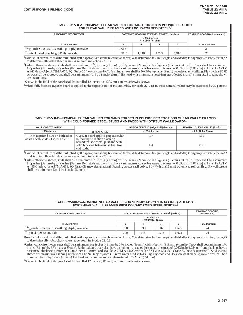
CHAP. 22, DIV. VIIITABLE 22-VIII-ATABLE 22-VIII-C
1997 UNIFORM BUILDING CODE
2–267
TABLE 22-VIII-A—NOMINAL SHEAR VALUES FOR WIND FORCES IN POUNDS PER FOOTFOR SHEAR WALLS FRAMED WITH COLD-FORMED STEEL 1,2
ASSEMBLY DESCRIPTION FASTENER SPACING AT PANEL EDGES 3 (inches) FRAMING SPACING (inches o.c.)
� 25.4 for mm� 0.0146 for N/mm
� 25.4 for mm 6 4 3 2 � 25.4 for mm15/32-inch Structural 1 sheathing (4-ply) one side 1,0654 — — — 247/16-inch rated sheathing (OSB) one side 9104 1,410 1,735 1,910 24
1Nominal shear values shall be multiplied by the appropriate strength reduction factor, Φ, to determine design strength or divided by the appropriate safety factor, Ω,to determine allowable shear values as set forth in Section 2219.3.
2Unless otherwise shown, studs shall be a minimum 15/8 inches (41 mm) by 31/2 inches (89 mm) with a 3/8-inch (9.5 mm) return lip. Track shall be a minimum11/4 inches (32 mm) by 31/2 inches (89 mm). Both studs and track shall have a minimum uncoated base metal thickness of 0.033 inch (0.84 mm) and shall be ASTMA 446 Grade A [or ASTM A 653, SQ, Grade 33 (new designation)]. Framing screws shall be No. 8 by 5/8-inch (16 mm) wafer head self-drilling. Plywood and OSBscrews shall be approved and shall be a minimum No. 8 by 1-inch (25 mm) flat head with a minimum head diameter of 0.292 inch (7.4 mm). Stud spacing shownare maximums.
3Screws in the field of the panel shall be installed 12 inches o.c. (305 mm) unless otherwise shown.4Where fully blocked gypsum board is applied to the opposite side of this assembly, per Table 22-VIII-B, these nominal values may be increased by 30 percent.
TABLE 22-VIII-B—NOMINAL SHEAR VALUES FOR WIND FORCES IN POUNDS PER FOOT FOR SHEAR WALLS FRAMEDWITH COLD-FORMED STEEL STUDS AND FACED WITH GYPSUM WALLBOARD 1,2
WALL CONSTRUCTION SCREW SPACING (edge/field) (inches) NOMINAL SHEAR VALUE (lbs/ft)
� 25.4 for mm ORIENTATION � 25.4 for mm � 0.0146 for N/mm
1/2-inch gypsum board on both sidesof wall with studs 24 inches o.c.
Gypsum board applied perpendicularto framing with strap blockingbehind the horizontal joint and withsolid blocking between the first twoend studs.
7/7
4/4
585
850
1Nominal shear values shall be multiplied by the appropriate strength reduction factor, Φ, to determine design strength or divided by the appropriate safety factor, Ω,to determine allowable shear values as set forth in Section 2219.3.
2Unless otherwise shown, studs shall be a minimum 15/8 inches (41 mm) by 31/2 inches (89 mm) with a 3/8-inch (9.5 mm) return lip. Track shall be a minimum11/4 inches (32 mm) by 31/2 inches (89 mm). Both studs and track shall have a minimum uncoated base metal thickness of 0.033 inch (0.84 mm) and shall be ASTMA 446 Grade A [or ASTM A 653, SQ, Grade 33 (new designation)]. Framing screws shall be No. 8 by 5/8-inch (16 mm) wafer head self-drilling. Drywall screwsshall be a minimum No. 6 by 1 inch (25 mm).
TABLE 22-VIII-C—NOMINAL SHEAR VALUES FOR SEISMIC FORCES IN POUNDS PER FOOTFOR SHEAR WALLS FRAMED WITH COLD-FORMED STEEL STUDS 1,2
ASSEMBLY DESCRIPTION FASTENER SPACING AT PANEL EDGES 3 (inches)FRAMING SPACING
(inches o.c.)
� 25.4 for mm� 0.0146 for N/mm
� 25.4 for mm 6 4 3 2 � 25.4 for mm15/32-inch Structural 1 sheathing (4-ply) one side 780 990 1,465 1,625 247/16-inch (OSB) one side 700 915 1,275 1,625 24
1Nominal shear values shall be multiplied by the appropriate strength reduction factor, Φ, to determine design strength or divided by the appropriate safety factor, Ω,to determine allowable shear values as set forth in Section 2219.3.
2Unless otherwise shown, studs shall be a minimum 15/8 inches (41 mm) by 31/2 inches (89 mm) with a 3/8-inch (9.5 mm) return lip. Track shall be a minimum 11/4inches (32 mm) by 31/2 inches (89 mm). Both studs and track shall have a minimum uncoated base metal thickness of 0.033 inch (0.084 mm) and shall not have abase metal thickness greater than 0.043 inch (1.10 mm) and shall be ASTM A 446 Grade A [or ASTM A 653, SQ, Grade 33 (new designation)]. Stud spacingshown are maximums. Framing screws shall be No. 8 by 5/8-inch (16 mm) wafer head self-drilling. Plywood and OSB screws shall be approved and shall be aminimum No. 8 by 1-inch (25 mm) flat head with a minimum head diameter of 0.292 inch (7.4 mm).
3Screws in the field of the panel shall be installed 12 inches (305 mm) o.c. unless otherwise shown.
CHAP. 22, DIV. IXTABLE 22-VIII-C2221
1997 UNIFORM BUILDING CODE
2–268
Division IX—OPEN WEB STEEL JOISTS
SECTION 2221 — ADOPTION CHAP. 22, DIV. IX
In addition to the requirements in the building code, the design,manufacture and use of open web steel joists shall be in accord-ance with the Standard Specification for Steel Joists, K-Series,LH-Series, DLH-Series and Joist Girders, 1994, published by the
Steel Joist Institute, 1205 48th Avenue, Suite A, Myrtle Beach, SC29577, as if set out at length herein.
Where other codes, standards or specifications are referred to inthis specification, they are to be considered as only an indicationof an acceptable method or material that can be used with theapproval of the building official.
2221
�
CHAP. 22, DIV. X2221
2222.51997 UNIFORM BUILDING CODE
2–269
Division X—DESIGN STANDARD FOR STEEL STORAGE RACKS
Based on the Specification for the Design, Testing and Utilization of Industrial Steel Storage Racks,1990 Edition, by the Rack Manufacturers Institute
SECTION 2222 — GENERAL PROVISIONS CHAP.22, DIV. X
2222.1 Scope.This division shall apply to pallet racks, movableshelf racks and stacker-racks made of cold-formed or hot-rolledsteel structural members. It shall not apply to other types of racks,such as cantilever racks, drive-in and drive-through racks and rackbuildings.
The design of racks not covered by this standard shall be in ac-cordance with the provisions of Section 1632 using the loads asdefined in this division.
EXCEPTION: The building official may waive the design re-quirements for storage racks less than or equal to 8 feet (2438 mm) inheight.
2222.2 Definitions. For the purpose of this division, certainterms are defined as follows:
FRAMES are the rigid-connection frames composed of postsand pallet beams in pallet racks, and the upright (trussed) frames.
MOVABLE-SHELF RACKS are a type of rack where theshelves are removable and replaceable in multiple locations in thesection opening.
PALLET is a portable platform on which goods are placed forstorage or transportation.
PALLET GUIDE is a device to prevent a pallet from sliding offits support beam or rail.
PALLET RACK (also Standard Pallet Rack) is a rack whichutilizes horizontal beams connected to prefabricated uprightframes to provide independent, multiple-level storage (usually oneither side of an aisle). The horizontal beams support pallets.
PALLET RACK BEAMS (also Shelf Beams) are horizontalstructural members used to support pallets in a rack.
STACKER RACKS (also Stacker Crane Racks) are a rackarrangement, usually higher than other types of racks, wherefloor-running storage and retrieval machines are used to shuttleloads. These machines are generally rail mounted and often fullyautomated and computer controlled.
STACKER-RACK BEAMS are horizontal structural mem-bers used to support pallets in a stacker rack.
STEEL STORAGE RACK is a single or multilevel storagesystem in single or multi-bays consisting of vertical columns orposts and horizontal beams. Diagonal and horizontal trussed brac-ing is often used to resist horizontal loads. The beams generallysupport pallets, and the system may be one of a number of differ-ent types (Standard Pallet Rack, Stacker Rack, etc.); see defini-tions of each type.
UNIT LOAD is a standardized load, meaning, for example,pallet load if pallets are used. Also refers to other standardizedloads such as barrels which may be stored without pallets.
2222.3 Materials. This standard contemplates the use of steel ofstructural quality as listed in Division I.
Steels not listed in the above provisions are not excluded, pro-vided they conform to the chemical and mechanical requirementsof one of the listed specifications or other published specifications
which establish their properties and structural suitability; andprovided they are subjected by either the producer or the purchaserto analyses, tests and other controls to the extent and in the mannerprescribed by one of the two listed specifications, as applicable.
2222.4 Applicable Design Specifications.Except as either mo-dified or supplemented herein, Division I, shall apply to the de-sign of steel storage racks.
2222.5 Integrity of Rack Installations. Individual rack compo-nents and assemblies thereof shall comply with this standard.
All rack installations and racks manufactured in conformitywith this standard shall display in one or more conspicuous loca-tions a permanent plaque each not less than 50 square inches(32 258 mm2] in area and showing the maximum permissible unitload in clear, legible print.
EXCEPTION: The building official may waive plaque installationfor racks not exceeding 12 feet (3658 mm) in height to top shelf, cover-ing a floor area less than 300 square feet (27.87 m2), with a unit loadnot exceeding 2,500 pounds (11 121 N), and without double stackingon top level.
Load application and rack configuration drawings shall be fur-nished with each rack installation. The drawings shall present thepermissible configurations or limitations as to the maximum num-ber of shelves or rails, the maximum distance between them, andthe maximum distance from the floor to the bottom shelf or rail.
The bottom of all posts shall be furnished with bearing plates,according to Section 2227.2. Drive-in, drive-through and stackerracks shall be anchored to the floor by anchor bolts capable of re-sisting the horizontal shear forces caused by the horizontal andvertical loads on the rack.
The stability of movable-shelf racks shall not be dependentupon movable shelves. Those components which provide stabil-ity, such as permanently bolted or welded top shelves and the lon-gitudinal and transverse diagonal bracing, shall be clearlyidentified on the rack configuration drawings. In specific mova-ble-shelf rack installations where rack height requires it, a con-spicuous warning is to be placed in the owner’s utilizationinstruction manual of any restrictions on shelf placement or shelfremoval. Such restrictions also are to be permanently posted in lo-cations clearly visible to forklift operators.
Lower portions of posts exposed to damage by forklift trucks orother moving equipment shall have protective devices. If not soprotected the rack structure may, at the option of the building offi-cial: (1) be designed to maintain its full design load capacity at al-lowable stresses with the exposed post capacity reduced byone-half, or (2) be designed to maintain its full design load capac-ity at 50 percent increased allowable stresses with the exposedpost assumed to have no carrying capacity.
Where racks are braced against the building structure, the build-ing structure shall be designed for the horizontal and verticalforces listed in Section 2226.1 imposed on the building structure.
Racks shall be installed with a maximum tolerance from thevertical of 1 inch in 10 feet (25.4 mm in 3048 mm) of height. Spe-cial conditions may require more restrictive tolerances.
Support of racks by foundations, concrete floor slabs or othermeans shall be in conformance with Chapter 18.
2222
CHAP. 22, DIV. X22232228.3.3
1997 UNIFORM BUILDING CODE
2–270
SECTION 2223 — DESIGN PROCEDURES ANDDIMENSIONAL LIMITATIONS
2223.1 General.All computations for allowable loads, stressesand deflections shall be in accordance with conventional methodsof structural design, and as specified in Section 2222.4, exceptwhere modified or supplemented herein. Where adequate meth-ods of design calculations are not available, justification by a test-ing program acceptable to the building official may be used.
2223.2 Dimensional Limitations.The limitations on flat-widthratios and slenderness ratios in Division I and Division V shall ap-ply except for the following conditions:
1. Slenderness limitations shall not be imposed on tensionmembers which do not resist compression forces under any load-ing condition.
2. The unbraced length of compression or tension membersshall be the length between connections to other structural mem-bers disposed in the direction of the pertinent radius of gyration, orfrom such a connection to the nearest attachment to an externalfixed structure, such as a floor.
SECTION 2224 — ALLOWABLE STRESSES ANDEFFECTIVE WIDTHS
2224.1 General.Allowable stresses and effective design widthsshall be as specified in Division I and Division IV except as pro-vided herein. Allowable stresses for working stress design may beincreased one-third when considering wind or earthquake forceseither acting alone or when combined with vertical loads.
2224.2 Perforated Compression Members.The effect of per-forations on the carrying capacity of compression members shallbe recognized by modification of the Q-factor. Q-values forperforated compression members shall be determined by stubcolumn tests acceptable to the building official. These membersshall be designed in an approved manner. The effects ofperforations on the capacity of members may be considered byusing the section properties based on the minimum net area.
2224.3 Torsional-flexural Buckling. Sections subject to tor-sional-flexural buckling shall be designed according to DivisionVII.
SECTION 2225 — PALLET AND STACKER-RACKBEAMS
2225.1 Allowable Loads.Where the shape of the cross sectionpermits, allowable loads of pallet-carrying beams shall bedetermined in accordance with Division I or Division IV.
2225.2 Deflections.At working load the deflections, includingpossible deformations in the end connections, shall not exceed1/180 of the span measured with respect to the beam ends.
2225.3 Determination by Test.Where the configuration of thecross section precludes calculation of allowable loads and deflec-tions, determination may be made with a testing program accept-able to the building official.
SECTION 2226 — FRAME DESIGN
2226.1 General.Frames shall be designed for the critical com-binations of vertical loads in the most unfavorable positions, hori-zontal loads as specified in Section 2228.3, and the additionaleffects of horizontal sway caused by looseness, if any, of the top tiebeam to post connections.
2226.2 Effective Lengths.Effective lengths based on valid en-gineering principles shall be used in the design of posts and up-right frames.
SECTION 2227 — CONNECTIONS AND BEARINGPLATES
2227.1 Connections.Adequate strength of connections to with-stand calculated resultant forces and moments, and adequate ri-gidity where such is required, shall be demonstrated bycalculation or by testing in an approved manner.
Beams shall have support connections capable of withstandingan upward force of 1,000 pounds (4448 N) per connection withinallowable design values of this code.
For movable-shelf racks, the top shelf and other fixed shelvesare to include support connections capable of withstanding anupward force of 1,000 pounds (4448 N) per connection within theallowable design values of this code.
The movable shelves are generally constructed of a set of frontand rear longitudinal beams connected to each other rigidly bytransverse members. The movable shelves are to be connected insuch a way to prevent forward displacement when lifting out thefront beam of the shelf.
2227.2 Bearing Plates.Provision shall be made to transfer postloads and moments into the floor. Said forces and moments shallbe consistent in magnitude, sense and direction with the rack anal-ysis. Allowable bearing stresses on the bottom of base plates shallbe determined in accordance with Chapter 19.
SECTION 2228 — LOADS
2228.1 Gravity Loads. Racks shall be designed for dead loads,live loads and unit loads as posted on the rack installation underSection 2222.5.
2228.2 Vertical Impact. Unit load-carrying beams, supportingarms, if any, and end connections shall be designed for an addi-tional vertical impact load of 25 percent of one unit load located toproduce maximum moments and shears. Impact stresses shall notexceed stresses referenced in Section 2224, nor shall they causedetrimental permanent deformations in connections. When allow-able loads are determined by tests, due allowance shall be madefor the additional impact load. Impact loads may be omitted whenchecking beam deflections and designing upright frames, postsand other vertical components.
2228.3 Horizontal Loads.
2228.3.1 General.All racks shall be designed for the horizontalforces and allowable stresses specified in this standard. Theseforces shall not cause permanent distortions of connections whensubject to test, or permanent residual sway deflections (of the en-tire rack when subject to full-scale rack tests) larger than 20 per-cent of the sway deflections measured under the simultaneousaction of horizontal and vertical loads.
2228.3.2 Horizontal stability. Horizontal stability shall be de-termined by applying horizontal forces simultaneously at allbeam-to-post connections equal to 1.5 percent of the maximumlive load plus dead load at the connection. The forces shall beapplied separately in each of the two principal directions of therack and in conjunction with full dead and live loads.
2228.3.3 Stacker racks or racks wholly or partially support-ing moving equipment. Racks shall be designed for maximumforces and their locations, transmitted from moving equipment toracks, and applicable longitudinal and transverse impact factorsdue to moving equipment.
CHAP. 22, DIV. X2228.3.3
2229.31997 UNIFORM BUILDING CODE
2–271
Devices acting as bumpers to stop moving equipment shall beconsidered in the design.
Forces described in this section need not act concurrently withthose described in Sections 2228.3.2 and 2228.5.1.
2228.4 Wind Loads.Outdoor racks exposed to wind shall be de-signed for the wind loads prescribed by Chapter 16 acting on thehorizontal projection of rack plus contents. For stability, consider-ation shall be given to loading conditions that produce large windforces combined with small stabilizing gravity forces, such asracks fully loaded, but with unit loads of much smaller weight thanthe maximum posted unit load.
Forces described in Sections 2228.3.2 and 2228.5.1 need not actconcurrently with wind loads. Forces described in Section2228.3.3 shall act concurrently with wind forces for design pur-poses.
2228.5 Earthquake Loads.
2228.5.1 General.Steel storage racks which are not connectedto buildings or other structures shall be designed to resist seismicforces in conformance with this standard.
2228.5.2 Minimum earthquake forces.The total minimumlateral force at strength design levels shall be determined in ac-cordance with Section 1630.2.1:
WHERE:R = 4.4 for racks or portions thereof where lateral stability is
dependent on diagonal or x-bracing. Connections forbracing members shall be capable of developing the re-quired strength of the members.
R = 5.6 for racks where the lateral stability is wholly depen-dent on moment-resisting frame action.
W = weight of rack structure plus contents. Where a numberof storage rack units are interconnected so there are aminimum of four columns in any direction on each col-umn line designed to resist horizontal forces, W may beequal to the total dead load plus 50 percent of the rack-rated capacity. In Seismic Zones 3 and 4, wholesale andretail areas, the 50 percent may only be used when com-bined with Cv/RT taken equal to 0.70Ca in Formula(30-4) and with 2.5/R taken equal to 0.70 in Formula(30-5).
Total seismic force shall be assumed to act nonconcurrently inthe direction of each of the main axes of the rack. For racks havingmore than two storage levels, the total lateral force, V, shall be dis-tributed over the height of the rack in accordance with
Fi �VWihi
�n
i�1
Wihi
in which Fi is the lateral force applied at Level i; Wi is the portionof the total weight; W, which is assigned to Level i; hi is the height
of Level i above the base of the rack; and n is the total number ofstorage levels. The lateral force, V, shall be distributed in propor-tion to the total weight, W.
Other R values may be considered based on submission ofsubstantiating data.
2228.6 Storage Racks in Buildings.Storage racks located inbuildings at levels above the ground level, rack buildings or racksthat depend on attachments to buildings or other structures at otherthan the floor level for their lateral stability, shall be designed toresist earthquake forces that consider the responses of the buildingand storage rack to earthquake ground motions as specified inChapter 16, Division III.
2228.7 Other Considerations.
2228.7.1 Overturning. In determining overturning moments,the total weight shall be assumed to act at a height equal to 1.15times the distance from the floor to the actual center of gravity ofall the horizontal forces.
Equal safety against an overturning moment shall be providedwhen only the top level of the rack is loaded, in which case it is tobe assumed that the force acts through the center of gravity of thetop load.
2228.7.2 Torsional forces.Torsional forces shall be consideredbased on the critical combination of loaded and unloaded storagespaces.
2228.7.3 Concurrent forces.Forces described in Sections2228.3.2, 2228.3.3 and 2228.4 need not be assumed to act concur-rently with earthquake loads.
SECTION 2229 — SPECIAL RACK DESIGNPROVISIONS
2229.1 Stability of Truss-braced Upright Frames.The maxi-mum allowable compression stress in the posts of truss-braced up-right frames shall be determined from Divisions I and IV.
2229.2 Overturning and Height-to-depth Ratio.Overturningshall be based on the critical combination of vertical and horizon-tal loads. Stabilizing forces provided by anchor bolts to the floorshall not be considered to resist overturning unless the anchors arespecifically designed and installed to resist the uplift forces. Un-less all columns are so anchored, the minimum ratio betweenrighting moment and overturning moment shall be 1.5. Sections2228.4 and 2228.7 shall be considered in the design.
The height-to-depth ratio of a storage rack shall not exceed 6 to1 measuring to the top of the topmost load unless the rack is an-chored or braced externally.
2229.3 Connections to Buildings.Connections of racks tobuildings, if any, shall be designed and installed to prevent reac-tions or displacements of the buildings or racks from damagingone another. Section 2228.5 shall be considered.
CHAP. 22, DIV. XI2229.32230
1997 UNIFORM BUILDING CODE
2–272
Division XI—DESIGN STANDARD FOR STRUCTURAL APPLICATIONS OF STEEL CABLES FOR BUILDINGS
This standard is based on the American Society of Civil EngineersStandard 17-95, Structural Applications of Steel Cables for Build-ings (ASCE 17-95) available from the American Society of CivilEngineers, 1801 Alexander Bell Drive, Reston, Virginia 20191-4400.
SECTION 2230 — ADOPTION CHAP. 22, DIV. XI
The American Society of Civil Engineers standard adopted by thisdivision provides requirements for the structural design, fabrica-tion and the installation of steel cables for use as primary structuralelements for the support of roofs and floors of buildings. Whereother codes, standards or specifications are referred to in this divi-sion, they are to be considered as only an indication of an accept-able method of material that can be used with the approval of thebuilding official.
2230
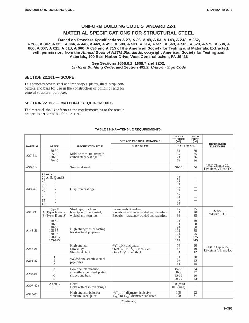
1997 UNIFORM BUILDING CODE STANDARD 22-1
3–391
UNIFORM BUILDING CODE STANDARD 22-1
MATERIAL SPECIFICATIONS FOR STRUCTURAL STEEL Based on Standard Specifications A 27, A 36, A 48, A 53, A 148, A 242, A 252,
A 283, A 307, A 325, A 366, A 446, A 449, A 490, A 500, A 501, A 514, A 529, A 563, A 569, A 570, A 572, A 588, A606, A 607, A 611, A 618, A 666, A 690 and A 715 of the American Society for Testing and Materials. Extracted,
with permission, from the Annual Book of ASTM Standards, copyright American Society for Testing andMaterials, 100 Barr Harbor Drive, West Conshohocken, P A 19428
See Sections 1808.6.1, 1808.7 and 2202,Uniform Building Code, and Section 402.2, Uniform Sign Code
SECTION 22.101 — SCOPE
This standard covers steel and iron shapes, plates, sheet, strip, con-nectors and bars for use in the construction of buildings and forgeneral structural purposes.
SECTION 22.102 — MATERIAL REQUIREMENTS
The material shall conform to the requirements as to the tensileproperties set forth in Table 22-1-A.
TABLE 22-1-A—TENSILE REQUIREMENTS
SIZE AND PRODUCT LIMITATIONS
TENSILESTRENGTH
(ksi)
YIELDPOINT(ksi)
REFERENCEDMATERIAL GRADE SPECIFICATION TITLE � 25.4 for mm � 6.89 for MPa
REFERENCEDELSEWHERE
A27-81a
60-3065-3570-3670-40
Mild- to medium-strengthcarbon steel castings
60657070
30353640
A36-81a Structural steel 58-80 36 UBC Chapter 22,Divisions VII and IX
A48-76
Class No.20 A, B, C and S25 �
30 �
35 �
40 �
45 �
50 �
55 �
60 �
Gray iron castings
202530354045505560
—————————
A53-82Type F
A (Types E and S)B (Types E and S)
Steel pipe, black andhot-dipped, zinc-coated;welded and seamless
Furnace—butt weldedElectric—resistance welded and seamlessElectric—resistance welded and seamless
454860
253035
UMCStandard 11-1
A148-81
80-4080-5090-60
105-85120-95150-125175-145
High-strength steel castingfor structural purposes
808090
105120150175
4050608595125145
A242-81High-strengthLow-alloyStructural steel
3/4� thick and underOver 3/4� to 11/2�, inclusiveOver 11/2� to 4� thick
706763
504642
UBC Chapter 22,Divisions VII and IX
A252-82123
Welded and seamless steelpipe piles
506066
303545
A283-81
ABCD
Low and intermediatestrength carbon steel platesshapes and bars
45-5550-6055-6560-72
24273033
A307-82a A and BB
BoltsBolts with cast-iron flanges
60 (min)100 (max) —
A325-83c High-strength bolts forstructural steel joints
1/2� to 1� diameter, inclusive11/8� to 11/2� diameter, inclusive
105120
9281
(Continued)
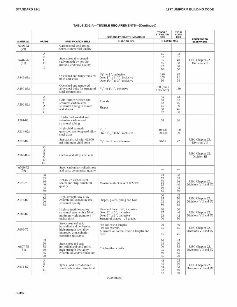
1997 UNIFORM BUILDING CODESTANDARD 22-1
3–392
TABLE 22-1-A—TENSILE REQUIREMENTS—(Continued)
MATERIALREFERENCEDELSEWHERE
YIELDPOINT(ksi)
TENSILESTRENGTH
(ksi)SIZE AND PRODUCT LIMITATIONS
SPECIFICATION TITLEGRADEMATERIALREFERENCEDELSEWHERE� 6.89 for MPa� 25.4 for mmSPECIFICATION TITLEGRADE
A366-72(79)
Carbon steel cold-rolledsheet, commercial quality
— —
A446-76(81)
ABCDEF
Steel sheet zinc-coated(galvanized) by hot-dipprocess structural quality
455255658270
333740508050
UBC Chapter 22,Division VII
A449-83a Quenched and tempered steelbolts and studs
1/4� to 1�, inclusiveOver 1� to 11/2�, inclusiveOver 11/2� to 3�, inclusive
12010590
928158
A490-83aQuenched and temperedalloy steel bolts for structuralsteel connections
1/2� to 11/2�, inclusive150 (min)170 (max) 130
A500-82a
ABCABC
Cold-formed welded andseamless carbon steelstructural tubing in roundsand shapes
Rounds
Shapes
455862455862
334246394650
A501-83Hot-formed welded andseamless carbon steelstructural tubing
58 36
A514-82aHigh-yield strengthquenched and tempered alloysteel plate
21/2�Over 21/2� to 6�, inclusive
110-130100-130
10090
A529-82 Structural steel with 42,000psi minimum yield point
1/2� maximum thickness 60-85 42 UBC Chapter 22,Division VII
A563-88a
OABCD
DH
Carbon and alloy steel nuts UBC Chapter 22,Division III
A569-72(79)
Steel, carbon hot-rolled sheetand strip, commercial quality — —
A570-79
303336404550
Hot-rolled carbon steelsheets and strip, structuralquality
Maximum thickness of 0.2299�
495253556065
303336404550
UBC Chapter 22,Divisions VII and IX
A572-82
42506065
High-strength low-alloycolumbium-vanadium steel,structural quality
Shapes, plates, piling and bars
60657580
42506065
UBC Chapter 22,Divisions VII and IX
A588-82
High-strength low-alloystructural steel with a 50 ksiminimum yield point to 4inches thick
Plate and bars to 4�, inclusiveOver 4� to 5�, inclusiveOver 5� to 8�, inclusiveStructural shapes—all grades
70676370
50464250
UBC Chapter 22,Divisions VII and IX
A606-75
Steel sheet and striphot-rolled and cold-rolledhigh-strength low-alloyimproved atmosphericcorrosion resistance
Hot-rolled cut lengthsHot-rolled coils,Annealed or normalized cut lengths andcoils
7065
65
5045
45
UBC Chapter 22,Divisions VII and IX
A607-75(81)
455055606570
Steel sheet and striphot-rolled and cold-rolledhigh-strength low-alloycolumbium and/or vanadium
Cut lengths or coils
606570758085
455055606570
UBC Chapter 22,Divisions VII and IX
A611-82
ABCDE
Types I and II cold-rolledsheet carbon steel, structural
4245485282
2530334080
UBC Chapter 22,Divisions VII and IX
(Continued)
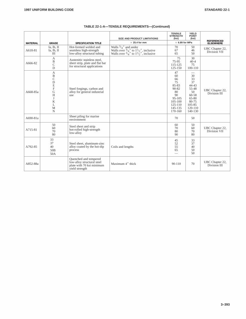
1997 UNIFORM BUILDING CODE STANDARD 22-1
3–393
TABLE 22-1-A—TENSILE REQUIREMENTS—(Continued)
MATERIALREFERENCEDELSEWHERE
YIELDPOINT(ksi)
TENSILESTRENGTH
(ksi)SIZE AND PRODUCT LIMITATIONS
SPECIFICATION TITLEGRADEMATERIALREFERENCEDELSEWHERE� 6.89 for MPa� 25.4 for mmSPECIFICATION TITLEGRADE
A618-81Ia, Ib, IIIa, Ib, II
III
Hot-formed welded andseamless high-strengthlow-alloy structural tubing
Walls 3/4� and underWalls over 3/4� to 11/2�, inclusiveWalls over 3/4� to 11/2�, inclusive
706765
504650
UBC Chapter 22,Division VII
A666-82
ABCD
Austenitic stainless steel,sheet strip, plate and flat barfor structural applications
7575-95
115-125125-150
3040-475
100-110
A668-85a
ABCDEFGHJKLMN
Steel forgings, carbon andalloy for general industrialuse
47606675
85-8390-82
8090
95-105105-100125-110145-135170-160
—303337
44-4355-48
5060-5865-8080-75
105-85120-110140-130
UBC Chapter 22,Division III
A690-81a Sheet piling for marineenvironment 70 50
A715-81
50607080
Steel sheet and striphot-rolled high-strengthlow-alloy
60708090
50607080
UBC Chapter 22,Division VII
A792-85
33374050B50A
Steel sheet, aluminum-zincalloy coated by the hot-dipprocess
Coils and lengths
45525565—
3337405050
A852-88a
Quenched and temperedlow-alloy structural steelplate with 70 ksi minimumyield strength
Maximum 4� thick 90-110 70 UBC Chapter 22,Division III
CHAP. 23, DIV. I2301
2302.11997 UNIFORM BUILDING CODE
2–273
Chapter 23
WOODNOTE: This chapter has been revised in its entirety.
Division I—GENERAL DESIGN REQUIREMENTS
SECTION 2301 — GENERAL
2301.1 Scope.The quality and design of wood members andtheir fastenings shall conform to the provisions of this chapter.
2301.2 Design Methods. Design shall be based on one of the fol-lowing methods.CHAP. 23, DIV. I
2301.2.1 Allowable stress design. Design using allowable stressdesign methods shall resist the load combinations of Section1612.3, in accordance with the applicable requirements of Section2305.
2301.2.2 Conventional light-frame construction. The designand construction of conventional light-frame wood structuresshall be in accordance with the applicable requirements of Section2305.
SECTION 2302 — DEFINITIONS
2302.1 Definitions. The following terms used in this chaptershall have the meanings indicated in this section:
AFPA is the American Forest and Paper Association, 1111 19thStreet, N.W., Suite 800, Washington, D.C. 20036 (formerlyNFoPA, National Forest Products Association).
AHA is the American Hardboard Association, Inc., 1210 W.Northwest Highway, Palatine, Illinois 60067.
AITC is the American Institute of Timber Construction, 7012S. Revere Parkway, Suite 140, Englewood, Colorado 80112.
ALSC is the American Lumber Standard Committee, Post Of-fice Box 210, Germantown, Maryland 20875-0210.
APA is the American Plywood Association, 7011 South 19thStreet, Tacoma, Washington 98411.
AWPA is the American Wood Preservers Association, PostOffice Box 286, Woodstock, Maryland 21163-0286.
BLOCKED DIAPHRAGM is a diaphragm in which allsheathing edges not occurring on framing members are supportedon and connected to blocking.
BRACED WALL LINE is a series of braced wall panels in asingle story that meets the requirements of Section 2320.11.3.
BRACED WALL PANEL is a section of wall braced inaccordance with Section 2320.11.3.
CONVENTIONAL LIGHT-FRAME CONSTRUCTION isa type of construction whose primary structural elements areformed by a system of repetitive wood-framing members. Refer toSection 2320 for conventional light-frame construction provi-sions.
DIAPHRAGM is a horizontal or nearly horizontal system act-ing to transmit lateral forces to the vertical-resisting elements.When the term “diaphragm” is used, it includes horizontal bracingsystems.
FIBERBOARD is a fibrous-felted, homogeneous panel madefrom lignocellulosic fibers (usually wood or cane) and having a
density of less than 31 pounds per cubic foot (497 kg/m3) but morethan 10 pounds per cubic foot (160 kg/m3).
GLUED BUILT-UP MEMBERS are structural elements, thesections of which are composed of built-up lumber, wood struc-tural panels or wood structural panels in combination with lumber,all parts bonded together with adhesives.
GRADE (Lumber) is the classification of lumber in regard tostrength and utility in accordance with UBC Standard 23-1 and thegrading rules of an approved lumber grading agency.
HARDBOARD is a fibrous-felted, homogeneous panel madefrom lignocellulosic fibers consolidated under heat and pressurein a hot press to a density not less than 31 pounds per cubic foot(497 kg/m3).
NELMA is the Northeastern Lumber Manufacturers Associa-tion, 272 Tuttle Road, Post Office Box 87 A, Cumberland Center,Maine 04021.
NLGA is the National Lumber Grades Authority, 103-4000Dominion Street, Burnaby B.C., Canada V5G 4G3.
NSLB is the Northern Softwood Lumber Bureau (serviced byNELMA), 272 Tuttle Road, Post Office Box 87 A, CumberlandCenter, Maine 04021.
NOMINAL LOADING is a design load that stresses a memberof fastening to the full allowable stress tabulated in this chapter.This loading may be applied for approximately 10 years, eithercontinuously or cumulatively, and 90 percent of this load may beapplied for the remainder of the life of the member or fastening.
NOMINAL SIZE (Lumber) is the commercial size designa-tion of width and depth, in standard sawn lumber and glued-lami-nated lumber grades; somewhat larger than the standard net size ofdressed lumber, in accordance with UBC Standard 23-1 for sawnlumber.
PARTICLEBOARD is a manufactured panel product consist-ing of particles of wood or combinations of wood particles andwood fibers bonded together with synthetic resins or other suit-able bonding system by a bonding process in accordance with ap-proved nationally recognized standards.
PLYWOOD is a panel of laminated veneers conforming toUBC Standard 23-2 or 23-3.
RIS is the Redwood Inspection Service, 405 Enfrente Drive,Suite 200, Novato, California 94949.
ROTATION is the torsional movement of a diaphragm about avertical axis.
SPIB is the Southern Pine Inspection Bureau, 4709 ScenicHighway, Pensacola, Florida 32504.
STRUCTURAL GLUED-LAMINATED TIMBER is anymember comprising an assembly of laminations of lumber inwhich the grain of all laminations is approximately parallel longi-tudinally, in which the laminations are bonded with adhesives.
SUBDIAPHRAGM is a portion of a larger wood diaphragmdesigned to anchor and transfer local forces to primary diaphragmstruts and the main diaphragm.
TREATED WOOD is wood treated with an approved preserv-ative under treating and quality control procedures.
CHAP. 23, DIV. I2302.12304.1
1997 UNIFORM BUILDING CODE
2–274
WCLIB is the West Coast Lumber Inspection Bureau, 6980S.W. Varnes Road, Post Office Box 23145, Portland, Oregon97223.
WOOD OF NATURAL RESISTANCE TO DECAY ORTERMITES is the heartwood of the species set forth below. Cor-ner sapwood is permitted on 5 percent of the pieces provided90 percent or more of the width of each side on which it occurs isheartwood. Recognized species are:
Decay resistant: Redwood, Cedars, Black Locust
Termite resistant: Redwood, Eastern Red Cedar
WOOD STRUCTURAL PANEL is a structural panel productcomposed primarily of wood and meeting the requirements ofUBC Standard 23-2 or 23-3. Wood structural panels include all-veneer plywood, composite panels containing a combination ofveneer and wood-based material, and matformed panels such asoriented strand board and waferboard.
WWPA is the Western Wood Products Association, YeonBuilding, 522 S. W. Fifth Avenue, Portland, Oregon 97204-2122.
SECTION 2303 — STANDARDS OF QUALITY
The standards listed below labeled a “UBC Standard” are alsolisted in Chapter 35, Part II, and are part of this code. The otherstandards listed below are recognized standards. (See Sections3503 and 3504.)
1. Grading rules.
1.1 UBC Standard 23-1, Classification, Definition, Meth-ods of Grading and Development of Design Values forAll Species of Lumber
1.2 Standard Grading Rules for Canadian Lumber, UnitedStates Edition, NLGA
1.3 Standard Grading Rules No. 17, WCLIB
1.4 Standard Grading Rules, WWPA
1.5 Grading Rules, NHPMA
1.6 Grading Rules, SPIB
1.7 Standard Specifications for Grades of California Red-wood Lumber, RIS
1.8 Standard Grading Rules, NELMA
2. Structural glued-laminated timber.
2.1 ANSI/AITC Standard A190.1 and ASTM D 3737,Design and Manufacture of Structural Glued-laminatedTimber
2.2 Standard Specifications for Structural Glued-lami-nated Timber of Softwood Species, AITC 117;Manufacturing, AITC 117; Design and Standard Speci-fications for Hardwood Glued-laminated Timber,AITC 119.
2.3 Inspection Manual AITC 200 of the American Instituteof Timber Construction, Tests for Structural Glued-laminated Timber.
2.4 AITC 500, Determination of Design Values for Struc-tural Glued-laminated Timber in accordance withASTM D 3737, American Institute of TimberConstruction.
3. Preservative treatment by pressure process and qualitycontrol.
3.1 Standard Specifications C1, C2, C3, C4, C9, C14, C15,C16, C22, C23, C24, C28 and M4, AWPA
4. Product standards.
4.1 UBC Standard 23-2, Construction and Industrial Ply-wood
4.2 UBC Standard 23-3, Performance Standard for Wood-Based Structural-Use Panels
4.3 ANSI A208.1, Particleboard
4.4 ASTM D 1037, Evaluating the Properties of Wood-based Fiber and Particle Panel Materials
4.5 ASTM D 1333, Determining Formaldehyde Levelsfrom Wood-based Products Under Defined Test Condi-tions Using a Large Chamber
4.6 ANSI 05.1, Wood Poles—Specifications and Dimen-sions
4.7 ASTM D 25, Round Timber Piles
4.8 ANSI/AHA A194.1, Cellulosic Fiber Insulating Board(Fiberboard)
4.9 ANSI/AHA 135.6, Hardboard Siding
5. Design standards.
5.1 ASTM D 5055, Structural Capacities of PrefabricatedWood I-Joists
5.2 ANSI/TPI 1 National Design Standard for Metal PlateConnected Wood Truss Construction
5.3 ANSI/TPI 2 Standard for Testing Performance for Met-al Plate Connected Wood Trusses
5.4 ASCE 16, Load and Resistance Factor Design Standardfor Engineered Wood Construction
6. Fire retardancy.
6.1 UBC Standard 23-4, Fire-retardant-treated Wood Testson Durability and Hygroscopic Properties
6.2 UBC Standard 23-5, Fire-retardant-treated Wood
7. Adhesives and glues.
7.1 ASTM D 3024, Dry Use Adhesive with Protein Base,Casein Type
7.2 ASTM D 2559, Wet Use Adhesives
7.3 APA Specification AFG-01, Adhesives for Field Glu-ing Plywood to Wood Framing
7.4 ASTM D 1101 and AITC 200 in Testing of Glue Jointsin Laminated Wood Product
8. Design values.
8.1 ASTM D 1990, Establishing Allowable Properties forVisually-Graded Dimension Lumber from In-GradeTests of Full-Size Specimens
8.2 ASTM D 245, Establishing Structural Grades andRelated Allowable Properties for Visually GradedLumber
8.3 ASTM D 2555, Standard Test Methods for EstablishingClear Wood Strength Values
SECTION 2304 — MINIMUM QUALITY
2304.1 Quality and Identification. All lumber, wood structuralpanels, particleboard, structural glued-laminated timber, end-jointed lumber, fiberboard sheathing (when used structurally),hardboard siding (when used structurally), piles and poles regu-lated by this chapter shall conform to the applicable standards andgrading rules specified in this code and shall be so identified by thegrade mark or certificate of inspection issued by an approvedagency.
CHAP. 23, DIV. I2304.1
2305.101997 UNIFORM BUILDING CODE
2–275
All preservatively treated wood required to be treated underSection 2306 shall be identified by the quality mark of an inspec-tion agency which has been accredited by an accreditation bodywhich complies with the requirements of the American LumberStandard Committee Treated Wood Program, or equivalent.
2304.2 Minimum Capacity or Grade. Minimum capacity ofstructural framing members may be established by performancetests. When tests are not made, capacity shall be based on allow-able stresses and design criteria specified in this code.
Studs, joists, rafters, foundation plates or sills, planking2 inches (51 mm) or more in depth, beams, stringers, posts, struc-tural sheathing and similar load-bearing members shall be of atleast the minimum grades set forth in the tables in this chapter.
Approved end-jointed lumber may be used interchangeablywith solid-sawn members of the same species and grade. Such useshall include, but not be limited to, light-framing joists, planks anddecking.
Wood structural panels shall be of the grades specified in UBCStandard 23-2 or 23-3.
2304.3 Timber Connectors and Fasteners. Safe loads anddesign practices for types of connectors and fasteners not men-tioned or fully covered in Division III, Part III, may be determinedin a manner approved by the building official.
The number and size of nails connecting wood members shallnot be less than that set forth in Tables 23-II-B-1 and 23-II-B-2.Other connections shall be fastened to provide equivalentstrength. End and edge distances and nail penetrations shall be inaccordance with the applicable provisions of Division III, Part III.
Fasteners for pressure-preservative treated and fire-retardanttreated wood shall be of hot-dipped zinc coated galvanized, stain-less steel, silicon bronze or copper. Fasteners for wood founda-tions shall be as required in Chapter 18, Division II. Fastenersrequired to be corrosion resistant shall be either zinc-coated fas-teners, aluminum alloy wire fasteners or stainless steel fasteners.
Connections depending on joist hangers or framing anchors,ties, and other mechanical fastenings not otherwise covered maybe used where approved.
2304.4 Fabrication, Installation and Manufacture.
2304.4.1 General. Preparation, fabrication and installation ofwood members and their fastenings shall conform to acceptedengineering practices and to the requirements of this code. Allmembers shall be framed, anchored, tied and braced to developthe strength and rigidity necessary for the purposes for which theyare used.
2304.4.2 Timber connectors and fasteners. The installation oftimber connectors and fasteners shall be in accordance with theprovisions set forth in Division III, Part III.
2304.4.3 Structural glued-laminated timber. The manufactureand fabrication of structural glued-laminated timber shall beunder the supervision of qualified personnel.
2304.4.4 Metal-plate-connected wood trusses. Metal-plate-connected wood trusses shall conform to the provisions of Divi-
sion V. Each manufacturer of trusses using metal plate connectorsshall retain an approved agency having no financial interest in theplant being inspected to make nonscheduled inspections of trussfabrication, delivery, and operations. The inspection shall coverall phases of truss operation, including lumber storage, handling,cutting, fixtures, presses or rollers, fabrication, bundling andbanding, handling and delivery.
2304.5 Dried Fire-retardant-treated Wood. Approved fire-retardant-treated wood shall be dried, following treatment, to amaximum moisture content as follows: solid-sawn lumber2 inches (51 mm) in thickness or less to 19 percent, and plywood to15 percent.
2304.6 Size of Structural Members. Sizes of lumber and struc-tural glued-laminated timber referred to in this code are nominalsizes. Computations to determine the required sizes of membersshall be based on the net dimensions (actual sizes) and not thenominal sizes.
2304.7 Shrinkage. Consideration shall be given in design to thepossible effect of cross-grain dimensional changes consideredvertically which may occur in lumber fabricated in a green condi-tion.
2304.8 Rejection. The building official may deny permission forthe use of a wood member where permissible grade characteristicsor defects are present in such a combination that they affect theserviceability of the member.
SECTION 2305 — DESIGN AND CONSTRUCTIONREQUIREMENTS
2305.1 General. The following design requirements apply.
2305.2 All wood structures shall be designed and constructed inaccordance with the requirements of Division I and Division II,Part I.
2305.3 Wind and earthquake load-resisting systems for all engi-neered wood structures shall be designed and constructed inaccordance with the requirements of Division II, Part II.
2305.4 The design and construction of wood structures usingallowable stress design methods shall be in accordance with Divi-sion III.
2305.5 The design and construction of conventional light-framewood structures shall be in accordance with Division IV.
2305.6 The design and installation of timber connectors and fas-teners shall be in accordance with Division III, Part III.
2305.7 Metal-plate-connected wood trusses shall conform to theprovisions of Division V.
2305.8 Design of structural glued built-up members with ply-wood components shall be in accordance with Division VI.
2305.9 Design of joists and rafters shall be permitted to be inaccordance with Division VII.
2305.10 Design of plank and beam flooring shall be permitted tobe in accordance with Division VIII.
CHAP. 23, DIV. II2305.102306.12
1997 UNIFORM BUILDING CODE
2–276
Division II—GENERAL REQUIREMENTS
Part I—REQUIREMENTS APPLICABLE TOALL DESIGN METHODS
SECTION 2306 — DECAY AND TERMITEPROTECTION
2306.1 Preparation of Building Site.Site preparation shall bein accordance with Section 3302.CHAP. 23, DIV. II
2306.2 Wood Support Embedded in Ground.Wood em-bedded in the ground or in direct contact with the earth and usedfor the support of permanent structures shall be treated wood un-less continuously below the groundwater line or continuouslysubmerged in fresh water. Round or rectangular posts, poles andsawn timber columns supporting permanent structures that areembedded in concrete or masonry in direct contact with earth orembedded in concrete or masonry exposed to the weather shall betreated wood. The wood shall be treated for ground contact.
2306.3 Under-floor Clearance.When wood joists or the bot-tom of wood structural floors without joists are located closer than18 inches (457 mm) or wood girders are located closer than 12 in-ches (305 mm) to exposed ground in crawl spaces or unexcavatedareas located within the periphery of the building foundation, thefloor assembly, including posts, girders, joists and subfloor, shallbe approved wood of natural resistance to decay as listed in Sec-tion 2306.4 or treated wood.
When the above under-floor clearances are required, the under-floor area shall be accessible. Accessible under-floor areas shallbe provided with a minimum 18-inch-by-24-inch (457 mm by 610mm) opening unobstructed by pipes, ducts and similar construc-tion. All under-floor access openings shall be effectively screenedor covered. Pipes, ducts and other construction shall not interferewith the accessibility to or within under-floor areas.
2306.4 Plates, Sills and Sleepers.All foundation plates or sillsand sleepers on a concrete or masonry slab, which is in direct con-tact with earth, and sills that rest on concrete or masonry founda-tions, shall be treated wood or Foundation redwood, all marked orbranded by an approved agency. Foundation cedar or No. 2 Foun-dation redwood marked or branded by an approved agency may beused for sills in territories subject to moderate hazard, where ter-mite damage is not frequent and when specifically approved bythe building official. In territories where hazard of termite damageis slight, any species of wood permitted by this code may be usedfor sills when specifically approved by the building official.
2306.5 Columns and Posts.Columns and posts located on con-crete or masonry floors or decks exposed to the weather or to watersplash or in basements and that support permanent structures shallbe supported by concrete piers or metal pedestals projecting abovefloors unless approved wood of natural resistance to decay ortreated wood is used. The pedestals shall project at least6 inches (152 mm) above exposed earth and at least 1 inch(25 mm) above such floors.
Individual concrete or masonry piers shall project at least 8 in-ches (203 mm) above exposed ground unless the columns or poststhat they support are of approved wood of natural resistance todecay or treated wood is used.
2306.6 Girders Entering Masonry or Concrete Walls.Endsof wood girders entering masonry or concrete walls shall be pro-vided with a 1/2-inch (12.7 mm) air space on tops, sides and endsunless approved wood of natural resistance to decay or treatedwood is used.
2306.7 Under-floor Ventilation. Under-floor areas shall beventilated by an approved mechanical means or by openings intothe under-floor area walls. Such openings shall have a net area ofnot less than 1 square foot for each 150 square feet (0.067 m2 foreach 10 m2) of under-floor area. Openings shall be located as closeto corners as practical and shall provide cross ventilation. The re-quired area of such openings shall be approximately equally dis-tributed along the length of at least two opposite sides. They shallbe covered with corrosion-resistant wire mesh with mesh open-ings of 1/4 inch (6.4 mm) in dimension. Where moisture due to cli-mate and groundwater conditions is not considered excessive, thebuilding official may allow operable louvers and may allow the re-quired net area of vent openings to be reduced to 10 percent of theabove, provided the under-floor ground surface area is coveredwith an approved vapor retarder.
2306.8 Wood and Earth Separation.Protection of woodagainst deterioration as set forth in the previous sections for speci-fied applications is required. In addition, wood used in construc-tion of permanent structures and located nearer than 6 inches (152mm) to earth shall be treated wood or wood of natural resistance todecay, as defined in Section 2302.1. Where located on concreteslabs placed on earth, wood shall be treated wood or wood of natu-ral resistance to decay. Where not subject to water splash or to ex-terior moisture and located on concrete having a minimumthickness of 3 inches (76 mm) with an impervious membrane in-stalled between concrete and earth, the wood may be untreatedand of any species.
Where planter boxes are installed adjacent to wood frame walls,a 2-inch-wide (51 mm) air space shall be provided between theplanter and the wall. Flashings shall be installed when the air spaceis less than 6 inches (152 mm) in width. Where flashing is used,provisions shall be made to permit circulation of air in the airspace. The wood-frame wall shall be provided with an exteriorwall covering conforming to the provisions of Section 2310.
2306.9 Wood Supporting Roofs and Floors.Wood structuralmembers supporting moisture-permeable floors or roofs that areexposed to the weather, such as concrete or masonry slabs, shall beapproved wood of natural resistance to decay or treated wood un-less separated from such floors or roofs by an impervious moisturebarrier.
2306.10 Moisture Content of Treated Wood.When woodpressure treated with a water-borne preservative is used in en-closed locations where drying in service cannot readily occur,such wood shall be at a moisture content of 19 percent or less be-fore being covered with insulation, interior wall finish, floor cov-ering or other material.
2306.11 Retaining Walls.Wood used in retaining or crib wallsshall be treated wood.
2306.12 Weather Exposure.Those portions of glued-laminated timbers that form the structural supports of a building orother structure and are exposed to weather and not properly pro-tected by a roof, eave overhangs of similar covering shall be pres-sure treated with an approved preservative or be manufacturedfrom wood of natural resistance to decay.
All wood structural panels, when designed to be exposed in out-door applications, shall be of exterior type, except as provided inSection 2306.2. In geographical areas where experience has dem-onstrated a specific need, approved wood of natural resistance todecay or treated wood shall be used for those portions of woodmembers which form the structural supports of buildings, balco-nies, porches or similar permanent building appurtenances whensuch members are exposed to the weather without adequate pro-
2306
CHAP. 23, DIV. II2306.122310.5
1997 UNIFORM BUILDING CODE
2–277
tection from a roof, eave, overhang or other covering to preventmoisture or water accumulation on the surface or at joints betweenmembers. Depending on local experience, such members may in-clude horizontal members such as girders, joists and decking; orvertical members such as posts, poles and columns; or both hori-zontal and vertical members.
2306.13 Water Splash.Where wood-frame walls and partitionsare covered on the interior with plaster, tile or similar materialsand are subject to water splash, the framing shall be protected withapproved waterproof paper conforming to Section 1402.1.
SECTION 2307 — WOOD SUPPORTING MASONRYOR CONCRETE
Wood members shall not be used to permanently support the deadload of any masonry or concrete.
EXCEPTIONS: 1. Masonry or concrete nonstructural floor or roofsurfacing not more than 4 inches (102 mm) thick may be supported bywood members.
2. Any structure may rest upon wood piles constructed in accord-ance with the requirements of Chapter 18.
3. Veneer of brick, concrete or stone applied as specified in Section1403.6.2 may be supported by approved treated wood foundationswhen the maximum height of veneer does not exceed 30 feet (9144mm) above the foundations. Such veneer used as an interior wall finishmay also be supported on wood floors that are designed to support theadditional load and designed to limit the deflection and shrinkage to1/600 of the span of the supporting members.
4. Glass block masonry having an installed weight of 20 pounds persquare foot (97.6 kg/m2) or less and installed with the provisions ofSection 2109.5. When glass block is supported on wood floors, thefloors shall be designed to limit deflection and shrinkage to 1/600 of thespan of the supporting members and the allowable stresses for theframing members shall be reduced in accordance with Division III,Part I.
See Division II, Part II for wood members resisting horizontalforces contributed by masonry or concrete.
SECTION 2308 — WALL FRAMING
The framing of exterior and interior walls shall be in accordancewith provisions specified in Division IV unless a specific design isfurnished.
Wood stud walls and bearing partitions shall not support morethan two floors and a roof unless an analysis satisfactory to thebuilding official shows that shrinkage of the wood framing willnot have adverse effects on the structure or any plumbing, electri-cal or mechanical systems, or other equipment installed thereindue to excessive shrinkage or differential movements caused byshrinkage. The analysis shall also show that the roof drainage sys-tem and the foregoing systems or equipment will not be adverselyaffected or, as an alternate, such systems shall be designed to ac-commodate the differential shrinkage or movements.
SECTION 2309 — FLOOR FRAMING
Wood-joisted floors shall be framed and constructed and anchoredto supporting wood stud or masonry walls as specified in Chapter16.
Fire block and draft stops shall be in accordance with Section708.
SECTION 2310 — EXTERIOR WALL COVERINGS
2310.1 General.Exterior wood stud walls shall be covered onthe outside with the materials and in the manner specified in this
section or elsewhere in this code. Studs or sheathing shall be cov-ered on the outside face with a weather-resistive barrier when re-quired by Section 1402.1. Exterior wall coverings of the minimumthickness specified in this section are based on a maximum studspacing of 16 inches (406 mm) unless otherwise specified.
2310.2 Siding.Solid wood siding shall have an average thick-ness of 3/8 inch (9.5 mm) unless placed over sheathing permittedby this code.
Siding patterns known as rustic, drop siding or shiplap shallhave an average thickness in place of not less than 19/32 inch(15 mm) and shall have a minimum thickness of not less than3/8 inch (9.5 mm). Bevel siding shall have a minimum thicknessmeasured at the butt section of not less than 7/16 inch (11 mm) anda tip thickness of not less than 3/16 inch (4.8 mm). Siding of lesserdimensions may be used, provided such wall covering is placedover sheathing which conforms to the provisions specified else-where in this code.
All weatherboarding or siding shall be securely nailed to eachstud with not less than one nail, or to solid 1-inch (25 mm) nominalwood sheathing or 15/32-inch (12 mm) wood structural panelsheathing or 1/2-inch (13 mm) particleboard sheathing with notless than one line of nails spaced not more than 24 inches (610mm) on center in each piece of the weatherboarding or siding.
Wood board sidings applied horizontally, diagonally or verti-cally shall be fastened to studs, nailing strips or blocking set at amaximum 24 inches (610 mm) on center. Fasteners shall be nailsor screws with a penetration of not less than 11/2 inches (38 mm)into studs, studs and wood sheathing combined, or blocking. Dis-tance between such fastenings shall not exceed 24 inches (610mm) for horizontally or vertically applied sidings and 32 inches(813 mm) for diagonally applied sidings.
2310.3 Plywood.When plywood is used for covering the exteri-or of outside walls, it shall be of the exterior type not less than3/8 inch (9.5 mm) thick. Plywood panel siding shall be installed inaccordance with Table 23-II-A-1. Unless applied over 1-inch (25mm) wood sheathing or 15/32-inch (12 mm) wood structural panelsheathing or 1/2-inch (13 mm) particleboard sheathing, joints shalloccur over framing members and shall be protected with a contin-uous wood batten, approved caulking, flashing, vertical or hori-zontal shiplaps; or joints shall be lapped horizontally or otherwisemade waterproof.
2310.4 Shingles or Shakes.Wood shingles or shakes and asbes-tos cement shingles may be used for exterior wall covering, pro-vided the frame of the structure is covered with building paper asspecified in Section 1402.1. All shingles or shakes attached tosheathing other than wood sheathing shall be secured with ap-proved corrosion-resistant fasteners or on furring strips attachedto the studs. Wood shingles or shakes may be applied over fiber-board shingle backer and sheathing with annular grooved nails.The thickness of wood shingles or shakes between wood nailingboards shall not be less than 3/8 inch (9.5 mm). Wood shingles orshakes and asbestos shingles or siding may be nailed directly toapproved fiberboard nailbase sheathing not less than 1/2-inch (13mm) nominal thickness with annular grooved nails.
The weather exposure of wood shingle or shake siding used onexterior walls shall not exceed maximums set forth in Table23-II-K.
2310.5 Particleboard. When particleboard is used for coveringthe exterior of outside walls, it shall be of the M-1, M-S and M-2Exterior Glue grades. Particleboard panel siding shall be installedin accordance with Tables 23-II-A-2 and 23-II-B-1. Panels shallbe gapped 1/8 inch (3.2 mm) and nails shall be spaced not less than3/8 inch (9.5 mm) from edges and ends of sheathing. Unlessapplied over 5/8-inch (16 mm) net wood sheathing or 1/2-inch (13
CHAP. 23, DIV. II2310.52314
1997 UNIFORM BUILDING CODE
2–278
mm) plywood sheathing or 1/2-inch (13 mm) particleboardsheathing, joints shall occur over framing members and shall becovered with a continuous wood batt; or joints shall be lapped hor-izontally or otherwise made waterproof to the satisfaction of thebuilding official. Particleboard shall be sealed and protected withexterior quality finishes.
2310.6 Hardboard. When hardboard siding is used for cover-ing the outside of exterior walls, it shall conform to Table 23-II-C.Lap siding shall be installed horizontally and applied to sheathedor unsheathed walls. Corner bracing shall be installed in conform-ance with Division IV. A weather-resistive barrier shall be in-stalled under the lap siding as required by Section 1402.1.
Square-edged nongrooved panels and shiplap grooved or non-grooved siding shall be applied vertically to sheathed or un-sheathed walls. Siding that is grooved shall not be less than1/4 inch (6.4 mm) thick in the groove.
Nail size and spacing shall follow Table 23-II-C and shall pene-trate framing 11/2 inches (38 mm). Lap siding shall overlap 1 inch(25 mm) minimum and be nailed through both courses and intoframing members with nails located 1/2 inch (13 mm) from bottomof the overlapped course. Square-edged nongrooved panels shallbe nailed 3/8 inch (9.5 mm) from the perimeter of the panel and in-termediately into studs. Shiplap edge panel siding with 3/8-inch(9.5 mm) shiplap shall be nailed 3/8 inch (9.5 mm) from the edgeson both sides of the shiplap. The 3/4-inch (19 mm) shiplap shall benailed 3/8 inch (9.5 mm) from the edge and penetrate through boththe overlap and underlap. Top and bottom edges of the panel shallbe nailed 3/8 inch (9.5 mm) from the edge. Shiplap and lap sidingshall not be force fit. Square-edged panels shall maintain a1/16-inch (1.6 mm) gap at joints. All joints and edges of sidingshall be over framing members, and shall be made resistant toweather penetration with battens, horizontal overlaps or shiplapsto the satisfaction of the building official. A 1/8-inch (3.2 mm) gapshall be provided around all openings.
2310.7 Nailing. All fasteners used for the attachment of sidingshall be of a corrosion-resistant type.
SECTION 2311 — INTERIOR PANELING
All softwood wood structural panels shall conform with the provi-sions of Chapter 8 and shall be installed in accordance with Table23-II-B-1. Panels shall comply with UBC Standard 23-3.
SECTION 2312 — SHEATHING
2312.1 Structural Floor Sheathing.Structural floor sheathingshall be designed in accordance with the general provisions of thiscode and the special provisions in this section.
Sheathing used as subflooring shall be designed to support allloads specified in this code and shall be capable of supporting con-centrated loads of not less than 300 pounds (1334 N) without fail-ure. The concentrated load shall be applied by a loaded disc,3 inches (76 mm) or smaller in diameter.
Flooring, including the finish floor, underlayment and subfloor,where used, shall meet the following requirements:
1. Deflection under uniform design load limited to 1/360 of thespan between supporting joists or beams.
2. Deflection of flooring relative to joists under a 1-inch-diameter (25 mm) concentrated load of 200 pounds (890 N) lim-ited to 0.125 inch (3.2 mm) or less when loaded midway between
supporting joists or beams not over 24 inches (610 mm) on centerand 1/360 of the span for spans over 24 inches (610 mm).
Floor sheathing conforming to the provisions of Table23-II-D-1, 23-II-D-2, 23-II-E-1, 23-II-F-1 or 23-II-F-2 shall bedeemed to meet the requirements of this section.
2312.2 Structural Roof Sheathing.Structural roof sheathingshall be designed in accordance with the general provisions of thiscode and the special provisions in this section. Structural roofsheathing shall be designed to support all loads specified in thiscode and shall be capable of supporting concentrated loads of notless than 300 pounds (1334 N) without failure. The concentratedload shall be applied by a loaded disc, 3 inches (76 mm) or smallerin diameter. Structural roof sheathing shall meet the following re-quirement:
1. Deflection under uniform design live and dead load limitedto 1/180 of the span between supporting rafters or beams and 1/240under live load only.
Roof sheathing conforming to the provisions of Tables23-II-D-1 and 23-II-D-2 or 23-II-E-1 and 23-II-E-2 shall bedeemed to meet the requirements of this section.
Wood structural panel roof sheathing shall be bonded by inter-mediate or exterior glue. Wood structural panel roof sheathing ex-posed on the underside shall be bonded with exterior glue.
SECTION 2313 — MECHANICALLY LAMINATEDFLOORS AND DECKS
A laminated lumber floor or deck built up of wood members set onedge, when meeting the following requirements, may be designedas a solid floor or roof deck of the same thickness, and continuousspans may be designed on the basis of the full cross section usingthe simple span moment coefficient.
Nail length shall not be less than two and one-half times the netthickness of each lamination. When deck supports are 4 feet (1219mm) on center or less, side nails shall be spaced not more than30 inches (762 mm) on center and staggered one third of the spac-ing in adjacent laminations. When supports are spaced more than4 feet (1219 mm) on center, side nails shall be spaced not morethan 18 inches (457 mm) on center alternately near top and bottomedges, and also staggered one third of the spacing in adjacent lami-nations. Two side nails shall be used at each end of butt-jointedpieces.
Laminations shall be toenailed to supports with 20d or largercommon nails. When the supports are 4 feet (1219 mm) on centeror less, alternate laminations shall be toenailed to alternate sup-ports; when supports are spaced more than 4 feet (1219 mm) oncenter, alternate laminations shall be toenailed to every support.
A single-span deck shall have all laminations full length.
A continuous deck of two spans shall not have more than everyfourth lamination spliced within quarter points adjoining sup-ports.
Joints shall be closely butted over supports or staggered acrossthe deck but within the adjoining quarter spans.
No lamination shall be spliced more than twice in any span.
SECTION 2314 — POST-BEAM CONNECTIONS
Where post and beam or girder construction is used, the designshall be in accordance with the provisions of this code. Positiveconnection shall be provided to ensure against uplift and lateraldisplacement.
CHAP. 23, DIV. II2314
2315.3.31997 UNIFORM BUILDING CODE
2–279
Part II—REQUIREMENTS APPLICABLE TOENGINEERED DESIGN OF WIND AND EARTHQUAKE
LOAD-RESISTING SYSTEMS
SECTION 2315 — WOOD SHEAR WALLS ANDDIAPHRAGMS
2315.1 General.Particleboard vertical diaphragms and lumberand wood structural panel horizontal and vertical diaphragms maybe used to resist horizontal forces in horizontal and vertical dis-tributing or resisting elements, provided the deflection in theplane of the diaphragm, as determined by calculations, tests oranalogies drawn therefrom, does not exceed the permissibledeflection of attached distributing or resisting elements. See UBCStandard 23-2 for a method of calculating the deflection of ablocked wood structural panel diaphragm.
Permissible deflection shall be that deflection up to which thediaphragm and any attached distributing or resisting element willmaintain its structural integrity under assumed load conditions,i.e., continue to support assumed loads without danger to occu-pants of the structure.
Connections and anchorages capable of resisting the designforces shall be provided between the diaphragms and the resistingelements. Openings in diaphragms that materially affect theirstrength shall be fully detailed on the plans and shall have theiredges adequately reinforced to transfer all shearing stresses.
Size and shape of each horizontal diaphragm and shear wallshall be limited as set forth in Table 23-II-G. The height of a shearwall shall be defined as:
1. The maximum clear height from foundation to bottom of di-aphragm framing above, or
2. The maximum clear height from top of diaphragm to bottomof diaphragm framing above.
The width of a shear wall shall be defined as the width of sheath-ing. See Figure 23-II-1, Section (a).
Where shear walls with openings are designed for force transferaround the openings, the limitations of Table 23-II-G shall applyto the overall shear wall including openings and to each wall pierat the side of an opening. The height of a wall pier shall be definedas the clear height of the pier at the side of an opening. The widthof a wall pier shall be defined as the sheathed width of the pier atthe side of an opening. Design for force transfer shall be based on arational analysis. Detailing of boundary members around theopening shall be provided in accordance with Section 2315. SeeFigure 23-II-1, Section (b).
In buildings of wood-frame construction where rotation is pro-vided for, the depth of the diaphragm normal to the open side shallnot exceed 25 feet (7620 mm) or two thirds the diaphragm width,whichever is the smaller depth. Straight sheathing shall not be per-mitted to resist shears in diaphragms acting in rotation.
EXCEPTIONS: 1. One-story, wood-framed structures with thedepth normal to the open side not greater than 25 feet (7620 mm) mayhave a depth equal to the width.
2. Where calculations show that diaphragm deflections can be toler-ated, the depth normal to the open end may be increased to adepth-to-width ratio not greater than 11/2:1 for diagonal sheathing or2:1 for special diagonal sheathed or wood structural panel or particle-board diaphragms.
In masonry or concrete buildings, lumber and wood structuralpanel diaphragms shall not be considered as transmitting lateralforces by rotation.
Diaphragm sheathing nails or other approved sheathing con-nectors shall be driven so that their head or crown is flush with thesurface of the sheathing.
2315.2 Wood Members Resisting Horizontal Forces Contrib-uted by Masonry and Concrete. Wood members shall not beused to resist horizontal forces contributed by masonry or con-crete construction in buildings over one story in height.
EXCEPTIONS: 1. Wood floor and roof members may be used inhorizontal trusses and diaphragms to resist horizontal forces imposedby wind, earthquake or earth pressure, provided such forces are notresisted by rotation of the truss or diaphragm. See Section 2315.1.
2. Vertical wood structural panel-sheathed shear walls may be usedto provide resistance to wind or earthquake forces in two-story build-ings of masonry or concrete construction, provided the followingrequirements are met:
2.1 Story-to-story wall heights shall not exceed 12 feet (3658mm).
2.2 Horizontal diaphragms shall not be considered to transmitlateral forces by rotation or cantilever action.
2.3 Deflections of horizontal and vertical diaphragms shall notpermit per-story deflections of supported masonry or con-crete walls to exceed 0.005 times each story height.
2.4 Wood structural panel sheathing in horizontal diaphragmsshall have all unsupported edges blocked. Wood structuralpanel sheathing for both stories of vertical diaphragms shallhave all unsupported edges blocked and for the lower storywalls shall have a minimum thickness of 15/32 inch (12 mm).
2.5 There shall be no out-of-plane horizontal offsets betweenthe first and second stories of wood structural panel shearwalls.
2315.3 Wood Diaphragms.
2315.3.1 Conventional lumber diaphragm construction. Suchlumber diaphragms shall be made up of 1-inch (25 mm) nominalsheathing boards laid at an angle of approximately 45 degrees tosupports. Sheathing boards shall be directly nailed to each inter-mediate bearing member with not less than two 8d nails for1-inch-by-6-inch (25 mm by 152 mm) nominal boards and three8d nails for boards 8 inches (203 mm) or wider; and three 8d nailsand four 8d nails shall be used for 6-inch and 8-inch (152 mm and203 mm) boards, respectively, at the diaphragm boundaries. Endjoints in adjacent boards shall be separated by at least one joist orstud space, and there shall be at least two boards between joints onthe same support. Boundary members at edges of diaphragmsshall be designed to resist direct tensile or compressive chordstresses and adequately tied together at corners.
2315.3.2 Special lumber diaphragm construction. Specialdiagonally sheathed diaphragms shall conform to conventionallumber diaphragm construction and shall have all elementsdesigned in conformance with the provisions of this code.
Each chord or portion thereof may be considered as a beamloaded with a uniform load per foot equal to 50 percent of the unitshear due to diaphragm action. The load shall be assumed as actingnormal to the chord, in the plane of the diaphragm, and eithertoward or away from the diaphragm. The span of the chord, or por-tion thereof, shall be the distance between structural members ofthe diaphragm, such as the joists, studs and blocking, which serveto transfer the assumed load to the sheathing.
Special diagonally sheathed diaphragms shall include conven-tional diaphragms sheathed with two layers of diagonal sheathingat 90 degrees to each other and on the same face of the supportingmembers.
2315.3.3 Wood structural panel diaphragms. Horizontal andvertical diaphragms sheathed with wood structural panels may beused to resist horizontal forces not exceeding those set forth inTable 23-II-H for horizontal diaphragms and Table 23-II-I-1 for
2315
CHAP. 23, DIV. II2315.3.32315.6
1997 UNIFORM BUILDING CODE
2–280
vertical diaphragms, or may be calculated by principles of me-chanics without limitation by using values of nail strength andwood structural panel shear values as specified elsewhere in thiscode. Wood structural panels for horizontal diaphragms shall be asset forth in Tables 23-II-E-1 and 23-II-E-2 for corresponding joistspacing and loads. Wood structural panels in shear walls shall be atleast 5/16 inch (7.9 mm) thick for studs spaced 16 inches (406 mm)on center and 3/8 inch (9.5 mm) thick where studs are spaced24 inches (610 mm) on center.
Maximum spans for wood structural panel subfloor underlay-ment shall be as set forth in Table 23-II-F-1. Wood structural pan-els used for horizontal and vertical diaphragms shall conform toUBC Standard 23-2 or 23-3.
All boundary members shall be proportioned and spliced wherenecessary to transmit direct stresses. Framing members shall be atleast 2-inch (51 mm) nominal in the dimension to which the woodstructural panel is attached. In general, panel edges shall bear onthe framing members and butt along their center lines. Nails shallbe placed not less than 3/8 inch (9.5 mm) in from the panel edge,shall be spaced not more than 6 inches (152 mm) on center alongpanel edge bearings, and shall be firmly driven into the framingmembers. No unblocked panels less than 12 inches (305 mm)wide shall be used.
Diaphragms with panel edges supported in accordance withTables 23-II-E-1, 23-II-E-2 and 23-II-F-1 shall not be consideredas blocked diaphragms unless blocking or other means of sheartransfer is provided.
2315.4 Particleboard Diaphragms.Vertical diaphragmssheathed with particleboard may be used to resist horizontalforces not exceeding those set forth in Table 23-II-I-2.
All boundary members shall be proportioned and spliced wherenecessary to transmit direct stresses. Framing members shall be atleast 2-inch (51 mm) nominal in the dimension to which the parti-cleboard is attached. In general, panel edges shall bear on theframing members and butt along their center lines. Nails shall beplaced not less than 3/8 inch (9.5 mm) in from the panel edge, shallbe spaced not more than 6 inches (152 mm) on center along paneledge bearings, and shall be firmly driven into the framing mem-bers. No unblocked panels less than 12 inches (305 mm) wideshall be used.
Diaphragms with panel edges supported in accordance withTable 23-II-F-2 shall not be considered as blocked diaphragms un-less blocking or other means of shear transfer is provided.
2315.5 Wood Shear Walls and Diaphragms in Seismic Zones3 and 4.
2315.5.1 Scope.Design and construction of wood shear wallsand diaphragms in Seismic Zones 3 and 4 shall conform to the re-quirements of this section.
2315.5.2 Framing. Collector members shall be provided totransmit tension and compression forces. Perimeter members atopenings shall be provided and shall be detailed to distribute theshearing stresses. Diaphragm sheathing shall not be used to splicethese members.
Diaphragm chords and ties shall be placed in, or tangent to, theplane of the diaphragm framing unless it can be demonstrated thatthe moments, shears and deflections and deformations resultingfrom other arrangements can be tolerated.
2315.5.3 Wood structural panels.Wood structural panels shallbe manufactured using exterior glue.
Wood structural panel diaphragms and shear walls shall be con-structed with wood structural panel sheets not less than 4 feet by8 feet (1219 mm by 2438 mm), except at boundaries and changesin framing where minimum sheet dimension shall be 24 inches(610 mm) unless all edges of the undersized sheets are supportedby framing members or blocking.
Framing members or blocking shall be provided at the edges ofall sheets in shear walls.
Wood structural panel sheathing may be used for splicing mem-bers, other than those noted in Section 2315.5.2, where the addi-tional nailing required to develop the transfer of forces will notcause cross-grain bending or cross-grain tension in the nailedmember.
2315.5.4 Heavy wood panels.Diagonally sheathed panels uti-lizing 2-inch (51 mm) nominal boards may be used to resist thesame permissible shears as 1-inch (25 mm) nominal lumber, ex-cept that 16d nails shall be used instead of 8d nails.
Panels utilizing straight decking overlaid with wood structuralpanels may be used to resist shear forces using the same shear val-ues as permitted for the wood structural panel alone. Wood struc-tural panel joints parallel to the decking shall be located at least1 inch (25 mm) offset from any parallel decking joint.
Heavy decking panels utilizing dowel pins, or vertically lami-nated panels connected by nailing units to each other, resist shearforces based on the permissible shear values of their connectors.
2315.5.5 Particleboard.Particleboard shall not be less thanType M “Exterior Glue.”
Shear walls shall be sheathed with particleboard sheets not lessthan 4 feet by 8 feet (1219 mm by 2438 mm) except at boundariesand changes in framing. The required nail size and spacing inTable 23-II-B-1 apply to panel edges only. All panel edges shall bebacked with 2-inch (51 mm) nominal or wider framing. Sheets arepermitted to be installed either horizontally or vertically. For3/8-inch (9.5 mm) particleboard sheets installed with the longdimension parallel to the studs spaced 24 inches (610 mm) on cen-ter, nails shall be spaced at 6 inches (152 mm) on center alongintermediate framing members. For all other conditions, nails ofthe same size shall be spaced at 12 inches (305 mm) on centeralong intermediate framing members.
2315.6 Fiberboard Sheathing Diaphragms.Wood stud wallssheathed with fiberboard sheathing may be used to resist horizon-tal forces not exceeding those set forth in Division III, Part IV. Thefiberboard sheathing, 4 feet by 8 feet (1219 mm by 2438 mm),shall be applied vertically to wood studs not less than 2-inch(51 mm) nominal in thickness spaced 16 inches (406 mm) on cen-ter. Nailing shown in Table 23-II-J shall be provided at the perime-ter of the sheathing board and at intermediate studs. Blocking notless than 2-inch (51 mm) nominal in thickness shall be provided athorizontal joints when wall height exceeds length of sheathingpanel, and sheathing shall be fastened to the blocking with nailssized as shown in Table 23-II-J spaced 3 inches (76 mm) on cen-ters each side of joint. Nails shall be spaced not less than 3/8 inch(9.5 mm) from edges and ends of sheathing. Marginal studs ofshear walls or shear-resisting elements shall be adequately an-chored at top and bottom and designed to resist all forces. Themaximum height-width ratio shall be 11/2:1.
TABLE 23-II-A-1TABLE 23-II-A-2
1997 UNIFORM BUILDING CODE
2–281
TABLE 23-II-A-1—EXPOSED PL YWOOD PANEL SIDING
MINIMUM THICKNESS1
(inch)MINIMUM NUMBER
STUD SPACING (inches)PLYWOOD SIDING APPLIED DIRECTLY
TO STUDS OR OVER SHEATHING
� 25.4 for mmMINIMUM NUMBER
OF PLIES � 25.4 for mm
3/8 3 162
1/2 4 241Thickness of grooved panels is measured at bottom of grooves.2May be 24 inches (610 mm) if plywood siding applied with face grain perpendicular to studs or over one of the following: (1) 1-inch (25 mm) board sheathing,
(2) 7/16-inch (11 mm) wood structural panel sheathing or (3) 3/8-inch (9.5 mm) wood structural panel sheathing with strength axis (which is the long directionof the panel unless otherwise marked) of sheathing perpendicular to studs.
TABLE 23-II-A-2—ALLOW ABLE SPANS FOR EXPOSED PARTICLEBOARD P ANEL SIDING
MINIMUM THICKNESS (inches)
� 25.4 for mm
STUD SPACING (inches) SidingExterior Ceilings and
Soffits
GRADE � 25.4 for mm Direct to Studs Continuous Support Direct to Supports
M-1M-S
M-2 “Exterior Glue”
16
24
5/8
5/8
3/8
3/8
3/8
3/8
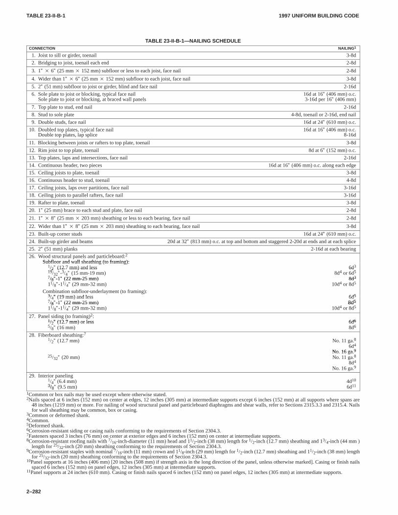
TABLE 23-II-B-1TABLE 23-II-B-1
1997 UNIFORM BUILDING CODE
2–282
TABLE 23-II-B-1—NAILING SCHEDULECONNECTION NAILING1
1. Joist to sill or girder, toenail 3-8d
2. Bridging to joist, toenail each end 2-8d
3. 1” � 6” (25 mm � 152 mm) subfloor or less to each joist, face nail 2-8d
4. Wider than 1” � 6” (25 mm � 152 mm) subfloor to each joist, face nail 3-8d
5. 2” (51 mm) subfloor to joist or girder, blind and face nail 2-16d
6. Sole plate to joist or blocking, typical face nail 16d at 16” (406 mm) o.c.Sole plate to joist or blocking, at braced wall panels 3-16d per 16” (406 mm)
7. Top plate to stud, end nail 2-16d
8. Stud to sole plate 4-8d, toenail or 2-16d, end nail
9. Double studs, face nail 16d at 24” (610 mm) o.c.
10. Doubled top plates, typical face nail 16d at 16” (406 mm) o.c.Double top plates, lap splice 8-16d
11. Blocking between joists or rafters to top plate, toenail 3-8d
12. Rim joist to top plate, toenail 8d at 6” (152 mm) o.c.
13. Top plates, laps and intersections, face nail 2-16d
14. Continuous header, two pieces 16d at 16” (406 mm) o.c. along each edge
15. Ceiling joists to plate, toenail 3-8d
16. Continuous header to stud, toenail 4-8d
17. Ceiling joists, laps over partitions, face nail 3-16d
18. Ceiling joists to parallel rafters, face nail 3-16d
19. Rafter to plate, toenail 3-8d
20. 1” (25 mm) brace to each stud and plate, face nail 2-8d
21. 1” � 8” (25 mm � 203 mm) sheathing or less to each bearing, face nail 2-8d
22. Wider than 1” � 8” (25 mm � 203 mm) sheathing to each bearing, face nail 3-8d
23. Built-up corner studs 16d at 24” (610 mm) o.c.
24. Built-up girder and beams 20d at 32” (813 mm) o.c. at top and bottom and staggered 2-20d at ends and at each splice
25. 2” (51 mm) planks 2-16d at each bearing
26. Wood structural panels and particleboard:2
Subfloor and wall sheathing (to framing):Subfloor and wall sheathing (to framing):1/2” (12.7 mm) and less 6d319 ” 3 ” 4 5/2” (12.7 mm) and less 6d
19/32”-3/4” (15 mm-19 mm) 8d4 or 6d57/8”-1” (22 mm-25 mm) 8d37/8”-1” (22 mm-25 mm) 8d3
11/8”-11/4” (29 mm-32 mm) 10d4 or 8d5
Combination subfloor-underlayment (to framing):3/ ” (19 mm) and less 6d53/4” (19 mm) and less 6d57/8”-1” (22 mm-25 mm) 8d57/8”-1” (22 mm-25 mm) 8d511/8”-11/4” (29 mm-32 mm) 10d4 or 8d5
27. Panel siding (to framing)2:1/2” (12 7 mm) or less 6d61/2” (12.7 mm) or less 6d65/8” (16 mm) 8d6
28. Fiberboard sheathing:71/2” (12.7 mm) No. 11 ga.8
6d4
No 16 ga9No. 16 ga.925/32” (20 mm) No. 11 ga.8
8d4
No. 16 ga.9
29. Interior paneling1/4” (6.4 mm) 4d103/8” (9.5 mm) 6d11
1Common or box nails may be used except where otherwise stated.2Nails spaced at 6 inches (152 mm) on center at edges, 12 inches (305 mm) at intermediate supports except 6 inches (152 mm) at all supports where spans are
48 inches (1219 mm) or more. For nailing of wood structural panel and particleboard diaphragms and shear walls, refer to Sections 2315.3.3 and 2315.4. Nailsfor wall sheathing may be common, box or casing.
3Common or deformed shank.4Common.5Deformed shank.6Corrosion-resistant siding or casing nails conforming to the requirements of Section 2304.3.7Fasteners spaced 3 inches (76 mm) on center at exterior edges and 6 inches (152 mm) on center at intermediate supports.8Corrosion-resistant roofing nails with 7/16-inch-diameter (11 mm) head and 11/2-inch (38 mm) length for 1/2-inch (12.7 mm) sheathing and 13/4-inch (44 mm )
length for 25/32-inch (20 mm) sheathing conforming to the requirements of Section 2304.3.9Corrosion-resistant staples with nominal 7/16-inch (11 mm) crown and 11/8-inch (29 mm) length for 1/2-inch (12.7 mm) sheathing and 11/2-inch (38 mm) length
for 25/32-inch (20 mm) sheathing conforming to the requirements of Section 2304.3.10Panel supports at 16 inches (406 mm) [20 inches (508 mm) if strength axis in the long direction of the panel, unless otherwise marked]. Casing or finish nails
spaced 6 inches (152 mm) on panel edges, 12 inches (305 mm) at intermediate supports.11Panel supports at 24 inches (610 mm). Casing or finish nails spaced 6 inches (152 mm) on panel edges, 12 inches (305 mm) at intermediate supports.
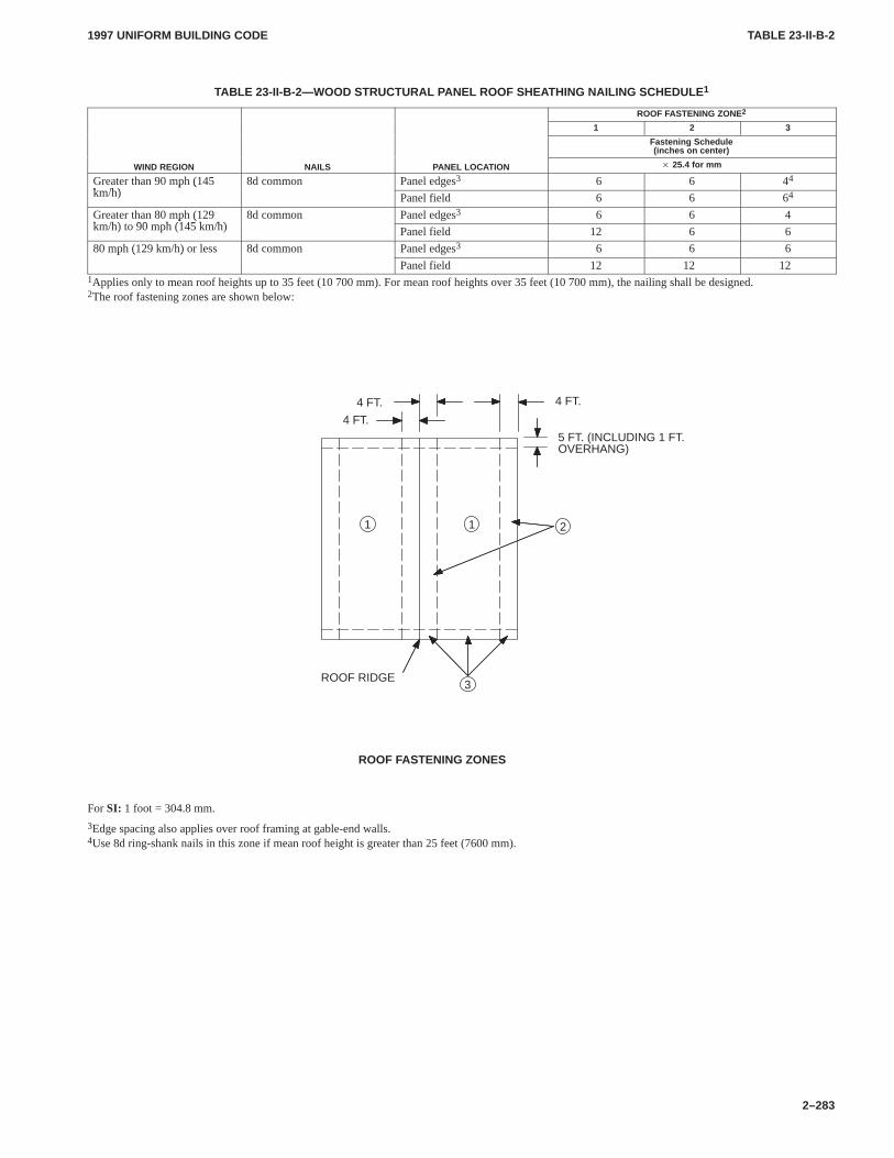
TABLE 23-II-B-2TABLE 23-II-B-2
1997 UNIFORM BUILDING CODE
2–283
TABLE 23-II-B-2—WOOD STRUCTURAL P ANEL ROOF SHEATHING NAILING SCHEDULE 1
ROOF FASTENING ZONE2
1 2 3
Fastening Schedule(inches on center)
WIND REGION NAILS PANEL LOCATION � 25.4 for mm
Greater than 90 mph (145k /h)
8d common Panel edges3 6 6 44p (km/h) Panel field 6 6 64
Greater than 80 mph (129k /h) t 90 h (145 k /h)
8d common Panel edges3 6 6 4p (km/h) to 90 mph (145 km/h) Panel field 12 6 6
80 mph (129 km/h) or less 8d common Panel edges3 6 6 6p ( )
Panel field 12 12 121Applies only to mean roof heights up to 35 feet (10 700 mm). For mean roof heights over 35 feet (10 700 mm), the nailing shall be designed.2The roof fastening zones are shown below:
ROOF FASTENING ZONES
5 FT. (INCLUDING 1 FT.OVERHANG)
1 1
3
2
4 FT.
ROOF RIDGE
4 FT. 4 FT.
For SI: 1 foot = 304.8 mm.
3Edge spacing also applies over roof framing at gable-end walls.4Use 8d ring-shank nails in this zone if mean roof height is greater than 25 feet (7600 mm).
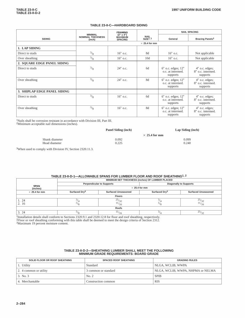
TABLE 23-II-CTABLE 23-II-D-2
1997 UNIFORM BUILDING CODE
2–284
TABLE 23-II-C—HARDBOARD SIDING
MINIMALFRAMING(2” 4”)
NAIL SPACING
SIDING
MINIMALNOMINAL THICKNESS
(inch)
FRAMING(2” x 4”)
MAXIMUMSPACING
NAILSIZE1, 2 General Bracing Panels 3
� 25.4 for mm
1. LAP SIDING
Direct to studs 3/8 16” o.c. 8d 16” o.c. Not applicable
Over sheathing 3/8 16” o.c. 10d 16” o.c. Not applicable
2. SQUARE EDGE PANEL SIDING
Direct to studs 3/8 24” o.c. 6d 6” o.c. edges; 12”o.c. at intermed.
supports
4” o.c. edges;8” o.c. intermed.
supports
Over sheathing 3/8 24” o.c. 8d 6” o.c. edges; 12”o.c. at intermed.
supports
4” o.c. edges;8” o.c. intermed.
supports
3. SHIPLAP EDGE PANEL SIDING
Direct to studs 3/8 16” o.c. 6d 6” o.c. edges; 12”o.c. at intermed.
supports
4” o.c. edges;8” o.c. intermed.
supports
Over sheathing 3/8 16” o.c. 8d 6” o.c. edges; 12”o.c. at intermed.
supports
4” o.c. edges;8” o.c. intermed.
supports
1Nails shall be corrosion resistant in accordance with Division III, Part III.2Minimum acceptable nail dimensions (inches).
Panel Siding (inch) Lap Siding (inch)
� 25.4 for mmShank diameterHead diameter
0.0920.225
0.0990.240
3When used to comply with Division IV, Section 2320.11.3.
TABLE 23-II-D-1—ALLOWABLE SPANS FOR LUMBER FLOOR AND ROOF SHEA THING1, 2
MINIMUM NET THICKNESS (inches) OF LUMBER PLACED
SPANPerpendicular to Supports Diagonally to Supports
SPAN(inches) � 25.4 for mm
� 25.4 for mm Surfaced Dry 3 Surfaced Unseasoned Surfaced Dry 3 Surfaced Unseasoned
Floors
1. 242. 16
3/45/8
25/3211/16
3/45/8
25/3211/16
Roofs
3. 24 5/8 11/163/4 25/32
1Installation details shall conform to Sections 2320.9.1 and 2320.12.8 for floor and roof sheathing, respectively.2Floor or roof sheathing conforming with this table shall be deemed to meet the design criteria of Section 2312.3Maximum 19 percent moisture content.
TABLE 23-II-D-2—SHEATHING LUMBER SHALL MEET THE FOLLOWINGMINIMUM GRADE REQUIREMENTS: BOARD GRADE
SOLID FLOOR OR ROOF SHEATHING SPACED ROOF SHEATHING GRADING RULES
1. Utility Standard NLGA, WCLIB, WWPA
2. 4 common or utility 3 common or standard NLGA, WCLIB, WWPA, NHPMA or NELMA
3. No. 3 No. 2 SPIB
4. Merchantable Construction common RIS
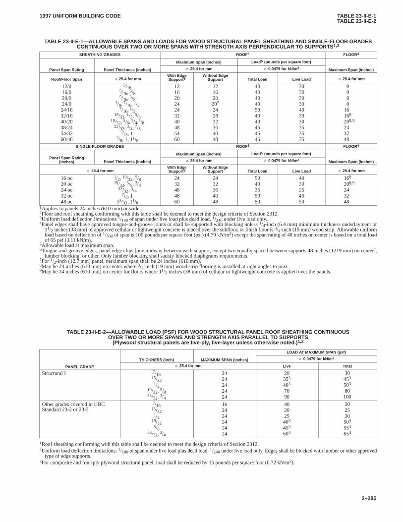
TABLE 23-II-E-1TABLE 23-II-E-2
1997 UNIFORM BUILDING CODE
2–285
TABLE 23-II-E-1—ALLOW ABLE SPANS AND LOADS FOR WOOD STRUCTURAL P ANEL SHEATHING AND SINGLE-FLOOR GRADESCONTINUOUS OVER TWO OR MORE SPANS WITH STRENGTH AXIS PERPENDICULAR T O SUPPORTS1,2
SHEATHING GRADES ROOF3 FLOOR4
Maximum Span (inches) Load 5 (pounds per square foot)
Panel Span Rating Panel Thickness (inches) � 25.4 for mm � 0.0479 for kN/m 2 Maximum Span (inches)
Roof/Floor Span � 25.4 for mmWith EdgeSupport 6
Without EdgeSupport Total Load Live Load � 25.4 for mm
12/016/020/024/024/1632/1640/2048/2454/3260/48
5/165/16, 3/85/16, 3/8
3/8, 7/16, 1/27/16, 1/2
15/32, 1/2, 5/819/32, 5/8, 3/4,7/8
23/32, 3/4, 7/87/8, 1
7/8, 1, 11/8
12162024243240485460
121620207
242832364048
40404040504040454545
30303030403030353535
0000
16168
208,9
243248
SINGLE-FLOOR GRADES ROOF3 FLOOR4
Panel Span RatingMaximum Span (inches) Load 5 (pounds per square foot)
Panel Span Rating(inches) Panel Thickness (inches) � 25.4 for mm � 0.0479 for kN/m 2 Maximum Span (inches)
� 25.4 for mmWith EdgeSupport 6
Without EdgeSupport Total Load Live Load � 25.4 for mm
16 oc20 oc24 oc32 oc48 oc
1/2, 19/32, 5/819/32, 5/8, 3/4
23/32, 3/47/8, 1
13/32, 11/8
2432484860
2432364048
5040355050
4030254050
168
208,9
243248
1Applies to panels 24 inches (610 mm) or wider.2Floor and roof sheathing conforming with this table shall be deemed to meet the design criteria of Section 2312.3Uniform load deflection limitations 1/180 of span under live load plus dead load, 1/240 under live load only.4Panel edges shall have approved tongue-and-groove joints or shall be supported with blocking unless 1/4-inch (6.4 mm) minimum thickness underlayment or
11/2 inches (38 mm) of approved cellular or lightweight concrete is placed over the subfloor, or finish floor is 3/4-inch (19 mm) wood strip. Allowable uniformload based on deflection of 1/360 of span is 100 pounds per square foot (psf) (4.79 kN/m2) except the span rating of 48 inches on center is based on a total loadof 65 psf (3.11 kN/m).
5Allowable load at maximum span.6Tongue-and-groove edges, panel edge clips [one midway between each support, except two equally spaced between supports 48 inches (1219 mm) on center],
lumber blocking, or other. Only lumber blocking shall satisfy blocked diaphgrams requirements.7For 1/2-inch (12.7 mm) panel, maximum span shall be 24 inches (610 mm).8May be 24 inches (610 mm) on center where 3/4-inch (19 mm) wood strip flooring is installed at right angles to joist.9May be 24 inches (610 mm) on center for floors where 11/2 inches (38 mm) of cellular or lightweight concrete is applied over the panels.
TABLE 23-II-E-2—ALLOWABLE LOAD (PSF) FOR WOOD STRUCTURAL P ANEL ROOF SHEATHING CONTINUOUSOVER TWO OR MORE SPANS AND STRENGTH AXIS PARALLEL T O SUPPORTS
(Plywood structural panels are five-ply , five-layer unless otherwise noted.) 1,2
LOAD AT MAXIMUM SPAN (psf)
THICKNESS (inch) MAXIMUM SPAN (inches) � 0.0479 for kN/m 2
PANEL GRADE � 25.4 for mm Live Total
Structural I 7/1615/321/2
19/32, 5/823/32, 3/4
2424242424
20353
403
7090
30453
503
80100
Other grades covered in UBCStandard 23-2 or 23-3
7/1615/321/2
19/325/8
23/32, 3/4
162424242424
402025403
453
603
502530503
553
653
1Roof sheathing conforming with this table shall be deemed to meet the design criteria of Section 2312.2Uniform load deflection limitations: 1/180 of span under live load plus dead load, 1/240 under live load only. Edges shall be blocked with lumber or other approved
type of edge supports.3For composite and four-ply plywood structural panel, load shall be reduced by 15 pounds per square foot (0.72 kN/m2).
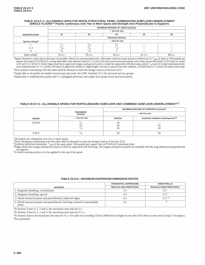
TABLE 23-II-F-1TABLE 23-II-G
1997 UNIFORM BUILDING CODE
2–286
TABLE 23-II-F-1—ALLOW ABLE SPAN FOR WOOD STRUCTURAL PANEL COMBINA TION SUBFLOOR-UNDERLAYMENT(SINGLE FLOOR)1,2 Panels Continuous over T wo or More Spans and Strength Axis Perpendicular to Supports
MAXIMUM SPACING OF JOISTS (inches)
� 25.4 for mm
IDENTIFICATION 16 20 24 32 48
Thickness (inches)
Species Group 3 � 25.4 for mm
12, 34
1/25/83/4
5/83/47/8
3/47/81
———
———
Span rating4 16 o.c. 20 o.c. 24 o.c. 32 o.c. 48 o.c.1Spans limited to value shown because of possible effects of concentrated loads. Allowable uniform loads based on deflection of 1/360 of span is 100 pounds per
square foot (psf) (4.79 kN/m2), except allowable total uniform load for 11/8-inch (29 mm) wood structural panels over joists spaced 48 inches (1219 mm) on centeris 65 psf (3.11 kN/m2). Panel edges shall have approved tongue-and-groove joints or shall be supported with blocking, unless 1/4-inch (6.4 mm) minimum thick-ness underlayment or 11/2 inches (38 mm) of approved cellular or lightweight concrete is placed over the subfloor, or finish floor is 3/4-inch (19 mm) wood strip.
2Floor panels conforming with this table shall be deemed to meet the design criteria of Section 2312.3Applicable to all grades of sanded exterior-type plywood. See UBC Standard 23-2 for plywood species groups.4Applicable to underlayment grade and C-C (plugged) plywood, and single floor grade wood structural panels.
TABLE 23-II-F-2—ALLOWABLE SPANS FOR PARTICLEBOARD SUBFLOOR AND COMBINED SUBFLOOR-UNDERLAYMENT 1,2
THICKNESSMAXIMUM SPACING OF SUPPORTS (inches) 3
THICKNESS(inches) � 25.4 for mm
GRADE � 25.4 for mm Subfloor Combined Subfloor-Underlayment 4,5
2-M-W 1/25/83/4
162024
—1624
2-M-3 3/4 20 20
1All panels are continuous over two or more spans.2Floor sheathing conforming with this table shall be deemed to meet the design criteria of Section 2312.3Uniform deflection limitation: 1/360 of the span under 100 pounds per square foot (4.79 kN/m2) minimum load.4Edges shall have tongue-and-groove joints or shall be supported with blocking. The tongue-and-groove panels are installed with the long dimension perpendicular
to supports.5A finish wearing surface is to be applied to the top of the panel.
TABLE 23-II-G—MAXIMUM DIAPHRAGM DIMENSION RA TIOS
HORIZONTAL DIAPHRAGMS SHEAR WALLS
MATERIAL Maximum Span-Width Ratios Maximum Height-Width Ratios
1. Diagonal sheathing, conventional 3:1 1:11
2. Diagonal sheathing, special 4:1 2:12
3. Wood structural panels and particleboard, nailed all edges 4:1 2:12, 3
4. Wood structural panels and particleboard, blocking omitted at intermediatejoints.
4:1 4
1In Seismic Zones 0, 1, 2 and 3, the maximum ratio may be 2:1.2In Seismic Zones 0, 1, 2 and 3, the maximum ratio may be 31/2:1.3In Seismic Zone 4, the maximum ratio may be 31/2:1 for walls not exceeding 10 feet (3048 mm) in height on one side of the door to a one-story Group U Occupancy.4Not permitted.
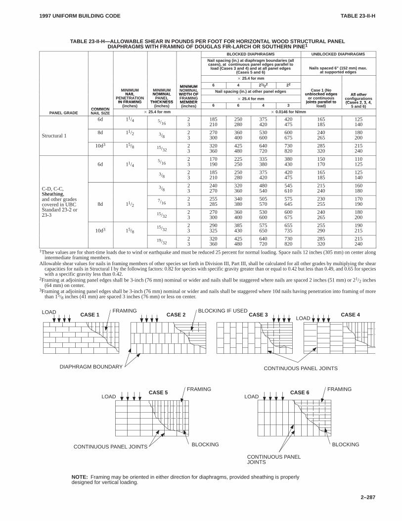
TABLE 23-II-HTABLE 23-II-H
1997 UNIFORM BUILDING CODE
2–287
TABLE 23-II-H—ALLOW ABLE SHEAR IN POUNDS PER FOOT FOR HORIZONTAL WOOD STRUCTURAL P ANELDIAPHRAGMS WITH FRAMING OF DOUGLAS FIR-LARCH OR SOUTHERN PINE 1
BLOCKED DIAPHRAGMS UNBLOCKED DIAPHRAGMS
Nail spacing (in.) at diaphragm boundaries (allcases), at continuous panel edges parallel to
load (Cases 3 and 4) and at all panel edges(Cases 5 and 6)
Nails spaced 6 ” (152 mm) max.at supported edges
� 25.4 for mm
MINIMUM 6 4 21/22 22
MINIMUMNAIL
MINIMUMNOMINAL
MINIMUMNOMINALWIDTH OF
Nail spacing (in.) at other panel edges Case 1 (Nounblocked edges All otherNAIL
PENETRATIONIN FRAMING
NOMINALPANEL
THICKNESS
WIDTH OFFRAMINGMEMBER
� 25.4 for mmunblocked edges
or continuousjoints parallel to
All otherconfigurations(Cases 2 3 4
COMMON
IN FRAMING(inches)
THICKNESS(inches)
MEMBER(inches) 6 6 4 3
joints parallel toload)
g(Cases 2, 3, 4,
5 and 6)
PANEL GRADECOMMONNAIL SIZE � 25.4 for mm � 0.0146 for N/mm
6d 11/4 5/1623
185210
250280
375420
420475
165185
125140
Structural 18d 11/2 3/8
23
270300
360400
530600
600675
240265
180200
10d3 15/8 15/3223
320360
425480
640720
730820
285320
215240
6d 11/45/16
23
170190
225250
335380
380430
150170
110125
3/823
185210
250280
375420
420475
165185
125140
C-D, C-C,Sheathing,
3/823
240270
320360
480540
545610
215240
160180
Sheathing,and other grades covered in UBCSt d d 23 2
8d 11/27/16
23
255285
340380
505570
575645
230255
170190
Standard 23-2 or23-3 15/32
23
270300
360400
530600
600675
240265
180200
10d3 15/815/32
23
290325
385430
575650
655735
255290
190215
19/3223
320360
425480
640720
730820
285320
215240
1These values are for short-time loads due to wind or earthquake and must be reduced 25 percent for normal loading. Space nails 12 inches (305 mm) on center alongintermediate framing members.
Allowable shear values for nails in framing members of other species set forth in Division III, Part III, shall be calculated for all other grades by multiplying the shearcapacities for nails in Structural I by the following factors: 0.82 for species with specific gravity greater than or equal to 0.42 but less than 0.49, and 0.65 for specieswith a specific gravity less than 0.42.
2Framing at adjoining panel edges shall be 3-inch (76 mm) nominal or wider and nails shall be staggered where nails are spaced 2 inches (51 mm) or 21/2 inches(64 mm) on center.
3Framing at adjoining panel edges shall be 3-inch (76 mm) nominal or wider and nails shall be staggered where 10d nails having penetration into framing of morethan 15/8 inches (41 mm) are spaced 3 inches (76 mm) or less on center.
CASE 5
FRAMINGCASE 1
NOTE: Framing may be oriented in either direction for diaphragms, provided sheathing is properlydesigned for vertical loading.
CONTINUOUS PANEL JOINTS
CASE 6FRAMING
BLOCKING
CASE 2 CASE 3 CASE 4
DIAPHRAGM BOUNDARY
BLOCKING IF USEDLOADLOAD
LOAD
CONTINUOUS PANEL JOINTS
LOADFRAMING
BLOCKING
CONTINUOUS PANELJOINTS
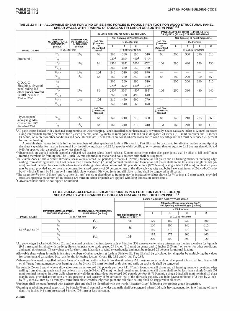
TABLE 23-II-I-1TABLE 23-II-I-2
1997 UNIFORM BUILDING CODE
2–288
TABLE 23-II-I-1—ALLOW ABLE SHEAR FOR WIND OR SEISMIC FORCES IN POUNDS PER FOOT FOR WOOD STRUCTURAL P ANELSHEAR WALLS WITH FRAMING OF DOUGLAS FIR-LARCH OR SOUTHERN PINE 1,2,3
PANELS APPLIED DIRECTLY TO FRAMINGPANELS APPLIED OVER 1/2-INCH (13 mm)OR 5/8-INCH (16 mm) GYPSUM SHEATHING
MINIMUM MINIMUM NAILNail Spacing at Panel Edges (in.) Nail Spacing at Panel Edges (in.)
MINIMUMNOMINAL PANEL
THICKNESS
MINIMUM NAILPENETRATION
IN FRAMINGNail Size
(Common� 25.4 for mm Nail Size
(Common� 25.4 for mm
THICKNESS(inches)
IN FRAMING(inches)
(Commonor
Galvanized6 4 3 2
(Commonor
Galvanized6 4 3 2
PANEL GRADE � 25.4 for mmGalvanized
Box) 5 � 0.0146 for N/mmGalvanized
Box) 5 � 0.0146 for N/mm
5/16 11/4 6d 200 300 390 510 8d 200 300 390 510
Structural I 3/8 2304 3604 4604 6104
7/16 11/2 8d 2554 3954 5054 6704 10d 280 430 550 73015/32 280 430 550 73015/32 15/8 10d 340 510 665 870 — — — — —5/16 11/4 6d 180 270 350 450 8d 180 270 350 450
C-D, C-C3/8 200 300 390 510 200 300 390 510C-D, C-C
Sheathing, plywoodpanel siding and
3/8 2204 3204 4104 5304g, p ypanel siding andother grades covered
7/16 11/2 8d 2404 3504 4504 5854 10d 260 380 490 640other grades coveredin UBC Standard23 2 23 3
15/32 260 380 490 640U C Sta da d23-2 or 23-3 15/32 15/8 10d 310 460 600 770 — — — — —
19/32 340 510 665 870Nail Size
(GalvanizedCasing)
Nail Size(Galvanized
Casing)
Plywood panelsiding in grades
5/16 11/4 6d 140 210 275 360 8d 140 210 275 360siding in gradescovered in UBCStandard 23-2
3/8 11/2 8d 160 240 310 410 10d 160 240 310 410
1All panel edges backed with 2-inch (51 mm) nominal or wider framing. Panels installed either horizontally or vertically. Space nails at 6 inches (152 mm) on centeralong intermediate framing members for 3/8-inch (9.5 mm) and 7/16-inch (11 mm) panels installed on studs spaced 24 inches (610 mm) on center and 12 inches(305 mm) on center for other conditions and panel thicknesses. These values are for short-time loads due to wind or earthquake and must be reduced 25 percentfor normal loading.
Allowable shear values for nails in framing members of other species set forth in Division III, Part III, shall be calculated for all other grades by multiplyingthe shear capacities for nails in Structural I by the following factors: 0.82 for species with specific gravity greater than or equal to 0.42 but less than 0.49, and0.65 for species with a specific gravity less than 0.42.
2Where panels are applied on both faces of a wall and nail spacing is less than 6 inches (152 mm) on center on either side, panel joints shall be offset to fall on differentframing members or framing shall be 3-inch (76 mm) nominal or thicker and nails on each side shall be staggered.
3In Seismic Zones 3 and 4, where allowable shear values exceed 350 pounds per foot (5.11 N/mm), foundation sill plates and all framing members receiving edgenailing from abutting panels shall not be less than a single 3-inch (76 mm) nominal member and foundation sill plates shall not be less than a single 3-inch (76mm) nominal member. In shear walls where total wall design shear does not exceed 600 pounds per foot (8.76 N/mm), a single 2-inch (51 mm) nominal sill platemay be used, provided anchor bolts are designed for a load capacity of 50 percent or less of the allowable capacity and bolts have a minimum of 2-inch-by-2-inch-by-3/16-inch (51 mm by 51 mm by 5 mm) thick plate washers. Plywood joint and sill plate nailing shall be staggered in all cases.
4The values for 3/8-inch (9.5 mm) and 7/16-inch (11 mm) panels applied direct to framing may be increased to values shown for 15/32-inch (12 mm) panels, providedstuds are spaced a maximum of 16 inches (406 mm) on center or panels are applied with long dimension across studs.
5Galvanized nails shall be hot-dipped or tumbled.
TABLE 23-II-I-2—ALLOWABLE SHEAR IN POUNDS PER FOOT FOR P ARTICLEBOARDSHEAR WALLS WITH FRAMING OF DOUGLAS FIR-LARCH OR SOUTHERN PINE 1,2,3
PANELS APPLIED DIRECT TO FRAMING
Allowable Shear (pounds per foot) 1
Nail Spacing at Panel Edges (inches)
MINIMUM NOMINAL PANEL MINIMUM NAIL PENETRATION� 25.4 for mm
MINIMUM NOMINAL PANELTHICKNESS (inches)
MINIMUM NAIL PENETRATIONIN FRAMING (inches)
Nail size (Common or6 4 3 2
PANEL GRADE � 25.4 for mmNail size (Common or
Galvanized Box) � 0.0146 for N/mm3/8 11/2 6d 120 180 230 3003/8 11/2 8d
130 190 240 315
M-S4 and M-24 1/211/2 8d
140 210 270 3501/2 15/8 10d5 185 275 360 4605/8
15/8 10d5200 305 395 520
1All panel edges backed with 2-inch (51 mm) nominal or wider framing. Space nails at 6 inches (152 mm) on center along intermediate framing members for 3/8-inch(9.5 mm) panel installed with the long dimension parallel to studs spaced 24 inches (610 mm) on center and 12 inches (305 mm) on center for other conditionsand panel thicknesses. These values are for short-time loads due to wind or earthquake and must be reduced 25 percent for normal loading.
Allowable shear values for nails in framing members of other species set forth in Division III, Part III, shall be calculated for all grades by multiplying the valuesfor common and galvanized box nails by the following factors: Group III, 0.82 and Group IV, 0.65.
2Where particleboard is applied on both faces of a wall and nail spacing is less than 6 inches (152 mm) on center on either side, panel joints shall be offset to fallon different framing members, or framing shall be 3-inch (76 mm) nominal or thicker and nails on each side shall be staggered.
3In Seismic Zones 3 and 4, where allowable shear values exceed 350 pounds per foot (5.11 N/mm), foundation sill plates and all framing members receiving edgenailing from abutting panels shall not be less than a single 3-inch (76 mm) nominal member and foundation sill plates shall not be less than a single 3-inch (76mm) nominal member. In shear walls where total wall design shear does not exceed 600 pounds per foot (8.76 N/mm), a single 2-inch (51 mm) nominal sill platemay be used, provided anchor bolts are designed for a load capacity of 50 percent or less of the allowable capacity and bolts have a minimum of 2-inch-by-2-inch-by-3/16-inch (51 mm by 51 mm by 5 mm) thick plate washers. Plywood joint and sill plate nailing shall be staggered in all cases.
4Products shall be manufactured with exterior glue and shall be identified with the words “Exterior Glue” following the product grade designation.5Framing at adjoining panel edges shall be 3-inch (76 mm) nominal or wider and nails shall be staggered where 10d nails having penetration into framing of more
than 15/8 inches (41 mm) are spaced 3 inches (76 mm) or less on center.
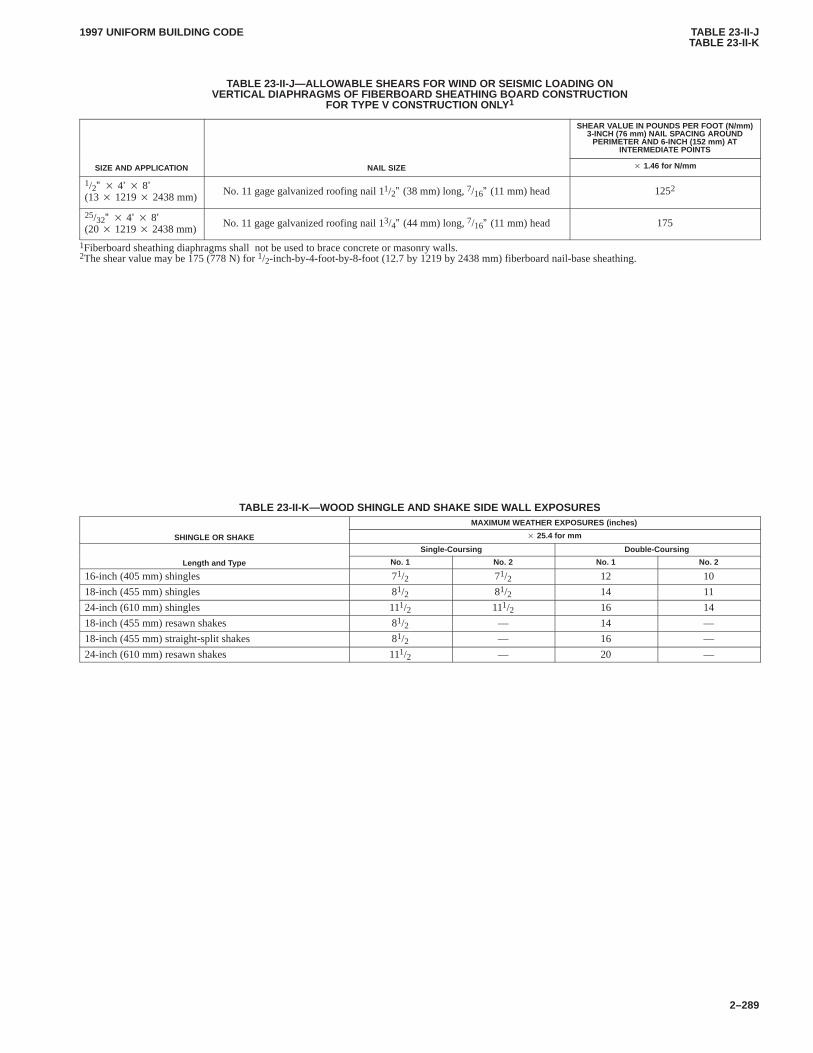
TABLE 23-II-JTABLE 23-II-K
1997 UNIFORM BUILDING CODE
2–289
TABLE 23-II-J—ALLOW ABLE SHEARS FOR WIND OR SEISMIC LOADING ONVERTICAL DIAPHRAGMS OF FIBERBOARD SHEA THING BOARD CONSTRUCTION
FOR TYPE V CONSTRUCTION ONLY1
SHEAR VALUE IN POUNDS PER FOOT (N/mm)3-INCH (76 mm) NAIL SPACING AROUND
PERIMETER AND 6-INCH (152 mm) ATINTERMEDIATE POINTS
SIZE AND APPLICATION NAIL SIZE � 1.46 for N/mm
1/2” � 4’ � 8’(13 � 1219 � 2438 mm)
No. 11 gage galvanized roofing nail 11/2” (38 mm) long, 7/16” (11 mm) head 1252
25/32” � 4’ � 8’(20 � 1219 � 2438 mm)
No. 11 gage galvanized roofing nail 13/4” (44 mm) long, 7/16” (11 mm) head 175
1Fiberboard sheathing diaphragms shall not be used to brace concrete or masonry walls.2The shear value may be 175 (778 N) for 1/2-inch-by-4-foot-by-8-foot (12.7 by 1219 by 2438 mm) fiberboard nail-base sheathing.
TABLE 23-II-K—WOOD SHINGLE AND SHAKE SIDE W ALL EXPOSURESMAXIMUM WEATHER EXPOSURES (inches)
SHINGLE OR SHAKE � 25.4 for mm
Single-Coursing Double-Coursing
Length and Type No. 1 No. 2 No. 1 No. 2
16-inch (405 mm) shingles 71/2 71/2 12 10
18-inch (455 mm) shingles 81/2 81/2 14 11
24-inch (610 mm) shingles 111/2 111/2 16 14
18-inch (455 mm) resawn shakes 81/2 — 14 —
18-inch (455 mm) straight-split shakes 81/2 — 16 —
24-inch (610 mm) resawn shakes 111/2 — 20 —
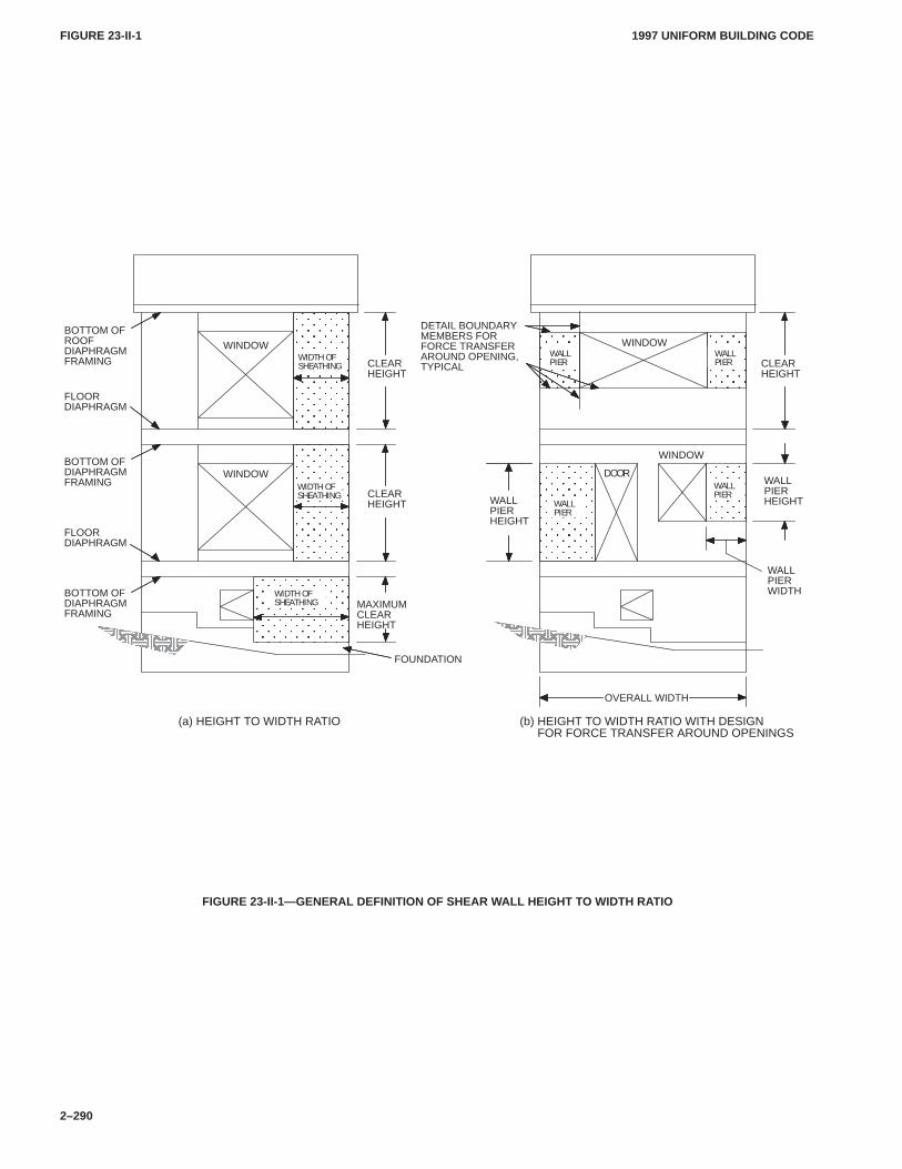
FIGURE 23-II-1FIGURE 23-II-1
1997 UNIFORM BUILDING CODE
2–290
ÏÏÏÏÏÏÏÏÏÏÏÏÏÏÏÏÏÏÏÏ
ÏÏÏÏÏÏÏÏÏÏÏÏÏÏÏÏÏÏÏÏÏÏÏÏÏÏÏÏÏÏÏÏÏÏÏÏÏÏÏÏÏÏÏÏÏÏÏÏÏÏÏÏÏÏÏÏÏÏÏÏÏÏÏÏÏÏÏÏ
ÏÏÏÏÏÏÏÏÏÏÏÏ
ÏÏÏÏÏÏÏÏ
ÏÏÏÏÏÏ
CLEARHEIGHT
CLEARHEIGHT
MAXIMUMCLEARHEIGHT
WIDTH OFSHEATHING
FLOORDIAPHRAGM
BOTTOM OFDIAPHRAGMFRAMING
BOTTOM OFROOFDIAPHRAGMFRAMING
BOTTOM OFDIAPHRAGMFRAMING
FLOORDIAPHRAGM
FOUNDATION
WINDOW
WINDOW
WINDOW
WINDOW
WALLPIER
CLEARHEIGHT
WALLPIERHEIGHTWALL
PIER
WALLPIER
WALLPIER
WALLPIERHEIGHT
OVERALL WIDTH
(b) HEIGHT TO WIDTH RATIO WITH DESIGNFOR FORCE TRANSFER AROUND OPENINGS
(a) HEIGHT TO WIDTH RATIO
DOOR
ÌÌÌÌÌÌÌÌÌÌ
ÌÌÌÌÌÌÌÌÌÌ
DETAIL BOUNDARYMEMBERS FORFORCE TRANSFERAROUND OPENING,TYPICAL
WIDTH OFSHEATHING
WIDTH OFSHEATHING
WALLPIERWIDTH
FIGURE 23-II-1—GENERAL DEFINITION OF SHEAR WALL HEIGHT T O WIDTH RATIO
CHAP. 23, DIV. III
2316.21997 UNIFORM BUILDING CODE
2–291
Division III—DESIGN SPECIFICATIONS FOR ALLOWABLE STRESS DESIGN OF WOOD BUILDINGS
Part I—ALLOWABLE STRESS DESIGN OF WOOD
This standard, with certain exceptions, is the ANSI/NFoPANDS-91 National Design Specification for Wood Constructionof the American Forest and Paper Association, Revised 1991Edition, and the Supplement to the 1991 Edition, NationalDesign Specification, adopted by reference.
The National Design Specification for Wood Construction,Revised 1991 Edition, and supplement are available from theAmerican Forest and Paper Association, 1111 19th Street, NW,Eighth Floor, Washington, DC, 20036.CHAP. 23, DIV. III
SECTION 2316 — DESIGN SPECIFICATIONS
2316.1 Adoption and Scope.The National Design Specifica-tion for Wood Construction, Revised 1991 Edition (NDS), whichis hereby adopted as a part of this code, shall apply to the designand construction of wood structures using visually graded lumber,mechanically graded lumber, structural glued laminated timber,and timber piles. National Design Specification Appendix SectionF, Design for Creep and Critical Deflection Applications, Appen-dix Section G, Effective Column Length, and Appendix Section J,Solution of Hankinson Formula are specifically adopted and madea part of this standard. The Supplement to the 1991 EditionNational Design Specification, Tables 2A, 4A, 4B, 4C, 4D, 4E,5A, 5B and 5C are specifically adopted and made a part of thisstandard.
Other codes, standards or specifications referred to in thisstandard are to be considered as only an indication of an accept-able method or material that can be used with the approval of thebuilding official, except where such other codes, standards orspecifications are specifically adopted by this code as primarystandards.
2316.2 Amendments.
1. Sec. 1.1. Delete and substitute the following:
The design of structures using visually graded lumber, mechan-ically graded lumber, structural glued laminated timber, timberpiles, and design of their connections shall be in accordance withChapter 23, Division III, Part 1.
2. Secs. 1.2 through 1.5. Delete.
3. Sec. 2.2. Delete first sentence and substitute the following:
Allowable stress design values for visually graded structurallumber, mechanically graded structural lumber and structuralglued laminated timber shall be in accordance with NDS Supple-ment Tables 2A, 4A, 4B, 4C, 4D, 5A, 5B and 5C. Values for spe-cies and grades not tabulated shall be submitted to the buildingofficial for approval.
4. Sec. 2.3.2.1. In fourth sentence, delete “or Figure B1 (seeAppendix B).”
5. Sec. 2.3.2.3. Delete and substitute the following:
2.3.2.3 When using Section 1612.3.1 basic load combinations, theLoad Duration Factor, CD, noted in Table 2.3.2 shall be permittedto be used. When using Section 1612.3.2 alternate load combina-tions, the one-third increase shall not be used concurrently withthe Load Duration Factor, CD.
6. Table 2.3.2. Delete and substitute as follows:
TABLE 2.3.2—LOAD DURATION FACTORS, CDDESIGN LOAD LOAD DURATION CD
Dead Load Permanent 0.9
Floor, Occupancy Live Load Ten Years 1.0
Snow Load Two Months 1.15
Roof Live Load Seven Days 1.25
Earthquake Load1 — 1.33
Wind Load2 — 1.33
Impact — 2.011.60 may be used for nailed and bolted connections exhibiting Mode III or IV
behavior, except that the increases for earthquake are not combined with theincrease allowed in Section 1612.3. The 60-percent increase for nailed andbolted connections exhibiting Mode III or IV behavior for earthquake shallnot be applicable to joist hangers, framing anchors, and other mechanicalfastenings, including straps and hold-down anchors. The 60-percent in-crease shall not apply to the allowable shear values in Tables 23-II-H,23-II-I-1, 23-II-I-2, 23-II-J or in Section 2315.3.
21.60 may be used for members and nailed and bolted connections exhibitingMode III or IV behavior, except that the increases for wind are not combinedwith the increase allowed in Section 1612.3. The 60-percent increase shallnot apply to the allowable shear values in Tables 23-II-H, 23-II-I-1,23-II-I-2, 23-II-J or in Section 2315.3.
7. Sec. 2.3.4. Add a second paragraph following Table 2.3.4:
The allowable unit stresses for fire-retardant-treated solid-sawnlumber and plywood, including fastener values, subject to pro-longed elevated temperatures from manufacturing or equipmentprocesses, but not exceeding 150�F (66�C), shall be developedfrom approved test methods that properly consider potentialstrength-reduction characteristics, including effects of heat andmoisture.
8. Sec. 2.3.6. Add second, third and fourth paragraphs asfollows:
The values for lumber and plywood impregnated with approvedfire-retardant chemicals, including fastener values, shall be sub-mitted to the building official for approval. Submittal to the build-ing official shall include all substantiating data. Such values shallbe developed from approved test methods and procedures thatconsider potential strength-reduction characteristics, includingthe effects of elevated temperatures and moisture. Other adjust-ments are applicable, except that the impact load-duration factorshall not apply.
Values for glued-laminated timber, including fastener designvalues, shall be recommended by the treater and submitted to thebuilding official for approval. Submittal to the building officialshall include all substantiating data.
In addition to the requirements specified in Section 207, fire-retardant lumber having structural applications shall be tested andidentified by an approved inspection agency in accordance withUBC Standard 23-5.
9. Sec. 2.3.8. Add new second and third paragraphs follow-ing Table 2.3.8:
For lumber I beams and box beams, the form factor, Cf, shall becalculated as:
Cf � �1��d2 � 143d2 � 88
� 1� Cg�
For SI: Cf ��
1��� d25.4�2 � 143
� d25.4�2 � 88
� 1� Cg���
2316
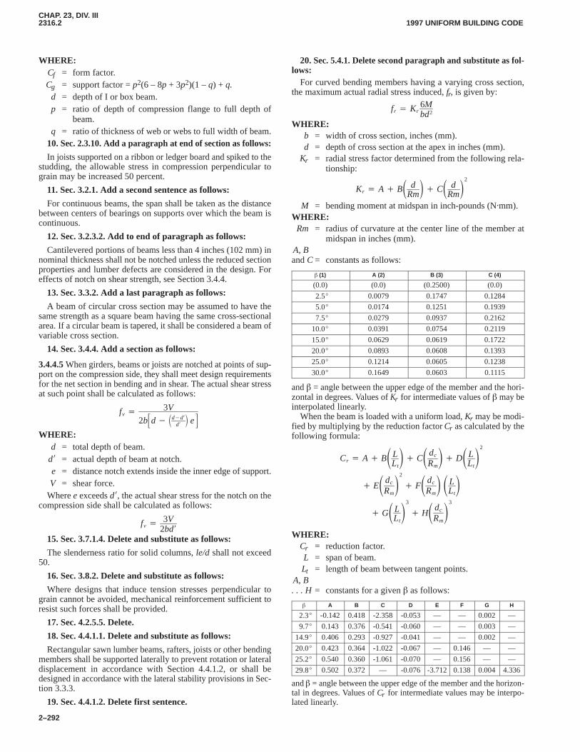
CHAP. 23, DIV. III2316.22316.2
1997 UNIFORM BUILDING CODE
2–292
WHERE:Cf = form factor.Cg = support factor = p2(6 – 8p + 3p2)(1 – q) + q.
d = depth of I or box beam.p = ratio of depth of compression flange to full depth of
beam.q = ratio of thickness of web or webs to full width of beam.
10. Sec. 2.3.10. Add a paragraph at end of section as follows:
In joists supported on a ribbon or ledger board and spiked to thestudding, the allowable stress in compression perpendicular tograin may be increased 50 percent.
11. Sec. 3.2.1. Add a second sentence as follows:
For continuous beams, the span shall be taken as the distancebetween centers of bearings on supports over which the beam iscontinuous.
12. Sec. 3.2.3.2. Add to end of paragraph as follows:
Cantilevered portions of beams less than 4 inches (102 mm) innominal thickness shall not be notched unless the reduced sectionproperties and lumber defects are considered in the design. Foreffects of notch on shear strength, see Section 3.4.4.
13. Sec. 3.3.2. Add a last paragraph as follows:
A beam of circular cross section may be assumed to have thesame strength as a square beam having the same cross-sectionalarea. If a circular beam is tapered, it shall be considered a beam ofvariable cross section.
14. Sec. 3.4.4. Add a section as follows:
3.4.4.5 When girders, beams or joists are notched at points of sup-port on the compression side, they shall meet design requirementsfor the net section in bending and in shear. The actual shear stressat such point shall be calculated as follows:
fv � 3V
2b�d� �d�d�d�� e�
WHERE:d = total depth of beam.
d� = actual depth of beam at notch.e = distance notch extends inside the inner edge of support.V = shear force.
Where e exceeds d�, the actual shear stress for the notch on thecompression side shall be calculated as follows:
fv � 3V2bd�
15. Sec. 3.7.1.4. Delete and substitute as follows:
The slenderness ratio for solid columns, le/d shall not exceed50.
16. Sec. 3.8.2. Delete and substitute as follows:
Where designs that induce tension stresses perpendicular tograin cannot be avoided, mechanical reinforcement sufficient toresist such forces shall be provided.
17. Sec. 4.2.5.5. Delete.
18. Sec. 4.4.1.1. Delete and substitute as follows:
Rectangular sawn lumber beams, rafters, joists or other bendingmembers shall be supported laterally to prevent rotation or lateraldisplacement in accordance with Section 4.4.1.2, or shall bedesigned in accordance with the lateral stability provisions in Sec-tion 3.3.3.
19. Sec. 4.4.1.2. Delete first sentence.
20. Sec. 5.4.1. Delete second paragraph and substitute as fol-lows:
For curved bending members having a varying cross section,the maximum actual radial stress induced, fr, is given by:
fr � Kr6Mbd2
WHERE:b = width of cross section, inches (mm).d = depth of cross section at the apex in inches (mm).
Kr = radial stress factor determined from the following rela-tionship:
Kr � A� B� dRm�� C� d
Rm�2
M = bending moment at midspan in inch-pounds (N�mm).WHERE:Rm = radius of curvature at the center line of the member at
midspan in inches (mm).A, Band C = constants as follows:
� (1) A (2) B (3) C (4)
(0.0) (0.0) (0.2500) (0.0)
2.5� 0.0079 0.1747 0.1284
5.0� 0.0174 0.1251 0.1939
7.5� 0.0279 0.0937 0.2162
10.0� 0.0391 0.0754 0.2119
15.0� 0.0629 0.0619 0.1722
20.0� 0.0893 0.0608 0.1393
25.0� 0.1214 0.0605 0.1238
30.0� 0.1649 0.0603 0.1115
and � = angle between the upper edge of the member and the hori-zontal in degrees. Values of Kr for intermediate values of � may beinterpolated linearly.
When the beam is loaded with a uniform load, Kr may be modi-fied by multiplying by the reduction factor Cr as calculated by thefollowing formula:
Cr � A� B�LLt�� C�dc
Rm�� D�L
Lt�2
� E�dc
Rm�2
� F�dc
Rm� �L
Lt�
� G�LLt�3
� H�dc
Rm�3
WHERE:Cr = reduction factor.L = span of beam.Lt = length of beam between tangent points.
A, B. . . H = constants for a given � as follows:
� A B C D E F G H
2.3� -0.142 0.418 -2.358 -0.053 — — 0.002 —
9.7� 0.143 0.376 -0.541 -0.060 — — 0.003 —
14.9� 0.406 0.293 -0.927 -0.041 — — 0.002 —
20.0� 0.423 0.364 -1.022 -0.067 — 0.146 — —
25.2� 0.540 0.360 -1.061 -0.070 — 0.156 — —
29.8� 0.502 0.372 — -0.076 -3.712 0.138 0.004 4.336
and � = angle between the upper edge of the member and the horizon-tal in degrees. Values of Cr for intermediate values may be interpo-lated linearly.
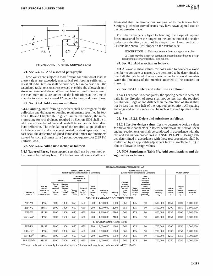
CHAP. 23, DIV. III2316.22316.2
1997 UNIFORM BUILDING CODE
2–293
P.T.
L
L1
�
P.T.
dc
dc/2
Rm
PITCHED AND TAPERED CURVED BEAM
21. Sec. 5.4.1.2. Add a second paragraph:
These values are subject to modification for duration of load. Ifthese values are exceeded, mechanical reinforcing sufficient toresist all radial tension shall be provided, but in no case shall thecalculated radial tension stress exceed one third the allowable unitstress in horizontal shear. When mechanical reinforcing is used,the maximum moisture content of the laminations at the time ofmanufacture shall not exceed 12 percent for dry conditions of use.
22. Sec. 5.4.4. Add a section as follows:
5.4.4 Ponding. Roof-framing members shall be designed for thedeflection and drainage or ponding requirements specified in Sec-tion 1506 and Chapter 16. In glued-laminated timbers, the mini-mum slope for roof drainage required by Section 1506 shall be inaddition to a camber of one and one-half times the calculated deadload deflection. The calculation of the required slope shall notinclude any vertical displacement created by short taper cuts. In nocase shall the deflection of glued-laminated timber roof membersexceed 1/2-inch (13 mm) for a 5 pound-per-square-foot (239 Pa)uniform load.
23. Sec. 5.4.5. Add a new section as follows:
5.4.5 Tapered Faces. Sawn tapered cuts shall not be permitted onthe tension face of any beam. Pitched or curved beams shall be so
fabricated that the laminations are parallel to the tension face.Straight, pitched or curved beams may have sawn tapered cuts onthe compression face.
For other members subject to bending, the slope of taperedfaces, measured from the tangent to the lamination of the sectionunder consideration, shall not be steeper than 1 unit vertical in24 units horizontal (4% slope) on the tension side.
EXCEPTIONS: 1. This requirement does not apply to arches.
2. Taper may be steeper at sections increased in size beyond designrequirements for architectural projections.
24. Sec. 8.3. Add a section as follows:
8.3 Allowable shear values for bolts used to connect a woodmember to concrete or masonry are permitted to be determined asone half the tabulated double shear value for a wood membertwice the thickness of the member attached to the concrete ormasonry.
25. Sec. 12.4.1. Delete and substitute as follows:
12.4.1 For wood-to-wood joints, the spacing center to center ofnails in the direction of stress shall not be less than the requiredpenetration. Edge or end distances in the direction of stress shallnot be less than one-half of the required penetration. All spacingand edge and end distances shall be such as to avoid splitting of thewood.
26. Sec. 13.2.1. Delete and substitute as follows:
13.2.1 Test for design values. Tests to determine design valuesfor metal plate connectors in lateral withdrawal, net section shearand net section tension shall be conducted in accordance with thetest and evaluation procedures in ANSI/TPI 1-1995. Design val-ues determined in accordance with these test procedures shall bemultiplied by all applicable adjustment factors (see Table 7.3.1) toobtain allowable design values.
27. NDS Supplement Table 5A. Add combinations and de-sign values as follows:
DESIGN VALUES IN POUNDS PER SQUARE INCH (psi)
BENDING ABOUT X–X AXIS(Loaded Perpendicular to Wide Faces of Laminations)
BENDING ABOUT Y–Y AXIS(Loaded Parallel to Wide Faces of Laminations) AXIALLY LOADED
Bending
CompressionPerpendicualr to
GrainCompres-
ShearParallel toGrain (ForMembers
COMBINATIONSYMBOl4
SPECIESOUTER
LAMINATIONS/CORE
LAMINATIONS5
TensionZoneStressedin
TensionFbxx
Compres-sion ZoneStressedin
Tension6Fbxx
TensionFace9,10 Fc⊥xx
Compres-sion
Face9,10 Fc⊥xx
ShearParallelto
Grain10Fvxx
Modulus ofElasticityExx
BendingFbyy
Compres-sion Per-pendicularto Grain(SideFaces)Fc⊥yy
ShearParallelto GrainFvyy
Grain (ForMembers
With MulitplePiece
LaminationsWhich arenot Edge
glued)13 Fvyy
Modulus ofElasticityEyy
TensionParallelto GrainFt
Compres-sionParallelto GrainFc
Modulus ofElasticityE
VISUALLY GRADED SOUTHERN PINE
26F–V1 SP/SP 2600 1300 650 650 200 1,800,000 1900 560 175 90 1,600,000 1150 1600 1,600,000
26F–V2 SP/SP 2600 1300 650 650 200 1,900,000 2200 650 175 90 1,800,000 1200 1650 1,800,000
26F–V3 SP/SP 2600 1300 650 650 200 1,900,000 2100 560 175 90 1,800,000 1150 1600 1,800,000
26F–V48 SP/SP 2600 2600 650 650 200 1,900,000 2100 560 175 90 1,800,000 1150 1600 1,800,000
E–RATED SOUTHERN PINE
28F–E1 SP/SP 2800 1400 650 650 200 2,000,000 1600 560 175 90 1,700,000 1300 1850 1,700,000
28F–E28 SP/SP 2800 2800 650 650 200 2,000,000 1600 560 175 90 1,700,000 1300 1850 1,700,000
30F–E115 SP/SP 3000 1500 650 650 200 2,000,000 1750 560 175 90 1,700,000 1250 1750 1,700,000
30F–E28,15 SP/SP 3000 3000 650 650 200 2,000,000 1750 560 175 90 1,700,000 1250 1750 1,700,000
15These combinations are only for nominal widths 6 inches and less, in accordance with AITC 117–93.
CHAP. 23, DIV. III2316.22319.5
1997 UNIFORM BUILDING CODE
2–294
Part II—PLYWOOD STRUCTURAL PANELS
SECTION 2317 — PLYWOOD STRUCTURAL PANELS
Values for plywood structural panels shall be in accordance withTable 23-III-A.
Part III—FASTENINGS
SECTION 2318 — TIMBER CONNECTORS ANDFASTENERS
2318.1 General. Timber connectors and fasteners may be used totransmit forces between wood members and between wood andmetal members. Allowable design values, Z and W, shall be deter-mined in accordance with Division III, Part I or this section. Modi-fications to allowable design values, and installation of timberconnectors and fasteners shall be in accordance with the provi-sions set forth in Division III, Part I.
2318.2 Bolts. Allowable lateral design values, Z||, Zm� and Zs�,in pounds for bolts in shear in seasoned lumber of Douglas fir-larch and Southern pine shall be as set forth in Tables 23-III-B-1and 23-III-B-2.
2318.3 Nails and Spikes.
2318.3.1 Allowable lateral loads. Allowable lateral design val-ues, Z, for common wire and box nails driven perpendicular to thegrain of the wood, when used to fasten wood members together,shall be as set forth in Tables 23-III-C-1 and 23-III-C-2.
A wire nail driven parallel to the grain of the wood shall not besubjected to more than two thirds of the lateral load allowed whendriven perpendicular to the grain. Toenails shall not be subjectedto more than five sixths of the lateral load allowed for nails drivenperpendicular to the grain.
In Seismic Zones 3 and 4, toenails shall not be used to transferlateral forces in excess of 150 pounds per foot (2188 N/m) fromdiaphragms to shear walls, drag struts (collectors) or other ele-ments, or from shear walls to other elements.
EXCEPTION: Structures built in accordance with Section 2320.
2318.3.2 Allowable withdrawal loads. Allowable withdrawaldesign values, W, for wire nails driven perpendicular to the grainof the wood shall be as set forth in Table 23-III-D.
Nails driven parallel to the grain of the wood shall not beallowed for resisting withdrawal forces.
2318.3.3 Spacing and penetration. Common wire nails shallhave penetration into the piece receiving the point as set forth inTables 23-III-C-1 and 23-III-C-2. Nails or spikes for which thegages or lengths are not set forth in Tables 23-III-C-1 and23-III-C-2 shall have a required penetration of not less than11 diameters, and allowable loads may be interpolated. Allowableloads shall not be increased when the penetration of nails into themember holding the point is larger than required by this section.
2318.4 Joist Hangers and Framing Anchors. Connections de-pending on joist hangers or framing anchors, ties and other me-chanical fastenings not otherwise covered may be used whereapproved.
2318.5 Miscellaneous Fasteners.
2318.5.1 Drift Bolts and Drift Pins.
2318.5.1.1 Withdrawal design values.Drift bolt and drift pinconnections loaded in withdrawal shall be designed in accordancewith good engineering practice.
2318.5.1.2 Lateral design values. Allowable lateral design val-ues for drift bolts and drift pins driven in the side grain of woodshall not exceed 75 percent of the allowable lateral design valuesfor common bolts of the same diameter and length in main mem-ber. Additional penetration of pin into members should be pro-vided in lieu of the washer, head and nut on a common bolt.
2318.5.2 Spike Grids.Wood-to-wood connections involvingspike grids for load transfer shall be designed in accordance withgood engineering practice.
Part IV—ALLOWABLE STRESS DESIGN FORWIND AND EARTHQUAKE LOADS
SECTION 2319 — WOOD SHEAR WALLS ANDDIAPHRAGMS
2319.1 Conventional Lumber Diaphragms. Conventionallumber diaphragms of Douglas fir-larch or Southern pine,constructed in accordance with Section 2315.3.1, may be used toresist shear due to wind or seismic forces not exceeding 300pounds per lineal foot (4.37 kN/m) of width. Where nails are usedwith sheathing and framing members with a specific gravity lessthan 0.49, the allowable unit shear strength of the diaphragm shallbe multiplied by the following factors: 0.82 for species with spe-cific gravity greater than or equal to 0.42 but less than 0.49, and0.65 for species with a specific gravity less than 0.42.
2319.2 Special Lumber Diaphragms. Special diagonallysheathed diaphragms of Douglas fir-larch or Southern pine,constructed in accordance with Section 2315.3.2, may be used toresist shears due to wind or seismic loads, provided such shear donot stress the nails beyond their allowable safe lateral strength anddo not exceed 600 pounds per lineal foot (8.75 kN/m) of width.Where nails are used with sheathing and framing members with aspecific gravity less than 0.49, the allowable unit shear strength ofthe diaphragm shall be multiplied by the following factors: 0.82for species with specific gravity greater than or equal to 0.42 butless than 0.49, and 0.65 for species with a specific gravity less than0.42.
2319.3 Wood Structural Panel Diaphragms. Horizontal andvertical diaphragms sheathed with wood structural panels may beused to resist horizontal forces not exceeding those set forth inTable 23-II-H for horizontal diaphragms and Table 23-II-I-1 forvertical diaphragms.
Where the wood structural panel is applied to both faces of ashear wall in accordance with Table 23-II-I-1, allowable shear forthe wall may be taken as twice the tabulated shear for one side,except that where the shear capacities are not equal, the allowableshear shall be either the shear for the side with the higher capacityor twice the shear for the side with the lower capacity, whichever isgreater.
2319.4 Particleboard Diaphragms. Vertical diaphragmssheathed with particleboard may be used to resist horizontalforces not exceeding those set forth in Table 23-II-I-2.
2319.5 Fiberboard Sheathing Diaphragms. Wood stud wallssheathed with fiberboard sheathing may be used to resist horizon-tal forces not exceeding those set forth in Table 23-II-J.
2317
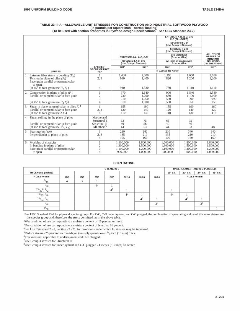
TABLE 23-III-ATABLE 23-III-A
1997 UNIFORM BUILDING CODE
2–295
TABLE 23-III-A—ALLOW ABLE UNIT STRESSES FOR CONSTRUCTION AND INDUSTRIAL SOFTWOOD PL YWOOD(In pounds per square inch—normal loading)
(To be used with section properties in Plywood-design Specifications—See UBC Standard 23-2)
EXTERIOR A-B, B-B, B-CC-C (PLUGGED)
Structural I C-D(Use Group 1 Stresses)
Structural II C-D(Use Group 3 Stresses)
EXTERIOR A-A, A-C, C-CC-D Sheathing(Exterior Glue)
ALL OTHERGRADES OF
INTERIORStructural I A-C, C-C
(Use Group I Stresses)All Interior Grades with
Exterior Glue
INTERIORINCLUDING
C-D SHEATHINGSPECIES1
GROUP OF FACEWet2 Dry3 Wet2 Dry3 Dry3
STRESS
SPECIESGROUP OF FACE
PLY � 0.00689 for N/mm 2
1. Extreme fiber stress in bending (Fb)Tension in plane of plies (Ft)Face grain parallel or perpendicular
to span(at 45° to face grain use 1/6 Ft )
12, 3
4
1,430980
940
2,0001,400
1,330
1,190820
780
1,6501,200
1,110
1,6501,200
1,110
2. Compression in plane of plies (Fc)Parallel or perpendicular to face grain
(at 45° to face grain use 1/3 Fc)
1234
970730610610
1,6401,2001,0601,000
900680580580
1,5401,100
990950
1,5401,100
990950
3. Shear in plane perpendicular to plies Fv4
Parallel or perpendicular to face grain(at 45° to face grain use 2 Fv)
12, 34
155120110
190140130
155120110
190140130
160120115
4. Shear, rolling, in the plane of plies
Parallel or perpendicular to face grain(at 45° to face grain use 11/3 Fs)
Marine andStructural IStructural IIAll others5
634944
755653
634944
755653 48
5. Bearing (on face)Perpendicular to plane of plies
12, 34
210135105
340210160
210135105
340210160
340210160
6. Modulus of elasticityIn bending in plane of pliesFace grain parallel or perpendicular
to span
1234
1,500,0001,300,0001,100,000900,000
1,800,0001,500,0001,200,0001,000,000
1,500,0001,300,0001,100,000900,000
1,800,0001,500,0001,200,0001,000,000
1,800,0001,500,0001,200,0001,000,000
SPAN RATING
C-C AND C-D UNDERLAYMENT AND C-C PLUGGED
THICKNESS (inches) 16” o.c. 20” o.c. 24” o.c. 48” o.c.
� 25.4 for mm 12/0 16/0 20/0 24/0 32/16 40/20 48/24 � 25.4 for mm
5/16 4 3 13/8 47 1
15/326, 1/2 47 1 1
19/32, 5/8 47 1 47 123/32, 3/4 47 1 47 1
7/8 38 38
11/8 1
1See UBC Standard 23-2 for plywood species groups. For C-C, C-D underlayment, and C-C plugged, the combination of span rating and panel thickness determinesthe species group and, therefore, the stress permitted, as in the above table.
2Wet condition of use corresponds to a moisture content of 16 percent or more.3Dry condition of use corresponds to a moisture content of less than 16 percent.4See UBC Standard 23-2, Section 23.221, for provisions under which Fv stresses may be increased.5Reduce stresses 25 percent for three-layer (four-ply) panels over 5/8 inch (16 mm) thick.6Thickness not applicable to underlayment and C-C plugged.7Use Group 3 stresses for Structural II.8Use Group 4 stresses for underlayment and C-C plugged 24 inches (610 mm) on center.
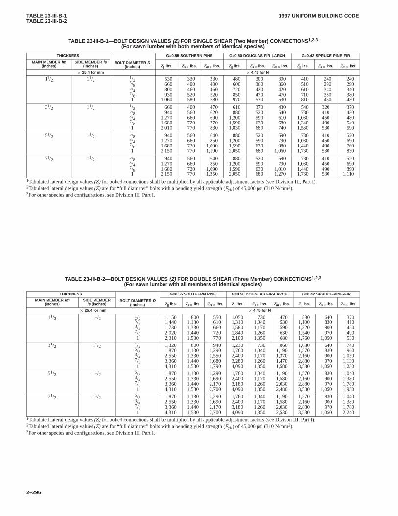
TABLE 23-III-B-1TABLE 23-III-B-2
1997 UNIFORM BUILDING CODE
2–296
TABLE 23-III-B-1—BOL T DESIGN VALUES (Z) FOR SINGLE SHEAR (Two Member) CONNECTIONS 1,2,3
(For sawn lumber with both members of identical species)
THICKNESS G=0.55 SOUTHERN PINE G=0.50 DOUGLAS FIR-LARCH G=0.42 SPRUCE-PINE-FIR
MAIN MEMBER lm(inches)
SIDE MEMBER ls(inches)
BOLT DIAMETER D(inches) Z|| lbs. Zs� lbs. Zm� lbs. Z|| lbs. Zs� lbs. Zm� lbs. Z|| lbs. Zs� lbs. Zm� lbs.
� 25.4 for mm � 4.45 for N
11/2 11/2 1/25/83/47/81
530 660 800 930
1,060
330 400 460 520 580
330 400 460 520 580
480 600 720 850 970
300 360 420 470 530
300 360 420 470 530
410 510 610 710 810
240 290 340 380 430
240 290 340 380 430
31/2 11/2 1/25/83/47/81
660 940
1,2701,6802,010
400 560 660 720 770
470 620 690 770 830
610 880
1,2001,5901,830
370 520 590 630 680
430 540 610 680 740
540 780
1,0801,3401,530
320410450490530
370 430 480 540 590
51/2 11/2 5/83/47/81
9401,2701,6802,150
560 660 720 770
640 850
1,0901,190
8801,2001,5902,050
520 590 630 680
590 790 980
1,060
7801,0801,4401,760
410450490530
520 690 760 830
71/2 11/2 5/83/47/81
9401,2701,6802,150
560 660 720 770
640 850
1,0901,350
8801,2001,5902,050
520 590 630 680
590 790
1,0101,270
7801,0801,4401,760
410450490530
520 690 890
1,1101Tabulated lateral design values (Z) for bolted connections shall be multiplied by all applicable adjustment factors (see Division III, Part I).2Tabulated lateral design values (Z) are for “full diameter” bolts with a bending yield strength (Fyb) of 45,000 psi (310 N/mm2).3For other species and configurations, see Division III, Part I.
TABLE 23-III-B-2—BOLT DESIGN VALUES (Z) FOR DOUBLE SHEAR (Three Member) CONNECTIONS 1,2,3
(For sawn lumber with all members of identical species)
THICKNESS G=0.55 SOUTHERN PINE G=0.50 DOUGLAS FIR-LARCH G=0.42 SPRUCE-PINE-FIR
MAIN MEMBER lm(inches)
SIDE MEMBERls (inches)
BOLT DIAMETER D(inches) Z|| lbs. Zs� lbs. Zm� lbs. Z|| lbs. Zs� lbs. Zm� lbs. Z|| lbs. Zs� lbs. Zm� lbs.
� 25.4 for mm � 4.45 for N
11/2 11/2 1/25/83/47/81
1,1501,4401,7302,0202,310
8001,1301,3301,4401,530
550 610 660 720 770
1,0501,3101,5801,8402,100
7301,0401,1701,2601,350
470 530 590 630 680
8801,1001,3201,5401,760
640 830 900 970
1,050
370 410 450 490 530
31/2 11/2 1/25/83/47/81
1,3201,8702,5503,3604,310
8001,1301,3301,4401,530
9401,2901,5501,6801,790
1,2301,7602,4003,2804,090
7301,0401,1701,2601,350
8601,1901,3701,4701,580
1,0801,5702,1602,8803,530
640 830 900 970
1,050
740 960
1,0501,1301,230
51/2 11/2 5/83/47/81
1,8702,5503,3604,310
1,1301,3301,4401,530
1,2901,6902,1702,700
1,7602,4003,1804,090
1,0401,1701,2601,350
1,1901,5802,0302,480
1,5702,1602,8803,530
830 900 970
1,050
1,0401,3801,7801,930
71/2 11/2 5/83/47/81
1,8702,5503,3604,310
1,1301,3301,4401,530
1,2901,6902,1702,700
1,7602,4003,1804,090
1,0401,1701,2601,350
1,1901,5802,0302,530
1,5702,1602,8803,530
830 900 970
1,050
1,0401,3801,7802,240
1Tabulated lateral design values (Z) for bolted connections shall be multiplied by all applicable adjustment factors (see Divison III, Part I).2Tabulated lateral design values (Z) are for “full diameter” bolts with a bending yield strength (Fyb) of 45,000 psi (310 N/mm2).3For other species and configurations, see Division III, Part I.
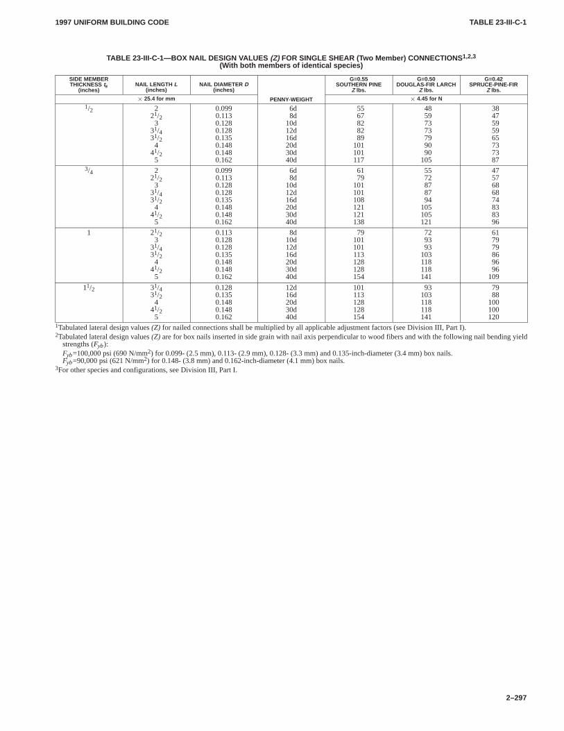
TABLE 23-III-C-1TABLE 23-III-C-1
1997 UNIFORM BUILDING CODE
2–297
TABLE 23-III-C-1—BOX NAIL DESIGN V ALUES (Z) FOR SINGLE SHEAR (Two Member) CONNECTIONS 1,2,3
(With both members of identical species)
SIDE MEMBERTHICKNESS ts
(inches)NAIL LENGTH L
(inches)NAIL DIAMETER D
(inches)
G=0.55SOUTHERN PINE
Z lbs.
G=0.50DOUGLAS-FIR LARCH
Z lbs.
G=0.42SPRUCE-PINE-FIR
Z lbs.
� 25.4 for mm PENNY-WEIGHT � 4.45 for N1/2 2
21/23
31/431/24
41/25
0.0990.1130.1280.1280.1350.1480.1480.162
6d8d
10d12d16d20d30d40d
5567828289
101101117
48597373799090
105
3847595965737387
3/4 221/23
31/431/24
41/25
0.0990.1130.1280.1280.1350.1480.1480.162
6d8d
10d12d16d20d30d40d
6179
101101108121121138
5572878794
105105121
4757686874838396
1 21/23
31/431/24
41/25
0.1130.1280.1280.1350.1480.1480.162
8d10d12d16d20d30d40d
79101101113128128154
729393
103118118141
617979869696
109
11/2 31/431/24
41/25
0.1280.1350.1480.1480.162
12d16d20d30d40d
101113128128154
93103118118141
7988
100100120
1Tabulated lateral design values (Z) for nailed connections shall be multiplied by all applicable adjustment factors (see Division III, Part I).2Tabulated lateral design values (Z) are for box nails inserted in side grain with nail axis perpendicular to wood fibers and with the following nail bending yield
strengths (Fyb):Fyb=100,000 psi (690 N/mm2) for 0.099- (2.5 mm), 0.113- (2.9 mm), 0.128- (3.3 mm) and 0.135-inch-diameter (3.4 mm) box nails.Fyb=90,000 psi (621 N/mm2) for 0.148- (3.8 mm) and 0.162-inch-diameter (4.1 mm) box nails.
3For other species and configurations, see Division III, Part I.
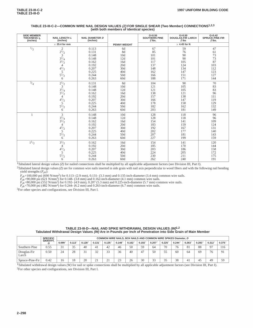
TABLE 23-III-C-2TABLE 23-III-D
1997 UNIFORM BUILDING CODE
2–298
TABLE 23-III-C-2—COMMON WIRE NAIL DESIGN V ALUES (Z) FOR SINGLE SHEAR (Two Member) CONNECTIONS 1,2,3
(with both members of identical species)
SIDE MEMBERTHICKNESS ts
(inches)NAIL LENGTH L
(inches)NAIL DIAMETER D
(inches)
G=0.55SOUTHERN PINE
Z lbs.
G=0.50DOUGLAS-FIR LARCH
Z lbs
G=0.42SPRUCE-PINE-FIR
Z lbs.
� 25.4 for mm PENNY-WEIGHT � 4.45 for N1/2 2
21/23
31/431/24
41/25
51/26
0.1130.1310.1480.1480.1620.1920.2070.2250.2440.263
6d8d
10d12d16d20d30d40d50d60d
6785
101101117137148162166188
59769090
105124134147151171
4761737387
103112123127144
3/4 21/23
31/431/24
41/25
51/26
0.1310.1480.1480.1620.1920.2070.2250.2440.263
8d10d12d16d20d30d40d50d60d
104121121138157166178182203
90105105121138147158162181
70838396
111119129132149
1 331/431/24
41/25
51/26
0.1480.1480.1620.1920.2070.2250.2440.263
10d12d16d20d30d40d50d60d
128128154183192202207227
118118141159167177181199
9696
109124131140143159
11/2 31/24
41/25
51/26
0.1620.1920.2070.2250.2440.263
16d20d30d40d50d60d
154185203224230262
141170186205211240
120144158172175191
1Tabulated lateral design values (Z) for nailed connections shall be multiplied by all applicable adjustment factors (see Division III, Part I).2Tabulated lateral design values (Z) are for common wire nails inserted in side grain with nail axis perpendicular to wood fibers and with the following nail bending
yield strengths (Fyb):Fyb=100,000 psi (690 N/mm2) for 0.113- (2.9 mm), 0.131- (3.3 mm) and 0.135-inch-diameter (3.4 mm) common wire nails.Fyb=90,000 psi (621 N/mm2) for 0.148- (3.8 mm) and 0.162-inch-diameter (4.1 mm) common wire nails.Fyb=80,000 psi (552 N/mm2) for 0.192- (4.9 mm), 0.207 (5.3 mm) and 0.225-inch-diameter (5.7 mm) common wire nails.Fyb=70,000 psi (482 N/mm2) for 0.244- (6.2 mm) and 0.263-inch-diameter (6.7 mm) common wire nails.
3For other species and configurations, see Division III, Part I.
TABLE 23-III-D—NAIL AND SPIKE WITHDRA WAL DESIGN VALUES (W)1,2
Tabulated W ithdrawal Design V alues (W) Are in Pounds per Inch of Penetration into Side Grain of Main Member
SPECIFICGRAVITY
COMMON WIRE NAILS, BOX NAILS AND COMMON WIRE SPIKES Diameter , DSPECIFICGRAVITY,
G 0.099� 0.113� 0.128� 0.131� 0.135� 0.148� 0.162� 0.192� 0.207� 0.225� 0.244� 0.263� 0.283� 0.312� 0.375�
Southern Pine 0.55 31 35 40 41 42 46 50 59 64 70 76 81 88 97 116
Douglas-FirLarch
0.50 24 28 31 32 33 36 40 47 50 55 60 64 69 76 91
Spruce-Pine-Fir 0.42 16 18 20 21 21 23 26 30 33 35 38 41 45 49 591Tabulated withdrawal design values (W) for nail or spike connections shall be multiplied by all applicable adjustment factors (see Division III, Part I).2For other species and configurations, see Division III, Part I.
CHAP. 23, DIV. IV2320
2320.5.4.31997 UNIFORM BUILDING CODE
2–299
Division IV—CONVENTIONAL LIGHT-FRAME CONSTRUCTION
SECTION 2320 — CONVENTIONAL LIGHT-FRAMECONSTRUCTION DESIGN PROVISIONS
2320.1 General.The requirements in this section are intendedfor conventional light-frame construction. Other methods may beused provided a satisfactory design is submitted showing com-pliance with other provisions of this code.
Only the following occupancies may be constructed in accord-ance with this division:CHAP. 23, DIV. IV
1. One-, two- or three-story buildings housing Group R Occu-pancies.
2. One-story Occupancy Category 4 buildings, as defined inTable 16-K, when constructed on a slab-on-grade floor.
3. Group U Occupancies.
4. Top-story walls and roofs of Occupancy Category 4 build-ings not exceeding two stories of wood framing.
5. Interior nonload-bearing partitions, ceilings and curtainwalls in all occupancies.
When total loads exceed those specified in Tables 23-IV-J-1,23-IV-J-3, and 23-IV-R-1, 23-IV-R-2, 23-IV-R-3, 23-IV-R-4,23-IV-R-7, 23-IV-R-8, 23-IV-R-9, 23-IV-R-10, 23-IV-R-11 and23-IV-R-12; 23-VII-R-1, 23-VII-R-3, 23-VII-R-7, 23-VII-R-9,23-VIII-A, 23-VIII-B, 23-VIII-C, 23-VIII-D, an engineeringdesign shall be provided for the gravity load system.
Other approved repetitive wood members may be used in lieu ofsolid-sawn lumber in conventional construction provided thesemembers comply with the provisions of this code.
2320.2 Design of Portions.When a building of otherwise con-ventional construction contains nonconventional structural ele-ments, those elements shall be designed in accordance withSection 1605.2.
2320.3 Additional Requirements for Conventional Construc-tion in High-wind Areas. Appendix Chapter 23 provisions forconventional construction in high-wind areas shall apply whenspecifically adopted.
2320.4 Additional Requirements for Conventional Construc-tion in Seismic Zones 0, 1, 2 and 3.
2320.4.1 Braced wall lines.Where the basic wind speed is notgreater than 80 miles per hour (mph) (129 km/h), buildings shallbe provided with exterior and interior braced wall lines. Spacingshall not exceed 34 feet (10 363 mm) on center in both the longitu-dinal and transverse directions in each story.
2320.4.2 Braced wall lines for high wind.Where the basicwind speed exceeds 80 mph (129 km/h), buildings shall be pro-vided with exterior and interior braced wall lines. Spacing shallnot exceed 25 feet (7620 mm) on center in both the longitudinaland transverse directions in each story.
EXCEPTION: In one- and two-story Group R, Division 3 build-ings, interior braced wall line spacing may be increased to not morethan 34 feet (10 363 mm) on center in order to accommodate one singleroom per dwelling unit not exceeding 900 square feet (83.6 m2). Thebuilding official may require additional walls to contain braced panelswhen this exception is used.
2320.4.3 Veneer.Anchored masonry and stone wall veneer shallnot exceed 5 inches (127 mm) in thickness and shall conform tothe requirements of Chapter 14.
2320.4.4 Lateral force-resisting system. Buildings in SeismicZone 3 that are not provided with braced wall lines in accordance
with Section 2320.4 or that are of unusual shape as described inSection 2320.5.4 shall have a lateral-force-resisting system de-signed to resist the forces specified in Chapter 16.
2320.5 Additional Requirements for Conventional Construc-tion in Seismic Zone 4.
2320.5.1 Braced wall lines.Buildings shall be provided withexterior and interior braced wall lines. Spacing shall not exceed25 feet (7620 mm) on center in both the longitudinal and trans-verse directions in each story.
EXCEPTION: In one- and two-story Group R, Division 3 build-ings, interior braced wall line spacing may be increased to not morethan 34 feet (10 363 mm) on center in order to accommodate one singleroom per dwelling unit not exceeding 900 square feet (83.61 m2). Thebuilding official may require additional walls to contain braced panelswhen this exception is used.
2320.5.2 Lateral-force-resisting system.When total loadssupported on wood framing exceed those specified in Tables23-IV-J-1, 23-IV-J-3, 23-IV-R-1, 23-IV-R-2, 23-IV-R-3,23-IV-R-4, 23-IV-R-7, 23-IV-R-8, 23-IV-R-9 and 23-IV-R-10,23-VII-R-1. 23-VII-R-3, 23-VII-R-7, 23-VII-R-9, 23-VIII-A,23-VIII-B, 23-VIII-C and 23-VIII-D, an engineering design shallbe provided for the lateral-force-resisting system.
2320.5.3 Veneer.Anchored masonry and stone wall veneer shallnot exceed 5 inches (127 mm) in thickness, shall conform to therequirements of Chapter 14 and shall not extend above the firststory.
2320.5.4 Unusually shaped buildings.When of unusual shape,buildings of light-frame construction shall have a lateral-force-resisting system designed to resist the forces specified in Chapter16. Buildings shall be considered to be of unusual shape when thebuilding official determines that the structure has framing irregu-larities, offsets, split levels or any configuration that creates dis-continuities in the seismic load path and may include one or moreof the following.
2320.5.4.1When exterior braced wall panels, as required by Sec-tion 2320.11.3, are not in one plane vertically from the foundationto the uppermost story in which they are required.
EXCEPTION: Floors with cantilevers or setbacks not exceedingfour times the nominal depth of the floor joists may support braced wallpanels provided:
1. Floor joists are 2 inches by 10 inches (51 mm by 254 mm) orlarger and spaced at not more than 16 inches (406 mm) on cen-ter.
2. The ratio of the back span to the cantilever is at least 2 to 1.3. Floor joists at ends of braced wall panels are doubled.4. A continuous rim joist is connected to ends of all cantilevered
joists. The rim joist may be spliced using a metal tie not lessthan 0.058 inch (1.47 mm) (16 galvanized gage) and 11/2 inches(38 mm) wide fastened with six 16d nails.
5. Gravity loads carried at the end of cantilevered joists are lim-ited to uniform wall and roof load and the reactions from head-ers having a span of 8 feet (2438 mm) or less.
2320.5.4.2When a section of floor or roof is not laterally sup-ported by braced wall lines on all edges.
EXCEPTION: Portions of roofs or floors which do not supportbraced wall panels above may extend up to 6 feet (1829 mm) beyonda braced wall line.
2320.5.4.3When the end of a required braced wall panel extendsmore than 1 foot (305 mm) over an opening in the wall below. Thisprovision is applicable to braced wall panels offset in plane and tobraced wall panels offset out of plane as permitted by Section2320.5.4.1, exception.
CHAP. 23, DIV. IV2320.5.4.32320.9.4
1997 UNIFORM BUILDING CODE
2–300
EXCEPTION: Braced wall panels may extend over an opening notmore than 8 feet (2438 mm) in width when the header is a 4-inch by12-inch (102 mm by 305 mm) or larger member.
2320.5.4.4When an opening in a floor or roof exceeds the lesserof 12 feet (3657 mm) or 50 percent of the least floor or roof dimen-sion.
2320.5.4.5Construction where portions of a floor level are verti-cally offset such that the framing members on either side of theoffset cannot be lapped or tied together in an approved manner asrequired by Section 2320.8.3.
EXCEPTION: Framing supported directly by foundations.
2320.5.4.6When braced wall lines do not occur in two perpen-dicular directions.
2320.5.5 Lumber roof decks.Lumber roof decks shall havesolid sheathing.
2320.5.6 Interior braced wall support. In one-story buildings,interior braced wall lines shall be supported on continuousfoundations at intervals not exceeding 50 feet (15 240 mm). Inbuildings more than one story in height, all interior braced wallpanels shall be supported on continuous foundations.
EXCEPTION: Two-story buildings may have interior braced walllines supported on continuous foundations at intervals not exceeding50 feet (15 240 mm) provided:
1. Cripple wall height does not exceed 4 feet (1219 mm).
2. First-floor braced wall panels are supported on doubled floorjoists, continuous blocking or floor beams.
3. Distance between bracing lines does not exceed twice thebuilding width parallel to the braced wall line.
2320.6 Foundation Plates or Sills.Foundations and footingsshall be as specified in Chapter 18. Foundation plates or sills rest-ing on concrete or masonry foundations shall be bolted as requiredby Section 1806.6.
2320.7 Girders. Girders for single-story construction or girderssupporting loads from a single floor shall not be less than 4 inchesby 6 inches (102 mm by 153 mm) for spans 6 feet (1829 mm) orless, provided that girders are spaced not more than 8 feet (2438mm) on center. Other girders shall be designed to support the loadsspecified in this code. Girder end joints shall occur over supports.When a girder is spliced over a support, an adequate tie shall beprovided. The end of beams or girders supported on masonry orconcrete shall not have less than 3 inches (76 mm) of bearing.
2320.8 Floor Joists.
2320.8.1 General.Spans for joists shall be in accordance withTables 23-IV-J-1 and 23-IV-J-2.
2320.8.2 Bearing.Except where supported on a 1-inch by4-inch (25 mm by 102 mm) ribbon strip and nailed to the adjoiningstud, the ends of each joist shall not have less than 11/2 inches(38 mm) of bearing on wood or metal, or less than 3 inches(76 mm) on masonry.
2320.8.3 Framing details.Joists shall be supported laterally atthe ends and at each support by solid blocking except where theends of joists are nailed to a header, band or rim joist or to an ad-joining stud or by other approved means. Solid blocking shall notbe less than 2 inches (51 mm) in thickness and the full depth ofjoist.
Notches on the ends of joists shall not exceed one fourth the joistdepth. Holes bored in joists shall not be within 2 inches (51 mm) ofthe top or bottom of the joist, and the diameter of any such holeshall not exceed one third the depth of the joist. Notches in the top
or bottom of joists shall not exceed one sixth the depth and shallnot be located in the middle third of the span.
Joist framing from opposite sides of a beam, girder or partitionshall be lapped at least 3 inches (76 mm) or the opposing joistsshall be tied together in an approved manner.
Joists framing into the side of a wood girder shall be supportedby framing anchors or on ledger strips not less than 2 inches by2 inches (51 mm by 51 mm).
2320.8.4 Framing around openings.Trimmer and headerjoists shall be doubled, or of lumber of equivalent cross section,when the span of the header exceeds 4 feet (1219 mm). The ends ofheader joists more than 6 feet (1829 mm) long shall be supportedby framing anchors or joist hangers unless bearing on a beam, par-tition or wall. Tail joists over 12 feet (3658 mm) long shall be sup-ported at header by framing anchors or on ledger strips not lessthan 2 inches by 2 inches (51 mm by 51 mm).
2320.8.5 Supporting bearing partitions.Bearing partitionsperpendicular to joists shall not be offset from supporting girders,walls or partitions more than the joist depth.
Joists under and parallel to bearing partitions shall be doubled.
2320.8.6 Blocking.Floor joists shall be blocked when requiredby the provisions of Division III, Part I or Section 2320.8.3.
2320.9 Subflooring.
2320.9.1 Lumber subfloor. Sheathing used as a structural sub-floor shall conform to the limitations set forth in Tables 23-II-D-1and 23-II-D-2.
Joints in subflooring shall occur over supports unlessend-matched lumber is used, in which case each piece shall bearon at least two joists.
Subflooring may be omitted when joist spacing does not exceed16 inches (406 mm) and 1-inch (25 mm) nominal tongue-and-groove wood strip flooring is applied perpendicular to the joists.
2320.9.2 Wood structural panels.Where used as structuralsubflooring, wood structural panels shall be as set forth in Tables23-II-E-1 and 23-II-E-2. Wood structural panel combination sub-floor underlayment shall have maximum spans as set forth inTable 23-II-F-1.
When wood structural panel floors are glued to joists with anadhesive in accordance with the adhesive manufacturer’s direc-tions, fasteners may be spaced a maximum of 12 inches (305 mm)on center at all supports.
2320.9.3 Plank flooring. Plank flooring shall be designed in ac-cordance with the general provisions of this code.
In lieu of such design, 2-inch (51 mm) tongue-and-grooveplanking may be used in accordance with Table 23-IV-A. Joints insuch planking may be randomly spaced, provided the system isapplied to not less than three continuous spans, planks are cen-ter-matched and end-matched or splined, each plank bears on atleast one support and joints are separated by at least 24 inches (610mm) in adjacent pieces. One-inch (25 mm) nominal strip square-edged flooring, 1/2-inch (12.7 mm) tongue-and-groove flooring or3/8-inch (9.5 mm) wood structural panel shall be applied overrandom-length decking used as a floor. The strip and tongue-and-groove flooring shall be applied at right angles to the span ofthe planks. The 3/8-inch (9.5 mm) plywood shall be applied withthe face grain at right angles to the span of the planks.
2320.9.4 Particleboard.Where used as structural subflooringor as combined subfloor underlayment, particleboard shall be asset forth in Table 23-II-F-2.
CHAP. 23, DIV. IV2320.10
2320.11.41997 UNIFORM BUILDING CODE
2–301
2320.10 Particleboard Underlayment.In accordance withapproved recognized standards, particleboard floor underlaymentshall conform to Type PBU. Underlayment shall not be less than1/4 inch (6.4 mm) in thickness and shall be identified by the grademark of an approved inspection agency. Underlayment shall be in-stalled in accordance with this code and as recommended by themanufacturer.
2320.11 Wall Framing.
2320.11.1 Size, height and spacing.The size, height and spac-ing of studs shall be in accordance with Table 23-IV-B except thatUtility grade studs shall not be spaced more than 16 inches (406mm) on center, or support more than a roof and ceiling, or exceed8 feet (2438 mm) in height for exterior walls and load-bearingwalls or 10 feet (3048 mm) for interior nonload-bearing walls.
2320.11.2 Framing details.Studs shall be placed with theirwide dimension perpendicular to the wall. Not less than threestuds shall be installed at each corner of an exterior wall.
EXCEPTION: At corners, a third stud may be omitted through theuse of wood spacers or backup cleats of 3/8-inch-thick (9.5 mm) woodstructural panel, 3/8-inch (9.5 mm) Type M “Exterior Glue” particle-board, 1-inch-thick (25 mm) lumber or other approved devices that willserve as an adequate backing for the attachment of facing materials.Where fire-resistance ratings or shear values are involved, woodspacers, backup cleats or other devices shall not be used unless specifi-cally approved for such use.
Bearing and exterior wall studs shall be capped with double topplates installed to provide overlapping at corners and at intersec-tions with other partitions. End joints in double top plates shall beoffset at least 48 inches (2438 mm).
EXCEPTION: A single top plate may be used, provided the plateis adequately tied at joints, corners and intersecting walls by at least theequivalent of 3-inch by 6-inch (76 mm by 152 mm) by 0.036-inch-thick (0.9 mm) galvanized steel that is nailed to each wall or segmentof wall by six 8d nails or equivalent, provided the rafters, joists ortrusses are centered over the studs with a tolerance of no more than1 inch (25 mm).
When bearing studs are spaced at 24-inch (610 mm) intervalsand top plates are less than two 2-inch by 6-inch (51 mm by 152mm) or two 3-inch by 4-inch (76 mm by 102 mm) members andwhen the floor joists, floor trusses or roof trusses which they sup-port are spaced at more than 16-inch (406 mm) intervals, suchjoists or trusses shall bear within 5 inches (127 mm) of the studsbeneath or a third plate shall be installed.
Interior nonbearing partitions may be capped with a single topplate installed to provide overlapping at corners and at intersec-tions with other walls and partitions. The plate shall be continu-ously tied at joints by solid blocking at least 16 inches (406 mm) inlength and equal in size to the plate or by 1/8-inch by 11/2-inch (3.2mm by 38 mm) metal ties with spliced sections fastened with two16d nails on each side of the joint.
Studs shall have full bearing on a plate or sill not less than 2 in-ches (51 mm) in thickness having a width not less than that of thewall studs.
2320.11.3 Bracing.Braced wall lines shall consist of bracedwall panels which meet the requirements for location, type andamount of bracing specified in Table 23-IV-C-1 and are in line oroffset from each other by not more than 4 feet (1219 mm). Bracedwall panels shall start at not more than 8 feet (2438 mm) from eachend of a braced wall line. All braced wall panels shall be clearlyindicated on the plans. Construction of braced wall panels shall beby one of the following methods:
1. Nominal 1-inch by 4-inch (25 mm by 102 mm) continuousdiagonal braces let into top and bottom plates and intervening
studs, placed at an angle not more than 60 degrees or less than45 degrees from the horizontal, and attached to the framing in con-formance with Table 23-II-B-1.
2. Wood boards of 5/8-inch (16 mm) net minimum thicknessapplied diagonally on studs spaced not over 24 inches (610 mm)on center.
3. Wood structural panel sheathing with a thickness not lessthan 5/16 inch (7.9 mm) for 16-inch (406 mm) stud spacing and notless than 3/8 inch (9.5 mm) for 24-inch (610 mm) stud spacing inaccordance with Tables 23-II-A-1 and 23-IV-D-1.
4. Fiberboard sheathing 4-foot by 8-foot (1219 mm by 2438mm) panels not less than 1/2 inch (13 mm) thick applied verticallyon studs spaced not over 16 inches (406 mm) on center when in-stalled in accordance with Section 2315.6 and Table 23-II-J.
5. Gypsum board [sheathing 1/2 inch (13 mm) thick by 4 feet(1219 mm) wide, wallboard or veneer base] on studs spaced notover 24 inches (610 mm) on center and nailed at 7 inches (178mm) on center with nails as required by Table 25-I.
6. Particleboard wall sheathing panels where installed in ac-cordance with Table 23-IV-D-2.
7. Portland cement plaster on studs spaced 16 inches (406 mm)on center installed in accordance with Table 25-I.
8. Hardboard panel siding when installed in accordance withSection 2310.6 and Table 23-II-C.
Method 1 is not permitted in Seismic Zones 2B, 3 and 4. Forcripple wall bracing, see Section 2320.11.5. For Methods 2, 3, 4, 6,7 and 8, each braced panel must be at least 48 inches (1219 mm) inlength, covering three stud spaces where studs are spaced16 inches (406 mm) apart and covering two stud spaces wherestuds are spaced 24 inches (610 mm) apart.
For Method 5, each braced wall panel must be at least 96 inches(2438 mm) in length when applied to one face of a braced wallpanel and 48 inches (1219 mm) when applied to both faces.
All vertical joints of panel sheathing shall occur over studs.Horizontal joints shall occur over blocking equal in size to thestudding except where waived by the installation requirements forthe specific sheathing materials.
Braced wall panel sole plates shall be nailed to the floor framingand top plates shall be connected to the framing above in accord-ance with Table 23-II-B-1. Sills shall be bolted to the foundationor slab in accordance with Section 1806.6. Where joists are per-pendicular to braced wall lines above, blocking shall be providedunder and in line with the braced wall panels.
2320.11.4 Alternate braced wall panels.Any braced wallpanel required by Section 2320.11.3 may be replaced by an alter-nate braced wall panel constructed in accordance with the follow-ing:
1. In one-story buildings, each panel shall have a length of notless than 2 feet 8 inches (813 mm) and a height of not more than10 feet (3048 mm). Each panel shall be sheathed on one face with3/8-inch-minimum-thickness (9.5 mm) plywood sheathing nailedwith 8d common or galvanized box nails in accordance with Table23-II-B-1 and blocked at all plywood edges. Two anchor boltsinstalled in accordance with Section 1806.6, shall be provided ineach panel. Anchor bolts shall be placed at panel quarter points.Each panel end stud shall have a tie-down device fastened to thefoundation, capable of providing an approved uplift capacity ofnot less than 1,800 pounds (816.5 kg). The tie-down device shallbe installed in accordance with the manufacturer’s recommenda-tions. The panels shall be supported directly on a foundation or onfloor framing supported directly on a foundation which is continu-ous across the entire length of the braced wall line. This founda-
CHAP. 23, DIV. IV2320.11.42320.12.8
1997 UNIFORM BUILDING CODE
2–302
tion shall be reinforced with not less than one No. 4 bar top andbottom.
2. In the first story of two-story buildings, each braced wallpanel shall be in accordance with Section 2320.11.4, Item 1,except that the plywood sheathing shall be provided on both faces,three anchor bolts shall be placed at one-fifth points, and tie-downdevice uplift capacity shall not be less than 3,000 pounds (1360.8kg).
2320.11.5 Cripple walls.Foundation cripple walls shall beframed of studs not less in size than the studding above with aminimum length of 14 inches (356 mm), or shall be framed of sol-id blocking. When exceeding 4 feet (1219 mm) in height, suchwalls shall be framed of studs having the size required for an addi-tional story.
Cripple walls having a stud height exceeding 14 inches (356mm) shall be braced in accordance with Table 23-IV-C-2. Solidblocking or wood structural panel sheathing may be used to bracecripple walls having a stud height of 14 inches (356 mm) or less. InSeismic Zone 4, Method 7 is not permitted for bracing any cripplewall studs.
Spacing of boundary nailing for required wall bracing shall notexceed 6 inches (152 mm) on center along the foundation plateand the top plate of the cripple wall. Nail size, nail spacing for fieldnailing and more restrictive boundary nailing requirements shallbe as required elsewhere in the code for the specific bracing mate-rial used.
2320.11.6 Headers.Headers and lintels shall conform to the re-quirements set forth in this paragraph and together with their sup-porting systems shall be designed to support the loads specified inthis code. All openings 4 feet (1219 mm) wide or less in bearingwalls shall be provided with headers consisting of either twopieces of 2-inch (51 mm) framing lumber placed on edge and se-curely fastened together or 4-inch (102 mm) lumber of equivalentcross section. All openings more than 4 feet (1219 mm) wide shallbe provided with headers or lintels. Each end of a lintel or headershall have a length of bearing of not less than 11/2 inches (38 mm)for the full width of the lintel.
2320.11.7 Pipes in walls.Stud partitions containing plumbing,heating, or other pipes shall be so framed and the joists underneathso spaced as to give proper clearance for the piping. Where a parti-tion containing such piping runs parallel to the floor joists, thejoists underneath such partitions shall be doubled and spaced topermit the passage of such pipes and shall be bridged. Whereplumbing, heating or other pipes are placed in or partly in a parti-tion, necessitating the cutting of the soles or plates, a metal tie notless than 0.058 inch (1.47 mm) (16 galvanized gage) and 11/2 in-ches (38 mm) wide shall be fastened to each plate across and toeach side of the opening with not less than six 16d nails.
2320.11.8 Bridging. Unless covered by interior or exterior wallcoverings or sheathing meeting the minimum requirements of thiscode, all stud partitions or walls with studs having aheight-to-least-thickness ratio exceeding 50 shall have bridgingnot less than 2 inches (51 mm) in thickness and of the same widthas the studs fitted snugly and nailed thereto to provide adequatelateral support.
2320.11.9 Cutting and notching.In exterior walls and bearingpartitions, any wood stud may be cut or notched to a depth not ex-ceeding 25 percent of its width. Cutting or notching of studs to adepth not greater than 40 percent of the width of the stud is per-mitted in nonbearing partitions supporting no loads other than theweight of the partition.
2320.11.10 Bored holes.A hole not greater in diameter than40 percent of the stud width may be bored in any wood stud. Boredholes not greater than 60 percent of the width of the stud are per-mitted in nonbearing partitions or in any wall where each boredstud is doubled, provided not more than two such successivedoubled studs are so bored.
In no case shall the edge of the bored hole be nearer than 5/8 inch(16 mm) to the edge of the stud. Bored holes shall not be located atthe same section of stud as a cut or notch.
2320.12 Roof and Ceiling Framing.
2320.12.1 General.The framing details required in this sectionapply to roofs having a minimum slope of 3 units vertical in12 units horizontal (25% slope) or greater. When the roof slope isless than 3 units vertical in 12 units horizontal (25% slope), mem-bers supporting rafters and ceiling joists such as ridge board, hipsand valleys shall be designed as beams.
2320.12.2 Spans.Allowable spans for ceiling joists shall be inaccordance with Tables 23-IV-J-3 and 23-IV-J-4. Allowable spansfor rafters shall be in accordance with Tables 23-IV-R-1 through23-IV-R-12, where applicable.
2320.12.3 Framing.Rafters shall be framed directly oppositeeach other at the ridge. There shall be a ridge board at least 1-inch(25 mm) nominal thickness at all ridges and not less in depth thanthe cut end of the rafter. At all valleys and hips there shall be asingle valley or hip rafter not less than 2-inch (51 mm) nominalthickness and not less in depth than the cut end of the rafter.
2320.12.4 Notches and holes.Notching at the ends of rafters orceiling joists shall not exceed one fourth the depth. Notches in thetop or bottom of the rafter or ceiling joist shall not exceed one sixththe depth and shall not be located in the middle one third of thespan, except that a notch not exceeding one third of the depth ispermitted in the top of the rafter or ceiling joist not further from theface of the support than the depth of the member.
Holes bored in rafters or ceiling joists shall not be within 2 in-ches (51 mm) of the top and bottom and their diameter shall notexceed one third the depth of the member.
2320.12.5 Framing around openings.Trimmer and header raf-ters shall be doubled, or of lumber of equivalent cross section,when the span of the header exceeds 4 feet (1219 mm). The ends ofheader rafters more than 6 feet (1829 mm) long shall be supportedby framing anchors or rafter hangers unless bearing on a beam,partition or wall.
2320.12.6 Rafter ties.Rafters shall be nailed to adjacent ceilingjoists to form a continuous tie between exterior walls when suchjoists are parallel to the rafters. Where not parallel, rafters shall betied to 1-inch by 4-inch (25 mm by 102 mm) (nominal) mini-mum-size crossties. Rafter ties shall be spaced not more than 4 feet(1219 mm) on center.
2320.12.7 Purlins.Purlins to support roof loads may be in-stalled to reduce the span of rafters within allowable limits andshall be supported by struts to bearing walls. The maximum spanof 2-inch by 4-inch (51 mm by 102 mm) purlins shall be 4 feet(1219 mm). The maximum span of the 2-inch by 6-inch (51 mm by152 mm) purlin shall be 6 feet (1829 mm) but in no case shall thepurlin be smaller than the supported rafter. Struts shall not besmaller than 2-inch by 4-inch (51 mm by 102 mm) members. Theunbraced length of struts shall not exceed 8 feet (2438 mm) and theminimum slope of the struts shall not be less than 45 degrees fromthe horizontal.
2320.12.8 Blocking.Roof rafters and ceiling joists shall be sup-ported laterally to prevent rotation and lateral displacement when
CHAP. 23, DIV. IV2320.12.8
2320.131997 UNIFORM BUILDING CODE
2–303
required by Division III, Part I, Section 4.4.1.2. Roof trusses shallbe supported laterally at points of bearing by solid blocking to pre-vent rotation and lateral displacement.
2320.12.9 Roof sheathing.Roof sheathing shall be in accord-ance with Tables 23-II-E-1 and 23-II-E-2 for wood structural pan-els, and Tables 23-II-D-1 and 23-II-D-2 for lumber.
Joints in lumber sheathing shall occur over supports unless ap-proved end-matched lumber is used, in which case each pieceshall bear on at least two supports.
Wood structural panels used for roof sheathing shall be bondedby intermediate or exterior glue. Wood structural panel roofsheathing exposed on the underside shall be bonded with exteriorglue.
2320.12.10 Roof planking.Planking shall be designed in ac-cordance with the general provisions of this code.
In lieu of such design, 2-inch (51 mm) tongue-and-grooveplanking may be used in accordance with Table 23-IV-A. Joints insuch planking may be randomly spaced, provided the system isapplied to not less than three continuous spans, planks arecenter-matched and end-matched or splined, each plank bears onat least one support, and joints are separated by at least 24 inches(610 mm) in adjacent pieces.
2320.13 Exit Facilities. In Seismic Zones 3 and 4, exterior exitbalconies, stairs and similar exit facilities shall be positively an-chored to the primary structure at not over 8 feet (2438 mm) oncenter or shall be designed for lateral forces. Such attachmentshall not be accomplished by use of toenails or nails subject towithdrawal.
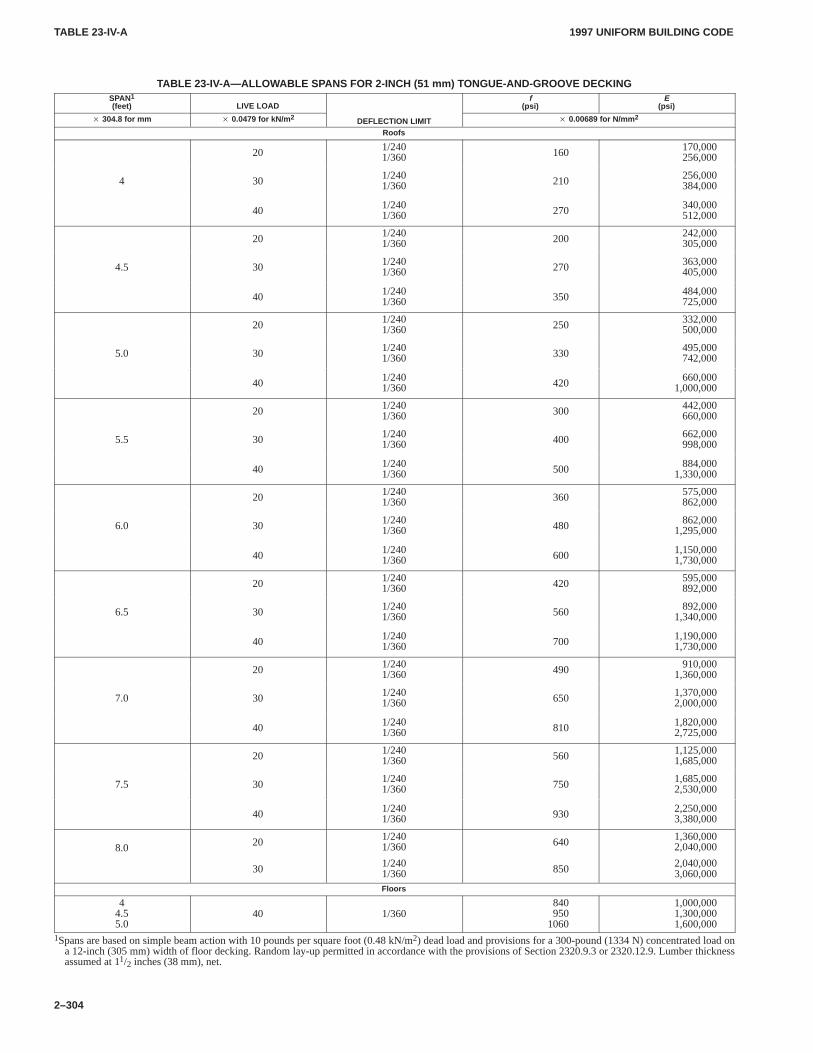
TABLE 23-IV-ATABLE 23-IV-A
1997 UNIFORM BUILDING CODE
2–304
TABLE 23-IV-A—ALLOW ABLE SPANS FOR 2-INCH (51 mm) T ONGUE-AND-GROOVE DECKINGSPAN1
(feet) LIVE LOADf
(psi)E
(psi)
� 304.8 for mm � 0.0479 for kN/m 2 DEFLECTION LIMIT � 0.00689 for N/mm 2
Roofs
20 1/2401/360 160 170,000
256,000
4 30 1/2401/360 210 256,000
384,000
40 1/2401/360 270 340,000
512,000
20 1/2401/360 200 242,000
305,000
4.5 30 1/2401/360 270 363,000
405,000
40 1/2401/360 350 484,000
725,000
20 1/2401/360 250 332,000
500,000
5.0 30 1/2401/360 330 495,000
742,000
40 1/2401/360 420 660,000
1,000,000
20 1/2401/360 300 442,000
660,000
5.5 30 1/2401/360 400 662,000
998,000
40 1/2401/360 500 884,000
1,330,000
20 1/2401/360 360 575,000
862,000
6.0 30 1/2401/360 480 862,000
1,295,000
40 1/2401/360 600 1,150,000
1,730,000
20 1/2401/360 420 595,000
892,000
6.5 30 1/2401/360 560 892,000
1,340,000
40 1/2401/360 700 1,190,000
1,730,000
20 1/2401/360 490 910,000
1,360,000
7.0 30 1/2401/360 650 1,370,000
2,000,000
40 1/2401/360 810 1,820,000
2,725,000
20 1/2401/360 560 1,125,000
1,685,000
7.5 30 1/2401/360 750 1,685,000
2,530,000
40 1/2401/360 930 2,250,000
3,380,000
8.0 20 1/2401/360 640 1,360,000
2,040,000
30 1/2401/360 850 2,040,000
3,060,000Floors
44.55.0
40 1/360840950
1060
1,000,0001,300,0001,600,000
1Spans are based on simple beam action with 10 pounds per square foot (0.48 kN/m2) dead load and provisions for a 300-pound (1334 N) concentrated load ona 12-inch (305 mm) width of floor decking. Random lay-up permitted in accordance with the provisions of Section 2320.9.3 or 2320.12.9. Lumber thicknessassumed at 11/2 inches (38 mm), net.
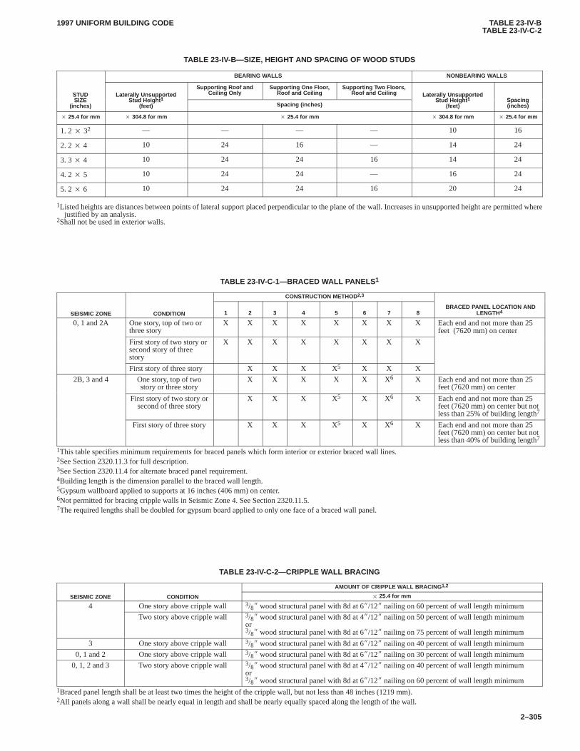
TABLE 23-IV-BTABLE 23-IV-C-2
1997 UNIFORM BUILDING CODE
2–305
TABLE 23-IV-B—SIZE, HEIGHT AND SPACING OF WOOD STUDS
BEARING WALLS NONBEARING WALLS
STUDSIZE
Laterally UnsupportedSt d Height 1
Supporting Roof andCeiling Only
Supporting One Floor,Roof and Ceiling
Supporting T wo Floors,Roof and Ceiling Laterally Unsupported
St d Height 1 SpacingSTUDSIZE
(inches)
Laterally UnsupportedStud Height 1
(feet) Spacing (inches)
Laterally UnsupportedStud Height 1
(feet)Spacing(inches)
� 25.4 for mm � 304.8 for mm � 25.4 for mm � 304.8 for mm � 25.4 for mm
1. 2 � 32 — — — — 10 16
2. 2 � 4 10 24 16 — 14 24
3. 3 � 4 10 24 24 16 14 24
4. 2 � 5 10 24 24 — 16 24
5. 2 � 6 10 24 24 16 20 24
1Listed heights are distances between points of lateral support placed perpendicular to the plane of the wall. Increases in unsupported height are permitted wherejustified by an analysis.
2Shall not be used in exterior walls.
TABLE 23-IV-C-1—BRACED WALL PANELS1
CONSTRUCTION METHOD2,3
SEISMIC ZONE CONDITION 1 2 3 4 5 6 7 8 BRACED PANEL LOCATION AND
LENGTH4
0, 1 and 2A One story, top of two orthree story
X X X X X X X X Each end and not more than 25feet (7620 mm) on center
First story of two story orsecond story of threestory
X X X X X X X X
First story of three story X X X X5 X X X
2B, 3 and 4 One story, top of twostory or three story
X X X X X X6 X Each end and not more than 25feet (7620 mm) on center
First story of two story orsecond of three story
X X X X5 X X6 X Each end and not more than 25feet (7620 mm) on center but notless than 25% of building length7
First story of three story X X X X5 X X6 X Each end and not more than 25feet (7620 mm) on center but notless than 40% of building length7
1This table specifies minimum requirements for braced panels which form interior or exterior braced wall lines.2See Section 2320.11.3 for full description.3See Section 2320.11.4 for alternate braced panel requirement.4Building length is the dimension parallel to the braced wall length.5Gypsum wallboard applied to supports at 16 inches (406 mm) on center.6Not permitted for bracing cripple walls in Seismic Zone 4. See Section 2320.11.5.7The required lengths shall be doubled for gypsum board applied to only one face of a braced wall panel.
TABLE 23-IV-C-2—CRIPPLE WALL BRACING
AMOUNT OF CRIPPLE WALL BRACING 1,2
SEISMIC ZONE CONDITION � 25.4 for mm
4 One story above cripple wall 3/8� wood structural panel with 8d at 6�/12� nailing on 60 percent of wall length minimum
Two story above cripple wall 3/8� wood structural panel with 8d at 4�/12� nailing on 50 percent of wall length minimumor3/8� wood structural panel with 8d at 6�/12� nailing on 75 percent of wall length minimum
3 One story above cripple wall 3/8� wood structural panel with 8d at 6�/12� nailing on 40 percent of wall length minimum
0, 1 and 2 One story above cripple wall 3/8� wood structural panel with 8d at 6�/12� nailing on 30 percent of wall length minimum
0, 1, 2 and 3 Two story above cripple wall 3/8� wood structural panel with 8d at 4�/12� nailing on 40 percent of wall length minimumor3/8� wood structural panel with 8d at 6�/12� nailing on 60 percent of wall length minimum
1Braced panel length shall be at least two times the height of the cripple wall, but not less than 48 inches (1219 mm).2All panels along a wall shall be nearly equal in length and shall be nearly equally spaced along the length of the wall.
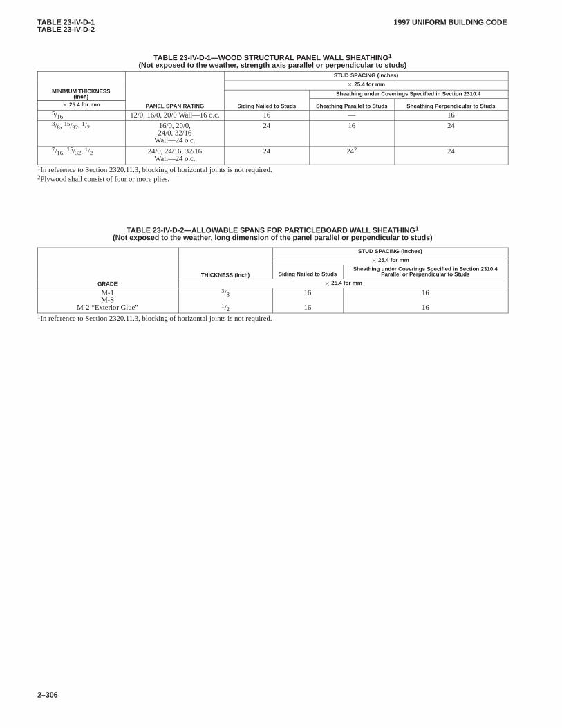
TABLE 23-IV-D-1TABLE 23-IV-D-2
1997 UNIFORM BUILDING CODE
2–306
TABLE 23-IV-D-1—WOOD STRUCTURAL PANEL WALL SHEA THING1
(Not exposed to the weather , strength axis parallel or perpendicular to studs)STUD SPACING (inches)
MINIMUM THICKNESS� 25.4 for mm
MINIMUM THICKNESS (inch) Sheathing under Coverings Specified in Section 2310.4(inch)
� 25.4 for mm PANEL SPAN RATING Siding Nailed to Studs Sheathing Parallel to Studs Sheathing Perpendicular to Studs5/16 12/0, 16/0, 20/0 Wall—16 o.c. 16 — 163/8, 15/32, 1/2 16/0, 20/0,
24/0, 32/16Wall—24 o.c.
24 16 24
7/16, 15/32, 1/2 24/0, 24/16, 32/16Wall—24 o.c.
24 242 24
1In reference to Section 2320.11.3, blocking of horizontal joints is not required.2Plywood shall consist of four or more plies.
TABLE 23-IV-D-2—ALLOWABLE SPANS FOR PARTICLEBOARD W ALL SHEA THING1
(Not exposed to the weather , long dimension of the panel parallel or perpendicular to studs)
STUD SPACING (inches)
� 25.4 for mm
THICKNESS (Inch) Siding Nailed to StudsSheathing under Coverings Specified in Section 2310.4
Parallel or Perpendicular to Studs
GRADE � 25.4 for mm
M-1M-S
M-2 “Exterior Glue”
3/8
1/2
16
16
16
161In reference to Section 2320.11.3, blocking of horizontal joints is not required.
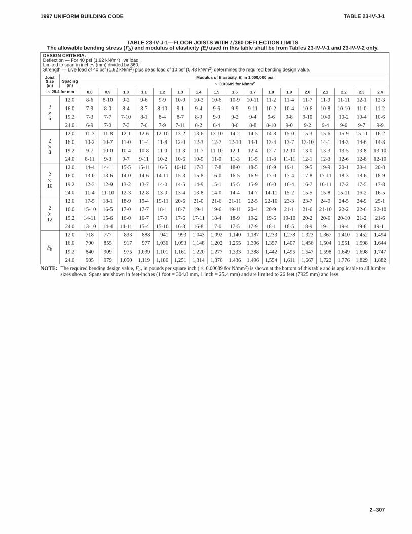
TABLE 23-IV-J-1TABLE 23-IV-J-1
1997 UNIFORM BUILDING CODE
2–307
TABLE 23-IV-J-1—FLOOR JOISTS WITH L/360 DEFLECTION LIMITSThe allowable bending stress ( Fb ) and modulus of elasticity (E) used in this table shall be from T ables 23-IV-V-1 and 23-IV-V-2 only .
DESIGN CRITERIA:Deflection — For 40 psf (1.92 kN/m2) live load.Limited to span in inches (mm) divided by 360.Strength — Live load of 40 psf (1.92 kN/m2) plus dead load of 10 psf (0.48 kN/m2) determines the required bending design value.
JoistSize Spacing
Modulus of Elasticity , E, in 1,000,000 psiJoistSize(in)
Spacing(in) � 0.00689 for N/mm 2
� 25.4 for mm 0.8 0.9 1.0 1.1 1.2 1.3 1.4 1.5 1.6 1.7 1.8 1.9 2.0 2.1 2.2 2.3 2.4
12.0 8-6 8-10 9-2 9-6 9-9 10-0 10-3 10-6 10-9 10-11 11-2 11-4 11-7 11-9 11-11 12-1 12-32�
16.0 7-9 8-0 8-4 8-7 8-10 9-1 9-4 9-6 9-9 9-11 10-2 10-4 10-6 10-8 10-10 11-0 11-2�
6 19.2 7-3 7-7 7-10 8-1 8-4 8-7 8-9 9-0 9-2 9-4 9-6 9-8 9-10 10-0 10-2 10-4 10-6624.0 6-9 7-0 7-3 7-6 7-9 7-11 8-2 8-4 8-6 8-8 8-10 9-0 9-2 9-4 9-6 9-7 9-9
12.0 11-3 11-8 12-1 12-6 12-10 13-2 13-6 13-10 14-2 14-5 14-8 15-0 15-3 15-6 15-9 15-11 16-22�
16.0 10-2 10-7 11-0 11-4 11-8 12-0 12-3 12-7 12-10 13-1 13-4 13-7 13-10 14-1 14-3 14-6 14-8�
8 19.2 9-7 10-0 10-4 10-8 11-0 11-3 11-7 11-10 12-1 12-4 12-7 12-10 13-0 13-3 13-5 13-8 13-10824.0 8-11 9-3 9-7 9-11 10-2 10-6 10-9 11-0 11-3 11-5 11-8 11-11 12-1 12-3 12-6 12-8 12-10
12.0 14-4 14-11 15-5 15-11 16-5 16-10 17-3 17-8 18-0 18-5 18-9 19-1 19-5 19-9 20-1 20-4 20-82�
16.0 13-0 13-6 14-0 14-6 14-11 15-3 15-8 16-0 16-5 16-9 17-0 17-4 17-8 17-11 18-3 18-6 18-9�
10 19.2 12-3 12-9 13-2 13-7 14-0 14-5 14-9 15-1 15-5 15-9 16-0 16-4 16-7 16-11 17-2 17-5 17-81024.0 11-4 11-10 12-3 12-8 13-0 13-4 13-8 14-0 14-4 14-7 14-11 15-2 15-5 15-8 15-11 16-2 16-5
12.0 17-5 18-1 18-9 19-4 19-11 20-6 21-0 21-6 21-11 22-5 22-10 23-3 23-7 24-0 24-5 24-9 25-12�
16.0 15-10 16-5 17-0 17-7 18-1 18-7 19-1 19-6 19-11 20-4 20-9 21-1 21-6 21-10 22-2 22-6 22-10�
12 19.2 14-11 15-6 16-0 16-7 17-0 17-6 17-11 18-4 18-9 19-2 19-6 19-10 20-2 20-6 20-10 21-2 21-61224.0 13-10 14-4 14-11 15-4 15-10 16-3 16-8 17-0 17-5 17-9 18-1 18-5 18-9 19-1 19-4 19-8 19-11
12.0 718 777 833 888 941 993 1,043 1,092 1,140 1,187 1,233 1,278 1,323 1,367 1,410 1,452 1,494
F16.0 790 855 917 977 1,036 1,093 1,148 1,202 1,255 1,306 1,357 1,407 1,456 1,504 1,551 1,598 1,644
Fb 19.2 840 909 975 1,039 1,101 1,161 1,220 1,277 1,333 1,388 1,442 1,495 1,547 1,598 1,649 1,698 1,747
24.0 905 979 1,050 1,119 1,186 1,251 1,314 1,376 1,436 1,496 1,554 1,611 1,667 1,722 1,776 1,829 1,882
NOTE: The required bending design value, Fb, in pounds per square inch (� 0.00689 for N/mm2) is shown at the bottom of this table and is applicable to all lumbersizes shown. Spans are shown in feet-inches (1 foot = 304.8 mm, 1 inch = 25.4 mm) and are limited to 26 feet (7925 mm) and less.
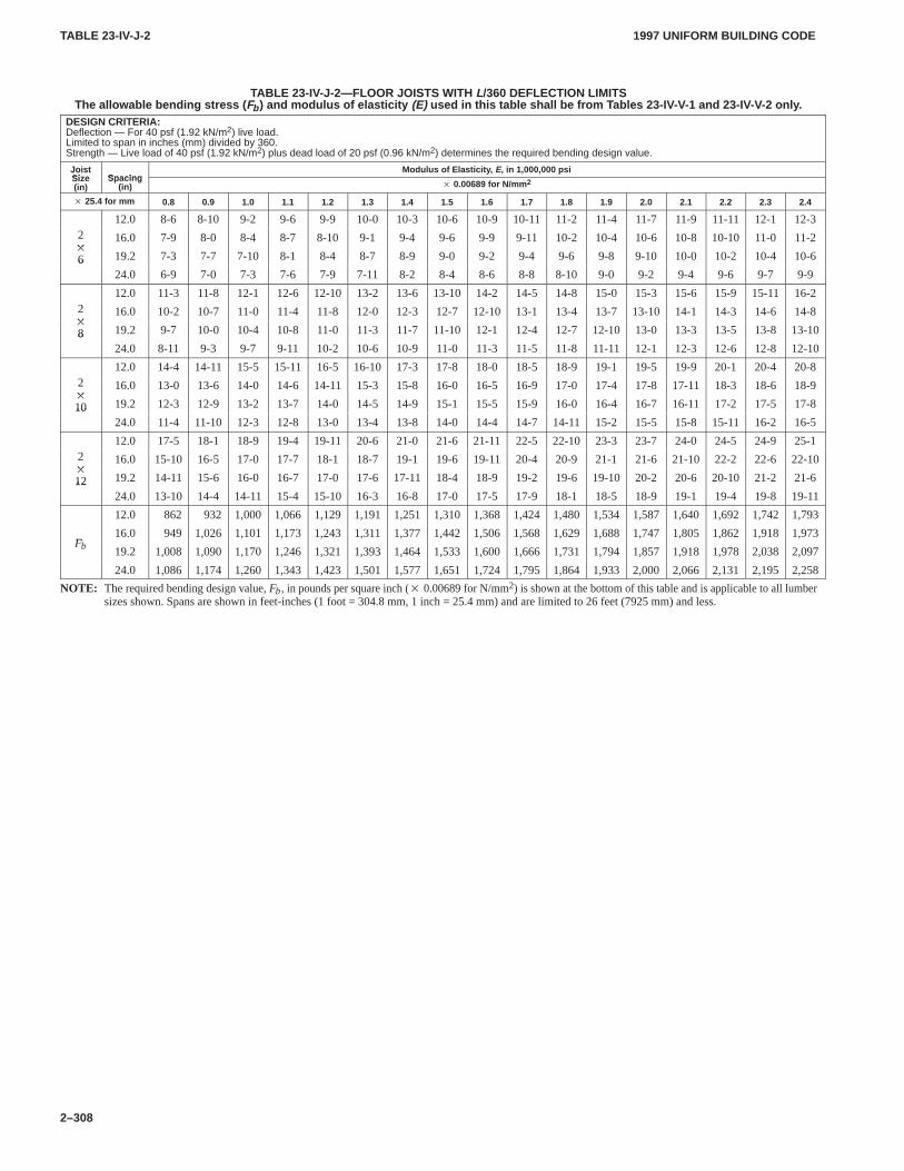
TABLE 23-IV-J-2TABLE 23-IV-J-2
1997 UNIFORM BUILDING CODE
2–308
TABLE 23-IV-J-2—FLOOR JOISTS WITH L/360 DEFLECTION LIMITSThe allowable bending stress ( Fb ) and modulus of elasticity (E) used in this table shall be from T ables 23-IV-V-1 and 23-IV-V-2 only .
DESIGN CRITERIA:Deflection — For 40 psf (1.92 kN/m2) live load.Limited to span in inches (mm) divided by 360.Strength — Live load of 40 psf (1.92 kN/m2) plus dead load of 20 psf (0.96 kN/m2) determines the required bending design value.
JoistSize Spacing
Modulus of Elasticity , E, in 1,000,000 psiJoistSize(in)
Spacing(in) � 0.00689 for N/mm 2
� 25.4 for mm 0.8 0.9 1.0 1.1 1.2 1.3 1.4 1.5 1.6 1.7 1.8 1.9 2.0 2.1 2.2 2.3 2.4
12.0 8-6 8-10 9-2 9-6 9-9 10-0 10-3 10-6 10-9 10-11 11-2 11-4 11-7 11-9 11-11 12-1 12-32�
16.0 7-9 8-0 8-4 8-7 8-10 9-1 9-4 9-6 9-9 9-11 10-2 10-4 10-6 10-8 10-10 11-0 11-2�
6 19.2 7-3 7-7 7-10 8-1 8-4 8-7 8-9 9-0 9-2 9-4 9-6 9-8 9-10 10-0 10-2 10-4 10-6624.0 6-9 7-0 7-3 7-6 7-9 7-11 8-2 8-4 8-6 8-8 8-10 9-0 9-2 9-4 9-6 9-7 9-9
12.0 11-3 11-8 12-1 12-6 12-10 13-2 13-6 13-10 14-2 14-5 14-8 15-0 15-3 15-6 15-9 15-11 16-22�
16.0 10-2 10-7 11-0 11-4 11-8 12-0 12-3 12-7 12-10 13-1 13-4 13-7 13-10 14-1 14-3 14-6 14-8�
8 19.2 9-7 10-0 10-4 10-8 11-0 11-3 11-7 11-10 12-1 12-4 12-7 12-10 13-0 13-3 13-5 13-8 13-10824.0 8-11 9-3 9-7 9-11 10-2 10-6 10-9 11-0 11-3 11-5 11-8 11-11 12-1 12-3 12-6 12-8 12-10
12.0 14-4 14-11 15-5 15-11 16-5 16-10 17-3 17-8 18-0 18-5 18-9 19-1 19-5 19-9 20-1 20-4 20-82�
16.0 13-0 13-6 14-0 14-6 14-11 15-3 15-8 16-0 16-5 16-9 17-0 17-4 17-8 17-11 18-3 18-6 18-9�
10 19.2 12-3 12-9 13-2 13-7 14-0 14-5 14-9 15-1 15-5 15-9 16-0 16-4 16-7 16-11 17-2 17-5 17-81024.0 11-4 11-10 12-3 12-8 13-0 13-4 13-8 14-0 14-4 14-7 14-11 15-2 15-5 15-8 15-11 16-2 16-5
12.0 17-5 18-1 18-9 19-4 19-11 20-6 21-0 21-6 21-11 22-5 22-10 23-3 23-7 24-0 24-5 24-9 25-12�
16.0 15-10 16-5 17-0 17-7 18-1 18-7 19-1 19-6 19-11 20-4 20-9 21-1 21-6 21-10 22-2 22-6 22-10�
12 19.2 14-11 15-6 16-0 16-7 17-0 17-6 17-11 18-4 18-9 19-2 19-6 19-10 20-2 20-6 20-10 21-2 21-61224.0 13-10 14-4 14-11 15-4 15-10 16-3 16-8 17-0 17-5 17-9 18-1 18-5 18-9 19-1 19-4 19-8 19-11
12.0 862 932 1,000 1,066 1,129 1,191 1,251 1,310 1,368 1,424 1,480 1,534 1,587 1,640 1,692 1,742 1,793
F16.0 949 1,026 1,101 1,173 1,243 1,311 1,377 1,442 1,506 1,568 1,629 1,688 1,747 1,805 1,862 1,918 1,973
Fb 19.2 1,008 1,090 1,170 1,246 1,321 1,393 1,464 1,533 1,600 1,666 1,731 1,794 1,857 1,918 1,978 2,038 2,097
24.0 1,086 1,174 1,260 1,343 1,423 1,501 1,577 1,651 1,724 1,795 1,864 1,933 2,000 2,066 2,131 2,195 2,258
NOTE: The required bending design value, Fb, in pounds per square inch (� 0.00689 for N/mm2) is shown at the bottom of this table and is applicable to all lumbersizes shown. Spans are shown in feet-inches (1 foot = 304.8 mm, 1 inch = 25.4 mm) and are limited to 26 feet (7925 mm) and less.
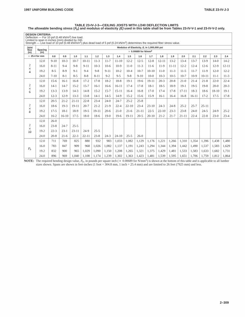
TABLE 23-IV-J-3TABLE 23-IV-J-3
1997 UNIFORM BUILDING CODE
2–309
TABLE 23-IV-J-3—CEILING JOISTS WITH L/240 DEFLECTION LIMITSThe allowable bending stress ( Fb ) and modulus of elasticity (E) used in this table shall be from T ables 23-IV-V-1 and 23-IV-V-2 only .
DESIGN CRITERIA:Deflection — For 10 psf (0.48 kN/m2) live load.Limited to span in inches (mm) divided by 240.Strength — Live load of 10 psf (0.48 kN/mm2) plus dead load of 5 psf (0.24 kN/m2) determines the required fiber stress value.
JoistSize Spacing
Modulus of Elasticity , E, in 1,000,000 psiJoistSize(in)
Spacing(in) � 0.00689 for N/mm 2
� 25.4 for mm 0.8 0.9 1.0 1.1 1.2 1.3 1.4 1.5 1.6 1.7 1.8 1.9 2.0 2.1 2.2 2.3 2.4
12.0 9-10 10-3 10-7 10-11 11-3 11-7 11-10 12-2 12-5 12-8 12-11 13-2 13-4 13-7 13-9 14-0 14-22�
16.0 8-11 9-4 9-8 9-11 10-3 10-6 10-9 11-0 11-3 11-6 11-9 11-11 12-2 12-4 12-6 12-9 12-11�
4 19.2 8-5 8-9 9-1 9-4 9-8 9-11 10-2 10-4 10-7 10-10 11-0 11-3 11-5 11-7 11-9 12-0 12-2424.0 7-10 8-1 8-5 8-8 8-11 9-2 9-5 9-8 9-10 10-0 10-3 10-5 10-7 10-9 10-11 11-1 11-3
12.0 15-6 16-1 16-8 17-2 17-8 18-2 18-8 19-1 19-6 19-11 20-3 20-8 21-0 21-4 21-8 22-0 22-42�
16.0 14-1 14-7 15-2 15-7 16-1 16-6 16-11 17-4 17-8 18-1 18-5 18-9 19-1 19-5 19-8 20-0 20-3�
6 19.2 13-3 13-9 14-3 14-8 15-2 15-7 15-11 16-4 16-8 17-0 17-4 17-8 17-11 18-3 18-6 18-10 19-1624.0 12-3 12-9 13-3 13-8 14-1 14-5 14-9 15-2 15-6 15-9 16-1 16-4 16-8 16-11 17-2 17-5 17-8
12.0 20-5 21-2 21-11 22-8 23-4 24-0 24-7 25-2 25-82�
16.0 18-6 19-3 19-11 20-7 21-2 21-9 22-4 22-10 23-4 23-10 24-3 24-8 25-2 25-7 25-11�
8 19.2 17-5 18-1 18-9 19-5 19-11 20-6 21-0 21-6 21-11 22-5 22-10 23-3 23-8 24-0 24-5 24-9 25-2824.0 16-2 16-10 17-5 18-0 18-6 19-0 19-6 19-11 20-5 20-10 21-2 21-7 21-11 22-4 22-8 23-0 23-4
12.0 26-02�
16.0 23-8 24-7 25-5�
10 19.2 22-3 23-1 23-11 24-9 25-51024.0 20-8 21-6 22-3 22-11 23-8 24-3 24-10 25-5 26-0
12.0 711 769 825 880 932 983 1,033 1,082 1,129 1,176 1,221 1,266 1,310 1,354 1,396 1,438 1,480
F16.0 783 847 909 968 1,026 1,082 1,137 1,191 1,243 1,294 1,344 1,394 1,442 1,490 1,537 1,583 1,629
Fb 19.2 832 900 965 1,029 1,090 1,150 1,208 1,265 1,321 1,375 1,429 1,481 1,533 1,583 1,633 1,682 1,731
24.0 896 969 1,040 1,108 1,174 1,239 1,302 1,363 1,423 1,481 1,539 1,595 1,651 1,706 1,759 1,812 1,864
NOTE: The required bending design value, Fb, in pounds per square inch (� 0.00689 for N/mm2) is shown at the bottom of this table and is applicable to all lumbersizes shown. Spans are shown in feet-inches (1 foot = 304.8 mm, 1 inch = 25.4 mm) and are limited to 26 feet (7925 mm) and less.
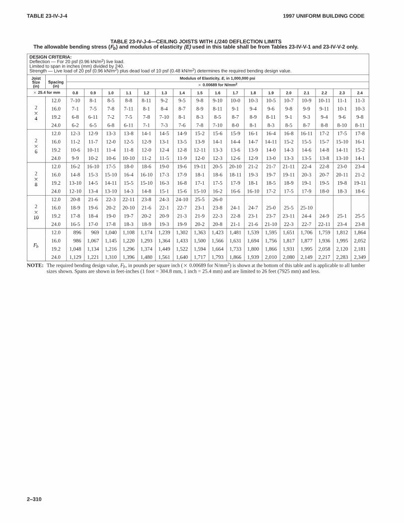
TABLE 23-IV-J-4TABLE 23-IV-J-4
1997 UNIFORM BUILDING CODE
2–310
TABLE 23-IV-J-4—CEILING JOISTS WITH L/240 DEFLECTION LIMITSThe allowable bending stress ( Fb ) and modulus of elasticity (E) used in this table shall be from T ables 23-IV-V-1 and 23-IV-V-2 only .
DESIGN CRITERIA:Deflection — For 20 psf (0.96 kN/m2) live load.Limited to span in inches (mm) divided by 240.Strength — Live load of 20 psf (0.96 kN/m2) plus dead load of 10 psf (0.48 kN/m2) determines the required bending design value.
JoistSize Spacing
Modulus of Elasticity , E, in 1,000,000 psiJoistSize(in)
Spacing(in) � 0.00689 for N/mm 2
� 25.4 for mm 0.8 0.9 1.0 1.1 1.2 1.3 1.4 1.5 1.6 1.7 1.8 1.9 2.0 2.1 2.2 2.3 2.4
12.0 7-10 8-1 8-5 8-8 8-11 9-2 9-5 9-8 9-10 10-0 10-3 10-5 10-7 10-9 10-11 11-1 11-32�
16.0 7-1 7-5 7-8 7-11 8-1 8-4 8-7 8-9 8-11 9-1 9-4 9-6 9-8 9-9 9-11 10-1 10-3�
4 19.2 6-8 6-11 7-2 7-5 7-8 7-10 8-1 8-3 8-5 8-7 8-9 8-11 9-1 9-3 9-4 9-6 9-8424.0 6-2 6-5 6-8 6-11 7-1 7-3 7-6 7-8 7-10 8-0 8-1 8-3 8-5 8-7 8-8 8-10 8-11
12.0 12-3 12-9 13-3 13-8 14-1 14-5 14-9 15-2 15-6 15-9 16-1 16-4 16-8 16-11 17-2 17-5 17-82�
16.0 11-2 11-7 12-0 12-5 12-9 13-1 13-5 13-9 14-1 14-4 14-7 14-11 15-2 15-5 15-7 15-10 16-1�
6 19.2 10-6 10-11 11-4 11-8 12-0 12-4 12-8 12-11 13-3 13-6 13-9 14-0 14-3 14-6 14-8 14-11 15-2624.0 9-9 10-2 10-6 10-10 11-2 11-5 11-9 12-0 12-3 12-6 12-9 13-0 13-3 13-5 13-8 13-10 14-1
12.0 16-2 16-10 17-5 18-0 18-6 19-0 19-6 19-11 20-5 20-10 21-2 21-7 21-11 22-4 22-8 23-0 23-42�
16.0 14-8 15-3 15-10 16-4 16-10 17-3 17-9 18-1 18-6 18-11 19-3 19-7 19-11 20-3 20-7 20-11 21-2�
8 19.2 13-10 14-5 14-11 15-5 15-10 16-3 16-8 17-1 17-5 17-9 18-1 18-5 18-9 19-1 19-5 19-8 19-11824.0 12-10 13-4 13-10 14-3 14-8 15-1 15-6 15-10 16-2 16-6 16-10 17-2 17-5 17-9 18-0 18-3 18-6
12.0 20-8 21-6 22-3 22-11 23-8 24-3 24-10 25-5 26-02�
16.0 18-9 19-6 20-2 20-10 21-6 22-1 22-7 23-1 23-8 24-1 24-7 25-0 25-5 25-10�
10 19.2 17-8 18-4 19-0 19-7 20-2 20-9 21-3 21-9 22-3 22-8 23-1 23-7 23-11 24-4 24-9 25-1 25-51024.0 16-5 17-0 17-8 18-3 18-9 19-3 19-9 20-2 20-8 21-1 21-6 21-10 22-3 22-7 22-11 23-4 23-8
12.0 896 969 1,040 1,108 1,174 1,239 1,302 1,363 1,423 1,481 1,539 1,595 1,651 1,706 1,759 1,812 1,864
F16.0 986 1,067 1,145 1,220 1,293 1,364 1,433 1,500 1,566 1,631 1,694 1,756 1,817 1,877 1,936 1,995 2,052
Fb 19.2 1,048 1,134 1,216 1,296 1,374 1,449 1,522 1,594 1,664 1,733 1,800 1,866 1,931 1,995 2,058 2,120 2,181
24.0 1,129 1,221 1,310 1,396 1,480 1,561 1,640 1,717 1,793 1,866 1,939 2,010 2,080 2,149 2,217 2,283 2,349
NOTE: The required bending design value, Fb, in pounds per square inch (� 0.00689 for N/mm2) is shown at the bottom of this table and is applicable to all lumbersizes shown. Spans are shown in feet-inches (1 foot = 304.8 mm, 1 inch = 25.4 mm) and are limited to 26 feet (7925 mm) and less.
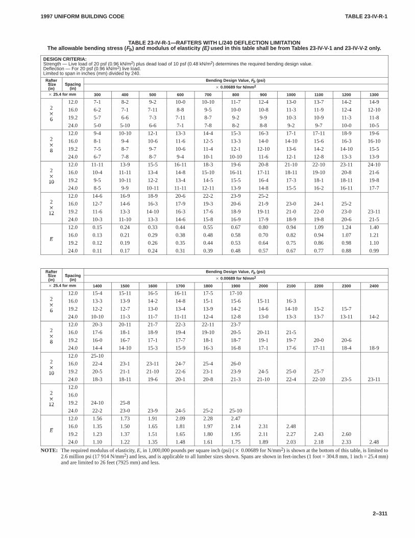
TABLE 23-IV-R-1TABLE 23-IV-R-1
1997 UNIFORM BUILDING CODE
2–311
TABLE 23-IV-R-1—RAFTERS WITH L/240 DEFLECTION LIMIT ATIONThe allowable bending stress ( Fb ) and modulus of elasticity (E) used in this table shall be from T ables 23-IV-V-1 and 23-IV-V-2 only .
DESIGN CRITERIA:Strength — Live load of 20 psf (0.96 kN/m2) plus dead load of 10 psf (0.48 kN/m2) determines the required bending design value.Deflection — For 20 psf (0.96 kN/m2) live load.Limited to span in inches (mm) divided by 240.
RafterSize Spacing
Bending Design V alue, Fb (psi)Rafter Size(in)
Spacing(in) � 0.00689 for N/mm 2
� 25.4 for mm 300 400 500 600 700 800 900 1000 1100 1200 1300
212.0 7-1 8-2 9-2 10-0 10-10 11-7 12-4 13-0 13-7 14-2 14-9
2�
16.0 6-2 7-1 7-11 8-8 9-5 10-0 10-8 11-3 11-9 12-4 12-10�
6 19.2 5-7 6-6 7-3 7-11 8-7 9-2 9-9 10-3 10-9 11-3 11-8624.0 5-0 5-10 6-6 7-1 7-8 8-2 8-8 9-2 9-7 10-0 10-5
212.0 9-4 10-10 12-1 13-3 14-4 15-3 16-3 17-1 17-11 18-9 19-6
2�
16.0 8-1 9-4 10-6 11-6 12-5 13-3 14-0 14-10 15-6 16-3 16-10�
8 19.2 7-5 8-7 9-7 10-6 11-4 12-1 12-10 13-6 14-2 14-10 15-5824.0 6-7 7-8 8-7 9-4 10-1 10-10 11-6 12-1 12-8 13-3 13-9
212.0 11-11 13-9 15-5 16-11 18-3 19-6 20-8 21-10 22-10 23-11 24-10
2�
16.0 10-4 11-11 13-4 14-8 15-10 16-11 17-11 18-11 19-10 20-8 21-6�
10 19.2 9-5 10-11 12-2 13-4 14-5 15-5 16-4 17-3 18-1 18-11 19-81024.0 8-5 9-9 10-11 11-11 12-11 13-9 14-8 15-5 16-2 16-11 17-7
212.0 14-6 16-9 18-9 20-6 22-2 23-9 25-2
2�
16.0 12-7 14-6 16-3 17-9 19-3 20-6 21-9 23-0 24-1 25-2�
12 19.2 11-6 13-3 14-10 16-3 17-6 18-9 19-11 21-0 22-0 23-0 23-111224.0 10-3 11-10 13-3 14-6 15-8 16-9 17-9 18-9 19-8 20-6 21-5
12.0 0.15 0.24 0.33 0.44 0.55 0.67 0.80 0.94 1.09 1.24 1.40
E16.0 0.13 0.21 0.29 0.38 0.48 0.58 0.70 0.82 0.94 1.07 1.21
E19.2 0.12 0.19 0.26 0.35 0.44 0.53 0.64 0.75 0.86 0.98 1.10
24.0 0.11 0.17 0.24 0.31 0.39 0.48 0.57 0.67 0.77 0.88 0.99
RafterSize Spacing
Bending Design V alue, Fb (psi)Rafter Size(in)
Spacing(in) � 0.00689 for N/mm 2
� 25.4 for mm 1400 1500 1600 1700 1800 1900 2000 2100 2200 2300 2400
212.0 15-4 15-11 16-5 16-11 17-5 17-10
2�
16.0 13-3 13-9 14-2 14-8 15-1 15-6 15-11 16-3�
6 19.2 12-2 12-7 13-0 13-4 13-9 14-2 14-6 14-10 15-2 15-7624.0 10-10 11-3 11-7 11-11 12-4 12-8 13-0 13-3 13-7 13-11 14-2
212.0 20-3 20-11 21-7 22-3 22-11 23-7
2�
16.0 17-6 18-1 18-9 19-4 19-10 20-5 20-11 21-5�
8 19.2 16-0 16-7 17-1 17-7 18-1 18-7 19-1 19-7 20-0 20-6824.0 14-4 14-10 15-3 15-9 16-3 16-8 17-1 17-6 17-11 18-4 18-9
212.0 25-10
2�
16.0 22-4 23-1 23-11 24-7 25-4 26-0�
10 19.2 20-5 21-1 21-10 22-6 23-1 23-9 24-5 25-0 25-71024.0 18-3 18-11 19-6 20-1 20-8 21-3 21-10 22-4 22-10 23-5 23-11
212.0
2�
16.0�
12 19.2 24-10 25-81224.0 22-2 23-0 23-9 24-5 25-2 25-10
12.0 1.56 1.73 1.91 2.09 2.28 2.47
E16.0 1.35 1.50 1.65 1.81 1.97 2.14 2.31 2.48
E19.2 1.23 1.37 1.51 1.65 1.80 1.95 2.11 2.27 2.43 2.60
24.0 1.10 1.22 1.35 1.48 1.61 1.75 1.89 2.03 2.18 2.33 2.48
NOTE: The required modulus of elasticity, E, in 1,000,000 pounds per square inch (psi) (� 0.00689 for N/mm2) is shown at the bottom of this table, is limited to2.6 million psi (17914 N/mm2) and less, and is applicable to all lumber sizes shown. Spans are shown in feet-inches (1 foot = 304.8 mm, 1 inch = 25.4 mm)and are limited to 26 feet (7925 mm) and less.
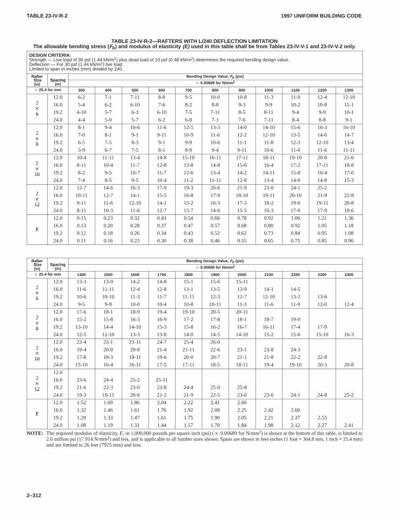
TABLE 23-IV-R-2TABLE 23-IV-R-2
1997 UNIFORM BUILDING CODE
2–312
TABLE 23-IV-R-2—RAFTERS WITH L/240 DEFLECTION LIMIT ATIONThe allowable bending stress ( Fb ) and modulus of elasticity (E) used in this table shall be from T ables 23-IV-V-1 and 23-IV-V-2 only .
DESIGN CRITERIA:Strength — Live load of 30 psf (1.44 kN/m2) plus dead load of 10 psf (0.48 kN/m2) determines the required bending design value.Deflection — For 30 psf (1.44 kN/m2) live load.Limited to span in inches (mm) divided by 240.
RafterSize Spacing
Bending Design V alue, Fb (psi)Rafter Size(in)
Spacing(in) � 0.00689 for N/mm 2
� 25.4 for mm 300 400 500 600 700 800 900 1000 1100 1200 1300
212.0 6-2 7-1 7-11 8-8 9-5 10-0 10-8 11-3 11-9 12-4 12-10
2�
16.0 5-4 6-2 6-10 7-6 8-2 8-8 9-3 9-9 10-2 10-8 11-1�
6 19.2 4-10 5-7 6-3 6-10 7-5 7-11 8-5 8-11 9-4 9-9 10-1624.0 4-4 5-0 5-7 6-2 6-8 7-1 7-6 7-11 8-4 8-8 9-1
212.0 8-1 9-4 10-6 11-6 12-5 13-3 14-0 14-10 15-6 16-3 16-10
2�
16.0 7-0 8-1 9-1 9-11 10-9 11-6 12-2 12-10 13-5 14-0 14-7�
8 19.2 6-5 7-5 8-3 9-1 9-9 10-6 11-1 11-8 12-3 12-10 13-4824.0 5-9 6-7 7-5 8-1 8-9 9-4 9-11 10-6 11-0 11-6 11-11
212.0 10-4 11-11 13-4 14-8 15-10 16-11 17-11 18-11 19-10 20-8 21-6
2�
16.0 8-11 10-4 11-7 12-8 13-8 14-8 15-6 16-4 17-2 17-11 18-8�
10 19.2 8-2 9-5 10-7 11-7 12-6 13-4 14-2 14-11 15-8 16-4 17-01024.0 7-4 8-5 9-5 10-4 11-2 11-11 12-8 13-4 14-0 14-8 15-3
212.0 12-7 14-6 16-3 17-9 19-3 20-6 21-9 23-0 24-1 25-2
2�
16.0 10-11 12-7 14-1 15-5 16-8 17-9 18-10 19-11 20-10 21-9 22-8�
12 19.2 9-11 11-6 12-10 14-1 15-2 16-3 17-3 18-2 19-0 19-11 20-81224.0 8-11 10-3 11-6 12-7 13-7 14-6 15-5 16-3 17-0 17-9 18-6
12.0 0.15 0.23 0.32 0.43 0.54 0.66 0.78 0.92 1.06 1.21 1.36
E16.0 0.13 0.20 0.28 0.37 0.47 0.57 0.68 0.80 0.92 1.05 1.18
E19.2 0.12 0.18 0.26 0.34 0.43 0.52 0.62 0.73 0.84 0.95 1.08
24.0 0.11 0.16 0.23 0.30 0.38 0.46 0.55 0.65 0.75 0.85 0.96
RafterSize Spacing
Bending Design V alue, Fb (psi)Rafter Size(in)
Spacing(in) � 0.00689 for N/mm 2
� 25.4 for mm 1400 1500 1600 1700 1800 1900 2000 2100 2200 2300 2400
212.0 13-3 13-9 14-2 14-8 15-1 15-6 15-11
2�
16.0 11-6 11-11 12-4 12-8 13-1 13-5 13-9 14-1 14-5�
6 19.2 10-6 10-10 11-3 11-7 11-11 12-3 12-7 12-10 13-2 13-6624.0 9-5 9-9 10-0 10-4 10-8 10-11 11-3 11-6 11-9 12-0 12-4
212.0 17-6 18-1 18-9 19-4 19-10 20-5 20-11
2�
16.0 15-2 15-8 16-3 16-9 17-2 17-8 18-1 18-7 19-0�
8 19.2 13-10 14-4 14-10 15-3 15-8 16-2 16-7 16-11 17-4 17-9824.0 12-5 12-10 13-3 13-8 14-0 14-5 14-10 15-2 15-6 15-10 16-3
212.0 22-4 23-1 23-11 24-7 25-4 26-0
2�
16.0 19-4 20-0 20-8 21-4 21-11 22-6 23-1 23-8 24-3�
10 19.2 17-8 18-3 18-11 19-6 20-0 20-7 21-1 21-8 22-2 22-81024.0 15-10 16-4 16-11 17-5 17-11 18-5 18-11 19-4 19-10 20-3 20-8
212.0
2�
16.0 23-6 24-4 25-2 25-11�
12 19.2 21-6 22-3 23-0 23-8 24-4 25-0 25-81224.0 19-3 19-11 20-6 21-2 21-9 22-5 23-0 23-6 24-1 24-8 25-2
12.0 1.52 1.69 1.86 2.04 2.22 2.41 2.60
E16.0 1.32 1.46 1.61 1.76 1.92 2.08 2.25 2.42 2.60
E19.2 1.20 1.33 1.47 1.61 1.75 1.90 2.05 2.21 2.37 2.53
24.0 1.08 1.19 1.31 1.44 1.57 1.70 1.84 1.98 2.12 2.27 2.41
NOTE: The required modulus of elasticity, E, in 1,000,000 pounds per square inch (psi) (� 0.00689 for N/mm2) is shown at the bottom of this table, is limited to2.6 million psi (17914 N/mm2) and less, and is applicable to all lumber sizes shown. Spans are shown in feet-inches (1 foot = 304.8 mm, 1 inch = 25.4 mm)and are limited to 26 feet (7925 mm) and less.
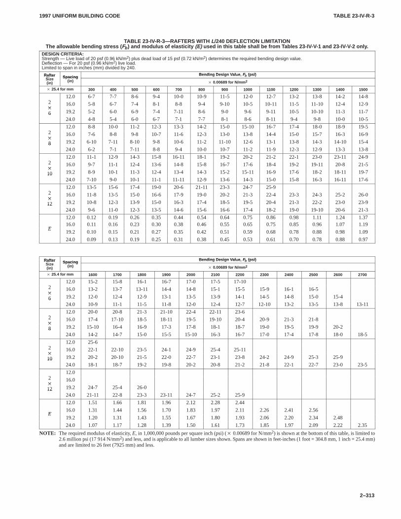
TABLE 23-IV-R-3TABLE 23-IV-R-3
1997 UNIFORM BUILDING CODE
2–313
TABLE 23-IV-R-3—RAFTERS WITH L/240 DEFLECTION LIMITATIONThe allowable bending stress ( Fb ) and modulus of elasticity (E) used in this table shall be from T ables 23-IV-V-1 and 23-IV-V-2 only .
DESIGN CRITERIA:Strength — Live load of 20 psf (0.96 kN/m2) plus dead load of 15 psf (0.72 kN/m2) determines the required bending design value.Deflection — For 20 psf (0.96 kN/m2) live load.Limited to span in inches (mm) divided by 240.
Rafter Bending Design V al e Fb (psi)RafterSi Spacing
Bending Design V alue, Fb (psi)RafterSize(in)
Spacing(in)
� 0.00689 for N/mm 2
� 25.4 for mm 300 400 500 600 700 800 900 1000 1100 1200 1300 1400 1500
212.0 6-7 7-7 8-6 9-4 10-0 10-9 11-5 12-0 12-7 13-2 13-8 14-2 14-8
2�
16.0 5-8 6-7 7-4 8-1 8-8 9-4 9-10 10-5 10-11 11-5 11-10 12-4 12-9�
6 19.2 5-2 6-0 6-9 7-4 7-11 8-6 9-0 9-6 9-11 10-5 10-10 11-3 11-7624.0 4-8 5-4 6-0 6-7 7-1 7-7 8-1 8-6 8-11 9-4 9-8 10-0 10-5
212.0 8-8 10-0 11-2 12-3 13-3 14-2 15-0 15-10 16-7 17-4 18-0 18-9 19-5
2�
16.0 7-6 8-8 9-8 10-7 11-6 12-3 13-0 13-8 14-4 15-0 15-7 16-3 16-9�
8 19.2 6-10 7-11 8-10 9-8 10-6 11-2 11-10 12-6 13-1 13-8 14-3 14-10 15-4824.0 6-2 7-1 7-11 8-8 9-4 10-0 10-7 11-2 11-9 12-3 12-9 13-3 13-8
212.0 11-1 12-9 14-3 15-8 16-11 18-1 19-2 20-2 21-2 22-1 23-0 23-11 24-9
2�
16.0 9-7 11-1 12-4 13-6 14-8 15-8 16-7 17-6 18-4 19-2 19-11 20-8 21-5�
10 19.2 8-9 10-1 11-3 12-4 13-4 14-3 15-2 15-11 16-9 17-6 18-2 18-11 19-71024.0 7-10 9-0 10-1 11-1 11-11 12-9 13-6 14-3 15-0 15-8 16-3 16-11 17-6
212.0 13-5 15-6 17-4 19-0 20-6 21-11 23-3 24-7 25-9
2�
16.0 11-8 13-5 15-0 16-6 17-9 19-0 20-2 21-3 22-4 23-3 24-3 25-2 26-0�
12 19.2 10-8 12-3 13-9 15-0 16-3 17-4 18-5 19-5 20-4 21-3 22-2 23-0 23-91224.0 9-6 11-0 12-3 13-5 14-6 15-6 16-6 17-4 18-2 19-0 19-10 20-6 21-3
12.0 0.12 0.19 0.26 0.35 0.44 0.54 0.64 0.75 0.86 0.98 1.11 1.24 1.37
E16.0 0.11 0.16 0.23 0.30 0.38 0.46 0.55 0.65 0.75 0.85 0.96 1.07 1.19
E19.2 0.10 0.15 0.21 0.27 0.35 0.42 0.51 0.59 0.68 0.78 0.88 0.98 1.09
24.0 0.09 0.13 0.19 0.25 0.31 0.38 0.45 0.53 0.61 0.70 0.78 0.88 0.97
Rafter Bending Design V al e Fb (psi)RafterSi Spacing
Bending Design V alue, Fb (psi)RafterSize(in)
Spacing(in)
� 0.00689 for N/mm 2
� 25.4 for mm 1600 1700 1800 1900 2000 2100 2200 2300 2400 2500 2600 2700
212.0 15-2 15-8 16-1 16-7 17-0 17-5 17-10
2�
16.0 13-2 13-7 13-11 14-4 14-8 15-1 15-5 15-9 16-1 16-5�
6 19.2 12-0 12-4 12-9 13-1 13-5 13-9 14-1 14-5 14-8 15-0 15-4624.0 10-9 11-1 11-5 11-8 12-0 12-4 12-7 12-10 13-2 13-5 13-8 13-11
212.0 20-0 20-8 21-3 21-10 22-4 22-11 23-6
2�
16.0 17-4 17-10 18-5 18-11 19-5 19-10 20-4 20-9 21-3 21-8�
8 19.2 15-10 16-4 16-9 17-3 17-8 18-1 18-7 19-0 19-5 19-9 20-2824.0 14-2 14-7 15-0 15-5 15-10 16-3 16-7 17-0 17-4 17-8 18-0 18-5
212.0 25-6
2�
16.0 22-1 22-10 23-5 24-1 24-9 25-4 25-11�
10 19.2 20-2 20-10 21-5 22-0 22-7 23-1 23-8 24-2 24-9 25-3 25-91024.0 18-1 18-7 19-2 19-8 20-2 20-8 21-2 21-8 22-1 22-7 23-0 23-5
212.0
2�
16.0�
12 19.2 24-7 25-4 26-01224.0 21-11 22-8 23-3 23-11 24-7 25-2 25-9
12.0 1.51 1.66 1.81 1.96 2.12 2.28 2.44
E16.0 1.31 1.44 1.56 1.70 1.83 1.97 2.11 2.26 2.41 2.56
E19.2 1.20 1.31 1.43 1.55 1.67 1.80 1.93 2.06 2.20 2.34 2.48
24.0 1.07 1.17 1.28 1.39 1.50 1.61 1.73 1.85 1.97 2.09 2.22 2.35
NOTE: The required modulus of elasticity, E, in 1,000,000 pounds per square inch (psi) (� 0.00689 for N/mm2) is shown at the bottom of this table, is limited to2.6 million psi (17914 N/mm2) and less, and is applicable to all lumber sizes shown. Spans are shown in feet-inches (1 foot = 304.8 mm, 1 inch = 25.4 mm)and are limited to 26 feet (7925 mm) and less.
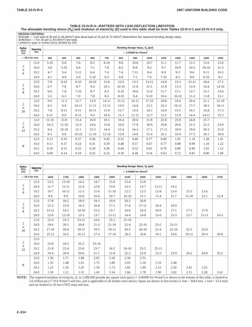
TABLE 23-IV-R-4TABLE 23-IV-R-4
1997 UNIFORM BUILDING CODE
2–314
TABLE 23-IV-R-4—RAFTERS WITH L/240 DEFLECTION LIMITATIONThe allowable bending stress ( Fb ) and modulus of elasticity (E) used in this table shall be from T ables 23-IV-V-1 and 23-IV-V-2 only .
DESIGN CRITERIA:Strength — Live load of 30 psf (1.44 kN/m2) plus dead load of 15 psf (0.72 kN/m2) determines the required bending design value.Deflection — For 30 psf (1.44 kN/m2) live load.Limited to span in inches (mm) divided by 240.
R ft Bending Design V al e F (psi)RafterSi Spacing
Bending Design V alue, Fb (psi)RafterSize(in)
Spacing(in)
� 0.00689 for N/mm 2
� 25.4 for mm 300 400 500 600 700 800 900 1000 1100 1200 1300 1400 1500
212.0 5-10 6-8 7-6 8-2 8-10 9-6 10-0 10-7 11-1 11-7 12-1 12-6 13-0
2�
16.0 5-0 5-10 6-6 7-1 7-8 8-2 8-8 9-2 9-7 10-0 10-5 10-10 11-3�
6 19.2 4-7 5-4 5-11 6-6 7-0 7-6 7-11 8-4 8-9 9-2 9-6 9-11 10-3624.0 4-1 4-9 5-4 5-10 6-3 6-8 7-1 7-6 7-10 8-2 8-6 8-10 9-2
212.0 7-8 8-10 9-10 10-10 11-8 12-6 13-3 13-11 14-8 15-3 15-11 16-6 17-1
2�
16.0 6-7 7-8 8-7 9-4 10-1 10-10 11-6 12-1 12-8 13-3 13-9 14-4 14-10�
8 19.2 6-0 7-0 7-10 8-7 9-3 9-10 10-6 11-0 11-7 12-1 12-7 13-1 13-6824.0 5-5 6-3 7-0 7-8 8-3 8-10 9-4 9-10 10-4 10-10 11-3 11-8 12-1
212.0 9-9 11-3 12-7 13-9 14-11 15-11 16-11 17-10 18-8 19-6 20-4 21-1 21-10
2�
16.0 8-5 9-9 10-11 11-11 12-11 13-9 14-8 15-5 16-2 16-11 17-7 18-3 18-11�
10 19.2 7-8 8-11 9-11 10-11 11-9 12-7 13-4 14-1 14-9 15-5 16-1 16-8 17-31024.0 6-11 8-0 8-11 9-9 10-6 11-3 11-11 12-7 13-2 13-9 14-4 14-11 15-5
212.0 11-10 13-8 15-4 16-9 18-1 19-4 20-6 21-8 22-8 23-9 24-8 25-7
2�
16.0 10-3 11-10 13-3 14-6 15-8 16-9 17-9 18-9 19-8 20-6 21-5 22-2 23-0�
12 19.2 9-4 10-10 12-1 13-3 14-4 15-4 16-3 17-1 17-11 18-9 19-6 20-3 21-01224.0 8-5 9-8 10-10 11-10 12-10 13-8 14-6 15-4 16-1 16-9 17-5 18-1 18-9
12.0 0.13 0.19 0.27 0.36 0.45 0.55 0.66 0.77 0.89 1.01 1.14 1.28 1.41
E16.0 0.11 0.17 0.24 0.31 0.39 0.48 0.57 0.67 0.77 0.88 0.99 1.10 1.22
E19.2 0.10 0.15 0.22 0.28 0.36 0.44 0.52 0.61 0.70 0.80 0.90 1.01 1.12
24.0 0.09 0.14 0.19 0.25 0.32 0.39 0.46 0.54 0.63 0.72 0.81 0.90 1.00
Rafter Bending Design V al e Fb (psi)RafterSize Spacin g
Bending Design V alue, Fb (psi)RafterSize(in)
Spacing(in)
� 0.00689 for N/mm 2
� 25.4 for mm 1600 1700 1800 1900 2000 2100 2200 2300 2400 2500 2600 2700
212.0 13-5 13-10 14-2 14-7 15-0 15-4 15-8
2�
16.0 11-7 11-11 12-4 12-8 13-0 13-3 13-7 13-11 14-2�
6 19.2 10-7 10-11 11-3 11-6 11-10 12-2 12-5 12-8 13-0 13-3 13-6624.0 9-6 9-9 10-0 10-4 10-7 10-10 11-1 11-4 11-7 11-10 12-1 12-4
212.0 17-8 18-2 18-9 19-3 19-9 20-3 20-8
2�
16.0 15-3 15-9 16-3 16-8 17-1 17-6 17-11 18-4 18-9�
8 19.2 13-11 14-5 14-10 15-2 15-7 16-0 16-4 16-9 17-1 17-5 17-9824.0 12-6 12-10 13-3 13-7 13-11 14-4 14-8 15-0 15-3 15-7 15-11 16-3
212.0 22-6 23-3 23-11 24-6 25-2 25-10
2�
16.0 19-6 20-1 20-8 21-3 21-10 22-4 22-10 23-5 23-11�
10 19.2 17-10 18-4 18-11 19-5 19-11 20-5 20-10 21-4 21-10 22-3 22-81024.0 15-11 16-5 16-11 17-4 17-10 18-3 18-8 19-1 19-6 19-11 20-4 20-8
212.0
2�
16.0 23-9 24-5 25-2 25-10�
12 19.2 21-8 22-4 23-0 23-7 24-2 24-10 25-5 25-111224.0 19-4 20-0 20-6 21-1 21-8 22-2 22-8 23-3 23-9 24-2 24-8 25-2
12.0 1.56 1.71 1.86 2.02 2.18 2.34 2.51
E16.0 1.35 1.48 1.61 1.75 1.89 2.03 2.18 2.33 2.48
E19.2 1.23 1.35 1.47 1.59 1.72 1.85 1.99 2.12 2.26 2.41 2.55
24.0 1.10 1.21 1.31 1.43 1.54 1.66 1.78 1.90 2.02 2.15 2.28 2.41
NOTE: The required modulus of elasticity, E, in 1,000,000 pounds per square inch (psi) (� 0.00689 for N/mm2) is shown at the bottom of this table, is limited to2.6 million psi (17914 N/mm2) and less, and is applicable to all lumber sizes shown. Spans are shown in feet-inches (1 foot = 304.8 mm, 1 inch = 25.4 mm)and are limited to 26 feet (7925 mm) and less.
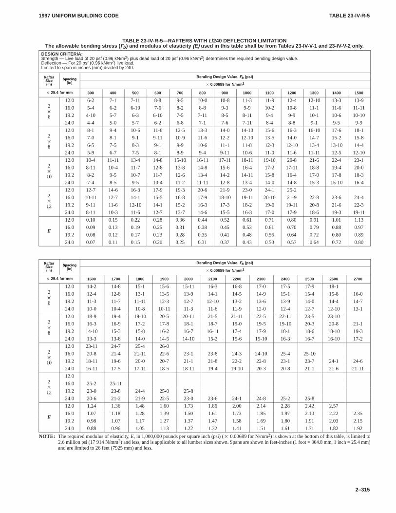
TABLE 23-IV-R-5TABLE 23-IV-R-5
1997 UNIFORM BUILDING CODE
2–315
TABLE 23-IV-R-5—RAFTERS WITH L/240 DEFLECTION LIMITATIONThe allowable bending stress ( Fb ) and modulus of elasticity (E) used in this table shall be from T ables 23-IV-V-1 and 23-IV-V-2 only .
DESIGN CRITERIA:Strength — Live load of 20 psf (0.96 kN/m2) plus dead load of 20 psf (0.96 kN/m2) determines the required bending design value.Deflection — For 20 psf (0.96 kN/m2) live load.Limited to span in inches (mm) divided by 240.
R ft Bending Design V al e F (psi)RafterSize Spacing
Bending Design V alue, Fb (psi)RafterSize(in)
Spacing(in)
� 0.00689 for N/mm 2
� 25.4 for mm 300 400 500 600 700 800 900 1000 1100 1200 1300 1400 1500
212.0 6-2 7-1 7-11 8-8 9-5 10-0 10-8 11-3 11-9 12-4 12-10 13-3 13-9
2�
16.0 5-4 6-2 6-10 7-6 8-2 8-8 9-3 9-9 10-2 10-8 11-1 11-6 11-11�
6 19.2 4-10 5-7 6-3 6-10 7-5 7-11 8-5 8-11 9-4 9-9 10-1 10-6 10-10624.0 4-4 5-0 5-7 6-2 6-8 7-1 7-6 7-11 8-4 8-8 9-1 9-5 9-9
212.0 8-1 9-4 10-6 11-6 12-5 13-3 14-0 14-10 15-6 16-3 16-10 17-6 18-1
2�
16.0 7-0 8-1 9-1 9-11 10-9 11-6 12-2 12-10 13-5 14-0 14-7 15-2 15-8�
8 19.2 6-5 7-5 8-3 9-1 9-9 10-6 11-1 11-8 12-3 12-10 13-4 13-10 14-4824.0 5-9 6-7 7-5 8-1 8-9 9-4 9-11 10-6 11-0 11-6 11-11 12-5 12-10
212.0 10-4 11-11 13-4 14-8 15-10 16-11 17-11 18-11 19-10 20-8 21-6 22-4 23-1
2�
16.0 8-11 10-4 11-7 12-8 13-8 14-8 15-6 16-4 17-2 17-11 18-8 19-4 20-0�
10 19.2 8-2 9-5 10-7 11-7 12-6 13-4 14-2 14-11 15-8 16-4 17-0 17-8 18-31024.0 7-4 8-5 9-5 10-4 11-2 11-11 12-8 13-4 14-0 14-8 15-3 15-10 16-4
212.0 12-7 14-6 16-3 17-9 19-3 20-6 21-9 23-0 24-1 25-2
2�
16.0 10-11 12-7 14-1 15-5 16-8 17-9 18-10 19-11 20-10 21-9 22-8 23-6 24-4�
12 19.2 9-11 11-6 12-10 14-1 15-2 16-3 17-3 18-2 19-0 19-11 20-8 21-6 22-31224.0 8-11 10-3 11-6 12-7 13-7 14-6 15-5 16-3 17-0 17-9 18-6 19-3 19-11
12.0 0.10 0.15 0.22 0.28 0.36 0.44 0.52 0.61 0.71 0.80 0.91 1.01 1.13
E16.0 0.09 0.13 0.19 0.25 0.31 0.38 0.45 0.53 0.61 0.70 0.79 0.88 0.97
E19.2 0.08 0.12 0.17 0.23 0.28 0.35 0.41 0.48 0.56 0.64 0.72 0.80 0.89
24.0 0.07 0.11 0.15 0.20 0.25 0.31 0.37 0.43 0.50 0.57 0.64 0.72 0.80
R ft Bending Design V al e F (psi)RafterSize Spacing
Bending Design V alue, Fb (psi)RafterSize(in)
Spacing(in)
� 0.00689 for N/mm 2
� 25.4 for mm 1600 1700 1800 1900 2000 2100 2200 2300 2400 2500 2600 2700
212.0 14-2 14-8 15-1 15-6 15-11 16-3 16-8 17-0 17-5 17-9 18-1
2�
16.0 12-4 12-8 13-1 13-5 13-9 14-1 14-5 14-9 15-1 15-4 15-8 16-0�
6 19.2 11-3 11-7 11-11 12-3 12-7 12-10 13-2 13-6 13-9 14-0 14-4 14-7624.0 10-0 10-4 10-8 10-11 11-3 11-6 11-9 12-0 12-4 12-7 12-10 13-1
212.0 18-9 19-4 19-10 20-5 20-11 21-5 21-11 22-5 22-11 23-5 23-10
2�
16.0 16-3 16-9 17-2 17-8 18-1 18-7 19-0 19-5 19-10 20-3 20-8 21-1�
8 19.2 14-10 15-3 15-8 16-2 16-7 16-11 17-4 17-9 18-1 18-6 18-10 19-3824.0 13-3 13-8 14-0 14-5 14-10 15-2 15-6 15-10 16-3 16-7 16-10 17-2
212.0 23-11 24-7 25-4 26-0
2�
16.0 20-8 21-4 21-11 22-6 23-1 23-8 24-3 24-10 25-4 25-10�
10 19.2 18-11 19-6 20-0 20-7 21-1 21-8 22-2 22-8 23-1 23-7 24-1 24-61024.0 16-11 17-5 17-11 18-5 18-11 19-4 19-10 20-3 20-8 21-1 21-6 21-11
212.0
2�
16.0 25-2 25-11�
12 19.2 23-0 23-8 24-4 25-0 25-81224.0 20-6 21-2 21-9 22-5 23-0 23-6 24-1 24-8 25-2 25-8
12.0 1.24 1.36 1.48 1.60 1.73 1.86 2.00 2.14 2.28 2.42 2.57
E16.0 1.07 1.18 1.28 1.39 1.50 1.61 1.73 1.85 1.97 2.10 2.22 2.35
E19.2 0.98 1.07 1.17 1.27 1.37 1.47 1.58 1.69 1.80 1.91 2.03 2.15
24.0 0.88 0.96 1.05 1.13 1.22 1.32 1.41 1.51 1.61 1.71 1.82 1.92
NOTE: The required modulus of elasticity, E, in 1,000,000 pounds per square inch (psi) (� 0.00689 for N/mm2) is shown at the bottom of this table, is limited to2.6 million psi (17914 N/mm2) and less, and is applicable to all lumber sizes shown. Spans are shown in feet-inches (1 foot = 304.8 mm, 1 inch = 25.4 mm)and are limited to 26 feet (7925 mm) and less.
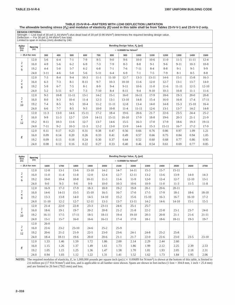
TABLE 23-IV-R-6TABLE 23-IV-R-6
1997 UNIFORM BUILDING CODE
2–316
TABLE 23-IV-R-6—RAFTERS WITH L/240 DEFLECTION LIMITATIONThe allowable bending stress ( Fb ) and modulus of elasticity (E) used in this table shall be from T ables 23-IV-V-1 and 23-IV-V-2 only .
DESIGN CRITERIA:Strength — Live load of 30 psf (1.44 kN/m2) plus dead load of 20 psf (0.96 kN/m2) determines the required bending design value.Deflection — For 30 psf (1.44 kN/m2) live load.Limited to span in inches (mm) divided by 240.
R ft Bending Design V al e F (psi)RafterSize Spacing
Bending Design V alue, Fb (psi)RafterSize(in)
Spacing(in)
� 0.00689 for N/mm 2
� 25.4 for mm 300 400 500 600 700 800 900 1000 1100 1200 1300 1400 1500
212.0 5-6 6-4 7-1 7-9 8-5 9-0 9-6 10-0 10-6 11-0 11-5 11-11 12-4
2�
16.0 4-9 5-6 6-2 6-9 7-3 7-9 8-3 8-8 9-1 9-6 9-11 10-3 10-8�
6 19.2 4-4 5-0 5-7 6-2 6-8 7-1 7-6 7-11 8-4 8-8 9-1 9-5 9-9624.0 3-11 4-6 5-0 5-6 5-11 6-4 6-9 7-1 7-5 7-9 8-1 8-5 8-8
212.0 7-3 8-4 9-4 10-3 11-1 11-10 12-7 13-3 13-11 14-6 15-1 15-8 16-3
2�
16.0 6-3 7-3 8-1 8-11 9-7 10-3 10-10 11-6 12-0 12-7 13-1 13-7 14-0�
8 19.2 5-9 6-7 7-5 8-1 8-9 9-4 9-11 10-6 11-0 11-6 11-11 12-5 12-10824.0 5-2 5-11 6-7 7-3 7-10 8-4 8-11 9-4 9-10 10-3 10-8 11-1 11-6
212.0 9-3 10-8 11-11 13-1 14-2 15-1 16-0 16-11 17-9 18-6 19-3 20-0 20-8
2�
16.0 8-0 9-3 10-4 11-4 12-3 13-1 13-10 14-8 15-4 16-0 16-8 17-4 17-11�
10 19.2 7-4 8-5 9-5 10-4 11-2 11-11 12-8 13-4 14-0 14-8 15-3 15-10 16-41024.0 6-6 7-7 8-5 9-3 10-0 10-8 11-4 11-11 12-6 13-1 13-7 14-2 14-8
212.0 11-3 13-0 14-6 15-11 17-2 18-4 19-6 20-6 21-7 22-6 23-5 24-4 25-2
2�
16.0 9-9 11-3 12-7 13-9 14-11 15-11 16-10 17-9 18-8 19-6 20-3 21-1 21-9�
12 19.2 8-11 10-3 11-6 12-7 13-7 14-6 15-5 16-3 17-0 17-9 18-6 19-3 19-111224.0 7-11 9-2 10-3 11-3 12-2 13-0 13-9 14-6 15-3 15-11 16-7 17-2 17-9
12.0 0.11 0.17 0.23 0.31 0.38 0.47 0.56 0.66 0.76 0.86 0.97 1.09 1.21
E16.0 0.09 0.14 0.20 0.26 0.33 0.41 0.49 0.57 0.66 0.75 0.84 0.94 1.05
E19.2 0.09 0.13 0.18 0.24 0.30 0.37 0.44 0.52 0.60 0.68 0.77 0.86 0.95
24.0 0.08 0.12 0.16 0.22 0.27 0.33 0.40 0.46 0.54 0.61 0.69 0.77 0.85
R ft Bending Design V al e F (psi)RafterSize Spacing
Bending Design V alue, Fb (psi)RafterSize(in)
Spacing(in)
� 0.00689 for N/mm 2
� 25.4 for mm 1600 1700 1800 1900 2000 2100 2200 2300 2400 2500 2600 2700
212.0 12-8 13-1 13-6 13-10 14-2 14-7 14-11 15-3 15-7 15-11
2�
16.0 11-0 11-4 11-8 12-0 12-4 12-7 12-11 13-2 13-6 13-9 14-0 14-3�
6 19.2 10-0 10-4 10-8 10-11 11-3 11-6 11-9 12-0 12-4 12-7 12-10 13-1624.0 9-0 9-3 9-6 9-9 10-0 10-3 10-6 10-9 11-0 11-3 11-5 11-8
212.0 16-9 17-3 17-9 18-3 18-9 19-2 19-8 20-1 20-6 20-11
2�
16.0 14-6 14-11 15-5 15-10 16-3 16-7 17-0 17-5 17-9 18-1 18-6 18-10�
8 19.2 13-3 13-8 14-0 14-5 14-10 15-2 15-6 15-10 16-3 16-7 16-10 17-2824.0 11-10 12-2 12-7 12-11 13-3 13-7 13-11 14-2 14-6 14-10 15-1 15-5
212.0 21-4 22-0 22-8 23-3 23-11 24-6 25-1 25-7
2�
16.0 18-6 19-1 19-7 20-2 20-8 21-2 21-8 22-2 22-8 23-1 23-7 24-0�
10 19.2 16-11 17-5 17-11 18-5 18-11 19-4 19-10 20-3 20-8 21-1 21-6 21-111024.0 15-1 15-7 16-0 16-6 16-11 17-4 17-9 18-1 18-6 18-11 19-3 19-7
212.0 26-0
2�
16.0 22-6 23-2 23-10 24-6 25-2 25-9�
12 19.2 20-6 21-2 21-9 22-5 23-0 23-6 24-1 24-8 25-2 25-81224.0 18-4 18-11 19-6 20-0 20-6 21-1 21-7 22-0 22-6 23-0 23-5 23-10
12.0 1.33 1.46 1.59 1.72 1.86 2.00 2.14 2.29 2.44 2.60
E16.0 1.15 1.26 1.37 1.49 1.61 1.73 1.86 1.99 2.12 2.25 2.39 2.53
E19.2 1.05 1.15 1.25 1.36 1.47 1.58 1.70 1.81 1.93 2.05 2.18 2.31
24.0 0.94 1.03 1.12 1.22 1.31 1.41 1.52 1.62 1.73 1.84 1.95 2.06
NOTE: The required modulus of elasticity, E, in 1,000,000 pounds per square inch (psi) (� 0.00689 for N/mm2) is shown at the bottom of this table, is limited to2.6 million psi (17914 N/mm2) and less, and is applicable to all lumber sizes shown. Spans are shown in feet-inches (1 foot = 304.8 mm, 1 inch = 25.4 mm)and are limited to 26 feet (7925 mm) and less.
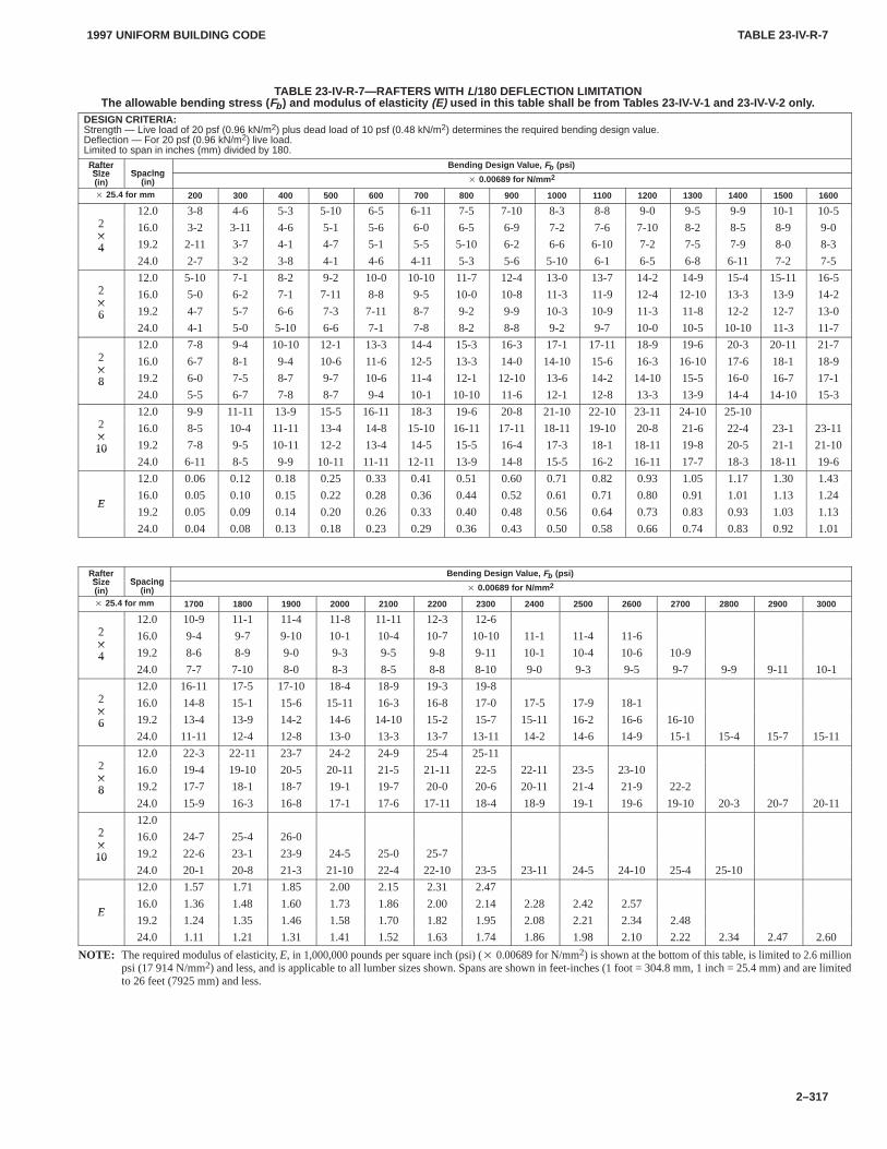
TABLE 23-IV-R-7TABLE 23-IV-R-7
1997 UNIFORM BUILDING CODE
2–317
TABLE 23-IV-R-7—RAFTERS WITH L/180 DEFLECTION LIMITATIONThe allowable bending stress ( Fb ) and modulus of elasticity (E) used in this table shall be from T ables 23-IV-V-1 and 23-IV-V-2 only .
DESIGN CRITERIA:Strength — Live load of 20 psf (0.96 kN/m2) plus dead load of 10 psf (0.48 kN/m2) determines the required bending design value.Deflection — For 20 psf (0.96 kN/m2) live load.Limited to span in inches (mm) divided by 180.
RafterSize Spacing
Bending Design V alue, Fb (psi)RafterSize(in)
Spacing(in) � 0.00689 for N/mm 2
� 25.4 for mm 200 300 400 500 600 700 800 900 1000 1100 1200 1300 1400 1500 1600
212.0 3-8 4-6 5-3 5-10 6-5 6-11 7-5 7-10 8-3 8-8 9-0 9-5 9-9 10-1 10-5
2�
16.0 3-2 3-11 4-6 5-1 5-6 6-0 6-5 6-9 7-2 7-6 7-10 8-2 8-5 8-9 9-0�
4 19.2 2-11 3-7 4-1 4-7 5-1 5-5 5-10 6-2 6-6 6-10 7-2 7-5 7-9 8-0 8-3424.0 2-7 3-2 3-8 4-1 4-6 4-11 5-3 5-6 5-10 6-1 6-5 6-8 6-11 7-2 7-5
212.0 5-10 7-1 8-2 9-2 10-0 10-10 11-7 12-4 13-0 13-7 14-2 14-9 15-4 15-11 16-5
2�
16.0 5-0 6-2 7-1 7-11 8-8 9-5 10-0 10-8 11-3 11-9 12-4 12-10 13-3 13-9 14-2�
6 19.2 4-7 5-7 6-6 7-3 7-11 8-7 9-2 9-9 10-3 10-9 11-3 11-8 12-2 12-7 13-0624.0 4-1 5-0 5-10 6-6 7-1 7-8 8-2 8-8 9-2 9-7 10-0 10-5 10-10 11-3 11-7
212.0 7-8 9-4 10-10 12-1 13-3 14-4 15-3 16-3 17-1 17-11 18-9 19-6 20-3 20-11 21-7
2�
16.0 6-7 8-1 9-4 10-6 11-6 12-5 13-3 14-0 14-10 15-6 16-3 16-10 17-6 18-1 18-9�
8 19.2 6-0 7-5 8-7 9-7 10-6 11-4 12-1 12-10 13-6 14-2 14-10 15-5 16-0 16-7 17-1824.0 5-5 6-7 7-8 8-7 9-4 10-1 10-10 11-6 12-1 12-8 13-3 13-9 14-4 14-10 15-3
212.0 9-9 11-11 13-9 15-5 16-11 18-3 19-6 20-8 21-10 22-10 23-11 24-10 25-10
2�
16.0 8-5 10-4 11-11 13-4 14-8 15-10 16-11 17-11 18-11 19-10 20-8 21-6 22-4 23-1 23-11�
10 19.2 7-8 9-5 10-11 12-2 13-4 14-5 15-5 16-4 17-3 18-1 18-11 19-8 20-5 21-1 21-101024.0 6-11 8-5 9-9 10-11 11-11 12-11 13-9 14-8 15-5 16-2 16-11 17-7 18-3 18-11 19-6
12.0 0.06 0.12 0.18 0.25 0.33 0.41 0.51 0.60 0.71 0.82 0.93 1.05 1.17 1.30 1.43
E16.0 0.05 0.10 0.15 0.22 0.28 0.36 0.44 0.52 0.61 0.71 0.80 0.91 1.01 1.13 1.24
E19.2 0.05 0.09 0.14 0.20 0.26 0.33 0.40 0.48 0.56 0.64 0.73 0.83 0.93 1.03 1.13
24.0 0.04 0.08 0.13 0.18 0.23 0.29 0.36 0.43 0.50 0.58 0.66 0.74 0.83 0.92 1.01
RafterSize Spacing
Bending Design V alue, Fb (psi)RafterSize(in)
Spacing(in) � 0.00689 for N/mm 2
� 25.4 for mm 1700 1800 1900 2000 2100 2200 2300 2400 2500 2600 2700 2800 2900 3000
212.0 10-9 11-1 11-4 11-8 11-11 12-3 12-6
2�
16.0 9-4 9-7 9-10 10-1 10-4 10-7 10-10 11-1 11-4 11-6�
4 19.2 8-6 8-9 9-0 9-3 9-5 9-8 9-11 10-1 10-4 10-6 10-9424.0 7-7 7-10 8-0 8-3 8-5 8-8 8-10 9-0 9-3 9-5 9-7 9-9 9-11 10-1
212.0 16-11 17-5 17-10 18-4 18-9 19-3 19-8
2�
16.0 14-8 15-1 15-6 15-11 16-3 16-8 17-0 17-5 17-9 18-1�
6 19.2 13-4 13-9 14-2 14-6 14-10 15-2 15-7 15-11 16-2 16-6 16-10624.0 11-11 12-4 12-8 13-0 13-3 13-7 13-11 14-2 14-6 14-9 15-1 15-4 15-7 15-11
212.0 22-3 22-11 23-7 24-2 24-9 25-4 25-11
2�
16.0 19-4 19-10 20-5 20-11 21-5 21-11 22-5 22-11 23-5 23-10�
8 19.2 17-7 18-1 18-7 19-1 19-7 20-0 20-6 20-11 21-4 21-9 22-2824.0 15-9 16-3 16-8 17-1 17-6 17-11 18-4 18-9 19-1 19-6 19-10 20-3 20-7 20-11
212.0
2�
16.0 24-7 25-4 26-0�
10 19.2 22-6 23-1 23-9 24-5 25-0 25-71024.0 20-1 20-8 21-3 21-10 22-4 22-10 23-5 23-11 24-5 24-10 25-4 25-10
12.0 1.57 1.71 1.85 2.00 2.15 2.31 2.47
E16.0 1.36 1.48 1.60 1.73 1.86 2.00 2.14 2.28 2.42 2.57
E19.2 1.24 1.35 1.46 1.58 1.70 1.82 1.95 2.08 2.21 2.34 2.48
24.0 1.11 1.21 1.31 1.41 1.52 1.63 1.74 1.86 1.98 2.10 2.22 2.34 2.47 2.60
NOTE: The required modulus of elasticity, E, in 1,000,000 pounds per square inch (psi) (� 0.00689 for N/mm2) is shown at the bottom of this table, is limited to 2.6 millionpsi (17914 N/mm2) and less, and is applicable to all lumber sizes shown. Spans are shown in feet-inches (1 foot = 304.8 mm, 1 inch = 25.4 mm) and are limitedto 26 feet (7925 mm) and less.
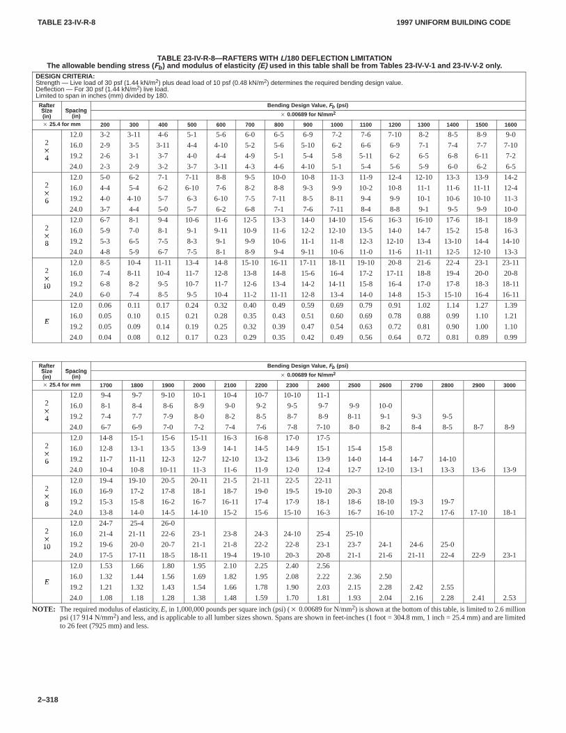
TABLE 23-IV-R-8TABLE 23-IV-R-8
1997 UNIFORM BUILDING CODE
2–318
TABLE 23-IV-R-8—RAFTERS WITH L/180 DEFLECTION LIMITATIONThe allowable bending stress ( Fb ) and modulus of elasticity (E) used in this table shall be from T ables 23-IV-V-1 and 23-IV-V-2 only .
DESIGN CRITERIA:Strength — Live load of 30 psf (1.44 kN/m2) plus dead load of 10 psf (0.48 kN/m2) determines the required bending design value.Deflection — For 30 psf (1.44 kN/m2) live load.Limited to span in inches (mm) divided by 180.
RafterSize Spacing
Bending Design V alue, Fb (psi)RafterSize(in)
Spacing(in) � 0.00689 for N/mm 2
� 25.4 for mm 200 300 400 500 600 700 800 900 1000 1100 1200 1300 1400 1500 1600
212.0 3-2 3-11 4-6 5-1 5-6 6-0 6-5 6-9 7-2 7-6 7-10 8-2 8-5 8-9 9-0
2�
16.0 2-9 3-5 3-11 4-4 4-10 5-2 5-6 5-10 6-2 6-6 6-9 7-1 7-4 7-7 7-10�
4 19.2 2-6 3-1 3-7 4-0 4-4 4-9 5-1 5-4 5-8 5-11 6-2 6-5 6-8 6-11 7-2424.0 2-3 2-9 3-2 3-7 3-11 4-3 4-6 4-10 5-1 5-4 5-6 5-9 6-0 6-2 6-5
212.0 5-0 6-2 7-1 7-11 8-8 9-5 10-0 10-8 11-3 11-9 12-4 12-10 13-3 13-9 14-2
2�
16.0 4-4 5-4 6-2 6-10 7-6 8-2 8-8 9-3 9-9 10-2 10-8 11-1 11-6 11-11 12-4�
6 19.2 4-0 4-10 5-7 6-3 6-10 7-5 7-11 8-5 8-11 9-4 9-9 10-1 10-6 10-10 11-3624.0 3-7 4-4 5-0 5-7 6-2 6-8 7-1 7-6 7-11 8-4 8-8 9-1 9-5 9-9 10-0
212.0 6-7 8-1 9-4 10-6 11-6 12-5 13-3 14-0 14-10 15-6 16-3 16-10 17-6 18-1 18-9
2�
16.0 5-9 7-0 8-1 9-1 9-11 10-9 11-6 12-2 12-10 13-5 14-0 14-7 15-2 15-8 16-3�
8 19.2 5-3 6-5 7-5 8-3 9-1 9-9 10-6 11-1 11-8 12-3 12-10 13-4 13-10 14-4 14-10824.0 4-8 5-9 6-7 7-5 8-1 8-9 9-4 9-11 10-6 11-0 11-6 11-11 12-5 12-10 13-3
212.0 8-5 10-4 11-11 13-4 14-8 15-10 16-11 17-11 18-11 19-10 20-8 21-6 22-4 23-1 23-11
2�
16.0 7-4 8-11 10-4 11-7 12-8 13-8 14-8 15-6 16-4 17-2 17-11 18-8 19-4 20-0 20-8�
10 19.2 6-8 8-2 9-5 10-7 11-7 12-6 13-4 14-2 14-11 15-8 16-4 17-0 17-8 18-3 18-111024.0 6-0 7-4 8-5 9-5 10-4 11-2 11-11 12-8 13-4 14-0 14-8 15-3 15-10 16-4 16-11
12.0 0.06 0.11 0.17 0.24 0.32 0.40 0.49 0.59 0.69 0.79 0.91 1.02 1.14 1.27 1.39
E16.0 0.05 0.10 0.15 0.21 0.28 0.35 0.43 0.51 0.60 0.69 0.78 0.88 0.99 1.10 1.21
E19.2 0.05 0.09 0.14 0.19 0.25 0.32 0.39 0.47 0.54 0.63 0.72 0.81 0.90 1.00 1.10
24.0 0.04 0.08 0.12 0.17 0.23 0.29 0.35 0.42 0.49 0.56 0.64 0.72 0.81 0.89 0.99
RafterSize Spacing
Bending Design V alue, Fb (psi)RafterSize(in)
Spacing(in) � 0.00689 for N/mm 2
� 25.4 for mm 1700 1800 1900 2000 2100 2200 2300 2400 2500 2600 2700 2800 2900 3000
212.0 9-4 9-7 9-10 10-1 10-4 10-7 10-10 11-1
2�
16.0 8-1 8-4 8-6 8-9 9-0 9-2 9-5 9-7 9-9 10-0�
4 19.2 7-4 7-7 7-9 8-0 8-2 8-5 8-7 8-9 8-11 9-1 9-3 9-5424.0 6-7 6-9 7-0 7-2 7-4 7-6 7-8 7-10 8-0 8-2 8-4 8-5 8-7 8-9
212.0 14-8 15-1 15-6 15-11 16-3 16-8 17-0 17-5
2�
16.0 12-8 13-1 13-5 13-9 14-1 14-5 14-9 15-1 15-4 15-8�
6 19.2 11-7 11-11 12-3 12-7 12-10 13-2 13-6 13-9 14-0 14-4 14-7 14-10624.0 10-4 10-8 10-11 11-3 11-6 11-9 12-0 12-4 12-7 12-10 13-1 13-3 13-6 13-9
212.0 19-4 19-10 20-5 20-11 21-5 21-11 22-5 22-11
2�
16.0 16-9 17-2 17-8 18-1 18-7 19-0 19-5 19-10 20-3 20-8�
8 19.2 15-3 15-8 16-2 16-7 16-11 17-4 17-9 18-1 18-6 18-10 19-3 19-7824.0 13-8 14-0 14-5 14-10 15-2 15-6 15-10 16-3 16-7 16-10 17-2 17-6 17-10 18-1
212.0 24-7 25-4 26-0
2�
16.0 21-4 21-11 22-6 23-1 23-8 24-3 24-10 25-4 25-10�
10 19.2 19-6 20-0 20-7 21-1 21-8 22-2 22-8 23-1 23-7 24-1 24-6 25-01024.0 17-5 17-11 18-5 18-11 19-4 19-10 20-3 20-8 21-1 21-6 21-11 22-4 22-9 23-1
12.0 1.53 1.66 1.80 1.95 2.10 2.25 2.40 2.56
E16.0 1.32 1.44 1.56 1.69 1.82 1.95 2.08 2.22 2.36 2.50
E19.2 1.21 1.32 1.43 1.54 1.66 1.78 1.90 2.03 2.15 2.28 2.42 2.55
24.0 1.08 1.18 1.28 1.38 1.48 1.59 1.70 1.81 1.93 2.04 2.16 2.28 2.41 2.53
NOTE: The required modulus of elasticity, E, in 1,000,000 pounds per square inch (psi) (� 0.00689 for N/mm2) is shown at the bottom of this table, is limited to 2.6 millionpsi (17914 N/mm2) and less, and is applicable to all lumber sizes shown. Spans are shown in feet-inches (1 foot = 304.8 mm, 1 inch = 25.4 mm) and are limitedto 26 feet (7925 mm) and less.
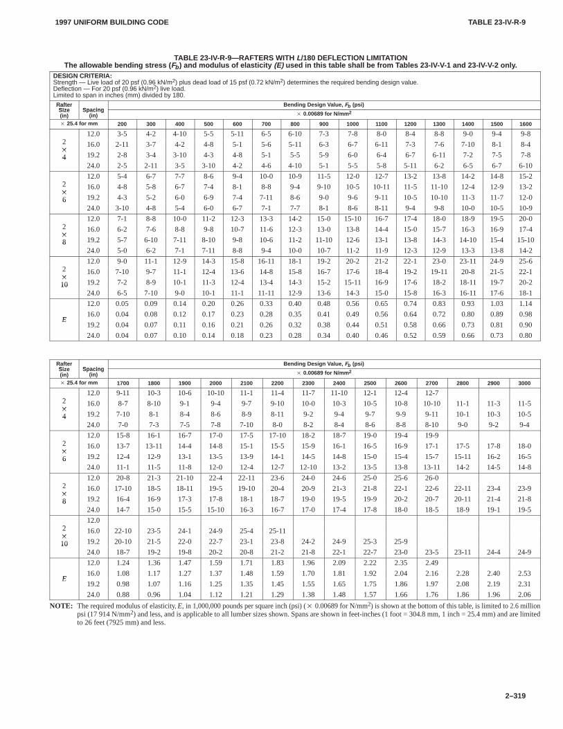
TABLE 23-IV-R-9TABLE 23-IV-R-9
1997 UNIFORM BUILDING CODE
2–319
TABLE 23-IV-R-9—RAFTERS WITH L/180 DEFLECTION LIMITATIONThe allowable bending stress ( Fb ) and modulus of elasticity (E) used in this table shall be from T ables 23-IV-V-1 and 23-IV-V-2 only .
DESIGN CRITERIA:Strength — Live load of 20 psf (0.96 kN/m2) plus dead load of 15 psf (0.72 kN/m2) determines the required bending design value.Deflection — For 20 psf (0.96 kN/m2) live load.Limited to span in inches (mm) divided by 180.
RafterSize Spacing
Bending Design V alue, Fb (psi)RafterSize(in)
Spacing(in) � 0.00689 for N/mm 2
� 25.4 for mm 200 300 400 500 600 700 800 900 1000 1100 1200 1300 1400 1500 1600
212.0 3-5 4-2 4-10 5-5 5-11 6-5 6-10 7-3 7-8 8-0 8-4 8-8 9-0 9-4 9-8
2�
16.0 2-11 3-7 4-2 4-8 5-1 5-6 5-11 6-3 6-7 6-11 7-3 7-6 7-10 8-1 8-4�
4 19.2 2-8 3-4 3-10 4-3 4-8 5-1 5-5 5-9 6-0 6-4 6-7 6-11 7-2 7-5 7-8424.0 2-5 2-11 3-5 3-10 4-2 4-6 4-10 5-1 5-5 5-8 5-11 6-2 6-5 6-7 6-10
212.0 5-4 6-7 7-7 8-6 9-4 10-0 10-9 11-5 12-0 12-7 13-2 13-8 14-2 14-8 15-2
2�
16.0 4-8 5-8 6-7 7-4 8-1 8-8 9-4 9-10 10-5 10-11 11-5 11-10 12-4 12-9 13-2�
6 19.2 4-3 5-2 6-0 6-9 7-4 7-11 8-6 9-0 9-6 9-11 10-5 10-10 11-3 11-7 12-0624.0 3-10 4-8 5-4 6-0 6-7 7-1 7-7 8-1 8-6 8-11 9-4 9-8 10-0 10-5 10-9
212.0 7-1 8-8 10-0 11-2 12-3 13-3 14-2 15-0 15-10 16-7 17-4 18-0 18-9 19-5 20-0
2�
16.0 6-2 7-6 8-8 9-8 10-7 11-6 12-3 13-0 13-8 14-4 15-0 15-7 16-3 16-9 17-4�
8 19.2 5-7 6-10 7-11 8-10 9-8 10-6 11-2 11-10 12-6 13-1 13-8 14-3 14-10 15-4 15-10824.0 5-0 6-2 7-1 7-11 8-8 9-4 10-0 10-7 11-2 11-9 12-3 12-9 13-3 13-8 14-2
212.0 9-0 11-1 12-9 14-3 15-8 16-11 18-1 19-2 20-2 21-2 22-1 23-0 23-11 24-9 25-6
2�
16.0 7-10 9-7 11-1 12-4 13-6 14-8 15-8 16-7 17-6 18-4 19-2 19-11 20-8 21-5 22-1�
10 19.2 7-2 8-9 10-1 11-3 12-4 13-4 14-3 15-2 15-11 16-9 17-6 18-2 18-11 19-7 20-21024.0 6-5 7-10 9-0 10-1 11-1 11-11 12-9 13-6 14-3 15-0 15-8 16-3 16-11 17-6 18-1
12.0 0.05 0.09 0.14 0.20 0.26 0.33 0.40 0.48 0.56 0.65 0.74 0.83 0.93 1.03 1.14
E16.0 0.04 0.08 0.12 0.17 0.23 0.28 0.35 0.41 0.49 0.56 0.64 0.72 0.80 0.89 0.98
E19.2 0.04 0.07 0.11 0.16 0.21 0.26 0.32 0.38 0.44 0.51 0.58 0.66 0.73 0.81 0.90
24.0 0.04 0.07 0.10 0.14 0.18 0.23 0.28 0.34 0.40 0.46 0.52 0.59 0.66 0.73 0.80
RafterSize Spacing
Bending Design V alue, Fb (psi)RafterSize(in)
Spacing(in) � 0.00689 for N/mm 2
� 25.4 for mm 1700 1800 1900 2000 2100 2200 2300 2400 2500 2600 2700 2800 2900 3000
212.0 9-11 10-3 10-6 10-10 11-1 11-4 11-7 11-10 12-1 12-4 12-7
2�
16.0 8-7 8-10 9-1 9-4 9-7 9-10 10-0 10-3 10-5 10-8 10-10 11-1 11-3 11-5�
4 19.2 7-10 8-1 8-4 8-6 8-9 8-11 9-2 9-4 9-7 9-9 9-11 10-1 10-3 10-5424.0 7-0 7-3 7-5 7-8 7-10 8-0 8-2 8-4 8-6 8-8 8-10 9-0 9-2 9-4
212.0 15-8 16-1 16-7 17-0 17-5 17-10 18-2 18-7 19-0 19-4 19-9
2�
16.0 13-7 13-11 14-4 14-8 15-1 15-5 15-9 16-1 16-5 16-9 17-1 17-5 17-8 18-0�
6 19.2 12-4 12-9 13-1 13-5 13-9 14-1 14-5 14-8 15-0 15-4 15-7 15-11 16-2 16-5624.0 11-1 11-5 11-8 12-0 12-4 12-7 12-10 13-2 13-5 13-8 13-11 14-2 14-5 14-8
212.0 20-8 21-3 21-10 22-4 22-11 23-6 24-0 24-6 25-0 25-6 26-0
2�
16.0 17-10 18-5 18-11 19-5 19-10 20-4 20-9 21-3 21-8 22-1 22-6 22-11 23-4 23-9�
8 19.2 16-4 16-9 17-3 17-8 18-1 18-7 19-0 19-5 19-9 20-2 20-7 20-11 21-4 21-8824.0 14-7 15-0 15-5 15-10 16-3 16-7 17-0 17-4 17-8 18-0 18-5 18-9 19-1 19-5
212.0
2�
16.0 22-10 23-5 24-1 24-9 25-4 25-11�
10 19.2 20-10 21-5 22-0 22-7 23-1 23-8 24-2 24-9 25-3 25-91024.0 18-7 19-2 19-8 20-2 20-8 21-2 21-8 22-1 22-7 23-0 23-5 23-11 24-4 24-9
12.0 1.24 1.36 1.47 1.59 1.71 1.83 1.96 2.09 2.22 2.35 2.49
E16.0 1.08 1.17 1.27 1.37 1.48 1.59 1.70 1.81 1.92 2.04 2.16 2.28 2.40 2.53
E19.2 0.98 1.07 1.16 1.25 1.35 1.45 1.55 1.65 1.75 1.86 1.97 2.08 2.19 2.31
24.0 0.88 0.96 1.04 1.12 1.21 1.29 1.38 1.48 1.57 1.66 1.76 1.86 1.96 2.06
NOTE: The required modulus of elasticity, E, in 1,000,000 pounds per square inch (psi) (� 0.00689 for N/mm2) is shown at the bottom of this table, is limited to 2.6 millionpsi (17914 N/mm2) and less, and is applicable to all lumber sizes shown. Spans are shown in feet-inches (1 foot = 304.8 mm, 1 inch = 25.4 mm) and are limitedto 26 feet (7925 mm) and less.
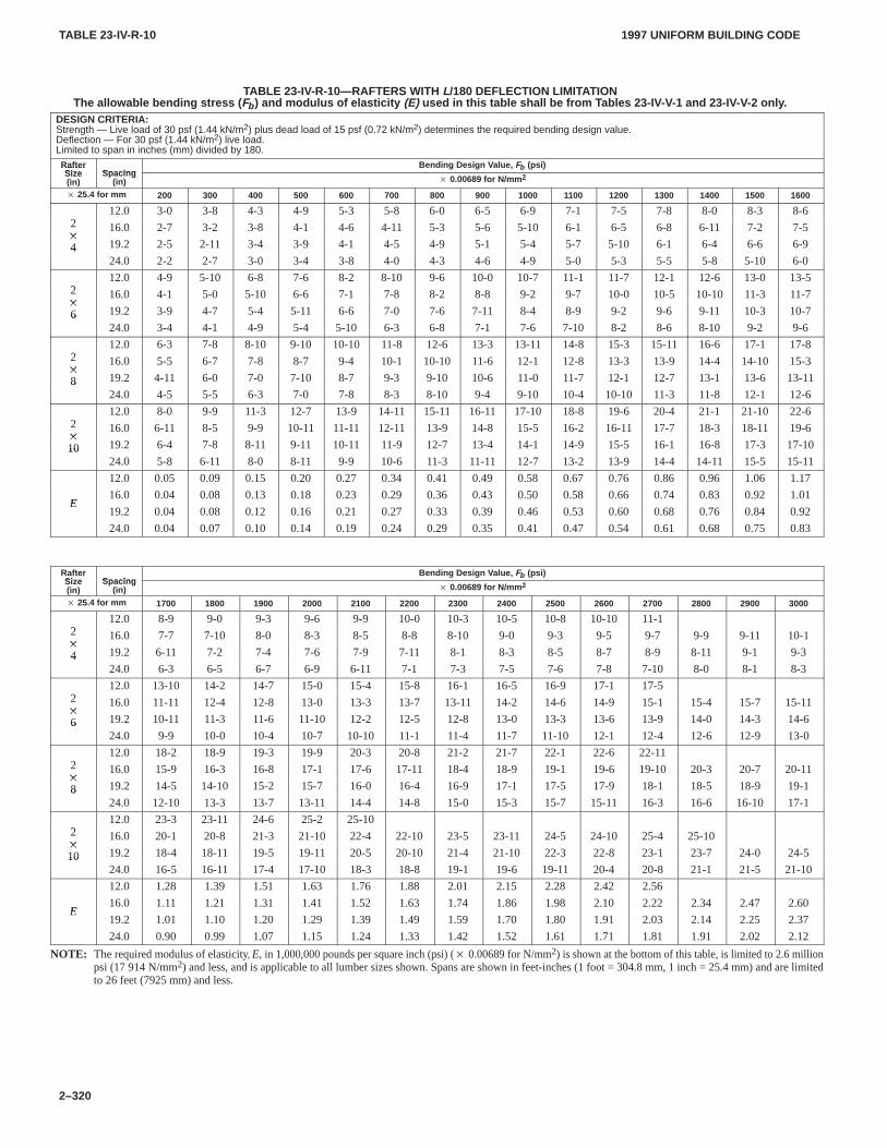
TABLE 23-IV-R-10TABLE 23-IV-R-10
1997 UNIFORM BUILDING CODE
2–320
TABLE 23-IV-R-10—RAFTERS WITH L/180 DEFLECTION LIMITATIONThe allowable bending stress ( Fb ) and modulus of elasticity (E) used in this table shall be from T ables 23-IV-V-1 and 23-IV-V-2 only .
DESIGN CRITERIA:Strength — Live load of 30 psf (1.44 kN/m2) plus dead load of 15 psf (0.72 kN/m2) determines the required bending design value.Deflection — For 30 psf (1.44 kN/m2) live load.Limited to span in inches (mm) divided by 180.
RafterSize Spacing
Bending Design V alue, Fb (psi)RafterSize(in)
Spacing(in) � 0.00689 for N/mm 2
� 25.4 for mm 200 300 400 500 600 700 800 900 1000 1100 1200 1300 1400 1500 1600
212.0 3-0 3-8 4-3 4-9 5-3 5-8 6-0 6-5 6-9 7-1 7-5 7-8 8-0 8-3 8-6
2�
16.0 2-7 3-2 3-8 4-1 4-6 4-11 5-3 5-6 5-10 6-1 6-5 6-8 6-11 7-2 7-5�
4 19.2 2-5 2-11 3-4 3-9 4-1 4-5 4-9 5-1 5-4 5-7 5-10 6-1 6-4 6-6 6-9424.0 2-2 2-7 3-0 3-4 3-8 4-0 4-3 4-6 4-9 5-0 5-3 5-5 5-8 5-10 6-0
212.0 4-9 5-10 6-8 7-6 8-2 8-10 9-6 10-0 10-7 11-1 11-7 12-1 12-6 13-0 13-5
2�
16.0 4-1 5-0 5-10 6-6 7-1 7-8 8-2 8-8 9-2 9-7 10-0 10-5 10-10 11-3 11-7�
6 19.2 3-9 4-7 5-4 5-11 6-6 7-0 7-6 7-11 8-4 8-9 9-2 9-6 9-11 10-3 10-7624.0 3-4 4-1 4-9 5-4 5-10 6-3 6-8 7-1 7-6 7-10 8-2 8-6 8-10 9-2 9-6
212.0 6-3 7-8 8-10 9-10 10-10 11-8 12-6 13-3 13-11 14-8 15-3 15-11 16-6 17-1 17-8
2�
16.0 5-5 6-7 7-8 8-7 9-4 10-1 10-10 11-6 12-1 12-8 13-3 13-9 14-4 14-10 15-3�
8 19.2 4-11 6-0 7-0 7-10 8-7 9-3 9-10 10-6 11-0 11-7 12-1 12-7 13-1 13-6 13-11824.0 4-5 5-5 6-3 7-0 7-8 8-3 8-10 9-4 9-10 10-4 10-10 11-3 11-8 12-1 12-6
212.0 8-0 9-9 11-3 12-7 13-9 14-11 15-11 16-11 17-10 18-8 19-6 20-4 21-1 21-10 22-6
2�
16.0 6-11 8-5 9-9 10-11 11-11 12-11 13-9 14-8 15-5 16-2 16-11 17-7 18-3 18-11 19-6�
10 19.2 6-4 7-8 8-11 9-11 10-11 11-9 12-7 13-4 14-1 14-9 15-5 16-1 16-8 17-3 17-101024.0 5-8 6-11 8-0 8-11 9-9 10-6 11-3 11-11 12-7 13-2 13-9 14-4 14-11 15-5 15-11
12.0 0.05 0.09 0.15 0.20 0.27 0.34 0.41 0.49 0.58 0.67 0.76 0.86 0.96 1.06 1.17
E16.0 0.04 0.08 0.13 0.18 0.23 0.29 0.36 0.43 0.50 0.58 0.66 0.74 0.83 0.92 1.01
E19.2 0.04 0.08 0.12 0.16 0.21 0.27 0.33 0.39 0.46 0.53 0.60 0.68 0.76 0.84 0.92
24.0 0.04 0.07 0.10 0.14 0.19 0.24 0.29 0.35 0.41 0.47 0.54 0.61 0.68 0.75 0.83
RafterSize Spacing
Bending Design V alue, Fb (psi)RafterSize(in)
Spacing(in) � 0.00689 for N/mm 2
� 25.4 for mm 1700 1800 1900 2000 2100 2200 2300 2400 2500 2600 2700 2800 2900 3000
212.0 8-9 9-0 9-3 9-6 9-9 10-0 10-3 10-5 10-8 10-10 11-1
2�
16.0 7-7 7-10 8-0 8-3 8-5 8-8 8-10 9-0 9-3 9-5 9-7 9-9 9-11 10-1�
4 19.2 6-11 7-2 7-4 7-6 7-9 7-11 8-1 8-3 8-5 8-7 8-9 8-11 9-1 9-3424.0 6-3 6-5 6-7 6-9 6-11 7-1 7-3 7-5 7-6 7-8 7-10 8-0 8-1 8-3
212.0 13-10 14-2 14-7 15-0 15-4 15-8 16-1 16-5 16-9 17-1 17-5
2�
16.0 11-11 12-4 12-8 13-0 13-3 13-7 13-11 14-2 14-6 14-9 15-1 15-4 15-7 15-11�
6 19.2 10-11 11-3 11-6 11-10 12-2 12-5 12-8 13-0 13-3 13-6 13-9 14-0 14-3 14-6624.0 9-9 10-0 10-4 10-7 10-10 11-1 11-4 11-7 11-10 12-1 12-4 12-6 12-9 13-0
212.0 18-2 18-9 19-3 19-9 20-3 20-8 21-2 21-7 22-1 22-6 22-11
2�
16.0 15-9 16-3 16-8 17-1 17-6 17-11 18-4 18-9 19-1 19-6 19-10 20-3 20-7 20-11�
8 19.2 14-5 14-10 15-2 15-7 16-0 16-4 16-9 17-1 17-5 17-9 18-1 18-5 18-9 19-1824.0 12-10 13-3 13-7 13-11 14-4 14-8 15-0 15-3 15-7 15-11 16-3 16-6 16-10 17-1
212.0 23-3 23-11 24-6 25-2 25-10
2�
16.0 20-1 20-8 21-3 21-10 22-4 22-10 23-5 23-11 24-5 24-10 25-4 25-10�
10 19.2 18-4 18-11 19-5 19-11 20-5 20-10 21-4 21-10 22-3 22-8 23-1 23-7 24-0 24-51024.0 16-5 16-11 17-4 17-10 18-3 18-8 19-1 19-6 19-11 20-4 20-8 21-1 21-5 21-10
12.0 1.28 1.39 1.51 1.63 1.76 1.88 2.01 2.15 2.28 2.42 2.56
E16.0 1.11 1.21 1.31 1.41 1.52 1.63 1.74 1.86 1.98 2.10 2.22 2.34 2.47 2.60
E19.2 1.01 1.10 1.20 1.29 1.39 1.49 1.59 1.70 1.80 1.91 2.03 2.14 2.25 2.37
24.0 0.90 0.99 1.07 1.15 1.24 1.33 1.42 1.52 1.61 1.71 1.81 1.91 2.02 2.12
NOTE: The required modulus of elasticity, E, in 1,000,000 pounds per square inch (psi) (� 0.00689 for N/mm2) is shown at the bottom of this table, is limited to 2.6 millionpsi (17914 N/mm2) and less, and is applicable to all lumber sizes shown. Spans are shown in feet-inches (1 foot = 304.8 mm, 1 inch = 25.4 mm) and are limitedto 26 feet (7925 mm) and less.
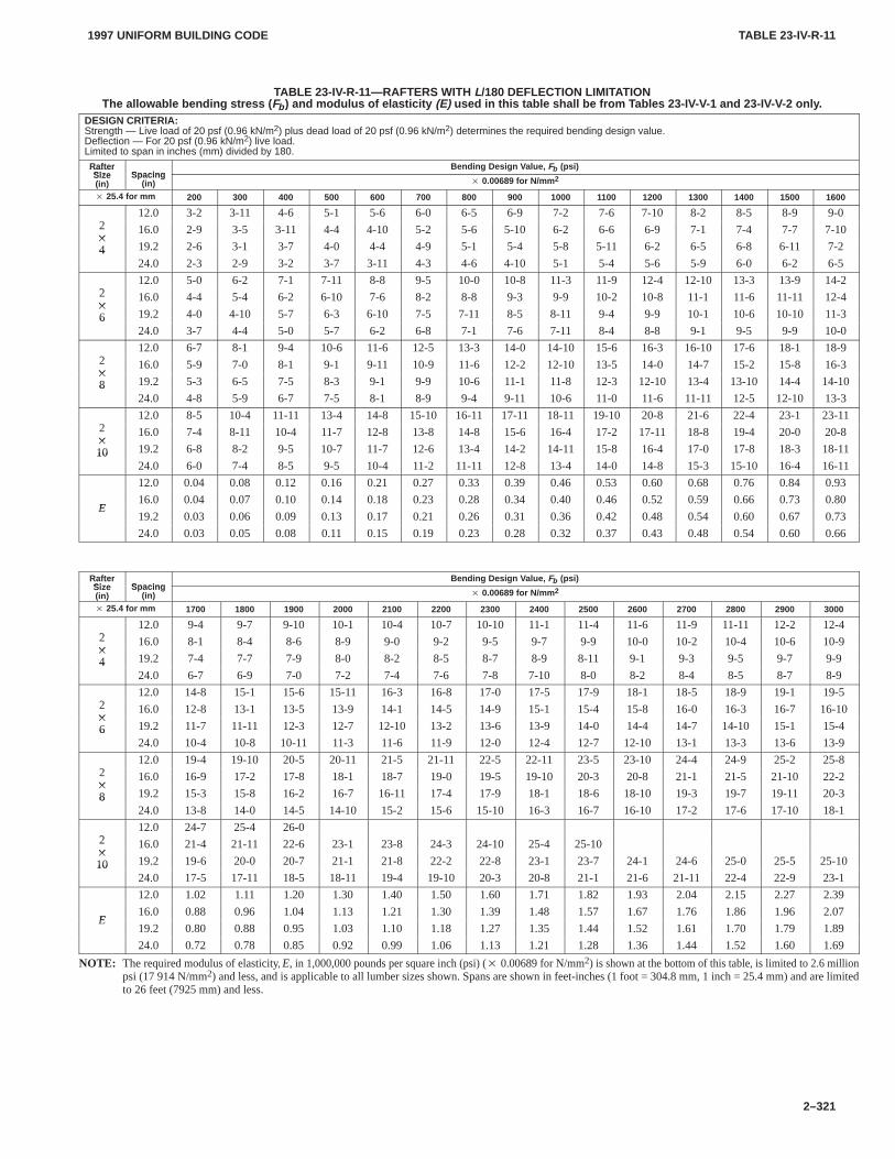
TABLE 23-IV-R-11TABLE 23-IV-R-11
1997 UNIFORM BUILDING CODE
2–321
TABLE 23-IV-R-11—RAFTERS WITH L/180 DEFLECTION LIMITATIONThe allowable bending stress ( Fb ) and modulus of elasticity (E) used in this table shall be from T ables 23-IV-V-1 and 23-IV-V-2 only .
DESIGN CRITERIA:Strength — Live load of 20 psf (0.96 kN/m2) plus dead load of 20 psf (0.96 kN/m2) determines the required bending design value.Deflection — For 20 psf (0.96 kN/m2) live load.Limited to span in inches (mm) divided by 180.
RafterSize Spacing
Bending Design V alue, Fb (psi)RafterSize(in)
Spacing(in) � 0.00689 for N/mm 2
� 25.4 for mm 200 300 400 500 600 700 800 900 1000 1100 1200 1300 1400 1500 1600
212.0 3-2 3-11 4-6 5-1 5-6 6-0 6-5 6-9 7-2 7-6 7-10 8-2 8-5 8-9 9-0
2�
16.0 2-9 3-5 3-11 4-4 4-10 5-2 5-6 5-10 6-2 6-6 6-9 7-1 7-4 7-7 7-10�
4 19.2 2-6 3-1 3-7 4-0 4-4 4-9 5-1 5-4 5-8 5-11 6-2 6-5 6-8 6-11 7-2424.0 2-3 2-9 3-2 3-7 3-11 4-3 4-6 4-10 5-1 5-4 5-6 5-9 6-0 6-2 6-5
212.0 5-0 6-2 7-1 7-11 8-8 9-5 10-0 10-8 11-3 11-9 12-4 12-10 13-3 13-9 14-2
2�
16.0 4-4 5-4 6-2 6-10 7-6 8-2 8-8 9-3 9-9 10-2 10-8 11-1 11-6 11-11 12-4�
6 19.2 4-0 4-10 5-7 6-3 6-10 7-5 7-11 8-5 8-11 9-4 9-9 10-1 10-6 10-10 11-3624.0 3-7 4-4 5-0 5-7 6-2 6-8 7-1 7-6 7-11 8-4 8-8 9-1 9-5 9-9 10-0
212.0 6-7 8-1 9-4 10-6 11-6 12-5 13-3 14-0 14-10 15-6 16-3 16-10 17-6 18-1 18-9
2�
16.0 5-9 7-0 8-1 9-1 9-11 10-9 11-6 12-2 12-10 13-5 14-0 14-7 15-2 15-8 16-3�
8 19.2 5-3 6-5 7-5 8-3 9-1 9-9 10-6 11-1 11-8 12-3 12-10 13-4 13-10 14-4 14-10824.0 4-8 5-9 6-7 7-5 8-1 8-9 9-4 9-11 10-6 11-0 11-6 11-11 12-5 12-10 13-3
212.0 8-5 10-4 11-11 13-4 14-8 15-10 16-11 17-11 18-11 19-10 20-8 21-6 22-4 23-1 23-11
2�
16.0 7-4 8-11 10-4 11-7 12-8 13-8 14-8 15-6 16-4 17-2 17-11 18-8 19-4 20-0 20-8�
10 19.2 6-8 8-2 9-5 10-7 11-7 12-6 13-4 14-2 14-11 15-8 16-4 17-0 17-8 18-3 18-111024.0 6-0 7-4 8-5 9-5 10-4 11-2 11-11 12-8 13-4 14-0 14-8 15-3 15-10 16-4 16-11
12.0 0.04 0.08 0.12 0.16 0.21 0.27 0.33 0.39 0.46 0.53 0.60 0.68 0.76 0.84 0.93
E16.0 0.04 0.07 0.10 0.14 0.18 0.23 0.28 0.34 0.40 0.46 0.52 0.59 0.66 0.73 0.80
E19.2 0.03 0.06 0.09 0.13 0.17 0.21 0.26 0.31 0.36 0.42 0.48 0.54 0.60 0.67 0.73
24.0 0.03 0.05 0.08 0.11 0.15 0.19 0.23 0.28 0.32 0.37 0.43 0.48 0.54 0.60 0.66
RafterSize Spacing
Bending Design V alue, Fb (psi)RafterSize(in)
Spacing(in) � 0.00689 for N/mm 2
� 25.4 for mm 1700 1800 1900 2000 2100 2200 2300 2400 2500 2600 2700 2800 2900 3000
212.0 9-4 9-7 9-10 10-1 10-4 10-7 10-10 11-1 11-4 11-6 11-9 11-11 12-2 12-4
2�
16.0 8-1 8-4 8-6 8-9 9-0 9-2 9-5 9-7 9-9 10-0 10-2 10-4 10-6 10-9�
4 19.2 7-4 7-7 7-9 8-0 8-2 8-5 8-7 8-9 8-11 9-1 9-3 9-5 9-7 9-9424.0 6-7 6-9 7-0 7-2 7-4 7-6 7-8 7-10 8-0 8-2 8-4 8-5 8-7 8-9
212.0 14-8 15-1 15-6 15-11 16-3 16-8 17-0 17-5 17-9 18-1 18-5 18-9 19-1 19-5
2�
16.0 12-8 13-1 13-5 13-9 14-1 14-5 14-9 15-1 15-4 15-8 16-0 16-3 16-7 16-10�
6 19.2 11-7 11-11 12-3 12-7 12-10 13-2 13-6 13-9 14-0 14-4 14-7 14-10 15-1 15-4624.0 10-4 10-8 10-11 11-3 11-6 11-9 12-0 12-4 12-7 12-10 13-1 13-3 13-6 13-9
212.0 19-4 19-10 20-5 20-11 21-5 21-11 22-5 22-11 23-5 23-10 24-4 24-9 25-2 25-8
2�
16.0 16-9 17-2 17-8 18-1 18-7 19-0 19-5 19-10 20-3 20-8 21-1 21-5 21-10 22-2�
8 19.2 15-3 15-8 16-2 16-7 16-11 17-4 17-9 18-1 18-6 18-10 19-3 19-7 19-11 20-3824.0 13-8 14-0 14-5 14-10 15-2 15-6 15-10 16-3 16-7 16-10 17-2 17-6 17-10 18-1
212.0 24-7 25-4 26-0
2�
16.0 21-4 21-11 22-6 23-1 23-8 24-3 24-10 25-4 25-10�
10 19.2 19-6 20-0 20-7 21-1 21-8 22-2 22-8 23-1 23-7 24-1 24-6 25-0 25-5 25-101024.0 17-5 17-11 18-5 18-11 19-4 19-10 20-3 20-8 21-1 21-6 21-11 22-4 22-9 23-1
12.0 1.02 1.11 1.20 1.30 1.40 1.50 1.60 1.71 1.82 1.93 2.04 2.15 2.27 2.39
E16.0 0.88 0.96 1.04 1.13 1.21 1.30 1.39 1.48 1.57 1.67 1.76 1.86 1.96 2.07
E19.2 0.80 0.88 0.95 1.03 1.10 1.18 1.27 1.35 1.44 1.52 1.61 1.70 1.79 1.89
24.0 0.72 0.78 0.85 0.92 0.99 1.06 1.13 1.21 1.28 1.36 1.44 1.52 1.60 1.69
NOTE: The required modulus of elasticity, E, in 1,000,000 pounds per square inch (psi) (� 0.00689 for N/mm2) is shown at the bottom of this table, is limited to 2.6 millionpsi (17914 N/mm2) and less, and is applicable to all lumber sizes shown. Spans are shown in feet-inches (1 foot = 304.8 mm, 1 inch = 25.4 mm) and are limitedto 26 feet (7925 mm) and less.
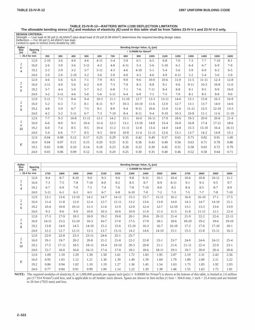
TABLE 23-IV-R-12TABLE 23-IV-R-12
1997 UNIFORM BUILDING CODE
2–322
TABLE 23-IV-R-12—RAFTERS WITH L/180 DEFLECTION LIMITATIONThe allowable bending stress ( Fb ) and modulus of elasticity (E) used in this table shall be from T ables 23-IV-V-1 and 23-IV-V-2 only .
DESIGN CRITERIA:Strength — Live load of 30 psf (1.44 kN/m2) plus dead load of 20 psf (0.96 kN/m2) determines the required bending design value.Deflection — For 30 psf (1.44 kN/m2) live load.Limited to span in inches (mm) divided by 180.
RafterSize Spacing
Bending Design V alue, Fb (psi)RafterSize(in)
Spacing(in) � 0.00689 for N/mm 2
� 25.4 for mm 200 300 400 500 600 700 800 900 1000 1100 1200 1300 1400 1500 1600
212.0 2-10 3-6 4-0 4-6 4-11 5-4 5-9 6-1 6-5 6-8 7-0 7-3 7-7 7-10 8-1
2�
16.0 2-6 3-0 3-6 3-11 4-3 4-8 4-11 5-3 5-6 5-10 6-1 6-4 6-7 6-9 7-0�
4 19.2 2-3 2-9 3-2 3-7 3-11 4-3 4-6 4-10 5-1 5-4 5-6 5-9 6-0 6-2 6-5424.0 2-0 2-6 2-10 3-2 3-6 3-9 4-0 4-3 4-6 4-9 4-11 5-2 5-4 5-6 5-9
212.0 4-6 5-6 6-4 7-1 7-9 8-5 9-0 9-6 10-0 10-6 11-0 11-5 11-11 12-4 12-8
2�
16.0 3-11 4-9 5-6 6-2 6-9 7-3 7-9 8-3 8-8 9-1 9-6 9-11 10-3 10-8 11-0�
6 19.2 3-7 4-4 5-0 5-7 6-2 6-8 7-1 7-6 7-11 8-4 8-8 9-1 9-5 9-9 10-0624.0 3-2 3-11 4-6 5-0 5-6 5-11 6-4 6-9 7-1 7-5 7-9 8-1 8-5 8-8 9-0
212.0 5-11 7-3 8-4 9-4 10-3 11-1 11-10 12-7 13-3 13-11 14-6 15-1 15-8 16-3 16-9
2�
16.0 5-2 6-3 7-3 8-1 8-11 9-7 10-3 10-10 11-6 12-0 12-7 13-1 13-7 14-0 14-6�
8 19.2 4-8 5-9 6-7 7-5 8-1 8-9 9-4 9-11 10-6 11-0 11-6 11-11 12-5 12-10 13-3824.0 4-2 5-2 5-11 6-7 7-3 7-10 8-4 8-11 9-4 9-10 10-3 10-8 11-1 11-6 11-10
212.0 7-7 9-3 10-8 11-11 13-1 14-2 15-1 16-0 16-11 17-9 18-6 19-3 20-0 20-8 21-4
2�
16.0 6-6 8-0 9-3 10-4 11-4 12-3 13-1 13-10 14-8 15-4 16-0 16-8 17-4 17-11 18-6�
10 19.2 6-0 7-4 8-5 9-5 10-4 11-2 11-11 12-8 13-4 14-0 14-8 15-3 15-10 16-4 16-111024.0 5-4 6-6 7-7 8-5 9-3 10-0 10-8 11-4 11-11 12-6 13-1 13-7 14-2 14-8 15-1
12.0 0.04 0.08 0.12 0.17 0.23 0.29 0.35 0.42 0.49 0.57 0.65 0.73 0.82 0.91 1.00
E16.0 0.04 0.07 0.11 0.15 0.20 0.25 0.31 0.36 0.43 0.49 0.56 0.63 0.71 0.78 0.86
E19.2 0.03 0.06 0.10 0.14 0.18 0.23 0.28 0.33 0.39 0.45 0.51 0.58 0.65 0.72 0.79
24.0 0.03 0.06 0.09 0.12 0.16 0.20 0.25 0.30 0.35 0.40 0.46 0.52 0.58 0.64 0.71
RafterSize Spacing
Bending Design V alue, Fb (psi)RafterSize(in)
Spacing(in) � 0.00689 for N/mm 2
� 25.4 for mm 1700 1800 1900 2000 2100 2200 2300 2400 2500 2600 2700 2800 2900 3000
212.0 8-4 8-7 8-10 9-0 9-3 9-6 9-8 9-11 10-1 10-4 10-6 10-8 10-11 11-1
2�
16.0 7-3 7-5 7-8 7-10 8-0 8-2 8-5 8-7 8-9 8-11 9-1 9-3 9-5 9-7�
4 19.2 6-7 6-9 7-0 7-2 7-4 7-6 7-8 7-10 8-0 8-2 8-4 8-5 8-7 8-9424.0 5-11 6-1 6-3 6-5 6-7 6-8 6-10 7-0 7-2 7-3 7-5 7-7 7-8 7-10
212.0 13-1 13-6 13-10 14-2 14-7 14-11 15-3 15-7 15-11 16-2 16-6 16-10 17-1 17-5
2�
16.0 11-4 11-8 12-0 12-4 12-7 12-11 13-2 13-6 13-9 14-0 14-3 14-7 14-10 15-1�
6 19.2 10-4 10-8 10-11 11-3 11-6 11-9 12-0 12-4 12-7 12-10 13-1 13-3 13-6 13-9624.0 9-3 9-6 9-9 10-0 10-3 10-6 10-9 11-0 11-3 11-5 11-8 11-11 12-1 12-4
212.0 17-3 17-9 18-3 18-9 19-2 19-8 20-1 20-6 20-11 21-4 21-9 22-2 22-6 22-11
2�
16.0 14-11 15-5 15-10 16-3 16-7 17-0 17-5 17-9 18-1 18-6 18-10 19-2 19-6 19-10�
8 19.2 13-8 14-0 14-5 14-10 15-2 15-6 15-10 16-3 16-7 16-10 17-2 17-6 17-10 18-1824.0 12-2 12-7 12-11 13-3 13-7 13-11 14-2 14-6 14-10 15-1 15-5 15-8 15-11 16-3
212.0 22-0 22-8 23-3 23-11 24-6 25-1 25-7
2�
16.0 19-1 19-7 20-2 20-8 21-2 21-8 22-2 22-8 23-1 23-7 24-0 24-6 24-11 25-4�
10 19.2 17-5 17-11 18-5 18-11 19-4 19-10 20-3 20-8 21-1 21-6 21-11 22-4 22-9 23-11024.0 15-7 16-0 16-6 16-11 17-4 17-9 18-1 18-6 18-11 19-3 19-7 20-0 20-4 20-8
12.0 1.09 1.19 1.29 1.39 1.50 1.61 1.72 1.83 1.95 2.07 2.19 2.31 2.43 2.56
E16.0 0.95 1.03 1.12 1.21 1.30 1.39 1.49 1.59 1.69 1.79 1.89 2.00 2.11 2.22
E19.2 0.86 0.94 1.02 1.10 1.19 1.27 1.36 1.45 1.54 1.63 1.73 1.83 1.92 2.03
24.0 0.77 0.84 0.91 0.99 1.06 1.14 1.22 1.30 1.38 1.46 1.55 1.63 1.72 1.81
NOTE: The required modulus of elasticity, E, in 1,000,000 pounds per square inch (psi) (� 0.00689 for N/mm2) is shown at the bottom of this table, is limited to 2.6 millionpsi (17914 N/mm2) and less, and is applicable to all lumber sizes shown. Spans are shown in feet-inches (1 foot = 304.8 mm, 1 inch = 25.4 mm) and are limitedto 26 feet (7925 mm) and less.
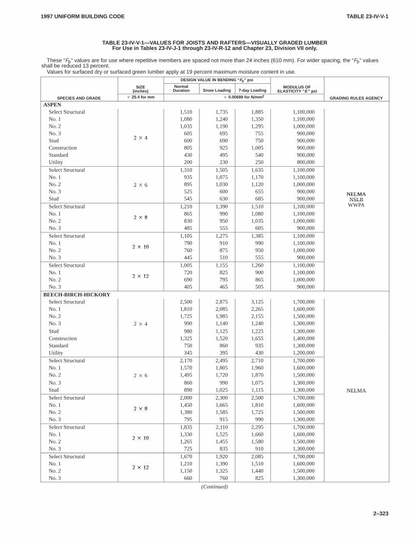
TABLE 23-IV-V-1TABLE 23-IV-V-1
1997 UNIFORM BUILDING CODE
2–323
TABLE 23-IV-V-1—VALUES FOR JOISTS AND RAFTERS—VISUALL Y GRADED LUMBERFor Use in T ables 23-IV-J-1 through 23-IV -R-12 and Chapter 23, Division VII only .
These “Fb” values are for use where repetitive members are spaced not more than 24 inches (610 mm). For wider spacing, the “Fb” valuesshall be reduced 13 percent.
Values for surfaced dry or surfaced green lumber apply at 19 percent maximum moisture content in use.DESIGN VALUE IN BENDING “ Fb ” psi
SIZE(inches)
NormalDuration Snow Loading 7-day Loading
MODULUS OFELASTICITY “ E ” psi
SPECIES AND GRADE � 25.4 for mm � 0.00689 for N/mm 2 GRADING RULES AGENCY
ASPENSelect Structural 1,510 1,735 1,885 1,100,000No. 1 1,080 1,240 1,350 1,100,000No. 2 1,035 1,190 1,295 1,000,000No. 3
2 � 4605 695 755 900,000
Stud 2 � 4 600 690 750 900,000Construction 805 925 1,005 900,000Standard 430 495 540 900,000Utility 200 230 250 800,000
Select Structural 1,310 1,505 1,635 1,100,000No. 1 935 1,075 1,170 1,100,000No. 2 2 � 6 895 1,030 1,120 1,000,000No. 3
2 � 6525 600 655 900,000 NELMA
Stud 545 630 685 900,000NELMANSLB
Select Structural 1,210 1,390 1,510 1,100,000NSLBWWPA
No. 12 � 8
865 990 1,080 1,100,000No. 2
2 � 8830 950 1,035 1,000,000
No. 3 485 555 605 900,000
Select Structural 1,105 1,275 1,385 1,100,000No. 1
2 � 10790 910 990 1,100,000
No. 22 � 10
760 875 950 1,000,000No. 3 445 510 555 900,000
Select Structural 1,005 1,155 1,260 1,100,000No. 1
2 � 12720 825 900 1,100,000
No. 22 � 12
690 795 865 1,000,000No. 3 405 465 505 900,000
BEECH-BIRCH-HICKORYSelect Structural 2,500 2,875 3,125 1,700,000No. 1 1,810 2,085 2,265 1,600,000No. 2 1,725 1,985 2,155 1,500,000No. 3 2 � 4 990 1,140 1,240 1,300,000
Stud 980 1,125 1,225 1,300,000Construction 1,325 1,520 1,655 1,400,000Standard 750 860 935 1,300,000Utility 345 395 430 1,200,000
Select Structural 2,170 2,495 2,710 1,700,000No. 1 1,570 1,805 1,960 1,600,000No. 2 2 � 6 1,495 1,720 1,870 1,500,000
No. 3 860 990 1,075 1,300,000Stud 890 1,025 1,115 1,300,000 NELMASelect Structural 2,000 2,300 2,500 1,700,000
NELMA
No. 12 � 8
1,450 1,665 1,810 1,600,000No. 2
2 � 81,380 1,585 1,725 1,500,000
No. 3 795 915 990 1,300,000
Select Structural 1,835 2,110 2,295 1,700,000No. 1
2 � 101,330 1,525 1,660 1,600,000
No. 22 � 10
1,265 1,455 1,580 1,500,000No. 3 725 835 910 1,300,000
Select Structural 1,670 1,920 2,085 1,700,000No. 1
2 � 121,210 1,390 1,510 1,600,000
No. 22 � 12
1,150 1,325 1,440 1,500,000No. 3 660 760 825 1,300,000
(Continued)
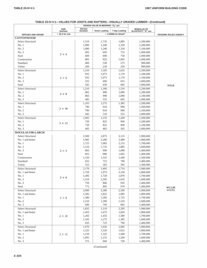
TABLE 23-IV-V-1TABLE 23-IV-V-1
1997 UNIFORM BUILDING CODE
2–324
TABLE 23-IV-V-1—VALUES FOR JOISTS AND RAFTERS—VISUALL Y GRADED LUMBER—(Continued)DESIGN VALUE IN BENDING “ Fb ” psi
SIZE(inches)
NormalDuration Snow Loading 7-day Loading
MODULUS OFELASTICITY “ E ” psi
SPECIES AND GRADE � 25.4 for mm � 0.00689 for N/mm 2 GRADING RULES AGENCY
COTTONWOODSelect Structural 1,510 1,735 1,885 1,200,000No. 1 1,080 1,240 1,350 1,200,000No. 2 1,080 1,240 1,350 1,100,000No. 3
2 � 4605 695 755 1,000,000
Stud 2 � 4 600 690 750 1,000,000Construction 805 925 1,005 1,000,000Standard 460 530 575 900,000Utility 200 230 250 900,000
Select Structural 1,310 1,505 1,635 1,200,000No. 1 935 1,075 1,170 1,200,000No. 2 2 � 6 935 1,075 1,170 1,100,000No. 3
2 � 6525 600 655 1,000,000
Stud 545 630 685 1,000,000 NSLBSelect Structural 1,210 1,390 1,510 1,200,000
NSLB
No. 12 � 8
865 990 1,080 1,200,000No. 2
2 � 8865 990 1,080 1,100,000
No. 3 485 555 605 1,000,000
Select Structural 1,105 1,275 1,385 1,200,000No. 1
2 � 10790 910 990 1,200,000
No. 22 � 10
790 910 990 1,100,000No. 3 445 510 555 1,000,000
Select Structural 1,005 1,155 1,260 1,200,000No. 1
2 � 12720 825 900 1,200,000
No. 22 � 12
720 825 900 1,100,000No. 3 405 465 505 1,000,000
DOUGLAS FIR-LARCHSelect Structural 2,500 2,875 3,125 1,900,000No. 1 and better 1,985 2,280 2,480 1,800,000No. 1 1,725 1,985 2,155 1,700,000No. 2 1,510 1,735 1,885 1,600,000No. 3 2 � 4 865 990 1,080 1,400,000Stud
2 � 4855 980 1,065 1,400,000
Construction 1,150 1,325 1,440 1,500,000Standard 635 725 790 1,400,000Utility 315 365 395 1,300,000
Select Structural 2,170 2,495 2,710 1,900,000No. 1 and better 1,720 1,975 2,150 1,800,000No. 1
2 � 61,495 1,720 1,870 1,700,000
No. 22 � 6
1,310 1,505 1,635 1,600,000No. 3 750 860 935 1,400,000Stud 775 895 970 1,400,000 WCLIBSelect Structural 2,000 2,300 2,500 1,900,000
WCLIBWWPA
No. 1 and better 1,585 1,825 1,985 1,800,000No. 1 2 � 8 1,380 1,585 1,725 1,700,000No. 2
2 � 81,210 1,390 1,510 1,600,000
No. 3 690 795 865 1,400,000
Select Structural 1,835 2,110 2,295 1,900,000No. 1 and better 1,455 1,675 1,820 1,800,000No. 1 2 � 10 1,265 1,455 1,580 1,700,000No. 2
2 � 101,105 1,275 1,385 1,600,000
No. 3 635 725 790 1,400,000
Select Structural 1,670 1,920 2,085 1,900,000No. 1 and better 1,325 1,520 1,655 1,800,000No. 1 2 � 12 1,150 1,325 1,440 1,700,000No. 2
2 � 121,005 1,155 1,260 1,600,000
No. 3 575 660 720 1,400,000
(Continued)
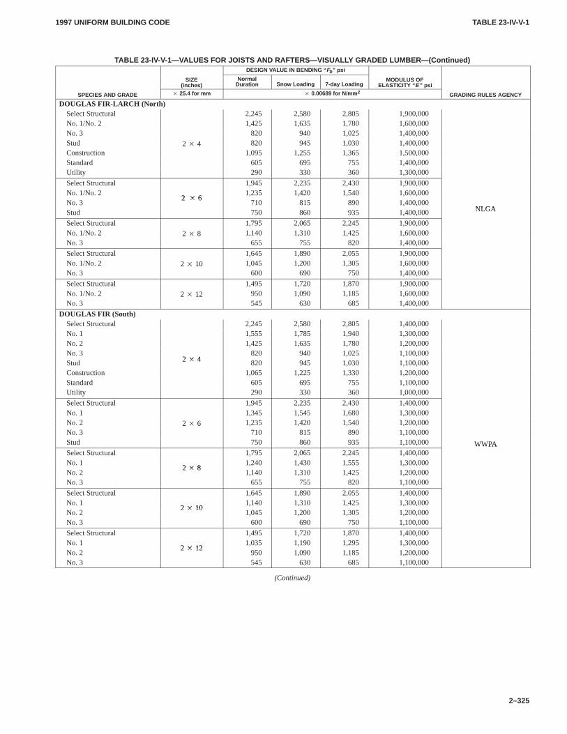
TABLE 23-IV-V-1TABLE 23-IV-V-1
1997 UNIFORM BUILDING CODE
2–325
TABLE 23-IV-V-1—VALUES FOR JOISTS AND RAFTERS—VISUALL Y GRADED LUMBER—(Continued)DESIGN VALUE IN BENDING “ Fb ” psi
SIZE(inches)
NormalDuration Snow Loading 7-day Loading
MODULUS OFELASTICITY “ E ” psi
SPECIES AND GRADE � 25.4 for mm � 0.00689 for N/mm 2 GRADING RULES AGENCY
DOUGLAS FIR-LARCH (North)Select Structural 2,245 2,580 2,805 1,900,000No. 1/No. 2 1,425 1,635 1,780 1,600,000No. 3 820 940 1,025 1,400,000Stud 2 � 4 820 945 1,030 1,400,000Construction
2 � 41,095 1,255 1,365 1,500,000
Standard 605 695 755 1,400,000Utility 290 330 360 1,300,000
Select Structural 1,945 2,235 2,430 1,900,000No. 1/No. 2
2 � 61,235 1,420 1,540 1,600,000
No. 32 � 6
710 815 890 1,400,000NLGAStud 750 860 935 1,400,000 NLGA
Select Structural 1,795 2,065 2,245 1,900,000No. 1/No. 2 2 � 8 1,140 1,310 1,425 1,600,000No. 3
2 � 8655 755 820 1,400,000
Select Structural 1,645 1,890 2,055 1,900,000No. 1/No. 2 2 � 10 1,045 1,200 1,305 1,600,000No. 3
2 � 10600 690 750 1,400,000
Select Structural 1,495 1,720 1,870 1,900,000No. 1/No. 2 2 � 12 950 1,090 1,185 1,600,000No. 3
2 � 12545 630 685 1,400,000
DOUGLAS FIR (South)Select Structural 2,245 2,580 2,805 1,400,000No. 1 1,555 1,785 1,940 1,300,000No. 2 1,425 1,635 1,780 1,200,000No. 3
2 � 4820 940 1,025 1,100,000
Stud 2 � 4 820 945 1,030 1,100,000Construction 1,065 1,225 1,330 1,200,000Standard 605 695 755 1,100,000Utility 290 330 360 1,000,000
Select Structural 1,945 2,235 2,430 1,400,000No. 1 1,345 1,545 1,680 1,300,000No. 2 2 � 6 1,235 1,420 1,540 1,200,000No. 3
2 � 6710 815 890 1,100,000
Stud 750 860 935 1,100,000 WWPASelect Structural 1,795 2,065 2,245 1,400,000
WWPA
No. 12 � 8
1,240 1,430 1,555 1,300,000No. 2
2 � 81,140 1,310 1,425 1,200,000
No. 3 655 755 820 1,100,000
Select Structural 1,645 1,890 2,055 1,400,000No. 1
2 � 101,140 1,310 1,425 1,300,000
No. 22 � 10
1,045 1,200 1,305 1,200,000No. 3 600 690 750 1,100,000
Select Structural 1,495 1,720 1,870 1,400,000No. 1
2 � 121,035 1,190 1,295 1,300,000
No. 22 � 12
950 1,090 1,185 1,200,000No. 3 545 630 685 1,100,000
(Continued)
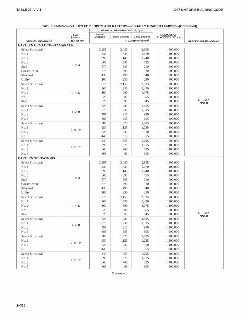
TABLE 23-IV-V-1TABLE 23-IV-V-1
1997 UNIFORM BUILDING CODE
2–326
TABLE 23-IV-V-1—VALUES FOR JOISTS AND RAFTERS—VISUALL Y GRADED LUMBER—(Continued)DESIGN VALUE IN BENDING “ Fb ” psi
SIZE(inches)
NormalDuration Snow Loading 7-day Loading
MODULUS OFELASTICITY “ E ” psi
SPECIES AND GRADE � 25.4 for mm � 0.00689 for N/mm 2 GRADING RULES AGENCY
EASTERN HEMLOCK—T AMARACKSelect Structural 2,155 2,480 2,695 1,200,000No. 1 1,335 1,535 1,670 1,100,000No. 2 990 1,140 1,240 1,100,000No. 3
2 � 4605 695 755 900,000
Stud 2 � 4 570 655 710 900,000Construction 775 895 970 1,000,000Standard 430 495 540 900,000Utility 200 230 250 800,000
Select Structural 1,870 2,150 2,335 1,200,000No. 1 1,160 1,330 1,450 1,100,000No. 2 2 � 6 860 990 1,075 1,100,000No. 3
2 � 6525 600 655 900,000
NELMAStud 520 595 645 900,000 NELMANSLB
Select Structural 1,725 1,985 2,155 1,200,000NSLB
No. 12 � 8
1,070 1,230 1,335 1,100,000No. 2
2 � 8795 915 990 1,100,000
No. 3 485 555 605 900,000
Select Structural 1,580 1,820 1,975 1,200,000No. 1
2 � 10980 1,125 1,225 1,100,000
No. 22 � 10
725 835 910 1,100,000No. 3 445 510 555 900,000
Select Structural 1,440 1,655 1,795 1,200,000No. 1
2 � 12890 1,025 1,115 1,100,000
No. 22 � 12
660 760 825 1,100,000No. 3 405 465 505 900,000
EASTERN SOFTWOODSSelect Structural 2,155 2,480 2,695 1,200,000No. 1 1,335 1,535 1,670 1,100,000No. 2 990 1,140 1,240 1,100,000No. 3
2 � 4605 695 755 900,000
Stud 2 � 4 570 655 710 900,000Construction 775 895 970 1,000,000Standard 430 495 540 900,000Utility 200 230 250 800,000
Select Structural 1,870 2,150 2,335 1,200,000No. 1 1,160 1,330 1,450 1,100,000No. 2 2 � 6 860 990 1,075 1,100,000No. 3
2 � 6525 600 655 900,000
NELMAStud 520 595 645 900,000 NELMANSLB
Select Structural 1,725 1,985 2,155 1,200,000NSLB
No. 12 � 8
1,070 1,230 1,335 1,100,000No. 2
2 � 8795 915 990 1,100,000
No. 3 485 555 605 900,000
Select Structural 1,580 1,820 1,975 1,200,000No. 1
2 � 10980 1,125 1,225 1,100,000
No. 22 � 10
725 835 910 1,100,000No. 3 445 510 555 900,000
Select Structural 1,440 1,655 1,795 1,200,000No. 1
2 � 12890 1,025 1,115 1,100,000
No. 22 � 12
660 760 825 1,100,000No. 3 405 465 505 900,000
(Continued)
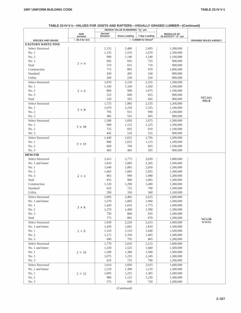
TABLE 23-IV-V-1TABLE 23-IV-V-1
1997 UNIFORM BUILDING CODE
2–327
TABLE 23-IV-V-1—VALUES FOR JOISTS AND RAFTERS—VISUALL Y GRADED LUMBER—(Continued)DESIGN VALUE IN BENDING “ Fb ” psi
SIZE(inches)
NormalDuration Snow Loading 7-day Loading
MODULUS OFELASTICITY “ E ” psi
SPECIES AND GRADE � 25.4 for mm � 0.00689 for N/mm 2 GRADING RULES AGENCY
EASTERN WHITE PINESelect Structural 2,155 2,480 2,695 1,200,000No. 1 1,335 1,535 1,670 1,100,000No. 2 990 1,140 1,240 1,100,000No. 3
2 � 4605 695 755 900,000
Stud 2 � 4 570 655 710 900,000Construction 775 895 970 1,000,000Standard 430 495 540 900,000Utility 200 230 250 800,000
Select Structural 1,870 2,150 2,335 1,200,000No. 1 1,160 1,330 1,450 1,100,000No. 2 2 � 6 860 990 1,075 1,100,000No. 3
2 � 6525 600 655 900,000
NELMAStud 520 595 645 900,000 NELMANSLB
Select Structural 1,725 1,985 2,155 1,200,000NSLB
No. 12 � 8
1,070 1,230 1,335 1,100,000No. 2
2 � 8795 915 990 1,100,000
No. 3 485 555 605 900,000
Select Structural 1,580 1,820 1,975 1,200,000No. 1
2 � 10980 1,125 1,225 1,100,000
No. 22 � 10
725 835 910 1,100,000No. 3 445 510 555 900,000
Select Structural 1,440 1,655 1,795 1,200,000No. 1
2 � 12890 1,025 1,115 1,100,000
No. 22 � 12
660 760 825 1,100,000No. 3 405 465 505 900,000
HEM-FIRSelect Structural 2,415 2,775 3,020 1,600,000No. 1 and better 1,810 2,085 2,265 1,500,000No. 1 1,640 1,885 2,050 1,500,000No. 2 1,465 1,685 1,835 1,300,000No. 3 2 � 4 865 990 1,080 1,200,000Stud
2 � 4855 980 1,065 1,200,000
Construction 1,120 1,290 1,400 1,300,000Standard 635 725 790 1,200,000Utility 290 330 360 1,100,000
Select Structural 2,095 2,405 2,615 1,600,000No. 1 and better 1,570 1,805 1,960 1,500,000No. 1
2 � 61,420 1,635 1,775 1,500,000
No. 22 � 6
1,270 1,460 1,590 1,300,000No. 3 750 860 935 1,200,000Stud 775 895 970 1,200,000 WCLIBSelect Structural 1,930 2,220 2,415 1,600,000
WCLIBWWPA
No. 1 and better 1,450 1,665 1,810 1,500,000No. 1 2 � 8 1,310 1,510 1,640 1,500,000No. 2
2 � 81,175 1,350 1,465 1,300,000
No. 3 690 795 865 1,200,000
Select Structural 1,770 2,035 2,215 1,600,000No. 1 and better 1,330 1,525 1,660 1,500,000No. 1 2 � 10 1,200 1,380 1,500 1,500,000No. 2
2 � 101,075 1,235 1,345 1,300,000
No. 3 635 725 790 1,200,000
Select Structural 1,610 1,850 2,015 1,600,000No. 1 and better 1,210 1,390 1,510 1,500,000No. 1 2 � 12 1,095 1,255 1,365 1,500,000No. 2
2 � 12980 1,125 1,220 1,300,000
No. 3 575 660 720 1,200,000
(Continued)
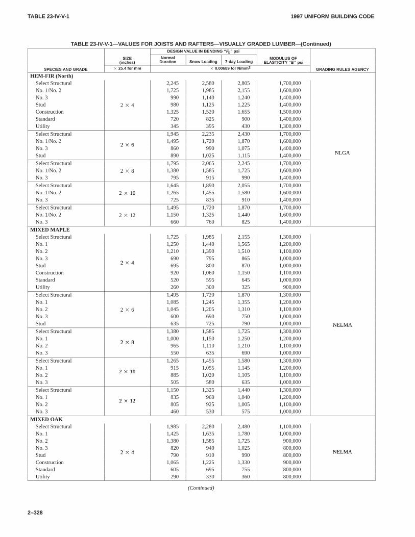
TABLE 23-IV-V-1TABLE 23-IV-V-1
1997 UNIFORM BUILDING CODE
2–328
TABLE 23-IV-V-1—VALUES FOR JOISTS AND RAFTERS—VISUALL Y GRADED LUMBER—(Continued)DESIGN VALUE IN BENDING “ Fb ” psi
SIZE(inches)
NormalDuration Snow Loading 7-day Loading
MODULUS OFELASTICITY “ E ” psi
SPECIES AND GRADE � 25.4 for mm � 0.00689 for N/mm 2 GRADING RULES AGENCY
HEM-FIR (North)Select Structural 2,245 2,580 2,805 1,700,000No. 1/No. 2 1,725 1,985 2,155 1,600,000No. 3 990 1,140 1,240 1,400,000Stud 2 � 4 980 1,125 1,225 1,400,000Construction
2 � 41,325 1,520 1,655 1,500,000
Standard 720 825 900 1,400,000Utility 345 395 430 1,300,000
Select Structural 1,945 2,235 2,430 1,700,000No. 1/No. 2
2 � 61,495 1,720 1,870 1,600,000
No. 32 � 6
860 990 1,075 1,400,000NLGAStud 890 1,025 1,115 1,400,000 NLGA
Select Structural 1,795 2,065 2,245 1,700,000No. 1/No. 2 2 � 8 1,380 1,585 1,725 1,600,000No. 3
2 � 8795 915 990 1,400,000
Select Structural 1,645 1,890 2,055 1,700,000No. 1/No. 2 2 � 10 1,265 1,455 1,580 1,600,000No. 3
2 � 10725 835 910 1,400,000
Select Structural 1,495 1,720 1,870 1,700,000No. 1/No. 2 2 � 12 1,150 1,325 1,440 1,600,000No. 3
2 � 12660 760 825 1,400,000
MIXED MAPLESelect Structural 1,725 1,985 2,155 1,300,000No. 1 1,250 1,440 1,565 1,200,000No. 2 1,210 1,390 1,510 1,100,000No. 3
2 � 4690 795 865 1,000,000
Stud 2 � 4 695 800 870 1,000,000Construction 920 1,060 1,150 1,100,000Standard 520 595 645 1,000,000Utility 260 300 325 900,000
Select Structural 1,495 1,720 1,870 1,300,000No. 1 1,085 1,245 1,355 1,200,000No. 2 2 � 6 1,045 1,205 1,310 1,100,000No. 3
2 � 6600 690 750 1,000,000
Stud 635 725 790 1,000,000 NELMASelect Structural 1,380 1,585 1,725 1,300,000
NELMA
No. 12 � 8
1,000 1,150 1,250 1,200,000No. 2
2 � 8965 1,110 1,210 1,100,000
No. 3 550 635 690 1,000,000
Select Structural 1,265 1,455 1,580 1,300,000No. 1
2 � 10915 1,055 1,145 1,200,000
No. 22 � 10
885 1,020 1,105 1,100,000No. 3 505 580 635 1,000,000
Select Structural 1,150 1,325 1,440 1,300,000No. 1
2 � 12835 960 1,040 1,200,000
No. 22 � 12
805 925 1,005 1,100,000No. 3 460 530 575 1,000,000
MIXED OAKSelect Structural 1,985 2,280 2,480 1,100,000No. 1 1,425 1,635 1,780 1,000,000No. 2 1,380 1,585 1,725 900,000No. 3
2 � 4820 940 1,025 800,000
NELMAStud 2 � 4 790 910 990 800,000
NELMA
Construction 1,065 1,225 1,330 900,000Standard 605 695 755 800,000Utility 290 330 360 800,000
(Continued)
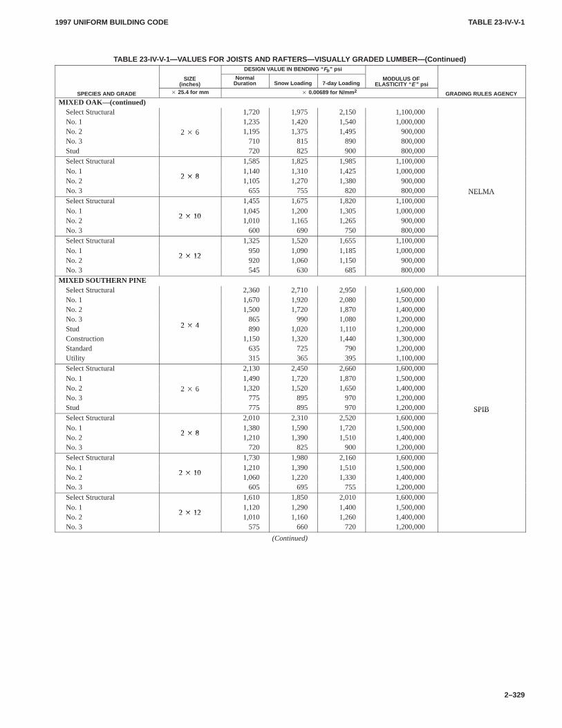
TABLE 23-IV-V-1TABLE 23-IV-V-1
1997 UNIFORM BUILDING CODE
2–329
TABLE 23-IV-V-1—VALUES FOR JOISTS AND RAFTERS—VISUALL Y GRADED LUMBER—(Continued)DESIGN VALUE IN BENDING “ Fb ” psi
SIZE(inches)
NormalDuration Snow Loading 7-day Loading
MODULUS OFELASTICITY “ E ” psi
SPECIES AND GRADE � 25.4 for mm � 0.00689 for N/mm 2 GRADING RULES AGENCY
MIXED OAK—(continued)Select Structural 1,720 1,975 2,150 1,100,000No. 1 1,235 1,420 1,540 1,000,000No. 2 2 � 6 1,195 1,375 1,495 900,000No. 3
2 � 6710 815 890 800,000
Stud 720 825 900 800,000Select Structural 1,585 1,825 1,985 1,100,000No. 1
2 � 81,140 1,310 1,425 1,000,000
No. 22 � 8
1,105 1,270 1,380 900,000No. 3 655 755 820 800,000 NELMASelect Structural 1,455 1,675 1,820 1,100,000
NELMA
No. 12 � 10
1,045 1,200 1,305 1,000,000No. 2
2 � 101,010 1,165 1,265 900,000
No. 3 600 690 750 800,000Select Structural 1,325 1,520 1,655 1,100,000No. 1
2 � 12950 1,090 1,185 1,000,000
No. 22 � 12
920 1,060 1,150 900,000No. 3 545 630 685 800,000
MIXED SOUTHERN PINESelect Structural 2,360 2,710 2,950 1,600,000No. 1 1,670 1,920 2,080 1,500,000No. 2 1,500 1,720 1,870 1,400,000No. 3
2 � 4865 990 1,080 1,200,000
Stud 2 � 4 890 1,020 1,110 1,200,000Construction 1,150 1,320 1,440 1,300,000Standard 635 725 790 1,200,000Utility 315 365 395 1,100,000Select Structural 2,130 2,450 2,660 1,600,000No. 1 1,490 1,720 1,870 1,500,000No. 2 2 � 6 1,320 1,520 1,650 1,400,000No. 3
2 � 6775 895 970 1,200,000
Stud 775 895 970 1,200,000 SPIBSelect Structural 2,010 2,310 2,520 1,600,000
SPIB
No. 12 � 8
1,380 1,590 1,720 1,500,000No. 2
2 � 81,210 1,390 1,510 1,400,000
No. 3 720 825 900 1,200,000
Select Structural 1,730 1,980 2,160 1,600,000No. 1
2 � 101,210 1,390 1,510 1,500,000
No. 22 � 10
1,060 1,220 1,330 1,400,000No. 3 605 695 755 1,200,000Select Structural 1,610 1,850 2,010 1,600,000No. 1
2 � 121,120 1,290 1,400 1,500,000
No. 22 � 12
1,010 1,160 1,260 1,400,000No. 3 575 660 720 1,200,000
(Continued)
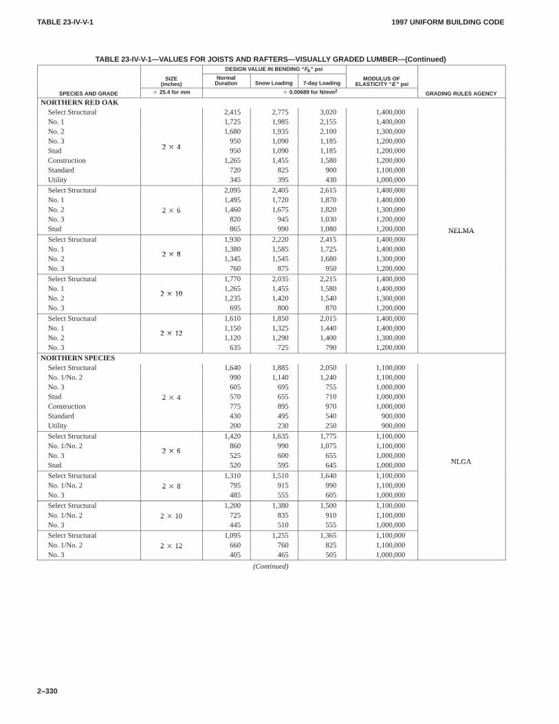
TABLE 23-IV-V-1TABLE 23-IV-V-1
1997 UNIFORM BUILDING CODE
2–330
TABLE 23-IV-V-1—VALUES FOR JOISTS AND RAFTERS—VISUALL Y GRADED LUMBER—(Continued)DESIGN VALUE IN BENDING “ Fb ” psi
SIZE(inches)
NormalDuration Snow Loading 7-day Loading
MODULUS OFELASTICITY “ E ” psi
SPECIES AND GRADE � 25.4 for mm � 0.00689 for N/mm 2 GRADING RULES AGENCY
NORTHERN RED OAKSelect Structural 2,415 2,775 3,020 1,400,000No. 1 1,725 1,985 2,155 1,400,000No. 2 1,680 1,935 2,100 1,300,000No. 3
2 � 4950 1,090 1,185 1,200,000
Stud 2 � 4 950 1,090 1,185 1,200,000Construction 1,265 1,455 1,580 1,200,000Standard 720 825 900 1,100,000Utility 345 395 430 1,000,000
Select Structural 2,095 2,405 2,615 1,400,000No. 1 1,495 1,720 1,870 1,400,000No. 2 2 � 6 1,460 1,675 1,820 1,300,000No. 3
2 � 6820 945 1,030 1,200,000
Stud 865 990 1,080 1,200,000 NELMASelect Structural 1,930 2,220 2,415 1,400,000
NELMA
No. 12 � 8
1,380 1,585 1,725 1,400,000No. 2
2 � 81,345 1,545 1,680 1,300,000
No. 3 760 875 950 1,200,000
Select Structural 1,770 2,035 2,215 1,400,000No. 1
2 � 101,265 1,455 1,580 1,400,000
No. 22 � 10
1,235 1,420 1,540 1,300,000No. 3 695 800 870 1,200,000
Select Structural 1,610 1,850 2,015 1,400,000No. 1
2 � 121,150 1,325 1,440 1,400,000
No. 22 � 12
1,120 1,290 1,400 1,300,000No. 3 635 725 790 1,200,000
NORTHERN SPECIESSelect Structural 1,640 1,885 2,050 1,100,000No. 1/No. 2 990 1,140 1,240 1,100,000No. 3 605 695 755 1,000,000Stud 2 � 4 570 655 710 1,000,000Construction
2 � 4775 895 970 1,000,000
Standard 430 495 540 900,000Utility 200 230 250 900,000
Select Structural 1,420 1,635 1,775 1,100,000No. 1/No. 2
2 � 6860 990 1,075 1,100,000
No. 32 � 6
525 600 655 1,000,000NLGAStud 520 595 645 1,000,000 NLGA
Select Structural 1,310 1,510 1,640 1,100,000No. 1/No. 2 2 � 8 795 915 990 1,100,000No. 3
2 � 8485 555 605 1,000,000
Select Structural 1,200 1,380 1,500 1,100,000No. 1/No. 2 2 � 10 725 835 910 1,100,000No. 3
2 � 10445 510 555 1,000,000
Select Structural 1,095 1,255 1,365 1,100,000No. 1/No. 2 2 � 12 660 760 825 1,100,000No. 3
2 � 12405 465 505 1,000,000
(Continued)
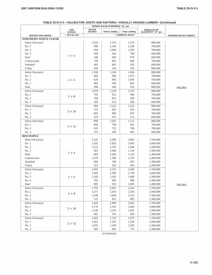
TABLE 23-IV-V-1TABLE 23-IV-V-1
1997 UNIFORM BUILDING CODE
2–331
TABLE 23-IV-V-1—VALUES FOR JOISTS AND RAFTERS—VISUALL Y GRADED LUMBER—(Continued)DESIGN VALUE IN BENDING “ Fb ” psi
SIZE(inches)
NormalDuration Snow Loading 7-day Loading
MODULUS OFELASTICITY “ E ” psi
SPECIES AND GRADE � 25.4 for mm � 0.00689 for N/mm 2 GRADING RULES AGENCY
NORTHERN WHITE CEDARSelect Structural 1,335 1,535 1,670 800,000No. 1 990 1,140 1,240 700,000No. 2 950 1,090 1,185 700,000No. 3
2 � 4560 645 700 600,000
Stud 2 � 4 540 620 670 600,000Construction 720 825 900 700,000Standard 405 465 505 600,000Utility 200 230 250 600,000
Select Structural 1,160 1,330 1,450 800,000No. 1 860 990 1,075 700,000No. 2 2 � 6 820 945 1,030 700,000No. 3
2 � 6485 560 605 600,000
Stud 490 560 610 600,000 NELMASelect Structural 1,070 1,230 1,335 800,000
NELMA
No. 12 � 8
795 915 990 700,000No. 2
2 � 8760 875 950 700,000
No. 3 450 515 560 600,000
Select Structural 980 1,125 1,225 800,000No. 1
2 � 10725 835 910 700,000
No. 22 � 10
695 800 870 700,000No. 3 410 475 515 600,000
Select Structural 890 1,025 1,115 800,000No. 1
2 � 12660 760 825 700,000
No. 22 � 12
635 725 790 700,000No. 3 375 430 465 600,000
RED MAPLESelect Structural 2,245 2,580 2,805 1,700,000No. 1 1,595 1,835 1,995 1,600,000No. 2 1,555 1,785 1,940 1,500,000No. 3
2 � 4905 1,040 1,130 1,300,000
Stud 2 � 4 885 1,020 1,105 1,300,000Construction 1,210 1,390 1,510 1,400,000Standard 660 760 825 1,300,000Utility 315 365 395 1,200,000
Select Structural 1,945 2,235 2,430 1,700,000No. 1 1,385 1,590 1,730 1,600,000No. 2 2 � 6 1,345 1,545 1,680 1,500,000No. 3
2 � 6785 905 980 1,300,000
Stud 805 925 1,005 1,300,000 NELMASelect Structural 1,795 2,065 2,245 1,700,000
NELMA
No. 12 � 8
1,275 1,470 1,595 1,600,000No. 2
2 � 81,240 1,430 1,555 1,500,000
No. 3 725 835 905 1,300,000
Select Structural 1,645 1,890 2,055 1,700,000No. 1
2 � 101,170 1,345 1,465 1,600,000
No. 22 � 10
1,140 1,310 1,425 1,500,000No. 3 665 765 830 1,300,000
Select Structural 1,495 1,720 1,870 1,700,000No. 1
2 � 121,065 1,225 1,330 1,600,000
No. 22 � 12
1,035 1,190 1,295 1,500,000No. 3 605 695 755 1,300,000
(Continued)
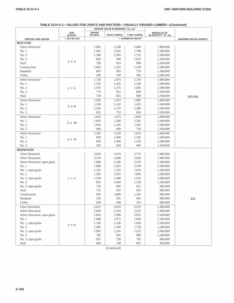
TABLE 23-IV-V-1TABLE 23-IV-V-1
1997 UNIFORM BUILDING CODE
2–332
TABLE 23-IV-V-1—VALUES FOR JOISTS AND RAFTERS—VISUALL Y GRADED LUMBER—(Continued)DESIGN VALUE IN BENDING “ Fb ” psi
SIZE(inches)
NormalDuration Snow Loading 7-day Loading
MODULUS OFELASTICITY “ E ” psi
SPECIES AND GRADE � 25.4 for mm � 0.00689 for N/mm 2 GRADING RULES AGENCY
RED OAKSelect Structural 1,985 2,280 2,480 1,400,000No. 1 1,425 1,635 1,780 1,300,000No. 2 1,380 1,585 1,725 1,200,000No. 3
2 � 4820 940 1,025 1,100,000
Stud 2 � 4 790 910 990 1,100,006Construction 1,065 1,225 1,330 1,200,000Standard 605 695 755 1,100,000Utility 290 330 360 1,000,000
Select Structural 1,720 1,975 2,150 1,400,000No. 1 1,235 1,420 1,540 1,300,000No. 2 2 � 6 1,195 1,375 1,495 1,200,000No. 3
2 � 6710 815 890 1,100,000
Stud 720 825 900 1,100,000 NELMASelect Structural 1,585 1,825 1,985 1,400,000
NELMA
No. 12 � 8
1,140 1,310 1,425 1,300,000No. 2
2 � 81,105 1,270 1,380 1,200,000
No. 3 655 755 820 1,100,000
Select Structural 1,455 1,675 1,820 1,400,000No. 1
2 � 101,045 1,200 1,305 1,300,000
No. 22 � 10
1,010 1,165 1,265 1,200,000No. 3 600 690 750 1,100,000
Select Structural 1,325 1,520 1,655 1,400,000No. 1
2 � 12950 1,090 1,185 1,300,000
No. 22 � 12
920 1,060 1,150 1,200,000No. 3 545 630 685 1,100,000
REDWOODClear Structural 3,020 3,470 3,775 1,400,000Select Structural 2,330 2,680 2,910 1,400,000Select Structural, open grain 1,900 2,180 2,370 1,100,000No. 1 1,680 1,935 2,100 1,300,000No. 1, open grain 1,335 1,535 1,670 1,100,000No. 2 1,595 1,835 1,995 1,200,000No. 2, open grain 2 � 4 1,250 1,440 1,565 1,000,000No. 3
2 � 4905 1,040 1,130 1,100,000
No. 3, open grain 735 845 915 900,000Stud 725 835 910 900,000Construction 950 1,090 1,185 900,000Standard 520 595 645 900,000 RISUtility 260 300 325 800,000
RIS
Clear Structural 2,615 3,010 3,270 1,400,000Select Structural 2,020 2,320 2,525 1,400,000Select Structural, open grain 1,645 1,890 2,055 1,100,000No. 1 1,460 1,675 1,820 1,300,000No. 1, open grain
2 � 61,160 1,330 1,450 1,100,000
No. 22 � 6
1,385 1,590 1,730 1,200,000No. 2, open grain 1,085 1,245 1,355 1,000,000No. 3 785 905 980 1,100,000No. 3, open grain 635 730 795 900,000Stud 660 760 825 900,000
(Continued)
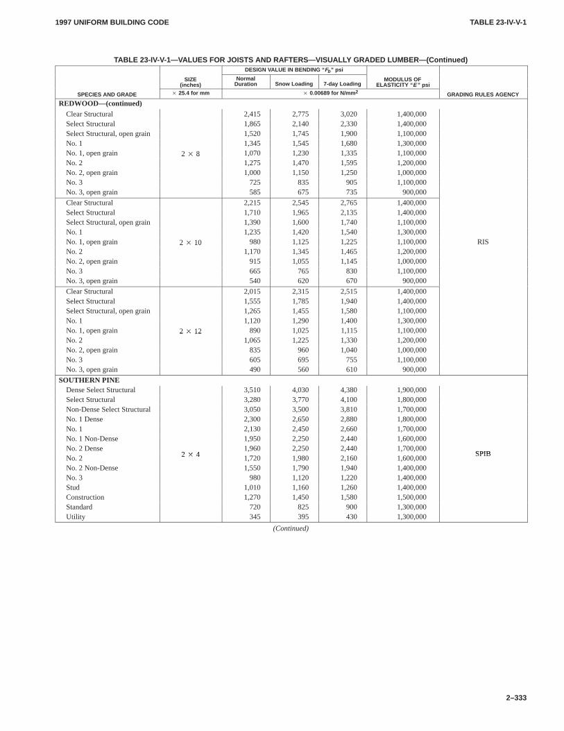
TABLE 23-IV-V-1TABLE 23-IV-V-1
1997 UNIFORM BUILDING CODE
2–333
TABLE 23-IV-V-1—VALUES FOR JOISTS AND RAFTERS—VISUALL Y GRADED LUMBER—(Continued)DESIGN VALUE IN BENDING “ Fb ” psi
SIZE(inches)
NormalDuration Snow Loading 7-day Loading
MODULUS OFELASTICITY “ E ” psi
SPECIES AND GRADE � 25.4 for mm � 0.00689 for N/mm 2 GRADING RULES AGENCY
REDWOOD—(continued)Clear Structural 2,415 2,775 3,020 1,400,000Select Structural 1,865 2,140 2,330 1,400,000Select Structural, open grain 1,520 1,745 1,900 1,100,000No. 1 1,345 1,545 1,680 1,300,000No. 1, open grain 2 � 8 1,070 1,230 1,335 1,100,000No. 2
2 � 81,275 1,470 1,595 1,200,000
No. 2, open grain 1,000 1,150 1,250 1,000,000No. 3 725 835 905 1,100,000No. 3, open grain 585 675 735 900,000
Clear Structural 2,215 2,545 2,765 1,400,000Select Structural 1,710 1,965 2,135 1,400,000Select Structural, open grain 1,390 1,600 1,740 1,100,000No. 1 1,235 1,420 1,540 1,300,000No. 1, open grain 2 � 10 980 1,125 1,225 1,100,000 RISNo. 2
2 � 101,170 1,345 1,465 1,200,000
No. 2, open grain 915 1,055 1,145 1,000,000No. 3 665 765 830 1,100,000No. 3, open grain 540 620 670 900,000
Clear Structural 2,015 2,315 2,515 1,400,000Select Structural 1,555 1,785 1,940 1,400,000Select Structural, open grain 1,265 1,455 1,580 1,100,000No. 1 1,120 1,290 1,400 1,300,000No. 1, open grain 2 � 12 890 1,025 1,115 1,100,000No. 2
2 � 121,065 1,225 1,330 1,200,000
No. 2, open grain 835 960 1,040 1,000,000No. 3 605 695 755 1,100,000No. 3, open grain 490 560 610 900,000
SOUTHERN PINEDense Select Structural 3,510 4,030 4,380 1,900,000Select Structural 3,280 3,770 4,100 1,800,000Non-Dense Select Structural 3,050 3,500 3,810 1,700,000No. 1 Dense 2,300 2,650 2,880 1,800,000No. 1 2,130 2,450 2,660 1,700,000No. 1 Non-Dense 1,950 2,250 2,440 1,600,000No. 2 Dense
2 � 41,960 2,250 2,440 1,700,000
SPIBNo. 2 2 � 4 1,720 1,980 2,160 1,600,000
SPIB
No. 2 Non-Dense 1,550 1,790 1,940 1,400,000No. 3 980 1,120 1,220 1,400,000Stud 1,010 1,160 1,260 1,400,000Construction 1,270 1,450 1,580 1,500,000Standard 720 825 900 1,300,000Utility 345 395 430 1,300,000
(Continued)
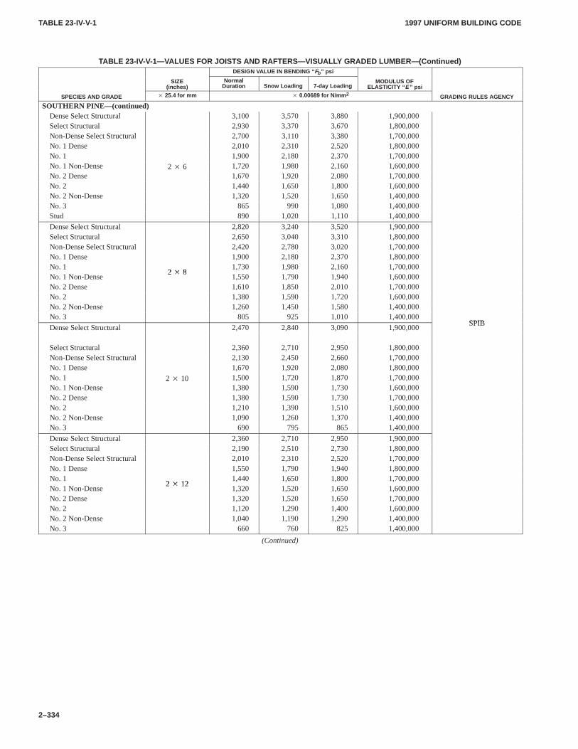
TABLE 23-IV-V-1TABLE 23-IV-V-1
1997 UNIFORM BUILDING CODE
2–334
TABLE 23-IV-V-1—VALUES FOR JOISTS AND RAFTERS—VISUALL Y GRADED LUMBER—(Continued)DESIGN VALUE IN BENDING “ Fb ” psi
SIZE(inches)
NormalDuration Snow Loading 7-day Loading
MODULUS OFELASTICITY “ E ” psi
SPECIES AND GRADE � 25.4 for mm � 0.00689 for N/mm 2 GRADING RULES AGENCY
SOUTHERN PINE—(continued)Dense Select Structural 3,100 3,570 3,880 1,900,000Select Structural 2,930 3,370 3,670 1,800,000Non-Dense Select Structural 2,700 3,110 3,380 1,700,000No. 1 Dense 2,010 2,310 2,520 1,800,000No. 1 1,900 2,180 2,370 1,700,000No. 1 Non-Dense 2 � 6 1,720 1,980 2,160 1,600,000No. 2 Dense
2 � 61,670 1,920 2,080 1,700,000
No. 2 1,440 1,650 1,800 1,600,000No. 2 Non-Dense 1,320 1,520 1,650 1,400,000No. 3 865 990 1,080 1,400,000Stud 890 1,020 1,110 1,400,000
Dense Select Structural 2,820 3,240 3,520 1,900,000Select Structural 2,650 3,040 3,310 1,800,000Non-Dense Select Structural 2,420 2,780 3,020 1,700,000No. 1 Dense 1,900 2,180 2,370 1,800,000No. 1
2 � 81,730 1,980 2,160 1,700,000
No. 1 Non-Dense2 � 8
1,550 1,790 1,940 1,600,000No. 2 Dense 1,610 1,850 2,010 1,700,000No. 2 1,380 1,590 1,720 1,600,000No. 2 Non-Dense 1,260 1,450 1,580 1,400,000No. 3 805 925 1,010 1,400,000
SPIBDense Select Structural 2,470 2,840 3,090 1,900,000
SPIB
Select Structural 2,360 2,710 2,950 1,800,000Non-Dense Select Structural 2,130 2,450 2,660 1,700,000No. 1 Dense 1,670 1,920 2,080 1,800,000No. 1 2 � 10 1,500 1,720 1,870 1,700,000No. 1 Non-Dense
2 � 101,380 1,590 1,730 1,600,000
No. 2 Dense 1,380 1,590 1,730 1,700,000No. 2 1,210 1,390 1,510 1,600,000No. 2 Non-Dense 1,090 1,260 1,370 1,400,000No. 3 690 795 865 1,400,000
Dense Select Structural 2,360 2,710 2,950 1,900,000Select Structural 2,190 2,510 2,730 1,800,000Non-Dense Select Structural 2,010 2,310 2,520 1,700,000No. 1 Dense 1,550 1,790 1,940 1,800,000No. 1
2 � 121,440 1,650 1,800 1,700,000
No. 1 Non-Dense2 � 12
1,320 1,520 1,650 1,600,000No. 2 Dense 1,320 1,520 1,650 1,700,000No. 2 1,120 1,290 1,400 1,600,000No. 2 Non-Dense 1,040 1,190 1,290 1,400,000No. 3 660 760 825 1,400,000
(Continued)
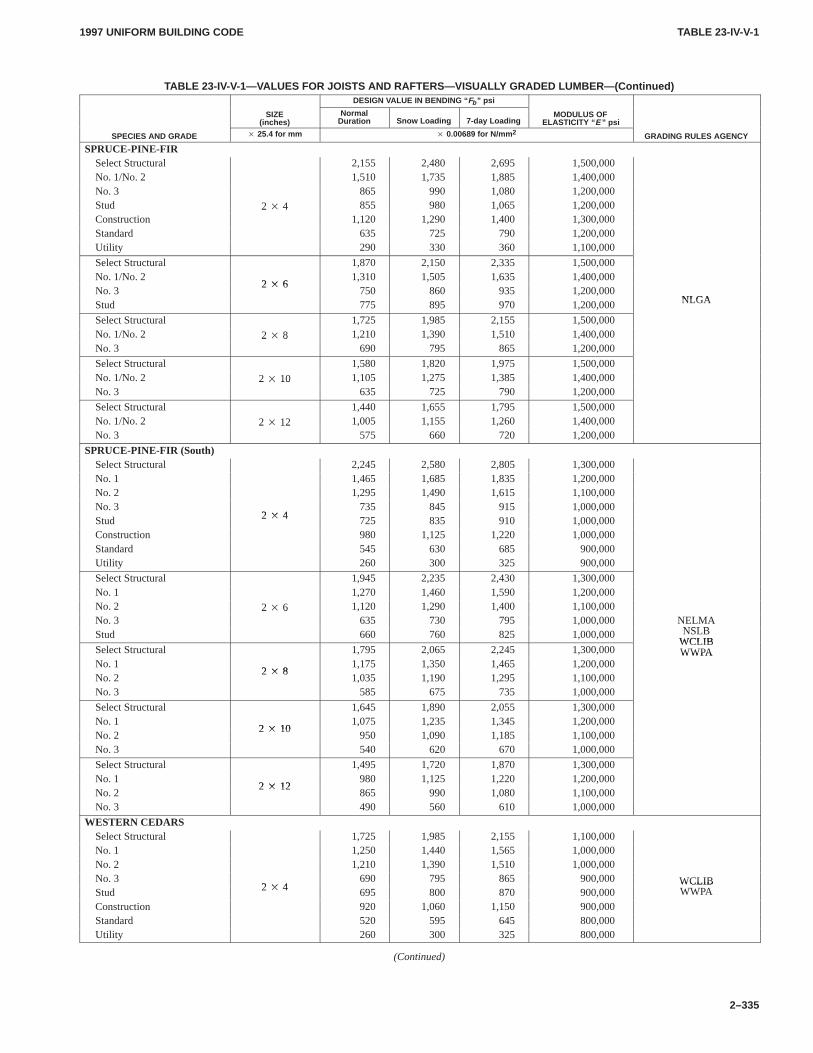
TABLE 23-IV-V-1TABLE 23-IV-V-1
1997 UNIFORM BUILDING CODE
2–335
TABLE 23-IV-V-1—VALUES FOR JOISTS AND RAFTERS—VISUALL Y GRADED LUMBER—(Continued)DESIGN VALUE IN BENDING “ Fb ” psi
SIZE(inches)
NormalDuration Snow Loading 7-day Loading
MODULUS OFELASTICITY “ E ” psi
SPECIES AND GRADE � 25.4 for mm � 0.00689 for N/mm 2 GRADING RULES AGENCY
SPRUCE-PINE-FIRSelect Structural 2,155 2,480 2,695 1,500,000No. 1/No. 2 1,510 1,735 1,885 1,400,000No. 3 865 990 1,080 1,200,000Stud 2 � 4 855 980 1,065 1,200,000Construction
2 � 41,120 1,290 1,400 1,300,000
Standard 635 725 790 1,200,000Utility 290 330 360 1,100,000
Select Structural 1,870 2,150 2,335 1,500,000No. 1/No. 2
2 � 61,310 1,505 1,635 1,400,000
No. 32 � 6
750 860 935 1,200,000NLGAStud 775 895 970 1,200,000 NLGA
Select Structural 1,725 1,985 2,155 1,500,000No. 1/No. 2 2 � 8 1,210 1,390 1,510 1,400,000No. 3
2 � 8690 795 865 1,200,000
Select Structural 1,580 1,820 1,975 1,500,000No. 1/No. 2 2 � 10 1,105 1,275 1,385 1,400,000No. 3
2 � 10635 725 790 1,200,000
Select Structural 1,440 1,655 1,795 1,500,000No. 1/No. 2 2 � 12 1,005 1,155 1,260 1,400,000No. 3
2 � 12575 660 720 1,200,000
SPRUCE-PINE-FIR (South)Select Structural 2,245 2,580 2,805 1,300,000No. 1 1,465 1,685 1,835 1,200,000No. 2 1,295 1,490 1,615 1,100,000No. 3
2 � 4735 845 915 1,000,000
Stud 2 � 4 725 835 910 1,000,000Construction 980 1,125 1,220 1,000,000Standard 545 630 685 900,000Utility 260 300 325 900,000
Select Structural 1,945 2,235 2,430 1,300,000No. 1 1,270 1,460 1,590 1,200,000No. 2 2 � 6 1,120 1,290 1,400 1,100,000No. 3
2 � 6635 730 795 1,000,000 NELMA
NSLBStud 660 760 825 1,000,000 NSLBWCLIB
Select Structural 1,795 2,065 2,245 1,300,000WCLIBWWPA
No. 12 � 8
1,175 1,350 1,465 1,200,000WWPA
No. 22 � 8
1,035 1,190 1,295 1,100,000No. 3 585 675 735 1,000,000
Select Structural 1,645 1,890 2,055 1,300,000No. 1
2 � 101,075 1,235 1,345 1,200,000
No. 22 � 10
950 1,090 1,185 1,100,000No. 3 540 620 670 1,000,000
Select Structural 1,495 1,720 1,870 1,300,000No. 1
2 � 12980 1,125 1,220 1,200,000
No. 22 � 12
865 990 1,080 1,100,000No. 3 490 560 610 1,000,000
WESTERN CEDARSSelect Structural 1,725 1,985 2,155 1,100,000No. 1 1,250 1,440 1,565 1,000,000No. 2 1,210 1,390 1,510 1,000,000No. 3
2 � 4690 795 865 900,000 WCLIB
Stud 2 � 4 695 800 870 900,000WCLIBWWPA
Construction 920 1,060 1,150 900,000Standard 520 595 645 800,000Utility 260 300 325 800,000
(Continued)
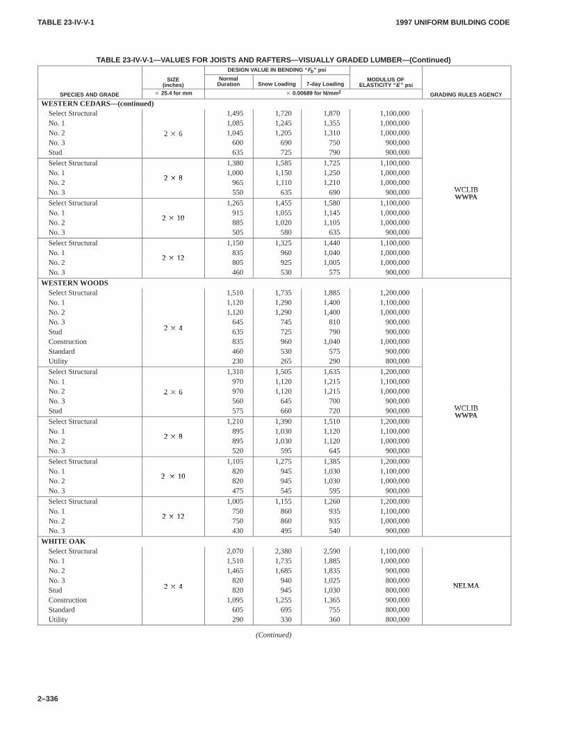
TABLE 23-IV-V-1TABLE 23-IV-V-1
1997 UNIFORM BUILDING CODE
2–336
TABLE 23-IV-V-1—VALUES FOR JOISTS AND RAFTERS—VISUALL Y GRADED LUMBER—(Continued)DESIGN VALUE IN BENDING “ Fb ” psi
SIZE(inches)
NormalDuration Snow Loading 7-day Loading
MODULUS OFELASTICITY “ E ” psi
SPECIES AND GRADE � 25.4 for mm � 0.00689 for N/mm 2 GRADING RULES AGENCY
WESTERN CEDARS—(continued)Select Structural 1,495 1,720 1,870 1,100,000No. 1 1,085 1,245 1,355 1,000,000No. 2 2 � 6 1,045 1,205 1,310 1,000,000No. 3
2 � 6600 690 750 900,000
Stud 635 725 790 900,000
Select Structural 1,380 1,585 1,725 1,100,000No. 1
2 � 81,000 1,150 1,250 1,000,000
No. 22 � 8
965 1,110 1,210 1,000,000WCLIBNo. 3 550 635 690 900,000 WCLIBWWPA
Select Structural 1,265 1,455 1,580 1,100,000WWPA
No. 12 � 10
915 1,055 1,145 1,000,000No. 2
2 � 10885 1,020 1,105 1,000,000
No. 3 505 580 635 900,000
Select Structural 1,150 1,325 1,440 1,100,000No. 1
2 � 12835 960 1,040 1,000,000
No. 22 � 12
805 925 1,005 1,000,000No. 3 460 530 575 900,000
WESTERN WOODSSelect Structural 1,510 1,735 1,885 1,200,000No. 1 1,120 1,290 1,400 1,100,000No. 2 1,120 1,290 1,400 1,000,000No. 3
2 � 4645 745 810 900,000
Stud 2 � 4 635 725 790 900,000Construction 835 960 1,040 1,000,000Standard 460 530 575 900,000Utility 230 265 290 800,000
Select Structural 1,310 1,505 1,635 1,200,000No. 1 970 1,120 1,215 1,100,000No. 2 2 � 6 970 1,120 1,215 1,000,000No. 3
2 � 6560 645 700 900,000
WCLIBStud 575 660 720 900,000 WCLIBWWPA
Select Structural 1,210 1,390 1,510 1,200,000WWPA
No. 12 � 8
895 1,030 1,120 1,100,000No. 2
2 � 8895 1,030 1,120 1,000,000
No. 3 520 595 645 900,000
Select Structural 1,105 1,275 1,385 1,200,000No. 1
2 � 10820 945 1,030 1,100,000
No. 22 � 10
820 945 1,030 1,000,000No. 3 475 545 595 900,000
Select Structural 1,005 1,155 1,260 1,200,000No. 1
2 � 12750 860 935 1,100,000
No. 22 � 12
750 860 935 1,000,000No. 3 430 495 540 900,000
WHITE OAKSelect Structural 2,070 2,380 2,590 1,100,000No. 1 1,510 1,735 1,885 1,000,000No. 2 1,465 1,685 1,835 900,000No. 3
2 � 4820 940 1,025 800,000
NELMAStud 2 � 4 820 945 1,030 800,000
NELMA
Construction 1,095 1,255 1,365 900,000Standard 605 695 755 800,000Utility 290 330 360 800,000
(Continued)
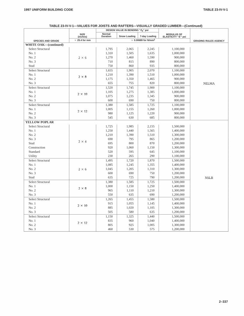
TABLE 23-IV-V-1TABLE 23-IV-V-1
1997 UNIFORM BUILDING CODE
2–337
TABLE 23-IV-V-1—VALUES FOR JOISTS AND RAFTERS—VISUALL Y GRADED LUMBER—(Continued)DESIGN VALUE IN BENDING “ Fb ” psi
SIZE(inches)
NormalDuration Snow Loading 7-day Loading
MODULUS OFELASTICITY “ E ” psi
SPECIES AND GRADE � 25.4 for mm � 0.00689 for N/mm 2 GRADING RULES AGENCY
WHITE OAK—(continued)Select Structural 1,795 2,065 2,245 1,100,000No. 1 1,310 1,505 1,635 1,000,000No. 2 2 � 6 1,270 1,460 1,590 900,000No. 3
2 � 6710 815 890 800,000
Stud 750 860 935 800,000
Select Structural 1,655 1,905 2,070 1,100,000No. 1
2 � 81,210 1,390 1,510 1,000,000
No. 22 � 8
1,175 1,350 1,465 900,000No. 3 655 755 820 800,000 NELMASelect Structural 1,520 1,745 1,900 1,100,000
NELMA
No. 12 � 10
1,105 1,275 1,385 1,000,000No. 2
2 � 101,075 1,235 1,345 900,000
No. 3 600 690 750 800,000
Select Structural 1,380 1,585 1,725 1,100,000No. 1
2 � 121,005 1,155 1,260 1,000,000
No. 22 � 12
980 1,125 1,220 900,000No. 3 545 630 685 800,000
YELLOW POPLARSelect Structural 1,725 1,985 2,155 1,500,000No. 1 1,250 1,440 1,565 1,400,000No. 2 1,210 1,390 1,510 1,300,000No. 3
2 � 4690 795 865 1,200,000
Stud 2 � 4 695 800 870 1,200,000Construction 920 1,060 1,150 1,300,000Standard 520 595 645 1,100,000Utility 230 265 290 1,100,000
Select Structural 1,495 1,720 1,870 1,500,000No. 1 1,085 1,245 1,355 1,400,000No. 2 2 � 6 1,045 1,205 1,310 1,300,000No. 3
2 � 6600 690 750 1,200,000
Stud 635 725 790 1,200,000 NSLBSelect Structural 1,380 1,585 1,725 1,500,000
NSLB
No. 12 � 8
1,000 1,150 1,250 1,400,000No. 2
2 � 8965 1,110 1,210 1,300,000
No. 3 550 635 690 1,200,000
Select Structural 1,265 1,455 1,580 1,500,000No. 1
2 � 10915 1,055 1,145 1,400,000
No. 22 � 10
885 1,020 1,105 1,300,000No. 3 505 580 635 1,200,000
Select Structural 1,150 1,325 1,440 1,500,000No. 1
2 � 12835 960 1,040 1,400,000
No. 22 � 12
805 925 1,005 1,300,000No. 3 460 530 575 1,200,000
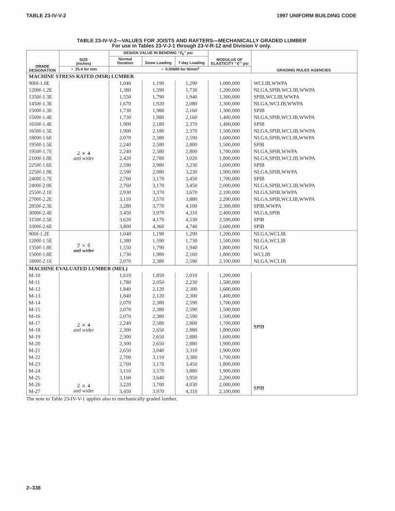
TABLE 23-IV-V-2TABLE 23-IV-V-2
1997 UNIFORM BUILDING CODE
2–338
TABLE 23-IV-V-2—VALUES FOR JOISTS AND RAFTERS—MECHANICALL Y GRADED LUMBERFor use in T ables 23-V-J-1 through 23-V -R-12 and Division V only .
DESIGN VALUE IN BENDING “ Fb ” psi
GRADE
SIZE(inches)
NormalDuration Snow Loading 7-day Loading
MODULUS OFELASTICITY “ E ” psi
GRADEDESIGNATION � 25.4 for mm � 0.00689 for N/mm 2 GRADING RULES AGENCIES
MACHINE STRESS RATED (MSR) LUMBER900f-1.0E 1,040 1,190 1,290 1,000,000 WCLIB,WWPA1200f-1.2E 1,380 1,590 1,730 1,200,000 NLGA,SPIB,WCLIB,WWPA1350f-1.3E 1,550 1,790 1,940 1,300,000 SPIB,WCLIB,WWPA1450f-1.3E 1,670 1,920 2,080 1,300,000 NLGA,WCLIB,WWPA1500f-1.3E 1,730 1,980 2,160 1,300,000 SPIB1500f-1.4E 1,730 1,980 2,160 1,400,000 NLGA,SPlB,WCLIB,WWPA1650f-1.4E 1,900 2,180 2,370 1,400,000 SPIB1650f-1.5E 1,900 2,180 2,370 1,500,000 NLGA,SPIB,WCLIB,WWPA1800f-1.6E 2,070 2,380 2,590 1,600,000 NLGA,SPlB,WCLlB,WWPA1950f-1.5E 2,240 2,580 2,800 1,500,000 SPlB1950f-1.7E 2 � 4 2,240 2,580 2,800 1,700,000 NLGA,SPIB,WWPA2100f-1.8E
2 � 4and wider 2,420 2,780 3,020 1,800,000 NLGA,SPIB,WCLIB,WWPA
2250f-1.6E 2,590 2,980 3,230 1,600,000 SPIB2250f-1.9E 2,590 2,980 3,230 1,900,000 NLGA,SPIB,WWPA2400f-1.7E 2,760 3,170 3,450 1,700,000 SPIB2400f-2.0E 2,760 3,170 3,450 2,000,000 NLGA,SPIB,WCLIB,WWPA2550f-2.1E 2,930 3,370 3,670 2,100,000 NLGA,SPIB,WWPA2700f-2.2E 3,110 3,570 3,880 2,200,000 NLGA,SPlB,WCLIB,WWPA2850f-2.3E 3,280 3,770 4,100 2,300,000 SPlB,WWPA3000f-2.4E 3,450 3,970 4,310 2,400,000 NLGA,SPlB3150f-2.5E 3,620 4,170 4,530 2,500,000 SPlB3300f-2.6E 3,800 4,360 4,740 2,600,000 SPlB
900f-1.2E 1,040 1,190 1,290 1,200,000 NLGA,WCLlB1200f-1.5E
2 � 61,380 1,590 1,730 1,500,000 NLGA,WCLlB
1350f-1.8E 2 � 6and wider
1,550 1,790 1,940 1,800,000 NLGA1500f-1.8E
and wider1,730 1,980 2,160 1,800,000 WCLIB
1800f-2.1E 2,070 2,380 2,590 2,100,000 NLGA,WCLIB
MACHINE EVALUA TED LUMBER (MEL)M-10 1,610 1,850 2,010 1,200,000M-11 1,780 2,050 2,230 1,500,000M-12 1,840 2,120 2,300 1,600,000M-13 1,840 2,120 2,300 1,400,000M-14 2,070 2,380 2,590 1,700,000M-15 2,070 2,380 2,590 1,500,000M-16 2,070 2,380 2,590 1,500,000M-17 2 � 4 2,240 2,580 2,800 1,700,000
SPlBM-18
2 � 4and wider 2,300 2,650 2,880 1,800,000
SPlB
M-19 2,300 2,650 2,880 1,600,000M-20 2,300 2,650 2,880 1,900,000M-21 2,650 3,040 3,310 1,900,000M-22 2,700 3,110 3,380 1,700,000M-23 2,760 3,170 3,450 1,800,000M-24 3,110 3,570 3,880 1,900,000M-25 3,160 3,640 3,950 2,200,000M-26 2 � 4 3,220 3,700 4,030 2,000,000
SPlBM-27
2 � 4and wider 3,450 3,970 4,310 2,100,000
SPlB
The note to Table 23-IV-V-1 applies also to mechanically graded lumber.
CHAP. 23, DIV. V2321
2321.41997 UNIFORM BUILDING CODE
2–339
Division V—DESIGN STANDARD FOR METAL PLATE CONNECTED WOOD TRUSSBased on ANSI/TPI 1-1995, National Design Standard for Metal Plate Connected
Wood Truss Construction, of the Truss Plate Institute
SECTION 2321 — METAL PLATE CONNECTED WOODTRUSS DESIGN
2321.1 Design and Fabrication.The design and fabrication ofmetal plate connected wood trusses shall be in accordance withANSI/TPI 1-1995.CHAP. 23, DIV. V
2321.2 Performance. Full-scale load tests in accordance withANSI/TPI 2 (see Section 2303.1, Item 5) may be required at theoption of the building official to provide a means of demonstratingthat minimum adequate performance is obtainable from specificmetal connector plates, various lumber types and grades, a partic-ular truss design and a particular fabrication procedure. ANSI/TPI 2 provides procedures for testing and evaluating wood trussesdesigned in accordance with ANSI/TPI 1.
2321.3 In-plant Inspection. Each truss manufacturer shall re-tain an approved agency having no financial interest in the plantbeing inspected to make nonscheduled inspections of truss fabri-cation and delivery operations. The inspections shall cover allphases of the truss operation, including lumber storage, handling,cutting, fixtures, presses or rollers, fabrication bundling and band-ing, handling, and delivery.
2321.4 Marking. Each truss shall be legibly branded, marked orotherwise have permanently affixed thereto the following infor-mation located within 2 feet (610 mm) of the center of the span onthe face of the bottom chord:
1. Identity of the company manufacturing the truss.
2. The design load.
3. The spacing of trusses.
CHAP. 23, DIV. VI23222323.2
1997 UNIFORM BUILDING CODE
2–340
Division VI—DESIGN STANDARD FOR STRUCTURAL GLUED BUILT-UP MEMBERS—PLYWOOD COMPONENTSBased on Design and Fabrication Specifications of the American Plywood Association
SECTION 2322 — PLYWOOD STRESSED SKINPANELS
2322.1 Scope.This standard covers requirements for the designof plywood stressed skin panels as referred to in Section 2305.8.
2322.2 Definition. A panel with stressed covers, or a stressedskin panel, is one in which the covering acts integrally with theframing members to resist bending loads in proportion to its effec-tive moment of inertia. It consists of several longitudinal framingmembers or ribs spaced by headers and covered on top alone or topand bottom with plywood panels.
2322.3 Design.CHAP. 23, DIV. VI
2322.3.1 Spacing of ribs.The clear distance between ribs shallnot exceed twice the basic spacing set forth in Table 23-VI-A.
2322.3.2 Skin bending.The stressed skin shall be capable of re-sisting bending stresses due to loads normal to the skin with allow-ance for direction of the face grain.
2322.3.3 Determination of section properties.For determina-tion of bending stresses, the section properties shall be calculatedconsidering that only the ribs or plies of the ribs and the plies in thestressed skin with grain parallel to the span of the ribs are effec-tive. If the clear distance between ribs is less than the basic spacing“b” as set forth in Table 23-VI-A, the effective width of the skin isequal to the full panel width. If the clear distance between ribs isgreater than the basic spacing “b,” the effective width of the skinsequals the sum of the widths of the ribs in contact with the stressedskin plus a portion of the skin extending a distance equal to 0.5 “b”each side of each rib.
For determination of horizontal shear, rolling shear, deflectionand splice stresses, the section properties shall be based on thegross section of all material having its grain parallel with the direc-tion of the principal stress. The modulus of elasticity used to calcu-late deflection shall be based on the modulus of elasticity of theplywood stressed skins.
2322.3.4 Method of design.Stressed skin panels shall be de-signed in accordance with accepted engineering formulas, with-out exceeding the allowable stresses specified in Section 2322.4.
2322.3.5 Splices.The stressed skin panels and ribs shall be con-tinuous in the longitudinal direction, except where adequatelyspliced and designed in accordance with Section 2322.4.
2322.4 Allowable Stresses.
2322.4.1 Panel stresses.
2322.4.1.1 Direct stress from bending.The allowable workingstresses in the stressed skin flanges shall not exceed the values setforth in Table 23-III-A for tension or compression when multi-plied by the factor “F”:
b = the clear distance between ribs in inches (mm).“b” = the basic spacing shown in Table 23-VI-A in inches
(mm).For b/“b” equal or less than 0.5, F equals 1.For b/“b” greater than 0.5 and less than 1.0
F = 0.67 (2 – b/“b” ).For b/“b” equal or greater than 1.0 and not greater than 2.0
F = 0.67.
2322.4.1.2 Rolling shear.The shear between interior ribs andplywood skin shall not exceed the values set forth in Table23-III-A for rolling shear. The allowable working stresses shall bereduced 50 percent at exterior ribs. This reduction applies to exte-rior stringers whose clear distance to the panel edge is less thanhalf the clear distance between stringers.
2322.4.1.3 Stress in plywood skin splices.
2322.4.1.3.1 Scarf-jointed splice in compression.The allow-able stress in the skin at the splice shall not exceed the values spe-cified in Section 2322.4.1.1. The slope of the scarf shall not besteeper than 1 unit vertical in 5 units horizontal (20% slope).
2322.4.1.3.2 Butt-jointed splice in compression.Where asplice plate is installed on one side of the joint, the allowable stressin the skin at the splice shall not exceed the values specified in Sec-tion 2322.4.1.1, provided said values are reduced in proportion tothe ratio of the width of the splice plate to the width of the stressedskin. The splice plate shall be at least equal in thickness and gradeto the skin being spliced. The splice plate shall be centered overthe joint with the face grain parallel to the face grain of the skin.The minimum length of the splice plate, measured parallel to thespan, shall not be less than the values set forth in Table 23-VI-B.Splice plates shall be preglued to the skins prior to assembly of thepanel. No percentage reduction is taken for compressive stress.
2322.4.1.3.3 Scarf-jointed splice in tension.The allowablestress in the skin at the splice shall not exceed the values specifiedin Section 2322.4.1.1. The slope of scarf shall not be steeper than1 unit vertical in 8 units horizontal (12.5% slope).
2322.4.1.3.4 Butt-jointed splice in tension.Where a spliceplate is installed, the allowable stress in the skin at the splice shallnot exceed the values set forth in Table 23-VI-C. The splice platethickness, position, orientation to face grain, installation andlength shall conform to Section 2322.4.1.3.2.
2322.4.2 Rib or longitudinal stresses.
2322.4.2.1 Bending.Bending stresses shall not exceed thevalues set forth in Chapter 23, Division III.
2322.4.2.2 Horizontal shear.Horizontal shear shall not exceedthe values set forth in Chapter 23, Division III.
2322.4.2.3 Splices in ribs or longitudinal members.Accu-rately fitted and well-glued scarf or finger joints are permitted pro-vided the maximum stress in bending does not exceed thepercentages of the basic flexural stress shown in ANSI/AITCA190.1 and ASTM D 3737. In the finger joint, the portion of thejoint occupied by the tips of the fingers at that cross section shallnot be considered as effective. Finger joints and other nonstandardconfigurations of scarf joints may be prequalified in accordancewith ANSI/AITC A190.1 and ASTM D 3737. The effective slopeof the joint shall also be determined.
2322.5 Fabrication. The plywood stressed skins shall be fabri-cated in accordance with the procedures specified in Section 2326.
SECTION 2323 — PLYWOOD CURVED PANELS
2323.1 Scope.This division covers requirements for the designof plywood curved panels as referred to in Section 2305.8. Fabri-cation procedure shall be in accordance with the requirements ofSection 2326.
2323.2 General Design.Curved panels may be designed as ei-ther curved flexural panels or arch panels. The curved flexural
CHAP. 23, DIV. VI2323.2
2323.7.21997 UNIFORM BUILDING CODE
2–341
panels act as a simple beam, without developing horizontal thrust.Bearing details are designed accordingly, with provision forhorizontal deflection. Tie rods are not required. Arch panels arestressed both in compression and in flexure. They exert horizontalthrust at the supports and therefore require tie rods or abutments.
2323.3 Definition.
2323.3.1 Core types.Curved plywood panels consist of full-length plywood faces top and bottom spaced by and joined withglue to a structural core capable of resisting the shearing forces.The core may consist of one or more layers of plywood,butt-jointed or full-length, glued over the full areas to the faces orspaced ribs constructed of single-piece or laminated plywood orlumber strips, spaced as required, either preglued or glued duringpanel assembly.
2323.4 Allowable Stresses.
2323.4.1 Plywood core.The allowable working stresses in ply-wood core type of construction in flexure, compression and ten-sion shall not exceed the values set forth in Table 23-III-A andreduced for curvature by multiplication by the following curva-ture factor:
1� 2000� tR�2
WHERE:R = radius of curvature at center line of member, inches
(mm).
t = thickness, out-to-out of plies parallel with the stress,inches (mm).
tR
= shall not exceed 1/125.
2323.4.2 Spaced ribs.The allowable working stresses in com-pression tension shall be established as specified in Section2323.4.1. Additionally, the allowable stresses shall be further re-duced as for stressed skin panels as specified in Section 2322.
2323.4.3 Radial stresses.The radial stresses induced by bend-ing moment in a curved spaced rib or plywood core panel shall becomputed by the formula:
SR �3M
2Rbh
WHERE:b = width of stringer, inches (mm).h = overall height of panel, inches (mm).
M = bending moment, in inch-pounds (N�mm), on a width ofpanel equal to the rib spacing.
R = radius of curvature at center line of member, inches(mm).
SR = actual stress in a radial direction, pounds per square inch(N/mm2).
When M is in the direction tending to decrease curvature (in-crease the radius) the stress is in tension and SR for plywood shallbe limited to one half the values shown for rolling shear in theplane of the plies in Table 23-III-A. SR for lumber ribs shall be lim-ited to one third the values shown for horizontal shear in Chapter23, Division III. When M is in the direction tending to increasecurvature (decrease the radius) the stress is in compression and SRfor plywood shall be limited to the values shown for compressionperpendicular to the grain in Table 23-III-A. SR for lumber ribsshall be limited to the values shown for compression perpendicu-lar to the grain in Chapter 23, Division III.
2323.5 Effective Cross Section.
2323.5.1 Direction of grain.All plywood and lumber having itsgrain parallel with the direction of stress shall be considered effec-tive in resisting the stress, except for spaced-rib panels whichshould be as outlined in Section 2322.
2323.5.2 Scarfed plywood joints.The slope of scarfed jointsshall not be steeper than one in eight in order to fully develop thestrength of the plywood elements.
2323.5.3 Glued-plywood butt joints with splice plates.Buttjoints with splice plates shall be designed in accordance with thisstandard. Splice plates shall be preglued to the skins prior toassembly of the panel.
2323.5.4 Butt joints without splice plates.The effectivestrength of solid plywood core panels and of laminated ribs in aspaced rib panel at a section containing a butt joint in any lamina-tion shall be determined by ignoring the butted lamination and anyother lamination containing a butt joint closer than 50 times thelamination thickness.
2323.5.5 Deflection.The deflection of curved panels containingbutt joints in either the core or the faces may be based on the grosssection of all material having its grain parallel with the direction ofprincipal stress, provided all butt joints are staggered at least 10times the lamination thickness.
2323.6 Design of Curved Flexural Panels.Curved flexuralpanels shall be designed as simple beams in accordance with theapplicable parts of this standard, with provisions to permit hori-zontal displacement at supports. The extent of this displacementshall be determined in accordance with accepted engineeringpractice.
2323.7 Design of Arch Panels.
2323.7.1 General.Arch panels shall be designed in accordancewith this standard as arches which are subjected to combinedbending and direct stress. Determination of vertical and horizontalreactions and maximum axial loads, moments and shears shall bebased on accepted engineering practice.
2323.7.2 Bending and direct stress.Combined bending and di-rect stress shall be calculated by the formula:
PAc
� MSf
� 1
c � 0.3E(l�d)2
WHERE:A = area in square inches (mm2) of arch cross section per
foot (mm) width of arch, of plies with their grain parallelto the direction of the stress.
c = allowable unit compressive stress in pounds per squareinch (N/mm2), as indicated by the above formula but notto exceed the values in Chapter 23, Division III.
d = thickness, out-to-out, of plies with their grain parallel tothe direction of the stress in inches (mm).
E = modulus of elasticity of skins in pounds per square inch(N/mm2).
f = allowable stress in extreme fiber, pounds per square inch(N/mm2), tension or compression, modified by Sections2322.4.1 and 2323.4.1 as applicable.
l = chord length in inches (mm) between points of zeromoment.
M = moment, in inch-pounds per foot (N�mm/mm) width ofarch.
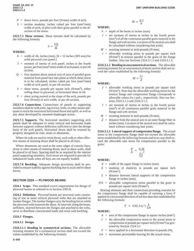
CHAP. 23, DIV. VI2323.7.22324.3.1.3
1997 UNIFORM BUILDING CODE
2–342
P = direct force, pounds per foot (N/mm) width of arch.S = section modulus, inches cubed per foot (mm3/mm)
width of arch, of plies with their grain parallel to the di-rection of the stress.
2323.7.3 Shear stresses.Shear stresses shall be calculated bythe following formula:
S�VQIb
WHERE:b = width of rib, inches (mm). [b = 12 inches (305 mm) for
solid plywood core panel.]I = moment of inertia of arch panel, inches to the fourth
power, per foot (mm4/mm) width of arch panel, or per ribsection.
Q = first moment about neutral axis of area of parallel grainmaterial from panel face into plane at which shear stressis to be calculated, inches cubed per foot (mm3/mm)width of arch panel, or per rib section.
S = shear stress, pounds per square inch (N/mm2), eitherrolling shear in plywood, or horizontal shear in rib.
V = shear acting normal to the slope of the arch, pounds perfoot (N/mm) of arch width, or per rib section.
2323.7.4 Connections.Connections of panels to supportingmembers shall be with nails, lag screws, bolts, or other means ade-quate to resist the maximum horizontal thrust and uplift, as well asany shear developed by assumed diaphragm action.
2323.7.5 Supports.The horizontal members supporting archpanels shall be adequate to resist vertical and horizontal loadsbetween supports without deflection sufficient to alter the designbasis of the arch panels. Horizontal thrust shall be resisted byproperly designed tie rods, struts or abutments.
Where tie rods are used to resist thrust, such rods or other effec-tive means of resisting thrust shall be placed in all bays.
Where abutments are used at the outer edges of exterior bays,struts or other means of resisting thrust, such as shear walls, shallbe placed in all bays. Spacing shall be as required by the interiorpanel supporting members. Such struts are required to provide forunbalanced loads when all bays are not equally loaded.
2323.7.6 Buckling. Adequate design provisions shall be pro-vided to ensure stability against buckling due to axial and/or shearforces.
SECTION 2324 — PLYWOOD BEAMS
2324.1 Scope.This standard covers requirements for design ofplywood beams as referred to in Section 2305.8.
2324.2 Definition. Plywood beams are structural units consist-ing of one or more vertical plywood webs that are attached tolumber flanges. The lumber flanges carry the bending forces whilethe plywood webs transmit the shear. At intervals along the beam,stiffeners, inserted between the flanges and attached to the webs,serve to distribute concentrated loads and resist web buckling.
2324.3 Flanges.
2324.3.1 Design.
2324.3.1.1 Bending in symmetrical sections.The allowableresisting moment for a symmetrical section shall not exceed thevalues established by the following formula:
M � 2t Ih
WHERE:h = depth of the beam in inches (mm).I = net moment of inertia in inches to the fourth power
(mm4) of all the continuous parallel grain material in theflange and web section. Location of the neutral axis shallbe calculated without considering butt joints.
M = resisting moment in inch-pounds (N�mm).t = allowable working stress in pounds per square inch
(N/mm2) in tension parallel to the grain of the flangelumber. Also see Sections 2324.3.1.3 and 2324.3.1.5.
2324.3.1.2 Bending in unsymmetrical sections.The allowableresisting moment for an unsymmetrical beam section shall not ex-ceed the value established by the following formula:
M �f IZ
WHERE:f = allowable working stress in pounds per square inch
(N/mm2). Note that the allowable working stress for thetension flange and compression flange corresponds toallowable values for t and c, respectively. Also see Sec-tions 2324.3.1.3 and 2324.3.1.5.
I = net moment of inertia in inches to the fourth power(mm4) of all continuous parallel grain material in theflange and web section.
M = resisting moment in inch-pounds (N�mm).Z = distance from the neutral axis to an outer flange fiber in
inches (mm). Location of the neutral axis shall be calcu-lated without considering butt joints.
2324.3.1.3 Lateral support of compression flange.The actualstress in the compression flange shall not exceed the allowablestress established by the following formula and in no case shall ex-ceed the allowable unit stress for compression parallel to thegrain:
PA
� 0.3E
�Ld�2
WHERE:d = width of the upper flange in inches (mm).E = modulus of elasticity in pounds per square inch
(N/mm2).L = distance between lateral supports of the compression
flange in inches (mm).P/A = allowable compression stress parallel to the grain in
pounds per square inch (N/mm2).Bracing elements and their connections providing restraint for
the compression flange shall be capable of resisting a force Fapplied in a horizontal direction of not less than that established bythe following formula:
F � 0.02A (c�) LLm
WHERE:A = area of the compression flange in square inches (mm2).c′ = the allowable compressive stress or the actual stress in
compression in pounds per square inch (N/mm2) as gov-erned by Section 2324.3.1
F = force applied in a horizontal direction in pounds (N).Lm = maximum permissible bracing for the actual stress.
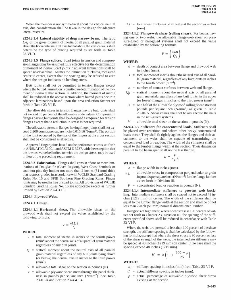
CHAP. 23, DIV. VI2324.3.1.32324.4.1.4
1997 UNIFORM BUILDING CODE
2–343
When the member is not symmetrical about the vertical neutralaxis, due consideration shall be taken in the design for adequatelateral restraint.
2324.3.1.4 Lateral stability of deep narrow beam.The ratioIx/Iy of the gross moment of inertia of all parallel grain materialabout the horizontal neutral axis to that about the vertical axis shalldetermine the type of bracing required as set forth in Table23-VI-D.
2324.3.1.5 Flange splices.Scarf joints in tension and compres-sion flanges may be assumed fully effective for the determinationof moment of inertia. Scarf joints in adjacent laminations shall bespaced no closer than 16 times the lamination thickness, measuredcenter to center, except that the spacing may be reduced to zerowhere the design indicates no bending stress.
Butt joints shall not be permitted in tension flanges exceptwhere the butted lamination is omitted in determination of the mo-ment of inertia at that section. In addition, the moment of inertiashall be reduced at the above section where butted joints occur inadjacent laminations based upon the area reduction factors setforth in Table 23-VI-E.
The allowable stress in tension flanges having butt joints shallnot exceed 80 percent of the allowable code values. Compressionflanges having butt joints shall be designed as required for tensionflanges except that a reduction in stress is not required.
The allowable stress in flanges having finger joints shall not ex-ceed 2,200 pounds per square inch (0.015 16 N/mm2). The portionof the joint occupied by the tips of the fingers at the cross sectionshall not be considered as effective.
Approved finger joints based on the performance tests set forthin ANSI/AITC A190.1 and ASTM D 3737, with the exception thatthe low test value be limited to twice the design stress, may be usedin lieu of the preceding requirement.
2324.3.2 Fabrication. Flanges shall consist of one or more lam-inations of Douglas fir (Coast Region), West Coast hemlock orsouthern pine dry lumber not more than 2 inches (51 mm) thickthat is stress-graded in accordance with WCLIB Standard GradingRules No. 16 and SPIB Southern Pine Grading Rules. Fingerjoints may be used in lieu of scarf joints. All provisions of WCLIBStandard Grading Rules No. 16 are applicable except as furtherlimited by Section 2324.3.1.5.
2324.4 Plywood Webs.
2324.4.1 Design.
2324.4.1.1 Horizontal shear.The allowable shear on theplywood web shall not exceed the value established by thefollowing formula:
V � vI � tQ
WHERE:I = total moment of inertia in inches to the fourth power
(mm4) about the neutral axis of all parallel grain materialregardless of any butt joints.
Q = statical moment about the neutral axis of all parallelgrain material regardless of any butt joints lying above(or below) the neutral axis in inches to the third power(mm3).
V = allowable total shear on the section in pounds (N).v = allowable plywood shear stress through the panel thick-
ness in pounds per square inch (N/mm2). See Table23-III-A and Section 2324.4.1.4.
�t = total shear thickness of all webs at the section in inches(mm).
2324.4.1.2 Flange-web shear (rolling shear).For beams hav-ing one or two webs, the allowable flange-web shear on pres-sure-glued or nail-glued systems shall not exceed the valueestablished by the following formula:
V � �nsdIQfl�
WHERE:d = depth of contact area between flange and plywood web
in inches (mm).I = total moment of inertia about the neutral axis of all paral-
lel grain material, regardless of any butt joints in inchesto the fourth power (mm4).
n = number of contact surfaces between web and flange.Qfl = statical moment about the neutral axis of all parallel
grain material, regardless of any butt joints, in the upper(or lower) flanges in inches to the third power (mm3).
s = one half of the allowable plywood rolling shear stress inpounds per square inch (N/mm2) as given in Table23-III-A. Shear values shall not be assigned to the nailsin the nail-glued systems.
V = allowable total shear on the section in pounds (N).
2324.4.1.3 Stiffeners for concentrated loads.Stiffeners shallbe placed over reactions and where other heavy concentratedloads occur. They shall fit tightly against the flanges and their at-tachment to the webs shall be capable of transmitting theconcentrated load or reaction. The width of the stiffeners shall beequal to the lumber flange width at the section. Their dimensionparallel to the beam span shall not be less than w.
w � Pc� b
WHERE:b = flange width in inches (mm).
c� = allowable stress in compression perpendicular to grainin pounds per square inch (N/mm2) for the flange lumberas set forth in Division III.
P = concentrated load or reaction in pounds (N).
2324.4.1.4 Intermediate stiffeners to prevent web buck-ling. Intermediate stiffeners shall be spaced not to exceed 48 in-ches (1219 mm) on center. The width of the stiffeners shall beequal to the lumber flange width at the section and shall be of notless than 2-inch (51 mm) nominal dimensioned lumber.
In regions of high shear, where shear stress is 100 percent of val-ues set forth in Chapter 23, Division III, the spacing of the stiff-eners specified above shall be reduced in accordance with Table23-VI-F.
Where the webs are stressed to less than 100 percent of the shearstrength, the stiffener spacing b shall be calculated by the follow-ing formula, except that where the shear stress is 90 percent or lessof the shear strength of the webs, the intermediate stiffeners maybe spaced at 48 inches (1219 mm) on center. In no case shall thespacing exceed 48 inches (1219 mm).
b� � b �1 �100� p
25�
WHERE:b = stiffener spacing in inches (mm) from Table 23-VI-F.b′ = actual stiffener spacing in inches (mm).p = actual percentage of allowable plywood shear stress
existing at the section.
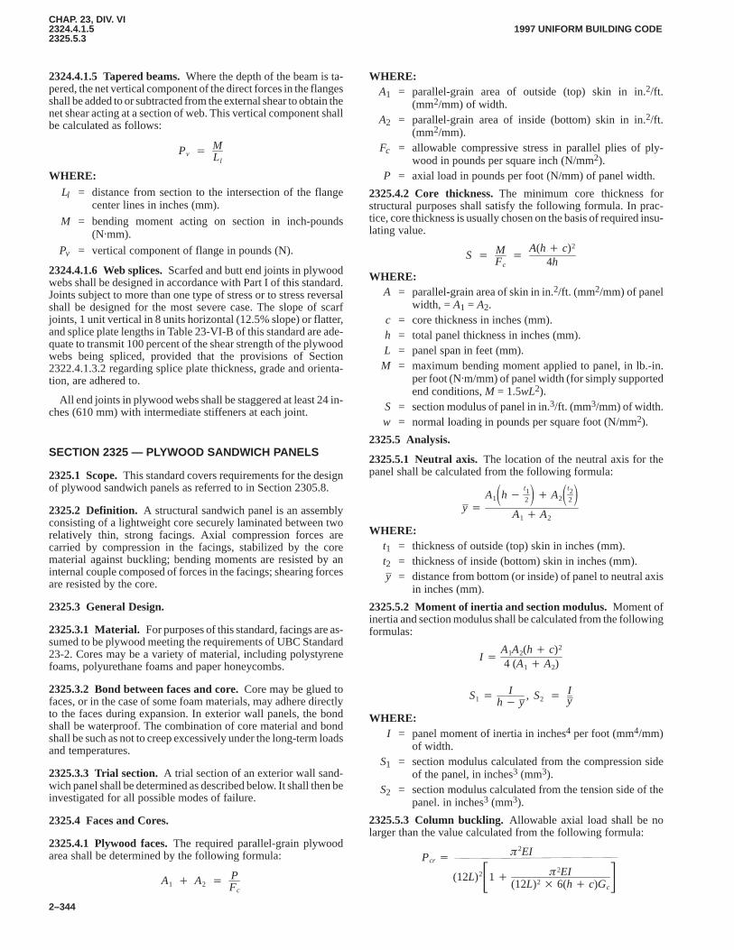
CHAP. 23, DIV. VI2324.4.1.52325.5.3
1997 UNIFORM BUILDING CODE
2–344
2324.4.1.5 Tapered beams.Where the depth of the beam is ta-pered, the net vertical component of the direct forces in the flangesshall be added to or subtracted from the external shear to obtain thenet shear acting at a section of web. This vertical component shallbe calculated as follows:
Pv � MLl
WHERE:Ll = distance from section to the intersection of the flange
center lines in inches (mm).
M = bending moment acting on section in inch-pounds(N�mm).
Pv = vertical component of flange in pounds (N).
2324.4.1.6 Web splices.Scarfed and butt end joints in plywoodwebs shall be designed in accordance with Part I of this standard.Joints subject to more than one type of stress or to stress reversalshall be designed for the most severe case. The slope of scarfjoints, 1 unit vertical in 8 units horizontal (12.5% slope) or flatter,and splice plate lengths in Table 23-VI-B of this standard are ade-quate to transmit 100 percent of the shear strength of the plywoodwebs being spliced, provided that the provisions of Section2322.4.1.3.2 regarding splice plate thickness, grade and orienta-tion, are adhered to.
All end joints in plywood webs shall be staggered at least 24 in-ches (610 mm) with intermediate stiffeners at each joint.
SECTION 2325 — PLYWOOD SANDWICH PANELS
2325.1 Scope.This standard covers requirements for the designof plywood sandwich panels as referred to in Section 2305.8.
2325.2 Definition. A structural sandwich panel is an assemblyconsisting of a lightweight core securely laminated between tworelatively thin, strong facings. Axial compression forces arecarried by compression in the facings, stabilized by the corematerial against buckling; bending moments are resisted by aninternal couple composed of forces in the facings; shearing forcesare resisted by the core.
2325.3 General Design.
2325.3.1 Material. For purposes of this standard, facings are as-sumed to be plywood meeting the requirements of UBC Standard23-2. Cores may be a variety of material, including polystyrenefoams, polyurethane foams and paper honeycombs.
2325.3.2 Bond between faces and core.Core may be glued tofaces, or in the case of some foam materials, may adhere directlyto the faces during expansion. In exterior wall panels, the bondshall be waterproof. The combination of core material and bondshall be such as not to creep excessively under the long-term loadsand temperatures.
2325.3.3 Trial section.A trial section of an exterior wall sand-wich panel shall be determined as described below. It shall then beinvestigated for all possible modes of failure.
2325.4 Faces and Cores.
2325.4.1 Plywood faces.The required parallel-grain plywoodarea shall be determined by the following formula:
A1 � A2 � PFc
WHERE:A1 = parallel-grain area of outside (top) skin in in.2/ft.
(mm2/mm) of width.A2 = parallel-grain area of inside (bottom) skin in in.2/ft.
(mm2/mm).Fc = allowable compressive stress in parallel plies of ply-
wood in pounds per square inch (N/mm2).P = axial load in pounds per foot (N/mm) of panel width.
2325.4.2 Core thickness.The minimum core thickness forstructural purposes shall satisfy the following formula. In prac-tice, core thickness is usually chosen on the basis of required insu-lating value.
S � MFc
�A(h� c)2
4hWHERE:
A = parallel-grain area of skin in in.2/ft. (mm2/mm) of panelwidth, = A1 = A2.
c = core thickness in inches (mm).h = total panel thickness in inches (mm).L = panel span in feet (mm).
M = maximum bending moment applied to panel, in lb.-in.per foot (N�m/mm) of panel width (for simply supportedend conditions, M = 1.5wL2).
S = section modulus of panel in in.3/ft. (mm3/mm) of width.w = normal loading in pounds per square foot (N/mm2).
2325.5 Analysis.
2325.5.1 Neutral axis.The location of the neutral axis for thepanel shall be calculated from the following formula:
y �A1�h�
t12� � A2�t2
2�
A1 � A2
WHERE:t1 = thickness of outside (top) skin in inches (mm).t2 = thickness of inside (bottom) skin in inches (mm).y = distance from bottom (or inside) of panel to neutral axis
in inches (mm).
2325.5.2 Moment of inertia and section modulus.Moment ofinertia and section modulus shall be calculated from the followingformulas:
I �A1A2(h� c)2
4 (A1 � A2)
S1 �I
h� y, S2 � I
y
WHERE:I = panel moment of inertia in inches4 per foot (mm4/mm)
of width.S1 = section modulus calculated from the compression side
of the panel, in inches3 (mm3).S2 = section modulus calculated from the tension side of the
panel. in inches3 (mm3).
2325.5.3 Column buckling.Allowable axial load shall be nolarger than the value calculated from the following formula:
(12L)2�1� �2EI(12L)2 � 6(h� c)Gc
�Pcr �
�2EI
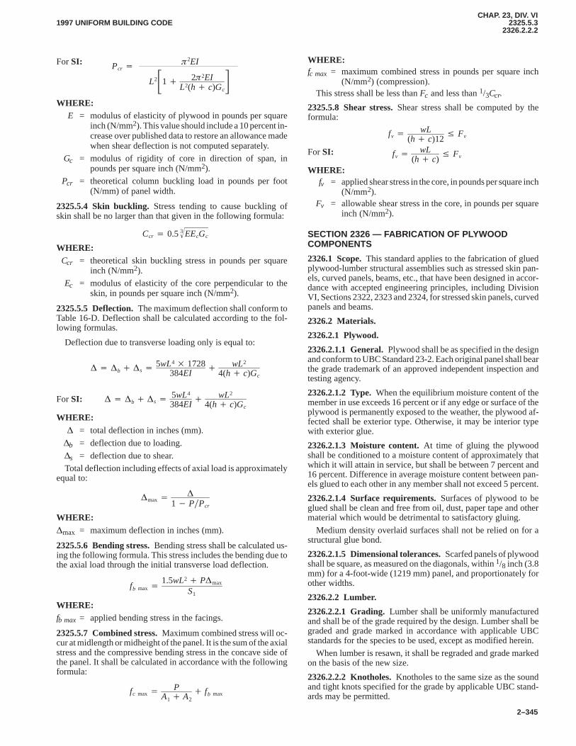
CHAP. 23, DIV. VI2325.5.3
2326.2.2.21997 UNIFORM BUILDING CODE
2–345
For SI:
L2�1� 2�2EIL2(h� c)Gc
�Pcr �
�2EI
WHERE:E = modulus of elasticity of plywood in pounds per square
inch (N/mm2). This value should include a 10 percent in-crease over published data to restore an allowance madewhen shear deflection is not computed separately.
Gc = modulus of rigidity of core in direction of span, inpounds per square inch (N/mm2).
Pcr = theoretical column buckling load in pounds per foot(N/mm) of panel width.
2325.5.4 Skin buckling.Stress tending to cause buckling ofskin shall be no larger than that given in the following formula:
Ccr � 0.5 EEcGc3�
WHERE:Ccr = theoretical skin buckling stress in pounds per square
inch (N/mm2).
Ec = modulus of elasticity of the core perpendicular to theskin, in pounds per square inch (N/mm2).
2325.5.5 Deflection.The maximum deflection shall conform toTable 16-D. Deflection shall be calculated according to the fol-lowing formulas.
Deflection due to transverse loading only is equal to:
� � �b � �s � 5wL4 � 1728384EI
� wL2
4(h� c)Gc
For SI: � � �b � �s � 5wL4
384EI� wL2
4(h� c)Gc
WHERE:� = total deflection in inches (mm).
�b = deflection due to loading.
�s = deflection due to shear.
Total deflection including effects of axial load is approximatelyequal to:
�max� �
1� P�Pcr
WHERE:�max = maximum deflection in inches (mm).
2325.5.6 Bending stress.Bending stress shall be calculated us-ing the following formula. This stress includes the bending due tothe axial load through the initial transverse load deflection.
fb max �1.5wL2 � P�max
S1
WHERE:fb max = applied bending stress in the facings.
2325.5.7 Combined stress.Maximum combined stress will oc-cur at midlength or midheight of the panel. It is the sum of the axialstress and the compressive bending stress in the concave side ofthe panel. It shall be calculated in accordance with the followingformula:
fc max � PA1 � A2
� fb max
WHERE:fc max = maximum combined stress in pounds per square inch
(N/mm2) (compression).This stress shall be less than Fc and less than 1/3Ccr.
2325.5.8 Shear stress.Shear stress shall be computed by theformula:
fv � wL(h� c)12
� Fv
For SI: fv � wL(h� c)
� Fv
WHERE:fv = applied shear stress in the core, in pounds per square inch
(N/mm2).Fv = allowable shear stress in the core, in pounds per square
inch (N/mm2).
SECTION 2326 — FABRICATION OF PLYWOODCOMPONENTS
2326.1 Scope.This standard applies to the fabrication of gluedplywood-lumber structural assemblies such as stressed skin pan-els, curved panels, beams, etc., that have been designed in accor-dance with accepted engineering principles, including DivisionVI, Sections 2322, 2323 and 2324, for stressed skin panels, curvedpanels and beams.
2326.2 Materials.
2326.2.1 Plywood.
2326.2.1.1 General.Plywood shall be as specified in the designand conform to UBC Standard 23-2. Each original panel shall bearthe grade trademark of an approved independent inspection andtesting agency.
2326.2.1.2 Type.When the equilibrium moisture content of themember in use exceeds 16 percent or if any edge or surface of theplywood is permanently exposed to the weather, the plywood af-fected shall be exterior type. Otherwise, it may be interior typewith exterior glue.
2326.2.1.3 Moisture content.At time of gluing the plywoodshall be conditioned to a moisture content of approximately thatwhich it will attain in service, but shall be between 7 percent and16 percent. Difference in average moisture content between pan-els glued to each other in any member shall not exceed 5 percent.
2326.2.1.4 Surface requirements.Surfaces of plywood to beglued shall be clean and free from oil, dust, paper tape and othermaterial which would be detrimental to satisfactory gluing.
Medium density overlaid surfaces shall not be relied on for astructural glue bond.
2326.2.1.5 Dimensional tolerances.Scarfed panels of plywoodshall be square, as measured on the diagonals, within 1/8 inch (3.8mm) for a 4-foot-wide (1219 mm) panel, and proportionately forother widths.
2326.2.2 Lumber.
2326.2.2.1 Grading.Lumber shall be uniformly manufacturedand shall be of the grade required by the design. Lumber shall begraded and grade marked in accordance with applicable UBCstandards for the species to be used, except as modified herein.
When lumber is resawn, it shall be regraded and grade markedon the basis of the new size.
2326.2.2.2 Knotholes.Knotholes to the same size as the soundand tight knots specified for the grade by applicable UBC stand-ards may be permitted.
CHAP. 23, DIV. VI2326.2.2.32326.3.5.2
1997 UNIFORM BUILDING CODE
2–346
2326.2.2.3 Moisture content.At time of gluing, the lumbershall be conditioned to a moisture content of approximately thatwhich it will attain in service, but shall be between 7 percent and16 percent.
The range of moisture content of the various pieces assembledinto a single panel or flange of a beam shall not exceed 5 percent.
2326.2.2.4 Surface requirements.Surfaces of lumber to beglued shall be clean and free from oil, dust and other foreignmatter which would be detrimental to satisfactory gluing.
Each piece of lumber shall be machine finished, but not sanded,to a smooth surface with a maximum allowable variation of1/64 inch (0.40 mm) in the surface to be glued.
Warp, twist, cup or other characteristics which would preventintimate contact of adjacent glued surfaces shall not be permitted.
2326.2.2.5 Flanges.Lumber for laminated flanges of beams andribs for curved panels shall conform with the applicable require-ments of ANSI/AITC Standard A190.1 and ASTM D 3737 re-gardless of the number of laminations.
2326.2.2.6 Transverse members.Lumber for headers, block-ing and stiffeners shall be of minimum 2-inch (51 mm) nominalthickness and Standard Grade or higher Douglas fir or West Coasthemlock or equal.
2326.2.3 Glue.
2326.2.3.1 General.Mixing, spreading, storage life, pot life andworking life, and assembly time and temperature shall be in accor-dance with the manufacturer’s recommendations.
2326.2.3.2 Interior type. When the equilibrium moisture con-tent of the member in use does not exceed 16 percent, glue may becasein type, containing a mold inhibitor, and conforming withASTM D 3024.
2326.2.3.3 Exterior type.When the equilibrium moisture con-tent of the member in use exceeds 16 percent, glue shall be of aphenol, resorcinol or melamine base and conform to ASTM D3024 and D 2559 and APA AFG-01.
2326.3 Fabrication.
2326.3.1 General.Units may be assembled in a one-step pro-cess using either nail-gluing or mechanical pressure includingpressure from clamps, presses, or other reasonably uniform mea-surable pressure, externally applied, to attach the plywood to theframing. If the unit is longer than available lengths of plywood, theskins and webs shall be spliced to full length, either with scarfjoints, or butt joints with glued splice plates. Flange laminations ofbeams having glue lines parallel to the web may be glued at thesame time as webs or preassembled. In either case, the laminatingshall conform to the applicable requirements of ANSI/AITC Stan-dard A1901.1 and ASTM D 3737.
If more than one unit is pressed at a time, care shall be taken toprevent distortion of any core material used in the assembly.
All cutouts for openings shall be reinforced as required in thedesign.
2326.3.2 Surfacing.The edges of framing members to whichplywood skins or webs are to be glued shall be surfaced prior toassembly so that the members have a maximum variation in sur-face of 1/64 inch (0.4 mm) and 1/32 inch (0.8 mm) in depth for allframing members (allowing for actual thickness of any spliceplates superimposed on blocking). This variation in depth shallapply to each framing member, as well as to the entire group offraming members within a unit.
Stiffeners for glued beams shall be surfaced prior to gluing sothat their surfaces are flush with those of the flanges within1/32 inch (0.8 mm), allowing for any superimposed plywood spliceplates.
For glued beams, flanges at all stiffener locations shall have amaximum deviation from square of 1/16 inch (1.6 mm) in 6 inches(152 mm), measured perpendicular to an accurate square gage.Twist or bow which would prevent intimate contact of webs, orwould cause the beam to deform, shall not be permitted.
Surfaces of high density overlaid plywood to be glued shall beroughened, as by a light sanding, before gluing.
2326.3.3 Glued joints.Plywood skins and webs shall be gluedto all framing members over their full contact area, except thatsolid core curved panels may have the width and spacing of thecontact area specified in the design.
All splice plates at butt joints in plywood skins and webs and allscarfed end joints shall be glued over their full contact area. Scarfjoints shall be glued, under pressure, and those plywood surfacesin contact with the framing members shall be sanded smooth withtape removed prior to assembly.
2326.3.4 End joints in lumber.
2326.3.4.1 General.End joints in stringers, ribs and flange ma-terial, including shims, shall be as specified in the design for thegrade and stress used.
2326.3.4.2 Scarf joints.Scarf joints in the lumber flanges shallbe well scattered throughout. Unless otherwise specified, in ad-joining laminations they shall be spaced not closer than 16 timesthe lamination thickness, measured from center to center. If shownon the approved plans, this spacing may be decreased to zerowhere the design indicates no bending stress. In flanges of three orless laminations, only one scarf joint shall be allowed at any onecross section; in flanges of four or more laminations, two scarfjoints shall be allowed at the same cross section. Scarf slopes shallnot be steeper than 1 unit vertical in 10 units horizontal (10%slope) unless otherwise permitted by the design.
2326.3.4.3 Butt joints.Stringer, rib and flange laminations shallnot be butt jointed unless specified in the design. If permitted andnot otherwise stipulated in the design, they shall be spaced at least30 times the lamination thickness in adjoining (actually touching)laminations, and at least 10 times the lamination thickness innonadjoining laminations.
2326.3.5 End joints in plywood.
2326.3.5.1 Scarf joints.When a skin or web is composed ofpanels less than full length, end joints shall be scarfed and glued,unless butt joints with plywood splice plates are permitted by thedesign. Slope of scarf joints shall not be steeper than 1 unit verticalin 8 units horizontal (12.5% slope).
2326.3.5.2 Butt joints in skins of panels.Butt joints shall bebacked with plywood splice plates glued to one side of the skin.For ribbed panels, when glued during panel assembly the spliceplate shall be backed with one or more pieces of lumber blocking,accurately machined in width so as to obtain adequate pressure.Lumber blocking by itself shall not be used for splicing skinsunless shown on the approved plans.
Splice plates shall be centered over the butt joint, and shall havetheir grain parallel with that of the skin. Plates shall extend towithin 1/4 inch (6.4 mm) of the ribs; the latter shall not be notchedto receive them, unless permitted by the design. Splice plates shallbe at least equal in thickness to the skin, except that minimumthickness shall be 1/2 inch (12.7 mm) if nail- or staple-glued.Minimum splice plate lengths shall be as shown in Table 23-VI-B.
CHAP. 23, DIV. VI2326.3.5.2
2326.51997 UNIFORM BUILDING CODE
2–347
Solid plywood core panels shall be scarf jointed to length if sospecified by the design. If designated on the approved plans, jointsin solid plywood core panels may be tightly butted, provided theywill conform readily with the curvature of the surface. Spacing ofbutt joints shall not be less than 10 times the lamination thickness.
2326.3.5.3 Butt joints in webs of beams.Butt joints shall bestaggered at least 24 inches (610 mm).
Splices at butt joints in webs shall be in accordance with the de-sign. Unless otherwise noted in the design, at all web butt joints aplywood shear splice plate shall be centered over the joint and pre-glued prior to assembly. The plate shall extend to within 1/4 inch(6.4 mm) of each flange on the inside of the beam, shall be at leastequal in thickness to the web being spliced, of a length as specifiedon the approved plans, and shall have its grain parallel to that ofthe web. No splice plate shall consist of more than two pieces ofplywood. Where the design provides for the stiffeners to act as theweb splices, web butt joints shall be located over the center of thestiffener, within 1/16 inch (1.6 mm), and webs shall be glued to thestiffener. The stiffener alone may be used as a splice plate when theweb is 24 inches (610 mm) deep or less, and is no thicker than3/8 inch (9.5 mm), or carries no more shear than would be allowedon a 3/8-inch (9.5 mm) panel.
2326.3.6 Stiffener location for beams.Stiffeners shall beplaced as shown on the approved plans, but in any case they shallbe spaced not to exceed 4 feet (1219 mm) on centers, and atreactions and other concentrated load joints.
Stiffeners shall be held in tight contact with the flanges bypositive lateral pressure during fabrication.
2326.3.7 Assembly.Ribs, stringers, flanges and other framingmembers shall be assembled accurately and shall be square. Jointsshall be made tight, and all framing members shall be of uniformthickness within 1/32 inch (0.8 mm).
All gluing surfaces shall be flush within 1/32 inch (0.8 mm).
Plywood may be lightly tacked to framing members so as tomaintain alignment during pressing.
2326.3.8 Tongue-and-groove edge joint.Where a tongue-and-groove-type edge joint for stressed skin and curved panels is spe-cified (and not otherwise detailed), the longitudinal framingmember forming the tongue shall be of at least 2-inch (51 mm)nominal thickness, set out 3/4 inch (19 mm) from the plywoodedge plus or minus 1/16 inch (1.6 mm). Edges of the tongue shall beeased so as to leave a flat shoulder at least 3/8 inch (9.5 mm) wide.Any corresponding framing member forming the base of thegroove shall be set back 1/4 inch to 1 inch (6.4 mm to 25 mm) morethan the amount by which the tongue protrudes. Abutting plywoodedges may be chamfered. One face may be cut back 1/16 inch (1.6mm) to provide a tight fit for the opposite face.
2326.3.9 Nail- and pressure-gluing.Curved units shall be lam-inated over a form. Means shall be used that will provide closecontact and substantially uniform pressure on panels and beams.Application of pressure or nailing may start at any point, but shallprogress to an end or ends. Movement of the units shall not bepermitted while the glue is setting.
Where clamping or other positive mechanical means are used,the pressure on the net framing area shall be sufficient to provideadequate contact and ensure good glue bond. Pressure shall beuniformly distributed by caul plates, beams or other effectivemeans.
In place of mechanical pressure methods, nail-gluing may beused for bonding plywood to lumber and plywood to plywood, butshall not be used for bonding lumber to lumber. Regardless of the
method used, the resulting glue line must meet the required stan-dards. Nails shall be at least 4d for plywood up to 3/8 inch (9.5 mm)thick, and 6d for 1/2-inch to 7/8-inch (12.7 mm to 22 mm) plywood,and 8d for 1-inch to 11/8-inch (25 mm to 29 mm) plywood. Nailsshall be spaced not to exceed 3 inches (76 mm) along the ribs forplywood through 3/8 inch (9.5 mm), or 4 inches (102 mm) forplywood 1/2 inch (12.7 mm) and thicker, using one line for gluelines 2 inches (51 mm) wide or less, two lines for glue lines morethan 2 inches (51 mm) wide and up to 4 inches (102 mm) wide,three lines for glue lines up to 10 inches (254 mm) wide and fourlines for 12-inch-wide (305 mm) glue lines. (If shorter nail lengthsare used in order to avoid penetrating the opposite face, spacingshall be decreased in proportion to actual penetration.)
Panels having solid plywood cores may be glued using staplesor nails, following a schedule of demonstrated effectiveness, butin no case spaced farther apart than 6 inches (152 mm) both ways.Length of fasteners is limited by the available thickness of thelaminations. Additional nailing, into temporary solid framing,may be required to provide close contact for adequate glue bonds.
In any case, it shall be the responsibility of the fabricator to pro-duce a glue bond which meets or exceeds the requirements of thisdivision.
2326.3.10 Insulation and ventilation. In hollow panels, insu-lating and vapor-barrier materials and ventilation provided as spe-cified in the design shall be securely fastened in the assembly insuch a way that they cannot interfere with the process of gluing theplywood skins to the framing members or with the ventilationpattern.
When specified, longitudinal sections shall be vented throughblocking and headers on the cool side of the insulation. Provisionshall be made to line up the ventholes in assembling panels, with adefinite ventilation pattern leading to the outdoors. Framingmembers shall not be notched for ventilation, unless shown on theapproved plans.
2326.4 Identification. Each member shall be identified by theappropriate trademark of the approved independent inspectionand testing agency, legibly applied so as to be clearly visible. If thestrength of one surface of a beam or panel is different from the oth-er, the top surface shall be identified.
2326.5 Test Samples.When glue bond test samples are takenfrom a member and from trim, they shall be taken as coresapproximately 2 inches (51 mm) in diameter, drilled perpen-dicular to the plane of the skins or webs, and no deeper than3/4 inch (19 mm) into any framing member. Samples at beamflanges shall be taken from the ends of the beams only. Centers ofcores shall normally be located in the top corner of the beam atpoints within 2 inches (51 mm) from one edge and up to 6 inches(152 mm) from the other.
No samples shall be taken from the same skin or web closer to-gether than 12 inches (305 mm), except as detailed in Exception 2.Samples shall be taken at a distance from the panel ends notgreater than the panel depth.
EXCEPTIONS: 1. One sample may be taken from one of the out-side longitudinal framing members, within the outer fourth points ofthe panel length, provided the framing member is notched no deeperthan 1/2 inch (12.7 mm) below its edge. The other outside longitudinalframing member may be sampled similarly, but at the opposite end ofthe panel.
2. Two samples per butt joint at any one cross section may be takenfrom skin or web splice plates. They shall be located midway betweenlongitudinal framing members, and shall be aligned longitudinally, oneon each side of the butt joint.
Samples through beam web splice plates shall be taken withinthe middle half of the span, at the center line of the beam depth.
CHAP. 23, DIV. VI2326.52326.6.3.4.1
1997 UNIFORM BUILDING CODE
2–348
Where the core of curved panels consists of solid plywood or asolid core material, only one core shall be taken at any one crosssection. Cross sections shall be no closer than 12 inches (305 mm)along the arc. Not more than four cores shall be taken from a4-foot-wide (1219 mm) panel, with a proportionate numberlimited to other widths. Ribs in such panels shall be sampled asrequired by this section, except that at ribs the core shall not extendmore than 3/4 inch (19 mm) into the rib.
Samples may be taken from other locations when approved bythe building official.
2326.6 Testing of Glued Joints.
2326.6.1 General.This section shall govern all glued jointswhich have not been subjected to prior inspection and testing suchas the glue line between plywood and lumber as contained inASTM D 1101 and AITC 200. These joints shall be referred to as“secondary” glue lines. Glued joints subjected to prior testingsuch as those in plywood shall be referred to as “primary” gluelines. Before testing, specimens shall be allowed to cure.
All secondary glue line testing shall be performed by approvedtesting agencies. Test specimens containing localized defects per-mitted by the grade of the material involved shall be discarded.
2326.6.2 Lumber-plywood side grain combinations.
2326.6.2.1 Selection of test samples.Lumber-plywood sidegrain samples shall be taken from members selected at random.They shall consist of 2-inch-diameter (51 mm) core of adequatedepth and location to yield sufficient material on both sides of thesecondary glue line.
Members to be sampled shall be selected to include productionvariables such as different lots of material, glue batches, shifts andcrews.
Trim may be acceptable in lieu of cores for sampling purposes ifit is truly representative of the member.
2326.6.2.2 Dry shear strength testing.Lumber and plywoodside grain specimens shall be tested in a block shear tool with theload applied through a self-aligning seat to ensure uniform lateraldistribution of the load. Rate of load application shall be 0.2 inch(5.1 mm) per minute. Ultimate load shall be read to the nearest5 pounds (22.2 N) and wood failure shall be determined to thenearest 5 percent.
2326.6.2.3 Durability testing.
2326.6.2.3.1 Interior. This test method shall be used in all caseswhere the durability requirement for the completed component isInterior.
Lumber and plywood side grain specimens shall be submergedin water at room temperature for a period of four hours and thendried at a temperature between 100°F and 105°F (37.8°C. and40.6°C) for a period of 19 hours with sufficient air circulation indrying cabinet to lower moisture content of specimen to a maxi-mum of 8 percent based on oven-dry weight. This test procedureshall be conducted through three cycles, unless all specimens havefailed. All specimens shall be inspected after the first and thirdcycles and all failures recorded. Total continuous delamination1 inch (25 mm) along the edge ofthe test specimen and 1/4 inch (6.4mm) deep shall be considered as failure.
2326.6.2.3.2 Exterior.This test method shall be used where thetest specimen contains exterior-type adhesives throughout andwhere the durability requirement for the completed component isExterior.
Lumber and plywood specimens shall be cycled by one of thefollowing methods:
1. Cold soak. Test specimens shall be submerged in water atroom temperature for 48 hours and then dried for eight hours at atemperature of 145°F (62.8°C) [± 5°F (2.8°C)], followed by twocycles of soaking for 16 hours and drying for eight hours underconditions described above. The specimens shall be soaked againfor a period of 16 hours.
2. Vacuum pressure. Place the specimens in the pressure vesseland weight them down. Admit water at a temperature of 65°F to80°F (18.3°C. to 26.7°C) in sufficient quantity so that the speci-mens are completely submerged. Separate the specimens by stick-ers, wire screens or other means in such a manner that all end grainsurfaces are freely exposed to the water. Draw a vacuum of 20inches to 25 inches (67.5 kPa to 84.4 kPa) of mercury (at sea level)and hold for 30 minutes. Release the vacuum and apply a pressureof 40 plus or minus 5 pounds per square inch (275.8 kPa ± 34.5kPa) for two hours.
While still wet, the specimens shall be tested in accordance withthe method specified above in Section 2326.6.2.2.
2326.6.2.4 Performance requirements.
2326.6.2.4.1 General.The minimum performance require-ments for laboratory testing of all side grain glue joint specimensshall be as specified in this section. If two or more grainorientations are present in any one test run or combinations of testruns, an adjusted average shear stress performance requirementshall be computed by the weighted average method.
2326.6.2.4.2 Dry shear strength requirements.The speci-mens shall have an average dry strength shear stress as set forth inTable 23-VI-G.
2326.6.2.4.3 Interior durability requirement. Ninety-five per-cent of all specimens shall pass the first cycle and 85 percent shallpass three cycles.
2326.6.2.4.4 Exterior durability requirement. Eighty-fivepercent of more wood failure shall be required for the overallaverage. Ninety percent of all specimens tested shall show 60percent or more wood failure, 80 percent of all specimens testedshall show 80 percent or more wood failure. Failure in any part oftest specimen, except glue failure in the secondary glue bondtested, is wood failure.
2326.6.3 Lumber end joints.
2326.6.3.1 General.Plain scarf joints and finger joints shall betested in accordance with the provisions of ASTM D 1101 andAITC 200.
2326.6.3.2 Selection of test samples.Test samples shall be ob-tained from full-size joints, or from scarf joints selected at randomfrom routine production. The latter shall be taken from the centerline of the lamination containing the scarf being sampled. Nomore than one sample shall be taken from any component crosssection and scarf samples shall not be closer than 4 feet (1219mm).
2326.6.3.3 Dry tension testing.Specimens shall be tested in ac-cordance with AITC 200.
2326.6.3.4 Durability testing.
2326.6.3.4.1 Interior. Test specimens shall be submerged inwater at room temperature for a period of four hours and then driedat a temperature between 100°F and 105°F (37.8°C. and 40.6°C)for a period of 19 hours with sufficient air circulation in dryingcabinet to lower moisture content of specimen to a maximum of 8percent based on oven-dry weight. This test procedure shall beconducted through three cycles, unless all specimens have failed.
CHAP. 23, DIV. VI2326.6.3.4.1
2327.21997 UNIFORM BUILDING CODE
2–349
The specimens then shall be tested dry in accordance with AITC200.
2326.6.3.4.2 Exterior.Test specimens shall be cycled by one ofthe following methods:
1. Cold soak. Test specimens shall be submerged in water atroom temperature for 48 hours and then dried for eight hours at atemperature of 145°F (62.8°C) [± 5°F (2.8°C)], followed by twocycles of soaking for 16 hours and drying for eight hours underconditions described above. The specimens shall be soaked againfor a period of 16 hours.
2. Vacuum pressure. Place the specimens in the pressure ves-sel and weight them down. Admit water at a temperature of 65°Fto 80°F (18.3°C. to 26.7°C) in sufficient quantity so that the speci-mens are completely submerged. Separate the specimens by stick-ers, wire screens, or other means in such a manner that all endgrain surfaces are freely exposed to the water. Draw a vacuum of20 inches to 25 inches (67.5 kPa to 84.4 kPa) of mercury (at sealevel) and hold for 30 minutes. Release the vacuum and apply apressure of 40 plus or minus 5 pounds per square inch (275.8 kPa ±34.5 kPa) for two hours.
The specimens shall then be tested wet in accordance withAITC 200.
2326.6.3.5 Performance requirements.
2326.6.3.5.1 General.The minimum performance require-ments for laboratory testing of all lumber end joint specimensshall be as specified in this section.
2326.6.3.5.2 Dry tension stress requirements.The test speci-mens shall have the tension stresses set forth in Table 23-VI-H. Notest value shall be less than twice the normal allowable stress.
Dry tension wood failure requirements regardless of speciesshall average not less than 80 percent except tests averaging atleast 10,000 pounds per square inch (69 N/mm2) in tension shallnot have less than 70 percent. The minimum requirement for 90percent of the individual specimens shall not be less than 40 per-cent wood failure.
2326.6.3.5.3 Interior durability requirement. Average woodfailure shall not be less than 70 percent.
2326.6.3.5.4 Exterior durability requirement. Average woodfailure shall not be less than 85 percent and the minimum require-ment for 90 percent of the individual specimens shall not be lessthan 50 percent.
2326.6.4 Plywood end joints.
2326.6.4.1 General.Plain plywood scarf joints shall be tested inaccordance with the provisions of this section. Splice butt jointsshall be tested as specified in Section 2326.6.2.
2326.6.4.2 Selection of test samples.Full width scarfs shall beselected at random from routine production. A minimum of 2 per-cent of the scarfs produced shall be sampled. At least 20 speci-mens suitable for testing shall be obtained from each 4 feet (1219mm) of scarf. They shall be equally distributed across the width.
2326.6.4.3 Dry tension.Specimens shall be tested in a tensionmachine equipped with wedge-type grips. Dry tension specimensshall be loaded at a rate of 0.4 inch (10 mm) per minute. Ultimateload shall be read to the nearest 5 pounds (22.2 N) and wood fail-ure on the joined surface estimated to the nearest 5 percent. Woodfailure shall be estimated on the scarf surface of the plies parallelto the direction of the tension load.
2326.6.4.4 Durability.
2326.6.4.4.1 Interior. Interior durability test specimens shall besub-merged in water at room temperature for a period of fourhours and then dried at a temperature between 100°F and 105°F(37.8°C. and 40.6°C) for a period of 19 hours with sufficient aircirculation in drying cabinet to lower moisture content ofspecimen to a maximum of 8 percent based on oven-dry weight.This test procedure shall be conducted through three cycles,unless all specimens have failed. Test specimens showingdelamination on the face or end in excess of 1/16 inch (1.6 mm)deep and 1/2 inch (12.7 mm) long at the scarf glue line shall beconsidered as failing.
2326.6.4.4.2 Exterior.Exterior durability test specimens shallbe cycled by one of the following methods:
1. Cold soak. Test specimens shall be submerged in water atroom temperature for 48 hours and then dried for eight hours at atemperature of 145°F (62.8°C) [± 5°F (2.8°C)], followed by twocycles of soaking for 16 hours and drying for eight hours underconditions described above. The specimens shall be soaked againfor a period of 16 hours.
2. Vacuum pressure. Place the specimens in the pressure ves-sel and weight them down. Admit water at a temperature of 65°Fto 80°F (18.3°C. to 26.7°C) in sufficient quantity so that the speci-mens are completely submerged. Separate the specimens by stick-ers, wire screens, or other means in such a manner that all endgrain surfaces are freely exposed to the water. Draw a vacuum of20 inches to 25 inches of mercury (67.5 kPa to 84.4 kPa) (at sealevel) and hold for 30 minutes. Release the vacuum and apply apressure of 40 ± 5 pounds per square inch (275.8 kPa ± 34.5 kPa)for two hours.
While still wet, the specimens shall be tested in a tension ma-chine equipped with wedge-type grips. Dry tension specimensshall be loaded at a rate of 0.4 inch (10 mm) per minute. Ultimateload shall be read to the nearest 5 pounds (22.2 N) and wood fail-ure on the joined surface estimated to the nearest 5 percent.
2326.6.4.5 Performance requirements.
2326.6.4.5.1 General.The minimum performance require-ments for laboratory testing of all lumber end joint specimensshall be as specified in this section.
2326.6.4.5.2 Dry tension stress.The average tension stress forGroup 1 shall be 4,000 pounds per square inch (28 N/mm2); forGroups 2 and 3, 2,800 pounds per square inch (19 N/mm2); and2,400 pounds per square inch (17 N/mm2) for Group 4, all ad-justed as required for inner ply species. Regardless of species,wood failure shall average not less than 80 percent and the mini-mum requirement for 90 percent of the individual test specimensshall not be less than 50 percent.
2326.6.4.5.3 Durability requirements.
1. Interior. Ninety-five percent of all test specimens shall passone cycle and 85 percent shall pass three cycles.
2. Exterior. Average wood failure shall not be less than 85percent.
SECTION 2327 — ALL-PLYWOOD BEAMS
2327.1 Scope.This part covers requirements for the design ofall-plywood beams as referred to in Section 2305.8.
2327.2 Definition. All-plywood beams are staple-glued struc-tural units consisting of one or more vertical layers of butt-jointedplywood for webs which resist both bending and shear forces. Ply-wood web splice plates located at web joints, and/or one or more
CHAP. 23, DIV. VI2327.22327.6.2
1997 UNIFORM BUILDING CODE
2–350
vertical layers of butt-jointed plywood for flanges, may also bestaple glued to the webs for added resistance to shear and bendingforces, if necessary. Plywood web stiffeners are staple-glued tosingle-layer webs to distribute concentrated loads and resist webbuckling at end supports and interior concentrated load points.(For design of plywood beams consisting of plywood websattached to lumber flanges, see Section 2324 of this division.)
2327.3 Allowable Stresses.Allowable stresses for plywoodused in all-plywood beams shall not exceed the values set forth inTable 23-III-A, except that allowable bending stress may be multi-plied by 2 for five-ply, five-layer plywood, and by 1.7 for three-,four- or five-ply, three-layer plywood. Five-ply, five-layer ply-wood with butt-jointed center ply shall be considered as three-layer plywood for design purposes.
2327.4 Design.
2327.4.1 Bending.The allowable resisting moment for a beamsection shall not exceed the value established by the following for-mula:
M �f IZ
WHERE:f = allowable working stress in bending for plywood, in
pounds per square inch (N/mm2). Also, see Section2327.3.
I = the minimum net moment of inertia, in inches to thefourth power (mm4), of all continuous parallel grain ma-terial at any beam section containing a web or flange buttjoint. Location of the neutral axis shall be calculatedwithout considering butt joints in the web of flanges (ifused). Also, see Section 2327.6.2. A web splice plate (ifused) shall be included in the net amount of inertia onlyif directly glued to the web layer containing the buttjoint.
M = resisting moment in inch-pounds (N�mm).
Z = distance in inches (mm) from the neutral axis to the ex-treme fiber in bending.
2327.4.2 Horizontal shear.The allowable shear on theplywood web shall not exceed the value established by thefollowing formula:
V � vI �tQ
WHERE:I = total moment of inertia, in inches to the fourth power
(mm4), of all parallel grain material in the web andflanges regardless of butt joints. Stiffeners or web spliceplates shall be disregarded.
Q = statical moment about the neutral axis, in inches to thethird power (mm3), of all parallel grain material in theweb and flanges, regardless of butt joints, lying above(or below) the neutral axis. Stiffeners or web spliceplates shall be disregarded.
V = allowable total shear on the section, in pounds (N).Loads may be disregarded that are located within a dis-tance from the support equal to the beam depth.
v = allowable plywood shear stress through the panel thick-ness, in pounds per square inch (N/mm2).
∑t = total shear thickness of continuous webs (and/or websplice plates and stiffeners, if applicable) at the neutral
axis of the section, in inches (mm). Also, see Section2327.6.2.
2327.4.3 Flange-web shear (rolling shear).For beams con-taining plywood flanges, the allowable flange-web shear on gluedjoints shall not exceed the value established by the following for-mula:
V � nsdIQfl
WHERE:d = depth of contact area between flange and web, in inches
(mm).I = total moment of inertia, in inches to the fourth power
(mm4), of all parallel grain material in the web andflanges regardless of butt joint. Stiffeners or web spliceplates shall be disregarded.
n = number of contact surfaces between web and flange.Qfl = statical moment about the neutral axis, in inches to the
third power (mm3), of all parallel grain material in theupper (or lower) flanges, regardless of butt joints.
s = one half of the allowable plywood rolling shear stress, inpounds per square inch (N/mm2).
V = allowable total shear on the section, in pounds (N).Loads may be disregarded that are located within a dis-tance from the support equal to the beam depth.
2327.4.4 Lateral stability. The compression edges of the beamshall be positively restrained from lateral buckling, as by fasteningto structural panel sheathing, framing spaced no further than 24inches (610 mm) on center, and/or by ceiling material.
2327.4.5 Connections.Bolts, lag screws or other similarlarge-diameter connectors shall not be used in web or flange ten-sion areas where bending stresses exceed the allowable values setforth in Table 23-III-A.
2327.5 Materials.
2327.5.1 Plywood.Plywood shall be as required in Section2326.2.1. Plywood pieces cut 41/2 inches (114 mm) or less inwidth for flanges shall be visually inspected after cutting for sizeof knots. Pieces containing knots in face or back plies larger thantwo thirds of the flange width shall not be used in fabricatingflanges for all-plywood beams.
2327.5.2 Glue.Glue shall be as specified in Section 2326.2.3.
2327.5.3 Staples.Staples shall be 16 gage by 7/16-inch (1.6 mmby 11 mm) crown, made from galvanized steel wire. Staple lengthshall be 1/8 inch (3.2 mm) less than the total thickness of materialsjoined.
2327.6 Fabrication.
2327.6.1 General.Plywood beams shall be fabricated with glueand staples. Plywood face grain for webs, flanges, web spliceplates and stiffeners shall be oriented parallel to the span (i.e.,horizontally).
2327.6.2 Web and flange end joints.End joints in plywoodwebs and flanges shall be located as specified in the design. Jointsin any web or flange lamination shall be spaced at least 24 inches(610 mm) from the nearest joint in any other lamination. Insingle-web beams, joints in webs shall be located at least 24 inches(610 mm) from any end or interior support.
Butt joints at ends of plywood web or flange pieces shall betrimmed square and tightly butted [maximum gap 1/32 inch (0.8mm)].

CHAP. 23, DIV. VI2327.6.3
2327.91997 UNIFORM BUILDING CODE
2–351
2327.6.3 Adhesive application.Adhesive shall be spread uni-formly over the full contact area of mating web and/or flange sur-faces.
If web or flange laminations are glued under pressure, suchpressure shall be applied by clamping or other mechanical means.Pressure shall be sufficient to provide adequate contact and ensuregood glue bonds [100 to 150 psi (689 to 1034 kPa) is suggested,unless otherwise specified by the adhesive manufacturer]. Move-ment of the members shall be prevented until the adhesive devel-ops sufficient handling strength as recommended by the adhesivemanufacturer.
In any case, it shall be the responsibility of the fabricator to pro-duce a glue bond which meets or exceeds applicable specifica-tions.
2327.6.4 Staple installation.Staples shall be installed withtheir crowns parallel to the plywood face-grain direction. Staplespacing shall be as shown in Figure 23-VI-1.
Installation of staples may start at any point but shall progress tothe end or ends of each piece. Pressure may be needed during stap-ling to flatten webs and flanges to ensure uniform contact betweenmating glued surfaces.
2327.6.5 Web splices.Splices at butt joints in webs shall be asspecified in the design. Butt joints shall be spliced with a plywoodplate centered over the joint. The splice plate shall be glued overits full contact area and stapled to the web in accordance with Fig-ure 23-VI-1. The plate shall extend to at least 1/4 inch (6.4 mm) of
each flange (if applicable); shall be equal in thickness to the web;shall be of a length as specified in the design or in Table 23-VI-B;and shall have its face-grain direction parallel with that of the web.In multiple-layer webs, the splice plate shall be directly glued tothe web containing the butt joint.
2327.6.6 Web stiffeners.Stiffeners for single-layer webs shallbe located as shown in the design, but in any case they shall beplaced at end supports and at interior concentrated-load points.
The stiffeners shall consist of a plywood plate glued over its fullcontact area and stapled to the web in accordance with Figure23-VI-1. The plate shall extend to at least 1/4 inch (6.4 mm) of eachflange (if applicable); shall be at least equal in thickness to theweb; shall be of a length as specified in the design, but in no caseless than 10 inches (254 mm); and shall have its face-graindirection parallel with that of the web. The end or ends of thestiffener shall extend at least 6 inches (152 mm) beyond the edgesof the support at the end and any interior supports.
Single-layer webs shall be reinforced at cutouts with a plywoodweb stiffener.
2327.7 Identification. Each member shall be identified as spe-cified in Section 2326.4.
2327.8 Test Samples.Test samples shall be as specified in Sec-tion 2326.5.
2327.9 Testing of Glued Joints.Plywood splice butt joints shallbe tested as specified in Section 2326.6.2.
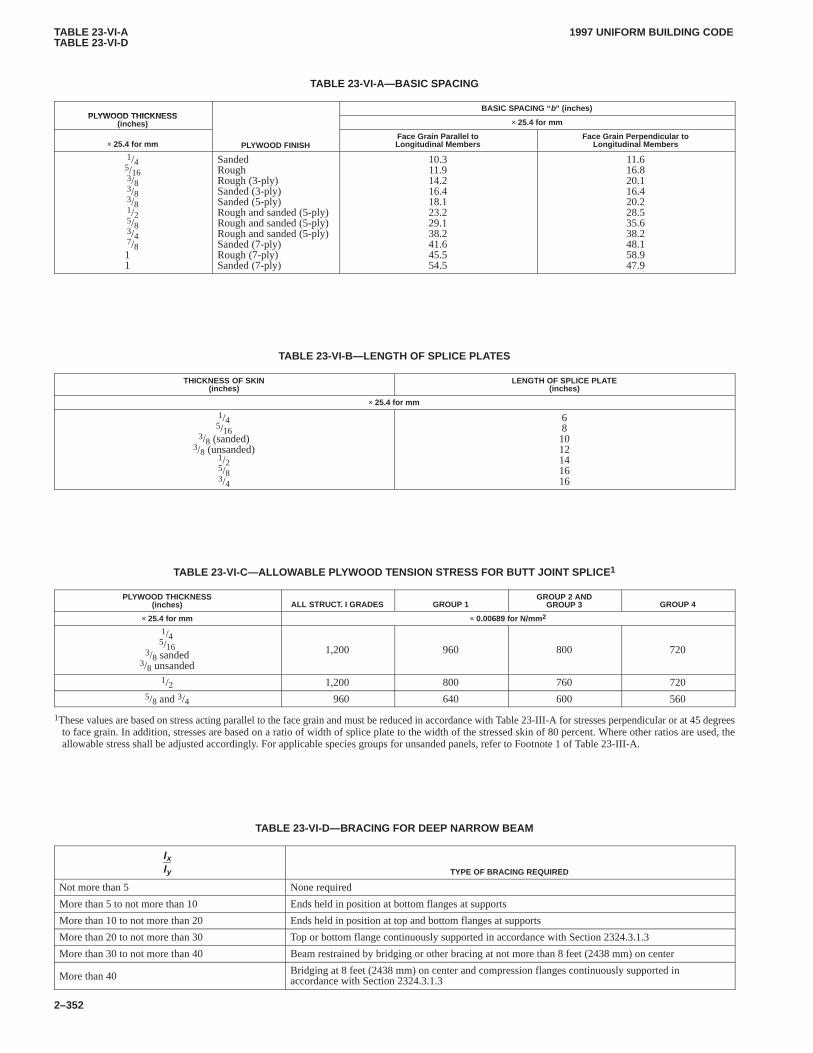
TABLE 23-VI-ATABLE 23-VI-D
1997 UNIFORM BUILDING CODE
2–352
TABLE 23-VI-A—BASIC SP ACING
PLYWOOD THICKNESSBASIC SPACING “ b” (inches)
PLYWOOD THICKNESS(inches) × 25.4 for mm
× 25.4 for mm PLYWOOD FINISHFace Grain Parallel toLongitudinal Members
Face Grain Perpendicular toLongitudinal Members
1/45/163/83/83/81/25/83/47/811
SandedRoughRough (3-ply)Sanded (3-ply)Sanded (5-ply)Rough and sanded (5-ply)Rough and sanded (5-ply)Rough and sanded (5-ply)Sanded (7-ply)Rough (7-ply)Sanded (7-ply)
10.311.914.216.418.123.229.138.241.645.554.5
11.616.820.116.420.228.535.638.248.158.947.9
TABLE 23-VI-B—LENGTH OF SPLICE PLA TES
THICKNESS OF SKIN(inches)
LENGTH OF SPLICE PLATE(inches)
× 25.4 for mm
1/45/16
3/8 (sanded)3/8 (unsanded)
1/25/83/4
681012141616
TABLE 23-VI-C—ALLOWABLE PLYWOOD TENSION STRESS FOR BUTT JOINT SPLICE 1
PLYWOOD THICKNESS(inches) ALL STRUCT. I GRADES GROUP 1
GROUP 2 ANDGROUP 3 GROUP 4
× 25.4 for mm × 0.00689 for N/mm 2
1/45/16
3/8 sanded3/8 unsanded
1,200 960 800 720
1/2 1,200 800 760 7205/8 and 3/4 960 640 600 560
1These values are based on stress acting parallel to the face grain and must be reduced in accordance with Table 23-III-A for stresses perpendicular or at 45 degreesto face grain. In addition, stresses are based on a ratio of width of splice plate to the width of the stressed skin of 80 percent. Where other ratios are used, theallowable stress shall be adjusted accordingly. For applicable species groups for unsanded panels, refer to Footnote 1 of Table 23-III-A.
TABLE 23-VI-D—BRACING FOR DEEP NARROW BEAM
IxIy TYPE OF BRACING REQUIRED
Not more than 5 None required
More than 5 to not more than 10 Ends held in position at bottom flanges at supports
More than 10 to not more than 20 Ends held in position at top and bottom flanges at supports
More than 20 to not more than 30 Top or bottom flange continuously supported in accordance with Section 2324.3.1.3
More than 30 to not more than 40 Beam restrained by bridging or other bracing at not more than 8 feet (2438 mm) on center
More than 40 Bridging at 8 feet (2438 mm) on center and compression flanges continuously supported inaccordance with Section 2324.3.1.3
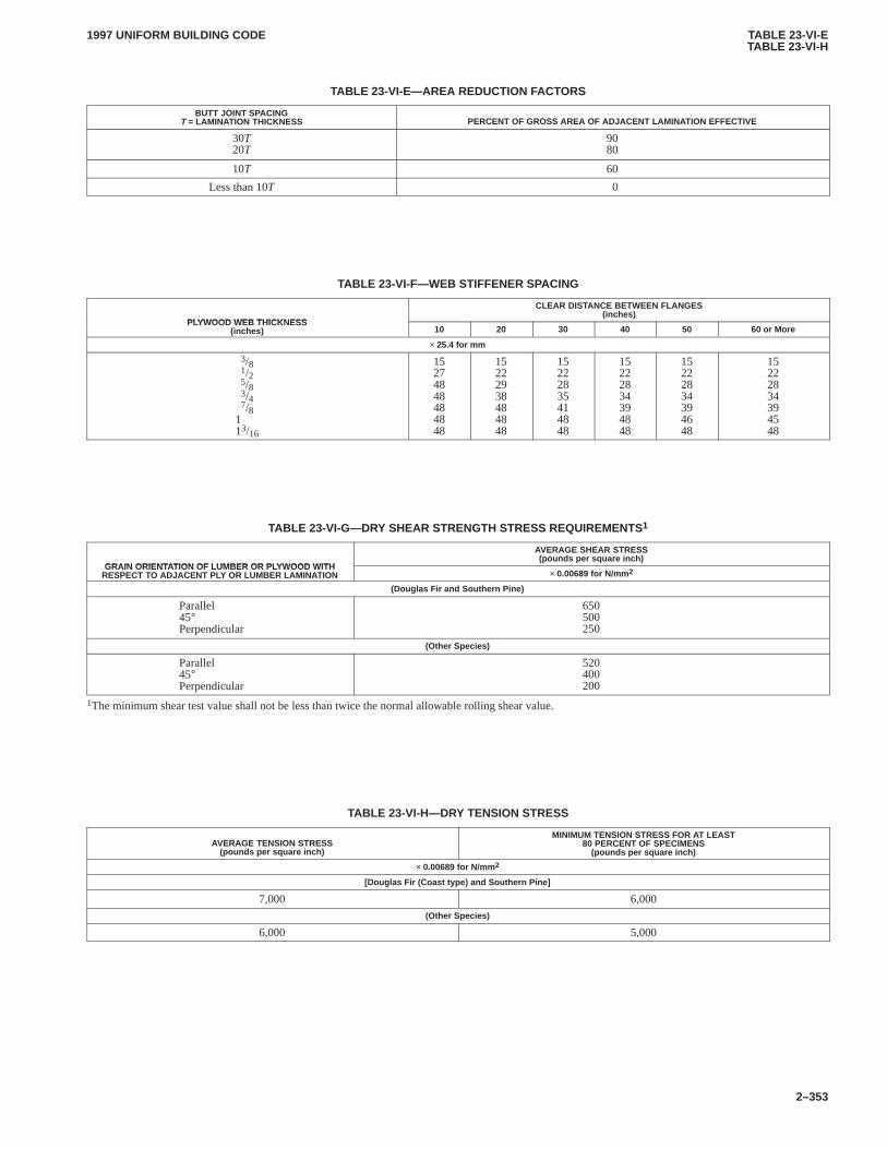
TABLE 23-VI-ETABLE 23-VI-H
1997 UNIFORM BUILDING CODE
2–353
TABLE 23-VI-E—AREA REDUCTION F ACTORS
BUTT JOINT SPACINGT = LAMINATION THICKNESS PERCENT OF GROSS AREA OF ADJACENT LAMINATION EFFECTIVE
30T20T
9080
10T 60
Less than 10T 0
TABLE 23-VI-F—WEB STIFFENER SPACING
PLYWOOD WEB THICKNESS
CLEAR DISTANCE BETWEEN FLANGES(inches)
PLYWOOD WEB THICKNESS(inches) 10 20 30 40 50 60 or More
× 25.4 for mm
3/81/25/83/47/8
113/16
15274848484848
15222938484848
15222835414848
15222834394848
15222834394648
15222834394548
TABLE 23-VI-G—DRY SHEAR STRENGTH STRESS REQUIREMENTS1
GRAIN ORIENTATION OF LUMBER OR PLYWOOD WITH
AVERAGE SHEAR STRESS(pounds per square inch)
GRAIN ORIENTATION OF LUMBER OR PLYWOOD WITHRESPECT TO ADJACENT PLY OR LUMBER LAMINATION × 0.00689 for N/mm 2
(Douglas Fir and Southern Pine)
Parallel45°Perpendicular
650500250
(Other Species)
Parallel45°Perpendicular
520400200
1The minimum shear test value shall not be less than twice the normal allowable rolling shear value.
TABLE 23-VI-H—DRY TENSION STRESS
AVERAGE TENSION STRESS(pounds per square inch)
MINIMUM TENSION STRESS FOR AT LEAST80 PERCENT OF SPECIMENS
(pounds per square inch)
× 0.00689 for N/mm 2
[Douglas Fir (Coast type) and Southern Pine]
7,000 6,000(Other Species)
6,000 5,000
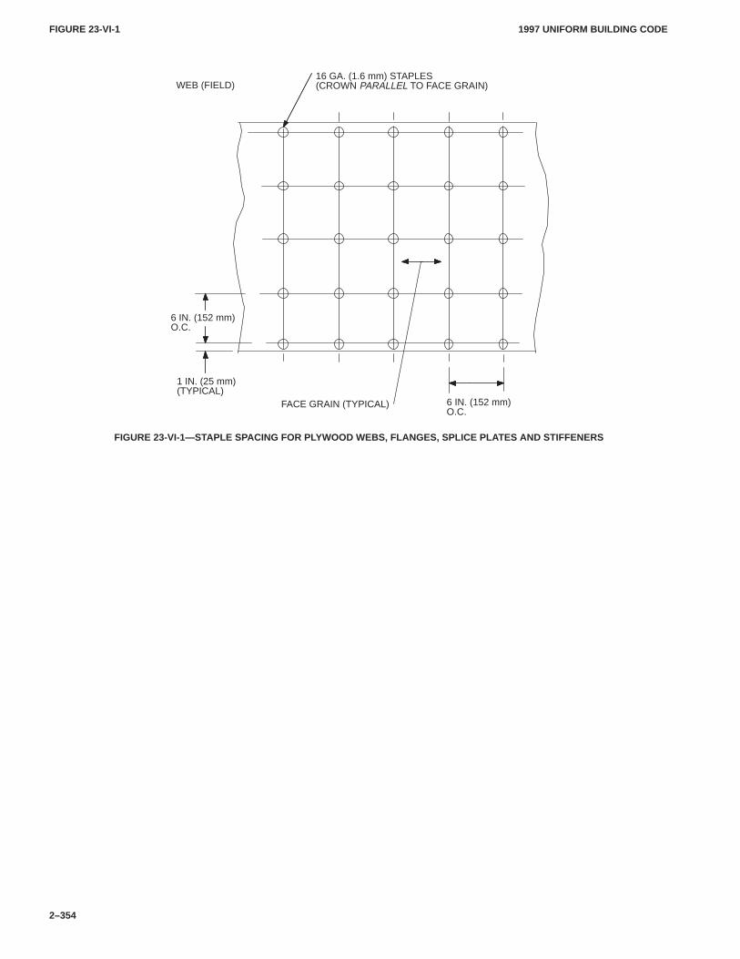
FIGURE 23-VI-1FIGURE 23-VI-1
1997 UNIFORM BUILDING CODE
2–354
FACE GRAIN (TYPICAL)
6 IN. (152 mm)O.C.
1 IN. (25 mm)(TYPICAL)
WEB (FIELD)16 GA. (1.6 mm) STAPLES(CROWN PARALLEL TO FACE GRAIN)
6 IN. (152 mm)O.C.
FIGURE 23-VI-1—STAPLE SPACING FOR PLYWOOD WEBS, FLANGES, SPLICE PLA TES AND STIFFENERS
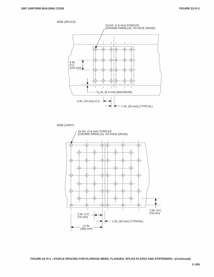
FIGURE 23-VI-1FIGURE 23-VI-1
1997 UNIFORM BUILDING CODE
2–355
3 IN. (76 mm) O.C.
4 IN.O.C.(102 mm)
1 IN. (25 mm) (TYPICAL)
WEB (SPLICE)16 GA. (1.6 mm) STAPLES(CROWN PARALLEL TO FACE GRAIN)
1/4 IN. (6.4 mm) (MAXIMUM)
WEB (JOINT)
16 GA. (1.6 mm) STAPLES(CROWN PARALLEL TO FACE GRAIN)
3 IN. O.C.(76 mm)
1 IN. (25 mm) (TYPICAL)
12 IN.(305 mm)
3 IN. O.C.(76 mm)
FIGURE 23-VI-1—STAPLE SPACING FOR PLYWOOD WEBS, FLANGES, SPLICE PLA TES AND STIFFENERS—(Continued)
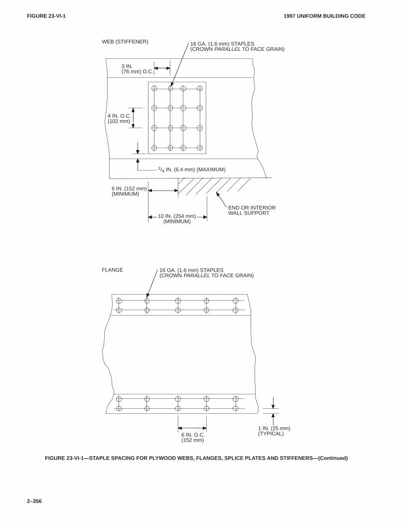
FIGURE 23-VI-1FIGURE 23-VI-1
1997 UNIFORM BUILDING CODE
2–356
3 IN.(76 mm) O.C.
4 IN. O.C.(102 mm)
WEB (STIFFENER) 16 GA. (1.6 mm) STAPLES(CROWN PARALLEL TO FACE GRAIN)
1/4 IN. (6.4 mm) (MAXIMUM)
6 IN. (152 mm)(MINIMUM)
10 IN. (254 mm)(MINIMUM)
END OR INTERIORWALL SUPPORT
16 GA. (1.6 mm) STAPLES(CROWN PARALLEL TO FACE GRAIN)
FLANGE
1 IN. (25 mm)(TYPICAL)6 IN. O.C.
(152 mm)
FIGURE 23-VI-1—STAPLE SPACING FOR PLYWOOD WEBS, FLANGES, SPLICE PLA TES AND STIFFENERS—(Continued)
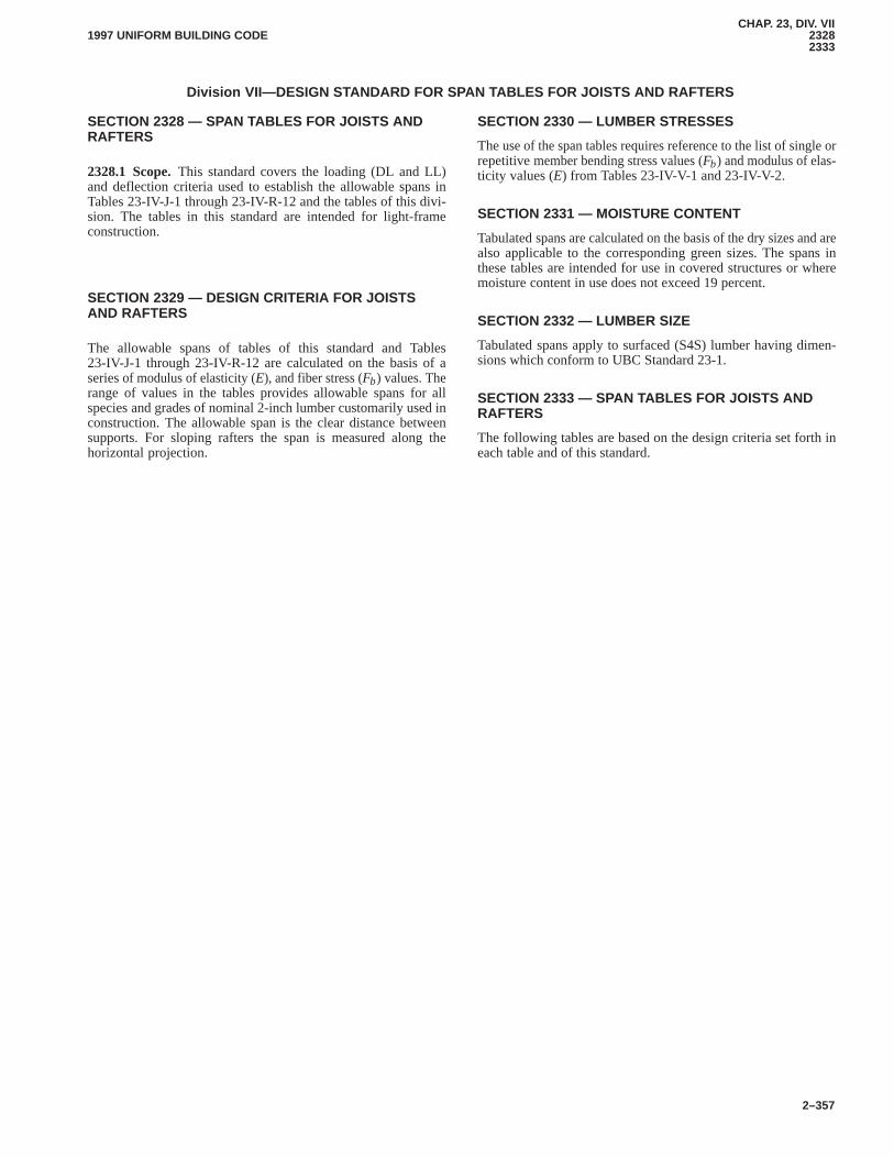
CHAP. 23, DIV. VII23282333
1997 UNIFORM BUILDING CODE
2–357
Division VII—DESIGN STANDARD FOR SPAN TABLES FOR JOISTS AND RAFTERS
SECTION 2328 — SPAN TABLES FOR JOISTS ANDRAFTERS
2328.1 Scope.This standard covers the loading (DL and LL)and deflection criteria used to establish the allowable spans inTables 23-IV-J-1 through 23-IV-R-12 and the tables of this divi-sion. The tables in this standard are intended for light-frameconstruction.CHAP. 23, DIV. VII
SECTION 2329 — DESIGN CRITERIA FOR JOISTSAND RAFTERS
The allowable spans of tables of this standard and Tables23-IV-J-1 through 23-IV-R-12 are calculated on the basis of aseries of modulus of elasticity (E), and fiber stress (Fb) values. Therange of values in the tables provides allowable spans for allspecies and grades of nominal 2-inch lumber customarily used inconstruction. The allowable span is the clear distance betweensupports. For sloping rafters the span is measured along thehorizontal projection.
SECTION 2330 — LUMBER STRESSES
The use of the span tables requires reference to the list of single orrepetitive member bending stress values (Fb) and modulus of elas-ticity values (E) from Tables 23-IV-V-1 and 23-IV-V-2.
SECTION 2331 — MOISTURE CONTENT
Tabulated spans are calculated on the basis of the dry sizes and arealso applicable to the corresponding green sizes. The spans inthese tables are intended for use in covered structures or wheremoisture content in use does not exceed 19 percent.
SECTION 2332 — LUMBER SIZE
Tabulated spans apply to surfaced (S4S) lumber having dimen-sions which conform to UBC Standard 23-1.
SECTION 2333 — SPAN TABLES FOR JOISTS ANDRAFTERS
The following tables are based on the design criteria set forth ineach table and of this standard.

TABLE 23-VII-J-1TABLE 23-VII-J-1
1997 UNIFORM BUILDING CODE
2–358
TABLE 23-VII-J-1—FLOOR JOISTS WITH L/360 DEFLECTION LIMITSThe allowable bending stress ( Fb ) and modulus of elasticity (E) used in this table shall be from T ables 23-IV-V-1 and 23-IV-V-2 only .
DESIGN CRITERIA:Deflection — For 50 psf (2.4 kN/m2) live load.Limited to span in inches (mm) divided by 360.Strength — Live load of 50 psf (2.4 kN/m2) plus dead load of 10 psf (0.48 kN/m2) determines the required bending design value.
JoistSize(in)
Spac-ing(in) Modulus of Elasticity , E, in 1,000,000 psi ( × 0.00689 for N/mm 2)
× 25.4 for mm 0.8 0.9 1.0 1.1 1.2 1.3 1.4 1.5 1.6 1.7 1.8 1.9 2.0 2.1 2.2 2.3 2.4
12.0 7-11 8-3 8-6 8-9 9-1 9-3 9-6 9-9 9-11 10-2 10-4 10-6 10-9 10-11 11-1 11-3 11-5
2 × 616.0 7-2 7-6 7-9 8-0 8-3 8-5 8-8 8-10 9-1 9-3 9-5 9-7 9-9 9-11 10-1 10-2 10-4
2 × 619.2 6-9 7-0 7-3 7-6 7-9 7-11 8-2 8-4 8-6 8-8 8-10 9-0 9-2 9-4 9-6 9-7 9-9
24.0 6-3 6-6 6-9 7-0 7-2 7-4 7-7 7-9 7-11 8-1 8-3 8-4 8-6 8-8 8-9 8-11 9-1
12.0 10-5 10-10 11-3 11-7 11-11 12-3 12-7 12-10 13-1 13-5 13-8 13-11 14-2 14-4 14-7 14-10 15-0
2 × 816.0 9-6 9-10 10-2 10-6 10-10 11-1 11-5 11-8 11-11 12-2 12-5 12-7 12-10 13-1 13-3 13-5 13-8
2 × 819.2 8-11 9-3 9-7 9-11 10-2 10-6 10-9 11-0 11-3 11-5 11-8 11-11 12-1 12-3 12-6 12-8 12-10
24.0 8-3 8-7 8-11 9-2 9-6 9-9 10-0 10-2 10-5 10-8 10-10 11-0 11-3 11-5 11-7 11-9 11-11
12.0 13-3 13-10 14-4 14-9 15-2 15-7 16-0 16-5 16-9 17-1 17-5 17-9 18-0 18-4 18-7 18-11 19-2
2 × 1016.0 12-1 12-7 13-0 13-5 13-10 14-2 14-7 14-11 15-2 15-6 15-10 16-1 16-5 16-8 16-11 17-2 17-5
2 × 1019.2 11-4 11-10 12-3 12-8 13-0 13-4 13-8 14-0 14-4 14-7 14-11 15-2 15-5 15-8 15-11 16-2 16-5
24.0 10-7 11-0 11-4 11-9 12-1 12-5 12-8 13-0 13-3 13-7 13-10 14-1 14-4 14-7 14-9 15-0 15-2
12.0 16-2 16-10 17-5 18-0 18-6 19-0 19-6 19-11 20-4 20-9 21-2 21-7 21-11 22-3 22-8 23-0 23-4
2 × 1216.0 14-8 15-3 15-10 16-4 16-10 17-3 17-8 18-1 18-6 18-10 19-3 19-7 19-11 20-3 20-7 20-10 21-2
2 × 1219.2 13-10 14-4 14-11 15-4 15-10 16-3 16-8 17-0 17-5 17-9 18-1 18-5 18-9 19-1 19-4 19-8 19-11
24.0 12-10 13-4 13-10 14-3 14-8 15-1 15-5 15-10 16-2 16-6 16-10 17-1 17-5 17-8 18-0 18-3 18-6
12.0 743 803 862 918 973 1,026 1,078 1,129 1,179 1,228 1,275 1,322 1,368 1,413 1,458 1,502 1,545
F16.0 817 884 949 1,011 1,071 1,130 1,187 1,243 1,298 1,351 1,404 1,455 1,506 1,555 1,604 1,653 1,700
Fb 19.2 869 940 1,008 1,074 1,138 1,201 1,261 1,321 1,379 1,436 1,491 1,546 1,600 1,653 1,705 1,756 1,807
24.0 936 1,012 1,086 1,157 1,226 1,293 1,359 1,423 1,485 1,547 1,607 1,666 1,724 1,781 1,837 1,892 1,946
NOTE: The required bending design value, Fb, in pounds per square inch (N/mm2) is shown at the bottom of this table and is applicable to all lumber sizes shown.Spans are shown in feet-inches (1 foot = 304.8 mm, 1 inch = 25.4 mm) and are limited to 26 feet (7925 mm) and less. Check sources of supply for availabilityof lumber in lengths greater than 20 feet (6096 mm).
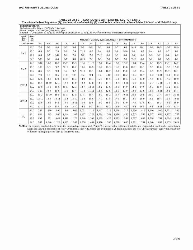
TABLE 23-VII-J-2TABLE 23-VII-J-2
1997 UNIFORM BUILDING CODE
2–359
TABLE 23-VII-J-2—FLOOR JOISTS WITH L/360 DEFLECTION LIMITSThe allowable bending stress ( Fb ) and modulus of elasticity (E) used in this table shall be from T ables 23-IV-V-1 and 23-IV-V-2 only .
DESIGN CRITERIA:Deflection — For 60 psf (2.87 kN/m2) live load.Limited to span in inches (mm) divided by 360.Strength — Live load of 60 psf (2.87 kN/m2) plus dead load of 10 psf (0.48 kN/m2) determines the required bending design value.
JoistSize(in)
Spac-ing(in) Modulus of Elasticity , E, in 1,000,000 psi ( × 0.00689 for N/mm 2)
× 25.4 for mm 0.8 0.9 1.0 1.1 1.2 1.3 1.4 1.5 1.6 1.7 1.8 1.9 2.0 2.1 2.2 2.3 2.4
12.0 7-5 7-9 8-0 8-3 8-6 8-9 8-11 9-2 9-4 9-7 9-9 9-11 10-1 10-3 10-5 10-7 10-9
2 × 616.0 6-9 7-0 7-3 7-6 7-9 7-11 8-2 8-4 8-6 8-8 8-10 9-0 9-2 9-4 9-6 9-7 9-9
2 × 619.2 6-4 6-7 6-10 7-1 7-3 7-6 7-8 7-10 8-0 8-2 8-4 8-6 8-8 8-9 8-11 9-0 9-2
24.0 5-11 6-2 6-4 6-7 6-9 6-11 7-1 7-3 7-5 7-7 7-9 7-10 8-0 8-2 8-3 8-5 8-6
12.0 9-10 10-2 10-7 10-11 11-3 11-6 11-10 12-1 12-4 12-7 12-10 13-1 13-4 13-6 13-9 13-11 14-2
2 × 816.0 8-11 9-3 9-7 9-11 10-2 10-6 10-9 11-0 11-3 11-5 11-8 11-11 12-1 12-3 12-6 12-8 12-10
2 × 819.2 8-5 8-9 9-0 9-4 9-7 9-10 10-1 10-4 10-7 10-9 11-0 11-2 11-4 11-7 11-9 11-11 12-1
24.0 7-9 8-1 8-5 8-8 8-11 9-2 9-4 9-7 9-10 10-0 10-2 10-5 10-7 10-9 10-11 11-1 11-3
12.0 12-6 13-0 13-6 13-11 14-4 14-8 15-1 15-5 15-9 16-1 16-5 16-8 17-0 17-3 17-6 17-9 18-0
2 × 1016.0 11-4 11-10 12-3 12-8 13-0 13-4 13-8 14-0 14-4 14-7 14-11 15-2 15-5 15-8 15-11 16-2 16-5
2 × 1019.2 10-8 11-1 11-6 11-11 12-3 12-7 12-11 13-2 13-6 13-9 14-0 14-3 14-6 14-9 15-0 15-2 15-5
24.0 9-11 10-4 10-8 11-0 11-4 11-8 11-11 12-3 12-6 12-9 13-0 13-3 13-6 13-8 13-11 14-1 14-4
12.0 15-2 15-10 16-5 16-11 17-5 17-11 18-4 18-9 19-2 19-7 19-11 20-3 20-8 21-0 21-4 21-7 21-11
2 × 1216.0 13-10 14-4 14-11 15-4 15-10 16-3 16-8 17-0 17-5 17-9 18-1 18-5 18-9 19-1 19-4 19-8 19-11
2 × 1219.2 13-0 13-6 14-0 14-5 14-11 15-3 15-8 16-0 16-5 16-9 17-0 17-4 17-8 17-11 18-3 18-6 18-9
24.0 12-1 12-7 13-0 13-5 13-10 14-2 14-7 14-11 15-2 15-6 15-10 16-1 16-5 16-8 16-11 17-2 17-5
12.0 767 830 890 949 1,005 1,061 1,114 1,167 1,218 1,268 1,317 1,366 1,413 1,460 1,506 1,551 1,596
F16.0 844 913 980 1,044 1,107 1,167 1,226 1,284 1,341 1,396 1,450 1,503 1,556 1,607 1,658 1,707 1,757
Fb 19.2 897 971 1,041 1,110 1,176 1,240 1,303 1,365 1,425 1,483 1,541 1,597 1,653 1,708 1,761 1,814 1,867
24.0 967 1,046 1,122 1,195 1,267 1,336 1,404 1,470 1,535 1,598 1,660 1,721 1,781 1,840 1,897 1,955 2,011
NOTE: The required bending design value, Fb, in pounds per square inch (N/mm2) is shown at the bottom of this table and is applicable to all lumber sizes shown.Spans are shown in feet-inches (1 foot = 304.8 mm, 1 inch = 25.4 mm) and are limited to 26 feet (7925 mm) and less. Check sources of supply for availabilityof lumber in lengths greater than 20 feet (6096 mm).
TABLE 23-VII-J-3TABLE 23-VII-J-3
1997 UNIFORM BUILDING CODE
2–360
TABLE 23-VII-J-3—FLOOR JOISTS WITH L/360 DEFLECTION LIMITSThe allowable bending stress ( Fb ) and modulus of elasticity (E) used in this table shall be from T ables 23-IV-V-1 and 23-IV-V-2 only .
DESIGN CRITERIA:Deflection — For 50 psf (2.4 kN/m2) live load.Limited to span in inches (mm) divided by 360.Strength — Live load of 50 psf (2.4 kN/m2) plus dead load of 20 psf (0.96 kN/m2) determines the required bending design value.
JoistSize(in)
Spac-ing(in) Modulus of Elasticity , E, in 1,000,000 psi ( × 0.00689 for N/mm 2)
× 25.4 for mm 0.8 0.9 1.0 1.1 1.2 1.3 1.4 1.5 1.6 1.7 1.8 1.9 2.0 2.1 2.2 2.3 2.4
12.0 7-11 8-3 8-6 8-9 9-1 9-3 9-6 9-9 9-11 10-2 10-4 10-6 10-9 10-11 11-1 11-3 11-5
2 × 616.0 7-2 7-6 7-9 8-0 8-3 8-5 8-8 8-10 9-1 9-3 9-5 9-7 9-9 9-11 10-1 10-2 10-4
2 × 619.2 6-9 7-0 7-3 7-6 7-9 7-11 8-2 8-4 8-6 8-8 8-10 9-0 9-2 9-4 9-6 9-7 9-9
24.0 6-3 6-6 6-9 7-0 7-2 7-4 7-7 7-9 7-11 8-1 8-3 8-4 8-6 8-8 8-9 8-11 9-1
12.0 10-5 10-10 11-3 11-7 11-11 12-3 12-7 12-10 13-1 13-5 13-8 13-11 14-2 14-4 14-7 14-10 15-0
2 × 816.0 9-6 9-10 10-2 10-6 10-10 11-1 11-5 11-8 11-11 12-2 12-5 12-7 12-10 13-1 13-3 13-5 13-8
2 × 819.2 8-11 9-3 9-7 9-11 10-2 10-6 10-9 11-0 11-3 11-5 11-8 11-11 12-1 12-3 12-6 12-8 12-10
24.0 8-3 8-7 8-11 9-2 9-6 9-9 10-0 10-2 10-5 10-8 10-10 11-0 11-3 11-5 11-7 11-9 11-11
12.0 13-3 13-10 14-4 14-9 15-2 15-7 16-0 16-5 16-9 17-1 17-5 17-9 18-0 18-4 18-7 18-11 19-2
2 × 1016.0 12-1 12-7 13-0 13-5 13-10 14-2 14-7 14-11 15-2 15-6 15-10 16-1 16-5 16-8 16-11 17-2 17-5
2 × 1019.2 11-4 11-10 12-3 12-8 13-0 13-4 13-8 14-0 14-4 14-7 14-11 15-2 15-5 15-8 15-11 16-2 16-5
24.0 10-7 11-0 11-4 11-9 12-1 12-5 12-8 13-0 13-3 13-7 13-10 14-1 14-4 14-7 14-9 15-0 15-2
12.0 16-2 16-10 17-5 18-0 18-6 19-0 19-6 19-11 20-4 20-9 21-2 21-7 21-11 22-3 22-8 23-0 23-4
2 × 1216.0 14-8 15-3 15-10 16-4 16-10 17-3 17-8 18-1 18-6 18-10 19-3 19-7 19-11 20-3 20-7 20-10 21-2
2 × 1219.2 13-10 14-4 14-11 15-4 15-10 16-3 16-8 17-0 17-5 17-9 18-1 18-5 18-9 19-1 19-4 19-8 19-11
24.0 12-10 13-4 13-10 14-3 14-8 15-1 15-5 15-10 16-2 16-6 16-10 17-1 17-5 17-8 18-0 18-3 18-6
12.0 866 937 1,005 1,071 1,135 1,198 1,258 1,317 1,375 1,432 1,488 1,542 1,596 1,649 1,701 1,752 1,802
F16.0 954 1,032 1,107 1,179 1,250 1,318 1,385 1,450 1,514 1,576 1,637 1,698 1,757 1,815 1,872 1,928 1,984
Fb 19.2 1,013 1,096 1,176 1,253 1,328 1,401 1,472 1,541 1,609 1,675 1,740 1,804 1,867 1,928 1,989 2,049 2,108
24.0 1,092 1,181 1,267 1,350 1,430 1,509 1,585 1,660 1,733 1,804 1,874 1,943 2,011 2,077 2,143 2,207 2,271
NOTE: The required bending design value, Fb, in pounds per square inch (N/mm2) is shown at the bottom of this table and is applicable to all lumber sizes shown.Spans are shown in feet-inches (1 foot = 304.8 mm, 1 inch = 25.4 mm) and are limited to 26 feet (7925 mm) and less. Check sources of supply for availabilityof lumber in lengths greater than 20 feet (6096 mm).
TABLE 23-VII-J-4TABLE 23-VII-J-4
1997 UNIFORM BUILDING CODE
2–361
TABLE 23-VII-J-4—FLOOR JOISTS WITH L/360 DEFLECTION LIMITSThe allowable bending stress ( Fb ) and modulus of elasticity (E) used in this table shall be from T ables 23-IV-V-1 and 23-IV-V-2 only .
DESIGN CRITERIA:Deflection — For 60 psf (2.87 kN/m2) live load.Limited to span in inches (mm) divided by 360.Strength — Live load of 60 psf (2.87 kN/m2) plus dead load of 20 psf (0.96 kN/m2) determines the required bending design value.
JoistSize(in)
Spac-ing(in) Modulus of Elasticity , E, in 1,000,000 psi ( × 0.00689 for N/mm 2)
× 25.4 for mm 0.8 0.9 1.0 1.1 1.2 1.3 1.4 1.5 1.6 1.7 1.8 1.9 2.0 2.1 2.2 2.3 2.4
12.0 7-5 7-9 8-0 8-3 8-6 8-9 8-11 9-2 9-4 9-7 9-9 9-11 10-1 10-3 10-5 10-7 10-9
2 × 616.0 6-9 7-0 7-3 7-6 7-9 7-11 8-2 8-4 8-6 8-8 8-10 9-0 9-2 9-4 9-6 9-7 9-9
2 × 619.2 6-4 6-7 6-10 7-1 7-3 7-6 7-8 7-10 8-0 8-2 8-4 8-6 8-8 8-9 8-11 9-0 9-2
24.0 5-11 6-2 6-4 6-7 6-9 6-11 7-1 7-3 7-5 7-7 7-9 7-10 8-0 8-2 8-3 8-5 8-6
12.0 9-10 10-2 10-7 10-11 11-3 11-6 11-10 12-1 12-4 12-7 12-10 13-1 13-4 13-6 13-9 13-11 14-2
2 × 816.0 8-11 9-3 9-7 9-11 10-2 10-6 10-9 11-0 11-3 11-5 11-8 11-11 12-1 12-3 12-6 12-8 12-10
2 × 819.2 8-5 8-9 9-0 9-4 9-7 9-10 10-1 10-4 10-7 10-9 11-0 11-2 11-4 11-7 11-9 11-11 12-1
24.0 7-9 8-1 8-5 8-8 8-11 9-2 9-4 9-7 9-10 10-0 10-2 10-5 10-7 10-9 10-11 11-1 11-3
12.0 12-6 13-0 13-6 13-11 14-4 14-8 15-1 15-5 15-9 16-1 16-5 16-8 17-0 17-3 17-6 17-9 18-0
2 × 1016.0 11-4 11-10 12-3 12-8 13-0 13-4 13-8 14-0 14-4 14-7 14-11 15-2 15-5 15-8 15-11 16-2 16-5
2 × 1019.2 10-8 11-1 11-6 11-11 12-3 12-7 12-11 13-2 13-6 13-9 14-0 14-3 14-6 14-9 15-0 15-2 15-5
24.0 9-11 10-4 10-8 11-0 11-4 11-8 11-11 12-3 12-6 12-9 13-0 13-3 13-6 13-8 13-11 14-1 14-4
12.0 15-2 15-10 16-5 16-11 17-5 17-11 18-4 18-9 19-2 19-7 19-11 20-3 20-8 21-0 21-4 21-7 21-11
2 × 1216.0 13-10 14-4 14-11 15-4 15-10 16-3 16-8 17-0 17-5 17-9 18-1 18-5 18-9 19-1 19-4 19-8 19-11
2 × 1219.2 13-0 13-6 14-0 14-5 14-11 15-3 15-8 16-0 16-5 16-9 17-0 17-4 17-8 17-11 18-3 18-6 18-9
24.0 12-1 12-7 13-0 13-5 13-10 14-2 14-7 14-11 15-2 15-6 15-10 16-1 16-5 16-8 16-11 17-2 17-5
12.0 877 949 1,018 1,084 1,149 1,212 1,273 1,333 1,392 1,449 1,506 1,561 1,615 1,669 1,721 1,773 1,824
F16.0 965 1,044 1,120 1,193 1,265 1,334 1,402 1,468 1,532 1,595 1,657 1,718 1,778 1,837 1,894 1,951 2,008
Fb 19.2 1,026 1,109 1,190 1,268 1,344 1,418 1,489 1,559 1,628 1,695 1,761 1,826 1,889 1,952 2,013 2,074 2,133
24.0 1,105 1,195 1,282 1,366 1,448 1,527 1,604 1,680 1,754 1,826 1,897 1,967 2,035 2,102 2,169 2,234 2,298
NOTE: The required bending design value, Fb, in pounds per square inch (N/mm2) is shown at the bottom of this table and is applicable to all lumber sizes shown.Spans are shown in feet-inches (1 foot = 304.8 mm, 1 inch = 25.4 mm) and are limited to 26 feet (7925 mm) and less. Check sources of supply for availabilityof lumber in lengths greater than 20 feet (6096 mm).
TABLE 23-VII-R-1TABLE 23-VII-R-1
1997 UNIFORM BUILDING CODE
2–362
TABLE 23-VII-R-1—RAFTERS WITH L/240 DEFLECTION LIMITSThe allowable bending stress ( Fb ) and modulus of elasticity (E) used in this table shall be from T ables 23-IV-V-1 and 23-IV-V-2 only .
DESIGN CRITERIA:Strength — Live load of 40 psf (1.92 kN/m2) plus dead load of 10 psf (0.48 kN/m2) determines the required bending design value.Deflection — For 40 psf live (1.02 kN/m2) load.Limited to span in inches (mm) divided by 240.
RafterSize(in)
Spacing(in) Bending Design V alue, Fb (psi) ( × 0.00689 for N/mm 2)
× 25.4 formm 300 400 500 600 700 800 900 1000 1100 1200 1300
12.0 5-6 6-4 7-1 7-9 8-5 9-0 9-6 10-0 10-6 11-0 11-5
2 × 616.0 4-9 5-6 6-2 6-9 7-3 7-9 8-3 8-8 9-1 9-6 9-11
2 × 619.2 4-4 5-0 5-7 6-2 6-8 7-1 7-6 7-11 8-4 8-8 9-124.0 3-11 4-6 5-0 5-6 5-11 6-4 6-9 7-1 7-5 7-9 8-1
12.0 7-3 8-4 9-4 10-3 11-1 11-10 12-7 13-3 13-11 14-6 15-1
2 × 816.0 6-3 7-3 8-1 8-11 9-7 10-3 10-10 11-6 12-0 12-7 13-1
2 × 819.2 5-9 6-7 7-5 8-1 8-9 9-4 9-11 10-6 11-0 11-6 11-1124.0 5-2 5-11 6-7 7-3 7-10 8-4 8-11 9-4 9-10 10-3 10-8
12.0 9-3 10-8 11-11 13-1 14-2 15-1 16-0 16-11 17-9 18-6 19-3
2 × 1016.0 8-0 9-3 10-4 11-4 12-3 13-1 13-10 14-8 15-4 16-0 16-8
2 × 1019.2 7-4 8-5 9-5 10-4 11-2 11-11 12-8 13-4 14-0 14-8 15-324.0 6-6 7-7 8-5 9-3 10-0 10-8 11-4 11-11 12-6 13-1 13-7
12.0 11-3 13-0 14-6 15-11 17-2 18-4 19-6 20-6 21-7 22-6 23-5
2 ×1216.0 9-9 11-3 12-7 13-9 14-11 15-11 16-10 17-9 18-8 19-6 20-3
2 ×1219.2 8-11 10-3 11-6 12-7 13-7 14-6 15-5 16-3 17-0 17-9 18-624.0 7-11 9-2 10-3 11-3 12-2 13-0 13-9 14-6 15-3 15-11 16-7
12.0 0.14 0.22 0.31 0.41 0.51 0.63 0.75 0.88 1.01 1.15 1.30
E16.0 0.12 0.19 0.27 0.35 0.44 0.54 0.65 0.76 0.88 1.00 1.12
E19.2 0.11 0.18 0.24 0.32 0.41 0.50 0.59 0.69 0.80 0.91 1.0324.0 0.10 0.16 0.22 0.29 0.36 0.44 0.53 0.62 0.71 0.81 0.92
RafterSize(in)
Spacing(in) Bending Design V alue, Fb (psi) ( × 0.00689 for N/mm 2)
× 25.4 formm 1400 1500 1600 1700 1800 1900 2000 2100 2200 2300 2400
12.0 11-11 12-4 12-8 13-1 13-6 13-10 14-2
2 × 616.0 10-3 10-8 11-0 11-4 11-8 12-0 12-4 12-7 12-11
2 × 619.2 9-5 9-9 10-0 10-4 10-8 10-11 11-3 11-6 11-9 12-0 12-424.0 8-5 8-8 9-0 9-3 9-6 9-9 10-0 10-3 10-6 10-9 11-0
12.0 15-8 16-3 16-9 17-3 17-9 18-3 18-9
2 × 816.0 13-7 14-0 14-6 14-11 15-5 15-10 16-3 16-7 17-0
2 × 819.2 12-5 12-10 13-3 13-8 14-0 14-5 14-10 15-2 15-6 15-10 16-324.0 11-1 11-6 11-10 12-2 12-7 12-11 13-3 13-7 13-11 14-2 14-6
12.0 20-0 20-8 21-4 22-0 22-8 23-3 23-11
2 × 1016.0 17-4 17-11 18-6 19-1 19-7 20-2 20-8 21-2 21-8
2 × 1019.2 15-10 16-4 16-11 17-5 17-11 18-5 18-11 19-4 19-10 20-3 20-824.0 14-2 14-8 15-1 15-7 16-0 16-6 16-11 17-4 17-9 18-1 18-6
12.0 24-4 25-2 26-0
2 ×1216.0 21-1 21-9 22-6 23-2 23-10 24-6 25-2 25-9
2 ×1219.2 19-3 19-11 20-6 21-2 21-9 22-5 23-0 23-6 24-1 24-8 25-224.0 17-2 17-9 18-4 18-11 19-6 20-0 20-6 21-1 21-7 22-0 22-6
12.0 1.45 1.61 1.77 1.94 2.12 2.30 2.48
E16.0 1.26 1.39 1.54 1.68 1.83 1.99 2.15 2.31 2.48
E19.2 1.15 1.27 1.40 1.54 1.67 1.81 1.96 2.11 2.26 2.42 2.5824.0 1.03 1.14 1.25 1.37 1.50 1.62 1.75 1.89 2.02 2.16 2.30
NOTE: The required modulus of elasticity, E, in 1,000,000 pounds per square inch is shown at the bottom of this table, is limited to 2.6 million psi (17.92 × 10⁶ kN/m2)and less, and is applicable to all lumber sizes shown. Spans are shown in feet-inches (1 foot = 304.8 mm, 1 inch = 25.4 mm) and are limited to 26 feet (7925mm) and less.
TABLE 23-VII-R-2TABLE 23-VII-R-2
1997 UNIFORM BUILDING CODE
2–363
TABLE 23-VII-R-2—RAFTERS WITH L/240 DEFLECTION LIMITSThe allowable bending stress ( Fb ) and modulus of elasticity (E) used in this table shall be from T ables 23-IV-V-1 and 23-IV-V-2 only .
DESIGN CRITERIA:Strength — Live load of 50 psf (2.40 kN/m2) plus dead load of 10 psf (0.48 kN/m2) determines the required bending design value.Deflection — For 50 psf (2.4 kN/m2) live load.Limited to span in inches (mm) divided by 240.
RafterSize(in)
Spacing(in) Bending Design V alue, Fb (psi) ( × 0.00689 for N/mm 2)
× 25.4 for mm 300 400 500 600 700 800 900 1000 1100 1200 1300
12.0 5-0 5-10 6-6 7-1 7-8 8-2 8-8 9-2 9-7 10-0 10-5
2 × 616.0 4-4 5-0 5-7 6-2 6-8 7-1 7-6 7-11 8-4 8-8 9-1
2 × 619.2 4-0 4-7 5-1 5-7 6-1 6-6 6-10 7-3 7-7 7-11 8-324.0 3-7 4-1 4-7 5-0 5-5 5-10 6-2 6-6 6-10 7-1 7-5
12.0 6-7 7-8 8-7 9-4 10-1 10-10 11-6 12-1 12-8 13-3 13-9
2 × 816.0 5-9 6-7 7-5 8-1 8-9 9-4 9-11 10-6 11-0 11-6 11-11
2 × 819.2 5-3 6-0 6-9 7-5 8-0 8-7 9-1 9-7 10-0 10-6 10-1124.0 4-8 5-5 6-0 6-7 7-2 7-8 8-1 8-7 9-0 9-4 9-9
12.0 8-5 9-9 10-11 11-11 12-11 13-9 14-8 15-5 16-2 16-11 17-7
2 × 1016.0 7-4 8-5 9-5 10-4 11-2 11-11 12-8 13-4 14-0 14-8 15-3
2 × 1019.2 6-8 7-8 8-7 9-5 10-2 10-11 11-7 12-2 12-9 13-4 13-1124.0 6-0 6-11 7-8 8-5 9-1 9-9 10-4 10-11 11-5 11-11 12-5
12.0 10-3 11-10 13-3 14-6 15-8 16-9 17-9 18-9 19-8 20-6 21-5
2 × 1216.0 8-11 10-3 11-6 12-7 13-7 14-6 15-5 16-3 17-0 17-9 18-6
2 × 1219.2 8-1 9-4 10-6 11-6 12-5 13-3 14-1 14-10 15-7 16-3 16-1124.0 7-3 8-5 9-4 10-3 11-1 11-10 12-7 13-3 13-11 14-6 15-1
12.0 0.14 0.21 0.29 0.39 0.49 0.60 0.71 0.83 0.96 1.10 1.24
E16.0 0.12 0.18 0.26 0.34 0.42 0.52 0.62 0.72 0.83 0.95 1.07
E19.2 0.11 0.17 0.23 0.31 0.39 0.47 0.56 0.66 0.76 0.87 0.9824.0 0.10 0.15 0.21 0.27 0.35 0.42 0.50 0.59 0.68 0.77 0.87
RafterSize(in)
Spacing(in) Bending Design V alue, Fb (psi) ( × 0.00689 for N/mm 2)
× 25.4 for mm 1400 1500 1600 1700 1800 1900 2000 2100 2200 2300 2400
12.0 10-10 11-3 11-7 11-11 12-4 12-8 13-0 13-3
2 × 616.0 9-5 9-9 10-0 10-4 10-8 10-11 11-3 11-6 11-9 12-0
2 × 619.2 8-7 8-11 9-2 9-5 9-9 10-0 10-3 10-6 10-9 11-0 11-324.0 7-8 7-11 8-2 8-5 8-8 8-11 9-2 9-5 9-7 9-10 10-0
12.0 14-4 14-10 15-3 15-9 16-3 16-8 17-1 17-6
2 × 816.0 12-5 12-10 13-3 13-8 14-0 14-5 14-10 15-2 15-6 15-10
2 × 819.2 11-4 11-8 12-1 12-5 12-10 13-2 13-6 13-10 14-2 14-6 14-1024.0 10-1 10-6 10-10 11-2 11-6 11-9 12-1 12-5 12-8 12-11 13-3
12.0 18-3 18-11 19-6 20-1 20-8 21-3 21-10 22-4
2 × 1016.0 15-10 16-4 16-11 17-5 17-11 18-5 18-11 19-4 19-10 20-3
2 × 1019.2 14-5 14-11 15-5 15-11 16-4 16-10 17-3 17-8 18-1 18-6 18-1124.0 12-11 13-4 13-9 14-3 14-8 15-0 15-5 15-10 16-2 16-6 16-11
12.0 22-2 23-0 23-9 24-5 25-2 25-10
2 × 1216.0 19-3 19-11 20-6 21-2 21-9 22-5 23-0 23-6 24-1 24-8
2 × 1219.2 17-6 18-2 18-9 19-4 19-11 20-5 21-0 21-6 22-0 22-6 23-024.0 15-8 16-3 16-9 17-3 17-9 18-3 18-9 19-3 19-8 20-1 20-6
12.0 1.38 1.53 1.69 1.85 2.01 2.18 2.36 2.54
E16.0 1.20 1.33 1.46 1.60 1.74 1.89 2.04 2.20 2.35 2.52
E19.2 1.09 1.21 1.33 1.46 1.59 1.73 1.86 2.00 2.15 2.30 2.4524.0 0.98 1.08 1.19 1.31 1.42 1.54 1.67 1.79 1.92 2.06 2.19
NOTE: The required modulus of elasticity, E, in 1,000,000 pounds per square inch is shown at the bottom of this table, is limited to 2.6 million psi (17.92 × 10⁶ kN/m2)and less, and is applicable to all lumber sizes shown. Spans are shown in feet-inches (1 foot = 304.8 mm, 1 inch = 25.4 mm) and are limited to 26 feet (7925mm) and less.
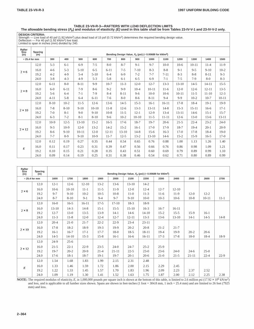
TABLE 23-VII-R-3TABLE 23-VII-R-3
1997 UNIFORM BUILDING CODE
2–364
TABLE 23-VII-R-3—RAFTERS WITH L/240 DEFLECTION LIMITSThe allowable bending stress ( Fb ) and modulus of elasticity (E) used in this table shall be from T ables 23-IV-V-1 and 23-IV-V-2 only .
DESIGN CRITERIA:Strength — Live load of 40 psf (1.92 kN/m2) plus dead load of 15 psf (0.72 kN/m2) determines the required bending design value.Deflection — For 40 psf (1.92 kN/m2) live load.Limited to span in inches (mm) divided by 240.
RafterSize Spacing
RafterSize(in)
Spacing(in) Bending Design V alue, Fb (psi) ( × 0.00689 for kN/m 2)
× 25.4 for mm 300 400 500 600 700 800 900 1000 1100 1200 1300 1400 1500
12.0 5-3 6-1 6-9 7-5 8-0 8-7 9-1 9-7 10-0 10-6 10-11 11-4 11-9
2 × 616.0 4-6 5-3 5-10 6-5 6-11 7-5 7-10 8-3 8-8 9-1 9-5 9-10 10-2
2 × 619.2 4-2 4-9 5-4 5-10 6-4 6-9 7-2 7-7 7-11 8-3 8-8 8-11 9-324.0 3-8 4-3 4-9 5-3 5-8 6-1 6-5 6-9 7-1 7-5 7-9 8-0 8-3
12.0 6-11 8-0 8-11 9-9 10-7 11-3 12-0 12-7 13-3 13-10 14-5 14-11 15-5
2 × 816.0 6-0 6-11 7-9 8-6 9-2 9-9 10-4 10-11 11-6 12-0 12-6 12-11 13-5
2 × 819.2 5-6 6-4 7-1 7-9 8-4 8-11 9-6 10-0 10-6 10-11 11-5 11-10 12-324.0 4-11 5-8 6-4 6-11 7-6 8-0 8-6 8-11 9-4 9-9 10-2 10-7 10-11
12.0 8-10 10-2 11-5 12-6 13-6 14-5 15-3 16-1 16-11 17-8 18-4 19-1 19-9
2 × 1016.0 7-8 8-10 9-10 10-10 11-8 12-6 13-3 13-11 14-8 15-3 15-11 16-6 17-1
2 × 1019.2 7-0 8-1 9-0 9-10 10-8 11-5 12-1 12-9 13-4 13-11 14-6 15-1 15-724.0 6-3 7-2 8-1 8-10 9-6 10-2 10-10 11-5 11-11 12-6 13-0 13-6 13-11
12.0 10-9 12-5 13-10 15-2 16-5 17-6 18-7 19-7 20-6 21-5 22-4 23-2 24-0
2 × 1216.0 9-3 10-9 12-0 13-2 14-2 15-2 16-1 17-0 17-9 18-7 19-4 20-1 20-9
2 × 1219.2 8-6 9-10 10-11 12-0 12-11 13-10 14-8 15-6 16-3 17-0 17-8 18-4 19-024.0 7-7 8-9 9-10 10-9 11-7 12-5 13-2 13-10 14-6 15-2 15-9 16-5 17-0
12.0 0.12 0.19 0.27 0.35 0.44 0.54 0.65 0.76 0.88 1.00 1.13 1.26 1.40
E16.0 0.11 0.17 0.23 0.31 0.39 0.47 0.56 0.66 0.76 0.86 0.98 1.09 1.21
E19.2 0.10 0.15 0.21 0.28 0.35 0.43 0.51 0.60 0.69 0.79 0.89 0.99 1.1024.0 0.09 0.14 0.19 0.25 0.31 0.38 0.46 0.54 0.62 0.71 0.80 0.89 0.99
RafterSize Spacing
RafterSize(in)
Spacing(in) Bending Design V alue, Fb (psi) ( × 0.00689 for kN/m 2)
× 25.4 for mm 1600 1700 1800 1900 2000 2100 2200 2300 2400 2500 2600 2700
12.0 12-1 12-6 12-10 13-2 13-6 13-10 14-2
2 × 616.0 10-6 10-10 11-1 11-5 11-9 12-0 12-4 12-7 12-10
2 × 619.2 9-7 9-10 10-2 10-5 10-8 11-0 11-3 11-6 11-9 12-0 12-224.0 8-7 8-10 9-1 9-4 9-7 9-10 10-0 10-3 10-6 10-8 10-11 11-1
12.0 16-0 16-5 16-11 17-5 17-10 18-3 18-9
2 × 816.0 13-10 14-3 14-8 15-1 15-5 15-10 16-3 16-7 16-11
2 × 819.2 12-7 13-0 13-5 13-9 14-1 14-6 14-10 15-2 15-5 15-9 16-124.0 11-3 11-8 12-0 12-4 12-7 12-11 13-3 13-6 13-10 14-1 14-5 14-8
12.0 20-4 21-0 21-7 22-2 22-9 23-4 23-11
2 × 1016.0 17-8 18-2 18-9 19-3 19-9 20-2 20-8 21-2 21-7
2 × 1019.2 16-1 16-7 17-1 17-7 18-0 18-5 18-11 19-4 19-9 20-2 20-624.0 14-5 14-10 15-3 15-8 16-1 16-6 16-11 17-3 17-8 18-0 18-4 18-9
12.0 24-9 25-6
2 × 1216.0 21-5 22-1 22-9 23-5 24-0 24-7 25-2 25-9
2 × 1219.2 19-7 20-2 20-9 21-4 21-11 22-5 23-0 23-6 24-0 24-6 25-024.0 17-6 18-1 18-7 19-1 19-7 20-1 20-6 21-0 21-5 21-11 22-4 22-9
12.0 1.54 1.68 1.83 1.99 2.15 2.31 2.48
E16.0 1.33 1.46 1.59 1.72 1.86 2.00 2.15 2.29 2.45
E19.2 1.22 1.33 1.45 1.57 1.70 1.83 1.96 2.09 2.23 2.37 2.5224.0 1.09 1.19 1.30 1.41 1.52 1.63 1.75 1.87 2.00 2.12 2.25 2.38
NOTE: The required modulus of elasticity, E, in 1,000,000 pounds per square inch is shown at the bottom of this table, is limited to 2.6 million psi (17.92 × 10⁶ kN/m2)and less, and is applicable to all lumber sizes shown. Spans are shown in feet-inches (1 foot = 304.8 mm, 1 inch = 25.4 mm) and are limited to 26 feet (7925mm) and less.
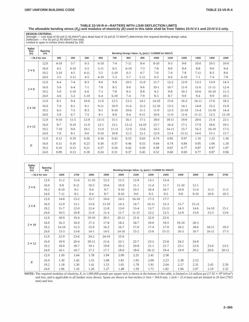
TABLE 23-VII-R-4TABLE 23-VII-R-4
1997 UNIFORM BUILDING CODE
2–365
TABLE 23-VII-R-4—RAFTERS WITH L/240 DEFLECTION LIMITSThe allowable bending stress ( Fb ) and modulus of elasticity (E) used in this table shall be from T ables 23-IV-V-1 and 23-IV-V-2 only .
DESIGN CRITERIA:Strength — Live load of 50 psf (2.40 kN/m2) plus dead load of 15 psf (0.72 kN/m2) determines the required bending design value.Deflection — For 50 psf (2.40 kN/m2) live load.Limited to span in inches (mm) divided by 240.
RafterSize Spacing
RafterSize(in)
Spacing(in) Bending Design V alue, Fb (psi) ( × 0.00689 for kN/m 2)
× 25.4 for mm 300 400 500 600 700 800 900 1000 1100 1200 1300 1400 1500
12.0 4-10 5-7 6-3 6-10 7-4 7-11 8-4 8-10 9-3 9-8 10-0 10-5 10-9
2 × 616.0 4-2 4-10 5-5 5-11 6-5 6-10 7-3 7-8 8-0 8-4 8-8 9-0 9-4
2 × 619.2 3-10 4-5 4-11 5-5 5-10 6-3 6-7 7-0 7-4 7-8 7-11 8-3 8-624.0 3-5 3-11 4-5 4-10 5-3 5-7 5-11 6-3 6-6 6-10 7-1 7-4 7-8
12.0 6-4 7-4 8-3 9-0 9-9 10-5 11-0 11-7 12-2 12-9 13-3 13-9 14-3
2 × 816.0 5-6 6-4 7-1 7-9 8-5 9-0 9-6 10-1 10-7 11-0 11-6 11-11 12-4
2 × 819.2 5-0 5-10 6-6 7-1 7-8 8-3 8-8 9-2 9-8 10-1 10-6 10-10 11-324.0 4-6 5-2 5-10 6-4 6-10 7-4 7-9 8-3 8-7 9-0 9-4 9-9 10-1
12.0 8-1 9-4 10-6 11-6 12-5 13-3 14-1 14-10 15-6 16-3 16-11 17-6 18-2
2 × 1016.0 7-0 8-1 9-1 9-11 10-9 11-6 12-2 12-10 13-5 14-1 14-8 15-2 15-9
2 × 1019.2 6-5 7-5 8-3 9-1 9-10 10-6 11-1 11-9 12-3 12-10 13-4 13-10 14-424.0 5-9 6-7 7-5 8-1 8-9 9-4 9-11 10-6 11-0 11-6 11-11 12-5 12-10
12.0 9-10 11-5 12-9 13-11 15-1 16-1 17-1 18-0 18-11 19-9 20-6 21-4 22-1
2 × 1216.0 8-7 9-10 11-0 12-1 13-1 13-11 14-10 15-7 16-4 17-1 17-9 18-6 19-1
2 × 1219.2 7-10 9-0 10-1 11-0 11-11 12-9 13-6 14-3 14-11 15-7 16-3 16-10 17-524.0 7-0 8-1 9-0 9-10 10-8 11-5 12-1 12-9 13-4 13-11 14-6 15-1 15-7
12.0 0.12 0.19 0.26 0.34 0.43 0.53 0.63 0.74 0.85 0.97 1.10 1.22 1.36
E16.0 0.11 0.16 0.23 0.30 0.37 0.46 0.55 0.64 0.74 0.84 0.95 1.06 1.18
E19.2 0.10 0.15 0.21 0.27 0.34 0.42 0.50 0.58 0.67 0.77 0.87 0.97 1.0724.0 0.09 0.13 0.18 0.24 0.31 0.37 0.45 0.52 0.60 0.69 0.77 0.87 0.96
RafterSize Spacing
RafterSize(in)
Spacing(in) Bending Design V alue, Fb (psi) ( × 0.00689 for kN/m 2)
× 25.4 for mm 1600 1700 1800 1900 2000 2100 2200 2300 2400 2500 2600 2700
12.0 11-2 11-6 11-10 12-2 12-5 12-9 13-1 13-4
2 × 616.0 9-8 9-11 10-3 10-6 10-9 11-1 11-4 11-7 11-10 12-1
2 × 619.2 8-10 9-1 9-4 9-7 9-10 10-1 10-4 10-7 10-9 11-0 11-3 11-524.0 7-11 8-1 8-4 8-7 8-10 9-0 9-3 9-5 9-8 9-10 10-0 10-3
12.0 14-8 15-2 15-7 16-0 16-5 16-10 17-3 17-7
2 × 816.0 12-9 13-1 13-6 13-10 14-3 14-7 14-11 15-3 15-7 15-11
2 × 819.2 11-7 12-0 12-4 12-8 13-0 13-4 13-7 13-11 14-3 14-6 14-10 15-124.0 10-5 10-8 11-0 11-4 11-7 11-11 12-2 12-5 12-9 13-0 13-3 13-6
12.0 18-9 19-4 19-10 20-5 20-11 21-6 22-0 22-6
2 × 1016.0 16-3 16-9 17-3 17-8 18-2 18-7 19-0 19-5 19-10 20-3
2 × 1019.2 14-10 15-3 15-9 16-2 16-7 17-0 17-4 17-9 18-2 18-6 18-11 19-324.0 13-3 13-8 14-1 14-5 14-10 15-2 15-6 15-11 16-3 16-7 16-11 17-3
12.0 22-9 23-6 24-2 24-10 25-6
2 × 1216.0 19-9 20-4 20-11 21-6 22-1 22-7 23-2 23-8 24-2 24-8
2 × 1219.2 18-0 18-7 19-1 19-8 20-2 20-8 21-1 21-7 22-1 22-6 23-0 23-524.0 16-1 16-7 17-1 17-7 18-0 18-6 18-11 19-4 19-9 20-2 20-6 20-11
12.0 1.50 1.64 1.78 1.94 2.09 2.25 2.41 2.58
E16.0 1.30 1.42 1.55 1.68 1.81 1.95 2.09 2.23 2.38 2.53
E19.2 1.18 1.30 1.41 1.53 1.65 1.78 1.91 2.04 2.17 2.31 2.45 2.5924.0 1.06 1.16 1.26 1.37 1.48 1.59 1.71 1.82 1.94 2.07 2.19 2.32
NOTE: The required modulus of elasticity, E, in 1,000,000 pounds per square inch is shown at the bottom of this table, is limited to 2.6 million psi (17.92 × 10⁶ kN/m2)and less, and is applicable to all lumber sizes shown. Spans are shown in feet-inches (1 foot = 304.8 mm, 1 inch = 25.4 mm) and are limited to 26 feet (7925mm) and less.
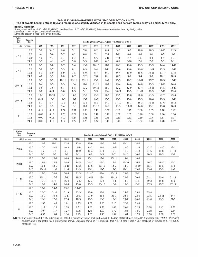
TABLE 23-VII-R-5TABLE 23-VII-R-5
1997 UNIFORM BUILDING CODE
2–366
TABLE 23-VII-R-5—RAFTERS WITH L/240 DEFLECTION LIMITSThe allowable bending stress ( Fb ) and modulus of elasticity (E) used in this table shall be from T ables 23-IV-V-1 and 23-IV-V-2 only .
DESIGN CRITERIA:Strength — Live load of 40 psf (1.92 kN/m2) plus dead load of 20 psf (0.96 kN/m2) determines the required bending design value.Deflection — For 40 psf (1.92 kN/m2) live load.Limited to span in inches (mm) divided by 240.
RafterSize(in)
Spacing(in) Bending Design V alue, Fb (psi) ( × 0.00689 for kN/m 2)
× 25.4 for mm 300 400 500 600 700 800 900 1000 1100 1200 1300 1400 1500
12.0 5-0 5-10 6-6 7-1 7-8 8-2 8-8 9-2 9-7 10-0 10-5 10-10 11-3
2 × 616.0 4-4 5-0 5-7 6-2 6-8 7-1 7-6 7-11 8-4 8-8 9-1 9-5 9-9
2 × 619.2 4-0 4-7 5-1 5-7 6-1 6-6 6-10 7-3 7-7 7-11 8-3 8-7 8-1124.0 3-7 4-1 4-7 5-0 5-5 5-10 6-2 6-6 6-10 7-1 7-5 7-8 7-11
12.0 6-7 7-8 8-7 9-4 10-1 10-10 11-6 12-1 12-8 13-3 13-9 14-4 14-10
2 × 816.0 5-9 6-7 7-5 8-1 8-9 9-4 9-11 10-6 11-0 11-6 11-11 12-5 12-10
2 × 819.2 5-3 6-0 6-9 7-5 8-0 8-7 9-1 9-7 10-0 10-6 10-11 11-4 11-824.0 4-8 5-5 6-0 6-7 7-2 7-8 8-1 8-7 9-0 9-4 9-9 10-1 10-6
12.0 8-5 9-9 10-11 11-11 12-11 13-9 14-8 15-5 16-2 16-11 17-7 18-3 18-11
2 × 1016.0 7-4 8-5 9-5 10-4 11-2 11-11 12-8 13-4 14-0 14-8 15-3 15-10 16-4
2 × 1019.2 6-8 7-8 8-7 9-5 10-2 10-11 11-7 12-2 12-9 13-4 13-11 14-5 14-1124.0 6-0 6-11 7-8 8-5 9-1 9-9 10-4 10-11 11-5 11-11 12-5 12-11 13-4
12.0 10-3 11-10 13-3 14-6 15-8 16-9 17-9 18-9 19-8 20-6 21-5 22-2 23-0
2 × 1216.0 8-11 10-3 11-6 12-7 13-7 14-6 15-5 16-3 17-0 17-9 18-6 19-3 19-11
2 × 1219.2 8-1 9-4 10-6 11-6 12-5 13-3 14-1 14-10 15-7 16-3 16-11 17-6 18-224.0 7-3 8-5 9-4 10-3 11-1 11-10 12-7 13-3 13-11 14-6 15-1 15-8 16-3
12.0 0.11 0.17 0.24 0.31 0.39 0.48 0.57 0.67 0.77 0.88 0.99 1.10 1.22
E16.0 0.09 0.15 0.20 0.27 0.34 0.41 0.49 0.58 0.67 0.76 0.86 0.96 1.06
E19.2 0.09 0.13 0.19 0.24 0.31 0.38 0.45 0.53 0.61 0.69 0.78 0.87 0.9724.0 0.08 0.12 0.17 0.22 0.28 0.34 0.40 0.47 0.54 0.62 0.70 0.78 0.87
RafterSize(in)
Spacing(in) Bending Design V alue, Fb (psi) ( × 0.00689 for kN/m 2)
× 25.4 for mm 1600 1700 1800 1900 2000 2100 2200 2300 2400 2500 2600 2700
12.0 11-7 11-11 12-4 12-8 13-0 13-3 13-7 13-11 14-2
2 × 616.0 10-0 10-4 10-8 10-11 11-3 11-6 11-9 12-0 12-4 12-7 12-10 13-1
2 × 619.2 9-2 9-5 9-9 10-0 10-3 10-6 10-9 11-0 11-3 11-5 11-8 11-1124.0 8-2 8-5 8-8 8-11 9-2 9-5 9-7 9-10 10-0 10-3 10-5 10-8
12.0 15-3 15-9 16-3 16-8 17-1 17-6 17-11 18-4 18-9
2 × 816.0 13-3 13-8 14-0 14-5 14-10 15-2 15-6 15-10 16-3 16-7 16-10 17-2
2 × 819.2 12-1 12-5 12-10 13-2 13-6 13-10 14-2 14-6 14-10 15-1 15-5 15-824.0 10-10 11-2 11-6 11-9 12-1 12-5 12-8 12-11 13-3 13-6 13-9 14-0
12.0 19-6 20-1 20-8 21-3 21-10 22-4 22-10 23-5 23-11
2 × 1016.0 16-11 17-5 17-11 18-5 18-11 19-4 19-10 20-3 20-8 21-1 21-6 21-11
2 × 1019.2 15-5 15-11 16-4 16-10 17-3 17-8 18-1 18-6 18-11 19-3 19-8 20-024.0 13-9 14-3 14-8 15-0 15-5 15-10 16-2 16-6 16-11 17-3 17-7 17-11
12.0 23-9 24-5 25-2 25-10
2 × 1216.0 20-6 21-2 21-9 22-5 23-0 23-6 24-1 24-8 25-2 25-8
2 × 1219.2 18-9 19-4 19-11 20-5 21-0 21-6 22-0 22-6 23-0 23-5 23-11 24-424.0 16-9 17-3 17-9 18-3 18-9 19-3 19-8 20-1 20-6 21-0 21-5 21-9
12.0 1.35 1.48 1.61 1.75 1.89 2.03 2.18 2.33 2.48
E16.0 1.17 1.28 1.39 1.51 1.63 1.76 1.88 2.01 2.15 2.28 2.42 2.56
E19.2 1.07 1.17 1.27 1.38 1.49 1.60 1.72 1.84 1.96 2.08 2.21 2.3424.0 0.95 1.04 1.14 1.23 1.33 1.43 1.54 1.64 1.75 1.86 1.98 2.09
NOTE: The required modulus of elasticity, E, in 1,000,000 pounds per square inch is shown at the bottom of this table, is limited to 2.6 million psi (17.92 × 10⁶ kN/m2)and less, and is applicable to all lumber sizes shown. Spans are shown in feet-inches (1 foot = 304.8 mm, 1 inch = 25.4 mm) and are limited to 26 feet (7925mm) and less.
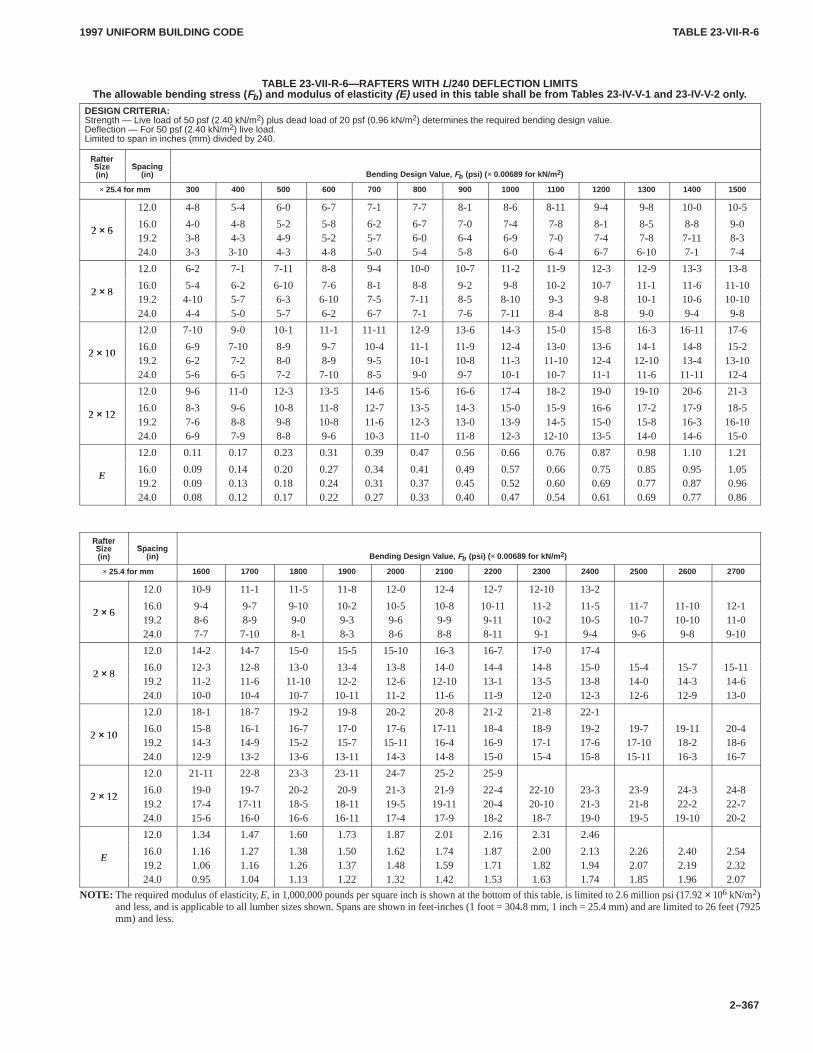
TABLE 23-VII-R-6TABLE 23-VII-R-6
1997 UNIFORM BUILDING CODE
2–367
TABLE 23-VII-R-6—RAFTERS WITH L/240 DEFLECTION LIMITSThe allowable bending stress ( Fb ) and modulus of elasticity (E) used in this table shall be from T ables 23-IV-V-1 and 23-IV-V-2 only .
DESIGN CRITERIA:Strength — Live load of 50 psf (2.40 kN/m2) plus dead load of 20 psf (0.96 kN/m2) determines the required bending design value.Deflection — For 50 psf (2.40 kN/m2) live load.Limited to span in inches (mm) divided by 240.
RafterSize Spacing
RafterSize(in)
Spacing(in) Bending Design V alue, Fb (psi) ( × 0.00689 for kN/m 2)
× 25.4 for mm 300 400 500 600 700 800 900 1000 1100 1200 1300 1400 1500
12.0 4-8 5-4 6-0 6-7 7-1 7-7 8-1 8-6 8-11 9-4 9-8 10-0 10-5
2 × 616.0 4-0 4-8 5-2 5-8 6-2 6-7 7-0 7-4 7-8 8-1 8-5 8-8 9-0
2 × 619.2 3-8 4-3 4-9 5-2 5-7 6-0 6-4 6-9 7-0 7-4 7-8 7-11 8-324.0 3-3 3-10 4-3 4-8 5-0 5-4 5-8 6-0 6-4 6-7 6-10 7-1 7-4
12.0 6-2 7-1 7-11 8-8 9-4 10-0 10-7 11-2 11-9 12-3 12-9 13-3 13-8
2 × 816.0 5-4 6-2 6-10 7-6 8-1 8-8 9-2 9-8 10-2 10-7 11-1 11-6 11-10
2 × 819.2 4-10 5-7 6-3 6-10 7-5 7-11 8-5 8-10 9-3 9-8 10-1 10-6 10-1024.0 4-4 5-0 5-7 6-2 6-7 7-1 7-6 7-11 8-4 8-8 9-0 9-4 9-8
12.0 7-10 9-0 10-1 11-1 11-11 12-9 13-6 14-3 15-0 15-8 16-3 16-11 17-6
2 × 1016.0 6-9 7-10 8-9 9-7 10-4 11-1 11-9 12-4 13-0 13-6 14-1 14-8 15-2
2 × 1019.2 6-2 7-2 8-0 8-9 9-5 10-1 10-8 11-3 11-10 12-4 12-10 13-4 13-1024.0 5-6 6-5 7-2 7-10 8-5 9-0 9-7 10-1 10-7 11-1 11-6 11-11 12-4
12.0 9-6 11-0 12-3 13-5 14-6 15-6 16-6 17-4 18-2 19-0 19-10 20-6 21-3
2 × 1216.0 8-3 9-6 10-8 11-8 12-7 13-5 14-3 15-0 15-9 16-6 17-2 17-9 18-5
2 × 1219.2 7-6 8-8 9-8 10-8 11-6 12-3 13-0 13-9 14-5 15-0 15-8 16-3 16-1024.0 6-9 7-9 8-8 9-6 10-3 11-0 11-8 12-3 12-10 13-5 14-0 14-6 15-0
12.0 0.11 0.17 0.23 0.31 0.39 0.47 0.56 0.66 0.76 0.87 0.98 1.10 1.21
E16.0 0.09 0.14 0.20 0.27 0.34 0.41 0.49 0.57 0.66 0.75 0.85 0.95 1.05
E19.2 0.09 0.13 0.18 0.24 0.31 0.37 0.45 0.52 0.60 0.69 0.77 0.87 0.9624.0 0.08 0.12 0.17 0.22 0.27 0.33 0.40 0.47 0.54 0.61 0.69 0.77 0.86
RafterSize Spacing
RafterSize(in)
Spacing(in) Bending Design V alue, Fb (psi) ( × 0.00689 for kN/m 2)
× 25.4 for mm 1600 1700 1800 1900 2000 2100 2200 2300 2400 2500 2600 2700
12.0 10-9 11-1 11-5 11-8 12-0 12-4 12-7 12-10 13-2
2 × 616.0 9-4 9-7 9-10 10-2 10-5 10-8 10-11 11-2 11-5 11-7 11-10 12-1
2 × 619.2 8-6 8-9 9-0 9-3 9-6 9-9 9-11 10-2 10-5 10-7 10-10 11-024.0 7-7 7-10 8-1 8-3 8-6 8-8 8-11 9-1 9-4 9-6 9-8 9-10
12.0 14-2 14-7 15-0 15-5 15-10 16-3 16-7 17-0 17-4
2 × 816.0 12-3 12-8 13-0 13-4 13-8 14-0 14-4 14-8 15-0 15-4 15-7 15-11
2 × 819.2 11-2 11-6 11-10 12-2 12-6 12-10 13-1 13-5 13-8 14-0 14-3 14-624.0 10-0 10-4 10-7 10-11 11-2 11-6 11-9 12-0 12-3 12-6 12-9 13-0
12.0 18-1 18-7 19-2 19-8 20-2 20-8 21-2 21-8 22-1
2 × 1016.0 15-8 16-1 16-7 17-0 17-6 17-11 18-4 18-9 19-2 19-7 19-11 20-4
2 × 1019.2 14-3 14-9 15-2 15-7 15-11 16-4 16-9 17-1 17-6 17-10 18-2 18-624.0 12-9 13-2 13-6 13-11 14-3 14-8 15-0 15-4 15-8 15-11 16-3 16-7
12.0 21-11 22-8 23-3 23-11 24-7 25-2 25-9
2 × 1216.0 19-0 19-7 20-2 20-9 21-3 21-9 22-4 22-10 23-3 23-9 24-3 24-8
2 × 1219.2 17-4 17-11 18-5 18-11 19-5 19-11 20-4 20-10 21-3 21-8 22-2 22-724.0 15-6 16-0 16-6 16-11 17-4 17-9 18-2 18-7 19-0 19-5 19-10 20-2
12.0 1.34 1.47 1.60 1.73 1.87 2.01 2.16 2.31 2.46
E16.0 1.16 1.27 1.38 1.50 1.62 1.74 1.87 2.00 2.13 2.26 2.40 2.54
E19.2 1.06 1.16 1.26 1.37 1.48 1.59 1.71 1.82 1.94 2.07 2.19 2.3224.0 0.95 1.04 1.13 1.22 1.32 1.42 1.53 1.63 1.74 1.85 1.96 2.07
NOTE: The required modulus of elasticity, E, in 1,000,000 pounds per square inch is shown at the bottom of this table, is limited to 2.6 million psi (17.92 × 10⁶ kN/m2)and less, and is applicable to all lumber sizes shown. Spans are shown in feet-inches (1 foot = 304.8 mm, 1 inch = 25.4 mm) and are limited to 26 feet (7925mm) and less.
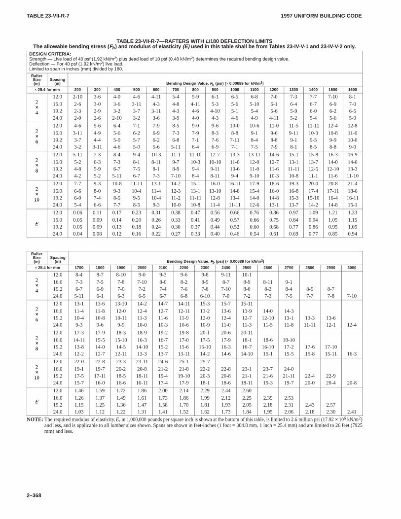
TABLE 23-VII-R-7TABLE 23-VII-R-7
1997 UNIFORM BUILDING CODE
2–368
TABLE 23-VII-R-7—RAFTERS WITH L/180 DEFLECTION LIMITSThe allowable bending stress ( Fb ) and modulus of elasticity (E) used in this table shall be from T ables 23-IV-V-1 and 23-IV-V-2 only .
DESIGN CRITERIA:Strength — Live load of 40 psf (1.92 kN/m2) plus dead load of 10 psf (0.48 kN/m2) determines the required bending design value.Deflection — For 40 psf (1.92 kN/m2) live load.Limited to span in inches (mm) divided by 180.
RafterSize(in)
Spacing(in) Bending Design V alue, Fb (psi) ( × 0.00689 for kN/m 2)
× 25.4 for mm 200 300 400 500 600 700 800 900 1000 1100 1200 1300 1400 1500 1600
212.0 2-10 3-6 4-0 4-6 4-11 5-4 5-9 6-1 6-5 6-8 7-0 7-3 7-7 7-10 8-1
2× 16.0 2-6 3-0 3-6 3-11 4-3 4-8 4-11 5-3 5-6 5-10 6-1 6-4 6-7 6-9 7-0×4 19.2 2-3 2-9 3-2 3-7 3-11 4-3 4-6 4-10 5-1 5-4 5-6 5-9 6-0 6-2 6-54
24.0 2-0 2-6 2-10 3-2 3-6 3-9 4-0 4-3 4-6 4-9 4-11 5-2 5-4 5-6 5-9
212.0 4-6 5-6 6-4 7-1 7-9 8-5 9-0 9-6 10-0 10-6 11-0 11-5 11-11 12-4 12-8
2× 16.0 3-11 4-9 5-6 6-2 6-9 7-3 7-9 8-3 8-8 9-1 9-6 9-11 10-3 10-8 11-0×6 19.2 3-7 4-4 5-0 5-7 6-2 6-8 7-1 7-6 7-11 8-4 8-8 9-1 9-5 9-9 10-06
24.0 3-2 3-11 4-6 5-0 5-6 5-11 6-4 6-9 7-1 7-5 7-9 8-1 8-5 8-8 9-0
212.0 5-11 7-3 8-4 9-4 10-3 11-1 11-10 12-7 13-3 13-11 14-6 15-1 15-8 16-3 16-9
2× 16.0 5-2 6-3 7-3 8-1 8-11 9-7 10-3 10-10 11-6 12-0 12-7 13-1 13-7 14-0 14-6×8 19.2 4-8 5-9 6-7 7-5 8-1 8-9 9-4 9-11 10-6 11-0 11-6 11-11 12-5 12-10 13-38
24.0 4-2 5-2 5-11 6-7 7-3 7-10 8-4 8-11 9-4 9-10 10-3 10-8 11-1 11-6 11-10
212.0 7-7 9-3 10-8 11-11 13-1 14-2 15-1 16-0 16-11 17-9 18-6 19-3 20-0 20-8 21-4
2× 16.0 6-6 8-0 9-3 10-4 11-4 12-3 13-1 13-10 14-8 15-4 16-0 16-8 17-4 17-11 18-6×10 19.2 6-0 7-4 8-5 9-5 10-4 11-2 11-11 12-8 13-4 14-0 14-8 15-3 15-10 16-4 16-1110
24.0 5-4 6-6 7-7 8-5 9-3 10-0 10-8 11-4 11-11 12-6 13-1 13-7 14-2 14-8 15-1
12.0 0.06 0.11 0.17 0.23 0.31 0.38 0.47 0.56 0.66 0.76 0.86 0.97 1.09 1.21 1.33
E16.0 0.05 0.09 0.14 0.20 0.26 0.33 0.41 0.49 0.57 0.66 0.75 0.84 0.94 1.05 1.15
E19.2 0.05 0.09 0.13 0.18 0.24 0.30 0.37 0.44 0.52 0.60 0.68 0.77 0.86 0.95 1.0524.0 0.04 0.08 0.12 0.16 0.22 0.27 0.33 0.40 0.46 0.54 0.61 0.69 0.77 0.85 0.94
RafterSize(in)
Spacing(in) Bending Design V alue, Fb (psi) ( × 0.00689 for kN/m 2)
× 25.4 for mm 1700 1800 1900 2000 2100 2200 2300 2400 2500 2600 2700 2800 2900 3000
212.0 8-4 8-7 8-10 9-0 9-3 9-6 9-8 9-11 10-1
2× 16.0 7-3 7-5 7-8 7-10 8-0 8-2 8-5 8-7 8-9 8-11 9-1×4 19.2 6-7 6-9 7-0 7-2 7-4 7-6 7-8 7-10 8-0 8-2 8-4 8-5 8-74
24.0 5-11 6-1 6-3 6-5 6-7 6-8 6-10 7-0 7-2 7-3 7-5 7-7 7-8 7-10
212.0 13-1 13-6 13-10 14-2 14-7 14-11 15-3 15-7 15-11
2× 16.0 11-4 11-8 12-0 12-4 12-7 12-11 13-2 13-6 13-9 14-0 14-3×6 19.2 10-4 10-8 10-11 11-3 11-6 11-9 12-0 12-4 12-7 12-10 13-1 13-3 13-66
24.0 9-3 9-6 9-9 10-0 10-3 10-6 10-9 11-0 11-3 11-5 11-8 11-11 12-1 12-4
212.0 17-3 17-9 18-3 18-9 19-2 19-8 20-1 20-6 20-11
2× 16.0 14-11 15-5 15-10 16-3 16-7 17-0 17-5 17-9 18-1 18-6 18-10×8 19.2 13-8 14-0 14-5 14-10 15-2 15-6 15-10 16-3 16-7 16-10 17-2 17-6 17-108
24.0 12-2 12-7 12-11 13-3 13-7 13-11 14-2 14-6 14-10 15-1 15-5 15-8 15-11 16-3
212.0 22-0 22-8 23-3 23-11 24-6 25-1 25-7
2× 16.0 19-1 19-7 20-2 20-8 21-2 21-8 22-2 22-8 23-1 23-7 24-0×10 19.2 17-5 17-11 18-5 18-11 19-4 19-10 20-3 20-8 21-1 21-6 21-11 22-4 22-910
24.0 15-7 16-0 16-6 16-11 17-4 17-9 18-1 18-6 18-11 19-3 19-7 20-0 20-4 20-8
12.0 1.46 1.59 1.72 1.86 2.00 2.14 2.29 2.44 2.60
E16.0 1.26 1.37 1.49 1.61 1.73 1.86 1.99 2.12 2.25 2.39 2.53
E19.2 1.15 1.25 1.36 1.47 1.58 1.70 1.81 1.93 2.05 2.18 2.31 2.43 2.5724.0 1.03 1.12 1.22 1.31 1.41 1.52 1.62 1.73 1.84 1.95 2.06 2.18 2.30 2.41
NOTE: The required modulus of elasticity, E, in 1,000,000 pounds per square inch is shown at the bottom of this table, is limited to 2.6 million psi (17.92 × 10⁶ kN/m2)and less, and is applicable to all lumber sizes shown. Spans are shown in feet-inches (1 foot = 304.8 mm, 1 inch = 25.4 mm) and are limited to 26 feet (7925mm) and less.
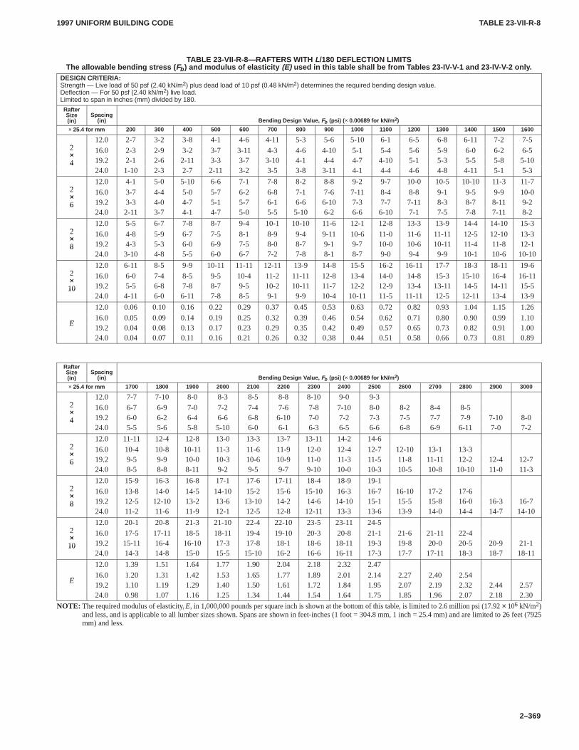
TABLE 23-VII-R-8TABLE 23-VII-R-8
1997 UNIFORM BUILDING CODE
2–369
TABLE 23-VII-R-8—RAFTERS WITH L/180 DEFLECTION LIMITSThe allowable bending stress ( Fb ) and modulus of elasticity (E) used in this table shall be from T ables 23-IV-V-1 and 23-IV-V-2 only .
DESIGN CRITERIA:Strength — Live load of 50 psf (2.40 kN/m2) plus dead load of 10 psf (0.48 kN/m2) determines the required bending design value.Deflection — For 50 psf (2.40 kN/m2) live load.Limited to span in inches (mm) divided by 180.
RafterSize(in)
Spacing(in) Bending Design V alue, Fb (psi) ( × 0.00689 for kN/m 2)
× 25.4 for mm 200 300 400 500 600 700 800 900 1000 1100 1200 1300 1400 1500 1600
212.0 2-7 3-2 3-8 4-1 4-6 4-11 5-3 5-6 5-10 6-1 6-5 6-8 6-11 7-2 7-5
2× 16.0 2-3 2-9 3-2 3-7 3-11 4-3 4-6 4-10 5-1 5-4 5-6 5-9 6-0 6-2 6-5×4 19.2 2-1 2-6 2-11 3-3 3-7 3-10 4-1 4-4 4-7 4-10 5-1 5-3 5-5 5-8 5-104
24.0 1-10 2-3 2-7 2-11 3-2 3-5 3-8 3-11 4-1 4-4 4-6 4-8 4-11 5-1 5-3
212.0 4-1 5-0 5-10 6-6 7-1 7-8 8-2 8-8 9-2 9-7 10-0 10-5 10-10 11-3 11-7
2× 16.0 3-7 4-4 5-0 5-7 6-2 6-8 7-1 7-6 7-11 8-4 8-8 9-1 9-5 9-9 10-0×6 19.2 3-3 4-0 4-7 5-1 5-7 6-1 6-6 6-10 7-3 7-7 7-11 8-3 8-7 8-11 9-26
24.0 2-11 3-7 4-1 4-7 5-0 5-5 5-10 6-2 6-6 6-10 7-1 7-5 7-8 7-11 8-2
212.0 5-5 6-7 7-8 8-7 9-4 10-1 10-10 11-6 12-1 12-8 13-3 13-9 14-4 14-10 15-3
2× 16.0 4-8 5-9 6-7 7-5 8-1 8-9 9-4 9-11 10-6 11-0 11-6 11-11 12-5 12-10 13-3×8 19.2 4-3 5-3 6-0 6-9 7-5 8-0 8-7 9-1 9-7 10-0 10-6 10-11 11-4 11-8 12-18
24.0 3-10 4-8 5-5 6-0 6-7 7-2 7-8 8-1 8-7 9-0 9-4 9-9 10-1 10-6 10-10
212.0 6-11 8-5 9-9 10-11 11-11 12-11 13-9 14-8 15-5 16-2 16-11 17-7 18-3 18-11 19-6
2× 16.0 6-0 7-4 8-5 9-5 10-4 11-2 11-11 12-8 13-4 14-0 14-8 15-3 15-10 16-4 16-11×10 19.2 5-5 6-8 7-8 8-7 9-5 10-2 10-11 11-7 12-2 12-9 13-4 13-11 14-5 14-11 15-510
24.0 4-11 6-0 6-11 7-8 8-5 9-1 9-9 10-4 10-11 11-5 11-11 12-5 12-11 13-4 13-9
12.0 0.06 0.10 0.16 0.22 0.29 0.37 0.45 0.53 0.63 0.72 0.82 0.93 1.04 1.15 1.26
E16.0 0.05 0.09 0.14 0.19 0.25 0.32 0.39 0.46 0.54 0.62 0.71 0.80 0.90 0.99 1.10
E19.2 0.04 0.08 0.13 0.17 0.23 0.29 0.35 0.42 0.49 0.57 0.65 0.73 0.82 0.91 1.0024.0 0.04 0.07 0.11 0.16 0.21 0.26 0.32 0.38 0.44 0.51 0.58 0.66 0.73 0.81 0.89
RafterSize(in)
Spacing(in) Bending Design V alue, Fb (psi) ( × 0.00689 for kN/m 2)
× 25.4 for mm 1700 1800 1900 2000 2100 2200 2300 2400 2500 2600 2700 2800 2900 3000
212.0 7-7 7-10 8-0 8-3 8-5 8-8 8-10 9-0 9-3
2× 16.0 6-7 6-9 7-0 7-2 7-4 7-6 7-8 7-10 8-0 8-2 8-4 8-5×4 19.2 6-0 6-2 6-4 6-6 6-8 6-10 7-0 7-2 7-3 7-5 7-7 7-9 7-10 8-04
24.0 5-5 5-6 5-8 5-10 6-0 6-1 6-3 6-5 6-6 6-8 6-9 6-11 7-0 7-2
212.0 11-11 12-4 12-8 13-0 13-3 13-7 13-11 14-2 14-6
2× 16.0 10-4 10-8 10-11 11-3 11-6 11-9 12-0 12-4 12-7 12-10 13-1 13-3×6 19.2 9-5 9-9 10-0 10-3 10-6 10-9 11-0 11-3 11-5 11-8 11-11 12-2 12-4 12-76
24.0 8-5 8-8 8-11 9-2 9-5 9-7 9-10 10-0 10-3 10-5 10-8 10-10 11-0 11-3
212.0 15-9 16-3 16-8 17-1 17-6 17-11 18-4 18-9 19-1
2× 16.0 13-8 14-0 14-5 14-10 15-2 15-6 15-10 16-3 16-7 16-10 17-2 17-6×8 19.2 12-5 12-10 13-2 13-6 13-10 14-2 14-6 14-10 15-1 15-5 15-8 16-0 16-3 16-78
24.0 11-2 11-6 11-9 12-1 12-5 12-8 12-11 13-3 13-6 13-9 14-0 14-4 14-7 14-10
212.0 20-1 20-8 21-3 21-10 22-4 22-10 23-5 23-11 24-5
2× 16.0 17-5 17-11 18-5 18-11 19-4 19-10 20-3 20-8 21-1 21-6 21-11 22-4×10 19.2 15-11 16-4 16-10 17-3 17-8 18-1 18-6 18-11 19-3 19-8 20-0 20-5 20-9 21-110
24.0 14-3 14-8 15-0 15-5 15-10 16-2 16-6 16-11 17-3 17-7 17-11 18-3 18-7 18-11
12.0 1.39 1.51 1.64 1.77 1.90 2.04 2.18 2.32 2.47
E16.0 1.20 1.31 1.42 1.53 1.65 1.77 1.89 2.01 2.14 2.27 2.40 2.54
E19.2 1.10 1.19 1.29 1.40 1.50 1.61 1.72 1.84 1.95 2.07 2.19 2.32 2.44 2.5724.0 0.98 1.07 1.16 1.25 1.34 1.44 1.54 1.64 1.75 1.85 1.96 2.07 2.18 2.30
NOTE: The required modulus of elasticity, E, in 1,000,000 pounds per square inch is shown at the bottom of this table, is limited to 2.6 million psi (17.92 × 10⁶ kN/m2)and less, and is applicable to all lumber sizes shown. Spans are shown in feet-inches (1 foot = 304.8 mm, 1 inch = 25.4 mm) and are limited to 26 feet (7925mm) and less.
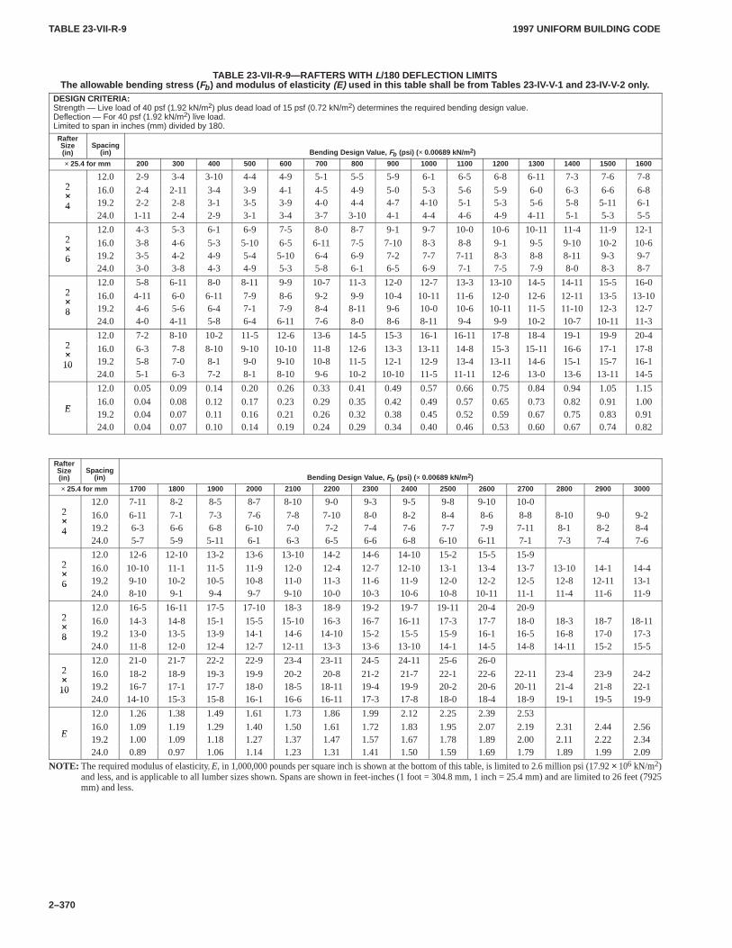
TABLE 23-VII-R-9TABLE 23-VII-R-9
1997 UNIFORM BUILDING CODE
2–370
TABLE 23-VII-R-9—RAFTERS WITH L/180 DEFLECTION LIMITSThe allowable bending stress ( Fb ) and modulus of elasticity (E) used in this table shall be from T ables 23-IV-V-1 and 23-IV-V-2 only .
DESIGN CRITERIA:Strength — Live load of 40 psf (1.92 kN/m2) plus dead load of 15 psf (0.72 kN/m2) determines the required bending design value.Deflection — For 40 psf (1.92 kN/m2) live load.Limited to span in inches (mm) divided by 180.
RafterSize(in)
Spacing(in) Bending Design V alue, Fb (psi) ( × 0.00689 kN/m2)
× 25.4 for mm 200 300 400 500 600 700 800 900 1000 1100 1200 1300 1400 1500 1600
212.0 2-9 3-4 3-10 4-4 4-9 5-1 5-5 5-9 6-1 6-5 6-8 6-11 7-3 7-6 7-8
2× 16.0 2-4 2-11 3-4 3-9 4-1 4-5 4-9 5-0 5-3 5-6 5-9 6-0 6-3 6-6 6-8×4 19.2 2-2 2-8 3-1 3-5 3-9 4-0 4-4 4-7 4-10 5-1 5-3 5-6 5-8 5-11 6-14
24.0 1-11 2-4 2-9 3-1 3-4 3-7 3-10 4-1 4-4 4-6 4-9 4-11 5-1 5-3 5-5
212.0 4-3 5-3 6-1 6-9 7-5 8-0 8-7 9-1 9-7 10-0 10-6 10-11 11-4 11-9 12-1
2× 16.0 3-8 4-6 5-3 5-10 6-5 6-11 7-5 7-10 8-3 8-8 9-1 9-5 9-10 10-2 10-6×6 19.2 3-5 4-2 4-9 5-4 5-10 6-4 6-9 7-2 7-7 7-11 8-3 8-8 8-11 9-3 9-76
24.0 3-0 3-8 4-3 4-9 5-3 5-8 6-1 6-5 6-9 7-1 7-5 7-9 8-0 8-3 8-7
212.0 5-8 6-11 8-0 8-11 9-9 10-7 11-3 12-0 12-7 13-3 13-10 14-5 14-11 15-5 16-0
2× 16.0 4-11 6-0 6-11 7-9 8-6 9-2 9-9 10-4 10-11 11-6 12-0 12-6 12-11 13-5 13-10×8 19.2 4-6 5-6 6-4 7-1 7-9 8-4 8-11 9-6 10-0 10-6 10-11 11-5 11-10 12-3 12-78
24.0 4-0 4-11 5-8 6-4 6-11 7-6 8-0 8-6 8-11 9-4 9-9 10-2 10-7 10-11 11-3
212.0 7-2 8-10 10-2 11-5 12-6 13-6 14-5 15-3 16-1 16-11 17-8 18-4 19-1 19-9 20-4
2× 16.0 6-3 7-8 8-10 9-10 10-10 11-8 12-6 13-3 13-11 14-8 15-3 15-11 16-6 17-1 17-8×10 19.2 5-8 7-0 8-1 9-0 9-10 10-8 11-5 12-1 12-9 13-4 13-11 14-6 15-1 15-7 16-110
24.0 5-1 6-3 7-2 8-1 8-10 9-6 10-2 10-10 11-5 11-11 12-6 13-0 13-6 13-11 14-5
12.0 0.05 0.09 0.14 0.20 0.26 0.33 0.41 0.49 0.57 0.66 0.75 0.84 0.94 1.05 1.15
E16.0 0.04 0.08 0.12 0.17 0.23 0.29 0.35 0.42 0.49 0.57 0.65 0.73 0.82 0.91 1.00
E19.2 0.04 0.07 0.11 0.16 0.21 0.26 0.32 0.38 0.45 0.52 0.59 0.67 0.75 0.83 0.9124.0 0.04 0.07 0.10 0.14 0.19 0.24 0.29 0.34 0.40 0.46 0.53 0.60 0.67 0.74 0.82
RafterSize(in)
Spacing(in) Bending Design V alue, Fb (psi) ( × 0.00689 kN/m2)
× 25.4 for mm 1700 1800 1900 2000 2100 2200 2300 2400 2500 2600 2700 2800 2900 3000
212.0 7-11 8-2 8-5 8-7 8-10 9-0 9-3 9-5 9-8 9-10 10-0
2× 16.0 6-11 7-1 7-3 7-6 7-8 7-10 8-0 8-2 8-4 8-6 8-8 8-10 9-0 9-2×4 19.2 6-3 6-6 6-8 6-10 7-0 7-2 7-4 7-6 7-7 7-9 7-11 8-1 8-2 8-44
24.0 5-7 5-9 5-11 6-1 6-3 6-5 6-6 6-8 6-10 6-11 7-1 7-3 7-4 7-6
212.0 12-6 12-10 13-2 13-6 13-10 14-2 14-6 14-10 15-2 15-5 15-9
2× 16.0 10-10 11-1 11-5 11-9 12-0 12-4 12-7 12-10 13-1 13-4 13-7 13-10 14-1 14-4×6 19.2 9-10 10-2 10-5 10-8 11-0 11-3 11-6 11-9 12-0 12-2 12-5 12-8 12-11 13-16
24.0 8-10 9-1 9-4 9-7 9-10 10-0 10-3 10-6 10-8 10-11 11-1 11-4 11-6 11-9
212.0 16-5 16-11 17-5 17-10 18-3 18-9 19-2 19-7 19-11 20-4 20-9
2× 16.0 14-3 14-8 15-1 15-5 15-10 16-3 16-7 16-11 17-3 17-7 18-0 18-3 18-7 18-11×8 19.2 13-0 13-5 13-9 14-1 14-6 14-10 15-2 15-5 15-9 16-1 16-5 16-8 17-0 17-38
24.0 11-8 12-0 12-4 12-7 12-11 13-3 13-6 13-10 14-1 14-5 14-8 14-11 15-2 15-5
212.0 21-0 21-7 22-2 22-9 23-4 23-11 24-5 24-11 25-6 26-0
2× 16.0 18-2 18-9 19-3 19-9 20-2 20-8 21-2 21-7 22-1 22-6 22-11 23-4 23-9 24-2×10 19.2 16-7 17-1 17-7 18-0 18-5 18-11 19-4 19-9 20-2 20-6 20-11 21-4 21-8 22-110
24.0 14-10 15-3 15-8 16-1 16-6 16-11 17-3 17-8 18-0 18-4 18-9 19-1 19-5 19-9
12.0 1.26 1.38 1.49 1.61 1.73 1.86 1.99 2.12 2.25 2.39 2.53
E16.0 1.09 1.19 1.29 1.40 1.50 1.61 1.72 1.83 1.95 2.07 2.19 2.31 2.44 2.56
E19.2 1.00 1.09 1.18 1.27 1.37 1.47 1.57 1.67 1.78 1.89 2.00 2.11 2.22 2.3424.0 0.89 0.97 1.06 1.14 1.23 1.31 1.41 1.50 1.59 1.69 1.79 1.89 1.99 2.09
NOTE: The required modulus of elasticity, E, in 1,000,000 pounds per square inch is shown at the bottom of this table, is limited to 2.6 million psi (17.92 × 10⁶ kN/m2)and less, and is applicable to all lumber sizes shown. Spans are shown in feet-inches (1 foot = 304.8 mm, 1 inch = 25.4 mm) and are limited to 26 feet (7925mm) and less.
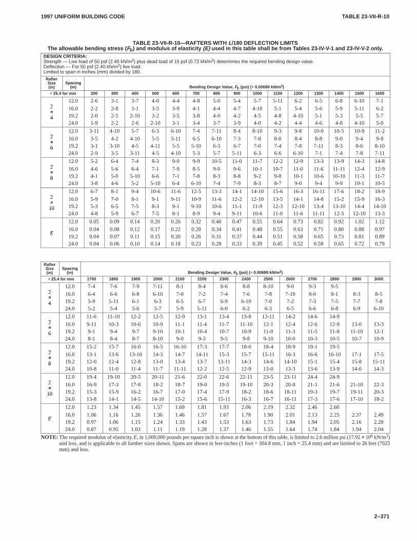
TABLE 23-VII-R-10TABLE 23-VII-R-10
1997 UNIFORM BUILDING CODE
2–371
TABLE 23-VII-R-10—RAFTERS WITH L/180 DEFLECTION LIMITSThe allowable bending stress ( Fb ) and modulus of elasticity (E) used in this table shall be from T ables 23-IV-V-1 and 23-IV-V-2 only .
DESIGN CRITERIA:Strength — Live load of 50 psf (2.40 kN/m2) plus dead load of 15 psf (0.72 kN/m2) determines the required bending design value.Deflection — For 50 psf (2.40 kN/m2) live load.Limited to span in inches (mm) divided by 180.
RafterSize(in)
Spacing(in) Bending Design V alue, Fb (psi) ( × 0.00689 kN/m2)
× 25.4 for mm 200 300 400 500 600 700 800 900 1000 1100 1200 1300 1400 1500 1600
212.0 2-6 3-1 3-7 4-0 4-4 4-8 5-0 5-4 5-7 5-11 6-2 6-5 6-8 6-10 7-1
2× 16.0 2-2 2-8 3-1 3-5 3-9 4-1 4-4 4-7 4-10 5-1 5-4 5-6 5-9 5-11 6-2×4 19.2 2-0 2-5 2-10 3-2 3-5 3-8 4-0 4-2 4-5 4-8 4-10 5-1 5-3 5-5 5-74
24.0 1-9 2-2 2-6 2-10 3-1 3-4 3-7 3-9 4-0 4-2 4-4 4-6 4-8 4-10 5-0
212.0 3-11 4-10 5-7 6-3 6-10 7-4 7-11 8-4 8-10 9-3 9-8 10-0 10-5 10-9 11-2
2× 16.0 3-5 4-2 4-10 5-5 5-11 6-5 6-10 7-3 7-8 8-0 8-4 8-8 9-0 9-4 9-8×6 19.2 3-1 3-10 4-5 4-11 5-5 5-10 6-3 6-7 7-0 7-4 7-8 7-11 8-3 8-6 8-106
24.0 2-9 3-5 3-11 4-5 4-10 5-3 5-7 5-11 6-3 6-6 6-10 7-1 7-4 7-8 7-11
212.0 5-2 6-4 7-4 8-3 9-0 9-9 10-5 11-0 11-7 12-2 12-9 13-3 13-9 14-3 14-8
2× 16.0 4-6 5-6 6-4 7-1 7-9 8-5 9-0 9-6 10-1 10-7 11-0 11-6 11-11 12-4 12-9×8 19.2 4-1 5-0 5-10 6-6 7-1 7-8 8-3 8-8 9-2 9-8 10-1 10-6 10-10 11-3 11-78
24.0 3-8 4-6 5-2 5-10 6-4 6-10 7-4 7-9 8-3 8-7 9-0 9-4 9-9 10-1 10-5
212.0 6-7 8-1 9-4 10-6 11-6 12-5 13-3 14-1 14-10 15-6 16-3 16-11 17-6 18-2 18-9
2× 16.0 5-9 7-0 8-1 9-1 9-11 10-9 11-6 12-2 12-10 13-5 14-1 14-8 15-2 15-9 16-3×10 19.2 5-3 6-5 7-5 8-3 9-1 9-10 10-6 11-1 11-9 12-3 12-10 13-4 13-10 14-4 14-1010
24.0 4-8 5-9 6-7 7-5 8-1 8-9 9-4 9-11 10-6 11-0 11-6 11-11 12-5 12-10 13-3
12.0 0.05 0.09 0.14 0.20 0.26 0.32 0.40 0.47 0.55 0.64 0.73 0.82 0.92 1.02 1.12
E16.0 0.04 0.08 0.12 0.17 0.22 0.28 0.34 0.41 0.48 0.55 0.63 0.71 0.80 0.88 0.97
E19.2 0.04 0.07 0.11 0.15 0.20 0.26 0.31 0.37 0.44 0.51 0.58 0.65 0.73 0.81 0.8924.0 0.04 0.06 0.10 0.14 0.18 0.23 0.28 0.33 0.39 0.45 0.52 0.58 0.65 0.72 0.79
RafterSize(in)
Spacing(in) Bending Design V alue, Fb (psi) ( × 0.00689 kN/m2)
× 25.4 for mm 1700 1800 1900 2000 2100 2200 2300 2400 2500 2600 2700 2800 2900 3000
212.0 7-4 7-6 7-9 7-11 8-1 8-4 8-6 8-8 8-10 9-0 9-3 9-5
2× 16.0 6-4 6-6 6-8 6-10 7-0 7-2 7-4 7-6 7-8 7-10 8-0 8-1 8-3 8-5×4 19.2 5-9 5-11 6-1 6-3 6-5 6-7 6-9 6-10 7-0 7-2 7-3 7-5 7-7 7-84
24.0 5-2 5-4 5-6 5-7 5-9 5-11 6-0 6-2 6-3 6-5 6-6 6-8 6-9 6-10
212.0 11-6 11-10 12-2 12-5 12-9 13-1 13-4 13-8 13-11 14-2 14-6 14-9
2× 16.0 9-11 10-3 10-6 10-9 11-1 11-4 11-7 11-10 12-1 12-4 12-6 12-9 13-0 13-3×6 19.2 9-1 9-4 9-7 9-10 10-1 10-4 10-7 10-9 11-0 11-3 11-5 11-8 11-10 12-16
24.0 8-1 8-4 8-7 8-10 9-0 9-3 9-5 9-8 9-10 10-0 10-3 10-5 10-7 10-9
212.0 15-2 15-7 16-0 16-5 16-10 17-3 17-7 18-0 18-4 18-9 19-1 19-5
2× 16.0 13-1 13-6 13-10 14-3 14-7 14-11 15-3 15-7 15-11 16-3 16-6 16-10 17-1 17-5×8 19.2 12-0 12-4 12-8 13-0 13-4 13-7 13-11 14-3 14-6 14-10 15-1 15-4 15-8 15-118
24.0 10-8 11-0 11-4 11-7 11-11 12-2 12-5 12-9 13-0 13-3 13-6 13-9 14-0 14-3
212.0 19-4 19-10 20-5 20-11 21-6 22-0 22-6 22-11 23-5 23-11 24-4 24-9
2× 16.0 16-9 17-3 17-8 18-2 18-7 19-0 19-5 19-10 20-3 20-8 21-1 21-6 21-10 22-3×10 19.2 15-3 15-9 16-2 16-7 17-0 17-4 17-9 18-2 18-6 18-11 19-3 19-7 19-11 20-310
24.0 13-8 14-1 14-5 14-10 15-2 15-6 15-11 16-3 16-7 16-11 17-3 17-6 17-10 18-2
12.0 1.23 1.34 1.45 1.57 1.69 1.81 1.93 2.06 2.19 2.32 2.46 2.60
E16.0 1.06 1.16 1.26 1.36 1.46 1.57 1.67 1.78 1.90 2.01 2.13 2.25 2.37 2.49
E19.2 0.97 1.06 1.15 1.24 1.33 1.43 1.53 1.63 1.73 1.84 1.94 2.05 2.16 2.2824.0 0.87 0.95 1.03 1.11 1.19 1.28 1.37 1.46 1.55 1.64 1.74 1.84 1.94 2.04
NOTE: The required modulus of elasticity, E, in 1,000,000 pounds per square inch is shown at the bottom of this table, is limited to 2.6 million psi (17.92 × 10⁶ kN/m2)and less, and is applicable to all lumber sizes shown. Spans are shown in feet-inches (1 foot = 304.8 mm, 1 inch = 25.4 mm) and are limited to 26 feet (7925mm) and less.
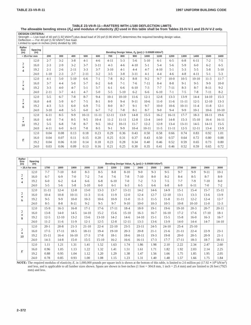
TABLE 23-VII-R-11TABLE 23-VII-R-11
1997 UNIFORM BUILDING CODE
2–372
TABLE 23-VII-R-11—RAFTERS WITH L/180 DEFLECTION LIMITSThe allowable bending stress ( Fb ) and modulus of elasticity (E) used in this table shall be from T ables 23-IV-V-1 and 23-IV-V-2 only .
DESIGN CRITERIA:Strength — Live load of 40 psf (1.92 kN/m2) plus dead load of 20 psf (0.96 kN/m2) determines the required bending design value.Deflection — For 40 psf (1.92 kN/m2) live load.Limited to span in inches (mm) divided by 180.
RafterSize(in)
Spacing(in) Bending Design V alue, Fb (psi) ( × 0.00689 kN/m2)
× 25.4 for mm 200 300 400 500 600 700 800 900 1000 1100 1200 1300 1400 1500 1600
212.0 2-7 3-2 3-8 4-1 4-6 4-11 5-3 5-6 5-10 6-1 6-5 6-8 6-11 7-2 7-5
2× 16.0 2-3 2-9 3-2 3-7 3-11 4-3 4-6 4-10 5-1 5-4 5-6 5-9 6-0 6-2 6-5×4 19.2 2-1 2-6 2-11 3-3 3-7 3-10 4-1 4-4 4-7 4-10 5-1 5-3 5-5 5-8 5-104
24.0 1-10 2-3 2-7 2-11 3-2 3-5 3-8 3-11 4-1 4-4 4-6 4-8 4-11 5-1 5-3
212.0 4-1 5-0 5-10 6-6 7-1 7-8 8-2 8-8 9-2 9-7 10-0 10-5 10-10 11-3 11-7
2× 16.0 3-7 4-4 5-0 5-7 6-2 6-8 7-1 7-6 7-11 8-4 8-8 9-1 9-5 9-9 10-0×6 19.2 3-3 4-0 4-7 5-1 5-7 6-1 6-6 6-10 7-3 7-7 7-11 8-3 8-7 8-11 9-26
24.0 2-11 3-7 4-1 4-7 5-0 5-5 5-10 6-2 6-6 6-10 7-1 7-5 7-8 7-11 8-2
212.0 5-5 6-7 7-8 8-7 9-4 10-1 10-10 11-6 12-1 12-8 13-3 13-9 14-4 14-10 15-3
2× 16.0 4-8 5-9 6-7 7-5 8-1 8-9 9-4 9-11 10-6 11-0 11-6 11-11 12-5 12-10 13-3×8 19.2 4-3 5-3 6-0 6-9 7-5 8-0 8-7 9-1 9-7 10-0 10-6 10-11 11-4 11-8 12-18
24.0 3-10 4-8 5-5 6-0 6-7 7-2 7-8 8-1 8-7 9-0 9-4 9-9 10-1 10-6 10-10
212.0 6-11 8-5 9-9 10-11 11-11 12-11 13-9 14-8 15-5 16-2 16-11 17-7 18-3 18-11 19-6
2× 16.0 6-0 7-4 8-5 9-5 10-4 11-2 11-11 12-8 13-4 14-0 14-8 15-3 15-10 16-4 16-11×10 19.2 5-5 6-8 7-8 8-7 9-5 10-2 10-11 11-7 12-2 12-9 13-4 13-11 14-5 14-11 15-510
24.0 4-11 6-0 6-11 7-8 8-5 9-1 9-9 10-4 10-11 11-5 11-11 12-5 12-11 13-4 13-9
12.0 0.04 0.08 0.13 0.18 0.23 0.29 0.36 0.43 0.50 0.58 0.66 0.74 0.83 0.92 1.01
E16.0 0.04 0.07 0.11 0.15 0.20 0.25 0.31 0.37 0.43 0.50 0.57 0.64 0.72 0.80 0.88
E19.2 0.04 0.06 0.10 0.14 0.18 0.23 0.28 0.34 0.40 0.46 0.52 0.59 0.65 0.73 0.8024.0 0.03 0.06 0.09 0.13 0.16 0.21 0.25 0.30 0.35 0.41 0.46 0.52 0.59 0.65 0.72
RafterSize(in)
Spacing(in) Bending Design V alue, Fb (psi) ( × 0.00689 kN/m2)
× 25.4 for mm 1700 1800 1900 2000 2100 2200 2300 2400 2500 2600 2700 2800 2900 3000
212.0 7-7 7-10 8-0 8-3 8-5 8-8 8-10 9-0 9-3 9-5 9-7 9-9 9-11 10-1
2× 16.0 6-7 6-9 7-0 7-2 7-4 7-6 7-8 7-10 8-0 8-2 8-4 8-5 8-7 8-9×4 19.2 6-0 6-2 6-4 6-6 6-8 6-10 7-0 7-2 7-3 7-5 7-7 7-9 7-10 8-04
24.0 5-5 5-6 5-8 5-10 6-0 6-1 6-3 6-5 6-6 6-8 6-9 6-11 7-0 7-2
212.0 11-11 12-4 12-8 13-0 13-3 13-7 13-11 14-2 14-6 14-9 15-1 15-4 15-7 15-11
2× 16.0 10-4 10-8 10-11 11-3 11-6 11-9 12-0 12-4 12-7 12-10 13-1 13-3 13-6 13-9×6 19.2 9-5 9-9 10-0 10-3 10-6 10-9 11-0 11-3 11-5 11-8 11-11 12-2 12-4 12-76
24.0 8-5 8-8 8-11 9-2 9-5 9-7 9-10 10-0 10-3 10-5 10-8 10-10 11-0 11-3
212.0 15-9 16-3 16-8 17-1 17-6 17-11 18-4 18-9 19-1 19-6 19-10 20-3 20-7 20-11
2× 16.0 13-8 14-0 14-5 14-10 15-2 15-6 15-10 16-3 16-7 16-10 17-2 17-6 17-10 18-1×8 19.2 12-5 12-10 13-2 13-6 13-10 14-2 14-6 14-10 15-1 15-5 15-8 16-0 16-3 16-78
24.0 11-2 11-6 11-9 12-1 12-5 12-8 12-11 13-3 13-6 13-9 14-0 14-4 14-7 14-10
212.0 20-1 20-8 21-3 21-10 22-4 22-10 23-5 23-11 24-5 24-10 25-4 25-10
2× 16.0 17-5 17-11 18-5 18-11 19-4 19-10 20-3 20-8 21-1 21-6 21-11 22-4 22-9 23-1×10 19.2 15-11 16-4 16-10 17-3 17-8 18-1 18-6 18-11 19-3 19-8 20-0 20-5 20-9 21-110
24.0 14-3 14-8 15-0 15-5 15-10 16-2 16-6 16-11 17-3 17-7 17-11 18-3 18-7 18-11
12.0 1.11 1.21 1.31 1.41 1.52 1.63 1.74 1.86 1.98 2.10 2.22 2.34 2.47 2.60
E16.0 0.96 1.05 1.13 1.22 1.32 1.41 1.51 1.61 1.71 1.82 1.92 2.03 2.14 2.25
E19.2 0.88 0.95 1.04 1.12 1.20 1.29 1.38 1.47 1.56 1.66 1.75 1.85 1.95 2.0524.0 0.78 0.85 0.93 1.00 1.08 1.15 1.23 1.31 1.40 1.48 1.57 1.66 1.75 1.84
NOTE: The required modulus of elasticity, E, in 1,000,000 pounds per square inch is shown at the bottom of this table, is limited to 2.6 million psi (17.92 × 10⁶ kN/m2)and less, and is applicable to all lumber sizes shown. Spans are shown in feet-inches (1 foot = 304.8 mm, 1 inch = 25.4 mm) and are limited to 26 feet (7925mm) and less.
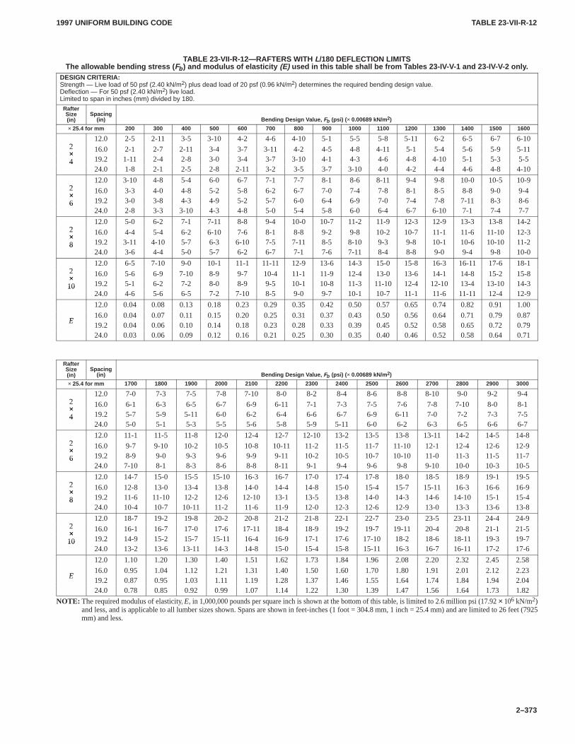
TABLE 23-VII-R-12TABLE 23-VII-R-12
1997 UNIFORM BUILDING CODE
2–373
TABLE 23-VII-R-12—RAFTERS WITH L/180 DEFLECTION LIMITSThe allowable bending stress ( Fb ) and modulus of elasticity (E) used in this table shall be from T ables 23-IV-V-1 and 23-IV-V-2 only .
DESIGN CRITERIA:Strength — Live load of 50 psf (2.40 kN/m2) plus dead load of 20 psf (0.96 kN/m2) determines the required bending design value.Deflection — For 50 psf (2.40 kN/m2) live load.Limited to span in inches (mm) divided by 180.
RafterSize(in)
Spacing(in) Bending Design V alue, Fb (psi) ( × 0.00689 kN/m2)
× 25.4 for mm 200 300 400 500 600 700 800 900 1000 1100 1200 1300 1400 1500 1600
212.0 2-5 2-11 3-5 3-10 4-2 4-6 4-10 5-1 5-5 5-8 5-11 6-2 6-5 6-7 6-10
2× 16.0 2-1 2-7 2-11 3-4 3-7 3-11 4-2 4-5 4-8 4-11 5-1 5-4 5-6 5-9 5-11×4 19.2 1-11 2-4 2-8 3-0 3-4 3-7 3-10 4-1 4-3 4-6 4-8 4-10 5-1 5-3 5-54
24.0 1-8 2-1 2-5 2-8 2-11 3-2 3-5 3-7 3-10 4-0 4-2 4-4 4-6 4-8 4-10
212.0 3-10 4-8 5-4 6-0 6-7 7-1 7-7 8-1 8-6 8-11 9-4 9-8 10-0 10-5 10-9
2× 16.0 3-3 4-0 4-8 5-2 5-8 6-2 6-7 7-0 7-4 7-8 8-1 8-5 8-8 9-0 9-4×6 19.2 3-0 3-8 4-3 4-9 5-2 5-7 6-0 6-4 6-9 7-0 7-4 7-8 7-11 8-3 8-66
24.0 2-8 3-3 3-10 4-3 4-8 5-0 5-4 5-8 6-0 6-4 6-7 6-10 7-1 7-4 7-7
212.0 5-0 6-2 7-1 7-11 8-8 9-4 10-0 10-7 11-2 11-9 12-3 12-9 13-3 13-8 14-2
2× 16.0 4-4 5-4 6-2 6-10 7-6 8-1 8-8 9-2 9-8 10-2 10-7 11-1 11-6 11-10 12-3×8 19.2 3-11 4-10 5-7 6-3 6-10 7-5 7-11 8-5 8-10 9-3 9-8 10-1 10-6 10-10 11-28
24.0 3-6 4-4 5-0 5-7 6-2 6-7 7-1 7-6 7-11 8-4 8-8 9-0 9-4 9-8 10-0
212.0 6-5 7-10 9-0 10-1 11-1 11-11 12-9 13-6 14-3 15-0 15-8 16-3 16-11 17-6 18-1
2× 16.0 5-6 6-9 7-10 8-9 9-7 10-4 11-1 11-9 12-4 13-0 13-6 14-1 14-8 15-2 15-8×10 19.2 5-1 6-2 7-2 8-0 8-9 9-5 10-1 10-8 11-3 11-10 12-4 12-10 13-4 13-10 14-310
24.0 4-6 5-6 6-5 7-2 7-10 8-5 9-0 9-7 10-1 10-7 11-1 11-6 11-11 12-4 12-9
12.0 0.04 0.08 0.13 0.18 0.23 0.29 0.35 0.42 0.50 0.57 0.65 0.74 0.82 0.91 1.00
E16.0 0.04 0.07 0.11 0.15 0.20 0.25 0.31 0.37 0.43 0.50 0.56 0.64 0.71 0.79 0.87
E19.2 0.04 0.06 0.10 0.14 0.18 0.23 0.28 0.33 0.39 0.45 0.52 0.58 0.65 0.72 0.7924.0 0.03 0.06 0.09 0.12 0.16 0.21 0.25 0.30 0.35 0.40 0.46 0.52 0.58 0.64 0.71
RafterSize(in)
Spacing(in) Bending Design V alue, Fb (psi) ( × 0.00689 kN/m2)
× 25.4 for mm 1700 1800 1900 2000 2100 2200 2300 2400 2500 2600 2700 2800 2900 3000
212.0 7-0 7-3 7-5 7-8 7-10 8-0 8-2 8-4 8-6 8-8 8-10 9-0 9-2 9-4
2× 16.0 6-1 6-3 6-5 6-7 6-9 6-11 7-1 7-3 7-5 7-6 7-8 7-10 8-0 8-1×4 19.2 5-7 5-9 5-11 6-0 6-2 6-4 6-6 6-7 6-9 6-11 7-0 7-2 7-3 7-54
24.0 5-0 5-1 5-3 5-5 5-6 5-8 5-9 5-11 6-0 6-2 6-3 6-5 6-6 6-7
212.0 11-1 11-5 11-8 12-0 12-4 12-7 12-10 13-2 13-5 13-8 13-11 14-2 14-5 14-8
2× 16.0 9-7 9-10 10-2 10-5 10-8 10-11 11-2 11-5 11-7 11-10 12-1 12-4 12-6 12-9×6 19.2 8-9 9-0 9-3 9-6 9-9 9-11 10-2 10-5 10-7 10-10 11-0 11-3 11-5 11-76
24.0 7-10 8-1 8-3 8-6 8-8 8-11 9-1 9-4 9-6 9-8 9-10 10-0 10-3 10-5
212.0 14-7 15-0 15-5 15-10 16-3 16-7 17-0 17-4 17-8 18-0 18-5 18-9 19-1 19-5
2× 16.0 12-8 13-0 13-4 13-8 14-0 14-4 14-8 15-0 15-4 15-7 15-11 16-3 16-6 16-9×8 19.2 11-6 11-10 12-2 12-6 12-10 13-1 13-5 13-8 14-0 14-3 14-6 14-10 15-1 15-48
24.0 10-4 10-7 10-11 11-2 11-6 11-9 12-0 12-3 12-6 12-9 13-0 13-3 13-6 13-8
212.0 18-7 19-2 19-8 20-2 20-8 21-2 21-8 22-1 22-7 23-0 23-5 23-11 24-4 24-9
2× 16.0 16-1 16-7 17-0 17-6 17-11 18-4 18-9 19-2 19-7 19-11 20-4 20-8 21-1 21-5×10 19.2 14-9 15-2 15-7 15-11 16-4 16-9 17-1 17-6 17-10 18-2 18-6 18-11 19-3 19-710
24.0 13-2 13-6 13-11 14-3 14-8 15-0 15-4 15-8 15-11 16-3 16-7 16-11 17-2 17-6
12.0 1.10 1.20 1.30 1.40 1.51 1.62 1.73 1.84 1.96 2.08 2.20 2.32 2.45 2.58
E16.0 0.95 1.04 1.12 1.21 1.31 1.40 1.50 1.60 1.70 1.80 1.91 2.01 2.12 2.23
E19.2 0.87 0.95 1.03 1.11 1.19 1.28 1.37 1.46 1.55 1.64 1.74 1.84 1.94 2.0424.0 0.78 0.85 0.92 0.99 1.07 1.14 1.22 1.30 1.39 1.47 1.56 1.64 1.73 1.82
NOTE: The required modulus of elasticity, E, in 1,000,000 pounds per square inch is shown at the bottom of this table, is limited to 2.6 million psi (17.92 × 10⁶ kN/m2)and less, and is applicable to all lumber sizes shown. Spans are shown in feet-inches (1 foot = 304.8 mm, 1 inch = 25.4 mm) and are limited to 26 feet (7925mm) and less.
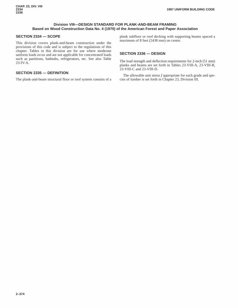
CHAP. 23, DIV. VIII23342336
1997 UNIFORM BUILDING CODE
2–374
Division VIII—DESIGN STANDARD FOR PLANK-AND-BEAM FRAMINGBased on Wood Construction Data No. 4 (1970) of the American Forest and Paper Association
SECTION 2334 — SCOPE
This division covers plank-and-beam construction under theprovisions of this code and is subject to the regulations of thischapter. Tables in this division are for use where moderateuniform loads occur and are not applicable for concentrated loadssuch as partitions, bathtubs, refrigerators, etc. See also Table23-IV-A.CHAP. 23, DIV. VIII
SECTION 2335 — DEFINITION
The plank-and-beam structural floor or roof system consists of a
plank subfloor or roof decking with supporting beams spaced amaximum of 8 feet (2438 mm) on center.
SECTION 2336 — DESIGN
The load strength and deflection requirements for 2-inch (51 mm)planks and beams are set forth in Tables 23-VIII-A, 23-VIII-B,23-VIII-C and 23-VIII-D.
The allowable unit stress f appropriate for each grade and spe-cies of lumber is set forth in Chapter 23, Division III.
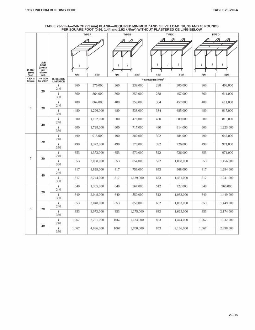
TABLE 23-VIII-ATABLE 23-VIII-A
1997 UNIFORM BUILDING CODE
2–375
TABLE 23-VIII-A—2-INCH (51 mm) PLANK—REQUIRED MINIMUM f AND E LIVE LOAD: 20, 30 AND 40 POUNDSPER SQUARE FOOT (0.96, 1.44 and 1.92 kN/m 2) WITHOUT PLASTERED CEILING BELOW
TYPE A TYPE B TYPE C TYPE D
PLANKSPAN
LIVELOAD(poundspersquare
l l l l l l l l l
PLANKSPAN(feet)
persquarefoot) f psi E psi f psi E psi f psi E psi f psi E psi
× 304.8for mm
× 0.0479for kN/m2
DEFLECTIONLIMITATION
× 0.00689 for N/mm2
20
l240
360 576,000 360 239,000 288 305,000 360 408,000
20l
360360 864,000 360 359,000 288 457,000 360 611,000
6 30
l240
480 864,000 480 359,000 384 457,000 480 611,000
6 30l
360480 1,296,000 480 538,000 384 685,000 480 917,000
40
l240
600 1,152,000 600 478,000 480 609,000 600 815,000
40l
360600 1,728,000 600 717,000 480 914,000 600 1,223,000
20
l240
490 915,000 490 380,000 392 484,000 490 647,000
20l
360490 1,372,000 490 570,000 392 726,000 490 971,000
7 30
l240
653 1,372,000 653 570,000 522 726,000 653 971,000
7 30l
360653 2,058,000 653 854,000 522 1,088,000 653 1,456,000
40
l240
817 1,829,000 817 759,000 653 968,000 817 1,294,000
40l
360817 2,744,000 817 1,139,000 653 1,451,000 817 1,941,000
20
l240
640 1,365,000 640 567,000 512 722,000 640 966,000
20l
360640 2,048,000 640 850,000 512 1,083,000 640 1,449,000
8 30
l240
853 2,048,000 853 850,000 682 1,083,000 853 1,449,000
8 30l
360853 3,072,000 853 1,275,000 682 1,625,000 853 2,174,000
40
l240
1,067 2,731,000 1067 1,134,000 853 1,444,000 1,067 1,932,000
40l
3601,067 4,096,000 1067 1,700,000 853 2,166,000 1,067 2,898,000
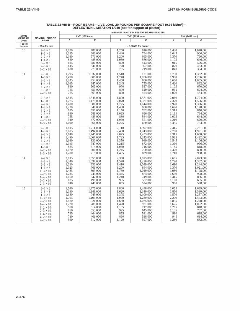
TABLE 23-VIII-BTABLE 23-VIII-B
1997 UNIFORM BUILDING CODE
2–376
TABLE 23-VIII-B—ROOF BEAMS—LIVE LOAD 20 POUNDS PER SQUARE FOOT (0.96 kN/m 2)—DEFLECTION LIMITATION L/240 (not for support of plaster)
MINIMUM I AND E IN PSI FOR BEAMS SPACED:SPAN
OF BEAM NOMINAL SIZE OF6′-0″ (1829 mm) 7′-0″ (2134 mm) 8′-0″ (2438 mm)
OF BEAM(feet)
NOMINAL SIZE OFBEAM f E f E f E
× 304.8for mm × 25.4 for mm × 0.00689 for N/mm 2
10 2–3× 61–3× 82–2× 81–4× 83–2× 82–3× 82–2× 10
1,0701,2351,030 880 685 615 630
780,000 680,000 570,000 485,000 380,000 340,000 273,000
1,2501,4401,2001,030 800 720 735
910,000 794,000 665,000 566,000 443,000 397,000 219,000
1,4301,6451,3701,175 915 820 840
1,040,000 906,000 760,000 646,000 506,000 453,000 364,000
11 2–3× 61–3× 82–2× 81–4× 83–2× 82–3× 82–2× 10
1,2951,4901,2451,065 830 745 765
1,037,000 905,000 754,000 647,000 503,000 453,000 363,000
1,5101,7401,4501,245 970 870 890
121,0001,056,000 880,000 755,000 587,000 529,000 424,000
1,7301,9901,6601,4201,105 995
1,020
1,382,0001,206,0001,005,000 862,000 670,000 604,000 484,000
12 2–3× 61–3× 82–2× 81–4× 83–2× 82–3× 81–6× 82–2× 101–3× 10
1,5451,7751,4801,270 985 890 755 910
1,090
1,346,0001,175,000 980,000 840,000 653,000 588,000 483,000 472,000 566,000
1,8002,0701,7251,4801,1501,035 880
1,0601,275
1,571,0001,371,0001,144,000 980,000 762,000 686,000 564,000 551,000 660,000
2,0602,3701,9701,6901,3151,1851,0051,2101,455
1,794,0001,566,0001,306,0001,120,000 870,000 784,000 644,000 629,000 754,000
13 2–3× 61–3× 82–2× 81–4× 83–2× 82–3× 81–6× 82–2× 101–3× 10
1,8152,0851,7401,4901,1601,045 885
1,0701,280
1,711,0001,494,0001,245,0001,067,000 830,000 747,000 614,000 600,000 719,000
2,1102,4302,0251,7351,3501,2151,0401,2451,495
1,997,0001,743,0001,453,0001,245,000 969,000 872,000 716,000 700,000 839,000
2,4152,7802,3151,9851,5451,3901,1851,4201,710
2,281,0001,991,0001,660,0001,422,0001,106,000 996,000 818,000 800,000 958,000
14 2–2× 83–2× 82–3× 81–6× 81–3× 10²–2× 101–4× 10³–2× 10²–3× 10
2,0151,3401,2101,0251,4851,2351,060 825 740
1,555,0001,037,000 933,000 766,000 899,000 749,000 642,000 499,000 449,000
2,3501,5701,4101,2001,7301,4451,240 965 865
1,815,0001,210,0001,089,000 894,000
1,049,000 874,000 749,000 582,000 524,000
2,6851,7901,6101,3701,9801,6501,4151,100 990
2,073,0001,382,0001,244,0001,021,0001,198,000 998,000 856,000 665,000 598,000
15 3–2× 82–3× 81–6× 81–3× 10²–2× 101–4× 10³–2× 10²–3× 101–6× 10⁴–2× 10²–2× 10
1,5401,3901,1801,7051,4201,220 950 850 735 710 960
1,275,0001,148,000 943,000
1,105,000 921,000 789,000 614,000 553,000 464,000 461,000 512,000
1,8001,6201,3751,9901,6601,4201,105 995 855 830
1,120
1,488,0001,340,0001,100,0001,289,0001,075,000 921,000 717,000 645,000 541,000 538,000 597,000
2,0551,8501,5702,2701,8951,6251,2651,135 980 945
1,280
1,699,0001,530,0001,257,0001,473,0001,228,0001,052,000 818,000 737,000 618,000 614,000 682,000
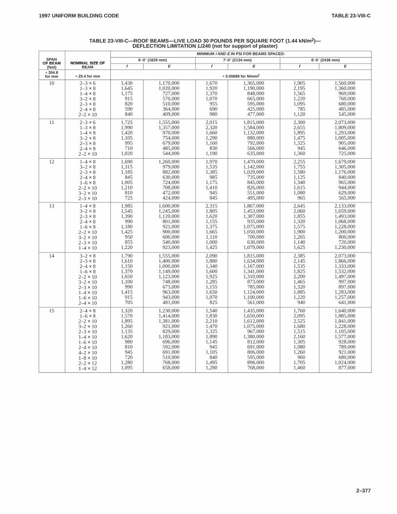
TABLE 23-VIII-CTABLE 23-VIII-C
1997 UNIFORM BUILDING CODE
2–377
TABLE 23-VIII-C—ROOF BEAMS—LIVE LOAD 30 POUNDS PER SQUARE FOOT (1.44 kN/m 2)—DEFLECTION LIMITATION L/240 (not for support of plaster)
MINIMUM I AND E IN PSI FOR BEAMS SPACED:SPAN
OF BEAM NOMINAL SIZE OF6′-0″ (1829 mm) 7′-0″ (2134 mm) 8′-0″ (2438 mm)
OF BEAM(feet)
NOMINAL SIZE OFBEAM f E f E f E
× 304.8for mm × 25.4 for mm × 0.00689 for N/mm 2
10 2–3× 61–3× 81–4× 83–2× 82–3× 82–4× 82–2× 10
1,4301,6451,175 915 820 590 840
1,170,0001,020,000 727,000 570,000 510,000 364,000 409,000
1,6701,9201,3701,070 955 690 980
1,365,0001,190,000 848,000 665,000 595,000 425,000 477,000
1,9052,1951,5651,2201,095 785
1,120
1,560,0001,360,000 969,000 760,000 680,000 485,000 545,000
11 2–3× 61–3× 81–4× 83–2× 82–3× 82–4× 82–2× 10
1,7251,9901,4201,105 995 710
1,020
1,555,0001,357,000 970,000 754,000 679,000 485,000 544,000
2,0152,3201,6601,2901,160 830
1,190
1,815,0001,584,0001,132,000 880,000 792,000 566,000 635,000
2,3002,6551,8951,4751,325 945
1,360
2,073,0001,809,0001,293,0001,005,000 905,000 646,000 725,000
12 1–4× 83–2× 82–3× 82–4× 81–6× 82–2× 10³–2× 10²–3× 10
1,6901,3151,185 845
1,0051,210 810 725
1,260,000 979,000 882,000 630,000 724,000 708,000 472,000 424,000
1,9701,5351,385 985
1,1751,410 945 845
1,470,0001,142,0001,029,000 735,000 845,000 826,000 551,000 495,000
2,2551,7551,5801,1251,3401,6151,080 965
1,679,0001,305,0001,176,000 840,000 965,000 944,000 629,000 565,000
13 1–4× 83–2× 82–3× 82–4× 81–6× 82–2× 10³–2× 10²–3× 101–4× 10
1,9851,5451,390 990
1,1801,425 950 855
1,220
1,600,0001,245,0001,120,000 801,000 921,000 900,000 600,000 540,000 923,000
2,3151,8051,6201,1551,3751,6651,1101,0001,425
1,867,0001,453,0001,307,000 935,000
1,075,0001,050,000 700,000 630,000
1,079,000
2,6452,0601,8551,3201,5751,9001,2651,1401,625
2,133,0001,659,0001,493,0001,068,0001,228,0001,200,000 800,000 720,000
1,230,000
14 3–2× 82–3× 82–4× 81–6× 82–2× 10³–2× 10²–3× 101–4× 101–6× 10²–4× 10
1,7901,6101,1501,3701,6501,100 990
1,415 915 705
1,555,0001,400,0001,000,0001,149,0001,123,000 748,000 673,000 963,000 943,000 481,000
2,0901,8801,3401,6001,9251,2851,1551,6501,070 825
1,815,0001,634,0001,167,0001,341,0001,310,000 873,000 785,000
1,124,0001,100,000 561,000
2,3852,1451,5351,8252,2001,4651,3201,8851,220 940
2,073,0001,866,0001,333,0001,532,0001,497,000 997,000 897,000
1,283,0001,257,000 641,000
15 2–4× 81–6× 82–2× 10³–2× 10²–3× 101–4× 101–6× 10²–4× 10⁴–2× 101–8× 10²–2× 121–4× 12
1,3201,5701,8951,2601,1351,620 980 810 945 720
1,2801,095
1,230,0001,414,0001,381,000 921,000 829,000
1,183,000 696,000 592,000 691,000 510,000 768,000 658,000
1,5401,8302,2101,4701,3251,8901,145 945
1,105 840
1,4951,280
1,435,0001,650,0001,612,0001,075,000 967,000
1,380,000 812,000 691,000 806,000 595,000 896,000 768,000
1,7602,0952,5251,6801,5152,1601,3051,0801,260 960
1,7051,460
1,640,0001,885,0001,841,0001,228,0001,105,0001,577,000 928,000 789,000 921,000 680,000
1,024,000 877,000
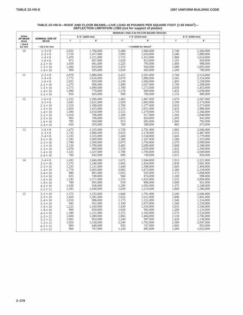
TABLE 23-VIII-DTABLE 23-VIII-D
1997 UNIFORM BUILDING CODE
2–378
TABLE 23-VIII-D—ROOF AND FLOOR BEAMS—LIVE LOAD 40 POUNDS PER SQUARE FOOT (1.92 kN/m 2)—DEFLECTION LIMITATION L/360 (not for support of plaster)
MINIMUM I AND E IN PSI FOR BEAMS SPACED:SPAN
OF BEAM NOMINAL SIZE OF6′-0″ (1829 mm) 7′-0″ (2134 mm) 8′-0″ (2438 mm)
OF BEAM(feet)
NOMINAL SIZE OFBEAM f E f E f E
× 304.8for mm × 25.4 for mm × 0.00689 for N/mm 2
10 1–3× 82–2× 81–4× 81–6× 82–2× 101–3× 101–4× 10
2,0551,7101,470 875
1,0501,260 900
1,700,0001,417,0001,211,000 697,000 681,000 819,000 585,000
2,4001,9951,7151,0201,2251,4701,050
1,984,0001,654,0001,413,000 813,000 795,000 956,000 683,000
2,7402,2801,9601,1651,4001,6801,200
2,266,0001,889,0001,614,000 929,000 908,000
1,092,000 780,000
11 2–2× 81–4× 81–6× 82–2× 101–3× 101–4× 10³–2× 10
2,0701,7751,0551,2751,5751,090 850
1,886,0001,616,000 929,000 906,000
1,090,000 779,000 605,000
2,4152,0701,2301,4901,7801,270 990
2,201,0001,886,0001,084,0001,057,0001,272,000 909,000 706,000
2,7602,3651,4051,7002,0301,4551,135
2,514,0002,154,0001,238,0001,208,0001,453,0001,038,000 806,000
12 1–6× 83–2× 82–2× 101–3× 101–4× 10³–2× 10²–3× 101–6× 10²–4× 10
1,2551,6451,5101,8201,3001,010 905 785 650
1,206,0001,631,0001,180,0001,415,0001,010,000 786,000 706,000 594,000 505,000
1,4651,9201,7602,1251,5151,1801,055 915 760
1,407,0001,903,0001,377,0001,651,0001,179,000 917,000 824,000 693,000 589,000
1,6702,1902,0102,4251,7351,3451,2051,045 865
1,607,0002,174,0001,573,0001,886,0001,346,0001,048,000 941,000 792,000 673,000
13 1–6× 82–3× 82–4× 83–2× 10²–2× 101–3× 10²–3× 101–4× 10²–4× 10
1,4751,7351,2351,1851,7802,1301,0701,525 760
1,535,0001,866,0001,335,0001,000,0001,500,0001,799,000 900,000
1,537,000 642,000
1,7202,0251,4401,3802,0752,4851,2501,780 890
1,791,0002,178,0001,558,0001,167,0001,750,0002,099,0001,050,0001,794,000 749,000
1,9652,3151,6451,5802,3702,8401,4252,0351,015
2,046,0002,487,0001,779,0001,333,0002,000,0002,398,0001,200,0002,049,000 856,000
14 2–4× 83–2× 10²–3× 101–4× 10²–4× 10³–3× 101–6× 101–8× 10⁴–2× 10²–2× 12
1,4351,3751,2351,770 880 825
1,145 780
1,0301,395
1,666,0001,246,0001,121,0001,605,000 801,000 749,000
1,571,000 691,000 936,000
1,040,000
1,6751,6051,4402,0651,025 960
1,335 910
1,2001,630
1,944,0001,454,0001,308,0001,873,000 935,000 874,000
1,833,000 806,000
1,092,0001,214,000
1,9151,8301,6452,3601,1751,1001,5251,0401,3751,860
2,221,0001,661,0001,494,0002,139,0001,068,000 998,000
2,094,000 921,000
1,248,0001,386,000
15 3–2× 10²–3× 10²–4× 10³–3× 101–6× 101–8× 10⁴–2× 10²–2× 123–2× 121–3× 124–2× 122–3× 12
1,5751,4201,010 945
1,225 900
1,1801,6001,0651,920 800 960
1,535,0001,381,000 986,000 921,000
1,160,000 850,000
1,151,0001,280,000 854,000
1,536,000 640,000 767,000
1,8401,6551,1751,1001,4301,0501,3751,8651,2402,240 935
1,120
1,791,0001,612,0001,151,0001,075,0001,354,000 992,000
1,343,0001,494,000 997,000
1,792,000 747,000 895,000
2,1001,8901,3451,2601,6351,2001,5752,1301,4202,5601,0651,280
2,046,0001,841,0001,314,0001,228,0001,546,0001,133,0001,534,0001,706,0001,138,0002,047,000 853,000
1,022,000
1997 UNIFORM BUILDING CODE STANDARD 23-1
3–395
UNIFORM BUILDING CODE STANDARD 23-1
CLASSIFICATION, DEFINITION, METHODS OF GRADING ANDDEVELOPMENT OF DESIGN VALUES FOR ALL SPECIES OF LUMBER
See Sections 2302.1 and 2303, Uniform Building Code
SECTION 23.101 — ADOPTION OF ASTM D 1990,ASTM D 245 AND ASTM D 2555, THE WOODHANDBOOK NO. 72, PS20-94 AND THE NATIONALGRADING RULE FOR DIMENSION LUMBER
Classification, definition, methods of grading and development ofdesign values for all species of lumber shall be in accordance withASTM D 1990-91, ASTM D 245-88 and ASTM D 2555-95 pub-lished by the American Society for Testing and Materials, WoodHandbook No. 72 published by the U.S. Department of Agricul-ture, Voluntary Product Standard PS20-94 published by the U.S.
Department of Commerce and the National Grading Rule forDimension Lumber promulgated by the National Grading RuleCommittee, Post Office Box 210, Germantown, Maryland20875-0210, and published in the American Lumber StandardCommittee certified grading rules, as if set out at length herein.
The grade mark on lumber or end-jointed lumber shall includean approved, easily distinguished mark, or insignia of the gradingagency which has been accredited by an accreditation body whichcomplies with the requirements of U.S. Department of CommercePS20-94, or equivalent.
�
�
1997 UNIFORM BUILDING CODE STANDARD 23-2
3–397
UNIFORM BUILDING CODE STANDARD 23-2
CONSTRUCTION AND INDUSTRIAL PLYWOODBased on Product Standard PS 1-95 (for Construction and Industrial Plywood) of the United States
Department of Commerce, and National Institute of Science and Technology Calculation of Diaphragm Action,an Engineering Standard of the International Conference of Building Officials
See Sections 1404.1, 2302.1, 2303 and 2304, and Tables 23-III-A,23-II-H, 23-II-I-1 and 23-II-E-2, Uniform Building Code
SECTION 23.201 — SCOPE
23.201.1 General.This standard covers construction and indus-trial plywood for both Exterior and Interior types. This standardalso covers construction and industrial hardwood plywood of redand white lauan (Philippine mahogany), tanoak, red alder andwestern poplar.
23.201.2 Wood Species.Plywood produced under this standardconsiders four species classifications: Groups 1, 2, 3 and 4. Thespecies used for the face and back plies are at the option of themanufacturer. When face and back veneers are of the same speciesgroup, the panels shall be identified as being of that species group.The species covered in each group are set forth in Table 23-2-A. Inaddition, other softwood or hardwood species having an averagespecific gravity of 0.41 or more, based on green volume and ovendry weight, may be used for inner plies except as required forpremium grades in Section 23.205.
SECTION 23.202 — DEFINITIONS
General definitions not included in the following section are to beinterpreted as defined in UBC Standard 23-1.
BACK is the side of a panel that is of lower veneer quality onany panel whose outer plies are of different veneer grades.
BORER HOLES are voids made by wood-boring insects, suchas grubs or worms.
BROKEN GRAIN is a (leafing, shelling, grain separation)separation on veneer surface between annual rings.
CENTERS are inner plies whose grain direction runs parallelto that of the outer plies. May be of parallel laminated plies.
CHECK is a lengthwise separation of wood fibers, usually ex-tending across the rings of annual growth caused chiefly by strainsproduced in seasoning.
CLASS I, CLASS II are terms used to identify different speciesgroup combinations of B-B concrete form panels. The standardprovides for two classes, Class I and Class II, as described in Sec-tion 23.205.3.
CORE is sometimes referred to as a crossband.
CROSSBAND GAP and CENTER GAP are open joints ex-tending through or partially through a panel, which results whencrossband or center veneers are not tightly butted.
CROSSBANDS are inner layers whose grain direction runsperpendicular to that of the outer plies. They may be of parallellaminated plies and are sometimes referred to as core.
DEFECTS, OPEN, are irregularities such as splits, openjoints, knotholes, or loose knots, that interrupt the smooth continu-ity of the veneer.
DELAMINATION is a visible separation between plies thatwould normally receive glue at their interface and be firmly con-tacted in the pressing operation. Wood characteristics, such aschecking, leafing, splitting and broken grain, are not to be con-
strued as delamination. See corresponding definition for thoseterms.
1. For purposes of reinspection, areas coinciding with openknotholes, pitch pockets, splits and gaps and other voids or charac-teristics permitted in the panel grade are not considered in evaluat-ing ply separation of Interior-type panels bonded with interior orintermediate glue.
2. In evaluating Interior panels bonded with exterior glue, dela-mination in any glueline shall not exceed 3 square inches (1935mm2) except where directly attributable to defects permitted in thegrade as follows:
Delamination associated with:
2.1 Knots and knotholes—shall not exceed the size of the de-fect plus a surrounding band not wider than 3/4 inch (19mm).
2.2 All other forms of permissible defects—shall not exceedthe size of the defect.
3. In evaluating Exterior-type panels for ply separation, the areacoinciding with the grade characteristics noted in Item 1 are con-sidered, and a panel is considered delaminated if visible ply sepa-ration at a single glueline in such area exceeds 3 square inches(1935 mm2).
EDGE SPLITS are wedge-shaped openings in the inner pliescaused by splitting of the veneer before pressing.
FACE is the better side of any panel whose outer plies are of dif-ferent veneer grades; also either side of a panel where the gradingrules draw no distinction between faces.
GROUP is the term used to classify species covered by thisstandard in an order that provides a basis for simplified marketingand efficient utilization. Species covered by the standard are clas-sified as Groups 1, 2, 3 and 4. See Table 23-2-A for listing of spe-cies in individual groups.
HEARTWOOD is the nonactive core of a log generally distin-guishable from the outer portion (sapwood) by its darker color.
INNER PLIES are other than exposed face and back plies in apanel construction.
JOINTED INNER PLIES are crossband and center veneerthat have had edges machine-squared to permit tightest possiblelayup.
KNOT is a natural characteristic of wood that occurs where abranch base is embedded in the trunk of a tree. Generally the sizeof a knot is distinguishable by (1) a difference in color of limb-wood and surrounding trunkwood; (2) abrupt change in growthring width between knot and bordering trunkwood; and (3) diame-ter of circular or oval shape described by points where checks onthe face of a knot that extend radially from its center to its side ex-perience abrupt change in direction.
KNOTHOLES are voids produced by the dropping of knotsfrom the wood in which they are originally embedded.
LAP is a condition where the veneers are so placed that onepiece overlaps the other.
1997 UNIFORM BUILDING CODESTANDARD 23-2
3–398
LAYER is a single veneer ply or two or more plies laminatedwith grain direction parallel. Two or more plies laminated withgrain direction parallel is a parallel laminated layer.
NOMINAL THICKNESS is full “designated” thickness. Forexample, 1/10-inch (2.5 mm) nominal veneer is 0.10 inch (2.5 mm)thick. Nominal 1/2-inch-thick (13 mm) panel is 0.50 inch (13 mm)thick. Also, commercial size designations are subject to accept-able tolerances.
PATCHES are insertions of sound wood or synthetic materialin veneers or panels for replacing defects. “Boat” patches are ovalshaped with sides tapering in each direction to a point or to a smallrounded end. “Router” patches have parallel sides and roundedends. “Sled” patches are rectangular with feathered ends.
PITCH POCKET is a well-defined opening between rings ofannual growth, usually containing, or which has contained, pitch,either solid or liquid.
PITCH STREAK is a localized accumulation of resin in conif-erous woods which permeates the cells forming resin soaks,patches or streaks.
PLUGS are sound wood of various shapes, including, amongothers, circular and dogbone, for replacing defective portions ofveneer used to fill openings and provide a smooth, level, durablesurface. Plugs usually are held in veneer by friction until veneersare bonded into plywood.
PLY is a single veneer lamina in a glued plywood panel. (Seealso “layer.”)
PLYWOOD is a flat panel, built up of sheets of veneer calledplies, united under pressure by a bonding agent to create a panelwith an adhesive bond between plies as strong as or stronger thanthe wood. Plywood is constructed of an odd number of layers withgrain of adjacent layers perpendicular. Layers may consist of asingle ply or two or more plies laminated with grain direction par-allel. Outer layers and all odd-numbered layers generally have thegrain direction oriented parallel to the long dimension of the pan-el. The odd number of layers with alternating grain directionequalizes strains, prevents splitting and minimizes dimensionalchange and warping of the panel.
Exterior type—Plywood of this type is produced with a Cgrade veneer or better throughout and is bonded with completelywaterproof adhesives. It is a plywood that will retain its glue bondwhen repeatedly wetted and dried or otherwise subjected to theweather, and is therefore intended for permanent exteriorexposure. Table 23-2-E lists the grades within this type. Adhesiveperformance requirements are provided in Section 23.207.
Interior type— Plywood of this type is moisture resistant. It isintended for all interior applications as well as applications whereit may be temporarily exposed to the elements. Table 23-2-D liststhe grades within this type. Adhesive performance requirementsare provided in Section 23.207.
Intermediate glue (IMG) type—Plywood of this type isbonded with adhesives that possess high-level bacteria, mold andmoisture resistance. It is plywood suitable for protected construc-tion and industrial uses where delays in providing protection maybe expected. Adhesive performance requirements are provided inSection 23.207. (The grades of IMG-type plywood generallyavailable are given in Table 23-2-D.)
Overlaid plywood is Exterior-type plywood to which has beenadded a resin-treated fiber surfacing material on one or both sides.It is made in two standard categories, “High Density” and “Me-dium Density,” and a “Special” category, all of which refer to thesurfacing materials. The overlay surfaces are permanently fusedto the base panel under heat and pressure. Although designed for
all types of moisture exposure and service, all overlaid plywood ismade only in the Exterior type. This refers to the base panel and tothe overlay itself.
REPAIR is any patch, plug or shim.
SAPWOOD is the living wood of lighter color occurring in theouter portion of a log. Sapwood is sometimes referred to as “sap.”
SHIM is a long narrow repair of wood or suitable synthetic notmore than 3/16 inch (4.8 mm) wide.
SHOP CUTTING PANELS are panels which have been re-jected as not conforming to grade requirements of standard gradesin this standard. Identification of these panels shall be with a sepa-rate mark that makes no reference to this standard and contains thenotation, “Shop Cutting Panel—All Other Marks Void.” Blisteredpanels are not considered as coming within the category coveredby this stamp.
SPAN RATING is a set of numbers used in marking sheathingand combination subfloor underlayment (single floor) grades ofplywood as described in Section 23.209.
SPLIT is lengthwise separation of wood fibers completelythrough the veneer caused chiefly by manufacturing process orhandling.
STREAKS are synonymous with “pitch streaks.”
STRUCTURAL I is a name used to identify panels that pro-vide for greatest refinement of engineering properties which maybe important in the use of plywood for structural components andother sophisticated engineered applications. Manufacturingrequirements include special provisions for species, panel con-struction and veneer grade characteristics as described in Section23.205.4.
TORN GRAIN. See “broken grain.”
TOUCH-SANDING is a sizing operation consisting of a lightsurface sanding in a sander. Sander skips to any degree are admis-sible.
VENEER consists of thin sheets of wood of which plywood ismade. Veneer is also referred to as plies in the glued panel.
WATERPROOF ADHESIVE is glue capable of bonding ply-wood in a manner to satisfy the exterior performance require-ments given herein.
WHITE POCKET is a form of decay (Fomes pini) that attacksmost conifers but has never been known to develop in wood inservice. In plywood manufacture, routine drying of veneer effec-tively removes any possibility of decay surviving.
Heavy white pockets may contain a great number of pockets, indense concentrations, running together and at times appearingcontinuous. Holes may extend through the veneer but woodbetween pockets appears firm. At any cross section extendingacross the width of the affected area, sufficient wood fiber shall bepresent to develop not less than 40 percent of the strength of clearveneer. Brown cubical and similar forms of decay which havecaused the wood to crumble are prohibited.
Light white pockets are advanced beyond incipient or stainstage to the point where the pockets are present and plainly visible,mostly small and filled with white cellulose and generally distrib-uted with no heavy concentrations. Pockets for the most part areseparate and distinct with few to no holes through the veneer.
WOOD FAILURE (PERCENT) is the area of wood fiber re-maining at the glueline following completion of the specifiedshear test. Determination is by means of visual examination andexpressed as a percent of the 1-square-inch (645 mm2) test area.(See Section 23.214 for test.)
1997 UNIFORM BUILDING CODE STANDARD 23-2
3–399
SECTION 23.203 — REQUIREMENTS
23.203.1 Workmanship. Unless otherwise specified, sandedplywood shall be surfaced on two sides. Faces and backs of panelsshall be full width and full length except that C grade and D gradebacks may be narrow on one edge or short on one end only, but bynot more than 1/8 inch (3.2 mm) for half the panel length or width,respectively. Inner plies shall be full width and length except thatone edge or end void not exceeding 1/8 inch (3.2 mm) in depth or8 inches (203 mm) in length per panel will be acceptable. Cross-band veneers not exceeding 1/8 inch (3.2 mm) in thickness may belapped but by not more than 3/16 inch (4.8 mm) when adjacent tofaces, or 1/2 inch (13 mm) when adjacent to backs, and providedsuch laps create no adjacent visible opening. Sanding defects re-sulting from crossband laps shall not be permitted in panel faces.
C or D grade veneers may be lapped by not more than 1/2 inch(13 mm), provided such laps create no adjacent visible opening.All plies of CD panels only shall be full length and full width ex-cept that no more than half the length of one edge nor half thewidth of one end may contain short or narrow plies. This is contin-gent on such plies not being short or narrow by more than 3/16 inch(4.8 mm), the aggregate area in the plane of the plies of such edgecharacteristics not exceeding 6 square inches (3871 mm2) in theentire panel, and such edge characteristics not occurring in morethan one ply at any panel cross section.
In grades other than CD, backs may be narrow on one edge orshort on one end only, but by not more than 1/8 inch (3.2 mm) forhalf the panel length or width, respectively; inner plies shall be fullwidth and length, except that one edge or end void not exceeding1/8 inch (3.2 mm) in depth or 8 inches (203 mm) in length per panelwill be acceptable.
Crossband gaps or center gaps, except as noted for pluggedcrossband and jointed crossband shall not exceed 1 inch (25 mm)in width for a depth of 8 inches (203 mm) (measured from paneledge) and the average of all gaps occurring in a panel shall not ex-ceed 1/2 inch (13 mm). Every effort shall be made to produceclosely butted core joints.
Where plugged inner plies are specified, inner plies shall be ofC-Plugged veneer and gaps between adjacent pieces of inner pliesshall not exceed 1/2 inch (13 mm). Where jointed inner plies arespecified, gaps between pieces of inner plies shall not exceed3/8 inch (9.5 mm), and the average of all gaps occurring in a panelshall not exceed 3/16 inch (4.8 mm).
Unless otherwise specified, plugged core (also referred to assolid core) shall be core and center construction of C-Plugged ve-neer, and gaps between adjacent pieces of core shall not exceed1/2 inch (13 mm). When jointed core is specified, gaps betweenpieces of core shall not exceed 3/8 inch (9.5 mm), and the averageof all gaps occurring in a panel shall not exceed 3/16 inch (4.8 mm).
Plywood shall be clean, well manufactured, and free from blis-ters, laps and other defects, except as expressly permitted herein.Panels shall have no continuous holes or through openings fromface to back.
End butt joints may be used only under the following condi-tions:
1. Decorative grades as provided in Section 23.205.2.
2. Butt joints having a total aggregate width not exceeding thewidth of the panel may occur in the center ply of five-ply, five-layer panels. The butt joints must be perpendicular to the grain ofthe panel face and back plies. The use of butt-jointed centers isallowed in Interior sanded grades in thicknesses up to and includ-ing 1/2 inch (13 mm), and in C-D and C-D Plugged thicknesses upto and including 3/4 inch (19 mm). End butt joints shall not be used
in Structural I panels. Panels with butt joints in center plies shall bemarked “butt-jointed center.”
Plywood panels shall be constructed in the grades and veneercombinations as set forth in Tables 23-2-D and 23-2-E. All termsused herein shall be interpreted as described in Section 23.202.Constructions for all panels shall conform to the minimumnumber of plies and layers as set forth in Table 23-2-C. Theproportion of wood with grain perpendicular to panel face grainshall not be less than 33 percent or more than 70 percent of the totalpanel thickness. The combined thickness of inner layers in panelshaving four or more plies shall not be less than 45 percent of thetotal panel thickness. For application of the above requirements,the panel thickness shall be the actual finished panel thickness andveneer thickness shall be the dry veneer thickness before layup.The grain of all layers shall be at right angles to the grain of adja-cent layers and to the ends or edges of the panels. The entire area ofeach contacting surface of the adjacent veneer plies including re-pairs shall be bonded with an adhesive in a manner to assure satis-factory compliance with the performance requirements for itstype as set forth in the tests described in this standard. Where faceor back plies consist of more than one piece of edge-joined veneer,gaps between adjacent pieces shall be graded as splits. Anyadhesive or bonding system that causes degradation of the woodor latent failure of bond will not be permitted.
For the purpose of veneer repairing or edge joining, strings, rib-bons or tapes up to 3/8-inch (9.5 mm) maximum width can occur ina glueline and shall be considered as allowable localized defects inthe evaluation of glueline test specimens. Wider strings, ribbonsor tapes may be used for veneer repairing or joining if they are pre-qualified to show bonding equal to the required bonding for thatpanel. Glueline test specimens cut to include the strings, ribbonsor tapes wider than 3/8 inch (9.5 mm) shall not be discarded be-cause of the presence of these materials.
Veneer strips may be joined by string stitching, provided thepunch for making holes prior to stitching has a dimension acrossthe grain of 0.095 inch (2.4 mm) or less and the holes are spaced1/2 inch (13 mm) center-to-center or greater. All veneer used forinner plies may be stitched. Stitched veneer used for outer plies islimited to panels with C or D grade faces or backs, except stitchedC veneer may not be used for faces in decorative panels. Panelsmay have face or back plies stitched but not both.
Shims or strips of veneer shall not be used to repair panel edgevoids. However, filling of permissible edge voids with approvedsynthetic fillers neatly applied will be admitted. Staples or pins ofmetal or synthetic material are prohibited. Face and back plies ofexposed N, A and B veneer panels shall have the bark or tight sur-face out. Plies directly under surfaces of overlaid panels are notconsidered exposed veneers.
23.203.2 Tolerance.A tolerance of + 0.0 inch − 1/16 inch(0.0625) (+ 0.0 mm – 1.6 mm) shall be allowed on the specifiedlength and/or width. Sanded panels shall have a thickness toler-ance of 1/64 inch (0.0156) (0.4 mm) of the specified panel thick-ness of 3/4 inch (19 mm) and less, and ± 3.0 percent of the specifiedthickness for panels thicker than 3/4 inch (19 mm). Unsanded,touch-sanded, and overlaid panels shall fall within a plus or minustolerance of 1/32 inch (0.0312) (0.8 mm) of the specified panelthickness for all thicknesses through 13/16 inch (21 mm), and suchpanels greater than 13/16 inch (21 mm) shall have a thickness toler-ance of 5 percent over or under the specified thickness. Panelthickness shall be based on a moisture content of 9 percent.
Panels shall be square within 1/64 inch per lineal foot (1.3 mmper m) for panels of 4-foot by 4-foot (1219 mm by 1219 mm) sizeor larger. Panels less than 4 feet (1219 mm) in length or width shallbe square within 1/16 inch (1.6 mm) measured along the short di-mension. All panels shall be sawn so that a straight line drawn
1997 UNIFORM BUILDING CODESTANDARD 23-2
3–400
from one comer to the adjacent corner shall fall within 1/16 inch(1.6 mm) of panel edge.
23.203.3 Moisture Content.Moisture content of panels at timeof shipment shall not exceed 18 percent of oven-dry weight as de-termined by the oven-dry test specified in Section 23.217.
SECTION 23.204 — VENEER
23.204.1 General.Except as noted, veneers shall be 1/10 inch(2.5 mm) or thicker in panels 3/8 inch (9.5 mm) rough (unsanded)thickness or over; 1/12 inch (2.1 mm) or thicker in panels of lesserthickness. In no case shall veneers used in face or back layers bethicker than 1/4 inch (6.4 mm), or veneers used in inner layersthicker than 5/16 inch (7.9 mm).
One-twelfth-inch (2.1 mm) veneer may be used as crossbandsin five-ply, five-layer, 1/2-inch (13 mm) panels and in parallel lam-inated layers.
One-sixteenth-inch (1.6 mm) veneer may be used for any ply infive-ply Exterior-type panels less than 1/2 inch (13 mm) in thick-ness, as the center only in other five-ply panels, and may be in-cluded in a parallel laminated layer.
Face and back veneers must be 1/8-inch (3.2 mm) minimumthickness for 19/32 inch and 5/8 inch (15.1 mm and 15.9 mm),three-, four- and five-ply, three-layer panels of C-D, C-D Plugged,C-C, C-C Plugged and Underlayment grades.
For further limitations on panel layup, refer to Table 23-2-Cpanel constructions and workmanship.
The average veneer thickness shall conform to the limitationsgiven in this standard within a tolerance of 5 percent of thespecified nominal thickness measured dry before layup.
Parallel laminated outer layers may be used only in C-C, C-D,Structural I C-C and C-D grades. Such layers shall consist ofveneers 1/10 inch (2.5 mm) or thicker in any thickness combinationnot exceeding 1/4-inch (6.4 mm) total layer thickness. The faceand back plies or exposed plies of outer layers shall conform to thespecies group and grade requirements for faces and backs, respec-tively, of the panel grade. The unexposed plies of outer layers, orsubface and subback plies, shall conform to the species group andgrade requirements for inner plies of the panel grade as specifiedin Sections 23.204.3 and 23.204.4.
The maximum split or gap in subfaces and subbacks shall be1/4 inch (6.4 mm) under the faces of Structural I C-C and C-D pan-els, 1/2 inch (13 mm) under the faces of C-C and C-D grades, and1/2 inch (13 mm) under D backs.
Parallel laminated inner layers in any grade shall consist ofveneers 1/16 inch (1.6 mm) or thicker in any thickness combinationnot exceeding 7/16-inch (11 mm) total layer thickness. Individualplies in such layers shall conform to the species group and graderequirements for inner plies of the panel grade.
The veneers used in each ply of each panel and the completedpanel shall conform with the applicable veneer grade and with theconstruction and workmanship requirements given herein.Additionally, the type and frequency of the characteristics shall befurther limited as set forth for the grades listed in Table 23-2-B.
23.204.2 Number of Plies.For a given thickness, the number ofplies used in the panel makeup shall not be less than as provided inTable 23-2-C.
23.204.3 Species for Faces and Backs.For purposes of thisstandard, veneer species are classified into the four groups givenin Table 23-2-A. The species of face and back plies may be fromany group; however, when a face or back is made of more than one
piece, the entire ply shall be of the same species. Panels, other thanunsanded and touch-sanded panels, with span ratings which areproduced with face and back veneers of the same species groupshall be classified as being of that species group. Touch-sandedpanels without span ratings that are manufactured with face andback plies of different species groups shall be identified by thelarger numbered species group (i.e., Group 4 is larger numberedthan Group 1). Sanded panels 3/8 inch (9.5 mm) or less in thicknessand decorative panels of any thickness that are manufactured withface and back plies of different species groups shall be identifiedby the face species group number. Sanded panels greater than3/8 inch (9.5 mm) that are manufactured with face and back plies ofdifferent species groups shall be identified by the larger numberedspecies group, except that sanded panels with C or D grade backsmay be identified by the face species group number if backs are nomore than one species group larger in number than the face and are1/8 inch (3.2 mm) or thicker before sanding. The species classifi-cation group (except for unsanded and touch-sanded panels withspan ratings) shall be set forth in the grade mark on each panel. SeeSection 23.209 for identification requirements for unsanded andtouch-sanded panels with span ratings. Where intermixing be-tween species groups occurs in the faces and backs of unsanded ortouch-sanded panels with span ratings, provisions of Table 23-2-Gshall be followed. (Douglas fir for the purpose . . . and loblolly[Pinus taeda] pines.) Because black, white and Engelmann sprucecannot be separated in veneer form by gross structure or minuteanatomy, these species shall be classed as Engelmann spruce un-less procedures are established for identification prior to peeling.
23.204.4 Species for Inner Plies.Inner plies may be of any spe-cies or of any softwood species or any hardwood species having apublished average specific gravity value of 0.41 or more, based ongreen volume and oven-dry weight, except as required for pre-mium panels in Section 23.205.
23.204.5 Scarfed Veneers.Scarfed veneer may be used for anyface, back or inner ply except as provided in Section 23.211.Scarfed joints shall not have a slope steeper than 1 in 8, but may bespecified at less than 1 in 8. Veneer in the scarf area shall not con-tain defects which reduce its effective cross section by more than20 percent. Veneer scarfed joints shall be glued with a waterproofadhesive.
23.204.6 Classification.All veneers used in the construction ofthe plywood panels shall conform to one of the following graderequirements of which N grade is the highest classification:
23.204.6.1 Grade N veneer.Grade N veneer (intended for natu-ral finish) shall be smoothly cut 100 percent heartwood or 100 per-cent sapwood, free from knots, knotholes, pitch pockets, opensplits, other open defects, and stain; limited to not more than twopieces in a 48-inch (1219 mm) width; not more than three pieces inwider panels; and well matched for color and grain.
Suitable synthetic fillers may be used to fill small cracks orchecks not more than 1/32 inch (0.8 mm) wide; small splits oropenings up to 1/16 inch (1.6 mm) wide if not exceeding 2 inches(51 mm) in length; and small chipped areas or openings not morethan 1/8 inch (3.2 mm) wide by 1/4 inch (6.4 mm) long. Pitchstreaks averaging not more than 3/8 inch (9.5 mm) in width andblending with color of wood are permitted.
Repairs shall be neatly made and parallel to grain and are lim-ited to a total of six in number in any 4-foot by 8-foot (1219 mm by2438 mm) face, with proportional limits for other sizes. They shallalso be well matched for color and grain.
Patches are limited to three “router” patches not exceeding1 inch (25 mm) in width and 31/2 inches (89 mm) in length.
No overlapping is permitted.
1997 UNIFORM BUILDING CODE STANDARD 23-2
3–401
Wood shims not exceeding 3/16 inch (4.8 mm) in width and12 inches (305 mm) in length that occur only at the ends of the pan-el are permitted.
23.204.6.2 Grade A veneer.Grade A veneer (suitable for paint-ing) shall be firm, smoothly cut and free from knots, pitch pockets,open splits and other open defects. It shall be well joined when ofmore than one piece.
Suitable synthetic fillers may be used to fill, in Exterior-typepanels, small cracks or checks not more than 1/32 inch (0.8 mm)wide; small splits or openings up to 1/16 inch (1.6 mm) wide, if notexceeding 2 inches (51 mm) in length; and small chipped areas oropenings not more than 1/8 inch (3.2 mm) wide by 1/4 inch (6.4mm) long. In Interior-type panels: small cracks or checks not morethan 3/16 inch (4.8 mm) wide; openings or depressions up to1/2 inch (13 mm) wide by 2 inches (51 mm) long or equivalentarea.
Pitch streaks averaging not more than 3/8 inch (9.5 mm) inwidth, blending with color of wood, are permitted.
Sapwood and discolorations are also permitted.
Repairs shall be wood or of synthetic patching material neatlymade and parallel to grain, limited to a total of 18 in number, ex-cluding shims, in any 4-foot by 8-foot (1219 mm by 2438 mm)face and shall have proportional limits on other sizes.
Patches are limited to the boat, router and sled types. Radius ofends of boat patches shall not exceed 1/8 inch (3.2 mm). Patchesshall not exceed 21/4 inches (57 mm) in width singly. Multiplepatches consisting of not more than two patches, neither of whichmay exceed 7 inches (178 mm) in length if either is wider than1 inch (25 mm) are permitted, except that there may be one multi-ple repair consisting of three die-cut veneer patches. Synthetic re-pairs shall not exceed 21/4 inches (57 mm) in width. Shims arepermitted except over or around patches or as multiple repairs.
23.204.6.3 Grade B veneer.Grade B veneer shall be solid andfree from open defects and broken grain except as noted. Slightlyrough grain and minor sanding and patching defects, includingsander skips not exceeding 5 percent of panel area are permitted.
Suitable synthetic filler may be used to fill, in Exterior-typepanels, small splits or openings up to 1/16 inch (1.6 mm) wide if notexceeding 2 inches (51 mm) in length and small chipped areas oropenings not more than 1/8 inch (3.2 mm) wide by 1/4 inch (6.4mm) long. In Interior-type panels: small cracks or checks not morethan 3/16 inch (4.8 mm) wide; openings or depressions up to1/2 inch (13 mm) wide by 2 inches (51 mm) long or equivalentarea.
Knots up to 1 inch (25 mm) measured across the grain if bothsound and tight, pitch streaks averaging not more than 1 inch (25mm) in width, and discolorations are permitted.
Splits not wider than 1/32 inch (0.8 mm) and vertical holes notexceeding 1/16 inch (1.6 mm) in diameter if not exceeding anaverage of one per square foot in number are permitted.Horizontal or surface tunnels limited to 1/16 inch (1.6 mm) across,1 inch (25 mm) in length, and 12 in number in a 4-foot by 8-foot(1219 mm by 2438 mm) panel or proportionately in panels ofother dimensions are also permitted.
Repairs shall be neatly made of wood or synthetic patching ma-terial. Repairs permitted are patches (“boat,” “router” and “sled”)not exceeding 3 inches (76 mm) in width individually whereoccurring in multiple repairs, or 4 inches (102 mm) in width whereoccurring singly. Synthetic veneer repairs shall not exceed4 inches (102 mm) in width. Synthetic panel repairs shall notexceed 21/4 inches (57 mm) in width. Shims are permitted.Synthetic shims shall completely fill kerfs or voids; shall present a
smooth level surface; and shall not crack, shrink or lose their bondunder Exterior-type plywood test exposures described in Sections23.215.2 and 23.215.3. Performance of synthetic shims undernormal conditions of service shall be comparable to that of woodshims.
Synthetic plugs not exceeding dimensions specified previouslywhich present solid, level, hard surfaces and whose performancesunder normal conditions of service are comparable to that of woodplugs are permitted.
23.204.6.4 Grade C veneer.Grade C veneer permits sandingdefects that will not impair the strength or serviceability of thepanel, knots if tight and not more than 11/2 inches (38 mm) acrossthe grain, and knotholes up to 1 inch (25 mm) measured across thegrain. An occasional knothole more than 1 inch (25 mm) but notmore than 11/2 inches (38 mm) measured across the grain, occur-ring in any section 12 inches (305 mm) along the grain in whichthe aggregate width of all knots and knotholes occurring whollywithin the section does not exceed 6 inches (152 mm) in a 48-inch(1219 mm) width, and proportionately for other widths is also per-mitted.
Splits tapering to a point and limited to 1/2 inch (13 mm) byone-half panel length, 3/8 inch (9.5 mm) by any panel length arepermitted, provided separation at one end does not exceed1/16 inch (1.6 mm) where split runs full panel length, or 1/4 inch(6.4 mm) maximum width where located within 1 inch (25 mm) ofparallel panel edge.
Voids due to missing wood on panel faces and backs not other-wise specified above shall not exceed the maximum width of knot-holes permitted in the grade and the length of such voids shall notexceed 6 inches (152 mm).
Repairs shall be wood or synthetic material, neatly made. Woodveneer repairs shall be die cut, and wood panel repairs shall berouter or sled type. Wood repairs shall not exceed 3 inches (76mm) in width individually where occurring in multiple repairs, or4 inches (102 mm) in width where occurring singly; plugs (circu-lar or “dog bone”) not exceeding 3 inches (76 mm) in widthindividually where occurring in multiple repairs or 4 inches (102mm) in width where occurring singly; and shims includingsynthetic as provided for in B grade.
Synthetic veneer repairs shall not exceed 4 inches (102 mm) inwidth.
Synthetic panel repairs shall not exceed 21/4 inches (57 mm) inwidth.
Shims are permitted.C-Plugged veneer (veneer used for faces of underlayment, C-D
Plugged and C-C Plugged grades, and inner plies of overlaid pan-els and other products if specified) may contain knotholes, wormand borer holes, and other open defects not larger than 1/4 inch by1/2 inch (6.4 mm by 13 mm), sound and tight knots up to 11/2 in-ches (38 mm) measured across the grain, splits up to 1/8 inch (3.2mm) wide, broken grain, pitch pockets, if solid and tight, plugs,patches and shims. Synthetic repairs in veneer shall not exceed4 inches (102 mm) in width. Synthetic panel repairs shall not ex-ceed 21/4 inches (57 mm) in width. Where grades havingC-Plugged face veneer are specified as fully sanded, sanding de-fects shall be the same as admitted under B grade. Sander skips toany degree shall be admissible in C-Plugged veneer.
23.204.6.5 Grade D veneer.Grade D veneer permits any num-ber of plugs, patches, shims, worm or borer holes, sanding defectsand other characteristics, provided they do not seriously impairthe strength or serviceability of the panels. See also Section23.203.
Tight knots are permitted in inner plies; and in D grade backswhere limited to 21/2 inches (64 mm) measured across the grain.
1997 UNIFORM BUILDING CODESTANDARD 23-2
3–402
In D grade backs, an occasional tight knot larger than 21/2 in-ches (64 mm) but not larger than 3 inches (76 mm) measuredacross the grain, occurring in any section 12 inches (305 mm)along the grain in which the aggregate width of all knots and knot-holes occurring wholly within the section does not exceed 10 in-ches (254 mm) in a 48-inch (1219 mm) width and proportionatelyfor other widths is also permitted.
Knotholes up to 21/2 inches (64 mm) across the grain, an occa-sional knothole larger than 21/2 inches (64 mm) but not larger than3-inch (76 mm) dimension occurring in any section 12 inches (305mm) along the grain in which the aggregate width of all knots andknotholes occurring wholly within the section does not exceed10 inches (254 mm) in a 48-inch (1219 mm) width, and propor-tionately for other widths; in sanded panels, knotholes not exceed-ing 21/2 inches (64 mm) across the grain in veneer thicker than1/8 inch (3.2 mm); and knotholes not exceeding 31/2 inches (89mm) across the grain are permitted in veneers at least two plies re-moved from the face and back plies of C-D and C-D Pluggedgrades having five or more plies.
Splits measured at a point 8 inches (203 mm) from their endshall not exceed 1 inch (25 mm) in width, tapering to not more than1/16 inch (1.6 mm) where split runs full panel length; how-ever, themaximum width within 8 inches (203 mm) of the end of the splitshall not exceed the maximum width of knotholes permitted with-in the grade.
Splits on panel faces and backs shall not exceed 1/4 inch (6.4mm) where located within 1 inch (25 mm) of parallel panel edge.
Voids due to missing wood on panel backs not otherwise speci-fied above shall not exceed the maximum width of knotholes per-mitted in the grade and the length of such voids shall not exceed6 inches (152 mm).
Any area 24 inches (610 mm) wide across the grain and 12 in-ches (305 mm) long, in which light or heavy white pocket occurs,shall not contain more than three of the following characteristics,in any combination: 6-inch (152 mm) width of heavy whitepocket; 12-inch (305 mm) width of light white pocket. One knot orknothole, 11/2 inches to 21/2 inches (38 mm to 64 mm), or twoknots or knotholes, 1 inch to 11/2 inches (25 mm to 38 mm); knotsor knotholes less than 1 inch (25 mm) shall not be considered. Sizeof any knot or knothole shall be measured in greatest dimension.Any repair in white pocket area shall be treated for gradingpurposes as a knothole.
23.204.6.6 Synthetic repairs.Synthetic fillers shall be limitedto the repair of minor defects as specified in this standard.Synthetic fillers shall be of an approved type.
23.204.6.7 Synthetic shims, patches and plugs.These repairsshall completely fill kerfs or voids; shall present a smooth, levelsurface; and shall not crack, shrink, or lose their bond. Perform-ance of synthetic shims, patches and plugs under normalconditions of service shall be comparable to that of wood repairs.The equivalency shall be established by testing and evaluation inaccordance with approved procedures.
SECTION 23.205 — PREMIUM GRADES
23.205.1 Marine Plywood.Marine grade shall be of Exterior-type meeting applicable requirements of this standard, and of oneof the following grades: A-A, A-B, B-B, High Density Overlay, orMedium Density Overlay, all as modified below for “Marine”plywood.
Only Douglas fir 1 and western larch veneer shall be used.
“A” faces shall be limited to a total of nine single repairs in a4-foot by 8-foot (1219 mm by 2438 mm) sheet, or to a proportion-ate number in any other size as manufactured. “B” faces or backswhere specified, and all inner plies, shall conform to “B” qualityveneer requirements and shall be full length and width.
All patches shall be glued with an adhesive meeting Exteri-or-type performance requirements of this standard and, in addi-tion, shall be set in the panel using a technique involving both heatand pressure.
When the inner ply veneers consist of two or more pieces of ve-neer, the edges shall be straight and square without lapping.
Neither edge of a panel shall have any crossband gap oredge-split in excess of 1/8 inch (3.2 mm) wide. Crossband gaps andedge-splits per 8 feet (2438 mm) of crossband ply shall not exceedfour in number. End splits and gaps on either end of a panel shallnot exceed 1/8 inch (3.2 mm) in aggregate width. Filling of cross-band gaps and edge-splits with crossband gaps and edge-split ma-terials that serve to conceal the gaps or splits is prohibited.
23.205.2 Decorative Panels.Specialty panels with decorativeface veneer treatments in the form of striations, grooving, emboss-ing, brushing, etc., which, except for the special face treatment,meet all of the requirements of this standard, including veneerqualities, glue bond performance and workmanship, shall be con-sidered as conforming to the standard.
An occasional butt joint up to 6 inches (152 mm) in width shallbe permitted for decorative effect in veneer on one panel face only.Where butt joints occur, the aggregate width of all knots and knot-holes and two thirds the aggregate width of all repairs, includingbutt joints, shall not exceed 6 inches (152 mm) in any area 12 in-ches (305 mm) along the grain by 48 inches (1219 mm) wide orproportionately for other widths.
23.205.3 Exterior B-B (Concrete Form) Panels.A panel espe-cially made for general concrete form use. Face veneers shall notbe less than B grade and shall always be from the same speciesgroup. Inner plies shall not be less than C grade. (See Table 23-2-Efor veneer grade limitations of High Density overlaid concreteform panels.) This grade of plywood is produced in two classesand panels of each class shall be identified accordingly. Panelsshall be sanded two sides, edge-sealed and, unless otherwise spe-cified, mill-oiled. Species shall be limited as follows and areapplicable also to High Density overlaid exterior concrete formpanels.
Class I—Faces of any Group 1 species, crossband of any Group1 or 2 species, and centers of any Group 1, 2, 3 or 4 species.
Class II—Faces of any Group 1 or 2 species, and crossband andcenters of any Group 1, 2, 3 or 4 species, or faces of Group 3 spe-cies of 1/8-inch (3.2 mm) minimum thickness before sanding,crossband of any Group 1, 2 or 3 species, and centers of any Group1, 2, 3 or 4 species.
23.205.4 Structural Grade Panels.Panels especially designedfor engineered applications such as structural components wheredesign properties including tension, compression, shear,cross-panel flexural properties and nail bearing may be ofsignificant importance. In addition to the special species, gradeand glue bond requirements set forth in Table 23-2-F, all otherprovisions of this standard for the specific types and grades form apart of the specifications for Structural grade panels.
23.205.5 Special Exterior.A premium panel of Exterior typethat may be produced of any specified species covered by thisstandard. It shall otherwise meet all of the requirements for Ma-rine Exterior and be produced in one of the following grades: A-A,A-B, B-B, High Density Overlay, or Medium Density Overlay.
1997 UNIFORM BUILDING CODE STANDARD 23-2
3–403
23.205.6 Underlayment, C-C Plugged.Face veneer shall be1/10 inch (2.5 mm) or thicker before sanding. The veneerimmediately adjacent to the face ply of C-C Plugged andUnderlayment shall be C grade or better with no knotholes over1 inch (25 mm) across the grain, except that (1) veneerimmediately adjacent to the face ply of Underlayment may beD grade with open defects up to 21/2 inches (64 mm) across thegrain or (2) veneer immediately adjacent to the face ply of C-CPlugged may be C grade with open defects up to 11/2 inches (38mm) across the grain, provided the face veneer is Group 1 orGroup 2 species of 1/6-inch (4.2 mm) minimum thickness beforesanding. Also see requirements set forth in Table 23-2-B.
SECTION 23.206 — OVERLAYS
23.206.1 General.The standard grades of overlaid plywood arelisted in Table 23-2-E.
23.206.2 High Density.The surfacing on the finished productshall be hard, smooth and of such character that further finishingby paint or varnish is not necessary. It shall consist of a cellulose-fiber sheet or sheets, containing not less than 45 percent resin sol-ids based on a volatile-free weight of fiber and resin. The resinshall be a thermosetting phenol or melamine type. The totalresin-impregnated materials for each face shall not be less than0.012 inch (0.3 mm) thick before pressing and shall weigh not lessthan 60 pounds per 1,000 square feet (0.29 kg/m2), including bothresin and fiber. The resin impregnation shall be sufficient to makea continuous bond without voids or blisters between the surfacingmaterial and the plywood. The overlay face is usually produced innatural translucent color, but certain other colors may be used bymanufacturers for identification.
Other resin-cellulose fiber overlay systems having a weight ofnot less than 60 pounds per 1,000 square feet (0.29 kg/m2) ofsingle surface exclusive of glueline, and which possess perform-ance capabilities of the above phenol system, may be identified asHigh Density Overlay. Determination of equivalent performanceshall be based on approved tests.
23.206.3 Medium Density.The resin-treated facing on the fin-ished product shall present a smooth, uniform surface intended forhigh-quality paint finishes. It shall consist of a cellulose-fibersheet containing not less than 17 percent resin solids for a beaterloaded sheet, or 22 percent for an impregnated sheet, both basedon the volatile-free weight of resin and fiber exclusive of glueline.The resin shall be a thermosetting phenol or melamine type. Theresin-treated material shall not weigh less than 58 pounds per1,000 square feet (0.28 kg/m2) of single face including both resinand fiber but exclusive of glueline. After application, the materialshall not measure less than 0.012 inch (0.3 mm) thick. Some evi-dence of the underlying grain may appear. The overlay face is pro-duced in a natural color and certain other colors.
Other resin-cellulose fiber overlay systems having a weight of58 pounds per 1,000 square feet (0.28 kg/m2) of single surface ex-clusive of glueline, and which possess performance capabilities ofthe above phenol system, may be identified as Medium DensityOverlay. Determination of equivalent performance shall be basedon approved test methods.
23.206.4 Special Overlays.Surfacing materials having specialcharacteristics which do not fit the exact description of High Den-sity or Medium Density types as outlined previously. These mustmeet the test requirements for overlaid plywood and have a dura-ble surface material. Panels shall be identified as “Special Over-lay.”
SECTION 23.207 — ADHESIVE BONDREQUIREMENTS
23.207.1 General.Lots represented by test panels shall be con-sidered as meeting the requirements of this standard if all of thefollowing minimum requirements are met.
23.207.2 Interior-type Bonded with Interior Glue (Underlay-ment, C-D Plugged and C-D).A panel shall be considered asmeeting the requirements of the standard if three or more of thefive test specimens pass. The material represented by the samplingshall be considered as meeting the requirements of this standard if90 percent or more of the panels pass the test described in Section23.213.
23.207.3 Interior-type Bonded with Exterior Glue (Struc-tural C-D). When tested in accordance with Section 23.213, theaverage wood failure of all test specimens, regardless of the num-ber of panels tested, shall not be less than 80 percent.
When more than one panel is tested:
1. At least 90 percent of the panels represented by the testpieces shall have 60 percent wood failure or better.
2. At least 95 percent of the panels represented by the testpieces shall have 30 percent wood failure or better.
These requirements are applicable separately and independ-ently to the results obtained from the vacuum-pressure test and theboiling test. Specimens cut through localized defects permitted inthe grade shall be discarded. Test specimens showing delamina-tion in excess of 1/8 inch (3.2 mm) deep and 1 inch (25 mm) longshall be rated as 0 percent wood failure.
23.207.4 All Other Grades of Interior-type Plywood.A panelshall be classed as failing if more than two of the five test speci-mens fail. The material represented by the sampling shall be con-sidered as meeting the requirements of this standard if 85 percentor more of the panels pass, when tested in accordance with Section23.213.
23.207.5 Mold Resistance.Underlayment, C-D Plugged, andStandard shall be made with an adhesive possessing a mold resis-tance equivalent to that created by adding, to plain protein glue,5 pounds (2.27 kg) of pentachlorophenol or its sodium salt per 100pounds (45.36 kg) of dry glue base.
IMG-type plywood shall be made with an adhesive possessing ahigh degree of resistance to attack by bacteria and mold organ-isms. Adhesives, in order to qualify for use in the manufacture ofIMG-type panels, must meet the “bacteria test” requirements pub-lished by the American Plywood Association. This procedure isspecifically designed for adhesive qualification and is not applica-ble to inspection and testing, as covered in Section 23.212.
23.207.6 Resistance to Elevated Temperature.Underlay-ment, C-D Plugged shall be made with an adhesive possessing re-sistance to temperatures up to 160°F (71°C) at least equal to that ofplain protein glue. Urea resin glue shall not be used in these gradesunless evidence is submitted indicating performance equivalent toplain protein glues.
23.207.7 Interior-type Bonded with Intermediate Glue(IMG-type). When tested in accordance with Section 23.214,IMG-type plywood shall be considered as meeting the require-ments of the standard if all of the following minimum conditionsare met:
1. The average wood failure of all test specimens, regardless ofthe number of panels tested, shall not be less than 45 percent.
2. When more than one panel is tested, at least 90 percent of thepanels represented by the test pieces shall have 30 percent woodfailure or better.
1997 UNIFORM BUILDING CODESTANDARD 23-2
3–404
Specimens cut through localized defects permitted in the gradeshall be discarded. Test specimens showing delamination in ex-cess of 1/8 inch (3.2 mm) deep and 1 inch (25 mm) long shall berated as 0 percent wood failure.
23.207.8 Exterior Type. When tested in accordance with Sec-tion 23.215, Exterior-type plywood shall be considered asmeeting the requirements of this standard if all of the followingminimum conditions are met:
1. The average wood failure of all test specimens, regardless ofthe number of panels tested, shall not be less than 85 percent.
2. When more than one panel is tested:
2.1 At least 75 percent of the panels represented by the testpieces shall have 80 percent wood failure or better.
2.2 At least 90 percent of the panels represented by the testpieces shall have 60 percent wood failure or better.
2.3 At least 95 percent of the panels represented by the testpieces shall have 30 percent wood failure or better.
These requirements are applicable separately and independ-ently to the results obtained from the vacuum-pressure test and theboiling test. Specimens cut through localized defects permitted inthe grade shall be discarded. Test specimens showing delamina-tion in excess of 1/8 inch (3.2 mm) deep and 1 inch (25 mm) longshall be rated as 0 percent wood failure.
Plywood shall be tested for heat durability as described in Sec-tion 23.215. Any delamination due to combustion shall be consid-ered as failure, except when occurring at a localized defectpermitted in the grade. When testing overlaid plywood. blisters orbubbles in the surface caused by combustion shall not beconsidered delamination.
The bond between veneers of overlaid plywood as well as thebond between the overlay and the base panel shall meet the woodfailure requirements described above for exterior. In evaluatingspecimens for separation of resin-treated face from the plywood,fiber failure shall be considered the same as wood failure.
SECTION 23.208 — GRADE MARKING
All plywood shall be grade marked in accordance with Section2303 of this code. No reference shall be made to this standard inthe certification or trademarking or grade marking of panels notconforming to all provisions of the standard. Each panel shall beidentified with the mark of a qualified inspection and testingagency that shall designate the species group classification or spanrating, glue bond type (Interior or Exterior), grade name or thegrade of face and back veneers, and a symbol signifying conform-ance with the standard.
Panels not fully satisfying Exterior veneer requirements shallbe identified as “Interior.” However, the additional notation “Ex-terior Glue” or “Intermediate” (IMG) may be used where applica-ble to supplement the designation of Interior grades bonded withExterior glue or Intermediate glue. Any further reference to adhe-sive bond, including those which imply premium performance orspecial warranty by the manufacturer, as well as manufacturer’sproprietary designations, shall be separated from the grade marksor trademarks of the testing agency by not less than 6 inches (152mm).
SECTION 23.209 — SPAN RATING FOR UNSANDEDAND TOUCH-SANDED PANELS
Grade marking or trademarking of C-C, C-D, Structural C-C andStructural C-D, and of C-C Plugged and Underlayment to be used
as combination subfloor underlayment (single floor) shall includea span rating for the thickness shown in Table 23-2-G. The num-bers are presented as a fraction in the marking of sheathing gradesof plywood, and as a single number for C-C Plugged andUnderlayment. They describe the recommended maximum spansin inches (mm) under normal use conditions and correspond withcommonly accepted criteria. For sheathing, the left-hand numberrefers to spacing of roof framing, and the right-hand number re-lates to spacing of the floor framing. The single number for Under-layment and C-C Plugged refers to spacing of the floor framing insingle floor applications. The span rating number is related to spe-cies and thickness of the panel face and back veneers and panelthickness. It is established by either one of the following proce-dures:
1. By specification as detailed in Table 23-2-G.
2. By performance testing to satisfy the strength, stiffness anddurability criteria as detailed in Section 23.210. Such perform-ance testing is to be performed by a qualified testing agency.
Panels manufactured as C-C, C-D, Structural C-C and Structur-al C-D shall not be sanded, touch-sanded, surface textured orthickness sized by any mechanical means. However, sanded ortouch-sanded panels which do not meet the grades for which theywere intended may be reclassified and marked as C-C or C-D, pro-vided the panels meet all applicable requirements for C-C or C-Dand the finished face and back veneers after sanding each have aminimum net thickness equal to 90 percent of the applicable thick-ness in Table 23-2-G.
SECTION 23.210 — PERFORMANCE TESTINGQUALIFICATION REQUIREMENTS
23.210.1 General.Acceptance of performance-tested plywoodunder this standard is based upon testing of panel strength,stiffness and durability. Panels selected for testing shall be of near-minimum grade and near-minimum thickness. All provisions ofveneer grade and panel workmanship are applicable.
23.210.2 Performance Testing.Panels qualified for perform-ance testing shall satisfy the criteria called for in this section whentested as required in Sections 23.210.3 and 23.210.4.
23.210.3 Structural Performance.
23.210.3.1 Concentrated loads.A minimum of 10 tests(specimens taken from at least five panels) shall be conducted forboth concentrated static and impact loads according to Section23.216. The tests shall be conducted for each exposure conditionspecified in Table 23-2-L or 23-2-N (wet, dry and/or wet/redry).
23.210.3.1.1 Deflection.At least 90 percent of tests shall deflectno more than the specified maximum.
23.210.3.1.2 Retest.If no more than two tests in a lot of 10 fail tomeet the deflection requirements, another lot of 10 may be testedfor that requirement. If no more than one test fails in this secondround of testing, the requirements shall be considered satisfied.
23.210.3.1.3 Ultimate load.For each lot, 100 percent of testsshall support the specified minimum ultimate load.
23.210.3.1.4 Retest.If no more than one test in a lot of ten failsto meet the minimum ultimate load requirement, another lot of 10may be tested for that requirement. If all pass the retest, the re-quirements shall be considered satisfied.
23.210.3.2 Uniform loads.A minimum of 10 tests (specimenstaken from at least five panels) shall be conducted for uniformload capacity according to Section 23.217. The tests shall be con-
1997 UNIFORM BUILDING CODE STANDARD 23-2
3–405
ducted for each exposure condition specified in Table 23-2-M or23-2-O.
23.210.3.2.1 Deflection.The average deflection shall not begreater than that specified.
23.210.3.2.2 Retest.If the average deflection is greater thanspecified, but does not exceed the requirement by 20 percent,another lot of 10 may be tested for that requirement. If the averageof the first and second lot taken together does not exceed thatspecified, the requirement shall be considered satisfied.
23.210.3.2.3 Ultimate load.For each lot, 100 percent of testsshall support the specified minimum ultimate load.
23.210.3.2.4 Retest.If no more than one test in a lot of 10 fails tomeet the ultimate load requirement, another lot of 10 may betested for that requirement. If all specimens pass this retest, the re-quirements shall be completely satisfied.
23.210.4 Bond Durability. Panels shall be classed as Exposure1 or Exterior.
23.210.4.1 ExposurePanels rated as Exposure 1 shall be soidentified and shall satisfy the bond requirements for Interiorpanels bonded with exterior glue as specified in Section 23.207.3.
23.210.4.2 Exterior. Panels rated as Exterior shall be so identi-fied and shall satisfy the bond requirements as specified in Section23.207.8.
23.210.5 Product Evaluation.Upon satisfactory completion ofthe appropriate requirements of Sections 23.210.3 and 23.210.4, amanufacturing specification will be written based on productevaluation under this section. This specification is to be used forquality assurance purposes by the manufacturer and the manufac-turer’s qualified testing agency. Product evaluation will be madeon the same lot supplied by the manufacturer for qualificationtesting. Control values established during product evaluation willbe the basis for quality evaluation of future production. The millspecification shall contain the following information.
23.210.5.1 Panel construction.Panels shall be defined as to ve-neer species and construction.
23.210.5.2 Mechanical properties.Twenty tests (specimenstaken from at least 10 panels) shall be evaluated for bendingstiffness both along and across the major panel axis according tothe procedures of Section 23.218. The control value for each paneldirection will be the sample mean and the minimum will be thelower value of a 90 percent confidence interval established on themean.
Ten tests (specimens taken from at least 10 different panels)shall be tested for maximum bending moment both along andacross the major panel axis according to the procedures of Section23.218. The control value for each panel direction will be theminimum observed value, or the sample mean less 1.8 times thesample standard deviation, whichever is the higher value.
23.210.6 Reexamination.
23.210.6.1 Quarterly reexamination.A product qualified byperformance testing shall be subjected to quarterly reexaminationby the manufacturer’s qualified testing agency. Panels shall betested according to the procedures of Section 23.210.5.2.
23.210.6.2 Resampling.Failure to meet established control val-ues shall result in an immediate intensive resampling of currentproduction which will be tested for the failing property. This re-sampling shall consist of 20 panels.
23.210.6.3 Requalification.When results of the resampling failto meet the applicable test requirements, a requalification forstructural properties under Section 23.210.3 shall be required.
SECTION 23.211 — SCARF- AND FINGER-JOINTEDPANELS
23.211.1 General.Neither panels with N faces nor the faces ofsuch panels, unless longer than 10 feet (3048 mm), shall be scarfedor finger jointed except when specifically so ordered. Panels ofother grades may be scarfed or finger jointed. Panels longer than12 feet (3658 mm) are necessarily scarfed. Scarf joints shall nothave a slope greater than 1 to 8, but may be specified as less than1 to 8. Joints shall be glued with a waterproof adhesive and meetthe test requirements specified in this section as applicable. Inaddition, the adhesive shall not show creep or flow characteristicsgreater than unjointed wood when subject to load under anyconditions of temperature and moisture.
23.211.2 Strength Requirements (Interior, IMG and Exteri-or) Scarfed and Finger-jointed Panels.Panels shall be tested inaccordance with Section 23.216.1. If the average ultimate stress ofthe three test specimens of any one panel is less than 4,000 psi(27.58 N/mm2) for panels of Group 1 species, or less than 2,800psi (19.3 N/mm2) for panels of Group 2 or Group 3 species, or2,400 psi (16.55 N/mm2) for panels of Group 4 species, then thatpanel fails. The jointed panels represented by the sampling are ac-ceptable if not more than one of the panels fails.
23.211.3 Scarf- and Finger-joint Durability for Interior andIMG Panels. Panels shall be tested as outlined in Section23.216.2. Test specimens showing continuous delamination in ex-cess of 1/16 inch (1.6 mm) deep and 1/2 inch (13 mm) long at thejoint glueline shall be considered as failing. More than one failingspecimen in a panel shall constitute failure of that panel. Thejointed panels represented by the sampling are acceptable if notmore than one of the panels fails.
23.211.4 Scarf-joint Durability for Exterior and InteriorPanel Bonded with Exterior and Intermediate Glue.Panelsshall be tested in accordance with Section 23.219.3. The materialrepresented by the sampling shall be evaluated in accordance withSections 23.207.2 and 23.207.3.
23.211.5 Finger-joint Durability for Exterior-type Panels andInterior-type Panels Bonded with Exterior or IntermediateGlue. Panels shall be tested in accordance with Section 23.216.The joints shall meet the following minimum conditions:
23.211.5.1The average wood failure rating of all specimens fromeach panel when tested in accordance with Section 23.216 shallnot be less than 85 percent.
23.211.5.2No single specimen from a panel (average of face andback gluelines) shall rate less than 60 percent wood failure.
23.211.5.3No single face or back glueline in any specimen shallrate less than 30 percent wood failure.
SECTION 23.212 — INSPECTION AND TESTING
23.212.1 General.The tests specified in this section shall beused to determine the glue bond quality of plywood producedunder this standard.
23.212.2 Inspections.All plywood designated as complyingwith this standard shall be subject to inspection prior to coating orfinishing, except that concrete form material may have a primingcoat of oil or other clear preparation before inspection. The aboverequirement does not apply to Interior-type plywood bonded with
1997 UNIFORM BUILDING CODESTANDARD 23-2
3–406
exterior glue or to Exterior-type plywood when tested for gluebond quality.
23.212.3 Plywood Panel Grade, Size and Thickness Reinspec-tions. If reinspection establishes that an item is more than 5 per-cent below grade or out of dimensional tolerance according to thegrade description, that item fails to pass the reinspection. The be-low-grade panels shall not be accepted. If reinspection establishesthat a disputed item is 5 percent or less below grade or out of di-mensional tolerance, it passes the reinspection. In addition to theabove 5 percent grade and dimensional tolerance, a 5 percent tol-erance shall apply separately to the inner-ply gap limitations, in-cluding the limitations applicable to the plugged crossband andjointed crossband, as specified in Section 23.203.
23.212.4 Plywood Glue Bond Quality Reinspections.Rein-spection of the unused panels shall be carried out following theprocedures specified in Sections 23.212, 23.213, 23.214 and23.215. If the reinspection tests establish that the glue bond qualitydoes not meet the requirements of Section 23.207, as applicable,the panels fail to pass the reinspection. If the glue bond quality re-quirements are met, panels pass the reinspection. Any delami-nated Exterior-type or overlaid panels are not acceptable.
23.212.5 Sampling for Panel Grade, Size and Thickness Rein-spections. Grade, size and thickness may include all panels of anitem in dispute. However, when approved, a reduced basis forsampling consisting of at least 20 percent or 300 panels,whichever is smaller, shall be inspected for conformance to grade.For reduced sampling, the quantity of panels selected from eachdisputed item shall be prorated according to the number of panels.Panels found to be below grade or out of tolerance for size andthickness shall have improper grademarks obliterated and shall beremarked for appropriate classification with a special inspectionmark registered by the qualified agency conducting thereinspection and applied by this agency’s authorized repre-sentative.
23.212.6 Sampling for Glue Bond Reinspections.For test pur-poses, 20 panels, or 5 percent of the panels, whichever is less, shallbe selected at random from the item which is in dispute. The num-ber of panels required shall be calculated by applying the “percentpanels” to the lot size and converting part panels to whole panelsby using a rounding procedure where 0.01 to 0.49 parts are consid-ered to be the smaller whole number, while 0.50 to 0.99 parts areconsidered to be the larger whole number. These panels shall beselected from locations distributed as widely as practicablethroughout the material being sampled. When an item, lot, or ship-ment involves panels with different adhesive bond requirementsas provided for in Section 23.207, testing and evaluation shallapply separately to each category.
Sampling shall include no less than 20 panels of Interior-typeUnderlayment, C-D Plugged, and C-D. Sampling of Interior-type(including the different adhesive qualities) or Exterior-type shallbe prorated on the basis of ratio of their volume to total volume(i.e., for shipments containing 50 percent Exterior, 10 Exteriorpanels shall be selected), but in no case shall less than 10 panels ofeach type or adhesive quality be selected. Shipments ofInterior-type plywood bonded with exterior glue shall be sampledin the same manner as Exterior plywood.
23.212.7 Specimen Preparation.One piece shall be cut fromeach Interior panel selected and from that piece five testspecimens shall be cut. Each specimen shall be 2 inches wide by5 inches (51 mm wide by 127 mm) along the grain. From eachExterior panel selected, one piece shall be cut from the panel andfrom that piece 10 test specimens shall be cut as described in Sec-tion 23.215.1. Of the 10 specimens cut from each test piece, five
shall be for vacuum pressure test, and five shall be for the boil test.From each overlaid panel selected, 10 specimens shall be cut asdescribed for Exterior plywood. These shall be for testing thebond between veneers. A second set of 10 specimens shall be cutto test the bond between the overlay and the base panel as de-scribed in Section 23.215.1.
From five of the Exterior test panels and five of the overlaid testpanels, 51/2-inch by 8-inch (140 mm by 203 mm) specimens shallbe cut and tested as described in Section 23.215.4.
SECTION 23.213 — TEST FOR INTERIOR-TYPEPLYWOOD
The test specimens prepared as described in Section 23.219.3shall be placed in a pressure vessel and completely submerged in110°F (43.3°C) water. A vacuum of 15 inches of mercury (50.7kPa) shall be drawn, maintained for 30 minutes and released.Specimens shall then be allowed to soak in the same water at at-mospheric pressure for four and one half hours with no additionalheating. They shall be removed and dried for 15 hours at 150°F(65.6°C) in an oven with fan-forced air circulation of 45 to 50 airchanges per minute. Specimens shall then be examined for dela-mination and evaluated in accordance with requirements given inthe following paragraph.
Total continuous visible delamination of 1/4 inch (6.4 mm) ormore in depth and 2 inches (51 mm) in length along the edges of a2-inch by 5-inch (51 mm by 127 mm) test specimen shall be con-sidered as failure. Where required, this shall be determined byprobing with a suitable feeler gage not greater than 0.013 inch (0.3mm) in thickness. When delamination occurs by reason of a local-ized defect permitted in the grade, other than white pocket, thattest specimen shall be discarded.
SECTION 23.214 — TESTS FOR IMG-TYPE PLYWOOD
23.214.1 Preparation of Test Specimens.Test specimens, tak-en as described in Section 23.219.3, shall be cut 31/4 inches (83mm) long and 1 inch (25 mm) wide, and kerfed one third of thelength of the specimen from each end, as illustrated in Figure23-2-1, so that a 1-inch (25 mm) square test area in the centerresults. Specimens shall be oriented so that the grain direction ofthe ply under test runs at a 90-degree angle to the length of thespecimen. Kerfing shall extend two thirds of the way through theply under test, and shall not penetrate the next glueline.
If the number of plies exceeds three, the cuts shall be made so asto test any two of the joints, but the additional plies need not bestripped except as demanded by the limitations of the width of theretaining jaws on the testing device. When desired, special jawsmay be constructed to accommodate the thicker plywood. If thenumber of plies exceeds three, the choice of joints to be testedshall be left to the discretion of the approved inspection and testingagency, but at least one half of the tests shall include the innermostjoints.
23.214.2 Vacuum Soak Test.The test specimens shall be placedin a pressure vessel and submerged in water 120°F (48.9°C). Avacuum of 15 inches of mercury (50.7 kPa) shall be drawn andmaintained for 30 minutes. Following release of vacuum,specimens shall continue soaking for 15 hours at atmosphericpressure. The temperature of the water shall not drop below 75°F(23.9°C) at any time during the 15-hour soaking period.Specimens shall then be removed from the vessel and tested whilewet by tension loading to failure in a shear testing machineoperated at a maximum head travel of 16 inches per minute (406mm per minute). Jaws of the machine shall securely grip the speci-men so there is no slippage. The percentage of wood failure of the
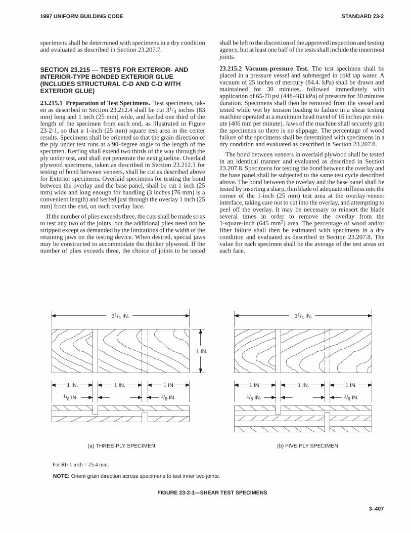
1997 UNIFORM BUILDING CODE STANDARD 23-2
3–407
specimens shall be determined with specimens in a dry conditionand evaluated as described in Section 23.207.7.
SECTION 23.215 — TESTS FOR EXTERIOR- ANDINTERIOR-TYPE BONDED EXTERIOR GLUE(INCLUDES STRUCTURAL C-D AND C-D WITHEXTERIOR GLUE)
23.215.1 Preparation of Test Specimens.Test specimens, tak-en as described in Section 23.212.4 shall be cut 31/4 inches (83mm) long and 1 inch (25 mm) wide, and kerfed one third of thelength of the specimen from each end, as illustrated in Figure23-2-1, so that a 1-inch (25 mm) square test area in the centerresults. Specimens shall be oriented so that the grain direction ofthe ply under test runs at a 90-degree angle to the length of thespecimen. Kerfing shall extend two thirds of the way through theply under test, and shall not penetrate the next glueline. Overlaidplywood specimens, taken as described in Section 23.212.3 fortesting of bond between veneers, shall be cut as described abovefor Exterior specimens. Overlaid specimens for testing the bondbetween the overlay and the base panel, shall be cut 1 inch (25mm) wide and long enough for handling (3 inches [76 mm] is aconvenient length) and kerfed just through the overlay 1 inch (25mm) from the end, on each overlay face.
If the number of plies exceeds three, the cuts shall be made so asto test any two of the joints, but the additional plies need not bestripped except as demanded by the limitations of the width of theretaining jaws on the testing device. When desired, special jawsmay be constructed to accommodate the thicker plywood. If thenumber of plies exceeds three, the choice of joints to be tested
shall be left to the discretion of the approved inspection and testingagency, but at least one half of the tests shall include the innermostjoints.
23.215.2 Vacuum-pressure Test.The test specimen shall beplaced in a pressure vessel and submerged in cold tap water. Avacuum of 25 inches of mercury (84.4. kPa) shall be drawn andmaintained for 30 minutes, followed immediately withapplication of 65-70 psi (448-483 kPa) of pressure for 30 minutesduration. Specimens shall then be removed from the vessel andtested while wet by tension loading to failure in a shear testingmachine operated at a maximum head travel of 16 inches per min-ute (406 mm per minute). Jaws of the machine shall securely gripthe specimens so there is no slippage. The percentage of woodfailure of the specimens shall be determined with specimens in adry condition and evaluated as described in Section 23.207.8.
The bond between veneers in overlaid plywood shall be testedin an identical manner and evaluated as described in Section23.207.8. Specimens for testing the bond between the overlay andthe base panel shall be subjected to the same test cycle describedabove. The bond between the overlay and the base panel shall betested by inserting a sharp, thin blade of adequate stiffness into thecorner of the 1-inch (25 mm) test area at the overlay-veneerinterface, taking care not to cut into the overlay, and attempting topeel off the overlay. It may be necessary to reinsert the bladeseveral times in order to remove the overlay from the1-square-inch (645 mm2) area. The percentage of wood and/orfiber failure shall then be estimated with specimens in a drycondition and evaluated as described in Section 23.207.8. Thevalue for each specimen shall be the average of the test areas oneach face.
NOTE: Orient grain direction across specimens to test inner two joints.
(a) THREE-PLY SPECIMEN (b) FIVE-PLY SPECIMEN
31/4 IN.
1 IN.
1 IN.
1/8 IN.
31/4 IN.
1 IN. 1 IN. 1 IN. 1 IN. 1 IN.
1/8 IN. 1/8 IN. 1/8 IN.
For SI: 1 inch = 25.4 mm.
FIGURE 23-2-1—SHEAR TEST SPECIMENS
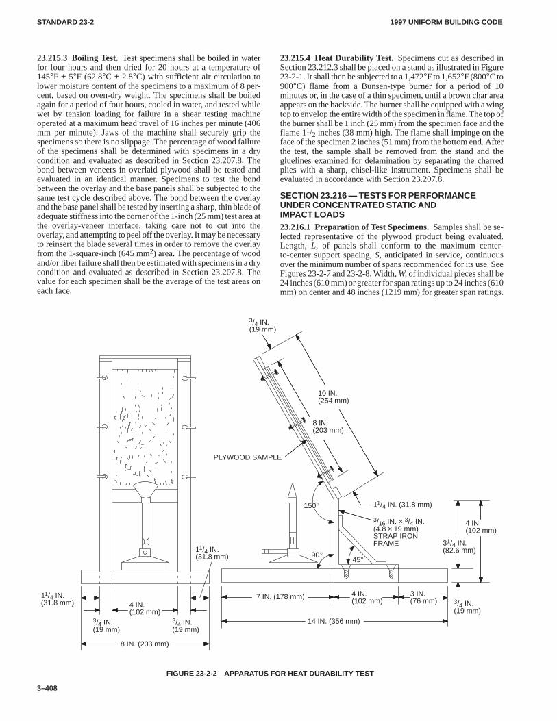
1997 UNIFORM BUILDING CODESTANDARD 23-2
3–408
23.215.3 Boiling Test.Test specimens shall be boiled in waterfor four hours and then dried for 20 hours at a temperature of145°F ± 5°F (62.8°C ± 2.8°C) with sufficient air circulation tolower moisture content of the specimens to a maximum of 8 per-cent, based on oven-dry weight. The specimens shall be boiledagain for a period of four hours, cooled in water, and tested whilewet by tension loading for failure in a shear testing machineoperated at a maximum head travel of 16 inches per minute (406mm per minute). Jaws of the machine shall securely grip thespecimens so there is no slippage. The percentage of wood failureof the specimens shall be determined with specimens in a drycondition and evaluated as described in Section 23.207.8. Thebond between veneers in overlaid plywood shall be tested andevaluated in an identical manner. Specimens to test the bondbetween the overlay and the base panels shall be subjected to thesame test cycle described above. The bond between the overlayand the base panel shall be tested by inserting a sharp, thin blade ofadequate stiffness into the corner of the 1-inch (25 mm) test area atthe overlay-veneer interface, taking care not to cut into theoverlay, and attempting to peel off the overlay. It may be necessaryto reinsert the blade several times in order to remove the overlayfrom the 1-square-inch (645 mm2) area. The percentage of woodand/or fiber failure shall then be estimated with specimens in a drycondition and evaluated as described in Section 23.207.8. Thevalue for each specimen shall be the average of the test areas oneach face.
23.215.4 Heat Durability Test.Specimens cut as described inSection 23.212.3 shall be placed on a stand as illustrated in Figure23-2-1. It shall then be subjected to a 1,472°F to 1,652°F (800°C to900°C) flame from a Bunsen-type burner for a period of 10minutes or, in the case of a thin specimen, until a brown char areaappears on the backside. The burner shall be equipped with a wingtop to envelop the entire width of the specimen in flame. The top ofthe burner shall be 1 inch (25 mm) from the specimen face and theflame 11/2 inches (38 mm) high. The flame shall impinge on theface of the specimen 2 inches (51 mm) from the bottom end. Afterthe test, the sample shall be removed from the stand and thegluelines examined for delamination by separating the charredplies with a sharp, chisel-like instrument. Specimens shall beevaluated in accordance with Section 23.207.8.
SECTION 23.216 — TESTS FOR PERFORMANCEUNDER CONCENTRATED STATIC ANDIMPACT LOADS23.216.1 Preparation of Test Specimens.Samples shall be se-lected representative of the plywood product being evaluated.Length, L, of panels shall conform to the maximum center-to-center support spacing, S, anticipated in service, continuousover the minimum number of spans recommended for its use. SeeFigures 23-2-7 and 23-2-8. Width, W, of individual pieces shall be24 inches (610 mm) or greater for span ratings up to 24 inches (610mm) on center and 48 inches (1219 mm) for greater span ratings.
90�
3/16 IN. × 3/4 IN.(4.8 × 19 mm)STRAP IRONFRAME
PLYWOOD SAMPLE
7 IN. (178 mm)11/4 IN.(31.8 mm)
3 IN.(76 mm)4 IN.
(102 mm)
8 IN. (203 mm)
150�
45°
14 IN. (356 mm)
4 IN.(102 mm)
3/4 IN.(19 mm)
3/4 IN.(19 mm)
11/4 IN.(31.8 mm)
3/4 IN.(19 mm)
3/4 IN.(19 mm)
31/4 IN.(82.6 mm)
8 IN.(203 mm)
10 IN.(254 mm)
11/4 IN. (31.8 mm)
4 IN.(102 mm)
FIGURE 23-2-2—APPARATUS FOR HEAT DURABILITY TEST
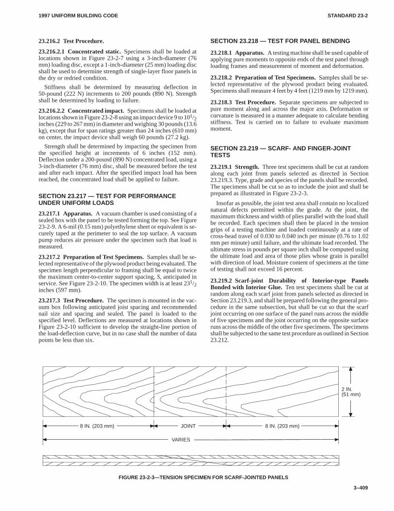
1997 UNIFORM BUILDING CODE STANDARD 23-2
3–409
23.216.2 Test Procedure.
23.216.2.1 Concentrated static.Specimens shall be loaded atlocations shown in Figure 23-2-7 using a 3-inch-diameter (76mm) loading disc, except a 1-inch-diameter (25 mm) loading discshall be used to determine strength of single-layer floor panels inthe dry or redried condition.
Stiffness shall be determined by measuring deflection in50-pound (222 N) increments to 200 pounds (890 N). Strengthshall be determined by loading to failure.
23.216.2.2 Concentrated impact.Specimens shall be loaded atlocations shown in Figure 23-2-8 using an impact device 9 to 101/2inches (229 to 267 mm) in diameter and weighing 30 pounds (13.6kg), except that for span ratings greater than 24 inches (610 mm)on center, the impact device shall weigh 60 pounds (27.2 kg).
Strength shall be determined by impacting the specimen fromthe specified height at increments of 6 inches (152 mm).Deflection under a 200-pound (890 N) concentrated load, using a3-inch-diameter (76 mm) disc, shall be measured before the testand after each impact. After the specified impact load has beenreached, the concentrated load shall be applied to failure.
SECTION 23.217 — TEST FOR PERFORMANCEUNDER UNIFORM LOADS
23.217.1 Apparatus.A vacuum chamber is used consisting of asealed box with the panel to be tested forming the top. See Figure23-2-9. A 6-mil (0.15 mm) polyethylene sheet or equivalent is se-curely taped at the perimeter to seal the top surface. A vacuumpump reduces air pressure under the specimen such that load ismeasured.
23.217.2 Preparation of Test Specimens.Samples shall be se-lected representative of the plywood product being evaluated. Thespecimen length perpendicular to framing shall be equal to twicethe maximum center-to-center support spacing, S, anticipated inservice. See Figure 23-2-10. The specimen width is at least 231/2inches (597 mm).
23.217.3 Test Procedure.The specimen is mounted in the vac-uum box following anticipated joist spacing and recommendednail size and spacing and sealed. The panel is loaded to thespecified level. Deflections are measured at locations shown inFigure 23-2-10 sufficient to develop the straight-line portion ofthe load-deflection curve, but in no case shall the number of datapoints be less than six.
SECTION 23.218 — TEST FOR PANEL BENDING
23.218.1 Apparatus.A testing machine shall be used capable ofapplying pure moments to opposite ends of the test panel throughloading frames and measurement of moment and deformation.
23.218.2 Preparation of Test Specimens.Samples shall be se-lected representative of the plywood product being evaluated.Specimens shall measure 4 feet by 4 feet (1219 mm by 1219 mm).
23.218.3 Test Procedure.Separate specimens are subjected topure moment along and across the major axis. Deformation orcurvature is measured in a manner adequate to calculate bendingstiffness. Test is carried on to failure to evaluate maximummoment.
SECTION 23.219 — SCARF- AND FINGER-JOINTTESTS
23.219.1 Strength.Three test specimens shall be cut at randomalong each joint from panels selected as directed in Section23.219.3. Type, grade and species of the panels shall be recorded.The specimens shall be cut so as to include the joint and shall beprepared as illustrated in Figure 23-2-3.
Insofar as possible, the joint test area shall contain no localizednatural defects permitted within the grade. At the joint, themaximum thickness and width of plies parallel with the load shallbe recorded. Each specimen shall then be placed in the tensiongrips of a testing machine and loaded continuously at a rate ofcross-head travel of 0.030 to 0.040 inch per minute (0.76 to 1.02mm per minute) until failure, and the ultimate load recorded. Theultimate stress in pounds per square inch shall be computed usingthe ultimate load and area of those plies whose grain is parallelwith direction of load. Moisture content of specimens at the timeof testing shall not exceed 16 percent.
23.219.2 Scarf-joint Durability of Interior-type PanelsBonded with Interior Glue. Ten test specimens shall be cut atrandom along each scarf joint from panels selected as directed inSection 23.219.3, and shall be prepared following the general pro-cedure in the same subsection, but shall be cut so that the scarfjoint occurring on one surface of the panel runs across the middleof five specimens and the joint occurring on the opposite surfaceruns across the middle of the other five specimens. The specimensshall be subjected to the same test procedure as outlined in Section23.212.
8 IN. (203 mm)
VARIES
JOINT 8 IN. (203 mm)
2 IN.(51 mm)
FIGURE 23-2-3—TENSION SPECIMEN FOR SCARF-JOINTED PANELS
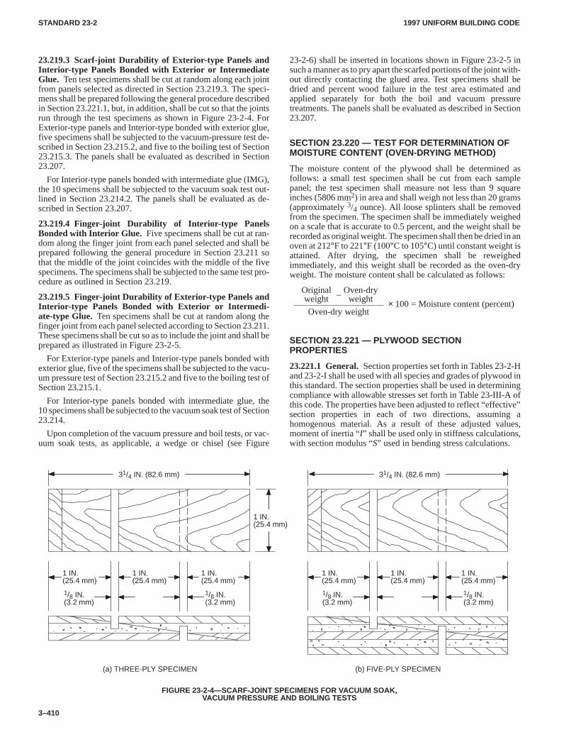
1997 UNIFORM BUILDING CODESTANDARD 23-2
3–410
23.219.3 Scarf-joint Durability of Exterior-type Panels andInterior-type Panels Bonded with Exterior or IntermediateGlue. Ten test specimens shall be cut at random along each jointfrom panels selected as directed in Section 23.219.3. The speci-mens shall be prepared following the general procedure describedin Section 23.221.1, but, in addition, shall be cut so that the jointsrun through the test specimens as shown in Figure 23-2-4. ForExterior-type panels and Interior-type bonded with exterior glue,five specimens shall be subjected to the vacuum-pressure test de-scribed in Section 23.215.2, and five to the boiling test of Section23.215.3. The panels shall be evaluated as described in Section23.207.
For Interior-type panels bonded with intermediate glue (IMG),the 10 specimens shall be subjected to the vacuum soak test out-lined in Section 23.214.2. The panels shall be evaluated as de-scribed in Section 23.207.
23.219.4 Finger-joint Durability of Interior-type PanelsBonded with Interior Glue. Five specimens shall be cut at ran-dom along the finger joint from each panel selected and shall beprepared following the general procedure in Section 23.211 sothat the middle of the joint coincides with the middle of the fivespecimens. The specimens shall be subjected to the same test pro-cedure as outlined in Section 23.219.
23.219.5 Finger-joint Durability of Exterior-type Panels andInterior-type Panels Bonded with Exterior or Intermedi-ate-type Glue. Ten specimens shall be cut at random along thefinger joint from each panel selected according to Section 23.211.These specimens shall be cut so as to include the joint and shall beprepared as illustrated in Figure 23-2-5.
For Exterior-type panels and Interior-type panels bonded withexterior glue, five of the specimens shall be subjected to the vacu-um pressure test of Section 23.215.2 and five to the boiling test ofSection 23.215.1.
For Interior-type panels bonded with intermediate glue, the10 specimens shall be subjected to the vacuum soak test of Section23.214.
Upon completion of the vacuum pressure and boil tests, or vac-uum soak tests, as applicable, a wedge or chisel (see Figure
23-2-6) shall be inserted in locations shown in Figure 23-2-5 insuch a manner as to pry apart the scarfed portions of the joint with-out directly contacting the glued area. Test specimens shall bedried and percent wood failure in the test area estimated andapplied separately for both the boil and vacuum pressuretreatments. The panels shall be evaluated as described in Section23.207.
SECTION 23.220 — TEST FOR DETERMINATION OFMOISTURE CONTENT (OVEN-DRYING METHOD)
The moisture content of the plywood shall be determined asfollows: a small test specimen shall be cut from each samplepanel; the test specimen shall measure not less than 9 squareinches (5806 mm2) in area and shall weigh not less than 20 grams(approximately 3/4 ounce). All loose splinters shall be removedfrom the specimen. The specimen shall be immediately weighedon a scale that is accurate to 0.5 percent, and the weight shall berecorded as original weight. The specimen shall then be dried in anoven at 212°F to 221°F (100°C to 105°C) until constant weight isattained. After drying, the specimen shall be reweighedimmediately, and this weight shall be recorded as the oven-dryweight. The moisture content shall be calculated as follows:
Originalweight
Oven-dryweight–
Oven-dry weight× 100 = Moisture content (percent)
SECTION 23.221 — PLYWOOD SECTIONPROPERTIES
23.221.1 General.Section properties set forth in Tables 23-2-Hand 23-2-I shall be used with all species and grades of plywood inthis standard. The section properties shall be used in determiningcompliance with allowable stresses set forth in Table 23-III-A ofthis code. The properties have been adjusted to reflect “effective”section properties in each of two directions, assuming ahomogenous material. As a result of these adjusted values,moment of inertia “I” shall be used only in stiffness calculations,with section modulus “S” used in bending stress calculations.
(a) THREE-PLY SPECIMEN (b) FIVE-PLY SPECIMEN
1 IN.(25.4 mm)
1/8 IN.(3.2 mm)
31/4 IN. (82.6 mm) 31/4 IN. (82.6 mm)
1 IN.(25.4 mm)
1 IN.(25.4 mm)
1 IN.(25.4 mm)
1 IN.(25.4 mm)
1 IN.(25.4 mm)
1/8 IN.(3.2 mm)
1/8 IN.(3.2 mm)
1/8 IN.(3.2 mm)
1 IN.(25.4 mm)
FIGURE 23-2-4—SCARF-JOINT SPECIMENS FOR VACUUM SOAK,VACUUM PRESSURE AND BOILING TESTS
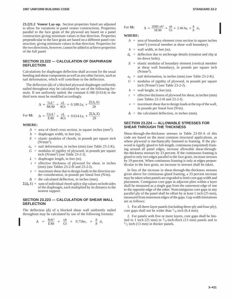
1997 UNIFORM BUILDING CODE STANDARD 23-2
3–411
23.221.2 Veneer Lay-up.Section properties listed are adjustedto allow for variations in panel veneer constructions. Propertiesparallel to the face grain of the plywood are based on a panelconstruction giving minimum values in that direction. Propertiesperpendicular to the face grain are based on a different panel con-struction, giving minimum values in that direction. Properties forthe two directions, however, cannot be added to achieve propertiesof the full panel.
SECTION 23.222 — CALCULATION OF DIAPHRAGMDEFLECTION
Calculations for diaphragm deflection shall account for the usualbending and shear components as well as any other factors, such asnail deformation, which will contribute to the deflection.
The deflection (∆) of a blocked plywood diaphragm uniformlynailed throughout may be calculated by use of the following for-mula. If not uniformly nailed, the constant 0.188 (0.614) in thethird term must be modified accordingly.
� �5vL3
8EAb�
vL4Gt
� 0.188Len ��(�cX)
2b
� �52vL3
EAb�
vL4Gt
� 0.614Len ��(�cX)
2bFor SI:
WHERE:A = area of chord cross section, in square inches (mm2).b = diaphragm width, in feet (m).E = elastic modulus of chords, in pounds per square inch
(N/mm2).en = nail deformation, in inches (mm) (see Table 23-2-K).G = modulus of rigidity of plywood, in pounds per square
inch (N/mm2) (see Table 23-2-J).L = diaphragm length, in feet (m).t = effective thickness of plywood for shear, in inches
(mm) (see Tables 23-2-H and 23-2-I).v = maximum shear due to design loads in the direction un-
der consideration, in pounds per lineal foot (N/m).∆ = the calculated deflection, in inches (mm).
Σ(∆cX) = sum of individual chord-splice slip values on both sidesof the diaphragm, each multiplied by its distance to thenearest support.
SECTION 23.223 — CALCULATION OF SHEAR WALLDEFLECTION
The deflection (∆) of a blocked shear wall uniformly nailedthroughout may be calculated by use of the following formula:
� �8vh3
EAb�
vhGt
� 0.75hen �hb
da
For SI: � �2000vh3
3EAb�
vhGt
� 2.46hen �hb
da
WHERE:A = area of boundary element cross section in square inches
(mm2) (vertical member at shear wall boundary).b = wall width, in feet (m).
da = deflection due to anchorage details (rotation and slip attie-down bolts).
E = elastic modulus of boundary element (vertical memberat shear wall boundary), in pounds per square inch(N/mm2).
en = nail deformation, in inches (mm) (see Table 23-2-K).G = modulus of rigidity of plywood, in pounds per square
inch (N/mm2) (see Table 23-2-J).h = wall height, in feet (m).t = effective thickness of plywood for shear, in inches (mm)
(see Tables 23-2-H and 23-2-I).v = maximum shear due to design loads at the top of the wall,
in pounds per lineal foot (N/m).
∆ = the calculated deflection, in inches (mm).
SECTION 23.224 — ALLOWABLE STRESSES FORSHEAR THROUGH THE THICKNESS
Shear-through-the-thickness stresses in Table 23-III-A of thiscode are based on the most common structural applications, aswhere plywood is mechanically fastened to framing. If the ply-wood is rigidly glued to full-length, continuous (unjointed) fram-ing around all panel edges, increase allowable shear-through-the-thickness stresses by 33 percent. If the continuous framing isglued to only two edges parallel to the face grain, increase stressesby 19 percent. When continuous framing is only at edges perpen-dicular to the face grain, no increase in stresses shall be taken.
In lieu of the increase in shear-through-the-thickness stressesgiven above for continuous glued framing, a 33 percent increasemay be taken when panels are regraded to limit core gap width andplacement. Contiguous core gaps in adjacent plies within a layershall be measured as a single gap from the outermost edge of oneto the opposite edge of the other. Noncontiguous core gaps in anyparallel ply of the panel shall be offset by at least 1 inch (25 mm),measured from innermost edges of the gaps. Gap width limitationsare as follows:
1. For all three-layer panels (including three-ply and four-ply),core gaps shall not be wider than 1/4 inch (6.4 mm).
2. For panels with five or more layers, core gaps shall be lim-ited to 1 inch (25 mm) in 1/2-inch-thick (13 mm) panels and to1/2 inch (13 mm) in thicker panels.
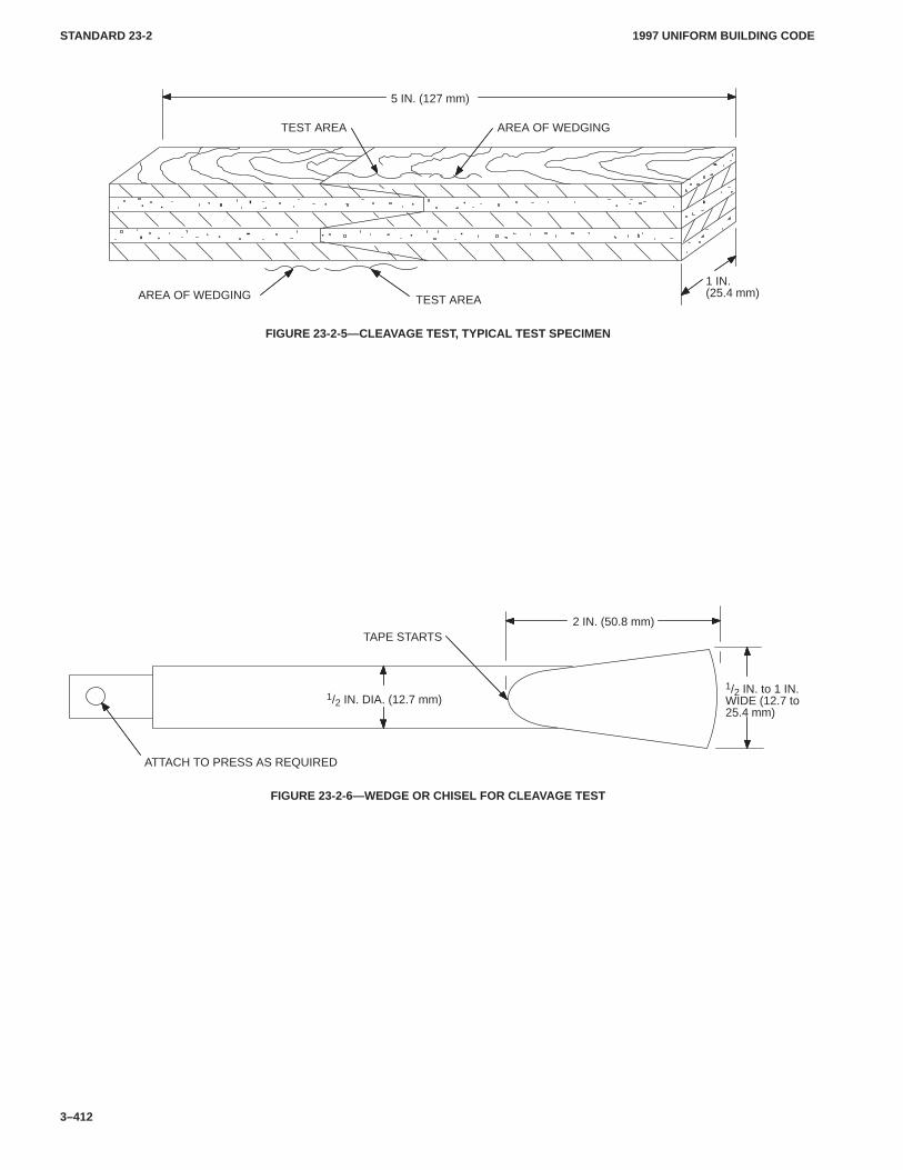
1997 UNIFORM BUILDING CODESTANDARD 23-2
3–412
TEST AREAAREA OF WEDGING
TEST AREA AREA OF WEDGING
5 IN. (127 mm)
1 IN.(25.4 mm)
FIGURE 23-2-5—CLEAVAGE TEST, TYPICAL TEST SPECIMEN
2 IN. (50.8 mm)
1/2 IN. DIA. (12.7 mm)
TAPE STARTS
ATTACH TO PRESS AS REQUIRED
1/2 IN. to 1 IN.WIDE (12.7 to25.4 mm)
FIGURE 23-2-6—WEDGE OR CHISEL FOR CLEAVAGE TEST
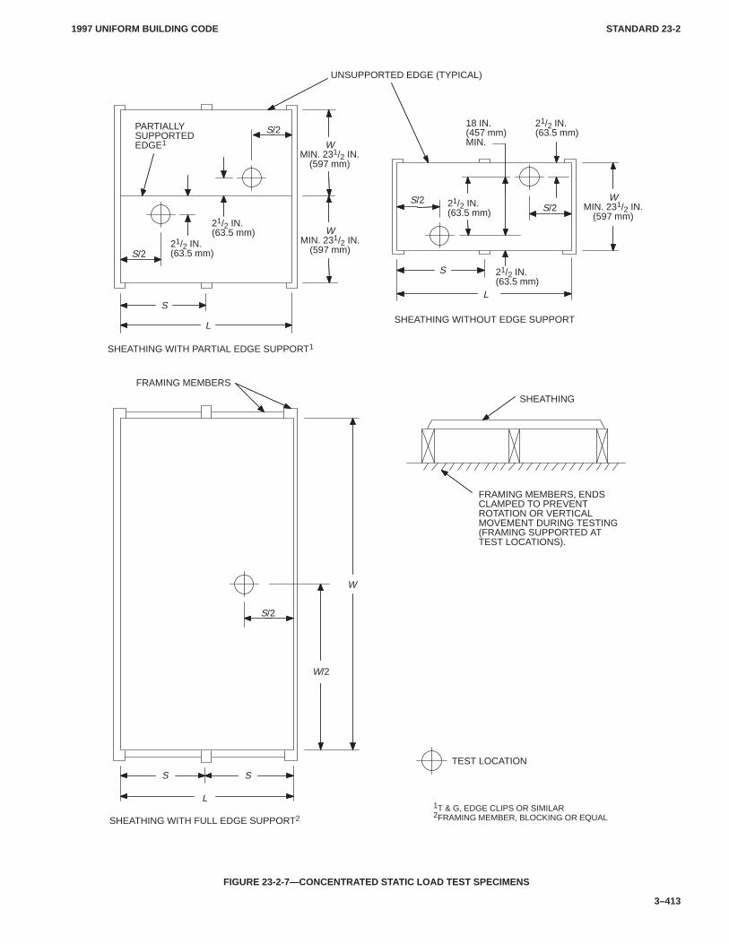
1997 UNIFORM BUILDING CODE STANDARD 23-2
3–413
1T & G, EDGE CLIPS OR SIMILAR2FRAMING MEMBER, BLOCKING OR EQUALSHEATHING WITH FULL EDGE SUPPORT2
SHEATHING WITHOUT EDGE SUPPORT
SHEATHING WITH PARTIAL EDGE SUPPORT1
TEST LOCATION
S S
L
S/2
FRAMING MEMBERS
SHEATHING
FRAMING MEMBERS, ENDSCLAMPED TO PREVENTROTATION OR VERTICALMOVEMENT DURING TESTING(FRAMING SUPPORTED ATTEST LOCATIONS).
SL
S/2
S
L
PARTIALLYSUPPORTEDEDGE1
21/2 IN.(63.5 mm)
S/2
S/2S/2
UNSUPPORTED EDGE (TYPICAL)
W/2
W
21/2 IN.(63.5 mm)
WMIN. 231/2 IN.
(597 mm)
WMIN. 231/2 IN.
(597 mm)
21/2 IN.(63.5 mm)
21/2 IN.(63.5 mm)
21/2 IN.(63.5 mm)
WMIN. 231/2 IN.
(597 mm)
18 IN.(457 mm)MIN.
FIGURE 23-2-7—CONCENTRATED STATIC LOAD TEST SPECIMENS
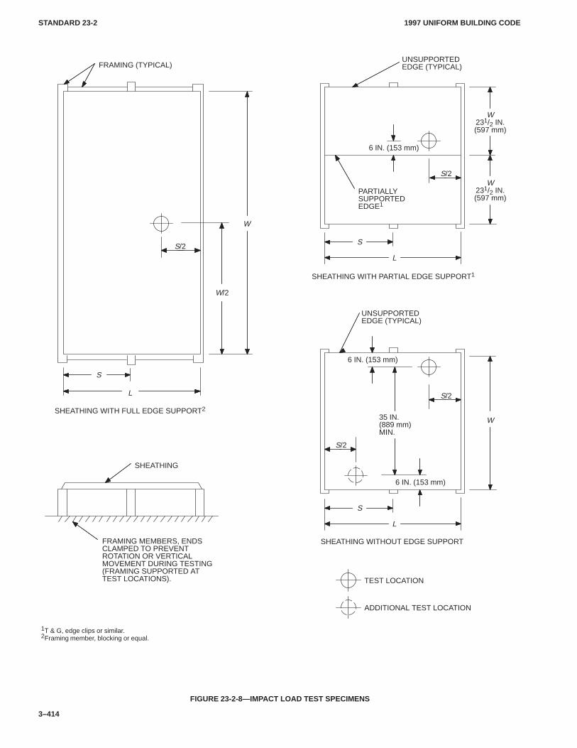
1997 UNIFORM BUILDING CODESTANDARD 23-2
3–414
1T & G, edge clips or similar.2Framing member, blocking or equal.
SHEATHING WITH FULL EDGE SUPPORT2
SHEATHING WITHOUT EDGE SUPPORT
SHEATHING WITH PARTIAL EDGE SUPPORT1
TEST LOCATION
S
L
S/2
FRAMING (TYPICAL)
SHEATHING
FRAMING MEMBERS, ENDSCLAMPED TO PREVENTROTATION OR VERTICALMOVEMENT DURING TESTING(FRAMING SUPPORTED ATTEST LOCATIONS).
S
L
PARTIALLYSUPPORTEDEDGE1
6 IN. (153 mm)
S/2
UNSUPPORTEDEDGE (TYPICAL)
W/2
W
W231/2 IN.(597 mm)
W231/2 IN.(597 mm)
S
L
6 IN. (153 mm)
S/2
UNSUPPORTEDEDGE (TYPICAL)
W
6 IN. (153 mm)
S/2
35 IN.(889 mm)MIN.
ADDITIONAL TEST LOCATION
FIGURE 23-2-8—IMPACT LOAD TEST SPECIMENS
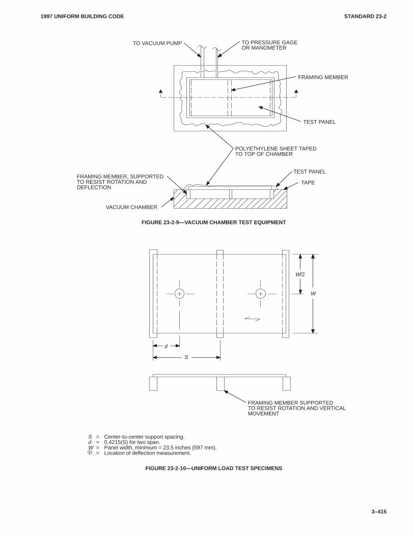
1997 UNIFORM BUILDING CODE STANDARD 23-2
3–415
VACUUM CHAMBER
FRAMING MEMBER, SUPPORTEDTO RESIST ROTATION ANDDEFLECTION
TAPE
TEST PANEL
POLYETHYLENE SHEET TAPEDTO TOP OF CHAMBER
TEST PANEL
FRAMING MEMBER
TO PRESSURE GAGEOR MANOMETER
TO VACUUM PUMP
FIGURE 23-2-9—VACUUM CHAMBER TEST EQUIPMENT
S = Center-to-center support spacing.d = 0.4215(S) for two span.W = Panel width, minimum = 23.5 inches (597 mm).
= Location of deflection measurement.
FRAMING MEMBER SUPPORTEDTO RESIST ROTATION AND VERTICALMOVEMENT
d
S
W
W/2
FIGURE 23-2-10—UNIFORM LOAD TEST SPECIMENS
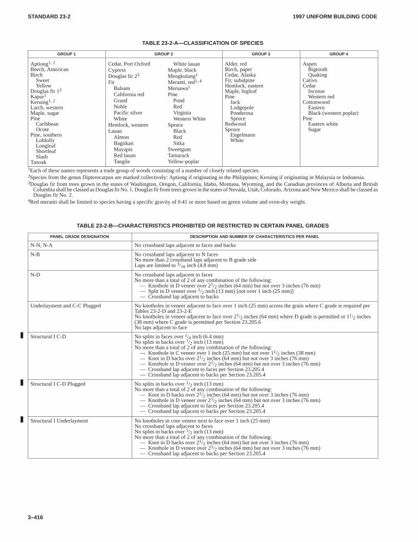
1997 UNIFORM BUILDING CODESTANDARD 23-2
3–416
TABLE 23-2-A—CLASSIFICATION OF SPECIES
GROUP 1 GROUP 2 GROUP 3 GROUP 4
Aptiong1, 2
Beech, AmericanBirch
SweetYellow
Douglas fir 13Kapur1Keruing1, 2
Larch, westernMaple, sugarPine
CaribbeanOcote
Pine, southernLoblollyLongleafShortleafSlash
Tanoak
Cedar, Port OxfordCypressDouglas fir 23
FirBalsamCalifornia redGrandNoblePacific silverWhite
Hemlock, westernLauan
AlmonBagtikanMayapisRed lauanTangile
White lauanMaple, blackMengkulang1
Meranti, red1, 4
Mersawa1
PinePondRedVirginiaWestern White
SpruceBlackRedSitka
SweetgumTamarackYellow-poplar
Alder, redBirch, paperCedar, AlaskaFir, subalpineHemlock, easternMaple, bigleafPine
JackLodgepolePonderosaSpruce
RedwoodSpruce
EngelmannWhite
AspenBigtoothQuaking
CativoCedar
IncenseWestern red
CottonwoodEasternBlack (western poplar)
PineEastern whiteSugar
1Each of these names represents a trade group of woods consisting of a number of closely related species.2Species from the genus Dipterocarpus are marked collectively: Aptiong if originating in the Philippines; Keruing if originating in Malaysia or Indonesia.3Douglas fir from trees grown in the states of Washington, Oregon, California, Idaho, Montana, Wyoming, and the Canadian provinces of Alberta and British
Columbia shall be classed as Douglas fir No. 1. Douglas fir from trees grown in the states of Nevada, Utah, Colorado, Arizona and New Mexico shall be classed asDouglas fir No. 2.
4Red meranti shall be limited to species having a specific gravity of 0.41 or more based on green volume and oven-dry weight.
TABLE 23-2-B—CHARACTERISTICS PROHIBITED OR RESTRICTED IN CERTAIN PANEL GRADES
PANEL GRADE DESIGNATION DESCRIPTION AND NUMBER OF CHARACTERISTICS PER PANEL
N-N, N-A No crossband laps adjacent to faces and backs
N-B No crossband laps adjacent to N facesNo more than 2 crossband laps adjacent to B grade sideLaps are limited to 3/16 inch (4.8 mm)
N-D No crossband laps adjacent to facesNo more than a total of 2 of any combination of the following:
— Knothole in D veneer over 21/2 inches (64 mm) but not over 3 inches (76 mm)— Split in D veneer over 1/2 inch (13 mm) [not over 1 inch (25 mm)]— Crossband lap adjacent to backs
Underlayment and C-C Plugged No knotholes in veneer adjacent to face over 1 inch (25 mm) across the grain where C grade is required perTables 23-2-D and 23-2-ENo knotholes in veneer adjacent to face over 21/2 inches (64 mm) where D grade is permitted or 11/2 inches(38 mm) where C grade is permitted per Section 23.205.6No laps adjacent to face
Structural I C-D No splits in faces over 1/4 inch (6.4 mm)No splits in backs over 1/2 inch (13 mm)No more than a total of 2 of any combination of the following:
— Knothole in C veneer over 1 inch (25 mm) but not over 11/2 inches (38 mm)— Knot in D backs over 21/2 inches (64 mm) but not over 3 inches (76 mm)— Knothole in D veneer over 21/2 inches (64 mm) but not over 3 inches (76 mm)— Crossband lap adjacent to faces per Section 23.205.4— Crossband lap adjacent to backs per Section 23.205.4
Structural I C-D Plugged No splits in backs over 1/2 inch (13 mm)No more than a total of 2 of any combination of the following:
— Knot in D backs over 21/2 inches (64 mm) but not over 3 inches (76 mm)— Knothole in D veneer over 21/2 inches (64 mm) but not over 3 inches (76 mm)— Crossband lap adjacent to faces per Section 23.205.4— Crossband lap adjacent to backs per Section 23.205.4
Structural I Underlayment No knotholes in core veneer next to face over 1 inch (25 mm)No crossband laps adjacent to facesNo splits in backs over 1/2 inch (13 mm)No more than a total of 2 of any combination of the following:
— Knot in D backs over 21/2 inches (64 mm) but not over 3 inches (76 mm)— Knothole in D veneer over 21/2 inches (64 mm) but not over 3 inches (76 mm)— Crossband lap adjacent to backs per Section 23.205.4
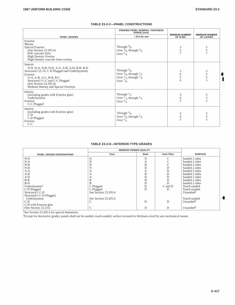
1997 UNIFORM BUILDING CODE STANDARD 23-2
3–417
TABLE 23-2-C—PANEL CONSTRUCTIONS
FINISHED PANEL NOMINAL THICKNESSRANGE (inch)
MINIMUM NUMBER MINIMUM NUMBERPANEL GRADES × 25.4 for mm
MINIMUM NUMBEROF PLIES
MINIMUM NUMBEROF LAYERS
ExteriorMarineSpecial Exterior
(See Section 23.205.4)B-B concrete formHigh Density OverlayHigh Density concrete form overlay
Through 3/8Over 3/8, through 3/4Over 3/4
357
357
InteriorN-N, N-A, N-B, N-D, A-A, A-B, A-D, B-B, B-D
Structural I (C-D, C-D Plugged and Underlayment)Exterior
A-A, A-B, A-C, B-B, B-CStructural I C-C and C-C Plugged(See Section 23.205.4)Medium Density and Special Overlays
Through 3/8Over 3/8, through 1/2Over 1/2, through 7/8Over 7/8
3456
3355
Interior(including grades with Exterior glue)Underlayment
ExteriorC-C Plugged
Through 1/2Over 1/2, through 3/4Over 3/4
345
335
Interior(including grades with Exterior glue)C-DC-D Plugged
ExteriorC-C
Through 5/8Over 5/8, through 3/4Over 3/4
345
335
TABLE 23-2-D—INTERIOR-TYPE GRADES
MINIMUM VENEER QUALITY
PANEL GRADES DESIGNATIONS Face Back Inner Plies SURFACE
N-NN-AN-BN-DA-AA-BA-DB-BB-DUnderlayment1C-D PluggedStructural I C-DStructural I C-D Plugged, UnderlaymentC-DC-D with Exterior glue(See Section 23.215)
NNNNAAABBC PluggedC PluggedSee Section 23.205.4
See Section 23.205.4C
C
NABDABDBDDD
D
D
CCCDDDDDD
C and DD
D
D
Sanded 2 sidesSanded 2 sidesSanded 2 sidesSanded 2 sidesSanded 2 sidesSanded 2 sidesSanded 2 sidesSanded 2 sidesSanded 2 sidesTouch-sandedTouch-sandedUnsanded2
Touch-sandedUnsanded2
Unsanded2
1See Section 23.205.6 for special limitations.2Except for decorative grades, panels shall not be sanded, touch-sanded, surface textured or thickness sized by any mechanical means.
�
�
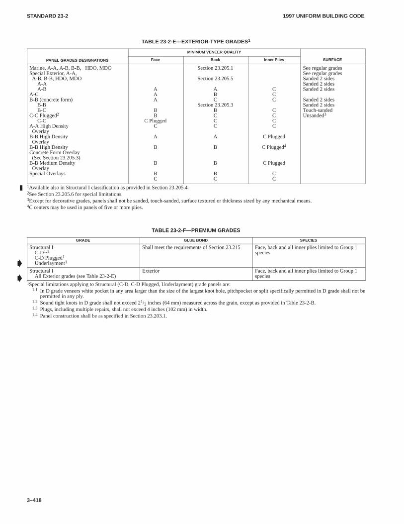
1997 UNIFORM BUILDING CODESTANDARD 23-2
3–418
TABLE 23-2-E—EXTERIOR-TYPE GRADES 1
MINIMUM VENEER QUALITY
PANEL GRADES DESIGNATIONS Face Back Inner Plies SURFACE
Marine, A-A, A-B, B-B, HDO, MDOSpecial Exterior, A-A,A-B, B-B, HDO, MDO
A-AA-B
A-CB-B (concrete form)
B-BB-C
C-C Plugged2C-C
A-A High DensityOverlay
B-B High DensityOverlay
B-B High DensityConcrete Form Overlay(See Section 23.205.3)
B-B Medium DensityOverlay
Special Overlays
AAA
BB
C PluggedC
A
B
B
BC
Section 23.205.1
Section 23.205.5
ABC
Section 23.205.3BCCC
A
B
B
BC
CCC
CCCC
C Plugged
C Plugged4
C Plugged
CC
See regular gradesSee regular gradesSanded 2 sidesSanded 2 sidesSanded 2 sides
Sanded 2 sidesSanded 2 sidesTouch-sandedUnsanded3
1Available also in Structural I classification as provided in Section 23.205.4.2See Section 23.205.6 for special limitations.3Except for decorative grades, panels shall not be sanded, touch-sanded, surface textured or thickness sized by any mechanical means.4C centers may be used in panels of five or more plies.
TABLE 23-2-F—PREMIUM GRADES
GRADE GLUE BOND SPECIES
Structural IC-D1.1
C-D Plugged1Underlayment1
Shall meet the requirements of Section 23.215 Face, back and all inner plies limited to Group 1species
Structural IAll Exterior grades (see Table 23-2-E)
Exterior Face, back and all inner plies limited to Group 1species
1Special limitations applying to Structural (C-D, C-D Plugged, Underlayment) grade panels are:1.1 In D grade veneers white pocket in any area larger than the size of the largest knot hole, pitchpocket or split specifically permitted in D grade shall not be
permitted in any ply.1.2 Sound tight knots in D grade shall not exceed 21/2 inches (64 mm) measured across the grain, except as provided in Table 23-2-B.1.3 Plugs, including multiple repairs, shall not exceed 4 inches (102 mm) in width.1.4 Panel construction shall be as specified in Section 23.203.1.
�
�
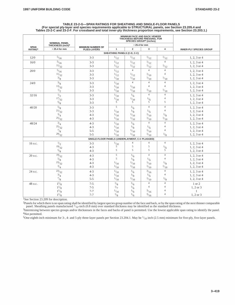
1997 UNIFORM BUILDING CODE STANDARD 23-2
3–419
TABLE 23-2-G—SPAN RATINGS FOR SHEATHING AND SINGLE-FLOOR PANELS(For special ply-layer and species requirements applicable to STRUCTURAL panels, see Section 23.205.4 and
Tables 23-2-C and 23-2-F. For crossband and total inner-ply thickness proportion requirements, see Section 23.203.1.)
NOMINAL PANEL
MINIMUM FACE AND BACK VENEERTHICKNESS BEFORE PRESSING, FOR
SPECIES GROUP3 (inches)
SPAN
NOMINAL PANELTHICKNESS (inch) 2
MINIMUM NUMBER OF× 25.4 for mm
SPANRATING1 × 25.4 for mm
MINIMUM NUMBER OFPLIES-LAYERS 1 2 3 4 INNER-PLY SPECIES GROUP
SHEATHING PANELS (C-D, C-C)
12/0 5/16 3-3 1/121/12
1/121/12 1, 2, 3 or 4
16/0 5/1611/32
3-33-3
1/121/12
1/121/12
1/121/12
4
1/12
1, 2, 3 or 41, 2, 3 or 4
20/0 5/1611/323/8
3-33-33-3
1/121/121/10
4
1/121/10
4
1/101/10
4
4
1/10
1, 2, 3 or 41, 2, 3 or 41, 2, 3 or 4
24/0 3/813/321/2
3-33-33-3
1/101/101/10
4
1/101/10
4
4
1/10
4
4
1/10
1, 2, 3 or 41, 2, 3 or 41, 2, 3 or 4
32/16 1/217/325/8
3-33-33-3
1/101/10
5
1/61/10
5
4
1/65
4
4
5
1, 2, 3 or 41, 2, 3 or 41, 2, 3 or 4
40/20 5/821/323/4
25/32
3-33-34-34-3
5
1/101/101/10
1/61/81/101/10
4
1/61/101/10
4
4
1/81/10
1, 2, 3 or 41, 2, 3 or 41, 2, 3 or 41, 2, 3 or 4
48/24 3/425/327/8
29/32
4-34-35-55-5
1/101/101/101/10
1/61/81/101/10
4
1/61/101/10
4
4
4
1/8
1, 2, 3 or 41, 2, 3 or 41, 2, 3 or 41, 2, 3 or 4
SINGLE-FLOOR PANELS (UNDERLAYMENT, C-C PLUGGED)
16 o.c. 1/219/325/8
3-34-34-3
1/105
5
4
5
5
4
5
5
4
1/65
1, 2, 3 or 41, 2, 3 or 41, 2, 3 or 4
20 o.c. 19/325/8
23/323/4
4-34-34-34-3
5
5
1/101/10
1/61/81/101/10
4
1/61/101/10
4
4
1/81/10
1, 2, 3 or 41, 2, 3 or 41, 2, 3 or 41, 2, 3 or 4
24 o.c. 23/323/47/8
4-34-35-5
1/101/101/10
1/61/81/10
3/161/61/10
4
4
1/8
1, 2, 3 or 41, 2, 3 or 41, 2, 3 or 4
48 o.c. 11/811/811/811/8
7-57-57-77-7
1/81/71/101/8
1/61/61/61/6
4
4
3/163/16
4
4
4
4
1 or 21, 2 or 3
11, 2 or 3
1See Section 23.209 for description.2Panels for which there is no span rating shall be identified by largest species group number of the face and back, or by the span rating of the next thinner comparable
panel. Sheathing panels manufactured 1/32-inch (0.8 mm) over standard thickness may be identified as the standard thickness.3Intermixing between species groups and/or thicknesses in the faces and backs of panel is permitted. Use the lowest applicable span rating to identify the panel.4Not permitted.5One-eighth-inch minimum for 3-, 4- and 5-ply three-layer panels per Section 23.204.1. May be 1/10 inch (2.5 mm) minimum for five-ply, five-layer panels.
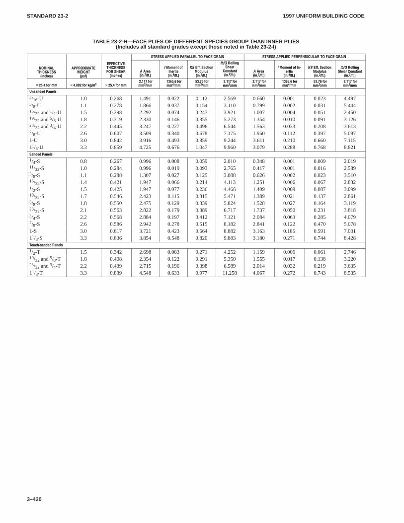
1997 UNIFORM BUILDING CODESTANDARD 23-2
3–420
TABLE 23-2-H—FACE PLIES OF DIFFERENT SPECIES GROUP THAN INNER PLIES(Includes all standard grades except those noted in Table 23-2-I)
������� �������� � ��������� ����� �� ������� ������������������ ������ ����� ��
����� �����������)-#(%1�
����!�� �� ������/1&�
������������������������� ��)-#(%1�
�� 0%"�)-���&2��
���.,%-2�.&�-%02)"�)-���&2��
����&&���%#2).-�.$3+31�)-���&2��
������.++)-'�(%"0�.-12"-2�)-���&2��
�� 0%"�)-���&2��
���.,%-2�.&��-4%02)"�)-���&2��
����&&���%#2).-�.$3+31�)-���&2��
������.++)-'�(%"0��.-12"-2
�)-���&2��
�����&.0�,, �������&.0�*'�,� �����&.0�,,�������&.0,,��,,
�����&.0,,��,,
�����&.0,,��,,
�������&.0,,��,,
�������&.0,,��,,
�����&.0,,��,,
�����&.0,,��,,
�������&.0,,��,,
�-1"-$%$��"-%+1
5/16-U 1.0 0.268 1.491 0.022 0.112 2.569 0.660 0.001 0.023 4.4973/8-U 1.1 0.278 1.866 0.037 0.154 3.110 0.799 0.002 0.031 5.44415/32 and 1/2-U 1.5 0.298 2.292 0.074 0.247 3.921 1.007 0.004 0.051 2.45019/32 and 5/8-U 1.8 0.319 2.330 0.146 0.355 5.273 1.354 0.010 0.091 3.12623/32 and 3/4-U 2.2 0.445 3.247 0.227 0.496 6.544 1.563 0.033 0.208 3.6137/8-U 2.6 0.607 3.509 0.340 0.678 7.175 1.950 0.112 0.397 5.0971-U 3.0 0.842 3.916 0.493 0.859 9.244 3.611 0.210 0.660 7.11511/8-U 3.3 0.859 4.725 0.676 1.047 9.960 3.079 0.288 0.768 8.821�"-$%$��"-%+1
1/4-S 0.8 0.267 0.996 0.008 0.059 2.010 0.348 0.001 0.009 2.01911/32-S 1.0 0.284 0.996 0.019 0.093 2.765 0.417 0.001 0.016 2.5893/8-S 1.1 0.288 1.307 0.027 0.125 3.088 0.626 0.002 0.023 3.51015/32-S 1.4 0.421 1.947 0.066 0.214 4.113 1.251 0.006 0.067 2.8321/2-S 1.5 0.425 1.947 0.077 0.236 4.466 1.409 0.009 0.087 3.09919/32-S 1.7 0.546 2.423 0.115 0.315 5.471 1.389 0.021 0.137 2.8615/8-S 1.8 0.550 2.475 0.129 0.339 5.824 1.528 0.027 0.164 3.11923/32-S 2.1 0.563 2.822 0.179 0.389 6.717 1.737 0.050 0.231 3.8183/4-S 2.2 0.568 2.884 0.197 0.412 7.121 2.084 0.063 0.285 4.0797/8-S 2.6 0.586 2.942 0.278 0.515 8.182 2.841 0.122 0.470 5.0781-S 3.0 0.817 3.721 0.423 0.664 8.882 3.163 0.185 0.591 7.03111/8-S 3.3 0.836 3.854 0.548 0.820 9.883 3.180 0.271 0.744 8.428�.3#(41"-$%$��"-%+1
1/2-T 1.5 0.342 2.698 0.083 0.271 4.252 1.159 0.006 0.061 2.74619/32 and 5/8-T 1.8 0.408 2.354 0.122 0.291 5.350 1.555 0.017 0.138 3.22023/32 and 3/4-T 2.2 0.439 2.715 0.196 0.398 6.589 2.014 0.032 0.219 3.63511/8-T 3.3 0.839 4.548 0.633 0.977 11.258 4.067 0.272 0.743 8.535
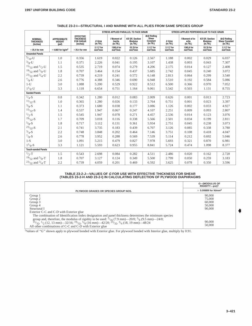
1997 UNIFORM BUILDING CODE STANDARD 23-2
3–421
TABLE 23-2-I—STRUCTURAL I AND MARINE WITH ALL PLIES FROM SAME SPECIES GROUP
������� �������� � ��������� ����� �� ������� ������������������ ������ ����� ��
����� �����������)-#(%1�
����!�� �� ������/1&�
������������������������� ��)-#(%1�
�� 0%"�)-���&2��
���.,%-2�.&�-%02)"�)-���&2��
����&&���%#2).-�.$3+31�)-���&2��
������.++)-'�(%"0�.-12"-2�)-���&2��
�� 0%"�)-���&2��
���.,%-2�.&��-4%02)"�)-���&2��
����&&���%#2).-�.$3+31�)-���&2��
������.++)-'�(%"0��.-12"-2
�)-���&2��
�����&.0�,, �������&.0�*'�,� �����&.0�,,�������&.0,,��,,
�����&.0,,��,,
�����&.0,,��,,
�������&.0,,��,,
�������&.0,,��,,
�����&.0,,��,,
�����&.0,,��,,
�������&.0,,��,,
�-1"-$%$��"-%+1
5/16-U 1.0 0.356 1.619 0.022 0.126 2.567 1.188 0.002 0.029 6.0373/8-U 1.1 0.371 2.226 0.041 0.195 3.107 1.438 0.003 0.043 7.30715/32 and 1/2-U 1.5 0.535 2.719 0.074 0.279 4.206 2.175 0.014 0.127 2.40819/32 and 5/8-U 1.8 0.707 3.464 0.154 0.437 5.685 2.742 0.045 0.240 3.07223/32 and 3/4-U 2.2 0.739 4.219 0.241 0.572 6.148 2.813 0.064 0.299 3.5407/8-U 2.6 0.776 4.388 0.346 0.690 6.948 3.510 0.192 0.584 5.0861-U 3.0 1.088 5.200 0.529 0.922 8.512 6.500 0.366 0.970 7.05211/8-U 3.3 1.118 6.654 0.751 1.164 9.061 5.542 0.503 1.131 8.755�"-$%$��"-%+1
1/4-S 0.8 0.342 1.280 0.012 0.083 2.009 0.626 0.001 0.013 2.72311/32-S 1.0 0.365 1.280 0.026 0.133 2.764 0.751 0.001 0.023 3.3973/8-S 1.1 0.373 1.680 0.038 0.177 3.086 1.126 0.002 0.033 4.92715/32-S 1.4 0.537 1.947 0.067 0.247 4.107 2.251 0.009 0.093 2.8071/2-S 1.5 0.545 1.947 0.078 0.271 4.457 2.536 0.014 0.123 3.07619/32-S 1.7 0.709 3.018 0.116 0.338 5.566 2.501 0.034 0.199 2.8115/8-S 1.8 0.717 3.112 0.131 0.361 5.934 2.751 0.045 0.238 3.07323/32-S 2.1 0.741 3.735 0.183 0.439 6.707 3.126 0.085 0.338 3.7803/4-S 2.2 0.748 3.848 0.202 0.464 7.146 3.751 0.108 0.418 4.0477/8-S 2.6 0.778 3.952 0.288 0.569 7.539 5.114 0.212 0.692 5.0461-S 3.0 1.091 5.215 0.479 0.827 7.978 5.693 0.321 0.870 6.98111/8-S 3.3 1.121 5.593 0.623 0.955 8.841 5.724 0.474 1.098 8.377�.3#(41"-$%$��"-%+1
1/2-T 1.5 0.543 2.698 0.084 0.282 4.511 2.486 0.020 0.162 2.72019/32 and 5/8-T 1.8 0.707 3.127 0.124 0.349 5.500 2.799 0.050 0.259 3.18323/32 and 3/4-T 2.2 0.739 4.059 0.201 0.469 6.592 3.625 0.078 0.350 3.596
TABLE 23-2-J—VALUES OF G FOR USE WITH EFFECTIVE THICKNESS FOR SHEAR(TABLES 23-2-H AND 23-2-I) IN CALCULATING DEFLECTION OF PLYWOOD DIAPHRAGMS
G—(MODULUS OFRIGIDITY—psi) 1
PLYWOOD GRADES OR SPECIES GROUP NOS. � 0.00689 for N/mm 2
Group 1Group 2Group 3Group 4Structural IExterior C-C and C-D with Exterior glue
The combination of Identification Index designation and panel thickness determines the minimum speciesgroup and, therefore, the modulus of rigidity to be used: 5/16 (7.9 mm)—20/0; 3/8 (9.5 mm)—24/0;15/32, 1/2 (12, 13 mm)—32/16; 19/32, 5/8 (16 mm)—42/20; 23/32, 3/4 (18, 19 mm)—48/24
All other combinations of C-C and C-D with Exterior glue
90,00075,00060,00050,00090,000
90,00050,000
1Values of “G” shown apply to plywood bonded with Exterior glue. For plywood bonded with Interior glue, multiply by 0.91.
�
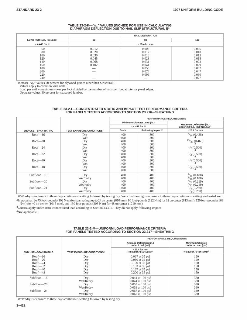
1997 UNIFORM BUILDING CODESTANDARD 23-2
3–422
TABLE 23-2-K— “en ” VALUES (INCHES) FOR USE IN CALCULATINGDIAPHRAGM DEFLECTION DUE TO NAIL SLIP (STRUCTURAL I) 1
NAIL DESIGNATION
LOAD PER NAIL (pounds) 6d 8d 10d
× 4.448 for N × 25.4 for mm
6080
100120140160180200220240
0.0120.0200.0300.0450.0680.102
————
0.0080.0120.0180.0230.0310.0410.0560.0740.096
—
0.0060.0100.0130.0180.0230.0290.0370.0470.0600.077
1Increase “en” values 20 percent for plywood grades other than Structural I.Values apply to common wire nails.Load per nail = maximum shear per foot divided by the number of nails per foot at interior panel edges.Decrease values 50 percent for seasoned lumber.
TABLE 23-2-L—CONCENTRATED STATIC AND IMPACT TEST PERFORMANCE CRITERIAFOR PANELS TESTED ACCORDING TO SECTION 23.216—SHEATHING
PERFORMANCE REQUIREMENTS
Minimum Ultimate Load (lb.)Maxim m Deflection (in )
× 4.448 for NMaximum Deflection (in.)
under 200-Lb. (890 N) Load 3
END USE—SPAN RATING TEST EXPOSURE CONDITIONS1 Static Following Impact 2 × 25.4 for mm
Roof—16
Roof—20
Roof—24
Roof—32
Roof—40
Roof—48
DryWetDryWetDryWetDryWetDryWetDryWet
400400400400400400400400400400400400
300300300300300300300300300300300300
7/16 (0.438)4
15/32 (0.469)4
1/2 (0.500)4
1/2 (0.500)4
1/2 (0.500)4
1/2 (0.500)4
Subfloor—16
Subfloor—20
Subfloor—24
DryWet/redry
DryWet/redry
DryWet/redry
400400400400400400
400400400400400400
3/16 (0.188)3/16 (0.188)7/32 (0.219)7/32 (0.219)1/4 (0.250)1/4 (0.250)
1Wet/redry is exposure to three days continuous wetting followed by testing dry. Wet conditioning is exposure to three days continuous wetting and tested wet.2Impact shall be 75 foot-pounds (102 N·m) for span ratings up to 24 on center (610 mm), 90 foot-pounds (122 N·m) for 32 on center (813 mm), 120 foot-pounds (163
N·m) for 40 on center (1016 mm), and 150 foot-pounds (203 N·m) for 48 on center (1219 mm).3Criteria apply under static concentrated load according to Section 23.216. They do not apply following impact.4Not applicable.
TABLE 23-2-M—UNIFORM LOAD PERFORMANCE CRITERIAFOR PANELS TESTED ACCORDING TO SECTION 23.217—SHEATHING
PERFORMANCE REQUIREMENTS
Average Deflection (in.)under Load (psf)
Minimum UltimateUniform Load (psf)
END USE—SPAN RATING TEST EXPOSURE CONDITIONS1× 25.4 for mm
× 0.0000479 for N/mm 2 × 0.0000479 for N/mm 2
Roof—16Roof—20Roof—24Roof—32Roof—40Roof—48
DryDryDryDryDryDry
0.067 at 35 psf0.080 at 35 psf0.100 at 35 psf0.133 at 35 psf0.167 at 35 psf0.200 at 35 psf
150150150150150150
Subfloor—16
Subfloor—20
Subfloor—24
DryWet/Redry
DryWet/Redry
DryWet/Redry
0.044 at 100 psf0.044 at 100 psf0.053 at 100 psf0.053 at 100 psf0.067 at 100 psf0.067 at 100 psf
330330330330330330
1Wet/redry is exposure to three days continuous wetting followed by testing dry.
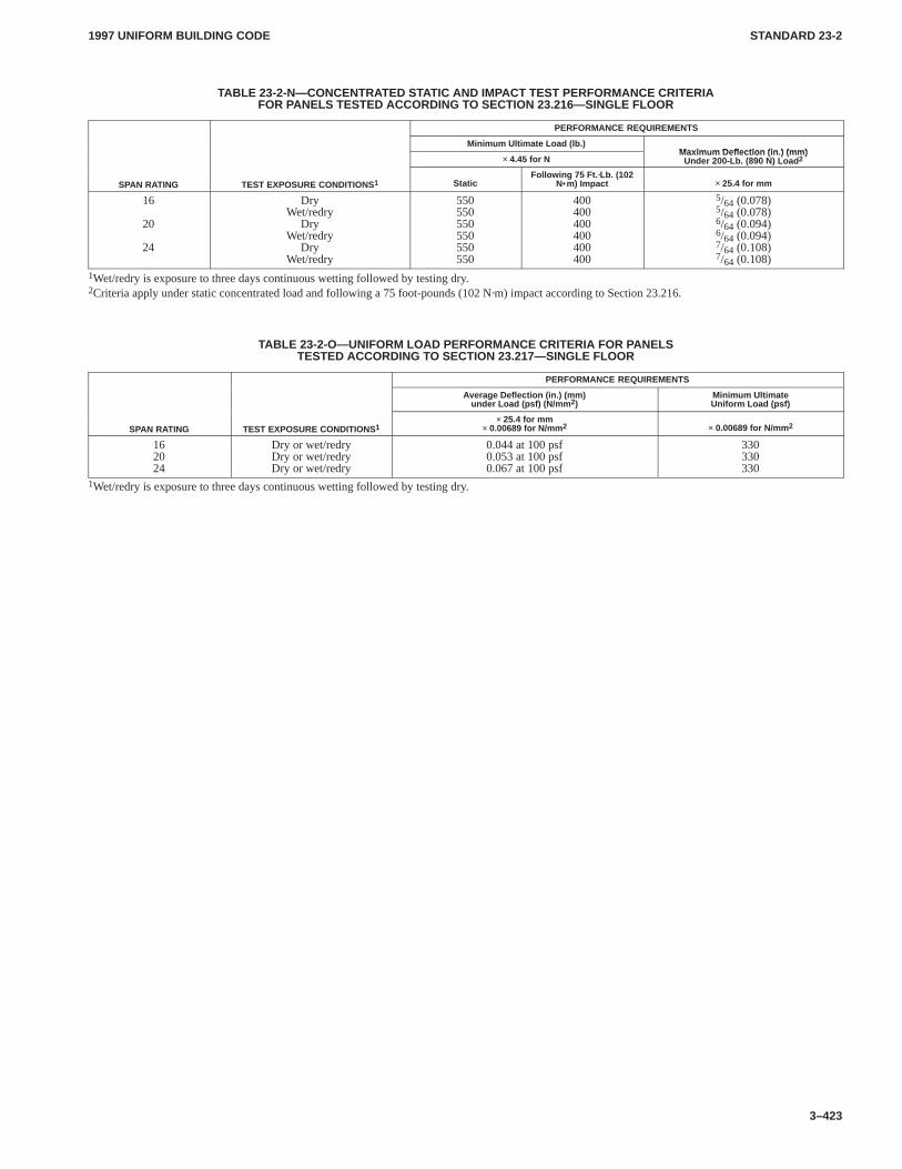
1997 UNIFORM BUILDING CODE STANDARD 23-2
3–423
TABLE 23-2-N—CONCENTRATED STATIC AND IMPACT TEST PERFORMANCE CRITERIAFOR PANELS TESTED ACCORDING TO SECTION 23.216—SINGLE FLOOR
PERFORMANCE REQUIREMENTS
Minimum Ultimate Load (lb.)Maxim m Deflection (in ) (mm)
× 4.45 for NMaximum Deflection (in.) (mm)
Under 200-Lb. (890 N) Load 2
SPAN RATING TEST EXPOSURE CONDITIONS1 StaticFollowing 75 Ft. ·Lb. (102
N•m) Impact × 25.4 for mm
16
20
24
DryWet/redry
DryWet/redry
DryWet/redry
550550550550550550
400400400400400400
5/64 (0.078)5/64 (0.078)6/64 (0.094)6/64 (0.094)7/64 (0.108)7/64 (0.108)
1Wet/redry is exposure to three days continuous wetting followed by testing dry.2Criteria apply under static concentrated load and following a 75 foot-pounds (102 N·m) impact according to Section 23.216.
TABLE 23-2-O—UNIFORM LOAD PERFORMANCE CRITERIA FOR PANELSTESTED ACCORDING TO SECTION 23.217—SINGLE FLOOR
PERFORMANCE REQUIREMENTS
Average Deflection (in.) (mm)under Load (psf) (N/mm 2)
Minimum UltimateUniform Load (psf)
SPAN RATING TEST EXPOSURE CONDITIONS1× 25.4 for mm
× 0.00689 for N/mm 2 × 0.00689 for N/mm 2
162024
Dry or wet/redryDry or wet/redryDry or wet/redry
0.044 at 100 psf0.053 at 100 psf0.067 at 100 psf
330330330
1Wet/redry is exposure to three days continuous wetting followed by testing dry.
1997 UNIFORM BUILDING CODE STANDARD 23-3
3–425
UNIFORM BUILDING CODE STANDARD 23-3
PERFORMANCE STANDARD FOR WOOD-BASEDSTRUCTURAL-USE PANELS
See Sections 2302.1, 2303, 2304.2 and 2502, andTables 23-II-H, 23-II-I-1 and 23-II-E-2, Uniform Building Code
SECTION 23.301 — ADOPTION OF USVPS CODEWood-based structural-use panels shall be in accordance withUnited States Voluntary Product Standard PS 2-92, “PerformanceStandard for Wood-Based Structural-Use Panels,” published by
the Department of Commerce, the American Plywood Associa-tion, copyright 1992, Post Office Box 11700, Tacoma, Washing-ton 98411 and TECO, 2401 Daniels Street, Madison, Wisconsin53704, as if set out at length herein.
�
1997 UNIFORM BUILDING CODE STANDARD 23-4
3–427
UNIFORM BUILDING CODE STANDARD 23-4
FIRE-RETARDANT-TREATED WOOD TESTS ON DURABILITYAND HYGROSCOPIC PROPERTIES
Based on American Society for Testing and Materials Standard Test Methods ASTM D 2898-81and D 3201-79. Extracted, with permission, from the Annual Book of ASTM Standards, copyright
American Society for Testing and Materials, 100 Barr Harbor Drive, West Conshohocken, PA 19428,and American Wood Preservers Association Standards C 20-83 and C 27-83
See Sections 201, 207 and 2303, Uniform Building Code
SECTION 23.401 — SCOPE
These methods cover the (1) durability of a fire-retardant treat-ment of wood and wood-base products under exposure to acceler-ated weathering, (2) measurement of the hygroscopic propertiesof fire-retardant-treated wood, and (3) identification classifica-tions for material having qualified under these tests. Thefire-retardant treatment for lumber and plywood is by pressure im-pregnation.
SECTION 23.402 — ACCELERATED WEATHERING
23.402.1 Scope.This section describes the conditioning methodfor a test specimen prior to subjecting that specimen to an appro-priate fire test. The condition simulates effects of leaching, dryingand temperature such as might reasonably be anticipated on awood element exposed to the weather over a long term.
23.402.2 Apparatus.The test apparatus shall be capable ofsubjecting the specimen uniformly to the test conditions describedin Section 23.402.4.
No special means of protecting the specimen back and edges arerequired, but water shall not impinge directly on those surfaceswhich are not exposed either to the weather in the assembled form,or to fire in the subsequent test. Water spray nozzles shall be pro-vided and arranged so as to distribute water evenly over the ex-posed specimen surface.
Heating shall be thermostatically controlled. Forced-air move-ment shall be uniform across the specimen surface, withprovisions made for adequate air changes to assure thoroughdrying.
23.402.3 Test Specimen.The test specimen shall include allthose essential parts of the corresponding fire test specimen thatmay be subjected to weather exposure in normal use.
Specimens may be mounted in sections which can be reas-sembled subsequently without trimming into the appropriate firetest specimen.
The specimen surface shall have a slope of 4 in 12.
23.402.4 Exposure Cycle.Subject the specimens to an expo-sure cycle consisting of twelve one-week cycles. Each cycle is toconsist of 96 hours of water exposure and 72 hours of drying.
Apply water in a moderately fine spray uniformly over the ex-posed specimen surfaces by spray nozzles that deliver an averageof 0.7 inch of water (174 Pa) per hour [0.0073 gallons per minuteper square foot (0.000307 m3/minute/m2) of specimen surface] ata temperature between 35°F and 60°F (1.7°C to 15.6°C). Do notrecirculate the water.
Dry at a thermostatically controlled temperature of 135°F to140°F (57.2°C to 60.0°C) in a room or cell. The controlling tem-perature shall be the air temperature measured 1 inch (25.4 mm)above the specimen surface. Accompany drying with the air
movement directed across the face of the specimens at a rate of atleast 25 feet (7620 mm) per minute.
At the end of each cycle, change the position of each specimenwithin the apparatus so that each specimen or segment occupiesapproximately an equal number of cycles in each location used.
23.402.5 Conditioning. Upon completion of the prescribed ex-posure, the specimen shall be conditioned to a moisture contentspecified by the applicable fire test standard.
SECTION 23.403 — HYGROSCOPIC PROPERTIES OFFIRE-RETARDANT WOOD
23.403.1 Scope. This section prescribes the method for deter-mining the moisture content of fire-retardant-treated wood sam-ples after exposure to a standard high relative humidity conditionof 92 ± 2 percent at 27°C ± 2°C.
23.403.2 Apparatus.Conditioning room or chamber with aircirculation and controlling instruments capable of being main-tained at 27°C ± 2°C and a relative humidity of 92 ± 2 percent.Other suitable means of maintaining these conditions are also ac-ceptable.
Oven, air-circulated and vented, capable of maintaining a tem-perature of 103°C ± 2°C.
A weighing scale or balance that will weigh a specimen withinan accuracy of ± 0.2 percent.
23.403.3 Test Specimens.Specimens shall be selected that rep-resent the lot. Unless otherwise specified, specimens shall be fullcross sections, no less than 25.4 millimeters along the grain, butlonger as needed to provide a minimum volume of 33 cubic centi-meters.
The specimens shall be penetrated by the chemical to be repre-sentative for the treated product.
The specimens shall be in moisture equilibrium with alaboratory ambient condition of 30 to 65 percent relative humidityor shall be exposed for at least seven days at such a condition priorto high-humidity exposure.
Untreated specimens, when available, of the same species orwood-base product and of the same size, shall be exposed to thepreconditioning, high-humidity exposure, and drying along withthe treated specimens.
23.403.4 Procedure.Weigh each specimen to an accuracy of± 0.2 percent.
Expose all specimens under constant humidity conditions of92 ± 2 percent at 27°C ± 2°C for seven days. Specimens shall besuitably suspended so that all surfaces are exposed.
Weigh each specimen immediately to an accuracy of ± 0.2 per-cent one at a time as they are removed from the conditioningchamber. Observe and record the general appearance of thespecimens.
�
1997 UNIFORM BUILDING CODESTANDARD 23-4
3–428
Dry each specimen in an oven at 103°C ± 2°C until approxi-mately constant weight is attained, and reweigh. Constant weightcan be assumed when two consecutive readings taken two hoursapart agree within 0.2 percent. Avoid drying for periods longerthan necessary to achieve constant weight, since thermal decom-position of chemical or wood might occur reflecting a higher thanactual moisture content.
23.403.5 Calculations.Calculate the “apparent” moisture con-tent of each sample prior to high-humidity exposure as follows:
Moisture content: percent = [(A – B)/B] × 100
WHERE:A = weight prior to high-humidity exposure.B = oven-dry weight.
Calculate the “apparent” moisture content of each sample afterhigh-humidity exposure as follows:
Moisture content: percent = [(C – B)/B] × 100
WHERE:B = oven-dry weight.C = weight after high-humidity exposure.
The change in the “apparent” moisture content of the specimensshall be calculated as the difference between the average moisturecontent for the treated and untreated specimens as calculated inthis section.
23.403.6 Report.The report shall include the following:
Complete identification of the fire-retardant product as to spe-cies of wood, wood product, and treatment.
Description of sampling procedure and number and dimensionsof test specimens.
General description of humidity chamber and controls used forthe test.
The average moisture content of the untreated specimens shallbe reported.
The average “apparent” moisture content for the treated speci-mens, both before and after high-humidity exposure, including thebasis of the computation; treated specimen (wood and chemical)or wood-only basis, shall be reported. The change in the averagemoisture content after high-humidity exposure compared to themoisture content of untreated specimens shall also be reported.
Report any change in the appearance of the specimen during ex-posure, including surface wetness, chemical exudation, or crystalson surface.
SECTION 23.404 — CLASSIFICATION
23.404.1 Scope.This part establishes the classification of fire-retardant-treated wood.
23.404.2 Classifications.
23.404.2.1 Interior Type A. Material that has been fire tested inaccordance with Section 207 of the code to qualify as fire-retar-dant-treated wood and has an equilibrium moisture content of notover 28 percent when tested at 92 ± 2 percent relative humiditywhen conditioned as specified in Section 23.403.
23.404.2.2 Interior Type B. Material that has been fire tested inaccordance with Section 207 of the code to qualify as fire-retardant-treated wood, but does not qualify as Interior Type Awhen conditioned as specified in Section 23.403.
23.404.2.3 Exterior type.Material that has been subjected tothe weathering test of Section 23.402 and then fire tested inaccordance with Section 207 of the Building Code to qualify asfire-retardant-treated wood.
1997 UNIFORM BUILDING CODE STANDARD 23-5
3–429
UNIFORM BUILDING CODE STANDARD 23-5
FIRE-RETARDANT-TREATED WOODDesign Values for Fire-retardant-treated Lumber
See Sections 207 and 2303, Uniform Building Code
SECTION 23.501 — SCOPE
This standard establishes the test protocol, acceptance criteria,and quality control procedure for assuring that fire-retardant treat-ments qualify for the design values assigned and that appropriatetreating and redrying methods are used. Only lumber pressure im-pregnated with fire-retardant chemicals that is identified by thequality mark of an approved inspection agency shall be eligiblefor the design values specified in the Building Code.
Part I—Test Protocol
SECTION 23.502 — TYPE OF MATERIAL
The effects of fire-retardant treatment shall be determined on thebasis of tests on matched samples of clear, straight-grain material.This is consistent with procedures presently used to establishdesign values and modifications for condition of use for visuallygraded sawn lumber.
SECTION 23.503 — NUMBER OF SPECIES
The effects of fire-retardant treatment may vary depending uponspecies. Because evaluation of such treatment for all species andproperties is considered prohibitive, testing of three species repre-sentative of a range of wood density and treating characteristics isrecommended. A specific treatment may be evaluated for onlyone of these species, but testing of three species representative of arange of wood density and treated characteristics isrecommended.
Qualification may be obtained for any one species by evalua-tion of that species.
SECTION 23.504 — IDENTIFICATION
Each fire-retardant treatment shall be identified by the commer-cial name assigned by the developer of the treatment and eachspecimen shall be marked to identify the drying temperatures andrelative humidity schedules used.
SECTION 23.505 — STRENGTH TESTING
Material to be subjected to strength testing shall be treated to thepenetration and retention level required for that treatment and spe-cies to meet the definition of fire-retardant-treated wood given inSection 207.
To allow for variability in treatment especially for species clas-sified as moderate to difficult to treat, it may be necessary to treatup to twice the number of samples required for test. Equalnumbers of samples of low and high treatability may be excludedfrom strength testing to ensure that material of average treatabilityis evaluated.
Following treatment, strength test material shall be dried at amaximum temperature of 160°F (71.1°C) with relative humidityschedules and air velocities that will simulate commercial condi-tions. A record of the operating conditions of the kiln shall be keptfor the entire run and shall include humidity conditions and tem-perature in the hottest part of the kiln.
SECTION 23.506 — SAMPLING AND TREATMENT
23.506.1 Species.For each fire-retardant treatment to be eval-uated for general qualification, strength test material shall be se-lected from each of the following species:
Southern pine (Pinus taeda or echinata)
Coast Douglas fir
White spruce (Picea glauca)
The southern pine material shall be all sapwood. Where a treat-ment is to be evaluated only for a particular species, strength testmaterial shall be selected from each such species.
23.506.2 Number of Samples, Size and Quality. For each spe-cies to be evaluated, 25 essentially clear, straight-grained 2 by 4s(51 by 102), 8 feet (2438 mm) or longer shall be selected from theproduction of one or more mills. All pieces shall be identified asbeing Surfaced Dry and shall have an average specific gravitywithin ± 10 percent of the average specific gravity (green volumebasis) of the species.
23.506.3 Sample Identification.From each 2-inch-by-4-inch(51 mm by 102 mm) member selected for sampling, twoend-matched 4-foot (1219 mm) blanks shall be cut for strengthtesting. One blank shall be designated for treatment and the otheras control. All blanks shall be coded as to member number andtreatment or control.
23.506.4 Pressure Treatment of Samples.All blanks to befire-retardant treated shall be processed in accordance with thespecific procedures established for the treatment being evaluated.Blanks shall be pressure treated and dried to a maximum moisturecontent of 19 percent in 2-inch by 4-inch (51 mm by 102 mm) by4-foot (1219 mm) size. The same treatment and drying times,stickering practices, and other procedures to be employed in com-mercial charges shall be used.
23.506.5 Conditioning of Blanks.After redrying to a maxi-mum moisture content of 19 percent, treated blanks and untreatedcontrols shall be conditioned at 68°F ± 6°F (20°C ± 3.3°C) and65 percent ± 1 percent relative humidity until approximate equi-librium weight is attained.
SECTION 23.507 — STRENGTH TESTS
23.507.1 Type and Number of Specimens.One- and one-half-inch-by-11/2-inch-by-23-inch (38 mm by 38 mm by 584 mm) stat-ic bending specimen, two 1-inch-by-1/4-inch-by-16-inch (25 mmby 6.4 mm by 406 mm) tension specimens, one 11/2-inch-by-11/2-inch-by-6-inch (38 mm by 38 mm by 152 mm) compressionspecimen, one 11/2-inch-by-11/2-inch-by-21/2-inch (38 mm by 38mm by 64 mm) shear specimen, and 11/2-inch-by-11/2-inch-by-2-inch (38 mm by 38 mm by 51 mm) specific gravity specimenshall be cut from each treated and untreated blank. Bending andcompression specimens from both treated and control blanks shallbe cut such that three sides of the specimen represent the originalsurfaces or edge of the 2-inch-by-4-inch (51 mm by 102 mm)member. Two sides of the shear and specific gravity specimensshall represent original surfaces. One of the 1-inch-wide (25 mm)faces of one of the tension specimens shall represent one originalsurface of the blank and one of the wide surfaces of the otherspecimen shall represent the opposite original blank surface.
1997 UNIFORM BUILDING CODESTANDARD 23-5
3–430
One method of selecting specimens to obtain the requiredplacement of original surfaces is shown in Figure 23-5-3. Any or-ientation of growth rings relative to the edge of the specimensshall be acceptable.
Tension specimens shall be further machined to the size andshape shown in Figure 23-5-2. Shear specimens shall be notchedas shown in Figure 23-5-1.
23.507.2 Slope of Grain.The slope of grain in all bendingspecimens and in the critical section of tension specimens shall be1 in 20 or less. Compression and shear specimens shall have aslope of grain of 1 in 16 or less.
23.507.3 Identification and Conditioning. The blank identifi-cation of each treated and control specimen shall be retained. Af-ter final machining, test specimens shall be reconditioned toconstant weight before test.
SECTION 23.508 — TESTING PROCEDURE
23.508.1 General.Testing procedures of an approvednationally recognized test standard shall be used. Loaddeformation curves shall be taken for static bending tests only.Maximum load shall be observed in all tests.
23.508.2 Order of Testing.The treated specimen and thematching untreated control from each blank shall be tested con-secutively.
23.508.3 Measurement.The dimensions of the criticalcross-sectional area, or in the case of the shear specimen the areaof the shear plane of each specimen, shall be measured to an accu-racy of at least 0.01 inch (0.254 mm).
23.508.4 Static Bending.Bending specimens shall be centerloaded at span of 21 inches (533 mm). A machine cross-headspeed of 0.075 inch per minute (1.9 mm per minute) shall be used.Bending specimens shall be positioned in the testing machinesuch that two opposite original surfaces represent the compressionand tension faces of the beam.
23.508.5 Moisture Samples.All moisture samples selectedfrom each specimen after test shall be oven dried at 103°C ± 2°Cuntil approximately constant weight of the untreated control isreached.
23.508.6 Specific Gravity.Dimensions of the specific gravitysamples shall be measured after final conditioning to determinevolume at 65 percent relative humidity. Samples shall be dried at103°C ± 2°C until approximate constant weight of the untreatedcontrol is reached.
SECTION 23.509 — REPORT
The treatment and redrying procedures shall be described in ac-cordance with Section 23.505.
The species evaluated and testing procedures followed shall befully described.
Individual values of treated and control specimens shall be re-ported for specific gravity, moisture content, modulus of elastic-ity, modulus of rupture, maximum tensile stress, maximumcompression stress, and maximum shear stress. Average values,standard deviations, average ratios of treated to control values,and median ratios of treated to control values shall be reported foreach strength and stiffness property and each species.
Part II—Acceptance Criteria
SECTION 23.510 — MINIMUM PROPERTY RATIO
A fire-retardant treatment evaluated for a particular species underthis standard shall qualify for the design value adjustments in Sec-tion 2304.3 of the Building Code if the median ratio of treated tountreated strength or stiffness for each of the following propertiesequals or exceeds the specified adjustment factor for that prop-erty:
Extreme fiber in bendingModulus of elasticityMaximum stress in tension parallel to grainMaximum stress in compression parallel to grainMaximum stress in horizontal shearQualification of the adjustment factor for compression perpen-
dicular to grain shall be based on the median factor for maximumstress in compression parallel to grain. Qualification of the adjust-ment factor for fastener loads shall be based on the lower of themedian ratio for maximum stress in compression parallel to grainand the median ratio for maximum stress in horizontal shear.
SECTION 23.511 — RESAMPLING
Where marginal results occur for one property, a second 25-piecesample may be taken for that property and the combined results ofthe first and second samples be used to determine qualification.
SECTION 23.512 — GENERAL QUALIFICATION
A treatment meeting the requirements of Section 23.510 for eachof the three species identified in Section 23.506 of this standardshall be considered qualifying for the design value adjustments inSection 2304.3 of the Building Code for all species.
Part III—Identification
SECTION 23.513 — PRODUCT ELIGIBILITY
Only lumber pressure impregnated with fire-retardant chemicalsthat is identified by the quality mark of an approved inspectionagency shall be eligible for the design value adjustments given inSection 2304.3 of the Building Code. Such agency shall maintaincontinuing supervision, testing and inspection over the quality ofthe treated product as necessary to (1) ensure compliance with thefire performance requirements for fire-retardant-treated wood inSection 207 and (2) ensure eligibility for strength classificationunder the provisions of this standard.
SECTION 23.514 — QUALIFICATION COMPLIANCE
The approved agency shall review and analyze the test data devel-oped in accordance with Part I of this standard and shall attest tothe following:
1. Competency of the personnel and the adequacy of the facili-ties of the testing laboratory.
2. Conformance of reported sampling and testing proceduresto Part I of this standard.
3. Compliance of test results with acceptance criteria in Part IIof this standard.
SECTION 23.515 — QUALITY MARK
The quality symbol shall indicate that the treated lumber bearingthe mark has been treated and redried in conformance with theprocedures established by the manufacturer of the treatmentwhich were used in the evaluation and qualification of thattreatment under Parts I and II of this standard.
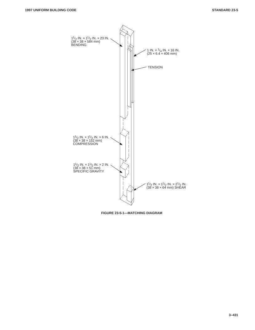
1997 UNIFORM BUILDING CODE STANDARD 23-5
3–431
11/2 IN. × 11/2 IN. × 23 IN.(38 × 38 × 584 mm)BENDING
11/2 IN. × 11/2 IN. × 6 IN.(38 × 38 × 152 mm)COMPRESSION
1 IN. × 1/4 IN. × 16 IN.(25 × 6.4 × 406 mm)
11/2 IN. × 11/2 IN. × 2 IN.(38 × 38 × 51 mm)SPECIFIC GRAVITY
11/2 IN. × 11/2 IN. × 21/2 IN.(38 × 38 × 64 mm) SHEAR
TENSION
FIGURE 23-5-1—MATCHING DIAGRAM
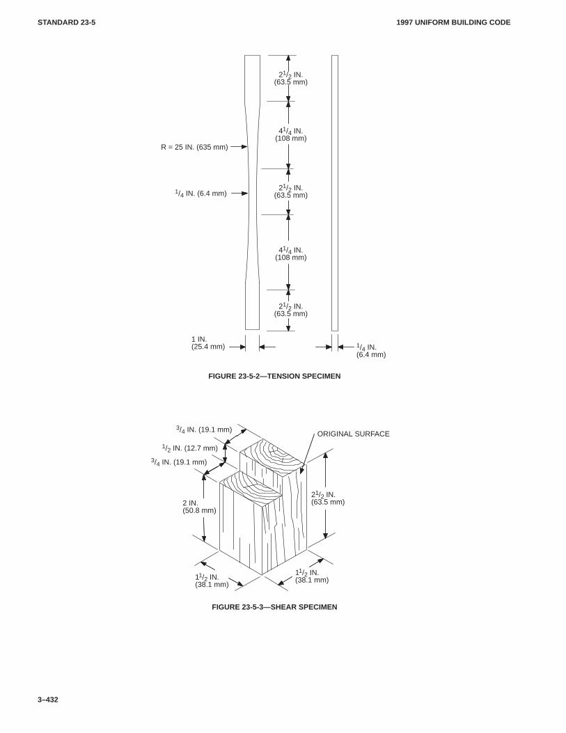
1997 UNIFORM BUILDING CODESTANDARD 23-5
3–432
1 IN.(25.4 mm) 1/4 IN.
(6.4 mm)
1/4 IN. (6.4 mm)
R = 25 IN. (635 mm)
21/2 IN.(63.5 mm)
41/4 IN.(108 mm)
21/2 IN.(63.5 mm)
21/2 IN.(63.5 mm)
41/4 IN.(108 mm)
FIGURE 23-5-2—TENSION SPECIMEN
21/2 IN.(63.5 mm)2 IN.
(50.8 mm)
11/2 IN.(38.1 mm)
3/4 IN. (19.1 mm)
1/2 IN. (12.7 mm)
ORIGINAL SURFACE
11/2 IN.(38.1 mm)
3/4 IN. (19.1 mm)
FIGURE 23-5-3—SHEAR SPECIMEN
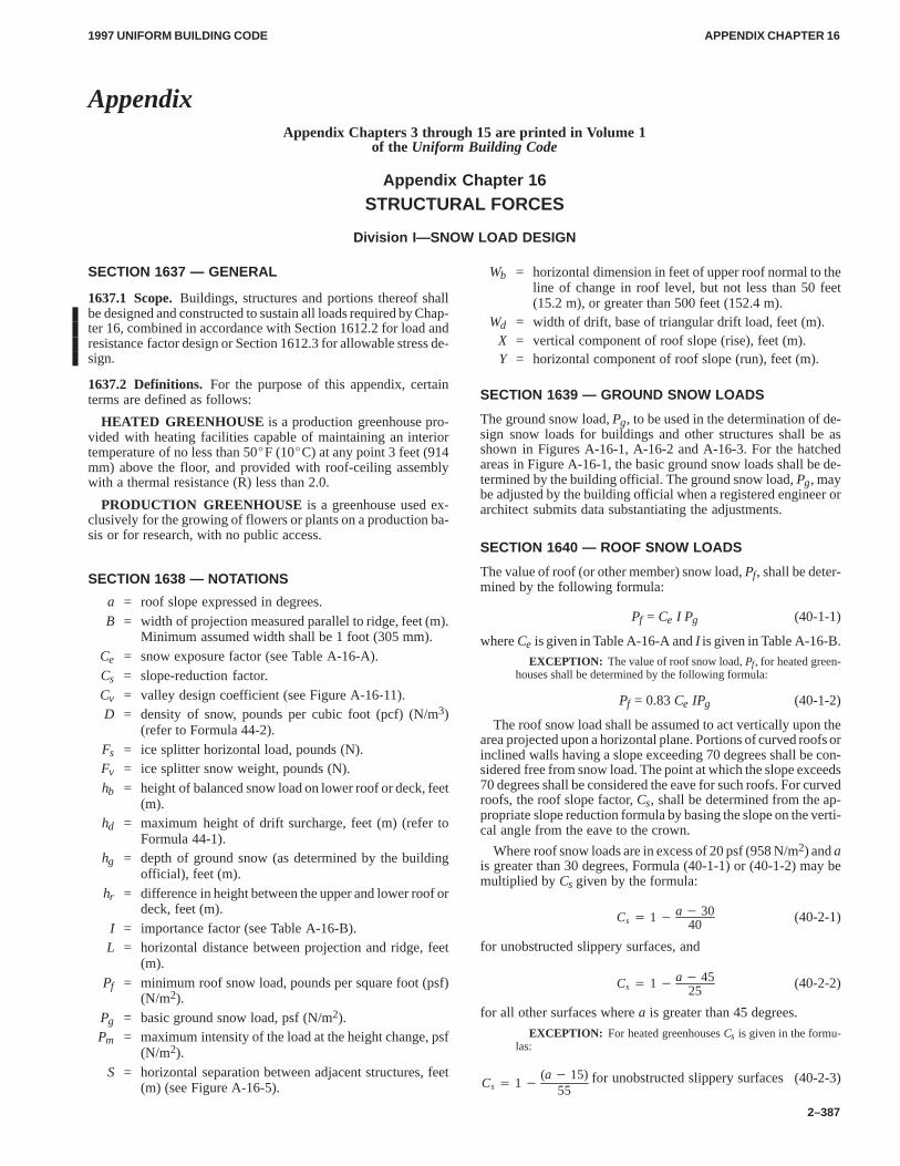
APPENDIX CHAPTER 16APPENDIX CHAPTER 16
1997 UNIFORM BUILDING CODE
2–387
AppendixAppendix Chapters 3 through 15 are printed in Volume 1
of the Uniform Building Code
Appendix Chapter 16
STRUCTURAL FORCES
Division I—SNOW LOAD DESIGN
SECTION 1637 — GENERAL
1637.1 Scope.Buildings, structures and portions thereof shallbe designed and constructed to sustain all loads required by Chap-ter 16, combined in accordance with Section 1612.2 for load andresistance factor design or Section 1612.3 for allowable stress de-sign.
1637.2 Definitions. For the purpose of this appendix, certainterms are defined as follows:
HEATED GREENHOUSE is a production greenhouse pro-vided with heating facilities capable of maintaining an interiortemperature of no less than 50�F (10�C) at any point 3 feet (914mm) above the floor, and provided with roof-ceiling assemblywith a thermal resistance (R) less than 2.0.
PRODUCTION GREENHOUSE is a greenhouse used ex-clusively for the growing of flowers or plants on a production ba-sis or for research, with no public access.
SECTION 1638 — NOTATIONS
a = roof slope expressed in degrees.B = width of projection measured parallel to ridge, feet (m).
Minimum assumed width shall be 1 foot (305 mm).Ce = snow exposure factor (see Table A-16-A).Cs = slope-reduction factor.Cv = valley design coefficient (see Figure A-16-11).D = density of snow, pounds per cubic foot (pcf) (N/m3)
(refer to Formula 44-2).Fs = ice splitter horizontal load, pounds (N).Fv = ice splitter snow weight, pounds (N).hb = height of balanced snow load on lower roof or deck, feet
(m).hd = maximum height of drift surcharge, feet (m) (refer to
Formula 44-1).hg = depth of ground snow (as determined by the building
official), feet (m).hr = difference in height between the upper and lower roof or
deck, feet (m).I = importance factor (see Table A-16-B).L = horizontal distance between projection and ridge, feet
(m).Pf = minimum roof snow load, pounds per square foot (psf)
(N/m2).Pg = basic ground snow load, psf (N/m2).Pm = maximum intensity of the load at the height change, psf
(N/m2).S = horizontal separation between adjacent structures, feet
(m) (see Figure A-16-5).
Wb = horizontal dimension in feet of upper roof normal to theline of change in roof level, but not less than 50 feet(15.2 m), or greater than 500 feet (152.4 m).
Wd = width of drift, base of triangular drift load, feet (m).X = vertical component of roof slope (rise), feet (m).Y = horizontal component of roof slope (run), feet (m).
SECTION 1639 — GROUND SNOW LOADS
The ground snow load, Pg, to be used in the determination of de-sign snow loads for buildings and other structures shall be asshown in Figures A-16-1, A-16-2 and A-16-3. For the hatchedareas in Figure A-16-1, the basic ground snow loads shall be de-termined by the building official. The ground snow load, Pg, maybe adjusted by the building official when a registered engineer orarchitect submits data substantiating the adjustments.
SECTION 1640 — ROOF SNOW LOADS
The value of roof (or other member) snow load, Pf, shall be deter-mined by the following formula:
Pf = Ce I Pg (40-1-1)
where Ce is given in Table A-16-A and I is given in Table A-16-B.
EXCEPTION: The value of roof snow load, Pf, for heated green-houses shall be determined by the following formula:
Pf = 0.83 Ce IPg (40-1-2)
The roof snow load shall be assumed to act vertically upon thearea projected upon a horizontal plane. Portions of curved roofs orinclined walls having a slope exceeding 70 degrees shall be con-sidered free from snow load. The point at which the slope exceeds70 degrees shall be considered the eave for such roofs. For curvedroofs, the roof slope factor, Cs, shall be determined from the ap-propriate slope reduction formula by basing the slope on the verti-cal angle from the eave to the crown.
Where roof snow loads are in excess of 20 psf (958 N/m2) and ais greater than 30 degrees, Formula (40-1-1) or (40-1-2) may bemultiplied by Cs given by the formula:
Cs � 1�
a� 3040
(40-2-1)
for unobstructed slippery surfaces, and
Cs � 1�
a� 4525
(40-2-2)
for all other surfaces where a is greater than 45 degrees.
EXCEPTION: For heated greenhouses Cs is given in the formu-las:
Cs � 1�
(a� 15)55
for unobstructed slippery surfaces (40-2-3)
APPENDIX CHAPTER 16APPENDIX CHAPTER 16
1997 UNIFORM BUILDING CODE
2–388
Cs � 1�
(a� 30)40
for other surfaces (40-2-4)
Where the ground snow load Pg is greater than 100 psf (4788N/m2) and a is greater than 20 degrees,
Cs � 1��
Pf � 20Pf��
a� 2040
� (40-2-5)
Cs � 1��
Pf � 958Pf��
a� 2040
�For SI:
The following conditions must be met before using Formulas(40-2-1), (40-2-2), (40-2-3), (40-2-4) and (40-2-5):
1. The height of all eaves exceeds hg, and
2. There are no obstructions adjacent to the structure for a dis-tance hg measured from the eave normal to the ridge line.
Where the eave height is less than hg but greater than hg /2, andcondition 2 above is met, the roof snow load reduction repre-sented by the last term in Formulas (40-2-1), (40-2-2) and(40-2-3) shall be divided by 2.
3. If Pg is 20 psf (958 N/m2) or less, design roof snow loadmust not be less than Pg. If Pg exceeds 20 psf (958 N/m2), designroof snow load must not be less than 20 psf (958 N/m2).
4. Reduced roof loads where Pg exceeds 70 psf (3352 N/m2)shall not be less than those obtained through use of Formula(40-1-1) for Pg equal to 70 psf (3352 N/m2).
SECTION 1641 — UNBALANCED SNOW LOADS,GABLE ROOFS
1641.1 General. In addition to the balanced load condition, un-balanced loading shall be considered for gable roofs in accord-ance with this section.
1641.2 Single-gable Roofs.Single-gable roofs with slopesgreater than 1/2 unit vertical in 12 units horizontal (4.2% slope)and less than 3 units vertical in 12 units horizontal (25% slope)shall be designed to sustain a uniformly distributed load of 0.5 Pfacting on one slope and 1.0 Pf on the opposite slope. Roofs withslopes greater than 3 units vertical in 12 units horizontal (25%slope) shall be designed to sustain a uniformly distributed loadequal to 1.25 Pf applied to one slope only.
1641.3 Multiple-gable Roofs.
1641.3.1 With parallel ridge lines.For multiple-gable roofswith parallel ridge lines having slopes exceeding 2 units verticalin 12 units horizontal (16.7% slope), the roof snow load shall beincreased from one half the applicable uniform roof load at theridge (0.5Pf) to three times the uniform load at the valley (3.0 Pf).
1641.3.2 With nonparallel ridge lines.Structural members atroof valleys for multiple-gable roofs having intersecting ridgelines in areas where Pg is greater than 70 psf (3352 N/m2) andwhere the slope is 3 units vertical in 12 units horizontal (16.7%slope) or greater shall be designed for Pf times Cv and the distribu-tion of loads is as shown in Figures A-16-12 and A-16-13 whereCv shall be determined from Figure A-16-11.
SECTION 1642 — UNBALANCED SNOW LOAD FORCURVED ROOFS
Portions of curved roofs having a slope exceeding 70 degreesshall be considered free of snow load. The equivalent slope of a
curved roof for calculating Cs is equal to the slope of a line fromthe point at which the slope exceeds 70 degrees to the crown. If theequivalent slope is less than 10 degrees or greater than 60 degrees,unbalanced snow loads need not be considered.
In all cases the windward side shall be considered free of snow.The unbalanced load varies linearly from 0.5Cs Pf to 2Cs Pf /Cewhere the slope is 30 degrees and decreasing to
2Cs Pf
Ce�1�
a� 3040
� at the eave.
If the ground or another roof abuts an arched roof structure witha slope exceeding 30 degrees at or within 3 feet (914 mm) of itseave, the snow load shall not be decreased between the 30-degreepoint and the eave, but shall remain constant at 2Cs Pf /Ce.
SECTION 1643 — SPECIAL EAVE REQUIREMENTS
Eave overhanging roof structures shall be designed to sustain auniformly distributed load of 2.0 Pf, or as determined by the build-ing official, to account for ice dams and snow accumulation asshown in Figure A-16-10. Heat strips or other exposed heat meth-ods may not be used in lieu of this design criterion. For shingle orshake roofs, hot or cold underlayment roofing is required on allroofs from the building edge for a distance of 5 feet (1524 mm) orto the ridge, whichever is less. All building exits underdown-slope eaves shall be protected from sliding snow and ice.
SECTION 1644 — DRIFT LOADS ON LOWER ROOFS,DECKS AND ROOF PROJECTIONS
1644.1 General.Multilevel roofs, lower roofs and decks of ad-jacent structures and roofs adjacent to projections shall be de-signed in accordance with this section.
1644.2 Drift Loads for Lower Roofs. The geometry of the sur-charge load produced by snow drifting shall be taken as the trian-gular load distributions shown in Figures A-16-4, A-16-5,A-16-6, A-16-7 and A-16-8. The height of the drift shall be calcu-lated according to the formula:
hd � 0.43 Wb3� Pg � 104�
� 1.5 (44-1)
For SI: 1 foot = 304.8 mm.
The value of hd can be taken from Figure A-16-9 for Wb < 600feet (182 880 mm).
WHERE:
D = 0.13Pg + 14.0 < 35 pcf (44-2)
For SI: D = 0.43 Pg + 2198 � 5495.
The width of the drift, Wd, in feet (mm), shall be taken as thesmaller of 4hd or 4 (hr – hb). If Wd exceeds the width of the lowerroof, the drift shall be truncated at the far edge of the roof, not re-duced to zero at this location. Drift loads need be considered onlywhen:
(hr – hb)/hb > 0.2 (44-3)
WHERE:
hb = Pf /D
and where Pf is evaluated on the basis of the lower roof.
The maximum intensity, Pm, of the snow load at the high pointof the drift in pounds per square foot (N/m2) is given by:
APPENDIX CHAPTER 16APPENDIX CHAPTER 16
1997 UNIFORM BUILDING CODE
2–389
Pm = D (hd + hb) < D hr (44-4)
1644.3 Roof of an Adjacent Lower Structure.Drifts may oc-cur on lower roofs of structures sited within 20 feet (6096 mm) ofa higher structure as depicted in Figure A-16-5. The height of thesurcharge on the lower structure shall be taken as hd multiplied by(20 – S)/20 [For SI: (6.1 – S)/6.1]to account for the horizontal sep-aration between structures, S, in feet (mm).
1644.4 Sliding Snow.Lower roofs that are located below roofshaving a slope greater than 2 units vertical in 12 units horizontal(16.7% slope) shall be designed for an increase in drift height of0.4hd, except that the total drift surcharge (1.4 hd ) shall not ex-ceed the height of the roof above the uniform snow depth (hr – hb).Sliding snow need not be considered if the lower roof is separateda distance, S, greater than hr or 20 feet (6096 mm) as shown in Fig-ures A-16-5 and A-16-6.
1644.5 Roof Projections.Mechanical equipment, penthouses,parapets and other projections above the roof can produce driftingas depicted in Figure A-16-7. Such drift loads shall be calculatedon all sides of projections having horizontal dimensions exceed-ing 15 feet (4572 mm). Drifts created at the perimeter of the roofby projections shall be computed using half the drift height fromFormula (44-1) (i.e., 0.5 hd) with Wb taken equal to the length ofthe roof associated with the projections. The value of Wb shall betaken as the maximum distance from the projection to the edges ofthe roof, or 50 feet (15 240 mm), whichever is less.
1644.6 Intersecting Drifts. When one snow drift intersectsanother at an angle as depicted in Figure A-16-8, the maximumunit pressure of the drift shall be taken as the greater of the twoindividual drifts, but not the sum of the two. The total load on thearea of intersection is increased, however, simply because of theassumed geometry of the intersecting drifts.
SECTION 1645 — RAIN ON SNOW
In geographic areas where intense rains may add to the roof snowload, the building official may require the use of an additional rainon snow surcharge of 5 psf (239 N/m2). This surcharge may bedisregarded where roof slopes exceed 1/2 unit vertical in 12 unitshorizontal (4.2% slope) or where the basic ground snow load, Pg,exceeds 50 psf (2394 N/m2). See Section 1611.7 for ponding.
SECTION 1646 — DEFLECTIONS
For roof slopes less than 1/2 unit vertical in 12 units horizontal(4.2% slope), the deflection of any structural member shall notexceed L/180 evaluated on the basis of roof snow loads plus Ktimes dead load, where K is defined in Table 16-E.
SECTION 1647 — IMPACT LOADS
Whenever Pg exceeds 70 psf (3352 N/m2), structures which couldbe subjected to impact loads (snow unloading from a higher roof)shall be designed for impact loading.
SECTION 1648 — VERTICAL OBSTRUCTIONS
Whenever Pg exceeds 70 psf (3352 N/m2), roof projections whichcould be subjected to sliding ice or snow shall be protected withice splitters or crickets, or shall be designed for these forces.These conditions apply whenever the roof slope is 3 units verticalin 12 units horizontal (25% slope) or greater [except those projec-tions within 36 inches (914 mm) of the ridge]. All ice splittersshall be constructed the full width of the projection base (see Fig-ure A-16-14).
Ice splitters shall be designed for a horizontal force Fs and theresultant moment produced from Fs being applied at midheight ofthe splitter given by:
Fs �Fv X
X2� Y2�
(48-1)
WHERE:
Fv = L (0.5L + B) Pf
The projection width, B, shall not exceed 6 feet (1829 mm)where the roof slope is greater than 2 units vertical in 12 units hor-izontal (16.7% slope) unless approved by the building official.Chimneys and similar projections at or near the eave of a roofshall have footings and roof/wall ties designed to resist the forceof the sliding snow. Cross-grain bending of wood ledgers andedge nailing of plywood shall not be considered to resist suchforces. Snow melting equipment shall not be considered to reducethe required design loads.
TABLE A-16-A—SNOW EXPOSURE COEFFICIENT (Ce)1,2
1. Roofs located in generally open terrain extending one-half mile(804.7 m) or more from the structure.
0.6
2. Structures located in densely forested or sheltered areas. 0.9
3. All other structures. 0.71The building official may determine this coefficient for specific structures with special local conditions. For Alaska, Arizona
and Hawaii, the coefficient shall be determined by the building official.2For roofs at or near grade with slopes less than 3 units vertical in 12 units horizontal (25% slope) or decks at or near grade,
Ce equals 1.0.
TABLE A-16-B—VALUES FOR OCCUPANCY IMPORTANCE FACTOR I
I
TYPE OF OCCUPANCY Snow
1. Essential facilities. 1.15
2. Any building where the primary occupancy is for assembly use formore than 300 persons (in one room).
1.15
3. Agricultural buildings, production greenhouses and other miscella-neous structures.
0.9
4. All others. 1.0
APPENDIX CHAPTER 16APPENDIX CHAPTER 16
1997 UNIFORM BUILDING CODE
2–390
ÓÓÓÓÓÓÓÓÓÓÓÓÓÓÓÓÓÓÓÓÓÓÓÓÓÓÓÓÓÓÓÓÓÓÓÓÓÓÓÓÓÓÓÓÓÓÓÓÓÓÓÓÓÓÓÓÓÓÓÓÓÓÓ
Ó
ÓÓÓÓÓÓÓÓÓÓÓÓÓÓÓÓÓÓÓÓÓÓÓÓÓÓÓÓÓÓÓÓÓÓÓÓÓÓÓÓÓÓÓÓÓÓÓÓ
Ó
In these areas, extreme local variations in snow loads preclude mapping at this scale;ground snow load, Pg, shall be established by the building official.
The zoned value is not appropriate for certain geographic settings, such as high country; inthese areas, ground snow load, Pg, shall be established by the building official.
In these areas, ground snow load, Pg, shall be established by the building official.
Those areas shown as 0 psf, 5 psf and 10psf (0 N/m2, 239 N/m2 and 479 N/m2) are forinformation only.
ÓÓÓÓÓÓÓÓÓÓÓÓ
Ó
ÓÓÓÓ
Ó
ÓÓÓÓÓÓÓÓÓÓÓÓÓÓÓÓÓÓÓÓÓÓÓÓÓÓÓÓÓÓÓÓÓÓÓÓÓÓÓÓÓÓ
Ó
ÓÓÓÓÓÓÓÓÓÓÓÓÓÓÓÓÓÓÓÓÓÓÓÓÓÓÓÓÓÓÓÓÓÓÓÓÓÓÓÓÓÓÓÓÓÓÓÓÓ
Ó
ÓÓÓÓÓÓÓÓÓÓÓÓÓÓÓÓÓÓ
Ó
ÓÓÓÓÓÓÓÓÓÓÓÓÓÓÓÓ
Ó
ÓÓÓÓÓÓÓÓÓ
Zero
10
35
20
10
15
15
25
25
20
30
25 3035
35
10
20
10
10
5Zero
Zero
Zero
15
10
5
15
5
Zero
Zero
10
5
Zero
5
ÓÓ
ÔÔ
20
30
25
105
15
10
15
ÓÓÓÓÓÓÓÓÓÓÓÓ
15
20
15
1010
15
20
20
2020
For SI: 1 psf = 47.8 N/m2.
FIGURE A-16-1—GROUND SNOW LOAD, Pg, FOR 50-YEAR MEANRECURRENCE INTERVAL FOR THE WESTERN UNITED STATES
APPENDIX CHAPTER 16APPENDIX CHAPTER 16
1997 UNIFORM BUILDING CODE
2–391
ÓÓÓÓÓÓÓÓÓÓÓÓÓÓÓÓÓÓÓÓ
Those areas shown as 0 psf, 5 psf and 10psf (0 N/m2, 239 N/m2 and 479 N/m2) are forinformation only.
In these areas, extreme local variations in snow loads preclude mapping at this scale; groundsnow load, Pg, shall be established by the building official.
The zoned value is not appropriate for certain geographic settings, such as high country; inthese areas, ground snow load, Pg, shall be established by the building official.
ÓÓÓÓÓÓÓÓÓÓÓÓÓÓ
ÓÓÓÓ
Zero
Zero5
5
5
10
15
15
15
1515
10
1020
2520
20
10
2020
20
2015
25
25 25
20
25
35
40
50
3050
5060
353530
35
30
30
30
40
40
40
40
4035
35
ÓÓÓÓÓÓ
For SI: 1 psf = 47.8 N/m2.
FIGURE A-16-2—GROUND SNOW LOAD, Pg, FOR 50-YEAR MEANRECURRENCE INTERVAL FOR THE CENTRAL UNITED STATES
APPENDIX CHAPTER 16APPENDIX CHAPTER 16
1997 UNIFORM BUILDING CODE
2–392
ÓÓÓÓÓÓÓÓÓÓÓÓÓÓÓÓÓÓÓÓÓÓÓÓÓÓÓÓÓÓÓÓÓÓÓÓÓÓÓÓÓÓÓÓÓÓÓÓÓÓÓÓÓÓÓÓÓÓÓÓÓÓÓÓÓÓÓÓÓÓÓÓÓÓÓÓÓÓÓÓÓÓÓÓÓÓÓÓÓÓÓÓÓÓÓÓÓÓÓÓÓÓÓÓÓÓÓÓÓÓ
Zero
4
40
20
25
3025
2530
30
35
3520
20
15
15
15
10
15
10
10
5
5
Zero
20
25
3035
40
50
50
60
50
3040 40
30
30
35
35
25
25
20
20
40
35
35
30
2530
15
25
50
50
60 60
40
30
35
40
60
80
70
90
100
Those areas shown as 0 psf, 5 psf and 10psf (0 N/m2, 239 N/m2 and 479 N/m2) are forinformation only.
ÓÓÓÓÓÓ
40
30
For SI: 1 psf = 47.8 N/m2.
In these areas, extreme local variations in snow loads preclude mapping at this scale;ground snow load, Pg, shall be established by the building official.
The zoned value is not appropriate for certain geographic settings, such as high country; inthese areas, ground snow load, Pg, shall be established by the building official.
FIGURE A-16-3—GROUND SNOW LOAD, Pg, FOR 50-YEAR MEANRECURRENCE INTERVAL FOR THE EASTERN UNITED STATES
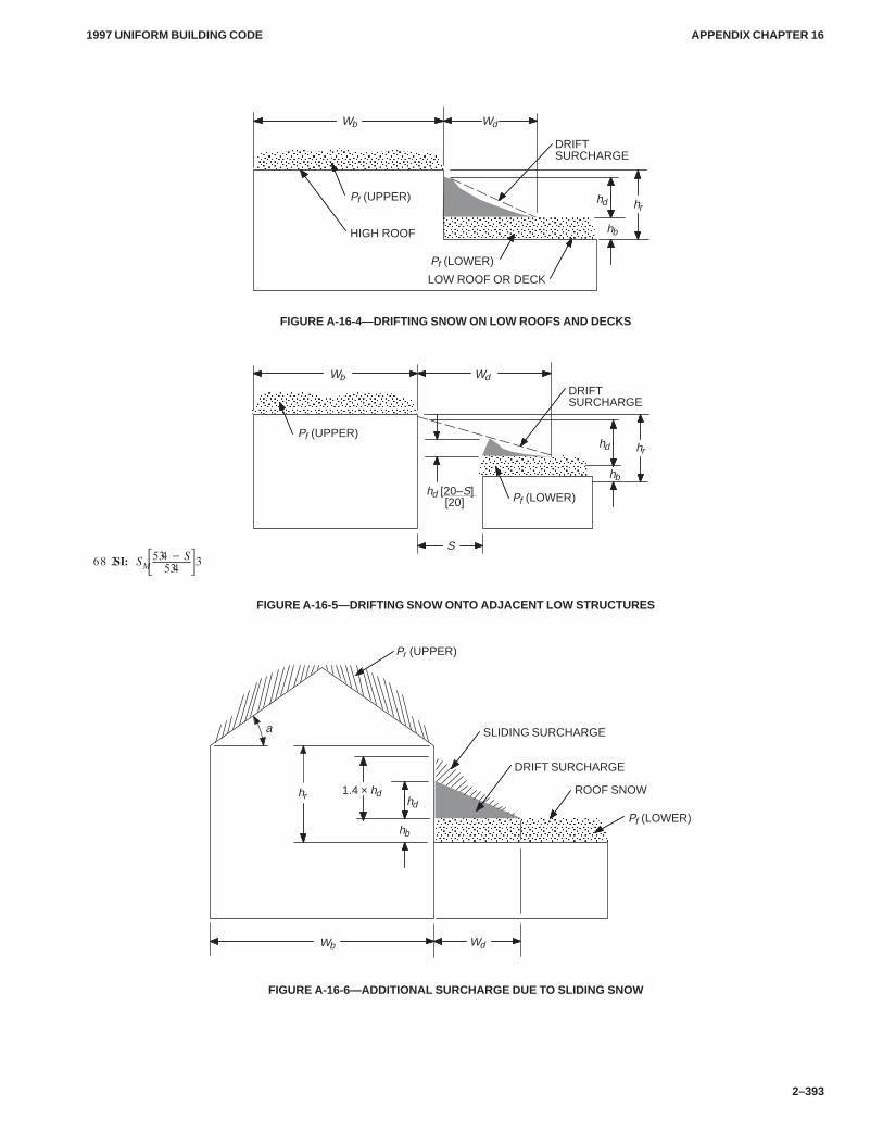
APPENDIX CHAPTER 16APPENDIX CHAPTER 16
1997 UNIFORM BUILDING CODE
2–393
ÓÓÓÓÓÓÓÓÓÓÓÓÓÓÓÓ
ÓÓÓÓÓÓÓÓÓÓÓÓÓÓÓÓÓÓ
DRIFTSURCHARGE
LOW ROOF OR DECK
HIGH ROOF
Pf (UPPER)
Wb
Pf (LOWER)
Wd
hb
hrhd
FIGURE A-16-4—DRIFTING SNOW ON LOW ROOFS AND DECKS
ÓÓÓÓÓÓÓÓÓÓÓÓ
ÓÓÓÓÓÓÓÓÓÓÓÓÓÓÓÓ
DRIFTSURCHARGE
S
hd [20–S] [20]
Pf (UPPER)
Pf (LOWER)
Wb Wd
hb
hrhd
����������������� �
�����
FIGURE A-16-5—DRIFTING SNOW ONTO ADJACENT LOW STRUCTURES
a
ÓÓÓÓÓÓÓÓÓÓÓÓÓÓÓÓÓÓ
DRIFT SURCHARGE
SLIDING SURCHARGE
ROOF SNOW
Pr (UPPER)
Pf (LOWER)
Wb Wd
hb
1.4 × hdhr hd
FIGURE A-16-6—ADDITIONAL SURCHARGE DUE TO SLIDING SNOW
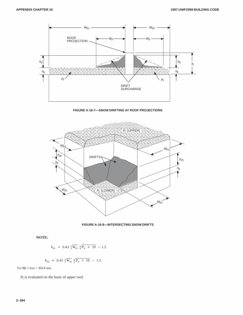
APPENDIX CHAPTER 16APPENDIX CHAPTER 16
1997 UNIFORM BUILDING CODE
2–394
ÓÓÓÓÓÓÓÓÓÓÓÓÓÓÓÓÓÓÓÓÓÓÓÓÓÓÓÓÓÓÓÓÓÓÓÓÓÓÓÓÓÓ
ÓÓÓÓÓÓÓÓÓÓÓÓÓÓÓÓÓÓÓÓÓ
ROOFPROJECTION
DRIFTSURCHARGE
Wb1 Wb2
hb hrhd
Wd Wd
Pf
hb hb
Pf
FIGURE A-16-7—SNOW DRIFTING AT ROOF PROJECTIONS
ÓÓÓÓÓÓÓÓÓÓÓÓÓÓÓÓÓÓÓÓÓÓÓÓÓÓÓÓÓÓÓÓÓÓÓÓÓÓÓÓÓÓÓÓÓÓÓÓÓÓ
ÓÓÓÓÓÓÓÓÓÓÓÓÓÓÓÓÓÓÓÓÓÓÓÓÓÓÓÓÓÓÓÓÓÓÓÓÓÓÓÓÓÓÓÓÓÓÓÓÓÓÓÓÓÓÓÓÓÓÓÓÓÓÓÓÓÓÓÓÓÓÓÓÓÓÓÓÓÓÓÓÓÓÓÓÓÓÓÓÓÓÓÓÓÓÓÓÓÓÓÓÓÓÓÓÓÓÓÓ
DRIFTS
Pf (UPPER)
Pf (LOWER)
Wb1
Wd1
hb
hd1
Wb2
Wd2
hb
hd2
FIGURE A-16-8—INTERSECTING SNOW DRIFTS
hd1 � 0.43 Wb13� Pg � 104�
� 1.5
hd2 � 0.43 Wb23� Pg � 104�
� 1.5
For SI: 1 foot = 304.8 mm.
Pf is evaluated on the basis of upper roof.
NOTE:
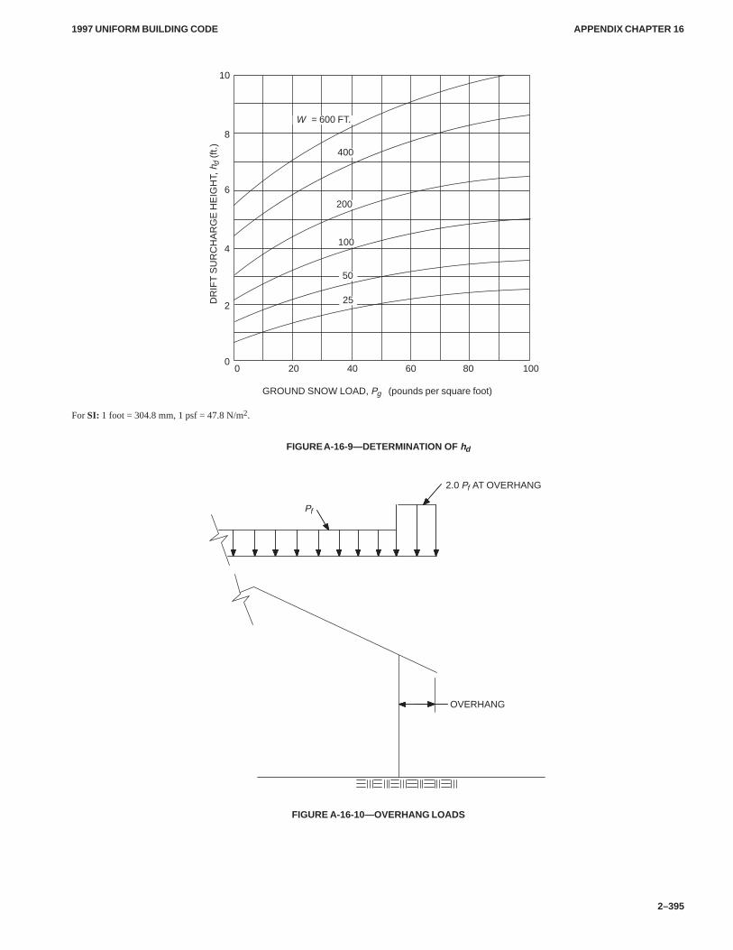
APPENDIX CHAPTER 16APPENDIX CHAPTER 16
1997 UNIFORM BUILDING CODE
2–395
GROUND SNOW LOAD, Pg (pounds per square foot)
200 40 60 80 100
10
100
200
400
W = 600 FT.
25
50
DR
IFT
SU
RC
HA
RG
E H
EIG
HT,
hd (f
t.)
8
6
4
2
0
For SI: 1 foot = 304.8 mm, 1 psf = 47.8 N/m2.
FIGURE A-16-9—DETERMINATION OF hd
2.0 Pf AT OVERHANG
OVERHANG
Pf
FIGURE A-16-10—OVERHANG LOADS
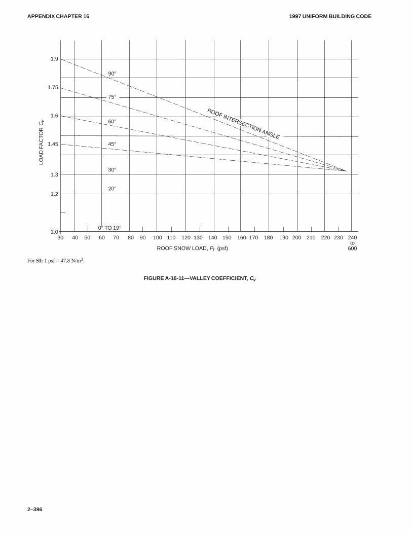
APPENDIX CHAPTER 16APPENDIX CHAPTER 16
1997 UNIFORM BUILDING CODE
2–396
ROOF SNOW LOAD, Pf (psf)
1.9
90°
60°
45°
30°
20°
1.6
1.45
1.3
1.0
1.2
1.75
LOA
D F
AC
TOR
Cv
40 60 80 100 120 140 160 180 200 220 240to
600
30 50 70 90 110 130 150 170 190 210 230
75°
0° TO 19°
For SI: 1 psf = 47.8 N/m2.
FIGURE A-16-11—VALLEY COEFFICIENT, Cv
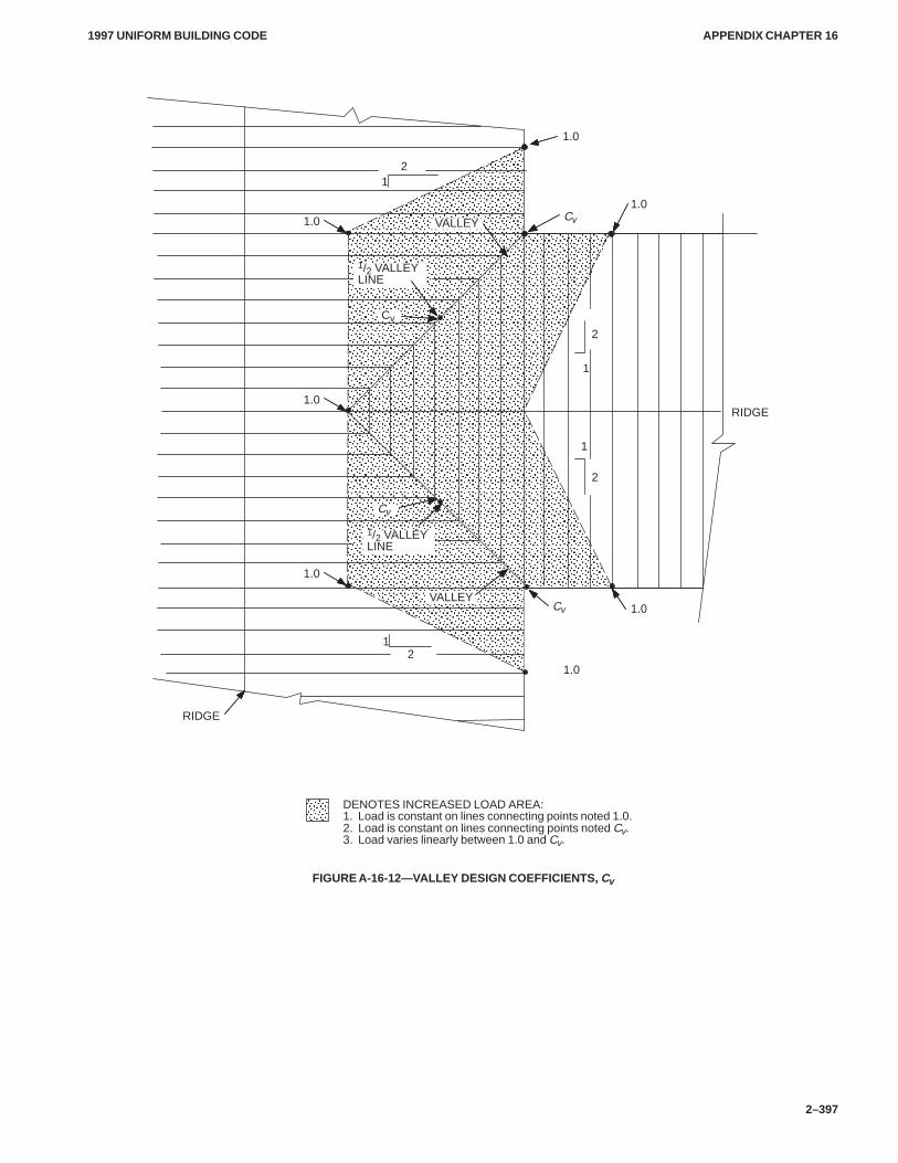
APPENDIX CHAPTER 16APPENDIX CHAPTER 16
1997 UNIFORM BUILDING CODE
2–397
ÓÓÓÓÓÓÓÓÓÓÓÓÓÓÓÓÓÓÓÓÓÓÓÓÓÓÓÓÓÓÓÓÓÓÓÓÓÓÓÓÓÓÓÓÓÓÓÓÓÓÓÓÓÓÓÓÓÓÓÓÓÓÓÓÓÓÓÓÓÓÓÓÓÓÓÓÓÓÓÓÓÓÓÓÓÓÓÓÓÓÓÓÓÓÓÓÓÓÓÓÓÓÓÓÓÓÓÓÓÓÓÓÓÓÓÓÓÓÓÓÓÓÓÓÓÓÓÓÓÓÓÓÓÓÓÓÓÓÓÓÓÓÓÓÓÓÓÓÓÓÓÓÓÓÓÓÓÓÓÓÓÓÓÓÓÓÓÓÓÓÓÓÓÓÓÓÓÓÓÓÓÓÓÓÓÓÓÓÓÓÓÓÓÓÓÓÓÓÓÓÓÓÓÓÓÓÓÓÓÓÓÓÓÓÓÓÓÓÓÓÓÓÓÓÓÓÓÓÓÓÓÓÓÓÓÓÓÓÓÓÓÓÓÓÓÓÓÓÓÓÓÓÓÓÓÓÓÓÓÓÓÓÓÓÓÓÓÓÓÓÓÓÓÓÓÓÓÓÓÓÓÓÓÓÓÓÓÓ
Ó
VALLEY
RIDGE
RIDGE
1
1.0
1.0
1.0
1.0
1.0
1
2
2
1
2
12
1/2 VALLEYLINE
DENOTES INCREASED LOAD AREA:1. Load is constant on lines connecting points noted 1.0.2. Load is constant on lines connecting points noted Cv.3. Load varies linearly between 1.0 and Cv.
ÓÓÓÓ
Cv
Cv
Cv
1/2 VALLEYLINE
Cv
1.0
1.0 VALLEY
FIGURE A-16-12—VALLEY DESIGN COEFFICIENTS, Cv
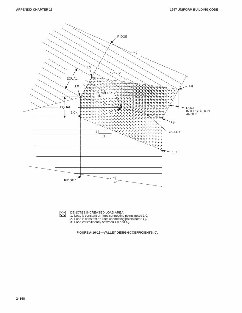
APPENDIX CHAPTER 16APPENDIX CHAPTER 16
1997 UNIFORM BUILDING CODE
2–398
ÓÓÓÓÓÓÓÓÓÓÓÓÓÓÓÓÓÓÓÓÓÓÓÓÓÓÓÓÓÓÓÓÓÓÓÓÓÓÓÓÓÓÓÓÓÓÓÓÓÓÓÓÓÓÓÓÓÓÓÓÓÓÓÓÓÓÓÓÓÓÓÓÓÓÓÓÓÓÓÓÓÓÓÓÓÓÓÓÓÓÓÓÓÓÓÓÓÓÓÓÓÓÓÓÓÓÓÓÓÓÓÓÓÓÓÓÓÓÓÓÓÓÓÓÓÓÓÓÓÓÓÓÓÓÓÓÓÓÓÓÓÓÓÓÓÓÓÓÓÓÓÓÓÓÓÓÓÓÓÓÓÓÓÓÓÓÓÓÓÓÓÓÓÓÓÓÓÓÓÓÓÓÓÓÓÓÓÓÓÓÓÓÓÓÓÓÓÓÓÓÓÓÓÓÓÓÓÓÓÓÓÓÓÓÓÓÓÓÓÓÓ
RIDGE
RIDGE
1.0
ROOFINTERSECTIONANGLE
VALLEY
1.0
1
2
1.0
1.0
1.0
1/2 VALLEYLINE
DENOTES INCREASED LOAD AREA:1. Load is constant on lines connecting points noted 1.0.2. Load is constant on lines connecting points noted Cv.3. Load varies linearly between 1.0 and Cv.
ÓÓÓÓ
Cv
Cv
EQUAL
EQUAL
FIGURE A-16-13—VALLEY DESIGN COEFFICIENTS, Cv
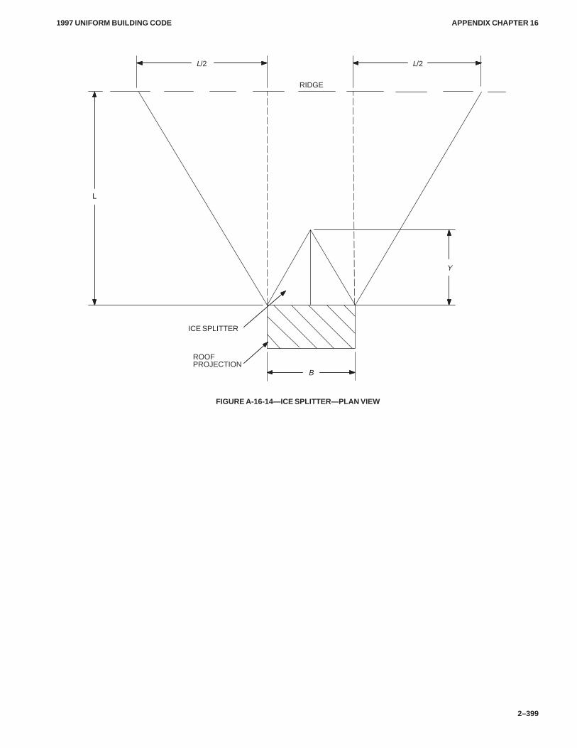
APPENDIX CHAPTER 16APPENDIX CHAPTER 16
1997 UNIFORM BUILDING CODE
2–399
RIDGE
ROOFPROJECTION
ICE SPLITTER
B
Y
L/2 L/2
L
FIGURE A-16-14—ICE SPLITTER—PLAN VIEW
APPENDIX CHAPTER 16APPENDIX CHAPTER 16
1997 UNIFORM BUILDING CODE
2–400
Division II—EARTHQUAKE RECORDING INSTRUMENTATION
SECTION 1649 — GENERAL
In Seismic Zones 3 and 4 every building over six stories in heightwith an aggregate floor area of 60,000 square feet (5574 m2) ormore, and every building over 10 stories in height regardless offloor area, shall be provided with not less than three approved re-cording accelerographs.
The accelerographs shall be interconnected for common startand common timing.
SECTION 1650 — LOCATION
The instruments shall be located in the basement, midportion, andnear the top of the building. Each instrument shall be located sothat access is maintained at all times and is unobstructed by roomcontents. A sign stating MAINTAIN CLEAR ACCESS TO THISINSTRUMENT shall be posted in a conspicuous location.
SECTION 1651 — MAINTENANCE
Maintenance and service of the instruments shall be provided bythe owner of the building, subject to the approval of the buildingofficial. Data produced by the instruments shall be made avail-able to the building official on request.
SECTION 1652 — INSTRUMENTATION OF EXISTINGBUILDINGS
All owners of existing structures selected by the jurisdiction au-thorities shall provide accessible space for the installation of ap-propriate earthquake-recording instruments. Location of saidinstruments shall be determined by the jurisdiction authorities.The jurisdiction authorities shall make arrangements to provide,maintain and service the instruments. Data shall be the propertyof the jurisdiction, but copies of individual records shall be madeavailable to the public on request and the payment of an appropri-ate fee.
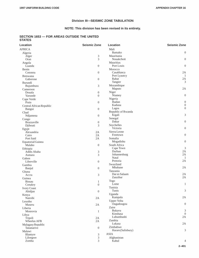
APPENDIX CHAPTER 16APPENDIX CHAPTER 16
1997 UNIFORM BUILDING CODE
2–401
Division III—SEISMIC ZONE TABULATION
NOTE: This division has been revised in its entirety.
SECTION 1653 — FOR AREAS OUTSIDE THE UNITEDSTATES
Location Seismic Zone Location Seismic ZoneAFRICA
Algeria Alger 3Oran 3
AngolaLuanda 0
BeninCotonou 0
BotswanaGaborone 0
BurundiBujumbura 3
CameroonDouala 0Yaounde 0
Cape VerdePraia 0
Central African RepublicBangui 0
ChadNdjamena 0
CongoBrazzaville 0Djibouti 3
EgyptAlexandria 2ACairo 2APort Said 2A
Equatorial GuineaMalabo 0
EthiopiaAddis Ababa 3Asmara 3
GabonLibreville 0
GambiaBanjul 0
GhanaAccra 3
GuineaBissau 1Conakry 0
Ivory CoastAbidjan 0
KenyaNairobi 2A
LesothoMaseru 2A
LiberiaMonrovia 1
LibyaTripoli 2AWheelus AFB 2A
Malagasy RepublicTananarive 0
MalawiBlantyre 3Lilongwe 3Zomba 3
MaliBamako 0
MauritaniaNouakchott 0
MauritiusPort Louis 0
MoroccoCasablanca 2APort Lyautcy 1Rabat 2ATangier 3
MozambiqueMaputo 2A
NigerNiamey 0
NigeriaIbadan 0Kaduna 0Lagos 0
Republic of RwandaKigali 3
SenegalDakar 0
SeychellesVictoria 0
Sierra LeoneFreetown 0
SomaliaMogadishu 0
South AfricaCape Town 3Durban 2AJohannesburg 2ANatal 1Pretoria 2A
SwazilandMbabane 2A
TanzaniaDar es Salaam 2AZanzibar 2A
TogoLome 1
TunisiaTunis 3
UgandaKampala 2A
Upper VoltaOugadougou 0
ZaireBukavu 3Kinshasa 0Lubumbashi 2A
ZambiaLukasa 2A
ZimbabweHarare (Salisbury) 3
ASIAAfghanistan
Kabul 4
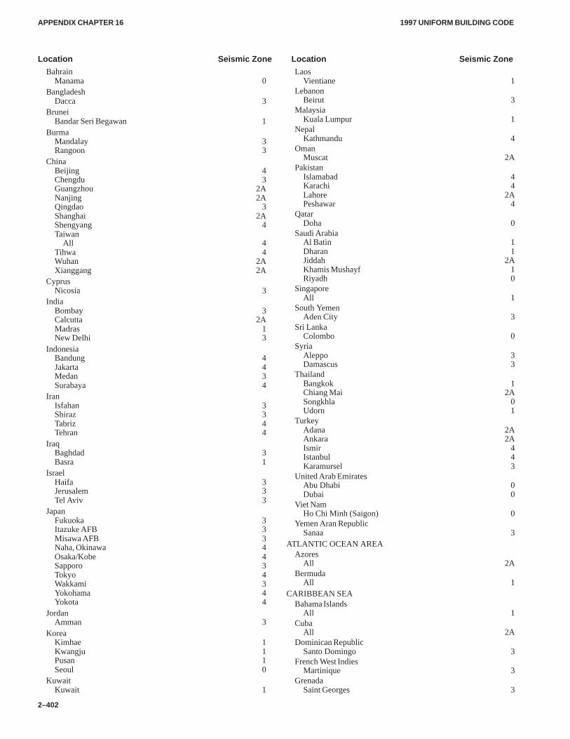
APPENDIX CHAPTER 16APPENDIX CHAPTER 16
1997 UNIFORM BUILDING CODE
2–402
Location Seismic Zone Location Seismic Zone
BahrainManama 0
BangladeshDacca 3
BruneiBandar Seri Begawan 1
BurmaMandalay 3Rangoon 3
ChinaBeijing 4Chengdu 3Guangzhou 2ANanjing 2AQingdao 3Shanghai 2AShengyang 4Taiwan
All 4Tihwa 4Wuhan 2AXianggang 2A
CyprusNicosia 3
IndiaBombay 3Calcutta 2AMadras 1New Delhi 3
IndonesiaBandung 4Jakarta 4Medan 3Surabaya 4
IranIsfahan 3Shiraz 3Tabriz 4Tehran 4
IraqBaghdad 3Basra 1
IsraelHaifa 3Jerusalem 3Tel Aviv 3
JapanFukuoka 3Itazuke AFB 3Misawa AFB 3Naha, Okinawa 4Osaka/Kobe 4Sapporo 3Tokyo 4Wakkami 3Yokohama 4Yokota 4
JordanAmman 3
KoreaKimhae 1Kwangju 1Pusan 1Seoul 0
KuwaitKuwait 1
LaosVientiane 1
LebanonBeirut 3
MalaysiaKuala Lumpur 1
NepalKathmandu 4
OmanMuscat 2A
PakistanIslamabad 4Karachi 4Lahore 2APeshawar 4
QatarDoha 0
Saudi ArabiaAl Batin 1Dharan 1Jiddah 2AKhamis Mushayf 1Riyadh 0
SingaporeAll 1
South YemenAden City 3
Sri LankaColombo 0
SyriaAleppo 3Damascus 3
ThailandBangkok 1Chiang Mai 2ASongkhla 0Udorn 1
TurkeyAdana 2AAnkara 2AIsmir 4Istanbul 4Karamursel 3
United Arab EmiratesAbu Dhabi 0Dubai 0
Viet NamHo Chi Minh (Saigon) 0
Yemen Aran RepublicSanaa 3
ATLANTIC OCEAN AREAAzores
All 2ABermuda
All 1CARIBBEAN SEA
Bahama IslandsAll 1
CubaAll 2A
Dominican RepublicSanto Domingo 3
French West IndiesMartinique 3
GrenadaSaint Georges 3
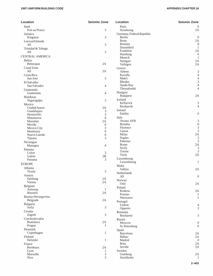
APPENDIX CHAPTER 16APPENDIX CHAPTER 16
1997 UNIFORM BUILDING CODE
2–403
Location Seismic Zone Location Seismic ZoneHaiti
Port au Prince 3Jamaica
Kingston 3Leeward Islands
All 3Trinidad & Tobago
All 3
CENTRAL AMERICABelize
Belmopan 2ACanal Zone
All 2ACosta Rica
San Jose 3El Salvador
San Salvador 4Guatemala
Guatemala 4Honduras
Tegucigalpa 3Mexico
Ciudad Juarez 2AGuadalajara 3Hermosillo 3Matamoros 0Mazatlan 2AMerida 0Mexico City 3Monterrey 0Nuevo Laredo 0Tijuana 3
NicaraguaManagua 4
PanamaColon 3Galeta 2BPanama 3
EUROPEAlbania
Tirana 3Austria
Salzburg 2AVienna 2A
BelgiumAntwerp 1Brussels 2A
Bosnia-HerzegovinaBelgrade 2A
BulgariaSofia 3
CroatiaZagreb 3
CzechoslovakiaBratislava 2APrague 1
DenmarkCopenhagen 1
FinlandHelsinki 1
FranceBordeaux 2ALyon 1Marseille 3Nice 3
Paris 0Strasbourg 2A
Germany, Federal RepublicBerlin 0Bonn 2ABremen 0Dusseldorf 1Frankfurt 2AHamburg 0Munich 1Stuttgart 2AVaihigen 2A
GreeceAthens 3Kavalla 4Makri 4Rhodes 3Sauda Bay 4Thessaloniki 4
HungaryBudapest 2A
IcelandKeflavick 3Reykjavik 4
IrelandDublin 0
ItalyAviano AFB 3Brindisi 0Florence 3Genoa 3Milan 2ANaples 3Palermo 3Rome 2ASicily 3Trieste 3Turin 2A
LuxembourgLuxembourg 1
MaltaValleta 2A
NetherlandsAll 0
NorwayOslo 2A
PolandKrakow 2APoznan 1Warszawa 1
PortugalLisbon 4Opporto 3
RomaniaBucharest 3
RussiaMoscow 0St. Petersburg 0
SpainBarcelona 2ABilbao 2AMadrid 0Rota 2ASeville 2A
SwedenGoteborg 2AStockholm 1
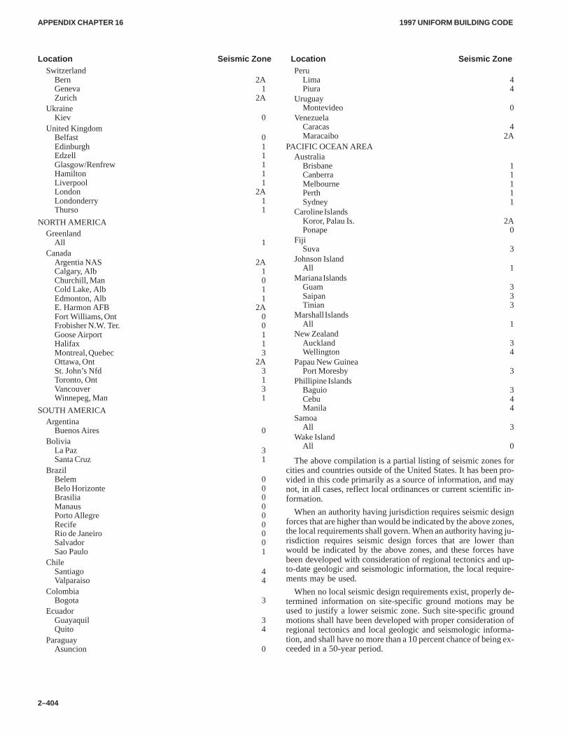
APPENDIX CHAPTER 16APPENDIX CHAPTER 16
1997 UNIFORM BUILDING CODE
2–404
Location Seismic Zone Location Seismic ZoneSwitzerland
Bern 2AGeneva 1Zurich 2A
UkraineKiev 0
United KingdomBelfast 0Edinburgh 1Edzell 1Glasgow/Renfrew 1Hamilton 1Liverpool 1London 2ALondonderry 1Thurso 1
NORTH AMERICAGreenland
All 1Canada
Argentia NAS 2ACalgary, Alb 1Churchill, Man 0Cold Lake, Alb 1Edmonton, Alb 1E. Harmon AFB 2AFort Williams, Ont 0Frobisher N.W. Ter. 0Goose Airport 1Halifax 1Montreal, Quebec 3Ottawa, Ont 2ASt. John’s Nfd 3Toronto, Ont 1Vancouver 3Winnepeg, Man 1
SOUTH AMERICAArgentina
Buenos Aires 0Bolivia
La Paz 3Santa Cruz 1
BrazilBelem 0Belo Horizonte 0Brasilia 0Manaus 0Porto Allegre 0Recife 0Rio de Janeiro 0Salvador 0Sao Paulo 1
ChileSantiago 4Valparaiso 4
ColombiaBogota 3
EcuadorGuayaquil 3Quito 4
ParaguayAsuncion 0
PeruLima 4Piura 4
UruguayMontevideo 0
VenezuelaCaracas 4Maracaibo 2A
PACIFIC OCEAN AREAAustralia
Brisbane 1Canberra 1Melbourne 1Perth 1Sydney 1
Caroline IslandsKoror, Palau Is. 2APonape 0
FijiSuva 3
Johnson IslandAll 1
Mariana IslandsGuam 3Saipan 3Tinian 3
Marshall IslandsAll 1
New ZealandAuckland 3Wellington 4
Papau New GuineaPort Moresby 3
Phillipine IslandsBaguio 3Cebu 4Manila 4
SamoaAll 3
Wake IslandAll 0
The above compilation is a partial listing of seismic zones forcities and countries outside of the United States. It has been pro-vided in this code primarily as a source of information, and maynot, in all cases, reflect local ordinances or current scientific in-formation.
When an authority having jurisdiction requires seismic designforces that are higher than would be indicated by the above zones,the local requirements shall govern. When an authority having ju-risdiction requires seismic design forces that are lower thanwould be indicated by the above zones, and these forces havebeen developed with consideration of regional tectonics and up-to-date geologic and seismologic information, the local require-ments may be used.
When no local seismic design requirements exist, properly de-termined information on site-specific ground motions may beused to justify a lower seismic zone. Such site-specific groundmotions shall have been developed with proper consideration ofregional tectonics and local geologic and seismologic informa-tion, and shall have no more than a 10 percent chance of being ex-ceeded in a 50-year period.
APPENDIX CHAPTER 16APPENDIX CHAPTER 16
1997 UNIFORM BUILDING CODE
2–405
Division IV—EARTHQUAKE REGULATIONS FORSEISMIC-ISOLATED STRUCTURES
SECTION 1654 — GENERAL
Every seismic-isolated structure and every portion thereof shallbe designed and constructed in accordance with the requirementsof this division and the applicable requirements of Chapter 16,Part IV.
The lateral-force-resisting system and the isolation systemshall be designed to resist the deformations and stresses producedby the effects of seismic ground motions as provided in this divi-sion.
Where wind forces prescribed by Chapter 16, Part III, producegreater deformations or stresses, such loads shall be used for de-sign in lieu of the deformations and stresses resulting from earth-quake forces.
SECTION 1655 — DEFINITIONS
The definitions of Section 1627 and the following apply to theprovisions of this division:
DESIGN DISPLACEMENT is the design-basis earthquakelateral displacement, excluding additional displacement due toactual and accidental torsion, required for design of the isolationsystem.
DESIGN-BASIS EARTHQUAKE is defined in Section1631.2.
EFFECTIVE DAMPING is the value of equivalent viscousdamping corresponding to energy dissipated during cyclic re-sponse of the isolation system.
EFFECTIVE STIFFNESS is the value of the lateral force inthe isolation system, or an element thereof, divided by the corre-sponding lateral displacement.
ISOLATION INTERFACE is the boundary between the up-per portion of the structure, which is isolated, and the lower por-tion of the structure, which moves rigidly with the ground.
ISOLATION SYSTEM is the collection of structural ele-ments that includes all individual isolator units, all structural ele-ments that transfer force between elements of the isolationsystem, and all connections to other structural elements. The iso-lation system also includes the wind-restraint system if such asystem is used to meet the design requirements of this section.
ISOLATOR UNIT is a horizontally flexible and verticallystiff structural element of the isolation system that permits largelateral deformations under design seismic load. An isolator unitmay be used either as part of or in addition to the weight-support-ing system of the building.
MAXIMUM CAPABLE EARTHQUAKE is the maximumlevel of earthquake ground shaking that may ever be expected atthe building site within the known geological framework. In Seis-mic Zones 3 and 4, this intensity may be taken as the level ofearthquake ground motion that has a 10 percent probability of be-ing exceeded in a 100-year time period.
MAXIMUM DISPLACEMENT is the maximum capableearthquake lateral displacement, excluding additional displace-ment due to actual and accidental torsion, required for design ofthe isolation system.
TOTAL DESIGN DISPLACEMENT is the design-basisearthquake lateral displacement, including additional displace-ment due to actual and accidental torsion, required for design ofthe isolation system, or an element thereof.
TOTAL MAXIMUM DISPLACEMENT is the maximumcapable earthquake lateral displacement, including additionaldisplacement due to actual and accidental torsion, required forverification of the stability of the isolation system, or elementsthereof, design of building separations, and vertical load testingof isolator unit prototypes.
WIND-RESTRAINT SYSTEM is the collection of structuralelements that provide restraint of the seismic-isolated structurefor wind loads. The wind-restraint system may be either an inte-gral part of isolator units or may be a separate device.
SECTION 1656 — SYMBOLS AND NOTATIONSThe symbols and notations of Section 1628 and the following pro-visions apply to the provisions of this division:
BD = numerical coefficient related to the effective damping ofthe isolation system at the design displacement, βD, asset forth in Table A-16-C.
BM = numerical coefficient related to the effective damping ofthe isolation system at the maximum displacement, βM,as set forth in Table A-16-C.
b = the shortest plan dimension of the structure, in feet(mm), measured perpendicular to d.
CAD = the seismic coefficient, Ca, as set forth in Table 16-Q.CAM = the seismic coefficient, Ca, as set forth in Table A-16-F
for shaking intensity, MMZNa.CVD = seismic coefficient, Cv, as set forth in Table 16-R.CVM = seismic coefficient, Cv, as set forth in Table A-16-G for
shaking intensity, MMZNv.DD = design displacement, in inches (mm), at the center of
rigidity of the isolation system in the direction underconsideration, as prescribed by Formula (58-1).
DD′ = design displacement, in inches (mm), at the center ofrigidity of the isolation system in the direction underconsideration, as prescribed by Formula (59-1).
DM = maximum displacement, in inches (mm), at the center ofrigidity of the isolation system in the direction underconsideration, as prescribed by Formula (58-3).
DM� = maximum displacement, in inches (mm), at the center ofrigidity of the isolation system in the direction underconsideration, as prescribed by Formula (59-2).
DTD = total design displacement, in inches (mm), of an ele-ment of the isolation system including both translationaldisplacement at the center of rigidity, DD, and the com-ponent of torsional displacement in the direction underconsideration, as specified in Section 1658.3.5.
DTM = total maximum displacement, in inches (mm), of an ele-ment of the isolation system, including both translation-al displacement at the center of rigidity, DM, and thecomponent of torsional displacement in the directionunder consideration, as specified by Section 1658.3.3.
d = the longest plan dimension of the structure, in feet(mm).
ELOOP= energy dissipated in kip-inches (kN-mm), in an isolatorunit during a full cycle of reversible load over a test dis-placement range from ∆+ to ∆-, as measured by the areaenclosed by the loop of the force-deflection curve.
ΣED = total energy dissipated, in kip-inches (kN-mm), of allunits of the isolation system during a full cycle ofresponse at the design displacement, DD.
�
APPENDIX CHAPTER 16APPENDIX CHAPTER 16
1997 UNIFORM BUILDING CODE
2–406
ΣEM = total energy dissipated, in kip-inches (kN-mm), of allunits of the isolation system during a full cycle ofresponse at the maximum displacement, DM.
e = the actual eccentricity, in feet (mm), measured in planbetween the center of mass of the structure above theisolation interface and the center of rigidity of theisolation system, plus accidental eccentricity, in feet(mm), taken as 5 percent of the maximum buildingdimension perpendicular to the direction of force underconsideration.
F– = negative force, in kips (kN), in an isolator unit during asingle cycle of prototype testing at a displacement am-plitude of ∆−.
F+ = positive force, in kips (kN), in an isolator unit during asingle cycle of prototype testing at a displacement am-plitude of ∆+.
�|FD+|max= sum, for all isolator units, of the absolute values of the
individual isolator unit’s maximum positive force inkips (kN) at positive displacement DD. For a given iso-lator unit, the maximum positive force at positive dis-placement, DD, is determined by comparing each of themaximum positive forces that occurred during eachcycle of the prototype test sequence associated with dis-placement increment DD, and selecting the maximumpositive value at positive displacement, DD.
�|FD+|min= sum, for all isolator units, of the absolute values of the
individual isolator unit’s minimum positive force inkips (kN) at positive displacement DD. For a given iso-lator unit, the minimum positive force at positive dis-placement, DD, is determined by comparing each of theminimum positive forces that occurred during eachcycle of the prototype test sequence associated with dis-placement increment DD, and selecting the minimumpositive value at positive displacement, DD.
�|FD–|max= sum, for all isolator units, of the absolute values of the
individual isolator unit’s maximum negative force inkips (kN) at negative displacement DD. For a given iso-lator unit, the maximum negative force at negative dis-placement, DD, is determined by comparing each of themaximum negative forces that occurred during eachcycle of the prototype test sequence associated with dis-placement increment DD, and selecting the maximumnegative value at negative displacement, DD.
�|FD- |min= sum, for all isolator units, of the absolute values of the
individual isolator unit’s minimum negative force inkips (kN) at negative displacement DD. For a given iso-lator unit, the minimum negative force at negative dis-placement, DD, is determined by comparing each of theminimum negative forces that occurred during eachcycle of the prototype test sequence associated with dis-placement increment DD, and selecting the minimumnegative value at negative displacement, DD.
�|FM+|max= sum, for all isolator units, of the absolute values of the
individual isolator unit’s maximum positive force inkips (kN) at positive displacement DM. For a given iso-lator unit, the maximum positive force at positive dis-
placement, DM, is determined by comparing each of themaximum positive forces that occurred during eachcycle of the prototype test sequence associated with dis-placement increment DM, and selecting the maximumpositive value at positive displacement, DM.
�|FM+|min= sum, for all isolator units, of the absolute values of the
individual isolator unit’s minimum positive force inkips (kN) at positive displacement, DM. For a given iso-lator unit, the minimum positive force at positive dis-placement, DM, is determined by comparing each of theminimum positive forces that occurred during eachcycle of the prototype test sequence associated with dis-placement increment DM and selecting the minimumpositive value at positive displacement, DM.
�|FM-|max= sum, for all isolator units, of the absolute values of the
individual isolator unit’s maximum negative force inkips (kN) at negative displacement DM. For a given iso-lator unit, the maximum negative force at negative dis-placement, DM, is determined by comparing each of themaximum negative forces that occurred during eachcycle of the prototype test sequence associated with dis-placement increment DM and selecting the maximumnegative value at negative displacement, DM.
�|FM-|min= sum, for all isolator units, of the absolute values of the
individual isolator unit’s minimum negative force inkips (kN) at negative displacement DM. For a given iso-lator unit, the minimum negative force at negative dis-placement, DM, is determined by comparing each of theminimum negative forces that occurred during eachcycle of the prototype test sequence associated with dis-placement increment DM and selecting the minimumnegative value at negative displacement, DM.
g = gravity constant (386.4 in/sec.2, or 9,810 mm/sec.2, forSI).
keff = effective stiffness of an isolator unit, in kips/inch as pre-scribed by Formula (65-1).
kDmax= maximum effective stiffness, in kips/inch (kN/mm), ofthe isolation system at the design displacement in thehorizontal direction under consideration.
kMmax= maximum effective stiffness, in kips/inch (kN/mm), ofthe isolation system at the maximum displacement inthe horizontal direction under consideration.
kDmin = minimum effective stiffness, in kips/inch (kN/mm), ofthe isolation system at the design displacement in thehorizontal direction under consideration.
kMmin = minimum effective stiffness, in kips/inch (kN/mm), ofthe isolation system at the maximum displacement inthe horizontal direction under consideration.
MM = numerical coefficient related to maximum capableearthquake response as set forth in Table A-16-D.
Na = near-source factor used in the determination of CAD andCAM related to both the proximity of the building orstructure to known faults with magnitudes and slip ratesas set forth in Tables 16-S and 16-U.
Nv = near-source factor used in the determination of CVD andCVM related to both the proximity of the building orstructure to known faults with magnitudes and slip ratesas set forth in Tables 16-T and 16-U.
�
�
�
�
�
APPENDIX CHAPTER 16APPENDIX CHAPTER 16
1997 UNIFORM BUILDING CODE
2–407
Rl = numerical coefficient related to the type of lateral-force-resisting system above the isolation system as set forthin Table A-16-E for seismic-isolated structures.
TD = effective period, in seconds, of seismic-isolated struc-ture at the design displacement in the direction underconsideration, as prescribed by Formula (58-2).
TM = effective period, in seconds, of seismic-isolated struc-ture at the maximum displacement in the directionunder consideration, as prescribed by Formula (58-4).
Vb = the total lateral seismic design force or shear on ele-ments of the isolation system or elements below the iso-lation system as prescribed by Formula (58-5).
Vs = the total lateral seismic design force or shear on ele-ments above the isolation system as prescribed by For-mula (58-8) and the limits specified in Section 1658.
W = the total seismic dead load defined in Section 1630.1.For design of the isolation system, W is the total seismicdead load weight of the structure above the isolation in-terface.
y = the distance, in feet (mm), between the center of rigidityof the isolation system rigidity and the element of inter-est, measured perpendicular to the direction of seismicloading under consideration.
βeff = effective damping of the isolation system and isolatorunit, as prescribed by Formula (65-2).
βD = effective damping of the isolation system at the designdisplacement, as prescribed by Formula (65-3).
βM = effective damping of the isolation system at the maxi-mum displacement, as prescribed by Formula (65-4).
∆+ = maximum positive displacement of an isolator unit dur-ing each cycle of prototype testing.
∆− = maximum negative displacement of an isolator unit dur-ing each cycle of prototype testing.
SECTION 1657 — CRITERIA SELECTION
1657.1 Basis for Design.The procedures and limitations for thedesign of seismic-isolated structures shall be determined consid-ering zoning, site characteristics, vertical acceleration, crackedsection properties of concrete and masonry members, occupancy,configuration, structural system and height in accordance withSection 1629, except as noted below.
1657.2 Stability of the Isolation System.The stability of thevertical load-carrying elements of the isolation system shall beverified by analysis and test, as required, for lateral seismic dis-placement equal to the total maximum displacement.
1657.3 Occupancy Categories.The importance factor, I, for aseismic-isolated building shall be taken as 1.0 regardless of occu-pancy category.
1657.4 Configuration Requirements.Each structure shall bedesignated as being regular or irregular on the basis of the struc-tural configuration above the isolation system, in accordance withSection 1629.5.
1657.5 Selection of Lateral Response Procedure.
1657.5.1 General.Any seismic-isolated structure may be, andcertain seismic-isolated structures defined below shall be, de-signed using the dynamic lateral response procedure of Section1659.
1657.5.2 Static analysis.The static lateral response procedureof Section 1658 may be used for design of a seismic-isolatedstructure, provided:
1. The structure is located at least 10 kilometers (km) from allactive faults.
2. The structure is located on Soil Profile Type SA, SB, SC or SD.
3. The structure above the isolation interface is equal to or lessthan four stories, or 65 feet (19.8 m), in height.
4. The effective period of the isolated structure, TM, is equal toor less than 3.0 seconds.
5. The effective period of the isolated structure, TD, is greaterthan three times the elastic, fixed-base period of the structureabove the isolation system, as determined by Formula (30-8) ofSection 1630.
6. The structure above the isolation system is of regular config-uration.
7. The isolation system is defined by all of the following attrib-utes:
7.1 The effective stiffness of the isolation system at the de-sign displacement is greater than one third of the effec-tive stiffness at 20 percent of the design displacement.
7.2 The isolation system is capable of producing a restor-ing force, as specified in Section 1661.2.4.
7.3 The isolation system has force-deflection propertieswhich are independent of the rate of loading.
7.4 The isolation system has force-deflection propertieswhich are independent of vertical load and bilateralload.
7.5 The isolation system does not limit maximum capableearthquake displacement to less than CVM/CVD timesthe total design displacement.
1657.5.3 Dynamic analysis.The dynamic lateral response pro-cedure of Section 1659 shall be used for design of seismic-isolated structures as specified below:
1. Response spectrum analysis. Response spectrum analysismay be used for design of a seismic-isolated structure, provided:
1.1 The structure is located on Soil Profile Type SA, SB, SCor SD.
1.2 The isolation system is defined by all of the attributesspecified in Section 1657.5.2, Item 7.
2. Time-history analysis. Time-history analysis may be usedfor design of any seismic-isolated structure and shall be used fordesign of all seismic-isolated structures not meeting the criteria ofSection 1657.5.3, Item 1.
3. Site-specific design spectra. Site-specific ground motionspectra of the design-basis earthquake and the maximum capableearthquake, developed in accordance with Section 1631.2, shallbe used for design and analysis of all seismic-isolated structuresas specified below:
1. The structure is located on Soil Profile Type SE or SF.
2. The structure is located within 10 km of an active fault.
SECTION 1658 — STATIC LATERAL RESPONSEPROCEDURE
1658.1 General.Except as provided in Section 1659, everyseismic-isolated structure, or portion thereof, shall be designedand constructed to resist minimum earthquake displacements and
�
�
�
APPENDIX CHAPTER 16APPENDIX CHAPTER 16
1997 UNIFORM BUILDING CODE
2–408
forces as specified by this section and the applicable requirementsof Section 1630.
1658.2 Deformation Characteristics of the Isolation Sys-tem. Minimum lateral earthquake design displacements andforces on seismic-isolated structures shall be based on the defor-mation characteristics of the isolation system.
The deformation characteristics of the isolation system shallexplicitly include the effects of the wind-restraint system if such asystem is used to meet the design requirements of this document.
The deformation characteristics of the isolation system shall bebased on properly substantiated tests performed in accordancewith Section 1665.
1658.3 Minimum Lateral Displacements.
1658.3.1 Design displacement.The isolation system shall bedesigned and constructed to withstand minimum lateral earth-quake displacements which act in the direction of each of themain horizontal axes of the structure in accordance with the for-mula:
DD �
�g
4�2�CVDTD
BD(58-1)
1658.3.2 Effective period at the design displacement.Theeffective period of the isolated structure at the design displace-ment, TD, shall be determined using the deformational character-istics of the isolation system in accordance with the formula:
TD � 2 �W
kDming� (58-2)
1658.3.3 Maximum displacement.The maximum displace-ment of the isolation system, DM, in the most critical direction ofhorizontal response shall be calculated in accordance with theformula:
DM �
�g
4�2�CVMTM
BM(58-3)
1658.3.4 Effective period at the maximum displace-ment. The effective period of the isolated structure at the maxi-mum displacement, TM, shall be determined using thedeformational characteristics of the isolation system in accord-ance with the formula:
TM � 2 �W
kMming� (58-4)
1658.3.5 Total displacement.The total design displacement,DTD, and the total maximum displacement, DTM, of elements ofthe isolation system shall include additional displacement due toactual and accidental torsion calculated considering the spatialdistribution of the lateral stiffness of the isolation system and themost disadvantageous location of mass eccentricity.
The total design displacement, DTD, and the of total maximumdisplacement DTM, of elements of an isolation system with uni-form spatial distribution of lateral stiffness shall not be taken asless than that prescribed by the formulas:
DTD � DD�1 � y 12eb2
� d2� (58-5)
DTM � DM�1 � y 12eb2
� d2� (58-6)
The total design displacement, DTD, and the total maximumdisplacement, DTM, may be taken as less than the value pre-scribed by Formulas (58-5) and (58-6), but not less than 1.1 timesDD and 1.1 times DM, respectively, provided the isolation systemis shown by calculation to be configured to resist torsion accord-ingly.
1658.4 Minimum Lateral Forces.
1658.4.1 Isolation system and structural elements at or belowthe isolation system.The isolation system, the foundation, andall structural elements below the isolation system shall be de-signed and constructed to withstand a minimum lateral seismicforce, Vb, using all of the appropriate provisions for a nonisolatedstructure where:
Vb = kDmaxDD (58-7)
1658.4.2 Structural elements above the isolation system.Thestructure above the isolation system shall be designed and con-structed to withstand a minimum shear force, Vs, using all of theappropriate provisions for a nonisolated structure where:
Vs �
kDmax DD
RI
(58-8)
The RI factor shall be based on the type of lateral-force-resist-ing system used for the structure above the isolation system.
1658.4.3 Limits on Vs. The value of Vs shall not be taken as lessthan the following:
1. The lateral seismic force required by Chapter 16, DivisionIII, for a fixed-base structure of the same weight, W, and a periodequal to the isolated period, TD.
2. The base shear corresponding to the design wind load.
3. The lateral seismic force required to fully activate the isola-tion system factored by 1.5 (e.g., one and one-half times the yieldlevel of a softening system, the ultimate capacity of a sacrificialwind-restraint system or the static friction level of a slidingsystem).
1658.5 Vertical Distribution of Force. The total force shall bedistributed over the height of the structure above the isolation in-terface in accordance with the formula:
Fx �Vswx hx
�
n
i�1
wihi
(58-9)
At each level designated as x, the force Fx shall be applied overthe area of the building in accordance with the mass distribution atthe level. Stresses in each structural element shall be calculated asthe effect of force, Fx, applied at the appropriate levels above thebase.
�
APPENDIX CHAPTER 16APPENDIX CHAPTER 16
1997 UNIFORM BUILDING CODE
2–409
1658.6 Drift Limits. The maximum interstory drift ratio of thestructure above the isolation system shall not exceed 0.010/RI .
SECTION 1659 — DYNAMIC LATERAL-RESPONSEPROCEDURE
1659.1 General.As required by Section 1657, every seis-mic-isolated structure, or portion thereof, shall be designed andconstructed to resist earthquake displacements and forces as spe-cified in this section and the applicable requirements of Section1631.
1659.2 Isolation System and Structural Elements below theIsolation System. The total design displacement of the isolationsystem shall not be taken as less than 90 percent of DTD as speci-fied by Section 1658.3.3.
The total maximum displacement of the isolation system shallnot be taken as less than 80 percent of DTM as prescribed by For-mula (58-6).
The design lateral shear force on the isolation system and struc-tural elements below the isolation system shall not be taken asless than 90 percent of Vb as prescribed by Formula (58-7).
The limits of the first and second paragraphs shall be evaluatedusing values of DTD and DTM determined in accordance with Sec-tion 1658.3, except that DD� may be used in lieu of DD and DM�
may be used in lieu of DM, where DD� and DM� are prescribed bythe formulas:
DD�
�
DD
1��
TTD�
2
�
(59-1)
DM�
�
DM
1��
TTM�
2
�
(59-2)
and T is the elastic, fixed-base period of the structure above theisolation system, as determined only by Formula (30-4) of Sec-tion 1630.
1659.3 Structural Elements above the Isolation System.Thedesign lateral shear force on the structure above the isolation sys-tem, if regular in configuration, shall not be taken as less than 80percent of VS as prescribed by Formula (58-8) or less than the lim-its specified by Section 1658.4.3.
EXCEPTION: The design lateral shear force on the structureabove the isolation system, if regular in configuration, may be taken asless than 80 percent, but not less than 60 percent, of VS provided time-history analysis is used for design of the structure.
The design lateral shear force on the structure above the isola-tion system, if irregular in configuration, shall not be taken as lessthan VS as prescribed by Formula (58-8) or less than the limitsspecified by Section 1658.4.3.
EXCEPTION: The design lateral shear force on the structureabove the isolation system, if irregular in configuration, may be takenas less than 100 percent, but not less than 80 percent, of VS, providedtime-history analysis is used for design of the structure.
1659.4 Ground Motion.
1659.4.1 Design spectra.Properly substantiated, site-specificspectra are required for design of all structures with an isolatedperiod, TM, greater than 3.0 seconds, or located on Soil ProfileType SE or SF or located within 10 km of an active fault or located
in Seismic Zone 1, 2A or 2B. Structures that do not require site-specific spectra and for which site-specific spectra have not beencalculated shall be designed using spectra based on Figure 16-3 ofChapter 16, Division III.
A design spectrum shall be constructed for the design-basisearthquake. This design spectrum shall not be taken as less thanthe response spectrum given in Figure 16-3 of Chapter 16, Divi-sion III, where the values of Ca shall be taken as equal to CAD andCv shall be taken as equal to CVD.
EXCEPTION: If a site-specific spectrum is calculated for the de-sign-basis earthquake, then the design spectrum may be taken as lessthan 100 percent, but not less than 80 percent of the response spectrumgiven in Figure 16-3 of Chapter 16, Division III, where the values ofCa shall be taken as equal to CAD and Cv shall be taken as equal to CVD.
A design spectrum shall be constructed for the maximum capa-ble earthquake. This spectrum shall not be taken as less than thespectrum given in Figure 16-3 of Chapter 16, Division III wherethe values of Ca shall be taken as equal to CAM and Cv shall betaken as equal to CVM. This spectrum shall be used to determinethe total maximum displacement and overturning forces for de-sign and testing of the isolation system.
EXCEPTION: If a site-specific spectrum is calculated for the max-imum capable earthquake, then the design spectrum may be taken asless than 100 percent, but not less than 80 percent of the response spec-trum given in Figure 16-3 of Chapter 16, Division III, where the valuesof Ca shall be taken as equal to CAM and Cv shall be taken as equal toCVM.
1659.4.2 Time histories.Pairs of appropriate horizontalground-motion time-history components shall be selected andscaled from not less than three recorded events. Appropriate timehistories shall have magnitudes, fault distances and source mech-anisms that are consistent with those that control the design-basisearthquake (or maximum capable earthquake). Where threeappropriate recorded ground motion time history pairs are notavailable, appropriate simulated ground motion time history pairsmay be used to make up the total number required. For each pair ofhorizontal ground-motion components, the square root sum of thesquares (SRSS) of the 5 percent-damped spectrum of the scaledhorizontal components shall be constructed. The motions shall bescaled such that the average value of the SRSS spectra does notfall below 1.3 times the 5 percent-damped spectrum of the design-basis earthquake (or maximum capable earthquake) by more than10 percent for periods from 0.5TD seconds to 1.25TM seconds.
1659.5 Mathematical Model.
1659.5.1 General.The mathematical models of the isolatedstructure, including the isolation system, the lateral-force-resist-ing system and other structural elements, shall conform to Section1631.3 and to the requirements of Sections 1659.5.2 and 1659.5.3below.
1659.5.2 Isolation system.The isolation system shall be mod-eled using deformational characteristics developed and verifiedby test in accordance with the requirements of Section 1658.2.
The isolation system shall be modeled with sufficient detail to:
1. Account for the spatial distribution of isolator units,
2. Calculate translation, in both horizontal directions, and tor-sion of the structure above the isolation interface, considering themost disadvantageous location of mass eccentricity,
3. Assess overturning/uplift forces on individual isolatorunits; and
4. Account for the effects of vertical load, bilateral load and/orthe rate of loading if the force deflection properties of the isolationsystem are dependent on one or more of these attributes.
�
APPENDIX CHAPTER 16APPENDIX CHAPTER 16
1997 UNIFORM BUILDING CODE
2–410
1659.5.3 Isolated structure.
1659.5.3.1 Displacement.The maximum displacement of eachfloor and the total design displacement and total maximum dis-placement across the isolation system shall be calculated using amodel of the isolated structure that incorporates the force-deflec-tion characteristics of nonlinear elements of the isolation systemand the lateral-force-resisting system.
Lateral-force-resisting systems with nonlinear elements in-clude, but are not limited to, irregular structural systems designedfor a lateral force less than Vs as prescribed by Formula (58-8) andthe limits specified by Section 1658.4.3, and regular structuralsystems designed for a lateral force less than 80 percent of Vs.
1659.5.3.2 Forces and displacements in key elements.Designforces and displacements in key elements of the lateral-force-resisting system may be calculated using a linear elastic model ofthe isolated structure, provided:
1. Pseudo-elastic properties assumed for nonlinear isolationsystem components are based on the maximum effective stiffnessof the isolation system.
2. All key elements of the lateral-force-resisting system arelinear.
1659.6 Description of Analysis Procedures.
1659.6.1 General.A response spectrum analysis or a time-history analysis, or both, shall be performed in accordance withSections 1631.4 and 1631.5 and the requirements of this section.
1659.6.2 Input earthquake.The design-basis earthquake shallbe used to calculate the total design displacement of the isolationsystem and the lateral forces and displacements of the isolatedstructure. The maximum capable earthquake shall be used to cal-culate the total maximum displacement of the isolation system.
1659.6.3 Response spectrum analysis.Response spectrumanalysis shall be performed using a modal damping value for thefundamental mode in the direction of interest not greater than theeffective damping of the isolation system or 30 percent of critical,whichever is less. Modal damping values for higher modes shallbe selected consistent with those appropriate for response spec-trum analysis of the structure above the isolation system on afixed base.
Response spectrum analysis used to determine the total designdisplacement and the total maximum displacement shall includesimultaneous excitation of the model by 100 percent of the mostcritical direction of ground motion and 30 percent of the groundmotion on the orthogonal axis. The maximum displacement of theisolation system shall be calculated as the vectorial sum of the twoorthogonal displacements.
1659.6.4 Time-history analysis.Time-history analysis shall beperformed with at least three appropriate pairs of horizontal time-history components, as defined in Section 1659.4.2.
Each pair of time histories shall be applied simultaneously tothe model, considering the most disadvantageous location ofmass eccentricity. The maximum displacement of the isolationsystem shall be calculated from the vectorial sum of the twoorthogonal displacements at each time step.
The parameter of interest shall be calculated for eachtime-history analysis. If three time-history analyses areperformed, then the maximum response of the parameter of inter-est shall be used for design. If seven or more time-history analysesare performed, then the average value of the response parameterof interest may be used for design.
1659.7 Design Lateral Force.
1659.7.1 Isolation system and structural elements at or belowthe isolation system.The isolation system, foundation and allstructural elements below the isolation system shall be designedusing all of the appropriate provisions for a nonisolated structureand the forces obtained from the dynamic analysis.
1659.7.2 Structural elements above the isolation sys-tem. Structural elements above the isolation system shall be de-signed using the appropriate provisions for a nonisolatedstructure and the forces obtained from the dynamic analysis di-vided by a factor of RI. The RI factor shall be based on the type oflateral-force-resisting system used for the structure above theisolation system.
1659.7.3 Scaling of results.When the factored lateral shearforce on structural elements, determined using either responsespectrum or time-history analysis, is less than minimum level pre-scribed by Sections 1659.1 and 1659.2, then all response parame-ters, including member forces and moments shall be adjustedupward proportionally.
1659.8 Drift Limits. Maximum interstory drift correspondingto the design lateral force, including displacement due to verticaldeformation of the isolation system, shall not exceed the follow-ing limits:
1. The maximum interstory drift ratio of the structure abovethe isolation system, calculated by response spectrum analysis,shall not exceed 0.015/RI .
2. The maximum interstory drift ratio of the structure abovethe isolation system, calculated by time-history analysis consid-ering the force-deflection characteristics of nonlinear elements ofthe lateral-force-resisting system, shall not exceed 0.020/RI .
The secondary effects of the maximum capable earthquake lat-eral displacement, ∆, of the structure above the isolation systemcombined with gravity forces shall be investigated if the intersto-ry drift ratio exceeds 0.010/RI .
SECTION 1660 — LATERAL LOAD ON ELEMENTSOF STRUCTURES AND NONSTRUCTURALCOMPONENTS SUPPORTED BY STRUCTURES
1660.1 General.Parts or portions of an isolated structure, per-manent nonstructural components and the attachments to them,and the attachments for permanent equipment supported by astructure shall be designed to resist seismic forces and displace-ments as prescribed by this section and the applicable require-ments of Section 1632.
1660.2 Forces and Displacements.
1660.2.1 Components at or above the isolation interface.Elements of seismic-isolated structures and nonstructural com-ponents, or portions thereof, which are at or above the isolationinterface, shall be designed to resist a total lateral seismic forceequal to the maximum dynamic response of the element or com-ponent under consideration.
EXCEPTION: Elements of seismic-isolated structures and non-structural components, or portions thereof, may be designed to resisttotal lateral seismic force as prescribed by Formula (32-1) or (32-2) ofSection 1632.
1660.2.2 Components that cross the isolation interface.Elements of seismic-isolated structures and nonstructural com-ponents, or portions thereof, that cross the isolation interface shallbe designed to withstand the total maximum displacement.
1660.2.3 Components below the isolation interface.Ele-ments of seismic-isolated structures and nonstructural compo-
�
APPENDIX CHAPTER 16APPENDIX CHAPTER 16
1997 UNIFORM BUILDING CODE
2–411
nents, or portions thereof, which are below the isolation interfaceshall be designed and constructed in accordance with the require-ments of Section 1632.
SECTION 1661 — DETAILED SYSTEMSREQUIREMENTS
1661.1 General.The isolation system and the structural systemshall comply with the requirements of Section 1633 and the mate-rial requirements of Chapters 19 through 23. In addition, the isola-tion system shall comply with the detailed system requirementsof this section and the structural system shall comply with the de-tailed system requirements of this section and the applicable por-tions of Section 1633.
1661.2 Isolation System.
1661.2.1 Environmental conditions.In addition to the require-ments for vertical and lateral loads induced by wind and earth-quake, the isolation system shall be designed with considerationgiven to other environmental conditions including aging effects,creep, fatigue, operating temperature and exposure to moisture ordamaging substances.
1661.2.2 Wind forces.Isolated structures shall resist designwind loads at all levels above the isolation interface in accordancewith the general wind design provisions. At the isolation inter-face, a wind restraint system shall be provided to limit lateral dis-placement in the isolation system to a value equal to that requiredbetween floors of the structure above the isolation interface.
1661.2.3 Fire resistance.Fire resistance for the isolation sys-tem shall meet that required for the building columns, walls orother structural elements in which it is installed.
Isolator systems required to have a fire-resistive rating shall beprotected with approved materials or construction assemblies de-signed to provide the same degree of fire resistance as the struc-tural element in which it is installed when tested in accordancewith UBC Standard 7-1. See Section 703.2.
Such isolation system protection applied to isolator units shallbe capable of retarding the transfer of heat to the isolator unit insuch a manner that the required gravity load-carrying capacity ofthe isolator unit will not be impaired after exposure to the standardtime-temperature curve fire test prescribed in UBC Standard 7-1for a duration not less than that required for the fire-resistive rat-ing of the structural element in which it is installed.
Such isolation system protection applied to isolator units shallbe suitably designed and securely installed so as not to dislodge,loosen, sustain damage, or otherwise impair its ability to accom-modate the seismic movements for which the isolator unit is de-signed and to maintain its integrity for the purpose of providingthe required fire-resistive protection.
1661.2.4 Lateral restoring force.The isolation system shall beconfigured to produce a restoring force such that the lateral forceat the total design displacement is at least 0.025W greater than thelateral force at 50 percent of the total design displacement.
EXCEPTION: The isolation system need not be configured toproduce a restoring force, as required above, provided the isolationsystem is capable of remaining stable under full vertical load and ac-commodating a total maximum displacement equal to the greater of ei-ther 3.0 times the total design displacement 36 CVM, inches (For SI:914.4 CVM, mm).
1661.2.5 Displacement restraint.The isolation system may beconfigured to include a displacement restraint that limits lateraldisplacement due to the maximum capable earthquake to less
than CVM/CVD times the total design displacement, provided thatthe seismic-isolated structure is designed in accordance with thefollowing criteria when more stringent than the requirements ofSection 1629.
1. Maximum capable earthquake response is calculated in ac-cordance with the dynamic analysis requirements of Sections1631 and 1659, explicitly considering the nonlinear characteris-tics of the isolation system and the structure above the isolationsystem.
2. The ultimate capacity of the isolation system and structuralelements below the isolation system shall exceed the strength anddisplacement demands of the maximum capable earthquake.
3. The structure above the isolation system is checked for sta-bility and ductility demand of the maximum capable earthquake.
4. The displacement restraint does not become effective at adisplacement less than 0.75 times the total design displacementunless it is demonstrated by analysis that earlier engagement doesnot result in unsatisfactory performance.
1661.2.6 Vertical load stability. Each element of the isolationsystem shall be designed to be stable under the maximum verticalload, 1.2D + 1.0L + |E|max and the minimum vertical load,0.80-|Emin|, at a horizontal displacement equal to the total maxi-mum displacement. The vertical earthquake load on an individualisolation unit due to overturning, |E|max and |E|min, shall be basedon peak response due to the maximum capable earthquake.
1661.2.7 Overturning. The factor of safety against globalstructural overturning at the isolation interface shall not be lessthan 1.0 for required load combinations. All gravity and seismicloading conditions shall be investigated. Seismic forces for over-turning calculations shall be based on the maximum capableearthquake and W shall be used for the vertical restoring force.
Local uplift of individual elements is permitted provided the re-sulting deflections do not cause overstress or instability of the iso-lator units or other building elements.
1661.2.8 Inspection and replacement.
1. Access for inspection and replacement of all components ofthe isolation system shall be provided.
2. The architect or engineer of record or a person designated bythe architect or engineer of record shall complete a final series ofinspections or observations of building separation areas and ofcomponents that cross the isolation interface prior to the issuanceof the certificate of occupancy for the seismic-isolated building.Such inspections and observations shall indicate that as-built con-ditions allow for free and unhindered displacement of the struc-ture to maximum design levels and that all components that crossthe isolation interface as installed, are able to accommodate thestipulated displacements.
3. Seismic-isolated buildings shall have a periodic monitoring,inspection and maintenance program for the isolation systemestablished by the architect or engineer responsible for the designof the system. The objective of such a program shall be to ensurethat all elements of the isolation system are able to perform tominimum design levels at all times.
4. Remodeling, repair or retrofitting at the isolation systeminterface, including that of components that cross the isolationinterface, shall be performed under the direction of an architect orengineer licensed in the appropriate disciplines and experiencedin the design and construction of seismic-isolated structures.
5. Horizontal displacement recording devices shall be installedat the isolation interface in seismic-isolated buildings.
APPENDIX CHAPTER 16APPENDIX CHAPTER 16
1997 UNIFORM BUILDING CODE
2–412
1661.2.9 Quality control. A quality control testing program forisolator units shall be established by the engineer responsible forthe structural design.
1661.3 Structural System.
1661.3.1 Horizontal distribution of force. A horizontal dia-phragm or other structural elements shall provide continuityabove the isolation interface and shall have adequate strength andductility to transmit forces (due to nonuniform ground motion)from one part of the building to another.
1661.3.2 Building separations.Minimum separations be-tween the isolated building and surrounding retaining walls orother fixed obstructions shall not be less than the total maximumdisplacement.
SECTION 1662 — NONBUILDING STRUCTURES
Nonbuilding structures shall be designed in accordance with therequirements of Section 1634 using design displacements andforces calculated in accordance with Section 1658 or 1659.
SECTION 1663 — FOUNDATIONS
Foundations shall be designed and constructed in accordancewith the requirements of Chapter 18 using design forces calcu-lated in accordance with Section 1658 or 1659.
SECTION 1664 — DESIGN AND CONSTRUCTIONREVIEW
1664.1 General.A design review of the isolation system and re-lated test programs shall be performed by an independent engi-neering team including persons licensed in the appropriatedisciplines, experienced in seismic analysis methods and thetheory and application of seismic isolation.
1664.2 Isolation System.Isolation system design review shallinclude, but not be limited to, the following:
1. Review of site-specific seismic criteria, including the devel-opment of site-specific spectra and ground motion time histories,and all other design criteria developed specifically for the project.
2. Review of the preliminary design, including the determina-tion of the total design displacement of the isolation system de-sign displacement and lateral force design level.
3. Overview and observation of prototype testing (Section1665).
4. Review of the final design of the entire structural system andall supporting analyses.
5. Review of the isolation system quality control testing pro-gram (Section 1661.2.9).
The engineer of record shall submit with the plans and calcula-tions a statement by all members of the independent engineeringteam stating that the above has been completed.
SECTION 1665 — REQUIRED TESTS OF ISOLATIONSYSTEM
1665.1 General.The deformation characteristics and dampingvalues of the isolation system used in the design and analysis ofseismic-isolated structures shall be based on the following tests ofa selected sample of the components prior to construction.
The isolation system components to be tested shall include thewind restraint system if such systems are used in the design.
The tests specified in this section are for establishing and vali-dating the design properties of the isolation system, and shall notbe considered as satisfying the manufacturing quality controltests of Section 1661.2.9.
1665.2 Prototype Tests.
1665.2.1 General.Prototype tests shall be performed separate-ly on two full-size specimens or sets of specimens, as appropriate,of each type and size of isolator unit of the isolation system. Thetest specimens shall include the wind restraint system, as well asindividual isolator units, if such systems are used in the design.Specimens tested shall not be used for construction.
1665.2.2 Record.For each cycle of tests the force-deflectionbehavior of the test specimen shall be recorded.
1665.2.3 Sequence and cycles.The following sequence of testsshall be performed for the prescribed number of cycles at a verti-cal load equal to the average D + 0.5L on all isolator units of acommon type and size:
1. Twenty fully reversed cycles of loading at a lateral force cor-responding to the wind design force.
2. Three fully reversed cycles of loading at each of the follow-ing increments of displacement: 0.2 DD, 0.5 DD and 1.0 DD, 1.0DM.
3. Three fully reversed cycles at the total maximum dis-placement, 1.0DTM.
4. (15CVD/CVABD), but not less than 10, fully reversed cyclesof loading at 1.0 times the total design displacement, 1.0DTD.
If an isolator unit is also a vertical load-carrying element, thenItem 2 of the sequence of cyclic tests specified above shall be per-formed for two additional vertical load cases:
(1) 1.2D + 0.5L + |E|
(2) 0.8D − |E|
where D and L are defined in Chapter 16, Division III. The verticaltest load on an individual isolator unit shall include the load incre-ment due to earthquake overturning, |E|, and shall be equal to orgreater than the peak earthquake vertical force response corre-sponding to the test displacement being evaluated. In these tests,the combined vertical load shall be taken as the typical or averagedownward force on all isolator units of a common type and size.
1665.2.4 Units dependent on loading rates.If the force-deflection properties of the isolator units are dependent on the rateof loading, then each set of tests specified in Section 1665.2.3shall be performed dynamically at a frequency equal to the in-verse of the effective period, TD, of the isolated structure.
If reduced-scale prototype specimens are used to quantify rate-dependent properties of isolators, the reduced-scale prototypespecimens shall be of the same type and material and be manufac-tured with the same processes and quality as full-scale proto-types, and shall be tested at a frequency that represents full-scaleprototype loading rates.
The force-deflection properties of an isolator unit shall be con-sidered to be dependent on the rate of loading if there is greaterthan a plus or minus 10 percent difference in the effective stiffnessat the design displacement when tested at a frequency equal to theinverse of the effective period, TD, of the isolated structure andwhen tested at any frequency in the range of 0.1 to 2.0 times theinverse of the effective period, TD, of the isolated structure.
APPENDIX CHAPTER 16APPENDIX CHAPTER 16
1997 UNIFORM BUILDING CODE
2–413
1665.2.5 Units dependent on bilateral load.If the force-deflection properties of the isolator units are dependent on bilater-al load, then the tests specified in Sections 1665.2.3 and 1665.2.4shall be augmented to include bilateral load at increments of thetotal design displacement 0.25 and 1.0, 0.50 and 1.0, 0.75 and 1.0,and 1.0 and 1.0.
EXCEPTION: If reduced-scale prototype specimens are used toquantify bilateral-load-dependent properties, then such scaled speci-mens shall be of the same type and material, and manufactured with thesame processes and quality as full-scale prototypes.
The force-deflection properties of an isolator unit shall be con-sidered to be dependent on bilateral load, if the bilateral and uni-lateral force-deflection properties have greater than a plus orminus 10 percent difference in effective stiffness at the design dis-placement.
1665.2.6 Maximum and minimum vertical load. Isolatorunits that carry vertical load shall be statically tested for the maxi-mum and minimum vertical load, at the total maximum displace-ment. In these tests, the combined vertical loads of 1.2D + 1.0L +|E|max shall be taken as the maximum vertical force, and the com-bined vertical load of 0.8D – |E|min shall be taken as the minimumvertical force, on any one isolator unit of a common type and size.The vertical load on an individual isolator unit shall include theload increment due to earthquake overturning, |E|max and |E|min,and shall be based on peak response due to the maximum capableearthquake.
1665.2.7 Sacrificial wind-restraint systems.If a sacrificialwind-restraint system is to be utilized, then the ultimate capacityshall be established by test.
1665.2.8 Testing similar units.The prototype tests are not re-quired if an isolator unit is of similar dimensional characteristicsand of the same type and material as the prototype isolator unitthat has been previously tested using the specified sequence oftests.
1665.3 Determination of Force-deflection Characteristics.The force-deflection characteristics of the isolation system shallbe based on the cyclic load tests of isolator prototypes specified inSection 1665.2.3.
As required, the effective stiffness of an isolator unit, keff, shallbe calculated for each cycle of loading by the formula:
keff �F�
� F�
��
� ��
(65-1)
where F+ and F- are the positive and negative forces at ∆+ and ∆-,respectively.
As required, the effective damping (βeff) of an isolator unit shallbe calculated for each cycle of loading by the formula:
�eff �
2��
ELoop
keff(|��| � |��| )2� (65-2)
where the energy dissipated per cycle of loading, ELoop, and theeffective stiffness, keff, shall be based on test displacements of ∆+
and ∆–.
1665.4 System Adequacy.The performance of the test speci-mens shall be assessed as adequate if the following conditions aresatisfied:
1. The force-deflection plots of all tests specified in Section1665.2 have a positive incremental force-carrying capacity.
2. For each increment of test displacement specified in Section1665.2.3, Item 2, and for each vertical load case specified in Sec-tion 1665.2.3:
2.1 There is no greater than a plus or minus 10 percent dif-ference between the effective stiffness at each of thethree cycles of test and the average value of effectivestiffness for each test specimen.
2.2 There is no greater than a 10 percent difference in theaverage value of effective stiffness of the two test spec-imens of a common type and size of the isolator unitover the required three cycles of test.
3. For each specimen there is no greater than a plus or minus20 percent change in the initial effective stiffness of each testspecimen over the (15CVD/CVABD), but not less than 10, cycles ofthe test specified in Section 1665.2.3, Item 4.
4. For each specimen there is no greater than a 20 percent de-crease in the initial effective damping over for the(15CVD/CVABD), but not less than 10, cycles of the test specifiedin Section 1665.2.3, Item 4.
5. All specimens of vertical load-carrying elements of the iso-lation system remain stable at the total maximum displacementfor static load as prescribed in Section 1665.2.6.
1665.5 Design Properties of the Isolation System.
1665.5.1 Maximum and minimum effective stiffness.At thedesign displacement, the maximum and minimum effective stiff-nesses of the isolation system, kDmax and kDmin, shall be based onthe cyclic tests of Section 1665.2.3 and calculated by the formu-las:
kDmax �
� |F�
D|max � � |F�
D |max
2DD(65-3)
kDmin �
� |F�
D|min � � |F�
D |min
2DD(65-4)
At the maximum displacement, the maximum and minimumeffective stiffness of the isolation system, kMmax and kMmin, shallbe based on the cyclic tests of Section 1665.2.3 and calculated bythe formulas:
kMmax �
� |F�
M|max � � |F�
M |max
2DM(65-5)
kMmin �
� |F�
M|min � � |F�
M |min
2DM(65-6)
For isolator units that are found by the tests of Sections1665.2.3, 1665.2.4 and 1665.2.5 to have force-deflection charac-teristics which vary with vertical load, rate of loading or bilateralload, respectively, the values of kDmax and kMmax shall be in-creased and the values of kDmin and kMmin shall be decreased, asnecessary, to bound the effects of measured variation in effectivestiffness.
1665.5.2 Effective damping.At the design displacement, theeffective damping of the isolation system, βD, shall be based onthe cyclic tests of Section 1665.2.3 and calculated by the formula:
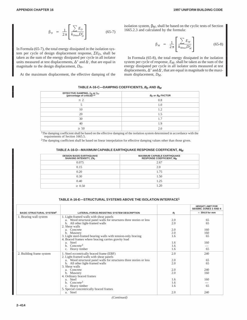
APPENDIX CHAPTER 16APPENDIX CHAPTER 16
1997 UNIFORM BUILDING CODE
2–414
�D �
12��
� ED
kDmaxD2D
� (65-7)
In Formula (65-7), the total energy dissipated in the isolation sys-tem per cycle of design displacement response, �ED, shall betaken as the sum of the energy dissipated per cycle in all isolatorunits measured at test displacements, ∆+ and ∆-, that are equal inmagnitude to the design displacement, DD.
At the maximum displacement, the effective damping of the
isolation system, βM, shall be based on the cyclic tests of Section1665.2.3 and calculated by the formula:
�M �
12��
� EM
kMmaxD2M
� (65-8)
In Formula (65-8), the total energy dissipated in the isolationsystem per cycle of response, EM, shall be taken as the sum of theenergy dissipated per cycle in all isolator units measured at testdisplacements, ∆+ and ∆-, that are equal in magnitude to the maxi-mum displacement, DM.
TABLE A-16-C—DAMPING COEFFICIENTS, BD AND BM
EFFECTIVE DAMPING, βD or βM(percentage of critical) 1,2 BD or BM FACTOR
� 2 0.8
5 1.0
10 1.2
20 1.5
30 1.7
40 1.9
� 50 2.01The damping coefficient shall be based on the effective damping of the isolation system determined in accordance with the
requirements of Section 1665.5.2The damping coefficient shall be based on linear interpolation for effective damping values other than those given.
TABLE A-16-D—MAXIMUM CAPABLE EARTHQUAKE RESPONSE COEFFICIENT, MM
DESIGN BASIS EARTHQUAKESHAKING INTENSITY, ZNv
MAXIMUM CAPABLE EARTHQUAKERESPONSE COEFFICIENT, MM
0.075 2.67
0.15 2.0
0.20 1.75
0.30 1.50
0.40 1.25
� 0.50 1.20
TABLE A-16-E—STRUCTURAL SYSTEMS ABOVE THE ISOLATION INTERFACE 1
HEIGHT LIMIT FORSEISMIC ZONES 3 AND 4
BASIC STRUCTURAL SYSTEM 2 LATERAL-FORCE-RESISTING SYSTEM DESCRIPTION RI � 304.8 for mm
1. Bearing wall system 1. Light-framed walls with shear panelsa. Wood structural panel walls for structures three stories or lessb. All other light-framed walls
2. Shear wallsa. Concreteb. Masonry
3. Light steel-framed bearing walls with tension-only bracing4. Braced frames where bracing carries gravity load
a. Steelb. Concrete3c. Heavy timber
2.02.0
2.02.01.6
1.61.61.6
6565
16016065
160—65
2. Building frame system 1. Steel eccentrically braced frame (EBF)2. Light-framed walls with shear panels
a. Wood structural panel walls for structures three stories or lessb. All other light-framed walls
3. Shear wallsa. Concreteb. Masonry
4. Ordinary braced framesa. Steelb. Concrete3c. Heavy timber
5. Special concentrically braced framesa. Steel
2.0
2.02.0
2.02.0
1.61.61.6
2.0
240
6565
240160
160—65
240
(Continued)
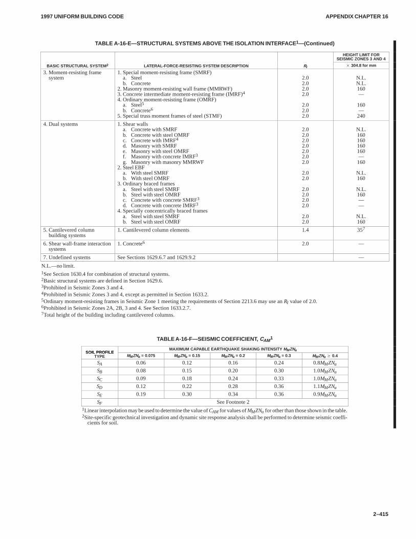
APPENDIX CHAPTER 16APPENDIX CHAPTER 16
1997 UNIFORM BUILDING CODE
2–415
TABLE A-16-E—STRUCTURAL SYSTEMS ABOVE THE ISOLATION INTERFACE 1—(Continued)
HEIGHT LIMIT FORSEISMIC ZONES 3 AND 4
BASIC STRUCTURAL SYSTEM 2 LATERAL-FORCE-RESISTING SYSTEM DESCRIPTION RI � 304.8 for mm
3. Moment-resisting framesystem
1. Special moment-resisting frame (SMRF)a. Steelb. Concrete
2. Masonry moment-resisting wall frame (MMRWF)3. Concrete intermediate moment-resisting frame (IMRF)4
4. Ordinary moment-resisting frame (OMRF)a. Steel5b. Concrete6
5. Special truss moment frames of steel (STMF)
2.02.02.02.0
2.02.02.0
N.L.N.L.160—
160—240
4. Dual systems 1. Shear wallsa. Concrete with SMRFb. Concrete with steel OMRFc. Concrete with IMRF4d. Masonry with SMRFe. Masonry with steel OMRFf. Masonry with concrete IMRF3g. Masonry with masonry MMRWF
2. Steel EBFa. With steel SMRFb. With steel OMRF
3. Ordinary braced framesa. Steel with steel SMRFb. Steel with steel OMRFc. Concrete with concrete SMRF3
d. Concrete with concrete IMRF3
4. Specially concentrically braced framesa. Steel with steel SMRFb. Steel with steel OMRF
2.02.02.02.02.02.02.0
2.02.0
2.02.02.02.0
2.02.0
N.L.160160160160—160
N.L.160
N.L.160——
N.L.160
5. Cantilevered columnbuilding systems
1. Cantilevered column elements 1.4 357
6. Shear wall-frame interactionsystems
1. Concrete6 2.0 —
7. Undefined systems See Sections 1629.6.7 and 1629.9.2 —
N.L.—no limit.1See Section 1630.4 for combination of structural systems.2Basic structural systems are defined in Section 1629.6.3Prohibited in Seismic Zones 3 and 4.4Prohibited in Seismic Zones 3 and 4, except as permitted in Section 1633.2.5Ordinary moment-resisting frames in Seismic Zone 1 meeting the requirements of Section 2213.6 may use an RI value of 2.0.6Prohibited in Seismic Zones 2A, 2B, 3 and 4. See Section 1633.2.7.7Total height of the building including cantilevered columns.
TABLE A-16-F—SEISMIC COEFFICIENT, CAM1
SOIL PROFILEMAXIMUM CAPABLE EARTHQUAKE SHAKING INTENSITY MMZNa
SOIL PROFILETYPE MMZNa = 0.075 MMZNa = 0.15 MMZNa = 0.2 MMZNa = 0.3 MMZNa � 0.4
SA 0.06 0.12 0.16 0.24 0.8MMZNa
SB 0.08 0.15 0.20 0.30 1.0MMZNa
SC 0.09 0.18 0.24 0.33 1.0MMZNa
SD 0.12 0.22 0.28 0.36 1.1MMZNa
SE 0.19 0.30 0.34 0.36 0.9MMZNa
SF See Footnote 21Linear interpolation may be used to determine the value of CAM for values of MMZNa for other than those shown in the table.2Site-specific geotechnical investigation and dynamic site response analysis shall be performed to determine seismic coeffi-
cients for soil.
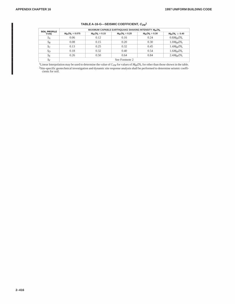
APPENDIX CHAPTER 16APPENDIX CHAPTER 16
1997 UNIFORM BUILDING CODE
2–416
TABLE A-16-G—SEISMIC COEFFICIENT, CVM1
SOIL PROFILEMAXIMUM CAPABLE EARTHQUAKE SHAKING INTENSITY MMZNv
SOIL PROFILETYPE MMZNv = 0.075 MMZNv = 0.15 MMZNv = 0.20 MMZNv = 0.30 MMZNv � 0.40
SA 0.06 0.12 0.16 0.24 0.8MMZNv
SB 0.08 0.15 0.20 0.30 1.0MMZNv
SC 0.13 0.25 0.32 0.45 1.4MMZNv
SD 0.18 0.32 0.40 0.54 1.6MMZNv
SE 0.26 0.50 0.64 0.84 2.4MMZNv
SF See Footnote 21Linear Interpolation may be used to determine the value of CVM for values of MMZNv for other than those shown in the table.2Site-specific geotechnical investigation and dynamic site response analysis shall be performed to determine seismic coeffi-
cients for soil.
APPENDIX CHAPTER 18APPENDIX CHAPTER 18
1997 UNIFORM BUILDING CODE
2–417
Appendix Chapter 18
WATERPROOFlNG AND DAMPPROOFlNG FOUNDATIONS
SECTION 1820 — SCOPE
Walls, or portions thereof, retaining earth and enclosing interiorspaces and floors below grade shall be waterproofed or damp-proofed according to this appendix chapter.
EXCEPTION: Walls enclosing crawl spaces.
SECTION 1821 — GROUNDWATER TABLEINVESTIGATION
A subsurface soils investigation shall be made in accordance withSection 1804.3, Item 3, to determine the possibility of the ground-water table rising above the proposed elevation of the floor orfloors below grade. The building official may require that this de-termination be made by an engineer or architect licensed by thestate to practice as such.
EXCEPTIONS: 1. When foundation waterproofing is provided. 2. When dampproofing is provided and the building official finds
that there is satisfactory data from adjacent areas to demonstrate thatgroundwater has not been a problem.
SECTION 1822 — DAMPPROOFING REQUIRED
Where the groundwater investigation required by Section 1821 in-dicates that a hydrostatic pressure caused by the water table willnot occur, floors and walls shall be dampproofed and a subsoildrainage system shall be installed in accordance with this appen-dix chapter.
EXCEPTION: Wood foundation systems shall be constructed inaccordance with Chapter 18, Division II.
SECTION 1823 — FLOOR DAMPPROOFING
1823.1 General.Dampproofing materials shall be installed be-tween the floor and base materials required by Section 1825.2.
EXCEPTION: Where a separate floor is provided above a con-crete slab, the dampproofing may be installed on top of the slab.
1823.2 Dampproofing Materials. Dampproofing installed be-neath the slab shall consist of not less than 6-mil (0.152 mm) poly-ethylene, or other approved methods or materials. Whenpermitted to be installed on top of the slab, dampproofing shallconsist of not less than 4-mil (0.1 mm) polyethylene, mopped-onbitumen or other approved methods or materials. Joints in mem-branes shall be lapped and sealed in an approved manner.
SECTION 1824 — WALL DAMPPROOFING
1824.1 General.Dampproofing materials shall be installed onthe exterior surface of walls, and shall extend from a point 6 inches(152 mm) above grade, down to the top of the spread portion of thefooting.
1824.2 Surface Preparation.Prior to application of damp-proofing materials on concrete walls, fins or sharp projections thatmay pierce the membrane shall be removed and all holes and re-cesses resulting from the removal of form ties shall be sealed witha dry-pack mortar, bituminous material, or other approved meth-ods or materials.
1824.3 Dampproofing Materials. Wall dampproofing shallconsist of a bituminous material, acrylic modified cement base
coating, any of the materials permitted for waterproofing in Sec-tion 1828.4, or other approved methods or materials. When suchmaterials are not approved for direct application to unit masonry,the wall shall be parged on the exterior surface below grade withnot less than 3/8 inch (9.5 mm) of portland cement mortar.
SECTION 1825 — OTHER DAMPPROOFINGREQUIREMENTS
1825.1 Subsoil Drainage System.When dampproofing is re-quired, a base material shall be installed under the floor and a drainshall be installed around the foundation perimeter in accordancewith this subsection.
EXCEPTION: When the finished ground level is below the floorlevel for more than 25 percent of the perimeter of the building, the basematerial required by Section 1825.2 need not be provided and the foun-dation drain required by Section 1825.3 need be provided only aroundthat portion of the building where the ground level is above the floorlevel.
1825.2 Base Material. Floors shall be placed over base materialnot less than 4 inches (102 mm) in thickness consisting of gravel orcrushed stone containing not more than 10 percent material thatpasses a No. 4 sieve (4.75 mm).
1825.3 Foundation Drain. The drain shall consist of gravel,crushed stone or drain tile.
Gravel or crushed stone drains shall contain not more than10 percent material that passes a No. 4 sieve (4.75 mm). The drainshall extend a minimum of 12 inches (305 mm) beyond the outsideedge of the footing. The depth shall be such that the bottom of thedrain is not higher than the bottom of the base material under thefloor, and the top of the drain is not less than 6 inches (152 mm)above the spread portion of the footing. The top of the drain shallbe covered with an approved filter membrane material.
When drain tile or perforated pipe is used, the invert of the pipeor tile shall be not higher than the floor elevation. The top of jointsor the top of perforations shall be protected with an approved filtermembrane material. The pipe or tile shall be placed on not lessthan 2 inches (51 mm) of gravel or crushed stone complying withthis section and covered with not less than 6 inches (152 mm) ofthe same material.
1825.4 Drainage Disposal.The floor base and foundation pe-rimeter drain shall discharge by gravity or mechanical means intoan approved drainage system.
EXCEPTION: Where a site is located in well-drained gravel orsand-gravel mixture soils, a dedicated drainage system need not be pro-vided.
SECTION 1826 — WATERPROOFING REQUIRED
Where the groundwater investigation required by Section 1821 in-dicates that a hydrostatic pressure caused by the water table doesexist, walls and floors shall be waterproofed in accordance withthis appendix chapter.
EXCEPTIONS: 1. When the groundwater table can be loweredand maintained at an elevation not less than 6 inches (152 mm) belowthe bottom of the lowest floor, dampproofing provisions in accordancewith Section 1822 may be used in lieu of waterproofing.
The design of the system to lower the groundwater table shall bebased on accepted principles of engineering which shall consider, butnot necessarily be limited to, the permeability of the soil, the rate at
Robert McCowan
APPENDIX CHAPTER 18APPENDIX CHAPTER 18
1997 UNIFORM BUILDING CODE
2–418
which water enters the drainage system, the rated capacity of pumps,the head against which pumps are to pump, and the rated capacity ofthe disposal area of the system.
2. Wood foundation systems constructed in accordance with Chap-ter 18, Division II, are to be provided with additional moisture-controlmeasures as specified in Section 1812.
SECTION 1827 — FLOOR WATERPROOFING
1827.1 General.Floors required to be waterproofed shall be ofconcrete designed to withstand anticipated hydrostatic pressure.
1827.2 Waterproofing Materials. Waterproofing of floorsshall be accomplished by placing under the slab a membrane ofrubberized asphalt, polymer-modified asphalt, butyl rubber, neo-prene, or not less than 6-mil (0.15 mm) polyvinyl chloride or poly-ethylene, or other approved materials capable of bridgingnonstructural cracks. Joints in the membrane shall be lapped notless than 6 inches (152 mm) and sealed in an approved manner.
SECTION 1828 — WALL WATERPROOFING
1828.1 General.Walls required to be waterproofed shall be ofconcrete or masonry designed to withstand the anticipated hydro-static pressure and other lateral loads.
1828.2 Wall Preparation. Prior to the application of water-proofing materials on concrete or masonry walls, the wall surfacesshall be prepared in accordance with Section 1824.2.
1828.3 Where Required. Waterproofing shall be applied from apoint 12 inches (305 mm) above the maximum elevation of thegroundwater table down to the top of the spread portion of thefooting. The remainder of the wall located below grade shall bedampproofed with materials in accordance with Section 1824.3.
1828.4 Waterproofing Materials. Waterproofing shall consistof rubberized asphalt, polymer-modified asphalt, butyl rubber, orother approved materials capable of bridging nonstructuralcracks. Joints in the membrane shall be lapped and sealed in an ap-proved manner.
1828.5 Joints.Joints in walls and floors, and between the walland floor, and penetrations of the wall and floor shall be made wa-tertight using approved methods and materials.
SECTION 1829 — OTHER DAMPPROOFING ANDWATERPROOFING REQUIREMENTS
1829.1 Placement of Backfill. The excavation outside the foun-dation shall be backfilled with soil which is free of organic ma-terial, construction debris and large rocks. The backfill shall beplaced in lifts and compacted in a manner which does not damagethe waterproofing or dampproofing material or structurally dam-age the wall.
1829.2 Site Grading.The ground immediately adjacent to thefoundation shall be sloped away from the building at not less than1 unit vertical in 12 units horizontal (8.3% slope) for a minimumdistance of 6 feet (1829 mm) measured perpendicular to the faceof the wall or an approved alternate method of diverting wateraway from the foundation shall be used. Consideration shall begiven to possible additional settlement of the backfill when estab-lishing final ground level adjacent to the foundation.
1829.3 Erosion Protection.Where water impacts the groundfrom the edge of the roof, downspout, scupper, valley, or otherrainwater collection or diversion device, provisions shall be usedto prevent soil erosion and direct the water away from the founda-tion.
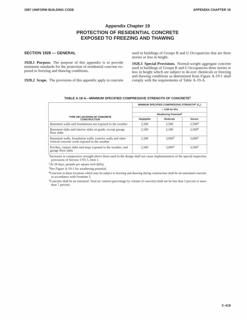
APPENDIX CHAPTER 19APPENDIX CHAPTER 19
1997 UNIFORM BUILDING CODE
2–419
Appendix Chapter 19
PROTECTION OF RESIDENTIAL CONCRETEEXPOSED TO FREEZING AND THAWING
SECTION 1928 — GENERAL
1928.1 Purpose.The purpose of this appendix is to provideminimum standards for the protection of residential concrete ex-posed to freezing and thawing conditions.
1928.2 Scope.The provisions of this appendix apply to concrete
used in buildings of Groups R and U Occupancies that are threestories or less in height.
1928.3 Special Provisions.Normal-weight aggregate concreteused in buildings of Groups R and U Occupancies three stories orless in height which are subject to de-icer chemicals or freezingand thawing conditions as determined from Figure A-19-1 shallcomply with the requirements of Table A-19-A.
TABLE A-19-A—MINIMUM SPECIFIED COMPRESSIVE STRENGTH OF CONCRETE1
MINIMUM SPECIFIED COMPRESSIVE STRENGTH2 (f’c )
� 6.89 for kPa
TYPE OR LOCATION OF CONCRETEWeathering Potential 3
TYPE OR LOCATION OF CONCRETECONSTRUCTION Negligible Moderate Severe
Basement walls and foundations not exposed to the weather 2,500 2,500 2,5004
Basement slabs and interior slabs on grade, except garagefloor slabs
2,500 2,500 2,5004
Basement walls, foundation walls, exterior walls and othervertical concrete work exposed to the weather
2,500 53,0005 3,0005
Porches, carport slabs and steps exposed to the weather, andgarage floor slabs
2,500 53,0005 3,5005
1Increases in compressive strength above those used in the design shall not cause implementation of the special inspectionprovisions of Section 1701.5, Item 1.
2At 28 days, pounds per square inch (kPa).3See Figure A-19-1 for weathering potential.4Concrete in these locations which may be subject to freezing and thawing during construction shall be air-entrained concrete
in accordance with Footnote 5.5Concrete shall be air entrained. Total air content (percentage by volume of concrete) shall not be less than 5 percent or more
than 7 percent.
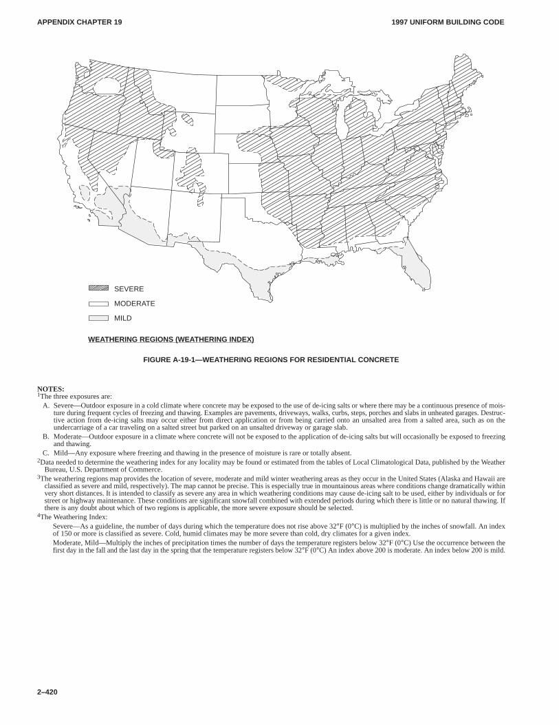
APPENDIX CHAPTER 19APPENDIX CHAPTER 19
1997 UNIFORM BUILDING CODE
2–420
WEATHERING REGIONS (WEATHERING INDEX)
SEVERE
MODERATE
MILD
FIGURE A-19-1—WEATHERING REGIONS FOR RESIDENTIAL CONCRETE
NOTES:1The three exposures are:
A. Severe—Outdoor exposure in a cold climate where concrete may be exposed to the use of de-icing salts or where there may be a continuous presence of mois-ture during frequent cycles of freezing and thawing. Examples are pavements, driveways, walks, curbs, steps, porches and slabs in unheated garages. Destruc-tive action from de-icing salts may occur either from direct application or from being carried onto an unsalted area from a salted area, such as on theundercarriage of a car traveling on a salted street but parked on an unsalted driveway or garage slab.
B. Moderate—Outdoor exposure in a climate where concrete will not be exposed to the application of de-icing salts but will occasionally be exposed to freezingand thawing.
C. Mild—Any exposure where freezing and thawing in the presence of moisture is rare or totally absent.2Data needed to determine the weathering index for any locality may be found or estimated from the tables of Local Climatological Data, published by the Weather
Bureau, U.S. Department of Commerce.3The weathering regions map provides the location of severe, moderate and mild winter weathering areas as they occur in the United States (Alaska and Hawaii are
classified as severe and mild, respectively). The map cannot be precise. This is especially true in mountainous areas where conditions change dramatically withinvery short distances. It is intended to classify as severe any area in which weathering conditions may cause de-icing salt to be used, either by individuals or forstreet or highway maintenance. These conditions are significant snowfall combined with extended periods during which there is little or no natural thawing. Ifthere is any doubt about which of two regions is applicable, the more severe exposure should be selected.
4The Weathering Index:Severe—As a guideline, the number of days during which the temperature does not rise above 32°F (0°C) is multiplied by the inches of snowfall. An indexof 150 or more is classified as severe. Cold, humid climates may be more severe than cold, dry climates for a given index.Moderate, Mild—Multiply the inches of precipitation times the number of days the temperature registers below 32°F (0°C) Use the occurrence between thefirst day in the fall and the last day in the spring that the temperature registers below 32°F (0°C) An index above 200 is moderate. An index below 200 is mild.
APPENDIX CHAPTER 21APPENDIX CHAPTER 21
1997 UNIFORM BUILDING CODE
2–421
Appendix Chapter 21
PRESCRIPTIVE MASONRY CONSTRUCTION IN HIGH-WIND AREAS
SECTION 2112 — GENERAL
2112.1 Purpose.The provisions of this chapter are intended topromote public safety and welfare by reducing the risk of wind-induced damages to masonry construction.
2112.2 Scope.The requirements of this chapter shall apply tomasonry construction in buildings when all of the following con-ditions are met:
1. The building is located in an area with a basic wind speedfrom 80 through 110 miles per hour (mph) (129 km/h through 177km/h).
2. The building is located in Seismic Zone 0, 1 or 2.
3. The building does not exceed two stories.
4. Floor and roof joists shall be wood or steel or of precast hol-lowcore concrete planks with a maximum span of 32 feet (9754mm) between bearing walls. Masonry walls shall be provided forthe support of steel joists or concrete planks.
5. The building is of regular shape.
2112.3 General.The requirements of Chapter 21 are applicableexcept as specifically modified by this chapter. Other methodsmay be used provided a satisfactory design is submitted showingcompliance with the provisions of Chapter 16, Part II, and otherapplicable provisions of this code.
Wood floor, roof and interior walls shall be constructed as speci-fied in Appendix Chapter 23 and as further regulated in this sec-tion.
In areas where the wind speed exceeds 110 mph (177 km/h),masonry buildings shall be designed in accordance with Chapter16, Part II, and other applicable provisions of this code.
Buildings of unusual shape or size, or split-level construction,shall be designed in accordance with Chapter 16, Part II, and otherapplicable provisions of this code.
In addition to the other provisions of this chapter, foundationsfor buildings in areas subject to wave action or tidal surge shall bedesigned in accordance with approved national standards.
All metal connectors and fasteners used in exposed locations orin areas otherwise subject to corrosion shall be of corrosion-resistant or noncorrosive material. When the terms “corrosionresistant” or “noncorrosive” are used in this chapter, they shallmean having a corrosion resistance equal to or greater than ahot-dipped galvanized coating of 1.5 ounces of zinc per squarefoot (3.95 g/m2) of surface area. When an element is required to becorrosion resistant or noncorrosive, all of its parts, such as screws,nails, wire, dowels, bolts, nuts, washers, shims, anchors, ties andattachments, shall be corrosion resistant.
2112.4 Materials.
2112.4.1 General.All masonry materials shall comply withSection 2102.2 as applicable for standards of quality.
2112.4.2 Hollow-unit masonry.
1. Exterior concrete block shall be a minimum of Grade N-IIwith a compressive strength of not less than 1,900 pounds persquare inch (psi) (13 091 kPa) on the net area.
2. Interior concrete block shall be a minimum of Grade S-IIwith a compressive strength of not less than 700 psi (4823 kPa) onthe gross area.
3. Exterior clay or shale hollow brick shall have a compressivestrength of not less than 2,500 psi (17 225 kPa) on the net area.Such hollow brick shall be at least Grade MW except that wheresubject to severe freezing it shall be Grade SW.
4. Interior clay or shale hollow brick shall be Grade MW with acompressive strength of 2,000 psi (13 780 kPa) on the net area.
2112.4.3 Solid masonry.
1. Exterior clay or shale bricks shall have a compressivestrength of not less than 2,500 psi (17 225 kPa) on the net area.
2. Exterior clay or shale bricks shall be Grade MW, except thatwhere subject to severe freezing they shall be Grade SW.
3. Interior clay or shale bricks shall have a compressivestrength of not less than 2,000 psi (13 780 kPa).
2112.4.4 Grout. Grout shall achieve a compressive strength ofnot less than 2,000 psi (13 780 kPa).
2112.4.5 Mortar. Mortar for exterior walls and for interior shearwalls shall be Type M or Type S.
2112.5 Construction Requirements.Grouted cavity wall andblock wall construction shall comply with Section 2104.
Unburned clay masonry and stone masonry shall not be used.
2112.6 Foundations.Footings shall have a thickness of not lessthan 8 inches (203 mm) and shall comply with Tables A-21-A-1and A-21-A-2 for width. See Figure A-21-1 for other applicabledetails.
Footings shall extend 18 inches (457 mm) below the undis-turbed ground surface or the frost depth, whichever is deeper.
Foundation stem walls shall be as wide as the wall they support.They shall be reinforced with reinforcing bar sizes and spacing tomatch the reinforcement of the walls they support.
Basement and other below-grade walls shall comply with TableA-21-B.
2112.7 Drainage.Basement walls and other walls or portionsthereof retaining more than 3 feet (914 mm) of earth and enclosinginterior spaces or floors below grade shall have a minimum4-inch-diameter (102 mm) footing drain as illustrated in TableA-21-B and Figure A-21-3.
The finish elevations around the building shall be graded to pro-vide a slope away from the building of not less than 1/4 unit verticalin 12 units horizontal (2% slope).
2112.8 Wall Construction.
2112.8.1 Minimum thickness.Reinforced exterior bearingwalls shall have a minimum 8-inch (203 mm) nominal thickness.Interior masonry nonbearing walls shall have a minimum 6-inch(152 mm) nominal thickness. Unreinforced grouted brick wallsshall have a minimum 10-inch (254 mm) thickness. Unreinforcedhollow-unit and solid masonry shall have a minimum 8-inch (203mm) nominal thickness.
EXCEPTION: In buildings not more than two stories or 26 feet(7924.8 mm) in height, masonry walls may be of 8-inch (203 mm)nominal thickness. Solid masonry walls in one-story buildings may beof 6-inch (152 mm) nominal thickness when not over 9 feet (2743 mm)
APPENDIX CHAPTER 21APPENDIX CHAPTER 21
1997 UNIFORM BUILDING CODE
2–422
in height, provided that when gable construction is used an additional6 feet (1829 mm) are permitted to the peak of the gable.
2112.8.2 Lateral support and height.All walls shall be later-ally supported at the top and bottom. The maximum unsupportedheight of bearing walls or other masonry walls shall be 12 feet(3658 mm). Gable-end walls may be 15 feet (4572 mm) at theirpeak.
Wood-framed gable-end walls on buildings shall comply withTable A-21-I and Figure A-21-17 or A-21-18.
2112.8.3 Walls in Seismic Zone 2 and use of stack bond.InSeismic Zone 2, walls shall comply with Figure A-21-2 as a mini-mum. Walls with stack bond shall be designed.
2112.8.4 Lintels. The span of lintels over openings shall not ex-ceed 12 feet (3658 mm), and lintels shall be reinforced. The re-inforcement bars shall extend not less than 2 feet (610 mm)beyond the edge of opening and into lintel supports.
Lintel reinforcement shall be within fully grouted cells inaccordance with Table A-21-E.
2112.8.5 Reinforcement.Walls shall be reinforced as shown inTables A-21-C-1 through A-21-C-5 and Figure A-21-2.
2112.8.6 Anchorage of walls to floors and roofs.Anchors be-tween walls and floors or roofs shall be embedded in grouted cellsor cavities and shall conform to Section 2112.9.
2112.9 Floor and Roof Systems.The anchorage of wood roofsystems which are supported by masonry walls shall comply withAppendix Sections 2337.5.1 and 2337.5.8, Table A-21-D and Fig-ure A-21-7.
Wood roof and floor systems which are supported by ledgers atthe inside face of masonry walls shall comply with Table A-21-D,Part I.
The ends of joist girders shall extend a distance of not less than6 inches (152 mm) over masonry or concrete supports and be at-tached to a steel bearing plate. This plate is to be located not morethan 1/2 inch (12.7 mm) from the face of the wall and is to be notless than 9 inches (229 mm) wide perpendicular to the length of thejoist girder. Ends of joist girders resting on steel bearing plates onmasonry or structural concrete shall be attached thereto with aminimum of two 1/4-inch (6.4 mm) fillet welds 2 inches (51 mm)long, or with two 3/4-inch (19 mm) bolts.
Ends of joist girders resting on steel supports shall be connectedthereto with a minimum of two 1/4-inch (6.4 mm) fillet welds 2 in-ches (51 mm) long, or with two 3/4-inch (19 mm) bolts. In steelframes, joist girders at column lines shall be field bolted to the col-umns to provide lateral stability during construction.
Steel joist roof and floor systems shall be anchored in accord-ance with Table A-21-H.
Wall ties spaced as shown in Table A-21-D, Part II, shall con-nect to framing or blocking at roofs and walls. Wall ties shall entergrouted cells or cavities and shall be 11/8-inch (29 mm) minimumwidth by 0.036 inch (0.91 mm) (No. 20 galvanized sheet gage)sheet steel.
Roof and floor hollow-core precast plank systems shall be an-chored in accordance with Table A-21-G.
Roof uplift anchorage shall enter a grouted bond beam re-inforced with horizontal bars as shown in Tables A-21-C-1through A-21-C-5 and Figure A-21-7.
2112.10 Lateral Force Resistance.
2112.10.1 Complete load path and uplift resistance.Strap-ping, approved framing anchors, and mechanical fasteners, bondbeams, and vertical reinforcement shall be installed to provide acontinuous tie from the roof to the foundation system. (See FigureA-21-8.) In addition, roof and floor systems, masonry shear walls,or masonry or wood cross walls shall provide lateral stability.
2112.10.2 Floor and roof diaphragms.Floor and roof dia-phragms shall be connected to masonry walls as shown in TableA-21-F, Part II.
Gabled and sloped roof members not supported at the ridgeshall be tied by ceiling joists or equivalent lateral ties located asclose to where the roof member bears on the wall as is practicallypossible, at not more than 48 inches (1219 mm) on center. Collarties shall not be used for these lateral ties. (See Figure A-21-17 andTable A-21-I.)
2112.10.3 Walls.Masonry walls shall be provided around allsides of floor and roof systems in accordance with Figure A-21-9and Table A-21-F.
The cumulative length of exterior masonry walls along eachside of the floor or roof systems shall be at least 20 percent of theparallel dimension. Required elements shall be without openingsand shall not be less than 48 inches (1219 mm) in width.
Interior cross walls (nonbearing) at right angles to bearing wallsshall be provided when the length of the building perpendicular tothe span of the floor or roof framing exceeds twice the distance be-tween shear walls or 32 feet (9754 mm), whichever is greater.Cross walls, when required, shall conform to Section 2112.10.4.
2112.10.4 Interior cross walls.When required by TableA-21-F, Part I, masonry walls shall be at least 6 feet (1829 mm)long and reinforced with 9 gage wire joint reinforcement spacednot more than 16 inches (406 mm) on center. Cross walls shallcomply with Footnote 3 of Table A-21-F, Part I.
Interior wood stud walls may be used to resist the wind loadfrom one-story masonry buildings in areas where the basic windspeed is 100 mph (161 km/h), Exposure C or less, and 110 mph(177 km/h), Exposure B. When wood stud walls are so used, theyshall:
1. Be perpendicular to exterior masonry walls at 15 feet (4572mm) or less on center.
2. Be at least 8 feet (2438 mm) long without openings and besheathed on at least one side with 15/32-inch (12 mm) wood struc-tural panel nailed with 8d common or galvanized box nails at 6 in-ches (152 mm) on center edge and field nailing. All unsupportededges of wood structural panels shall be blocked.
3. Be connected to wood blocking or wood joists below withtwo 16d nails at 16 inches (406 mm) on center through their sillplates. They shall be connected to footings with 1/2-inch-diameter(12.7 mm) bolts at 3 feet 6 inches (1067 mm) on center.
4. Connect to wood roof systems as outlined in Table A-21-F,Part II, as a cross wall. Wood structural panel roof sheathing shallhave all unsupported edges blocked.
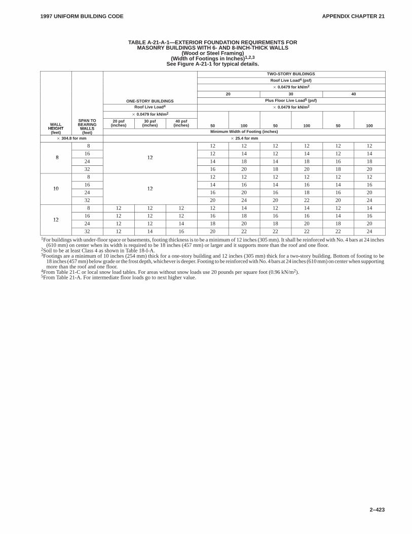
APPENDIX CHAPTER 21APPENDIX CHAPTER 21
1997 UNIFORM BUILDING CODE
2–423
TABLE A-21-A-1—EXTERIOR FOUNDATION REQUIREMENTS FORMASONRY BUILDINGS WITH 6- AND 8-INCH-THICK WALLS
(Wood or Steel Framing)(Width of Footings in Inches) 1,2,3
See Figure A-21-1 for typical details.
TWO-STORY BUILDINGS
Roof Live Load 4 (psf)
� 0.0479 for kN/m 2
20 30 40
ONE-STORY BUILDINGS Plus Floor Live Load 5 (psf)
Roof Live Load 4� 0.0479 for kN/m 2
� 0.0479 for kN/m 2
WALLHEIGHT
SPAN TOBEARING
WALLS
20 psf(inches)
30 psf(inches)
40 psf(inches) 50 100 50 100 50 100
HEIGHT(feet)
WALLS(feet) Minimum Width of Footing (inches)
� 304.8 for mm � 25.4 for mm
8 12 12 12 12 12 12
816
1212 14 12 14 12 14
824
1214 18 14 18 16 18
32 16 20 18 20 18 20
8 12 12 12 12 12 12
1016
1214 16 14 16 14 16
1024
1216 20 16 18 16 20
32 20 24 20 22 20 24
8 12 12 12 12 14 12 14 12 14
1216 12 12 12 16 18 16 16 14 16
1224 12 12 14 18 20 18 20 18 20
32 12 14 16 20 22 22 22 22 241For buildings with under-floor space or basements, footing thickness is to be a minimum of 12 inches (305 mm). It shall be reinforced with No. 4 bars at 24 inches
(610 mm) on center when its width is required to be 18 inches (457 mm) or larger and it supports more than the roof and one floor.2Soil to be at least Class 4 as shown in Table 18-I-A.3Footings are a minimum of 10 inches (254 mm) thick for a one-story building and 12 inches (305 mm) thick for a two-story building. Bottom of footing to be
18 inches (457 mm) below grade or the frost depth, whichever is deeper. Footing to be reinforced with No. 4 bars at 24 inches (610 mm) on center when supportingmore than the roof and one floor.
4From Table 21-C or local snow load tables. For areas without snow loads use 20 pounds per square foot (0.96 kN/m2).5From Table 21-A. For intermediate floor loads go to next higher value.
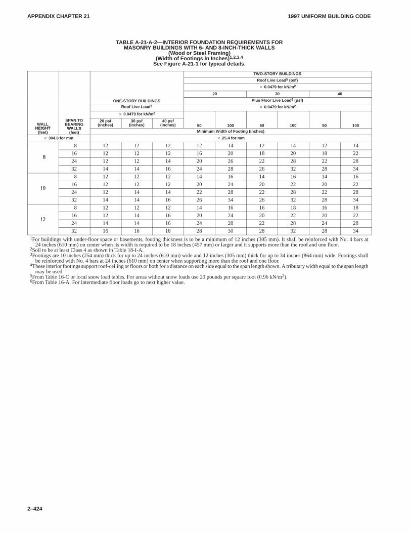
APPENDIX CHAPTER 21APPENDIX CHAPTER 21
1997 UNIFORM BUILDING CODE
2–424
TABLE A-21-A-2—INTERIOR FOUNDATION REQUIREMENTS FORMASONRY BUILDINGS WITH 6- AND 8-INCH-THICK WALLS
(Wood or Steel Framing)(Width of Footings in Inches) 1,2,3,4
See Figure A-21-1 for typical details.
TWO-STORY BUILDINGS
Roof Live Load 5 (psf)
� 0.0479 for kN/m 2
20 30 40
ONE-STORY BUILDINGS Plus Floor Live Load 6 (psf)
Roof Live Load 5� 0.0479 for kN/m 2
� 0.0479 for kN/m 2
WALLHEIGHT
SPAN TOBEARING
WALLS
20 psf(inches)
30 psf(inches)
40 psf(inches) 50 100 50 100 50 100
HEIGHT(feet)
WALLS(feet) Minimum Width of Footing (inches)
� 304.8 for mm � 25.4 for mm
8 12 12 12 12 14 12 14 12 14
816 12 12 12 16 20 18 20 18 22
824 12 12 14 20 26 22 28 22 28
32 14 14 16 24 28 26 32 28 34
8 12 12 12 14 16 14 16 14 16
1016 12 12 12 20 24 20 22 20 22
1024 12 14 14 22 28 22 28 22 28
32 14 14 16 26 34 26 32 28 34
8 12 12 12 14 16 16 18 16 18
1216 12 14 16 20 24 20 22 20 22
1224 14 14 16 24 28 22 28 24 28
32 16 16 18 28 30 28 32 28 341For buildings with under-floor space or basements, footing thickness is to be a minimum of 12 inches (305 mm). It shall be reinforced with No. 4 bars at
24 inches (610 mm) on center when its width is required to be 18 inches (457 mm) or larger and it supports more than the roof and one floor.2Soil to be at least Class 4 as shown in Table 18-I-A.3Footings are 10 inches (254 mm) thick for up to 24 inches (610 mm) wide and 12 inches (305 mm) thick for up to 34 inches (864 mm) wide. Footings shall
be reinforced with No. 4 bars at 24 inches (610 mm) on center when supporting more than the roof and one floor.4These interior footings support roof-ceiling or floors or both for a distance on each side equal to the span length shown. A tributary width equal to the span length
may be used.5From Table 16-C or local snow load tables. For areas without snow loads use 20 pounds per square foot (0.96 kN/m2).6From Table 16-A. For intermediate floor loads go to next higher value.
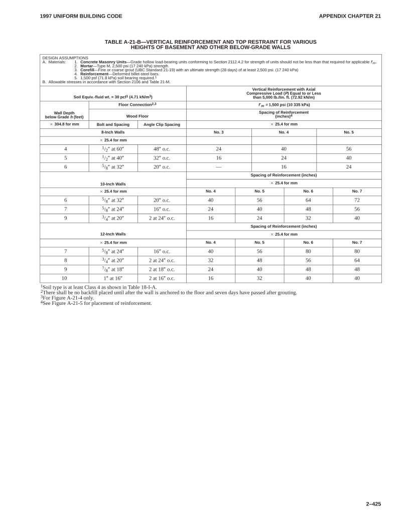
APPENDIX CHAPTER 21APPENDIX CHAPTER 21
1997 UNIFORM BUILDING CODE
2–425
TABLE A-21-B—VERTICAL REINFORCEMENT AND TOP RESTRAINT FOR VARIOUSHEIGHTS OF BASEMENT AND OTHER BELOW-GRADE WALLS
DESIGN ASSUMPTIONSA. Materials: 1. Concrete Masonry Units —Grade hollow load-bearing units conforming to Section 2112.4.2 for strength of units should not be less than that required for applicable f′m.
2. Mortar —Type M, 2,500 psi (17 240 kPa) strength.3. Corefill —Fine or coarse grout (UBC Standard 21-19) with an ultimate strength (28 days) of at least 2,500 psi. (17 240 kPa)4. Reinforcement —Deformed billet-steel bars.5. 1,500 psf (71.8 kPa) soil bearing required.1
B. Allowable stresses in accordance with Section 2106 and Table 21-M.
Soil Equiv.-fluid wt. = 30 pcf 1 (4.71 kN/m3)
Vertical Reinforcement with AxialCompressive Load ( P) Equal to or Less
than 5,000 lb./lin. ft. (72.92 kN/m)
Floor Connection 2,3 f ′m = 1,500 psi (10 335 kPa)
Wall Depthbelow Grade h (feet) Wood Floor
Spacing of Reinforcement(inches) 4
� 304.8 for mm Bolt and Spacing Angle Clip Spacing � 25.4 for mm
8-Inch Walls No. 3 No. 4 No. 5
� 25.4 for mm
4 1/2″ at 60″ 48″ o.c. 24 40 56
5 1/2″ at 40″ 32″ o.c. 16 24 40
6 5/8″ at 32″ 20″ o.c. — 16 24
Spacing of Reinforcement (inches)
10-Inch Walls � 25.4 for mm
� 25.4 for mm No. 4 No. 5 No. 6 No. 7
6 5/8″ at 32″ 20″ o.c. 40 56 64 72
7 5/8″ at 24″ 16″ o.c. 24 40 48 56
9 3/4″ at 20″ 2 at 24″ o.c. 16 24 32 40
Spacing of Reinforcement (inches)
12-Inch Walls � 25.4 for mm
� 25.4 for mm No. 4 No. 5 No. 6 No. 7
7 5/8″ at 24″ 16″ o.c. 40 56 80 80
8 3/4″ at 20″ 2 at 24″ o.c. 32 48 56 64
9 7/8″ at 18″ 2 at 18″ o.c. 24 40 48 48
10 1″ at 16″ 2 at 16″ o.c. 16 32 40 40
1Soil type is at least Class 4 as shown in Table 18-I-A.2There shall be no backfill placed until after the wall is anchored to the floor and seven days have passed after grouting.3For Figure A-21-4 only.4See Figure A-21-5 for placement of reinforcement.
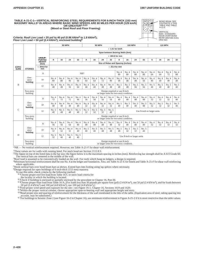
APPENDIX CHAPTER 21APPENDIX CHAPTER 21
1997 UNIFORM BUILDING CODE
2–426
TABLE A-21-C-1—VERTICAL REINFORCING STEEL REQUIREMENTS FOR 6-INCH-THICK (153 mm)MASONRY WALLS 1 IN AREAS WHERE BASIC WIND SPEEDS ARE 80 MILES PER HOUR (129 km/h)
OR GREATER2,3,4,5
(Wood or Steel Roof and Floor Framing)
Criteria: Roof Live Load = 20 psf to 40 psf (0.96 kN/m 2 to 1.9 kN/m 2);Floor Live Load = 50 psf (2.4 kN/m 2); enclosed building 6
80 MPH 90 MPH 100 MPH 110 MPH
� 1.61 for km/h
Span between Bearing Walls (feet)
UNSUP-� 304.8 for mm
UNSUP-PORTEDHEIGHT
8 16 24 32 8 16 24 32 8 16 24 32 8 16 24 32PORTEDHEIGHT
(feet) Size of Rebar and Spacing (inches)
EXPO-SURE STORIES
� 304.8 formm
� 25.4 for mm
8 NR* No. 480
No. 480
No. 480
No. 480
No. 464
No. 464
No. 472
No. 488
One-story
building10 No. 4
80No. 4
88No. 4
96No. 4
96No. 4
64No. 4
64No. 4
72No. 4
80No. 4
48No. 4
48No. 4
48No. 4
56No. 4
40No. 4
40No. 4
40No. 4
48
Bbuilding
12 No. 448
No. 448
No. 456
No. 464
No. 440
No. 440
No. 448
No. 448
No. 548
No. 548
No. 556
No. 556
No. 540
No. 540
No. 540
No. 540
Two-storybuilding
Design required or use 8-inchor larger units for two-story condition.
8 No. 472
No. 472
No. 472
No. 496
No. 456
No. 456
No. 456
No. 456
No. 440
No. 440
No. 448
No. 448
No. 432
No. 432
No. 432
No. 440
One-story
building10 No. 4
40No. 4
40No. 4
40No. 4
48No. 4
32No. 4
32No. 4
32No. 4
32No. 5
40No. 5
40No. 5
40No. 5
48No. 5
32No. 5
32No. 5
32No. 5
40
Cbuilding
12 No. 540
No. 548
No. 548
No. 548
No. 532
No. 532
No. 532
No. 540 Use 8-inch or larger units
Two-storybuilding
Design required or use 8-inchor larger units for two-story condition.
8 No. 456
No. 456
No. 464
No. 480
No. 448
No. 448
No. 448
No. 448
No. 432
No. 440
No. 440
No. 440
No. 432
No. 432
No. 432
No. 432
One-story
building10 No. 4
32No. 4
32No. 4
32No. 4
40No. 5
40No. 5
40No. 5
48No. 5
48No. 5
48No. 5
32No. 5
32No. 5
40
Dbuilding
12 No. 532
No. 540
No. 540
No. 540 Use 8-inch or larger units
Two-storybuilding
Design required or use 8-inchor larger units for two-story condition.
*NR — No vertical reinforcement required. However, see Table A-21-F for shear wall reinforcement.1These values are for walls with running bond. For stack bond see Section 2112.8.3.2The figure on top of the listed data is the bar size; the figure below it is the maximum spacing in inches (mm). Reinforcing bar strength shall be A 615 Grade 60.
The vertical bars are centered in the middle of the wall.3Roof load is assumed to be concentrically loaded on the wall. For roofs which hang on ledgers, a design is required.4Minimum horizontal reinforcement shall be one No. 4 at the ledger and foundation. Also, see Table A-21-E for lintels and Table A-21-F for shear wall reinforcing
where applicable.5Hook vertical bars over bond beam bars as shown. Extend bars into footing using lap splices where necessary.6Design required for open buildings of 6-inch-thick (153 mm) masonry.
To use this table, check criteria by the following method:6.1Choose proper roof live load from Table 16-C or snow load criteria for
the locality in which the building is located.6.2Check if building is enclosed or partially enclosed by the procedure in Chapter 16, Part III.6.3Choose proper floor load from Table 16-A. [For loads less than 50 pounds per square foot (psf) (2.4 kN/m2), use 50 psf (2.4 kN/m2), and for loads between
50 psf (2.4 kN/m2) and 100 psf (4.8 kN/m2), use 100 psf (4.8 kN/m2).]6.4Find proper wind speed and exposure for the site—see Figure 16-1, Chapter 16, Sections 1619 and 1620.6.5Within the proper vertical column, choose appropriate span-to-bearing wall and appropriate height and story.6.6Read proper size and spacing of reinforcement for the thickness of the wall mentioned in the title of the table. (Equivalent area of steel, taking spacing into
account, may be substituted.)6.7For buildings in Seismic Zone 2 (see Figure 16-2 in Chapter 16), use minimum reinforcement in Figure A-21-2 if it is more restrictive than the table values.
BOND BEAM. SEEFOOTNOTE 4 THISTABLE AND TABLEA-21-E
VERTICALBAR STANDARDHOOK OVER BONDBEAM (alternate everyother bar)
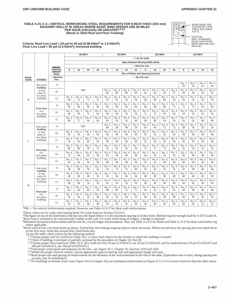
APPENDIX CHAPTER 21APPENDIX CHAPTER 21
1997 UNIFORM BUILDING CODE
2–427
TABLE A-21-C-2—VERTICAL REINFORCING STEEL REQUIREMENTS FOR 8-INCH-THICK (203 mm)MASONRY WALLS 1 IN AREAS WHERE BASIC WIND SPEEDS ARE 80 MILES
PER HOUR (129 km/h) OR GREATER 2,3,4,5
(Wood or Steel Roof and Floor Framing)
Criteria: Roof Live Load = 20 psf to 40 psf (0.96 kN/m 2 to 1.9 kN/m 2);Floor Live Load = 50 psf (2.4 kN/m 2); enclosed building
80 MPH 90 MPH 100 MPH 110 MPH
� 1.61 for km/h
Span between Bearing Walls (feet)
UNSUP-� 304.8 for mm
UNSUP-PORTEDHEIGHT
8 16 24 32 8 16 24 32 8 16 24 32 8 16 24 32HEIGHT
(feet) Size of Rebar and Spacing (inches)
EXPO-SURE STORIES
� 304.8 formm
� 25.4 for mm
One-storybuilding
8 No. 356
No. 356
No. 364
No. 364
buildingor top
story oft t
10 NR* No. 480
No. 480
No. 488
No. 488
No. 464
No. 464
No. 464
No. 472
No. 448
No. 448
No. 456
No. 456
B
ytwo-storybuilding 12 No. 4
64No. 4
72No. 4
72No. 4
72No. 4
56No. 4
56No. 4
56No. 4
56No. 4
40No. 4
40No. 5
64No. 5
64No. 5
56No. 5
56No. 5
56No. 5
56
First story8 No. 3
96No. 3
96No. 3
96No. 3
96No. 3
96No. 3
96No. 3
96No. 3
96No. 3
96No. 3
88No. 3
80No. 3
72No. 3
72No. 3
72No. 3
64No. 3
64First story
of atwo-storybuilding
10 No. 388
No. 380
No. 372
No. 364
No. 364
No. 364
No. 356
No. 356
No. 472
No. 472
No. 464
No. 464
No. 464
No. 456
No. 456
No. 456y
building12 No. 4
80No. 4
72No. 4
64No. 4
64No. 4
64No. 4
56No. 4
56No. 4
48No. 4
48No. 4
48No. 5
64No. 5
56No. 5
56No. 5
56No. 5
48No. 5
48
One-storybuilding
8 NR* No. 348
No. 348
No. 348
No. 356
No. 464
No. 464
No. 472
No. 472
No. 448
No. 456
No. 456
No. 456
buildingor top
story oft t
10 No. 456
No. 456
No. 464
No. 464
No. 448
No. 448
No. 448
No. 448
No. 556
No. 556
No. 556
No. 556
No. 548
No. 548
No. 548
No. 548
C
ytwo-storybuilding 12 No. 5
56No. 5
64No. 5
64No. 5
64No. 5
48No. 5
48No. 5
48No. 5
48No. 6
56No. 6
56No. 6
56No. 6
56No. 6
40No. 6
40No. 6
40No. 6
48
First story8 No. 3
80No. 3
80No. 3
56No. 3
72No. 3
56No. 3
56No. 3
56No. 3
56No. 4
72No. 4
72No. 4
72No. 4
64No. 4
56No. 4
56No. 4
56No. 4
56First story
of atwo-storybuilding
10 No. 472
No. 464
No. 464
No. 456
No. 456
No. 448
No. 448
No. 448
No. 564
No. 556
No. 556
No. 556
No. 548
No. 548
No. 548
No. 548y
building12 No. 5
64No. 5
64No. 5
56No. 5
56No. 5
48No. 5
48No. 5
48No. 5
48No. 6
56No. 6
56No. 6
48No. 6
48No. 6
48No. 6
40No. 6
40No. 6
40
One-storybuilding
8 No. 348
No. 348
No. 356
No. 356
No. 464
No. 472
No. 472
No. 480
No. 456
No. 456
No. 456
No. 456
No. 440
No. 448
No. 448
No. 448
buildingor top
story oft t
10 No. 448
No. 448
No 448
No. 456
No. 556
No. 564
No. 564
No. 564
No. 548
No. 548
No. 548
No. 548
No. 540
No. 540
No. 540
No. 540
D
ytwo-storybuilding 12 No. 5
48No. 5
48No. 5
56No. 5
56No. 6
56No. 6
56No. 6
56No. 6
56No. 6
48No. 6
48No .6
48No. 6
48No. 6
40No. 6
40No. 6
40No. 6
40D
First story8 No. 3
64No. 3
64No. 3
64No. 3
56No. 4
80No. 4
80No. 4
72No. 4
72No. 4
64No. 4
56No. 4
56No. 4
56No. 4
48No. 4
48No. 4
48No. 4
48First story
of atwo-storybuilding
10 No. 456
No. 456
No. 456
No. 448
No. 448
No. 564
No. 564
No. 556
No. 548
No. 548
No. 548
No. 548
No. 540
No. 540
No. 540
No. 532y
building12 No. 5
56No. 5
56No. 5
48No. 5
48No. 6
56No. 6
56No. 6
56No. 6
48No. 6
48No. 6
48No. 6
40No. 6
40No. 6
40No. 6
32No. 6
32No. 6
32
*NR — No vertical reinforcement required. However, see Table A-21-F for shear wall reinforcement.1These values are for walls with running bond. For stack bond see Section 2112.8.3.2The figure on top of the listed data is the bar size; the figure below it is the maximum spacing in inches (mm). Reinforcing bar strength shall be A 615 Grade 60.3Roof load is assumed to be concentrically loaded on the wall. For roofs which hang on ledgers, a design is required.4Minimum horizontal reinforcement shall be one No. 4 at the ledger and foundation. Also, see Table A-21-E for lintels and Table A-21-F for shear wall reinforcing
where applicable.5Hook vertical bars over bond beam as shown. Extend bars into footing using lap splices where necessary. Where second-story bar spacing does not match those
on the first story, hook bars around floor bond beam also.To use this table, check criteria by the following method:
5.1Choose proper roof live load from Table 16-C or snow load criteria for the locality in which the building is located.5.2Check if building is enclosed or partially enclosed by the procedure in Chapter 16, Part III.5.3Choose proper floor load from Table 16-A. [For loads less that 50 psf (2.4 kN/m2), use 50 psf (2.4 kN/m2), and for loads between 50 psf (2.4 kN/m2) and
100 psf (4.8 kN/m2), use 100 psf (4.8 kN/m2).]5.4Find proper wind speed and exposure for the site—see Figure 16-1, Chapter 16, Sections 1619 and 1620.5.5Within the proper vertical column, choose appropriate span-to-bearing wall and appropriate height and story.5.6Read proper size and spacing of reinforcement for the thickness of the wall mentioned in the title of the table. (Equivalent area of steel, taking spacing into
account, may be substituted.)5.7For buildings in Seismic Zone 2 (see Figure 16-2 in Chapter 16), use minimum reinforcement in Figure A-21-2 if it is more restrictive than the table values.
BOND BEAM. SEEFOOTNOTE 4 THISTABLE AND TABLEA-21-E
VERTICALBAR STANDARDHOOK OVER BONDBEAM (alternate everyother bar)
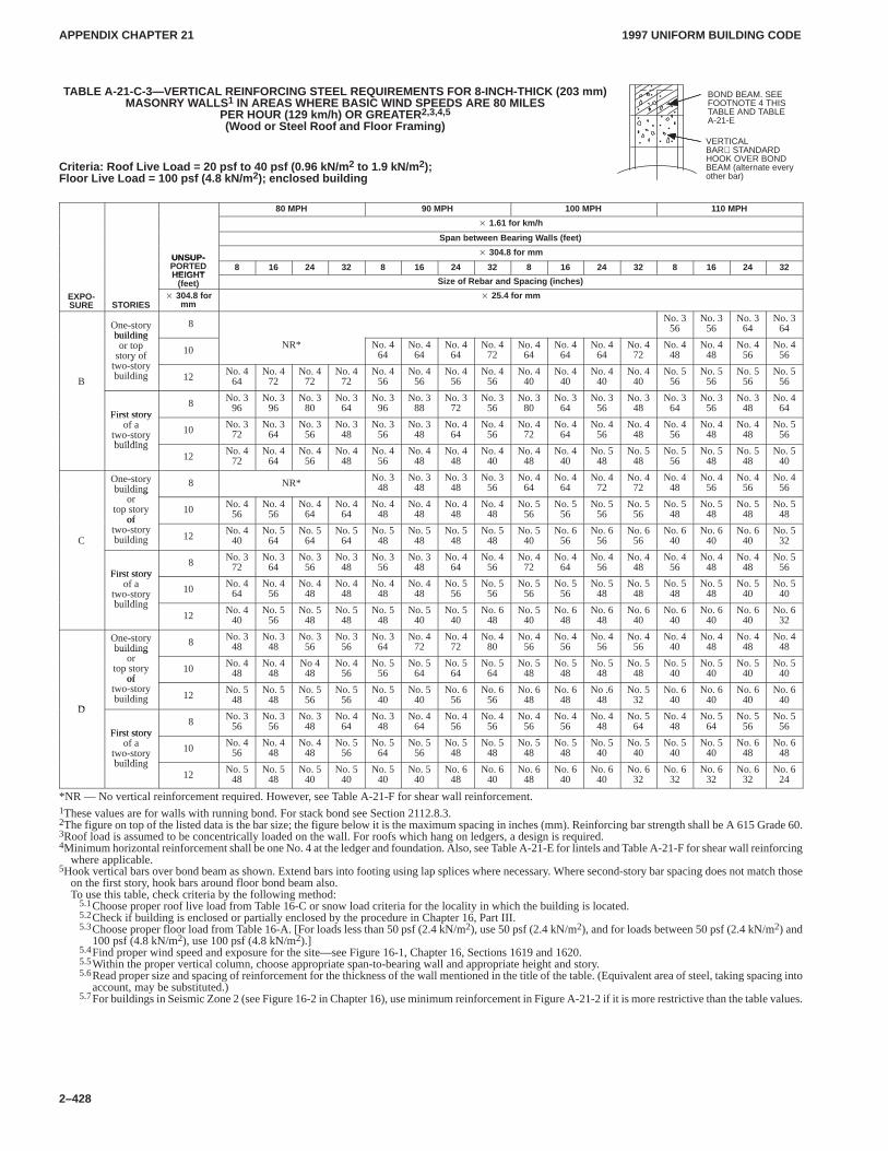
APPENDIX CHAPTER 21APPENDIX CHAPTER 21
1997 UNIFORM BUILDING CODE
2–428
TABLE A-21-C-3—VERTICAL REINFORCING STEEL REQUIREMENTS FOR 8-INCH-THICK (203 mm)MASONRY WALLS 1 IN AREAS WHERE BASIC WIND SPEEDS ARE 80 MILES
PER HOUR (129 km/h) OR GREATER 2,3,4,5
(Wood or Steel Roof and Floor Framing)
Criteria: Roof Live Load = 20 psf to 40 psf (0.96 kN/m 2 to 1.9 kN/m 2);Floor Live Load = 100 psf (4.8 kN/m 2); enclosed building
80 MPH 90 MPH 100 MPH 110 MPH
� 1.61 for km/h
Span between Bearing Walls (feet)
UNSUP-� 304.8 for mm
UNSUP-PORTEDHEIGHT
8 16 24 32 8 16 24 32 8 16 24 32 8 16 24 32HEIGHT
(feet) Size of Rebar and Spacing (inches)
EXPO-SURE STORIES
� 304.8 formm
� 25.4 for mm
One-storybuilding
8 No. 356
No. 356
No. 364
No. 364
buildingor top
story oft t
10 NR* No. 464
No. 464
No. 464
No. 472
No. 464
No. 464
No. 464
No. 472
No. 448
No. 448
No. 456
No. 456
B
ytwo-storybuilding 12 No. 4
64No. 4
72No. 4
72No. 4
72No. 4
56No. 4
56No. 4
56No. 4
56No. 4
40No. 4
40No. 4
40No. 4
40No. 5
56No. 5
56No. 5
56No. 5
56
First story8 No. 3
96No. 3
96No. 3
80No. 3
64No. 3
96No. 3
88No. 3
72No. 3
56No. 3
80No. 3
64No. 3
56No. 3
48No. 3
64No. 3
56No. 3
48No. 4
64First story
of atwo-storybuilding
10 No. 372
No. 364
No. 356
No. 348
No. 356
No. 348
No. 464
No. 456
No. 472
No. 464
No. 456
No. 448
No. 456
No. 448
No. 448
No. 556y
building12 No. 4
72No. 4
64No. 4
56No. 4
48No. 4
56No. 4
48No. 4
48No. 4
40No. 4
48No. 4
40No. 5
48No. 5
48No. 5
56No. 5
48No. 5
48No. 5
40
One-storybuilding
8 NR* No. 348
No. 348
No. 348
No. 356
No. 464
No. 464
No. 472
No. 472
No. 448
No. 456
No. 456
No. 456building
ortop story
of10 No. 4
56No. 4
56No. 4
64No. 4
64No. 4
48No. 4
48No. 4
48No. 4
48No. 5
56No. 5
56No. 5
56No. 5
56No. 5
48No. 5
48No. 5
48No. 5
48
C
oftwo-storybuilding 12 No. 4
40No. 5
64No. 5
64No. 5
64No. 5
48No. 5
48No. 5
48No. 5
48No. 5
40No. 6
56No. 6
56No. 6
56No. 6
40No. 6
40No. 6
40No. 5
32
First story8 No. 3
72No. 3
64No. 3
56No. 3
48No. 3
56No. 3
48No. 4
64No. 4
56No. 4
72No. 4
64No. 4
56No. 4
48No. 4
56No. 4
48No. 4
48No. 5
56First story
of atwo-storybuilding
10 No. 464
No. 456
No. 448
No. 448
No. 448
No. 448
No. 556
No. 556
No. 556
No. 556
No. 548
No. 548
No. 548
No. 548
No. 540
No. 540y
building12 No. 4
40No. 5
56No. 5
48No. 5
48No. 5
48No. 5
40No. 5
40No. 6
48No. 5
40No. 6
48No. 6
48No. 6
40No. 6
40No. 6
40No. 6
40No. 6
32
One-storybuilding
8 No. 348
No. 348
No. 356
No. 356
No. 364
No. 472
No. 472
No. 480
No. 456
No. 456
No. 456
No. 456
No. 440
No. 448
No. 448
No. 448building
ortop story
of10 No. 4
48No. 4
48No 448
No. 456
No. 556
No. 564
No. 564
No. 564
No. 548
No. 548
No. 548
No. 548
No. 540
No. 540
No. 540
No. 540
D
oftwo-storybuilding 12 No. 5
48No. 5
48No. 5
56No. 5
56No. 5
40No. 5
40No. 6
56No. 6
56No. 6
48No. 6
48No .6
48No. 5
32No. 6
40No. 6
40No. 6
40No. 6
40D
First story8 No. 3
56No. 3
56No. 3
48No. 4
64No. 3
48No. 4
64No. 4
56No. 4
56No. 4
56No. 4
56No. 4
48No. 5
64No. 4
48No. 5
64No. 5
56No. 5
56First story
of atwo-storybuilding
10 No. 456
No. 448
No. 448
No. 556
No. 564
No. 556
No. 548
No. 548
No. 548
No. 548
No. 540
No. 540
No. 540
No. 540
No. 648
No. 648y
building12 No. 5
48No. 5
48No. 5
40No. 5
40No. 5
40No. 5
40No. 6
48No. 6
40No. 6
48No. 6
40No. 6
40No. 6
32No. 6
32No. 6
32No. 6
32No. 6
24
*NR — No vertical reinforcement required. However, see Table A-21-F for shear wall reinforcement.1These values are for walls with running bond. For stack bond see Section 2112.8.3.2The figure on top of the listed data is the bar size; the figure below it is the maximum spacing in inches (mm). Reinforcing bar strength shall be A 615 Grade 60.3Roof load is assumed to be concentrically loaded on the wall. For roofs which hang on ledgers, a design is required.4Minimum horizontal reinforcement shall be one No. 4 at the ledger and foundation. Also, see Table A-21-E for lintels and Table A-21-F for shear wall reinforcing
where applicable.5Hook vertical bars over bond beam as shown. Extend bars into footing using lap splices where necessary. Where second-story bar spacing does not match those
on the first story, hook bars around floor bond beam also.To use this table, check criteria by the following method:
5.1Choose proper roof live load from Table 16-C or snow load criteria for the locality in which the building is located.5.2Check if building is enclosed or partially enclosed by the procedure in Chapter 16, Part III.5.3Choose proper floor load from Table 16-A. [For loads less than 50 psf (2.4 kN/m2), use 50 psf (2.4 kN/m2), and for loads between 50 psf (2.4 kN/m2) and
100 psf (4.8 kN/m2), use 100 psf (4.8 kN/m2).]5.4Find proper wind speed and exposure for the site—see Figure 16-1, Chapter 16, Sections 1619 and 1620.5.5Within the proper vertical column, choose appropriate span-to-bearing wall and appropriate height and story.5.6Read proper size and spacing of reinforcement for the thickness of the wall mentioned in the title of the table. (Equivalent area of steel, taking spacing into
account, may be substituted.)5.7For buildings in Seismic Zone 2 (see Figure 16-2 in Chapter 16), use minimum reinforcement in Figure A-21-2 if it is more restrictive than the table values.
BOND BEAM. SEEFOOTNOTE 4 THISTABLE AND TABLEA-21-E
VERTICALBAR STANDARDHOOK OVER BONDBEAM (alternate everyother bar)
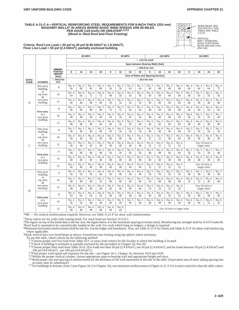
APPENDIX CHAPTER 21APPENDIX CHAPTER 21
1997 UNIFORM BUILDING CODE
2–429
TABLE A-21-C-4—VERTICAL REINFORCING STEEL REQUIREMENTS FOR 8-INCH-THICK (203 mm)MASONRY WALLS 1 IN AREAS WHERE BASIC WIND SPEEDS ARE 80 MILES
PER HOUR (129 km/h) OR GREATER 2,3,4,5
(Wood or Steel Roof and Floor Framing)
Criteria: Roof Live Load = 20 psf to 40 psf (0.96 kN/m 2 to 1.9 kN/m 2);Floor Live Load = 50 psf (2.4 kN/m 2); partially enclosed building
80 MPH 90 MPH 100 MPH 110 MPH
� 1.61 for km/h
Span between Bearing Walls (feet)
UNSUP-� 304.8 for mm
UNSUP-PORTEDHEIGHT
8 16 24 32 8 16 24 32 8 16 24 32 8 16 24 32HEIGHT
(feet) Size of Rebar and Spacing (inches)
EXPO-SURE STORIES
� 304.8 formm
� 25.4 for mm
One-storybuilding
8 No. 496
No. 496
No. 380
No. 388
No. 356
No. 356
No. 364
No. 364
No. 340
No. 348
No. 348
No. 348
No. 464
No. 464
No. 464
No. 472building
ortop story
of10 No. 4
64No. 4
64No. 4
72No. 4
72No. 4
48No. 4
56No. 4
56No. 4
56No. 4
40No. 4
40No. 4
40No. 4
40No. 5
48No. 5
56No. 5
56No. 5
56
B
oftwo-storybuilding 12 No. 4
40No. 4
48No. 4
48No. 4
48No. 5
56No. 5
56No. 5
56No. 5
56No. 5
40No. 5
40No. 5
40No. 5
40No. 6
48No. 6
48No. 6
48No. 6
48
First story8 No. 3
96No. 3
96No. 3
88No. 3
80No. 3
72No. 3
72No. 3
64No. 3
64No. 3
48No. 3
48No. 3
48No. 3
48No. 4
64No. 4
64No. 4
64No. 4
64First story
of atwo-storybuilding
10 No. 348
No. 348
No. 348
No. 348
No. 464
No. 456
No. 456
No. 456
No. 448
No. 448
No. 448
No. 440
No.440
No. 556
No. 556
No. 548y
building12 No. 4
48No. 4
48No. 4
48No. 4
40No. 4
40No. 5
56No. 5
56No. 5
48No. 5
48No. 5
40No. 5
40No. 5
40No. 6
48No. 6
48No. 6
48No. 6
48
One-storybuilding
8 No. 340
No. 340
No. 340
No. 340
No. 456
No. 456
No. 456
No. 456
No. 440
No. 440
No. 440
No. 448
No. 556
No. 556
No. 556
No. 556building
ortop story
of10 No. 4
40No. 4
40No. 4
40No. 4
40No. 5
48No. 5
48No. 5
48No. 5
48No. 5
32No. 5
32No. 5
40No. 5
40No. 6
40No. 6
40No. 6
40No. 6
40
C
oftwo-storybuilding 12 No. 5
40No. 5
40No. 5
40No. 5
40No. 6
40No. 6
48No. 6
48No. 6
48No. 6
32No. 6
32No. 6
32No. 6
32Use 10-inch or
larger units
First story8 No. 3
48No. 3
48No. 3
48No. 3
48No. 4
56No. 4
56No. 4
56No. 4
56No. 4
48No. 4
48No. 4
40No. 4
40No. 5
56No. 5
56No. 5
56No. 5
48First story
of atwo-storybuilding
10 No. 440
No. 440
No. 440
No. 440
No. 548
No. 548
No. 548
No. 548
No. 540
No. 540
No. 540
No. 648
No. 648
No. 648
No. 640
No. 640y
building12 No. 5
40No. 5
40No. 5
40No. 6
48No. 6
48No. 6
48No. 6
40No. 6
40No. 6
32No. 6
32No. 6
32No. 6
32Use 10-inch or
larger units
One-storybuilding
8 No. 456
No. 456
No. 456
No. 464
No. 440
No. 448
No. 448
No. 448
No. 556
No. 556
No. 556
No. 556
No. 548
No. 548
No. 548
No. 548building
ortop story
of10 No. 5
48No. 5
48No. 5
48No. 5
56No. 5
40No. 5
40No. 5
40No. 5
40No. 6
56No. 6
48No. 6
48No. 6
48No. 6
32No. 6
32No. 6
40No. 6
40
D
oftwo-storybuilding 12 No. 6
48No. 6
48No. 6
48No. 6
48No. 6
40No. 6
40No. 6
40No. 6
40No. 6
24No. 6
32No. 6
32No. 6
32Use 10-inch or
larger unitsD
First story8 No. 4
64No. 4
64No. 4
64No. 4
56No. 4
48No. 4
48No. 4
48No. 4
48No. 4
40No. 4
40No. 5
56No. 5
56No. 5
48No. 5
48No. 5
48No. 5
40First story
of atwo-storybuilding
10 No. 556
No. 556
No. 548
No. 548
No. 540
No. 540
No. 540
No. 540
No. 648
No. 648
No. 648
No. 640
No. 640
No. 640
No. 632
No. 632y
building12 No. 6
48No. 6
48No. 6
48No. 6
48No. 6
40No. 6
40 Use 10-inch or larger units
*NR — No vertical reinforcement required. However, see Table A-21-F for shear wall reinforcement.1These values are for walls with running bond. For stack bond see Section 2112.8.3.2The figure on top of the listed data is the bar size; the figure below it is the maximum spacing in inches (mm). Reinforcing bar strength shall be A 615 Grade 60.3Roof load is assumed to be concentrically loaded on the wall. For roofs which hang on ledgers, a design is required.4Minimum horizontal reinforcement shall be one No. 4 at the ledger and foundation. Also, see Table A-21-E for lintels and Table A-21-F for shear wall reinforcing
where applicable.5Hook vertical bars over bond beam as shown. Extend bars into footing using lap splices where necessary.
To use this table, check criteria by the following method:5.1Choose proper roof live load from Table 16-C or snow load criteria for the locality in which the building is located.5.2Check if building is enclosed or partially enclosed by the procedure in Chapter 16, Part III.5.3Choose proper floor load from Table 16-A. [For loads less than 50 psf (2.4 kN/m2), use 50 psf (2.4 kN/m2), and for loads between 50 psf (2.4 kN/m2) and
100 psf (4.8 kN/m2) , use 100 psf (4.8 kN/m2).]5.4Find proper wind speed and exposure for the site—see Figure 16-1, Chapter 16, Sections 1619 and 1620.5.5Within the proper vertical column, choose appropriate span-to-bearing wall and appropriate height and story.5.6Read proper size and spacing of reinforcement for the thickness of the wall mentioned in the title of the table. (Equivalent area of steel, taking spacing into
account, may be substituted.)5.7For buildings in Seismic Zone 2 (see Figure 16-2 in Chapter 16), use minimum reinforcement in Figure A-21-2 if it is more restrictive than the table values.
BOND BEAM. SEEFOOTNOTE 4 THISTABLE AND TABLEA-21-E
VERTICALBAR STANDARDHOOK OVER BONDBEAM (alternate everyother bar)
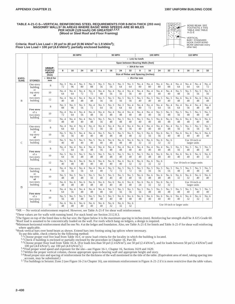
APPENDIX CHAPTER 21APPENDIX CHAPTER 21
1997 UNIFORM BUILDING CODE
2–430
TABLE A-21-C-5—VERTICAL REINFORCING STEEL REQUIREMENTS FOR 8-INCH-THICK (203 mm)MASONRY WALLS 1 IN AREAS WHERE BASIC WIND SPEEDS ARE 80 MILES
PER HOUR (129 km/h) OR GREATER 2,3,4,5
(Wood or Steel Roof and Floor Framing)
Criteria: Roof Live Load = 20 psf to 40 psf (0.96 kN/m 2 to 1.9 kN/m 2);Floor Live Load = 100 psf (4.8 kN/m 2); partially enclosed building
80 MPH 90 MPH 100 MPH 110 MPH
� 1.61 for km/h
Span between Bearing Walls (feet)
UNSUP-� 304.8 for mm
UNSUP-PORTEDHEIGHT
8 16 24 32 8 16 24 32 8 16 24 32 8 16 24 32HEIGHT
(feet) Size of Rebar and Spacing (inches)
EXPO-SURE STORIES
� 304.8 formm
� 25.4 for mm
One-storybuilding
8 No. 372
No. 496
No. 380
No. 388
No. 356
No. 356
No. 364
No. 364
No. 480
No. 480
No. 480
No. 488
No. 464
No. 464
No. 464
No. 472building
ortop story
of10 No. 4
64No. 4
64No. 4
72No. 4
72No. 4
48No. 4
56No. 4
56No. 4
56No. 4
40No. 4
40No. 4
40No. 4
40No. 5
48No. 5
56No. 5
56No. 5
56
B
oftwo-storybuilding 12 No. 4
40No. 4
48No. 4
48No. 4
48No. 5
56No. 5
56No. 5
56No. 5
56No. 5
40No. 5
40No. 5
40No. 5
40No. 6
48No. 6
48No. 6
48No. 6
48
First story8 No. 3
88No. 3
96No. 3
56No. 4
72No. 3
64No. 3
56No. 3
64No. 4
64No. 4
80No. 4
72No. 4
64No. 4
56No. 4
64No. 4
56No. 4
48No. 4
48First story
of atwo-storybuilding
10 No. 472
No. 464
No. 456
No. 448
No. 456
No. 448
No. 448
No. 440
No. 448
No. 440
No. 556
No. 548
No. 556
No. 548
No. 548
No. 540y
building12 No. 4
48No. 4
40No. 4
40No. 5
48No. 5
56No. 5
48No. 5
48No. 5
40No. 5
40No. 5
40No. 6
48No. 6
48No. 6
48No. 6
48No. 6
40No. 6
40
One-storybuilding
8 No. 464
No. 464
No. 472
No. 472
No. 456
No. 456
No. 456
No. 456
No. 440
No. 440
No. 440
No. 448
No. 556
No. 556
No. 556
No. 556building
ortop story
of10 No. 5
56No. 5
56No. 4
40No. 4
40No. 5
48No. 5
48No. 5
48No. 5
48No. 5
32No. 6
56No. 6
56No. 5
40No. 6
40No. 6
40No. 6
40No. 6
40
C
oftwo-storybuilding 12 No. 5
40No. 5
40No. 5
40No. 5
40No. 6
40No. 6
48No. 6
48No. 6
48No. 6
32No. 6
32No. 6
32No. 6
32Use 10-inch or
larger units
First story8 No. 4
72No. 4
64No. 4
56No. 4
48No. 4
56No. 4
48No. 4
48No. 4
40No. 4
40No. 4
40No. 4
40No. 5
48No. 5
56No. 5
48No. 5
48No. 5
40First story
of atwo-storybuilding
10 No. 564
No. 556
No. 548
No. 548
No. 548
No. 548
No. 540
No. 540
No. 540
No. 648
No. 648
No. 640
No. 640
No. 640
No. 640
No. 632y
building12 No. 5
40No. 6
48No. 6
48No. 6
40No. 6
40No. 6
40No. 6
40No. 6
32No. 6
32No. 6
32No. 6
32 Use 10-inch or larger units
One-storybuilding
8 No. 456
No. 456
No. 456
No. 464
No. 440
No. 572
No. 572
No. 572
No. 556
No. 556
No. 556
No. 556
No. 548
No. 548
No. 548
No. 548building
ortop story
of10 No. 5
48No. 5
48No. 5
48No. 5
56No. 5
40No. 5
40No. 5
40No. 5
40No. 6
56No. 6
48No. 6
48No. 6
48No. 6
32No. 6
32No. 6
40No. 6
40
D
oftwo-storybuilding 12 No. 6
48No. 6
48No. 6
48No. 6
48No. 6
40No. 6
40No. 6
40No. 6
40No. 6
24No. 6
32No. 6
32No. 6
32Use 10-inch or
larger unitsD
First story8 No. 4
64No. 4
56No. 4
48No. 4
48No. 4
48No. 5
64No. 5
56No. 5
56No. 5
56No. 5
48No. 5
48No. 5
48No. 5
48No. 5
40No. 5
40No. 5
40First story
of atwo-storybuilding
10 No. 556
No. 548
No. 548
No. 540
No. 540
No. 540
No. 648
No. 648
No. 648
No. 640
No. 640
No. 640
No. 640
No. 632
No. 632
No. 632y
building12 No. 6
48No. 6
48No. 6
40No. 6
40No. 6
40No. 6
32No. 6
32No. 6
32 Use 10-inch or larger units
*NR — No vertical reinforcement required. However, see Table A-21-F for shear wall reinforcement.1These values are for walls with running bond. For stack bond see Section 2112.8.3.2The figure on top of the listed data is the bar size; the figure below it is the maximum spacing in inches (mm). Reinforcing bar strength shall be A 615 Grade 60.3Roof load is assumed to be concentrically loaded on the wall. For roofs which hang on ledgers, a design is required.4Minimum horizontal reinforcement shall be one No. 4 at the ledger and foundation. Also, see Table A-21-E for lintels and Table A-21-F for shear wall reinforcing
where applicable.5Hook vertical bars over bond beam as shown. Extend bars into footing using lap splices where necessary.
To use this table, check criteria by the following method:5.1Choose proper roof live load from Table 16-C or snow load criteria for the locality in which the building is located.5.2Check if building is enclosed or partially enclosed by the procedure in Chapter 16, Part III.5.3Choose proper floor load from Table 16-A. [For loads less than 50 psf (2.4 kN/m2), use 50 psf (2.4 kN/m2), and for loads between 50 psf (2.4 kN/m2) and
100 psf (4.8 kN/m2), use 100 psf (4.8 kN/m2).]5.4Find proper wind speed and exposure for the site—see Figure 16-1, Chapter 16, Sections 1619 and 1620.5.5Within the proper vertical column, choose appropriate span-to-bearing wall and appropriate height and story.5.6Read proper size and spacing of reinforcement for the thickness of the wall mentioned in the title of the table. (Equivalent area of steel, taking spacing into
account, may be substituted.)5.7For buildings in Seismic Zone 2 (see Figure 16-2 in Chapter 16), use minimum reinforcement in Figure A-21-2 if it is more restrictive than the table values.
BOND BEAM. SEEFOOTNOTE 4 THISTABLE AND TABLEA-21-E
VERTICALBAR STANDARDHOOK OVER BONDBEAM (alternate everyother bar)
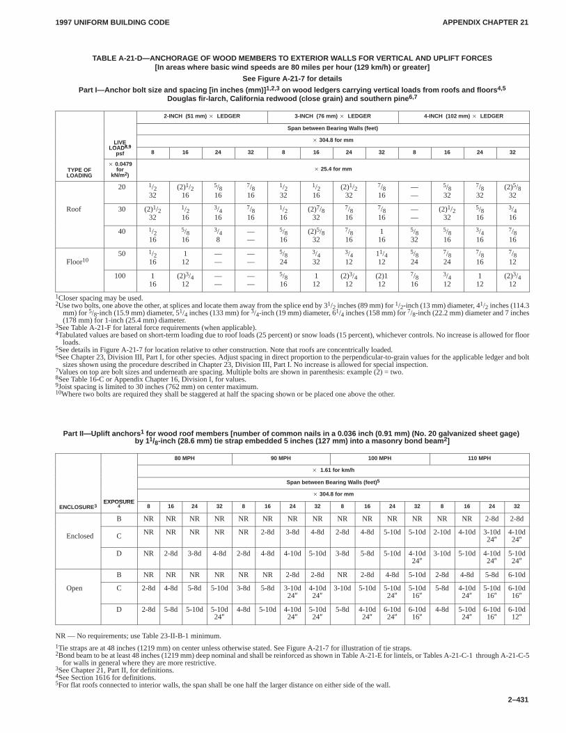
APPENDIX CHAPTER 21APPENDIX CHAPTER 21
1997 UNIFORM BUILDING CODE
2–431
TABLE A-21-D—ANCHORAGE OF WOOD MEMBERS TO EXTERIOR WALLS FOR VERTICAL AND UPLIFT FORCES[In areas where basic wind speeds are 80 miles per hour (129 km/h) or greater]
See Figure A-21-7 for details
Part I—Anchor bolt size and spacing [in inches (mm)] 1,2,3 on wood ledgers carrying vertical loads from roofs and floors 4,5
Douglas fir-larch, California redwood (close grain) and southern pine 6,7
2-INCH (51 mm) � LEDGER 3-INCH (76 mm) � LEDGER 4-INCH (102 mm) � LEDGER
Span between Bearing Walls (feet)
LIVELOAD8 9
� 304.8 for mmLIVELOAD8,9
psf 8 16 24 32 8 16 24 32 8 16 24 32
TYPE OFLOADING
� 0.0479for
kN/m2)� 25.4 for mm
20 1/232
(2)1/216
5/816
7/816
1/232
1/216
(2)1/232
7/816
——
5/832
7/832
(2)5/832
Roof 30 (2)1/232
1/216
3/416
7/816
1/216
(2)7/832
7/816
7/816
——
(2)1/232
5/816
3/416
40 1/216
5/816
3/48
——
5/816
(2)5/832
7/816
116
5/832
5/816
3/416
7/816
Floor1050 1/2
16112
——
——
5/824
3/432
3/412
11/412
5/824
7/824
7/816
7/812
100 116
(2)3/412
——
——
5/816
112
(2)3/412
(2)112
7/816
3/412
112
(2)3/412
1Closer spacing may be used.2Use two bolts, one above the other, at splices and locate them away from the splice end by 31/2 inches (89 mm) for 1/2-inch (13 mm) diameter, 41/2 inches (114.3
mm) for 5/8-inch (15.9 mm) diameter, 51/4 inches (133 mm) for 3/4-inch (19 mm) diameter, 61/4 inches (158 mm) for 7/8-inch (22.2 mm) diameter and 7 inches(178 mm) for 1-inch (25.4 mm) diameter.
3See Table A-21-F for lateral force requirements (when applicable).4Tabulated values are based on short-term loading due to roof loads (25 percent) or snow loads (15 percent), whichever controls. No increase is allowed for floor
loads.5See details in Figure A-21-7 for location relative to other construction. Note that roofs are concentrically loaded.6See Chapter 23, Division III, Part I, for other species. Adjust spacing in direct proportion to the perpendicular-to-grain values for the applicable ledger and bolt
sizes shown using the procedure described in Chapter 23, Division III, Part I. No increase is allowed for special inspection.7Values on top are bolt sizes and underneath are spacing. Multiple bolts are shown in parenthesis: example (2) = two.8See Table 16-C or Appendix Chapter 16, Division I, for values.9Joist spacing is limited to 30 inches (762 mm) on center maximum.10Where two bolts are required they shall be staggered at half the spacing shown or be placed one above the other.
Part II—Uplift anchors 1 for wood roof members [number of common nails in a 0.036 inch (0.91 mm) (No. 20 galvanized sheet gage) by 11/8-inch (28.6 mm) tie strap embedded 5 inches (127 mm) into a masonry bond beam 2]
80 MPH 90 MPH 100 MPH 110 MPH
� 1.61 for km/h
Span between Bearing Walls (feet) 5
EXPOSURE� 304.8 for mm
ENCLOSURE3EXPOSURE
4 8 16 24 32 8 16 24 32 8 16 24 32 8 16 24 32
B NR NR NR NR NR NR NR NR NR NR NR NR NR NR 2-8d 2-8d
Enclosed C NR NR NR NR NR 2-8d 3-8d 4-8d 2-8d 4-8d 5-10d 5-10d 2-10d 4-10d 3-10d24″
4-10d24″
D NR 2-8d 3-8d 4-8d 2-8d 4-8d 4-10d 5-10d 3-8d 5-8d 5-10d 4-10d24″
3-10d 5-10d 4-10d24″
5-10d24″
B NR NR NR NR NR NR 2-8d 2-8d NR 2-8d 4-8d 5-10d 2-8d 4-8d 5-8d 6-10d
Open C 2-8d 4-8d 5-8d 5-10d 3-8d 5-8d 3-10d24″
4-10d24″
3-10d 5-10d 5-10d24″
5-10d16″
5-8d 4-10d24″
5-10d16″
6-10d16″
D 2-8d 5-8d 5-10d 5-10d24″
4-8d 5-10d 4-10d24″
5-10d24″
5-8d 4-10d24″
6-10d24″
6-10d16″
4-8d 5-10d24″
6-10d16″
6-10d12″
NR — No requirements; use Table 23-II-B-1 minimum.1Tie straps are at 48 inches (1219 mm) on center unless otherwise stated. See Figure A-21-7 for illustration of tie straps.2Bond beam to be at least 48 inches (1219 mm) deep nominal and shall be reinforced as shown in Table A-21-E for lintels, or Tables A-21-C-1 through A-21-C-5
for walls in general where they are more restrictive.3See Chapter 21, Part II, for definitions.4See Section 1616 for definitions.5For flat roofs connected to interior walls, the span shall be one half the larger distance on either side of the wall.
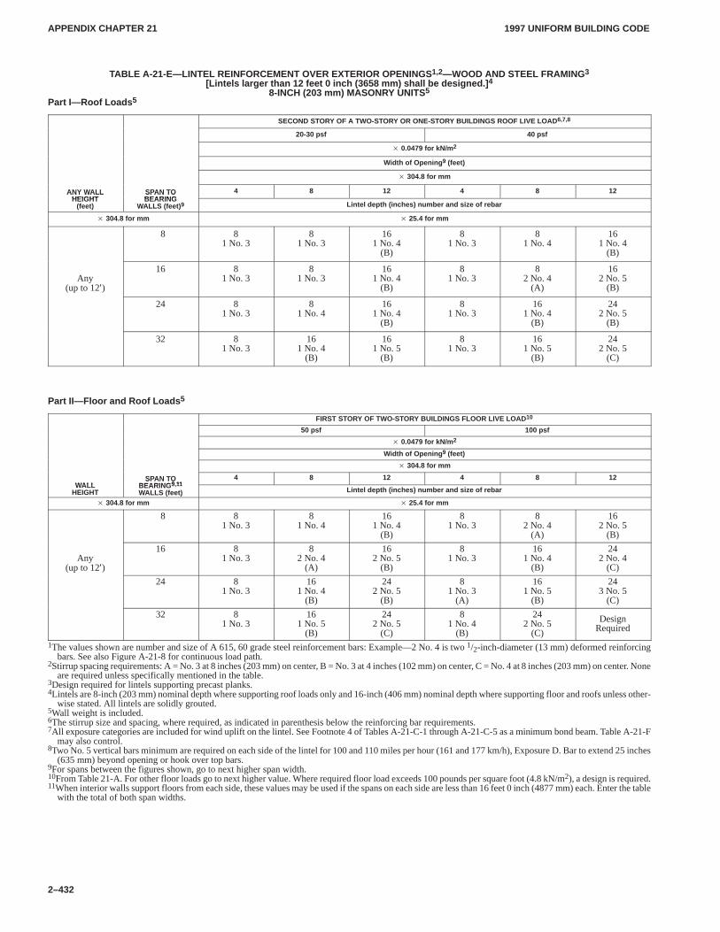
APPENDIX CHAPTER 21APPENDIX CHAPTER 21
1997 UNIFORM BUILDING CODE
2–432
TABLE A-21-E—LINTEL REINFORCEMENT OVER EXTERIOR OPENINGS 1,2—WOOD AND STEEL FRAMING 3
[Lintels larger than 12 feet 0 inch (3658 mm) shall be designed.] 4
8-INCH (203 mm) MASONRY UNITS 5
Part I—Roof Loads 5
SECOND STORY OF A TWO-STORY OR ONE-STORY BUILDINGS ROOF LIVE LOAD 6,7,8
20-30 psf 40 psf
� 0.0479 for kN/m 2
Width of Opening 9 (feet)
� 304.8 for mm
ANY WALLHEIGHT
SPAN TOBEARING
4 8 12 4 8 12ANY WALLHEIGHT
(feet)
SPAN TOBEARING
WALLS (feet) 9 Lintel depth (inches) number and size of rebar
� 304.8 for mm � 25.4 for mm
8 81 No. 3
81 No. 3
161 No. 4
(B)
81 No. 3
81 No. 4
161 No. 4
(B)
Any(up to 12′)
16 81 No. 3
81 No. 3
161 No. 4
(B)
81 No. 3
82 No. 4
(A)
162 No. 5
(B)
24 81 No. 3
81 No. 4
161 No. 4
(B)
81 No. 3
161 No. 4
(B)
242 No. 5
(B)
32 81 No. 3
161 No. 4
(B)
161 No. 5
(B)
81 No. 3
161 No. 5
(B)
242 No. 5
(C)
Part II—Floor and Roof Loads 5
FIRST STORY OF TWO-STORY BUILDINGS FLOOR LIVE LOAD 10
50 psf 100 psf
� 0.0479 for kN/m 2
Width of Opening 9 (feet)
� 304.8 for mm
WALLSPAN TO
BEARING 9 114 8 12 4 8 12
WALLHEIGHT
SPAN TOBEARING 9,11
WALLS (feet) Lintel depth (inches) number and size of rebar
� 304.8 for mm � 25.4 for mm
8 81 No. 3
81 No. 4
161 No. 4
(B)
81 No. 3
82 No. 4
(A)
162 No. 5
(B)
Any(up to 12′)
16 81 No. 3
82 No. 4
(A)
162 No. 5
(B)
81 No. 3
161 No. 4
(B)
242 No. 4
(C)
24 81 No. 3
161 No. 4
(B)
242 No. 5
(B)
81 No. 3
(A)
161 No. 5
(B)
243 No. 5
(C)
32 81 No. 3
161 No. 5
(B)
242 No. 5
(C)
81 No. 4
(B)
242 No. 5
(C)
DesignRequired
1The values shown are number and size of A 615, 60 grade steel reinforcement bars: Example—2 No. 4 is two 1/2-inch-diameter (13 mm) deformed reinforcingbars. See also Figure A-21-8 for continuous load path.
2Stirrup spacing requirements: A = No. 3 at 8 inches (203 mm) on center, B = No. 3 at 4 inches (102 mm) on center, C = No. 4 at 8 inches (203 mm) on center. Noneare required unless specifically mentioned in the table.
3Design required for lintels supporting precast planks.4Lintels are 8-inch (203 mm) nominal depth where supporting roof loads only and 16-inch (406 mm) nominal depth where supporting floor and roofs unless other-
wise stated. All lintels are solidly grouted.5Wall weight is included.6The stirrup size and spacing, where required, as indicated in parenthesis below the reinforcing bar requirements.7All exposure categories are included for wind uplift on the lintel. See Footnote 4 of Tables A-21-C-1 through A-21-C-5 as a minimum bond beam. Table A-21-F
may also control.8Two No. 5 vertical bars minimum are required on each side of the lintel for 100 and 110 miles per hour (161 and 177 km/h), Exposure D. Bar to extend 25 inches
(635 mm) beyond opening or hook over top bars.9For spans between the figures shown, go to next higher span width.10From Table 21-A. For other floor loads go to next higher value. Where required floor load exceeds 100 pounds per square foot (4.8 kN/m2), a design is required.11When interior walls support floors from each side, these values may be used if the spans on each side are less than 16 feet 0 inch (4877 mm) each. Enter the table
with the total of both span widths.
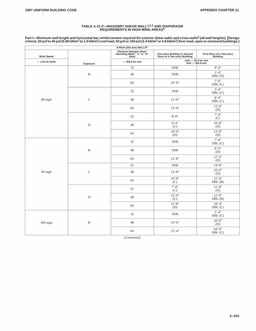
APPENDIX CHAPTER 21APPENDIX CHAPTER 21
1997 UNIFORM BUILDING CODE
2–433
TABLE A-21-F—MASONRY SHEAR WALL 1,2,3 AND DIAPHRAGMREQUIREMENTS IN HIGH-WIND AREAS4
Part I—Minimum wall length and horizontal bar reinforcement required for exterior shear walls and cross walls 5 (all wall heights). [Designcriteria: 20 psf to 40 psf (0.96 kN/m 2 to 1.9 kN/m 2) roof load; 50 psf or 100 psf (2.4 kN/m 2 or 4.8 kN/m 2) floor load; open or enclosed buildings.]
8-INCH (203 mm) WALLS 6
Wind Speed
Distance between ShearResisting Walls 7 “ L” or “ b”
(feet)One-story Building or SecondStory of a Two-story Building
First Story of a Two-storyBuilding
� 1.61 for km/hExposure
� 304.8 for mm inch � 25.4 for mmfoot � 304.8 mm
32 NSR 9′-4″
B 48 NSR 5′-4″DBL (D)
64 10′-0″ 7′-6″DBL (C)
32 NSR 5′-4″DBL (C)
80 mph C 48 11′-0″ 8′-8″DBL (C)
64 13′-4″ 15′-0″(D)
32 8′-8″ 7′-0″(C)
D 48 9′-4″(C)
10′-8″(D)
64 10′-0″(D)
13′-8″(D)
32 NSR 7′-8″DBL (C)
B 48 NSR 8′-0″(D)
64 12′-8″ 12′-0″(D)
32 NSR 14′-8″
90 mph C 48 13′-8″ 10′-0″(D)
64 10′-8″(C)
15′-6″DBL (B)
32 7′-8″(C)
11′-8″(D)
D 48 12′-0″(C)
12′-8″DBL (B)
64 11′-8″(D)
18′-4″DBL (C)
32 NSR 5′-4″DBL (C)
100 mph B 48 10′-0″ 10′-0″(D)
64 15′-4″ 64′-8″DBL (C)
(Continued)
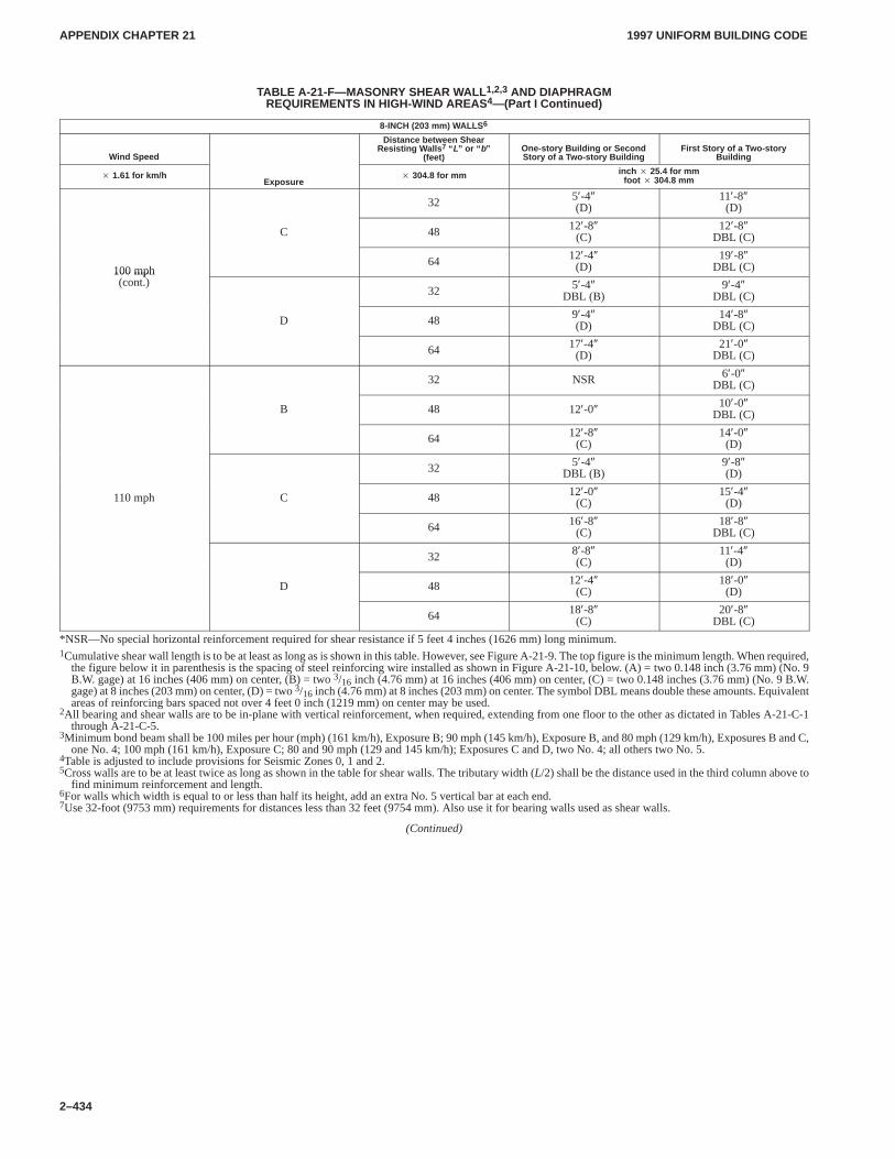
APPENDIX CHAPTER 21APPENDIX CHAPTER 21
1997 UNIFORM BUILDING CODE
2–434
TABLE A-21-F—MASONRY SHEAR WALL 1,2,3 AND DIAPHRAGMREQUIREMENTS IN HIGH-WIND AREAS4—(Part I Continued)
8-INCH (203 mm) WALLS 6
Wind Speed
Distance between ShearResisting Walls 7 “ L” or “ b”
(feet)One-story Building or SecondStory of a Two-story Building
First Story of a Two-storyBuilding
� 1.61 for km/hExposure
� 304.8 for mm inch � 25.4 for mmfoot � 304.8 mm
32 5′-4″(D)
11′-8″(D)
C 48 12′-8″(C)
12′-8″DBL (C)
100 mph64 12′-4″
(D)19′-8″
DBL (C)100 mph(cont.)
32 5′-4″DBL (B)
9′-4″DBL (C)
D 48 9′-4″(D)
14′-8″DBL (C)
64 17′-4″(D)
21′-0″DBL (C)
32 NSR 6′-0″DBL (C)
B 48 12′-0″ 10′-0″DBL (C)
64 12′-8″(C)
14′-0″(D)
32 5′-4″DBL (B)
9′-8″(D)
110 mph C 48 12′-0″(C)
15′-4″(D)
64 16′-8″(C)
18′-8″DBL (C)
32 8′-8″(C)
11′-4″(D)
D 48 12′-4″(C)
18′-0″(D)
64 18′-8″(C)
20′-8″DBL (C)
*NSR—No special horizontal reinforcement required for shear resistance if 5 feet 4 inches (1626 mm) long minimum.1Cumulative shear wall length is to be at least as long as is shown in this table. However, see Figure A-21-9. The top figure is the minimum length. When required,
the figure below it in parenthesis is the spacing of steel reinforcing wire installed as shown in Figure A-21-10, below. (A) = two 0.148 inch (3.76 mm) (No. 9B.W. gage) at 16 inches (406 mm) on center, (B) = two 3/16 inch (4.76 mm) at 16 inches (406 mm) on center, (C) = two 0.148 inches (3.76 mm) (No. 9 B.W.gage) at 8 inches (203 mm) on center, (D) = two 3/16 inch (4.76 mm) at 8 inches (203 mm) on center. The symbol DBL means double these amounts. Equivalentareas of reinforcing bars spaced not over 4 feet 0 inch (1219 mm) on center may be used.
2All bearing and shear walls are to be in-plane with vertical reinforcement, when required, extending from one floor to the other as dictated in Tables A-21-C-1through A-21-C-5.
3Minimum bond beam shall be 100 miles per hour (mph) (161 km/h), Exposure B; 90 mph (145 km/h), Exposure B, and 80 mph (129 km/h), Exposures B and C,one No. 4; 100 mph (161 km/h), Exposure C; 80 and 90 mph (129 and 145 km/h); Exposures C and D, two No. 4; all others two No. 5.
4Table is adjusted to include provisions for Seismic Zones 0, 1 and 2.5Cross walls are to be at least twice as long as shown in the table for shear walls. The tributary width (L/2) shall be the distance used in the third column above to
find minimum reinforcement and length.6For walls which width is equal to or less than half its height, add an extra No. 5 vertical bar at each end.7Use 32-foot (9753 mm) requirements for distances less than 32 feet (9754 mm). Also use it for bearing walls used as shear walls.
(Continued)
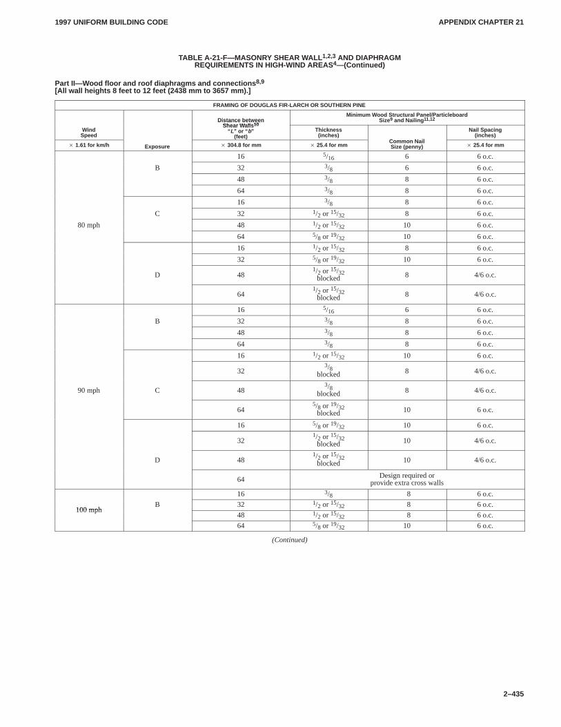
APPENDIX CHAPTER 21APPENDIX CHAPTER 21
1997 UNIFORM BUILDING CODE
2–435
TABLE A-21-F—MASONRY SHEAR WALL 1,2,3 AND DIAPHRAGMREQUIREMENTS IN HIGH-WIND AREAS4—(Continued)
Part II—Wood floor and roof diaphragms and connections 8,9
[All wall heights 8 feet to 12 feet (2438 mm to 3657 mm).]
FRAMING OF DOUGLAS FIR-LARCH OR SOUTHERN PINE
Distance betweenShear Walls 10
Minimum Wood Structural Panel/ParticleboardSize9 and Nailing 11,12
WindSpeed
Distance betweenShear Walls 10
“ L” or “ b”(feet)
Thickness(inches)
C N il
Nail Spacing(inches)
� 1.61 for km/h Exposure � 304.8 for mm � 25.4 for mmCommon NailSize (penny) � 25.4 for mm
16 5/16 6 6 o.c.
B 32 3/8 6 6 o.c.
48 3/8 8 6 o.c.
64 3/8 8 6 o.c.
16 3/8 8 6 o.c.
C 32 1/2 or 15/32 8 6 o.c.
80 mph 48 1/2 or 15/32 10 6 o.c.
64 5/8 or 19/32 10 6 o.c.
16 1/2 or 15/32 8 6 o.c.
32 5/8 or 19/32 10 6 o.c.
D 481/2 or 15/32
blocked 8 4/6 o.c.
641/2 or 15/32
blocked 8 4/6 o.c.
16 5/16 6 6 o.c.
B 32 3/8 8 6 o.c.
48 3/8 8 6 o.c.
64 3/8 8 6 o.c.
16 1/2 or 15/32 10 6 o.c.
323/8
blocked 8 4/6 o.c.
90 mph C 483/8
blocked 8 4/6 o.c.
645/8 or 19/32
blocked 10 6 o.c.
16 5/8 or 19/32 10 6 o.c.
321/2 or 15/32
blocked 10 4/6 o.c.
D 481/2 or 15/32
blocked 10 4/6 o.c.
64 Design required orprovide extra cross walls
16 3/8 8 6 o.c.
100 mphB 32 1/2 or 15/32 8 6 o.c.
100 mph48 1/2 or 15/32 8 6 o.c.
64 5/8 or 19/32 10 6 o.c.
(Continued)
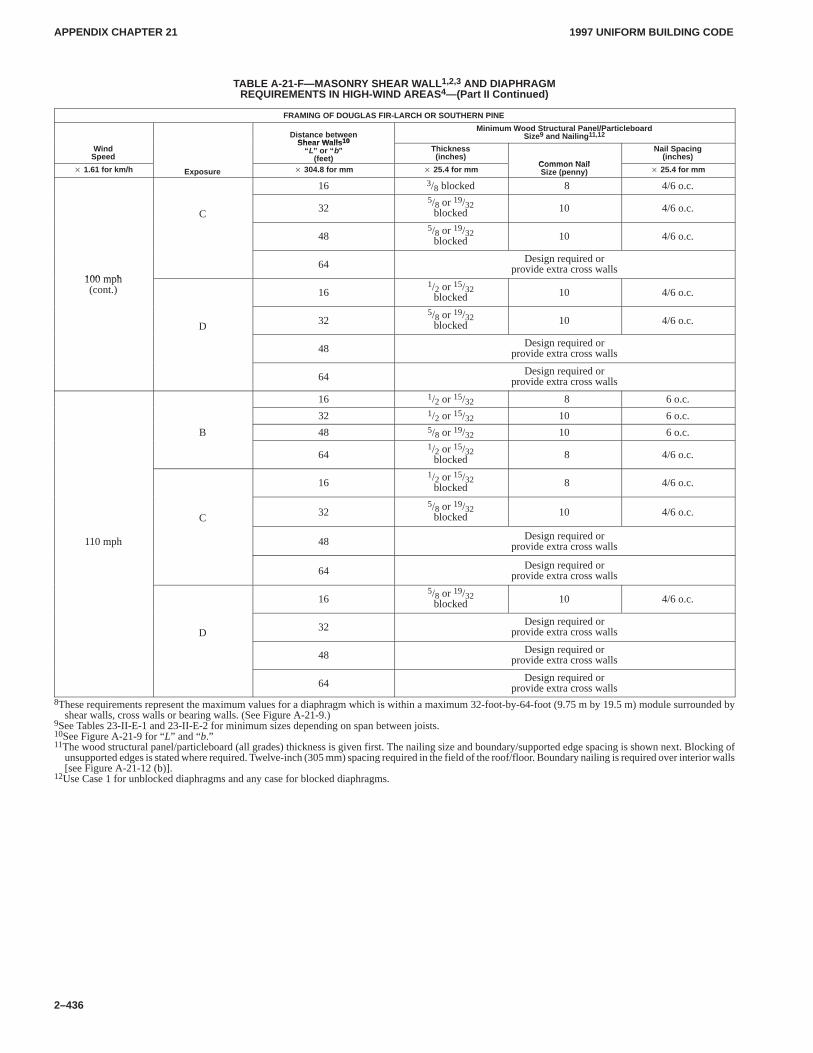
APPENDIX CHAPTER 21APPENDIX CHAPTER 21
1997 UNIFORM BUILDING CODE
2–436
TABLE A-21-F—MASONRY SHEAR WALL 1,2,3 AND DIAPHRAGMREQUIREMENTS IN HIGH-WIND AREAS4—(Part II Continued)
FRAMING OF DOUGLAS FIR-LARCH OR SOUTHERN PINE
Distance betweenShear Walls 10
Minimum Wood Structural Panel/ParticleboardSize9 and Nailing 11,12
WindSpeed
Shear Walls 10
“ L” or “ b”(feet)
Thickness(inches)
Common Nail
Nail Spacing(inches)
� 1.61 for km/h Exposure � 304.8 for mm � 25.4 for mmCommon NailSize (penny) � 25.4 for mm
16 3/8 blocked 8 4/6 o.c.
C 325/8 or 19/32
blocked 10 4/6 o.c.
485/8 or 19/32
blocked 10 4/6 o.c.
100 mph64 Design required or
provide extra cross walls100 mph(cont.) 16
1/2 or 15/32blocked 10 4/6 o.c.
D 325/8 or 19/32
blocked 10 4/6 o.c.
48 Design required orprovide extra cross walls
64 Design required orprovide extra cross walls
16 1/2 or 15/32 8 6 o.c.
32 1/2 or 15/32 10 6 o.c.
B 48 5/8 or 19/32 10 6 o.c.
641/2 or 15/32
blocked 8 4/6 o.c.
161/2 or 15/32
blocked 8 4/6 o.c.
C 325/8 or 19/32
blocked 10 4/6 o.c.
110 mph 48 Design required orprovide extra cross walls
64 Design required orprovide extra cross walls
165/8 or 19/32
blocked 10 4/6 o.c.
D 32 Design required orprovide extra cross walls
48 Design required orprovide extra cross walls
64 Design required orprovide extra cross walls
8These requirements represent the maximum values for a diaphragm which is within a maximum 32-foot-by-64-foot (9.75 m by 19.5 m) module surrounded byshear walls, cross walls or bearing walls. (See Figure A-21-9.)
9See Tables 23-II-E-1 and 23-II-E-2 for minimum sizes depending on span between joists.10See Figure A-21-9 for “L” and “b.”11The wood structural panel/particleboard (all grades) thickness is given first. The nailing size and boundary/supported edge spacing is shown next. Blocking of
unsupported edges is stated where required. Twelve-inch (305 mm) spacing required in the field of the roof/floor. Boundary nailing is required over interior walls[see Figure A-21-12 (b)].
12Use Case 1 for unblocked diaphragms and any case for blocked diaphragms.
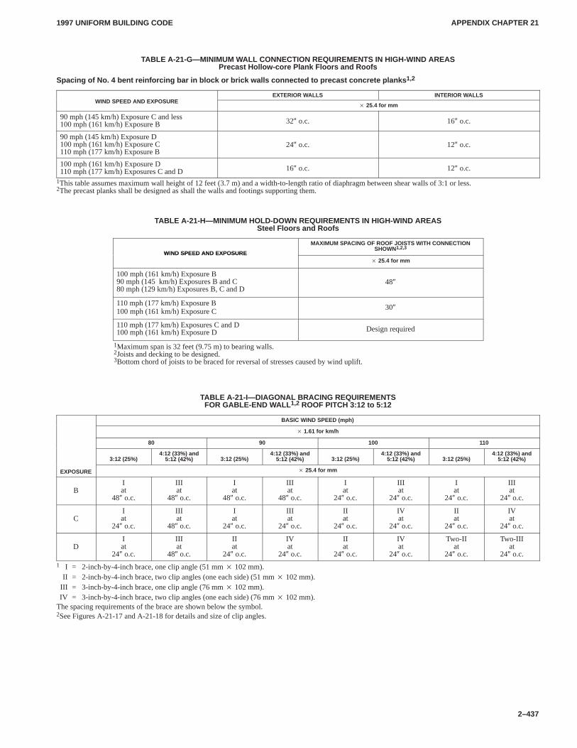
APPENDIX CHAPTER 21APPENDIX CHAPTER 21
1997 UNIFORM BUILDING CODE
2–437
TABLE A-21-G—MINIMUM WALL CONNECTION REQUIREMENTS IN HIGH-WIND AREASPrecast Hollow-core Plank Floors and Roofs
Spacing of No. 4 bent reinforcing bar in block or brick walls connected to precast concrete planks 1,2
WIND SPEED AND EXPOSUREEXTERIOR WALLS INTERIOR WALLS
WIND SPEED AND EXPOSURE� 25.4 for mm
90 mph (145 km/h) Exposure C and less100 mph (161 km/h) Exposure B 32″ o.c. 16″ o.c.
90 mph (145 km/h) Exposure D100 mph (161 km/h) Exposure C110 mph (177 km/h) Exposure B
24″ o.c. 12″ o.c.
100 mph (161 km/h) Exposure D110 mph (177 km/h) Exposures C and D 16″ o.c. 12″ o.c.
1This table assumes maximum wall height of 12 feet (3.7 m) and a width-to-length ratio of diaphragm between shear walls of 3:1 or less.2The precast planks shall be designed as shall the walls and footings supporting them.
TABLE A-21-H—MINIMUM HOLD-DOWN REQUIREMENTS IN HIGH-WIND AREASSteel Floors and Roofs
WIND SPEED AND EXPOSURE
MAXIMUM SPACING OF ROOF JOISTS WITH CONNECTIONSHOWN1,2,3
WIND SPEED AND EXPOSURE� 25.4 for mm
100 mph (161 km/h) Exposure B90 mph (145 km/h) Exposures B and C80 mph (129 km/h) Exposures B, C and D
48″
110 mph (177 km/h) Exposure B100 mph (161 km/h) Exposure C 30″
110 mph (177 km/h) Exposures C and D100 mph (161 km/h) Exposure D Design required
1Maximum span is 32 feet (9.75 m) to bearing walls.2Joists and decking to be designed.3Bottom chord of joists to be braced for reversal of stresses caused by wind uplift.
TABLE A-21-I—DIAGONAL BRACING REQUIREMENTSFOR GABLE-END WALL 1,2 ROOF PITCH 3:12 to 5:12
BASIC WIND SPEED (mph)
� 1.61 for km/h
80 90 100 110
3:12 (25%)4:12 (33%) and
5:12 (42%) 3:12 (25%)4:12 (33%) and
5:12 (42%) 3:12 (25%)4:12 (33%) and
5:12 (42%) 3:12 (25%)4:12 (33%) and
5:12 (42%)
EXPOSURE � 25.4 for mm
BIat
48″ o.c.
IIIat
48″ o.c.
Iat
48″ o.c.
IIIat
48″ o.c.
Iat
24″ o.c.
IIIat
24″ o.c.
Iat
24″ o.c.
IIIat
24″ o.c.
CIat
24″ o.c.
IIIat
48″ o.c.
Iat
24″ o.c.
IIIat
24″ o.c.
IIat
24″ o.c.
IVat
24″ o.c.
IIat
24″ o.c.
IVat
24″ o.c.
DIat
24″ o.c.
IIIat
48″ o.c.
IIat
24″ o.c.
IVat
24″ o.c.
IIat
24″ o.c.
IVat
24″ o.c.
Two-IIat
24″ o.c.
Two-IIIat
24″ o.c.
1 I = 2-inch-by-4-inch brace, one clip angle (51 mm � 102 mm).II = 2-inch-by-4-inch brace, two clip angles (one each side) (51 mm � 102 mm).
III = 3-inch-by-4-inch brace, one clip angle (76 mm � 102 mm).IV = 3-inch-by-4-inch brace, two clip angles (one each side) (76 mm � 102 mm).
The spacing requirements of the brace are shown below the symbol.2See Figures A-21-17 and A-21-18 for details and size of clip angles.
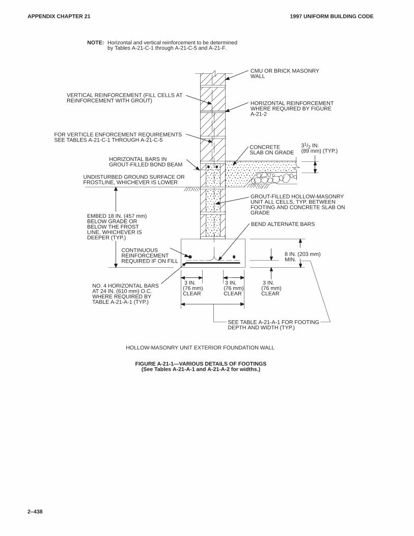
APPENDIX CHAPTER 21APPENDIX CHAPTER 21
1997 UNIFORM BUILDING CODE
2–438
ÎÎÎÎÎÎÎÎÎÎÎÎÎÎÎÎÎÎÎÎÎÎÎÎ
ÎÎÎÎÎÎÎÎÎÎÎÎÎÎÎÎÎÎÎÎÎÎÎÎ
UNDISTURBED GROUND SURFACE ORFROSTLINE, WHICHEVER IS LOWER
CMU OR BRICK MASONRYWALL
VERTICAL REINFORCEMENT (FILL CELLS ATREINFORCEMENT WITH GROUT)
SEE TABLE A-21-A-1 FOR FOOTINGDEPTH AND WIDTH (TYP.)
8 IN. (203 mm)MIN.
EMBED 18 IN. (457 mm)BELOW GRADE ORBELOW THE FROSTLINE, WHICHEVER ISDEEPER (TYP.)
NOTE: Horizontal and vertical reinforcement to be determinedby Tables A-21-C-1 through A-21-C-5 and A-21-F.
FOR VERTICLE ENFORCEMENT REQUIREMENTSSEE TABLES A-21-C-1 THROUGH A-21-C-5
CONCRETESLAB ON GRADE
HORIZONTAL REINFORCEMENTWHERE REQUIRED BY FIGUREA-21-2
31/2 IN.(89 mm) (TYP.)
GROUT-FILLED HOLLOW-MASONRYUNIT ALL CELLS, TYP. BETWEENFOOTING AND CONCRETE SLAB ONGRADE
BEND ALTERNATE BARS
CONTINUOUSREINFORCEMENTREQUIRED IF ON FILL
NO. 4 HORIZONTAL BARSAT 24 IN. (610 mm) O.C.WHERE REQUIRED BYTABLE A-21-A-1 (TYP.)
HORIZONTAL BARS INGROUT-FILLED BOND BEAM
HOLLOW-MASONRY UNIT EXTERIOR FOUNDATION WALL
3 IN.(76 mm)CLEAR
3 IN.(76 mm)CLEAR
3 IN.(76 mm)CLEAR
FIGURE A-21-1—VARIOUS DETAILS OF FOOTINGS(See Tables A-21-A-1 and A-21-A-2 for widths.)
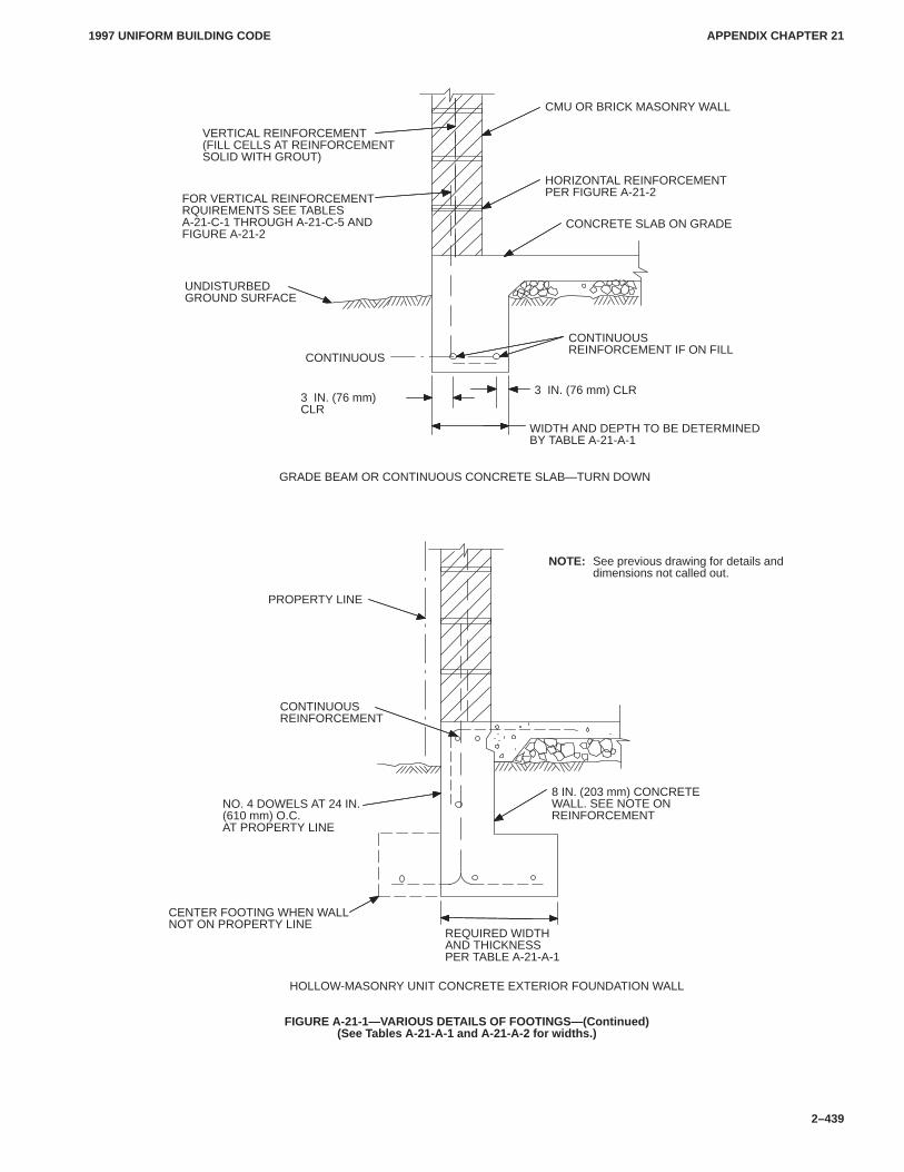
APPENDIX CHAPTER 21APPENDIX CHAPTER 21
1997 UNIFORM BUILDING CODE
2–439
NOTE: See previous drawing for details anddimensions not called out.
REQUIRED WIDTHAND THICKNESSPER TABLE A-21-A-1
8 IN. (203 mm) CONCRETEWALL. SEE NOTE ONREINFORCEMENT
CONTINUOUSREINFORCEMENT
NO. 4 DOWELS AT 24 IN.(610 mm) O.C.AT PROPERTY LINE
CENTER FOOTING WHEN WALLNOT ON PROPERTY LINE
PROPERTY LINE
CONTINUOUSREINFORCEMENT IF ON FILL
WIDTH AND DEPTH TO BE DETERMINEDBY TABLE A-21-A-1
CONCRETE SLAB ON GRADE
UNDISTURBEDGROUND SURFACE
FOR VERTICAL REINFORCEMENTRQUIREMENTS SEE TABLESA-21-C-1 THROUGH A-21-C-5 ANDFIGURE A-21-2
VERTICAL REINFORCEMENT(FILL CELLS AT REINFORCEMENTSOLID WITH GROUT)
CMU OR BRICK MASONRY WALL
HORIZONTAL REINFORCEMENTPER FIGURE A-21-2
GRADE BEAM OR CONTINUOUS CONCRETE SLAB—TURN DOWN
HOLLOW-MASONRY UNIT CONCRETE EXTERIOR FOUNDATION WALL
CONTINUOUS
3 IN. (76 mm) CLR3 IN. (76 mm)CLR
FIGURE A-21-1—VARIOUS DETAILS OF FOOTINGS—(Continued)(See Tables A-21-A-1 and A-21-A-2 for widths.)
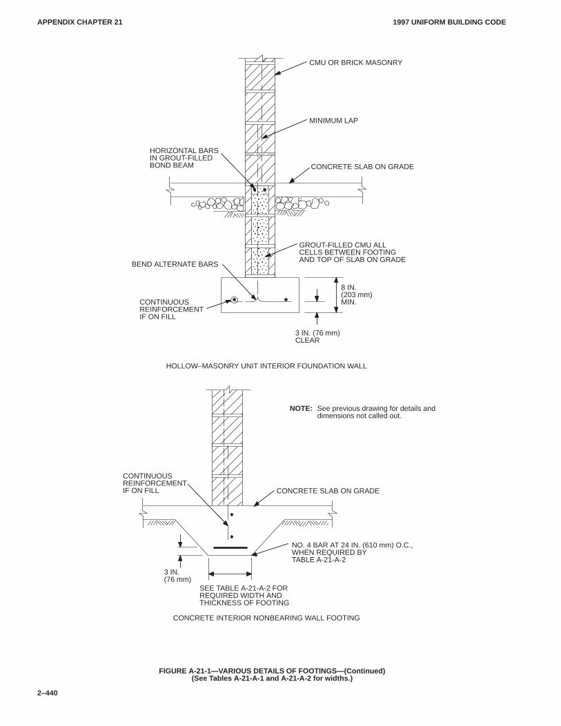
APPENDIX CHAPTER 21APPENDIX CHAPTER 21
1997 UNIFORM BUILDING CODE
2–440
ÎÎÎÎÎÎÎÎÎÎÎÎÎÎÎÎÎÎÎÎÎ
BEND ALTERNATE BARS
CONCRETE SLAB ON GRADE
CMU OR BRICK MASONRY
CONTINUOUSREINFORCEMENTIF ON FILL CONCRETE SLAB ON GRADE
NO. 4 BAR AT 24 IN. (610 mm) O.C.,WHEN REQUIRED BYTABLE A-21-A-2
HOLLOW–MASONRY UNIT INTERIOR FOUNDATION WALL
HORIZONTAL BARSIN GROUT-FILLEDBOND BEAM
SEE TABLE A-21-A-2 FORREQUIRED WIDTH ANDTHICKNESS OF FOOTING
GROUT-FILLED CMU ALLCELLS BETWEEN FOOTINGAND TOP OF SLAB ON GRADE
8 IN.(203 mm)MIN.
CONCRETE INTERIOR NONBEARING WALL FOOTING
3 IN.(76 mm)
3 IN. (76 mm)CLEAR
CONTINUOUSREINFORCEMENTIF ON FILL
NOTE: See previous drawing for details anddimensions not called out.
MINIMUM LAP
FIGURE A-21-1—VARIOUS DETAILS OF FOOTINGS—(Continued)(See Tables A-21-A-1 and A-21-A-2 for widths.)
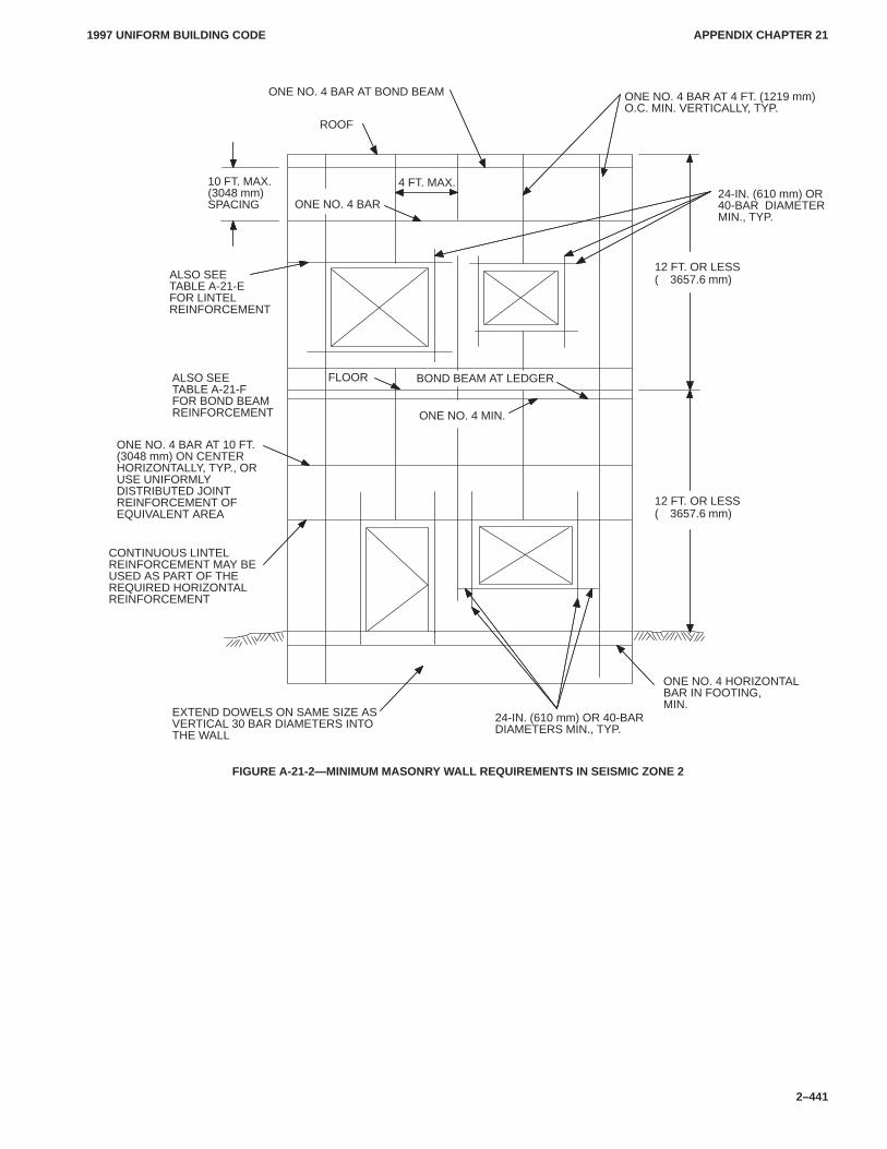
APPENDIX CHAPTER 21APPENDIX CHAPTER 21
1997 UNIFORM BUILDING CODE
2–441
ONE NO. 4 BAR AT BOND BEAM
ROOF
ONE NO. 4 BAR AT 4 FT. (1219 mm)O.C. MIN. VERTICALLY, TYP.
FLOOR
ALSO SEETABLE A-21-EFOR LINTELREINFORCEMENT
ALSO SEETABLE A-21-FFOR BOND BEAMREINFORCEMENT
CONTINUOUS LINTELREINFORCEMENT MAY BEUSED AS PART OF THEREQUIRED HORIZONTALREINFORCEMENT
ONE NO. 4 HORIZONTALBAR IN FOOTING,MIN.
EXTEND DOWELS ON SAME SIZE ASVERTICAL 30 BAR DIAMETERS INTOTHE WALL
ONE NO. 4 BAR AT 10 FT.(3048 mm) ON CENTERHORIZONTALLY, TYP., ORUSE UNIFORMLYDISTRIBUTED JOINTREINFORCEMENT OFEQUIVALENT AREA
10 FT. MAX.(3048 mm)SPACING ONE NO. 4 BAR
4 FT. MAX.
24-IN. (610 mm) OR 40-BAR DIAMETERS MIN., TYP.
BOND BEAM AT LEDGER
ONE NO. 4 MIN.
12 FT. OR LESS(�3657.6 mm)
24-IN. (610 mm) OR40-BAR DIAMETERMIN., TYP.
12 FT. OR LESS(�3657.6 mm)
FIGURE A-21-2—MINIMUM MASONRY WALL REQUIREMENTS IN SEISMIC ZONE 2
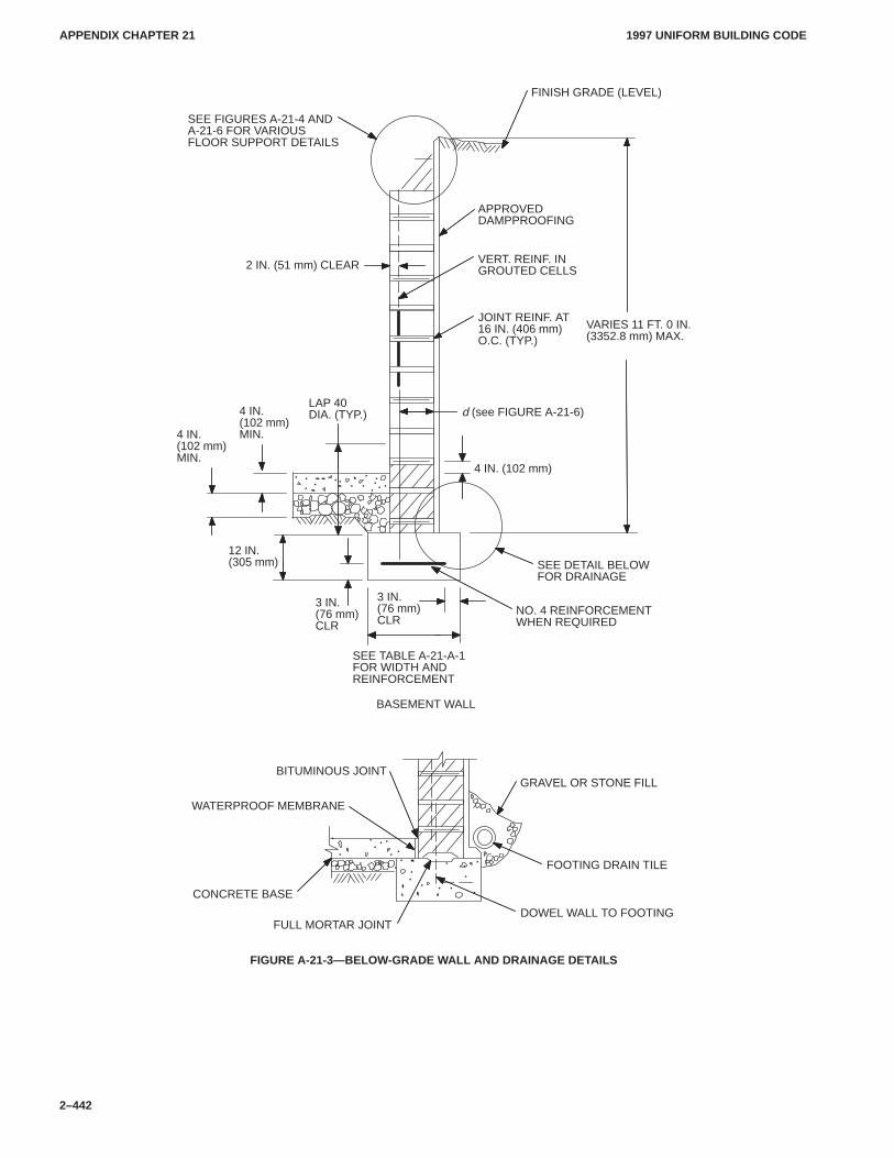
APPENDIX CHAPTER 21APPENDIX CHAPTER 21
1997 UNIFORM BUILDING CODE
2–442
3 IN.(76 mm)CLR
SEE FIGURES A-21-4 ANDA-21-6 FOR VARIOUSFLOOR SUPPORT DETAILS
LAP 40DIA. (TYP.)
NO. 4 REINFORCEMENTWHEN REQUIRED
BASEMENT WALL
FINISH GRADE (LEVEL)
APPROVEDDAMPPROOFING
VERT. REINF. INGROUTED CELLS
d (see FIGURE A-21-6)
JOINT REINF. AT16 IN. (406 mm)O.C. (TYP.)
SEE TABLE A-21-A-1FOR WIDTH ANDREINFORCEMENT
SEE DETAIL BELOWFOR DRAINAGE
GRAVEL OR STONE FILL
FOOTING DRAIN TILE
DOWEL WALL TO FOOTINGFULL MORTAR JOINT
BITUMINOUS JOINT
WATERPROOF MEMBRANE
4 IN. (102 mm)
2 IN. (51 mm) CLEAR
4 IN.(102 mm)MIN.
12 IN.(305 mm)
CONCRETE BASE
VARIES 11 FT. 0 IN.(3352.8 mm) MAX.
3 IN.(76 mm)CLR
4 IN.(102 mm)MIN.
FIGURE A-21-3—BELOW-GRADE WALL AND DRAINAGE DETAILS
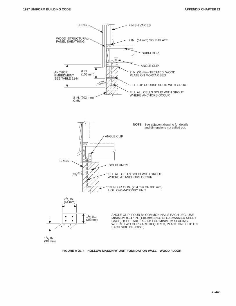
APPENDIX CHAPTER 21APPENDIX CHAPTER 21
1997 UNIFORM BUILDING CODE
2–443
ANCHOREMBEDMENT,SEE TABLE 21-N
SIDING FINISH VARIES
2 IN. (51 mm) SOLE PLATE
8 IN. (203 mm)CMU
ANGLE CLIP
FILL ALL CELLS SOLID WITH GROUTWHERE ANCHORS OCCUR
FILL TOP COURSE SOLID WITH GROUT
2 IN. (51 mm) TREATED WOODPLATE ON MORTAR BED
SUBFLOOR
NOTE: See adjacent drawing for detailsand dimensions not called out.
ANGLE CLIP
BRICKSOLID UNITS
FILL ALL CELLS SOLID WITH GROUTWHERE AT ANCHORS OCCUR
10 IN. OR 12 IN. (254 mm OR 305 mm)HOLLOW-MASONRY UNIT
11/2 IN.(38 mm)
11/2 IN.(38 mm)
21/2 IN.(64 mm)
ANGLE CLIP: FOUR 8d COMMON NAILS EACH LEG. USEMINIMUM 0.047 IN. (1.04 mm) (NO. 18 GALVANIZED SHEETGAGE). (SEE TABLE A-21-B FOR MINIMUM SPACING.WHERE TWO CLIPS ARE REQUIRED, PLACE ONE CLIP ONEACH SIDE OF JOIST.)
WOOD STRUCTURALPANEL SHEATHING
6 IN.(153 mm)
FIGURE A-21-4—HOLLOW-MASONRY UNIT FOUNDATION WALL—WOOD FLOOR
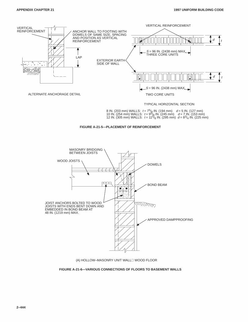
APPENDIX CHAPTER 21APPENDIX CHAPTER 21
1997 UNIFORM BUILDING CODE
2–444
d
ÏÏ
ÏÏ
ÏÏ
ÏÏ
VERTICAL REINFORCEMENT
EXTERIOR EARTH SIDE OF WALL
S = 96 IN. (2438 mm) MAX.THREE CORE UNITS
ANCHOR WALL TO FOOTING WITHDOWELS OF SAME SIZE, SPACINGAND POSITION AS VERTICALREINFORCEMENT
8 IN. (203 mm) WALLS: t = 75/8 IN. (194 mm) d = 5 IN. (127 mm)10 IN. (254 mm) WALLS: t = 95/8 IN. (245 mm) d = 7 IN. (153 mm)12 IN. (305 mm) WALLS: t = 115/8 IN. (295 mm) d = 83/4 IN. (225 mm)
S = 96 IN. (2438 mm) MAX.
TWO CORE UNITS
VERTICALREINFORCEMENT
ALTERNATE ANCHORAGE DETAIL
d t
t
TYPICAL HORIZONTAL SECTION
LAP
FIGURE A-21-5—PLACEMENT OF REINFORCEMENT
ÎÎÎÎÎÎÎÎÎÎÎÎÎÎÎ
MASONRY BRIDGING BETWEEN JOISTS
(A) HOLLOW–MASONRY UNIT WALL WOOD FLOOR
WOOD JOISTS
JOIST ANCHORS BOLTED TO WOODJOISTS WITH ENDS BENT DOWN ANDEMBEDDED IN BOND BEAM AT48 IN. (1219 mm) MAX.
APPROVED DAMPPROOFING
BOND BEAM
DOWELS
FIGURE A-21-6—VARIOUS CONNECTIONS OF FLOORS TO BASEMENT WALLS
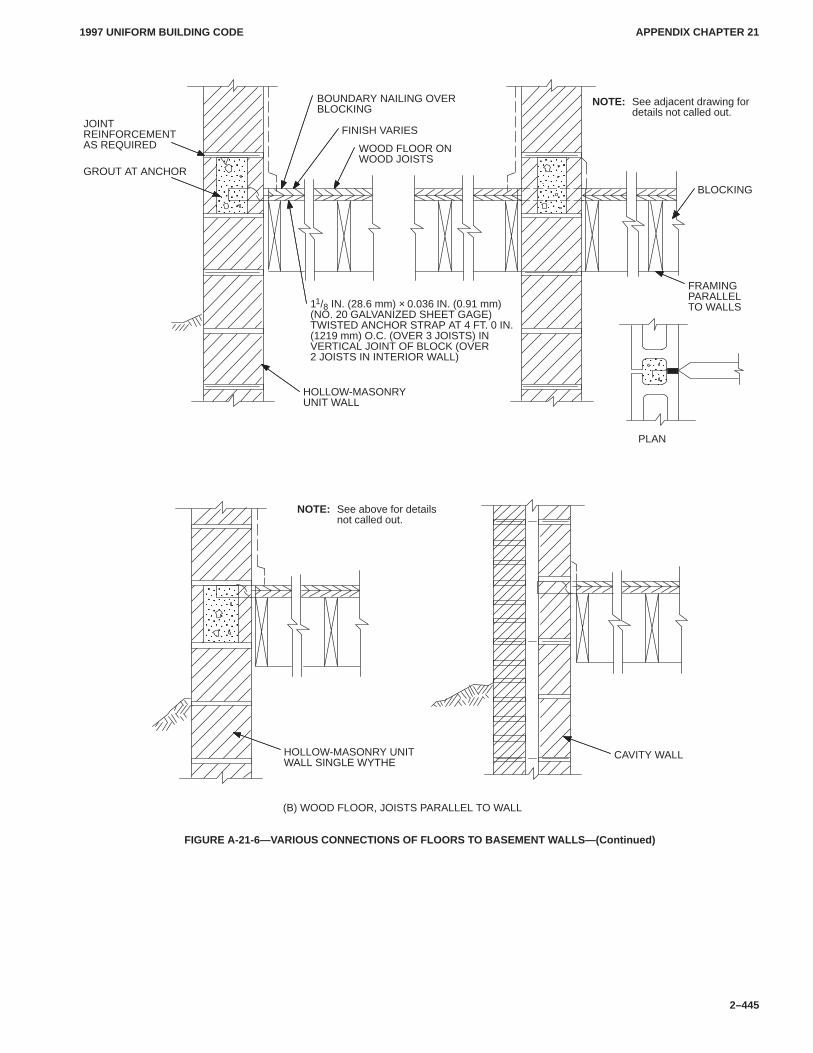
APPENDIX CHAPTER 21APPENDIX CHAPTER 21
1997 UNIFORM BUILDING CODE
2–445
ÎÎÎÎ
ÎÎÎÎÎÎÎÎÎÎÎÎ
GROUT AT ANCHORÎÎÎÎÎÎÎÎ
JOINTREINFORCEMENTAS REQUIRED
FINISH VARIES
WOOD FLOOR ONWOOD JOISTS
BLOCKING
PLAN
11/8 IN. (28.6 mm) × 0.036 IN. (0.91 mm)(NO. 20 GALVANIZED SHEET GAGE)TWISTED ANCHOR STRAP AT 4 FT. 0 IN.(1219 mm) O.C. (OVER 3 JOISTS) INVERTICAL JOINT OF BLOCK (OVER2 JOISTS IN INTERIOR WALL)
HOLLOW-MASONRYUNIT WALL
ÎÎÎÎÎÎÎÎÎÎÎÎ
HOLLOW-MASONRY UNITWALL SINGLE WYTHE
CAVITY WALL
(B) WOOD FLOOR, JOISTS PARALLEL TO WALL
BOUNDARY NAILING OVERBLOCKING
FRAMINGPARALLELTO WALLS
NOTE: See adjacent drawing fordetails not called out.
NOTE: See above for detailsnot called out.
FIGURE A-21-6—VARIOUS CONNECTIONS OF FLOORS TO BASEMENT WALLS—(Continued)
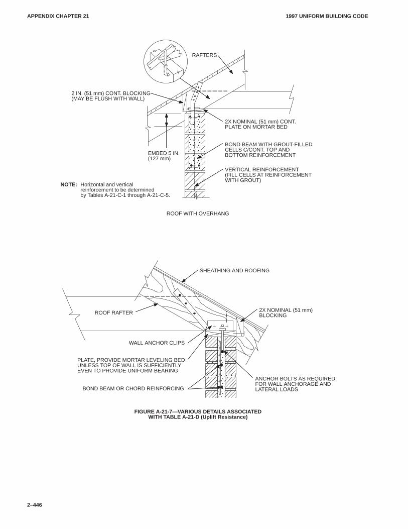
APPENDIX CHAPTER 21APPENDIX CHAPTER 21
1997 UNIFORM BUILDING CODE
2–446
ÎÎÎÎÎÎÎÎÎÎÎÎ
RAFTERS
ROOF WITH OVERHANG
NOTE: Horizontal and verticalreinforcement to be determinedby Tables A-21-C-1 through A-21-C-5.
2 IN. (51 mm) CONT. BLOCKING (MAY BE FLUSH WITH WALL)
BOND BEAM WITH GROUT-FILLED CELLS C/CONT. TOP AND BOTTOM REINFORCEMENTEMBED 5 IN.
(127 mm)
VERTICAL REINFORCEMENT (FILL CELLS AT REINFORCEMENT WITH GROUT)
2X NOMINAL (51 mm) CONT.PLATE ON MORTAR BED
ÎÎÎÎÎÎÎ
ÎÎÎÎÎÎÎÎÎÎÎÎÎÎÎÎÎÎÎÎÎÎÎÎ
WALL ANCHOR CLIPS
SHEATHING AND ROOFING
2X NOMINAL (51 mm)BLOCKING
BOND BEAM OR CHORD REINFORCING
PLATE, PROVIDE MORTAR LEVELING BEDUNLESS TOP OF WALL IS SUFFICIENTLYEVEN TO PROVIDE UNIFORM BEARING
ANCHOR BOLTS AS REQUIREDFOR WALL ANCHORAGE ANDLATERAL LOADS
ROOF RAFTER
FIGURE A-21-7—VARIOUS DETAILS ASSOCIATEDWITH TABLE A-21-D (Uplift Resistance)
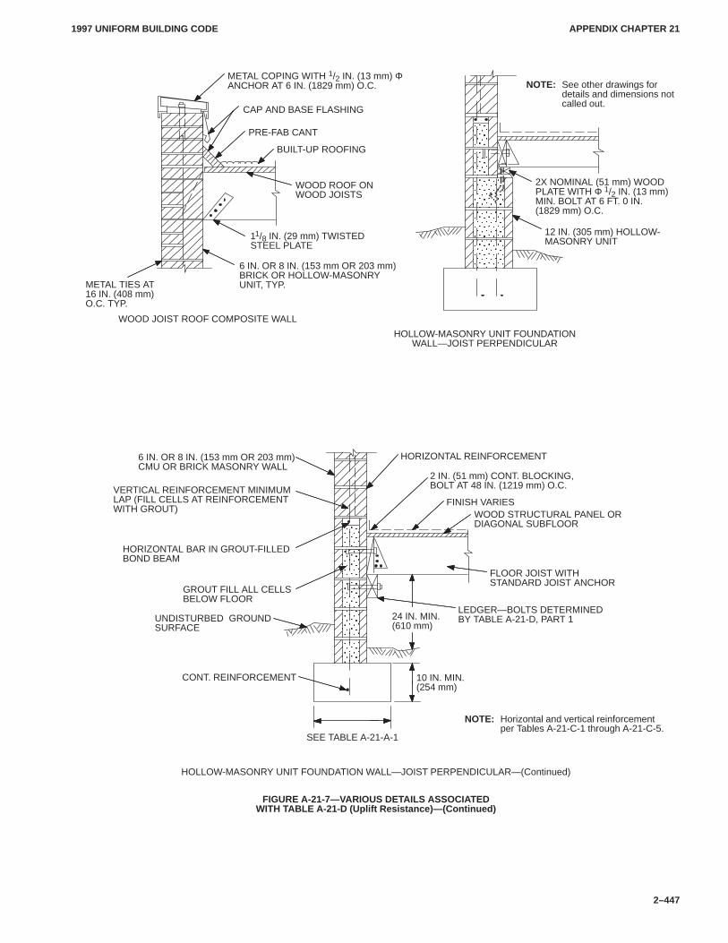
APPENDIX CHAPTER 21APPENDIX CHAPTER 21
1997 UNIFORM BUILDING CODE
2–447
METAL COPING WITH 1/2 IN. (13 mm) ΦANCHOR AT 6 IN. (1829 mm) O.C.
ÎÎÎÎÎÎÎÎÎÎÎÎÎÎÎÎÎÎ
CAP AND BASE FLASHING
PRE-FAB CANT
BUILT-UP ROOFING
WOOD ROOF ONWOOD JOISTS
11/8 IN. (29 mm) TWISTEDSTEEL PLATE
6 IN. OR 8 IN. (153 mm OR 203 mm)BRICK OR HOLLOW-MASONRYUNIT, TYP.METAL TIES AT
16 IN. (408 mm)O.C. TYP.
NOTE: See other drawings for details and dimensions notcalled out.
12 IN. (305 mm) HOLLOW-MASONRY UNIT
2X NOMINAL (51 mm) WOODPLATE WITH Φ 1/2 IN. (13 mm)MIN. BOLT AT 6 FT. 0 IN.(1829 mm) O.C.
HOLLOW-MASONRY UNIT FOUNDATIONWALL—JOIST PERPENDICULAR
WOOD JOIST ROOF COMPOSITE WALL
HOLLOW-MASONRY UNIT FOUNDATION WALL—JOIST PERPENDICULAR—(Continued)
SEE TABLE A-21-A-1
NOTE: Horizontal and vertical reinforcementper Tables A-21-C-1 through A-21-C-5.
UNDISTURBED GROUNDSURFACE
CONT. REINFORCEMENT
6 IN. OR 8 IN. (153 mm OR 203 mm)CMU OR BRICK MASONRY WALL
HORIZONTAL REINFORCEMENT
2 IN. (51 mm) CONT. BLOCKING,BOLT AT 48 IN. (1219 mm) O.C.
FINISH VARIESWOOD STRUCTURAL PANEL ORDIAGONAL SUBFLOOR
FLOOR JOIST WITH STANDARD JOIST ANCHOR
LEDGER—BOLTS DETERMINED BY TABLE A-21-D, PART 1
10 IN. MIN.(254 mm)
24 IN. MIN.(610 mm)
ÎÎÎÎÎÎÎÎÎÎÎÎÎÎÎÎÎÎÎÎÎÎÎÎÎÎÎ
GROUT FILL ALL CELLSBELOW FLOOR
HORIZONTAL BAR IN GROUT-FILLEDBOND BEAM
VERTICAL REINFORCEMENT MINIMUMLAP (FILL CELLS AT REINFORCEMENTWITH GROUT)
FIGURE A-21-7—VARIOUS DETAILS ASSOCIATEDWITH TABLE A-21-D (Uplift Resistance)—(Continued)
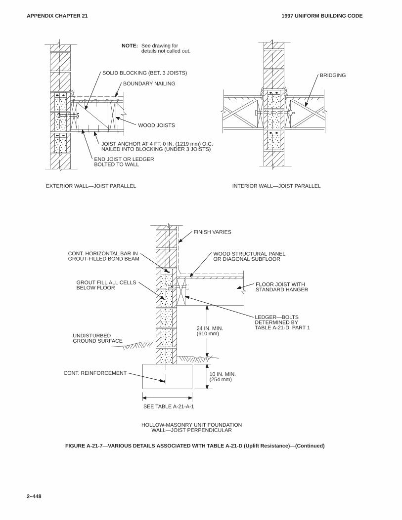
APPENDIX CHAPTER 21APPENDIX CHAPTER 21
1997 UNIFORM BUILDING CODE
2–448
ÎÎÎÎÎÎÎÎÎÎÎÎÎÎÎÎÎÎÎÎÎÎÎÎÎÎÎÎÎÎ
HOLLOW-MASONRY UNIT FOUNDATIONWALL—JOIST PERPENDICULAR
GROUT FILL ALL CELLSBELOW FLOOR
UNDISTURBED GROUND SURFACE
CONT. REINFORCEMENT
FINISH VARIES
WOOD STRUCTURAL PANELOR DIAGONAL SUBFLOOR
FLOOR JOIST WITHSTANDARD HANGER
SEE TABLE A-21-A-1
10 IN. MIN.(254 mm)
24 IN. MIN.(610 mm)
CONT. HORIZONTAL BAR INGROUT-FILLED BOND BEAM
ÎÎÎÎÎÎÎÎÎÎÎÎÎÎ
NOTE: See drawing fordetails not called out.
JOIST ANCHOR AT 4 FT. 0 IN. (1219 mm) O.C.NAILED INTO BLOCKING (UNDER 3 JOISTS)
WOOD JOISTS
BOUNDARY NAILING
SOLID BLOCKING (BET. 3 JOISTS)
END JOIST OR LEDGERBOLTED TO WALL
BRIDGING
EXTERIOR WALL—JOIST PARALLEL INTERIOR WALL—JOIST PARALLEL
ÎÎÎÎÎÎÎÎÎÎÎÎ
LEDGER—BOLTSDETERMINED BY TABLE A-21-D, PART 1
FIGURE A-21-7—VARIOUS DETAILS ASSOCIATED WITH TABLE A-21-D (Uplift Resistance)—(Continued)
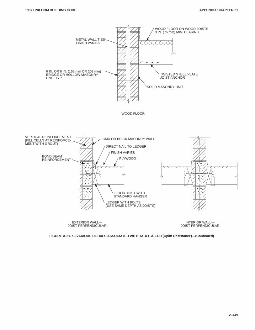
APPENDIX CHAPTER 21APPENDIX CHAPTER 21
1997 UNIFORM BUILDING CODE
2–449
METAL WALL TIESFINISH VARIES
WOOD FLOOR
ÎÎÎÎÎÎÎÎÎÎÎÎÎÎÎÎÎÎÎÎÎ
ÎÎÎÎÎÎÎÎÎÎÎÎÎÎ
6 IN. OR 8 IN. (153 mm OR 203 mm)BRIDGE OR HOLLOW-MASONRYUNIT, TYP.
WOOD FLOOR ON WOOD JOISTS 3 IN. (76 mm) MIN. BEARING
TWISTED STEEL PLATEJOIST ANCHOR
SOLID MASONRY UNIT
BOND BEAMREINFORCEMENT
EXTERIOR WALL—JOIST PERPENDICULAR
INTERIOR WALL—JOIST PERPENDICULAR
CMU OR BRICK MASONRY WALL
DIRECT NAIL TO LEDGER
FINISH VARIES
PLYWOOD
LEDGER WITH BOLTS(USE SAME DEPTH AS JOISTS)
VERTICAL REINFORCEMENT(FILL CELLS AT REINFORCE-MENT WITH GROUT)
FLOOR JOIST WITHSTANDARD HANGER
FIGURE A-21-7—VARIOUS DETAILS ASSOCIATED WITH TABLE A-21-D (Uplift Resistance)—(Continued)
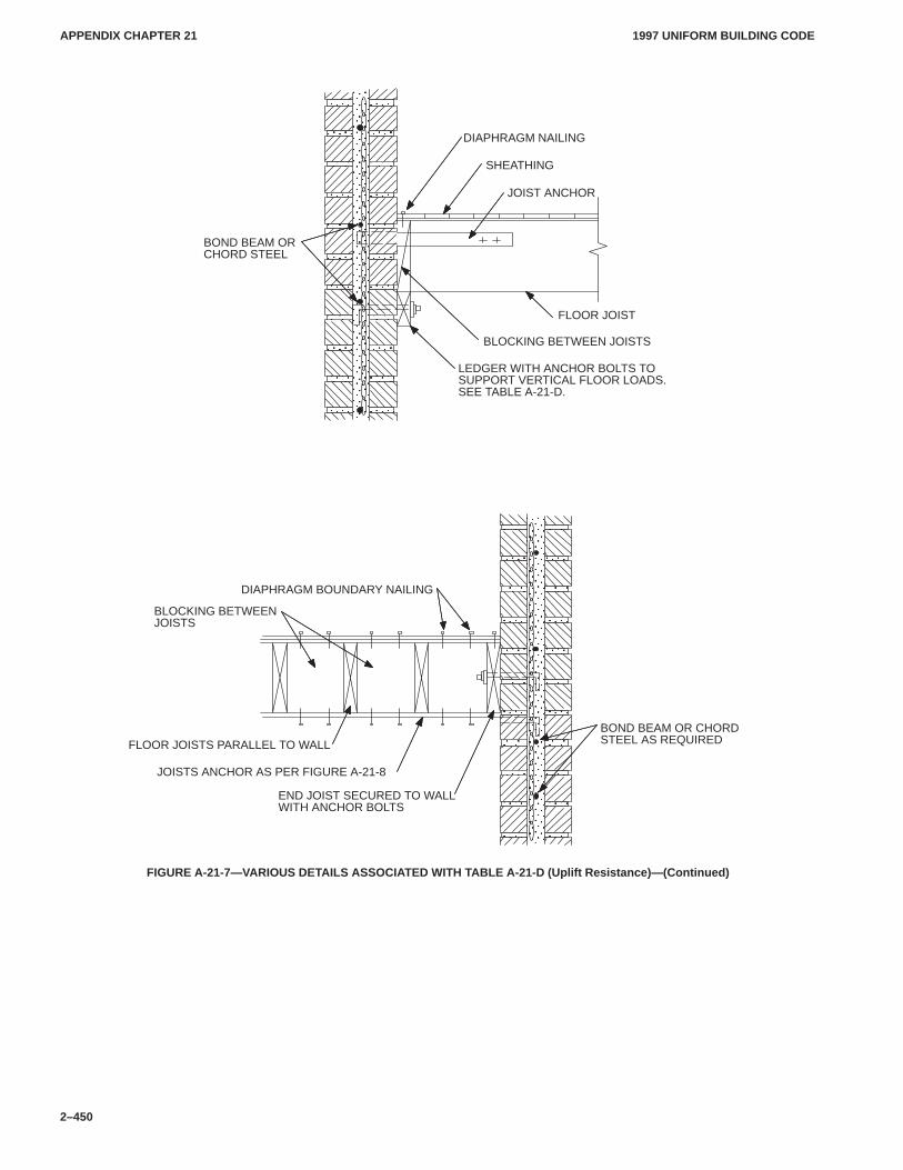
APPENDIX CHAPTER 21APPENDIX CHAPTER 21
1997 UNIFORM BUILDING CODE
2–450
ÎÎÎÎÎÎÎÎÎÎÎÎÎÎÎÎÎÎÎÎÎÎÎÎÎÎÎÎÎÎ
ÎÎÎÎÎÎÎÎÎÎÎÎ
ÎÎÎÎÎÎÎÎÎÎÎÎÎÎÎÎ
ÎÎÎÎÎÎÎÎ
ÎÎÎÎÎÎÎÎ
ÎÎÎÎÎÎÎÎ
ÎÎÎÎÎÎÎÎ
ÎÎÎÎÎÎÎÎÎÎÎÎÎÎÎÎ
ÎÎÎÎÎÎÎÎÎÎÎÎÎÎÎÎÎÎÎÎÎÎÎÎÎÎÎÎÎÎÎÎÎÎÎÎÎÎÎÎÎÎÎÎÎ
ÎÎÎÎÎÎÎÎÎÎ
ÎÎÎÎÎÎÎÎÎÎ
ÎÎÎÎÎ
JOIST ANCHOR
BOND BEAM ORCHORD STEEL
FLOOR JOIST
DIAPHRAGM NAILING
LEDGER WITH ANCHOR BOLTS TO SUPPORT VERTICAL FLOOR LOADS.SEE TABLE A-21-D.
SHEATHING
END JOIST SECURED TO WALLWITH ANCHOR BOLTS
BOND BEAM OR CHORDSTEEL AS REQUIRED
BLOCKING BETWEENJOISTS
DIAPHRAGM BOUNDARY NAILING
JOISTS ANCHOR AS PER FIGURE A-21-8
FLOOR JOISTS PARALLEL TO WALL
BLOCKING BETWEEN JOISTS
FIGURE A-21-7—VARIOUS DETAILS ASSOCIATED WITH TABLE A-21-D (Uplift Resistance)—(Continued)
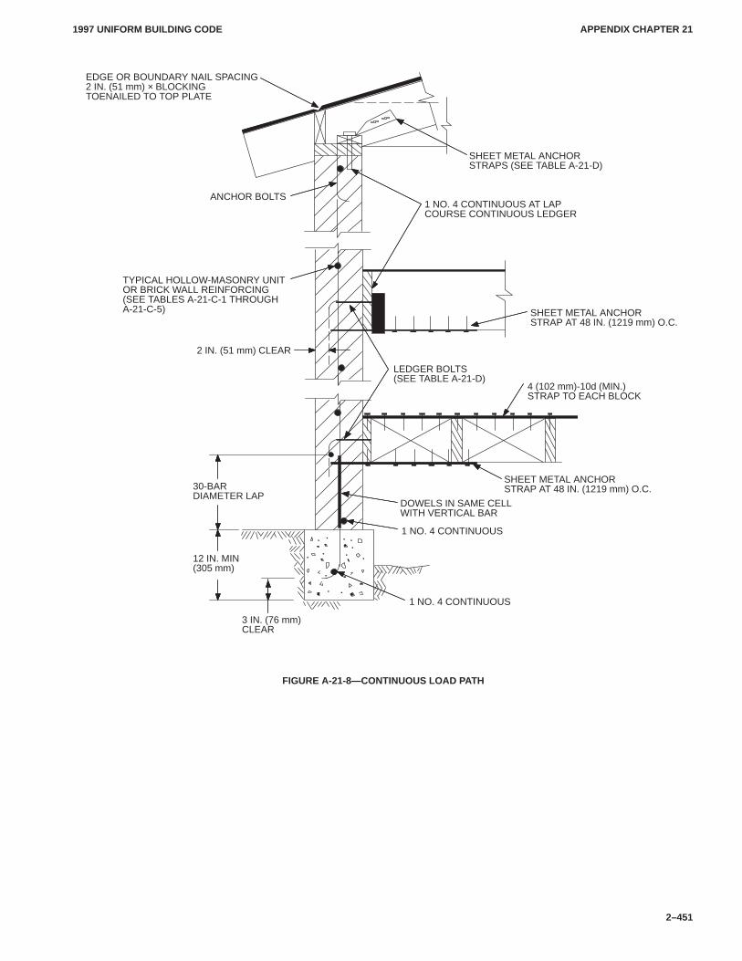
APPENDIX CHAPTER 21APPENDIX CHAPTER 21
1997 UNIFORM BUILDING CODE
2–451
2 IN. (51 mm) CLEAR
LEDGER BOLTS(SEE TABLE A-21-D)
3 IN. (76 mm)CLEAR
DOWELS IN SAME CELLWITH VERTICAL BAR
SHEET METAL ANCHORSTRAP AT 48 IN. (1219 mm) O.C.
1 NO. 4 CONTINUOUS
4 (102 mm)-10d (MIN.)STRAP TO EACH BLOCK
SHEET METAL ANCHORSTRAPS (SEE TABLE A-21-D)
1 NO. 4 CONTINUOUS AT LAP COURSE CONTINUOUS LEDGER
SHEET METAL ANCHORSTRAP AT 48 IN. (1219 mm) O.C.
ANCHOR BOLTS
EDGE OR BOUNDARY NAIL SPACING2 IN. (51 mm) × BLOCKINGTOENAILED TO TOP PLATE
TYPICAL HOLLOW-MASONRY UNIT OR BRICK WALL REINFORCING(SEE TABLES A-21-C-1 THROUGHA-21-C-5)
30-BARDIAMETER LAP
12 IN. MIN(305 mm)
1 NO. 4 CONTINUOUS
FIGURE A-21-8—CONTINUOUS LOAD PATH
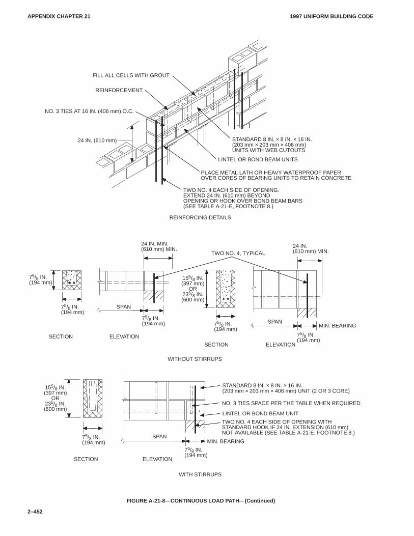
APPENDIX CHAPTER 21APPENDIX CHAPTER 21
1997 UNIFORM BUILDING CODE
2–452
FILL ALL CELLS WITH GROUT
REINFORCING DETAILS
REINFORCEMENT
NO. 3 TIES AT 16 IN. (406 mm) O.C.
24 IN. (610 mm) STANDARD 8 IN. × 8 IN. × 16 IN.(203 mm × 203 mm × 406 mm)UNITS WITH WEB CUTOUTS
LINTEL OR BOND BEAM UNITS
TWO NO. 4, TYPICAL
SPAN
PLACE METAL LATH OR HEAVY WATERPROOF PAPER OVER CORES OF BEARING UNITS TO RETAIN CONCRETE
SPAN
WITHOUT STIRRUPS
ELEVATION
SECTION ELEVATION
SECTION
SECTION ELEVATION
WITH STIRRUPS
SPAN
75/8 IN.(194 mm)
LINTEL OR BOND BEAM UNIT
STANDARD 8 IN. × 8 IN. × 16 IN.(203 mm × 203 mm × 406 mm) UNIT (2 OR 3 CORE)
NO. 3 TIES SPACE PER THE TABLE WHEN REQUIRED
TWO NO. 4 EACH SIDE OF OPENING WITH STANDARD HOOK IF 24 IN. EXTENSION (610 mm)NOT AVAILABLE (SEE TABLE A-21-E, FOOTNOTE 8.)
24 IN. MIN.(610 mm) MIN.
TWO NO. 4 EACH SIDE OF OPENING.EXTEND 24 IN. (610 mm) BEYOND OPENING OR HOOK OVER BOND BEAM BARS(SEE TABLE A-21-E, FOOTNOTE 8.)
75/8 IN.(194 mm)
75/8 IN.(194 mm)
75/8 IN.(194 mm)
75/8 IN.(194 mm)
75/8 IN.(194 mm)
MIN. BEARING
75/8 IN.(194 mm)
155/8 IN.(397 mm)
OR235/8 IN.(600 mm)
155/8 IN.(397 mm)
OR235/8 IN.(600 mm)
24 IN.(610 mm) MIN.
MIN. BEARING
FIGURE A-21-8—CONTINUOUS LOAD PATH—(Continued)
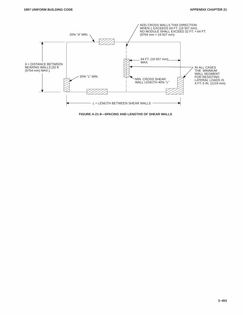
APPENDIX CHAPTER 21APPENDIX CHAPTER 21
1997 UNIFORM BUILDING CODE
2–453
L = LENGTH BETWEEN SHEAR WALLS
64 FT. (19 507 mm)MAX.b = DISTANCE BETWEEN
BEARING WALLS [32 ft.(9754 mm) MAX.]
ADD CROSS WALLS THIS DIRECTIONWHEN L EXCEEDS 64 FT. (19 507 mm). NO MODULE SHALL EXCEED 32 FT. × 64 FT. (9754 mm × 19 507 mm)20% “b” MIN.
20% “L” MIN.MIN. CROSS SHEARWALL LENGTH 40% “L”
IN ALL CASESTHE MINIMUMWALL SEGMENTFOR RESISTINGLATERAL LOADS IS4 FT. 0 IN. (1219 mm)
FIGURE A-21-9—SPACING AND LENGTHS OF SHEAR WALLS
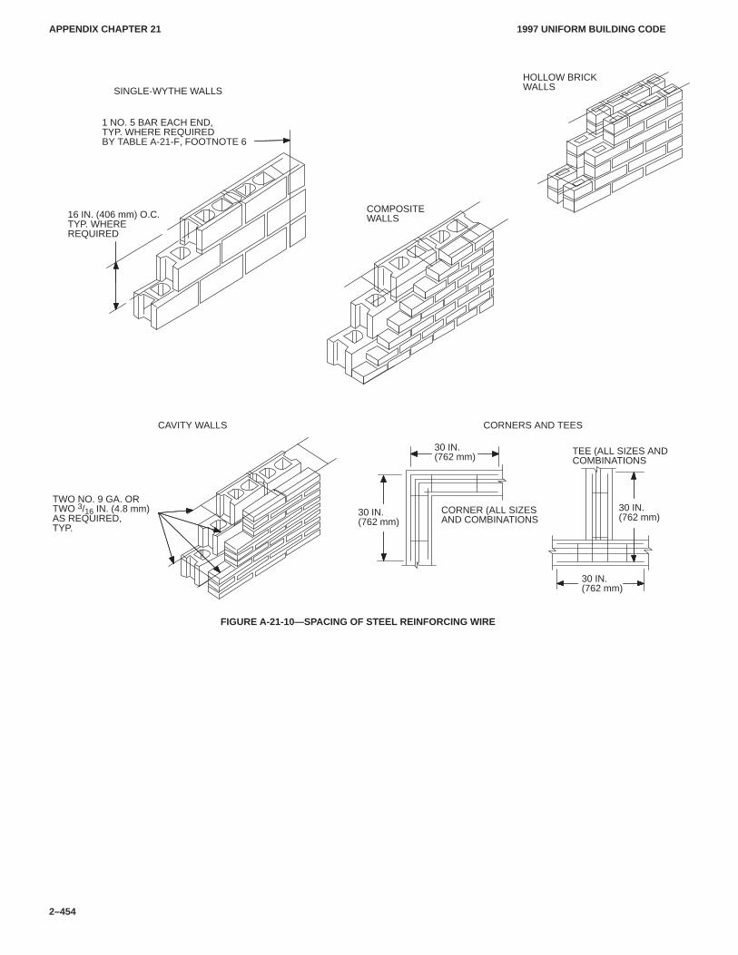
APPENDIX CHAPTER 21APPENDIX CHAPTER 21
1997 UNIFORM BUILDING CODE
2–454
30 IN.(762 mm)
CORNER (ALL SIZES AND COMBINATIONS
CAVITY WALLS CORNERS AND TEES
30 IN.(762 mm)
TEE (ALL SIZES AND COMBINATIONS
COMPOSITE WALLS
HOLLOW BRICKWALLSSINGLE-WYTHE WALLS
16 IN. (406 mm) O.C.TYP. WHEREREQUIRED
TWO NO. 9 GA. ORTWO 3/16 IN. (4.8 mm)AS REQUIRED,TYP.
1 NO. 5 BAR EACH END, TYP. WHERE REQUIRED BY TABLE A-21-F, FOOTNOTE 6
30 IN.(762 mm)30 IN.
(762 mm)
FIGURE A-21-10—SPACING OF STEEL REINFORCING WIRE
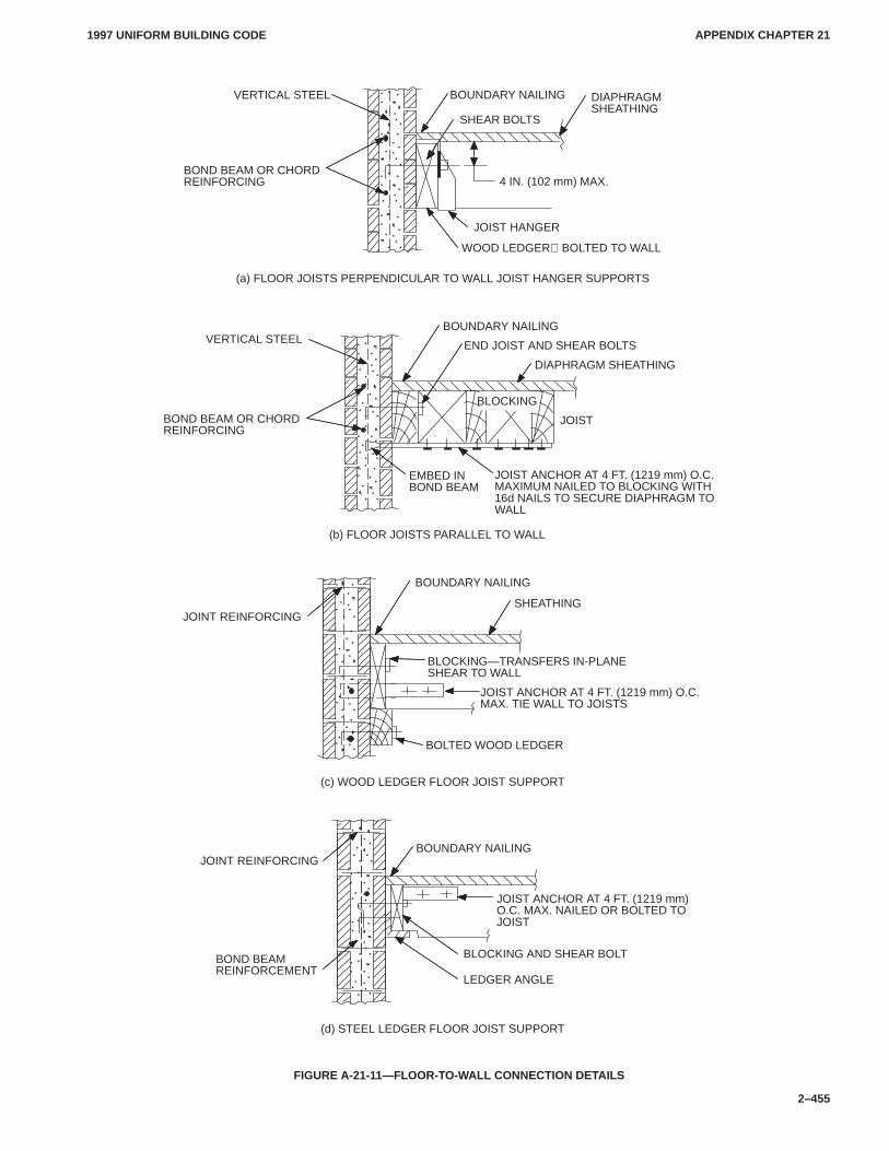
APPENDIX CHAPTER 21APPENDIX CHAPTER 21
1997 UNIFORM BUILDING CODE
2–455
BLOCKING
(d) STEEL LEDGER FLOOR JOIST SUPPORT
BOND BEAMREINFORCEMENT
LEDGER ANGLE
BLOCKING AND SHEAR BOLT
JOIST ANCHOR AT 4 FT. (1219 mm)O.C. MAX. NAILED OR BOLTED TOJOIST
(c) WOOD LEDGER FLOOR JOIST SUPPORT
BOLTED WOOD LEDGER
JOIST ANCHOR AT 4 FT. (1219 mm) O.C.MAX. TIE WALL TO JOISTS
BLOCKING—TRANSFERS IN-PLANESHEAR TO WALL
JOINT REINFORCING
BOUNDARY NAILING
SHEATHING
(b) FLOOR JOISTS PARALLEL TO WALL
EMBED INBOND BEAM
JOIST ANCHOR AT 4 FT. (1219 mm) O.C. MAXIMUM NAILED TO BLOCKING WITH16d NAILS TO SECURE DIAPHRAGM TOWALL
JOIST
BOUNDARY NAILING
END JOIST AND SHEAR BOLTS
(a) FLOOR JOISTS PERPENDICULAR TO WALL JOIST HANGER SUPPORTS
BOUNDARY NAILINGVERTICAL STEEL DIAPHRAGMSHEATHING
BOND BEAM OR CHORDREINFORCING
SHEAR BOLTS
4 IN. (102 mm) MAX.
JOIST HANGER
WOOD LEDGER BOLTED TO WALL
VERTICAL STEEL
BOND BEAM OR CHORDREINFORCING
DIAPHRAGM SHEATHING
JOINT REINFORCINGBOUNDARY NAILING
FIGURE A-21-11—FLOOR-TO-WALL CONNECTION DETAILS
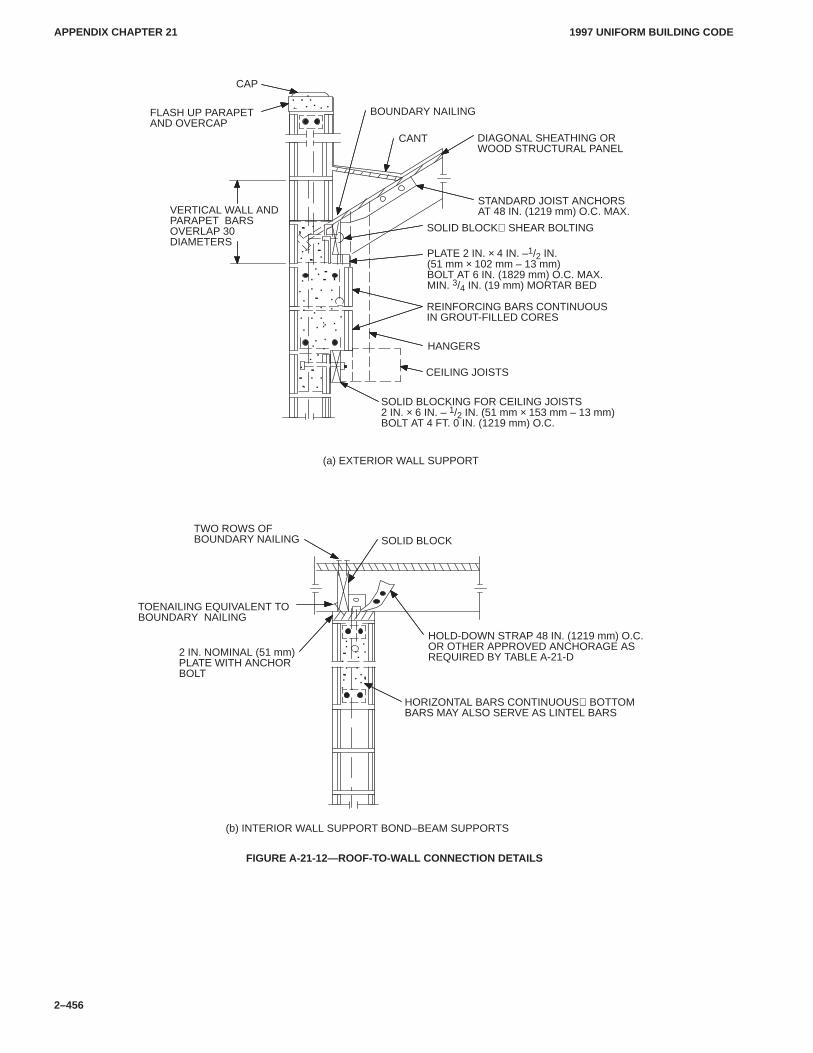
APPENDIX CHAPTER 21APPENDIX CHAPTER 21
1997 UNIFORM BUILDING CODE
2–456
TWO ROWS OFBOUNDARY NAILING SOLID BLOCK
(b) INTERIOR WALL SUPPORT BOND–BEAM SUPPORTS
(a) EXTERIOR WALL SUPPORT
TOENAILING EQUIVALENT TOBOUNDARY NAILING
HOLD-DOWN STRAP 48 IN. (1219 mm) O.C.OR OTHER APPROVED ANCHORAGE ASREQUIRED BY TABLE A-21-D
HORIZONTAL BARS CONTINUOUS BOTTOMBARS MAY ALSO SERVE AS LINTEL BARS
2 IN. NOMINAL (51 mm)PLATE WITH ANCHORBOLT
HANGERS
CAP
CANT
FLASH UP PARAPETAND OVERCAP
DIAGONAL SHEATHING ORWOOD STRUCTURAL PANEL
SOLID BLOCKING FOR CEILING JOISTS2 IN. × 6 IN. – 1/2 IN. (51 mm × 153 mm – 13 mm)BOLT AT 4 FT. 0 IN. (1219 mm) O.C.
REINFORCING BARS CONTINUOUS IN GROUT-FILLED CORES
CEILING JOISTS
STANDARD JOIST ANCHORSAT 48 IN. (1219 mm) O.C. MAX.
SOLID BLOCK SHEAR BOLTING
PLATE 2 IN. × 4 IN. –1/2 IN.(51 mm × 102 mm – 13 mm)BOLT AT 6 IN. (1829 mm) O.C. MAX.MIN. 3/4 IN. (19 mm) MORTAR BED
VERTICAL WALL ANDPARAPET BARSOVERLAP 30DIAMETERS
BOUNDARY NAILING
FIGURE A-21-12—ROOF-TO-WALL CONNECTION DETAILS
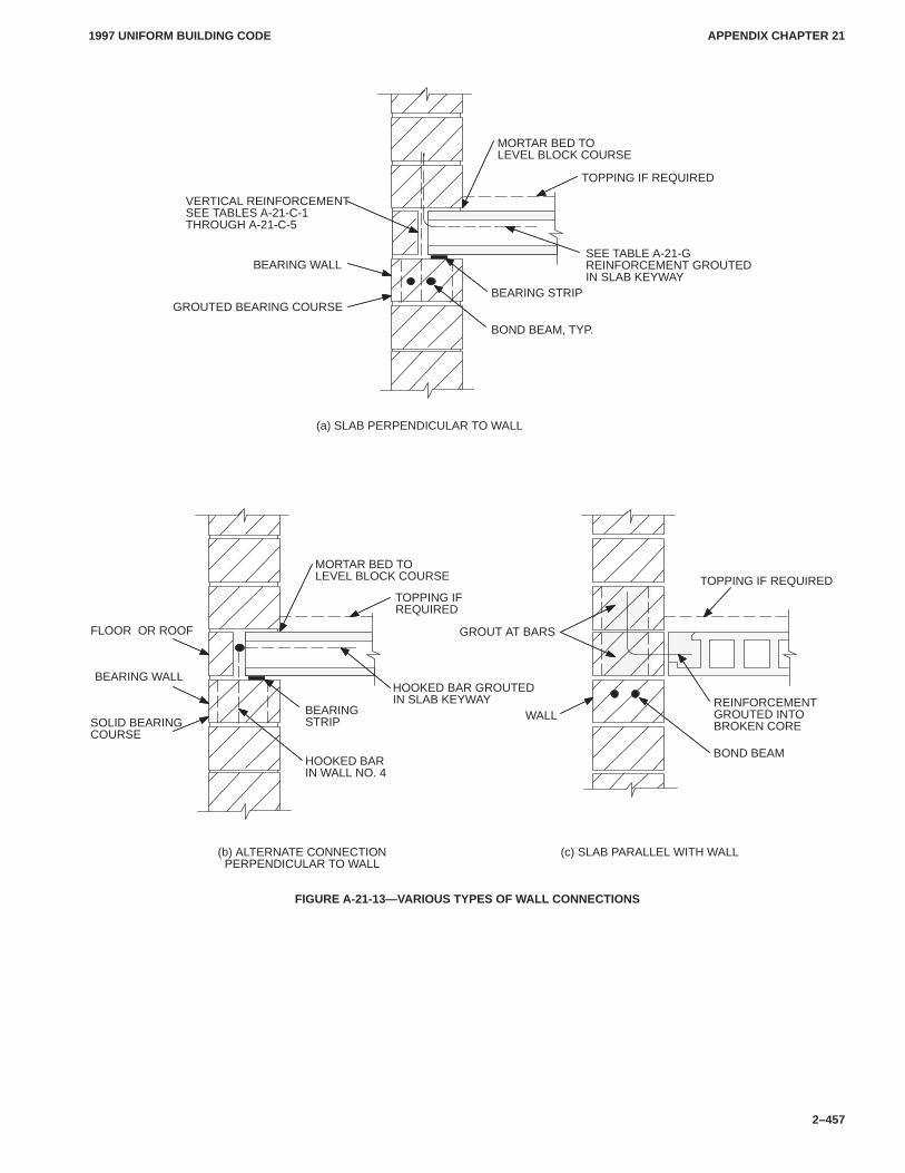
APPENDIX CHAPTER 21APPENDIX CHAPTER 21
1997 UNIFORM BUILDING CODE
2–457
BOND BEAM
(c) SLAB PARALLEL WITH WALL(b) ALTERNATE CONNECTIONPERPENDICULAR TO WALL
WALLREINFORCEMENTGROUTED INTOBROKEN CORE
TOPPING IF REQUIRED
(a) SLAB PERPENDICULAR TO WALL
MORTAR BED TOLEVEL BLOCK COURSE
SEE TABLE A-21-GREINFORCEMENT GROUTEDIN SLAB KEYWAY
BEARING WALL
GROUTED BEARING COURSEBEARING STRIP
BOND BEAM, TYP.
TOPPING IF REQUIRED
MORTAR BED TOLEVEL BLOCK COURSE
BEARINGSTRIP
TOPPING IFREQUIRED
HOOKED BAR GROUTED IN SLAB KEYWAY
HOOKED BAR IN WALL NO. 4
SOLID BEARINGCOURSE
VERTICAL REINFORCEMENTSEE TABLES A-21-C-1THROUGH A-21-C-5
FLOOR OR ROOF
BEARING WALL
GROUT AT BARS
FIGURE A-21-13—VARIOUS TYPES OF WALL CONNECTIONS
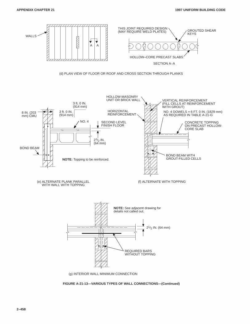
APPENDIX CHAPTER 21APPENDIX CHAPTER 21
1997 UNIFORM BUILDING CODE
2–458
ÎÎÎÎ
ÎÎ
REQUIRED BARSWITHOUT TOPPING
(g) INTERIOR WALL MINIMUM CONNECTION
NOTE: See adjacent drawing for details not called out.
21/2 IN. (64 mm)
NOTE: Topping to be reinforced.
(f) ALTERNATE WITH TOPPING
BOND BEAM
SECOND LEVELFINISH FLOOR
21/2 IN.(64 mm)
3 ft. 0 IN.(914 mm)
(d) PLAN VIEW OF FLOOR OR ROOF AND CROSS SECTION THROUGH PLANKS
SECTION A–A
THIS JOINT REQUIRED DESIGN(MAY REQUIRE WELD PLATES)
WALLS
HOLLOW–CORE PRECAST SLABS
GROUTED SHEARKEYS
VERTICAL REINFORCEMENT(FILL CELLS AT REINFORCEMENTWITH GROUT)
HOLLOW-MASONRYUNIT OR BRICK WALL
NO. 4 DOWELS × 6 FT. 0 IN. (1829 mm)AS REQUIRED IN TABLE A-21-G
HORIZONTALREINFORCEMENT
BOND BEAM WITHGROUT-FILLED CELLS
A A
CONCRETE TOPPINGON PRECAST HOLLOW-CORE SLAB
8 IN. (203mm) CMU
NO. 4
(e) ALTERNATE PLANK PARALLELWITH WALL WITH TOPPING
3 ft. 0 IN.(914 mm)
FIGURE A-21-13—VARIOUS TYPES OF WALL CONNECTIONS—(Continued)
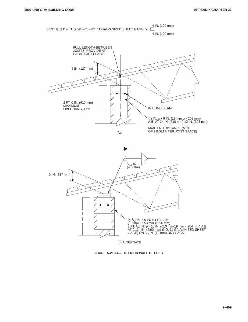
APPENDIX CHAPTER 21APPENDIX CHAPTER 21
1997 UNIFORM BUILDING CODE
2–459
(b) ALTERNATE
P 1/2 IN. × 6 IN. × 1 FT. 2 IN.(13 mm × 153 mm × 356 mm)2 FT. 3/4 IN. φ × 10 IN. (610 mm-19 mm × 254 mm) A.B.AT 0.114 IN. (2.90 mm) (NO. 11 GALVANIZED SHEETGAGE) ON 3/4 IN. (19 mm) DRY PACK
FULL LENGTH BETWEENJOISTS. PROVIDE ATEACH JOIST SPACE
2 FT. 0 IN. (610 mm)MAXIMUM OVERHANG, TYP. IN BOND BEAM
3/4 IN. φ × 8 IN. (19 mm φ × 203 mm)A.B. AT 24 IN. (610 mm) 12 IN. (305 mm)
MAX. END DISTANCE (MIN.OF 2 BOLTS PER JOIST SPACE)(a)
BENT P 0.114 IN. (2.90 mm) (NO. 11 GALVANIZED SHEET GAGE) ×4 IN. (102 mm)
3/16 IN.(4.8 mm)
4 IN. (102 mm)
5 IN. (127 mm)
5 IN. (127 mm)
L
L
FIGURE A-21-14—EXTERIOR WALL DETAILS
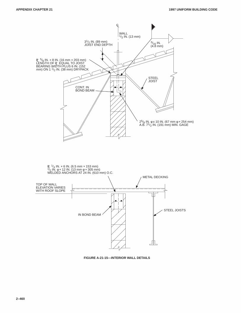
APPENDIX CHAPTER 21APPENDIX CHAPTER 21
1997 UNIFORM BUILDING CODE
2–460
TOP OF WALLELEVATION VARIESWITH ROOF SLOPE
IN BOND BEAMSTEEL JOISTS
METAL DECKING
P 1/4 IN. × 6 IN. (6.5 mm × 153 mm)1/2 IN. φ × 12 IN. (13 mm φ × 305 mm)WELDED ANCHORS AT 24 IN. (610 mm) O.C.
CONT. INBOND BEAM
31/2 IN. (89 mm)JOIST END DEPTH
STEELJOIST
P 5/8 IN. × 8 IN. (16 mm × 203 mm)LENGTH OF P EQUAL TO JOISTBEARING WIDTH PLUS 6 IN. (152mm) ON 1 1/2 IN. (38 mm) DRYPACK
25/8 IN. φ x 10 IN. (67 mm φ × 254 mm)A.B. 71/2 IN. (191 mm) MIN. GAGE
WALL1/2 IN. (13 mm)
3/16 IN.(4.8 mm)
CL
L
L
L
FIGURE A-21-15—INTERIOR WALL DETAILS
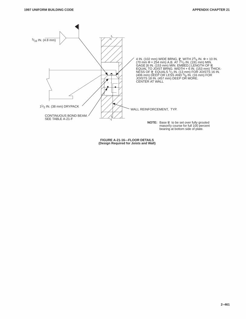
APPENDIX CHAPTER 21APPENDIX CHAPTER 21
1997 UNIFORM BUILDING CODE
2–461
11/2 IN. (38 mm) DRYPACK
CONTINUOUS BOND BEAM.SEE TABLE A-21-F
WALL REINFORCEMENT, TYP.
4 IN. (102 mm) WIDE BRNG. P WITH 23/4 IN. Φ × 10 IN.(70 mm Φ × 254 mm) A.B. AT 71/2 IN. (191 mm) MIN.GAGE [6 IN. (153 mm) MIN. EMBED.] LENGTH OF PEQUAL TO JOIST BRNG. WIDTH + 6 IN. (153 mm) THICK-NESS OF P EQUALS 1/2 IN. (13 mm) FOR JOISTS 16 IN.(406 mm) DEEP OR LESS AND 5/8 IN. (16 mm) FORJOISTS 18 IN. (457 mm) DEEP OR MORE.CENTER AT WALL
NOTE: Base P to be set over fully groutedmasonry course for full 100 percentbearing at bottom side of plate.
3/16 IN. (4.8 mm)
L
L
L
L
FIGURE A-21-16—FLOOR DETAILS(Design Required for Joists and Wall)
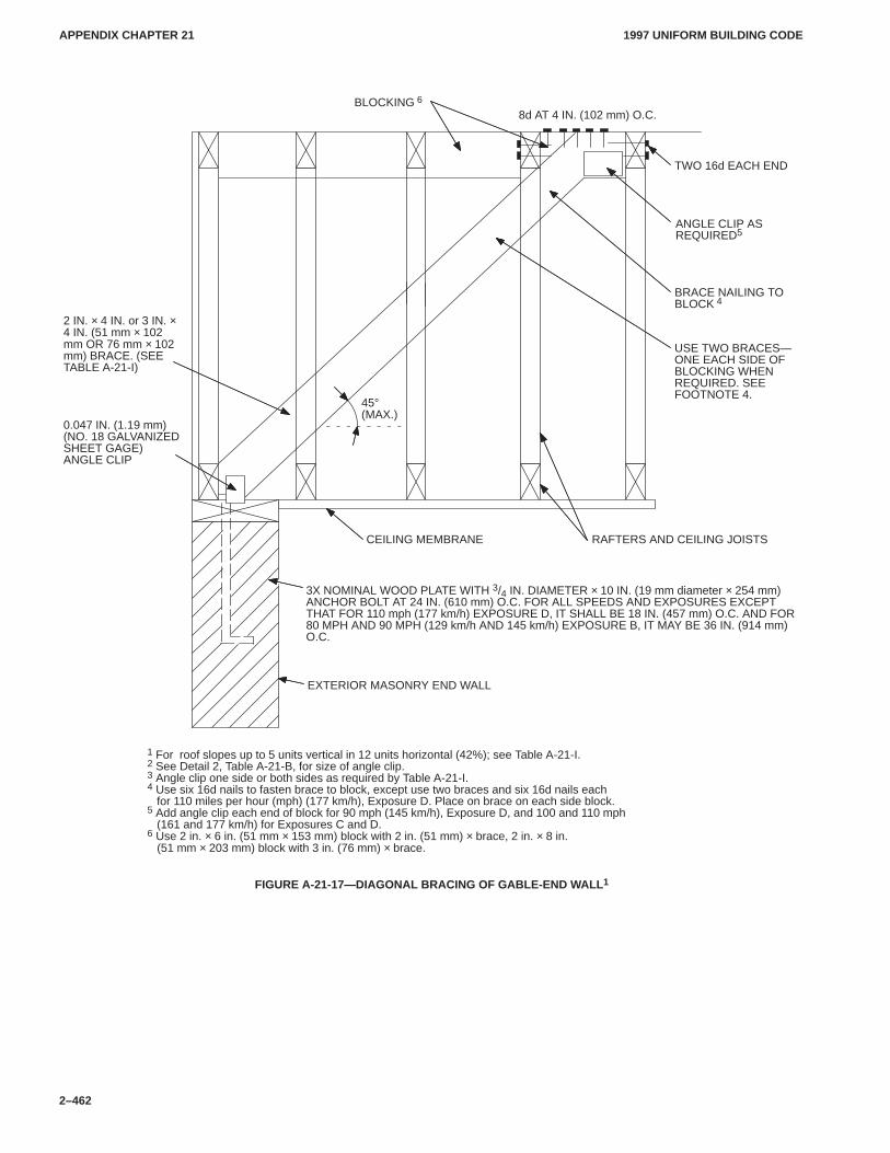
APPENDIX CHAPTER 21APPENDIX CHAPTER 21
1997 UNIFORM BUILDING CODE
2–462
8d AT 4 IN. (102 mm) O.C.
TWO 16d EACH END
2 IN. × 4 IN. or 3 IN. ×4 IN. (51 mm × 102mm OR 76 mm × 102mm) BRACE. (SEETABLE A-21-I)
CEILING MEMBRANE RAFTERS AND CEILING JOISTS
EXTERIOR MASONRY END WALL
0.047 IN. (1.19 mm)(NO. 18 GALVANIZEDSHEET GAGE)ANGLE CLIP
3X NOMINAL WOOD PLATE WITH 3/4 IN. DIAMETER × 10 IN. (19 mm diameter × 254 mm)ANCHOR BOLT AT 24 IN. (610 mm) O.C. FOR ALL SPEEDS AND EXPOSURES EXCEPTTHAT FOR 110 mph (177 km/h) EXPOSURE D, IT SHALL BE 18 IN. (457 mm) O.C. AND FOR80 MPH AND 90 MPH (129 km/h AND 145 km/h) EXPOSURE B, IT MAY BE 36 IN. (914 mm)O.C.
1 For roof slopes up to 5 units vertical in 12 units horizontal (42%); see Table A-21-I.2 See Detail 2, Table A-21-B, for size of angle clip.3 Angle clip one side or both sides as required by Table A-21-I.4 Use six 16d nails to fasten brace to block, except use two braces and six 16d nails each for 110 miles per hour (mph) (177 km/h), Exposure D. Place on brace on each side block.5 Add angle clip each end of block for 90 mph (145 km/h), Exposure D, and 100 and 110 mph (161 and 177 km/h) for Exposures C and D.6 Use 2 in. × 6 in. (51 mm × 153 mm) block with 2 in. (51 mm) × brace, 2 in. × 8 in. (51 mm × 203 mm) block with 3 in. (76 mm) × brace.
BLOCKING 6
ANGLE CLIP ASREQUIRED5
45°(MAX.)
BRACE NAILING TOBLOCK 4
USE TWO BRACES—ONE EACH SIDE OFBLOCKING WHENREQUIRED. SEEFOOTNOTE 4.
FIGURE A-21-17—DIAGONAL BRACING OF GABLE-END WALL 1
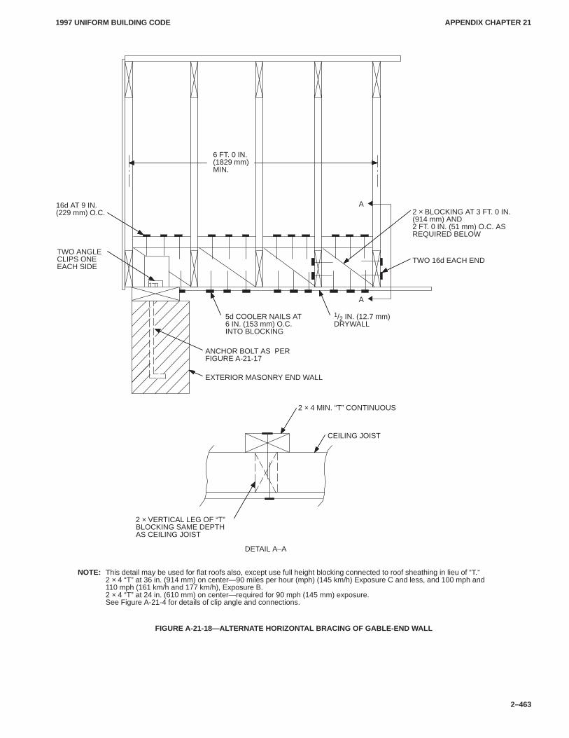
APPENDIX CHAPTER 21APPENDIX CHAPTER 21
1997 UNIFORM BUILDING CODE
2–463
2 × VERTICAL LEG OF “T”BLOCKING SAME DEPTHAS CEILING JOIST
DETAIL A–A
CEILING JOIST
2 × 4 MIN. “T” CONTINUOUS
1/2 IN. (12.7 mm)DRYWALL
ANCHOR BOLT AS PERFIGURE A-21-17
5d COOLER NAILS AT6 IN. (153 mm) O.C.INTO BLOCKING
EXTERIOR MASONRY END WALL
6 FT. 0 IN.(1829 mm)MIN.
TWO 16d EACH END
2 × BLOCKING AT 3 FT. 0 IN.(914 mm) AND2 FT. 0 IN. (51 mm) O.C. ASREQUIRED BELOW
16d AT 9 IN.(229 mm) O.C.
A
NOTE: This detail may be used for flat roofs also, except use full height blocking connected to roof sheathing in lieu of “T.”2 × 4 “T” at 36 in. (914 mm) on center—90 miles per hour (mph) (145 km/h) Exposure C and less, and 100 mph and110 mph (161 km/h and 177 km/h), Exposure B.2 × 4 “T” at 24 in. (610 mm) on center—required for 90 mph (145 mm) exposure.See Figure A-21-4 for details of clip angle and connections.
TWO ANGLECLIPS ONEEACH SIDE
A
FIGURE A-21-18—ALTERNATE HORIZONTAL BRACING OF GABLE-END WALL
APPENDIX CHAPTER 23APPENDIX CHAPTER 23
1997 UNIFORM BUILDING CODE
2–465
Appendix Chapter 23
CONVENTIONAL LIGHT-FRAME CONSTRUCTION IN HIGH-WIND AREAS
SECTION 2337 — GENERAL
2337.1 Purpose.The provisions of this chapter are intended topromote public safety and welfare by reducing the risk of wind-induced damages to conventional light-frame construction.
2337.2 Scope.This chapter applies to regular-shaped buildingswhich have roof structural members spanning 32 feet (9.75 m) orless, are not more than three stories in height, are of conventionallight-frame construction and are located in areas with a basic windspeed from 80 through 110 miles per hour (mph) (129 km/hthrough 177 km/h).
EXCEPTION: Detached carports and garages not exceeding 600square feet (55.7 m2) and accessory to Group R, Division 3 Occupan-cies need only comply with the roof-member-to-wall-tie requirementsof Section 2337.5.8.
2337.3 Definitions. For the purpose of this chapter, certainterms are defined as follows:
CORROSION RESISTANT or NONCORROSIVE is mate-rial having a corrosion resistance equal to or greater than ahot-dipped galvanized coating of 1.5 ounces of zinc per squarefoot (4 g/m2) of surface area.
2337.4 General.The requirements of Section 2320 are applica-ble except as specifically modified by this chapter. Other methodsmay be used, provided a satisfactory design is submitted showingcompliance with the provisions of Section 1611.4 and other appli-cable portions of this code.
In addition to the other provisions of this chapter, foundationsfor buildings in areas subject to wave action or tidal surge shall bedesigned in accordance with approved national standards.
When an element is required to be corrosion resistant or non-corrosive, all of its parts, such as screws, nails, wire, dowels, bolts,nuts, washers, shims, anchors, ties and attachments, shall also becorrosion resistant or noncorrosive.
2337.5 Complete Load Path and Uplift Ties.
2337.5.1 General.Blocking, bridging, straps, approved fram-ing anchors or mechanical fasteners shall be installed to providecontinuous ties from the roof to the foundation system. (See Fig-ure A-23-1.)
Tie straps shall be 11/8-inch (28.6 mm) by 0.036-inch (0.91 mm)(No. 20 gage) sheet steel and shall be corrosion resistant as hereinspecified. All metal connectors and fasteners used in exposed lo-cations or in areas otherwise subject to corrosion shall be ofcorrosion-resistant or noncorrosive material.
2337.5.2 Walls-to-foundation tie. Exterior walls shall be tied toa continuous foundation, or an elevated foundation system in ac-cordance with Section 2337.10.
2337.5.3 Sills and foundation tie. Foundation plates resting onconcrete or masonry foundations shall be bolted to the foundationwith not less than 1/2-inch-diameter (13 mm) anchor bolts with7-inch-minimum (178 mm) embedment into the foundation. Inareas where the basic wind speed is 90 mph (145 km/h) or greater,the maximum spacing of anchor bolts shall be 4 feet (1219 mm) oncenter. Structures located where the basic wind speed is less than90 mph (145 km/h) may have anchor bolts spaced not more than6 feet (1829 mm) on center.
2337.5.4 Floor-to-foundation tie.The lowest-level exteriorwall studs shall be connected to the foundation sill plate or an ap-proved elevated foundation system with bent tie straps spaced notmore than 48 inches (1219 mm) on center. Tie straps shall benailed and installed in accordance with Table A-23-B and FigureA-23-1.
2337.5.5 Wall framing details.The spacing of 2-inch-by-4-inch studs (51 mm by 102 mm) in exterior walls shall not exceed16 inches (406 mm) on center for areas with a basic wind speed of90 mph (145 km/h) or greater.
Mechanical fasteners complying with this chapter shall be in-stalled as required to connect studs to the sole plates, foundationsill plate and top plates of the wall.
Interior main cross-stud partitions shall be installed approxi-mately perpendicular to the exterior wall when the length of thestructure exceeds the width. The maximum distance betweenthese partitions shall not exceed the width of the structure. Interiormain cross-stud partition walls shall be securely fastened to exte-rior walls at the point of intersection with fasteners as required byTable 23-II-B-1. The main cross-stud partitions shall be coveredon both sides by materials as described in Section 2337.5.6.
2337.5.6 Wall sheathing. All exterior walls and required interi-or main cross-stud partitions shall be sheathed in accordance withTable A-23-A. The total width of sheathed wall elements shall notbe less than 50 percent of the exterior wall length or 60 percent ofthe width of the building for required interior main cross-stud par-titions. The exterior wall sheathing or covering shall extend fromthe foundation sill plate or girder to the top plates at the roof leveland shall be adequately attached thereto.
A sheathed wall element not less than 4 feet (1219 mm) in widthshall be installed at each corner or as near thereto as possible.There shall not be less than one 4-foot (1219 mm) sheathed wallelement for every 20 feet (6096 mm) or fraction thereof of walllength. The height-to-length ratio of required sheathed wall ele-ments shall not exceed 3 for wood structural panel or particleboardand 11/2 (38 mm) for other sheathing materials listed in TableA-23-A.
2337.5.7 Floor-to-floor tie. Upper-level exterior wall studsshall be aligned and connected to the wall studs below with a tiestrap as required by Table A-23-B.
2337.5.8 Roof-members-to-wall tie.Tie straps shall be pro-vided from the side of the roof-framing member to the exteriorstuds, posts or other supporting members below the roof. The wallstuds to which the roof-framing members are tied shall be alignedwith the roof-framing member and be connected in accordancewith Table A-23-B.
The eave overhang shall not exceed 3 feet (914 mm) unless ananalysis is provided showing that the required resistance is pro-vided to prevent uplift.
Where openings exceed 6 feet (1829 mm) in width, the requiredtie straps shall be doubled at each edge of the opening and con-nected to a doubled full-height wall stud. When openings exceed12 feet (3658 mm) in width, ties designed to prevent uplift shall beprovided.
EXCEPTION: The opening width may be increased to 16 feet(4877 mm) for garages and carports accessory to Group R, Division 3Occupancies when constructed in accordance with the following:
APPENDIX CHAPTER 23APPENDIX CHAPTER 23
1997 UNIFORM BUILDING CODE
2–466
1. Approved column bases shall be a minimum 3/16-inch (4.8 mm)steel plate embedded not less than 8 inches (203 mm) into theconcrete footing and connected to a minimum 4-inch-by-4-inch(102 mm by 102 mm) wood post with two 5/8-inch-diameter(15.9 mm) through bolts.
2. Beams over openings shall be connected to minimum 4-inch by4-inch (102 mm by 102 mm) wood posts below with an ap-proved 3/16-inch (4.8 mm) steel post cap with two 5/8-inch-diameter (15.9 mm) through bolts to the posts and to the beams.
2337.5.9 Ridge ties.Opposing rafters shall be aligned at theridge and be connected at the rafters with a tie strap in accordancewith Table A-23-C.
2337.6 Masonry Veneer.Anchor ties shall be spaced so as tosupport not more than 11/3 square feet (860 mm2) of wall area butnot more than 12 inches (305 mm) on center vertically. The mate-rials and connection details shall comply with Chapter 14.
2337.7 Roof Sheathing.Solid roof sheathing shall be appliedand shall consist of a minimum 1-inch-thick (25 mm) nominallumber applied diagonally or a minimum 15/32-inch-thick(11.9 mm) wood structural panel or particleboard or other ap-proved sheathing applied with the long dimension perpendicularto supporting rafters. Sheathing shall be nailed to roof framing inan approved manner. The end joints of wood structural panels orparticleboard shall be staggered and shall occur over blocking,rafters or other supports.
2337.8 Gable-end Walls.The roof overhang at gabled endsshall not exceed 2 feet (610 mm) unless an analysis showing thatthe required resistance to prevent uplift is provided.
Gable-end wall studs shall be continuous between points of lat-eral support which are perpendicular to the plane of the wall.
Gable-end wall studs shall be attached with approved mechani-cal fasteners at the top and bottom.
2337.9 Roof Covering.Roof coverings shall be approved andshall be installed and fastened in accordance with Chapter 15 and
with the manufacturer’s instructions. In areas with basic windspeeds of 90 mph (145 km/h) or greater strip asphalt shingles shallbe fastened with a minimum of six fasteners and hand sealed.
2337.10 Elevated Foundation.
2337.10.1 General.When approved, elevated foundations sup-porting not more than one story and meeting the provisions of thissection may be used. A foundation investigation may be requiredby the building official.
2337.10.2 Material. All exposed wood-framing members shallbe treated wood. All metal connectors and fasteners used in ex-posed locations shall be corrosion-resistant or noncorrosive steel.
2337.10.3 Wood piles.The spacing of wood piles shall not ex-ceed 8 feet (2438 mm) on center. Square piles shall not be less than10 inches (254 mm) and tapered piles shall have a tip of not lessthan 8 inches (203 mm). Ten-inch-square (64516 mm2) piles shallhave a minimum embedment length of 10 feet (3048 mm) andshall project not more than 8 feet (2438 mm) above undisturbedground surface. Eight-inch (203 mm) taper piles shall have a mini-mum embedment length of 14 feet (4267 mm) and shall projectnot more than 7 feet (2134 mm) above undisturbed ground sur-face.
2337.10.4 Girders.Floor girders shall be solid sawn timber,built-up 2-inch-thick (51 mm) lumber or trusses. Splices shall oc-cur over wood piles. The floor girders shall span in the directionparallel to the potential floodwater and wave action.
2337.10.5 Connections.Wood piles may be notched to providea shelf for supporting the floor girders. The total notching shall notexceed 50 percent of the pile cross section. Approved bolted con-nections with 1/4-inch (6.4 mm) corrosion-resistant or noncorro-sive steel plates and 3/4-inch-diameter (19 mm) bolts shall beprovided. Each end of the girder shall be connected to the piles us-ing a minimum of two 3/4-inch-diameter (19 mm) bolts.
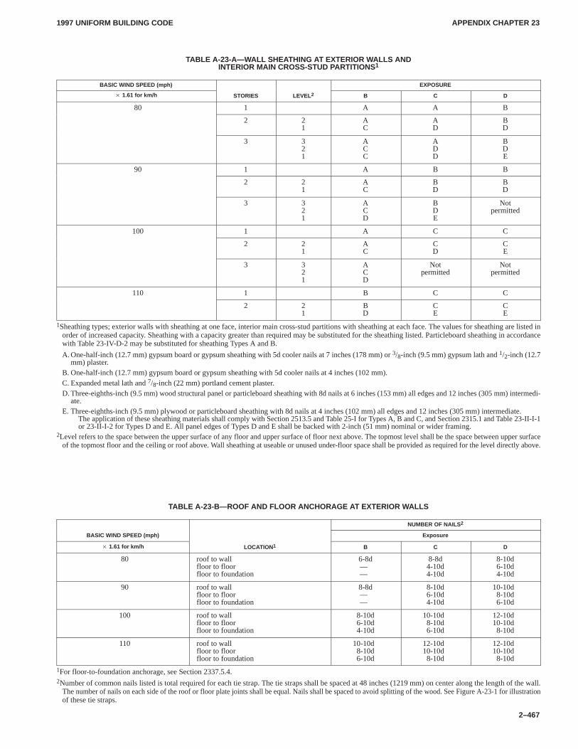
APPENDIX CHAPTER 23APPENDIX CHAPTER 23
1997 UNIFORM BUILDING CODE
2–467
TABLE A-23-A—W ALL SHEA THING AT EXTERIOR WALLS ANDINTERIOR MAIN CROSS-STUD PARTITIONS1
BASIC WIND SPEED (mph) EXPOSURE
� 1.61 for km/h STORIES LEVEL 2 B C D
80 1 A A B
2 21
AC
AD
BD
3 321
ACC
ADD
BDE
90 1 A B B
2 21
AC
BD
BD
3 321
ACD
BDE
Notpermitted
100 1 A C C
2 21
AC
CD
CE
3 321
ACD
Notpermitted
Notpermitted
110 1 B C C
2 21
BD
CE
CE
1Sheathing types; exterior walls with sheathing at one face, interior main cross-stud partitions with sheathing at each face. The values for sheathing are listed inorder of increased capacity. Sheathing with a capacity greater than required may be substituted for the sheathing listed. Particleboard sheathing in accordancewith Table 23-IV-D-2 may be substituted for sheathing Types A and B.
A. One-half-inch (12.7 mm) gypsum board or gypsum sheathing with 5d cooler nails at 7 inches (178 mm) or 3/8-inch (9.5 mm) gypsum lath and 1/2-inch (12.7mm) plaster.
B. One-half-inch (12.7 mm) gypsum board or gypsum sheathing with 5d cooler nails at 4 inches (102 mm).C. Expanded metal lath and 7/8-inch (22 mm) portland cement plaster.D. Three-eighths-inch (9.5 mm) wood structural panel or particleboard sheathing with 8d nails at 6 inches (153 mm) all edges and 12 inches (305 mm) intermedi-
ate.E. Three-eighths-inch (9.5 mm) plywood or particleboard sheathing with 8d nails at 4 inches (102 mm) all edges and 12 inches (305 mm) intermediate.
The application of these sheathing materials shall comply with Section 2513.5 and Table 25-I for Types A, B and C, and Section 2315.1 and Table 23-II-I-1 or 23-II-I-2 for Types D and E. All panel edges of Types D and E shall be backed with 2-inch (51 mm) nominal or wider framing.
2Level refers to the space between the upper surface of any floor and upper surface of floor next above. The topmost level shall be the space between upper surfaceof the topmost floor and the ceiling or roof above. Wall sheathing at useable or unused under-floor space shall be provided as required for the level directly above.
TABLE A-23-B—ROOF AND FLOOR ANCHORAGE A T EXTERIOR WALLS
NUMBER OF NAILS 2
BASIC WIND SPEED (mph) Exposure
� 1.61 for km/h LOCATION1 B C D
80 roof to wallfloor to floorfloor to foundation
6-8d——
8-8d4-10d4-10d
8-10d6-10d4-10d
90 roof to wallfloor to floorfloor to foundation
8-8d——
8-10d6-10d4-10d
10-10d8-10d6-10d
100 roof to wallfloor to floorfloor to foundation
8-10d6-10d4-10d
10-10d8-10d6-10d
12-10d10-10d8-10d
110 roof to wallfloor to floorfloor to foundation
10-10d8-10d6-10d
12-10d10-10d8-10d
12-10d10-10d8-10d
1For floor-to-foundation anchorage, see Section 2337.5.4.2Number of common nails listed is total required for each tie strap. The tie straps shall be spaced at 48 inches (1219 mm) on center along the length of the wall.
The number of nails on each side of the roof or floor plate joints shall be equal. Nails shall be spaced to avoid splitting of the wood. See Figure A-23-1 for illustrationof these tie straps.
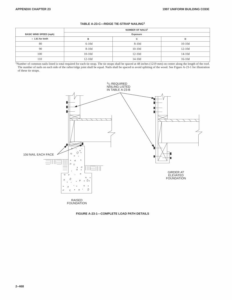
APPENDIX CHAPTER 23APPENDIX CHAPTER 23
1997 UNIFORM BUILDING CODE
2–468
TABLE A-23-C—RIDGE TIE-STRAP NAILING 1
NUMBER OF NAILS 1
BASIC WIND SPEED (mph) Exposure
� 1.61 for km/h B C D
80 6-10d 8-10d 10-10d
90 8-10d 10-10d 12-10d
100 10-10d 12-10d 14-10d
110 12-10d 14-10d 16-10d1Number of common nails listed is total required for each tie strap. The tie straps shall be spaced at 48 inches (1219 mm) on center along the length of the roof.
The number of nails on each side of the rafter/ridge joint shall be equal. Nails shall be spaced to avoid splitting of the wood. See Figure A-23-1 for illustrationof these tie straps.
10d NAIL EACH FACE
RAISEDFOUNDATION
GIRDER ATELEVATED
FOUNDATION
1/2 REQUIRED NAILING LISTED IN TABLE A-23-B
FIGURE A-23-1—COMPLETE LOAD P ATH DETAILS
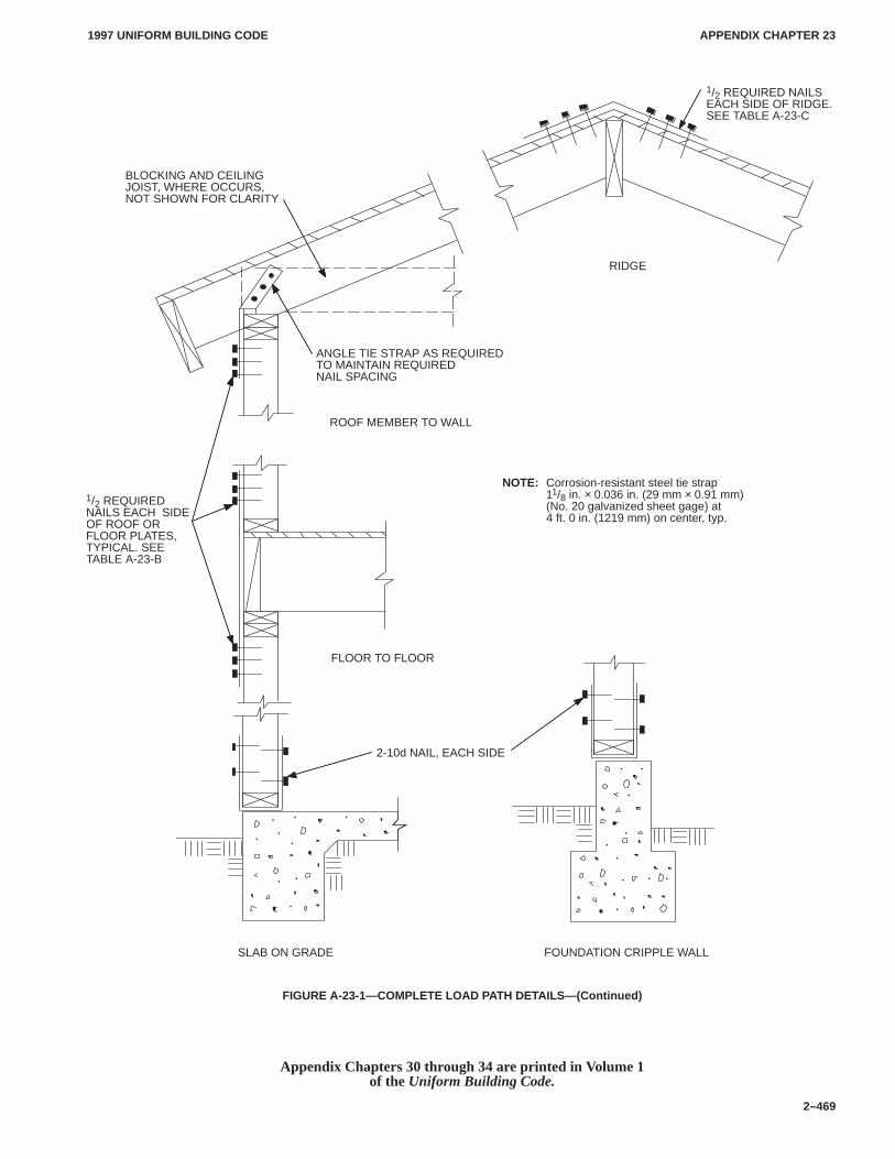
APPENDIX CHAPTER 23APPENDIX CHAPTER 23
1997 UNIFORM BUILDING CODE
2–469
2-10d NAIL, EACH SIDE
SLAB ON GRADE FOUNDATION CRIPPLE WALL
FLOOR TO FLOOR
ANGLE TIE STRAP AS REQUIRED TO MAINTAIN REQUIREDNAIL SPACING
RIDGE
ROOF MEMBER TO WALL
1/2 REQUIREDNAILS EACH SIDEOF ROOF ORFLOOR PLATES,TYPICAL. SEETABLE A-23-B
NOTE: Corrosion-resistant steel tie strap11/8 in. × 0.036 in. (29 mm × 0.91 mm)(No. 20 galvanized sheet gage) at4 ft. 0 in. (1219 mm) on center, typ.
BLOCKING AND CEILING JOIST, WHERE OCCURS, NOT SHOWN FOR CLARITY
1/2 REQUIRED NAILS EACH SIDE OF RIDGE. SEE TABLE A-23-C
FIGURE A-23-1—COMPLETE LOAD P ATH DETAILS—(Continued)
Appendix Chapters 30 through 34 are printed in Volume 1of the Uniform Building Code.
Related Documents


![NASA-STD-10002 Facilities Design Standard7.3 Structural Requirements of New Buildings 7.3.1 [FDSR 48] The structural design of new buildings, including wind and seismic design, shall](https://static.cupdf.com/doc/110x72/61329d76dfd10f4dd73a909a/nasa-std-10002-facilities-design-standard-73-structural-requirements-of-new-buildings.jpg)


