• r , a .. • STRUCTURAL DESIGN MANUAL FOR IMPROVED INLETS AND CULVERTS Research, DevelOpment, and Technology Turner-Fairbank Highway Research Center 6300 Georgetown Pike Mclean, Virginia 221 01 Report No. FHWA - IP-83-6 Final Report June 1983 This document is tv11il1bl1 to the U.S. public through the Natio nal Technical Information Sa.--ica, Springfield , Virginia 22161 Archival May no longer reflect current or accepted regulation, policy, guidance or practice.

Welcome message from author
This document is posted to help you gain knowledge. Please leave a comment to let me know what you think about it! Share it to your friends and learn new things together.
Transcript

•
r ,
a
..
•
STRUCTURAL DESIGN MANUAL FOR IMPROVED INLETS AND CULVERTS
Research, DevelOpment, and Technology
Turner-Fairbank Highway Research Center 6300 Georgetown Pike Mclean, Virginia 22101
Report No. FHWA - IP-83-6
Final Report June 1983
This document is tv11il1bl1 to the U.S. public through the National Technical Information Sa.--ica, Springfield, Virginia 22161
Archiva
l
May no
long
er ref
lect c
urren
t or a
ccep
ted re
gulat
ion, p
olicy
, guid
ance
or pr
actic
e.

FOREWORD
This manual provides design procedures for the structural design of culverts and improved inlets. Culverts are conduits which convey drainage across or from the highway right-of-way. In addition to this hydraulic function, culverts must also carry construction and highway traffic and earth loads. Designing culverts and culvert inlet structures for these loads is the focus of this manual.
This manual should be of interest to roadway, hydraulic and structural design engineers. Sufficient copies are being distributed to provide a minimum of one copy to each FHWA regional office, division office and State highway agency.
g~ R. ~ Bet s old Director, Office of Implementation
NOTICE
This document is disseminated under the sponsorship of the Department of Transportation in the interest of information exchange. The United States Government assumes no liability for its contents or use thereof. The contents of this report reflect the views of the contractor, who is responsible for the accuracy of the data presented herein. The contents do not nec essarily reflect the official policy of the Department of Transportation. This report does not constitute a standard, specification, or regulation.
The United States Government does not endorse products or manufacturers. Trade or manufacturer's names appear herein only because they are considered essential to the object of this document.
Archiva
l
May no
long
er ref
lect c
urren
t or a
ccep
ted re
gulat
ion, p
olicy
, guid
ance
or pr
actic
e.

J. Report No. 2. Government Accession No.
FHWA-IP-83-6
4. Title and Subtitle
Structural Design Manual for Improved Inlets and Culverts
Technical Report Documentation Page
3. Recipient's Catalog No.
5. Report Date
June 1983 6. Performing Organization Code
~-----------------------------------C 8. Performing Organization Report No. 7. Authorl s)
Timothy J. McGrath and Frank J. Heger 9. Performing Organization Name and Address
Simpson Gumpertz and Heger, Inc. 1696 Massachusetts Avenue Cambridge, Massachusetts 02138
JO. Work Unit No. (TRAIS)
35H3-143 l l. Contract or Grant No.
DOT-FH-11-969 2
1-------------------------------------oj 13. Type of Report and Period Covered
l 2. Sponsoring Agency Name and Address
Office of Implementation, HRT-10 Federal Highway Administration 6300 Georgetown Pike McLean. Vir~inia 22101
15. Supplementary Notes Robert Wood, HRT-10 FHWA Co-COTR: Philip Thompson, HNG-31
Claude Napier, HNG-32
l 6. Abstract
Final Report 11/79 -· 9182
14. Sponsoring Agency Code
This manual provides structural design methods for culverts and for improved inlets Manual methods for structural analysis are included with a complete design procedure and example problems for both circular and box culverts. These manual methods are supplemented by computer programs which are contained in the Appendices Example standard plans have been prepared for headwalls, wingwalls, side tapered, and slope tapered culverts for both single and two cell inlets. Tables of example designs are provided for each standard plan to illustrate a range of design parameters.
17. Key Words 18. Distribution Statement
Culverts, Improved Inlets, Structural Design, Computer Program
No restrictions. This document is available to the public through the National Technical Information Service, Springfield, Virginia 22161
19. Security Classil. (of this report)
Unclassified
Form DOT F 1700.7 CB-72l
20. Security Classif. (of this page)
Unclassified
Reproduction of completed page authorized
21· No. of Pages 22. Price
338
Archiva
l
May no
long
er ref
lect c
urren
t or a
ccep
ted re
gulat
ion, p
olicy
, guid
ance
or pr
actic
e.

TABLE OF CONTENTS
Acknowledgements Table of Contents List of Figures List of Tables Notations
I.
2.
3.
4.
5.
6.
INTRODUCTION I.I Objective 1.2 Scope 1.3 Types and Geometry of Improved Inlets 1.4 Appurtenant Structures
LOADS ON INLET STRUCTURES 2.1 Culvert Weight 2.2 Fluid Loads 2.3 Earth Loads 2.4 Construct ion Loads 2.5 Distribution of Earth Pressures on Culvert
MANUAL METHODS FOR STRUCTURAL ANALYSIS 3.1 Reinforced Concrete Box Sections 3.2 Rigid Pipe Sections 3.3 Flexible Pipe Sections
STRUCTURAL DESIGN OF INLET STRUCTURES 4.1 Reinforced Concrete Design 4.2 Corrugated Metal Pipe Design Method
COMPUTERIZED ANALYSIS AND DESIGN OF REINFORCED CONCRETE SECTIONS 5.1 Box Sections 5.2 Circular and Elliptical Pipe Sections
DESIGN OF APPURTENANT STRUCTURES 6.1 Circular to Square Transition 6.2 Wingwal Is and Headwal Is 6.3 Apron Slabs
REFERENCES
APPENDIX A - CORRUGATED METAL CULVERT DESIGN
APPENDIX B - USERS MANUAL - IMPROVED INLET BOX SECTION PROGRAM, BOXCAR
APPENDIX C - USERS MANUAL - PIPE DESIGN PROGRAM, PIPECAR
APPENDIX D - DESIGN EXAMPLES
APPENDIX E- IMPROVED INLET DESIGN TABLES
APPENDIX F - DERIVATION OF EQUATIONS FOR LOCATING CULVERTS WITHIN EMBANKMENTS
APPENDIX G - TYPICAL DETAILS FOR IMPROVED INLETS
APPENDIX H - COMPUTER PROGRAM LISTINGS
- ii -
Page i
ii iii iv v
I I I 2 8
9 9 9
10 11 11
15 15 21 28
29 29 48
49 49 53
59 59 61 63
65
A-I - A-28
B-1 - B-20
C-1 - C-18
D-1 - D-44
E-1 - E-22
F-1 - F-12
G-1 - G-12
H-1 - H-107
Archiva
l
May no
long
er ref
lect c
urren
t or a
ccep
ted re
gulat
ion, p
olicy
, guid
ance
or pr
actic
e.

LIST OF FIGURES
Chapter I
Figure 1-1 Figure 1-2 Figure 1-3
Chapter 2
Figure 2-1
Chapter 3
Figure 3-1 Figure 3-2
Figure 3-3
Figure 3-4
Figure 3-5 Figure 3-6
Chapter 4
Figure 4-1 Figure 4-2
Figure 4-3
Figure 4-4
Figure 4-5
Figure 4-6
Figure 4-7
Chapter 5
Figure 5-1 Figure 5-2
Chapter 6
Figure 6-1 Figure 6-2
Figure 6-3
Side Tapered Box Section or Pipe Inlet Geometry Additional Geometry for Side Tapered Pipe Inlets Slope Tapered Box Section Inlets
Distribution of Earth Pressure on Culverts
Coefficients for M, N, and V Due to Earth Load on Circular Pipe Coefficients for M, N and V Due to Earth Load on Elliptical Pipe with U/V = 0.1 Coefficients for M, N and V Due to Earth Load on Elliptical Pipe with U/V = 0.5 Coefficients for M, N and V Due to Earth Load on Elliptical Pipe with U/V = 1.0 Coefficients for M, N and V Due to Pipe Weight on Narrow Support Coefficients for M, N and V Due to Water Load on Circular Pipe
Typical Reinforcing Layout for Single Cell Box Culverts Locations of Critical Sections for Shear and Flexure Design in Single Cell Box Sections Typical Reinforcing Layout and Location of Design Sections for Shear and Flexure Design of Two Cell Box Culverts Typical Reinforcing Layout and Locations of Critical Sections for Shear and Flexure Design in Pipe Sections Critical Shear Location in Circular Pipe For Olander (7) Earth Pressure Distribution Location of Critical Shear Section for Straight Members with Uniformly Distributed Load Design Considerations for Slope Tapered Inlets
Single Cel 1 Box Section Loading Cases Pipe Section Load Cases
Circular to Square Transition Section Loading Diagram and Typical Reinforcing Layout for Cantilever Type Retaining Wall Skewed Headwall Detail
- iii -
3 6 7
12
22
23
24
25 26 27
31
32
33
3
42
43 47
51 55
60
62 64
Archiva
l
May no
long
er ref
lect c
urren
t or a
ccep
ted re
gulat
ion, p
olicy
, guid
ance
or pr
actic
e.

LIST OF TABLES
Chapter 3
Table 3-1
Table 3-2
Chapter 4
Table 4-1
Design Forces in Single Cell Box Culverts
Design Forces in Two Cell Box Culverts
Strength Reduction Factors in Current AASHTO Standard Specifications for Highway Bridges
- iv -
16
18
36
Archiva
l
May no
long
er ref
lect c
urren
t or a
ccep
ted re
gulat
ion, p
olicy
, guid
ance
or pr
actic
e.

NOTATIONS
A s
A SC
A. SI
A so
A scr
A smax
A . smm
A sy
A v
A vr
B. I
B 0
8'
tension reinforcement area on width b, in. 2
inside tension reinforcement area on width b, in. 2
at pipe crown
inside tension reinforcement area on width b, in. 2 at pipe invert
oustide tension reinforcement area on width b, in.2 at pipe springline
tension reinforcement area on width b, required for crack control, in. 2
maximum area of flexural reinforcing on width b based on concrete compres-. . 2
s1on, m.
minimum area of flexural reinforcing on width b, in.2
tension reinforcement area on width b, required for flexural criteria, in. 2
stirrup reinforcing area on width b, in.2 in each line of stirrups at circum
ferential spacing s, in.
stirrup reinforcing area required to resist shear forces on width b, in. 2 in each
line of stirrups at circumferential spacings, in.
stirrup reinforcing area required to resist radial tension stresses on width b, in. 2
in each line of stirrups at circumferential spacings, in.
inside span of face section of improved inlet, in.
inside span of box culvert, or inside diameter of pipe culvert, in.
outside span of box or pipe culvert, in.
mean span of box or pipe culvert, in.
- v -
Archiva
l
May no
long
er ref
lect c
urren
t or a
ccep
ted re
gulat
ion, p
olicy
, guid
ance
or pr
actic
e.

crack control coefficient for effect of cover and spacing of reinforcement
b width of box or pipe section used for analysis. Usually b = 12 in.
C 1 crack control coefficient for type of reinforcing
c coefficient used in the determination of the critical shear location m
cml'cm2'cm3 coefficient for determination of bending moment due to earth, pipe and fluid
loads, respectively
cnl' cn2'cn3
cvl' cv2' cv3
D eq
D. I
D 0
D'
d
coefficient for determination of thrust due to earth, pipe and fluid loads,
respectively
coefficient for determination of shear due to earth, pipe and fluid loads,
respectively
equivalent circular diameter of an elliptical section, in.
depth of fluid inside culvert, in.
inside rise of box culvert, or inside diameter of pipe culvert, in.
ultimate 3-edge bearing strength of pipe, lbs/ft/ft
outside rise of box culvert, or inside diameter of pipe culvert, in.
mean rise of box or pipe culvert, in.
distance from compression face of reinforced concrete section to centroid of
tension reinforcing, in.
e thrust eccentricity as given by Eq. 4.17
F al I approximate depression of control section below the stream bed, ft
- vi -
Archiva
l
May no
long
er ref
lect c
urren
t or a
ccep
ted re
gulat
ion, p
olicy
, guid
ance
or pr
actic
e.

F c factor for effect of curvature on shear strength in curved sections
Fer factor for adjusting crack control relative to average maximum crack width of
0.0 I in. when Fer = 1.0
F d factor for crack depth effect resulting in increase in diagonal tension (shear)
strength with decreasing d.
F e soi I-structure interaction factor that relates actual load on culvert to weight of
column of earth directly over culvert
F N coefficient for effect of thrust on shear strength
F rp coefficient for effect of local materials and manufacturing process on radial
tension strength of concrete in precast concrete pipe
F vp coefficient for effect of local materials and manufacturing process on the
diagonal tension strength of concrete in precast concrete pipe
f' c
f y
GI 'G2 •••
g, g'
H e
H' e
coefficients used in hand analysis of two cell box culverts
design compressive strength of concrete, lbs/in. 2
design ultimate stress in stirrup, lbs/in. 2; may be governed by maximum
anchorage force that can be developed between stirrup and each inner rein
forcement wire or bar, or by yield strength f , whichever is less y
specified tensile yield strength of reinforcement, lbs/in.2
coefficients used in hand analysis of one cell box culverts
factor in equations for area of reinforcement for ultimate flexure
height of fill over top of buried culvert, ft
height of fill over horizontal centerline of buried culvert, ft
- vii -
Archiva
l
May no
long
er ref
lect c
urren
t or a
ccep
ted re
gulat
ion, p
olicy
, guid
ance
or pr
actic
e.

HH horizontal haunch dimension, in.
Hv vertical haunch dimension, in.
h overall thickness of member (wall thickness), in.
M
M c
coefficient for effect of axial force at service load stress
coefficient for moment arm at service load stress
ratio of offset distances for elliptical pipe section (u/v)
horizontal distance from throat section to invert of bend section in a slope
tapered inlet, ft (Figure 1-3)
load factor used to multiply calculated design forces under service conditions to
get ultimate forces
overall length of improved inlet, ft (Figures l-l and 1-3)
length of fol I section of slope tapered inlet, ft (Figure l-3)
length of bend section of slope tapered inlet, ft (Figure 1-3)
span length used in the determination of the critical shear location for
uniformly distributed loads, in.
development length of reinforcing bar, in.
moment acting on cross section of width b, service load conditions, in.-lbs
(taken as absolute value in design equations, always +)
moment in bottom slab of box section acting on section of width b, service load
conditions, in.-lbs
maximum midspan moment acting on cross section of width b, in.-lbs
- viii -
Archiva
l
May no
long
er ref
lect c
urren
t or a
ccep
ted re
gulat
ion, p
olicy
, guid
ance
or pr
actic
e.

M s
N
moment at corner of box section acting on section of width b, service load
conditions, in.-lbs
moment in side wal I of box section acting on section of width b, service load
conditions, in.-lbs
ultimate moment acting on cross section of width b, in.-lbs
axial thrust acting on cross section of width b, service load condition (+ when
compressive, - when tensile), lbs
Nt' Ns' Nb axial thrust acting on cross section of width b, of top, side or bottom slab,
respectively, service load condition(+ when compressive, - when tensile), lbs
n
p
ultimate axial thrust acting on cross section of width b, lbs
number of layers of reinforcement in a cage (I or 2)
ratio of area of tension reinforcement to area of concrete section, Eq. 4.25
soil pressure at bottom of pipe or box section that reacts soil, fluid, and dead
load, lbs/in./section width b
fluid pressure acting on inside of pipe, lb/in./section width b
soil pressure at invert of pipe section, lb/in./section width b
soil pressure at crown of pipe section, lb/in./section width b
lateral soil pressure on box section, lbs/in./section width b
soi I pressure at top of pipe or box section, lb/in./ section width b
vertical pressure applied to box section, lb/in./section width b
radius to centerline of pipe wall, in.
- ix -
Archiva
l
May no
long
er ref
lect c
urren
t or a
ccep
ted re
gulat
ion, p
olicy
, guid
ance
or pr
actic
e.

r radius to inside reinforcement, in. s
r 1 radius to inside of side section of elliptical pipe, in. (Figure 1-2)
r 2 radius to inside top and bottom section of elliptical pipe, in. (Figure 1-2)
S slope of culvert barrel, ft/ft
S df stirrup design factor used in Equation 4.34 lb/in/section width b
sf slope of fall, ft/ft
S slope of natural channel, ft/ft 0
s circumferential spacing of shear or radial tension stirrup reinforcement, in.
si spacing (longitudinal) of circumferential reinforcement, in.
T taper of side wall of improved inlet (Figure 1-1)
TB' T 5, TT thickness of bottom, side and top slabs of box culvert, respectively, in.
u
v
thickness of centerwall of two-span box section, in.
clear cover distance from tension face of reinforcing to tension face of con
crete, in.
horizontal offset distance from center of elliptical pipe to center of rotation of
radius r 1, in. (Figure 1-2)
shear force acting on cross section of width b, service load condition, lbs (taken
as absolute value in design equations, always+)
basic shear strength of cross-section of width b, where M/V cj> d < 3.0, lbs v
general shear strength of cross-section of width b, where M/V <l>vd < 3.0, lbs
-x-
Archiva
l
May no
long
er ref
lect c
urren
t or a
ccep
ted re
gulat
ion, p
olicy
, guid
ance
or pr
actic
e.

v
w
w e
w
x
ultimate shear force acting on cross section of width b, lbs
vertical offset distance from center of elliptical pipe to center of rotation of
radius r 2
, in. (Figure 1-2)
width of weir crest, ft
total weight of earth on unit length of buried structure, lbs/ft
total weight of fluid inside unit length of buried structure, lbs/ft
weight of unit length of structure, lbs/ft
uniformly distributed load used in the determination of the critical shear
location, lbs/in./section width b
horizontal coordinate, in.
distance from point of maximum midspan moment to point where M/V <I> d = 3.0, v
in.
y vertical coordinate, in.
ye vertical coordinate from top of box section (Figure 2-1 ), in.
z longitudinal coordinate, in.
zmt' zmb distance from bend point in top and bottom slab reinforcing, respectively, to
point of zero moment, in.
a , a . ratio of lateral to vertical soil pressure on box culvert max mm
8 AASHTO coefficient used to compute design loads
- xi -
Archiva
l
May no
long
er ref
lect c
urren
t or a
ccep
ted re
gulat
ion, p
olicy
, guid
ance
or pr
actic
e.

e
angle over which earth load is applied to buried pipe, degrees
bedding angle over which soil support is provided to pipe to resist applied loads,
degrees
unit weight of concrete, lb/ft3
unit weight of internal fluid, lbs/ft3
unit weight of soil, lbs/ft3
angle from vertical to a design section, degrees; in circular pipe, this is the
angle from the invert; in elliptical pipe, this is the angle from a vertical line
through the center of rotation of r 1 or r 2
flexure strength reduction factor for variability in material strengths or
manufacturing tolerances
. shear strength reduction factor for variability in material strengths or manu
facturing tolerances
- xii -
Archiva
l
May no
long
er ref
lect c
urren
t or a
ccep
ted re
gulat
ion, p
olicy
, guid
ance
or pr
actic
e.

STRUCTURAL DESIGN MANUAL FOR
IMPROVED INLETS AND CULVERTS
Timothy J. McGrath, and Fronk J. Heger
FHWA Project DOT-FH-11-9692
I. INTRODUCTION
I. I Objective
This Manual provides structural design methods for inlets having specific configurations that
improve hydraulic flow in culverts. Hydraulic design methods for obtaining these inlet
configurations are given in Hydraulic Engineering Circular No. 13 (HEC No. 13), "Hydraulic
Design of Improved Inlets for Cuvlerts" (I), first published in 1972 by the Federal Highway
Administration (FHWA). HEC No. 13 contains a series of charts and tables for determining
the improvement in hydraulic performance obtained with bevelled headwalls, falls and side
or slope tapered inlets.
Design methods and typical detai Is for the component structures found in improved inlets,
such as wing walls, headwalls, aprons and the inlet itself, are also presented in this Manual.
These methods cover inlets to reinforced concrete pipe, reinforced concrete box sections
and corrugated metal pipe. They also apply to the design of culvert barrels, themselves, for
each of the above type conduits.
1.2 Scope
The Manual is based on a review of the current state of the art for the design of culverts
and inlet structures. This review included published technical literature, industry sources
and state transportation agencies. Existing practices were reviewed for accuracy, complex
ity, design time and applicability to improved inlet design. Those methods that reflect
current practice and best account for the structural behavior of improved inlets are included
in this Manual. Existing methods were selected wherever possible. New methods were
developed only where there were gaps in existing design methods.
Archiva
l
May no
long
er ref
lect c
urren
t or a
ccep
ted re
gulat
ion, p
olicy
, guid
ance
or pr
actic
e.

2
The principal design methods covered in this Manual are for the inlet itself; however, since
headwalls, wingwalls and aprons are also important to the proper hydraulic function of an
improved inlet, design information is also included for these components.
The Manual includes both hand and computer methods for analysis and design. The computer
programs were written for a large computer, ,but the hand methods are readily program
mable for hand-held calculators.
Hand analysis and design methods are provided for:
• One and two cell reinforced concrete box culverts
• Reinforced concrete pipe culverts
• Corrugated metal pipe culverts
Computer analysis and design methods are provided for:
• One eel I reinforced concrete box culverts
• Reinforced concrete pipe culverts
General design approaches, design criteria and typical detai Is for wingwal Is, headwal Is and
circular to square transition sections are also presented in the Manual.
1.3 Types and Geometry of Improved Inlets
The five basic combinations of geometry to improve the hydraulic capacity of inlets are
listed below. Typical plans, details and reinforcing arrangements of improved inlets are
included in Appendix G, and typical designs are included in Appendix E.
1.3. I Bevel led Headwal I
A bevel can be characterized as a large chamfer that is used to decrease flow contraction at
the inlet. A bevel is shown schematically in Figure 1-1, in conjunction with other features I
described below. A bevel is not needed on the sides for wingwalls flared between 30° and
60°. A bevelled headwall is a geometrical feature of the headwall and does not require
unique structural design. Reinforced concrete pipe sections are generally precast, and can
have a bevel formed at the time of manufacture, or in the case of pipe with bel I and spigot
Archiva
l
May no
long
er ref
lect c
urren
t or a
ccep
ted re
gulat
ion, p
olicy
, guid
ance
or pr
actic
e.

w
3
..._,,;:i.__--Wingwall Flare Angle T
B. I
For Circular Pipe B. = D. I I
Headwall Bevel
Pion
Face Section
r Culvert Without Fall
----'-------- -----
1--- --- ----
Fall (OptionaO- - - - -15: - - -I
Elevation
Figure 1-1 SIDE TAPERED BOX SECTION OR PIPE INLET GEOMETRY
Archiva
l
May no
long
er ref
lect c
urren
t or a
ccep
ted re
gulat
ion, p
olicy
, guid
ance
or pr
actic
e.

4
joints, tests have shown that the bell will improve hydraulic capacity much the same as a
bevel. Corrugated metal pipe can have bevels cast as a part of the reinforced concrete
headwall. Typically, a bevel should be used at the face of all culvert entrances.
1.3.2 Bevelled Headwall with Fall
A fall is a depression in front of the entrance to a non-tapered culvert or, as shown in
Figure 1-1, in front of a side tapered inlet. A fall is used to increase the head at the throat
section. Structurally a fal I apron represents a slab on grade, and should be designed as such.
1.3.3 Side Tapered Inlet
A side tapered inlet is a pipe or box section with an enlarged face area, with the transition
to the culvert barrel accomplished by tapering the side wall (Figure 1-1). A bevel is
generally provided at the top and sides of the face of a side tapered inlet, except as noted
earlier.
For simplicity of analysis and design, a side tapered inlet may be considered to behave
structurally as a series of typical non-tapered culverts of varying span and load. The span
becomes shorter as the sides of the structure taper from the face section to the throat
section, but the load increases as the embankment slopes upward from the face of the
culvert. Because of these differing influences, the reinforcing design may be governed at
the face, throat or some intermediate section. As a minimum, designs should be completed
for the face, throat and midlength sections. Typically, inlet structures are relatively short,
and the most conservative combination of these designs can be selected for the entire
structure. For longer structures where the use of two designs may be economical, either the
face or mid-length design, whichev.er gives the greater requirement, may be used in the
outer half of the structure, and the throat or mid-length design, whichever gives the greater
requirement, may be used in the inner half of the structure. For longer structures it may be
necessary and/or economical to obtain designs at additional intermediate locations along the
inlet. Equations for locating side tapered inlets within embankments, and determining
heights of fi 11 for design are included in Appendix F.
Additional geometry required to define a side tapered pipe inlet is shown in Figure 1-2.
These inlets taper from a pseudo-elliptical shape at the face to a circular section at the
throat. The face sections are not true ellipses, but are defined geometrically using the same
Archiva
l
May no
long
er ref
lect c
urren
t or a
ccep
ted re
gulat
ion, p
olicy
, guid
ance
or pr
actic
e.

5
principles as the precast concrete "elliptical" sections defined in ASTM C507 (AASHTO
M207). For simplicity, this shape will be called elliptical in this Manual. The elliptical
sections are formed by intersecting top, bottom and side circular segments with different
radii and centers, and can be defined by four parameters as shown, the radii r 1, and r
2 and
the offset distances u and v.
One method of defining the geometry of an inlet along its length in terms of the taper, T,
the coordinate z, the ratio u/v, and the diameter at the throat, o., is shown in Figure 1-2. I
The u/v ratio can be selected by the designer and will typically vary from 0 to I. A ratio
near 1.0 will produce top and bottom sections that are rounded, while a value near zero will
produce very flat top and bottom sections. A ratio of u/v:::: 0.5 is used for the horizontal
elliptical pipe in ASTM C507 (AASHTO M207). Any consistent geometry that produces the
desired face section may be used by the designer. The angle e, is defined as the angle from
the vertical, measured about the center of rotation of the radius of the circular segment
being considered. Thus, the point of reference for e varies for each of the four circular
segments, as well as along the longitudinal axis of the inlet.
1.3.4 Side Tapered Inlet with Fall
The hydraulic capacity of a side tapered inlet can be increased further by incorporating a
fal I, as described above, in front of the inlet. This is shown in Figure 1-1.
1.3.5 Slope Tapered Inlet
A slope tapered inlet is a side tapered inlet, with a fall incorporated into the tapered portion
of the structure, as shown in Figure 1-3. Structural design of a slope tapered inlet can be
completed in the same manner as a side tapered inlet, except that the bend section, where
segments L2 and L3 intersect (Figure 1-3) rather than the midlength is typically the critical
section for structural design. Thus, for slope tapered inlets the face, bend and throat
sections must be investigated to determine the critical sections for design. As for side
tapered inlets, additional sections should be investigated in longer structures. Only box
sections are normally used for slope tapered inlets, since the structure is generally cast-in
place. When it is cost effective to use a slope tapered inlet with a pipe culvert, a circular
to square transition section can be provided. (See Section 6.1 ). Equations for locating slope
tapered culverts within embankments and for determining heights of fi 11 at various sections
are presented in Appendix F.
Archiva
l
May no
long
er ref
lect c
urren
t or a
ccep
ted re
gulat
ion, p
olicy
, guid
ance
or pr
actic
e.

6
Section A-A
A
Elliptical Inlet
A
o. I
v(z)
lnferGection @ e :;; ,Ar-atan(;Yv)
O. = B. I I
z
Circular Pipe (Barrel Section)
Pion
o. I
s
Elevation
K 1
= ~ (ratio is constant)
+~--VI +(-dj-)2] D. +-' 2
u(z) =
v(z) = u(z) K I
o. I 2 + v(z)
Figure l -2 ADDITIONAL GEOMETRY FOR SIDE TAPERED PIPE INLETS
Archiva
l
May no
long
er ref
lect c
urren
t or a
ccep
ted re
gulat
ion, p
olicy
, guid
ance
or pr
actic
e.

7
w
Face Section
Throat Section
Fall D. I
s
Elevation
Figure 1-3 SLOPE TAPERED BOX SECTION INLETS
Archiva
l
May no
long
er ref
lect c
urren
t or a
ccep
ted re
gulat
ion, p
olicy
, guid
ance
or pr
actic
e.

8
1.4 Appurtenant Structures
Other structures that may be required at the entrance to culverts, besides the culvert barrel
itself and the inlet, include headwalls, wingwalls, apron slabs and circular to square
transition sections. Design of these structures is discussed briefly in Chapter 6. Typical
detai Is are provided in Appendix G.
Archiva
l
May no
long
er ref
lect c
urren
t or a
ccep
ted re
gulat
ion, p
olicy
, guid
ance
or pr
actic
e.

9
2. LOADS ON INLET STRUCTURES
Inlet structures are subjected to the same loading conditions as are ordinary culvert
structures. These are culvert weight, internal fluid weight, earth load and vehicle loads.
2.1 Culvert Weight
The total weight of a reinforced concrete culvert per unit length, W , at a given section can p
be obtained from tables in the American Concrete Pipe Association (ACPA) Pipe Design
Handbook (2), or from the following simplified equations for approximate total weight of
structure in lbs per ft. These equations apply when Di' Bi' h, r I' r 2, u, v, HH, Hy, T 5, TT
and TB are in inches, and the concrete unit weight is 150 lbs per cu. ft.
Circular: W = 3.3 h (D. + h) Eq. 2.1 p I
Elliptical (Fig. 1-2): W p = 4.2h f 2 +~) arcton ( ~ ) + (r 1 + ~) G.57 -arctrn ( ~j ) Eq. 2.2
Box Sections: WP = 1.04 ~i + 2T S)(T T +TB)+ 2(DiT S + HHHV~ Eq. 2.3
The weight of corrugated metal structures is smal I relative to the earth load, and is
generally neglected in design.
2.2 Fluid Loads
The weight of fluid per unit length, W f' inside a culvert fi I led with fluid can be calculated
from the following simplified equations for approximate total weight of water in lbs per ft.
These equations apply when Di' Bi' r 1, r2, u and v are in inches, and the fluid unit weight is
62.5 lbs per cu. ft. (This unit weight is slightly higher than the normal unit weight of clean
water to account for any increases due to dissolved matter.)
Circular: wf 2 Eq. 2.4 = 0.34 D.
I
Elliptical: wf = 0.87 {r / arctan ( ~ ) + r 1 2 ~.57 - arctan ( ~ 0 -uv} Eq. 2.5
Box Sections: wf = 0.43 (B. x D.) Eq. 2.6 I I
Archiva
l
May no
long
er ref
lect c
urren
t or a
ccep
ted re
gulat
ion, p
olicy
, guid
ance
or pr
actic
e.

10
2.3 Earth Loads
Earth load in lbs/ft is determined by multiplying the weight of the earth prism load above
the extremities of the inlet by a soil-structure interaction factor, Fe· The following
equation applies when B is in inches, H is in feet and Y is in lbs/cu. ft. o e s
W = F Y B H /12 e e s o e Eq. 2. 7a
For pipe under deep fill, the earth load due to the backfill between the springline and crown
is generally ignored, and Eq. 2.7a can be used, to compute the total load. However, for pipe
inlets, which are under relatively low heights of fill, this load makes up a substantial part of
the total load, and Eq. 2. 7b is more appropriate. Units are the same as for Eq. 2. 7a, D is in 0
inches.
We = F Y B (H + D /72)/ 12 e s o e o Eq. 2.7b
F represents the ratio of the earth load on the culvert to the earth prism load, and may be e determined by the Marston-Spangler theory of earth loads on pipe (2, 3) or the approxima-
tions presented below may be used.
Equations that may be used to locate culverts within embankments and determine the height
of fill over design sections are presented in Appendix F.
2.3. I Soil Structure Interaction Factor for Rigid Culverts
When rigid conduits are installed with compacted sidefill they are subject to less load than
when the sidefil I is loosely installed. This is because the compacted sidefi 11 is relatively
stiff and can carry more load, resulting in less "negative arching" of the earth load onto the
culvert. Other factors which affect the load on a conduit include trench width, if
applicable, burial depth to span ratio and soil type. Since inlet structures are generally
short relative to the culvert barrel, and since they are typically under very low fil I heights,
it is recommended that conservative values be used for the soi I structure interaction factor.
Suggested values are 1.2 for sections installed with compacted sidefi 11, and 1.5 for sections
installed with loose sidefill.
Archiva
l
May no
long
er ref
lect c
urren
t or a
ccep
ted re
gulat
ion, p
olicy
, guid
ance
or pr
actic
e.

11
For box culverts, 1981 AASHTO Standard Specifications for Highway Bridges (4) (abbrevi
ated as AASHTO in the following text) allow the use of F = 1.0, but some recently e completed soil structure interaction studies (5) indicate that this may be unconservative.
Use of the above values is recommended for both reinforced concrete pipe and box sections.
2.3.2 Flexible Culverts
For flexible metal culverts, AASHTO allows F to be taken equal to 1.0 for both trench and e embankment installations; however, like box culverts, current research indicates that
flexible metal culverts carry a load that is greater than the earth prism load. Estimates of
the actual Fe are as high as 1.3 (6).
2.3.3 Other lnstal lat ions
Various methods may be used to reduce the loads on culverts in embankment and trench
installations, including negative projection and induced trench (2, 3). The loads for such
installations may also be determined by accepted methods based on tests, soil-structure
interaction analyses (generally by finite element methods), or previous experience. How
ever, these installation methods generally are used only for deep burial conditions and thus
are not relevant to inlet designs.
2.4 Construction Loads
Inlet structures included in this Manual will not normally be subjected to highway loads, but
may be loaded by miscellaneous construction or maintenance equipment, such as bulldozers
and mowing machines. A uniformly distributed load equal to at least 240 lbs/sq. ft. is
recommended for this condition. This is the equivalent of 2 ft. of 120 lbs per cu. ft. earth.
This minimum surcharge is recommended only to account for random unanticipated loads.
Any significant expected loads should be specifically considered in design.
2.5 Distribution of Earth Pressures on Culvert
2.5.1 Rigid Culverts
Earth pressures are distributed around various rigid culvert types as shown in Figure 2-1.
Archiva
l
May no
long
er ref
lect c
urren
t or a
ccep
ted re
gulat
ion, p
olicy
, guid
ance
or pr
actic
e.

12
a. Box Culverts
b. Circular Sections
c. Elliptical Sections
Pt= Pb= F y H e s e
P s = ex Y s (He + Ye)
or approximately D
Ps = cxY s (He+ 20 )
Eq. 2.8
Eq. 2.9a
Eq. 2.9b
Eq. 2.10
Eq. 2.11
pt and pb from Eq. 2.10 and 2.11 above
See Notations section for definition of Q for elliptical sections.
Figure 2-1 DISTRIBUTION OF EARTH PRESSURE ON CULVERTS
Archiva
l
May no
long
er ref
lect c
urren
t or a
ccep
ted re
gulat
ion, p
olicy
, guid
ance
or pr
actic
e.

13
For box culverts, earth pressures are assumed uniformly distributed over the top and bottom
of the culvert, and with linear variation with depth along the sides, as shown in Figure 2-1.
Sometimes, especially for simplified hand analysis, the lateral pressure is assumed uniform
over the culvert height. A lateral pressure coefficient, Cl. = 0.25, is recommended in
AASHTO for rigid culverts. However, because of variations in installation conditions a more
rational and conservative design is obtained by designing for maximum stress resultants
produced by the range of Cl. values between 0.25 and 0.50.
Suggested pressure distributions for circular and elliptical rigid pipe are presented in Figures
2-lb and 2-lc. These distributions consist of a radially applied earth pressure over a
specified load angle, S 1, at the top of the pipe, and a radially applied bedding pressure over
a specified bedding angle, S2, at the bottom of the pipe. This pressure distribution is based
on the work of Olander (7). Olander proposed that the load and bedding angles always add up
to 360 degrees; however, this results in increased lateral pressure on the sides of the pipe as
the bedding angle, s2
, decreases. This is not consistent with expected behavior, and results
in unconservative designs for narrow bedding angles. In view of this, the load angle should
be limited to a maximum of 240 degrees. This limitation should apply even in cases where
the bedding and load angles do not add up to 360 degrees, as is shown in Figure 2-1 b.
The same system for distribution of earth pressure can also be used for elliptical pipe, as
shown in Figure 2-1 c. The earth pressure is always applied normal to the curved segments
that make up the elliptical section, that is, radial to the center of curvature of the
particular segment.
2.5.2 Flexible Culverts
The distribution of earth pressure on a flexible metal culvert tends to be a fairly uniform
radial pressure, since the pipe readily deforms under load, and can mobilize earth pressures
at the sides to help resist vertical loads. No pressure distribution is shown here, however,
since metal culvert design is done by semi-empirical methods and typically a specific
pressure distribution need not be assumed by the designer.
Archiva
l
May no
long
er ref
lect c
urren
t or a
ccep
ted re
gulat
ion, p
olicy
, guid
ance
or pr
actic
e.

15
3. MANUAL METHODS FOR STRUCTURAL ANALYSIS
Given the loads and distributions of Chapter 2, any method of elastic structural analysis may
be used to determine the moments, thrusts, and shears at critical locations in the structure.
The structural analysis and design of culverts can be completed very efficiently by
computer. Computer programs are presented in Chapter 5 for analysis and design of
reinforced concrete single cell box culverts, and circular and elliptical pipe culverts. The
methods discussed below are appropriate for hand analysis, or are readily programmable for
a hand-held calculator.
None of the computer or hand analysis methods presented in this Manual account for effects
of variations in wall stiffness caused by cracking. This is consistent with current general
reinforced concrete design practice. The reduction in stiffness produced by cracking
becomes more significant when soil-structure interaction is considered, using finite element
models of the pipe-soi I system. Models that account for such changes in stiffness have been
developed and correlated with test results, but currently these are only being used for
research on the behavior of buried conduits.
3.1 Reinforced Concrete Box Sections
The first step in box section design is to select trial wall and haunch dimensions. Typically
haunches are at an angle of 45°, and the dimensions are taken equal to the top slab
thickness. After these dimensions are estimated, the section can then be analyzed as a rigid
frame, and moment distribution is often used for this purpose. A simplified moment
distribution was developed by AREA (8) for box culverts under railroads. Modifications of
these equations are reproduced in Tables 3-1 and 3-2 for one and two cell box culverts
respectively. This analysis is based on the following assumptions.
• The lateral pressure is assumed to be uniform, rather than to vary with depth.
• The top and bottom slabs are assumed to be of equal thickness, as are the side wal Is.
• Only boxes with "standard" haunches or without haunches can be considered. Standard haunches have horizontal and vertical dimensions equal to the top slab thickness.
• The section is assumed doubly symmetrical, thus separate moments and shears are not calculated for the the top and bottom slabs, since these are nearly identical.
Archiva
l
May no
long
er ref
lect c
urren
t or a
ccep
ted re
gulat
ion, p
olicy
, guid
ance
or pr
actic
e.

16
Table 3-1
DESIGN FORCES IN SINGLE CELL BOX CULVERTS
Flexure Design Sections: 8, I I, 12, 15 -10 <'-'II -
Shear Design Sections: Method I : I 0, 13 Method 2: 9, I 0, 13, 14 ~ ;--______________ ..__...~~..!.-~.
fv He + + + + + --
s' - - H'e =Re+(O'+TT) . 2
x. c:.
y
Design Pressures
p - a y H' smax max s e
(D' - T T)2 p a y H' - y smin = min s e f 2 D'
Geometry Constants
T 3D1
G - T I - T 38,
s 9H 5
H G2 = D'B'T 3 s
2H 3
G3 = B'H (-1- + T 2
T
6HH 3T T G 4 = 8' ( 1.02 - B"'
TT -)
T 3 s T 3
T +TT> s
{""""\ ---
o' HH T!> --
For boxes with no haunches (HH = HV = 0) G2 = G3 = G4 = 0
f s
Eq. 3.1
Eq. 3.2
Eq. 3.3
Eq. 3.4
Eq. 3.5
Eq. 3.6
Eq. 3.7
Archiva
l
May no
long
er ref
lect c
urren
t or a
ccep
ted re
gulat
ion, p
olicy
, guid
ance
or pr
actic
e.

Table 3-1 (Cont.)
Design Moments
Moment @ origin:
( M0 max)- _ pvB'
2 ~ - I .5G3 + 0.5G1-{p smax }*@'2~ GI - G2 UJ Eq. 3•8 M . - 12 I + G l - c3 p . I 2 I + G I - G3 o mm smm
Design Shears
Shear in top and bottom slab:
Shear in sidewall:
Design Thrusts
Thrust in bottom slab:
Thrust in sidewall:
*Use p or p . as fol lows: smax smm
*
Mb(x) ={~o m~x) o mm
*
M (y) ={~o m~x) s o mm
Vb(x) B' = P)2 - x)
v (y) s
• Locations 8, 9 and I 0 use p only. smax
+ O.Sp x(B' - x) v
*
+(sm~x} Psmm
O.Sy (D' - y)
• Locations I l, 12 and 13 check both p and p . for governing case. smax smm
• Locations 14 and l 5 use p . only. smm
Notes:
I. Analysis is for boxes with standard haunches (HH = H V = TT).
Eq. 3.11
Eq. 3. l 2
Eq. 3.13
Eq. 3.14
2. Equations may be used to analyze box sections with no haunches by setting G2 = G3 = G4 = 0.0.
3. See Eq. 4.22 for determination of xdc'
4. If M8
is negative use A . for sidewall inside reinforcing, and do not check shear at smm
Section 9.
17
Archiva
l
May no
long
er ref
lect c
urren
t or a
ccep
ted re
gulat
ion, p
olicy
, guid
ance
or pr
actic
e.

18
Table 3-2
DESIGN FORCES IN TWO CELL BOX CULVERTS
Flexure Design Sections: 8, 11, 12, 15, 18
Shear Design Sections Method I: I 0, I 7 Method 2: 9, 10, 16, 17
Design Pressures
He
)I.de:
ycD' (TS+ 0.5 Tc)
8'
(D' - T J2 T
2D'
Geometry Constants
Fl 8'2 8' 3 81
T2 (- - I) + - (- - I) 3T 2 T
F2 I D' 8') - _]_ =3 <r +
T T2
F3 8' 8' I) =2 (- -T 2T
F4 8'3 4812 98'
9 1-3-7 +--T
F5 D' 9 9 9 38' =3- T2 + D'T - [).2" + T3 2T
T 3D• F6
- _T_ - T 38• s
------75
e/
For boxes with standard haunches
For boxes without haunches
Eq. 3.15
Eq. 3.16
Eq. 3.17
Eq. 3.18
Eq. 3.19
Eq. 3.20
Eq. 3.21
Eq. 3.22
Eq. 3.23
Archiva
l
May no
long
er ref
lect c
urren
t or a
ccep
ted re
gulat
ion, p
olicy
, guid
ance
or pr
actic
e.

Table 3-2 (Cont.)
Design Moments
Moments at Origin:
G::~: )= Mov + {~:::~:) * Eq. 3.24
Boxes with standard haunches and uniform wall thickness (HH = Hv =TT =TS= T 8):
Pv B'F 4F 3 - 4F 12 8 ( 2 )
F2Fl - F3 M
OV =
{ Mosmax)-{ P smax)* D'
2 ~F 5F J - 3F / ~ Mosmin - Psmin 8 ~ (F2F I - F /> - )
Boxes without haunches (HH = Hv = 0, TT = TB I. T 5):
B'2 pv Mov = - _1_2_ ( l + 2F 6 )
Moment in bottom slab:
2 (Nsmax)* 0.5 pvx + N . x smin
Moment in sidewall:
* +{ Psma. x)
Psmin O.Sy (D' - y)
Design Shears
Shear in bottom slab:
Eq. 3.2Sa
Eq. 3.26a
Eq. 3.25b
Eq. 3.26b
Eq. 3.27
Eq. 3.28
Eq. 3.29
19
Archiva
l
May no
long
er ref
lect c
urren
t or a
ccep
ted re
gulat
ion, p
olicy
, guid
ance
or pr
actic
e.

20
Table 3-2 (Cont.)
Shear in sidewall:
Design Thrusts
Thrust in bottom slab:
D' 2
Thrust in side slab; boxes with haunches:
{ ~sm~x)= smm
{ ~osm~x) * osmm
Thrust in side slab, boxes without haunches:
{~::~:)= p~s· 0: ~::}G:::}· D,2 F6 ( )
* Use p or p . as follows: smax smm
• • •
Notes:
Locations 8, 9 and I 0 use p only • smax
Locations l l and l 2 check both p and p smax smin"
Locations l S, l 6, l 7 and 18 use p . only • smm
I. For boxes with standard haunches and al I wal Is of the same thickness (HH = Hv = TT = TS = TB) use Eqs. 3.2Sa, 3.26a and 3.32a.
Eq. 3.30
Eq. 3.3 l
Eq. 3.32a
Eq. 3.32b
2. For boxes with no haunches and side walls with the same or different thickness than the top and bottom slabs (HH = Hv = O, and TT = TB f. TS) use Eqs. 3.2Sb, 3.26b and 3.32b.
3. See Eq. 4.22 for determination of xdc"
4. If M8
is negative, use A . for sidewal I inside reinforcing, and do not check shear at smin
Section 9.
5. Geometry constants FI through F 5 are not required for boxes without haunches.
Archiva
l
May no
long
er ref
lect c
urren
t or a
ccep
ted re
gulat
ion, p
olicy
, guid
ance
or pr
actic
e.

21
The equations cover the load cases of earth, dead and internal fluid loads. Any one of these
cases can be dropped by setting the appropriate unit weight (soil, concrete or fluid) to zero
when computing the design pressures Pv and Ps·
The equations provide moments, shears and thrusts at design sections. These design forces
can then be used in the design equations presented in Chapter 4 to size the reinforcing based
on the assumed geometry.
3.2 Rigid Pipe Sections
Using the coefficients presented in Figures 3-1 through 3-6, the following equations may be
used to determine moments, thrusts and shears in the pipe due to earth, pipe and internal
fluid loads:
M (c I W + c 2 W + c 3 W f) B'
= m e m p m 2 Eq. 3.33
N = cnl w + c 2 w + c 3 wf e n p n Eq. 3.34
v = c I W + c 2 W + c 3 Wf v e v p v Eq. 3.35
Figure 3-1 provides coefficients for earth load analysis of circular pipe with 3 loading
conditions B 1 = 90°, 120° and 180°. In all cases, S2 = 360° - B 1• These load conditions are
normally referenced by the bedding angle, B 2
• The 120° and 90° bedding cases correspond
approximately with the traditional Class B and Class C bedding conditions (2, 3). These
coefficients should only be used when the sidefill is compacted during installation.
Compacting the sidefi II allows the development of the beneficial lateral pressures assumed
in the analysis. If the sidefi I ls are not compacted (this is not recommended), then a new
analysis should be completed using the computer program described in Section 5.2 with
reduced load angles, B 1.
Figures 3-2, 3-3 and 3-4 provide coefficients for earth load analysis of elliptical pipe having
various ratios of span to rise (B'/D') and offset distances (u/v). Coefficients for two bedding
conditions are provided, corresponding to traditional Class B and Class C bedding conditions
(2). These coefficients also should only be used for pipe installed with compacted sidefill.
Coefficients for other B'/D' and u/v ratios may be obtained by interpolation between
coefficients for the given ratios.
Archiva
l
May no
long
er ref
lect c
urren
t or a
ccep
ted re
gulat
ion, p
olicy
, guid
ance
or pr
actic
e.

22
MOMENT
a 2 = as shown
0.1 8 I = 360° - 62
-0.1
0.6
THRUST
0.5
0.4
c nl 0.3
.----- ~ --v "[....--- i--- --~ ~ --- ~ ~ ~ ""v- r--
~ i::::--~ 90° // I - r-.::::: ,__
~ 120° 62 = r--~90° -180° -
c= 120° 82 = 180°
0.2
0.1
0.0
0.4
SHEAR
0.3
0.2
0 vl
0.1
o.o
-0.1
// i----.
~ ~
"""""' ,V v ' .......
---~ ~ ~ 82 =
I.A" .......
82 = ["'-..
llJ: v ~ ~90° ~ ' 90° >----
~
""" 120°-120° 180°-1-180°
'~ ~ ~ ~
' ~ ~ v
-........... i---0.2
0 10 20 30 40 50 60 70 80 90 I 00 I I 0 120 130 40 150 160 170 18 0
Angle From Invert, g _Degrees
Figure 3-1 COEFFICIENTS FORM, N AND V DUE TO EARTH LOAD ON CIRCULAR PIPE
Archiva
l
May no
long
er ref
lect c
urren
t or a
ccep
ted re
gulat
ion, p
olicy
, guid
ance
or pr
actic
e.

0.2
0.1
0.0
-0.1
-0.2
0.6
o.s
0.4
0.3
0.2
0.1
0.0
o.s
0.4
0.3
0.2
0.1 cvl
0.0
-0.1
-0.2
-0.3
-0.4
B'
~ Bedding Width O 7B 1 lo,= MOMENT
Class B:- · o
~ - 1:;rs Class C: ----- O.SB -
B' -1.so 0 lo,=
I
B'ID': as shown L7S-
'\\ ~ j ~ ~~~~~ng -
I \ 1.2S bf' I.SO -, ~
~~ ~- \ l.7S/ L,,.. ~? v
"'. . ~~ --~~ ~' ~ ~
/
............. ,../'
'~ .... ~ ~ ~ ~ .,....
........ ~~ ~---= .__ ... :;-.... _ - -- - ::--- -- -- ---
~ - ~ r--.......... THRUST ~ - '"--
~ v l,,ioll""' ~
~ ~ ./' ~
JJ ~ ........
A ~"' ... ............
'~ ~ ~ -...::: ~
....... .......... .........
""" ~ ~· ....;:: ---~ r\s·1~ B• .......
~ ~ lo,= / - ~ l.2S-~ / v I.SO
1.2s-
l.7S I.SO-v l.7S -
,. .. . SHEAR .I
.:::, _ ...... - r ~~
~
,~ ~ ..... ~ 't'
~ ~ ...,1 ~ /
'\ ~ ~ ·~ B' j .... ~ lo,=
I '\ "- 1.2s-~ ,~
~ I .2S-h\ I .SO I .SO-
l.7S I .7S
B' ~ ~ I \\ A lo,= -~ I
\~ YJ --=---- • ~ ........ ~ --- -- -0 IO 20 30 40 SO 60 70 80 90 I 00 I I 0 120 130 140 I SO 160 I 70 180
Angle From Vertical, Q - Degrees
Figure 3-2 COEFFICIENTS FORM, N ANDV DUE TO EARTH LOAD ON ELLIPTICAL PIPE WITH U/V = 0.1
23
Archiva
l
May no
long
er ref
lect c
urren
t or a
ccep
ted re
gulat
ion, p
olicy
, guid
ance
or pr
actic
e.

24
0.2
0.1
0.0
-0.1
-0.2
0.6
o.s
0.4
c nl
0.3
0.2
0.1
n.n
o.s
0.4
0.3
0.2
0.1 c vi 0.0
-0.1
-0.2
-0.3
-0.4
B'
~ Bedding Width O
78 MOMENT ::::~ lo,= Class B:- · o
~ ~ l.2S Class C: ----- O.SB
0· B'
ill\ I I.SO
' lo,=
l.7S- -~ ~~~~~ng
B'ID': as shown
~ I \ I .2S
L/ ~
I.SO -
~ ~~ \ · 1.7S
~ '/
I v \" .. ~~ ~ i...--v / ~' ~ i-.i...' 't-. _,,,,.,,,,.
../
~ ~ ~~ ~- ~ ~ c..v~ ...... ii. 1-.......: _........ .... ~ t-- .... -- -::: - - -~ ~ r.::-::::....: :.__ ...... - - -- -::: - r-- - - -- -
--;..: °".=F".z:i -=--~ "'~.$ THRUST .,,. !:;:"" .::r-.l' - s:"' -,; r ;.- ~ ~~ ......
.,;"~ ~ ~ ""' .... 1
l,o~~ ~· ~ ....
~ ~ ~ !::" .....
"' r--~ ...... _
.,;"~ ~ --i.,....:: '\ r-..l1 r--.._ ..... _
c:,_.,,....
~ -~ ~\ / I) ~ - ..... " B' B' ~==.. ~
~ lo,= lo,= ~
~ -~ -1.2s l.2S-
~ r-- v ~ I.SO I.SO-
-l.7S l.7S -
,.
SHEAR ,, -
y1~ ........_ V'"G ~ ..
~ ~ , ..... ~ 1.1
!/) ~ ~ ~ ~ B' ~ ID,=
y ~ I .2S
"" ~ '-...
l.L:J -
r\\ I.SO I.SO-l.7S
~ 1.75
\\ \, / B' !llh... lo, - '""S ~ \\ ~ ~ ~
....__
...... ~ ~ \ ~~ v ...:::- -.,... -- -· -
0 I 0 20 30 40 SO 60 70 80 90 I 00 110 120 130 140 I SO 160 I 70 180
Angle From Vertical, g _Degrees
Figure 3-3 COEFFICIENTS FOR M, N AND V DUE TO EARTH LOAD ON ELLIPTICAL PIPE WITH U/V = 0.5
Archiva
l
May no
long
er ref
lect c
urren
t or a
ccep
ted re
gulat
ion, p
olicy
, guid
ance
or pr
actic
e.

0.2
0.1
0.0
-0.1
-0.2
0.6
o.s
0.4
cnl
0.3
0.2
0.1
0.0
o.s
0.4
0.3
0.2
0.1 cvl
0.0
-0.1
-0.2
-0.3
-0.4
B'
~ MOMENT lo,= Bedding Width
0 78 "" ... Class B:- • o
~ ~ l.2S Class C: ----- O.SB . B'
~ I.SO 0 lo,= '
B'ID': as shown I .7S' ~~ l.2S 1.---= ~ ~~~1~ng ~ \ ~ I I.SO-'I ~ r l.7S
' ' ~~ \ I h r ·~ I~~ _,~ ~ ~ ~ ~
....... rv "' ::::-.,.,, __.., ~ '""' ~ ~ - ~ -- - - .,-.:;-r: ~ ---,. - . - - -- -- -- -- - ~
~,,;;:-~ i.-.;;-..: ..;;;r-..,s ·$~ THRUST .,. ,,;; ~ ""' ~ ...........
~ ~ ~ ,... ....
,,._
---~ ....
,,, :$. ~ "' .... i...~,,,?:
~ r ~ ~ r...:['o .... ,,,.
!'-'~ ---~ ~ ~.::::: ~ r-::::. -- ,_ --
~ ~ \\\ (; ~ ~ B' 8' ~ ID,= !?.... -lo,= ..._
~ -1.2s l.2S
~ --1.so I.SO
I .7S I .7S
SHEAR
~ z--~ ...._ '17.- ~
~~ ~ ~~ r-..
I~ V\ ,\ ~ .. ~ B' '-. lo,=
-)' \\ J .2S- I-'>. ~ l.2S
~ I.SO ' I.SO-l.7S
' J.7S
\ \ ~ 8' :>... .....-::: lo, -~ ~ l. ~ ~ --.
~ ~ ~ - ~~ v· .... ~ ~ ~-
0 I 0 20 30 40 SO 60 70 80 90 I 00 110 120 130 140 I SO 160 I 70 180
Angle From Vertical, g - Degrees
Figure 3-4 COEFFICIENTS FOR M, N AND V DUE TO EARTH LOAD ON ELLIPTICAL PIPE WITH U/V = 1.0
25
Archiva
l
May no
long
er ref
lect c
urren
t or a
ccep
ted re
gulat
ion, p
olicy
, guid
ance
or pr
actic
e.

26
0.3
'!~'! MOMENT ------· .
-
"' --- -·-~- ---0.2
~ - --------
--1----- ·-0.1
!"-. 1-----......_ ,__.... "- ---""' '- --~ ~........._ --i----- --0.1
-0.2
0.4
THRUST ...... -+.-
v v ~ / ~
-_/ v "" " "' "'~ -............ .......__ ---
0.3
0.2
0.1
-0.0
-0.1
-0.2
0.5
~
"""----SHEAR
---~-- -----0.4
""' 1'..
"" ·---
,____ __ - ---- -- ----- -- ----
~ --
0.3
0.2
" 0.1 ~
"" I'-.._ .......... -- v ~ ~ .....__ ___ -- p,_... --~ ----
0.0
-0. I
-0.2 0 I 0 20 30 40 50 60 70 80 90 I 00 110 120 130 140 150 160 170 180
Invert Crown Angle From Invert, g _Degrees
Figure 3-5 COEFFICIENTS FOR M, N AND V DUE TO PIPE WEIGHT ON NARROW SUPPORT
Archiva
l
May no
long
er ref
lect c
urren
t or a
ccep
ted re
gulat
ion, p
olicy
, guid
ance
or pr
actic
e.

0.0
-0.I
0.0
-0.1
-0.2
cn3 -0.3
-0.4
-0.5
-0.6
0.4
0.3
0.2
0.0
-0.1
-0.2
s2
- as shown
THRUST
__ ... ~ ~ t--h-v ,,,,,,...
~ ~
__.. B2 = B2 = '---
~
~-L->-180° 180°-~ ~ l---' ~ 120°
I-- - 90° 120° 90°
SHEAR
-v ~
Vi ~ - ~~ ~
B2 =
~£ v I m-- ~ ,----~ ._ 180°
i.-- B2 = ~ ' !~ ~ 120°
I'-...... 1- 90°
I~ 180° ~ -............. u I I ~ V'" 120° ~ !'--90° - r:::;;... ...... "--
l j
0 I 0 20 30 40 50 60 70 80 90 I 00 110 120 130 140 I SO 160 I 70 180
Angle From Invert, 0- Degrees
F~igllnt U COEFFICIENTS FOR M, N AND V DUE TO WATER LOAD ON CIRCULAR PIPE
27
Archiva
l
May no
long
er ref
lect c
urren
t or a
ccep
ted re
gulat
ion, p
olicy
, guid
ance
or pr
actic
e.

28
Figure 3-5 provides coefficients for dead load analysis of circular pipe. These coefficients
represent a narrow bedding condition, since concrete pipe are generally installed on a flat
bedding. Figure 3-6 provides coefficients for water load analysis of circular pipe. The
coefficients in Figures 3-5 and 3-6 can also be used to approximate the moments, thrusts
and shears in elliptical pipe of equal span for these two less critical types of load.
3.3 Flexible Pipe Sections
Flexible pipe culverts are typically designed by semi-empirical methods which have been in
use for many years. Design by these methods does not include a structural analysis per se,
since the analysis is generally implicit in the design equations. The current AASHTO
design/analysis methods for corrugated metal pipe are presented in Appendix A.
For large or unusual structures, including inlets, most manufacturers offer special
modifications to corrugated metal culverts to improve the structural behavior. These
modifications are usually proprietary, and designers should consult with the manufacturers
before completing detailed designs.
Archiva
l
May no
long
er ref
lect c
urren
t or a
ccep
ted re
gulat
ion, p
olicy
, guid
ance
or pr
actic
e.

29
4. STRUCTURAL DESIGN OF INLET STRUCTURES
Structural design of reinforced concrete culvert and inlet structures is quite different than
design for corrugated metal structures. For reinforced concrete inlets, the designer
typically selects a trial wall thickness and then sizes the reinforcing to meet the design
requirements. For precast structures the trial wall thickness is normally limited to standard
wall thicknesses established in material specifications such as ASTM C76, C655 and C789
(AASHTO M 170, M242 and M259). For corrugated metal structures, the designer typically
selects a standard wal I thickness and corrugation type that provide the required ring
compression and seam strength, and the required stiffness to resist buckling and installation
loads.
The design approach suggested herein is to treat inlet structures, that have varying cross
sections, as a series of slices that behave as typical culvert sections. Representative slices
along the length of the inlet are selected for design. The face and throat sections and one
or more additional slices are usually included. For reinforced concrete structures, either
the reinforcement design for the maximum condition is used for the entire inlet, or several
bands of reinforcement whose requirements are interpolated from the several "slice" designs
are used for the actual structure. For corrugated metal structures, the structure
requirements are usually based on the maximum condition. This approach is i I lustrated in
the example problems in Appendix D. Special considerations required for slope tapered
inlets (Figure 1-3) are discussed in Section 4.1.6.
4.1 Reinforced Concrete Design
The method for the design of reinforced concrete pipe and box sections presented below was
recently adopted by the American Concrete Pipe Association and has been recommended by
the AASHTO Rigid Culvert Liaison Committee for adoption by the AASHTO Bridge
Committee. This design method provides a set of equations for sizing the main circumfer
ential reinforcing in a buried reinforced concrete culvert. For additional criteria, such as
temperature reinforcing in monolithic structures, the designer should refer to the appropri
ate sections of AASHTO (4).
Typically, the design process involves a determination of reinforcement area for strength
and crack control at various governing locations in a slice and checks for shear strength and
certain reinforcement limits.
Archiva
l
May no
long
er ref
lect c
urren
t or a
ccep
ted re
gulat
ion, p
olicy
, guid
ance
or pr
actic
e.

30
The number and location of sections at which designers must size reinforcing and check
shear strength will vary with the shape of the cross section and the reinforcing scheme used.
Figure 4-1 shows typical reinforcing schemes for precast and cast-in-place one eel I box
sections. The design sections for these schemes are shown in Figure 4-2. For flexural
design of box sections with typical geometry and load conditions, locations I, 8 and 15 will
be positive moment design locations (tension on inside) and locations 4, 5, I I and 12 wi 11 be
negative moment design locations. Shear design is by two methods; one is relatively simple,
and requires checking locations 3, 6, I 0 and 13 which are located at a distance <l>vd from the
tips of haunches. The second method is slightly more complex, and requires checking
locations 2, 7, 9 and 14 which are where the M/Vd ratio equals 3.0 and locations 3, 6, I 0 and
13 which are located at a distance cj> d from the tips of haunches. The design methods wil I v be discussed in subsequent sections. Typical reinforcing schemes and design locations for
two eel I box sections are shown in Figure 4-3.
A typical reinforcing layout and typical design sections for pipe are shown in Figure 4-4.
Pipes have three flexure design locations and two shear design locations. Figure 4-4 is also
applicable to elliptical sections.
4.1. I Limit States Design Criteria
The concept of limit states design has long been used in buried pipe engineering practice,
although it generally is not formally defined as such. In this design approach, the structure
is proportioned to satisfy the following limits of structural behavior:
• Minimum ultimate strength equal to strength required for expected service loading times a load factor.
• Control of crack width at expected service load to maintain suitable protection of reinforcement from corrosion, and in some cases, to limit infiltration or exfiltration of fluids.
In addition, provisions are incorporated to account for a reduction of ultimate strength and
service load performance that may result from variations in dimensions and nominal
strength properties within manufacturing tolerances allowed in standard product specifica
tions, or design codes.
Moments, thrusts and shears at critical points in the pipe or box section, caused by the
design loads and pressure distribution, are determined by elastic analysis. In this analysis,
Archiva
l
May no
long
er ref
lect c
urren
t or a
ccep
ted re
gulat
ion, p
olicy
, guid
ance
or pr
actic
e.

31
• I L As2 3" min. p I
~~
~I"-- A s4
1 As3 ,
I- zmb
a. Precost box sections
b. Cost-in-place box sections
Note: Reinforcing Designations Correspond To Those Used In ASTM C789 And CBSO
Figure 4-1 TYPICAL REINFORCING LAYOUT FOR SINGLE CELL BOX CULVERTS
Archiva
l
May no
long
er ref
lect c
urren
t or a
ccep
ted re
gulat
ion, p
olicy
, guid
ance
or pr
actic
e.

32
Flexure Design Locations
Flexure Design Locations:
Steel Area
Shear Design Locations:
Method I: 3, 6, 10, 13
Shear Design Locations
Precast
4, 5, 11, 12
15
8
Method 2: 2, 3, 6, 7, 9, IO, 13, 14
Cast-In-Place
5, 11, 12
15
8
4
*Note: For method 2 shear design, any distributed load within a distance if, d from the tip of the haunch is neglected. Thus the shear strengths at locations 4, 5, vi I and 12 are compared to the shear forces at locations 3, 6, IO, and 13 respectively.
Figure 4-2 LOCATIONS OF CRITICAL SECTIONS FOR SHEAR AND FLEXURE DESIGN IN SINGLE CELL BOX SECTIONS
Archiva
l
May no
long
er ref
lect c
urren
t or a
ccep
ted re
gulat
ion, p
olicy
, guid
ance
or pr
actic
e.

a. Typical reinforcing layout: cast-in-place two cell box culvert
Flexure Design Sections
*See note, Figure 4-2
<I> d v
Shear Design Sections
, I
b. Design locations: two cell box culverts
Figure 4-3 TYPICAL REINFORCING LAYOUT AND LOCATION OF DESIGN SECTIONS FOR SHEAR AND FLEXURE DESIGN OF TWO CELL BOX CULVERTS
33
Archiva
l
May no
long
er ref
lect c
urren
t or a
ccep
ted re
gulat
ion, p
olicy
, guid
ance
or pr
actic
e.

34 Crown
A so
Springline __ _,
Invert
Flexure Design Locations: 1,5 Maximum Positive Moment Locations At Invert & Crown. 3 Maximum Negative Moment Location Near Springline.
Shear Design Locations:
Notes:
2,4 Locations Near Invert and Crown Where M/V<f, d = 3.0 v
I. Reinforcing in Crown (A ) will be the same as that used at the invert unless mat quadrant or other special %~inforcing arrangements are used. '
2. Design Locations are the same for elliptical sections.
Figure 4-4 TYPICAL REINFORCING LAYOUT AND LOCATIONS OF CRITICAL SECTIONS FOR SHEAR AND FLEXURE DESIGN IN PIPE SECTIONS
Archiva
l
May no
long
er ref
lect c
urren
t or a
ccep
ted re
gulat
ion, p
olicy
, guid
ance
or pr
actic
e.

35
the section stiffness is usually assumed constant, but it may be varied with stress level,
based on experimentally determined stiffness of cracked sections at the crown, invert and
springlines in computer analysis methods. Ultimate moments, thrusts and shears required
for design are determined by multiplying calculated moments, thrusts, and shears (service
conditions) by a load factor (Lf) as follows:
Eq. 4.1
Eq. 4.2
Eq. 4.3
Load Factors for Ultimate Strength: The minimum load factors given below are appropriate
when the design bedding is selected near the poorest extreme of the expected installation,
and when the design earth load is conservatively estimated using the Marston-Spangler
method (2, 3) for culvert or trench installations. Alternatively, these minimum load factors
may be applied when the weight of earth on the buried section and the earth pressure
distribution are determined by a soil-structure interaction analysis in which soil properties
are selected at the lower end of their expected practical range. Also, the suggested load
factors are intended to be used in conjunction with the strength reduction factors given
below.
The 1981 AASHTO Bridge Specifications (4) specify use of a minimum load factor of 1.3 for
all loads, multiplied by S coefficients of 1.0 for dead and earth load and 1.67 for live load
plus impact. Thus the effective load factors are 1.3 for earth and dead load and
1.3 x 1.67 = 2.2 for live loads. These load factors are applied to the moments, thrusts and
shears resulting from the loads determined in Chapter 2.
Strength Reduction Factors: Strength reduction factors, cp, provide "for the possibility that
small adverse variations in material strengths, workmanship, and dimensions, while individu
ally within acceptable tolerances and limits of good practice, may combine to result in
understrength" (4). Table 4-1 presents the maximum cp factors given in the 198 l AASHTO
Bridge Specification.
Archiva
l
May no
long
er ref
lect c
urren
t or a
ccep
ted re
gulat
ion, p
olicy
, guid
ance
or pr
actic
e.

36
Tobie 4-1
STRENGTH REDUCTION FACTORS IN CURRENT AASHTO STANDARD SPECIFICATIONS FOR HIGHWAY BRIDGES (4)
Flexure Shear
a. Section 1.15.7
b. Section 1.5.30
Box Cu Iver ts Precast(a} Cast-in-Place(b)
I .0 (d) 0.9
0.9 0.85
Pipe Culverts Precast(c)
I .0 (d) 0.9
c. Currently recommended by AASHTO Rigid Culvert Liaison Committee for adoption by AASHTO Bridge Committee.
d. The use of a strength reduction factor equal to 1.0 is contrary to the philosophy of ultimate strength design; however, it has been justified by the Rigid Culvert Committee on the basis that precast sections are a manufactured product, and are subject to better qua I ity control than are cast-in-place structures. Because welded wire fabric, the reinforcing normally used in precast box and pipe sections, can develop its ultimate strength before failing in flexure, the use of cj> = 1.0 with the yield strength stil I provides a margin for variations equal to the ratio of the yield strength to the ultimate strength. If hot rolled reinforcing is used in a precast structure, or if any unusual conditions exist, a strength reduction factor of 0.9, instead of 1.0, should be used in flexural calculations.
4.1.2 Design of Reinforcement for Flexural Strength
Design for flexural strength is required at sections of maximum moment, as shown in
Figures 4-2, 4-3 and 4-4.
(a) Reinforcement for Flexural Strength, A s
g = 0.85 bf' c
d may be approximated as
d = 0.96h - tb
Eq. 4.4
Eq. 4.5
Eq. 4.6
Archiva
l
May no
long
er ref
lect c
urren
t or a
ccep
ted re
gulat
ion, p
olicy
, guid
ance
or pr
actic
e.

(b) Minimum Reinforcement
For precast or cast-in-place box sections: min. A = 0.002 bh s
For precast pipe sections:
For inside face of pipe:
For outside face of pipe:
For elliptical reinforcement
in circular pipe:
For pipe 33 inch diameter
and smaller with a single cage
of reinforcement in the middle
third of the pipe wall:
min. A = (B. + h)2/65,000 . S I 2 mm. A = 0.75 (B. + h) /65,000
S I
min. A = 2.0 (B. + h)2/65,000 S I
min. 2 A = 2.0 (B. + h) I 65,000
S I
37
Eq. 4.7
Eq. 4.8
Eq. 4.9
Eq. 4.10
Eq. 4.11
In no case shall the minimum reinforcement in precast pipe be less than
0.07 square inches per linear foot.
(c) Maximum Flexural Reinforcement Without Stirrups
(I) Limited by radial tension (inside reinforcing of curved members only):
max. inside A f s y = l.33b r -ff: F s I/ 1
c rp Eq. 4.12
Where rs is the radius of the inside reinforcement = (Di + 2t b)/2 for circular
pipe.
The term F is a factor used to reflect the variations that local materials and rp manufacturing processes can have on the tensile strength (and therefore the
radial tension strength) of concrete in precast concrete pipe. Experience
within the precast concrete pipe industry has shown that such variations are
significant. F may be determined with Eq. 4.13 below when a manufacturer rp has a sufficient amount of test data on pipe with large amounts of reinforcing
(greater than A by Eq. 4.12) to determine a statistically valid test strength, s
Dlut' using the criteria in AST M C655 (AASHTO M242) "Standard
Specification for Reinforced Concrete D-Load Culvert, Storm Drain and
Sewer Pipe."
Archiva
l
May no
long
er ref
lect c
urren
t or a
ccep
ted re
gulat
ion, p
olicy
, guid
ance
or pr
actic
e.

38
(DL t + 9 W /D.) u p I D. (D. + h)
1230 rs dff"J 1 1 Frp = Eq. 4.13
Once determined, F may be applied to other pipe built by the same process rp and with the same materials. If Eq. 4.13 yields values of F less than 1.0, a rp value of 1.0 may stil I be used if a review of test results shows that the failure
mode was diagonal tension, and not radial tension.
If max. inside A is less than A required for flexure, use a greater d to reduce the s s required A , or use radial stirrups, as specified later. s
(2) Limited by concrete compression:
maxA f s y = 5.5 x 10
4 g' <l>f d
(87,000 + f ) y
- 0.75 N u
where: g' !1 ({f' - 4000}1} ="0.85 - 0.05 tclOOO j bf~
0.65 b f I < g' < 0.85 b f I c c
Eq. 4.14
Eq. 4.15
If max A is less than A required for flexure, use a greater d to reduce the required s s A , or the member must be designed as a compression member subjected to combined s axial load and bending. This design should be by conventional ultimate strength
methods, meeting the requirements of the AASHTO Bridge Specification, Section
1.5.1 I. Stirrups provided for diagonal or radial tension may be used to meet the
lateral tie requirements of this section if they are anchored to the compression
reinforcement, as well as to the tension reinforcement.
4.1.3 Crack Control Check
Check flexural reinforcement for adequate crack width control at service loads.
Crack Width Control Factor:
F er = Eq. 4.16
Archiva
l
May no
long
er ref
lect c
urren
t or a
ccep
ted re
gulat
ion, p
olicy
, guid
ance
or pr
actic
e.

where:
Notes:
e
= crack control factor, see note c.
=
Note: If e/d is less than I.IS, crack control will not govern and
Eq. 4.16 should not be used.
0. 7 4 + 0.1 e/ d
Note: If e/d > 1.6, use j = 0.90.
I = I - is!_
e
39
Eq. 4.17
Eq. 4.18
Eq. 4.19
B 1 and C 1 are crack control coefficients that define performance of different
reinforcements in 0.0 I in. crack strength tests of reinforced concrete sections.
Crack control coefficients B 1 and C 1 for the type reinforcements noted below are:
Type Reinforcement (RTYPE)
I. Smooth wire or plain bars
2. Welded smooth wire fabric, 8 in. max. spacing of Jongitudinals
3. Welded deformed wire fabric, deformed wire, deformed bars, or any reinforcement with stirrups anchored thereto
2 3 0.5 tb Si
1.0 n
1.0 1.5
2 3 0.5 tb Si
1.9 n
a. Use n = I when the inner and the outer cages are each a single layer.
Use n = 2 when the inner and the outer cages are each made up from multiple layers.
b. For type 2 reinforcement having (t~ si )/n > 3.0, also check Fer using coefficients B 1 and C 1 for type 3 reinforcement, and use the larger value for Fer·
c. F is a crack control factor related to the limit for the average maximum crack er
width that is needed to satisfy performance requirements at service load. When
Archiva
l
May no
long
er ref
lect c
urren
t or a
ccep
ted re
gulat
ion, p
olicy
, guid
ance
or pr
actic
e.

40
Fer = 1.0, the average maximum crack width is 0.0 I inch for a reinforcement area
As. If a limiting value of less than 1.0 is specified for Fer' the probability of an 0.0 I
inch crack is reduced. No data is available to correlate values of F with specific er crack widths other than 0.0 I inches at Fer = 1.0.
If the calculated F is greater than the limiting F , increase A by the ratio: calculated er er s F /limiting F , or decrease the reinforcing spacing. er er
4.1.4 Shear Strength Check
Method I: This method is given in Section 1.5.35 G of the AASHTO Bridge Specification for
shear strength of box sections (4). Under uniform load, the ultimate concrete strength,¢ V v c
must be greater than the ultimate shear force, V , computed at a distance ¢ d from the u v
face of a support, or from the tip of a haunch with inclination of 45 degrees or greater with
horizontal:
<1> v = 3¢ rr bd v c v-V'c
v < th v u - 'l'v c
Eq. 4.20
Eq. 4.21
Current research (9) indicates that this method may be unconservative in some conditions,
most importantly, in the top and bottom slab, near the center wall of two cell box culverts.
Thus, Method 2 should also be checked.
Method 2: Method 2 is based on research sponsored by the American Concrete Pipe
Association (9), and is more complex than Method I, but it reflects the behavior of
reinforced concrete sections under combined shear, thrust and moment with greater
accuracy than Method I, or the current provisions in the reinforced concrete design section
of the AASHTO Bridge Specification.
Determine V at the critical shear strength location in the pipe or box. For buried pipe, this u
occurs where the ratio M/V<j> d = 3.0, and for boxes, it occurs either where M/V<j> d = 3.0 or v . v at the face of supports (or tip of haunch). Distributed load within a distance¢ d from the v face of a support may be neglected in calculating V , but should be included in calculating
u the ratio M/V<j> d.
v
Archiva
l
May no
long
er ref
lect c
urren
t or a
ccep
ted re
gulat
ion, p
olicy
, guid
ance
or pr
actic
e.

41
(a) For pipe, the location where M/V <l>vd = 3.0 varies with bedding and load
pressure distributions. For the distributions shown in Figure 2-1 b, it varies
between about 10 degrees and 30 degrees from the invert. For the Olander
bedding conditions (Figure 2-1 b), the location where M/V ¢. d = 3.0 in a circular v
(b)
pipe can be determined from Figure 4-5, based on the parameter r / <P. d. For m v
noncircular pipe or other loading conditions, the critical location must be
determined by inspection of the moment and shear diagrams.
For box sections, the location where M /V <P. d = 3.0 is at xd from the point u u v c of maximum positive moment, determined as follows:
where
xdc = 3 t ( $vd)2 + 2 9M:/, - $v~ Eq. 4.22
w
is the distance from the point of maximum positive moment (mid-span for equal end moments) to the point of critical shear
is the uniformly distributed load on the section, use p or p as . s v appropriate
is the maximum positive moment on span
This equation can be nondimensionalized by dividing all terms by the mean span, .Q,, of the
section being considered. Figure 4-6 is a plot of the variation of xd I .Q, with £/ ¢. d for c v
several typical values of cm' where
= 2M
c w .Q,2
Eq. 4.23
At sections where M/V <l>vd ~ 3.0 , shear is governed by the basic shear strength, Vb'
calculated as:
where: <l>v vb = (I.I+ 63 p)~
A s p = <P. bd v
max. f' = 7000 psi c
=
< 0.02 -
< 1.25
= for straight members
Eq. 4.24
Eq. 4.25
Eq. 4.26
Eq. 4.27a
Archiva
l
May no
long
er ref
lect c
urren
t or a
ccep
ted re
gulat
ion, p
olicy
, guid
ance
or pr
actic
e.

42
10 ---·- .~ ·- ------- .... ___
--1---·-· ---
~~- - ~- -
J 82 I 82
~ \ ,,_
:S r --1..-' ._ -..._ r---- ·-
~90~ ____. ~ I'---90°-~
r--120° ----- r--- - 120~ L---
I ~180° --- I -180
[\ \ - ~-
\ ---
I I I I ~ ~--I \ \ JI \
rm
~ v
- ·-- -
\ ' ~ r-;Areo nearest invert is s2 as shown
~ always most critical for 81 "360° - 82 pipe without wheel loads
\ I I r =mean radius ~ --m
I~ I\ ~ I \ I ~ /\! - ~-'--'-0 0 20 40 60 BO IUO 120 140 16ll 180
Angle Fram Invert - Degrees
Figure 4-5 CRITICAL SHEAR LOCATION IN CIRCULAR PIPE FOR
OLANDER (7) EARTH PRESSURE DISTRIBUTION
Archiva
l
May no
long
er ref
lect c
urren
t or a
ccep
ted re
gulat
ion, p
olicy
, guid
ance
or pr
actic
e.

$1,
<I> d v
30
25
20
15'
10
5
Figure 4-6
2M c __ c m - w9.,2
0.1
Moment Coefficient (c ) rn
0.083 0.10 0.12 0.1 7 0.25
43
W =Total Load Max. Positive Moment
0.2
xdc
R.
0.3 0.4 0.5
LOCATION OF CRITICAL St-EAR SECTION FOR STRAIGHT MEMBERS WITH UNIFORMLY DISTRIBUTED LOAD
Archiva
l
May no
long
er ref
lect c
urren
t or a
ccep
ted re
gulat
ion, p
olicy
, guid
ance
or pr
actic
e.

44
F c
=
=
=
d I+ 2r
m when moment produces tension on the inside of a pipe
when moment produces tension on the outside of a pipe
N 1.0 - 0.12 vu > 0.75
u
Eq. 4.27b
Eq. 4.27c
Eq. 4.28
The term F is a factor used to reflect the variations that local materials and vp manufacturing processes can have on the tensile strength (and therefore diagonal tension
strength) of concrete in precast concrete pipe. Experience within the precast concrete pipe
industry has shown that such variations are significant. F may be determined with Eq. vp 4.29 below when a manufacturer has a sufficient amount of test data on pipe that fail in
diagonal tension to determine a statistically valid test strength, Dlut' using the criteria in
ASTM C655 (AASHTO M242) "Specifications for Reinforced Concrete D-Load Culvert,
Storm Drain and Sewer Pipe."
F (DL t + I I W /D.) D. C U p I I
293 F d (I. I + 63 p) d ~ Eq. 4.29
Once determined, F may be applied to other pipe built by the same process and with the vp same materials. F = 1.0 gives predicted 3-edge bearing test strengths in reasonably good
vp agreement with pipe industry experience, as reflected in the pipe designs for Class 4
strengths given in ASTM C76, "Standard Specification for Reinforced Concrete Culvert,
Storm Drain, and Sewer Pipe." Thus, it is appropriate to use F = 1.0 for pipe vp manufactured by most combinations of process and local materials. Available 3-edge
bearing test data show minimum values of F of about 0.9 for poor quality materials and/or vp processes, as wel I as possible increases up to about 1.1, or more, with some combinations of
high quality materials and manufacturing process. For tapered inlet structures, F vp = 0.9 is
recommended in the absence of test data.
If ¢ Vb < V , either use stirrups, as specified in 4.1.5 below, or if M/Vcp d < 3.0, calculate v u v the general shear strength, as given below.
Shear strength will be greater than Vb when M/Vcpvd < 3.0 at critical sections at the face
of supports or, for members under concentrated load, at the edge of the load application
Archiva
l
May no
long
er ref
lect c
urren
t or a
ccep
ted re
gulat
ion, p
olicy
, guid
ance
or pr
actic
e.

45
point. The increased shear strength when M/V <j>, d v < 3.0, termed the general shear
strength, V c' is:
< 4.5 {fr bd <k -V 'c v
Eq. 4.30 (M/V <k d + I) v
If M/V cj>vd ~ 3.0, use M/V <l>vd = 3.0 in Eq. 4.30. V c shal I be determined based on M/V <l>vd at
the face of supports in restrained end flexural members and at the edges of concentrated
loads. Distributed load within a distance <k d from the face of a support may be neglected in v calculating V , but should be included for determining M/V <j>, d. u v
4.1.5 Stirrups
Stirrups are used for increased radial tension and/or shear strength.
(a) Maximum Circumferential Spacing of Stirrups:
For boxes, max. s = 0.60 <k d v
For pipe, max. s = 0.75 ¢. d v
(b) Maximum Longitudinal Spacing and Anchorage Requirements for Stirrups
Eq. 4.3 la
Eq. 4.3 lb
Longitudinal spacing of stirrups shal I equal s i' Stirrups shal I be anchored around
each inner reinforcement wire or bar, and the anchorage at each end shall develop
the ultimate strength, f , used for design of the stirrups. Also, f shal I not be v v
greater than f for the stirrup material. y
(c) Radial Tension Stirrups (curved members only):
I • Is (M - 0.45 N <k d) u u v f r <k d vs v
(d) Shear Stirrups (also resist radial tension):
I. Is f <k d v v
V is determined in Eq. 4.30 except use V ~ 2-f'i7 b ¢, d c c re v
Avr = 0 for straight members.
Eq. 4.32
Eq. 4.33
Archiva
l
May no
long
er ref
lect c
urren
t or a
ccep
ted re
gulat
ion, p
olicy
, guid
ance
or pr
actic
e.
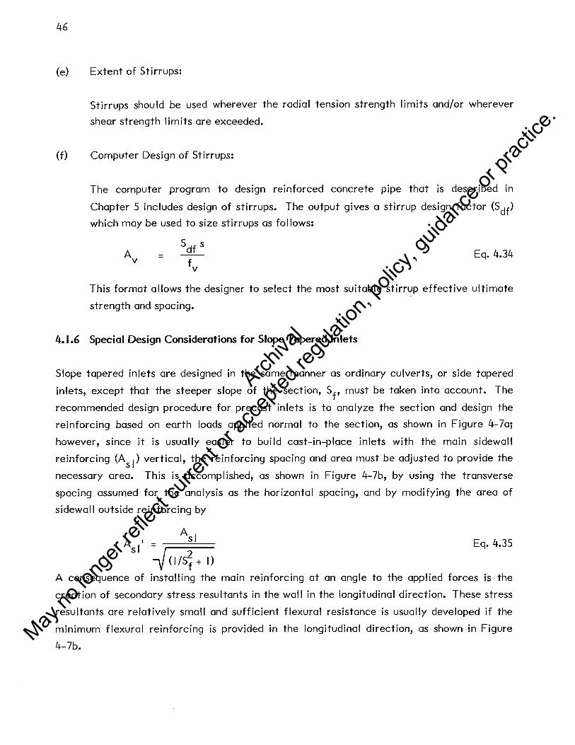
46
(e) Extent of Stirrups:
Stirrups should be used wherever the radial tension strength limits and/or wherever
shear strength limits are exceeded.
(f) Computer Design of Stirrups:
The computer program to design reinforced concrete pipe that is described in
Chapter 5 includes design of stirrups. The output gives a stirrup design factor (Sdf)
which may be used to size stirrups as fol lows:
A v
Eq. 4.34
This format allows the designer to select the most suitable stirrup effective ultimate
strength and spacing.
4.1.6 Special Design Considerations for Slope Tapered Inlets
Slope tapered inlets are designed in the same manner as ordinary culverts, or side tapered
inlets, except that the steeper slope of the section, Sf' must be taken into account. The
recommended design procedure for precast inlets is to analyze the section and design the
reinforcing based on earth loads applied normal to the section, as shown in Figure 4-7a;
however, since it is usually easier to build cast-in-place inlets with the main sidewall
reinforcing (As I) vertical, the reinforcing spacing and area must be adjusted to provide the
necessary area. This is accomplished, as shown in Figure 4-7b, by using the transverse
spacing assumed for the analysis as the horizontal spacing, and by modifying the area of
sidewall outside reinforcing by
A I sl
A consequence of
i (l/S~ + I)
Eq. 4.35
installing the main reinforcing at an angle to the applied forces is the
creation of secondary stress resultants in the wal I in the longitudinal direction. These stress
resultants are relatively small and sufficient flexural resistance is usually developed if the
minimum flexural reinforcing is provided in the longitudinal direction, as shown in Figure
4-7b.
Archiva
l
May no
long
er ref
lect c
urren
t or a
ccep
ted re
gulat
ion, p
olicy
, guid
ance
or pr
actic
e.

47
Design for load perpendicular to section
a. Dimensions, loads and reinforcement area, A 1 based on analysis for loads transverse to slope of slope to8ered inlet.
Longitudinal reinforcing to meet minimum requirements for flexural reinforcing :::: 0.002 bh, maximum spacing equals 12 in.
Main reinforcing installed vertically,
Area = As/J< l/Sl) + I Based on analysis i,n a. above.
b. Reinforcing requirements when main reinforcing is installed vertically, and transverse reinforcing is parallel to slope.
Figure 4-7 DESIGN CONSIDERATIONS FOR SLOPE TAPERED IWL..ETS
Archiva
l
May no
long
er ref
lect c
urren
t or a
ccep
ted re
gulat
ion, p
olicy
, guid
ance
or pr
actic
e.

48
4.2 Corrugated Metal Pipe Design Method
The AASHTO design method for corrugated metal structures has been successfully used for
many years, and is reproduced in Appendix A. As noted in Chapter 3, many manufacturers
provide proprietary modifications to large or unusual corrugated metal culverts, and should
be consulted prior to completion of detailed designs.
The use of side tapered corrugated metal inlets requires the design of horizontal elliptical
sections. The current AASHTO Bridge Specifications provide for the design of horizontal
ellipses only under section 1.9.6 Long Span Structural Plate Structures. Long-span
structures are set apart from typical corrugated metal pipe in that:
• "Special features", such as longitudinal or circumferential stiffeners, are required to control deformations in the top arc of the structure.
• The design criteria for buckling and handling do not apply.
The concept of special features was introduced by the corrugated metal pipe industry to
help stiffen long-span structures without using heavier corrugated metal plate, on the theory
that the extra stiffness provided by the special features allows the use of lighter corrugated
metal plate, since the combined stiffness of the plate and special feature may be used in
design. thus, for such structures, the corrugated metal plate alone need not meet the
handling and buckling criteria. This approach results in more economical structures for
large spans.
The concept of special features also applies to side tapered corrugated metal inlets;
however, it is not practical to provide special features for small inlets, and thus a special
condition exists. The recommended approach for these structures is that either special
features must be provided, or the handling and buckling criteria must be met by the
corrugated metal section alone. This is not specifically allowed by the AASHTO Bridge
Specification, but is within the design philosophy of the code.
Archiva
l
May no
long
er ref
lect c
urren
t or a
ccep
ted re
gulat
ion, p
olicy
, guid
ance
or pr
actic
e.

49
5. COMPUTERIZED ANALYSIS AND DESIGN OF REINFORCED CONCRETE SECTIONS
Computer programs that make the analysis and design of concrete culvert and inlet sections
both simple and cost effective are described in this Chapter. Use of the computer methods
allows the engineer to make a more complete evaluation of various culvert configurations
for a given installation.
5.1 Box Sections
The design program for buried reinforced concrete box sections provides a comprehensive
structural analysis and design method that may be used to design any single cell rectangular
box section with or without haunches. For tapered inlet design, the program may be used to
design cross sections at various locations along the longitudinal axis that the designer may
then assemble into a single design. This program is modelled after a similar program that
was used to develop ASTM Specification C789 (AASHTO M259) "Precast Reinforced
Concrete Box Sections for Culverts, Storm Drains and Sewers". This section gives a general
description of the program. Specific information needed to use the program is given in
Appendix B. A program listing is provided in Appendix H.
5.1.1 Input Variables
The fol lowing parameters are input variables in the program:
• Cu Ive rt geometry
• Loading data
• Material properties
• Design data
span, rise, wal I thicknesses, and haunch dimensions.
depth of fi II, density of fi II, lateral pressure coefficients, soil-structure interaction factor, depth of internal fluid, and density of fluid.
reinforcing tensile yield strength, concrete compressive strength, and concrete density.
load factors, concrete cover over reinforcement, wire diameter, wire spacing, type of reinforcing used, layers of reinforcing used, capacity reduction factor, and limiting crack control factor.
Archiva
l
May no
long
er ref
lect c
urren
t or a
ccep
ted re
gulat
ion, p
olicy
, guid
ance
or pr
actic
e.

50
The only parameters that must be specified are the span, rise, and depth of fill. If no values
are input for the remaining parameters, then the computer will use standard default values.
Default values are listed in Appendix B (Table B-1) for all the input parameters.
5.1.2 Loadings
The program analyzes the five loading cases shown in Figure 5-1. The loading cases are
separated into two groups; permanent dead loads (Cases I, 2 and 3) that are always
considered present and additional dead loads (Cases 4 and 5) that are considered present only
when they tend to increase the design force under consideration. The two foot surcharge
load (Section 2.4) is added to the height of fi 11, and is therefore considered as a permanent
dead load.
Earth pressures are assumed distributed uniformly across the width of the section and vary
linearly with depth. Soil reactions are assumed to be uniformly distributed across the base
of the culvert.
5.1.3 Structural Analysis
To determine the design moments, thrusts, and shears, the program employs the stiffness
matrix method of analysis. Box culverts are idealized as 4 member frames of unit width.
For a given frame, member stiffness matrices are assembled into a global stiffness matrix; a
joint load matrix is assembled, and conventional methods of matrix analysis are employed.
For simplicity, the fixed end force terms and flexibility coefficients for a member with
linearly varying haunches are determined by numerical integration. The trapezoidal rule
with 50 integration points is used and a sufficiently high degree of accuracy is obtained.
5.1.4 Design of Reinforcing
The program incorporates the design method entitled "Design Method for Reinforced
Concrete Pipe and Box Sections", developed by Simpson Gumpertz & Heger Inc. for the
American Concrete Pipe Association (9). This method is presented in Chapter 4. For a
given trial wal I thickness and haunch arrangements the design procedure consists of
determining the required steel reinforcement based on flexural strength and checking limits
based on crack control, concrete compressive strength, and diagonal tension strength. If the
limits are exceeded, the designer may choose to increase the amount of steel reinforcement,
Archiva
l
May no
long
er ref
lect c
urren
t or a
ccep
ted re
gulat
ion, p
olicy
, guid
ance
or pr
actic
e.

!
I. Dead Load
WT= F H y e e s
w = F H y r e e s
0.5 F H y Ts e e s
2. Vertical Earth Load
,w_~_=_a_. _y_H ___ .._~ 0.5 w5TTT - _ s min s e "'~
3. Minimum Lateral Soil Load
wr = yfDf
4. Internal Fluid Load
51
"""""' _ ___._ _______ _;.._-_-_-_~ ~.5w sB TB
w B (a -a . ) y (H + D. + TT + T8) s max mm s e 1
5. Maximum Lateral Soil Load
Figure 5-1 SINGLE CELL BOX SECTION LOADING CASES
Archiva
l
May no
long
er ref
lect c
urren
t or a
ccep
ted re
gulat
ion, p
olicy
, guid
ance
or pr
actic
e.

52
add stirrups for diagonal tension, or change the wal I thicknesses and haunch geometry as
required to provide a satisfactory design.
The following limitations apply to the use of the program to design box sections:
• Only transverse reinforcement areas are computed.
• Anchorage lengths must be calculated and added to the theoretical cut-off lengths determined by the program.
• The program does not design wall thicknesses (these must be input by the user).
• The program does not design shear reinforcement, but prints a message when shear reinforcement is required.
These limitations are included to allow the structural designer the maximum possible
flexibility in selecting reinforcing, i.e. type (hot rolled reinforcing bar or smooth or
deformed welded wire fabric), size and spacing.
The maximum forces at the design sections (Figure 4-2) are determined by taking the forces
due to the permanent dead load cases, and adding to them the forces due to the additional
dead load cases, if they increase the maximum force. Five steel areas designated as AS I,
AS2, AS3, AS4 and ASS in Figure 4-1 are sized based on the maximum governing moment at
each section. The area AS I is the maximum of the steel areas required to resist moments at
locations 5, 11 and 12 in Figure 4-2. Areas AS2, AS3, AS4 and ASS are designed to resist
moments at locations I, 15, S and 4, respectively. The steel areas determined for flexural
strength requirements are then checked for crack control. The program then checks shear
by both Methods I and 2 (Section 4.1.4) at the locations shown in Figure 4-2. The more
conservative criteria is used as the limiting shear capacity.
For the reinforcing scheme for precast box sections (Figure 4-1 a), the theoretical cutoff
lengths, 51,d for AS I in the top and the bottom slab are calculated from the assumption of
uniformly distributed load across the width of the section. The point where the negative
moment envelope is zero is computed from the minimum midspan moment. Informative
messages are printed when excessive concrete compression governs the design or when
stirrups are required due to excessive shear stresses.
Archiva
l
May no
long
er ref
lect c
urren
t or a
ccep
ted re
gulat
ion, p
olicy
, guid
ance
or pr
actic
e.

53
5.1.5 Input/Output Description
The amount of data required for the program is very flexible because much of the data is
optional. Input for a particular box culvert may range from a minimum of 3 cards to a
maximum of 16 cards depending on the amount of optional input data required by the
designer. The type of data to be supplied on each card is specified in Appendix B. A
program with minimum data would require only a title card, data card I specifying the span,
rise and depth of fi 11, and data card 15 indicating the end of the input data.
The amount of output can be controlled by the user, as described in Appendix B. The
minimum amount of output that will be printed is an echo print of the input data and a one
page summary of the design. An example design summary sheet is included in Appendix B.
Additional available output includes maps of major input arrays, displacements, end forces,
moments, thrusts and shears at critical sections, and shear and flexure design tables.
5.2 Circular and Elliptical Pipe Sections
The program for buried reinforced concrete pipe has the capability to analyze and design
circular, and horizontal elliptical pipe. Information needed to use the program is presented
in Appendix C.
5.2.1 Input Variables and Dimensional Limitations
The following parameters are input variables in the program:
• Pipe Geometry
• Loading Data
• Material Properties
• Design Data
diameter for circular pipe, or radius I, radius 2, horizontal offset, and vertical offset for elliptical pipe, and wall thickness (see Figure 1-2)
depth of fi 11 over crown of pipe, density of fi 11, bedding angle, load angle, soi I structure interaction factor, depth of internal fluid and fluid density
reinforcing tensile yield strength, concrete compressive strength and concrete density
load factors, concrete cover over inner and outer reinforcement, wire diameters, wire spacing, reinforcing type, layers of reinforcing, capacity reduction factor, crack control factor, shear process factor and radial tension process factor
Archiva
l
May no
long
er ref
lect c
urren
t or a
ccep
ted re
gulat
ion, p
olicy
, guid
ance
or pr
actic
e.

54
The pipe geometry and height of fill are the only required input parameters. Default values
are assumed for any optional data not specified by the user. Appendix C (Table C-1) lists all
the input parameters and their associated default values.
The program has the following limitations:
• The specified load angle must be between 180° and 300°.
• The specified bedding angle must be between I 0° and 180°.
• The sum of the bedding and load angles must be less than or equal to 360°.
• Only circumferential reinforcement is designed.
• Wal I thicknesses must be selected by the designer.
• Internal pressure is not a design case.
5.2.2 Loadings
The program analyzes the three load cases shown in Figure 5-2. Load cases I and 2 are
considered as permanent dead load, and load case 3 is considered additional dead load and is
used in design only if it increases the design force under consideration. The two foot
surcharge load suggested in Section 2.4 should be added to the height of fill input into the
program.
5.2.3 Structural Analysis
Due to symmetry, it is only necessary to analyze one half of the pipe section. The pipe is
modelled as a 36 member plane frame with boundary supports at the crown and invert. Each
member spans 5 degrees and is located at middepth of the pipe wall. For each member of
the frame, a member stiffness matrix is formed, and then transformed into a global
coordinate system. The loads on the pipe are calculated as pressures applied normal and
tangential to each of the 36 members. These pressures are converted into nodal pressures
that act radially and tangentially to the pipe. Loads at each joint are assembled into a joint
load matrix, and a solution is obtained by a recursion algorithm from which member end
forces are obtained at each joint. Analysis is completed separately for each load condition.
Archiva
l
May no
long
er ref
lect c
urren
t or a
ccep
ted re
gulat
ion, p
olicy
, guid
ance
or pr
actic
e.

I . Pipe Weight
2. Soil Weight
3. Internal Fluid Load
Note: These load cases also apply to elliptical sections.
Figure 5-2 PIPE SECTION LOAD CASES
55
Archiva
l
May no
long
er ref
lect c
urren
t or a
ccep
ted re
gulat
ion, p
olicy
, guid
ance
or pr
actic
e.

56
5.2.4 Design of Reinforcing
Forces or moments for ultimate strength design are determined by summing the stress
resultants obtained from the analyses for dead load, and earth load, and fluid load, (if the
latter increases the force under consideration), and multiplying the resultant by the
appropriate load factor.
The design procedure consists of determining reinforcement areas based on bending moment
and axial compression at locations of maximum moment, and checking for radial tension
strength, crack control, excessive concrete compression and diagonal tension strength. If
necessary, the reinforcement areas are increased to meet these other requirements. The
design procedure is the same as used for box sections (See Chapter 4).
Reinforcing is designed at three locations; inside crown, inside invert and outside springline
(See Figure 4-4). These areas are designated A , A . and A , respectively. Critical shear · SC SJ SO
locations are determined by locating the points where M /V ¢ d equals 3.0 (See Chapter 4). u u v
Shear forces are calculated at each of these points and compared to the maximum shear
strength. When the applied shear exceeds the shear strength, stirrups are designed by
outputting a stirrup design factor (S df). This is then used to determine stirrup area by the
following equation:
A v
Sdis) =-f
v Eq. 5.1
This allows the designer to select a desirable stirrup spacing and to vary f depending upon v
the developable strength of the stirrup type used. The stirrup reinforcing strength, f , is v based on either the yield strength of the stirrup material, or the developable strength of the
stirrup anchorage, whichever is less.
5.2.5 Input/Output Description
The amount of data required for the program is very flexible because much of the data is
optional. For an elliptical pipe, the number of data cards required may range from 5 cards
to 14 cards. For circular pipe design, one less card is required. The type of data to be
specified on each card and format is described in Appendix C. The first card for every
design is a problem identification card which may be used to describe the structure being
designed. The remaining cards are data cards. Data cards I through 3 are required cards
Archiva
l
May no
long
er ref
lect c
urren
t or a
ccep
ted re
gulat
ion, p
olicy
, guid
ance
or pr
actic
e.

57
that specify the pipe geometry and height of fill. Data cards 4 through 12 specify the
loading data, material strengths, and design criteria to be used. A data card over 12
indicates that the end of the data stream has been reached. For elliptical pipe, a design
with a minimum amount of data would require a title card, data cards I through 3 specifying
the culvert geometry and height of fill, and a data card with code greater than 12,
indicating the end of the data stream. For circular pipe, data card 2 is not required.
The amount of output can be controlled by the user, as described in Appendix C. The
minimum amount of information that wil I be printed is an echo print of the input data and a
one page summary of the design. Additional available output includes stiffness matrices,
displacements, moments, thrusts and shears at each node point and a table of design forces.
Archiva
l
May no
long
er ref
lect c
urren
t or a
ccep
ted re
gulat
ion, p
olicy
, guid
ance
or pr
actic
e.

59
6. DESIGN OF APPURTENANT STRUCTURES
In order to integrate an improved inlet into a culvert system, several appurtenant structures
may be required. These structures, which include circular to square transition sections,
wingwal Is, headwal Is and aprons also require the attention of a structural engineer. The
design of these structures is governed by the AASHTO Bridge Specifications (4), as is the
design of inlets. Design requirements of these structures are discussed below. Typical
suggested details are included in Appendix G. Suggested designs for several of these
structures are presented in Appendix E.
6.1 Circular to Square Transition
In some instances it is desirable to use a cast-in-place box inlet with a circular culvert
barrel. This requires the use of a transition section that meets the following criteria:
• The cross section must provide a smooth transition from a square to a circular shape. The rise and span of the square end should be equal to the diameter of the circular section.
• The length of the transition section must be at least one half the diameter of the circular section.
The outside of the transition section is not restricted by any hydraulic requirements; thus
structural, and construction considerations should be used to determine the shape. Typi
cally, for cast-in-place structures the simplest method is to make the outside square, and
maintain the box section reinforcing arrangement throughout the length of the section. This
simplifies the form work for the outside and allows the use of the same reinforcing layout
throughout the length of the section, avoiding the need to bend each bar to a different
shape. A suggested geometry and reinforcing diagram is shown in Figure 6-1 and
Appendix G.
Reinforcing for transition sections can be sized by designing for the loads at the square end
of the section according to the design method of Chapter 4 and then using that reinforcing
throughout the length of the structure.
Typically, the transition section will be a cast-in-place structure up against a precast pipe
section. It is important that the backfill be well compacted (95% of maximum AASHTO T-
99) around both structures to preclude signficant longitudinal discontinuity stresses due to
the differing stiffnesses of the two structures.
Archiva
l
May no
long
er ref
lect c
urren
t or a
ccep
ted re
gulat
ion, p
olicy
, guid
ance
or pr
actic
e.

60
Square Cross Section With or Without Haunches
Section A-A
Circular Cross Section
... A
Section B-B
Figure 6-1 CIRCULAR TO SQUARE TRANSITION SECTION
Archiva
l
May no
long
er ref
lect c
urren
t or a
ccep
ted re
gulat
ion, p
olicy
, guid
ance
or pr
actic
e.

61
6.2 Wingwal Is and Headwal Is
At the opening of an improved inlet it is common to use a headwall and wingwalls to hold
the toe of the embankment back from the entrance, protecting it from erosion (Figure 1-1 ).
The headwall is a retaining wall with an opening for the culvert. It derives support from
attachment to the culvert, and is subject to less lateral soil pressure than a retaining wall of
equal size since the culvert replaces much of the backfill. The wingwalls are retaining walls
placed at either side of the headwal I, usually at an angle (Figure 1-1 ).
6.2.1 Wingwal Is
Wingwalls are designed as retaining walls and pose no unusual problems for the engineer.
The methods of design and construction of retaining wal Is vary widely, and it is not possible
to cover al I of these in this Manual. There are a number of soi I mechanics texts (IO, 11, 12)
that explain in detail the analysis of retaining walls; also, in 1967 the FHWA published
"Typical Plans for Retaining Walls" ( 13) which gives typical designs for cantilever and
counterfort type retaining wal Is. For the purpose of demonstrating typical detai Is, one of
the drawings from this document was revised and reproduced in Appendix G. The revisions
made were to change the steel areas to reflect the use of reinforcing with a yield stress of
60,000 psi, which is the most common type in current use. The loading diagram and typical
reinforcing layout for this drawing are shown in Figure 6-2.
The designs are based on working stress methods given in Section 1.5 of the AASHTO Bridge
Specification (4).
For large culverts, the headwal Is and wingwal Is should always be separated by a structural
expansion joint. For smaller structures, this expansion joint may be omitted at the
discretion of the designer.
6.2.2 Headwal Is
Headwal Is are similar in appearance to wingwal Is but behave much differently because of
the culvert opening. The presence of the culvert greatly reduces the lateral pressure on the
wall, and since the headwall is normally secured to the culvert barrel, the lateral forces do
not normally need to be carried to the foot of the wal I. Thus, for this case, only a smal I
amount of reinforcing as shown in the typical detai Is in Appendix G need be placed in the
Archiva
l
May no
long
er ref
lect c
urren
t or a
ccep
ted re
gulat
ion, p
olicy
, guid
ance
or pr
actic
e.

62
//, ;r. -
H' /3
D
w
I. j p = 24.9 (H' )2 w
B I I. I (H' )2 p = v w
PH = 22.3 (H' )2 w
y 5
= 120 lbs./cu. ft.
Figure 6-2 LOADING DIAGRAM AND TYPICAL REINFORCING LAYOUT FOR CANTILEVER TYPE RETAINING WALL
H' w
Archiva
l
May no
long
er ref
lect c
urren
t or a
ccep
ted re
gulat
ion, p
olicy
, guid
ance
or pr
actic
e.

63
wall. If the headwall is not anchored to the inlet, culvert or the wing walls, then the
headwall must be designed to span horizontally across the width of the inlet, and vertical
edge beams must be provided on each side of the inlet, cantilevering up from the foundation.
Skewed Headwalls: A special design case for a headwall occurs when the face of a culvert is
skewed relative to the barrel (Figure 6-3). This requires special design for the headwal I, and
the portion of the culvert which is not a closed rectangle. The headwall is designed as a
vertical beam to support the loads on the edge portion of the culvert slab that is beyond the
closed rectangular sections of the culvert. This produces a triangular distribution of load
from the culvert slab to be supported by the vertical beam action of the headwall.
Transverse reinforcing in the culvert is sized as required in the closed rectangular sections,
and in the area of the skew, this reinforcing is cut off at the skew face of the headwall
beam. In addition, U-bars are provided at the skew edge, as shown in Figure 6-3. Skewed
headwalls are not recommended for normal installations. The best hydraulic performance is
received from a headwall that is perpendicular to the barrel.
6.3 Apron Slabs
Apron slabs are slabs on grade in front of the culvert face section. They are primarily used
to protect against erosion, and to hold the slope of fall sections. Apron slabs should be
treated as slabs on grade for design purposes.
Archiva
l
May no
long
er ref
lect c
urren
t or a
ccep
ted re
gulat
ion, p
olicy
, guid
ance
or pr
actic
e.

64
Skew Angle
o0 to 45°
Same Size As ASI
_,_---Main Reinforcing
Use Same Reinforcing Scheme As Box Section
Design as Typical Box Section
Main & Longitudinal Reinforcing
SECTION A-A
Figure 6-3 SKEWED HEADWALL DETAIL
Archiva
l
May no
long
er ref
lect c
urren
t or a
ccep
ted re
gulat
ion, p
olicy
, guid
ance
or pr
actic
e.

66
11. Hough, B.K., Basic Soils Engineering, 2nd Ed. The Ronald Press Co., New York, 1969
12. Sowers, G. B., Sowers, G. F ., Introductory Soi Is Mechanics and Foundations, 3rd Ed.,
Macmillan Publishing Co., Inc., New York, 1970
13. Typical Plans for Retaining Walls, Federal Highway Administration, Washington,
D.C., September 1967
Archiva
l
May no
long
er ref
lect c
urren
t or a
ccep
ted re
gulat
ion, p
olicy
, guid
ance
or pr
actic
e.

65
REFERENCES
I. Harrison, L. J., Morris, J. L., Normann, J.M., Johnson, F. L., "Hydraulic Design of
Improved Inlets for Culverts," Hydraulic Engineering Circular No. 13, U. S. Depart
ment of Transportation, Federal Highway Administration, Washington, D. C., August
1972, Reprinted December 1978
2. Design Handbook - Concrete Pipe, American Concrete Pipe Association, Vienna, VA,
1980
3. "Design and Construction of Sanitary and Storm Sewers," WPCF MANUAL OF
PRACTICE NO. 9, Water Pollution Control Federation, Washington, D. C. 1970
4. "Standard Specifications for Highway Bridges", American Association of State
Highway and Transportation Officials, Twelfth Edition, 1977 (updated to 1981 via
interim specifications)
5. Katona, M. G., Vittes, P. D., Lee, C. H., Ho, H. T ., "CANOE - 1980, Box Culverts and
Soils Models" Rough Draft, Prepared for Federal Highway Administration Office of
Research and Development, August 1980
6. Duncan, J. M., "A Design Method for Metal Culvert Structures Based on Finite
Element Analyses," Kaiser Aluminum Chemical Sales Inc.
7. Olander, H. C., "Stress Analysis of Concrete Pipe" Engineering Monograph No. 6, U.
S. Department of the Interior, Bureau of Reclamation, October 1950
8. Manual for Railway Engineering - Part 16 Reinforced Concrete Box Culverts,
American Roi lway Engineering Association, Chicago, 111., 1980
9. Heger, F. J., McGrath, T. J., Design Method for Reinforced Concrete Pipe and Box
Sections, Report prepared for the Technical Committee of the American Concrete
Pipe Association, December 1980
10. Lambe, T. W., Whitman, R. V., Soil Mechanics, John Wiley & Sons, Inc., New York,
1969
Archiva
l
May no
long
er ref
lect c
urren
t or a
ccep
ted re
gulat
ion, p
olicy
, guid
ance
or pr
actic
e.

A-I
APPENDIX A
CORRUGATED MET AL CUL VERT DESIGN
AASHTO Standard Specifications for Highway Bridges - 1977, and 1978, 1979, 1980 and
1981 Interim Specifications
Section 1.9 Soil Corrugated Metal Structure Interaction Systems
Section 2.23 Construction and Installation of Soil Metal Plate Structure Interaction Systems
Archiva
l
May no
long
er ref
lect c
urren
t or a
ccep
ted re
gulat
ion, p
olicy
, guid
ance
or pr
actic
e.

A-2
240 HIGHWAY BRIDGES
SECTION 9-SOIL-CORRUGATED METAL STRUCTURE INTERACTION SYSTEMS
1.9.1-GENERAL
(A) Scope
The specifications of this section are intended for the structural design of corrugated metal structures. It must be recognized that a buried flexible structure is a composite structure made up of the metal ring and the soil envelope; and both materials play a vital part in the structural design of flexible metal structures.
(B) Service Load Design
This is a working stress method, as traditionally used for culvert design.
(C) Load Factor Design
This is an alternate method of design based on ultimate strength principles.
(D) Loads
Design load, P, shall be the pressure acting on the structure. For earth pressures see Article l.2.2(A). For live load see Articles 1.2.3-1.2.9, 1.2.12 and 1.3.3, except that the words "When the depth of fill is 2 feet (0.610m) or more" in paragraph 1 of Art.1.3.3 need not be considered. For loading combinations see Article 1.2.22.
(E) Design
(1) The thrust in the wall must be checked by three criteria. Each considers the mutual function of the metal wall and the soil envelope surrounding it. The criteria are: ·
(a) Wall area (b) Buckling stress (c) Seam strength (structures with longitudinal seams)
Archiva
l
May no
long
er ref
lect c
urren
t or a
ccep
ted re
gulat
ion, p
olicy
, guid
ance
or pr
actic
e.

( '
1.9.1 DESIGN 241
(2) Thrust in the wall is:
T s
p x 2
Where P = Design load, lbs/sq.ft. (N/m2) S = Diameter or Span, ft. (m) T = Thrust, lbs/ft. (N/m)
(3) Handling and installation strength. Handling and installation strength must be sufficient to withstand impact
forces when shipping and placing the pipe.
(4) Minimum cover Height of cover over the structure must be sufficient to prevent damage
to the buried structure. A minimum of 2 feet (.610m) is suggested.
(F) Materials
The materials shall conform to the AASHTO specifications referenced herein.
(G) Soil Design
(1) Soil parameters The performance of a flexible culvert is dependent on soil structure inter
action and soil stiffness. The following must be considered:
(a) Soils . (1) The type and anticipated behavior of the foundation soil must be
considered; i.e., stability for bedding and settlement under load. (2) The type, compacted density and strength properties of the soil
envelope immediately adjacent to the pipe must be established. Dimensions of culvert soil envelope-general recommended criteria for lateral limits are as follows:
Trench width-2 ft. (.610rn) minimum each side of culvert. This recommended limit should be modified as necessary to account for variables such as poor in situ soils.
Embankment installations-one diameter or span each side of culvert. The minimum upper limit of the soil envelope is one foot (.305m)
above the culvert. Good side fill is considered to be a granular material with little or no plasticity and free of organic material, i.e., AASHTO classification groups A-1, A-2 and A-3 and compacted to a minimum 90 percent of standard density based on AASHTO Specifications T99 (ASTM D 698).
(3) The density of the embankment material above the pipe must be determined. See Article l.2.2(A).
A-3
Archiva
l
May no
long
er ref
lect c
urren
t or a
ccep
ted re
gulat
ion, p
olicy
, guid
ance
or pr
actic
e.

A-4
242 HIGHWAY BRIDGES 1.9.1
(2) Pipe arch design
Corner pressures must be accounted for in the design of the corner backfill. Corner pressure is considered to be approximately equal to thrust divided by the radius of the pipe arch corner. The soil envelope around the corners of pipe arches must be capable of supporting this pressure.
(3) Arch design
(a) Special design considerations may be applicable. A buried flexible structure may raise two important considerations. First is that it is undesirable to make the metal arch relatively unyielding or fixed compared to the adjacent sidefill. The use of massive footings or piles to prevent any settlement of the arch is generally not recommended. Where poor materials are encountered consideration should be given to removing some or all of this poor material and replacing it with acceptable material. The footing should be designed to provide uniform longitudinal settlement, of acceptable magnitude from a functional aspect. Providing for the arch to settle will protect it from possible drag down forces caused by the consolidation of the adjacent sidefill.
The second consideration is bearing pressure of soils under footings. Recognition must be given to the effect of depth of the base of footing and the direction of the footing reaction from the arch.
Footing reactions for the metal arch are considered to act tangential to the metal plate at its point of connection to the footing. The value of the reaction is the thrust in the metal arch plate at the footing.
(b) Invert slabs and/or other appropriate alternates shall be provided when scour is anticipated.
(H) Abrasive or Corrosive Conditions
Extra metal thickness, or coatings, may be required for resistance to corrosion and/or abrasion.
For a highly abrasive condition, a special design may be required.
(I) Minimum Spacing
When multiple lines of pipes or pipe arches greater than 48 inches (l.219m) in diameter or span are used, they shall be spaced so that the sides of the pipe shall be no closer than one-half diameter or three feet (.914m), whichever is less, to permit adequate compaction of backfill material. For diameters up to and including 48 inches (l.219m), the minimum clear spacing shall be not less than two feet (.610m).
(J) End Treatment
Protection of end slopes may require special consideration where backwater conditions may occur, or where erosion and uplift could be a problem. Culvert ends constitute a major run-off-the-road hazard if not properly designed. Safety treatment such as structurally adequate grating that conforms to the embankment slope, extension of culvert length beyond the
Archiva
l
May no
long
er ref
lect c
urren
t or a
ccep
ted re
gulat
ion, p
olicy
, guid
ance
or pr
actic
e.

1.9.1 DESIGN 243
point of hazard, or provision of guard rail are among the alternatives to be considered.
End walls on skewed alignment require a special design.
(K) Construction and Installation The construction and installation shall conform to Section 23, Division II.
1.9.2-SERVICE LOAD DESIGN
(A) Wall Area
where A Ts fa
A = Ts/fa
Required wall area, in2/ft (m2/m) = Thrust, Service Load, lbs/ft (N/m)
Allowable stress-specified minimum yield point, psi (MPa), div:ded by safety factor (fy/SF)
(B) Buckling Corrugations with the required wall area, A, shall be checked for possible
buckling. If allowable buckling stress, fe,ISF, is less than fa, required area must be
recalculated using fe,/SF in lieu of fa· Formulae for buckling are:
HS<~ .J 24Em then fer = fu - ~( kS )2 k ~ 48Em r
r PF4Em 12Em IfS > - -- thenf = --k fu er (kS!r)2
Where fu = Specified minimum tensile strength, psi (MPa) fer = Critical buckling stress, psi (MPa) k = Soil stiffness factor = 0.22 S = Diameter or span, inches (m) r Radius of gyration of corrugation, in. (m)
Em = Modulus of elasticity of metal, psi (MPa)
(C) Seam Strength For pipe fabricated with longitudinal seams (riveted, spot-welded, bolted),
the seam strength shall be sufficient to develop the thrust in the pipe wall. The required seam strength shall be:
A-5
Archiva
l
May no
long
er ref
lect c
urren
t or a
ccep
ted re
gulat
ion, p
olicy
, guid
ance
or pr
actic
e.

A-6
244 HIGHWAY BRIDGES
Where SS = Required seam strength in pounds per foot (N/m) T5 = Thrust in pipe wall, lbs/ft (Nim) SF = Safety Factor
1.9.2
(D) Handling and Installation Strength
Handling and installation rigidity is measured by a Flexibility Factor, FF, determined by the formula
Where FF s
E m I
= = = =
Flexibility Factor, inches per pound (m/N) Pipe diameter or maximum span, inches (m) Modulus of elasticity of the pipe material, psi (MPa) Moment of inertia per unit length of cross section of the pipe wall, inches to the 4th power per inch (m4/m).
1.9.3-LOAD FACTOR DESIGN
(A) Wall Area
A = T1/¢ify
Where A = Area of pipe wall, in21ft (m21m) TL = Thrust, load factor, lbs/ft (Nim)
fy = Specified minimum yield point, psi (MPa) ¢i = Capacity modification factor
(B) Buckling
If fer is less than fy then A must be recalculated using fer in lieu of fy.
rjif4Em Ifs < - --- then f = f k fu er u
f 2 _u_(ks/r)2
48Em
Wherefu fer k s = r
Em
r jif4Em If s > - --- then fer k fu
12Em (ks/r) 2
Specified minimum metal strength, psi (MPa) Critical buckling stress, psi (MPa) Soil stiffness factor = 0.22 Pipe diameter or span, inches (m) Radius of gyration of corrugation, inches (m) Modulus of elasticity of metal, psi (MPa)
Archiva
l
May no
long
er ref
lect c
urren
t or a
ccep
ted re
gulat
ion, p
olicy
, guid
ance
or pr
actic
e.

I \
1.9.3 DESIGN 245
(C) Seam Strength For pipe fabricated with longitudinal seams (riveted, spot-welded, bolted),
the seam strength shall be sufficient to develop the thrust in the pipe wall. The required seam strength shall be:
SS= TL <I>
Where SS = Required seam strength in pounds/ft (Nim) TL = Thrust multiplied by applicable factor, in pounds/lin. ft.
(N/m) <I> = Capacity modification factor
(0) Handlin!) and Installation Strength
Handling rigidity is measured by a Flexibility Factor, FF, determined by the formula
Where FF = Flexibility Factor, inches per pound (m/N) s = Pipe diameter of maximum span, inches (m)
Modulus of elasticity of the pipe material, psi (MPa) Moment of inertia per unit length of cross section of the pipe wall, inches to the 4th power per inch (m4 /m).
Em = I =
1.9.4-CORRUGATED METAL PIPE
(A) General (1) Corrugated metal pipe and pipe-arches may be of riveted, welded or
lock seam fabrication with annular or helical corrugations. The specifications are:
Steel Aluminum AASHTO M190, M196 AASHTO M36, M245, M190
(2) Service load design-safety factor, SF: Seam strength = 3.0 Wall area = 2.0 Buckling = 2.0
(3) Load factor design-capacity modification factor, ¢. Helical pipe with lock seam or fully welded seam
<I> = 1.00
Annular pipe with spot welded, riveted or bolted seam
<P = 0.67
A-7
Archiva
l
May no
long
er ref
lect c
urren
t or a
ccep
ted re
gulat
ion, p
olicy
, guid
ance
or pr
actic
e.

A-8
246 HIGHWAY BRIDGES 1.9.4
(4) Flexibility factor (a) For steel conduits, FF should generally not exceed the following
values:
l/4" (6.4mm) and 1/2" (12.7mm) depth corrugation FF = 4.3 X 10⁻²
l" (25.4mm) depth corrugation FF = 3.3 X 10⁻²
(b) For aluminum conduits, FF should generally not exceed the following values:
1/4" (6.4mm) and 1/2" (12.7mm) depth corrugation FF= 9.5 X io-2
l" (25.4mm) depth corrugation FF = 6 X 10⁻²
(5) Minimum Cover The minimum cover for design loads shall be Span/8 but not less than 12-
inches (.305 m). (The minimum cover shall be measured from the top of rigid pavement or the bottom of flexible pavement).
For construction requirements see Article 2.23.10.
(B) Seam Strength
(1) Minimum Longitudinal Seam Strength
2 X 1/2 150.8 X 12.7) and 2-2/3 X 112 (67.8 X 12.7 mm) Corrugated
Steel Pipe 3 X 1 176.2 X 25.4 mm) Corrugated
Steel Pipe
Thickness linches)
Imm)
0.064(1.63) 0.07912.01) o.1oa12.77) 0.138(3.51) 0.16814.27)
Riveted or Spot Welded ··,_Riveted or Spot Welded
Rivet Single Double Rivet Size Rivets Rivets Thickness Size
(inch) (Kips/foot) I Kips/foot) (inches) (inch) (mm) (kN/m) lkN/m) (mm) (mm)
5/16(7.9) 16.71244) 21.61315) 0.064(1.63) 3/819.5)
5/1617.9) 18.2(266) 29.81435) 0.079(2.01) 3/8(9.5)
3/8(9.5) 23.4(342) 46.81685) 0.10912.77) 7/16(11.1)
3/8(9.5) 24.51358) 49.01715) 0.13813.51) 7/16(11.1)
3/8(9.5) 25.61374) 51.31748) 0.168(4.27) 7/16111.1)
2 X 1/2 (50.8 X 12.7) and 2-2/3 X 1/2 (67.8 X 12.7mm) Corrugated Aluminum Pipe
Riveted
Rivet Single Double Thickness Size Rivets Rivets
(inches)(mm) (inch)(mm) (Kips/foot)(kN/m) (Kips/foot)(kN/m)
0.06011.5) 5/16(7.9) 9.0(131) 14.01204)
0.07511.9) 5/16(7.9) 9.0(131) 18.0(263)
0.10512.7) 3/819.5) 15.6(228) 31.5(460)
0.135(3.4) 3/8(9.5) 16.2(236) 33.01482)
0.164(4.2) 3/8(9.5) 16.8(245) 34.0(496)
Double Rivets
!Kips/foot) lkN/m)
28.71419) 35.7(521) 53.01773) 63.7(930) 70.7(1033)
Archiva
l
May no
long
er ref
lect c
urren
t or a
ccep
ted re
gulat
ion, p
olicy
, guid
ance
or pr
actic
e.

A-9
( 1.9.4 DESIGN 247
3 X 1 (76.2 X 25.4mm) Corrugated 6 X 1 (152.4 X 25.4mm) Corrugated Aluminum Pipe Aluminum Pipe
Riveted Riveted
Rivet Double Rivet Double
Thickness Size Rivets Thickness Size Rivets (inches) (inch) (Kips/foot) (inches) (inch) (Kips/foot)
(mm) (mm) (kN/m) (mm) (mm) lkN/m)
0.060(1.5) 3/8(9.5) 16.5(239) 0.060(1.5) 1/2(12.7) 16.0(232)
0.075(1.9) 3/8(9.5) 20.5(297) 0.075(1.9) 1/2(12.7) 19.9(288)
0.105(2.7) 112(12.7) 28.0(406) 0.105(2.7) 1/2(12.7) 27.9(405)
0.135(3.4) 1/2(12.7) 42.0(608) 0.135(3.4) 1/2112.7) 35.9(520)
0.164(4.2) 1/2(12.7) 54.5(790) 0.16714.2) 1/2(12.7) 43.5(631)
(C) Section Properties
(1) Steel conduits
l·l/2 X 114 (38.2 X 6.4mm) Corrugation 2-2/3 X 1/2 167.8 X 12.7mm) Corrugation
Thickness As r IX 10-:i A, r IX 10-:1
(inches) (sq.in/ft) (in.) (in\1in) (sq.in/ft) (in.) (in 1/in)
(mm) (mm2/m) (mm) (mm'imm) (mm 2/m) (mm) lmm"1/mm)
0.028 0.304 (.71) 1643.5) 0.034 0.380
( (.86) (804.3) 0.040 0.456 0.0816 0.253 0.465 0.1702 1.121
(1.02) 1965.2) (2.07) (4144.9) 1984.3) (4.32) (18365.3)
0.052 0.608 0.0824 0.344 0.619 0.1707 1.500
(1.32) (1286.9) (2.09) (5635.8) (1310.2) (-1.341 (24574.5)
0.064 0.761 0.0832 0.439 0.775 0.1712 1.892
(1.63) (1610.8) (2.11) (7192.1) (1640.4) (4.35) 130996.6)
0.079 0.950 0.0846 0.567 0.968 0.1721 2.392
(2.01) (2010.8) (2.15) (9289.2) (2048.9) 14.37) (39188.1)
0.109 1.331 0.0879 0.857 1.356 0.1741 3.425
(2.77) (2817.31 (2.23) (14040.2) 12870.2) (4.42) 156111.8)
0.138 1.712 0.0919 1.205 1.744 0.1766 4.533
(3.51) 13623.7) (2.33) (197 41.5) 13691.5) (4.49) 174264.1)
0.168 2.098 0.0967 1.635 2.133 0.1795 5.725
(4.27) (4440.8) (2.46) (26786.2) (4514.9) (4.56) (93792.7)
3 X 1 176.2 X 25.4mm) Corrugation 5 X 1 (127 X 25.4mm) Corrugation
Thickness A, r IX 10-:1 A, r I X 10-:1
(inches) (sq.in/ft) (in.) lin'iin) !sq.in/ft) (in.) lin'lin)
(mm) (mm2/m) (mm) (mm'imm) (mm2/m) (mm) (mm·11mm)
0.064 0.890 0.3417 8.659 0.794 0.3657 8.850
(1.63) (1883.81 (8.68) (141860) (1680.6) (9.29) (144990)
0.079 1.113 0.3427 10.883 0.992 0.3663 11.092
(2.01) (2355.9) (8.70) (178296) 12099.7) (9.30) (181720)
0.109 1.560 0.3488 15.459 1.390 0.3677 15.650
(2.77) (3302.0) (8.86) (253265) (2942.2) (9.34) (2563941
0.138 2.008 0.3472 20.183 1.788 0.3693 20.317
(3.51) (4250.3) (8.82) (330658) (3784.6) (9.38) (332853)
0.168 2.458 0.3499 25.091 2.186 0.3711 25.092
(4.27) (5202.81 (8.89) (411065) (4627.0J (9.43) (411082)
Archiva
l
May no
long
er ref
lect c
urren
t or a
ccep
ted re
gulat
ion, p
olicy
, guid
ance
or pr
actic
e.

A-10
248 HIGHWAY BRIDGES 1.9.4
(2) Aluminum conduits
1-112 X 1/4 (38.2 X 6.4mm) Corrugation 2-2/3 X 1/2 (67.8 X 12.7mm) Corrugation
Thickness A, r I X 10-3 A, r I X 10-" (inches) (sq.in/ft) (in.) (in4 /inl (sq.in/ft) (in.) lin4 /in)
(mm) (mm1/m) (mm) (mm4 /mm) (mm2/m) (mm) (mm4 /mm)
0.048 0.608 0.0824 0.344 (1.22) (1286.9) (2.09) (5635.8) 0.060 0.761 0.0832 0.349 0.775 0.1712 1.892 (1.52) (1610.8 (2.11) (5717.71 (1640.4) (4.35) (30996.6)
0.968 0.1721 2.392 (2048.9) (4.37) (39188.1)
1.356 0.1741 3.425 (2870.2) (4.42) (56111.8)
1.745 0.1766 4.533 (3693.6) (4.49) (74264.1)
2.130 0.1795 5.725 (4508.5) (4.56) (93792.7)
3 X l (/'b.2 X 25.4mm) Corrugation 6 X 1 0 52.4 X 25.4mm)
Effective Thickness A, r I X 10-" A, Area r I X 10-3
(inches) (sq.in/ft) (in.) (in 11in) (sq.in/ft) (sq.in/ft) (in.) (in4 /in) (mm) (mm1/m) (mm) (mm 4/mml (mm1/m) (mm2/m) (mm) (mm4 /mm)
0.060 0.890 0.3417 8.659 0.775 0.387 0.3629 8.505 (1.52) (1883.8) (8.68) (141860) (1640.4) (819.2) (9.22) (139337) O.D75 1.118 0.3427 10.883 0.968 0.484 0.3630 10.631 (l .91) (2366.4) (8.70) (1782961 (2048.9) (1024.5) (9.22) (174168) 0.105 1.560 0.3488 15.459 1.356 0.678 0.3636 14.340 (2.671 (3302.0i (8.86) (253265) (2870.2) (1435. l) (9.24) (234932) 0.135 2.088 0.3472 20.183 1.744 0.872 0.3646 19.319 (3.43) (4419.6) (8.82) (330658) (3691.5) (1845.7) (9.26) (316503) 0.164 2.458 0.3499 25.091 2.133 1.066 0.3656 23.760 (4.17) (5202.8) (8.89) (411065) (4514.9) (2256.4) (9.29) (389260)
(D) Chemical and Mechanical Requirements
(1) Aluminum-Corrugated Metal Pipe and Pipe-Arch Material requirements-AASHTO M 197
Mechanical properties for design
Minimum Tensile
Strength psi (MPa)
Minimum Yield Point
psi (MPa)
Mod. of Elast.
psi (MPa)
31,000(213.737) 24,000(165.474) 10 x 106(68947)
(2) Steel-Corrugated Metal Pipe and Pipe-Arch Material requirements-AASHTO M 218
M 246
Archiva
l
May no
long
er ref
lect c
urren
t or a
ccep
ted re
gulat
ion, p
olicy
, guid
ance
or pr
actic
e.

(
(
- I
. .
f • 'mi~~~!~'.. 1.9.4 DESIGN
Mechanical properties for design
Minimum Tensile
Strength psi (MPa)
45,000(310.264)
(E) Smooth lined Pipe
Minimum Yield Point
psi (MPa)
33,000(227 .527)
Mod. of Elast.
psi (MPa)
29 x 106(199948)
249
Corrugated metal pipe composed of a smooth liner and corrugated shell attached integrally at helical seams spaced not more than 30 inches (.762 m) apart may be designed in accordance with Article 1.9.l on the same basis as a standard corrugated metal pipe having the same corrugations as the shell and a weight per foot (m) equal to the sum of the weights per foot (m) of liner and helically corrugated shell. The shell shall be limited to corrugations having a maximum pitch of 3 inches (76.2mm) and a thickness of not less than 60 percent of the total thickness of the equivalent standard pipe.
1.9.5-STRUCTURAL PLATE PIPE STRUCTURES
(A) General (1) Structural plate pipe, pipe arches, and arches shall be bolted with
annular corrugations only. The specifications are:
Aluminum AASHTO M219
(2) Service load design-safety factor, SF Seam strength = 3.0 Wall area= 2.0 Buckling = 2.0
Steel AASHTO Ml67
(3) Load factor design-capacity modification factor, </>
</> = 0.67
(4) Flexibility factor (a) For steel conduits, FF should generally not exceed the following
values: 6" X 2" (152.4 X 50.8mm) corrugation FF = 2.0 X 10⁻² (Pipe) 6" X 2" (152.4 X 50.8mm) corrugation FF= 3.0 X 10⁻² (Pipe-arch) 6" X 2" (152.4 X 50.8mm) corrugation FF = 3.0 X 10⁻² (Arch)
(b) For aluminum conduits, FF should generally not exceed the following values:
9" X 21/2" (228.6 X 63.5mm) corrugation FF= 2.5 X 10⁻² (Pipe) 9" X 21/2" (228.6 X 63.5mm) corrugation FF = 3.6 X 10⁻² (Pipe
arch) 9" X 21/2" (228.6 X 63.5mm) corrugation FF = 7.2 X 10⁻² (Arch)
A-II
Archiva
l
May no
long
er ref
lect c
urren
t or a
ccep
ted re
gulat
ion, p
olicy
, guid
ance
or pr
actic
e.

A-12
249A HIGHWAY BRIDGES 1.9.5
(5) Minimum cover The minimum cover for design loads shall be Span/8 but not less than 12-
inches (.305m). (The minimum cover shall be measured from the top of rigid pavement or the bottom of flexible ·pavement). For Construction requirements see Article 2.23.10.
(B) Seam Strength
Minimum Longitudinal Seam Strengths 6 X 2 (152.4 X 50.8mm) Steel Structure Plate Pipe
Thickness Bolt Size 4 Bolts/ft(.305m) 6 Bolts/ft(.305m) 8 Bolts/ft(.305m)
(inches) (inch) (Kips/foot) !Kips/foot) (Kips/foot) (mm) (mm) lkN/m) (kN/m) ikN/m)
0.109(2. 77) 3/4(19.1) 43.01627 .8) 0.138(3.51) 3/4(19.1) 62.01905.2) 0.168(4.27) 3/4(19.1) 81.0(1182.6) 0.18814.78) 3/4(19.1) 93.0(1357.8) 0.218(5.54) 3/4(19.1) 112.011635.2) 0.249(6.32) 3/4(19.1) 132.011927.2) 0.28017.11) 3/4(19.1) 144.012102.4) 18012628.0) 194(2832.4)
9 X 2-1/2 1228.6 X 63.5mm) Aluminum Structural Plate Pipe
Thickness (inches)
(mm)
0.10(2.54) 0.12513.18) 0.15(3.81) 0.17514.45) 0.20015.08) 0.225(5.72) 0.250(6.35)
(C) Section Properties
(1) Steel conduits
Bolt Size (inch)
3/4(19.1) 3/4(19.1) 3/4(19.1) 3/4(19.1) 3/4(19.1) 3/4119.1) 3/4(19.1)
Steel Bolts Aluminum Bolts 5-1/2 Bolts 5-1/2 Bolts
Per ft(.305m) Per ft(.305m) . (Kips/foot) (Kips/foot)
lkN/m) (kN/m)
28.0(408.8) 26.4(385.4) 41.01598.6) 34.8(508.1) 54.1(789.9) 44.41648.2) 63. 7(930.0) 52.8(770.9) 73.4(1071.6) 52.8(770.9) 83.211214.7) 52.8(770.9) 93.1(1359.3) 52.8(770.9)
6" X 2" (152.4 X 50.8mm) Corrugations
Thickness A, r IX 10-:i
(inches) (sq.in/ft) (in.) (in4 /in)
(mm) (mm'im) (mm) (mm4 /mm)
0.10912.77) 1.55613293.5) 0.682(17 .32) 60.4111989713)
0.13813.51) 2.00314239. 7) 0.684(17.37) 78.17511280741)
0.16814.27) 2.44915183.7) 0.686117.42) 96.163(1575438)
0.18814.78) 2.73915797.6) 0.688117.48) 108.00011769364)
0.218t5.54) 3.199(6771.2) 0.690( l 7 .53) 126.922(2079363)
0.249(6.32) 3.65017725.8) 0.692117 .58) 146.17212394735)
0.280(7.11) 4.11918718.6) 0.695117 .65) 165.83612716891)
Archiva
l
May no
long
er ref
lect c
urren
t or a
ccep
ted re
gulat
ion, p
olicy
, guid
ance
or pr
actic
e.

i \
( •.
' ~ . 0! \ . · INTERIM : .. -~': ' t :_ ', <:· "J9~t :~i -~·:Y:~~"-
1.9.5 DESIGN
(2) Aluminum conduits
9" X 2-1/2" (228.6 X 63.5mm) Corrugations
Thickness A, r IX 10-:i
(inches) (sq.in/ft) (in.) (in"1/in) (mm) (mm2/m) (mm) (mm•tmm)
0.100(2.54) 1.404(2971.8) 0.8438(21.43) 83.065(1360854) 0.125(3.18) 1.750(3704.2) 0.8444121.45) 103.991(1703685) 0.150(3.81) 2.100(4445.0) 0.8449121.46) 124.883(2045958) 0.175(4.45) 2.449(5183.72) 0.8454121.47) 145.895(2390198) 0.200(5.08) 2.799(5924.6) 0.8460121.49) 166.959(2735289) 0.225(5.72) 3.149(6665.4) 0.8468121.51) 188.179(3082937) 0.250(6.35) 3.501(7410.5) 0.8473(21.52) 209.434(3431157)
(D) Chemical and Mechanical Properties
(1) Aluminum-Structural plate pipe, pipe-arch, and arch Material requirements-AASHTO M 219, Alloy 5052
Mechanical properties for design
Minimum Minimum Thickness Tensile Yield
(inches) Strength Point (mm) psi (MPa) psi IMPa)
0.100 to 0.175 35,000 24.000 (2.54 to 4.45) (241.316) (165.474)
0.176 to 0.250 34,000 24,000 (4.47 to 6.35) (234.421) (165.474)
(2) Steel-Structural plate pipe, pipe-arch, and arch Material requirements-AASHTO M 167
Mechanical properties for design
Minimum Tensile
Strength psi (MPa)
45,000 (310.264)
(E) Structural Plate Arches
Minimum Yield Point
psi IMPal
33,000 (227.527.)
Mod. of Elast.
psi IMPa)
29 x 106
(199948)
Mod. of Elast.
psi (MPa)
10 x 10° (68947)
10 x 106
(68947)
2498
The design of structural plate arches should be based on ratios of a rise to span of 0.3 minimum.
1.9.6-LONG SPAN STRUCTURAL PLATE STRUCTURES
(A) General
Long span structural plate structures are short span bridges defined as: (1) Structural Plate Structures (pipe, pipe arch, and arch) which exceed
maximum sizes imposed by 1.9.5.
A-13
Archiva
l
May no
long
er ref
lect c
urren
t or a
ccep
ted re
gulat
ion, p
olicy
, guid
ance
or pr
actic
e.
A-14
249C HIGHWAY BRIDGES 1.9.6
(2) Special shapes of any size which involve a relatively large radius of curvature in crown or side plates. Vertical ellipses, horizontal ellipses, underpasses, low profile arches, high profile arches, and inverted pear shapes are the terms describing these special shapes.
Wall Strength and Chemical and Mechanical Properties shall be in accordance with Article 1.9.5. The construction and installation shall conform to Section 23, Division II.
(B) Design
Long span structures shall be designed in accordance with Art. 1.9.1, 1.9.2 or 1.9.3 and 1.9.5. Requirements for buckling and flexibility factor do not apply. Substitute twice the top arc radius for the span in the formulae for thrust. Long span structures shall include acceptable special features. Minimum requirements are detailed in Table 1.
(2) Acceptable special features (a) Continuous longitudinal structural stiffeners connected to the corru
gated plates at each side of the top arc. Stiffeners may be metal or reinforced concrete or combination thereof.
(b) Reinforcing ribs formed from structural shapes curved to conform to the curvature of the plates, fastened to the structure as required to insure integral action with the corrugated plates, and spaced at such intervals as necessary to increase the moment of inertia of the section to that required by the design. (3) Design for deflection Soil design and placement requirements for long span structures limit
deflection satisfactorily. However, construction procedures must be such that severe deformations do not occur during construction.
(4) Soil design Granular type soils shall be used as structure backfill (the envelope next
to the metal structure). The order of preference of acceptable structure backfill materials is as follows:
(a) Well graded sand and gravel; sharp, rough or angular if possible. (b) Uniform sand or gravel. (c) Approved stabilized soil shall be used only under direct supervision
of a competent, experienced soils engineer. Plastic soils shall not be used. The structure backfill material shall conform to one-of the following soil
classifications from AASHTO Specification M 145, Table 2: For height of fill less than 12 feet (3.658m), A-1, A-3, A-2-4 and A-2-5; for height of fill of 12 feet (3.658m) and more, A-1, A-3. Structure backfill shall be placed and compacted to not less than 90 percent density per AASHTO T 180.
The extent of the select structural backfill about the barrel is dependent on the quality of the adjacent embankment. For ordinary installations, with good quality, well compacted embankment or in situ soil adjacent to the structure backfill, a width of structural backfill six feet (1.829m) beyond the structure is sufficient. The structure backfill shall also extend to an elevation two (.610m) to four feet (1.219m) over the structure.
It is ·not necessary to excavate native soil at the sides if the quality of the native soil is already as good as the proposed compacted side-fill. The soil
Archiva
l
May no
long
er ref
lect c
urren
t or a
ccep
ted re
gulat
ion, p
olicy
, guid
ance
or pr
actic
e.

(
1.9.6 DESIGN 249D
over the top shall also be select and shall be carefully and densely compacted.
(C) Structural Plate Shapes
STANDARD TERMINOLOGY OF STRUCTURAL PLATE SHAPES INCLUDING LONG SPAN STRUCTURES.
0 0 0 PIPE ARCH
ROUllD VERTICAL ELLIPSE
£'\ 0 ·+· ARCH
UNDERPASS HORIZONTAL ELLIPSE
A LOW PROFILE ARCH
HIGH PROFILE ARCH
INVERTED PEAR
FIGURE 1.9.6.
(D) End Treatment When headwalls are not used, special attention may be necessary at the
ends of the structure. Severe bevels and skews are not recommended. For
A-15
Archiva
l
May no
long
er ref
lect c
urren
t or a
ccep
ted re
gulat
ion, p
olicy
, guid
ance
or pr
actic
e.

A-16
249E HIGHWAY BRIDGES 1.9.6
hydraulic structures, additional reinforcement of the end is recommended to secure the metal edges at inlet and outlet against hydraulic forces. Reinforced concrete or structural steel collars, or tension tiebacks or anchors in soil, partial headwalls and cut off walls below invert elevation are some of the methods which can be used. Square ends may have side plates beveled up to a maximum 2:1 slope. Skew ends up to 15° with no bevel, are permissible. When this is done on spans over 20 feet (6.096m) the cut edge must be reinforced with reinforced concrete or structural steel collar. When full headwalls are used and they are skewed, the offset portion of the metal structure shall be supported by the headwall. A special headwall shall be designed for skews exceeding 15°. The maximum skew shall be limited to 35°.
(E) Multiple Structures
Care must be exercised on the design of multiple, closely spaced structures to control unbalanced loading. Fills should be kept level over the series of structures when possible. Significant roadway grades across the series of structures require checking stability of the flexible structures under the resultant unbalanced loading.
Archiva
l
May no
long
er ref
lect c
urren
t or a
ccep
ted re
gulat
ion, p
olicy
, guid
ance
or pr
actic
e.

1111
250
I. TOP ARC
HIGHWAY BRIDGES
TABLE 1
Minimum Requirements for Long Span Structures With Acceptable Special Features
TOP RADIUS JN FT (m) 15-17 17-20 20-23 23-25
1.9.6
15 (4.572) (4.572-5.182) (5.182-6.096) (6.096-7.010) (7.010-7.620)
Minimum Thicknesa (mm) 6 X 2 Corrugated Steel Plates (152.4 x 50.8)
.109" (2.77)
.138" (3.51)
.168" (4.27)
JI, MINIMUM COVER IN FT. (m) TOP RADIUS IN FT. (m)
.218" (5.54)
.249" (6.32)
Steel Thickness' 15 15-17 17-20 20-23 23·25 in in. (mm) (4.572) (4.572-5.182) (5.182-6.096) (6.096-7.010) (7.010-7.620)
.109 2.5 (2.771 (.762) .138 2.5 (3.51) 1.7621 .168 2.5 14.271 (.7621 .188 2.5 (4.781 (.7621 .218 2.0 15.541 (.6101 .249 2.0 (6.321 (.6101 .280 2.0 (7.111 (.6101
III. GEOMETRIC LIMITS
A. Maximum Plate Radius-25 Ft. (7.620m) B. Maximum Central Angle of Top Arc = 80° C. Minimum Ratio, Top Arc Radius to Side Arc
Radius= 2 D. Maximum Ratio, Top Arc Radius to Side
Arc Radius = 5 *
3.0 f.9141
3.0 (.9141
3.0 (.9141
2.5 (.7621
2.0 (.6101
2.0 (.6101
*NOTE: Sharp radii generate high soil bearing pressures.
3.0 (.9141
3.0 f.9141
2.5 f.7621
2.5 1.7621
2.5 1.7621
Avoid high ratios when significant heights of fill are involved.
IV. SPECIAL OESIGNS
Structures not described herein shall be regarded as special designs.
3.0 f.9141
3.0 4.0 (.9141 (1.2191
3.0 4.0 (.9141 (1.2191
(1) When reinforcing ribs are used the moment of inertia of the composite section shall be equal to or greater than the moment of inertia of the minimum plate thickness shown.
A-17
Archiva
l
May no
long
er ref
lect c
urren
t or a
ccep
ted re
gulat
ion, p
olicy
, guid
ance
or pr
actic
e.

A-18
430 HIGHWAY BRIDGES
Section 23-CONSTRUCTION AND INSTALLATION OF SOIL METAL PLATE STRUCTURE .
INTERACTION SYSTEMS
2.23.1-GENERAL
This item shall consist of furnishing corrugated metal or structural plate pipe, pipe-arches and arches conforming to these specifications and of the sizes and dimensions required on the plans, and installing such structures at the places designated on the plans or by the Engineer, and in conformity with the lines and grades established by the Engineer. Pipe shall be either circular or elongated as specified or shown on the plans.
The thickness of plates or sheets shall be as determined in Art. 1.9.2, Division I, and the radius of curvature shall be as shown on the plans. Each plate or sheet shall be curved to one or more circular arcs.
The plates at longitudinal and circumferential seams of structural plates shall be connected by bolts. Joints shall be staggered so that not more than three plates come together at any one point.
2.23.2-FORMING AND PUNCHING OF CORRUGATED STRUCTURAL PLATES AND SHEETS FOR PIPE
(A) Structural Plate Pipe
Structural plates of steel shall conform to the requirements of AASHTO M 167 and aluminum to the requirements of AASHTO M 219.
Plates shall be formed to provide lap joints. The bolt holes shall be so punched that all plates having like dimensions, curvature, and the same number of bolts per foot (m) of seam shall be interchangeable. Each plate shall be curved to the proper radius so that the cross-sectional dimensions of the finished structure will be as indicated on the drawings or as specified.
Unless otherwise specified, bolt holes along those edges of the plates that form longitudinal seams in the finished structure shall be in two rows. Bolt holes along those edges of the plates that form circumferential seams in the
Archiva
l
May no
long
er ref
lect c
urren
t or a
ccep
ted re
gulat
ion, p
olicy
, guid
ance
or pr
actic
e.

INTERIM ' ' 1981
2.23.2
INTERIM 1980
CONSTRUCTION
INTEHll\1 197~
431
finished structure shall provide for a bolt spacing of not more than 12 in. (0.305m). The minimum distance from center of hole to edge of the_plate shall be not less than 1-3/4 times the diameter of the bolt. The diameter of the bolt holes in the longitudinal seams shall not exceed the diameter of the bolt by more than 118 inch (3.2mm).
Plates for forming skewed or sloped ends shall be cut so as to give the angle of skew or slope specified. Burned edges shall be free from oxide and burrs and shall present a workmanlike finish. Legible identification numerals shall be placed on each plate to designate its proper position in the finished structure. (B) Corrugated Metal Pipe
Corrugated steel pipe shall conform to the requirements of AASHTO M 36 and aluminum to the requirements of AASHTO M 196.
Punching and forming of sheets shall conform to AASHTO M 36.
(C) Elongation
Ii elongated structural plate or corrugated metal pipe is specified or called for on the plans, the plates or pipes shall be formed so that the finished pipe is elliptical in shape with the vertical diameter approximately five percent greater than the nominal diameter of the pipe. Pipe-arches shall not be elongated. Elongated pipes shall be installed with the longer axis vertical.
2.23.3-ASSEMBL Y (A) General
Corrugated metal pipe, and structural plate pipe shall be assembled in accordance with the manufacturer's instructions. All pipe shall be unloaded and handled with reasonable care. Pipe or plates shall not be rolled or dragged over gravel or rock and shall be prevented from striking rock or other hard objects during placement in trench or on bedding.
Corrugated metal pipe shall be placed on the bed starting at downstream end with the inside circumferential laps pointing downstream.
Bituminous coated pipe and paved invert pipe shall be installed in a similar manner to corrugated metal pipe with special care in handling to avoid damage to coatings. Paved invert pipe shall be installed with the invert pavement placed and centered on the bottom.
Structural plate pipe, pipe arches, and arches shall be installed in accordance with the plans and detailed erection instructions. Bolted longitudinal seams shall be well fitted with the lapping plates parallel to each other. The applied bolt torque for 3/4" (19.1 mm) diameter high strength steel bolts shall be a minimum of 100 ft.-lbs. (135.58Nm) and a maximum of 300ft.-lbs. (406.74Nm); for3/4" (19.lmm) diameteralumninum bolts, the applied bolt torque shall be a minimum of 100 ft.-lbs. (135.58Nm) and a maximum of 150 ft.-lbs. (203.37Nm). There is no structural requirement for residual torque; the important factor is the seam fit-up.
Joints for corrugated metal culvert and drainage pipe shall meet the following performance requirements:
( 1) Field Joints Transverse field joints shall be of such design that the successive con
nection of pipe sections will form a continuous line free from appreciable irregularities in the flow line. In addition, the joints shall meet the general performance requirements described in items ( 1) through ( 3 ). Suitable
A-19
Archiva
l
May no
long
er ref
lect c
urren
t or a
ccep
ted re
gulat
ion, p
olicy
, guid
ance
or pr
actic
e.

A-20
432 HIGHWAY BRIDGES 2.23.3
transverse field joints, which satisfy the requirements for one or more of the subsequently defined joint performance categories, can be obtained with the following types of connecting bands furnished with the suitable band-end fastening devices.
(a)Corrugated bands (b )Bands with projections (c)Flat bands (d)Bands of special design that engage factory reformed ends of
corrugated pipe. Other equally effective types of field joints may be used with the
approval of the Engineer. (2) Joint Types
Applications may require either "Standard" or "Special" joints. Standard joints are for pipe not subject to large soil movements or disjointing forces, these joints are satisfactory for ordinary installations, where simple slip type joints are typically used. Special joints are for more adverse requirements such as the need to withstand soil movements or resist disjointing forces. Special designs must be considered for unusual conditions as in poor foundation conditions. Downdrain joints are required to resist longitudinal hydraulic forces. Examples of this are steep slopes and sharp curves.
(3) Soil Conditions
The requirements of the joints are dependent upon the soil conditions at the construction site. Pipe backfill which is not subject to piping action is classified as "Nonerodible." Such backfill typically includes granular soil (with grain sizes equivalent to coarse sand, small gravel, or larger) and cohesive clays.
Backfill that is subject to piping action, and would tend either to infiltrate the pipe or to be easily washed by exfiltration of water from the pipe, is classified as "Erodible." Such backfill typically includes fine sands, and silts.
Special joints are required when poor soii conditions are encountered such as when the backfill or foundation material is characterized by large soft spots or voids. If construction in such soil is unavoidable, this condition can only be tolerated for relatively low fill heights, since the pipe must span the soft spots and support imposed loads. Backfills of organic silt, which are typically semifluid during installation, are included in this classification.
(4) Joint Properties
The requirements for joint properties are divided into the six categories shown on Table 2.23.3. Properties are defined and requirements are given in the following Paragraphs (a) through (f). The values for various types of pipe can be determined by a rational analysis or a suitable test.
(a) Shear Strength-The shear strength required of the joint is expressed as a percent of the calculated shear strength of the pipe on a transverse cross section remote from the joint.
(b) Moment Strength-The moment strength required of the joint is expressed as a percent of the calculated moment capacity of the pipe on a transverse cross section remote from the joint.
Archiva
l
May no
long
er ref
lect c
urren
t or a
ccep
ted re
gulat
ion, p
olicy
, guid
ance
or pr
actic
e.

2.23.3 CONSTRUCTION 433
(a) Shear Strength-The shear strength required of the joint is expressed as a percent of the calculated shear strength of the pipe on a transverse cross section remote from the joint.
(b) Moment Strength-The moment strength required of the joint is expl'essed as a percent of the calculated moment capacity of the pipe on a transverse cross section remote from the joint. In lieu of the required moment strength, the pipe joint may be furnished with an allowable slip as defined in Paragraph ( 4 )( c ).
(c) Allowable Slip-The allowable slip is the maximum slip that a pipe can withstand without disjointing, divided by a factor of safety.
(d) Soiltightness-Soiltightness refers to openings in the joint through which soil may infiltrate. Soiltightness is influenced by the size of the opening (maximum dimension normal to the direction that the soil may infiltrate) and the length of the channel (length of the path along which the soil may infiltrate). No opening may exceed 1 inch (.025m). In addition, for all categories, if the size of the opening exceeds 1/8 inch (.003m), the length of the channel must be at least four times the size of the opening. Furthermore, for non-erodible, erodible, or poor soils, the ratio of D 8 5 soil size to size of opening must be greater than 0.3 for medium to fine sand or 0.2 for uniform sand; these ratios need not be met for cohesive backfills where the plasticity index exceeds 12. As a general guideline, a backfill material containing a high percentage of fine grained soils requires investigation for the specific type of joint to be used to guard against soil infiltration.
(e) Watertightness-Watertightness may be specified for joints of any category where needed to satisfy other criteria. The leakage rate shall be measured with the pipe in place or at an approved test facility.
(B)-Assembly of Long-Span Structures
Long-span structures covered in Article 1.9.10 rrtay require deviation from the normal good practice of loose bolt assembly. Unless held in shape by cables, struts, or backfill, longitudinal seams should be tightened when the plates are hung. Care should be taken to properly align plates circumferentially and to avoid permanent distortion from specified shape. This may require temporary shoring. The variation before backfill shall not exceed 2 percent of the span or rise, whichever is greater, but in no case shall exceed 5 inches (.127m). The rise of arches with a ratio of top to side radii of three or more should not deviate from the specified dimensions by more than 1 percent of the span.
2.23.4-BEDDI NG
When, in the opinion of the Engineer, the natural soil does not provide a suitable bedding, a bedding blanket conforming to Figure 2.23A shall be provided. Bedding shall be uniform for the full length of the pipe.
Bedding of long-span structures with invert plates exceeding 12 ft. (3.658m) in radius requires a preshaped excavation or bedding blanket for a minimum width of 10 ft. (3.048m) or half the top radius of the structure, whichever is
A-21
Archiva
l
May no
long
er ref
lect c
urren
t or a
ccep
ted re
gulat
ion, p
olicy
, guid
ance
or pr
actic
e.

TABLE 2.23.3-Categories of Pipe Joints
Soil Condition
Shear Momentl Tensile 0-42" Dia
(O-l.066 m) 48"-84" Dia
(l.219-2.134 m) Slip
Non-Erodible
Standard 2% 0 0
NA
Positive 10% 10
5000 lbs (22.24 kN) 10,000 lbs (44.48 kN)
l inch (.025 m) NA Soiltightness2
Watertightness See Paragraph (A)(4)(e)
1 See Paragraph ( 4)(b).
Erodible
Standard 10% 0
0.3 or 0.2
Positive 10% 10
5000 lbs (22.24 kN) 10,000 lbs (44.48 kN)
1 inch (.025 m) 0.3 or 0.2
2 Minimum ratio of D 8 5 soil size of opening 0.3 for medium to fine sand and 0.2 for uniform sand. Structural plate pipe, pipe-arches and arches shall be installed in accordance with the
plans and detailed erection instructions.
Poor ---
Positive ~ 10
5000lbs (22.24 kN) 10,000 lbs (44.48 kN)
0.3 or 0.2
.,. CJ:)
~
::i:: -Cl ::i:: :;:: > ~ t:d ::0 -tJ Cl
I~
~ !-:> CJ:)
~
)> I
N N
Archiva
l
May no
long
er ref
lect c
urren
t or a
ccep
ted re
gulat
ion, p
olicy
, guid
ance
or pr
actic
e.

2.23.4 CONSTRUCTION 435
less. This preshaping may be a simple "v" shape fine graded in the soil in accordance with Figure 2.23 E.
2.23.5-PIPE FOUNDATION
The foundation material under the pipe shall be investigated for its ability to support the load. If rock strata or boulders are closer than 12 inches (.305m) under the pipe, the rock or boulders shall be removed and replaced with suitable granular material as shown in Figure 2.23B. Where, in the opinion of the Engineer, the natural foundation soil is such as to require stabilization, such material shall be replaced by a layer of suitable granular material as shown in Figure 2.23C. Where an unsuitable material (peat, muck, etc.) is encountered at or below invert elevation during excavation, the necessary subsurface exploration and analysis shall be made and corrective treatment shall be as directed by the Engineer.
For shapes such as pipe arches, horizontal ellipses or underpasses, where relatively large radius inverts are joined by relatively small radius corners or sides, the corrective treatment shall provide for principal support of the structure at the adjoining corner or side plates and insure proper settlement of those high pressure zones relative to the low pressure zone under the invert, as shown in Figure 2.23 F. This allows the invert to settle uniformly.
2.23.6-FILL REQUIREMENTS
(A) Sidefill
Sidefill material within one pipe diameter of the sides of pipe and not less than one foot (.305m) over the pipe shall be fine readily compactible soil or granular fill material. Sidefill beyond these limits may be regular embankment fill. Job-excavated soil used as backfill shall not contain stones retained on a 3-inch (76.2mm) ring, frozen lumps, chunks of highly plastic clay, or other objectionable material. Sidefill material shall be noncorrosive.
Sidefill material shall be placed as shown in Figure 2.23D, in layers not exceeding 6 inches (.152m) in compacted thickness at near optimum moisture content by engineer-approved equipment to the density required for superimposed embankment fill. Other approved compacting equipment may be used for sidefill more than 3 feet (.914m) from sides of pipe. The sidefill shall be placed and compacted with care under the haunches of the pipe and shall be brought up evenly and simultaneously on both sides of the pipe to not less than 1 foot (.305m) above the top for the full length of the pipe. Fill above this elevation may be material for embankment fill. The width of trench shall be kept to the minimum width required for placing pipe, placing adequate bedding and sidefill, and safe working conditions. Ponding or jetting of sidefill will not be permitted except upon written permission by the Engineer.
(Bl-Backfill For Long-Span Structures
While basic backfill requirements for long-span struckral-plate structures are similar to those for smaller structures, their size is such that excellent
A-23
Archiva
l
May no
long
er ref
lect c
urren
t or a
ccep
ted re
gulat
ion, p
olicy
, guid
ance
or pr
actic
e.

A-24
436 HIGHWAY BRIDGES 2.23.6
control of soil placement and compaction must be maintained. Because these structures are especially designed to fully mobilize soil-structure interaction, a large portion of their full strength is not realized until backfill (sidefill and overfill) is in place. Of particular importance is control of structure shape. Equipment and construction procedures used shall be such that excessive structure distortion will not occur. Structure shape shall be checked regularly during backfilling to verify acceptability of the construction methods used. Magnitude of allowable shape changes will be specified by the manufacturer (fabricator of long-span structures). The manufacturer shall provide a qualified construction inspector to aid the Engineer during all structure backfilling. The Inspector shall advise the Engineer on the acceptability of all backfill material and methods and the proper monitoring of the shape. Structure backfill material shall be placed in horizontal uniform layers not exceeding 8 inches (.203m) in thickness after compaction and shall be brought up uniformly on both sides of the structure. Each layer shall be compacted to a density not less than 90 percent per AASHTO T 180. The structure backfill shall be constructed to the minimum lines and grades shown on the plans, keeping it at or below the level of adjacent soil. Permissible exceptions to required structure backfill density are: the area under the invert, the 12 inch to 18 inch (.305 to .457 m) width of soil immediately adjacent to the large radius side plates of high profile arches and inverted pear shapes, and the lower portion of the first horizontal lift of overfill carried ahead of and under heavy construction earth movers initially crossing the structure.
2.23.7-BRACING
Temporary bracing shall be installed and shall remain in place as required to protect workmen during construction.
For long-span structures which require temporary bracing to handle backfilling loads, the bracing shall not be removed until the fill is completed or to a height over the crown equal to 1/4 the span.
2.23.8-CAMBER
The invert grade of the pipe shall be cambered, when required, by an amount sufficient to prevent the development of a sag or back slope in the flow line as the foundation under the pipe settles under the weight of embankment. The amount of camber shall be based on consideration of the flow-line gradient, height of fill, compressive characteristics of the supporting soil, and depth of supporting soil stratum to rock.
When specified on the plans, long-span structures shall be vertically elongated approximately 2 percent during installation to provide for compression of the backfill under higher fills.
2.23.9-ARCH SUBSTRUCTURES AND HEADWALLS
Substructures and headwalls shall be designed in accordance with the requirements of Division I.
Each side of each arch shall rest in a groove formed into the masonry or shall rest on a galvanized angle or channel securely anchored to or embedded in the
Archiva
l
May no
long
er ref
lect c
urren
t or a
ccep
ted re
gulat
ion, p
olicy
, guid
ance
or pr
actic
e.

2.23.9
N'om1l7ol rp;p-;;Dl
,,I
CONSTRUCTION
l'ltf"nominol p;p,z diom,zfer excepf ror slr1.1ct1.1rol p/ore pipe wnt?rt? ha91h or bt?dd1i79 ore /7t?€d nof (2,KCIUd JV/c///; oJ'" bo//O/Tl ,o/CJl<Z
~)(ist1n9 9ro1.1nd
4.37
Bedding blanl<ef or sutlab/e
!"(?54mm) min. for !12" (!l. 7 mm) deplh corrugafions
2"(508mm)min f"or !"(254mm) depf/) corrugahons
granular maier/a/ 3"(7<;.Z mm) f"or z·or ?~''(50.8 or c;35 mm) deplh corrugal/ons
( 4.) f3t-OOING
Normol P;p,z D S1.1itob/e 9ron1.1ICJr material
.·.·.
-1~....---,-6 ~::;~:d "-~1--·-'-·.:_·_··-'-··~·-··-· ----··~·~:··~~~=~~·
-0-~~"<';(,'\: ~ S 1.1i lobltz 9rar;ulor moleriol uni/or;nly compoc l12d.
I 30 ""7/#1 Ma)(. of 0+4' (0/n m +!. Z/9m)
{C.)YlfLD/N6 ro!JNOAT/0#1 (13.)ROC/( ;=ouN04T!O!V
S1d1r rill
2 0 minimum D
I /'Z'(J,~~Bm) I mC1x1mvm
/_._~___,_r--<-~ C-x1stm; 9rovnd . ·,. ~C !SZmm)Co/Tipoc !<?cl /oy<?rs
-'-----'~-' lo clensdy speu/ied ror oo'./tlaol
(O.) 5/DErl!.l 121??bonkm12al.
FIGURE 2.23
A-25
Archiva
l
May no
long
er ref
lect c
urren
t or a
ccep
ted re
gulat
ion, p
olicy
, guid
ance
or pr
actic
e.

A-26
438 HIGHWAY BRIDGES
W = MINIMUM OF 10' ( 3.048 m.)
OR RT/2
DENSELY COMPACTED STRUCTURE BACKFILL ---.......__ - -"'=
DENSELY COMPACTED STRUCTURE
BACKFILL~----= - --~ ----
E
SOFT MATERIAL
2.23.9
1=-=---=-= ~~~~~~~,_ ~~~
------~
SOFT MATERIAL
DIFFERENTIAL EXCAVATION REQUIRED AS SHOWN TO INSURE PROPER RELATIVE MOTION AS INDICATED BY ARROWS. IF ENTIRE FOUNDATION IS OVER EXCAVATED AREA UNDER LARGE RADIUS INVERT PLATES SHALL NOT BE COMPACTED AS DENSELY AS UNDER CORNERS OR SIDES TO PROVIDE RELATIVE YIELDING OF INVERT COMPARED TO CORNERS OR SIDES
F
FIGURE 2.23 E and F
Archiva
l
May no
long
er ref
lect c
urren
t or a
ccep
ted re
gulat
ion, p
olicy
, guid
ance
or pr
actic
e.

2.23.9 CONSTRUCTION 439
substructure. Where the span of the arch is greater than 15 feet (4.572m) or the skew angle is more than 20 degrees, a metal bearing surface, having a width of at least equal to the depth of the corrugation, shall be provided for all arches.
Metal bearings may be either rolled structural or cold formed galvanized angles or channels, not less than 3/16 inch ( 4.Smm) in thickness with the horizontal leg securely anchored to the substructure on a maximum of 24 inch (.610m) centers. When the metal bearing is not embedded in a groove in the substructure, one vertical leg should be punched to allow bolting to the bottom row of plates.
Where an invert slab is provided which is not integral with the arch footing, the invert slab shall be continuously reinforced.
When backfilling arches before headwalls are placed, the first material shall be placed midway between the ends of the arch, forming as narrow a ramp as possible until the top of the arch is reached. The ramp shall be built evenly from both sides and the backfilling material shall be thoroughly compacted as it is placed. After the two ramps have been built to depth specified to the top of the arch, the remainder of the backfill shall be deposited from the top of the arch both ways from the center to the ends, and as evenly as possible on both sides of the arch.
If the headwalls are built before the arch is backfilled, the filling material shall first be placed adjacent to one headwall, until the top of the arch is reached, after which the fill shall be dumped from the top of the arch toward the other headwall, with care being taken to deposit the material evenly on both sides of the arch.
In multiple installations the procedure above specified shall be followed, but extreme care shall be used to bring the backfill up evenly on each side of each arch so that unequal pressure will be avoided.
In all cases the filling material shall be thoroughly but not excessively tamped. Puddling the backfill will not be permitted.
2.23.10-COVER OVER PIPE DURING CONSTRUCTION
All pipe shall be protected by sufficient cover before permitting heavy construction equipment to pass over them during construction.
2.23.11-WORKMANSHIP AND INSPECTION
In addition to compliance with the details of construction, the completed structure shall show careful finished workmanship in all particulars. Structures on which the spelter coating has been bruised or broken either in the shop or in shipping, or which shows defective workmanship, shall be rejected unless repaired to the satisfaction of the Engineer. The following defects are specified as constituting poor workmanship and the presence of any or all of them in any individual culvert plate or in general in any shipment shall constitute sufficient cause for rejection unless repaired:
1. Uneven laps. 2. Elliptical shaping (unless specified). 3. Variation from specified alignment.
A-27
Archiva
l
May no
long
er ref
lect c
urren
t or a
ccep
ted re
gulat
ion, p
olicy
, guid
ance
or pr
actic
e.

A-28
440 HIGHWAY BRIDGES 2.23.11
4. Ragged edges. 5. Loose, unevenly lined or spaced bolts. 6. Illegible brand. 7. Bruised, scaled, or broken spelter coating. 8. Dents or bends in the metal itself.
2.23.12-METHOD OF MEASUREMENT
Corrugated metal and structural plate pipe, pipe-arches or arches shall be measured in linear feet (m) installed in place, completed, and accepted. The number of linear feet (m) shall be the average of the top and bottom centerline lengths for pipe, the bottom centerline length for pipe-arches, and the average of springing line lengths for arches.
2.23.13-BASIS OF PAYMENT
The lengths, determined as herein given shall be paid for at the contract unit prices per linear foot (m) bid for corrugated metal and structural plate pipe, pipe-arch or arches of the several sizes, as the case may be, which prices and payments shall constitute full compensation for furnishing, handling, erecting, and installing the pipe, pipe-arches or arches and for all materials, labor, equipment, tools, and incidentals necessary to complete this item, but for arches shall not constitute payment for concrete or masonry headwalls and foundations, or for excavation. Arch
ival
May no
long
er ref
lect c
urren
t or a
ccep
ted re
gulat
ion, p
olicy
, guid
ance
or pr
actic
e.

B-l
APPENDIX B
USERS MANUAL - IMPROVED INLET BOX SECTION PROGRAM, BOXCAR
This Appendix provides the information needed to use the computer program BOXCAR (BOX
section Concrete And Reinforcing design) to design reinforcing for one cell box section
inlets. The program is sufficiently general that it may also be used to design box sections
for g'eneral applications, except that surface applied wheel loads are not included. For a
general description of the program and method of analysis, see Section 5.1. For information
on the loads and design methods see Chapters 2, 3 and 4.
B. I . Input Data
FIRST CARD:
Problem I dent if ication
REMAINING CARDS:
Data
Format (I 9A4, A3, 11)
Card Columns I through 79 are read and echo printed in the
output. These columns can be used for job identification. An
integer from 0 to 3 in card column 80 controls the amount of
output to be printed. For a description of the avai I able output,
see Section B.2.
For mat (12, 4A4, A2, 6F I 0.3)
The first field (12) is an input code that internally identifies the
type of data being input. The second field (4A4, A2) is a
comment field which is used to identify the data on each card
and is echo printed in the output. The remaining fields (6F I 0.3)
are data items. Table B-1 describes the specific input data and
format required for each card and default values for each
parameter. If default values are used for all the parameters on
any given card, then that card may be omitted.
Archiva
l
May no
long
er ref
lect c
urren
t or a
ccep
ted re
gulat
ion, p
olicy
, guid
ance
or pr
actic
e.

B-2
Table B-1
FORMAT FOR DAT A INPUT, BOXCAR
Code Description (Note 2) Name of Units Default (Note I) Variables Value
Card 1-2 3-20 21-80 Columns
Format 12 4A4, A2 6F 10.3
Required Inside Span s. ft None Data 01 Inside Rise DI. ft None
Depth of Fi 11 hi ft None
Top Slab Thickness TT in. T (Note 6)
02 Bottom Slab Thickness TB in. T(Note 6) Side Wal I Thickness TS in. T (Note 6)
Horizontal Haunch Dim. HH in. T(Note 6) 03 Vertical Haunch Dim. HV in. T (Note 6)
Optional Soil unit weight 'Ys pcf 120. Data 04 Concrete unit weight 'Ye pcf ISO. (Note S) Fluid unit weight 'Y f pcf 62.S
Lateral Soi I Pressure (Min.) a . (Note 3) None 0.2S min. Lateral Soil Pressure (Max.) am ax. None o.s
OS Soil Structure Int. Factor Fe None I .2 (Note 7) Flag for Side Load Fig None 0 (Note 4)
Load Factor Lf None 1.3 06 Flexure Cap. Red. Factor <Pf None 0.9
Shear Capacity Red.Factor <l>v None 0.9
07 Depth of Fluid of in. D. I
Steel Yield Stress f ksi 6S. 08 Concrete Compressive
y
Strength f' c ksi s.
Concrete Covers Top - Outside tbl in. I • Side - Outside tb2 in. I •
09 Bottom - Outside tb3 in. I • Top - Inside tb4 in. I • Bottom - Inside tbs in. I • Side - Inside tb6 in. I •
Archiva
l
May no
long
er ref
lect c
urren
t or a
ccep
ted re
gulat
ion, p
olicy
, guid
ance
or pr
actic
e.

B-3
Table B-1 (cont.)
10 Limiting Crack Width Factor F None 1.0 er
Number of Layers of 11 Steel Reinforcing NLAY None I
Optional Reinforcing Type RTYPE (Note 8) None 2 Data (Note 5) Wire Diameters
AS I - Outside Steel SDATA (1-3) in. 0.08T(Note 6) 12 AS2 - Inside Steel - Top SDATA (4) in. 0.08T(Note 6)
AS3 - Inside Steel - Bottom SDATA (5) in. 0.08T(Note 6) AS4 - Inside Steel - Side SDATA (6) in. 0.08T(Note 6)
Wire Spacing AS I - Outside Steel SDATA (7-9) in. 2.
13 AS 2 - Inside Steel - Top SDATA (10) in. 2. AS 3 - Inside Steel - Bottom SDAT A (I I) in. 2. AS 4 - Inside Steel - Side SDATA ( 12) in. 2.
Over Required 13 End of Data
NOTES
I. The input cards do not need to be numerically ordered by code number; however, a code number greater than 13 must be the final data card.
2. The data punched in this field is arbitrary; it is echo printed in the output and may be helpful to the user for identification of the data in card columns 21-80.
3. a min. defaults to 0.25 if input less than O.
4. If FLG = O, the initial side load (Load Case 3) is considered as 'permanent' dead load. If FLG IO, the initial side load is considered as an additional dead load.
5. If the designer wishes to change any item on an optional data card from the default value, then all the items on that card must be given, even if the default values are desired.
6. For span ~ 7 .O ft T = span/ 12 + I
For span > 7 .0 ft T = span/ 12
7. If the soi I structure interaction factor is input as less than O. 75, it wil I default to 1.2.
8. RTYPE = I for smooth reinforcing with longitudinals spaced greater than 8 in. = 2 for smooth reinforcing with longitudinals spaced less than or equal to 8 in. = 3 for deformed reinforcing.
Archiva
l
May no
long
er ref
lect c
urren
t or a
ccep
ted re
gulat
ion, p
olicy
, guid
ance
or pr
actic
e.

B-4
B.2. Output
Column 80 of the problem identification card is the "DEBUG" parameter that
controls the amount of output to be printed. An integer from 0 to 3 is specified in
this column with each increasing number providing more output, as listed below.
Table B-2 shows sample output, in the order that it is printed.
DEBUG= 0 o Echo print of input data o Summary table for design
DEBUG= I o Output from debug = 0 o Listing of BDA TA, IBDA TA, SDAT A, and ISDA TA arrays o Moments, thrusts and shears at design sections
DEBUG= 2 o Output from debug = I o Summary table for flexural design o Summary table for shear design
DEBUG= 3 o Output from debug = 2 o Displacement matrix o Member end forces
B.2.1 Debug = 0
Echo print of input data: The program prints the data cards as they are read to allow the
designer to check the input and to identify the design (Table B-2a).
Summary Table for Design: This table presents all important design parameters for the box
section. If stirrups are required at a certain location, the stirrup design must be done by
hand in accordance with Section 4.1.5. A row of stars (***) under the steel area column
shows that steel design at that location is governed by concrete compression (Section 4.1.3)
and the member must be designed with a thicker section, or designed as a compression
member according to AASHTO ultimate strength design methods. (Table B-2j).
B.2.2 Debug = I
Listing of BDATA, IBDATA, SDATA, ISDATA arrays: All of the input data and some
additional parameters that are calculated from input data are stored in two arrays, BOAT A,
and SDAT A. Maps of these arrays are presented in Tables B-3 and B-4 respectively. When
these arrays are listed in the output, two parallel arrays, IBDATA and ISDATA are also
output. These parallel arrays contain flags which indicate whether the
Archiva
l
May no
long
er ref
lect c
urren
t or a
ccep
ted re
gulat
ion, p
olicy
, guid
ance
or pr
actic
e.

B-5
Table B-2
SAMPLE OUTPUT FROM BOX CULVERT DESIGN PROGRAM
a. Echo Print of Input Data
10.5 X b BCX TEST RUN WITH 4 FEET OF COVER 3 ---- T-s p AN-;REE-;-B-UR !Al - ---1 0 • 5-00 _____ 6_:Cio_o____ 4 • 0 0 0
2 TT,TB,TS R.ooo 8.0~i~~~8~~0~0~0~~~~~~~~~~~~~~~~~ 3 H H , H V -- - 8• 0 c 0 8 • 0 0 0
6 FA CT 0 R !?-------~-------1_._l0 0 ____ Q_~_-2_ D_Q __ ___ Q • i,l_ 5jl_ --------------- --- - ------8 STRENGT~ &o.ooo 3.000 9 CUNCRET~ COVERS 2.000 2.000 2.00~0 ___ 1~-~o~o~o __ ~l~·~c~a~o __ ----"'.1~·~0~0~0-~
11 REINFORCING 1.uao 3.POO 99 E ~ID CF g-~.T A
********~•*********~~*****·~·~**~**~~i*~***~**~***••*•*~*~~··•*••t*** *. _-,..,..,,~.........-.. -,.-c----'""-·..-----~,~-~-~-.. ~-==-=-~:.-=--,-=---.....,..-,,-~.~--. .,,..-.--~- ---,------- ~.---_ _,_..,_..=,,=~- ----· -o..--=-"··-~ ,,..,,,,=~-~== . .......,-.~-~-=~'=:;-=~-"'~""" ___ _
* ALL UJfORl"ATION PRESENTElJ rs FUR REVI_E_W_L APPROV_~_LJ_I_J_!__T_ffiPRETAIJJJ~-----------* AND APPLICA-TIONBYA-REGiST-ERED E~JGINEER. ' *
"'* * * * •• * .. .,. * * * * ..... * .. * 1t j * * * * * * * * "' • * .. * ... * *. * * .. * • * * * * * * * * 'fl** .. * * * * 11! *·* * .... '* 1' .. *
b. Listing of BOAT A Array
PARAMETER DATA SOURCE 1 - INSIDE SPAN C IN) 0.12600E 03 INPUT 2 INSIDE RISE f IN~ 0.72000E 02 INPUT 3 TOP SLABTHK IN 0 .80000E 01 INPUT 4 BOT SLABTHK CINJ o.SOOOOE 01 INPUT 5 SIDE WALL T (IN) 0.80000E 01 INPUT 6 CONC UN IT WT KC I 0.86800[-04 ASSUMED 7 SOIL UNIT WT KC! 0.69444E-04 ASSUMED e FLU ID UNT WT KC I 0.36170E-04 ASSUMED 9 FLEX CAPRED FACT 0.90000E 00 INPUT
10 BURIAL DEPTH IN 0.48000E 02 INPUT 11 HORIZ H.AUNCH IN 0.80000E 01 INPUT 12 VERT HAUNCH IN 0.80000E 01 INPUT 13 SHEAR CAP REO FR 0.85000[ 00 INPUT 14 LAT SOILPRESS CO o.25oooi:: 00 ASSUMED 15 SOIL-STR INT COF 0.12000E 01 ASSUMED 16 FLUID DEPTH (IN) o.12000E 02 ASSUMED 17 ***E~PTY***~**** o.o NO VALUE 18 CONCRE'TE E CKSI l 0.33202E 04 ASSUMED 19 STEEL E (KS!) 0.29000[ 05 ASSUMED 20 STEEL STR !KS!) o.6ooooE 02 INPUT 21 CONCRETE STR KS! 0.30COOE 01 INPUT 22 LOAD FACTOR MF,V 0.130COE 01 INPUT 23 LOAD FACTOR 0.13000[ 01 INPUT 24 .01 CRACK FACTOR 0.10000[ 01 ASSUMED 25 ***EMPTY******** o.o NO VALUE 26 ~! LAYERS CF RE INF O.IOOOOE 01 INPUT 27 REINFORCING TYPE o.3ooooE 01 !!\PUT 28 ***EMPTY~******* o.o NO VALUE 29 :::¢t.tE~PTY~:!:**,,1.:*** o.o NO VALUE 30 TOP OUT CVR (IN) Q,20000E 01 INPUT 31 SIDE OUT CVR IN o.zoooor 01 INPUT 32 80T :JUT CVR (IN) 0.20000E 01 INPUT 33 TOP INS CVR ( IN) 0 .20000[ 01 INPUT 39 B~T ms CVR CJNl o.2gcoor 01 iNPUT 35 S DE INS CVR N 0.2 OOOE 01 NPUT
Archiva
l
May no
long
er ref
lect c
urren
t or a
ccep
ted re
gulat
ion, p
olicy
, guid
ance
or pr
actic
e.

B-6
Tobie B-2 (Cont.)
c. Listing oif SDATA Array
PARAMATER DATA SOURCE __ _,,,t .~IB.£.....illL ol!L,~.9Lll> (1.!Ul..Q.O~_JL..J)~.S!l.!1&:.ll_
2 WIRE DIA OUT SDE Oe64000E 00 ASSUMED 3 W I R E DI A _Q_l.lJ_..e. Q_L_.Q_. 6 4 _(L(!Q_LQ_O _A 5-S..U.11.ED__ 4 WIRE DIA INS TOP 0.64000E 00 ASSUMED 5 WI eJ,;_QJ_~_JNS _ _B_QJ __ .Q. 6lt Q_O_O E _c Q ___ ASS.!Jlilll__ 6 WIRE DIA INS SDE Oo64000E 00 ASSUMED 7 W IRE S .E.LQQLT Q ~~JJ.Q_Q..E_JLLJ.S..S...lL!:1UL_ 8 ~IRE SPA CUT SDE 0.20000E 01 ASSUMED
--~r_e_~ __ $!:}. __ O_U"( _ _BOJ _J). ?D o_o 0 E __ Ql AS su~.f:Q__ 10 llIRE SPA INS TOP o.2oocoE 01 ASSUMED
__ L!_ __ ll IBLS.f'A_Hl L~ 01.__Q_~_O_QQ__Q E __ Q 1 A$ S L11'1.IL_ 12 WIRE SPA INS SDE 0.20000E 01 ASSUMED 13 * * * f;,l:lJ'Jl~~~ ~~~ ~--JL• O~-~~-·--"~~-,,..Jrn_J' AW.IL 14 ***EMPTY******** o.o NO VALUE 1 5 · • ** E l'1 P 'tY.** * '*:..!.'!.!.~-· O . _~JQ__JL~J,JiL 16 ***EMPTY******** O.O NO VALUE 1 7 * uE M E'.IY _!_*.!*: *-***_Q • Q _____ ---·-- __ NO _VALJ!L 18 ***E"PTY******** O.O NO VALUE 1 9 TOP s T ~LLLI tl __ JJLh Q NQ ... X.A l.J!L 20 BOT STEEL LTH IN O.O NO VALUE 21 U*:.E:r-1_F'.l'L*._***.*:_*** __ Q_.!) ~IQ_ V_ALJJL 22 ***EMPTY******** o.o NO VALUE 23 ***~_!'.!_f'_IY!.*!~**.*.*. o.o ____________ NO VALl.li:_ 24 ***EMPTY******** O.O ~O VALUE 2 5 6ALS9l!,_)LHJ.Q. ___ p._l O_O)l.,O_f. __ 01. __ A~Sutu:.!L_ 26 ***EMPTY******** O.O MO VALUE 2 7 * * * E M P_U.!_!_*_*.!~_*._lt __ Q~Q__ ________ NQ __ V ~!..ll_~_ 28 ***EMPTY******** C.O NO VALUE 2 9 * * *Et'_f_TJ _*:!_ **:* ** *_9 • g_ __ _NO_ VAJ.\LL 30 D OUT TOP <IN> 0.56800E 01 ASSUMED 31 D OUT. SlJ2L _(Jti.?,, _ _jl.~6_8_1,QC~Ol~-~Ss\Jll.~ 32 D OUT BOTT <IN> Oe56800E 01 ASSUl'ED 3 3 D IN TQp __ U_~ > ____ J) o6E>8OJJ_E__Q1 AS SU~EQ_ 34 D IN BOTT <IN> Oo66800E 01 ASSUMED 35 D IN SIDE _(__!_N_!._ __ _c.!.§_6_8OOE_O1__ A~~_lL~'..~-
d. Joint Displacement Table
DISPLACEMENT MATR~~--:_INCHES AND RADIANS
LOAD CASE NODE 1 2 3 4 5
1 Y -.73a1E-07 0,447~E-07 D.3545E-D3 -.2365E-03 0.3545[-03 ---~--y--=:·232TE::-os~.:~.8554 E-03 - .s 731E ..:1 o o .291 OE-1 o --~873 lE-10
ROT -.2441E-03 -.965JE-03 Q,1499E-03 -.9546E-04 Ool309E-03 -------o:ss66E:.011-~icE-070.6s11~=o~;ssosE--~o-4-o~.6s11E-·C!C.0""4---2 x --------- 0232 lE-03 - .8554 E-03 0 .111OE-09 - ._3638E-10 0el11OE-09
o.24tfiE-03 D.9651E-03 -,1409E-03 D.9546E•04 -.1409E-~3 y
ROl 3 x
y ROT
4 x y
ROT
Archiva
l
May no
long
er ref
lect c
urren
t or a
ccep
ted re
gulat
ion, p
olicy
, guid
ance
or pr
actic
e.

Table B-2 (Cont.)
e. Member End Forces Table
END FCRCESt KIPS A~C INCH-KIPS _ ______ __A :UJD__ _ Et:_E:ND ________________ _
LOAD FXLA FYLA BMA FXLB FYLB BMB . CASE FX El--~- MOMENT FX fY MQ.tiUil
MEMBlR l 1 -0.20393 o.55830 6.qo739 o.20393 0.55830 -6.80741 ~_l;_1_EllR ____ L ___ 2 _____ __ Q•9__ _J_.215~9 ___ :;g._[J31Ql 0 0 0 ___ 3._;;>159_9 _____ -=52.P302_2__ MEMBER 1 3 Q.68124 0.00000 4.C9291 -0.68124 -0.00000 -4.09286 MEMBlR 1 4 -0.35298 -C.HGQQ _______ ___:_g_ 0 77264 0035298 ll!JLQ_QJ)_O ___2_~]_7263
MEMBER 1 5 D.68124 Oo~COJD 4.09291 -0.68124 -O.OOODO -4.09286 -----~ r; !lB • .fB_ __ 2 ___ L ___ , ___ ri ! 2 ~-~ 9 4 - .Q.• 2 o 3 '.J. 3 ___ ·----·--§... .8:._I~ - o.,~2..'l5.i_ _____ Qt2JJ.l23 : 2-3 .,12.llb._
MEMBER 2 2 3.40799 n.r 52.G3087 -3.40799 o.o -52.03087 MlMBER 2. 3 -0.00000 0.6'tl2~i ------~ __ ._Q".)_2_88 OoOOOO.ll ________ Il•89.2Jl9 ____ :_4._J'+81i.3__
--MEM-BER---2--4- ----~1~00-000 -0:35298 -2.77264 -0.00000 -o.11;io5 6.03486 MEMBER 2 5 -0.00000 0.64125 ----~_Q'Z_?JlJt OoOOOQO ___ 0•892Q'L _____ :4_•3'+88-3__
---MEMBE_R ___ 3 ___ i ______ --0:20393 1. 2915 8 23 .121 s1 -o.2'0393 1.29150 -23.12149 ----~EM~rn ~ ? o.o 3_._~)5J-'L-~--- s2.03094 Q..,_Q_ ;l~21;i2•l -~;:_ui:u~
MEMBER ~ 3 1.00542 OoCOOOD 4.34880 -1.00542 -0.00000 -4.34872 MEMBER 3 4 -0.7720~ -0.11754 -6.03487 0.77205 -0.11754 .. . 6.03482
--ME:f.1-BE:R:--3-- 5 ----1:00!J42 ______ 6 :rocino --- · -~34880 -1. 00542------=o .oocroo-- -------:..4 .-34s'i2--MEMBER 4 1 0.92494 0.20393 23.12140 •Co92494 -0.20393 -6.80731
-·MEMBER 'I 2-----3-~'t 0799 0 .-0 -----------5-2~ 03088 -3.4 0799 _____ 0 .o- - -- ·------52~ 03 088
__ "!EMBER 4~-~3~--~~0~QODOO OoA92Q'.L-,~~~-·~i-~34B_77 -O•JLOOOO ~ll•§4Jg5~~---,!! ~0,9.?~:;?._ MEMBER 4 4 -0.00000 -J,772C5 -6.03485 o.ooaoo -C.35298 2.77265 MEMBER 4 5 0.00000 o.e7_? __ ~9 4.34877 -0.00000 0.64_J_?L ____ _:_4_.~-~
CD I
-....J
Archiva
l
May no
long
er ref
lect c
urren
t or a
ccep
ted re
gulat
ion, p
olicy
, guid
ance
or pr
actic
e.

Table B-2 (Cont.)
f. IDf~sign Forces Table
- -- ----- ·- --------- --------- --------------· SERVICE LOADS UL THlATE LOADS
-------------------------------------------------------- -----------------------------------·------- - -- - -------·--- ~- ·-- --- --- --- ------------------. ----- -- -- - -· ---~ ------ ---------~------- - ------ --------- ------·---- ·-------·--·--·---------SECT IOllC GROUP 1 GROUP 2
----· -- r-'UME!'U._ SHEAR MPl,,JJ.S __ . .Y£..b!J.~-. -~~--MNJ:G l/~~(' f!'IM-Ai: fYHt EMt:tUJ EV MIN 1 63.507 o.o 2.773 o.o -4.093 o.o 86.164 o.o o.o o.o
___ ___g ________ .;_Q ·~ll_ ___ LillL ___ 2~_L-.,__ __ JJ.~ Q Q o ____ :.'!.!..Q1_3 ___ _::_Q__.p o c 4 2.j:l_ll_6 ____ g_.2J8 ___ Jl·L _.o__ 3 --1.394 2.826 2.113 o.lloo -4.093 -o.co0 o.o 3.674 -14.933 o.o 4 -21.696 3.098 2.7'/3 o.ooo -4.093 -O.GOO o.o 4.028 -33.525 O.J)_____
---5- ------::.., 13 :;;1;9---o-:301---2~8if, _____ o. 5 65-----:1~426 -0:339 o~ o- 1. 04 7---_77~864 -o .050
-~-~-_f!_ ______ ~~--~:27 •. U~~~ 7-=-·.5.!lPJL .. ~~o • ~ .~ l_~.; !.P.t~,,.~--· ~".'.-0 ._,l,l 7 .o •.!L~ 0 ! lH!..ll~L1.fl.2l - o ... ~ I o.o O.C D·C o.o o.o o.o o.o O.O o.o o.o
-~5.883. o.o 11.112 o.o -1.912 o.o _o_.n o.o -8_~_!_011 o~ 9 ---o.Q·------o;o 0.-0-------0.0 _____ 0~0------0:·0 --- o.-o o.o o.o c.o ____ 1 [I __ ... __ _: E 4 • _8Jl 7__ ___ Q !.§5_2 __ .. __ 6~!3 ~------o__. ':1_4jl_ ____ :_':!. 5 ~ L __ __:.ll_ ~ .. '! o 7 O • _o _____ L._i.? __ 9 __ ::75 •. 'f.1 o o ,_Q __
11 -68.323 0.113 4.3e2 o.569 -2.261 -o.53F o.o 1.143 -91.766 o.o --~12_. ·---~~--~ .. 1.o.2~i-. ~~-3~..J.QP 4_.684 ~ .JQ;L~~-i..a2.~-·ll o .• o a"'~'*-..12a.4 -':t .al..!L_
13 -13.1/4 -3.37~ 4.210 OoG94 -4.349 o.o o.o O.O -22.779 -4.388 14 35.585 -2.198 2.858 o.l)_6_1 ____ :__'!.-.]~2._ __ o_.o _'!_'i.,._'2/'.6.___n_.__Q _o._o ______ ..::2. •. 8.~-
---15--·-----;1~-()3 o.o 1.862 o.o -4.349 o.o 95.374 o.o o.o o.o
ME'lEER THRUST NPL US ~JN EG FNMAX FNMIN ~~-·-J OP_.-·-~~-~ ::- O •'±TL~-~~~· ~--C·0"~~~~-··~-~~~.:::.C 16al-. -Jl.162.... ~..,.t.5.ll.fi. _____ _
SlDI:: -'+.S33 o.eoo -o.ooa -5.633 -5.633 __ fl_ OT _______ -:l.• 2_0 9 o. 112 -1_. o o 5 - o .:568 ~ •. a~-------
__ _0',B~O MOM_E ~ T _I_OP 20.01222 ZER9--11Qi1_ENT 80TTOM 21~7044~8~---
JNCHES FROM CEN~ERLINE OF SIDEWALL
**~NOTE: ALL UNITS ARE KIPS AND INCHES
OJ I
CX>
Archiva
l
May no
long
er ref
lect c
urren
t or a
ccep
ted re
gulat
ion, p
olicy
, guid
ance
or pr
actic
e.

Table B-2 (Cont.)
g. Flexure Design Table
'*'11:***'* FLEXURE DESIGN TABLE ****** ''··~·'"'t;::-·::·:7
REINrORCING AS 8 AS 1 AS 2 AS 3 AS 4
---------------------------------- --------------· -- ---- -------------
__ U_ESIG:~ StClION 4 _5:11 12 15 8
ULTI"ATE ~C~ENT ------'iN:K"Irs-iFf __ _ 33.5f,?J.9 u .• \.fui~
ULTIMATE T~.RUST
KIPS/FT
QE PTH_lQ_illi_b I 'J.
STtEL AREASIFLtXl
1.50613
~000
0.09230
5.63281 2087919 0.16163 0.56848 5063281
--~·-€2.§_o QQ__ s • 6 so o o 6. 6 8 o o o 6 ._fillo_Q_o ____ G,..~J1J1.9_
------------------------------Q,24Rl7 0 ol14lb 0.24726 0.21092 -0.06230
~Q._l_N_o_~~! ____ -----------------· ..
-~--!11.~_LU.!...llE EL SQ,IN,/FT
0.192,00
----- ----~---------~---·--·-----~------
MAX• FLEX ,TEEL 0.95663 ----------~(l__._!_"1_._LE_!_ ______ _
-~--2.~.12.2 Qjl G .1 9 2 0 0 o. 19;;_0 o _o_,_l.n.Jl Q _o._...l.2a.!!..Q_
---- ··-------------·-----------0 ,9 0!104 0.93946 1.14517 1.14008 1.07678
.. _ .. fJl.ACJLI ~JDE X -3 • o O 2 L'L--~-:_o • L~ 1~~-L-~--·-2~·.2 .. 'LL2_8 ___ ___::1l_. 15J .. 1_2 -Jti_O~O.O ~ ~---·-·0-• .. Q. __ _
GOVEKNING STEEL o.192Qa o.24817 0.19200 0.24726 0.27092 0·19200 -~-§_~ __ ._IN .1 F !--------~---- ·------
G 0 VERN I NG MODE "IN• STEEL F_L_EXURE MIN. STEEL Fq:~URE Fli,KURE ____ ~J.t:l.-il~
b. Met hod I Shear Design Table
___ _Q_!:_g_GN~U.llQ~-- 3 ALL SECTIONS ARE AT D
__ ..E_!<_l!r;l__lHE H A!JNC H _______________ _
___ !Lb.JI MAlL~J:I.~8- 3 .6 ·r4 KIPS/F 1
ALLDi-IAHLE SHEAR K I_f'SIF L_
9.520
DIAGU~JAL HNSION Q,3p,5953 -~-IN" o[x--l.-iMi1'--
lJEPTH TO STEEL 5.68000
-- __ l ~i ·~----
__ , ___ ::;] J~B \!Y. .LB.1..9 . .UJ KE D ? No
••* S~EAR DESIGN TABLE - MET!;LQQ *** 6 10 13
0 • a. 0 ~.q ____!t.ill..a__
9.520 9.520 90520
L15Jl.Ll2 0.460939
5.68000 5 .6 8 0 0 0 5.68000
---------------------·
.-.~--~------~- N."'-o _____ _ 0 OJ I
\.0
Archiva
l
May no
long
er ref
lect c
urren
t or a
ccep
ted re
gulat
ion, p
olicy
, guid
ance
or pr
actic
e.

Table B-2 (Cont.)
i. Method 2 Shear Design Tobie
****** SHEAR DESIGN TABLE - METHOD 2 ******
DESIGN SEC I ICfli 2 4 5
Ml<V*PHI*D>- 3.000 1.724 15.400
---------
:'.~74 ~~-1.l.L~T LI1~_! E S ~EA_~- 2_. 5-t.~8----~ _o __ .JHUL KIPS/Fl
ULTIMATE THRUST 0.162 0.162 5 .6 3 3 KIPSl~F~l ______________ _
----------·--
--~TEEL RA I IC 0.003G29 OaOG3314
5.~Rnnn UEPTH 10 STEEL 6.68000 -------IN.
UISfA'ICE FROM A-END, I~.
THRUST FACTOR <FN)
DIAGONAL HNS ION
32.621 12.000
0 0989'114 00993356
5.;>09 60641 - -·-·---=-------------· STRENGT~, KIPS/FT
ULTIMATE SI-EAR/ o.483287 0 .553274
iL~JL04 2~;
5068000
12.000
0.150000
6 .2 6 9 ------------·-
0.14 :J403 __ A'=!-_O lrJ_A_H_L_E_S_HE Ac.cR ___________ _ ---------
n.n __ _JJ_.O NEW STlEL AREA DUE OoO ---- ---------------T 0 DIAGONAL TENSION
7 9 11 12 14
---------------··------------------o.o o.o 10.902 1.937 3.080
o.o 0 ~JL ~~~-~·-3JlJl.. .,.20_1,1..;!;l~,;.s(l,1-_
o.o 0. 5 .633 o.568 0.568
9...· 0 ~,, 0 o _.J1Jl:L?JLL ............. ....JL•_Q __ .Q __ i2Jl_~ Q •JLQlll..L
o.o OoO _____ 5 _ _.__68 0 Q__Q_ ____ ~._68_Q_Q._O 6 • Q_8_Q_Q_!L_
o.o o.o 12.000 122.000 99. 6 76
o.o OoO o._75ooon ,_..__ ___ o_. 9 8 0 6 9 1 0.967945
o.o o.c 6.269 6.530 50413
o.o o.o 0.227970 0.671977 0.527999
o.o o.o o.o o.o Oo_.,o'-----
SQ •I N •IF l _ -~~-
(JJ I
0
Archiva
l
May no
long
er ref
lect c
urren
t or a
ccep
ted re
gulat
ion, p
olicy
, guid
ance
or pr
actic
e.

B-11
Tobie B-2 (Cont.)
j. Design Summary Sheet
10.5 FT. SPAN X 6.0 FT. RISE REINFORCED CONCRETE BOX SECTIC~
····~***************~***************~*~*********~********•••*****•****** ------
I ~ S T A L L A T I O N D A T A
11_E.IGl_-iL_(_JF_UJ-Lr1Yl::!LC:Y_bY._~P,J_~u________ ------------~-·-9_QQ__ __ _ UNIT WEIGHT, PCF 120 oOOO
--------~ l "JI t!lJ~---L~JERAl,_;>_Q_I_l- PRESSURE C:O Eff_l_CIE NT 0 • 250 ~AXIMUM LATERAL SOIL PkESSURE COEFFICIENT 0.500 SO IL_ ~$,.T RUC TUR L .. {N TE RAC U2tLf,Q ffFLCU"':N,;..T~---~--------~1 o-1..Q.,~O~·---
L (; A D _ _I__l\l_ ___ G __ Q~_!_A ____ _
--------------------=l~o30_~0 __ _ ________ LOAD FAClOR - MOMEfllT AND Sf-'.EAR LOAD FACTOR - THRUST
~-~---~~-~"-'T"-R"--E"'-'f\jGTH REDUCT I ON FA_CTQR-FL[;)(UR_E 1. 3 00
·----------~-2-0,,.P~--STRENGTH REDUCTION FACTOM-OIAGONAL TENSION
-------=L=I-~ITING CRACK WIDTH FACTOR
P R 0 P E R T I E S
o. 850 1. OO_Q ___ _
_______ _...S~T...,E_E l. - M ~ N I MUM _ _s_p EC I F I E..Q,.J'._lj;_l._LJ T F\_L~~-~~~-SoeI;;,.,_ ----------~fi.JL'-Q 0,_,Q...,_ -~-CC NCR ET E - SPECIFJED COMPRESSIVE STRENGTH, KSI 30000
-------~R~EINFORCING TYPE 3.~·~o~o~o __ _
-----~-...:..lOP SLAB THICKNESS, IN. -~----~--~-----~~.&-•POQ __ ~ e crroM'~·su·srH 1 cK"Nf: ss, 1 N. a. o oo
--------=-~IQJ_ WALL THICKNESS, IN• -------------------~8_!_QJJ_O __ _ ~ORIZONTAL HAUNCH UIMENSIONt IN. a.ooo
-------~V F;_~!_f _M. ___ H AUN CH D P\ E 'IS I 0 N , IN • 8 ~Jl_Q_O __ _ CONCRETE COVER OVER STEEL, IN.
----------..bT OP SLAR - OIJ TS I DE F HE,_,------------------?•Jl.1JQ.._ s1oE WALL - OUTSIDE FACE 2.000
-------------"--'BOTTOM SLAB - OUTSIDE FACE 2_.Q_QQ _____ _ tOP SLAB - INSIDE FA CE 1. 000 BOTTOM SLAB - Il\SIDE FACE L~QQQ __ _ SIDE WALL - INSIDE FACE 1.000
R E I N F 0 R C I N G S T E E L D A T A
------------------------------------------------------------------------AREA
SQ_!_JlJ_~--- ST_I_R_R_U_P_s _________ ------------PER FT REQUIRED?
TOP SLAB - INSIDE FACE 0 .2 4 7 NO T Of'__~L AB - OUTSIDE FACE 0.192 NO -------· BOTTOM SL AB - INSIDE FA CE 0 .2 71 NO SIDE WALL - OUTSIDE FACE 0 .2 48 NO
WALL 0 .i 9 2 NO -------
SIDE - PIS IDE FA CE
•PROGRAM ASSIGNED VALUE
l~E SIDE WALL OUTSIDE FACE STEEL IS BENT AT THE CULVERT CORNERS AND EXT ENDED INTO THE 0 UT SI DE FACE 0 F THE TOP A NO BOTTOM SL ABS• THE _______ _
________ l_H_E_O_R_E_T_I-CAL CUT-OFF LENGTHS MEASURED FROM THE BEND POINT ARE 21.7
ANU 23o4 IN. RESPECTIVELY• ANCHORAGE LENGTHS MUST BE ADDED.
Archiva
l
May no
long
er ref
lect c
urren
t or a
ccep
ted re
gulat
ion, p
olicy
, guid
ance
or pr
actic
e.

B-12
Table B-3 MAP OF BOAT A ARRAY
Index of l'\lotation Description Units
~DATt Design Computer Note l Method Code
s. SPAN inside span of box section in. I
2 R. RISE inside rise of box section in. I
3 TT TT thickness of top slab in.
4 TB TB thickness of bottom slab in.
5 TS TS thickness of side wall in.
6 ye GA MAC unit weight of concrete kips/in. 3
7 ys GA MAS unit weight of soil kips/in. 3
8 yf GAMAF unit weight of fluid in box kips/in. 3
9 <Pf POF capacity reduction factor for flexure none
10 H H depth of f i II in. e 11 HH HH horizontal width of haunch in.
12 H HV vertical height of haunch in. v 13 cjlv POV capacity reduction factor for shear none
14 (). min ZETA lateral soil pressure coefficient none
15 F BETA soil structure interaction factor none e 16 df DF depth of fluid in.
18 E EC modulus of elasticity of concrete ksi c 19 E ES modulus of elasticity of steel ksi s 20 f y FY specified yield strength of reinforcing ksi
21 f' FCP specified compressive strength ksi c of concrete
22 L f mv FLMV load factor for moment & shear none
23 Lfn FLN load factor for thrust none
24 FCR FCR factor for crack control none relative to I for 0.0 I" crack
26 NLAY NLAY number of layers of none circumferential reinforcing
27 RTYPE RTYPE type of reinforcing steel none
Archiva
l
May no
long
er ref
lect c
urren
t or a
ccep
ted re
gulat
ion, p
olicy
, guid
ance
or pr
actic
e.

B-13
Table B-3 (continued)
Index of Notation Description Units BDAT~ Design Computer (Note I
Method Code
30 tbl CT ( I ) concrete cover over top slab outside steel (ASI)
in.
31 tb2 CT (2) concrete cover over side wall in. outside steel (ASI)
32 tb3 CT (3) concrete cover over bottom slab in. outside steel (ASI)
33 tb4 CT (4) concrete cover over top slab In. inside steel (AS2)
34 tbs CT (5) concrete cover over bottom slab in. inside steel (AS3)
35 tb6 CT (6) concrete cover over side wall in. inside steel (AS4)
Notes:
I . Some index numbers are not listed here because those slots in the array were not used.
Archiva
l
May no
long
er ref
lect c
urren
t or a
ccep
ted re
gulat
ion, p
olicy
, guid
ance
or pr
actic
e.

B-14
Table B-4
MAP OF SDAT A ARRAY
Index of Description Units SDATA (Note I)
Wire diameter: I - outside steel top slab in. 2 - outside steel side wall in. 3 - outside steel bottom slab in. 4 - inside steel top slab in. 5 - inside steel bottom slab in. 6 - inside steel side wal I in.
Wire Spacing: 7 - outside steel top slab in. 8 - outside steel side wall in. 9 - outside steel bottom slab in. 10 - inside steel top slab in. 11 - inside steel bottom slab in. 12 - inside steel side wal I in.
19 - length of outside steel in top slab in. 20 - length of outside steel in bottom slab in.
25 Lateral soi I pressure ratio (Note 2) none
Depth of steel reinforcing: 30 - outside steel top slab in. 31 - outside steel side wall in. 32 - outside steel bottom slab in. 33 - inside steel top slab in. 34 - inside steel bottom slab in. 35 - inside steel side wall in.
I. Some index numbers are not listed here because those slots in the array were not used.
2. Lateral soi I pressure ratio - (a rv )/ rv - max - ""min ""min"
Archiva
l
May no
long
er ref
lect c
urren
t or a
ccep
ted re
gulat
ion, p
olicy
, guid
ance
or pr
actic
e.

Output Note
FLEXURE
MIN STEEL
CRACK WIDTH
MAXCONCOMPR
8-15
Table B-5
DESCRIPTION OF GOVERNING MODE OUTPUT NOTES
Description
Steel area based on ultimate flexural strength requirements.
Steel area based on minimum steel requirements.
Steel based on crack requirements at service load.
Design by usual methods is not possible due to maximum concrete
compression. Section must be designed as a compression member, or
reanalyzed with a different wal I thickness or installation conditions.
Archiva
l
May no
long
er ref
lect c
urren
t or a
ccep
ted re
gulat
ion, p
olicy
, guid
ance
or pr
actic
e.

B-16
items in the BOAT A or SDAT A arrays were input, assumed, or if no value is present (Table
B-2b & c).
Moments, Thrusts, and Shears at Design Sections: This table presents the forces at the 15
design locations in the box section (Figure B-1). Under the service load category, two types
of loads are shown, Group I and Group 2. Group I loads are considered permanent loads,
including dead load, vertical soil load and the minimum lateral load case (unless FLG f. O,
see Table B-1, Note 4) and are always included in the calculation of ultimate forces. Group
2 loads are considered "additional" loads and are only included in the calculation of ultimate
forces if they increase the magnitude of the Group I forces. Additional loads are normally
fluid load and the additional lateral soil load (a - a .. ). The ultimate loads are found by max ~mm
adding Group I and Group 2 forces to obtain the "worst case" and multiplying by the
appropriate load factor (Table B-2f).
The sign convention on the forces is as follows: positive thrust is tensile, positive shear
decreases the moment from the A to the B end of the member and positive moment causes
tension on the inside steel.
The zero moment top and bottom distances represent the maximum distance from the A end
(Figure B-2) of the member to the point of zero moment in the member.
B.2.3 Debug = 2
Summary Table for Flexural Design: This table presents all the information required to
design steel reinforcing based on flexure, minimum steel, maximum steel and crack control.
AS I is taken as the maximum of the steel areas required at Sections 5, 11 and 12. AS2, AS3,
AS4 and AS8 are the steel areas required at Sections I, 15, 8 and 4 respectively. The table
also lists the governing design criteria at each section (Table B2-g). See Table B-5 for a
description of the governing mode output notes.
Summary Table for Shear Design: This table presents all the information used to evaluate
the diagonal tension strength. Design Sections 3, 6, I 0 and 13 are for shear design by
Method I. Design Sections 3, 6, I 0 and 13 are for shear design by Method 2 at d from the tip
of the haunch and design Sections 2, 7, 9 and 14 are for shear design by Method 2 where
M/V <f> d = 3.0. The program always checks shear design by both methods, and uses the most v
conservative (Table B-2h & i).
Archiva
l
May no
long
er ref
lect c
urren
t or a
ccep
ted re
gulat
ion, p
olicy
, guid
ance
or pr
actic
e.

Flexure Design Locations
Flexure Design Locations:
Steel Area
Shear Design Locations:
Method I: 3, 6, 10, 13 Method2: 2,3,6, 7,9, 10, 13, 14
Shear Design Locations
Precast
4, 5, I I, 12
15
8
Cast-In-Place
5, 11, 12
15
8
4
B-17
*Note: For Method 2 shear design, any distributed load within a distance </> d from the tip of the haunch is neglected. Thus the shear strengths at locations 4, 5, vi I and 12 are compared to the shear forces at locations 3, 6, IO, and 13 respectively.
Figure B-1 LOCATIONS OF CRITICAL SECTIONS FOR SHEAR AND FLEXURE DESIGN IN SINGLE CELL BOX SECTIONS
Archiva
l
May no
long
er ref
lect c
urren
t or a
ccep
ted re
gulat
ion, p
olicy
, guid
ance
or pr
actic
e.

B-18
B.2.4 Debug = 3
Displacement Matrix: This table presents the joint displacements for each load condition in
a global coordinate system, as shown in Figure B-2. These displacements are based on an
elastic analysis of an uncracked concrete section, and are not estimates of expected field
displacements. They are used only for consistency checks (Table B-2d).
Member End Forces: This table presents the equivalent member end forces used in
application of the direct s!iffness method. These forces are in the local coordinate system
with the local x-axis along the member and positive from end A to end B. (Figure B-2). The
local y-axis is always positive towards the inside of the box section and the moment fol lows
the right-hand rule from x to y for sign (Table B-2e).
Archiva
l
May no
long
er ref
lect c
urren
t or a
ccep
ted re
gulat
ion, p
olicy
, guid
ance
or pr
actic
e.

B-19
Node I Member Node 2
Member 4 Member 2
Node 4 Member 3 Node 3 _____________________ .,... ....... x ,~'{>?
Notes: I. Member directions are taken clockwise. Thus end .A of member I is at node I and end A of member 3 is at node 3.
2. Rotations are positive counterclockwise.
Figure B-2 FRAME MODEL USED FOR COMPUTER ANALYSIS OF BOX SECTIONS
Archiva
l
May no
long
er ref
lect c
urren
t or a
ccep
ted re
gulat
ion, p
olicy
, guid
ance
or pr
actic
e.

C-1
APPENDIX C
USERS MANUAL - PIPE DESIGN PROGRAM, PIPECAR
This Appendix provides the necessary information to use the computer program PIPECAR
(PIPE culvert Concrete And Reinforcing design) to design reinforcing for circular and
elliptical reinforced concrete pipe. For a general description of the program and the
method of analysis used, see Section 5.2. For information on the loads and design methods
see Chapters 2, 3, and 4.
C.I INPUT DATA
FIRST CARD:
Problem Identification:
REMAINING CARDS:
Data:
Format (I 9A4, A3, 11 ),
Card Columns I through 79 are read and are echo printed in the
output. An integer from 0 to 3 in card column 80 controls the
amount of output printed. For a description of the available
output, see Section C.2.
Format (12, 4A4, A2, 4F I 0.3)
The first field (Columns I and 2) is an input code that internally
identifies the type of data read on each card. The second field
(Columns 3 through 20) is a comment field which may be used
by the designer to identify the information being input on each
card. The remaining fields (4F I 0.3) are for input data. Table
C-1 describes the input data and format for each card, and
default values for each parameter. If default values are used
for al I the items on any given card, then that card may be
omitted.
Archiva
l
May no
long
er ref
lect c
urren
t or a
ccep
ted re
gulat
ion, p
olicy
, guid
ance
or pr
actic
e.

C-2
Code (Note I)
Card 1-2 Column
Format 12
01 Required (Note 3) Data
02 (Note 3)
03
Optional Data 04 (Note 5)
05
06
07
08
09
10
Table C-1
FORMAT FOR DAT A INPUT
Description (l\Jote 2) Name of Variable
3-20 21-60
4A4, A2 4F 10.3
Inside Diameter or Side Radius Bi or r 1 Crown/Invert Radius
I~ Depth of Fi 11 e
Horizontal Offset u Vertical Offset v
Thickness h
Bedding Angle B2 Load Angle f3 I Soi I Structure Int. Factor F e
Soi I Unit Weight Ys Concrete Unit Weight ye Fluid Unit Weight yf
Depth of Fluid df
Steel Yield Stress f Concrete Compressive Stress f'Y
c
Outside Concrete Cover t Inside Concrete Cover tbo
bi
Load Factor L$ Flexure Cap Red Factor
Shear Cap Red Factor q/ v
Inside Wire Diameter d. in
Outside Wire Diameter d out Reinforcing Type RTYPE (Note 7) Number of Layers of NLAY Circumferential Reinforcing
Units Default Values
in. None in. None ft None
in. None in. None
in. None
Degrees 90 (Note 4) Degrees 270 (Note 4)
None I .2 (Note 6)
pcf 120. pcf 150. pcf 62.5
in. D. I
ksi 65. ksi 5.
in. 1.0 in. 1.0
None 1.3 None 0.9 None 0.9
in. 0.08h
in. 0.08h None 2. None I •
Archiva
l
May no
long
er ref
lect c
urren
t or a
ccep
ted re
gulat
ion, p
olicy
, guid
ance
or pr
actic
e.

II
12
Required OVER 12
NOTES
Table C-1 (Cont.)
Inside Wire Spacing Outside Wire Spacing
Limiting Crack Width Factor Radial Tens ion Process Factor Shear Process Factor
End of Data
C-3
s . in. 2. ,Q,m. s 1n. 2. ,Q,out
F er None 1.0
F None 1.0 Frp
None 1.0 vp
I. The input cards do not need to be ordered by code number; however, a code number greater than 12 must be the final data card.
2. The data punched in this field is arbitrary; it will be echo printed in the output and is helpful to the user for identification of the data in card columns 21-61.
3. Since the program can design either circular or elliptical pipe shapes, there are different input criteria for each shape. For circular pipe, B. should be specified as the inside diameter of the pipe, radius 2 must be blank ot 0., and the card with Code= 02 should not be used. For elliptical pipe, d and r7 must be specified on the card with Code = 0 I and the offset distances u an v mus1 be specified on the card with Code= 02. Note that for~?> r
1, a horizontal ellipse will be designed, r
1 > r2,
would define a vertical ellipse, 15t.Jt tHis is not operational at this time.
4. The load angle <s 1) must be between 180° and 300° and the bedding angle (B
2) must
be between 60° anti 180°. If B 1 +s 2 ~ 360° then the program will set s
2 = 360 - B
1•
5. If the designer wishes to change any item on an optional data card from the default value, then all the items on that card must be given, even if the default values are used.
6. If the soil structure interaction factor is input less than 0.75 it will default to 1.2.
7. RTYPE = I for smooth reinforcing with longitudinals spaced greater than 8 in., = 2 for smooth reinforcing with longitudinals spaced greater than or equal to 8 in., = 3 for deformed reinforcing.
Archiva
l
May no
long
er ref
lect c
urren
t or a
ccep
ted re
gulat
ion, p
olicy
, guid
ance
or pr
actic
e.

C-4
C.2 Output
Column 80 of the problem identification card is the "DEBUG" parameter that controls the
amount of output to be printed. An integer from 0 to 3 is specified in this column with each
increasing number providing more output, as listed below. Table C-2 shows sample output,
in the order that it is printed.
DEBUG= 0 • Echo print of input data
• Summary table for design
DEBUG= I • Output from debug = 0
• Listing of BDATA and IBDATA arrays
• Table of ultimate forces
• Flexure design table
• Shear design table
DEBUG= 2 • Output from debug = I
• Pipe geometry
• Loads applied at each joint
• Pipe, soil, and fluid weights
• Service load moments, thrusts, and shears at each joint
DEBUG= 3 • Output from debug = 2
• Displacements
C.2.1 Debug = 0
Echo print of input data: The program prints the data cards as they are read to al low the
designer to check the input and to identify the design (Table C-2a).
Summary Table for Design: This table (Table C-2j) presents al I important design parameters
for the pipe section. If stirrups are required at a certain location, the stirrup design factor
is output. A row of stars (***) under the steel area column shows that steel design at that
location was governed by concrete compression (Section 4.1.2) and the member must be
designed with a thicker section, or designed as a compression member according to AASHTO
ultimate strength design methods.
Archiva
l
May no
long
er ref
lect c
urren
t or a
ccep
ted re
gulat
ion, p
olicy
, guid
ance
or pr
actic
e.

Table C-2 C-5
SAMPLE OUTPUT FROM PIPE CULVERT DESIGN PROGRAM
a. Echo Print of Input Data
09576/SIDE TAPERED RCP TEST RUN lOX 7-THROAT-RUND 8/4/82 3 1 IN SD D I-AMiTN j" 84 • 0 '.:c-0 O;:-=--~----------!'...DP_T_H_F_IL LC F Tl 70500 3 THICKMESCINl 8.000
SCIL STRUCTuRE INTERACTIOrJ FAcroR MODIFIED ,,.;.,,;; _______________________ _
* *'* * • .,..-.. -... * * ;-;; +·"'·*;.·-*-***-~* .. -" 'll '1:·-*** * *** * *-*., 1': 1l: ***•**'* .... "***** ;;;-; ••• * **** ** '* '*** -----~----··-----------~-- * * ALL INFORl"ATHH! PRESENTED IS FOR REVIEW't APPROVAGttiTER-PRETATIO_N_* __ _
* ·-------*--'-Ac:..N:..=' D__:::A PPL LC_A_T_!_ o_,~~LA REGISTER ED ENGINE ER • *
* * ---~_;•..;.*.;;.'*.;;,* * !!! '* _* ~..!_* *-~~"!,.;~ ~~!:!...~ * * * * * * "* * * * ~ i: '* .. * * .": * * * * 1'I '.*~~,,,!-!-.!.""~-'!!.'!' .:!~~:."!,.,* * '* -* 'le 1' -~ *-~-
I:>. List ing of BOAT A Array
MAP OF BOAT A ARRAY
PARAMETER DATA SOURCE
1 SPRING RADIUS (IN) 42. 000 INPUT 2 CROWN RADIUS ( IN J 42. 000 ASSUMED 3 HEIGHT OF FILL ( Flj 7.500 INPUT 4 HORIZ OFFSET (IN 0 .ooo ASSUMEC 5 VERTICAL OFFSET H~l 0 .ooo ASSUMED 6 WALL THICKNESS 8 .ooo INPUT 7 BEDDING ANGLE CDEG l 90. 000 ASSUMEC 8 SOIL-STRUC INT COEFF 1.200 ASSUMED 9 SOIL UNIT WT!LB/FT3l 120.000 ASSUMEC
10 CONC UNIT WT LB/FT3 150. 000 ASSUMEC 11 FLUID UNT WT(LB/FT31 62.500 ASSUMED 12 DEPTH OF FLUID (IN 84 .ooo ASSUMEC 13 TENSTRGTH STEEL!KS! 65.000 ASSUMED 14 COMPSTRGTH CCNC KSI 5 .ooo ASSUMED 15 CONCOV:OUT STEEL(INI 1.000 ASSUMEC 16 CONCOV:IN STEEL (IN 1. 000 ASSUMEC 17 LOAD FACTOR: HO~,SHR 1. 300 ASSUMEC 18 LOAD FACTOR: THRUST 1. 300 ASSUMED 19 INSIDE WIRE OIAM(INJ o.o NO VALUE 20 OUTSIDE HIREOIAMCINJ o.o NO VALl:E 21 TYPE OF REINFORCING 2 .ooo ASSUMED 22 # LAYERS CIRCUM REIN 1.000 ASSUMEC 23 SPCG INSO WIRES (!NJ 2. 000 ASSUMEC 24 SPCG OUTSD WIRESCINJ 2. 000 ASSUMED 25 CAP RED FACTOR FLEX 0 .900 ASSUMED 26 CRACK FACTOR 1.000 ASSUMED 27 MOD LS ELAS: STL (KS I l 29000. 000 ASSUMEC 28 MODLS ELAS:CONC(KSI} 4286.824 ASSUMEC 29 MEAN RAO:SPRGLN N 46.000 ASSUMEB 30 MEAN RAD:CRWNIVTllN 46. 000 ASSUME 31 EQIV CIRC DIAM ( INj 84 .ooo ASSUMEC 32 LOAD ANGLE (DEG 270.000 ASSUMEC
~~ CAP RED FAC6tR SH~AR £· 900 H~8~~B PAO TENS PR FAC CR • 000 35 SHEAR PROCESS FACTOR 1.000 ASSUMEC
Archiva
l
May no
long
er ref
lect c
urren
t or a
ccep
ted re
gulat
ion, p
olicy
, guid
ance
or pr
actic
e.

Table C-2 (Cont.)
c. Pipe Geometry Tobie
GEOr-'·ETl\Y DEG FR OM X <I l Y ( I l ALEN ( I ) SI< I> co< I>
JOINT VERTICAL . INCHES FROM CENTER __ __JN(:HES. _____ _ -------·--·-·-- .. _____ .... .. ______ .. ________________ -46.ii-oo____ -4-.013 o.o 0.044 0.999:·
A< I> RAD !_ANS
1 o. o.o 2 5. 4_._o o 0 _,__ _____ -45_._§2 5 '+. 013 0. 087 0 .1 ~) 0 .991 3 1 iJ. 7.988 -45.3Ql 4.013 0.175 0.216 0.976
=----~-4'+.433 4.013 0.262 0.301 0.954 ..;43:226 4.013 0.349 o.3s3 Oo924
4 15. 11.90_6 5-- 2·0. 15.733
. . . -~!·~'OJ~--- 4.013 0.436 0.462 _0.887 ;6 25. l9 0 1LILO ---------7 3o. 23.omo -39.837 4.013 0.524 o.537 8 35. 26 •. >;A4 ·-. -37.681 4.013 Oo6ll 0.609 9 40. 29.5i;a -35:-238 4.H3 o.698 o.676
10 45. 32.527 -32.527 40013 0.785 0.737 -·~·-~· -1i sb. ·35:238~- ·:-29~568'"~------~-~--4:-il"i~3--~--o7873 --~---~o:793 0.609
12 55. 31.681 -26.385 4.013 0.960 0.843 0.537 13 &o~-------39.837 ::23~000___ 4.013 lo047 o-:-887 o.462 14 650 410690 -19o'l40 40013 lol,__34 _Q___!924 Oo383 15 10. 43.226 -15.733 4.013 1.222 0.954 0.301
c~--~-~·~6~--~~~1-~· 44.433 ;-Jl,-~Q6 4.01~ 1.3Q9 \L~:JL~ 17 so. 45.301 -7.988 4.013 lo396 e.991 0.131 18 85. 450825 -4.009 4.013 lo4Jl4 ______ Q__o,'1';1_? __ (!_.__!)~ 9-----9!). 46.oao -o.o&o_____ 4.013 1.511 0.999 -0.044
20 95. 45.825 4.009 4.013 i.658 0.991 -0.131 21 100. 45.301 i:9a8 4.013 1.145 o.976 -0.21_6_
~-~-~~2,g,~~~-J£.~·~- 44 .433 J,1 ~'? o~ ... ,. ... _ -~~-__ !_!,.QJ~3~-~--~~.ll.-~-~~~~-~-·-~· lL~~-~-~.~--~-~P.~Jlj_ 23 110. 43.226 15.733 40013 1.920 Oo924 -0.383
____ ..:::2 4 __ J 15. 41 • 6 9 o _J_.1 • 4 4 l' 4. o 13 2. o o 1 o_ • .aa 1 - _n_.__%2 __ 25 12u. 39.837 23.000 4.013 2.094 o.843 -0.537 2 6 12 5. 31 .681 2 6 038 4 4. o 13 2-._182 _Q.1"1.~---------·:: . .0 .. _Ei_.IL9 _
______ 2_7 ____ i 3 0 ~ -- 3 5 • 2 3 8 2 9 ~ 5 6 8 4 • 0 13 2 • 2 6 9 0 • 7 3 7 - 0 • 6 7 6
2 a 1_~ 5. 3 2 • s 21 3.? .. ~2v 4 • o 13 2. 3 !:i_6 a..&J{I. -.o. .. ui_ 29 140. 29.5B8 35.23P 4.013 20443 0.609 -D.793 30 145. 26.385 31.6e1 4.013 2.531 o._~~1 -o.._e~
-------3i ____ 15o-.---- 23.oco 39;831·-- 4.013 2.618 o.462 -o.887 32 1_55o 19 044 0 41.690 4 o 013 2 •_l_9_5 _______ __o e}8;3 ______ _:-_Q_o_9_£!!__ 33 160. 15.733 43.226 4e013 2.793 Oo301 -C.954 34 165. !.1·906 44.433 4.013 2.880 o-~~16.. -o~_li._ j5 110. 7.988 45.301 40013 2.967 0.131 -0.991 3 6 175. 4 • 0 fl 9 4 5 • 8 2 5 4 • 0 13 3 • 0 5 4 0 • J:)_4 4 - 0 • 9 9 9 37 1ea. o.ooo 46.ono o.o 3.142 o.o o.o
n I ~
Archiva
l
May no
long
er ref
lect c
urren
t or a
ccep
ted re
gulat
ion, p
olicy
, guid
ance
or pr
actic
e.

d. Joint Pressure Table
-----------
13 60. 14 65. Er 70.
31 150 • .52 155. .53 i 60: .5 4 165. 35 36 -----57
PIPE WEIGhT=
1 70. 175. 18 ().
____ OEA_Q ____________ _
2.408 KIPS/FOOT
S-Oil \.JEIGl-T= 10.667 KIPS/FOOT
_F_LUIU_ i.i_t_IG!il= 20404_ KI_P:S!_F'_\!()_I_ __ _
Table C-2 (Cont.)
LOADS AT EACH JOINT, KIPS/IN/FOOT SOIL
0o1325_26 0.134608 0 .136236 __ O!_Q 0.137402 0.138103 0.138337
FLUID
-------------------------------------------------------
n • -....J
Archiva
l
May no
long
er ref
lect c
urren
t or a
ccep
ted re
gulat
ion, p
olicy
, guid
ance
or pr
actic
e.

e.
Table C-2 (Cont.)
Joint Displacement Table
DISPLACEMENTS INCHES
_ _____ L() A D,~I._,N'-'G'------ ---·--···- _____________ LQ__ADING ________________________ l._Q_!QJ_l\j_G _________ _ 2 3 1 2 3 1 2 3
---- - -- --·-~---- - -~---·-
ELlMlNT 1 2 3 ~-..2<.~ __ ..f.!.Jl_~-----__ o ~-o o o o Q o.l ~ 1.(l_lD - o ~~-2 4 ~ 96 D~_a,92.2 9.Jl~-~__Jl~Q_li.l.D~!L.tt~?~ J.9Jill=Jl.!!_.O_o ;u.LU..O..:.li._
Y uoC O.O OoO -Oo91191D-04-0.22724D-03-0o47930D-04 -0.34020D-03-0o89386D-03-0ol8879D-03 K 0 T . Q • c D. ~ 0 0 a - 9. 4 4 0 0 1 D - G 4 -o ,_l_l 21 9 D - 0 3 - 0 .2 3 9.l_l'i_D- ~Q_._]_~ll_i?_D_:-_Q_~_o_._2_l.']_~_D_-:.P_~=-a-~ 1.f>_'l..8..9.D :-_0_4 __ ------ELEM~-~'r--·--4------------------ -- - -- -- 5 --- 6
x Q 0 10e6 7D - u 3 0. 22 6 76 D- o;,__g_,_li') l.QI . .P- ')'L_ __ 0 .2 4 62 1 c .. _Q L_O__,J,_;; !j_Q.9_Q_:_QJ_O ,_18.78 2P = 0 3 __ Q_. 4_4 .7 6_~1) .. Q~_Q ._12 5.f>.1D_-_Q2. _ o_,3 3_6 _~.6 D .. M__ -·v -----=-0. 1:i3~40-o;:a~i95~i90='.!2-~. 4136oD-o 3 -o .1162 3D-02-o .334440-02-0o10301o-o3 -o 0166340-02-0 0497140-02-0 01 o535D-02
____ K_Ql__ -:'2..!.l E~.! IJ.:.R.:5- 0 • 3168 0 _o - 0 ~..:.W11..Q2J.R:;.Q!.l__::_P ~JLU '!_O_:.Q. ~;:_O~o-1.Q_Q2~6.!i.t~Q.=Q i - 0 .1 9.~.Ji .. 9.Q~Q_QJ._ZJ)..:_~ l.OJl.fi.!l~ ELt.MtNT 7 8 9
• / l Q 2 70 - L 3 0. 212€3 o- 02 0 .5 3 7 42.D.-G 3 __ o. 1025 4 c-: 0 2 .... 0 .• ~_;:> 24 8 0 - 0 2 o __ • 7.B 708_0_-_0 3 ___ 0_.138 0 3Q_- Q2_JL,_45_D5 3 D~_o_2 _ _o_.10 7.1.2D_::-ll2____ Y -o ~ ~ i'l-130 =ri 2=-0-~·6 'i37ll0: 02 - e 0142-920:.:.0 2 -- o. 26s-8 60-o 2 -o. 854190 - 02-0 .18134 D-o 2 - o o 31628D-02- o .i 02 88o-o1- o. 213 550-02
KOT . -col 4 16 90- OS- 0 • 5119 "ID-0 3-C o 110910-0 3 -0 o l 490 3 D-0_3 -Do 5 363 30-0 3_-:._0_o 11664 0-0 3 __ '.'"_9_,1_453_50 :.03_:-_Q o5_3_9_0~ D:-0_3_:.0 .. o ll11E>D.:".0_;L__ - -- --ELEMlNT - -- -- io ---------- ---- -- - - - .. -- --11-- ----- - - 12
- -· x ______ ~ - v_ o) I5 ?9 0 -o 2.Jl.!.2.2-W.Q.:.2.S,_Q_~ill.5? 9..:Q.<~-·-0 0 .21~3 5 D -o ~___j,,o 7 36..2.f&:_J:2_.,Q.,U2J1.(iD-:oz •. __o_,251 580 ~Q.2_JI. BB Q6ll0.::0.2.....Jlo2,0.~llU=.Jl2 Y -U.~5e69D-02-0.ll895D-Ol-0.252800-02 -Oo394960-02-0ol33020-C1-0o282740-02 70o424510-02-0o14471D-Ol-Oo307550-02
R_OT __ -- - 8. 137310 - _03-=Q_! ~3_!.Q:_Q.0_:9 0 114 4]_0_'.'"_Q_L __ ~_O• _1]_5_57D_".'.g ;_-_Q_~ '!-~~_f,80 - 0 3- 0 ,_l __ GJ.Z_9 [)..:0.)___'.:jl_.._u_a8 20-_o 3_-.j) __ ._'!_3_5 3_3.J)-=-0_3...0_ • .9_6_82. 40~JLIL_ ELEMENT 13 14 15
x . . 0 • 2 d" 8 3 D - 0 2 0 • 1 0 _1 4 9 0 - r 1 0 0 2 3 D 0_3_ D - n 2 0 • 3 1 5 5 10 - 0 2 0 • 113 2 9 0 - 0 1 0 0 2_6 3 2 7 o.- 0 2 0 • 3 3 9 2 8 0 - c 2 0 ol 2 2 9 0 0 - 0 1 0 0 2 8 5 74 0 - 0 2 --y-- - - :o-;-;;<l/240-:.: oi= 6 ~-15j91[):.81-u 0 32&8'io-:.o 2--.:0. 4635 5 0=02=0~-16068D-r1-0--..3 4oiiao:.o 2:-:-0:-li 74 210-02:.0-:-165270:.:.01 ::o-.3 socio= 0-2-RO l ...... - ~> ,'.! ~(,8 !:JD:: 04 '." o!.~I_l_~.Q.Q.:J!.~.:Q,,"8 3 7 2~;:_0_~ _'.'",o. ,148.2 0 D:.Q4 -0,,o 3 O.ill.!l;J'~· - O~A!t6 02,!l.,:,0.!+,,__:_9,.olj~jl3_gQ_::P.!t.-.JJ ... _?.2,66J,,O :.Q) . .::Jt.._5_&0 9.ii.P=.P..i._
ELt.Ml:N I 16 17 18 x 0. ~~El 50 -02 0o12 9 890- 01 0 o3 02 4 0 D-0 2 0 0 3 f,54 0 o- 02 0o133970- Cl _ _Q__.312~6 D-0_2 __ 0_o~9_6_8JD_:-JL2 _ _Q_,J~_'!_9'.1_[):-_Q_l __ Q_. ;u5_B_50.:"..c..2.__
-.,---:.-5. ii 8 a28o-:.: 02- o .16eo 7Hi:. o ,35 51io-:.:o~o~4 s3o 5 c ::0-2-o o l 69550- o 1- O 03572 i o-=-02 - o o4 83 89D-02- o o 17o2GD-o1- o o3 5 7 500- o 2 l'.'J_J __ . - :-G. ~ 4 .H7!J-_C4_:_[J ~ :L_4__I_~_!l_- 0 3: G 0_3_!1.§_§_§_l).:_Q~--~_il 0 1_38_12Q__:Q.i.:.Q..!..§J.!L'.JJ'.IJ..:_Q_4_- 0 .1 I_O_QJJ.D::J)_!!_ __ Q_..f>U nri:- 05 __ 0 ._11_'!__8 5 D.'.'.0.LO o.4 .. 8.H912-- 0.6_
ELE1101T 19 20 21 ~~·---~- ____ Q..o.~ §~l.'!__E;D:-,gL..Q.d_~_g_~Q.:.Q.LJL~~l 22f2.!l=.1'.L ___ 9, ~.46~ 1 D :Jl2~J...-+-1.8.ill.::Ji LQ •• _3~02,l O.D:.0-L-Jl..3 2.6 ~ 30 ::.Q2J o,12 06 90 ,- U.1.""'1., 2.8 ~ '.190.:::02.__
Y -2,484250-C2-0o170730-01-0o357190-02 -Oo485380-02-0o17150D-Ol-Oo357460-02 -0.48855D-02-0ol73030-01-0o359400-C2 ROT G. 2 5176D-04 0 .86 5 ~9 D-04 0 .173280-0 4 O_o 4 27_8 6D-04 0o1563 8D-O 3 Jl.!.~_3_1Q5_0-0 4 0 o 586..1.6D.::Q.LJ __ o_V.3_113 O_::_O~ ___ Q_._'!_H _Llbl::_O~------ --TL-l Ml~T-------22________ ----- . 23 - 24
x . _e.300980-02 OollllOD-01. 00264820-02 . 00271090-02 Oo998470-C2 Oo239640-02 __ 9_._ve33D_:0_2 __ 0!__8_7_46Q0-02 .. 0~211670:-.P2_ -y-- - ~O o 4 54 fiD-o2-=o .175700-c-~i.\-~36388[)-.:.o ;;--..:~~ • 5 045 4 D.:.-02-o .1798OD-01-0 o 3 7iss().::-o2 - 0 05184 70-02-0o185 49D-01- 0 o3 82 900- O 2 Ro T . J o124 ~4 D -o 4 o. 274 4 rn - o 3 o o 6 o o 9 rn- 04 o o_.(l_,;39.fM- o 4 a o3 2 o 42.Q- Q3 !l.! 1!!75 6 o-p 4 o ~~f>_Q:_Q!L.Y.,,·-3~~D..::.l1.}..Jl,..J..9Z..1LO..::Jl.!!_
--~-~--~E"i..lMlNT 25 26 27
x _00204130-02 0.745010-02 0.182160-02 0.169890-02 o.615230-02 Oo15237D-02 o.;~f,3...QD-:.Q? .. Jl..!_119Jl~ID_-__ o_z_Q_o_l23.~8.D.::02__ --y------:.:-u·; "36 596-:0 2-00192810-a1-=-o-;-391-940-0 2-~. 558660-02-0o2o1660- c 1-0. 4165 60-0 2 - o o s 84110- 02- o 0211 s4 D- 01-0 o4 38 310-02
KOT o.~S4170-04 D.38268D-03 :.854320-04 0.1C316C-03 o.398080-03 00892300-04 0.104220-03 Oo40289D-03 0~906160-04 - ----- ELEMENT ___ ·213--·-----·---------·- ·-- ·--· _______ 2_9 __________________ --- ------··--·-·- 30 --- - --
_x ___ .-J!.!12..§_§J.2::Jl2 0 0 37 4 89 0 - 0 2 c 096 51_10 -o ~--Po Z.2EJ o-o 3 0 0 2 7 2 43 D - 02 0 0 7 232 6 O-Q3 ' Q 0 5 5]J)!2D .. Q3__Q •.l,,8j_,:S_8_D_::.Q.Ll...r.?.l.?.~2D..::..Q.L-y -D.b12340-02-Uo223060-01-0o462530-02 -Oo64220D-02-0.234910-0l-0.488350-02 •Q.672590-02-0.246960-Cl-00514760-02
KOT 00102640-03 Oo39730D-03 Oo896170-04 Oo9B515D-04 o.38171D-03 o.863110-04 0.919930-04 o.356700-03 Oo808240'.'"04 ------ELE:ii-C:N"'f- - --- -3i - ----------- 32 . . ---------33- --- --- . - - .. - --
x 0,367360-03 0.115810-02 00345170-03 Co22197C-03 00634490-03 00213590-03 0.118760-03 0,276630-03 00119020-03 --- -,,---.:Q;--,"f228-6- 02- o. 258720-o1- o o 54 0660.;D;;- ~-0, 73-oo3c-o 2-0 o 2697 OD - o 1-0 o 56495 o-o 2 - O~ 754 656 .:-02:0 ~27 94 3o:. oi: (j-;-586 ~30: o2-
R OT O.f~26B0-04 00323040-03 00733260-04 0.725730-04 0,281660-03 00640260-04 0.601800-04 Oo23363D-03 ~311.Q.Q-04 l LEM UJT 3 4 -~ ·~· 3 5 -~· ~·-----3-6~-~ ·-- ---
O o~2974D-04 Oo65718o·o4 Oo5737eo-o4 Ool7469D-04-0o262620-04 00224100-04 o.324620-o5-o.346790-04 00637750-05 -0~11;[1;;0:02- o~2s749·o= o 1-0~6m5D-o2 · - o. 7902-90_. 02·::0~2935 20- 01-0.61181o-::1)2-:-o;799=,-30.::a2.:.:a-029724o-_.01-.:0 0626 180- 02
ROT D.46j910-04 0.180130-03 0.410320-04 0.315320-04 0.122450-03 0;279100-04 0.159490-04 0.619400-C4 0.141_230-04 --- ------u-E"r't: rn 31
x u.a o.o OoO y -Oo8Q29j0-02 -0.298510-01 -0.629000-02
ROT Q,O OoO OoO
n "1 CXJ
Archiva
l
May no
long
er ref
lect c
urren
t or a
ccep
ted re
gulat
ion, p
olicy
, guid
ance
or pr
actic
e.

Table C-2 (Cont.)
f. Moments, Thrusts and Shears at Joints
. . ; ,.,,, ·'t~::;·~· ~-~- SER VJ CE lQAD_ JJii<!JS_H~l-EUE.LJ.,.,,t .S,!iEAB LlSI ES£Elb MOMENLJJN .KI__£S/FI > ,.. ,.
DEAD LOAD ____ S~O~lL LOAD FLJ,lJD LOAD.,_ _____ _
LEG. FROM ------------------------------ ------------------------------ ------------------------------JOINT VERTICAL N V M_ N V M N V M
1 o. 001902 1.2027 26.4381 3.5193 -O.G002 61.7218 -0.6454 -0.0150 13.2007 -~--,,~--<'-.--~~,.~----~5_.!.~~-~~~---Q!.£'.ll l l •. 1;i lZ~~~?.lo] 16.!t.~-~-~-~-~,;i,..'t,:;j ';l o~..M~gJL.~_3_';l l - a o.£.33 7 0 ...uu l 2 • .9U5..li_
5 10. D.3842 1.0846 17.2305 3.6341 1.3357 56.2613 -0.6221 Oa2711 12.1522 ---~4__ 1 :i. 0. 4 68 6 1._Q_l41) ___ 1hQU 6 ______ 3. 7_]_Q_l ___ l~l6_4 ___ 49_.LOli 7 - o_._5_9_3 o __ 0~6JJ--1J)-tllD_b_!__
5 20. 09:i439 0.9387 9.D866 3.9644 203958 41.0010 -0.5539 0.4999 809988 _________ .fi __________ 2'.J. o.6C95 o!_e;;J2 ____ !2_.4_76_'L ______ i..~.1.1rn~ ___ 2_._Z!!.?~-~Q.Q2.~2 _____ :-Jl_._50.6..2 __ Q_,..fil6_a_ __ 6_ .. a2s_.L_
30. Oo66:i2 0.7722 202027 4.4371 209410 19.1446 -D.4545 0.6218 4.4059 ----~-_1L,. _______ ~_3_~-•·-~~-. --~--~---o .!LtQJ __ lJ_._6_8_ll_,:JJ__. J 2 22 --~-~-~--....... !L•6-'i19..~..,..,..,2__._;lf>.3.9~~h22H ...........::.n.,--3'.:l .9-a............_Q..Ji_3 l 1 l ""816!1.
~ 4a. o.7463 o.5938 -3,2es3 4.9466 2.3012 -404240 -003460 006021 -0.6143 ___ 1_o _____ _'15.___ _______ Jl_• 1116 o. 5.o ?51 ________ :- 5. 4 q o 4 _ _ _____ 5_.J7~e __ 2_. _4 ~6 2 ___ ::- 15. o :315 _____ .. _o.29.E>4 _______ o ._5_3_3~_2_0 c:i 09_a__
11 5~. Oo7B69 o.4123 -1.3212 5.3100 2.0019 -23.9626 -Oo2536 o.4459 -408780 12 5~. o. 7925 o .3?~3JL_'.'.'_8-• 8_o 21 ________ ~·-52.Ql __ 1_._5l'+;i ____ ":.~1.1'±~9 ______ _'.".o_.21a'L _____ o._;)_5_9_~6_._4.2_il_
---15-----f,(J-;--- o.7888 0.2360 -9.9242 5.6458 1.1672 -36.6495 -0.1908 0.2744 -7.7684 ~~=~! ,'±~~~~-~~J, 5 ~~.~~~-___ JhLL61 .Q ·U-12-L...:--.l o._J o 12~~~ -~~-~5 __ '!,,l..li'L-...J!~•.7Jl2I~.:~40_o 5.::l~----Jt.~IQ,!l-,__.JJ..,.,l.9 2.~.&..•.1 o..~
15 1J. 0.1550 0.0126 -11.1502 5.7836 o.4236 -42.97'1 -0.1510 0.1145 -9.3213 16 I?· o.7262 -0.0021 -u_.u2!l_8_3__ 5.Ji.l)li_L.___~--°-2_2._~!f!!._._0_0_35 -O.l!;i02 o .. MlO -9063.ll__ 17 Bil. 006904 -0.0712 -1101372 5.8010 -0.2098 -4307573 -001496 -0.0271 -9.6587 1a 8:. o.6483 -0.1340 -10o72n7 5.7708 -0.4805 "'. __ if2.3598 -l.lol5'l7 __ ":.0_._os93 __ ~..'2_.!t22..B__
-----1:;------gJ. 0 • 6 QO 8 ·3 .l 90 0-.:i o:o&s3 ______ -S._7i85---a:-71BB--39 .9 390 -0 .1649 -0 o l 451 -8 09496
~~---g,JL~-~-~-2..2•_ o~54§7 -O!..Z.3JJ.L.._-:.,'l-olJ,'22~~~-~~'-~·a___:.o~~;u""_~; . .3§._~2....U. -o.J.J..H---=...Q•.l.939 ____ -a, •. 2Ji.hl-. 21 lOJo 0.4929 -0.2799 -8.1527 5.5586 -1.094~ ·32.5606 -0.1985 -002355 -704010 ____ 2_~ ________ 1 Q5 .__ o. 43 4 4 - o. HD ____ :-6• 956~--- 5 o 45 71 -1_._23)_;i ___ :--_27_ 081_~_;3 _____ -_Q.•22 Q;J ______ ."'.'_0 ._269~--~6_!..383_1L__
25 110. 0.3141 -Q.3384 -5.6426 s.3451 -1.3342 -22.1011 -0.2452 -0.2959 -5.2448 24 11 :-' ,. 0.3129 -o.3556 -4._?434 5.2255 -1.4033 -1? __ .1948 -Q._•21JfJ __ :JL!._;_u__l!L___:..'L•Ol_~ 25 12J. 002519 -0.3648 -2.7911 501014 -lo4397 -11.4703 -0.2998 -0.3256 -2.7260 26 125_. .~--~-o_.1918 -c·!..::;66~ .. ---=.h:3180 4,!'~155 -1~44L :~·6(;.5_;? .-JL.~2.84 ."'.'0•,32:3...1,..~.Jt.O'l,Q._ 27 13.J. 0.1335 -0.3601 Ool454 4.8505 -1.4188 000970 -0.3570 -0.3254 -0.0906 28 '"" ~vve Oo078Q -Q,3468 lo_~§.")4 4o728'J -103648 506988 -0.3849 •(l_0_~J'L1 __ 1_oJ'lJ_f, __ 2'1 14J. j Q 14:i 0 ------·-·-----··- ---· 31 l~U.
..32 15:5. 3..3 l6-J:
___ 3_4 ____ :l_§_ 5. 3:i 17J. 36
--"!,T 175. 18J.
0.0261 -0.3267 2.9269 4.6133 -1.2842 11.0328 -0.4116 -0.2575 2.4305 __ 4 •_.! 8'3_9 4. 5 o 5 7 -l.!__@_5_~_!..2-'2-_QJ ______ .:.9-!.'13_6 6 __ -Q_!..?_Ii.3 __ .]!.2U2 __
5.3356 4.4Q82 -1.0529 20.4823 -0.4593 -002457 4.6279 6. 3428 1+ 03221 -o ._9 074 2 t'f .!4274 -Q dZ-.i~Q4~l.2-!!:~.~---~-~·!5-i.!LJL_ 7.1928 402505 -0.7457 2707537 -004962 -0.1749 603291
_h§700 401930 -005709 3QdQ_g_l -0!50'l] __ -Q__!_t~11 ___ fi•9~Q_9 __ 803624 4.1512 -0.3862 3203267 -0.5195 -0.0908 7.4033 8.6616 4.1258 -0.1948 33.4959 -0.5255 -0.0459 7.6785
----s.--Y619- 4 01213 o • o 33.8e11 - o .52_8_o--o-;o 1o1101
n I
'°
Archiva
l
May no
long
er ref
lect c
urren
t or a
ccep
ted re
gulat
ion, p
olicy
, guid
ance
or pr
actic
e.

C-10
Table C-2 (Cont.)
g. Table of Ultimate Forces
DES l G N L 0 CA TI~O~r.J-~· MOMENT THRUST SHEAR
-------~---------·----· ----------OE G rROM IN.KIPS/FOOT KIPS/FOOT KIPS/FOOT
__ !_~~----------------------
0. 0 131.76S' 3. 9 g 3-~~--~~JL~_Q ---·~~~---- ·- ---
17.92 84.968 5.744 4 .7p
-,5. no -84.401 P,. 297 0 .17 0
148 • 8 g 3 7. 72 5 5.097 2. 09 2
180 •OU 65.!:i46 4.424 o.o
h. _ Flexure Design Table
FLEXURE DESIGN TABLE
OESIGN LOCATIC ~ DESIGN VALUES GOVERNING DESIGN
------------R EI N FOR CI NG - STF:EL STIRRUP STIRRUP GOVERNING D lG FK l.I•
lNVcPT FLEXUR~ CRACK CONTROL CRACK INDEX
RADIAL TENSION INDEX AREA RAT IO FACTOR E XTE_!-! T ____ f-1()() E ____
SG .JN,/Fl SQ.I~o/FT SQ.IN,/FT IN.
o.o Oo3ll 0.110 0.353 c .46 0 0 .311 0.0043 o.o o.s FLEXURE ----·----
7':o.~0 0.139 o.o o. n o.o 0 .139 0.0019 o.o o.o FLEXURE
18 0. u 0 Q .130 o.o 0. 0 0.204 0.130 o.001s o.o o.o MIN STEEL
1. Shear Design Table
SHEAR DESIGN TABLE
----------------------------------------------------------------------------DESIGN REQUIRED STEEL STIRRUP ST IFRUP GCVERNING LUCA TIO~ R~JNf~ORCii'JG RATIO FApOR QT_ENT MODE DEG FROM SQ.IN./FT IN.
INVERT
11.92 o.o 0. 0 0. 0 o.o OOESNOTGOVRN
148.88 0. () o.o o.o o. 0 DOESNOTGOVRN
Archiva
l
May no
long
er ref
lect c
urren
t or a
ccep
ted re
gulat
ion, p
olicy
, guid
ance
or pr
actic
e.

Table C-2 (Cont.)
j. Summary Table for Design
8~oUINCH DIAMETER REINFORCED CO~CRETE CIRCULAR PIPE
---------- ·- - -· ··-· ----------·----------- .. -·---·---·-··--------------------·--·--------1 NS l ALL AT l ON DATA
-----------------------------------------------------------------------·----7 .so HEIGHT OF FILL AeOVE CROWN, FT,
UNIT WUGHTt PCF ~~-~$ 0 rT~sYRuf fin{ T' INTER ACT I 0 NCO EF F,i c IE tn
·~~~~~~~~1,,,._2p.oo 1 .20
_____ ____El!=_QQI_l\:J:_ _ _!il\:Ci_~f:_!__Qf_G~j:__!:__S __________ _ ___________ 9_.9_.jl_O __ _ L0AD A~GLE, DEGREES
---~S~T EEL - ~J NI f'1\!M __ $£[::C_J_EJ_E D_ YI EL_Q__§_I_B_J;__S_$ __ , _ _E_$J _______ _ REINFORCI~!G TYPE
__________ __:"!__G_._o_E_J.,_~J!_f3.l_ Qf_B_F~J~ lJB.Lli'!L __________ -·---CONCRETE - SPECIFIED COMPRESSIVE STRESS, PSI
__ L_ __ Sl _ _A __ p __ L ~-G __ Q. _A __ LL ____________________ ------··--------·-----·--
____ L 0 A D _ _£}1_C_!_g_~ __ ".'_ ~ _Q_M E NT A N D S HE A R LOAD FACTOR - THRUST
-------·----P 1 P E D A T A
210.00
·---~651100. 2.
5 0 co.
1 • 30 1 .~ D
-----------------------------------------------------------------------w .-LL Tl- r n: N f s s ;-"Tf.1. ·---~-~~-- -e:o o-~-------~IN s I u E CONCRETE COVER OVER STEEL t HI_•______ 1.~0
OUTSIDE CONC-~i-fE COVER iOVER STEEL, IN. --------,-1-.-,-0·G
F L U I D D A T A
____ F_-L_U_l_O CENSITYt PCF. oErrn oF F'LuTo, rncHEs AeovE rnvrn-T
62 .50 8 4. 00
_____ l_N_V_E RT - IN $_.!_(Jf:._f\_~I_[\IF_{J~~-I NG t~• IN• IF T • ----------~DO.• 313
191
SPRINGLINE- OUTSIDl REJNFORCING, SQoIN.IFT. CRO~N- INSIDE REINFORCING, SG.IN./FT. 0.130
C-l l
Archiva
l
May no
long
er ref
lect c
urren
t or a
ccep
ted re
gulat
ion, p
olicy
, guid
ance
or pr
actic
e.

C-12
C.2.2 Debug = I
Listing of BDATA and IBDATA arrays: All of the input data and some additional parameters
which are calculated from input data are stored in the BOAT A array. A map of this array is
presented in Table C-3. When this array is listed in the output, a parallel array, IBOAT A is
also output. This parallel array contains flags which indicate whether the items in the
BOAT A array were input, assumed, or if no value is present (Table C-2b).
Table of Ultimate Forces: This table (Table C-2g) lists the ultimate moments, thrusts and
shears at each of the five design locations (Figure' C-1) in the pipe. These are the forces
used to complete the reinforcing design.
Flexure Design Table: This table (Table C-2h) lists the reinforcing requirements for flexure
and crack control, and the index value for radial tension. Also listed is the governing design,
the steel ratio produced by that design and stirrup requirements if the radial tension index
was greater than 1.0. The governing mode is also listed. The output notes under governing
mode are described more fully in Table C-4.
Shear Design Table: This table (Table C-2i) summarizes the design calculations for shear
strength. The values listed are the circumferential reinforcing area required to produce the
required shear strength, the steel ratio produced by that reinforcing and any stirrup
requirements if the circumferential reinforcing required to meet the shear requirements is
greater than that needed to meet the flexure or crack requirements.
C.2.3 Debug = 2
Pipe Geometry: This table (Table C-2c) lists the coordinates and angle from vertical (8) and
the lengths and unit sines and cosines of each member. The pipe model is shown in
Figure C-2.
Loads Applied at Each Joint: This table (Table C-2d) lists the radial and tangential pressure
at each joint due to earth, fluid and dead load. The units are kips per circumferential inch
per longitudinal foot.
Archiva
l
May no
long
er ref
lect c
urren
t or a
ccep
ted re
gulat
ion, p
olicy
, guid
ance
or pr
actic
e.

C-13
Pipe, Soil and Fluid Weights: The total applied loads on the pipe for each load condition.
Units are kips per foot (Table C-2d).
Moments, Thrusts and Shears at Joints: This table (Table C-2f) lists the service load
moment thrust and shear at each joint. The forces are listed separately for the three load
conditions.
C.2.4 Debug = 3
Joint Displacements: This table (Table C-2e) lists the displacements for each joint due to
each load condition. The displacements are in a global coordinate system, with positive x
and y displacements as shown in Figure C-2 and rotations positive counterclockwise from
the y to the x axis.
Archiva
l
May no
long
er ref
lect c
urren
t or a
ccep
ted re
gulat
ion, p
olicy
, guid
ance
or pr
actic
e.

C-14 Crown
A so
. Springline
A. SI
Invert
Flexure Design Locations: 1,5 Maximum positive moment locations at invert and crown. 3 Maximum negative moment location near springline.
Shear Design Locations:
Notes:
2,4 Locations near invert and crown where M/Vef, d = 3.0 v
I. Reinforcing in crown (A ) will be the same as that used at the invert unless mat, quadrant, or other speciafCf.einforcing arrangements are used.
2. Design locations are the same for elliptical sections.
Figure C-1 TYPICAL REINFORCING LAYOUT AND LOCATIONS OF CRITICAL SECTIONS FOR SHEAR AND FLEXURE DESIGN IN PIPE SECTIONS
Archiva
l
May no
long
er ref
lect c
urren
t or a
ccep
ted re
gulat
ion, p
olicy
, guid
ance
or pr
actic
e.
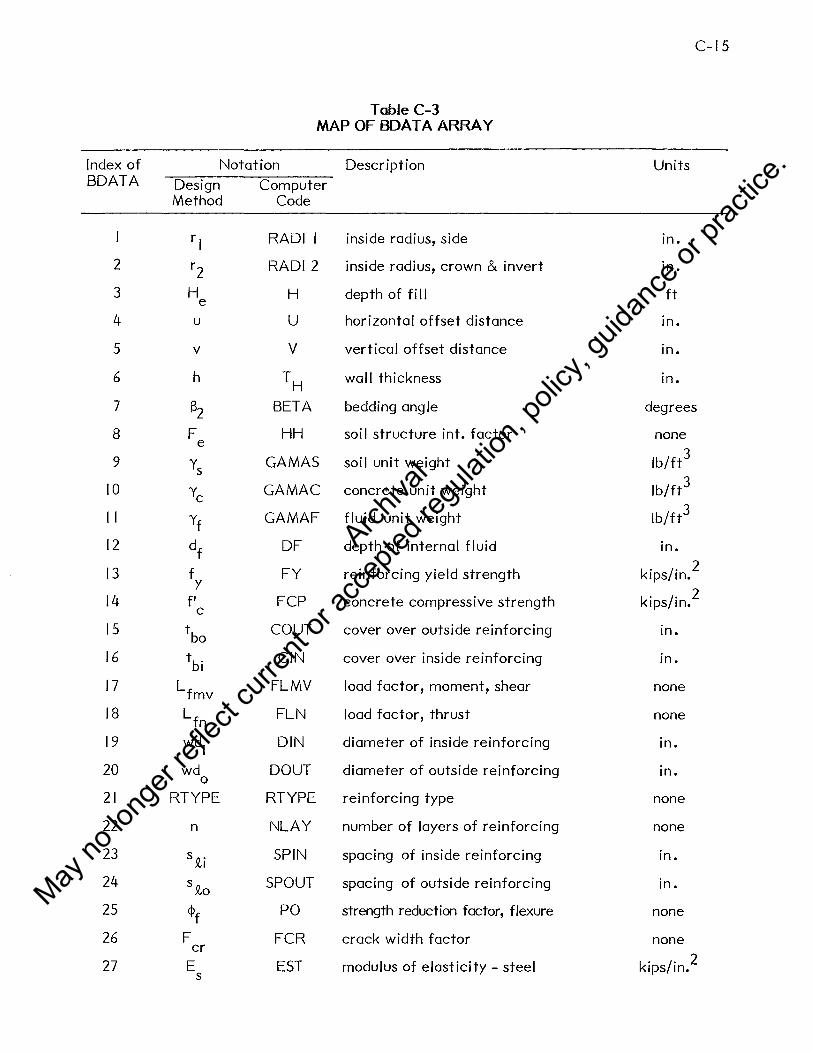
C-15
Table C-3 MAP OF BOAT A ARRAY
Index of Notation Description Units BDATA Design Computer
Method Code
rl RADII inside radius, side in.
2 r2 RADI 2 inside radius, crown & invert in.
3 H H depth of fi 11 ft e 4 u u horizontal offset distance in.
5 v v vertical offset distance in.
6 h TH wall thickness in.
7 B2 BETA bedding angle degrees
8 F HH soil structure int. factor none e
9 Ys GA MAS soil unit weight lb/ft3
10 Ye GA MAC concrete unit weight lb/ft3
II yf GAMAF fluid unit weight lb/ft3
12 df DF depth of internal fluid in.
13 f FY reinforcing yield strength kips/in. 2
y 2 14 f' FCP concrete compressive strength kips/in. c
15 tbo COUT cover over outside reinforcing in.
16 tbi CIN cover over inside reinforcing in.
17 L f mv
FLMV load factor, moment, shear none
18 Lfn FLN load factor, thrust none
19 wd. DIN diameter of inside reinforcing in. I
20 wd DOUT diameter of outside reinforcing in. 0
21 RTYPE RTYPE reinforcing type none
22 n NLAY number of layers of reinforcing none
23 s ,Q,i SPIN spacing of inside reinforcing in.
24 s,Q,o SPOUT spacing of outside reinforcing in.
25 <Pf PO strength reduction factor, flexure none
26 F FCR crack width factor none er 27 E EST modulus of elasticity - steel kips/in. 2
s
Archiva
l
May no
long
er ref
lect c
urren
t or a
ccep
ted re
gulat
ion, p
olicy
, guid
ance
or pr
actic
e.

C-16
Table C-3 (Cont.)
Index of Notation Description Units BDATA Design Computer
Method Code
28 E ECON modulus of elasticity - concrete kips/in. 2 c
29 r ml RADMI mean radius, side in.
30 r m2 RADM2 mean radius, crown, invert 1n.
31 D EQUID equivalent circular diameter In. eq 32 B1 BETAS load angle degrees
33 ¢d POD strength reduction factor, none diagonal tension
34 F FRP radial tension strength none rp process factor
35 F FVP diagonal tension strength none v process factor
Table C-4
DESCRIPTION OF GOVERNING MODE OUTPUT NOTES
Output Note
FLEXURE
MIN STEEL
CRACK
RADTEN + FLEX
RADTEN +CR
DT NOSTIRUPS
DT +STIRRUPS
MAXCONCOMPR
Description
Steel area based on ultimate flexural strength requirements.
Steel area based on minimum steel requirements.
Steel based on crack requirements at service load.
Steel area based on ultimate flexural strength requirements, but stirrups are required to meet radial tension requirements.
Steel area based on crack requirements but stirrups required to meet radial tension requirements.
Diagonal tension strength is exceeded based on steel required for flexure or crack. Stirrups may be used, or the circumferential steel may be increased to the amount shown.
Diagonal tension strength is exceeded based on steel required for flexure or crack. Stirrups must be used.
Design by usual methods is not possible due to maximum concrete compression. Section must be designed as a compression member, or reanalyzed with a different wall thickness or installation conditions.
Archiva
l
May no
long
er ref
lect c
urren
t or a
ccep
ted re
gulat
ion, p
olicy
, guid
ance
or pr
actic
e.

+.
y e
v
e
@ Member Number 0 Joint Number
x ...
Note: For Circular Pipe u = v = O and r 1 = r 2
Figure C-2 FRAME MODEL USED FOR COMPUTER ANALYSIS OF CIRCULAR AND ELLIPTICAL PIPE
C-17
Archiva
l
May no
long
er ref
lect c
urren
t or a
ccep
ted re
gulat
ion, p
olicy
, guid
ance
or pr
actic
e.

D-1
APPENDIX D - DESIGN EXAMPLES
D. I Side Tapered Box Section Inlet Design D- 2- D-20
D.2 Side Tapered Reinforced Concrete Pipe Inlet Design D-21 -D-38
D.3 Side Tapered Corrugated Metal Pipe Inlet Design D-39-D-44
Archiva
l
May no
long
er ref
lect c
urren
t or a
ccep
ted re
gulat
ion, p
olicy
, guid
ance
or pr
actic
e.

D-2
D. I - SIDE TAPERED BOX SECTION INLET DESIGN EXAMPLE
D.1.1 Problem: Determine the reinforcing requirements for a cast-in-place side tapered
box inlet. For geometry use the results of Example No. I in Reference I.
D.1.2 Design Data
s = 2 e
B. I
D. I
Given Data
Face Throat
I 0.5 ft 7.0 ft
6.0 ft 6.0 ft
TT' TB' TS 8 in.*
Throat
s = 0.029 e ,
Bf= I 01-6 11 LI = 7'-0"
3'-6" Midlength Section
D. = 61-011
I
HH,HV
Ys
Ye
Yf a . mm.
amax.
<l>f
<l>y
Fer f y f' c tbo
tbi
Lf R Type
Fvp
Note: Add 2' surcharge for miscellaneous unanticipated loads.
B. 84 * Estimated wall thickness = T =TI + I = TI + I = 8"
8 in.
120 pcf
150 pcf
62.5 pcf
0.25
0.50
0.90
0.85
1.0
60.0 ksi
3.0 ksi
2.0 in.
1.0 in.
1.3
3 = Def. bar
1.0
Archiva
l
May no
long
er ref
lect c
urren
t or a
ccep
ted re
gulat
ion, p
olicy
, guid
ance
or pr
actic
e.

D-3
BOX SECTION INLET DESIGN EXAMPLE (Continued)
D.1.3
H e@ Face = 2' + 2' = 4' D.
TT= 4 + ~ + ~2 = 7.67' H~@ Face = H + _1 + Say 8'-0" e 2
He@ Throat I I
= 4 + LI (5 + S ) = 4 + 7 (2 + 0.029) = 7. 7' Say 8'-0" e o
H~@ Throat = 7. 7' + 3.67' = I 1.37' Say 11'-6"
He @ Midlength 7 I Say 6'-0" = 4 + 2 <2 + 0.029) = 5.85'
Bi @ Midlength I 0.5 + 7.0 = 8. 75' = 2
H ' @ Midlength = 6 + 3.67 = 9.67' Say 10'-0" e
Calculate Soi I Pressure
Throat
Face
= y H F + y TT + 2 y D' Ts/B' s e e c c
D' 8 8 = 6 + TI = 6.67'; B' = 7 + TI = 7 .67'
= ( 120)(8)( 1.2) + ( 150)( 182) + (2)( 150)(6.67)( ~2)/7 .67
p = a y H' = (0.5)( 120)( I 1.5) = 690 psf smax. max. s e = 57 .5 lb/in./ft
(D' T )2
P = a y H' -Y - T smin. min. s e f 2R'
8 2 (6.67 - u>
= (0.25)( 120)( 11.5) - 62.5 (2)(6.67) = 176 psf
Eq. 3.1
= 1,426 psf
= 118.8 lb/in./ft
Eq. 3.2
Eq. 3.3
= 14. 7 lb/in./ft
D' 8 8 = 6 + TI = 6.67'; B' = I 0.5 + TI = I 1.17'
= ( 120)(4)( 1.2) + ( 150)( 182
) + (2)( 150)(6.67)( 182)/ 11.17 = 795 psf Eq. 3.1
= 66.3 lb/in./ft
Psmax. = (0.5)( 120)(8) = 480 psf = 40 lb/in./ft
8 2 (6.67 -TI)
p smin. = (0.25)( 120)(8) - 62.5 (2)(6•67) = 71 psf
= 5.9 lb/in./ft
Eq. 3.2
Eq. 3.3
Archiva
l
May no
long
er ref
lect c
urren
t or a
ccep
ted re
gulat
ion, p
olicy
, guid
ance
or pr
actic
e.

D-4
BOX SECTION INLET DESIGN EXAMPLE (Continued)
Midlength
D' = 6 + 182 = 6.67'; B' = 8. 75 + 1
82 = 9.42'
= ( 120)(6)( 1.2) + ( 150)(~) + (2)( 150)(6.67)(-fL)/9.42 = I, I 06 psf Eq. 3.1
= 92.1 lb/in./ft
Psmax. =
Psmin. =
(0.5)( 120)( I 0) = 600 psf = 50 lb/in./ft
8 2 (62.5)(6.67 - TI) (0.25)( 120)( IO) - (2)(6•67) = 131 psf
= I 0.9 lb/in./ ft
D.1.4 Calculate Moments, Thrusts & Shears @ Design Sections
Eq. 3.2
Eq. 3.3
Using the following equations, calculate the moments, thrusts, and shears at design
locations shown on Fig. 4-2.
Design Moments *
Moment in bottom slab: Mb(x) = {:om~x·)+ 0.5 Pv x (B' - x) omm.
* * Moment in sidewall: Ms (y) = {~om~x·) + {Psm~x·)o.Sy (D' _ y)
omm. Psmm. where:
Eq. 3.9
Eq. 3.10
{ Momax.)- - Pv B'2 (' - 1.5 G3 + 0.5 G4)-/Psmax.)* W'2 ( GI - G2 \0 Momin. - 12 I+ GI - G3 \Psmin. ~2 \'+GI - G3) Eq. 3.8
T 3
D' T GI = T 3 B' Eq. 3.4
s 9 HHS TT
G2 = D' B' T 3 (I - D') Eq. 3.5 s
3 2 HH (-'- TT
G3 = B' T 2 + T3) Eq. 3.6 T S
3 6 HH 3 TT TT
G4 = [31 (1.02- Bl+ --"J) Eq. 3.7 Ts
Archiva
l
May no
long
er ref
lect c
urren
t or a
ccep
ted re
gulat
ion, p
olicy
, guid
ance
or pr
actic
e.

D-5
BOX SECTION INLET DESIGN EXAMPLE (Continued)
M M . * Use omax. or omm. as follows:
Psmax. Psmin.
Location 8, 9, and 10, use Psmax. only.
Locations I I, 12, and 13 check both p and p . for governing case. smax. smm.
Locations 14 and IS use Psmin. only.
Design Shears
Shear in bottom slab:
Shear in sidewall:
Design Thrusts
Th . b 1 b {Nbmax.} {Psmax.)* D' rust in ottom s a : N . = . 2 bmm. Psmm.
Thrust in sidewall: p B' v
NS = -2-
Throat - Design Moments
= (8/ 12)3 (6.67) -(8/ 12)3 (7 .67) -
0.870
= (9) (8/ 12)5
(I _ 8/ 12) = o. 70 (6.67) (7 .67) (8/ 12)3 6·67
7•67 (8/12)2 (8/12)3
Eq. 3.11
Eq. 3.12
Eq. 3.13
Eq. 3.14
Eq. 3.4
Eq. 3.5
Eq. 3.6 = (2) (8/ 12)3
( I + 8/ 12 ) = 0.348
= (6)(8/ 12) (1.02 - (3)(8/ 12) + (8/ 12)3) = 0.917 Eq. 3. 7 7 .67 7 .67 (8/ 12)3
= (-118.8)(92)2
f1-( 1.5)(0.348)+(0.S)(0.917)\-/ p smax.}~0)2 [ 0.87-0.070 ~\ l M
0
M . omm.
12 \ I + 0.870 - 0.348 J \..Psmin. LI 2 ~ +0.870-0.348) J = -51558.9 -{p sm~x·) 280.33
Psmm. Eq. 3.8
= -51558.9 - (57.5)(280.33) = -67680 in.-lb/ft
= -51558.9 - ( 14. 7)(280.33) = -55680 in.-lb/ft
Archiva
l
May no
long
er ref
lect c
urren
t or a
ccep
ted re
gulat
ion, p
olicy
, guid
ance
or pr
actic
e.

D-6
BOX SECTION INLET DESIGN EXAMPLE (Continued)
Throat - Design Moments
Design Coordinate Moment
Location x y Psmin. Psmax. (in.) (in.) (in.-lb/ft) (in.-lb/ft)
8 40.00 -21630 } Sidewal I moment Eq. 3.10 II 12.00 -49680 -44210
12 12.00 1370 -10630 ) Bottom slab moment Eq. 3.9 15 46.00 70010
Throat - Design Shears
= (0.96 (8) - I) = 6.68 in.
= (0.96 (8) - 2) = 5.68 in.
= 0.85 (6.68) = 5.68 in.
= 0.85 (5.68) = 4.83 in.
2M ~ M (<j> d)
2 +~-<I> d @ u = 3.0 xdc v w v v <I> d u v Eq. 4.22
@Design Location 9
Do not investigate
@ Design Location 14 (positive moment region)
[ 2 (2)(700 I 0) :1 xdc = 3 L\ (5.68) + (9)( I 18.8) - 5.6~ = 21.29 in.
xcoord@l 4 = 46.00 - 21.29 = 24. 71 in.
Archiva
l
May no
long
er ref
lect c
urren
t or a
ccep
ted re
gulat
ion, p
olicy
, guid
ance
or pr
actic
e.

D-7
BOX SECTION INLET DESIGN EXAMPLE (Continued)
Throat - Design Shears
Design Coordinate Design Location x y Shear
(in.) (in.) (lbs/ft)
9 No Check M8 < 0
10 16.83 1330 Shear in sidewall Eq. 3.12
II 12.00 1610
12 12.00 4040
13 17.68 3360
J Shear in bottom slab
14 24.71 2530
Eq. 3.11
Throat - Design Thrusts
N = (57.5) (<6•67)( 12)\ = 2300 lb/ft bmax. 2 )
Nbmin. = ( 14. 7) ~6•67~( 12>) = 590 lb/ft
Eq. 3.13
Ns = (I I 8.8)(i67)( 12) = 5470 lb/ft Eq. 3.14
Face - Design Moments
= (8/ 12)3
(6.67) = 0.597 (8/ 12)3 (I I. 17)
Eq. 3.4
(9) (8/ 12)5
(I _ 8/ 12) 3 6 67 = 0.048
(6.67)( I 1.17) (8/ 12) • = Eq. 3.5
= (2)1~8{~2)3 ( I 2 + 8/ 12 3) = 0.239 Eq. 3.6 • (8/ 12) (8/ 12)
M 0
= (6)(8/ 12) fi .02 - (3)(8/ 12) + (8/ 12)3 ) = 0.659 Eq. 3. 7 11.17 \ 11.17 (8/12)3
= <-66.3>< 134>2
(1-< 1.5><0.239)+<o.5)(0.659~-{psmax}~s0)2 ~ o.597-o.04s ~LJ 12 I + 0.597 - 0.239 p
5 . 12 I +0.597-0.239 mm.
= -70935.1 -{Psm~x·} 215.61 Psmm.
Eq. 3.8
= -70935.1 - (40)(215.61) = -79560 in.-lb/ft
M . om in. = -70935.1 - (5.9)(215.61) = -72210 in.-lb/ft
Archiva
l
May no
long
er ref
lect c
urren
t or a
ccep
ted re
gulat
ion, p
olicy
, guid
ance
or pr
actic
e.

D-8
BOX SECTION INLET DESIGN EXAMPLE (Continued)
Face - Design Moments
Design Coordinate Moment for
Location x y Psmin. Psmax. (in.) (in.) (in.-lb/ft) (in.-lb/f t)
8 40.00 -47560 ) Sidewal I moment 11 12.00 -69800 -63240
12 12.00 -23680 -31030 ) Bottom slab moment 15 67.00 +76600
Face - Design Shears
@ Design Location 9
Do not investigate
@ Design Location 14
+ W£;~~~~> - s.6~ = 33.96 in.
xcoord@l 4 = 67 .00 - 33.96 = 33.04 in.
Design Coordinate Design Location x y Shear
(in.) (in.) (lbs/ft)
9 No Check M8 < 0
10 16.83 930 Shear in sidewall
11 12.00 1120
12 12.00 3650
13 16.83 3330 Shear in bottom slab
14 33.04 2250
Face - Design Thrusts
= (40)(80/2) = 1600 lb/ft
= (5.9)(80/2) = 240 lb/ft
= (66.3)( 134)/2 = 4440 lb/ft
Eq. 3.10
Eq. 3.9
Eq. 3.12
Eq. 3.11
Eq. 3.13
Eq. 3.13
Eq. 3.14
Archiva
l
May no
long
er ref
lect c
urren
t or a
ccep
ted re
gulat
ion, p
olicy
, guid
ance
or pr
actic
e.

D-9
BOX SECTION INLET DESIGN EXAMPLE (Continued)
Mid-Length - Design Moments
= (8/ 12)3
(6.67) - o. 708 (8/ 12)3 (9 .42)
Eq. 3.4
= (9) (8/ 12)5
(I _ 8/ 12) = 0_057 (6.67)(9.42)(8/12)3 6•67
Eq. 3.5
M 0
= (2) (8/ 12)3
( I + 8/ 12 ) _ O 283 9•42 (8/ 12)2 (8/ 12)3 - •
__ (6)(8/ 12) ( 11 02 (3)(8/ 12) (8/ 12)3 ) _ O 768 E 3 7 9.42 ,. - 9.42 + (8/12)3 - . q ••
= (-92.1 )(I 13)2 (1-(1.5)(0.283)+(0.5)(0. 7 68)\ _J p smax)!'i§0)2 0. 708-0.057 Jl 12 \ I + 0. 708 - 0.283 ) \rsmin. L 12 I +O. 708-0.283} J
= -65988. I -{Psm~x·} 243.65 - Eq. 3.8 Psmm.
Eq. 3.6
M om ax. = -78170in.-lb/ft
= -68640 in.-lb/ft
Design y Moment for
Location Coordinate Psmin. Psmax. (in.) (in.-lb/ft) (in.-lb/ft)
8 40.00 -38170 Sidewal I moment Eq. 3.10
11 12.00 -64190 -57770
x Coordinate
12 12.00 -12830 -22360 Bottom slab moment Eq. 3.9
15 56.50 +78360
Archiva
l
May no
long
er ref
lect c
urren
t or a
ccep
ted re
gulat
ion, p
olicy
, guid
ance
or pr
actic
e.

D-10
BOX SECTION INLET DESIGN EXAMPLE (Continued}
Midlength Design Shears
@ Design Location 9
Do not investigate
@ Design Location 14
[ 2 (2)(78360) ~l xdc = 3 L (5.68) + (9)(92• I) - 5.6~ = 27.59 in.
xcoord@l 4 = 56.50 - 27 .59 = 28.91 in.
Design Coordinate Design Location x y Shear
(in.) (in.) (lbs/ft) } 9 No Check M8 < 0
10 16.83 1160 Shear in sidewall
11 12.00 1400
Eq. 3.12
12 12.00 4100 } 13 16.83 3650 Shear in bottom slab
14 28.91 2540
Eq. 3.11
Midlength Design Thrusts
N bmax. = (50) (<6•6~( 129= 2000 lb/ft Eq. 3.13
Nb . = (I 0.9)(40) = 440 lb/ft Eq. 3.13 min.
NS (92. I )(9.42)( 12) = 5200 lb/ft Eq. 3.14 = 2
Archiva
l
May no
long
er ref
lect c
urren
t or a
ccep
ted re
gulat
ion, p
olicy
, guid
ance
or pr
actic
e.

D-11
BOX SECTION INLET DESIGN EXAMPLE (Continued)
Summary of Design Moments, Thrusts and Shears
Section Design Service Load Forces Ultimate Load Forces *
Location M N v M N vu u u (in.-lb/ft) (lb/ft) (lb/ft) (in.-lb/ft) (lb/ft) (lb/ft)
s -21630 MS < 0 - No Flexure Design Required
9 Ms< 0 - No Shear Design Required
10 ** ** 1330 1730
11 -496SO 5470 1610 -645SO 7110 2090 Throat
12 -10630 2300 4040 -13S20 2990 5250
13 ** ** 3360 4370
14 ** 590 2530 770 3290
15 70010 590 ** 91010 770
s -47560 MS < 0 - No Flexure Design Required
9 Ms< 0 - No Shear Design Required
10 ** ** 930 1210
11 -69SOO 4400 1120 -90740 5720 1460 Face
12 -31030 1600 3650 -40340 20SO 4750
13 ** ** 3330 4330
14 ** 240 2250 310 2930
15 76600 240 ** 995SO 310
s -3Sl70 MS < 0 - No Flexure Design Required
9 Ms< 0 - No Shear Design Required
10 ** ** 1160 1510
Mid- 11 -64190 5200 1400 -S3450 6760 IS20 Length 12 -22360 2000 4100 -29070 2600 5330
13 ** ** 3650 4750
14 ** 440 2540 570 3300
15 7S360 440 ** IOIS70 570
* Load factor x service load force - Eq. 4.1, 4.2, and 4.3.
** Force at this location not required for calculations.
Archiva
l
May no
long
er ref
lect c
urren
t or a
ccep
ted re
gulat
ion, p
olicy
, guid
ance
or pr
actic
e.

D-12
BOX SECTION INLET DESIGN EXAMPLE (Continued)
D.1.5 Reinforcing Design
Flexure
A s
g
d
= { g ~f d - Nu -,/g E (~fd) 2 - Nu (2~fd - h) - 2M] } f~ = 0.85 b f'c = (0.85)( 12)(3000) = 30600
= 0.96 h - tb
= (0.96)(8) - I = 6.68"
= (0.96)(8) - 2 = 5.68"
To inner steel (positive moment)
To outer steel (negative moment)
<l>t = 0.90
where: 0.65 b f' < g' < 0.85 b f' c c
g' = ~.85 - 0.05 ( (300~ oo6g00>) J ( 12)(3000) = 32400
(0.85)( 12)(3000) = 30600 < 32400 use g' = 30600
= 0.002 b h
= (0.002)( 12)(8) = 0.192 in. 2 /ft
Eq. 4.4
Eq. 4.5
Eq. 4.6
Eq. 4.14
Eq. 4.15
Eq. 4.7
Archiva
l
May no
long
er ref
lect c
urren
t or a
ccep
ted re
gulat
ion, p
olicy
, guid
ance
or pr
actic
e.

BOX SECTION INLET DESIGN EXAMPLE (Continued)
Flexure
Section Design M N <Pt d As u u Location (in.-lb/ft) (lb/ft) (in.) (in~/ft)
g (+M) Mg < 0 - Use min. As
11 (-M) -645go 7110 5. 112 0.130 Throat
12 (-M) -13g20 2990 5. 112 0.007
15 (+M) +91010 770 6.012 0.256*
g (+M) Mg < 0 - Use min. As
11 (-M) -90740 5720 5. 112 0.243* Face 12 (-M) -40340 2ogo 5.112 o.1og
15 (+M) +995go 310 6.012 0.286*
8 (+M) M8 < 0 - Use min. As
Mid 11 (-M) -83450 6760 5.112 0.203* Length 12 (-M) -29070 2600 5. 112 0.063
15 (+M) +101870 570 6.012 0.291*
* Governs design at this location.
Crack Width Control Check
F = er (30000)(<P f )( d)(As) ~ + N ~d. - h/2) _ C b h2 .... {fr" l L JI I V'<j
e = M +d-b. N 2
~ o.74 + 0.1 a I
= I _iQ e
where j ~ 0.90
For Reinforcement Type 3 (RTYPE = 3)
3 =
min. A s (in. 2/ft)
0.192*
0. 192*
0. 192*
0.192
0. 192*
0.192 0. 192*
0.192
0. 192*
o. 192
0. 192*
0.192
D-13
max. As
(in. 2/ft)
o.gs7
0.938
I. 138
0.904 0.949
I. 143
0.891
0.943
I .140
Eq. 4.16
Eq. 4.17
Eq. 4.18
Eq. 4.19
Archiva
l
May no
long
er ref
lect c
urren
t or a
ccep
ted re
gulat
ion, p
olicy
, guid
ance
or pr
actic
e.

D-14
BOX SECTION INLET DESIGN EXAMPLE (Continued)
Crack Width Control Check
Conservatively assume circumferential reinforcement spacing = 12 in. (s Jl)
n = (inner and outer cages are each a single layer)
Bl = (0.5) (I )2 ( 12) = 1.a2 (for tension on inside)
Bl = (0.5) (2)2 ( 12) = 2.aa (for tension on outside) I
Sect. Design M N d Bl e e/d A F sf lex er
Location (in.-lb/ft) (lb/ft) (in.) (in.) (in.2/ft)
a -21630 Ma < 0 - No Check Required
II -49680 5470 5.6a 2.8a 10.76 l.a9 0.90 1.91 0.192 < 0 Throat
12 -10630 2300 5.68 2.aa 6.30 I • II 0.192 * 15 +70010 590 6.6a I .82 121.34 18. 16 0.90 1.05 0.256 < 0
a -47560 Ma < 0 - No Check Required
II -69800 4400 5.6a 2.8a 17.54 3.09 0.90 1.41 0.243 < 0 Face
12 -31030 1600 5.68 2.8a 21.07 3.71 0.90 1.32 0.192 < 0
15 +76600 240 6.68 1.82 321 .85 4a.18 0.90 1.02 0.286 0. 15
8 -3al70 Ma < 0 - No Check Required
Mid II -64190 5200 5.68 2.8a 14.02 2.47 0.90 1.57 0.203 < 0 Length 12 -22360 2000 5.6a 2.8a 12.86 2.26 0.90 I .66 0.192 < 0
15 +7a360 440 6.68 I .82 180.77 27.06 0.90 1.03 0.291 0.20
* e/d < 1.15; therefore, crack control wi 11 not govern.
Since F er < 1.0 at all sections, flexure reinforcement wi 11 govern design at al I locations.
Archiva
l
May no
long
er ref
lect c
urren
t or a
ccep
ted re
gulat
ion, p
olicy
, guid
ance
or pr
actic
e.

D-15
BOX SECTION INLET DESIGN EXAMPLE (Continued)
Calculate Shear Strength
Method I - Locations I 0 and 13
<j>Vc = 3<j>v~ bd Eq. 4.20
Used = 5.68 (conservative) @throat & midlength section
= (3)(0.85)-{3000 ( 12)(5.68) = 9520 lbs/ft
Eq. 4.21
Section Design v <!>V u c Location (lbs/ft) (lbs/ft)
10 1730 9520 Throat
13 4370 9520
10 1210 9520 Face
13 4330 9520
Mid 10 1510 9520
Length 13 4750 9520
<j>V c > Vu; therefore, shear does not govern design.
Method 2 - Locations 9, 10, 13 and 14
For M/(V<j>vd) ~ 3.0
<j>Vb = ( I • I + 63p) -{f.: ~ bd cdFv0 Eq. 4.24 v Fe FN
A s Eq. 4.25 p = bd <l>v
Fd 0.8 1.6 < 1.25 Eq. 4.26 = +d -
F = Eq. 4.27a c
Archiva
l
May no
long
er ref
lect c
urren
t or a
ccep
ted re
gulat
ion, p
olicy
, guid
ance
or pr
actic
e.

D-16
BOX SECTION INLET DESIGN EXAMPLE (Continued)
+
Calculate Shear Strength - Method 2
Nu = 1.0- 0.12 v > 0.75
u
For M/(V¢v d) < 3.0
4¢v vb 4.s-rr b d <P IJ IC V ¢V c
( V~d + 1)
< FN =
Section Design M Nu v d A u u s
Location (in.-lb/ft) (lb/ft) (lb/ft) (in.) (in. 2/ft)
9
10 1730 Throot * 5.68 0.192
II -64580 7110 2090
12 -13820 2990 5250 * 5.68 0.192
13 4370
14 770 3290 6.68 0.256
9
10 1210 Face * 5.68 0.243
11 -90740 5720 1460
12 -40340 2080 4750 * 5.68 0.192
13 4330
14 310 2930 6.68 0.286
9
10 1510 Mid * 5.68 0.203
Length 11 -83450 6760 1820
12 -29070 2600 5330 * 5.68 0.192
13 4750
14 570 3300 6.68 0.291
M/V<l>vd > 3.0, use 3.0
p M Vuq,vd
No Check - M8
< 0
0.0033 6.400 +
0.0033 0.545
0.0038 3.000
No Check - M8
< 0
0.0042 12.873+
0.0033 I. 759
0.0042 3.00
No Check - M8
< 0
0.0035 9 .497 +
0 .0033 1.130
0.0043 3.000
Eq. 4.28
Eq. 4.30
Fd FN <l>vVb <P v v c
(lb/ft) (lb/ft)
1.082 0.750 5990 5990
1.082 0.932 4820 12480
1.040 0.972 5350 5350
1.082 0.750 6250 6250
1.082 0.947 4740 6870
1.040 0.987 5370 5370
1.082 0.750 6050 6050
1.082 0.941 4770 8960
1.040 0.979 5440 5440
* Sheor strength (<!>Vb) at tip of haunch (Sections 11, 12) is compared to shear force (Vu) at <I> vd from tip of haunch (I 0, 13).
¢vVb > Vu at all sections; therefore, shear will not govern design.
Archiva
l
May no
long
er ref
lect c
urren
t or a
ccep
ted re
gulat
ion, p
olicy
, guid
ance
or pr
actic
e.

\
D-17
BOX SECTION DESIGN EXAMPLE (Cont.)
lr.5 FT. SPAN X 6.0 FT. RISE REINFORCED CONCRETE CULVE"RT
I ~ $ T A L L A T I 0 N D A T A
~~~~~~~_H_E_I_G_H_T~_O_F~F_I_L_L~O_V_E_R_._C_U~L_V_E_R_T~,_F_T~~~~~~~~~~~~~~~~~~~4·00_0~~~~~~-UNIT WEIGHT, PCF 120.000 MINIMUM LATERAL SOIL PRESSURE COEFFICIENT Q.250 ~AXIMUM LATlRAL SOIL PRESSURE COEFFICIE_N_T~~~~~~~~~~~~---'o~.-5.~0~0~~~~~~-
SOIL - ST~UCTU~E INTERACTION CO~FFICIE~~~!T'--~~~~~~~~~~~~--=1~·~2~0~0=--~~~~~~
L 0 A D I N G D A T A
LCAD FACTOR - ~O~E~T AND SHEAR LOAD FACTOR - THRUST
M A T E R I A L P R O P E R ·T I E S
STEEL - MINIMUM SPECIFIED YIELD STRESS, KSI CONCRETE - SPECIFIED COMPRESSIVE STRENGTH, KSI
C C N C R E T E D A T A
TCP SLAB THICKNESS, IN. BOTTOM SLAB THICKNESS, IN. SIDE WALL THICKNESS, I~.
HORIZONTAL HAUNCH DIMENSION, IN. VERTICAL HAUNCH DIMENS10Nt IN. CC~CRET~ COVER OVER STEEL, IN.
TGP SLAB - OUTSIDE FACE SIDE WALL - OUTSIDE FACE BOTTOM SLAB - OUTSIDE FACE TOP SLAB - INSIDE FACE BOTTOM SLAB - INSIDE FACE SIDE WALL INSIDE FACE
R E I N F 0 R C I N G S T E E L
LOCATION
TOP SLAB - INSIDE FACE TOP SLAB - OUTSIDE FACE BOTTOM SLAB - Hi SI DE FACE SIDE WALL - OUTSIDE FA CE SIDE WALL - INSIDE FA CE
*PROGRAM ASSIGNED VALUE
0 A T A
ARE A SQ. I~!.
PER FT
0.247 0 .19 2 0 .2 71 0 .2 48 0 .192
MIN 11 IRE
SPAC 1 G IN.
2. 0.,. 2. 0.,. 2 .I)* 2 .o" 2. [J *
1. 3 00 1.300
60.000 3. 0 00
a.ooo a.ooo a.ooo s.ooo a.ooo
2.coo 2.000 2.ooc 1. 0 00 1.coo 1. 0 0()
STIRRUPS REQUIRED?
NO NO ~JO
NO NO
THE SIDE WALL OUTSIDE FACE STEEL IS BENT AT THE CULVERT CORNERS AND EXTENDED I~TO THE OUTSIDE FACE OF THE TOP A~D BOTTOM SLABS. THE THEORETICAL CUT-OFF LENGTHS MEASURED FROM THE BEND POINT ARE 2lo7 ANO 23.4 IN. RESPECTIVELY• ANCHORAGE LENGTHS MUST BE ADDEO.
Archiva
l
May no
long
er ref
lect c
urren
t or a
ccep
ted re
gulat
ion, p
olicy
, guid
ance
or pr
actic
e.

,---\
(
D-18
BOX SECTION DESIGN EXAMPLE (Cont.)
a.a FT. SPAN x 6.0 FT. RISE REINFORCED CONCRETE CULVERT
I ~ S T A L L A T I 0 N D A T A
I-EIGHT OF f·1LL OVER CULVERT,FT 6.00_0 _____ _ L~IT WEIGHT, PCF 120.000 MI~IMUM LATERAL SOIL PRESSURE COEFFICIENT 0.250 MAXI"IU•~ LATERAL SOIL PRESSURE 6)EF-F!CIENT-------------0~.-5~~0~0------
SOIL - STRUCTURE INTERACTION COEFFIC~E~Nc:...:..T~~~~~~~~~~~~~~1~·~2~0~0::..-~~~~~
L C A D I M G D A T A
LOAD FACTOR - MOME~T AND SHEAR LOAD FACTOR - THRUST
M A T E R I A L PROPERTIES
STEEL - MINIMU~ SPECIFIED YIELD STRESSt KSI CO~CRETE - SPECIFIED COMPRESSIVE STRENGTHt KSI
C 0 N C R E T E D A T A
TOP SLAB THICKNESSt IN• EOTTOM SLAB THICKNESS, IN. ~!OE WALL THICKNESS, IN. 1-CRILONTAL HAUNCH DIMENSION, IN. VERTICAL HAUNCH DIMENSION, iN. CO"ICRETE COVER OVER STEELt IN.
TOP SLAB - OUTSIDE FACE SIDE WALL - OUTSIDE FACE BOTTOM SLAB - OUTSIDE FACE TOP SLAB - INSIDE FACE BOTTOM SLAB - INSIDE FACE SIDE WALL - INSIDE FACE
R t I N F 0 R C I N G S T E E L
LDCATIO'!
D A T A
AREA SQo INo PER FT
MIN WIRE
SPAC'G IN.
1.300 1.300
60.000 3. C DO
a.ooo a.coo a.ooo a.ooo a.coo
2.000 2.000 2.coo 1.000 1.000 i.ooo
STIRRUPS REQUIRED?
----------------------------~-~---------------------------------------TOP SLAB - INSIDE FACE 0.256 2.0• NO TOP SLAB - OUTSIDE FACE 0.192 2.0,. NO_ BCTTCM SL AB - PlSIDE FACE 0 .2 76 2.0. NO SIDE wALL - UuTSIOE FACE G o2 l C 2.G* NO SIDE IJALL - INSIDE FACE 0.192 2o0* NO
wPRUGRAM ASSIGNED VALUE
11-E SIDE WALL OUTSIDE FACE STEEL IS BENT AT THE CULVERT CORNERS AND EXTENDED INTO TH~ OUTSIDE FACE OF THE TOP AND BOTTOM SLABS. THE THEORETICAL CUT-OFF LENGTHS MEASURED FROM THE BEND POINT ARE la.5 ~~D 19.7 IN. RESPECTIVELY. ANC~ORAGE LENGTHS MUST BE ADDED.
Archiva
l
May no
long
er ref
lect c
urren
t or a
ccep
ted re
gulat
ion, p
olicy
, guid
ance
or pr
actic
e.

D-19
BOX SECTION DESIGN EXAMPLE (Cont.)
\ ----- -------7-.-0-F_T_o_S_P_A_N_X--&-.-il-F-T-.-R-I S_E _R_E rn· FOR CED CONCRETE CULVERT
I N S T A L L A T I 0 N D A T A
________ h_E_I_G_H_T~OF FILL OVER CULVERTtFT 8·0~00=-----·----UNIT lo/EIGHT, PCF 120.000 ~INIMUM LATEHAL SOIL PRESSURE COEFFICIENT 0.250 f'AX P.~UM LATERAL SOIL PRESSURE COEFFIC-I[~l-'-T---------------'o-'.-'5""0-0~------SOIL - STRUCTURE INTERACTION COEFFICIENT 1.200
L 0 A D I N G 0 A T A
LOAD FACTOR - MOMENT AND SHEAR LCAD FACTOR --- THRUST
MATERIAL PROPERTIES
STEEL - MINIMUM SPECIFIED YIELD STRESS, KSI CONCRETE - SPECIFIED COMPRE~SIVE STRENGTH, KSI
CONCRETE D A T A
lOP SLAB THICKNESS, IN. BOTTOM SLAB THICKNESS, IN. SIDE WA LL TH IC KN ES St IN• HORIZONTAL HAUNCH DIMENSION, IN. VERTICAL HAUNCH DIMENSION, !No CONCRETE COVER OVER STEEL, IN.
TOP SLAB - OUTSIDE FACE SIDE WALL - OUTSIDE FACE BOTTOM SLAB - OUTSIDE FACE TOP SLAB - INSIDE FACE
~---------~BOTTOM SLAB - INSIDE FACE SIDE WALL - INSIDE FACE
REINFORCING S T E E L
LOCATION
TOP SLAB - INSIDE FA CE TOP SLAB - OUTSIDE FACE BOTTOM SLAB - INSIDE FACE SIDE WALL - OUTS IDE FA CE SIDE \o/A LL - INSIDE FA CE
D A T A
ARE A SQ. IN. PER FT
0 .2 2 2 0.192 0.239 0 .19 2 0.192
MIN WIRE
SPAC 'G !No
2.a• 2.0• 2.0* 2.0• 2.0.
1.300 1.300
60.000 3. 0 00
8.000 8.000 8.000 8. 0 00 s.ooo
2. 00 0 2.000 2.GOO 1.o00 1.ooo,~------1.000
STIRRUPS REQUIRED?
NO NO NO NO NO
----------------------------------------------------------------------•PROGRAM ASSIGN~D VALUE
lHE SIDE ~ALL OUTSIDE FACE STEEL IS BENT AT THE CULVERT CORNERS AND ________ E_x_T.;..E~NDED rnTo THE ouTsroE F rct'Dfrnt-rop AND'BcYTD'M sLABs. THE
lHEORETICAL CUT-OFF LENGTHS MEASURED FROM THE BEND POINT ARE 15.7 AND 16.6 INo RESPECTIVELY. ANCHORAGE LENGTHS MUST BE ADDED.
Archiva
l
May no
long
er ref
lect c
urren
t or a
ccep
ted re
gulat
ion, p
olicy
, guid
ance
or pr
actic
e.

D-20
BOX SECTION INLET DESIGN EXAMPLE (Continued)
D.1.6 Summary of Design Example D. I
Compare hand and computer designs for throat face and midlength sections.
Location Desig- Required Steel Area, in. 2 /ft
nation* Throat Face Mid-Length
Hand Computer Hand Computer Hand Computer
Top slab - inside AS2 0.256 0.222 0.286 0.247 0.291 0.256
Top slab - outside AS8 0.192 0.192 0.192 0.192 0.192 0.192
Bottom slab - inside AS3 0.256 0.239 0.286 0.271 0.291 0.276
Sidewall - outside ASI 0.192 0.192 0.243 0.248 0.203 0.210
Sidewall - inside AS4 0.192 0.192 0.192 0.192 0.192 0.192
* Also refer to Figure 4-1.
Conclusion: Since structure is relatively short, it is probably most efficient to use a
single design by selecting the most conservative combination of areas from the
individual designs.
Location Desig- Required Area, in.2/ft Governed at
nation* Hand Computer
Top slab - inside AS2 0.291 0.256 Mid-Length
Top slab - outside AS8 0.192 0.192 All Sections
Bottom slab - inside AS3 0.291 0.276 Mid-Length
Sidewall - outside ASI 0.243 0.248 Face
Sidewall - inside AS4 0.192 0.192 All Sections
Archiva
l
May no
long
er ref
lect c
urren
t or a
ccep
ted re
gulat
ion, p
olicy
, guid
ance
or pr
actic
e.

D-21
D.2 SIDE TAPERED REINFORCED CONCRETE PIPE INLET DESIGN EXAMPLE
D.2.1 Problem: Determine the reinforcing requirements for a side tapered pipe inlet. For
geometry, use the results of Example No. 2-A in Reference I.
D.2.2 Design Data
Face
so= 0.05
L 1 = 6'-0"
D. = 7'-0" I
Throat
B. = 7'-0" I
3°-0" ' i-i--............_ Midlength Section
Note: Add 2' surcharge for miscellaneous unanticipated loads
Assume h = 8" (B wall @throat)
H (ci) Face = 2' + 2' = 4' e~
Given Data
Ys = 120 pcf
ye = 150 pcf
yf = 62.5 pcf
¢f = 0.9
¢v = 0.9
Fer = 1.0
Fvp = 1.0
F = 1.0 rp
f' = 5000 psi c
f = 65000 psi y
tbo' tbi = I in.
Class C Bedding Angle:
Circular - 90°
Elliptical - 0.5 B'
RTYPE = 2, smooth WWF
Fe= 1.2
T = 4.1
n=I
L He @ Midlength Section = 4' +-:}- <f + S
0) = 4 + ~ <i + 0.05) = 5.65'
e Say 6'-0"
I He @ Throat = 4 + 6 (2 + 0.05) = 7 .3' Say 7'-6"
Archiva
l
May no
long
er ref
lect c
urren
t or a
ccep
ted re
gulat
ion, p
olicy
, guid
ance
or pr
actic
e.

D-22
SIDE TAPERED REINFORCED CONCRETE PIPE INLET DESIGN EXAMPLE (Continued)
Culvert Geometry
h
Throat Section
Assume: u/v = 0.5 = k 1, T yp. for HE pipe
Taper= 4.0
Throat: D. = 84" I
Face:
u
v
=
r = 84/2 + 8/2 = 46" m
z/T (I /k 1 - ,/ I + I fkT )
l+l/kl-~
-- ~ - 23.56 - 47 12" k I - 0.5 - •
D. I
+2=
Di 84 = 2 +v=T +47.12"=89.12"
See Figure 1-2.
Midlength:
Throat Section
-- Face Section
h
72/4 ( 110.5 - -f: 110.52 l s24 =36•44.,
I + I /0.5 - 11 + I /0.52
= 36/4 (I /0.5 - .,; I + I /0.52 l s24 = 39.22"
I + I /0.5 - ./1 + I /0.52
Archiva
l
May no
long
er ref
lect c
urren
t or a
ccep
ted re
gulat
ion, p
olicy
, guid
ance
or pr
actic
e.

D-23
SIDE TAPERED REINFORCED CONCRETE PIPE INLET DESIGN EXAMPLE (Continued)
u = ¥ + ¥- 39.22 = 11.78"
v 11.78 23.56" = -u:s-- =
r2 84
23.56" = 65.56" = 2+
D.2.3 Calculate Applied Loads
Throat (Circular Section)
Earth Load We
R = F y B (H + ~) e s o e o
Eq. 2. 7b
100( 100) = (1.2)(120)(12"") 7.5 + (12)(6) = 10670 lb/ft
Dead Load W p
= 3.3 (h)(D. + h) = (3.3)(8)(84 + 8) = 2430 lb/ft I
Internal Fluid Load W f
= 0.34 D~ = (0.34)(84)2 = 2400 lb/ft I
Face (Elliptical Section)
Earth Load We
B0
= 2 (h + r 1
+ u) = 2 (8 + 36.44 + 23.56) = 136 in.
R0
= 100 in.
136 I 00 ) We = ( 1.2)( 120)(12"")(4 + ( 12)(6) = 8790 lb/ft
R = B = D. + 2h = I 00 in. 0 0 I
Eq. 2.1
Eq. 2.4
Eq. 2. 7b
Archiva
l
May no
long
er ref
lect c
urren
t or a
ccep
ted re
gulat
ion, p
olicy
, guid
ance
or pr
actic
e.

D-24
SIDE TAPERED REINFORCED CONCRETE PIPE INLET DESIGN EXAMPLE (Continued)
Dead Load WP
W p = 4.2 h (Ir 2 + ~) arctan (~) + (r 1 + ~)( 1.57 - arctan (~))] Eq. 2.2
= (4.2)(8) ['89.12 + ~) arctan (0.5) + (36.44 + ~)( 1.57 - arctan (0.5)Q
= 2950 lb/ft
Internal Fluid Load W f
W f = 0.87 ~~ arctan (~) + rT ( 1.57 - arctan (~)) - u ~ Eq. 2.5
= 0.87 @39. 122) arctan (0.5) + 36.44 2 ( 1.57 - arctan (0.5)) - (23.56)(4 7. 12)]
= 3520 lb/ft2
Midlength
Earth Load We
B = 2(8+39.22+ 11.78) = 118 in. 0
R = 100 in. 0
w 118 ~ 100 ) = I 0460 lb/ft = ( 1.2)( 120)(12) 6 + (12)(6) e Eq. 2. 7b
Dead Load WP
W p = (4.2)(8) ~5.56 + ~) arctan (0.5) + (39.22 + ~)( 1.57 - arctan (0.5))] Eq. 2.2
= 2690 lb/ft
Internal Fluid Load Wf
W f = 0.87 t65.562) arctan (0.5) + 39.222
( 1.57 - arctan (0.5)) - (I I. 78)(23.56)]
= 2970 lb/ft Eq. 2.5
Archiva
l
May no
long
er ref
lect c
urren
t or a
ccep
ted re
gulat
ion, p
olicy
, guid
ance
or pr
actic
e.

D-25
SIDE TAPERED REINFORCED CONCRETE PIPE INLET DESIGN EXAMPLE (Continued)
D.2.4 Calculate Moments, Thrusts & Shears @ Design Sections
Using the following equations, calculate the moments, thrusts, and shears at design
locations I through 5 shown on Figure 4-4.
M B' = (Cml We+ Cm2 WP+ Cm3 Wf)2
N = Cnl We+ Cn2 WP+ Cn3 Wf
v = C I W + C 2 W + C 3 Wf v e v p v
M = Lf M u
N = Lf N u
v = Lf V u
Throat - Design Locations (Figure 4-4)
Design Location
@invert
2 near invert where M/Vd = 3.0 (Figure 4-5)
r = 46"
3
4
5
cp:d ~ <Pv (0.96 h - t b) = 0.9 ~0.96)(8) - 1] = 6. 01
maximum negative moment based on
earth load only (Fig. 3-1)
near crown where M/Vd = 3.0 (Fig. 4-5)
crown
Eq. 3.33
Eq. 3.34
Eq. 3.35
Eq. 4.1
Eq. 4.2
Eq. 4.3
Eq.4.6
85 = 1800
Archiva
l
May no
long
er ref
lect c
urren
t or a
ccep
ted re
gulat
ion, p
olicy
, guid
ance
or pr
actic
e.

D-26
SIDE TAPERED REINFORCED CONCRETE PIPE INLET DESIGN EXAMPLE (Continued)
Throat (Continued)
DESIGN MOMENTS
Design c ml cm2 cm3 M Mu Location Fig. 3-1 Fig. 3-5 Fig. 3-6 (in.-lb/ft) (in.-lb/ft)
= oo 0.13 0.20 0. 12 99410 129230
2 = 19° 0.09 0.10 0.08 64180 83440
3 = 75° -0.09 -0. 10 -0.09 -65290 -84870
4 = 149° 0.04 0.05 0.04 29640 38530
5 = 180° 0.07 0.08 0.07 51030 66340
DESIGN THRUSTS
Design en, cn2 cn3 N N u Location Fig. 3-1 Fig. 3-5 Fig. 3-6 (lb/ft) (lb/ft)
= 00 0.32 o. 12 -0.28 3030 3940
2 = 19° 0.36 0.22 -0.24 3800 4940
3 = 75° 0.53 0.30 -0.07 6220 8080
4 = 149° 0.41 -0.02 -0. 19 3870 5030
5 = 180° 0.38 -0.09 -0.22 3310 4300
DESIGN SHEARS
Design cvl cv2 cv3 v v u Location Fig. 3-1 Fig. 3-5 Fig. 3-6 (lb/ft) (lb/ft)
= 00 Not Applicable
2 = 19° 0.21 0.40 0.20 3690 4800
3 = 75° Not Applicable
4 = 149° -0. 10 -0. 11 -0. 11 -1600 -2080
5 = 180° Not Applicable
Archiva
l
May no
long
er ref
lect c
urren
t or a
ccep
ted re
gulat
ion, p
olicy
, guid
ance
or pr
actic
e.

D-27
SIDE TAPERED REINFORCED CONCRETE PIPE INLET DESIGN EXAMPLE (Continued)
Face - Design Locations (Fig. 4-4)
Flexure Design Location
@invert
3 maximum negative moment based on earth load only (Fig. 3-3)
5 crown
Shear Design Location
2 and 4 where M/¢Vd = 3.0
From Eqs. 3.33 and 3.35, using earth load only
M Cml We B' ¢Vd = 2 C I W d (j) = 3
v e v
Cm I _ (3)(2)(d)(cjl) _ (3)(2)(6.68)(0.9) _ o 282
CV I - B' - 120 + 8 - •
el = 00
63 = 80°
es = 180°
B'/D' -- 120 + 8 I 39 84 + 8 = •
CRITICAL SHEAR LOCATION Location 8 c
ml cvl Cml/Cvl Fig. 3-3 Fig. 3-3
2 10° 0. 13 0.30 0.433 15° 0.08 0.37 0.216 M/Vd=3@ 13° 20° 0.03 0.40 0.075
160° 0.05 -0.20 -0.25 M/Vd=3@ 161° 165° 0.07 -0.15 -0.467
4
DESIGN MOMENTS
Design c ml c m2
c m3
M M u Location Fig. 3-3 Fig. 3-5 Fig. 3-6 (in.-lb/ft) (in.-lb/ft)
I = 00 0.17 0.20 0.12 160430 208560 2 = 13° 0.10 0.13 0.10 103330 134330 3 = 80° -0.12 -0.10 -0.08 -104410 -135730 4 = 161° 0.05 0.07 0.06 54860 71320 5 = 180° 0.10 0.08 0.07 87130 113270
Archiva
l
May no
long
er ref
lect c
urren
t or a
ccep
ted re
gulat
ion, p
olicy
, guid
ance
or pr
actic
e.
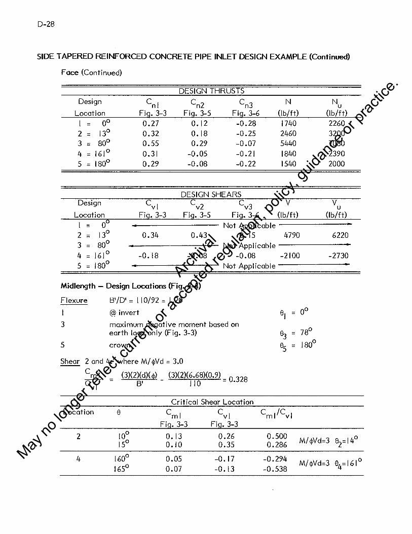
D-28
SIDE TAPERED REINFORCED CONCRETE PIPE INLET DESIGN EXAMPLE (Continued)
Face (Continued)
DESIGN THRUSTS Design cnl cn2 cn3 N Nu
Location Fig. 3-3 Fig. 3-5 Fig. 3-6 (lb/ft) (lb/ft)
= oo 0.27 0.12 -0.28 1740 2260 2 = 13° 0.32 0.18 -0.25 2460 3200 3 = 80° 0.55 0.29 -0.07 5440 7080 4 = 161° 0.31 -0.05 -0.21 1840 2390 5 = 180° 0.29 -0.08 -0.22 1540 2000
DESIGN SHEARS Design cvl cv2 cv3 v v u
Location Fig. 3-3 Fig. 3-5 Fig. 3-6 (lb/ft) (lb/ft)
= 00 Not Applicable 2 = 13° 0.34 0.43 0. 15 4790 6220 3 = 80° Not Applicable 4 = 161° -0.18 -0.08 -0.08 -2100 -2730 5 = 180° Not Applicable
Midlength - Design Locations (Fig. 4-4)
Flexure B'/D' = 110/92 = 1.20
@invert el = oo
3 maximum negative moment based on 78° earth load only (Fig. 3-3) 83 =
5 crown 85 = 180°
Shear 2 and 4: where M/ ¢Vd = 3.0
Cm I (3)(2)(d)( cp) (3)(2)(6.68)(0.9) _ o 328 C = B' 110 - •
vi
Critical Shear Location Location e c ml cvl Cml/Cvl
Fig. 3-3 Fig. 3-3
2 10° 0. 13 0.26 0.500 M/¢Vd=3 0
15° 0.10 0.35 0.286 82=14
4 160° 0.05 -0. 17 -0.294 M/¢Vd=3 0 165° 0.07 -0.13 -0.538
84=161
Archiva
l
May no
long
er ref
lect c
urren
t or a
ccep
ted re
gulat
ion, p
olicy
, guid
ance
or pr
actic
e.

D-29
SIDE TAPERED REINFORCED CONCRETE PIPE INLET DESIGN EXAMPLE (Continued)
Midlength (Continued)
DESIGN MOMENTS
Design c ml cm2 cm3 M Mu Location Fig. 3-3 Fig. 3-5 Fig. 3-6 (in.-lb/ft) (in.-lb/ft)
= oo 0.16 0.21 0. 12 142720 185540
2 = 14° 0.10 o. 13 0. 10 93100 121030
3 = 78° -0.12 -0.10 -0.08 -96900 -125970
4 = 161° 0.06 0.07 0.06 54680 71080
5 = 180° 0.09 0.08 0.07 75050 97560
DESIGN THRUSTS
Design cnl cn2 cn3 N N u Location Fig. 3-3 Fig. 3-5 Fig. 3-6 (lb/ft) (lb/ft)
= 00 0.28 0.12 -0.28 2420 3150
2 = 14° 0.33 0. 19 -0.25 3220 4190
3 = 78° 0.56 0.30 -0.07 6460 8390
4 = 161° 0.33 -0.06 -0.21 2670 3470
5 = 180° 0.31 -0.08 -0.22 2370 3090
DESIGN SHEARS
Design cvl cv2 cv3 v vu Location Fig. 3-3 Fig. 3-5 Fig. 3-6 (lb/ft) (lb/ft)
= 00 Not Applicable
2 = 14° 0.30 0.43 0.15 4740 6160
3 = 78° Not Applicable
4 = 161° -0.14 -0.08 -0.08 -1920 -2490
5 = 180° Not Applicable
Archiva
l
May no
long
er ref
lect c
urren
t or a
ccep
ted re
gulat
ion, p
olicy
, guid
ance
or pr
actic
e.

D-30
SIDE TAPERED REINFORCED CONCRETE PIPE INLET DESIGN EXAMPLE (Continued)
D.2.5 Reinforcing Design
Flexure
As = {g $f d - Nu-./ g ~ ($d)2
- Nu (2 $fd - h) - 2 SJ ) * Eq. 4.4
g - 0.85 b f'c = (0.85)( 12)(5000) = 51000 lb/in. Eq. 4.5
= (6.68)(0.9) = 6.0 I <l>f d
A s = (51000)(0.60 I) - Nu -~ 51000 ~I 000)(6.0 I )
2 - Nu ( (2)(6.0 I) - 8) - 2 MJ
65000
= 4. 717 - 6~~0 - 0.003474-v 1843351.3 - 4.024 Nu - 2 Mu
Minimum Steel
Inside 2
(Bi + h)
Asmin. = 65000
Throat: (84 + 8)2
. 2/ Asmin. = 65000 = 0.130 m. ft
Face: ( 120 + 8)2 o 252 . 2 I Asmin. = 65000 = • m. ft
Midlength: (I 02 + 8)2
. 2/ Asmin. = 65000 = 0.186 m. ft
Outside
(B. + h)2
Asmin. = O. 75 ---'-~-50_0_0_
Throat:
Face:
Midlength:
Asmin. = (0.75)(0.130) = 0.098 in.2/ft
A . = (0. 7 5)(0.252) = 0.189 in. 2 /ft sm1n.
A . =(0.75)(0.186)=0.140in.2/ft smm.
Maximum Steel
(
(5.5 x I 04) g' ¢ fd
Asmax. = (87000 + f y) -0.75Nu) I f y
(Inside)
(Inside)
(Inside)
(Outside)
(Outside)
(Outside)
Eq. 4.8
Eq. 4.9
Eq. 4.14
Archiva
l
May no
long
er ref
lect c
urren
t or a
ccep
ted re
gulat
ion, p
olicy
, guid
ance
or pr
actic
e.

D-31
SIDE TAPERED REINFORCED CONCRETE PIPE INLET DESIGN EXAMPLE (Continued)
Maximum Steel (Continued)
g' = ~.85 - 0.05 c·c -4000) J , 1000 bf c Eq. 4.15
g' = ~.85 - 0.05 ( 5ooo - 4ooo) J ( 12X5000) - 48000 1000 -
(0.65)( 12)(5000) < 48000 < (0.85)( 12)(5000) o.k.
N ( (5.5 x I0
4)(48000X0.9)(6.68) _ o.75 N ) I A = = 1.606 - 866~0 smax. 87000 + 65000 u 65000
FLEXURAL REINFORCEMENT
Section Design M N A u u s
Location (in.-lb/ft) (lb/ft) (in.2/ft)
129230 3940 0.304
Throat 3 84870 8080 0.142
5 66340 4300 0.130
208560 2260 0.546
Face 3 135730 7080 0.292
5 113270 2000 0.280
185540 3150 0.471 Mid- 3 125970 8390 0.252 Length
5 97560 3090 0.226
0.0 I Inch Crack Width Control
Bi [M + N (d - ~) 2_ f.;""J Fer = (30000)(q, f)(d)(As) j i - CI b h V f c
e
Bl
cl
M+d-b. = N 2
=
=
=
=
0.74 + 0.1~2. 0.9
I
I-~ e
1.0 For Type 2 reinforcing - smooth WWF
1.5
A smin. A smax.
(in. 2 /ft) (in. 2 /ft)
0.130 1.561
0.098 I .513
0.130 1.556
0.252 1.580
0.189 1.524
0.252 1.583
0.186 1.570
0.140 1.509
0.186 1.570
Eq. 4.16
Eq. 4.17
Eq. 4.18
Eq. 4.19
Archiva
l
May no
long
er ref
lect c
urren
t or a
ccep
ted re
gulat
ion, p
olicy
, guid
ance
or pr
actic
e.

D-32
SIDE TAPERED REINFORCED CONCRETE PIPE INLET DESIGN EXAMPLE (Continued)
CRACK CONTROL REINFORCEMENT
Section Design M N e A sflex Fer
Location (in.lb/ft) (lb/ft) (in.) (in. 2/ft)
99410 3030 35.49 0.90 1.20 0.304 0.324 Throat 3 65290 6220 13.18 0.90 1.84 0.142 < 0
5 51030 3310 18.10 0.90 1.50 0.130 < 0
160430 1740 94.88 0.90 1.07 0.546 0.918
Face 3 104410 5440 21.87 0.90 1.38 0.292 0.274
5 87130 1540 59.26 0.90 1 • I I 0.280 0.191
142720 2420 61.66 0.90 I. 11 0.471 0.803 Mid- 3 96900 6460 17.68 0.90 I .52 0.252 0.050 Length
5 75050 2370 34.35 0.90 1.21 0.226 < 0
In all cases the crack control factor (F ) is less than 1.0; therefore, the flexural er reinforcement will govern the design.
Shear (Method 2 for Pipe)
$vVb = (I.I +63P)Fc $vbd (:~:~) A A A
-- s < 0 02 s s p ¢ b d - • = (0.9)( 12)(6.68) = 72.T4
F c =
Throat:
v
1 d @design locations 2 & 4 moment
+~produces tension on inside of pipe m
F I 6•68 I 073 c = + (42 + 4)(2) = •
Eq. 4.24
Eq. 4.25
Eq. 4.27b
Face: rm depends upon whether the design section is in the r 1 or r2 segment.
arctan u/v = 26.6° > 14° & ( 180° - 160°); therefore, r is located in m segment r2
Archiva
l
May no
long
er ref
lect c
urren
t or a
ccep
ted re
gulat
ion, p
olicy
, guid
ance
or pr
actic
e.

D-33
SIDE TAPERED REINFORCED CONCRETE PIPE INLET DESIGN EXAMPLE {Continued)
Face:
F = I + 6•68 = 1.036
c (2)(89.12 + 4)
Midlength:
F c = + (2)(6~:~~ + 4) = 1.048
N F N = 1.0 - 0.12 Vu ~ 0. 7 5
u Eq. 4.28
SHEAR STRENGTH
Section Design N v A p FN ¢Vb u u s
Location (lb/ft) (lb/ft) (in. 2 /ft) (lb/ft)
2 4940 4800 0.304 0.0042 0.877 7690 Throat
4 5030 2080 0.130 0.0018 0.750 8000
2 3200 6220 0.546 0.0076 0.938 8620 Face
4 2390 2730 0.280 0.0039 0.895 7700
Mid- 2 4190 6160 0.471 0.0065 0.918 8320 Length 4 3470 2490 0.226 0.0031 0.833 7870
<P vb > v ; therefore, shear does not govern design. v u
Archiva
l
May no
long
er ref
lect c
urren
t or a
ccep
ted re
gulat
ion, p
olicy
, guid
ance
or pr
actic
e.

(
D-34
RCP PIPE DESIGN EXAMPLE (Cont.)
120oOlNCH SPAN X 84o0INCH RISE REINFORCED ELLIPTICAL CONCRETE PIPE **********~*~•*******•**********************~*************************
INSTALLATION DATA
HEIGHT OF FILL ABOVE CROWN, FT, UNIT WEIGHT, PCF SOIL-SlRUCTURE INTERACTION COEFFICIENT BEDDING ANGLE, DEGREES LOAD A~GLEt DEGREES
MATERIAL PROPERTIES
STEEL - MINIMUM SPECIFIED YIELD STRESS, PSI REINFORCING TYPE NO. OF LAYERS OF REINFORCING
CONCRElE - SPECIFIED COMPRESSIVE STRESS, PSI
L 0 A D I N G D A T A
LOAD FACTOR - MOMENT ANO SHEAR LOAD FACTOR - THRUST STRENGTH REDUCTION FACTOR-FLEXURE STRENGTH REDUCTION FACTOR-DIAGONAL TENSION CRACK ~IDTH REDUCTION FACTOR
P I P E D A T A
RADIUS 1, IN. RADIUS 2t INo ~ALL T~ICKNESSt IN. INSIDE CONCRETE COVER OVER STEEL, IN. OUTSIDE CONCRETE COVER OVER STEEL• IN.
F L U I D D A T A
FLUIU UENSITY, PCF. DEPTH OF FLUIDtINCHES ABOVE INVERT
R E 1 N f 0 R C I N G S T E E L D A T A
INVERT- INSIDE REINFORCING, SQ.IN./FT. SPRINGLINE- OUTSIDl REINFORCING, SQ.INo/FT. CROWN- INSIDE REINFORCING, SGoI~./FT.
4o00 120.00
1.2 Ci BB.DO
212.00
65000. 2. 1.
5000.
1.30 1.30 0.90 0.90 1.00
36.44 B9ol2
B.oo 1.00 1.00
62.50 B4.00
o.55B 0 .291. 0 .257.
Archiva
l
May no
long
er ref
lect c
urren
t or a
ccep
ted re
gulat
ion, p
olicy
, guid
ance
or pr
actic
e.

RCP PIPE DESIGN EXAMPLE (Cont.)
1~2.0INCH SPAN X 84oOINCH RISE REINFORCED ELLIPTICAL CONCRETE PIPE **************•*9****~**•***********•********•*******•************•***
I N S T A L L A T I 0 N D A T A
HEIGHT OF FILL ABOVE CROIJNt FT, UNIT IJEISHT, PCF SOIL-SlRUCTURE INTERACTION COEFFICIENT BEDDING ANGLE, DEGREES LOAD ANGLEt UEGREES
M A T E R I A L P R 0 P E R T I E S
STEEL - MINIMUM SPECIFIED YIELD STRESS, PSI REINFORCING TYPE NO. OF LAYERS OF REINFORCING
CONCRElE - SPECIFIED COMPRESSIVE STRESS, PSI
LOADING DATA
LOAD FACTOR - MOMENT ANO SHEAR LOAD FACTOR - THRUST STRENGlH REDUCTION FACTOR-FLEXURE STRENGl~ REDUCTION FACTOR-DIAGONAL TENSION CRACK IJIDTH REDUCTION FACTOR
PIPE DATA
RADIUS lt IN. RADIUS 2, IN. IJALL TblCKNESS~ IN. INSIDE CONCRETE COVER OVER STEELt IN. OUTSIDE CONCRETE COVER OVER STEEL• IN.
FLUID DATA
FLU!U DENSITY, PCF. DEPTH OF FLUIDtINCHES ABOVE INVERT
R E I N F ~ R C I N G S T E E L D A T A
lNVERT- INSIDE REINFORCING, SQ.IN./FT. SPRINGLINE- OUTSIDE REINFORCING, SQ.INo/FT. CROUN- INSIDE REINFORCING. so.rN./FT.
6.oo 120.00
1.20 80.00
280.00
65000. 2. 1.
5000.
1.30 1.30 0.90 0.90 1.00
39.22 65.56
8.00 l.oo 1 .• 0 0
62.50 84.00
o.479 0.223 0.209
D-35
Archiva
l
May no
long
er ref
lect c
urren
t or a
ccep
ted re
gulat
ion, p
olicy
, guid
ance
or pr
actic
e.

D-36
RCP PIPE DESIGN EXAMPLE (Cont.)
1 N S T A L L A T I 0 N D A T A
-----------------------------------------------------------------------HEIGHT cc FILL ABOVE CROWN, Flt _7.50 UNIT IHIGHTt PCF 12u no s 0 I L- s TR u c Tu RE I NT ER f. c Ti o'"';.J~c-n""'E'"'F'""F __ I_C_I'"'"'E""" r""! T:c------------- i-:2 0-----B EDD ING ANGLE, DEGREES 90.CO _____ L,--=-O=-A=-D.=..c...cA....:~1-G_L_E_.__;;__;;Dc_Ec_G....:R:_E.::..E_Scc..::;.--"--------------'---------'2 7 ~ ~·a·o ____ _
MATERIAL PROPERTIES
_____ S_T_E_E_L_-_M--=I~N~I~M~U,...M_.,-s~P-E~C=I~F~I~E_D_Y....:I....:E'--L'--D_S_T_R_E_._s_s~·--'-P~S_I __________ 65QOO.'------REINFORCING TY~~ 2o ~O. OF LAYERS OF REINF0RCING lo
CONCRElE - SPECIFIED COMPRESSIVE S~T~R=E=s~s-.-=p~s--=I:------------=5~0~0~0,-.-----
L 0 A D I ~ G 0 A T A
LOAD F•CTOR - MOMENT ANO SHEAR 1.30 LOAD FACTOR - THP.UST 1.30 STRENGTH REDUCTION FACTOR-FLEXURE 0.90 STRENGTH REDUCTION F A·crc"R-DI AGO~~AL 'rrn""s'"'r'""o"'""~""!----------~o .90 ___ _ CRACK WIDTH REDUCTION FACTOR loOO
PIPE D/\TA
WALL T!-1ICKNESS. HJ. 8000 INSIDE COMCRETE COV~K OVER STEELt IN. 1.0D
_____ U_U_T s IDE c 0 NCR ET E cov ER 0 v ER s T E-E-L-,-I-rJ-.-------------1 • o_o ____ _
FLUID DATA
FLUID DENSITY, PCF. 62.50 -----D~E=P=T_H_U~F-,,F~L~U-I,-D'--,-l~N-C-H~E-S~A~B~o-v~E-I~N-·v-r~_~R=T---------------84~00 ____ _
R E I N F 0 R C I N G S T E E L D A T A
INVERT- INSIDE RlINFORCINGt SQ.IN./FT. 0.311 s DR ING LINE - 0 u Ts IDE R EI N""F""""O""R'"""'c'"'r'"'Ncc' G,-,-s"·a=--. =I .-:r:-.--;1-;oF--=T-.------------=o • 1 3 9------C RO II ei -
0
INSIDE REINFORCING, SQ.IN.IFT. Ool30
Archiva
l
May no
long
er ref
lect c
urren
t or a
ccep
ted re
gulat
ion, p
olicy
, guid
ance
or pr
actic
e.

D-37
SIDE TAPERED REINFORCED CONCRETE PIPE INLET DESIGN EXAMPLE (Continued)
D.2.6 Summary - Design Example D.2
Compare hand and computer designs for face, midlength & throat.
REQUIRED STEEL AREAS, IN.2/FT
Face Midlength Throat
Hand Computer Hand Computer Hand Computer
Invert - inside 0.546 0.558 0.471 0.479 0.304 0.311
Springline - outside 0.292 0.291 0.252 0.223 0.142 0.139
Crown - inside 0.280 0.257 0.226 0.209 0.130 0.130
Conclusion: Design of the face section governs the design of the entire section.
Archiva
l
May no
long
er ref
lect c
urren
t or a
ccep
ted re
gulat
ion, p
olicy
, guid
ance
or pr
actic
e.

D-39
D.3 - SIDE TAPERED CORRUGATED MET AL INLET DESIGN EXAMPLE
D.3.1 Problem: Determine the gage and corrugation required for a side tapered corrugated
steel inlet meeting the geometry requirements of Example No. 2-B in Reference I.
D.3.2 Design Data:
Face
Throat
so= 0.05
Bf= 108"
~v··-
; .' 4 -
~ _M~dlength Section
D. = 78" I
B. = 78" I
Steel Corrugated Pipe:
f u = 45,000 psi
f y = 33,000 psi
E = 29 x I06psi
Fill Heights:
Face:
H = 2' + 2' = 4.0' e
Mid length: 30 I
He= 4 + T2 (5 +So) e
30 I = 4 + T2 (2 + 0.05)
= 5.38' Say 5.5'
Throat:
H = e 60 I
4 + T2 (5 +So) e
I = 4 + 5 (2 + 0.05)
= 6.75' Say 7.0'
Note: Add 2'-0" surcharge for miscellaneous unanticipated loads.
Archiva
l
May no
long
er ref
lect c
urren
t or a
ccep
ted re
gulat
ion, p
olicy
, guid
ance
or pr
actic
e.

D-40
SIDE TAPERED CORRUGATED MET AL INLET DESIGN EXAMPLE (Continued}
Culvert Geometry
Throat Section
Midlength Section
Face Section
Throat Section
Assume u/v = 0.5 = k 1
D. = 78" I
LI = 60"
( I /k I --/ I + I /kT ) z/T D. I
r I (z) = + 2 I + I /k I --JI + I /kT
z/4 ( 1/0.5 _ -.j I + l/0.52 ) 78 39 .0 - 0.0773 z = + 2=
I + 1/0.5 --JI + l/0.52
D. u(z) z i- r I (z) = 0.3273 z = T+
v(z) = u(z)
= 0.6546 z kl D.
r 2
(z) I v (z) 39 + 0.6546 z Span 2(r1
+u) = 2+ = =
Location z r I u v r2 Span
Face 60 34.36 19.64 39.28 78.28 108
Mid length 30 36.68 9.82 19.64 58.64 93
Throat 0 39 0 0 39 78
Archiva
l
May no
long
er ref
lect c
urren
t or a
ccep
ted re
gulat
ion, p
olicy
, guid
ance
or pr
actic
e.

SIDE TAPERED CORRUGATED MET AL INLET DESIGN EXAMPLE (Continued)
D.3.3 Calculate Applied Loads:
R Earth Load - W = F y B (H + -
6°) e e s o e
• Neglect corrugation depth; therefore, B = B., R = R . 0 I 0 I
• Fe = 1.0 (flexible culvert)
78 We = 1.0 ( 120) B (H + T'J?") = 120 • span (H + 1.08) 0 e I LoO e
Location Span H w e e
(ft) (ft) (lb/ft)
Face 9.0 4.0 5486
Midlength 7.75 5.5 6120
Throat 6.5 7.0 6302
D.3.4 Metal Ring Design
D-41
Use service load design method: AASHTO - Interim Specifications Bridges (1981),
Section 1.9.2.
Thrust w
e T = 2
Required cross-sectional wall area:
(SF) We(SF) A = T-f-= 2 f
y y
SF= 2
f = 33000 psi y
Location w e (lb/ft)
Face 5486
Midlength 6120
Throat 6302
T
(lb/ft)
2743
3060
3151
Area
(in.2/ft)
0.166
0.186
0.191
Archiva
l
May no
long
er ref
lect c
urren
t or a
ccep
ted re
gulat
ion, p
olicy
, guid
ance
or pr
actic
e.

D-42
SIDE TAPERED CORRUGATED MET AL INLET DESIGN EXAMPLE (Continued)
Flexibility: s2
(FF) = ET
E = 29 x I 06 psi
= sz E(FF)
S = span - use 2 times r 2 for non-circular shape.
Assume a I" depth corrugation; therefore, (FF) = 0.033 (AASHTO, Section 1.9.4).
Location
Face
Midlength
Throat
2 x r2
(in.)
156.6
117. 3
78
I req
(in. 4/ft)
25.6 x 10 -3
14.4 x I 0 -3
6.36 x 10 -3
Select a corrugation for steel conduit that meet the required area and moment of
inertia calculated.
Choose a 3 x I corrugation with the following properties:
Location s Corr. t A I r
(in.) (in.) (in. 2/ft) (in.4/ft) (in.)
Face 108 3xl 0.168 2.46 25.09x I o-3* 0.3490
Midlength 93 3xl 0.109 1.56 I 5.46x I 0 -3 0.3488
Throat 78 3xl 0.064 0.89 8.66x I 0 -3
0.3410
* 2% less than required for handling, but since the face will be stiffened by the head
wall, this is acceptable.
Archiva
l
May no
long
er ref
lect c
urren
t or a
ccep
ted re
gulat
ion, p
olicy
, guid
ance
or pr
actic
e.

D-43
SIDE TAPERED CORRUGATED MET AL INLET DESIGN EXAMPLE (Continued)
Wall Buckling
If the computed buckling stress divided by the required safety factor is less than the
service load steel stress, f 0
, the required wall area must be recalculated using f c/SF
in lieu of f • a
If S
If S
r = radius of gyration
k = soil stiffness factor
For granular backfill with 90% min. standard density, use k = 0.22.
For al I sections, r ~ 0.34 •
.!.. ~4E _ 0.34 k f - 0.22
u
(24) 29 x I 06 45000 = 192 in.
Use 2 x r 2 in place of span in calculating buckling capacity. Since 2 x r2 is less than
I 92 in. in al I cases, use:
=
2 2 = 22500 - 45000 (0.22) (2) 48 (29 x I 06)
= 22500 - 0.0352 ( 2
: 2
)
2
Location (2r 2)/r f /SF f =TIA er a (psi) (psi)
Face 460.6 15032 1115
Midlength 345 18310 1962
Throat 228.3 20665 3540
Si nee fer/SF > fa' buck Ii ng does not govern.
Archiva
l
May no
long
er ref
lect c
urren
t or a
ccep
ted re
gulat
ion, p
olicy
, guid
ance
or pr
actic
e.

D-44
SIDE TAPERED CORRUGATED MET AL INLET DESIGN EXAMPLE (Continued)
Seam Strength
(SS) = T (SF)
Location T SS t Double Rivets
(lb/ft) (k/ft) (k/ft)
Face 2743 8.23 0.168 70.7
Midlength 3060 9. 18 0.109 53.0
Throat 3151 9.45 0.064 28.7
Summary
Use a 3 x I corrugated steel pipe with the following properties:
Location s Corr. t (in.) (in.)
Face 108 3xl 0.168
Midlength 93 3xl 0.109
Throat 78 3xl 0.064
Since this is a relatively short structure, use a 3 x I corrugation with t = 0.168 in.
throughout.
Archiva
l
May no
long
er ref
lect c
urren
t or a
ccep
ted re
gulat
ion, p
olicy
, guid
ance
or pr
actic
e.

E-1
APPENDIX E - IMPROVED INLET EXAMPLE DESIGNS
The following tables present designs for various types of improved inlets and appurtenant
structures based on the design methods in this manual, and the example standard plans
presented in Appendix G.
Tables E-1 through E-5 present designs for reinforced concrete box section inlets. The
following geometric and design parameters are assumed for these designs:
• Slope of earth embankment above box, S = 2 : I. e
• Fall slope, Sf= 2: I, where applicable.
• Culvert slope, S = 0.03, except for Tables E-4 and E-5 where S = 0.06.
• Sidewall Taper, T = 4 : I, except for one cell slope tapered sections (Tables E-3 and
E-4) where T = 6 : I.
• All box sections have 45° haunches with dimensions equal to the top slab thickness,
i.e. HH = Hv = Tr
• Reinforcing strength, f = 60,000 psi. y
• Concrete strength, f ' = 3,000 psi. c
• Cover over reinforcing tb = 2 in. clear, except for bottom reinforcing of bottom slab
where tb = 3 in. clear.
• The heights of fill at the face and throat section are shown for each design. In
addition to the fill shown, a two-foot surcharge load is included for each design. All
soil is assumed to have a unit weight of 120 pcf. A soil structure interaction
coefficient of 1.2 is applied to the earth load.
• Two conditions of lateral soil pressure were considered, equal to 0.25 and 0.50 times
the vertical soi I pressure. The worst case at each design section was chosen for
design.
Archiva
l
May no
long
er ref
lect c
urren
t or a
ccep
ted re
gulat
ion, p
olicy
, guid
ance
or pr
actic
e.

E-2
Table E-6 presents designs for side tapered reinforced concrete pipe inlets. The following
geometry and design parameters are assumed for these designs.
•
•
•
•
•
•
•
Slope of earth embankment above pipe, Se = 2 : I •
Culvert slope, S = 0.03 •
Sidewall taper, T = 4: I •
Reinforcing strength, f = 65,000 psi • y
Concrete strength, f ' = 5,000 psi • c
Cover over reinforcing, tb = I in. clear, inside and outside •
The heights of fi II at the face (Hf) and throat (Ht) are shown for each design. In
addition to the fill shown, a two foot surcharge load is included in each design. All
soil is assumed to have a unit weight of 120 pcf. A soil structure interaction factor
of 1.2 is applied to all earth load.
Table E-7 presents designs for side tapered corrugated metal pipe inlets. The slopes, tapers,
heights of fill and soil unit weight are all the same as for the corresponding reinforced
concrete pipe inlets.
Figures E-1, E-2 and E-3 present algorithms for sizing headwalls for cast-in-place concrete,
precast concrete and corrugated metal inlets. Following are Tables E-8, E-9, E-10 and E-11
presenting headwal I designs for one eel I and two eel I box, concrete pipe and corrugated
metal pipe, respectively.
Figures E-4, E-5 .and E-6 show typical designs of skewed headwalls for a concrete box
section, precast concrete pipe and a corrugated metal pipe, respectively.
Table E-12 shows apron designs for several sizes of culvert opening, and Table E-13 shows
designs for two sizes of square to circular transition sections.
Archiva
l
May no
long
er ref
lect c
urren
t or a
ccep
ted re
gulat
ion, p
olicy
, guid
ance
or pr
actic
e.

E-3
Table E-1
REINFORCING REQUIREMENTS - ONE CELL SIDE TAPERED BOX INLETS
Span x Rise at Throat 5x5 6x6 7x7 8x8 9x9 10 x 10 12 x 12
Dimension* Inlet Geometry (ft-in.)
Bi (Throat) 5'-0" 6'-0" 7'-0" 8'-0" 9'-0" 10'-0" 12'-0"
D. 5-0 6-0 7-0 8-0 9-0 10-0 12-0 I
Bf 7-6 9-0 10-6 12-0 13-6 15-0 18-0
LI 5-0 6-0 7-0 8-0 9-0 10-0 12-0
TT 0-8 0-8 0-8 0-8 0-9 0-10 1-0
Ts 0-8 0-8 0-8 0-8 0-9 0-10 1-0
TB 0-9 0-9 0-9 0-9 0-10 0-11 1-1
Hf 1-0 1-0 1-0 1-0 1-2 1-3 1-6
Ht 3-8 4-2 4-9 5-3 5-11 6-7 7-10
Bgr Required Reinforcement Area (in.2/ft) Designation
IA 0.20 0.20 0.20 0.27 0.31 0.36 0.46
IB 0.20 0.20 0.20 0.27 0.31 0.36 0.46
2A 0.20 0.20 0.27 0.38(12)** 0.45(4)** 0.52(4)** 0.77(4)**
3A 0.20 0.21 0.31 0.43(12)** 0.51 (4)** 0.62(4)** 1.04(4)**
4A 0.20 0.20 0.20 0.20 0.22 0.24 0.29
4B 0.20 0.20 0.20 0.20 0.22 0.24 0.29
8A 0.20 0.20 0.20 0.20 0.22 0.24 0.29
Long. I 0.13 0.13 0.13 0.13 0.13 0.13 0.13
* See Appendix G, Sheet I.
** Numbers in parentheses indicate maximum bar spacing (in.) as limited by crack control. Otherwise maximum spacing is 3 times slab thickness or 18 in., whichever is less.
Other Design Parameters
Embankment slope, Se = 2: I Reinforcing yield strength, fy = 60,000 psi
Culvert barrel slope, S = 0.03: I Concrete compressive strength, f'c = 3,000 psi
Taper, T = 4:1 Haunch dimensions, HH = Hv =TT
I
Archiva
l
May no
long
er ref
lect c
urren
t or a
ccep
ted re
gulat
ion, p
olicy
, guid
ance
or pr
actic
e.

E-4
Table E-2
REINFORCING REQUIREMENTS - TWO CELL SIDE TAPERED BOX INLETS
Span x Rise at Throat 5x5 6x6 7x7 8x8 9x9 10 x 10 12 x 12
Dimension* Inlet Geometry (ft-in.)
Bi (Throat) 5'-0" 6'-0" 7'-0" 8'-0" 9'-0" 10'-0" 12'-0"
Di 5-0 6-0 7-0 8-0 9-0 10-0 12-0
Bf/2 7-6 9-0 10-6 12-0 13-6 15-0 18-0
LI 10-0 12-0 14-0 16-0 18-0 20-0 24-0
TT 0-8 0-8 0-8 0-9 0-10 1-0 1-4
Ts 0-8 0-8 0-8 0-9 0-10 1-0 1-4
TB 0-9 0-9 0-9 0-10 0-11 1-1 1-5
Tc 0-8 0-8 0-8 0-9 0-10 1-0 1-4
Hf 1-0 1-0 1-0 1-0 1-2 1-3 1-6
Ht 6-4 7-4 8-5 9-6 10-8 11-10 14-3
Bar Required Reinforcement Area (in.2/tt) Designation
IA 0.20 0.20 0.20 0.22 0.24 0.29 0.39
18 0.20 0.20 0.20 0.22 0.24 0.29 0.39
2A 0.20 0.20 0.26 0.32 0.39 0.42 0.51
3A 0.20 0.20 0.26 0.32 0.39 0.42 0.51
4A 0.20 0.20 0.20 0.22 0.24 0.29 0.39
48 0.20 0.20 0.20 0.22 0.24 0.29 0.39
SA 0.20 0.25 0.20 0.40 0.60 0.55 0.63
88 0.20 0.25 0.20 0.40 0.60 0.55 0.63
BC (Length) NR NR 0.49(8'-0") 0.61 (9'-0") 0.84( I 0'-0") I. I I (12'-0") 1.26( 16'-0")
SD (Length) NR NR 0.49(8'-0") 0.61 (9'-0") 0.84( I 0'-0") I. I I ( 12'-0") 1.26( 16'-0")
Long. I 0.13 0.13 0.13 0.13 0.13 0.13 0.13
NR = Not Required
* See Appendix G, Sheet 2
Other Design Parameters
Embankment slope, Se= 2: I Reinforcing yield strength, fy = 60,000 psi
Culvert barrel slope, S = 0.03: I Concrete compressive strength, f'c = 3,000 psi
Taper, T = 4:1 Haunch dimensions, HH = Hy = TT
Archiva
l
May no
long
er ref
lect c
urren
t or a
ccep
ted re
gulat
ion, p
olicy
, guid
ance
or pr
actic
e.

E-'5
Table E-3
REINFORCING REQUIREMENTS - ONE CELL SLOPE TAPERED BOX INLETS
Span x Rise at Throat 5x5 5x5 5x5 7 x 7 7 x 7 7x7
Fall (ft) 2 4 6 2 4 6
Dimension* Inlet Geometry (ft-in.)
B. I
5'-0" 5'-0" 5'-0" 7'-0" 7'-0" 7'-0"
D. I
5-0 5-0 5-0 7-0 7-0 7-0
Bf 7-6 8-10 10-2 10-6 11-4 12-8
LI 7-6 11-6 15-6 10-6 12-11 16-11
L2 5-0 9-0 13-0 5-4 9-5 13-5
L3 2-6 2-6 2-6 5-2 3-6 3-6
LB 1-3 1-3 1-3 1-9 1-9 1-9
Fall 2-0 4-0 6-0 2-0 4-0 6-0
TT 0-8 0-8 0-8 0-8 0-8 0-9
Ts 0-8 0-8 0-8 0-8 0-8 0-9
TB 0-9 0-9 0-9 0-9 0-9 0-10
Hf 1-0 1-0 1-0 1-0 1-0 1-1
Ht 7-4 11-4 15-4 9-1 12-3 16-4
Bar Required Reinforcement Area (in.2/ft) Designation
IA 0.20 0.20 0.20 0.26 0.31 0.33
IB 0.20 0.20 0.20 0.26 0.31 0.33
2A 0.20 0.27 0.35 0.46(12)** 0.68(4)** 0.80(4)**
3A 0.20 0.28 0.36 0.60(12)** 0.78(4)** 0.88(4)**
4A 0.20 0.20 0.20 0.20 0.20 0.22
4B 0.20 0.20 0.20 0.20 0.20 0.22
SA 0.20 0.20 0.20 0.20 0.20 0.22
Long. I 0.13 0.13 0.13 0.13 0.13 0.13
Long. 2 0.20 0.20 0.20 0.20 0.20 0.22
* See Appendix G, Sheet 3.
** Numbers in parentheses indicate maximum bar spacing (in.) as limited by crack control. Otherwise maximum spacing is 3 times slab thickness or 18 in., whichever is less.
Other Design Parameters
Embankment slope, Se = 2: I Reinforcing yield strength, fy = 60,000 psi
Culvert barrel slope, S = 0.03: I Concrete compressive strength, f'c = 3,000 psi
Taper, T = 6: I Haunch dimensions, HH =Hy= TT
Archiva
l
May no
long
er ref
lect c
urren
t or a
ccep
ted re
gulat
ion, p
olicy
, guid
ance
or pr
actic
e.

E-6
Table E-3 (Cont.)
REINFORCING REQUIREMENTS - ONE CELL SLOPE TAPERED llOX INLETS
Span x Rise at Throat 7 x 7 9x9 9x9 9x9 9x9 9 x 9
Fall (ft) 8 2 4 6 8 10
Dimension* Inlet Geometry (ft-in.)
B. I
7'-0" 9'-0" 9'-0" 9'-0" 9'-0" 9'-0"
Di 7-0 9-0 9-0 9-0 9-0 9-0
Bf 14-0 13-6 13-9 15-1 16-5 17-9
LI . 20-11 13-6 14-4 18-4 22-4 26-4
L2 17-5 5-8 9-10 13-10 17-10 21-10
L3 3-6 7-10 4-6 4-6 4-6 4-6
Ls 1-9 2-3 2-3 2-3 2-3 2-3
Fall 8-0 2-0 4-0 6-0 8-0 10-0
TT 0-10 0-9 0-10 1-0 1-2 1-4
Ts 0-10 0-9 0-10 1-0 1-2 1-4
TB 0-11 0-10 0-11 1-1 1-3 1-5
Hf 1-2 1-2 1-2 1-3 1-4 1-6
Ht 20-6 10-11 13-5 17-6 21-7 25-9
Bar Required Reinforcement Area (in.2/ft) Designation
IA 0.33 0.57 0.42 0.40 0.37 0.39
IB 0.33 0.57 0.42 0.40 0.37 0.39
2A 0.88(4)** 1.05(4)** 1.06(4)** 0.96(4)** 1.06(8)** 1.02(12)**
3A 0.99(4)** J.21(4)** J .20(4)** J.09(4)** 1.20(8)** 1.21(12)**
4A 0.24 0.22 0.24 0.29 0.34 0.39
48 0.24 0.22 0.24 0.29 0.34 0.39
8A 0.24 0.28 0.24 0.29 0.34 0.39
Long. I 0.13 0.13 0.13 0.13 0.13 0.13
Long. 2 0.24 0.22 0.24 0.29 0.34 0.39
* See Appendix G, Sheet 3.
** Numbers in parentheses indicate maximum bar spacing (in.) as limited by crack control. Otherwise maximum spacing is 3 times slab thickness or 18 in., whichever is less.
Other Design Parameters
Embankment slope, Se= 2: I Reinforcing yield strength, fy = 60,000 psi
Culvert barrel slope, S = 0.03: I Concrete compressive strength, f'c = 3,000 psi
Taper, T = 6:1 Haunch dimensions, HH = Hv =TT
Archiva
l
May no
long
er ref
lect c
urren
t or a
ccep
ted re
gulat
ion, p
olicy
, guid
ance
or pr
actic
e.

f_-7
Table E-4
REINFORCING REQUIREMENTS - ONE CELL SLOPE TAPERED BOX INLETS
Span x Rise at Throat 6x6 6x6 6x6 8x8 8x8 8x8
Fall (ft) 2 4 6 2 4 6
Dimension* Inlet Geometry (ft-in.)
Bi (Throat) 6'-0" 6'-0" 6'-0" 81-0" 8'-0" 8'-0"
Di 6-0 6-0 6-0 8-0 8-0 8-0
Bf 9-0 10-0 11-4 12-0 12-5 13-9
LI 9-0 12-0 16-0 12-0 13-4 17-4
L2 4-11 9-0 13-0 5-0 9-4 13-4
L3 4-1 3-0 3-0 7-0 4-0 4-0
Ls 1-7 1-7 1-7 2-1 2-1 2-1
Fall 2-0 4-0 6-0 2-0 4-0 6-0
TT 0-8 0-8 0-8 0-8 0-8 0-10
Ts 0-8 0-8 0-8 0-8 0-8 0-10
Ts 0-9 0-9 0-9 0-9 0-9 0-11
Hf 1-0 1-0 1-0 1-0 1-0 1-2
Ht 8-2 11-9 15-9 9-11 12-8 16-9
Bar Required Reinforcement Areo (in.2/ft) Designation
IA 0.20 0.20 0.26 0.39 0.55 0.39
18 0.20 0.20 0.26 0.39 0.55 0.39
2A 0.29 0.39 0.55(4)** 0.79(4)** 1.21 (4)** 1.00(4)**
3A 0.31 0.42 0.62(4)** 0.93(4)** 1.34(4)** I .12(4)**
4A 0.20 0.20 0.20 0.20 0.20 0.24
48 0.20 0.20 0.20 0.20 0.20 0.24
BA 0.20 0.20 0.20 0.20 0.35 0.24
Long. I 0.13 0.13 0.13 0.13 0.13 0.13
Long. 2 0.20 0.20 0.20 0.20 0.20 0.24
* See Appendix G, Sheet 3.
** Numbers in parentheses indicate maximum bar spacing (in.) as limited by crack control. Otherwise maximum spacing is 3 times slab thickness or 18 in., whichever is less.
Other Design Parameters
Embankment slope, Se = 2: I Reinforcing yield strength, fy = 60,000 psi
Culvert barrel slope, S = 0.06: I Concrete compressive strength, f'c = 3,000 psi
Taper, T = 6:1 Haunch dimensions, HH = Hv = TT
Archiva
l
May no
long
er ref
lect c
urren
t or a
ccep
ted re
gulat
ion, p
olicy
, guid
ance
or pr
actic
e.

E-8
Table E-4 (Cont.}
REINFORCING REQUIREMENTS - ONE CELL SLOPE TAPERED BOX INLETS
Span x Rise at Throat 8x8 10 x 10 10 x 10 10 x 10 10 x 10 10 x 10
Fall (ft) 8 2 4 6 8 10
Dimension* Inlet Geometry (ft-in.}
8 i (Throat) 8'-0" 10'-0" 10'-0" 10'-0" 10'-0" 10'-0"
D. I
8-0 10-0 10-0 10-0 10-0 10-0
Bf 15-2 15-0 15-0 16-3 17-7 18-11
LI 21-5 15-0 15-0 18-9 22-9 26-9
L2 17-5 5-2 9-8 13-9 17-9 21-9
L3 4-0 9-10 5-4 5-0 5-0 5-0
Ls 2-1 2-8 2-8 2-8 2-8 2-8
Fall 8-0 2-0 4-0 6-0 8-0 10-0
TT 1-0 0-10 1-0 1-2 1-4 1-6
Ts 1-0 0-10 1-0 1-2 1-4 1-6
TB 1-1 0-11 1-1 1-3 1-5 1-7
Hf 1-3 1-3 1-3 1-4 1-6 1-7
Ht 20-10 11-11 13-11 17-11 22-0 26-2
Bar Required Reinforcement Area (in. 2/ft) Designation
IA 0.38 0.74 0.42 0.40 0.39 0.44
IB 0.38 0.74 0.42 0.40 0.39 0.44
2A 0.90(4)** 1.20(4)** 0.92(4)** 0.88(4)** 1.04(8)** 1.10( 12)**
3A I .04(4)** 1.40(4)** I .09(4)** 1.11 (4)** 1.25(8)** 1.33( 12)
4A 0.29 0.24 0.29 0.34 0.39 0.44
48 0.29 0.24 0.29 0.34 0.39 0.44
8A 0.29 0.36 0.29 0.34 0.39 0.44
Long. I 0.13 0.13 0.13 0.13 0.13 0.13
Long. 2 0.29 0.24 0.29 0.34 0.39 0.44
* See Appendix G, Sheet 3.
** Numbers in parentheses indicate maximum bar spacing (in.) as limited by crack control. Otherwise maximum spacing is 3 times slab thickness or 18 in., whichever is less.
Other Design Parameters
Embankment slope, Se = 2: I Reinforcing yield strength, fy = 60,000 psi
Culvert barrel slope, S = 0.06: I Concrete compressive strength, f'c = 3,000 psi
Taper, T = 6:1 Haunch dimensions, HH = Hy = TT
Archiva
l
May no
long
er ref
lect c
urren
t or a
ccep
ted re
gulat
ion, p
olicy
, guid
ance
or pr
actic
e.

Table E-4 (Cont.)
REINFORCING REQUIREMENTS - ONE CELL SLOPE TAPERED BOX INLETS
Span x Rise at Throat
Fall (ft)
Dimension*
Bi (Throat)
D. I
Bar Designation
IA
IB
2A
3A
4A
4B
BA
Long. I
Long. 2
12 x 12
2
12'-0"
12-0
18-0
18-0
S-3
12-9
3-2
2-0
1-2
1-2
1-3
1-6
13-11
O.S7
O.S7
I .04(4)**
1.30(4)**
0.34
0.34
0.34
0.13
0.34
* See Appendix G, Sheet 3.
12 x 12
4
12'-0"
12-0
18-0
18-0
9-10
8-2
3-2
4-0
1-4
1-4
1-S
1-6
IS-11
a.so a.so
0.97(4)**
1.20(4)**
0.39
0.39
0.39
0.13
0.39
12 x 12 12 x 12
6 8
Inlet Geometry (ft-in.)
12'-0"
12-0
18-8
20-1
14-1
6-0
3-2
6-0
1-6
1-6
1-7
1-7
19-0
12'-0"
12-0
20-0
24-1
18-1
6-0
3-2
8-0
1-8
1-8
1-9
1-8
23-1
12 x 12
10
12'-0"
12-0
21-4
28-1
22-1
6-0
3-2
10-0
1-10
1-10
1-11
1-9
27-3
Required Reinforcement Area (in.2/tt)
0.4S
0.4S
1.10(8)**
1.36(8)**
0.44
0.44
0.44
0.13
0.44
0.48
0.48
I .20(8)**
I .S3(8)**
0.48
0.48
0.48
0.13
0.48
O.S3
O.S3
1.38( 12)**
I. 70( 12)**
O.S3
O.S3
O.S3
0.13
O.S3
12 x 12
12
12'-0"
12-0
22-8
32-1
26-1
6-0
3-2
12-0
2-0
2-0
2-1
1-11
31-4
O.SB
O.SB
I.SO
1.83
o.ss O.SB
O.SB
0.13
O.SB
** Numbers in parentheses indicate maximum bar spacing (in.) as limited by crack control. Otherwise maximum spacing is 3 times slab thickness or 18 in., whichever is less.
Other Design Parameters
Embankment slope, Se = 2: I
Culvert barrel slope, S = 0.06: I
Taper, T = 6: I
Reinforcing yield strength, fy = 60,000 psi
Concrete compressive strength, f'c = 3,000 psi
Haunch dimensions, HH = Hy = TT
E-13
Archiva
l
May no
long
er ref
lect c
urren
t or a
ccep
ted re
gulat
ion, p
olicy
, guid
ance
or pr
actic
e.

E-10
Table E-5
REINFORCING REQUIREMENTS - TWO CELL SLOPE TAPERED BOX INLETS
Span x Rise at Throat 6x6 6x6 6x6 BxB BxB BxB
Fall (ft) 2 4 6 2 4 6
Dimension* Inlet Geometry (ft-in.)
B. 6'-0" 6'-0" 61-0" B'-0" B'-0" B'-0" I
D. 6-0 6-0 6-0 B-0 B-0 B-0 I
Bf IB-0 IB-0 20-0 24-0 24-0 24-B
LI 12-0 12-0 16-0 16-0 16-0 17-5
L2 4-6 9-0 13-0 4-6 9-0 13-5
L3 7-6 3-0 3-0 11-6 7-0 4-0
LB 1-7 1-7 1-7 2-1 2-1 2-1
Fall 2-0 4-0 6-0 2-0 4-0 6-0
TT 0-B 0-B 0-10 1-0 1-0 l-0
Ts 0-B 0-B 0-10 1-0 1-0 1-0
TB 0-9 0-9 0-11 1-1 1-1 1-1
Tc 0-B 0-B 0-10 1-0 1-0 1-0
Hf 1-0 1-0 1-0 1-0 1-0 1-0
Ht 9-B 11-9 15-9 11-11 13-11 16-B
Bar Required Reinforcement Area (in.2/tt) Designation
IA 0.20 0.20 0.24 0.29 0.29 0.29
IB 0.20 0.20 0.24 0.29 0.29 0.29
2A 0.23 0.25 0.24 0.29 0.32 0.36
3A 0.23 0.25 0.24 0.29 0.32 0.36
4A 0.20 0.20 0.24 0.29 0.29 0.29
4B 0.20 0.20 0.24 0.29 0.29 0.29
BA 0.20 0.23 0.24 0.29 0.29 0.34
BB 0.20 0.23 0.24 0.29 0.29 0.34
BC (Length) 0.3B(B'-0") 0.46(B'-0") 0. I 4(B'-0") 0.20(9'-0") 0.53(9'-0") 0.69(9'-0")
BD (Length) 0.3B(B'-0") 0.46(B'-0") O. I 4(B'-0") 0.20(9'-0") 0.53(9'-0") 0.69 (9'-0")
Long. I 0.13 0.13 0.13 0.13 0.13 0.13
Long.2 0.20 0.20 0.24 0.29 0.29 0.29
* See Appendix G, Sheet 4.
Other Design Parameters
Embankment slope, Se = 2: I Reinforcing yield strength, fy = 60,000 psi
Culvert barrel slope, S = 0.06:1 Concrete compressive strength, f'c = 3,000 psi
Taper, T = 4: I Haunch dimensions, HH = Hy = TT
Archiva
l
May no
long
er ref
lect c
urren
t or a
ccep
ted re
gulat
ion, p
olicy
, guid
ance
or pr
actic
e.

Table E-5 (Cont.) E-1.1
REINFORCING REQUIREMENTS - TWO CELL SLOPE TAPERED BOX INLETS
Span x Rise at Throat 10 x 10 10 x 10 10 x 10 12 x 12 12 x 12 12 x 12
Fall (ft) 2 4 6 2 4 6
Dimension* Inlet Geometry (ft-in.)
Bi 10'-0" 10'-0" 10'-0" 12'-0" 12'-0" 12'-0"
Di 10-0 10-0 10-0 12-0 12-0 12-0
Bf 30-0 30-0 30-0 36-0 36-0 36-0
LI 20-0 20-0 20-0 24-0 24-0 24-0
L2 4-6 9-0 13-7 4-5 9-0 13-6
L3 15-6 11-0 6-5 19-7 15-0 10-6
Ls 2-8 2-8 2-8 3-2 3-2 3-2
Fall 2-0 4-0 6-0 2-0 4-0 6-0
TT 1-4 1-4 1-4 1-8 1-8 1-8
Ts 1-4 1-4 1-4 1-8 1-8 1-8
Ts 1-5 1-5 1-5 1-9 1-9 1-9
Tc 1-4 1-4 1-4 1-8 1-8 1-8
Hf 1-3 1-3 1-3 1-6 1-6 1-6
Ht 14-5 16-5 18-5 16-11 18-11 20-11
Bar Required Reinforcement Areo (in.2/tt) Designation
IA 0.39 0.39 0.39 0.48 0.48 0.48
IB 0.39 0.39 0.39 0.48 0.48 0.48
2A 0.39 0.42 0.45 0.48 0.53 0.59
3A 0.39 0.42 0.45 0.48 0.53 0.59
4A 0.39 0.39 0.39 0.48 0.48 0.48
48 0.39 0.39 0.39 0.48 0.48 0.48
8A 0.39 0.39 0.41 0.48 0.48 0.59
88 0.39 0.39 0.41 0.48 0.48 0.59
8C (Length) 0.16( 12'-0") 0. 68( 12'-0") 0.83( 12'-0") 0.23( 14'-0") 0.95( 14'-0") 1.19( I 4'-0")
8D (Length) 0.16( 12'-0") 0.68( 12'-0") 0.83( 12'-0") 0.23( 14'-0") 0.95( 14'-0") 1.19( 14'-0")
Long. I 0.13 0.13 0.13 0.13 0.13 0.13
Long.2 0.39 0.39 0.39 0.48 0.48 0.48
* See Appendix G, Sheet 4.
Other Design Parameters
Embankment slope, Se = 2:1 Reinforcing yield strength, f = 60,000 psi y Culvert barrel slope, S = 0.06: I Concrete compressive strength, f'c = 3,000 psi
Taper, T = 4:1 Haunch dimensions, HH = Hv = TT
Archiva
l
May no
long
er ref
lect c
urren
t or a
ccep
ted re
gulat
ion, p
olicy
, guid
ance
or pr
actic
e.

E-12
Table E-6
REINFORCING REQUIREMENTS - SIDE TAPERED REINFORCED CONCRETE PIPE INLETS
Diameter at Throat 4
Dimension*
D. I
4'-0"
Bf 6-0
r 1 @ Face 5 I -8f6
r2 @ Face 7 4- 716
u@ Face 11 I - 316
v@ Face 7 2 - 716
LI 4-0
h 0-4
Hf 1-0
Ht 3-2
Bar Designation
Asi 0.29
Ase 0.14
A 0.17 so
* See Appendix G, Sheet 5.
Other Design Parameters
Embankment slope, Se = 2: I
Culvert barrel slope, S = 0.03: I
Taper, T = 4:1
6 8 JO 12
Inlet Geometry (ft-in.)
6'-0" 81-0" 10'-0" 12'-0"
9-0 12-0 15-0 18-0
7 2 - 616
9 3- 416
3 4 - 2q: 7
5-0fl
I 9 - 2.!1 9 13- 1% 6 - 11 8 16 11 - 616
9 I - 1116
7 2 - 716
I 3 - 34
I 3 - 11-g
I 5 - 2.!1 9 7 1oJ. 3 - 11 8 16 6 - 616 - 4
6-0 8-0 10-0 12-0
0-6 0-8 0-10 1-0
1-0 1-0 1-3 1-6
4-2 5-3 6-7 7-10
Required Reinforcement Areo (in.2/ft)
0.49
0.23
0.27
0.81 1.27 J .84
0.36 0.56 0.80
0.41 0.59 0.82
Reinforcing yield strength, fy = 65,000 psi
Concrete compressive strength, f'c = 5,000 psi
Archiva
l
May no
long
er ref
lect c
urren
t or a
ccep
ted re
gulat
ion, p
olicy
, guid
ance
or pr
actic
e.

Table E-7
CORRUGATION REQUIREMENTS - SIDE TAPERED MET AL PIPE INLETS
Diameter at Throat 4 6 8
Dimension* Inlet Geometry (ft-in.)
Di 4'-0" 61-011 81-0"
Bf 6-0 9-0 12-0
r 1 @Face 5 I -&ft 7
2 - 616 9
3-416
r2 @Face 7 I 9 - 2.U. 4- 716 6 - I lg 16 u @Face I~ 9 7
- 16 I - 1116 2 - 716
v@ Face 7 2 - 716
I 3- I lg 13 5 - 216
LI 4-0 6-0 8-0
Hf 1-0 1-2 1-6
Ht 3-1 4-4 5-9
Designs Without Special Features (in.)
Corrugation 3xl 6x2 6x2
Thickness 0.109 0.109 0.168
Designs With Special Features** (in.)
Corrugation 6x2
Thickness 0.109
* See Appendix G, Sheet 6.
** As per the AASHTO Bridge Specification Section 1.9.6
Other Design Parameters
10
10'-0"
15-0
3 4- 24
9 11 - 616
I 3 - 34
9 6- 616
10-0
1-11
7-2
6x2
0.249
6x2
0.109
12
12'-0"
18-0
5-~ 13 - 1o-}
I 3 - I lg
I 7- ID/i
12-0
2-3
8-7
6x2
0.109
Embankment slope, Se= 2:1
Culvert barrel slope, S = 0.03: I
Corrugated metal, fy = 33,000 psi, fu = 45,000 psi
Taper, T = 4: I
E-13
Archiva
l
May no
long
er ref
lect c
urren
t or a
ccep
ted re
gulat
ion, p
olicy
, guid
ance
or pr
actic
e.

E-14
t Ts s Bf
TH= > 12" T2 -
t Bf
TH = 14 + 24 w
tf Bf
sin F > 12 sin F = T2 -
t = t f sin F + tw cos F - Ts s Wingwall Flare Angle, F
ds TH + tf cos F =
a. Wingwall Flare Angles Less Thon or Equal to 45°
TH= Bf
> 12 T2 -TH Bf
ts = 24 > 6 -
tf = TS+ ts - dt -
Bevel Angle, B tw
TH+ tf cos F
Wingwall Flare Angle, F = sin F
b. Wingwall Flare Angles Greater Than 45°
Figure E-1 HEADWALL DIMENSIONS FOR CAST-IN-PLACE REINFORCED CONCRETE STRUCTURES
- tw sin F
TH . tan F sin F
Archiva
l
May no
long
er ref
lect c
urren
t or a
ccep
ted re
gulat
ion, p
olicy
, guid
ance
or pr
actic
e.

E-15
8" min,
B f 4" . 24' min.
Wingwall Flare Angle, F ts = dt + tf sin F + tw cos F - T 5
t s
a. Wingwall Flare Angles Less Than 60°
Bf. 811 •
24' mm.
B f' 4" . 24' min.
Wingwall Flare Angle, F
t = w
TH+ tf cos F
sin F
ts = t w cos F + t f sin F + dt
b. Wingwall Flare Angles Greater Than or Equal to 60°
Figure E-2 HEADWALL DIMENSIONS FOR PRECAST CONCRETE CULVERTS
Archiva
l
May no
long
er ref
lect c
urren
t or a
ccep
ted re
gulat
ion, p
olicy
, guid
ance
or pr
actic
e.

E-16
t s Bf dt dt
TH= -+-- > 8+--24 tan B - tan B
Bf t = 14 + 24
TH w
Bf sin F tf > 12 sin F = 12
ts = dt + t f sin F + t w cos F Wingwall Flare Angle, F
d = TH+ tf cos F - tw sin F s
o. Wingwall Flare Angles Less Than 60°
t s
dt Wingwall Flare Angle, F
t s =
t = w TH+ tf cos F
sin F
b. Wingwoll Flare Angles Greater Thon or Equal to 60°
Figure E-3 HEADWALL DIMENSIONS FOR CORRUGATED MET AL PIPE
> 12"
Archiva
l
May no
long
er ref
lect c
urren
t or a
ccep
ted re
gulat
ion, p
olicy
, guid
ance
or pr
actic
e.

Tobie E-8
BOX SECTION HEADWALL DESIGNS - 45° WINGWALL FLARE ANGLE
Headwall TT Ts TH t t tf ds dh dt Opening
w s
Span x Rise
(ft x ft) (in.) (in.) (in.) (in.) (in.) (in.) (in.) (in.) (in.)
5.0 x 5.0 8.0 8.0 12.0 16.5 9.7 8.5 6.3 8.0 2.5
6.0 x 6.0 8.0 8.0 12.0 17.0 10.0 8.5 6.0 8.0 3.0
7.0 x 7.0 8.0 8.0 12.0 17.5 10.4 8.5 5.6 8.0 3.5
8.0 x 8.0 8.0 8.0 12.0 18.0 10.7 8.5 5.3 8.0 4.0
9.0 x 9.0 9.0 9.0 12.0 18.5 10.1 8.5 4.9 9.0 4.5
10.0 x 10.0 10.0 10.0 12.0 19.0 9.4 8.5 4.6 10.0 5.0
12.0 x 12.0 12.0 12.0 12.0 20.0 8.1 8.5 3.9 12.0 6.0
I. Above designs are based on 45 degree bevel angle and 45 degree flare angle. See Figure E-1 for other angles.
2. See Sheet 7, Appendix G for key to dimensions and reinforcing requirements.
3. Designs are applicable to one and two cell box sections.
Tobie E-9
BOX SECTION HEADWALL DESIGNS - 60° WINGWALL FLARE ANGLE
Headwall TT TS TH t t tf dh dt Opening w s
Span x Rise
(ft x ft) (in.) (in.) (in.) (in.) (in.) (in.) (in.) (in.)
5.0 x 5.0 8.0 8.0 12.0 16.1 6.0 4.0 8.0 2.5
6.0 x 6.0 8.0 8.0 12.0 15.9 6.0 3.5 8.0 3.0
7.0 x 7.0 8.0 8.0 12.0 15.6 6.0 3. I 8 .() 3.5
8.0 x 8.0 8.0 8.0 12.0 15.4 6.0 2.7 8.0 4.0
9.0 x 9.0 9.0 9.0 12.0 15.6 6.0 3.1 9.0 4.5
10.0 x 10.0 10.0 10.0 12.0 15.9 6.0 3.5 10.0 s.o
12.0 x 12.0 12.0 12.0 12.0 16.4 6.0 4.4 12.0 6.0
I. Above designs are based on 45 degree bevel angle and 60 degree wingwall angle. See Figure E-1 for dimensions for other angles.
2. See Sheet 7, Appendix G for key to dimensions and other requirements.
3. These designs are applicable to one and two cell box sections.
E-17
Archiva
l
May no
long
er ref
lect c
urren
t or a
ccep
ted re
gulat
ion, p
olicy
, guid
ance
or pr
actic
e.

E-18
Table E-10
REINFORCED CONCRETE PIPE HEADWALL DESIGNS - 45° WINGWALL FLARE ANGLE
Headwall h TH tw ts tf d dh dt Opening s
Diameter
(ft) (in.) (in.) (in.) (in.) (in.) (in.) (in.) (in.)
4 4.0 12.0 16.0 17.7 11.3 8.7 12.0 2.4
6 6.0 12.0 17.0 18.6 12.7 9.0 12.9 3.6
8 8.0 12.0 18.0 19.5 14.1 9.3 12.0 4.8
10 10.0 13.0 19.0 20.4 15.6 10.6 12.0 6.0
12 12.0 14.0 20.0 21.3 17.0 11.9 12.0 7.2
14 14.0 15.0 21.0 23.3 19.8 14.2 14.0 8.4
I. Above designs are based on 45 45 degree vevel angle and 45 degree wingwoll angle. See Figure E-2 for dimensions for other angles.
2. See Sheet 8, Appendix G for key to dimensions and other requirements.
Table E-11
CORRUGATED METAL PIPE HEADWALL DESIGNS- 45° WINGWALL FLARE ANGLE
Headwall TH t ts tf d dh dt Opening w s
Diameter
(ft) (in.) (in.) (in.) (in.) (in.) (in.) (in.)
4 12.0 16.0 19.3 8.5 6.7 8.0 2.0
6 12.0 17.0 21.0 8.5 6.0 8.0 3.0
8 12.0 18.0 22.7 8.5 5.3 8.0 4.0
10 12.0 19.0 24.4 8.5 4.6 10.0 5.0
12 12.0 20.0 26.2 8.5 3.9 . 12.0 6.0
16 16.0 22.0 31.6 11.3 8.4 16.0 8.0
20 20.0 24.0 37.0 14.1 13.0 20.0 10.0
I. Above designs are based on 45 degree bevel angle and 45 degree wingwall angle. See Figure E-3 for dimensions for other angles.
2. See Sheet 8, Appendix G for key to dimensions and other requirements.
Archiva
l
May no
long
er ref
lect c
urren
t or a
ccep
ted re
gulat
ion, p
olicy
, guid
ance
or pr
actic
e.

Headwall Skew= 30°
o•-111 11
8
101-21 11
8
a. Plan
2'-~" 4
Note 2
b. Section A-A
01-611
01-811
8'-0"
01-811
8'-0"
Notes:
I. Dimensions as shown use reinforcing as for typical non-skewed headwal I. See App. G., Sheet 7.
2. Foundation and cutoff wall to be designed based on local conditions.
Figure E-4 SKEWED HEADWALL FOR 8 X 8 BOX SECTION
E-19
Archiva
l
May no
long
er ref
lect c
urren
t or a
ccep
ted re
gulat
ion, p
olicy
, guid
ance
or pr
actic
e.

E-20
Headwall Skew= 30°
a.
2' 1.lrr - 8
A~
Plan
I' ~II - 16
b. Section A-A
l'-1.2_" 16
l'-11.2_" 16
01-811
1 '-0"
01-611
61-011
01-6 11
01-611
01-6 11
INotes:
I . Dimensions as shown, use re-inforcing as for typical rion-skewed headwall. See Appendix G, Sheet 8.
2. Foundation and cutoff wall to be designed based on local conditions.
Figure E-5 SKEWED HEADWALL FOR 72" REINFORCED CONCRETE PIPE
Archiva
l
May no
long
er ref
lect c
urren
t or a
ccep
ted re
gulat
ion, p
olicy
, guid
ance
or pr
actic
e.

Headwall Skew= 30°
11-61 11
2
A~ 71_4l211 -
16
5'-3~"
a. Plan
11-61 11
I· 8 .. i
1'-0J'. 0'-2"
0'-1 ~" 01-811
b. Section A-A
~A
4'-0"
Notes:
I .
2.
Dimensions as shown, use reinforcing as for typical nonskewed headwall. See Appendix G, Sheet 8.
Foundation and cutoff wall to be designed based on local conditions.
Figure E-6 SKEWED HEADWALL FOR 48" CORRUGATED MET AL PIPE
E-21 _
Archiva
l
May no
long
er ref
lect c
urren
t or a
ccep
ted re
gulat
ion, p
olicy
, guid
ance
or pr
actic
e.

E--22
Table E-12
APRON DESIGNS - '30° WINGWALLS, Sf= 2: I
Bf Di s Fall Lb LF WP
(ft) (ft) (ft) (ft-in.) (ft-in.) (ft-in.)
2 3-0 3-10 13-11 4 3-0 7-10 18-6
6.0 6.0 0.03 6 3-0 11-10 23-1 8 3-0 15-10 27-9
10 3-0 19-10 32-4
2 7-0 3-7 26-3 4 7-0 7-7 30-10
14.0 14.0 0.03 6 7-0 11-7 35-5 8 7-0 15-7 40-1
10 7-0 19-7 44-8
2 5-0 3-5 19-8 4 5-0 7-5 24-4
10.0 10.0 0.06 6 5-0 11-5 28-11 8 5-0 15-5 33-7
10 5-0 19-5 38-2
2 6-0 3-3 28-9 4 6-0 7-3 33-4
18.0 12.0 0.06 6 6-0 11-3 37-11 8 6-0 15-3 42-7
10 6-0 19-3 47-2
Table E-13
REINFORCING REQUIREMENTS - SQUARE TO CIRCULAR TRANSITION SECTIONS
Diameter @Throat (ft) 4 8
Fill Over Transition (ft) 4 to 10 8 10 12 14
Bar Required Reinforcement Area (in.2/ft) Designation
IA 0.20 0.20 0.22 0.26 0.30
IB 0.20 0.20 0.22 0.26 0.30
2A 0.20 0.37 0.46(4) 0.61(4) 0.85
3A 0.20 0.42 0.50(4) 0.73(4) 0.97
4A 0.20 0.20 0.20 0.20 0.20
SA 0.20 0.20 0.20 0.20 0.20
Long. I 0.13 0.13 0.13 0.13 0.13
Archiva
l
May no
long
er ref
lect c
urren
t or a
ccep
ted re
gulat
ion, p
olicy
, guid
ance
or pr
actic
e.

F-l
APPENDIX F DERIVATION OF EQUATIONS FOR LOCATING CULVERTS WITHIN EMBANKMENTS
F.1 Derive Equations to Determine Elevations of Critical Points and Lengths of Critical
Sections for Slope Tapered Inlets
F.1.1 Definition of Terms
Assume the fol lowing parameters are known:
Slopes: Stream bed (S ), Fall (Sf)' Embankment (S ) 0 I e
Lengths: LI' L2, L3, LT and vertical "Fall"
Elevations: Points EE, E0
Barrel Diameter: D. I
Determine the following variables:
Slopes: Barrel (S)
Lengths: LE' L0 , L, LB
Elevations: EF' ET' EB' Es
Archiva
l
May no
long
er ref
lect c
urren
t or a
ccep
ted re
gulat
ion, p
olicy
, guid
ance
or pr
actic
e.

F-2
F .1.2 Determine the lengths LE & L0
TH: Selected by designer
D. DHi' DHo = TI' (or as selected by designer, 12 in. min.)
Dy; = Di~ s: + I
Dv0
= Di~ :::: Di (0.5% error for S = 0.1 O)
by similar triangles:
= s e
S (DV. + DH.) - TH L _ e 1 1
E- l+SS e o
by similar calculations:
S (DV + DH ) - TH L _ e o o o- I-SS
e o
Eq. F. I
Eq. F.2
Eq. F.3
Archiva
l
May no
long
er ref
lect c
urren
t or a
ccep
ted re
gulat
ion, p
olicy
, guid
ance
or pr
actic
e.
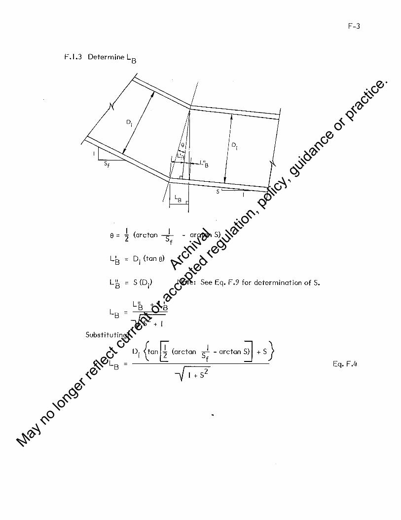
F-3
F.1.3 Determine L8
D. I
s
e = I (arctan + - arctan S) 2 f
L' = D. (tan e) B I
L" B = S (Di) Note: See Eq. F.9 for determination of S.
L" + L' L
_ B B B - -v s2
+ I Substituting:
Di ~an[ (arctan ~ - arctan ~ + S) Eq. F.4
Archiva
l
May no
long
er ref
lect c
urren
t or a
ccep
ted re
gulat
ion, p
olicy
, guid
ance
or pr
actic
e.

F-4
F .1.4 Determine elevations EF, E6 , Ep Es
El. EF = (El. EE) - S0
LE Eq. F.S
El. ET = (El. EF) - Fall Eq. F.6
El. EB = (El. ET)+ S (L 3 +LB) Eq. F.7
El. Es = El. Eo +so Lo Eq. F.8
F.1.5 Determine slope of barrel S
s = Eq. F.9
F .1.6 Determine height of fi II over inlet at face, Hf' and along length, H(x), where x
is horizontal distance from face of culvert
Hf varies with site conditions and height of headwall, and must include any
surcharge loads being considered.
I I H(x) = Hf + x ( T + T ), 0 < x < L2 f e Eq. F. IOa
Eq. F.IOb
Archiva
l
May no
long
er ref
lect c
urren
t or a
ccep
ted re
gulat
ion, p
olicy
, guid
ance
or pr
actic
e.

F-5
F.2 Derive Equations to Determine Elevations of Critical Points and Lengths of Critical
Sections for Side T opered Inlets with Fall
F.2.1 Definition of Terms
s
Inlet Elevation without Fall
Inlet Elevation with Fall
--------Fall
D. --- I --- ---
L Le ---.W.....--l.__...1----------------_:::._---------------------1t---------1 LT
Assume the fol lowing parameters are known:
Slopes: Stream bed (S ), Fall (Sf)' Embankment (S ) o e
Lengths: L 1, LT' and vertical 11F all 11
Elevations: Points EE' E0
Determine the following variables:
Slopes: Barrel (S)
Lengths: LC' LF' LB' L, L0
Elevations: EC' EB, EF, ET
Archiva
l
May no
long
er ref
lect c
urren
t or a
ccep
ted re
gulat
ion, p
olicy
, guid
ance
or pr
actic
e.

F-6
F .2.2 Determine lengths
s 0
L . c
TH: Selected by designer
Fall
DH == D/ 12, (or selected by designer, 12 in. min.)
Dy== Di~ :::: D. (0.5% error for S == 0.10) 1
::: o./2 minimum, selected by designer I
For inlet location without Fall:
Eq. F.11
Archiva
l
May no
long
er ref
lect c
urren
t or a
ccep
ted re
gulat
ion, p
olicy
, guid
ance
or pr
actic
e.

F-7
F.2.2 (continued)
Due to the increased number of variables, the remaining parameters are most
easily determined by an iterative process.
a. Estimate barrel slope S
s (LT - Lo -L'E) so - Fall
LT - (LO + LB + LI)
b. Determine remaining lengths
L. = I
Fall' =
LF =
LE =
[Fall - LI S
(~So2+ I
+ (Dy+ DH)
-{s2:; )] Se
Sf [Fall - S (LI + LB)+ S0
(Li +LB)]
I - S S 0 f
Fall+ S0
(L'E - LC)
[Fa 11' - S (LB + L I )] sf
LB + LC + LF
Eq. F.12
Eq. F.13
Eq. F.14
Eq. F.15
Eq. F.16
Eq. F.17
Note: LE and/or LC may be negative indicating that the points EF and/or EC
are located outside the toe of the embankment (to the left of point EE in the
figure on Section F.2.1 ).
L Eq. F.18
c. Check result, calculate 6
LF 6 = S (L - L - L ) - S (L + L ) - -
o T 0 C B Sf Eq. F.19
d. If 6 > a.a I, calculate a new S
s SL+ 6 =
L Eq. F.2a
Repeat steps b and c. This iteration will normally close with one additional
cycle. See Example.
Archiva
l
May no
long
er ref
lect c
urren
t or a
ccep
ted re
gulat
ion, p
olicy
, guid
ance
or pr
actic
e.

F-8
F.2.3 Determine elevations
Eq. F.2 l
Eq. F.22
Eq. F.23
El. ET =El. EF - SL l Eq. F.24
Eq. F.25
F.2.4 Determine height of fill over inlet at face (Hf) and along length H(x) where x
is the horizontal distance from the face of the culvert.
Hf varies with site conditions and height of headwall. Must include any
surcharge loads being considered.
l H(x) = Hf + x(S + S) Eq. F .26 e
Archiva
l
May no
long
er ref
lect c
urren
t or a
ccep
ted re
gulat
ion, p
olicy
, guid
ance
or pr
actic
e.

F-9
F.2.5 Example - Side tapered inlet with fall
a.
b.
Given
D. = B. = 4.0 ft so = o.as I I
LT = 3Sa ft s = 2 e LI = 4.a ft sf = 2
Fall= I.SD. I
= 6.a ft
Designer selected parameters
Dy ::: Di = 4.0 ft
Di 4.0 DH = T2 = 12 = a.33 ft => Use I .a ft min.
TH = I .a ft (for simplicity)
El. EE = 17.5 ft
El. E0 = a.a ft
c. Determine remaining variables
L' E
s
L. I
= I - ~ S ~ e (DV + DH) - TH J e o -
= 1 _ ~(o.as) [2<4.a + 1.a) - 1.a] = 1 a.a ft
= I + J e So ~ e (Dy + DH) - TH J = 1 + 2/0•05) ~(4 + u - 1] = 8.1811
::: (LT - Lo - L'E) so - Fall - (3Sa - 1a - 8.18) a.as - 6.a - a a317 LT - (L0 + L 8 +LI) - 3Sa - (I a+ 2 + 4) - •
= ~all - LI S + (Dy+ DH) <-Js0
2 +I -Fi >] Se
= Eo - 4.oco.0317) + (4 + u<-./0.052 + 1 -~0.03112 + ~2 = 11.75 tt
Archiva
l
May no
long
er ref
lect c
urren
t or a
ccep
ted re
gulat
ion, p
olicy
, guid
ance
or pr
actic
e.

F-10
Example - Side tapered inlet with fall (continued)
Sf (fall - S (LI +LB)+ S0
(Li+ L8)] LC = L'E - LB - Li - I - So Sf
= 8.18 _ 2 _ 11. 75 _ 2 [6 - 0.0317 (4+2) + 0.05 (I I. 75+2)] I - (0.05) 2
Fall' = Fall+ so (L'E - Le) = 7.41 ft
= -20.0 I ft
LF = [£al I' - S(L8 + LI 0 Sf = fl_.41 - 0.0317 (2 + 4U 2 = 14.44 ft
LE = LB + Le + LF = 2 + (-20.01) + 14.44 = -3.57 ft
L = LT - (LE + L0
) = 350.0 - (-3.57 + I 0.0) = 343.57 ft
d. Check !J.
tJ. = o.os [Isa - 10 - (-20.01IJ- o.0317 (343.57 + 2) - 1 ~44 = -0.174
e. !J. > 0.0 I; therefore, recalculate S and lengths LF' LE' LC' L
S _ SL + tJ. _ 0.0317 (343.57) + (-0.174) _ 0 0312 - L - (343.57) - '
L. = r: -4(0.0312) + (4 + I) ( ~o.os2 + I - ~0.03122 + I J 2 I -
=ll.76ft
L _ 818 _2 _ 117.6 _ 2 6.0--0.0312(4+2)+0.0S(ll.76+2) 2003 f C - ' ' I - 0.05 (2) = - ' t
Fall' = 6.0 + 0.05 ~.18 - (-20.03[) = 7.41 ft
LF = 7 .41 - 0.0312(2 + 4) 2 = 14.45
LE = 2 + (-20.03) + 14.45 = -3.58
L = 350 - (-3.58 + I 0) = 343.58
f. Check !J.
!J. = 0.05 350 - I 0 - (-20.03) - 0.0312 (343.58 + 2)
!J. < 0.0 I , Okay
14.45 -2- = -0.006
Archiva
l
May no
long
er ref
lect c
urren
t or a
ccep
ted re
gulat
ion, p
olicy
, guid
ance
or pr
actic
e.

F-11
Example - Side tapered inlet with fall (continued)
g. Determine elevations
El. Ee = El. EE - S0 Le = 17 .5 - (0.05)(-20.03) = 18.50 ft
El. E8 = El. Ee - LF/Sf = 18.50 - 14.45/2 = 11.28 ft
El. EF = El. Es - s Ls = I 1.28 - 0.0312(2) = 11.22 ft
El. ET = El. EF - SL I = I 1.22 - 0.0312(4) = 11.10 ft
h. Determine height of fill
:::: I ft at headwal I + 2.0 ft surcharge
Hf = I + 2 = 3.0 ft
I Hthroat = 3 + 4 (0.0313 + 2 ) = 5.13 ft
1. Summary Sketch
Le= 20.03'
LE= 3.58'
------
LF = 14.45' ·
Archiva
l
May no
long
er ref
lect c
urren
t or a
ccep
ted re
gulat
ion, p
olicy
, guid
ance
or pr
actic
e.

F-12
F.3 Derive Equations to Determine Elevation of Critical Points and Lengths of Critical
Sections for Side Tapered Inlets Without Fall
Note: This case is a simplification of Case B. All the necessary equations have been
derived previously, and are assembled here for simplicity.
TH: Selected by designer
D. DH = TI' (or as selected by the designer, 12 in. min.)
Dy = Di~ ::;; D. I
LE = I + S S e o ~e(Dv +DH) -T~
Lo I ~e(Dv +DH) - T HJ =
1-S s e 0
Hf varies with site conditions and height of headwall. Must include any
surcharge being considered.
I H(x) = Hf + x (S + S) e
Archiva
l
May no
long
er ref
lect c
urren
t or a
ccep
ted re
gulat
ion, p
olicy
, guid
ance
or pr
actic
e.

G-1
APPENDIX G - TYPICAL DETAILS FOR IMPROVED INLETS
I. Typical Reinforcing Layout - Side Tapered Single Cell Box Inlets
2. Typical Reinforcing Layout - Side Tapered Two Cell Box Inlets
3. Typical Reinforcing Layout - Slope Tapered Single Cell Box Inlets
4. Typical Reinforcing Layout - Slope Tapered Two Cell Box Inlets
5. Typical Reinforcing Layout - Side Tapered Reinforced Concrete Pipe Inlets
6. Side Tapered Corrugated Metal Inlet
7. Headwall Detai Is for Box Inlets
8. Headwal I Detai Is For Pipe Inlets
9. Cantilever Wingwall Designs
I 0. Miscellaneous Improved Inlet Details
Archiva
l
May no
long
er ref
lect c
urren
t or a
ccep
ted re
gulat
ion, p
olicy
, guid
ance
or pr
actic
e.

H•adwo.11 And VVinqwa.11 Slruc+ure, S-.. Sh•efo 7 ~ O•idl/s.
Splice To Barrel Reinforcing-Min. Lap 1.0 ..ed (Afore 4)
5,qua~e fo t'~cvlar lr-ansll'ion 1~ cvlvt!!rl Is clrc1Jfe1,.. pipe.
Cl./lverf fu,..re( pt'pe or 6o)(.' secfe'on.
TYPICAL PLAN
s
Square ~ C1"rcula~ Translf-ion, See Sheef 10 If Required
Throal Geclr'on.
-SECTION A-A
ROTES:
1.
2.
3.
4.
5.
6.
7.
s.
9.
Design Specifications: AASHTO Standard Specifications for Highway Bridges, 1977 and 1978, 1979, 1980 and 1981 Interim Specifications.
For reinforcing schedule for specific inlet sizes see Appendix E.
For reinforcing and cover requirements for precast concrete box sections see ASTM Standard Specification C789 {AASHTO M259).
i~r d~~~0r~~en!dbll:cc~e/a"{~grc~~g,AA~~eTOba;!~tf~~e~~~el~t ~~~g~h11' 18~ smaller bars as:
See Section 1.5.14 for requir,ed development lengths of other types of reinforcing.
If (H8 + TS - 2 in.) < 1d for bar 8A then bar lA 11ust be extended beyond the tip of the haunch by:
(td bar SA) - C"ii + T0 - 2 in.) (Area of bar SA) (1d bar lA)
( 1d bar BA) (Area bar lA)
Alternate reinforcing •che111e h to omit bar SA, make bar lA the size of lA or BA whichever is larger, and extend it across the top of slab, lapping it 12 in.
Temperature and •hrinkage reinforcing •u•t meet the requirements of the AASHTO Bridge Specification Section 1.5.12. The total reinforcing provided •hall be at least 1/8 sq in./ft and be spaced not 11ore than 3 tiM• the wall or slab thickness nor 18 in.
If haunches are not uaed, or if reinforcing sizes lar13"er than fB are used for bars lA or lB, additional reinforcing area, above that needed to •eet flexural requirements, may be necessary to meet the development length requirements of the AASHTO Bridge Specification Section l.5.13.
See notes on Sheet 9 for reinforcing and concrete requirements.
r- Syrnrnefr(c Qbov.,C 1 cenf~r//n~.
I 6Qr 8A (N'ofe '"')
b,,r /A
2"Clear fyp/col /r1:Jt'cle cover
TYPICAL 5£CTION - SINGLE CELL BOX INLETS
T&•H'v; /,'7.tJ (Nofe 4)
13. + z (T. - ?"
Bar 4-A
l;•H',,..1.,[I (/.lo~e <J.) L.&c" 16
I .---l-12._o,.~l.-l-I /'?In, ~ .. ,,,.,. fa
gr-I~,..
CIRCUMFERENTIAL REINFORCING DIMENSIONS
U.S. DEPARTMENT OF TRANSPORTATION FEDERAL HIGHWAY ADMINISTRATION
WASHINGTON, D.C.
Example St1:1ndard Plans For Improved Inlets
TYPICAL REINFORCING LAYOUT
SIDE TAPERED SINGLE CELL BOX INLETS , .. ~ ..... RECOMMENDED 9..g_, Q ~
Chl•f 0..'9Mct l~tlo::r= RECOMMENDED ~ ,drJ:t:ai,
Chl•f Hydraulic• Branch
RECOMMENDED_, ;S<.&..t:.,. Chier l!lrlq. Dl•I
APPROVED1~.:l..lilll0...C~::.......-""'!ilil. .. ~ Director, OfflM flf f1119l111 .....
Archiva
l
May no
long
er ref
lect c
urren
t or a
ccep
ted re
gulat
ion, p
olicy
, guid
ance
or pr
actic
e.

&.;,. BA ,..,,r 88
L,
7en-?peralvre ti %r<nK.age l<einl'orcrl-?9 ) Nofe 7.
Cutven'· (:;,a,.,..ef 2 cell box.. sec1"ton Srde faperec' ~ CtTf( .box. thief. 01'" 2 st'ng(a C't!(( precasf box..
o,. pt'pe secf,'ons (Mole 10 ).
Headwa.11 And Winqwal/ Srruc+ure, See She-.f 7
For De+a;/,..
/ I
I I
"'I I I I I
-...... r
--
--
TYPICAL PLAN
5pa.cing 1.sr Or 18 /riche'i> Which.ever Is Less
~Thro~.< Seet;o,...,
- - -- : - -. .
°'
- -- - : : - -51 - -
I
SECTION A-A
2"
&r IA bar4A
Tc 2'Cfeor ftp/co( .hstde caver
6( fo fy/z)
o'
Hv
o' Te
TYPICAL SECTION - TWO CELL BOX INLET
NO'l'BS:
1. Design Specifications: AASHTO Standard Specifications for Highway Bridges, 1977 and ~97S, 1979, l9SO and l9Sl Interim Specifications.
2.
3.
'·
s.
6.
7.
8.
9.
For reinforcing schedule for· specific inlet sizes see Appendix E.
Por reinforcing requirements for precast concrete box sections see ASTM Standard Specification C7S9 (AASHTO M259).
Por defo[med bar reinforcing, basic development length (t,rl) is determined according to the AASHTO Bridge Specification Se"?:tion 1.5.14 for fll or smaller bars as:
0.04 Ab fy - ::. o. 0004 dbfy ::. 12 in.
~ See Section 1.5.14 for required development lengths of other types of reinforcing.
If (H8 + TS - 2 in.) < .e.d for bar SA then bar lA must be extended beyond the tip of the haunch by:
(td bar SA) - (8ii + T9
- 2 in.) (Area of bac SA) (td bar lA) ::. 12"
(.td bar BA) (Area bar lA)
Alternate reinforcing scheme is to omit bar SA, make bar lA the size of lA or SA whichever is larger, and extend it across the top of slab, lapping it 12 in. with bar SC.
Tenaperature and shrinkage reinforcing must meet the requirements of the AASHTO Bridge Specification Section 1.5.12. The total reinforcing provided shall be at least l/S sq in./ft and be spaced not more than 3 times the wall or slab thickness nor 18 in.
If haunche• are not u•ed, or if reinforcing sizes larger than IS are used for bars lA or 18, additional reinforcing area, above that needed to 11eet flexural requirements, may be necessary to meet the development length requirements of the AASHTO Bridge Specification Section 1.5.13.
See notes on Sheet 9 for reinforcing and concrete requirements.
10. If precast box or pipe se~tions are used to form the two cell culvert, the two cell inlet may still be used as shown provided the engineer •odifies the center wall geometry for a box section barrel, or desi9na a two cell square to circular transition section similar to that shown for one cell transitions in Sheet 10.
Be,r I 6
BQrS 2A . .SA,cSAeno'86 L"ng{h .,,. f'~t.1irea by o'n15">
6ors 13C onallO
Ctr<CUMFEl<E:NTIAL ~e/N~Ol<CING OIMeNSIONS
U.S. DEPARTMENT OF TRANSPORTATION FEDERAL HIGHWAY ADMINISTRATION
WASHINGTON, D.C.
Example Standard Plans For Improved Inlets
TYPICAL REINFORCING LAYOUT
SIDE TAPERED TWO CELL BOX. INLETS ;De ht SHI•
Director, Office or E111l11M1"htt
Archiva
l
May no
long
er ref
lect c
urren
t or a
ccep
ted re
gulat
ion, p
olicy
, guid
ance
or pr
actic
e.

Lt
!7hr/nl:o.9e ti Te'7'1pero•u~ /(e,r,/le;1"C(n9 Orn/f L111p F"or ~har1' In/el Gtrvc.tures
Sp/ice (en9IA eqvaf fo f.o £.d..
cvlv.erf barrel, p/pe or bo)t.. secf.<on.
Sf ope ~pered box. 1hle1'. Square fo c/rc<.1/ar fr-cnsilion t'f'c-vlve,.f Is C"!rcl/far ;clpe.
Headwall And Winqwal/ Structure See Sheet 7 For Derails. ·
TYPICAL PLAN
Ou~slc:/e s/r:l~woll /ongdvc/.nat f"l!!1'nl1orc/ng -1-o rnt1ef. r-~""'1/red /'1')1.,,,.,,..,vm /llex.v,-al ,..,_,.,,,r,,,.,.,"'" f$ (As • 0. 024 Ts, in 'Yl'f. )
Sq<I..,... lo c/rculcn~o,,sllt'on, sieteo ~er 10 /f' l'"#!lf'vire<:I
~ocd seclt'on
lJ"1q><,;.,.,'-'tn space'1?9 l.s T or is t'n. Nhichever is less.
SECTION A-A
Long '2 oulsic/e sld~wal( longt'ludt'na! re1nl'orc/,-,9, Se~ SecftC:r? A·A
Av 16
ROTBS:
l.
2.
3.
4.
5.
6.
7.
s.
9.
Design Specifications: AASHTO Standard Specifications for Highway Bridges, 1977 and 1978, 1979, 1980 and 1981 Interim Specifications.
For reinforcing schedule for specific inlet sizes see Appendix E.
For reinforcing and cover requirements for precast concrete box sections see ASTM Standard Specification C7S9 (AASBTO M259).
~~~e::if~:;e:cc~~~ i~: i~!0 ~~! n~~:~c B:7;;e10E;:~f f i~eant9i~hn ~~'t)ti~~ 1.5.14 for tll or smaller bars as:
See Section 1. S.14 for required development lengths of other types of reinforcing.
If (H + Ts - 2 in.) < .t.d for bar SA then bar lA must be extende'N beyond the tip of the haunch by:
(.ld bar 8A) - C"u + T9 - 2 in.) (Area of bar SA) ~~----~-~---------- (.t.d bar lA) ~
{ld bar SA) (Area bar lA) 12"
Alternate reinforcing scheme is to omit bar SA, make bar lA the size of lA or SA whichever is larger, and extend it across the top of slab, lapping it for 12 in.
Temperature and shrinkage reinforcing must meet the requirements of the AASHTO Bridge Specification Section l.S.12. The total reinforcing provided shall be at least 1/8 sq in./ft and be s1>9ced not more than 3 times the wall or slab thickness nor 18 in.
If h•unchea are not used, or if reinforcing •izea larger than tS ate uaed for bars lA or lB, then additional reinforcing area, above that needed to 11eet flexural requirements may be neces•ary to raeet the development length requirements of the AASHTO Bridge Specification section 1.5.13.
See notes on Sheet 9 for reinforcing and concrete requirements.
10. The lengths of bars lA, lB, 4A, and 48 are for the L3 segment.
These lengths must be multiplied .by -Ji + (l/Sf) 2 for all of ~~~u~ •egment, except the segment LB where transition lengths
~ I
Syrr,rneh·/c ah<>vf ca,.,,t.~/,;.,e.
l
l!>a- 2A
See Nol~ SI
/.la<Jnches o,o.f.<..,..,,,/ (Nof.e B) Jl'ii!'Max.
(ovls<cle sir:lewa II)
TYPICAL SECTION- SINGLE CELL BOX INLETS
O;_+IT-14v- 2" (Nof-e 10)
.Te.fHv ... 1.1.tc1. [I e. ie:. (Nof~s 4, 10) ~-"'-~--
18d2 •Ts ~4' I
CIRCUMFERENTIAL
Sars ZA, .5A And IJA
O{ +Tr - Hv -z• (I.lo!• !O)
Bar 4A
REINFORCING DIMENSIONS
U.S. DEPARTMENT OF TRANSPORTATION FEDERAL HIGHWAY ADMINISTRATION
WASHINGTON, D.C.
Example Standard Plans For Improved Inlet•
TYPICAL REINFORCING LAYOUT
SLOPE TAPERED SINGLE CELL BOX INLETS . ......... . RECOMMENDED 12,l.- e ~
Chief De11t:df/.,.c::io:=
RECOMMENDED~ /8_{).qp;., Ch~t ... HfdTOt:: Bronc:h Director, Office of E.,luerf-.
Archiva
l
May no
long
er ref
lect c
urren
t or a
ccep
ted re
gulat
ion, p
olicy
, guid
ance
or pr
actic
e.

Tc
Shri'nl::a9e. J fernpere;..fvre ~et',..,forc.r°r1g, f..lcf.~ 7,
8A ond 86
W-H-+t-HIITTtTime.,
1811
Maxirnurn --+---+--Hit---+ (Nofe 7)
SECTION A-A
s
Culver~ barre/ 1'-wo ~ell l:x:n" stfk;'f'i ·on t:Jr""
2 .stiylc:- cell precasr bt>JI(. or P'f>t' ~.<<ons.(N'ol<?tO),
Di
Ba,. /A
Lon9 2 oulside st'o'ewQ(f fon91"f-vcl/na( re1nf'.,rc1'n~ see sec1'1onA.·A
2•
8
o"
5ar 'ZA
2 11Clt!'O,,. ~ypt'cal fn91.'de cov~,..
Di
Hv
2'Clear-, fyp1C...f ou1'et't:I~ cov~r ~Keep>' boffo,..,
TYPICAL SECTION - TINO CELL BOX INLET
llOTl!S:
l.
2.
3.
4.
5.
6.
7.
8.
9.
Design Specifications: AASHTO Standard Specifications for Highway Bridges, 1977 and 1978, 1979, 1980 and 1981 Interim Spec! f ications.
For reinforcing schedule for specific inlet sizes see Appendix
"· For reinforcing and cover requirements for precast concrete box sections see ASTM Standard Specification C789 (AASHTO M259).
~~~e::f~:~e:c:oa:di~~int~or~h~n9Ms~;sOicBrdi~~:lof:eecnitfi~:~9i~~ ~~~~i~~ 1.5.14 for Ill or smaller bars as:
See Section 1. 5.14 for required development lengths of other types of reinforcing.
If (H8 + T8 - 2 in.) < l.d for bar BA then bar lA must be extended beyond the tip of the haunch by:
(td bar BA) - <°e + Ts - 2 in.) (Area of bar SA) (.td bar lA) ~ 12"
(td bar BA) (Area bar lA)
Alternate reinforcing scheme is to omit bar BA, make bar lA the size of lA or BA whichever is larger, and extend it across the top of slab, lapping it for 12 in. with bar BC.
Temperature and shrinkage reinforcing aust meet the requirements of the AASHTO Bridge Specification Section 1.5.12. The total reinforcing provided shall be at least l/B sq in./ft and be spaced not more than 3 times the wall or slab thickness nor 18 in.
If haunches are not used, or if reinforcing sizes larger than tB are used for bars lA or lB, additional reinforcing area, above that needed to meet flexural requirements, may be necessary to meet the development length requirements of the AASRTO Bridge Specification Section 1.5.13.
See notes on Sheet 9 for reinforcing and concrete requirements.
10. If precast box or pipe sections are used to form the two cell culvert, the two cell inlet may still be used as shown provided tllie engineer raodifies the center wall geometry for a box sectlon barrel, or designs a two cell square to circular transition seetion similar to that shown for one cell transitions in Sheet 10.
11. The lengths of bars lA, 19, 4A, and 4B are for the L3
segment.
These lengths must be multiplied by "'1 + (l/Sf) 2 for all of the L2 segment, except the segment LB where transition lengths occur.
8ar /A
'2 { 6< '75- 2' ) ,. Tc. (Var-t<:-a) · I Ba,.s 2A, 3A, 6A. o,.,c:/ 8&
CIRCUMFERENTIAL RSINFORC/NG DIMENSIONS.
U.S. DEPARTMENT OF TRANSPORTATION FEDERAL HIGHWAY ADMINISTRATION
WASHINGTON, D.C.
Example Standard Plans For Improved Inlets
TYPICAL REINFORCING LAYOUT
SLOPE TAPERED TWO CELL BOX INLETS ;De Net So•I•
RECOMMENDED O,,t.,,,. <l ~ Chlo! O.ol~<tlo;;;:;;.: SHEET NO.
RECOMMENDED fftfhn CJtlet Hydr lie• Branch
APPROVED·..::J'-'c.=:""":......"'--":::::>o"""':il-01rectar, t>fflce of E:111h1Hrl111
4
Archiva
l
May no
long
er ref
lect c
urren
t or a
ccep
ted re
gulat
ion, p
olicy
, guid
ance
or pr
actic
e.

Headwall And Wingwall Sfruc+,,,re S•• Shf. ~ For Oeof.
r,
TYPICAL
r[ Radius r1
s
SECTION
Ci,-cu/a,- cufve1- r barrel
PLAN
AA
O' t
Clrcufar culv~rl barrel
ROTBS:
l.
2.
3.
4.
s.
TYPICAL SECTfOAJ C·C
1"ctear l'or pr_eCQsr 'Z'Cleor !'or Cosr-in-place
r'cleor f'o..- prec.:;sf 2" C'l~or f'or cr:;s.,t •in-place
Design Specifications: AASHTO Standard Specifications for Highway Bridges, 1977 and 1978, 1979, 1980, and 1981 Interim Specifications.
Material properties, dimensional tolerances and longitudinal reinforcing to conform to the requirements of ASTM C76 (AASHTO Ml70).
For splices in welded smooth wire fabric, the length of overlap, measured from the outermost cross wires of each fabric sheet shall not be less than one spacing of cross wire plus 2 in., nor less than 1.5.e.d nor 6 in. td is determined according to AASHTO Section 1. S. 20B as:
0. 27 A f I. • ___ w __z...
d sv Fc See the AASHTO Bridge Specifications for splice requirements of other types of reinforcing.
Inside crown reinforcing area A90
will be equal to inside in
:~~!me r~!"~~!~~ng area A 81 unless an alternate reinforcing
Alternate reinforcing scheme consists of overlapping the inside cage at the invert in order to provide the extra reinforcing normally required at that location. Other alternate reinforcing schemes may be used provided they meet the requirements of the AASHTO Bridge Specifications. Any pipe in which an alternate reinforcing scheme is used must have the top clearly marked to assure proper installation.
FACE
TNo layers of' inside reinl'orcln9 rn1.1sf -fol-QI orea As/. One foyer n->V'Sf- be 9realer Mon C1reQ A sc
~Top of' p/pe mvsl be I cfearly rnorKecl.
ALTel<A.IA7e REl/..IFOR.CING lAYOUT(t<./O{e ~)
Applies r'o bolh c/,..cv(or oncl elft'pf/cal secr't'cms.
SECTION B-B
/nsicle sparo = '? ( i./ ,.. r, ) !t?slde a.lse = 2 ( r2 -v) = Of°
U.S. DEPARTMENT OF TRANSPORTATION
FEDERAL HIGHWAY ADMINISTRATION
WASHINGTON, D. C.
Example Standard Plans For Improved Inlets
TYPICAL REINFORCING LAYOUT
SIDE TAPERED PIPE INLET Do llot lo,ole
IHl!ET NO.
5
Archiva
l
May no
long
er ref
lect c
urren
t or a
ccep
ted re
gulat
ion, p
olicy
, guid
ance
or pr
actic
e.

,/
Headwall And Wingwo.11 Sfrucfure, See Sh~ef 8 For De+ails
I I
------------- I ------------ I
.~.--:J:--4 - I
~ I
t;_tf/pft'ca(, fo circvlar side raperea' mlef,
I I I
TYPICAL PLAN
SECTION A-A
l.
2.
3.
Design Specificationa:. AASBTO Standard Specifications for ::,:~'i~lc::l:~:.• 1977, and 1978, 1979, 1980, and 1981 Inter i•
Corrug:ated •tal inlets are flea:ible culverts, and their perforaance i• dependent on •oil-structure interaction and soil stiffness. See AASBTO 1.9.l(G).
Se•• ••l' be bolted, aa shown, riveted or apot welded provided they ... t the atre,,.th require•nta of the AASBTO Bridge Specification.
THROAT
ELLIPTICAL
SE:CTION C-C
SECTION B-B
Inside Span • Z( u + r,)
Inside Rise • Z(rz. -v-)
U.S. DEPARTMENT OF TRANSPORTATION FEDERAL HIGHWAY ADMINISTRATION
WASHINGTON, D.C.
Example Standard Plans For Improved Inlet•
SIDE TAPERED CORRUGATED METAL INLET .. .. , .. _ RECOMMENDED~~fl#!
Chier°""'" t ,
RECOMMENDED,-.~.L'"~lll.l::'ch1e1-H1•rHlln Brendl
RECOMM~~.~,~~ APPROVED '2:2- ;e -;o;-, <" 6 '<f'
Director, Office of E1t1........., 6
Archiva
l
May no
long
er ref
lect c
urren
t or a
ccep
ted re
gulat
ion, p
olicy
, guid
ance
or pr
actic
e.

I I I I r-----+--h------------t-i-+-----..
I I I
Nt'ngNoll !'lore angle as sefecrec:J by des19ner.
O/mensr'on keys - see Appenr:l/x & l"or sp•ci.f',·c s/z:es
PLAN 1-/eADNAll rOR CAST-llv'-PlAC'E SINGLc Cell 60X 1/.llET(SIMllAR FOR ~ST) Fr.AN f-/eADWALL FOR CAST-1/tJ-PLACe TNO CELL BOX INL!!.TS (SIMILAR FO/fl. PA.ECA~T)
A~
~o
r 1 I I I I
~ .. I .6 I o; I I h/ I I I I I I I I J L ------------
0 : f A~
°"'o r 1 I I I
I I I I
(} .. I --.e. c.-r- .c O.{ I I I I I I I I I L --- - ------------------- _J
A .. EL€VATICN He ..... ONALL F"OR CAST-IN-R.ACE TWO CELL eox. IAll..ET
(SIMIL.;4..1<. FOi<. P/li:ECAST)
Wr~ll l'Wr. ~la SECT/CW 6-e f'~eCAST ~ SCCT!ON SECTI~ ~ ;: e,Aloh
CAST·//../- PLA.Cc BOX SECTIOAI
trtf!!..
'4€;1'1." SECTfOAI C-C
P6'E'CAST 60X secrtON
".1,. v.-1-.. ~1'---t=~~~i-_j
•., C fo mohl. 1o,,,,·,1W;,..~i1 ... ,.. ,;, °"" ~~,·o-;,.
&.-•I o'/,,.._,.,..,,,,. some qs ,t,,,o 0.ve:I.
SECTION C·C::: CAST-N-PLN:.E BOX. SECTIQV'
-· l.
2.
l.
'· 5.
'·
7.
.. '·
De•ign •pecUication•z AAsmro Standard Speciflcatton• f;~1 •l:::r•f. ;~:rrT~at1f:: •. plu• it11, it1t, it10 and
ror wingwall flare angle• 9reater than t5°, a beftl with the •- diMnaiona •• the top beftl auat be ueed at the aides •
.. ,,.1 dl.Mnolon d~ • O. s' a 1112 for cs0 beHl a119la and dt • a 1/12 for ll be•el a119le.
Anchor bolta, 10 in. long and l/.C in. di-ter into threeded inHrta auat haYe working ahear capacitJ of 4000 lb•.
TM apc.ce Mt ... n tvo cell precaat boa: nctiona auat either Ille filled with concrete or with aoil C011P9Cted to a ainia• 151, of •tandard den•it7 IN.Md on AASlftO ,...,,_ The tera a refer• to the face wi•ttt of an inlet. Thia tera iS applicable to •ide and •lope tapered inlet• wl\ich are not abown here.. Poe two cell bos MC=~:::: •r!2 •hould be aubatltuted for •f in all diMn-
Local •it• coftllitioM •uat be e•alMted to .. ter11ine foundation and cutoff wall requir-nta. Particular attention ahould M paid to erffio• areundl titre entrance and to depth of froat pene-tratlon.
- not•• on lhMt I for relnfo.rclnt and conor•" requir-nta.
bcept a• noted ainlawa concrete conr •hall M 2 In. Offr pri .. r7 reinforcint and 1-1/2 in. oftr atirrupe and ti••·
U.S. DEPARTMENT OF TRANSPORTATION FEDERAL HIGHWAY ADMINISTRATION
WASHINGTON, D.C.
Example Standard Plans For Improved lnl9ta
HEADWALL DETAILS FOR BOX INLETS
RECOMMEND ED (J,/..,.lt!!:t!:J Chlef~-'1 tkM19r
RECOMMENDEI!,~ ~ Ch .. f "1•ewll• INllCh
RECO-NDED ~ Qt.f ..... ~
APPROYED-"""""-..llL..aii.~-... DlrMNr, Offlce .............
Archiva
l
May no
long
er ref
lect c
urren
t or a
ccep
ted re
gulat
ion, p
olicy
, guid
ance
or pr
actic
e.

81
I ~---<-1- -- - - -----,-+------.
I '
' ' I' t.J- -------------
Br
Pt.AN view l-IEAONALL ro~ RE!NR)~CcO CONCR€Tc P!Pe /NLET(SMl(.A/(. f'O~ Ca<J<UGATEO #ICTAL) PLAN VIEW HcAONALL FOR SIDE 7APEl<.EO RE!Nf'"OR.CEO CONCl<cTE PtPC /AILcT (SIMILA/<. ~ COr<!<UGAieO Mt"?i'\L)
<s .............. ,, ......... . A:t~ r•lni'o,-ct'l""tt; ,..,"',·,..,..,,,.,.,,. ..
5<"d' SO"<::f/of"! S·5 fb,. vr,.1'/cal rt1it?l'ol"c1'ng of s(cl<"S ol' h .. ad'wafl
M>l'f s j l.i•c/e-ar
SeCT/ON A·A. REIAl~CEO CONCkEf'e Prr'e
&.Ml~"· 0,45•
dt(Nol-•2)
SO"d' cl.,.fr:,,·/ 6•6 R(flnl'o,-c«/ Cc>r"/t:l"'•f. pipd' {'_,. rdinfbl"c(nr; ~ilc.,
seCTION e.. e. CO(l.l(tJGATeO METAL Plf'C
SECTION 6·6 REl~!="O/eCEO CONCRETE P/Pe
l.
2.
3.
'· 5.
... "'·
Design Specification•: AASll'l"O Standard Specification• for Bi9hva7 lrid9e1 1977, and 1978, 1979, 1980, 1981 Interia Specifications.
·Bevel di .. naion dt; • 0.5 Br/12 for ts0 beYel and d-t • Bf/12 for 33° bevel.
Anchor bolt• 10 in. lont, 3/4 in. di .. ter. lluat haYe vorkint •hear capacit7 of 4000 lba.
see not•• on lheet t for reinforcing and concrete r•quire•nt•.
Local •it• condition• au•t be ••aluated to deteraine foundation and cut off wall r.equir••nta. Particular attention should be paid to eroaion around the entrance and to depth of froat penetration.
Except •• noted, ainiaum coyer o••r reinforcing •hall be 2 in. oyer priaar1 reinforcing and 1-1/2 in. over •tirrup• and ti••·
The auitabilit7 of galvanised anchor bolta for ..t>ed•nt in concrete or galvanised aheet ag:ainat concrete auat be ••aluated ba•ed on local aateriala and condition•. Additional protection ••r be required.
SE.CT/ON O·O
U.S. DEPARTMENT OF TRANSPORTATION FEDERAL HIGHWAY ADMINISTRATION
WASHINGTON, D.C.
Example Standard ·Plans For Improved Inlet•
HEADWALL DETAILS FOR PIPE JNLETS
.. ----RECOMMENDE~~~
Ch•fD .. I 1 •
RECOMMENDE __ ....._.""""''-'---
ct11et HJ • lr•Kfl Dlreclor, Office of ,......_...
Archiva
l
May no
long
er ref
lect c
urren
t or a
ccep
ted re
gulat
ion, p
olicy
, guid
ance
or pr
actic
e.

WALL DIMENSIONS REINFORCING STEEL SCHEDULE QUANTITIES MAXIMUM ~ Lm. Ft. o~ W.11
BEARING
Bar A Bar c Bar £ Bar F Bar G Bar J Bar K Concrl!!tl!! Rein.f. PllE_BSURE H
H B ,-,. Tw D St!!!el
,.~ Size Spacing a. b Length Size Spacing a b Length Size Spacing a b length Size Spacing Length Size Spacing length ~ize Spacing length Length Cu. Yds. *""Lbs !6p~F't.
"' 4'-d' 0!.9" 1'-zYe" /'-3' 4 I'- ro" 5'-7" 1'-7' !D'-10· 4 I '-t;," 3'-7" 4 1'- r,," 3' .. 7" 4'-5" 0.4/<D zo.e /.OJ 14>
7 4-8 0-10 J-3 /-3 4 / - IO IO- 7 / - 9 B-O 4 I - <O 4-/ 4 / - c;, 4- I 5-5 o.49z Z3.0 /.ZZ 7
8 5-4 1-0 J-3'1e 1-3 4 I - IP 7-7 J-11 9-z 4 I- co 4-7 4 1-c;, 4-7 !D-5 0.51&9 ZE..4 /.39 8
9 t&-0 I - I /-~ 1-3 4 /-(,; 8-7 Z-1 /0-4 4 /-(,; 5-1 4 /-CD 5- I 7-5 0.<048 .29.2 /,fOO 9
JO &-7 1-3 J-4~ J-3 4 1-1'/e 9-7 Z-3 /I-ID 4 1-t'le 5-r,, 4 1- /Yz 5-r,, B-5 0.725 33.9 /,76 10
II 7-4 1-s /-4~ 1-6 4 1-a!t-z 10-7 e-11> /Z-9 4 JCS 1/2" 5'-o" 2'-G:i' 7'-e." 4 0-10~ r,,-1 4 1-Bft (D-/ 9-Z 0.90:1 37.0 /,95 II
IZ 8-0 ,_ ro 1-sv.. I-ID 4 /-3~• 11-1 Z-7 13-8 5 1- !Yi 5-r,, 2-7 7-9 4 0-7~ ro-11 4 1-31-t r,,-7 10-z 0.993 47.7 ZJIO 12
IS 8-8 J-B /-5\ /·ID 5 1-r,, /2-7 z-10 /5-/ 5 1-r,, 5-7 2-10 8-1 5 0-9 7-4 4 1-rD 7· / 11-Z J.084 55.Z z.sz /:I
14 9-Z 1-9 /-Ii~ J-(o "' J-8~t /3-7 Z-11 1.0-e "' 1-B'lt I0-4 Z-11 B-11 5 0-10!14 7-9 4 1-81;'2 7-5 1e-z /,/(o7 t&J.7 2.58· '"" 15 9·/I 1-11 N•'4 1-r;, '° /-5 /4-7 3-z 17-5 r,, I- 5 <D-7 .3- 2 9-5 "' o-0'le 8-7 4 /-S 8-0 13-Z /.2~ 79.9 I!. 71!! 15
/f, I0-7 2-1 /-7~ /-(D '° /-9 8-4 3-4 II- 4 "' /-9 5 -IO 3-4 B·IO (j, 1'-9" 3 1-C0 11 3'- 4" 5~ 11" <O 1'-9" 14 '- 4" "' 0-7 9-/ 4 /-9 8-9 14-Z /.%1 9e:o Z.89 /(,,
17 //-3 2-3 1-7~ 1-<D 7 1-11 !l.i 9-0 3-7 /2-3 7 1-111/4 5-1/ 3-7 9-2 7 1-11114 3-10 3-7 IO- 9 7 1-11~ 15 - 4 ID 0-7 3/4 g-G> 4 1-11 114 9-3 15-z /.459 104.4 3.04 /7
18 11-10 2-4 /·BY4-,_,,,
7 1-9 9-ID 3-B 12-10 7 /·9 ID- 4 3-B 9-8 7 /-9 3-10 3-B (o -10 7 /-'?! /(o- 4 7 0-7 J0-5 4 J-'i!J 9-7 /(o-Z /,553 /Z7.9 3.ZS 18
1,9 12·7 Z-11> 1-8" ... /-9 7 /-(o 10-0 3-1/ /3-7 7 1-ri> <0-9 3-11 /0-4 7 /-t;, 4-1 3-11 7-4 7 /-(,, /7 - / 7 0-IO 10-11 4 1-G> 10-z /(o-1 / 1.1s8 151. 7 3,45 19
.ZO 13-3 Z·9 /-9~ /-9 8 /-9 /0-8 4-Z 14-(o 8 I-'?! r;,-11 4-2 10-9 8 /-9 4-ID 4-e B-4 8 /-9 18-/ 7 0-7 11-4 4 /-9 10-IO n-11 /,l%fD 160.3 3.55 zo
21 l!J-11 2-10 2-z~ 2-0 8 /-9" 11-e 4-9 /5-7 8 /-9%: 7-3 4-9 11-8 8 /-9;!/4 4-9 4-9 9-2 B /-9% /8-/0 7 0-7~ 11-ro 4 1-9 94 10·8 /8·(,, 2.ez7 1roe.4 s.sz D
zz 14-(o .9-0 2-3 2-0 8 1-1/12 11-10 4·11 /t;,·5 8 1-1fi 7-8 4-11 /2-3 8 1-1'1-z 4-9 4-11 9-4 8 /·7ile. /9-10 7 o-roV,e 11-10 4 /-7/;z 11-0 /'i!J-(D 2.352 IBI0.5 4,00 z.z a /!5- 3 3-0 e-374 z-o 9 t-9~ /2-5 s-o 17-J 9 ,_,% 8-/ 5-0 /2-9 9 1-9~ 5-7 5-0 10-3 9 /-9°14 20-10 8 0-7¥4 IZ-JO 4 /-9;4 //-9 20-r,, Z,49Z Z/7.0 4.zs es 24 /5·11 3-:S Z·4Y.. 2-3 9 /-9 /3-3 5-4 /B-3 9 /-9 8·8 5·4 /3-8 9 /-9 5-10 5-4 10·/0 9 /-'<) ?./- 7 8 0-7 13-3 4 /-9 /2-1 Z/·3 Z.754 233.4 4.40 1?4
25 /ll>-7 3-3 2-5 2-3 JO J-11~ 14-0 5-5 19-1 /0 /-// '14 g-3 5-5 14-4 10 1-11'/4 IO·/O 5-5 11-11 10 t-11Y4 2z-7 9 0-1% /4-3 4 1-11 !14 /2-8 ze-3 2.898 Z78.Z 4.r..7 25
Z6 17-2 3-(o Z-5~ Z·ID JO /-go/~ 14-7 5-8 19-11 /0 J-9 341 9-8 s-e 15-0 JO 1-9~ 7-1 5-B 12-5 10 /-q ~/4- 23-4 9 0-1¥4 /4-r,, 4 /-9% 13-0 23-0 3.173 3'.)0.8 4.az l!(o
Z7 17·// .9·1'> z-<D'i 2-<& JO 1-1f2 15-0 5-9 eo-5 JO 1-1/12 9-// 5-9 JS-4 JO 1-11,,_ 7-1 5·9 /2-IO 10 /-7/lz 24-4 9 o-ro'le /5-3 4 /-7'1t. /:J-8 ?.4-0 3.335 344.0 5.08 27
es 18-7 3-9 Z-7 e-g- JO /-Ii> /5-5 6·/ Z.J· Z JO 1-(o JO-Z r,,-1 15-11 JO /-ID 7-4 ID- I /3-/ 10 /-r,, 25-/ 9 o-co 15·7 4 /·!',, 14-0 ?.4-g 3.(o40 379.1& 5.21 ea Z9 /9-3 3-9 e-7'4 2-9 II /-9 1i0-5 ro-z ZZ-3 II /-9 11-0 IO·Z /(o-/0 II 1-9 B-5 ID-Z /4-3 II 1-9 zr,,-1 10 0-7 /t&-B ' /-9 14·8 25-9 3,805 421,0 5.49 29
30 19-10 4-0 Z-8~ 3-0 II /- o.a;,,. 1.0-11 lb·5 23-0 II I- c; ~4 11-z I0-5 17-3 II 1-coo/.t. 8-8 <D-5 /4-9 II t-G%. 2ro-10 JO 0-li>V.,. /(o-11 4 /-~3/.j. /4-11 z<1>-ro 4.JZZ 477.0 5-.(o!I !IO
*'* e :
~ -
i '~0:1 I 'S<"e Nor'e G lo.- NOTES
3·1 Finished Ground woll ..Jot',,fs
I. The designs presented here are based on the Federal Highway Administra- 122" Fo, H ~zo' .. I Line tion Publication 11Reinforced Concrete Retaining Walls," September 1967. _'Y,4 Fo, H ~eo' '
.Ar..;:"
\ Wing walls may be designed as retaining walls according to current
'J L~,. AASHTO working stress or ultimate strength procedures.
2. DESIGNOATA: n = 10, f = 1200 psi; f = 24000 psi; Weight of soil= 120 IZ ~ . pcf; Weight of concretec= 150 pcf; A.n81e of Internal Friction= 33°41'i
ear K. v; For H~ zo' Earth pressures determined from Rankine's formula.
[>..---Bare L For SUding: The coefficient of friction between masonry end soil is taken I a ...... ~./~,."Ctr..--... !J'4" For H > zo'
-----as 0.45. A scfety factor of 1.5 is provided against sliding,
9".R ~ . Few Overtwnlng: A minimum safety factor of 2 is provided ogainst
~ /!Jar!...~~ II! Bar F overturning. Resultant of the loads is at or within the middle third of the ""4~ J!.!D"ctrs. --- / footing.
~ 3. CONCRETE: All concrete shall be Closs A(AE) with a minimum 28 day I b compressive strength f' = 3,000 psi. The air entraining agent shall meet
See Elevation ~ Bar A with the approval of t~ engineer. All exposed edges of walls shall be BARS A,C f e For Rein1'orcin9 - #.+fRIB' Dow•ls 1-F Apron .....---- -- • chamfered 3/4 in. except as noted.
l: . . Slab /s Used . 4. REN'ORCING STEEU Reinforcing steel shall be deformed bou con· Note : The rein'f'orcinq echedules ~liown ,,,.,, onll.J 'for
Wtttt,o t'>ol"• ·Nole 7 forming to ASTM A6 l 5. Dimensions relating to spacing of reinforcing steel are from center to center of hors. Bending dimensions are from out the correspondin9 wall dimension• li•f11tl. If' F'ootln'J
t'IO" Min. to out of the bors. Minimum cover for reinforcing bors shall be 2 in. clear dimension• ar11 varied to obfaln « more deeiro.bl• •oil Op-fional Apron Slab • . Weep Hole---....._ unless shown otherwise. Bars A end C are extended 35 bor diameters pre•eure, a correspondin9 chan9e mutsf b11 mat:le See 5ht!!llf 10 1
.-J:. ~--...
beyond point of theoretical cut~ff. m the foofinq de~ign t-o adjus-t reinforcing. -©- Bar c 5 • FCJUt.DATION PRESSURE: When the maximum beorin9 pressures shown
.I- - =----- = vfo,M(M•fch Ba,K) I i.---- in the tables exceed the allowable bearing pressure of the soil at the site, I . ' V--- #4 • 3'-0" L11n9+h a pile footing may be used, or the width of footing may be modified to ,.,.
U.S. TRANSPORTATION 'T,. . ..- /. reduce the maximvm bearing pressures. DEPARTMENT OF
l(ForH~zo' ~ v 6. WALL JOlt.4TS: Expansion joints at o maximum spacing ~f 90 ft. ond
~ ' contraction joints at o maximum spacing of 30 ft. shall be provided in the FEDERAL HIGHWAY ADMINISTRATION ~ "For ,.,,.zo• l Sar G walls. If rustication grooves ore used, the joints shall be spaced to
~ correspond with rustications.
ol ·• -~ 7. WEEP HOl.£S: Weep holes shall be provided at a spacing not to exceed WASHINGTON, D.C. ~
- - - ,; - • Bar€ 15 ft, Suitable underdrains located at the bock of the stem ond connected . .. • r. Bar L I to on outtet pipe may be used in I ieu of weep holes. Example Standard Plans For Improved Inlet• 1 "+~f!.IP"Cfr5. BAOCFLl.: The wall shall be backfilled with a well graded, free draining
~L3"c/r. I [._-Bar J l 8-
:'~ Bare I.. material.
s· ~:!. Foo ring k.ey FC>lR'l>ATIOf"l.IS ON ROCK: Footings ploced on non~yielding material may =- I -- r 9. CANTILEVER DESIGNS be permitted to hove the resultant of the loads foll within the middle half. WINGWALL
(/!-t&") I The designs of these footings are beyond the scope of this project.
;eco•
' (fj/.4) 10. \L TERNA 'IE DESIGN< The apron slob may be cost integrally with the ..........
(H~io') retaining wall and the foundation omitted. This combination of wing walls
8 it'9 H""/0' ond apron slob requires a separate analysis and reinforcing layout and is RECOMMENDEDclLi ~? RECOM~;.~~1~1~L beyond the scope of this project.
_,., __ ELEVA.TION Chief r>n~ uonar=
9 SEC Tl ON RECOMMENDED /)IT),,_ APPROVED l;2""',;o! A a~ p (Back !"e:rce) Chi.f HJdroir1fc1 Bro11cll Dlr.ctor, Office of 1!111l11Hrl111
Archiva
l
May no
long
er ref
lect c
urren
t or a
ccep
ted re
gulat
ion, p
olicy
, guid
ance
or pr
actic
e.

"'p
Oi
SECl/ON A·A
5•e Glieef 9 ....... Ai'""""'l"'S' Wolf Oel..11£
c,.tt.f. wfdl4 = W • Wp; '2P
~,. ,..,~., "" ~ w,,. lo G> " "'-411
18'
SECTION e-e
~ L
_--::::::::::; .
CIR.CU LA!<. 70 GQt.JARe TRANSlllCN OIJi.IVI...
~"" 6ir::le s. ... r k>g/• b.;.(6( ,;., !""'-)
/S 0 l>.Dl>!J 6( 50° O,J'ZS 6l 45• ().~()6 6(
See Sheef 7 fl'br 7op 6ev•I Fte9<Jire,.,..,.,.,f,.
DelAILS
.I~
",.__...,__ - ,;_,~16,, & f21ce m/n'
~.~~-
SECT!ONC-C
U.S. DEPARTMENT OF TRANSPORTATION FEDERAL HIGHWAY ADMINISTRATION
WASHINGTON, D.C.
Example Standard Plans For Improved Inlet•
MISCELLANEOUS IMPROVED
INLET DETAILS .. --· RECOMMENDED ~£.6.
Clll•f 9'f... slon
APPROVED ~-.;/ . <: Olrutor, Offtee ef Et1tl11Mt1111
-.tTllO.
10
Archiva
l
May no
long
er ref
lect c
urren
t or a
ccep
ted re
gulat
ion, p
olicy
, guid
ance
or pr
actic
e.

Program BOXCAR
Program PIPECAR
H-2 - H-60
H-61 - H-107
H-1
Archiva
l
May no
long
er ref
lect c
urren
t or a
ccep
ted re
gulat
ion, p
olicy
, guid
ance
or pr
actic
e.

H~
·~ G LEVEL 21 MAIN DATE : P.2251
c c C PROGRAM BOXCAR c C ANALYSTS J~D nESIGN PROGRAM FOR ONE CELL REI~F. CONCRETE BOX SECTIO~S c C SUBMITTlD TO FEDERAL HlGHWAY AD~INISTRATION AUGUST 1962 C DFVELOP[n FOR ~HWA PROJECT NO. DOT-FH-11-9~92
C RY SIMPSON GU~PERTl AND HEGER INC. 1696 MASSACHUSETTS AVENUE C CAMBRIGE.MASSACHUSETTS 02138 C EXAMPLE STA~OAPD PLANS FOR IMPRCVEO INLETS c C THIS IS THE MAIN PROGRA~. IT SEQUENf IALLY CALLS THE VARIOUS c SUBROUTINES N~ECED TO carPLETE THE ANALYSIS AND DESIGN OF THE C ONE CELL BCX. c c
c
c
c
c
c
c
c
c
c
REAL~4 Jl0ADC12,~>
REAL•q !NtK(4,~GJtKAAC4t3t3>tKABC4t3t3)tKBAC4t3t3>tKPBC4t3t3>
INTEGER ISOATAC35>,IRDATAC35> I~TEGER ICONC6>
co~~ONIRSCALEISPAN,RISEtTTtTBtTS,GA~AC,GAMAS,GAMAFtPGtHtHHtHVtQ•
1 ZfTA,BETA,nF,~1.EC~rs,FYtFCP.FLMVtFLN,Q2,Q3,NLAYtRTYPEtQ4,Q5, 2 CT<6>tSUAJA(35>
COMMCN/RARRAY/UC12t5>tW1(4t5>tW2C4t5>tA(495),8(4,5),CC4t5), 1 PMEMB<4,25>tX(5Q,4>
COMMON/ANALIJLOADtSTI~C12t12>tFIX~0(4t5t4)tDM<fi>tDVC6>tDPC6)• 1 AS<S>,SRATIO<&>
COMMCN/lSCALE/NITtNOLC,IDBUG,JR,IW,ITAPE,JPATH,JCYC,NINT
CO~MON/HARRAY/AMOM<2n.s>,VC2Dt5>,P<3t5>,FXLAC4,5),FYLA(4t5) 1 t8MA(4 9 5> 9 FXLB<4t5>,FYLB<4•5>tBMB<4t5>tENOMt2~.5ltE~DV<20t5>t 2 GRMlC20)tGRV1C2C>tGRPlC3),GRV2NG<2D>tGR~2NG<20>,GRV2PLC20> 3 tGR~2PL<2CltGRP2PL<3>,GRP2NG<3>tFP~IN<3>•FV'I~C20>tF,MIN<20), q FPMAX(3)tFV,AXC2D>tF,MAXl2C>tZMOMltZMUMBtXLl2C>
COMMON/IFLAGSIIBOATAtISUATA,ICON
C ************•~********ENC OF CO~MON ***************************** c
Archiva
l
May no
long
er ref
lect c
urren
t or a
ccep
ted re
gulat
ion, p
olicy
, guid
ance
or pr
actic
e.

H-3
l \I G LE\IEL 21 MAIN DATE = 82251 18135109
c INT ER NA L UNITS ARE KIPStAND INCHES c
IR:'5 IW=6
4 IPATH::l 1 CALL RREAD<ISTOP)
GO TO (2,3>tISTOP 2 CALL INI T
IF<IPATH.LE.O>GO TO 4 CALL DESIGN IF<IPATH.LE.O)G0 TO 4 CALL OUTPUT GO TO 1
3 CONTINUE ENO
Archiva
l
May no
long
er ref
lect c
urren
t or a
ccep
ted re
gulat
ion, p
olicy
, guid
ance
or pr
actic
e.

H-4
II G LEVEL 21 RREAC DATE : 82251 18/35109
SUBROUTINE RREAD<ISTOP> c C THlS ROUTINE READS ALL THE INPUT IN A SPECIFIED FORMAT ANO C TRANSFfRS THE DATA INTn THE 5DATA AND SOATA ARRAYS. THE EXECUTION OF RREAD C JS CONTPOLLED BY THE KODE VARIABLE ON THE INPUT CARDS• A KCDE C GREATER THAN 13 SIGNALS THE END OF THE INPUT DATA. RREAD REPRINTS C THE INPUT CARDS AS Il READS THEM AS A CHECK FOR THE USER. c
INTEGER ISDATAf35JtIRCAT•C35> COMMON IIFLAGSI IBDATAtISDATA COMMON IRSCALE/ BOATA(35>tSDATAl35) COMHON/ISCALE/NITtNOLOtIOBUGtIRtIWtlTAPEtIPATHtICYCtNINT DIMENSION TEXT<5>t016) DlME~s1r' LATC15)
c * • * * * ~ • * * * * * * * * * * * * ~ * * * * * * * * * * * * * * * * * c
c
IJRITE<IW,99> 99 F.ORr~AT<'l'>
REAO<IRt1021tE~D=995> <eDATA(J),J:l,20>tIDPUG 1020 FORMAT<19A4tA3tI1>
WRITE<IWt1021> CBOATA<I>tI=lt20>t IOBUG 1021 FORMAT<1Xt19A4,A3tll )
DO 5 I::l,35 SDATA<I >=O• IS 0.11. TA< I > : C BDATA<l>=C,.
5 I BO AT A< I > = C SLE N:l;.>. SLE'12:SL£N•SLEN SLEN3=SLEN2•SLEN SLD::lOOO.
1 READ< IRt100vtEND=995) KODEt<TEXT<I>tI=lt5>tCDCI>tI=l,6) 1000 FORMAT<I2t4A4tA2,6FlO.~>
IF ( KODEeGT.13> GO TO 999 K=L A HK ODE> WklTFtl~t203DJ KODEt<TEXT<JJ,I=lt5>tCOtI>tl=ltK>
2000 FOR~AT<1Xtl2t4A4tA2t6Fl0.3> 6 CONTINUE
GO TO <10t20t30t40t50t60t70t80t90t100t110t120t130>tKODE
C SPANtRISEt A~D DEPTH OF FILLt KODE=l 10 CONTINUE
BDATA<l>=D,l>•SLEN 80ATA<2>=UC2)•Slf.N BDATAllO>=D<3>*SLEN IBDATA<l):l 1BDATA<2>=1
Archiva
l
May no
long
er ref
lect c
urren
t or a
ccep
ted re
gulat
ion, p
olicy
, guid
ance
or pr
actic
e.
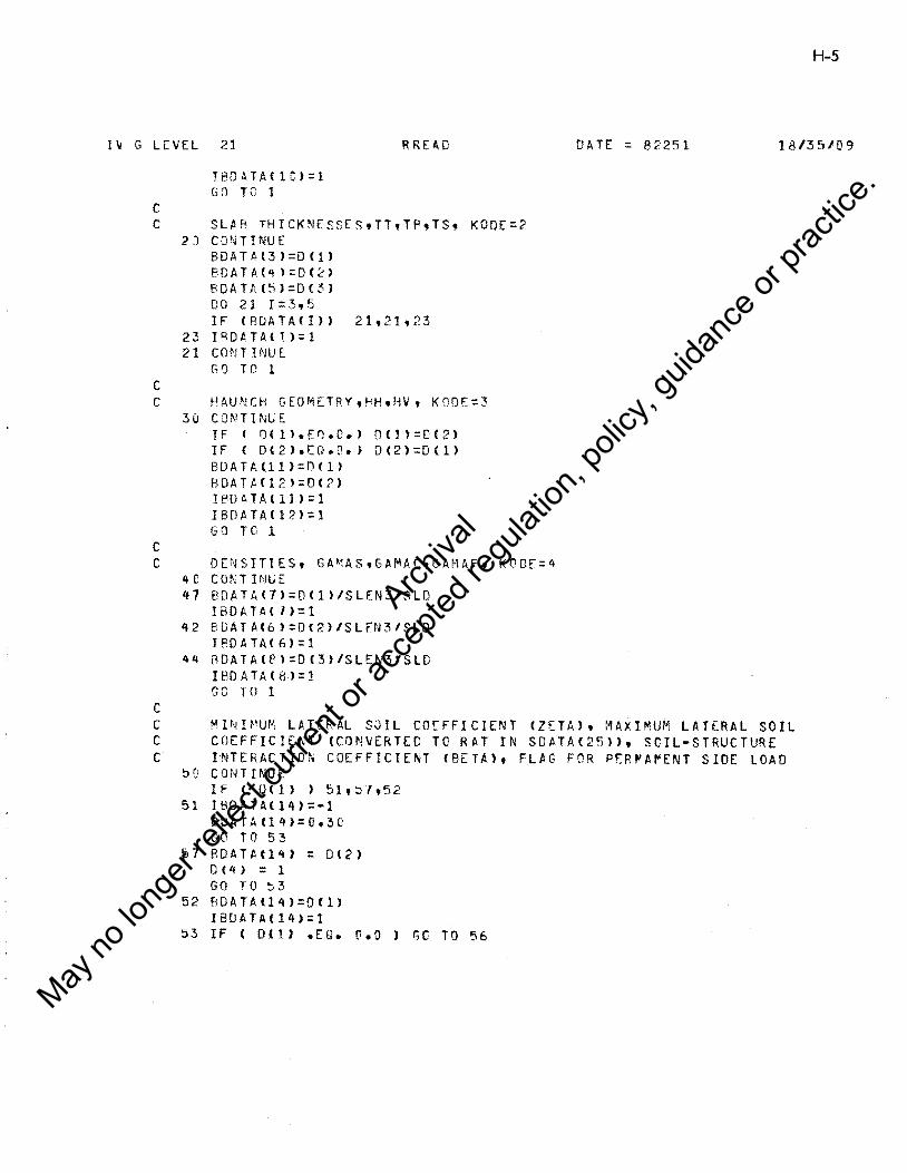
H-5
11.J G LEVEL 21 RREAD DATE = 82251 18135/09
c
TBOATA<lC>=l G:l TO 1
C SLAR THICKNESSEStTTtTFtTSt K0DE=2
c
2 J C 0 ~~TI NU E BOATAt3>=D<1> PDATA(q):QC~>
BDATAC5>=D<3l 00 21 I= 3, 5 IF CBDATA<I>> 21t21t23
23 IRDATAl!l=l 21 COMTHJUE
GO TO 1
C HAUNCH GEOMETRV,HHtHV, KODE=3
c
30 CONTINUE IF < O<ll.E~.e.> 0Cll=D<2> IF < 0(2>.EQ.O.> DC2>=D<l> BDATIH11>=DC1> BOATAC12l=O<?> ! RO AT AC 11 > = 1 IBDATAC12>=1 GO TO 1
C DENSITIES, GA~AS,GAMACtGAMAFt KODE=4
c
4C cm:TINtJE 47 BOATA<7>=D<l>ISLEN3/SLD
IBDATA< l>=l 42 BOATAC6):0c2>1SLEN3/SLD
I 60 AT A< 6 > = 1 44 RDATA<8>=D<3>1SLEN3/SLO
IBO A TAC Bl:: 1 GC TO 1
C MINl~UM LATERAL SOIL COEFFICIENT <ZETA>t MAXIMUM LATERAL SOIL C COEFFICIENT <CONVERTED TO RAT IN SOATA<25>>, SCIL-STRUCTURE C INTERACTION COEFFICIENT <BETA>, FLAG FOR PER~A~ENT SIDE LOAD
51J CONTINUE IF C O<l> > 51,~J,52
51 IBDATA<l4>=-1 RUATAU4>=0.30 GO T 0 5 3
57 BDATAtlq) : D<2> 0(4) = 1 GO TO ~ 3
52 BDATAtl4>=DCl> IBDATA04>=1
53 IF C Dll> .EG. o.o ) GO TO 56
Archiva
l
May no
long
er ref
lect c
urren
t or a
ccep
ted re
gulat
ion, p
olicy
, guid
ance
or pr
actic
e.

H-6
IV G LEVEL 21 HRE AO
c c c
c c
c c
c c
SOATA<25>=0<2>1D<1> - 1.0 56 ISDATA<25> : 1
IF < 0<4>.N~.C.J IPDATAC14>=2 IF c nC3)-.5 > 54,55t55
54 PUATA<l5>=1•2 lPDATA<l5>=·l l'O T 0 1
~5 8DATA<l5>=Dl3> IBO AT A< 15 >: l GO TO 1
LOAD FACTOR, CAPACITY RED. FACTORS
60 ClHHTNUE.
7U
B £l
81
90
92
95
HDATA<22>=!J<l> 80ATAl23J=D<l> BDATAC9>=0<2> 8uATAtl~>=OC3)
IBDATA<22>=1 !BDATA<23>=1 IBDATA<9>=1 TEIDATAC13>=1 GO TO 1
DEPTH OF FLLIIDt CDNTINU E ROATA<lf:J:::Ofll I BO A.TA< 16) : l GO TO .1
KODE::7
MATERIAL STRENf,THSt FY,FCPt CONTINUE IF ( UlI>.Ethr•> GO TC 81 BDATAC20>=D<l> IBDATAt2U>=l IF { D«2>.f.Q.O.J GO TO 1 80ATAC21)::Q(2> IHDATA<21>=1 GO TO 1
CONCRETE COVER t KOOE:t; CGNT INUE DO '15 I=lt 6 IF ( DCI>>95tq5t92 BDATAC29+I>=D<I> IBDATAC29+1>=1 CONT1NtJf. GO TO 1
KOOE=8
DATE :: 82251 18/35/09
KODE=6
Archiva
l
May no
long
er ref
lect c
urren
t or a
ccep
ted re
gulat
ion, p
olicy
, guid
ance
or pr
actic
e.

IV G LEVEL 21 R READ DATE : ~2251
c c c
CRACK FACTOR. KCDE=lO
c
100 CONTINUE RDATA<24>=Df1> IBDATA<24>=1 GO TO 1
C REINFORCING TYPE ANO NUMB[R OF LP.YERS
c
11 0 C 0 N T I l\IU t: 8 DAT A ( 2 c > = 0 C 1 > RnATA«27>=0<2> JBOATAC26>=1 18DATA<27>=1 GO TO l
C WIRE DIAMETERS KOOE=l2
c
120 CONTINUE DO 121 I=3t6 TF COCI•2)) 121•121t122
122 SDATACI>=UfI-2> ISDATACI>=l
121 CUNTI"!UE IF <ISDATAC3> .NE. 1> GO TO 1
ISDATAtl>=l ISOATA<2>=1 SDA TAU> =D Cl> SDATAC2>=Df1> GO T 0 1
C ~IRE SPACING, KCDE=13
c
130 CONTINUE DO 135 I=9tl2 TF CDCI-8>> l35,135tl3~
133 SDATACl>=DtI•BJ ISDATA(l>=t
135 CONT !l\IUE IF <ISDATAC9) eNE. 1J GO TO l ISOATAC7 >=l I SOP.TA ( 8): 1 SDATAC7>=D<l> SOATAtB>=D<U GO T 0 1
C ENO OF DATAt KOOE.Glel3 999 CONTINUE
WRITEfIW,2000> KOOE,CTEXTCI>tl=l 9 5> 994 CONTINUE
H-7
18 /35 /09
Archiva
l
May no
long
er ref
lect c
urren
t or a
ccep
ted re
gulat
ion, p
olicy
, guid
ance
or pr
actic
e.

H-8
IV G LEVE.L 21
ISTf'P=l GO TC 95E
995 ISTOP=2 996 COl\!TINUE
RETUP,"l E. ND
RREAD DATE = 82251 18/3 510'3
Archiva
l
May no
long
er ref
lect c
urren
t or a
ccep
ted re
gulat
ion, p
olicy
, guid
ance
or pr
actic
e.

H-9
IV G LEVEL 21 I ~JI T DATE = 82251 18/35/09
SUPROUTINE rnrr c C THIS Sl'BP.CUTP~E FILLS OUT THE R DATA AMO SDATA A.RRAYS.1.11-ERE C ~fEDEDt IT CALCULATES VALUES FROM INPUT AND INSERTS THEM INTO C THE APFROPRIATE ARRAY. C TNIT ASSIGNS n~~AULT VALUES ON THE FOLLOWJNG BASIS: C IBDATA<•>OR ISDATA<•>=l ·VALUE HAS PEEN INPUT NO VALUE NEEDED C rcDATA<*>Cq JSOATA<•>=S-VALUE HAS ~CT ~EEN INPUT, DEFALLT VALUE C GIVE~ TO RDATAf*) OR SDATA<•>; IROATA(*) OR IPDATAlt) IS THEN C SFT EOUAL TO -1. C TPIS RCUTI~E ALSO CHECKS FOR ERROR CONDITIO~S IN THE INPUT DATA C A~O PRINTS T~E BDATA AND SDATA ARRAYS FOR AN IDBLG VALUE GREATER C TI-' A r,1 ~:.
c c
c
I~TEGER ISCATAC35>tIPDATA<35> CO~MON IIFLACS/ IBDATAtlSDATA CC~MON IRSCALE/ ADATA(35>tSDATAC35> CO~M0N IISCALE/~IT1NOL01IDBUG1IR1IW1ITAPE1IPATH1ICYC1NINT
C0MMGN /IAHRAY/~EMB<4t2>
COMM[N /qARRftY/ FILll6U>1PMEMB<4t25> E~UlVALENCE<l-'tBDATA<l">>
lQUIVALE~CE fPDATA<l>tSPAN>,<BDATAl:?J,RJSE> EQUIVALE~CE<TTtPDATA<3>>t<TBtBDATAC4l>t<TStBDATAt5>>1<HHt
1 BCATAlll>>t<HVtBDATA<l2)) DIME~SIC~ ASSUM~(35>
DIME~SICN SQURCE<8> DATA SOL~CE/4HINPUt4HT t~HNO Vt4HALUEt4HASSUt4HMED 14H Flt
1 4H Ar; I REAL~B SCRIPT<7~>, rTEXT<75> DATA SCRJPT/8HINSIOE s.B~PAN <I~>.eHJNSIDE RtEHISE <IN>.
1 eHTOP SLABt8HlHK (JNJ,iHeOT SLARt8HTHK (IN>.~HS!DE WALt l 8HL T <IN>t8HCONC UNI18HT WT KClt8~SOIL UNI18HT WT KCit 1 8H~LUJG UN18HT ~T KCJ,BHFLEX CAPt8HRED FACT18HBURIAL Dt 1 8HEPTH IN18HHOFdZ HAoRHlJNCH 1Nt81-'VERT HAU.Pt-1\CH INt 1 8HSHEAR CAtA~P RED FR181-'LAT SOILt81-'PRESS CC181-'SOIL-STR1 1 BH TNT COF18HFLUID DEtBHPTH <IN>18H***EMPTY18Ht*******• 1 8HCONCRE.T~t8H E <KS! >18HSTEEL E tBH <KSI) 18HSTEEL ST, 1 8HR <KSI>oRH(OfCRETE18H STR KSI,PHLOAD FAC,8HTOR MtV t 18HLOAU FAC,~~TOR P 18H.Ol CRACtR~K FACTORtBHiii[MPTYt 1 8H*•******t8H# LAYERSt8HOF REINF18HREINFORC1EHING TYPEt 1 8H•••EMPTYt8H********tBH***l~PTYt8H********t8HTOP OUT , l 8HCVR (JN>t8HSIDE our.AH CVR IN t8HBOT OUT 181-lCVR <IN>. 1 8HTOP INS t8HCVk <IN>1PH~OT INS ,eHCVR <IN>1PHSIDE INS, 1 8H CVR IN
DATA TTEXT/8HWIRE DIAt8H OUT T0Pt8HWIRE DIAtBH OUT SDE18HWIRE OIAt 1 8H OUT BOToBHYIRE DIAt8H INS TOP,8HWIRE DIA18H INS BOT,
Archiva
l
May no
long
er ref
lect c
urren
t or a
ccep
ted re
gulat
ion, p
olicy
, guid
ance
or pr
actic
e.

H-10
1V r. l>'VH 21 TUT r) A T E = e 2 2 5 1
c
1 1
t:;H \~IRE 3'-i OUT
C'IAt8H HS SDftl3Hl.IIRE SUE,2HlJTRE SPfltHh 0 L! T
SPA,8H OUT T0Pt8HWIRE SPA, B(')T,8HWIR.E SP .t,,, 8H TMS TOP,
PH WI RE SPllt<\h HS BOT,IH'l..!IRE SPA,8H ms SDf t8t-1 •**EMPTY, 1 AH•~-·~~**tPH**•E~PTY1Rt-*w******tAH•••EMPTYtFH•••~••**t 1 kH•••lMPTYtEH*•***•**tBH•••EMPTYtFH*•******tRH***E~PTYt B~~••*>~**•AMTOP STEEtPHL LTH IN.RHBOT STEEt8HL LTH INt
1 PH~••EMPTY,BH*****r*•tb~***lMPTYt8H****••**tAH•••EMPTYt 1 RH·~·····•·RH•••E~PTYtAH********tBH LAT sc,at-IL RATIO, 1 RH•••EMPTYt2H•~•*****tAH•••EMPTY,FH•*******'EH•••EMPTYt 1 8~r••**~**t8H**TEMPTY,RH********•AHD OUT TCt8HP llN) , J brn: UUT SI,u;n[ <HDt8HD OUT ROt8~'TT <PJhBHC IN TOP, 1 RH <IN> ,eHD IN 80T,RHT <IN> ,AHD IN SIDtPHE <IN> I
!F(HDATA<l>.EO.G> Gf" Tl". lJ!'.1 I~ CCRISEl12 •• LT.2.>.0R.CRISE/12 •• GT.2ry.)) GO TO 102 00 '-' I=lt'+ M ~-'' tH It 1 >: 1
5 >.i~~fHI.2>=I•l r~ [ '' B ( 4 , 2 ) : 1 THICK :FLOAT(IFIX<SPAN/12.+.5>> A3SU''E< 3>=THICK•J • IF t SPAN.~T.R4.) ASSUME<3>=TH[CK Tt-'1CK=ASSUi'EC3) ASSllll'E< 4 >=THICK ASSUf'El ~1 >=THICK ASSU~E(6):0.Rl8~-04
ASSU~E<7>=D.69444444E-04
ASSU~'[(fl):lJ.3617E-J4
ASSLWEC<Jl=0•50 C ASSUME<lD> IS THE DEPTH OF FILL- FATAL ERROR IF OMMITTED
ASSLJ"EC 11) =THICK OSSUMEC 12>=TPICK ASSLJVEC13):G.9 ASSU,AE<l4):Q.25 ASSU~E< 15>=1.2 ASSUll'EC U>=RISE ASSU"">::<20>=65. ASSUME<21> :"i~ ASSUME<22>=1.3 ASSllM>C?:'i>=ASSU~E<22)
AS5UME<24>=1.c ASSUMEC26>=1.'}0 AS'SU"'EC27>=2• ASSU'~E<3D>=1• ASSUME(3l>=l• ASSUll'•<32>=1· ASSUf".[(33):1. ASSU1"'E< 34 >=l •
18135109
Archiva
l
May no
long
er ref
lect c
urren
t or a
ccep
ted re
gulat
ion, p
olicy
, guid
ance
or pr
actic
e.

H-11
lV r; LEVEL 21 INIT [!ATE : 8?251 18/35/09
c
ASSU"'E<35>=1• DO lD I=~h16 IF l!BOATA(l) > 10t9t10
9 IBOATA< I >=·l BDAT A<I > =ASSU1'1E (I>
1 u CO~IT INUE DO 2'} 1=20t24 IF ( IADATACI> 2~tl9t20
1g IflDATACI>=-1 BOAT A(! >=ASSUME<!>
2C CONTINUE 00 22 I=26t27 IF < IBDATA<I> 2?t2lt22
21 IBOATAtn=-1 BDATA(I>=ASSU~EfI>
22 CONTINUE DO 2'+ I=3Gt35
IF CIBDATA<I)) 24t23,24 23 IBDATA<l)=•l
BDATA<I>=ASSUME<I> 24 CONTINUE
BDATAC19>=?9000. BOA1AC18>=<BOATA<6Jt1728000.>••le5•~3.•SQRTCBCATA<21>•1000.>/
1 1 000. IBDATA< 19>=·1 IBDATAC18):•1
C INITIALIZE PMEMB<ItJ) 110 rr. s1
8 0 COl'H INU [ Q1=0. Q2= 0. GO TO 8 2
81 IF <<HH.EQeOa>.OR.CHV.EQ.0.)) GC TC 80 Ql: HHIHV /2 • Q2:H V•T S/HH /2 •
82 Dl=TS+HH+Ql•TT D2=TT+HV+Q2 D3=T8+HV+Q2 D'+=TS+HH+Ql*TB PMEMB<l tl>=D2 PMEMB<2tl>=Dl PMEMBl3tl>=D3 P ME ~fH 4 11> =D't PME MB <1t2) =02 PMEMBC212):D4 PMEMB<3t2>=D3 PMEMB<4t2>=Dl
Archiva
l
May no
long
er ref
lect c
urren
t or a
ccep
ted re
gulat
ion, p
olicy
, guid
ance
or pr
actic
e.

H-12
IV G Lt:..VE.L 21
t-> MC:- ~'. fJ ( l , :-< ) = T T P~C:-Mb(2,3>=TS
PME!~FlC3 ,~)::TB
D'ffMfH4 ,J)=TS 1 ::::5 PM;+TS
G2=RISE+<TT+Tb>/2. PMt:"MP( 1 t'+) ::ql PM[~,R<:?t4>=G2
PMEMF'(3t4)::Q1 Pi"EMR<4,4l:Q2 PMEMe(l,5)::HH+TS/2. PMEMB<2,5>=HV+TT/2. P~E~8(3,5>=HH+TSl2.
PMfVR(4t5>=HV+T8/2a PME~9fl,6>=HH+TSl2.
P~E~P<2•6>=HV+TF/2e
PMfME<3t~>=HH+TSl2.
PMErBC4t6>=HV+TTl2. GQ TO 14'1
lG ~ CONT HiU E wRITF<I•~t9CJ9)
I1"IT [)ATE = 82251
wRITECiw,lQJ(!) FORM~T<' SPAM, W rq T E <I w , 1 (t 1 C > TPA11-:=-1
RISE, A~D DEPTH CF FILL MUST BE GIVEN•'>
GO TO 150 lCl CCJNTI!\UE
S P A M =SP A. N / l 2 • ~lRITE<IW,999i
WRlTEllWtlCQl) SPAN
18/35/09
1201 FORMAT<' PERMITTED RA~GE OF SPANS IS 3 FT TC 2£ FT. SPA~ GIVEN ASlODEC 7~ 1 •,F2C.3> IJRITF<IWtlUH> IPATH=-1 GO Tu 15:
102 CONT If.JUE WRITE <I w t9S9 > RISE =RI SE 112 .. WRITF.<IW,l~D2> RISE
100~ FORMAT(' PERMITTED RA~GE OF RISES IS 2 FT TO 2C FT. RISE GIVEN AS' 1,F2D.3)
l.iRTTE<IlltlOH> IPATH=-1
999 FJRMAT(t ••• INPUT ERROR *~*'> 1010 FORMAT< ' EXECUTIC~ FOR THIS PROBLEM HAS SEEN TERMINATED.•>
GO TO 15G 14 9 CUN T I NU E
B=A~AXl<TTtTBtTS>
Archiva
l
May no
long
er ref
lect c
urren
t or a
ccep
ted re
gulat
ion, p
olicy
, guid
ance
or pr
actic
e.

H-13
1\! G LEVll 21 I~; IT DPf = 82?51 18135/C'?
fl S 3 t. ! '' f < l > = (, • ( ti "' T T ~SSU~f(?l=D.~e•?
ASSu~·i:_::, :~ ):r'. .,(;P•·;:i
A. S S t.t ,, r ( 4 > = ~ • :. I'. ,.. -r T
ASS 11 "E < !:! l = G • C 2,.. TB ASSUME(lt=:.rB•TS orJ ::,i I=7,12 ,~S$11MF< 1>=2 ..
31 CCl',;TINUE DO 3? 1=1'12 IF C ISDATA<I>
32 ISO A TAC 1'=·1 ISGATf1( 1+29>=-l SOATAHl=ASSUVE CI> IF (J .GT .. 6> GO TO 33
34 CONT Ii\iU E A=TT lf {l .Er. 2 .rR. I .EQ.f } A=TS IF CI .Ew. ~ .vR. I .Ea. 5 ) A=TR SDATAl29•1>=A-ROATAC29+l>•SOATACI>I~.
IF <ISOATAII+29) .NE. •1> ISDATACI+29>=1
tF l ISDATA<25) *EQ. O.J G0 TO 994 Gf} TO 9gf,
994 SOATtll25> = ;~.SIRDAH <14> - 1 !SD~TAt2!::>=-l
WPITF<Jw,405~)
4 ~· :i r: FUR"'' AT ( 1111 /, 3 X t 6 q C 1 H *) t I , 3 X t 1 H * , t 7 X t 1 H *,I, 3 X t 1Hwt1 X t l'ALL I~FGRMATIO~ PRESENTED IS FOR REVIEWt APPROVALt INTERPRETATION 2 ~•,1,3x,·~ AND APPLICATION BY A REGISTERED ENGINEER. 1 ,25XtlH•tlt 33x,1H~,~1x,1~~,1,3x,6S<lP•>>
99~ IF l IOBUG-EQ.O> GO TO 9fl \..'RITF<IV,99)
99 FOHMAT<l~l,l//l,T43t'~AP CF RDATA A~D SDATA ARRAYS•,// > wRITE(I;..1 ,3'.'JiJ
3CC1 FORMATc•o·,~10,•PARAMETER•tT28t'OATA'tT37,•SOURCE'tT73, 1 'PARAMATER•,T93, 1 DATA•,T102t'S0URCE' >
DO 'FC 1=1.:'>5 Jr = I " 2 • l KF = I .. 2 IF <IRDATA<I>> 702t 7Clt 700
700 J = 1 IF ClRDATA<I> .fG. 2 > J = 7 G'l T0 7'::3
701 J = 3 GO TC 7S3
702 J = 5 703 IF (!SDATA<I>> 1r&,7~5,7C4
OE BUG
OEE!UG
DEBUG
Archiva
l
May no
long
er ref
lect c
urren
t or a
ccep
ted re
gulat
ion, p
olicy
, guid
ance
or pr
actic
e.

1-1-14
J~ G LEVEL 21
704 N : 1 GO TO 101
705 N : 3 GO TO 7Q7
706 N : 5 707 Jl = J+ 1
l~IT DATE : 82251 18/35109
Nl = N + 1 WRITECJ~,3COE>I•lSCRIPl<M>•K=JF,KFl.BDATA<I>•<SCllRCE<K>•K=J,Jl)t
1 ItCTTEXTCK>tK=JF,KF>tSLATA<I>t<SOURCE<K>tK=NtNl> 3COO FORMAT<' 'tl2t3X,2AB.E12.5t2Xt2A4,T65tl2t3Xt2A8tE12.e,2x.2A4)
9UO CONTINUE DEBUG 9Jl CONTINUE lnC: CO~TINUE
RETURN ENO
Archiva
l
May no
long
er ref
lect c
urren
t or a
ccep
ted re
gulat
ion, p
olicy
, guid
ance
or pr
actic
e.

H-15
I" G LEVEL 21 DESIGN DATE = 82251 18/35/09
SUBROUTINE DESIG~
r C THIS SUPRCLTINl SEQUENTIALLY CALLS OT~ER SUBRCUTI~ES I~ ORDER TO C COMPLFTE THE ANALYSIS ANn DESIGN OF THf ONE CFLL ROX. C A PRINTOUT OF THE x,y. DEFLECTIONS AND ROTATIONS FCR EACH MEMBER C AND LOADING CASE IS AVAILABLE WITH AN IDBUG VALUE GREATER THAN 2. c
c
c
c
c
COMMON/RARRAY/UC12,5>.FIL<lOD>•P~EMRC4,25>
co~~CN/RSCALE/SPAN,RISE,rT,TB,TS,GA~Ac,~AMAS,EA•AF,PDtHtHHtHV,Q,
1 ZETA,BETAtDF,Ql,ECtEStFYtFCPtFL~V,FLN,02t03tNLAY,RTYPE,Q4,Q5, 2 CT<b1,SDATAC35)
C0MMON/ANAL/PC12,5>tSTIFC12t12>tFIXM0(4,5,4),0Mf6),DV<6>,DPf6)t lAS<&>tSi<AT!fl\6)
COMMON IISCALE/NIT,NCLO,IDBUG,IR,IW,ITAPEtIPATH,ICYC,NINT
I CY C=O 1 CONTINUE
DfJ 2 I=lt4 CALL GENJS(l)
2 CONTINUE
CALL GSTIF
CALL GENLD
CALL ~ATMP<STIFt9,Pt ~.u.12>
C (XPAND DlSPLAClMENT MATRIX FOR REACTION COMPONENTS no lD J=lt5 U<12,J>=U<5,J) unn,J>=U<R,J> U<9tJ>=u<7,Jl u ( 7' ,J) = ~. uca,J>=u. U<ll,J>=C•
10 CONTINUE IF <IDBUG.LT.3> GO TO 12 WRITECIWt99>
99 FORMATC•1•,/I/ WRITi:-<IWtlOOO>
1000 FCR~ATC 1 G 1 tT29,•DISPLACE~ENT MATRI~ - INCHES ~~D RADIANS'• 1 .//,T38t'L0AD CASE'•' ,T2,• NODE •,T1s,•1•,T30,•2•,T42,•3•,T54, 2 •4•,T66,•~• >
DO ll J = 1 , 4 JA = J•3-2 J"B = J•3-1 JC : 3*J WRITE<&,1002> JtfU<~A,K>tK=lt5)
WRITE<6tl003) <U<JA,KJ,K:l,5)
Archiva
l
May no
long
er ref
lect c
urren
t or a
ccep
ted re
gulat
ion, p
olicy
, guid
ance
or pr
actic
e.

H-16
l\i G LEVEL 21 DESIGN
c
c
WRITE<6,1JD4> <UCJCtKJtK=lt5> 1~&2 FOR~~T(Ts.r1.11a.•x•.Tt3,5<F1D.4·?~)l
lf.O~ FQRMAT<TlO,•Y•,T13t5CEl0.4,2X>> 1004 FORMAT(TRt 'R0T~tT13t5CE1D.4t2X>J
11 CONTINUE 12 CONTINUE
CALL ENDFO CALL Slf'SPN CALL FM.XMN IF lIPATH .LE. :J) RETURN
CALL DESCK RETURN END
OATE' : ll2251 18/35/09
Archiva
l
May no
long
er ref
lect c
urren
t or a
ccep
ted re
gulat
ion, p
olicy
, guid
ance
or pr
actic
e.

H-17
lV G LEVl:.L 21 GEN.JS DATE = 82251 18/35/09
SUBRCUTl~E GENJS(M) c C GENlRlTES FLEVJBILITY COEFICIENTS FRO• ONE CELL ROX GECMETRY. C FnR ~r~BERS WITH LINEARLY VARYING ~AL~CHES THESE COEFFICIE~TS ~RE
C DETERMINED BY ~U~ERICAL INTEGRATION. c C THE INTEGRATION POI~TS ARE N 0 T AT EOUAL INTERVALS
REAL*4 M1(5Jl.M2(5D>.M3t50>,M4(50>tM5(50ltM6(5CJ REAL•4 INER<4,5r> COMMON /RSCALE/ ROATA<3~>
COMMON IRARRAY/ FILtlfDl,PMEMBC4,25>tXX<5Dt4),INER COMMCN /ISCALE/ N N:5D EQU I IJ ALB CE CED AT A <11 h H H, <B 0 A TA ( 12 > , H V >t < E 0 HA <18 > , EC > DA= P~·1 EM!::' <Mt 1 > OB:::Pf>!E,..B <M•2 > OC:Pr1EN R Hh 3) SP:PMEMB<Mt4) ALA=PMEf'B<M,5) ALR:::PME~8(~1,6)
Xl=ALA Y2=SP-ALR CA:::<OA-OC>IALA CR= CDB-DC> I ALB IF ((HHaEa.o.>.OR.(HV.EQ.O.>> GO TO 5 DXl =ALA I'S. DX2=lSP•ALA-AlB>l39e DX3=ALBl5. GO TO 6
!3 OXl=SP/49. DY2=0Xl OX3=DX1
6 X=-DXl DO 1 0 I: 1, 6 Y=X+DXl D=D A-CA'* X INERCMtI>=D•D•O*fC XXCitM>=X
10 CCNT1NUE DO 11 I =7'45 x:X+DX2 D=OC INERCMtI>=O•D*D*EC XXCI,M>=X
11 C 0 N TI NU t. nn 12 I=46,5t! X=X+OX3 D=DC+CB•CX-X2>
Archiva
l
May no
long
er ref
lect c
urren
t or a
ccep
ted re
gulat
ion, p
olicy
, guid
ance
or pr
actic
e.

H-18
lV v LEVE.L 21
INER<~tll=D•C*D*EC XX(!,M)::)(
12 CONTINUE DO 2': I=ltN X ::XX t I, M > D=SP·X ~ U I> =1 • M 2 l I > =D MS< I > =X M4<I >=D~D M5CI>=D•X ME.<I>=X*X
20 COf\.iTrNUE
GENJS
PME~BCMt7>=TRAP(MltNtSP•M>
PMEMBCMt8>=TRAP<M2,NtSPtMJ PMEM6C~tq>::TRAP<M3~N,SPtM>
PMEMBCM,lD>=TRAP<M~tNtSPt~> PMFMBCM.11>=TRAP(M5,NtSP,M> PMEMECMtl2l=TRAPlM6,NtSPtM> RETURN
ENO
DATE : 82251 18/35/09
Archiva
l
May no
long
er ref
lect c
urren
t or a
ccep
ted re
gulat
ion, p
olicy
, guid
ance
or pr
actic
e.

H-19
IV G LEVEL 21 TRAP OAlE : 82251 18/35109
FUNCTION TRAP<MOMtNtStM> c C USES THE TRAPEZOIDAL RULE ~ITH 50 INTEGRATION POINTS TC OBTAIN C THE FLEXIBILITY COEFFICIENTS c C THIS IS THE 2ND VERSION OF THIS PROGRAM C THE INTEGRATION POINTS ARE N 0 T AT EQUAL I~TERVALS
REAL•4 INER<4,50),MOM<l> COMMON /RARRAYI FLt260>tX<5Dt•>~INER
K:N•l H=SIK TRA P::O. 00 1 I=ltK TRAP=TRAP+<MCM<I>IINER<Mtl>+MOMCI+l>/I~tRCMtI+l>>•
1 CX(l+ltMJ-X(l,M)) 1 CONTINUE
TRAP=0.5tlRAP RETURN END
Archiva
l
May no
long
er ref
lect c
urren
t or a
ccep
ted re
gulat
ion, p
olicy
, guid
ance
or pr
actic
e.

H-20
1\1 G LEVU 21 GSTIF DATE : @22!H .18135/09
sueROUTINE GSTIF c C GENERATES STIFFNESS MATRIX C FLEXIBILITY COEFFICIENTS ARE INVERTED AND ASSEMELEO TO OBTAIN C STIFF~ESS ~ATRIX
c c
c
COMMOW/RSCALE/SPANtRISE,TTtTBtTStGAMAC,GAHAS,GAMAF~PO.HeHHtHVtGt 1 lETA,BETAtOF,~1,ECtES,FY,FCPtfLMVtFLNtQ2,Q3,NLAYtRTYPEtG4tG5t 2 CT(6),SDATA<35> COMMGN/RARRAYIUC12t~>tW1(4,5),W2C4t5>tA(4t5>,e<~t5>tC<4t5>t
1 PMEMB(4,25>tX(50t4> COMMON /INAL/FlllbU) tSTIFC12tl2J COMMON IISCALE/NITtNOLDtIDBUG,IRtIW,ITAPEtlPAT~,ICYCtNINT OIME~SION F(3t3>tAKC3t3>tUN(3,3>
DO 8 I=1t12 D 0 8 J: 1t12
8 STIFCI,J>=O• DC lD I=l,4
C GENERATE SCRIPT F DO 6 J:2,3 F(J,l):Q, F(l,J): ·J. AK<l,J):::(.\• AKfJtl>=C•
6 CuNTINUt. F<3,~>=PME~A<J,7)
F<2t3>=FME~R<It8>
Ff?t2>=PMEMB<Itl~> F<3,2>=Ff2t3> OC=PMEM8Cit31•12. SP:Pf<!EM F CI,,.> F<l•l>=SP/DC/EC
C INVERT F TO GEr AK DELTA=F<2t2>•F(3,3> •FC2t3>•F<3t2> AKCltl>=lalffltl> A~C2t2>=FC3,3>1DELTA AKlj9j):F(2t2>1DELTA AKf2,3>=·Ff2,3>IOELTA AKC5t2>=AK<2,~1
CALL ASSEM<ItAKJ lD CONTINUE
c C REMOVE REACT!UN COMPONENTS
00 12 J=lt12 STIF<7,J):::STIFC9tJ> STI~<BtJ>=STI~<lOtJ>
Archiva
l
May no
long
er ref
lect c
urren
t or a
ccep
ted re
gulat
ion, p
olicy
, guid
ance
or pr
actic
e.

IV G LEVEL 21
STIFt9,~)::STIF<l2tJ>
12 COMT TNUE DO 13 l=lt12 STIFlit7>=STIFtI,9> STIF<ItR>=STIF,I,10> STIFtI,q):STIFflt12>
13 CUN TINU £
GST IF
CALL CROUT<STIFt9•12> RETURN n10
H-21
O.HE :: e '251 18135/09
Archiva
l
May no
long
er ref
lect c
urren
t or a
ccep
ted re
gulat
ion, p
olicy
, guid
ance
or pr
actic
e.

H-22
IV G LEVt..L 21 ASSElll DATE :: 82251 18135/09
SUBR0UTINE ISSE~<MtAK>
c C ASSEMBLES THE MEMBER STIFFNESS MATRICES INTO A GLOBAL STIFFNESS C f'l.ATFdX c c
REAL~4 ~AAf4,3,3>,KA8(4t3t3>,KBAC4,3,3>t~A8l4t3t3)
COMMrN IRARRAYIFILtl6QJ,PMEMB<4t25),FIL1<40Cl,KAAtKAPtKBAtKBB COM~CN /IARRAY/MEMBC4,2) COM~ N IISCALf/NITtNOLDtIOPUGtIRtIWtITAPEtIPATHtlCYCtNINT COHMCN l•NAL/ FIL2C6C) ,STIF<12t12> DIM~~SIO~ D<3t3>tAK<3t31
J TA:: I~ EM P CM , 1 ) ,JTB::W[1'!0(M,2> SP=PME~B<M,4>
IRAA=3• <JT A-1 > IRBB=3* < JT A-1>
c ...... FORM KBA DO 1 I=lt3 0 0 1 J:1,3
c
1 Q(l,J)::•AKCI,J> DO 11 I=lt3
11 n(J,3)::C(J,3)+SP•n<I.2> 00 26 I=lt3 DO 2f. J::l,3
26 KBAC~,I,J>=DCI,Jl TF C M.N[.ll CALL ROTS<~tD>
DO 'l I::l,3 !ROW=IRAA+I 00 R J: lt3 ICOL=IRBB+J
8 STIF<ICCLtIRC~>=STIF<ICOL,IROW>+C(utI>
c ...... FORM KAe 00 3 1:1,3 DO 3 J=lt3
c
3 O<I,J>=KBACMtJtl> DO 13 I=lt3 DC 13 ,J:l,3
13 KA?C~tltJ>:DfitJ> IF ( M.NE,.l> CALL ROTSCM~O> DO 6 1::1,3 IROW=IRAA+I DO 6 J=lt3 I COL =IR E!B+J
6 STIFllROWt!COL>=STIFCIRCYtlCOL>+OlitJ>
Archiva
l
May no
long
er ref
lect c
urren
t or a
ccep
ted re
gulat
ion, p
olicy
, guid
ance
or pr
actic
e.

IV G LEVEL 21 ASSEI"'
C ••.••FORM KB B DO 5 I=l•3 00 5 J=l,3
c
5 D<I•J>: AKCitJ> DO 23 I=lt3 00 23 J=l·3
23 KBB(MtltJ):D(J,J) IF < M.NE.t> CALL ROTS<~tD> DO 4 I=lt3 IROW=IRBB+I DO 'I J=lt3 I COL =IR flR+J
4 STIFCIROWtlCOL):STIFCIROWtICOL)+O<ItJ>
C •••••FORM KA A flO 7 1:1,3
c
DO 7 J=lt-' 7 ocI,J>= AKf ItJ>
DO 17 l=lt3 17 D<I,3>=D<It3>+SP•DCit2>
DO 27 J=lt3 27 0(3,J>=DC3tJ>+SP•DC2tJ>
00 30 I=lt3 DO 30 J:l,3
30 KAAIMtltJ>=D<ItJ> IF C M.~E.ll CALL ROTSC~tD>
DO 2 !=1•3 IROw:IRAA+I DO 2 J: 1 t3 I COL =IR A A+J
2 SlIF<IROWtICOL>=STIF<IROWtlCOL>+D<ItJ>
DATE = 82251
c ••••• MEM8ER ~ATRJCES ARE NOW IN THE GLCBAL STIFF~ESS MATRIX c
RETUHN ENO
H-23
18/3 5109
Archiva
l
May no
long
er ref
lect c
urren
t or a
ccep
ted re
gulat
ion, p
olicy
, guid
ance
or pr
actic
e.

H-24
1\1 G LEVr.:L 21 ROTS DATE = 82251 18/35/09
SUBRCUTihE RCTS<~tDJ c C CHANGES MEMBER STIFFNESS MATRICES FRC~ LOCAL COORDINATE SYSTEM TO C GLOBAL COORDI~ATE SYSTEM c
OTM~~SION 0(3,3> bO TU Clt2t3t4ltM
l R nu RN 2 F:.l.
GO TO 5 3 D<2,3>=-Dl2t3>
0(3,2>=·0'3,2> GO TO 1
4 i::: ... 1. 5 D<l,3>:F*Df2t3>
0<3tll=F.,.D<3t2) T=D<2t2> 0(2t2>=D<ltl> 0<1,U=T Df2t3l:J. D<3,2>=u. GO T 0 1 ENO
Archiva
l
May no
long
er ref
lect c
urren
t or a
ccep
ted re
gulat
ion, p
olicy
, guid
ance
or pr
actic
e.

IV G LEVEL 21 Cf:\OUT
SUBROUTI~E CROUT<AtNt~F>
c C I~VERTS STIFFNESS ~ATRIX
c DlMU;SIUN A<2> R=A<l> JAA =1 D 0 1 J= 2, ~: JAA=JAA+NF
1 A<JAA> = A<JAA>IB JD : C D Cl 2 J= 2, N Jl=..1-1 JO:JO+NF J B: J +JO CO 3 I=J1N s= '.J • IA= I-NF DO 4 K=ltJl IA = IA+NF KA=JC+K
4 S=S+A<I~>•AC~A> vA=vO+I
3 A <JA>=A <.JA >-S ff ( .J-~; ) 7 '2 '2
7 ~1::>:,J+l
J O:JC
S=v• IO= I O+t>1 F ,JA:J-NF o:J 6 K=l1Jl JA = JA+'.llF KA =K+IO
6 S=A<JA>•A<KA>+S IB=J+ IO
5 A<IA>=<~<IP>-S>IA<JP> 2 CONTJrWE
Rt TL/RN END
H-25
OATE = 82251 18/35/09
Archiva
l
May no
long
er ref
lect c
urren
t or a
ccep
ted re
gulat
ion, p
olicy
, guid
ance
or pr
actic
e.

H-26
l\I G LEVEL 21 GEN LO DATE = 82251 18/35/09
SURRCUTINE ~E~LO
c C GENERATES JOINT LOAD MATRIX c
c
c
FIEAL•4 MOM<:->D> REAL~4 ~LOAD<12,5>
C.OM~CN/RSCALE/SPANtPISEtTTtTBtTS,G~~ACtGAMAStEAMAFtPCtHtHHtHV,Q,
1 ZETA,HETA,DF,Ql,ECtES•FY,FCP,FLMV,FLN,Q2,Q3,NLAYtRTYPE,Q4,Q5, 2 CTCh),SDATAC35) CQMMO~/RARRAY/U(12.5>,Wl<4,5),W2<4t5>,AC4t5>tB<4,5>,C<4t5>t
1 PME~R(4,25J,~C~0,4) CQ~MON IISCALFl~JT,NOLC,IDBLJGeTRtI~,JTAPE,JPAT~,JCYCtNINT
CG~MO~IANALIJLOA0tSTIF<12t12>tF!X~C(4,5,4)
INTEGER*2 I80ATA<35ltISDATA<3~>
COMMON /!FLAGS/ IBOATAtISOATA
00 25'.l I=l,4 DO 250 J=lt5 DO 25\l K=lt4
25C FIXMC<I,J,K>=r. on 2J1 1=1,4 DO 2Cl J=lt5 liiltI,J>=''• l.!2<I,J>=O. ACI,J>=G. p<J,J>=O. C<ltJ>=O.
201 CGNTINUE DO 21~ I=l,12 DO 215 J=lt5
215 JL0AD(I,J>=O. DO 110(, L=lt4 GO TO llDt2~t30t40 ),L
C CONCRfTl DEAD LOAD - LOADING CONDITION 1 10 CONTINUE
G= GA r'. AC* 12 • l.iT=TT•G PS:CTS•PMEMHC2t4>+HH•~V>tG
!.'R=TR•G SP:PMEMB <l t4> WR=WT+IJB+2.•PS/SP PS = PS/2e w=l.IR-wB Wl(l,I>=WT \.11(3,J>:W \.12(1tl>=IJ1 IJ2C3tl>=l.I
Archiva
l
May no
long
er ref
lect c
urren
t or a
ccep
ted re
gulat
ion, p
olicy
, guid
ance
or pr
actic
e.
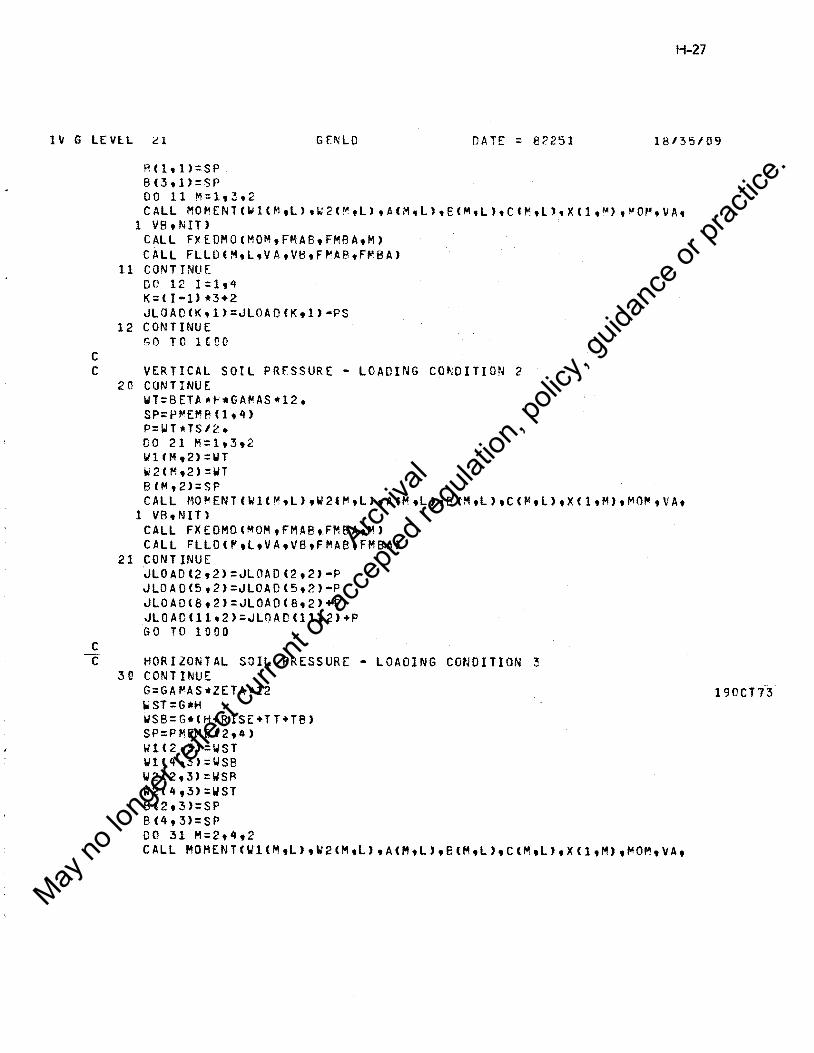
H-27
IV G LEVlL ~l GENLD DATE = 82251 18135/09
c
R<ltl>=SP 8(3,l>::SP 00 11 M=lt3t2 CALL MOMENT<Wl<MtL>.~2f~tL>tA<M,L>tB<M.L>tCCMtL>.X<1,M>.~o~.vA.
I vs.NIT> CALL FYEDMO<MOMtFMABtFMBAtM> CALL FLLO<MtL,VAtVBtF~ABtF~BA>
11 CONTINUE DO 12 I=lt'+ K= <I •I> •3+2 JLOAD<Ktl>=JLOAO<Ktl>•PS
12 CONTINUE GO TO HOO
C VERTICAL SOIL PRESSURE - LOADING CO~DITION 2
c
2 0 CONTINUE WT=BETA•H•GA~AS•12. SP=P~EMRC1t4>
P=WT •TS I '2. • DO 21 M=lt3t2 l./lCMt2>=WT lii2<M,2):1JT B<Mt2>=SP CALL MOMENTfWl<MtL>tW2l~tL1tACMtL1tBCMtL>tC<"•L>tXCltM>tMO",VAt
1 VBtNIT> CALL FXEOMO<MOM,FMABtFMBAtM> CALL FLLOC~tltVAtVBtFMABtFMBA>
21 CONTINUE jLOADl2t2>=JLOAD<2t2>·P JLOAD<5,2>=JLOADC5t2>•P JLOADC8t2>=JLOAOC8t2>+P JLOADlllt2>=JLOADC11t2>+P GO TO 1000
--C- HORIZONTAL SOIL PRESSURE • LOADING CONDITION ~ 30 CONTINUE
G=GA~AS•ZETA1112
WST=G•H WSB=G•tH+RISE+TT+TB> SP:PMEMeC2t41 Wl<2t3>=WST Wlt4t3>:WSB W2C2t3>=WSA W2C4,3):WST BC2t3>=SP 8(4,3>=SP DO 31 M=2t4t2 CALL MOMENT(Wl<MtL>tW2<MtL>tACMtL>tB<MtL1tClMtL>tXC1tM>tMOMtVAt
190CT i3
Archiva
l
May no
long
er ref
lect c
urren
t or a
ccep
ted re
gulat
ion, p
olicy
, guid
ance
or pr
actic
e.
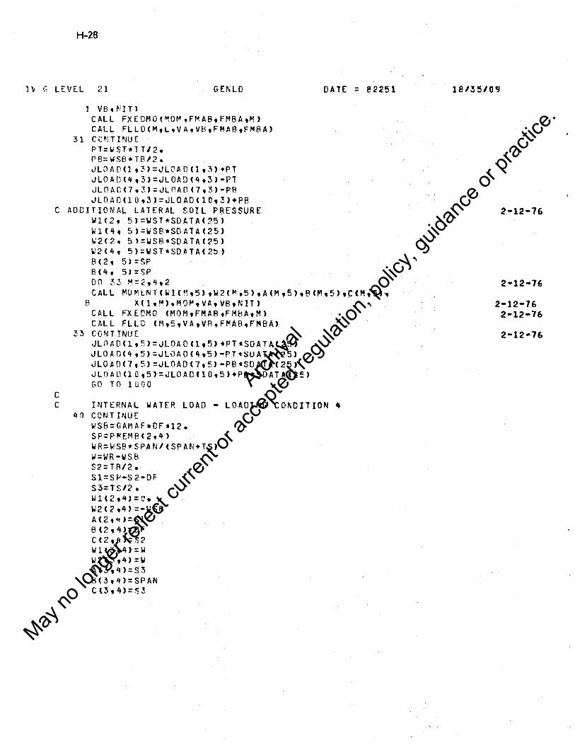
H-28
H G LEVEL 21 GEN LO
l VB, NIT> CALL FXEDMO(MQM,FMABtFMBAtM> CALL FLLO<MtLtVAtVBtFMABtFMBA>
3 1 CC N TI NU E PT:l.JST•TTl2. P8=1o1SB•TRl2. JLOAD<1t3>=JLOAD<1t3>+PT JLOA0<4t3>=JLOA0<4t3>·PT JLOAD(7t3):JLOADf7t3>·PB JLOADC10t3>=JLOADC1Dt3>+PB
C ADDITIONAL LATERAL SOIL PRESSURE w1c2, 5>=WST•SOATA<25> w1C4t 5>=WSB•SOATAC25> W2(2, 5l:WSB•SOATA<25) W2(4, 5):WST•SDATAC2~) B<2t 5):SP BC4t 5>=SP 00 ~3 M=2t4t2
DATE: = 82251
CALL MUMlNTlWlCMt5>tW2{M,5)tAIMt5>tB<Mt5>tCCM~5))
c
B XCltM)tMOMtVAtVBtNIT> CALL FXEDMO CMOMtFMABtFMkAtM) CALL FLLD <Mt5tVA,VR,F~AB,FMBA>
33 COMT INUE JLOADClt5>=JLOAO<lt5>+PTtSOATAC25) JLOAD<4t5):JLOA0<4t5>•PT•SUATAC25> JLOADC7,5>=JLOAD<7t5>•PB•SOATA(25> JLOAO(l0,5>=JLOADf10t5>•PB*SDATAc2e> GO TO l!JQO
C INTERNAL WATER LOAD - LOADING CO~DITION • 40 CONTINUE
WSB:GAMAF•DFtl2. SP=P!lEMP<2,4> WR=WSB*SPAN/(SPAN+TS) IJ=WR•WSEl S2=TRl2. Sl=Sf'•S2•DF S3=TSl2 • Wlt2t'tJ::n. W2<2t4)::•WSB A(2t<t>=Sl Bl2t4>=DF C<2,t+>=S2 1.11(3,4):\,/ W2 0 ,4) ::W AC3,t.i>=S~
8(3,1.f):SPAN C l3, 4)::S3
18/35/09
2-12-76 2•12•76
2-12•76
Archiva
l
May no
long
er ref
lect c
urren
t or a
ccep
ted re
gulat
ion, p
olicy
, guid
ance
or pr
actic
e.

H-29
IV G LEVEL 21 GENLO DATE ::: 82251 18135/09
c
~1< 4 .4> =-wSB W2(lt.4>=a. Al4t4):::.S2 !H4, L;>:DF C<4,4):Sl P=WR .. rs JLOAC< e,4>=JLOADC 8,4)+P JL0AD<llt4):~LOADlllt4>+P 00 41 M=2t4 CALL MOMENT<Wl<M,L>,W2<~tL>•A<MtL>,B<MtL>tClMtL>tXC1,M>tMOMtVA,
1 VBtf'\JT> CALL FXEOMO<~O~.FMAB,FMBAtM> CALL FLLOCMtLtVAtVBtF~ABtF~BA>
41 CONTINUE
1(1 C 0 C t1 NT !NU t' 1010 DO 1003 J=lt5
JLOAOC7tJ>=JLOADl~tJ> JLUADCBtJ>=JLOAD<lOtJ> JLOAOl9,J>=JLOADll2tJ>
1 ii 0 3 C 0 NT INU f. RETURN END
Archiva
l
May no
long
er ref
lect c
urren
t or a
ccep
ted re
gulat
ion, p
olicy
, guid
ance
or pr
actic
e.

H-30
IV G LEVEL 21 MOMENT DATE : 82251
c C GENERATES "E~BER MOMENTS ANO SHEARS c c
REAL~4 MOM(lJ,XCl) CO~MON IISCALEf~ITtNOLDtIOBUG,IRtlWt!TAPEtIPATP
1 CONTINUE IF ( w1.£0.o •• ANO. W2.£Q.O. ) GO TO 101 QM::W2-loll QP:Wl+W2 S=A+R+C
c C COMPUTE 8-RAR,VA,AND VB
IF (Qp) 9tl0t9
c
10 BBAR::B/2. GO TC 1l
9 BBAR=<Wl*B+2.~QMw813.J/QP
11 VA::QP*Bt(8+C-BBARJ/2elS V8:QP•B•<A+8BAR>l2e/S
C GENERATE MO~ENTS
DO 100 I=ltN Y=X (I> IF CY.LE.A> GO TO 3 IF <Y.GE.A+B> GO TO 2 XP=Y -A WX=Wl•)(P+QM•XP*XP/2 .IB XPBAR=lWl•XP+2.~QM•XP•XPl3e/8)/f2.•Wl+QM~XPIB> MOM<I>=VA•Y•WX•rXP•XPBARJ GO TO 100
2 MOMtI>=VB•tS•Y) GO TO 100
3 MOMCIJ:VA•Y 100 CONTINUE
GO TO 110 101 CONTINUE
00 Ui2 I=ltN 102 MO~<I>=O.
VA:O. VB=O•
11 fl CONTINUE RETURN ENO
18135/09
Archiva
l
May no
long
er ref
lect c
urren
t or a
ccep
ted re
gulat
ion, p
olicy
, guid
ance
or pr
actic
e.

IV G LEVEL 21 F XE OMO
SUBRCUTI~E FXED~O(MOM1FMAB1F.~BA1M>
c C GENERATES MEMBER FIXED E~O MOMENT~.
c
DA TE : 82251
COMMON /RARRAY/ FIL<16C>,PMEMBC4t25l, XC50,4) REAL•4 .,4.J5 •• J6,MOMU> Ul M ENS l 0 N A ( 5 0 ) COMMON IISCALE/ NIT DU 1 I=l1NlT A<I>=MOMCI)•XCitM>
1 CONTINUE J4:PMEMBCM•l0) J5=PME.M ti CM t 11) S= PMEMB<M.4> J6=P~EMJ;(M112>
Cl=S•TRAP«A•NlTtStM> DU 2 I= 1 t NIT ACI>=MOM<I>•CS•X<ItM>>
2 CONTINUI:. C2=S•TR~PCAtNITtSt~>
o=-J5•J~+J'+•J& FMAB=C-J5•Cl+J6•C2>10 FMBA=C•J4•Cl+J5•C2>1D RETURN END
H-31
18/35/09
Archiva
l
May no
long
er ref
lect c
urren
t or a
ccep
ted re
gulat
ion, p
olicy
, guid
ance
or pr
actic
e.

H-32
IV G LEVEL 21 FLLD OA. TE : 8 2251 18/35/09
SUBROUTINE FLLDCMtLtVAtVB,FMAB,FMBA> c c C ASSEMBLES ~EMRER FIXED END ~OMENTS A~D S~EARS I~TC JOI~l LCAD ~ATRIXa
c REAL•4 JLOA0(12t5) COMMON/ANAL/JLOADtSTIFC12tl2ltFIXM0<4t5t4l COMMON /RARRAY/ FILt16D>tPMEMBC4·25> COMMON IISCALE/~IT,NOLDtIDBUGt!Rtl~tlTAPEtlPAT~tICYCtNINT DIMENSION ISUB(4,4ltSVl4> DATA ISUBl2t5t3t6t4t7tbt9t8t1lt9tl2t10tltl2t31 DATA SV/•1.,-1.,1.,1.1 V=<FMAB+FMBA>IPME~B<Mt4> IF r IOBUG.LT.3> GO TO 1
1 CONTINUE VA=VA+V Vfl:VB•V FIXMOCMaLtl>=FMAB FIXM0<MtLt2>=FMBA FIXMO<MtLt3>=VA Fl X MO CM t L, 4) =VB 11= I SUR <l t M > 12=lSUBC2,M> I3:ISUB(3,M) I4=ISUB<4tM> S:SV H'D JLOAD<IltL>=JLCAD<IltL>+S•VA JL~AD<l2tLJ=JLOADCI2tL>+S•VB JLOAO<I3tL>=JLOAD<l3tL>-FMAB JLOAD<I4tL>=JLOAD(l4tL>-FMBA RETURtJ ENO
.. ,,,.-~-,.,.---.. ~~ -·
Archiva
l
May no
long
er ref
lect c
urren
t or a
ccep
ted re
gulat
ion, p
olicy
, guid
ance
or pr
actic
e.

lV li LEVt.L 21 MAT MP
c
SURROUTI~E MATMP(A,NtRtM•D,NF) OIME~SIUN A<2),BC2),0(2l
H-33
DATE = 82251 18/35/09
C MULTIPLifS INVERTED STIFFNESS MATRIX BY LOAD MATRIX TO GET DISPLACEMENTS C FOR EACH LUAD CONDITION. c C DOUBLE PRECISION AtBtCtD1S
C=ACl> J8=1~NF
DO 1(1 J:l,M JB=J!:l+NF
l!l Q(J~>=BCJR}/C I A:: l no 21 1=2,N 11::1-1 IA=IA+l+NF C=A4IA> JB:::-NF 00 <:l J::l tM S=O• JA:: l-NF ,JB=-.lB+NF 00 2c K=hII JA :: JA+~lF
KB=K+JB 22 S::S+A(JAJ•Df~B)
JB:. I +JB 21 OCIR>=<B<IBJ•S>IC
DO 1 ~O ! =2 ,N JP::N+l-I !Pl =IP+ 1 IA=< TP-1 >*Nf+IP IH=-NF DO ll'O J=ltM S=O. IR=IB+NF KA=IA DO l!l2 K=IPI.N K A:;:KA+NF KB=K+IB
l02 S=S+AlKA>*D<KB> KB=IP+IB
100 D<KB>=D<KB>-S RETURN ENO
Archiva
l
May no
long
er ref
lect c
urren
t or a
ccep
ted re
gulat
ion, p
olicy
, guid
ance
or pr
actic
e.

H-34
lV G LEVEL 21 DATE = 82251 18/35/09
SU8f('\UT If\E El\OFfJ c C DETERMINES MEMPER END FORCES PRINTS MEMBER ENO FORCES TABLE C FOR !DBUG EQUAL TJ 3 c
REAL•4 ~LCA0(12,5>
REAL INERl4,5a>,KAA(4,3,3),~ABl4,3,3>tKBA(4,3,31,~BB<4t3t3>
c C REAL SCALAR Cv~MON
c
COMMDN/RSCALEISPAN,RISE,TT,TP,TStGAMAC.GAMASeGAMAFtPDtH•HH,HVtQ• 1 ZETA,BElA,OF,Q1,EC,ES,FY,FCPtFLMV,FLN,Q2,Q3,NLAY,RTYPE,Q4,Q5, 2 CT<E>tSOATAl35)
C REAL CO~MON ARRAYS
c
c c
CU~MON/RARRAY!UC12,5>tWlC4,~1tW2<4t5>tA(q,5)tB<4t5>tCl4t5>t
1 PMEMB<4•25J,Xl50t4J C 0 MM 0 NIP ARR A Y II '•'ER tr A A , KA 8 , KB At K 8 8 COMMON /ANAL/ JLOAD tSTIFC12t12>tFIXMOC4t5t4>
CUMMON/HARRAY/AMOM<2n,51,vc20,5),p(3,5),FXLA(4,5>,FYLA(4,5) 1 ,BMA<4,5),FXLB<q,5),FYLA<4,5>tBMB<4,5J,ENOM<2Dt51tENDVC20t5Jt 2 GRM1C2tJ,~RV1C20>,GRF1<3>,GRV2NGC2C>tGRN2NG<2C>tGRV2PLf20J 3 tGRM2PL<2JJ,GRP2PLC3),GRP2NG<3>tFPMIN(3),FVMINf20)tFMMIN(2D>t 4 FPMAX<3>tFVMAX<2DJ,FMMAY<2D>tZMOMT,ZMOMBtXLC20)
C INTE~EK SCALAR COMMON
c c
c
CO~MON IISCALEl~ITtNOLDtIDPUGtIRtIW,ITAPEtIPAlftICYC,NINT
I~TEGER CO~MON ARRAYS COMMON /IARRAY/MEMBC4,2J
C SCRATCH OIME~SION Of3t3>tUA<3>tUB<3>tFB<3> IF < ID8UG .GE. 3 > WRITECIWtlG99)
1~99 FORMATl'l'tT5ry,•END FORCES• KIPS AND INCH-KIPS•,/ 1 T43,•A-END'tT93,•e-E~o·,1,14x~·LOAo•,~x. 1 •FXLA'tllXt•FYLA't 1 11x.•RMA•,11x,•FXLB•.11x,•FYLe•.11x,•8~B'tltl4X,•~ASE•,ex. 2 ' FX •,91,• FY •,9x,•MOMENT•,1sx,• FX •,9x,• Fy •,9x, 3 •MOMEr~T•
0 0 1 M: 1, 4 00 1 N= 1t5 F XL A ( 1'•1, N >: 0 • 0 FYLI\ CM,N):(),.(1 FXLB(Mt!IJ>=o.o FYLB<MtN>=O.~'
BMACMtl'.>=o.o
COMMON
Archiva
l
May no
long
er ref
lect c
urren
t or a
ccep
ted re
gulat
ion, p
olicy
, guid
ance
or pr
actic
e.

IV fl LEVEL 21
BMBCMtN>=o.o 1 CONTINUE
DU 100 11=lt4 JTA = MEMB<M,1) JTA = MEMl3CMt2> I< = 3•(JTA•U+l L = 3•<JTB .. 1>+1 DO 5 N=l•5
ENDFC
GO TO <l~tlltl2tl3>tM lU UACl> : IJtK.N>
UAC2> : UCK+l,N) UA(3) : UfK+2•N> UB(lJ = UCLtN> U8(2> : U<L+1•N> UBl3> : U&L+2tN1 GO TO 14
11 UA<l> =•U<K+ltN> lJAC2> : U<K,N> UAC3>: U<K+2,N> UBCl> =•U<L+l•N> UBC2> : U<LtN> U8(3) = U<L+:>,N> GO T 0 1't
12 llACl> = -ucK.~> UA<2> = •UCK+ltN> UA<3> : UCK+2•N> U8Cl1 = •U<LtN> UR(2) = •UCL+ltN> UB<3>: U<L+2,N> .r.o TO 14
l~ UA<l> : UCK+ltN> U AC 2 > : •UC K, N > UA(3) : U(K+2tN> UBCl> : UCL+l.N> Utl(c) = -UCLtN> UBC3) : UCL+2tN>
14 CONTINU£ DO 2 J:le3 00 2 J=lt3
2 D<I•J> = KBArM,I,J> CALL SOLYE<FBtUAtO> 00 3 I=t.3 00 3 J=lt3
3 D<I•J' : KBB<M•ItJ) CALl SOLVECUAtUBtU> DO 4 I=lt3
4 FBCI>: FB<l>+UA<l> c
H-35
DATE. :: 82251 18/35/09
Archiva
l
May no
long
er ref
lect c
urren
t or a
ccep
ted re
gulat
ion, p
olicy
, guid
ance
or pr
actic
e.

H-36
lV G LEVEL 21 E 1\0 FC
c
FXLBlMt~> = FB<lJ FYUHMtN> = F8(2J
BMB<M,l\J = FB<3>
fXLACM.~> :-FB<l> FYLA<M,N> =-FR(2J HMA(~,N> =-FR<2>•PMEMB(Mt4>•FB(3)
!'i CONTINUE l (l 0 c 0 NT mu E c
c
00 2GO M:lt4 DO 25C N=lt5 FYLAfMtNl = FYLA<M,N>+FIYMD<MtNt3J
BMA(M,l\l = BMACMtN>•FIXMOCMtNtl> FYLH<M,N) : FYLB(M,Nl+FIXMOCM,N,4)
BMB<MtN> : BM9CMtNJ+FIXMD<MtNt2>
C DEBUG OUTPUT c
IF< IOBlG .LT. 3 l GO TO 1102
DAT[ = 82251
WRlltCIWtllCC> MtNtFXLA<MtN>tFYLAl~tN)tBMA<MtN>tFXLB(MtN>t 1 FYLB<MtNltBMB<MtN>
llDO FORMAT(• MEMBfR't2I5t~Fl5,5t5Xt3Fl5e5l
11Ci2 CONT rNUE c 250 2·00
CONTINUE CONTINUE R ETUR~J END
18/35/0CJ
Archiva
l
May no
long
er ref
lect c
urren
t or a
ccep
ted re
gulat
ion, p
olicy
, guid
ance
or pr
actic
e.

1\1 G LEVEL 21 SOL VE
SUBROUTINE SOLVE<DUtDFtA~) c C MULTIPLIES 3X3 MATRIX BY 3Xl ~ATRIX. c
DIMENSIU~ DU<3>,DF<3JtAKC3t3> DO 1 I=1t3 DU<I>=O. DC l K=l,3
1 DU<I>=DU<T>+AKfltK)*DF<K> RETURN um
H-37
DATE = ll2251 181351013
Archiva
l
May no
long
er ref
lect c
urren
t or a
ccep
ted re
gulat
ion, p
olicy
, guid
ance
or pr
actic
e.

H-38
1\i G LEVEL 21 SI~SPM DATE = 82251 18/35/09
SUBR0UTINE SI~SPN c C GIVEN THE ME~BER END FORCES AND THE LOADING VALUES C THE SERVICE LOAD FORCES AP[ CALCULATED AT THE CRITICAL DESIGN SECTIONS c c
c
c
c
c
c
c
c
c
COMMCN/RSCALEISPANtRISEtTT,TB,TStGA~AC,GAMAStEA~AFtPLtHt~HtHVt
1 POV t 1 
l \I .G LEVEL 21 S IMSPN
XL(8) =RISEl~.+tTT+TB>l4. XL<9J =a.o
C MEMBER 4 - SIDE ~ALL
XL<lrt> = Xl<E-> XLCll> = XU5>
C BOTTOM SLAB
c
c
D= A~INltSDATAC32>tSOATAC34> > D=O•POV XL<!2>=TS/2.+SPAN-HH XL<13> = XLC12) • D XL<14>=o.u XLt15>=<SPAN+TS)/2•
DO 11 I=lt5 rvn >=o.o TM<I>=O.'l 00 11 J=lt2:<
ENDM<JtI >=Ii.I') ENOVCJ,I>=Q.t' AMOMCJ,I>=r.o VCJtI>=O•C!
11 CO"JTINUE
GO TO (ll'Jt2Dt3L't't0)tlJ C MEMBER 1
10 Il=l 12=3
1'+=4 GO TC 6 0
C ME'~BER 2 2 C I 1= B
l;,>=6 14=5 GO T 0 6 0
C MEMBER 3 30 Il= 15
12=13 I 4: 12 GO T 0 6 C
C ~EM8ER 4
c
4 0 Il= 0 I2=10 14=11
60 CONTINUE
C Il : CENTlR SPAN MOMENT
DATE = 82251
C 12 = PHI*D FROM HAUNCHt SHEAR ANO ~OMENT
H-39
18/35/09
Archiva
l
May no
long
er ref
lect c
urren
t or a
ccep
ted re
gulat
ion, p
olicy
, guid
ance
or pr
actic
e.

H-40
1\/ r- LEVEL 21 Sil'SPN DATE = 82251 18/3510'3.
C 14 ~ TIP OF HAUNCH, SHEAR AND MO~ENT c
IF
1 4~
1
1
1
1 c
c c c
l 46
c c c
1 c
l 2 3
c c c
1 c
DO
IF
HG LDCN:l,5 Il.EQ. C > GO TO 45 ENDM<IltLDCNJ=ENDl'OCeMACMtLOCNJ,BMR<M,LCC~l,XL<Il>t
PME~B(,.,,'4) > CONTINUE END M ( I 2' LDC ~1) = rn D MO (EM A ( M 'L DCN) 'eM B ( M 'L D c N) 'XL (I 2)'
PME~B<Mt4l)
ENDV<12.tor~J=ENDSHR<BMACMtLDCNJ,8MB<M,LDC~>.XL<I2>·
PMEMB<M,4>> ENDM<I4tLDCN>=ENDl'O<RMA<MtLDCN>tBMBCMtLDCN>eXLt14>t
PMEMB<Mt4)J ENDV<I4,LDCN>=ENDSHR<8MA<M,LDCN>tBMB<M,LDCN>tXL<I4>•
PMEMB<Mt4))
IF er-• .EQ. l •AND• LDC~ .GE• 3) GO TO lOU <M .EQ. ? .AND. LOC'-.' ·LT. 3 ) GO TO 1 O!J
IF er .EQ. 3 .AND• LDCN .EQ • 3) GO TO 1(l0 IF O' .[Q. 3 •A NO. LDCN • [Q. 5) GO TO 100 JF 0-' .EQ • 4 •A.ND. LDCN .LT• 3) GO TO ICC
MOMENT FOR CH!TER SPAN POINTS 1. s, 15
IF ( 11 .Ee. 0 > GO TO 46 CALL MOMENT<Wl(M,LOCNJ,W2<M,LOCNJ,A(MeLDC~>,B<M,LOCN),
ClMtLDC~>,XL<Il>tAMOl'<IltLDCN>,DUM,Du~.1> CONTINUE"
~OMENT AT POINTS 3, 6, lOt 13
CALL MnMENTC~l(M,LOCNJ,W2<MtLOCN>tACMtLDCN>tB<MtLOCN>, C(MtLDCNltXL(J2>tAM0Mfl2tLUCN>tRLtRKtl>
IF <XL<I2> .LE. A<MtLDCN>> V<I£,LOCN>=KL IF <XLCI2> .GT. ACH,LDCN> .A~O. XL<I2> .LT. A<M.LDCN>+
B<MtLDCN» V<I2tLDCN>=RL-Wl<M,LOCN>•<XL<I2>-A<MtLDCN>>·<W2<~tLDCN>
-w1<M,LDCN>>•<XLfI2>·A<M,LDCN>>••212.IBlMtLDCN> TF <XL<I2> .GE. A <MtLDCN>+B<MtLDCN» V<I2tlCCN>=-RR
MOMENT AT THE HAUNCHES; POINTS 4t 5, llt 12
CALL MOMENT<Wl(MaLOCNJ,W2<M,LOCN>tA<M.LDCN>·BlMtLDCN>, ClMtLDCN>tAL(l4>tA~O~Cl4tLDCN>tDUMt0UMtl>
IF <XL(J4) eLEa AC~tLDCN>> V(l4tLDCN>=RL IF <XL(I4> .GT. A<MtLDCN> aAND. XL<I4> .LTa A<MtLDCN>+
Archiva
l
May no
long
er ref
lect c
urren
t or a
ccep
ted re
gulat
ion, p
olicy
, guid
ance
or pr
actic
e.

H-4
l\/ G LEVEt 21 S!ptSPN DATE = 82251 18/35109
c
c c
l B<M•LOC~>> 2 V<14tLOCN>=RL•W1<~,LDCN>•fXLfl4)-ACMtLDCN>)•CW2(M,LOCN>
3 -WlCMtLDCl>>•fXLf14)•AlMtLOCN>)*•212./q(~tLDC~>
I~ <XLfI4> .GE. A(~.LDCN>+B(~tLCC~>> V<I4.LDCN>=·RR
100 CONTINUE" 2[
H-42
IV G LEVEL 21 S !1'1 SPN ilAH = 82251 18/35/09
c
c
3?7
c c c
320
CALL MOMENT<~l<~tlCC~>.w2c~,LDCN),AC~tLCCN>tBCMtLDCN>,
1 CCMtLDCN>tXLCJ >t•MO"(J tLDC~J,RL,RRtl>
1 2 3
1
1
IF (XL<J > eLE. ACf'lltLDCN>> VCJ ,LDCN>=RL IF CXL(J .GT. A(M,LDCNJ .AND. XL<J > .LT. ACMtLDCN>+
8CMtLDC!\)) V(J ,LOCN>=RL-WlC~tLDCN>•CXL<J >-ACM,LDC~>>-tW2C~tLDC~>
-Id CM•LDCrJ>> *fXL <J >-Acr--,,LDO!l >*+2/2a/B<M,LDCN> 1F CXLCJ > .r:;E. ll<MtLDC~Jl+EHMtllJCN» VCJ ,LOCN>=·RR
A~OMtJ,LDCN>=AMOMCJtLDCN>+ENDMOCEMAC~tLDCN>tB~BlMtLDCNJtXLfJ),
P~EMR<f.1.,4) > V(J,LCCN>=VlJ,LOCNJ+ENOSHRCBMACMtLDCN>tBM8CMtLDC~>tXLC~Jt
PMEt'-BCM,4> > CONT TNU E IF < M .NE. 1 ) GO TO 34C
BOTTOM SLAB
TF XL<14> .r,[. SPAN+TS/2.-~H > GC TO 340 M:3 J::: 14 GO TO 322
3 4 '.l C ONT I NU E c C FIND LCCATIO~ CF Q ~QMENT IN TCP AND BOTTC~ SLABS c
DMT: DMT + A~0M<J.3>•TAFSfN - 31 + AMOM(l,5) DMR: DMB+AMOMfl5t3>•IABSCN - 3) + A~OM(15t5> lF < CMT .u:. r..c > GO TO 75 ZMOMT = <SPAM + TS>l2.- SQRT<2.•C~T/WT>
75 IF<D~B ·LE· n.a ) GO TO 76 ZMO•B=CSPA~+TS>l2. + SQRT<2•*0~8/W8>
H CONTH~UE
c C FIND WHERE ~/V0=3.D IN THE SIDE WALL c
IF 'AMOMC8tl)+AM0M(8,2)+AMOM(&t3>+A~0~(8t5J .LT. D.O ) 1 GO TO ~U~
0: AMI~l<SDATAC3l>tSOATAC35)) D=D •POV X=TE/2• - HV - D + PMEMBC4t4Jl2GO.C+ RISE L::6 TEMPl =·fAMOMC6.l)+AMOM<6t2>+AMOM<6,3J+AMOMf6t5>>1CV<6tlJ+V(6,2)+
l VC6t3>+V(6,5)) 70 L=L+1
IF ( L .Ea. 8 > L=9 50 CONTINUE
Archiva
l
May no
long
er ref
lect c
urren
t or a
ccep
ted re
gulat
ion, p
olicy
, guid
ance
or pr
actic
e.

IV G LEVE.L 21 SIMSPN DATE ::: 82251
x=x-PMEM8(4,4)/200. T[ll1P:TEMP1
IF < L .EQ. 10> GO TO 50~
IF<L.LE. 8 .AND. X.LE.<RISE+TR>l2.> L=9 IF ex .LT. To/2.+HV+ 0 ) GO TO 490
TV l =O • u TMl=O.O DO 450 K=lt5
H-43
18135109
CALL MOMENT<WlC4,KltW2<4,K>tAf4,K>,Rl4tK>tC<4tK>tXtTMCK>tRL,RK 1 tl>
IF CX eLE. A<4tK» TV<K>::RL IF <X .GT.Ar4,K) .AND. X .LT. A<4tK>+8<4tKJ>
1 TVlK>=RL-Wl<4tK>•<X-AC4tK>>·<W2<4tK>•Wll4tKll*IX•A(4,K>>•*2 2 12e/Bl4,K>
IF <X .r,r. A(4tKJ+B<4,K) > TV<K>=-RR TV<K>=TV<KJ+ENDSHRlBMAt4,K),8MBl4tKltXtP~EMBf4,4))
TMCK):TMlK)+ ENDMOC~MA<4tK>tBMBC4tK>tX,PME~8(4,4)) IF ( I< eEO. 4 ) GO TC 45~
nH:TMl+TM <K> TVl:TVl+TV<K)
450 CONTI "JUE D : SOATAt35J•~OV
IF ( T'41 •LT• 0 • G > G C TC 5 0 TEMPI : 3.0 • ABStTMl/TVl/DJ IF <TEMPl * TEMP .GT. o.o > GO TO 485 IF < ABS<TEMP> .LT. APS<Tf~PU > GO TO 71;
485 DO 475 J=lt5 V<L,J):TV<JJ A.1110M<LtJ>=T~<J>
475 COP-JTI~UE
XL ( L > =X IF <TEMPl • TEMP .GT. O.C > GO TC 5D G 0 TO 70
490 CONTINUE DO 495 l=lt5 VCltI> : O.O AMOMCLtI) = O.O
495 CONTINUE XLCL> = o.o
505 CONTINUE IF f IBl?l:IG ;LT; ~ J r;c TO 506 l.IRITE < IWt509>
509 !=ORMAT tlHf> WRITE tIW,510>
!'.DD FORMAT Cll,T40t•SE'.RVICE MOMENTS ANO SHEARS FOR EACH LUAU '• 1•co~oITION•,1,sx,125<1H->tllt6Xt•OESIGN•.sx.•orsT. FROM•tT35,•MO~E 2~1 n Hl • K f P S IF T J • , T1 0 0 t 'S HE AR < i< I P~ S IF T > ' t I t 5 X t ' S E C TI 0 N ' t 6 X t ' A - END < I N • 3J'tT25t45(1H-Jt17Xt44(1H•)9//9T26,•Lc-1•.6x1•Lc-2•,~x.•Lc-3•,&x,
Archiva
l
May no
long
er ref
lect c
urren
t or a
ccep
ted re
gulat
ion, p
olicy
, guid
ance
or pr
actic
e.

H-44
111 G LEVEL n SI~SP"1 CATE = 82251
q•LC-4't6X,•LC-5'1l6X, 1 Lc-1•,6x,•Lc-2•,6Xt'LC-3'•6X,•LC-4•,6X• 5 1 LC•5'>
DO ":Jn l=ltl5 WPITE<rw.sca> ItXL<I>ttA~OM<L.I>.L=lt5),(V(LtI>tL=lt5>
5~8 FORM/,T (5X,T51F1r.2,5CF1~.2>,1ox,5<F10·2))
5D7 COMTINlJE 5C6 CO..,.TINUE
R ETtJ R~! END
Archiva
l
May no
long
er ref
lect c
urren
t or a
ccep
ted re
gulat
ion, p
olicy
, guid
ance
or pr
actic
e.

H-45
lV G LEVEL 21 DATE = 1:\2251 18/35/09
SUPRCUTT~[ FMXM~
c C DETERMINES T~E fI~IMUM A~D MAXI~UM DESIGN FORCES ANO RESULTING C ULTIMATE FORCES AT THE CRITICAL DESIGN LOCATIONS• c
c
c
c
c
c
c
c
REAL•4 JLOAD!l~o5) REAL~4 INER<4,5r>tKAA(4,3,3l,KAB<4,3,3>tKBA<4t3t3>tK!B<4t3t3)
CO~MONIRSCALE/SPAN,RISEtTTtTBtTStGA~ACtGAMAStGAMAFtPO,Ht~HtHVtDt
1 ZETAtBETAtnF,QltECtEStFY,FCPtFLMVtFLNtQ?tQ3tNLAYtRTYPEt04,Q5t 2 CT<c>tSDATA(35) CO~MGN/RARRAY/Ull2t5ltW1C4t5>tW2l4.5>•A<4t5>,e<4t5>,C<4t5>•
l P~fM8(4t25)tXl5Ct4>
co~~GN/RARRAV/JNERtKAA.KARtKBA,~BB
CC~MC~/ANAL/JLCADtSTIF(12t12>tFIX~OC4t5t4ltDMCf>tDV<6>tDPt6),
1 AS<E>tSRATI0<6>
COMM0N/JSCALEl~ITtNOLDtIDBUGtIRtIWtlTAPEtIPATHtlCYCtNINT
COMM0N/IARRAY/M[M8<4t?>
CUMMCNl~ARRAY/A~OM(20t5ltV<20t5l,P<3t5>,FXLA(4,5)tfYLAC4t5)
1 tBMAC4t5>•FXLB(~,5>tFYLR<4t5>•BM8<4•5>tE~D~<2rt5>tE~OV(20,5)t 2 GRr1c20>,GRV1<?~>tGRP1<!)tGRV2N~<2D>tGRM2NGC2C>tGRV2PL(20> 3 .GR~2PLC2C>tGRP2PLC3)eGRP2NG<3>.FPMINC3ltFVMI~C20>tFMMI~C20>• 4 FP~AX<~J,FVMAXC2D>tF~MAXl20>tZMC~TtZMCMBtXL<20)
CvMMON/IFLAGS/lRDATA<35>tISDATA<35>tICON<6> DIMENSION SIDEC3> DATA SIDE/ 1 TOP•,•SIDE•t•BOT• I
!'I: 3 COEF3=c.o DO 1nu L=l•2"
GtH'l<L>=v.0 ('.:RVlH>=C.D GRM2PL<L>=c.c GRV2PL<L>=:.n GRM2NG <L ):I' ... J GR V 2N r, ( L > = C: .. fl IF <L .. GT. 3> GO Tf\ 1':10 GRPl<L>=o.c GR r 2P L ( L) =I'\. n GRP2NIHL>=IJ.O
lO!i CCll\TI"iUE IF CIBOATAC14) eEQ. 2) GO TO 102
COEF3=1.0
Archiva
l
May no
long
er ref
lect c
urren
t or a
ccep
ted re
gulat
ion, p
olicy
, guid
ance
or pr
actic
e.

H-46
IV G LEVEL 21 DATE = 82251 18135109
c
I 4:::4 1C2 CONTINUE
DO l I = lt 15 GKM1CI>=AMOM<I,ll+A~0Mflt2>+AMOM<It3>•COEF~ ~RV1<I>=V<Itl>+V<!t2>+VCI,3>•CCEF3 00 l K=l4t5
GRM2PL<I>=GRM2PL<I>+<l.+SIGNtletAM0MfltK>>tl2e*AMOM<ItK> GRM2NGCI>=GRM2~G<I>•<1.•SIGN<letAMO~CI,K>>>l2.•AMOM<ItK> GRV2PlCI>=GRV2PL(T)+C1;+SIGN<l.,V<I1K>>>l2.•VfltK> GRV2NGlll=GRV2~G(!)+tle•SlGNtl.,VCitK>>>l2.•V<ItK>
l CONTINUE DO :'i I= lt3
GRPl<I>=PlI,11+Plit2>•Pflt3>•CCEF3 00 3 K=I4t5
GRP2PL<I>=GRP2Pl<I>+tl.+SIGNtl•tP<ItK)))/2e•PCltK> GRP2NG<I>=GRP2NG<I)+(l,•SIGN<l.,PlltK>>>l2e•PCltK>
~ CON TINU£ !JO 5 K=lt15
FVMIN<K>=<GRV1fK>+GRV2NG<K>>•FLMV FMMINCK>=lGRMlCK)+GRM2NGCK>>•FLMV FVMAXfK):CGRVl<K>+GRV2Pl(K>>•FLMV ~MMAX<K>=<GRMl<K>+GRM2PL<K>>•FLMV IF <FMMI~<K> .GT. o.t> FMMIN<K>=o.o IF <FV~IN<K> .GT. o.n> FV~IN(K):O.C
IF <FMMAX<K> .LT. o.o> FMMAX<K>=O·O IF <FVMAYfK) .LT. o.o> FVMAX<K>=D.D IF < K .GT. 3 l GO TO 5 FPMINCK):tGRPl<K>+GRP2NGCK>>•FlN FPMAX<K>=<GRPllK)+GRP2PLfK>>•FLN
5 CONTINUE
C SPECIAL SHEAR DESIGN SECTIONS
c t
DO 2 J = 6t7tl FMMINCJ>:CGRM1CJ> + GRM2PL<Jl)•FLMV
FMMAX(J):(GRM1{j)+GRM2PL<J>>*FL~V If <FHMIN<J> .GT. o.n> FMMINtJ>=D.D IF <FMMAX(J) .LT. o.c> FMMAX(J):Q.D
K : J+3 F~MINtK):CGk~l<K> + GRM2PLtK>>•FL~V
FMMAX<K>=<GRM1(K)+GRM2PL<K>>•FLMV IF <FMMIN<K> .GT. O,Q) FMMINCK>=DeO IF <FMMAXCK> .LT. o.c> FMMAXCK>=C.o
2 CO~HINUE IF < FM!'IINCl) .NE. OeO > GO TO 1'198 IF < FMMINC15>.NE. O.O > GO TO 1498
C DERUG OUTPUT
Archiva
l
May no
long
er ref
lect c
urren
t or a
ccep
ted re
gulat
ion, p
olicy
, guid
ance
or pr
actic
e.

H-47
1\1 G LEVEL 21 FMYMN DATE = 82251 18/35/09
c IFCIDBUG.LT.1> GO TO 1203
1498 CONTINUE WR IT E <I \olt 1 UJl >
1101 FORMAT<'l'tT33t'SERVICE LOAos•,T90,•ULTIMATE LCAOS•,/,T13, 1 56(1H->.T79t34(1H-> •'•' SECTION•,120.•GROUP 1•,T50t 2 'GROUP 2' )
WRITECIWtl103> 1103 FORMAT<T13t•MOMENT•,T25,•SHEAR•.T35,•MPLus•.145,•VPLUS•tT56t
2 'MNEG•.T66,•VNEG'tT79,•FMMAX•,T89t•FVMAX'tT95t'FMMlN'tT109 3 ,•FVMII'>.'> WRITECIWt1102>CitGRMl(I>tGRV1<I>tGRM2PL<I>tG~V2PL<I>tGRM2NG<I>•
1 GRV2NGCI>tFMMAX<I>tFVMAXCI>tFMMIN<I>tFVMINCIJtl=lt15J 1102 FORMATCT4tl2tT1Dt6F10a3tT75•4Fl0,3>
WRITEHw,1105> WRITE<IW,1106) fSIOE<IJ,GRPlfIJ,GRF2PL<I>tGRP2~GCIJtFPMAXlI>t
l FPMIN<I>t I=lt3> IF ( FMMINC1) .NE. o.a GO TO 1500 IF ( FMM!NC15>.NE. o.a GO TC 1501 GO TO 1502
1500 J=l GO TO 1504
1501 J::3 150'+ IPATH :: 0
WRITE<IWt1503> SIOECJ> 1503 FURMATC/llt'ONEGATJVE MOMENT EXISTS IN MIDSPAN OF '•A4t'SLAB•'•'•
1' THE DESIGN SUBROUTINE IS NOT EQUIPPED TO ADEQUATELY•,!, 2 ' HANDLE SUCH A CASE AND THE REINFORCING DESIGN SHOULD'•'• 3 ' BE COMPLETED BY HAND lJSING THE P'O~nns, THRUSTS, AND '•'· 4 ' SHEARS GIVEN ABOVE' >
GO TO 121l3 1502 CONTINUE
ZMOMBC=SPAN+TS-ZMO~R
WRITE<IWt1104) ZMOMT,ZMOMBC ll04 FOR~AT<•O ZERO MOMENT TOP •,F15.5,T5G,•ZERO MO~ENT BCTTOM'tF15.5t/
lt'D INCHES FROM CENTEPLINE OF SIOEWALL'tl/ llt'D**•NOTE: ALL UNITS ARE KIPS AND INCHES'tlt'l'
1105 FORMATC'O MEMBER•tT13.•THRUST•,T35,•NPLus•,T56,•NNEG•, 2 T79t'F~~AX•tT99,•FNM!~'>
1106 FORMATC T3tA4t2XtF10e3tl1XtFl0.3t10Xtfl0.3tlOXt4XtF10,3t 1 lOYtFl0 .. 3>
12fJ3 CONTINUE RETURN ENO
Archiva
l
May no
long
er ref
lect c
urren
t or a
ccep
ted re
gulat
ion, p
olicy
, guid
ance
or pr
actic
e.

H-48
l~ & LEVEL 21 DES CK DATE : 82251 18/35/09
SUBROUTINE DESCK c C CALCULATES THE QUIRED STEEL AREA AT THE FLEXURE DESIGN C LOCATIONS BASED O~ THE FOLLOWING: FLEXURE C MINIMUM STEEL FOR FLEXURE C LIMITING CONCRETE COMPRESSION C 0.01•• CRACK AT SERVICE LOADS C IT CHECKS ~OR DIAGONAL TENSION SHEAR AT THE APPROPRIATE DESIGN C LOCATIONS USlNo METHODS l(AASHTO> AND 2 C A PRINTOUT OF THE FLEXURE DESIGN TABLE, SHEAR DE~IGN TABLE MET~OD l C AND SHEAR DESIGN TABLE METHOD 2 ARE AVAILABLE WITH AN IDBUG VALUE C GREATER THAN l• c
c
c
c
c
c
c
c
c
REAL•4 ~LOAD<12.5>
REAL•4 !NERC4t50>tKAA<4t~t3>,KAB(4,3,3>tKAA<4t3t3>tKP8C4t3t3>
COMMON/RSCALE/SPANtRI~EtTTtTB1TStGAMACtGAMA!1GAMAFtPOF1HtHHtHV1 1 Prv, 1 ZETA,BETAtOF,Ql,EC,ES,FY,FCP,FLMVtFLNtFCRtG3tNLAYtRTYPltQ4tG5t 2 CT<h>tSDATA<35>
COMMGN/RARRAYIU<12t5J,WlC4t5ltW2f415)1A(4t5>1BC415>1CC4t5>t 1 PMEMB<qt2bltXlbGt4> COMMONIRARRAY/I~ERtKAAtKABtKBAtKBB
COMMON/ANAL/JL0AD,STIF<12tl2>,FIXMOC415t4>tOM(6>1DVC6>,DPC6>• l AS<~>,SRATIO(G>
COMMON/JSCALE/NIT1NOLCtIDeUGtIRtIMtITAPEtIPATHtICYCtNINT
CO~MON/IARRAY/MEMB<4t2>
CO~MCN/HARRAY/AMOMl20t5>1VC2Dt5>tP<315>tFXLA<4t5>tFYLAC4,5) l tBMAC4t5>tFXLB<4t5ltFYLBC4t5l,RMBC4,5>tEN0~<20t5>tE~DV<20t5>1
2 GR~ll2D>tG~VlC20>1GRP1<3>tGRV2NGC2D>tGRM2NG<2DJtGRV2PL<20> 3 tGR~2PL<20>,GRP2PL<3>,GRP2NGC3>tFPMINC3>tFVMINC20>,FMMINl2Q), 4 FP~AXC3>,F¥MAX<20)1F~MAXC20>1ZMOMT1ZMOMBtXL<2D>
COMHON/IFLAGS/IRDATA<35>tISDATAC35>tICCN<6>
REAL MUtNUtMOtNOtNLAYtNO INTEGER AASHT0<4>tCHECKC8) DIMENSION INDEXC8>1DSC6>tSIDFC3>,SHC81lO>tPOikTf6),GOVERNC15J,
1 PRINTC18>tZlC4,6>tCRACKC6>1AMIN<6>1AMAXC6),AREAFLC6) DIMENSION INDEX2(8) DATA INDEX 12t4t5tlt9tllt12t14/1SIDE/t IN'•' CUT't
1 'BOTH•/,POINT/•4 •1•5:11•,•12 '•'l '•'15 '•'8 'I 2 1GOVERN/' FL't4HEXUR,4HE t4H MINt4H. ST,4~EEL t4~CRAC•
Archiva
l
May no
long
er ref
lect c
urren
t or a
ccep
ted re
gulat
ion, p
olicy
, guid
ance
or pr
actic
e.

l IJ G LEVEL 21 DES CK
3 4HK Wlt4HDT~ t4HMAX t4HCON ,4HCOMP I DATA INDEX2/2•3t6t7~9tl~t13tl4/
DATE : 82251
DATA AAS~TOl3t&t1Dt13 ltCHECK/30t33,31,35,3l,35,32,34/, 1 YES/t YES•/,NOI' NO • I
c C FIND DESIGN VALUES FOR EACH REINFORCING MEMPER
OC 71 L=l,8 DO 71 M=ltH SH<L,r~>=c.o
11 CCHJTINUE c r.; AS 1
c
OMf 1 J:-FMMH;(4) DPtl>=ABS«FP~T~fl))
D~<2>=AMAXl(•FMMINt5),-FMMINfll>>
DP<2>=A~~CFPMINC2>>
D~C3>=-F~MINC12l
DPC3J:ARS<FPMINt3>>
C AS 2
c
D M < 4 J =FM t1 AX< 1 > 0P<4>=ARSCFP~AX(l>>
c :. s 3
c c
c
c
c
!JMC5):fMMAX<15) OPC5>=AES<FPMAX 0))
AS 4 0Ml6J=FMMAX(8) OP<6>=APS(FPMAXC2))
OS Cl }:Tl D S < 2 >=TS 0S(3)::T8 OS t 4 >=TT D S < 5) ::TR OS<fi>::TS
FYPSI=fY-tlOCO. FCPPSl=FCP•lr:oo. Bl=u,85-0,05•<FCP-q,) IF <Al .GTe 0.85> Bl=0.85 IF <Rl .LT• 0.65) Bl=0.65 no 10 I=lt6 FLAY=o.o COl=O.O
ICON<I>=l
H-49
18/35/09
Archiva
l
May no
long
er ref
lect c
urren
t or a
ccep
ted re
gulat
ion, p
olicy
, guid
ance
or pr
actic
e.

H-50
IVG LEVEL 21 DES CK DATE = R2251 18135/09
c c
c c c
c c c
c
i=1NO STEEL AREA FOR FLEXURE
PHIDF:SOATAC29+IJ•POF El'= 10 .2 •FCPPS I ~LEX =E~•PHIDF•*2 - OP<I>~lOD0.•<2.~PHlOF-DS<I>> •
1 ::>GGO.O•DMH> IF (C"LfX .LT. 1.1.c AS<I> = 1.CE15 IF <FLLX .Gf· n.o> ASCI>=<fO•PHIOF - OPCIJ•lOOO.a -
1 SQRT<EO•cLEXJ > I FYPSI SR A TIO <I >=AS c I > /l 2•IPH1 D F .ll.RE"AFLH>=ASC I>
MINIMUM STEEL AREA FOR FLEXURE
AMl~<I>=~.D24•DS<I>
IF CAS<I>.GT,.1"a".'24*0S(l)) GO TO 2 AS<I>=DS<I>•n.024 SRATJO<l>=ASlIJ/12.IPHIDF J CON <I>= 2
2 AREAMF=6.6E5*8l•FCPPSI*PHIOF/FYPSIICFYPSI+87000e> 1 •(750.~DP<I>IFYPSI>
AM,6.Xf I >=ARF,,•~i= IF (ASCI> .LT. AREA~F> GO TO 3
WRITfC]~,1001> POINTCIJ,CM<I>tDP<I>,AS<I>tAREA~F
10Ul FORMAT<1Xt90C'*'>tlt 1 OESIGN NOT PCSSIBLE AT SECTION '1A4t' DUE• 2t' TO EXCESSIVE CONCRFTE COMPRESSION'/' DM='tF10e3t' IN.KIPS/FT' ~ t5Xt•OP= 'tF1D.3t' KIPS/FT.•,/,T5,•REQUI~EO STEEL AREA : •, 4Fl0e3•' SQ.JN.fFT.•,1cx.•MAXl~UM STEEL AREA = 'tFl0.3t
3
1000
2.0 o a
5 • sn.1N.IFT.•,1,1x,90(•••> ,,,,, ASCI>: l.OE15 SRAT!O<I> = l.OE15 ICMH I> =4
GO TO UI CONTINUE
STEEL AREA BASED ON ~.01 INCH CRACK
K=P.TYPE+Oe5 GO TO <11'.10Gt2000t300\JJ, K c 0=1. 0 R2=(u.e•CT<I>••2•SDATA(6+I)/NLAY>••<l.13.) GO TO 14 0 CCi=l•b B2=1.0 FLAY=CT<I>~·2~soaTA(t+IJ/NLAY
GO TO 140 3000 CC':l.9
Archiva
l
May no
long
er ref
lect c
urren
t or a
ccep
ted re
gulat
ion, p
olicy
, guid
ance
or pr
actic
e.

H-51
IV C:i LEVEL 21 DESCK DATE :: 82251 18/3510':1
B2=<0.5•CTCI>••2•SD~TAC6+l>INLAY>••C1.13.> 14G CNTilllUE
MU=OMCI>/FLMV*lOOO• N~=OPCI)/FLN•Inoo.
E=MO/NO+SDATAf29+I>·DS<I>/2. I~ <El~DATA<29+IJ .LT. le15) GC TC 13 AJ=0.74+0el•EISDATA<29+I> IF CAJ .GT. 0.9 ) AJ:0.9 AP=ls/(1s•AJ•SDATAC29+I)/EJ
7 CONTINUE R2 = CMC + NO•<SDATA<29+I>-DS<T>t~.>>IAJ/AP RI = CO•l2e•DS<I>**2*SQRT<FCPPSI> AREAOl = <R2•R1J•B2/30000.IPHIOFIFCR
IF < C!Jl .EQ. 1 > GO TO 9 IF (FLAY eLT. 3) GO TO 11
C'.ll=l• c I): 1. 9
B2=C0.5•FLAY>••flel3.> ARE!J12=AREA01 GO TO 1
9 IF C ARED12 eGT. AREAOl > AREAOl=ARED12 11 CONTI~UE
CRAC~<I>~AREAOl/ASCI> IF < CRACK<!) .LE. le ) GO TO 13
TCCHdI>=3 AS< I >=AREA!H SRATIOCI>=AS<I>l12e/PHIDF
13 CONTI NUr l c co~;TI~U E
IFCIDBU~.LT.2> GO TO 164 DO 2007 I=lt6 PRINT<3•I•2>: GOVERN<ICONCI>•3•2) PRINT<3•1·1> = GOVERN<ICONCI>•3•1> PRINTl3•1> = GOVERN<ICCN<I>•3>
·2ub7 CONTINUE WRITECIWt2005) <POINTCIJtI=lt6)t(DM<l>tI=lt6>t<DPCI>tl=lt6Jt
1 (SOATAC29+I>tI=lt6lt<AREAFLCl>tI=lt6>tCAHIN<I>tl=lt6>t 2 <AMAX<I>tl=lt6lt<CRACK<IltI=l,6ltCAS<l>tl=ltE>
2005 FORMAT<'0'tT5Ct'**•*** FLEXURE DESIGN TABLE •«****'•'• 1'0REINFORCING'tT28t'AS 8 1 tT52t'AS l'tT73t'AS 2'tT88t'AS 3 1 tT103, 2 'AS 4'tltT43t23f'~'>tl•'OOESIGN SECTI0N'tT29t6fA4tllX>tlt 3 1 DULTIMATE MOMENT'tT2Ct6F15.5tlt' IN,KIPS/FT•,1, 4 •OULTfMATE fHRUST•,t20,~F15.5tlt' KIPS/FT•,/, 5 •ODEPT~ TC STEEL'tT2Ct6Fl5e5tlt' JN.•tlt b •osTEEL ARtASCFLEX>'tT20t6F15.5tlt' SQ.IN~/FT•,1, 7 'OMIN• FLEX STEEL'tT20t6F15.5tlt' SQeJN./FT•,1, 8 ~~~i~. FLE~ $fEEl•tT2Dt6Ft5.51/;• SQ.IN./FT•tlt 9 1 0CRACK INDEX•1T20t6Fl5e5tltlt
Archiva
l
May no
long
er ref
lect c
urren
t or a
ccep
ted re
gulat
ion, p
olicy
, guid
ance
or pr
actic
e.
H-52
IV G LEV'EL 21 DES CK DATE = e2251
c c c
c c c
c
•JGOVERNING STEEL'tT20t6Fl5.5.lt• SQ.IN./FT•,/) WRITE C IWt2J99> <PRI~TCT>tl=ltl8)
2~9g FORMAT<' GOVERNING MODE'tT26t6<3A4t3X>tlt 1 1' 164 CO~lTINUE
IF <A~<2>.~T. AS<3>> GC TO 25 AS<2>=ASC3> I CO ~i ( 2 > = l C 0 N < 3 > SRATI0<2>=SRATI0<3>
25 CONTI!\JUE DO 3~; T=:'it5 AS<I>=ASCI+l> SRATIO<I>=SRATIO<I+l) ICC'iJ<I>=ICOMCl+l)
3C CC~HINUE
DIAGONAL TENSION CHECK
FCP$I=FCPPSI IF < FCPPSI .GT. 7000.> FCPS1=7000.G
AASHTC SHEAR CHECK - METHOD 1
DO &J I=lt4 Nl = 3 Zl<lt5) =NO D = A~IN1<SDATA<CHECK<2•I-ll),SOATA<CHECK<2•I>> > IF (fl'ol~IN<AASHTOlI>>.NE. OeO > GO TO 61 D = SDATACCHECK<2•I>J ~; 1 = 1
61 IF <F~~AX<AASHTO<I>>.NE. O.O J GC TO 62 D = SCATA<CHECK<2*I-l>> ~Jl = 2
6? CONTINUE PHIDV = D• P'JV
VU =A~AXl<FV~AX<AAS~TC<I>>t-FV~I~<AASHTO<I>J>
IF (VU eLTe Oe036 * SQRTCFCPSI> * PHIDV >GO TO 65 WRITE<IWt9501J AASHTOtI>tSIOE<Nl> I SD AT A ( 2 5 +I > = 1 Zl<I,5> =YES
65 COl\JTil\~E
ZlCltl> = VU Zl<It2>= Q.936 * SQRTCFCPSI> * PHIDV ZlCI,3> = Zl<Itl> I Zl<It2J Zl<I,4>= D
60 CONTINUE
DO 432 I=l t5 432 SRATIO<I>=SRATIO<IJ•PCFIPOV
18/35/09
Archiva
l
May no
long
er ref
lect c
urren
t or a
ccep
ted re
gulat
ion, p
olicy
, guid
ance
or pr
actic
e.

IV G LEVEL 21 Ut.SCK DATE = 82251
c
c
CONTPJUE DO 1500 I=l•3 R!-'Ol=SRATI0<2> ~U=A8SIFPMAY<I>>
IF C!•2) 11GG.21QJ,31JO
C TOP SLAB c
c c c
c
110 0 C Cl ~n I NU E
K1=2 RHOl=SRIHJOCl> R HO 2 ::SR A Tl 0 CH DP.'=SDATA(33> DDUT=SDATAC3Cl GO TO 4!HlC
SIDE io!ALL
21 Q :J C O~JT INU E N = 3 K 1 = 6 RH02:SRATIOC5) DPl=SDATAC~5>
DOU T :::SD AT A< 3 l ) GO TO 4JOO
C ROTTnM SLAfi c
c
c
31UD CONTINUE N : 7 !\ 1 = 8 RH02=SR ,aTJO C4) DPl=SDATAC34) OOUT::SOATA<32}
4 ~ 0 0 C 0 N T HW E DO £7130 K=~hl<l
VU=AMAXl<FVMAXtINOEX<K>>1-FV~I~CINDEX<K>>> VU2 = AMAX1CFVMAX<INOEX2<K>>t•FVMINCINOEX2CK>>>
IF < VU .Ea. O.O > GO TO 2500 IF (fM~AXCINDEX<K>>+FMMIN<INDEX<K>> ) sooa, 6000t 7000
5!H:O RHO=RHOl MU=FMMI~<INDE~<K>>
D=GOl! T !\!1=2
H-53
18/35/09
Archiva
l
May no
long
er ref
lect c
urren
t or a
ccep
ted re
gulat
ion, p
olicy
, guid
ance
or pr
actic
e.

H-54
IVG LEVEL 21 DES CK f'ATE : P2251 18/35/09
c
c
c
GODO RHO=AM1Nl(RHOltRH02J HU=FMMAX<TNDEX<K>J D=AMI~lfDJ~,OOUT>
ti 1=3 GO TC AOun
7 0 C R ~l n =RH 0 2 MU=FM~AX<I~D[X(KJ)
D=DIM '.Jl =1
P. or: COl'lTI NUE SHCK~l):ABSCMU/VU/D/PCV>
SHK·2>=VU2 SH(.'<: t.'.'.J =~•U SH<K •4> :fU·ll'l SrHK,!::i):fl
IF ( Rl10 .Gr. 0.02 ) RrO=G.02
IF C FD .GT. 1·25 ) FD:l.25 FN=0.5•NU/VU/6.G+SORTC0.25+fNU/VUl6.DJ••2>
1F(fN.L'•"·75l FN:G.75 AMVC=ABSCMU/VU/D/POV> JF(A~VO.GT.3.C> A~VD=~.U
VC = <l.1+63.~~RHOJ • SQRT<FCPSIJ * POV ~o •12.~FOIFN•
l 4.l<AMVD•l·> IF<VC .GT. 4.~•SQRT<FCPSI>•P)V•12.•D> VC:4.5•SGRTCFCPSiltPOV•12.•D ROT = Vl2•10f~.Q/VC SHCKt6): XL<IND[X(KJJ SHCK.7l:FN SH<K,e>=VC/1000.0 SHfK.'1>:RnT
IF < ROT .Lf. 1.G > G0 TO 25GO ASINC=3.96A•VU2•FN*<A~VD•l.>/FOISQRT<FCPSI>·0·2095•0•PDV
SHfKtH>=ASHJC IF ( ASINC/12.1°CV/O .LT. O.D2 J GO TO 9500
WRITE<IWt95~1> INOEXfK>tSIOEtNl> 9b01 FOR~AT(l/T3n,5u(lH•>tl•T30t'*'•4AXt'*''''T3n,•••t20x.•WARNING'•
1 21Xt'*'tltT3n,•••,qx,•OES1GN NCT POSSIBLE AT SECTION •.12,6x, 2 ·~•.t,T3G,•~'t6Xt•STIRRUPS ARE REQUIRED ON 1 tA4t'SIDE STEEL'• 3 3Xt'*'tltT3Dt5~<'•'> J
ISDATA<l3+!0=1 SHtKtlO> = 1.0E15
GO TO 2500 950C fF ( ~u .LT. n.I) ) GO TO 2no1
IF (1•2> 1~03t1002t1006
Archiva
l
May no
long
er ref
lect c
urren
t or a
ccep
ted re
gulat
ion, p
olicy
, guid
ance
or pr
actic
e.

IV G LEVEL 21 DES CK
c C 80TT0~ SLAB
c
1006 crJNTINU£ JFCASINC .LT. AS(4) > GO TO 2500 ASC4):::ASINC IC0Nf4):'t SRATI0<4>=6SI~C/12.IDIFDV
GO TO 25!1:J
C SIDE wALL
c
1002 CONTINUE IF<ASINC .tr. AS<5>> GO TO 2500 AS<5>=ASINC ICONC5>=4 SRATIG<5>=ASINC/12e/D/PDV GO TO 2500
C TOP SLAB
c
1003 CONTINUE IF<ASINC.LT.AS<3t> GO TO 25~0
AS<3>=ASINC ICON<3>=4 SRATIOC3>=ASINC/l2.ID/POV GO TO 25'hl
2001 CONTINUE IF<l.E0.1> GO Tu 2093 IF<ASINC.LT.AS<2>> GO TO 2500 AS<2>=ASINC ICON<2>=4 SRAT1UC2>=ASINC/12./0/PDV GO TO 2500
2D03 IFCASINCeLT.ASCl>> GO TO 2500 ASCl>=ASINC ICOt:<1>=4 S~ATIOCl)=ASINC/12.IC/FOV
25 0 0 CO~' TT NUE 1500 CONTINUE
c
OATE ::: 82251
SDATA<l9> ::: ZMOMT + TS/2. - CT<l> - SDATA<l>l2. SDATAl2Dl =SPAN • lMCM8 + le5•TS • CT<3> • SOATA<3)12.
c c
IF<IORUG.LT.2> GO TO 174 ~RITE<Iw.2noe> <AASHTC(K)tK=lt4>t<<Zl<ItJ>,I=l.4>,J=lt5J
H-55
18/35/09
2D08 FORMAT<lltT46 9 '•** SHFAR DESIGN TABLE - MET~CD 1 ***'tit 1 'CDESIGN SECTION•,T32t3fl2t24XJtI2tlt' ALL SECTIONS ARE AT D'tl• 2 'FROM THE HAUNCH'tlt'OULTIMATE SHEAR'tT26t4CFlC.3t16X)tlt
Archiva
l
May no
long
er ref
lect c
urren
t or a
ccep
ted re
gulat
ion, p
olicy
, guid
ance
or pr
actic
e.

H-56
1\i G LEVEL 21 DESCK DATE = 82251 le/35/05
3 ' KIPS/FT•,1,•0ALLOWABLE SHEAR'tT26t4CF10t3t16X>tlt ~ ' KIPS/FT•,1,•nnIAGONAL TENSION•,T29t3fF1~.6tlfX>tFl0.6tlt 4 • INDEX LJMIT'tlt'~DEPTH ·TO STEEL•tT28t4<Fl0.5t16X>tlt 5 ' JN.•,J,•Q~TTRRUPS REQUIRFD?•,T31,31A4t22X>tA4 ) WPITE(l~t2GJ6) <INDEXCK>tK=lt 8),CtSH(KtI>tK=lt H>tl=ltlDJ
2t~u Fo~rAT<'~'•/,T4bt•****** SHEAR DESIGN TABLE • ~ETHOD 2 ******'tit l *JDESIGN SECTION'tT26tP<I2tllX>tltltlt 2 •GM/(VjPHJ•O)•,T20,ecF10.3,3X),/,/, 3 '0l'LTI~ATE SHEAP 1 tT2~t8fF1C.3t ~X),J,• 4 '~llLTil"ATE THRUST 1 tT20t8ff10.3,3X>tlt' 5 ·~~TEEL RATIO'tT23tACF10.6t3X),I,
l<IFS/FT 1 tlt KIF~/FT•tlt
6 •OOEPTH T~ STfEL•,r22,ecF1n.5,3x>,1,1x,•1N.•,1, 7 'DOISTPNCE FROM'tT20t8lFl0.3,3X>tlt' A-ENO, IN•'tlt 8 '~THRUST FACTOR CFN>•tT23,8CF1Q.6,3X>,lt q •JD!AGChAL TENSI0~·,120.scFI0.3t3X)tl•' STRE~GTHt KIPS/FT•,1, 1 'DULTIMATE SHEAR/ 'tT23t8CFl0.6t3X>tl•' ALLOWABLE SHEAR•,/, 2 'DNEW STEEL AREA DUE'tT23t8CFl0.6t3X>tlt' TO DIAGONAL TENSION•,/ 3 ' sa.IN •. IFT' )
174 RETUEN El\D
Archiva
l
May no
long
er ref
lect c
urren
t or a
ccep
ted re
gulat
ion, p
olicy
, guid
ance
or pr
actic
e.

OUTPUT DATE : e2251
SUPP0UTI~E SUTPUT c C ORGt~IZES ~~L F~I~lS OUT A ONE CELL BCX DESIGN SU,MAkY SHElr. ~ THE "RI~T ~UT ltCLLJDES THE FOLLOWING: C I~STALLATJO~ DATA C LOAQTNG DATA C MAT[FIAL PROPERTIES c CONt~ETE oeTA C RE!NFORCI~f. STEEL CATA C TrE OlJTPUT IS t.VAIUd3LE WITH ALL IDBUG VALUES• c
c
c
COMMJN llFLIGS/ T~DATA,ISOATA
C (; ~· M'; r-1 I IS C AU flt IT t HH D , ID fW G t I R t I I. , IT APE t IP AT t- , ICY C t NIN T INTfGER ISD,TAC35>,IPCATt<35J COMMCNIRSCALFIBDATA(35>,SDATAt35) REAL JL~ADfl2t5l
C~M~ONlt.~ALluLOADtSTIFC12tl?>,FIXM0<4,5t4>tD~((),DV<E>tDP<6>t 1 AS(~),~RATJ0(~)
E Q U I V t. L l ~; C ~ ( S P A t,: t 8 [') A TA ( 1 ) ) n1"ln:s1on STAP(5,2>tISB<!:i>tnIRRC2> DATA srJRR ,, NG ··'*YES' I CATA I~B/3,l,4,2t51
T:l. l'f.-(lf C:::l <' • D=la72f,Ef-OSPA~=BDATAC1l/C+T
ORISE=8CATA<2>1C+T 0H=PrATA<10}/C+T OGAM:S=POATAf7>•D+T [> 7f T t =!3 0 AT A U 4 > ALPHJ', = <l+SDATA<25»•1'DATAf14) 1= < lPCATAf14).[Q.2> CZFTA=C• or 3P 1=1,5 K=ISPCI l SIAf.lfltl>=>'~(i<l
3 G COf,: TI NU E. STAP<lt?>= STIRR<MAXDCISDATA<l4>•ISCATAC15>tl~CITAC26))+ 1 STAR<2,2>= STAPC1t2> STA8f3t2>= STIRR(MAX~CISDATA<20>tISDATAC21>t!SOATAf29J)+l> STAB(4,2>= STJRRCMAXC<ISDATtC16>tISDATAC19>tISDA1A(27>t
l !SDATAC2A>tISDATA<l7J,JSDATAll8)J+l) STAR<5 9 2>= STARC4t2>
~RITFClWtl> OSPA~tORISE
wRITF<Hl,4) ~·RrTro~,Y7>
WRITECI~t5> ~HtOGAMASt0ZETAtALPHAtBDATA<l5>
H-57
Archiva
l
May no
long
er ref
lect c
urren
t or a
ccep
ted re
gulat
ion, p
olicy
, guid
ance
or pr
actic
e.

H-58
l\I G LEVE.L 21
c \oRITFCil.i•b> '<:RIT"..lIW•97>
0 UT PUT D.ll.TE = 8 2251 18/35/09
WRIT~<IW,7) 8DATA<22J,RCATA€23>tPDATAC9JtBOATAtl3>tBDATAC24) c
c
c
c
c
l.RITE<Iw.2> t,1RITE(l\..lt97) !,.; Kr T F: (! w '3) 8D AT A ( ?(' ) 'e f) A TA ( 21 ) 'p DA TA ( 2 7)
:..RITC'"Cil.tRl WRITUiwt97> i.iRITFU1t1.9>
1 CBDATA<I>tT=3~t35>
i.'RlTl'U<.:tlC> WRTTE<Jw,97J VRITE<IWtlU
C6DATAC!ltl=3t5>tCBDATA<I>tI=lltl2>t
~RITFCIW,121 <CSTA8<I,JltJ=lt2>tI=lt5>
C••••• F 0 R M A T S c
97 FORMAT<T1Dt72<•-•>> c .......
1 FOR~AT<•1•,r1~.F•.1,• FT. SPA~ x •,F4.lt' FT. RISE REINFCRCEC cc~c
lRETE BOX SECTIO~'IT1Dt72C•~•>>
c ••••• • ~ORMAT( /Tl~t'l N S r A L l A T I O N 0 A l A1q
c ••••• 5 ~ORMAT<l12t'HEIGHT OF FILL OVER CULVERTtFT•,r1c,F12.3,1,
1 T12t'U~IT MEIGHTt PCF'tT7CtFl2o3tlt 2 112t'~INIMUM LATERAL SOIL PRESSURE COEFFICIENT'tT7P,Fl2.3tlt 3 T12,•MAXIMUM LATERAL SOIL PRESSURE COEFFICIENT'•T7CtFl2o3tlt 4 T12,·~0!L - STRUCTURE I~TERACTION COEFFICIENT•,r70,F12.3 )
c ...... 6 FORMAT< /TlCt'L 0 A D I N G 0 AT A'>
c ...... 7 FORMAT<T12t 1 LOAO FACTOR - MOMENT ANO SHtAR•,T7CtF12.3,/
1 Tl2t'LCID FACTnR - T~RUST'tT70,F12.3tl•
2 T12t'STRENGTH REDUCTION FACTOR-FLEXURE',T70tF12.3tlt 3 T12t 1 STRENGTH REDUCTION FACTOR-DIAGDNAL TENSION 1 tT70tF12o3tlt 4 T12t•LJMITING CR-CK WlUIH FACTOR 1 tT7D,F12e3>
c ...... ? FORMAT« IT10t'M A T E R I A L P R 0 P E R T I E S')
c ••••• 3 FUR~AT&T12t'STEEL • MI~I~U~ SPECIFIED YIELD STRESSt KSl'tT7Dt
1 F12.3/Tl2t'CC~CRETE - SPECIFIED CO~PRESSIVE STRENGTH, KSl't
Archiva
l
May no
long
er ref
lect c
urren
t or a
ccep
ted re
gulat
ion, p
olicy
, guid
ance
or pr
actic
e.

l\J G LEVE.L 21 OUTPUT tlATE = !l2251
2 T70tF12.3tl• 3 T12t 1 REINFORCT~G TYPE'1T70~F12.3>
c ...... R F-ORMAT< /Tlo.•c c N c R E T E D A T A•>
c ••••• e< FORMAT<
1 Tl2t 1 TOP SLAB THICKNESS, IN. 1 ,T70,F12.3/ 2 112,•BOTTOM SLAR THICKNESSt IN.•·T7D.F12.3/ 3 Tl2t 'SIOt ~ALL JHICK~Ess, IN.•,T70tF12.6t/t 4 T121'HDRIZUNTAL HAUNCH DIMENSION, lNe'1T7DtF12.3/ 5 T12t 1 VERTICAL HAUNCH DIMENSION, 1N.•1T701F12.3tl , 6 T12t 1 CONCRETE COVER CVER STEELt JN. 1 1T10,1. l Tl81'TOP SLAB • OUTSIDE FACE•1T701F12.31/1 9 Tl8t 1SIOE WALL • OUTSIDE FACE'1T701F12.31lt 2 TlBt'BOTTOM SLAB - OUTSIDE FACE'1T7~1Fl2e3 t /1 7 T18t 1 TOP SLAB - INSIDE FACE•tT70tF12.3tlt 8 T18t'BOTTOM SLAB • !~SIDE FACE'tl701F12.31/1 1 Tl81'SIDE WALL - INSIDE FACE'1T701Fl2•3 >
c ••••• 10 FORMAH /Tl!J.'R E I N F 0 R C I N G S T E E L
c •••• ~ 0 A T A'>
H-59
18/35109
11 FORMAT<112135X•'AREA'tl9X·l·T12tl2X,•LOCATTC~·.14x.•sa. IN.•t6Xt l'STTRRUPS'tltT12t34Xt'PER FT•,1x,•REQUTRED?'tltT12t7DflH-> )
c ...... 12 FORMAT< T 12,' TOP SL AB - INSIDE FACE•t
1 6X1F5 •. 3t10X1A4/ 1 Tl 2 t' TOP SLAB - OUTSIDE FACE'• 1 6XtF5e3110XtA4/ 2 Tl 2 t • BOTTOM SLAR - INSIDE FACE•, 3 6X • r=5. 3t10 X t A'+ I 4 T 12, • SIDE l.IALL - 'JUTS IDE FACE't ti 6XtF5e3t10XtA41 6 T12t• SIDf WALL - INSIDE FACE•t 7 6XtF5.3t10XtA'+/ 8 T12t7GP•'»
c ...... 13 FORMAT<T12t' •PROGRAM ASSIGNED VALUE•t/
1 Tl2t•THE SIDE WALL OUTSIDE FACE STEEL IS BENT AT THE CULVERT CORN 2ERS ANO•t T121•EXTENDlO INTO THE OUTSIDE FACE OF THE TOP ANO SOTTO 3M SLABS. THE'/T121 'THEORETICAL CUT•OFF LENGTHS MEASURED FROM•, 4 ' THE eEND POINT ARE'tF5.11/T12t'ANO•,Fs.1,• I~. RESPECTIVELY. '• 6 'ANCHORAGE LENGTHS ~UST BE ADDEO.•>
c ••••• RETURN El\ID
Archiva
l
May no
long
er ref
lect c
urren
t or a
ccep
ted re
gulat
ion, p
olicy
, guid
ance
or pr
actic
e.

Archiva
l
May no
long
er ref
lect c
urren
t or a
ccep
ted re
gulat
ion, p
olicy
, guid
ance
or pr
actic
e.

APPENDIX H - C£HVlER PRCGRAM USTit«iS
Program BOXCAR
Program PIPECAR
H-2 - H-60
H-61 - H-107
H-1
Archiva
l
May no
long
er ref
lect c
urren
t or a
ccep
ted re
gulat
ion, p
olicy
, guid
ance
or pr
actic
e.

Archiva
l
May no
long
er ref
lect c
urren
t or a
ccep
ted re
gulat
ion, p
olicy
, guid
ance
or pr
actic
e.

H-61
lV G LEVEL 21 LlATE = 82251 18/44/55
c c c c c c c c c c c c c c c c
c
RY
PR.OGRA~ 1-'IPECAR
ANALYSIS ANO DFSIGN PROGRAM FOR REINFCRCED CC~CRETE PIPE
SUPMITTED TO FEDERAL HIGHWAY ADMINISTRATION AUGLST 1982 DEVELOPED F~P FHWA PROJECT NO. DOT•FH•l1•9692 SIMPSO~ GUMPERTZ AND HEGER INC. 169& HASSAC~USETTS AVENUE
CAMBRIGE,~ASSACHUSETTS 02138 EXAMPLE STANDARD PLANS FOR IMPROVED INLETS
THIS IS THE MAIN PROGRAM. IT SEQUENTIALLY CALLS THE VARIOUS SUBROUTINES NEEDED TO COMPLETE THE ANALYSIS AND DESIGN OF THE PIPE
COMMON/ISCALf/IDRUGtlPATH COMMON/IFLAG/IBDATA<35) COMMON/PRESS/DLPR(37),0LPT<37>tSLPRC37>tSLPTC37>tFLPRC37>
ltFLPTC31> CUMMON/COUROIX<3l>tYC37>tA(37)tBtBS CO~MON/RSCALE/RDATA(35>
COMMCN/STLAR/AREA1C5>,SRATI0<5>tSGOVC5>tAREADTC5>tSTEXTC5), 1STSPA<5> COMMONIDESIG~/DM<5>tDV<5>tDPC5>tVLCC<5> CO~MCN/PROPISIC37)tCOC37>tALENl37J
COMMCN/CONSTIK1<3t3t3E>tK2<3t3•36>tK12f3t3t36) CO~MCN/LOAD/F1<3t3t36>,F2C3,3t36>
CD~MCN/DISPIU~<3t3t37>
COMMON/PV~/PV~1<3t3t36>tPVM2C3t3t36>
COMMON/REACTIIR<3t3t2> DOURLE PRECISION Kl• K2t K12t Flt F2t PVMlt PV~2 DOUBLE PRECISION UNtR
20CO CONTINUE IPA Hl=ii CALL REAU IF CIPATH .GT.O> GO TC 3000 IF<IPATH .LT. G> GO TC lDOO CALL HJIT IF <IPATH .LT. ~> GO TO 1000 CALL GEOMET CALL LOADS CALL ST I FF CALL LDMATR<OLPRtULPltlJ CALL LOMATR<SLPRtSLPTt2> CALL LOMATR<FLPR,FLPT,3~ CALL RECUR
00030 00020 00040 00050
00070 00080 00090 oc 100 00110 00120 00130 00140 00150
0017( 0018( 00190 0020( 0021( 0022( 0023£ 0024( 0025( 0026( 0027{ 0028( 0029( 00301
Archiva
l
May no
long
er ref
lect c
urren
t or a
ccep
ted re
gulat
ion, p
olicy
, guid
ance
or pr
actic
e.

H-62
IV G LEVEL 21
CALL REt.CT CALL THSH~G
CA.LL PVMMAX CALL OESGN CALL PRit,1T
1 f} G 0 C 0 ~i T I ~w E t;O TO 2L::IJ
3 J G u C o ~n TN U E STOP
M ti I ~J DATE = 82251 18/44/55
00320 ll031C 00330
00350 l'IO:W.6C 00370 00380 ll039C 0(1400
Archiva
l
May no
long
er ref
lect c
urren
t or a
ccep
ted re
gulat
ion, p
olicy
, guid
ance
or pr
actic
e.

H-63
Ill G LEVEL 21 READ DATE = 82251 18/li lf.155
SU% C't!T !NE RUD c C THIS SUBRCUTTN~ READS ALL THE INPUT I~ A SPECIFIED FORMAT AND C TRANSFERS THF DATA INTO THE ROATA ARRAY. THE EXECUTION OF READ C IS CO~TRCLLED BY THE KOOE VARIABLE ON THf INPUT CARU~• A KOOE C GREATER THAN 1? SIGNALS TH~ END OF THE INPUT DATA. READ REPRINTS C THE INPUT CARDS A~ IT READS THEM AS A CHECK FOP THE USER. c
c c c c c c
5
COM•CN/!FLAG/IADATAC35) C0~~8~/RSCALE/8DATA<35)
CO~K0N/ISCALEIID9UG,!PATH DIME~~ION T~XT<~>.Ol~).LAT(l2>,DSCPTR(~)
OAT~ LAT 13,2,1,3,3,1,2,2,3,4,2,31 * ~ x • • • * ~ * * - ~ * • • * • * * TSDATA = VALU~ MQT READ
=+1 VALUf WAS RfAD =·l VftlUE WAS DEFAULTED
WIRE DIAVETERS ARf NOT CEFAULTEO
DO :':· I:I,35 BOAT AU> =O. 0 IPDATA<I)=Q CU!\!TJNUE WRITE C6t99)
(PDATA<I>, I=lt20), IDBUG H2C
c
FUR.~HH lHl) REA0(5,lD20tE~0:993)
~ORVAT C lgAqt A3tll
c c c c c c c
JDBUG CONTROLS PRI~T I DBU G =~------INPUT ARRAY AND TOTAL LOADS ANO FINAL DESIGN
=l------A80VE + RlACTIONS AND DESIGN FORCES =2------ABOVE + GEOMETRYtMOMENTS,THRUSTS A~D SHEARS =3------AeOVE + STIFFNE~S MATRICES ANO JCI~T
DIS Pl ACH'EMTS
3 WRITr CE,1021) (POATA<I>,1=1,20>.IDBUG 1G21 FORMAT tlX,2CA4,!2) 1 READ <5.lDOP> ~ODEt <TEXTlIJ, I:l,5), <D<IJ, I:l,6>
IF C KODl .GT. 12 > GO TO 995 4 K=LAT<KOOE>
GO TO <10t2C,30,40,5D,6C,76,80,9Dtl0Dtl1Ct12D>t KODE c C RADIUSlt RADIUS~, DEPTH 0F FILL c
KODE=l
lC ccrn T mu E JF(Q(2) .EQ. o.r) GO TC 15 WRITEC6,1ro21 K~DEtCTEXT<I>.I=l·=>•<O<JJ,I=l,K) BDATAtl >=D<l>
00440
00480 00491} no 5 o o (.10510
G0530 (•0550 l'.l056l' 00570 00580
00600 OOHO ".'062 IJ 00630 00640
00690 007('0 00710 00720 00730 00740
t:l082( 0085C 0086C C!.l90t
0092(
0093( 00931 0093; 0095!
Archiva
l
May no
long
er ref
lect c
urren
t or a
ccep
ted re
gulat
ion, p
olicy
, guid
ance
or pr
actic
e.

H-64
lV G LEVEL 21 READ DATE = 82251
15
c
BOATAt2 ):0(2) RDATA<3 J:Df3) IBDATAtl):l JRDATAO>=l I 80 AT A ( ~ > :: l GO TO 1 CONT !Nu E ~RITE<6tl301J KOOEtCTEXT<I>tI=lt5>tD<l>tD(3> BUATAU>=O<l>12 BDATA<2>=0Cl)/2 B.DA TA (3 1 :o ( 3) IeOATAt 1>=1 I BO AT At 3 >: 1 t80ATA<2>=-l BUATA<4l=n.noooo1 ROATA<5>::0e000001 I80ATAt4>=-1 TRDATAC5>=•1 GO TO 1
c; litlft KODE=2 c 2->
25
c
CONTINUE ~RITE<6tlDD3> KODFe(TEXT<I>tI=lt5>tf0(1Jtl=ltK> BUAIAf'+J::{J(lJ
BDATA<5>=DC2> IBDATAfl\)::1 TROATH 5)::1 CONTINUE GO T 0 1
C SLAB THICK~ESS KODE=3 c 30 CONTINlJf
~RITE<6tlOD4> KODEt<TEXTCI>tI=lt5>t<DCI>•I=ltK) BDATA<6>=DO> IBDATACF.>>=l GO TC 1
18/4 4 /55
C0960 0097C
00990 010 00 "1001
£11020
Clf!40
DHl70
Cll UO t'llOl 0111 c 0112(1
01150 Ol16C
01180
!J119( 01191 0120( l"l12H 0122(
c c c 41>
BEDDING ANGLEt LOAD ANGLEt SOIL-STRUCTURE INfERACTION COEFFICIENTt KOOE=4
CONTINUE WKITEC6,iOC5> KODEtlTEXT<I>tl=lt5>tCDlI>tI=ltK> BDATAC7>=DU> ll:!DATA<J>:::l BOATAC32>=D<2> I BO AT Al~ 2 >:: l 80ATA<8>=0C3>
0125( Cl125l 0126( n121C
Archiva
l
May no
long
er ref
lect c
urren
t or a
ccep
ted re
gulat
ion, p
olicy
, guid
ance
or pr
actic
e.

IV G LEVEL 21
c
IBDATA<e>=l GG TC l
READ
~ OF SITIEs; GA~ASt GA~Ac, GAMAF c
CDNTINUE
DATE = 82251
KODE=<=i
~RIT~<6,l&Q6) KOCE,<TEXTtI>tI=lt5>,fD<l>tI=ltKJ RDATAC9>=D<l> RDATA<l C'):Qf?)
RDATA<lll=D<3> I:lDATA(9l=l IBD A TA< 1 0 > : 1 IBDATA(ll>=l GO T 0 1
c C FLUID P~RAMETERS c
KODE=6
6i..
c
co~lTPWE
~RIT[CG,1~07> KODE,<TfXT<I>tI=lt5>tCDtI>tl=ltK> BDATA<l2>=0'1l J80ATA(12>=1 GO TC 1
C MATERJAL STRE~GTH; F<Y>,F<CF> KCDE=7
CONT l!\!U;:: WRITFC6,1D~B> KODE,CTEXT<I>tI=1t5>t<OCI>tI=ltKJ I~ CC<l> ,(Q. D.> GO TO 71
71
c
f\OATA<l3>=CC1> l!:!DATA<13>=1 IF CUf2) .EQ. Je> GO TO 1 F<DAT.Hl4>=D<2> IPOATA(llf):l GO TO 1
C CON CR ET E CO V ER c
CCNT mu E.
KODE=8
i.IRI1t.f6,1G09> KllUEtCTEXTCI> tl=lt5Jt<DC T>tI=ltK> ROATA<15>=D<1> HIDATAf15>=1 BDATA<H:.>=D<:>> JeOATAC H>=l GO T0 1
c C LOAD FACTORS, CAP. RED. FACTORS c 9() CONT mu E
1<00£=9
H-65
18/44155
01290 01300
01320
".11330 013;31 01340 0135 0 01360 01370 01380 01390 1'.11400
01420
01430 01431 01440 0145[! 01'160
01480
01490. 01491 01500 01510 01520 01530 01540 01550 !J1560
1)158 0
!'11 !;q[
01591 0160[ 0161ll 016?( 0163( 0164(
01671
Archiva
l
May no
long
er ref
lect c
urren
t or a
ccep
ted re
gulat
ion, p
olicy
, guid
ance
or pr
actic
e.

H-66
IV G LEVU 21 Rf AD OA H: : 82251
(,
~kITE<i,101~> KODE,<TEXT<J> ,I:1,5J,(CtIJ,I=l,K> ROATt.<1 "/l:::[Hl) ::<OATAt2~i>=D<2J
8 DAT A< 3 3 > = [1 C~ > IBDATA<l7):1 Tf3DATA(25J=l 150AlAL~3l=l
G 0 T 0 1
C WIRE DIAMETERS,TYPF,LAYERS c
K0DE=l l'J
1 : ,, !,.,;. i..'
1 5
1 JI
c
CONT mu E WRITE<!: '1011> KOOE, <TEXT<Iltl=1,5>t <D<I> tI=ltlC' 1
IF <fitlJ .;:Q. "•0 >GO T0 lf'~,
ROATAClG)::D(l > I 80 t. TA ( 1 9) :: 1 IF<DC2) .EQ. ~.> GO TO 1"6 FDAT/Jf,P):D<~.)
lBIJATA<2">=1 TF ([(3) .EQ. ~.t> GO TO 117 PDATH21>=1'1CO:J IBDATAt21):1 It- ([~ c 'f > • E Q • ii• n GO T n 1 BDATA<22>=1H4> !BOATA<22l=l r,n TO 1
C WIRE SPflCI !\G KODE=11 c 1H
c
CONTli\IUE WHITEf6tl012> KC~Et<TEXTtl>tI=l,5ltCDfI>tI=1tK> IF (J(l) .Ea. ~.o ) GC TC 115 RDATfl<23J::C~l)
IBDAT~(23):1
I f- < [1 < 2 > • E Q • r, • !2 > G 0 T 0 l P,DATA(24J:::OC2> tRDATAt24>=1 GO TO 1
C DESIGN FACTORS F CR , FR P t F VP K0[l£:::12 c 12t co~:THJUE
WRITE<6t1013> K~DEt<TEXT<I>•I=1t5>tlD<J>,I=ltKl 8DATA<26):0(1) RDAT/!(~•+1.:D<c>
BDATAn'iJ.:[1(3> IHDATA<2f):l IBOATA<34>=1
18144/55
01671 01680
l'.11700
01720
01740
01 750 01751 01760 01770 0178!) n 790 C18 OC 01810 01820 0183( 01840 01850 lJl 860 C!1A70 0188C
01900
(11910 01911 0192C 0193( 01940 0195C Cl 96( 0197( l'.1198(
0201C 02011
Archiva
l
May no
long
er ref
lect c
urren
t or a
ccep
ted re
gulat
ion, p
olicy
, guid
ance
or pr
actic
e.

RE~ D DATE = 82251
TRD AT A. ( 3 5) = 1 Gf) TO 1
c C E~u OF DATft ~CDE AT 12 c
c
CONTPlUE IPAH-=1 iHTF(o,luP.!)
C i=_:R·'lf,T STATE"'E':TS FOR INFUT VALUES c
lLCC FJR~AT cr2, 444, A?t EFlD.3 ) 1~[1 FOR~ATC5Xtl2t~X•5A4,3~t12HINSDOIA~<INJt1Xti=l~.3,
126Xtl2HQPTHFILLIFT>t1XtFl0•3> lcC? FURMAT<~V,I?t3X,~A4t3Ytl2~RADIUS 1<INJ,1XtF10.3t2X,
l12HRfiDIUS 2rIH1.1x.F1r.3,2x.12HOPTHFTLI CFTJt1Y.Fl0.3l 1~~3 FOR~ATt5XtI2t3Xt5A4t3Xt12~H0RIZ C~(JN>tlXtFlo.3,~x.
112HV~RT OSCFD.1XtFlf'a3J l~C4 FOR~AT<~Ytl2t3X,5A4t3X.12HTHICK~ES(JNJtlXtFl0•3> 11 ~ F0RMATC5X,J?a3X,5A4,3X 9 12HRED. ANGL~ tlYtFln.~.2v.
ll2HLGAU ANGLE ,1x,~1l.5t2Kt!?H~L-Sf I~T co,1x,F1D.3 1 [6 FnR•ATC5YtI2,3X,5A4t3Xtl?HSOJL f#/FT3J,1x.F10.3,2x.
lllHCCNC (d/FT3ltlX,Fl0o3t2Xt1~HfLUlVlff/fTj)91XtF10.3) l·"r7 FCRr"ATl:;Y.J.?,,W."il\4.3Xtl2HDPTHFLUCfIMJ,IY,Fl0.3J 1~~8 FORMATC5X,J?,3X,~A4t3X,12HFY CKSI>tlX,FlD.3t2X,
l1?HFCP CKS!hlXtFlS.3> 1 ~9 FOR~ATl~XtI2t~Xt5A4t~~tl2H0UTSDCOVtIN>t1YtF10o3t2Xt
l12HIMSOCOV CJ~J,lXtFlC.3>
1 lC FJRMAT(5Xt12t!~.~A4o3X,'LOAD FACTOR •,1x,F10.3,2x, l'PHI FLEXURE •,1x,Fto.3,2x,•PHI SHEAR •,1x,F10.3>
lJll FQRMATC~x.1?,3Xo5A4t3Yt12HINSI~ WIRDlAtlYtFlJ.~,2x,
112H8UTSO WIRDIA•lXtF1D.3t2Xt12HREI~FG TYPE t1XtF1D.3t2X, 112Hff o~ LAYERS ,1x,F1~.3)
l 12 FUR~AT(SX.12,3x,~A4.~Y,12HIN~IDWIRSPCG,1XtF1D.3t2X,
112~0UT~OWIRSPCGt1XtFl~.3)
1L13 FOR~ATt~XtI2t3Xt5A4t3Xt12HPHI FLEX tlX•FlD.3t2Xt 112HFRP .1x.~1n.~.2x,12HFVP t1XtF10·3>
lul4 FORMAT(l/,35H11 mo OF DATA. EXECUTION TERMINATED ) yc35 CQN11NUt.
RETURM E NU
H-67
lH/4 4 /55
02')80
02100
n211 o 1Jn20 02129
t'.'2131 02132 fl2U3 !'.12134 021.35
02137 02138
12140 82141 0214? 02143 O::> 1 44 C2145 ')2146
C2 l 49 02150 '.'.121 '51 !'.12152 02153
02157 G216 0 02170
Archiva
l
May no
long
er ref
lect c
urren
t or a
ccep
ted re
gulat
ion, p
olicy
, guid
ance
or pr
actic
e.

H-68
IVG LE.VE.L 21 !NIT CATE : 82251 18144/55
SUBROUTINE rnn c c THIS s•mRCUTHll'.: FILLS Ol.;T THE RDATA ARRAY. WHERE !\EEDEDt IT C CALCULATES VALUES FROr INPUT AND INSERTS THEM l~lC THE BDATA C ARRAY. C INIT ASSIGN~ DEFAULT VALUES ON THE FOLLOWING BASIS: C IRDATA<t>=l -VALUE HAS HEEN INPUT, NC VALUE NEECEO c IBDATA(i):".I -VALUE 1-4Vi ~·er 8FTN INPUT.DEFAULT VALUE GIVE!\ C IQ HOATAt•>;IHDATAC*> lS THEN SET EGUAL TO •l C THIS ROUTINE ALSO CHECKS FOR ERROR CC\DITIONS I~ THE I~PUT DATA C ANO PRINTS THf PDATA A~D IBOATA ARRAYS FOR IDBUr VALUE GREATER C THAN C. c c
c
COMMON/RSlALEIBDATA<35> C i.l M MO~J I IS CALF IT n F< 1J r, "I PATH COMM0N/IFLAG/IBDATAC35) Dl~ENSIC\ ASSUME(35>tSCRJPT<2DO> DATA SCRIPTl4HSPR!t4Hf\!G Rt'+H.llOillt'lHS t4HUNh4HCHC\.lt4H~; RAt
14HDIUS,4H t4H<IN),4HHEIG,4HHT Dt4HF Fit4HLL t4H<FT>.4HHORI. 14HZ ~F,4HFSETt4H ,4H(J~J,4HVE?T,4HICALt4H OFFt4HSET t4H<IN>t 14HWALL•4H THlt4HC~NEt4HSS t4HCINlt4HBEDUt4HI~G t4HANGL,4HE t, l4HDEG>t4HSOILt4H-SIR .. 4HUC lt4HNT Ct4HOEFFt4HSCIL,4H LNI,4HT wr. 14HfLF/t4HFT3>,4HCONC,4H l1NJ,4HT WT,4HtLB/t4HFT3)t4HFLUI.,4HD UNt 14HT WTt4HCLBtt4HFT3)t4HOtPT,4HH 0Ft4H FLUt4HlU t4HtlN1t4HTENSt l4HTRGTt4~H ST,4HEELC,4HKSI>,4HCOMP,4HSTRGe4HT~ C.4HONC(,•HKSI>• l4HCOMC,4~0V:0,4HUT St4HltELt4H(IN> .. 4HCO,Ct4~cv:I,4HN STt4HEEL' l4HCIN>·•HLOAD.4H FAC,4HTOR:,4H MOM,4H,SHRt4HLCA0.4H FACt4HTnR:, 14~ THRt4HUST t4HlNSit4~DE Wt4HIRE t4HDlAMt4H(IN>t4HOUTSt4HIDE t 14HWIREt4HOIA~•4HCTN>t4HTYPE•4H OF t4HREINt4HFCRCt4HING t4Hff LA, l4HYtRSt4H ~IRt4HCU~ t4HREI~t4HSPC6t4H INSt4HO Wlt4HRES t4H<IN)t l4HSDCGt4H OUT.4HSD Wt4HIRES•4Ht!N>.4HCAP ,4HRfn ,4HF~CTt4HOR F, 14HL[X ,q~CRACt4HK FAt4HCrOR,4H ,qH t4HMCDLt4HS ELt4HAS:s, 14HTL (,4HKS!>t4HMOOL,4HS Elt4HAS:Ce4HONC<t4HKSI>t4HMEANt4H RADt 14M:SPKt4HGLN ,4H(IN),4MMEANt4H MAOt4H!CRWt4HNIVTt4H<INJ,4HEQIVt l4H CIR,4HC OI,4HAM t4HCTN>e4HLOA0,4H ANf. 9 4HLE .4H <• 14~0EG>,•HCAP t4HRED t4M~ACTt4HOR St4HH£A~t4~R~C t4HTENS,4M PROt 14HC FAt4HCTQR,4HSHrA,4HR PRt4HOCES.,4HS FA,4HCTOR/
D IM nJ SI 0 N S 0 UR C !: Hd DATA SOURCEl•Assu•,•MED ···~o v•,•aLuE•,•INPU•.,•T ,, re::: D PI=3.14159265~5897
C CHECK GEOMETRY OF PIPE
IF <BDATA<l> .GT. BDATA<2>> N:•l IF <BDATA(l) .Ew. G> GU lU 1~0
IF <ABS<BDATAC2+N)/lCSDATA<4>~•2+8DATA<5>••2J•••5+8DATA<l-N>>·l>
Cl2210
C22.60 02270 '.':2280
!'J229!S 0229£ IJ2297 'J229E IJ229'3
02310 !12320 02330 f!2 3 4 0 1123!H i!236C l'.l236 l
0236' '-1237(
02 4 4 {
0246 02471 024 8(
Archiva
l
May no
long
er ref
lect c
urren
t or a
ccep
ted re
gulat
ion, p
olicy
, guid
ance
or pr
actic
e.

IVG LEVEL 21 !NIT DATE : 82251
c c c
c
leGT. G. 005> GO TO 1C3 IF ClBDATACG) .C"U. ~> GO TO 2CG
CHECK REDDING ANGLE
IF IIRDATA<7> .NE. D>.GO TO 22 HUATAf7> :: 0 ·~!,.('
r '30 AT A l 7 ) = · 1
22 IF (~DATA(7}•3C. )300, g4, 94 ~q IF CRDATAC7> - 180.J ) 205 , 2~5, 3~0
3D: WR1TfC6,5GO> llRITE(f,.11=1€'1
ll~b ~ORMtT(24HG BEDDING ANGLE MODIFIED > I~ t RDATA<7> .LT. 50. > BDATAC7) :: 30. IF<BDATA(7) .GT. l8Da > BOATA<7> :: 180. I8DATAC7> = •1 CO!\JTP:UE
C CHEC~ REDDING AND LOAD ANGLES c
c
IF< BDATA<32> .NE. C.OC > GO TO 20 PDATA<32J = 3b0. - PD~TA<7> IEDATA< 32>=-1 GO TO 2'4 cr:~!TINUE
IF < POATA(32J .GE. lPO. > GO TO 206 ROATAf32) :: 180.0 IBDATAC3:?> = -1 l.JRITEC6.5tl0l wRlTE<hll?J5>
2 [\ (, C 0 .,! T HJI ! i:-
! F l(ROATAC7>+BOATA(32)l .LE. 360•> GO TO 204 ~;RJTF (,:,,5i:rn WRIT" (6,1104l l'iRIT'<6tl 1C5>
1104 FORMATC~BHD BEDDING A~D LOAD ANGLES INCO~SJSTE~T tltl> 1105 FORVAT(21HC LOAD ANGLE MODIFIED )
RDATA<32>=36u.O-POATA<7> IBDATA<32>=-1
2fl4' r.o~JTINUE
C CHECK SOIL STRUCTURE INTERACTION FACTOR c
IF<BDATA<R> .GE. ~.75> GO TO 776 BUATA<8>=1.2 IBDATA<B>=-1 WRITE<bt777>
H-69
18/44/55
02490 02530
02510
02550
Archiva
l
May no
long
er ref
lect c
urren
t or a
ccep
ted re
gulat
ion, p
olicy
, guid
ance
or pr
actic
e.

H-70
IVG U~VEL 21 Ii\ l T OATE = 8?251
111 FORMATClCY,'SCil STF~CTUR: I~TERACTION FACTCF ~CDIFIED'> -7 ff:, C l"l T H1U E
c c c c ';I'-
f.
SET DEFAULT V/lllJ'"'.; l~UfY OF ASSUME REFfRS TO POSITIO~ I~ PSCALE COMMON
c:.1~.!T I~.!UE
ASSLH't:< l>=q'.!.C /l.SSUME< 8 >=l •2 ASSU~F<9>=~?C.C
ossu··1 F< 1'1>=15;::.'j ASSU!'-'F(ll1=62.5 A SS lW F < 1 2 > = 2 • it ( fl C A T A. ( ? ) - P 0 A T A < 5 ) ) ASSUM[( 13>=E::l .. ~'
ASSUr-'':< lq):5.0 A. SS (I ~· t ( 1 5 ) = l • '.; A S S LI f' E < 1 6 > = 1 • :1
ASSUM[( 17>=1 •. 3 ASSU~EC18>=ASSUME<17>
C QG NOT ASSUME ~IDE DIA~ETERS
c
9
ASSl. 1 1t.E< 21 > =2. ASSlWF<22>=1. A s s u I•' f_ ( ? 3 ) = 2 • :! A SS U ~~ f. < ? 4 > = 2 , C ASSU..,.F<?S>=O.'J'.J t SS lJ '·' E t 2 6 > = 1 , .J u f,SSU~'E< :~~<) =O .J A S S l! ~· F ( 3 '+ ) = 1 • '' .~. s s IJ ~·. ( ::'· 5 ) = 1 • 0 RnATA<l8l=PD/llAC17) I!?ul'IAClh>=JEDATA(lf> DU l r: I = 7 • '? F. IF flHOATA<I>> lG,9,1~
IRO,\TA<! >=-1 t"'UAT r. (I) =A.SSu~·r (I) IF ct DATA< I> .u1. o.n IRDATA<I>=G
l \} COMTINUE
c
DO 13 1=33,35 I~<IPDATAfil> 13,14,13
1 4 I BO AT A < I ) = -1 BOATACI>=ASSUME<I>
13 co~nrnuE
12 CO'l!TINU[
C CALCUL/l.TE ES, EC" MEAN RADII, EQUIVALU1T DIAMETER c
18/44/5~
0?"180 02~9(i
:12610 02620
02640 02650
026 7 0 026 8C '!:?69C
G271C ~2720
C274C 0275(
0277[ 0278[
0279( 02 8 0~ 028H ns2c 0283Cl 02 8 'IG
Archiva
l
May no
long
er ref
lect c
urren
t or a
ccep
ted re
gulat
ion, p
olicy
, guid
ance
or pr
actic
e.

H-71
1\1 G LfVEL 21 I I\ IT OATE = 82251 18/44/55
BDATA<27):2qooo.o 8DATA<2R>=fOD~TA<lG>>••l.5*33e*SGRTCBDATAt14l•lDOO.>llOOO. UVRAT=8UATAC4)/QOATA<~>
FOATA<3l>=~ORTC2.•f8DATA<2l••2•ATAl\CUVRAT>+BDATA<1>*•2*<PI/2·
H. TA r ! (UV R AT > > - RD A 1 fl. < 1+ > ., RD AT A < 5 > > IP I > * 2 • IErnATfl< ?.7>=-1 IROATAt?R>=-1 JROATA<29>=-1 18D1PAC3C>=-l IBD1i.TAC31>=-1 ?OATAC29>=RDATAC1>+PDATA<6>12 EOATA<3D>=BDATJI C2>+PCATAC6>1? IF lbDATA«12> .LE. <2.•CBDATA<2>·BDATA<5>>>> GC TO 101 WRITEtftlG2>
102 FORMA7l45HC D[PTH OF FLUID TOO LARGEt SET TO FULL DEPTH> BDATAC12>=ASSUME<12>
101 co~JTINUE
GO TO 14'3 luO CO~HINUf
WRITE<h5u0> !.IRITF<&,l'.JOU>
l~JD FURMAT<22Ht RAOII MUST Bf GIVEN.> ~JRIT'<6t11C0>
IPATr.=-1 GO TO 150
1J3 WRITE<6•5QC) i.1Rllf:l6tll05)
1103 FCRMATC2SHO GEO~ETRY ~UST BE CONSISTENT > WKITEC6tl100) IPATH=-1
2JG CONTINUE wRITEU:.,5'.10> 1,,fRITE<6t200D>
2cao FORMAT <?.5HC THICKNESS MUST RE GIVEN ) YRIT~<f tlHlO> JPATb=-1 GO TO 150
~DO FURMATC23HO *** INPUT ERROR *** > llDC FORMAT< 45HO EXECUTION OF THIS PIPE HAS BEEN TERMINATED >
149 CONTINUE c C CHECK FOR ~UMPER OF LAYERS OF WIRE c
IF <FDATA<22> .GT. 2.> RDATAC22>=2• WRITf<6 t4C50>
4050 ~ORMAT<llf//t32Xt69Cl,_,•>tlt32Xt1H•t67XtlH•tlt32XtlH*tlXt l'ALL INFCR~~TION PRESE~TED IS FOR REVIEWt APFRCVALt INTERPRETATION
02880 02890
02910 02 920 ".'2930 02 94 c
02960 02970
C3 02 0 03 030 03041J
!)3060 0307C 03080 03090 ~31DO
03120 03130 t\3140 0315C 0316C 03170
o~ 190 C32Ct' 032H
0331 G
0333(
0335C
Archiva
l
May no
long
er ref
lect c
urren
t or a
ccep
ted re
gulat
ion, p
olicy
, guid
ance
or pr
actic
e.

H-72
IV G LEVEL 21 INIT DATE = 82251 18/44/55
2 *'tlt32Xt•* ANC APPLICATION BY A REGISTERED ENGINEER.'t25X,1H*•'• 332Xt1H*t67Xt1H•tlt32Xt6~(1H•>>
IF ( ID~UG .LT. 1 ) GC TO 15u WRITEC6e405l>
4051 FORMAT<1Hl> IF<ROATA(l) .ro. BDATAf2)) GO TO 60QD WRITE<6t6002> GO TO 6!!'.ll
~OCD WRITE<6,6CC3> 6002 FCRMAT<ll/e5Xtl20<JH•)~l,1QX,2RHELLIPTICAL PIPE ANALYSIS AND,
17H OESIG~tlt5Xtl20(1H*>> 6Uu3 FORMATfl//~~x,12GClH*>tltlOX,29HCIRCULAR PIPE ANALYSIS AND DEt
l.4HSIGNtlt5Xt120ClH•>> 6001 CONTINUE
IJRITf<&,5non> 5DOD FORMAT<lltT30e•MAP OF ROATA ARRAY'tll/24Xt9HPARAMETERtl2Xt
1 'UATA't8Yt'S0URCE•,J> no 5!".06 I=l.35 IFCIBOATAfl>> 5QOlt5002t5003
5001 J:l N:2 GO T 0 5 t'.l 04
5002 J:3 N : 4 GO TO 50{)4
5003 .1:5
50Li4
5005 5006 15 ()
II! = f: KF : 5•T ,Jf = KF-<t WRITEC6,5005> It<SCRIPT<LF>tLF:JF,~F>tBDATA<J>,SOURCE<J>,SOURCE<N>
FORMAT< l 5X t I 2 t 2 X t 5 A'+ t 3 X t F 10 • 3 t 4 X, 2 A 4 > CONTHJIJI=" CONTINUE RETURN END
033f.01 IJ.3361 G3 36'-1)3363 03364 (lj.365
' 1')3368 l)jj 10i
03400
03440
0342G
03452 !J3453
034 70 03480 0349C 03500 035H
Archiva
l
May no
long
er ref
lect c
urren
t or a
ccep
ted re
gulat
ion, p
olicy
, guid
ance
or pr
actic
e.

H-73
1" G LEVEL 21 GEOM ET DATE = 82251 18/44155
c c c c c c r c
c
c c c
6 () ()
500
SUPPOUTINE GEOMET
CILCULATES COORDINATES OF T"HE NODES, AND THE LEl\€TH ANC DIRECTIONAL SINES AND COSINES OF ME~BERS FOR CIRCULAR AND ELLIPTICAL PIPE. A PRINTOUT OF THIS INFORMATION IS AVAILABLE WITH aN JOBUG VALUE GPEATEK T~Af"J 1
CUMMON/RSCALE/RADIJ, RADI2tHtUtVtTHtBETAtHHtGA~AStGAMACtGAMAF,OF•
lFYtFCP,COUT,CIN,FLMV,FL~,OlNtODUTtRTYPE,NLAYtSPINtSPCUTtPOtFCRtEST 1.Ecn~,RAOMltPADM2,EPUIOtRETAS,POD
COMMCN/COOROIX<37>,Y<37>,At3l),8,BS COMMONIPROP/SI<~7>tC0<37),ALEN<37)
CU~MON/!SCALEIIOAUG,IPATH
DI~ENSION DEGC37>
M=O PI=3.141592653589/ lFfBfTA .NE. 180.> ~O TO 200 P=119.9~p111eo.o
BS: t 11180.
CUNT INU E IF <RETAS .EG. lAG. RETA=RE~A•PT/18~.
PETAS:BETAS•PI/180.
P2 : ATAN<U/V) DO 3f0 1:1,37 DEGll1 = <I-1> * 5.00000 A<I>=<I•l>•PI/36
GENERATE COORDINATES
IFfA<I> .GT. <PI•P2>> GO TO 700 !F CAfI> .GT, P2) CO TC 600 X t1 >=RA 01"2 •SHH U I)) Y<I>=•RAOM2•CCSCA<I>>+V GO TO ::ion CONT It.JUE ¥<I>=RAOMl*SINtA<I>>+U YCI>=·RAOMl*COS<A<I>> CONTINUE. IF (M .GE. l) GO TO 75r IF t·ATA~<X<I>IYCI>> .LE. <BETA+0.0017l/2e> GC TO 800 8::2 ••A <I •l)
M=l • LE. 3.142.41 IF C BETAS ;Eh lEIS. > M : 2
!l355C
03553 03554
03560 03570
O:S6CO 03610
036/f 0 Olflf50 D:S660
o:s 700
03710
03720
03750
03760 !)3 780 03790 03800 03810 03820 (l3830 03 8lf 0 03850 03860
Archiva
l
May no
long
er ref
lect c
urren
t or a
ccep
ted re
gulat
ion, p
olicy
, guid
ance
or pr
actic
e.

H-74
1\1 G LEVE.L 21 G EOM£T DATE = 22251
c
IF (<BETA+BETl'<S> .LTe 6 .. 28144) GO TO 750 BS=8 M=2 GO TC1 BDO
750 IF < M .EQ. 2 J GO TO BOC lF<-ATAN<X<I>IV<I>> .Lf.<6.2815-BETAS>/2.> GO TO 80C RS=2.,tA<I> M=2 GO HJ BGJ CClNT INUE X<I>=RADM2•SI~<A<IJ>
C XCI>=RAnM3•SIN<A<I>> c
YlI>=-RAD~2*COS<AEI>>·V
c C Y<ll=-RAOM31COS<A<I>>-VB c 80C CONTINUE
IFCl .Ea. 1> GO TO 300 ALEN<I-1>=<<YCI>-Xfl-1>>**2+CY<I>·YCI•1>)**2>*•D.5 SI<I-l>=<Y<I>-Y<I•l>>IALf~<I-1>
CO<I-l>=<X<I>-X<I·l>>IALEN<I·l> 3GO COMT INUE
IF (!Df\UG .LT• 2) GO TO 1300 l.IRITfC6t99)
99 FORMATC1H1) \JR I H. <6, 10 !l C > 1'1RITE<ttl40C> ~RITEC6t1201JCitDEGCI>tX<I>tYCI>tALEN<I>tA<I>tSI<I>tCO<I>t
1 1:1,37 ) 1100 CONTINUE
18/44155
luQO FORMAT<Jl,54X,BHGEOMETRYtlt6Xt1~I,5Xt8fOEG FRO~t5Xt4HX<I>tl2Xt
1 4HY<Tl •l2Xt7HALENCI)tl?Xt4HA<I>•l~X,5HSI<I>t12Xt5HC0(J)) 12CD FURMATC37(5Xtl?t6XtF4.0t1Xtfl2e~t5X,4(F12.3,5X>tF12.3tl>
14GO FORMAT<4X,~~JOINTt4X,8HVERTICALt5XtlPHINCHES FPOM CENTERt13Xt 1 6HINCHEStllXt7HRADIANS >
1300 CONTINUE RETURN END
03910 03920 03930
03940
0395!l
03%0
0391'J 03980 0399 0 04000 04010 0'+ 0 2 0 04 04 0 (14 0 50
04 070 (!4 080
04100
Ml 70 04180 04190
Archiva
l
May no
long
er ref
lect c
urren
t or a
ccep
ted re
gulat
ion, p
olicy
, guid
ance
or pr
actic
e.

l V G LEVEL 21
C••**Y***********•••• C•••*****•*•~t•******
SUBROUTINE LOADS c
H-75
MAI 1\1 DATE = 82251 18/44155
C Cf,LCU-LATES THF NOR~AL AND TANGENTIAL PRESSURESCKIPSIIN/FT> ON EACH C JOINT QUE TO PIPE SOIL ANO FLUID LOAOS.POSITIVE RADIAL PRESSURE IS C ASSUMEn TC BE ACTING TOWARD THE CE~TER AND POSITIVE TANGE~TIAL C PRESSURE TS ASSUMED TQ RE CLOCKWISE. C A PRINTOUT OF THIS INFORMATION ALONG WITH A SUMMARY OF C THE TOTAL APPLIED PIPEt SOIL ANO FLUID LOADS; IS AVAILABLE C WITH A~ IDBUG VALUE GREATER THAN 1. c
c c c
8"iC:
l .i 00 9 5 (c
c c c
COMMGNIRSCALEIRAUlltRADI2tHtUtVtTHtRETAtHHtGA~AStGAMACtGAMAFtDFt lFY,FCPtCOUTtCJN,FLMVtFLNtDINtDOUTtRTYPEtNLAYtSPINtSPCUT1PO,FCRtEST 1tECON,RADM1tRAOM2,EQUIDtBETAStPOO COMMON/~OORn/X(37>.Yt~7>tAf37>tBtRS
co~~ON/PROP/SI<37>,c0<37),ALENf37)
ro~MO~/ISCALEIIOBUG,IPATH
COMMON/IFLAG/IBDATAC35J COMMON/PRESS/DLPR<37>tDLPT<37),SLPR<37>tSLPT<~7>tFLPR<37J,
lcLPTC37> DIMf~SION OEG<37> OIMENSIONRfi1,,0C37>tPREACT<37J,T(37>,S<37J REAL LeLF
Sf"T FLUID LEVEL TO NU-REST JOINT
IF<IP.DATA(12> .EQ. l> GO TO 850 FS:YC37>-TH/2• GO TO 91;n DO lOOG J::i,37 FS:Y(J)+THl2.•COS(A(J)) IF(FS .GE.lOF+YCl)+TH/2.>> GO TO 950 CONTINUE CONT INU £ 82::: 0 .o 8'+=0.tl 8 7= 0 .G 88::: r; .o Pw=c.o R 5:: 1 •a 86::1.0 Fl=l.O PI=3.1'+15926535897
TOTAL SOIL LOAD
w=GA MAS .. HH. (TH+ fi AD I1 + IJ). ( H·• (RAD I 2-v +TH) 13 6) / 6 0 c 0.
03520 03530 04230
04240 04 25 0
0428( 04290 04300 Olf 3? 0 O't33C
O'+ 310 Olf 34 Cl
04342
043!H {!4360 0437t 0438( 04 39( 0440C ')4 41(
0442(
0365(
Archiva
l
May no
long
er ref
lect c
urren
t or a
ccep
ted re
gulat
ion, p
olicy
, guid
ance
or pr
actic
e.

H-76
n G LEVEL 21 LC ADS
R3:RAOM1 IF CEQUID .~E. D~D> R3=fEQUIO+TH>l2.
c C OLANDER SCIL PRESSURE DISTRJBUTION c
C=SINC<PIIE-1•>•812e)l~.l(PI/A-1.>
D=SINCCPI/B+l.>*B/2e)l2.ltPI/B+le) PINV=W/2e/R3/(C+0)
DATE = €2251
A5=PI•flSl2. E=SINCCPl/2e/A9-le>*A9>12./CPI/2e/A9·1.> F=SIN<<Pl/2elA9+le)•A~>t2.ICPI/2e/A9+1.> PTOP=W/2e/R3/CE+F) DO 100 I=lt37 DEGCI> : CI-1> • 5eOOOOC IF <I .tQe l> GC TO 225 IF <I .EQ. 37> GO TO 101 GO TO 250
225 CONT !NU E C DEAD LOAC C DLPR = DEAD LOAD • NORMAL PRESSURE C OLPT = DEAD LOAD - TANGENTIAL PRESSURE c
OLPRCl>=·THAGAMACll4400D.O DLPR<37>=·0LPRC1> 0 LP T < 1 > :: ".I e 0 DLPT C57 > ::O eO GO TO 101
25ll CONTINUE L=lCXCI+l)•XCI-1>>**2+CY<l+l)•YtI-1>)**2>**D•5 CA=fXCI+l>-X<I-l>>IL ~A=<Y<I+l>•YCI-l>>IL
DLPR<I>=DLPRCl>•CA OLPTCl>=DLPR(37)•SA
UH CONTINUE PW=TH•GAMAC•ALEN<l>•2e/144000.+PW
C • SO IL LOAD C SLPR = SOIL - NORMAL PRESSURE C SLPT = SOIL • TANGE~TIAL PRESSURE c
3 0: 0
SLPT<I>=iJ.O IF CA<I> .GT. (8/2.>> GO TO 300 SLPRtI>=PINV•COSiPI/B•A<I>> GO TO j:>Q
CONTINUE IF ( _A<l> .GT. BS/2e >GO TO ~10
SLPR<I>=O.O G-O-J() 3 5 0
310 SLPRCI>=PTOPtSINCOe5•CACI>-BS/2•>*CPI/A9>>
18/44/55
044 7C 04480
!)4482
0449( {)450C ~4510
04530 04540 ')4 5 5 0 045H
0458() 04590 04600 0461( 0463 c 04641 (}4 642
0465( Olf66C
04680 0465( 04 7 0 c 0471( 04 72( Olt-73( 0474( 04 75( 0476( 047fif Olf. 791 047%
1)480( C481C 0482( 0483{ 0484(
Archiva
l
May no
long
er ref
lect c
urren
t or a
ccep
ted re
gulat
ion, p
olicy
, guid
ance
or pr
actic
e.
1V G LEVEL 21 LOADS
35C CO~'TINUE
Q(l>=SLPR<I>~COSCA<I>J
IF <I .E~. I> GO TO 20C IF < f., ( I> •GT• 812 • > GO T 0 4 (' 0 P2=<0<I )+QCI-1> >12.•ALEN<I-1>+82 GO TO 200
40(, CONTINUE B4=<Q<I>+QCI-1>>12.•ALEN<I-l>+B4
2 0 G c I) rn IN u E c C FLPR = FLUID NORMAL PRESSURE C FLPT = FLUID TANGENTIAL PRESSURE c
DATE: : e?251
FLUID LOAD
FLPR<I>=<FS-<Y< I>+TH/2.•COSCA<I>>>>•GAMAF/1440G0e0•<·1.0> IF <FLPR<I> .GT. o.o> FLPR<J>=o.o FLPT<I>=f1.D PREACTfJ> = r.o T<I>=FLFR<I>•COS<A<I>> LF = RADI2/RAOM2 IFCA(J) .GT. <PI-ATAN<U/VJ» GO TO 107 IF<ACI> .GT. ATAN<UIV>> LF=RADll/RADMl
1U7 C'J'HINUF: FLPR <I>=FLPR <I> •LF B 7= <HI > + T CI -1> > / 2 ••A LEN CI -1 > •L F + R 7
lCC CCl!IJ1INUf c C ADJUST SOIL AND FLUID PRESSURES FOR BALANCE c
55 (.
6lJU
7U (;
5DO
IF (\,) .ui. o.n> GO TO 55C b5=82/1Jt2. Pf.i=l?.4•<·2.C>IW PBOT=-R7/R3/CC+0> OU 5UO .i=lt37 IF <A<J> .GT. <812.>> GO TO 600 SLPR(J):SLPRCJ>IB~
PREACT<J>=P80T•CCOS<ACJ>•PI/8J) S(J>=PREACT<J>•COSCAfJJ> GO TO 700 CONTINUE SLPR<J>=SLPR<JJ/86 C 0\1 T JNU E IF <J .Ea. l>GO TO 500 IF <A<J> .GT. B/2el GO TO 500 88=<S<JJ+S<J-1JJ/2e•ALEN<J-1J+B8 CONTINUE IF <E7 .~E. CJ Fl=•BB/87 DO l.~00 K=1t37 FLPR<K>=FLPRCKJ+PREACT<KJ/Fl
H-77
18/4lt/55
04860 0'4870 IJ488 0
04900 04910 04920 ~4930
04940 0'496(1 0'4971 04972
04980 04990 '.)5000 05001 05010 0502C
05 05 ( !l506C 0507( 05080
05 0 8~
0511( 0512( 0513t 0514( 0516( 0517( 0518 ( 0519( 052 0( 0521( 0522( 0523( 0524( 0525( 0526( 0527( 05281 0529( 05j0( 0531 (
Archiva
l
May no
long
er ref
lect c
urren
t or a
ccep
ted re
gulat
ion, p
olicy
, guid
ance
or pr
actic
e.

H-78
IV G LEVEL 21 LOtfJS DATE = 82251
c c c
IF <IDBUG .LT. 2) GO TO 30CO
PRINT LOA~S TAAL[
WRITt:(&,99) 99 FORM ATC lHl)
l.iRITr::C6,140~>
1400 FORMAT<lll,57X,36HLOADS AT EACH JOINT, KIPS/IN/FOOT IJRIT[lbd5Cr>
1500 FOR~AT<3tX,4~DEAL,2PX,4HSOJL,28X,5Hl=LUIO> ~;RI TC<6, 155C)
1550 FURMATCl?X,PHOEG FR0M,5X,24ClH-l,9X,24<1H-),9X,?4<1H•) \..'RIP .. <6,160':1)
18/44/55
1 & u 0 !=OR f"'. A-, < tX, 1HIt!"iX,8 HVE RT IC Al, 8 X, 6 HR AD I AL, 9 X '4 HT ANG, 2 ( 14 X' 6HR AD I AL, 1 9X,4HTANG ) )
\JR IT EC 6, 1 7 0 0 > <I , DEG CI >. DL PR <I > t Dl PT f I ) , SL PR <I ) , SL PT CI ) , != l PR <I h lFLPT<I>, I=lt37>
1700 FOR~ATl5X,I2,7X,F4.o,4x,i::12.6,3X,F12.6.6X,1=12.6,3Xtf12.6t6X, 11=12 .6,3X ,F12 .6)
3'.'Cl? C 1J~HI~UE
IF <IOEUG .LT. J > GO TJ 4CQCT iiJ R I H. c 6 , 1 8 0 G > P \I
1800 FORMATCll/,14H0 PIPE WEIGHT=,F9.3,1QH KIPSIFOCT WRITEtbd90J> ~!
1900 !=ORMAT<lel4H':l SOIL ~fIGHT=,F9.3,10H KIPS/FOOT > BlTMP = -2.C:•B7 WRlTFt6,200D> P7TMP
2COC FORMATtltl~H~ FLUID WEIGHT=,F9.3t10H KIPS/F00T 'HiCD CO'HINUE
RETURN END
0532 r 0533(
!)5332
0534 c
0536G
0538(
05400
054211
05460
0548~
G5490
0551!1
0553()
05570 05 5 8 Cl
0559 0
Archiva
l
May no
long
er ref
lect c
urren
t or a
ccep
ted re
gulat
ion, p
olicy
, guid
ance
or pr
actic
e.

IV G Lt.Vt.L 21 STTFF DATE = 82251
SUPRl"\UTINE STJl='F c C CALCULAT~S ~EMBER STIFFNESS SUBMATRIClS c
c
CUMMQN/PROP/S1f37ltCOC37>tALEN<37> COMMCNIRSCAL[/0UM(5>tTbtDUMMC21JtECONtDf2) COM~0~/ISCALE/!OPUG,JPATH
COMMGN/CONST/Kl <3•3t3~J,K2C3t3t36ltK12C3t3t36) OOU8L~ PPECISIO~ Klt K2t Kl2t MI
AR'.::ll=l2••TH l"i I= THu3 DO 1~0 0 I=l,:'if> Cl=ECON.JA.LEf\1(1) C2=MI/ALEN<I>•*2 Al=C1•(CO<I>*•2*AREA+12.•SI<I>••2•C2> A2=Cl•CSICI>•*2*AREA•12.~C0fl>••2•C2> A3=C1•SilI>+COCI>*lAREA-12.•C2> A4=~·•SI(!)•ECON•C2
A5=A41SICJJ.•CO<I> fl 6=4. "MI •C 1 Klfldd>=Al K2(ltld>=A1 K12<1tltI>=-A1 Kl<lt2tI>=A3 KlC2'1tI>=A:Z. K2<1 t2.I >=A3 K2( 2,1, I>:A3 1<12Clt2tr>=-A3 K12C2tltI>=·A3 KU1'3tI>=-A4 Kl<3tltI >=·A4 K12<1'3tIJ=-A4 K1<2t2tI>=A2 f<2f2t2tI>=A2 Kl2C2,2,I>=-A.2 Kl< 2,3, I >=115 KlC3t2tI>=A5 K12<2t3tI>=A5 K2( 2,3, I>=-A5 K2(3,2t I>=-A5 Kl2<3,2,I>=·A5 '<H3t3,!>=A6 K2C3t3tI>=A6 K12<3t3tI>=0.5*Ab K2<l,3, Il=A4 K2(3tlt!J=.t..4 Kl2(3,1,!):h4
H-79
18 /4 4/55
0563(1
05&32
05640 0565 () ~5660 IJ568C
0570C. 057Ui ('.15 7 8 !) !2579( 058 0( 0581( 0582( 0583C 05 8'+ c IJ585C 0586(
05 88 (
1'1593[
05971
Archiva
l
May no
long
er ref
lect c
urren
t or a
ccep
ted re
gulat
ion, p
olicy
, guid
ance
or pr
actic
e.

lV G LEVEL 21
lUC CONTINUE 2 0 IJ CONTINUE
RETURl\J END
STIFF DATE = 8?251 18/44/55
0606Q
0612~ 0613 0614
Archiva
l
May no
long
er ref
lect c
urren
t or a
ccep
ted re
gulat
ion, p
olicy
, guid
ance
or pr
actic
e.

H-81
IV G LEVEL 21 LOP' A TR DATE : 82251 le/44155
SUBPOUTINE LOMATR<PtPT,K> c C FOR E~CH LOADING CONDITION, LDMATR GENERATES THE LOAD MATRICES C FOR E~CH ~CI~T FROM THE ~E ... BER PROPERTIES AND THE RADIAL AND C TA~GE~TIAL PRESSURES. THE LDMATR VALUES, REPRESENT THE REACTIONS. C AT EACH E~O OF A ~EMBER DUE TO THE APPLIED LOADS c c
c
OIMf~SION P(~7>,PT<37>
COMMON/PROP/Sl(37>tC0(37>tALEN<37> CUMMQ~/LUADIFll3t~•3b>tF2C3t3t36)
DOUBLE PPECISION Flt F2, Clt C2
DO 100 I=lt~(,
C 1: SI 0 >*ALEN <I > C2=CO<I>•ALENfI> Fl(ltKtI>=Cll<-2D.>•<7.tP(!)+3.•PCI+l>>-C218.•<3.*PT<I>+
lPT<I+l>) FlC2tKtI>:C2120.•<7e•F<T>+3.•PtI+l>>-Cl/8e•C3•*Pl(JJ+PTCI+l)) ~lC3tKtI>=ALENCil••2/60.•t3.•PCI>+2••PCI+l)) F2<1,K,I>=Cll<-20.>•<3.•PCI>+7.•PCI+l>>-C2/8•*<PT<I>+
13.•PHI+l)) F2<2tKtI>=~2/20.•t3.•P<IJ+7.•Pfl+l>>·Cl/8.•<PT<I>+3.•PT<I•1>> F2C3,K,I}=ALENCI>••2/60.0•<2•*P(l)+3.•PCI+1>>*C•laOJ
lUC CONTINUE RETURN END
06180
0619~ !l6200 06210
0623C 0624( 06250 06270
~!;~cl 0630 0631 0632 D633G. 063'+d 06350 0636~ 063"fij Arch
ival
May no
long
er ref
lect c
urren
t or a
ccep
ted re
gulat
ion, p
olicy
, guid
ance
or pr
actic
e.
H-82
1\1 G LEVEL 21 RECUR DATE = 82252 1213 '+12'+
SUBROUTINE RECUR c C ASSUMES T~AT JOI~T l(INVERT> IS FIXED AND JOINT ~7<CRO~N> ONLY C DEFLECTS I~ THE Y-DIRECTION. GIVEN THESE RCUNDARY CONDITIONS A~O C THE LOAD AND STIFFNESS ~ATRICES THE DEFLECTION AT JOINT 37 IS C CALCULATED AND ALL OTHER JOINT XtY DEFLECTIONS ANO ROTATIONS C ARE snLVEO RECURSIV~LY. C A PRINTOUT OF THIS INFOR~ATION IS •v~ILABLE WIT~ AN IDRUG VALUE C EQUAL TO 3 c c
c
300
'+ J fl
5UO
(,U 0
COMMON/ISCALE/IDBUG,IPATH CO~MJN/CCNSTl~1<3t3t3E>tK2f3t3t36) t¥12C3t3t36> C0MMON/LOAD/FlC3t3t36)tF2(3,3,36> CUMMON/DISP/UNC3t3t37) DOUBLE PRECISION Klt K2t K12, Flt F2t K12T(3,3> DOUBLE PPECISIO\ UNt PC3t3t37>tOf3t3t37>,0(3),A(3,3>tBC3t3>t
1CC3,3>
00 lGO I=lt3 DO l'Hl J=lt3 A<ItJ>=K2<ItJtl>+KlCI,J,2) C<I.J>=F2(!,J,l)+Fl<ItJt2> CONTINUE CALL MATINV(AtR> CALL MATMPYC8,K12(1tlt2>tPC1tlt2>> CALL MATMPY<RtC,QCltlt2>J DO 2£:D L=3t3f 00 .EO !=1'3 DO 31'\(' J:l,3 Kl2T<JtI>=Kl2fI,J,L-1> co•1r I"JUf CALL MAT~PYCK12TtPCltl•L-1>tA> DO 4'.'C I=lt..'i 00 4'10 J=lt3 AfltJJ = K2CltJtL-1> - ACI,J> + Kl(I,J,L> CONTINUE CALL ~~TINVCAtB> CALL ~ATMPYCK12TtGC1tltL-1>tCJ oo srio 1:1,3 DO 5'<0 J=lt3 CCI,J> = F2<I•J•L•1> - C<ItJ> + Fl<ItJtL> CONTINUE CALL MAlHPY(BtCtGCltltL>> IF CL .E'Q. 3o)G0 TO 6!10 C AL L M A 1M P Y C R ,;< 12 <1 , 1 t L ) t P ( 1 t 1 t L ) > GO TO 200 CONTJNUE
06410
06 '+ 3 0 06'+2C 0644 Cl 0645[)
0648(
0650C 065l!l 0652C 0653C 0654( 0655( 0656C 0657( 0659( 0660[ 06610 06620 0663( 0664~ 0665C 0666C
0668 0 0669C 0670( 0671C 0672C
0674( 0675( 0676C 06 77 ( 0678( 0679(
Archiva
l
May no
long
er ref
lect c
urren
t or a
ccep
ted re
gulat
ion, p
olicy
, guid
ance
or pr
actic
e.

H-83
lV G LEVEL 21 RECUR DATE = 82252 12/34/24
20C
O<l>=Kl2<1t?.tl> C<2>=Kl2<2t2•L> D<3>=Kl2L'it2•U (ALL MATXC~ro,R,P<l,1,36>> CO~H HWE OIJ 7CD K=l •3 UNCltKt37J=J.roo UNC3,K,37):Q,.'.JO'.: U~C2,Kt37):(K2<2tlt36)•QfltKt36) - K2<2t3t36)•QC3tKt36) +
1 K2(2t2,36)•Q(2,K,36> + F2<2tKt36) > I 2 <K2<2•lt36>•P<ltlt36) - ~2(2t3tj~)•Pt3tlt36) + ~ K2f2t2t36)*fl.ODD + P(2tlt36J ) )
UN < 1 , K, 1 > = 'l • ) OD J UN<2.K.1>=0.rooJ U ~,! < 3 , Kt 1 ) = C .. Q D Q
UNfltKt36>=-P<ltlt36)~UN<2•Kt37)+Q€ltKt36>
UNC2tKt3&>:-PC2tlt36)•UN<2tKtS7)+Q(2tKt36) UNC3,Kt~6>=-PC3tlt3&>•U~<2.Kt37>+Ql3tKt36J
no C')~JTPJUE
L=35 l.! Cl CONTINUE
CALL MAT~PYCP<ltltL>tUN<l•l•L+1)tA>
DC R"'O l=lt3 oo a n d=1·3 UN< I.J,U:flC ItJtU •Af ItJl
RJG COMTHJUE
c
l =L-1 IF<L .Gi. 2> GO TO lOCG IFCICBUG .LT. 3> GO TO 2500
C wRITfS OISPLACE~ENTS c
1.'RTP'.<6t99> 99 FURMATll~1)
11
12.
!.181Tf<6t20UU> i.'Rl TU6t2J01> .. K.ITUt>t2LH)2l DC 1200 L=lt35t3 LlTMP = L+l L2TMP = L+2 wRITf<6t2lOO>LtllTMP,L2TMP DO 1200 1:1,3 GO TO (11tl2tl3>•I WRIT Ft 6 • 1 1 <UN ( I, J t L) t J = 1t3) t UIN (T • .J, L + 1 ) • J: 1t3 >t CUN (J t J t l + 2)
ltJ=lt3> GO TO 12JO WRIT><6t2><U~<ItJtL>t~=l,3>,<UNCltJtl+l>tJ=lt3)tCUN<ItJtl+2)
ltJ=l.3)
0680 %81' 06821 06831 06841 0686(
D692( 0693 ( r694 c 0695( !1696( 0697( 0698( 0699! 07 0 0 ( (lf 0 lC rn02c 11703( !J7 O'H G705t
0706(
G10BC 07081 !.HOB:: 07 09(
071 lC 0711] 0712( 0713( 07131 0713~ 0713~
Archiva
l
May no
long
er ref
lect c
urren
t or a
ccep
ted re
gulat
ion, p
olicy
, guid
ance
or pr
actic
e.

H-84
IV G LEVt.L 21 RECUR OATE = 82252 12/34/2lf
GO TO 12il0 13 WRIT~C6t3>tU~lltJtl)tJ=lt3>t(UWCitJtl+l)tJ=lt3),(UN<ItJtl+2)
ltJ=l,3) 1200 CONTINUE
wRITfC6,2003) tCUNCitJt37>,J=lt3>tI=lt3> 2003 FOR~AT<~x.eH ELEMENTt8Xt2H37tlt2Xt'X't3Xt3<E12.5t2X>tlt
2 \,) Q 0 no1
2002
12x,•v•,3x,3C[l2.5t2X)tlt1Xt'R0T't2Xt3(El2e5t2X>> FORMAT<llt51Xt22HDISPLACEMENTSt INCHES ti> FORMATC23X,7~LOADINGt32XtlHLOADINGt31Xt7HLOADING>
coR~AT<t4x,•1•,11x.•2•,11x,•3•,14x,•1•,11x,•2•,gx,•3•,
l14Xt'l'tl1Xt'2't11Xt•3•tl> 2100 FORMAT<6Xt8H £LEMENTt8Xtl2t38Xtl2t3BXtl2J
l 2 3
250il
FORMATt2x.•x•,5x,3E12t5t2Xt3El?.5t2Xt3E12.5) FORMAT(2X,•Y•t5Xt3E12t5t2Xt3El2•~t2Xt3E12,5>
FORMATC1Xt'ROT•t4Xt3Et2.5t2Xt3E12.5t2Xt3El2.5) CONTINUE RETURN END
07LH 07135 07136 07140 0715('
07170 07171
0718[
0720C 0721C "7220
Archiva
l
May no
long
er ref
lect c
urren
t or a
ccep
ted re
gulat
ion, p
olicy
, guid
ance
or pr
actic
e.

H-85
IV G LEVl:.L 21 REACT DATE : f!2252 1213'+/2'+
SUP.ROUTINE REACT c C CALCULATES THE MO~ENTSt THRUSTS AND SHEARS AT JOINT !<INVERT> AND C JOINT 37(CROWN> c c
c
1 o a
300 2f. c
700
81.) 0
COMMCN/REACTIIR<3t3t2> CO~MON/DESIG~/OMC5)eDP<5>tOVf5>tVLOCC5J
co~~ON/CONST/Klf3t3t36>tK2<3t3t36ltK12<3t3t36> COMMON/OISP/UNC3t3t37J COMMGN/LOAD/FlC3t3t36)9F2<3t3t36) COMMGN/ISCALE/IOBUGtIPATH DOUHLE PRECISION ~1, K2t K12t Flt F2t UN DOUBLE PRECISION RtT<3t3>tB<3t3>tC<3t3)
CALL MATMPYCK12<ltltl)tU~tltlt2>tB> DO 100 I=lt:> OD l'.'O J:I,3 RC!tJtl>=BCTtJ>-FllitJtl> CONTINUE DO 2f!U I=lt3t2 T<ltlJ=Kl2fltlt3~>
T<lt2>:K12(2tlt36) T<lt3>=~12<3•It36) TC2tl>=OeODO Tc2,2>=0.oon TC2,3):ti.ODO T<3,I>:O.ODO ro,2>=0.000 TU,3>=o.ooo CALL MATMPYCTtUNfltlt36>tC> DO 300 J:J,3 RtitJt2) : CCltJ> • F2<ItJt36) ~ K2Clt2t36>tU~C2tJt37) cotn mu E CONTINUE DM<l>=Rf3tltll+R<3t2tl> DPC1>=R<ltltl>+R<lt2tl> IF <DABS<DM<l>+R<3•3tl>> eLT• ABS<D~<l>>> GO TO 700 DM(l):DM<l>+R<3t3tl> DP<l>=OP<l>+R<lt3tl) D~t5>=-~<3tlt2)•R<3t2t2> 0Pt5>=R<lt1•2>+R<lt2t2> If <DABS<DMC5>-Rf5t3t2)) eLT. ABS<DMC5))) GO TQ 800 DM<5>=DM<5>-R<3t3•2> 0Pf5):0P<5)+R<lt3t2> CONT H~LIE DO 801 J=1t3 R<3tJt2l : -Rf3tJt2>
083 70
OA3AO 0839( 0840C 084H 08420
0846( 084 7C 08'+8C 0849( 0850( 0851( 0852( 08::>3( 0854(
0856( 0857(
0859C 0860( 0861( 0862(
086'4C 0865C 0866( OA67C
0869( 0870( 0871(
Archiva
l
May no
long
er ref
lect c
urren
t or a
ccep
ted re
gulat
ion, p
olicy
, guid
ance
or pr
actic
e.

H-86
1V 10 LEVEL 21
flGl CtJNT!NUE RETURN fND
!:'UCT CATE = t2252 12/34/24
0882' 0883'
Archiva
l
May no
long
er ref
lect c
urren
t or a
ccep
ted re
gulat
ion, p
olicy
, guid
ance
or pr
actic
e.
I
/
H-87
IV G LEVEL 21 DATE = 82252 12134/24
SUE:'Ri)UTJi'JE THSH:"Q c C CALCULATES THE INTERNAL T~RUSTS, SHEARS AND MCMENTS AT EACH END OF C EACH "'PIPER C PV~l REPRESE~TS THE FORCES AT THE LEFT ENO 0F A HEMEER C PVM? REPRESENTS THE FORCES AT TYE RIGHT END OF A ME~BER C PV~•(X,Yt2> X REFERS TO THE P, V OR M FOR X:1,2,3 PESPECTIVELY C Y REFERS TC THE LC~OING CCNOITIC~ C Z REFF.RS TO THE ELEMENT C A PRINTOUT OF THE SERVICE LOAD FORCES IS AVAILABLE WITH AN IDBUG C VALU[ GREATE~ T~A~ 1 c c
c
99
2
CUMMON/PROP/$T(37ltC0(37),ALEN<37> CUMMONILOADIF1<3t3t36),F2<3t3t36) CO~Mr~tISCALE/IDRUGtIPATH C1MMO~/CONST/K1(3,3,3EJ,K2(3,3,36>tK12(3t3t36)
co~MO~/OISP/UN(3t3,37)
COMMON/PVM/PV~l<3t3t36),PVM2<3,3t36)
DOUHLE PRECISION Klt K2t Kl2t Kl2T<3t3>t PVMlt PVM2t UN,FltF2 DOUBLE PRECISION TC3t3>tDC3t3ltR<3t3ltEC3t3>,Gf3,3>tSC3t3>tWC3,3> CQMMO~/REACTI/REAC<3•3t2>
DOUBLE FPECIStO~ AC9>tRE~C
IF (ID!:! U G •LT. 2 > WRITE(6,99> FDR MA 1 C 1H1 > i.IRITEt6,6[H!> C Dr! T I NU f. DEG = Q • 0 DO 2~C !::!,"if, T<1tl>=COCI> Tf1,2l=SI<I> T<l,3>=o.ooo T< 2' 1> = -s I< I> T<2•2>=CO<M TC2,3>:.'J.ODO TC3,l)::l'l.000 T(.392)::Q.Q0Q Tt3,3>::1.0DD DO 3uLJ L::1,3 00 3CO :'-1=1•3
GO TO 2
K12T<M•L> :: K12<L,M,I> CONTINUE CALL MATMPY<Kl(ltltI>tUNCltltl>tD> CALL MA1MPYCK12<1,1,r1,u~c1.1,r+l)9[)
CALL MAlMPY<Kl2T<ltl>tUNfltltI>tR> CALL MATMPY<K2fltltIJ,UN<ftltI+l>tS>
07261
0730( 0731( 0732( 1)733( 0734{ '735(
0738( 0739t
0741( 0742(
IJ7 4 4 c
0748(
0749( 0751( 0752( 0753( !)754( 07 56 ( 0757( 075~[ 0759(.
Archiva
l
May no
long
er ref
lect c
urren
t or a
ccep
ted re
gulat
ion, p
olicy
, guid
ance
or pr
actic
e.

H-88
lV G LEVEL 21 T~SHfHJ DATE : e~252 12134124
DO 400 J::l,3 DO 4'!0 K=l,3
4 & (I
GCJ,K> : DCJ,K> - Fl<J,K,I> + ECJ,K) wfJ,K) : PfJtK> • F2CJ,Ktl> + S(J,K> CUNT INUE
c c c
CALL MATMPYfT•G•PVMlfl•l•T>> CALL MATMPY(TtWtPVM2<1tltl>> IF <IDBl.IG .LT.2> GO TC 200
WRITE THRUSTS SHEARS ANO
I F < 1 • E Q • 1 > GO T 0 2 0 1 J3 = 0 DO 2 03 Jl = h3
DU 2C3 J2: lt3 J3 = J3 + 1
MOMENTS
ACJ3> = <PVMlCJ2,JltI>-PVM2lJ2,Jl,I-1>>12.QOOOOOO 203 CONTINUE
DEG=<I-1>•5.00000 WRITE<6•204> ltDEGt<A<J5)1J5:1,9> GO TO 230
201 WRITE<6t204> I.DEG,CREACCJ6,l,1>,J6=lt3>t<REACfJ6t2t1>1J6:1,3J, 1 CREACCJ61311>tJ6:1,3>
2ll0 CONTINUE IF < IDBUG .LTe 2 ) GO TO 1200 I :3 7 DEG :: 18!J.O WRITE<61204> IenEGtfREAClJ6tlt2>tJ6=lt3>tCREACCJ6t2t2>tJ6:1,3>t
1 <REACCJ6tSt~>,J6:1,3>
600 FORMATll/T36t'SERVICE LOAD THRUST<KIPS/FT>t S~EAR<KIPS/FTJt. '• 11 MOMENT<IN.KIPSIFT>'lltT36t'DEAD LOA0•,111,•sorL LOAD 1 tT105, 2 •FLUID LOAOt/,Tl2t'DEG. FROM•t5Xt3CC1H•>t5X,3~<1K•)15X.30f1H•lt 3 ,,, JOINT 9 tT12t'VERTJCAL'tT30t2<'~·.9x,•v•,9x,·~·.1•x>.•N~,9x,
4 •v•.qx,•M• > 204 FORMATl2XtI2tTl2tf4.0tT24t2CSF10t4t5X>t3FlOe4 >
1201J CONTINUE RETIJRN nm
07600!
07611 0764~ 0765 0766 1)76 7
0776(
0785( 0786(
'
"
\
Archiva
l
May no
long
er ref
lect c
urren
t or a
ccep
ted re
gulat
ion, p
olicy
, guid
ance
or pr
actic
e.

H-89
1\1 G LEVEL 21 MftTHV OATE : e2252 12/34/24
SUBROUTINE MATINV<AtB> c C INVERTS 3 X ~ ~ATRIX
c
c
c
OOU~LE PRECISIO~ A(3t3>tP<~t3>tDELTA
DELTA=A<ltl>•A<2t2>*A<3t3>+A(lt~>*A<2t3>•A(3tl>+A(lt3>*A(2tl>* 1A(3,2J•Af3t1>•A<212>••<11~>-AC3t2>•A(2t3>•A<lt1>•A<3t3>•A(2tl>• 1At112)
R<ltl>=<AC2t2>*AC3t3>·A<2t3>*A~3t2>>1DELTA 8<1t?>=·<A<lt2>•A<3t3>·A<3t2>•A(lt3))/0ELTA R<1,3>=<A<l12>•Af2t3>•AC2t2>•A(ltj))/0ELTA P<2tl>=·<A<2tl>*A<313>·A<3tl>•A<2t3>>1DELTA B<2•2>=<Afltl>•A<3t3>•A(lt3l•A<3tl>>IOELTA B<2t3>=·<A<ltl>•A<2t3>-AC2tl>•A(lt3>>IOELTA 8(3,l>=<Al2tl>*A<3t2>-A<3tl>•AC2t2>>1DELTA BC3t2>:•(Afltl>•A<3t2>·A<3tl>*AC1t2>>1DELTA B<3t3>=<ACltl>•A<2t2>·A<2tl>•Atlt2>>1DELTA RETURN END
07900
079 3 (i 0794C 07950
I 0191c 0798C 0799C 080 cc 0801( 0802( OB 0 30 0804C 0805( 0807( 0808(
Archiva
l
May no
long
er ref
lect c
urren
t or a
ccep
ted re
gulat
ion, p
olicy
, guid
ance
or pr
actic
e.

H-90
IVG LEVEL 21 M ATM PY DATE = 82252
SURROUTl~E MATMPY<AtB•C> c C GENERATES ~ATRIX MULTIPLICATION c
DOUBLE PRECISION A(3t3lt Rf3,3), C(3t3> c
DO H I=lt3 00 l" J=l.3 C<I.J>=O.!iDO DO 1 r K = 1, 3 Cf I,J>:C(!,J)+Atl,~>*P<K,Jl
lC' CONT INlJf. RETURrY END
12/34/24
0812C
!"Bl 4 C 0815( 0816( 08 l 7C 0818(
(
Archiva
l
May no
long
er ref
lect c
urren
t or a
ccep
ted re
gulat
ion, p
olicy
, guid
ance
or pr
actic
e.

lV G LEVEL 21 ~ATXCQ
c C MULTIPLIES 3X5 MATRIX BY 3Xl MATRIX c
c
lv
DOUHLE PRECISION X<3>tA<3,3> t Y<3>
DO 1':' I=lt3 YCT> = 11.0DG 00 ln K=l.,3 Y<I>=Y<I>+ACI,K>•X<K> COMTINIJE RET URI\!
ENO
H-91
DATE = 822~2 12 /3 4/24
0825(
0827C
08290 083 oc 0831C 0832C L'S 3 3 G
Archiva
l
May no
long
er ref
lect c
urren
t or a
ccep
ted re
gulat
ion, p
olicy
, guid
ance
or pr
actic
e.

H-92
IV G LEVE.L 21 PVMMAX DATE :: ~2252 12/3lf/24
SUBROUTINE PV~MAX
c C LOCATES A~D CALCULA~ES THE THRUSTS, SHEARS ANO MOMENTS AT THE 5 C CRITICAL DESIGN SECTIONS. THE PROCEDURE FOR FINDING THE EXACT C LOCATION OF M/PHIVD=3.0 ASSUMES LINEAR SHEAR A~D QUADRATIC C ~OMENT DISTRIBUTJON ON A MrMBER. C L-OAD FACTORS ARE THEN USED TO CO~VERT DESIGN FORCES TO ULTIMATE C FORCES. c
c
COMMON/PVM/PVMll3t3,3E>tFVM2C3t3•36> CUMMON/RSCALE/RAOlltRAOl~.H.u.v.THtBETA.HHtGA,AStGAMACtGAMAFtDF,
1FY,FCPtCOUTtCIN,FLMVtFLNtDINtDOUT,RTYPEtNLAYtSPINtSPOUT,POtFCRt 1ESTtECONtRAOMitRADM2tEQUID,BETAStPOD COMMON/PROP/SIC37J.C0f37>.ALEN<~7>
COMMON/COORD/X(37>tY(37>tA(37>tRtBS COMMON/DESJGN/DMl5>•0PCS>,OV<5>tVLOCC5> COMMON/ISCALf/IOBUGtIPATH DOUBLE PRECISION PVMlt PVM2 REAL ~M A'J.
C L IS INDEX FOR LOCATIONS AT WHICH DESIGN WILL BE CHECKED c
L=2 c C SEARCH FOR MEMBER NEAR I~VERT WHERE ~/V0=3
c N=O DO 300 1=2• 36 G:PVM1<3tltI>+PVM1f3t2tl> C::(PVM1<2•1tll+PVM1(2t2•I>-PVM2C2,1tI-1>-PV~2<2t2•I-1>>12• F::0.5•<PVMl<ltltI>+PV~l(lt2tll-PVM2<ltltI•lJ•PVM2Clt2tI•l>) IFCDABSCC+(PVM1c2.3,IJ-PVM2f2t3tI-lJ)/2.> .Lr. ABS(C)) GO TO 400 c=c•<PVM1(2~3.I>•PVM2C2t3tl•l>>l2. G ::G + PVM 1C3 t 3 t l) F::F+0.5•CPVM1Clt3tI>·PVMl<lt3tI•l>>
'+DD CONTINUE O::POO•<TH•CIN•OIN/2•> IF (DlN .EQ.C.O> O::O-POD•0,04•TH IF CG .GT. a.OJ GO TO 350 D:POD•<TH•COUT•DOUTl2e> IF <DOUT .EQ. o.o> D=O-P00•0.04•TH
350 IF CABSCG/C~D> .LE. 3.0> GO TO 200 Gl=G Cl::C Fl=F
300 CONTtNUE 2!:l0 CONTINUE
J::I -1
08870
118880 0889( 08900
0892t
08950 0896C
0893(
08 96(;
08970
0897<:
0898Q r 09010 Cl9C20 0903C 09 040 090"i
0906~ 09 t'7
0909 '908~
0912C
0915d
0916~ 0917 0918a 091"~
0920~ 0921
Archiva
l
May no
long
er ref
lect c
urren
t or a
ccep
ted re
gulat
ion, p
olicy
, guid
ance
or pr
actic
e.

•
H-93
1\1 G LEVEL 21 PVMMAX DATE = 82252 1213 't/2,.
.Jl=l .12:,1
2aoo CONTINUE
c
VllNI T=< r.-CU/AI FN<J> 8Q=3.0•D•VUNIT+Cl XL=<•BQ+$RRTtRQ•Bw-2e•VUNIT•<3eO•D•Cl•Gl))J/VUNIT OM<L>=Gl-Cl•XL-D.S•VUNIT•Xl*Xl DP<L>=Fl+(F-Fll •XLIAL£NtJ> OV<L>=Cl4VUNIT*YL VLOC<L>=ACJ2>+~a0872t6•XL/ALfN(J)*~l
IF <L eEQ. 4> GO TO 2100
C SEARCH FOR LOCATION OF MAX NEG MOMENT
11 tiO
1300
lHO c c c
MMA)l::IJ.D fl 0 1 i; () 0 I:: l'.0 • 2 B S=PV~1<3tltl>+PVM1(3t2tI> TFCOABSCS+PVM1<3•3•I>> .GT. ABS<S>> GO TO 1100 IF <ABSCS> .LT. ABS<MMAX» GO TO 1000 MMAX=S GO TO 1300 CONTINUE IF<DABS<S+PVM1<3t3tl>> .LT. ABS<MMAXl> GO TO lt-00 MMAX:S+PVM1(3,3,I> CONTINUE OML'l>:S DV<3>=tPVMlC2tltl)+PV~1<2t2tI>•PVM2f2tltI-1J•PVM2<2t2tI-1>>12. nP(~):(PVMl<l.1.I>•PVMl<lt2•I>-PVM2Cl,1.r-1>•PVM2(1,2.1-1JJl2.
VLOCC5>=A<I> TF<nABS<OMC3>+PVM1<3•3•I>> .LTe ABS<DM<3>>> GC TO 1000 DMC3):PVMlf3t3tI>+OMC3) DP(3J:CPVM1<1•3•T>•PV~2Clt3•I-l>Jl2e+OPC3)
DV<3>=<PVMlf2t3tI>·PV~2<2t3tI-1>>12.+DV<3> CONTINUE
SEAPCH FOR MEMBER NEAR CROW~ WHERE M/V0:3
T :3 F-1400 CO"JTINUE
G:PVM1(3tltI>+PVM1<3t2tl> C:(PVM1<2tltI>+PVM1<2t2tl>-PVM2<2,l,I-l>•PVM2(2t2tI•1>>12. F:0.5•<PVM1<1tl•l>+PVM1<1•2tl>•PVM2Clt19!-l>•PVM2(1t2tl•!)J IF<DABS<C+<PV~1(2t3tl>·PVM2<2t3tl•l>>l2.) eLT. ABS<C>> GC TO 1500 C=C+lPV~1<2•3•l>·PVM2<2t3•I-1))12.
G=G+'PVr-11<3t3tI> f:F+C.5•<PVM1<1t3tI>•PVM2Cl•3•I-1>>
15!!0 CONTINUE D:POD•<TH•CIN•DIN12.)
09220 0923C O<J240 1)9250
0.92.6q. 0927Q !1928( '1~29( 0930( 0933C 0934(
0935C 0936( 0937(
0939( 0940C 0941( 0942(
09,.4C 0945C 091t6C O'Hlt 09481J 09,. 9 c
0951C 0952~ 0953~ 0954d
0955}
0956( 0957~
0958~
O':f59~ I
0961·l 0962 O':f63 096'4 0965~
Archiva
l
May no
long
er ref
lect c
urren
t or a
ccep
ted re
gulat
ion, p
olicy
, guid
ance
or pr
actic
e.

H-94
lV G LEVE.L 21 PVMMAX
IF <DIN .EQ. o.c> D=D·PCD•<IJ.!l4~TH> JF CG .GT.0.(1) GO TO 1450 D=POD*<TH-COUT•DOUT/2e> IF CDOUT .Ea. Cl.Cl D:C•POD*ll•O'+•TH
1450 CONTINUF: C:::APS(Cl IFCAHS<GIC/0) .L(a 3.D> GO TO 160G (, l=fi Cl=C ,:: 1 = F' I=I-1 GO TO 14!10
16CO CONTINUE L=4 J:::I Jl= -1 J2::J+l GO TO 2000
21no CONTINUE VLOC<1>::Afl) VL0Cf5):A(31> DIJ 2400 J=l•5 OM<J>:OMCJl•FLMV DVfJ>=D~CJ)•FLMV
DP CJ >=DP < J) *FL 11.1
249C CONTTlllUE RETURN END
DATE :: 82252 12/34/24
0968(
0971 Q 0972d
0973l 0974 .' 0975 097FiC1
0911r 097AC
1
0979~ D9Alt 0982 0983 0984 1)9 8 5 !l986 09A7 0988 0989 0990 0991 0992 0993 0994 0995
f Archiva
l
May no
long
er ref
lect c
urren
t or a
ccep
ted re
gulat
ion, p
olicy
, guid
ance
or pr
actic
e.

H-95
IV G LEVl:.L 21 DESG"'I DATE : 82251 18144155
SUBROUTINE DESGN c C CALCULATES THE REQUIRED STEEL AREAS AT DESIGN LOCATIONS lt 3 AND 5 C BASED ON THE FOLLO~ING: FLEXURE C MI~IMUM STEEL FOR FLEXURE C LIMITING CONCRETE COMPRESSION C u.01'' CRACK AT SERVICE LOADS C IT CHECKS FOR RADIAL TENSlCN AT DESIGN LOCATICNS 1 AND 5 ANO C ff REGUIR£0 CALCULATES THE CIRCUMFERENTIAL EXTENT AND l"'AXIMU~
C SPACING OF STIPRUPS. C IT ALSO CHECKS THE DIAGONAL TENSION SHEAR AT DESIGN LOCATIONS 2 C ANO 4 ANO IF REQVIREDt CALCULATES THE CIRCUMFERENTIAL EXTE~T AND C ~AXIMUM SPACING OF STIRRUPS. C ALL THE .CALCULATED STEEL AREAS ARE PASSED TO THE PRINT SUBROUTINE C THROUGH THE COMMOM BLOCK STLAR C A PRINTOUT OF THE ULTIMATE FORCES AT EACH DESIGN SECTION, ALONG C ~ITH FLEXURE AND S~EAR DESIGN TABLES ARE AVAILABLE WITH AN ID8Ut C VALUE GREATER THAM 0• c
c c c c c c c c c
c
COMMON/RSCALE/RADl1tRADI2tHtUtVtTHtBETA,HHtGAMAS,GAMACtGAMAFtOFt 1 FY t F C P, C 0 UT , C IN t FL M V t FUi t DI N, D 0 UT , RT YP E, ~ L A Y t SPIN , S PC UT , p·o, F CR, EST 1tECONtRADM1tRAD~2tEGU1DtPETAStPODtFRPt~VP
COMMQNIISCALEIIDRUGtIPATH COM"ON/PVMIPVM1<3t3t36>tPVM2<3t3t36> COMMON/DESIGN/DM<5>tDPC5>,DV<5>,VLOC<5> COMMONISTLARIAREA1(5),SRATIOC5>tSGOVC5>tAREAOTC5>tSTEXTf5),
1STSPAC5> DOUBLE PRECISIO~ PVMlt PVM2
AREAl<l> =INSIDE STEEL AT INVERT AREA1<2> = MIVD=3 NEAR INVERT
TAKE MAX OF H> AND C2> FOR INSIDE STEEL AT INVERT. AREi1<3> : OUTSIDE STEEL AREA1C4) = M/V0=3 NEAR CROWN AREA1<5> = INSIDE STEEL AT CROWN
TAKE MAX OF C4> ANO (5) FOR INSIDE STEEL AT CPCwN
COMMON/COORO/X(37>tY(37>,Af37>tR REAL JtMG,NOtMltNltMlPSitNlPSitNLAYtMRADtNRAD DIMENSION AREAF<5>tAREACC5ltROT<5>tCRIND<5> ~IMENSION RLOC<9>tGOVERN(27>tRAD<2>tDAG(2)
DATA RAO/'tHRADit'l-HAL ltDAG/4HOIAGt4H0NALltRLCC/'tHINVEt4HRT t 12H t4HSPRit4HNGLit2HNE.,4.HCROW,4HN t2H I
DATA GOVERN/4HOOESt4HNOTGt4HOVRNt4HFLEXt4HURE t4H t4HMIN t l4HSTEEt4HL t4HD.Dlt4H CRAt4HCK t4HRADTt4PE~+Ft4HLEX t4HRA0Tt 14~EN+C~~HR t4HDT Nt4HOSTit4HRUPSt4HDT+St4HTl~Rt4HUPS t4HMAXCt 14HONCC, 4H'lMPR/
10060 10070
10040 10050
lHOO lGllO
10130 10140 10150 10160 10170 10180 10181
10200 10210
10220
10230 1024( 102 5( 1026( 1027[ 10271
Archiva
l
May no
long
er ref
lect c
urren
t or a
ccep
ted re
gulat
ion, p
olicy
, guid
ance
or pr
actic
e.

H-96
IV G LEVEL 21 OESGN DATE = 82251 1811+4/55
c
901
c c c
c c c
c
DO 1Hll I=lt5 AREAlCl >=o.o AREAF<I>=o.o AREAC<I >=o.o fl.DTIT>=o.o SRATIO< I>:O.C AREADT< I >=o.o STEXT<I>=O•O SGOV<I>=O•O CONTINUE w = ATAl'HU/V) Bl=0.85·0.05•<FCP-4.> IF <Fl 1 •GT. 0 .a 5 > B 1::. Cl • 8 5 IF< Bl eLTe Oe65) 81::.0.65 FCPPSI=FCP•lDOO. FYPSI=FY•lOOOe PI:3.1415926535897 SPM~=<RADMl+U)*2•
DESIGN STEEL AT THREE MOMENT SECTION~
DO 1 L=lt5t2 CAS""IN:t.O c 01 =o. FLAY=O• OIAM:OIN IF<L .Ea. 3> DIAM=DOUT Ml=ABSCOt-HL>) Nl=DPCL> MlPS I::M 1 *l Ooo. N 1 PS I ::N 1't 1 0 0 () • DH:0.04•TH IFCDIAM eGTe Oe> DH=DIAMl2e C IM=CIN IFCL .EQ. 3) CIM=COUT D=PO•CT~·CIM•OH> Q:10.2•FCPPSI
REQUIRED STEEL FOR FLEXURE
IFCQ*lQ•D•D•NlPSI•(2.•0•TH>•2••HlPSI> eLTe O.> GO TO 1111 AREAllL):(Q~D-NlPSI-SGRTCQ•CQ•D•D•NlPSI•<2•*D•TH>-2.•M1PSI>>
1)/FYPSI AREAFtL>=AREAlCL> SRATIO<L>=AREA1CL)/fl2e•D> SGOV CU =l•
10280
10300
10310, 10320[ 103301 10~40,
10350
10380
10400 10410
10430 10440 1C:45 10460 10470 1Q480 11J49 11J5C 1051 10520 10530
10560
10571 10580 10590
1060( 1061C
Archiva
l
May no
long
er ref
lect c
urren
t or a
ccep
ted re
gulat
ion, p
olicy
, guid
ance
or pr
actic
e.

'*
H-97
IV G LEVt:..L 21 DESGN DATE :: 82251 1814 4/55
c c
c c c 2
1111 1 ll
·c c c c 3
c
MINIMUM STEEL AREA FOR FLEXURE
IF <L .[Q. 3> CAS~N=l'.l.75
IFtAREAl<L> .GT. CASMN•SPMN••2e/65000.> GO TO 2 AREAl<L>=CASMN•SPMN**2•/65000. AREAF<L>=AREAl<L> SRATIOlL> = AREAlfL>lf12.•D> SGOV<U=2•
CHECK CONCRETE CO~PRESSION
AREAMF:5.5E4•12.•Bl•FCPPSI•D/ lCFYPSI•<B7QOC.+FYPSI>>·D.75•NlPSIIFYPSI
IFCAREAI<L> .LT. AREAMF> GO TO 3 WRITE<6tlO>L•OMCL>tDP<L>tAREAl<L>tAREAMF FORMATf//tlHOt95(1H*>tl t5Xt29HDESIGN NOT POSSIBLE AT POINT tilt
17H DUE TOtlt5Xt34Ht:..XCESSIVE CONCRETE CC~PRESSICl Ml=tF1.2t 112H IN.KIPSIFT.,5X,3HNl=tF7.2t9H KIPS/FT. ,111,sx.20HREQUIRED STEE lL AREA=t lF6.3tllH SQ.IN./FT.,15Xtl9H~AXIMUM STEEL AREA=tF6e3tllH SQeINe/FT. 1,1, 195< lH•) >
AREAltL>=l•OE26 AREAF<L>=AREAlCL> RDT<U=l.OE~6
SRATIO<L>=l.OE26 SGOVtL> =s.c GO TO 1
CHECK RADIAL TENSION AT CROWN ANO INVERT DESiGN RADIAL TENSION STIRRUPS If .REQUIRED
IF<L eEQ• 3> GO TO 990 RADTEN=(MlPSI•0.45•NlPSI•0)/12.ID/fRAOI2+CIM>ll.2/SORTlFCPPSI>*FRP RDT<L>=KADTEN IF<RAOTEN eLE. le> GO TO 99u SGOV<L> :4,. K=Ll2e+0."15 WRITE<6,850l RLOCC3•K-2>tRLOCC3•K-l>tRLOC<3•K>tRADll>tRAD<2J
C SIZE RADIAL TENSION STIRRUPS c
c C EXTENT OF RADIAL TENSION STIRRUPS c
K=2 IFCL .Ea. 5JK:36
10630
10650
10671 10680
10700
10720 10730 lOHO 10750
10770 10780 10780 10790 1(1790 10791
10801 1C810
10830 108'+0
10860
108801' 10890 10900 10910
10920
10930 10931
Archiva
l
May no
long
er ref
lect c
urren
t or a
ccep
ted re
gulat
ion, p
olicy
, guid
ance
or pr
actic
e.

H-98
IV G LEVEL 21 DESGN DATE ::: 82251 1814'!/55
872 COMTINUE MRAD=<PV~1E3t1tK>•PVM1(3t2tK>>•FLMv~1ono.
NRAD::: 0.5•<PVM1<1tltKl+PVMl<lt2tK>•PVM2CltltK•l>•PV~2<lt2tK•l)>* lFLN~lllOO.
IF<PVMlf3t3tK> .LT. D.OJ GO TO 871 MRAD=<MRAD•PVMlC3t3tKJ•~L~V•lOOO.>
~RAD=NRAD+cn.5•<PVMl<lt3tK>-PV~2(1t3tK•l)))•FLN•lOOD.
8 11 C 0 NT I NU E RADST::: RADI2•CIN IF<ACK> .GT. W)RADST=RADil+CIN RAOTEN=<MRAD•0.45•NRAD*D)/Cl2.•0•tRADSTl*1•2*SGRTCFCPPSI>> IF<RADTEN .LT. 1) GO TO R73 K=K+ 1 IF<L .ED. 5>K=K•2 GO TO 812
P., 73 CONTINUE IF<L .EG. 5) K=38-K STSPA(L> : G.7•0 IFU<K> .LT. IJ) GO TO 87'! STEXT<L> =<RAOM2•W+RADM1t<A<K>-W>Jt2. GO TO 99()
874 CONTINUE
c c c 990
STEYT<L>=2.•RADM2•A<K>
CON TINUt SIM=SPIN
STEEL AREA BASED ON D.Dl I~CH CRACK
IFCL .EG. 3) SIM=SPOUT ITMP : IFIX<PTYPE> GO to (100Dt2DriOt3DOOJtITMP
1000 CO:l.O B2=<D.5tCIK**2•SIM/NLAY>**ll.13.> GO TO l'!O
2000 CO::l.5 B2::1.0 FLAY=CIM•*2••SIM/NLAY GO TO HO
3000 C0=1~9 B2=<D•5•CIM••2•SIM/NLAY>••tl./3e>
14 0 Mo::-1-nPSI JFLMV NG=NlPS I/FLN D=DIPOE=MO/NO+D~TH/2.
IFCCEID> eLT. 1.15> GO TO 1 619 J:0.74+0.l•E/D
IF<J .GT. 0.90> J:U.90 P=l .1 U .-J•D/E>
10940 10950 10960 10961 Hl97!! 10980 1 ('1990 110 00 11001 110Cl2 11010 11020 11030 11040 11050 11060
t
11070 11080 lllnO 11110 11120 11130 11140
11170
11210 11220 112~0
11250 11260 11270 11280 11290 11300 11310 11320 11330 11340 11350
11360 11370 11390 11400 11410
Archiva
l
May no
long
er ref
lect c
urren
t or a
ccep
ted re
gulat
ion, p
olicy
, guid
ance
or pr
actic
e.

IV G LEVEL 21 0 ES C\!'li 0/H[ = 82251
62C
(,25 6~c
c
c ONT mu E Ol=<MD+~O*<n-TH/2.))RE2/l3DOOD.•J•F•PD•D•FCR)
~l=C ~B2•12a~THt•2·•SQRTCFCPPSI>IC30000a•FCR•C~PD>
/J.REA''l::::Ql-~l
IF<C~l .EQ. 1.> GD TO 625 TFCFLAY .LT. 3.> GO TO 650 CDl=l• c:=1 .. q R2=< .5•FLAY>••<lol3.> i\RE~12=AREAf'l
G:J TO 62'.l !F<AREV12 .GT. AREADl> AR£AC1=ARED12 CONTINUE CRACK=AREADl/AR[Al<L> CR! ~If) (L) =t:RACK ARE1\C<L >=AREA01
C SERVICE LOAD CRACK CONTROL INDEX LIMIT c
IFCCRACK .LE.lo> GO TO 1 1~csGOV<L> .ro. 4.) Gr TO 6&6 SGOV CU :::3. GO TO E.b7
E>fdi CJ~.! T PW E.
~ t; '.J V < L > = 5 • 667 COMTINUE c C STElL AREA IS DETER~INEO RY CRACK CONTROL c
1 c c c
i\Rf:A1 (l > =AREA"1 SRATJO<L>=AREAlCL)/(12.•C•PO> CO 'JT I NU E.
DO RlQ K=2t 1+.2 S T I ~ 1 f'l: 0 • 0 ,'IREVRT=O.O ARE:VOT:::O.I) Ml:: ~.RSC DMCK>) Nl=OPCK> VU:ABS<rlVUO>
EVALUATE DIAGONAL TENSION SHEAR
IF<K eEQ• 4) GO TO 1051 SRAT=SRATIO(l)•PO/PDO IF<SGOVH> .LT. Be> 'SO TO· ll'l52. SGOVCIO : fl.O AREAHK>=l.OE25 SRATIOlK):l.DE26
H-99
18/44155
11420
114"'0 11460 11470 11480 11490 11500 115l!J 11520 11530 11540 11550
11570
11590 11600 11610 11620 11630 111)40 l165C
11670
11690
1171('
117 3C
11750
11770 117BO 11790 11791
11793 11794
Archiva
l
May no
long
er ref
lect c
urren
t or a
ccep
ted re
gulat
ion, p
olicy
, guid
ance
or pr
actic
e.

H-100
1'1 G LEVEL 21 DESGN
GO TO 810 1051 SRAT=SRATIO<S>*PO/POO
IF<SGOVC5) .LT. ReO>GO TO 1052 SGOVCK> = 8.0 AREAl<K>=I.OE26 SRATIOtK>=l·~E26
lli52 CONTINUE IF fSRAT eGTe Oe02> SRAT=Oe02 M1PSI=Ml'*1000. N 1 PS I =N 1 * 1 JJ :." O. VUPS I=VU*l 000. OH:: O .04 •TH IF COIN .GT. C.0) OH::CIN/2. O::TH-Cir-.•OH FD:: a •8+ l eb/D
DATE = 82:>51
IFCFD .GT. le25> F0:1.25 F~::D.5-<Nl/6e/VU>+SQRT~~.25+<Nl/6e/VU>••2e)
IFCFN .LT. Oe75> FN:0.75 R:RADMl IFCVLOCCKJ •LTe WJ R::RADM2 !F<VLOCCK> .GT. PI-W> R=RAOM2 RADST::R+CIN-THl2. IF ( FCPPSJ .r;r. 1000. ) FCPPS!=7ooc. FC=l·0•0/2a/R VC::Clel+b3eD•SRAT>*SQRT<FCPPSl>•POD•12.0*D*FD•FVP/CFC•FN> ROT I N=VUPSI /VC
18/44/55
lr( KUTlN •LE• le) GO TO 8 AREAllKJ::Q.1587•FC•FN•VUPSI/lFO•FVP•SQRTlFCFPSI>J-0.20952•POD•D SGOV<K>=6• SRATIOCKJ:AREA1<K>IC12.•0•POD) IFCSRATIO<K> .LT. C.02> GO TO 9050 SGOV 00 =7.0 AREAltK>=l•UE26 SRATJO<K>=l·OE26
9U50 CONTINUE IF<K .EQ. 4>GO TO 9 WRITECbt850>RLOCCl>tRLOC<2>,RLOCC3>,0A6(1JtDAG«2> GO TO 6
9 WRITE<6,850>RLOCC7J,RLOCC8>tRLOC(9)t0AG<l>tCAGf2> 6 STIND=2• 8 CONTINUE c C STIRRUP DESIGN c
IFfSTIND .EQ. o.o> GO TO 830 c CSTIRRUP DESIGN FOR RADIAL TENSION c
11796
11798 11799
118 01 11820 11830 11840 11850 llBf.O 11870
11890 11.90 0 11910 11911 11920 11930 ll "J40 11950 11'960 11970
1204 0
12060 12 Qfil
12063 12070 12071 12072 12073 12 080 12120
12140
12160
12180
Archiva
l
May no
long
er ref
lect c
urren
t or a
ccep
ted re
gulat
ion, p
olicy
, guid
ance
or pr
actic
e.

IV G LEVEL 21 DESGN
c CSTIRRUP DESIGN FnR DIAGONAL TENSION c
DATE = 82251
IF < VC .GT. 2*SORT<FCPPSI>•12.•POD•D> VC=2.•SQRT<FCPPSI> 1•12. •PfiO•D
AREVDT=1.11<POD•D>•<VUPSI•FC-POD•VCJ+AREVRT 880 CONTINUE.
AR~AUl(K):AREVOT
N=Vl.OC<K>IO.f!B7266+C.5
H-IOI
18/44/55
5 0 0 0 C 0 l\f TI NU E Vl:C.5•<PV~l<2tltN)+PVM1<2t2t~l-PVM2<2•1•N-1>·PVM2<2~2tN•1>>•FL~V Ml=<PVM1<3tltN)+PVM1(3t2tN>>*FLMV Nl=C•5*<PVMlfl,ltN>+PVM1<1t2tN>•PVM2<1tltN-l>•PVM?(1t2tN-l>>•FLN IF<DABS<Vl+<0.5•(PVM1<2t3tN>-PVM2<2t3tN•1>>>•FLMV> .LT. A~~<Vl>>
1 GO TO 4COO Vl=Vl+D.5•(PVM1<2t3tN>•PVM2<2t3tN-1>>*FL~V
Ml=Ml+PVM1<3t3t~>*FLMV
Nl=~l+D.5•<PVM1<lt3tN>·PVM2<1,3,N-l>>•FLN
4 0 00 CONTTNU E OH=OOUT CIM=COUT IF f~l .LT. o.o> GO TO 66DD CIM=CIN OH=OJN
6600 COl'.JTJNUE Vl=ABS<Vl) MlPSI:ABS<MA•lDOO.) NlPSI=N1~1cou.
V 1 PS I :V 1 • 1 0 0 0 • IF<DH .EQ. o.o>DH=O.D8*TH D=TH-Cil'1•DH/2. FLl='.!.80+1.6/D IF <FO .GT. 1.25 > FO=l.25 FN:Ce5-<N11Vll6.J+SQRT<0.25+(NllV1/6.)••2) IF<FN .LT. 0.75) FN=0.75 R=RADMl IF CA<N> .LT. \I) R=RADM;:> IF <A<N> .GT. CPI-Wl> R=RADM2 l='C:l.0+012.IR SR AT =SR AT I 0 < 1 > t P 0 IP 0 0 IF<L .EQ. 4>SRAT:SRATI0<5>•PO/PCO IF<Ml .GT. ~.OJ GO TO 66Cl FC:1.o-01c2.•R) SRAT=SRATI0<3>•PO/PCO
66iil CONTtl\IUE
VC=<l.1+63e0•SR~TJ•SQRT<FCPPSI>•P00•0•12.•FD•FVP/CFC•FN> 1•4e/(~1PSil<V1PSI•POD•0)+1>
12220
12270
12281 12310 i232e 12330 12340
12360 12370 1::>3? c 12390 124 D 0 12'HC 12420 124 3 c 12440 12450 124f.O 124 70 124fH) 12490 124 1'11
12510 12520 1253 D 12531 1254(} 1255!} 12560 12570
12 5P 125
12
Archiva
l
May no
long
er ref
lect c
urren
t or a
ccep
ted re
gulat
ion, p
olicy
, guid
ance
or pr
actic
e.

H-102
l\J G l':::VEL 21 OESGN DATE = 82251 18/44/55
IF C VC .GT. 4.5~SQRTfFCPPSI>•POO•D*12.IF~J VC=4.5~SGRTCFCPPSJ) lr.POD"'D*l2.,/<;;M
TF IVC .r;E .. V1PSI> GO TO 6000 N= f~ + l IFCK .E~.4) N=~-2.
GO TO 5 ~!J
bCOC corJTPllUE IF<~ .Eo. 4) GO TO 7GO STEXT<K>=RAOM2•AfN)•2.0 IFlACN) .&T. w> STEXTCK>=tRADM2•W+<ACN>·W>•R'D~l)*2•
STSPA(K):Q.75•P0D•D GO TO 81
7 Q r; O Cu !\I r IN U E STEYT<K>=<Pl-ACN>>•RACM2•2• IFCACNJ .LT. <PI-W>J STEXT<KJ=<b•PADM2+(PJ•A<~J-W>•RADH1J•2.
STSPACK>=Da75•POn•O GO TO Blff
830 AREADTCKJ:n.o 81 ci co~n rn11E
IC'C!DBUG aLT• l> GO TC 950 h'RIT:::<6t84'3> l.'kITEC6.e51J DO P.48 L=l.5 KF = <SGOV(L)+l .> " 3. JF = KF - 2 VLCTM = VLOC(L>•lRC./PI WRITE<6t852JVLCTMtOMCL>,OP<L>,DV<LJ
b4B CONTTNUE 849 FJRMAT<1Hlt/ll//,16Xt24HTABLE OF ULTIMATE FORCEStltlXt57ClH·>>
850 FORMATClltT3G.5CClH*>tltT30tlH•t48XtlHt,/,T30tlH•,18X, 17HWAR~I~G,23XtlH*tltT3C,lH•t9Xt21HSTIRRUPS REGUIREO AT t2A4tA2t8Xt lHHr, lltT3Dt1Htt5MtlnHTO RESIST ~2A418H TENSIONt13XtlH*tltT3Dt50ClH*))
851 FOR~AT<llt1Ye7H nESJGN,1.1X,8HLnCATION,lDXt6HMOMENT19X,6HTHRUSTt 19Kt5HSHEARtlt1X157ClH•>tlt1Xt8HDEG FROM•7Xt12HIN.KIPS/FOOT,5Xt 2qHKIPS/FCOT,5X,9HKIPSIFOOT,/,2Xt6HINVERT>
t~2 FORMAT<l,2X,F6.216X1Fl2.314XtFl0.3,4X,FlOe3J l.lRITE\6,710>
710 i::QRMAT<1Hltlll/t,49Yt'FLEYURE DESIGN TABLE't/,lX,lllllH->tllt 15Xt'DESIGN•,1,4x,•LOCATI0~·.21x,•DESIGN VALUES't36Xt'GOVERNING DES 2IG~·.1,4x,er1H->t3Xt45(1~->.~X,50C1H->tllt4X,•CEG FkCM•,1ox,•REINF ~ORCI~G•,9x,•cRACK•,3x,•RADIAL TENSION•,1sx.•sTEEL•,3x,•STIRRUP'~
43Xt'STIRRUP•,3x,•GOVERNING·,1,5Xt'INVERT•,sx,•FLEXURE't3Xt'CRACK c 50 NTR OL' , 3X ,,, I ND EX•, 7Y •'I NOE X t, 11 X, 'AR EA' , 5X, 'RAT IO', 3X, 'FACT OR t, 64X,•EXTENT•,1x, 1 MOOE•,1,15X,•SQ.JN./FT•,4x,•SQ.IN.IFT•,31x,•SQ.IN. 71FTt,22 X,' TN .. '>
[JIJ 701 L=lt5t2 KF=<SGOV(L)+l.>*3•
1262( 12650 1?66C 126 7C 12680 12690
127 30 12740
1278 0 12790 12800 12830 12840 12850 12860 12870 12880
12901
12930 12940 12940 12.950
Archiva
l
May no
long
er ref
lect c
urren
t or a
ccep
ted re
gulat
ion, p
olicy
, guid
ance
or pr
actic
e.

1'I G LEVEL 21
Jf:K F-2 VLCTM::VLOC<L>•lBO.IPI IF<AREAC<L> .GE. O> GO TO 719 AREAC(L):::.Q C R P' D < L > ::: 0 • lJ
118 CONTINUE
H-103
DATE :: 82251 18/44/55
719 WRITE<6t720> VLCTM,AREAF<L>tAREACtLltCRIND<L>tRDT<L>tAREAlCL>t lSRATIO<L>tAREADT<L>tSTEXTlL>,lGOVERN<LF>tLF=JF,KF>
72G FOR~ATClt5XtF6e2t5X,F7.3t6X,F7.3t5XtF5.3,9XtF6e3tlOX,F7.3t2Xtf6e4t
11x.Fe.1,2x,Fe.1,3x,3A4> 701 CO~T !NUE
WRITE<6t711J 711 FORMATC/////////,29Xt'SHEAR DESIGN TABLE 9 tltlX,76ClH•ltlt
1sx,•OESIGN•,1x,•REQUTPE0•,7x,•s1EEL't5X,•STTRRUP•,sx,•sTIRRUP't 2sx,•GOVERNI~G•,1,4x,•LOCATION•,sx,•REINFORCING•,5x,•RATI0•,6y,
3'FACT0R't6X,•EXTENT•,1x,•MODE'•'•4x,•DEG FROM'16X,•so.1N./FT•,3ox, 4'IN.•,/,5X,•INVERT'>
DO 702 L=2t4t2 KF:fSGOV<L>+l.>•3. JF:K F •2 VLCTM=VLOCCL)*l&~./Pl WRITEC6,721>VLCTMtAREAllL>tSRATIO<L>tAREADTCL>tSTEXTCL>t
l<GOVERNlLF),LF:JFtKF> 721 FORMAT(J,5XtF6.2,ex,F1.3,6X,F6.4,4X,F8.1,3x,~e~1,4x.~A4> 702 CONTINUE
950 CONTINUE END
13020 13 030 Arch
ival
May no
long
er ref
lect c
urren
t or a
ccep
ted re
gulat
ion, p
olicy
, guid
ance
or pr
actic
e.

H-104
IV G LEVEL 21 PRINT DATE = 82251 18144/55
SUBROUTINE PRINT c C ORGANIZES AND PRINTS OUT A PIPE DESIGN SUMMARY S~EET FRO~ DATA C ACCUMULATEO IN THE COMMON BLOCKS STLAR<CALCULATED STEEL AREAS FROM C SUBROUTINE DESI~N> AND RSCALEC8DATA ARRAY GENERATED IN SUBROUTINES C READ AND I~IT>
C THE PRINTOUT INCLUDES THE FOLLOWING: C l~STALLATION DATA C ~ATERIAL PROPERTIES C LOADING DATA C PIPE DATA C FLUTO DATA C REINFORCING DATA C THE OUTPUT IS AVAILABLE wITH ALL IDSUG VALUES. c
c
COMMONIRSCALEIRAD11•RADI2tHtUtVtTHtBfTAtHHtGAMAStGAMACtGAMAFtOFt !FY,FCP,COUTtCINtFLMVtFL~tDlNtDOUTtRTYPEtNLAYtSPINtSPOUTtPGtFCR
ltEST,ECONtRADMl,RAOM~tEQUIDtBETAStPOD
COMM0NISTLAHIAREA1<5>tSRAT!0(5)tSGCV(5)tAREADTf5>tSTEXTt5) ltSTSPA(5J
INTEGER RTYPEtP
C SET UP DESIGN TABLES c
99 "1RITFt6,'Ci9) FORMATClHl) IF CRADil .(Q. RAD12> GO TO 10 SPAN=2.0•CU+RADI1> RISE=2.0•(RA012-V> WRITFC6.1noo>SPANtPISE
lCOO FORMATClHOtF5.lt12HINCH SPAN X tF5.1t45HI~CH RISE REINFORCED ELLIP lTICAL CONCRETE PIPEtlt71ClH+J)
Ga T 0 2 G lil PlTMP = RADI1•2.
wRITEC6t2DOO>RlTMP 2000 FORMATC1H0,~5.lt47HINCH DIAMETER REINFORCED CONCRETE CIRCULAR PIPE
ltlt7HlH*>> 2u COMTPJUE
ltlRITEH:i t600G> 6000 FORHATf1HO.t.34H I N s TALL AT I 0 N DAT A ,1,1x,11r1H->>
BTMP : ~£TA~18B.J3.141;92653~
BTMPS= BETAS•180.0/3.1415926536 WRITE<6t700~JHtGAMAStHHtBl~PtBTMFS
7COO FORMATC5Xt31HHEIGHT OF FILL ABOVE CROWN, FTt29X,F6.2tlt5Xtl6HUNIT lWEIGHlt PCFtqqrtF6.2tlt5Xt 138HSOIL•STRUCTURE INTERACTTON COEFFICIENT t22X,F6.2 t
llt5Xt22h~EDOING ANGLEt DEGREES t38Xt~6.2 t
2/t5Xt2C~LOAD ANGLEt DEGREES t40XtF6.2l
13070
13 oec 13090
13110 13120 13130
13140
13160
13210
13260 1338G
Archiva
l
May no
long
er ref
lect c
urren
t or a
ccep
ted re
gulat
ion, p
olicy
, guid
ance
or pr
actic
e.

H-105
lV G LEVEL 21 PRINT DATE = E2251 18/44/55
l.'RITE<6t30fl0> 3JOC FORMATClHOtlt38H M A. T [ R I A L P R 0 P E R T I E S ,1,1x
1 • 71 , 11-1• ) )
FCPT~ = ~CP•lGOD. WRITf C&t4D00)FYTMP,RTYPF!NLAY,fCPTM
4 0 FORMAT<~X,43HSTEEL - rJNIMUM SPECIFIED YIELD STRESSt PSI t
117X,F6.n,/.!3X•l6HREINFORrIN~ TVPE ,36X,~6.Dt
Jl,13Xt?HHNO. OF LAYERS OF REINFORCING t24X,F6.C, 1/,5Xt45~~0NCRETE - SFECIFIED CQM~RESSIVt STRESS, PSI , ll':JXtFb.U)
WRIH'.Cf,,9f10G) 9~DO ~ORMATflH~tlt24H l 0 AD I N G U A l A tlt1Xt71(1H->>
wRITF(htlCGl> FL~V,FLN,POtPODtFCR 10Cl FOR~AT(~X,3"~LUA0 FACTOR - ~OMENT A~D SHEARt3CXtF6.2tl
lt~Xt2DHLOAO FACTOR - THRUST 14CXtF6.2tlt5Xt 133HSTRENGTH REDUCTION FACTOR-FLEXUHEt21XtF&.2,/, 15Xt42HSTRENGTH REDUCT IO~ FACTOR-DIAGONAL TENSI0N,18XtF6.2tl,5X, 12HHLTMITING CRACK WIDTH FACTOR t32XtF6.2>
WRITF(f>.?001) 2no1 FURMAT<lHOtltlRH p I p E D A T A ,1,1x,71ClH-))
I~ <RADil .NE. RAD!2) WRITEC6t3GD2J RADiltRAOI? WKITE<6t3CC1> THtCIN,CCUT
3~U2 FOR~AT<5Xtl3~RADIUS lt JN.,47XtF6.2,lt5Xt13~RADJUS 2t IN., 147XtF6.2)
3D01 FORMATC5Xtl9HWALL THICKNESS, IN. t41Xtf6.2tl• 15Xt6RHINSIDE CONCRETE COVER OVER STEEL, INa t22X,F6.2t 1/t5Xt3AHOUTSTOE CONCRETE COVER OVER STFELt IN. t22XtF6.2)
wRTTEl6t4Pnl> GA~AF,OF 4LD1 FORMAT<lHDtlt2DH FL U T D DA T A ,1,1X,71<1H->tlt
15Xtl9HFLUID DENSITY, PCFe t41XtF6.2,l,5Xt 1~4HDEPTH OF FLUIDtINCHES ABOVE INVERT t26X,F6.2)
WRITCC6,5tHll> ~CDl FURMATflHOtlt44H R E I NF 0 R C I N G ST E EL D A T A
lltl Y<t7U1H•Jl ASI "JV=A RE Al ( 1) ASSPR:AREAl(j> ASCR~=AREA1<5>
STEXTM = AMAXl(STEXT(1J+Oa5tSTEXT<2>+C.5 J AREDTX = AMAXl<AREADT<lltAREADT<2>> STSPAM = STSPA<2> IF <STSPAll) .NE. D.>STSPAM=AM!Nl<STSPA(lJtSTSPAl2)) tF <SGOVCl> .LT. 4. )GO TO 191 WRITEl6t6D01> ASINVtASSPRtASCRN
6001 FO~~ATC5Xt3AHINVERT- INSIDE REINFORCING, SQ.I~./FT. t22Xt 1F6.3,1,i:;x,43HSPRINGLINE- OUTSIDE REINFORCI~G. SQ.TN-/FT.,11x, 1F6.3,1,5Xt37HCROWN• INSIDE PEINFCRCING, sa.1~./~T.t23XtF6.3)
IF f SGOV<1> .F.Q. 8•> GO TO 103
13280
133 ':: 0
13320 13330 13340 13350 1336() 13450
13480 134 90
13530
13550 13560 13570 13580 1.3590 13600 1361(1 13630
13650 1366C 13680
nno 13720 13730
13770 137AO 13790 13800 13810
Archiva
l
May no
long
er ref
lect c
urren
t or a
ccep
ted re
gulat
ion, p
olicy
, guid
ance
or pr
actic
e.

H-106
iv G LEVEL 21 PRINT DATE : 82251
WRITft6t7DOl> STEXTM,OREOTX,STSPAM 7001 FORMATtlt5Xt22HSTIRRUPS REQUIRED OVER .F~.o.2x.
116HlNCHES AT INVERTt lt5X,21HSTIRRUP DESIGN FACTOR 132H; AV=SDF•SPACING/lSTIRRUP YIELD> t8X,F6.1tl• 15Xt31HMAXIMUM STIRRUP SPACI~G, INCHES,29X,F6.1>
GO TO 103 UH IF <SGOVC2l .LT. 7, >GO TO 102
WRITE<6t60Dl> ASINVtASSPR,ASCRN WR!TE<6,7001> STEXT~tARECTXtSTSPAM GO TO 103
1J2 IF <SGOV<2> .NE. 6.> GO TO 1138 WRITE(6,600llASINV,ASSPRtASCRN WRITE(6,7001) STEXTMtAREDTX,STSPAM ASINV=AREA1<2>
1U3 CREXTM : AMAXl,SlEXTC4)+0.5tSTEXT<5>+0.5 CRASTM: AMAX1tAREADT<4>tAREADTC5)) CRSTSP : STSPA<4> IF CSTSPA<5> .NE. O.>CRSTSP:AMINlCSTSPA(4>tSTSPAt5>> IF <SGOVC5) .LT.'+•> 60 TO 104 IF ( SGOV<5> •EQ. 8•> GO TO 110 WRITEC6t8001) CREXTM,CRASTM,CRSTSP
8001 FORMATC/,5Xt22HSTIRRUPS REQUIRED OVER tF6.o,2x, 115HINCHE~ AT CRCWN tlt5Xt21HSTIRRUP DESIGN FACTCR 132H; AV=SDF•SPACING/CSTIRRUP YIELD> t8XtF6.ltlt 15~t31HMAXIMUM STIRRUP SPACINGt INCHESt29XtF6.lJ
GO TO 11".l 104 IF tSGOV(4) .LT. 7.) GO TO 1C5
WRITE(6t8001) CREXTM.CRAST~tCRSTSP GO T'J llJ
105 IF ($GOV(l4J .~!E• 6. > GO TO 106 wRITE<6t800ll CREXTMtCRASTM,CRSTSP A SC R ~J =ARE A 1 C '+ > IF<SGOVtl> eGE. '+•O>GC TO 1a9 IF<SGOV<2> .NE. 6.0>GO TO 1C9 WRITW::: <6 t 9001> WRITEC6t6001) ASINV,ASSPR,ASCRN GO TO 110
139 MRITEl6t9002>
18/44/55
9002 FORMATC/t45HOALTERNATE REINFORCING WITHOUT CRO~~ STIRRUPStl> WRITEC6tfi001JASINV,ASSPRtASCRN IFCSGOV<2> .Ea. 8.0 > GO TO 110 ~RITEC6t7001> STEXTMtAREDTXtSTSPAM GO TO llD
106 IF <SGOVCl> .GE. 4.> GO TO 110 IF CS GOV C2> .NE" 6.> GO TO 110
1J7 WRITEt6.9001> -9001 FOR~ATClt39HbALTERNATE REINFORCING WIT~OUT STIPRUPS ti>
WRITEC6 9 6D01> ASINV,ASSPRtASCRN
13830
13850 13860 13870 13880
1390~
13920 13930
13950
1'+010
1ttu30
14050 14 c 60 141)80
l'+lCO 1'+120
1'+ 14 0 1'+141 141'+2 1'+ 1'+ 3 141'+4 1'+ 1'+5 14146
14148
1-4150 14170 14180 l'+ 19 0
14210
Archiva
l
May no
long
er ref
lect c
urren
t or a
ccep
ted re
gulat
ion, p
olicy
, guid
ance
or pr
actic
e.

1\1 G LEVEL 21 PRINT
lU8
11 u
GO TO 110 CONTINUr: WR1Tf<6,6001J ASINV.ASSPR,ASCRN CDNT I t.IUE RETU!H~
END
H-107
DATE = e2251 113/44/55
14 22 0 14240 142!10 1'1270 14280 14290
Archiva
l
May no
long
er ref
lect c
urren
t or a
ccep
ted re
gulat
ion, p
olicy
, guid
ance
or pr
actic
e.

Archiva
l
May no
long
er ref
lect c
urren
t or a
ccep
ted re
gulat
ion, p
olicy
, guid
ance
or pr
actic
e.
Related Documents