Structural Design and Analysis ENAE 483/788D - Principles of Space Systems Design U N I V E R S I T Y O F MARYLAND Structural Design and Analysis • Loads and Load Sources – Designing or Critical Loads – Load Information / Estimation • Piece Parts Analysis – Margin of Safety Definition – Factors of Safety to use – Summary Table • Important Structural Concepts – Primary/Secondary Structure – Failsafe & Fracture Critical Structure – Aerospace Materials – Structural Failure 1 © 2011 David L. Akin - All rights reserved http://spacecraft.ssl.umd.edu

Welcome message from author
This document is posted to help you gain knowledge. Please leave a comment to let me know what you think about it! Share it to your friends and learn new things together.
Transcript
Structural Design and AnalysisENAE 483/788D - Principles of Space Systems Design
U N I V E R S I T Y O FMARYLAND
Structural Design and Analysis• Loads and Load Sources
– Designing or Critical Loads– Load Information / Estimation
• Piece Parts Analysis– Margin of Safety Definition– Factors of Safety to use– Summary Table
• Important Structural Concepts– Primary/Secondary Structure– Failsafe & Fracture Critical Structure– Aerospace Materials– Structural Failure
1
© 2011 David L. Akin - All rights reservedhttp://spacecraft.ssl.umd.edu
Structural Design and AnalysisENAE 483/788D - Principles of Space Systems Design
U N I V E R S I T Y O FMARYLAND
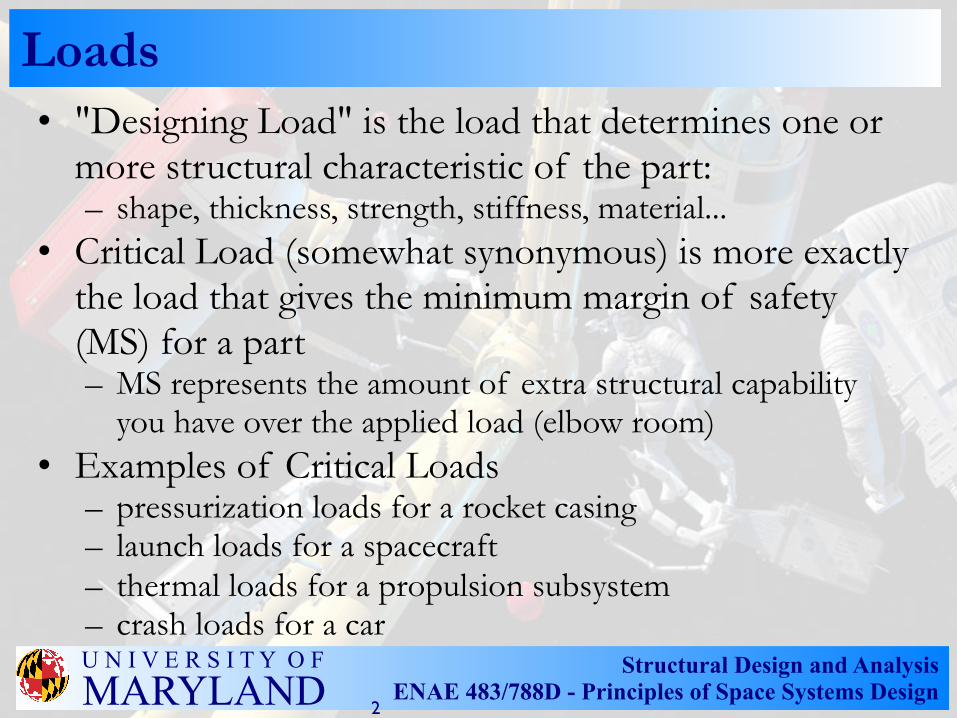
Loads• "Designing Load" is the load that determines one or
more structural characteristic of the part:– shape, thickness, strength, stiffness, material...
• Critical Load (somewhat synonymous) is more exactly the load that gives the minimum margin of safety (MS) for a part– MS represents the amount of extra structural capability
you have over the applied load (elbow room)• Examples of Critical Loads
– pressurization loads for a rocket casing– launch loads for a spacecraft– thermal loads for a propulsion subsystem– crash loads for a car
2
Structural Design and AnalysisENAE 483/788D - Principles of Space Systems Design
U N I V E R S I T Y O FMARYLAND
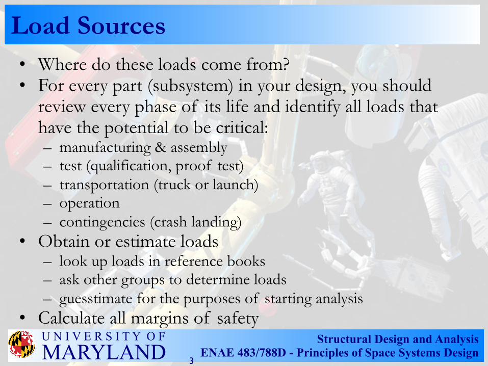
Load Sources• Where do these loads come from?• For every part (subsystem) in your design, you should
review every phase of its life and identify all loads that have the potential to be critical:– manufacturing & assembly– test (qualification, proof test)– transportation (truck or launch)– operation– contingencies (crash landing)
• Obtain or estimate loads– look up loads in reference books– ask other groups to determine loads – guesstimate for the purposes of starting analysis
• Calculate all margins of safety
3
Structural Design and AnalysisENAE 483/788D - Principles of Space Systems Design
U N I V E R S I T Y O FMARYLAND
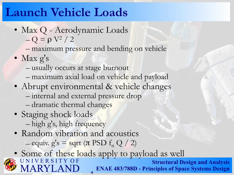
Launch Vehicle Loads• Max Q - Aerodynamic Loads
– Q = ρ V2 / 2– maximum pressure and bending on vehicle
• Max g's– usually occurs at stage burnout– maximum axial load on vehicle and payload
• Abrupt environmental & vehicle changes– internal and external pressure drop– dramatic thermal changes
• Staging shock loads– high g's, high frequency
• Random vibration and acoustics– equiv. g's = sqrt (π PSD fn Q / 2)
• Some of these loads apply to payload as well
4
Structural Design and AnalysisENAE 483/788D - Principles of Space Systems Design
U N I V E R S I T Y O FMARYLAND
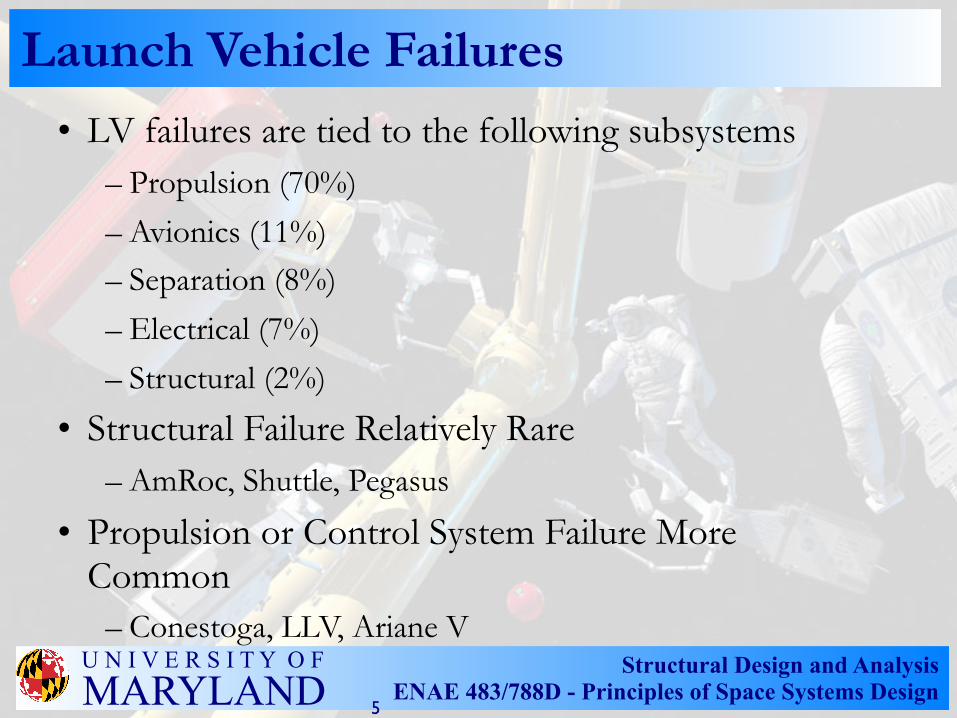
Launch Vehicle Failures• LV failures are tied to the following subsystems
– Propulsion (70%)
– Avionics (11%)– Separation (8%)
– Electrical (7%)
– Structural (2%)
• Structural Failure Relatively Rare– AmRoc, Shuttle, Pegasus
• Propulsion or Control System Failure More Common
– Conestoga, LLV, Ariane V
5
Structural Design and AnalysisENAE 483/788D - Principles of Space Systems Design
U N I V E R S I T Y O FMARYLAND
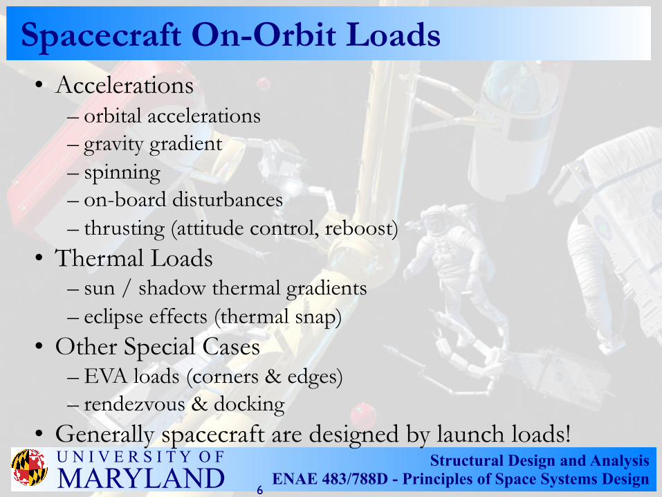
Spacecraft On-Orbit Loads • Accelerations
– orbital accelerations– gravity gradient– spinning– on-board disturbances– thrusting (attitude control, reboost)
• Thermal Loads– sun / shadow thermal gradients– eclipse effects (thermal snap)
• Other Special Cases– EVA loads (corners & edges)– rendezvous & docking
• Generally spacecraft are designed by launch loads!
6
Structural Design and AnalysisENAE 483/788D - Principles of Space Systems Design
U N I V E R S I T Y O FMARYLAND
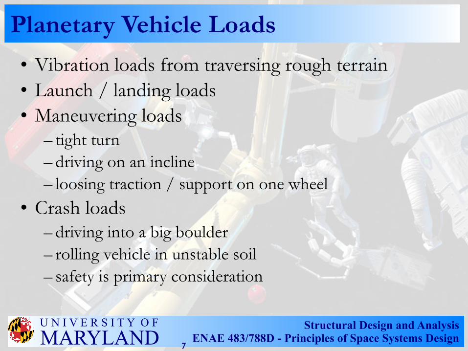
Planetary Vehicle Loads
• Vibration loads from traversing rough terrain• Launch / landing loads• Maneuvering loads
– tight turn– driving on an incline– loosing traction / support on one wheel
• Crash loads– driving into a big boulder– rolling vehicle in unstable soil– safety is primary consideration
7
Structural Design and AnalysisENAE 483/788D - Principles of Space Systems Design
U N I V E R S I T Y O FMARYLAND
Piece Parts Analysis• Structural analysis of a system consists of at least
the following three tasks– Load Cycle Modeling (system-level) - iterative process– Piece-Part Analysis (static) - minimum margins of
safety– Fracture and Fatigue Analysis (dynamic) - safe life
analysis
• Piece Parts Analysis– Identify all loads on each part / subsystem– Calculate margins of safety– Tabulate minimum margins of safety
• Example: OTD Boom Piece Parts Analysis
8
Structural Design and AnalysisENAE 483/788D - Principles of Space Systems Design
U N I V E R S I T Y O FMARYLAND
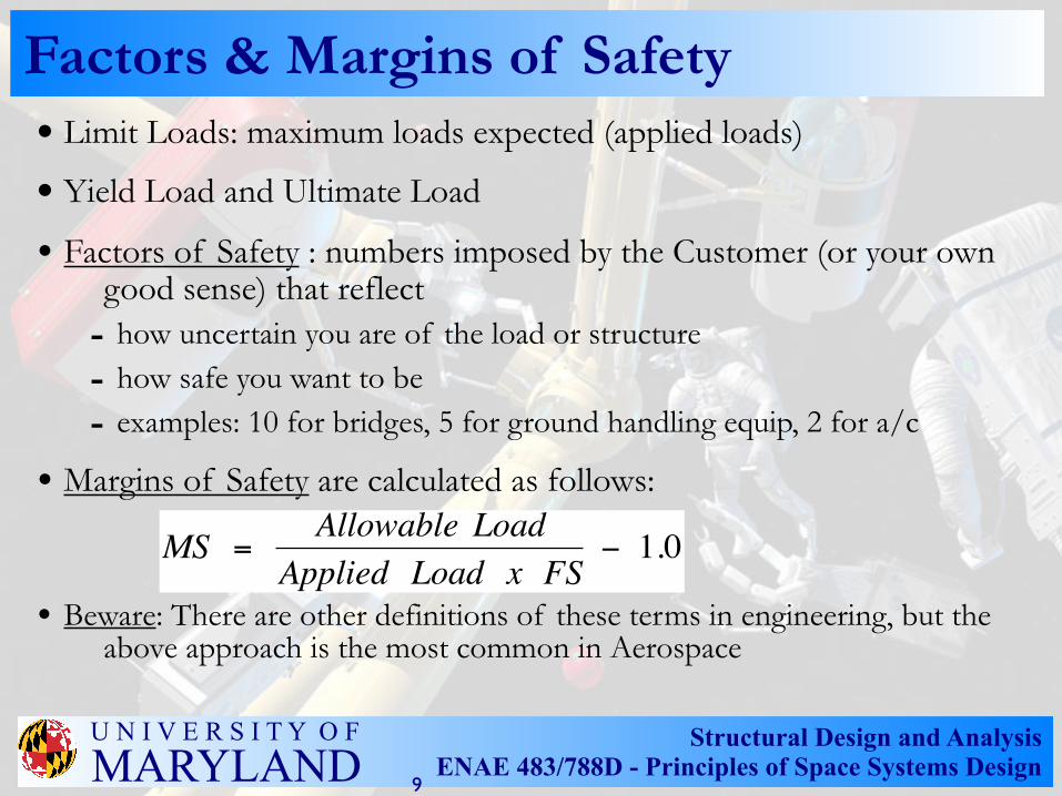
• Limit Loads: maximum loads expected (applied loads)
• Yield Load and Ultimate Load
• Factors of Safety : numbers imposed by the Customer (or your own good sense) that reflect
- how uncertain you are of the load or structure- how safe you want to be- examples: 10 for bridges, 5 for ground handling equip, 2 for a/c
• Margins of Safety are calculated as follows:
• Beware: There are other definitions of these terms in engineering, but the above approach is the most common in Aerospace
MS = Allowable LoadApplied Load x FS
− 1.0
Factors & Margins of Safety
9
Structural Design and AnalysisENAE 483/788D - Principles of Space Systems Design
U N I V E R S I T Y O FMARYLAND
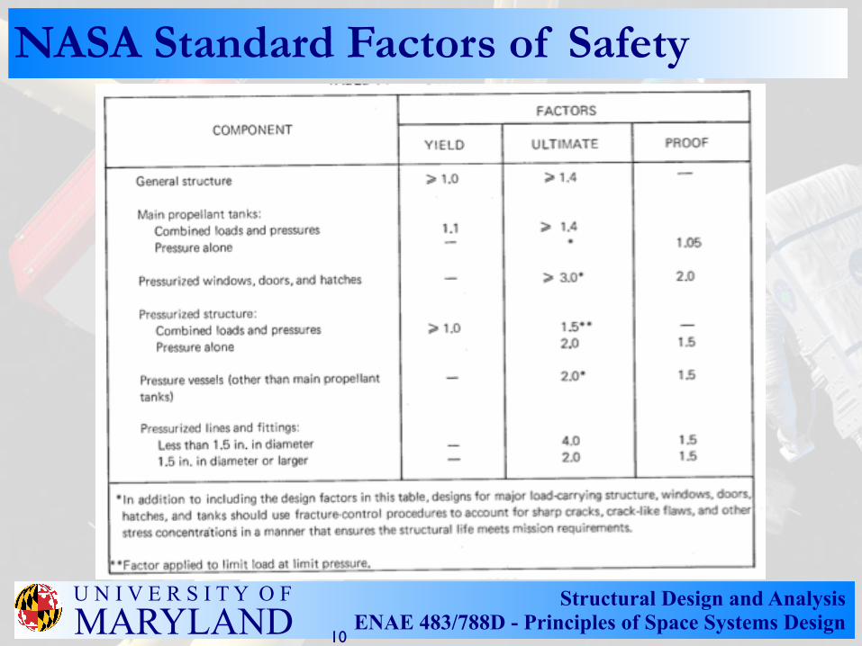
NASA Standard Factors of Safety
10
Structural Design and AnalysisENAE 483/788D - Principles of Space Systems Design
U N I V E R S I T Y O FMARYLAND
Primary Structure• Primary, Secondary, & Tertiary Structure
– Primary structure is the system's backbone (carries all of the major loads imposed on vehicle)
– Secondary structure includes all essential appendages and support structures (such as solar arrays, antennas, & fuel tanks)
– Tertiary structures are less-essential mounting hardware (brackets, component housings, connector panels)
• Example of primary structure– Thin-walled cylindrical launch vehicle– Challenge is to figure out how to react shear & torsion
stresses– Buckling of skin is most common failure mode– Buckling of a cylindrical section:
σcrit = E t / R sqrt [3(1-ν2)]
11
Structural Design and AnalysisENAE 483/788D - Principles of Space Systems Design
U N I V E R S I T Y O FMARYLAND
Critical Structure• Critical Items List (CIL) contains all parts that
– are deemed criticality 1 by FMEA (ie, single point failures)– are fracture critical (ie, stressed to the point where a flaw will grow to
critical size) • Failsafe & Fracture Critical Structure
– Catastrophic failure is generally defined by customer – Failsafe structure can take redistributed loads after failure (ie, not single
point failures); shall release no hazardous mass; shall not change dynamics significantly; shall have no fatigue problems
– Low-risk structure is not primary structure; has only a remote possibility of failure; will not propagate a crack in 4 lifetimesσmax < Ftu / [ 4 (1-0.5 R) Kt ]
– Fracture critical parts must be labeled and analyzed as such, then inspected, treated, and tracked more carefully than conventional parts
• Crack Growth Analysis (FLAGRO)– All FC parts must be shown good for four lifetimes of load cycles with
an initial flaw (determined by NDI)
12
Structural Design and AnalysisENAE 483/788D - Principles of Space Systems Design
U N I V E R S I T Y O FMARYLAND
Aerospace Materials• Comparison of specific stiffness, specific
strength, and buckling parameter for a variety of aerospace metals and composites
• Definition of Structural Failure– Detrimental Yield vs Textbook Yield
• deformation that detrimentally affects functionality of system
• 0.2% Tresca yield condition (assumes system linear in first place)
– Ultimate Failure• any material rupture or loss of functionality
13
Structural Design and AnalysisENAE 483/788D - Principles of Space Systems Design
U N I V E R S I T Y O FMARYLAND
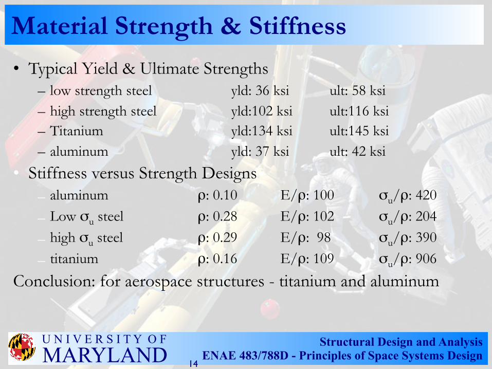
Material Strength & Stiffness• Typical Yield & Ultimate Strengths
– low strength steel yld: 36 ksi ult: 58 ksi– high strength steel yld:102 ksi ult:116 ksi – Titanium yld:134 ksi ult:145 ksi – aluminum yld: 37 ksi ult: 42 ksi
• Stiffness versus Strength Designs– aluminum ρ: 0.10 E/ρ: 100 σu/ρ: 420
– Low σu steel ρ: 0.28 E/ρ: 102 σu/ρ: 204
– high σu steel ρ: 0.29 E/ρ: 98 σu/ρ: 390
– titanium ρ: 0.16 E/ρ: 109 σu/ρ: 906
Conclusion: for aerospace structures - titanium and aluminum
14
Structural Design and AnalysisENAE 483/788D - Principles of Space Systems Design
U N I V E R S I T Y O FMARYLAND
Structural Analysis• Some key structural formulas that are handy to
have for early (back-of-the-envelope) design analyses:
– Spring & Beam Stiffnesses
– Beam Natural Frequencies– Euler Buckling Loads
– Stresses in Simple Pressurized Shellσhoop = p R / t ; σlong = p R / 2 t
– Random Vibe and Acoustic Equivalent g's
• Get a copy of Roark and Young, Formulas for Stress and Strain
15
Structural Design and AnalysisENAE 483/788D - Principles of Space Systems Design
U N I V E R S I T Y O FMARYLAND
Structural Analysis
• Definition of Example Problem• Definition of Load Cases• Analysis of Stresses• Tabulation of Margins of Safety• Identification of Critical Load Case
16
Structural Design and AnalysisENAE 483/788D - Principles of Space Systems Design
U N I V E R S I T Y O FMARYLAND
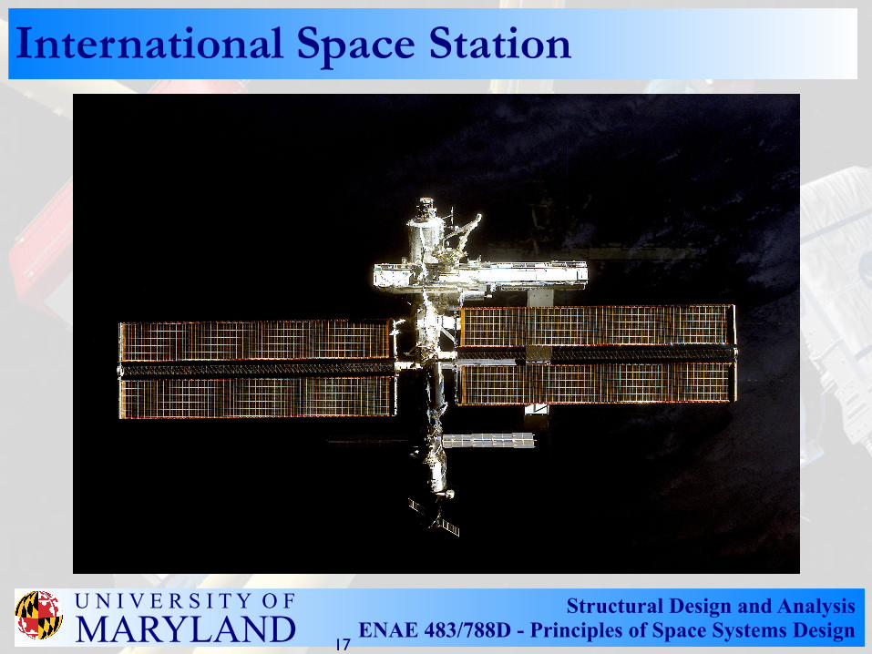
International Space Station
17
Structural Design and AnalysisENAE 483/788D - Principles of Space Systems Design
U N I V E R S I T Y O FMARYLAND
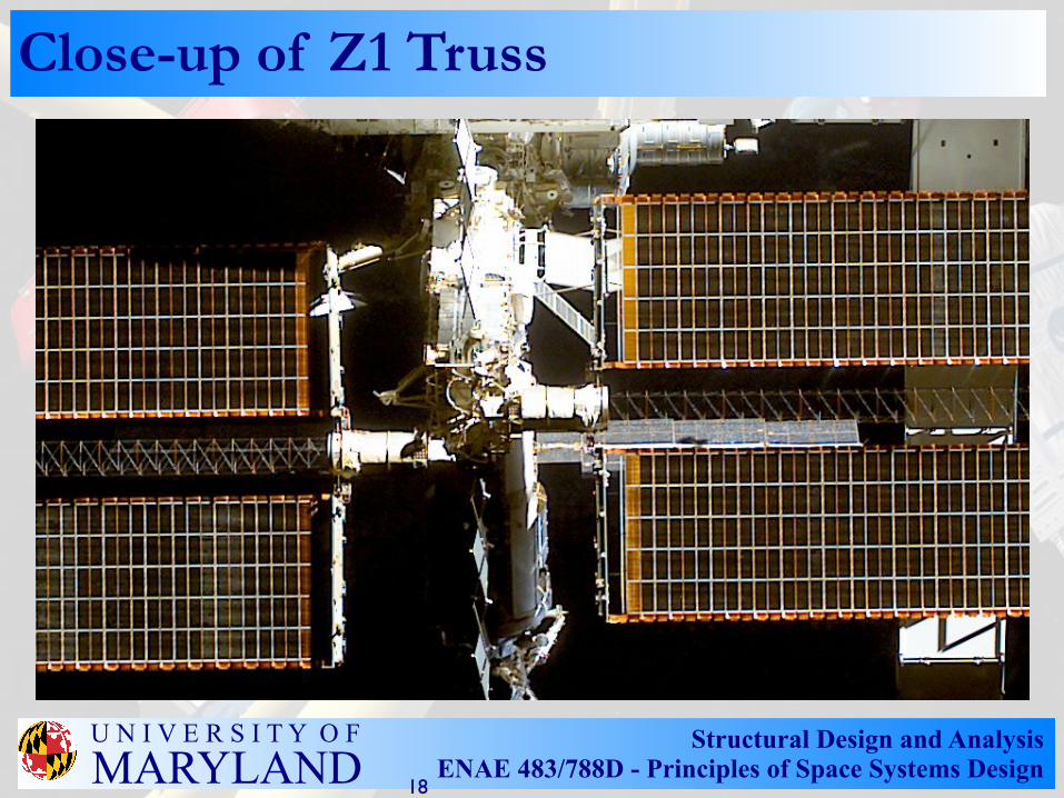
Close-up of Z1 Truss
18
Structural Design and AnalysisENAE 483/788D - Principles of Space Systems Design
U N I V E R S I T Y O FMARYLAND
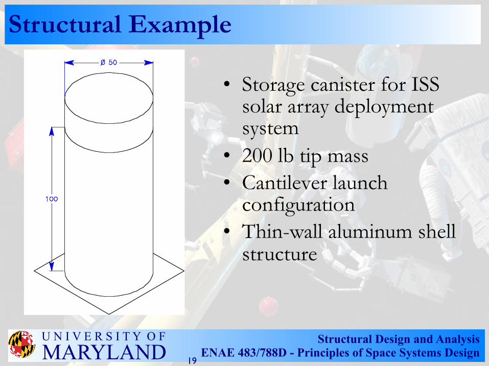
Structural Example
• Storage canister for ISS solar array deployment system
• 200 lb tip mass• Cantilever launch
configuration• Thin-wall aluminum shell
structure
19

Structural Design and AnalysisENAE 483/788D - Principles of Space Systems Design
U N I V E R S I T Y O FMARYLAND
Loads Sources
• Launch– Accelerations– Pressurization– Acoustics– Random Vibration– Thermal
• Crash Landing• On-Orbit
20
Structural Design and AnalysisENAE 483/788D - Principles of Space Systems Design
U N I V E R S I T Y O FMARYLAND
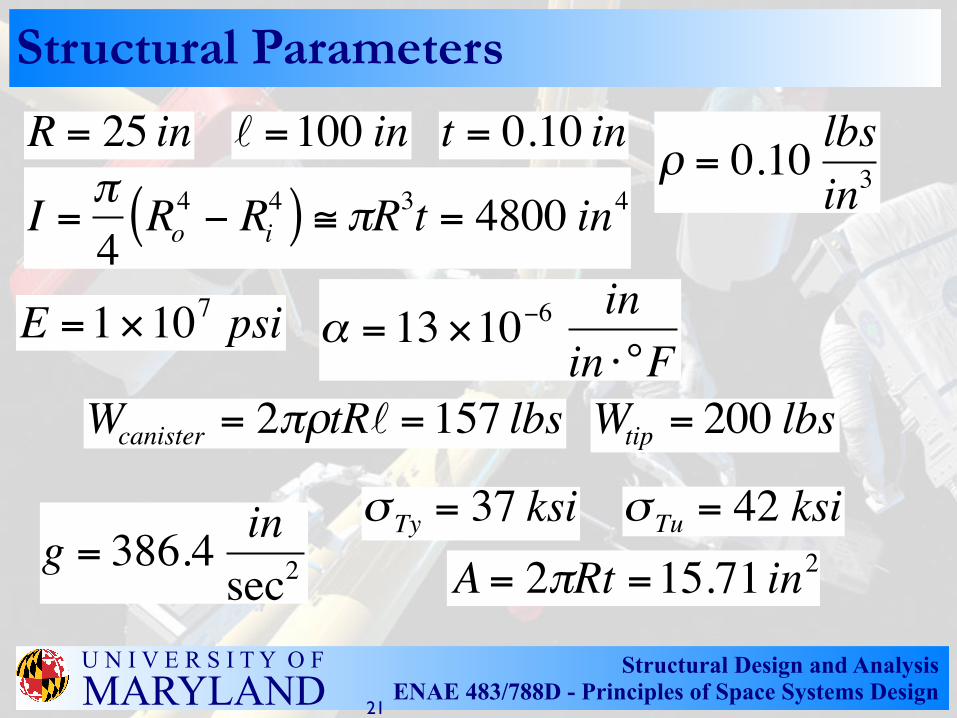
Structural Parameters
E =1×10⁷ psi α = 13 ×10−6 inin ⋅°F
ρ = 0.10 lbsin3I = π
4Ro4 − Ri
4( ) ≅ πR3t = 4800 in4R = 25 in =100 in t = 0.10 in
Wcanister = 2πρtR = 157 lbs Wtip = 200 lbs
σ Ty = 37 ksi σ Tu = 42 ksiA = 2πRt =15.71 in2g = 386.4 in
sec2
21
Structural Design and AnalysisENAE 483/788D - Principles of Space Systems Design
U N I V E R S I T Y O FMARYLAND
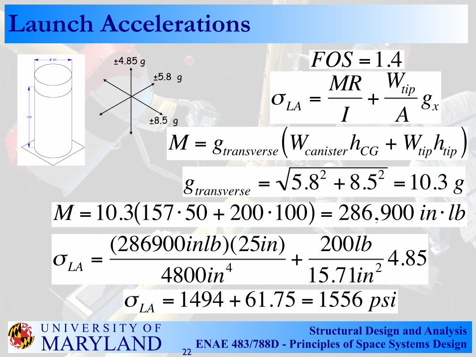
Launch Accelerations ±4.85 g
±5.8 g
±8.5 g
FOS =1.4σ LA =
MRI+Wtip
Agx
M = gtransverse WcanisterhCG +Wtiphtip( )gtransverse = 5.82 + 8.52 =10.3 g
M =10.3 157 ⋅50 + 200 ⋅100( ) = 286,900 in ⋅ lb
σ LA =(286900inlb)(25in)
4800in4+200lb15.71in2
4.85
σ LA = 1494 + 61.75 = 1556 psi
22

Structural Design and AnalysisENAE 483/788D - Principles of Space Systems Design
U N I V E R S I T Y O FMARYLAND
Pressurization LoadsFOS = 3.0
σHoop =PRt=(14.7psi)(25in)
0.1in= 3675 psi
σ Longitudinal =PR2t
= 1838 psi
23
Structural Design and AnalysisENAE 483/788D - Principles of Space Systems Design
U N I V E R S I T Y O FMARYLAND
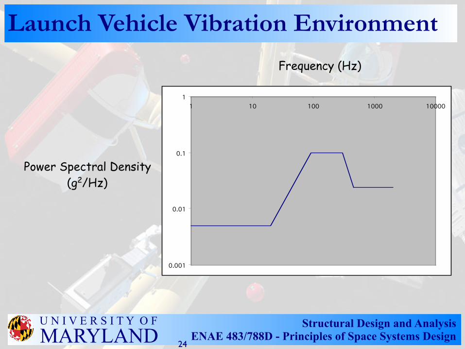
Launch Vehicle Vibration Environment
Frequency (Hz)
Power Spectral Density(g2/Hz)
0.001
0.01
0.1
11 10 100 1000 10000
24
Structural Design and AnalysisENAE 483/788D - Principles of Space Systems Design
U N I V E R S I T Y O FMARYLAND
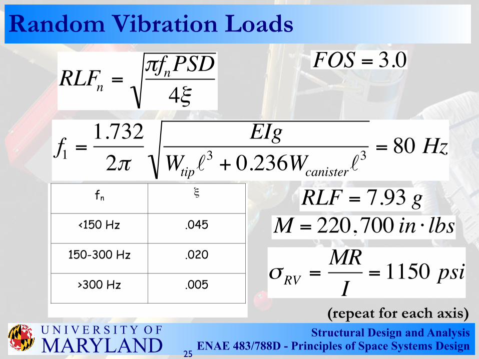
Random Vibration LoadsFOS = 3.0
RLFn =πfnPSD4ξ
f1 =
1.7322π
EIgWtip
3 + 0.236Wcanister3 = 80 Hz
fn ξ
<150 Hz .045
150-300 Hz .020
>300 Hz .005
RLF = 7.93 g
(repeat for each axis)
M = 220,700 in ⋅ lbs
σRV =MRI= 1150 psi
25
Structural Design and AnalysisENAE 483/788D - Principles of Space Systems Design
U N I V E R S I T Y O FMARYLAND
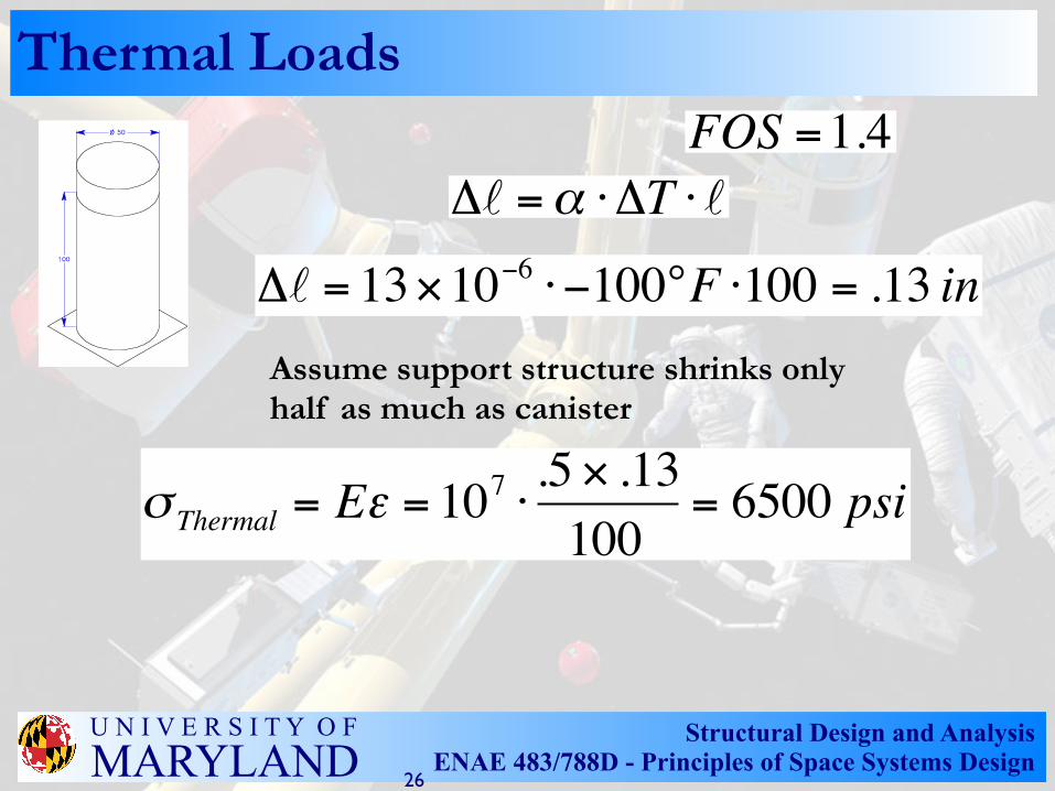
Thermal LoadsFOS =1.4
Δ =α ⋅ΔT ⋅
σ Thermal = Eε = 107 ⋅.5 × .13100
= 6500 psi
Δ = 13×10−6 ⋅ −100°F ⋅100 = .13 in
Assume support structure shrinks only half as much as canister
26
Structural Design and AnalysisENAE 483/788D - Principles of Space Systems Design
U N I V E R S I T Y O FMARYLAND
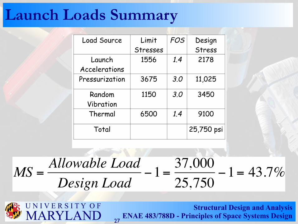
Launch Loads SummaryLoad Source Limit
StressesFOS Design
StressLaunch
Accelerations1556 1.4 2178
Pressurization 3675 3.0 11,025
RandomVibration
1150 3.0 3450
Thermal 6500 1.4 9100
Total 25,750 psi
MS = Allowable LoadDesign Load
−1= 37,00025,750
−1= 43.7%
27
Structural Design and AnalysisENAE 483/788D - Principles of Space Systems Design
U N I V E R S I T Y O FMARYLAND
Observations about Launch Loads
• Individual loads could be applied to same position on canister at same times - conservative approach is to use superposition to define worst case
• 43% margin indicates that canister is substantially overbuilt - if launch loads turn out to be critical load case, redesign to lighten structure and reduce mass.
28
Related Documents