1/18 ???? REF.: nnnn ???? Tel : ???? PAGE: ???? Fax :???? DATE: 31-Jan-2012 ???? email: ???? DESIGN: SCH GABLE CANOPY: TIMBER ???,????:SUBURB Wind Class N2 Vu = 40 m/s qz= 0.96 kPa Vp = 33 m/s qz= 0.65 kPa 1.01: Dimension & Geometry Canopy Width = L = 6.000 m Rise 1.2426 m Canopy Pitch 22.5 degrees 0.393 radians 1/3 Rise 0.4142 m Rafter Length = L1 = 3.247 m d = 2/3 Rise 0.8284 m Load Width = Rafter Spacing = 1.200m Gable End Area 3.7279m² Collar-Tie Length = 4.000 m 1.02: Estimate Moments to Rafters for Collar-Tied Roof Trusses (Dead Loading) kPa kN/m LF LF SWT 0.03 DL (cladding) 0.04 DL(battens) 0.02 DL+SWT 0.09 0.11 0.9 1.2 along projected length = Fy = DL cos (alpha) = 0.10 kN/m W1 = wL/2 = 0.299 kN W2 = wL/2 = 0.299 kN W = 2 *W1 = 0.599 kN Reaction A = 0.299 kN Reaction B = 0.299 kN Maximum = R1 = 0.299 kN Span Moment M1=w.L^2/8 = 0.449 kNm Collar-Tie Force F =(Ra.L/2 - W1.L/4)/d = 0.542 kN Rafter Moment - udl M1=w.L1^2/8 = 0.132 kNm Ra ft er Mo ment from Co ll ar- Ti e M2 =( 2/ 9) Fs in ( α).L1 = 0.150 kNm Resultant Rafter Moment (Est.) M1+M2 = 0.281 kNm Ridge Reactions Bx = -F = -0.542 kN By = W1-Ra = 0.000 kN 1.03: Live Load LL = 0.37 kPa adopt 0.25 kPa and also check directly for point load of 1.8kN factored kPa kN/m LF kN/m 1 LL 0.25 0.30 1.5 0.45 1.04: Moments to Rafters for Collar-Tied Roof Trusses (Live Loading) Considering Uniformly Distributed Loading(UDL) W1 = wL/2 = 0.900 kN W2 = wL/2 = 0.900 kN W = 2 *W1 = 1.800 kN Reaction A = 0.900 kN Reaction B = 0.900 kN Maximum = R1 = 0.900 kN Span Moment - UDL M1=w.L^2/8 = 1.35kNm Collar-Tie Force F =(Ra.L/2 - W1.L/4)/d = 1.63 kN Rafter Moment - udl M1=w.L1^2/8 = 0.395 kNm Ra ft er Moment from Coll ar-Tie M2=( 2/ 9)Fsin( α).L1 = 0.450 kNm Resultant Rafter Moment (Est.) M1+M2 = 0.845 kNm ... Ridge Reactions Bx = -F = -1.630 kN By = W1-Ra = 0.000 kN Considering Point Load at Ridge Point Load P1 = 1.80kN Reaction A = 0.900 kN Reaction B = 0.900 kN Span Moment - Point Load M=P1.L/4 = 2.700 kNm span moment - point load at apex Collar-Tie Force - Point Load F = Ra.L/(2.d) = 3.259 kN Raft er Moment - Point Load M2=(2/9)Fs in( α).L1 = 0.900kNm max Max: 0.900 kNm < WindLoad Ridge Reactions Bx = -F = -3.259 kN By = P1-Ra = 0.900 kN (C)Roy Harrison Associates schGableCanopyTimber.xls Calcs

Welcome message from author
This document is posted to help you gain knowledge. Please leave a comment to let me know what you think about it! Share it to your friends and learn new things together.
Transcript
8/3/2019 Structural Calculations for Timber Canopy with Gable Roof
http://slidepdf.com/reader/full/structural-calculations-for-timber-canopy-with-gable-roof 1/18
1/18
???? REF.: nnnn
???? Tel : ???? PAGE:
???? Fax :???? DATE: 31-Jan-2012
???? email: ???? DESIGN: SCH
GABLE CANOPY: TIMBER
???,????:SUBURB
Wind Class
N2 Vu = 40 m/s qz= 0.96 kPa
Vp = 33 m/s qz= 0.65 kPa
1.01: Dimension & Geometry
Canopy Width = L = 6.000 m Rise 1.2426 m
Canopy Pitch 22.5 degrees 0.393 radians 1/3 Rise 0.4142 m
Rafter Length = L1 = 3.247 m d = 2/3 Rise 0.8284 m
Load Width = Rafter Spacing = 1.200 m Gable End Area 3.7279 m²
Collar-Tie Length = 4.000 m
1.02: Estimate Moments to Rafters for Collar-Tied Roof Trusses (Dead Loading)
kPa kN/m LF LF
SWT 0.03
DL (cladding) 0.04
DL(battens) 0.02
DL+SWT 0.09 0.11 0.9 1.2
along projected length = Fy = DL cos (alpha) = 0.10 kN/m
W1 = wL/2 = 0.299 kN
W2 = wL/2 = 0.299 kN
W = 2 *W1 = 0.599 kN
Reaction A = 0.299 kN
Reaction B = 0.299 kN
Maximum = R1 = 0.299 kN
Span Moment M1=w.L^2/8 = 0.449 kNm
Collar-Tie Force F =(Ra.L/2 - W1.L/4)/d = 0.542 kN
Rafter Moment - udl M1=w.L1^2/8 = 0.132 kNm
Rafter Moment from Collar-Tie M2=(2/9)Fsin(α).L1 = 0.150 kNm
Resultant Rafter Moment (Est.) M1+M2 = 0.281 kNm
Ridge Reactions Bx = -F = -0.542 kN By = W1-Ra = 0.000 kN
1.03: Live LoadLL = 0.37 kPa adopt 0.25 kPa and also check directly for point load of 1.8kN
factored
kPa kN/m LF kN/m
1 LL 0.25 0.30 1.5 0.45
1.04: Moments to Rafters for Collar-Tied Roof Trusses (Live Loading)
Considering Uniformly Distributed Loading(UDL)
W1 = wL/2 = 0.900 kN
W2 = wL/2 = 0.900 kN
W = 2 *W1 = 1.800 kN
Reaction A = 0.900 kN
Reaction B = 0.900 kN
Maximum = R1 = 0.900 kN
Span Moment - UDL M1=w.L^2/8 = 1.35 kNm
Collar-Tie Force F =(Ra.L/2 - W1.L/4)/d = 1.63 kN
Rafter Moment - udl M1=w.L1^2/8 = 0.395 kNm
Rafter Moment from Collar-Tie M2=(2/9)Fsin(α).L1 = 0.450 kNm
Resultant Rafter Moment (Est.) M1+M2 = 0.845 kNm ...
Ridge Reactions Bx = -F = -1.630 kN By = W1-Ra = 0.000 kN
Considering Point Load at Ridge
Point Load P1 = 1.80 kN
Reaction A = 0.900 kN
Reaction B = 0.900 kN
Span Moment - Point Load M=P1.L/4 = 2.700 kNm span moment - point load at apex
Collar-Tie Force - Point Load F = Ra.L/(2.d) = 3.259 kN
Rafter Moment - Point Load M2=(2/9)Fsin(α).L1 = 0.900 kNm max
Max: 0.900 kNm < WindLoadRidge Reactions Bx = -F = -3.259 kN By = P1-Ra = 0.900 kN
(C)Roy Harrison Associates schGableCanopyTimber.xls Calcs
8/3/2019 Structural Calculations for Timber Canopy with Gable Roof
http://slidepdf.com/reader/full/structural-calculations-for-timber-canopy-with-gable-roof 2/18
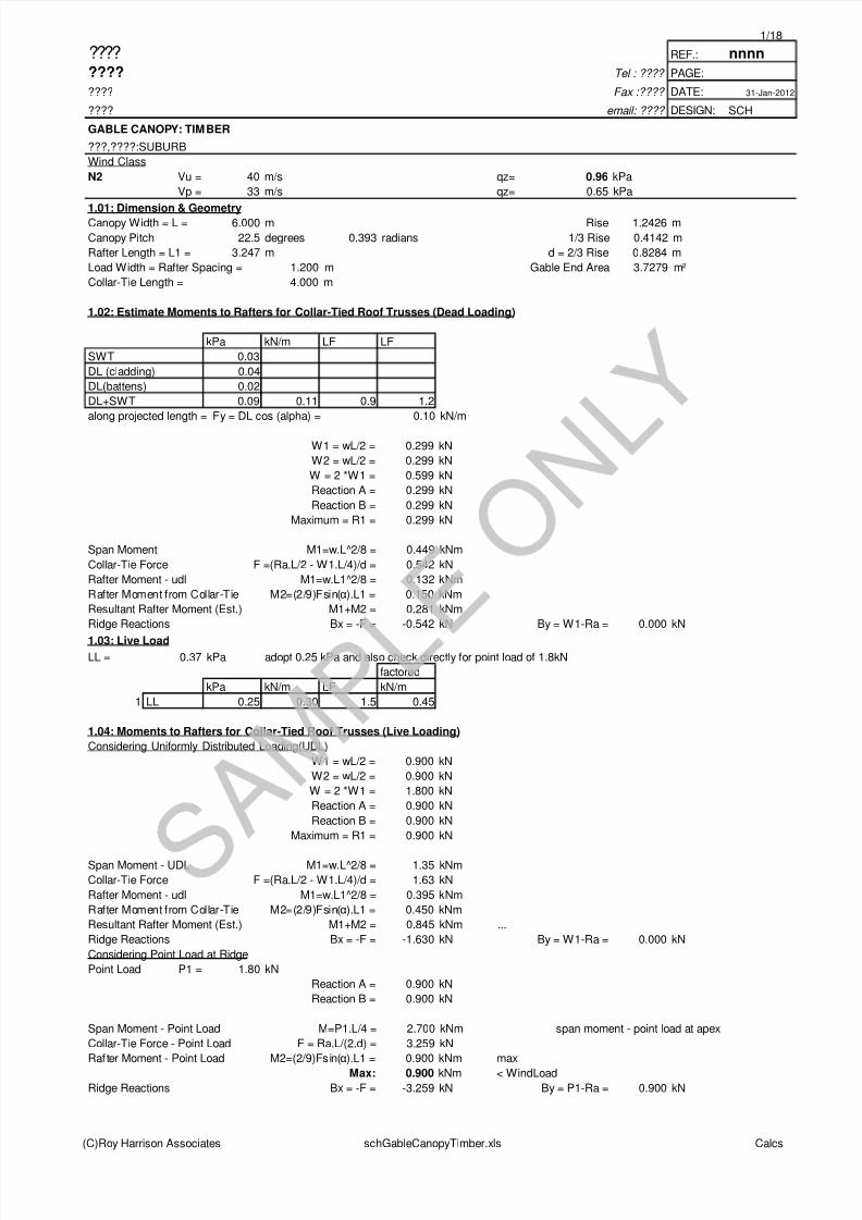
2/18
???? REF.: nnnn
???? Tel : ???? PAGE:
???? Fax :???? DATE: 31-Jan-2012
???? email: ???? DESIGN: SCH
GABLE CANOPY: TIMBER
???,????:SUBURB
Wind Class
N2 Vu = 40 m/s qz= 0.96 kPa
Vp = 33 m/s qz= 0.65 kPa
1.05: Wind Class Pressures (theta=0) /1
(-ve, uplift)
Windward Slope Cpn1= -0.3 p1 = -0.29 kPa w1= 0.346 kN/m
Leeward Slope Cpn2 = -0.6 p2 = -0.58 kPa w2= 0.691 kN/m
wx wy
w1 0.13 0.32 kN/m wx,wy are components of w1,w2 distributed along length of rafter
w2 0.26 0.64 kN/m vertical and horizontal loads distributed across projected lengths equal w1,w2
W Wx Wy Directions
w1 1.122 -0.43 -1.04 kN/m -1 -1 {+ve, vertical down, horizontal push to right}
w2 2.244 -0.86 -2.07 kN/m -1 -1
sum -1.29 -3.11 kN/m
1.06: Reactions
Ra Rb checksum
Load 1 -0.73 -0.30 kN -1.04
Load 2 -0.61 -1.47 kN -2.07
(-ve, tiedown) Resultant -1.34 -1.77 kN -3.11
Nett Horizontal Reaction -0.43 kN <<--
1.07: Collar-Tie Force
Collar-T ie Force F =(-W1y.L/4 - W1x.h/2 + Ra.L/2 )/d = -2.65 kN -ve, Compression
Ridge Reactions Bx = W1x - F = 3.08 kN By = W1y-Ra = 0.30 kN
1.08: Estimate of Maximum Moment Simply Supported Beams (Wind Loading)
Rafter1 Rafter2
Rafter Moment - udl M1=w.L1^2/8 = 0.46 0.91 kNm
Rafter Moment from Collar-Tie M2=(2/9)Fsin(α).L1 = 0.73 0.73 kNm
Resultant Rafter Moment (Est.) M1+M2 = -1.19 -1.64 kNm -1 -1 max -1.64
NB: The maximum moment in the span is less than the sum of the maximum resulting from the LH and RH loads, for these two maxima
do not occur at the same location in the span. It is therefore a conservative estimate.
1.09: Wind Class Pressures (theta=0) /2
(-ve, uplift)
Windward Slope Cpn1= 0 p1 = 0.00 kPa w1= 0.000 kN/m
Leeward Slope Cpn2 = 0.6 p2 = 0.58 kPa w2= 0.691 kN/m
wx wy
w1 0.00 0.00 kN/m wx,wy are components of w1,w2 distributed along length of rafter
w2 0.26 0.64 kN/m vertical and horizontal loads distributed across projected lengths equal w1,w2
W Wx Wy Directions
w1 0.000 0.00 0.00 kN/m 1 1w2 2.244 0.86 2.07 kN/m 1 1
sum 0.86 2.07 kN/m
1.10: Reactions roller pin
Ra Rb checksum
Load 1 0.00 0.00 kN 0.00
Load 2 0.61 1.47 kN 2.07
(-ve, tiedown) Resultant 0.61 1.47 kN 2.07
Nett Horizontal Reaction 0.86 kN
1.11: Collar-Tie Force
Collar-Tie Force F =(-W1y.L/4 - W1x.h/2 + Ra.L/2 )/d = 2.20 kN +ve, Tension
Ridge Reactions Bx = W1x - F = -2.20 kN By = W1y-Ra = -0.61 kN
1.12: Estimate of Maximum Moment Simply Supported Beams (Wind Loading)Rafter1 Rafter2
Rafter Moment - udl M1=w.L1^2/8 = 0.00 0.91 kNm
Rafter Moment from Collar-Tie M2=(2/9)Fsin(α).L1 = 0.61 0.61 kNm
(C)Roy Harrison Associates schGableCanopyTimber.xls Calcs

8/3/2019 Structural Calculations for Timber Canopy with Gable Roof
http://slidepdf.com/reader/full/structural-calculations-for-timber-canopy-with-gable-roof 3/18
3/18
???? REF.: nnnn
???? Tel : ???? PAGE:
???? Fax :???? DATE: 31-Jan-2012
???? email: ???? DESIGN: SCH
GABLE CANOPY: TIMBER
???,????:SUBURB
Wind Class
N2 Vu = 40 m/s qz= 0.96 kPa
Vp = 33 m/s qz= 0.65 kPa
Resultant Rafter Moment (Est.) M1+M2 = 0.61 1.52 kNm 1 1 max 1.52
1.13: Wind Class Pressures (Theta=90) \1
(-ve, uplift)
Windward Slope Cpn1= -0.3 p1 = -0.29 kPa w1= 0.346 kN/m
Leeward Slope Cpn2 = -0.3 p2 = -0.29 kPa w2= 0.346 kN/m
wx wy
w1 0.13 0.32 kN/m wx,wy are components of w1,w2 distributed along length of rafter
w2 0.13 0.32 kN/m vertical and horizontal loads distributed across projected lengths equal w1,w2
W Wx Wy Directions
w1 1.122 -0.43 -1.04 kN/m -1 -1
w2 1.122 -0.43 -1.04 kN/m -1 -1
sum -0.86 -2.07 kN/m
1.14: Reactions
Ra Rb checksum
Load 1 -0.73 -0.30 kN -1.04
Load 2 -0.30 -0.73 kN -1.04
(-ve, tiedown) Resultant -1.04 -1.04 kN -2.07
Nett Horizontal Reaction 0.00 kN
1.15: Collar-Tie Force
Collar-T ie Force F =(-W1y.L/4 - W1x.h/2 + Ra.L/2 )/d = -1.56 kN -ve, Compression
Ridge Reactions Bx = W1x - F = 1.98 kN By = W1y-Ra = 0.00 kN
1.16: Estimate of Maximum Moment Simply Supported Beams (Wind Loading)
Rafter1 Rafter2
Rafter Moment - udl M1=w.L1^2/8 = 0.46 0.46 kNm
Rafter Moment from Collar-Tie M2=(2/9)Fsin(α).L1 = 0.43 0.43 kNm
Resultant Rafter Moment (Est.) M1+M2 = -0.88 -0.88 kNm -1 -1 max -0.88
NB: The maximum moment in the span is less than the sum of the maximum resulting from the LH and RH loads, for these two maxima
do not occur at the same location in the span. It is therefore a conservative estimate.
1.17: Wind Class Pressures (Theta=90) \2
(-ve, uplift)
Windward Slope Cpn1= 0.4 p1 = 0.38 kPa w1= 0.461 kN/m
Leeward Slope Cpn2 = 0.4 p2 = 0.38 kPa w2= 0.461 kN/m
wx wy
w1 0.18 0.43 kN/m wx,wy are components of w1,w2 distributed along length of rafter
w2 0.18 0.43 kN/m vertical and horizontal loads distributed across projected lengths equal w1,w2
W Wx Wy Directionsw1 1.496 0.57 1.38 kN/m 1 1
w2 1.496 0.57 1.38 kN/m 1 1
sum 1.15 2.76 kN/m
1.18: Reactions
Ra Rb checksum
Load 1 0.98 0.40 kN 1.38
Load 2 0.40 0.98 kN 1.38
(-ve, tiedown) Resultant 1.38 1.38 kN 2.76
Nett Horizontal Reaction 0.00 kN
1.19: Collar-Tie Force
Collar-Tie Force F =(-W1y.L/4 - W1x.h/2 + Ra.L/2 )/d = 2.07 kN +ve, Tension
Ridge Reactions Bx = W1x - F = -2.65 kN By = W1y-Ra = 0.00 kN
1.20: Estimate of Maximum Moment Simply Supported Beams (Wind Loading)
Rafter1 Rafter2
Rafter Moment - udl M1=w.L1^2/8 = 0.61 0.61 kNm
(C)Roy Harrison Associates schGableCanopyTimber.xls Calcs
8/3/2019 Structural Calculations for Timber Canopy with Gable Roof
http://slidepdf.com/reader/full/structural-calculations-for-timber-canopy-with-gable-roof 4/18
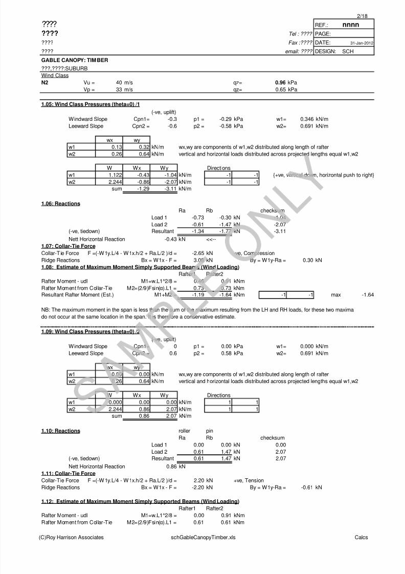
4/18
???? REF.: nnnn
???? Tel : ???? PAGE:
???? Fax :???? DATE: 31-Jan-2012
???? email: ???? DESIGN: SCH
GABLE CANOPY: TIMBER
???,????:SUBURB
Wind Class
N2 Vu = 40 m/s qz= 0.96 kPa
Vp = 33 m/s qz= 0.65 kPa
Rafter Moment from Collar-Tie M2=(2/9)Fsin(α).L1 = 0.57 0.57 kNm
Resultant Rafter Moment (Est.) M1+M2 = 1.18 1.18 kNm 1 1 max 1.18
1.21: LoadCase Combinations
LF = 0.9 1.20 1.50
Ridge
Collar-Tie Force Rafter Moment Ra Rb Rbx Bx By
kN kNm kN kN kN kN
G = SWT + DL 0.54 T 0.281 0.30 0.30 0.00 -0.54 0.00
LL 1.63 T 0.845 0.90 0.90 0.00 -1.63 0.00
PL 3.26 T 0.900 0.90 0.90 0.00 -3.26 0.90
WL (theta=0) /1 -2.65 C -1.64 -1.34 -1.77 -0.43 3.08 0.30
WL (theta=0) /2 2.20 T 1.52 0.61 1.47 0.86 -2.20 -0.61
WL (theta=90) /1 -1.56 C -0.88 -1.04 -1.04 0.00 1.98 0.00WL (theta=90) /2 2.07 T 1.18 1.38 1.38 0.00 -2.65 0.00
0.9G 0.49 T 0.25 0.27 0.27 0.00 -0.49 0.00
1.2G 0.65 T 0.34 0.36 0.36 0.00 -0.65 0.00
1.2G + 1.5LL 3.09 T 1.61 1.71 1.71 0.00 -3.09 0.00
1.2G + 1.5PL 5.54 T 1.69 1.71 1.71 0.00 -5.54 1.35
0.9G + WL0/1 -2.17 C -1.39 -1.07 -1.50 -0.43 2.60 0.30
1.2G + WL0/2 2.85 T 1.86 0.97 1.83 0.86 -2.85 -0.61
0.9G + WL90/1 -1.07 C -0.63 -0.77 -0.77 0.00 1.50 0.00
1.2G + WL90/2 2.72 T 1.52 1.74 1.74 0.00 -3.30 0.00
min -2.17 C -1.39 -1.07 -1.50 -0.43 -5.54 -0.61
max 5.54 T 1.86 1.74 1.83 0.86 2.60 1.35
abs(max) 5.54 1.86 1.74 1.83 0.86 5.54 1.35(+ve sagging moment)
(-ve hogging moment)
(-ve, tie-down reaction)
(-ve compression)
Consider Point Load Centre of Collar-Tie
P = 1.1 kN M= PL/4 = 1.10 kNm
Consider Point Load on Collar-Tie Located Near Ends (similar to TDA pergola guide)
P = 1.1 kN M=Pab/L = 0.31 kNm a = 0.300 m b= 3.700 m
RIDGE BOARD
None load bearing connection board: size to AS1684.2
T = thickness of rafter = 45 mm Grade Same as Rafter: F7
D = Depth of rafter + 50mm = 190 mm
ADOPT: RIDGE BOARD 190 x 45 F7
(C)Roy Harrison Associates schGableCanopyTimber.xls Calcs
8/3/2019 Structural Calculations for Timber Canopy with Gable Roof
http://slidepdf.com/reader/full/structural-calculations-for-timber-canopy-with-gable-roof 5/18
5/18
???? REF.: nnnn
???? Tel : ???? PAGE:
???? Fax :???? DATE: 31-Jan-2012
???? email: ???? DESIGN: SCH
GABLE CANOPY: TIMBER
???,????:SUBURB
Wind Class
N2 Vu = 40 m/s qz= 0.96 kPa
Vp = 33 m/s qz= 0.65 kPa
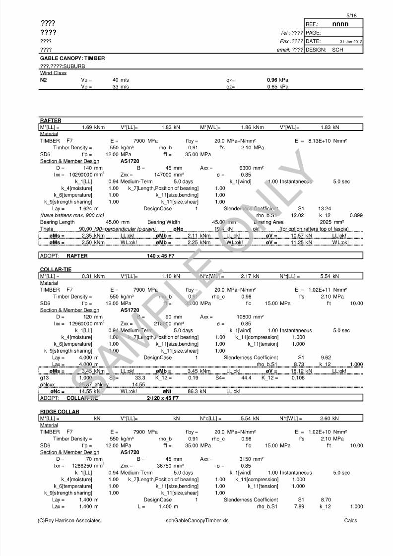
RAFTER
M*[LL] = 1.69 kNm V*[LL]= 1.83 kN M*[WL]= 1.86 kNm V*[WL]= 1.83 kN
Material
TIMBER F7 E = 7900 MPa f'by = 20.0 MPa=N/mm² EI = 8.13E+10 Nmm²
Timber Density = 550 kg/m³ rho_b 0.91 f's 2.10 MPa
SD6 f'p = 12.00 MPa f'l = 35.00 MPa
Section & Member Design AS1720
D = 140 mm B = 45 mm Axx = 6300 mm²
Ixx = 10290000 mm4
Zxx = 147000 mm³ ø = 0.85
k_1[LL] 0.94 Medium-Term 5.0 days k_1[wind] 1.00 Instantaneous 5.0 sec
k_4[moisture] 1.00 k_7[Length,Position of bearing] 1.00
k_6[temperature] 1.00 k_11[size,bending] 1.00k_9[strength sharing] 1.00 k_11[size,shear] 1.00
Lay = 1.624 m DesignCase 1 Slenderness Coefficient S1 13.24
{have battens max. 900 c/c} rho_b.S1 12.02 k_12 0.899
Bearing Length 45.00 mm Bearing Width 45.00 mm Bearing Area 2025 mm²
Theta 90.00 {90=perpendicular to grain} øNp 19.4 kN ok! (for option rafters top of fascia)
øMs = 2.35 kNm LL:ok! øMb = 2.11 kNm LL:ok! øV = 10.57 kN LL:ok!
øMs = 2.50 kNm WL:ok! øMb = 2.25 kNm WL:ok! øV = 11.25 kN WL:ok!
ADOPT: RAFTER 140 x 45 F7
COLLAR-TIE
M*[LL] = 0.31 kNm V*[LL]= 1.10 kN N*c[WL] = 2.17 kN N*t[LL] = 5.54 kN
Material
TIMBER F7 E = 7900 MPa f'by = 20.0 MPa=N/mm² EI = 1.02E+11 Nmm²Timber Density = 550 kg/m³ rho_b 0.91 rho_c 0.98 f's 2.10 MPa
SD6 f'p = 12.00 MPa f'l = 35.00 MPa f'c 15.00 MPa f't 10.00
Section & Member Design AS1720
D = 120 mm B = 90 mm Axx = 10800 mm²
Ixx = 12960000 mm4
Zxx = 216000 mm³ ø = 0.85
k_1[LL] 0.94 Medium-Term 5.0 days k_1[wind] 1.00 Instantaneous 5.0 sec
k_4[moisture] 1.00 k_7[Length,Position of bearing] 1.00 k_11[compression] 1.000
k_6[temperature] 1.00 k_11[size,bending] 1.00 k_11[tension] 1.000
k_9[strength sharing] 1.00 k_11[size,shear] 1.00
Lay = 4.000 m DesignCase 1 Slenderness Coefficient S1 9.62
Lax = 4.000 m rho_b.S1 8.73 k_12 1.000
øMs = 3.45 kNm LL:ok! øMb = 3.45 kNm LL:ok! øV = 18.12 kN LL:ok!
g13 1.000 S3= 33.3 K_12 = 0.19 S4= 44.4 K_12 = 0.106
øNcxx 25.87 øNcyy 14.55
øNc = 14.55 kN WL:ok! øNt 86.3 kN LL:ok!ADOPT: COLLAR-TIE 2\120 x 45 F7
RIDGE COLLAR
M*[LL] = kN V*[LL]= kN N*c[LL] = 5.54 kN N*t[WL] = 2.60 kN
Material
TIMBER F7 E = 7900 MPa f'by = 20.0 MPa=N/mm² EI = 1.02E+10 Nmm²
Timber Density = 550 kg/m³ rho_b 0.91 rho_c 0.98 f's 2.10 MPa
SD6 f'p = 12.00 MPa f'l = 35.00 MPa f'c 15.00 MPa f't 10.00
Section & Member Design AS1720
D = 70 mm B = 45 mm Axx = 3150 mm²
Ixx = 1286250 mm4
Zxx = 36750 mm³ ø = 0.85
k_1[LL] 0.94 Medium-Term 5.0 days k_1[wind] 1.00 Instantaneous 5.0 sec
k_4[moisture] 1.00 k_7[Length,Position of bearing] 1.00 k_11[compression] 1.000
k_6[temperature] 1.00 k_11[size,bending] 1.00 k_11[tension] 1.000k_9[strength sharing] 1.00 k_11[size,shear] 1.00
Lay = 1.400 m DesignCase 1 Slenderness Coefficient S1 8.70
Lax = 1.400 m L = 1.400 m rho_b.S1 7.89 k_12 1.000
(C)Roy Harrison Associates schGableCanopyTimber.xls Calcs
8/3/2019 Structural Calculations for Timber Canopy with Gable Roof
http://slidepdf.com/reader/full/structural-calculations-for-timber-canopy-with-gable-roof 6/18
6/18
???? REF.: nnnn
???? Tel : ???? PAGE:
???? Fax :???? DATE: 31-Jan-2012
???? email: ???? DESIGN: SCH
GABLE CANOPY: TIMBER
???,????:SUBURB
Wind Class
N2 Vu = 40 m/s qz= 0.96 kPa
Vp = 33 m/s qz= 0.65 kPa
g13 1.000 S3= 20.0 K_12 = 0.52 S4= 31.1 K_12 = 0.216
øNcxx 19.67 øNcyy 8.14
øNc = 8.14 kN LL:ok! øNt 26.8 kN WL:ok!
ADOPT: RIDGE COLLAR 70 x 45 F7
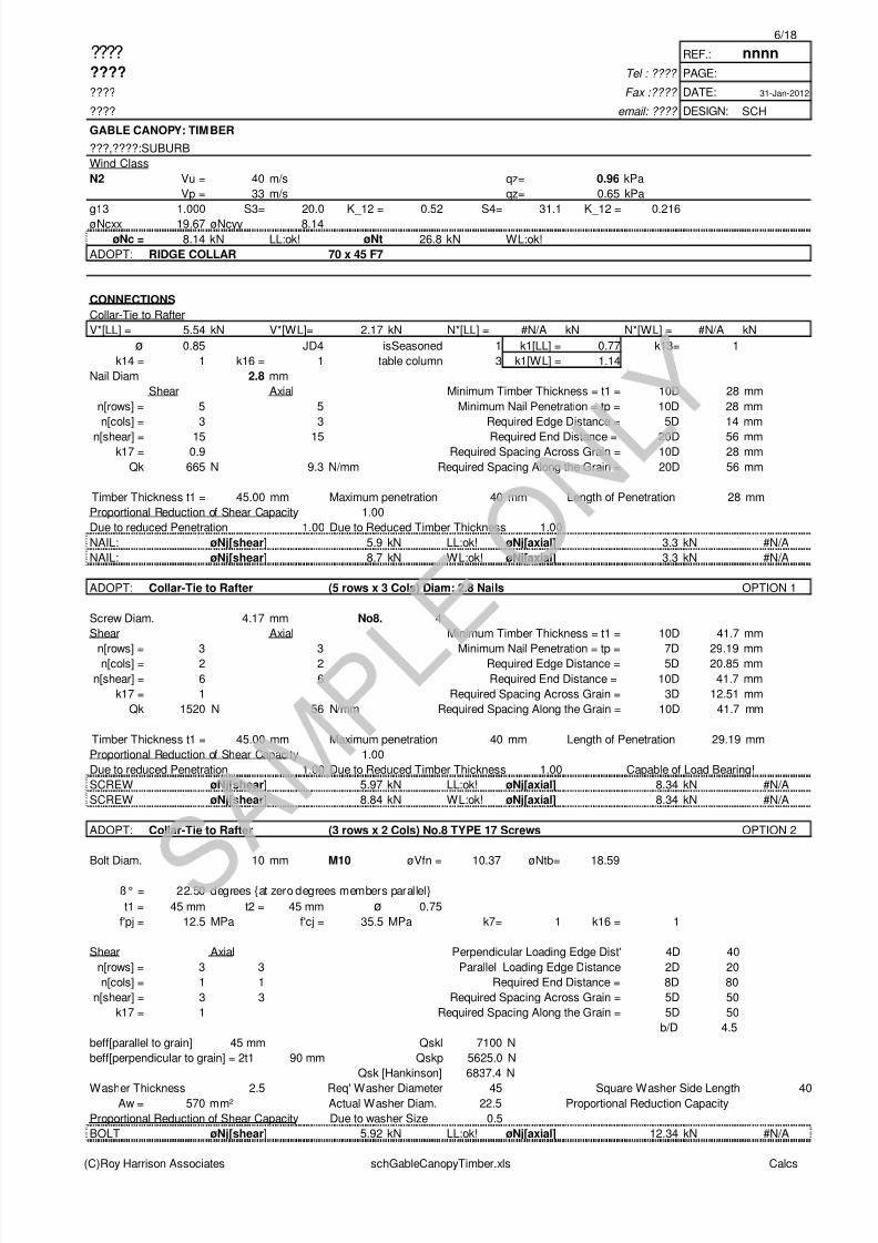
CONNECTIONS
Collar-Tie to Rafter
V*[LL] = 5.54 kN V*[WL]= 2.17 kN N*[LL] = #N/A kN N*[WL] = #N/A kN
ø 0.85 JD4 isSeasoned 1 k1[LL] = 0.77 k13= 1
k14 = 1 k16 = 1 table column 3 k1[WL] = 1.14
Nail Diam 2.8 mm
Shear Axial Minimum Timber Thickness = t1 = 10D 28 mm
n[rows] = 5 5 Minimum Nail Penetration = tp = 10D 28 mm
n[cols] = 3 3 Required Edge Distance = 5D 14 mm
n[shear] = 15 15 Required End Distance = 20D 56 mmk17 = 0.9 Required Spacing Across Grain = 10D 28 mm
Qk 665 N 9.3 N/mm Required Spacing Along the Grain = 20D 56 mm
Timber Thickness t1 = 45.00 mm Maximum penetration 40 mm Length of Penetration 28 mm
Proportional Reduction of Shear Capacity 1.00
Due to reduced Penetration 1.00 Due to Reduced Timber Thickness 1.00
NAIL: øNj[shear] 5.9 kN LL:ok! øNj[axial] 3.3 kN #N/A
NAIL: øNj[shear] 8.7 kN WL:ok! øNj[axial] 3.3 kN #N/A
ADOPT: Collar-Tie to Rafter (5 rows x 3 Cols) Diam: 2.8 Nails OPTION 1
Screw Diam. 4.17 mm No8. 4
Shear Axial Minimum Timber Thickness = t1 = 10D 41.7 mm
n[rows] = 3 3 Minimum Nail Penetration = tp = 7D 29.19 mmn[cols] = 2 2 Required Edge Distance = 5D 20.85 mm
n[shear] = 6 6 Required End Distance = 10D 41.7 mm
k17 = 1 Required Spacing Across Grain = 3D 12.51 mm
Qk 1520 N 56 N/mm Required Spacing Along the Grain = 10D 41.7 mm
Timber Thickness t1 = 45.00 mm Maximum penetration 40 mm Length of Penetration 29.19 mm
Proportional Reduction of Shear Capacity 1.00
Due to reduced Penetration 1.00 Due to Reduced Timber Thickness 1.00 Capable of Load Bearing!
SCREW øNj[shear] 5.97 kN LL:ok! øNj[axial] 8.34 kN #N/A
SCREW øNj[shear] 8.84 kN WL:ok! øNj[axial] 8.34 kN #N/A
ADOPT: Collar-Tie to Rafter (3 rows x 2 Cols) No.8 TYPE 17 Screws OPTION 2
Bolt Diam. 10 mm M10 øVfn = 10.37 øNtb= 18.59
ß° = 22.50 degrees {at zero degrees members parallel}
t1 = 45 mm t2 = 45 mm ø 0.75
f'pj = 12.5 MPa f'cj = 35.5 MPa k7= 1 k16 = 1
Shear Axial Perpendicular Loading Edge Dist' 4D 40
n[rows] = 3 3 Parallel Loading Edge Distance 2D 20
n[cols] = 1 1 Required End Distance = 8D 80
n[shear] = 3 3 Required Spacing Across Grain = 5D 50
k17 = 1 Required Spacing Along the Grain = 5D 50
b/D 4.5
beff[parallel to grain] 45 mm Qskl 7100 N
beff[perpendicular to grain] = 2t1 90 mm Qskp 5625.0 N
Qsk [Hankinson] 6837.4 N
Washer Thickness 2.5 Req' Washer Diameter 45 Square Washer Side Length 40Aw = 570 mm² Actual Washer Diam. 22.5 Proportional Reduction Capacity
Proportional Reduction of Shear Capacity Due to washer Size 0.5
BOLT øNj[shear] 5.92 kN LL:ok! øNj[axial] 12.34 kN #N/A
(C)Roy Harrison Associates schGableCanopyTimber.xls Calcs

8/3/2019 Structural Calculations for Timber Canopy with Gable Roof
http://slidepdf.com/reader/full/structural-calculations-for-timber-canopy-with-gable-roof 7/18
7/18
???? REF.: nnnn
???? Tel : ???? PAGE:
???? Fax :???? DATE: 31-Jan-2012
???? email: ???? DESIGN: SCH
GABLE CANOPY: TIMBER
???,????:SUBURB
Wind Class
N2 Vu = 40 m/s qz= 0.96 kPa
Vp = 33 m/s qz= 0.65 kPa
BOLT øNj[shear] 8.77 kN WL:ok! øNj[axial] 18.28 kN #N/A
ADOPT: Collar-Tie to Rafter (3 rows x 1 Cols) M10 (Property Class 4.6 Bolts)+22.5 washers OPTION 3
CONNECTIONS
Ridge Collar
V*[LL] = 5.54 kN V*[WL]= 2.60 kN N*[LL] = #N/A kN N*[WL] = #N/A kN
ø 0.85 JD4 isSeasoned 1 k1[LL] = 0.77 k13= 1
k14 = 1 k16 = 1 table column 3 k1[WL] = 1.14
Nail Diam 2.8 mm
Shear Axial Minimum Timber Thickness = t1 = 10D 28 mm
n[rows] = 20 20 Minimum Nail Penetration = tp = 10D 28 mm
n[cols] = 2 2 Required Edge Distance = 5D 14 mmn[shear] = 40 40 Required End Distance = 20D 56 mm
k17 = 0.75 Required Spacing Across Grain = 10D 28 mm
Qk 665 N 9.3 N/mm Required Spacing Along the Grain = 20D 56 mm
Timber Thickness t1 = 45.00 mm Maximum penetration 40 mm Length of Penetration 28 mm
Proportional Reduction of Shear Capacity 1.00
Due to reduced Penetration 1.00 Due to Reduced Timber Thickness 1.00
NAIL: øNj[shear] 13.1 kN LL:ok! øNj[axial] 8.9 kN #N/A
NAIL: øNj[shear] 19.3 kN WL:ok! øNj[axial] 8.9 kN #N/A
Length>300mm,NOT practical Length of fastening 1120 W idth of Fastening : 56
ADOPT: Ridge Collar (20 rows x 2 Cols) Diam: 2.8 Nails OPTION 1
Screw Diam. 4.17 mm No8. 4
Shear Axial Minimum Timber Thickness = t1 = 10D 41.7 mmn[rows] = 3 3 Minimum Nail Penetration = tp = 7D 29.19 mm
n[cols] = 2 2 Required Edge Distance = 5D 20.85 mm
n[shear] = 6 6 Required End Distance = 10D 41.7 mm
k17 = 1 Required Spacing Across Grain = 3D 12.51 mm
Qk 1520 N 56 N/mm Required Spacing Along the Grain = 10D 41.7 mm
Timber Thickness t1 = 45.00 mm Maximum penetration 40 mm Length of Penetration 29.19 mm
Proportional Reduction of Shear Capacity 1.00
Due to reduced Penetration 1.00 Due to Reduced Timber Thickness 1.00 Capable of Load Bearing!
SCREW øNj[shear] 5.97 kN LL:ok! øNj[axial] 8.34 kN #N/A
SCREW øNj[shear] 8.84 kN WL:ok! øNj[axial] 8.34 kN #N/A
Space: ok! Length of fastening 125.1 Width of Fastening : 54.21
ADOPT: Ridge Collar (3 rows x 2 Cols) No.8 TYPE 17 Screws OPTION 2
Bolt Diam. 10 mm M10 øVfn = 10.37 øNtb= 18.59
ß° = 0.00 degrees {at zero degrees members parallel}
t1 = 45 mm t2 = 45 mm ø 0.75
f'pj = 12.5 MPa f'cj = 35.5 MPa k7= 1 k16 = 1
Shear Axial Perpendicular Loading Edge Dist' 4D 40
n[rows] = 2 2 Parallel Loading Edge Distance 2D 20 40
n[cols] = 1 1 Required End Distance = 8D 80
n[shear] = 2 2 Required Spacing Across Grain = 5D 50
k17 = 1 Required Spacing Along the Grain = 5D 50
b/D 4.5
beff[parallel to grain] 45 mm Qskl 7100 N
beff[perpendicular to grain] = 2t1 90 mm Qskp 5625 N
Qsk [Hankinson] 7100 NWasher Thickness 2.5 Req' Washer Diameter 45 Square Washer Side Length 40
Aw = 570 mm² Actual Washer Diam. 45 Proportional Reduction Capacity
Proportional Reduction of Shear Capacity Due to washer Size 1
(C)Roy Harrison Associates schGableCanopyTimber.xls Calcs

8/3/2019 Structural Calculations for Timber Canopy with Gable Roof
http://slidepdf.com/reader/full/structural-calculations-for-timber-canopy-with-gable-roof 8/18
8/18
???? REF.: nnnn
???? Tel : ???? PAGE:
???? Fax :???? DATE: 31-Jan-2012
???? email: ???? DESIGN: SCH
GABLE CANOPY: TIMBER
???,????:SUBURB
Wind Class
N2 Vu = 40 m/s qz= 0.96 kPa
Vp = 33 m/s qz= 0.65 kPa
BOLT øNj[shear] 8.20 kN LL:ok! øNj[axial] 8.23 kN #N/A
BOLT øNj[shear] 12.14 kN WL:ok! øNj[axial] 12.18 kN #N/A
Space: ok! Length of fastening 130 Width of Fastening : 40
ADOPT: Ridge Collar (2 rows x 1 Cols) M10 (Property Class 4.6 Bolts)+45.0 washers OPTION 3
CONNECTIONS
Rafter to Ridgeboard
V*[LL] = 1.35 kN V*[WL]= 0.61 kN N*[LL] = #N/A kN N*[WL] = #N/A kN
ø 0.85 JD4 isSeasoned 1 k1[LL] = 0.77 k13= 1
k14 = 1 k16 = 1 table column 3 k1[WL] = 1.14
Nail Diam 2.8 mm
Shear Axial Minimum Timber Thickness = t1 = 10D 28 mm
n[rows] = 4 4 Minimum Nail Penetration = tp = 10D 28 mmn[cols] = 1 1 Required Edge Distance = 5D 14 mm
n[shear] = 4 4 Required End Distance = 20D 56 mm
k17 = 1.00 Required Spacing Across Grain = 10D 28 mm
Qk 665 N 9.3 N/mm Required Spacing Along the Grain = 20D 56 mm
Timber Thickness t1 = 45.00 mm Maximum penetration 40 mm Length of Penetration 28 mm
Proportional Reduction of Shear Capacity 1.00
Due to reduced Penetration 1.00 Due to Reduced Timber Thickness 1.00
NAIL: øNj[shear] 1.7 kN LL:ok! øNj[axial] 0.9 kN #N/A
NAIL: øNj[shear] 2.6 kN WL:ok! øNj[axial] 0.9 kN #N/A
Space: ok! Length of fastening 224 Width of Fastening : 28
ADOPT: Rafter to Ridgeboard (4 rows x 1 Cols) Diam: 2.8 Nails OPTION 1
Screw Diam. 4.17 mm No8. 4Shear Axial Minimum Timber Thickness = t1 = 10D 41.7 mm
n[rows] = 2 2 Minimum Nail Penetration = tp = 7D 29.19 mm
n[cols] = 1 1 Required Edge Distance = 5D 20.85 mm
n[shear] = 2 2 Required End Distance = 10D 41.7 mm
k17 = 1 Required Spacing Across Grain = 3D 12.51 mm
Qk 1520 N 56 N/mm Required Spacing Along the Grain = 10D 41.7 mm
Timber Thickness t1 = 45.00 mm Maximum penetration 40 mm Length of Penetration 29.19 mm
Proportional Reduction of Shear Capacity 1.00
Due to reduced Penetration 1.00 Due to Reduced Timber Thickness 1.00 Capable of Load Bearing!
SCREW øNj[shear] 1.99 kN LL:ok! øNj[axial] 2.78 kN #N/A
SCREW øNj[shear] 2.95 kN WL:ok! øNj[axial] 2.78 kN #N/A
Space: ok! Length of fastening 83.4 Width of Fastening : 41.7
ADOPT: Rafter to Ridgeboard (2 rows x 1 Cols) No.8 TYPE 17 Screws OPTION 2
Bolt Diam. 10 mm M10 øVfn = 10.37 øNtb= 18.59
ß° = 90.00 degrees {at zero degrees members parallel}
t1 = 45 mm t2 = 45 mm ø 0.75
f'pj = 12.5 MPa f'cj = 35.5 MPa k7= 1 k16 = 1
Shear Axial Perpendicular Loading Edge Dist' 4D 40
n[rows] = 1 1 Parallel Loading Edge Distance 2D 20 40
n[cols] = 1 1 Required End Distance = 8D 80
n[shear] = 1 1 Required Spacing Across Grain = 5D 50
k17 = 1 Required Spacing Along the Grain = 5D 50
b/D 4.5
beff[parallel to grain] 45 mm Qskl 7100 N
beff[perpendicular to grain] = 2t1 90 mm Qskp 5625.0 NQsk [Hankinson] 5625.0 N
Washer Thickness 2.5 Req' Washer Diameter 45 Square Washer Side Length 40
Aw = 570 mm² Actual Washer Diam. 45 Proportional Reduction Capacity
(C)Roy Harrison Associates schGableCanopyTimber.xls Calcs

8/3/2019 Structural Calculations for Timber Canopy with Gable Roof
http://slidepdf.com/reader/full/structural-calculations-for-timber-canopy-with-gable-roof 9/18
9/18
???? REF.: nnnn
???? Tel : ???? PAGE:
???? Fax :???? DATE: 31-Jan-2012
???? email: ???? DESIGN: SCH
GABLE CANOPY: TIMBER
???,????:SUBURB
Wind Class
N2 Vu = 40 m/s qz= 0.96 kPa
Vp = 33 m/s qz= 0.65 kPa
Proportional Reduction of Shear Capacity Due to washer Size 1
BOLT øNj[shear] 3.25 kN LL:ok! øNj[axial] 4.11 kN #N/A
BOLT øNj[shear] 4.81 kN WL:ok! øNj[axial] 6.09 kN #N/A
Space: ok! Length of fastening 80 Width of Fastening : 40
ADOPT: Rafter to Ridgeboard (1 rows x 1 Cols) M10 (Property Class 4.6 Bolts)+45.0 washers OPTION 3
CONNECTIONS
Rafter to Perimeter Frame (Fascia Beams)
V*[LL] = 1.83 kN V*[WL]= 1.50 kN N*[LL] = #N/A kN N*[WL] = 0.86 kN
ø 0.85 JD4 isSeasoned 1 k1[LL] = 0.77 k13= 1
k14 = 1 k16 = 1 table column 3 k1[WL] = 1.14
Nail Diam 2.8 mm
Shear Axial Minimum Timber Thickness = t1 = 10D 28 mmn[rows] = 5 5 Minimum Nail Penetration = tp = 10D 28 mm
n[cols] = 1 1 Required Edge Distance = 5D 14 mm
n[shear] = 5 5 Required End Distance = 20D 56 mm
k17 = 0.90 Required Spacing Across Grain = 10D 28 mm
Qk 665 N 9.3 N/mm Required Spacing Along the Grain = 20D 56 mm
Timber Thickness t1 = 45.00 mm Maximum penetration 40 mm Length of Penetration 28 mm
Proportional Reduction of Shear Capacity 1.00
Due to reduced Penetration 1.00 Due to Reduced Timber Thickness 1.00
NAIL: øNj[shear] 2.0 kN LL:ok! øNj[axial] 1.1 kN #N/A
NAIL: øNj[shear] 2.9 kN WL:ok! øNj[axial] 1.1 kN WL:ok!
Space: ok! Length of fastening 140 Width of Fastening : 56
ADOPT: Rafter to Perimeter Frame (5 rows x 1 Cols) Diam: 2.8 Nails OPTION 1
Screw Diam. 4.17 mm No8. 4
Shear Axial Minimum Timber Thickness = t1 = 10D 41.7 mm
n[rows] = 2 2 Minimum Nail Penetration = tp = 7D 29.19 mm
n[cols] = 1 1 Required Edge Distance = 5D 20.85 mm
n[shear] = 2 2 Required End Distance = 10D 41.7 mm
k17 = 1 Required Spacing Across Grain = 3D 12.51 mm
Qk 1520 N 56 N/mm Required Spacing Along the Grain = 10D 41.7 mm
Timber Thickness t1 = 45.00 mm Maximum penetration 40 mm Length of Penetration 29.19 mm
Proportional Reduction of Shear Capacity 1.00
Due to reduced Penetration 1.00 Due to Reduced Timber Thickness 1.00 Capable of Load Bearing!
SCREW øNj[shear] 1.99 kN LL:ok! øNj[axial] 2.78 kN #N/A
SCREW øNj[shear] 2.95 kN WL:ok! øNj[axial] 2.78 kN WL:ok!
Space: ok! Length of fastening 54.21 Width of Fastening : 41.7
ADOPT: Rafter to Perimeter Frame (2 rows x 1 Cols) No.8 TYPE 17 Screws OPTION 2
Bolt Diam. 10 mm M10 øVfn = 10.37 øNtb= 18.59
ß° = 90.00 degrees {at zero degrees members parallel} {90 equals bolt to fascia, 22.5deg's = bolt to rafter}
t1 = 45 mm t2 = 45 mm ø 0.75
f'pj = 12.5 MPa f'cj = 35.5 MPa k7= 1 k16 = 1
Shear Axial Perpendicular Loading Edge Dist' 4D 40
n[rows] = 1 1 Parallel Loading Edge Distance 2D 20 40
n[cols] = 2 2 Required End Distance = 8D 80
n[shear] = 2 2 Required Spacing Across Grain = 5D 50
k17 = 1 Required Spacing Along the Grain = 5D 50
b/D 4.5
beff[parallel to grain] 45 mm Qskl 7100 Nbeff[perpendicular to grain] = 2t1 90 mm Qskp 5625 N
Qsk [Hankinson] 5625 N
Washer Thickness 2.5 Req' Washer Diameter 45 Square Washer Side Length 40
(C)Roy Harrison Associates schGableCanopyTimber.xls Calcs

8/3/2019 Structural Calculations for Timber Canopy with Gable Roof
http://slidepdf.com/reader/full/structural-calculations-for-timber-canopy-with-gable-roof 10/18
10/18
???? REF.: nnnn
???? Tel : ???? PAGE:
???? Fax :???? DATE: 31-Jan-2012
???? email: ???? DESIGN: SCH
GABLE CANOPY: TIMBER
???,????:SUBURB
Wind Class
N2 Vu = 40 m/s qz= 0.96 kPa
Vp = 33 m/s qz= 0.65 kPa
Aw = 570 mm² Actual Washer Diam. 22.5 Proportional Reduction Capacity
Proportional Reduction of Shear Capacity Due to washer Size 0.5
BOLT øNj[shear] 3.25 kN LL:ok! øNj[axial] 8.23 kN #N/A
BOLT øNj[shear] 4.81 kN WL:ok! øNj[axial] 12.18 kN WL:ok!
Space: ok! Length of fastening 80 Width of Fastening : 90
ADOPT: Rafter to Perimeter Frame (2 rows x 1 Cols) M10 (Property Class 4.6 Bolts)+22.5 washers OPTION 3
Maximum Bending Moment Fascia Beams
NB: For canopies attached to an existing building only. Only bending in a vertical plane considered {strong axis bending}.
Rafter Spacing 1.200 m
Fascia Beam Span 3.000 m
Number of Rafter Spacings in Span 2.500 =n isOdd 0.50 {=0(zero) Odd else Even}
Number of Raf ters in Span 1.500Bay Width 3.000 m
Minimum Number of Bays 1
Minimum Total Columns 4
From Rafter end reactions Simplified from Udl wind udl = (3/8)p2 + (1/8)p1
Action Moment Reaction Action Moment
kN kNm kN kPa kN/m kNm
Wind -1.50 -1.18 -1.13 Wind -0.252 -0.756 -0.85
Liveload 1.83 1.44 1.37 Liveload 0.250 0.750 0.84
For point loading of fascia M = (n^2-1)PL/8n , n is odd M = nPL/8 , n is even M=PL/3 for n=3, forces=2
Ra=Rb=(n-1)P/2
FASCIA BEAMS
M*[LL] = 1.44 kNm V*[LL]= 1.37 kN M*[WL]= 1.18 kNm V*[WL]= 1.13 kNMaterial
TIMBER F7 E = 7900 MPa f'by = 20.0 MPa=N/mm² EI = 2.03E+11 Nmm²
Timber Density = 550 kg/m³ rho_b 0.91 f's 2.10 MPa
SD6 f'p = 12.00 MPa f'l = 35.00 MPa
Section & Member Design AS1720
D = 190 mm B = 45 mm Axx = 8550 mm²
Ixx = 2.572E+07 mm4
Zxx = 270750 mm³ ø = 0.85
k_1[LL] 0.94 Medium-Term 5.0 days k_1[wind] 1.00 Instantaneous 5.0 sec
k_4[moisture] 1.00 k_7[Length,Position of bearing] 1.00
k_6[temperature] 1.00 k_11[size,bending] 1.00
k_9[strength sharing] 1.00 k_11[size,shear] 1.00
Lay = 1.200 m DesignCase 1 Slenderness Coefficient S1 13.26
{have rafters max. 900 c/c} rho_b.S1 12.04 k_12 0.898
Bearing Length 90.00 mm Bearing Width 30.00 mm Bearing Area 2700 mm²
Theta 90.00 {90=perpendicular to grain} øNp 25.9 kN ok! (for option rafters top of fascia)øMs = 4.33 kNm LL:ok! øMb = 3.89 kNm LL:ok! øV = 14.35 kN LL:ok!
øMs = 4.60 kNm WL:ok! øMb = 4.13 kNm WL:ok! øV = 15.26 kN WL:ok!
ADOPT: FASCIA BEAMS 190 x 45 F7
CONNECTIONS
Fascia Beam to Posts
V*[LL] = 1.37 kN V*[WL]= 1.13 kN N*[LL] = #N/A kN N*[WL] = #N/A kN
ø 0.85 JD4 isSeasoned 1 k1[LL] = 0.77 k13= 1
k14 = 1 k16 = 1 k1[WL] = 1.14
Bolt Diam. 10 mm M10 øVfn = 10.37 øNtb= 18.59
ß° = 90.00 degrees {at zero degrees members parallel} {90 equals bolt to fascia, 22.5deg's = bolt to rafter}t1 = 45 mm t2 = 45 mm ø 0.75
f'pj = 12.5 MPa f'cj = 35.5 MPa k7= 1 k16 = 1
(C)Roy Harrison Associates schGableCanopyTimber.xls Calcs
8/3/2019 Structural Calculations for Timber Canopy with Gable Roof
http://slidepdf.com/reader/full/structural-calculations-for-timber-canopy-with-gable-roof 11/18
11/18
???? REF.: nnnn
???? Tel : ???? PAGE:
???? Fax :???? DATE: 31-Jan-2012
???? email: ???? DESIGN: SCH
GABLE CANOPY: TIMBER
???,????:SUBURB
Wind Class
N2 Vu = 40 m/s qz= 0.96 kPa
Vp = 33 m/s qz= 0.65 kPa
Shear Axial Perpendicular Loading Edge Dist' 4D 40
n[rows] = 1 1 Parallel Loading Edge Distance 2D 20 40
n[cols] = 2 2 Required End Distance = 8D 80
n[shear] = 2 2 Required Spacing Across Grain = 5D 50
k17 = 1 Required Spacing Along the Grain = 5D 50
b/D 4.5
beff[parallel to grain] 45 mm Qskl 7100 N
beff[perpendicular to grain] = 2t1 90 mm Qskp 5625 N
Qsk [Hankinson] 5625 N
Washer Thickness 2.5 Req' Washer Diameter 45 Square Washer Side Length 40
Aw = 570 mm² Actual Washer Diam. 45 Proportional Reduction Capacity
Proportional Reduction of Shear Capacity Due to washer Size 1.00
BOLT øNj[shear] 6.50 kN LL:ok! øNj[axial] 8.23 kN #N/A
BOLT øNj[shear] 9.62 kN WL:ok! øNj[axial] 12.18 kN #N/A
Space: ok! Length of fastening 80 Width of Fastening : 90
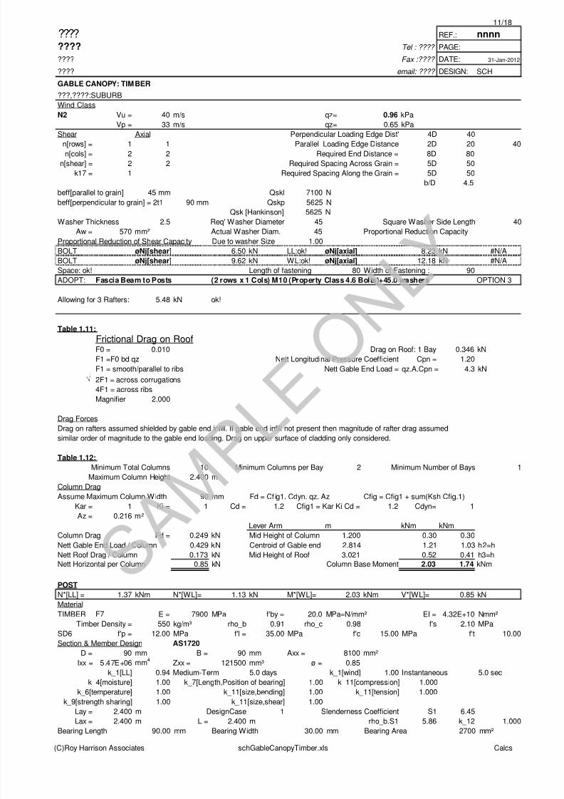
ADOPT: Fascia Beam to Posts (2 rows x 1 Cols) M10 (Property Class 4.6 Bolts)+45.0 washers OPTION 3
Allowing for 3 Rafters: 5.48 kN ok!
Table 1.11:
Frictional Drag on RoofF0 = 0.010 Drag on Roof: 1 Bay 0.346 kN
F1 =F0 bd qz Nett Longitudinal Pressure Coefficient Cpn = 1.20
F1 = smooth/parallel to ribs Nett Gable End Load = qz.A.Cpn = 4.3 kN
2F1 = across corrugations
4F1 = across ribs
Magnifier 2.000
Drag ForcesDrag on rafters assumed shielded by gable end infill. If gable end infill not present then magnitude of rafter drag assumed
similar order of magnitude to the gable end loading. Drag on upper surface of cladding only considered.
Table 1.12:
Minimum Total Columns 10 Minimum Columns per Bay 2 Minimum Number of Bays 1
Maximum Column Height 2.400 m
Column Drag
Assume Maximum Column Width 90 mm Fd = Cf ig1. Cdyn. qz. Az Cfig = Cfig1 + sum(Ksh Cfig.1)
Kar = 1 Ki = 1 Cd = 1.2 Cfig1 = Kar Ki Cd = 1.2 Cdyn= 1
Az = 0.216 m²
Lever Arm m kNm kNm
Column Drag Fd = 0.249 kN Mid Height of Column 1.200 0.30 0.30
Nett Gable End Load / Column 0.429 kN Centroid of Gable end 2.814 1.21 1.03 h2=h
Nett Roof Drag / Column 0.173 kN Mid Height of Roof 3.021 0.52 0.41 h3=h
Nett Horizontal per Column 0.85 kN Column Base Moment 2.03 1.74 kNm
POST
N*[LL] = 1.37 kNm N*[WL]= 1.13 kN M*[WL]= 2.03 kNm V*[WL]= 0.85 kN
Material
TIMBER F7 E = 7900 MPa f'by = 20.0 MPa=N/mm² EI = 4.32E+10 Nmm²
Timber Density = 550 kg/m³ rho_b 0.91 rho_c 0.98 f's 2.10 MPa
SD6 f'p = 12.00 MPa f'l = 35.00 MPa f'c 15.00 MPa f't 10.00
Section & Member Design AS1720
D = 90 mm B = 90 mm Axx = 8100 mm²
Ixx = 5.47E+06 mm4
Zxx = 121500 mm³ ø = 0.85
k_1[LL] 0.94 Medium-Term 5.0 days k_1[wind] 1.00 Instantaneous 5.0 sec
k_4[moisture] 1.00 k_7[Length,Position of bearing] 1.00 k_11[compression] 1.000
k_6[temperature] 1.00 k_11[size,bending] 1.00 k_11[tension] 1.000
k_9[strength sharing] 1.00 k_11[size,shear] 1.00Lay = 2.400 m DesignCase 1 Slenderness Coefficient S1 6.45
Lax = 2.400 m L = 2.400 m rho_b.S1 5.86 k_12 1.000
Bearing Length 90.00 mm Bearing Width 30.00 mm Bearing Area 2700 mm²
(C)Roy Harrison Associates schGableCanopyTimber.xls Calcs

8/3/2019 Structural Calculations for Timber Canopy with Gable Roof
http://slidepdf.com/reader/full/structural-calculations-for-timber-canopy-with-gable-roof 12/18
12/18
???? REF.: nnnn
???? Tel : ???? PAGE:
???? Fax :???? DATE: 31-Jan-2012
???? email: ???? DESIGN: SCH
GABLE CANOPY: TIMBER
???,????:SUBURB
Wind Class
N2 Vu = 40 m/s qz= 0.96 kPa
Vp = 33 m/s qz= 0.65 kPa
Theta 0.00 {90=perpendicular to grain} øNp 75.5 kN ok! (for option rafters top of fascia)
øMs = 2.07 kNm WL:ok! øMb = 2.07 kNm WL:ok! øV = 14.46 kN WL:ok!
g13 1.000 S3= 26.7 K_12 = 0.29 S4= 26.7 K_12 = 0.294
øNcxx 28.50 øNcyy 28.50
øNc = 28.50 kN LL:ok! øNt 68.9 kN WL:ok!
ADOPT: POST 1/90 x 90 F7
GABLE END FASCIA BEAM
With no gable end infill, just a decorative finish across end of canopy. With infill becomes beam bent about weak axis.
Gable End Load to Fascia = W = 2.15 kN FullSpan = 6.000 m M=W.L/6 = 2.15 kNm
Span = 3.000 m M=W.L/6 = 1.07 kNmGABLE END FACIA
M*[LL] = #N/A kNm V*[LL]= #N/A kN M*[WL]= 1.07 kNm V*[WL]= 1.07 kN
Material
TIMBER F7 E = 7900 MPa f'by = 20.0 MPa=N/mm² EI = 1.14E+10 Nmm²
Timber Density = 550 kg/m³ rho_b 0.91 f's 2.10 MPa
SD6 f'p = 12.00 MPa f'l = 35.00 MPa
Section & Member Design AS1720
D = 45 mm B = 190 mm Axx = 8550 mm²
Iyy = 1.443E+06 mm4
Zyy = 64125 mm³ ø = 0.85
k_1[LL] 0.94 Medium-Term 5.0 days k_1[wind] 1.00 Instantaneous 5.0 sec
k_4[moisture] 1.00 k_7[Length,Position of bearing] 1.00
k_6[temperature] 1.00 k_11[size,bending] 1.00
k_9[strength sharing] 1.00 k_11[size,shear] 1.00
Lay = 3.000 m DesignCase 1 Slenderness Coefficient S1 2.42{have rafters max. 900 c/c} rho_b.S1 2.19 k_12 1.000
øMs = 1.02 kNm #N/A øMb = 1.02 kNm #N/A øV = 14.35 kN #N/A
øMs = 1.09 kNm WL:ok! øMb = 1.09 kNm WL:ok! øV = 15.26 kN WL:ok!
ADOPT: GABLE END FACIA 45 x 190 F7
STRUT If Gable end fascia to be braced/supported back to the purlins at 1000 c/c
N*c[WL] = 2.15 kN
Material
TIMBER F7 E = 7900 MPa f'by = 20.0 MPa=N/mm² EI = 1.02E+10 Nmm²
Timber Density = 550 kg/m³ rho_b 0.91 rho_c 0.98 f's 2.10 MPa
SD6 f'p = 12.00 MPa f'l = 35.00 MPa f'c 15.00 MPa f't 10.00
Section & Member Design AS1720
D = 70 mm B = 45 mm Axx = 3150 mm²Ixx = 1286250 mm
4Zxx = 36750 mm³ ø = 0.85
k_1[LL] 0.94 Medium-Term 5.0 days k_1[wind] 1.00 Instantaneous 5.0 sec
k_4[moisture] 1.00 k_7[Length,Position of bearing] 1.00 k_11[compression] 1.000
k_6[temperature] 1.00 k_11[size,bending] 1.00 k_11[tension] 1.000
k_9[strength sharing] 1.00 k_11[size,shear] 1.00
Lay = 2.800 m DesignCase 1 Slenderness Coefficient S1 12.30
Lax = 2.800 m L = 2.800 m rho_b.S1 11.16 k_12 0.942
g13 1.000 S3= 40.0 K_12 = 0.13 S4= 62.2 K_12 = 0.054
øNcxx 5.24 øNcyy 2.17
øNc = 2.17 kN WL:ok!
ADOPT: STRUT 70 x 45 F7
(C)Roy Harrison Associates schGableCanopyTimber.xls Calcs
8/3/2019 Structural Calculations for Timber Canopy with Gable Roof
http://slidepdf.com/reader/full/structural-calculations-for-timber-canopy-with-gable-roof 13/18
13/18
???? REF.: nnnn
???? Tel : ???? PAGE:
???? Fax :???? DATE: 31-Jan-2012
???? email: ???? DESIGN: SCH
GABLE CANOPY: TIMBER
???,????:SUBURB
Wind Class
N2 Vu = 40 m/s qz= 0.96 kPa
Vp = 33 m/s qz= 0.65 kPa
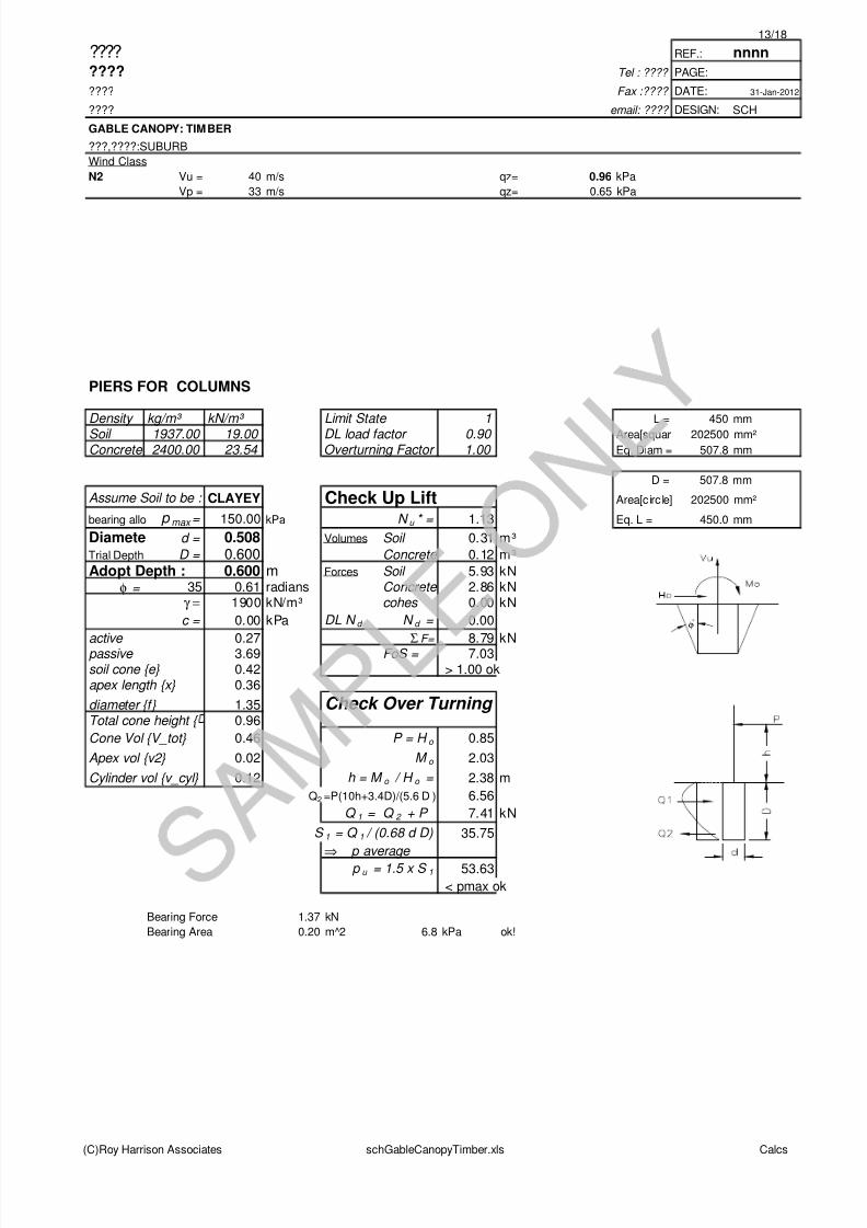
PIERS FOR COLUMNS
Density kg/m³ kN/m³ Limit State 1 L = 450 mm
Soil 1937.00 19.00 DL load factor 0.90 Area[squar 202500 mm²
Concrete 2400.00 23.54 Overturning Factor 1.00 Eq. Diam = 507.8 mm
D = 507.8 mm
Assume Soil to be : CLAYEY Check Up Lift Area[circ le] 202500 mm²
bearing allo p max = 150.00 kPa N u * = 1.13 Eq. L = 450.0 mm
Diamete d = 0.508 Volumes Soil 0.31 m³
Trial Depth D = 0.600 Concrete 0.12 m³
Adopt Depth : 0.600 m Forces Soil 5.93 kN
φ = 35 0.61 radians Concrete 2.86 kNγ = 1900 kN/m³ cohes 0.00 kN
c = 0.00 kPa DL N d N d = 0.00
active 0.27 Σ F= 8.79 kNpassive 3.69 FoS = 7.03soil cone {e} 0.42 > 1.00 okapex length {x} 0.36
diameter {f} 1.35 Check Over Turning Total cone height { 0.96
Cone Vol {V_tot} 0.46 P = H o 0.85
Apex vol {v2} 0.02 M o 2.03
Cylinder vol {v_cyl} 0.12 h = M o / H o = 2.38 m
Q2 =P(10h+3.4D)/(5.6 D ) 6.56
Q 1 = Q 2 + P 7.41 kN
S 1 = Q 1 / (0.68 d D) 35.75
⇒ p average
p u = 1.5 x S 1 53.63
< pmax ok
Bearing Force 1.37 kN
Bearing Area 0.20 m^2 6.8 kPa ok!
φ
(C)Roy Harrison Associates schGableCanopyTimber.xls Calcs
8/3/2019 Structural Calculations for Timber Canopy with Gable Roof
http://slidepdf.com/reader/full/structural-calculations-for-timber-canopy-with-gable-roof 14/18
14/18
???? REF.: nnnn
???? Tel : ???? PAGE:
???? Fax :???? DATE: 31-Jan-2012
???? email: ???? DESIGN: SCH
GABLE CANOPY: TIMBER
???,????:SUBURB
Wind Class
N2 Vu = 40 m/s qz= 0.96 kPa
Vp = 33 m/s qz= 0.65 kPa
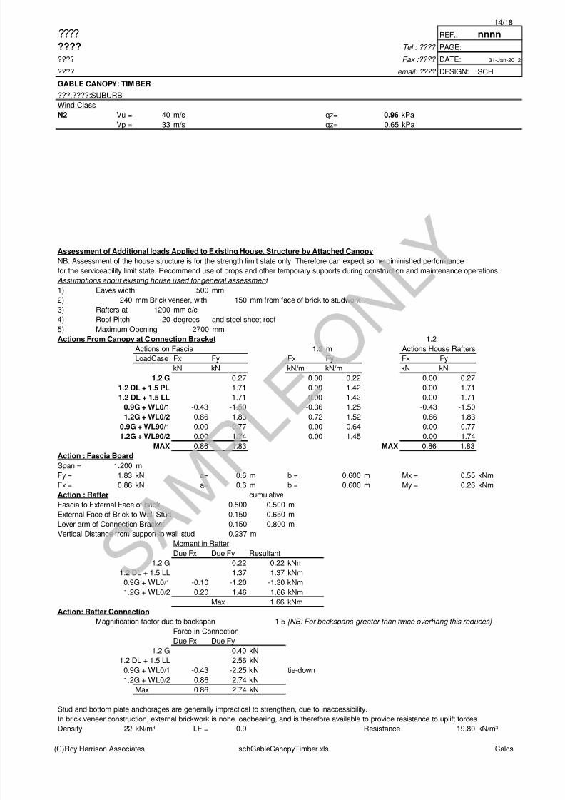
Assessment of Additional loads Applied to Existing House. Structure by Attached Canopy
NB: Assessment of the house structure is for the strength limit state only. Therefore can expect some diminished performance
for the serviceability limit state. Recommend use of props and other temporary supports during construction and maintenance operations.
Assumptions about existing house used for general assessment 1) Eaves width 500 mm
2) 240 mm Brick veneer, with 150 mm from face of brick to studwork
3) Rafters at 1200 mm c/c
4) Roof Pitch 20 degrees and steel sheet roof
5) Maximum Opening 2700 mm
Actions From Canopy at Connection Bracket 1.2
Actions on Fascia 1.2 m Actions House Rafters
LoadCase Fx Fy Fx Fy Fx Fy
kN kN kN/m kN/m kN kN
1.2 G 0.27 0.00 0.22 0.00 0.27
1.2 DL + 1.5 PL 1.71 0.00 1.42 0.00 1.71
1.2 DL + 1.5 LL 1.71 0.00 1.42 0.00 1.71
0.9G + WL0/1 -0.43 -1.50 -0.36 -1.25 -0.43 -1.50
1.2G + WL0/2 0.86 1.83 0.72 1.52 0.86 1.830.9G + WL90/1 0.00 -0.77 0.00 -0.64 0.00 -0.77
1.2G + WL90/2 0.00 1.74 0.00 1.45 0.00 1.74
MAX 0.86 1.83 MAX 0.86 1.83
Action : Fascia Board
Span = 1.200 m
Fy = 1.83 kN a= 0.6 m b = 0.600 m Mx = 0.55 kNm
Fx = 0.86 kN a= 0.6 m b = 0.600 m My = 0.26 kNm
Action : Rafter cumulative
Fascia to External Face of brick 0.500 0.500 m
External Face of Brick to Wall Stud 0.150 0.650 m
Lever arm of Connection Bracket 0.150 0.800 m
Vertical Distance from support to wall stud 0.237 m
Moment in Rafter
Due Fx Due Fy Resultant
1.2 G 0.22 0.22 kNm1.2 DL + 1.5 LL 1.37 1.37 kNm
0.9G + WL0/1 -0.10 -1.20 -1.30 kNm
1.2G + WL0/2 0.20 1.46 1.66 kNm
Max 1.66 kNm
Action: Rafter Connection
Magnification factor due to backspan 1.5 {NB: For backspans greater than twice overhang this reduces}
Force in Connection
Due Fx Due Fy
1.2 G 0.40 kN
1.2 DL + 1.5 LL 2.56 kN
0.9G + WL0/1 -0.43 -2.25 kN tie-down
1.2G + WL0/2 0.86 2.74 kN
Max 0.86 2.74 kN
Stud and bottom plate anchorages are generally impractical to strengthen, due to inaccessibility.
In brick veneer construction, external brickwork is none loadbearing, and is therefore available to provide resistance to uplift forces.
Density 22 kN/m³ LF = 0.9 Resistance 19.80 kN/m³
(C)Roy Harrison Associates schGableCanopyTimber.xls Calcs
8/3/2019 Structural Calculations for Timber Canopy with Gable Roof
http://slidepdf.com/reader/full/structural-calculations-for-timber-canopy-with-gable-roof 15/18
15/18
???? REF.: nnnn
???? Tel : ???? PAGE:
???? Fax :???? DATE: 31-Jan-2012
???? email: ???? DESIGN: SCH
GABLE CANOPY: TIMBER
???,????:SUBURB
Wind Class
N2 Vu = 40 m/s qz= 0.96 kPa
Vp = 33 m/s qz= 0.65 kPa
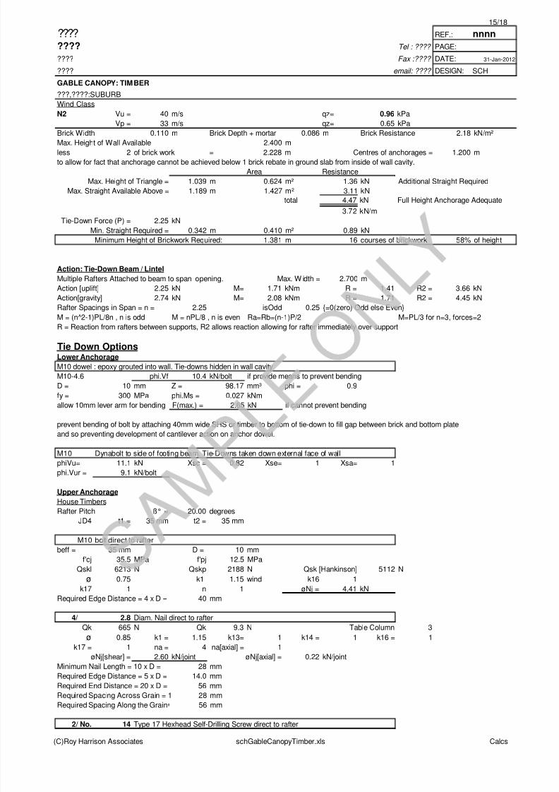
Brick Width 0.110 m Brick Depth + mortar 0.086 m Brick Resistance 2.18 kN/m²
Max. Height of Wall Available 2.400 m
less 2 of brick work = 2.228 m Centres of anchorages = 1.200 m
to allow for fact that anchorage cannot be achieved below 1 brick rebate in ground slab from inside of wall cavity.
Area Resistance
Max. Height of Triangle = 1.039 m 0.624 m² 1.36 kN Additional Straight Required
Max. Straight Available Above = 1.189 m 1.427 m² 3.11 kN
total 4.47 kN Full Height Anchorage Adequate
3.72 kN/m
Tie-Down Force (P) = 2.25 kN
Min. Straight Required = 0.342 m 0.410 m² 0.89 kN
Minimum Height of Brickwork Required: 1.381 m 16 courses of brickwork 58% of height
Action: Tie-Down Beam / Lintel
Multiple Rafters Attached to beam to span opening. Max. W idth = 2.700 mAction [uplift] 2.25 kN M= 1.71 kNm R = 1.41 R2 = 3.66 kN
Action[gravity] 2.74 kN M= 2.08 kNm R = 1.71 R2 = 4.45 kN
Rafter Spacings in Span = n = 2.25 isOdd 0.25 {=0(zero) Odd else Even}
M = (n^2-1)PL/8n , n is odd M = nPL/8 , n is even Ra=Rb=(n-1)P/2 M=PL/3 for n=3, forces=2
R = Reaction from rafters between supports, R2 allows reaction allowing for rafter immediately over support
Tie Down OptionsLower Anchorage
M10 dowel : epoxy grouted into wall. Tie-downs hidden in wall cavity
M10-4.6 phi.Vf 10.4 kN/bolt if provide means to prevent bending
D = 10 mm Z = 98.17 mm³ phi = 0.9
fy = 300 MPa phi.Ms = 0.027 kNm
allow 10mm lever arm for bending F(max.) = 2.65 kN if cannot prevent bending
prevent bending of bolt by attaching 40mm wide SHS or timber to bottom of tie-down to fill gap between brick and bottom plate
and so preventing development of cantilever action on anchor dowel.
M10 Dynabolt to side of footing beam. Tie-Downs taken down external face of wall
phiVu= 11.1 kN Xsc = 0.82 Xse= 1 Xsa= 1
phi.Vur = 9.1 kN/bolt
Upper Anchorage
House Timbers
Rafter Pitch ß° = 20.00 degrees
JD4 t1 = 35 mm t2 = 35 mm
M10 bolt direct to rafter
beff = 35 mm D = 10 mm
f'cj 35.5 MPa f'pj 12.5 MPa
Qskl 6213 N Qskp 2188 N Qsk [Hankinson] 5112 N
ø 0.75 k1 1.15 wind k16 1
k17 1 n 1 øNj = 4.41 kN
Required Edge Distance = 4 x D = 40 mm
4/ 2.8 Diam. Nail direct to rafter
Qk 665 N Qk 9.3 N Table Column 3
ø 0.85 k1 = 1.15 k13= 1 k14 = 1 k16 = 1
k17 = 1 na = 4 na[axial] = 1
øNj[shear] = 2.60 kN/joint øNj[axial] = 0.22 kN/joint
Minimum Nail Length = 10 x D = 28 mm
Required Edge Distance = 5 x D = 14.0 mm
Required End Distance = 20 x D = 56 mm
Required Spacing Across Grain = 1 28 mmRequired Spacing Along the Grain 56 mm
2/ No. 14 Type 17 Hexhead Self-Drilling Screw direct to rafter
(C)Roy Harrison Associates schGableCanopyTimber.xls Calcs
8/3/2019 Structural Calculations for Timber Canopy with Gable Roof
http://slidepdf.com/reader/full/structural-calculations-for-timber-canopy-with-gable-roof 16/18
16/18
???? REF.: nnnn
???? Tel : ???? PAGE:
???? Fax :???? DATE: 31-Jan-2012
???? email: ???? DESIGN: SCH
GABLE CANOPY: TIMBER
???,????:SUBURB
Wind Class
N2 Vu = 40 m/s qz= 0.96 kPa
Vp = 33 m/s qz= 0.65 kPa
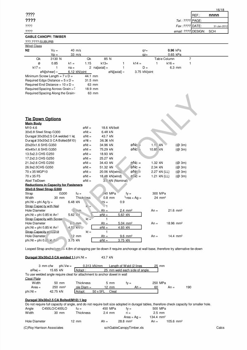
Qk 3130 N Qk 85 N Table Column 7
ø 0.85 k1 = 1.15 k13= 1 k14 = 1 k16 = 1
k17 = 1 na = 2 na[axial] = 1 D = 6.3 mm
øNj[shear] = 6.12 kN/joint øNj[axial] = 3.75 kN/joint
Minimum Screw Length = 7 x D = 44.1 mm
Required Edge Distance = 5 x D = 31.5 mm
Required End Distance = 10 x D = 63 mm
Required Spacing Across Grain = 18.9 mm
Required Spacing Along the Grain 63 mm
Tie Down OptionsMain BodyM10-4.6 øNf = 18.6 kN/bolt
30x0.8 Steel Strap G300 øNt = 6.48 kN
Duragal 30x30x2.5 CA welded 1 le øNt = 43.7 kN
Duragal 30x30x2.5 CA Bolted(M10) øNt = 36.36 kN
20x20x1.6 SHS G350 øNt = 34.96 kN øNc = 1.17 kN (@ 3m)
40x40x1.6 SHS G350 øNt = 75.29 kN øNc = 10.85 kN (@ 3m)
13.5x2.3 CHS G250 øNt = 18.93 kN
17.2x2.3 CHS G250 øNt = 25.27 kN
21.3x2.6 CHS G250 øNt = 34.43 kN øNc = 1.32 kN (@ 3m)
26.9x2.0CHS G350 øNt = 51.32 kN øNc = 2.34 kN (@ 3m)
70 x 35 MGP10 øNt = 20.06 kN{wind} øNc = 2.27 kN {LL} (@ 3m)
70 x 35 F5 øNt = 18.48 kN{wind} øNc = 1.21 kN {LL} (@ 3m)
Abel TieDown øNt = 3.6 kN (Nominal)
Reductions in Capacity for Fasteners30x0.8 Steel Strap G300
Strap G300 fu = 340 MPa fy = 300 MPa
Width 30 mm Thickness 0.8 mm rea = Ag = 24 mm²
phi.Nt = phi Ag fy = 6.48 kN phi = 0.9
Strap Capacity with Nail kt = 1
Hole Diameter 3 mm Ah = 2.4 mm² An = 21.6 mm²
phi.Nt = phi 0.85 kt An 5.62 kN øNt = 5.62 kN
Strap Capacity with Screw kt = 1
Hole Diameter 6.3 mm Ah = 5.04 mm² An = 18.96 mm²
phi.Nt = phi 0.85 kt An 4.93 kN øNt = 4.93 kN
Strap Capacity with Bolt kt = 1
Hole Diameter 12 mm Ah = 9.6 mm² An = 14.4 mm²
phi.Nt = phi 0.85 kt An 3.75 kN øNt = 3.75 kN
Looped Strap anchorage => 4.8m of strapping per tie-down if require anchorage at wall base, therefore try alternative tie-down
Duragal 30x30x2.5 CA welded 1 l phi.Nt = 43.7 kN
3 mm cfw phi.Vw = 0.313 kN/mm Length of W eld (2 lines 25 mm
øRwj = 15.65 kN Adopt : 25 mm weld each side of angle.
To use welded angle require cleat for attachment to anchor dowel in wall
Cleat Plate
Width 50 mm Thickness 5 mm fy = 250 MPa
Area = 250 mm² ole Diam = 12 mm Ah = 60 An = 190
phi.Nt = 42.75 kN Adopt: 50 x 5FL Cleat
Duragal 30x30x2.5 CA Bolted(M10) 1 leg
Do not require full capacity of angle, and do not require bolt size adopted in duragal tables, therefore check capacity for smaller hole.
Angle C450LO/C400LO fu = 450 MPa fy = 500 MPa
Width 30 mm Thickness 2.4 mm ri = 2.5 mm
Area = Ag = 134.4 mm²
Hole Diameter 12 mm Ah = 28.8 mm² An = 105.6 mm²
(C)Roy Harrison Associates schGableCanopyTimber.xls Calcs

8/3/2019 Structural Calculations for Timber Canopy with Gable Roof
http://slidepdf.com/reader/full/structural-calculations-for-timber-canopy-with-gable-roof 17/18
17/18
???? REF.: nnnn
???? Tel : ???? PAGE:
???? Fax :???? DATE: 31-Jan-2012
???? email: ???? DESIGN: SCH
GABLE CANOPY: TIMBER
???,????:SUBURB
Wind Class
N2 Vu = 40 m/s qz= 0.96 kPa
Vp = 33 m/s qz= 0.65 kPa
phi = 0.9 kt = 1
phi.Nt = phi Ag fy = 60.49 kN phi.Nt = phi 0.85 kt An 36.36 kN
phi.Nt = 36.36 kN Therefore can bolt angle top and bottom without need for cleat.
70 x 35 F5
H = 70 B = 35 Area = Ag = 2450.0 mm²
Hole Diameter 14 mm Ah = 490 mm² An = 1960.0 mm²
ø 0.85 k1 = 1 k4 = 1 k6 = 1 k11 = 1
ft' = 8.2 MPa
øNt = 13.7 kN Therefore can bolt timber at base
Table TN18/1.12 Rafter Strengthening Plates {stiffeners}C-SECTIONS (Fielders)
75LC10 øMs = 1.72 kNm x 2.00 = 3.44 kNm
75LC12 øMs = 2.08 kNm x 2.00 = 4.16 kNm
75LC15 øMs = 2.56 kNm x 2.00 = 5.11 kNm
TIMBERS
90x35 F7 øMs = 0.80 kNm x 2.00 = 1.60 kNm wind {1800 long}
øMs = 0.76 kNm x 2.00 = 1.52 kNm liveload {1800 long}
90x45 MGP10 øMs = 0.98 kNm x 2.00 = 1.96 kNm wind {1800 long}
øMs = 0.92 kNm x 2.00 = 1.84 kNm liveload {1800 long}
90x35 MGP12 øMs = 1.12 kNm x 2.00 = 2.24 kNm wind {1800 long}
øMs = 1.06 kNm x 2.00 = 2.12 kNm liveload {1800 long}
90x45 MGP12 øMs = 1.45 kNm x 2.00 = 2.90 kNm wind {1800 long}
øMs = 1.36 kNm x 2.00 = 2.72 kNm liveload {1800 long}
Table TN18/1.13 Tie-Down Beams Over Openings
Prydabeams
PB1.4 øMb = 2.22 kNm (@2.4m)
PB1.6 øMb = 2.88 kNm (@3m)
PB1.8 øMb = 3.68 kNm (@3.6m)
PB2.0 øMb = 5.65 kNm (@3.6m)
PB3.0 øMb = 8.80 kNm (@3.6m)
C-SECTIONS (Fielders) (@2.7m) (@3.6m) Flange
75LC10 øMs = 1.72 kNm øMb = 0.49 kNm øMb = 0.29 kNm 44
75LC12 øMs = 2.08 kNm øMb = 0.61 kNm øMb = 0.34 kNm 44
75LC15 øMs = 2.56 kNm øMb = 0.79 kNm øMb = 0.42 kNm 45
F100LC10 øMs = 2.63 kNm øMb = 0.71 kNm øMb = 0.42 kNm 44
F100LC12 øMs = 3.20 kNm øMb = 0.91 kNm øMb = 0.55 kNm 44
F100LC15 øMs = 3.89 kNm øMb = 1.20 kNm øMb = 0.69 kNm 45
F100LC19 øMs = 5.09 kNm øMb = 1.50 kNm øMb = 0.82 kNm 45
F100LC24 øMs = 6.48 kNm øMb = 1.83 kNm øMb = -- kNm 46
F150LC12 øMs = 5.87 kNm øMb = 3.35 kNm øMb = 2.12 kNm 64
F150LC15 øMs = 7.58 kNm øMb = 4.32 kNm øMb = 2.64 kNm 64
F150LC19 øMs = 9.58 kNm øMb = 5.68 kNm øMb = 3.37 kNm 64
F150LC24 øMs = 13.13 kNm øMb = 7.23 kNm øMb = 4.36 kNm 64
F200LC15 øMs = 10.96 kNm øMb = 8.00 kNm øMb = 5.16 kNm 74
F200LC19 øMs = 15.98 kNm øMb = 10.98 kNm øMb = 7.27 kNm 75
F200LC24 øMs = 20.34 kNm øMb = 15.07 kNm øMb = 9.41 kNm 76
F250LC19 øMs = 20.28 kNm øMb = 13.90 kNm øMb = 8.09 kNm 71
F250LC24 øMs = 28.00 kNm øMb = 18.13 kNm øMb = 10.50 kNm 71NB: Typically wider than 40mm cavity, and therefore only suitable if space available above cavity in eaves space.
SHS/RHS (Tubeline C350LO) (@2.7m) (@3.6m)
(C)Roy Harrison Associates schGableCanopyTimber.xls Calcs

8/3/2019 Structural Calculations for Timber Canopy with Gable Roof
http://slidepdf.com/reader/full/structural-calculations-for-timber-canopy-with-gable-roof 18/18
18/18
???? REF.: nnnn
???? Tel : ???? PAGE:
???? Fax :???? DATE: 31-Jan-2012
???? email: ???? DESIGN: SCH
GABLE CANOPY: TIMBER
???,????:SUBURB
Wind Class
N2 Vu = 40 m/s qz= 0.96 kPa
Vp = 33 m/s qz= 0.65 kPa
35x35x1.6SHS øMs = 0.81 kNm øMb = 0.78 kNm øMb = 0.76 kNm
35x35x2.0SHS øMs = 0.97 kNm øMb = 0.94 kNm øMb = 0.92 kNm
35x35x2.5SHS øMs = 1.16 kNm øMb = 1.12 kNm øMb = 1.09 kNm
35x35x3.0SHS øMs = 1.33 kNm øMb = 1.29 kNm øMb = 1.25 kNm
40x40x1.6SHS øMs = 1.07 kNm øMb = 1.05 kNm øMb = 1.03 kNm
40x40x2.0SHS øMs = 1.30 kNm øMb = 1.27 kNm øMb = 1.24 kNm
40x40x2.5SHS øMs = 1.57 kNm øMb = 1.53 kNm øMb = 1.49 kNm
40x40x3.0SHS øMs = 1.80 kNm øMb = 1.76 kNm øMb = 1.72 kNm
40x40x4.0SHS øMs = 2.12 kNm øMb = 2.07 kNm øMb = 2.02 kNm
50x20x2.5RHS øMs = 1.42 kNm øMb = 1.22 kNm øMb = 1.15 kNm
50x20x3.0RHS øMs = 1.63 kNm øMb = 1.39 kNm øMb = 1.31 kNm
(C)Roy Harrison Associates schGableCanopyTimber.xls Calcs
Related Documents