RESEARCH PAPER Structural and microfluidic analysis of hollow side-open polymeric microneedles for transdermal drug delivery applications Dhananjay W. Bodhale Asim Nisar Nitin Afzulpurkar Received: 8 April 2009 / Accepted: 8 June 2009 / Published online: 7 July 2009 Ó Springer-Verlag 2009 Abstract In this paper, we present a new design of hol- low, out-of-plane polymeric microneedle with cylindrical side-open holes for transdermal drug delivery (TDD) applications. A detailed literature review of existing designs and analysis work on microneedles is first pre- sented to provide a comprehensive reference for researchers working on design and development of micro-electrome- chanical system (MEMS)-based microneedles and a source for those outside the field who wish to select the best available microneedle design for a specific drug delivery or biomedical application. Then, the performance of the proposed new design of microneedles is numerically characterized in terms of microneedle strength and flow rate at applied inlet pressures. All the previous designs of hollow microneedles have side-open holes in the lumen section with no integrated reservoir on the same chip. We have proposed a new design with side-open holes in the conical section to ensure drug delivery on skin insertion. Furthermore, the present design has an integrated drug reservoir on the back side of the microneedles. Since MEMS-based, hollow, side-open polymeric microneedles with integrated reservoir is a new research area, there is a notable lack of applicable mathematical models to analy- tically predict structural and fluid flow under various boundary conditions. That is why, finite element (FE) and computational fluid dynamic (CFD) analysis using ANSYS rather than analytical systems has been used to facilitate design optimization before fabrication. The analysis has involved simulation of structural and CFD analysis on three-dimensional model of microneedle array. The effect of axial and transverse loading on the microneedle during skin insertion is investigated in the stress analysis. The analysis predicts that the resultant stresses due to applied bending and axial loads are in the safe range below the yield strength of the material for the proposed design of the microneedles. In CFD analysis, fluid flow rate and pressure drop in the microneedles at applied inlet pressures are numerically and theoretically investigated. The CFD analysis predicts uniform flow through the microneedle array for each microneedle. Theoretical and numerical results for the flow rate and pressure drop are in close agreement with each other, thereby validating the CFD analysis. For the proposed design of microneedles, feasible fabrication techniques such as micro-hot embossing and ultraviolet excimer laser methods are proposed. The results of the present theoretical study provide valuable bench- mark and prediction data to fabricate optimized designs of the polymeric, hollow microneedles, which can be suc- cessfully integrated with other microfluidic devices for TDD applications. Keywords Computational fluid dynamic analysis Drug delivery Hollow, polymeric microneedle Hot embossing Transdermal drug delivery 1 Introduction Transdermal drug delivery (TDD) refers to the movement of pharmaceutical compound across the skin to reach the systemic circulation for subsequent distribution in the D. W. Bodhale (&) A. Nisar N. Afzulpurkar School of Engineering and Technology, Asian Institute of Technology (AIT), Pathum Thani 12120, Thailand e-mail: [email protected]; [email protected] A. Nisar e-mail: [email protected] N. Afzulpurkar e-mail: [email protected] 123 Microfluid Nanofluid (2010) 8:373–392 DOI 10.1007/s10404-009-0467-9

Welcome message from author
This document is posted to help you gain knowledge. Please leave a comment to let me know what you think about it! Share it to your friends and learn new things together.
Transcript

RESEARCH PAPER
Structural and microfluidic analysis of hollow side-open polymericmicroneedles for transdermal drug delivery applications
Dhananjay W. Bodhale Æ Asim Nisar ÆNitin Afzulpurkar
Received: 8 April 2009 / Accepted: 8 June 2009 / Published online: 7 July 2009
� Springer-Verlag 2009
Abstract In this paper, we present a new design of hol-
low, out-of-plane polymeric microneedle with cylindrical
side-open holes for transdermal drug delivery (TDD)
applications. A detailed literature review of existing
designs and analysis work on microneedles is first pre-
sented to provide a comprehensive reference for researchers
working on design and development of micro-electrome-
chanical system (MEMS)-based microneedles and a source
for those outside the field who wish to select the best
available microneedle design for a specific drug delivery
or biomedical application. Then, the performance of the
proposed new design of microneedles is numerically
characterized in terms of microneedle strength and flow
rate at applied inlet pressures. All the previous designs of
hollow microneedles have side-open holes in the lumen
section with no integrated reservoir on the same chip. We
have proposed a new design with side-open holes in the
conical section to ensure drug delivery on skin insertion.
Furthermore, the present design has an integrated drug
reservoir on the back side of the microneedles. Since
MEMS-based, hollow, side-open polymeric microneedles
with integrated reservoir is a new research area, there is a
notable lack of applicable mathematical models to analy-
tically predict structural and fluid flow under various
boundary conditions. That is why, finite element (FE) and
computational fluid dynamic (CFD) analysis using ANSYS
rather than analytical systems has been used to facilitate
design optimization before fabrication. The analysis has
involved simulation of structural and CFD analysis on
three-dimensional model of microneedle array. The effect
of axial and transverse loading on the microneedle during
skin insertion is investigated in the stress analysis. The
analysis predicts that the resultant stresses due to applied
bending and axial loads are in the safe range below the
yield strength of the material for the proposed design of
the microneedles. In CFD analysis, fluid flow rate and
pressure drop in the microneedles at applied inlet pressures
are numerically and theoretically investigated. The CFD
analysis predicts uniform flow through the microneedle
array for each microneedle. Theoretical and numerical
results for the flow rate and pressure drop are in close
agreement with each other, thereby validating the CFD
analysis. For the proposed design of microneedles, feasible
fabrication techniques such as micro-hot embossing and
ultraviolet excimer laser methods are proposed. The results
of the present theoretical study provide valuable bench-
mark and prediction data to fabricate optimized designs of
the polymeric, hollow microneedles, which can be suc-
cessfully integrated with other microfluidic devices for
TDD applications.
Keywords Computational fluid dynamic analysis �Drug delivery � Hollow, polymeric microneedle �Hot embossing � Transdermal drug delivery
1 Introduction
Transdermal drug delivery (TDD) refers to the movement
of pharmaceutical compound across the skin to reach the
systemic circulation for subsequent distribution in the
D. W. Bodhale (&) � A. Nisar � N. Afzulpurkar
School of Engineering and Technology, Asian Institute
of Technology (AIT), Pathum Thani 12120, Thailand
e-mail: [email protected]; [email protected]
A. Nisar
e-mail: [email protected]
N. Afzulpurkar
e-mail: [email protected]
123
Microfluid Nanofluid (2010) 8:373–392
DOI 10.1007/s10404-009-0467-9
human body. TDD systems cover a wide range of non-
invasive and minimally invasive technologies for deliver-
ing drugs and vaccines across the skin (Barry 2001;
Prausnitz 2004; Schuetz et al. 2005). Transdermal drug
delivery devices can be divided into active and passive
devices, based on the technologies used for skin perme-
ation. In passive devices, the methods used for skin
permeation are chemical enhancers, emulsions and lipid
assemblies, as well as biological methods such as peptides
(Prausnitz 2004; Schuetz et al. 2005; Schreier and Bouwstra
1994; Karande et al. 2004). A recent trend toward
increasing use of active methods for skin permeation has
been reported by Brown et al. (2006). The most common
active methods of skin permeation are jet injectors, ionto-
phoresis, electroporation, ultrasound, microneedles, pow-
der injection, ablation and tape stripping (Arora et al.
2008). One of the major drawbacks of TDD systems has
been their inability to deliver the drugs through the skin
within the desired therapeutic range. To overcome this
limitation, many studies have been conducted on new drug
delivery methods using emerging micro- and nanotech-
nologies. The major focus of MEMS for drug delivery has
been toward the development of microneedles for mini-
mally invasive TDD applications. Many developments in
the use of micron-size needles have been reported recently
to dramatically increase transdermal delivery, especially
for macromolecules. Using MEMS technology, micronee-
dles with various sizes, shapes and materials have been
fabricated. In vitro and in vivo studies have shown suc-
cessful applications of solid microneedles in terms of skin
permeability for a broad range of molecules, DNA vaccines
and nanoparticles. In addition, hollow microneedles have
also been developed for insulin delivery.
Most common traditional methods to deliver drugs are by
means of oral delivery and with the help of syringes and
hypodermic needles. The use of syringes and hypodermic
needles has been utilized to deliver drug for over 150 years
(McAllister et al. 2000). Hypodermic syringes were first
developed by C. Pravaz and A. Wood in the 1850s
(McGrew and McGrew 1985). These hypodermic syringes
are mostly used for body fluid extraction, vaccination and
medication. Hypodermic syringes with pointed, hollow
needles have been fabricated with various materials using
different methods; however, the fundamental design of
these needles remains the same since their first use. There
are some disadvantages of conventional oral drug delivery
and injections, such as oral drug delivery can create drug
absorption problems in the gastrointestinal tract or side
effects of liver damage. In addition, the syringes and
hypodermic needles penetrate into the deep dermis layer of
the skin and create pain and infections. Moreover, con-
ventional hypodermic needles pose various health hazards,
such as transmission of blood-borne pathogens (e.g., HIV
(human immunodeficiency virus) and hepatitis; Jagger et al.
1988). As needles pierce the skin easily for drug delivery,
injection is still a prominent method. To avoid all the lim-
itations of conventional drug delivery, microneedles can
play an important role for drug delivery without causing
pain and infections. Currently, the size of some of the
smallest needles for injection available in the market is in
the range between 30 and 31 gauge, with outer diameters of
305–254 lm (Zachary and Nicholas 2005). The micronee-
dles must have enough strength to pierce the outer epider-
mis of the human skin and should not have any type of side
effect on the skin. Hence, it becomes important to study the
properties of the skin while designing the microneedle.
Human skin is composed of three layers: epidermis, dermis
and subcutaneous tissue. The epidermis can be divided into
three important layers: the outer most stratum corneum
composed of fibrous keratinized dead cells, a layer of living
epidermis and the basal layer or stratum germinativum.
Stratum corneum is about 10–15-lm thick. The living
epidermis is approximately 150-lm thick. Stratum corneum
forms a protective barrier layer that prevents the loss of
body fluids and blocks the entry of any external material
into the body. Hypodermic needles cause pain during
injection because they penetrate deep into the skin and
make excessive contact with sensory organs. Microneedles,
on the other hand, are fabricated using MEMS technology
that penetrates only the epidermis layer for minimally
invasive transdermal drug delivery and fluid sampling.
Sharp projections of microneedles that penetrate the stratum
germinativum, and not beyond, are pain free, since there are
no sensory organs or nerve endings that could trigger any
sensation of pain. In addition, such projections cannot cause
bleeding since blood capillaries cannot be reached. Various
researchers have reported integration of microneedle arrays
with other microfluidic devices such as micropumps for
TDD applications (Zahn et al. 2004; Ma Bin et al. 2006;
Roxhed et al. 2007; Yang Ruoting et al. 2006).
MEMS-based microfluidic devices have dimensions in
micrometers. A microneedle is different from standard
hypodermic needles used in medical applications, as gen-
erally the length of the MEMS-based microneedles are less
than 1 mm. Thus, microneedles are significantly smaller in
length than ordinary needles. A significant distinction that
can be made in microneedles is whether microneedles are
solid or hollow. Hollow microneedles have an internal bore
or lumen, which allows flow of fluid or drug through the
microneedles. Solid and hollow microneedles have been
fabricated with the following design variations: solid
microneedles that pierce the skin to make it more permeable,
solid microneedles coated with dry powder drugs or vac-
cines for dissolution in the skin, polymer microneedles
with encapsulated vaccine for release in the skin, and
hollow microneedles for direct fluid injection into the skin.
374 Microfluid Nanofluid (2010) 8:373–392
123
Microneedles can also be classified according to the
fabrication process involved. Based on the fabrication
process, the microneedles are classified as in-plane and out-
of-plane microneedles. Many different designs of out-of-
plane and in-plane, solid and hollow microneedles have
been developed. In-plane microneedles are fabricated with
the microneedles parallel to the plane of the substrate. Out-
of-plane microneedles are fabricated with the microneedles
normal to the plane of the substrate. A schematic illustra-
tion of in-plane and out-of-plane microneedles is shown in
Fig. 1. The limitation of in-plane microneedles is that it is
difficult to fabricate microneedle arrays with two-dimen-
sional geometry and hence cannot be used for biomedical
applications to deliver the drugs in the desired amount.
(Griss et al. 2002; Gerstel and Place 1976). However, the
length of the in-plane microneedle can be controlled very
accurately than the out-of-plane microneedles (Roxhed
2007). Out-of-plane microneedles are suitable for fabrica-
tion in two-dimensional array by wafer-level processing
and are desirable for transdermal drug delivery (Griss et al.
2002; Henry et al. 1998a, b). In addition, the density of out-
of-plane microneedle array plays an important role in
controlling flow resistance. The flow resistance can be
decreased by increasing the density of the microneedles in
an array (Griss et al. 2002). However, to control the length
and high aspect ratio is a challenge in the out-of-plane
fabrication process (Roxhed 2007). The different catego-
ries of microneedles are summarized in Table 1.
Material selection is an important issue, as microneedles
may break during skin insertion and can cause undesirable
effects on health. Many research groups (Griss et al. 2002;
Khumpuang et al. 2003; Gardeniers et al. 2003; Stoeber
and Liepmann 2000, 2002; Paik et al. 2004; Choi et al.
2006; Mukherjee et al. 2004; Shibata et al. 2007; Wilke
et al. 2005a, b) used silicon as material for microneedle
fabrication. As silicon is a brittle material (Runyam and
Bean 1990), it can break during skin penetration and cause
harmful problems due to particles remaining in the skin. In
some cases, the silicon particles can pass via blood directly
to the heart and cause blockage of the artery. The patient
may die within a few minutes (Khumpuang et al. 2003).
Thus, silicon is not an established biomaterial (Runyam
and Bean 1990). Many polymer materials have a long
history of biocompatibility, possess excellent mechanical
properties (Ambrose and Clanto 2004) and are cost
Masking material
Silicon Substrate
Top view
Top view
Side View
Top viewOut-of-Plane
structure
In-plane structure
Silicon substrate
Fig. 1 A schematic illustration of in-plane and out-of-plane
microneedles
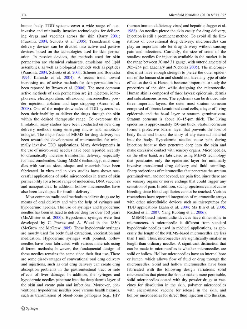
Table 1 Categories of microneedles
Geometry
In plane Out of plane Application
Structure Solid Silicon, metal, polymer, silicon
dioxide
Silicon, metal, polymer,
silicon dioxide
Electrodes for sensing,
stimulation and perforation
Hollow Silicon and nitride/oxide Silicon, metal Injection, sampling of fluids
Metal Silicon dioxide
Polymer Silicon
Polymer
Advantages Ease of integration with electronics
on a single substrate
High density arrays of
microneedles can be realized
Microfluid Nanofluid (2010) 8:373–392 375
123
effective. Polymeric microneedles can be fabricated from
novel biocompatible engineering materials such as plastics,
biodegradable polymers and water-soluble polymers (e.g.,
polycarbonate, polyglicolide acid (PGA) and carboxy-
methylcellulose). Some research groups (Park et al. 2005;
Aoyagi et al. 2007; Yu 2005; Jeong et al. 2008) have used
polymers as material for microneedle fabrication. Park
et al. (2005) and Kuo and Yukon (2004) successfully
fabricated and characterized polymeric microneedles for
various drug delivery applications.
For skin piercing, the microneedle must have enough
strength and should not fracture during insertion. The skin
resistance forces acting on the microneedle depend directly
on the cross-sectional area of the microneedle tip (Aggar-
wal and Johnston 2004). Hence, it is necessary to decrease
the area of the tip as much as possible. However, the area
cannot be reduced beyond a certain limit in case of a
hollow microneedle. There is also a risk of clogging in
hollow microneedles with openings at the top of the mi-
croneedles (Griss et al. 2002). Most of the research groups
(Khumpuang et al. 2003; Gardeniers et al. 2003; Stoeber
and Liepmann 2000; Mukherjee et al. 2004; Shibata et al.
2007; Yu 2005; Wilke et al. 2005a, b; Davis et al. 2005)
have developed microneedles with openings at the tip,
designed symmetrically and asymmetrically. Griss et al.
(2002) designed microneedles with a side opening to
increase the area for drug exposure. The geometry of the
microneedle decides the strength. Aggarwal and Johnston
(2004) reported that the cylindrical microneedles can
withstand more load than square or rectangular micronee-
dles with the same area.
To design the microneedle for drug delivery, certain
other parameters need to be taken into account, such as
pressure, pressure drop, velocity of fluid and flow rate.
Drug delivery applications require precise flow rates
between 10 and 100 lL/min (Prausnitz et al. 2000).
Applied pressure between 10 and 100 kPa is recommended
for various designs of micropumping devices available in
the market that can be integrated with microneedles
(Khumpuang et al. 2003). To get the desired and continu-
ous flow rate, the dimensions and position of the hole of the
microneedle also plays an important role. The flow rate
increases with decrease in length and increase in the inner
diameter of the microneedle (Khumpuang et al. 2003). In
addition, a flat, hollow tip may cause obstruction to the
fluid flow due to punched skin tissues (Gardeniers et al.
2003). Hence, it is necessary to keep the hole off-centered.
The forces created from the flow resistance can cause
breaking of the device and hence the flow resistance should
be controlled (Stoeber and Liepmann 2000). The flow
resistance decreases with increase in microneedles density
per unit area (Griss et al. 2002; Stoeber and Liepmann
2000).
A variety of technologies and fabrication methods have
been developed to fabricate microneedles for drug delivery
applications. These include silicon microfabrication and
polymeric micromolding techniques (Varadan 2006). Very
few research groups have used polymeric fabrication
techniques. Among them Aoyagi et al. (2007) and Park
et al. (2005) used injection-molding technique for poly-
meric microneedle fabrication. To fabricate hollow mi-
croneedles with a side opening, it is very important to
develop a good technique of fabrication. Aoyagi et al.
(2007) used ultraviolet (UV) excimer laser fabrication
technique to create holes in polymeric microneedles.
The microneedle design analysis involves strength
modeling and CFD analysis. Many research studies have
been conducted for structural and microfluidics (flow)
analysis of the microneedles. Shibata et al. (2007) con-
ducted numerical and experimental studies for mechanical
stability analysis of hollow cylindrical microneedle using
silicon dioxide (SiO2) material. Wilke et al. (2005a, b) used
numerical analysis for fluidic system to ensure uniform
release of the fluid from each hollow microneedle.
Aggarwal and Johnston (2004) used finite element modeling
(FE) analysis for prediction of various forces acting on the
microneedle during skin insertion. Aoyagi et al. (2008)
used FEM simulation and confirmed that the stress con-
centration occurred severely at the tip area of the micro-
needle, and the sharp tip angle of the microneedle could be
easily inserted into the skin. Paik et al. (2004) used in-plane
single crystal silicon microneedle array for drug delivery
and performed FEM simulation and experiments on
microneedle for stress analysis by applying bending load at
the tip of the microneedle. Stoeber and Liepmann (2002)
developed a syringe using MEMS technology and designed
fluid mechanical model to avoid the clogging of the
microneedle at the inlet by increasing the internal diameter
of the syringe in two steps. Stoeber and Liepmann (2002)
performed the CFD simulation using CFD ACE? Software
to calculate the shear rate in the flow for the appropriate
scaling of the stepped internal lumen diameters. The study
of the fluidic system of the microneedle was also done
experimentally by many researchers (Griss et al. 2002,
Griss et al. 2003; Gardeniers et al. 2003; Matteucci et al.
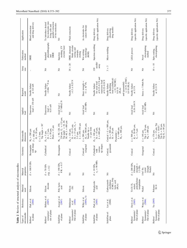
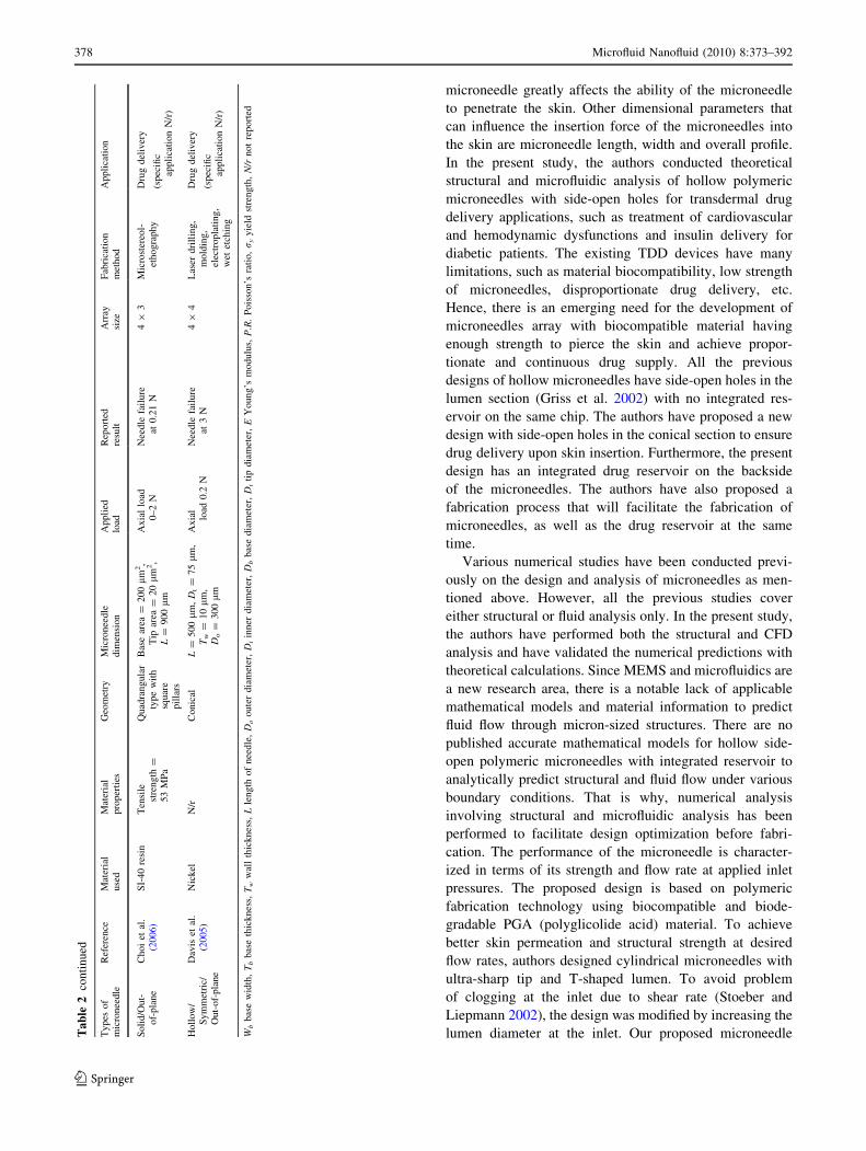
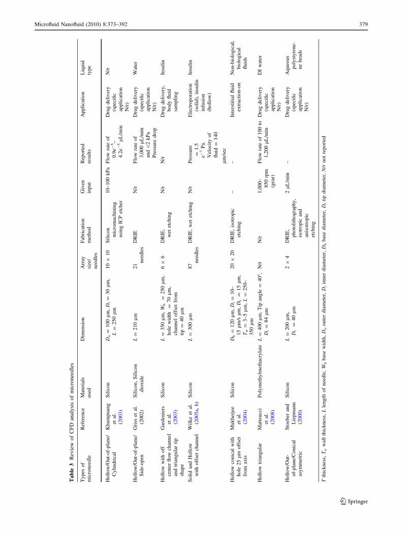
2008). A review of design and analysis of various cate-
gories of microneedles along with types of fabrication
method, applications and performance characteristics are
summarized and referenced in Tables 2 and 3, respectively.
The first and foremost requirement that any design of
microneedle must meet is its ability to penetrate the skin
without breaking. Metallic microneedles are strong enough
to penetrate the skin. However, polymeric materials for
microneedles must be selected to have adequate mechani-
cal strength. Another important factor in microneedle
design is the shape of the microneedle. The sharp tip of the
376 Microfluid Nanofluid (2010) 8:373–392
123
Ta
ble
2R
evie
wo
fst
ruct
ura
lan
aly
sis
of
mic
ron
eed
les
Types
of
mic
ronee
dle
Ref
eren
ceM
ater
ial
use
dM
ater
ial
pro
per
ties
Geo
met
ryM
icro
nee
dle
dim
ensi
on
Appli
edlo
adR
eport
edre
sult
Arr
aysi
zeF
abri
cati
on
met
hod
Appli
cati
on
Holl
ow
/in
pla
ne
Pai
ket
al.
(2004
)S
ilic
on
E=
168.9
GP
aR
ecta
ngula
rw
ith
shar
pti
p
Wb
=200
lm
T=
100
lm
,D
i=
20
lm
,
L=
2m
m,
Tip
Angle
=30�
Tra
nsv
erse
load
=130
mN
Nee
dle
fail
ure
at124
mN
–D
RIE
Blo
od
extr
acti
on
and
dru
gdel
iver
y
Holl
ow
/sy
mm
etri
c/out
of
pla
ne
Shib
ata
etal
.(2
007
)S
ilic
on
dio
xid
eE
=70
GP
a
P.R
.=
0.2
Cyli
ndri
cal
Do
=5
lm
,D
i=
3l
m,
L=
50
lm
,P
itch
=13
lm
Tra
nsv
erse
load
=0.5
3m
N
Nee
dle
fail
ure
[2.6
8e-
8N
mN
/rS
tandar
dphoto
lith
ogra
phy
and
DR
IE
To
intr
oduce
des
ired
bio
-mole
cule
sin
toli
vin
gce
lls
and
par
alle
lex
trac
tion
of
bio
-mole
cule
s
Soli
d/O
ut-
of-
pla
ne
Aoyag
iet
al.
(2007
)P
oly
lact
icac
idE
=190
GP
a,P
.R.
=0.1
7R
ecta
ngula
rW
b=
90,
120,
150,
230
lm
,T
b=
115
lm
,T
ipan
gle
=10,
20,
30,
40,
L=
400
lm
Axia
llo
ad=
2.7
MP
a/2
NN
/rN
/rIn
ject
ion
mold
ing,
UV
exci
mer
lase
r
N/r
Holl
ow
/A
sym
met
ric/
Out-
of-
pla
ne
Mukher
jee
etal
.(2
004
)
Sil
icon
(Si)
N/r
Conic
alD
b=
120
lm
,D
i=
10–15
lm
,D
t=
15
lm
,T
w=
3–5
lm
,L
=250–350
lm
N/r
Nee
dle
fail
ure
[1.5
±0.2
5N
20
920
DR
IE,
dia
mond
bla
de
circ
ula
rsa
win
gan
dis
otr
opic
etch
ing
Flu
idex
trac
tion
Soli
d/O
ut-
of-
pla
ne
Wil
ke
etal
.(2
005a,
b)
Sil
icon
N/r
Conic
al/
oct
agonal
L=
280
lm
,D
b=
186.6
6l
m,
Nee
dle
tip
=\
1l
mw
ide
Axia
llo
ad3.1
83
MP
aS
hea
rst
rength
=11
±4e6
Pa
N/r
Wet
etch
ing
tech
nolo
gy
(KO
H)
As
elec
trodes
for
cance
rth
erap
y
Soli
d/O
ut-
of-
pla
ne
Par
ket
al.
(2005)
Poly
gly
coli
cac
idE
=10
GP
a,r
y=
90
MP
aC
yli
ndri
cal
wit
hvar
ious
tip
shap
es
Do
=100
lm
,D
t=
10
lm
,L
=600
lm
N/r
Nee
dle
fail
ure
for
axia
llo
adof
0.1
5–0.2
Nan
dtr
ansv
erse
load
of
0.2
2–0.2
4N
120 n
eedle
/ar
ray
Inje
ctio
nm
old
ing
Dru
gdel
iver
y
(spec
ific
appli
cati
on
N/r
)
Soli
d/O
ut-
of-
pla
ne
Lee
etal
.(2
008)
Car
boxym
eth-
ylc
ellu
lose
(CM
C),
Poly
lact
icac
id(P
LA
)
N/r
Conic
al,
pyra
mid
alC
onic
al[
L=
800
lm
,D
b=
200
lm
,D
t=
20
lm
Pyra
mid
al[
L=
600
lm
,W
b=
300
lm
,
N/r
Nee
dle
fail
ure
atB
uck
ling
load
(cyli
ndri
cal)
=0.1
N(C
MC
),0.5
1N
(PL
A)
and
(pyra
mid
al)
=1.8
N.
(CM
C),
8.9
N(P
LA
)
39
3M
icro
-mold
ing
Dru
gdel
iver
y(d
isso
lvin
gdru
gnee
dle
)
Holl
ow
/S
ym
met
ric/
Out-
of-
pla
ne
Dav
iset
al.
(2005
)T
i-C
U-T
i,nic
kel
,poly
ethyle
ne-
tere
pth
alat
e
E=
200
GP
a,U
ltim
ate
stre
ngth
=1.2
GP
a
Conic
alL
=500
lm
,R
t=
30–80
lm
,T
w=
5l
m
Axia
llo
ad0.1
8–3.0
4N
Nee
dle
fail
ure
at3.5
NN
/rL
IGA
pro
cess
Dru
gdel
iver
y
(spec
ific
appli
cati
on
N/r
)
Holl
ow
/S
ym
met
ric/
Out-
of-
pla
ne
Wan
get
al.
(2006)
Nic
kel
5.9
e7P
a(y
ield
stre
ngth
Nic
kel
)
Oct
agonal
L=
140
lm
,T
ipL
=50
lm
,W
B=
200
lm
Axia
llo
ad3.1
83
MP
aS
tres
s=
7.9
8e6
Pa
N/r
Novel
elec
tropla
ting
met
hod
Dru
gdel
iver
y
(spec
ific
appli
cati
on
N/r
)
Holl
ow
/S
ym
met
ric/
Out-
of-
pla
ne
Yu
(2005)
Poly
mer
SU
-8N
/rC
onic
alL
=170
lm
,T
w=
15
lm
,T
ipan
gle
=10.0
1�,
Tip
Di
=50
lm
,T
ipD
o=
80
lm
N/r
Nee
dle
fail
ure
at12.1
1N
10
910
Spin
coat
ing,
elec
tropla
ting
Dru
gdel
iver
y
(spec
ific
appli
cati
on
N/r
)
Microfluid Nanofluid (2010) 8:373–392 377
123
microneedle greatly affects the ability of the microneedle
to penetrate the skin. Other dimensional parameters that
can influence the insertion force of the microneedles into
the skin are microneedle length, width and overall profile.
In the present study, the authors conducted theoretical
structural and microfluidic analysis of hollow polymeric
microneedles with side-open holes for transdermal drug
delivery applications, such as treatment of cardiovascular
and hemodynamic dysfunctions and insulin delivery for
diabetic patients. The existing TDD devices have many
limitations, such as material biocompatibility, low strength
of microneedles, disproportionate drug delivery, etc.
Hence, there is an emerging need for the development of
microneedles array with biocompatible material having
enough strength to pierce the skin and achieve propor-
tionate and continuous drug supply. All the previous
designs of hollow microneedles have side-open holes in the
lumen section (Griss et al. 2002) with no integrated res-
ervoir on the same chip. The authors have proposed a new
design with side-open holes in the conical section to ensure
drug delivery upon skin insertion. Furthermore, the present
design has an integrated drug reservoir on the backside
of the microneedles. The authors have also proposed a
fabrication process that will facilitate the fabrication of
microneedles, as well as the drug reservoir at the same
time.
Various numerical studies have been conducted previ-
ously on the design and analysis of microneedles as men-
tioned above. However, all the previous studies cover
either structural or fluid analysis only. In the present study,
the authors have performed both the structural and CFD
analysis and have validated the numerical predictions with
theoretical calculations. Since MEMS and microfluidics are
a new research area, there is a notable lack of applicable
mathematical models and material information to predict
fluid flow through micron-sized structures. There are no
published accurate mathematical models for hollow side-
open polymeric microneedles with integrated reservoir to
analytically predict structural and fluid flow under various
boundary conditions. That is why, numerical analysis
involving structural and microfluidic analysis has been
performed to facilitate design optimization before fabri-
cation. The performance of the microneedle is character-
ized in terms of its strength and flow rate at applied inlet
pressures. The proposed design is based on polymeric
fabrication technology using biocompatible and biode-
gradable PGA (polyglicolide acid) material. To achieve
better skin permeation and structural strength at desired
flow rates, authors designed cylindrical microneedles with
ultra-sharp tip and T-shaped lumen. To avoid problem
of clogging at the inlet due to shear rate (Stoeber and
Liepmann 2002), the design was modified by increasing the
lumen diameter at the inlet. Our proposed microneedleTa
ble
2co
nti
nu
ed
Types
of
mic
ronee
dle
Ref
eren
ceM
ater
ial
use
dM
ater
ial
pro
per
ties
Geo
met
ryM
icro
nee
dle
dim
ensi
on
Appli
edlo
adR
eport
edre
sult
Arr
aysi
zeF
abri
cati
on
met
hod
Appli
cati
on
Soli
d/O
ut-
of-
pla
ne
Choi
etal
.(2
006)
SI-
40
resi
nT
ensi
lest
rength
=53
MP
a
Quad
rangula
rty
pe
wit
hsq
uar
epil
lars
Bas
ear
ea=
200
lm
2,
Tip
area
=20
lm
2,
L=
900
lm
Axia
llo
ad0–2
NN
eedle
fail
ure
at0.2
1N
49
3M
icro
ster
eol-
ethogra
phy
Dru
gdel
iver
y
(spec
ific
appli
cati
on
N/r
)
Holl
ow
/S
ym
met
ric/
Out-
of-
pla
ne
Dav
iset
al.
(2005
)N
ickel
N/r
Conic
alL
=500
lm
,D
t=
75
lm
,T
w=
10
lm
,D
o=
300
lm
Axia
llo
ad0.2
NN
eedle
fail
ure
at3
N4
94
Las
erdri
llin
g,
mold
ing,
elec
tropla
ting,
wet
etch
ing
Dru
gdel
iver
y
(spec
ific
appli
cati
on
N/r
)
Wb
bas
ew
idth
,T
bbas
eth
icknes
s,T
ww
all
thic
knes
s,L
length
of
nee
dle
,D
ooute
rdia
met
er,
Di
inner
dia
met
er,
Db
bas
edia
met
er,
Dt
tip
dia
met
er,
EY
oung’s
modulu
s,P
.R.
Pois
son’s
rati
o,r
yyie
ldst
rength
,N
/rnot
report
ed
378 Microfluid Nanofluid (2010) 8:373–392
123
Ta
ble
3R
evie
wo
fC
FD
anal
ysi
so
fm
icro
nee
dle
s
Ty
pes
of
mic
ronee
dle
Ref
eren
ceM
ater
ials
use
d
Dim
ensi
on
Arr
ay
size
/
nee
dle
s
Fab
rica
tio
n
met
ho
d
Giv
en
inp
ut
Rep
ort
ed
resu
lts
Ap
pli
cati
on
Liq
uid
typ
e
Ho
llo
w/O
ut-
of-
pla
ne/
Cyli
nd
rica
l
Kh
um
puan
g
etal
.
(20
03)
Sil
ico
nD
o=
10
0l
m,
Di
=3
0l
m,
L=
25
0lm
10
91
0S
ilic
on
mic
rom
achin
ing
usi
ng
ICP
etch
er
10
–10
0k
Pa
Flo
wra
teo
f
0.9
e-5–
4.2
e-5
lL/m
in
Dru
gd
eliv
ery
(sp
ecifi
c
app
lica
tio
n
N/r
)
N/r
Ho
llo
w/O
ut-
of-
pla
ne/
Sid
e-o
pen
Gri
sset
al.
(20
02)
Sil
ico
n,
Sil
ico
n
dio
xid
e
L=
21
0l
m2
1
nee
dle
s
DR
IEN
/rF
low
rate
of
3,0
00
lL
/min
and
\2
kP
a
Pre
ssure
dro
p
Dru
gd
eliv
ery
(sp
ecifi
c
app
lica
tio
n
N/r
)
Wat
er
Ho
llo
ww
ith
off
cente
rfl
ow
chan
nel
and
tria
ng
ula
rti
p
shap
e
Gar
den
iers
etal
.
(20
03)
Sil
ico
nL
=3
50
lm
,W
b=
25
0l
m,
ho
lew
idth
=7
0l
m,
chan
nel
off
set
from
tip
=4
0l
m
69
6D
RIE
,
wet
etch
ing
N/r
N/r
Dru
gd
eliv
ery
,
bo
dy
flu
id
sam
pli
ng
Insu
lin
So
lid
and
Ho
llo
w
wit
ho
ffse
tch
ann
el
Wil
ke
etal
.
(20
05a,
b)
Sil
ico
nL
=3
00
lm
87
nee
dle
s
DR
IE,
wet
etch
ing
N/r
Pre
ssure
=1
.5
e-7
Pa.
Vel
oci
tyo
f
flu
id=
14
0
lm
/sec
Ele
ctro
po
rati
on
(so
lid
),in
suli
n
infu
sio
n
(ho
llo
w)
Insu
lin
Ho
llo
wco
nic
alw
ith
ho
le2
5l
mo
ffse
t
from
axis
Mu
kh
erje
e
etal
.
(20
04)
Sil
ico
nD
b=
12
0l
m,
Di
=1
0–
15
lm/s
lm,
Dt
=1
5lm
,
Tw
=3
–5
lm
,L
=2
50
–
35
0lm
20
920
DR
IE,
isotr
opic
etch
ing
––
Inte
rsti
tial
flu
id
extr
acti
on-o
n
No
n-b
iolo
gic
al,
bio
log
ical
flu
ids
Ho
llo
wtr
iang
ula
rM
atte
ucc
i
etal
.
(20
08)
Po
lym
eth
ylm
eth
acry
late
L=
40
0l
m,
Tip
ang
le=
40�,
Di
=8
4lm
N/r
N/r
1,0
00
–
85
0rp
m
(gea
r)
Flo
wra
teo
f1
00
to
1,2
00
lL/m
in
Dru
gd
eliv
ery
(sp
ecifi
c
app
lica
tio
n
N/r
)
DI
wat
er
Ho
llo
w/O
ut-
of-
pla
ne/
Co
nic
al
asy
mm
etri
c
Sto
eber
and
Lie
pm
ann
(20
00)
Sil
ico
nL
=2
00
lm
,
Di
=4
0l
m
29
4D
RIE
,
ph
oto
lith
og
rap
hy
,
isotr
op
ican
d
anis
otr
op
ic
etch
ing
2lL
/min
–D
rug
del
iver
y
(sp
ecifi
c
app
lica
tio
n
N/r
)
Aq
ueo
us
po
lyst
yre
ne-
ne
bea
ds
Tth
ick
nes
s,T
ww
all
thic
knes
s,L
len
gth
of
nee
dle
,W
bb
ase
wid
th,
Do
ou
ter
dia
met
er,
Di
inner
dia
met
er,
Db
bas
ed
iam
eter
,D
tti
pd
iam
eter
,N
/rn
ot
repo
rted
Microfluid Nanofluid (2010) 8:373–392 379
123

arrays are designed to be integrated with micropumping
devices, which can provide 10–100 kPa of pressure at the
outlet. Although the present study discusses only theoreti-
cal design and analysis of hollow out-of-plane polymeric
microneedles with side-open holes, the authors have also
proposed appropriate fabrication process to highlight that
the proposed fabrication process will facilitate integration
by fabricating microneedles with integrated drug reservoir
at the same time, which has not been done previously. The
proposed fabrication process combines micro-hot emboss-
ing and excimer laser to fabricate hollow polymeric
structures and integrated drug reservoir.
2 Proposed design and fabrication process for hollow
microneedles
2.1 Mechanical design specifications
A schematic illustration of the proposed microneedle
design with dimensions is shown in Fig. 2a and b.
The proposed hollow polymeric microneedle has an
ultra-sharp tip for easy skin insertion. The microneedle has
two geometrical sections; the first one is a cylindrical
section, which provides enough strength to the micronee-
dle, and other one in conical section, which provides ease
of skin insertion. The length of the microneedle is 200 lm
and the outer diameter of the microneedle is 150 lm to
increase the bending strength. As shear rate during fluid
flow is responsible for clogging (Stoeber and Liepmann
2000), to reduce the shear rate, the lumen is designed in
two steps to avoid clogging at the inlet. The proposed
design becomes strong enough to pierce the skin easily due
to side-open lumen. In extreme cases, there will not be any
effect on drug delivery after the damage to the microneedle
tip, as the lumen is quite away from the tip area.
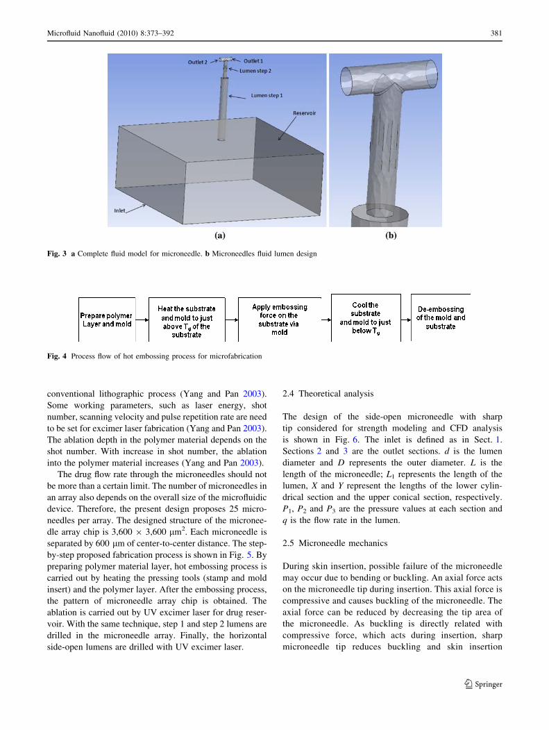
2.2 Microfluidic model design
The constant flow rate through the microneedles in skin is
important for drug delivery application. Many researchers
proposed the tip-open, hollow microneedle designs for
drug delivery. However, during skin insertion, the micro-
needle tip may be damaged and can cause resistance to the
drug flow. Hence, it is a good idea to keep side-open holes
in microneedles to avoid resistance to the fluid flow inside
the skin. Fluid model of our proposed microneedle design
for CFD analysis is shown in Fig. 3.
2.3 Fabrication process
Micro-hot embossing technique and ultraviolet (UV) ex-
cimer laser beam technique have been proposed for
microneedle array and lumen fabrication. The micro-hot
embossing has many advantages, as this process includes
comparatively simple machines, low mechanical influence
on mold insert, small thermal cycles approximately 40�C
and high-quality replication (Becker and Heim 1999). In
addition, this technique provides the ability to fabricate
extremely small structures with thin polymer foils. The
mold insert for hot embossing can be fabricated from sil-
icon and nickel, which are the most used materials for
molds (Becker and Heim 1999). It can be fabricated in a
number of ways from CNC machining of stainless steel for
microstructures of 100 lm range, for LIGA technologies,
and of microstructures with dimensions of few micrometers
range and high aspect ratios (Becker and Heim 1999).
Some researchers have used microinjection molding and
spin coating technique to fabricate polymer microneedles
(Aoyagi et al. 2007; Park et al. 2005; Yu 2005). Micro-hot
embossing technique is different from the above techniques,
as in hot embossing the heating temperature is just above the
glass transition temperature (Tg) (Varadan 2006). In addition,
we can use polymer films as starting materials instead of
pallets of polymers used in injection molding (Varadan 2006).
The process flow for hot embossing is shown in Fig. 4
(Deodhar et al. 2005). Due to small thermal cycles, this
method provides low internal stresses with high structural
replication accuracy and flexibility (Becker and Heim 1999).
UV excimer laser beam is a very useful and reliable
micromachining technique for organic materials such as
polymers, plastic, etc. UV excimer laser does not burn or
melt the material like infrared (IR) lasers and ablates the
organic material by breaking the individual molecules by
converting from solid state to gaseous state (Faulkner
2006). The complex geometric polymeric structures can be
easily ablated using excimer laser, which is difficult byFig. 2 a Schematic illustration of 3D microneedle with base and
b dimensions of the structure (all dimensions are in lm)
380 Microfluid Nanofluid (2010) 8:373–392
123
conventional lithographic process (Yang and Pan 2003).
Some working parameters, such as laser energy, shot
number, scanning velocity and pulse repetition rate are need
to be set for excimer laser fabrication (Yang and Pan 2003).
The ablation depth in the polymer material depends on the
shot number. With increase in shot number, the ablation
into the polymer material increases (Yang and Pan 2003).
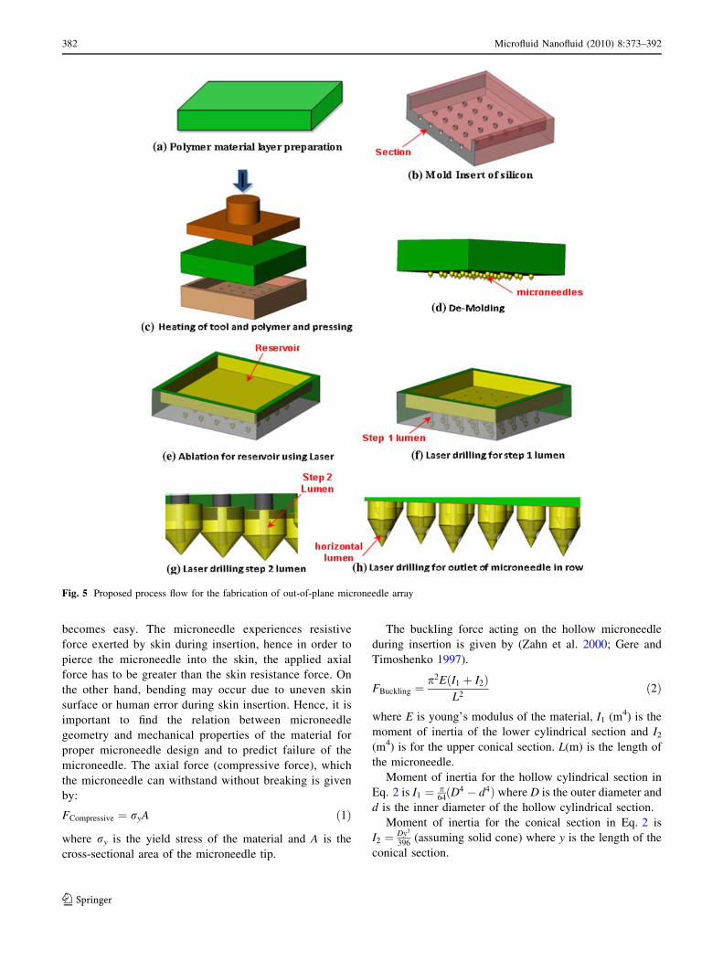
The drug flow rate through the microneedles should not
be more than a certain limit. The number of microneedles in
an array also depends on the overall size of the microfluidic
device. Therefore, the present design proposes 25 micro-
needles per array. The designed structure of the micronee-
dle array chip is 3,600 9 3,600 lm2. Each microneedle is
separated by 600 lm of center-to-center distance. The step-
by-step proposed fabrication process is shown in Fig. 5. By
preparing polymer material layer, hot embossing process is
carried out by heating the pressing tools (stamp and mold
insert) and the polymer layer. After the embossing process,
the pattern of microneedle array chip is obtained. The
ablation is carried out by UV excimer laser for drug reser-
voir. With the same technique, step 1 and step 2 lumens are
drilled in the microneedle array. Finally, the horizontal
side-open lumens are drilled with UV excimer laser.
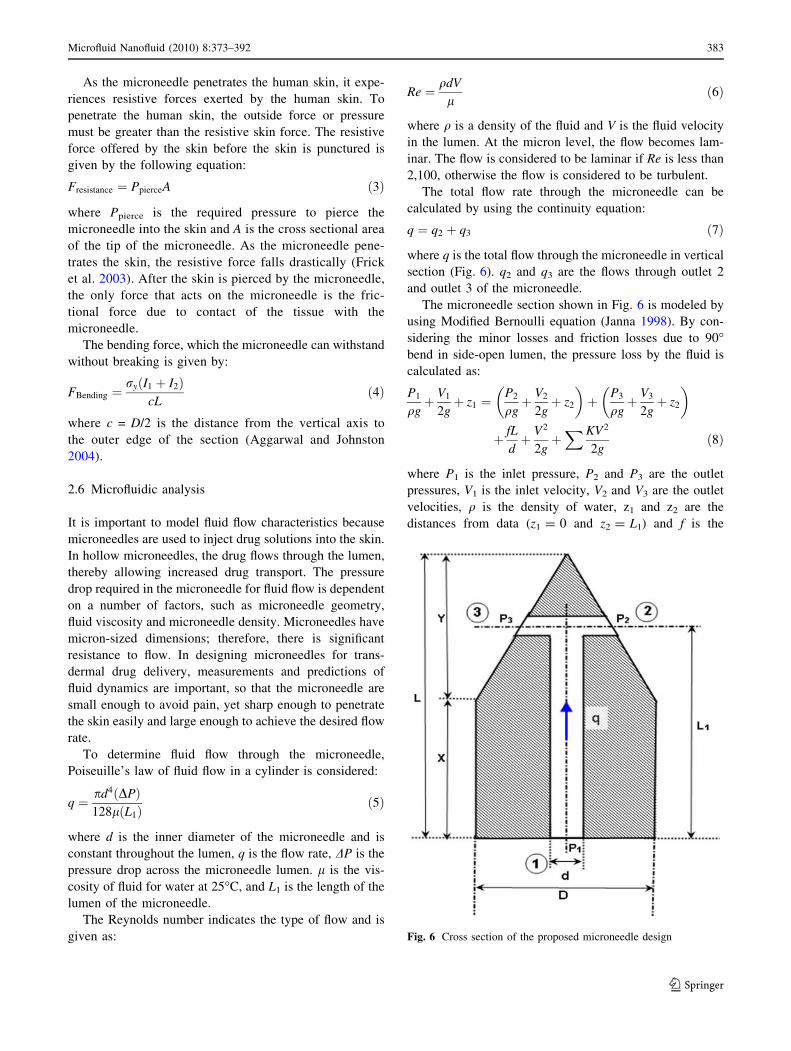
2.4 Theoretical analysis
The design of the side-open microneedle with sharp
tip considered for strength modeling and CFD analysis
is shown in Fig. 6. The inlet is defined as in Sect. 1.
Sections 2 and 3 are the outlet sections. d is the lumen
diameter and D represents the outer diameter. L is the
length of the microneedle; L1 represents the length of the
lumen, X and Y represent the lengths of the lower cylin-
drical section and the upper conical section, respectively.
P1, P2 and P3 are the pressure values at each section and
q is the flow rate in the lumen.
2.5 Microneedle mechanics
During skin insertion, possible failure of the microneedle
may occur due to bending or buckling. An axial force acts
on the microneedle tip during insertion. This axial force is
compressive and causes buckling of the microneedle. The
axial force can be reduced by decreasing the tip area of
the microneedle. As buckling is directly related with
compressive force, which acts during insertion, sharp
microneedle tip reduces buckling and skin insertion
Fig. 4 Process flow of hot embossing process for microfabrication
Fig. 3 a Complete fluid model for microneedle. b Microneedles fluid lumen design
Microfluid Nanofluid (2010) 8:373–392 381
123
becomes easy. The microneedle experiences resistive
force exerted by skin during insertion, hence in order to
pierce the microneedle into the skin, the applied axial
force has to be greater than the skin resistance force. On
the other hand, bending may occur due to uneven skin
surface or human error during skin insertion. Hence, it is
important to find the relation between microneedle
geometry and mechanical properties of the material for
proper microneedle design and to predict failure of the
microneedle. The axial force (compressive force), which
the microneedle can withstand without breaking is given
by:
FCompressive ¼ ryA ð1Þ
where ry is the yield stress of the material and A is the
cross-sectional area of the microneedle tip.
The buckling force acting on the hollow microneedle
during insertion is given by (Zahn et al. 2000; Gere and
Timoshenko 1997).
FBuckling ¼p2E I1 þ I2ð Þ
L2ð2Þ
where E is young’s modulus of the material, I1 (m4) is the
moment of inertia of the lower cylindrical section and I2
(m4) is for the upper conical section. L(m) is the length of
the microneedle.
Moment of inertia for the hollow cylindrical section in
Eq. 2 is I1 ¼ p64
D4 � d4ð Þ where D is the outer diameter and
d is the inner diameter of the hollow cylindrical section.
Moment of inertia for the conical section in Eq. 2 is
I2 ¼ Dy3
396(assuming solid cone) where y is the length of the
conical section.
Fig. 5 Proposed process flow for the fabrication of out-of-plane microneedle array
382 Microfluid Nanofluid (2010) 8:373–392
123
As the microneedle penetrates the human skin, it expe-
riences resistive forces exerted by the human skin. To
penetrate the human skin, the outside force or pressure
must be greater than the resistive skin force. The resistive
force offered by the skin before the skin is punctured is
given by the following equation:
Fresistance ¼ PpierceA ð3Þ
where Ppierce is the required pressure to pierce the
microneedle into the skin and A is the cross sectional area
of the tip of the microneedle. As the microneedle pene-
trates the skin, the resistive force falls drastically (Frick
et al. 2003). After the skin is pierced by the microneedle,
the only force that acts on the microneedle is the fric-
tional force due to contact of the tissue with the
microneedle.
The bending force, which the microneedle can withstand
without breaking is given by:
FBending ¼ry I1 þ I2ð Þ
cLð4Þ
where c = D/2 is the distance from the vertical axis to
the outer edge of the section (Aggarwal and Johnston
2004).
2.6 Microfluidic analysis
It is important to model fluid flow characteristics because
microneedles are used to inject drug solutions into the skin.
In hollow microneedles, the drug flows through the lumen,
thereby allowing increased drug transport. The pressure
drop required in the microneedle for fluid flow is dependent
on a number of factors, such as microneedle geometry,
fluid viscosity and microneedle density. Microneedles have
micron-sized dimensions; therefore, there is significant
resistance to flow. In designing microneedles for trans-
dermal drug delivery, measurements and predictions of
fluid dynamics are important, so that the microneedle are
small enough to avoid pain, yet sharp enough to penetrate
the skin easily and large enough to achieve the desired flow
rate.
To determine fluid flow through the microneedle,
Poiseuille’s law of fluid flow in a cylinder is considered:
q ¼ pd4 DPð Þ128l L1ð Þ
ð5Þ
where d is the inner diameter of the microneedle and is
constant throughout the lumen, q is the flow rate, DP is the
pressure drop across the microneedle lumen. l is the vis-
cosity of fluid for water at 25�C, and L1 is the length of the
lumen of the microneedle.
The Reynolds number indicates the type of flow and is
given as:
Re ¼ qdV
lð6Þ
where q is a density of the fluid and V is the fluid velocity
in the lumen. At the micron level, the flow becomes lam-
inar. The flow is considered to be laminar if Re is less than
2,100, otherwise the flow is considered to be turbulent.
The total flow rate through the microneedle can be
calculated by using the continuity equation:
q ¼ q2 þ q3 ð7Þ
where q is the total flow through the microneedle in vertical
section (Fig. 6). q2 and q3 are the flows through outlet 2
and outlet 3 of the microneedle.
The microneedle section shown in Fig. 6 is modeled by
using Modified Bernoulli equation (Janna 1998). By con-
sidering the minor losses and friction losses due to 90�bend in side-open lumen, the pressure loss by the fluid is
calculated as:
P1
qgþ V1
2gþ z1 ¼
P2
qgþ V2
2gþ z2
� �þ P3
qgþ V3
2gþ z2
� �
þ fL
dþ V2
2gþXKV2
2gð8Þ
where P1 is the inlet pressure, P2 and P3 are the outlet
pressures, V1 is the inlet velocity, V2 and V3 are the outlet
velocities, q is the density of water, z1 and z2 are the
distances from data (z1 = 0 and z2 = L1) and f is the
Fig. 6 Cross section of the proposed microneedle design
Microfluid Nanofluid (2010) 8:373–392 383
123
friction factor. Since the above section is symmetrical
about a vertical axis, the outlet pressure, velocity and head
(z1 and z2) remain the same. Hence Eq. 8 can be modified
as:
P1
qgþ V2
1
2gþ z1 ¼
Poutlet
qgþ V2
2gþ z2
� �þ fL
dþ V2
2g
þXKV2
2g: ð9Þ
The pressure drop can be calculated from Eq. 9:
DP ¼ l128qðL1Þ
pd4þ q
8q2
p2d4K1 þ K2ð Þ ð10Þ
where K1 and K2 are loss coefficient factors for square edge
inlet and T-joint outlet for branched flow. The values of K1
and K2 for the proposed design are taken as 0.5 and 0.69,
respectively (Janna 1998). The friction factor for laminar
flow is given as f ¼ 64Re (Janna 1998). The first term on the
right-hand side in Eq. 10 describes the pressure drop due to
viscous shear force (Batchelor 1967) and the second term
describes the inertial effect at the inlet and exit (Stoeber
and Liepmann 2000).
3 Numerical simulation
3.1 Structural analysis
The structural analysis of the single microneedle was
conducted using finite element software ANSYS. The
microneedle experiences a bending force, axial force and
many other forces during skin insertion. The single out-of-
plane microneedle was modeled with fixed base and free
tip end for bending and axial stress analysis. The structural
model was built using element SOLID 191, which is
mostly used to model polymeric materials. Linear isotropic
material properties of polyglicolide acid (PGA) were used
for analysis (Young’s modulus of 10 GPa, Poisson ratio of
0.2 and yield strength of 90 MPa were considered (Ratner
et al. 1996)).
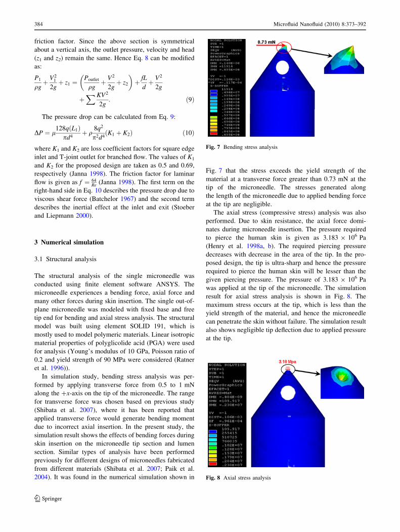
In simulation study, bending stress analysis was per-
formed by applying transverse force from 0.5 to 1 mN
along the ?x-axis on the tip of the microneedle. The range
for transverse force was chosen based on previous study
(Shibata et al. 2007), where it has been reported that
applied transverse force would generate bending moment
due to incorrect axial insertion. In the present study, the
simulation result shows the effects of bending forces during
skin insertion on the microneedle tip section and lumen
section. Similar types of analysis have been performed
previously for different designs of microneedles fabricated
from different materials (Shibata et al. 2007; Paik et al.
2004). It was found in the numerical simulation shown in
Fig. 7 that the stress exceeds the yield strength of the
material at a transverse force greater than 0.73 mN at the
tip of the microneedle. The stresses generated along
the length of the microneedle due to applied bending force
at the tip are negligible.
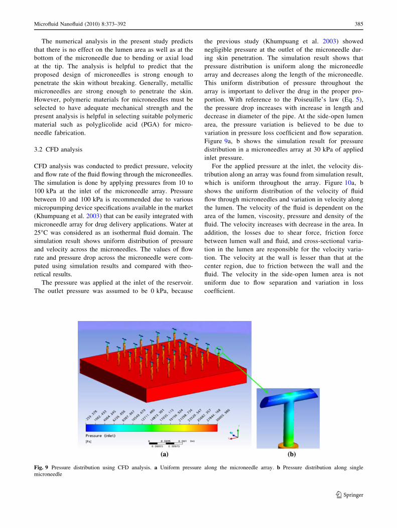
The axial stress (compressive stress) analysis was also
performed. Due to skin resistance, the axial force domi-
nates during microneedle insertion. The pressure required
to pierce the human skin is given as 3.183 9 106 Pa
(Henry et al. 1998a, b). The required piercing pressure
decreases with decrease in the area of the tip. In the pro-
posed design, the tip is ultra-sharp and hence the pressure
required to pierce the human skin will be lesser than the
given piercing pressure. The pressure of 3.183 9 106 Pa
was applied at the tip of the microneedle. The simulation
result for axial stress analysis is shown in Fig. 8. The
maximum stress occurs at the tip, which is less than the
yield strength of the material, and hence the microneedle
can penetrate the skin without failure. The simulation result
also shows negligible tip deflection due to applied pressure
at the tip.
Fig. 7 Bending stress analysis
Fig. 8 Axial stress analysis
384 Microfluid Nanofluid (2010) 8:373–392
123
The numerical analysis in the present study predicts
that there is no effect on the lumen area as well as at the
bottom of the microneedle due to bending or axial load
at the tip. The analysis is helpful to predict that the
proposed design of microneedles is strong enough to
penetrate the skin without breaking. Generally, metallic
microneedles are strong enough to penetrate the skin.
However, polymeric materials for microneedles must be
selected to have adequate mechanical strength and the
present analysis is helpful in selecting suitable polymeric
material such as polyglicolide acid (PGA) for micro-
needle fabrication.
3.2 CFD analysis
CFD analysis was conducted to predict pressure, velocity
and flow rate of the fluid flowing through the microneedles.
The simulation is done by applying pressures from 10 to
100 kPa at the inlet of the microneedle array. Pressure
between 10 and 100 kPa is recommended due to various
micropumping device specifications available in the market
(Khumpuang et al. 2003) that can be easily integrated with
microneedle array for drug delivery applications. Water at
25�C was considered as an isothermal fluid domain. The
simulation result shows uniform distribution of pressure
and velocity across the microneedles. The values of flow
rate and pressure drop across the microneedle were com-
puted using simulation results and compared with theo-
retical results.
The pressure was applied at the inlet of the reservoir.
The outlet pressure was assumed to be 0 kPa, because
the previous study (Khumpuang et al. 2003) showed
negligible pressure at the outlet of the microneedle dur-
ing skin penetration. The simulation result shows that
pressure distribution is uniform along the microneedle
array and decreases along the length of the microneedle.
This uniform distribution of pressure throughout the
array is important to deliver the drug in the proper pro-
portion. With reference to the Poiseuille’s law (Eq. 5),
the pressure drop increases with increase in length and
decrease in diameter of the pipe. At the side-open lumen
area, the pressure variation is believed to be due to
variation in pressure loss coefficient and flow separation.
Figure 9a, b shows the simulation result for pressure
distribution in a microneedles array at 30 kPa of applied
inlet pressure.
For the applied pressure at the inlet, the velocity dis-
tribution along an array was found from simulation result,
which is uniform throughout the array. Figure 10a, b
shows the uniform distribution of the velocity of fluid
flow through microneedles and variation in velocity along
the lumen. The velocity of the fluid is dependent on the
area of the lumen, viscosity, pressure and density of the
fluid. The velocity increases with decrease in the area. In
addition, the losses due to shear force, friction force
between lumen wall and fluid, and cross-sectional varia-
tion in the lumen are responsible for the velocity varia-
tion. The velocity at the wall is lesser than that at the
center region, due to friction between the wall and the
fluid. The velocity in the side-open lumen area is not
uniform due to flow separation and variation in loss
coefficient.
Fig. 9 Pressure distribution using CFD analysis. a Uniform pressure along the microneedle array. b Pressure distribution along single
microneedle
Microfluid Nanofluid (2010) 8:373–392 385
123
4 Results and discussion
4.1 Stress analysis
The first set of simulation results explains the mechanical
strength of the microneedle. According to the theoretical
calculation, maximum compressive force experienced by
the microneedle before microneedle failure is 0.282 mN.
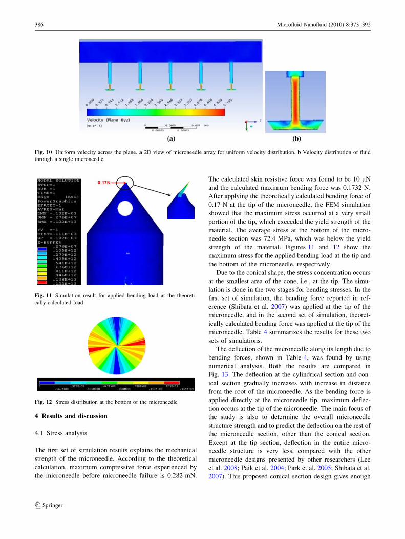
The calculated skin resistive force was found to be 10 lN
and the calculated maximum bending force was 0.1732 N.
After applying the theoretically calculated bending force of
0.17 N at the tip of the microneedle, the FEM simulation
showed that the maximum stress occurred at a very small
portion of the tip, which exceeded the yield strength of the
material. The average stress at the bottom of the micro-
needle section was 72.4 MPa, which was below the yield
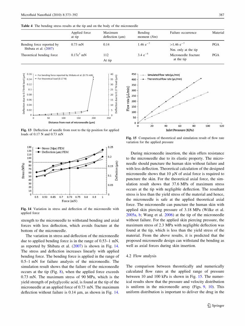
strength of the material. Figures 11 and 12 show the
maximum stress for the applied bending load at the tip and
the bottom of the microneedle, respectively.
Due to the conical shape, the stress concentration occurs
at the smallest area of the cone, i.e., at the tip. The simu-
lation is done in the two stages for bending stresses. In the
first set of simulation, the bending force reported in ref-
erence (Shibata et al. 2007) was applied at the tip of the
microneedle, and in the second set of simulation, theoret-
ically calculated bending force was applied at the tip of the
microneedle. Table 4 summarizes the results for these two
sets of simulations.
The deflection of the microneedle along its length due to
bending forces, shown in Table 4, was found by using
numerical analysis. Both the results are compared in
Fig. 13. The deflection at the cylindrical section and con-
ical section gradually increases with increase in distance
from the root of the microneedle. As the bending force is
applied directly at the microneedle tip, maximum deflec-
tion occurs at the tip of the microneedle. The main focus of
the study is also to determine the overall microneedle
structure strength and to predict the deflection on the rest of
the microneedle section, other than the conical section.
Except at the tip section, deflection in the entire micro-
needle structure is very less, compared with the other
microneedle designs presented by other researchers (Lee
et al. 2008; Paik et al. 2004; Park et al. 2005; Shibata et al.
2007). This proposed conical section design gives enough
Fig. 11 Simulation result for applied bending load at the theoreti-
cally calculated load
Fig. 12 Stress distribution at the bottom of the microneedle
Fig. 10 Uniform velocity across the plane. a 2D view of microneedle array for uniform velocity distribution. b Velocity distribution of fluid
through a single microneedle
386 Microfluid Nanofluid (2010) 8:373–392
123
strength to the microneedle to withstand bending and axial
forces with less deflection, which avoids fracture at the
bottom of the microneedle.
The variation in stress and deflection of the microneedle
due to applied bending force is in the range of 0.53–1 mN,
as reported by Shibata et al. (2007) is shown in Fig. 14.
The stress and deflection increases linearly with applied
bending force. The bending force is applied in the range of
0.5–1 mN for failure analysis of the microneedle. The
simulation result shows that the failure of the microneedle
occurs at the tip (Fig. 8), when the applied force exceeds
0.73 mN. The maximum stress of 90 MPa, which is the
yield strength of polyglycolic acid, is found at the tip of the
microneedle at an applied force of 0.73 mN. The maximum
deflection without failure is 0.14 lm, as shown in Fig. 14.
During microneedle insertion, the skin offers resistance
to the microneedle due to its elastic property. The micro-
needle should puncture the human skin without failure and
with less deflection. Theoretical calculation of the designed
microneedle shows that 10 lN of axial force is required to
puncture the skin. For the theoretical axial force, the sim-
ulation result shows that 37.6 MPa of maximum stress
occurs at the tip with negligible deflection. The resultant
stress is less than the yield stress of the material and hence,
the microneedle is safe at the applied theoretical axial
force. The microneedle can puncture the human skin with
applied skin piercing pressure of 3.18 MPa (Wilke et al.
2005a, b; Wang et al. 2006) at the tip of the microneedle
without failure. For the applied skin piercing pressure, the
maximum stress of 2.3 MPa with negligible deflection was
found at the tip, which is less than the yield stress of the
material. From the above results, it is predicted that the
proposed microneedle design can withstand the bending as
well as axial forces during skin insertion.
4.2 Flow analysis
The comparison between theoretically and numerically
calculated flow rates at the applied range of pressure
between 10 and 100 kPa is shown in Fig. 15. The numer-
ical results show that the pressure and velocity distribution
is uniform in the microneedle array (Figs. 9, 10). This
uniform distribution is important to deliver the drug in the
Table 4 The bending stress results at the tip and on the body of the microneedle
Applied force
at tip
Maximum
deflection (lm)
Bending
moment (Nm)
Failure occurrence Material
Bending force reported by
Shibata et al. (2007)
0.73 mN 0.14 1.46 e-7 [1.46 e-7
Nm. only at the tip
PGA
Theoretical bending force 0.17e3 mN 112
At tip
3.4 e-5 Microneedle fracture
at the tip
PGA
Fig. 14 Variation in stress and deflection of the microneedle with
applied force
Fig. 15 Comparison of theoretical and simulation result of flow rate
variation for the applied pressure
Fig. 13 Deflection of needle from root to the tip position for applied
loads of 0.17 N and 0.73 mN
Microfluid Nanofluid (2010) 8:373–392 387
123
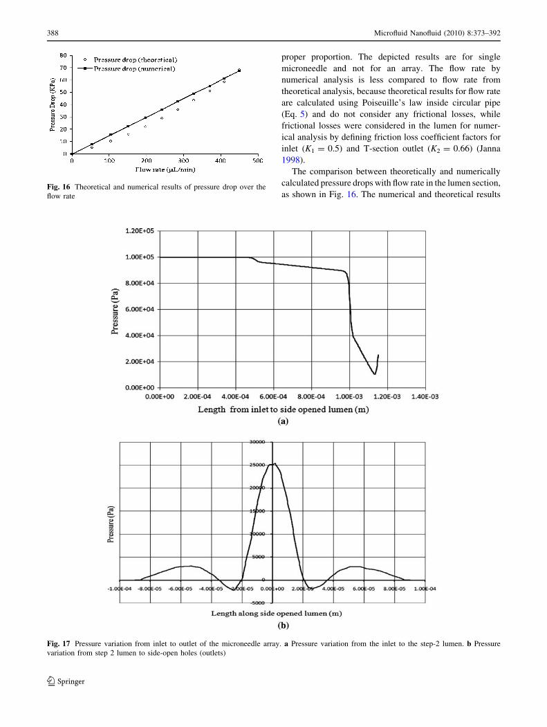
proper proportion. The depicted results are for single
microneedle and not for an array. The flow rate by
numerical analysis is less compared to flow rate from
theoretical analysis, because theoretical results for flow rate
are calculated using Poiseuille’s law inside circular pipe
(Eq. 5) and do not consider any frictional losses, while
frictional losses were considered in the lumen for numer-
ical analysis by defining friction loss coefficient factors for
inlet (K1 = 0.5) and T-section outlet (K2 = 0.66) (Janna
1998).
The comparison between theoretically and numerically
calculated pressure drops with flow rate in the lumen section,
as shown in Fig. 16. The numerical and theoretical results
Fig. 17 Pressure variation from inlet to outlet of the microneedle array. a Pressure variation from the inlet to the step-2 lumen. b Pressure
variation from step 2 lumen to side-open holes (outlets)
Fig. 16 Theoretical and numerical results of pressure drop over the
flow rate
388 Microfluid Nanofluid (2010) 8:373–392
123

are depicted for an array and not for single microneedle.
The total pressure drop is the sum of pressure drop due to
viscous shear force of Poiseuille’s law and inertia effects
(Stoeber and Liepmann 2000; Batchelor 1967), which are
considered for theoretical analysis (Eq. 10). CFD analysis
has been validated by theoretical analysis showing that
the boundary conditions used in the analysis are reason-
ably accurate to predict the pressure drop for various flow
rates.
The pressure variation along the microneedle length is
shown in Fig. 17a and b. Initially, the pressure remains
constant throughout the reservoir. Pressure drop takes place
in step 1-lumen (Refer Fig. 3a), due to reduction in the area
along the length. Similarly, the pressure drops in step-2
lumen due to further reduction in the area along the length.
Due to the sudden impact of fluid at the T-junction, the
pressure increases suddenly at the end of the step-2 lumen
up to 25 kPa. Figure 17b shows the pressure variation in
the side-open zone. The pressure reduces rapidly after the
impact of fluid at the top mid-region of the T-section.
The small back flow occurs at the top mid-region of the
T-section in the microneedle and flow separation takes
place in the horizontal lumen; hence, the intensity of fluid
velocity decreases. Due to pressure difference, the fluid
flows out from the microneedle side-opened holes at low
velocity, which is sufficient for drug delivery applications.
The relationship between pressure and velocity of the
fluid flow along the vertical (steps 1 and 2) and horizontal
side-open lumen is shown in Fig. 18a, b. The pattern of
pressure and velocity variation is the same throughout the
microneedle array. Hence, the pressure–velocity relation-
ship was analyzed only in the individual lumen. At 100 kPa
Fig. 18 Pressure velocity relationship along the horizontal lumen area. a Pressure–velocity plot from the inlet to step-2 lumen. b Pressure–
velocity plot from step-2 lumen to side-open hole (outlet)
Microfluid Nanofluid (2010) 8:373–392 389
123

of applied inlet pressure, the result (Fig. 18a, b) shows that
the velocity increases from the inlet to the outlet region,
and the fluid pressure decreases with increase in distance
from the inlet to the outlet. There is velocity variation
across the lumen due to varying cross-sectional area. Ini-
tially at the inlet, the velocity is very small, but it increases
rapidly at step-1 lumen. Due to the same cross-sectional
area in step-1 lumen, the velocity becomes constant and
again increases rapidly due to decrease in thecross-sec-
tional area at step-2 lumen. Simulation result shows that
the fluid velocity along step-2 lumen is constant, and at T-
section shows small amount of backflow due to the sudden
impact with the lumen wall (Fig. 10). Hence the velocity of
the fluid becomes negligibly small and again increases
gradually due to pressure difference of 25 kPa (outlet
pressure = 0) (Fig. 18b). In the horizontal lumen, the
intensity of fluid velocity is low compared to step-2 lumen.
Only one side of the lumen is considered in Fig. 18b, due
to dimensional symmetry.
5 Conclusions
This paper first presents an in-depth review of design and
analysis of MEMS-based various categories of micronee-
dles, fabrication methods, performance parameters and their
medical applications where reported. Then, theoretical
design and analysis of new, hollow, out-of-plane polymeric
microneedles with cylindrical, side-open holes and inte-
grated reservoir is presented for TDD applications such as
treatment of cardiovascular and hemodynamic dysfunctions
and insulin delivery for diabetic patients. Suitable fabrica-
tion techniques such as micro-hot embossing process and
ultraviolet excimer laser drilling are proposed for side-open
polymeric hollow microneedles. Theoretical calculations
are done to validate the numerical analysis. The analysis
predicts that the performance of the microneedle in terms of
mechanical strength and flow rate has a crucial impact on
transdermal drug delivery applications. Theoretical and
simulation results are summarized below:
1. The maximum deflection occurs at the tip of the
microneedle due to the very small conical section. At
0.73 mN of force, the microneedle tip does not fail as
the maximum stress is below 90 MPa (yield strength
of PGA). Hence, there is no chance for the micronee-
dle to fail at the base, but for the theoretically
calculated load of 0.17 N, the buckling occurs at the
tip and the tip fails. However, the stress at the base of
the microneedle is below the yield strength of the
material. Thus, the designed polymeric microneedles
have less possibility of failure, as stresses generated
due to applied loads are less than the yield strength of
the material.
2. At a theoretically calculated axial force of 10 lN, the
simulation result shows that 37.6 MPa of maximum
stress occurs at the tip with negligible deflection. The
resultant stress is less than the yield stress of the
material and hence the microneedle design is safe at
the applied theoretical axial force.
3. The velocity decreases in a small region at the top of
the T-section due to the sudden impact, but fluid flows
out from the microneedle side-open holes, due to
pressure difference, with a sufficient flow rate that is
suitable for drug delivery application. Hence, it is
predicted that the effect of backflow of fluid from the
T-section will have no significant effect on flow rate
through the microneedles.
4. In the numerical solution, a maximum flow rate of
270 lL/min and a minimum flow rate of 32 lL/min
are achieved through a single microneedle at 100 and
10 kPa of inlet pressure, respectively. The range of
flow rates achieved from the analysis of the proposed
design of microneedle is suitable for drug delivery
application. The numerically and theoretically pre-
dicted values of flow rate are in close agreement,
thereby validating the CFD analysis results.
The proposed novel design of the polymeric micronee-
dle array, with side-open holes in the conical section and
integrated reservoir, is suitable to be integrated into various
categories of micropumping devices operating in the range
of 10–100 kPa of outlet pressure. Based on the extensive
literature review and design and analysis of microneedles
presented in this paper, the authors conclude that the
overall commercialization of MEMS microneedles in drug
delivery and biomedical application is still in its beginning.
A lot of technical information is available for a number of
microneedle concepts. However, many of the novel
microneedle designs reported in literature for drug delivery
and other biomedical applications still need to be incor-
porated into practical devices. Our future work will involve
fabrication of the proposed design of microneedle and
integration with other microfluidic devices, such as mi-
cropump, for integrated drug delivery applications. The
fabrication results of the polymeric microneedle array shall
be presented in a subsequent paper.
References
Aggarwal P, Johnston CR (2004) Geometrical effects in mechanical
characterizing of microneedle for biomedical applications. Sens
Actuators B 102:226–234
390 Microfluid Nanofluid (2010) 8:373–392
123
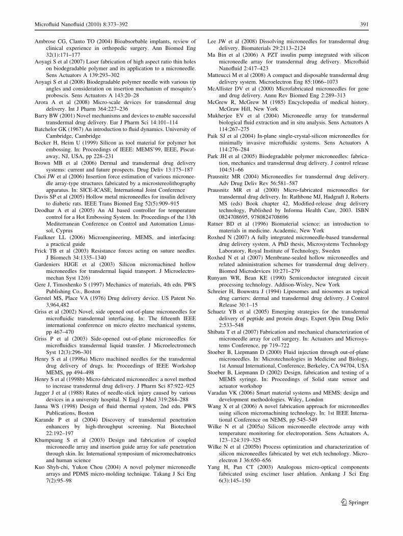
Ambrose CG, Clanto TO (2004) Bioabsorbable implants, review of
clinical experience in orthopedic surgery. Ann Biomed Eng
32(1):171–177
Aoyagi S et al (2007) Laser fabrication of high aspect ratio thin holes
on biodegradable polymer and its application to a microneedle.
Sens Actuators A 139:293–302
Aoyagi S et al (2008) Biodegradable polymer needle with various tip
angles and consideration on insertion mechanism of mosquito’s
proboscis. Sens Actuators A 143:20–28
Arora A et al (2008) Micro-scale devices for transdermal drug
delivery. Int J Pharm 364:227–236
Barry BW (2001) Novel mechanisms and devices to enable successful
transdermal drug delivery. Eur J Pharm Sci 14:101–114
Batchelor GK (1967) An introduction to fluid dynamics. University of
Cambridge, Cambridge
Becker H, Heim U (1999) Silicon as tool material for polymer hot
embossing. In: Proceedings of IEEE: MEMS’99, IEEE, Piscat-
away, NJ, USA, pp 228–231
Brown MB et al (2006) Dermal and transdermal drug delivery
systems: current and future prospects. Drug Deliv 13:175–187
Choi JW et al (2006) Insertion force estimation of various micronee-
dle array-type structures fabricated by a microstereolithography
apparatus. In: SICE-ICASE, International Joint Conference
Davis SP et al (2005) Hollow metal microneedles for insulin delivery
to diabetic rats. IEEE Trans Biomed Eng 52(5):909–915
Deodhar A et al (2005) An AI based controller for temperature
control for a Hot Embossing System. In: Proceedings of the 13th
Mediterranean Conference on Control and Automation Limas-
sol, Cyprus
Faulkner LL (2006) Microengineering, MEMS, and interfacing:
a practical guide
Frick TB et al (2003) Resistance forces acting on suture needles.
J Biomech 34:1335–1340
Gardeniers HJGE et al (2003) Silicon micromachined hollow
microneedles for transdermal liquid transport. J Microelectro-
mechan Syst 12(6)
Gere J, Timoshenko S (1997) Mechanics of materials, 4th edn. PWS
Publishing Co., Boston
Gerstel MS, Place VA (1976) Drug delivery device. US Patent No.
3,964,482
Griss et al (2002) Novel, side opened out-of-plane microneedles for
microfluidic transdermal interfacing. In: The fifteenth IEEE
international conference on micro electro mechanical systems,
pp 467–470
Griss P et al (2003) Side-opened out-of-plane microneedles for
microfluidics transdermal liquid transfer. J Microelectromech
Syst 12(3):296–301
Henry S et al (1998a) Micro machined needles for the transdermal
drug delivery of drugs. In: Proceedings of IEEE Workshop
MEMS, pp 494–498
Henry S et al (1998b) Micro-fabricated microneedles: a novel method
to increase transdermal drug delivery. J Pharm Sci 87:922–925
Jagger J et al (1988) Rates of needle-stick injury caused by various
devices in a university hospital. N Engl J Med 319:284–288
Janna WS (1998) Design of fluid thermal system, 2nd edn. PWS
Publications, Boston
Karande P et al (2004) Discovery of transdermal penetration
enhancers by high-throughput screening. Nat Biotechnol
22:192–197
Khumpuang S et al (2003) Design and fabrication of coupled
microneedle array and insertion guide array for safe penetration
through skin. In: International symposium of micromechatronics
and human science
Kuo Shyh-chi, Yukon Chou (2004) A novel polymer microneedle
arrays and PDMS micro-molding technique. Takang J Sci Eng
7(2):95–98
Lee JW et al (2008) Dissolving microneedles for transdermal drug
delivery. Biomaterials 29:2113–2124
Ma Bin et al (2006) A PZT insulin pump integrated with silicon
microneedle array for transdermal drug delivery. Microfluid
Nanofluid 2:417–423
Matteucci M et al (2008) A compact and disposable transdermal drug
delivery system. Microelectron Eng 85:1066–1073
McAllister DV et al (2000) Microfabricated microneedles for gene
and drug delivery. Annu Rev Biomed Eng 2:289–313
McGrew R, McGrew M (1985) Encyclopedia of medical history.
McGraw Hill, New York
Mukherjee EV et al (2004) Microneedle array for transdermal
biological fluid extraction and in situ analysis. Sens Actuators A
114:267–275
Paik SJ et al (2004) In-plane single-crystal-silicon microneedles for
minimally invasive microfluidic systems. Sens Actuators A
114:276–284
Park JH et al (2005) Biodegradable polymer microneedles: fabrica-
tion, mechanics and transdermal drug delivery. J control release
104:51–66
Prausnitz MR (2004) Microneedles for transdermal drug delivery.
Adv Drug Deliv Rev 56:581–587
Prausnitz MR et al (2000) Micro-fabricated microneedles for
transdermal drug delivery. In: Rathbone MJ, Hadgraft J, Roberts
MS (eds) Book chapter 42, Modified-release drug delivery
technology, Published by Informa Health Care, 2003. ISBN
0824708695, 9780824708696
Ratner BD et al (1996) Biomaterial science: an introduction to
materials in medicine. Academic, New York
Roxhed N (2007) A fully integrated microneedle-based transdermal
drug delivery system. A PhD thesis, Microsystems Technology
Laboratory, Royal Institute of Technology, Sweden
Roxhed N et al (2007) Membrane-sealed hollow microneedles and
related administration schemes for transdermal drug delivery.
Biomed Microdevices 10:271–279
Runyam WR, Bean KE (1990) Semiconductor integrated circuit
processing technology. Addison-Wisley, New York
Schreier H, Bouwstra J (1994) Liposomes and niosomes as topical
drug carriers: dermal and transdermal drug delivery. J Control
Release 30:1–15
Schuetz YB et al (2005) Emerging strategies for the transdermal
delivery of peptide and protein drugs. Expert Opin Drug Deliv
2:533–548
Shibata T et al (2007) Fabrication and mechanical characterization of
microneedle array for cell surgery. In: Actuators and Microsys-
tems Conference, pp 719–722
Stoeber B, Liepmann D (2000) Fluid injection through out-of-plane
microneedles. In: Microtechnologies in Medicine and Biology,
1st Annual International, Conference, Berkeley, CA 94704, USA
Stoeber B, Liepmann D (2002) Design, fabrication and testing of a
MEMS syringe. In: Proceedings of Solid state sensor and
actuator workshop
Varadan VK (2006) Smart material systems and MEMS: design and
development methodologies. Wiley, London
Wang X et al (2006) A novel fabrication approach for microneedles
using silicon micromachining technology. In: 1st IEEE Interna-
tional Conference on NEMS, pp 545–549
Wilke N et al (2005a) Silicon microneedle electrode array with
temperature monitoring for electroporation. Sens Actuators A,
123–124:319–325
Wilke N et al (2005b) Process optimization and characterization of
silicon microneedles fabricated by wet etch technology. Micro-
electron J 36:650–656
Yang H, Pan CT (2003) Analogous micro-optical components
fabricated using excimer laser ablation. Amkang J Sci Eng
6(3):145–150
Microfluid Nanofluid (2010) 8:373–392 391
123
Yang Ruoting et al (2006) Dynamic modeling and control of a micro-
needle integrated piezoelectric micropump for diabetes care. In:
Sixth IEEE Conference on nanotechnology, pp 146–149
Yu H (2005) Fabrication of a Hollow metallic microneedle array
using scanning laser direct writing. In: 9th international confer-
ence on miniaturized systems for chemistry and life sciences,
Boston, MA, USA
Zachary JH, Nicholas AP (2005) Microfabricated drug delivery
devices. Int J Pharm 306(1–2):15–23
Zahn JD et al (2000) Microfabricated polysilicon microneedles for
minimally invasive biomedical devices. Biomed Microdevices
2:295–303
Zahn JD et al (2004) Continuous on-chip micropumping for micronee-
dle-enhanced drug delivery. Biomed Microdevices 6(3):183–190
392 Microfluid Nanofluid (2010) 8:373–392
123
Related Documents