STRUCTURAL ANALYSIS REPORT PREPARED FOR: JEFFERSON COUNTY 120 FT SELF-SUPPORTED TOWER EQUIPMENT INSTALLATION SULLIVAN TOWER SULLIVAN, WISCONSIN EDGE PROJECT NUMBER: 10125 JUNE 12, 2014 624 Water Street Prairie du Sac, Wisconsin 53578 608.644.1449 Phone 608.644.1549 Fax www.edgeconsult.com

Welcome message from author
This document is posted to help you gain knowledge. Please leave a comment to let me know what you think about it! Share it to your friends and learn new things together.
Transcript

STRUCTURAL ANALYSIS REPORT
PREPARED FOR:
JEFFERSON COUNTY
120 FT SELF-SUPPORTED TOWER EQUIPMENT INSTALLATION
SULLIVAN TOWER SULLIVAN, WISCONSIN
EDGE PROJECT NUMBER: 10125
JUNE 12, 2014
624 Water Street Prairie du Sac, Wisconsin 53578
608.644.1449 Phone 608.644.1549 Fax
www.edgeconsult.com


TABLE OF CONTENTS
SECTION 1 EXECUTIVE SUMMARY 1
SECTION 2 INTRODUCTION 2
2.1 PURPOSE OF REPORT 2
2.2 SCOPE OF SERVICES 2
SECTION 3 ANALYSIS 3
3.1 BACKGROUND INFORMATION 3
3.2 LOADING CONDITION 3
3.3 ANALYSIS CRITERIA 3
3.4 ANALYSIS METHOD 4
3.5 ASSUMPTIONS 4
SECTION 4 RESULTS 5
4.1 TOWER STRUCTURE 5
4.2 TOWER FOUNDATIONS 5
4.3 RECOMMENDATIONS 5
SECTION 5 LIMITATIONS AND RESTRICTIONS 6
FIGURES Figure 1: Feedline Placement Diagram APPENDICES Appendix A: TIA-222-G Analysis Criteria Definitions Appendix B: Structural Calculations

Sullivan Tower_Structural Analysis Report_2014-06-12.docx Edge #10125 -1-
SECTION 1 EXECUTIVE SUMMARY
Site Name: Sullivan Tower Site Location: Sullivan, Wisconsin Purpose: Equipment Installation Tower Type: 120 ft. Self-Supported Tower We have completed a structural analysis for the above described tower. One loading scenario was considered in the analysis. The loading condition takes into account the existing tower loading along with the proposed loading. The loading condition is described in Section 3.2, with reference to the feedline placement diagram (Figure 1). Under the TIA-222-G requirements, the completed a structural analysis is considered a feasibility analysis since information regarding the tower structure, foundation system, and/or soil conditions were not available at the time of the study. The following information was not available and is required for a rigorous analysis to be completed:
Geotechnical Report Foundation Design Documents and Drawings
The results of our feasibility analysis indicate that the existing tower may be capable of supporting the proposed change in loading. However, per TIA-222-G, final acceptance of the changed condition must be based upon a rigorous structural analysis. Refer to Section 3.5 for additional information regarding assumptions for this analysis. Please refer to the report which follows this summary for further information. Feel free to contact us if you have any questions or concerns.

Sullivan Tower_Structural Analysis Report_2014-06-12.docx Edge #10125 -2-
SECTION 2 INTRODUCTION
2.1 PURPOSE OF REPORT Edge performed a structural analysis of the existing tower to determine whether the tower is structurally adequate to support both the existing and proposed loads pursuant to the Structural Standard for Antenna Supporting Structures and Antennas, ANSI/TIA-222-G. This assessment was completed using background information provided by the client and/or obtained in the field (where noted) and in conformance with current applicable codes, client directed protocols, and the judgment of the structural engineer. 2.2 SCOPE OF SERVICES The scope of services for this project included structural analysis and modeling of the tower structure in accordance with client supplied information. A feasibility analysis was completed. It should be noted that per the TIA-222-G standard, changes to the tower structure or loading cannot be performed without a rigorous analysis. See Executive Summary for information required for a rigorous analysis to be completed. This report summarizes the structural analysis results.

Sullivan Tower_Structural Analysis Report_2014-06-12.docx Edge #10125 -3-
SECTION 3 ANALYSIS
3.1 BACKGROUND INFORMATION The subject tower is an existing 120 foot tall self-supported tower. Based on available information, it was not definitely known the manufacturer or date designed; however, the tower was likely designed by Pirod. It is our understanding that the tower geometry has not been altered from the original design. We were provided the following information at the project outset:
1. Structural Tower Mapping: Edge Eng. File: 10125 dated 6/11/2014 2. Proposed antenna and feedline loading configuration
3.2 LOADING CONDITION The listed heights for microwave dishes are representative of the antenna centerline. For dipole antennas the listed heights represent the base of the antenna. The following loading condition was considered during this analysis:
Antenna # Manufacturer & Model #
Mounting Type
Technology / Notes
Coax Details Carrier / Owner
Status Height (#) Size Location
89' 1 Andrew DB224-A 3' Side Mount Dipole (1) 7/8" Leg A County Proposed
115' 1 Andrew D8C-22 Pipe Mount Dish (1) EW90
(To Be Removed) Leg A County
Existing (Remove Dish)
115' 1 Scientic Atlanta Box Wire TMA (1) 5/8"
(To Be Removed) Leg B County
Existing (Remove Antennas)
119' 1 Andrew DB224-A 3' Side Mount Dipole (1) 7/8" Leg A County Proposed
120' 1 Radiowaves HP3-11EX Pipe Mount Dish (1) EW90 Leg A County Proposed
The loading condition is further described in the Designed Appurtenance Loading table provided in Appendix B. The feedline placement associated with the proposed loading condition which was considered in this analysis is attached as Figure 1. 3.3 ANALYSIS CRITERIA This analysis was performed in accordance with TIA-222-G per the current Wisconsin Commercial Building Code (IBC 2009). The basic wind speed for Jefferson County, Wisconsin is 90 mph with no ice, 40 mph with 0.75 inches of ice, and a 60 mph service wind speed for deflection calculations. This analysis utilized the following Tower Structure Class, Topographic Category and Exposure Criteria:
Tower Structure Class: III Topographic Category: 1 Exposure Criteria: C

Sullivan Tower_Structural Analysis Report_2014-06-12.docx Edge #10125 -4-
These criteria were selected based on the location and use of the subject tower (per TIA-222-G). The client and/or tower owner must review these criteria for applicability and notify Edge Consulting if a different tower structure class, topographic category, or exposure criteria are warranted. Definitions of the different categories and criteria were taken from the TIA-222-G standard and are provided in Appendix A. 3.4 ANALYSIS METHOD Structural analysis computations and modeling of the tower structure were performed using TNX Tower Version 6.1 software. TNX Tower is a general-purpose modeling, analysis, and design program created specifically for communications towers using the TIA-222-G (including Addenda No. 1 and 2) or any previous TIA/EIA Standards back to RS-222 (1959). Steel design is checked using the AISC ASD 9th Edition or the AISC LRFD Specifications. This program automatically generates nodes and elements for a subsequent finite element analysis (FEA) for standard tower types including self-support towers, guyed towers and monopoles. It allows entry of dishes, feedlines, discrete loads (loads from appurtenances) and user defined loads anywhere on the tower. TNX Tower uses wind effects from multiple directions and ice loads to develop pressure coefficients, wind pressures, ice loads and resulting forces on the tower per TIA code requirements. The tower foundation system was also reviewed for the resulting applied forces due to the proposed change in loading. Items reviewed include checking the global overturning and shear of the foundation system. In addition, the anchor bolts and guy anchors (where applicable) were also reviewed for structural adequacy. 3.5 ASSUMPTIONS As the tower drawings were not available for this analysis, the grade of the materials used was not available. Using the specifications from similar towers along with the AISC steel manual, a steel grade of A572-50 was assumed for the solid round members, a steel grade of A36 was assumed for the angle members, and a steel grade of A687 was assumed for the anchor bolts. If it is determined that these assumptions are not accurate, this analysis is void and an additional analysis should be performed.

Sullivan Tower_Structural Analysis Report_2014-06-12.docx Edge #10125 -5-
SECTION 4 RESULTS
4.1 TOWER STRUCTURE The results of our feasibility analysis indicate that the existing tower may be capable of supporting the proposed change in loading. However, per TIA-222-G, final acceptance of the changed condition must be based upon a rigorous structural analysis. Refer to Section 3.5 for additional information regarding assumptions for this analysis. The results of the analysis are shown in the following table. The ratio listed for each tower element represents the capacity ratio calculated for the controlling member(s) for each element type.
Capacity Ratio(%)
Comment
Legs0'-20' 49.2% Adequate
Diagonals70'-90' 48.3% Adequate
Girts70'-90' 18.5% Adequate
Bolts30'-50' Diagonals 19.1% Adequate
Tower Structure Elements
Capacity - Results
Diagrams of the towers maximum deflection, tilt, and twist are provided in Appendix B. 4.2 TOWER FOUNDATIONS The results of our feasibility analysis indicate that the existing tower anchor rods may be capable of supporting the proposed change in loading. However, per TIA-222-G, final acceptance of the changed condition must be based upon a rigorous structural analysis. Refer to Section 3.5 for additional information regarding assumptions for this analysis. Refer to Appendix B for support calculations. 4.3 RECOMMENDATIONS The client and tower owner shall closely review this report including assumptions made, analysis criteria selected and loading conditions modeled. Any questions or discrepancies with these items shall be clarified with the engineer. Edge recommends that qualified personnel assess the physical condition of the tower, in accordance with the guidelines and frequency provided in the TIA-222-G standard. If the proposed loading condition is altered from that analyzed, this report shall be deemed obsolete and further analysis will be required.

Edge #10125 -6-
SECTION 5 LIMITATIONS AND RESTRICTIONS
1. This report was prepared in accordance with generally accepted structural engineering practices common to the tower industry and makes no other warranties, either expressed or implied, as to the professional advice provided under the terms of the agreement between Engineer and Client. This report has not been prepared for uses or parties other than those specifically named, or for uses or applications other than those enumerated herein. The report may contain insufficient or inaccurate information for other purposes, applications, and/or other uses.
2. This report is intended for the use of the client, and cannot be utilized or relied upon by other parties without the written consent of Edge Consulting Engineers.
3. Edge consulting Engineers is not responsible for any, and all, tower modifications completed prior to, or hereafter, which Edge Consulting Engineers was not, or will not, be directly involved.
4. The model, conclusions, and recommendations contained within this report are based upon the supplied and attained information as described within the report. If it is known, or becomes known, that any item(s) are in conflict with what is described within this document, this report should be considered void and Edge Consulting Engineers should be contacted immediately.
5. Edge Consulting Engineers disclaims all liability for any information, conclusion, or recommendation that is not expressly stated or represented within this report.
6. Edge Consulting Engineers shall not be liable for any incidental, consequential, indirect, special or punitive damages arising out of any claim associated with the use of this report.
7. The scope of worked performed for this analysis is limited to the items in which we were furnished complete and accurate information.
8. Accessories and appurtenances such as antenna mounts, feed line ladders, climbing ladders, lighting mounts, etc. were not analyzed as part of this work, and Edge Consulting Engineers, Inc. makes no claim as to their adequacy of their design or their installation.
9. This analysis was performed under the assumption that all tower elements are in like new condition, free from rust and other deterioration. It is also assumed the tower was properly installed per construction documents, and that the tower and all associated appurtenances were originally designed and fabricated in accordance with all applicable codes and standards. Edge Consulting Engineers cannot account for, nor be held responsible, if tower elements are deteriorated, damaged, and/or missing.
10. This tower analysis was performed based upon the antenna, feed line and other appurtenance loading and placement as described within this report. Any alterations to the described loading or placement will require re-analysis of the tower, and the findings contained in this report are not valid.
11. The loading conditions utilized for this analysis is based on information provided by the client, and readily available manufacturer/vendor information (antenna and mount projected areas, weight and shape factors). However, if the described loading criteria and design assumptions within this report are not accurate, are altered, or changed in any form, this analysis shall be considered void and an additional analysis must be performed.
12. It is the responsibility of the client and the tower owner to thoroughly review the existing and proposed loading, and bring any discrepancy to the attention of Edge Consulting Engineers.
13. Modification designs are to be based upon a rigorous analysis per the TIA-222-G standard. As such designs assume any suggested modifications are installed as recommended and are not intended to address temporary conditions on the tower as modifications are being performed. It is strongly recommended that the Installer of any tower modification thoroughly assess installation procedures and how temporary conditions present while modifications are being performed influence tower members. Installer is responsible for sequence of operation and any required temporary bracing or strengthening of tower during modification operations.
14. Site-specific loading or local building code requirements may be more stringent than the minimum loading requirements specified in the Standard. These and other unique loads or loading combination requirements are to be specified by the owner (in the procurement specifications).
15. Supplementary rime ice and in-cloud ice loadings (including thickness, density, escalation with height and corresponding wind speed) are to be included in the procurement specification when appropriate for a given site location.
16. The service loads and deformation limits specified in the Standard are the minimum requirements for communication structures. When more stringent requirements are required for a specific application, the serviceability limit state basic wind speed and, if required, the serviceability limit state design ice thickness; the deformation limitations (twist, sway and horizontal displacement) and the location/elevation where the deformation limitations apply are to be included in the procurement specification.

FIGURE 1
FEEDLINE PLACEMENT DIAGRAM

TOWER COAX ROUTING
NORTH
4
FACE A-B
FACE C-A
FACE B-C
A
B
C 1
32
5

APPENDIX A
TIA-222-G ANALYSIS CRITERIA DEFINITIONS

Feasibility Structural Analysis A feasibility structural analysis is used as a preliminary review to identify the impact of
proposed changed conditions. This type of analysis determines the overall stability and the adequacy of the main structural members to support a proposed changed condition. A feasibility structural analysis does not include the evaluation of connections and may consider that the structure has been properly installed and maintained.
The reactions from a feasibility structural analysis may be compared to the original design
reactions to identify the impact on foundations due to proposed changed conditions. When the original design reactions are based upon an Allowable Stress Design procedure, the original reactions shall be multiplied by a 1.35 factor for comparison to the reactions determined in accordance with this Standard.
Rigorous Structural Analysis A rigorous structural analysis is used to determine the final acceptance of proposed
changed conditions and/or required modifications. This type of analysis determines the overall stability and the adequacy of structural members, foundations and connection details. A rigorous structural analysis may consider that the structure has been properly installed and maintained.
For a rigorous analysis of a foundation, site specific geotechnical and foundation data are
required. Note: Certain foundation details and connection details (such as inside weld sizes of flanged
leg connections) cannot be determined without dismantling the structure or extensive field nondestructive testing. The assumptions regarding these types of details shall be documented along with the results of the rigorous structural analysis.
Tower Structure Class:
Class I Structures that due to height, use or location represent a low hazard to human life and
damage to property in the event of failure and/or used for services that are optional and/or where a delay in returning the services would be acceptable.
Class II Structures that due to height, use or location represent a substantial hazard to human life
and/or damage to property in the event of failure and/or used for services that may be provided by other means.
Class III Structures that due to height, use or location represent a high hazard to human life
and/or damage to property in the event of failure and/or used primarily for essential communications.

Topographic Categories:
Category 1 No abrupt changes in general topography, e.g. flat or rolling terrain, no wind speed-up
consideration shall be required. Category 2 Structures located at or near the crest of an escarpment. Wind speed-up shall be
considered to occur in all directions. Structures located vertically on the lower half of an escarpment or horizontally beyond 8 times the height of the escarpment from its crest, shall be permitted to be considered as Category 1.
Category 3 Structures located in the upper half of a hill. Wind speed-up shall be considered to occur
in all directions. Structures located vertically on the lower half of a hill shall be permitted to be considered Category 1.
Category 4 Structures located in the upper half of a ridge. Wind speed-up shall be considered to
occur in all directions. Structures located vertically on the lower half of a ridge shall be permitted to be considered as Category 1.
Exposure Criteria:
Exposure B Urban and suburban areas, wooded areas, or other terrain with numerous closely spaced
obstructions having the size of single-family dwellings or larger. Use of this exposure shall be limited to those areas for which terrain representative of Exposure B surrounds the structure in all directions for a distance of at least 2,600 ft. or twenty times the height of the structure, whichever is greater.
Exposure C Open terrain with scattered obstructions having heights generally less than 30 ft. This
category includes flat, open country, grasslands and shorelines in hurricane prone regions.
Exposure D Flat, unobstructed shorelines exposed to wind flowing over open water (excluding
shorelines in hurricane prone regions) for a distance of at least 1 mile. Shorelines in Exposure D include inland waterways, lakes and non-hurricane coastal areas. Exposure D extends inland a distance of 660 ft. or twenty times the height of the structure, whichever is greater. Smooth mud flats, salt flats and other similar terrain shall be considered as Exposure D.

APPENDIX B
STRUCTURAL CALCULATIONS
Edge Consulting Engineers, Inc. 624 Water Street
Prairie du Sac, WI 53578 Phone: (608) 644-1449 FAX: (608) 644-1549
Job: Sullivan Tower Project: 10125 Client: Jefferson County Drawn by: esippel App'd:
Code: TIA-222-G Date: 06/11/14 Scale: NTS Path:
\\edgeex02\active_projects\10100\10125\Structural\Tower Model\Sullivan Tower_TNX Tower_2014-06-10.eri
Dwg No. E-1
120.0 ft
110.0 ft
90.0 ft
70.0 ft
50.0 ft
30.0 ft
20.0 ft
0.0 ft
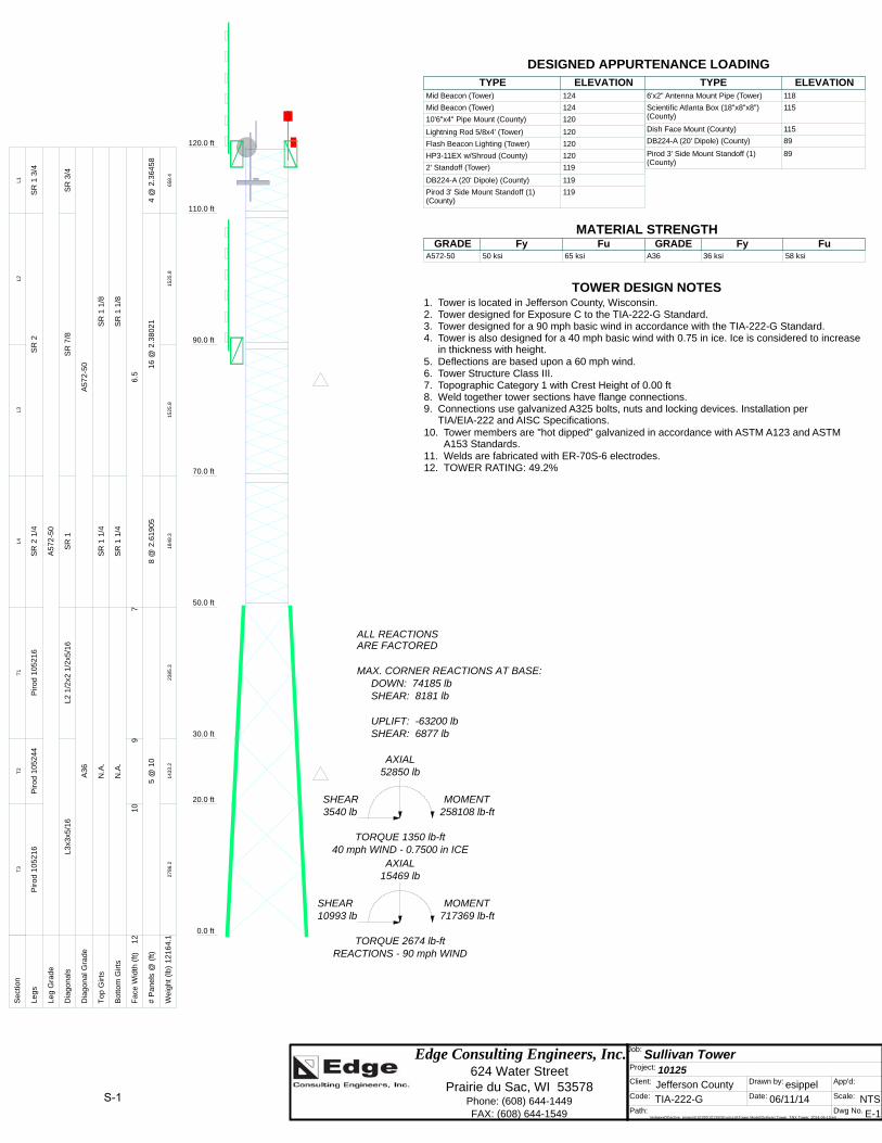
REACTIONS - 90 mph WINDTORQUE 2674 lb-ft
10993 lbSHEAR
717369 lb-ftMOMENT
15469 lbAXIAL
40 mph WIND - 0.7500 in ICETORQUE 1350 lb-ft
3540 lbSHEAR
258108 lb-ftMOMENT
52850 lbAXIAL
SHEAR: 6877 lbUPLIFT: -63200 lb
SHEAR: 8181 lbDOWN: 74185 lb
MAX. CORNER REACTIONS AT BASE:
ARE FACTOREDALL REACTIONS
S
ect
ion
L1L2
L3L4
T1
T2
T3
L
eg
sS
R 1
3/4
SR
2S
R 2
1/4
Pir
od
10
52
16
Pir
od
10
52
44
Pir
od
10
52
16
L
eg
Gra
de
A5
72
-50
D
iag
on
als
SR
3/4
SR
7/8
SR
1L
2 1
/2x2
1/2
x5/1
6L
3x3
x5/1
6
D
iag
on
al G
rad
eA
57
2-5
0A
36
T
op
Gir
tsS
R 1
1/8
SR
1 1
/4N
.A.
B
ott
om
Gir
tsS
R 1
1/8
SR
1 1
/4N
.A.
F
ace
Wid
th (
ft)
6.5
79
10
12
#
Pa
ne
ls @
(ft
)4
@ 2
.36
45
81
6 @
2.3
80
21
8 @
2.6
19
05
5 @
10
W
eig
ht
(lb
)65
8.4
1525
.815
25.8
1849
.323
85.3
1433
.227
86.2
12
16
4.1
Mid Beacon (Tower) 124 Mid Beacon (Tower) 124 10'6"x4" Pipe Mount (County) 120 Lightning Rod 5/8x4' (Tower) 120 Flash Beacon Lighting (Tower) 120 HP3-11EX w/Shroud (County) 120 2' Standoff (Tower) 119 DB224-A (20' Dipole) (County) 119 Pirod 3' Side Mount Standoff (1) (County)
119 6'x2" Antenna Mount Pipe (Tower) 118 Scientific Atlanta Box (18"x8"x8") (County)
115 Dish Face Mount (County) 115 DB224-A (20' Dipole) (County) 89 Pirod 3' Side Mount Standoff (1) (County)
89DESIGNED APPURTENANCE LOADINGTYPE TYPEELEVATION ELEVATION
Mid Beacon (Tower) 124
Mid Beacon (Tower) 124
10'6"x4" Pipe Mount (County) 120
Lightning Rod 5/8x4' (Tower) 120
Flash Beacon Lighting (Tower) 120
HP3-11EX w/Shroud (County) 120
2' Standoff (Tower) 119
DB224-A (20' Dipole) (County) 119
Pirod 3' Side Mount Standoff (1) (County)
119
6'x2" Antenna Mount Pipe (Tower) 118
Scientific Atlanta Box (18"x8"x8") (County)
115
Dish Face Mount (County) 115
DB224-A (20' Dipole) (County) 89
Pirod 3' Side Mount Standoff (1) (County)
89
MATERIAL STRENGTHGRADE GRADEFy FyFu Fu
A572-50 50 ksi 65 ksi A36 36 ksi 58 ksi
TOWER DESIGN NOTES1. Tower is located in Jefferson County, Wisconsin.2. Tower designed for Exposure C to the TIA-222-G Standard.3. Tower designed for a 90 mph basic wind in accordance with the TIA-222-G Standard.4. Tower is also designed for a 40 mph basic wind with 0.75 in ice. Ice is considered to increase
in thickness with height.5. Deflections are based upon a 60 mph wind.6. Tower Structure Class III.7. Topographic Category 1 with Crest Height of 0.00 ft8. Weld together tower sections have flange connections.9. Connections use galvanized A325 bolts, nuts and locking devices. Installation per
TIA/EIA-222 and AISC Specifications.10. Tower members are "hot dipped" galvanized in accordance with ASTM A123 and ASTM
A153 Standards.11. Welds are fabricated with ER-70S-6 electrodes.12. TOWER RATING: 49.2%
S-1

Edge Consulting Engineers, Inc. 624 Water Street
Prairie du Sac, WI 53578 Phone: (608) 644-1449 FAX: (608) 644-1549
Job: Sullivan Tower Project: 10125 Client: Jefferson County Drawn by: esippel App'd:
Code: TIA-222-G Date: 06/11/14 Scale: NTS Path:
\\edgeex02\active_projects\10100\10125\Structural\Tower Model\Sullivan Tower_TNX Tower_2014-06-10.eri
Dwg No. E-5
TIA-222-G - Service - 60 mph Maximum Values
0
0
0.5
0.5
1
1
1.5
1.5
2
2
Deflection (in)120.00
110.00
90.00
70.00
50.00
30.00
20.00
0.00
Ele
vati
on
(ft
)
0
0
0.05
0.05
0.1
0.1
0.15
0.15
Tilt (deg)0
0
0.05
0.05
0.1
0.1
Twist (deg)120.00
110.00
90.00
70.00
50.00
30.00
20.00
0.00
S-2

Edge Consulting Engineers, Inc. 624 Water Street
Prairie du Sac, WI 53578 Phone: (608) 644-1449 FAX: (608) 644-1549
Job: Sullivan Tower Project: 10125 Client: Jefferson County Drawn by: esippel App'd:
Code: TIA-222-G Date: 06/11/14 Scale: NTS Path:
\\edgeex02\active_projects\10100\10125\Structural\Tower Model\Sullivan Tower_TNX Tower_2014-06-10.eri
Dwg No. E-7
Feed Line Distribution Chart0' - 120'
Round Flat App In Face App Out Face Truss Leg
Face A
110.00
90.00
70.00
50.00
30.00
20.00
0.00
120.00
Ele
vati
on
(ft
)
EW
90
(C
ou
nty
)
LD
F5
-50
A (
7/8
FO
AM
) (C
ou
nty
)
LD
F5
-50
A (
7/8
FO
AM
) (C
ou
nty
)
Face B
5.005.005.005.00
119.00
5.00
89.00
Face C
110.00
90.00
70.00
50.00
30.00
20.00
0.00
120.00
5.005.005.005.00
119.00
5.00
89.00
3/8
" G
rou
nd
(T
ow
er)
3/4
" R
igid
Co
nd
uit
(To
we
r)
S-3

Anchor Rod CalculationsDistance from TOC to Bottom of Leveling Nut (lar) =
Project Name - Sullivan Tower ()Sullivan, WisconsinEdge #10125
10125 Completed By: EJS
Checked By: BPB
Anchor Rod Parameters:Detail Type = d *Per ANSI/TIA-222-G, Section 4.9.9
Detail Factor (η) = 0.50Distance from TOC to Bottom of Leveling Nut (l ar) = 3.00 in 3
Number of Rods (Nb) = 6Rod Diameter (Db) = 1.00 in
Coarse Threads Per Inch (n) = 8.00Area of Rod (Ab) = 0.79 in2
Rod Yield Stress (Fy) = 105 ksiRod Tensile Strength (Fu) = 125 ksi
Max Compression per Leg (Cmax) = 74.2 kip/leg 74185.13
Max Tension per Leg (Tmax) = 63.2 kip/leg -63199.55
Max Shear per Leg (Vmax) = 8.2 kip/leg -7113.25 -4040.68
Area using Tensile Root Diameter (A n) = 0.61 in2
Ultimate Anchor Rod Demand and Resistance
Applied Shear per Rod (Vu) = 1.36 kip/rod
Applied Axial per Rod (Pu) = 12.36 kip/rod
Available Tensile Strength (φRnt) = 60.57 kip/rod 55.22
Combined Shear and Tension Check (Applicable for Detail Type d):
Unity = 3.00
Available Shear Strength (φRn) = 33.1 kip/rod
Plastic Section Modulus of Rod (Z) = 0.113 in3
Shear & Tension = 0.207 OK
bu N
VV max
bu N
PP max
b
ar
D
lRatio
0.1
bunv AFR 45.075.0
nunt AFR 8.0
29743.
4
nDA bn
6
9743.3
nD
Zb
0.65 ∙ ∙0.9 ∙ ∙
1.0
S-4
Related Documents


