STRUCTURAL ANALYSIS – I Syllabus: UNIT – I PROPPED CANTILEVERS: Analysis of propped cantilevers-shear force and Bending moment diagrams-Deflection of propped cantilevers. UNIT – II FIXED BEAMS – Introduction to statically indeterminate beams with U. D. load central point load, eccentric point load. Number of point loads, uniformly varying load, couple and combination of loads shear force and Bending moment diagrams-Deflection of fixed beams effect of sinking of support, effect of rotation of a support. UNIT – III CONTINUOUS BEAMS: Introduction-Clapeyron’s theorem of three moments- Analysis of continuous beams with constant moment of inertia with one or both ends fixed-continuous beams with overhang, continuous beams with different moment of inertia for different spans-Effects of sinking of supports-shear force and Bending moment diagrams. UNIT-IV SLOPE-DEFLECTION METHOD: Introduction, derivation of slope deflection equation, application to continuous beams with and without settlement of supports. UNIT – V ENERGY THEOREMS: Introduction-Strain energy in linear elastic system, expression of strain energy due to axial load, bending moment and shear forces - Castigliano’s first theorem-Deflections of simple beams and pin jointed trusses. UNIT – VI MOVING LOADS and INFLUENCE LINES: Introduction maximum SF and BM at a given section and absolute maximum S.F. and B.M due to single concentrated load U. D load longer than the span, U. D load shorter than the span, two point loads with fixed distance between them and several point loads-Equivalent uniformly distributed load- Focal length. INFLUENCE LINES: Definition of influence line for SF, Influence line for BM- load position for maximum SF at a section-Load position for maximum BM at a sections, ingle point load, U.D. load longer than the span, U.D. load shorter than the span- Influence lines for forces in members of Pratt and Warren trusses.

Welcome message from author
This document is posted to help you gain knowledge. Please leave a comment to let me know what you think about it! Share it to your friends and learn new things together.
Transcript

STRUCTURAL ANALYSIS – I
Syllabus:
UNIT – I
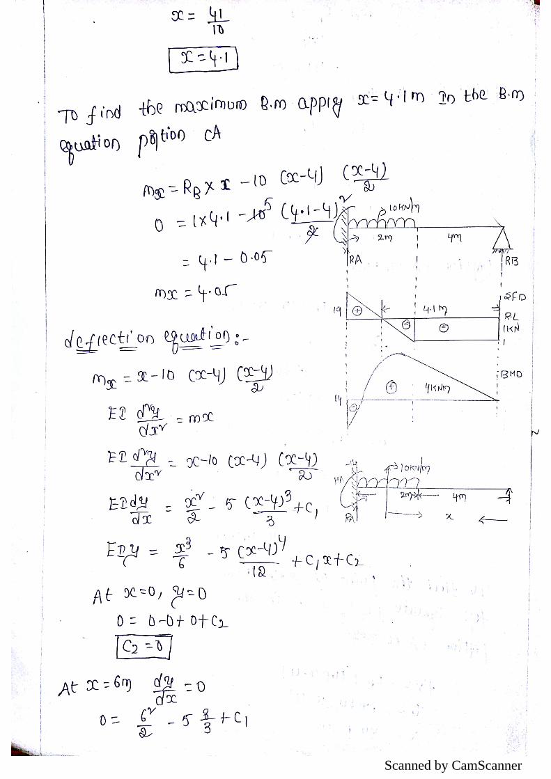
PROPPED CANTILEVERS: Analysis of propped cantilevers-shear force and Bending
moment diagrams-Deflection of propped cantilevers.
UNIT – II
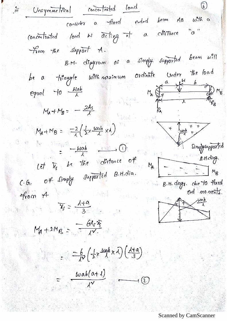
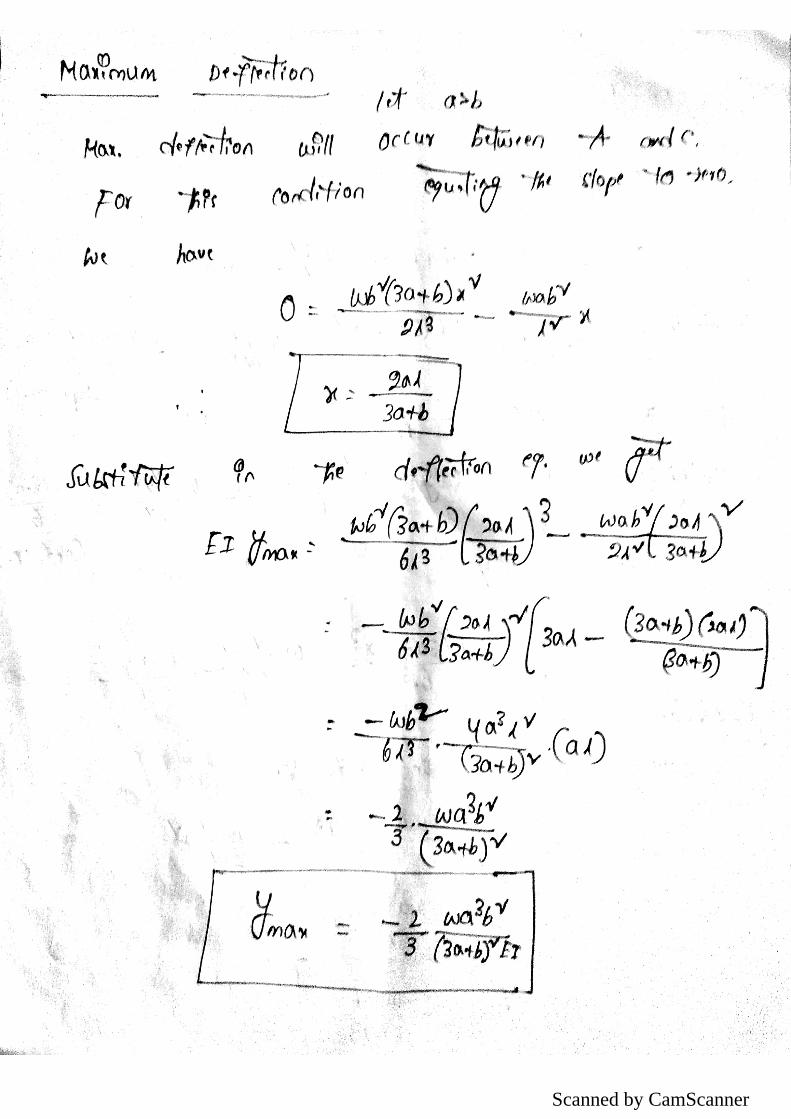
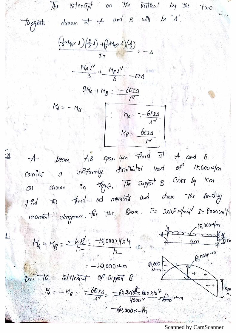
FIXED BEAMS – Introduction to statically indeterminate beams with U. D. load central
point load, eccentric point load. Number of point loads, uniformly varying load, couple
and combination of loads shear force and Bending moment diagrams-Deflection of fixed
beams effect of sinking of support, effect of rotation of a support.
UNIT – III
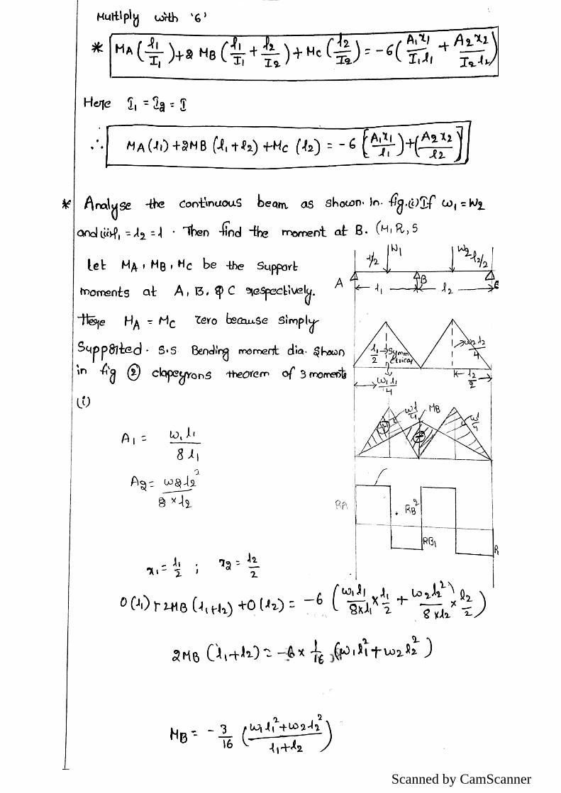
CONTINUOUS BEAMS: Introduction-Clapeyron’s theorem of three moments-
Analysis of continuous beams with constant moment of inertia with one or both ends
fixed-continuous beams with overhang, continuous beams with different moment of
inertia for different spans-Effects of sinking of supports-shear force and Bending moment
diagrams.
UNIT-IV
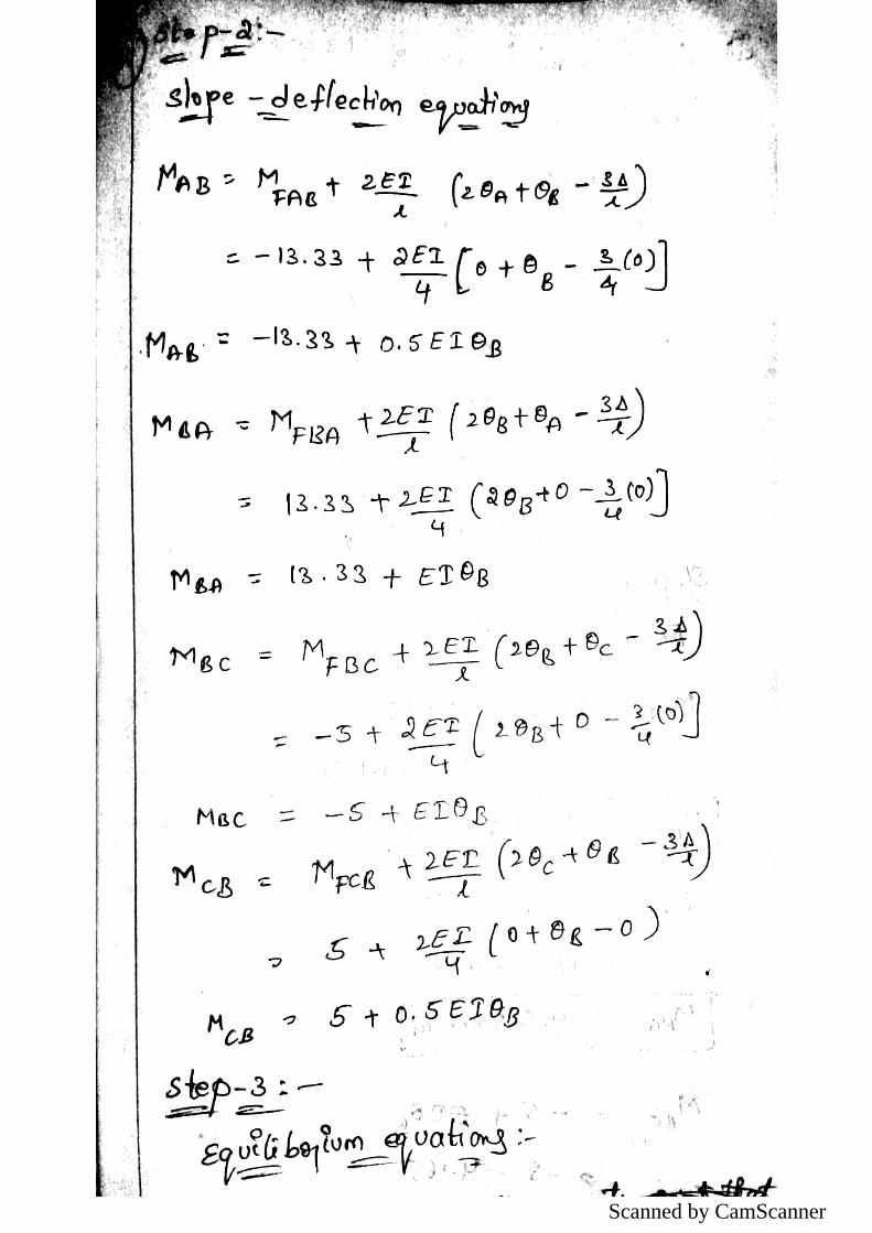
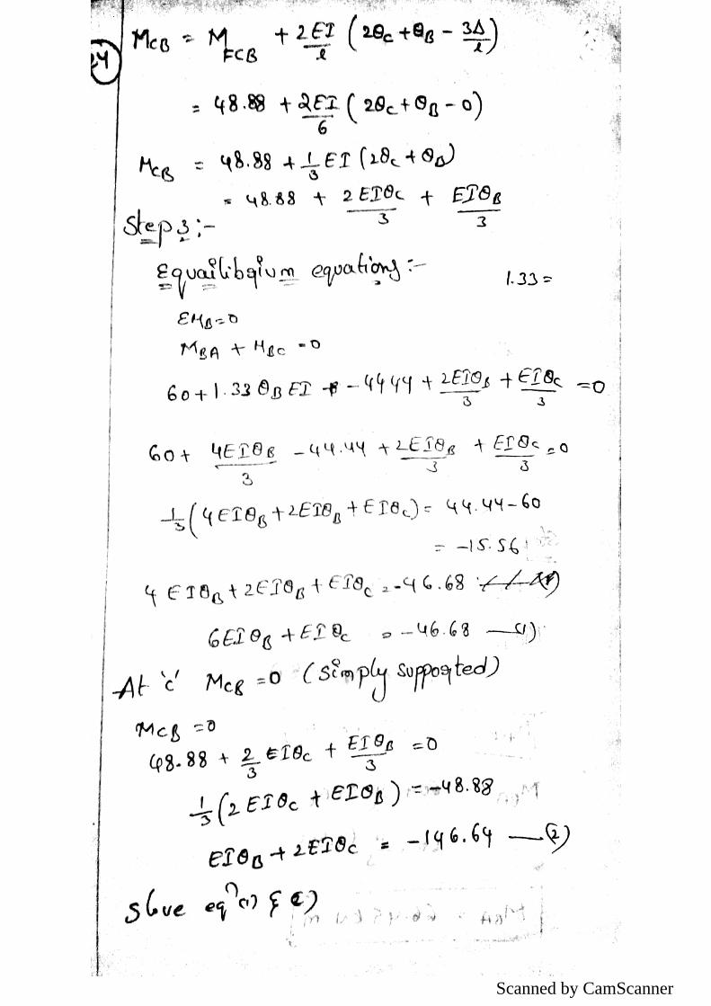
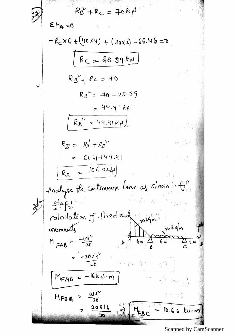
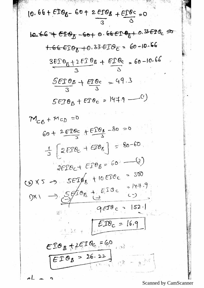
SLOPE-DEFLECTION METHOD: Introduction, derivation of slope deflection
equation, application to continuous beams with and without settlement of supports.
UNIT – V
ENERGY THEOREMS: Introduction-Strain energy in linear elastic system, expression
of strain energy due to axial load, bending moment and shear forces - Castigliano’s first
theorem-Deflections of simple beams and pin jointed trusses.
UNIT – VI
MOVING LOADS and INFLUENCE LINES: Introduction maximum SF and BM at a
given section and absolute maximum S.F. and B.M due to single concentrated load U. D
load longer than the span, U. D load shorter than the span, two point loads with fixed
distance between them and several point loads-Equivalent uniformly distributed load-
Focal length.
INFLUENCE LINES: Definition of influence line for SF, Influence line for BM- load
position for maximum SF at a section-Load position for maximum BM at a sections,
ingle point load, U.D. load longer than the span, U.D. load shorter than the span-
Influence lines for forces in members of Pratt and Warren trusses.

Scanned by CamScanner

Scanned by CamScanner
Scanned by CamScanner

Scanned by CamScanner

Scanned by CamScanner

Scanned by CamScanner
Scanned by CamScanner

Scanned by CamScanner

Scanned by CamScanner

Scanned by CamScanner

Scanned by CamScanner

Scanned by CamScanner
Scanned by CamScanner

Scanned by CamScanner

Scanned by CamScanner
Scanned by CamScanner

Scanned by CamScanner

Scanned by CamScanner
Scanned by CamScanner

Scanned by CamScanner

Scanned by CamScanner

Scanned by CamScanner
Scanned by CamScanner

Scanned by CamScanner

Scanned by CamScanner
Scanned by CamScanner

Scanned by CamScanner

Scanned by CamScanner

Scanned by CamScanner

Scanned by CamScanner

Scanned by CamScanner

Scanned by CamScanner

Scanned by CamScanner

Scanned by CamScanner

Scanned by CamScanner

Scanned by CamScanner

Scanned by CamScanner
Scanned by CamScanner

Scanned by CamScanner

Scanned by CamScanner
Scanned by CamScanner

Scanned by CamScanner

Scanned by CamScanner

Scanned by CamScanner

Scanned by CamScanner

Scanned by CamScanner

Scanned by CamScanner

Scanned by CamScanner

Scanned by CamScanner

Scanned by CamScanner

Scanned by CamScanner

Scanned by CamScanner
Scanned by CamScanner

Scanned by CamScanner

Scanned by CamScanner
Scanned by CamScanner

Scanned by CamScanner

Scanned by CamScanner

Scanned by CamScanner

Scanned by CamScanner

Scanned by CamScanner

Scanned by CamScanner
Scanned by CamScanner

Scanned by CamScanner
Scanned by CamScanner

Scanned by CamScanner

Scanned by CamScanner

Scanned by CamScanner
Scanned by CamScanner

Scanned by CamScanner
Scanned by CamScanner

Scanned by CamScanner

Scanned by CamScanner

Scanned by CamScanner

Scanned by CamScanner

Scanned by CamScanner
Scanned by CamScanner

Scanned by CamScanner

Scanned by CamScanner

Scanned by CamScanner
Scanned by CamScanner

Scanned by CamScanner

Scanned by CamScanner
Scanned by CamScanner

Scanned by CamScanner

Scanned by CamScanner
Scanned by CamScanner

Scanned by CamScanner

Scanned by CamScanner

Scanned by CamScanner

Scanned by CamScanner
Scanned by CamScanner

Scanned by CamScanner
Scanned by CamScanner

Scanned by CamScanner

Scanned by CamScanner

Scanned by CamScanner

Scanned by CamScanner

Scanned by CamScanner

Scanned by CamScanner

Scanned by CamScanner
Scanned by CamScanner

Scanned by CamScanner

Scanned by CamScanner
Scanned by CamScanner

Scanned by CamScanner

Scanned by CamScanner

Scanned by CamScanner

Scanned by CamScanner

UNIT - VI
-STRAIN ENERGY-
Introduction: - Strain energy is as the energy which is stored within a material when work has
been done on the material. Here it is assumed that the material remains elastic
whilst work is done on it so that all the energy is recoverable and no permanent
deformation occurs due to yielding of the material,
Strain energy U = work done
Thus for a gradually applied load the work done in straining the material will be
given by the shaded area under the load-extension graph of Fig.
U = P δ
Work done by a gradually applied load.
The unshaded area above the line OB of Fig. 7.1 is called the complementary
energy, a quantity which is utilized in some advanced energy methods of solution
and is not considered within the terms of reference of this text.

Scanned by CamScanner

Scanned by CamScanner

Scanned by CamScanner

Scanned by CamScanner
Scanned by CamScanner

Scanned by CamScanner

UNIT-VI
MOVING LOADS AND INFLUENCE LINES
Definitions of influence line
An influence line is a diagram whose ordinates, which are plotted as a function of
distance along the span, give the value of an internal force, a reaction, or a
displacement at a particular point in a structure as a unit load move across the
structure.
An influence line is a curve the ordinate to which at any point equals the value of
some particular function due to unit load acting at that point.
An influence line represents the variation of either the reaction, shear, moment, or
deflection at a specific point in a member as a unit concentrated force moves over the
member.
In engineering, an influence line graphs the variation of a function (such as the shear felt in a
structure member) at a specific point on a beam or truss caused by a unit load placed at any point
along the structure. Some of the common functions studied with influence lines include reactions
(the forces that the structure’s supports must apply in order for the structure to remain static),
shear, moment, and deflection (Deformation). Influence lines are important in designing beams
and trusses used in bridges, crane rails, conveyor belts, floor girders, and other structures where
loads will move along their spanThe influence lines show where a load will create the maximum
effect for any of the functions studied.
Influence lines are both scalar and additiveThis means that they can be used even when the load
that will be applied is not a unit load or if there are multiple loads applied. To find the effect of
any non-unit load on a structure, the ordinate results obtained by the influence line are multiplied
by the magnitude of the actual load to be applied. The entire influence line can be scaled, or just
the maximum and minimum effects experienced along the line. The scaled maximum and
minimum are the critical magnitudes that must be designed for in the beam or truss
In cases where multiple loads may be in effect, the influence lines for the individual loads may
be added together in order to obtain the total effect felt by the structure at a given point. When
adding the influence lines together, it is necessary to include the appropriate offsets due to the
spacing of loads across the structure. For example, a truck load is applied to the structure. Rear
axle, B, is three feet behind front axle, A, then the effect of A at x feet along the structure must
be added to the effect of B at (x – 3) feet along the structure—not the effect of B at x feet along
the structure.
Many loads are distributed rather than concentrated. Influence lines can be used with either
concentrated or distributed loadings. For a concentrated (or point) load, a unit point load is
moved along the structure. For a distributed load of a given width, a unit-distributed load of the
same width is moved along the structure, noting that as the load nears the ends and moves off the
structure only part of the total load is carried by the structure. The effect of the distributed unit
load can also be obtained by integrating the point load’s influence line over the corresponding
length of the structures.

1) A system of concentrated load, role beam left to right, s.s beam span of 10m and 10 KN
load leading
Find 1.Absolute max +ve S.F
2. .Absolute max -ve S.F
3..Absolute max BM
Solution
1. Absolute max +ve S.F
Using the similar triangle method and we get the x, y & z values
X = 0.85 m
Y = 0.75 m
Z = 0.55 m
S.F = (10×1)+(15×0.83)+(20×0.75)+(10×0.55)
= 43.25 KN
Using the similar triangle method and we get the l, m, n & o values
L=0.8 m

M = 0.65 m
N = 0.55 m
O = 0.35 m
S.F = (20×1)+(10×0.8)+(15×0.65)+(20×0.55)+(10×0.35)
= 52.25 KN
Absolute max -ve S.F
Using the similar triangle method and we get the l, m, n & o values
L = 0.35 m
M = 0.55 m
N = 0.7 m
O = 0.8 m
S.F = (10×1)+(20×0.8)+(15×0.7)+(10×0.55)+(20×0.35)
= - 49 KN
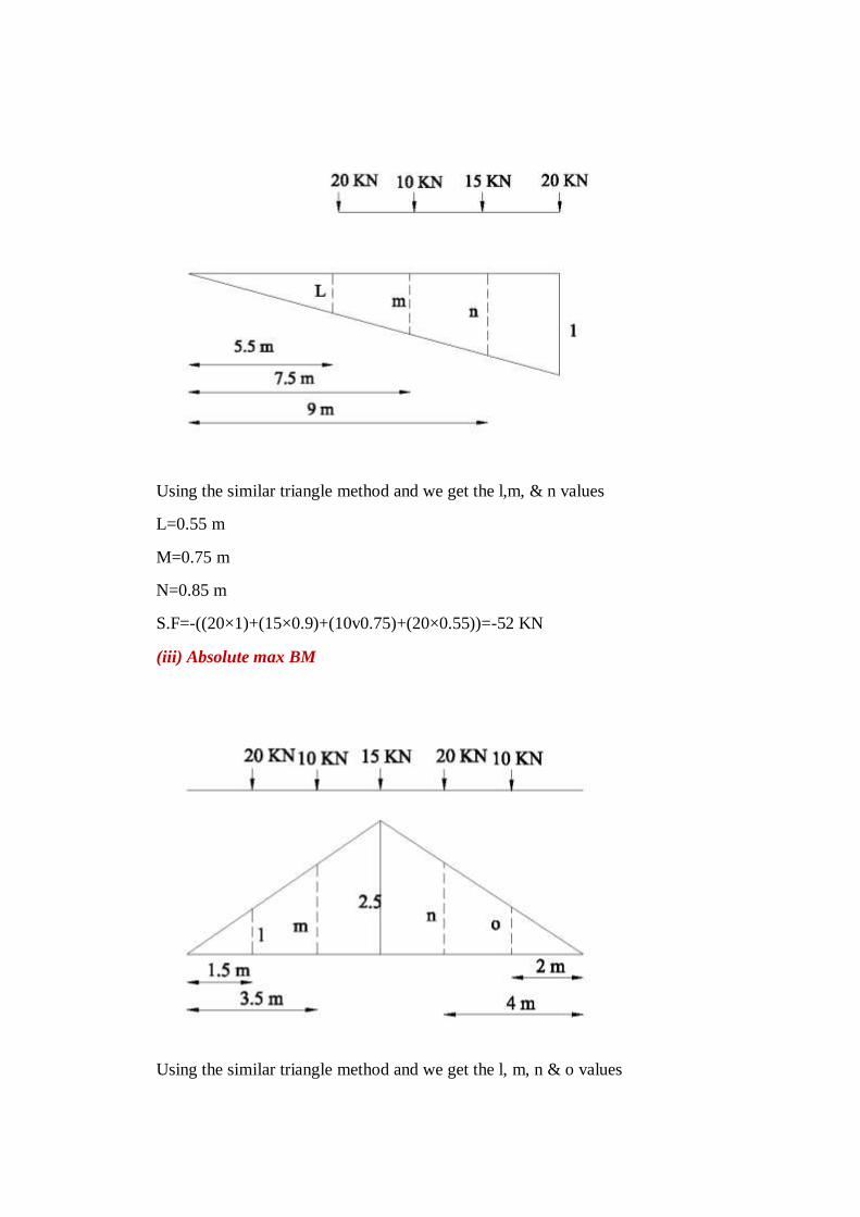
Using the similar triangle method and we get the l,m, & n values
L=0.55 m
M=0.75 m
N=0.85 m
S.F=-((20×1)+(15×0.9)+(10v0.75)+(20×0.55))=-52 KN
(iii) Absolute max BM
Using the similar triangle method and we get the l, m, n & o values

L = 0.75 m
M = 1.75 m
N = 2 m
O = 1 m
Max BM = (20×0.75) +(10×1.75)+(15×2.5)+(20×2)+(10×1)
= 22.75 KN
2) The four equal loads of 150 KN ,each equally spaced at apart 2m and UDL of 60 KN/m
at a distance of 1.5m from the last 150 KN loads cross a girder of 20m from span R to
L.Using influence line ,calculate the S.F and BM at a section of 8m from L.H.S
support when leading of 150KN 5m from L.H.S.
Solution
(i) Max BM
L = 3 m
M = 4.2 m
N = 4.4 m
0 = 3.6 m
P = 3 m
A = 11.25 m2
BM = (150×3)+(150×4.2)+(150×4.4)+(150×306)+(60×11.25)
= 2955 KNm

ii) Shear Force
Compute maximum end shear for the given beam loaded with moving loads as shown in
Figure
L = 0.25 m,
M = 0.3 m,
N = 0.55 m,
O = 0.45 m,
P = 0.375 m
SF = ((150×0.25)+(150×0.35)+(150×0.55)+(150×0.45)+(60×1.41))
= 144. KN

Where do you get rolling loads in practice?
Shifting of load positions is common enough in buildings. But they are more
pronounced in bridges and in gantry girders over which vehicles keep rolling.
Name the type of rolling loads for which the absolute maximum bending moment occurs at
the midspan of a beam.
Single concentrated load
udl longer than the span
udl shorter than the span
Also when the resultant of several concentrated loads crossing a span, coincides with
a concentrated load then also the maximum bending moment occurs at the centre of
the span.
What is meant by absolute maximum bending moment in a beam?
When a given load system moves from one end to the other end of a girder, depending
upon the position of the load, there will be a maximum bending moment for every
section.
The maximum of these bending moments will usually occur near or at the midspan.
The maximum of maximum bending moments is called the absolute maximum
bending moment.
Where do you have the absolute maximum bending moment in a simply supported beam
when a series of wheel loads cross it?
When a series of wheel loads crosses a simply supported beam, the absolute
maximum bending moment will occur near midspan under the load Wcr , nearest to
midspan (or the heaviest load).
If Wcr is placed to one side of midspan C, the resultant of the load system R shall be
on the other side of C; and Wcr and R shall be equidistant from C.
Now the absolute maximum bending moment will occur under Wcr .
If Wcr and R coincide, the absolute maximum bending moment will occur at
midspan.
What is the absolute maximum bending moment due to a moving udl longer than the span
of a simply supported beam?
When a simply supported beam is subjected to a moving udl longer than the span, the
absolute maximum bending moment occurs when the whole span is loaded.
Mmax max = wl2/ 8

State the location of maximum shear force in a simple beam with any kind of loading.
In a simple beam with any kind of load, the maximum positive shear force occurs at
the left hand support and maximum negative shear force occurs at right hand support.
What is meant by maximum shear force diagram?
Due to a given system of rolling loads the maximum shear force for every section of
the girder can be worked out by placing the loads in appropriate positions.
When these are plotted for all the sections of the girder, the diagram that we obtain is
the maximum shear force diagram.
This diagram yields the ‘design shear’ for each cross section.
What is meant by influence lines?
An influence line is a graph showing, for any given frame or truss, the variation of
any force or displacement quantity (such as shear force, bending moment, tension,
deflection) for all positions of a moving unit load as it crosses the structure from one
end to the other.
What are the uses of influence line diagrams?
Influence lines are very useful in the quick determination of reactions, shear force,
bending moment or similar functions at a given section under any given system of
moving loads and
Influence lines are useful in determining the load position to cause maximum value of
a given function in a structure on which load positions can vary.
Draw the influence line diagram for shear force at a point X in a simply supported beam
AB of span ‘l’ m.
Draw the ILD for bending moment at any section X of a simply supported beam and mark
the ordinates.

What do you understand by the term reversal of stresses?
In certain long trusses the web members can develop either tension or compression
depending upon the position of live loads.
This tendancy to change the nature of stresses is called reversal of stresses.
State Muller-Breslau principle.
Muller-Breslau principle states that, if we want to sketch the influence line for any
force quantity (like thrust, shear, reaction, support moment or bending moment) in a
structure,
We remove from the structure the resistant to that force quantity and
We apply on the remaining structure a unit displacement corresponding to that force
quantity.
The resulting displacements in the structure are the influence line ordinates sought.
State Maxwell-Betti’s theorem.
In a linearly elastic structure in static equilibrium acted upon by either of two systems
of external forces, the virtual work done by the first system of forces in undergoing
the displacements caused by the second system of forces is equal to the virtual work
done by the second system of forces in undergoing the displacements caused by the
first system of forces.
Maxwell Betti’s theorem helps us to draw influence lines for structures.
What is the necessity of model analysis?
When the mathematical analysis of problem is virtually impossible.
Mathematical analysis though possible is so complicated and time consuming that the
model analysis offers a short cut.
The importance of the problem is such that verification of mathematical analysis by
an actual test is essential.
Define similitude.
Similitude means similarity between two objects namely the model and the prototype
with regard to their physical characteristics:
Geometric similitude is similarity of form
Kinematic similitude is similarity of motion
Dynamic and/or mechanical similitude is similarity of masses and/or
forces.
State the principle on which indirect model analysis is based.
The indirect model analysis is based on the Muller Breslau principle.
Muller Breslau principle has lead to a simple method of using models of structures to
get the influence lines for force quantities like bending moments, support moments,
reactions, internal shears, thrusts, etc.,
To get the influence line for any force quantity,
(i) remove the resistant due to the force,
(ii) apply a unit displacement in the direction
(iii) plot the resulting displacement diagram.
This diagram is the influence line for the force.
What is the principle of dimensional similarity?
Dimensional similarity means geometric similarity of form.
This means that all homologous dimensions of prototype and model must be in some
constant ratio.
What is Begg’s deformeter?
Begg’s deformeter is a device to carry out indirect model analysis on structures.
It has the facility to apply displacement corresponding to moment, shear or thrust at
any desired point in the model.
In addition, it provides facility to measure accurately the consequent displacements all
over the model.
Name any four model making materials.
Perspex,
plexiglass,
acrylic,
plywood,
sheet araldite
bakelite
Micro-concrete,
mortar and plaster of paris

What is ‘dummy length’ in models tested with Begg’s deformeter.
Dummy length is the additional length (of about 10 to 12mm) left at the extremities of
the model to enable any desired connection to be made with the gauges.
What are the three types of connections possible with the model used with Begg’s
deformeter.
Hinged connection
Fixed connection
Floating connection
What is the use of a micrometer microscope in model analysis with Begg’s deformeter.
Micrometer microscope is an instrument used to measure the displacements of any
point in the x and y directions of a model during tests with Begg’s deformeter.
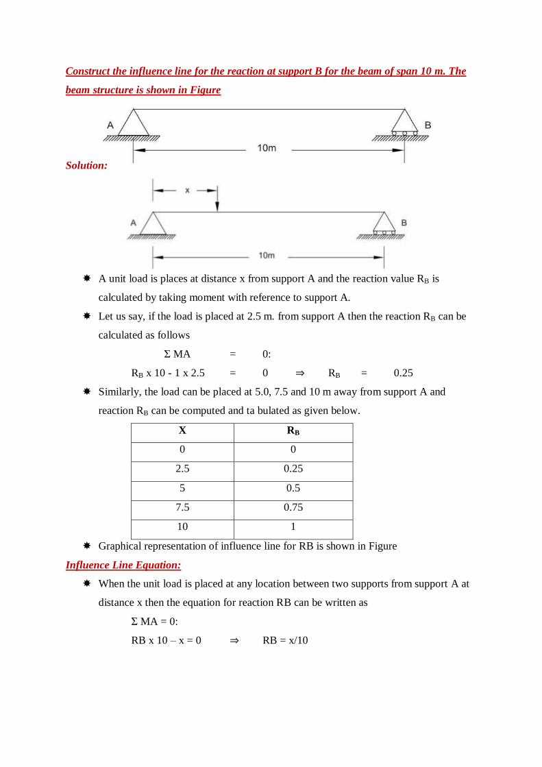
Construct the influence line for the reaction at support B for the beam of span 10 m. The
beam structure is shown in Figure
Solution:
A unit load is places at distance x from support A and the reaction value RB is
calculated by taking moment with reference to support A.
Let us say, if the load is placed at 2.5 m. from support A then the reaction RB can be
calculated as follows
Σ MA = 0:
RB x 10 - 1 x 2.5 = 0 ⇒ RB = 0.25
Similarly, the load can be placed at 5.0, 7.5 and 10 m away from support A and
reaction RB can be computed and ta bulated as given below.
X RB
0 0
2.5 0.25
5 0.5
7.5 0.75
10 1
Graphical representation of influence line for RB is shown in Figure
Influence Line Equation:
When the unit load is placed at any location between two supports from support A at
distance x then the equation for reaction RB can be written as
Σ MA = 0:
RB x 10 – x = 0 ⇒ RB = x/10

Find the maximum positive live shear at point C when the beam as shown in figure, is
loaded with a concentrated moving load of 10 kN and UDL of 5 kN/m.
Concentrated load:
the maximum live shear force at C
will be when the concentrated load
10 kN is located just before
C or just after C.
Our aim is to find positive live
shear and hence, we will put 10 kN
just after C.
In that case, Vc = 0.5 x 10 = 5 kN.
UDL:
the maximum positive live shear
force at C willbe when the
UDL 5 kN/m is acting between
x = 7.5 and x = 15.
Vc = [ 0.5 x (15 –7.5) (0.5)] x 5 = 9.375
Total maximum Shear at C:
(Vc) max = 5 + 9.375 = 14.375.

Muller Breslau Principle for Qualitative Influence Lines
In 1886, Heinrich Müller Breslau proposed a technique to draw influence lines
quickly.
The Müller Breslau Principle states that the ordinate value of an influence line for any
function on any structure is proportional to the ordinates of the deflected shape that is
obtained by removing the restraint corresponding to the function from the structure
and introducing a force that causes a unit displacement in the positive direction.
Procedure:
First of all remove the support corresponding to the reaction and apply a force in the
positive direction that will cause a unit displacement in the direction of RA
Deflected shape of beam
The resulting deflected shape will be proportional to the true influence line for the
support reaction at A.
Influence line for support reaction A
The deflected shape due to a unit displacement at A is shown in above Figure:1 and
matches with the actual influence line shape as shown in Figure 3.
Note that the deflected shape is linear, i.e., the beam rotates as a rigid body without
any curvature. This is true only for statically determinate systems.

Overhang beam
Deflected shape of beam
Now apply a force in the positive direction that will cause a unit displacement in the
direction of VC.
The resultant deflected shape is shown above Figure. Again, note that the deflected
shape is linear.
Influence line for shear at section C

Overhang beam - 2
Beam structure
To construct influence line for moment, we will introduce hinge at C and that will
only permit rotation at C.
Now apply moment in the positive direction that will cause a unit rotation in the
direction of Mc.
The deflected shape due to a unit rotation at C is shown in Figure and matches with
the actual shape of the influence line as shown in Figure 3.
Deflected shape of beam
Influence line for moment at section C

Maximum shear in beam supporting UDLs
UDL longer than the span
Influence line for moment at section C
Suppose the section C is at mid span, then maximum moment is given by

UDL longer than the span
Influence line for support reaction at A
Influence line for support reaction at B
Influence line for shear at section C

Maximum negative shear is given by
Maximum positive shear is given by
Related Documents