Jurg Conzett – Traversina Bridge Mome nt Load ing

STRUCTURAL ANALYSIS : Determining Structural Capacity
Jan 16, 2016
STRUCTURAL ANALYSIS : Determining Structural Capacity. From Structural Analysis we have developed an understanding of all : Actions - Applied forces such as dead load, live load, wind load, seismic load. Reactions - Forces generated at the boundary conditions that maintain equilibrium. - PowerPoint PPT Presentation
Welcome message from author
This document is posted to help you gain knowledge. Please leave a comment to let me know what you think about it! Share it to your friends and learn new things together.
Transcript

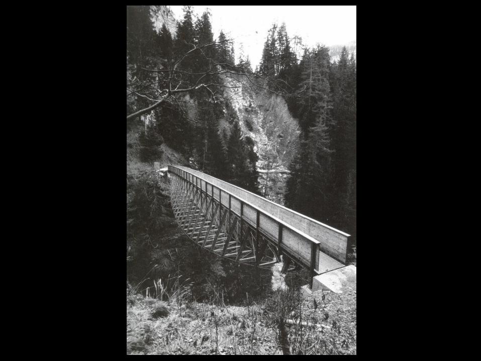
Jurg Conzett – Traversina Bridge
Moment
Loading

Riccardo Morandi – Santa Barbara Power Station


Materials Review

Stress-Strain curve
allow
Myf f
I
allow
Myf f
I
= Modulus of Elasticity = E
fy

Stress-Strain curve

Comparison of materials
Modulus of Elasticity (E)Yield Stress (fy)
compressionbending tensionMaterial
Steel
Wood
Concrete
Glass
29,000 ksi
1700 ksi
3100 ksi
10,000 ksi
36 ksi
1.0 ksi
0.5 ksi
24 ksi
36 ksi
0.7 ksi
0.3 ksi
24 ksi
36 ksi
1.5 ksi
3 ksi
145 ksi

Comparison of materials
Modulus of Elasticity (E) compressionbending tensionMaterial
Steel
Wood
Concrete
Glass
17
1
2
6
36
1
0.5
24
50
1
0.5
34
24
1
2
97
Yield Stress (fy)

Allowable Stress Design
Make sure that materials do not reach their yield stress by providing a factor of safety (FOS).

Factor of Safety
Steel: 0.6

Factor of Safety
Steel: 0.6
Allowable flexural stress = factor of safety x yield stress
Fb = 0.6 x fy
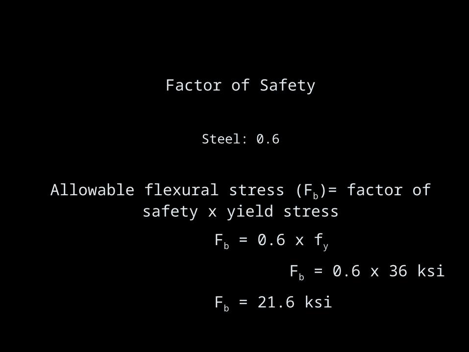
Factor of Safety
Steel: 0.6
Allowable flexural stress (Fb)= factor of safety x yield stress
Fb = 0.6 x fy
Fb = 0.6 x 36 ksi
Fb = 21.6 ksi

Moment = bending stress (fb) x SECTION MODULUS
What is section modulus?

Moment = bending stress x SECTION MODULUS
What is section modulus?
Property of the cross sectional shape.

Moment = bending stress x SECTION MODULUS
What is section modulus?
Property of the cross sectional shape.
Where do you find it?
Look it up in the tables OR calculate it

Section Modulus = S = b h2
6
b
hneutral axis
b
h

Deflection

Deflection
the measured amount a member moves depends upon:
• Rigidity or stiffness of the material
• Property of the cross sectional shape
• Length of beam
• Load on beam

Deflection
• Rigidity or stiffness of the material
Modulus of Elasticity (E)
• Property of the cross sectional shape
Moment of Inertia (I)

Moment of Inertia
• Property of the cross sectional shape
Where do you find it?
Look it up in tables OR calculate it

Moment of inertia = I = b h3 12
b
hneutral axis
b
h
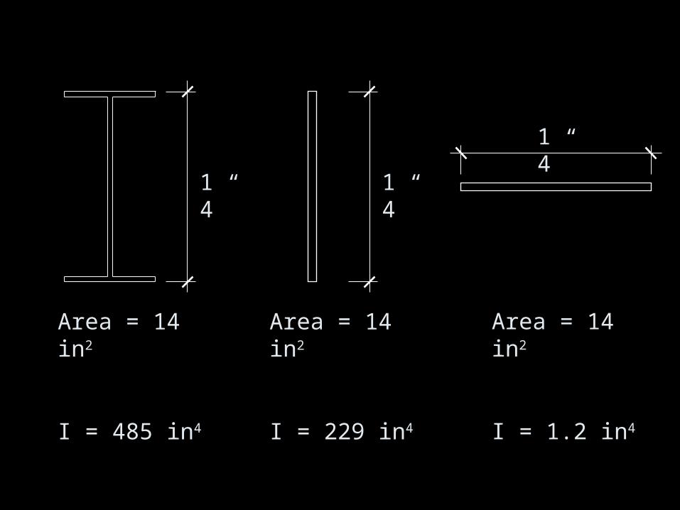
14”
Area = 14 in2
I = 485 in4
Area = 14 in2
I = 229 in4
Area = 14 in2
I = 1.2 in4
14”
14”
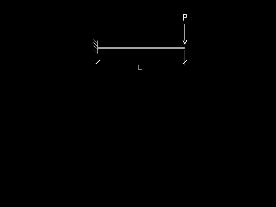
P
L

P
L
P
L
Rx Ry M

Deflection = P L3 3 E I
P
L
P
L
Rx Ry M
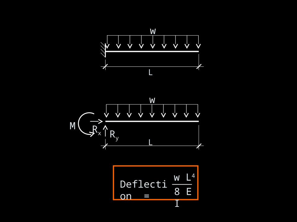
Deflection = w L4 8 E I
w
L
L
Rx Ry
w
M

Deflection = 5 w L4 384 E I
w
L
LRx Ry
w
Ry

Deflection = P L3
48 E I
P
L
L
Rx Ry Ry
P

Moment of Inertia
• Property of the cross sectional shape
Where do you find it?
Look it up in tables OR calculate it
Bigger Moment of Inertia, smaller deflection

STRUCTURAL ANALYSIS :
Determining Structural Capacity

From Structural Analysis we have developed an understanding of all :
Actions - Applied forces such as dead load, live load, wind load, seismic load.
Reactions - Forces generated at the boundary conditions that maintain equilibrium.
Internal forces - Axial, shear and moment (P V M) in each structural element.

Determination of Structural Capacity is based on each element’s ability to perform under the applied actions, consequent reactions and internal forces without :
Yielding - material deforming plastically (tension and/or stocky compression).
Buckling - phenomenon of compression when a slender element loses stability.
Deflecting Excessively - elastic defection that may cause damage to attached materials/finishes – bouncy floors.

TENSILE YIELDING and ALLOWABLE STRESS :

deformation
stre
ss
FY = yield stress
Elastic Range
Plastic Range

deformation
stre
ss
FY
fA
Force on the spring generates an axial stress and elastic deformation
P1
(fA = P/Area of Section)

deformation
stre
ss
FY
When Force is removed, the spring elastically returns to its original shape

deformation
stre
ss
FY
fA
A Larger Force may generate an axial stress sufficient to cause plastic deformation
P2
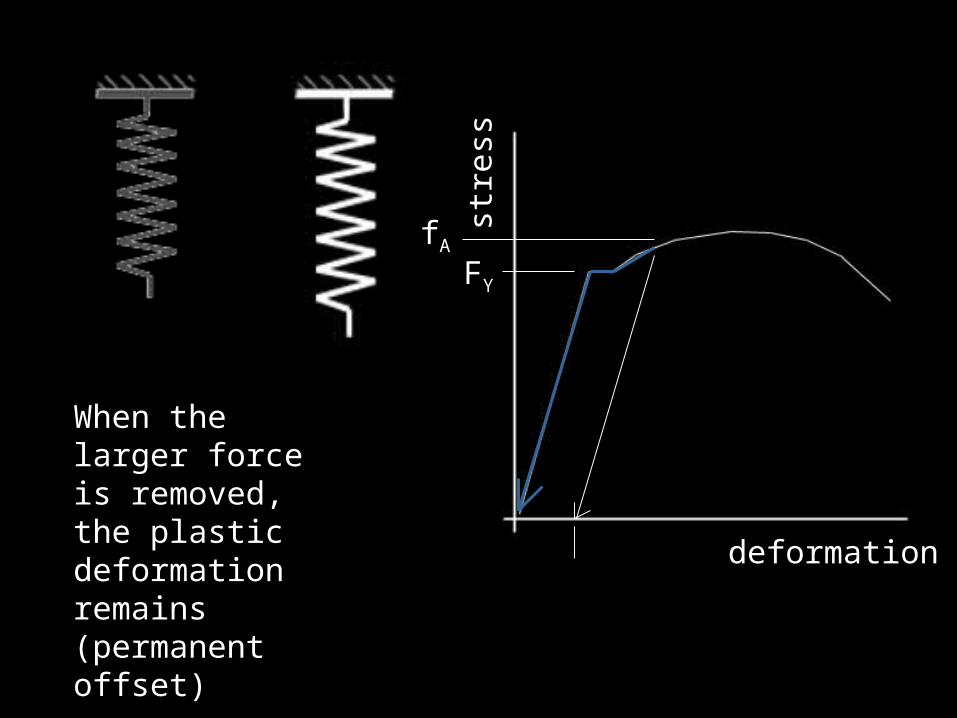
deformation
stre
ss
FY
fA
When the larger force is removed, the plastic deformation remains (permanent offset)

deformation
stre
ss
FY
fT
To be certain that the tension stress never reaches the yield stress, Set an ALLOWABLE TENSILE STRESS :
FTension = 0.60 FY

If using A36 Steel : FY = 36 ksi
Allowable Tensile Stress (FT ):
FT = 0.60 FY = 0.60 (36 ksi) = 21.6 ksi

If using A36 Steel : FY = 36 ksi
Allowable Tensile Stress FT:
FT = 0.60 FY = 0.60 (36 ksi) = 21.6 ksi
P = 5,000 lb or 5 kips
fA = P/Area (actual axial stress fA = P/A)
P force
Aarea
fA stress

If using A36 Steel : FY = 36 ksi
Allowable Tensile Stress :
FT = 0.60 FY = 0.60 (36 ksi) = 21.6 ksi
P = 5,000 lb or 5 kips
fA = P/Area
FT = Pmax /AreaRequiredPmax
Areq
FT stress

If using A36 Steel : FY = 36 ksi
Allowable Tensile Stress :
FT = 0.60 FY = 0.60 (36 ksi) = 21.6 ksi
P = 5,000 lb or 5 kips
fA = P/Area
FT = Pmax /AreaRequired
AreaRequired = Pmax/FT
Areq
Pmax
FT stress

If using A36 Steel : FY = 36 ksi
Allowable Tensile Stress :
FT = 0.60 FY = 0.60 (36 ksi) = 21.6 ksi
P = 5,000 lb or 5 kips
fA = P/Area
FT = Pmax /AreaRequired
AreaRequired = Pmax/FT = 5k / 21.6 ksi
= .25 in2
Areq
5k
21.6 ksi

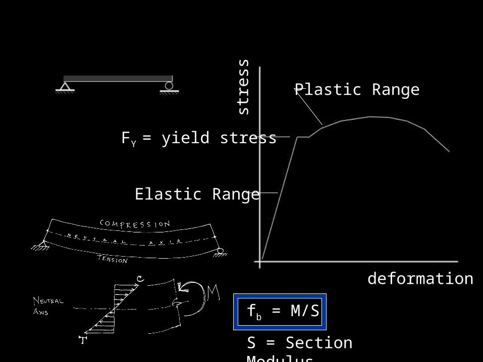
FLEXURAL YIELDING and ALLOWABLE BENDING STRESS :

deformation
stre
ss
FY = yield stress
Elastic Range
Plastic Range
fb = M/S
S = Section Modulus

deformation
stre
ss
FY
fb
Force on the BEAM generates an bending stress (tension and compression) and elastic deformation
(fb = Mmax/S)
P1

deformation
stre
ss
FY
When Force is removed, the BEAM elastically returns to its original shape

deformation
stre
ss
FY
fb
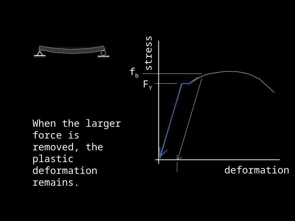
A Larger Force may generate an bending stress sufficient to cause plastic deformation
P2
deformation
stre
ss
FY
fb
When the larger force is removed, the plastic deformation remains.

deformation
stre
ss
FY
Fb
To be certain that the bending stress never reaches the yield stress, Set an ALLOWABLE BENDING STRESS :
Fbending = 0.60 FY

If using A36 Steel : FY = 36 ksi
Allowable Bending Stress (Fb) :
Fb = 0.60 FY = 0.60 (36 ksi) = 21.6 ksi
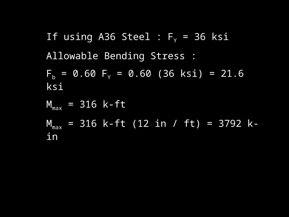
If using A36 Steel : FY = 36 ksi
Allowable Bending Stress :
Fb = 0.60 FY = 0.60 (36 ksi) = 21.6 ksi
Mmax = 316 k-ft
Mmax = 316 k-ft (12 in / ft) = 3792 k-in

If using A36 Steel : FY = 36 ksi
Allowable Bending Stress :
Fb = 0.60 FY = 0.60 (36 ksi) = 21.6 ksi
Mmax = 316 k-ft
Mmax = 316 k-ft (12 in / ft) = 3792 k-in
fb = M/S (actual bending stress fb = M/S)
If using A36 Steel : FY = 36 ksi
Allowable Bending Stress :
Fb = 0.60 FY = 0.60 (36 ksi) = 21.6 ksi
Mmax = 316 k-ft
Mmax = 316 k-ft (12 in / ft) = 3792 k-in
fb = M/S
Fb = Mmax / SRequired

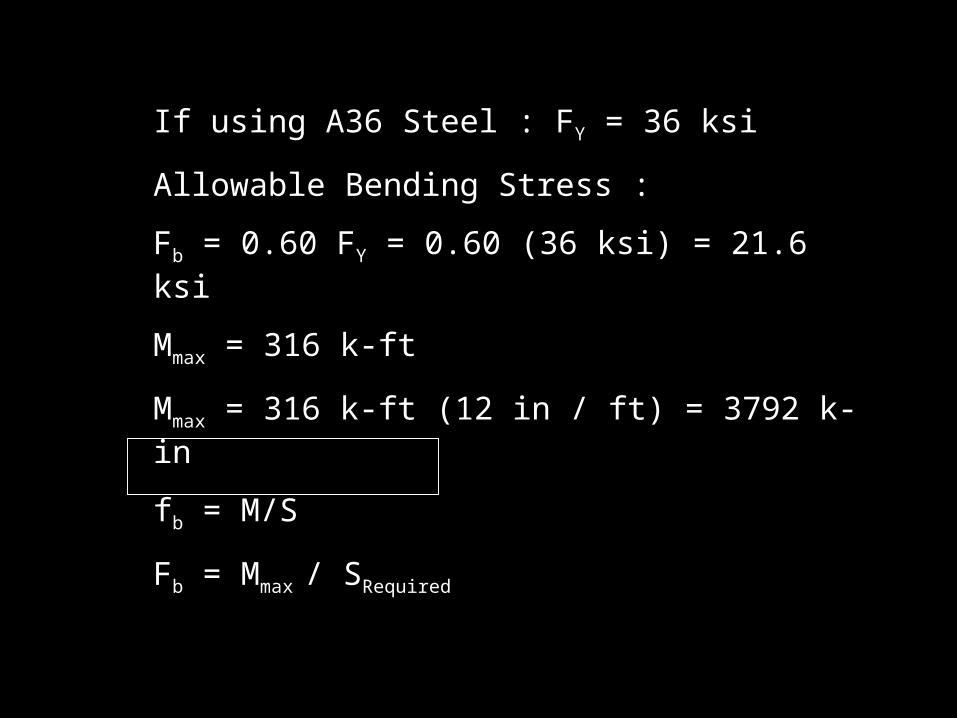
If using A36 Steel : FY = 36 ksi
Allowable Bending Stress :
Fb = 0.60 FY = 0.60 (36 ksi) = 21.6 ksi
Mmax = 316 k-ft
Mmax = 316 k-ft (12 in / ft) = 3792 k-in
fb = M/S
Fb = Mmax / SRequired
SRequired = Mmax / Fb

If using A36 Steel : FY = 36 ksi
Allowable Bending Stress :
Fb = 0.60 FY = 0.60 (36 ksi) = 21.6 ksi
Mmax = 316 k-ft
Mmax = 316 k-ft (12 in / ft) = 3792 k-in
fb = M/S
Fb = Mmax / SRequired
SRequired = Mmax / Fb = 3792 k-in / 21.6 ksi = 176 in3


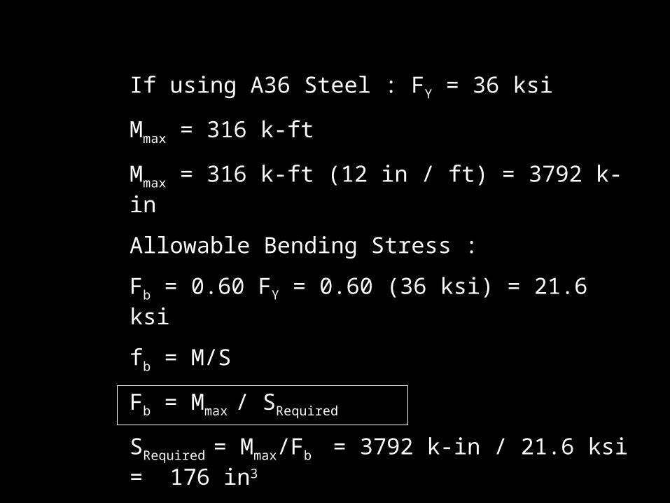
If using A36 Steel : FY = 36 ksi
Mmax = 316 k-ft
Mmax = 316 k-ft (12 in / ft) = 3792 k-in
Allowable Bending Stress :
Fb = 0.60 FY = 0.60 (36 ksi) = 21.6 ksi
fb = M/S
Fb = Mmax / SRequired
SRequired = Mmax/Fb = 3792 k-in / 21.6 ksi = 176 in3
Use W24x76 : SX-X = 176in3

BUCKLING and ALLOWABLE COMPRESSION STRESS :

PC Buckling is a compressive phenomenon that depends on :
1. ‘unbraced length’ of the compression element:(k x l)
2. shape of the section:(radius of gyration ryy)
3. Allowable Material compressive stress:(Fc)

‘unbraced length’ (kxl) depends upon the boundary conditions of an element
l

The radius of gyration (ryy) is a property of a members cross section.
It measures the distance from the neutral axis a member’s area may be considered to be acting
I = Ar2
r = (I/A)0.5
(I = moment of inertia)

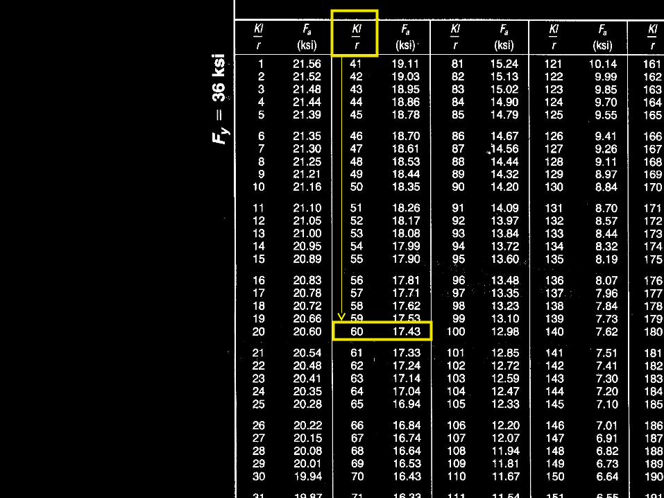
Allowable Compression Stress Fc depends on ‘kl/r’
k = 1.0
l = 15 ft = 180 in
assume ryy = 3.0 in.**
kl/r = 60
Fc = 17.4 ksi
** we must always come back and verify this assumption **

If using A36 Steel : FY = 36 ksi
Pmax = 240 kips (typ. read this from your P diagram]
Allowable Compression Stress (Fc) :
FC = 17.4 ksi
fC = P/Area
FC = Pmax/AreaRequired
AreaRequired = Pmax/FC = 240k / 17.4 ksi = 13.8 in2
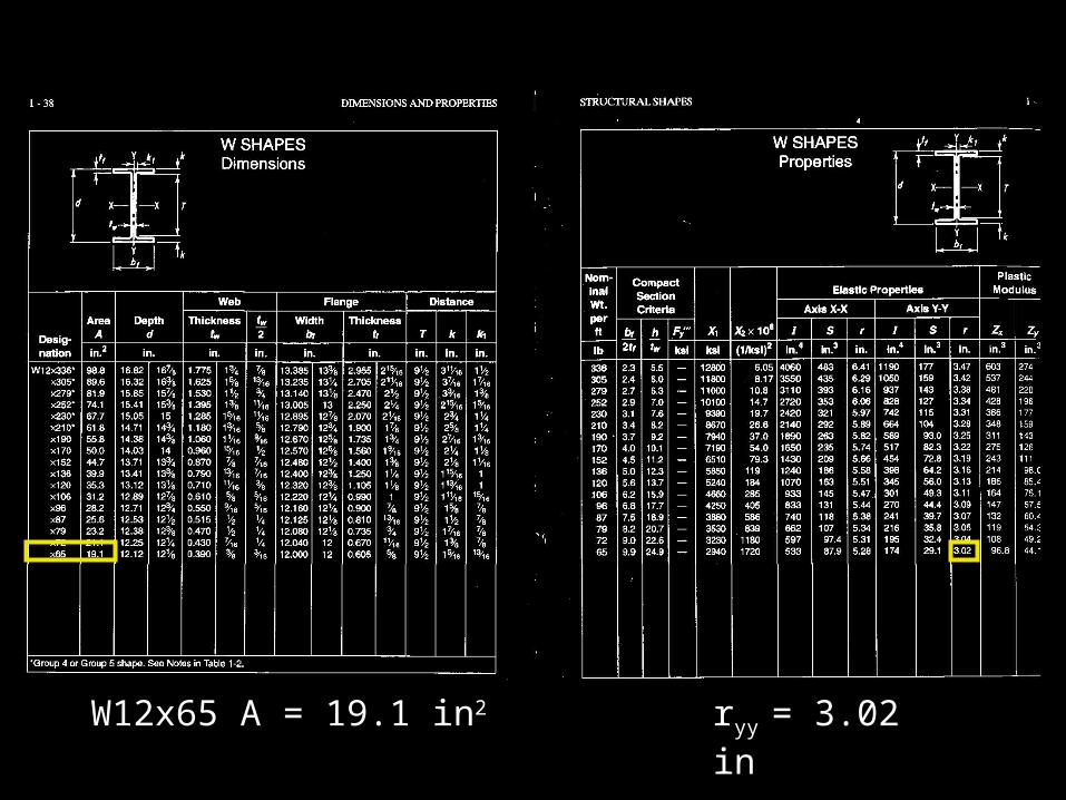
ryy = 3.02 inW12x65 A = 19.1 in2


If using A36 Steel : FY = 36 ksi
Pmax = 240 kips
Allowable Compression Stress :
FC = 17.4 ksi
fC = P/Area
FC = Pmax/AreaRequired
AreaRequired = Pmax/FC = 240k / 17.4 ksi = 13.8 in2
Use W12x65 Area = 19.1 in2
check actual stress: fC = P/A
fC = 240 kips / 19.1 in2 = 12.6 ksi OK!

BUCKLING and ALLOWABLE COMPRESSION STRESS :

Allowable Compression Stress depends on slenderness ratio = kl/r

Slenderness Ratio = kl/r
k = coefficient which accounts for buckling shape
for our project gravity columns, k=1.0
for moment frames see deformed shape

Slenderness Ratio = kl/r
l = unbraced length (inches)

rx > ry
Slenderness Ratio = kl/r
r = radius of gyration (inches)
typical use ry (weak direction)

Allowable Compression Stress (Fc)
slenderness ratio = kl/r
assume r = 2 in., k = 1.0
lcolumn = 180 in
kl/r = 90
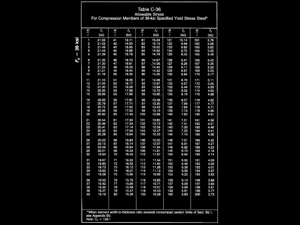
use Table C-36 to
determine Fc = 14.2 ksi

Pmax Column 2 = 238 kips (assume columns are continuous from foundation to roof, total length 30 feet)
FC = 14.2 ksi
AreaRequired = Pmax/FC = 238k / 14.2 ksi = 16.8 in2


Pmax Column 2 = 238 kips (assume columns are continuous from foundation to roof, total length 30 feet)
FC = 14.2 ksi
AreaRequired = Pmax/FC = 238k / 14.2 ksi = 16.8 in2
Use W12x65 Area = 19.1 in2
fC = Pmax/Area = 238 k / 19.1 in2 = 12.5 ksi

Pmax Column 2 = 238 kips (assume columns are continuous from foundation to roof, total length 30 feet)
FC = 14.2 ksi
AreaRequired = Pmax/FC = 238k / 14.2 ksi = 16.8 in2
Use W12x65 Area = 19.1 in2
fC = Pmax/Area = 238 k / 19.1 in2 = 12.5 ksi
check ry for W12x65 and verify FC

Pmax Column 2 = 238 kips (assume columns are continuous from foundation to roof, total length 30 feet)
FC = 14.2 ksi
AreaRequired = Pmax/FC = 238k / 14.2 ksi = 16.8 in2
Use W12x65 Area = 19.1 in2
fC = Pmax/Area = 238 k / 19.1 in2 = 12.5 ksi
check ry for W12x65 and verify FC
ry (W12x65) = 3.02
kl/r = (1.0)(180 in)/3.02in = 60

Pmax Column 2 = 238 kips (assume columns are continuous from foundation to roof, total length 30 feet)
FC = 14.2 ksi
AreaRequired = Pmax/FC = 238k / 14.2 ksi = 16.8 in2
Use W12x65 Area = 19.1 in2
fC = Pmax/Area = 238 k / 19.1 in2 = 12.5 ksi
check ry for W12x65 and verify FC
ry (W12x65) = 3.02
kl/r = (1.0)(180 in)/3.02in = 60, using Table C-36
Fc = 17.4 ksi

Pmax Column 2 = 238 kips (assume columns are continuous from foundation to roof, total length 30 feet)
FC = 14.2 ksi
AreaRequired = Pmax/FC = 238k / 14.2 ksi = 16.8 in2
Use W12x65 Area = 19.1 in2
fC = Pmax/Area = 238 k / 19.1 in2 = 12.5 ksi
check ry for W12x65 and verify FC
ry (W12x65) = 3.02
kl/r = (1.0)(180 in)/3.02in = 60, using Table C-36
Fc = 17.4 ksi > fc , therefore ok

Column 2, Efficiency Check: W12x65
fC = 12.5 ksi (actual stress fc = P/A)
FC = 17.4 ksi [allowable stress from chart C-36]
fC/FC < 1.0

Column 2, Efficiency Check: W12x65
fC = 12.5 ksi
FC = 17.4 ksi
fC/FC = 12.5 ksi/17.4 ksi = 0.72 < 1.0

Column 2, Efficiency Check: W12x65
fC = 12.5 ksi
FC = 17.4 ksi
fC/FC = 12.5 ksi/17.4 ksi = 0.72 < 1.0
(72% of capacity is used)

ALLOWABLE BENDING + COMPRESSION:


80 kips
40 kips 40 kips
200 kips200 kips

- compression
- co
mpre
ssio
n
+ t
ensi
on
- 40 kips
+ 2
00 k
ips
- 2
00 k
ips
80 kips 80 kips
900 k-ft
900 k-ft900 k-ft
Axial Diagram
Moment Diagram
fa=P/Area
fb=M/S


Axial Stress (fa)
Bending Stress (fb)
Combined Stress (fa+fb)
+
+ =
=

Axial Stress (fa)
Bending Stress (fb)
+
+
To be certain that the combined stress (bending + axial) never reaches the yield stress, use the INTERACTION EQUATION
fb/Fb + fa/Fa < 1.0

Mmax = 900 k-ft Pmax = 200 kips
Assume 50% capacity of bending (fb)
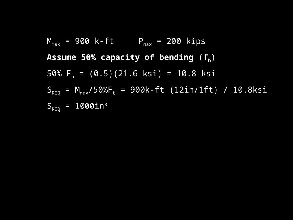
Mmax = 900 k-ft Pmax = 200 kips
Assume 50% capacity of bending (fb)
50% Fb = (0.5)(21.6 ksi) = 10.8 ksi
SREQ = Mmax/50%Fb = 900k-ft (12in/1ft) / 10.8ksi
SREQ = 1000in3


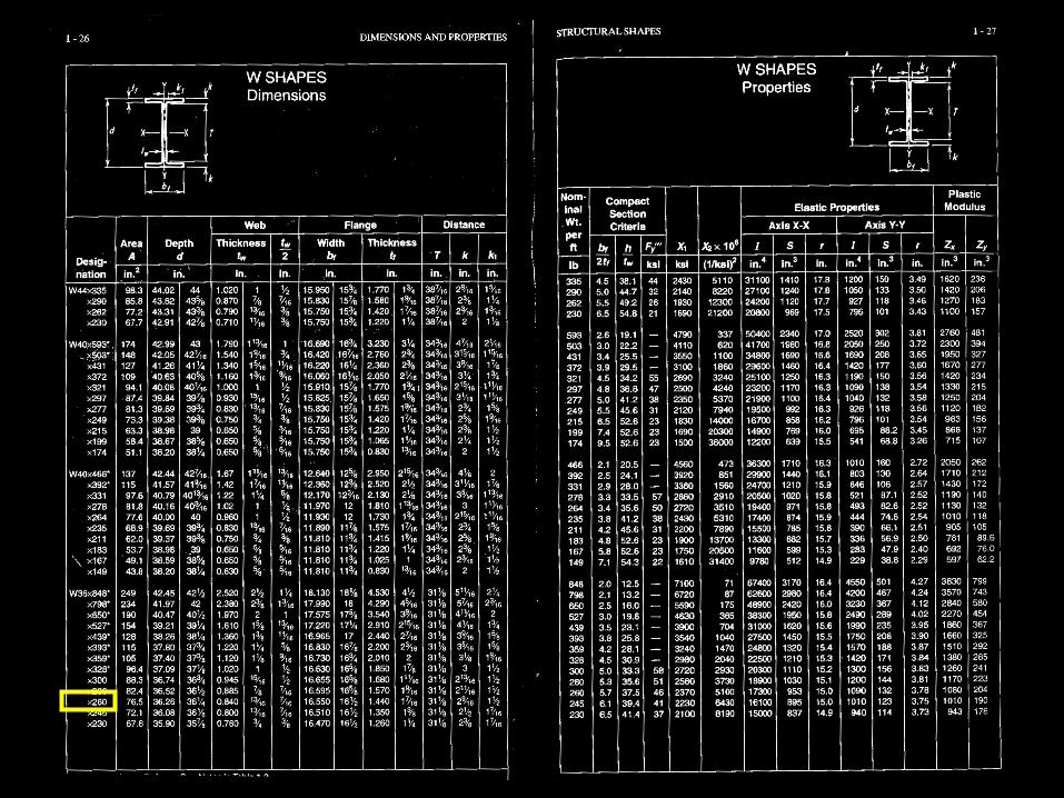

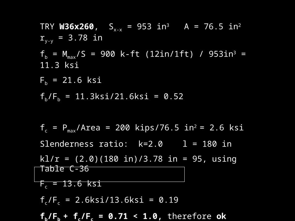
TRY W36x260, Sx-x = 953 in3 A = 76.5 in2 ry-y = 3.78 in

TRY W36x260, Sx-x = 953 in3 A = 76.5 in2 ry-y = 3.78 in
fb = Mmax/S = 900 k-ft (12in/1ft) / 953in3 = 11.3 ksi

TRY W36x260, Sx-x = 953 in3 A = 76.5 in2 ry-y = 3.78 in
fb = Mmax/S = 900 k-ft (12in/1ft) / 953in3 = 11.3 ksi
Fb = 21.6 ksi
fb/Fb = 11.3ksi/21.6ksi = 0.52

TRY W36x260, Sx-x = 953 in3 A = 76.5 in2 ry-y = 3.78 in
fb = Mmax/S = 900 k-ft (12in/1ft) / 953in3 = 11.3 ksi
Fb = 21.6 ksi
fb/Fb = 11.3ksi/21.6ksi = 0.52
fc = Pmax/Area = 200 kips/76.5 in2 = 2.6 ksi
Slenderness ratio: k=2.0 l = 180 in
kl/r = (2.0)(180 in)/3.78 in = 95


TRY W36x260, Sx-x = 953 in3 A = 76.5 in2 ry-y = 3.78 in
fb = Mmax/S = 900 k-ft (12in/1ft) / 953in3 = 11.3 ksi
Fb = 21.6 ksi
fb/Fb = 11.3ksi/21.6ksi = 0.52
fc = Pmax/Area = 200 kips/76.5 in2 = 2.6 ksi
Slenderness ratio: k=2.0 l = 180 in
kl/r = (2.0)(180 in)/3.78 in = 95, using Table C-36
Fc = 13.6 ksi
fc/Fc = 2.6ksi/13.6ksi = 0.19
fb/Fb + fc/Fc = 0.71 < 1.0, therefore ok
Assume 70% capacity of bending (fb)
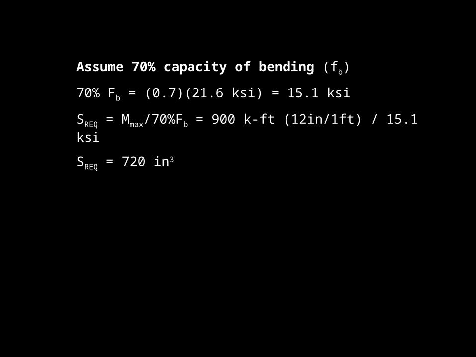
Assume 70% capacity of bending (fb)
70% Fb = (0.7)(21.6 ksi) = 15.1 ksi
SREQ = Mmax/70%Fb = 900 k-ft (12in/1ft) / 15.1 ksi
SREQ = 720 in3


TRY W33x201, Sx-x = 684 in3 A = 59.1 in2 ry-y = 3.56 in

TRY W33x201, Sx-x = 684 in3 A = 59.1 in2 ry-y = 3.56 in
fb = Mmax/S = 900 k-ft (12 in/1 ft) / 684 in3 = 14.2 ksi

TRY W33x201, Sx-x = 684 in3 A = 59.1 in2 ry-y = 3.56 in
fb = Mmax/S = 900 k-ft (12 in/1 ft) / 684 in3 = 14.2 ksi
Fb = 21.6 ksi
fb/Fb = 14.2 ksi/21.6 ksi = 0.73

TRY W33x201, Sx-x = 684 in3 A = 59.1 in2 ry-y = 3.56 in
fb = Mmax/S = 900 k-ft (12 in/1 ft) / 684 in3 = 14.2 ksi
Fb = 21.6 ksi
fb/Fb = 14.2 ksi/21.6 ksi = 0.73
fc = Pmax/Area = 200 kips/59.1 in2 = 3.4 ksi
Slenderness ratio: k=2.0 l = 180 in
kl/r = (2.0)(180 in)/3.56 in = 101


TRY W33x201, Sx-x = 684 in3 A = 59.1 in2 ry-y = 3.56 in
fb = Mmax/S = 900 k-ft (12 in/1 ft) / 684 in3 = 14.2 ksi
Fb = 21.6 ksi
fb/Fb = 14.2 ksi/21.6 ksi = 0.73
fc = Pmax/Area = 200 kips/59.1 in2 = 3.4 ksi
Slenderness ratio: k=2.0 l = 180 in
kl/r = (2.0)(180 in)/3.56 in = 101, using Table C-36
Fc = 12.85 ksi
fc/Fc = 3.4 ksi/12.85 ksi = 0.26
fb/Fb + fc/Fc = 0.99 < 1.0, therefore ok

Related Documents