Annals of Biomedical Engineering, Vol. 34, No. 3, March 2006 ( C 2006) pp. 455–464 DOI: 10.1007/s10439-005-9051-y Stress Relaxation in Porcine Septal Cartilage During Electromechanical Reshaping: Mechanical and Electrical Responses DMITRIY E. PROTSENKO, 1 KEVIN HO, 1 and BRIAN J. F. WONG 1, 2, 3 1 Beckman Laser Institute, University of California Irvine, 1002 Health Sciences Road East, Irvine, CA 92612; 2 Department of Otolaryngology- Head and Neck Surgery, University of California Irvine, 101 The City Drive Bld. 25 Rt. 81, Orange, CA 92868; and 3 Department of Biomedical Engineering Rockwell Engineering Center 204, University of California Irvine, Irvine, CA 92612 (Received 20 October 2004; accepted 18 August 2005; published online: 1 February 2006) Abstract—Electromechanical reshaping (EMR) of facial carti- lage has recently been developed as an alternative to classic sur- gical techniques to alter cartilage shape. This study focuses on determining the underlying physical mechanisms responsible for shape change (stress relaxation) in mechanically deformed fa- cial cartilage specimens exposed to constant electric fields. Flat porcine nasal septal cartilage specimens were deformed by an aluminum jig into semicylindrical shapes while a constant elec- tric voltage was applied to the concave and convex surfaces of the specimen. Mechanical stress, electric current and resistance were measured during voltage application. Specimen shape reten- tion was measured as retained bend angle. Total electric charge transferred in the electric circuit was calculated from the electric current measurement. Electrical resistance, transferred charge and the bend angle increase with increase in voltage application time until bend angle reaches maximum value determined by the jig ge- ometry. Then, the bend angle decreases and electrical parameters nearly saturate. The time dependent behavior of electric current was analyzed using the Cottrell equation. The observed changes in electric current suggest that during the initial 1–2 min of EMR non- linear diffusion determines electro-chemical reaction rates, which are then followed by a linear diffusion dominated process. Close correlation between alteration of cartilage mechanical state and change in its electrical properties suggest that an electro-chemical reaction is the dominant mechanism behind EMR. Keywords—Electrochemistry, Cartilage, Tissue reshaping, Shape change, Reconstructive Surgery, Otolaryngology, Plastic surgery. INTRODUCTION Changing the shape of cartilage tissue in the face, neck, and upper airways is an important element of many recon- structive and aesthetic operations in these regions. Potential clinical applications include the correction of deviations of the nasal septum and the treatment of post intubation steno- sis in trachea and larynx. Classic septal surgery as well as other surgical shape change procedures is often complex, Address correspondence to Dmitriy E. Protsenko, Beckman Laser Institute, University of California Irvine, 1002 Health Sciences Road East, Irvine, CA 92612. Electronic mail: [email protected] invasive, requiring incisions, and sutures to balance the intrinsic elastic forces within the tissue that resist deforma- tion, and in the case of airway surgery prolonged patient recovery times may be required. 3,6,10,16,19 An alternative approach to the conventional surgical procedures is thermally accelerated cartilage reshaping or thermoforming performed using laser 14, 21, 27 or radio fre- quency (RF) 17 heat sources. During relatively fast laser heating (about 10 ◦ C per second) the thermoforming effect occurs at temperatures of 58–60 ◦ C, which is very close to viability threshold for chondrocytes. 5 , 6 The complexity of monitoring temperature during any clinical procedure poses further challenges for preservation of a viable chon- drocyte population. The absorption of laser or RF energy by the thermocouples may interfere with direct tempera- ture measurements and indirect monitoring methods such as accousto-optics or radiometry may not provide sufficient accuracy. We developed a new method to reshape cartilage based upon exposure of mechanically deformed specimens to a DC electric field. 15 , 22 Cartilage electromechanical reshaping (EMR) or electroforming produces a shape retention effect similar to thermally induced shape change techniques, but without the generation of heat. In our preliminary experiments we demonstrated that the degree of the shape change increases with the increase in the applied voltage and application time, and depends on composition of the electrode and the polarity of the applied voltage with respect to geometry of the deformation. 15 Very small elevations in temperature (∼1 ◦ C) during EMR eliminate heat as a mechanism responsible for shape change. However, evidence of electrochemical reactions (e.g., metal deposition on cartilage surface and generation of hydrogen gas bubbles at the cartilage-metal interface) observed during EMR suggests a chemically-mediated mechanism of internal stress relaxation. Cartilage is a poroelastic tissue composed predomi- nantly of a collagen type II scaffold, proteoglycans (gly- coproteins), cells (chondrocytes) and water. The elastic 455 0090-6964/06/0300-0455/0 C 2006 Biomedical Engineering Society

Welcome message from author
This document is posted to help you gain knowledge. Please leave a comment to let me know what you think about it! Share it to your friends and learn new things together.
Transcript
Annals of Biomedical Engineering, Vol. 34, No. 3, March 2006 ( C© 2006) pp. 455–464DOI: 10.1007/s10439-005-9051-y
Stress Relaxation in Porcine Septal Cartilage During ElectromechanicalReshaping: Mechanical and Electrical Responses
DMITRIY E. PROTSENKO,1 KEVIN HO,1 and BRIAN J. F. WONG1, 2, 3
1Beckman Laser Institute, University of California Irvine, 1002 Health Sciences Road East, Irvine, CA 92612; 2Department ofOtolaryngology- Head and Neck Surgery, University of California Irvine, 101 The City Drive Bld. 25 Rt. 81, Orange, CA 92868; and
3Department of Biomedical Engineering Rockwell Engineering Center 204, University of California Irvine, Irvine, CA 92612
(Received 20 October 2004; accepted 18 August 2005; published online: 1 February 2006)
Abstract—Electromechanical reshaping (EMR) of facial carti-lage has recently been developed as an alternative to classic sur-gical techniques to alter cartilage shape. This study focuses ondetermining the underlying physical mechanisms responsible forshape change (stress relaxation) in mechanically deformed fa-cial cartilage specimens exposed to constant electric fields. Flatporcine nasal septal cartilage specimens were deformed by analuminum jig into semicylindrical shapes while a constant elec-tric voltage was applied to the concave and convex surfaces ofthe specimen. Mechanical stress, electric current and resistancewere measured during voltage application. Specimen shape reten-tion was measured as retained bend angle. Total electric chargetransferred in the electric circuit was calculated from the electriccurrent measurement. Electrical resistance, transferred charge andthe bend angle increase with increase in voltage application timeuntil bend angle reaches maximum value determined by the jig ge-ometry. Then, the bend angle decreases and electrical parametersnearly saturate. The time dependent behavior of electric currentwas analyzed using the Cottrell equation. The observed changes inelectric current suggest that during the initial 1–2 min of EMR non-linear diffusion determines electro-chemical reaction rates, whichare then followed by a linear diffusion dominated process. Closecorrelation between alteration of cartilage mechanical state andchange in its electrical properties suggest that an electro-chemicalreaction is the dominant mechanism behind EMR.
Keywords—Electrochemistry, Cartilage, Tissue reshaping,Shape change, Reconstructive Surgery, Otolaryngology, Plasticsurgery.
INTRODUCTION
Changing the shape of cartilage tissue in the face, neck,and upper airways is an important element of many recon-structive and aesthetic operations in these regions. Potentialclinical applications include the correction of deviations ofthe nasal septum and the treatment of post intubation steno-sis in trachea and larynx. Classic septal surgery as well asother surgical shape change procedures is often complex,
Address correspondence to Dmitriy E. Protsenko, Beckman LaserInstitute, University of California Irvine, 1002 Health Sciences RoadEast, Irvine, CA 92612. Electronic mail: [email protected]
invasive, requiring incisions, and sutures to balance theintrinsic elastic forces within the tissue that resist deforma-tion, and in the case of airway surgery prolonged patientrecovery times may be required.3,6,10,16,19
An alternative approach to the conventional surgicalprocedures is thermally accelerated cartilage reshaping orthermoforming performed using laser14,21,27 or radio fre-quency (RF)17 heat sources. During relatively fast laserheating (about 10◦C per second) the thermoforming effectoccurs at temperatures of 58–60◦C, which is very closeto viability threshold for chondrocytes.5,6 The complexityof monitoring temperature during any clinical procedureposes further challenges for preservation of a viable chon-drocyte population. The absorption of laser or RF energyby the thermocouples may interfere with direct tempera-ture measurements and indirect monitoring methods suchas accousto-optics or radiometry may not provide sufficientaccuracy.
We developed a new method to reshape cartilage basedupon exposure of mechanically deformed specimensto a DC electric field.15,22 Cartilage electromechanicalreshaping (EMR) or electroforming produces a shaperetention effect similar to thermally induced shape changetechniques, but without the generation of heat. In ourpreliminary experiments we demonstrated that the degreeof the shape change increases with the increase in theapplied voltage and application time, and depends oncomposition of the electrode and the polarity of the appliedvoltage with respect to geometry of the deformation.15
Very small elevations in temperature (∼1◦C) during EMReliminate heat as a mechanism responsible for shapechange. However, evidence of electrochemical reactions(e.g., metal deposition on cartilage surface and generationof hydrogen gas bubbles at the cartilage-metal interface)observed during EMR suggests a chemically-mediatedmechanism of internal stress relaxation.
Cartilage is a poroelastic tissue composed predomi-nantly of a collagen type II scaffold, proteoglycans (gly-coproteins), cells (chondrocytes) and water. The elastic
455
0090-6964/06/0300-0455/0 C© 2006 Biomedical Engineering Society
456 PROTSENKO et al.
behavior of cartilage arises largely due to the interplayof the fixed negative charges of the proteoglycan aggre-gates constrained by the collagen matrix with boundedwater molecules shielding proteoglycan subunits as wellas free cations and anions ions dissolved in the interstitialwater.4,18 Electrostatic repulsive forces generated in me-chanically deformed cartilage resist applied loads and actto restore cartilage to its original shape after the load isremoved.19,24 It is known that changes in tissue pH or ionicstrength of interstitial fluid alters distribution of the inter-nal fixed charge and affects the cartilage electromechanicalproperties.9,20,25 For example, the cartilage elastic modulusincreases with a reduction in pH and vice versa.8,20
Alteration of the internal charge distribution has beenproposed as one of the mechanisms of action for thermo-forming.2 Bagratashvili et al.2 suggested that heating car-tilage up to a certain threshold temperature breaks the hy-drogen bonds between proteoglycans and water moleculesand/or bonds between individual proteoglycans compo-nents. Thus, the matrix is “stripped” of its negative charge,i.e., depolarized, and subsequently re-polarized when thetissue cools. The re-polarization of the proteoglycan sub-units during thermal relaxation (cooling) may minimizeelectrostatic repulsion and thus allow “fixation” of cartilageinto new shapes.
Although the precise molecular mechanisms behindEMR is presently unknown it is likely that the stress re-laxation and shape change occur as a consequence of re-distribution of fixed electric charge associated with proteo-glycan aggregates embedded in the collagen matrix andalteration of mobile ions concentration. Both fixed andfree electric charges are important contributors to cartilageelectro-mechanical properties.4,13 Changes in cartilage in-ternal electric charge composition alter cartilage electricalimpedance, which might be used to monitor the reshap-ing process. This study evaluates mechanical and electricalevents in cartilage during EMR. In particular, we measuredstress relaxation and the accompanying changes in electriccurrent and resistance. Characterization of the mechanicaleffects of the EMR in terms of net electrical and electro-chemical tissue changes will provide insight into the pro-cesses responsible for shape change as well as providing auseful means to monitor this process.
MATERIALS AND METHODS
Porcine septal cartilage specimens were removed fromcrania of pigs obtained from a local abattoir (CloughertyPacking Company, Vernon, CA). Soft tissue including theperichondrium was dissected from the specimen. Since theproperties of this tissue vary slightly along the cranial-caudal axis,30 only the distal one-third of the septum wasused for these studies. Specimens were stored in 0.9% salinesolution at +5◦C for no longer than 48 h. Just prior to use,intact septal cartilages were cut into rectangular flat slabs
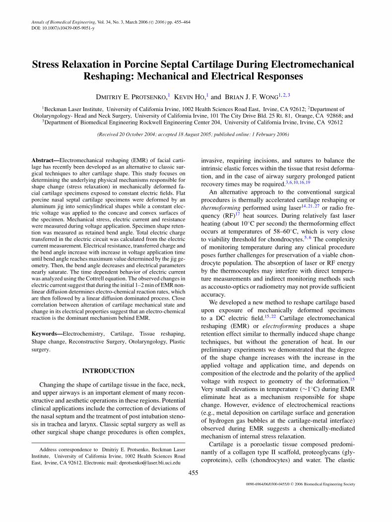
FIGURE 1. Schematic diagram of cartilage reshaping appara-tus and setup for electric measurement during EMR exper-iment. A cartilage specimen was inserted between convexcylindrical electrode mounted on micropositioner and concavesemi-cylindrical electrode mounted on a load cell. Reshapingvoltage is supplied by direct current source (DC) to the convex(anode) and concave (cathode) electrodes. Resistance of thecartilage-electrodes system was calculated from current andvoltage measurements.
(2.0 ± 0.1 mm thick, 6.2 ± 0.2 mm wide and 15.5 ± 0.2 mmlong, average ± standard deviation measurements for 207samples) and immediately placed in the electroforming jig.
Figure 1 shows the electroforming jig and apparatus usedto measure electrical and mechanical properties. Cartilagesamples were held between two concentric semi-cylindricalaluminum electrodes. Aluminum was selected as an elec-trode material because it is malleable and can be readilyshaped to conform to the relatively complex geometriesfound in cartilage frameworks within the head and neck.A semi-cylindrical geometry for the jig was consistentwith reshaping geometry used in our previous studies oflaser cartilage reshaping28,29 and geometry of the deforma-tion obtained with this jig can be easily described math-ematically (see below). The lower concave electrode wasmounted on a load cell (LCL-454G, Omega Inc., Stamford,CT) and the upper convex electrode was attached to a cal-ibrated micropositioner. The excitation voltage to the loadcell was provided by a signal conditioner which also am-plified and low-pass filtered the output signal (OM5-WBS,Omega Inc.). The upper electrode of the jig was loweredonto the specimen until it assumed a semi-cylindrical shapeand was in good electrical contact with both upper and lowerelectrodes. The sides of the specimen were exposed to air.The load cell allowed measurement of the force required todeform the specimen into a curved shape. The positive andnegative poles of a programmable power supply (E3646A,Agilent Technologies, Inc., Palo Alto, CA) were attachedto the convex and concave electrodes, respectively. Thepower supply unit supplied the DC electroforming volt-age and provided a means to monitor the current passingthrough the specimen. Mechanical reaction force, voltage

Stress Relaxation in Porcine Septal Cartilage During Electromechanical Reshaping 457
FIGURE 2. Voltage pattern and corresponding current observed during EMR experiment. Characteristic electrical parametersmeasured before and during early stages of voltage up-ramping (A), during voltage up-ramping (B) and during voltage down-ramping (C) are shown.
and electric current were simultaneously recorded with aPC-based analog to digital converter (AT-MIO-16XE-50,National Instruments, Austin, TX) and custom designedsoftware (LabView, National Instruments). The electricalresistance of the electrode-cartilage system was calculatedfrom current and voltage measurements.
At the beginning of each experiment, the initial mechan-ical reaction force exerted on the load cell as a result of thedeformation of the cartilage in the jig was equal to 3.7 ±0.2 N.
A voltage pattern applied to a cartilage graft togetherwith corresponding current trace are shown in Fig. 2. Asmall probe voltage step, Vp, (∼1 mV) was applied for 60 s.to determine the initial electrical resistance of the electrode-cartilage system. Then, the voltage across the electrodeswas increased at the rate of 1 V/s to a given steady stateelectroforming voltage, Vef , and was maintained at this levelfor a given time interval. Then, the voltage was reduced atthe same rate of 1 V/s to the probe voltage level of Vp andwas maintained at this level for additional 60 s to allow forthe final measurement of the impedance of the electrode-cartilage system. Steady state electroforming voltage, Vef ,
varied from 1 to 10 V and its application time varied from30 s to 6 min, respectively.
In control experiments the cartilage was secured in thejig for 6 min without application of any external voltage.The reaction force and spontaneous electric current weremonitored during experiment.
Following electrical parameters were determined fromthe voltage and current traces:
Ri—electrical resistance of electrode-cartilage system priorto electroforming, Ri = Vp/Ii, where Ii is a steady-statecurrent measured during initial application of voltage Vp,
Rf—electrical resistance of electrode cartilage system afterelectroforming, Rf = Vp/If , where If is a steady-statecurrent measured during final application of voltage Vp,
V0i—overvoltage (voltage corresponding to zero current)during initial voltage rise,
V0f—overvoltage during final voltage drop (as the electro-forming process terminates),
I +m —maximum positive current obtained in experiment,
Vim—voltage corresponding to I +m ,
I −m —maximum negative current obtained in experiment,

458 PROTSENKO et al.
Qtot—total electric charge transferred between electrodesduring experiment, Qtot = ∫
I(t)dt, were I(t) is electriccurrent measured during experiment and t is time.
After the cartilage sample was removed from the jig thebend angle, θ , defined from an assumption that deformedsample assumes the shape of a circular arc segment wascalculated from recurrent equation:
L = 2Li sin(θ/2)
θ, (1)
where L is the distance between the ends of the bent sampleand Li is the initial length of the sample before deforma-tion.12 Then, the sample was warped around and secured toa plastic cylinder with diameter equal to the convex elec-trode diameter and rehydrated in 0.9% saline solution for15 min. The reshaping angle was measured after rehydra-tion again.12 Surface of the specimens was examined usinga dissection microscope to observe electrode position ofelectrode material onto the cartilage.
RESULTS
Visually Observed Effects
Formation of bubbles/foam was observed when the volt-age applied to electrodes exceeded approximately 1.5 V.The bubble formation was localized to the interface of thespecimen and the anode (concave electrode). The relativeintensity of bubble formation increased with voltage, andpeaked during initial 20–30 s of the EMR and graduallydecreased toward the end of the procedure. After EMR,microscopic examination of the cartilage surface contactedwith the cathode (convex electrode) revealed traces of elec-trodeposits of electrode material. Visually, the density ofthe deposits increased with electroforming voltage, Vef , andtime.
Reshaping Angle vs. Time and Voltage
Figure 3 shows a collage of six cartilage specimenselectroformed from 1 to 6 min at Vef of 4 V. Figure4 shows final bend angle as a function of time for Vef
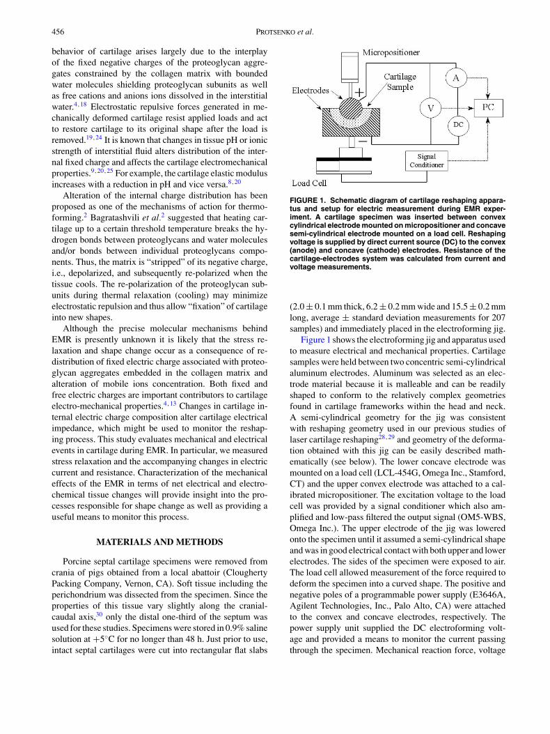
at 2, 6, 8, and 10 V. Bend angle was measured im-mediately after the sample was removed from the jigfor each exposure time. Maximum possible bend anglecorresponds to the case where the cartilage specimenprecisely conforms to the shape of the jig (160◦). ForVef ≤ 6 V the bend angle steadily increases with time inall investigated time ranges. For Vef > 6 V, the bend anglesteadily increases with time, peaks, and then decreases. Thetime required to achieve the maximal bend angle decreasesas the applied voltage increases. Specimens reshaped athigher voltages corresponding to the secondary decrease inthe bend angle appear on inspection softer and less elastic.Rehydration reduces the bend angle by about 20% for allelectroforming voltage and time combinations.15,22 Sig-
FIGURE 3. Cartilage specimens electroformed during applica-tion of Vef of 4 V from 1 to 6 min.
nificant residual swelling and curling of electroformed aswell as control specimens23 observed after rehydration insaline bath for a time more than 30 min makes comparativeanalysis of the bend angle difficult.
In control experiments a small reshaping angle of about20◦ was observed after the cartilage was secured in thejig for 6 min. However, subsequent rehydration for 15 minin saline solution restored the specimen to its original flatshape.
The measurement error of the sample bend angle origi-nates from uncertainty in the measurement of the distance,L, Equation (1), measured between the ends of the bent sam-ple. Experimentally the length, L, can be measured as thelength of the chord joining the ends of either concave or con-vex surfaces of the sample. For the average values of initiallength before deformation, Li, of 15 mm, sample thicknessof 1.2 mm and bend angle, θ , of 140◦ the variation in themeasured length L from 10 to 11.2 mm constitutes mea-surement error of less than 6%. However, experimentallyobserved variations in bend angel are higher. In the time–voltage interval when the bend angle steadily increases and
Stress Relaxation in Porcine Septal Cartilage During Electromechanical Reshaping 459
FIGURE 4. Bend angle, θ, as a function of electroforming timefor electroforming voltages, Vef, of 2, 6, 8, and 10 V. Standarddeviations are shown for data obtained at 2 and 10 V. Statisticalvariation of data obtained at 6 and 8 V is similar.
peaks standard deviation of the bend angle average valuedecreases from 15 to 7% for the bend angles of 60 and 140◦,respectively. Standard deviation of the bend angle of 25–30% was observed in the specimens exhibiting secondarydecrease in the bend angle. Such high uncertainty in thebend angle value is largely due to tissue softening and sub-sequent inability of the specimen to preserve stable shapeduring removal from the jig and geometrical measurement.It should be pointed out that similar degree of variance inbend angle has been observed in experiments on cartilagereshaping performed with laser irradiation and immersionin hot saline bath.28,29
Relaxation of Reaction Force and Changein Electrical Parameters
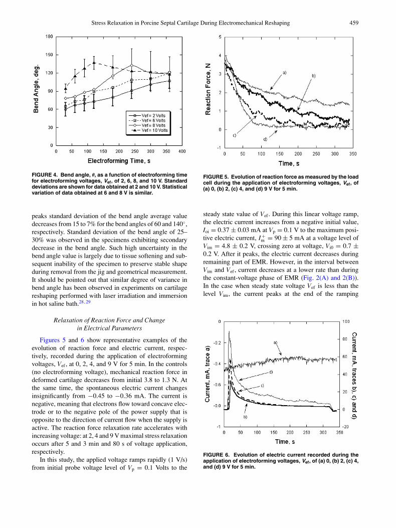
Figures 5 and 6 show representative examples of theevolution of reaction force and electric current, respec-tively, recorded during the application of electroformingvoltages, Vef , at 0, 2, 4, and 9 V for 5 min. In the controls(no electroforming voltage), mechanical reaction force indeformed cartilage decreases from initial 3.8 to 1.3 N. Atthe same time, the spontaneous electric current changesinsignificantly from −0.45 to −0.36 mA. The current isnegative, meaning that electrons flow toward concave elec-trode or to the negative pole of the power supply that isopposite to the direction of current flow when the supply isactive. The reaction force relaxation rate accelerates withincreasing voltage: at 2, 4 and 9 V maximal stress relaxationoccurs after 5 and 3 min and 80 s of voltage application,respectively.
In this study, the applied voltage ramps rapidly (1 V/s)from initial probe voltage level of Vp = 0.1 Volts to the
FIGURE 5. Evolution of reaction force as measured by the loadcell during the application of electroforming voltages, Vef, of(a) 0, (b) 2, (c) 4, and (d) 9 V for 5 min.
steady state value of Vef . During this linear voltage ramp,the electric current increases from a negative initial value,Ioi = 0.37 ± 0.03 mA at Vp = 0.1 V to the maximum posi-tive electric current, I +
m = 90 ± 5 mA at a voltage level ofVim = 4.8 ± 0.2 V, crossing zero at voltage, Vi0 = 0.7 ±0.2 V. After it peaks, the electric current decreases duringremaining part of EMR. However, in the interval betweenVim and Vef , current decreases at a lower rate than duringthe constant-voltage phase of EMR (Fig. 2(A) and 2(B)).In the case when steady state voltage Vef is less than thelevel Vim, the current peaks at the end of the ramping
FIGURE 6. Evolution of electric current recorded during theapplication of electroforming voltages, Vef, of (a) 0, (b) 2, (c) 4,and (d) 9 V for 5 min.
460 PROTSENKO et al.
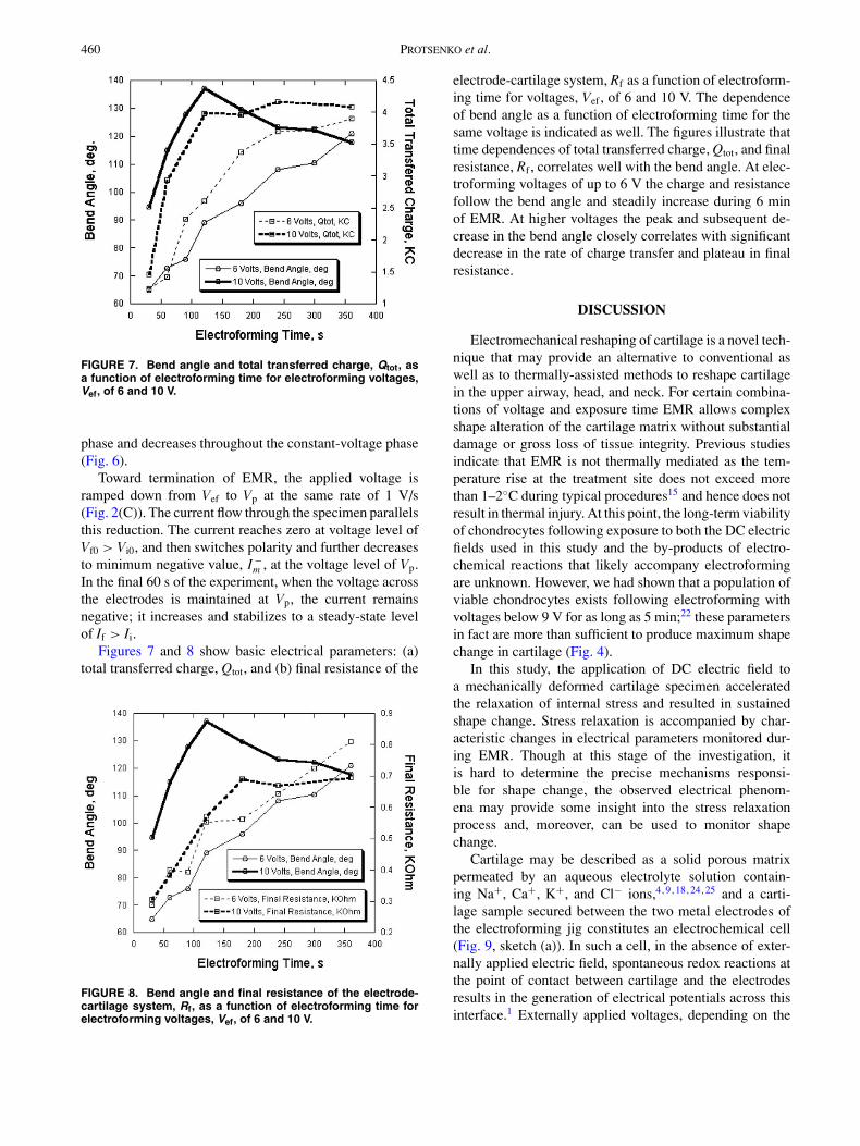
FIGURE 7. Bend angle and total transferred charge, Qtot, asa function of electroforming time for electroforming voltages,Vef, of 6 and 10 V.
phase and decreases throughout the constant-voltage phase(Fig. 6).
Toward termination of EMR, the applied voltage isramped down from Vef to Vp at the same rate of 1 V/s(Fig. 2(C)). The current flow through the specimen parallelsthis reduction. The current reaches zero at voltage level ofVf0 > Vi0, and then switches polarity and further decreasesto minimum negative value, I −
m , at the voltage level of Vp.In the final 60 s of the experiment, when the voltage acrossthe electrodes is maintained at Vp, the current remainsnegative; it increases and stabilizes to a steady-state levelof If > Ii.
Figures 7 and 8 show basic electrical parameters: (a)total transferred charge, Qtot, and (b) final resistance of the
FIGURE 8. Bend angle and final resistance of the electrode-cartilage system, Rf, as a function of electroforming time forelectroforming voltages, Vef, of 6 and 10 V.
electrode-cartilage system, Rf as a function of electroform-ing time for voltages, Vef , of 6 and 10 V. The dependenceof bend angle as a function of electroforming time for thesame voltage is indicated as well. The figures illustrate thattime dependences of total transferred charge, Qtot, and finalresistance, Rf , correlates well with the bend angle. At elec-troforming voltages of up to 6 V the charge and resistancefollow the bend angle and steadily increase during 6 minof EMR. At higher voltages the peak and subsequent de-crease in the bend angle closely correlates with significantdecrease in the rate of charge transfer and plateau in finalresistance.
DISCUSSION
Electromechanical reshaping of cartilage is a novel tech-nique that may provide an alternative to conventional aswell as to thermally-assisted methods to reshape cartilagein the upper airway, head, and neck. For certain combina-tions of voltage and exposure time EMR allows complexshape alteration of the cartilage matrix without substantialdamage or gross loss of tissue integrity. Previous studiesindicate that EMR is not thermally mediated as the tem-perature rise at the treatment site does not exceed morethan 1–2◦C during typical procedures15 and hence does notresult in thermal injury. At this point, the long-term viabilityof chondrocytes following exposure to both the DC electricfields used in this study and the by-products of electro-chemical reactions that likely accompany electroformingare unknown. However, we had shown that a population ofviable chondrocytes exists following electroforming withvoltages below 9 V for as long as 5 min;22 these parametersin fact are more than sufficient to produce maximum shapechange in cartilage (Fig. 4).
In this study, the application of DC electric field toa mechanically deformed cartilage specimen acceleratedthe relaxation of internal stress and resulted in sustainedshape change. Stress relaxation is accompanied by char-acteristic changes in electrical parameters monitored dur-ing EMR. Though at this stage of the investigation, itis hard to determine the precise mechanisms responsi-ble for shape change, the observed electrical phenom-ena may provide some insight into the stress relaxationprocess and, moreover, can be used to monitor shapechange.
Cartilage may be described as a solid porous matrixpermeated by an aqueous electrolyte solution contain-ing Na+, Ca+, K+, and Cl− ions,4,9,18,24,25 and a carti-lage sample secured between the two metal electrodes ofthe electroforming jig constitutes an electrochemical cell(Fig. 9, sketch (a)). In such a cell, in the absence of exter-nally applied electric field, spontaneous redox reactions atthe point of contact between cartilage and the electrodesresults in the generation of electrical potentials across thisinterface.1 Externally applied voltages, depending on the
Stress Relaxation in Porcine Septal Cartilage During Electromechanical Reshaping 461
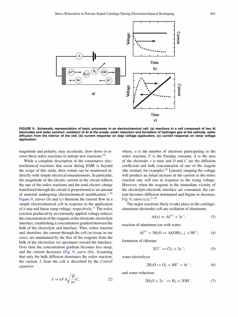
FIGURE 9. Schematic representation of basic processes in an electrochemical cell: (a) reactions in a cell composed of two Alelectrodes and water solution: oxidation of Al at the anode, water reduction and formation of hydrogen gas at the cathode, waterdiffusion from the interior of the cell, (b) current response on step voltage application, (c) current response on ramp voltageapplication.
magnitude and polarity, may accelerate, slow down or re-verse these redox reactions or initiate new reactions.26
While a complete description of the constitutive elec-trochemical reactions that occur during EMR is beyondthe scope of this study, their extent can be monitored in-directly with simple electrical measurements. In particular,the magnitude of the electric current in the circuit reflectsthe rate of the redox reactions and the total electric chargetransferred through the circuit is proportional to an amountof material undergoing electrochemical modification.1,26
Figure 9, curves (b) and (c) illustrate the current flow in asimple electrochemical cell in response to the applicationof a step and linear ramp voltage, respectively.11 The redoxreaction produced by an externally applied voltage reducesthe concentration of the reagents at the electrode-electrolyteinterface, establishing a concentration gradient between thebulk of the electrolyte and interface. Thus, redox reactionand, therefore, the current through the cell (or tissue in ourcase), are maintained by the flux of the reagents from thebulk of the electrolyte (or specimen) toward the interface.Over time the concentration gradient becomes less steep,and the current decreases (Fig. 9, curve (b)). Assumingthat only the bulk diffusion dominates the redox reaction,the current, I, from the cell is described by the Cottrellequation:
I = nF A
√D
π tC, (2)
where, n is the number of electrons participating in theredox reaction, F is the Faraday constant, A is the areaof the electrode, t is time and D and C are the diffusioncoefficient and bulk concentration of one of the reagent(the oxidant, for example).26 Linearly ramping the voltagewill produce an initial increase in the current as the redoxreaction rate will rise in response to the rising voltage.However, when the reagents in the immediate vicinity ofthe electrolyte-electrode interface are consumed, the cur-rent becomes diffusion dominated and begins to decrease,Fig. 9, curve (c)).11,26
The major reactions likely to take place in the cartilage-aluminum electrodes cell are oxidation of aluminum:
Al(s) ↔ Al3+ + 3e−; (3)
reaction of aluminum ion with water:
Al3+ + 3H2O ↔ Al(OH)3 ↓ +3H+; (4)
formation of chlorine:
2Cl− ↔ Cl2 + 2e−; (5)
water electrolysis
2H2O ↔ O2 + 4H+ + 4e−; (6)
and water reduction:
2H2O + 2e− ↔ H2 + 2OH−. (7)
462 PROTSENKO et al.
Reactions (3)–(6) occur at the anode and (7) take placenear the cathode. Reactions (3) and (4) lead to dissolutionof the anode and deposition of aluminum onto the cartilagesurface. The water electrolysis reaction requires a thresholdvoltage to proceed (in the ideal case the theoretical voltagelevel is 1.23 V at 25◦C).31 The release of hydrogen, oxy-gen, and chlorine gas is manifested by the formation ofbubbles/foam on the cartilage surface.
In an electrochemical cell composed of an electrolyteand two identical electrodes, the redox reactions at eachelectrode are the same and the net voltage drop across sucha cell is zero. However, in our case, a spontaneous netvoltage drop across the electroforming jig (with the carti-lage specimen secured in it) was observed in the absenceof an externally applied voltage. The spontaneous polar-ity of the jig-cartilage system was such that the concaveelectrode (Fig. 1) had the highest electric potential and be-came a spontaneous anode. This spontaneous voltage dropis likely resulted from the difference in contact area betweenthe cartilage and the electrodes at the concave and convexsurfaces as well as from a difference in concentration oftissue electrolyte in the compressed and stretched regionsof the cartilage specimen.
A small external voltage (referred to as an overvoltage)applied to the jig, equal in magnitude but opposite in polar-ity to the spontaneous net voltage cancels the spontaneouselectric current produced by the jig-cartilage system. Dur-ing initial ramping up of the voltage we observed zero netcurrent at the voltage level, V0i, (0.7 ± 0.2 V). The overvolt-age, V0f , observed during the ramping down of voltage atthe conclusion of the EMR exceeds the initial level, V0i andincreases with the electroforming voltage, Vef , and time.
The lack of appreciable change in the electric currentobserved in the control experiments (Fig. 6, curve corre-sponding to Vef = 0) indicate that in the absence of an ex-ternal electric field the spontaneous redox reactions proceedat a constant rate without significant alteration of specimenchemical composition. In the same control experiment car-tilage internal stress undergoes partial relaxation, (Fig. 5,curve corresponding to Vef = 0), but this relaxation did notresult in any shape change once the specimen is removedfrom the jig (Fig. 4).
The changes in electric current observed during the EMRexperiments reflect the dynamics of the induced electro-chemical reactions, (Figs. 2 and 6). Since the polaritiesof the external and spontaneous voltages are opposite, theramping up of the external applied voltage to V0i first slowsand then completely stops the redox reaction. In this volt-age interval, the current first changes from the negativeIi to zero. Further increasing the voltage reverses the re-dox reaction and accelerates it in the new direction, i.e.,at the concave electrode (spontaneous anode) oxidation isreplaced by reduction and at the convex electrode oxidationoccurs. The current switches direction and rises from zeroto a maximum positive level. At the end of the voltage
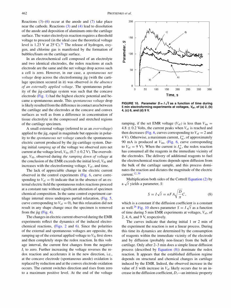
FIGURE 10. Parameter S = I√
t as a function of time during5 min electroforming experiments at voltages, Vef, of (a) 2, (b)4, (c) 6, and (d) 9 V.
ramping, if the set EMR voltage (Vef) is less than Vim =4.8 ± 0.2 Volts, the current peaks when Vef is reached andthen decreases (Fig. 6, curves corresponding to Vef = 2 and4 V). Otherwise, a maximum current, I +
m , of approximately90 mA is produced at Vim, (Fig. 6, curve correspondingto Vef = 9 V). When the current is I +
m , the redox reactionhas consumed all the reagents in the immediate vicinity ofthe electrodes. The delivery of additional reagents to fuelthe electrochemical reactions depends upon diffusion fromthe bulk of the cartilage sample, and this process domi-nates the reaction and dictates the magnitude of the electriccurrent.12,30
Multiplication both sides of the Cottrell Equation (2) bya
√t yields a parameter, S:
S = I√
t = nF A
√D
πC, (8)
which is a constant if the diffusion coefficient is a constantas well.26 Fig. 10 shows parameter S = I
√t as a function
of time during 5 min EMR experiments at voltages, Vef , of2, 4, 6, and 9 V, respectively.
The curves indicate that during initial 1 or 2 min ofthe experiment the reaction is not a linear process. Duringthis time its dynamics are determined by the consumptionof reagents within the immediate vicinity of the electrodeand by diffusion (probably non-linear) from the bulk ofcartilage. Only after 2–3 min does a simple linear diffusionprocess (described by Equation (8)) dominate the redoxreaction. It appears that the established diffusion regimedepends on structural and chemical changes in cartilageinduced by the EMR. Indeed, the observed increase in thevalue of S with increase in Vef likely occurs due to an in-crease in the diffusion coefficient, D,—an intrinsic property

Stress Relaxation in Porcine Septal Cartilage During Electromechanical Reshaping 463
of the tissue. S increases for values of Vef up to 6 V andthen saturates—which is similar to the trends observed withthe bend angle as a function of applied voltage. As shownin Fig. 4, bend angle (a macroscopic and bulk measureof electrochemically induced tissue changes) also saturatesafter Vef exceeds 6 V in 5 min EMR experiment (Fig. 4,curves corresponding to Vef of 8 and 10 V).
The final bend angle correlates with the total transferredcharge, Qtot, and final resistance of the electrode-cartilagesystem, Rf , in Figs. 7 and 8, respectively. According toFaraday’s second law, Qtot is proportional to the number ofmoles, M, participating in the redox process:
Qtot =∫
I dt = MnF (9)
Figure 7, curves corresponding to Vef of 10 V, demon-strate that during the initial 3 min of EMR the amountof material undergoing electrochemical change increasesmuch more rapidly than during the subsequent 2 min. Inthe initial 3 min the alteration of cartilage chemical compo-sition also transforms the mechanical state of the cartilage.The mechanical transformation is reflected by the increaseand subsequent peak in bend angle. This initial high-redoxreaction rate proceeds until all chemical processes respon-sible for cartilage mechanical transformation are completedand the cartilage sample reaches its maximum bend angle(Fig. 7). After that, the much lower reaction rate likely in-dicates that a process such as diffusion of the reagents frominterior of the sample is taking place in cartilage samplethat has been transformed into a new mechanical state.
The time-dependent behavior of final resistance, Rf ,(Fig. 8) correlates closely with bend angle. The relationshipbetween Rf and the total charge transferred, Qtot is muchless clear. It should be noted that in the present study, themeasured resistance of the cartilage-electrodes system isnot the pure ohmic resistance of cartilage tissue. Instead itis composed of two components: the classic ohmic resis-tance of the sample bulk and the Faradic resistance of theelectrochemical reaction,26 (Fig. 9). It is not clear whichcomponent has a greater impact on the overall change inresistance. However, it is unlikely that the major mechanismfor the final resistance increase is due to the loss of water—one of the major reagents of the proposed redox reactions.The loss of water affects both components: the ohmic com-ponent through the loss of the media for the charge carriers(dissolved ions), and the Faradic component through de-crease of the concentration of the reagents participating inspontaneous electro-chemical reaction. Assuming that allthe electrical energy in the electroforming experiment isconsumed by water electrolysis and reduction, Equations(6) and (7), respectively, and the dehydration due to thesurface evaporation is negligible,7 the amount of waterlost during 5 min of EMR at 10 V is only ∼20 µM or∼0.36 mg, Equation (9), Fig. 6. This is less than 0.4%of the initial water content in the cartilage sample. Thus,
sample dehydration is very small and its effect on increasein the resistance is minimal.
The correlation of total charge transfer, impedance andcurrent measurements (reflecting the gross electric changesin the cartilage sample) with the bend angle (reflecting me-chanical changes) suggests stress relaxation can be moni-tored during EMR. Saturation effects observed in electricimpedance and current may be used to indicate both optimalstress relaxation and shape change. Hence, continuing to ex-pose mechanically deformed cartilage grafts to an electricfield beyond these the observation of these plateaus may re-sult in significant softening and loss in sample elasticity andreduced shape preservation (Fig. 4, curves correspondingto Vef of 8 and 10 V).
Though the observed correlation between electrical andmechanical events demonstrate that stress relaxation goeshand-in-hand with electro-chemical reactions it is not clearthat the oxidation-reduction reactions (Equations (3)–(7))are directly responsible for alteration of cartilage mechani-cal state. Instead, release of reaction products, for instanceH+ and OH− ions, might through alteration of local ionicstrength and/or pH lead to changes in tissue stiffness,8,9
though pH related changes being reversible cannot aloneaccount for shape change Another possible mechanism ofaction for EMR is due to local depletion of proteoglycanseither electro-chemically induced or through diffusion ofproteoglycan molecules in electric field. Inhomogeneousdistribution of proteoglycans through the sample can be re-sponsible for the shape change.25 To investigate mechanismof EMR further studies of molecular and ionic compositionof the electrically treated samples, in particular, analysisof pH and proteoglycans content within the sample will berequired.
ACKNOWLEDGMENTS
This work was supported by Air Force Office of Sci-entific Research (FA9550–04–1–0101) and the NationalInstitutes of Health (DC005572, DC 00170, RR 01192).The authors express their gratitude to Dr. Patrick Farmerfor his helpful discussions and to Chao Li and Ryan Wrightfor assistance with the experiments.
REFERENCES
1Albery, J., Electrode Kinetics, Oxford: Claredon Press, 1–891975.
2Bagratashvili, V. N., E. N. Sobol, A. P. Sviridov, V. K. Popov,A. I. Omel’chenko, and S. M. Howdle. Thermal and diffusionprocesses in laser-induced stress relaxation and reshaping ofcartilage. J. Biomech. 30:813–817, 1997.
3Brent B., Technical advances in ear reconstruction with autoge-nous rib cartilage grafts: Personal experience with 1200 cases.Plast. Reconstr. Surg. 104:319–334, 1999.
4Buschmann, M. D., and A. J. Grodzinsky. A molec-ular model of proteoglycan-associated electrostatic forces
464 PROTSENKO et al.
in cartilage mechanics. J. Biomech. Eng. 117:179–192,1995.
5Darren, S. G., J. A. Kimball, and B. J. Wong. Shape retentionin porcine-septal cartilage following Nd:YAG (λ = 1.36) laser-mediated reshaping. Lasers. Surg. Med. 29:160–164, 2001.
6Diaz, S. H., G. Aguilar, R. Basu, E. J. Lavernia, and B. J. Wong.Modeling the thermal response of porcine cartilage to laser ir-radiation. Proc. SPIE. 4617:47–56, 2002.
7Dı́az, S. H., G. Aguilar, E. J. Lavernia, and B. J. Wong. Modelingthe thermal response of porcine cartilage to laser irradiation.IEEE J. Sel. Top. Quantum Electron. 7:944–951, 2001.
8Eisenberg, S. R., and A. J. Grodzinsky. The kinetics of chemi-cally induced nonequilibrium swelling of articular cartilage andcorneal stroma. J. Biomech. Eng. 109:79–89, 1987.
9Frank, E. H., and A. J. Grodzinsky, Cartilage electromechanics– I. Electrokinetic transduction and the effect of electrolyte pHand ionic strength. J. Biomech. 20:615–627, 1987.
10Fry H. Interlocked stresses in human nasal septal cartilage. Br.J. Plast. Surg. 19:276–278, 1966.
11Geiger, W. H., and M. D. Hawely. Choosing and Performing anelectrochemical experiment. In: Physical Methods of Chemistry,edited by B. W. Rossiter and J. F. Hamilton. New York: JohnWiley and Sons, 1986, pp. 1–54.
12Gray, D. S., J. A. Kimball, and B. J. Wong. Shape retentionin porcine septal cartilage following Nd:YAG laser mediatedreshaping. Lasers Surg. Med. 29:160–164, 2001.
13Gu, W. Y., W. M. Lai, and V. C. Mow. Transport of fluid andions trough a porous-permeable charged-hydrated tissue, andstreaming potential data on normal bovine articular cartilage. J.Biomech. 26:709–723, 1993.
14Helidonis, E., E. Sobol, G. Kavvalos, J. Bizakis, P.Christodoulou, G. Velegrakis, J. Segas, and V. Bagratashvili.Laser shaping of composite cartilage grafts. Am. J. Otolaryngol.14:410–412, 1993.
15Ho, K. K., S. H. Diaz-Valdes, D. E. Protsenko, G. Aguilar, andB. J. Wong. Electromechanical reshaping of septal cartilage.Laryngoscope. 113:1916–1921, 2003.
16Johns, M. E., D. E. Mattox, and J. C. Price. Atlas of Head andNeck Surgery. Philadelphia: B. C. Decker Inc., 1990.
17Keefe, M., A. Rasouli, S. Telenkov, A. M. Karamzadeh, T. E.Milner, R. L. Crumley, and B. J. Wong. Radiofrequency carti-lage reshaping: efficacy, biophysical measurements, and tissueviability. Arch. Facial. Plast. Surg. 5:46–52, 2003.
18Lee, R. C., E. H. Frank, A. J. Grodzinsky, and D. K. Roylance.Oscillatory compressional behavior of articular cartilage and its
associated electromechanical properties. J. Biomech. Eng. 103:280–292, 1981.
19Lovice, D. B., M. D. Mingrone, and D. M. Toriumi. Grafts andimplants in rhinoplasty and nasal reconstruction. Otolaryngol.Clin. North. Am. 32:113–141, 1999.
20Myers, T. G., G. K. Aldis, and S. Naili. Ion induced deformationof soft tissue. Bull. Math. Biol. 57:77–98, 1995.
21Ovchinnikov, Y., E. Sobol, V. Svistushkin, A. Shekhter, V.Bagratashvili, and A. Sviridov. Laser septochondrocorrection.Arch. Facial. Plast. Surg. 4:180–185, 2002.
22Protsenko, D. E., K. H. Ho, and B. J. Wong. Monitoring of elec-trical properties during cartilage reshaping. Proc. SPIE. 4949:307–310, 2003.
23Setton, L. A., H. Tohyama, and V. C. Mow. Swelling and curlingbehaviors of articular cartilage. J. Biomech. Eng. 120: 355–361,1998.
24Spilker, R. L., J. K. Suh, and V. C. Mow. A finite elementanalysis of the indentation stress-relaxation response of lin-ear biphasic articular cartilage. J. Biomech. Eng. 114:191–201,1992.
25Sun, D. D., W. E. Gu., Likhitpanichkul, W. M. Lai, andV. C. Mow. The Influence of the fixed negative chargeson mechanical and electrical behaviors of articular cartilageunder unconfined compression. J. Biomed. Eng. 126: 6–16,2004.
26Vassos, B.H., and G.W. Ewing. Electroanalytical Chemistry.New York: John Wiley and Sons, 1983, pp. 1–36.
27Wang, Z., D. F. Perrault, M. M. Pankratov, and S. M.Shapshay. Endoscopic laser-assisted reshaping of collapsed tra-cheal cartilage: A laboratory study. Ann. Otol. Rhinol. Laryngol.105: 176–181, 1996.
28Wright, R., D. E. Protsenko, S. Diaz, K. Ho, and B. J. Wong.Shape retention in porcine and rabbit nasal septal cartilage usingsaline bath immersion and Nd:YAG laser irradiation. LasersSurg. Med. 37: 201–209, 2005.
29Wright, R., K. H. Ho, D. E. Protsenko, S. Diaz, and B. J. Wong.Effect of bath water temperature and immersion time on bendangle during cartilage thermoforming. Proc. SPIE. 4949: 293–299, 2003.
30Wong, B. J., K. Chao, and H. K. Kim. The porcine and lago-morph septal cartilages: models for tissue engineering andmorphologic cartilage research. Am. J. Rhinol. 15:109–116,2001.
31Zumdahl, S. S., Chemistry. Lexington: Heath and Co, 1989,p. 841.
Related Documents