TECHNISCHE MECHANIK, Band 25, Heft 1, (2005), 59-79 Manuskripteingang: 17. Dezember 2004 Analyzing Laminated Structures from Fibre-Reinforced Composite Material – An Assessment K. Rohwer, S. Friedrichs, C. Wehmeyer In the open literature there is available a tremendous number of models and methods for analyzing laminated structures. With respect to the assumptions across the laminate thickness, theories with C z 1 -continuous functions are to be distinguished from layer-wise approaches, where for the latter the functional degrees of freedom can be dependent or independent of the number of layers. Transverse shear and normal stresses are more accurate when obtained by locally evaluating the equilibrium conditions. Guidelines are needed as to which model is suitable for what task. Especially for layer-wise models a fair judgment is missing. To ease up this deficiency two simple layer-wise models are evaluated and compared with models based on C z 1 -continuous functions. It turns out that for standard application the FSDT with improved transverse shear stiffness is a good choice with respect to efficiency. 1 Introduction Exceptionally high stiffness and strength to weight ratios are the driving forces behind the success story of fibre reinforced composite structures in advanced lightweight constructions. For aerospace applications the triumphant progress is evident, culminating in the of late announcement of a “First Composite Jetliner“. But also high-speed ships, terrestrial vehicles and machines where high velocity or acceleration is requested utilize the advantage of this material more and more often. A set-up from layers with unidirectional reinforcement oriented in different directions, termed ‘multidirectional laminate’, has developed as a standard design. Homogenization of fiber and matrix behavior results in effective layer properties. In the following a homogeneous orthotropic layer is assumed as the smallest entity of the structure. Closed form solutions to this 3D elasticity problem of laminated structures are scarce and limited in scope. Pagano (1969) and Pagano (1970) have developed solutions for simply supported rectangular plates with symmetric lamination undergoing cylindrical and bidirectional bending, respectively; the fiber orientation is limited to 0˚ and 90˚. Ren (1987) has extended the cylindrical bending solution to infinitely long cylindrical shells. Noor and Burton (1990a), (1992) have provided solutions for the bending, buckling and vibration of antisymmetrically laminated rectangular plates, periodic in the in-plane directions. Savithri and Varadan (1992) studied plates under uniformly distributed and concentrated loads. All these approaches use Fourier expansions in the in-plane directions resulting in sets of ordinary differential equations with constant coefficients, which can be solved exactly. The unknown coefficients of the solutions are determined by boundary and interface conditions in thickness direction. As an alternative, 3D finite elements can be applied. Accounting for the large difference in stiffness between the layers requires at least one element per layer. Edge ratio limitations for 3D elements in connection with a large number of layers, which can be in excess of one hundred, then give rise to an enormous computational effort. Such an effort may be acceptable for solving specific questions; as a general procedure for analyzing complete structures it is by far too expensive. As a way out, the structural slenderness can be utilized for certain assumptions in thickness direction, which reduce the problem dimensions to two. Assumptions are usually made for the displacement distribution, and the functions selected for the different displacement components specify the analysis model. C z 1 function theories assume displacements varying continuously differentiable across the thickness regardless of the layer boundaries. Best known C z 1 representatives are the Classical Lamination Theory (CLT) and the First Order Shear Deformation Theory (FSDT). Both models assume the in-plane displacements to vary linearly in thickness direction whereas the transverse displacements remain constant. Neither CLT nor FSDT allow directly calculating transverse stresses with acceptable accuracy. Furthermore, a large number of so-called Higher Order 59

Welcome message from author
This document is posted to help you gain knowledge. Please leave a comment to let me know what you think about it! Share it to your friends and learn new things together.
Transcript

TECHNISCHE MECHANIK, Band 25, Heft 1, (2005), 59-79 Manuskripteingang: 17. Dezember 2004
Analyzing Laminated Structures from Fibre-Reinforced Composite Material – An Assessment K. Rohwer, S. Friedrichs, C. Wehmeyer In the open literature there is available a tremendous number of models and methods for analyzing laminated structures. With respect to the assumptions across the laminate thickness, theories with Cz
1-continuous functions are to be distinguished from layer-wise approaches, where for the latter the functional degrees of freedom can be dependent or independent of the number of layers. Transverse shear and normal stresses are more accurate when obtained by locally evaluating the equilibrium conditions. Guidelines are needed as to which model is suitable for what task. Especially for layer-wise models a fair judgment is missing. To ease up this deficiency two simple layer-wise models are evaluated and compared with models based on Cz
1-continuous functions. It turns out that for standard application the FSDT with improved transverse shear stiffness is a good choice with respect to efficiency. 1 Introduction Exceptionally high stiffness and strength to weight ratios are the driving forces behind the success story of fibre reinforced composite structures in advanced lightweight constructions. For aerospace applications the triumphant progress is evident, culminating in the of late announcement of a “First Composite Jetliner“. But also high-speed ships, terrestrial vehicles and machines where high velocity or acceleration is requested utilize the advantage of this material more and more often. A set-up from layers with unidirectional reinforcement oriented in different directions, termed ‘multidirectional laminate’, has developed as a standard design. Homogenization of fiber and matrix behavior results in effective layer properties. In the following a homogeneous orthotropic layer is assumed as the smallest entity of the structure. Closed form solutions to this 3D elasticity problem of laminated structures are scarce and limited in scope. Pagano (1969) and Pagano (1970) have developed solutions for simply supported rectangular plates with symmetric lamination undergoing cylindrical and bidirectional bending, respectively; the fiber orientation is limited to 0˚ and 90˚. Ren (1987) has extended the cylindrical bending solution to infinitely long cylindrical shells. Noor and Burton (1990a), (1992) have provided solutions for the bending, buckling and vibration of antisymmetrically laminated rectangular plates, periodic in the in-plane directions. Savithri and Varadan (1992) studied plates under uniformly distributed and concentrated loads. All these approaches use Fourier expansions in the in-plane directions resulting in sets of ordinary differential equations with constant coefficients, which can be solved exactly. The unknown coefficients of the solutions are determined by boundary and interface conditions in thickness direction. As an alternative, 3D finite elements can be applied. Accounting for the large difference in stiffness between the layers requires at least one element per layer. Edge ratio limitations for 3D elements in connection with a large number of layers, which can be in excess of one hundred, then give rise to an enormous computational effort. Such an effort may be acceptable for solving specific questions; as a general procedure for analyzing complete structures it is by far too expensive. As a way out, the structural slenderness can be utilized for certain assumptions in thickness direction, which reduce the problem dimensions to two. Assumptions are usually made for the displacement distribution, and the functions selected for the different displacement components specify the analysis model. Cz
1 function theories assume displacements varying continuously differentiable across the thickness regardless of the layer boundaries. Best known Cz
1 representatives are the Classical Lamination Theory (CLT) and the First Order Shear Deformation Theory (FSDT). Both models assume the in-plane displacements to vary linearly in thickness direction whereas the transverse displacements remain constant. Neither CLT nor FSDT allow directly calculating transverse stresses with acceptable accuracy. Furthermore, a large number of so-called Higher Order
59

Theories have been developed using consecutively higher order polynomials or other functions with continuous derivatives. Due to different fiber orientation the transverse shear stiffness can change considerably from layer to layer. That causes an abrupt change of transverse shear at the layer interface, which cannot be matched by displacement functions with continuous derivatives. This deficiency gave rise to proposing layer-wise models, where the displacement functions in thickness direction are assumed for each layer separately. Displacement continuity at layer interfaces leads to Cz
0 function theories, and equilibrium conditions can be applied to reduce the number of functional degrees of freedom, which, in the end, can be independent of the number of layers. A generalized formulation including Cz
1 and Cz0 models is given by Reddy (1987).
There is an exceptionally large amount of models and methods available, and the number is continuously growing. Rare, however, are objective comparisons between them without the intention to emphasize the quality of a certain new approach. As exceptions can be regarded the assessments by Noor and Burton (1990b), Rohwer (1992), and Yang et al. (2000). Noor and Burton (1990b) have reviewed 400 publications, but details concerning the accuracy and application limits of the different theories are missing. Rohwer’s (1992) study is restricted to models with Cz
1-continuous functions. Both assessments cannot account for the latest developments. Yang et al. (2000) have focused on the development of shell finite elements in general; only one chapter is devoted to laminated composites. Timarci and Aydogdu (2005) recently compared the accuracy of several Cz
0 models with respect to buckling of symmetric cross-ply square plates. The following elaboration upgrades and completes a recent contribution by Rohwer and Rolfes (2004). Like this work the present paper aims at a thorough and up-to-date assessment of some analysis methods for laminated structures. It should be pointed out that the large number of models available prohibits completeness; rather a limited number is selected. For the assessment three different aspects are considered important. Primarily, the accuracy of the models as compared to 3D elasticity results must be accounted for. Furthermore, the effort necessary to reach certain accuracy needs to be included in the evaluation. In addition, the suitability for developing finite elements and using them in the frame of existing FEM programs is of importance. As a first step to a full assessment available information will be given concerning these three aspects. Considering the non-isotropic strength of laminated composites the transverse stresses are of greater importance than for structures from homogeneous isotropic material. Methods for their determination are reviewed in a special chapter. 2 Cz
1 Function Theories As a first choice to approximate the displacement distribution in thickness direction continuously differentiable varying functions can be selected. Theories based on such functions are named Cz
1 function theories. The standard model of this type is the Classical Lamination Theory (CLT) specified by the displacement assumption of
0 0
0 0
0
u u w / xv v w / yw w 0
−∂ ∂ = + −∂ ∂
z⋅
z .
(1)
where x/y/z denotes a Cartesian coordinate system, u/v/w are the displacement components in these directions; the reference surface of the laminate is defined at z = 0. Because of the Bernoulli hypothesis this model gets by with the three functional degrees of freedom (FDOF) u0, v0 and w0. It yields sufficient accuracy for rather slender structures only, as demonstrated by Rohwer (1992). Owing to second derivatives in the strain-displacement relations the CLT needs Cxy
1-continuous shape functions if applied for a finite element development. Dropping the Bernoulli hypothesis leads to the First-Order Shear Deformation Theory (FSDT) with displacements as
0 1
0 1
0
u u uv v vw w 0
= + ⋅
(2)
That increases the number of FDOF to five. Yang et al. (1966) and Whitney and Pagano (1970) have extended the FSDT to laminated composites. Satisfying accuracy is obtained for more bulky structures as well, but a
60

transverse shear correction is needed. Deriving at suitable shear corrections for laminated composites is more involved than for homogeneous materials. Rohwer (1988) has proposed a reasonable procedure; Altenbach (2000) has presented a method, which works for sandwiches as well. Cxy
0-continuous functions suffice for developing finite elements. Higher order Cz
1 function theories can be set up in the form
0 ini
0 ii 1
0
u u uv v vw w 0=
= +
∑ z⋅ (3)
where n is usually limited to 3 in order to keep the computational effort low. Jemielita (1990) pointed out that it was B.F. Vlasov in 1957 who first proposed a kinematical hypothesis with cubic in-plane displacement distributions in connection with constant transverse displacements for a plate of homogenous, isotropic material. His approach assured vanishing shear strains at the plate surfaces. If the reference surface coincides with the mid-surface, then vanishing transverse shear strains at the upper and lower surface requires skipping of the quadratic term, leaving the number of FDOF at seven. Several ideas have been brought forward to further reduce this number, the first of which is due to M.V.V. Murthy (1981). He introduced average rotations βx and βy in the sense of a least squares fit; they are related to the initial functions by
2x 31
y 31
uu 3h ,vv 20
β = + β (4)
with h denoting the total laminate thickness. Therewith the displacement distribution
0 x 0 x 0 3
0 y 0 y 0 2
0
u u 5 w / x w / xz 5v v 5 w / y w / y4 3h
w w 0 0
β + ∂ ∂ β + ∂ ∂ = + β + ∂ ∂ ⋅ − β + ∂ ∂ ⋅
z (5)
contains but five FDOF. The accuracy is improved as compared to the FSDT; on the other hand Cxy
1-continuous functions are needed again for application in finite elements. A different approach has been proposed by Reddy (1984). He used the condition of vanishing transverse shear strains at the upper and lower surface also to replace u3 and v3, which leads to a displacement distribution as shown in equation (6). The accuracy of this five FDOF model is comparable to the one by Murthy; again Cxy
1-continuity is needed for finite element shape functions.
0 1 1 0 3
0 1 1 0 2
0
u u u u w / x4zv v v z v w / y3h
w w 0 0
+ ∂ ∂ = + ⋅ − + ∂ ∂ ⋅
. (6)
Based on Reddy’s theory, Senthilnathan et al. (1987) split up the transverse displacement w0 into a bending and a shear contribution, wb and ws, respectively. Identifying the rotations u1 and v1 with the respective derivatives of wb the displacement distribution comes out as
0 b s 3
0 b s 2
b s
u u w / x w / x4zv v w / y z w / y3h
w w w 0 0
∂ ∂ ∂ ∂ = − ∂ ∂ ⋅ − ∂ ∂ ⋅ +
. (7)
This manipulation reduces the number of FDOF to four. However, the accuracy suffers, with the transverse displacements in some cases close to the results of the Reddy/Murthy theories but sometimes worse than FSDT. Rohwer (1992) has pointed out that this approach provides insufficient freedom to model anisotropy effects. As a result discrepancies appear in the in-plane displacements. Finite element shape functions require Cxy
1-continuity.
61

Idlbi et al. (1997) recommended using a sine function instead of polynomials to describe the in-plane displacements.
0 0 1 0
0 0 2 0
0
u u w / x w / xh zv v w / y z w / y sin .
hw w 0 0
∂ ∂ ω + ∂ ∂ π = − ∂ ∂ ⋅ + ω + ∂ ∂ ⋅ ⋅ π
(8)
Results from this model are closer to the 3D elasticity solution than those from CLT, FSDT and Reddy’s theory, and the number of FDOF is five. A finite element based on this approach would need shape functions with Cxy
1-continuity. A different type of higher order theories increases the polynomial order of the transverse displacements w. Whitney and Sun (1974) proposed a quadratic polynomial for w keeping the in-plane displacements linear. This has been further refined by Kwon and Akin (1987) who eliminated the term linear in w by placing the reference surface in the mid-surface and enforcing zero shear strain at the upper and lower edge. That leads to
0 12
0 1
0 2
u u u 0v v v z 0 zw w 0 w
= + ⋅ − ⋅
. (9)
Furthermore, the same conditions are used to set up the relations
1 022
1 02
u w / xw / x 4 ,v w / yw / y 3h
+ ∂ ∂∂ ∂ = − + ∂ ∂∂ ∂
z .
(10)
which, again, reduces the number of FDOF to five. No transverse shear correction factor is needed but the accuracy is slightly inferior to the FSDT with a proper shear correction. Kwon and Akin (1987) used a mixed formulation for a finite element development with displacements and bending moments as unknown functions. In case of a pure displacement formulation finite elements based on the plane stress assumption would need Cxy
0-continuous shape functions only. Reissner (1975) introduced a combination of cubic in-plane and quadratic transverse displacements, which was applied to laminated plates by Lo et al. (1977) and further refined by Pandya and Kant (1988a), (1988b). The displacement field is assumed as
0 1 32 3
0 1 3
0 2
u u u 0 uv v v z 0 z vw w 0 w 0
= + ⋅ + ⋅ + ⋅
(11)
Setting the three components w1, u2 and v2 to zero defines a special condition; simply placing the reference surface in the mid-surface and enforcing zero transverse shear strains at upper and lower edge would result in the relations
2 1
2 1
u w /1 .v w /2
∂ ∂ = − ∂ ∂
xy
(12)
The proposed model delivers rather accurate results on the expense of eight FDOF. For a finite element development displacement functions with Cxy
0-continuity are sufficient. Using the method of multiple scales, Wu et al. (1996), (1997) presented an asymptotic expansion of the 3D elasticity equations with material properties piecewise continuous in thickness direction. Shell thickness over radius is used as the perturbation parameter. Successive integration leads to a process embracing the CLT, the FSDT, and the cubic model by Reddy (1984), respectively, as first-order approximations to the three-dimensional theory. The procedure allows improving the solutions obtained by the respective theories in an adaptive and hierarchical manner without increasing the number of FDOF.
62
As a result of this survey it can be stated that for standard applications the FSDT with suitable shear correction delivers sufficiently accurate results at acceptable expenses. But in special cases it may be necessary to increase the order of polynomials in thickness direction. Rohwer et al. (2001) have presented such a case, where in the case of local thermal loads polynomials of up to 5th order are required for modeling in-plane as well as transverse displacements in order to determine reliable stresses. Because of the considerably large effort involved with an application of such high-order models they should be restricted to cases where they are really needed. Table 1 assembles information about different Cz
1 function theories. Though the approach by Wisniewski and Schrefler (1993) starts out from a layer-wise linear assumption for the in-plane displacements the expansion into laminate-wise series makes it a Cz
1-model. The effort required for the different theories is characterized by the number of FDOF involved. The third column provides some information about the accuracy as compared to a 3D solution. In this respect differences appear mainly for low slenderness ratios which are not very common in lightweight constructions. It should be kept in mind that a 2D treatment is not suitable for extremely low slenderness ratios. Thus, the application range where the differences really count is rather limited. The last column specifies how well the model is suited for finite element application. If the shape functions require Cxy
1 continuity an implementation into standard FEM software and a common use with existing elements will be difficult if not impossible.
Reference FDOF Accuracy of Displacements
FE Requirement
CLT 3 - - Cxy1
FSDT 5 +, needs shear correction Cxy0
Murthy (1981) 5 + Cxy1
Reddy (1984) 5 + Cxy1
Idlbi et al. (1997) 5 ++ Cxy1
Kwon/Akin (1987) 5 0 Cxy0
Pandya/Kant (1988) 8 ++ Cxy0
Wisniewski/ Schrefler (1993)
Depending on series truncation
Not sufficient information available
Cxy0
Table 1 Assessment of Cz1 function theories
3 Layerwise Models A closer look at Pagano’s 3D elasticity solutions for laminates switching between 0º and 90º layers (Pagano (1969), Pagano (1970)) makes clear that for smaller slenderness ratios Cz
1 function theories have difficulties to accurately model the in-plane displacements. This has been clearly demonstrated in a technical note by Pagano and Hatfield (1972). They analyzed bidirectional laminated, simply supported square plates of side length a and thickness h under a double sinusoidal surface load. For slenderness ratios a/h < 10 the in-plane displacements show a pronounced layer-wise zigzagging distribution, which can be traced back to an abrupt change of material properties across the layer interfaces. The effect certainly cannot be captured by Cz
1-continuous displacements. This observation gave rise to develop analysis models, which consider each layer separately. Assumptions are made for displacement and/or stress distributions over each layer thickness separately leading to functions of the in-plane coordinates only. In the following an overview over a number of proposed models will be given. Due to the markedly intensive research activities in this field the list may not be complete.
3.1 Number of FDOF depending on the number of layers In general the three displacement components u(k), v(k) w(k) specified in layer k can be written as
(k) (k) (k) (k)0 jn
(k) (k) (k) (k)0 j
j 1(k) (k) (k) (k)0 j
u u (x, y) u (x, y) (z)v v (x, y) v (x, y) (zw w (x, y) w (x, y) (z)=
⋅χ
= + ⋅χ ⋅ψ
∑j
j
j
) .
(13)
In thickness direction identical functions χ(k) are assumed for the two in-plane displacements, but they may differ from the distribution ψ(k) of the transverse displacement. With N layers the number of FDOF amounts to 3(n+1)N. In general this number is reduced to 3(nN+1) by enforcing Cz
0 displacement compatibility between
63

layers. Only in case of delaminations the inter-layer compatibility is suspended. Cho and Kim (2001) and Kim and Cho (2002) have treated this problem; they assured compatibility in major areas and added terms representing possible jumps in slipping and opening displacements. For modeling the delaminations Kim et al. (2003a), Kim et al. (2003b) and Chattopadhyay et al. (2004) used the Heaviside unit step functions
ii
i
1 for z zH(z z )
0 for z z≥
− = < (14)
where zi denotes the layer surface coordinates. That leads to an approach with the number of FDOF independent of the number of layers but dependent on the number of delaminations. Assuring displacement compatibility between layers leads to a zigzag distribution of the in-plane displacements across the laminate thickness. A large number of theories are based on such Cz
0 assumptions. In a historical review Carrera (2003) has pointed out that basic contributions in this field should be credited to Lekhnitskii (1935), Ambartsumian (1969) and Reissner (1984). Unfortunately, some of the earlier publications are difficult to attain, especially those published in Russian language. Reissner’s mixed variational theorem provides a general tool for approximating displacements and stresses likewise. However, besides the not yet mathematically proven stability and convergence of most mixed approaches the standard finite element software tools are not capable of including elements of that type. Cz
0-compatibility can be reached in different ways. Mau (1973) started from a layer-wise linear distribution of the in-plane displacements and constant transverse ones. He multiplied the compatibility conditions at the layer interfaces with Lagrange factors and added them to the potential energy functional. That increases the number of FDOF to 6N-1, but it has the advantage that the transverse shear stresses at the layer interfaces are directly obtained as the values of the Lagrange multipliers. Further, Wu and Yen (1993) proposed a layer-wise cubic approximation for the in-plane displacements and layer-wise quadratic polynomials for the transverse displacement, while inter-layer compatibility is again reached by multiplying the corresponding conditions with Lagrange factors. The number of FDOF adds up to 14N – 3. Most simple and straightforward is the elimination of dispensable freedoms. A more elegant approach uses the Heaviside unit step-function. Therewith, the displacement distribution in thickness direction can be written as
n n(i)
j j j j j i ij 1 j 1
0 n n(i)
0 j j j j j ij 1 j 1
0 m m(i)
j j j j j i ij 1 j 1
u (z) u (z) (z ) H(z z )
u uv v v (z) v (z) (z ) H(z z )w w
w (z) w (z) (z ) H(z z )
= =
= =
= =
⋅χ ⋅ χ − χ ⋅ −
= + ⋅χ + ⋅ χ − χ ⋅ −
⋅ψ ⋅ ψ − ψ ⋅ −
∑ ∑
∑ ∑
∑ ∑
N 1
i 1
.−
=
i
∑ (15)
This formulation includes laminate-wise Cz
1-continuous functions as well as layer-wise functions, which meet Cz
0 displacement continuity conditions at the layer interfaces. For the in-plane displacements Srinivas (1973) has assumed a piecewise linear distribution between the values at the interfaces; the transverse displacements remain constant. In the above nomenclature the approach reads
[ ][ ]
(i)0 1 i iN 1
(i)0 1 i i
i 10
u u u z z H(z z )v v v z z z H(z z )w w 0 0
−
=
ϕ ⋅ − ⋅ − = + ⋅ + ϑ ⋅ − ⋅ −
∑ , (16)
which leads to 2N+3 FDOF. Results show a good accuracy also for sandwich type structures with a weak core. A 3D continuum-based implementation of this approach to a quadrilateral finite element is provided by Barbero (1992). Cxy
0-continuity conditions are sufficient for the shape functions. Wisniewski and Schrefler (1993) started out from Srinivas’ approach. As mentioned above they reduced the number of FDOF by expanding the in-plane interface displacements into either Taylor or Chebyshev series valid over the whole laminate. Therewith the model ends up as a Cz
1 function theory where the number of FDOF depends on the series truncation. A finite
64

element based on this model needs but Cxy0-continuity for the shape functions. Reddy and Savoia (1992)
extended Srinivas’ approach by applying a piecewise linear approximation for all three displacement components. Compatibility at the layer interfaces is enforced, leading to 3N + 3 FDOF; again the shape functions need to fulfil Cxy
0-continuity only. Though not mentioned in their paper, Masud and Panahandeh (1999) used such an approach to develop a shell finite element. For in-plane as well as for transverse displacements Lee and Liu (1992a) assumed piecewise Hermite cubic interpolation functions, which require function values and slopes at both layer surfaces for specification. Compatibility and equilibrium for transverse shear and normal stresses at layer interfaces are used for elimination. That leads to a number of 6N+6 FDOF. This procedure allows obtaining transverse shear and normal stresses directly from the constitutive equations. Lu and Liu (1992) used the same piecewise Hermite cubic interpolation functions for the in-plane displacements while the transverse displacements remained constant over the laminate thickness. By means of interface compatibility and equilibrium for transverse shear at all layer surfaces the number of FDOF is reduced to 4N + 1. In both approaches finite element shape function must satisfy the Cxy
1-continuity condition. An expansion in thickness direction for all three displacement components was proposed by Robbins and Reddy (1993). They used Lagrangian interpolation polynomials defined over certain subdivisions only. Because of the interpolation process displacement compatibility is automatically assured. Assuming a non-constant transverse displacement allows to model traction-free edges more accurately. The number of FDOF amounts to three times the interpolation node points. If these node points are positioned at the layer surfaces the procedure leads to 3N *(polynomial order) + 3 FDOF. Instead of Lagrangian polynomials Ahmed and Basu (1994) used integrals of Legendre polynomials as layer-wise hierarchic shape functions. Polynomials of third and higher order are applied for all three displacement components. Interlayer compatibility conditions reduce the number of FDOFs. Thus, with third order polynomials the model leads to 9N + 3 FDOF. Finite element shape functions for both the afore-mentioned models suffice with Cxy
0-continuity. In-plane displacements are approximated layer-wise linearly by Cho and Averill (2000), whereas for the transverse displacements a sublaminate-wise linear distribution is assumed. Each sublaminate may comprise several layers. Compatibility and transverse shear stress equilibrium at the layer interfaces are enforced, where the shear strain terms that involve transverse displacements are averaged. In order to allow for a Cxy
0 finite element development the derivatives of the transverse displacements are coupled with corresponding bending and shear angles by means of a penalty parameter. That leads to three displacements and two rotations at each sublaminate surface, which makes the number of FDOF = 5Nsub + 5, where Nsub is the number of sublaminates. The approach by Pai and Palazotto (2001) starts out from a model for which the number of FDOF is independent of the number of layers. It is therefore treated in the following chapter.
Reference FDOF FE Requirement Mau (1973) 6N – 1 Cxy
0, mixed formulation Wu/Yen (1993) 14N – 3 Cxy
0, mixed formulation Srinivas (1973) 2N + 3 Cxy
0 Reddy/Savoia (1992) 3N + 3 Cxy
0 Lee/Liu (1992a) 6N + 6 Cxy
1 Lu/Liu (1992) 4N + 1 Cxy
1 Robbins/Reddy (1993) 3N*(polyn. order) + 3, if interpolation
nodes are positioned at layer surfaces Cxy
0
Ahmed/Basu (1994) 3N*(polyn. order) + 3 Cxy0
Cho/Averill (2000) 5Nsub + 5 Cxy0
Pai/Palazotto (2001) 2Nsub + 3 Cxy1
Table 2 Cz0-compatible models with FDOF depending on the layer number
Table 2 comprises some information about Cz
0-compatible models in which the number of FDOF depend on the number of layers. Unfortunately, a comparative study between them with respect to accuracy is not available. Very accurate results for academic examples can be expected. For real structures with layer numbers sometimes in excess of 100 the large number of FDOF is an evident handicap. Computation time increases drastically since not only the number of degrees of freedom but also the bandwidth of the stiffness matrix is proportionally expanded. Therefore, it can be stated that in general layer-wise models with the number of FDOF depending on the number of layers are not suitable for practical application.
65

3.2 Number of FDOF Independent of the Number of Layers Applying compatibility and equilibrium conditions at layer interfaces in a suitable manner allows setting up layer-wise models for which the number of FDOF does not depend on the number of layers. A considerable research effort in this field has led to many models of that type. In the following some of them will be outlined and assessed. Like Srinivas (1973), Sun and Whitney (1973) assumed the in-plane displacements to vary linearly over each layer, whereas the transverse displacements remain constant. By enforcing not only the compatibility but also the transverse shear equilibrium at layer interfaces they could reduce the number of FDOF to five. This advantage, however, must be paid of by the deficiency that the change of transverse shear angle between layers is strictly fixed to the change of the transverse shear modulus. Furthermore, finite elements using this model require Cxy
1-continuity for the transverse displacement shape functions. Based on a refined approximate shear deformation theory by Di Sciuva (1983) the same author has developed a corresponding finite element (Di Sciuva 1985). The refinement consists in a superposition of layer-wise linear functions for the in-plane displacements. Interface equilibrium of transverse shear stresses allows expressing the layer-wise linear functions by shear rotations. A closer inspection reveals that the model is identical to that proposed earlier by Sun and Whitney (1973). In the finite element bi-linear shape functions are chosen for the in-plane displacements and the shear rotations whereas for the transverse displacements bi-cubic Hermite interpolation polynomials are used. Lee et al. (1990) assumed the in-plane displacements layer-wise cubically distributed and the transverse displacement remaining constant.
(k) (k) (k) (k)0 1 0 2 3
(k) (k) (k) (k)0 1 0 2 2
(k)0
u u u w / x u4zv v v w / y z v3h
w w 0 0
− ∂ ∂
= + − ∂ ∂ ⋅ + ⋅
. (17)
Displacement compatibility and equilibrium against transverse shear at layer interfaces are utilized for eliminating unknowns. The model is thus left with five FDOF. The same approach, somewhat more elegantly presented using the Heaviside unit step functions, was introduced by Savithri and Varadan (1990). Again these models suffer from a fixed relation of the change of transverse shear angle between layers. Since the strain specifications include second derivatives of the displacements finite element shape functions must satisfy Cxy
1-continuity conditions. In the frame of a diploma thesis Friedrichs and Wehmeyer (2004) have compared the performance of the layer-wise models by Sun and Whitney (1973) or Di Sciuva (1983) and Lee et al. (1990) or Savithri and Varadan (1990) against the 3D elasticity solution of Pagano (1970) and several laminate-wise models. Using material properties of a conventional carbon HT-fiber reinforced composite they studied the displacements of rectangular, simply supported plates with a [0,90]S lay-up under cosine distributed transverse load. For varying slenderness Figure 1 depicts the center deflection related to the corresponding values of the 3D elasticity solution.
Figure 1. Relative center deflections of a [0,90]S plate, layer thickness [0.25, 0.25]S
66

It shows that the models of Sun and Whitney (1973) or Di Sciuva (1983) with in-plane displacements assumed layer-wise linearly deliver quite accurate results down to a slenderness ratio of 2. The accuracy lies between the laminate-wise models of Reddy (1984) and Pandya/Kant (1988). The layer-wise cubic models by Lee et al. (1990) or Savithri and Varadan (1990), however, provide too small deflections. Their results are somewhat more accurate than the CLT but inferior to the FSDT. For a slenderness ratio of 5 the resulting maximum in-plane displacements u(0;b/2) and v(a/2;0) are shown in Figure 2. Only the upper half of the laminate is displayed, the lower half is to be supplemented anti-symmetrically. Furthermore, the normal rotations uCLT and vCLT are subtracted in order to make the differences between the models more visible. It becomes obvious that the layer-wise models are able to reproduce the kink at the layer interfaces. But the overall approach to the 3D solution is not fully satisfying. The differences vanish for higher slenderness ratios.
Figure 2. In-plane displacements of a [0,90]S plate, layer thickness [0.25, 0.25]S
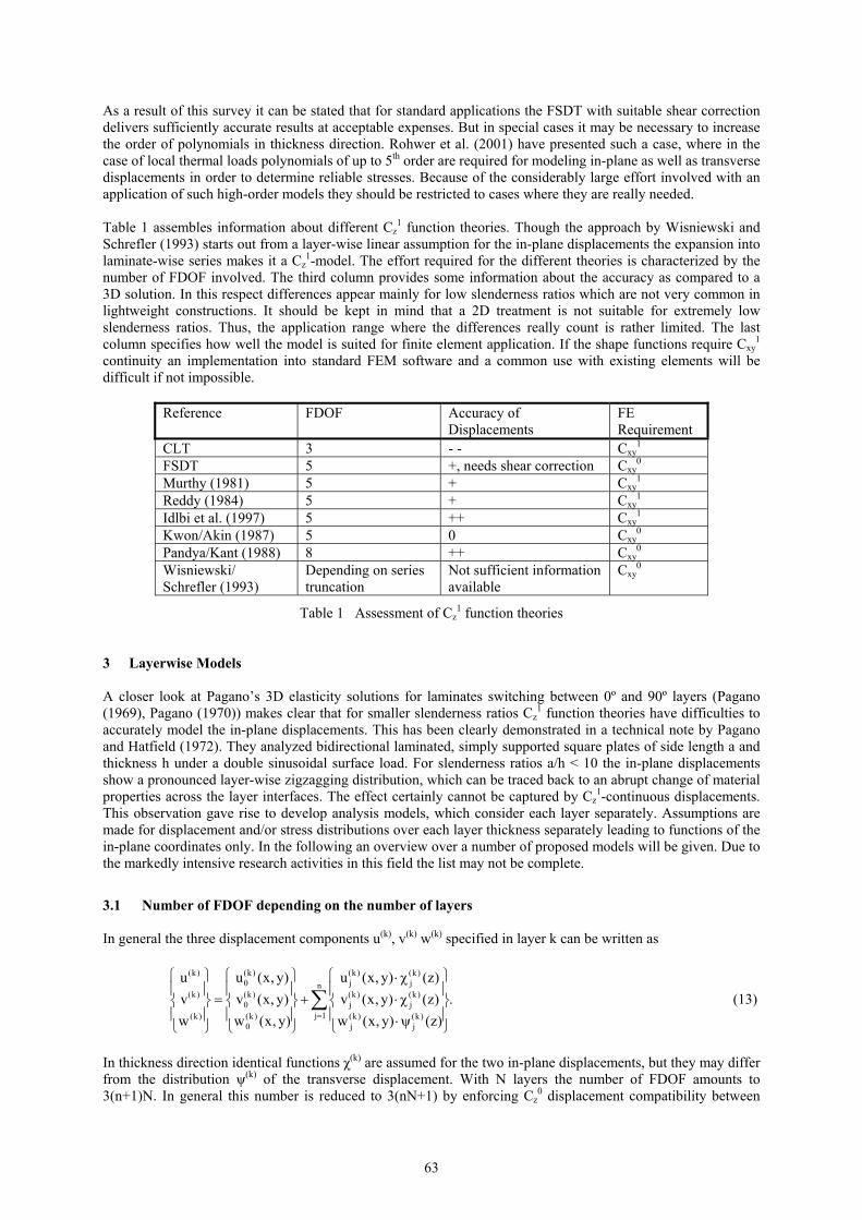
Friedrichs and Wehmeyer (2004) studied many different configurations. In all cases the layer-wise cubic model always performed somewhat too stiff, whereas in most cases the layer-wise linear model delivered results quite close to the 3D solution. A larger deviation appeared when increasing the thickness of the 0º layer on the expenses of the 90º layer. As an example Figures 3 and 4 show the resulting displacements for a layer thickness of [0.40, 0.10]S. The fixed change of the transverse shear angle at the layer interface results in a more flexible behavior. That moves the center deflection of the layer-wise cubic models somewhat closer to the 3D solution, but now the layer-wise linear models react too flexible.
Figure 3. Relative center deflections of a [0,90]S plate, layer thickness [0.40, 0.10]S
67
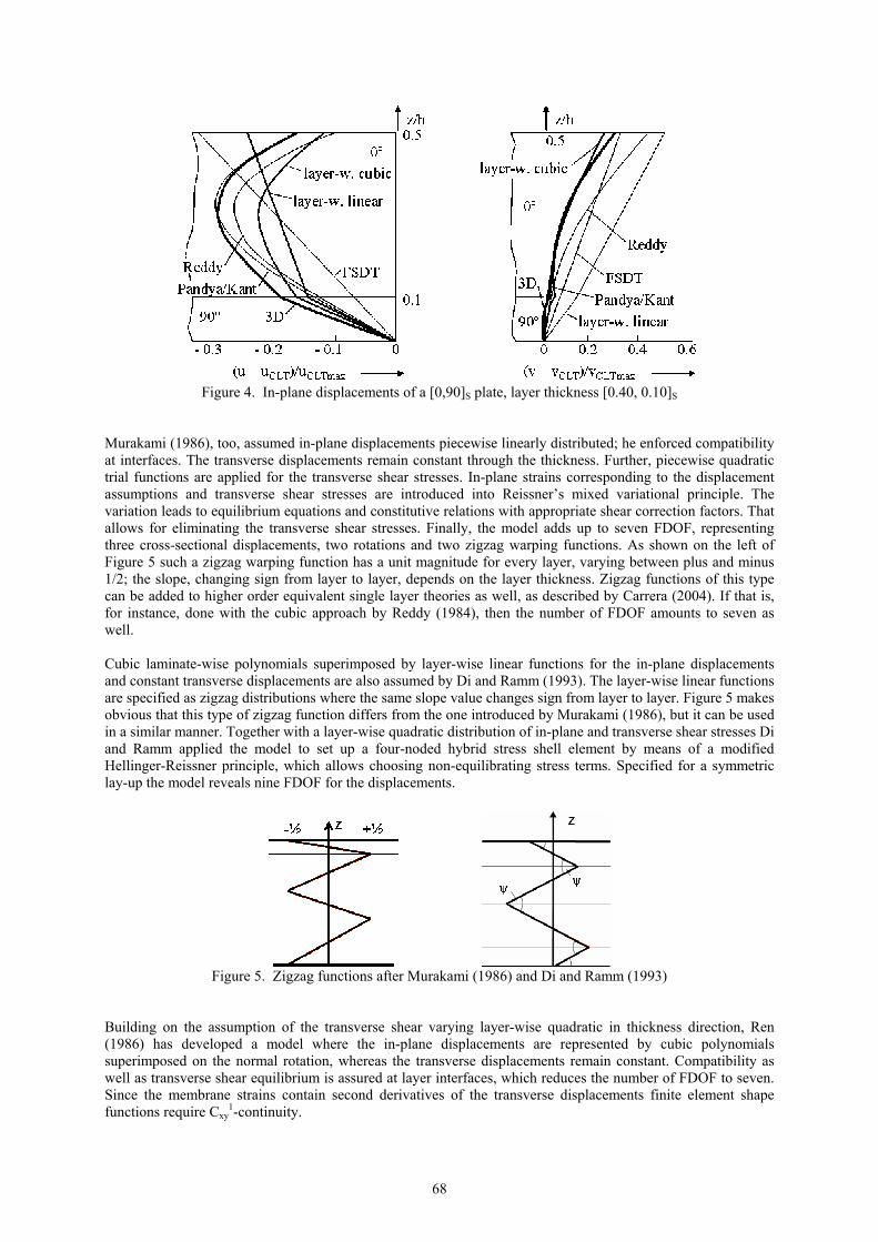
Figure 4. In-plane displacements of a [0,90]S plate, layer thickness [0.40, 0.10]S
Murakami (1986), too, assumed in-plane displacements piecewise linearly distributed; he enforced compatibility at interfaces. The transverse displacements remain constant through the thickness. Further, piecewise quadratic trial functions are applied for the transverse shear stresses. In-plane strains corresponding to the displacement assumptions and transverse shear stresses are introduced into Reissner’s mixed variational principle. The variation leads to equilibrium equations and constitutive relations with appropriate shear correction factors. That allows for eliminating the transverse shear stresses. Finally, the model adds up to seven FDOF, representing three cross-sectional displacements, two rotations and two zigzag warping functions. As shown on the left of Figure 5 such a zigzag warping function has a unit magnitude for every layer, varying between plus and minus 1/2; the slope, changing sign from layer to layer, depends on the layer thickness. Zigzag functions of this type can be added to higher order equivalent single layer theories as well, as described by Carrera (2004). If that is, for instance, done with the cubic approach by Reddy (1984), then the number of FDOF amounts to seven as well. Cubic laminate-wise polynomials superimposed by layer-wise linear functions for the in-plane displacements and constant transverse displacements are also assumed by Di and Ramm (1993). The layer-wise linear functions are specified as zigzag distributions where the same slope value changes sign from layer to layer. Figure 5 makes obvious that this type of zigzag function differs from the one introduced by Murakami (1986), but it can be used in a similar manner. Together with a layer-wise quadratic distribution of in-plane and transverse shear stresses Di and Ramm applied the model to set up a four-noded hybrid stress shell element by means of a modified Hellinger-Reissner principle, which allows choosing non-equilibrating stress terms. Specified for a symmetric lay-up the model reveals nine FDOF for the displacements.
Figure 5. Zigzag functions after Murakami (1986) and Di and Ramm (1993)
Building on the assumption of the transverse shear varying layer-wise quadratic in thickness direction, Ren (1986) has developed a model where the in-plane displacements are represented by cubic polynomials superimposed on the normal rotation, whereas the transverse displacements remain constant. Compatibility as well as transverse shear equilibrium is assured at layer interfaces, which reduces the number of FDOF to seven. Since the membrane strains contain second derivatives of the transverse displacements finite element shape functions require Cxy
1-continuity.
68

For their layer reduction technique, Lee and Liu (1992b) started out from the approach proposed by Lu and Liu (1992). This technique reduces the n-layer laminate to a four-layer one, leaving only those two layers adjacent to the interface of interest unchanged but lumping the stiffness coefficients of the layers above and below to equivalent single layers each. The number of FDOF depends on the employed equivalent layer theory. With a cubic approach for the in-plane displacements in all four remaining layers and constant transverse displacements the model contains 17 FDOF. Cxy
1-continuity conditions are required for finite element shape functions. For the in-plane displacements Di Sciuva (1992) further proposed cubic laminate-wise polynomials with transverse shear vanishing at upper and lower surface, superimposed by layer-wise linear functions. The transverse displacements are left constant. Enforcing geometric continuity leads to
[ ][ ]
(i)0 1 1 0 i i3 N 1
(i)0 1 1 0 i i2
i 10
u u u u w / x z z H(z z )4zv v v z v w / y z z H(z z )3h
w w 0 0 0
−
=
. + ∂ ∂ ϕ ⋅ − ⋅ − = + ⋅ − + ∂ ∂ ⋅ + ϑ ⋅ − ⋅ −
∑ (18)
The 2(N-1) + 5 functional degrees of freedom are reduced by fulfilling 2(N-1) equilibrium conditions of transverse shear stresses at the layer interfaces. Therewith, the model ends up with five FDOF. For a finite element development this theory has the shortcoming that the transverse deflection must be Cxy
1-continuous if conforming shape functions are requested. A similar model with an extension to non-symmetric laminates was also proposed by Cho and Parmerter (1993) as well as by Shu and Sun (1994). Of importance is the remark by Cho and Parmerter that determining the transverse shear stresses from the in-plane stresses by integrating equilibrium conditions leads to much better results than directly applying the constitutive equations. In addition to his Cz
1-continuous model Idlbi et al. (1997) superimposed laminate-wise linear plus sine functions with layer-wise linear functions for the in-plane displacements. The transverse displacements are left constant. Geometric continuity as well as equilibrium of shear stresses at layer interfaces is used for eliminating functional degrees of freedom. This is an approach equivalent to the one by Di Sciuva (1992), besides replacing the cubic terms by sinusoidal terms. It leads to five FDOF. For finite elements Cxy
1-continuous shape functions are requested as well. Pai and Palazotto (1995) proposed a laminate model, which starts out from assuming laminate-wise linear and layer-wise quadratic and cubic in-plane displacements, whereas the transverse displacements are combined from laminate-wise constant and layer-wise linear and quadratic functions. That would result in 6N + 5 functional degrees of freedom. This number is reduced by means of three compatibility equations at every layer interface and three equilibrium conditions at the interfaces and the outer surfaces. Thus the model ends up with five FDOF. The same authors further developed the model by introducing the concept of sublaminates (Pai and Palazotto (2001)). Since shear rotation angles remain independent for each sublaminate the number of FDOF increases to 2Nsub + 3, where Nsub is the number of sublaminates. Like Di Sciuva (1992), Cho and Oh (2003) assumed in-plane displacements to vary laminate-wise cubically plus layer-wise linearly; the transverse displacements, however, are approximated laminate-wise quadratic.
[ ][ ]
(i)0 1 2 3 i iN 1
2 3 (i)0 1 2 3 i i
i 10 1 2
u u u u u z z H(z z )v v v z v z v z z z H(z z )w w w w 0 0
−
=
. ϕ ⋅ − ⋅ − = + ⋅ + ⋅ + ⋅ + ϑ ⋅ − ⋅ −
∑ (19)
Displacement compatibility at layer interfaces and transverse shear equilibrium at layer surfaces are used for reducing the number of FDOF to seven. Finite elements based on this model need shape functions with Cxy
1-continuity. Liu and Li (1996) proposed so-called local-global superposition theories where laminate-wise polynomials assumed for the in-plane displacements are superimposed by certain layer-wise polynomials with but two degrees of freedom. By means of the interface compatibility and transverse shear equilibrium conditions the layer-dependency can be eliminated. Obviously, the layer-wise polynomial must be complete in order to avoid singularity effects and coordinate dependency. With laminate-wise cubic polynomials for the in-plane displacements and constant transverse displacements the theory ends up with 13 FDOF. Using this model for developing finite elements would require Cxy
0-continuous shape functions only.
69

Based on Reissner’s mixed variational principle Carrera (1996) and Carrera (1998) developed a refined multilayered model with interlaminar stress continuity, which was further elaborated by Brank and Carrera (2000). The model approximates the in-plane displacements by a laminate-wise linear function superimposed by a layer-wise linear zigzag function; the transverse displacements remain constant. Furthermore the transverse shear stresses are approximated layer-wise quadratic. Equilibrium against transverse shear at the layer interfaces and application of the material law allow eliminating the stresses, leaving the model with seven FDOF and Cxy
0-continuity requirement for finite element shape functions. Ossadzow et al. (1999) proposed the in-plane displacements to be modeled by a combination of linear and sinusoidal Cz
1-continuous functions, superimposed by layer-wise linear functions. The transverse displacements remain constant. To reduce the number of unknowns the displacement continuity at interfaces and the transverse shear equilibrium conditions at all layer surfaces are enforced. Therewith, the theory leads to five FDOF. Finite element shape functions need, however, Cxy
1-continuity. Karama et al. (2003) have further developed this approach. For the in-plane displacements the laminate-wise distribution combines linear and exponential functions; this is superimposed by a layer-wise combination also from linear and exponential functions. The transverse displacements are assumed constant. Displacement compatibility at the layer interfaces and transverse shear equilibrium at all layer surfaces is assured. That also leads to five FDOF and Cxy
1-continuity condition for finite element shape functions.
Reference FDOF FE Requirement Sun/Whitney (1973), Di Sciuva (1983)
5 Cxy1
Murakami (1986) 7 Cxy1 (Cxy
0 for mixed form.) Ren (1986) 7 Cxy
1 Lee et al. (1990), Savithri/Varadan (1990)
5 Cxy1
Lee/Liu (1992b) 17, for cubic in-plane displ. Cxy1
Di Sciuva (1992), Cho/Parmerter (1993), Shu/Sun (1994)
5 C1
Di/Ramm (1993) 9 displacements Cxy0, hybrid stress formulation
Pai/Palazotto (1995) 5 Cxy1
Liu/Li (1996) 13 Cxy1 (Cxy
0 for non-conform.) Idlbi et al. (1997) 5, sinusoidal in-plane displ. Cxy
1 Ossadzow et al. (1999) 5 Cxy
1 Brank/Carrera (2000) 7 Cxy
0, mixed formulation Cho/Oh (2003) 7 Cxy
1 Karama et al. (2003) 5 Cxy
1 Carrera (2004) 7 Cxy
1
Table 3 Cz0-compatible models with FDOF independent of the layer number
4 Equilibrium of Transverse Stresses Because of its superior flexibility in analyzing complex structures the displacement method has evolved as a standard procedure for finite element programs. Displacements, as the primary results, however, are not sufficient to fully characterize the structural behavior. In addition the state of stress is needed, especially since most failure criteria are formulated in stresses. In principle the stresses can be obtained via the material law by multiplying the material properties with the strains, where the strains are specified by displacement derivatives. This procedure usually renders suitable in-plane stresses even for simple models like CLT or FSDT. But transverse shear and normal stresses either show severe deficiencies or even are not attainable in this way. Much more satisfactory transverse stresses are reached by locally applying equilibrium conditions. A number of different procedures have been proposed in this respect, which can be classified as one-step and two-step methods, respectively.
70
4.1 One-step Methods A straightforward application of the 3D equilibrium conditions in in-plane direction yields the transverse shear stresses as integral of the in-plane stress derivatives.
( )( )
xz x xy
yz xy y
/ x / y dz
/ x / y dz
τ = − ∂σ ∂ + ∂τ ∂
τ = − ∂τ ∂ + ∂σ ∂
∫∫
(20)
The equilibrium condition in transverse direction uses derivatives of these stresses to determine the transverse normal stress.
(21) ( )z xz yz/ x / y dzσ = − ∂τ ∂ + ∂τ ∂∫
Such a process is generally possible and in many cases leads to rather accurate results. Pryor and Barker (1971) have applied it to determine transverse shear stresses in connection with the first order shear deformation theory of Whitney and Pagano (1970). Lo et al. (1978) used their cubic in-plane and quadratic transverse displacement model as proposed in Lo et al. (1977). Corresponding to the statement by Cho and Parmerter (1993) as cited above Lo et al. (1978) also found that integrating the equilibrium conditions provides better transverse stresses than applying the material law. Engblom and Ochoa (1985) started from a quadratic distribution of the in-plane displacements and calculated all three transverse stress components by means of equilibrium equations. Even in connection with the CLT, evaluating the equilibrium conditions often yields acceptable transverse shear stresses as has been shown by Rohwer (1992). In special cases, however, for instance under non-constantly distributed thermal loads, the displacement distribution in thickness direction must be modeled by higher order functions as to determine the transverse normal stress accurately enough. Rohwer et al. (2001) have pointed that out and gave reasons. As a disadvantage, the straightforward use of equilibrium conditions requires higher order shape functions for modeling the displacements in the in-plane direction. Determining the in-plane stresses from the material law needs to apply strains, which are specified by at least first derivatives of displacements. Thus, transverse shear stresses would need second derivatives and transverse normal stresses even third derivatives, so that the shape functions must be at least cubic. If the strains contain second derivatives of the displacements even fourth order shape functions must be used. In order to release this constraint the so-called extended 2D method was introduced by Rolfes and Rohwer (1997), Rolfes et al. (1998a) and Rolfes et al. (1998b). On calculating the transverse shear stresses this method starts with substituting integrals over the in-plane stresses by membrane forces and bending moments. Under certain simplifying assumptions the membrane force derivatives can be neglected and the bending moment derivatives can be expressed in terms of transverse shear forces. Then the transverse shear stresses can be determined from the transverse shear forces and the transverse normal stress is obtained from the derivatives of the transverse shear forces. This procedure reduces the necessary order of the shape functions by one.
4.2 Multiple-step Methods Stresses determined by application of the equilibrium conditions can be further improved in different ways. Most outstanding is the predictor-corrector approach by Noor, Burton and Peters (1990) and Noor, Burton and Peters (1991), which specifies an iterative process. In the predictor phase it starts with calculating initial in-plane stresses by means of the first order shear deformation theory including a rough assumption for the shear correction factor. Then 3D equilibrium equations are applied to obtain the transverse shear and normal stresses and the corresponding strain energy. Different approaches are possible in the corrector phase. One option determines more accurate estimates of the shear correction factors by matching the transverse shear strain energy with that obtained initially; these factors are then used to determine a better overall structural response. Another option uses the determined stresses for computing improved through-the-thickness displacement distributions by means of the material law and by an energy minimization. The applicability of the first option to thermal loads and to stress sensitivities was demonstrated by Noor, Kim and Peters (1994). Noor and Malik (1999), as well as Park and Kim (2000), extended the second option to sandwich structures. Noor and Malik (2000) further proposed a slightly different predictor-corrector process. It starts out from the through-the-thickness displacement distributions of a panel with the same lay-up but with simply supported edges. In conjunction with an energy minimization technique the distributions are used to determine improved displacement functions for
71

the actual boundary conditions. Therewith, the material law allows calculating in-plane stresses and their derivatives. From then on the process follows the second option as described above. Park and Kim (2002) and Park, Lee and Kim (2003) described two re-analysis procedures, which utilize the results of post-processing procedures for improvements. Both approaches start out from the results of an FSDT model, use 3D equilibrium conditions for determining transverse stresses and therewith recover the displacement distribution by means of the material law. They split the recovered in-plane displacements into a linear and a warping contribution. The first approach uses the warping part for constructing a global force vector. Together with the original structural stiffness matrix the updated force vector is applied to yield improved displacements. The second one uses the warping contributions, multiplies them with an unknown scaling factor, which is determined by setting up and solving additional equilibrium equations. An iterative process updates the displacement distribution. 5 Conclusion Calculating stresses in laminated structures is an important and by no means easy task. The situation becomes even more complex through the almost unmanageable number of models and procedures available. In some cases even the same model is proposed again, just with a different outer appearance. Clear guide-lines are missing as to which model is suitable for what task. This paper aims at contributing to an improved overview. It screens those publications, which, in the view of the authors, are of importance. Information about the expenses associated with a model is provided by the number of FDOF. Its suitability for application in standard finite element codes is denoted through the continuity requirement for the shape functions and by highlighting whether the underlying variational formulation is a displacement or mixed (hybrid) approach. From the screening the following findings can be outlined:
• All layer-wise models with the number of FDOF depending on the number of layers are too expensive for practical application.
• Layer-wise models with the number of FDOF independent of the number of layers either need Cxy1-
continuous shape functions, a mixed/hybrid approach, or lead to non-conforming approximations. In the first case higher order shape functions and incompatibility with existing codes are the consequences. For mixed/hybrid or non-conforming approaches stability and convergence is still not proved.
• For structures with usual slenderness rates and smooth loading the FSDT with improved transverse shear stiffness can be regarded as a good choice. Transverse stresses should be determined by application of the equilibrium conditions.
• In special cases higher-order Cz1-models, which require but Cxy
0-compatible shape functions, may be of advantage.
• Only limited knowledge is available with respect to the accuracy of layer-wise models. A study limited to linear and cubic models with the number of FDOF independent of the number of layers showed deficiencies for certain lay-ups. A fair comparison of comparable models would be a meritorious task for the future.
These statements may be used as a guide-line; however, engineering judgment is still needed when deciding upon the model for stress analysis of layered structures. Especially the field of application for higher order or layer-wise theories is limited. Depending on the conditions at hand it may rather be suitable to use 3D finite elements right away.
72

References Ahmed, N.U. and Basu, P.K.: Higher-Order Finite Element Modelling of Laminated Composite Plates,
International Journal for Numerical Methods in Engineering, 37, (1994), 123-139. Altenbach, H.: An Alternative Determination of Transverse Shear Stiffnesses for Sandwich and Laminated
Plates, International Journal of Solids and Structures, 37, (2000), 3503-3520. Ambartsumian, S.A.: Theory of Anisotropic Plates, translated from Russian by T. Cheron, edited by J.E.Ashton,
Technomic Publishing Company, (1969). Barbero, E.J.: A 3-D Finite Element for Laminated Composites with 2-D Kinematic Constraints, Computers and
Structures, 45, 2, (1992), 263-271. Brank, B. and Carrera, E.: Multilayered Shell Finite Element With Interlaminar Continuous Shear Stresses: A
Refinement of the Reissner-Mindlin Formulation, International Journal for Numerical Methods in Engineering, 48, (2000), 843-874.
Carrera, E.: C0 Reissner-Mindlin Multilayered Plate Elements Including Zig-Zag and Interlaminar Stress
Continuity, International Journal for Numerical Methods in Engineering, 39, (1996), 1797-1820. Carrera, E.: A Refined Multilayered Finite-Element Model Applied to Linear and Non-Linear Analysis of
Sandwich Plates, Composites Science and Technology, 58, (1998), 1553-1569. Carrera, E.: Historical Review of Zig-Zag Theories for Multilayered Plates and Shells, Applied Mechanics
Review, 56, 3, (2003), 287-308. Carrera, E.: On the Use of the Murakami’s Zig-Zag Function in the Modeling of Layered Plates and Shells,
Computers and Structures, 82, (2004), 541-554. Chattopadhyay, A., Kim, H.S. and Ghoshal, A.: Non-Linear Vibration Analysis of Smart Composite Structures
with Discrete Delamination Using a Refined Layerwise Theory, Journal of Sound and Vibration, 273, 1-2, (2004), 387-407.
Cho, M. and Parmerter, R.R.: Efficient Higher Order Composite Plate Theory for General Lamination
Configuration, AIAA-Journal, 31, 7, (1993), 1299-1306. Cho, Y.B. and Averill, R.C.: First Order Zig-Zag Sublaminate Plate Theory and Finite Element Model for
Laminated Composite and Sandwich Panels, Composite Structures, 50, (2000), 1-15. Cho, M. and Kim, J.-S.: Higher-Order Zig-Zag Theory for Laminated Composites With Multiple Delaminations,
Journal of Applied Mechanics, 68, (2001), 869-877. Cho, M. and Oh, J.: Higher Order Zig-Zag Plate Theory Under Thermo-Electric-Mechanical Loads Combined,
Composites: Part B, 34, (2003), 67-82. Di, S. and Ramm, E.: Hybrid Stress Formulation for Higher-Order Theory of Laminated Shell Analysis,
Computer Methods in Applied Mechanics and Engineering, 109, (1993), 359-376. Di Scuiva, M.: A Refinement of the Transverse Shear Deformation Theory for Multilayered Anisotropic Plates.
Atti del Dipartimento di Ingegneria Aeronautica e Spaziale del Politecnico di Torino, Publ. No. 5, (1983). Di Scuiva, M.: Development of an Anisotropic, Multilayered, Shear-Deformable Rectangular Plate Element.
Computers and Structures, 21, 4, (1985), 789-796. Di Sciuva, M.: Multilayered Anisotropic Plate Models With Continuous Interlaminar Stresses, Composite
Structures, 22, (1992), 149-167. Engblom, J.J. and Ochoa, O.O.: Through-the-Thickness Stress Predictions for Laminated Plates of Advanced
Composite Materials, International Journal for Numerical Methods in Engineering, 21, (1985), 1759-1776.
73

Friedrichs, S. and Wehmeyer, C.: Comparative Study on Analysis Models for Layered Composite Plates. Diploma Thesis, University of Applied Sciences, Bremen, (2004).
Idlbi, A., Karama, M. and Touratier, M.: Comparison of Various Laminated Plate Theories, Composite
Structures, 37, (1997), 173-184. Jemielita, G.: On Kinematical Assumptions of Refined Theories of Plates: A Survey, Journal of Applied
Mechanics, 57, (1990), 1088-1091. Karama, M., Afaq, K.S. and Mistou, S.: Mechanical Behaviour of Laminated Composite Beam by the New
Multi-Layered Laminated Composite Structures Model with Transverse Shear Stress Continuity, International Journal of Solids and Structures, 40, (2003), 1525-1546.
Kim, H.S., Chattopadhyay, A. and Ghoshal, A.: Dynamic Analysis of Composite Laminates with Multiple
Delamination Using Improved Layerwise Theory, AIAA-Journal, 41, 9, (2003a), 1771-1779. Kim, H.S., Chattopadhyay, A. and Ghoshal, A.: Characterization of Delamination Effect on Composite
Laminates Using a New Generalized Layerwise Approach, Computers and Structures, 81, 15, (2003b), 1555-1566.
Kim, J.-S. and Cho, M.: Buckling Analysis for Delaminated Composites Using Plate Bending Elements Based
on Higher-Order Zig-Zag Theory, International Journal for Numerical Methods in Engineering, 22, (2002), 1323-1343.
Kwon, Y.W. and Akin, J.E.: Analysis of Layered Composite Plates Using a High-Order Deformation Theory,
Computers and Structures, 27, 5, (1987), 619-623. Lee, C.-Y. and Liu, D.: An Interlaminar Stress Continuity Theory for Laminated Composite Analysis,
Computers and Structures, 44, 1, (1992a), 69-78. Lee, C.-Y. and Liu, D.: Layer Reduction Technique for Composite Laminate Analysis, Computers and
Structures, 44, 6, (1992b), 1305-1315. Lee, K.H., Senthilnathan, N.R., Lim, S.P., Chow, S.T.: An Improved Zig-zag Model fort he Bending of
Laminated Composite Plates, Composite Structures, 15, (1990), 137-148. Lekhnitskii, S.G.: Strength Calculation of Composite Beams, Vestnik Inzhen i Tekhnikov, No. 9, (1935). Liu, D. and Li, X.: An Overall View of Laminate Theories Based on Displacement Hypothesis, Journal of
Composite Materials, 30, 14, (1996), 1539-1561. Lo, K.H., Christensen, R.M. and Wu, E.M.: A High-Order Theory of Plate Deformation, Parts 1 and 2, Journal
of Applied Mechanics, 44, (1977), 663-676. Lo, K.H., Christensen, R.M. and Wu, E.M.: Stress Solution Determination for High Order Plate Theory,
International Journal of Solids and Structures, 14, (1978), 655-662. Lu, X. and Liu, D.: An Interlaminar Shear Stress Continuity Theory for Both Thin and Thick Composite
Laminates, Journal of Applied Mechanics, 59, (1992), 502-509. Masud, A. and Panahandeh, M.: Finite-Element Formulation for Analysis of Laminated Composites, Journal of
Engineering Mechanics, 125, 10, (1999), 1115-1124. Mau, S.T.: A Refined Laminated Plate Theory, Journal of Applied Mechanics, 40, (1973), 606-607. Murakami, H.: Laminated Composite Plate Theory With Improved In-Plane Responses, Journal of Applied
Mechanics, 53, (1986), 661-666. Murthy, M.V.V.: An Improved Transverse Shear Deformation Theory for Laminated Anisotropic Plates, NASA
Technical Paper 1903, (1981).
74

Noor, A.K. and Burton, W.S.: Three-Dimensional Solutions for Antisymmetrically Laminated Anisotropic Plates, Journal of Applied Mechanics, 57, (1990a), 182-188.
Noor, A.K. and Burton, W.S.: Assessment of Computational Models for Multilayered Composite Shells, Applied
Mechanics Review, 43, 4, (1990b), 67-96. Noor, A.K., Burton, W.S. and Peters, J.M.: Predictor-Corrector Procedures for Stress and Free Vibration
Analyses of Multilayered Composite Plates and Shells, Computer Methods in Applied Mechanics and Engineering, 82, (1990), 341-363.
Noor, A.K., Burton, W.S. and Peters, J.M.: Assessment of Computational Models for Multilayered Composite
Cylinders, International Journal of Solids and Structures, 27, 10, (1991), 1269-1286. Noor, A.K. and Burton, W.S.: Three-Dimensional Solutions for the Thermal Buckling and Sensitivity
Derivatives of Temperature-Sensitive Multilayered Angle-Ply Plates, Journal of Applied Mechanics, 59, (1992), 848-856.
Noor, A.K., Kim, Y.H. and Peters, J.M.: Transverse Shear Stress Coefficients in Multilayered Composite Panels,
AIAA-Journal, 32, 6, (1994), 1259-1269. Noor, A.K. and Malik, M.: Accurate Determination of Transverse Normal Stresses in Sandwich Panels
Subjected to Thermomechanical Loadings, Computer Methods in Applied Mechanics and Engineering, 178, (1999), 431-443.
Noor, A.K. and Malik, M.: An Assessment of Five Modelling Approaches for Thermo-Mechanical Stress
Analysis of Laminated Composite Panels, Computational Mechanics, 25, (2000), 43-58. Ossadzow, C., Touratier, M. and Muller, P.: Deep Doubly Curved Multilayered Shell Theory, AIAA-Journal, 37,
1, (1999), 100-109. Pagano, N.J.: Exact Solutions for Composite Laminates in Cylindrical Bending, Journal of Composite Materials,
3, (1969), 389-411. Pagano, N.J.: Exact Solutions for Rectangular Bidirectional Composites and Sandwich Plates, Journal of
Composite Materials, 4, (1970), 20-34. Pagano, N.J. and Hatfield, S.J.: Elastic Behavior of Multilayered Bidirectional Composites, AIAA-Journal, 10, 7,
(1972), 931-933. Pai, P.F. and Palazotto, A.N.: Nonlinear Displacement-Based Finite-Element Analyses of Composite Shells – a
New Total Lagrangian Formulation, International Journal of Solids and Structures, 32, 20, (1995), 3047–3073.
Pai, P.F. and Palazotto, A.N.: A Higher-Order Sandwich Plate Theory Accounting for 3-D Stresses,
International Journal of Solids and Structures, 38, (2001), 5045–5062. Pandya, B.N. and Kant, T.: Flexural Analysis of Laminated Composites Using Refined Higher-Order C0 Plate
Bending Elements, Computer Methods in Applied Mechanics and Engineering, 66, (1988a), 173-198. Pandya, B.N. and Kant, T.: A Refined Higher-Order Generally Orthotropic C0 Plate Bending Element,
Computers and Structures, 28, 2, (1988b), 119-133. Park, J.W. and Kim, Y.H.: Predictor-Corrector Approach for the Analysis of Sandwich Panels, AIAA-Journal,
38, 8, (2000), 1489-1493. Park, J.W. and Kim, Y.H.: Re-Analysis Procedure for Laminated Plates Using FSDT Finite Element Model,
Computational Mechanics, 29, (2002), 226-242. Park, J.W., Lee, K.C. and Kim, Y.H.: Comparative Study of Finite Element Based Response Evaluation Methods
for Laminated Plates, Computational Mechanics, 32, (2003), 115-133.
75
Pryor, C.W. and Barker, R.M.: A Finite Element Analysis Including Transverse Shear Effects for Application to Laminated Plates, AIAA-Journal, 9, 5, (1971), 912-917.
Reddy, J.N.: A Simple Higher-Order Theory for Laminated Composite Plates, Journal of Applied Mechanics,
51, (1984), 745-752. Reddy, J.N.: A Generalization of Two-Dimensional Theories of Laminated Composite Plates, Communications
in Applied Numerical Methods, 3, (1987), 173-180. Reddy, J.N. and Savoia, M.: Layer-Wise Shell Theory for Postbuckling of Laminated Circular Cylindrical
Shells, AIAA Journal, 30, 8, (1992), 2148-2154. Reissner, E.: On Transverse Bending of Plates, Including the Effect of Transverse Shear Deformation,
International Journal of Solids and Structures, 11, (1975), 569-573. Reissner, E.: On a Certain Mixed Variational Theory and a Proposed Application, International Journal for
Numerical Methods in Engineering, 20, (1984), 1366-1368. Ren, J.G.: A New Theory of Laminated Plate, Composites Science and Technology, 26, (1986), 225-239. Ren, J.G.: Exact Solutions for Laminated Cylindrical Shells in Cylindrical Bending, Composites Science and
Technology, 29, (1987), 169-187. Robbins, D.H. jr. and Reddy, J.N.: Modelling of Thick Composites Using a Layerwise Laminate Theory,
International Journal for Numerical Methods in Engineering, 36, (1993), 655-677. Rohwer, K.: Improved Transverse Shear Stiffness for Layered Finite Elements, DFVLR-FB 88-32,
Braunschweig (1988). Rohwer, K.: Application of Higher Order Theories to the Bending Analysis of Layered Composite Plates,
International Journal of Solids and Structures, 29, (1992), No. 1, 105-119. Rohwer, K., Rolfes, R. and Sparr, H.: Higher-Order Theories for Thermal Stresses in Layered Plates,
International Journal of Solids and Structures, 28, (2001), 3673-3687. Rohwer, K. and Rolfes, R.: Stress Analysis of Laminated Structures from Fibre-Reinforced Composite Material.
Paper I-3, 4th International Congress on Computational Mechanics and Simulation, Kanpur, India, (2004). Rolfes, R. and Rohwer, K.: Improved Transverse Shear Stresses in Composite Finite Elements Based on First
Order Shear Deformation Theory, International Journal for Numerical Methods in Engineering, 40, (1997), 51-60.
Rolfes, R., Rohwer, K. and Ballerstaedt, M.: Efficient Linear Transverse Normal Stress Analysis of Layered
Composite Plates, Computers and Structures, 68, (1998a), 643-652. Rolfes, R., Noor, A.K. and Sparr, H.: Evaluation of Thermal Stresses in Composite Plates Based on First-Order
Shear Deformation Theory, Computer Methods in Applied Mechanics and Engineering, 167, (1998b), 355-368.
Savithri, S. and Varadan, T.K.: Accurate Bending Analysis of Laminated Orthotropic Plates, AIAA-Journal, 28,
10, (1990), 1842-1844. Savithri, S. and Varadan, T.K.: Laminated Plates under Uniformly Distributed and Concentrated Loads, Journal
of Applied Mechanics, 59, (1992), 211-214. Senthilnathan, N.R., Lim, S.P., Lee, K.H. and Chow, S.T.: Buckling of Shear-Deformable Plates, AIAA-Journal,
25, 9, (1987), 1268-1271. Shu, X. and Sun, L.: An Improved Higher-Order Theory for Laminated Composite Plates. Computers and
Structures, 50, 2, (1994), 231-236.
76

Srinivas, S.: A Refined Analysis of Composite Laminates, Journal of Sound and Vibration, 30, 4, (1973), 495-507.
Sun, C.-T. and Whitney, J.M.: Theories for the Dynamic Response of Laminated Plates. AIAA-Journal, 11, 2,
(1973), 178-183. Timarci, T. and Aydogdu, M.: Buckling of Symmetric Cross-ply Square Plates with Various Boundary
Conditions. Composite Structures, 68, (2005), 381-389. Whitney, J.M. and Pagano, N.J.: Shear Deformation in Heterogeneous Anisotropic Plates, Journal of Applied
Mechanics, 37, (1970), 1031-1036. Whitney, J.M. and Sun, C.-T.: A Refined Theory for Laminated Anisotropic, Cylindrical Shells, Journal of
Applied Mechanics, 41, (1974), 471-476. Wisniewski, K. and Schrefler, B.A.: Hierarchical Multi-Layered Element of Assembled Timoshenko Beams,
Computers and Structures, 48, 2, (1993), 255-261. Wu, Ch.-P. and Yen, Ch.-B.: Interlaminar Stress Mixed Finite Element Analysis of Unsymmetrically Laminated
Composite Plates, Computers and Structures, 49, 3, (1993), 411-419. Wu, Ch.-P., Tarn, J.-Q. and Chi, S.-M.: An Asymptotic Theory for Dynamic Response of Doubly Curved
Laminated Shells, International Journal of Solids and Structures, 33, 26, (1996), 3813-3841. Wu, Ch.-P., Tarn, J.-Q. and Chen, P.-Y.: Refined Asymptotic Theory of Doubly Curved Laminated Shells,
Journal of Engineering Mechanics, 123, 12, (1997), 1238-1246. Yang, H.T.C., Saigal, S., Masud, A. and Kapania, R.K.: A Survey of Recent Shell Finite Elements, International
Journal for Numerical Methods in Engineering, 47, (2000), 101-127. Yang, P.C., Norris, C.H. and Stavsky, Y.: Elastic Wave Propagation in Heterogeneous Plates, International
Journal of Solids and Structures, 2, (1966), 665-684.
Addresses: Prof. Dr.-Ing. habil. Klaus Rohwer, DLR, Institut für Faserverbundleichtbau und Adaptronik, Lilienthalplatz 7, 38108 Braunschweig. email: [email protected] Dipl.-Ing. Stefan Friedrichs, ThyssenKrupp DAVEX GmbH, Anwendungstechnik, Kurt-Schumacher-Straße 100, 45881 Gelsenkirchen, email: [email protected] Dipl.-Ing. Christof Wehmeyer, Debstedter Straße 5b, 27607 Langen. email: [email protected]
77
Related Documents