Journal of Engineering Research (University of Tripoli, Libya) Issue (25) March 2018 41 STRESS ANALYSIS OF AIRCRAFT FUSELAGE STRUCTURES Gamal M. Ashawesh, Asala A. Alzanati and Adel A. Kurban Aeronautical Engineering Department, University of Tripoli, Libya E-mail:[email protected] ملخص الذه الورقة تتناول ه كهيكليةئص اللخصاب ام لغة "بايثون"، لحساستخدا بارنامج حاسوبة ب تاب ال، وعزم القصور الذاتيثقلة في مركز ال متمثل وهيكل القص والثني لمقطع الجاد إجهاديي . لبرنامج تسمح الصيغة المعممة لقطع لجسم طائرةل أي م اء تحلي بإجرع مكون من قشرة واضنية طو ير مقطعين ت ثل. وقد اخ أو غير متمائري، متماث أو غير دا ا ن دائريء كا سوا ل جسم طائرة ا ق أيضج. وتم التحقلبرنامئج ا نتاق من والتحقيلتحل مصدر منشور وذلك لغرض الستي حالة من ا كدر من دقةمج التلبرناستخدام المتناهية باصر العنايل نموذج اامج عن طريق تحل البرن جاري( MSC/PATRAN 2004 ) مع( MSC/NASTRAN 2004 ) لمختارتين.لة الحا استي احد در نيوملومية من ان ع طوئرة من قشرة واضلطا جسم ا نموذج يتكون تكونحمال خاضعةلي القص وال وتمية القص نوع بع ستخدام عنصر صفيحة رلقشرة با تمثيل ا( CQUAD4 ) و تمثيلعض استخدام بابي عنصر قضي(Bar) بقت الشروط الحدية . كما طلكابولية اى النموذج مع عل وذلك بتطبيق عنصرلنقاطوب التقييد متعدد ا أسلستعمال ا نوع صلب من( REB2 ) ند موضع تأثير ع إضافة أيب فيي دون التسب لجسم تؤثر بالتساولى مقطع احمال عكد من أن التأ وذلك لحمل البة له. و ص جد ان نتائجلبرنامج ا الح اليئج المنشورة فيلنظرية ونتائج النتا متوافقة بشكل جيد مع اخرى. البحوث اABSTRACT This paper deals with developing a computer program using Python language, to calculate the structural properties, bending and shear stresses of the aircraft fuselage section. The structural properties are in the form of the center of gravity and moment of inertias. The generalized formulation allows performing the analysis of the circular and non-circular fuselage sections with skins and multiple stringers. Two aircraft fuselage sections from the open literature are selected as case studies in the analysis and validation of the developed program. The developed program is validated also with the finite element model generated and analyzed by the commercial finite element software, MSC/PATRAN 2004 and MSC/NASTRAN 2004 respectively for one case study of the fuselage section. The fuselage model has consisted of skin and stringers made from aluminum materials and subjected to shear and torsional loads. The fuselage skin is modeled using CQAD4 shear panel elements and Bar elements for the stringers. Cantilever boundary condition is implemented to the fuselage model. The Multi-Point Constrained, MPC is used by the application of rigid element, REB2 at the location of the applied load. This is to make sure that the loads in the section are equally applied without adding any stiffness to the fuselage model. The results of the program are in good agreement with theoretical and fuselage model results available in open literature.

Welcome message from author
This document is posted to help you gain knowledge. Please leave a comment to let me know what you think about it! Share it to your friends and learn new things together.
Transcript
Journal of Engineering Research (University of Tripoli, Libya) Issue (25) March 2018 41
STRESS ANALYSIS OF AIRCRAFT FUSELAGE STRUCTURES
Gamal M. Ashawesh, Asala A. Alzanati and Adel A. Kurban
Aeronautical Engineering Department, University of Tripoli, Libya
E-mail:[email protected]
الملخصتابة برنامج حاسوب باستخدام لغة "بايثون"، لحساب الخصائص الهيكلية كتتناول هذه الورقة
.إليجاد إجهادي القص والثني لمقطع الهيكلو متمثلة في مركز الثقل، وعزم القصور الذاتيالمكون من قشرة واضالع بإجراء تحليل أي مقطع لجسم طائرةتسمح الصيغة المعممة للبرنامج
جسم طائرة لسواء كان دائرًيا أو غير دائري، متماثال أو غير متماثل. وقد اُخِتير مقطعين طوالنيةكدراستي حالة من مصدر منشور وذلك لغرض التحليل والتحقق من نتائج البرنامج. وتم التحقق أيًضا
جاري البرنامج عن طريق تحليل نموذج العناصر المتناهية باستخدام البرنامج التدقة من (MSC/PATRAN 2004) مع(MSC/NASTRAN 2004 ).ألحد دراستي الحالة المختارتين
خاضعة ألحمال تكون يتكون نموذج جسم الطائرة من قشرة واضالع طوالنية من األلومنيوم تمثيلو (CQUAD4)تمثيل القشرة باستخدام عنصر صفيحة ُربعية القص نوع وتمالقص واللي
على النموذج مع الكابولية . كما طبقت الشروط الحدية (Bar)عنصر قضيبي باستخداماالضالع عند موضع تأثير (REB2)صلب من نوع استعمال أسلوب التقييد متعدد النقاط وذلك بتطبيق عنصر
الحمل وذلك للتأكد من أن األحمال على مقطع الجسم تؤثر بالتساٍوي دون التسبب في إضافة أي متوافقة بشكل جيد مع النتائج النظرية ونتائج المنشورة في الي الحالبرنامج نتائج جد ان صالبة له. و
البحوث االخرى.
ABSTRACT
This paper deals with developing a computer program using Python language, to
calculate the structural properties, bending and shear stresses of the aircraft fuselage
section. The structural properties are in the form of the center of gravity and moment of
inertias. The generalized formulation allows performing the analysis of the circular and
non-circular fuselage sections with skins and multiple stringers. Two aircraft fuselage
sections from the open literature are selected as case studies in the analysis and validation
of the developed program. The developed program is validated also with the finite
element model generated and analyzed by the commercial finite element software,
MSC/PATRAN 2004 and MSC/NASTRAN 2004 respectively for one case study of the
fuselage section. The fuselage model has consisted of skin and stringers made from
aluminum materials and subjected to shear and torsional loads. The fuselage skin is
modeled using CQAD4 shear panel elements and Bar elements for the stringers.
Cantilever boundary condition is implemented to the fuselage model. The Multi-Point
Constrained, MPC is used by the application of rigid element, REB2 at the location of the
applied load. This is to make sure that the loads in the section are equally applied without
adding any stiffness to the fuselage model. The results of the program are in good
agreement with theoretical and fuselage model results available in open literature.
Journal of Engineering Research (University of Tripoli, Libya) Issue (25) March 2018 42
KEYWORDS: Fuselage Stresses; Centre of Gravity, Stiffness’s; Bending; Shear
Stresses; Finite Element.
INTRODUCTION
When designing an aircraft, it is all about finding the optimal proportion of the weight
of the vehicle and payload. It needs to be strong and stiff enough to withstand the
exceptional circumstances in which it has to operate. Durability is an important factor. In
addition, if a part fails, it does not necessarily result in failure of the whole aircraft, [1-3].
The main sections of an aircraft, the fuselage, tail, and wing, determine its external
shape. The load-bearing members of these main sections, those subjected to major forces,
are called the airframe. In transport aircraft, the majority of the fuselage is cylindrical or
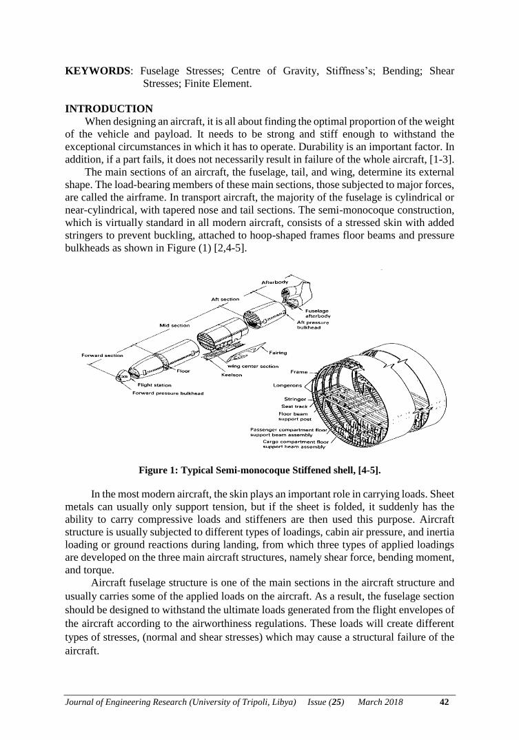
near-cylindrical, with tapered nose and tail sections. The semi-monocoque construction,
which is virtually standard in all modern aircraft, consists of a stressed skin with added
stringers to prevent buckling, attached to hoop-shaped frames floor beams and pressure
bulkheads as shown in Figure (1) [2,4-5].
Figure 1: Typical Semi-monocoque Stiffened shell, [4-5].
In the most modern aircraft, the skin plays an important role in carrying loads. Sheet
metals can usually only support tension, but if the sheet is folded, it suddenly has the
ability to carry compressive loads and stiffeners are then used this purpose. Aircraft
structure is usually subjected to different types of loadings, cabin air pressure, and inertia
loading or ground reactions during landing, from which three types of applied loadings
are developed on the three main aircraft structures, namely shear force, bending moment,
and torque.
Aircraft fuselage structure is one of the main sections in the aircraft structure and
usually carries some of the applied loads on the aircraft. As a result, the fuselage section
should be designed to withstand the ultimate loads generated from the flight envelopes of
the aircraft according to the airworthiness regulations. These loads will create different
types of stresses, (normal and shear stresses) which may cause a structural failure of the
aircraft.
Journal of Engineering Research (University of Tripoli, Libya) Issue (25) March 2018 43
In this work, two approaches are used to obtain the applied stresses along the
fuselage structure. The first approach is the theoretical analysis, which is done by
developing a computer program using Python Language to determine the structural
properties in the form of fuselage stiffness, a center of gravity, and both bending and
shear stresses distributions around the fuselage sections. The second approach is done by
modeling and simulating the fuselage section presented in [3] using the commercial finite
element program, MSC/PATRAN 2004 as pre-and post-processer and analyzed using
MSC/NASTRAN 2004. The obtained results of the fuselage sections using the two
approaches and [3] are compared and validated.
METHODOLOGY, FORMULATION, AND PROCEDURE Assumptions
• The material is homogeneous.
• The material is isotropic.
• The material is elastic.
• The longitudinal stiffeners and spar flanges carry only axial stresses.
• The web, skin and spars webs carry only shear stresses.
• The axial stress is constant over the cross-section of each longitudinal stiffeners.
• The shearing stress is uniform through the thickness of the webs.
• Transverse frames and ribs are rigid within their own planes and have no rigidity
normal to their plane.
• Stress concentration factor is neglected.
Bending Stresses
Normal at any point in the structure can be determined as a function of the applied
moments at that point and the area properties of the cross-section. Equation 1 shows that
the longitudinal stress is found by using the following equation, [3 and 5]:
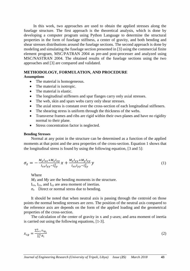
𝜎𝑧 = −𝑀𝑦𝐼𝑥𝑥+𝑀𝑥𝐼𝑥𝑦
𝐼𝑥𝑥𝐼𝑦𝑦−𝐼𝑥𝑦2 𝑥 +
𝑀𝑥𝐼𝑦𝑦+𝑀𝑦𝐼𝑥𝑦
𝐼𝑥𝑥𝐼𝑦𝑦−𝐼𝑥𝑦2 𝑦 (1)
Where
MX and My are the bending moments in the structure.
Ixx, Iyy, and Ixy are area moment of inertias.
σz Direct or normal stress due to bending.
It should be noted that when neutral axis is passing through the centroid on those
points the normal bending stresses are zero. The position of the neutral axis compared to
the reference axis are depends on the form of the applied loading and the geometrical
properties of the cross-section.
The calculation of the center of gravity in x and y-axes; and area moment of inertia
is carried out using the following equations, [1-3].
𝑥𝑐𝑔 =∑ 𝑥𝑖𝐵𝑖
𝑛𝑖=1
∑ 𝐵𝑖𝑛𝑖
(2)
Journal of Engineering Research (University of Tripoli, Libya) Issue (25) March 2018 44
𝑦𝑐𝑔 =∑ 𝑦𝑖𝐵𝑖
𝑛𝑖=1
∑ 𝐵𝑖𝑛𝑖
(3)
Where
Bi Boom area of the ith skin-stringer.
xi distance between the reference axis and the ith skin-Stringer in the x-direction.
yi distance between the reference axis and the ith skin-Stringer in the y-direction.
The second moment of area about the centroid is given as
Ixx = ∑ Biyi2n
i=1
Iyy = ∑ Bixi2n
i=1 (4)
Ixy = ∑ Bini=1 xiyi
The area moments of inertia about the principal axis are calculated using the
developed program in terms of Iuu and Ivv and Iuv as illustrated in [3,6]. The bending stress
is calculated using equation (1) for an unsymmetrical fuselage sections, and then it is
reduced for the symmetrical fuselage sections, Ixy=0. The bending stress is usually
calculated at each spar boom or stringer with respect to the principal axis, u and v, [2-6].
Structural Idealization
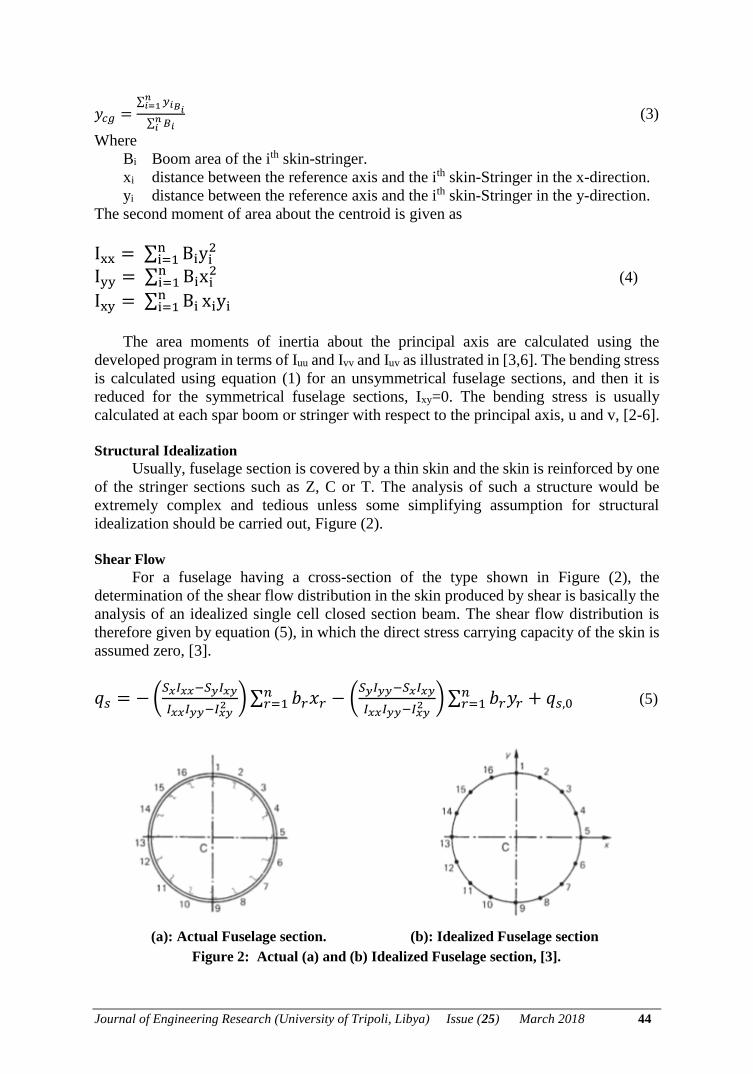
Usually, fuselage section is covered by a thin skin and the skin is reinforced by one
of the stringer sections such as Z, C or T. The analysis of such a structure would be
extremely complex and tedious unless some simplifying assumption for structural
idealization should be carried out, Figure (2).
Shear Flow
For a fuselage having a cross-section of the type shown in Figure (2), the
determination of the shear flow distribution in the skin produced by shear is basically the
analysis of an idealized single cell closed section beam. The shear flow distribution is
therefore given by equation (5), in which the direct stress carrying capacity of the skin is
assumed zero, [3].
𝑞𝑠 = − (𝑆𝑥𝐼𝑥𝑥−𝑆𝑦𝐼𝑥𝑦
𝐼𝑥𝑥𝐼𝑦𝑦−𝐼𝑥𝑦2 ) ∑ 𝑏𝑟𝑥𝑟
𝑛𝑟=1 − (
𝑆𝑦𝐼𝑦𝑦−𝑆𝑥𝐼𝑥𝑦
𝐼𝑥𝑥𝐼𝑦𝑦−𝐼𝑥𝑦2 ) ∑ 𝑏𝑟𝑦𝑟 + 𝑞𝑠,0
𝑛𝑟=1 (5)
(a): Actual Fuselage section. (b): Idealized Fuselage section
Figure 2: Actual (a) and (b) Idealized Fuselage section, [3].
Journal of Engineering Research (University of Tripoli, Libya) Issue (25) March 2018 45
Equation (5) is applicable to loading cases in which the shear loads, Sx and Sy are not
applied through the section shear center so that the effects of shear and torsion are
included simultaneously. Alternatively, if the position of the shear center is known, the
loading system may be replaced by shear loads acting through the shear center together
with a pure torque, and the corresponding shear flow distributions may be calculated
separately and then superimposed to obtain the final distribution.
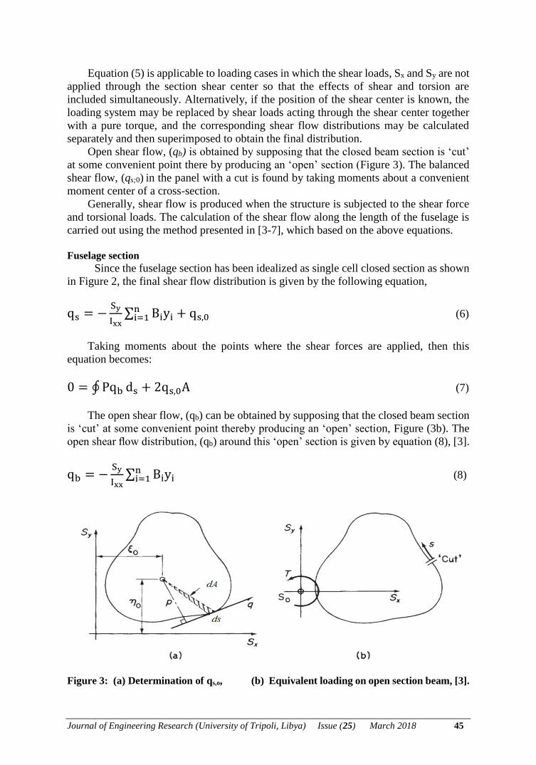
Open shear flow, (qb) is obtained by supposing that the closed beam section is ‘cut’
at some convenient point there by producing an ‘open’ section (Figure 3). The balanced
shear flow, (qs;0) in the panel with a cut is found by taking moments about a convenient
moment center of a cross-section.
Generally, shear flow is produced when the structure is subjected to the shear force
and torsional loads. The calculation of the shear flow along the length of the fuselage is
carried out using the method presented in [3-7], which based on the above equations.
Fuselage section
Since the fuselage section has been idealized as single cell closed section as shown
in Figure 2, the final shear flow distribution is given by the following equation,
qs = −Sy
Ixx∑ Biyi
ni=1 + qs,0 (6)
Taking moments about the points where the shear forces are applied, then this
equation becomes:
0 = ∮ Pqb ds + 2qs,0A (7)
The open shear flow, (qb) can be obtained by supposing that the closed beam section
is ‘cut’ at some convenient point thereby producing an ‘open’ section, Figure (3b). The
open shear flow distribution, (qb) around this ‘open’ section is given by equation (8), [3].
qb = −Sy
Ixx∑ Biyi
ni=1 (8)
Figure 3: (a) Determination of qs,o, (b) Equivalent loading on open section beam, [3].
Journal of Engineering Research (University of Tripoli, Libya) Issue (25) March 2018 46
The final shear flow of the closed fuselage single section is given by
qs = qb + qs,0 (9)
Shear stress distributions, τ due to applied shear force and applied torsion for the fuselage
sections can be obtained as:
Shear Stress, 𝜏 =𝑞𝑠
𝑡 (10)
Where:
qs is the final shear flow, (N/mm).
t is the thickness of the skin, (mm).
COMPUTER PROGRAM
Educational programs have contributed to a great level in improving the teaching-
learning process and in the analysis at early or preliminary design stage; the otherwise
difficult concepts for students to understand are made easy by these programs. Detailed
homework assignments were usually given to the students in the aircraft component
design course that require the students to use an available program and should be given
to them starting from the load estimation until the final estimation of stresses on an
aircraft fuselage structure.
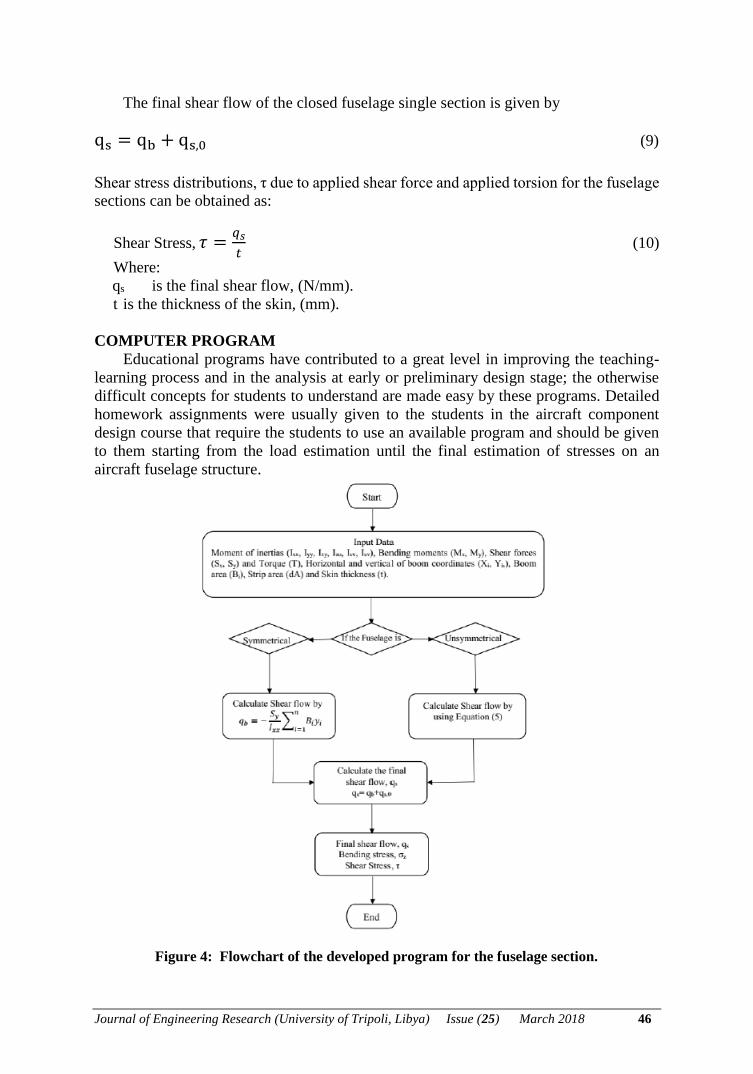
Figure 4: Flowchart of the developed program for the fuselage section.
Journal of Engineering Research (University of Tripoli, Libya) Issue (25) March 2018 47
This will make them clear about the application of these advanced topics in analysis
and design of aircraft structures. To bring in all the important concepts taught in the
aircraft structures course namely: symmetric and asymmetric bending, shear center and
shear of open and closed symmetrical and unsymmetrical section of a semi-monocoque
fuselage structure. Therefore, the first aim of the project work is to develop a computer
program using the Python Computer Language, [8] that can conveniently compute all
structure properties in the form of the center of gravity, stiffnesses, shear flows and
bending and shear stresses at any section along the aircraft fuselage length. The detailed
input data required and the overall process of the developed program are illustrated in a
simple manner using flow chart shown in Figure (4).
Two case studies from the open literature, [3] are selected and used in the developed
program for obtaining the structural properties, final shear flow, normal stresses due to
bending moments and shear stresses due to applied shear force and torsional moment.
CASES ANALYSIS AND RESULTS
Case study 1: Fuselage circular section, [3]
This problem is presented in [3], page number 338 to calculate the following:
1. Centre of gravity. 2. Moments of inertias. 3. Shear flow.
4. Bending and shear stresses
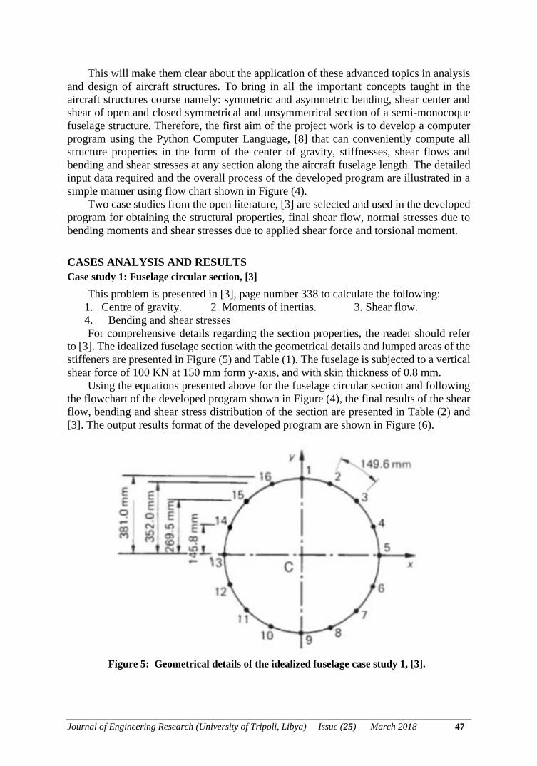
For comprehensive details regarding the section properties, the reader should refer
to [3]. The idealized fuselage section with the geometrical details and lumped areas of the
stiffeners are presented in Figure (5) and Table (1). The fuselage is subjected to a vertical
shear force of 100 KN at 150 mm form y-axis, and with skin thickness of 0.8 mm.
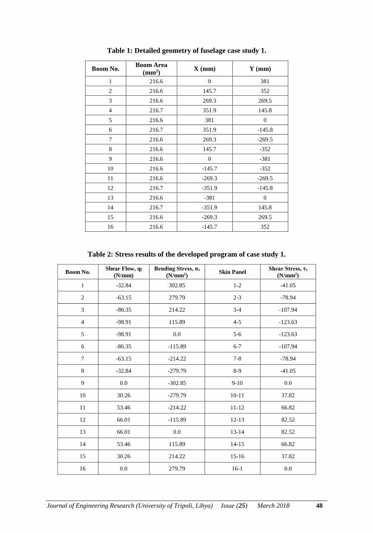
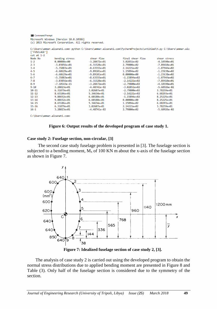
Using the equations presented above for the fuselage circular section and following
the flowchart of the developed program shown in Figure (4), the final results of the shear
flow, bending and shear stress distribution of the section are presented in Table (2) and
[3]. The output results format of the developed program are shown in Figure (6).
Figure 5: Geometrical details of the idealized fuselage case study 1, [3].
Journal of Engineering Research (University of Tripoli, Libya) Issue (25) March 2018 48
Table 1: Detailed geometry of fuselage case study 1.
Boom No. Boom Area
(mm2) X (mm) Y (mm)
1 216.6 0 381
2 216.6 145.7 352
3 216.6 269.3 269.5
4 216.7 351.9 145.8
5 216.6 381 0
6 216.7 351.9 -145.8
7 216.6 269.3 -269.5
8 216.6 145.7 -352
9 216.6 0 -381
10 216.6 -145.7 -352
11 216.6 -269.3 -269.5
12 216.7 -351.9 -145.8
13 216.6 -381 0
14 216.7 -351.9 145.8
15 216.6 -269.3 269.5
16 216.6 -145.7 352
Table 2: Stress results of the developed program of case study 1.
Boom No. Shear Flow, qf
(N/mm)
Bending Stress, σz
(N/mm2) Skin Panel
Shear Stress, τs
(N/mm2)
1 -32.84 302.85 1-2 -41.05
2 -63.15 279.79 2-3 -78.94
3 -86.35 214.22 3-4 -107.94
4 -98.91 115.89 4-5 -123.63
5 -98.91 0.0 5-6 -123.63
6 -86.35 -115.89 6-7 -107.94
7 -63.15 -214.22 7-8 -78.94
8 -32.84 -279.79 8-9 -41.05
9 0.0 -302.85 9-10 0.0
10 30.26 -279.79 10-11 37.82
11 53.46 -214.22 11-12 66.82
12 66.01 -115.89 12-13 82.52
13 66.01 0.0 13-14 82.52
14 53.46 115.89 14-15 66.82
15 30.26 214.22 15-16 37.82
16 0.0 279.79 16-1 0.0
Journal of Engineering Research (University of Tripoli, Libya) Issue (25) March 2018 49
Figure 6: Output results of the developed program of case study 1.
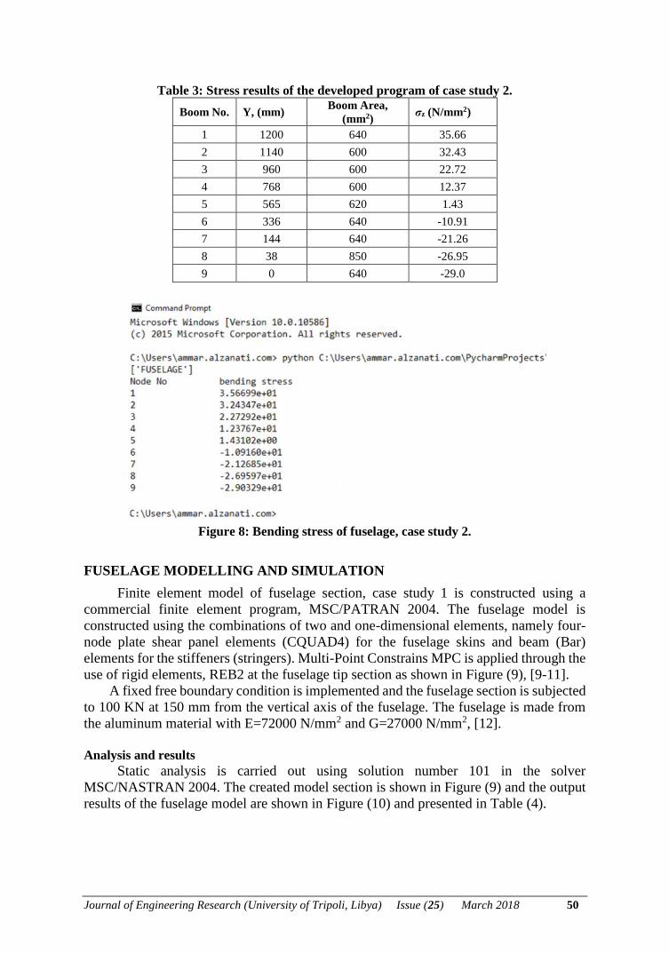
Case study 2: Fuselage section, non-circular, [3]
The second case study fuselage problem is presented in [3]. The fuselage section is
subjected to a bending moment, Mx of 100 KN m about the x-axis of the fuselage section
as shown in Figure 7.
Figure 7: Idealized fuselage section of case study 2, [3].
The analysis of case study 2 is carried out using the developed program to obtain the
normal stress distributions due to applied bending moment are presented in Figure 8 and
Table (3). Only half of the fuselage section is considered due to the symmetry of the
section.
Journal of Engineering Research (University of Tripoli, Libya) Issue (25) March 2018 50
Table 3: Stress results of the developed program of case study 2.
Boom No. Y, (mm) Boom Area,
(mm2) σz (N/mm2)
1 1200 640 35.66
2 1140 600 32.43
3 960 600 22.72
4 768 600 12.37
5 565 620 1.43
6 336 640 -10.91
7 144 640 -21.26
8 38 850 -26.95
9 0 640 -29.0
Figure 8: Bending stress of fuselage, case study 2.
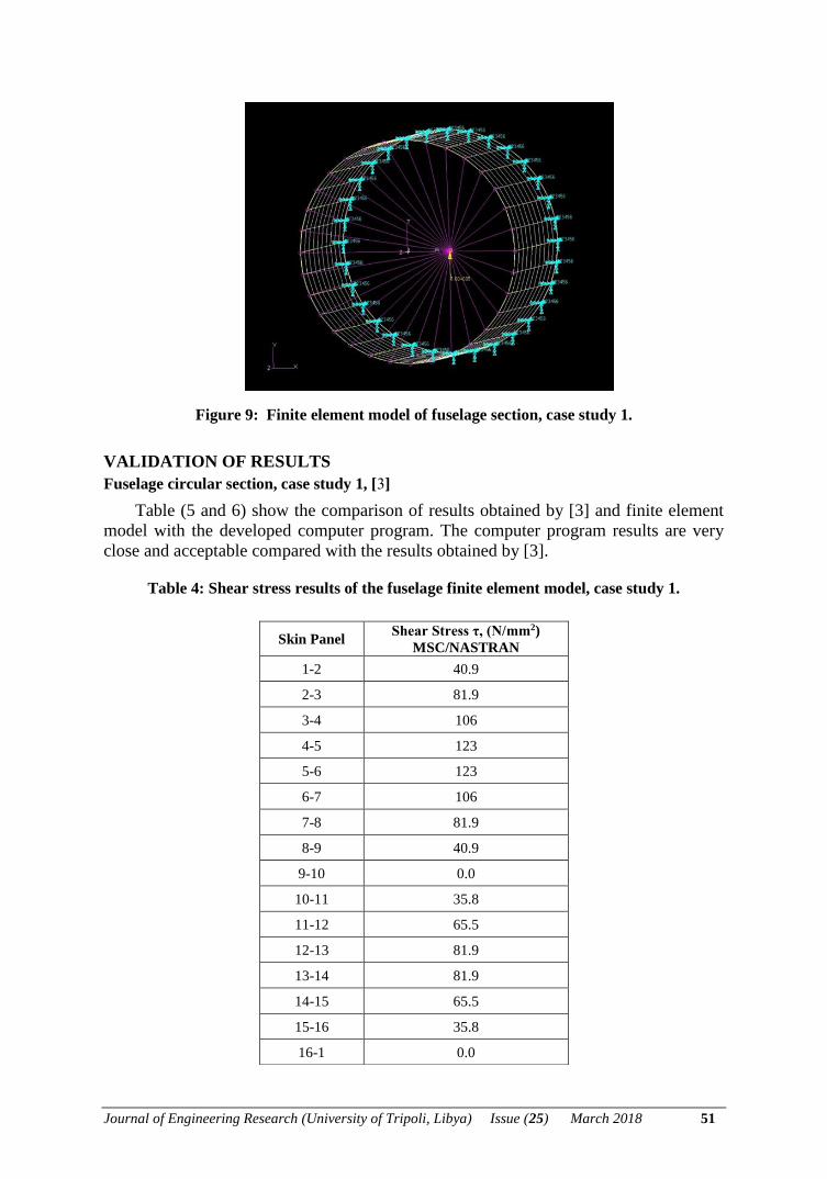
FUSELAGE MODELLING AND SIMULATION
Finite element model of fuselage section, case study 1 is constructed using a
commercial finite element program, MSC/PATRAN 2004. The fuselage model is
constructed using the combinations of two and one-dimensional elements, namely four-
node plate shear panel elements (CQUAD4) for the fuselage skins and beam (Bar)
elements for the stiffeners (stringers). Multi-Point Constrains MPC is applied through the
use of rigid elements, REB2 at the fuselage tip section as shown in Figure (9), [9-11].
A fixed free boundary condition is implemented and the fuselage section is subjected
to 100 KN at 150 mm from the vertical axis of the fuselage. The fuselage is made from
the aluminum material with E=72000 N/mm2 and G=27000 N/mm2, [12].
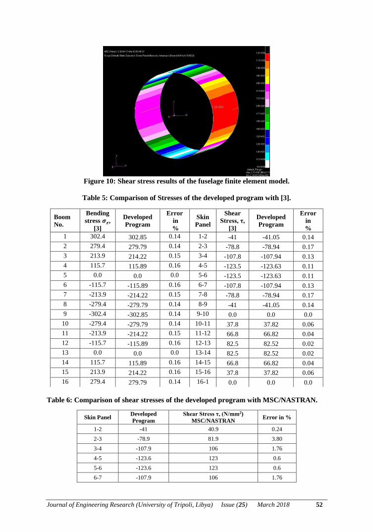
Analysis and results
Static analysis is carried out using solution number 101 in the solver
MSC/NASTRAN 2004. The created model section is shown in Figure (9) and the output
results of the fuselage model are shown in Figure (10) and presented in Table (4).
Journal of Engineering Research (University of Tripoli, Libya) Issue (25) March 2018 51
Figure 9: Finite element model of fuselage section, case study 1.
VALIDATION OF RESULTS
Fuselage circular section, case study 1, [3]
Table (5 and 6) show the comparison of results obtained by [3] and finite element
model with the developed computer program. The computer program results are very
close and acceptable compared with the results obtained by [3].
Table 4: Shear stress results of the fuselage finite element model, case study 1.
Skin Panel Shear Stress τ, (N/mm2)
MSC/NASTRAN
1-2 40.9
2-3 81.9
3-4 106
4-5 123
5-6 123
6-7 106
7-8 81.9
8-9 40.9
9-10 0.0
10-11 35.8
11-12 65.5
12-13 81.9
13-14 81.9
14-15 65.5
15-16 35.8
16-1 0.0
Journal of Engineering Research (University of Tripoli, Libya) Issue (25) March 2018 52
Figure 10: Shear stress results of the fuselage finite element model.
Table 5: Comparison of Stresses of the developed program with [3].
Table 6: Comparison of shear stresses of the developed program with MSC/NASTRAN.
Skin Panel Developed
Program
Shear Stress τ, (N/mm2)
MSC/NASTRAN Error in %
1-2 -41 40.9 0.24
2-3 -78.9 81.9 3.80
3-4 -107.9 106 1.76
4-5 -123.6 123 0.6
5-6 -123.6 123 0.6
6-7 -107.9 106 1.76
Boom
No.
Bending
stress 𝝈𝒛,
[3]
Developed
Program
Error
in
%
Skin
Panel
Shear
Stress, τ,
[3]
Developed
Program
Error
in
%
1 302.4 302.85 0.14 1-2 -41 -41.05 0.14
2 279.4 279.79 0.14 2-3 -78.8 -78.94 0.17
3 213.9 214.22 0.15 3-4 -107.8 -107.94 0.13
4 115.7 115.89 0.16 4-5 -123.5 -123.63 0.11
5 0.0 0.0 0.0 5-6 -123.5 -123.63 0.11
6 -115.7 -115.89 0.16 6-7 -107.8 -107.94 0.13
7 -213.9 -214.22 0.15 7-8 -78.8 -78.94 0.17
8 -279.4 -279.79 0.14 8-9 -41 -41.05 0.14
9 -302.4 -302.85 0.14 9-10 0.0 0.0 0.0
10 -279.4 -279.79 0.14 10-11 37.8 37.82 0.06
11 -213.9 -214.22 0.15 11-12 66.8 66.82 0.04
12 -115.7 -115.89 0.16 12-13 82.5 82.52 0.02
13 0.0 0.0 0.0 13-14 82.5 82.52 0.02
14 115.7 115.89 0.16 14-15 66.8 66.82 0.04
15 213.9 214.22 0.16 15-16 37.8 37.82 0.06
16 279.4 279.79 0.14 16-1 0.0 0.0 0.0
Journal of Engineering Research (University of Tripoli, Libya) Issue (25) March 2018 53
7-8 -78.9 81.9 3.80
8-9 -41 40.9 0.24
9-10 0.0 0.0 0.0
10-11 37.8 35.8 5.29
11-12 66.8 65.5 1.94
12-13 82.5 81.9 0.72
13-14 82.5 81.9 0.72
14-15 66.8 65.5 1.94
15-16 37.8 35.8 5.29
16-1 0.0 0.0 0.0
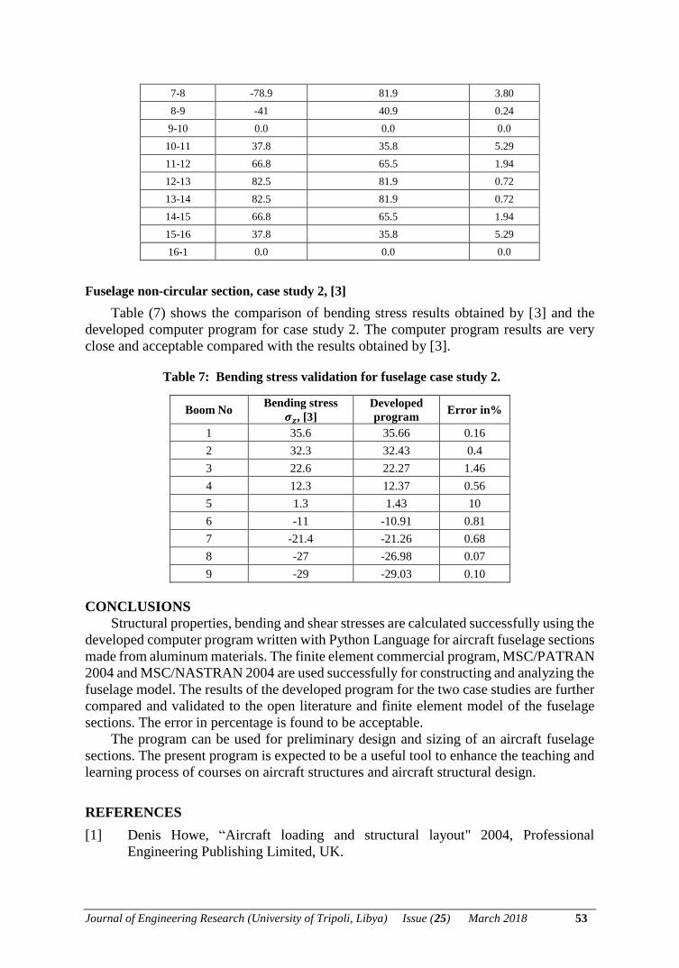
Fuselage non-circular section, case study 2, [3]
Table (7) shows the comparison of bending stress results obtained by [3] and the
developed computer program for case study 2. The computer program results are very
close and acceptable compared with the results obtained by [3].
Table 7: Bending stress validation for fuselage case study 2.
Boom No Bending stress
𝝈𝒛, [3]
Developed
program Error in%
1 35.6 35.66 0.16
2 32.3 32.43 0.4
3 22.6 22.27 1.46
4 12.3 12.37 0.56
5 1.3 1.43 10
6 -11 -10.91 0.81
7 -21.4 -21.26 0.68
8 -27 -26.98 0.07
9 -29 -29.03 0.10
CONCLUSIONS
Structural properties, bending and shear stresses are calculated successfully using the
developed computer program written with Python Language for aircraft fuselage sections
made from aluminum materials. The finite element commercial program, MSC/PATRAN
2004 and MSC/NASTRAN 2004 are used successfully for constructing and analyzing the
fuselage model. The results of the developed program for the two case studies are further
compared and validated to the open literature and finite element model of the fuselage
sections. The error in percentage is found to be acceptable.
The program can be used for preliminary design and sizing of an aircraft fuselage
sections. The present program is expected to be a useful tool to enhance the teaching and
learning process of courses on aircraft structures and aircraft structural design.
REFERENCES
[1] Denis Howe, “Aircraft loading and structural layout" 2004, Professional
Engineering Publishing Limited, UK.

Journal of Engineering Research (University of Tripoli, Libya) Issue (25) March 2018 54
[2] Ms. Srilaxmi, “Design and static stress analysis of fuselage for military transport
aircraft”, International Journal & Magazine of Engineering Technology,
Management and Research, volume 3, September 2016, pp 485-490.
[3] Megson, T.H.G, “Aircraft Structures for Engineering Students”, Fourth Edition,
2007, Elsevier Ltd, Oxford, UK.
[4] Niu, M.C. “Airframe stress analysis, and sizing”, 1997, Hong Kong Conmilit
Press.
[5] Bruhn, E.F. “Analysis and design of flight vehicle structures”, June 1973, Jacobs
Publishing Inc, U.S.A.
[6] Abdoussalam M. E. “Determination of elastic Properties and stress along the span
of aircraft wing", BSc Project, Tripoli University, spring 2013.
[7] Ilhan S, en, “Aircraft Fuselage Design Study”, MSC thesis, Delft University of
technology, Dec. 2010.
[8] Kiusalaas, J. “Numerical Methods in Engineering with Python 3”, third edition.
[9] Rodden, P. W. and Johnson, H. E. “Linear static analysis user guide",
MSC/NASTRAN, version 2003, The Macneal-Schwendler Corporation.
[10] Schuster J., Schere T. “Automated Sizing Process of a Complete Aircraft
Structure for the Usage within a MOD Process” Deutscher Luft und
Raumfahrtkongress, Document ID: 420137, 2016.
[11] Hadjez F. and Necib B. “Stress Analysis of an Aircraft Fuselage with and without
Portholes using CAD/CAE Process” Journal of Aeronautics & Aerospace
Engineering, ISSN: 2168-9792, 2015.
[12] Achyutha K., Akash M. and Shiva A. “Finite Element Modeling and Analysis of
Fuselage Stiffened Panel Subjected to cabin Pressurization” ICAMB 2012, Jan 9-
11 2012.
Related Documents


