Strengthening behavior of few-layered graphene/ aluminum composites S.E. Shin a , H.J. Choi b , J.H. Shin a , D.H. Bae a, * a Department of Materials Science and Engineering, Yonsei University, Seoul 120-749, Republic of Korea b School of Advanced Materials Engineering, Kookmin University, Seoul 136-702, Republic of Korea ARTICLE INFO Article history: Received 26 February 2014 Accepted 17 October 2014 Available online 25 October 2014 ABSTRACT Strengthening behavior of composite containing discontinuous reinforcement is strongly related with load transfer at the reinforcement–matrix interface. We selected multi-walled carbon nanotube (MWCNT) and few-layer graphene (FLG) as a reinforcing agent. By varying a volume fraction of the reinforcement, aluminum (Al) matrix composites were produced by a powder metallurgy method. Uniform dispersion and uniaxial alignment of MWCNT and FLG in the Al matrix are evidenced by high-resolution transmission electron micro- scope analysis. Although the reinforcements have a similar molecular structure, FLG has a 12.8 times larger specific surface area per volume more than MWCNT due to geometric difference. Therefore an increment of a yield stress versus a reinforcement volume fraction for FLG shows 3.5 times higher than that of MWCNT Consequently, for both reinforce- ments, the composite strength proportionally increases with the specific surface area on the composite, and the composites containing 0.7 vol% FLG exhibit 440 MPa of tensile strength. Ó 2014 Elsevier Ltd. All rights reserved. 1. Introduction Graphene has attracted interest as a reinforcing agent for metal matrix composites due to excellent mechanical proper- ties based on the strong sp 2 CAC bonds, which are similar to fullerene and carbon nanotube [1,2]. Furthermore, it has mer- its over other carbon-based nano materials, which originate from its inherent two-dimensional (2-D) morphology; the pla- nar structure is more favorable to load transfer as well as to impeding atomic diffusion at high temperatures, as compared to its 0-D and 1-D counterparts. Consequently, it provides superior strength for composites at both room temperature and high temperatures. In order to transmit the excellent properties of graphene to composites, uniform dispersion of an individually-exfoliated graphene is one key factor. Several processes have been intro- duced to exfoliate graphite to single-layer or few-layer graph- ene by mechanical and/or chemical means [3–5]. Mechanical exfoliation using a tape dispenser [2] or atomic force micros- copy (AFM) [6] has exhibited inadequate productivity for large-scale industrial applications. Although large-scale syn- thesis of graphene by gas phase techniques (e.g., thermal chemical vapor deposition) [7–9] is actively ongoing, this pro- cess is still costly and has restrictions in terms of the selec- tion of the substrate materials. Chemical exfoliation by a solution process has been suggested as a relatively cheap pro- cess [10–12], and yet presents difficulties for scalable synthe- sis due to complex synthesis steps and the requirement for a large amount of chemicals and acid. Recently, solid phase techniques, combined with ball-milling processes, have http://dx.doi.org/10.1016/j.carbon.2014.10.044 0008-6223/Ó 2014 Elsevier Ltd. All rights reserved. * Corresponding author. E-mail address: [email protected] (D.H. Bae). CARBON 82 (2015) 143 –151 Available at www.sciencedirect.com ScienceDirect journal homepage: www.elsevier.com/locate/carbon

Welcome message from author
This document is posted to help you gain knowledge. Please leave a comment to let me know what you think about it! Share it to your friends and learn new things together.
Transcript
C A R B O N 8 2 ( 2 0 1 5 ) 1 4 3 –1 5 1
.sc ienced i rec t .com
Avai lab le a t wwwScienceDirect
journal homepage: www.elsevier .com/ locate /carbon
Strengthening behavior of few-layered graphene/aluminum composites
http://dx.doi.org/10.1016/j.carbon.2014.10.0440008-6223/� 2014 Elsevier Ltd. All rights reserved.
* Corresponding author.E-mail address: [email protected] (D.H. Bae).
S.E. Shin a, H.J. Choi b, J.H. Shin a, D.H. Bae a,*
a Department of Materials Science and Engineering, Yonsei University, Seoul 120-749, Republic of Koreab School of Advanced Materials Engineering, Kookmin University, Seoul 136-702, Republic of Korea
A R T I C L E I N F O
Article history:
Received 26 February 2014
Accepted 17 October 2014
Available online 25 October 2014
A B S T R A C T
Strengthening behavior of composite containing discontinuous reinforcement is strongly
related with load transfer at the reinforcement–matrix interface. We selected multi-walled
carbon nanotube (MWCNT) and few-layer graphene (FLG) as a reinforcing agent. By varying
a volume fraction of the reinforcement, aluminum (Al) matrix composites were produced
by a powder metallurgy method. Uniform dispersion and uniaxial alignment of MWCNT
and FLG in the Al matrix are evidenced by high-resolution transmission electron micro-
scope analysis. Although the reinforcements have a similar molecular structure, FLG has
a 12.8 times larger specific surface area per volume more than MWCNT due to geometric
difference. Therefore an increment of a yield stress versus a reinforcement volume fraction
for FLG shows 3.5 times higher than that of MWCNT Consequently, for both reinforce-
ments, the composite strength proportionally increases with the specific surface area on
the composite, and the composites containing 0.7 vol% FLG exhibit 440 MPa of tensile
strength.
� 2014 Elsevier Ltd. All rights reserved.
1. Introduction
Graphene has attracted interest as a reinforcing agent for
metal matrix composites due to excellent mechanical proper-
ties based on the strong sp2 CAC bonds, which are similar to
fullerene and carbon nanotube [1,2]. Furthermore, it has mer-
its over other carbon-based nano materials, which originate
from its inherent two-dimensional (2-D) morphology; the pla-
nar structure is more favorable to load transfer as well as to
impeding atomic diffusion at high temperatures, as
compared to its 0-D and 1-D counterparts. Consequently, it
provides superior strength for composites at both room
temperature and high temperatures.
In order to transmit the excellent properties of graphene to
composites, uniform dispersion of an individually-exfoliated
graphene is one key factor. Several processes have been intro-
duced to exfoliate graphite to single-layer or few-layer graph-
ene by mechanical and/or chemical means [3–5]. Mechanical
exfoliation using a tape dispenser [2] or atomic force micros-
copy (AFM) [6] has exhibited inadequate productivity for
large-scale industrial applications. Although large-scale syn-
thesis of graphene by gas phase techniques (e.g., thermal
chemical vapor deposition) [7–9] is actively ongoing, this pro-
cess is still costly and has restrictions in terms of the selec-
tion of the substrate materials. Chemical exfoliation by a
solution process has been suggested as a relatively cheap pro-
cess [10–12], and yet presents difficulties for scalable synthe-
sis due to complex synthesis steps and the requirement for a
large amount of chemicals and acid. Recently, solid phase
techniques, combined with ball-milling processes, have
144 C A R B O N 8 2 ( 2 0 1 5 ) 1 4 3 –1 5 1
enabled production of scalable quantities of carbon-base
nano-materials by applying shear forces on pristine agglom-
erated particles [13–15].
Even though one has developed a scalable process to pro-
duce few-layer graphene (FLG), an additional technical hurdle
is in the uniform dispersion of the graphene in the metal
matrix, which has closely packed atomic structures. Hence,
graphene/metal composites have been seldom investigated
compared to polymer matrix composites, although the great
strength and light weight features of graphene/metal com-
posites are expected to lead to applications of such compos-
ites in the automotive and aerospace industries.
Aluminum (Al) matrix composites reinforced with FLG
have recently been produced using different synthesis tech-
niques with powder metallurgy (PM) routes. Table 1 summa-
rizes the fabrication processes and resulting properties of
recently developed Al/FLG composites [16–21]. Similar to
other nanostructured composites, dispersion of nanoscale
reinforcement is a critical issue in Al/FLG composites. Poorly
dispersed FLG may act as defect sites, significantly deteriorat-
ing the performance of the final composites [16,17]. Consoli-
dation processes are also important for Al/FLG composites
because a selection of high-processing temperatures to avoid
insufficient powder consolidation leads to unfavorable reac-
tions (e.g., transformation of FLG to carbides) [17,18–20]. Even
though some composites have been produced via cost-inef-
fective routes or using expensive materials (e.g., graphene
oxide), they did not exhibit tensile elongation or they exhib-
ited very limited tensile strength (<300 MPa). Furthermore,
the microstructure of Al/FLG composites with an atomic-scale
resolution has not been well reported; atomic-scale resolution
images may provide detailed information on the morphology
of FLG and the interface between Al and FLG [17,20,21]. Rein-
forcement in composites may enhance the strength of
the matrix by (i) carrying a great amount of load instead
of the matrix and by (ii) interrupting the plastic deformation
of the matrix. Hence, two important factors to determine
the strengthening efficiency of reinforcement, other than its
intrinsic mechanical properties and volume fraction, are (i)
how much load can be effectively transmitted from the
matrix to the reinforcement and (ii) how much the stress dis-
tribution can be altered by the reinforcement. Both are
Table 1 – Experimental tensile strength and hardness of FLG-re
Graphene content Fabrication techniques
0.1 wt% Ball-millingHot isostatic pressing: 550 �C, 4 hHot extrusion: 550 �C, 4:1 ratio
0.3 wt% Ball-millingSintering: 580 �C, 2 hHot extrusion: 440 �C, 20:1 ratio
0.3 wt% Ball-millingSintering: 600 �C, 6 hHot extrusion: 470 �C, 2:1 ratio
0.3 wt% Ball-millingSintering: 500 �C, 5 h
5 wt.% Ball-millingSintering: 600 �C, 5 h
affected by bonding strength between the matrix and rein-
forcement, morphology/surface area of the reinforcement,
and spatial distribution of the reinforcement [22,23]. Although
experimental work on the effect of volume fraction of the
reinforcement on the strength of composites [24,25] and the-
oretical work on the bonding strength between metal and car-
bon-based nano materials [26–29] has been conducted, the
role of morphology and surface area on the reinforcement
has not been extensively investigated. In particular, a com-
parison study on the strengthening behavior of reinforce-
ments with a variety of shapes (e.g., fullerene–sphere/0-D,
carbon nanotube–tube/1-D, and graphene–planar/2-D), but
with similar intrinsic mechanical properties, would be highly
interesting.
The primary objective of this work is to produce Al matrix
composites with well-dispersed FLG using a scalable powder
metallurgy approach. Here, we introduce a favorable route
to produce centimeter-scale Al/FLG composites with excellent
performances. This work also aims to examine tensile proper-
ties of the Al/FLG composite as a function of volume fraction
of FLG, so as to compare the strengthening behavior of FLG
with that of multi-walled carbon nanotube (MWCNT). The
present study also carefully investigates the microstructure
of the composites at an atomic scale to provide detailed infor-
mation on the structure of nano-carbon materials and nano-
carbon/Al interface structure. Further, this work quantifies
the effect of shape factor (i.e., tube versus sheet) and specific
surface area of reinforcement on the composite strength.
2. Experimental
2.1. Sample preparation
Aluminum (Al)-based composites containing FLG were fabri-
cated by hot-rolling of ball-milled powder. At first, graphite
flakes (6–8 nm thickness and 120–150 m2/g typical specific
surface area) were mechanically exfoliated by planetary ball
milling in the presence of isopropyl alcohol ((CH3)2CHOH). A
stainless steel bowl (500 mL) was charged with graphite flakes
(2 g) and stainless steel balls (�5 mm diameter, 30 g) at a ball-
to-powder weight ratio of 15:1, together with 50 mL of isopro-
pyl alcohol. Planetary milling was performed at a rotation
inforced composites.
Mechanical properties Research group
Tensile strength:262 MPa
Bartolucci et al. [16]
Tensile strength:250 MPa
Wang et al. [17]
Vickers hardness:85 HvTensile strength:280 MPa
Rashad et al. [18]
Vickers micro-hardness:90 lHv
Perez et al. [19]
Vickers hardness: 70 HvCompressive strength: 180 MPa
Latief et al. [20]
C A R B O N 8 2 ( 2 0 1 5 ) 1 4 3 –1 5 1 145
speed of 200 RPM for 1 h; it was paused for 75 min after every
15-min milling to maintain ambient processing temperature
without any process control agent. Afterwards, the isopropyl
alcohol was evaporated and dried at 150 �C for 3 h. Graphite
flakes are supposed to be exfoliated by shear forces on con-
tact between powder and balls during milling. Due to the
weak van der Waals-like coupling between graphite layers,
the graphene sheets in graphite can slide easily with respect
to one another. To address this, additional milling was con-
ducted for further exfoliation of graphite nanosheets into
FLG and for dispersion of the FLG in Al powder. The exfoliated
graphite flakes were exfoliated further into FLG and were also
mixed with Al powder (99.5% purity and <150 lm diameter)
using a planetary mill at a rotation speed of 100 RPM for 3 h,
with a process control agent of 1 wt.% stearic acid (CH3
(CH2)16CO2H). Milling was paused for 15 min after every
15 min of milling. Finally, for further dispersion of FLG in Al
powder, the planetary-milled mixture was high energy ball-
milled in an attritor at 500 RPM for 6 h in a purified argon
atmosphere. FLG, attached on the Al powder surface, is grad-
ually embedded and is dispersed inside Al powder.
A variety of ball-milled powders were fabricated by varying
the volume fraction of FLG (i.e. 0.3, 0.5 and 0.7 vol%). The ball-
milled powder was containerized in a copper tube (60 mm in
diameter, 150 mm in height, and 1.5 mm in thickness), com-
pacted, and was then hot-rolled. The sample was heated to
a pre-determined temperature of 500 �C at a heating rate of
15 �C/min, and rolling was conducted with a 12% reduction
per pass; the final thickness of samples was 1 mm. After roll-
ing, the copper container was mechanically removed. Since
FLG was embedded inside the Al powder, it did not signifi-
cantly interrupt consolidation of Al powder during hot rolling,
providing a fully dense composite sheet.
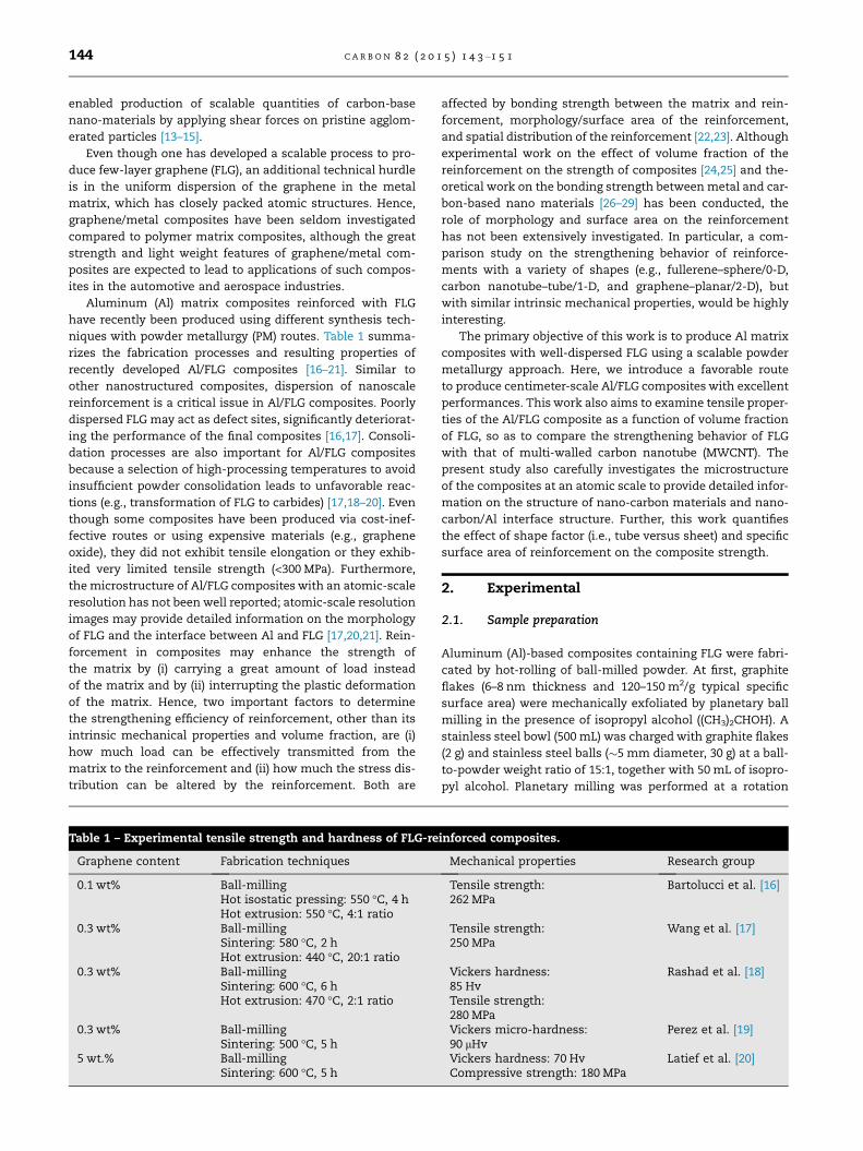
Fig. 1 – SEM images of (a) FLG attached to Al powder using a pla
embedded and dispersed in Al powder using an attrition mill at
(c), respectively.
2.2. Characterization
Morphology of the ball-milled powder varied according to
milling condition, as was observed using scanning electron
microscopy (SEM). Microstructure of the Al/FLG composite
was observed using a high resolution transmission electron
microscope (HRTEM, JEOL 2000). Thin foil specimens from
the sheets were carefully prepared by an ion beam 6 milling
method (Gatan, Model 600, Oxford, UK). The structure of
FLG was also investigated by Raman spectroscopy using a
Jobin–Yvon microspectrometer (LabRam HR, Jobin–Yvon Co.
Ltd., France). Spectra were collected under ambient condi-
tions using the 532-nm line of an argon-ion laser. Uniaxial
tension tests were conducted for the annealed specimens
under the constant cross-head speed condition of an initial
strain rate of 1 · 10�4 s�1. The apparent yield properties were
determined using the 0.2% offset method. Tensile specimens
(thickness: 1 mm, gauge length: 12.5 mm, gauge width: 6 mm,
and grip length: 25 mm for both upper and lower) were pre-
pared from the hot-rolled Al composite sheet according to
the standard ASTM B-209 and loaded in the rolling direction.
The tests were repeated five times, and each test was
conducted from different samples that were processed in a
different batch using the same route.
3. Results and discussion
3.1. Microstructures
Morphologies of ball-milled Al/FLG composite powders are
shown in Fig. 1. Exfoliated FLG sheets with sizes below
10 lm are observed on the surface of the Al powder, where
FLG is marked by an arrow in Fig. 1a. Fig. 1b displays magnified
netary mill at 100 RPM (FLG is marked by an arrow). (c) FLG
500 RPM. (b) and (d) display the magnified images of (a) and
1400 1600 1800 2000 2200 2400 2600 2800
Exfoliated graphite powder
Al/0.7 vol.% FLG
Al/0.5 vol.% FLG
Al/0.3 vol.% FLG
Initial graphite powder
D band 2D band
Inte
nsity
(a.u
.)
Raman shift (cm-1)
532 nmG band
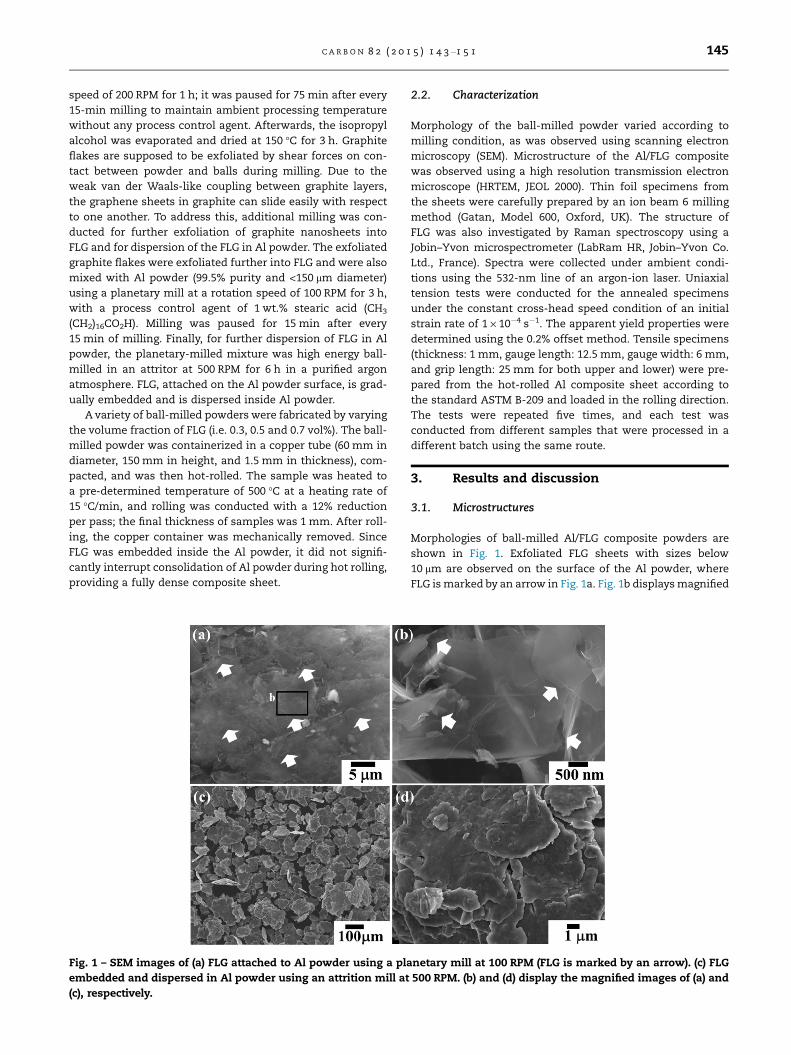
Fig. 2 – Raman spectrum of initial graphite powder,
exfoliated graphite powder and hot-rolled Al/FLG
composites. (A colour version of this figure can be viewed
online.)
146 C A R B O N 8 2 ( 2 0 1 5 ) 1 4 3 –1 5 1
images of rectangles in Fig. 1a, where FLG is thin enough to
transmit the electron beam so the Al powder underneath the
FLG can be seen. Fig. 1c exhibits the powder morphology after
attrition milling. FLG is not observed on the powder surface
even in the magnified images of Fig. 1d. Hence, the FLG is sup-
posed to be embedded and dispersed inside the Al powder.
Fig. 2 provides Raman spectra of the initial graphite pow-
der, exfoliated graphite powder and Al/FLG composites with
various volume fractions of FLG. Typical D-band (from defect
and amorphous carbon), G-band (from graphite), and 2D band
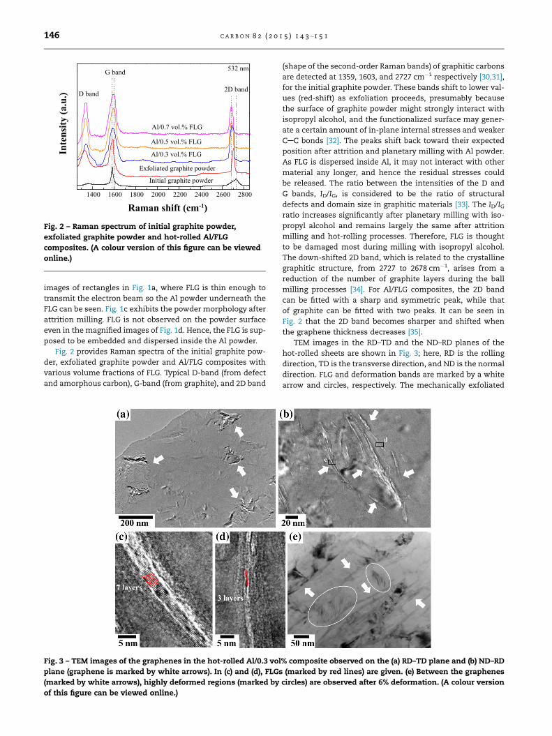
Fig. 3 – TEM images of the graphenes in the hot-rolled Al/0.3 vol
plane (graphene is marked by white arrows). In (c) and (d), FLGs
(marked by white arrows), highly deformed regions (marked by
of this figure can be viewed online.)
(shape of the second-order Raman bands) of graphitic carbons
are detected at 1359, 1603, and 2727 cm�1 respectively [30,31],
for the initial graphite powder. These bands shift to lower val-
ues (red-shift) as exfoliation proceeds, presumably because
the surface of graphite powder might strongly interact with
isopropyl alcohol, and the functionalized surface may gener-
ate a certain amount of in-plane internal stresses and weaker
CAC bonds [32]. The peaks shift back toward their expected
position after attrition and planetary milling with Al powder.
As FLG is dispersed inside Al, it may not interact with other
material any longer, and hence the residual stresses could
be released. The ratio between the intensities of the D and
G bands, ID/IG, is considered to be the ratio of structural
defects and domain size in graphitic materials [33]. The ID/IGratio increases significantly after planetary milling with iso-
propyl alcohol and remains largely the same after attrition
milling and hot-rolling processes. Therefore, FLG is thought
to be damaged most during milling with isopropyl alcohol.
The down-shifted 2D band, which is related to the crystalline
graphitic structure, from 2727 to 2678 cm�1, arises from a
reduction of the number of graphite layers during the ball
milling processes [34]. For Al/FLG composites, the 2D band
can be fitted with a sharp and symmetric peak, while that
of graphite can be fitted with two peaks. It can be seen in
Fig. 2 that the 2D band becomes sharper and shifted when
the graphene thickness decreases [35].
TEM images in the RD–TD and the ND–RD planes of the
hot-rolled sheets are shown in Fig. 3; here, RD is the rolling
direction, TD is the transverse direction, and ND is the normal
direction. FLG and deformation bands are marked by a white
arrow and circles, respectively. The mechanically exfoliated
% composite observed on the (a) RD–TD plane and (b) ND–RD
(marked by red lines) are given. (e) Between the graphenes
circles) are observed after 6% deformation. (A colour version
0.00 0.05 0.10 0.15 0.20 0.250
100
200
300
400
500
True strain
True
stre
ss (M
Pa) Al/0.3 vol. % FLG
Al/0.7 vol. % FLG
Al/0.5 vol. % FLG
Pure Al (unmilled)
Pure Al (milled)
strain rate - 1x10⁻⁴s-1
0.00 0.01 0.02 0.03 0.04 0.05250
300
350
400
450
500
550
600
650
Experimental data (Al/FLG) Experimental data (Al/MWCNT [36]) Calculated strength
Reinforcement volume fraction
Yie
ld st
ress
(MPa
)
dσc /dVFLG= 26.5 GPa dσc /dVMWCNT= 7.5 GPa
(a)
(b)
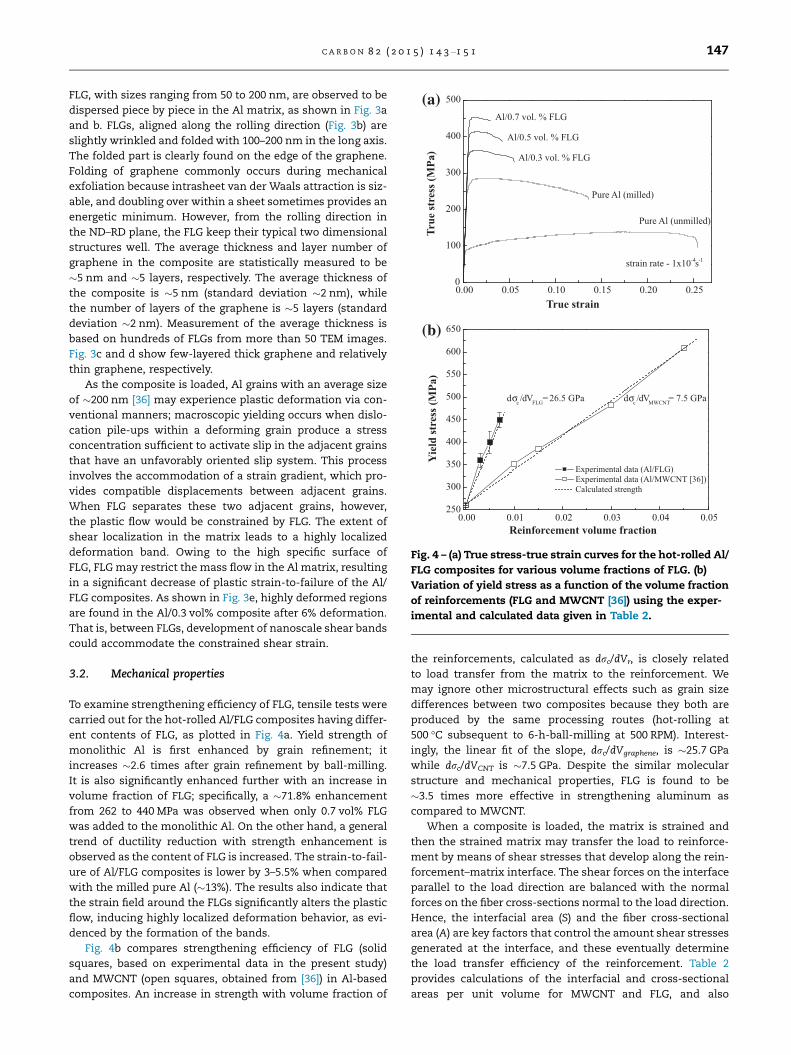
Fig. 4 – (a) True stress-true strain curves for the hot-rolled Al/
FLG composites for various volume fractions of FLG. (b)
Variation of yield stress as a function of the volume fraction
of reinforcements (FLG and MWCNT [36]) using the exper-
imental and calculated data given in Table 2.
C A R B O N 8 2 ( 2 0 1 5 ) 1 4 3 –1 5 1 147
FLG, with sizes ranging from 50 to 200 nm, are observed to be
dispersed piece by piece in the Al matrix, as shown in Fig. 3a
and b. FLGs, aligned along the rolling direction (Fig. 3b) are
slightly wrinkled and folded with 100–200 nm in the long axis.
The folded part is clearly found on the edge of the graphene.
Folding of graphene commonly occurs during mechanical
exfoliation because intrasheet van der Waals attraction is siz-
able, and doubling over within a sheet sometimes provides an
energetic minimum. However, from the rolling direction in
the ND–RD plane, the FLG keep their typical two dimensional
structures well. The average thickness and layer number of
graphene in the composite are statistically measured to be
�5 nm and �5 layers, respectively. The average thickness of
the composite is �5 nm (standard deviation �2 nm), while
the number of layers of the graphene is �5 layers (standard
deviation �2 nm). Measurement of the average thickness is
based on hundreds of FLGs from more than 50 TEM images.
Fig. 3c and d show few-layered thick graphene and relatively
thin graphene, respectively.
As the composite is loaded, Al grains with an average size
of �200 nm [36] may experience plastic deformation via con-
ventional manners; macroscopic yielding occurs when dislo-
cation pile-ups within a deforming grain produce a stress
concentration sufficient to activate slip in the adjacent grains
that have an unfavorably oriented slip system. This process
involves the accommodation of a strain gradient, which pro-
vides compatible displacements between adjacent grains.
When FLG separates these two adjacent grains, however,
the plastic flow would be constrained by FLG. The extent of
shear localization in the matrix leads to a highly localized
deformation band. Owing to the high specific surface of
FLG, FLG may restrict the mass flow in the Al matrix, resulting
in a significant decrease of plastic strain-to-failure of the Al/
FLG composites. As shown in Fig. 3e, highly deformed regions
are found in the Al/0.3 vol% composite after 6% deformation.
That is, between FLGs, development of nanoscale shear bands
could accommodate the constrained shear strain.
3.2. Mechanical properties
To examine strengthening efficiency of FLG, tensile tests were
carried out for the hot-rolled Al/FLG composites having differ-
ent contents of FLG, as plotted in Fig. 4a. Yield strength of
monolithic Al is first enhanced by grain refinement; it
increases �2.6 times after grain refinement by ball-milling.
It is also significantly enhanced further with an increase in
volume fraction of FLG; specifically, a �71.8% enhancement
from 262 to 440 MPa was observed when only 0.7 vol% FLG
was added to the monolithic Al. On the other hand, a general
trend of ductility reduction with strength enhancement is
observed as the content of FLG is increased. The strain-to-fail-
ure of Al/FLG composites is lower by 3–5.5% when compared
with the milled pure Al (�13%). The results also indicate that
the strain field around the FLGs significantly alters the plastic
flow, inducing highly localized deformation behavior, as evi-
denced by the formation of the bands.
Fig. 4b compares strengthening efficiency of FLG (solid
squares, based on experimental data in the present study)
and MWCNT (open squares, obtained from [36]) in Al-based
composites. An increase in strength with volume fraction of
the reinforcements, calculated as drc/dVr, is closely related
to load transfer from the matrix to the reinforcement. We
may ignore other microstructural effects such as grain size
differences between two composites because they both are
produced by the same processing routes (hot-rolling at
500 �C subsequent to 6-h-ball-milling at 500 RPM). Interest-
ingly, the linear fit of the slope, drc/dVgraphene, is �25.7 GPa
while drc/dVCNT is �7.5 GPa. Despite the similar molecular
structure and mechanical properties, FLG is found to be
�3.5 times more effective in strengthening aluminum as
compared to MWCNT.
When a composite is loaded, the matrix is strained and
then the strained matrix may transfer the load to reinforce-
ment by means of shear stresses that develop along the rein-
forcement–matrix interface. The shear forces on the interface
parallel to the load direction are balanced with the normal
forces on the fiber cross-sections normal to the load direction.
Hence, the interfacial area (S) and the fiber cross-sectional
area (A) are key factors that control the amount shear stresses
generated at the interface, and these eventually determine
the load transfer efficiency of the reinforcement. Table 2
provides calculations of the interfacial and cross-sectional
areas per unit volume for MWCNT and FLG, and also
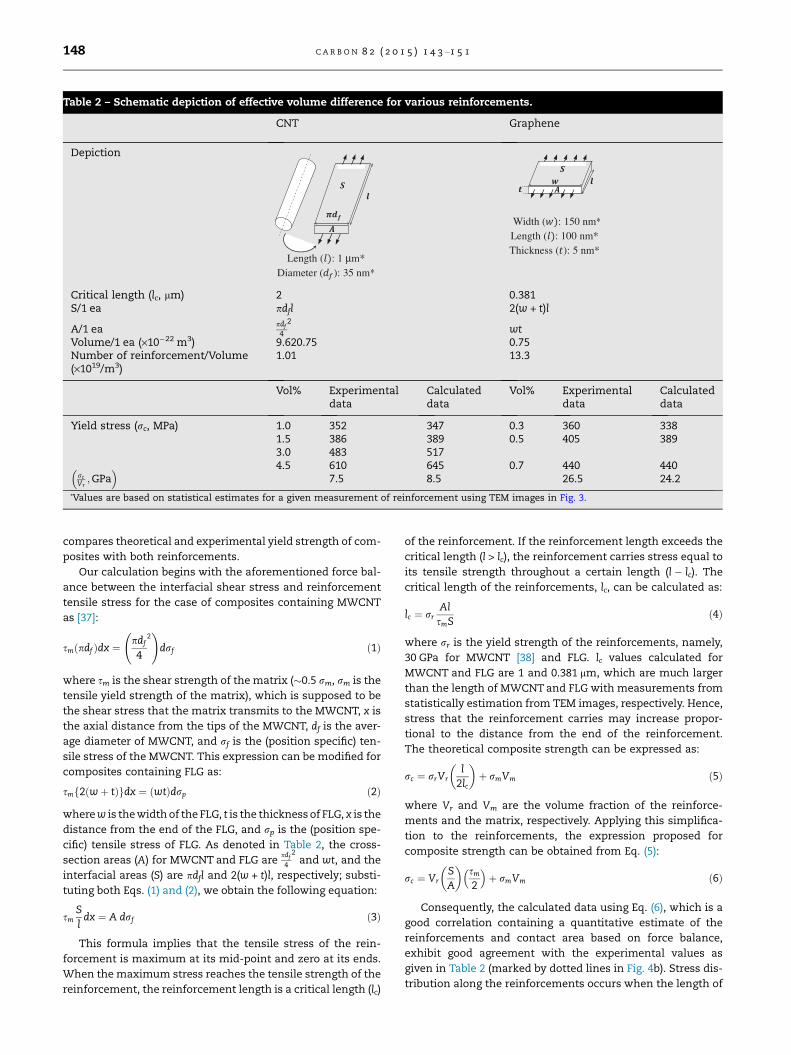
Table 2 – Schematic depiction of effective volume difference for various reinforcements.
CNT Graphene
Depiction
Critical length (lc, lm) 2 0.381S/1 ea pdfl 2(w + t)l
A/1 eapdf
4
2wt
Volume/1 ea (·10�22 m3) 9.620.75 0.75Number of reinforcement/Volume(·1019/m3)
1.01 13.3
Vol% Experimentaldata
Calculateddata
Vol% Experimentaldata
Calculateddata
Yield stress (rc, MPa) 1.0 352 347 0.3 360 3381.5 386 389 0.5 405 3893.0 483 5174.5 610 645 0.7 440 440
rcVr;GPa
� �7.5 8.5 26.5 24.2
*Values are based on statistical estimates for a given measurement of reinforcement using TEM images in Fig. 3.
148 C A R B O N 8 2 ( 2 0 1 5 ) 1 4 3 –1 5 1
compares theoretical and experimental yield strength of com-
posites with both reinforcements.
Our calculation begins with the aforementioned force bal-
ance between the interfacial shear stress and reinforcement
tensile stress for the case of composites containing MWCNT
as [37]:
smðpdf Þdx ¼ pdf
4
2 !
drf ð1Þ
where sm is the shear strength of the matrix (�0.5 rm, rm is the
tensile yield strength of the matrix), which is supposed to be
the shear stress that the matrix transmits to the MWCNT, x is
the axial distance from the tips of the MWCNT, df is the aver-
age diameter of MWCNT, and rf is the (position specific) ten-
sile stress of the MWCNT. This expression can be modified for
composites containing FLG as:
smf2ðwþ tÞgdx ¼ ðwtÞdrp ð2Þ
where w is the width of the FLG, t is the thickness of FLG, x is the
distance from the end of the FLG, and rp is the (position spe-
cific) tensile stress of FLG. As denoted in Table 2, the cross-
section areas (A) for MWCNT and FLG arepdf
4
2and wt, and the
interfacial areas (S) are pdfl and 2(w + t)l, respectively; substi-
tuting both Eqs. (1) and (2), we obtain the following equation:
smS
ldx ¼ A drf ð3Þ
This formula implies that the tensile stress of the rein-
forcement is maximum at its mid-point and zero at its ends.
When the maximum stress reaches the tensile strength of the
reinforcement, the reinforcement length is a critical length (lc)
of the reinforcement. If the reinforcement length exceeds the
critical length (l > lc), the reinforcement carries stress equal to
its tensile strength throughout a certain length (l � lc). The
critical length of the reinforcements, lc, can be calculated as:
lc ¼ rrAlsmS
ð4Þ
where rr is the yield strength of the reinforcements, namely,
30 GPa for MWCNT [38] and FLG. lc values calculated for
MWCNT and FLG are 1 and 0.381 lm, which are much larger
than the length of MWCNT and FLG with measurements from
statistically estimation from TEM images, respectively. Hence,
stress that the reinforcement carries may increase propor-
tional to the distance from the end of the reinforcement.
The theoretical composite strength can be expressed as:
rc ¼ rrVrl
2lc
��þ rmVm ð5Þ
where Vr and Vm are the volume fraction of the reinforce-
ments and the matrix, respectively. Applying this simplifica-
tion to the reinforcements, the expression proposed for
composite strength can be obtained from Eq. (5):
rc ¼ VrSA
� �sm
2
��þ rmVm ð6Þ
Consequently, the calculated data using Eq. (6), which is a
good correlation containing a quantitative estimate of the
reinforcements and contact area based on force balance,
exhibit good agreement with the experimental values as
given in Table 2 (marked by dotted lines in Fig. 4b). Stress dis-
tribution along the reinforcements occurs when the length of
0.000 0.002 0.004 0.006 0.008 0.010 0.012 0.014250
300
350
400
450
500
550
600
650
700
Reinforcement volume fraction
Present study
Short fiber composites [37]
Piggott [43]
Halpin-Tsai [42]Shear-lag [40]
Yie
ld st
ress
(MPa
)
0.00 0.02 0.04 0.06 0.08 0.10 0.12 0.14
150
200
250
300
350
400
450
500 [17] [18] [19] [20] Present study
Reinforcement volume fraction
Yie
ld st
ress
(MPa
)
(a)
(b)
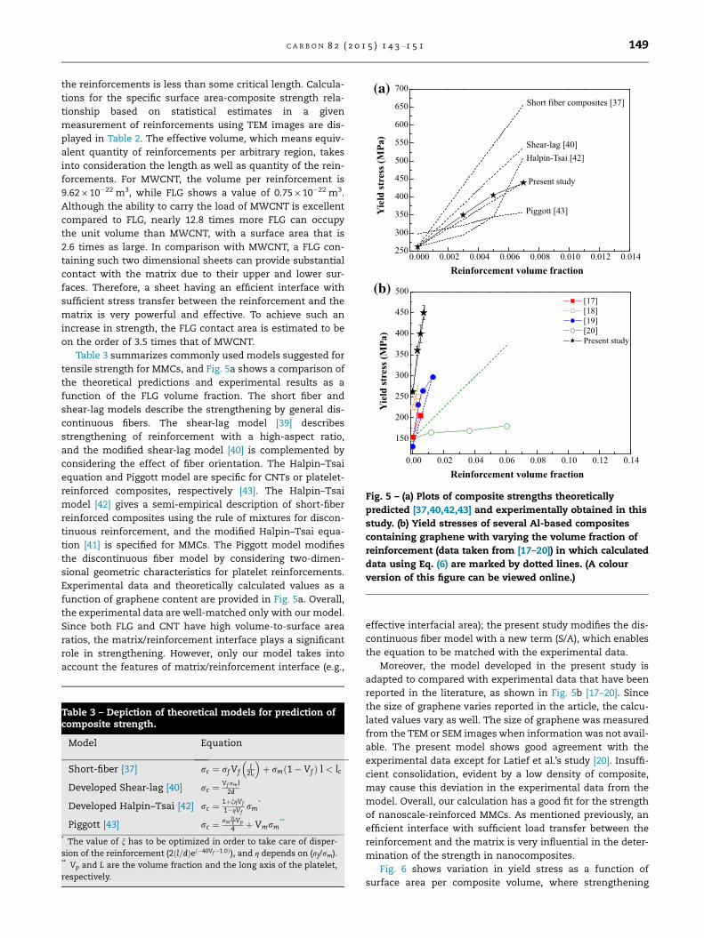
Fig. 5 – (a) Plots of composite strengths theoretically
predicted [37,40,42,43] and experimentally obtained in this
study. (b) Yield stresses of several Al-based composites
containing graphene with varying the volume fraction of
reinforcement (data taken from [17–20]) in which calculated
data using Eq. (6) are marked by dotted lines. (A colour
version of this figure can be viewed online.)
C A R B O N 8 2 ( 2 0 1 5 ) 1 4 3 –1 5 1 149
the reinforcements is less than some critical length. Calcula-
tions for the specific surface area-composite strength rela-
tionship based on statistical estimates in a given
measurement of reinforcements using TEM images are dis-
played in Table 2. The effective volume, which means equiv-
alent quantity of reinforcements per arbitrary region, takes
into consideration the length as well as quantity of the rein-
forcements. For MWCNT, the volume per reinforcement is
9.62 · 10�22 m3, while FLG shows a value of 0.75 · 10�22 m3.
Although the ability to carry the load of MWCNT is excellent
compared to FLG, nearly 12.8 times more FLG can occupy
the unit volume than MWCNT, with a surface area that is
2.6 times as large. In comparison with MWCNT, a FLG con-
taining such two dimensional sheets can provide substantial
contact with the matrix due to their upper and lower sur-
faces. Therefore, a sheet having an efficient interface with
sufficient stress transfer between the reinforcement and the
matrix is very powerful and effective. To achieve such an
increase in strength, the FLG contact area is estimated to be
on the order of 3.5 times that of MWCNT.
Table 3 summarizes commonly used models suggested for
tensile strength for MMCs, and Fig. 5a shows a comparison of
the theoretical predictions and experimental results as a
function of the FLG volume fraction. The short fiber and
shear-lag models describe the strengthening by general dis-
continuous fibers. The shear-lag model [39] describes
strengthening of reinforcement with a high-aspect ratio,
and the modified shear-lag model [40] is complemented by
considering the effect of fiber orientation. The Halpin–Tsai
equation and Piggott model are specific for CNTs or platelet-
reinforced composites, respectively [43]. The Halpin–Tsai
model [42] gives a semi-empirical description of short-fiber
reinforced composites using the rule of mixtures for discon-
tinuous reinforcement, and the modified Halpin–Tsai equa-
tion [41] is specified for MMCs. The Piggott model modifies
the discontinuous fiber model by considering two-dimen-
sional geometric characteristics for platelet reinforcements.
Experimental data and theoretically calculated values as a
function of graphene content are provided in Fig. 5a. Overall,
the experimental data are well-matched only with our model.
Since both FLG and CNT have high volume-to-surface area
ratios, the matrix/reinforcement interface plays a significant
role in strengthening. However, only our model takes into
account the features of matrix/reinforcement interface (e.g.,
Table 3 – Depiction of theoretical models for prediction ofcomposite strength.
Model Equation
Short-fiber [37] rc ¼ rf Vfl
2lc
� �þ rmð1� Vf Þ l < lc
Developed Shear-lag [40] rc ¼Vf rml
2d
Developed Halpin–Tsai [42] rc ¼1þngVf
1�gVfrm
*
Piggott [43] rc ¼ rm2Lt Vp
4 þ Vmrm**
* The value of n has to be optimized in order to take care of disper-
sion of the reinforcement (2ðl=dÞeð�40Vf�1:0Þ), and g depends on (rf/rm).** Vp and L are the volume fraction and the long axis of the platelet,
respectively.
effective interfacial area); the present study modifies the dis-
continuous fiber model with a new term (S/A), which enables
the equation to be matched with the experimental data.
Moreover, the model developed in the present study is
adapted to compared with experimental data that have been
reported in the literature, as shown in Fig. 5b [17–20]. Since
the size of graphene varies reported in the article, the calcu-
lated values vary as well. The size of graphene was measured
from the TEM or SEM images when information was not avail-
able. The present model shows good agreement with the
experimental data except for Latief et al.’s study [20]. Insuffi-
cient consolidation, evident by a low density of composite,
may cause this deviation in the experimental data from the
model. Overall, our calculation has a good fit for the strength
of nanoscale-reinforced MMCs. As mentioned previously, an
efficient interface with sufficient load transfer between the
reinforcement and the matrix is very influential in the deter-
mination of the strength in nanocomposites.
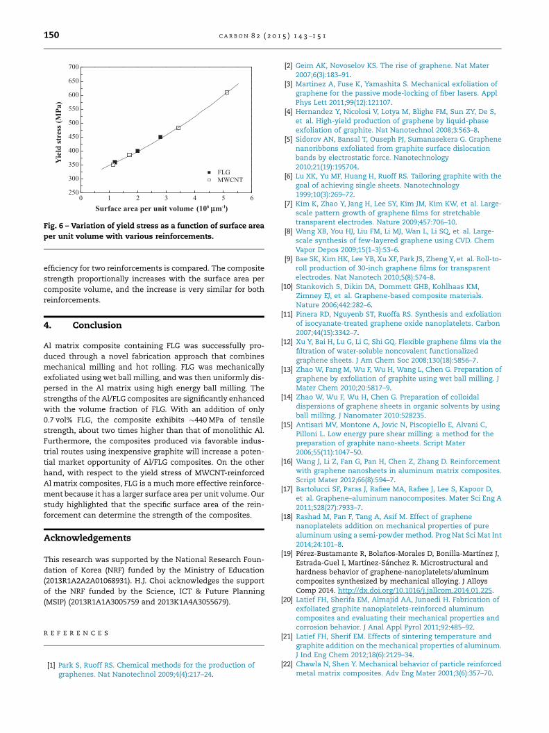
Fig. 6 shows variation in yield stress as a function of
surface area per composite volume, where strengthening
0 1 2 3 4 5 6250
300
350
400
450
500
550
600
650
700
FLG MWCNT
Surface area per unit volume (106 μ μm-1)
Yie
ld st
ress
(MPa
)
Fig. 6 – Variation of yield stress as a function of surface area
per unit volume with various reinforcements.
150 C A R B O N 8 2 ( 2 0 1 5 ) 1 4 3 –1 5 1
efficiency for two reinforcements is compared. The composite
strength proportionally increases with the surface area per
composite volume, and the increase is very similar for both
reinforcements.
4. Conclusion
Al matrix composite containing FLG was successfully pro-
duced through a novel fabrication approach that combines
mechanical milling and hot rolling. FLG was mechanically
exfoliated using wet ball milling, and was then uniformly dis-
persed in the Al matrix using high energy ball milling. The
strengths of the Al/FLG composites are significantly enhanced
with the volume fraction of FLG. With an addition of only
0.7 vol% FLG, the composite exhibits �440 MPa of tensile
strength, about two times higher than that of monolithic Al.
Furthermore, the composites produced via favorable indus-
trial routes using inexpensive graphite will increase a poten-
tial market opportunity of Al/FLG composites. On the other
hand, with respect to the yield stress of MWCNT-reinforced
Al matrix composites, FLG is a much more effective reinforce-
ment because it has a larger surface area per unit volume. Our
study highlighted that the specific surface area of the rein-
forcement can determine the strength of the composites.
Acknowledgements
This research was supported by the National Research Foun-
dation of Korea (NRF) funded by the Ministry of Education
(2013R1A2A2A01068931). H.J. Choi acknowledges the support
of the NRF funded by the Science, ICT & Future Planning
(MSIP) (2013R1A1A3005759 and 2013K1A4A3055679).
R E F E R E N C E S
[1] Park S, Ruoff RS. Chemical methods for the production ofgraphenes. Nat Nanotechnol 2009;4(4):217–24.
[2] Geim AK, Novoselov KS. The rise of graphene. Nat Mater2007;6(3):183–91.
[3] Martinez A, Fuse K, Yamashita S. Mechanical exfoliation ofgraphene for the passive mode-locking of fiber lasers. ApplPhys Lett 2011;99(12):121107.
[4] Hernandez Y, Nicolosi V, Lotya M, Blighe FM, Sun ZY, De S,et al. High-yield production of graphene by liquid-phaseexfoliation of graphite. Nat Nanotechnol 2008;3:563–8.
[5] Sidorov AN, Bansal T, Ouseph PJ, Sumanasekera G. Graphenenanoribbons exfoliated from graphite surface dislocationbands by electrostatic force. Nanotechnology2010;21(19):195704.
[6] Lu XK, Yu MF, Huang H, Ruoff RS. Tailoring graphite with thegoal of achieving single sheets. Nanotechnology1999;10(3):269–72.
[7] Kim K, Zhao Y, Jang H, Lee SY, Kim JM, Kim KW, et al. Large-scale pattern growth of graphene films for stretchabletransparent electrodes. Nature 2009;457:706–10.
[8] Wang XB, You HJ, Liu FM, Li MJ, Wan L, Li SQ, et al. Large-scale synthesis of few-layered graphene using CVD. ChemVapor Depos 2009;15(1–3):53–6.
[9] Bae SK, Kim HK, Lee YB, Xu XF, Park JS, Zheng Y, et al. Roll-to-roll production of 30-inch graphene films for transparentelectrodes. Nat Nanotech 2010;5(8):574–8.
[10] Stankovich S, Dikin DA, Dommett GHB, Kohlhaas KM,Zimney EJ, et al. Graphene-based composite materials.Nature 2006;442:282–6.
[11] Pinera RD, Nguyenb ST, Ruoffa RS. Synthesis and exfoliationof isocyanate-treated graphene oxide nanoplatelets. Carbon2007;44(15):3342–7.
[12] Xu Y, Bai H, Lu G, Li C, Shi GQ. Flexible graphene films via thefiltration of water-soluble noncovalent functionalizedgraphene sheets. J Am Chem Soc 2008;130(18):5856–7.
[13] Zhao W, Fang M, Wu F, Wu H, Wang L, Chen G. Preparation ofgraphene by exfoliation of graphite using wet ball milling. JMater Chem 2010;20:5817–9.
[14] Zhao W, Wu F, Wu H, Chen G. Preparation of colloidaldispersions of graphene sheets in organic solvents by usingball milling. J Nanomater 2010:528235.
[15] Antisari MV, Montone A, Jovic N, Piscopiello E, Alvani C,Pilloni L. Low energy pure shear milling: a method for thepreparation of graphite nano-sheets. Script Mater2006;55(11):1047–50.
[16] Wang J, Li Z, Fan G, Pan H, Chen Z, Zhang D. Reinforcementwith graphene nanosheets in aluminum matrix composites.Script Mater 2012;66(8):594–7.
[17] Bartolucci SF, Paras J, Rafiee MA, Rafiee J, Lee S, Kapoor D,et al. Graphene–aluminum nanocomposites. Mater Sci Eng A2011;528(27):7933–7.
[18] Rashad M, Pan F, Tang A, Asif M. Effect of graphenenanoplatelets addition on mechanical properties of purealuminum using a semi-powder method. Prog Nat Sci Mat Int2014;24:101–8.
[19] Perez-Bustamante R, Bolanos-Morales D, Bonilla-Martınez J,Estrada-Guel I, Martınez-Sanchez R. Microstructural andhardness behavior of graphene-nanoplatelets/aluminumcomposites synthesized by mechanical alloying. J AlloysComp 2014. http://dx.doi.org/10.1016/j.jallcom.2014.01.225.
[20] Latief FH, Sherifa EM, Almajid AA, Junaedi H. Fabrication ofexfoliated graphite nanoplatelets-reinforced aluminumcomposites and evaluating their mechanical properties andcorrosion behavior. J Anal Appl Pyrol 2011;92:485–92.
[21] Latief FH, Sherif EM. Effects of sintering temperature andgraphite addition on the mechanical properties of aluminum.J Ind Eng Chem 2012;18(6):2129–34.
[22] Chawla N, Shen Y. Mechanical behavior of particle reinforcedmetal matrix composites. Adv Eng Mater 2001;3(6):357–70.
C A R B O N 8 2 ( 2 0 1 5 ) 1 4 3 –1 5 1 151
[23] Song SG, Shin N, Gray GT, Roberts JA. Reinforcement shapeeffects on the fracture behavior and ductility of particulate-reinforced 6061-Al matrix composites. Metall Mater Trans A1996;27A:3739–46.
[24] George R, Kashyap KT, Rahul R, Yamdagni S. Strengthening incarbon nanotube/aluminium (CNT/Al) composites. ScriptMater 2005;53(10):1159–63.
[25] Barrera EV, Sims J, Callahan DL. Development of fullerene-reinforced aluminum. J Mater Res 1995;10(2):366–71.
[26] Song HY, Zha XW. Mechanical properties of Ni-coated singlegraphene sheet and their embedded aluminum matrixcomposites. Commun Theor Phys 2010;54(1):143–7.
[27] Xu ZP, Buehler MJ. Interface structure and mechanicsbetween graphene and metal substrates: a first-principlesstudy. J Phys Condens Mat 2010;22(48):485301.
[28] Banhart F. Interactions between metals and carbonnanotubes: at the interface between old and new materials.Nanoscale 2009;1:201–13.
[29] He Y, Zhang J, Wang Y, Yu Z. Coating geometries of metals onsingle-walled carbon nanotubes. Appl Phys Lett 2010;96.063108-1-3.
[30] Castiglioni C, Tommasini M, Zerbi G. Raman spectroscopy ofpolyconjugated molecules and materials: confinement effectin one and two dimensions. Phil Trans R Soc Lond A2004;362:2425–59.
[31] Kudin KN, Ozbas B, Schniepp HC, Prud’homme RK, Aksay IA,Car R. Raman spectra of graphite oxide and functionalizedgraphene sheets. Nano Lett 2008;8:36–41.
[32] Wang Z, Ciselli P, Peijs T. The extraordinary reinforcingefficiency of single-walled carbon nanotubes in orientedpoly(vinyl alcohol) tapes. Nanotechnology 2007;18:455709.
[33] Antunes EF, Lobo AO, Corat EJ, Trava-Airoldi VJ, Martin AA,Verıssimo C. Comparative study of first- and second-order
Raman spectra of MWCNT at visible and infrared laserexcitation. Carbon 2006;44(11):2202–11.
[34] Ferrari AC, Meyer JC, Scardaci V, Casiraghi C, Lazzeri M, MauriF, et al. Raman spectrum of graphene and graphene layers.Phys Rev Lett 2006;97(18):187401.
[35] Li D, Zhan D, Yan J, Sun CL, Li ZW, Ni ZH, et al. Thickness andstacking geometry effects on high frequency overtone andcombination Raman modes of graphene. J Raman Spectrosc2013;44:86–91.
[36] Choi HJ, Shin JH, Bae DH. Grain size effect on thestrengthening behavior of aluminum-based compositescontaining multi-walled carbon nanotubes. Compos SciTechnol 2011;71(15):1699–705.
[37] Courtney TH. Mechanical behavior of materials. 2nded. Singapore: McGraw-Hill Book Co; 2000.
[38] Zhong R, Cong H, Hou P. Fabrication of nano-Al basedcomposites reinforced by single-walled carbon nanotubes.Carbon 2003;41:848–51.
[39] Hedgepeth JM. Stress concentrations in filamentarystructures. Technical report. Washington, D.C.: NationalAeronautics and Space Administration (US), LangleyResearch Center; 1961 May. Report No.: NASA-TN-D-882.
[40] Ryu HJ, Cha SI, Hong SH. Generalized shear-lag model forload transfer in SiC/Al metal-matrix composites. J Mater Res2003;18:2851–8.
[41] Halpin JC, Kardos JL. The Halpin–Tsai equations: a review.Polym Eng Sci 1976;16(5):344–52.
[42] Yeh MK, Tai NH, Liu JH. Mechanical behavior of phenolic-based composites reinforced with multi-walled carbonnanotubes. Carbon 2006;44:1–9.
[43] Piggott MR. Loading-bearing fibrecomposites. Oxford: Pergamon; 1980.
Related Documents