Strength prediction of single- and double-lap joints by standard and extended finite element modelling R.D.S.G. Campilho, M.D. Banea, A.M.G. Pinto, L.F.M. da Silva, A.M.P. de Jesus ABSTRACT The structural integrity of multi-component structures is usually determined by the strength and durability of their unions. Adhesive bonding is often chosen over welding, riveting and bolting, due to the reduction of stress concentrations, reduced weight penalty and easy manufacturing, amongst other issues. In the past decades, the Finite Element Method (FEM) has been used for the simulation and strength prediction of bonded structures, by strength of materials or fracture mechanics-based criteria. Cohesive-zone models (CZMs) have already proved to be an effective tool in modelling damage growth, surpassing a few limitations of the aforementioned techniques. Despite this fact, they still suffer from the restriction of damage growth only at predefined growth paths. The eXtended Finite Element Method (XFEM) is a recent improvement of the FEM, developed to allow the growth of discontinuities within bulk solids along an arbitrary path, by enriching degrees of freedom with special displacement functions, thus overcoming the main restriction of CZMs. These two techniques were tested to simulate adhesively bonded single- and double-lap joints. The comparative evaluation of the two methods showed their capabilities and/or limitations for this specific purpose. Keywords Bonded joint, Finite element analysis, Cohesive zone models 1. Introduction The structural integrity of multi-component structures is usually determined by the strength and durability of their unions [1]. On this issue, adhesive bonding provides several advantages over welding, riveting and bolting, such as reduction of stress concentra- tions, reduced weight penalty and easy manufacturing [2]. Different approaches were employed in the past to predict the mechanical behaviour of bonded assemblies. In the early stages of bonded structures analyses, theoretical studies were popular [3–7], which employed simplifying assumptions in the structures geometry, materials behaviour, loading, and boundary conditions, to formulate efficient closed-form elasticity solutions for the local fields in the adhesive region. The main advantage of analytical modelling is that the structure can be analysed quickly, although with lot of embedded simplifications [8]. In the computers age, FEM codes to simulate the mechanical behaviour of structures were rapidly implemented, providing a more accurate insight on this subject. In the FEM, each compo- nent of the adhesive joint is treated as a continuum and the analysis of large displacements, such as those seen in the single-lap joints, is also available. Accounting for the materials plasticity was also made easier, since FEM codes actually incorporate several complex material laws. One of the first FEM works on bonded assemblies dates back to the 1970s when Wooley and Carver [9] conducted a stress analysis on single-lap joints. On the strength prediction of bonded assemblies, two different lines of analyses were developed over the years: the strength of materials and fracture mechanics-based methods. The strength of materials approach is based on the evaluation of allowable stresses [10,11] or strains [12,13], by theoretical formulations or the FEM. The assemblies strength can be predicted by comparing the respective equivalent stresses or strains at the critical regions, obtained by stress or strain-based criteria, with the properties of the structure constituents. These criteria are highly mesh dependent, as stress singularities are present at the end of the overlapping regions due to the sharp corners [14–16]. As for fracture mechanics, using Linear- Elastic Fracture Mechanics (LEFM), an inherent flaw is required for the calculation of the stress intensity factors or strain energy. The limitations of the reported approaches are surpassed by CZMs, combining elements of strength and fracture approaches to derive the fracture loads [17,18]. The use of CZMs in fracture problems has become frequent in recent years. One of the most important advantages of CZMs is related to their ability to brought to you by CORE View metadata, citation and similar papers at core.ac.uk provided by Repositório Científico do Instituto Politécnico do Porto

Welcome message from author
This document is posted to help you gain knowledge. Please leave a comment to let me know what you think about it! Share it to your friends and learn new things together.
Transcript

Strength prediction of single- and double-lap joints by standard and
extended finite element modelling
R.D.S.G. Campilho, M.D. Banea, A.M.G. Pinto, L.F.M. da Silva, A.M.P. de Jesus
ABSTRACT
The structural integrity of multi-component structures is usually determined by the strength and durability of their unions. Adhesive bonding is
often chosen over welding, riveting and bolting, due to the reduction of stress concentrations, reduced weight penalty and easy manufacturing,
amongst other issues. In the past decades, the Finite Element Method (FEM) has been used for the simulation and strength prediction of bonded
structures, by strength of materials or fracture mechanics-based criteria. Cohesive-zone models (CZMs) have already proved to be an effective tool in
modelling damage growth, surpassing a few limitations of the aforementioned techniques. Despite this fact, they still suffer from the restriction of
damage growth only at predefined growth paths. The eXtended Finite Element Method (XFEM) is a recent improvement of the FEM, developed to
allow the growth of discontinuities within bulk solids along an arbitrary path, by enriching degrees of freedom with special displacement functions,
thus overcoming the main restriction of CZMs. These two techniques were tested to simulate adhesively bonded single- and double-lap joints. The
comparative evaluation of the two methods showed their capabilities and/or limitations for this specific purpose.
Keywords
Bonded joint, Finite element analysis, Cohesive zone models
1. Introduction
The structural integrity of multi-component structures is usually
determined by the strength and durability of their unions [1]. On
this issue, adhesive bonding provides several advantages over
welding, riveting and bolting, such as reduction of stress concentra-
tions, reduced weight penalty and easy manufacturing [2]. Different
approaches were employed in the past to predict the mechanical
behaviour of bonded assemblies. In the early stages of bonded
structures analyses, theoretical studies were popular [3–7], which
employed simplifying assumptions in the structures geometry,
materials behaviour, loading, and boundary conditions, to formulate
efficient closed-form elasticity solutions for the local fields in
the adhesive region. The main advantage of analytical modelling is
that the structure can be analysed quickly, although with lot of
embedded simplifications [8].
In the computers age, FEM codes to simulate the mechanical
behaviour of structures were rapidly implemented, providing a
more accurate insight on this subject. In the FEM, each compo-
nent of the adhesive joint is treated as a continuum and the
analysis of large displacements, such as those seen in the single-lap
joints, is also available. Accounting for the materials plasticity was
also made easier, since FEM codes actually incorporate several
complex material laws. One of the first FEM works on bonded
assemblies dates back to the 1970s when Wooley and Carver [9]
conducted a stress analysis on single-lap joints. On the strength
prediction of bonded assemblies, two different lines of analyses
were developed over the years: the strength of materials and
fracture mechanics-based methods. The strength of materials
approach is based on the evaluation of allowable stresses [10,11]
or strains [12,13], by theoretical formulations or the FEM. The
assemblies strength can be predicted by comparing the respective
equivalent stresses or strains at the critical regions, obtained by
stress or strain-based criteria, with the properties of the structure
constituents. These criteria are highly mesh dependent, as stress
singularities are present at the end of the overlapping regions due to
the sharp corners [14–16]. As for fracture mechanics, using Linear-
Elastic Fracture Mechanics (LEFM), an inherent flaw is required for
the calculation of the stress intensity factors or strain energy.
The limitations of the reported approaches are surpassed by
CZMs, combining elements of strength and fracture approaches to
derive the fracture loads [17,18]. The use of CZMs in fracture
problems has become frequent in recent years. One of the most
important advantages of CZMs is related to their ability to
brought to you by COREView metadata, citation and similar papers at core.ac.uk
provided by Repositório Científico do Instituto Politécnico do Porto
simulate onset and growth of damage without the requirement of
an initial flaw, unlike classical fracture mechanics approaches.
CZMs are based on spring [19] or cohesive elements [20,21],
connecting plane or three-dimensional (3D) solid elements of
structures. The cohesive elements should be placed along the
paths where damage is prone to occur, which can be difficult to
identify. However, in bonded assemblies damage growth is
restricted to well defined planes, i.e., at the interfaces between
the adhesive and the adherends, or cohesively in the adhesive,
which allows surpassing this limitation [22,23]. A broad variety of
works were published that prove the feasibility of this technique
to model bonded assemblies, with promising results. Kafkalidis
and Thouless [24] performed a FEM analysis of symmetric and
asymmetric single-lap joints using a CZM approach including the
adhesive plasticity by means of a traction–separation law with a
trapezoidal shape. Using cohesive-zone parameters determined
for the particular combination of materials used, the numerical
predictions for different bonded shapes showed excellent agree-
ment with the experimental observations. The numerical models
predicted accurately the failure loads, displacements and defor-
mations of the joints. Campilho et al. [22] evaluated the tensile
behaviour of adhesively bonded single-strap repairs on laminated
composites as a function of the overlap length and the patch
thickness. A numerical FEM methodology including a CZM with a
trapezoidal shape in pure modes I and II was used to simulate a
thin ductile adhesive layer. An excellent agreement was found
between the experiments and the numerical simulations on the
failure modes, elastic stiffness and strength of the repairs.
The recently developed XFEM is an extension of the FEM, and
its fundamental features were presented in first hand in the late
1990s by Belytschko and Black [25]. It is based on the idea of
partition of unity presented by Melenk and Babuska [26], which
consists on local enrichment functions for the nodal displace-
ments to model crack growth and separation between crack
faces [27]. With this technique, discontinuities such as cracks
are simulated as enriched features, by allowing discontinuities to
grow through the enrichment of the degrees of freedom of the
nearby nodes with special displacement functions. As the crack-
tip changes its position and path due to loading conditions, the
XFEM algorithm creates the necessary enrichment functions for
the nodal points of the finite elements around the crack path/tip.
Compared to CZMs, XFEM excels in simulating crack onset and
growth along an arbitrary path without the requirement of the
mesh to match the geometry of the discontinuities neither
remeshing near the crack [28]. This can be an advantage to CZM
modelling for the simulation of bonded engineering plastics or
polymer–matrix composites, where adherend cracking may occur
after initiation in the adhesive.
Varying applications to this innovative technique were pro-
posed to simulate different engineering problems. In 2000,
Sukumar et al. [29] updated the method to three-dimensional
damage simulation. Modelling of intersecting cracks with multi-
ple branches, multiple holes and cracks emanating from holes
were addressed by Daux et al. [30]. The problem of cohesive
propagation of cracks in concrete structures was studied by
Moe s and Belytschko [31], considering three-point bending and
four-point shear scaled specimens. More advanced features such
as plasticity, contacting between bodies and geometrical non-
linearities, which show a particular relevance for the simulation
of fracture in structures, are already available within the scope of
XFEM. The employment of plastic enrichments in XFEM model-
ling is accredited to Elguedj et al. [32], which used a new enriched
basis function to capture the singular fields in elasto-plastic
fracture mechanics. Modelling of contact by the XFEM was firstly
introduced by Dolbow et al. [33] and afterwards adapted to
frictional contact by Khoei and Nikbakht [34]. Fagerstro m and
Larsson [35] implemented geometrically non-linearities within
XFEM.
This work aims the comparison and evaluation of CZM and
XFEM modelling, currently implemented in the FEM package
ABAQUSs, to simulate the behaviour of adhesively bonded single-
and double-lap joints between aluminium adherends, bonded
with the brittle adhesive Araldites AV138. The study comprises a
variety of overlap lengths, between 5 and 20 mm, to test both
modelling solutions under different conditions, between an
approximately even level of shear stresses along the bond up to
the large shear stress gradients found in joints with bigger bond
lengths. This work will equally allow the discussion of the
capabilities and/or limitations of these two methods to model
bonded structures, by direct comparisons with experimental data.
2. Experimental work
2.1. Characterisation of the materials
The aluminium alloy AW6082 T651 was selected for the
adherends, characterised by a high tensile strength (340 MPa as
specified by the manufacturer) obtained through artificial ageing at
a temperature of approximately 180 1C [36]. This specific alloy was
chosen due to its wide use in Europe for several structural
applications under different extruded and laminated shapes. The
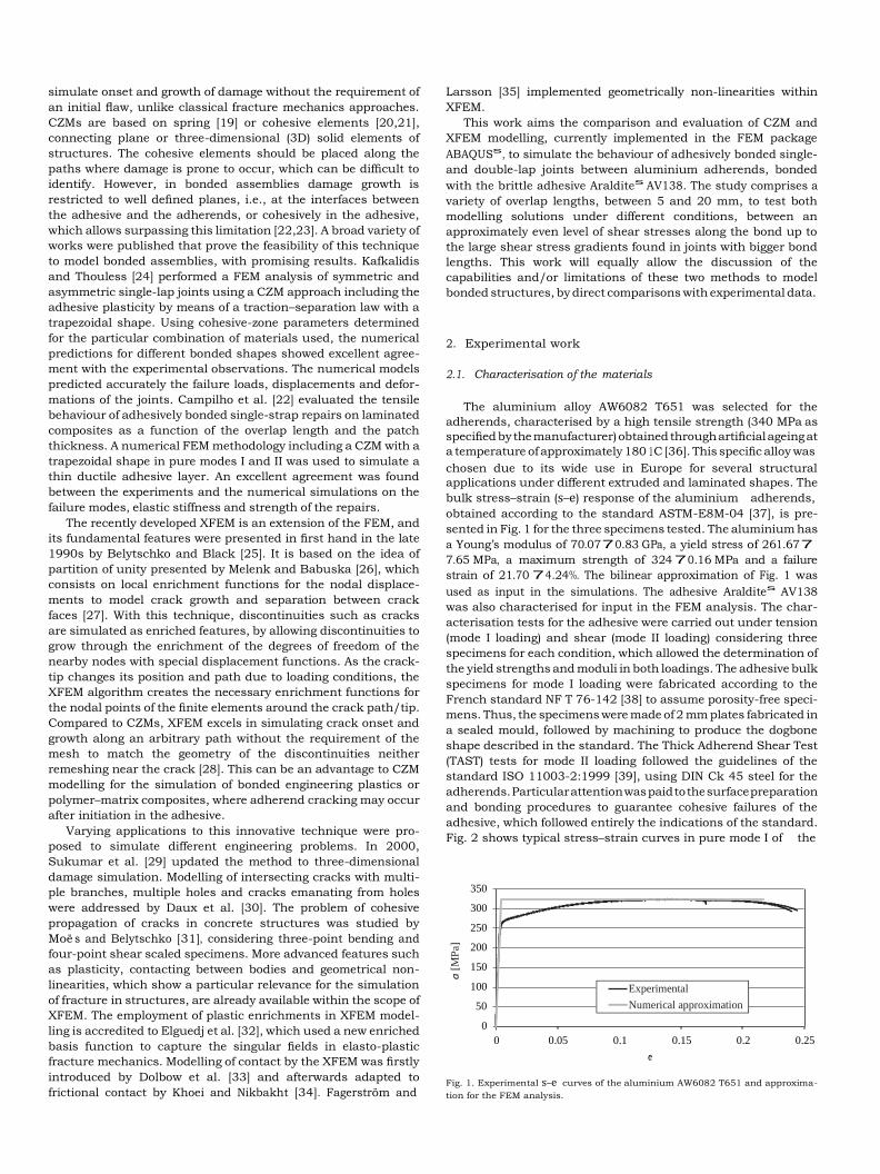
bulk stress–strain (s–e) response of the aluminium adherends,
obtained according to the standard ASTM-E8M-04 [37], is pre-
sented in Fig. 1 for the three specimens tested. The aluminium has
a Young’s modulus of 70.0770.83 GPa, a yield stress of 261.67 7
7.65 MPa, a maximum strength of 324 70.16 MPa and a failure
strain of 21.70 74.24%. The bilinear approximation of Fig. 1 was
used as input in the simulations. The adhesive Araldites AV138
was also characterised for input in the FEM analysis. The char-
acterisation tests for the adhesive were carried out under tension
(mode I loading) and shear (mode II loading) considering three
specimens for each condition, which allowed the determination of
the yield strengths and moduli in both loadings. The adhesive bulk
specimens for mode I loading were fabricated according to the
French standard NF T 76-142 [38] to assume porosity-free speci-
mens. Thus, the specimens were made of 2 mm plates fabricated in
a sealed mould, followed by machining to produce the dogbone
shape described in the standard. The Thick Adherend Shear Test
(TAST) tests for mode II loading followed the guidelines of the
standard ISO 11003-2:1999 [39], using DIN Ck 45 steel for the
adherends. Particular attention was paid to the surface preparation
and bonding procedures to guarantee cohesive failures of the
adhesive, which followed entirely the indications of the standard.
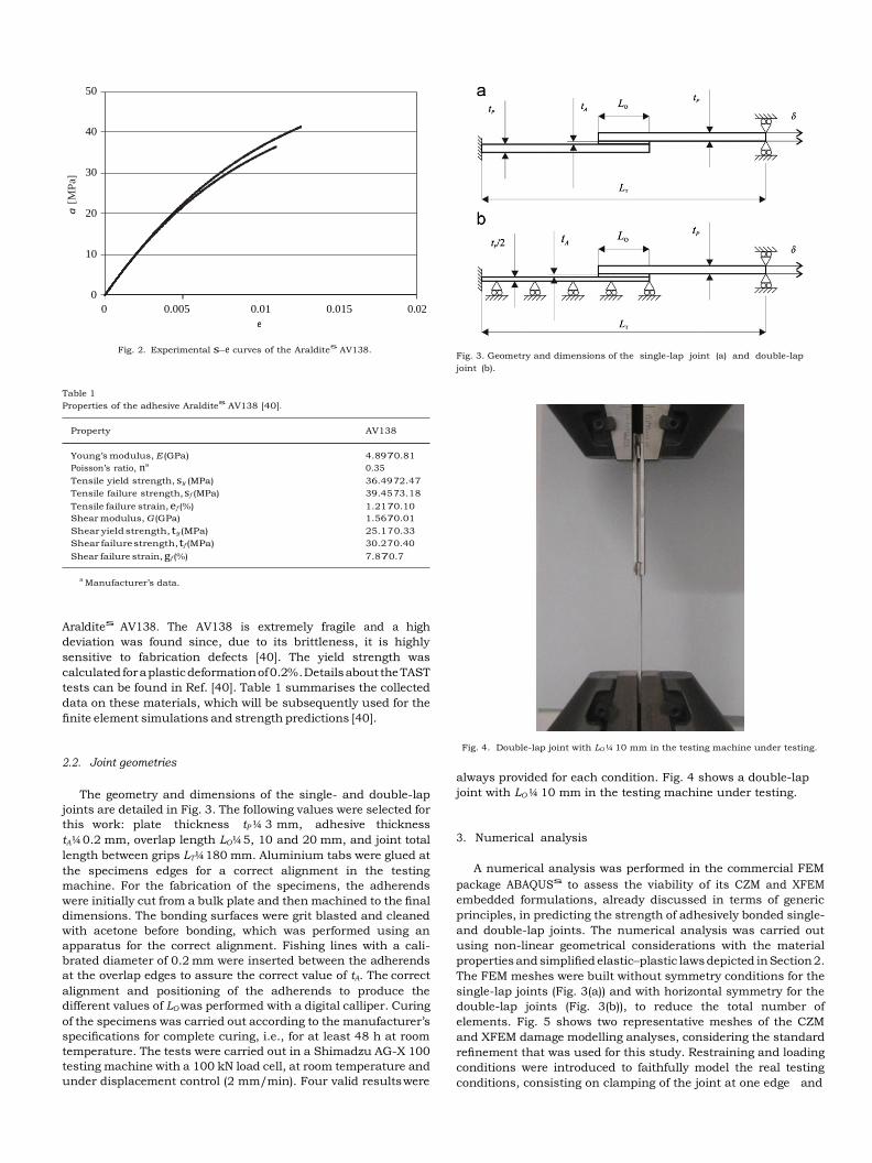
Fig. 2 shows typical stress–strain curves in pure mode I of the
350
300
250
200
150
100
50
0
0 0.05 0.1 0.15 0.2 0.25
e
Fig. 1. Experimental s–e curves of the aluminium AW6082 T651 and approxima-
tion for the FEM analysis.
Experimental
Numerical approximation
a [
MP
a]
50
40
30
20
10
0
0 0.005 0.01 0.015
e
Fig. 2. Experimental s–e curves of the Araldites
AV138.
0.02
Fig. 3. Geometry and dimensions of the single-lap joint (a) and double-lap
joint (b).
Table 1
Properties of the adhesive Araldites
AV138 [40].
Property AV138
Young’s modulus, E (GPa) 4.89 7 0.81
Poisson’s ratio, na 0.35
Tensile yield strength, sy (MPa) 36.49 72.47
Tensile failure strength, sf (MPa) 39.45 73.18
Tensile failure strain, ef (%) 1.21 7 0.10
Shear modulus, G (GPa) 1.56 7 0.01
Shear yield strength, ty (MPa) 25.1 7 0.33
Shear failure strength, tf (MPa) 30.2 7 0.40
Shear failure strain, gf (%) 7.8 7 0.7
a Manufacturer’s data.
Araldites AV138. The AV138 is extremely fragile and a high
deviation was found since, due to its brittleness, it is highly
sensitive to fabrication defects [40]. The yield strength was
calculated for a plastic deformation of 0.2%. Details about the TAST
tests can be found in Ref. [40]. Table 1 summarises the collected
data on these materials, which will be subsequently used for the
finite element simulations and strength predictions [40].
2.2. Joint geometries
The geometry and dimensions of the single- and double-lap
joints are detailed in Fig. 3. The following values were selected for
this work: plate thickness tP ¼ 3 mm, adhesive thickness
tA ¼ 0.2 mm, overlap length LO ¼ 5, 10 and 20 mm, and joint total
length between grips LT ¼ 180 mm. Aluminium tabs were glued at
the specimens edges for a correct alignment in the testing
machine. For the fabrication of the specimens, the adherends
were initially cut from a bulk plate and then machined to the final
dimensions. The bonding surfaces were grit blasted and cleaned
with acetone before bonding, which was performed using an
apparatus for the correct alignment. Fishing lines with a cali-
brated diameter of 0.2 mm were inserted between the adherends
at the overlap edges to assure the correct value of tA. The correct
alignment and positioning of the adherends to produce the
different values of LO was performed with a digital calliper. Curing
of the specimens was carried out according to the manufacturer’s
specifications for complete curing, i.e., for at least 48 h at room
temperature. The tests were carried out in a Shimadzu AG-X 100
testing machine with a 100 kN load cell, at room temperature and
under displacement control (2 mm/min). Four valid results were
Fig. 4. Double-lap joint with LO ¼ 10 mm in the testing machine under testing.
always provided for each condition. Fig. 4 shows a double-lap
joint with LO ¼ 10 mm in the testing machine under testing.
3. Numerical analysis
A numerical analysis was performed in the commercial FEM
package ABAQUSs to assess the viability of its CZM and XFEM
embedded formulations, already discussed in terms of generic
principles, in predicting the strength of adhesively bonded single-
and double-lap joints. The numerical analysis was carried out
using non-linear geometrical considerations with the material
properties and simplified elastic–plastic laws depicted in Section 2.
The FEM meshes were built without symmetry conditions for the
single-lap joints (Fig. 3(a)) and with horizontal symmetry for the
double-lap joints (Fig. 3(b)), to reduce the total number of
elements. Fig. 5 shows two representative meshes of the CZM
and XFEM damage modelling analyses, considering the standard
refinement that was used for this study. Restraining and loading
conditions were introduced to faithfully model the real testing
conditions, consisting on clamping of the joint at one edge and
a [
MP
a]
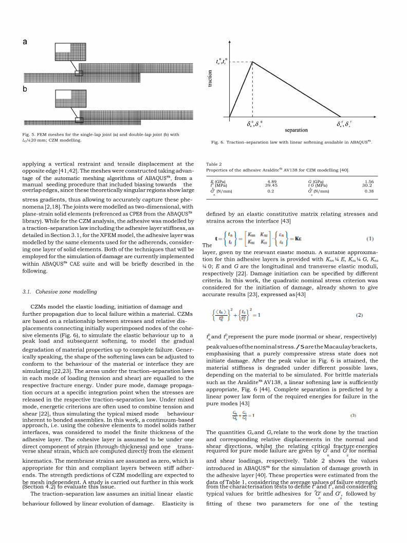
Fig. 5. FEM meshes for the single-lap joint (a) and double-lap joint (b) with
LO ¼ 20 mm; CZM modelling. Fig. 6. Traction–separation law with linear softening available in ABAQUS
s.
applying a vertical restraint and tensile displacement at the
opposite edge [41,42]. The meshes were constructed taking advan-
tage of the automatic meshing algorithms of ABAQUSs, from a manual seeding procedure that included biasing towards the
Table 2
Properties of the adhesive Araldites
AV138 for CZM modelling [40].
E (GPa) 4.89 G (GPa) 1.56 t0
(MPa) 39.45 t 0 (MPa) 30.2 n s
overlap edges, since these theoretically singular regions show large Gc
(N/mm) 0.2 Gc (N/mm) 0.38
n s
stress gradients, thus allowing to accurately capture these phe-
nomena [2,18]. The joints were modelled as two-dimensional, with
plane-strain solid elements (referenced as CPE8 from the ABAQUSs
library). While for the CZM analysis, the adhesive was modelled by
a traction–separation law including the adhesive layer stiffness, as
detailed in Section 3.1, for the XFEM model, the adhesive layer was
modelled by the same elements used for the adherends, consider-
ing one layer of solid elements. Both of the techniques that will be
employed for the simulation of damage are currently implemented
within ABAQUSs CAE suite and will be briefly described in the
following.
3.1. Cohesive zone modelling
CZMs model the elastic loading, initiation of damage and
further propagation due to local failure within a material. CZMs
defined by an elastic constitutive matrix relating stresses and
strains across the interface [43]
The matrix K contains the stiffness parameters of the adhesive
layer, given by the relevant elastic moduli. A suitable approxima-
tion for thin adhesive layers is provided with Knn ¼ E, Kss ¼ G, Kns
¼ 0; E and G are the longitudinal and transverse elastic moduli,
respectively [22]. Damage initiation can be specified by different
criteria. In this work, the quadratic nominal stress criterion was
considered for the initiation of damage, already shown to give
accurate results [23], expressed as [43]
are based on a relationship between stresses and relative dis-
placements connecting initially superimposed nodes of the cohe-
sive elements (Fig. 6), to simulate the elastic behaviour up to a t0 and t0 represent the pure mode (normal or shear, respectively) peak load and subsequent softening, to model the gradual n s
degradation of material properties up to complete failure. Gener-
ically speaking, the shape of the softening laws can be adjusted to
conform to the behaviour of the material or interface they are
simulating [22,23]. The areas under the traction–separation laws
in each mode of loading (tension and shear) are equalled to the
respective fracture energy. Under pure mode, damage propaga-
tion occurs at a specific integration point when the stresses are
released in the respective traction–separation law. Under mixed
mode, energetic criterions are often used to combine tension and
shear [22], thus simulating the typical mixed mode behaviour inherent to bonded assemblies. In this work, a continuum-based
peak values of the nominal stress. / S are the Macaulay brackets,
emphasising that a purely compressive stress state does not
initiate damage. After the peak value in Fig. 6 is attained, the
material stiffness is degraded under different possible laws,
depending on the material to be simulated. For brittle materials
such as the Araldites AV138, a linear softening law is sufficiently
appropriate, Fig. 6 [44]. Complete separation is predicted by a
linear power law form of the required energies for failure in the
pure modes [43]
approach, i.e. using the cohesive elements to model solids rather
interfaces, was considered to model the finite thickness of the
adhesive layer. The cohesive layer is assumed to be under one
direct component of strain (through-thickness) and one trans- verse shear strain, which are computed directly from the element
The quantities Gn and Gs relate to the work done by the traction
and corresponding relative displacements in the normal and
shear directions, whilst the relating critical fracture energies required for pure mode failure are given by Gc and Gc for normal
n s
kinematics. The membrane strains are assumed as zero, which is
appropriate for thin and compliant layers between stiff adher-
ends. The strength predictions of CZM modelling are expected to
be mesh independent. A study is carried out further in this work (Section 4.2) to evaluate this issue.
and shear loadings, respectively. Table 2 shows the values
introduced in ABAQUSs for the simulation of damage growth in
the adhesive layer [40]. These properties were estimated from the
data of Table 1, considering the average values of failure strength from the characterisation tests to define t0 and t0, and considering
n s The traction–separation law assumes an initial linear elastic typical values for brittle adhesives for Gc and Gc, followed by
n s
behaviour followed by linear evolution of damage. Elasticity is fitting of these two parameters for one of the testing
i
configurations (single-lap joint with LO ¼ 20 mm). These values
were subsequently applied to all configurations tested.
3.2. eXtended Finite Element Modelling
The XFEM is also tested in this work to assess its feasibility in
simulating damage propagation in adhesively bonded joints. The
XFEM formulation embedded in ABAQUSs CAE suite was used,
whose basic principles and analysis technique are briefly
described in this section [43]. As an extension to the conventional
FEM, the XFEM is based on the integration of enrichment func-
tions in the Finite Element formulation, although retaining its
basic properties such as sparsity and symmetry of the resulting
stiffness matrix. These functions allow modelling the displace-
ment jump between crack faces that occur during the propagation
of a crack. The fundamental expression of the displacement vector u,
including the displacements enrichment, is written as [43]
ba, and the associated elastic asymptotic crack-tip functions, Fa(x)
[45]. Fa(x) are only used in ABAQUSs for stationary cracks, which
is not the current scenario. In the presence of damage
propagation, a different approach is undertaken, based on the
establishment of phantom nodes that subdivide elements cut by a
crack and simulate separation between the newly created sub-
elements. By this approach, the asymptotic functions are discarded,
and only the displacement jump is included in the formulation.
Propagation of a crack along an arbitrary path is made possible by
the use of phantom nodes that initially have exactly the same
coordinates than the real nodes and that are completely constrained
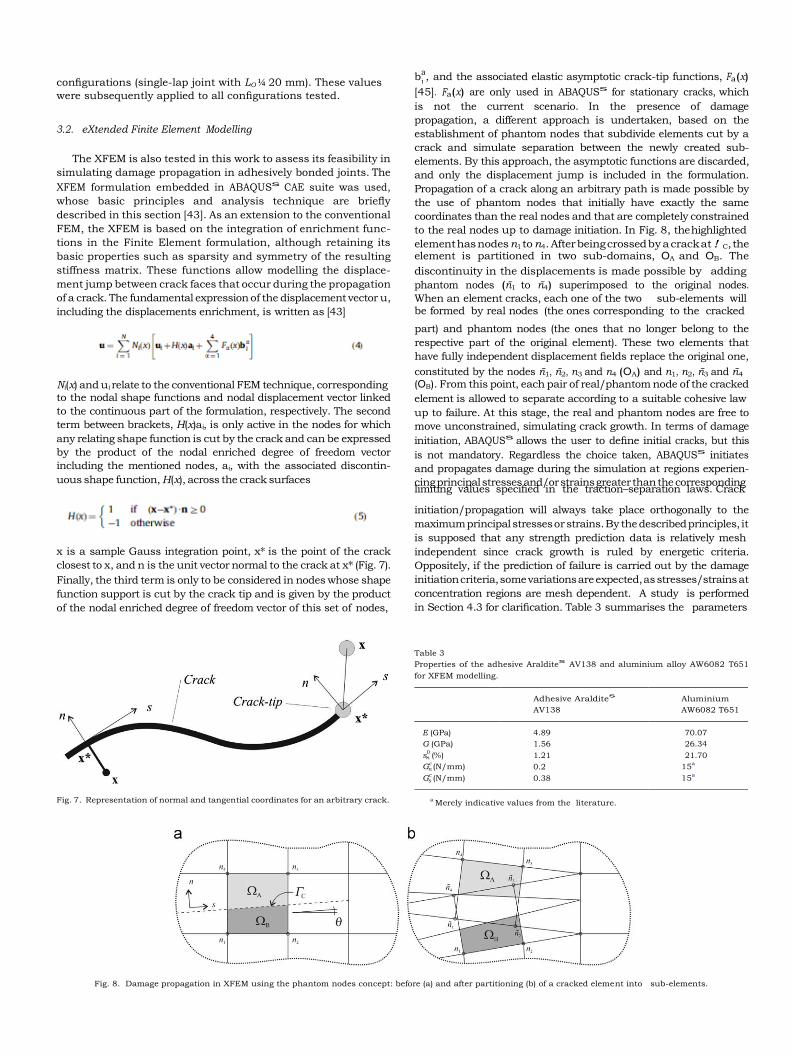
to the real nodes up to damage initiation. In Fig. 8, the highlighted
element has nodes n1 to n4. After being crossed by a crack at ! C, the element is partitioned in two sub-domains, OA and OB. The
discontinuity in the displacements is made possible by adding
phantom nodes (n1 to n4) superimposed to the original nodes.
When an element cracks, each one of the two sub-elements will be formed by real nodes (the ones corresponding to the cracked
part) and phantom nodes (the ones that no longer belong to the
respective part of the original element). These two elements that
have fully independent displacement fields replace the original one,
constituted by the nodes n1, n2, n3 and n4 (OA) and n1, n2, n3 and n4
Ni(x) and ui relate to the conventional FEM technique, corresponding
to the nodal shape functions and nodal displacement vector linked
to the continuous part of the formulation, respectively. The second
term between brackets, H(x)ai, is only active in the nodes for which
any relating shape function is cut by the crack and can be expressed
by the product of the nodal enriched degree of freedom vector
including the mentioned nodes, ai, with the associated discontin-
uous shape function, H(x), across the crack surfaces
(OB). From this point, each pair of real/phantom node of the cracked
element is allowed to separate according to a suitable cohesive law
up to failure. At this stage, the real and phantom nodes are free to
move unconstrained, simulating crack growth. In terms of damage
initiation, ABAQUSs allows the user to define initial cracks, but this
is not mandatory. Regardless the choice taken, ABAQUSs initiates
and propagates damage during the simulation at regions experien-
cing principal stresses and/or strains greater than the corresponding limiting values specified in the traction–separation laws. Crack
initiation/propagation will always take place orthogonally to the
maximum principal stresses or strains. By the described principles, it
is supposed that any strength prediction data is relatively mesh
x is a sample Gauss integration point, x* is the point of the crack
closest to x, and n is the unit vector normal to the crack at x* (Fig. 7).
Finally, the third term is only to be considered in nodes whose shape
function support is cut by the crack tip and is given by the product
of the nodal enriched degree of freedom vector of this set of nodes,
Fig. 7. Representation of normal and tangential coordinates for an arbitrary crack.
independent since crack growth is ruled by energetic criteria.
Oppositely, if the prediction of failure is carried out by the damage
initiation criteria, some variations are expected, as stresses/strains at
concentration regions are mesh dependent. A study is performed
in Section 4.3 for clarification. Table 3 summarises the parameters
Table 3
Properties of the adhesive Araldites
AV138 and aluminium alloy AW6082 T651
for XFEM modelling.
n
n
s
a Merely indicative values from the literature.
Fig. 8. Damage propagation in XFEM using the phantom nodes concept: before (a) and after partitioning (b) of a cracked element into sub-elements.
Adhesive Araldites
Aluminium
AV138 AW6082 T651
E (GPa) 4.89 70.07
G (GPa) 1.56 26.34
s0 (%) 1.21 21.70
Gc (N/mm) 0.2 15
a
Gc (N/mm) 0.38 15
a
n
n
introduced in ABAQUSs for damage propagation in the adhesive layer
and aluminium adherends. s0 represents the maximum principal
strain that will lead to damage initiation. It should be emphasised
that, due to the intrinsic principles of XFEM as explained above, only
one strength/strain parameter is to be introduced in ABAQUSs,
corresponding to the maximum principal strength/strain that will
trigger the initiation of damage. In Table 3, the value of s0 for the
aluminium adherends is defined from the average value of failure
strain obtained in the tensile bulk tests to this material. The values of Gc and Gc are typical values from the aluminium literature.
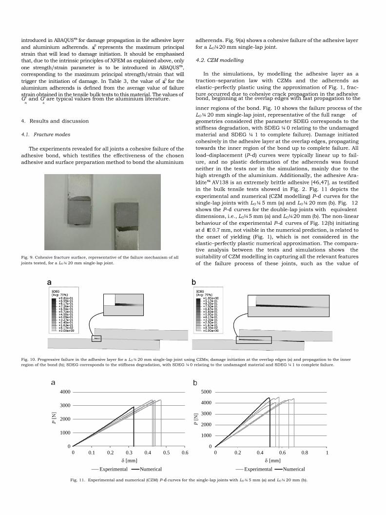
adherends. Fig. 9(a) shows a cohesive failure of the adhesive layer
for a LO ¼ 20 mm single-lap joint.
4.2. CZM modelling
In the simulations, by modelling the adhesive layer as a
traction–separation law with CZMs and the adherends as
elastic–perfectly plastic using the approximation of Fig. 1, frac-
ture occurred due to cohesive crack propagation in the adhesive bond, beginning at the overlap edges with fast propagation to the
n s
inner regions of the bond. Fig. 10 shows the failure process of the
LO ¼ 20 mm single-lap joint, representative of the full range of
4. Results and discussion
4.1. Fracture modes
The experiments revealed for all joints a cohesive failure of the
adhesive bond, which testifies the effectiveness of the chosen
adhesive and surface preparation method to bond the aluminium
Fig. 9. Cohesive fracture surface, representative of the failure mechanism of all
joints tested, for a LO ¼ 20 mm single-lap joint.
geometries considered (the parameter SDEG corresponds to the
stiffness degradation, with SDEG ¼ 0 relating to the undamaged
material and SDEG ¼ 1 to complete failure). Damage initiated
cohesively in the adhesive layer at the overlap edges, propagating
towards the inner region of the bond up to complete failure. All
load–displacement (P–d) curves were typically linear up to fail-
ure, and no plastic deformation of the adherends was found
neither in the tests nor in the simulations, mainly due to the
high strength of the aluminium. Additionally, the adhesive Ara-
ldites AV138 is an extremely brittle adhesive [46,47], as testified
in the bulk tensile tests showed in Fig. 2. Fig. 11 depicts the
experimental and numerical (CZM modelling) P–d curves for the
single-lap joints with LO ¼ 5 mm (a) and LO ¼ 20 mm (b). Fig. 12
shows the P–d curves for the double-lap joints with equivalent
dimensions, i.e., LO ¼ 5 mm (a) and LO ¼ 20 mm (b). The non-linear
behaviour of the experimental P–d curves of Fig. 12(b) initiating
at d E0.7 mm, not visible in the numerical prediction, is related to
the onset of yielding (Fig. 1), which is not considered in the
elastic–perfectly plastic numerical approximation. The compara-
tive analysis between the tests and simulations shows the
suitability of CZM modelling in capturing all the relevant features
of the failure process of these joints, such as the value of
Fig. 10. Progressive failure in the adhesive layer for a LO ¼ 20 mm single-lap joint using CZMs; damage initiation at the overlap edges (a) and propagation to the inner
region of the bond (b); SDEG corresponds to the stiffness degradation, with SDEG ¼ 0 relating to the undamaged material and SDEG ¼ 1 to complete failure.
4000
3000
2000
1000
0
0
0.1 0.2 0.3 0.4 0.5 0.6
5000
4000
3000
2000
1000
0
0
0.2 0.4 0.6 0.8 1
[mm] [mm]
Experimental Numerical Experimental Numerical
Fig. 11. Experimental and numerical (CZM) P–d curves for the single-lap joints with LO ¼ 5 mm (a) and LO ¼ 20 mm (b).
P [
N]
P [
N]
Pm
/Pm
av
g [
%]
6000
5000
4000
3000
2000
1000
0
0
0,1 0,2 0,3 0,4 0,5 0,6
14000
12000
10000
8000
6000
4000
2000
0
0
0.3 0.6 0.9 1.2 1.5 1.8
() [mm] () [mm]
Experimental Numerical Experimental Numerical
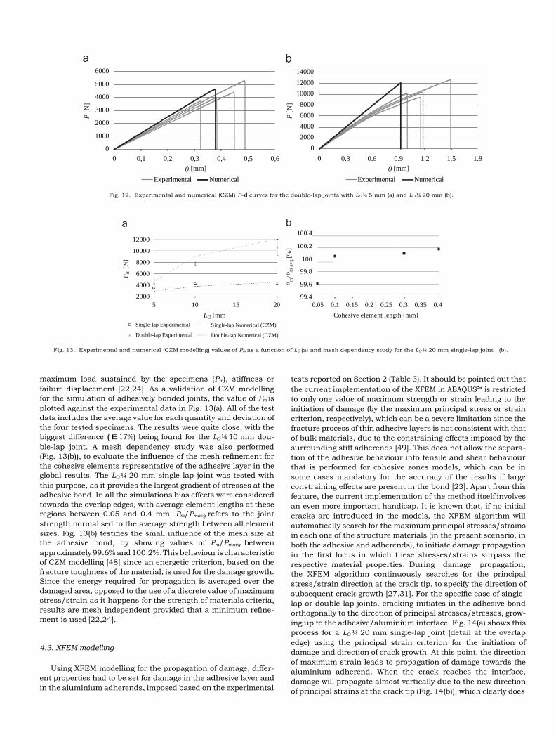
Fig. 12. Experimental and numerical (CZM) P–d curves for the double-lap joints with LO ¼ 5 mm (a) and LO ¼ 20 mm (b).
12000
10000
100.4
100.2
8000 100
6000 99.8 4000 99.6 2000 99.4
5 10 15 20
LO [mm]
0.05 0.1 0.15 0.2 0.25 0.3 0.35 0.4
Cohesive element length [mm]
Single-lap Experimental Single-lap Numerical (CZM)
Double-lap Experimental Double-lap Numerical (CZM)
Fig. 13. Experimental and numerical (CZM modelling) values of Pm as a function of LO (a) and mesh dependency study for the LO ¼ 20 mm single-lap joint (b).
maximum load sustained by the specimens (Pm), stiffness or
failure displacement [22,24]. As a validation of CZM modelling
for the simulation of adhesively bonded joints, the value of Pm is
plotted against the experimental data in Fig. 13(a). All of the test
data includes the average value for each quantity and deviation of
the four tested specimens. The results were quite close, with the
biggest difference (E17%) being found for the LO ¼ 10 mm dou-
ble-lap joint. A mesh dependency study was also performed
(Fig. 13(b)), to evaluate the influence of the mesh refinement for
the cohesive elements representative of the adhesive layer in the
global results. The LO ¼ 20 mm single-lap joint was tested with
this purpose, as it provides the largest gradient of stresses at the
adhesive bond. In all the simulations bias effects were considered
towards the overlap edges, with average element lengths at these
regions between 0.05 and 0.4 mm. Pm/Pmavg refers to the joint
strength normalised to the average strength between all element
sizes. Fig. 13(b) testifies the small influence of the mesh size at
the adhesive bond, by showing values of Pm/Pmavg between
approximately 99.6% and 100.2%. This behaviour is characteristic
of CZM modelling [48] since an energetic criterion, based on the
fracture toughness of the material, is used for the damage growth.
Since the energy required for propagation is averaged over the
damaged area, opposed to the use of a discrete value of maximum
stress/strain as it happens for the strength of materials criteria,
results are mesh independent provided that a minimum refine-
ment is used [22,24].
4.3. XFEM modelling
Using XFEM modelling for the propagation of damage, differ-
ent properties had to be set for damage in the adhesive layer and
in the aluminium adherends, imposed based on the experimental
tests reported on Section 2 (Table 3). It should be pointed out that
the current implementation of the XFEM in ABAQUSs is restricted
to only one value of maximum strength or strain leading to the
initiation of damage (by the maximum principal stress or strain
criterion, respectively), which can be a severe limitation since the
fracture process of thin adhesive layers is not consistent with that
of bulk materials, due to the constraining effects imposed by the
surrounding stiff adherends [49]. This does not allow the separa-
tion of the adhesive behaviour into tensile and shear behaviour
that is performed for cohesive zones models, which can be in
some cases mandatory for the accuracy of the results if large
constraining effects are present in the bond [23]. Apart from this
feature, the current implementation of the method itself involves
an even more important handicap. It is known that, if no initial
cracks are introduced in the models, the XFEM algorithm will
automatically search for the maximum principal stresses/strains
in each one of the structure materials (in the present scenario, in
both the adhesive and adherends), to initiate damage propagation
in the first locus in which these stresses/strains surpass the
respective material properties. During damage propagation,
the XFEM algorithm continuously searches for the principal
stress/strain direction at the crack tip, to specify the direction of
subsequent crack growth [27,31]. For the specific case of single-
lap or double-lap joints, cracking initiates in the adhesive bond
orthogonally to the direction of principal stresses/stresses, grow-
ing up to the adhesive/aluminium interface. Fig. 14(a) shows this
process for a LO ¼ 20 mm single-lap joint (detail at the overlap
edge) using the principal strain criterion for the initiation of
damage and direction of crack growth. At this point, the direction
of maximum strain leads to propagation of damage towards the
aluminium adherend. When the crack reaches the interface,
damage will propagate almost vertically due to the new direction
of principal strains at the crack tip (Fig. 14(b)), which clearly does
P [
N]
Pm
[N
]
P [
N]

Fig. 14. Progressive failure of a LO ¼ 20 mm single-lap joint using XFEM (the arrows represent the directions of maximum principal strain): damage initiation within the
adhesive at the overlap edges (a) and damage growth to the aluminium adherend (b).
12000
10000
8000
6000
4000
2000
5
10 15 20
140
120
100
80
60
40
0.05
0.1
0.15
0.2
LO [mm]
Single-lap Experimental Single-lap Numerical (XFEM)
Double-lap Experimental Double-lap Numerical (XFEM)
Element length and height [mm]
Fig. 15. Experimental and numerical (XFEM modelling) values of Pm as a function of LO (a) and mesh dependency study for the LO ¼ 20 mm single-lap joint (b).
not reflect the real behaviour of single-lap joints. Damage propa-
gation along the adhesive bond is thus rendered unfeasible with
this technique, since the algorithm will always search for max-
imum stresses/strains at the crack tip, shifting the crack to the
adherends, disregarding what happens within the adhesive layer
and thus preventing damage propagation along the adhesive
bond. From this discussion it becomes clear that XFEM, as it is
currently implemented, is only suitable for the identification of
the locus of damage initiation in adhesive bonds, by comparing
the maximum principal stress/strain in each of the constituent
materials to the respective maximum values. However, it does
not show to be suited for the simulation of damage growth, as
the principle for defining the crack direction (orthogonal to the
maximum principal stress/strain) does not model accurately the
propagation of damage in multi-material structures as it does not
consider the initiation of damage outside the tip of the cracks that
emerge from the structure boundaries nor does it take into
account the prospect of damage growth along interfaces between
different materials. For the specific case of bonded joints, a
modification of the XFEM algorithm that would consider these
possibilities would bring a significant breakthrough for the
simulation of these structures, with the accuracy of CZMs but
eliminating the major handicap of this method to follow the
damage paths specified by the placement of the cohesive ele-
ments. As a result of this handicap, a different solution is
proposed, supported by the brittleness of the adhesive used. The
maximum strength of the joints will be predicted by the initiation
of cohesive cracking of the adhesive layer at the overlap edges,
using the maximum principal strain criterion as it showed to be
slightly less mesh sensitive than the maximum principal stress
criterion. Fig. 15(a) compares the experimental and XFEM data
considering the maximum principal strain criterion, showing that
the XFEM is moderately accurate in simulating these structures
with brittle adhesives that lead to a catastrophic failure of the
joint as soon as the maximum strain of the adhesive is attained
anywhere in the structure. However, the proposed methodology
was only acceptable due to the brittleness of the adhesive since, if
a ductile adhesive had been used instead, the predictions would
clearly underestimate the experiments. Another handicap
of XFEM modelling using the proposed technique is the mesh
size dependency of the stresses/strains [50]. P–d curves for XFEM
are not presented here, but there show a similar agreement
to Figs. 11 and 12, except for small variations on the values
of Pm. Fig. 15(b) shows the values of Pm/Pmavg, as defined
for Fig. 13(a), for element sizes at the overlap edges (equal length
and height) between 0.05 and 0.2 mm, showing that, as expected,
this method is extremely mesh dependent.
5. Concluding remarks
The main objective of this work was to evaluate the capabil-
ities and/or limitations of using the current implementations
of Cohesive Zone Modelling or eXtended Finite Element Modelling
available in ABAQUSs to simulate the behaviour and strength of
adhesively bonded joints. With this purpose, single- and double-lap
Crack initiation
Crack growth
Pm
[N
]
Pm
/Pm
av
g [%
]
joints between aluminium adherends were considered, bonded
with the brittle adhesive Araldites AV138. A variety of overlap
lengths was tested, between 5 and 20 mm, to test both solutions for
fracture modelling under different load gradients, i.e., between an
approximately even level of shear stresses along the bond up to the
large shear stress gradients found in joints with bigger bond
lengths. The direct comparisons between the experimental data
and the output of the simulations revealed accurate predictions for
the Cohesive Zone Modelling technique. This was expected, since
this technique has been extensively validated for a wide variety of
engineering problems, with positive results being expected, pro-
vided that the shape of the chosen cohesive laws are consistent
with the constitutive behaviour of the material they are simulating.
The eXtended Finite Element Method, expanding Cohesive Zone
Modelling by the allowance of crack propagation along arbitrary
directions within solid continuum elements, did not show to be
suited for damage propagation in bonded joints as it is currently
implemented, since the direction of crack growth is ruled by the
maximum principal stresses/strains at the crack tip which, in
bonded joints, invariably leads to damage growth towards and
within the adherends. This clearly does not reflect the behaviour of
bonded joints and can be attributed to an algorithm for propagation
not still suited to multi-material structures as it does not search for
failure points outside the crack tip nor following the interfaces
between different materials. Restriction of damage propagation
only for the adhesive layer is also rendered unfeasible to surpass
this limitation as crack propagation halts when the crack attains the
aluminium. Due to the brittleness of the adhesive used, the
eXtended Finite Element Method was used to predict failure by
damage onset at the overlap edges, which showed satisfactory
results in terms of quantitative results and dependence with the
overlap length, but extremely mesh dependent. Some principles
were proposed to modify this promising technique for the simula-
tion of bonded joints.
Acknowledgements
The authors would like to thank the Portuguese Foundation for
Science and Technology for supporting the work here presented.
References
[1] Messler RW. Joining of advanced materials. Stoneham, USA: Butterworths/
Heinemann; 1993.
[2] R.D.S.G. Campilho, de Moura MFSF, Domingues JJMS. Modelling single and
double-lap repairs on composite materials. Composites Science and Technol-
ogy 2005;65:1948–58.
[3] Volkersen O. Die nietkraftoerteilung in zubeanspruchten nietverbindungen
konstanten loschonquerschnitten. Luftfahrtforschung 1938;15:41–7.
[4] Goland M, Reissner E. The stresses in cemented joints. Journal of Applied
Mechanics 1944;66:17–27.
[5] Sze pe F. Strength of adhesive-bonded lap joints with respect to change of
temperature and fatigue. Experimental Mechanics 1966;6:280–6.
[6] Hart-Smith LJ. Adhesive-bonded single-lap joints. NASA Technical Report CR-
112236. Hampton, USA: Langley Research Centre; 1973.
[7] Pirvics J. Two dimensional displacement–stress distributions in adhesive
bonded composite structures. The Journal of Adhesion 1974;6:207–28.
[8] Panigrahi SK, Pradhan B. Three dimensional failure analysis and damage
propagation behavior of adhesively bonded single lap joints in laminated FRP
composites. Journal of Reinforced Plastics and Composites 2007;26:183–201.
[9] Wooley GR, Carver DR. Stress concentration factors for bonded lap joint.
Journal of Aircraft 1971;8:817–20.
[10] Harris JA, Adams RD. Strength prediction of bonded single-lap joints by non-
linear finite element methods. International Journal of Adhesion & Adhesives
1984;4:65–78.
[11] Bigwood DA, Crocombe AD. Non-linear adhesive bonded joint design ana-
lyses. International Journal of Adhesion & Adhesives 1990;10:31–41.
[12] Crocombe AD, Adams RD. An elastoplastic investigation of the peel test. The
Journal of Adhesion 1982;13:241–67.
[13] Lee SJ, Lee GL. Development of a failure model for the adhesively bonded
tubular single lap joint. The Journal of Adhesion 1992;40:1–14.
[14] Qian ZQ, Akisanya AR. An investigation of the stress singularity near the free
edge of scarf joints. European Journal of Mechanics A/Solids 1999;18:443–63.
[15] Dragoni E, Mauri P. Intrinsic static strength of friction interfaces augmented
with anaerobic adhesives. International Journal of Adhesion & Adhesives
2000;20:315–21.
[16] Feih S, Shercliff HR. Adhesive and composite failure prediction of single-L
joint structures under tensile loading. International Journal of Adhesion &
Adhesives 2005;25:47–59.
[17] Cavalli MN, Thouless MD. The effect of damage nucleation on the toughness
of an adhesive joint. The Journal of Adhesion 2001;76:75–92.
[18] Campilho RDSG, de Moura MFSF, Domingues JJMS. Stress and failure analyses
of scarf repaired CFRP laminates using a cohesive damage model. Journal of
Adhesion Science and Technology 2007;21:855–970.
[19] Cui W, Wisnom MR. A combined stress-based and fracture-mechanics-based
model for predicting delamination in composites. Composites 1993;24:467–74.
[20] Petrossian Z, Wisnom MR. Prediction of delamination initiation and growth
from discontinuous plies using interface elements. Composites: Part A—
Applied Science and Manufacturing 1998;29:503–15.
[21] Feraren P, Jensen HM. Cohesive zone modelling of interface fracture near
flaws in adhesive joints. Engineering Fracture Mechanics 2004;71:2125–42.
[22] Campilho RDSG, de Moura MFSF, Domingues JJMS. Using a cohesive damage
model to predict the tensile behaviour of CFRP single-strap repairs. Interna-
tional Journal of Solids and Structures 2008;45:1497–512.
[23] R.D.S.G. Campilho, de Moura MFSF, Pinto AMG, Morais JJL, Domingues JJMS.
Modelling the tensile fracture behaviour of CFRP scarf repairs. Composites:
Part B—Engineering 2009;40:149–57.
[24] Kafkalidis MS, Thouless MD. The effects of geometry and material properties
on the fracture of single lap-shear joints. International Journal of Solids and
Structures 2002;39:4367–83.
[25] Belytschko T, Black T. Elastic crack growth in finite elements with minimal
remeshing. International Journal of Fracture Mechanics 1999;45:601–20.
[26] Melenk JM, Babuska I. The partition of unity finite element method: basic
theory and applications. Seminar fur Angewandte Mathematik, Eidgenos-
sische Technische Hochschule, Research Report No. 96-01, January, CH-8092
Zurich, Switzerland, 1996.
[27] Moe s N, Dolbow J, Belytschko T. A finite element method for crack growth
without remeshing. International Journal for Numerical Methods in Engi-
neering 1999;46:131–50.
[28] Mohammadi S. Extended finite element method for fracture analysis of
structures. New Jersey, USA: Blackwell Publishing; 2008.
[29] Sukumar N, Moe s N, Moran B, Belytschko T. Extended finite element method
for three-dimensional crack modeling. International Journal for Numerical
Methods in Engineering 2000;48:1549–70.
[30] Daux C, Moe s N, Dolbow J, Sukumark N, Belytschko T. Arbitrary branched and
intersecting cracks with the extended finite element method. International
Journal for Numerical Methods in Engineering 2000;48:1741–60.
[31] Moe s N, Belytschko T. Extended finite element method for cohesive crack
growth. Engineering Fracture Mechanics 2002;69:813–33.
[32] Elguedj T, Gravouil A, Combescure A. Appropriate extended functions for X-
FEM simulation of plastic fracture mechanics. Computer Methods in
Applied Mechanics and Engineering 2006;195:501–15.
[33] Dolbow J, Moe s N, Belytschko T. An extended finite element method for
modeling crack growth with frictional contact. Finite Elements in Analysis
and Design 2000;36:235–60.
[34] Khoei AR, Nikbakht M. Contact friction modeling with the extended finite
element method (X-FEM). Journal of Materials Processing Technology
2006;177:58–62.
[35] Fagerstro m M, Larsson R. Theory and numerics for finite deformation fracture
modelling using strong discontinuities. International Journal for Numerical
Methods in Engineering 2006;66:911–48.
[36] PMGP Moreira, de Jesus AMP, Ribeiro AS, de Castro PMST. Fatigue crack
growth in friction stir welds of 6082-T6 and 6061-T6 aluminium alloys: a
comparison. Theoretical and Applied Fracture Mechanics 2008;50:81–91.
[37] ASTM-E8M-04. Standard test methods for tension testing of metallic materi-
als [Metric], 2004.
[38] NF T 76-142. Me thode de preparation de plaques d’adhe sifs structuraux pour
la re alisation d’e prouvettes d’essai de caracte risation, 1988.
[39] ISO 11003-2:1993(E). Adhesives—determination of shear behavior of struc-
tural bonds, Part II: thick adherend tensile test method, 1993.
[40] da Silva LFM, RAM da Silva, JAG Chousal, AMG Pinto. Alternative methods to
measure the adhesive shear displacement in the thick adherend shear test.
Journal of Adhesion Science and Technology 2008;22:15–29.
[41] Goyal VK, Johnson ER, Goyal VK. Predictive strength–fracture model for
composite bonded joints. Composite Structures 2008;82:434–46.
[42] Radice JJ, Vinson JR. On the analysis of adhesively bonded structures: a high
order semielastic adhesive layer model. Composites Science and Technology
2008;68:376–86.
[43] ABAQUSs
HTML Documentation, Dassault Systemes, 2009.
[44] Alfano G. On the influence of the shape of the interface law on the application
of cohesive-zone models. Composites Science and Technology 2006;66:723–30.
[45] Sukumar N, Prevost JH. Modeling quasi-static crack growth with the
extended finite element method, Part I: computer implementation. Interna-
tional Journal for Solids and Structures 2003;40:7513–37.
[46] Banea MD, da Silva LFM. The effect of temperature on the mechanical proper-
ties of adhesives for the automotive industry. Proceedings of the IMechE, Part L:
Journal of Materials: Design and Applications 2010;224:51–62.

[47] Banea MD, da Silva LFM. Mechanical characterization of flexible adhesives.
The Journal of Adhesion 2009;85:261–85.
[48] Campilho RDSG, de Moura MFSF, Domingues JJMS. Numerical prediction on
the tensile residual strength of repaired CFRP under different geometric
changes. International Journal of Adhesion & Adhesives 2009;29:195–205.
[49] Xie D, Waas AM. Discrete cohesive zone model for mixed-mode fracture using
finite element analysis. Engineering Fracture Mechanics 2006;73:1783–96.
[50] Panigrahi SK, Pradhan B. Three dimensional failure analysis and damage
propagation behavior of adhesively bonded single lap joints in laminated FRP
composites. Journal of Reinforced Plastics and Composites 2007;26:183–201.
Related Documents