Structural Mechanics MARIA FRÖLING STRENGTH DESIGN METHODS FOR LAMINATED GLASS Licentiate Dissertation

STRENGTH DESIGN METHODS FOR LAMINATED GLASS,
Nov 08, 2014
DESIGN METHODS FOR LAMINATED GLASS
Welcome message from author
This document is posted to help you gain knowledge. Please leave a comment to let me know what you think about it! Share it to your friends and learn new things together.
Transcript

Structural
Mechanics
MARIA FRÖLING
STRENGTH DESIGN METHODSFOR LAMINATED GLASS
Licentiate Dissertation

Denna sida skall vara tom!

Copyright © 2011 by Structural Mechanics, LTH, Sweden.Printed by Media-Tryck LU, Lund, Sweden, May, 2011 (Pl).
For information, address:
Division of Structural Mechanics, LTH, Lund University, Box 118, SE-221 00 Lund, Sweden.Homepage: http://www.byggmek.lth.se
Structural MechanicsDepartment of Construction Sciences
ISRN LUTVDG/TVSM--11/3071--SE (1-76)ISSN 0281-6679
STRENGTH DESIGN METHODS
FOR LAMINATED GLASS
MARIA FRÖLING


Acknowledgements
The work in this thesis has been performed at the Department of Construction Sciences,at Lund University. The financial support from the Swedish Research Council FORMAS,Glasbranschföreningen and Svensk Planglasförening is gratefully acknowledged.I would like to thank my supervisors Anne Landin and Kent Persson for their guidance,support and encouragement. I owe gratitude to Kent Persson for his practical advice, helpwith technical details and fruitful feedback.The reference group of this project is acknowledged for their interest in the project, sup-port and advice.Technical help from personnel at the center for scientific and technical computing at LundUniversity, LUNARC, is acknowledged. I would also like to thank Bo Zadig for help withgraphical details. A thanks is directed to Johan Lorentzon for technical assistance.I would like to thank the whole Department of Construction Sciences, and especially theDivision of Structural Mechanics, for providing a supportive, open and creative work at-mosphere.Finally I thank my family and friends for support and friendship.
i

Abstract
In this thesis, methods for efficiently determining stresses in laminated glass structures aredeveloped and tested. The laminated glass structures comprise both bolted and adhesivejoints.A recently developed finite element is suggested to be suitable for the modeling of lam-inated glass structures. The element is implemented and tested. It is proven by meansof a simple test example that the element can be used in finite element analysis of lami-nated glass structures and give a good accuracy with a small fraction of the correspondingmodel size using standard solid elements. As an illustration of how the element wouldperform when more complicated glass structures are concerned, a similar element is im-plemented in the commercial finite element software ABAQUS and is used to analyzea laminated glass structure comprising one bolt fixing. The element performs well bothwhen it comes to accuracy and efficiency. It is indicated thatthe new finite element iswell suited for modeling laminated glass structures.The new finite element is rigourously tested and compared to standard solid elementswhen it comes to the modeling of laminated glass structures.It is shown that the new finiteelement is superior to standard solid elements when it comesto modeling of laminatedglass. The new element is applied to laminated glass structures comprising bolted andadhesive joints. Good results concerning accuracy and efficiency are obtained. The resultsshow that the element may well be suited to model complex laminated glass structureswith several bolted or adhesive joints.The new element is used in the development of a method to compute stress concentrationfactors for laminated glass balustrades with 2+2 bolt fixings. The stress concentrationfactors are represented graphically in design charts. The use of the design charts allowthe maximum principal stresses of the balustrade to be determined without using finiteelement analysis or advanced mathematics. The stresses canbe computed for an arbitrarycombination of geometry parameters of the balustrade.It is illustrated how design charts for laminated glass balustrades with 3+3 bolt fixings aredeveloped.Keywords: finite element, computational techniques, laminated glass, stress concentra-tion factor, design chart, bolt fixing, adhesive joint, balustrade.
iii


Contents
1 Introduction 11.1 Background . . . . . . . . . . . . . . . . . . . . . . . . . . . . . . . . . 11.2 Aim and Objectives . . . . . . . . . . . . . . . . . . . . . . . . . . . . . 31.3 Limitations . . . . . . . . . . . . . . . . . . . . . . . . . . . . . . . . . 3
2 Theory and Methods 32.1 The Material Glass . . . . . . . . . . . . . . . . . . . . . . . . . . . . . 32.2 Types of Glass . . . . . . . . . . . . . . . . . . . . . . . . . . . . . . . . 4
2.2.1 Annealed Glass . . . . . . . . . . . . . . . . . . . . . . . . . . . 52.2.2 Fully Tempered Glass . . . . . . . . . . . . . . . . . . . . . . . 52.2.3 Heat Strengthened Glass . . . . . . . . . . . . . . . . . . . . . . 52.2.4 Laminated Glass . . . . . . . . . . . . . . . . . . . . . . . . . . 5
2.3 Mechanical Properties of Glass . . . . . . . . . . . . . . . . . . . . .. . 52.4 Stress Prediction of Laminated Glass Structures . . . . . .. . . . . . . . 6
3 Related Research on Laminated Glass 83.1 Introduction . . . . . . . . . . . . . . . . . . . . . . . . . . . . . . . . . 83.2 Experimental Results . . . . . . . . . . . . . . . . . . . . . . . . . . . . 83.3 Analytical Results . . . . . . . . . . . . . . . . . . . . . . . . . . . . . . 93.4 Numerical Results . . . . . . . . . . . . . . . . . . . . . . . . . . . . . . 113.5 Discussion . . . . . . . . . . . . . . . . . . . . . . . . . . . . . . . . . . 14
4 Stress Prediction of a Bolt Fixed Balustrade 144.1 General . . . . . . . . . . . . . . . . . . . . . . . . . . . . . . . . . . . 144.2 Description of Example . . . . . . . . . . . . . . . . . . . . . . . . . . . 154.3 Finite Element Analysis Using Three Dimensional Solid Elements . . . . 164.4 Finite Element Analysis Using M-RESS Elements . . . . . . . . .. . . . 174.5 Stress Prediction Using Design Charts . . . . . . . . . . . . . . . .. . . 174.6 Results and Comparison . . . . . . . . . . . . . . . . . . . . . . . . . . 19
5 Summary of the Papers 195.1 Paper1 . . . . . . . . . . . . . . . . . . . . . . . . . . . . . . . . . . . . 195.2 Paper 2 . . . . . . . . . . . . . . . . . . . . . . . . . . . . . . . . . . . 195.3 Paper 3 . . . . . . . . . . . . . . . . . . . . . . . . . . . . . . . . . . . 20
6 Conclusions and Future Work 20
v

APPENDED PAPERS
Paper 1Applying Solid-shell Elements to Laminated Glass StructuresMaria Fröling and Kent Persson
Paper 2Computational Methods for Laminated GlassMaria Fröling and Kent Persson
Paper 3Designing Bolt Fixed Laminated Glass with Stress Concentration FactorsMaria Fröling and Kent Persson
vii

1 Introduction
1.1 Background
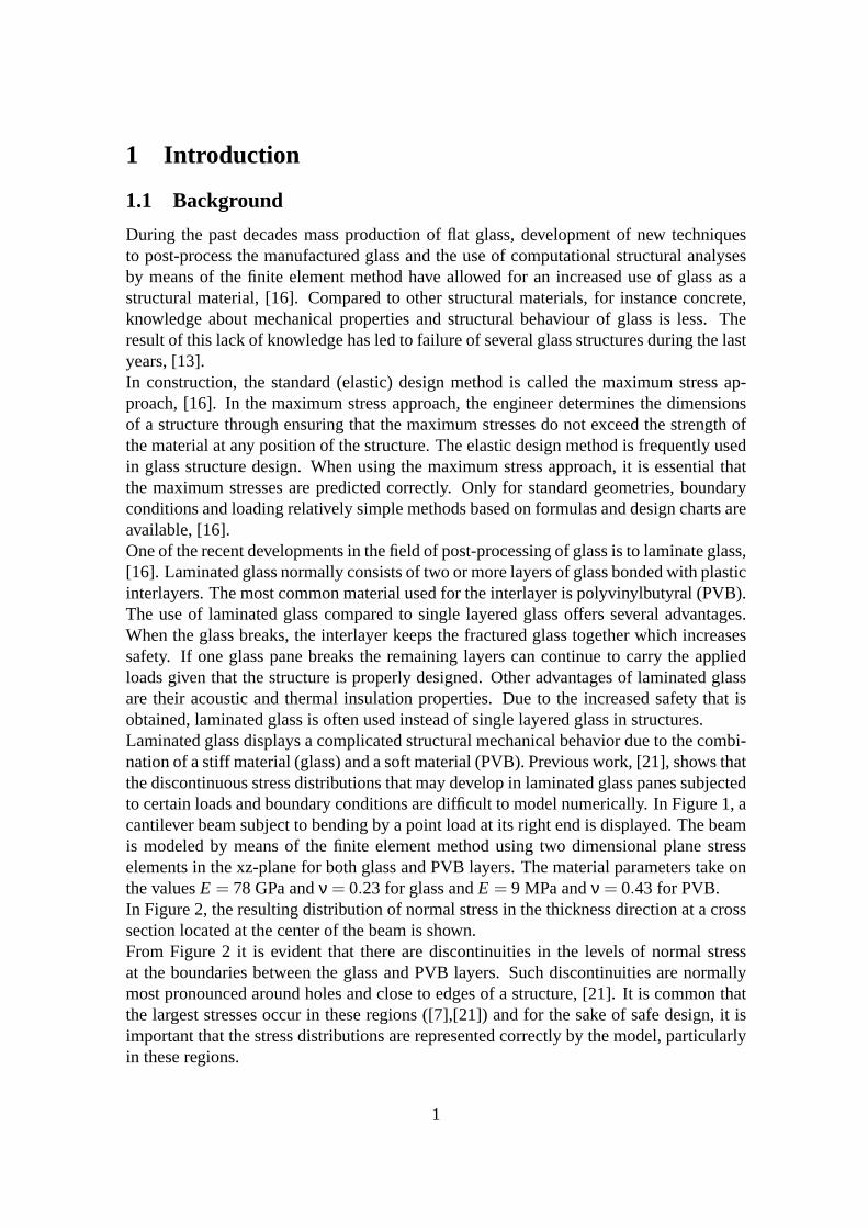
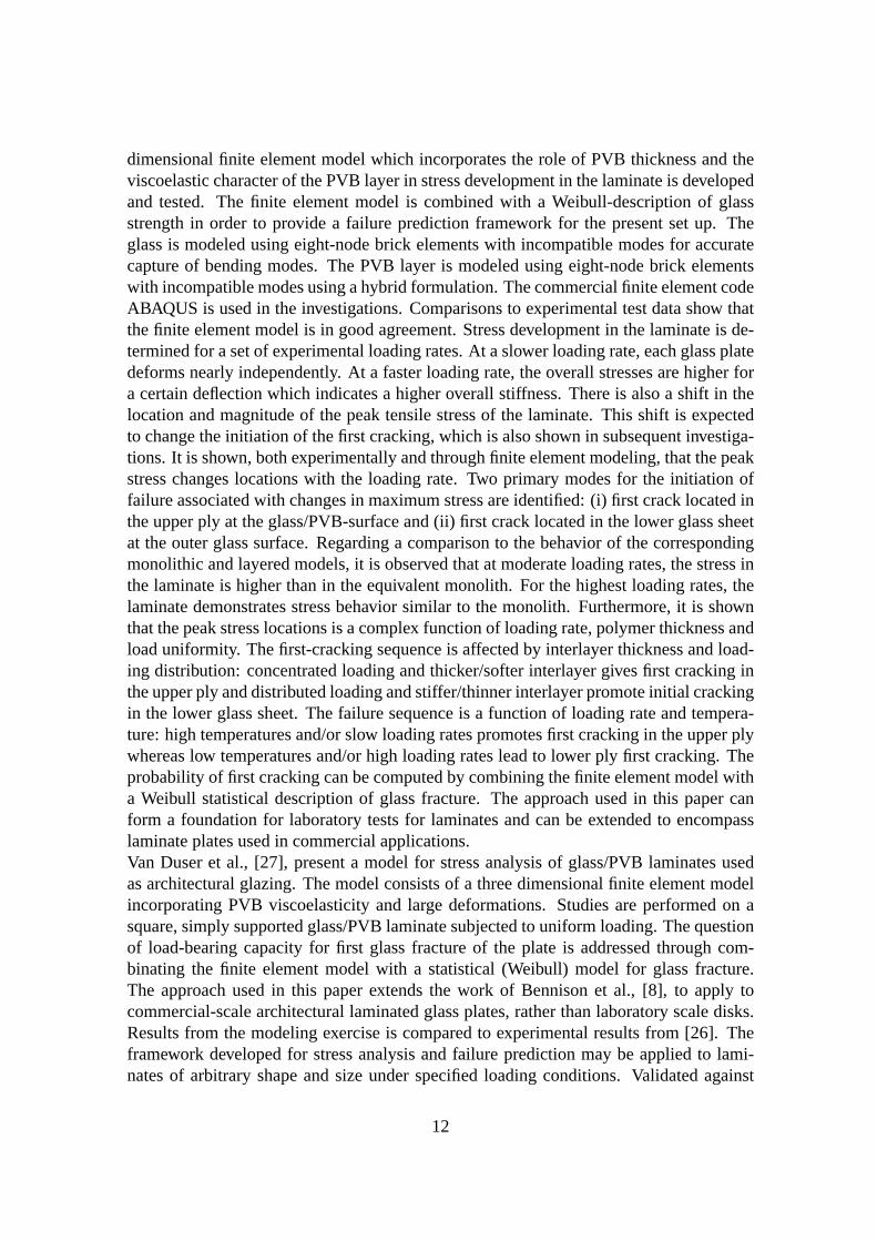
During the past decades mass production of flat glass, development of new techniquesto post-process the manufactured glass and the use of computational structural analysesby means of the finite element method have allowed for an increased use of glass as astructural material, [16]. Compared to other structural materials, for instance concrete,knowledge about mechanical properties and structural behaviour of glass is less. Theresult of this lack of knowledge has led to failure of severalglass structures during the lastyears, [13].In construction, the standard (elastic) design method is called the maximum stress ap-proach, [16]. In the maximum stress approach, the engineer determines the dimensionsof a structure through ensuring that the maximum stresses donot exceed the strength ofthe material at any position of the structure. The elastic design method is frequently usedin glass structure design. When using the maximum stress approach, it is essential thatthe maximum stresses are predicted correctly. Only for standard geometries, boundaryconditions and loading relatively simple methods based on formulas and design charts areavailable, [16].One of the recent developments in the field of post-processing of glass is to laminate glass,[16]. Laminated glass normally consists of two or more layers of glass bonded with plasticinterlayers. The most common material used for the interlayer is polyvinylbutyral (PVB).The use of laminated glass compared to single layered glass offers several advantages.When the glass breaks, the interlayer keeps the fractured glass together which increasessafety. If one glass pane breaks the remaining layers can continue to carry the appliedloads given that the structure is properly designed. Other advantages of laminated glassare their acoustic and thermal insulation properties. Due to the increased safety that isobtained, laminated glass is often used instead of single layered glass in structures.Laminated glass displays a complicated structural mechanical behavior due to the combi-nation of a stiff material (glass) and a soft material (PVB). Previous work, [21], shows thatthe discontinuous stress distributions that may develop inlaminated glass panes subjectedto certain loads and boundary conditions are difficult to model numerically. In Figure 1, acantilever beam subject to bending by a point load at its right end is displayed. The beamis modeled by means of the finite element method using two dimensional plane stresselements in the xz-plane for both glass and PVB layers. The material parameters take onthe valuesE = 78 GPa andν = 0.23 for glass andE = 9 MPa andν = 0.43 for PVB.In Figure 2, the resulting distribution of normal stress in the thickness direction at a crosssection located at the center of the beam is shown.From Figure 2 it is evident that there are discontinuities inthe levels of normal stressat the boundaries between the glass and PVB layers. Such discontinuities are normallymost pronounced around holes and close to edges of a structure, [21]. It is common thatthe largest stresses occur in these regions ([7],[21]) and for the sake of safe design, it isimportant that the stress distributions are represented correctly by the model, particularlyin these regions.
1

zP
x
Figure 1: A cantilever laminated glass beam subjected to a point load.
−500 −400 −300 −200 −100 0 100 200 300 400 500
−2
−1.5
−1
−0.5
0
0.5
1
1.5
2
Normal stress (MPa)
Thi
ckne
ss d
irect
ion
(mm
)
Figure 2: Distribution of normal stress along thickness.
Stress distributions as in Figure 2 are well captured by three dimensional solid elements.The disadvantage is that the resulting finite element modelsbecome very large whichrequires great computational effort. When modeling an engineering structure that com-prises laminated glass panes, the computational time required may prevent fast and simpleevaluation of different design alternatives. Papers 1 and 2deal with the implementationof a new method for increasing the computational efficiency when modeling laminatedglass structures by means of the finite element method.In the design of glass structures, tables and graphs contained in design standards canbe utilized when considering common geometries and boundary conditions. For morecomplicated geometries and boundary conditions, for instance bolt fixings, a detailedcomputational analysis is often required, [16]. The standard method for predicting thestress distribution in a laminated glass structure with several bolt fixings is to use threedimensional solid elements in finite element analyses. Verylarge finite element modelsare required for an accurate stress prediction of this type of structures, which makes theanalyses practically impossible from a computational perspective. Using the method de-scribed in Papers 1 and 2, analyses are made possible, but decent knowledge about finiteelement analysis is required. The topic of Paper 3 is the development of design charts forbolt fixed laminated glass balustrades with a variable number of bolts. Thus, the design of
2
bolt fixed glass balustrades is made possible without performing advanced mathematicsor finite element analyses.
1.2 Aim and Objectives
The aim of this thesis is to provide means of efficiently determining the stress distributionin advanced laminated glass structures. A recently developed finite element is imple-mented in finite element analysis and applied to laminated glass structures comprisingstructures that contain bolted and adhesive joints. The performance of the element interms of accuracy and computational efficiency is tested andcompared to conventionalthree dimensional solid element models. For bolt fixed laminated glass balustrades, de-sign charts are developed for the determination of the stress distributions. The objectiveis to provide a relatively simple design tool for users that are less familiar with the finiteelement method.
1.3 Limitations
In the work developed in this thesis, some limitations are necessary. In the modeling ofthe bolts, only one type of bolt is used. It is a bolt for a cylindrical bore hole. Only onecombination of thickness and material of the bush is considered. We also limit ourselves tostress predictions, leaving out details of further design work. When the design charts aredeveloped, we restrict ourselves to the analysis of indoor balustrades, which somewhatsimplifies the load situation since wind loads do not need to be considered, [9]. It isintended that the charts are not to be used for the highest line load (3 kN/m) according toSwedish construction standards, since for this case, a point load giving rise to a worst caseloading situation is required in the analysis, [9]. Further, Swedish construction standards,[9], are used consistently when determining the load combination and balustrade heightused in the analyses. It is assumed that the gravitational body force due to the weight ofthe structure could be neglected.
2 Theory and Methods
2.1 The Material Glass
Generally, glass forms when a liquid is cooled down in such a way that "freezing" happensinstead of crystallization, [20]. Glasses do not consist ofa geometrically regular networkof crystals, but of an irregular network of silicon and oxygen atoms with alkaline parts inbetween, [16]. The most common oxide glass, silico-soda-lime glass, is used to produceglazing, [20]. Table 1 shows the chemical composition of silico-soda-lime glass accordingto European construction standards, [16].When manufacturing glass, four primary operations can be identified: batching, melting,fining and forming, [20]. While the three first operations are used in all glass manufactur-ing processes, the forming and the subsequent post-processdepend on which end product
3

Table 1: Chemical composition of silico-soda-lime glass (mass %).Component Chemical formula Content (mass %)Silica sand SiO2 69-74
Lime (calcium oxide) CaO 5-14Soda Na2O 10-16
Magnesia MgO 0-6Alumina Al2O3 0-3Others 0.5
that is manufactured. During the batching process, the correct mix of raw materials isselected based on chemistry, purity, uniformity and particle size, [20]. When melting theraw materials, glass furnaces are used. Different furnacesare used for producing differentend products. The aim of the glass fining process is to producea molten glass that isuniform in terms of composition and temperature and also bubble free.Flat glass (which could be used for architectural glazing) is produced by the float process,which was introduced by Pilkington Brothers Ltd in the 1950s,[20]. It is noteworthy thatthis mass production process, together with continuously improved post-processes, havemade glass cheap enough to allow it to be used extensively in the construction industry andto grow in importance as construction material during the past 50 years. Within the lasttwo decades, further development within the field of post-processing operations, togetherwith numerical analyses of structures (finite element analyses) have enabled glass to beused as structural elements in architectural glazing, [16]. In the start of the float process,the raw materials are melted in a furnace. Then, a fining process is used to eliminatebubbles. Later, the melt is poured onto a pool of molten tin, float, under a nitrogenatmosphere in order to prevent corrosion of the tin bath. Tinhas higher specific weight(weight per unit volume) than glass, so that the glass floats on the tin. The glass spreadsout and forms a smooth flat sheet at an equilibrium thickness of 6-7 mm. In order toproduce various glass thicknesses, rollers working from the top of the glass are used. Thespeed of the rollers controls the glass thickness. The rangeof commercial glass thicknessis 2-19 mm, [20]. During this phase, the glass is gradually cooled. The next step of theprocess is the annealing lehr, which slowly cools the glass in order to prevent that residualstresses are induced within the glass. After the lehr, the glass is inspected and it is ensuredthat visual defects and imperfections are removed. The glass is cut to a typical size of 3.21× 6.00 m, [16], and then stored.The standard flat glass produced through the float process is called annealed glass, [16].Often further post-processing of the glass is required in order to produce glass productswith different properties. For instance lamination of the glass and hole drilling are madeat this stage.
2.2 Types of Glass
During the post-processing phase, glass types and productswith different properties canbe manufactured. Below, the most common glass types are described.
4

2.2.1 Annealed Glass
Annealed glass is standard float glass without further treatment. At breakage, annealedglass splits into large fragments, [16].
2.2.2 Fully Tempered Glass
Another commonly used term for fully tempered glass is toughened glass. During temper-ing, float glass is heated and then cooled rapidly (quenched)by cold air jets. The aim ofthe tempering process is to create a parabolic residual stress field that has tensile stressesin the core and compressive stresses at the surfaces of the glass. The surface of the glassalways contains some cracks. Under a tensile stress field, the cracks are allowed to grow.If the glass is subjected to loads, cracks will not grow unless there is a net tensile stressfield at the surface of the glass. Fully tempered glass usually breaks into small harmlesspieces and therefore fully tempered glass is also termed safety glass, [16].
2.2.3 Heat Strengthened Glass
Heat strengthened glass is produced similarly as fully tempered glass, but the cooling rateis lower. The resulting residual stress is lower, and thus the tensile strength is lower thanfor fully tempered glass. At fracture, the fragments are larger than for fully temperedglass. On the other hand, the larger glass fragments allow for a greater post-breakage loadcapacity than for fully tempered glass, [16].
2.2.4 Laminated Glass
Laminated glass consists of two or more glass panes bonded bya plastic interlayer. Theglass panes can have different thicknesses and heat treatments. Most common among thelamination processes is autoclaving, [16]. The use of laminated glass in architectural glaz-ing is of great advantage for two reasons. Firstly, if one glass pane breaks, the remainingpanes can continue to carry the applied loads given that the structure is properly designed.Secondly, the scattered glass pieces can stick to the interlayer and thereby serve to pre-vent people from getting injured. The interlayer is most often made of polyvinylbutyral,PVB. The nominal thickness of a single foil of PVB is 0.38 mm. Itis common that two(0.76 mm) or four (1.52 mm) foils form one PVB interlayer, [16]. PVB is a viscoelasticmaterial whose physical properties depend on the temperature and the load duration.
2.3 Mechanical Properties of Glass
Glass is an elastic, isotropic material and exhibits brittle fracture. In contrast to otherconstruction materials, no plastic deformation occurs prior to failure. Therefore, localstress concentrations, occurring for instance close to bolt holes, are not reduced.The brit-tle characteristic of glass is of concern when constructingwith glass as a load bearingelement.
5
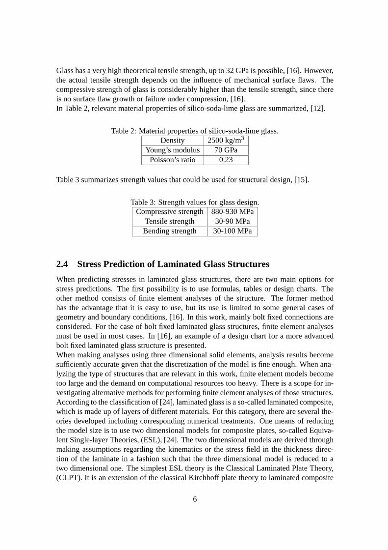
Glass has a very high theoretical tensile strength, up to 32 GPa is possible, [16]. However,the actual tensile strength depends on the influence of mechanical surface flaws. Thecompressive strength of glass is considerably higher than the tensile strength, since thereis no surface flaw growth or failure under compression, [16].In Table 2, relevant material properties of silico-soda-lime glass are summarized, [12].
Table 2: Material properties of silico-soda-lime glass.Density 2500 kg/m3
Young’s modulus 70 GPaPoisson’s ratio 0.23
Table 3 summarizes strength values that could be used for structural design, [15].
Table 3: Strength values for glass design.Compressive strength880-930 MPa
Tensile strength 30-90 MPaBending strength 30-100 MPa
2.4 Stress Prediction of Laminated Glass Structures
When predicting stresses in laminated glass structures, there are two main options forstress predictions. The first possibility is to use formulas, tables or design charts. Theother method consists of finite element analyses of the structure. The former methodhas the advantage that it is easy to use, but its use is limitedto some general cases ofgeometry and boundary conditions, [16]. In this work, mainly bolt fixed connections areconsidered. For the case of bolt fixed laminated glass structures, finite element analysesmust be used in most cases. In [16], an example of a design chart for a more advancedbolt fixed laminated glass structure is presented.When making analyses using three dimensional solid elements, analysis results becomesufficiently accurate given that the discretization of the model is fine enough. When ana-lyzing the type of structures that are relevant in this work,finite element models becometoo large and the demand on computational resources too heavy. There is a scope for in-vestigating alternative methods for performing finite element analyses of those structures.According to the classification of [24], laminated glass is aso-called laminated composite,which is made up of layers of different materials. For this category, there are several the-ories developed including corresponding numerical treatments. One means of reducingthe model size is to use two dimensional models for compositeplates, so-called Equiva-lent Single-layer Theories, (ESL), [24]. The two dimensional models are derived throughmaking assumptions regarding the kinematics or the stress field in the thickness direc-tion of the laminate in a fashion such that the three dimensional model is reduced to atwo dimensional one. The simplest ESL theory is the ClassicalLaminated Plate Theory,(CLPT). It is an extension of the classical Kirchhoff plate theory to laminated composite
6
plates. In the CLPT theory, the assumptions regarding the displacement field are suchthat straight lines normal to the midsurface remain straight and normal to the midsurfaceafter deformation. Thus, the transverse shear and transverse normal effects are neglected(plane stress). The First Order Shear Deformation Theory, (FSDT), extends the ESL the-ory through including a transverse shear deformation in thekinematic assumptions suchthat the transverse shear strain is assumed to be constant with respect to the thicknesscoordinate. In terms of kinematic assumptions this means that straight lines normal to themidsurface do not remain perpendicular to the midsurface after deformation. There arealso higher order theories for laminated composite plates.The higher order theories maybe able to more accurately describing the interlaminar stress distributions. On the otherhand, they also require considerably more computational effort. In the Third Order ShearDeformation Theory, the assumption on straightness and normality of straight lines nor-mal to the midsurface after deformation is relaxed. The result is a quadratic variation ofthe transverse stresses through each layer. Even higher order shear deformation theoriesare available, but the theories are complicated algebraically and expensive numerically,and yield a comparatively little gain in computational accuracy. The simple ESL laminatetheories are often not capable of accurately determining the three dimensional stress fieldat ply level, which may be required for an accurate description of the stress distribution ina complex laminated glass structure.An alternative is to use Layerwise Theories, [24]. The Layerwise Theories contain fullthree dimensional kinematics and constitutive relations.They also fulfill requirements onC0
z continuity, ([24], [11]). These requirements should necessarily be fulfilled in order tocorrectly describe the stress field in the thickness direction that characterizes laminatedglass. Even if there are some computational advantages compared to full three dimen-sional element models, for instance that two dimensional finite elements could be used inthe analysis, in the modeling of advanced structures the models may be computationallyinefficient and difficult to implement, [24].There exist several other layerwise models for laminated plates, see [24] and referencestherein. It is not the intention to provide a full review of various Layerwise Theories, sothe interested reader is referred to the references provided in the reference cited above.Another possible method, which is adopted in this work, is touse solid-shell elements. Asolid-shell element is a three dimensional solid element which is modified so that shelllike structures could be modeled in an appropriate manner. The basis for the solid-shellelement used in this work, [10], is a conventional eight nodethree dimensional solidelement. Since low-order three dimensional solid elementsare used in order to modelshell like structures, locking phenomena occur. In the solid-shell formulation, certainmethods are incorporated such that locking is prevented. A review of solid-shell elementsis provided in Paper 2. We note that through maintaining three dimensional constitutiverelations and kinematic assumptions, the stress distribution of laminated glass can beaccurately determined. The computational efficiency is increased due to the use of aspecial reduced integration scheme that only requires one integration point per materiallayer.
7
3 Related Research on Laminated Glass
3.1 Introduction
Past research on glass has focused mainly on monolithic (single-layered) glass, whereasthe properties of laminated glass remain less well understood. The aim of this sectionis to review past research on the properties and behavior of laminated glass for architec-tural glazing. The review is subdivided into sections, where the first section deals withexperimental testing, the second with analytical methods and the last section reviews nu-merical testing results. In the last section, emphasis is onFinite Element Method (FEM)analyses. It is shown that a clear cut division of previous research findings into these dis-tinct categories is difficult, but the subdivision is rathera means of providing a structuredpresentation of the available knowledge.
3.2 Experimental Results
Most analyses on laminated glass units are experimental. This is particularly the case forplates, since the behavior is very complex, [1]. In this review we consider test results forboth beams and plates. Studies on glass beams are often used to approximate the behaviorof glass plates. According to Asik, [1], this methodology is (generally) not acceptable,since the two structures have different stress and displacement fields.One of the first studies on the behavior of architectural laminated glass subjected to struc-tural loading is conducted by Hooper, [18]. In that study, the fundamental behavior ofarchitectural laminates in bending is assessed. This is done by means of studies of lami-nated glass beams subjected to four-point bending. First, analytical formulas are derivedfor the shear force at the interface between glass and the interlayer and the central de-flection respectively. These expressions are then used in combination with experimentalbending tests in order to provide general understanding about the behavior of laminatedglass beams subjected to bending as well as to produce data oninterlayer shear stiffnesses(shear moduli) for various loading and temperature conditions. Results show that thebending resistance of the laminated glass is dependent uponthe thickness and shear mod-ulus of the interlayer. The physical properties of the interlayer are dependent upon thetemperature and the duration of the loading. From an architectural designer’s perspective,laminated glass which is subjected to sustained loads should be treated as consisting oftwo independent glass layers. For short-term loading, the bending stresses of the glasscould be determined on the basis of an interlayer shear modulus corresponding to themaximum temperature at which such loading is likely to occur. When the glass is sub-jected to both sustained and short-term loading, the combined bending stress values in theglass layers may be calculated using the principle of superposition.Behr et al., [3], reports on studies on the behavior of laminated glass units consisting oftwo glass plates with an interface of PVB. The glass units are subjected to lateral pressure(wind loads). Experiments are conducted in order to find out whether the behavior of alaminated glass unit is similar to that of a monolithic glassunit of the same thickness orto that of a layered glass unit consisting of two glass units and no interlayer. Results show
8

that the glass unit behaves more like a monolithic glass unitat room temperature. Whentemperatures are high, the behavior approaches that of two glass units without interlayer.Laminated glass units (two glass plates with a PVB interlayer) under uniform lateral loadsand simply supported boundary conditions are investigatedexperimentally in Behr et al.,[4]. According to the results, interlayer thickness effects on the structural behavior (interms of corner stresses and center deflections) of laminated glass units are not large.Further, long-duration load tests at different temperatures are performed. For this case,the response in structural behavior is increasing as a function of time at load. Rates ofincrease in response in structural behavior decrease with time at load. In overview, theexperimental data gathered during the tests are within theoretically derived monolithicand layered bounds on stresses and deflections.Minor and Reznik, [22], study the failure behavior of laminated glass units. Three speci-men sizes are used in the tests. Annealed monolithic glass samples are used as referencespecimens. Laminated glass samples of the same dimensions and thicknesses as the refer-ence specimens are tested to failure using the same loading rates as for the failure analysisof the reference specimens. Failure strengths are evaluated as functions of several vari-ables: glass type (heat treatment), temperature and surface condition (subjected to surfacedamage or not). The most interesting result is that annealedlaminated glass strengths areequal to annealed monolithic glass strengths at room temperature. This result is valid forall three sample sizes. Another interesting result is that when temperatures are increased,laminated glass strengths decrease.Behr et al., [5], makes a reliability analysis of the glass strength data presented in [22].The results of this analysis support the conclusions made in[22]. However, the reliabilityanalyses suggest that the issue of the relative strength between monolithic glass unitsversus laminated glass units is complex at elevated temperatures. Whereas a clear strengthreduction occurs in laminated glass at 77◦C, little strength reduction occurs at 49◦C. Thisindicates the possible existence of a break point in the relation between temperature andlateral pressure strength for laminated glass at around 49◦C. Thus, for temperatures abovethis threshold it is suggested that the structural behaviorof laminated glass is not longersimilar to that of monolithic glass.
3.3 Analytical Results
Analytical work on laminated glass properties are scarce. In addition, most results arederived under various simplificating assumptions, [13].In early work by for instance Vallabhan et al., [25], a previously developed computermodel is used in order to analyze layered and monolithic rectangular glass plates subjectedto uniform lateral pressure. The layered and monolithic plates have the same in-plane ge-ometry total thickness. So-called strength-factors are developed for a variety of glassplate geometries. The strength-factor is defined as the ratio between maximum stresses ina monolithic plate and those in a layered plate. It is noteworthy that for certain geometriesand loads, layered glass plates can possess larger maximum stresses than an equivalentmonolithic glass plate. This result has an implication for the behavior of laminated glassplates, since a laminated glass plate is considered to display structural mechanical be-
9

haviour in between the limiting cases of monolithic and layered plates. It is implied thatthe maximum stresses in a laminated glass plate can be close to (and even exceed) themaximum stresses in an equivalent monolithic glass plate under certain conditions.Vallabhan et al., [26], use the principle of minimum potential energy and variational cal-culus, [17], in order to develop a mathematical model for thenonlinear analysis of lami-nated glass units. The final model consists of five nonlinear differential equations whichare solved numerically and validated through full-scale experiments. The test specimensare square plates of laminated glass. The plates are simply supported and subjected to lat-eral pressure in increments. Stresses and corresponding principal stresses are calculatedas a function of the lateral pressure. The results of the mathematical model compare verywell with the experimental results. It is suggested that further research focuses on testingthe mathematical model for various thicknesses of the laminated glass plates.Norville et al., [23], set up an analytical beam model that explains data on deflection andstress for laminated glass beams under uniform load. The experimental data are presentedin [6]. In the model, the PVB interlayer performs the functions of maintaining spacingbetween the glass sheets and transferring a fraction of the horizontal shear force betweenthose sheets. The PVB interlayer increases the section modulus, i.e. the ratio betweenthe bending moment at a cross section and the stress on the outer glass fiber at that crosssection, of a laminated glass beam, and the magnitude of the flexural (bending) stressesin the outer glass fibers is therefore reduced. Thus, the strength of a laminated glass beamis higher than that of a monolithic glass beam with the same nominal thickness.The analytical model of [26] is used in [1] in order to providea set of graphs that shed lighton the nonlinear behavior of simply supported, laminated glass plates typically used forarchitectural glazing. Such plates have very thin glass plies, which results in that they mayundergo large deflections solely due to their own weights. This results in complex stressfields, which the author studies extensively. The result of the study is that the laminatedglass plate that is studied undergoes very complex and nonlinear behavior when uniformlydistributed load is applied. A conclusion is that nonlinearanalysis is the only acceptabletype of analysis for laminated glass plates.In [2], a theoretical model for the behavior of laminated glass beams is presented. It isassumed that the glass beams are very thin such that large deflection behavior is used inthe model building. The minimum potential energy and variational principles are used inthe derivations. Three coupled nonlinear differential equations are obtained and closedform solutions are presented for simply supported laminated glass beams. The model isverified for the simply supported laminated glass beam through usage of experimentaldata and for a fixed supported laminated glass beam by means offinite element modeling.Also, the behavior of laminated glass is presented in comparison with the behaviors ofmonolithic and layered glass beams. Displacement, moment and stress functions for asimply supported laminated glass beam are given for the use in design to determine thestrength of a laminated glass beam. It is proven analytically that the behavior of a simplysupported laminated glass beam is linear even under large deflection. On the other hand,for the case of the fixed supported laminated glass beam, effects of membrane stressesare substantial and nonlinearities arise from geometric constraints. A discussion aboutthe behavior of laminated glass beams versus laminated glass plates is conducted. It
10
is concluded that as earlier work on laminated glass plates show that simply supportedglass plates undergo nonlinear behavior, simply supportedlaminated glass beams maynot be used to draw conclusions about the behavior of laminated glass plates. In contrast,it is concluded that a study of nonlinear behavior of laminated glass beams makes senseconcerning the behavior of laminated glass plates due to considerable similarities betweenthese two cases.Foraboschi, [13], sets up an analytical model for laminatedglass beams under uniaxialbending. The model predicts stress developments and strength of laminated glass beamswith given geometries, glass moduli of elasticity and PVB moduli of elasticity in shear.The ultimate load is determined using a design value of the glass tensile strength. Themodel is valid under the following assumptions: (i) plane cross sections in the wholebeam, as well as in the PVB interlayer, do not remain plane andnormal to the longitudi-nal axis (ii) glass is modeled in a linear elastic manner (iii) PVB is modeled in a linearelastic manner by means of the modulus of elasticity in shear, given that the value of thisparameter is related to temperature and duration of loading. The latter assumptions al-lows a closed-form solution to the problem, contrary to the case when PVB is modeled ina viscoelastic manner. Since no particular simplificationsare made when formulating themodel, the model predictions are in excellent agreement with test results. In particular,no presumed strength-factor, [25], has been used in order toaccount for the contributionof the PVB layer to the bending capacity through its capacityto transfer horizontal shearforce between the glass layers. An analysis of commercial-scale laminated glass beams ismade in order to gain information regarding the rational design of laminated glass beams.Failure strengths and loads are determined for these cases.A comparison is made betweenthe laminated glass model and monolithic and layered equivalency models respectivelywith respect to failure strengths and loads. Some of the major results are: 1) The greaterthe value of the shear modulus of elasticity of PVB and the thinner the PVB layer, thecloser the prediction of the stress values are to those of themonolithic equivalency modeland the greater is the tensile strength of the beam. 2) Irrespective of parameter values, thelayered model is not suitable for analyzing laminated glassbeams with the actual loadsand boundary conditions. The conditions of the layered model is only approached as thetemperature is reaching a value that prevails during fire explosure or similar conditions.3) When the thickness of the beam is designed appropriately, the strength of the beam israised by up to 70-80 %. 4) The historical assumption that thestrength of laminated glassis equal to 60 % of the strength of monolithic glass of the samethickness is sufficientlypreservative, but it doesn’t represent a lower bound. The benefit of using the above rela-tion is that it provides a simplification, but at the cost of the risk of underestimating theactual load-bearing capacity. 5) The behavior of the monolithic equivalency model is faraway from that of a laminated glass beam, and the implementation of the model for designpurposes is not recommended.
3.4 Numerical Results
A study of stress development and first cracking of glass-PVB(Butacite) laminates isperformed in [8]. Fracture behavior is studied during loading in biaxial bending. A three
11
dimensional finite element model which incorporates the role of PVB thickness and theviscoelastic character of the PVB layer in stress development in the laminate is developedand tested. The finite element model is combined with a Weibull-description of glassstrength in order to provide a failure prediction frameworkfor the present set up. Theglass is modeled using eight-node brick elements with incompatible modes for accuratecapture of bending modes. The PVB layer is modeled using eight-node brick elementswith incompatible modes using a hybrid formulation. The commercial finite element codeABAQUS is used in the investigations. Comparisons to experimental test data show thatthe finite element model is in good agreement. Stress development in the laminate is de-termined for a set of experimental loading rates. At a slowerloading rate, each glass platedeforms nearly independently. At a faster loading rate, theoverall stresses are higher fora certain deflection which indicates a higher overall stiffness. There is also a shift in thelocation and magnitude of the peak tensile stress of the laminate. This shift is expectedto change the initiation of the first cracking, which is also shown in subsequent investiga-tions. It is shown, both experimentally and through finite element modeling, that the peakstress changes locations with the loading rate. Two primarymodes for the initiation offailure associated with changes in maximum stress are identified: (i) first crack located inthe upper ply at the glass/PVB-surface and (ii) first crack located in the lower glass sheetat the outer glass surface. Regarding a comparison to the behavior of the correspondingmonolithic and layered models, it is observed that at moderate loading rates, the stress inthe laminate is higher than in the equivalent monolith. For the highest loading rates, thelaminate demonstrates stress behavior similar to the monolith. Furthermore, it is shownthat the peak stress locations is a complex function of loading rate, polymer thickness andload uniformity. The first-cracking sequence is affected byinterlayer thickness and load-ing distribution: concentrated loading and thicker/softer interlayer gives first cracking inthe upper ply and distributed loading and stiffer/thinner interlayer promote initial crackingin the lower glass sheet. The failure sequence is a function of loading rate and tempera-ture: high temperatures and/or slow loading rates promotesfirst cracking in the upper plywhereas low temperatures and/or high loading rates lead to lower ply first cracking. Theprobability of first cracking can be computed by combining the finite element model witha Weibull statistical description of glass fracture. The approach used in this paper canform a foundation for laboratory tests for laminates and canbe extended to encompasslaminate plates used in commercial applications.Van Duser et al., [27], present a model for stress analysis ofglass/PVB laminates usedas architectural glazing. The model consists of a three dimensional finite element modelincorporating PVB viscoelasticity and large deformations. Studies are performed on asquare, simply supported glass/PVB laminate subjected to uniform loading. The questionof load-bearing capacity for first glass fracture of the plate is addressed through com-binating the finite element model with a statistical (Weibull) model for glass fracture.The approach used in this paper extends the work of Bennison etal., [8], to apply tocommercial-scale architectural laminated glass plates, rather than laboratory scale disks.Results from the modeling exercise is compared to experimental results from [26]. Theframework developed for stress analysis and failure prediction may be applied to lami-nates of arbitrary shape and size under specified loading conditions. Validated against
12
more extensive data the method may be used to develop new design standards for lam-inated glass. Regarding the finite element model, the glass sheets are modeled using8-node solid elements with incompatible modes to avoid locking in bending. The PVBinterlayer is modeled using eight-node solid elements withincompatible modes using ahybrid formulation in order to account for nearly incompressible deformations. The com-mercial program ABAQUS is used for the analysis. Accuracy ofthe finite element modelis obtained through successively refining the mesh until mesh-independent results are ob-tained. The model predictions are in excellent agreement with data presented in [26].One of the main findings of the study is that for most of the range of pressure used in thestudy, the probability of failure is lower than the monolithic limit, except at low pressures.At those pressures and stresses that would be used in design,laminate strength for thiscase would be predicted to be higher than for the equivalent monolithic glass plate. Sincethe concept of layered and monolithic limits is defined basedon small strain analysis ofbeams, and doesn’t take into account the membrane-dominated stress state that developsin large deflection of plates close to glass first cracking, a stress analysis that involvescomparison to these limiting states could be misleading. Infact, if the derivation of theselimits are based on transition to membrane-like behavior (large deflections), the stressesand deflections for a layered system in the membrane limit areexactly the same as forthe equivalent monolithic plate. Since the monolithic limit ignores the thickness of theinterlayer, the first cracking strength of the laminate may be larger than that of the mono-lith. Further, it is shown that stress development in the laminate is temperature (or loadingrate) dependent. The influence of temperature can be diminished at large deflections asmembrane stresses dominate and the coupling between the glass sheets play a lesser rolein the stress development. Somewhat surprisingly, for typical glass Weibull moduli (m∼5-10) the probability of first cracking is only weakly dependent on temperature.The model of van Duser et al., [27], is based on a three dimensional finite element formu-lation. Thus, the resulting model becomes very large and thecomputations are expensive.This is noted by Ivanov, [19], who aims at investigating the effect of design parameterson the strength and stiffness of glass laminates. Another aim is to perform structural opti-mization of glass laminates. It is emphasized that both complicated analytical models thatrequire numerical solutions and computationally expensive models are inappropriate forsuch analyses. The paper treats the case of a simply supported glass/PVB beam. The fol-lowing simplifications are used: (i) only a plane beam is considered and (ii) the problem isconfined to small strains and displacements. The representation of the laminated glass as aplane multilayer beam leads to a plane problem of theory of elasticity, which requires lessequations although the same degree of discretization through the thickness of the beamand makes the corresponding finite element analysis more computationally efficient. Thematerials (glass and PVB) are both represented by linearly elastic material models. Atthe first stage of the analysis, a finite element model is developed. The model is usedfor the analysis of the case bending of a laminated glass beamunder transverse forces.The beam is analysed by means of the finite element analysis software ANSYS 6.1. Alinear finite element analysis is performed and yields data on nodal deflections, strainsand stresses. The analysis shows that the bending stress in the glass layers is determinantfor the load-bearing capability of laminated glasses, but the shear in the PVB layer is
13
important for glass-layer interaction. Based on this first analysis step an analytical modelof a laminated glass beam is developed. The model is based on Bernoulli-Euler beamtheory for each glass layer, with an additional differential equation for the PVB interlayershear interaction. The obtained differential equations are easily solved analytically for thecase of a simply supported beam under uniform transverse load. The mathematical modelis validated against the previously developed two dimensional finite element model andagainst analytical results from [2]. For both cases, the results of the analytical model showgreat agreement with other solutions. The model is used to perform a parametric study ofthe influence of layer thicknesses on deflections and stresses of a beam under transverseuniform load. Later, the model is utilized for lightweight structure optimization of layerthicknesses. The results show that the inner layer of laminated glasses could be thinnerthan the external glass layer and that the optimally designed laminated glasses could besuperior to monolithic glasses in all criteria.
3.5 Discussion
To summarize the review above, one can conclude that most of the investigations doneconsider beams and plates of regular geometries subjected to standard point loads or uni-formly distributed loads. Some attention is directed towards the physical properties of theinterlayer. A main issue is to place laminated glass structural behavior correctly in rela-tion to the behavior of layered and monolithic equivalency models for different geometriesand loading cases. Some investigations deal with the fracture behaviour of simple struc-tures. Analytical models of various complexity have been developed in order to describethe structural mechanic behaviour of laminated glass beams. Finite element models aremainly three dimensional and are developed for the purpose of investigating failure be-haviour or for optimization purposes. In all cases the structures are simple (beams andplates) and the boundary conditions are standard. One author mentions that model sizeconstitutes a limitation when it comes to analyzing laminated glass beams subjected touniaxial bending for optimization purposes. The remedy is to use a plane (two dimen-sional) finite element model rather than a full (three dimensional) model.
4 Stress Prediction of a Bolt Fixed Balustrade
4.1 General
In this section an example of a glass structure with bolted joints is used in order to demon-strate the use of the two stress prediction methods presented in this thesis. The exam-ple comprises a laminated glass balustrade of the type presented in Paper 3. Since thebalustrade in this example has 3+3 bolts, it is simultaneously shown how the concept ofdesign charts can be expanded to balustrades with the increased number of bolts. Theresults in terms of accuracy are compared to results that areobtained when a standardfinite element method is used.
14
4.2 Description of Example
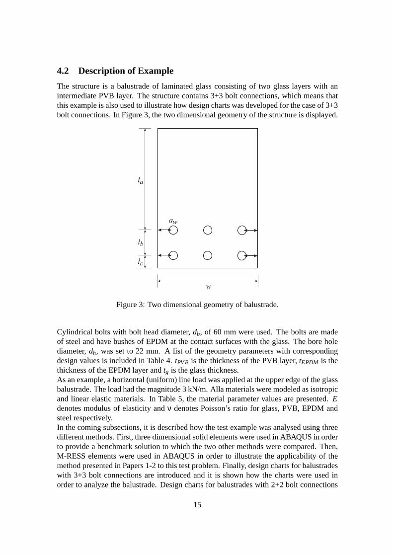
The structure is a balustrade of laminated glass consistingof two glass layers with anintermediate PVB layer. The structure contains 3+3 bolt connections, which means thatthis example is also used to illustrate how design charts wasdeveloped for the case of 3+3bolt connections. In Figure 3, the two dimensional geometryof the structure is displayed.
w
lb
lc
la
aw
Figure 3: Two dimensional geometry of balustrade.
Cylindrical bolts with bolt head diameter,db, of 60 mm were used. The bolts are madeof steel and have bushes of EPDM at the contact surfaces with the glass. The bore holediameter,dh, was set to 22 mm. A list of the geometry parameters with correspondingdesign values is included in Table 4.tPVB is the thickness of the PVB layer,tEPDM is thethickness of the EPDM layer andtg is the glass thickness.As an example, a horizontal (uniform) line load was applied at the upper edge of the glassbalustrade. The load had the magnitude 3 kN/m. Alla materials were modeled as isotropicand linear elastic materials. In Table 5, the material parameter values are presented.Edenotes modulus of elasticity andν denotes Poisson’s ratio for glass, PVB, EPDM andsteel respectively.In the coming subsections, it is described how the test example was analysed using threedifferent methods. First, three dimensional solid elements were used in ABAQUS in orderto provide a benchmark solution to which the two other methods were compared. Then,M-RESS elements were used in ABAQUS in order to illustrate theapplicability of themethod presented in Papers 1-2 to this test problem. Finally, design charts for balustradeswith 3+3 bolt connections are introduced and it is shown how the charts were used inorder to analyze the balustrade. Design charts for balustrades with 2+2 bolt connections
15
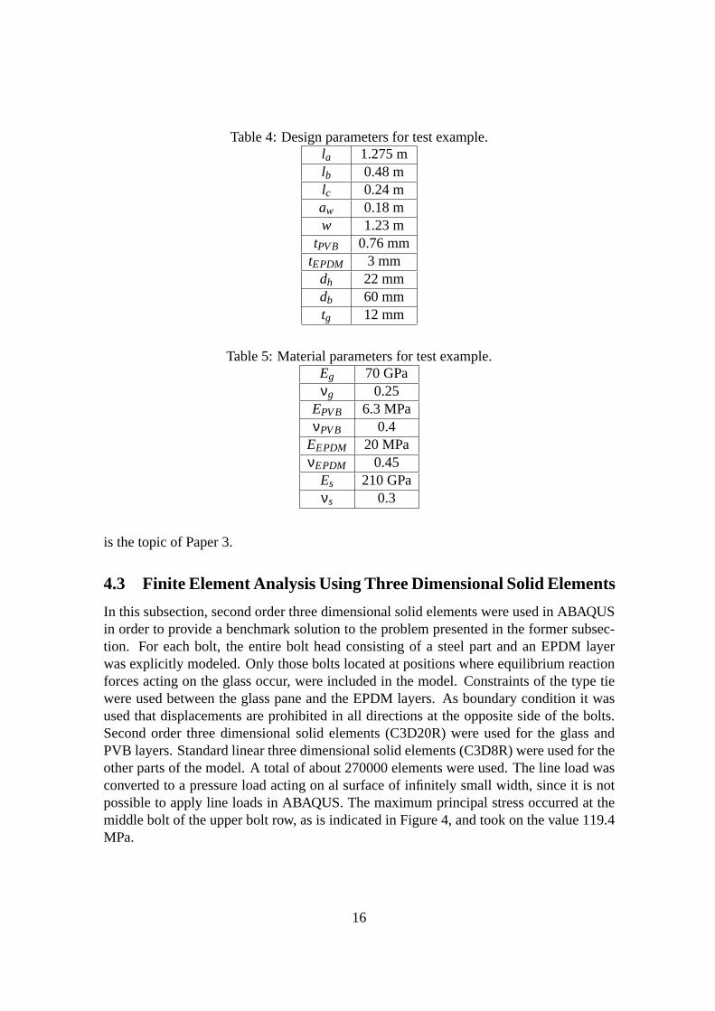
Table 4: Design parameters for test example.la 1.275 mlb 0.48 mlc 0.24 maw 0.18 mw 1.23 m
tPVB 0.76 mmtEPDM 3 mm
dh 22 mmdb 60 mmtg 12 mm
Table 5: Material parameters for test example.Eg 70 GPaνg 0.25
EPVB 6.3 MPaνPVB 0.4
EEPDM 20 MPaνEPDM 0.45
Es 210 GPaνs 0.3
is the topic of Paper 3.
4.3 Finite Element Analysis Using Three Dimensional Solid Elements
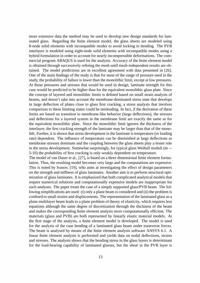
In this subsection, second order three dimensional solid elements were used in ABAQUSin order to provide a benchmark solution to the problem presented in the former subsec-tion. For each bolt, the entire bolt head consisting of a steel part and an EPDM layerwas explicitly modeled. Only those bolts located at positions where equilibrium reactionforces acting on the glass occur, were included in the model.Constraints of the type tiewere used between the glass pane and the EPDM layers. As boundary condition it wasused that displacements are prohibited in all directions atthe opposite side of the bolts.Second order three dimensional solid elements (C3D20R) were used for the glass andPVB layers. Standard linear three dimensional solid elements (C3D8R) were used for theother parts of the model. A total of about 270000 elements were used. The line load wasconverted to a pressure load acting on al surface of infinitely small width, since it is notpossible to apply line loads in ABAQUS. The maximum principal stress occurred at themiddle bolt of the upper bolt row, as is indicated in Figure 4,and took on the value 119.4MPa.
16
(Avg: 75%)S, Max. Principal
−1.195e+07−1.003e+06+9.944e+06+2.089e+07+3.184e+07+4.278e+07+5.373e+07+6.468e+07+7.563e+07+8.657e+07+9.752e+07+1.085e+08+1.194e+08
Figure 4: Maximum principal stresses for balustrade using three dimensional solid ele-ments.
4.4 Finite Element Analysis Using M-RESS Elements
In this subsection, the model of the previous subsection wasused, but the element type ofthe laminated glass was selected to be M-RESS. A modification of the model of the formersubsection was necessary. The line load was distributed to nine equidistant points andapplied as concentrated forces using manual lumping. In this model, two element layersper glass layer and one element layer for the PVB layer were used. In total, around 160000elements were used. The maximum principal stress of the glass balustrade reached 125.5MPa.
4.5 Stress Prediction Using Design Charts
In the course of writing this section, design charts for balustrades with 3+3 bolt connec-tions were developed. The in-plane geometry of the balustrade is that of Figure 3. Whencomparing to the case of a balustrade with 2+2 bolt connections, the set of unknown pa-rameters is the same. The development of the new design charts is thus a simple extensionof the already developed charts. Table 6 displays the designparameters and the ranges ofvariation for each parameter.In Figure 5, the design chart that applies to the test exampleof this section is displayed.Next, it is illustrated how the maximum principal stress of aglass balustrade with geom-etry parameters according to Table 6 and material parameters according to Table 5 wascomputed. First, the nominal stress value,σNom, was computed using equations (1), (35),(37) and (39) of Paper 3.Equation (1) gaveR2 = 3000·1.23· (1+ 1.275
0.48 )≈ 1.3492·104 N.
From equation (1):M(0.48) = (1.3492·104)·1.275·0.48(1.275+0.48) ≈ 4.7049·103 Nm.
17

Table 6: List of geometry parameters.Parameter Value
la 1.25 mlc 0.24 m
tPVB 0.76 mmtEPDM 3 mm
lb 0.2, 0.4, 0.8 maw 0.1-(w2 -0.15) m in step of 0.025w 0.9-2.7 m in step of 0.3 mdh 15-40 mm in step of 5 mmtg 6, 8, 10, 12 mmdb 60 mm
Equation (19) gave (using Matlab):N(0.48)≈−1.8008·105 N.Equation (20) yieldedM(0.48) = 1
2(4.7049·103+0.012· (−1.8008·105))≈ 1.2720·103
Nm.Finally, equation (21) gaveσNom= 1.2720·103
1.23·0.01226
−(−1.8008·105)
1.23·0.012 ≈ 55.3 MPa.
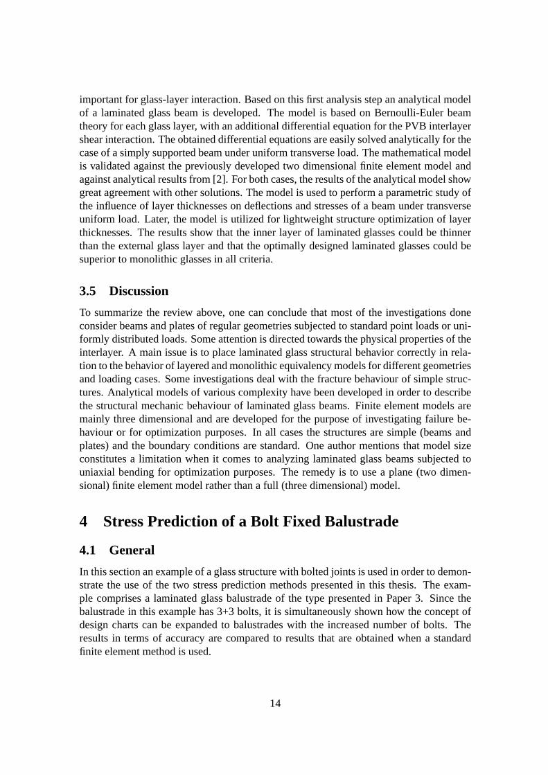
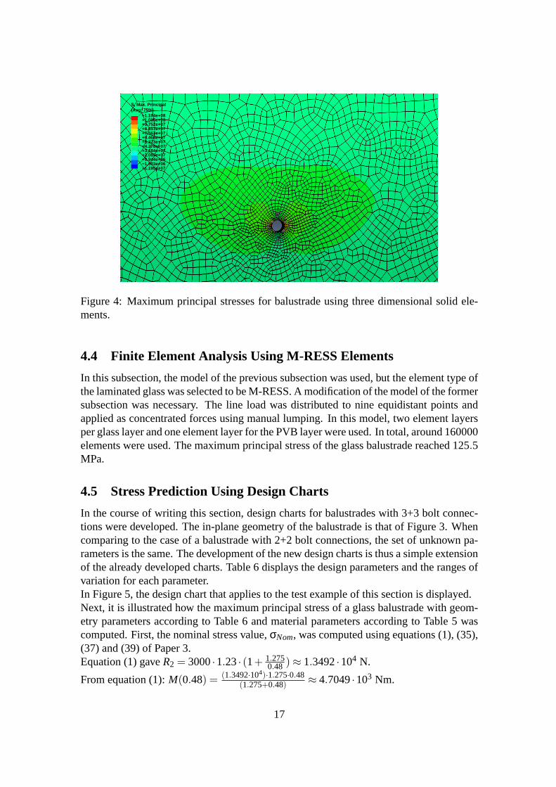
In Figure 5, the applicable design chart for this case is displayed. The chart was selectedas the one which has parameter values closest to the actual design example.
0.1 0.15 0.2 0.25 0.3 0.35 0.4 0.452.1
2.2
2.3
2.4
2.5
2.6
2.7
2.8
aw
(m)
α
lb = 0.2 m
lb = 0.4 m
lb = 0.8 m
Figure 5: Design chart fortg = 12 mm,w= 1.2 m,db = 60 mm anddh = 20 mm.
In the diagram,aw = 0.18 m was chosen on the x-axis, whereas in the case oflb onehad to interpolate between the isolines corresponding tolb = 0.4 m andlb = 0.8 m. Thevalue ofα which corresponded to the actual combination of parametersaw and lb, was
18
read off from the diagram, which yieldedα ≈ 2.44. The maximum principal stress of thebalustrade was determined according toσ = α ·σNom= 2.44·55.3≈ 134.9 MPa.
4.6 Results and Comparison
This subsection is devoted to a discussion and comparison ofthe results obtained using thevarious design methods discussed in this section. In Table 7, the values of maximum prin-cipal stress are presented. From the table one can conclude that the results are sufficiently
Table 7: Comparison of different methods for stress prediction.Method Maximum principal stress (MPa)
FEM, solid elements 119.4FEM, M-RESS 125.5Design chart 134.9
close to each other in order to classify the methods as yielding equivalent results. Morerigorous comparisons of the two first methods are provided inPapers 1-2. The result usingthe third method carries some uncertainties related to meshdensity when constructing thechart, the selection of the design chart to match the actual set of parameters, parameterinterpolation and reading off the chart.
5 Summary of the Papers
5.1 Paper1
M. Fröling and K. Persson. Applying Solid-shell Elements toLaminated Glass Struc-tures. Published in:Glass Worldwide, Issue 31, Sept/Oct 2010, 144-146.
Summary: Solid-shell finite elements are proposed by Maria Fröling and Kent Perssonfor the efficient and accurate modeling of laminated glass structures. The elements areapplied to two test examples and performance is compared to 3D elasticity theory. Oneexample involves a real world structure, where special attention is directed to the predic-tion of stress distribution around point fixings.
5.2 Paper 2
M. Fröling and K. Persson. Computational Methods for Laminated Glass. Submitted to:International Journal of Applied Glass Science.
Summary: A new solid-shell finite element is proposed for the purposeof efficient andaccurate modeling of laminated glass structures. The element is applied to two test ex-amples and the performance concerning accuracy and efficiency is compared to standardthree dimensional solid elements. Further examples illustrate how the element could beapplied in the modeling of laminated glass structures with bolted and adhesive joints.
19
5.3 Paper 3
M. Fröling and K. Persson. Designing Bolt Fixed Laminated Glass with Stress Concen-tration Factors. Submitted to:International Journal of Applied Glass Science.
Summary: A method for determining stress concentration factors forlaminated glassbalustrades with 2+2 bolt fixings is developed. The stress concentration factors are pre-sented graphically in design charts. Through the use of simple formulas and the designcharts, the maximum principal stresses of the balustrade can be determined for an arbi-trary combination of the geometry parameters involved.
6 Conclusions and Future Work
This thesis deals with the development of methods for stressprediction of bolt fixed lam-inated glass structures. On one hand, a recently developed finite element, [10], is imple-mented and it is proven that the performance is accurate whenit comes to the modelingof thin laminated glass structures subjected to bending as well as for laminated glass withbolted and adhesive joints. The computational performanceis strongly improved com-pared to when a standard three dimensional solid element is used. One can conclude thatthis element could be used in finite element analyses of complex laminated glass struc-tures with many bolt fixings or adhesive joints. On the other hand, a method is developedsuch that the maximum principal stress of a laminated glass balustrade with 2+2 bolt fix-ings could be determined using simple formulas and design charts. This leads to greattime savings for the designer, since an investigation of thestresses of balustrades withdifferent design parameters could be performed without finite element analyses. It is alsonot necessary for the designer to possess the advanced knowledge of the finite elementmethod which is required in order to analyse advanced glass structures.For future work, a number of extensions can be made when it comes to the development ofthe design charts. The must obvious extension is to develop similar charts for balustradeswith 3+3 bolt fixings. The development of these charts is to a great deal finished, whichhas been demonstrated in Section 4. There are possibilitiesfor developing charts forparameter combinations that have not been taken into account, for instance consideringdifferent thicknesses of the PVB layer. Other materials forthe interlayer could also beconsidered. It could also be interesting to consider other types of bolts and bolts forcountersunk holes. It is of course of interest to make sure that the design charts are inline with current Eurocodes, since Eurocodes substitute Swedish construction standardsfrom the beginning of year 2011. An extension to include outdoor balustrades wouldalso be within reach. Less obvious is to consider other typesof connections, see [16]for an overview of different types of connections. Especially adhesive connections areof interest, because the larger contact area between the connection and the glass leads toa redistribution of the stress concentrations that glass may be subjected to. The use ofglued connections also leads to greater transparency of thestructure. Furthermore, onemay consider to develop similar charts for other types of structures, for instance facades.
20
References
[1] M.Z. Asik. Laminated Glass Plates: Revealing of Nonlinear Behavior.Computersand Structures, 81, 2659-2671, (2003).
[2] M.Z. Asik and S. Tezcan. A Mathematical Model for the Behavior of LaminatedGlass Beams.Computers and Structures, 83, 1742-1753, (2005).
[3] R.A. Behr, J.E. Minor, M.P. Linden, C.V.G.Vallabhan. Laminated Glass Units underUniform Lateral Pressure.Journal of Structural Engineering, 111, 5, 1037-1050,(1985).
[4] R.A. Behr, J.E. Minor, M.P. Linden. Load Duration and Interlayer Thickness Effectson Laminated Glass.Journal of Structural Engineering. 112, 6, 1441-1453, (1986).
[5] R.A. Behr, M.J. Karson, J.E. Minor. Reliability Analysis ofWindow Glass FailurePressure Data.Struct. Safety, 11, 43-58, (1991).
[6] R.A. Behr, J.E. Minor, H.S. Norville. Structural Behavior of Architectural Lami-nated Glass.Journal of Structural Engineering, 119, 1, 202-222, (1993).
[7] C. Bength.Bolt Fixings in Toughened Glass. Master’s thesis, Lund University ofTechnology, (2005).
[8] S.J. Bennison, A. Jagota, C.A. Smith. Fracture of Glass/polyvinylbutyral (Butacite)Laminates in Biaxial Flexure.J. Am. Ceram. Soc., 82, 7, 1761-1770, (1999).
[9] Boverket. Regelsamling för konstruktion - Boverkets konstruktionsregler, BKR,byggnadsverkslagen och byggnadsverksförordningen, Elanders Gotab, Vällingby,(2003).
[10] R.P.R. Cardoso, J.W. Yoon, M. Mahardika, S. Choudhry, R.J. Alves de Sousa andR.A. Fontes Valente. Enhanced Assumed Strain (EAS) and Assumed Natural Strain(ANS) Methods for One-point Quadrature Solid-shell Elements. International Jour-nal for Numerical Methods in Engineering, 75, 156-187, (2008).
[11] E. Carrera. Historical Review of Zig-Zag Theories for Multilayered Plates andShells.Appl. Mech. Rev., 56, (2003).
[12] EN 572-1:2004.Glass in Building - Basic Soda Lime Silicate Glass Products -Part1: Definitions and General Physical and Mechanical Properties. CEN, 2004.
[13] P. Foraboschi. Behavior and Failure Strength of Laminated Glass Beams.Journal ofEngineering Mechanics, 12, 1290-1301, (2007).
[14] C.S. Gerhard.Finite Element Analysis of Geodesically Stiffened Cylindrical Com-posite Shells using a Layerwise Theory, PhD thesis, VPI State Univ., (1994).
[15] Glafo, Glasforskningsinstitutet.Boken om glas. Allkopia, Växjö, (2005).
21
[16] M. Haldimann, A. Luible A and M. Overend.Structural Use of Glass. StructuralEngineering Documents, 10. IABSE, Zürich, (2008).
[17] G.A. Holzapfel.Nonlinear Solid Mechanics-A Continuum Approach for Engineer-ing. John Wiley & Sons Ltd, Chichester, (2010).
[18] J.A. Hooper. On the Bending of Architectural Laminated Glass.Int. J. Mech. Sci.,15, 309-323, (1973).
[19] I.V. Ivanov. Analysis, Modelling, and Optimization ofLaminated Glasses as PlaneBeam.International Journal of Solids and Structures, 43, 6887-6907, (2006).
[20] E. Le Bourhis.Glass-Mechanics and Technology. Wiley-VHC, Weinheim, (2008).
[21] J. Malmborg.A Finite Element Based Design Tool for Point Fixed LaminatedGlass.Master’s thesis, Lund University of Technology, (2006).
[22] J.E. Minor, P.L. Reznik. Failure Strengths of LaminatedGlass.Journal of StructuralEngineering, 116, 4, 1030-1039, (1990).
[23] H.S. Norville, K.W. King, J.L. Swofford. Behavior and Strength of Laminated Glass.Journal of Engineering Mechanics, 124, 1, 46-53, (1998).
[24] J.N. Reddy.Mechanics of Laminated Composite Plates. Theory and analysis. CRCPress, Boca Raton, (1997).
[25] C.V.G. Vallabhan, J.E. Minor, S.R. Nagalla. Stresses in Layered Glass Units andMonolithic Glass Plates.Journal of Structural Engineering, 113, 1, 36-43, (1987).
[26] C.V.G. Vallabhan, Y.C. Das, M. Magdi, M.Z. Asik, J.R. Bailey. Analysis of Lami-nated Glass Units.Journal of Structural Engineering, 119, 5, 1572-1585, (1993).
[27] A. Van Duser, A. Jagota, S.J. Bennison. Analysis of Glass/polyvinyl Butyral Lam-inates Subjected to Uniform Pressure.Journal of Engineering Mechanics, 125, 4,435-442, (1999).
22

Paper 1
APPLYING SOLID-SHELL ELEMENTS TOLAMINATED GLASSSTRUCTURES
MARIA FRÖLING AND KENT PERSSON

Applying Solid-shell Elements to Laminated Glass Structures
Maria Fröling and Kent Persson
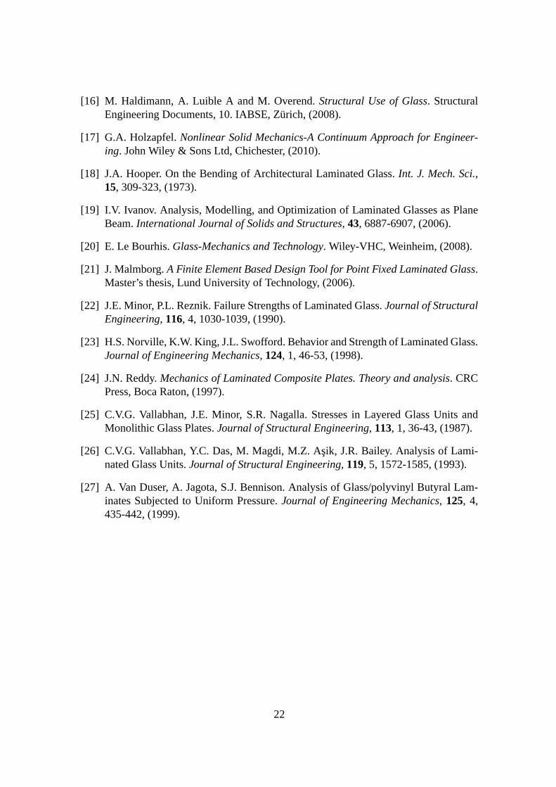
Abstract
Solid-shell finite elements are proposed by Maria Fröling and Kent Persson for the efficient andaccurate modeling of laminated glass structures. The elements are applied to twotest examplesand performance is compared to 3D elasticity theory. One example involves a real world structure,where special attention is directed to the prediction of stress distribution around point fixings.
Introduction
Although glass is commonly used as a structural material, knowledge about its mechanicalproperties and structural behaviour is less than for other structural materials. Therefore,it may be difficult to predict the strength of glass structures, which may result in suddenfailures [4]. One alternative to the use of single layered glass is the use of laminatedglass, ie two or more layers of glass bonded with plastic interlayers. A major advantageof laminated glass is that a properly designed structure allows for one glass pane to break,while the remaining layers can continue to carry the appliedloads.The combination of very stiff (glass) and very soft (PVB) materials makes a laminatedglass pane behave in a complicated manner [1]. The discontinuous stress distributions thatmay develop in laminated glass panes subject to certain loads and boundary conditions aredifficult to model numerically by means of the finite element method. The discontinuitiesare particularly pronounced around holes and edges and since it is common that the largeststresses occur in these regions, it is important that stressdistributions are representedcorrectly by the model.The stress distributions are well captured by 3D solid elements but the application of theseelements to large real world structures with several point fixings leads to very large mod-els, which are practically impossible to analyse using standard computational resources.One means of overcoming the problem of poor computational efficiency is to use shellelements. However, the shell theories that are required in order accurately to determinestress distributions in laminated glass structures are complicated. In this work, a novelso-called solid-shell finite element [3] is implemented andapplied to test examples thatcomprise laminated glass structures. The element is developed for modeling compositestructures with different material properties in each layer.The reason why the solid-shell element is appropriate for the modeling of this type of com-posite structures is that the element only requires one element layer per material layer butincludes several integration points through thickness. This feature leads to great savingsin terms of computational time, still preserving great accuracy.Implementation of the element is relatively straight-forward. Further advantages com-pared to shell-elements are that the full 3D constitutive laws are maintained, the use of
1
rotational degrees of freedom is avoided and that contact situations are more easily mod-eled through the presence of physical nodes on top and bottomsurfaces. The element hasproved to be both robust and efficient through extensive testing.
Numerical Tests
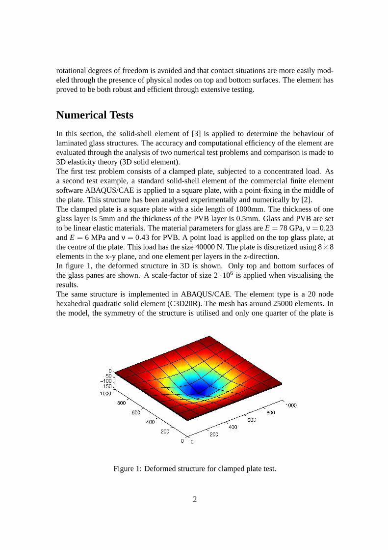
In this section, the solid-shell element of [3] is applied todetermine the behaviour oflaminated glass structures. The accuracy and computational efficiency of the element areevaluated through the analysis of two numerical test problems and comparison is made to3D elasticity theory (3D solid element).The first test problem consists of a clamped plate, subjectedto a concentrated load. Asa second test example, a standard solid-shell element of thecommercial finite elementsoftware ABAQUS/CAE is applied to a square plate, with a point-fixing in the middle ofthe plate. This structure has been analysed experimentallyand numerically by [2].The clamped plate is a square plate with a side length of 1000mm. The thickness of oneglass layer is 5mm and the thickness of the PVB layer is 0.5mm.Glass and PVB are setto be linear elastic materials. The material parameters forglass areE = 78 GPa,ν = 0.23andE = 6 MPa andν = 0.43 for PVB. A point load is applied on the top glass plate, atthe centre of the plate. This load has the size 40000 N. The plate is discretized using 8×8elements in the x-y plane, and one element per layers in the z-direction.In figure 1, the deformed structure in 3D is shown. Only top andbottom surfaces ofthe glass panes are shown. A scale-factor of size 2·106 is applied when visualising theresults.The same structure is implemented in ABAQUS/CAE. The elementtype is a 20 nodehexahedral quadratic solid element (C3D20R). The mesh has around 25000 elements. Inthe model, the symmetry of the structure is utilised and onlyone quarter of the plate is
Figure 1: Deformed structure for clamped plate test.
2

modeled.Table 1 summarises results for the two models. The variable of interest is the midpointdeflection in the z-direction of the lower glass pane. Also, the numbers of variables of themodels are reported. All results are given as fractions of the corresponding result for the3D model.For this test, the result using solid-shell elements deviates approximately 10 % from thecorresponding result using 3D solids. The model size when the solid-shell elements areused is less than 0.5 % of the model size when 3D solids are used. These results illustratethe relatively good accuracy that is achieved with the use ofsolid-shell elements but witha very small fraction of the model size for the correspondingmodel using 3D solids.In the case of the square plate with point-fixing, the geometry of the structure is that of a500mm× 500mm plate of laminated toughened glass, with a bolt hole atthe centre. Thediameter of the hole is 28mm.For symmetry reasons, only half of the plate is modeled. The model is set up to mimic acompression test, where a compression force is applied on top of a cylindrical bolt affixedto the glass [2]. The glass plate rests on a steel frame with dimensions such that theunsupported area of the glass plate becomes 424mm× 424mm. The bolt has a diameterof 50mm. In the compression test, the top cylindrical metal piece (spreader plate) is putat the location of the bolt hole and a compression force is applied to the bolt.In the modeling work, some simplifications are made. There isa rubber gasket betweenthe frame and the glass and only this part of the frame is modeled. The same modelingstrategy is chosen for the bolt, where an EPDM ring is placed between the bolt and theglass. The inner diameter of the EPDM ring is 34mm.All materials are modeled as linear elastic. The bolt ring and the rubber gasket are con-nected to the glass by constraints with the type tie. The rubber gasket is assumed to belocked in all directions. In order to reflect the conditions of the compression test, a deflec-tion of 4.75mm is applied to the top of the EPDM ring. This corresponds to a deflectionof the upper glass pane, close to the bolt hole, of approximately 3mm.The solid-shell element of [3] is not implemented in ABAQUS/CAE. In order to get anidea of the performance of this type of element applied to a structure with a point fixing,a similar element in ABAQUS/CAE is used, namely an eight-nodequadrilateral in-planegeneral-purpose continuum shell element (SC8R) is used for the laminated glass part. Forthe other parts, standard eight-node linear brick elements(C3D8R) are used. In total,around 11000 elements are used. For comparison, the same model is implemented us-ing 20-node quadratic brick elements (C3D20R). For this model, approximately 32000elements are used. The finite element meshes for both models are displayed in Figure 2.Figure 3 shows result graphs for the two models. The result variable is maximum principal
Table 1: Comparison between solid-shell elements and 3D solid elements for clampedplate test.
Element type Midpoint defl. in z-dir. No of variables3D solids (ABAQUS/CAE) 1 1
Solid-shell elements 1.10 0.003
3
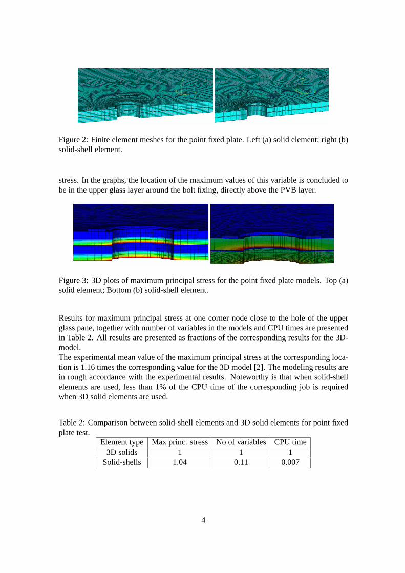
Figure 2: Finite element meshes for the point fixed plate. Left (a) solid element; right (b)solid-shell element.
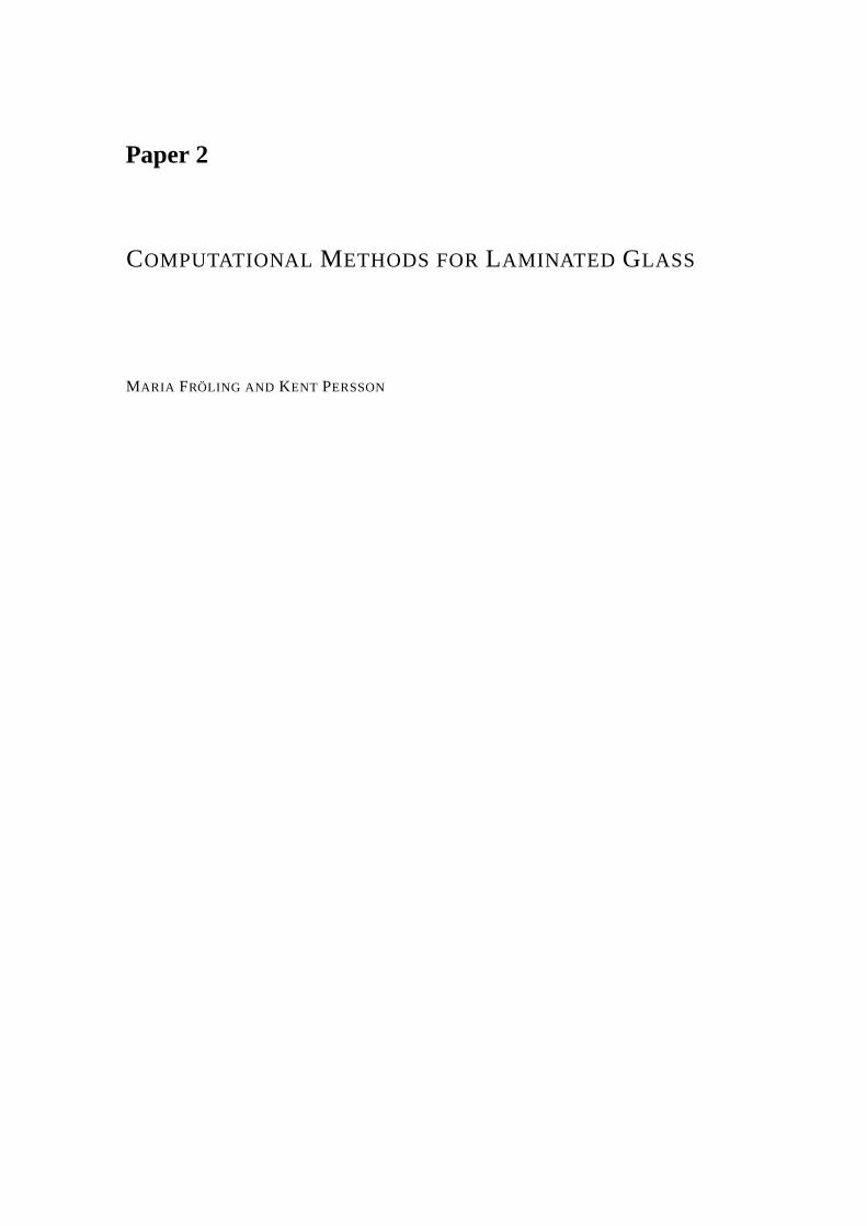
stress. In the graphs, the location of the maximum values of this variable is concluded tobe in the upper glass layer around the bolt fixing, directly above the PVB layer.
Figure 3: 3D plots of maximum principal stress for the point fixed plate models. Top (a)solid element; Bottom (b) solid-shell element.
Results for maximum principal stress at one corner node closeto the hole of the upperglass pane, together with number of variables in the models and CPU times are presentedin Table 2. All results are presented as fractions of the corresponding results for the 3D-model.The experimental mean value of the maximum principal stressat the corresponding loca-tion is 1.16 times the corresponding value for the 3D model [2]. The modeling results arein rough accordance with the experimental results. Noteworthy is that when solid-shellelements are used, less than 1% of the CPU time of the corresponding job is requiredwhen 3D solid elements are used.
Table 2: Comparison between solid-shell elements and 3D solid elements for point fixedplate test.
Element type Max princ. stress No of variables CPU time3D solids 1 1 1
Solid-shells 1.04 0.11 0.007
4

Conclusion and Outlook
In this work, numerical tests have been performed to assess the performance of a relativelynew so-called solid- shell element [3]. Overall, performance of the element is good incomparison to standard 3D solid elements but with considerably smaller model sizes andthus, shorter CPU times. For a real-world like glass balustrade with one point-fixing, lessthan 1% of the CPU time is required when modeling the structurewith solid-shells thanwith 3D solids. Given that the dimensions and number of point-fixings of this structureare small compared to those of real-world structures, it is possible to imagine the greattime savings that are obtained when analysing larger and more complex structures usingthe solid-shell element. The long-term goal of this work is to implement the solid-shellelement [3] in a glass design programme, Clear Sight, which has been developed in workby [5]. It is intended that large glass shell structures withan arbitrary number of pointfixings could be appropriately designed with standard computer power. The results of thecurrent work show that the solid-shell element is well suited for this purpose.
Acknowledgements
The support from The Swedish Research Council FORMAS, Glasbranschföreningen andSvensk Planglasförening is gratefully acknowledged.
References
[1] M. Z. Açik and S. Tezcan. A mathematical model for the behavior of laminated glassbeams.Computers and Structures, 83, 1742-1753, (2005).
[2] C. Bength.Bolt fixings in toughened glass. Master’s Thesis, Division of StructuralMechanics at Lund University of Technology, Sweden, (2005).
[3] R. P. R. Cardoso, J. W. Yoon, M. Mahardika, S. Choudhry, R. J. Alves de Sousa andR. A. Fontes Valente. Enhanced assumed strain (EAS) and assumed natural strain(ANS) methods for one-point quadrature solid-shell elements.International Journalfor Numerical Methods in Engineering, 75, 156-187, (2008).
[4] P. Foraboschi. Behavior and failure strength of laminated glass beams.Journal ofEngineering Mechanics, 133, 12, 1290-1301, (2007).
[5] J. Malmborg.A finite element based design tool for point fixed laminated glass,Master’s Thesis, Division of Structural Mechanics at Lund University of Technol-ogy, Sweden, (2006).
5

Paper 2
COMPUTATIONAL METHODS FORLAMINATED GLASS
MARIA FRÖLING AND KENT PERSSON


Computational Methods for Laminated Glass
Maria Fröling and Kent Persson
Abstract
A new solid-shell finite element is proposed for the purpose of efficient and accurate modelingof laminated glass structures. The element is applied to two test examples and theperformanceconcerning accuracy and efficiency is compared to standard three dimensional solid elements.Further examples illustrate how the element could be applied in the modeling of laminated glassstructures with bolted and adhesive joints.
1 Introduction
It is common today to use glass as a structural material. Unfortunately the strength designand structural behavior of glass is less known than for otherstructural materials like steel,wood or concrete. Thus, there is a risk for inaccurate predictions of the strength of glassstructures which could result in sudden failures, [12].In order to increase safety, laminated glass may be used instead of single layered glass.Laminated glass consists of two or more glass layers bonded with plastic interlayers.The most common material used for the interlayer is polyvinalbutyral, PVB. The use oflaminated glass should allow for the glass panes to break while the remaining layers cancontinue to carry the design loads, and the scattered glass pieces can stick onto the plasticinterlayer, and thereby prevent injury.On the other hand, laminated glass displays a complicated mechanical behavior due tothe combination of a very stiff material (glass) and a very soft material (PVB), [4]. Alaminated glass-PVB plate is less stiff than a monolithic glass structure of correspond-ing dimensions, which leads to larger displacements. Furthermore, under certain loadsand boundary conditions, discontinuous stress distributions develop in laminated glassstructures, ([5], [23]).Regions close to supports and connections are often subjected to concentrated forces.Since glass is a brittle material that not show plastic deformations before failure, the abil-ity to distribute stresses at load is limited and thus stressconcentrations easily develops.Glass fails under tension and in reality the tensile strength is much less than its theoreticalcounterpart. This is due to the impact of defects on the surface. The defects are createdduring manufacturing, treatment (such as hole drilling andcutting) and the use of theglass, [5].The discontinuities of the stress distributions of laminated glass structures are most pro-nounced around holes and edges, that is, in the regions wherethe largest stress concen-trations often occur, since these regions often are subjected to concentrated forces andmay have larger amounts of micro defects. In order to illustrate the discontinuous stressdistributions that may arise in a laminated glass structure, a simple example is provided.In Figure 1 below a cantilever beam subjected to bending by a point load at its free end isdisplayed.
1
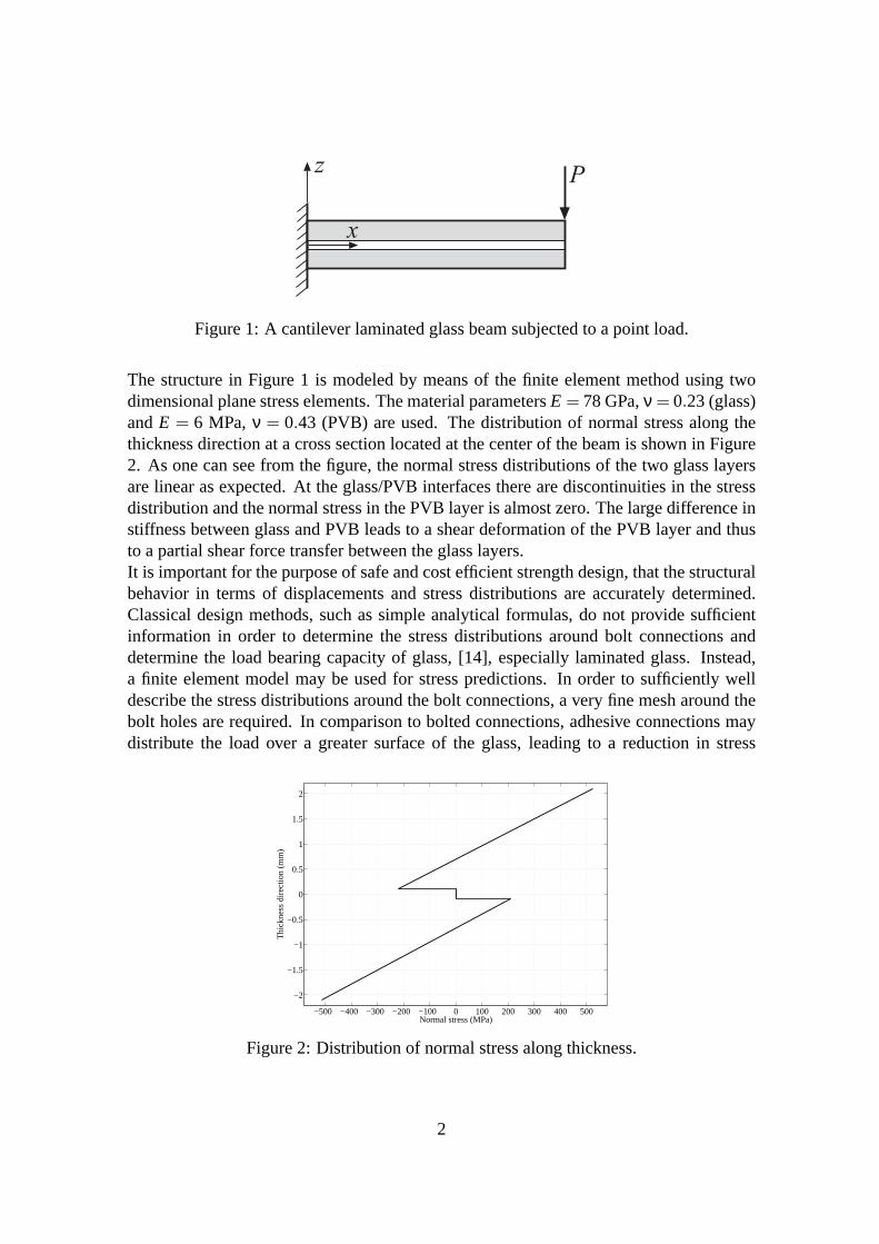
zP
x
Figure 1: A cantilever laminated glass beam subjected to a point load.
The structure in Figure 1 is modeled by means of the finite element method using twodimensional plane stress elements. The material parametersE = 78 GPa,ν = 0.23 (glass)andE = 6 MPa,ν = 0.43 (PVB) are used. The distribution of normal stress along thethickness direction at a cross section located at the centerof the beam is shown in Figure2. As one can see from the figure, the normal stress distributions of the two glass layersare linear as expected. At the glass/PVB interfaces there are discontinuities in the stressdistribution and the normal stress in the PVB layer is almostzero. The large difference instiffness between glass and PVB leads to a shear deformationof the PVB layer and thusto a partial shear force transfer between the glass layers.It is important for the purpose of safe and cost efficient strength design, that the structuralbehavior in terms of displacements and stress distributions are accurately determined.Classical design methods, such as simple analytical formulas, do not provide sufficientinformation in order to determine the stress distributionsaround bolt connections anddetermine the load bearing capacity of glass, [14], especially laminated glass. Instead,a finite element model may be used for stress predictions. In order to sufficiently welldescribe the stress distributions around the bolt connections, a very fine mesh around thebolt holes are required. In comparison to bolted connections, adhesive connections maydistribute the load over a greater surface of the glass, leading to a reduction in stress
−500 −400 −300 −200 −100 0 100 200 300 400 500
−2
−1.5
−1
−0.5
0
0.5
1
1.5
2
Normal stress (MPa)
Thi
ckne
ss d
irect
ion
(mm
)
Figure 2: Distribution of normal stress along thickness.
2

concentrations. Despite this advantage, there are few examples of load bearing adhesiveconnections used in glass structures and appropriate design guidelines are lacking, [27].For load bearing adhesive connections, the maximum stresses occur in edge regions ofthe adhesive layer and for accurate design of the connectionit is important to achieveaccurate enough stress predictions in these critical regions. Finite element analysis isrecommended as a tool for stress prediction, [1].Accurate predictions of laminated glass strength can be obtained through finite elementanalyzes using three dimensional solid elements. However,to make precise predictionof the stress distribution several elements must be employed in the thickness directionof each layer resulting in that standard computational resources limit the scope of theanalyzes that can be made. Large real world structures with several point fixings are thuspractically impossible to analyze, since it easily needs millions of degrees of freedom fora correct result.According to the classification of [25], a laminated glass plate falls into the categorylaminated composites, which are made up of layers of different materials. It is possibleto reduce the three dimensional elasticity problem to a two dimensional one by mak-ing suitable assumptions regarding the kinematics or stress state through the thickness ofthe laminate. In the simplest of those laminate theories, the kinematic assumptions thatstraight lines normal to the xy-plane before deformation remain straight after deformationand do not undergo thickness stretching are used. These assumptions are the same as inthe classical Kirchhoff and Reissner Mindlin plate theories. The structure is in a stateof plane stress. The use of these theories as a basis for a finite element model reducesthe model size and increases computational efficiency. However, due to the material dis-continuity in the thickness direction of a glass/PVB composite, this structure experiencespiecewise continuous displacement and transverse stresses in the thickness direction. Therequirements that these two conditions are fulfilled are termedC0
z-requirements, [9]. Un-fortunately, the two dimensional laminate theories do not fulfill all these demands. Theresulting stress distributions are erraneous and the discontinuous stress distribution shownin Figure 2 is not correctly predicted.An alternative is to use a layerwise laminate theory that contains full three dimensionalkinematics and constitutive relations, [25]. The corresponding finite element model pos-sesses some computational advantages compared to a full three dimensional solid elementmodel. These advantages relate to the fact that a two dimensional data structure (two di-mensional finite elements) could be used. In the modeling of advanced structures, thelayerwise model may however be computationally inefficient, [25], and cumbersome toimplement.Instead it may be appropriate to use so-called solid-shell elements, such as the elementpresented in [8]. The element is developed for modeling composite structures with dif-ferent material properties in each layer. In particular, the full three dimensional consti-tutive laws are maintained allowing for a correct stress distribution prediction, especiallyat loads and supports. Since the element only requires one element in the thickness di-rection of each material layer, but includes several integration points through thickness,great computational savings are made and and good accuracy is obtained. The imple-mentation of the element is relatively straight-forward. Afurther advantage compared
3

to plate or shell element formulations is that contact situations are more easily modeledthrough the presence of physical nodes on top and bottom surfaces of the element. Ofgreat importance for applications with bolted joints is that the full three dimensional ma-terial definition is used and all stress components are calculated which may be importantat the supports. The element has proven to be both robust and efficient through extensivetesting.In this work, the solid-shell element in [8] was implementedand applied to test examplescomprising laminated glass structures. The accuracy and efficiency of the solid-shellelement were examined. The results were compared to the results that were obtained witha three dimensional solid element. Finally, the application of solid-shell elements to realglass structures is illustrated through several examples.
2 The Solid-Shell Concept: An Overview of the Litera-ture
A solid-shell element is a three dimensional solid element which is modified in order tobe suited for the analysis of shell-like structures. The modifications are made in a man-ner so that typical shell properties like bending and in plane stretching can be modeledapproprietly using one element in the thickness direction only. When using a low orderthree dimensional solid element for the modeling of shell-like structures, certain lock-ing phenomena occur. The solid-shells are constructed in a fashion such that locking isprevented.The solid-shell concept stems from work by [16]. In that paper, several solid-shell ele-ments are presented. Common for these elements is that they all employ the AssumedNatural Strain (ANS) method, [11], to prevent locking. Other contributions to the litera-ture on solid-shell elements are for instance [24] and [17].[15] discusses several lockingphenomena occuring in low order solid-shell elements and the focus is particularly onlarge deformations’ problems. [3] proposes a new class of eight-node solid finite ele-ments. The elements can be used both for three dimensional and thin shell applications.The elements use the Enhanced Assumed Strain (EAS) approach, [26], in order to pre-vent locking problems. However, the use of the EAS method in these cases leads to poorcomputational efficiency. The Reduced Enhanced Solid-Shell(RESS) elements presentedin ([2], [8]) are eight-node solid-shells. Due to a special one-point quadrature integrationscheme, these elements possess considerably higher computational efficiency than theirpredecessors of [3]. The integration scheme requires only one element layer for a single-layered material, but uses multiple integration points through thickness. This leads tohigh computational efficiency and great accuracy. The reduced integration scheme re-quires physical stabilization to prevent zero-energy modes. The stabilization method of[7] and the ANS method are employed for this purpose. In orderfor the Modified RESS(M-RESS) element, [8], to pass the membrane patch test, the stabilization method basedon results of ([22], [21]) is used. For instance the B-bar approach, [18], is used in order toalleviate locking problems that occur due to the stabilization procedure. The EAS method,[26], plays an important role in preventing various types ofother locking problems that
4
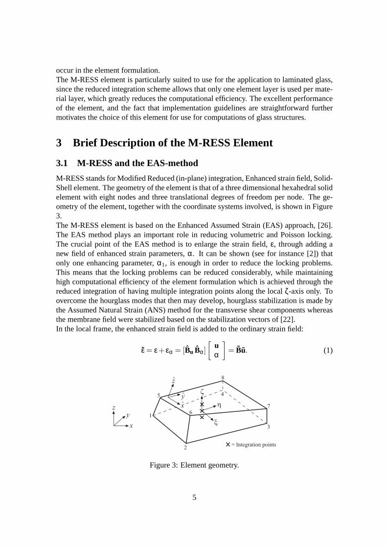
occur in the element formulation.The M-RESS element is particularly suited to use for the application to laminated glass,since the reduced integration scheme allows that only one element layer is used per mate-rial layer, which greatly reduces the computational efficiency. The excellent performanceof the element, and the fact that implementation guidelinesare straightforward furthermotivates the choice of this element for use for computations of glass structures.
3 Brief Description of the M-RESS Element
3.1 M-RESS and the EAS-method
M-RESS stands for Modified Reduced (in-plane) integration, Enhanced strain field, Solid-Shell element. The geometry of the element is that of a three dimensional hexahedral solidelement with eight nodes and three translational degrees offreedom per node. The ge-ometry of the element, together with the coordinate systemsinvolved, is shown in Figure3.The M-RESS element is based on the Enhanced Assumed Strain (EAS) approach, [26].The EAS method plays an important role in reducing volumetric and Poisson locking.The crucial point of the EAS method is to enlarge the strain field, ε, through adding anew field of enhanced strain parameters,α. It can be shown (see for instance [2]) thatonly one enhancing parameter,α1, is enough in order to reduce the locking problems.This means that the locking problems can be reduced considerably, while maintaininghigh computational efficiency of the element formulation which is achieved through thereduced integration of having multiple integration pointsalong the localζ-axis only. Toovercome the hourglass modes that then may develop, hourglass stabilization is made bythe Assumed Natural Strain (ANS) method for the transverse shear components whereasthe membrane field were stabilized based on the stabilization vectors of [22].In the local frame, the enhanced strain field is added to the ordinary strain field:
ε = ε+ εα = [Bu Bα]
[
uα
]
= Bu. (1)
yÙ
xÙ
zÙ
1
2
3
45
67
8
z
x
y
h
x
z
= Integration points
Figure 3: Element geometry.
5
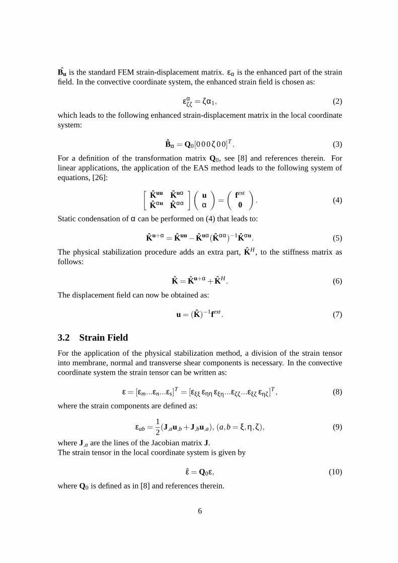
Bu is the standard FEM strain-displacement matrix.εα is the enhanced part of the strainfield. In the convective coordinate system, the enhanced strain field is chosen as:
εαζζ = ζα1, (2)
which leads to the following enhanced strain-displacementmatrix in the local coordinatesystem:
Bα = Q0[000ζ 00]T . (3)
For a definition of the transformation matrixQ0, see [8] and references therein. Forlinear applications, the application of the EAS method leads to the following system ofequations, [26]:
[
Kuu Kuα
Kαu Kαα
](
uα
)
=
(
fext
0
)
. (4)
Static condensation ofα can be performed on (4) that leads to:
Ku+α = Kuu− Kuα(Kαα)−1Kαu
. (5)
The physical stabilization procedure adds an extra part,KH , to the stiffness matrix asfollows:
K = Ku+α + KH. (6)
The displacement field can now be obtained as:
u = (K)−1fext. (7)
3.2 Strain Field
For the application of the physical stabilization method, adivision of the strain tensorinto membrane, normal and transverse shear components is necessary. In the convectivecoordinate system the strain tensor can be written as:
ε = [εm...εn...εs]T = [εξξ εηη εξη...εζζ...εξζ εηζ]
T, (8)
where the strain components are defined as:
εab =12(J
,au,b+J
,bu,a), (a,b= ξ,η,ζ), (9)
whereJ,a are the lines of the Jacobian matrixJ.
The strain tensor in the local coordinate system is given by
ε = Q0ε, (10)
whereQ0 is defined as in [8] and references therein.
6
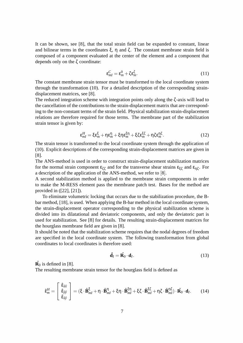
It can be shown, see [8], that the total strain field can be expanded to constant, linearand bilinear terms in the coordinatesξ, η andζ. The constant membrane strain field iscomposed of a component evaluated at the center of the element and a component thatdepends only on theζ coordinate:
εCmI = ε0
m+ζεζm. (11)
The constant membrane strain tensor must be transformed to the local coordinate systemthrough the transformation (10). For a detailed description of the corresponding strain-displacement matrices, see [8].The reduced integration scheme with integration points only along theζ-axis will lead tothe cancellation of the contributions to the strain-displacement matrix that are correspond-ing to the non-constant terms of the strain field. Physical stabilization strain-displacementrelations are therefore required for those terms. The membrane part of the stabilizationstrain tensor is given by:
εHmI = ξεξ
m+ηεηm+ξηεξη
m +ξζεξζm +ηζεηζ
m . (12)
The strain tensor is transformed to the local coordinate system through the application of(10). Explicit descriptions of the corresponding strain-displacement matrices are given in[8].The ANS-method is used in order to construct strain-displacement stabilization matricesfor the normal strain componentεζζ and for the transverse shear strainsεξζ andεηζ. Fora description of the application of the ANS-method, we referto [8].A second stabilization method is applied to the membrane strain components in orderto make the M-RESS element pass the membrane patch test. Bases for the method areprovided in ([22], [21]).
To eliminate volumetric locking that occurs due to the stabilization procedure, the B-bar method, [18], is used. When applying the B-bar method in thelocal coordinate system,the strain-displacement operator corresponding to the physical stabilization scheme isdivided into its dilatational and deviatoric components, and only the deviatoric part isused for stabilization. See [8] for details. The resulting strain-displacement matrices forthe hourglass membrane field are given in [8].It should be noted that the stabilization scheme requires that the nodal degrees of freedomare specified in the local coordinate system. The following transformation from globalcoordinates to local coordinates is therefore used:
dI = R0 ·dI . (13)
R0 is defined in [8].The resulting membrane strain tensor for the hourglass fieldis defined as
εHm =
εxx
εyy
εxy
= (ξ · BξmI +η · Bη
mI+ξη · BξηmI+ξζ · Bξζ
mI+ηζ · BηζmI) · R0 ·dI . (14)
7
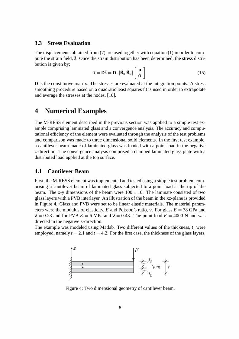
3.3 Stress Evaluation
The displacements obtained from (7) are used together with equation (1) in order to com-pute the strain field,ε. Once the strain distribution has been determined, the stress distri-bution is given by:
σ = Dε = D · [Bu Bα]
[
uα
]
. (15)
D is the constitutive matrix. The stresses are evaluated at the integration points. A stresssmoothing procedure based on a quadratic least squares fit isused in order to extrapolateand average the stresses at the nodes, [10].
4 Numerical Examples
The M-RESS element described in the previous section was applied to a simple test ex-ample comprising laminated glass and a convergence analysis. The accuracy and compu-tational efficiency of the element were evaluated through the analysis of the test problemsand comparison was made to three dimensional solid elements. In the first test example,a cantilever beam made of laminated glass was loaded with a point load in the negativez-direction. The convergence analysis comprised a clampedlaminated glass plate with adistributed load applied at the top surface.
4.1 Cantilever Beam
First, the M-RESS element was implemented and tested using a simple test problem com-prising a cantilever beam of laminated glass subjected to a point load at the tip of thebeam. The x-y dimensions of the beam were 100× 10. The laminate consisted of twoglass layers with a PVB interlayer. An illustration of the beam in the xz-plane is providedin Figure 4. Glass and PVB were set to be linear elastic materials. The material param-eters were the modulus of elasticity,E and Poisson’s ratio,ν. For glassE = 78 GPa andν = 0.23 and for PVBE = 6 MPa andν = 0.43. The point loadF = 4000 N and wasdirected in the negative z-direction.The example was modeled using Matlab. Two different values of the thickness,t, wereemployed, namelyt = 2.1 andt = 4.2. For the first case, the thickness of the glass layers,
zF
xtg
tg
tPVB t
Figure 4: Two dimensional geometry of cantilever beam.
8
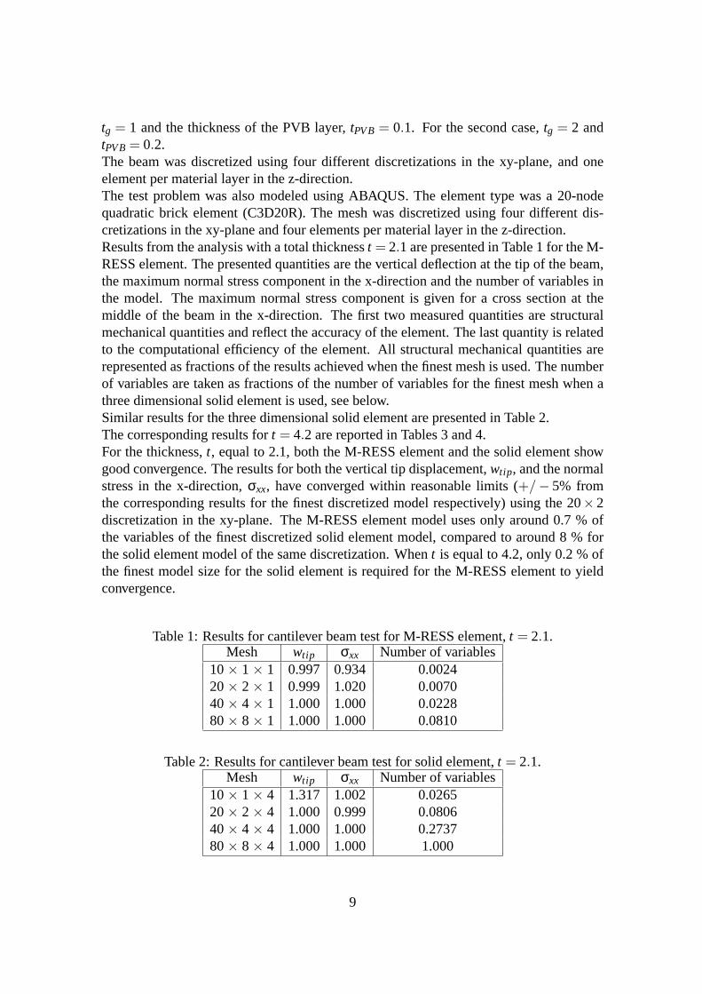
tg = 1 and the thickness of the PVB layer,tPVB= 0.1. For the second case,tg = 2 andtPVB= 0.2.The beam was discretized using four different discretizations in the xy-plane, and oneelement per material layer in the z-direction.The test problem was also modeled using ABAQUS. The element type was a 20-nodequadratic brick element (C3D20R). The mesh was discretized using four different dis-cretizations in the xy-plane and four elements per materiallayer in the z-direction.Results from the analysis with a total thicknesst = 2.1 are presented in Table 1 for the M-RESS element. The presented quantities are the vertical deflection at the tip of the beam,the maximum normal stress component in the x-direction and the number of variables inthe model. The maximum normal stress component is given for across section at themiddle of the beam in the x-direction. The first two measured quantities are structuralmechanical quantities and reflect the accuracy of the element. The last quantity is relatedto the computational efficiency of the element. All structural mechanical quantities arerepresented as fractions of the results achieved when the finest mesh is used. The numberof variables are taken as fractions of the number of variables for the finest mesh when athree dimensional solid element is used, see below.Similar results for the three dimensional solid element arepresented in Table 2.The corresponding results fort = 4.2 are reported in Tables 3 and 4.For the thickness,t, equal to 2.1, both the M-RESS element and the solid element showgood convergence. The results for both the vertical tip displacement,wtip, and the normalstress in the x-direction,σxx, have converged within reasonable limits (+/− 5% fromthe corresponding results for the finest discretized model respectively) using the 20×2discretization in the xy-plane. The M-RESS element model uses only around 0.7 % ofthe variables of the finest discretized solid element model,compared to around 8 % forthe solid element model of the same discretization. Whent is equal to 4.2, only 0.2 % ofthe finest model size for the solid element is required for theM-RESS element to yieldconvergence.
Table 1: Results for cantilever beam test for M-RESS element,t = 2.1.Mesh wtip σxx Number of variables
10× 1× 1 0.997 0.934 0.002420× 2× 1 0.999 1.020 0.007040× 4× 1 1.000 1.000 0.022880× 8× 1 1.000 1.000 0.0810
Table 2: Results for cantilever beam test for solid element,t = 2.1.Mesh wtip σxx Number of variables
10× 1× 4 1.317 1.002 0.026520× 2× 4 1.000 0.999 0.080640× 4× 4 1.000 1.000 0.273780× 8× 4 1.000 1.000 1.000
9
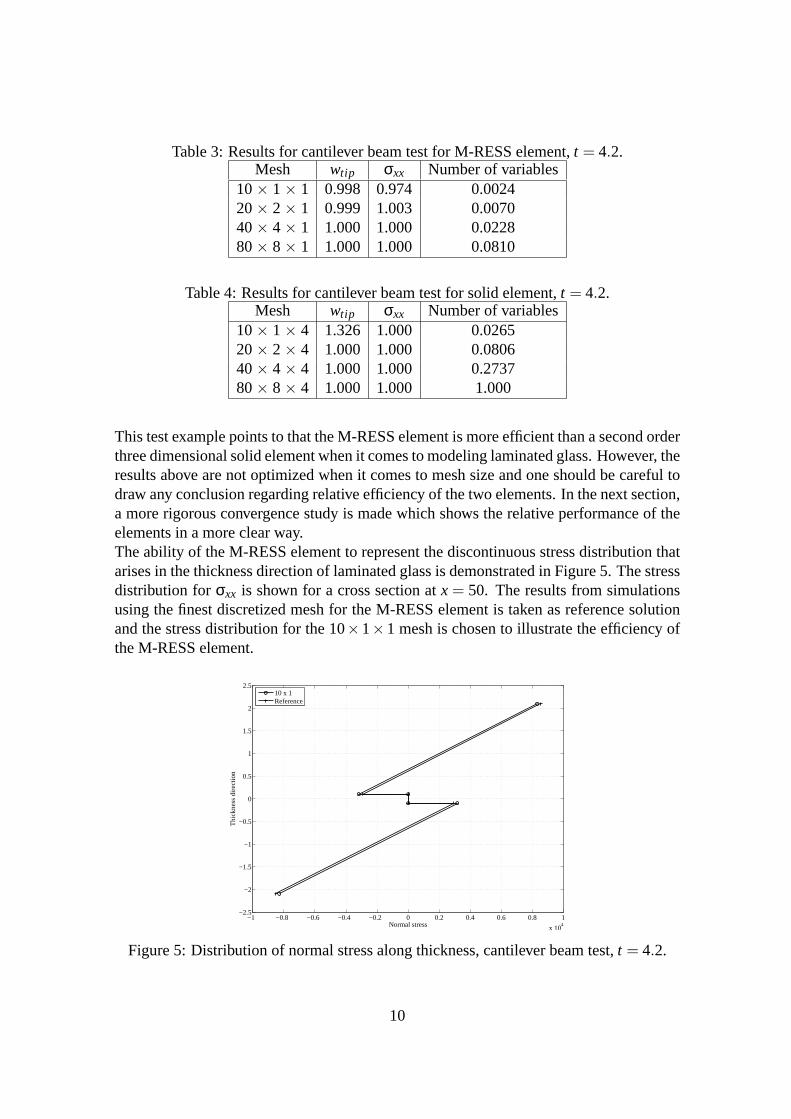
Table 3: Results for cantilever beam test for M-RESS element,t = 4.2.Mesh wtip σxx Number of variables
10× 1× 1 0.998 0.974 0.002420× 2× 1 0.999 1.003 0.007040× 4× 1 1.000 1.000 0.022880× 8× 1 1.000 1.000 0.0810
Table 4: Results for cantilever beam test for solid element,t = 4.2.Mesh wtip σxx Number of variables
10× 1× 4 1.326 1.000 0.026520× 2× 4 1.000 1.000 0.080640× 4× 4 1.000 1.000 0.273780× 8× 4 1.000 1.000 1.000
This test example points to that the M-RESS element is more efficient than a second orderthree dimensional solid element when it comes to modeling laminated glass. However, theresults above are not optimized when it comes to mesh size andone should be careful todraw any conclusion regarding relative efficiency of the twoelements. In the next section,a more rigorous convergence study is made which shows the relative performance of theelements in a more clear way.The ability of the M-RESS element to represent the discontinuous stress distribution thatarises in the thickness direction of laminated glass is demonstrated in Figure 5. The stressdistribution forσxx is shown for a cross section atx = 50. The results from simulationsusing the finest discretized mesh for the M-RESS element is taken as reference solutionand the stress distribution for the 10×1×1 mesh is chosen to illustrate the efficiency ofthe M-RESS element.
−1 −0.8 −0.6 −0.4 −0.2 0 0.2 0.4 0.6 0.8 1
x 104
−2.5
−2
−1.5
−1
−0.5
0
0.5
1
1.5
2
2.5
Normal stress
Thi
ckne
ss d
irect
ion
10 x 1Reference
Figure 5: Distribution of normal stress along thickness, cantilever beam test,t = 4.2.
10

From the figure it is clear that the use of the M-RESS element produces results that arerepresenting theσxx distribution in the z-direction well, for a relatively coarse mesh.
4.2 Convergence Analysis
This convergency analysis comprised of a clamped square plate of a laminated glassloaded by a pressure surface load, Figure 6. The laminate consisted of two glass panesand one intermediate layer made of PVB. The surface load of 4000 per unit area actedon the surface of the uppermost glass pane. The in-plane dimensions of the plate were1000×1000 and the total thickness was 21 whereas the glass thickness was 10 and theinterlayer thickness 1. Both glass and PVB were modeled as linear elastic materials andthe same material parameters as for the cantilever beam testwere used. The plate wasclamped, thus all displacements of the four sides were constrained to zero.Three different elements were tested in the finite element analysis of the plate; the M-RESS element, a linear 8-node (C3D8R) and a quadratic 20-node element (C3D20R),both standard isoparametric quadrilateral elements with reduced integration. The analyseswith the 8- and 20-node elements were made using the commercial FE package ABAQUSand the analyses with the M-RESS element were made using Matlab. For the M-RESSelement, one element for each material layer was used in the thickness direction whereasthe 8-node element required four elements and the 20-node two elements for each elementlayer to reach a reasonable convergence rate.To evaluate the models, the in-plane stress in one directionand the vertical displacement atthe center point of the bottom glass surface were compared. Results from the convergenceanalysis are shown in Figures 7 and 8. The results in the figures were normalized to theresults using the 20-node element and 2 millions degrees of freedom.The 8-node element showed very poor convergence rate for theclamped laminated platestructure. Not even by using 500.000 degrees of freedom the element reached a sufficientresult, especially not for the stresses that showed about 20% error. The 20-node elementshowed much better convergence rate as shown in Figure 8. About 3000 degrees of free-dom was needed to get less than 5 % error for both the displacents and the stresses. TheM-RESS element that performed extremely well and only required about 300 degrees of
Z
Y
X
Figure 6: Geometry of the clamped plate.
11

102
103
104
105
106
−20
0
20
40
60
80
100
No of dofs
Err
or, %
M−RESSC3D8R
102
103
104
105
106
−20
0
20
40
60
80
100
No of dofs
Err
or, %
M−RESSC3D8R
Figure 7: Comparison of the M-RESS and the 8-node quadrilateral element, displacementversus number of degrees of freedom to the left and stress versus number of degrees offreedom to the right.
102
103
104
105
106
−30
−20
−10
0
10
20
30
40
No of dofs
Err
or, %
M−RESSC3D20R
102
103
104
105
106
−20
−15
−10
−5
0
5
10
15
20
No of dofs
Err
or, %
M−RESSC3D20R
Figure 8: Comparison of the M-RESS and the 20-node quadrilateral element, displace-ment versus number of degrees of freedom to the left and stress versus number of degreesof freedom to the right.
freedom to get less than 5 % error for the displacements and about 700 degrees of freedomfor the stresses to get less than 5 % error.A conclusion is that standard isoparametric elements with linear approximating functionsis not recommended for analyzing laminated glass and the M-RESS element is an excel-lent choice for analyzing laminated glass.
5 Application to Glass Structures
In the previous section the ability of the M-RESS element to represent displacementsand stress distributions of laminated glass structures is demonstrated. In order to fullyillustrate the usefulness of the approach, this section deals with the application of the M-RESS element to several real glass structures comprising laminated glass. All examples
12
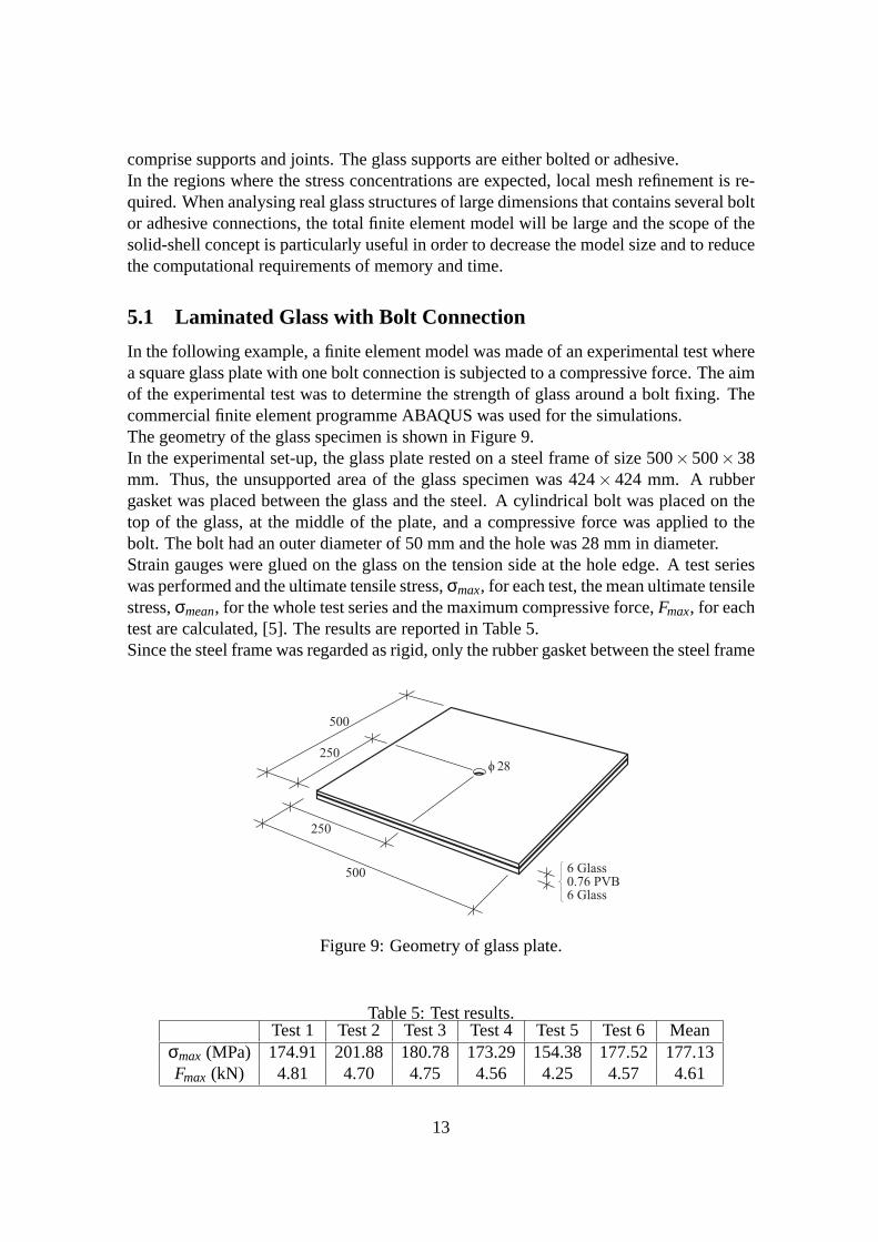
comprise supports and joints. The glass supports are eitherbolted or adhesive.In the regions where the stress concentrations are expected, local mesh refinement is re-quired. When analysing real glass structures of large dimensions that contains several boltor adhesive connections, the total finite element model willbe large and the scope of thesolid-shell concept is particularly useful in order to decrease the model size and to reducethe computational requirements of memory and time.
5.1 Laminated Glass with Bolt Connection
In the following example, a finite element model was made of anexperimental test wherea square glass plate with one bolt connection is subjected toa compressive force. The aimof the experimental test was to determine the strength of glass around a bolt fixing. Thecommercial finite element programme ABAQUS was used for the simulations.The geometry of the glass specimen is shown in Figure 9.In the experimental set-up, the glass plate rested on a steelframe of size 500×500×38mm. Thus, the unsupported area of the glass specimen was 424× 424 mm. A rubbergasket was placed between the glass and the steel. A cylindrical bolt was placed on thetop of the glass, at the middle of the plate, and a compressiveforce was applied to thebolt. The bolt had an outer diameter of 50 mm and the hole was 28mm in diameter.Strain gauges were glued on the glass on the tension side at the hole edge. A test serieswas performed and the ultimate tensile stress,σmax, for each test, the mean ultimate tensilestress,σmean, for the whole test series and the maximum compressive force, Fmax, for eachtest are calculated, [5]. The results are reported in Table 5.Since the steel frame was regarded as rigid, only the rubber gasket between the steel frame
500
500
250
250o 28
6 Glass0.76 PVB6 Glass
Figure 9: Geometry of glass plate.
Table 5: Test results.Test 1 Test 2 Test 3 Test 4 Test 5 Test 6 Mean
σmax (MPa) 174.91 201.88 180.78 173.29 154.38 177.52 177.13Fmax (kN) 4.81 4.70 4.75 4.56 4.25 4.57 4.61
13

and the glass plate was modeled. Similarly, the bolt has an EPDM ring that protects theglass from direct contact with the steel bolt. Only the EPDM ring was modeled. The innerdiameter of the EPDM ring was 34 mm and the ring had a thicknessof 3 mm.Due to symmetry, only half of the plate was modeled.All materials were modeled as linear elastic and isotropic and the material parameters areshown in Table 6.Since no slip between the rubber and the glass was expected, afull tie constraint wasapplied. The load for the compression test was set to the meanvalue of the maximumforce from the experimental tests, see Table 5. The load was applied on the top of theEPDM ring. Along the symmetry line, symmetry boundary conditions were applied. Therubber frame was constrained to zero displacement in all directions.The M-RESS element was used in the modeling of the laminated glass plate. For the otherparts of the model, a standard eight-node linear brick element (C3D8R) was employed.The model contained around 11000 elements. The laminated glass part had one elementlayer per material layer and the EPDM ring as well as the rubber gasket parts had threeelement layers in the thickness direction. In Figure 10, thefinite element mesh for thewhole structure in the vicinity of the bolt hole is displayed. As can be seen, the mesh wasrefined close to the bolt hole.As a comparison, numerical tests were performed by use of ABAQUS and 20-node second
Table 6: Material parameters for model.Material E (MPa) ν
Glass 78000 0.23PVB 5.2 0.45
Rubber 1 0.45EPDM 7 0
ZY
X
Figure 10: Finite element mesh for square plate model.
14
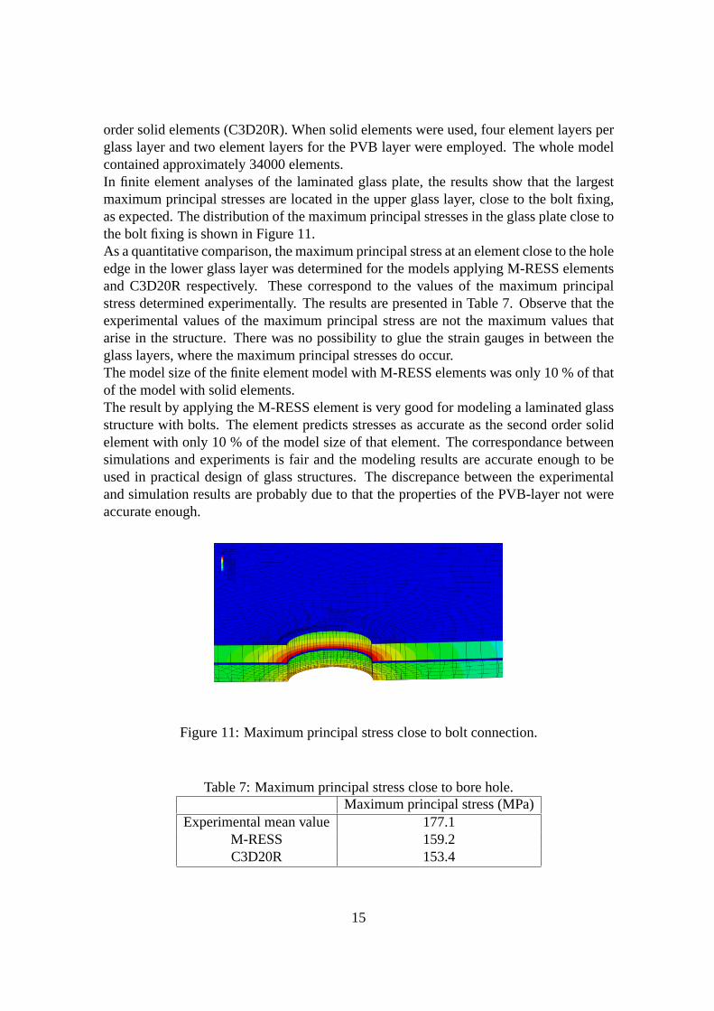
order solid elements (C3D20R). When solid elements were used, four element layers perglass layer and two element layers for the PVB layer were employed. The whole modelcontained approximately 34000 elements.In finite element analyses of the laminated glass plate, the results show that the largestmaximum principal stresses are located in the upper glass layer, close to the bolt fixing,as expected. The distribution of the maximum principal stresses in the glass plate close tothe bolt fixing is shown in Figure 11.As a quantitative comparison, the maximum principal stressat an element close to the holeedge in the lower glass layer was determined for the models applying M-RESS elementsand C3D20R respectively. These correspond to the values of the maximum principalstress determined experimentally. The results are presented in Table 7. Observe that theexperimental values of the maximum principal stress are notthe maximum values thatarise in the structure. There was no possibility to glue the strain gauges in between theglass layers, where the maximum principal stresses do occur.The model size of the finite element model with M-RESS elementswas only 10 % of thatof the model with solid elements.The result by applying the M-RESS element is very good for modeling a laminated glassstructure with bolts. The element predicts stresses as accurate as the second order solidelement with only 10 % of the model size of that element. The correspondance betweensimulations and experiments is fair and the modeling results are accurate enough to beused in practical design of glass structures. The discrepance between the experimentaland simulation results are probably due to that the properties of the PVB-layer not wereaccurate enough.
(Avg: 75%)SPOS, (fraction = 1.0)SNEG, (fraction = −1.0)S, Max. Principal
−2.848e−01+1.322e+01+2.673e+01+4.024e+01+5.374e+01+6.725e+01+8.076e+01+9.426e+01+1.078e+02+1.213e+02+1.348e+02+1.483e+02+1.618e+02
Figure 11: Maximum principal stress close to bolt connection.
Table 7: Maximum principal stress close to bore hole.Maximum principal stress (MPa)
Experimental mean value 177.1M-RESS 159.2C3D20R 153.4
15

5.2 Glass Beam with Adhesive Joint
This example deals with the finite element modeling of an experimental test with the aimof determining the shear capacity of an adhesive joint in a large dimension glass beam.A series of tests consisting of a four-point bending test of abeam with a three meter spanwere conducted. The beams were constructed by three flat-glass elements measuring 250× 2000 mm2 with a width of 12 mm. They were joined in overlap joints at themiddleof the three meter span by two adhesive joints each measuring250 × 250 mm. Thearrangement of three glass elements was chosen to create a symmetrical beam in order toobtain pure shear stresses in the joints, see Figure 12.Five types of adhesives were tested consisting of three stiff adhesives; a UV curing acry-late, a polyurethane glue and an epoxy, and two soft, rubber-like, adhesives based on silylmodified polymers (SMP), commonly found as adhesives in automotive glass gluing. Theadhesive layers were about 0.2 mm in thickness for the stiff adhesives and about 2 mmfor the soft adhesives. The tests revealed that a soft weak SMP-based adhesive may, for alarge shear-joint, result in a stronger joint than for usinga stiff strong adhesive, see Table8.Tests were also conducted on small specimens (20× 20 mm2) to evaluate material proper-ties and material models for the various types of adhesives,[20]. These material properties
P/2
250
P/2
250
5 4 37
A - A
A A
1200
6
12
B B
3000
Adhesive layer
2000
Figure 12: Test setup of four-point bending test of glass beam with adhesive joint.
Table 8: Ultimate load and deformations at the mid-point of the beam.Type of adhesive Total applied load (kN) Displacement (mm)
SMP type 1 49.3 51SMP type 2 48.8 50
Epoxy 30.3 10Polyurethane 10.3 3.5
UV-curing glue 22.3 7.5
16
were utilized in the finite element modeling of the jointed beam.In order to evaluate the tested adhesives the glass beam was simulated in ABAQUS bothby use of the M-RESS element and an eight node three-dimensional quadratic solid ele-ment (C3D20R). Here, the results from the simulation with the epoxy adhesive are pre-sented and a comparison is made from using the two element types. The flat glass el-ements were modeled as three dimensional objects with a Young’s Modulus of 70 GPaand a Poisson’s ratio of 0.23. The epoxy joint was modelled according to the evaluatedmaterial model from the tests of the small specimens to a Young’s Modulus of 1500 MPaand a Poisson’s ratio of 0.25.To ensure that the load was applied symmetrical, the load wasapplied on a referencepoint coupled to nodes by a kinematic coupling constraint. The load was applied asa displacement of the reference point. The magnitude of the displacement was -0.006m in the load direction. All other possible displacements ofthe reference point wereconstrained to zero. At the supports, displacements were prevented in the load directionand in the thickness direction of the beam.In the finite element model with M-RESS elements, one element layer per material layerwas applied in the thickness direction. The model containedapproximately 16000 ele-ments. For three-dimensional solid elements, the model contained about 34000 elements.As a comparison between experimental results and the results from the finite elementsimulations, the displacement in the load direction at point 4 of Figure 12 was taken astest variable. Results from experiment and simulations are presented in Table 9. Bothof the finite element models give accurate enough results, and it is noted that the modelwith M-RESS elements requires merely 20 % of the model size of the model with solidelements.For the stiffer adhesives, stress-concentrations occurred at the corners of the joint andconsequently the critical shear stress was first reached there. For the silicones the stresseswere more evenly distributed, the concentrations were observed at the edges of the jointand of less magnitude than in the stiffer adhesives. The principal pattern of the stressdistribution is shown in Figure 13.From the results it is shown that the concentration of stresses plays a decisive role in theultimate load of the joints. The apparently stronger glues turn out to have less ultimateload than the silicones due to the high magnitude of the stress-concentrations in the cor-ners. The only glue to compete with the silicones is the Epoxy, which due to its highultimate shear stress supports the stress concentrations better.
Table 9: Ultimate deformations at the mid-point of the beam.Test Displacement (mm)
Experimental 10.00M-RESS 10.20C3D20R 10.24
17
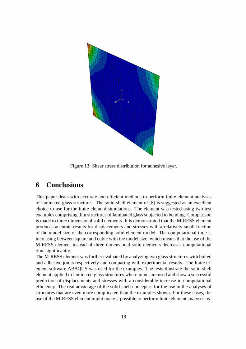
Figure 13: Shear stress distribution for adhesive layer.
6 Conclusions
This paper deals with accurate and efficient methods to perform finite element analysesof laminated glass structures. The solid-shell element of [8] is suggested as an excellentchoice to use for the finite element simulations. The elementwas tested using two testexamples comprising thin structures of laminated glass subjected to bending. Comparisonis made to three dimensional solid elements. It is demonstrated that the M-RESS elementproduces accurate results for displacements and stresses with a relatively small fractionof the model size of the corresponding solid element model. The computational time isincreasing between square and cubic with the model size, which means that the use of theM-RESS element instead of three dimensional solid elements decreases computationaltime significantly.The M-RESS element was further evaluated by analyzing two glass structures with boltedand adhesive joints respectively and comparing with experimental results. The finite el-ement software ABAQUS was used for the examples. The tests illustrate the solid-shellelement applied to laminated glass structures where jointsare used and show a successfulprediction of displacements and stresses with a considerable increase in computationalefficiency. The real advantage of the solid-shell concept isfor the use in the analyses ofstructures that are even more complicated than the examplesshown. For these cases, theuse of the M-RESS element might make it possible to perform finite element analyses us-
18
ing standard computational resources, whereas the models would become too large usingconventional three dimensional solid elements.
References
[1] R.D. Adams and J.A. Harris. The Influence of Local Geometryon the Strengthof Adhesive Joints.International Journal of Adhesion and Adhesives, 7, 2, 69-80,(1987).
[2] R.J. Alves de Sousa, R.P.R. Cardoso, R.A. Fontes Valente, J.W.Yoon, J.J. Grá-cio and R.M. Natal Jorge. A New One-point Quadrature EnhancedAssumed Strain(EAS) Solid-shell Element with Multiple Integration Points Along Thickness: Part 1- Geometrically Linear Applications.International Journal for Numerical Methodsin Engineering, 62, 952-977, (2005).
[3] R.J. Alves de Sousa, R.M. Natal Jorge, R.A. Fontes Valente and J.M.A. César de Sá.A New Volumetric and Shear Locking-free 3D Enhanced Strain Element.Engineer-ing Computations, 20, 896-925, (2003).
[4] M.Z. Açik and S. Tezcan. A Mathematical Model for the Behavior of LaminatedGlass Beams.Computers and Structures, 83, 1742-1753, (2005).
[5] C. Bength.Bolt Fixings in Toughened Glass. Master’s thesis, Lund University ofTechnology, (2005).
[6] Boverket. Regelsamling för konstruktion - Boverkets konstruktionsregler, BKR,byggnadsverkslagen och byggnadsverksförordningen. Elanders Gotab, Vällingby,(2003).
[7] R.P.R. Cardoso, J.W. Yoon, J.J. Grácio, F. Barlat, J.M.A. César de Sá. Developmentof a One Point Quadrature Shell Element for Nonlinear Application with Contactand Anisotropy.Computer Methods in Applied Mechanics and Engineering, 191,5177-5206, (2002).
[8] R.P.R. Cardoso, J.W. Yoon, M. Mahardika, S. Choudhry, R.J. Alves de Sousa andR.A. Fontes Valente. Enhanced Assumed Strain (EAS) and Assumed Natural Strain(ANS) Methods for One-point Quadrature Solid-shell Elements. International Jour-nal for Numerical Methods in Engineering, 75, 156-187, (2008).
[9] E. Carrera. Historical Review of Zig-Zag Theories for Multilayered Plates andShells.Appl. Mech. Rev., 56, 287-308, (2003).
[10] D.J. Chen, D.K. Shah and W.S. Chan. Interfacial Stress Estimation Using Least-square Extrapolation and Local Stress Smoothing in Laminated Composites.Com-puters and Structures, 58, 765-774, (1996).
[11] E.N. Dvorkin and K.J. Bathe. A Continuum Mechanics Based Four-node Shell El-ement for General Nonlinear Analysis.Engineering and Computations, 1, 77-88,(1984).
19
[12] P. Foraboschi. Behavior and Failure Strength of Laminated Glass Beams.Journal ofEngineering Mechanics, 133, 12, 1290-1301, (2007).
[13] M. Fröling and K. Persson. Application of Solid-shell Elements to Laminated GlassStructures.Proceedings of the XXIV A.T.I.V. International Conference/59th NGFAnnual Meeting, July 9-10 2009, Parma, Italy.
[14] M. Haldimann, A. Luible and M. Overend.Structural Use of Glass. Structural En-gineering Documents, 10. IABSE, Zürich, (2008).
[15] M. Harnau and K. Schweizerhof. About Linear and Quadratic "Solid-Shell" Ele-ments at Large Deformations.Computers and Structures, 80, 805-817, (2002).
[16] R. Hauptmann and K. Schweizerhof. A Systematic Development of ’Solid-shell’Element Formulations for Linear and Nonlinear Analyses Employing Only Dis-placement Degrees of Freedom.International Journal for Numerical Methods inEngineering, 42, 49-69, (1998).
[17] R. Hauptmann, K. Schweizerhof and S. Doll. Extension of the ’Solid-shell’ Conceptfor Application to Large Elastic and Large Elastoplastic Deformations.InternationalJournal for Numerical Methods in Engineering, 49, 1121-1141, (2000).
[18] T.J.R. Hughes.The Finite Element Method: Linear Static and Dynamic FiniteEle-ment Analysis. Dover Editions, New Jersey, Second edition, (2000).
[19] P. Krawczyk. Nonlinear Analysis of Layered Structureswith Weak Interfaces, PhDthesis, École Polytechnique Fédérale de Lausanne, (2006).
[20] O. Larsson.Shear Capacity in Adhesive Glass-joints. Master’s thesis, Lund Univer-sity of Technology, (2008).
[21] K.P. Li and S. Cescotto. An 8-node Brick Element with MixedFormulation for LargeDeformation Analyses.Computer Methods in Applied Mechanics and Engineering,141, 157-204, (1997).
[22] W.K. Liu, Y. Guo, S. Tang and T. Belytschko. A Multiple-quadrature Eight-nodeHexahedral Finite Element for Large Deformation Elastoplastic Analysis.ComputerMethods in Applied Mechanics and Engineering, 154, 69-132, (1998).
[23] J. Malmborg.A Finite Element Based Design Tool for Point Fixed LaminatedGlass.Master’s thesis, Lund University of Technology, (2006).
[24] H. Parish. A Continuum-based Shell Theory for Non-linear Applications.Interna-tional Journal for Numerical Methods in Engineering, 38, 1855-1883, (1995).
[25] J.N. Reddy.Mechanics of Laminated Composite Plates. Theory and Analysis. CRCPress, Boca Raton, (1997).
[26] J.C. Simo and M.S. Rifai. A Class of Mixed Assumed Strain Methods and theMethod of Incompatible Modes.International Journal for Numerical Methods inEngineering, 29, 1595-1638, (1990).
[27] B. Weller and T. Schadow. Designing of Bonded Joints in Glass Structures.Proceed-ings of the 10th Glass Performance Days, June 15-18 2007, Tampere, Finland.
20

Paper 3
DESIGNINGBOLT FIXED LAMINATED GLASS WITH STRESSCONCENTRATION FACTORS
MARIA FRÖLING AND KENT PERSSON

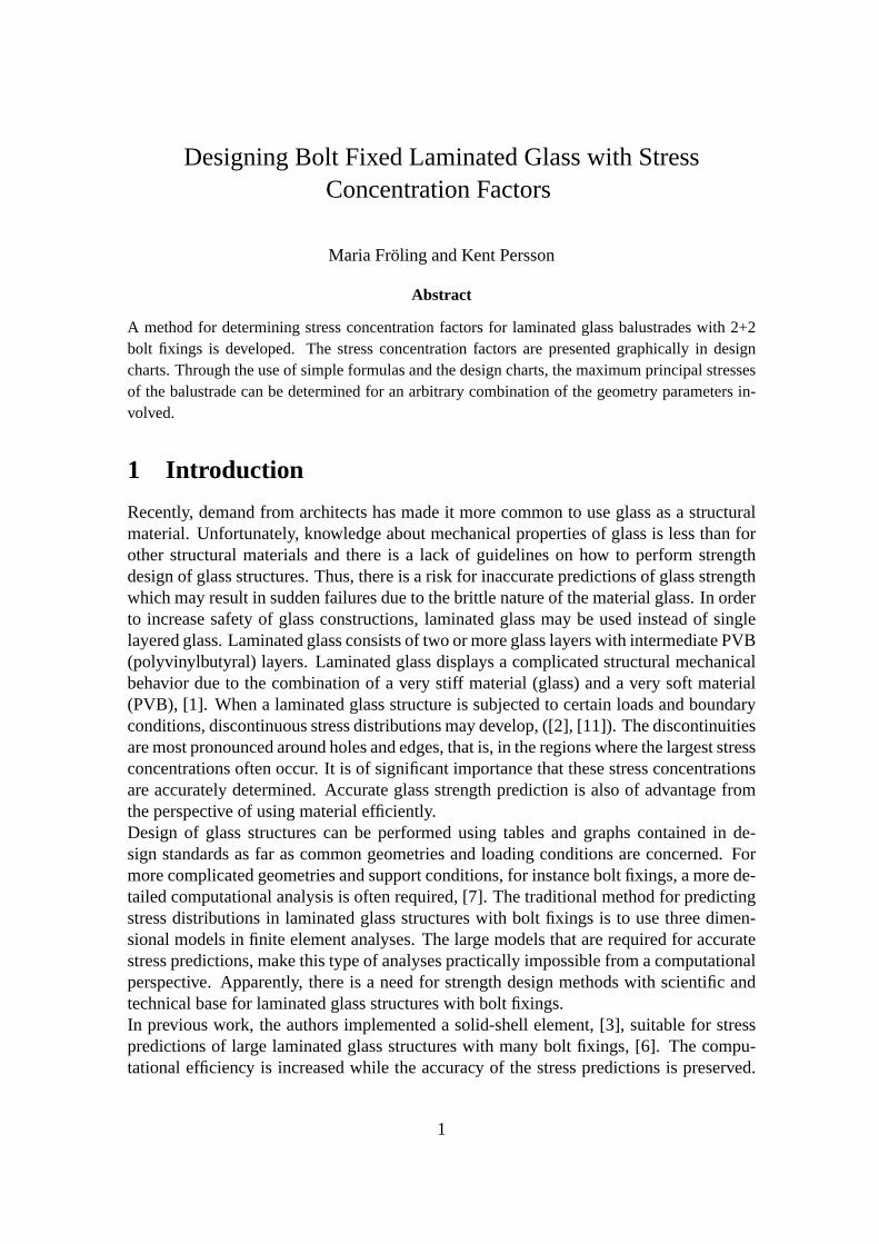
Designing Bolt Fixed Laminated Glass with StressConcentration Factors
Maria Fröling and Kent Persson
Abstract
A method for determining stress concentration factors for laminated glass balustrades with 2+2bolt fixings is developed. The stress concentration factors are presented graphically in designcharts. Through the use of simple formulas and the design charts, the maximumprincipal stressesof the balustrade can be determined for an arbitrary combination of the geometry parameters in-volved.
1 Introduction
Recently, demand from architects has made it more common to use glass as a structuralmaterial. Unfortunately, knowledge about mechanical properties of glass is less than forother structural materials and there is a lack of guidelineson how to perform strengthdesign of glass structures. Thus, there is a risk for inaccurate predictions of glass strengthwhich may result in sudden failures due to the brittle natureof the material glass. In orderto increase safety of glass constructions, laminated glassmay be used instead of singlelayered glass. Laminated glass consists of two or more glasslayers with intermediate PVB(polyvinylbutyral) layers. Laminated glass displays a complicated structural mechanicalbehavior due to the combination of a very stiff material (glass) and a very soft material(PVB), [1]. When a laminated glass structure is subjected to certain loads and boundaryconditions, discontinuous stress distributions may develop, ([2], [11]). The discontinuitiesare most pronounced around holes and edges, that is, in the regions where the largest stressconcentrations often occur. It is of significant importancethat these stress concentrationsare accurately determined. Accurate glass strength prediction is also of advantage fromthe perspective of using material efficiently.Design of glass structures can be performed using tables andgraphs contained in de-sign standards as far as common geometries and loading conditions are concerned. Formore complicated geometries and support conditions, for instance bolt fixings, a more de-tailed computational analysis is often required, [7]. The traditional method for predictingstress distributions in laminated glass structures with bolt fixings is to use three dimen-sional models in finite element analyses. The large models that are required for accuratestress predictions, make this type of analyses practicallyimpossible from a computationalperspective. Apparently, there is a need for strength design methods with scientific andtechnical base for laminated glass structures with bolt fixings.In previous work, the authors implemented a solid-shell element, [3], suitable for stresspredictions of large laminated glass structures with many bolt fixings, [6]. The compu-tational efficiency is increased while the accuracy of the stress predictions is preserved.
1

However, the use of this method requires advanced knowledgeof finite element analy-sis. In the present work, the solid-shell element is used in finite element analysis in or-der to develop a method for determining stress concentration factors for laminated glassbalustrades with 2 + 2 bolt fixings. With the use of the stress concentration factors, themaximum of the largest principal stress of the balustrade can be determined for arbi-trary geometrical parameter combinations. The computed stress values could be used instrength design of the balustrade.Design methods in terms of formulas, tables or graphs are particularly rare when it comesto bolt fixed laminated glass design. A comprehensive overview of the current state ofknowledge is given in [7]. Existing design methods for vertical bolt fixed glass are typ-ically constructed for the case of a uniformly distributed wind load and fixed positionsof the bolts. In this work, simple formulas and charts are developed for balustrades sub-jected to a uniform line load and with variable positions of the bolt fixings. The aim isto make the design of bolt fixed laminated glass balustrades possible without performinghigh level mathematics or advanced finite element analysis.
2 Available Methods for Stress Prediction of Bolt FixedLaminated Glass
Currently, few studies are available that describe guidelines or methods for stress pre-diction of bolt fixed laminated glass. In [12], a single glasspane with one bolt fixingis investigated. The pane is subjected to in-plane load. Forstress predictions, a finiteelement analysis is performed. A novelty is that a procedurefor verification of the fi-nite element model is developed. This procedure is of advantage, because is serves tostandardize the required finite element analyses so that a designer less experienced withfinite element analysis can obtain reliable results. As mentioned previously, [7] providesan excellent overview on how to deal with glass in its role as astructural material. Inthe book, an example of a design chart for bolt fixed laminatedglass is presented. Thedimensions of the glass panes can be selected given the position of the bolts, the designstrength and a specific value of the load. The load type is a uniformly distributed windload. In [13], guidelines for structural analyses of glass panels subjected to in-plane shearforces are given. The analyses are performed by means of the finite element method. Theguidelines are valid for linear supported as well as point fixed glass panes. [14] presentsexperimental and numerical investigations of small-scaled axially compressed laminatedglass panels that are point fixed. A comprehensive stress analysis is made, a parametricstudy is performed and an empirical formula for the stress concentration factor is derived.[11] deals with the development of a design program for bolt fixed laminated glass fa-cades and balustrades. The program aims to facilitate design of those glass structures andthe user does not need to have any knowledge about the finite element method.Many of the existing stress prediction methods for laminated glass design contain rec-ommendations on how to perform finite element analyses. Thatmeans that the designeror analyst has to be very familiar with the finite element method. One major aim of thiswork is to present a method that does not require knowledge ofneither finite element
2

analysis nor advanced mathematics. Overall, few stress prediction methods exist for lam-inated glass structures with bolt fixings, and for this particular case of laminated glassbalustrades with four bolt fixings with non-fixed positions,only the work of [11] exists.As a complement to that work, this paper develops simple formulas and charts that can beused for stress prediction of bolt fixed laminated glass balustrades.
3 Design of Bolt-fixed Balustrade Glass with Stress Con-centration Factors
In this paper, a method is developed for determining stress concentration factors,α, forbolt fixed laminated glass balustrades.α relates the nominal stress value,σNom, to themaximum (positive) principal stress value,σ. σ typically occurs in the vicinity of a hole.σNom is defined as the maximum (positive) principal stress for thecase of a laminatedglass structure of the same dimensions as the balustrade, but without holes. However, theinfluence of the reaction forces at the bolt locations are included in the computation.WhenσNom has been determined, the case of a balustrade with bolt fixings can be con-sidered. It remains to find the stress concentration factorα asσ = ασNom, whereσ is themaximum (positive) principal stress of the balustrade.σ occurs at the edge of a bore hole.This problem is too complicated to be treated analytically.A later section deals with thefinite element modelling of a balustrade with 2+2 bolt fixings. With the aid of the finiteelement model, design charts are developed so that the stress concentration factors,α, canbe determined for arbitrary parameter combinations.
4 Stresses in a Laminated Glass without Holes
A laminated glass without holes subjected to three-point bending can be modelled as asimply supported beam that is subjected to a bending moment,given that the load andboundary conditions are symmetric. The maximum principal stresses for a laminatedbeam that is subjected to a bending moment may be determined analytically, [4]. Thestresses are derived for a laminated glass beam consisting of two glass layers with aninterlayer of PVB. Figure 1 shows the geometry of the beam model applied to a balustrade.
R2
Glass
Glass
R1 PTot
PVB
lb la
x
Figure 1: Geometry of beam model.
3
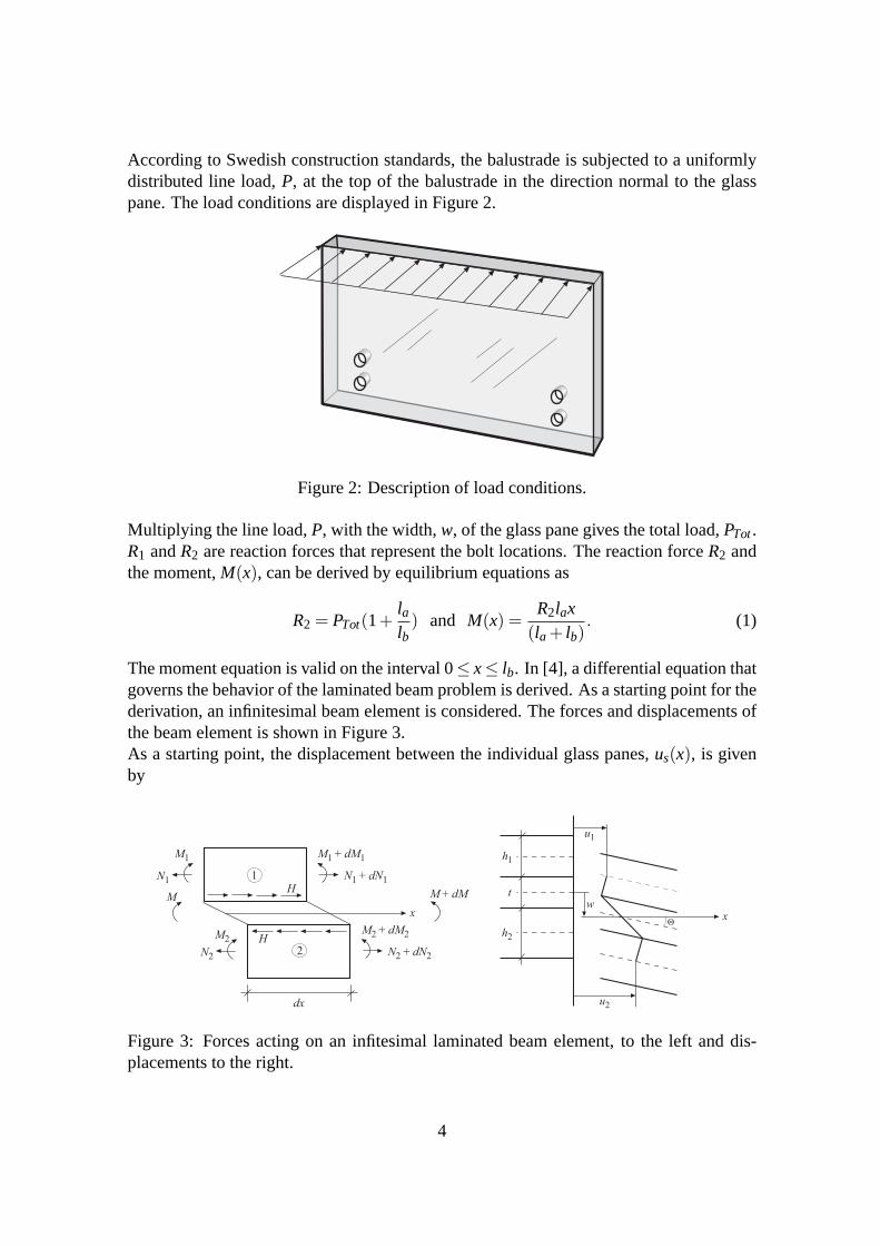
According to Swedish construction standards, the balustrade is subjected to a uniformlydistributed line load,P, at the top of the balustrade in the direction normal to the glasspane. The load conditions are displayed in Figure 2.
Figure 2: Description of load conditions.
Multiplying the line load,P, with the width,w, of the glass pane gives the total load,PTot.R1 andR2 are reaction forces that represent the bolt locations. The reaction forceR2 andthe moment,M(x), can be derived by equilibrium equations as
R2 = PTot(1+lalb) and M(x) =
R2lax(la+ lb)
. (1)
The moment equation is valid on the interval 0≤ x≤ lb. In [4], a differential equation thatgoverns the behavior of the laminated beam problem is derived. As a starting point for thederivation, an infinitesimal beam element is considered. The forces and displacements ofthe beam element is shown in Figure 3.As a starting point, the displacement between the individual glass panes,us(x), is givenby
M1 M1 + dM1
N1 N1 + dN1
M2M2 + dM2
N2 N2 + dN2
1
2
M + dMH
H
x
M
dx
h1
u2
x
h2
u1
w
t
Q
Figure 3: Forces acting on an infitesimal laminated beam element, to the left and dis-placements to the right.
4
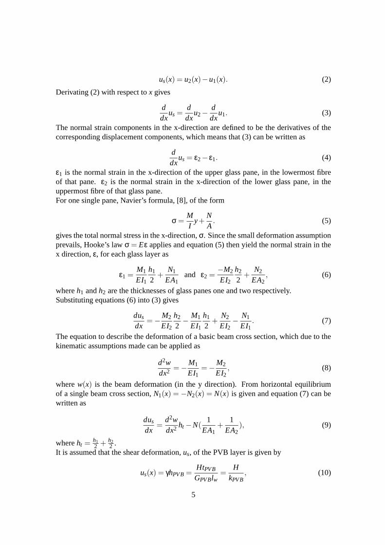
us(x) = u2(x)−u1(x). (2)
Derivating (2) with respect tox gives
ddx
us =ddx
u2−ddx
u1. (3)
The normal strain components in the x-direction are defined to be the derivatives of thecorresponding displacement components, which means that (3) can be written as
ddx
us = ε2− ε1. (4)
ε1 is the normal strain in the x-direction of the upper glass pane, in the lowermost fibreof that pane.ε2 is the normal strain in the x-direction of the lower glass pane, in theuppermost fibre of that glass pane.For one single pane, Navier’s formula, [8], of the form
σ =MI
y+NA. (5)
gives the total normal stress in the x-direction,σ. Since the small deformation assumptionprevails, Hooke’s lawσ = Eε applies and equation (5) then yield the normal strain in thex direction,ε, for each glass layer as
ε1 =M1
EI1
h1
2+
N1
EA1and ε2 =
−M2
EI2
h2
2+
N2
EA2, (6)
whereh1 andh2 are the thicknesses of glass panes one and two respectively.Substituting equations (6) into (3) gives
dus
dx=−
M2
EI2
h2
2−
M1
EI1
h1
2+
N2
EI2−
N1
EI1. (7)
The equation to describe the deformation of a basic beam cross section, which due to thekinematic assumptions made can be applied as
d2wdx2 =−
M1
EI1=−
M2
EI2, (8)
wherew(x) is the beam deformation (in the y direction). From horizontal equilibriumof a single beam cross section,N1(x) = −N2(x) = N(x) is given and equation (7) can bewritten as
dus
dx=
d2wdx2 ht −N(
1EA1
+1
EA2), (9)
whereht =h12 + h2
2 .It is assumed that the shear deformation,us, of the PVB layer is given by
us(x) = γhPVB=HtPVB
GPVBlw=
HkPVB
, (10)
5
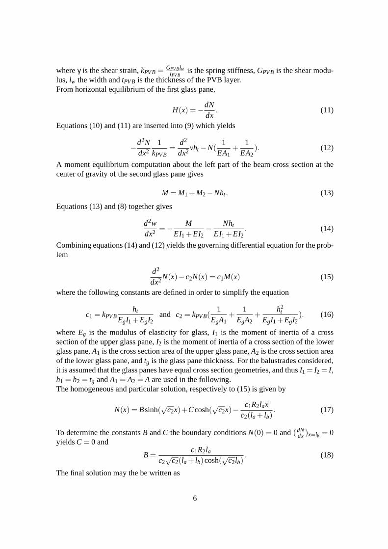
whereγ is the shear strain,kPVB=GPVBlw
tPVBis the spring stiffness,GPVB is the shear modu-
lus, lw the width andtPVB is the thickness of the PVB layer.From horizontal equilibrium of the first glass pane,
H(x) =−
dNdx
. (11)
Equations (10) and (11) are inserted into (9) which yields
−
d2Ndx2
1kPVB
=d2
dx2vht −N(1
EA1+
1EA2
). (12)
A moment equilibrium computation about the left part of the beam cross section at thecenter of gravity of the second glass pane gives
M = M1+M2−Nht . (13)
Equations (13) and (8) together gives
d2wdx2 =−
MEI1+EI2
−
Nht
EI1+EI2. (14)
Combining equations (14) and (12) yields the governing differential equation for the prob-lem
d2
dx2N(x)−c2N(x) = c1M(x) (15)
where the following constants are defined in order to simplify the equation
c1 = kPVBht
EgI1+EgI2and c2 = kPVB(
1EgA1
+1
EgA2+
h2t
EgI1+EgI2). (16)
whereEg is the modulus of elasticity for glass,I1 is the moment of inertia of a crosssection of the upper glass pane,I2 is the moment of inertia of a cross section of the lowerglass pane,A1 is the cross section area of the upper glass pane,A2 is the cross section areaof the lower glass pane, andtg is the glass pane thickness. For the balustrades considered,it is assumed that the glass panes have equal cross section geometries, and thusI1 = I2 = I ,h1 = h2 = tg andA1 = A2 = A are used in the following.The homogeneous and particular solution, respectively to (15) is given by
N(x) = Bsinh(√
c2x)+Ccosh(√
c2x)−c1R2lax
c2(la+ lb). (17)
To determine the constantsB andC the boundary conditionsN(0) = 0 and(dNdx )x=lb = 0
yieldsC= 0 and
B=c1R2la
c2√
c2(la+ lb)cosh(√
c2lb). (18)
The final solution may the be written as
6
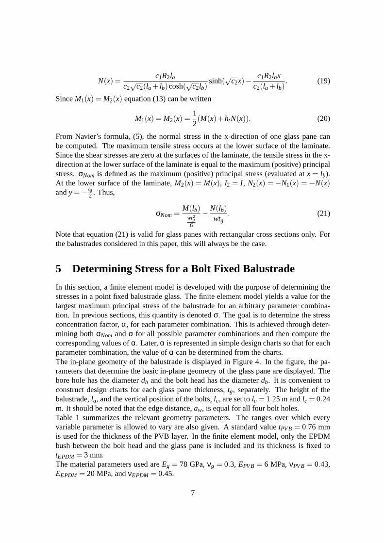
N(x) =c1R2la
c2√
c2(la+ lb)cosh(√
c2lb)sinh(
√
c2x)−c1R2lax
c2(la+ lb). (19)
SinceM1(x) = M2(x) equation (13) can be written
M1(x) = M2(x) =12(M(x)+htN(x)). (20)
From Navier’s formula, (5), the normal stress in the x-direction of one glass pane canbe computed. The maximum tensile stress occurs at the lower surface of the laminate.Since the shear stresses are zero at the surfaces of the laminate, the tensile stress in the x-direction at the lower surface of the laminate is equal to themaximum (positive) principalstress.σNom is defined as the maximum (positive) principal stress (evaluated atx = lb).At the lower surface of the laminate,M2(x) = M(x), I2 = I , N2(x) = −N1(x) = −N(x)andy=−
tg2 . Thus,
σNom=M(lb)
wt2g6
−
N(lb)wtg
. (21)
Note that equation (21) is valid for glass panes with rectangular cross sections only. Forthe balustrades considered in this paper, this will always be the case.
5 Determining Stress for a Bolt Fixed Balustrade
In this section, a finite element model is developed with the purpose of determining thestresses in a point fixed balustrade glass. The finite elementmodel yields a value for thelargest maximum principal stress of the balustrade for an arbitrary parameter combina-tion. In previous sections, this quantity is denotedσ. The goal is to determine the stressconcentration factor,α, for each parameter combination. This is achieved through deter-mining bothσNom andσ for all possible parameter combinations and then compute thecorresponding values ofα. Later,α is represented in simple design charts so that for eachparameter combination, the value ofα can be determined from the charts.The in-plane geometry of the balustrade is displayed in Figure 4. In the figure, the pa-rameters that determine the basic in-plane geometry of the glass pane are displayed. Thebore hole has the diameterdh and the bolt head has the diameterdb. It is convenient toconstruct design charts for each glass pane thickness,tg, separately. The height of thebalustrade,la, and the vertical position of the bolts,lc, are set tola = 1.25 m andlc = 0.24m. It should be noted that the edge distance,aw, is equal for all four bolt holes.Table 1 summarizes the relevant geometry parameters. The ranges over which everyvariable parameter is allowed to vary are also given. A standard valuetPVB= 0.76 mmis used for the thickness of the PVB layer. In the finite element model, only the EPDMbush between the bolt head and the glass pane is included and its thickness is fixed totEPDM = 3 mm.The material parameters used areEg = 78 GPa,νg = 0.3, EPVB= 6 MPa,νPVB= 0.43,EEPDM = 20 MPa, andνEPDM = 0.45.
7

aw
w
lb
lc
la
Figure 4: Geometry of balustrade.
Table 1: List of geometry parameters.Parameter Value
la 1.25 mlc 0.24 m
tPVB 0.76 mmtEPDM 3 mm
lb 0.2, 0.4, 0.8 maw 0.1-(w2 -0.1) in step of 0.025w 0.9-2.7 m in step of 0.3 mdh 15-40 mm in step of 5 mmtg 6, 8, 10, 12 mmdb 60 mm
The complex geometry of the balustrade requires the use of a mesh generator. The solid-shell element, [3], used has quadrilateral in-plane geometry and therefore a quadrilateralmesh generator is used. In the finite element analysis, the mesh generator and finiteelement program of [5] and [9] are used together with Matlab.Due to symmetry, onlyhalf of the balustrade needs to be modeled. Along the symmetry line, displacements inthe in-plane direction normal to the symmetry line are set tozero.When computingα, a value of the line loadP is arbitrary but is in the simulations set tothe valueP= 3 kN/m. When the charts are constructed,α can be determined irrespectiveof design load by use of the available charts.When modeling the bolts, only the EPDM bushes are included in the model. The bushesare modeled by means of a spring model, where springs are connected, in all three coor-dinate directions, to the nodes that are located on the contact surfaces between bush andglass. In the direction normal to the balustrade, springs with stiffness
8

k=EEPDM∆A
tEPDM(22)
are connected, [15].∆A is the influence area of each node, determined by
∆A=∫
ANTdA. (23)
N is the global shape function vector, [5]. Equivalently, forthe other coordinate directionsshear springs with stiffness
ks =GEPDM∆A
tEPDM(24)
are used, [10]. The springs are fixed to their surrounding, which means that the corre-sponding displacements are set to zero. The spring stiffnesses,ki, are thus assembled intothe global stiffness matrix,K , according to
K ii = K ii +ki. (25)
ki represents the spring stiffness corresponding to degree offreedomi. The bushes aremodeled explicitly only for the sides of the laminate where the reaction forces are actingon the glass. These positions are indicated in Figure 1. On the other sides of the laminate,the bolts are not modelled.When meshing the structure, a two dimensional mesh of the geometry illustrated in Figure4 is first created. To form a three-dimensional mesh, this mesh is swept in the directionnormal to the two dimensional structure. A special feature of the solid-shell element, [3],only one element per material layer is required to reach a good solution.
6 Design Charts for Determination of Stress Concentra-tion Factors
The process of determiningσ by means of the finite element method described in the pre-vious section is time consuming and requires decent knowledge about the finite elementmethod. In order for the glass designer to avoid using the finite element method, a sim-plified method for determiningσ for arbitrary combinations of certain design parametersis suggested. The method contains graphical representations, design charts, that allowαto be determined for a certain parameter combination. WhenσNom is determined for thesame parameters,σ is practically known. The required equations for determination ofσNom are (1), (19), (20) and (21).One design chart is made for each possible combination of glass thickness,tg, glasspane width,w, bolt head diameter,db, and bore hole diameter,dh. As examples, de-sign charts for the parameter combination [w = 0.9 m, db = 60 mm,dh = 15 mm] with[tg = 6,8,10,12] mm are shown in Figures 5-8.The suggested method for determiningσ by use of the design charts starts with computingσNom for an arbitrary combination of the parameterstg, w andlb. The design chart for the
9
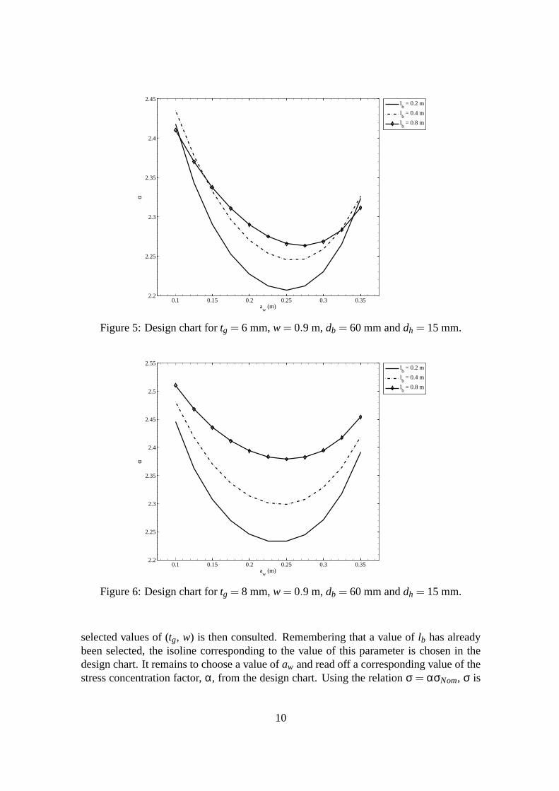
0.1 0.15 0.2 0.25 0.3 0.352.2
2.25
2.3
2.35
2.4
2.45
aw
(m)
α
lb = 0.2 m
lb = 0.4 m
lb = 0.8 m
Figure 5: Design chart fortg = 6 mm,w= 0.9 m,db = 60 mm anddh = 15 mm.
0.1 0.15 0.2 0.25 0.3 0.352.2
2.25
2.3
2.35
2.4
2.45
2.5
2.55
aw
(m)
α
lb = 0.2 m
lb = 0.4 m
lb = 0.8 m
Figure 6: Design chart fortg = 8 mm,w= 0.9 m,db = 60 mm anddh = 15 mm.
selected values of (tg, w) is then consulted. Remembering that a value oflb has alreadybeen selected, the isoline corresponding to the value of this parameter is chosen in thedesign chart. It remains to choose a value ofaw and read off a corresponding value of thestress concentration factor,α, from the design chart. Using the relationσ = ασNom, σ is
10

0.1 0.15 0.2 0.25 0.3 0.352.2
2.25
2.3
2.35
2.4
2.45
2.5
2.55
2.6
aw (m)
α
lb = 0.2 m
lb = 0.4 m
lb = 0.8 m
Figure 7: Design chart fortg = 10 mm,w= 0.9 m,db = 60 mm anddh = 15 mm.
0.1 0.15 0.2 0.25 0.3 0.352.15
2.2
2.25
2.3
2.35
2.4
2.45
2.5
2.55
2.6
2.65
aw
(m)
α
lb = 0.2 m
lb = 0.4 m
lb = 0.8 m
Figure 8: Design chart fortg = 12 mm,w= 0.9 m,db = 60 mm anddh = 15 mm.
determined.σ is the maximum (positive) principal stress value in the balustrade and thisvalue is compared to a fracture criterion. If the fracture criterion is met, the parametercombination is possible. If the value ofσ fails to meet the fracture criterion, at least oneparameter value has to be changed and the procedure to determine σ starts over again.
11

The optimal positions of the bolts may be determined directly from the design charts.Since the lowest value ofα gives the lowest stresses at the bolts, the charts directly providethis information.
7 Conclusions
A method for the determination of stress concentration factors has been developed for twoply laminated glass balustrades with 2 + 2 bolt fixings. Usingthe method, the designer candetermine the maximum (positive) principal stress value for each combination of glass plythickness, width of the glass pane, bolt position, bolt headdiameter and bore hole diam-eter using simple formulas and charts, and thus avoiding advanced and computationallyexpensive finite element analysis.
References
[1] M.Z. Açik and S. Tezcan. A Mathematical Model for the Behavior of LaminatedGlass Beams.Computers and Structures, 83, 1742-1753, (2005).
[2] C. Bength.Bolt Fixings in Toughened Glass. Master’s thesis, Lund University ofTechnology, (2005).
[3] R.P.R. Cardoso, J.W. Yoon, M. Mahardika, S. Choudhry, R.J. Alves de Sousa andR.A. Fontes Valente. Enhanced Assumed Strain (EAS) and Assumed Natural Strain(ANS) Methods for One-point Quadrature Solid-shell Elements. International Jour-nal for Numerical Methods in Engineering, 75, 156-187, (2008).
[4] C. Carrick and J. Vasur.Styvhet och Hållfasthet hos Laminerat Glas. MasterâAZsthesis, Royal Institute of Technology, (2002).
[5] O. Dahlblom et al.CALFEM-A Finite Element Toolbox to MATLAB. Division ofStructural Mechanics Report TVSM 9001, Lund University of Technology, (1999).
[6] M. Fröling and K. Persson. Application of Solid-shell Elements to Laminated GlassStructures.Proceedings of the XXIV A.T.I.V. Conference/59th NGF Annual Meeting,July 9-10 2009, Parma, Italy.
[7] M. Haldimann, A. Luible and M. Overend.Structural Use of Glass. Structural En-gineering Documents, 10. IABSE, Zürich, (2008).
[8] S. Heyden, O. Dahlblom, A. Olsson and G. Sandberg.Introduktion till Struk-turmekaniken. Studentlitteratur, (2008).
[9] J. Lorentzon.CALFEM Meshing Module. Division of Structural Mechanics and Di-vision of Solid Mechanics, Lund University of Technology, (2010).
[10] M.R. Maheri and R.D. Adams. Determination of Dynamic Shear Modulus of Struc-tural Adhesives in Thick Adherend Shear Test Specimens.International Journal ofAdhesion and Adhesives, 22, 119-127, (2002).
12

[11] J. Malmborg.A Finite Element Based Design Tool for Point Fixed LaminatedGlass.Master’s thesis, Lund University of Technology, (2006).
[12] I. Maniatis.Numerical and Experimental Investigations on the Stress Distribution ofBolted Glass Connections under In-plane Loads. Doctoral thesis, Technische Uni-versität München, (2006).
[13] D. Mocibob.Glass Panel under Shear Loading - Use of Glass Envelopes in BuildingStabilization. Doctoral thesis, École Polytechnique Fédérale de Lausanne, (2008).
[14] D. Mocibob and J. Belis. Coupled Experimental and Numerical Investigation ofStructural Glass Panels with Small Slenderness Subjected to Locally Introduced Ax-ial Compression.Engineering Structures, 32, 753-761, (2010).
[15] N.S. Ottosen and H. Petersson.Introduction to the Finite Element Method. 2nd Ed.Division of Structural Mechanics Report TVSM 3014, Lund University of Technol-ogy, (1991).
[16] D.G. Zill and M.R. Cullen.Differential Equations with Boundary-Value Problems.4th Ed. International Thomson Publishing Inc., (1997).
13
Related Documents