Strathprints Institutional Repository MacLeod, Charles Norman and Dobie, Gordon and Pierce, Stephen Gareth and Summan, Rahul and Morozov, Maxim (2016) Machining- based coverage path planning for automated structural inspection. IEEE Transactions on Automation Science and Engineering. ISSN 1545-5955 , http://dx.doi.org/10.1109/TASE.2016.2601880 This version is available at http://strathprints.strath.ac.uk/57980/ Strathprints is designed to allow users to access the research output of the University of Strathclyde. Unless otherwise explicitly stated on the manuscript, Copyright © and Moral Rights for the papers on this site are retained by the individual authors and/or other copyright owners. Please check the manuscript for details of any other licences that may have been applied. You may not engage in further distribution of the material for any profitmaking activities or any commercial gain. You may freely distribute both the url ( http://strathprints.strath.ac.uk/ ) and the content of this paper for research or private study, educational, or not-for-profit purposes without prior permission or charge. Any correspondence concerning this service should be sent to Strathprints administrator: [email protected] brought to you by CORE View metadata, citation and similar papers at core.ac.uk provided by University of Strathclyde Institutional Repository

Welcome message from author
This document is posted to help you gain knowledge. Please leave a comment to let me know what you think about it! Share it to your friends and learn new things together.
Transcript

Strathprints Institutional Repository
MacLeod, Charles Norman and Dobie, Gordon and Pierce, Stephen
Gareth and Summan, Rahul and Morozov, Maxim (2016) Machining-
based coverage path planning for automated structural inspection. IEEE
Transactions on Automation Science and Engineering. ISSN 1545-5955 ,
http://dx.doi.org/10.1109/TASE.2016.2601880
This version is available at http://strathprints.strath.ac.uk/57980/
Strathprints is designed to allow users to access the research output of the University of
Strathclyde. Unless otherwise explicitly stated on the manuscript, Copyright © and Moral Rights
for the papers on this site are retained by the individual authors and/or other copyright owners.
Please check the manuscript for details of any other licences that may have been applied. You
may not engage in further distribution of the material for any profitmaking activities or any
commercial gain. You may freely distribute both the url (http://strathprints.strath.ac.uk/) and the
content of this paper for research or private study, educational, or not-for-profit purposes without
prior permission or charge.
Any correspondence concerning this service should be sent to Strathprints administrator:
brought to you by COREView metadata, citation and similar papers at core.ac.uk
provided by University of Strathclyde Institutional Repository

1
> REPLACE THIS LINE WITH YOUR PAPER IDENTIFICATION NUMBER (DOUBLE-CLICK HERE TO EDIT) <
Abstract—The automation of robotically delivered Non
Destructive Evaluation (NDE) inspection shares many aims with
traditional manufacture machining. This paper presents a new
hardware and software system for automated thickness mapping
of large-scale areas, with multiple obstacles, by employing
CAD/CAM inspired path planning to implement control of a
novel mobile robotic thickness mapping inspection vehicle. A
custom post-processor provides the necessary translation from
CAM Numeric Code through to robotic kinematic control to
combine and automate the overall process. The generalised steps
to implement this approach for any mobile robotic platform are
presented herein and applied, in this instance, to a novel
thickness mapping crawler. The inspection capabilities of the
system were evaluated on an indoor mock-inspection scenario,
within a motion tracking cell, to provide quantitative
performance figures for positional accuracy. Multiple thickness
defects simulating corrosion features on a steel sample plate were
combined with obstacles to be avoided during the inspection. A
minimum thickness mapping error of 0.21 mm and mean path
error of 4.41 mm were observed for a 2 m2 carbon steel sample of
10 mm nominal thickness.
The potential of this automated approach has benefits in
terms of repeatability of area coverage, obstacle avoidance and
reduced path overlap, all of which directly lead to increased task
efficiency and reduced inspection time of large structural assets.
Note to Practitioners— Current industrial robotic inspection
approaches largely consist of manual control of robotic platform
motion to desired points, with the aim of producing an number of
straight scans for larger areas, often spaced meters apart.
Structures featuring large surface area and multiple obstacles,
are routinely inspected with such manual approaches, which are
both labour intensive, error prone and do not guarantee
acquisition of full area coverage.
The presented system addresses these limitations through a
combined hardware and software approach. Core to the
operation of the system is a fully wireless, differential drive
crawler with integrated active ultrasonic wheel probe, to provide
remote thickness mapping. Automation of path generation
algorithms is produced using commercial CAD/CAM software
algorithms, and this paper sets out an adaptable methodology
for producing a custom post-processor to convert the exported G-
Codes to suitable kinematic commands for mobile robotic
Manuscript received March 31, 2015. revised January 15, 2016, Accepted
August 2016. This work was supported in part by the Engineering and Physical Sciences
Research Council and forms part of the core research programme within the
U.K. Research Centre for NDE.
C. N. Macleod, G. Dobie, S. G. Pierce, R. Summan and M. Morozov are
with the Department of Electronic and Electrical Engineering, University of
Strathclyde, Glasgow G1 1XW, U.K. (email: [email protected];
[email protected];[email protected];[email protected]
k, [email protected]).
platforms. The differential drive crawler is used in this paper
to demonstrate the process. This approach has benefits in terms
of improved industrial standardisation and operational
repeatability.
The inspection capabilities of the system were documented on
an indoor mock-inspection scenario, within a motion tracking cell
to provide quantitative performance figures for the approach.
Future work is required to integrate on-board positioning
strategies, removing the dependency on global systems, for full
automated deployment capability.
Index Terms— Automated Coverage Path Planning,
Automated Robotic Inspection, Automated NDE, CAD/CAM
Based Path Planning.
I. INTRODUCTION
ith a concerted and growing emphasis on human safety
[1] and the environment [2], greater information is
required on the current state and condition of the world
infrastructure. Higher operational demands such as greater
working loads and longer working lifetimes [3], coupled to
reduced capital investment in replacement designs, has exerted
greater strain and stress on numerous components critically
affecting their condition and safe working lifetime [4] .
To ensure that infrastructure owners, operators and planners
have sufficient information readily available to them regarding
the state and condition of their asset, numerous advances and
developments have been demonstrated in the field of Non
Destructive Evaluation (NDE). The process of detailed
imaging and examination of structures in a sensitive, safe and
inherently non-intrusive manner has numerous advantages in
operational, financial and safety terms. Quantitative
information on the condition of parts and components, allow
skilled personnel or emerging automated approaches to make
decisions on remaining lifetime and required replacement,
ensuring maximum asset value, usage and safety.
Numerous applications requiring inspection on large scale
structures, such as those found in the energy sector, are often
in areas difficult to access and hazardous to human beings [4].
This, along with the requirements for greater inspection
accuracy and efficiency has underpinned a research and
development drive to automate current NDE inspection
techniques [4,5]. Only by delivering NDE inspection systems
to all points of interest within a structure, can full-scale
coverage of the assembly be undertaken. There exists a drive
to ensure full coverage to ensure no defects are overlooked or
neglected. Automation of such inspection procedures
improves accuracy by reducing human error [6], which can
Machining Based Coverage Path Planning for
Automated Structural Inspection Charles Norman Macleod, Gordon Dobie, Stephen Gareth Pierce, Rahul Summan, Maxim Morozov
W
2
> REPLACE THIS LINE WITH YOUR PAPER IDENTIFICATION NUMBER (DOUBLE-CLICK HERE TO EDIT) <
often be categorised as the weakest link in the NDE supply
chain [7]. Task efficiency and completion times can
potentially be further improved through employment of a
swarm of autonomous intelligent systems. Furthermore
automated processing of collected NDE sensor data can then
be undertaken to aid defect detection and recognition,
especially when dealing with large sensor datasets [8].
The requirement for autonomous NDE systems has driven
research and development in robotic inspection platforms
capable of accessing structures and undertaking NDE using
specialised sensors [9]. Previous research within the Centre for
Ultrasonic Engineering (CUE) (University of Strathclyde) has
focussed on mobile crawlers [4,9], localisation strategies and
approaches through novel visual [10] and Bayesian methods
[11], along with multi sensor (Ultrasonic, Visual and Magnetic
Flux Leakage (MFL)) payload delivery [12-14]. Similarly
inspired research has been undertaken internationally
focussing on areas such as robot design [15-16], path planning
for crawlers [5,17-18] and component inspection [19-20]. All
path-planning approaches described in [5,17-18]
fundamentally design their method for optical or visual
inspection deployment techniques, which coincidentally only
perform surface inspection and do not perform internal
imaging. Internal imaging of structures, such as thickness
mapping, is commonly undertaken using ultrasonic techniques
which require consistent control of sensor-to-surface
normality and typically feature a very much reduced single-
point measurement inspection volume when compared to
visual sensors. The genetic algorithm [5], spanning-tree [17]
and Voronoi [18] path planning algorithms presented do not
therefore naturally directly translate to automated internal
imaging and ultrasonic thickness mapping applications.
Current industrial state-of-the-art large-area asset remote
thickness mapping inspection approaches largely consist of
full manual remote control of a robotic delivery platform with
an integrated ultrasonic sensor. The operator manually
controls platform motion to desired points, with the aim of
producing a number of straight scans for larger areas, often
spaced meters apart. Structures such as oil storage tanks,
featuring large surface areas and multiple access hatch
obstacles, are routinely inspected with such approaches and
can take up to a number of days to inspect in such a labour
intensive manner, while still not acquiring full area scanning
coverage [21-23].
This paper presents contributions to the field of automated
inspection of large-scale assets, building on the current
technology and the level presented above. Such contributions,
most notably, relate to a new adaptation of an automated path
planning strategy, platform design, robot control and data
processing. Firstly, a core contribution presented herein is a
software pipeline for performing coverage path planning,
especially suited for internal imaging and thickness mapping
inspections. Built upon traditional CAD/CAM operations and
introduced for the first time for automated mobile robot
inspection applications, this approach is applicable to many
mobile robotic devices. A second core contribution is
introduced through a proof-of-concept demonstration of a
simulated inspection scenario. This is undertaken using a
custom novel robotic inspection platform which allows for the
characterisation of complete system performance.
Section II details path planning concepts, with a focus on
inspection related approaches, highlighting similarities
between such NDE application areas and traditional
machining operations. Section III introduces the hardware,
firmware and software developed for this body of work.
Section IV details the technical structure of the proof-of-
concept demonstration, utilised to undertake a mock industrial
inspection. The subsequent proof-of-concept demonstration
characterisation results are introduced and analysed in Section
V. Section VI concludes the paper and notes future areas of
relevant work.
II. PATH PLANNING
For remote inspection procedures to achieve greater
coverage and efficiency, fundamental changes in the approach
of both current delivery platforms and their associated control
and path planning systems are required. Automated path
planning must be introduced to replace traditional inefficient
manual approaches. Path generation algorithms produce the
necessary waypoints and trajectories for automated travel of
the platform and deployment of sensors to the points of
interest. Path planning strategies must account for desired area
and volume coverage while also ensuring obstacle avoidance.
Additionally they must consider and ensure both safe access
and exit of the complete system.
A. Coverage Path Planning
Coverage Path Planning (CPP) is the procedure of
determining a path that passes over all points of an area or
volume while avoiding obstacles [24]. Example robotic
applications that fundamentally require such a planning
strategy include vacuum cleaning robots, painting robots,
underwater imaging systems, demining robots, lawn mowers,
agricultural robots and window cleaners [25-28]. Cao et al
[28] defined a set of criteria and requirements for robotic
systems undertaking CPP operations in 2D environments.
1. The robot must move through all the points in the target
area covering it completely.
2. The robot must inherently have the ability to fill the
region without overlapping paths.
3. Continuous and sequential operation without any
repetition of path is required
4. The robot must avoid all obstacles
5. Simple motion trajectories (e.g. straight lines or circles)
should be used for simplicity and control.
6. An “optimal” path is desired under available conditions.
CPP algorithms can be classified as heuristic or complete
depending on whether or not they provably guarantee
complete coverage of the free space [24]. Additionally they
can also be classified as either off or on-line. Off-line

3
> REPLACE THIS LINE WITH YOUR PAPER IDENTIFICATION NUMBER (DOUBLE-CLICK HERE TO EDIT) <
programming requires a priori knowledge of the environment
and it remaining static throughout the operation window [29],
while on-line algorithms feature no a priori knowledge and
utilise real-time sensor measurements to profile the
environment and path plan based on the acquired information.
Automation of path planning can yield benefits in terms of
production, efficiency, and safety. The industry application
which has received considerable research and industrial focus
in automated area CPP, is that of spray painting [30]. More
recently CPP for industrial component inspection has
undergone significant research in high value manufacturing
applications, especially in aerospace, with a variety of NDE
sensors being deployed [20,31-35]. Internal imaging
applications in the manufacturing sector have utilised
conventional robot arms to ensure sensor-to-surface normality
and [20,35] present a CAD/CAM inspired path-planning
toolbox for such robot deployment mechanisms.
CPP for crawler devices has also recently attracted research
interest in areas such as material handling and logistics [36],
vacuum cleaners, agriculture [37], demining [27] and
inspection [5,17,18,33-34], Traditional path planning
algorithms for such platforms has focussed on Configuration
Space (C-Space) representations such as Voronoi diagram
[38], regular & occupancy grids, generalised cones [39], quad-
tree [40] and vertex graphs. Additionally CPP for Aerial
platforms has received attention for opportunities in
surveillance [41], agriculture [42] and disaster and emergency
management.
B. Inspection path planning
Although sharing similarities to other industrial robotic
application CPP strategies, automated inspection CPP is
further challenging insofar that typical NDE applications
require scanning of features that would normally be classed as
obstacles in traditional robotics. This subtle distinction must
be considered, as robotic positioning and path planning
algorithms must not safely avoid such an object, by
traditionally moving as far as possible away from the object,
but carefully approach such objects to allow NDE sensors to
be deployed with very precise sensor-surface stand-off
distance control. Stand-off distance must be consistent, along
or around such objects, while also being repeatable, to allow
industry code compliant inspection strategies to be deployed at
regular intervals. This latter point ensures operators are able to
confidently monitor rate of change of inspected structures.
Automated identification and selection of such features
requiring inspection, for enhanced throughput and automation
is very much in its infancy [35] and is not considered in this
body of work. Avoidance strategies must not only recognise
obstacles, but also be intelligent in determining them as
features requiring inspection, or in fact just obstacles requiring
avoidance. Therefore a future requirement would be to group
objects into those that require inspection and those requiring
avoidance.
One critical exception to traditional object avoidance
strategies and of significance to automated NDE systems is
when deploying contact based traction platforms. Crawler
platforms such as wheeled or gripper clamps, deploying
traditional ferromagnetic/friction strategies or more advanced
approaches such as vacuum devices [43], use surfaces for
successful manoeuvring. Additionally such strategies must
also consider the platform propulsion technique and its
requirements when deciding courses of action.
It is therefore logical that all parts of an automated NDE
system, except contact based inspection/localisation sensors
and traction devices, should always avoid contact to nearby
objects throughout the inspection process. This is highly
applicable in deployment strategies of tight space or confined
access, en-route to a desired inspection point.
C. Inspection Path Planning Parameters
Path or motion planning is a key component in the
realisation of autonomous robotic systems [44]. From a
robotic perspective, path planning is the method and approach
to progress to a defined goal or location. Interlinked and
conflicting parameters such as obstacle avoidance, velocity,
completion time and robustness define the overall strategy and
technique. These are discussed in greater detail below,
highlighting the key parameters of inspection path planning:
1) Deployment Platform Design
The deployment platform dictates the optimum path
planning strategy to be investigated. Full 6 D.O.F. platforms
(aerial, conventional robot arms ) can naturally manoeuvre to
positions along paths that low D.O.F rail constrained scanners
and surface traction platforms (crawlers) cannot achieve. This
additional freedom allows greater flexibility dealing with
challenging access constraints albeit at the expense of obstacle
avoidance.
2) Area & geometry to be inspected & imaged
The area, point or object requiring inspection naturally
dictates the path planning strategy. For example simple flat
rectangular geometries would typically require traditional
parallel raster scanning techniques, while spiral geometries
would require circular loop paths. Complex shaped surfaces
naturally require complex spline type paths.
3) Inspection Sensor
When considering path step-over, of critical importance is
the sensor active aperture or sensor footprint. The sensor
choice and area to be inspected are closely interlinked insofar
that they directly dictate the number of imaging passes
required to completely satisfy the coverage requirements.
Sensor resolution is controlled by design fundamentals and
relates to the window and sampling area of the sensor.
4) Inspection Path Pattern
The NDE path pattern is directly dictated by parameters
such as inspection speed and desired resolution. Firstly, the
sampling time of traditional NDE sensors defines the
maximum motion velocity which directly limits the overall
inspection time. Path resolution is dictated by the largest
spacing increment between subsequent waypoints, while
measurement resolution is fundamentally limited by the
maximum sensor and path resolution. Additionally overall
4
> REPLACE THIS LINE WITH YOUR PAPER IDENTIFICATION NUMBER (DOUBLE-CLICK HERE TO EDIT) <
inspection time is directly controlled by the motion velocity
and measurement spacing along the desired path.
5) Platform & Sensor Positioning Strategies
The precision, accuracy and repeatability of the platform
and sensor positioning system ultimately limit the maximum
inspection coverage rate, as inaccuracies would yield greater
required path overlap and multiple sweeps. Additionally the
initial tolerance of any acquired surface/object metrology
information can affect the coverage rate as multiple
incremental sweeps may be required to image the feature.
6) Material & Surface Properties
The material under inspection can influence the path
planning strategy in two distinct manners. Firstly, the delivery
platform may use a particular method of traction (e.g.
magnetic) and restrict its movement to surfaces that suit such
constraints. Secondly, the material itself may dictate the pose
of the NDE sensor to very specific values or ranges,
depending on parameters such as surface roughness or local
geometry.
D. Inspection & Machining Path Planning Parallels
The automation of traditional machining operations began
with Numeric Control (NC) in 1952 [45]. NC offered control
of mechanical actuators, through electronic commands. The
advent of Computer Numeric Control (CNC) allowed more
complex multi-axis machining tool paths to be generated
efficiently and safely [46,47].
It is identified herein that both automated inspection and
traditional machining path planning, share many common
aims and goals. Firstly, they both desire to efficiently fully
cover large areas of both planar and complex geometry while
retaining sensor-to-surface normality of the tool/sensor.
Additionally, both scenarios can feature boundaries and areas
that are to be left untouched. Furthermore each application
can require singular paths around distinct components of both
simple and complex nature.
The individual concepts of manufacturing path planning, for
milling operations, are considered below along with the
corresponding parallels to NDE inspection concepts. Table 1
summarises the equivalent parameters.
1) Manufacturing Process Planning
This considers the overall process and flow of undertaking
milling operations. Similarly, in automated inspection
applications such planning is undertaken to maximise asset or
component utilisation or value. Such an inspection example
scenario would include that of a storage vessel inspection,
which would likely require draining, prepared accordingly and
then inspected, prior to painting and return to service.
2) Machine Tool and Controller Hardware Design
Kinematics.
This considers the physical capabilities, in terms of speeds,
acceleration and range of movements which can be achieved
by the machine tool. In an automated NDE context this relates
to the deployment platform design, its degrees of freedom, its
controller and positioning feedback strategies
3) Cutting Parameter Estimates and Modelling
In traditional machining operations, parameters such as
cutting force and travel velocities, are highly dependent on
the material, cutting tool, desired throughput and machine
rigidity. Optimisation allows operators to specify maximum
safe permissible cutting parameters for maximum throughput
feed rates. Similarly in an inspection context, the sensor
defines parameters such as contact pressure, maximum travel
velocity and sampling window. Additionally, the surface and
geometry to be inspected, along with the platform design and
control strategies, define travel velocities and accelerations,
especially with surface contact traction devices.
4) Path Generation
Manufacturing operations require the efficient movement of
the cutter across the areas and features requiring machining.
Similarly NDE sensors require to be scanned in a repeatable
and precise fashion across areas requiring inspection.
5) Machining Simulation and Verification
To allow operators to visualise and proceed with machining
operations, simulation of the tool cutter with respect to the
machined part is typically performed. This ensures the final
part is as manufactured with no errors, produced by stray
cutting operations, while also allowing the operator to plan the
physical process around items such as fixturing and cycle
time. In automated NDE applications, such simulations offer
the operator the opportunity to ensure compliance with the
required feature coverage while also ensuring no collisions
with the sample or surroundings.
Path Planning Equivalent Parameters
Machining
Manufacturing
Process
Planning
Machine tool and
Controller Hardware
Design Kinematics.
Cutting Parameter
Estimates and
Modelling
Path
Generation
Machining
Simulation
and
Verification
Equivalent
Parameter
Automated
Inspection
Inspection
Process
Planning
Deployment Platform
Design Inspection Sensor
Inspection
Path Pattern
Inspection
Simulation
and
Verification
Platform & Sensor
Positioning Strategies
Material & Surface
Properties Deployment
Platform Design Table 1. Illustrated are the equivalent and comparable
parameters of Machining and Automated Inspection path
planning.
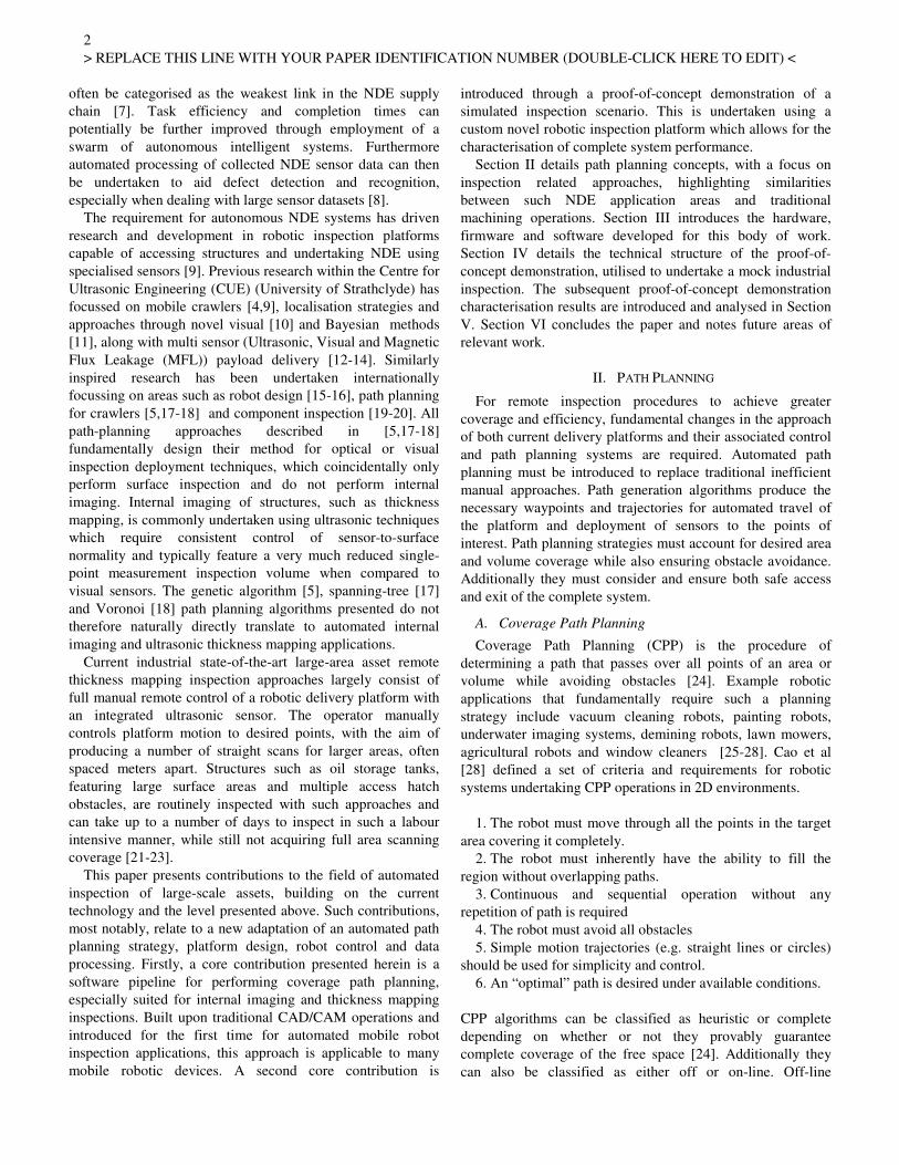
E. Traditional Machining: Pocket milling
In typical negative machining operations a pocket is defined
as an area with defined borders in which material should be
removed. It must be noted that the borders can be defined
inside or outside the part denoting a closed or open pocket
respectively [42]. Additionally, island units are defined as
areas that are to be left un-machined and avoided (Fig. 1).
Such path operations are generated using the Configuration
Space methods descibed in [49,50]. Such operations share
strong similarities to many common NDE inspection scanning
scenarios, where areas are desired to be scanned with raster
scan paths while avoiding obstacles.
5
> REPLACE THIS LINE WITH YOUR PAPER IDENTIFICATION NUMBER (DOUBLE-CLICK HERE TO EDIT) <
Fig. 1. a) Closed Pockets, b) Closed Pockets with Island, c) d)
Open Pocket with Bounds, e) Completely open pocket, f) Open
pocket with Island [48]. Illustrated is the varying pocket milling
machining operation for each case.
F. Machine Control and Implementation
The industrial standard for machine tool operation through
Computer Aided Manufacturing (CAM) techniques is that of
G-Code [51]. G-Code is a standardised high level NC
language that is accepted by all standard CNC machine tools.
Movements such as straight line (G01) and arc interpolations
(G02,G03) are standard operations along with control of
plunge-rate, feed-rate and spindle speed. These basic functions
allow a variety of operations to be undertaken and machining
functions to be then performed. Additional G-Code functions
have been added to the standard protocol which allow more
complex operations to be performed.
1) Post-Processors
A post-processor is a tool that translates output statements
from a robot simulator to a target robot language (G-Code),
for deployment of off-line path planning programming
algorithms [52,53]. Post processors can be categorised as
system-dependent, application dependent or generic [53].
System dependant post-processors translate robot simulation
commands into a specific robot language, traditionally
applicable to a certain manufacturer or system protocol [54].
Application dependant post-processors are made for a specific
application with custom sequences. Generic post-processors
are theoretically capable of translating multiple simulator
commands into languages for multiple robot controllers [53].
III. OVERALL SYSTEM DESIGN
To evaluate and highlight the scalable benefits of machining
based path planning for automated structural inspection a
comprehensive suite of hardware and software was developed.
Firstly, a novel ultrasonic sensing inspection platform the
Automated Ultrasonic Thickness (AUT) Remote Sensing
Agent (RSA) was adapted and optimised, building on previous
work [55], to investigate the feasibility of multiple obstacle
automated inspection.
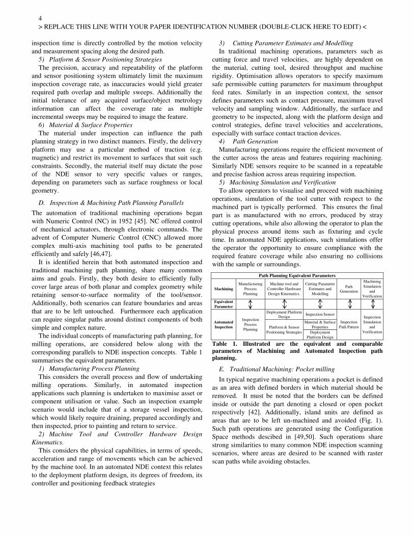
Secondly, a software pipeline was developed, utilising both
commercial and custom developed packages to undertake and
highlight coverage path planning for automated inspection
applications. The overall system structure and flow is shown
below in Figure 2.
Commercial CAD/CAM software was used to generate
machining path trajectories, while a custom post-processor
and control and processing packages were developed
specifically for this body of work and the AUT RSA, in an
established custom software package (RSA GUI) [4]
Fig. 2. Overall System Structure and Flow. Highlighted is the
detailed breakdown of commercially developed, previously
developed and newly developed work, with direct reference to
their corresponding relevant section in the manuscript.
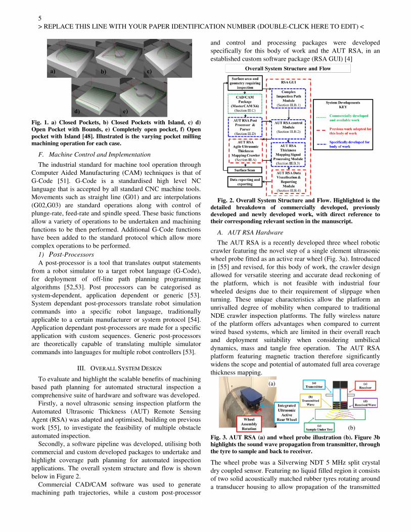
A. AUT RSA Hardware
The AUT RSA is a recently developed three wheel robotic
crawler featuring the novel step of a single element ultrasonic
wheel probe fitted as an active rear wheel (Fig. 3a). Introduced
in [55] and revised, for this body of work, the crawler design
allowed for versatile steering and accurate dead reckoning of
the platform, which is not feasible with industrial four
wheeled designs due to their requirement of slippage when
turning. These unique characteristics allow the platform an
unrivalled degree of mobility when compared to traditional
NDE crawler inspection platforms. The fully wireless nature
of the platform offers advantages when compared to current
wired based systems, which are limited in their overall reach
and deployment suitability when considering umbilical
dynamics, mass and tangle free operation. The AUT RSA
platform featuring magnetic traction therefore significantly
widens the scope and potential of automated full area coverage
thickness mapping.
Fig. 3. AUT RSA (a) and wheel probe illustration (b). Figure 3b
highlights the sound wave propagation from transmitter, through
the tyre to sample and back to receiver.
The wheel probe was a Silverwing NDT 5 MHz split crystal
dry coupled sensor. Featuring no liquid filled region it consists
of two solid acoustically matched rubber tyres rotating around
a transducer housing to allow propagation of the transmitted
(a)
(b)

6
> REPLACE THIS LINE WITH YOUR PAPER IDENTIFICATION NUMBER (DOUBLE-CLICK HERE TO EDIT) <
compressional wave and receive signals respectively (Fig. 3b).
The wheel probe has an approximate horizontal minimum
spatial resolution of 24 mm.
The integrated drive electronics consisted of a custom
single channel high voltage square wave pulser. A boost DC-
DC convertor provided a 110V drive excitation voltage.
Newly developed acquisition electronics, for enhanced signal
recovery, consisted of a custom implemented single channel
low-noise pre amplifier (AD8015 & AD8370 [56]) coupled to
a high speed Field Programmable Gate Array (FPGA)
Analogue to Digital Convertor (ADC) [57]. A USB
connection established with the on-board General Purpose
Processor (GPP), allowed buffering and transferring of raw
data to the host computer (Fig. 4.)
Fig. 4. Newly Developed Ultrasonic Acquisition Structure. All
ultrasonic data, and co-incidentally all robot variables, are
transferred wirelessly back to a computer base station GUI.
Positional tracking and feedback control of the AUT RSA
within the laboratory volume was achieved using a VICON
Six Degree of Freedom (D.O.F.) Motion Capture System
(VMCS) [58]. This photogrammetry system utilises multiple
optical cameras to track the pose of a unique arrangement of
retro-reflective markers attached to the platform.
1) AUT RSA Firmware
New low-level firmware, stored on an embedded
microcontroller, was specifically developed for control of the
active rear wheel. A Proportional Derivative (PD) controller
was implemented to ensure the rotation angle of the rear wheel
matched the desired angle and that of the result of the two
front wheels differential. The controller was manually tuned to
ensure a suitable response profile and minimum overshoot.
B. RSA GUI
Additional software packages were developed and current
packages modified within an established custom C++ Personal
Computer (PC) RSA Graphical User Interface (GUI) for full
control of the AUT RSA.
The GUI features a 3D visual world representation, where
structural asset Computer Aided Drawing (CAD) models can
be imported, displayed and the position of the robot relative to
the sample visualised. Path trajectories can be manually
selected across the sample and subsequent NDE results can be
displayed and visualised relative to the sample. All RSA
parameters including raw NDE results are logged and can be
visualised live if desired.
1) Complex Inspection Path Module
This package allowed complex shaped surfaces and
geometries to be imported into the 3D visual world. This
feature allowed subsequent desired path planning algorithms
and results to be overlaid and displayed on the inspection
geometry.
2) AUT RSA Control Module
This module featured the necessary functions and parameter
settings, such as wheel velocity and pose, to allow control and
optimisation of the additional D.O.F found on the AUT RSA
with its active rear wheel. This module also included a
manually tuned PID heading controller, with positional
information measured by the VMCS, to maintain path
following and attain desired waypoints.
3) AUT RSA Thickness Mapping Signal Processing
Module
All captured raw ultrasonic signals were wirelessly
transferred to the remote RSA GUI. Due to the compressive
nature of the wheel probe tyre and the variation in sound
propagation through the tyre and sample, accurate calculation
of the thickness of the sample based on conventional time of
flight information between the transmitted pulse and the first
back-wall echo return was deemed unsuitable. Therefore the
corresponding thickness of the material was calculated using
successive back-wall echos, with three successive echos
utilised for averaging purposes. Additionally small local
variations in coupling between tyre and surface yield
corresponding change in back wall echo amplitude, with
poorly coupled instances yielding reduced amplitudes. The
minimum peak detection amplitude of each back wall echo
must therefore take into consideration the coupling
environment. As the receive acquisition process begins shortly
after the firing pulse, the largest peak in the acquired captured
data logically corresponds to the first back wall echo. Due to
the attenuative nature of traditional materials successive back
wall echoes have correspondingly reduced amplitudes. The
peak detection algorithm (1) therefore accounted for variation
in the amplitude of the first echo and detection of both the
second and third maxima based on the former (Fig. 5).
Fig. 5. Back Wall Echo Thickness Measurement. Successive wall
reflections are utilised for averaging purposes to determine
sample material thickness
௧ = ቀ௩×(௧య௧భ)ସ ቁ (1)
Where mt =Material thickness (mm) and vc =Speed of
sound in material (mm/s). Each ultrasonic acquisition was
both time and position-stamped. The position of the AUT
RSA as measured by the VMCS, was that of the centre of
turning rotation, namely the central point of the front two
drive wheels. As the wheel probe was located at the rear of the
platform, displaced in one axis along the length of the robot,
A1 =1st
back wall echo amplitude (V).
t1 =1st
back wall echo time (s).
A2 =2nd
back wall echo amplitude (V).
t2 =2nd
back wall echo time (s).
A3 =3rd
back wall echo amplitude (V).
t3 =3rd
back wall echo time (s).

7
> REPLACE THIS LINE WITH YOUR PAPER IDENTIFICATION NUMBER (DOUBLE-CLICK HERE TO EDIT) <
the position of the actual ultrasonic measurement followed an
arc movement centred on the RSA centre of rotation. A 2D
coordinate transform was utilised to calculate the point of
ultrasonic measurement as shown in (2,3) where ȌRSA equals
the yaw angle (°) of the AUT RSA as measured by the VMCS,
DTTC the distance (mm) from the transducer to AUT RSA
turning centre and RSATCx, RSATCy represent the VMCS
measured turning centre positions. _ݏ_ݏܯ௫ = ܦ) × cosߖோௌ) + ௬ݏ_ݏܯ_ ௫ (2)ܣ = ܦ) × sinߖோௌ) + ௬ (3)ܣ
Therefore all ultrasonic measurements were recorded at their
correct position of capture.
4) AUT RSA Data Visualisation & Reporting Module
A new module for results visualisation and processing was
implemented within MATLAB, but able to be called from the
RSA GUI. This package allowed the previous inspection
geometry to be exported and all scan data, including thickness
data and sensor scan paths to be overlaid on the geometry.
Additionally this module allows quantifiable results to be
obtained on parameters such as thickness deviation to original
and sensor path error.
C. CAD/CAM Package
The Mastercam X6 package was utilised for CAM
operations and subsequent machining inspired path
trajectories.
1) Custom AUT RSA Machine Tool
A custom machine tool was designed within Mastercam to
simulate the AUT RSA when undertaking an inspection
operation (Table 2). The working envelope of the AUT RSA
was represented as a cylinder of diameter 460 mm. This was
calculated from the turning centre origin between the drive
wheels to the safe outer maximum limit of extension of any
part of the platform. This included the whole case, the active
back wheel in all orientations and all associated connectors.
Additional parameters were specified in relation to
deployment velocities based on traditional speed and rate
variables (Table 3). Index AUT RSA Parameter Machine Tool
Parameter (mm)
1 UT Wheel Probe Nominal Contact Area Diameter
(20 mm)
Cutter Diameter
2 UT Wheel Probe Diameter (65 mm) Flute Size
3 Wheel Probe Wheel Arch Nominal Height to
Ground (73 mm)
Shoulder Size
4 AUT RSA Height (105 mm) Overall Height
5 AUT RSA Working Envelope Diameter (460 mm) Shank Diameter
6 AUT RSA Working Envelope Diameter (460 mm) Holder Diameter
7 Holder Not Utilised - Nominal (1 mm) Holder Height
Table 2. Highlighted are AUT RSA tool parameters and their
equivalent machine tool parameter in the CAD/CAM
environment.
AUT RSA Parameter Machine Tool Parameter
RSA scanning speed (25 mm/s) Feed Rate (mm per minute)
RSA travelling speed (50 mm/s) Retract Rate (mm per minute)
RSA UT acquisition frequency (10
Hz)
Spindle Speed (revolutions per
minute)
Table 3. Documented is the AUT RSA Auxiliary tool parameters
and their corresponding equivalent machine tool parameter.
In 2D milling commands Mastercam features no intelligent
tool collision protection by adaption of the path trajectory. It is
a requirement of the operator to ensure no collisions occur by
reviewing the generated path motion simulation. Due to the
rear swing nature of the active back wheel of the AUT RSA,
the full working envelope of the AUT RSA can, as discussed
above, be defined with a radius of 230mm from the turning
centre of the AUT RSA. The actual working envelope at any
particular instance of time will consist of a partial section of
the full envelope defined by the current pose of the platform.
Therefore 230 mm of clearance around the contours of each
island was specified to ensure no collisons.
D. AUT RSA Post-Processor
A custom system-dependent post processor and parser was
developed for the AUT RSA to allow path trajectory
algorithms to be simulated and deployed in inspection
scenarios. The post processor was created to export only a
limited number of basic function G-Codes (G01,G02,G03) and
subsequently allow straight line and arc functions in a proof-
of-concept demonstrator.
A parser was implemented within MATLAB to accept the
post-processed numeric control (NC) output and convert this
into suitable XML structured commands, as utilised for all
desired paths and coordinates in the established RSA GUI. As
all arcs are fundamentally represented by a finite number of
straight-line sections, the parser first required the operator to
specify the maximum length of any arc divided straight line
sections. Each arc is was then divided into the corresponding
number of straight-line interpolations from the start to the end
of the arc.
E. AUT RSA Ultrasonic Calibration
The thickness mapping ability of the AUT RSA system was
evaluated on a single straight-line path on a 10mm thick
calibration sample plate (Carbon Steel S275 plate), 2000 mm
long and 300 mm wide. A reference thickness measurement
was taken ten times along the same path using a calibrated
micrometer calliper. The result of this scan, with speed of
sound set as 5920m/s, is shown in Table 4. To note is the
small but consistent underestimate of sample thickness.
Parameter Micrometer
Value
AUT RSA
Value
Error
Mean Thickness 9.98 mm 9.61 mm -0.37 mm
Minimum Thickness 9.73 mm 8.86 mm -0.87 mm
Maximum Thickness 10.21 mm 10.12 mm -0.09 mm
Thickness Standard
Deviation
0.15 mm 0.35 mm 0.2 mm
Table 4. AUT RSA ultrasonic thickness reference scan results
with corresponding error characterisation against reference
micrometer readings.
IV. PROOF-OF-CONCEPT DEMONSTRATION
Large steel plate structures are utilised in many industrial
structures not limited to oil and gas storage tanks, ship hulls
and wind turbine towers. Due to environment and local
conditions these plates are often subject to corrosion and as

8
> REPLACE THIS LINE WITH YOUR PAPER IDENTIFICATION NUMBER (DOUBLE-CLICK HERE TO EDIT) <
such gradually face loss of thickness. To confirm with
appropriate legislation and ensure integrity, thickness mapping
is periodically undertaken across the plated structure.
Automated thickness mapping is a challenging inspection,
when considering full area coverage, due to logistics such as
structure features/obstructions, robotic logistics and
environmental conditions.
The combination of the AUT RSA and machining based
path planning approach yield themselves directly to the
challenge of automated full area coverage inspection scanning.
A sample, with typical obstacles and simulated defects was
produced, to undertake a mock inspection scan and highlight
proof-of-concept.
A. Industrial Sample
A sub-scale sample (2000 x 1000 x 10 mm Carbon Steel
(S275) plate), including obstructions and simulated defects,
was fabricated to mimic a traditional plated floor. Two
obstructions were affixed to the plate to mimic typical
industrial obstacles protruding through the floor (Table 5).
Additionally seven flat bottom holes of 25 mm, all of varying
depths, were machined into the underside of the plate at
various locations to simulate localised loss of thickness (Fig.
6). The locations of these defects and their micrometer-
measured depth are described in Table 6.
Fig. 6. Industrial Sample Diagram (a). Highlighted is the two top
surface obstacles and seven bottom surface artificial defects.
Photo of complete set-up and AUT RSA highlighted in (b)
Obstacle
Number Description
Industrial
Representation
1 Rectangular box of width 270 mm and breadth
170 mm, centred at (135, 85)
Pipe Duct
2 40mm Diameter Cylinder centred at (1500,
425)
Pipe Riser
Table 5. Industrial sample obstacle information with
corresponding industrial component equivalent representation
Defect Number Diameter (mm) Location(x,y)
(mm)
Micrometer
Measured Plate
Thickness (mm)
1 25 600,710 8.25
2 25 900,710 6.08
3 25 1200,710 3.85
4 25 1500,710 1.66
5 25 750,510 6.20
6 25 1050,510 3.74
7 25 1350,510 0.80
Table 6. Industrial sample artificial defect location information
with corresponding reference micrometer thickness reading.
A manual ultrasonic thickness benchmark was conducted,
prior to obstacle fitment, using standard equipment (5 MHz
GE Roto-Array and Olympus Omniscan MX2). The reference
thickness map is shown in Figure 7 highlighting the nominal
10 mm thickness and varying depth defects.
Fig. 7. Reference Industrial Thickness Map. Shown is the
thickness change detected across all seven (25 mm diameter)
defects, six (10mm diameter defects) and one non-artificial defect
close to the plate centre.
All seven 25 mm diameter artificial defect flat-bottomed
holes were located. Additionally a further defect was located
nearby to defect 6, where on investigation of the surface area
an adhesive film was found present which did not permit the
ultrasonic wave to propagate through to the sample. An
additional six 10 mm diameter holes present within the
sample, near bottom centre right, but not related to this body
of work, were also detected.
B. Automated Inspection Path Planning Strategy
To highlight proof-of-concept, a suitable measurement
scanning strategy was developed. A raster scan with consistent
spacing, across the sample, while avoiding the obstacles was
deemed to highlight the benefits of this novel approach,
especially when considering large-scale structures.
The CAD model of the industrial sample was produced in
Mastercam to generate the appropriate numeric control output
based on standard milling operations. The sample area was
reduced to 1800 x 800 mm to allow safety margins for the
robot. An open pocket with multiple island operations was
selected with each island representing an obstacle. The desired
stepover between paths was set to 50 mm, rather than the 10
mm minimum to ensure complete full area thickness mapping
based on the transducer aperture area. This compromise was
deemed justifiable and suitable in terms of coverage and task
completion time, whilst still allowing scalability to the full
value. The generated path, shown in Mastercam, is detailed
below in Figure 8.
(a)
(b)
9
> REPLACE THIS LINE WITH YOUR PAPER IDENTIFICATION NUMBER (DOUBLE-CLICK HERE TO EDIT) <
Fig. 8 Industrial Sample Scan Generated Path in Mastercam.
Highlighted is the raster scan with 50 mm step-over and obstacle
avoidance working envelope boundaries required to ensure no
collisions when the AUT RSA is scanning.
The operation was then simulated to ensure no collisions and
then exported through the CUE RSA post-processor and
parser with a minimum arc interpolation distance of 10 mm
selected. This was based on knowledge of the obstacle
curvatures and the experience of the RSA drivetrain not being
accurate on small distance motions due to the ramp-up phase
of the motors [59].
The desired waypoints were then computed, exported into
the RSA GUI and visually displayed for the operator, while
offering the capacity to simulate the robot undertaking the
scan path.
V. RESULTS AND DISCUSSION
1) NDE Results
The ultrasonic thickness map with superimposed defect
outlines highlighting their location and size is shown in Figure
9. The result highlights the successful nature of the generated
paths in avoiding both obstacles and simultaneously thickness
mapping the sample. Run out areas from the steel sample
perimeter, shown by the outer red lines at 2000 x 1000 mm,
were manufactured from Medium Density Fibreboard at a
similar height of 10 mm. The scan was undertaken in
timeframe of 15 minutes.
Defect 1 was not fully detected as both path trajectories
failed to intersect with the defect centreline. This underlined
the importance of correctly defining both path scanning
resolution, and minimum defect detection size to avoid loss of
coverage events.
Fig. 9 AUT RSA Thickness Map with Overlaid Defects. Shown is
the inbuilt obstacle avoidance ability of the strategy and the
sample thickness measured at all scanned points and thickness
changes detected near defects.
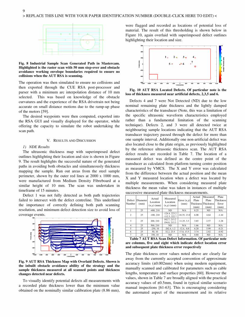
To visually identify potential defects all measurements with
a recorded plate thickness lower than the minimum value
obtained on the nominally similar calibration plate (8.86 mm),
were flagged and recorded as locations of potential loss of
material. The result of this thresholding is shown below in
Figure 10, again overlaid with superimposed defect outlines
highlighting their location and size.
Fig. 10 AUT RSA Located Defects. Of particular note is the
loss of thickness measured near artificial defects, 2,3,5 and 6.
Defects 4 and 7 were Not Detected (ND) due to the low
nominal remaining plate thickness and the lightly damped
characteristics of the transducer (Note, this was a limitation of
the specific ultrasonic waveform characteristics employed
rather than a fundamental limitation of the scanning
technique). Defects 2, and 3 were all detected twice at
neighbouring sample locations indicating that the AUT RSA
transducer trajectory passed through the defect for more than
one sample interval. Additionally one non-artificial defect was
also located close to the plate origin, as previously highlighted
by the reference ultrasonic thickness scan. The AUT RSA
defect results are recorded in Table 7. The location of a
measured defect was defined as the centre point of the
transducer as calculated from platform turning centre position
as measured by VMCS. The X and Y error was calculated
from the difference between the actual position and the mean
X and Y measured location when a defect was located by
multiple measurements. When considering measured plate
thickness the mean value was taken in instances of multiple
successive measured plate thickness measurements.
Defect
Number
Diameter
(mm)
Actual
Location
(x,y) (mm)
Measured
Location
(x,y) (mm)
Error (x,y)
(mm)
Actual
Plate
Thickness
(mm)
Measured
Plate
Thickness
(mm)
Plate
Thickness
Error
(mm)
1 25 -400, 210 ND N/A 8.25 ND N/A
2 25 -100, 210 -124.4, 223.2
-112.3, 222.7 -18.35, 13.0 6.08 4.64 -1.44
3 25 200, 210 182.7, 213.2
194.8, 213.3 11.25, 3.3 3.85 2.57 -1.28
4 25 500, 210 ND N/A 1.66 ND N/A
5 25 -250, 10 -262.4, 1.2 -12.4, -8.8 6.20 5.99 -0.21
6 25 50, 10 32.2, 23.5 17.8, 13.5 3.74 2.82 -0.92
7 25 350, 10 ND N/A 0.80 ND N/A
Table 7 AUT RSA Scan Defect Information. Of particular note
are columns, five and eight which indicate defect location error
and subsequent plate thickness error respectively
The plate thickness error values noted above are clearly far
away from the currently accepted convention of approximate
accuracy limits (±0.002mm) when using modern equipment,
manually scanned and calibrated for parameters such as cable
lengths, temperature and surface properties [60]. However the
values, shown in Table 7 are broadly aligned with the practical
accuracy values of ±0.5mm, found in typical similar scenario
manual inspections [61-63]. This is encouraging considering
the automated aspect of the measurement and its relative

10
> REPLACE THIS LINE WITH YOUR PAPER IDENTIFICATION NUMBER (DOUBLE-CLICK HERE TO EDIT) <
infancy.
Clearly as remaining plate thickness is obtained through
time of flight measurement, a further calibration of plate
velocity could be undertaken on the actual sample to better
align the actual and measured results. As precision ultrasonic
measurement was not the core focus of this body of work and
the sensor platform was calibrated on a reference sample prior
to deployment it was felt that this was unnecessary.
Fundamentally the ultrasonic thickness accuracy is a result
of many parameters, such as the characteristics of the
transducer receiver, instrument calibration, uniformity of
material sound velocity and the performance of the automated
thickness extraction algorithms.
The positional x,y error of each defect relies firstly on the
pitch of the ultrasonic transducer, whereupon a smaller pitch
will give a much reduced measurement aperture centred at a
common point. Secondly, the error is dependent on the
positional accuracy of the centre of the active back wheel
mechanism, which itself is fundamentally dependant on the
overall system path accuracy. This appreciation is critical to
understanding the importance of overall platform and system
path and position accuracy, which is detailed in the following
section.
The current convention for desired probe position
measurement accuracy, and in turn defect location position
accuracy, is typically dependant on the application and
techniques being deployed. In typical manual inspection
applications < 1mm is desired, with some constrained
geometry automated applications, typically using optimised
low D.O.F Cartesian scanning rigs being far lower than this
(±0.1mm) [64]. It must be noted the results from this novel
implementation are further away from its manual counterpart
than desired, but as stated are highly related to the platform
path and pose accuracy which is now considered.
2) System Path Accuracy
To characterise the performance of the AUT RSA and
quantify the path error for the scan, the desired and actual
paths were compared. The 6 D.O.F. pose estimate, as
measured by the VMCS, of the AUT RSA was sampled at a
frequency of 50Hz. The path error at any individual VMCS
measured point was defined as the perpendicular distance
from the desired straight-line path to the VMCS measured
point. The path accuracy statistical information is shown in
Table 8. It is worth noting that both the large positive and
negative path errors were encountered at corners or turning
locations, while the lower mean and Root Mean Square
(RMS) errors highlight the overall system performance, when
considering the dominant straight-line path sections. Parameter Value
Max Path Error (Positive) +13.48 mm
Max Path Error (Negative) -19.38 mm
Mean Path Error (Absolute) 4.41 mm
RMS Error 6.14 mm
Path Error Standard Deviation 6.10 mm
Table 8 AUT RSA Path Accuracy.
The system path accuracy was dependent on many factors.
Firstly, the rigidity of the platform and the accuracy to which
the zero degree angle of the active back wheel mechanism was
first set and maintained. Secondly, the operation and
performance of the AUT RSA pose heading controllers in
controlling the platform pose along desired paths. Thirdly, the
accuracy and resolution of the VMCS motion tracking system
and the accuracy to which the VMCS object was defined
initially with respect to the turning centre of the platform. It is
the authors opinion that these were done to a sufficient
standard to highlight the current state-of-the-art.
Previous studies of the XY mean squared path error
encountered on a similar kinematic platform for NDE were
found to be 7.10 mm at best, utilising an Extended Kalman
Filter (EKF) and ultrasonic based tracking system, and 45.5
mm at worst using pure odometry from wheel encoders [11].
Such large error values were also observed in a motorised
pipeline inspection robot utilising pure odometry [65], where
the authors provided raw estimates of robot pose and hence
defect location within an error range of 300 to 900 mm. Of
particular note in [11] was that the path error was directly
proportional to path length, and as found also in this body of
work, the largest error deviations were located at turning
points or corners.
To compensate for such errors, White et al. [66] highlighted
that with the introduction of a manufacturing inspired
interferometry based laser tracker (Leica LTD-800) positional
accuracies as high as ±0.1mm can be obtained and as expected
the accuracy of the crawler was highly dependent on the core
accuracy of its pose measurement system. Work undertaken
on characterising the accuracy of the VMCS was undertaken
in [67] and highlighted it to be nominally > 1 mm, further
highlighting the core accuracy limits achievable from the
presented system and scan.
In [66] the laser tracker provided positional information, of
a pan-tilt controlled retro-reflector, attached to an inspection
crawler, into an EKF position and control strategy. It is worth
noting that no detailed orientation accuracy was measured and
that such equipment, while being of very high monetary value
also requires full line of sight with the tracker base station at
all times (often not a practically attainable constraint). With
regards to the current body of work the authors believe that
due to that due to afore-mentioned nature of obstacles in the
inspection environment and the inherit ability to avoid these
with the presented path planning strategy, it would be very
challenging to ensure continuous line of sight during an
inspection scan employing solely laser tracker based
approaches. Future practical inspection systems will likely use
tracking systems commensurate with the required application
accuracy and suitability.
VI. CONCLUSION AND FUTURE WORK
The authors have presented a new comprehensive hardware
and software solution for automated robotic NDE inspection
scenarios. The new approach was demonstrated on a novel
thickness mapping robot used to measure simulated corrosion
wall thickness loss, in a steel sample plate representative of

11
> REPLACE THIS LINE WITH YOUR PAPER IDENTIFICATION NUMBER (DOUBLE-CLICK HERE TO EDIT) <
many real inspection geometries.
The core hardware, critical to the realisation of the complete
strategy, related to the development of the novel AUT RSA, a
differential driven robot platform incorporating an actively
driven rear ultrasonic wheel probe. The design allowed for
versatile steering and accurate dead reckoning of the platform,
while undertaking thickness mapping measurements, which is
currently not feasible with industrial inspection platforms.
The similarities between traditional machining operations
and NDE inspection path planning requirements were
highlighted to be in areas including coverage efficiency,
simulation and obstacle avoidance, while also in less-apparent
areas such as path step-over and continuous sensor-to-surface
normality requirements. A toolchain strategy was presented
that allowed standard G-Code to be translated into the
kinematic drive parameters for the mobile robotic inspection
vehicle. The approach presented is quite general, relying on
definition of robot platform specific kinematic parameters to
achieve the correct G-Code post processing.
Utilisation of commercial machining path generation
algorithms (in this example Mastercam) allowed the software
system to be developed swiftly using an industry standard
common language and methodology. This has commercial and
operational benefits in providing a consistent and repeatable
approach to path coverage, independent of individual NDE
inspectors. Additional software was developed to acquire and
process the raw ultrasonic measurement data to automatically
produce a resultant thickness map.
The complete system was deployed on a mock industrial
thickness mapping inspection scenario to highlight proof of
principle and performance, with the results of this in terms of
obstacle avoidance, ultrasonic thickness mapping and path
accuracy presented and discussed. A minimum thickness
mapping error of 0.21 mm and mean path error of 4.41 mm
were observed for a 2 m2 carbon steel sample of 10 mm
nominal thickness. These results compare favourably with
typical values obtained in related manual and robotic
inspection scenarios.
In summary, such a demonstration and contributions
improve and build-on the current state-of-the-art in large-
scale-asset remote inspection and allow the potential for
increased automation of the task with technical, commercial
and safety benefits as described above.
Future work would investigate the addition and integration
of on-board location sensor systems, while assessing their
performance on parameters such as path accuracy, in an effort
to remove global systems such as the VMCS for full remote
automated inspection.
Furthermore, this new approach is not fundamentally
limited to crawler platforms and could be scaled up to other
platforms, such as aerial, by including the Z-Axis components
of the CAM generated numeric code and combining with
suitable kinematic model of the robotic platform in the post-
processor. Therefore it can be conceived that the foundations
to a scalable and flexible obstacle avoiding path planning
strategy for robotic inspection applications have been
presented.
REFERENCES
[1] HSE �The Health and Safety of Great Britain� Health and Safety
Executive 2009, http://www.hse.gov.uk/, Accessed Apr. 2014.
[2] SEPA �Protecting Scotland�s Environment � A 10 Year Perspective�
Scottish Environmental Protection Agency, 2011.
[3] Ramírez, P. A. P. and Utne, I. B. �Challenges due to aging plants�,
Process Safety Progress, vol. 30, issue 2, pp. 196�199, 2011.
[4] Dobie, G., Summan, R., Pierce, S. G., Galbraith, W. and Hayward, G., �A
noncontact ultrasonic platform for structural inspection� Sensors
Journal, IEEE , vol.11, no.10, pp. 2458-2468, Oct. 2011.
[5] Lim, R.S.; Hung Manh La; Weihua Sheng, "A Robotic Crack Inspection
and Mapping System for Bridge Deck Maintenance," Automation
Science and Engineering, IEEE Transactions on , vol.11, no.2,
pp.367,378, April 2014
[6] Hancock, P.A. and Chignell, M.H., , �Mental workload dynamics in
adaptive interface design�, Systems, Man and Cybernetics, IEEE
Transactions on , vol.18, no.4, pp.647-658, Jul. /Aug. 1988.
[7] Farley, J.M. and Babcock, M., �Best Practice in the Application of NDT �
An Update� In World Conference on NDT, 2004.
[8] Aldrin, J. C, Coughlin, C. R., Forsyth, D. S. and Welter, J. T., �Progress on
the Development of Automated Data Analysis Algorithms and
Software for Ultrasonic Inspection of Composites� Review of Progress
in Quantitative Nondestructive Evaluation (QNDE). Baltimore,
Maryland, 2013.
[9] Friedrich, M., Dobie, G., Chan, C.C., Pierce, S.G., Galbraith, Marshall, W.
S., and Hayward, G., �Miniature Mobile Sensor Platforms for Condition
Monitoring of Structures�. Sensors Journal, IEEE , vol.9, no.11, pp.1439-
1448, Nov. 2009.
[10] Dobie, G., Summan, R., MacLeod, C.N. and Pierce, S.G., �Visual odometry
and image mosaicing for NDE�. NDT and E International, vol. 57, pp.
17-25, 2013
[11] Summan, R., Pierce, S.G., Dobie, G., Hensman, J. and MacLeod, C.N.,
�Practical constraints on real time Bayesian filtering for NDE
applications�, Mechanical Systems and Signal Processing, vol. 42, issue
1-2, pp. 181-193. 2014.
[12] Dobie, G., Pierce, S. G. and Hayward, G., �The feasibility of synthetic
aperture guided wave imaging to a mobile sensor platform�, NDT and
E International, vol. 58. pp. 10-17, 2013.
[13] Dobie, G., Spencer, A., Burnham, K., Pierce, S. G., Worden, K., Galbraith,
W. and Hayward, G. �Simulation of ultrasonic lamb wave generation,
propagation and detection for an air coupled robotic scanner�,
Ultrasonics, vol. 51, issue 3, pp. 258-269, 2011.
[14] Friedrich, M., Pierce, S.G., Galbraith, W. and Hayward. G., �Data fusion
in automated robotic inspection systems�, Insight-Non-Destructive
Testing and Condition Monitoring, vol. 50, no. 2, pp. 88-94, 2008.
[15] Fabien Tache. Robot Locomotion and Localization on 3D Complex-
Shaped Structures. PhD thesis, ETH Zurich, 2010. 48
[16] Katrasnik, J.; Pernus, F.; Likar, B., "A Survey of Mobile Robots for
Distribution Power Line Inspection," in Power Delivery, IEEE
Transactions on , vol.25, no.1, pp.485-493, Jan. 2010
[17] A. Correll, N. Martinoli. Multirobot inspection of industrial machinery.
Robotics & Automation Magazine, IEEE, 16:103{112, 2009.
[18] A. Breitenmoser, H. Sommer, R. Siegwart, Adaptive Multi–Robot
Coverage of Curved Surfaces, Distributed Autonomous Robotic Systems,
Volume 104, Springer Tracts in Advanced Robotics pp 3-16
[19] A. Correll, N. Martinoli. Multirobot inspection of industrial machinery.
Robotics & Automation Magazine, IEEE, 16:103{112, 2009.
[20] C. Mineo, B. Wright, I. Nicholson, I. Cooper, G. Pierce, PAUT inspection
of complex shaped composite materials through 6 DOFs robotic
manipulators, Insight Journal, Volume 57, No 3, March 2015,
[21] Alstom Inspection Robotics, http://www.inspection-robotics.com
Accessed Nov. 2015.
[22] Silverwing NDT Scoprion, http://www.silverwingndt.com/ultrasonic-
testing/scorpion-remote-ut-thickness-measurements, Accessed Nov.
2015.
[23] Techitest Ceta, http://www.tecnitestndt.com/wall-crawler/, Accessed

12
> REPLACE THIS LINE WITH YOUR PAPER IDENTIFICATION NUMBER (DOUBLE-CLICK HERE TO EDIT) <
Nov. 2015..
[24] Galceran, E. and Carreras, M., �A survey on coverage path planning for
robotics, Robotics and Autonomous Systems�, vol. 61, issue 12, pp.
1258-1276, Dec. 2013.
[25] Atkar, P., Greenfield, A.L., Conner, D.C., Choset, H. and Rizzi, A.,
�Uniform coverage of automotive surface patches�, The International
Journal of Robotics Research, vol. 24, no. 11, pp. 883-898, Nov. 2005.
[26] Hert, S., Tiwari, S. and Lumelsky, V., �A terrain-covering algorithm for
an auv�, Autonomous Robots 3, pp. 91-119, 1996.
[27] Acar, E.U., Choset, H., Zhang, Y. and Schervish, M., �Path planning for
robotic demining: robust sensor-based coverage of unstructured
environments and probabilistic methods�, International Journal of
Robotics Research, vol. 22, pp. 441-466, 2003.
[28] Cao, Z.L., Huang, Y. and Hall, E.L., �Region filling operations with
random obstacle avoidance for mobile robotics�, Journal of Robotic
Systems, vol. 5, issue 2. pp. 87-102, 1988.
[29] Choset, H., �Coverage for robotics�a survey of recent results�, Annals
of Mathematics and Artificial Intelligence, vol. 31, issue 1-4, pp. 113-
126, 2001.
[30] Atkar, P., Greenfield, A, L., Conner, D. C., Choset, H. and Rizzi, A.,
�Uniform Coverage of Automotive Surface Patches�, The International
Journal of Robotics Research, vol. 24, no. 11, pp. 883- 898, Nov. 2005.
[31] Olivieri, P., Birglen, L., Maldague, X. and Mantegh I., �Coverage path
planning for eddy current inspection on complex aeronautical parts�,
Robotics and Computer-Integrated Manufacturing, vol. 30, issue 3, pp.
305-314, June 2014,
[32] Sattar, T.P. and Brenner, A.A. �Robotic system for inspection of test
objects with unknown geometry using NDT methods� Industrial Robot:
An International Journal, vol. 36, issue. 4, pp. 340�343, 2009.
[33] Weihua Sheng; Hongjun Chen; Ning Xi, "Navigating a Miniature
Crawler Robot for Engineered Structure Inspection," Automation
Science and Engineering, IEEE Transactions on , vol.5, no.2,
pp.368,373, April 2008
[34] Englot, B.H. and Franz S. TI �Three-dimensional coverage planning for
an underwater inspection robot� International Journal of Robotics
Research, vol. 32 issue: 9-10, pp. 1048-1073, 2013.
[35] C. Mineo, S. G. Pierce, P. I. Nicholson, B. Wright, I. Cooper, Robotic path
planning for non-destructive testing - a custom MATLAB toolbox
approach, Robotics and Computer-Integrated Manufacturing Journal
� Accepted for publication on 18th May 2015.
[36] Hoff, E.B. and Sarker, B. R., �An overview of path design and
dispatching methods for automated guided vehicles�, Integrated
Manufacturing Systems, vol. 9 issue. 5, pp. 296-307, 1998.
[37] Jin, J. and Tang L., �Coverage path planning on three-dimensional
terrain for arable farming� Journal of Field Robotics, vol. 28, issue 3,
pp. 424-440, 2011.
[38] Donald, B.R., �Motion Planning with Six Degrees of Freedom�,
Massachusetts Institute Technology Artificial Intelligence Laboratory,
Technical Report AIM-791, 1984.
[39] Brooks, R. A., �Solving the find path problem by representing free space
as generalized cones� A.I Memo No 674, Massachusetts Institute
Technology, May 1982.
[40] Kambhampati, S. and Davis, L.S., �Multiresolution path planning for
mobile robots�, Robotics and Automation, IEEE Journal of , vol.2, no.3,
pp.135-145, Sep. 1986
[41] Babel L., �Flight path planning for unmanned aerial vehicles with
landmark-based visual navigation�, Robotics and Autonomous
Systems, vol. 62, issue 2, pp 142-150, Feb. 2014.
[42] Barrientos, A., Colorado, J., Cerro, J. d., Martinez, A., Rossi, C., Sanz, D.
and Valente, J., �Aerial remote sensing in agriculture: A practical
approach to area coverage and path planning for fleets of mini aerial
robots�, Journal of Field Robotics, vol. 28, pp. 667-689, 2011.
[43] BL Luk, KP Liu, AA Collie, DS Cooke, and S. Chen. Tele-operated
climbing and mobile service robots for remote inspection and
maintenance in nuclear industry. Industrial Robot: An International
Journal, 33(3):194{204, 2006.
[44] Fahimi, F., Autonomous Robots Modeling, Path Planning, and Control,
Springer US, 2009.
[45] Pease W, �An automatic machine tool� Scientific American, issue Sep.,
pp. 101-115, 1952.
[46] Thyer, G. E., Computer numerical control of machine tools, Industrial
Press, Incorporated, 1988.
[47] Dragomatz, D. and Mann, S., �A classified bibliography of literature on
NC milling path generation�, Computer-Aided Design, vol. 29, issue 3,
pp. 239-247, Mar. 1997.
[48] http://cncsimulator.info/OnlineHelp/OnlineHelp.html?PocketMilling.
html, Accessed Feb. 2014.
[49] Yong Seok Suh, Kunwoo Lee, NC milling tool path generation for
arbitrary pockets defined by sculptured surfaces, Computer-Aided
Design, Volume 22, Issue 5, June 1990, Pages 273-284.
[50] Marshall S., Griffiths G.J., �A survey of cutter-path construction
techniques for milling machines� International Journal of Production
Research, Volume 32, Issue 12, 1994
[51] Xu, X.W., Wang, L. and Rong, Y., ‘STEP-NC and function blocks for
interoperable manufacturing’, Automation Science and Engineering,
IEEE Transactions on , vol. 3, no. 3, pp. 297- 308, Jul. 2006.
[52] Neto, P. and Mendes, N., ‘Direct off-line robot programming via a
common CAD package’, Robotics and Autonomous Systems, vol. 61,
issue 8, pp. 896-910, Aug. 2013.
[53] Chan, S.F. and Kwan R., ‘Post-processing methodologies for off-line
robot programming within computer integrated manufacture’, Journal
of Materials Processing Technology, vol. 139, issues 1-3, Aug. 2003.
[54] Gadow, R., Candel, A. and Floristán, M., ‘Optimized robot trajectory
generation for thermal spraying operations and high quality coatings on
free-form surfaces’, Surface and Coatings Technology, vol. 205, issue 4,
pp. 1074-1079, Nov. 2010.
[55] Dobie, G., Galbraith, W., MacLeod, C.N., Summan, R., Pierce, S.G. and
Gachagan, A., ‘Automatic ultrasonic robotic array’, 40th Annual
Review of Progress in Quantitative Nondestructive Evaluation, pp.
1881-1888, Baltimore, Maryland, USA, 2013
[56] Analog Devices, http://www.analog.com/, Accessed Nov. 2015.
[57] KNJN LLC, http://www.knjn.com/, Accessed Nov. 2015.
[58] VICON Motion Capture Systems, http://www.vicon.com/, Accessed Nov.
2015
[59] Gordon Dobie. Ultrasonic Sensor Platforms for Non-Destructive
Evaluation. PhD thesis, University of Strathclyde, 2010. 4, 215
[60] Nelligan, T. ‘ An Introduction to Ultrasonic Thicnkess Gauging –
Olympus’. www.olympus-ims.com, Accessed Nov. 2015
[61] Drury, J.C., ‘Corrosion Monitoring and Thickness Measurement - What
are we doing wrong?’, Insight. 39(1) : 17-20; 1997
[62] Porter, R.,‘Non-destructive Examinations Applied to Hull Structure’
Proceedings of the 7th European Conference on Non-Destructive
Testing, 26-29 May 1998,
[63] Weire,D.R., Pardini, A.F., ‘Evaluation of UT Wall Thickness
Measurements and Measurement Methodology”, Pacific Northwest
National Laboratory, www.pnnl.gov, Accessed Nov. 2015.
[64] Marietta NDT, http://www.marietta-ndt.com, Accessed Nov. 2015.
[65] H. Schempf, E. Mutschler, A. Gavaert, G. Skoptsov, and W. Crowley.
Visual and Nondestructive Evaluation Inspection of Live Gas Mains
using the ExplorerTM family of Pipe Robots. Journal of Field Robotics,
27(3):217, 2010. 47
[66] TS White, R. Alexander, G. Callow, A. Cooke, S. Harris, and J. Sargent. A
Mobile Climbing Robot for High Precision Manufacture and Inspection
of Aerostructures. The International Journal of Robotics Research,
24(7):589, 2005. 48
[67] R. Summan, S.G. Pierce, C.N. Macleod, G. Dobie, T. Gears, W. Lester, P.
Pritchett, P. Smyth, Spatial calibration of large volume
photogrammetry based metrology systems, Measurement, Volume 68,
May 2015, Pages 189-200, ISSN 0263-2241,
Related Documents