Strategic Use of Pseudo-ductile Cementitious Composites in Concrete Structures Christopher K.Y. Leung Dept. of Civil Engineering Hong Kong University of Science and Technology Hong Kong, CHINA SAR Presented at Concrete Seminar 2011 on Recent Advances in Concrete Materials and Testing

Welcome message from author
This document is posted to help you gain knowledge. Please leave a comment to let me know what you think about it! Share it to your friends and learn new things together.
Transcript

Strategic Use of Pseudo-ductile Cementitious Composites in Concrete Structures
Christopher K.Y. Leung Dept. of Civil Engineering
Hong Kong University of Science and Technology Hong Kong, CHINA SAR
Presented at Concrete Seminar 2011 on Recent Advances in Concrete Materials and Testing

Outline
• Introduction to Pseudo-ductile Cementitious Composites (PDCC) – Design Principle
– Large Scale Applications
– Selective Applications
• Research on Strategic Use of PDCC at HKUST – Permanent Formwork for Structures
– Anchorage Zone of Post-tensioned Members
• Conclusions and Outlook

σσσσ
εεεε
Concrete
Conventional Fiber Reinforced Concrete (FRC)
PDCC
Tensile σσσσ−−−−εεεε Behavior of Cementitious Materials
Opening of a Single Crack under Decreasing Stress
Formation of Multiple Cracks Under Increasing Stress
Pseudo-Ductile Cementitious Composites (PDCC)
• Strength similar to Normal Concrete but exhibit Very High Ductility – Failure Strain up to several percents – Failure preceded by Formation of Well-Controlled Multiple
Cracks

If Gbridge > Gtip
Strain For
From Fracture Analysis σσσσP
Crack Bridging First Cracking occurs at a Stress Stress Level below σσσσp
(σσσσB) Increase in Stress after first cracking mation of Multiple Cracks
Gbridge
δδδδP HardeningCrack Opening (δδδδ)
Physical Principle (Li and Leung, ASCE J Engineering Mechanics, 1992)
- Gtip depends on matrix fracture toughness and composite modulus - Gbridge depends on the properties of fiber, matrix and interface
as well as fiber geometry and volume fraction
- Through the proper choice of composite micro-parameters to satisfy Gbridge > Gtip , Strain Hardening can be achieved
- Before ultimate failure, crack opening is kept below δδδδp

PDCC under Bending
PDCC
Test Results from Wang et
al (1997)
Engineering Properties of PDCC • Very High Deformation Capability • Closely Spaced Multiple Cracking before Ultimate
Failure • Very High Energy Absorption and Damping • Excellent Control of Crack Opening
– Improved Long-term Durability
Transport Properties and Crack Control

Road Widened to Provide Emergency Parking Space
PDCC Applications • Hida Tunnel, Japan
– Sprayed PDCC Lining
• Mihara Bridge, Hokkaido, Japan – Composite Steel/PDCC Deck
Sprayed PDCC Lining Self-Flow PDCC placed on top of for Hida Tunnel Steel Section for Mihara Bridge

Strategic Use of PDCC • PDCC are far more expensive than Normal
Concrete – PDCC/Concrete ~ 5-6 times in cost
• High cost limits application in large volumes • Innovative use in Selected Parts of
Structures can bring along higher performance/cost and wider acceptance of the material

Strategic Use of PDCC - Example
• Link Slab for Highway Bridges– In the U.S., Steel Expansion Joints in Bridges often deteriorate
and leak– Water (with Salt) may go through the joint, leading to corrosion of
underlying steel girder
• Solution: Replacing Joint with Link Slab made of Pseudo-ductile Cementitious Composites
• Field Trial in Michigan show NO degradation after two years

Strategic Use of PDCC - Example
• Coupling Beam for Building
• Use of Steel Reinforced PDCC Coupling Beams can significantly increase damping of the Building
• Core and Columns sufficient to carry seismic action• External Shear Walls can be removed to allow better
views.

Strategic Use of PDCC –Research Studies at HKUST

PDCC Permanent Formwork• Durability of Concrete Structure governed by quality of cover
concrete• Un-cracked Concrete with low w/b ratio has excellent transport
properties and hence good durability – Reinforced concrete members are designed to crack– Cracking will have significant effect on transport properties
• PDCC Permanent Formwork Controls Surface Crack Opening and Guarantees Long-term Durability– Can be used in Critical Parts of a Structure
TidalZone
Bridge PierBridge Deck under Severe Environment
and Heavy Traffic
PermanentFormwork

PDCC Employed for Experimental Work
• Matrix of the following composition– Cement:fly ash:silica fume:sand=0.18:0.8:0.02:0.2
• 2 Vol% of PVA fiber added
0
1
2
3
4
5
6
0 1 2 3 4 5 6
Strain(%)
Stress(MPa)
Tensile Stress Strain Behavior
Multiple Crackingof Specimen

PDCC Formwork Fabrication
• 2 Types of FormworkPrepared
• Plate (400x100x25mm)• U shape Formwork• Surface Preparation
– Smooth surface– Transverse grooves– Longitudinal grooves– Roughened with Chips
• Beams prepared by Casting of Plain Concrete
图5 表面处理
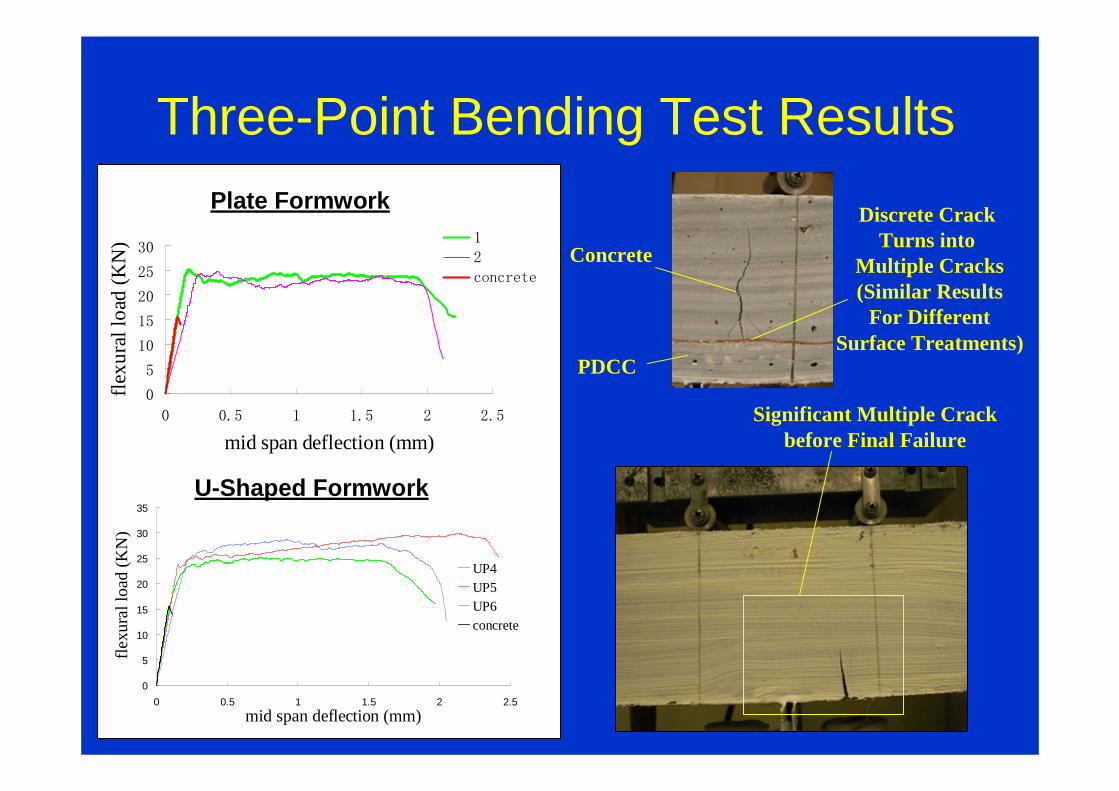
Three-Point Bending Test Results
0
5
10
15
20
25
30
0 0.5 1 1.5 2 2.5
mid span deflection (mm)
flex
ural
load
(K
N) 1
2
concrete
0
5
10
15
20
25
30
35
0 0.5 1 1.5 2 2.5
mid span deflection (mm)
flex
ural
load
(K
N)
UP4UP5UP6concrete
Plate Formwork
U-Shaped Formwork
Concrete
PDCC
Discrete Crack Turns into
Multiple Cracks(Similar Results
For DifferentSurface Treatments)
Significant Multiple Crackbefore Final Failure

GFRP Reinforced PDCC Formwork
• Experimental Results show Ability of PDCC Formwork in Controlling Cracks
• GFRP can be added to provide Flexural Capacity– No Steel Needed for Some Cases
– Simplify Construction for Members Requiring Multiple Layers of Steel
• GFRP does not corrode despite of Small Cover
• Excessive Crack Opening is a Concern when GFRP is used in Plain Concrete– Not a Problem With PDCC
• Optical Fiber Sensors can be Installed in GFRP to make Smart Formwork– Remove Difficulties associated with Site Installation

Beams made with GFRP Reinforced PDCC Formwork
13001300200
GFRP Reinforcement PDCC Formwork
100100
150
70
30 30
20
80
SU1 SF1
Loading Configuration
Sections for U-shaped and Flat Formwork

Test Results• Designed load of 14.6kN (from conventional RC
analysis) approached or exceeded in both cases• Beam with flat formwork shows delamination failure
SF1
SU1
Delamination
Loading point
Crushingof Concrete
Localized Flexural
Crack

Beams made with GFRP Reinforced PDCC Formwork
750 750300
@100spacing@100spacing
Loading Configuration
Sections for U-shaped and Flat Formwork
150 150
30 30
250
20100
150
BU BF

Test Results
• Designed load of 94.5kN• Beam with flat formwork shows delamination failure at 73kN• Beam with U-shaped formwork fails in rupture at 106kN
Crushingof Concrete
Localized Flexural
Crack
Delamination

Mechanism of Delamination Failure
Locations of Stirrups around the inclined crack
Flexural CrackInclined Crack underCombined Flexure/Shear
Loading Points
Tensile Stresses in PDCC
Tension in GFRP
CompressionIn ConcreteHigh Shear Stress along
Concrete/PDCC InterfaceInterfacial
Delamination

Additional Tests on Beams with U-shaped Formwork
Delamination8531.9433.5GFRP 5Ф6 Steel 2T8
G5Y8
Delamination8933.4433.5GFRP 5Ф6 Steel 2T8
G5Y8
Flexure10639.84.235.4GFRP 4Ф6Steel 2T10
G4Y10
Flexure112424.235.4GFRP 4Ф6Steel 2T10
G4Y10
Flexure11743.94.336.7GFRP 3Ф6Steel 2T12
G3Y12
Flexure11643.54.336.7GFRP 3Ф6Steel 2T12
G3Y12
FailureMode
TestLoad kN
Testmoment(kN.m)
M/bd 2
(N/mm 2)TheoreticalMoment (kN.m)
ReinforcementDetail
Series
More GFRP in the Formwork leads to higher interfacial stress which favors Delamination Failure

Load vs Deflection Curves and Failure Modes
0
20
40
60
80
100
120
140
0 10 20 30 40
displacement(mm)
Load(kN)
G5Y8
G4Y10
G3Y12
Failure right aboveThe upper level of
The Horizontal Plate
Concrete Crushing
G4Y10 G5Y8
Similar Ductility DespiteDifferent GFRP/Steel Ratios
(may be due to InterfacialDelamination in cases withHigher GFRP Content)

A Design Example4m Laterally Spanning Deck for a Footbridge
• With Loading from BS5400, Maximum Moment calculated to be 2.33 kNm
• Member made with Flat GFRP/PDCC Formwork + mPlain Concrete exhibit Load Capacity of 9.6 kN
• With U-shaped GFRP/PDCC Formwork, Load Capacity increases to 10.3 kNm– Permanent Formwork Suitable for Construction of the Deck
– NO need to add Steel Reinforcements
– Very High Durability under Aggressive Environment
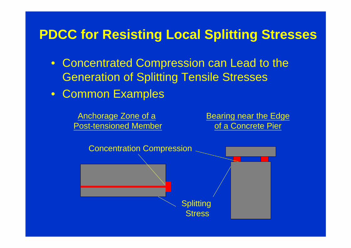
PDCC for Resisting Local Splitting Stresses
• Concentrated Compression can Lead to the Generation of Splitting Tensile Stresses
• Common Examples
Anchorage Zone of a Post-tensioned Member
Bearing near the Edgeof a Concrete Pier
Concentration Compression
Splitting Stress

Loaded Area
Principal Stresses obtained from 3D Finite Element Analysis of a Rectangular Prism under Concentrated Compression
• High Splitting Tension is found on Exterior Surface of the Specimen
• Splitting prevented by closely-spaced steel hoops in Conventional Design– Labor Intensive Construction– Problem with Concrete Compaction
External Surfaces
Part Analyzed
ConcentratedCompression
Area

A New Design Concept
Regular Concrete
PDCC
A Post-tensioned Concrete Beam
High Performance Pseudo-Ductile Material Employed in theRegion around the Anchor to replace Steel Reinforcements

Experimental Verification of the New Concept
Three Types of Specimens Tested
Plain Concrete Concrete + Stirrup Concrete +PDCC
150mm
PDCC150mm
wL
Stirrups
Concrete: σσσσc = 39 MPa or 57.3 MPa
PDCC: σσσσc = 52.7 MPa, first cracking strength = 2.8 MPa(2% PVA)
Ultimate strength = 3.3 MPa, Failure Strain = 1%

Results
590Concrete + Steel (1%)
686Concrete + PDCC
465Plain Concrete0.6457.3 MPa
445Concrete + Steel (2.8%)
378Concrete + PDCC
247Plain Concrete0.1657.3 MPa
445Concrete + Steel (1%)
587Concrete + PDCC
314Plain Concrete0.3639 MPa
Ultimate Load (kN)Specimen TypeAL/AConcrete Strength
Note: For Steel, ‘%’ represents the Area Fraction of Confining Reinforcement
• PDCC can replace All the Confining Steel for Common Situation (Steel area fraction about 1%)
• PDCC can provide 80% of the Load Capacity for Congested Situations– Can replace most of the reinforcements for such a case

Effect of Material Properties
• Tensile Ductility Improvement is much more beneficial than Pure increase in Compressive Strength
• Load Capacity Improves even with the use of PDCC with Lower Compressive Strength
• If PDCC Strength is too Low, Failure Occurs by Compressive Crushing– NO improvement over Plain Concrete
6220.36Not used in these specimens83.8
8070.360.754.664.2583.570.0
5340.361.714.323.7742.670.0
6550.360.803.473.1658.770.0
5560.36Not used in these specimens70.0
UltimateStrain
(%)
UltimateStrength
(MPa)
First CrackingStrength
(MPa)
CubeStrength
(MPa)
UltimateLoad (kN)
LoadingratioAL/A
PDCCConcreteCube
Strength(MPa)

A Simple Design Approach
• Calculate Total Splitting Tensile Force in Anchorage Zone (0.9D in extent) from an Elastic Analysis
• Equate this to the total Resistance, given by (σfc)(B)(0.9D), where σfc is the first cracking strength of the PDCC
x
D
~0.9D
x
σσσσyy
Tension
Compression
Results of 2D Analysis
B

Results
6.7 %8618074.250.60.36
-2.3 %6406553.160.60.36
3.3 %7096862.80.80.64
0 %3783782.80.40.16
-2.4 %5675812.80.60.36
Predicted-ExptExpt
Predicted (kN)
Expt(kN)
Ultimate LoadFirst Cracking Strength of PDCC (MPa)
a/D(AL/A)
• Predicted Values from Simple Analysis Agree well with Test Data
• More Data is needed for Full Verification but the Simple Method Shows Promise for Design

Conclusions and Future Outlook
• Strategic Use of PDCC in Structures can – improve structural durability
– facilitate the construction process
– simplify complex designs
• This approach has good potential for practical applications
• Future Developments– Cost should be further reduced through better Material
Design– Focus on Durability (Crack Control) and Performance-
Based Design (with degree of damage being a performance criterion)
Related Documents


