Carefully read these instructions, along with the ‘Outback Flat Attached Installation Guide’. Lay out the main components in order of assembly on the ground and check them against the delivery note. The ‘Components’ section identifies each part of your Stratco Clearspan Gable and shows the location of the components. Mark out the overall area of your verandah, patio or carport and ensure it is free from obstructions. Beam to wall connections can cause difficulty if they coincide with door and window openings, so avoid these in your design. Ensure there is reasonable access for materials and working space and consider the disposal of run off water. Check the post and beam positions on the ground, roughly check they are square and mark the hole locations. If you do not have all the necessary tools or information, contact Stratco for advice. Before starting lay out all components and check them against the delivery docket. The parts description identifies additional gable parts, and the component layout diagram indicates their fastening position. Outback Gable CLEARSPAN ATTACHED TOOLS REQUIRED • Drill & Hex-Head Adaptor • Rivet Gun • Tape Measure • Tin Snips • Spirit Level • Hack-Saw • Post Hole Digger • Silicone Gun • Spanner or Ratchet • Adjustable Construction Props • Turn Up/Down Tool • Concrete BEFORE YOU START • Drill & Hex/Phillips Head Adaptors • Rivet Gun • Tape Measure • Tin Snips • Spirit Level • Hack-Saw It is important to check your Local Government Authority requirements before the installation of your new Stratco OutbackFlat Verandah. It is the builder’s responsibility to ensure any existing structure that an Outback Flat is being attached to is adequately reinforced to accommodate the additional loads imposed by the verandah, patio or carport. Read these instructions thoroughly before starting your project and refer to them constantly during each stage of construction. Contact Stratco for advice if you do not have the necessary tools or information. Before starting, lay out the main components in order of assembly on the ground and check them against the delivery note. The ‘Components’ section identifies each part of your Outback Flat Verandah or Carport and shows the relative location of the components. Mark out the overall area of your verandah, patio or carport and ensure that it is free from obstructions. Beam to wall connections can cause difficulty if they coincide with door and window openings, so avoid these in your design. Ensure there is reasonable access for materials and working space and consider the disposal of run-offwater. Check the column and beam positions on the ground; roughly check they are square by measuring the diagonals, then mark out the column locations. If columns are to be ‘in ground’, dig the holes to Stratco specifications. • Post Hole Digger • Silicone Gun • Spanner or Ratchet • Adjustable Construction Props • Turn Up/Down Tool • Concrete • Ladder The Outback kit does not include fixings to attach the unit to an existing structure or concrete/masonry anchors for the column installation. If required, they must be purchased as additional items. Outback Flat Attached VERANDAHS | PATIOS | CARPORTS

Welcome message from author
This document is posted to help you gain knowledge. Please leave a comment to let me know what you think about it! Share it to your friends and learn new things together.
Transcript

INSTATAT LLATATA IONGUIDE
Carefully read these instructions, along with the ‘Outback Flat Attached Installation Guide’. Lay out the main components in order of assembly on the ground and check them against the delivery note. The ‘Components’ section identifies each part of your Stratco Clearspan Gable and shows the location of the components.
Mark out the overall area of your verandah, patio or carport and ensure it is free from obstructions. Beam to wall connections can cause difficulty if they coincide with door and window openings, so avoid these in your design. Ensure there is reasonable access for materials and working space and consider the disposal of run off water. Check the post and beam positions on the ground, roughly check they are square and mark the hole locations. If you do not have all the necessary tools or information, contact Stratco for advice. Before starting lay out all components and check them against the delivery docket. The parts description identifies additional gable parts, and the component layout diagram indicates their fastening position.
Outback GableCLEARSPAN ATTACHED
TOOLS REQUIRED• Drill & Hex-Head Adaptor• Rivet Gun• Tape Measure• Tin Snips• Spirit Level• Hack-Saw• Post Hole Digger• Silicone Gun• Spanner or Ratchet• Adjustable Construction Props• Turn Up/Down Tool• Concrete
BEFORE YOU START
FInAL FIXInG
Back Channel
12x20mm Hex Head Self Drilling Screws with Domed Washers
Outback Deck
Outback Deck
Outback Rooflite
Rooflite Infill
Foam Insert
3mm Rivets
250mm
Outback Deck
Dip in theprofile
No dip in the profile
Outback Deck
Outback Rooflite profileNote: each side of the profile is different, andfits with the corresponding edge on the deck
Turn deck up
Turn deck down
Gutter EndBack Channel End
Laying direction Prevailing wind
Both rivets and screwsto be located in the
pan of the sheet
Back Channel FixingFixing Locations Front Fascia Beam Fixing
Backchannel
Rivet from underside 12x20 Hex head screws
INSTALLATIONGUIDE
mAInTEnAnCE
Concrete raisedup to column
M12x75 masonry anchors or M10x75screwbolts
Column
Footing plate
Figure 9.0 Figure 9.1
Final Fixing into the Concrete FootingThoroughly check the posts with a spirit level. When plumb, fi ll the post hole with approximately 150mm of concrete and use a shovel or pole to agitate the concrete to remove any air pockets. Repeat this process until the hole is full, continually checking the posts as you go. The concrete must have a slight slope that runs away from the column to ensure any water does not pool around the base (Figure 9.0). Once the concrete is set remove any temporary bracing or props.
Final Fixing onto Existing Concrete If the columns are to be fi xed to an existing concrete slab with a footing plate, each plate must be fi xed to the concrete with two M12x75 masonry anchors or two M12x75 screwbolts (Figure 9.1). The minimum distances from an anchor hole to the concrete edge is 75mm for M12 anchors.
Important noteDo not allow soil to remain in permanent contact with the columns, as corrosion will result in the base of the column. Refer to the “Selection, Use and Maintenance of Stratco Steel Products” brochure for complete details of the maintenance requirements.
DownpipesBefore attaching the downpipes, rivet the downpipe bracket to the column and bend the fl anges along the ‘break-line’ to accept the downpipe. Slide the downpipe over the downpipe outlet and rivet into position. Rivet the downpipe to the brackets. Weatherproof all the fasteners with silicone.
Regular maintenance is essential to maintain the good looks of all Stratco steel products and to ensure you receive the maximum life-span possible. Washing with clean water must be frequent enough to prevent the accumulation of dust, salts, and pollutants that may reduce the life of the product. Stratco steel products that are regularly washed by rain require no additional maintenance. No Stratco steel structure or materials are recommended for use over, or in close proximity, to swimming pools or spas. No material that retains water (such as dirt or paving sand) should be placed against the columns. Care must be taken when determining the location of Stratco steel products so that they are not placed in close contact with sources of pollution or environmental factors that could aff ect the life of the steel. Refer to the ‘Selection, Use and Maintenance’ brochure for more information.
lift the back of the gutter into the corner mitre of the side gutter. Check the roof sheets overhang into the gutter by 50mm and the gutters are square in relation to the framework. Fix the front gutter with rivets at one metre spacings through the end of the roof sheets into the gutter’s back lip. For units with a deck overhang, fi x the gutter to the roof sheets with two rivets per pan. Rivet and seal the front gutter to the mitre and the gutter straps to the roof sheets. Lift the fi nal side gutter so that its front end slides into the mitre and the stop end slides up behind the back channel. Fix the gutter in position as previously described and waterproof with silicone. The downpipe is not attached at this stage, as the columns are not yet fi xed in their vertical position.
Gutter Outlet Assembly To mark the position of the outlet, place the downpipe in line with the column. Mark and cut a hole in the base of the gutter near the back chamfer. Insert the downpipe outlet from the inside of the gutter and rivet in place using 3.2mm rivets (Figure 8.1). Remove any swarf and waterproof with silicone.
Rivet pop to gutter Gutter
Gutter outlet(downpipe pop)
Notched beam filler
Downpipe
AB120mm
120mm
Side gutter
Front gutter
Mitred gutter ends fitinside the mitre bracket
Mitre bracket
RivetGutterStrap
Figure 8.0 Figure 8.1 Figure 8.2
ADDITIOnAL mATERIALS
TOOLS REQUIRED• Drill & Hex/Phillips Head Adaptors• Rivet Gun• Tape Measure• Tin Snips• Spirit Level• Hack-Saw
It is important to check your Local Government Authority requirements before the installation of your new Stratco Outback® Flat Verandah. It is the builder’s responsibility to ensure any existing structure that an Outback Flat is being attached to is adequately reinforced to accommodate the additional loads imposed by the verandah, patio or carport. Read these instructions thoroughly before starting your project and refer to them constantly during each stage of construction. Contact Stratco for advice if you do not have the necessary tools or information.
Before starting, lay out the main components in order of assembly on the ground and check them against the delivery note. The ‘Components’ section identifi es each part of your Outback Flat Verandah or Carport and shows the relative location of the components.
Mark out the overall area of your verandah, patio or carport and ensure that it is free from obstructions. Beam to wall connections can cause diffi culty if they coincide with door and window openings, so avoid these in your design. Ensure there is reasonable access for materials and working space and consider the disposal of run-off water. Check the column and beam positions on the ground; roughly check they are square by measuring the diagonals, then mark out the column locations. If columns are to be ‘in ground’, dig the holes to Stratco specifi cations.
DECKInGTurning the Decking EndsWhile still at ground level, the ends of the decking need to be turned up or down approximately 30 degrees using a turn up/down tool to aid in weather proofi ng. Turn the ends of the decking up at the back channel end and down at the gutter end (Figure 6.0).
Laying and Installing the DeckingDecking should have a 50mm overhang into the gutter and is laid with the overlapping rib facing away from the prevailing wind (Figure 6.1). Ensure all of the sheets have locking ribs on the same side. Mark the back channel and front fascia beam every 1000mm to check the decking is laid square.
Lift the fi rst sheet into place and push it fi rmly into the BIP foam in the back channel to weather proof it. Check the sheet is square against the back channel and side fascia beam. At the back channel end, rivet the decking from underneath through the raised edge on the bottom of the back channel with two 3.2mm rivets per pan (Figure 6.2). Seal the rivets with silicone. At each supporting beam, fi x the sheet with two 12x20 hex head self-drilling screws per pan (Figure 6.2) (In cyclonic conditions use three 12x20 hex head
self-drilling screws per pan on supporting beams and three rivets per pan at the back channel). Remove any swarf.
Lay the next sheet of decking over the previous sheet’s side lap (Figure 6.1). At the back channel end press down on the lap until the sheets clip together, continue working along the length of the sheet using a timber block (to avoid damaging the sheet) and rubber mallet. Finish by sliding the roof sheet fi rmly into the BIP foam on the back channel. For larger spans you may need to temporarily support the underside of the roof sheeting while clipping the laps together. Continue this process until all the roof decking is installed.
Decking parallel to Back ChannelIf the decking runs parallel to the back channel, slide the fi rst roof sheet sideways into the BIP foam in the back channel for a weather proof seal. The sheeting is secured to the back channel with rivets at 200mm centres (150mm centres for cyclonic conditions), and it is secured to the beams running parallel with the decking using hex head screws at 500mm centres. The roof sheets are fi xed as standard to the supporting beams (Figure 6.2).
OUTBACK ROOFLITE™ InSTALLATIOnRoofl ite is fastened using 12x20mm hex head self-drilling screws with domed washers at maximum 2000mm centres. Fix through the groove located along the top of the Roofl ite connectors (Figure 7.1). To fi nish the exposed end of the Roofl ite an infi ll is required. Fasten the infi ll over the Roofl ite with 12x20mm screws and domed washers on both sides through the pre-drilled holes. Connect the infi ll to the underside of the decking with 3mm rivets, seal the rivets with silicone. Finally, a foam insert is placed into the backchannel end of the Roofl ite.
An Outback Roofl ite can be used to add natural light. The polycarbonate Roofl ite overlaps the deck by snapping or sliding over the already installed sheets that have been spaced 250mm apart (note the profi le of the Roofl ite is diff erent on each side, and therefore must align with the correct connection on the deck). Ensure the lower tab of the Roofl ite touches the Outback deck at the points shown (Figure 7.0) and all sheeting is pushed fi rmly into the back channel. 9mm holes must be pre-drilled through the Roofl ite at all of the fastener locations prior to fi xing to allow for thermal expansion. The
Figure 7.1Figure 7.0
GUTTER ASSEmBLYGutter preparationTo establish the inside gutter length ‘A’ (Figure 8.0), measure from the back of the back channel to the outside of the front fascia and subtract 5mm for the mitre bracket. To establish the inside gutter length for units with a deck overhang, subtract 55mm from the total roof sheet length. To establish inside gutter length ‘B’ for the front gutter, measure the length of the front fascia beam and subtract 5mm for each mitre bracket.
Attach the stop ends to the side gutters with four rivets per stop end. Remove any swarf and waterproof with silicone. On the gutter ends that will form a corner, cut a 45 degree mitre. Fit the mitre brackets using 3mm sealed rivets to fasten the mitre to the gutter then waterproof with silicone.
First Side Gutter Assembly After fi xing a gutter mitre bracket to the corner of the fi rst side gutter, lift the gutter into place so the stop end slides up behind the back channel. Use rivets to fasten the gutter’s back lip to the roofi ng at the maximum spacing of one metre. Install the gutter straps at least every metre (Figure 8.2). Waterproof the rivets with silicone. Ensure the front face of the gutter remains vertical and even.
Front Gutter Assembly On the front gutter, attach a gutter mitre to the end opposite the side gutter. Slide the fl at end of the gutter straps inside the rib of the roof sheets every metre. Hang the front gutter on the gutter straps and using a rolling action,
• Post Hole Digger• Silicone Gun• Spanner or Ratchet• Adjustable Construction Props• Turn Up/Down Tool• Concrete• Ladder
The Outback kit does not include fi xings to attach the unit to an existing structure or concrete/masonry anchors for the column installation. If required, they must be purchased as additional items.
BEFORE YOU START
Figure 6.0 Figure 6.1 Figure 6.2
Outback® Flat AttachedVERANDAHS | PATIOS | CARPORTS
QUEENSLANDORMEAU Ph: (07) 3451 4444 1 Mavis Crt• CRESTMEAD Ph: 3451 4411 179 Magnesium Dve• TOOWOOMBA Ph: 4638 9322 167 Herries St• VIRGINIA Ph: 3451 4411 2037 Sandgate Rd• CABOOLTURE Ph: 5431 4100 17 Concorde Pl• MAROOCHYDORE Ph: 5351 0100 14 Pike St, Kunda Park• GOLD COAST Ph: 3451 4411 108 Eastlake St, Carrara• CAPALABA Ph: 3451 4411 Cnr. Smith St & Redland Bay Rd• ARCHERFIELD Ph: 3451 4411 Cnr. Beaudesert & Granard Rd• REDBANK PLAINS Ph: 3451 4411 326 Kruger Pde
NEW SOUTH WALESHUNTINGWOOD Ph: (02) 8811 7211 15 Liberty Rd• CAMPBELLTOWN Ph: 8811 7211 22 Blaxland Rd• PENRITH Ph: 8811 7211 125 Coreen Ave• THORNTON Ph: 4922 2777 2 Hartley Dve, Thornton
AUSTRALIAN CAPITAL TERRITORYFYSHWICK Ph: (02) 6280 5905 25 Tennant St
VICTORIAEPPING Ph: (03) 9409 9260 17 Scanlon Dr• DEER PARK Ph: 9409 9260 1027 Western Hwy• FERNTREE GULLY Ph: 9409 9260 881 Burwood Hwy• DANDENONG Ph: 9409 9260 14 Princes Hwy, Doveton
SOUTH AUSTRALIAGEPPS CROSS Ph: (08) 8349 5559 125 Cavan Rd• RICHMOND Ph: 8349 5559 221 Marion Rd, Marleston• ST MARYS Ph: 8349 5559 1197 South Rd• LONSDALE Ph: 8349 5559 Cnr. Dyson & O’Sullivan Beach Rd• ST AGNES Ph: 8349 5559 129 Tolley Rd• GAWLER Ph: 8522 1132 16 Main North Rd, Willaston• GOOLWA Ph: 8555 2825 29 Hutchinson St• VICTOR HARBOR Ph: 8552 5164 95 Victoria St• MURRAY BRIDGE Ph: 8531 9191 15 Hindmarsh Rd• KADINA Ph: 8828 1555 9 Kennett St• RIVERLAND Ph: 8582 4666 53 Zante Rd, Berri• PORT AUGUSTA Ph: 8642 0300 70 Victoria Pde• WHYALLA Ph: 8645 7344 50 Ian St, Whyalla Norrie
WESTERN AUSTRALIACANNING VALE Ph: (08) 9455 5111 183 Bannister Rd• MALAGA Ph: 9455 5111 Cnr. Marshall Rd & Energy St• BALCATTA Ph: 9455 5111 140 Balcatta Rd• MANDURAH Ph: 9455 5111 11 Fitzgerald Rd• BUNBURY Ph: 9791 4200 Cnr. Strickland St & Zaknic Pl• BUSSELTON Ph: 9752 3122 18 Wright St• KALGOORLIE Ph: 9080 8080 8 Federal Rd• BROOME Ph: 9191 3800 26 Hunter St
NORTHERN TERRITORYBERRIMAH Ph: (08) 8944 2300 780 Stuart Hwy• ALICE SPRINGS Ph: 8950 9898 6 Ghan Rd• KUNUNURRA Ph: 9169 1900 2 Cocus Wy WA
NEW ZEALANDCHRISTCHURCH Ph: (03) 338 9063 55 Hands Rd
AUCKLAND Ph: (09) 274 6487Block 4, 22 Harris Rd, East Tamaki
www.stratco.com.au
All brands and logos/images accompanied by ® or ™ are trade marks of Stratco (Australia) Pty Limited.
BROCDAO
© Copyright October 07 20k/5/10
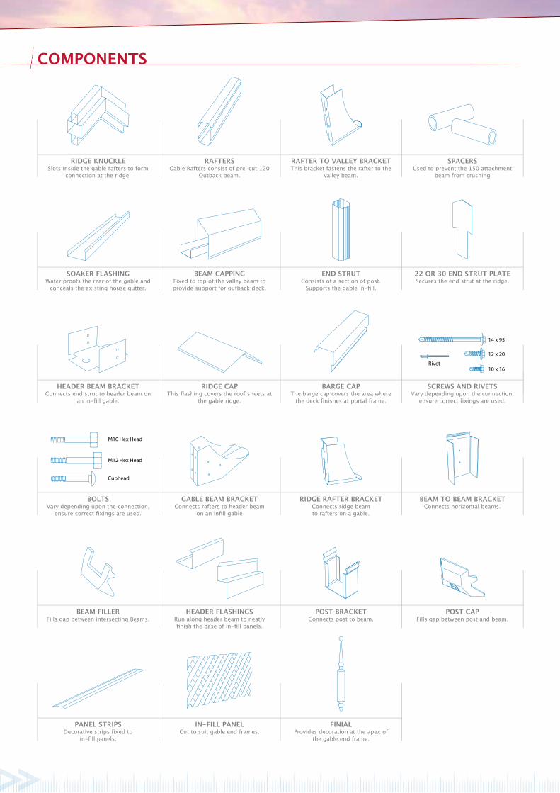
COmpOnEnTS
RIDGE KnUCKLESlots inside the gable rafters to form
connection at the ridge.
RAFTERSGable Rafters consist of pre-cut 120
Outback beam.
SpACERSUsed to prevent the 150 attachment
beam from crushing
RAFTER TO VALLEY BRACKETThis bracket fastens the rafter to the
valley beam.
SOAKER FLASHInGWater proofs the rear of the gable and
conceals the existing house gutter.
BEAm CAppInGFixed to top of the valley beam to provide support for outback deck.
22 OR 30 EnD STRUT pLATESecures the end strut at the ridge.
EnD STRUTConsists of a section of post.
Supports the gable in-fill.
pAnEL STRIpSDecorative strips fixed to
in-fill panels.
In-FILL pAnELCut to suit gable end frames.
FInIALProvides decoration at the apex of
the gable end frame.
BEAm FILLERFills gap between intersecting Beams.
HEADER FLASHInGSRun along header beam to neatly finish the base of in-fill panels.
pOST CApFills gap between post and beam.
pOST BRACKETConnects post to beam.
BOLTSVary depending upon the connection,
ensure correct fixings are used.
GABLE BEAm BRACKETConnects rafters to header beam
on an infill gable
BEAm TO BEAm BRACKETConnects horizontal beams.
RIDGE RAFTER BRACKETConnects ridge beamto rafters on a gable.
HEADER BEAm BRACKETConnects end strut to header beam on
an in-fill gable.
RIDGE CApThis flashing covers the roof sheets at
the gable ridge.
SCREWS AnD RIVETSVary depending upon the connection,
ensure correct fixings are used.
BARGE CApThe barge cap covers the area where
the deck finishes at portal frame.
14 x 95
12 x 20
10 x 16Rivet
M10 Hex Head
M12 Hex Head
Cuphead

8
1
4
183
7
9
6
52
13
15
16
17
12
11
10
14
COmpOnEnT LAYOUT
ADDITIOnAL mATERIALSPlease note that the Stratco Outback kit does not include any brackets or fixings to attach the unit to the existing structure, or concrete/masonry anchors for column installation. Other items not included in the standard kit are infill panels and accessories, finials, box gutters, cover flashings and concrete.
Ridge Capping
Flat Section
Outback Deck
Ridge Beam
Ridge Knuckle
Gable Rafter
Valley Beam
Angle Back Channel
Beam Capping
Gable Beam Bracket
Header Beam
Barge Cap
Post Bracket
Post
Gutter
Header Beam Bracket
End Strut
End Strut Plate
1
2
3
4
5
6
7
8
9
10
11
12
13
14
15
16
17
18

60 x 44 x 2.0 G450 Galvanised Channel
Rafter Strengthening Bracket
M12 Bolt
Timber Rafter
Figure 2 Figure 3
InTRODUCTIOnPlease read these assembly instructions thoroughly before commencing the construction. Double check all dimensions, levels and bolting locations before cutting, screwing or bolting structural members. It is recommended that the persons erecting the structure have had some previous building experience because some modifications to the existing house structure are required.
ATTACHInG TO An EXISTInG STRUCTUREThe builder is to ensure the existing house/structure is of a suitable structural integrity and complies with all the relevant Australian Building codes and standards. For more information regarding the suitability of the house structure to accommodate the Stratco Attached Clearspan Gable, consult a structural engineer or a building authority. It is the builder’s responsibility to ensure that the existing house roof structure is strengthened correctly.
Refer to section 2.1 if attaching Clearspan Gable on its side to a house, section 2.2 if attaching on its end to a house or refer to both sections if attaching the gable on its side and end.
Attaching On Side To HouseA Stratco Clearspan attached on its side to a house is attached to the existing eaves overhang at the fascia, or to an existing wall if height permits.
The first objective in the construction is to fix a structural side beam along the fascia or wall, to which the Gable Unit is attached.
Most existing houses have not been designed for the attachment of portal framed gables to their side, therefore additional strengthening of the house rafters must be performed.
In order to strengthen the existing house rafters, the roof tiles or roof sheets need to be lifted to expose the roof frame. Steel rafter brackets and channels are then bolted along the house rafters. Refer to section 2.1.1.
A 150mm Outback beam is bolted to the strengthening brackets at the fascia. Once the 150 attachment beam is secured to the house, the Gable Unit can be erected and fastened to the beam.
Rafter StrengtheningThe first step is to determine the number of rafters which need to be strengthened and their location relative to the unit. You will have to lift some roof tiles or roof sheets to discover the rafter positions and spacings. The number of rafters which need to be strengthened is determined by the builder, however spacing is recommended not to exceed 1200mm.
Note: It is the builder’s responsibility to ensure the existing rafters and fascia are adequately reinforced and strengthened to accommodate any additional attached structure. The reinforcing method must be approved by the appropriate council or engineer.
It is recommended an adjustable rafter strengthening bracket is used in conjunction with an extension channel, as shown in (Figure 3).
The adjustable rafter strengthening bracket is shown in (Figure 2). Please note that this bracket may not be suitable for applications where the front face of the house gutter is higher than 120 mm. In these cases please contact Stratco for alternative solutions.
The adjustable rafter strengthening bracket allows for an adjustment of pitch in the range of 15 to 30 degrees. The distance the bracket extends past the fascia is also adjustable to allow for standard gutters (minimum extension) or box gutters with a width of up to 200mm.
In conjunction with rafter strengthening brackets a channel is fixed to the side of the house rafter (Figure 3). The bottom end of the channel will be located at the base of the house rafter. Holes should be marked and pre-drilled in the channel to suit the location of existing holes in the bracket. The channel will extend beyond the bracket so additional holes are to be drilled in the channel at approximately 500mm centres.
Adjustable Rafter
Strengthening Bracket

Bracket Arm
M12 x 40 Cup Head Bolt
T Piece
Tighten To 35Nm Torque
M12 Washer
M12 Spring Washer
M12 Nut
Rafter
105 Attachment Beam
Fix Bracket As Close As Possible To The Base Of The Gutter
Rafter Strengthening Bracket
Outback Roof SheetEnough Clearance For Roof Sheets To Run Into House Gutter
Figure 4
Figure 5
Initially the bracket T piece shall be fixed to the bracket arm with two M12 cup head bolts (hand tighten only), a spring washer is to be located between the standard M12 washer and nut (Figure 4). Mark the position of the bracket on the fascia and notch a rectangular hole in the fascia allowing the bracket to be fed through the front of the fascia.
The hole may need to be enlarged slightly if the M12 cup head bolts interfere with the fascia. Insert the bracket through the fascia and fix with the channel to the house rafter using M12 hex head bolts through the existing holes in the bracket and further up the channel (Figure 6). Adjust the T piece so it is horizontal and has the appropriate extension past the fascia to allow for fixing of the attachment beam. T piece connection bolts are to be tightened to a minimum 50Nm torque.
Fix the bracket as close to the base of the gutter as possible (recommended minimum distance 10mm from lowest end of gutter), as shown in (Figure 50).
The 150 attachment beam is fixed to the end plate to ensure the carport roof sheets drain into the existing house gutter (Figure 5).
After fixing all the brackets and channels, the 150 attachment beam is fixed in place.
Prop up the 150 attachment beam in position with the double flange on top, the beam will need to be located at a height on the bracket which allows clearance between the gable roof sheets and the gutter. Fix to the end plates of the rafter bracket using two M12 bolts, with the bolt head on the 150 attachment beam side. Insert spacers to prevent the beam from crushing, and bolt in position, using nuts and washers.
The 150 attachment beam becomes the base for the attachment of the Clearspan Gable unit. (Figure 6) shows a unit attached at the side.
Note: Do not over tighten bolts as this can lead to a visible indentation due to the high gloss nature of the material. Refer to (Figure 7) for fixing spacers.
To insert spacers drill 13mm holes through the 150 attachment beam. Then drill 16mm holes on the outside face only, ie, this time do not drill all the way through. This will allow the spacer to slide in from the outside and stop at the other side as shown in (Figure 7).
A cover flashing may be ordered as an additional option and custom made to cover the exposed brackets and holes through fascia. Rivet flashings in place, (Figure 8) suggests a simplified flashing.
Figure 6
Refer Figure 4
Timber Rafter
Channel
Birds Mouth
Stud Wall
Channel Extension
Recommended Channel ExtensionBeyond Birds Mouth: 1900mmRecommended Web Overhang: 400mm
150 Attachment Beam Fixed To Rafter Bracket With Two M12 Bolts
Rafter
150 Attachment BeamEaves Overhang Brick Work
Gutter
Rafter Strengthening Bracket Attached To Rafter With 6 x M12 Hex Head Bolts
Web Overhang
A
A

ImpORTAnT: Ensure that the double thickness portion is at the top when installing all beams and rafters.
Note: The rafters are supplied pre-cut and drilled at the ridge as shown in (Figure 10). Insert ridge knuckle into the pre-cut rafters and screw together using two 12x20 hex head self drilling screws through both sides of each rafter and two 12x20 hex head self drilling screws through the top (double flange side) of each rafter.
Beam Capping
Beam Channel
Double Flange
Spacer
Enlarge Hole (16mm This Side Only)
Washer
M12 Bolt
13mm Hole
Rafter Strengthening
Bracket
150 Attachment Beam
Nut
2.2 Attaching On End To HouseIf fixing a Clearspan Gable on its end to a wall, two alternatives are available. Ridge and valley beams are fixed directly to the wall using beam to wall brackets. This option will not require a rear gable frame and back channel is fixed to the wall to accommodate sheets running along the wall. The other alternative requires valley beams be fixed to the wall and a rear gable frame installed. The rear gable frame will need to be slightly offset from the wall to allow the appropriate bracket fixing.
If fixing a Clearspan Gable on its end with suspension brackets to a fascia (Figure 9) typically a soaker flashing is used. In this case the gable rafter at the rear of the unit is to be set back sufficiently from the house fascia to accommodate the house gutter and infill panel (refer to Figures 22 and 23).
If fixing a Clearspan Gable on its end to an attachment beam, elevated to the existing house gutter height, the attachment beam is to be as close as possible (within 5mm) to the outside face of the gutter (Figure 24). The 150 attachment beam is fixed to rafter strengthening brackets as detailed in section 2.1.1.
2.2.1 Fascia Strengthening It is recommended extended fascia strengthening brackets are fastened at a spacing not exceeding 1200mm centres to fascia and
3.0 GABLE FRAmE ASSEmBLY
Figure 7
Beam Capping
House Gutter
150 Attachment Beam
FasciaStrengthening Bracket
Cover Flashing (Optional)
Rivet
Rivet
Figure 8
120 Gable Rafter
SoakerFlashing
Beam Capping
Back Channel
Valley Beam
Gutter
In-Fill Panel
Suspension Bracket
Extended Facia Strengthening Bracket ( Attached To Rafter & Back Channel)
Soffit Lining
Figure 9
Figure 10
Open Gable Rafter In-Fill Gable Rafter
rafters (Figure 9). Brackets and reinforcement channels are also recommended to the first rafter either side of the valley beams. Secure brackets to rafters with 12x25mm timber fixing screws through pre-drilled holes and bolt through backchannel and fascia with M10 bolts.
Note: It is the builder’s responsibility to ensure the existing rafters and fascia are adequately reinforced and tied down to accommodate any additional attached structure loads.
Collar Tie Length (L < 3000)
Fix Bracket To Rafter Using Four 12 x x20 Hex Head Screws
Fix Collar Tie Using Two 12 x x20 Hex Head Screws
Each Side
Locate The Break On The Top Groove Of
Valley Beam
Fix Beam Capping To Channel Using 3mm Rivets Each Side At 500mm Centre
Fix Beam Channel To Top Of The Valley Beam Using 12 x 20 Hex Head Self Drilling Screws At 500mm Centres
Beam Channel
Beam Capping
Valley Beam
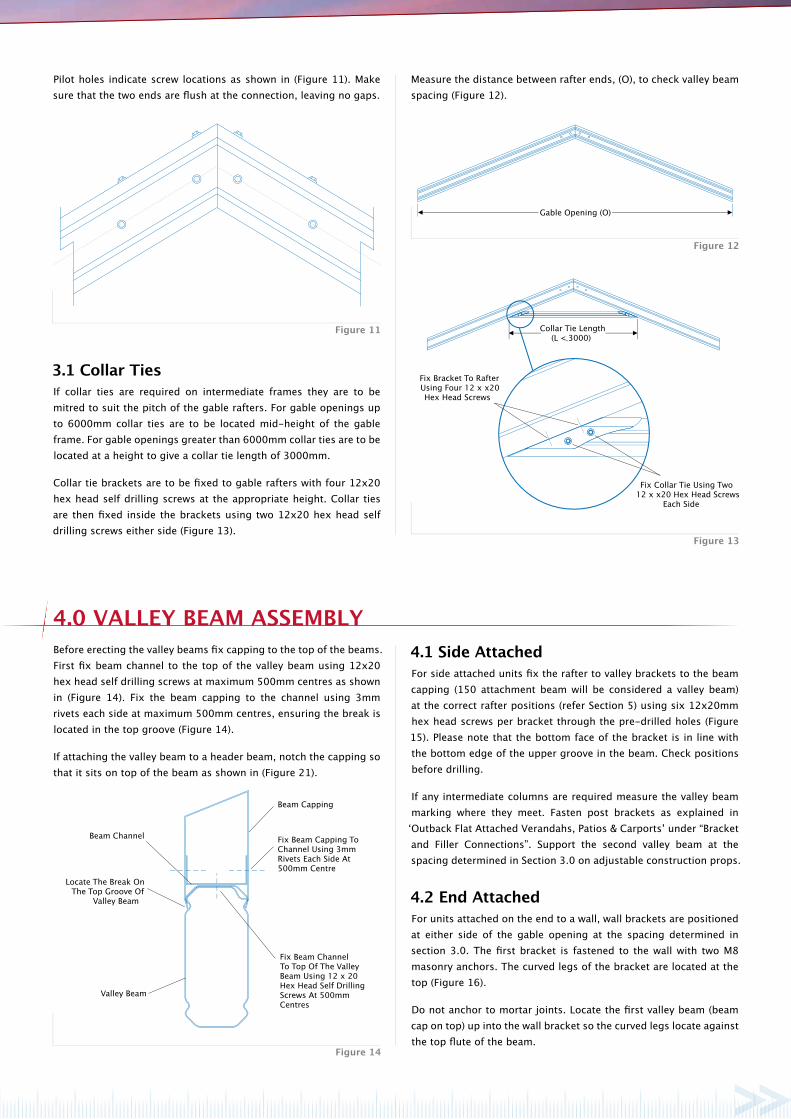
3.1 Collar TiesIf collar ties are required on intermediate frames they are to be mitred to suit the pitch of the gable rafters. For gable openings up to 6000mm collar ties are to be located mid-height of the gable frame. For gable openings greater than 6000mm collar ties are to be located at a height to give a collar tie length of 3000mm.
Collar tie brackets are to be fixed to gable rafters with four 12x20 hex head self drilling screws at the appropriate height. Collar ties are then fixed inside the brackets using two 12x20 hex head self drilling screws either side (Figure 13).
Figure 14
Measure the distance between rafter ends, (O), to check valley beam spacing (Figure 12).
Before erecting the valley beams fix capping to the top of the beams. First fix beam channel to the top of the valley beam using 12x20 hex head self drilling screws at maximum 500mm centres as shown in (Figure 14). Fix the beam capping to the channel using 3mm rivets each side at maximum 500mm centres, ensuring the break is located in the top groove (Figure 14).
If attaching the valley beam to a header beam, notch the capping so that it sits on top of the beam as shown in (Figure 21).
Pilot holes indicate screw locations as shown in (Figure 11). Make sure that the two ends are flush at the connection, leaving no gaps.
4.0 VALLEY BEAm ASSEmBLY4.1 Side AttachedFor side attached units fix the rafter to valley brackets to the beam capping (150 attachment beam will be considered a valley beam) at the correct rafter positions (refer Section 5) using six 12x20mm hex head screws per bracket through the pre-drilled holes (Figure 15). Please note that the bottom face of the bracket is in line with the bottom edge of the upper groove in the beam. Check positions before drilling.
If any intermediate columns are required measure the valley beam marking where they meet. Fasten post brackets as explained in ‘Outback Flat Attached Verandahs, Patios & Carports’ under “Bracket and Filler Connections”. Support the second valley beam at the spacing determined in Section 3.0 on adjustable construction props.
4.2 End AttachedFor units attached on the end to a wall, wall brackets are positioned at either side of the gable opening at the spacing determined in section 3.0. The first bracket is fastened to the wall with two M8 masonry anchors. The curved legs of the bracket are located at the top (Figure 16).
Do not anchor to mortar joints. Locate the first valley beam (beam cap on top) up into the wall bracket so the curved legs locate against the top flute of the beam.
Figure 11
Figure 12
Figure 13
Gable Opening (O)

150 VALLEY BEAM WITH
22° RAFTER TO VALLEY BRACKET
150 VALLEY BEAM WITH
30° RAFTER TO VALLEY BRACKET
120 VALLEY BEAM WITH
22° RAFTER TO VALLEY BRACKET
120 VALLEY BEAM WITH
30° RAFTER TO VALLEY BRACKET
Bracket Position Inline With The Bottom Edge Of The Upper Groove
20
25
25
30
25
25
30
25
25
30
25
25
Bracket Position Inline With The Bottom Edge Of The Upper Groove
Bracket Position Inline With The Bottom Edge Of The Upper Groove
Bracket Position Inline With The Bottom Edge Of The Upper Groove
40
Beam Capping
150 Valley Beam
Wall Bracket
Two M8 Masonry Anchors With Minimum Embedment of 65mm
or Two 8mm Diameter Screwbolts With a
Minimum Embedment of 65mm
Minimum Edge Distance of Bolts and Screws is 10 x dia
15
Figure 16
The valley beam is fastened to the wall bracket with 10x16 hex head screws in the pre-drilled holes while the opposite end is supported on adjustable construction props.
For units attached on the end to a fascia, suspension brackets are positioned at either side of the gable opening at the spacing determined in Section 3.0 (Figure 12). The top tab of the suspension bracket must be located between the fascia and back channel. A minimum of two M6 bolts with washers are fixed through back channel, suspension bracket and fascia (Figure 17).
If back channel is not present, (ie, no adjacent flat roof) locate a 2mm washer plate behind fascia at suspension bracket. Fix through bracket, fascia and plate.
The first valley beam is fastened into the suspension bracket with 10x16 hex head screws through the dimples while the opposite end is supported on adjustable construction props.
Figure 15

120 Gable Rafter
SoakerFlashing
Back Channel
Valley Beam
Gutter
In-Fill Panel
M6 Bolts and Washers
Suspension Bracket
1 mm Stepped Back Channel
Beam Capping
Facia
Two 10 x 16 Hex Head Self Drilling Screws
Beam To Beam Bracket
Attachment (Header) Beam
Beam Filler
Two 10 x 16 Hex Head Self Drilling Screws Either Side
Valley Beam Capping
120 Rafter
Rafter To Valley Bracket
Two 12 x 20 Hex Head Screws Either Side
Valley Beam
5.0 GABLE FRAmE COnnECTIOn5.1 Gable FramesThe rafter to valley brackets are attached to the beam capping using six 12x20 hex head screws (Figure 15, Section 4.1) at the appropriate locations.
Fix the gable rafters into the rafter to valley brackets with two 12x20 hex head screws either side (Figure 19).
If attached on the end, attach the second valley beam into the wall or suspension bracket.
Intermediate frames should be spaced evenly and fixed into rafter to valley brackets as previously described.
A rear gable frame without a header beam is fixed as per an intermediate frame.
Figure 19
For units attached on the end to an attachment beam (Figure 24), beam to beam brackets are positioned at either side of the gable opening at the spacing determined in Section 3.0 (Figure 12).
Fix beam to beam brackets to the attachment beam (header beam) with two 10x16 hex head screws so they clamp the beam filler to the beam (Figure 18).
The first valley beam is fastened over the beam to beam bracket with two 10x16 hex head screws either side while the opposite end is supported on adjustable construction props.
If any intermediate columns are required measure the valley beam marking where they meet. Fasten post brackets as explained in the Stratco Installation Guide ‘Outback Flat Attached Verandah, Patios & Carports’ under “Bracket and Filler Connections”. This can be done before valley beams are fixed in place.
Support the second valley beam on adjustable construction props but do not fix to the wall, fascia or attachment beam until the front gable frame has been attached.
Fix the rafter to valley brackets to the beam capping at the correct rafter positions (refer Section 5). Fixing details as indicated in Section 4.1.
5.2 Gable Frame With Infill
5.2.1 Front Infill Where there is an infill at the front of the unit (and/or rear, in the case of side attached), run the front fascia beam of the flat roof section (if applicable) continuously across the opening to support the infill panel and form a header beam (the gutter subsequently runs full length of the header beam). Measure the end gable frame opening and attach gable beam brackets to the header beam at the appropriate spacing using a minimum of four 10x16 hex head self drilling screws.
Rafters are supplied notched at the base to fit the gable beam brackets. Rafters are fastened inside the gable beam brackets with a minimum of three 10x16 hex head self drilling screws either side as shown in (Figures 20 or 21).
5.2.2 Rear Infill A rear header beam will be required if the unit includes infill to the rear gable frame. For units attached at the rear with suspension brackets, the rear header is fixed between valley beams using beam to beam brackets. If fixed at the rear to an attachment beam (Figure 22), the attachment beam becomes the header (valley Rafters are supplied notched at the base to fit the gable beam brackets. Rafters are fastened inside the gable beam brackets with a minimum of three 10x16 hex head self drilling screws either side as shown in (Figures 20 or 21).
Figure 17
Figure 18

Attach Rafter To Bracket Using a Minimum of Three 10 x 16
Hex Head Self Drilling Screws Each Side
Attach Gable Beam Bracket Using a Minimum of Four
10 x 16 Hex Head Self Drilling Screws
Gable Beam Bracket
Valley Beam
Header Beam
120 Gable Rafter
SoakerFlashing
Beam Capping
Back Channel
Valley Beam
Gutter
In-Fill Panel
Suspension Bracket
Steel Facia Bracket ( Attached To Rafter & Back Channel)
Split Tail Soft Pull Rivets
20mm Gap
Rafter Setback
Soffit Lining
5.2.2.1 Soaker Flashing In the case of a rear infill panel, a soaker flashing is used to conceal the existing house gutter, waterproof the rear end of the gable and neatly finish the base of the in-fill panel (Figure 22).
The rear gable frame and header beam are set back in order to accommodate the standard soaker flashing which is optional with the Outback unit (Figure 23). The frame is fixed on the rear header beam into gable beam brackets as previously detailed.
Fix the standard soaker flashing into position on top of the back channel and underneath the gutter. Infill panels must be fixed with split tail soft pull rivets at 500mm centres a minimum of 20 mm above the pan of the soaker flashing.
This will reduce the possibility of moisture being absorbed into the sheet. See Section 14 for details of fixing infill panels to gable frames.
note: 1. A custom made soaker flashing will need to be ordered to
the required dimensions. The rafter setback will need to be adjusted to suit.
2. Do not form stop ends at either end of the soaker flashing.
3. Soaker flashing is not to come in contact with the base of the house gutter.
5.2.2.2 Header FlashingWhen a gable is fixed at the rear to an attachment beam, elevated to the existing house gutter height, typically a header flashing is used in conjunction with the rear infill. In this case, the rear attachment beam is considered a header and along with the rear gable frame is fixed as close as possible (within 5mm) to the existing gutter in order to accommodate the header flashing. The gable frame is fixed on the rear header to gable beam brackets as previously described.
Fix the header flashing into position over the existing gutter lip with rivets. Infill panels are located behind the header flashing and fixed with split tail soft pull rivets at 500mm centres (Figure 24).
Refer Section 14 for details of fixing infill panels to gable frames.
Figure 23
Figure 20
Attach Rafter To Bracket Using a Minimum of Three 10 x 16
Hex Head Self Drilling Screws Each Side
Beam Capping
Rafter
Header Beam
Gable Beam Bracket
Attach Gable Beam Bracket Using a Minimum of Four
10 x 16 Hex Head Self Drilling Screws
Valley Beam
Notch Beam Capping To Fit Over Beam
Figure 21
Soaker Flashing
Figure 22

Header Flashing
Split Tail
Soft Pull Rivet
Beam Capping
Valley Beam
150 Attachment Beam
House Gutter
Fascia
Strengthening Bracket
Infill Panel
Two 12 x 20 Hex Head Self
Drilling Screws on Each Side
Ridge Rafter Bracket
Angled Back Channel
Six 12 x 20 Hex Head Self
Drilling Screws
Attach Angled Back Channel To Ridge Beam Using 10 x 16 Hex Head Self Drilling Screws at 500mm Centres
Overhanging 150
Ridge Beam
Overhang Back Channel Flush With End of Beam
Attach Angled Back Channel To ridge Beam Using 10 x 16 Hex Head Self Drilling Screws at 500mm Centres
Attach Using 10 x 16 Hex Head Self Drilling Screws at 500mm Centres Along
Doublle Flange of Ridge Beam 150 Ridge Beam
Overhang Back Channel
6.1 Assembling Ridge BeamAssemble ridge beam before attaching to gable frames. Fix angled back channel to both sides of the ridge beam using 10x16 hex head self drilling screws at 500mm centres, ensuring that the top of the back channel is in line with the bottom of the beam chamfer as shown in (Figure 25). The back channel should run 34mm past the end of the beam at both ends of the ridge beam. If there is no rear portal frame, finish the back channel flush at one end.
Fasten 10x16 hex head self drilling screws at 500mm centres along the double flange of the ridge beam (Figure 25).
In the case of decking overhanging the gable frame, run the angled back channel to the end of the overhanging ridge beam as shown in (Figure 26). A ridge rafter bracket will be required on both sides of the ridge to support overhang.
6.1 Attaching Ridge BeamFix the ridge rafter bracket at the ridge with six 12x20 hex head self drilling screws through the gable frame and into the ridge knuckle.
Position the ridge beam so that the angled back channel rests on the gable frame (Figure 27). Fix the ridge rafter bracket using two 12x20 hex head self drilling screws each side (top screw may be fastened through the backchannel into the bracket & beam).
Figure 26
6.0 RIDGE BEAm
Figure 24
Figure 27Figure 25

50 x 50mm SHS Column Reinforcement
68 Outback Column50 x 50 x 3.0mm
68mm
B
B
68mm
Section B - B
30mm
Two 12 x 20mm Hex Head Screws Through Both Sides Of The Column
SHS Column Reinforcement (Not Always Required)
Two 12 x 20mm Hex Head Screws Through Both Sides Of The Column
Two 12 x 20mm Hex Head Screws Through Both Sides
Of The Column
Column Embedded Minimum 300mm Into Footing
Brick
Corbel
Depth As
Width As
10 x 30mm Counter Sunk Self Drilling Screws
Post Bracket
Post Cap
Notched Beam Filler
Beam Bracket
10 x 16 Self Drilling Screws
80
75
25min 100
Figure 28 Figure 29
Assemble the remaining framework of the flat verandah (if applicable) as per the installation guide; ‘Outback Flat Attached Verandah, Patios And Carports’.
If fixing the columns into the ground, dig the holes to the specified size. Place a full or half brick in the bottom of the hole as shown in (Figure 29).
Measure from the underside of the beam to the top of the brick and cut posts to this length at each post location.
8.1 68 Outback ColumnIf 50x50 mm square hollow sections (SHS) have been supplied, the fluted 68 Outback columns will need to be reinforced.
Cut the 50mm SHS 75mm shorter than the fluted post and slide into the column.
Ensure the square section is positioned inside the column and fix using two 12x20 hex head screws per side, at both ends, as detailed in figure 28 and 29.
Regardless of whether the column is reinforced, slide the top of the 68 Outback column over the installed post bracket until it is flush with the underside of the fascia beam.
The unfluted faces of the column should be aligned with each face of the post to beam bracket.
Fasten the 68 Outback column to the post bracket using two 12x20 hex head screws either side as shown in (Figure 29).
Use construction props or bracing to hold columns in position, but do not concrete in place at this stage.
7.0 REmAInInG ASSEmBLY
8.0 COLUmnS AnD FOOTInGS

Two 12 x 20mm Hex Head
Screws Either Side
Upstand Brace
Footing Plate
Footing Upstand
Two M12 x 75 Masonry
Anchors or M12 x 75
Screwbolts
30mm (Minimum)
Two 12 x 20mm Hex Head Screws Through Both Sides Of Column
50mm SHS Footing Plate Fixed To Slab Using Four Masonary Anchors, Min 75mm Embedment.
50mm SHS Footing Plate
50mm SHS
50mm
100mm
Figure 30 Figure 31
the post to beam bracket. Fasten using two 12x20 hex head screws either side as shown in (Figure 29).
Use construction props or bracing to hold columns in position but do not bolt to the concrete slab at this stage.
9.2 SHS Reinforced Column Footing plateSlide the SHS reinforced footing bracket into the bottom of the column, pre-drill and fasten with two 12x20 hex head screws on either side of the post. Locate the top screws approximately 100mm from the base of the footing plate, and the bottom screws 50mm from the base. This is shown in (Figure 31).
Slide the top of the column over the post bracket and align the column and footing bracket. (it may be necessary to lift the fascia beam slightly to slide the column over the post bracket). The unfluted faces of the column should be aligned with each face of the post to beam bracket. Fasten using two 12x20 hex head screws either side as shown in (Figure 29).
Use construction props or bracing to hold columns in position but do not bolt to the concrete slab at this stage.
Footing brackets are available when fixing posts to an existing concrete slab.
Establish the column lengths by measuring the distance from the underside of the fascia beam to the concrete slab, less the thickness of the footing plate (or 20mm for Outback footing plate).
9.1 68 Outback Column Footing plateFor non-reinforced 68 Outback posts, cut the columns to length, and assemble the footing bracket by sliding the legs of the footing upstand through the slots in the footing plate (Figure 30). The upstand bracing must be located between the legs of the upstand.
Slide the assembled footing bracket and bracing into the bottom of the column, and fasten with two 12x20 hex head screws either side ensuring the top screws are located at least 15mm from the top of the upstand with screws being a minimum 30mm apart. This is shown in (Figure 30).
Slide the top of the column over the post bracket and align the column and footing bracket. (it may be necessary to lift the fascia beam slightly to slide the column over the post bracket). The unfluted faces of the column should be aligned with each face of
9.0 FOOTInG pLATES
To prevent moisture from entering the beams and for aesthetics, any beams with exposed ends require endcaps be fitted. Align the endcap and push into the exposed beam end. The postcaps can be fitted over the post-beam connection. Align the two lugs with the two exposed holes of the post bracket and push firmly.
10.0 CAppInG

Rivet Pop To Gutter
Gutter
Gutter Outlet Downpipe Pop
Notched Beam Filler
Downpipe
Outback® Deck
Gable Frame
Header BeamGutter
Rivet tabs to top of Beam Capping at
1 metre intervals
Beam Capping
Figure 33
11.1 Gutter Outlet AssemblyPosition the downpipes in line with columns then cut a hole in the base of the gutter near the back chamfer. Insert the downpipe outlet from the inside of the gutter and rivet in place using 3mm rivets (Figure 33). Remove any swarf and waterproof with silicone.
If a flat verandah is included connect the gutter to the flat roof Outback as described in ‘Outback Flat Attached Verandah, Patios & Carports’.
Where there is no flat roof adjacent the gable, the gutter is attached to the top of the beam capping. Cut 30mm tabs in the gutter back lip at 1000mm intervals and fold back. Fix the gutter to the beam capping, through the tabs with rivets as shown in (Figure 32). Once decking is attached (Section 12.0) fit gutter straps at maximum 1000mm intervals, attaching to the top of the decking with rivets. Waterproof rivets with silicone.
Figure 32
down to beam cappingBack channel fixed upside
Outback ® Deck
Outback® Deck
Gable Frame
Front Facia Beam Header Beam
Beam Capping
Valley Beam Column
Gable Beam Bkt
12.1 Flat Roof (If Applicable)Attach the decking to the flat roof verandah first as laid out under
“DECKING” (’Outback Flat Attached Verandah, Patios & Carports’), starting from the valley beam and working away, on both sides.
The back channel is attached upside down (the shorter leg on top) along beam capping to assist the fixing of decking. (Figure 34).
12.2 Clearspan GableWhen attaching the decking to the gable, start from the rear on one side of the gable. Fix the deck to the angled back channel at the ridge, and to the capping at the valley beam. If the deck of the flat roof section runs perpendicular to the valley beams, align the ribs of the gable decking up with the flat roof section. The Outback decking will need to overhang the beam capping allowing water to flow directly into the gutter (Figure 32).
Figure 34
11.0 GUTTERInG
12.0 ATTACH DECKInG

Ridge CapFix Ridge Cap to Back Channel with rivets
Outback® Deck
Fix to front of ridge with two 12 x 20 hex head self drilling screws
Fix to strut with two 10 x 16 hex head self drilling screws
Fix bracket to header with two 10 x 16 hex head self drilling screws
Fix strut to bracket with two 10 x 16 hex head screws either side
Gutter
Infill Panel
Header Beam
Split Tail Soft Pull Rivets
Header Flashing
ribs of the gable decking up with the flat roof section. The Outback decking will need to overhang the beam capping allowing water to flow directly into the gutter (Figure 32).
Position the ridge cap over the ridge beam and two angled back channels and rivet into the channel (Figure 35). Position the ridge cap over the ridge beam and two angled back channels and rivet into the channel (Figure 35).
Two styles of header flashings are available to neatly finish the base of infill panels, one is used on header beams with gutter and the other for headers without gutter. Gable infill panels are to be cut in triangular shapes to fit the end frame. Panels can be painted to the desired colour before installing.
End struts are fixed mid-span of the header to a header beam bracket at the base and an end strut plate at the ridge (Figure 36).
Figure 35
12.2 Clearspan GableWhen attaching the decking to the gable, start from the rear on one side of the gable. Fix the deck to the angled back channel at the ridge, and to the capping at the valley beam. If the deck of the flat roof section runs perpendicular to the valley beams, align the
14.1 Header Beam With GutterAttach the header flashing to the rear gutter lip with rivets. Infill panels are fixed through the top groove of rafters and the end strut with 8x35mm self embedding self drilling screws at maximum 500mm centres in non-cyclonic areas and 250mm centres in cyclonic areas. Panels are fixed at the base through the header flashing with split tail soft pull rivets at maximum 500mm centres (Figure 37).
Figure 36
Figure 37
Rivet
Barge Cap is Screwed to
Gable Rafter
Gable Rafter
Outback Decking Barge Cap
Rivet
Barge Cap is Screwed to Gable Rafter
Gable Rafter
Outback Decking Barge Cap14.2 Header Beam Without GutterInfill panels are fixed through the top groove of rafters and the lower groove of the header beam with 8x35mm self embedding self drilling screws. Fix at maximum 500mm centres in non-cyclonic areas and 250mm centres in cyclonic areas. Panels are fixed to the end strut at the same spacings. Attach the header flashing to the underside of the header beam with 10x16 hex head screws to neatly finish the base of the infill panels (Figure 38).
Figure 39
Header Beam
8 x 35mm Self Embedding Screw
10 x 16 Hex Head
Self Drilling Screws
Header Flashing
In�ll Panel
Figure 38
14.0 InFILL pAnELS
15.0 ATTACHInG BARGE CAp
13.0 RIDGE CAppInG

16.0 FInAL FIXInG
17.0 HELpFUL TIpS
You have now completed your new Stratco Outback. Your Stratco Outback will give you many years of service by simply following the important recommendations set out in the Stratco ‘Selection, Use and Maintenance’ brochure.
We recommend you wash and wipe down your Stratco Outback unit with a soft broom, mop or sponge as frequently as you would wash your car to maintain its duco. More frequent cleaning and rinsing will be required in severe environments.
18.0 mAInTEnAnCE
Leave plastic coating on members until they are about to be fastened to the structure. This will help prevent scratching of the colorbond® finish.
Sweep the roof and clean gutters after the completion of work. Ensure any swarf and rivet stubs are removed as they can cause unsightly rust stains.
Double check all measurements and drilling locations before proceeding.
Regularly check framework for squareness and vertical alignment to make sure it hasn’t moved during construction.
Leave all construction props and/or bracing in place until concrete is set or columns are bolted to the slab.
COnTACT
1300 165 165
www.stratco.com.au
All brands and logos/images accompanied by ® or ™ are trade marks of Stratco (Australia) Pty Limited.
© Copyright February 2012 BROCDCG
If barge capping is required at the ends of the unit, attach the barge cap by screwing the lower lip to the rafter and rivet the top section to the deck, as shown in (Figure 39). Mitre the barge at the apex of the gable for a neat finish. Run the barge cap along the gable section to where it meets the flat verandah deck and finish neatly.
Before securing columns in position ensure a minimum fall of 1 in 500 (12mm for every 6m) towards downpipe/s.
16.1 Final Fixing Into Concrete Thoroughly check posts with a spirit level. When plumb, fill the post hole with approximately 150mm of concrete and use a shovel or pole to agitate the concrete to remove and air pockets. Repeat this process until the hole is full, continually checking the posts. Once the concrete is set remove any temporary bracing or props. The concrete must be finished slightly raised towards the column to ensure water runs away from the column.
16.2 Final Fixing Onto Existing Concrete If fixing the columns to an existing concrete slab with a footing plate, each plate must be fixed to the concrete as specified in (Figures 30 or 31) as appropriate. The minimum distances from an anchor hole to the concrete edge is 75mm.
16.3 Downpipes Before attaching the downpipes, rivet the downpipe bracket to the column and bend the flanges along the ‘break-line’ to accept the downpipe. Slide the downpipe over the downpipe outlet and rivet into position. Rivet the downpipe to the brackets. Weatherproof all fasteners with silicone.
Related Documents