IIR Conference: Ammonia Refrigeration Technology, Ohrid, 2009 THE USE OF STRAIN GAUGE STRESS MONITORING SYSTEMS ON AMMONIA REFRIGERATION PIPEWORK AFFECTED BY UNDERGROUND MINING SURFACE SUBSIDENCE. Jonathan E Fryer ISECO Consulting Services Pty Ltd 723 Burwood Road, Hawthorn East, Victoria 3123 Australia Ph +61 3 9882 7340, Fax +60 3 9882 7339, E-mail [email protected] ABSTRACT In 2008, an underground long wall coal mine was drilled approximately 200meters deep under part of an exiting turkey processing facility which uses ammonia refrigeration piping systems for process cooling and cold storage. To minimize the risk of pipe work failure due to stress induced by ground subsidence, the pipe work at this site was replaced before the mining commenced. The replacement piping design was modelled using the Whesso Pipe Stress Analysis software PSA 5 and for selected sections of piping additional pipe support displacements (to simulate ground subsidence) were added to the model. This was necessary to demonstrate compliance with The Australian Standard AS4041 –Pressure Piping. Strain gauges were installed on 64 sections of pipe work identified as likely to experience high stress. A web based monitoring and alarm system was installed to provide early warning if predetermined trigger levels were exceeded. The paper discusses why flexibility analysis should be carried out on ammonia refrigeration piping systems, compares the predicted stresses with actual measured stress at a number of piping locations, shows how remedial action reduced actual stresses and provides lessons learnt from strain gauge installation and monitoring at an industrial food processing facility. 1. INTRODUCTION In Australia, the Refrigeration Standards state that any ammonia refrigeration piping installation shall comply with the relevant pressure and piping standards. To achieve this, it is necessary to have pipe stress calculations carried out to certify the pipe grade and materials used are suitable for the service duty. The standard also calls up that the piping system installation is to be to a designated installation class, this class designation nominates the welding, testing procedures and the supervision process. The programme used by ISECO to carry out the stress calculations is PSA-5. This complies with ASME B31.3 Process Piping and in turn ASME B31.5 Refrigeration Piping both codes calling up identical rules for flexibility analysis. 2. REQUIREMENTS FOR AMMONIA PIPING DESIGN The Australian Standard AS 1677.2:1998 Refrigerating Systems clause 3.6.1 states that piping and fittings shall comply with AS/NZS 1200 Pressure Equipment. This also notes that AS/NZS 1200 references AS 4041 Pressure Piping and also states other standards for piping. ASME B31.5 would be acceptable under the alternative provisions of AS/NZS 1200.

Welcome message from author
This document is posted to help you gain knowledge. Please leave a comment to let me know what you think about it! Share it to your friends and learn new things together.
Transcript
IIR Conference: Ammonia Refrigeration Technology, Ohrid, 2009
THE USE OF STRAIN GAUGE STRESS MONITORING SYSTEMS ON AMMONIA REFRIGERATION PIPEWORK AFFECTED BY
UNDERGROUND MINING SURFACE SUBSIDENCE.
Jonathan E Fryer ISECO Consulting Services Pty Ltd
723 Burwood Road, Hawthorn East, Victoria 3123 Australia Ph +61 3 9882 7340, Fax +60 3 9882 7339, E-mail [email protected]
ABSTRACT
In 2008, an underground long wall coal mine was drilled approximately 200meters deep under part of an exiting turkey processing facility which uses ammonia refrigeration piping systems for process cooling and cold storage. To minimize the risk of pipe work failure due to stress induced by ground subsidence, the pipe work at this site was replaced before the mining commenced. The replacement piping design was modelled using the Whesso Pipe Stress Analysis software PSA 5 and for selected sections of piping additional pipe support displacements (to simulate ground subsidence) were added to the model. This was necessary to demonstrate compliance with The Australian Standard AS4041 –Pressure Piping.
Strain gauges were installed on 64 sections of pipe work identified as likely to experience high stress. A web based monitoring and alarm system was installed to provide early warning if predetermined trigger levels were exceeded.
The paper discusses why flexibility analysis should be carried out on ammonia refrigeration piping systems, compares the predicted stresses with actual measured stress at a number of piping locations, shows how remedial action reduced actual stresses and provides lessons learnt from strain gauge installation and monitoring at an industrial food processing facility.
1. INTRODUCTION
In Australia, the Refrigeration Standards state that any ammonia refrigeration piping installation shall comply with the relevant pressure and piping standards. To achieve this, it is necessary to have pipe stress calculations carried out to certify the pipe grade and materials used are suitable for the service duty. The standard also calls up that the piping system installation is to be to a designated installation class, this class designation nominates the welding, testing procedures and the supervision process. The programme used by ISECO to carry out the stress calculations is PSA-5. This complies with ASME B31.3 Process Piping and in turn ASME B31.5 Refrigeration Piping both codes calling up identical rules for flexibility analysis.
2. REQUIREMENTS FOR AMMONIA PIPING DESIGN
The Australian Standard AS 1677.2:1998 Refrigerating Systems clause 3.6.1 states that piping and fittings shall comply with AS/NZS 1200 Pressure Equipment. This also notes that AS/NZS 1200 references AS 4041 Pressure Piping and also states other standards for piping. ASME B31.5 would be acceptable under the alternative provisions of AS/NZS 1200.
IIR Conference: Ammonia Refrigeration Technology, Ohrid, 2009
It is our view this chain of references and standards make it mandatory that all ammonia systems piping design comply with AS 4041 – 2006 Pressure Piping.
3. BACKGROUND
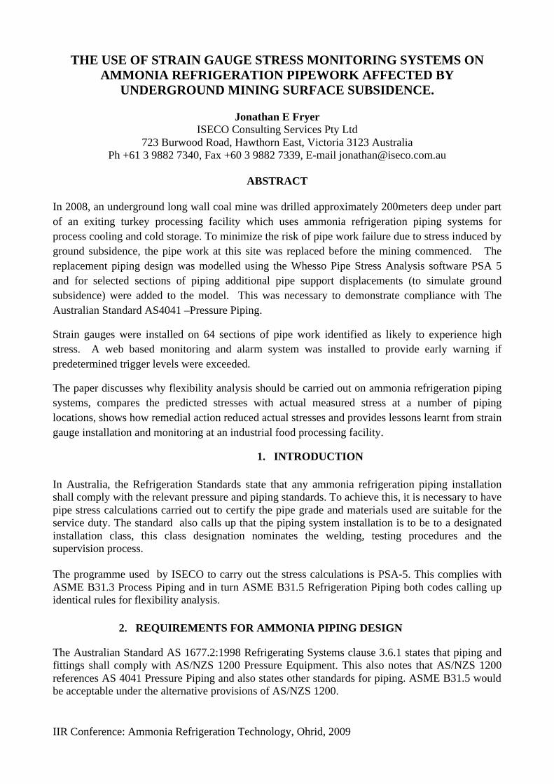
The Colliery is located approximately 80 kilometers south west of Sydney in the township of Tahmoor NSW. The mining company has previously mined 24 longwalls to the north and west of the mine’s current location. Longwall 24A is a continuation of an existing mine and is located directly below the turkey plant property and is approximately 90 meters from the Processing Plant at its closest point.
Figure 1 Overlay with the mine plan.
4. RESULTS OF PIPING STRESS CALULATIONS
For each pipe section modeled, it was necessary to run two calculations, the first to determine a base stress level, which is the resultant pipe stress from self weight, operating pressure and thermal expansion and contraction. The second model had the predicted ground movements of up to 50 to 60mm ( at the pipe support points ) due to mining related subsidence added to the base case to give an overall result . A summary of a sample of calculations for the low temperature piping systems is shown in Table 1 Table 1 Summary of stress calculations Ref No
Location Base Stress due to thermal and pressure
Stress due to thermal pressure and subsidence
1 Low temp wet return branch to carton freezer ( Nozzle 7 )
27 MPa 109 MPa
2 Low temp wet return line dropper to Stock room east/west (Nozzle 4 )
27.4MPa 77MPa
3 Low temp wet return connection to accumulator
37.8 MPA 54.8 MPa
4 Low temp wet return connection to low temp glycol chiller ( Nozzle 3 )
Less than 20 MPa 36.7 MPa

IIR Conference: Ammonia Refrigeration Technology, Ohrid, 2009
Figure 2 Visual representation of a section of the PSA stress model output With the above information the maximum calculated stress can be compared against the allowable maximum stress for the piping material and welding and testing procedures allowed by the relevant standards.
5. INSTALLING STRAIN GAUGES
From the stress model outputs, the key locations of peak stress due to combined thermal and subsidence effects were identified. At each of these locations a configuration of electrical resistance strain gauges were installed by a specialist company . Longitudinal stress was measured at four equally spaced locations around the circumference of the pipe , hoop stress and 45degree torsional stress was measured with a multi element rosette gauge .
Figure 3 Location of Strain Gauges

IIR Conference: Ammonia Refrigeration Technology, Ohrid, 2009
6. COMPARING RESULTS TO OPERATION STATUS PRESSURE STRESS To check the results of the pressure stress ( or hoop stress as its more commonly known ) is relatively easy if the actual internal pressure of the pipe and diameter and wall thickness are known. Pressure stress is calculated from eq.(1) Sp= Pd2 /( D2-d2) (1)
The results of a spot check at one location are shown in the Table 2 Table 2 Comparison of measured and calculated Stress Location Time &
Date Pipe Pressure kPa Absolute
Pipe Outside diameter (mm)
Pipe inside diameter (mm)
Calculated Pressure Stress MPa
Measured Pressure Stress MPa
Predicted Pressure Stress MPa
Condenser gas inlet
10.38am 12/ 5/08
1191 88.9 77.9 3.95 4.1 6.7
Note : The predicted pressure stress is based on piping and refrigerant gas temperature at worst case design of 46 0C ( 1827 kPa A ). From the above it can be seen that the actual measured pressure stress of 4.1 MPa agrees well with the calculated value of 3.95MPa. PIPE STRESS DUE TO DEFROST The monitoring provided a unique opportunity to check actual stresses in a refrigeration piping network during a range of operating conditions. One such area that is presented below is the piping associated with a carton freezing tunnel on the site. Strain gauges were mounted on each of the coil connections. The figures below show the changes occurring during a manual defrost operation which had the following steps: Manually close the low temp pump liquid feed valve to the coil, 15minutes later manually open the hot gas valve to the coil, leave on defrost for approx. 1 hour.
Figure 4 Low Temp Pumped Liquid into Coil

IIR Conference: Ammonia Refrigeration Technology, Ohrid, 2009
From Figure 4 the following pattern can be detected: (Note: When analysing look at the direction and magnitude of change in stress) a) The torsional stress changes by approximately 20 MPa when the liquid supply is shut off but
no significant changes in other stresses until the hot gas valve is opened. b) Once hot gas valve is opened, all stresses change with largest change of 15MPa on 270 degree
longitudinal stress. c) The stresses on the 90 degree axis (ie opposite to 270 degrees) change by only 7 MPa in the
same direction which implies that bending and a compression are occurring simultaneously. (If this was pure bending the 90 degrees would be mirror image of the 270 degrees.)
d) The 0 degrees and 180 degrees stresses are opposite in sign with the 180 degrees being 13.8MPa compared to 9.6 MPa on the 0 degrees.
Figure 5 Hot Gas into Coil From Figure 5 the following can be observed: a) The largest variation in stress is the 270 degree axis, which changed by 12.1MPa b) All stress values have moved in the same direction indicating that stresses are mainly
compressive or tensile with some torsion.
Figure 6 Low Temp Wet Return Out of Coil

IIR Conference: Ammonia Refrigeration Technology, Ohrid, 2009
From Figure 6 the following can be observed: a) The largest change in stress was on the 180 degree axis, nearly 40 MPa. On the opposite axis
0 degrees, stress values changed in the opposite direction by 30 MPa indicating bending and some compression or tensile stress.
b) The 90 degree and 270 degrees changed in the same direction indicating compression or tensile stress ( probably compressive as pipe warms up during defrost ).
c) The hoop stress increased initially then dropped before stabilising at its original level . In summary , the above shows that stresses in refrigeration pipes do change as the process changes and as would be expected, the largest changes in stress occurred in the larger diameter wet return piping which has the least flexibility.
7. REMEDIAL ACTION AS A RESULT OF STRESS MONITORING
On the 2nd of May 2008 we identified that the stress on the strain gauge set Cond- 3 located at the 80mm NB discharge gas inlet pipe to the condenser was increasing steadily . As part of the monitoring procedure , trigger levels for remedial action had been set by taking the maximum allowable stress for the type of piping material and operating temperature ,less a safety factor. An early warning level known as the Blue level was set and a higher level known as Amber was also set. Figure 7 shows the 90 degree axis longitudinal strain gauge trending towards a blue trigger .
Figure 7 Increasing Stress on 90 degree axis The analysis showed that the change in stress was likely to be caused by an increasing bending in the pipe due to minor tilting of the condenser foundations most likely as a result of mining induced ground settlement . Refer to Figure 8 which shows how the combination of an existing tensile stress plus the new bending could create the pattern shown on the gauges.
Bending + Tensile Stress = Resultant Stress
Figure 8 Combining Stresses

IIR Conference: Ammonia Refrigeration Technology, Ohrid, 2009
An instruction with marked up photographs was issued to site to increase the length of the support rod on the hanger upstream of the gauge point to reduce the bending stress experienced. This was completed on the 2nd of June and the resultant reduction in stress is as shown in Figure 9 .
Figure 9 Reduced Stress on 90 degree axis This shows that as predicted the mining induced stresses would change at a reasonably slow rate and that the use of appropriate trigger levels and remedial actions can safely counter those effects.
8. LESSONS LEARNT STRAIN GAUGING & REFRIGERATION PIPING
To provide a guide for future projects where strain gauges may be required on refrigeration piping the following should be considered:
• Three dimensional piping drawings showing pipe support locations, all pipe lengths, bends, insulation & cladding etc should be used as input to the stress models. These can then be marked up to indicate required position of strain gauges.
• Take care that baseline readings are taken with pipes empty and at ambient temperature (This was difficult in a production environment).
• It was found that the wiring and data taker units had susceptibility to temperature which would show as a gradual reduction in stress as temperature increased and then increasing again at night. In future more work should be done to eliminate this effect.
• Gauges located in plant rooms and other areas with large amounts of electrical equipment often showed rapid spikes due to electrical interference, causing false trigger alarms.
• Care should be taken to seal junction boxes from water ingress.
10. CONCLUSIONS
All ammonia refrigeration piping systems should be subjected to a flexibility analysis. Where the designer has doubt regarding the ability of the system to comply, a comprehensive analysis should be made. The Whesso PSA-5 Pipe Stress Software based on ASME B31.3 & B31.5 has been found suitable for use in modelling refrigeration pipe stresses under thermal and subsidence loadings and provides an easily used output.
IIR Conference: Ammonia Refrigeration Technology, Ohrid, 2009
The use of electric resistance strain gauging to measure refrigeration pipe stress changes in a site subjected to unusual ground subsidence has been proven workable.
NOMENCLATURE
Sp pressure stress (Pa) Subscripts P internal pressure (Pa) A Absolute Pressure D outside diameter (m) D inside diameter (m)
REFERENCES
1. American Society of Mechanical Engineers , 2002, Process Piping ASME B31.3, USA 2. BMT WBM, 2008, Inghams Pipe stress Monitoring System Specification, Australia 3. Mine Subsidence engineering Consultants, 2008, Management Plan Rev J, Australia 4. Standards Australia, 2006, Pressure Piping AS 4041, Australia 5. Standards Australia, 2000, Pressure equipment AS/NZS 1200 , Australia 6. Standards Australia , 1998, Refrigerating Systems AS/NZS 1677.2, Australia 7. Whessoe Computing Systems, 2005, Pipe Stress Analysis PSA5 Manual, United Kingdom
Related Documents


