Accepted Manuscript Not Copyedited 1 Strain Estimation of CFRP Confined Concrete Columns Using Energy Approach Thong M. Pham 1 and Muhammad N.S. Hadi, M.ASCE 2 Abstract A new model is presented for calculating the axial strain of carbon fiber reinforced polymer (CFRP) confined concrete columns. An energy balance approach is introduced to establish a relationship of the energy absorption between a confined concrete column and CFRP. The proposed model was verified using a large database collected from 167 CFRP confined plain concrete specimens. This database contains 98 circular specimens with diameters ranging between 100 mm and 152 mm and 69 square specimens having a side length ranging between 100 mm and 152 mm. The database covers unconfined concrete strengths from 20 MPa to 50 MPa. The proposed model shows very good correlation with the experimental results. In addition, the proposed model also provides comparative prediction of strain of CFRP confined concrete columns in two extreme cases: insufficient confinement and heavy confinement, which are not usually well predicted by other models. CE Database subject headings: Carbon Fiber Reinforced Polymer; Energy methods; Energy dissipation; Stress-strain relations. 1 Lecturer, Faculty of Civil Engineering, HCMC University of Technology, Ho Chi Minh City, Vietnam; Currently Ph.D. Candidate, School of Civil, Mining and Environmental Engineering, University of Wollongong, Wollongong, NSW 2522, Australia. Email: [email protected] 2 Associate Professor, School of Civil, Mining and Environmental Engineering, University of Wollongong, Wollongong, NSW 2522, Australia (corresponding author). Email: [email protected] Journal of Composites for Construction. Submitted November 25, 2012; accepted May 14, 2013; posted ahead of print May 16, 2013. doi:10.1061/(ASCE)CC.1943-5614.0000397 Copyright 2013 by the American Society of Civil Engineers J. Compos. Constr. Downloaded from ascelibrary.org by UNIVERSITY OF WOLLONGONG on 05/16/13. Copyright ASCE. For personal use only; all rights reserved.

Welcome message from author
This document is posted to help you gain knowledge. Please leave a comment to let me know what you think about it! Share it to your friends and learn new things together.
Transcript
Accep
ted M
anus
cript
Not Cop
yedit
ed
1
Strain Estimation of CFRP Confined Concrete Columns
Using Energy Approach
Thong M. Pham1 and Muhammad N.S. Hadi, M.ASCE2
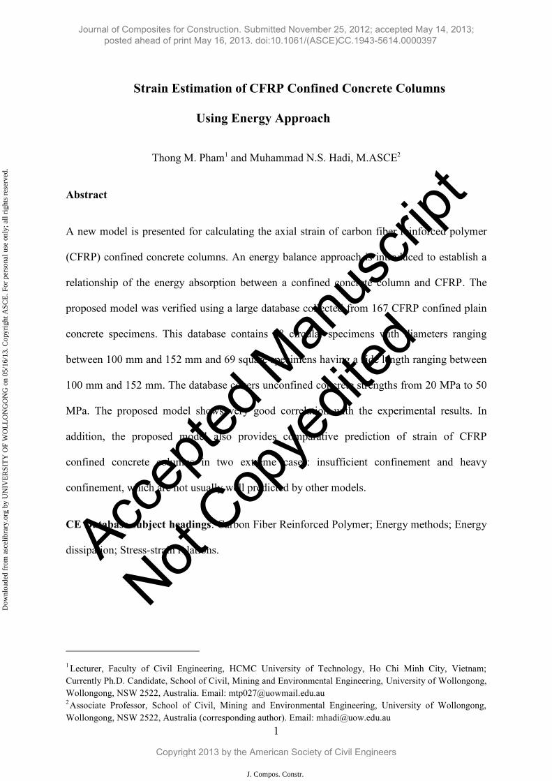
Abstract
A new model is presented for calculating the axial strain of carbon fiber reinforced polymer
(CFRP) confined concrete columns. An energy balance approach is introduced to establish a
relationship of the energy absorption between a confined concrete column and CFRP. The
proposed model was verified using a large database collected from 167 CFRP confined plain
concrete specimens. This database contains 98 circular specimens with diameters ranging
between 100 mm and 152 mm and 69 square specimens having a side length ranging between
100 mm and 152 mm. The database covers unconfined concrete strengths from 20 MPa to 50
MPa. The proposed model shows very good correlation with the experimental results. In
addition, the proposed model also provides comparative prediction of strain of CFRP
confined concrete columns in two extreme cases: insufficient confinement and heavy
confinement, which are not usually well predicted by other models.
CE Database subject headings: Carbon Fiber Reinforced Polymer; Energy methods; Energy
dissipation; Stress-strain relations.
1 Lecturer, Faculty of Civil Engineering, HCMC University of Technology, Ho Chi Minh City, Vietnam; Currently Ph.D. Candidate, School of Civil, Mining and Environmental Engineering, University of Wollongong, Wollongong, NSW 2522, Australia. Email: [email protected] 2Associate Professor, School of Civil, Mining and Environmental Engineering, University of Wollongong, Wollongong, NSW 2522, Australia (corresponding author). Email: [email protected]
Journal of Composites for Construction. Submitted November 25, 2012; accepted May 14, 2013; posted ahead of print May 16, 2013. doi:10.1061/(ASCE)CC.1943-5614.0000397
Copyright 2013 by the American Society of Civil Engineers
J. Compos. Constr.
Dow
nloa
ded
from
asc
elib
rary
.org
by
UN
IVE
RSI
TY
OF
WO
LL
ON
GO
NG
on
05/1
6/13
. Cop
yrig
ht A
SCE
. For
per
sona
l use
onl
y; a
ll ri
ghts
res
erve
d.
Accep
ted M
anus
cript
Not Cop
yedit
ed
2
Introduction
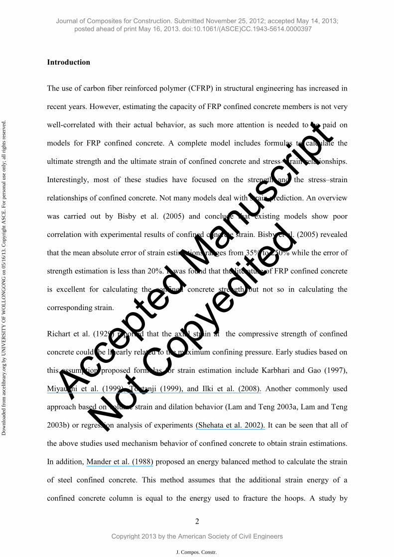
The use of carbon fiber reinforced polymer (CFRP) in structural engineering has increased in
recent years. However, estimating the capacity of FRP confined concrete members is not very
well-correlated with their actual behavior, as such more attention is needed to be paid on
models for FRP confined concrete. A complete model includes formulas to calculate the
ultimate strength and the ultimate strain of confined concrete and stress–strain relationships.
Interestingly, most of these studies have focused on the strength and the stress–strain
relationships of confined concrete. Not many models deal with strain prediction. An overview
was carried out by Bisby et al. (2005) and conclude that existing models show poor
correlation with experimental results of confined concrete strain. Bisby et al. (2005) revealed
that the mean absolute error of strain estimations ranges from 35% to 250% while the error of
strength estimation is less than 20%. It was found that the literature of FRP confined concrete
is excellent for calculating the confined concrete strength but not so in calculating the
corresponding strain.
Richart et al. (1929) reported that the axial strain at the compressive strength of confined
concrete could be linearly related to the maximum confining pressure. Early studies based on
this assumption proposed formulas for strain estimation include Karbhari and Gao (1997),
Miyauchi et al. (1999), Toutanji (1999), and Ilki et al. (2008). Another commonly used
approach based on volume strain and dilation behavior (Lam and Teng 2003a, Lam and Teng
2003b) or regression analysis of experiments (Shehata et al. 2002). It can be seen that all of
the above studies used mechanism behavior of confined concrete to obtain strain estimations.
In addition, Mander et al. (1988) proposed an energy balanced method to calculate the strain
of steel confined concrete. This method assumes that the additional strain energy of a
confined concrete column is equal to the energy used to fracture the hoops. A study by
Journal of Composites for Construction. Submitted November 25, 2012; accepted May 14, 2013; posted ahead of print May 16, 2013. doi:10.1061/(ASCE)CC.1943-5614.0000397
Copyright 2013 by the American Society of Civil Engineers
J. Compos. Constr.
Dow
nloa
ded
from
asc
elib
rary
.org
by
UN
IVE
RSI
TY
OF
WO
LL
ON
GO
NG
on
05/1
6/13
. Cop
yrig
ht A
SCE
. For
per
sona
l use
onl
y; a
ll ri
ghts
res
erve
d.
Accep
ted M
anus
cript
Not Cop
yedit
ed
3
Saadatmanesh et al. (1994) adopted this method to calculate the strain of FRP confined
concrete. This present study develops relationships between the additional energy absorption
of a confined concrete column and the energy absorbed by the confinement material. A new
methodology is introduced to calculate the confined concrete strain in circular and square
sections.
Analytical investigation
Strain energy and energy absorption
Strain energy is the energy stored in a structural elastic member as a result of the work
performed on the member by an external load. It is defined as the energy absorbed by the
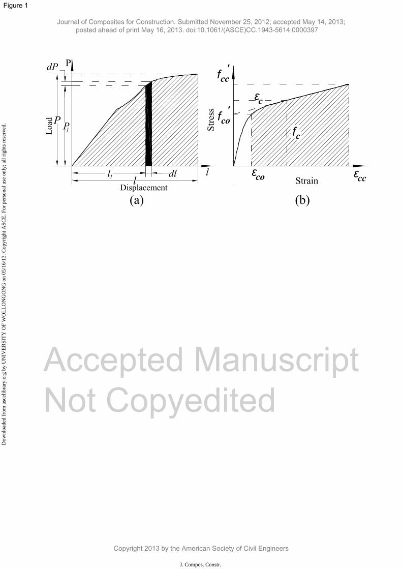
structural member during the loading process. For an axially loaded column, the work done
by the applied load is equal to the area under the load – displacement curve as shown in Fig.
1a and Eq. 1. In a similar manner, the energy absorbed by the external FRP in a FRP confined
concrete column could be estimated by using Eq. 1:
0
PdWU (1)
where U is the strain energy, W is the work done by the applied load, P is the applied load, l is
the displacement, and dl is an increment of the displacement.
The energy stored in the column core is transferred to compress concrete, to deform the FRP,
to create cracks in concrete, and to vertically compress the FRP. Some energies are also lost
in unknown consumptions. Due to the limited understanding of the behavior inside FRP
confined concrete, it will be inappropriate to use directly the balanced energy approach
proposed by Mander et al. (1988) for steel confined concrete. In this study, it is assumed that
there is a possible linear relationship between the energy absorption of the column and the
external FRP, which is discussed below.
Journal of Composites for Construction. Submitted November 25, 2012; accepted May 14, 2013; posted ahead of print May 16, 2013. doi:10.1061/(ASCE)CC.1943-5614.0000397
Copyright 2013 by the American Society of Civil Engineers
J. Compos. Constr.
Dow
nloa
ded
from
asc
elib
rary
.org
by
UN
IVE
RSI
TY
OF
WO
LL
ON
GO
NG
on
05/1
6/13
. Cop
yrig
ht A
SCE
. For
per
sona
l use
onl
y; a
ll ri
ghts
res
erve
d.
Accep
ted M
anus
cript
Not Cop
yedit
ed
4
To further investigate the energy transfer, early studies focused on FRP tubes made from high
strength and high stiffness fibers. Unlike ductile metals, fibers and resins are brittle and they
fail by fracture after an initial elastic deformation. The fracture strain of a typical carbon fiber
is around 1.5 - 2.0% so that they may absorb less energy than conventional metals. However,
they actually perform much better when comparison is made in terms of the specific energy
absorption, which is the energy per unit mass (Lu and Yu 2003). It is found that the specific
energy absorption of fiber is affected by fiber strength, elastic properties, the ratio of diameter
to thickness of FRP, fiber orientation, and sectional geometries (Wolff et al. 1994). These
studies confirm that using directly the balanced energy method proposed for steel confined
concrete for FRP confined concrete is inappropriate.
Energy in structural members
The widely accepted model shown in Fig. 1b is recommended by ACI-440-2R.08 (2008) for
stress-strain relationship of FRP confined concrete columns. It was adopted herein to
calculate the energy absorption of a FRP confined concrete column as described below:
cc
cccccc dfAW0
(2)
where Wcc is the strain energy of confined concrete, Acc is the gross sectional area of confined
concrete, fc is the stress of confined concrete, c is the strain of confined concrete, cc is the
strain at peak stress of confined concrete, and d c is an increment of the axial strain.
The stress–strain curve shown in Fig. 1b has been slightly modified to obtain a simple
integration. An expression (Eq. 3) was extracted from Eq. 2 to calculate the energy absorption
of the concrete core, in which the volumetric strain energy (Ucc) equals the area under the
experimental stress–strain curves. When the strain of confined concrete is below the peak
strain of the corresponding unconfined concrete, the effect of FRP is negligible. Thus, this
Journal of Composites for Construction. Submitted November 25, 2012; accepted May 14, 2013; posted ahead of print May 16, 2013. doi:10.1061/(ASCE)CC.1943-5614.0000397
Copyright 2013 by the American Society of Civil Engineers
J. Compos. Constr.
Dow
nloa
ded
from
asc
elib
rary
.org
by
UN
IVE
RSI
TY
OF
WO
LL
ON
GO
NG
on
05/1
6/13
. Cop
yrig
ht A
SCE
. For
per
sona
l use
onl
y; a
ll ri
ghts
res
erve
d.
Accep
ted M
anus
cript
Not Cop
yedit
ed
5
study assumes that the additional energy in the column core equals the area under the
experimental stress–strain curves starting from the value of unconfined concrete strain as
shown in Fig. 1b and Eq. 3:
2)ff)((
dfU'
cc'cococc
cccc
cc
co
(3)
where Ucc is the volumetric strain energy of confined concrete, f’cc is the confined concrete
strength, f’co is the unconfined concrete strength and co is its corresponding strain.
Similarly, the energy absorbed by FRP could be calculated as follows:
)21
( ffccff fAW (4)
where Wf is the strain energy of FRP, ff and f are the rupture strength and rupture strain of
FRP obtained from flat coupon tests and f is the volumetric ratio of FRP as shown in Eqs. 5
and 6.
The volumetric ratio ( f) of FRP of circular sections and square sections could be calculated
as follows:
For circular sections:
dt
f4
(5)
For square sections:
trbrbt
f )4()]28(4[
22 (6)
Journal of Composites for Construction. Submitted November 25, 2012; accepted May 14, 2013; posted ahead of print May 16, 2013. doi:10.1061/(ASCE)CC.1943-5614.0000397
Copyright 2013 by the American Society of Civil Engineers
J. Compos. Constr.
Dow
nloa
ded
from
asc
elib
rary
.org
by
UN
IVE
RSI
TY
OF
WO
LL
ON
GO
NG
on
05/1
6/13
. Cop
yrig
ht A
SCE
. For
per
sona
l use
onl
y; a
ll ri
ghts
res
erve
d.
Accep
ted M
anus
cript
Not Cop
yedit
ed
6
where t is the thickness of FRP, d is the diameter of the section, and r is the radius of the
round corner of the section.
It is found that the rupture strain of FRP on the confined concrete is much lower than that
obtained from flat coupon tests (Xiao and Wu 2000; Pessiki et al. 2001; Carey and Harries
2005). Therefore, the volumetric strain energy of FRP on a column could be estimated as
follows:
)21
( fefeff fU (7)
where Uf is the volumetric strain energy of FRP, and ffe and fe are the actual rupture strength
and rupture strain of FRP on the columns, respectively.
Finally, the energy absorbed by the column is calculated using Eq. 3 and the energy absorbed
by FRP is estimated using Eq. 7. Next, a regression analysis based on a database was used to
obtain a linear relationship between them. Based on that equation, a model to calculate the
strain of confined concrete at peak stress was derived.
Experimental Database
Test database
Several experimental tests have been conducted on FRP confined concrete by researchers
over the past few decades. This present study collated a test database of 329 FRP confined
plain concrete specimens reported by Demers and Neale (1994), Watanable et al. (1997),
Matthys et al. (1999), Rochette and Labossière (2000), Xiao and Wu (2000), Suter and
Pinzelli (2001), Parvin and Wang (2001), Pessiki et al. (2001), Shehata et al. (2002), De
Lorenzis et al. (2002), Karabinis and Rousakis (2002), Lam and Teng (2003b), Chaallal et al.
(2003), Ilki and Kumbasar (2003), Masia et al. (2004), Berther et al. (2005), Lam et al.
Journal of Composites for Construction. Submitted November 25, 2012; accepted May 14, 2013; posted ahead of print May 16, 2013. doi:10.1061/(ASCE)CC.1943-5614.0000397
Copyright 2013 by the American Society of Civil Engineers
J. Compos. Constr.
Dow
nloa
ded
from
asc
elib
rary
.org
by
UN
IVE
RSI
TY
OF
WO
LL
ON
GO
NG
on
05/1
6/13
. Cop
yrig
ht A
SCE
. For
per
sona
l use
onl
y; a
ll ri
ghts
res
erve
d.
Accep
ted M
anus
cript
Not Cop
yedit
ed
7
(2006), Saenz and Pantelides (2006), Jiang and Teng (2007), Valdmanis et al. (2007), Al-
Salloum (2007), Rousakis et al. (2007), Wang and Wu (2008), Tao et al. (2008), Wu and Wei
(2010), Rousakis and Karabinis (2012), and Hadi et al. (2013). The main focus of this study is
on CFRP, as such test results of materials other than CFRP were excluded from this database.
Moreover, test results of circular sections not reporting actual rupture strain ( fe) of FRP were
excluded.
Few studies concluded that square columns confined with FRP provide a little (Mirmiran et
al., 1998) or no strength improvement (Wu and Zhou, 2010). Thus, this study deals only with
round corner square specimens, as such specimens with sharp corners were excluded from the
database. Since the procedure of calculating the strain of FRP confined concrete is based on
the ascending type of specimens (as shown in Fig. 1), the test results of square specimens
which have a descending type were excluded from the database. After excluding all the
above, the database contained the test results of 167 FRP confined plain concrete specimens:
98 circular specimens and 69 square specimens. The circular specimens included in the
database have diameters d ranging from 100 mm to 152 mm and having unconfined concrete
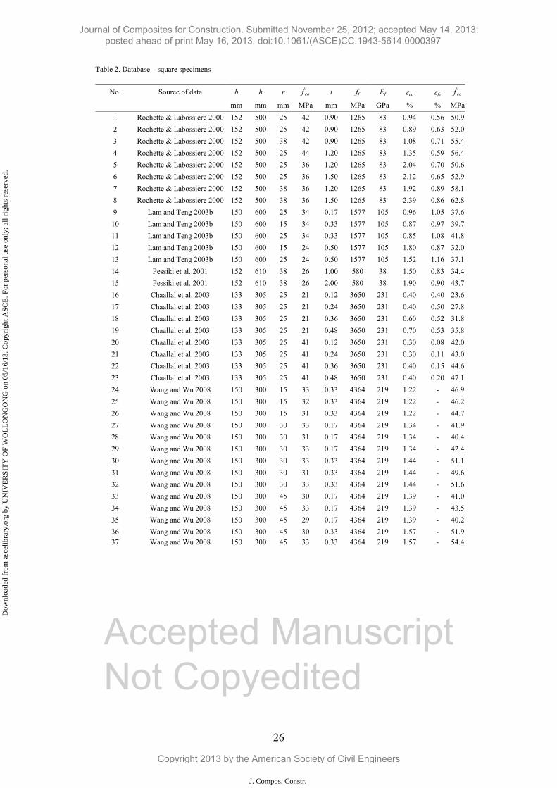
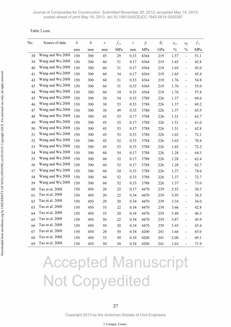
strengths 'cof between 30 MPa and 50 MPa. The square specimens have a side length ranging
between 100 mm and 152 mm and unconfined concrete strength ranging between 20 MPa and
50 MPa.
Confinement ratio, which was calculated by dividing the confining pressure ( lf ) by the
unconfined concrete strength ( 'cof ), varied between 2 % and 99 % for circular specimens and
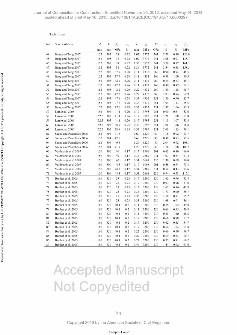
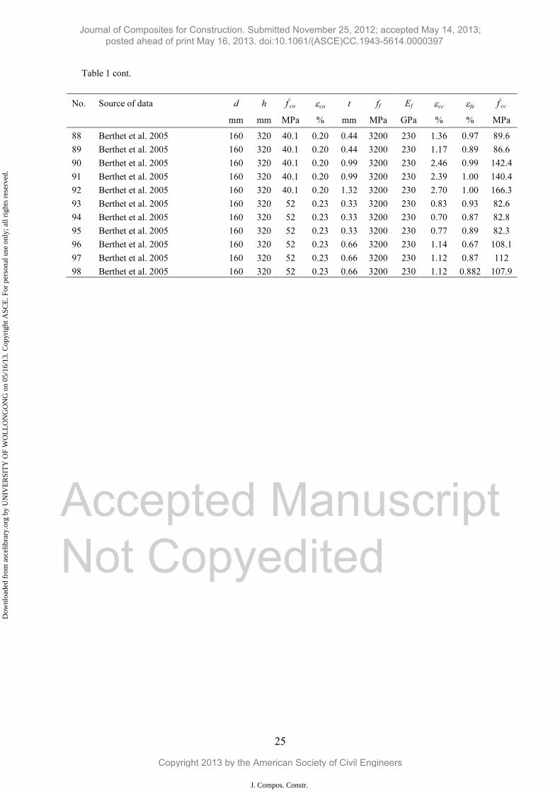
between 1 % and 60 % for square specimens. The database of circular specimens is reported
in Table 1 and that for square specimens is reported in Table 2.
Assumptions
Journal of Composites for Construction. Submitted November 25, 2012; accepted May 14, 2013; posted ahead of print May 16, 2013. doi:10.1061/(ASCE)CC.1943-5614.0000397
Copyright 2013 by the American Society of Civil Engineers
J. Compos. Constr.
Dow
nloa
ded
from
asc
elib
rary
.org
by
UN
IVE
RSI
TY
OF
WO
LL
ON
GO
NG
on
05/1
6/13
. Cop
yrig
ht A
SCE
. For
per
sona
l use
onl
y; a
ll ri
ghts
res
erve
d.
Accep
ted M
anus
cript
Not Cop
yedit
ed
8
The actual rupture strain of CFRP is usually reported for circular sections but not for square
sections. When the actual rupture strain of CFRP was not included in the test results, it was
assumed to be 0.55 of the rupture strain from flat coupon tests, as recommended by ACI-
440.2R-08 (2008). In addition, when the axial strain at peak stress of unconfined concrete
( co) was not specified, εco was assumed to be equal to 0.002 or values estimated by the
equation by Tasdemir et al. (1998). The performance of the proposed model was compared by
using two different methods for estimating the values of εco. In the first method, εco was
calculated using the equation proposed by Tasdemir et al. (1998). In the second method, εco
was assumed to be 0.002. Results of using the first method proved to be better than the second
method. Therefore, the equation proposed by Tasdemir et al. (1998) was used as shown in Eq.
8:
6'2'co 10)10539.29067.0( coco ff
(8)
The proposed strain model
A linear relationship is assumed between the energy absorbed by a column core and CFRP for
both circular sections and square sections. The energy absorption was calculated using Eqs. 3
and 7 while a regression analysis was carried out to obtain an equation for the energy
absorbed in the form shown in Eq. 9. Based on this equation, a new formula is proposed to
calculate the strain at peak stress of CFRP confined concrete.
fcc UkU (9)
where k is the proportion factor which is a function of fiber stiffness and sectional geometries.
Strain estimation for circular sections
Journal of Composites for Construction. Submitted November 25, 2012; accepted May 14, 2013; posted ahead of print May 16, 2013. doi:10.1061/(ASCE)CC.1943-5614.0000397
Copyright 2013 by the American Society of Civil Engineers
J. Compos. Constr.
Dow
nloa
ded
from
asc
elib
rary
.org
by
UN
IVE
RSI
TY
OF
WO
LL
ON
GO
NG
on
05/1
6/13
. Cop
yrig
ht A
SCE
. For
per
sona
l use
onl
y; a
ll ri
ghts
res
erve
d.
Accep
ted M
anus
cript
Not Cop
yedit
ed
9
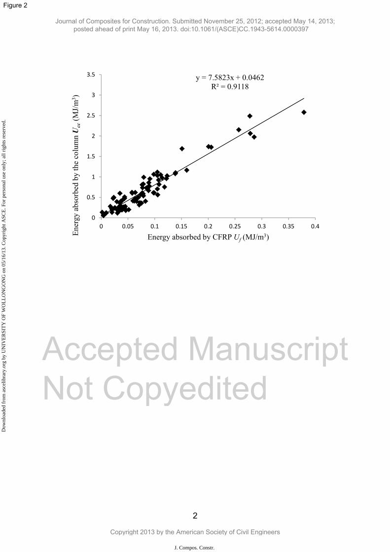
The energy absorption of 98 circular specimens was estimated using Eqs. 3 and 7, and the
results are presented in Fig. 2. Next, a regression analysis was undertaken to attain the
following equation:
fcc U.U 67 (10)
Substituting Eqs. 3 and 7 into Eq. 10, results in the following equation:
)ff(dftk
'cc
'co
fefecocc
4 (11)
where the proportion factor k is equal to 7.6. This expression could be used to calculate the
strain of CFRP confined concrete columns in circular sections. Using this calculated strain,
any model could be utilized to calculate the confined concrete strength. Lam and Teng model
(2003a) was adopted to express another form of Eq. 11 as follows:
tf.fdftk
fe'
co
fefecocc 33
2 (12)
Strain estimation for square sections
For circular sections, the methodology proposed in this paper was used to establish a
relationship between energy absorption of the whole column section and FRP. The energy
absorption of the FRP was calculated for all over the perimeter of the section. This calculation
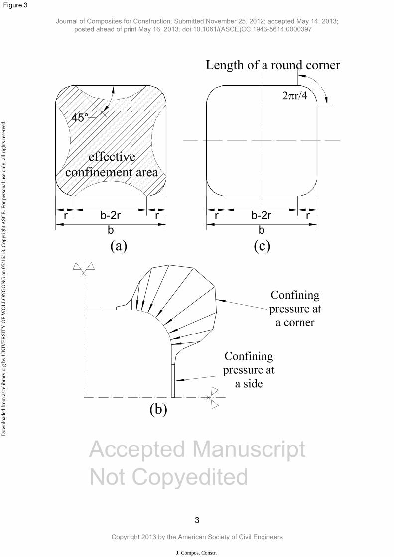
did not provide a comparable correlation between the two energies in Eq. 9. Thus, the energy
absorption of the column core at the effective area shown in Fig. 3a is considered for the
square specimens, which accounts for stress concentration at the corners. Details of the above
modifications are analyzed in the following sections.
The energy absorption is sensitive to the geometry of the column (Wolff et al. 1994). Thus
equations simulating the relationship between absorption energies of a column and CFRP
distinguish square specimens from circular specimens. In addition, it is widely recognized that
the confining pressure of a square column confined with CFRP is not uniform. Karabinis et al.
Journal of Composites for Construction. Submitted November 25, 2012; accepted May 14, 2013; posted ahead of print May 16, 2013. doi:10.1061/(ASCE)CC.1943-5614.0000397
Copyright 2013 by the American Society of Civil Engineers
J. Compos. Constr.
Dow
nloa
ded
from
asc
elib
rary
.org
by
UN
IVE
RSI
TY
OF
WO
LL
ON
GO
NG
on
05/1
6/13
. Cop
yrig
ht A
SCE
. For
per
sona
l use
onl
y; a
ll ri
ghts
res
erve
d.
Accep
ted M
anus
cript
Not Cop
yedit
ed
10
(2008) and Csuka and Kollár (2012) proved that the confining pressure mostly concentrates
on round corners of the column while this confining pressure is negligible at other zones as
shown in Fig. 3b. Therefore, energy absorption used to rupture CFRP is assumed to be only
available at the round corners. In such a case, a corner energy ratio kc, which is the ratio of the
total length of four round corners (as shown in Fig. 3c) to the circumference of the section, is
introduced to account for the reduction of energy absorbed by CFRP as follows:
)(rbr
kc 42 (13)
where b is the side length of a square section and r is the round radius at corners of the
section.
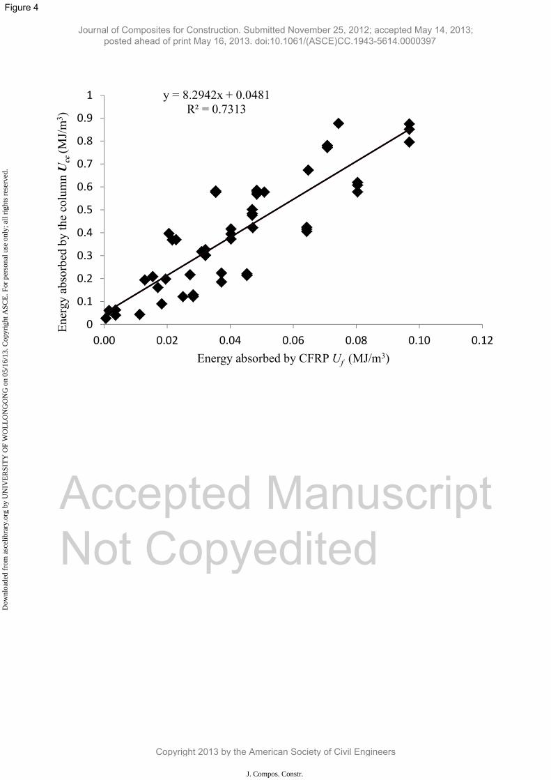
For square sections, the energy absorbed by CFRP shown in Fig. 4 is modified by adding the
corner energy ratio kc as follows:
)21
( fefefcf fkU (14)
Early studies on steel confined concrete have reported the well-known assumption that the
concrete in a square section is confined by the transverse reinforcement through arching
actions (Mander et al. 1988; Cusson and Paultre 1995). Consequently, only the concrete
contained by four second-degree parabolas as shown in Fig. 3a is well confined while the
confinement effect at other zones is negligible. As further evidence, a few experimental
studies (Mirmiran et al. 1998; Rochette and Labossière 2000), and analytical studies
(Karabinis et al. 2008) also confirmed that only part of the section is fully confined in terms
of FRP confined concrete columns. It is assumed that the energy absorption of the effective
area is proportional to the total energy absorbed of the whole section shown in Eq. 3. In this
study, the energy absorption of square specimens is assumed as the energy absorbed by the
Journal of Composites for Construction. Submitted November 25, 2012; accepted May 14, 2013; posted ahead of print May 16, 2013. doi:10.1061/(ASCE)CC.1943-5614.0000397
Copyright 2013 by the American Society of Civil Engineers
J. Compos. Constr.
Dow
nloa
ded
from
asc
elib
rary
.org
by
UN
IVE
RSI
TY
OF
WO
LL
ON
GO
NG
on
05/1
6/13
. Cop
yrig
ht A
SCE
. For
per
sona
l use
onl
y; a
ll ri
ghts
res
erve
d.
Accep
ted M
anus
cript
Not Cop
yedit
ed
11
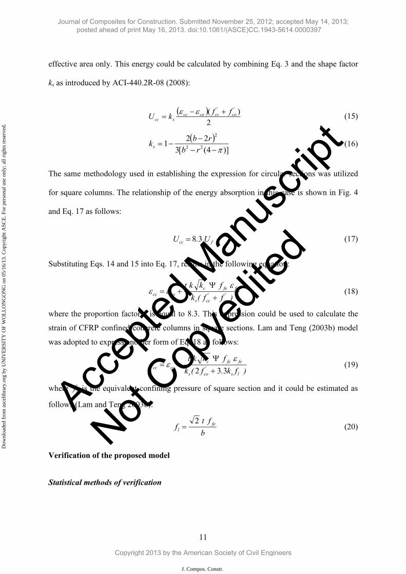
effective area only. This energy could be calculated by combining Eq. 3 and the shape factor
ks as introduced by ACI-440.2R-08 (2008):
2)( ''
cocccoccscc
ffkU (15)
)]4([322
1 22
2
rbrb
ks (16)
The same methodology used in establishing the expression for circular sections was utilized
for square columns. The relationship of the energy absorption in this case is shown in Fig. 4
and Eq. 17 as follows:
fcc U.U 38 (17)
Substituting Eqs. 14 and 15 into Eq. 17, results in the following equation:
)ff(kfkkt
'co
'ccs
fefeccocc (18)
where the proportion factor k is equal to 8.3. This expression could be used to calculate the
strain of CFRP confined concrete columns in square sections. Lam and Teng (2003b) model
was adopted to express another form of Eq. 18 as follows:
)fk.f(kfkkt
ls'
cos
fefeccocc 332
(19)
where lf is the equivalent confining pressure of square section and it could be estimated as
follows (Lam and Teng 2003b):
bft
f fel
2 (20)
Verification of the proposed model
Statistical methods of verification
Journal of Composites for Construction. Submitted November 25, 2012; accepted May 14, 2013; posted ahead of print May 16, 2013. doi:10.1061/(ASCE)CC.1943-5614.0000397
Copyright 2013 by the American Society of Civil Engineers
J. Compos. Constr.
Dow
nloa
ded
from
asc
elib
rary
.org
by
UN
IVE
RSI
TY
OF
WO
LL
ON
GO
NG
on
05/1
6/13
. Cop
yrig
ht A
SCE
. For
per
sona
l use
onl
y; a
ll ri
ghts
res
erve
d.
Accep
ted M
anus
cript
Not Cop
yedit
ed
12
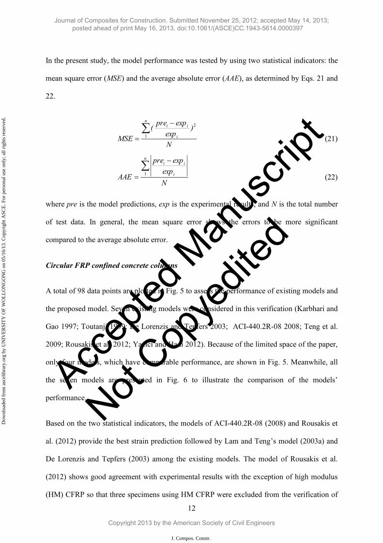
In the present study, the model performance was tested by using two statistical indicators: the
mean square error (MSE) and the average absolute error (AAE), as determined by Eqs. 21 and
22.
N
)exp
exppre(
MSE
n
i
ii
1
2
(21)
Nexp
exppre
AAE
n
i
ii
1 (22)
where pre is the model predictions, exp is the experimental results, and N is the total number
of test data. In general, the mean square error shows the errors to be more significant
compared to the average absolute error.
Circular FRP confined concrete columns
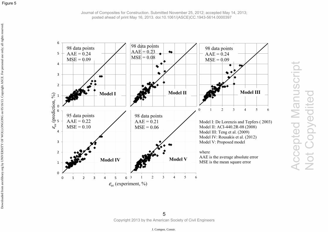
A total of 98 data points are plotted in Fig. 5 to assess the performance of existing models and
the proposed model. Seven existing models were considered in this verification (Karbhari and
Gao 1997; Toutanji 1999; De Lorenzis and Tepfers 2003; ACI-440.2R-08 2008; Teng et al.
2009; Rousakis et al. 2012; Yazici and Hadi 2012). Because of the limited space of the paper,
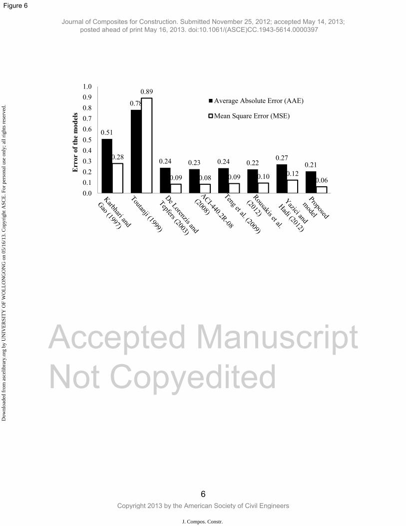
only four models, which have comparable performance, are shown in Fig. 5. Meanwhile, all
the seven models are presented in Fig. 6 to illustrate the comparison of the models’
performance.
Based on the two statistical indicators, the models of ACI-440.2R-08 (2008) and Rousakis et
al. (2012) provide the best strain prediction followed by Lam and Teng’s model (2003a) and
De Lorenzis and Tepfers (2003) among the existing models. The model of Rousakis et al.
(2012) shows good agreement with experimental results with the exception of high modulus
(HM) CFRP so that three specimens using HM CFRP were excluded from the verification of
Journal of Composites for Construction. Submitted November 25, 2012; accepted May 14, 2013; posted ahead of print May 16, 2013. doi:10.1061/(ASCE)CC.1943-5614.0000397
Copyright 2013 by the American Society of Civil Engineers
J. Compos. Constr.
Dow
nloa
ded
from
asc
elib
rary
.org
by
UN
IVE
RSI
TY
OF
WO
LL
ON
GO
NG
on
05/1
6/13
. Cop
yrig
ht A
SCE
. For
per
sona
l use
onl
y; a
ll ri
ghts
res
erve
d.
Accep
ted M
anus
cript
Not Cop
yedit
ed
13
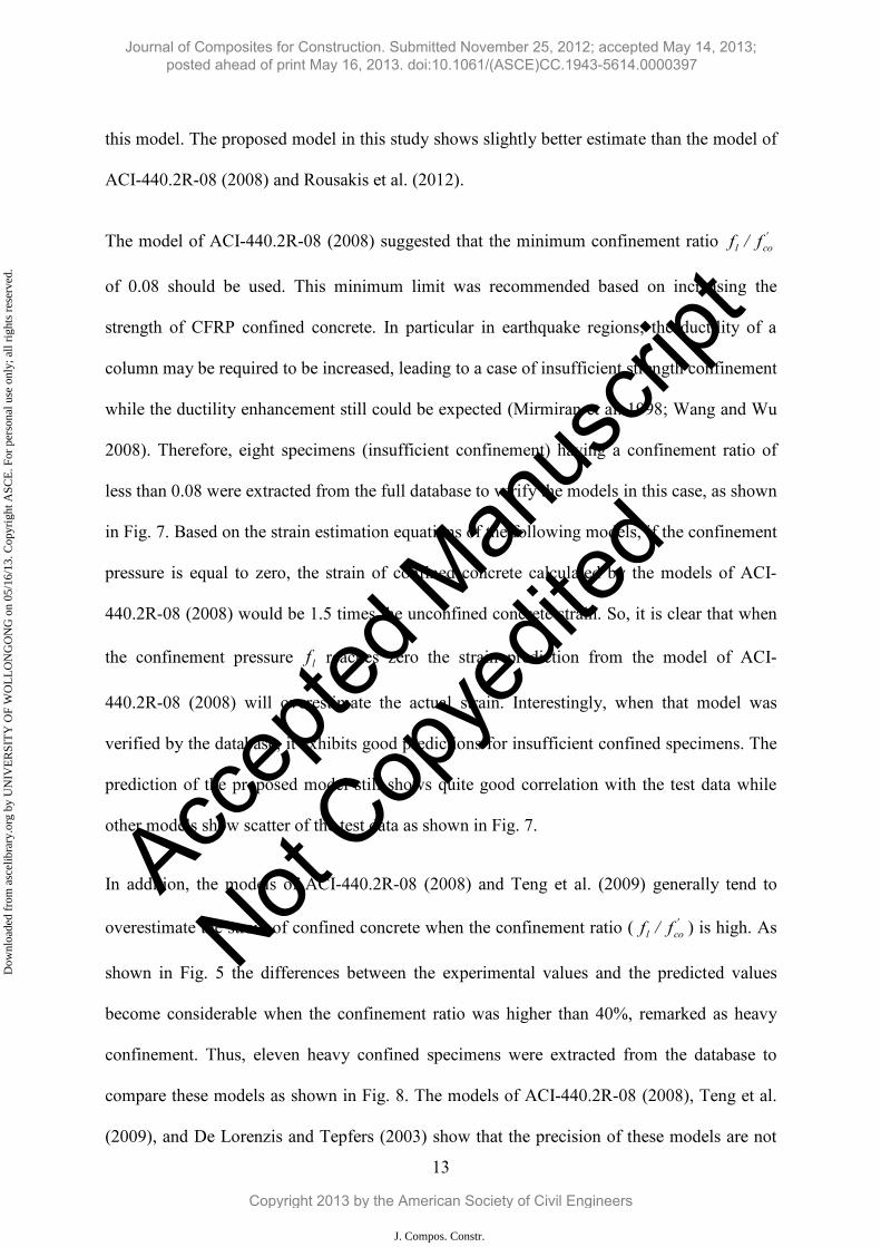
this model. The proposed model in this study shows slightly better estimate than the model of
ACI-440.2R-08 (2008) and Rousakis et al. (2012).
The model of ACI-440.2R-08 (2008) suggested that the minimum confinement ratio 'col f/f
of 0.08 should be used. This minimum limit was recommended based on increasing the
strength of CFRP confined concrete. In particular in earthquake regions, the ductility of a
column may be required to be increased, leading to a case of insufficient strength confinement
while the ductility enhancement still could be expected (Mirmiran et al. 1998; Wang and Wu
2008). Therefore, eight specimens (insufficient confinement) having a confinement ratio of
less than 0.08 were extracted from the full database to verify the models in this case, as shown
in Fig. 7. Based on the strain estimation equations of the following models, if the confinement
pressure is equal to zero, the strain of confined concrete calculated by the models of ACI-
440.2R-08 (2008) would be 1.5 times the unconfined concrete strain. So, it is clear that when
the confinement pressure lf reaches zero the strain prediction from the model of ACI-
440.2R-08 (2008) will overestimate the actual strain. Interestingly, when that model was
verified by the database, it exhibits good predictions for insufficient confined specimens. The
prediction of the proposed model still shows quite good correlation with the test data while
other models show scatter of the test data as shown in Fig. 7.
In addition, the models of ACI-440.2R-08 (2008) and Teng et al. (2009) generally tend to
overestimate the strain of confined concrete when the confinement ratio ( 'col f/f ) is high. As
shown in Fig. 5 the differences between the experimental values and the predicted values
become considerable when the confinement ratio was higher than 40%, remarked as heavy
confinement. Thus, eleven heavy confined specimens were extracted from the database to
compare these models as shown in Fig. 8. The models of ACI-440.2R-08 (2008), Teng et al.
(2009), and De Lorenzis and Tepfers (2003) show that the precision of these models are not
Journal of Composites for Construction. Submitted November 25, 2012; accepted May 14, 2013; posted ahead of print May 16, 2013. doi:10.1061/(ASCE)CC.1943-5614.0000397
Copyright 2013 by the American Society of Civil Engineers
J. Compos. Constr.
Dow
nloa
ded
from
asc
elib
rary
.org
by
UN
IVE
RSI
TY
OF
WO
LL
ON
GO
NG
on
05/1
6/13
. Cop
yrig
ht A
SCE
. For
per
sona
l use
onl
y; a
ll ri
ghts
res
erve
d.
Accep
ted M
anus
cript
Not Cop
yedit
ed
14
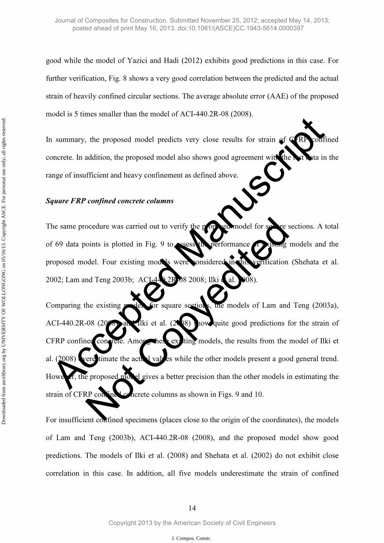
good while the model of Yazici and Hadi (2012) exhibits good predictions in this case. For
further verification, Fig. 8 shows a very good correlation between the predicted and the actual
strain of heavily confined circular sections. The average absolute error (AAE) of the proposed
model is 5 times smaller than the model of ACI-440.2R-08 (2008).
In summary, the proposed model predicts very close results for strain of CFRP confined
concrete. In addition, the proposed model also shows good agreement with the test data in the
range of insufficient and heavy confinement as defined above.
Square FRP confined concrete columns
The same procedure was carried out to verify the proposed model for square sections. A total
of 69 data points is plotted in Fig. 9 to assess the performance of existing models and the
proposed model. Four existing models were considered in this verification (Shehata et al.
2002; Lam and Teng 2003b; ACI-440.2R-08 2008; Ilki et al. 2008).
Comparing the existing models for square sections, the models of Lam and Teng (2003a),
ACI-440.2R-08 (2008), and Ilki et al. (2008) show quite good predictions for the strain of
CFRP confined concrete. Among these existing models, the results from the model of Ilki et
al. (2008) overestimate the actual values while the other models present a good general trend.
However, the proposed model gives a better precision than the other models in estimating the
strain of CFRP confined concrete columns as shown in Figs. 9 and 10.
For insufficient confined specimens (places close to the origin of the coordinates), the models
of Lam and Teng (2003b), ACI-440.2R-08 (2008), and the proposed model show good
predictions. The models of Ilki et al. (2008) and Shehata et al. (2002) do not exhibit close
correlation in this case. In addition, all five models underestimate the strain of confined
Journal of Composites for Construction. Submitted November 25, 2012; accepted May 14, 2013; posted ahead of print May 16, 2013. doi:10.1061/(ASCE)CC.1943-5614.0000397
Copyright 2013 by the American Society of Civil Engineers
J. Compos. Constr.
Dow
nloa
ded
from
asc
elib
rary
.org
by
UN
IVE
RSI
TY
OF
WO
LL
ON
GO
NG
on
05/1
6/13
. Cop
yrig
ht A
SCE
. For
per
sona
l use
onl
y; a
ll ri
ghts
res
erve
d.
Accep
ted M
anus
cript
Not Cop
yedit
ed
15
concrete when the confinement ratio is high (six data points having measured strain greater
than 3 as shown in Fig. 9).
Conclusions
From the theoretical analyses presented in this study, the following conclusions are drawn:
1. The proposed model provides very good predictions compared to the experimental
results. It also shows a good agreement with the test data in the range of insufficient and
heavy confinement, which are usually are not predicted well by other models.
2. Only a proportion of the energy absorbed by the whole column is transferred to
rupture the FRP.
3. The formula to calculate the strain of square sections is still not as good as that of
circular sections thus further study needs to be carried out in this case.
Finally, a new model is proposed in this study to calculate the strain of confined concrete
based on energy absorption method. The performance of the proposed model show very good
correlations with experimental results. However, the precision of the proposed model should
be improved when it would be calibrated with a larger reliable database in the future. This
methodology could be developed to cover reinforced concrete columns confined with FRP.
Acknowledgement
The first author would like to acknowledge the Vietnamese Government and the University of
Wollongong for the support of his full PhD scholarship. The authors thank PhD scholar Mr.
Ida Bagus Rai Widiarsa for his database. Furthermore, the constructive comments of the
editor and the reviewers are grateful appreciated.
Journal of Composites for Construction. Submitted November 25, 2012; accepted May 14, 2013; posted ahead of print May 16, 2013. doi:10.1061/(ASCE)CC.1943-5614.0000397
Copyright 2013 by the American Society of Civil Engineers
J. Compos. Constr.
Dow
nloa
ded
from
asc
elib
rary
.org
by
UN
IVE
RSI
TY
OF
WO
LL
ON
GO
NG
on
05/1
6/13
. Cop
yrig
ht A
SCE
. For
per
sona
l use
onl
y; a
ll ri
ghts
res
erve
d.
Accep
ted M
anus
cript
Not Cop
yedit
ed
16
Notations
The following symbols are used in this paper:
Acc = gross sectional area of confined concrete;
b = side length of a square section;
d = diameter of the section;
dl = increment of the displacement;
d c = increment of the axial strain;
fc = stress of concrete;
ff = rupture strength of FRP obtained from flat coupon tests;
ffe = actual rupture strength of FRP on the columns;
fl = confining pressure of the confined concrete specimen;
f’cc = confined concrete strength;
f’co = unconfined concrete strength;
k = proportion factor showing the relationship between the energy absorption of the
column core and external FRP;
kc = corner energy ratio;
l = displacement;
P = applied load;
r = radius of the round corner of the section;
t = thickness of FRP;
U = strain energy;
Ucc = volumetric strain energy of confined concrete;
Uf = volumetric strain energy of FRP;
W = work done by the applied load;
Wcc = strain energy of confined concrete;
Wf = strain energy of FRP;
c = axial strain of concrete;
cc = axial strain at peak stress of confined concrete;
co = axial strain at the peak stress of unconfined concrete;
f = rupture strain of FRP obtained from flat coupon tests;
fe = rupture strain of FRP on the columns; and
f = volumetric ratio of FRP.
Journal of Composites for Construction. Submitted November 25, 2012; accepted May 14, 2013; posted ahead of print May 16, 2013. doi:10.1061/(ASCE)CC.1943-5614.0000397
Copyright 2013 by the American Society of Civil Engineers
J. Compos. Constr.
Dow
nloa
ded
from
asc
elib
rary
.org
by
UN
IVE
RSI
TY
OF
WO
LL
ON
GO
NG
on
05/1
6/13
. Cop
yrig
ht A
SCE
. For
per
sona
l use
onl
y; a
ll ri
ghts
res
erve
d.
Accep
ted M
anus
cript
Not Cop
yedit
ed
17
References
Al-Salloum, Y.A. (2007). "Influence of edge sharpness on the strength of square concrete columns confined with FRP composite laminates." Composites Part B: Engineering, 38(5), 640-650.
American Concrete Institute (ACI). (2008). "Guide for the Design and Construction of Externally Bonded FRP Systems for Strengthening Concrete Structures." 440.2R-08, Farmington Hills, MI.
Berthet, J.F., Ferrier, E., and Hamelin, P. (2005). "Compressive behavior of concrete externally confined by composite jackets. Part A: experimental study." Construction and Building Materials, 19(3), 223-232.
Bisby, L.A., Dent, A.J.S., and Green, M.F. (2005). "Comparison of confinement models for fiber-reinforced polymer-wrapped concrete." ACI Structural Journal, 102(1), 62-72.
Carey, S.A., and Harries, K.A. (2005). "Axial Behavior and Modeling of Confined Small-, Medium-, and Large-Scale Circular Sections with Carbon Fiber-Reinforced Polymer Jackets." ACI Structural Journal, 102(4), 596-596.
Chaallal, O., Shahawy, M., and Hassan, M. (2003). "Performance of axially loaded short rectangular columns strengthened with carbon fiber-reinforced polymer wrapping." Journal of Composites for Construction, 7(3), 200-208.
Csuka, B., and Kollár, L.P. (2012). "Analysis of FRP confined columns under eccentric loading." Composite Structures, 94(3), 1106-1116.
Cusson, D., and Paultre, P. (1995). "Stress-Strain Model for Confined High-Strength Concrete." Journal of Structural Engineering, 121(3), 468-477.
De Lorenzis, L., and Tepfers, R. (2003). "Comparative Study of Models on Confinement of Concrete Cylinders with Fiber-Reinforced Polymer Composites." Journal of Composites for Construction, 7(3), 219-237.
De Lorenzis L., Micelli F. and La Tegola A. (2002). "Influence of specimen size and resin type on the behavior of FRP-confined concrete cylinders". In: Shenoi RA, Moy SSJ, Hollaway LC, editors, Advanced Polymer Composites for Structural Applications in Construction, Proceedings of the First International Conference, London, UK: Thomas Telford, 231–239.
Demers, M., and Neale, K. W. (1994). "Strengthening of concrete columns with unidirectional composite sheets". Developments in short and medium span bridge engineering, A. A. Mufti, B. Bakht, and L. G. Jaeger, eds., Canadian Society for Civil Engineering, Montreal, 895–905.
Hadi, M.N.S., Pham, T.M., and Lei, X. (2013). "New Method of Strengthening Reinforced Concrete Square Columns by Circularizing and Wrapping with Fiber-Reinforced Polymer or Steel Straps." Journal of Composites for Construction, 17(2), 229-238.
Journal of Composites for Construction. Submitted November 25, 2012; accepted May 14, 2013; posted ahead of print May 16, 2013. doi:10.1061/(ASCE)CC.1943-5614.0000397
Copyright 2013 by the American Society of Civil Engineers
J. Compos. Constr.
Dow
nloa
ded
from
asc
elib
rary
.org
by
UN
IVE
RSI
TY
OF
WO
LL
ON
GO
NG
on
05/1
6/13
. Cop
yrig
ht A
SCE
. For
per
sona
l use
onl
y; a
ll ri
ghts
res
erve
d.
Accep
ted M
anus
cript
Not Cop
yedit
ed
18
Ilki, A., and Kumbasar, N. (2003). "Compressive behaviour of carbon fibre composite jacketed concrete with circular and non-circular cross-sections." Journal of earthquake Engineering, 7(3), 381-406.
Ilki, A., Peker, O., Karamuk, E., Demir, C., and Kumbasar, N. (2008). "FRP retrofit of low and medium strength circular and rectangular reinforced concrete columns." Journal of Materials in Civil Engineering, 20(2), 169-188.
Jiang, T., and Teng, J.G. (2007). "Analysis-oriented stress-strain models for FRP-confined concrete." Engineering Structures, 29(11), 2968-2986.
Karabinis, A., Rousakis, T., and Manolitsi, G. (2008). "3D Finite-Element Analysis of Substandard RC Columns Strengthened by Fiber-Reinforced Polymer Sheets." Journal of Composites for Construction, 12(5), 531-540.
Karabinis, A.I., and Rousakis, T.C. (2002). "Concrete confined by FRP material: a plasticity approach." Engineering Structures, 24(7), 923-932.
Karbhari, V.M., and Gao, Y. (1997). "Composite Jacketed Concrete under Uniaxial Compression Verification of Simple Design Equations." Journal of Materials in Civil Engineering, 9(4), 185-193.
Lam, L., and Teng, J.G. (2003a). "Design-oriented stress-strain model for FRP-confined concrete." Construction and Building Materials, 17(6-7), 471-489.
Lam, L., and Teng, J.G. (2003b). "Design-oriented stress-strain model for FRP-confined concrete in rectangular columns." Journal of Reinforced Plastics and Composites, 22(13), 1149-1186.
Lam, L., Teng, J.G., Cheung, C.H., and Xiao, Y. (2006). "FRP-confined concrete under axial cyclic compression." Cement and Concrete Composites, 28(10), 949-958.
Lu, G., and Yu, T.X. (2003). Energy absorption of structures and materials. Boca Raton, Woodhead Publishing.
Mander, J.B., Park, R., and Priestley, M.J.N. (1988). "Theoretical Stress-Strain Model for Confined Concrete." Journal of Structural Engineering, 114(8), 1804-1826.
Masia, M.J., Gale, T.N., and Shrive, N.G. (2004). "Size effects in axially loaded square-section concrete prisms strengthened using carbon fibre reinforced polymer wrapping." Canadian Journal of Civil Engineering, 31(1), 1-1.
Matthys S., Taerwe L. and Audenaert K. (1999). "Tests on axially loaded concrete columns confined by fiber reinforced polymer sheet wrapping". In: Dolan CW, Rizkalla SH, and Nanni SH, editors, Proceedings of the Fourth International Symposium on Fiber Reinforced Polymer Reinforcement for Reinforced Concrete Structures, SP-188, Farmington, Michigan, USA: American Concrete Institute, 217–229.
Mirmiran, A., Shahawy, M., Samaan, M., Echary, H.E., Mastrapa, J.C., and Pico, O. (1998). "Effect of Column Parameters on FRP-Confined Concrete." Journal of Composites for Construction, 2(4), 175-185.
Journal of Composites for Construction. Submitted November 25, 2012; accepted May 14, 2013; posted ahead of print May 16, 2013. doi:10.1061/(ASCE)CC.1943-5614.0000397
Copyright 2013 by the American Society of Civil Engineers
J. Compos. Constr.
Dow
nloa
ded
from
asc
elib
rary
.org
by
UN
IVE
RSI
TY
OF
WO
LL
ON
GO
NG
on
05/1
6/13
. Cop
yrig
ht A
SCE
. For
per
sona
l use
onl
y; a
ll ri
ghts
res
erve
d.
Accep
ted M
anus
cript
Not Cop
yedit
ed
19
Miyauchi, K., Inoue, I., Kuroda, T., and Kobayashi, A. (1999). "Strengthening effects of concrete column with carbon fiber sheet." Transactions of the Japan Concrete Institute, 21, 143-150.
Parvin, A., and Wang, W. (2001). "Behavior of FRP Jacketed Concrete Columns under Eccentric Loading." Journal of Composites for Construction, 5(3), 146-152.
Pessiki, S., Harries, K.A., Kestner, J.T., Sause, R., and Ricles, J.M. (2001). "Axial behavior of reinforced concrete columns confined with FRP jackets." Journal of Composites for Construction, 5(4), 237-245.
Richart, F.E., Brandtzaeg, A., and Brown, R.L. (1929). "The failure of plain and spirally reinforced concrete in compression." Bulletin 1990, Univ. of Illinois Engineering Experimental Station, Champaign, III.
Rochette, P., and Labossière, P. (2000). "Axial Testing of Rectangular Column Models Confined with Composites." Journal of Composites for Construction, 4(3), 129-136.
Rousakis, T., and Karabinis, A. (2012). "Adequately FRP confined reinforced concrete columns under axial compressive monotonic or cyclic loading." Materials and Structures, 45(7), 957-975.
Rousakis, T., Rakitzis, T., and Karabinis, A. (2012). Empirical Modelling of Failure Strains of Uniformly FRP Confined Concrete Columns. The 6th International Conference on FRP Composites in Civil Engineering - CICE 2012, Rome.
Rousakis, T.C., Karabinis, A.I., and Kiousis, P.D. (2007). "FRP-confined concrete members: Axial compression experiments and plasticity modelling." Engineering Structures, 29(7), 1343-1353.
Saadatmanesh, H., Ehsani, M.R. and Li, M.W. (1994). "Strength and Ductility of Concrete Columns Externally Reinforced With Fiber-Composite Straps." ACI Structural Journal 91(4): 434-447.
Saenz, N., and Pantelides, C. (2006). "Short and Medium Term Durability Evaluation of FRP-Confined Circular Concrete." Journal of Composites for Construction, 10(3), 244-253.
Shehata, I.A.E.M., Carneiro, L.A.V., and Shehata, L.C.D. (2002). "Strength of short concrete columns confined with CFRP sheets." Materials and Structures, 35(1), 50-58.
Suter, R. and Pinzelli, R. (2001). "Confinement of concrete columns with FRP sheets". Proc., 5th Int. Symp. on Fiber-Reinforced Polymer Reinforcement for Concrete Structures (FRPRCS–5), C. Burgoyne, ed., Thomas Telford, London, 793–802.
Tao, Z., Yu, Q., and Zhong, Y.Z. (2008). "Compressive behaviour of CFRP-confined rectangular concrete columns." Magazine of Concrete Research, 60(10), 735-745.
Teng, J.G., Jiang, T., Lam, L., and Luo, Y.Z. (2009). "Refinement of a Design-Oriented Stress-Strain Model for FRP-Confined Concrete." Journal of Composites for Construction, 13(4), 269-278.
Journal of Composites for Construction. Submitted November 25, 2012; accepted May 14, 2013; posted ahead of print May 16, 2013. doi:10.1061/(ASCE)CC.1943-5614.0000397
Copyright 2013 by the American Society of Civil Engineers
J. Compos. Constr.
Dow
nloa
ded
from
asc
elib
rary
.org
by
UN
IVE
RSI
TY
OF
WO
LL
ON
GO
NG
on
05/1
6/13
. Cop
yrig
ht A
SCE
. For
per
sona
l use
onl
y; a
ll ri
ghts
res
erve
d.
Accep
ted M
anus
cript
Not Cop
yedit
ed
20
Tasdemir, M.A., Tasdemir, C., Akyüz, S., Jefferson, A.D., Lydon, F.D. And Barr, B.I.G. (1998). "Evaluation of strains at peak stresses in concrete: a three-phase composite model approach." Cement and Concrete Composites 20(4): 301-318.
Toutanji, H.A. (1999). "Stress-strain characteristics of concrete columns externally confined with advanced fiber composite sheets." ACI Materials Journal, 96(3), 397-404.
Valdmanis, V., De Lorenzis, L., Rousakis, T., and Tepfers, R. (2007). "Behaviour and capacity of CFRP-confined concrete cyliners subjected to monotonic and cyclic axial compressive load." Structural Concrete, 8(4), 187-190.
Wang, L.M., and Wu, Y.F. (2008). "Effect of corner radius on the performance of CFRP-confined square concrete columns: Test." Engineering Structures, 30(2), 493-505.
Watanabe, K., Nakamura, H., Honda, Y., Toyoshima, M., Iso, M., Fujimaki, T., Kaneto, M. and Shirai, N. (1997). "Confinement effect of FRP sheet on strength and ductility of concrete cylinders under uniaxial compression." In: Non-Metallic (FRP) Reinforcement for Concrete Structures, Proceedings of the Third International Symposium, vol. 1, Sapporo, Japan: Japan Concrete Institute, 233–240.
Wolff, C., Bastid, P., and Bunsell, A.R. (1994). "Relation of energy absorption of composite structures to material strength." Composites Engineering, 4(2), 195-218.
Wu, Y.F., and Wei, Y.Y. (2010). "Effect of cross-sectional aspect ratio on the strength of CFRP-confined rectangular concrete columns." Engineering Structures, 32(1), 32-45.
Wu, Y.F., and Zhou, Y.W. (2010). "Unified Strength Model Based on Hoek-Brown Failure Criterion for Circular and Square Concrete Columns Confined by FRP." Journal of Composites for Construction, 14(2), 175-184.
Xiao, Y., and Wu, H. (2000). "Compressive behavior of concrete confined by carbon fiber composite jackets." Journal of Materials in Civil Engineering, 12(2), 139-146.
Yazici, V., and Hadi, M.N.S. (2012). "Normalized Confinement Stiffness Approach for Modeling FRP-Confined Concrete." Journal of Composites for Construction, 16(5), 520-528.
Journal of Composites for Construction. Submitted November 25, 2012; accepted May 14, 2013; posted ahead of print May 16, 2013. doi:10.1061/(ASCE)CC.1943-5614.0000397
Copyright 2013 by the American Society of Civil Engineers
J. Compos. Constr.
Dow
nloa
ded
from
asc
elib
rary
.org
by
UN
IVE
RSI
TY
OF
WO
LL
ON
GO
NG
on
05/1
6/13
. Cop
yrig
ht A
SCE
. For
per
sona
l use
onl
y; a
ll ri
ghts
res
erve
d.
Accep
ted M
anus
cript
Not Cop
yedit
ed
21
List of Figures
Figure 1. (a) Load - displacement diagram; (b) A typical stress-strain curve of FRP confined
concrete
Figure 2. Energy relationship of circular sections
Figure 3. (a) Effective confinement area; (b) Confining pressure of square sections; (c) Round
corners of square sections
Figure 4. Energy relationship of square sections
Figure 5. Performance of models on circular specimens
Figure 6. Accuracy comparisons for strain prediction of circular specimens among the models
Figure 7. Performance of models on circular specimens (insufficient confinement)
Figure 8. Performance of models on circular specimens (heavy confinement)
Figure 9. Performance of models on square specimens
Figure 10. Accuracy comparisons for strain prediction of square specimens among the models
Journal of Composites for Construction. Submitted November 25, 2012; accepted May 14, 2013; posted ahead of print May 16, 2013. doi:10.1061/(ASCE)CC.1943-5614.0000397
Copyright 2013 by the American Society of Civil Engineers
J. Compos. Constr.
Dow
nloa
ded
from
asc
elib
rary
.org
by
UN
IVE
RSI
TY
OF
WO
LL
ON
GO
NG
on
05/1
6/13
. Cop
yrig
ht A
SCE
. For
per
sona
l use
onl
y; a
ll ri
ghts
res
erve
d.

Accep
ted M
anus
cript
Not Cop
yedit
ed
22
List of Tables
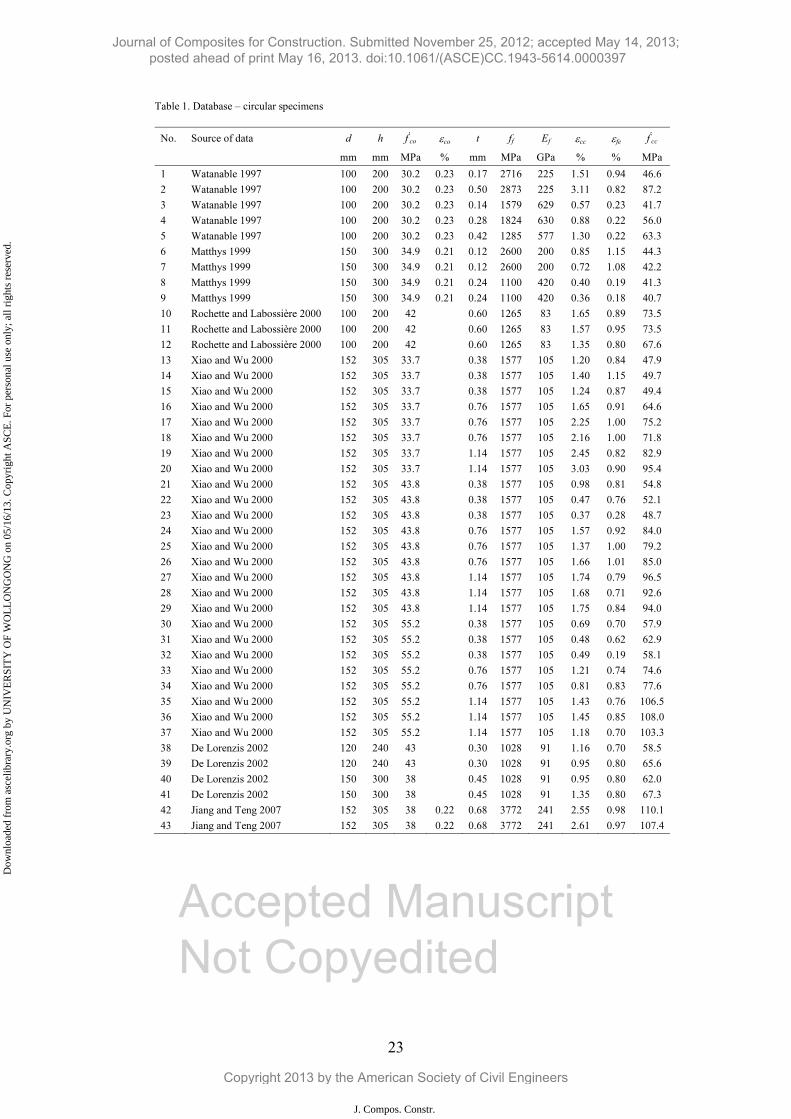
Table 1. Database of CFRP – confined circular concrete cylinders for model development
Table 2. Database of CFRP – confined square concrete columns for model development
Journal of Composites for Construction. Submitted November 25, 2012; accepted May 14, 2013; posted ahead of print May 16, 2013. doi:10.1061/(ASCE)CC.1943-5614.0000397
Copyright 2013 by the American Society of Civil Engineers
J. Compos. Constr.
Dow
nloa
ded
from
asc
elib
rary
.org
by
UN
IVE
RSI
TY
OF
WO
LL
ON
GO
NG
on
05/1
6/13
. Cop
yrig
ht A
SCE
. For
per
sona
l use
onl
y; a
ll ri
ghts
res
erve
d.
23
Table 1. Database – circular specimens
No. Source of data d h f'co co t ff Ef cc fe f'
cc
mm mm MPa % mm MPa GPa % % MPa
1 Watanable 1997 100 200 30.2 0.23 0.17 2716 225 1.51 0.94 46.6 2 Watanable 1997 100 200 30.2 0.23 0.50 2873 225 3.11 0.82 87.2 3 Watanable 1997 100 200 30.2 0.23 0.14 1579 629 0.57 0.23 41.7 4 Watanable 1997 100 200 30.2 0.23 0.28 1824 630 0.88 0.22 56.0 5 Watanable 1997 100 200 30.2 0.23 0.42 1285 577 1.30 0.22 63.3 6 Matthys 1999 150 300 34.9 0.21 0.12 2600 200 0.85 1.15 44.3 7 Matthys 1999 150 300 34.9 0.21 0.12 2600 200 0.72 1.08 42.2 8 Matthys 1999 150 300 34.9 0.21 0.24 1100 420 0.40 0.19 41.3 9 Matthys 1999 150 300 34.9 0.21 0.24 1100 420 0.36 0.18 40.7 10 Rochette and Labossière 2000 100 200 42 0.60 1265 83 1.65 0.89 73.5 11 Rochette and Labossière 2000 100 200 42 0.60 1265 83 1.57 0.95 73.5 12 Rochette and Labossière 2000 100 200 42 0.60 1265 83 1.35 0.80 67.6 13 Xiao and Wu 2000 152 305 33.7 0.38 1577 105 1.20 0.84 47.9 14 Xiao and Wu 2000 152 305 33.7 0.38 1577 105 1.40 1.15 49.7 15 Xiao and Wu 2000 152 305 33.7 0.38 1577 105 1.24 0.87 49.4 16 Xiao and Wu 2000 152 305 33.7 0.76 1577 105 1.65 0.91 64.6 17 Xiao and Wu 2000 152 305 33.7 0.76 1577 105 2.25 1.00 75.2 18 Xiao and Wu 2000 152 305 33.7 0.76 1577 105 2.16 1.00 71.8 19 Xiao and Wu 2000 152 305 33.7 1.14 1577 105 2.45 0.82 82.9 20 Xiao and Wu 2000 152 305 33.7 1.14 1577 105 3.03 0.90 95.4 21 Xiao and Wu 2000 152 305 43.8 0.38 1577 105 0.98 0.81 54.8 22 Xiao and Wu 2000 152 305 43.8 0.38 1577 105 0.47 0.76 52.1 23 Xiao and Wu 2000 152 305 43.8 0.38 1577 105 0.37 0.28 48.7 24 Xiao and Wu 2000 152 305 43.8 0.76 1577 105 1.57 0.92 84.0 25 Xiao and Wu 2000 152 305 43.8 0.76 1577 105 1.37 1.00 79.2 26 Xiao and Wu 2000 152 305 43.8 0.76 1577 105 1.66 1.01 85.0 27 Xiao and Wu 2000 152 305 43.8 1.14 1577 105 1.74 0.79 96.5 28 Xiao and Wu 2000 152 305 43.8 1.14 1577 105 1.68 0.71 92.6 29 Xiao and Wu 2000 152 305 43.8 1.14 1577 105 1.75 0.84 94.0 30 Xiao and Wu 2000 152 305 55.2 0.38 1577 105 0.69 0.70 57.9 31 Xiao and Wu 2000 152 305 55.2 0.38 1577 105 0.48 0.62 62.9 32 Xiao and Wu 2000 152 305 55.2 0.38 1577 105 0.49 0.19 58.1 33 Xiao and Wu 2000 152 305 55.2 0.76 1577 105 1.21 0.74 74.6 34 Xiao and Wu 2000 152 305 55.2 0.76 1577 105 0.81 0.83 77.6 35 Xiao and Wu 2000 152 305 55.2 1.14 1577 105 1.43 0.76 106.5 36 Xiao and Wu 2000 152 305 55.2 1.14 1577 105 1.45 0.85 108.0 37 Xiao and Wu 2000 152 305 55.2 1.14 1577 105 1.18 0.70 103.3 38 De Lorenzis 2002 120 240 43 0.30 1028 91 1.16 0.70 58.5 39 De Lorenzis 2002 120 240 43 0.30 1028 91 0.95 0.80 65.6 40 De Lorenzis 2002 150 300 38 0.45 1028 91 0.95 0.80 62.0 41 De Lorenzis 2002 150 300 38 0.45 1028 91 1.35 0.80 67.3 42 Jiang and Teng 2007 152 305 38 0.22 0.68 3772 241 2.55 0.98 110.1 43 Jiang and Teng 2007 152 305 38 0.22 0.68 3772 241 2.61 0.97 107.4
Accepted Manuscript Not Copyedited
Journal of Composites for Construction. Submitted November 25, 2012; accepted May 14, 2013; posted ahead of print May 16, 2013. doi:10.1061/(ASCE)CC.1943-5614.0000397
Copyright 2013 by the American Society of Civil Engineers
J. Compos. Constr.
Dow
nloa
ded
from
asc
elib
rary
.org
by
UN
IVE
RSI
TY
OF
WO
LL
ON
GO
NG
on
05/1
6/13
. Cop
yrig
ht A
SCE
. For
per
sona
l use
onl
y; a
ll ri
ghts
res
erve
d.
24
No. Source of data d h f'co co t ff Ef cc fe f'
cc
mm mm MPa % mm MPa GPa % % MPa
44 Jiang and Teng 2007 152 305 38 0.22 1.02 3772 241 2.79 0.89 129.0 45 Jiang and Teng 2007 152 305 38 0.22 1.02 3772 241 3.08 0.93 135.7 46 Jiang and Teng 2007 152 305 38 0.22 1.36 3772 241 3.70 0.87 161.3 47 Jiang and Teng 2007 152 305 38 0.22 1.36 3772 241 3.54 0.88 158.5 48 Jiang and Teng 2007 152 305 37.7 0.28 0.11 4332 260 0.90 0.94 48.5 49 Jiang and Teng 2007 152 305 37.7 0.28 0.11 4332 260 0.91 1.09 50.3 50 Jiang and Teng 2007 152 305 42.2 0.26 0.11 4332 260 0.69 0.73 48.1 51 Jiang and Teng 2007 152 305 42.2 0.26 0.11 4332 260 0.89 0.97 51.1 52 Jiang and Teng 2007 152 305 42.2 0.26 0.22 4332 260 1.30 1.18 65.7 53 Jiang and Teng 2007 152 305 42.2 0.26 0.22 4332 260 1.03 0.94 62.9 54 Jiang and Teng 2007 152 305 47.6 0.28 0.33 4332 251 1.30 0.90 82.7 55 Jiang and Teng 2007 152 305 47.6 0.28 0.33 4332 251 1.94 1.13 85.5 56 Jiang and Teng 2007 152 305 47.6 0.28 0.33 4332 251 1.82 1.06 85.5 57 Lam et al. 2006 152 304 41.1 0.26 0.17 3795 251 0.90 0.81 52.6 58 Lam et al. 2006 152.5 305 41.1 0.26 0.17 3795 251 1.21 1.08 57.0 59 Lam et al. 2006 152.5 305 41.1 0.26 0.17 3795 251 1.11 1.07 55.4 60 Lam et al. 2006 152.5 305 38.9 0.25 0.33 3795 251 1.91 1.06 76.8 61 Lam et al. 2006 152.5 305 38.9 0.25 0.33 3795 251 2.08 1.13 79.1 62 Saenz and Pantelides 2006 152 304 41.8 0.60 1220 87 1.18 0.92 83.7 63 Saenz and Pantelides 2006 152 304 47.5 0.60 1220 87 0.88 0.93 81.5 64 Saenz and Pantelides 2006 152 304 40.3 1.20 1220 87 2.04 0.92 108.1 65 Saenz and Pantelides 2006 152 304 41.7 1.20 1220 87 1.76 1.08 109.5 66 Valdmanis et al 2007 150 300 40 0.17 0.17 1906 201 0.63 0.89 66.0 67 Valdmanis et al 2007 150 300 40 0.17 0.34 2389 231 1.07 0.84 87.2 68 Valdmanis et al 2007 150 300 40 0.17 0.51 2661 236 1.36 0.69 96.0 69 Valdmanis et al 2007 150 300 44.3 0.17 0.17 1906 201 0.58 0.74 73.3 70 Valdmanis et al 2007 150 300 44.3 0.17 0.34 2389 231 0.54 0.43 82.6 71 Valdmanis et al 2007 150 300 44.3 0.17 0.51 2661 236 0.94 0.78 115.1
72 Berthet et al. 2005 160 320 25 0.23 0.17 3200 230 1.63 0.96 42.8 73 Berthet et al. 2005 160 320 25 0.23 0.17 3200 230 0.93 0.96 37.8 74 Berthet et al. 2005 160 320 25 0.23 0.17 3200 230 1.67 0.96 45.8 75 Berthet et al. 2005 160 320 25 0.23 0.33 3200 230 1.73 0.90 56.7 76 Berthet et al. 2005 160 320 25 0.23 0.33 3200 230 1.58 0.91 55.2 77 Berthet et al. 2005 160 320 25 0.23 0.33 3200 230 1.68 0.91 56.1 78 Berthet et al. 2005 160 320 40.1 0.2 0.11 3200 230 0.55 1.02 49.8 79 Berthet et al. 2005 160 320 40.1 0.2 0.11 3200 230 0.66 0.95 50.8 80 Berthet et al. 2005 160 320 40.1 0.2 0.11 3200 230 0.61 1.20 48.8 81 Berthet et al. 2005 160 320 40.1 0.2 0.17 3200 230 0.66 0.88 53.7 82 Berthet et al. 2005 160 320 40.1 0.2 0.17 3200 230 0.62 0.85 54.7 83 Berthet et al. 2005 160 320 40.1 0.2 0.17 3200 230 0.64 1.04 51.8 84 Berthet et al. 2005 160 320 40.1 0.2 0.22 3200 230 0.60 0.79 59.7 85 Berthet et al. 2005 160 320 40.1 0.2 0.22 3200 230 0.69 0.83 60.7 86 Berthet et al. 2005 160 320 40.1 0.2 0.22 3200 230 0.73 0.81 60.2 87 Berthet et al. 2005 160 320 40.1 0.2 0.44 3200 230 1.44 0.92 91.6
Table 1 cont.
Accepted Manuscript Not Copyedited
Journal of Composites for Construction. Submitted November 25, 2012; accepted May 14, 2013; posted ahead of print May 16, 2013. doi:10.1061/(ASCE)CC.1943-5614.0000397
Copyright 2013 by the American Society of Civil Engineers
J. Compos. Constr.
Dow
nloa
ded
from
asc
elib
rary
.org
by
UN
IVE
RSI
TY
OF
WO
LL
ON
GO
NG
on
05/1
6/13
. Cop
yrig
ht A
SCE
. For
per
sona
l use
onl
y; a
ll ri
ghts
res
erve
d.
25
No. Source of data d h f'co co t ff Ef cc fe f'
cc
mm mm MPa % mm MPa GPa % % MPa
88 Berthet et al. 2005 160 320 40.1 0.20 0.44 3200 230 1.36 0.97 89.6 89 Berthet et al. 2005 160 320 40.1 0.20 0.44 3200 230 1.17 0.89 86.6 90 Berthet et al. 2005 160 320 40.1 0.20 0.99 3200 230 2.46 0.99 142.4 91 Berthet et al. 2005 160 320 40.1 0.20 0.99 3200 230 2.39 1.00 140.4 92 Berthet et al. 2005 160 320 40.1 0.20 1.32 3200 230 2.70 1.00 166.3 93 Berthet et al. 2005 160 320 52 0.23 0.33 3200 230 0.83 0.93 82.6 94 Berthet et al. 2005 160 320 52 0.23 0.33 3200 230 0.70 0.87 82.8 95 Berthet et al. 2005 160 320 52 0.23 0.33 3200 230 0.77 0.89 82.3 96 Berthet et al. 2005 160 320 52 0.23 0.66 3200 230 1.14 0.67 108.1 97 Berthet et al. 2005 160 320 52 0.23 0.66 3200 230 1.12 0.87 112 98 Berthet et al. 2005 160 320 52 0.23 0.66 3200 230 1.12 0.882 107.9
Table 1 cont.
Accepted Manuscript Not Copyedited
Journal of Composites for Construction. Submitted November 25, 2012; accepted May 14, 2013; posted ahead of print May 16, 2013. doi:10.1061/(ASCE)CC.1943-5614.0000397
Copyright 2013 by the American Society of Civil Engineers
J. Compos. Constr.
Dow
nloa
ded
from
asc
elib
rary
.org
by
UN
IVE
RSI
TY
OF
WO
LL
ON
GO
NG
on
05/1
6/13
. Cop
yrig
ht A
SCE
. For
per
sona
l use
onl
y; a
ll ri
ghts
res
erve
d.
26
Table 2. Database – square specimens
No. Source of data b h r f'co t ff Ef cc fe f'
cc
mm mm mm MPa mm MPa GPa % % MPa
1 Rochette & Labossière 2000 152 500 25 42 0.90 1265 83 0.94 0.56 50.9
2 Rochette & Labossière 2000 152 500 25 42 0.90 1265 83 0.89 0.63 52.0
3 Rochette & Labossière 2000 152 500 38 42 0.90 1265 83 1.08 0.71 55.4
4 Rochette & Labossière 2000 152 500 25 44 1.20 1265 83 1.35 0.59 56.4
5 Rochette & Labossière 2000 152 500 25 36 1.20 1265 83 2.04 0.70 50.6
6 Rochette & Labossière 2000 152 500 25 36 1.50 1265 83 2.12 0.65 52.9
7 Rochette & Labossière 2000 152 500 38 36 1.20 1265 83 1.92 0.89 58.1
8 Rochette & Labossière 2000 152 500 38 36 1.50 1265 83 2.39 0.86 62.8
9 Lam and Teng 2003b 150 600 25 34 0.17 1577 105 0.96 1.05 37.6
10 Lam and Teng 2003b 150 600 15 34 0.33 1577 105 0.87 0.97 39.7
11 Lam and Teng 2003b 150 600 25 34 0.33 1577 105 0.85 1.08 41.8
12 Lam and Teng 2003b 150 600 15 24 0.50 1577 105 1.80 0.87 32.0
13 Lam and Teng 2003b 150 600 25 24 0.50 1577 105 1.52 1.16 37.1
14 Pessiki et al. 2001 152 610 38 26 1.00 580 38 1.50 0.83 34.4
15 Pessiki et al. 2001 152 610 38 26 2.00 580 38 1.90 0.90 43.7
16 Chaallal et al. 2003 133 305 25 21 0.12 3650 231 0.40 0.40 23.6
17 Chaallal et al. 2003 133 305 25 21 0.24 3650 231 0.40 0.50 27.8
18 Chaallal et al. 2003 133 305 25 21 0.36 3650 231 0.60 0.52 31.8
19 Chaallal et al. 2003 133 305 25 21 0.48 3650 231 0.70 0.53 35.8
20 Chaallal et al. 2003 133 305 25 41 0.12 3650 231 0.30 0.08 42.0
21 Chaallal et al. 2003 133 305 25 41 0.24 3650 231 0.30 0.11 43.0
22 Chaallal et al. 2003 133 305 25 41 0.36 3650 231 0.40 0.15 44.6
23 Chaallal et al. 2003 133 305 25 41 0.48 3650 231 0.40 0.20 47.1
24 Wang and Wu 2008 150 300 15 33 0.33 4364 219 1.22 - 46.9
25 Wang and Wu 2008 150 300 15 32 0.33 4364 219 1.22 - 46.2
26 Wang and Wu 2008 150 300 15 31 0.33 4364 219 1.22 - 44.7
27 Wang and Wu 2008 150 300 30 33 0.17 4364 219 1.34 - 41.9
28 Wang and Wu 2008 150 300 30 31 0.17 4364 219 1.34 - 40.4
29 Wang and Wu 2008 150 300 30 33 0.17 4364 219 1.34 - 42.4
30 Wang and Wu 2008 150 300 30 33 0.33 4364 219 1.44 - 51.1
31 Wang and Wu 2008 150 300 30 31 0.33 4364 219 1.44 - 49.6
32 Wang and Wu 2008 150 300 30 33 0.33 4364 219 1.44 - 51.6
33 Wang and Wu 2008 150 300 45 30 0.17 4364 219 1.39 - 41.0
34 Wang and Wu 2008 150 300 45 33 0.17 4364 219 1.39 - 43.5
35 Wang and Wu 2008 150 300 45 29 0.17 4364 219 1.39 - 40.2
36 Wang and Wu 2008 150 300 45 30 0.33 4364 219 1.57 - 51.9 37 Wang and Wu 2008 150 300 45 33 0.33 4364 219 1.57 - 54.4
Accepted Manuscript Not Copyedited
Journal of Composites for Construction. Submitted November 25, 2012; accepted May 14, 2013; posted ahead of print May 16, 2013. doi:10.1061/(ASCE)CC.1943-5614.0000397
Copyright 2013 by the American Society of Civil Engineers
J. Compos. Constr.
Dow
nloa
ded
from
asc
elib
rary
.org
by
UN
IVE
RSI
TY
OF
WO
LL
ON
GO
NG
on
05/1
6/13
. Cop
yrig
ht A
SCE
. For
per
sona
l use
onl
y; a
ll ri
ghts
res
erve
d.
27
No. Source of data b h r f'co t ff Ef cc fe f'
cc
mm mm mm MPa mm MPa GPa % % MPa
38 Wang and Wu 2008 150 300 45 29 0.33 4364 219 1.57 - 51.1
39 Wang and Wu 2008 150 300 60 31 0.17 4364 219 1.65 - 42.8
40 Wang and Wu 2008 150 300 60 31 0.17 4364 219 1.65 - 43.0
41 Wang and Wu 2008 150 300 60 34 0.17 4364 219 1.65 - 45.4
42 Wang and Wu 2008 150 300 60 31 0.33 4364 219 1.76 - 54.8
43 Wang and Wu 2008 150 300 60 31 0.33 4364 219 1.76 - 55.0
44 Wang and Wu 2008 150 300 60 34 0.33 4364 219 1.76 - 57.4
45 Wang and Wu 2008 150 300 30 54 0.33 3788 226 1.37 - 69.6
46 Wang and Wu 2008 150 300 30 53 0.33 3788 226 1.37 - 69.2
47 Wang and Wu 2008 150 300 30 49 0.33 3788 226 1.37 - 65.5
48 Wang and Wu 2008 150 300 45 53 0.17 3788 226 1.51 - 62.7
49 Wang and Wu 2008 150 300 45 52 0.17 3788 226 1.51 - 61.0
50 Wang and Wu 2008 150 300 45 53 0.17 3788 226 1.51 - 62.8
51 Wang and Wu 2008 150 300 45 53 0.33 3788 226 1.65 - 72.1
52 Wang and Wu 2008 150 300 45 52 0.33 3788 226 1.65 - 70.4
53 Wang and Wu 2008 150 300 45 53 0.33 3788 226 1.65 - 72.2
54 Wang and Wu 2008 150 300 60 54 0.17 3788 226 1.28 - 64.3
55 Wang and Wu 2008 150 300 60 52 0.17 3788 226 1.28 - 62.4
56 Wang and Wu 2008 150 300 60 52 0.17 3788 226 1.28 - 62.7
57 Wang and Wu 2008 150 300 60 54 0.33 3788 226 1.37 - 74.6
58 Wang and Wu 2008 150 300 60 52 0.33 3788 226 1.37 - 72.7
59 Wang and Wu 2008 150 300 60 52 0.33 3788 226 1.37 - 73.0
60 Tao et al. 2008 150 450 20 22 0.17 4470 239 2.53 - 30.3
61 Tao et al. 2008 150 450 20 22 0.34 4470 239 3.95 - 38.5
62 Tao et al. 2008 150 450 20 20 0.34 4470 239 3.34 - 36.0
63 Tao et al. 2008 150 450 35 22 0.34 4470 239 3.66 - 42.8
64 Tao et al. 2008 150 450 35 20 0.34 4470 239 3.48 - 40.3
65 Tao et al. 2008 150 450 50 22 0.34 4470 239 3.87 - 45.9
66 Tao et al. 2008 150 450 50 20 0.34 4470 239 3.43 - 43.4
67 Tao et al. 2008 150 450 20 50 0.34 4200 241 1.66 - 65.0
68 Tao et al. 2008 150 450 35 50 0.34 4200 241 2.08 - 69.1
69 Tao et al. 2008 150 450 50 50 0.34 4200 241 1.65 - 71.9
Table 2 cont.
Accepted Manuscript Not Copyedited
Journal of Composites for Construction. Submitted November 25, 2012; accepted May 14, 2013; posted ahead of print May 16, 2013. doi:10.1061/(ASCE)CC.1943-5614.0000397
Copyright 2013 by the American Society of Civil Engineers
J. Compos. Constr.
Dow
nloa
ded
from
asc
elib
rary
.org
by
UN
IVE
RSI
TY
OF
WO
LL
ON
GO
NG
on
05/1
6/13
. Cop
yrig
ht A
SCE
. For
per
sona
l use
onl
y; a
ll ri
ghts
res
erve
d.
y = 7.5823x + 0.0462R² = 0.9118
0
0.5
1
1.5
2
2.5
3
3.5
0 0.05 0.1 0.15 0.2 0.25 0.3 0.35 0.4
Ener
gy a
bsor
bed
by th
e co
lum
n Ucc
(MJ/
m3 )
Energy absorbed by CFRP Uf (MJ/m3)
2
Accepted Manuscript Not Copyedited
Journal of Composites for Construction. Submitted November 25, 2012; accepted May 14, 2013; posted ahead of print May 16, 2013. doi:10.1061/(ASCE)CC.1943-5614.0000397
Copyright 2013 by the American Society of Civil Engineers
J. Compos. Constr.
Dow
nloa
ded
from
asc
elib
rary
.org
by
UN
IVE
RSI
TY
OF
WO
LL
ON
GO
NG
on
05/1
6/13
. Cop
yrig
ht A
SCE
. For
per
sona
l use
onl
y; a
ll ri
ghts
res
erve
d.
3
Accepted Manuscript Not Copyedited
Journal of Composites for Construction. Submitted November 25, 2012; accepted May 14, 2013; posted ahead of print May 16, 2013. doi:10.1061/(ASCE)CC.1943-5614.0000397
Copyright 2013 by the American Society of Civil Engineers
J. Compos. Constr.
Dow
nloa
ded
from
asc
elib
rary
.org
by
UN
IVE
RSI
TY
OF
WO
LL
ON
GO
NG
on
05/1
6/13
. Cop
yrig
ht A
SCE
. For
per
sona
l use
onl
y; a
ll ri
ghts
res
erve
d.
y = 8.2942x + 0.0481R² = 0.7313
0
0.1
0.2
0.3
0.4
0.5
0.6
0.7
0.8
0.9
1
0.00 0.02 0.04 0.06 0.08 0.10 0.12
Ener
gy a
bsor
bed
by th
e co
lum
n Ucc
(MJ/m
3 )
Energy absorbed by CFRP Uf (MJ/m3)
Accepted Manuscript Not Copyedited
Journal of Composites for Construction. Submitted November 25, 2012; accepted May 14, 2013; posted ahead of print May 16, 2013. doi:10.1061/(ASCE)CC.1943-5614.0000397
Copyright 2013 by the American Society of Civil Engineers
J. Compos. Constr.
Dow
nloa
ded
from
asc
elib
rary
.org
by
UN
IVE
RSI
TY
OF
WO
LL
ON
GO
NG
on
05/1
6/13
. Cop
yrig
ht A
SCE
. For
per
sona
l use
onl
y; a
ll ri
ghts
res
erve
d.
0
1
2
3
4
5
6
0 1 2 3 4 5 6
98 data pointsAAE = 0.21 MSE = 0.06
Model V
Model I: De Lorenzis and Tepfers ( 2003) Model II: ACI-440.2R-08 (2008)Model III: Teng et al. (2009)Model IV: Rousakis et al. (2012) Model V: Proposed model
where AAE is the average absolute error MSE is the mean square error
0
1
2
3
4
5
6
0 1 2 3 4 5 6
95 data pointsAAE = 0.22 MSE = 0.10
Model IV
εcc (experiment, %)
0 1 2 3 4 5 6
98 data pointsAAE = 0.24 MSE = 0.09
98 data pointsAAE = 0.23 MSE = 0.08
0
1
2
3
4
5
698 data pointsAAE = 0.24 MSE = 0.09
ε cc
(pre
dict
ion,
%) Model IIIModel IIModel I
5
Acc
epte
d M
anus
crip
t N
ot C
opye
dite
d
Journal of Composites for Construction. Submitted November 25, 2012; accepted May 14, 2013; posted ahead of print May 16, 2013. doi:10.1061/(ASCE)CC.1943-5614.0000397
Copyright 2013 by the American Society of Civil Engineers
J. Compos. Constr.
Dow
nloa
ded
from
asc
elib
rary
.org
by
UN
IVE
RSI
TY
OF
WO
LL
ON
GO
NG
on
05/1
6/13
. Cop
yrig
ht A
SCE
. For
per
sona
l use
onl
y; a
ll ri
ghts
res
erve
d.
0.51
0.78
0.24 0.23 0.24 0.220.27
0.210.28
0.89
0.09 0.08 0.09 0.10 0.120.06
0.00.10.20.30.40.50.60.70.80.91.0
Average Absolute Error (AAE)
Mean Square Error (MSE)
Err
or o
f the
mod
els
6
Accepted Manuscript Not Copyedited
Journal of Composites for Construction. Submitted November 25, 2012; accepted May 14, 2013; posted ahead of print May 16, 2013. doi:10.1061/(ASCE)CC.1943-5614.0000397
Copyright 2013 by the American Society of Civil Engineers
J. Compos. Constr.
Dow
nloa
ded
from
asc
elib
rary
.org
by
UN
IVE
RSI
TY
OF
WO
LL
ON
GO
NG
on
05/1
6/13
. Cop
yrig
ht A
SCE
. For
per
sona
l use
onl
y; a
ll ri
ghts
res
erve
d.
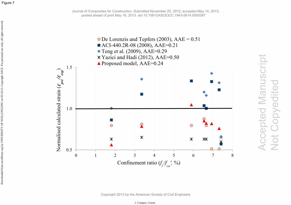
0.5
1.0
1.5
0 1 2 3 4 5 6 7 8
Nor
mal
ised
cal
cula
ted
stra
in (εpre/εexp)
Confinement ratio (fl/f
co', %)
De Lorenzis and Tepfers (2003), AAE = 0.51ACI-440.2R-08 (2008), AAE=0.21Teng et al. (2009), AAE=0.29Yazici and Hadi (2012), AAE=0.50Proposed model, AAE=0.24
Acc
epte
d M
anus
crip
t N
ot C
opye
dite
d
Journal of Composites for Construction. Submitted November 25, 2012; accepted May 14, 2013; posted ahead of print May 16, 2013. doi:10.1061/(ASCE)CC.1943-5614.0000397
Copyright 2013 by the American Society of Civil Engineers
J. Compos. Constr.
Dow
nloa
ded
from
asc
elib
rary
.org
by
UN
IVE
RSI
TY
OF
WO
LL
ON
GO
NG
on
05/1
6/13
. Cop
yrig
ht A
SCE
. For
per
sona
l use
onl
y; a
ll ri
ghts
res
erve
d.
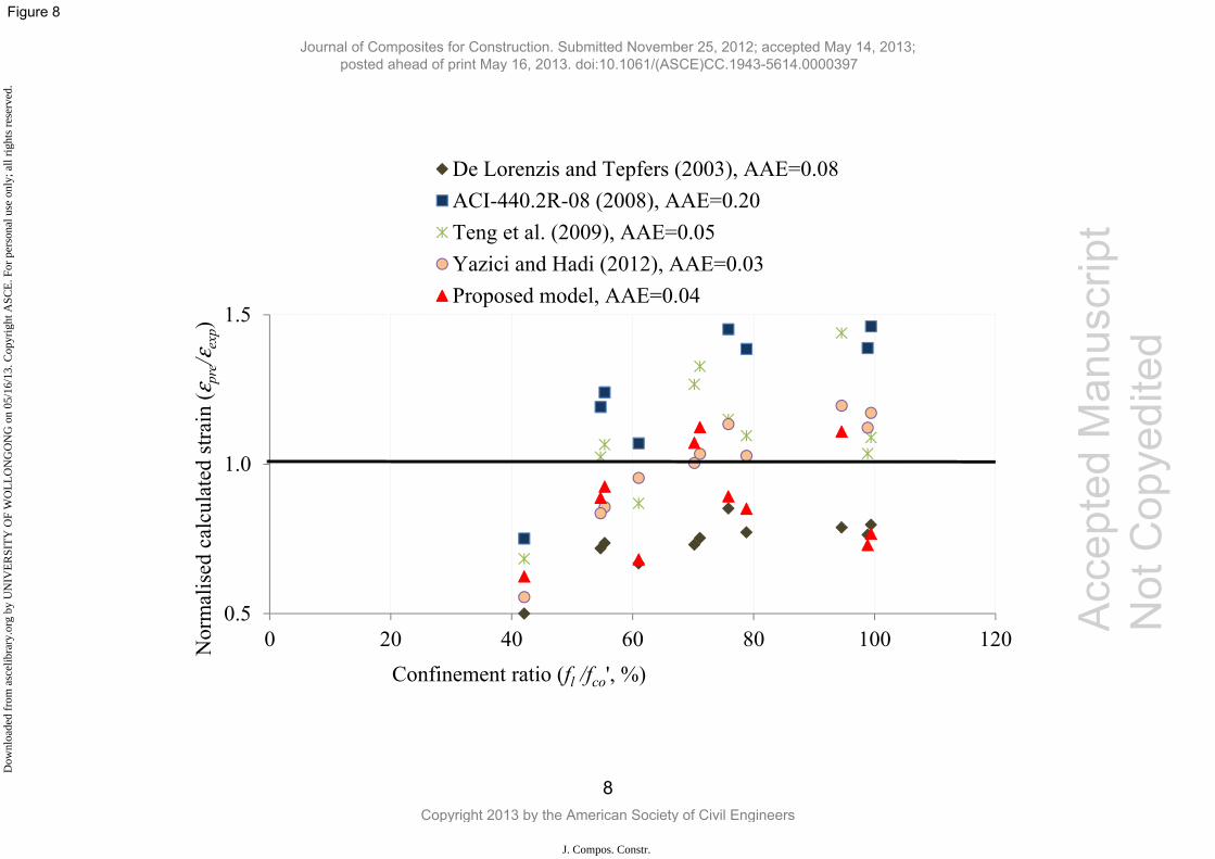
0.5
1.0
1.5
0 20 40 60 80 100 120Nor
mal
ised
cal
cula
ted
stra
in (ε
pre/ε
exp)
Confinement ratio (fl /fco', %)
De Lorenzis and Tepfers (2003), AAE=0.08ACI-440.2R-08 (2008), AAE=0.20Teng et al. (2009), AAE=0.05Yazici and Hadi (2012), AAE=0.03Proposed model, AAE=0.04
8
Acc
epte
d M
anus
crip
t N
ot C
opye
dite
d
Journal of Composites for Construction. Submitted November 25, 2012; accepted May 14, 2013; posted ahead of print May 16, 2013. doi:10.1061/(ASCE)CC.1943-5614.0000397
Copyright 2013 by the American Society of Civil Engineers
J. Compos. Constr.
Dow
nloa
ded
from
asc
elib
rary
.org
by
UN
IVE
RSI
TY
OF
WO
LL
ON
GO
NG
on
05/1
6/13
. Cop
yrig
ht A
SCE
. For
per
sona
l use
onl
y; a
ll ri
ghts
res
erve
d.
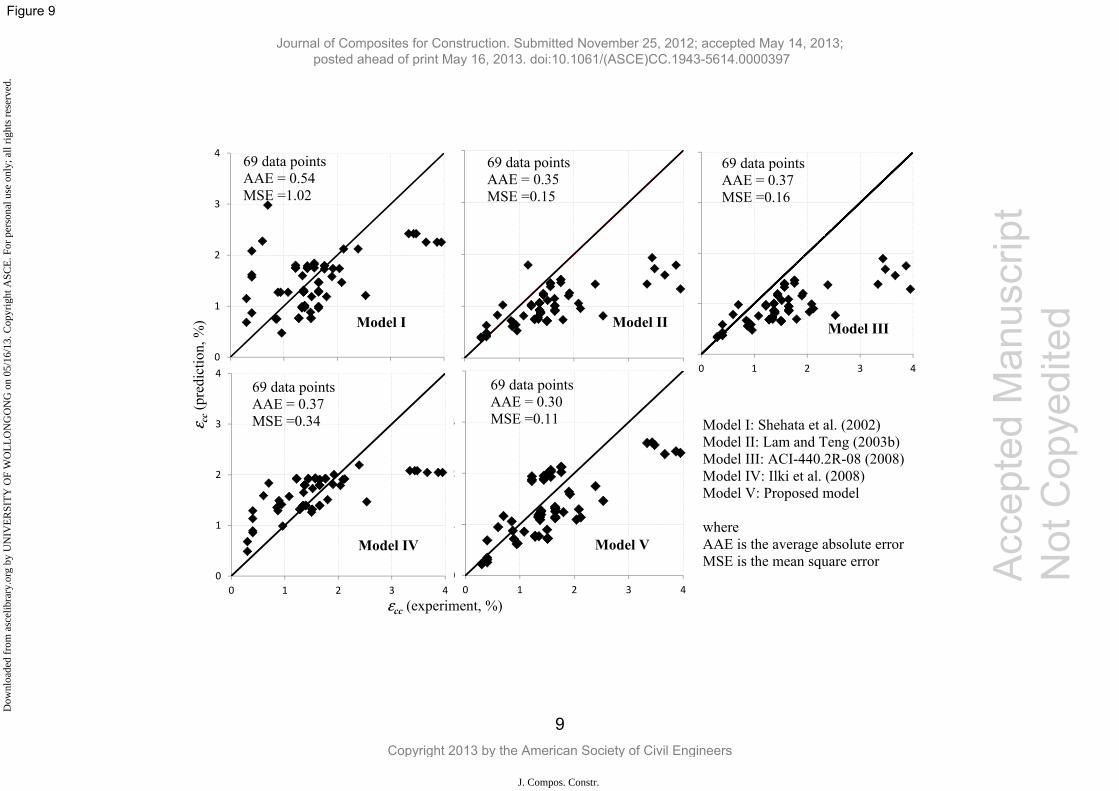
0
1
2
3
4
0 1 2 3 4
69 data pointsAAE = 0.37 MSE =0.16
Model III
0
1
2
3
4
0 1 2 3 4
69 data pointsAAE = 0.35 MSE =0.15
Model II
0
1
2
3
4
0 1 2 3 4
69 data pointsAAE = 0.30 MSE =0.11
Model V
0
1
2
3
4
0 1 2 3 4
69 data pointsAAE = 0.54 MSE =1.02
Model I
Model I: Shehata et al. (2002) Model II: Lam and Teng (2003b) Model III: ACI-440.2R-08 (2008) Model IV: Ilki et al. (2008) Model V: Proposed model
where AAE is the average absolute error MSE is the mean square error
0
1
2
3
4
0 1 2 3 4
69 data pointsAAE = 0.37 MSE =0.34
Model IV
εcc (experiment, %)
ε cc
(pre
dict
ion,
%)
9
Acc
epte
d M
anus
crip
t N
ot C
opye
dite
d
Journal of Composites for Construction. Submitted November 25, 2012; accepted May 14, 2013; posted ahead of print May 16, 2013. doi:10.1061/(ASCE)CC.1943-5614.0000397
Copyright 2013 by the American Society of Civil Engineers
J. Compos. Constr.
Dow
nloa
ded
from
asc
elib
rary
.org
by
UN
IVE
RSI
TY
OF
WO
LL
ON
GO
NG
on
05/1
6/13
. Cop
yrig
ht A
SCE
. For
per
sona
l use
onl
y; a
ll ri
ghts
res
erve
d.
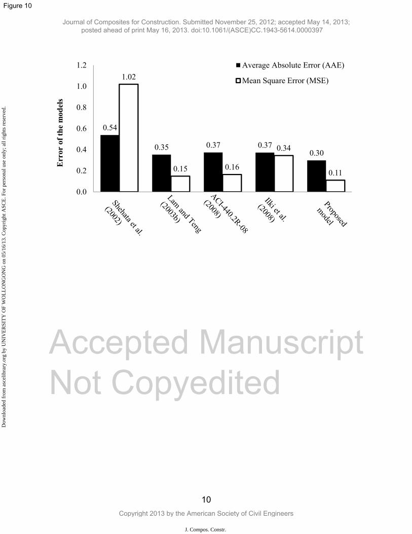
0.54
0.35 0.37 0.370.30
1.02
0.15 0.16
0.34
0.11
0.0
0.2
0.4
0.6
0.8
1.0
1.2 Average Absolute Error (AAE)
Mean Square Error (MSE)
Err
or o
f the
mod
els
10
Accepted Manuscript Not Copyedited
Journal of Composites for Construction. Submitted November 25, 2012; accepted May 14, 2013; posted ahead of print May 16, 2013. doi:10.1061/(ASCE)CC.1943-5614.0000397
Copyright 2013 by the American Society of Civil Engineers
J. Compos. Constr.
Dow
nloa
ded
from
asc
elib
rary
.org
by
UN
IVE
RSI
TY
OF
WO
LL
ON
GO
NG
on
05/1
6/13
. Cop
yrig
ht A
SCE
. For
per
sona
l use
onl
y; a
ll ri
ghts
res
erve
d.
Related Documents