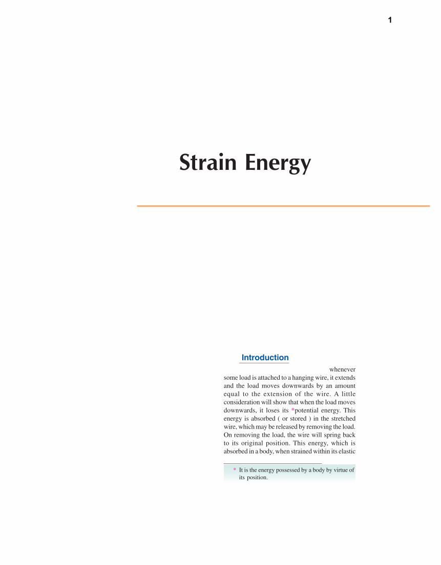
Strain Energy and Impact Loading 8.1. Introduction We have studied in Chapter 2 that whenever some load is attached to a hanging wire, it extends and the load moves downwards by an amount equal to the extension of the wire. A little consideration will show that when the load moves downwards, it loses its *potential energy. This energy is absorbed ( or stored ) in the stretched wire, which may be released by removing the load. On removing the load, the wire will spring back to its original position. This energy, which is absorbed in a body, when strained within its elastic * It is the energy possessed by a body by virtue of its position. 8 Chapter 1

Welcome message from author
This document is posted to help you gain knowledge. Please leave a comment to let me know what you think about it! Share it to your friends and learn new things together.
Transcript
Strain Energy and
Impact Loading
8.1. IntroductionWe have studied in Chapter 2 that whenever
some load is attached to a hanging wire, it extendsand the load moves downwards by an amountequal to the extension of the wire. A littleconsideration will show that when the load movesdownwards, it loses its *potential energy. Thisenergy is absorbed ( or stored ) in the stretchedwire, which may be released by removing the load.On removing the load, the wire will spring backto its original position. This energy, which isabsorbed in a body, when strained within its elastic
* It is the energy possessed by a body by virtue ofits position.
8C h a p t e r
1
Atif
Typewritten Text
Unit-III
Atif
Typewritten Text
Atif
Typewritten Text
Atif
Typewritten Text
Atif
Typewritten Text
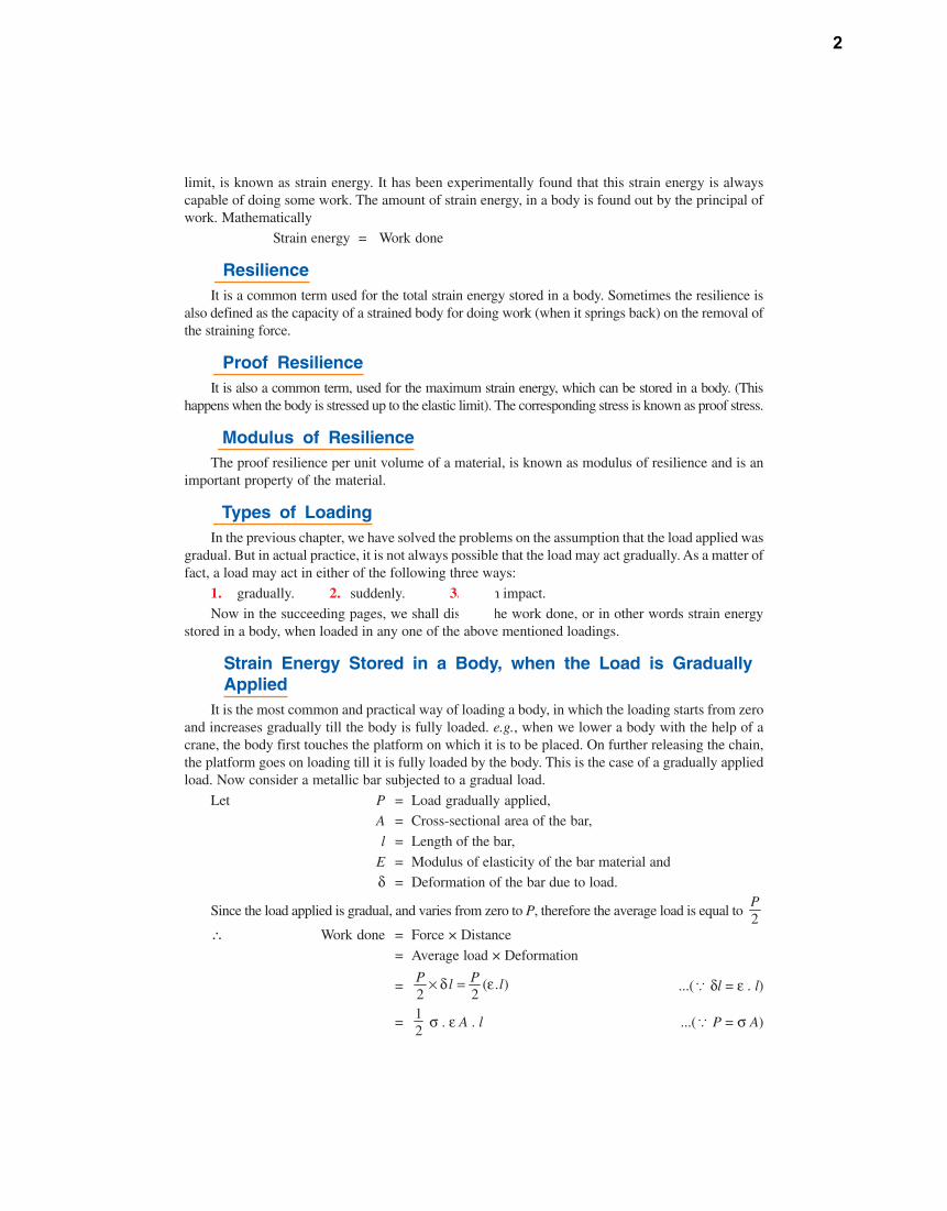
limit, is known as strain energy. It has been experimentally found that this strain energy is alwayscapable of doing some work. The amount of strain energy, in a body is found out by the principal ofwork. Mathematically
Strain energy = Work done
8.2. ResilienceIt is a common term used for the total strain energy stored in a body. Sometimes the resilience is
also defined as the capacity of a strained body for doing work (when it springs back) on the removal ofthe straining force.
8.3. Proof ResilienceIt is also a common term, used for the maximum strain energy, which can be stored in a body. (This
happens when the body is stressed up to the elastic limit). The corresponding stress is known as proof stress.
8.4. Modulus of ResilienceThe proof resilience per unit volume of a material, is known as modulus of resilience and is an
important property of the material.
8.5. Types of LoadingIn the previous chapter, we have solved the problems on the assumption that the load applied was
gradual. But in actual practice, it is not always possible that the load may act gradually. As a matter offact, a load may act in either of the following three ways:
1. gradually. 2. suddenly. 3. with impact.Now in the succeeding pages, we shall discuss the work done, or in other words strain energy
stored in a body, when loaded in any one of the above mentioned loadings.
8.6. Strain Energy Stored in a Body, when the Load is GraduallyApplied
It is the most common and practical way of loading a body, in which the loading starts from zeroand increases gradually till the body is fully loaded. e.g., when we lower a body with the help of acrane, the body first touches the platform on which it is to be placed. On further releasing the chain,the platform goes on loading till it is fully loaded by the body. This is the case of a gradually appliedload. Now consider a metallic bar subjected to a gradual load.
Let P = Load gradually applied,A = Cross-sectional area of the bar,
l = Length of the bar,
E = Modulus of elasticity of the bar material andδ = Deformation of the bar due to load.
Since the load applied is gradual, and varies from zero to P, therefore the average load is equal to 2P
∴ Work done = Force × Distance
= Average load × Deformation
= ( . )2 2P Pl l× δ = ε ...(ä δl = ε . l)
=12
σ . ε A . l ...(ä P = σ A)
2
=12
× Stress × Strain × Volume
=12
AlEσ× σ × × ...(ä
Eσε = )
=21
2Al
Eσ× ×
Since the strain energy stored is also equal to the work done, therefore strain energy stored,
U =2
2Al
Eσ ×
2
2V
Eσ= × ...(ä Al = Volume = V)
We also know that modulus of resilience= Strain energy per unit volume
=2
2Eσ
EXAMPLE 8.1. Calculate the strain energy strored in a bar 2 m long, 50 mm wide and 40 mmthick when it is subjected to a tensile load of 60kN. Take E as 200 GPa.
SOLUTION. Given : Length of bar (l) = 2 m = 2 × 103 mm ; Width of bar (b) = 50 mm ; Thicknessof bar (t) = 40 mm ; Tensile load on bar (P) = 60 kN = 60 × 103 N and modulus of elasticity (E) = 200GPa = 200 × 103 N/mm2
We know that stress in the bar,
σ =360 10
50 40PA
×=× = 30 N/mm2
∴ Strain energy stored in the bar,
U =22
3(30)
2 2 (200 10 )V
Eσ × =
× × × 4 × 10⁶ N-mm
= 9 × 10³ N-mm = 9 kN-mm Ans.
8.7. Strain Energy Stored in a Body when the Load is SuddenlyApplied
Sometimes in factories and workshops, the load is suddenly applied on a body. e.g., when welower a body with the help of a crane, the body is, first of all, just above the platform on which it is tobe placed. If the chain breaks at once at this moment the whole load of the body begins to act on theplatform. This is the case of a suddenly applied load. Now consider a bar subjected to a sudden load.
P = Load applied suddenly,A = Cross-sectional area of the bar,
l = Length of the bar,
E = Modulus of elasticity of the material,δ = Deformation of the bar, and
σ = Stress induced by the application of the sudden load
Since the load is applied suddenly, therefore the load (P) is constant throughout the process ofdeformation of the bar.
∴ Work done = Force × Distance = Load × Deformation ...(i)
= P × δl
3
We know that strain energy stored,
U =2
2σ × AlE
...(ii)
Since the strain energy stored is equal to the work done, therefore2
2Al
Eσ × = P × δl = P × l
Eσ
... ( )l lEσδ =
or σ = 2 × PA
It means that the stress induced in this case is twice the stress induced when the same load isapplied gradually. Once the stress (σ), is obtained, the corresponding instantaneous deformation (δl)and the strain energy may be found out as usual.
EXAMPLE 8.2. An axial pull of 20 kN is suddenly applied on a steel rod 2.5 m long and1000 mm2 in cross-section. Calculate the strain energy, which can be absorbed in the rod. TakeE = 200 GPa.
SOLUTION. Given : Axial pull on the rod (P) = 20 kN = 20 × 103 N ; Length of rod (l) = 2.5 m= 2.5 × 103 mm ; Cross-sectional area of rod (A) =1000 mm2 and modulus of elasticity (E) = 200GPa = 200 × 103 N/mm2.
We know that stress in the rod, when the load is suddenly applied,
σ =220 10
2 21000
PA
×× = × = 440 N/mm2
and volume of the rod,V = l . A = (2.5 × 103) × 1000 = 2.5 × 106 mm3
∴ Strain energy which can be absorbed in the rod,
U =22
3(40)
2 2 (200 10 )V
Eσ × =
× × × (2.5 × 10⁶) N-mm
= 10 × 103 N-mm = 10 kN-mm Ans.
EXAMPLE 8.3 A steel rod of 28 mm diameter is 2.5 m long. Find the maximum instantaneousstress and work done at maximum elongation, when an axial load of 50 kN is suddenly applied toit. Also calculate the maximum dynamic force in the rod. Take E = 200 GPa.
SOLUTION. Given : Diameter of rod (d) = 28 mm ; Length of rod (l) = 2.5 m = 2.5 × 103 mm ;Axial load on rod (P) = 50 kN = 50 × 103 N and modulus of elasticity (E) = 200 GPa = 200 × 103
N/mm2.
Maximum Instantaneous stressWe know that cross-sectional area of rod,
A =4π
× (d)2 = 4π
× (28)2 = 615.8 mm2
and maximum instantaneous stress, when the load is suddenly applied,
σmax =350 10
2 2615.8
PA
×× = × = 162.4 N/mm2 = 162.4 MPa Ans.
Work done at maximum elongation We know that maximum elongation,
δl =3
3
1 162.4 (2.5 10 )
200 10max
Eσ × × ×=
× = 2.03 mm
4
and work done = P × δl = (50 × 103) × 2.03 = 101.5 × 10³ N-mm= 101.5 kN-mm Ans.
Maximum dynamic forceWe also know that maximum dynamic force,
= A × σmax = 615.8 × 162.4 = 100 × 103 N = 100 kN Ans.
8.8. Strain Energy Stored in a Body, when the Load is Appliedwith Impact
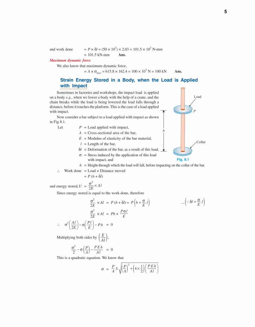
Sometimes in factories and workshops, the impact load is appliedon a body e.g., when we lower a body with the help of a crane, and thechain breaks while the load is being lowered the load falls through adistance, before it touches the platform. This is the case of a load appliedwith impact.
Now consider a bar subject to a load applied with impact as shownin Fig 8.1.
Let P = Load applied with impact,
A = Cross-sectional area of the bar,
E = Modulus of elasticity of the bar material,l = Length of the bar,
δl = Deformation of the bar, as a result of this load,
σ = Stress induced by the application of this loadwith impact, and
h = Height through which the load will fall, before impacting on the collar of the bar.
∴ Work done = Load × Distance moved
= P (h + δl)
and energy stored,U =2
2Al
Eσ ×
Since energy stored is equal to the work done, therefore
2
2Eσ × Al = P (h + δl) = ( ).P h l
Eσ+ ... ( ).l l
Eσδ =∵
2
2Eσ × Al = Ph +
P lEσ
∴ σ2
2Al Pl
P hE E
⎛ ⎞ ⎛ ⎞− σ −⎜ ⎟ ⎜ ⎟⎝ ⎠ ⎝ ⎠
= 0
Multiplying both sides by ( ) ,EAl
( )2
2P E hP
A Alσ − σ − = 0
This is a quadratic equation. We know that
σ = ( ) ( )2 142
P E hP PA A Al
⎛ ⎞± + × ⎜ ⎟⎝ ⎠
Fig. 8.1
5
=2
1 1AE hP
A Pl
⎡ ⎤± +⎢ ⎥
⎣ ⎦
Once the stress (σ)is obtained, the corresponding instantaneous deformation (δl) or the strainenergy stored may be found out as usual.
Cor. When δ is very small as compared to h, thenWork done = Ph
∴2
2Eσ Al = Ph
or σ2 =2 E Ph
Al
∴ σ =2 E P h
Al
EXAMPLE 8.4. A 2 m long alloy bar of 1500 mm2 cross-sectional area hangs verticallyand has a collar securely fixed at its lower end. Find the stress induced in the bar, when aweight of 2 kN falls from a height of 100 mm on the collar. Take E = 120 GPa. Also find thestrain energy stored in the bar.
SOLUTION. Given : Length of bar (l) = 2 m = 2 × 103 mm ; Cross-sectional area of bar (A) = 1500mm2 ; Weight falling on collar of bar (P) = 2 kN = 2 × 10³ N ; Height from which weight falls (h) =100 mm and modulus of elasticity (E) = 120 GPa = 120 × 103 N/mm2.Stress induced in the bar
We know that in this case, extension of the bar will be small and negligible as compared to theheight (h) from where the weight falls on the collar (due to small value of weight i.e., 2 kN and a largevalue of h i.e., 100 mm). Therefore stress induced in the bar
σ =3 3
3
2 2 (120 10 ) (2 10 ) 100. 1500 (2 10 )
E P hA l
× × × × ×=× × N/mm2
= 126.5 N/mm2 = 126.5 MPa Ans.Strain energy stored in the bar
We also know that volume of the bar,
V = l . A = (2 × 103) × 1500 = 3 × 106 mm3
and strain energy stored in the bar,
U =22
2(126.5)
2 2 (120 10 )V
Eσ × =
× × × (3 × 10⁶) N-mm
= 200 × 103 N-mm = 200 N-m Ans.
EXAMPLE 8.5. A steel bar 3 m long and 2500 mm2 in area hangs vertically, which is securelyfixed on a collar at its lower end. If a weight of 15 kN falls on the collar from a height of 10 mm,determine the stress developed in the bar. What will be the strain energy stored in the bar? Take Eas 200 GPa.
SOLUTION. Given : Length of bar (l) = 3 m = 3 × 103 mm ; Area of bar (A) = 2500 mm2 ; Weightfalling on collar of bar (P) = 15 kN = 15 × 103 N ; Height from which weight falls (h) = 10 mm andmodulus of elasticity (E) = 200 GPa = 20 × 103 N/mm2.Stress developed in the bar
We know that in this case, extension of the bar will be considerable as compared to the height (h)from where the weight falls on the collar (due to a large value of weight i.e., 15 kN and a small value
6
of h = 10 mm). Therefore stress developed in the bar,
σ =2
1 1AE hP
A Pl
⎡ ⎤+ +⎢ ⎥
⎣ ⎦
=
3 3
3 3
15 10 2 2500 (200 10 ) 101 1
2500 (15 10 ) (3 10 )
⎡ ⎤× × × × ×⎢ ⎥+ +
× × ×⎢ ⎥⎣ ⎦ N/mm2
= 6 ( 1 + 14.9) = 95.4 N/mm2 = 95.4 MPa Ans.Strain energy stored in the bar
We know that volume of the bar,
V = l . A = ( 3 × 103) × 2500 = 7.5 × 106 mm3
and strain energy stored in the bar,
U =22
3(95, 4)
2 2 (200 10 )V
Eσ × =
× × × 7.5 × 10⁶ N-mm
= 170.6 × 10³ N-mm = 170.6 N-m Ans.
EXAMPLE 8.6. A copper bar of 12 mm diameter gets stretched by 1 mm under a steady loadof 4 kN. What stress would be produced in the bar by a weight 500 N, the weight falls through 80mm before striking the collar rigidly fixed to the lower end of the bar ? Take Young’s modulus forthe bar material as 100 GPa.
SOLUTION. Given : Diameter of bar (d) = 12 mm ; Change in length of bar (δl) = 1 mm ; Load onbar (P1) = 4 kN = 4 × 10³ N ; Weight falling on collar (P2) = 500 N ; Height from which weight falls(h) = 80 mm and modulus of elasticity (E) = 100 GPa = 100 × 103 N/mm2
Let l = Length of the copper bar.
We know that cross-sectional area of the bar,
A =4π
× (d)2 = 4π
× (12)2 = 113.1 mm2
and stretching of the bar (δl),
l =3
3 3
. (4 10 ). 113.1 (100 10 ) 2.83 10
×= =× × ×
P l lA E
∴ l = 1 × (2.83 × 103) = 2.83 × 103 mm
We also know that stress produced in the bar by the falling weight.
σ = 2
2
21 1
P A E hA P l
⎛ ⎞+ +⎜ ⎟
⎝ ⎠
=3
3
2 113.1 (100 10 ) 801500 1 1113.1 500 (2.83 10 )
⎛ ⎞× × × ×⎜ ⎟+ +⎜ ⎟× ×⎝ ⎠
N/mm2
= 4.2 (1 + 35.77) = 162.52 N/mm2 = 162.52 MPa Ans.
EXAMPLE 8.7. An unknown weight falls through 10 mm on a collar rigidly attached to the lowerend of a vertical bar 4 m long and 600 mm2 in section. If the maximum instantaneous extension is knownto be 2 mm, what is the corresponding stress and the value of unknown weight. Take E = 200 GPa.
SOLUTION. Given : Height from which weight falls (h) = 10 mm ; Length (l ) = 4 m = 4 × 103 mm;Cross-sectional area of bar (A) = 600 mm2 ; Instananeous extension (δl) = 2 mm and modulus ofelasticity (E) = 200 GPa = 200 × 103 N/mm2.
7
Atif
Line

8.10. Strain Energy Stored in a Body due to Shear StressConsider a cube ABCD of length l fixed at the bottom face AB as shown in Fig 8.5.Let P = Force applied tangentially on the face DC,
τ = Shear stress
φ = Shear strain, andN = Modulus of rigidity or
shear modulus.
If the force P is applied gradually then the average forceis equal to P/2.
∴ Work done = Average force ×Distance
=2P
× DD1
=12
× P × AD × φ ...(ä DD1 = AD × φ)
=12
× τ × DC × l × AD × φ ...(ä P = τ × DC × l)
=12
× τ × φ × DC × AD × l
=12
(stress × strain × volume)
=12
VNτ× τ × × ... ( )N
τφ =∵
=2
2V
Nτ × ...(where V is the volume)
Since energy stored is also equal to the work done, therefore energy stored,
U =2
2V
Nτ ×
We also know that modulus of resilience
= Strain energy per unit volume
=2
2 Nτ
EXAMPLE 8.11. A rectangular body 500 mm long, 100 mm wide and 50 mm thick is subjectedto a shear stress of 80 MPa. Determine the strain energy stored in the body. Take N = 85 GPa.
SOLUTION. Given : Length of rectangular body (l) = 500 mm ; Width of rectangular body (b) =100 mm ; Thickness of rectangular body (t) = 50 mm ; Shear stress (τ) = 80 MPa = 80 N/mm2 andmodulus of rigidity (N) = 85 N/mm2.
We know that volume of the bar,V = l.b.t = 500 × 100 × 50 = 2.5 × 106 mm3
and strain energy stored in the body,
U =22
3(80)
2 2 (85 10 )V
Nτ × =
× × × 2.5 × 10⁶ N-mm
= 94.1 × 10³ N-mm = 94.1 N-m Ans.
Fig. 8.5. Strain energy due to shear stress
8
Torsion of
Circular Shafts
27.1. IntroductionIn workshops and factories, a turning force
is always applied to transmit energy by rotation.This turning force is applied either to the rim of apulley, keyed to the shaft or at any other suitablepoint at some distance from the axis of the shaft.The product of this turning force and the distancebetween the point of application of the force andthe axis of the shaft is known as torque, turningmoment or twisting moment. And the shaft is saidto be subjected to torsion. Due to this torque,every cross-section of the shaft is subjected tosome shear stress.
27.2. Assumptions for ShearStress in a Circular ShaftSubjected to Torsion
Following assumptions are made, while
27C h a p t e r
www.cgasp
irants.
com
9
finding out shear stress in a circular shaft subjected to torsion:1. The material of the shaft is uniform throughout.
2. The twist along the shaft is uniform.
3. Normal cross-sections of the shaft, which were plane and circular before the twist, remain planeand circular even after the twist.
4. All diameters of the normal cross-section, which were straight before the twist, remain straightwith their magnitude unchanged, after the twist.
A little consideration will show that the above assumptions are justified, if the torque applied issmall and the angle of twist is also small.
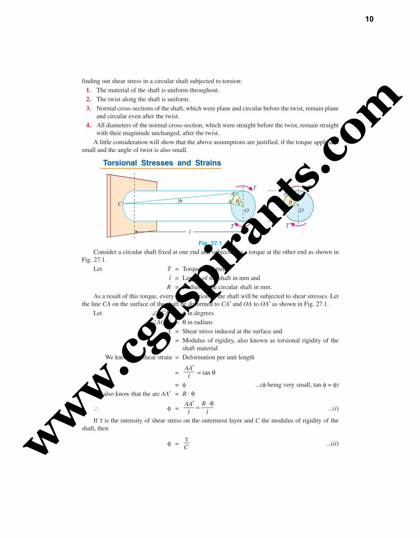
27.3. Torsional Stresses and Strains
Fig. 27.1
Consider a circular shaft fixed at one end and subjected to a torque at the other end as shown inFig. 27.1.
Let T = Torque in N-mm,
l = Length of the shaft in mm andR = Radius of the circular shaft in mm.
As a result of this torque, every cross-section of the shaft will be subjected to shear stresses. Letthe line CA on the surface of the shaft be deformed to CA′ and OA to OA′ as shown in Fig. 27.1.
Let ∠ACA′ = φ in degrees∠AOA′ = θ in radians
τ = Shear stress induced at the surface and
C = Modulus of rigidity, also known as torsional rigidity of theshaft material.
We know that shear strain = Deformation per unit length
=AAl
′ = tan θ
= φ ...(φ being very small, tan φ = φ)We also know that the arc AA′ = R · θ
∴ φ =RAA
l l′ ⋅ θ= ...(i)
If τ is the intensity of shear stress on the outermost layer and C the modulus of rigidity of theshaft, then
φ =Cτ
...(ii)www.cgasp
irants.
com
10
From equations (i) and (ii), we find that
Cτ
=R
l⋅ θ
or C
R lτ ⋅θ=
If τX be the intensity of shear stress, on any layer at a distance x from the centre of the shaft, then
X
xτ
=C
R l⋅ θτ = ...(iii)
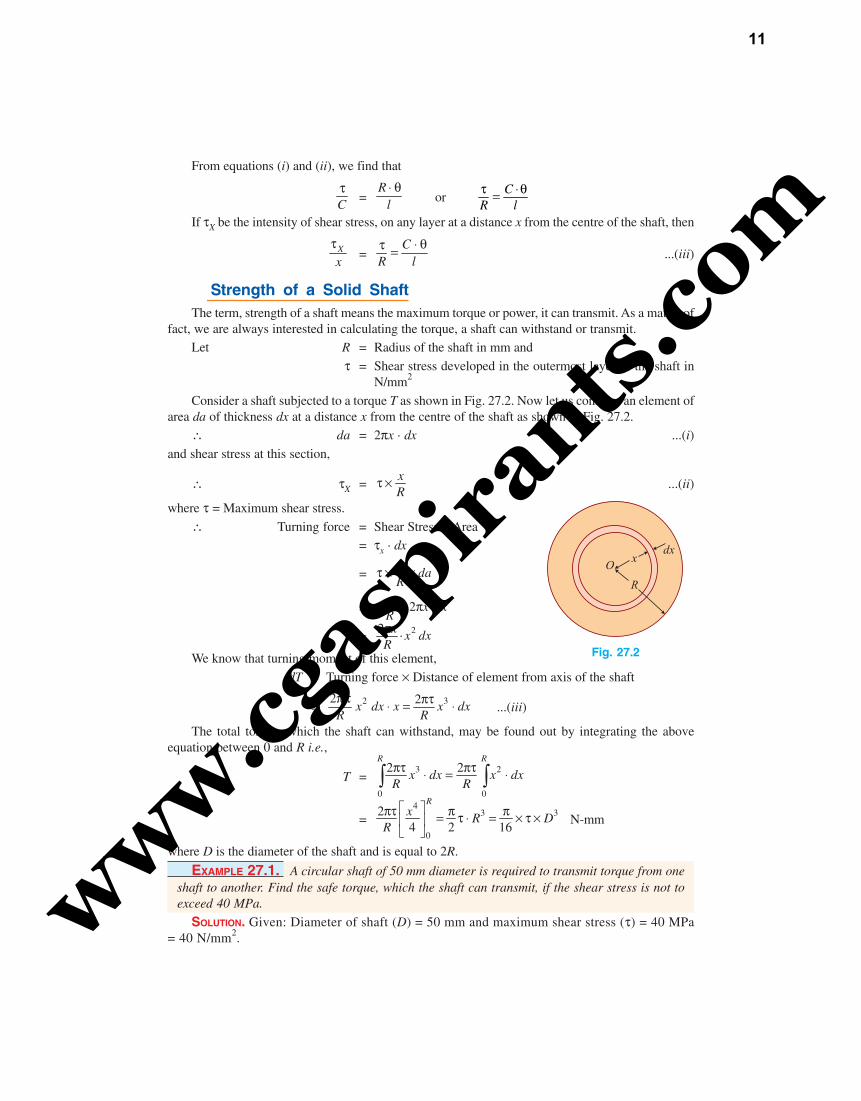
27.4. Strength of a Solid ShaftThe term, strength of a shaft means the maximum torque or power, it can transmit. As a matter of
fact, we are always interested in calculating the torque, a shaft can withstand or transmit.Let R = Radius of the shaft in mm and
τ = Shear stress developed in the outermost layer of the shaft inN/mm2
Consider a shaft subjected to a torque T as shown in Fig. 27.2. Now let us consider an element ofarea da of thickness dx at a distance x from the centre of the shaft as shown in Fig. 27.2.
∴ da = 2πx · dx ...(i)
and shear stress at this section,
∴ τX =xR
τ × ...(ii)
where τ = Maximum shear stress.
∴ Turning force = Shear Stress × Area= τx · dx
=x daR
τ × ×
= 2 ·τ × πxx dx
R
=22 ·x x dx
Rπ
We know that turning moment of this element,
dT = Turning force × Distance of element from axis of the shaft
=2 32 2x dx x x dx
R Rπ τ πτ⋅ = ⋅ ...(iii)
The total torque, which the shaft can withstand, may be found out by integrating the aboveequation between 0 and R i.e.,
T =3 2
0 0
2 2R R
x dx x dxR Rπτ πτ⋅ = ⋅∫ ∫
=4
3 3
0
24 2 16
Rx R D
R
⎡ ⎤πτ π π= τ ⋅ = × τ ×⎢ ⎥⎣ ⎦
N-mm
where D is the diameter of the shaft and is equal to 2R.
EXAMPLE 27.1. A circular shaft of 50 mm diameter is required to transmit torque from oneshaft to another. Find the safe torque, which the shaft can transmit, if the shear stress is not toexceed 40 MPa.
SOLUTION. Given: Diameter of shaft (D) = 50 mm and maximum shear stress (τ) = 40 MPa= 40 N/mm2.
Fig. 27.2
www.cgasp
irants.
com
11
We know that the safe torque, which the shaft can transmit,
T =3 340 (50)
16 16Dπ π× τ × = × × N-mm
= 0.982 × 10⁶ N-mm = 0.982 kN-m Ans.
EXAMPLE 27.2. A solid steel shaft is to transmit a torque of 10 kN-m. If the shearing stressis not to exceed 45 MPa, find the minimum diameter of the shaft.
SOLUTION. Given: Torque (T) = 10 kN-m = 10 × 106 N-mm and maximum shearing stress (τ) = 45MPa = 45 N/mm2.
Let D = Minimum diameter of the shaft in mm.
We know that torque transmitted by the shaft (T),
10 × 106 =3 345
16 16D Dπ π× τ × = × × = 8.836 D3
∴ D3 =610 10
8.836×
= 1.132 × 10⁶
or D = 1.04 × 102 = 104 mm Ans.
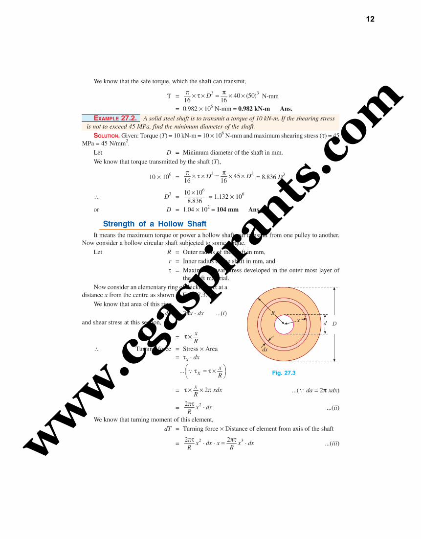
27.5. Strength of a Hollow ShaftIt means the maximum torque or power a hollow shaft can transmit from one pulley to another.
Now consider a hollow circular shaft subjected to some torque.
Let R = Outer radius of the shaft in mm,r = Inner radius of the shaft in mm, and
τ = Maximum shear stress developed in the outer most layer ofthe shaft material.
Now consider an elementary ring of thickness dx at adistance x from the centre as shown in Fig. 27.3.
We know that area of this ring,
da = 2πx · dx ...(i)and shear stress at this section,
τX =xR
τ ×
∴ Turning force = Stress × Area= τX · dx
... XxR
⎛ ⎞τ = τ ×⎜ ⎟⎝ ⎠∵
= 2x xdxR
τ × × π ...(ä da = 2π xdx)
= 22 x dxRπτ ⋅ ...(ii)
We know that turning moment of this element,
dT = Turning force × Distance of element from axis of the shaft
= 2 32 2x dx x x dxR Rπτ πτ⋅ ⋅ = ⋅ ...(iii)
Fig. 27.3
www.cgasp
irants.
com
12
The total torque, which the shaft can transmit, may be found out by integrating the above equationbetween r and R.
∴ T =3 32 2
R R
r r
x dx x dxR Rπτ πτ⋅ = ⋅∫ ∫
=4 4 4 442 2 N-mm
4 4 16
R
r
R r D dxR R D
⎛ ⎞ ⎛ ⎞⎡ ⎤ − −πτ πτ π= = × τ ×⎜ ⎟ ⎜ ⎟⎢ ⎥ ⎜ ⎟ ⎜ ⎟⎣ ⎦ ⎝ ⎠ ⎝ ⎠
where D is the external diameter of the shaft and is equal to 2R and 2d is the internal diameter of theshaft and is equal to 2r.NOTE: We have already discussed in Art. 27.3 that the shear stress developed at a point is proportional to its
distance from the centre of the shaft. It is thus obvious that in the central portion of a shaft, the shearstress induced is very small. In order to utilize the material to the fuller extent, hollow shafts are used.
EXAMPLE 27.3. A hollow shaft of external and internal diameter of 80 mm and 50 mm isrequired to transmit torque from one end to the other. What is the safe torque it can transmit, if theallowable shear stress is 45 MPa ?
SOLUTION. Given: External diameter (D) = 80 mm; Internal diameter (d) = 50 mm and allowableshear stress (τ) = 45 MPa = 45 N/mm2.
We know that torque transmitted by the shaft,
T =4 4 4 4(80) (50)
4516 16 80
D dD
⎡ ⎤ ⎡ ⎤− −π π× τ × = × ×⎢ ⎥ ⎢ ⎥⎣ ⎦ ⎣ ⎦
N-mm
= 3.83 × 10⁶ N-mm = 3.83 kN-m Ans.
27.6. Power Transmitted by a ShaftWe have already discussed that the main purpose of a shaft is to transmit power from one shaft to
another in factories and workshops. Now consider a rotating shaft, which transmits power from oneof its ends to another.
Let N = No. of revolutions per minute andT = Average torque in kN-m.
Work done per minute = Force × Distance = T × 2πN = 2πNT
Work done per second =2 kN-m
60NTπ
Power transmitted = Work done in kN-m per second
=2 kW
60NTπ
NOTE: If the torque is in the N-m, then work done will also be in N-m and power will be in watt (W).
EXAMPLE 27.4. A circular shaft of 60 mm diameter is running at 150 r.p.m. If the shearstress is not to exceed 50 MPa, find the power which can be transmitted by the shaft.
Solution. Given: Diameter of the shaft (D) = 60 mm ; Speed of the shaft (N) = 150 r.p.m. andmaximum shear stress (τ) = 50 MPa = 50 N/mm2.www.cg
aspira
nts.co
m
13
Atif
Line
6. A hollow shaft of external and internal diameters as 80 mm and 50 mm respectively is transmittingpower at 150 r.p.m. Determine the power, which the shaft can transmit, if the shearing stress isnot to exceed 40 MPa. (Ans. 53.6 kW)
7. A hollow shaft has to transmit 53 kW at 160 r.p.m. If the maximum shear stress is 50 MPa andinternal diameter is half of the external diameter, find the diameters of the shaft.
(Ans. 70 mm; 35 mm)
27.7. Polar Moment of InertiaThe moment of inertia of a plane area, with respect to an axis perpendicular to the plane of the
figure, is called polar moment of inertia with respect to the point, where the axis intersects the plane.In a circular plane, this point is always the centre of the circle. We know that
Rτ
=C
l⋅ θ
...(i) ... (from Art. 27.3)
and T =3
16Dπ × τ × ...(ii) ... (from Art. 27.3)
or τ = 316T
DπSubstituting the value of τ in equation (i),
316T
D Rπ ×=
Cl⋅ θ
or3
16
T
D Rπ × ×=
Cl⋅ θ
4
32
T
Dπ ×=
Cl⋅ θ
... Radius,2DR⎛ ⎞=⎜ ⎟
⎝ ⎠
TJ
=C
l⋅ θ
...(iii)
where J =4
32Dπ × . It is known as polar moment of inertia.
The above equation (iii) may also be written as :
Rτ
=CT
J l⋅ θ= ... C
R l⋅ θτ⎛ ⎞=⎜ ⎟
⎝ ⎠∵
NOTES. 1. In a hollow circular shaft the polar moment of inertia,
J =4 4( )
32D dπ −
where d is the internal diameter of the shaft.
2. The term JR is known as torsional section modulus or polar modulus. It is similar to section modulus
which is equal to Iy
.
3. Thus polar modulus for a solid shaft,
Zp =4 32
32 16D D
Dπ π× =
and the polar modulus for a hollow shaft,
Zp =4 4 4 42 ( ) ( )
32 16D d D d
D Dπ π− = −www.cg
aspira
nts.co
m
14
Atif
Line
EXAMPLE 27.9. Calculate the maximum torque that a shaft of 125 mm diameter can transmit,if the maximum angle of twist is 1° in a length of 1.5 m. Take C = 70 GPa.
SOLUTION. Given: Diameter of shaft (D) = 125 mm ; Angle of twist (θ) = 1° = 180π
rad ; Length of
the shaft (l) = 1.5 m = 1.5 × 103 mm and modulus of rigidity (C) = 70 GPa = 70 × 103 N/mm2.
Let T = Maximum torque the shaft can transmit.We know that polar moment of inertia of a solid circular shaft,
J =4 4( ) (125)
32 32Dπ π× = = 24.0 × 106 mm4
and relation for torque transmitted by the shaft,
TJ
=C
l⋅ θ
624.0 10
T
×=
3
3
(70 10 ) /180
1.5 10
× π×
= 0.814
∴ T = 0.814 × (24.0 × 106) = 19.5 × 10⁶ N-mm
= 19.5 kN-m Ans.
EXAMPLE 27.10. Find the angle of twist per metre length of a hollow shaft of 100 mmexternal and 60 mm internal diameter, if the shear stress is not to exceed 35 MPa. Take C = 85GPa.
SOLUTION. Given: Length of the shaft (l) = 1 m = 1 × 103 mm ; External diameter (D) = 100 mm;Internal diameter (d) = 60 mm ; Maximum shear stress (τ) = 35 MPa = 35 N/mm2 and modulus ofrigidity (C) = 85 GPa = 85 × 103 N/mm2.
Let θ = Angle of twist in the shaft.We know that torque transmitted by the shaft,
T =4 4 4 4(100) (60)
3516 16 100
D dD
⎡ ⎤ ⎡ ⎤− −π π× τ × = × ×⎢ ⎥ ⎢ ⎥⎢ ⎥ ⎢ ⎥⎣ ⎦ ⎣ ⎦
N-mm
= 5.98 × 10⁶ N-mm
We also know that polar moment of inertia of a hollow circular shaft,
J =4 4 4 4[ ] [(100) (60) ]
32 32D dπ π− = − = 8.55 × 106 mm4
and relation for the angle of twist,
TJ
=C
l⋅ θ
or 6 3
6 3
5.98 10 (85 10 )
8.55 10 1 10
× × θ=× ×
= 85.θ
∴ θ =6
6
5.98 10
(8.55 10 ) 85
×× ×
= 0.008 rad = 0.5° Ans.
EXAMPLE 27.11. A solid shaft of 120 mm diameter is required to transmit 200 kW at 100r.p.m. If the angle of twists not to exceed 2°, find the length of the shaft. Take modulus of rigidityfor the shaft material as 90 GPa.
SOLUTION. Given : Diameter of shaft (D) = 120 mm; Power (P) = 200 kW ; Speed of shaft (N) = 100
r.p.m. ; Angle of twist (θ) = 2° = 2
180π
rad. and modulus of rigidity (C) = 90 GPa = 90 × 103 N/mm2.www.cgasp
irants.
com
15
Atif
Line
We also know that torque transmitted by the solid shaft,
T1 =3 31 (200)
16 16Dπ π× τ × = × τ × = 500 × 103 π τ N-mm ...(i)
Similarly, torque transmitted by the hollow shaft,
T2 =4 4 4 4(250) (150)
N-mm16 16 250
D dD
⎡ ⎤ ⎡ ⎤− −π π× τ × = × τ ×⎢ ⎥ ⎢ ⎥⎢ ⎥ ⎢ ⎥⎣ ⎦ ⎣ ⎦
= 850 × 103 π τ N-mm
∴ Power transmitted by hollow shaftPower transmitted by solid shaft
=3
23
1
50 10
500 10
TT
× π τ=× π τ
= 1.7 Ans.
(b) Ratio of angles of twist in both the shaftsWe know that relation for angle of twist for a shaft,
Rτ
=C
l⋅ θ
or θ = l
RCτ
∴ Angle of twist for the solid shaft,
θ1 = 100l l
RC Cτ τ= ... 1 200where 100 mm
2 2D
R⎛ ⎞= = =⎜ ⎟⎝ ⎠
Similarly angle of twist for the hollow shaft,
θ2 = 125l l
RC Cτ τ= ... 1 250where 125 mm
2 2D
R⎛ ⎞= = =⎜ ⎟⎝ ⎠
∴ Angle of twist of hollow shaftAngle of twist of solid shaft
= 2
1
100125125
100
lC
lC
τθ
= =τθ = 0.8 Ans.
27.8. Replacing a ShaftSometimes, we are required to replace a solid shaft by a hollow one, or vice versa. In such cases,
the torque transmitted by the new shaft should be equal to that by the replaced shaft. But sometimes,there are certain other conditions which have also to be considered while designing the new shaft.
EXAMPLE 27.15. A solid steel shaft of 60 mm diameter is to be replaced by a hollow steelshaft of the same material with internal diameter equal to half of the external diameter. Find thediametres of the hollow shaft and saving in material, if the maximum allowable shear stress issame for both shafts.
SOLUTION. Given: Diameter of solid shaft (D) = 60 mm.Diameter of the hollow shaft
Let D = External diameter of the hollow shaft,
d = Internal diameter of the hollow shaft (equal to D1/2) andτ = Shear stress developed in both the shafts.
We know that torque transmitted by the solid shaft,
T =3 3(60)
16 16Dπ π× τ × = × τ × ...(i)www.cg
aspira
nts.co
m
16
Atif
Line
and torque transmitted by the hollow shaft,
T1 =4 44 41 1
1 1
(0.5 )16 16
D DD dD D
⎡ ⎤⎡ ⎤ −−π π× τ × = × τ × ⎢ ⎥⎢ ⎥⎢ ⎥ ⎢ ⎥⎣ ⎦ ⎣ ⎦
=310.9375
16Dπ × τ × ...(ii)
Since the torque transmitted and allowable shear stress in both the cases are same, thereforeequating the equations (i) and (ii),
3(60)16π × τ × =
310.9375
16Dπ × τ ×
∴ D13 =
3(60)0.9375
= 230400 mm3
or D1 = 61.3 mm Ans.
and d =61.3
2 = 30.65 mm Ans.
Saving in materialWe know that saving in material
=
2 2 2
2
(60) ((61.3) (30.65) )3600 28194 4
3600(60)4
π π⎡ ⎤ ⎡ ⎤− −⎢ ⎥ ⎢ ⎥ −⎣ ⎦ ⎣ ⎦ =π
= 0.217 = 21.7% Ans.
EXAMPLE 27.16. A solid shaft of 80 mm diameter is to be replaced by a hollow shaft ofexternal diameter 100 mm. Determine the internal diameter of the hollow shaft if the same poweris to be transmitted by both the shafts at the same angular velocity and shear stress.
SOLUTION. Given: Diameter of solid shaft (D) = 80 mm and external diameter of hollow shaft(D1) = 100 mm.
Let d = Internal diameter of the hollow shaft, andτ = Shear stress developed in both the shafts.
We know that torque transmitted by the solid shaft,
T = 3 3(80)16 16
Dπ π× τ × = × τ × ...(i)
and torque transmitted by the hollow shaft,
T1 =4 4 4 4(100)
16 16 100D d d
D
⎡ ⎤ ⎡ ⎤− −π π× τ × = × τ ×⎢ ⎥ ⎢ ⎥⎢ ⎥ ⎢ ⎥⎣ ⎦ ⎣ ⎦
...(ii)
Since both the torques are equal, therefore equating the equations (i) and (ii),
2(80)16π × τ × =
4 4(100)16 100
d⎡ ⎤−π × τ × ⎢ ⎥⎢ ⎥⎣ ⎦
(80)3 =4 4 4
3(100)(100)
100 100d d− = −
4
100d
= (100)3 – (80)3 = 488 × 103
d4 = (488 × 103) × 100 = 488 × 105 = 4880 × 104
∴ d = 8.36 × 10 = 83.6 mm Ans.www.cgasp
irants.
com
17
EXAMPLE 27.17. A solid aluminium shaft 1 m long and of 50 mm diameter is to be replaced bya hollow shaft of the same length and same outside diameter, so that the hollow shaft could carry thesame torque and has the same angle of twist. What must be the inner diameter of the hollow shaft ?
Take modulus of rigidity for the aluminium as 28 GPa and that for steel as 85 GPa.SOLUTION. Given: Length of aluminium shaft (lA) = 1 m = 1 × 103 mm ; Diameter of aluminium shaft
(DA) = 50 mm ; Length of steel shaft (lS) = 1 m = 1 × 103 mm ; Outside diameter of steel shaft (DS) = 50mm; Modulus of rigidity for aluminium (CA) = 28 GPa = 28 × 103 N/mm2 and modulus of rigidity for steel= 85 GPa = 85 × 103 N/mm2.
Let dS = Inner diameter of steel shaft in mm.We know that polar moment of inertia of the solid aluminium shaft,
JA = 4 4 4(50) mm32 32
Dπ π× = ×
We also know that relation for angle of twist
TJ
=C
l⋅ θ
or θ = T lJC
⋅
∴ θA =4 3
rad.(50) 28 10
32
A AT l⋅π × × ×
and θS =4 4 3
rad.[(50) ( ) ] 85 10
32
S ST l
d
⋅π × − × ×
Since both the angles of twists (i.e., θA and θB) are same, therefore equating these values,
4 3(50) 28 1032
A AT l⋅π × × ×
=4 4 3[(50) ( ) ] 85 10
32
S ST l
d
⋅π × − × ×
Substituting TA = TS and lA = lS in the above equation,
(50)4 × 28 = [(50)4 – d4] × 85175 × 106 = (531.25 × 10⁶) – 85 d4
85 d4 = (531.25 × 10⁶) – (175 × 106) = 356.25 × 10⁶
d4 =6356.25 10
85×
= 4.191 × 106 mm4
∴ d = 45.25 mm Ans.
EXAMPLE 27.18. A hollow steel shaft of 300 mm external diameter and 200 mm internaldiameter has to be replaced by a solid alloy shaft. Assuming the same values of polar modulus forboth, calculate the diameter of the latter and work out the ratio of their torsional rigidities. TakeC for steel as 2.4 C for alloy.
SOLUTION. Given: External diameter of steel shaft (D) = 300 mm ; Internal diameter of steel shaft(d) = 200 mm and modulus of rigidity for steel (CS) = 2.4 (where CA is the modulus of rigidity for thealloy).
Diameter of the solid alloy shaftLet D1 = Diameter of the solid alloy shaft.
We know that polar modulus of hollow steel shaft,
ZS =4 4 4 4( ) [(300) (200) ]
16 16 300D d
Dπ π− = −
× mm3www.cgasp
irants.
com
18
Chapter 27 : Torsion of Circular Shafts � 673
C = Modulus of rigidity or shear modulus andV = Volume of the body.
But in the case of a solid circular shaft, the torsional stress varies from zero at the central axis toa maximum τ at the surface. Now, consider a circular shaft of diameter D, subjected to shear stress (τ)at its surface. Now, let us consider an elementary ring of thickness dx and a distance x from the axis ofthe shaft.
∴ Area of the ring, da = 2πx dxand its volume V = l · 2πx dx
We know that shear stress at this section,
θ =xR
τ ×∴ Strain energy stored in this ring
=2 2 2 2
32 2
2 2 22 2 2
q xl x dx l x dx l x dxC C R CR
τ τ× ⋅ π = × ⋅ ⋅ π = ⋅ π ⋅
The total strain energy stored in the shaft may be found out by integrating the above equationfrom zero to R.
∴ U =2
32
0
22
R
l x dxCR
τ ⋅ π ⋅∫
=
2 2 43
2 200
4
RRl l xx dx
CR CR
⎡ ⎤τ π τ π= ⎢ ⎥⎣ ⎦
∫
=22 2 2
4 4 2l R DlC C
τ π τ ⎛ ⎞= × π ×⎜ ⎟⎝ ⎠
...2DR⎛ ⎞=⎜ ⎟
⎝ ⎠ä
=2
4V
Cτ × ... 2
4V D lπ⎛ ⎞= × ×⎜ ⎟
⎝ ⎠ä
∴ For Solid Circular Shaft, U =2
4V
Cτ ×
NOTE. If the shaft is a hollow one, then by integrating the equation between r and R instead of integrating itfrom zero to R, we get the strain energy stored,
∴ For Hollow Circular Shaft, U =2 22
24D d
VC D
⎛ ⎞+τ ×⎜ ⎟⎜ ⎟⎝ ⎠
EXAMPLE 27.23. A solid steel shaft 120 mm diameter and 1.5 m long is used to transmitpower from one pulley to another. Determine the maximum strain energy that can be stored in theshaft, if maximum allowable shear stress is 50 MPa. Take shear modulus as 80 GPa.
SOLUTION. Given: Diameter of shaft (D) = 120 mm ; Length of shaft (l) = 1.5 m = 1.5 × 103 mm;Allowable shear stress (τ) = 50 MPa = 50 N/mm2 and shear modulus (C) = 80 GPa = 80 × 103 N/mm2.
We know that volume of the shaft,
V = 2 3(120) (1.5 10 )4π × × × = 16.96 × 106 mm3
and strain energy stored in the shaft,
U =22
63
(50)16.96 10
4 4 (80 10 )V
Cτ × = × ×
× × N-mm
= 132.5 ××××× 103 N-mm Ans.www.cgasp
irants.
com
19
Related Documents