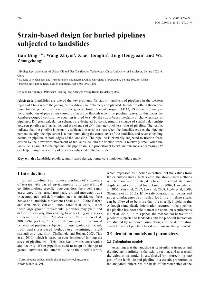
236 DOI 10.1007/s12182-012-0204-y Han Bing 1, 3 , Wang Zhiyin 1 , Zhao Honglin 2 , Jing Hongyuan 3 and Wu Zhangzhong 3 1 Beijing Key Laboratory of Urban Oil and Gas Distribution Technology, China University of Petroleum, Beijing 102249, China 2 College of Mechanical and Transportation Engineering, China University of Petroleum, Beijing 102249, China 3 PetroChina Pipeline R&D Center, Langfang, Hebei 065000, China © China University of Petroleum (Beijing) and Springer-Verlag Berlin Heidelberg 2012 Abstract: Landslides are one of the key problems for stability analysis of pipelines in the western region of China where the geological conditions are extremely complicated. In order to offer a theoretical basis for the pipe-soil interaction, the general finite element program ABAQUS is used to analyze the distribution of pipe strain caused by landslide through which the pipeline passes. In this paper the Ramberg-Osgood constitutive equation is used to study the strain-based mechanical characteristics of pipelines. Different calculation schemas are designed by considering the change of spatial relationship between pipeline and landslide, and the change of D/t, diameter-thickness ratio of pipeline. The results indicate that the pipeline is primarily subjected to tension stress when the landslide crosses the pipeline perpendicularly, the pipe strain is a maximum along the central axis of the landslide, and reverse bending occurs on pipeline at both edges of the landslide. The pipeline is primarily subjected to friction force caused by the downward movement of the landslide, and the friction force is relatively small when the landslide is parallel to the pipeline. The pipe strain is in proportional to D/t, and this means decreasing D/t can help to improve security of pipelines subjected to the landslide. Key words: Landslide, pipeline, strain-based design, numerical simulation, failure mode Strain-based design for buried pipelines subjected to landslides 1 Introduction Buried pipelines can traverse hundreds of kilometers of terrain with varied environmental and geotechnical conditions. Along specific route corridors, the pipeline may experience long term, large scale ground movement due to accumulated soil deformation such as subsidence, frost heave and landslide movement (Zhao et al, 2006; Barbas and Weir, 2007; Yun et al, 2007; Tarek et al, 2009). Under these large ground movements, pipelines may yield and deform excessively, thus causing local buckling or wrinkles (Scheiner et al, 2006; Mahdavi et al, 2008; Shuai et al, 2008; Zhang et al, 2008). For the analysis of mechanical behavior of pipelines subjected to large geological hazard, traditional stress-based methods use the minimum yield strength as a load limit (Challamela and Buhan, 2003; Tian et al, 2010), which is based on consideration of limiting the stress of pipeline wall. This ideas lean towards conservative and security. When pipelines need to adapt to change of ground curvature, the latter will decide the pipeline strain, which expressed as pipeline curvature, not the values from the calculated stress. In this case, the strain-based methods will be more appropriate, it is based on a limit state and displacement controlled load (Limura, 2004; Hawlader et al, 2006; Yun et al, 2007; Liu et al, 2008; Hyde et al, 2009; Shantanu et al, 2011). If the safe operation can be assured under displacement-controlled load, the pipeline strain can be allowed to be more than the specified yield strain. Although some plastic deformation occurred in the pipeline, the pipeline has been able to meet the operation requirements (Li et al, 2007). In this paper, the mechanical behavior of pipelines subjected to landslides and the pipe-soil interaction are studied by numerical simulation, and the deformation characteristics of pipelines based on strain are also presented. 2 Calculation models and parameters 2.1 Calculation models the pipeline is infinite in the axial direction, and as a result the calculation model is established by intercepting one part of the landslide and pipeline in a certain proportion as the analytical object. On the basis of characteristics of the *Corresponding author. email: [email protected] Received July 15, 2011 Pet.Sci.(2012)9:236-241

Welcome message from author
This document is posted to help you gain knowledge. Please leave a comment to let me know what you think about it! Share it to your friends and learn new things together.
Transcript
236DOI 10.1007/s12182-012-0204-y
Han Bing1, 3 , Wang Zhiyin1, Zhao Honglin2, Jing Hongyuan3 and Wu Zhangzhong3
1 Beijing Key Laboratory of Urban Oil and Gas Distribution Technology, China University of Petroleum, Beijing 102249, China2 College of Mechanical and Transportation Engineering, China University of Petroleum, Beijing 102249, China3 PetroChina Pipeline R&D Center, Langfang, Hebei 065000, China
© China University of Petroleum (Beijing) and Springer-Verlag Berlin Heidelberg 2012
Abstract: Landslides are one of the key problems for stability analysis of pipelines in the western region of China where the geological conditions are extremely complicated. In order to offer a theoretical basis for the pipe-soil interaction, the general finite element program ABAQUS is used to analyze the distribution of pipe strain caused by landslide through which the pipeline passes. In this paper the Ramberg-Osgood constitutive equation is used to study the strain-based mechanical characteristics of pipelines. Different calculation schemas are designed by considering the change of spatial relationship between pipeline and landslide, and the change of D/t, diameter-thickness ratio of pipeline. The results indicate that the pipeline is primarily subjected to tension stress when the landslide crosses the pipeline perpendicularly, the pipe strain is a maximum along the central axis of the landslide, and reverse bending occurs on pipeline at both edges of the landslide. The pipeline is primarily subjected to friction force caused by the downward movement of the landslide, and the friction force is relatively small when the landslide is parallel to the pipeline. The pipe strain is in proportional to D/t, and this means decreasing D/t can help to improve security of pipelines subjected to the landslide.
Key words: Landslide, pipeline, strain-based design, numerical simulation, failure mode
Strain-based design for buried pipelines subjected to landslides
1 IntroductionBuried pipelines can traverse hundreds of kilometers
of terrain with varied environmental and geotechnical conditions. Along specific route corridors, the pipeline may experience long term, large scale ground movement due to accumulated soil deformation such as subsidence, frost heave and landslide movement (Zhao et al, 2006; Barbas and Weir, 2007; Yun et al, 2007; Tarek et al, 2009). Under these large ground movements, pipelines may yield and deform excessively, thus causing local buckling or wrinkles (Scheiner et al, 2006; Mahdavi et al, 2008; Shuai et al, 2008; Zhang et al, 2008). For the analysis of mechanical behavior of pipelines subjected to large geological hazard, traditional stress-based methods use the minimum yield strength as a load limit (Challamela and Buhan, 2003; Tian et al, 2010), which is based on consideration of limiting the stress of pipeline wall. This ideas lean towards conservative and security. When pipelines need to adapt to change of ground curvature, the latter will decide the pipeline strain,
which expressed as pipeline curvature, not the values from the calculated stress. In this case, the strain-based methods will be more appropriate, it is based on a limit state and displacement controlled load (Limura, 2004; Hawlader et al, 2006; Yun et al, 2007; Liu et al, 2008; Hyde et al, 2009; Shantanu et al, 2011). If the safe operation can be assured under displacement-controlled load, the pipeline strain can be allowed to be more than the specified yield strain. Although some plastic deformation occurred in the pipeline, the pipeline has been able to meet the operation requirements (Li et al, 2007). In this paper, the mechanical behavior of pipelines subjected to landslides and the pipe-soil interaction are studied by numerical simulation, and the deformation characteristics of pipelines based on strain are also presented.
2 Calculation models and parameters
2.1 Calculation models
the pipeline is infinite in the axial direction, and as a result the calculation model is established by intercepting one part of the landslide and pipeline in a certain proportion as the analytical object. On the basis of characteristics of the
*Corresponding author. email: [email protected] July 15, 2011
Pet.Sci.(2012)9:236-241
238
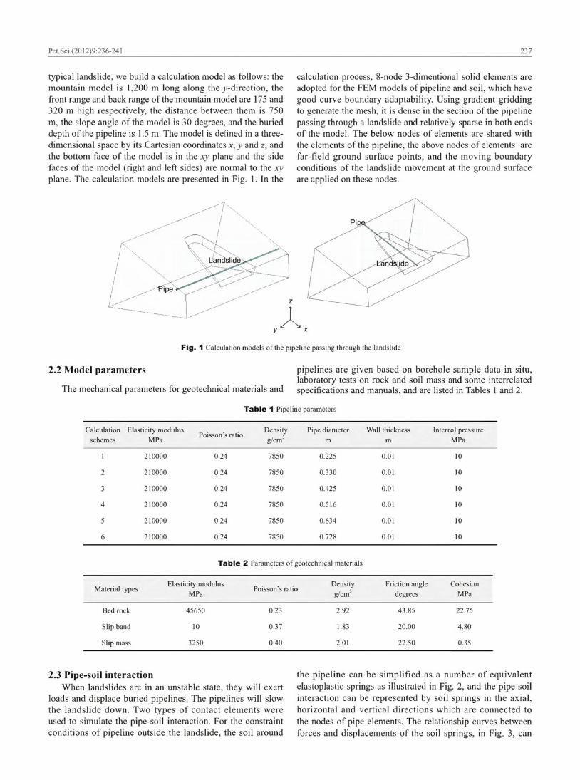
be described by only two parameters, the yield stress and the maximum elastic deformation value. In Fig. 3 Pu, Tu, and Qu represent the yield stresses in the axial, horizontal, and
p t qd qu represent the maximum elastic deformation values in the three directions, respectively, and their calculation formulas can refer to the ASCE guidelines (ASCE, 2001).
For a pipeline inside a landslide, the pipe-soil interaction (PSI) can be simulated using the PSI elements which have only one degree-of-freedom of displacement on nodes. The one side of the PSI element has common nodes shared with the pipe element below, and the nodes on the other sides of the PSI element represent far-yield surface, so the boundary conditions of the ground movement are generally given on these nodes.
The deformation of the PSI elements is the relative
(1) �� �� �
where � �� � � , u f u p is the pipeline displacement, m; e i is the local direction vector.
In Fig. 4, e1 is the axial direction of the pipeline, and e2 is
elements produce strains caused by relative displacement, the stresses will be applied to the nodes at the pipeline. The stress-strain behavior may be linearly elastic, or nonlinearly elastic-plastic, this depends on the constitutive model adopted by the PSI elements.
xy
z
Fig. 2 Idealized representation of soil with discrete springs
(c) Soil spring in the vertical direction Fig. 3 Relationship curves between forces and displacements of soil springs
qu
Qu
Q
qd
Qd
H
e1
e2
e3
PSI element
Pipeline discretedwith beam elements
Pipeline edge
Pipe centerline
Ground surfaceFar-field edge 3
2
1
4
Fig. 4 Diagram of pipe-soil interaction element
The PSI elements are not real to mesh the soil around
of PSI elements. The PSI elements do not include soil density, and the inertia effect of soil can be simulated with the concentrated mass applied to nodes of PSI elements in practical analysis. Based on experimental results, the calculation parameters of the constitutive relation of PSI elements can be determined as follows: the element stiffness in the axial, vertical, and horizontal directions are 730, 1,460 and 1,460 N/m, respectively, the stiffness index is 0.125, and the interface friction angle is 25°.
3 Constitutive equations for the pipe material and the pipeline failure modes
3.1 Constitutive equations
p
Pu
P
p
Pu
(a) Soil spring in the horizontal direction
t
Tu
T
t
Tu
Tu
Tu
t
t
(b) Soil spring in the axial direction
Pet.Sci.(2012)9:236-241

239
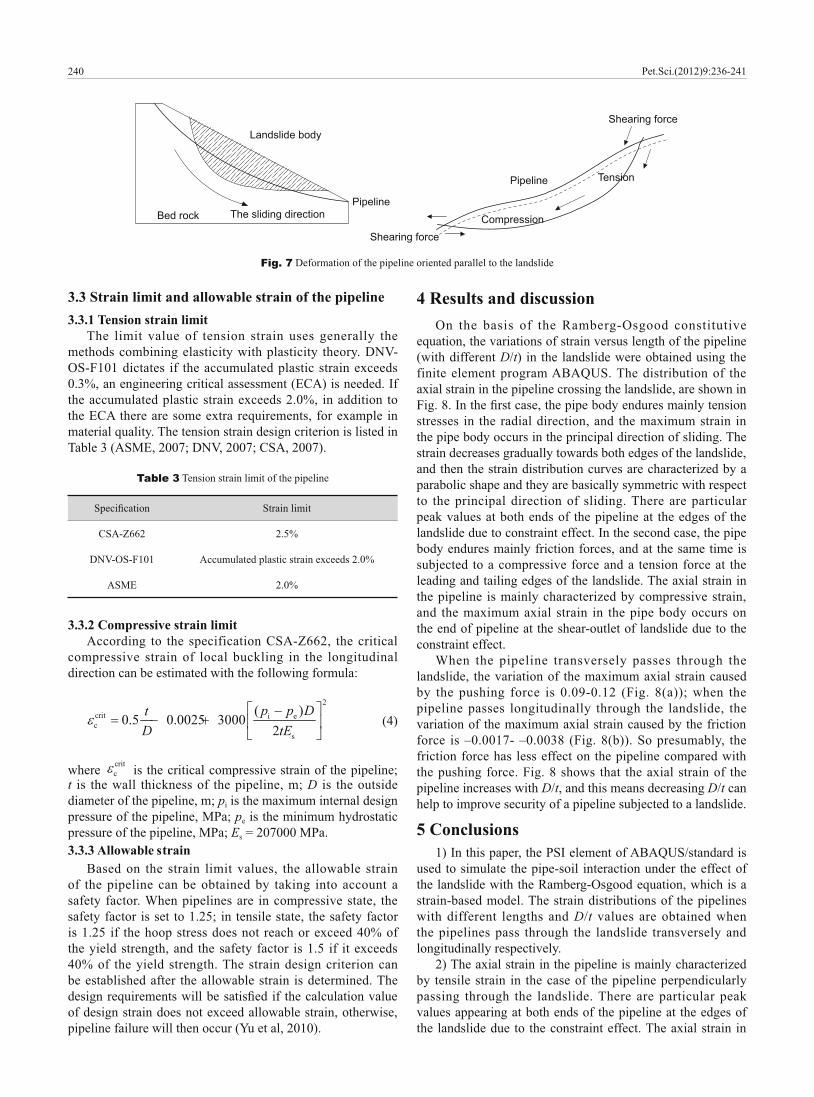
adapted to analyzing the forces applied on the pipeline. One is the trillinear model (as shown Fig. 5(a)), and the stress-strain curve of the pipeline can be divided into three stages in this model, i.e. elastic (E1), elastic-plastic (E2) and plastic stages. The failure will occur when the stress applied on the pipeline exceeds 0 or the strain of the pipeline exceeds 2.
material in the post yield state (Liu and Sun, 2005):
(2)
1
0
�
�
where E is the stiffness of the pipeline in the initial loading state, MPa; is the engineering strain; is the axial tension stress, MPa; 0 is the yield stress of the pipeline, which is generally defined as the stress at 0.5% strain, MPa; and n and are the parameters of Ramberg-Osgood. The practical stress-strain curve of the pipe material can be simulated well with this model within 4% yield strain, and the model is also used to estimate the deformation mode of the pipeline.
ABAQUS /Standard provides a deformation theory, the Ramberg-Osgood plasticity model, for use in developing fully plastic solutions for fracture mechanics applications in ductile metals. The model is most commonly applied in static loading with small-displacement analysis for which the fully plastic solution must be developed in a part of the model.
3.2 Pipeline failure modes
The failure modes of pipelines subjected to landslides are connected with the patterns and angles which pipelines pass through landslides (Lin et al, 2010). If the landslide is perpendicular to the pipeline (as shown Fig. 6), the direction of sliding is perpendicular to the pipeline axis, the pipeline is mainly subjected to a pushing force from the landslide, and subjected to shearing forces at the lateral edges of the landslide. If the landslide is parallel to the pipeline (Fig. 7), the direction of sliding is parallel to the pipeline axis, and then the pipeline is mainly subjected to a friction force caused by the landslide, which could lead to local wrinkling or buckling of the pipe wall. And there are a compressive force and a tensional force applied on the pipeline at the leading and tailing edges of the landslide, respectively, which could lead to tensile failure. The force exerted on the pipeline can be split into vertical and horizontal components when the angle between the pipeline axial direction and the sliding direction is smaller than 90 degrees, and the effects of landslide movement on the pipeline include pushing force, tension force and shearing force.
Another is the Ramberg-Osgood model (as shown Fig. 5(b)), the function suggested by Ramberg-Osgood can be used to describe stress-strain characteristics of the pipeline
Fig. 5 Stress-strain curves of the pipeline
E1
E2
E
( 1, 1)
0
( 2, 2)
E0
(a) Trilinear model
(b) Ramberg-Osgood model
Fig. 6 Deformation of the pipeline passing perpendicularly through the landslide
Pipeline
The sliding direction
Shearing force
Pushing force
Pipeline Shearing force
Pet.Sci.(2012)9:236-241
240
3.3 Strain limit and allowable strain of the pipeline3.3.1 Tension strain limit
The limit value of tension strain uses generally the methods combining elasticity with plasticity theory. DNV-OS-F101 dictates if the accumulated plastic strain exceeds 0.3%, an engineering critical assessment (ECA) is needed. If the accumulated plastic strain exceeds 2.0%, in addition to the ECA there are some extra requirements, for example in material quality. The tension strain design criterion is listed in Table 3 (ASME, 2007; DNV, 2007; CSA, 2007).
Table 3 Tension strain limit of the pipeline
Strain limit
CSA-Z662 2.5%
DNV-OS-F101 Accumulated plastic strain exceeds 2.0%
ASME 2.0%
3.3.2 Compressive strain limitAccording to the specification CSA-Z662, the critical
compressive strain of local buckling in the longitudinal direction can be estimated with the following formula:
(4)2
crit i ec
s
( )0.5 0.0025 3000
2p p Dt
D tE
where critc is the critical compressive strain of the pipeline;
t is the wall thickness of the pipeline, m; D is the outside diameter of the pipeline, m; pi is the maximum internal design pressure of the pipeline, MPa; pe is the minimum hydrostatic pressure of the pipeline, MPa; Es = 207000 MPa.3.3.3 Allowable strain
Based on the strain limit values, the allowable strain of the pipeline can be obtained by taking into account a safety factor. When pipelines are in compressive state, the safety factor is set to 1.25; in tensile state, the safety factor is 1.25 if the hoop stress does not reach or exceed 40% of the yield strength, and the safety factor is 1.5 if it exceeds 40% of the yield strength. The strain design criterion can be established after the allowable strain is determined. The
of design strain does not exceed allowable strain, otherwise, pipeline failure will then occur (Yu et al, 2010).
4 Results and discussionOn the basis of the Ramberg-Osgood constitutive
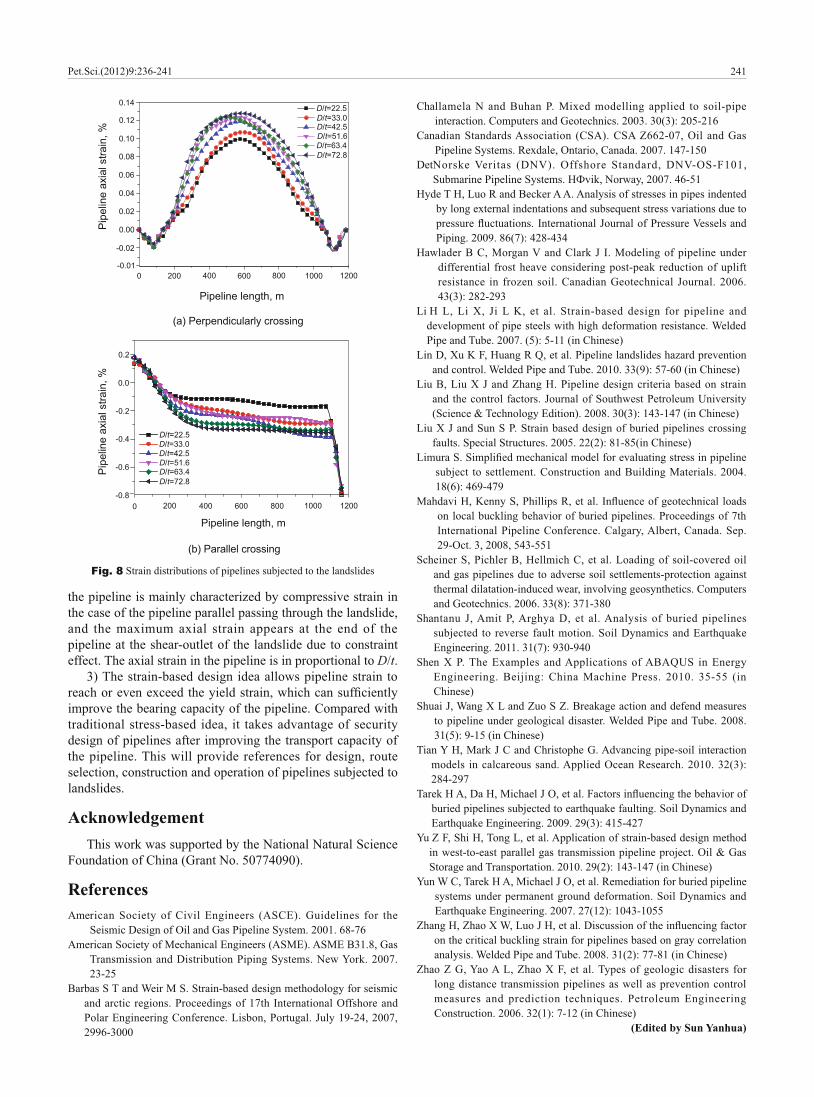
equation, the variations of strain versus length of the pipeline (with different D/t) in the landslide were obtained using the finite element program ABAQUS. The distribution of the axial strain in the pipeline crossing the landslide, are shown in
stresses in the radial direction, and the maximum strain in the pipe body occurs in the principal direction of sliding. The strain decreases gradually towards both edges of the landslide, and then the strain distribution curves are characterized by a parabolic shape and they are basically symmetric with respect to the principal direction of sliding. There are particular peak values at both ends of the pipeline at the edges of the landslide due to constraint effect. In the second case, the pipe body endures mainly friction forces, and at the same time is subjected to a compressive force and a tension force at the leading and tailing edges of the landslide. The axial strain in the pipeline is mainly characterized by compressive strain, and the maximum axial strain in the pipe body occurs on the end of pipeline at the shear-outlet of landslide due to the constraint effect.
When the pipeline transversely passes through the landslide, the variation of the maximum axial strain caused by the pushing force is 0.09-0.12 (Fig. 8(a)); when the pipeline passes longitudinally through the landslide, the variation of the maximum axial strain caused by the friction force is –0.0017- –0.0038 (Fig. 8(b)). So presumably, the friction force has less effect on the pipeline compared with the pushing force. Fig. 8 shows that the axial strain of the pipeline increases with D/t, and this means decreasing D/t can help to improve security of a pipeline subjected to a landslide.
5 Conclusions1) In this paper, the PSI element of ABAQUS/standard is
used to simulate the pipe-soil interaction under the effect of the landslide with the Ramberg-Osgood equation, which is a strain-based model. The strain distributions of the pipelines with different lengths and D/t values are obtained when the pipelines pass through the landslide transversely and longitudinally respectively.
2) The axial strain in the pipeline is mainly characterized by tensile strain in the case of the pipeline perpendicularly passing through the landslide. There are particular peak values appearing at both ends of the pipeline at the edges of the landslide due to the constraint effect. The axial strain in
Fig. 7 Deformation of the pipeline oriented parallel to the landslide
Landslide body
PipelineThe sliding directionBed rock
TensionPipeline
CompressionShearing force
Shearing force
Pet.Sci.(2012)9:236-241
241
the pipeline is mainly characterized by compressive strain in the case of the pipeline parallel passing through the landslide, and the maximum axial strain appears at the end of the pipeline at the shear-outlet of the landslide due to constraint effect. The axial strain in the pipeline is in proportional to D/t.
3) The strain-based design idea allows pipeline strain to
improve the bearing capacity of the pipeline. Compared with traditional stress-based idea, it takes advantage of security design of pipelines after improving the transport capacity of the pipeline. This will provide references for design, route selection, construction and operation of pipelines subjected to landslides.
AcknowledgementThis work was supported by the National Natural Science
Foundation of China (Grant No. 50774090).
References Ame rican Society of Civil Engineers (ASCE). Guidelines for the
Seismic Design of Oil and Gas Pipeline System. 2001. 68-76Ame rican Society of Mechanical Engineers (ASME). ASME B31.8, Gas
Transmission and Distribution Piping Systems. New York. 2007. 23-25
Bar bas S T and Weir M S. Strain-based design methodology for seismic and arctic regions. Proceedings of 17th International Offshore and Polar Engineering Conference. Lisbon, Portugal. July 19-24, 2007, 2996-3000
Cha llamela N and Buhan P. Mixed modelling applied to soil-pipe interaction. Computers and Geotechnics. 2003. 30(3): 205-216
Can adian Standards Association (CSA). CSA Z662-07, Oil and Gas Pipeline Systems. Rexdale, Ontario, Canada. 2007. 147-150
Det Norske Veritas (DNV). Offshore Standard, DNV-OS-F101,
Hyd e T H, Luo R and Becker A A. Analysis of stresses in pipes indented by long external indentations and subsequent stress variations due to
Piping. 2009. 86(7): 428-434Haw lader B C, Morgan V and Clark J I. Modeling of pipeline under
differential frost heave considering post-peak reduction of uplift resistance in frozen soil. Canadian Geotechnical Journal. 2006. 43(3): 282-293
Li H L, Li X, Ji L K, et al. Strain-based design for pipeline and development of pipe steels with high deformation resistance. Welded Pipe and Tube. 2007. (5): 5-11 (in Chinese)
Lin D, Xu K F, Huang R Q, et al. Pipeline landslides hazard prevention and control. Welded Pipe and Tube. 2010. 33(9): 57-60 (in Chinese)
Liu B, Liu X J and Zhang H. Pipeline design criteria based on strain and the control factors. Journal of Southwest Petroleum University (Science & Technology Edition). 2008. 30(3): 143-147 (in Chinese)
Liu X J and Sun S P. Strain based design of buried pipelines crossing faults. Special Structures. 2005. 22(2): 81-85(in Chinese)
subject to settlement. Construction and Building Materials. 2004. 18(6): 469-479
on local buckling behavior of buried pipelines. Proceedings of 7th International Pipeline Conference. Calgary, Albert, Canada. Sep. 29-Oct. 3, 2008, 543-551
Sch einer S, Pichler B, Hellmich C, et al. Loading of soil-covered oil and gas pipelines due to adverse soil settlements-protection against thermal dilatation-induced wear, involving geosynthetics. Computers and Geotechnics. 2006. 33(8): 371-380
Sha ntanu J, Amit P, Arghya D, et al. Analysis of buried pipelines subjected to reverse fault motion. Soil Dynamics and Earthquake Engineering. 2011. 31(7): 930-940
She n X P. The Examples and Applications of ABAQUS in Energy Engineering. Beijing: China Machine Press. 2010. 35-55 (in Chinese)
Shu ai J, Wang X L and Zuo S Z. Breakage action and defend measures to pipeline under geological disaster. Welded Pipe and Tube. 2008. 31(5): 9-15 (in Chinese)
Tia n Y H, Mark J C and Christophe G. Advancing pipe-soil interaction models in calcareous sand. Applied Ocean Research. 2010. 32(3): 284-297
buried pipelines subjected to earthquake faulting. Soil Dynamics and Earthquake Engineering. 2009. 29(3): 415-427
Yu Z F, Shi H, Tong L, et al. Application of strain-based design method in west-to-east parallel gas transmission pipeline project. Oil & Gas Storage and Transportation. 2010. 29(2): 143-147 (in Chinese)
Yun W C, Tarek H A, Michael J O, et al. Remediation for buried pipeline systems under permanent ground deformation. Soil Dynamics and Earthquake Engineering. 2007. 27(12): 1043-1055
on the critical buckling strain for pipelines based on gray correlation analysis. Welded Pipe and Tube. 2008. 31(2): 77-81 (in Chinese)
Zha o Z G, Yao A L, Zhao X F, et al. Types of geologic disasters for long distance transmission pipelines as well as prevention control measures and prediction techniques. Petroleum Engineering Construction. 2006. 32(1): 7-12 (in Chinese)
(Edited by Sun Yanhua)
Fig. 8 Strain distributions of pipelines subjected to the landslides
Pipeline length, m
Pip
elin
e ax
ial s
train
, %D/t=22.5D/t=33.0D/t=42.5D/t=51.6D/t=63.4D/t=72.8
0.14
0.12
0.10
0.08
0.06
0.04
0.02
0.00
-0.02
0 200 400 600 800 1000 1200-0.01
(a) Perpendicularly crossing
0.2
0.0
-0.2
-0.4
-0.6
-0.80 200 400 600 800 1000 1200
Pipeline length, m
Pip
elin
e ax
ial s
train
, %
D/t=22.5D/t=33.0D/t=42.5D/t=51.6D/t=63.4D/t=72.8
(b) Parallel crossing
Pet.Sci.(2012)9:236-241
Related Documents


