Straight Talk: Laser and Coherence Scanning 3D Microscope Capabilities

Welcome message from author
This document is posted to help you gain knowledge. Please leave a comment to let me know what you think about it! Share it to your friends and learn new things together.
Transcript

Straight Talk:Laser and Coherence Scanning 3D Microscope Capabilities

Outline
10/31/2013 2Bruker Confidential
• Introductions
• Brief overview of 3D optical microscope techniques
• Common misunderstandings about 3D microscopes based on interference/coherence techniques
• Examples of imaging metrology applications
• Summary

IntroductionsBruker Nano Surfaces Division
10/31/2013 3Bruker Confidential
• Scanning Probe Microscopy
• 3D Optical Microscopy
• Stylus Profilometry
• Tribology and Mechanical Testing

IntroductionsBruker Stylus and Optical Metrology
10/31/2013 4Bruker Confidential
• Technology Leadership
• 60+ Patents
• 3 R&D 100 Awards
• 6 Photonics Circle of Excellence Awards
• Manufacturing Excellence
• Lean, six sigma-based process
• >100 systems/quarter capacity
• Rapid production ramp capability
Bruker NSD SOM is part of Bruker Materials (BMAT), a division of Bruker

IntroductionsSpeaker
Matt Novak, Ph.D.
Manager, Applications Development
Stylus and Optical Metrology
• Applications at Bruker (approaching 3 years)
• Industry experience (~17 years) optical engineering, fabrication and metrology
• Earned Ph.D. working in private sector metrology capital equipment
10/31/2013 5Bruker Confidential

Why “Straight Talk?”Balanced Information on 3D Microscopes
10/31/2013 6Bruker Confidential
Money
Search for and
Purchase Equipment
Time
Tool Training and Learning
..to increase Productivity
Value from metrology
Capital metrology equipment is an investment in…
Experience shows industry partners have lost all three of these due to some more prevalent misunderstandings
• Technicians, engineers, and researchers faced with choices about metrology with 3D imaging microscopes
• Those that have heard it is difficult to use 3D microscopes based on interference technology
• People who have had poor results from 3D microscopes based on interference
• LSCM users who like the performance but need faster images for larger areas
Who Will Benefit?Intended Webinar Audience
10/31/2013 7Bruker Confidential
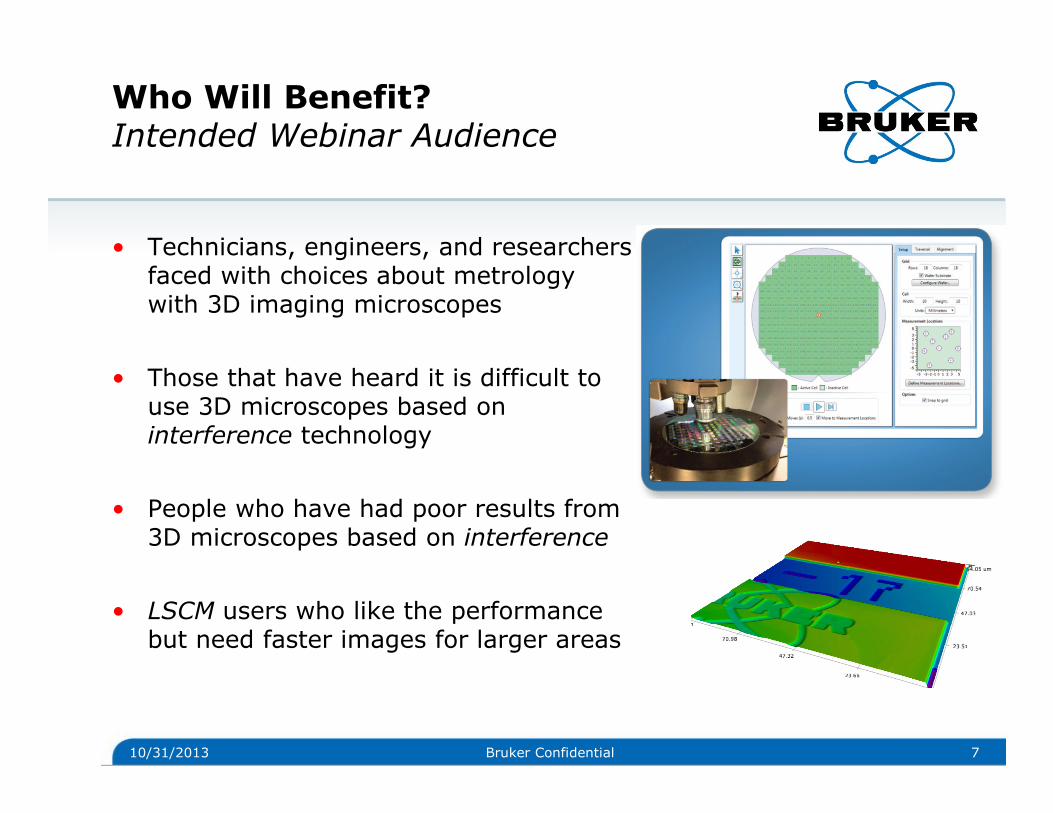
• Be aware of 3D microscope techniques for metrology at nm, µm and mmscales
• Know why 3D microscopes based on light coherence are among the world’s fastest and most capable for all ranges
• Be able to decide with confidencewhether this type of 3D microscope is right for your needs
• Know the value delivered for accurate, gage capable imaging metrology by this core technology
Key Value from WebinarAfter the Presentation You Will…
10/31/2013 8Bruker Confidential

Outline
10/31/2013 9Bruker Confidential
• Introductions
• Brief overview of 3D optical microscope techniques
• Common misunderstandings about 3D microscopes based on interference/coherence techniques
• Examples of imaging metrology applications
• Summary

Overview of 3D Optical MicroscopesExample Technology Implementations
10/31/2013 10Bruker Confidential
You may be familiar with or have heard of…
Digital Scanning (DSM)
Axial Chromatic Confocal
Laser Scanning Confocal (LSCM)
Spinning Disk Confocal (SDCM)
Coherence Scanning Interference (CSIM)
White Light Interference (WLIM)
Focus Variation
3D optical microscopes – choices abound!
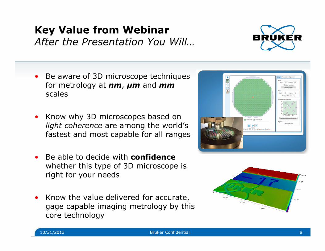
Overview of 3D Optical MicroscopesFocus on Two Key Industry Technologies
10/31/2013 11Bruker Confidential
LS
CM • Two Sensors (CCD
and PMT sensor for laser scan)
• Raster Scan XY with laser for each image section
• Scan optics (sample) vertically to build 3D
WL
IM
• CCD is image and height data sensor
• Full image section obtained at camera frame rate
• Height data computed from interference information

LSCM Laser Scanning MicroscopeBrief Overview of Operation
10/31/2013 12Bruker Confidential
XY Scanning
Assembly
White light
source
CCD
LaserHalf mirror
Half mirror
Half
mirror Pinhole
PMT SensorSample
Condensing
lens
Light intensity builds height map
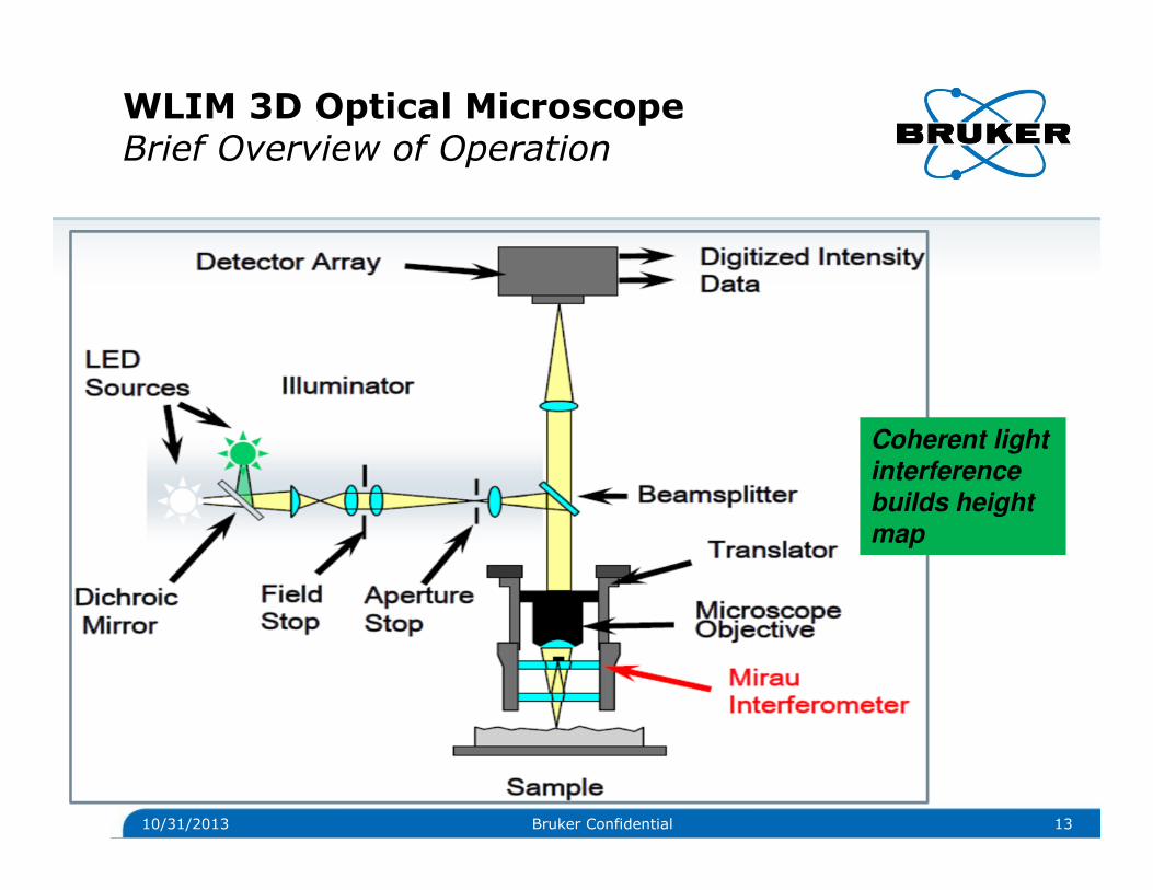
WLIM 3D Optical MicroscopeBrief Overview of Operation
10/31/2013 13Bruker Confidential
Coherent light interference builds height map

Outline
10/31/2013 14Bruker Confidential
• Introductions
• Brief overview of 3D optical microscope techniques
• Common misunderstandings about 3D microscopes based on interference/coherence techniques
• Examples of imaging metrology applications
• Summary

Common Misconceptions – WLIMStraight Talk on Various Topics
You may have heard someone say WLI 3D microscopes…
• …are hard to use
• …can’t measure steep slopes or roughness
• …can’t provide color images
• …can’t measure low reflectance surfaces
• …have poor signal because “out of focus” light intrudes
In reality end users will find WLI 3D microscopes…
• …are fast, easy to set up
• …can measure 60°+ slopes and roughness
• …can image with color CCD
• …can measure surfaces with <0.05% reflectance
• …have excellent SNR, resolution and accuracy
10/31/2013 15Bruker Confidential

10/31/2013 16Bruker Confidential
• Next slides show key concepts about technologies (LSCM and WLIM)
• Concepts illustrate how 3D microscope systems under discussion address 3D areal measurement
• Focus on key concepts will help you decide which technology will provide fastest, highest quality data best suited for your needs
• Other misunderstandings about WLIM systems will be addressed with example applications
Common Misconceptions – WLIMKey Technical Concepts

LSCM 3D Optical Microscope Key PointBroader Intensity Signal, Sharper at High Magnification
10/31/2013 17Bruker Confidential
Practical Implication: Highest accuracy data at high magnification and image stitching
Good for single FOV applications or applications where vertical resolution is unimportant, speed not critical

WLIM 3D Optical Microscope Key PointSharp Coherence Signal, Sharp at All Magnifications
10/31/2013 18Bruker Confidential
Practical Implication: Highest accuracy data on areas of interest obtained fastest at lowest magnifications
Great where a large area with good resolution is required, speed is critical

LSCM and WLIM Comparison Key PointMethods of 3D Image Acquisition
10/31/2013 19Bruker Confidential
Practical Implication: Imaging extended areas at useful vertical resolution is fastest with WLI 3D microscopes
Larger vertical sample range - greater WLIM speed advantage

Outline
10/31/2013 20Bruker Confidential
• Introductions
• Brief overview of 3D optical microscope techniques
• Common misunderstandings about 3D microscopes based on interference/coherence techniques
• Examples of imaging metrology applications
• Summary

3D Microscopes ApplicationsGround Shaft Defect, Automatic Detection
10/31/2013 21Bruker Confidential
1.7 mm x 2.3 mm area
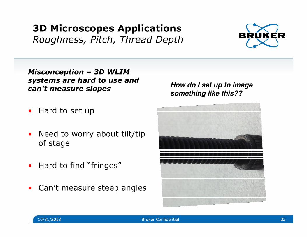
3D Microscopes ApplicationsRoughness, Pitch, Thread Depth
Misconception – 3D WLIM systems are hard to use and can’t measure slopes
• Hard to set up
• Need to worry about tilt/tip of stage
• Hard to find “fringes”
• Can’t measure steep angles
10/31/2013 22Bruker Confidential
How do I set up to image something like this??

3D Microscopes ApplicationsRoughness, Pitch, Thread Depth
10/31/2013 23Bruker Confidential
Reality
Vertical scan ~ 700 microns
Angle 55.1°°°°
Time to Data < 30 seconds
(place part, find focus, measure)
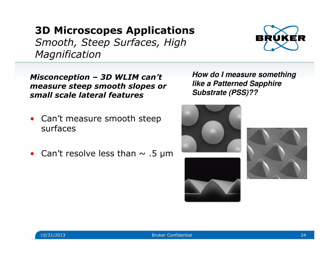
3D Microscopes ApplicationsSmooth, Steep Surfaces, High Magnification
Misconception – 3D WLIM can’t measure steep smooth slopes or small scale lateral features
• Can’t measure smooth steep surfaces
• Can’t resolve less than ~ .5 µm
10/31/2013 24Bruker Confidential
How do I measure something like a Patterned Sapphire Substrate (PSS)??

3D Microscopes ApplicationsHBLED PSS Structure Metrology
10/31/2013 25Bruker Confidential
Reality
PSS can be measuredusing 3D WLIM
~ 15 µm x 15 µm FOV (115X)
Time to Data < 7 secondsper wafer site
(auto focus, measure)

3D Microscopes ApplicationsRoughness Metrology
10/31/2013 26Bruker Confidential
Misconception – 3D WLIM can’t measure surface roughness
• Can’t correlate to stylus measurement of Ra
• Can’t properly image any machined surfaces

3D Microscopes ApplicationsExample Roughness Metrology
10/31/2013 27Bruker Confidential
Reality
Roughness can be measured
using 3D WLIM
ISO 4287 and 4288 standards
ensure comparisons
ISO 25178-2 for 3D areal data

3D Microscopes ApplicationsLow/Variable Reflectance Step Metrology
Misconception – 3D WLIM systems cannot measure low and different reflectance samples
• Dark plastic, black materials can’t be measured
• Low reflectance causes problems for 3D WLI microscopes
10/31/2013 28Bruker Confidential
How do I image and measure areas of high and low reflectance, like this?

10/31/2013 29Bruker Confidential
3D Microscopes ApplicationsLow/Variable Reflectance Step Metrology
Reality
3D WLIM can image
low/variable
reflectance samples
USB insertion Depth ~450 µmOver 4 mm x 4 mm area
Z resolution ~ 3 nm
Time to Data ~ 40 seconds
(place part, focus, measure)

3D Microscopes ApplicationsExample Color Imaging + Metrology
Misconception – 3D WLIM systems cannot produce a color image
• Monochrome only 3D WLI systems can’t measure and image in color
• Can’t tell materials apart in WLI systems
10/31/2013 30Bruker Confidential
How do I image this and see colors as well as height?

10/31/2013 31Bruker Confidential
3D Microscopes ApplicationsCu Wire Bond Cavity Depth, IMC Formation Inspection
Reality
3D WLIM can image color
Wire Bond Cavity, Depth ~ 1 µm
Time to Data < 15 seconds Color image using interferometric objective

3D Microscopes ApplicationsExample Diffuse Surface Imaging + GR&R
Misconception – 3D WLIM systems provide poor signal on low reflection/dark/diffuse surfaces
• “Quasi confocal” systems suffer from poor signal due to light pollution
• Difficult to measure diffuse or rough surfaces accurately
10/31/2013 32Bruker Confidential
How do I image this and obtain meaningful metrology data?

10/31/2013 33Bruker Confidential
3D Microscopes ApplicationsExample Diffuse Surface Imaging + GR&R
Reality
3D WLIM can image diffusesurfaces over large area
Sensor Depth ~ 30 µm
GR&R < 5% for production standard lsl and usl
Time to Data < 30 seconds
(place part, focus, measure)

3D Microscopes ApplicationsMicrofluidic Example Trench + Defect
10/31/2013 34
• Geometries conducive to 3D imaging metrology
• Trench widths, depths on order of few to ~ 25 µm
Etched Si 1.5 µm x 7 µmchannels with defect (center) Time to data < 10 seconds
with 3 nm vertical resolution

Outline
10/31/2013 35Bruker Confidential
• Introductions
• Brief overview of 3D optical microscope techniques
• Common misunderstandings about 3D microscopes based on interference/coherence techniques
• Examples of imaging metrology applications
• Summary
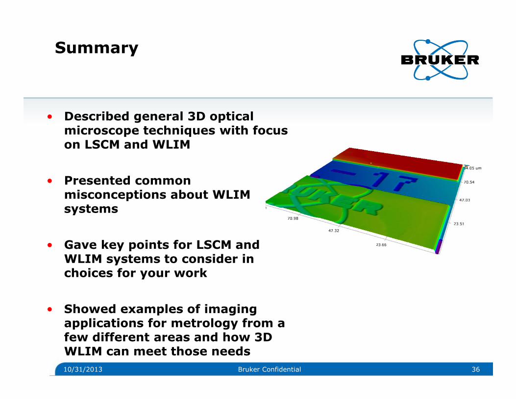
Summary
• Described general 3D optical microscope techniques with focus on LSCM and WLIM
• Presented common misconceptions about WLIM systems
• Gave key points for LSCM and WLIM systems to consider in choices for your work
• Showed examples of imaging applications for metrology from a few different areas and how 3D WLIM can meet those needs
10/31/2013 36Bruker Confidential


© Copyright Bruker Corporation. All rights reserved.
www.bruker.com
Related Documents