STORMWATER QUALITY CONTROL GUIDELINES The purpose of these guidelines is to help property owners, developers, and applicants design and implement their projects in compliance with local, state, and federal regulations to reduce stormwater runoff and pollution potential, reduce erosion and sedimentation, and protect water quality. These guidelines apply to both private development projects and municipal capital improvement projects. At a minimum, development projects with significant stormwater pollution potential are required to mitigate impacts through implementation of Best Management Practices 1 (BMPs) to the maximum extent practicable. 2 If sufficient site planning or design measures are not implemented to the maximum extent practicable, then the development project must include post-construction BMPs and/or treatment control BMPs. A development with significant stormwater pollution potential is one that includes one or more of the following. A project located in the Hillside Overlay District which creates and/or replaces 500 square feet or more of impervious surfacing. A project that causes substantial or potentially substantial adverse change in the quantity and/or quality of stormwater runoff generated from the site. A project that is constructed in a sensitive area in which plant or animal life or their habitats are rare or especially valuable, including any area in the following categories: Habitats containing or supporting “rare and endangered” species as defined by the State Fish and Game Commission; Perennial and intermittent streams and their tributaries that support aquatic habitat; Riparian corridors; and Wetlands. A project which results in a land disturbance of one acre or more. A project that consists of a total parcel size of five acres or more. 1 Best Management Practices (BMPs) are activities, prohibition of practices, maintenance procedures, and other management practices to prevent or reduce impacts on water quality. BMPs also include treatment requirements, operating procedures, and practices to control site runoff, spillage or leaks, waste disposal, or drainage from raw material storage. 2 Maximum extent practicable (MEP) is a term used in the 1987 Clean Water Act. It is not defined by Federal law or regulation. When reviewing proposed development projects, City staff uses current performance standards and best professional judgment to determine whether proposed stormwater controls meet the “maximum extent practicable.” Planning Services Division 3675 Mt. Diablo Boulevard, Suite 210 Lafayette, CA 94549 Tel. (925) 284-1976 • Fax (925) 284-1122 http://www.ci.lafayette.ca.us

Welcome message from author
This document is posted to help you gain knowledge. Please leave a comment to let me know what you think about it! Share it to your friends and learn new things together.
Transcript
STORMWATER QUALITY CONTROL GUIDELINES The purpose of these guidelines is to help property owners, developers, and applicants design and
implement their projects in compliance with local, state, and federal regulations to reduce stormwater
runoff and pollution potential, reduce erosion and sedimentation, and protect water quality. These
guidelines apply to both private development projects and municipal capital improvement projects. At
a minimum, development projects with significant stormwater pollution potential are required to
mitigate impacts through implementation of Best Management Practices1 (BMPs) to the maximum
extent practicable.2 If sufficient site planning or design measures are not implemented to the
maximum extent practicable, then the development project must include post-construction BMPs
and/or treatment control BMPs.
A development with significant stormwater pollution potential is one that includes one or more of the following.
A project located in the Hillside Overlay District which creates and/or replaces 500 square feet or
more of impervious surfacing.
A project that causes substantial or potentially substantial adverse change in the quantity and/or
quality of stormwater runoff generated from the site.
A project that is constructed in a sensitive area in which plant or animal life or their habitats are
rare or especially valuable, including any area in the following categories:
Habitats containing or supporting “rare and endangered” species as defined by the State Fish
and Game Commission;
Perennial and intermittent streams and their tributaries that support aquatic habitat;
Riparian corridors; and
Wetlands.
A project which results in a land disturbance of one acre or more.
A project that consists of a total parcel size of five acres or more.
1 Best Management Practices (BMPs) are activities, prohibition of practices, maintenance procedures, and other
management practices to prevent or reduce impacts on water quality. BMPs also include treatment requirements, operating
procedures, and practices to control site runoff, spillage or leaks, waste disposal, or drainage from raw material storage.
2 Maximum extent practicable (MEP) is a term used in the 1987 Clean Water Act. It is not defined by Federal law or
regulation. When reviewing proposed development projects, City staff uses current performance standards and best
professional judgment to determine whether proposed stormwater controls meet the “maximum extent practicable.”
Planning Services Division 3675 Mt. Diablo Boulevard, Suite 210
Lafayette, CA 94549
Tel. (925) 284-1976 • Fax (925) 284-1122
http://www.ci.lafayette.ca.us

2
Table 1 provides a summary of site planning practices and post-construction BMPs by development
type. This table and the following descriptions should be used to determine appropriate site planning
and design options and acceptable BMPs depending on project-specific characteristics. Detailed
guidance on site planning and design options can be found in Start at the Source by the Bay Area
Stormwater Management Agencies Association.3 Additional BMP guidance can be found in the
California Stormwater Best Management Practices Handbooks.4
In addition, a development project may be subject to the C.3 provisions of the City’s National Pollutant
Discharge Elimination System (NPDES) Permit if it creates or replaces 2,500 square feet or more of
impervious area. For more information on the C.3 provisions, see the attached handout or the Contra
Costa Clean Water Program’s Stormwater C.3 Guidebook available at www.cccleanwater.org.
PART I – SITE PLANNING PRACTICES
Minimizing impacts on stormwater quality from projects during the site planning and design phase is
the most effective way to reduce impacts on stormwater quality and runoff and reduce the need for
treatment control BMPs. Source control measures, site design and landscape features, and other
stormwater management BMPs should be included during the pre-design, planning phase of a project.
All proposed projects should use the following (or equivalent) site planning and design practices
whenever possible.
A. Planning and open space design options.
i.) Cluster/infill development. Clustering or concentrating development can minimize total
impervious area, conserve natural areas, provide community space, and promote
watershed protection.
ii.) Open space design. Preserve natural topography, existing drainage courses and existing
vegetation. Protect areas that provide water quality benefits and/or are necessary to
maintain riparian and aquatic biota. Clearing and grading of native vegetation should be
limited to the minimum needed to build lots, allow access, and provide fire protection.
Any land disturbance should result in a naturally appearing slope or landform. Provide
undeveloped, vegetated buffer zones between development and streams, wetlands,
drainage areas, etc.
B. Minimize directly connected impervious area (DCIA). This is one of the most important site
planning and design options for stormwater quality protection as impervious areas directly
connected to the storm drain system or surface water body are the greatest contributor to
stormwater pollution. Directly connected impervious surface is any area covered by pavement,
building roofs, and other impervious surfaces that drain directly into a catch basin, area drain,
or other conveyance structure. Impervious areas draining directly into filtration devices would
not be considered a DCIA. Minimizing DCIA can be achieved in two ways: 1) limiting overall
impervious land coverage and 2) directing runoff to pervious areas for infiltration,
retention/detention, or filtration before finally discharging downstream to water bodies or the
3 Start at the Source is available through www.basmaa.org.
4 The Handbooks are available through www.cabmphandbooks.com.
3
municipal storm drain system. For example, drain some or all runoff to adjacent landscaping
for bio-filtration. Drain some or all runoff to treatment structures (swales, sand/media filters,
detention basins).
C. Minimization of hardscape areas. The hardscape or impervious areas of a site should be
minimized in order to maximize permeable surfaces which absorb and biodegrade certain
toxins. This will also reduce the volume of runoff into the storm drainage system or surface
water body.
D. Permeable pavement options. Use porous alternatives to impermeable surfacing such as
pervious concrete, porous asphalt, turf block, brick, natural stone, concrete unit pavers, crushed
aggregate, and cobbles. For residential projects, hardscape areas in yards should utilize
alternative surfaces such as raised wood decks, pavers, unmortared brick, stone or tile which
allow absorption at joints and reduce runoff. Similar surface materials should be used for areas
such as sideyards and entry walkways. It is important to note that pervious surface materials
should be constructed on a pervious base such as gravel or sand, and not concrete, in order to
be effective. Furthermore, some balance needs to be considered in areas having geotechnical
stability concerns.
E. Driveway design options. Imperviousness can be reduced by designing shared driveways that
connect two or more homes together and by using alternative methods and materials such as
crushed aggregate, unit pavers on sand, paving only under wheel paths, and flared driveways.
Direct impervious driveways to pervious areas for infiltration prior to entering the stormwater
system.
F. Landscape options. Parking areas and other expanses of impervious surface should drain into
existing vegetation or new vegetated areas such as swales and concave median strips designed
to promote infiltration. Swales and median strips can filter out, absorb, and biodegrade certain
toxins before the remaining runoff discharges into the storm drain system. Vegetative swales
can be incorporated into the required perimeter landscaping of a project. Select plant species
for their filtering and infiltration potential. Design for low-maintenance landscaping including
native species, water conservation measures, and integrated pest management. Design efficient
irrigation systems and minimize overspray and excess runoff. Minimize use of fertilizers,
herbicides, and pesticides.
G. Building design and construction options.
i.) Direct rooftop to pervious areas. Roof top drains should be directed to on-site pervious
areas such as yards, open channels, or vegetated areas where lot size and soil conditions
are adequate to absorb such runoff. (Not appropriate for slopes > 10%.) Avoid routing
rooftop runoff to the roadway and the stormwater conveyance system. Several
downspouts should be provided to better distribute rain runoff to pervious areas.
Downspout pop-up drains located in lawns have been used effectively to achieve this
objective.
ii.) Building size. Reduce the size of the building footprint to allow for more pervious area.
4
iii.) Benign roofing materials. Avoid roofing, gutters, and trim made of copper or other
unprotected metals that could leach into runoff.
iv.) Alternative building materials. Use alternative building materials that incorporate green
technology, use less toxic materials in their manufacture, or require minimal maintenance.
Plastic and plastic-wood composites do not need to be pressure treated, a process
requiring the use of toxic and poisonous materials that can leach into runoff. Use sand
and metal barriers for pest control instead of chemicals or chemically treated materials.
v.) Water storage systems. Incorporate dry-wells or cisterns for water retention and/or reuse
into building design. Except as a last resort, avoid using oversized underground pipes as
a retention facility. They are difficult to maintain in the long-term.
H. Sidewalk and street design options.
i.) Sidewalk design. Where practical, locate sidewalks on only one side of the street, provide
common walkways linking pedestrian areas, and use pervious materials.
ii.) Reduce residential street width and rights-of-way. Design residential streets and rights-
of-way for minimum pavement width needed to support travel lanes; on-street parking;
emergency, maintenance, and service vehicle access, and open channels. Street widths
should be based on traffic volume. Utilities and storm drains should be located within the
pavement section of the right-of-way.
iii.) Reduce residential street length. Reduce the total length of residential streets by
examining alternative layouts that increase the number of homes served per unit length.
iv.) Minimize cul-de-sacs. Minimize the number of residential street cul-de-sacs and
incorporate landscaped areas to reduce their impervious cover. The radius should be the
minimum needed for emergency and maintenance vehicles. Alternative turnarounds
should be considered.
v.) Curb/swale system. Minimize the use of curbs and gutters which concentrate and direct
runoff. Use vegetated open channels to convey and treat stormwater runoff where
density, topography, soils and slope permit such a design.
I. Parking lot options.
i.) Reduce parking lot imperviousness. Reduce the impervious cover of parking lots by
incorporating efficient parking lanes and using pervious materials in spillover parking areas.
ii.) Stormwater treatment on parking lots. Provide stormwater treatment for parking lot
runoff using bioretention areas, filter strips, and other practices that can be integrated into
required landscaping areas and traffic islands.
iii.) Hybrid parking lot. Reduce impervious surface coverage by using impervious materials
for driving aisles and permeable materials such as pervious concrete, unit pavers, crushed
aggregate, porous asphalt, and turf block for stalls or low traffic areas.
5
iv.) Parking grove. Use a grid of trees and bollards on pervious material to delineate parking
stalls and create a parking grove. This design not only shades parked cars but also
presents an attractive open space when cars are absent.
J. Pollution Prevention Measures.
i.) Improve stormwater management. Implement design features and BMPs so that new
stormwater outfalls do not discharge unmanaged stormwater into jurisdictional wetlands,
creeks, or sensitive areas.
ii.) Design features as treatment. Design courtyards, plazas, and amenity open space to store,
filter or treat rainfall. Plumb new pools to drain to the sanitary sewer system. Drain decorative ponds, fountains, or spas to the sanitary sewer system.
PART II – CONSTRUCTION BMPs
Projects should minimize erosion and control sediment during and after construction. Submittal of an
erosion and sediment control plan or, for projects one acre or greater in size, a stormwater pollution
prevent plan (SWPPP) is usually required prior to issuance of a building permit. The plan should
specify all control measures that will be used or which are anticipated to be used, including but not
limited to those listed below. For more specific information on these control measures, refer to the
City’s handout Minimum Construction Site Management Practices for Stormwater Pollution
Prevention.
Limit access routes and stabilize driveways and access points.
Phase construction to limit areas and periods susceptible to erosion impacts.
Stabilize areas denuded by construction activities as soon as possible with seeding, mulching, sod
stabilization, vegetative buffer strips, plastic covering, or application of ground base on areas to
be paved.
Protect adjacent properties with vegetative buffer strips, sediment barriers or filters, dikes or
mulching.
Delineate clearing limits, easements, setbacks, sensitive or critical areas and their buffers, and
trees and drainage courses by marking them in the field.
Stabilize and prevent erosion from temporary conveyance channels and outlets.
Use sediment controls and filtration to remove sediment from water generated by dewatering or
collected on-site during construction.
Install permanent erosion controls (e.g. retaining wall, slope protection, outfall energy dissipater)
for slopes greater than 10 percent.
6
Use proper construction material and construction waste storage, handling, and disposal
practices.
Use proper vehicle and equipment cleaning, fueling, and maintenance practices.
Control and prevent the discharge of all potential pollutants, including but not limited to,
pesticides, petroleum products, nutrients, solid wastes, and construction chemicals.
Prepare a contingency plan in the event of unexpected rain or BMP failure, including but not
limited to, an immediate response plan, storing extra or alternative control materials onsite
(stakes, fences, hay bales), notifying the local agency, etc.
PART III – POST-CONSTRUCTION BMPs
The goals of post-construction BMPs are to prevent and control erosion and sedimentation, provide
source control of potential pollutants, control and treat runoff, and protect wetlands and water quality
resources. Post-construction BMPs are required if a project cannot achieve stormwater quality
standards through site-planning measures alone. Vegetative swales or other biofilters are
recommended as the preferred choice for post-construction BMPs for all projects with suitable
landscape areas, because these measures are relatively economical and require limited maintenance.
For projects where landscape based treatment is impracticable, or insufficient to meet required design
criteria, other post-construction BMPs should be incorporated. All post-construction BMPs must be
maintained to operate effectively. The BMPs listed below can be routinely designed into a project to
control specific sources of pollutants once a project is completed.
A. Education and Training. Provide practical information materials on good housekeeping of
hazardous products, proper use and disposal for hazardous products, and prohibited discharge
practices and materials to residents and tenants.
B. Roof Downspout System. Direct roof drains to pervious areas to allow infiltration prior to
discharging to water bodies or the municipal storm drain system.
C. Runoff Control. Maintain post-development peak runoff rate and average volume of runoff at
levels that are similar to pre-development levels.
D. Stream Erosion Control. Direct runoff through an erosion control structure such as an energy
dissipater or other form of outlet protection prior to entering the stream or other water body.
Biotechnical controls should be used for stream bank protection whenever possible.
E. Vegetated Filter Strip. Use vegetated filter strips to treat sheet flow.
F. Swales and/or Flow-Through Planters. Drainage from all paved surfaces, including streets,
parking lots, driveways, commercial drive-through areas, and roofs should be routed through
swales, buffer strips or flow-through planters prior to discharge to the storm drain system.
Roof downspout systems can alternatively be used to treat roof drainage.
7
G. Labeling and Maintenance of Storm Drain Facilities. Label new storm drain inlets with "No
Dumping-Drains to Bay" to alert the public to the destination of stormwater and to prevent
direct discharge of pollutants into the storm drain.
H. Vehicle/Equipment Cleaning. Commercial/industrial facilities or multi-family residential
developments of 50 units or greater should either provide a covered, bermed area for washing
activities or discourage vehicle/equipment washing by removing hose bibs and installing signs
prohibiting such uses. Vehicle/equipment washing areas shall be paved, designed to prevent
run-on or runoff from the area, and plumbed to drain to the sanitary sewer.
Commercial car wash facilities shall be designed and operated such that no runoff from the
facility is discharged to the storm drain system. Wastewater from the facility shall discharge to
the sanitary sewer or wastewater reclamation system.
I. Common Area Litter Control. Implement trash management and litter control for commercial
and industrial projects or large-scale residential developments to prevent litter and debris from
being carried to water bodies or the storm drain system.
J. Food Service Facilities. Design food service facilities (including restaurants and grocery
stores) to have a sink or other area for cleaning floor mats, containers, and equipments, that is
connected to a grease interceptor prior to discharging to the sanitary sewer system. The
cleaning area should be large enough to clean the largest mat or piece of equipment to be
cleaned.
K. Refuse Areas. Trash compactors, enclosures and dumpster areas should be covered and
protected from roof and surface drainage. Install a self-contained drainage system that
discharges to the sanitary sewer if water cannot be diverted from the areas.
L. Outdoor Storage Controls. Oils, fuels, solvents, coolants, and other chemicals stored outdoors
must be in containers and protected from drainage by secondary containment structures such as
berms, dikes, liners, vaults or roof covers and/or drain to the sanitary sewer system. Bulk
materials stored outdoors must also be protected from drainage with berms and covers. Process
equipment stored outdoors must be inspected for proper function and leaks, stored on
impermeable surfaces and covered. Implement a regular program of sweeping and litter control
and develop a spill cleanup plan for storage areas.
M. Cleaning, Maintenance and Processing Controls. Areas used for washing, steam cleaning,
maintenance, repair or processing must have impermeable surfaces and containment berms,
roof covers, recycled water wash facility, and discharge to the sanitary sewer. Discharges to
the sanitary sewer may require pretreatment systems and/or approval of an industrial waste
discharge permit.
N. Loading Dock Controls. Design loading docks to be covered, surrounded by berms or curbs, or
constructed to prevent drainage onto or from the area. Position roof downspouts to direct
stormwater away from the loading area. Water from loading dock areas shall be drained to the
sanitary sewer, or diverted and collected for ultimate discharge to the sanitary sewer. Door
skirts between the trailers and the building should be installed to prevent exposure of loading
activities to rain.
8
O. Street Sweeping. Implement a program to regularly sweep streets, sidewalks and parking lots
to prevent the accumulation of litter and debris. Debris resulting from pressure washing should
be trapped and collected to prevent entry into the storm drain system. Washwater containing
any cleaning agent or degreaser should be collected and discharged to the sanitary sewer.
P. Fuel Dispensing Controls. Fuel dispensing areas must be on impermeable surfaces extending
10 to 12 feet beyond the actual dispensing area and covered. They must be constructed to
prevent drainage across or from the dispensing area, and must drain to a sump/tank or clarifier
to allow for testing and interruption of stormwater flow before discharge to the storm drain
system.
PART IV – TREATMENT CONTROL BMPs
If sufficient site planning, design measures, or post-construction BMPs are not implemented to the
maximum extent practicable, then the development project must include treatment control BMPs.
Stormwater systems must be designed to address the environmental effects of non-point source
pollution and increases in runoff volume and velocity caused by the development. There are four basic
strategies for treating runoff.
Infiltrate runoff into the soil (examples: infiltration trench, infiltration basin, or
retention/irrigation)
Retain/detain runoff for later release with the detention providing treatment (examples: wet
pond or extended detention “dry” basin)
Convey runoff slowly through vegetation (example: vegetated swale, vegetated buffer strip, or
bioretention)
Treat runoff on a flow-through basis using various treatment technologies (examples: wet vaults
or separators5)
BMPs should be based on site conditions and sized in accordance with one or more of the following
volume and flow based hydraulic design criteria,
A. Volume-based design. Design criteria for treatment measures relying on infiltration and detention.
i.) The maximized stormwater capture volume for the area, based on historical rainfall records,
determined using the formula and volume capture coefficients set forth in Urban Runoff
Quality Management, WEF Manual of Practice No. 23/ASCE Manual of Practice No. 87,
(1998), pages 175-178, or
ii.) Volume of annual runoff required to achieve 80% or more capture, determined in accordance
with the methodology in Section 5.5.1 and Appendix D in the California Stormwater Quality
5 According to the Regional Water Quality Control Board, drain inlet filters and oil/water separators in their current form
have very limited ability to effectively remove pollutants found in urban runoff and use of these devices as a stand-
alone treatment control does not meet the Maximum Extent Practicable compliance standard.
9
Association Stormwater Best Management Practice, New Development and Redevelopment
Handbook (2003), using local rainfall data.
B. Flow-based design. Design criteria for treatment measures relying on filtration (e.g., swales, sand
filters, or wetlands)
i.) Intensity-duration-frequency – An option based on ten percent of the 50-year peak flow rate,
or
ii.) Percentile rainfall intensity – An option based on the runoff flow produced by a rain event
equal to at least two times the 85th percentile hourly rainfall intensity based on historical
records of hourly rainfall depths, or
iii.) 0.2 inches/hour – An option based on the runoff flow resulting from a rain event equal to at
least 0.2 inches per hour intensity (this is the recommended option).
C. Treatment BMPs. Appropriate treatment controls include public domain BMPs and manufactured
(proprietary) BMPs such as wet ponds, constructed wetlands, vegetated swales, bioretention, and
wet vaults. See the California Stormwater Quality Association Stormwater Best Management
Practice Handbooks for fact sheets on the various treatment controls.
D. Operation and maintenance. The long-term performance of BMPs hinges on ongoing and
proper maintenance. An operation and maintenance agreement must be provided by the project
sponsor for any project using treatment control BMPs. See Appendix F of the Stormwater C.3
Guidebook for guidance on preparing an operation and maintenance plan.
Rev. 2006.10.01
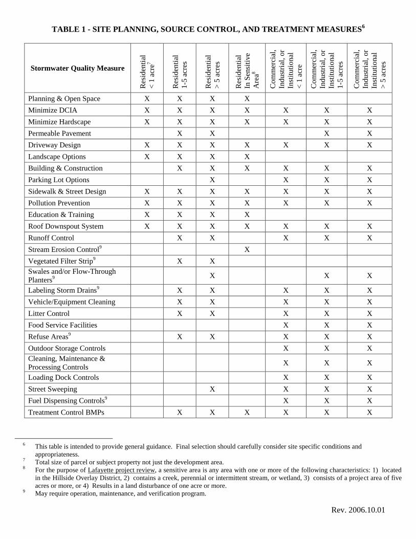
TABLE 1 - SITE PLANNING, SOURCE CONTROL, AND TREATMENT MEASURES6
Stormwater Quality Measure
Res
iden
tial
< 1
acr
e7
Res
iden
tial
1-5
acr
es
Res
iden
tial
> 5
acr
es
Res
iden
tial
In S
ensi
tive
Are
a8
Co
mm
erci
al,
Ind
ust
rial
, o
r
Inst
itu
tio
nal
< 1
acr
e
Co
mm
erci
al,
Ind
ust
rial
, o
r
Inst
itu
tio
nal
1-5
acr
es
Co
mm
erci
al,
Ind
ust
rial
, o
r
Inst
itu
tio
nal
> 5
acr
es
Planning & Open Space X X X X
Minimize DCIA X X X X X X X
Minimize Hardscape X X X X X X X
Permeable Pavement X X X X
Driveway Design X X X X X X X
Landscape Options X X X X
Building & Construction X X X X X X
Parking Lot Options X X X X
Sidewalk & Street Design X X X X X X X
Pollution Prevention X X X X X X X
Education & Training X X X X
Roof Downspout System X X X X X X X
Runoff Control X X X X X
Stream Erosion Control9 X
Vegetated Filter Strip9 X X
Swales and/or Flow-Through
Planters9
X X X
Labeling Storm Drains9 X X X X X
Vehicle/Equipment Cleaning X X X X X
Litter Control X X X X X
Food Service Facilities X X X
Refuse Areas9 X X X X X
Outdoor Storage Controls X X X
Cleaning, Maintenance &
Processing Controls X X X
Loading Dock Controls X X X
Street Sweeping X X X X
Fuel Dispensing Controls9 X X X
Treatment Control BMPs X X X X X X
6 This table is intended to provide general guidance. Final selection should carefully consider site specific conditions and
appropriateness. 7 Total size of parcel or subject property not just the development area.
8 For the purpose of Lafayette project review, a sensitive area is any area with one or more of the following characteristics: 1) located
in the Hillside Overlay District, 2) contains a creek, perennial or intermittent stream, or wetland, 3) consists of a project area of five
acres or more, or 4) Results in a land disturbance of one acre or more. 9 May require operation, maintenance, and verification program.
December 1, 2012 Page 1 of 8
Preparing a Stormwater Control Plan for a Small Land Development Project
Addendum to the Stormwater C.3 Guidebook
December 1, 2012
Introduction As of December 1, 2012, development projects that create or replace 2,500 square feet* or more of impervious surface (roofs or pavement) must incorporate one or more specified measures to reduce runoff. This requirement is part of municipalities’ comprehensive effort to reduce runoff pollution. The requirement is mandated by Provision C.3.i. in the Municipal Regional Stormwater Permit issued by the California Regional Water Quality Control Boards for the San Francisco Bay Region and Central Valley Region.
It is fairly easy to achieve compliance with the stormwater requirements for small land development projects. Compliance for each project must be carefully documented. Please complete the following form and submit it as directed by municipal staff. *All projects that create or replace 10,000 square feet or more of impervious surface—and auto service facilities, gas stations, restaurants, and uncovered parking lots that create or replace 5,000 square feet or more of impervious surface—are “Regulated Projects,” and require a more comprehensive Stormwater Control Plan. See the Contra Costa Clean Water Program Stormwater C.3 Guidebook.
Step-by-Step Instructions The steps are:
1. Fill out the Project Data Form (below) and select one or more runoff reduction measures. 2. Prepare a site plan or sketch. Specify and design the runoff reduction measure you will use to meet
the stated minimum requirements. 3. Complete your submittal, which will include:
Project Data Form Site Plan or Sketch Completed checklist for each Runoff Reduction Measure selected
December 1, 2012 Page 2 of 8
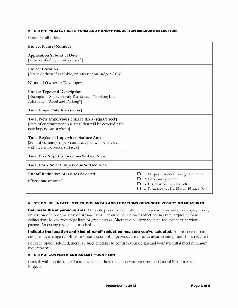
► STEP 1: PROJECT DATA FORM AND RUNOFF REDUCTION MEASURE SELECTION
Complete all fields.
Project Name/Number
Application Submittal Date [to be verified by municipal staff]
Project Location [Street Address if available, or intersection and/or APN]
Name of Owner or Developer
Project Type and Description [Examples: “Single Family Residence,” “Parking Lot Addition,” “Retail and Parking”]
Total Project Site Area (acres)
Total New Impervious Surface Area (square feet) [Sum of currently pervious areas that will be covered with new impervious surfaces]
Total Replaced Impervious Surface Area [Sum of currently impervious areas that will be covered with new impervious surfaces.]
Total Pre-Project Impervious Surface Area
Total Post-Project Impervious Surface Area
Runoff Reduction Measures Selected
(Check one or more)
1. Disperse runoff to vegetated area 2. Pervious pavement 3. Cisterns or Rain Barrels 4. Bioretention Facility or Planter Box
► STEP 2: DELINEATE IMPERVIOUS AREAS AND LOCATIONS OF RUNOFF REDUCTION MEASURES
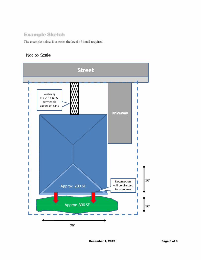
Delineate the impervious area. On a site plan or sketch, show the impervious area—for example, a roof, or portion of a roof, or a paved area—that will drain to your runoff reduction measure. Typically these delineations follow roof ridge lines or grade breaks. Alternatively, show the type and extent of pervious paving. An example sketch is attached.
Indicate the location and kind of runoff reduction measure you’ve selected. At least one option, designed to manage runoff from some amount of impervious area—or to avoid creating runoff—is required.
For each option selected, there is a brief checklist to confirm your design and your submittal meet minimum requirements.
► STEP 3: COMPLETE AND SUBMIT YOUR PLAN
Consult with municipal staff about when and how to submit your Stormwater Control Plan for Small Projects.
December 1, 2012 Page 3 of 8
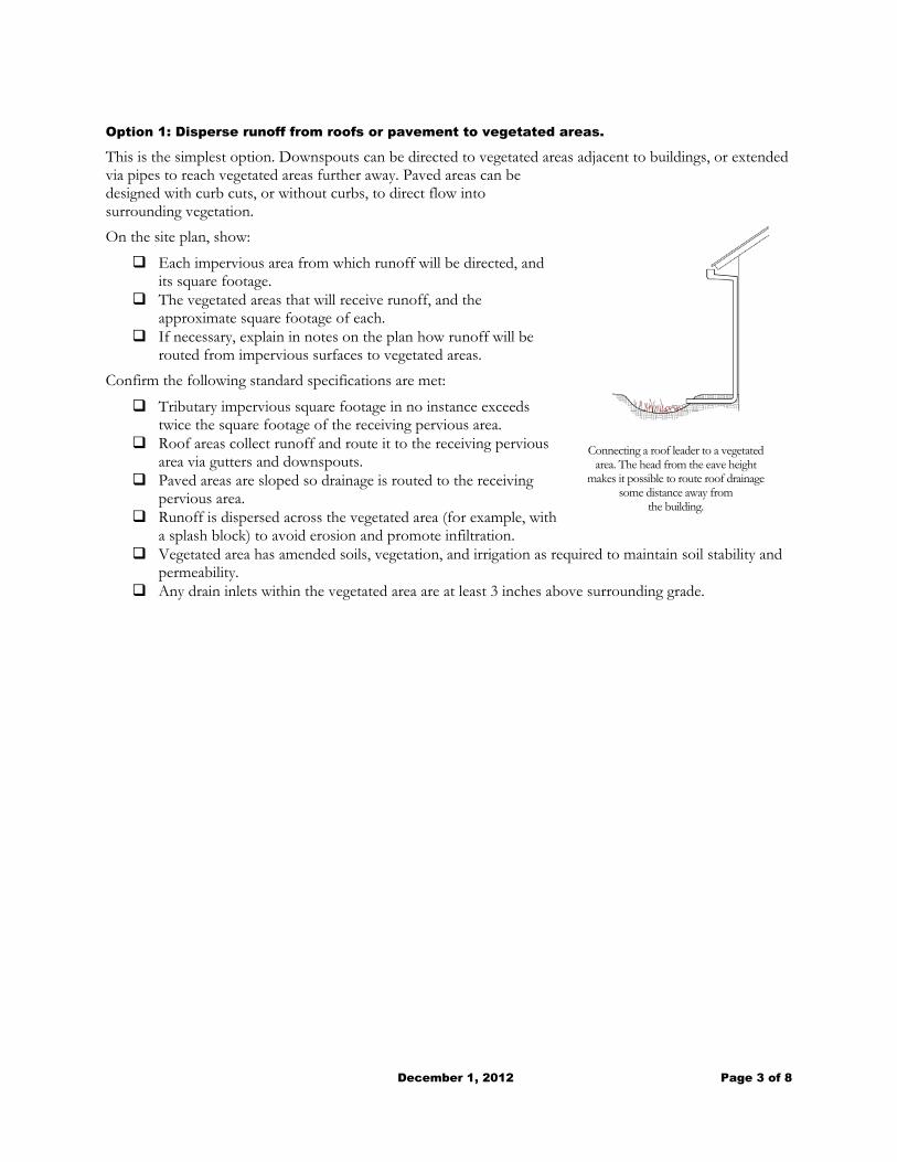
Option 1: Disperse runoff from roofs or pavement to vegetated areas.
This is the simplest option. Downspouts can be directed to vegetated areas adjacent to buildings, or extended via pipes to reach vegetated areas further away. Paved areas can be designed with curb cuts, or without curbs, to direct flow into surrounding vegetation.
On the site plan, show:
Each impervious area from which runoff will be directed, and its square footage.
The vegetated areas that will receive runoff, and the approximate square footage of each.
If necessary, explain in notes on the plan how runoff will be routed from impervious surfaces to vegetated areas.
Confirm the following standard specifications are met:
Tributary impervious square footage in no instance exceeds twice the square footage of the receiving pervious area.
Roof areas collect runoff and route it to the receiving pervious area via gutters and downspouts.
Paved areas are sloped so drainage is routed to the receiving pervious area.
Runoff is dispersed across the vegetated area (for example, with a splash block) to avoid erosion and promote infiltration.
Vegetated area has amended soils, vegetation, and irrigation as required to maintain soil stability and permeability.
Any drain inlets within the vegetated area are at least 3 inches above surrounding grade.
Connecting a roof leader to a vegetated area. The head from the eave height
makes it possible to route roof drainage some distance away from
the building.
December 1, 2012 Page 4 of 8
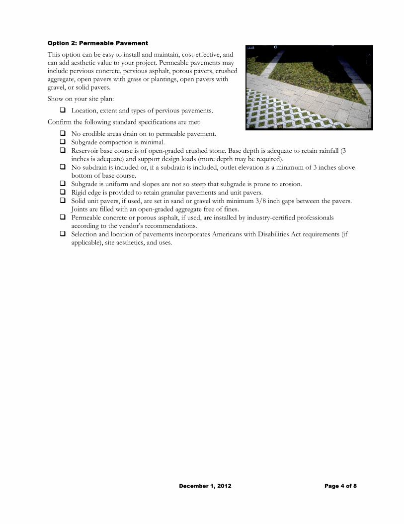
Option 2: Permeable Pavement
This option can be easy to install and maintain, cost-effective, and can add aesthetic value to your project. Permeable pavements may include pervious concrete, pervious asphalt, porous pavers, crushed aggregate, open pavers with grass or plantings, open pavers with gravel, or solid pavers.
Show on your site plan:
Location, extent and types of pervious pavements.
Confirm the following standard specifications are met:
No erodible areas drain on to permeable pavement. Subgrade compaction is minimal. Reservoir base course is of open-graded crushed stone. Base depth is adequate to retain rainfall (3
inches is adequate) and support design loads (more depth may be required). No subdrain is included or, if a subdrain is included, outlet elevation is a minimum of 3 inches above
bottom of base course. Subgrade is uniform and slopes are not so steep that subgrade is prone to erosion. Rigid edge is provided to retain granular pavements and unit pavers. Solid unit pavers, if used, are set in sand or gravel with minimum 3/8 inch gaps between the pavers.
Joints are filled with an open-graded aggregate free of fines. Permeable concrete or porous asphalt, if used, are installed by industry-certified professionals
according to the vendor’s recommendations. Selection and location of pavements incorporates Americans with Disabilities Act requirements (if
applicable), site aesthetics, and uses.
December 1, 2012 Page 5 of 8
Option 3: Cisterns or Rain Barrels
Use of cisterns or rain barrels to comply with this requirement is subject to municipality approval. Planning and Building Permits may be required for larger systems.
Show on your site plan:
Impervious areas tributary to each cistern or rain barrel. Location of each cistern or rain barrel.
Confirm the following standard specifications are met:
Rain barrels are sited at grade on a sound and level surface at or near gutter downspouts. Gutters tributary to rain barrels are screened with a leaf guard or maximum ½-inch to ¼-inch-
minimum corrosion-resistant metallic hardware fabric. Water collected will be used for irrigation only. Openings are screened with a corrosion-resistant metallic fine mesh (1/16 inch or smaller) to prevent
mosquito harborage. Large openings are secured to prevent entry by children. Rain barrels and gutters are to be cleaned annually. The Contra Costa Mosquito and Vector Control District is informed of the installation. The District
will be provided additional information and/or rights of entry if they request.
December 1, 2012 Page 6 of 8
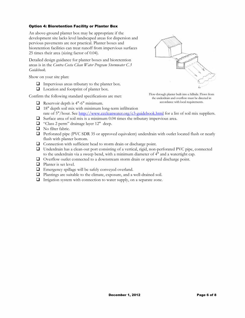
Option 4: Bioretention Facility or Planter Box
An above-ground planter box may be appropriate if the development site lacks level landscaped areas for dispersion and pervious pavements are not practical. Planter boxes and bioretention facilities can treat runoff from impervious surfaces 25 times their area (sizing factor of 0.04).
Detailed design guidance for planter boxes and bioretention areas is in the Contra Costa Clean Water Program Stormwater C.3 Guidebook.
Show on your site plan:
Impervious areas tributary to the planter box. Location and footprint of planter box.
Confirm the following standard specifications are met:
Reservoir depth is 4"-6" minimum. 18" depth soil mix with minimum long-term infiltration
rate of 5"/hour. See http://www.cccleanwater.org/c3-guidebook.html for a list of soil mix suppliers. Surface area of soil mix is a minimum 0.04 times the tributary impervious area. “Class 2 perm” drainage layer 12" deep. No filter fabric. Perforated pipe (PVC SDR 35 or approved equivalent) underdrain with outlet located flush or nearly
flush with planter bottom. Connection with sufficient head to storm drain or discharge point. Underdrain has a clean-out port consisting of a vertical, rigid, non-perforated PVC pipe, connected
to the underdrain via a sweep bend, with a minimum diameter of 4" and a watertight cap. Overflow outlet connected to a downstream storm drain or approved discharge point. Planter is set level. Emergency spillage will be safely conveyed overland. Plantings are suitable to the climate, exposure, and a well-drained soil. Irrigation system with connection to water supply, on a separate zone.
Flow-through planter built into a hillside. Flows from the underdrain and overflow must be directed in
accordance with local requirements.
December 1, 2012 Page 7 of 8
Useful Resources The following references may be useful for design. Designs must meet the minimum standard specifications in this supplement to the Stormwater C.3 Guidebook.
Contra Costa Clean Water Program Stormwater C.3 Guidebook. Available at http://www.cccleanwater.org/c3-guidebook.html
Start At the Source: Design Guidance Manual for Stormwater Quality. Bay Area Stormwater Management Agencies Association, 1999. Available at http://www.cccleanwater.org/c3-resources.html Stormwater Control for Small Projects Fact Sheets. Bay Area Stormwater Management Agencies Association, 2012. Available at http://www.cccleanwater.org/c3-resources.html
Concrete Promotion Council of Northern California www.concreteresources.net.
California Asphalt Pavement Association http://www.californiapavements.org/stormwater.html
Interlocking Concrete Pavement Institute http://www.icpi.org/
Porous Pavements, by Bruce K. Ferguson. 2005. ISBN 0-8493-2670-2
December 1, 2012 Page 8 of 8
Example Sketch The example below illustrates the level of detail required.
16’
25’
10’
Not to Scale
Related Documents