STORMWATER MANAGEMENT TESTING REPORT BED ONE Bedminster Township, Somerset County, New Jersey September 2021 Prepared For: GLADSTONE DESIGN, INC. 265 Main Street Gladstone, New Jersey 07934 Attn: Mr. Robert Moschello, P.E. Prepared By: GEO-TECHNOLOGY ASSOCIATES, INC. Geotechnical and Environmental Consultants 14 Worlds Fair Drive, Suite A Somerset, New Jersey 08873 GTA Job No: 31211310

Welcome message from author
This document is posted to help you gain knowledge. Please leave a comment to let me know what you think about it! Share it to your friends and learn new things together.
Transcript

STORMWATER MANAGEMENT TESTING REPORT
BED ONE Bedminster Township, Somerset County, New Jersey
September 2021
Prepared For: GLADSTONE DESIGN, INC.
265 Main Street Gladstone, New Jersey 07934 Attn: Mr. Robert Moschello, P.E.
Prepared By:
GEO-TECHNOLOGY ASSOCIATES, INC. Geotechnical and Environmental Consultants
14 Worlds Fair Drive, Suite A Somerset, New Jersey 08873 GTA Job No: 31211310

GEO-TECHNOLOGY ASSOCIATES, INC. GEOTECHNICAL AND ENVIRONMENTAL CONSULTANTS A Practicing Geoprofessional Business Association Member Firm
14 Worlds Fair Drive, Suite A, Somerset, NJ 08873 (732) 271-9301
Abingdon, MD Baltimore, MD Laurel, MD Frederick, MD Waldorf, MD New Castle, DE Georgetown, DE Somerset, NJ NYC Metro York, PA Quakertown, PA Beaver Falls, PA Malvern, OH Sterling, VA Nashville, TN Charlotte, NC Raleigh, NC
Visit us on the web at www.gtaeng.com
September 2, 2021
Gladstone Design, Inc. 265 Main Street Gladstone, New Jersey 07934 Attn: Mr. Robert Moschello, P.E. Re: Stormwater Management Testing Report Bed One Bedminster Township, Somerset County, New Jersey Dear Rob:
In accordance with our agreement dated July 13, 2021 Geo-Technology Associates, Inc. (GTA) has performed subsurface exploration and in-situ infiltration testing for the planning and design of stormwater management (SWM) facilities at a site located in Bedminster Township, Somerset County, New Jersey. The exploration consisted of excavating 46 test pits, visually classifying the encountered soils, and performing in-situ infiltration testing. The results of the field and laboratory testing, and GTA’s recommendations regarding the design and construction of the proposed SWM facilities are included in this report. GTA appreciates the opportunity to have been of assistance to you on this project. Please contact our office at (732) 271-9301 if you have questions or require additional information.
Very truly yours, GEO-TECHNOLOGY ASSOCIATES, INC.
Allison Tether, P.G. Senior Project Manager
Dennis C. Loh, P.E. Vice President
AMT/DCL:amt Job No. 31211310 Attachments

TABLE OF CONTENTS
SUBJECT PAGE
INTRODUCTION .......................................................................................................................... 1
SITE CONDITIONS ....................................................................................................................... 1
PROPOSED SWM BASIN CONSTRUCTION ............................................................................. 2
SITE GEOLOGY ............................................................................................................................ 2
SUBSURFACE EXPLORATION .................................................................................................. 3
LABORATORY TESTING............................................................................................................ 4
SUBSURFACE CONDITIONS ..................................................................................................... 5
INFILTRATION TEST RESULTS ................................................................................................ 6
CONCLUSIONS AND RECOMMENDATIONS ....................................................................... 11
LIMITATIONS ............................................................................................................................. 12
ASFE—Important Information About Your Geotechnical Engineering Report
APPENDICES
Appendix A – Figures (2 pages) Figure 1 – Site Location Map Figure 2 – Test Pit Location Plan (11x17)
Appendix B –Test Pit Logs (47 pages) Notes for Exploration Logs Logs of Test Pits (46 pages)
Appendix C – Laboratory Data (6 pages) Particle Size Distribution Reports (7 pages) Atterberg Limit Report (4 pages)
STORMWATER MANAGEMENT TESTING REPORT
BED ONE BEDMINSTER TOWNSHIP
SOMERSET COUNTY, NEW JERSEY SEPTEMBER 2021
INTRODUCTION
This report presents the results of subsurface explorations and in-situ infiltration testing
performed by Geo-Technology Associates, Inc. (GTA) for the planning and design of stormwater
management (SWM) facilities at a site in Bedminster Township, Somerset County, New Jersey. The
site is located adjacent to and south of Burnt Mills Road west of U.S. Route 202/206, and is
identified as Lot 7 in Block 71 on the Bedminster Township tax map. Please refer to the Site
Location Map, which is Figure 1 in Appendix A of this report.
GTA was provided with a plan prepared by Gladstone Design, Inc. (GDI) titled Soil Testing
Locations Plan dated June 2, 2021. The plan indicates the site boundaries, existing site features and
topography, and the layout of 6 proposed SWM basins. The plan also indicated the locations of 29
requested explorations, including proposed basin bottom elevations and requested test depths.
Following our exploration, GTA presented preliminary infiltration results to GDI and was requested
to perform additional testing throughout the site to evaluate if the Hydrologic Soil Group (HSG)
classification is appropriate based on the actual site conditions.
According to Chapter 12 of the NJ Stormwater BMP Manual, test pits and infiltration tests
must be performed within each SWM infiltration basin location. At least two test pits and infiltration
tests should be performed for basins with an infiltration area of up to 10,000 square feet, and one
additional test must be performed for each additional 10,000 square feet of infiltration area.
Infiltration tests are to be performed at the planned level of infiltration or deeper if hydraulically
restrictive soils are present within 8 feet of the proposed basin bottom level. Therefore, the test pits
must extend at least 8 feet below the planned level of infiltration.
SITE CONDITIONS
The site is bounded by Burnt Mills Road to the north, U.S. Route 202/206 to the east, an
off-ramp from Interstate 78 to the south, and a park and wooded areas to the west. The northwestern
Stormwater Management Testing Report Bed One September 2021 GTA Project No. 31211310
2
corner of the site is presently occupied by a bank and an existing office building is located in the
south-central portion of the site. Two large at-grade parking lots are present in the north-central and
southern portions of the site. An existing man-made pond is located adjacently west of the office
building, which connects to a stream running roughly east to west through the center of the property.
The areas adjacent to the stream are mapped as wetland areas on the plan provided to us. The open
portions of the site are predominantly landscaped lawn areas surrounding the office building and a
wooded area is present in the northern portion of the site.
Based on our visual observations and review of the ground surface topography shown on the
plan provided to us, the site generally slopes gently from about Elevation (EL) 190 feet in the
southeastern corner of the site and about EL 180 feet in the northeastern corner of the site, down to
about EL 162 feet in the west-central portion of the site surrounding the existing pond.
PROPOSED SWM BASIN CONSTRUCTION
The plan provided to us indicates the locations of 6 proposed SWM basins and a potential
basin area in the northern portion of the site. The plan indicates 29 requested explorations located
within the proposed and potential basin areas, as well as requested depths for the infiltration testing
and total depths of the explorations. Based on scaled measurements, we understand the bottom of the
proposed basins will range from about 1,000 square feet up to about 6,500 square feet in area and
will be established between EL 164 feet to EL 168 feet. Infiltration testing was requested at 16
locations within the potential SWM area in the northern portion of the site at depths of about 8 feet
below the ground surface.
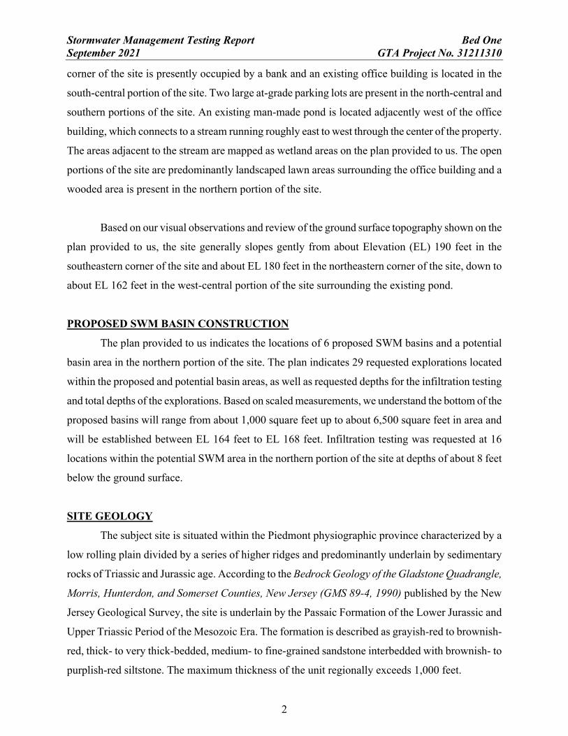
SITE GEOLOGY
The subject site is situated within the Piedmont physiographic province characterized by a
low rolling plain divided by a series of higher ridges and predominantly underlain by sedimentary
rocks of Triassic and Jurassic age. According to the Bedrock Geology of the Gladstone Quadrangle,
Morris, Hunterdon, and Somerset Counties, New Jersey (GMS 89-4, 1990) published by the New
Jersey Geological Survey, the site is underlain by the Passaic Formation of the Lower Jurassic and
Upper Triassic Period of the Mesozoic Era. The formation is described as grayish-red to brownish-
red, thick- to very thick-bedded, medium- to fine-grained sandstone interbedded with brownish- to
purplish-red siltstone. The maximum thickness of the unit regionally exceeds 1,000 feet.
Stormwater Management Testing Report Bed One September 2021 GTA Project No. 31211310
3
The surficial geology of the site, as shown on the Surficial Geology of the Gladstone
Quadrangle, Somerset, Hunterdon, and Morris Counties, New Jersey (OFM 84, 2011) published by
the New Jersey Geological Survey consists primarily of weathered shale, siltstone, and sandstone.
This unit is described as reddish-brown, brown, and yellowish-brown clayey silt, silty clay, and
sandy silt with some to many shale chips, and pebbles and cobbles of siltstone and sandstone. The
weathered zone can be as much as 20 feet, but is generally less than 5 feet thick. The mapping also
indicates a band of alluvium, which runs generally east to west through the central portion of the site
in the vicinity of the existing pond. The alluvium is described as dark brown, brown, reddish-brown,
yellowish-brown and gray sand, silt, clay and pebble gravel and contains variable amounts of
organic matter. The alluvium can be as much as 15 feet thick.
Please refer to the referenced publications for more detailed descriptions of the geologic
members.
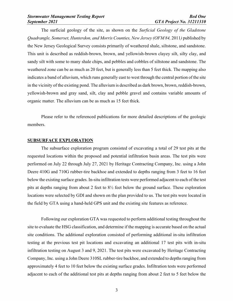
SUBSURFACE EXPLORATION
The subsurface exploration program consisted of excavating a total of 29 test pits at the
requested locations within the proposed and potential infiltration basin areas. The test pits were
performed on July 22 through July 27, 2021 by Heritage Contracting Company, Inc. using a John
Deere 410G and 710G rubber-tire backhoe and extended to depths ranging from 3 feet to 16 feet
below the existing surface grades. In-situ infiltration tests were performed adjacent to each of the test
pits at depths ranging from about 2 feet to 8½ feet below the ground surface. These exploration
locations were selected by GDI and shown on the plan provided to us. The test pits were located in
the field by GTA using a hand-held GPS unit and the existing site features as reference.
Following our exploration GTA was requested to perform additional testing throughout the
site to evaluate the HSG classification, and determine if the mapping is accurate based on the actual
site conditions. The additional exploration consisted of performing additional in-situ infiltration
testing at the previous test pit locations and excavating an additional 17 test pits with in-situ
infiltration testing on August 3 and 9, 2021. The test pits were excavated by Heritage Contracting
Company, Inc. using a John Deere 310SL rubber-tire backhoe, and extended to depths ranging from
approximately 4 feet to 10 feet below the existing surface grades. Infiltration tests were performed
adjacent to each of the additional test pits at depths ranging from about 2 feet to 5 feet below the

Stormwater Management Testing Report Bed One September 2021 GTA Project No. 31211310
4
ground surface. These exploration locations were selected by GTA and located in the field using a
hand-held GPS unit and the existing site features as reference.
The approximate locations of the explorations performed for this study are shown on the Test
Pit Location Plan, which is included as Figure 2 in Appendix A. Detailed descriptions of the
encountered subsurface conditions are indicated on the Logs of Test Pits, which are presented in
Appendix B. The ground surface elevations shown on the exploration logs were obtained by
interpolating between contours shown on the plan provided to us and should be considered
approximate.
Soil samples obtained from the test pits were brought to GTA’s laboratory for visual
classification by a geotechnical engineer and limited laboratory testing. The soil descriptions shown
on the logs are therefore based on visual observation of the samples, supplemented by the laboratory
results.
LABORATORY TESTING
Laboratory testing performed for this study included grain-size distribution and Atterberg
Limits testing for classification of the soils in accordance with the Unified Soil Classification System
(USCS), and natural moisture content determinations. Detailed results of the laboratory testing
performed for this study are included in Appendix C. The results of the testing are summarized in the
following table:
SUMMARY OF LABORATORY TESTING
LOCATION DEPTH (ft.) LL (%) PI (%) USCS CLASSIFICATION NMC (%)
TP-11 3 32.1 9.3 Clayey GRAVEL with sand (GC)
[FILL] 9.4
TP-16 4 NP NP Silty GRAVEL with sand (GM) [FILL] 10.7
TP-17 5 NP NP Silty GRAVEL with sand (GM) [FILL] 8.7
TP-19 3 NP NP Silty SAND with gravel (SM) [FILL] 10.7
TP-23 4½ 33.6 11.4 Lean CLAY with gravel (CL) 14.7
TP-33 2 32.7 12.4 Sandy Lean CLAY (CL) 24.4
TP-42 3 33.6 13.6 Lean CLAY (CL) 23.1
*Note: NP=Non-plastic, LL=Liquid Limit, PI=Plasticity Index, NMC=Natural Moisture Content

Stormwater Management Testing Report Bed One September 2021 GTA Project No. 31211310
5
SUBSURFACE CONDITIONS
An approximately 4- to 13-inch-thick layer of topsoil was encountered at the ground surface
in the test pits performed for this study, averaging approximately 6 inches. Below the topsoil,
existing fill materials were encountered in 39 of the 46 explorations. The fill extended to depths
ranging from about 2 to 8 feet below the existing surface grades, and predominantly consisted of
silty gravel in the explorations performed in the northern portion of the site and sandy silt in the
explorations closer to the existing office building. The existing fill soils were generally consistent
with the natural site soils and likely placed during construction of the existing buildings as part of the
site grading. However, basalt cobbles and boulders were encountered within the fill in several of the
test pits performed in the northern wooded portion of the site, which was unique to that area and
differed from the native residual shale soils.
A layer of organic silt was observed in 4 of the test pits performed adjacently north of the
existing pond area. The organic soils were generally about 2 feet in thickness and overlying the
residual clay soils. The natural soils encountered below the topsoil, fill, and organic materials appear
to be consistent with the geologic mapping, and generally consisted of residual shale soils. The soils
profile generally a few feet of lean clays (CL) soils, which graded into silty gravel (GM) overlying
highly-weathered shale bedrock. The surface of weathered rock was encountered in 15 of the 46 test
pits at depths ranging from about 7 to 16 feet below the ground surface.
Groundwater was not observed in the test pits performed for this study. However, seepage of
perched or trapped water was observed in 5 of the 46 test pits at depths ranging from about 4 to 10
feet below the existing surface grades. Long-term groundwater readings were not obtained because
the explorations were backfilled for safety considerations. It should be anticipated that seepage of
water atop impermeable layers or trapped within locally porous zones may occur in construction
excavations at varying depths throughout the site, and that fluctuation in the groundwater levels will
occur due to variations in precipitation, seasonal factors, and other factors, such as site development
activities. Soil mottling indicative of the seasonal high groundwater level was not observed in any of
the test pits performed for this study. Therefore, we believe the seasonal high groundwater elevation
is below the depths excavated in the test pits.

Stormwater Management Testing Report Bed One September 2021 GTA Project No. 31211310
6
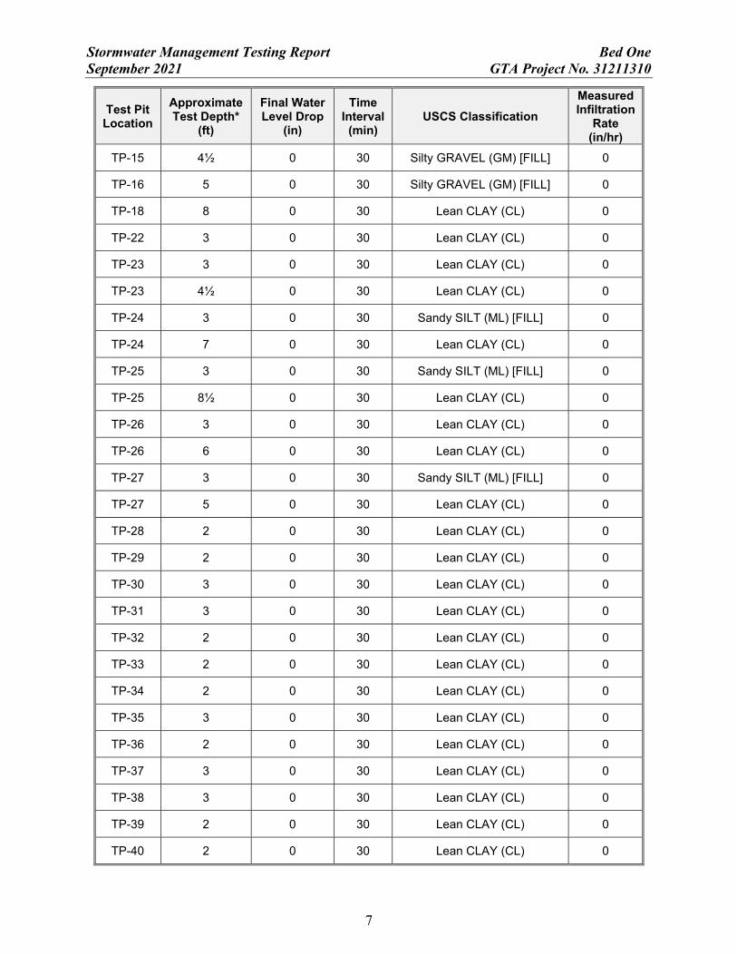
INFILTRATION TEST RESULTS
In-situ infiltration tests were performed adjacent to each of the test pits performed for this
study using a double-ring infiltrometer in accordance with the ASTM D 3385 test procedure. The
tests were performed at depths ranging from approximately 2 to 8½ feet below the ground surface
within the existing fill and natural soils. The results of the infiltration tests performed for this study
are summarized in the following table:
SUMMARY OF INFILTRATION TEST RESULTS
Test Pit Location
Approximate Test Depth*
(ft)
Final Water Level Drop
(in)
Time Interval
(min) USCS Classification
Measured Infiltration
Rate (in/hr)
TP-1 8 0 30 Lean CLAY (CL) 0
TP-2 8 0 30 Lean CLAY (CL) 0
TP-3 8 0 30 Lean CLAY (CL) 0
TP-4 8 0 30 Lean CLAY (CL) 0
TP-5 8 0 30 Lean CLAY (CL) 0
TP-6 8 0 30 Lean CLAY (CL) 0
TP-7 5 0 30 Lean CLAY (CL) 0
TP-7 8 0 30 Lean CLAY (CL) 0
TP-8 3 0 30 Lean CLAY (CL) 0
TP-8 8 0 30 Lean CLAY (CL) 0
TP-9 3 0 30 Silty GRAVEL (GM) [FILL] 0
TP-9 5 0 30 Lean CLAY (CL) 0
TP-9 8 0 30 Lean CLAY (CL) 0
TP-10 4 0 30 Lean CLAY (CL) 0
TP-10 8 0 30 Lean CLAY (CL) 0
TP-11 5 0 30 Lean CLAY (CL) 0
TP-12 6 0 30 Lean CLAY (CL) 0
TP-12 8 0 30 Lean CLAY (CL) 0
TP-13 5 0 30 Lean CLAY (CL) [FILL] 0
TP-14 5½ 0 30 Lean CLAY (CL) 0
Stormwater Management Testing Report Bed One September 2021 GTA Project No. 31211310
7
Test Pit Location
Approximate Test Depth*
(ft)
Final Water Level Drop
(in)
Time Interval
(min) USCS Classification
Measured Infiltration
Rate (in/hr)
TP-15 4½ 0 30 Silty GRAVEL (GM) [FILL] 0
TP-16 5 0 30 Silty GRAVEL (GM) [FILL] 0
TP-18 8 0 30 Lean CLAY (CL) 0
TP-22 3 0 30 Lean CLAY (CL) 0
TP-23 3 0 30 Lean CLAY (CL) 0
TP-23 4½ 0 30 Lean CLAY (CL) 0
TP-24 3 0 30 Sandy SILT (ML) [FILL] 0
TP-24 7 0 30 Lean CLAY (CL) 0
TP-25 3 0 30 Sandy SILT (ML) [FILL] 0
TP-25 8½ 0 30 Lean CLAY (CL) 0
TP-26 3 0 30 Lean CLAY (CL) 0
TP-26 6 0 30 Lean CLAY (CL) 0
TP-27 3 0 30 Sandy SILT (ML) [FILL] 0
TP-27 5 0 30 Lean CLAY (CL) 0
TP-28 2 0 30 Lean CLAY (CL) 0
TP-29 2 0 30 Lean CLAY (CL) 0
TP-30 3 0 30 Lean CLAY (CL) 0
TP-31 3 0 30 Lean CLAY (CL) 0
TP-32 2 0 30 Lean CLAY (CL) 0
TP-33 2 0 30 Lean CLAY (CL) 0
TP-34 2 0 30 Lean CLAY (CL) 0
TP-35 3 0 30 Lean CLAY (CL) 0
TP-36 2 0 30 Lean CLAY (CL) 0
TP-37 3 0 30 Lean CLAY (CL) 0
TP-38 3 0 30 Lean CLAY (CL) 0
TP-39 2 0 30 Lean CLAY (CL) 0
TP-40 2 0 30 Lean CLAY (CL) 0
Stormwater Management Testing Report Bed One September 2021 GTA Project No. 31211310
8
Test Pit Location
Approximate Test Depth*
(ft)
Final Water Level Drop
(in)
Time Interval
(min) USCS Classification
Measured Infiltration
Rate (in/hr)
TP-41 2 0 30 Lean CLAY (CL) 0
TP-42 3 0 30 Lean CLAY (CL) 0
TP-43 2 0 30 Sandy SILT (ML) [FILL] 0
TP-43 5 0 30 Lean CLAY (CL) 0
TP-44 5 0 30 Lean CLAY (CL) 0
TP-45 3 0 30 Lean CLAY (CL) 0
TP-46 2 0 30 Lean CLAY (CL) 0
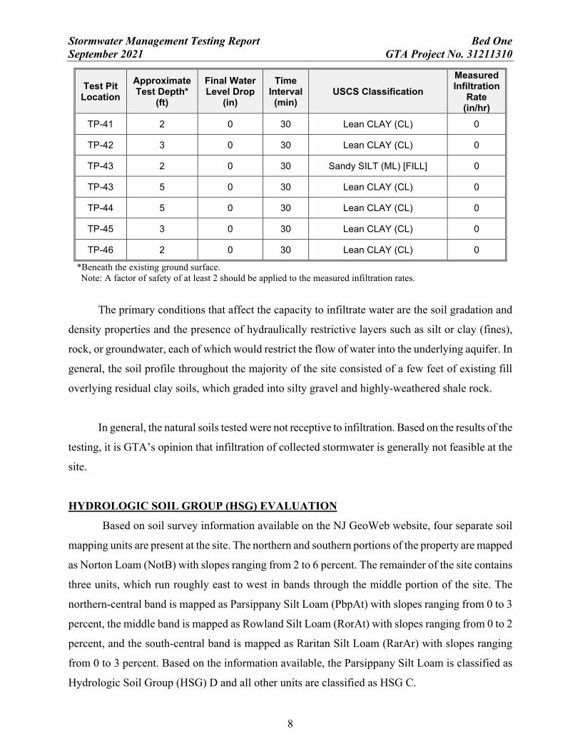
*Beneath the existing ground surface. Note: A factor of safety of at least 2 should be applied to the measured infiltration rates.
The primary conditions that affect the capacity to infiltrate water are the soil gradation and
density properties and the presence of hydraulically restrictive layers such as silt or clay (fines),
rock, or groundwater, each of which would restrict the flow of water into the underlying aquifer. In
general, the soil profile throughout the majority of the site consisted of a few feet of existing fill
overlying residual clay soils, which graded into silty gravel and highly-weathered shale rock.
In general, the natural soils tested were not receptive to infiltration. Based on the results of the
testing, it is GTA’s opinion that infiltration of collected stormwater is generally not feasible at the
site.
HYDROLOGIC SOIL GROUP (HSG) EVALUATION
Based on soil survey information available on the NJ GeoWeb website, four separate soil
mapping units are present at the site. The northern and southern portions of the property are mapped
as Norton Loam (NotB) with slopes ranging from 2 to 6 percent. The remainder of the site contains
three units, which run roughly east to west in bands through the middle portion of the site. The
northern-central band is mapped as Parsippany Silt Loam (PbpAt) with slopes ranging from 0 to 3
percent, the middle band is mapped as Rowland Silt Loam (RorAt) with slopes ranging from 0 to 2
percent, and the south-central band is mapped as Raritan Silt Loam (RarAr) with slopes ranging
from 0 to 3 percent. Based on the information available, the Parsippany Silt Loam is classified as
Hydrologic Soil Group (HSG) D and all other units are classified as HSG C.

Stormwater Management Testing Report Bed One September 2021 GTA Project No. 31211310
9
According to Chapter 7 of the National Engineering Handbook, HSG D soils have high
runoff potential and a saturated hydraulic conductivity of less than or equal to 0.06 inches per hour
for all soil layers within 40 inches of the ground surface. HSG C soils have moderately high runoff
potential and a saturated hydraulic conductivity between 0.14 and 1.42 inches per hour for all soil
layers within 40 inches of the ground surface.
Because our initial infiltration tests at the site resulted in zero infiltration, GTA was requested
to perform additional explorations throughout the areas mapped as NotB, RorAt, and RarAr, which
are all classified as HSG C, to determine if the HSG classifications are appropriate based on the
actual site conditions.
According to Chapter 12, for areas where the HSG is either unknown or inaccurate with
respect to field conditions, a minimum of one soil profile pit and four soil borings shall be conducted
within each soil mapping unit less than 2 acres in area. If the unit is larger than 2 acres, an additional
soil pit and two soil borings shall be conducted for each additional 2 acres. In all cases, soil profile
pits may be performed in place of soil borings. Scaled measurements of the units, excluding areas
presently occupied by buildings and pavements, were provided to us by GDI. The acreage of the
undeveloped area within each unit and number of infiltration tests performed for this study are
summarized in the following table:
Soil Mapping Unit Current
HSG Undeveloped Area
(acres) Total Explorations
Required
NotB (North) C 2.11 8
PbpAt D 2.26 -
RorAt C 2.78 8
RarAr C 1.77 5
NotB (South) C 3.09 8
The explorations performed throughout the site generally encountered a few feet of existing
fill materials overlying residual clay soils, which graded into silty gravel. The existing fill in the
northern half of the site generally extended to depths of about 5 feet below the ground surface, and

Stormwater Management Testing Report Bed One September 2021 GTA Project No. 31211310
10
the fill encountered in the southern half of the site generally extended to depths of about 2 feet below
the ground surface.
Based on Chapter 12, soils can be considered HSG D if the permeability rates of the most
restrictive soil layer within the upper 40 inches is less than 0.14 inches per hour. Additionally, soils
can be classified as HSG D if the depth to bedrock is less than 20 inches or the depth to the seasonal
high groundwater table (SHWT) is less than 24 inches below the ground surface. However, the
explorations performed for this study did not encountered bedrock or SHWT at or above these
depths.
GTA performed in-situ infiltration tests within the upper 40 inches of the soil profile
throughout the site. The infiltration tests were performed using a double-ring infiltrometer in
accordance with the ASTM D 3385 test procedure, and the results of the testing are included in the
Summary of Infiltration Test Results table on Page 6 of this report. In areas where the existing fill
materials were present within the to 40 inches of the soil profile and the testing equipment could not
be properly seated to prevent leaking due to the presence of gravel and cobbles within the fill,
additional infiltration tests were performed within the natural soils underlying the fill materials. The
results of the testing performed within each soil unit are summarized below.
Norton Loam – NotB (Northern Unit)
GTA performed several infiltration tests at varying depths throughout the unit. Four of the
infiltration tests (TP-8, TP-26, TP-28, and TP-29) performed within natural clay soils encountered in
the top 40 inches of the soil profile and two infiltration tests (TP-9 and TP-27) performed within the
existing fill materials in the top 40 inches of the soil profile were not receptive to infiltration and
resulted in 0 inches per hour. Infiltration tests were attempted in Test Pits TP-7 and TP-12 within the
existing fill materials; however, due to the presence of gravel and cobbles within the fill, the
infiltration equipment could not be properly seated to prevent leaking. Therefore, infiltration tests
were performed within the underlying natural soils at depths of 5 feet and 6 feet below the ground
surface, respectively. The natural soils tested at these locations were not receptive to infiltration.

Stormwater Management Testing Report Bed One September 2021 GTA Project No. 31211310
11
Rowland Silt Loam – RorAt
GTA performed 8 infiltration tests at varying depths throughout the unit. Four of the
infiltration tests (TP-41, TP-42, TP-45, and TP-46) performed within natural clay soils encountered
in the top 40 inches of the soil profile and three infiltration tests (TP-24, TP-25, and TP-43)
performed within the existing fill materials in the top 40 inches of the soil profile were not receptive
to infiltration and resulted in 0 inches per hour. An infiltration test was attempted in Test Pit TP-44
within the existing fill materials; however, due to the presence of gravel and cobbles within the fill,
the infiltration equipment could not be properly seated to prevent leaking. Therefore, an infiltration
test was performed within the underlying natural clay soils at a depth of 5 feet below the ground
surface. The natural clay soils tested at this location were not receptive to infiltration.
Raritan Silt Loam – RarAr
GTA performed 5 infiltration tests (TP-22, TP-23, TP-30, TP-38 and TP-40) within the
natural clay soils encountered in the top 40 inches of the soil profile, which were not receptive to
infiltration and resulted in 0 inches per hour.
Norton Loam – NotB (Southern Unit)
GTA performed 8 infiltration tests (TP-31, TP-32, TP-33, TP-34, TP-35, TP-36, TP-37, and
TP-39) within the natural clay soils encountered in the top 40 inches of the soil profile, which were
not receptive to infiltration and resulted in 0 inches per hour.
CONCLUSIONS AND RECOMMENDATIONS
We believe the subsurface conditions and infiltration test results indicate that infiltration of
collected stormwater is generally not feasible at the site. Based on the results of our field
explorations and infiltration testing, it is GTA’s opinion that the soils tested at this site meet the
criteria outlined in Chapter 12 to be classified as HSG D.
At two of the test locations performed within the northern NotB unit (TP-7 and TP-12) and
one location performed within the RorAt unit (TP-44), infiltration tests were attempted within the
upper 40 inches of the soil profile but the equipment could not be properly seated to prevent leaking
due to the presence of gravel, cobbles, and debris within the existing fill soils. Therefore, additional
testing was performed within the natural soils immediately underlying the fill materials, which were

Stormwater Management Testing Report Bed One September 2021 GTA Project No. 31211310
12
consistent with HSG D soils. In addition, at the locations within these units where existing fill
materials were present within 40 inches of the ground surface (TP-9, TP-24, TP-25, TP-27 and
TP-43) and in-situ infiltration testing was able to be performed with the double-ring infiltrometer
equipment, the results indicate that the existing fill materials were not receptive to infiltration.
Therefore, based on the composition of the existing fill materials and results of the field infiltration
testing where able to be performed within the fill, we believe the fill matrix also exhibits
characteristics of HSG D soils per Chapter 12.
LIMITATIONS
This report, including all supporting test pit logs, field data, field notes, laboratory test data,
calculations, estimates and other documents prepared by GTA in connection with this project have
been prepared for the exclusive use of Gladstone Design, Inc. (Client) pursuant to the Agreement
between GTA and Client dated July 13, 2021, and in accordance with generally accepted
engineering practice. All terms and conditions set forth in the Agreement and the General Provisions
attached thereto are incorporated herein by reference. No warranty, express or implied, is made
herein. Use and reproduction of this report by any other person without the expressed written
permission of GTA and Client is unauthorized and such use is at the sole risk of the user.
The analysis and recommendations contained in this report are based on the data obtained
from limited observation and testing of the encountered materials. Test pits indicate soil conditions
only at specific locations and times, and only at the depths penetrated. They do not necessarily
reflect strata or variations that may exist between test pit locations. Consequently, the analysis and
recommendations must be considered preliminary until the subsurface conditions can be verified by
direct observation at the time of construction. If variations of subsurface conditions from those
described in this report are noted during construction, recommendations in this report may need to be
re-evaluated.
In the event that any changes in the nature, design, or location of the facilities are planned,
the conclusions and recommendations contained in this report should not be considered valid unless
the changes are reviewed and conclusions of this report are verified in writing. GTA is not
responsible for any claims, damages, or liability associated with interpretation of subsurface data or

Stormwater Management Testing Report Bed One September 2021 GTA Project No. 31211310
13
reuse of the subsurface data or engineering analysis without the expressed written authorization of
GTA.
The scope of our services for this geotechnical exploration did not include any environmental
assessment or investigation for the presence or absence of wetlands, or hazardous or toxic materials
in the soil, surface water, groundwater or air, on or below or around this site. Any statements in this
report or on the logs regarding odors or unusual or suspicious items or conditions observed are
strictly for the information of our Client.
This report and the attached logs are instruments of service. The subject matter of this report
is limited to the facts and matters stated herein. Absence of a reference to any other conditions or
subject matter shall not be construed by the reader to imply approval by the writer.
31211310 GEO-TECHNOLOGY ASSOCIATES, INC.

Geotechnical-Engineering ReportImportant Information about This
Subsurface problems are a principal cause of construction delays, cost overruns, claims, and disputes.
While you cannot eliminate all such risks, you can manage them. The following information is provided to help.
The Geoprofessional Business Association (GBA) has prepared this advisory to help you – assumedly a client representative – interpret and apply this geotechnical-engineering report as effectively as possible. In that way, you can benefit from a lowered exposure to problems associated with subsurface conditions at project sites and development of them that, for decades, have been a principal cause of construction delays, cost overruns, claims, and disputes. If you have questions or want more information about any of the issues discussed herein, contact your GBA-member geotechnical engineer. Active engagement in GBA exposes geotechnical engineers to a wide array of risk-confrontation techniques that can be of genuine benefit for everyone involved with a construction project.
Understand the Geotechnical-Engineering Services Provided for this ReportGeotechnical-engineering services typically include the planning, collection, interpretation, and analysis of exploratory data from widely spaced borings and/or test pits. Field data are combined with results from laboratory tests of soil and rock samples obtained from field exploration (if applicable), observations made during site reconnaissance, and historical information to form one or more models of the expected subsurface conditions beneath the site. Local geology and alterations of the site surface and subsurface by previous and proposed construction are also important considerations. Geotechnical engineers apply their engineering training, experience, and judgment to adapt the requirements of the prospective project to the subsurface model(s). Estimates are made of the subsurface conditions that will likely be exposed during construction as well as the expected performance of foundations and other structures being planned and/or affected by construction activities.
The culmination of these geotechnical-engineering services is typically a geotechnical-engineering report providing the data obtained, a discussion of the subsurface model(s), the engineering and geologic engineering assessments and analyses made, and the recommendations developed to satisfy the given requirements of the project. These reports may be titled investigations, explorations, studies, assessments, or evaluations. Regardless of the title used, the geotechnical-engineering report is an engineering interpretation of the subsurface conditions within the context of the project and does not represent a close examination, systematic inquiry, or thorough investigation of all site and subsurface conditions.
Geotechnical-Engineering Services are Performed for Specific Purposes, Persons, and Projects, and At Specific TimesGeotechnical engineers structure their services to meet the specific needs, goals, and risk management preferences of their clients. A geotechnical-engineering study conducted for a given civil engineer
will not likely meet the needs of a civil-works constructor or even a different civil engineer. Because each geotechnical-engineering study is unique, each geotechnical-engineering report is unique, prepared solely for the client.
Likewise, geotechnical-engineering services are performed for a specific project and purpose. For example, it is unlikely that a geotechnical-engineering study for a refrigerated warehouse will be the same as one prepared for a parking garage; and a few borings drilled during a preliminary study to evaluate site feasibility will not be adequate to develop geotechnical design recommendations for the project.
Do not rely on this report if your geotechnical engineer prepared it: • for a different client;• for a different project or purpose;• for a different site (that may or may not include all or a portion of
the original site); or• before important events occurred at the site or adjacent to it;
e.g., man-made events like construction or environmental remediation, or natural events like floods, droughts, earthquakes, or groundwater fluctuations.
Note, too, the reliability of a geotechnical-engineering report can be affected by the passage of time, because of factors like changed subsurface conditions; new or modified codes, standards, or regulations; or new techniques or tools. If you are the least bit uncertain about the continued reliability of this report, contact your geotechnical engineer before applying the recommendations in it. A minor amount of additional testing or analysis after the passage of time – if any is required at all – could prevent major problems.
Read this Report in FullCostly problems have occurred because those relying on a geotechnical-engineering report did not read the report in its entirety. Do not rely on an executive summary. Do not read selective elements only. Read and refer to the report in full.
You Need to Inform Your Geotechnical Engineer About ChangeYour geotechnical engineer considered unique, project-specific factors when developing the scope of study behind this report and developing the confirmation-dependent recommendations the report conveys. Typical changes that could erode the reliability of this report include those that affect:
• the site’s size or shape;• the elevation, configuration, location, orientation,
function or weight of the proposed structure and the desired performance criteria;
• the composition of the design team; or • project ownership.
As a general rule, always inform your geotechnical engineer of project or site changes – even minor ones – and request an assessment of their impact. The geotechnical engineer who prepared this report cannot accept

responsibility or liability for problems that arise because the geotechnical engineer was not informed about developments the engineer otherwise would have considered.
Most of the “Findings” Related in This Report Are Professional OpinionsBefore construction begins, geotechnical engineers explore a site’s subsurface using various sampling and testing procedures. Geotechnical engineers can observe actual subsurface conditions only at those specific locations where sampling and testing is performed. The data derived from that sampling and testing were reviewed by your geotechnical engineer, who then applied professional judgement to form opinions about subsurface conditions throughout the site. Actual sitewide-subsurface conditions may differ – maybe significantly – from those indicated in this report. Confront that risk by retaining your geotechnical engineer to serve on the design team through project completion to obtain informed guidance quickly, whenever needed.
This Report’s Recommendations Are Confirmation-DependentThe recommendations included in this report – including any options or alternatives – are confirmation-dependent. In other words, they are not final, because the geotechnical engineer who developed them relied heavily on judgement and opinion to do so. Your geotechnical engineer can finalize the recommendations only after observing actual subsurface conditions exposed during construction. If through observation your geotechnical engineer confirms that the conditions assumed to exist actually do exist, the recommendations can be relied upon, assuming no other changes have occurred. The geotechnical engineer who prepared this report cannot assume responsibility or liability for confirmation-dependent recommendations if you fail to retain that engineer to perform construction observation.
This Report Could Be MisinterpretedOther design professionals’ misinterpretation of geotechnical-engineering reports has resulted in costly problems. Confront that risk by having your geotechnical engineer serve as a continuing member of the design team, to:
• confer with other design-team members;• help develop specifications;• review pertinent elements of other design professionals’ plans and
specifications; and• be available whenever geotechnical-engineering guidance is needed.
You should also confront the risk of constructors misinterpreting this report. Do so by retaining your geotechnical engineer to participate in prebid and preconstruction conferences and to perform construction-phase observations.
Give Constructors a Complete Report and GuidanceSome owners and design professionals mistakenly believe they can shift unanticipated-subsurface-conditions liability to constructors by limiting the information they provide for bid preparation. To help prevent the costly, contentious problems this practice has caused, include the complete geotechnical-engineering report, along with any attachments or appendices, with your contract documents, but be certain to note
conspicuously that you’ve included the material for information purposes only. To avoid misunderstanding, you may also want to note that “informational purposes” means constructors have no right to rely on the interpretations, opinions, conclusions, or recommendations in the report. Be certain that constructors know they may learn about specific project requirements, including options selected from the report, only from the design drawings and specifications. Remind constructors that they may perform their own studies if they want to, and be sure to allow enough time to permit them to do so. Only then might you be in a position to give constructors the information available to you, while requiring them to at least share some of the financial responsibilities stemming from unanticipated conditions. Conducting prebid and preconstruction conferences can also be valuable in this respect.
Read Responsibility Provisions CloselySome client representatives, design professionals, and constructors do not realize that geotechnical engineering is far less exact than other engineering disciplines. This happens in part because soil and rock on project sites are typically heterogeneous and not manufactured materials with well-defined engineering properties like steel and concrete. That lack of understanding has nurtured unrealistic expectations that have resulted in disappointments, delays, cost overruns, claims, and disputes. To confront that risk, geotechnical engineers commonly include explanatory provisions in their reports. Sometimes labeled “limitations,” many of these provisions indicate where geotechnical engineers’ responsibilities begin and end, to help others recognize their own responsibilities and risks. Read these provisions closely. Ask questions. Your geotechnical engineer should respond fully and frankly.
Geoenvironmental Concerns Are Not CoveredThe personnel, equipment, and techniques used to perform an environmental study – e.g., a “phase-one” or “phase-two” environmental site assessment – differ significantly from those used to perform a geotechnical-engineering study. For that reason, a geotechnical-engineering report does not usually provide environmental findings, conclusions, or recommendations; e.g., about the likelihood of encountering underground storage tanks or regulated contaminants. Unanticipated subsurface environmental problems have led to project failures. If you have not obtained your own environmental information about the project site, ask your geotechnical consultant for a recommendation on how to find environmental risk-management guidance.
Obtain Professional Assistance to Deal with Moisture Infiltration and MoldWhile your geotechnical engineer may have addressed groundwater, water infiltration, or similar issues in this report, the engineer’s services were not designed, conducted, or intended to prevent migration of moisture – including water vapor – from the soil through building slabs and walls and into the building interior, where it can cause mold growth and material-performance deficiencies. Accordingly, proper implementation of the geotechnical engineer’s recommendations will not of itself be sufficient to prevent moisture infiltration. Confront the risk of moisture infiltration by including building-envelope or mold specialists on the design team. Geotechnical engineers are not building-envelope or mold specialists.
Copyright 2019 by Geoprofessional Business Association (GBA). Duplication, reproduction, or copying of this document, in whole or in part, by any means whatsoever, is strictly prohibited, except with GBA’s specific written permission. Excerpting, quoting, or otherwise extracting wording from this document is permitted only with the express written
permission of GBA, and only for purposes of scholarly research or book review. Only members of GBA may use this document or its wording as a complement to or as an element of a report of any kind. Any other firm, individual, or other entity that so uses this document without being a GBA member could be committing negligent
Telephone: 301/565-2733e-mail: [email protected] www.geoprofessional.org

APPENDIX A
Figures
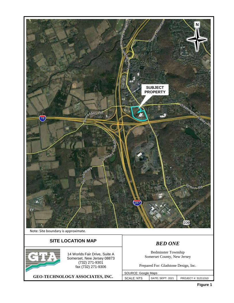
Figure 1
BED ONE
Bedminster Township
Somerset County, New Jersey
Prepared For: Gladstone Design, Inc.
14 Worlds Fair Drive, Suite ASomerset, New Jersey 08873
(732) 271-9301
fax (732) 271-9306
GEO-TECHNOLOGY ASSOCIATES, INC.
SITE LOCATION MAP
SCALE: NTS DATE: SEPT. 2021 PROJECT #: 31211310
SOURCE: Google Maps
Note: Site boundary is approximate.
SUBJECT PROPERTY
N
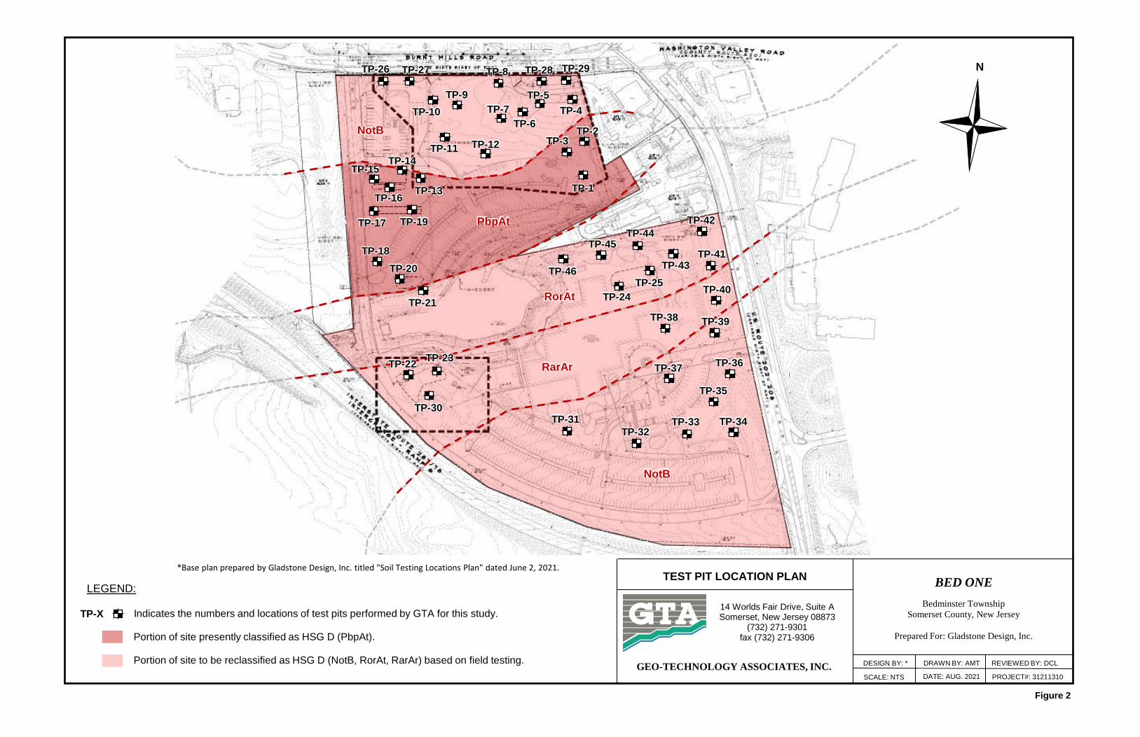
Figure 2
TEST PIT LOCATION PLAN
SCALE: NTS
BED ONE
Bedminster Township
Somerset County, New Jersey
Prepared For: Gladstone Design, Inc.
14 Worlds Fair Drive, Suite ASomerset, New Jersey 08873
(732) 271-9301fax (732) 271-9306
GEO-TECHNOLOGY ASSOCIATES, INC.DATE: AUG. 2021 PROJECT#: 31211310
DESIGN BY: * DRAWN BY: AMT REVIEWED BY: DCL
*Base plan prepared by Gladstone Design, Inc. titled "Soil Testing Locations Plan" dated June 2, 2021.
LEGEND:
Indicates the numbers and locations of test pits performed by GTA for this study.
N
TP-21
TP-20
TP-18
TP-19 TP-17
TP-16
TP-14
TP-13
TP-11
TP-9
TP-10
TP-12
TP-7
TP-6
TP-5
TP-4
TP-2
TP-1
TP-8 TP-28 TP-29 TP-27 TP-26
TP-25
TP-24
TP-30 TP-31
TP-32 TP-33 TP-34
TP-35
TP-36 TP-37
TP-38
TP-40
TP-41
TP-42
TP-43
TP-44TP-45
TP-46
TP-X
TP-15
TP-23 TP-22
TP-39
TP-3
NotB
PbpAt
RorAt
RarAr
NotB
Portion of site presently classified as HSG D (PbpAt).
Portion of site to be reclassified as HSG D (NotB, RorAt, RarAr) based on field testing.

APPENDIX B
Exploration Logs


0
5
10
15
20
25
30
174.6
169.0
164.0
163.0
CL
GM
5 In. of TopsoilFILL - Red-brown, moist, silty gravel with sand, cobbles, and boulders (Basalt)
Dark yellow-brown, moist, Lean CLAY
Red-brown, moist, Silty GRAVEL (Residual Shale)
Test pit complete at 12 Ft. due to refusal on weathered rock.
- Infiltration rate =0 in/hr at 8 Ft.
LOG OF TEST PIT NO. TP-1 (SP-17)
PROJECT: Bed One PROJECT NO.: 31211310PROJECT LOCATION: Bedminster Township, Somerset County, New Jersey
CLIENT: Gladstone Design, Inc.GROUNDWATER ENCOUNTERED: N/E
DATE STARTED: 7/22/2021 GROUND SURFACE ELEVATION: 175 Ft.DATE COMPLETED: 7/22/2021 DATUM: Topo
CONTRACTOR: Heritage Contracting Company, Inc. LOGGED BY: AFSEQUIPMENT: John Deere 710G CHECKED BY: AMT
NOTES:Locations and elevations are approximate.Backfilled on completion.
LOG OF TEST PIT NO. TP-1 (SP-17)
EL
EV
AT
ION
(ft
.)
DE
PT
H (
ft.)
US
CS
GR
AP
HIC
SY
MB
OL
DESCRIPTION REMARKS
Sheet 1 of 1
Sheet 1 of 1

0
5
10
15
20
25
30
177.1
172.5
166.5
165.5
CL
GM
5 In. of TopsoilFILL - Red-brown, moist, silty gravel with sand, cobbles, and boulders (Basalt)
- with buried topsoil layer (6 In. in thickness) at 4-1/2 Ft.Red-brown and gray, moist, Lean CLAY
Dark red-brown, moist, Silty GRAVEL (Residual Shale)
Test pit complete at 12 Ft. due to refusal on weathered rock.
- Infiltration rate =0 in/hr at 8 Ft.
LOG OF TEST PIT NO. TP-2 (SP-16)
PROJECT: Bed One PROJECT NO.: 31211310PROJECT LOCATION: Bedminster Township, Somerset County, New Jersey
CLIENT: Gladstone Design, Inc.GROUNDWATER ENCOUNTERED: N/E
DATE STARTED: 7/22/2021 GROUND SURFACE ELEVATION: 177.5 Ft.DATE COMPLETED: 7/22/2021 DATUM: Topo
CONTRACTOR: Heritage Contracting Company, Inc. LOGGED BY: AFSEQUIPMENT: John Deere 710G CHECKED BY: AMT
NOTES:Locations and elevations are approximate.Backfilled on completion.
LOG OF TEST PIT NO. TP-2 (SP-16)
EL
EV
AT
ION
(ft
.)
DE
PT
H (
ft.)
US
CS
GR
AP
HIC
SY
MB
OL
DESCRIPTION REMARKS
Sheet 1 of 1
Sheet 1 of 1

0
5
10
15
20
25
30
175.6
170.0
165.0
160.0
CL
GM
5 In. of TopsoilFILL - Red-brown, moist, silty gravel with sand, cobbles, and boulders (Basalt)
Dark yellow-brown, moist, Lean CLAY
- Red-brown at 8 Ft.
Red-brown, moist, Silty GRAVEL (Residual Shale)
Test pit complete at 16 Ft. due to refusal on weathered rock.
- Infiltration rate =0 in/hr at 8 Ft.
LOG OF TEST PIT NO. TP-3 (SP-15)
PROJECT: Bed One PROJECT NO.: 31211310PROJECT LOCATION: Bedminster Township, Somerset County, New Jersey
CLIENT: Gladstone Design, Inc.GROUNDWATER ENCOUNTERED: N/E
DATE STARTED: 7/23/2021 GROUND SURFACE ELEVATION: 176 Ft.DATE COMPLETED: 7/23/2021 DATUM: Topo
CONTRACTOR: Heritage Contracting Company, Inc. LOGGED BY: AFSEQUIPMENT: John Deere 710G CHECKED BY: AMT
NOTES:Locations and elevations are approximate.Backfilled on completion.
LOG OF TEST PIT NO. TP-3 (SP-15)
EL
EV
AT
ION
(ft
.)
DE
PT
H (
ft.)
US
CS
GR
AP
HIC
SY
MB
OL
DESCRIPTION REMARKS
Sheet 1 of 1
Sheet 1 of 1

0
5
10
15
20
25
30
180.5
175.0
172.0171.5171.0
CL
GMHW
6 In. of TopsoilFILL - Red-brown, moist, silty gravel with sand, cobbles, and boulders (Basalt)
- Red brown and light gray at 2 Ft.
- with wire and pocket of dark yellow-brown poorly-graded sand at 5 Ft.
Red-brown and light gray, moist, Lean CLAY
Red-brown, moist, Silty GRAVEL (Residual Shale)Red-brown, moist, Highly-weathered ROCK (Shale)Test pit complete at 10 Ft. due to refusal on weathered rock.
- Infiltration rate =0 in/hr at 8 Ft.
LOG OF TEST PIT NO. TP-4 (SP-8)
PROJECT: Bed One PROJECT NO.: 31211310PROJECT LOCATION: Bedminster Township, Somerset County, New Jersey
CLIENT: Gladstone Design, Inc.GROUNDWATER ENCOUNTERED: N/E
DATE STARTED: 7/23/2021 GROUND SURFACE ELEVATION: 181 Ft.DATE COMPLETED: 7/23/2021 DATUM: Topo
CONTRACTOR: Heritage Contracting Company, Inc. LOGGED BY: AFSEQUIPMENT: John Deere 710G CHECKED BY: AMT
NOTES:Locations and elevations are approximate.Backfilled on completion.
LOG OF TEST PIT NO. TP-4 (SP-8)
EL
EV
AT
ION
(ft
.)
DE
PT
H (
ft.)
US
CS
GR
AP
HIC
SY
MB
OL
DESCRIPTION REMARKS
Sheet 1 of 1
Sheet 1 of 1

0
5
10
15
20
25
30
180.1
174.5
170.5
169.5169.0
CL
GM
HW
5 In. of TopsoilFILL - Red-brown, moist, silty gravel with sand, cobbles, and boulders (Basalt)
Dark yellow-brown, moist, Lean CLAY
- Red-brown at 7 Ft.
Dark red-brown, moist, Silty GRAVEL (Residual Shale)
Dark red-brown, moist, Highly-weathered ROCK (Shale)Test pit complete at 11-1/2 Ft. due to refusal on weathered rock.
- Infiltration rate =0 in/hr at 8 Ft.
LOG OF TEST PIT NO. TP-5 (SP-9)
PROJECT: Bed One PROJECT NO.: 31211310PROJECT LOCATION: Bedminster Township, Somerset County, New Jersey
CLIENT: Gladstone Design, Inc.GROUNDWATER ENCOUNTERED: N/E
DATE STARTED: 7/23/2021 GROUND SURFACE ELEVATION: 180.5 Ft.DATE COMPLETED: 7/23/2021 DATUM: Topo
CONTRACTOR: Heritage Contracting Company, Inc. LOGGED BY: AFSEQUIPMENT: John Deere 710G CHECKED BY: AMT
NOTES:Locations and elevations are approximate.Backfilled on completion.
LOG OF TEST PIT NO. TP-5 (SP-9)
EL
EV
AT
ION
(ft
.)
DE
PT
H (
ft.)
US
CS
GR
AP
HIC
SY
MB
OL
DESCRIPTION REMARKS
Sheet 1 of 1
Sheet 1 of 1

0
5
10
15
20
25
30
178.1
173.0
169.5169.0168.5
CL
GMHW
5 In. of TopsoilFILL - Red-brown, moist, silty gravel with sand, cobbles, and boulders (Basalt)
Red-brown, moist, Lean CLAY
Dark red-brown, moist, Silty GRAVEL (Residual Shale)Dark red-brown, moist, Highly-weathered ROCK (Shale)Test pit complete at 10 Ft. due to refusal on weathered rock.
- Infiltration rate =0 in/hr at 8 Ft.
LOG OF TEST PIT NO. TP-6 (SP-10)
PROJECT: Bed One PROJECT NO.: 31211310PROJECT LOCATION: Bedminster Township, Somerset County, New Jersey
CLIENT: Gladstone Design, Inc.GROUNDWATER ENCOUNTERED: N/E
DATE STARTED: 7/23/2021 GROUND SURFACE ELEVATION: 178.5 Ft.DATE COMPLETED: 7/23/2021 DATUM: Topo
CONTRACTOR: Heritage Contracting Company, Inc. LOGGED BY: AFSEQUIPMENT: John Deere 710G CHECKED BY: AMT
NOTES:Locations and elevations are approximate.Backfilled on completion.
LOG OF TEST PIT NO. TP-6 (SP-10)
EL
EV
AT
ION
(ft
.)
DE
PT
H (
ft.)
US
CS
GR
AP
HIC
SY
MB
OL
DESCRIPTION REMARKS
Sheet 1 of 1
Sheet 1 of 1

0
5
10
15
20
25
30
177.0
172.5
167.5167.0166.5
CL
GMHW
6 In. of TopsoilFILL - Red-brown, moist, silty gravel with sand, cobbles, and boulders (Basalt)
Dark yellow-brown, moist, Lean CLAY
- Dark red-brown at 6 Ft.
Dark red-brown, moist, Silty GRAVEL (Residual Shale)Dark red-brown, moist, Highly-weathered ROCK (Shale)Test pit complete at 11 Ft. due to refusal on weathered rock.
- Unable to sitinfiltration deviceat 3 Ft.
- Infiltration rate =0 in/hr at 5 Ft.
- Infiltration rate =0 in/hr at 8 Ft.
LOG OF TEST PIT NO. TP-7 (SP-11)
PROJECT: Bed One PROJECT NO.: 31211310PROJECT LOCATION: Bedminster Township, Somerset County, New Jersey
CLIENT: Gladstone Design, Inc.GROUNDWATER ENCOUNTERED: N/E
DATE STARTED: 7/23/2021 GROUND SURFACE ELEVATION: 177.5 Ft.DATE COMPLETED: 7/23/2021 DATUM: Topo
CONTRACTOR: Heritage Contracting Company, Inc. LOGGED BY: AFSEQUIPMENT: John Deere 710G CHECKED BY: AMT
NOTES:Locations and elevations are approximate.Backfilled on completion.
LOG OF TEST PIT NO. TP-7 (SP-11)
EL
EV
AT
ION
(ft
.)
DE
PT
H (
ft.)
US
CS
GR
AP
HIC
SY
MB
OL
DESCRIPTION REMARKS
Sheet 1 of 1
Sheet 1 of 1

0
5
10
15
20
25
30
177.0
175.0
168.5168.0
CL
HW
6 In. of TopsoilFILL - Dark red-brown, moist, silty gravel with brick, asphalt, and concrete fragments
Dark red-brown, moist, Lean CLAY with sand with gravel
Dark red-brown, moist, Highly-weathered ROCK (Shale)Test pit complete at 9-1/2 Ft. due to refusal on weathered rock.
- Infiltration rate =0 in/hr at 3 Ft.
- Infiltration rate =0 in/hr at 8 Ft.
LOG OF TEST PIT NO. TP-8 (SP-5)
PROJECT: Bed One PROJECT NO.: 31211310PROJECT LOCATION: Bedminster Township, Somerset County, New Jersey
CLIENT: Gladstone Design, Inc.GROUNDWATER ENCOUNTERED: N/E
DATE STARTED: 7/23/2021 GROUND SURFACE ELEVATION: 177.5 Ft.DATE COMPLETED: 7/23/2021 DATUM: Topo
CONTRACTOR: Heritage Contracting Company, Inc. LOGGED BY: AFSEQUIPMENT: John Deere 710G CHECKED BY: AMT
NOTES:Locations and elevations are approximate.Backfilled on completion.
LOG OF TEST PIT NO. TP-8 (SP-5)
EL
EV
AT
ION
(ft
.)
DE
PT
H (
ft.)
US
CS
GR
AP
HIC
SY
MB
OL
DESCRIPTION REMARKS
Sheet 1 of 1
Sheet 1 of 1

0
5
10
15
20
25
30
176.6
172.0
163.0
CL
5 In. of TopsoilFILL - Dark red-brown, moist, silty gravel with asphalt and brick fragments
- with black asphalt layer (12 In. in thickness) at 4 Ft.
Dark red-brown, moist, Lean CLAY with sand
Test pit complete at 14 Ft. due to refusal.
- Infiltration rate =0 in/hr at 3 Ft.
- Infiltration rate =0 in/hr at 5 Ft.
- Infiltration rate =0 in/hr at 8 Ft.
LOG OF TEST PIT NO. TP-9 (SP-4)
PROJECT: Bed One PROJECT NO.: 31211310PROJECT LOCATION: Bedminster Township, Somerset County, New Jersey
CLIENT: Gladstone Design, Inc.GROUNDWATER ENCOUNTERED: N/E
DATE STARTED: 7/23/2021 GROUND SURFACE ELEVATION: 177 Ft.DATE COMPLETED: 7/23/2021 DATUM: Topo
CONTRACTOR: Heritage Contracting Company, Inc. LOGGED BY: AFSEQUIPMENT: John Deere 710G CHECKED BY: AMT
NOTES:Locations and elevations are approximate.Backfilled on completion.
LOG OF TEST PIT NO. TP-9 (SP-4)
EL
EV
AT
ION
(ft
.)
DE
PT
H (
ft.)
US
CS
GR
AP
HIC
SY
MB
OL
DESCRIPTION REMARKS
Sheet 1 of 1
Sheet 1 of 1

0
5
10
15
20
25
30
176.1
172.5
165.5
CL
5 In. of TopsoilFILL - Dark red-brown, moist, silty gravel with cobbles.
- with black asphalt layer (12 In. in thickness) at 3 Ft.
Dark red-brown, moist, Lean CLAY
Test pit complete at 11 Ft. due to refusal.
- Infiltration rate =0 in/hr at 4 Ft.
- Infiltration rate =0 in/hr at 8 Ft.
LOG OF TEST PIT NO. TP-10 (SP-3)
PROJECT: Bed One PROJECT NO.: 31211310PROJECT LOCATION: Bedminster Township, Somerset County, New Jersey
CLIENT: Gladstone Design, Inc.GROUNDWATER ENCOUNTERED: N/E
DATE STARTED: 7/26/2021 GROUND SURFACE ELEVATION: 176.5 Ft.DATE COMPLETED: 7/26/2021 DATUM: Topo
CONTRACTOR: Heritage Contracting Company, Inc. LOGGED BY: AFSEQUIPMENT: John Deere 410G CHECKED BY: AMT
NOTES:Locations and elevations are approximate.Backfilled on completion.
LOG OF TEST PIT NO. TP-10 (SP-3)
EL
EV
AT
ION
(ft
.)
DE
PT
H (
ft.)
US
CS
GR
AP
HIC
SY
MB
OL
DESCRIPTION REMARKS
Sheet 1 of 1
Sheet 1 of 1

0
5
10
15
20
25
30
175.1
171.0
162.5
CL
5 In. of TopsoilFILL - Dark red-brown, moist, clayey gravel with sand, cobbles, and boulders
- with black asphalt layer (6 In. in thickness) at 4 Ft.Dark red-brown, moist, Lean CLAY
- with wood fragments at 7 Ft.
Test pit complete at 13 Ft.
- Infiltration rate =0 in/hr at 5 Ft.
- Perched waterseepage at 7 Ft.
LOG OF TEST PIT NO. TP-11 (SP-12)
PROJECT: Bed One PROJECT NO.: 31211310PROJECT LOCATION: Bedminster Township, Somerset County, New Jersey
CLIENT: Gladstone Design, Inc.GROUNDWATER ENCOUNTERED: N/E
DATE STARTED: 7/26/2021 GROUND SURFACE ELEVATION: 175.5 Ft.DATE COMPLETED: 7/26/2021 DATUM: Topo
CONTRACTOR: Heritage Contracting Company, Inc. LOGGED BY: AFSEQUIPMENT: John Deere 410G CHECKED BY: AMT
NOTES:Locations and elevations are approximate.Backfilled on completion.
LOG OF TEST PIT NO. TP-11 (SP-12)
EL
EV
AT
ION
(ft
.)
DE
PT
H (
ft.)
US
CS
GR
AP
HIC
SY
MB
OL
DESCRIPTION REMARKS
Sheet 1 of 1
Sheet 1 of 1
0
5
10
15
20
25
30
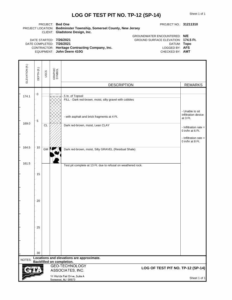
174.1
169.0
164.5
161.5
CL
GM
5 In. of TopsoilFILL - Dark red-brown, moist, silty gravel with cobbles
- with asphalt and brick fragments at 4 Ft.
Dark red-brown, moist, Lean CLAY
Dark red-brown, moist, Silty GRAVEL (Residual Shale)
Test pit complete at 13 Ft. due to refusal on weathered rock.
- Unable to sitinfiltration deviceat 3 Ft.
- Infiltration rate =0 in/hr at 6 Ft.
- Infiltration rate =0 in/hr at 8 Ft.
LOG OF TEST PIT NO. TP-12 (SP-14)
PROJECT: Bed One PROJECT NO.: 31211310PROJECT LOCATION: Bedminster Township, Somerset County, New Jersey
CLIENT: Gladstone Design, Inc.GROUNDWATER ENCOUNTERED: N/E
DATE STARTED: 7/26/2021 GROUND SURFACE ELEVATION: 174.5 Ft.DATE COMPLETED: 7/26/2021 DATUM: Topo
CONTRACTOR: Heritage Contracting Company, Inc. LOGGED BY: AFSEQUIPMENT: John Deere 410G CHECKED BY: AMT
NOTES:Locations and elevations are approximate.Backfilled on completion.
LOG OF TEST PIT NO. TP-12 (SP-14)
EL
EV
AT
ION
(ft
.)
DE
PT
H (
ft.)
US
CS
GR
AP
HIC
SY
MB
OL
DESCRIPTION REMARKS
Sheet 1 of 1
Sheet 1 of 1
0
5
10
15
20
25
30
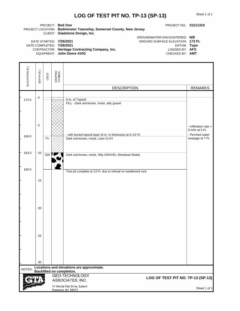
172.6
166.0
163.0
160.0
CL
GM
5 In. of TopsoilFILL - Dark red-brown, moist, silty gravel
- with buried topsoil layer (6 In. in thickness) at 6-1/2 Ft.Dark red-brown, moist, Lean CLAY
Dark red-brown, moist, Silty GRAVEL (Residual Shale)
Test pit complete at 13 Ft. due to refusal on weathered rock.
- Infiltration rate =0 in/hr at 5 Ft.
- Perched waterseepage at 7 Ft.
LOG OF TEST PIT NO. TP-13 (SP-13)
PROJECT: Bed One PROJECT NO.: 31211310PROJECT LOCATION: Bedminster Township, Somerset County, New Jersey
CLIENT: Gladstone Design, Inc.GROUNDWATER ENCOUNTERED: N/E
DATE STARTED: 7/26/2021 GROUND SURFACE ELEVATION: 173 Ft.DATE COMPLETED: 7/26/2021 DATUM: Topo
CONTRACTOR: Heritage Contracting Company, Inc. LOGGED BY: AFSEQUIPMENT: John Deere 410G CHECKED BY: AMT
NOTES:Locations and elevations are approximate.Backfilled on completion.
LOG OF TEST PIT NO. TP-13 (SP-13)
EL
EV
AT
ION
(ft
.)
DE
PT
H (
ft.)
US
CS
GR
AP
HIC
SY
MB
OL
DESCRIPTION REMARKS
Sheet 1 of 1
Sheet 1 of 1

0
5
10
15
20
25
30
172.6
168.0
161.0
CL
5 In. of TopsoilFILL - Dark red-brown, moist, silty gravel
Dark yellow-brown and red-brown, moist, Lean CLAY with sand and gravel
- Dark red-brown and gray, sand and gravel grade out at 9 Ft.
Test pit complete at 12 Ft. due to refusal.
- Infiltration rate =0 in/hr at 5-1/2 Ft.
- Perched waterseepage at 8 Ft.
LOG OF TEST PIT NO. TP-14 (SP4A-2)
PROJECT: Bed One PROJECT NO.: 31211310PROJECT LOCATION: Bedminster Township, Somerset County, New Jersey
CLIENT: Gladstone Design, Inc.GROUNDWATER ENCOUNTERED: N/E
DATE STARTED: 7/26/2021 GROUND SURFACE ELEVATION: 173 Ft.DATE COMPLETED: 7/26/2021 DATUM: Topo
CONTRACTOR: Heritage Contracting Company, Inc. LOGGED BY: AFSEQUIPMENT: John Deere 410G CHECKED BY: AMT
NOTES:Locations and elevations are approximate.Backfilled on completion.
LOG OF TEST PIT NO. TP-14 (SP4A-2)
EL
EV
AT
ION
(ft
.)
DE
PT
H (
ft.)
US
CS
GR
AP
HIC
SY
MB
OL
DESCRIPTION REMARKS
Sheet 1 of 1
Sheet 1 of 1

0
5
10
15
20
25
30
171.1
166.0
164.0
159.5
OL
CL
5 In. of TopsoilFILL - Dark red-brown, moist, silty gravel
Dark brown, moist, Organic SILT
Dark yellow-brown and red-brown, moist, Lean CLAY with sand and gravel
Test pit complete at 12 Ft. due to refusal.
- Infiltration rate =0 in/hr at 4-1/2 Ft.
LOG OF TEST PIT NO. TP-15 (SP4A-1)
PROJECT: Bed One PROJECT NO.: 31211310PROJECT LOCATION: Bedminster Township, Somerset County, New Jersey
CLIENT: Gladstone Design, Inc.GROUNDWATER ENCOUNTERED: N/E
DATE STARTED: 7/26/2021 GROUND SURFACE ELEVATION: 171.5 Ft.DATE COMPLETED: 7/26/2021 DATUM: Topo
CONTRACTOR: Heritage Contracting Company, Inc. LOGGED BY: AFSEQUIPMENT: John Deere 410G CHECKED BY: AMT
NOTES:Locations and elevations are approximate.Backfilled on completion.
LOG OF TEST PIT NO. TP-15 (SP4A-1)
EL
EV
AT
ION
(ft
.)
DE
PT
H (
ft.)
US
CS
GR
AP
HIC
SY
MB
OL
DESCRIPTION REMARKS
Sheet 1 of 1
Sheet 1 of 1

0
5
10
15
20
25
30
171.7
164.0
162.0
159.0
OL
CL
4 In. of TopsoilFILL - Dark red-brown, moist, silty gravel with sand
Dark brown, moist, Organic SILT
Dark yellow-brown and red brown, moist, Lean CLAY with sand and gravel
Test pit complete at 13 Ft. due to refusal.
- NMC = 10.7%
- Infiltration rate =0 in/hr at 5 Ft.
- Moderateperched waterseepage at 10 Ft.
LOG OF TEST PIT NO. TP-16 (SP4B-1)
PROJECT: Bed One PROJECT NO.: 31211310PROJECT LOCATION: Bedminster Township, Somerset County, New Jersey
CLIENT: Gladstone Design, Inc.GROUNDWATER ENCOUNTERED: N/E
DATE STARTED: 7/26/2021 GROUND SURFACE ELEVATION: 172 Ft.DATE COMPLETED: 7/26/2021 DATUM: Topo
CONTRACTOR: Heritage Contracting Company, Inc. LOGGED BY: AFSEQUIPMENT: John Deere 410G CHECKED BY: AMT
NOTES:Locations and elevations are approximate.Backfilled on completion.
LOG OF TEST PIT NO. TP-16 (SP4B-1)
EL
EV
AT
ION
(ft
.)
DE
PT
H (
ft.)
US
CS
GR
AP
HIC
SY
MB
OL
DESCRIPTION REMARKS
Sheet 1 of 1
Sheet 1 of 1

0
5
10
15
20
25
30
169.6
163.5
162.0
159.0
OL
CL
5 In. of TopsoilFILL - Dark red-brown, moist, silty gravel with sand
Dark brown, moist, Organic SILT
Dark yellow-brown and red-brown, moist, Lean CLAY with sand and gravel
Test pit complete at 11 Ft. due to refusal.
- NMC = 8.7%
LOG OF TEST PIT NO. TP-17 (SP4C-1)
PROJECT: Bed One PROJECT NO.: 31211310PROJECT LOCATION: Bedminster Township, Somerset County, New Jersey
CLIENT: Gladstone Design, Inc.GROUNDWATER ENCOUNTERED: N/E
DATE STARTED: 7/26/2021 GROUND SURFACE ELEVATION: 170 Ft.DATE COMPLETED: 7/26/2021 DATUM: Topo
CONTRACTOR: Heritage Contracting Company, Inc. LOGGED BY: AFSEQUIPMENT: John Deere 410G CHECKED BY: AMT
NOTES:Locations and elevations are approximate.Backfilled on completion.
LOG OF TEST PIT NO. TP-17 (SP4C-1)
EL
EV
AT
ION
(ft
.)
DE
PT
H (
ft.)
US
CS
GR
AP
HIC
SY
MB
OL
DESCRIPTION REMARKS
Sheet 1 of 1
Sheet 1 of 1

0
5
10
15
20
25
30
168.1
161.0
156.5
CL
5 In. of TopsoilFILL - Dark red-brown, moist, silty gravel
Dark yellow-brown, moist, Lean CLAY
Test pit complete at 12 Ft. due to refusal.
- Infiltration rate =0 in/hr at 8 Ft.
LOG OF TEST PIT NO. TP-18 (SP-18)
PROJECT: Bed One PROJECT NO.: 31211310PROJECT LOCATION: Bedminster Township, Somerset County, New Jersey
CLIENT: Gladstone Design, Inc.GROUNDWATER ENCOUNTERED: N/E
DATE STARTED: 7/26/2021 GROUND SURFACE ELEVATION: 168.50 Ft.DATE COMPLETED: 7/26/2021 DATUM: Topo
CONTRACTOR: Heritage Contracting Company, Inc. LOGGED BY: AFSEQUIPMENT: John Deere 410G CHECKED BY: AMT
NOTES:Locations and elevations are approximate.Backfilled on completion.
LOG OF TEST PIT NO. TP-18 (SP-18)
EL
EV
AT
ION
(ft
.)
DE
PT
H (
ft.)
US
CS
GR
AP
HIC
SY
MB
OL
DESCRIPTION REMARKS
Sheet 1 of 1
Sheet 1 of 1

0
5
10
15
20
25
30
169.6
162.0
160.0
158.0
OL
CL
5 In. of TopsoilFILL - Dark red-brown, moist, silty sand with gravel
Dark brown, moist, Organic SILT
Dark yellow-brown and gray, moist, Lean CLAY
Test pit complete at 12 Ft. due to refusal.
- NMC = 10.7%
LOG OF TEST PIT NO. TP-19 (SP4C-2)
PROJECT: Bed One PROJECT NO.: 31211310PROJECT LOCATION: Bedminster Township, Somerset County, New Jersey
CLIENT: Gladstone Design, Inc.GROUNDWATER ENCOUNTERED: N/E
DATE STARTED: 7/27/2021 GROUND SURFACE ELEVATION: 170 Ft.DATE COMPLETED: 7/27/2021 DATUM: Topo
CONTRACTOR: Heritage Contracting Company, Inc. LOGGED BY: AFSEQUIPMENT: John Deere 410G CHECKED BY: AMT
NOTES:Locations and elevations are approximate.Backfilled on completion.
LOG OF TEST PIT NO. TP-19 (SP4C-2)
EL
EV
AT
ION
(ft
.)
DE
PT
H (
ft.)
US
CS
GR
AP
HIC
SY
MB
OL
DESCRIPTION REMARKS
Sheet 1 of 1
Sheet 1 of 1
0
5
10
15
20
25
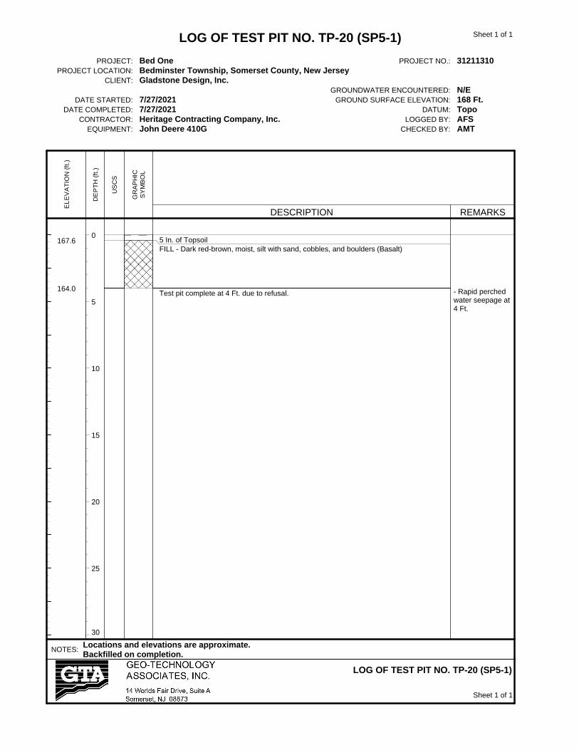
30
167.6
164.0
5 In. of TopsoilFILL - Dark red-brown, moist, silt with sand, cobbles, and boulders (Basalt)
Test pit complete at 4 Ft. due to refusal. - Rapid perchedwater seepage at4 Ft.
LOG OF TEST PIT NO. TP-20 (SP5-1)
PROJECT: Bed One PROJECT NO.: 31211310PROJECT LOCATION: Bedminster Township, Somerset County, New Jersey
CLIENT: Gladstone Design, Inc.GROUNDWATER ENCOUNTERED: N/E
DATE STARTED: 7/27/2021 GROUND SURFACE ELEVATION: 168 Ft.DATE COMPLETED: 7/27/2021 DATUM: Topo
CONTRACTOR: Heritage Contracting Company, Inc. LOGGED BY: AFSEQUIPMENT: John Deere 410G CHECKED BY: AMT
NOTES:Locations and elevations are approximate.Backfilled on completion.
LOG OF TEST PIT NO. TP-20 (SP5-1)
EL
EV
AT
ION
(ft
.)
DE
PT
H (
ft.)
US
CS
GR
AP
HIC
SY
MB
OL
DESCRIPTION REMARKS
Sheet 1 of 1
Sheet 1 of 1

0
5
10
15
20
25
30
166.6
164.0
5 In. of TopsoilFILL - Dark red-brown, moist, silt with sand, cobbles, and boulders (Basalt)
Test pit complete at 3 Ft. due to refusal. - Offset by 7 Ft.and encounteredrefusal at 3 Ft.again.
LOG OF TEST PIT NO. TP-21 (SP5-2)
PROJECT: Bed One PROJECT NO.: 31211310PROJECT LOCATION: Bedminster Township, Somerset County, New Jersey
CLIENT: Gladstone Design, Inc.GROUNDWATER ENCOUNTERED: N/E
DATE STARTED: 7/27/2021 GROUND SURFACE ELEVATION: 167 Ft.DATE COMPLETED: 7/27/2021 DATUM: Topo
CONTRACTOR: Heritage Contracting Company, Inc. LOGGED BY: AFSEQUIPMENT: John Deere 410G CHECKED BY: AMT
NOTES:Locations and elevations are approximate.Backfilled on completion.
LOG OF TEST PIT NO. TP-21 (SP5-2)
EL
EV
AT
ION
(ft
.)
DE
PT
H (
ft.)
US
CS
GR
AP
HIC
SY
MB
OL
DESCRIPTION REMARKS
Sheet 1 of 1
Sheet 1 of 1

0
5
10
15
20
25
30
169.2
167.5
160.5160.0
158.5
CL
GMHW
4 In. of TopsoilFILL - Dark red-brown, moist, silty gravel with concrete and asphalt fragments
Dark red-brown, moist, Lean CLAY
Dark red-brown, moist, Silty GRAVEL (Residual Shale)Dark red-brown, moist, Highly-weathered ROCK (Shale)
Test pit complete at 11 Ft. due to refusal on weathered rock.
- Infiltration rate =0 in/hr at 3 Ft.
LOG OF TEST PIT NO. TP-22 (SP9-1)
PROJECT: Bed One PROJECT NO.: 31211310PROJECT LOCATION: Bedminster Township, Somerset County, New Jersey
CLIENT: Gladstone Design, Inc.GROUNDWATER ENCOUNTERED: N/E
DATE STARTED: 7/27/2021 GROUND SURFACE ELEVATION: 169.50 Ft.DATE COMPLETED: 7/27/2021 DATUM: Topo
CONTRACTOR: Heritage Contracting Company, Inc. LOGGED BY: AFSEQUIPMENT: John Deere 410G CHECKED BY: AMT
NOTES:Locations and elevations are approximate.Backfilled on completion.
LOG OF TEST PIT NO. TP-22 (SP9-1)
EL
EV
AT
ION
(ft
.)
DE
PT
H (
ft.)
US
CS
GR
AP
HIC
SY
MB
OL
DESCRIPTION REMARKS
Sheet 1 of 1
Sheet 1 of 1
0
5
10
15
20
25
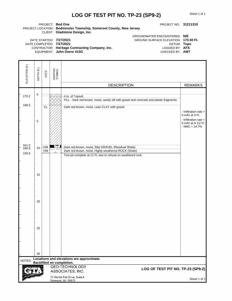
30
170.2
168.5
161.0160.5
159.5
CL
GMHW
4 In. of TopsoilFILL - Dark red-brown, moist, sandy silt with gravel and concrete and plastic fragments
Dark red-brown, moist, Lean CLAY with gravel
Dark red-brown, moist, Silty GRAVEL (Residual Shale)Dark red-brown, moist, Highly-weathered ROCK (Shale)
Test pit complete at 11 Ft. due to refusal on weathered rock.
- Infiltration rate =0 in/hr at 3 Ft.
- Infiltration rate =0 in/hr at 4-1/2 Ft.- NMC = 14.7%
LOG OF TEST PIT NO. TP-23 (SP9-2)
PROJECT: Bed One PROJECT NO.: 31211310PROJECT LOCATION: Bedminster Township, Somerset County, New Jersey
CLIENT: Gladstone Design, Inc.GROUNDWATER ENCOUNTERED: N/E
DATE STARTED: 7/27/2021 GROUND SURFACE ELEVATION: 170.50 Ft.DATE COMPLETED: 7/27/2021 DATUM: Topo
CONTRACTOR: Heritage Contracting Company, Inc. LOGGED BY: AFSEQUIPMENT: John Deere 410G CHECKED BY: AMT
NOTES:Locations and elevations are approximate.Backfilled on completion.
LOG OF TEST PIT NO. TP-23 (SP9-2)
EL
EV
AT
ION
(ft
.)
DE
PT
H (
ft.)
US
CS
GR
AP
HIC
SY
MB
OL
DESCRIPTION REMARKS
Sheet 1 of 1
Sheet 1 of 1

0
5
10
15
20
25
30
174.6
170.5
164.0
CL
5 In. of TopsoilFILL - Dark red-brown, moist, sandy silt with gravel, brick, and plastic fragments
- with black asphalt layer (4 In. in thickness) at 2 Ft.
- with wood fragments at 4 Ft.Dark red-brown, moist, Lean CLAY
Test pit complete at 11 Ft. due to refusal.
- Infiltration rate =0 in/hr at 3 Ft.
- Infiltration rate =0 in/hr at 7 Ft.
LOG OF TEST PIT NO. TP-24 (SP8-1)
PROJECT: Bed One PROJECT NO.: 31211310PROJECT LOCATION: Bedminster Township, Somerset County, New Jersey
CLIENT: Gladstone Design, Inc.GROUNDWATER ENCOUNTERED: N/E
DATE STARTED: 7/27/2021 GROUND SURFACE ELEVATION: 175 Ft.DATE COMPLETED: 7/27/2021 DATUM: Topo
CONTRACTOR: Heritage Contracting Company, Inc. LOGGED BY: AFSEQUIPMENT: John Deere 410G CHECKED BY: AMT
NOTES:Locations and elevations are approximate.Backfilled on completion.
LOG OF TEST PIT NO. TP-24 (SP8-1)
EL
EV
AT
ION
(ft
.)
DE
PT
H (
ft.)
US
CS
GR
AP
HIC
SY
MB
OL
DESCRIPTION REMARKS
Sheet 1 of 1
Sheet 1 of 1

0
5
10
15
20
25
30
176.7
169.5
166.0
165.0
CL
GM
4 In. of TopsoilFILL - Dark red-brown, moist, sandy silt with gravel, brick fragments, and a 6 In. thicklayer of yellow-brown, poorly-graded sand along the northern sidewall.
- with black asphalt (3 In. in thickness) at 2-1/2 Ft.
- with wood fragments at 7 Ft.Dark red-brown, moist, Lean CLAY
Dark red-brown, moist, Silty GRAVEL (Residual Shale)
Test pit complete at 12 Ft. due to refusal.
- Infiltration rate =0 in/hr at 3 Ft.
- Infiltration rate =0 in/hr at 8-1/2 Ft.
LOG OF TEST PIT NO. TP-25 (SP8-2)
PROJECT: Bed One PROJECT NO.: 31211310PROJECT LOCATION: Bedminster Township, Somerset County, New Jersey
CLIENT: Gladstone Design, Inc.GROUNDWATER ENCOUNTERED: N/E
DATE STARTED: 7/27/2021 GROUND SURFACE ELEVATION: 177 Ft.DATE COMPLETED: 7/27/2021 DATUM: Topo
CONTRACTOR: Heritage Contracting Company, Inc. LOGGED BY: AFSEQUIPMENT: John Deere 410G CHECKED BY: AMT
NOTES:Locations and elevations are approximate.Backfilled on completion.
LOG OF TEST PIT NO. TP-25 (SP8-2)
EL
EV
AT
ION
(ft
.)
DE
PT
H (
ft.)
US
CS
GR
AP
HIC
SY
MB
OL
DESCRIPTION REMARKS
Sheet 1 of 1
Sheet 1 of 1

0
5
10
15
20
25
30
174.7
173.0
165.5
CL
GM
4 In. of TopsoilFILL - Dark red-brown, moist, sandy silt with gravel and asphalt fragments
Dark yellow-brown and gray, moist, Lean CLAY
- with wood fragments at 3 Ft.
Dark red-brown, wet, Silty GRAVEL (Residual Shale)
Test pit complete at 11 Ft. due to refusal.
- Infiltration rate =0 in/hr at 3 Ft.
- Infiltration rate =0 in/hr at 6 Ft.
LOG OF TEST PIT NO. TP-26 (SP-1)
PROJECT: Bed One PROJECT NO.: 31211310PROJECT LOCATION: Bedminster Township, Somerset County, New Jersey
CLIENT: Gladstone Design, Inc.GROUNDWATER ENCOUNTERED: N/E
DATE STARTED: 7/27/2021 GROUND SURFACE ELEVATION: 175 Ft.DATE COMPLETED: 7/27/2021 DATUM: Topo
CONTRACTOR: Heritage Contracting Company, Inc. LOGGED BY: AFSEQUIPMENT: John Deere 410G CHECKED BY: AMT
NOTES:Locations and elevations are approximate.Backfilled on completion.
LOG OF TEST PIT NO. TP-26 (SP-1)
EL
EV
AT
ION
(ft
.)
DE
PT
H (
ft.)
US
CS
GR
AP
HIC
SY
MB
OL
DESCRIPTION REMARKS
Sheet 1 of 1
Sheet 1 of 1

0
5
10
15
20
25
30
174.7
171.0
165.0
CL
GM
4 In. of TopsoilFILL - Dark red-brown, moist, sandy silt with gravel- with irrigation line at 1 Ft.
- with wood fragments at 3 Ft.
Dark yellow-brown, moist, Lean CLAY
Dark red-brown, wet, Silty GRAVEL (Residual Shale)
Test pit complete at 11 Ft. due to refusal.
- Infiltration rate =0 in/hr at 3 Ft.
- Infiltration rate =0 in/hr at 5 Ft.
LOG OF TEST PIT NO. TP-27 (SP-2)
PROJECT: Bed One PROJECT NO.: 31211310PROJECT LOCATION: Bedminster Township, Somerset County, New Jersey
CLIENT: Gladstone Design, Inc.GROUNDWATER ENCOUNTERED: N/E
DATE STARTED: 7/27/2021 GROUND SURFACE ELEVATION: 175 Ft.DATE COMPLETED: 7/27/2021 DATUM: Topo
CONTRACTOR: Heritage Contracting Company, Inc. LOGGED BY: AFSEQUIPMENT: John Deere 410G CHECKED BY: AMT
NOTES:Locations and elevations are approximate.Backfilled on completion.
LOG OF TEST PIT NO. TP-27 (SP-2)
EL
EV
AT
ION
(ft
.)
DE
PT
H (
ft.)
US
CS
GR
AP
HIC
SY
MB
OL
DESCRIPTION REMARKS
Sheet 1 of 1
Sheet 1 of 1

0
5
10
15
20
25
30
180.6
179.0
177.0
173.0
CL
GM
HW
5 In. of TopsoilFILL - Dark red-brown, moist, sandy silt with gravel
Dark red-brown, moist, Lean CLAY
Dark red-brown, moist, Silty GRAVEL (Residual Shale)
Dark red-brown, moist, Highly-weathered ROCK (Shale)
Test pit complete at 10 Ft. due to refusal on weathered rock.
- Infiltration rate =0 in/hr at 2 Ft.
LOG OF TEST PIT NO. TP-28 (SP-6)
PROJECT: Bed One PROJECT NO.: 31211310PROJECT LOCATION: Bedminster Township, Somerset County, New Jersey
CLIENT: Gladstone Design, Inc.GROUNDWATER ENCOUNTERED: N/E
DATE STARTED: 7/27/2021 GROUND SURFACE ELEVATION: 181 Ft.DATE COMPLETED: 7/27/2021 DATUM: Topo
CONTRACTOR: Heritage Contracting Company, Inc. LOGGED BY: AFSEQUIPMENT: John Deere 410G CHECKED BY: AMT
NOTES:Locations and elevations are approximate.Backfilled on completion.
LOG OF TEST PIT NO. TP-28 (SP-6)
EL
EV
AT
ION
(ft
.)
DE
PT
H (
ft.)
US
CS
GR
AP
HIC
SY
MB
OL
DESCRIPTION REMARKS
Sheet 1 of 1
Sheet 1 of 1

0
5
10
15
20
25
30
180.6
179.0
175.0
171.5
CL
GM
HW
5 In. of TopsoilFILL - Dark red-brown, moist, sandy silt with gravel
Dark red-brown, moist, Lean CLAY
Dark red-brown, moist, Silty GRAVEL (Residual Shale)
Dark red-brown, moist, Highly-weathered ROCK (Shale)Test pit complete at 10 Ft. due to refusal weathered rock.
- Infiltration rate =0 in/hr at 2 Ft.
LOG OF TEST PIT NO. TP-29 (SP-7)
PROJECT: Bed One PROJECT NO.: 31211310PROJECT LOCATION: Bedminster Township, Somerset County, New Jersey
CLIENT: Gladstone Design, Inc.GROUNDWATER ENCOUNTERED: N/E
DATE STARTED: 7/27/2021 GROUND SURFACE ELEVATION: 181 Ft.DATE COMPLETED: 7/27/2021 DATUM: Topo
CONTRACTOR: Heritage Contracting Company, Inc. LOGGED BY: AFSEQUIPMENT: John Deere 410G CHECKED BY: AMT
NOTES:Locations and elevations are approximate.Backfilled on completion.
LOG OF TEST PIT NO. TP-29 (SP-7)
EL
EV
AT
ION
(ft
.)
DE
PT
H (
ft.)
US
CS
GR
AP
HIC
SY
MB
OL
DESCRIPTION REMARKS
Sheet 1 of 1
Sheet 1 of 1

0
5
10
15
20
25
30
169.6
168.0
165.0
163.0
160.0
CL
GM
HW
5 In. of TopsoilFILL - Red-brown, moist, silty gravel with concrete and asphalt fragments- with abandoned electric conduit at 1 Ft.
Red-brown, moist, Lean CLAY
Red-brown, moist, Silty GRAVEL (Residual Shale)
Red-brown, moist, Highly-weathered ROCK (Shale)
Test pit complete at 10 Ft. due to refusal on weathered rock.
- Infiltration rate =0 in/hr at 3 Ft.
LOG OF TEST PIT NO. TP-30
PROJECT: Bed One PROJECT NO.: 31211310PROJECT LOCATION: Bedminster Township, Somerset County, New Jersey
CLIENT: Gladstone Design, Inc.GROUNDWATER ENCOUNTERED: N/E
DATE STARTED: 8/9/2021 GROUND SURFACE ELEVATION: 170 Ft.DATE COMPLETED: 8/9/2021 DATUM: Topo
CONTRACTOR: Heritage Contracting Company, Inc. LOGGED BY: DSPEQUIPMENT: John Deere 310SL CHECKED BY: AMT
NOTES:Location and elevation are approximate.Backfilled on completion.
LOG OF TEST PIT NO. TP-30
EL
EV
AT
ION
(ft
.)
DE
PT
H (
ft.)
US
CS
GR
AP
HIC
SY
MB
OL
DESCRIPTION REMARKS
Sheet 1 of 1
Sheet 1 of 1

0
5
10
15
20
25
30
174.1
172.5
170.5
CL
5 In. of TopsoilFILL - Red-brown, moist, silty gravel with concrete fragments
Red-brown, moist, Sandy Lean CLAY
Test pit complete at 4 Ft.
- Infiltration rate =0 in/hr at 3 Ft.
LOG OF TEST PIT NO. TP-31
PROJECT: Bed One PROJECT NO.: 31211310PROJECT LOCATION: Bedminster Township, Somerset County, New Jersey
CLIENT: Gladstone Design, Inc.GROUNDWATER ENCOUNTERED: N/E
DATE STARTED: 8/9/2021 GROUND SURFACE ELEVATION: 174.5 Ft.DATE COMPLETED: 8/9/2021 DATUM: Topo
CONTRACTOR: Heritage Contracting Company, Inc. LOGGED BY: DSPEQUIPMENT: John Deere 310SL CHECKED BY: AMT
NOTES:Location and elevation are approximate.Backfilled on completion.
LOG OF TEST PIT NO. TP-31
EL
EV
AT
ION
(ft
.)
DE
PT
H (
ft.)
US
CS
GR
AP
HIC
SY
MB
OL
DESCRIPTION REMARKS
Sheet 1 of 1
Sheet 1 of 1

0
5
10
15
20
25
30
178.1177.5
175.5
174.5
CL
GM
5 In. of TopsoilFILL - Red-brown, moist, silty gravel with concrete fragmentsRed-brown, moist, Sandy Lean CLAY
Red-brown, moist, Silty GRAVEL (Residual Shale)
Test pit complete at 4 Ft.
- Infiltration rate =0 in/hr at 2 Ft.
LOG OF TEST PIT NO. TP-32
PROJECT: Bed One PROJECT NO.: 31211310PROJECT LOCATION: Bedminster Township, Somerset County, New Jersey
CLIENT: Gladstone Design, Inc.GROUNDWATER ENCOUNTERED: N/E
DATE STARTED: 8/9/2021 GROUND SURFACE ELEVATION: 178.5 Ft.DATE COMPLETED: 8/9/2021 DATUM: Topo
CONTRACTOR: Heritage Contracting Company, Inc. LOGGED BY: DSPEQUIPMENT: John Deere 310SL CHECKED BY: AMT
NOTES:Location and elevation are approximate.Backfilled on completion.
LOG OF TEST PIT NO. TP-32
EL
EV
AT
ION
(ft
.)
DE
PT
H (
ft.)
US
CS
GR
AP
HIC
SY
MB
OL
DESCRIPTION REMARKS
Sheet 1 of 1
Sheet 1 of 1
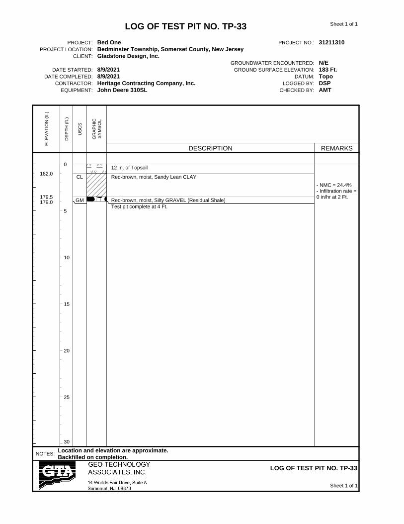
0
5
10
15
20
25
30
182.0
179.5179.0
CL
GM
12 In. of Topsoil
Red-brown, moist, Sandy Lean CLAY
Red-brown, moist, Silty GRAVEL (Residual Shale)Test pit complete at 4 Ft.
- NMC = 24.4%- Infiltration rate =0 in/hr at 2 Ft.
LOG OF TEST PIT NO. TP-33
PROJECT: Bed One PROJECT NO.: 31211310PROJECT LOCATION: Bedminster Township, Somerset County, New Jersey
CLIENT: Gladstone Design, Inc.GROUNDWATER ENCOUNTERED: N/E
DATE STARTED: 8/9/2021 GROUND SURFACE ELEVATION: 183 Ft.DATE COMPLETED: 8/9/2021 DATUM: Topo
CONTRACTOR: Heritage Contracting Company, Inc. LOGGED BY: DSPEQUIPMENT: John Deere 310SL CHECKED BY: AMT
NOTES:Location and elevation are approximate.Backfilled on completion.
LOG OF TEST PIT NO. TP-33
EL
EV
AT
ION
(ft
.)
DE
PT
H (
ft.)
US
CS
GR
AP
HIC
SY
MB
OL
DESCRIPTION REMARKS
Sheet 1 of 1
Sheet 1 of 1

0
5
10
15
20
25
30
185.0
182.5182.0
CL
GM
12 In. of Topsoil
Red-brown, moist, Sandy Lean CLAY
Red-brown, moist, Silty GRAVEL (Residual Shale)Test pit complete at 4 Ft.
- Infiltration rate =0 in/hr at 2 Ft.
LOG OF TEST PIT NO. TP-34
PROJECT: Bed One PROJECT NO.: 31211310PROJECT LOCATION: Bedminster Township, Somerset County, New Jersey
CLIENT: Gladstone Design, Inc.GROUNDWATER ENCOUNTERED: N/E
DATE STARTED: 8/9/2021 GROUND SURFACE ELEVATION: 186 Ft.DATE COMPLETED: 8/9/2021 DATUM: Topo
CONTRACTOR: Heritage Contracting Company, Inc. LOGGED BY: DSPEQUIPMENT: John Deere 310SL CHECKED BY: AMT
NOTES:Location and elevation are approximate.Backfilled on completion.
LOG OF TEST PIT NO. TP-34
EL
EV
AT
ION
(ft
.)
DE
PT
H (
ft.)
US
CS
GR
AP
HIC
SY
MB
OL
DESCRIPTION REMARKS
Sheet 1 of 1
Sheet 1 of 1
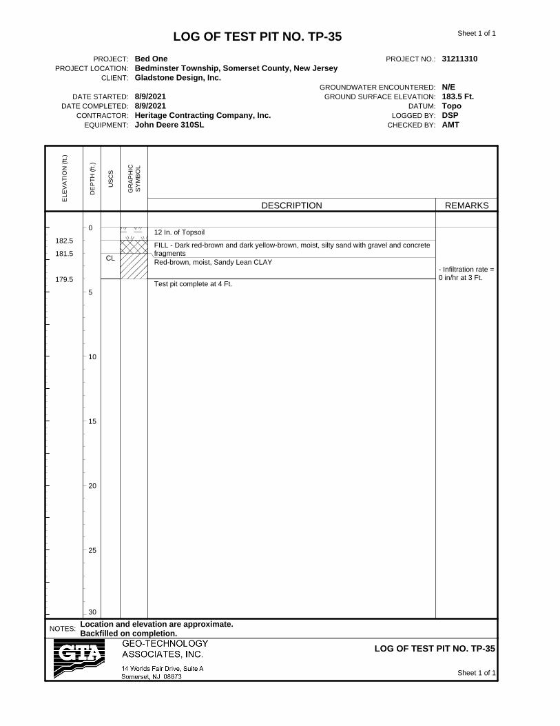
0
5
10
15
20
25
30
182.5
181.5
179.5
CL
12 In. of Topsoil
FILL - Dark red-brown and dark yellow-brown, moist, silty sand with gravel and concretefragmentsRed-brown, moist, Sandy Lean CLAY
Test pit complete at 4 Ft.
- Infiltration rate =0 in/hr at 3 Ft.
LOG OF TEST PIT NO. TP-35
PROJECT: Bed One PROJECT NO.: 31211310PROJECT LOCATION: Bedminster Township, Somerset County, New Jersey
CLIENT: Gladstone Design, Inc.GROUNDWATER ENCOUNTERED: N/E
DATE STARTED: 8/9/2021 GROUND SURFACE ELEVATION: 183.5 Ft.DATE COMPLETED: 8/9/2021 DATUM: Topo
CONTRACTOR: Heritage Contracting Company, Inc. LOGGED BY: DSPEQUIPMENT: John Deere 310SL CHECKED BY: AMT
NOTES:Location and elevation are approximate.Backfilled on completion.
LOG OF TEST PIT NO. TP-35
EL
EV
AT
ION
(ft
.)
DE
PT
H (
ft.)
US
CS
GR
AP
HIC
SY
MB
OL
DESCRIPTION REMARKS
Sheet 1 of 1
Sheet 1 of 1

0
5
10
15
20
25
30
185.0
182.0
CL
12 In. of Topsoil
Red-brown, moist, Sandy Lean CLAY
Test pit complete at 4 Ft.
- Infiltration rate =0 in/hr at 2 Ft.
LOG OF TEST PIT NO. TP-36
PROJECT: Bed One PROJECT NO.: 31211310PROJECT LOCATION: Bedminster Township, Somerset County, New Jersey
CLIENT: Gladstone Design, Inc.GROUNDWATER ENCOUNTERED: N/E
DATE STARTED: 8/9/2021 GROUND SURFACE ELEVATION: 186 Ft.DATE COMPLETED: 8/9/2021 DATUM: Topo
CONTRACTOR: Heritage Contracting Company, Inc. LOGGED BY: DSPEQUIPMENT: John Deere 310SL CHECKED BY: AMT
NOTES:Location and elevation are approximate.Backfilled on completion.
LOG OF TEST PIT NO. TP-36
EL
EV
AT
ION
(ft
.)
DE
PT
H (
ft.)
US
CS
GR
AP
HIC
SY
MB
OL
DESCRIPTION REMARKS
Sheet 1 of 1
Sheet 1 of 1

0
5
10
15
20
25
30
175.8
174.5
173.0172.5
CL
GM
8 In. of TopsoilFILL - Dark red-brown, moist, silty gravel with sand and glass fragments
Red-brown, moist, Sandy Lean CLAY
Red-brown, moist, Silty GRAVEL (Residual Shale)Test pit complete at 4 Ft.
- Infiltration rate =0 in/hr at 3 Ft.
LOG OF TEST PIT NO. TP-37
PROJECT: Bed One PROJECT NO.: 31211310PROJECT LOCATION: Bedminster Township, Somerset County, New Jersey
CLIENT: Gladstone Design, Inc.GROUNDWATER ENCOUNTERED: N/E
DATE STARTED: 8/9/2021 GROUND SURFACE ELEVATION: 176.5 Ft.DATE COMPLETED: 8/9/2021 DATUM: Topo
CONTRACTOR: Heritage Contracting Company, Inc. LOGGED BY: DSPEQUIPMENT: John Deere 310SL CHECKED BY: AMT
NOTES:Location and elevation are approximate.Backfilled on completion.
LOG OF TEST PIT NO. TP-37
EL
EV
AT
ION
(ft
.)
DE
PT
H (
ft.)
US
CS
GR
AP
HIC
SY
MB
OL
DESCRIPTION REMARKS
Sheet 1 of 1
Sheet 1 of 1

0
5
10
15
20
25
30
175.0
174.0
172.0
CL
12 In. of Topsoil
FILL - Dark red-brown, moist, silty gravel with sand and twigs
Red-brown, moist, Lean CLAY
Test pit complete at 4 Ft.
- Infiltration rate =0 in/hr at 3 Ft.
LOG OF TEST PIT NO. TP-38
PROJECT: Bed One PROJECT NO.: 31211310PROJECT LOCATION: Bedminster Township, Somerset County, New Jersey
CLIENT: Gladstone Design, Inc.GROUNDWATER ENCOUNTERED: N/E
DATE STARTED: 8/9/2021 GROUND SURFACE ELEVATION: 176 Ft.DATE COMPLETED: 8/9/2021 DATUM: Topo
CONTRACTOR: Heritage Contracting Company, Inc. LOGGED BY: DSPEQUIPMENT: John Deere 310SL CHECKED BY: AMT
NOTES:Location and elevation are approximate.Backfilled on completion.
LOG OF TEST PIT NO. TP-38
EL
EV
AT
ION
(ft
.)
DE
PT
H (
ft.)
US
CS
GR
AP
HIC
SY
MB
OL
DESCRIPTION REMARKS
Sheet 1 of 1
Sheet 1 of 1

0
5
10
15
20
25
30
177.4
174.5
CL
13 In. of Topsoil
Red-brown, moist, Sandy Lean CLAY
Test pit complete at 4 Ft.
- Infiltration rate =0 in/hr at 2 Ft.
LOG OF TEST PIT NO. TP-39
PROJECT: Bed One PROJECT NO.: 31211310PROJECT LOCATION: Bedminster Township, Somerset County, New Jersey
CLIENT: Gladstone Design, Inc.GROUNDWATER ENCOUNTERED: N/E
DATE STARTED: 8/9/2021 GROUND SURFACE ELEVATION: 178.5 Ft.DATE COMPLETED: 8/9/2021 DATUM: Topo
CONTRACTOR: Heritage Contracting Company, Inc. LOGGED BY: DSPEQUIPMENT: John Deere 310SL CHECKED BY: AMT
NOTES:Location and elevation are approximate.Backfilled on completion.
LOG OF TEST PIT NO. TP-39
EL
EV
AT
ION
(ft
.)
DE
PT
H (
ft.)
US
CS
GR
AP
HIC
SY
MB
OL
DESCRIPTION REMARKS
Sheet 1 of 1
Sheet 1 of 1

0
5
10
15
20
25
30
182.4
179.0
CL7 In. of TopsoilRed-brown, moist, Lean CLAY
Test pit complete at 4 Ft.
- Infiltration rate =0 in/hr at 2 Ft.
LOG OF TEST PIT NO. TP-40
PROJECT: Bed One PROJECT NO.: 31211310PROJECT LOCATION: Bedminster Township, Somerset County, New Jersey
CLIENT: Gladstone Design, Inc.GROUNDWATER ENCOUNTERED: N/E
DATE STARTED: 8/9/2021 GROUND SURFACE ELEVATION: 183 Ft.DATE COMPLETED: 8/9/2021 DATUM: Topo
CONTRACTOR: Heritage Contracting Company, Inc. LOGGED BY: DSPEQUIPMENT: John Deere 310SL CHECKED BY: AMT
NOTES:Location and elevation are approximate.Backfilled on completion.
LOG OF TEST PIT NO. TP-40
EL
EV
AT
ION
(ft
.)
DE
PT
H (
ft.)
US
CS
GR
AP
HIC
SY
MB
OL
DESCRIPTION REMARKS
Sheet 1 of 1
Sheet 1 of 1

0
5
10
15
20
25
30
182.0
179.0
CL
12 In. of Topsoil
Red-brown, moist, Lean CLAY
Test pit complete at 4 Ft.
- Infiltration rate =0 in/hr at 2 Ft.
LOG OF TEST PIT NO. TP-41
PROJECT: Bed One PROJECT NO.: 31211310PROJECT LOCATION: Bedminster Township, Somerset County, New Jersey
CLIENT: Gladstone Design, Inc.GROUNDWATER ENCOUNTERED: N/E
DATE STARTED: 8/9/2021 GROUND SURFACE ELEVATION: 183 Ft.DATE COMPLETED: 8/9/2021 DATUM: Topo
CONTRACTOR: Heritage Contracting Company, Inc. LOGGED BY: DSPEQUIPMENT: John Deere 310SL CHECKED BY: AMT
NOTES:Location and elevation are approximate.Backfilled on completion.
LOG OF TEST PIT NO. TP-41
EL
EV
AT
ION
(ft
.)
DE
PT
H (
ft.)
US
CS
GR
AP
HIC
SY
MB
OL
DESCRIPTION REMARKS
Sheet 1 of 1
Sheet 1 of 1

0
5
10
15
20
25
30
177.6
176.0
174.0
CL
5 In. of TopsoilFILL - Red-brown, moist, silty gravel
- with stone and burlap at 1-1/2 Ft.Red-brown, moist, Lean CLAY
Test pit complete at 4 Ft.
- NMC = 23.1%- Infiltration rate =0 in/hr at 3 Ft.
LOG OF TEST PIT NO. TP-42
PROJECT: Bed One PROJECT NO.: 31211310PROJECT LOCATION: Bedminster Township, Somerset County, New Jersey
CLIENT: Gladstone Design, Inc.GROUNDWATER ENCOUNTERED: N/E
DATE STARTED: 8/9/2021 GROUND SURFACE ELEVATION: 178 Ft.DATE COMPLETED: 8/9/2021 DATUM: Topo
CONTRACTOR: Heritage Contracting Company, Inc. LOGGED BY: DSPEQUIPMENT: John Deere 310SL CHECKED BY: AMT
NOTES:Location and elevation are approximate.Backfilled on completion.
LOG OF TEST PIT NO. TP-42
EL
EV
AT
ION
(ft
.)
DE
PT
H (
ft.)
US
CS
GR
AP
HIC
SY
MB
OL
DESCRIPTION REMARKS
Sheet 1 of 1
Sheet 1 of 1

0
5
10
15
20
25
30
172.5
168.0167.5 CL
6 In. of TopsoilFILL - Red-brown, moist, sandy silt with brick fragments
- with stone and wood fragments at 4 Ft.
Red-brown, moist, Lean CLAYTest pit complete at 5-1/2 Ft.
- Infiltration rate =0 in/hr at 2 Ft.
- Infiltration rate =0 in/hr at 5 Ft.
LOG OF TEST PIT NO. TP-43
PROJECT: Bed One PROJECT NO.: 31211310PROJECT LOCATION: Bedminster Township, Somerset County, New Jersey
CLIENT: Gladstone Design, Inc.GROUNDWATER ENCOUNTERED: N/E
DATE STARTED: 8/9/2021 GROUND SURFACE ELEVATION: 173 Ft.DATE COMPLETED: 8/9/2021 DATUM: Topo
CONTRACTOR: Heritage Contracting Company, Inc. LOGGED BY: DSPEQUIPMENT: John Deere 310SL CHECKED BY: AMT
NOTES:Location and elevation are approximate.Backfilled on completion.
LOG OF TEST PIT NO. TP-43
EL
EV
AT
ION
(ft
.)
DE
PT
H (
ft.)
US
CS
GR
AP
HIC
SY
MB
OL
DESCRIPTION REMARKS
Sheet 1 of 1
Sheet 1 of 1
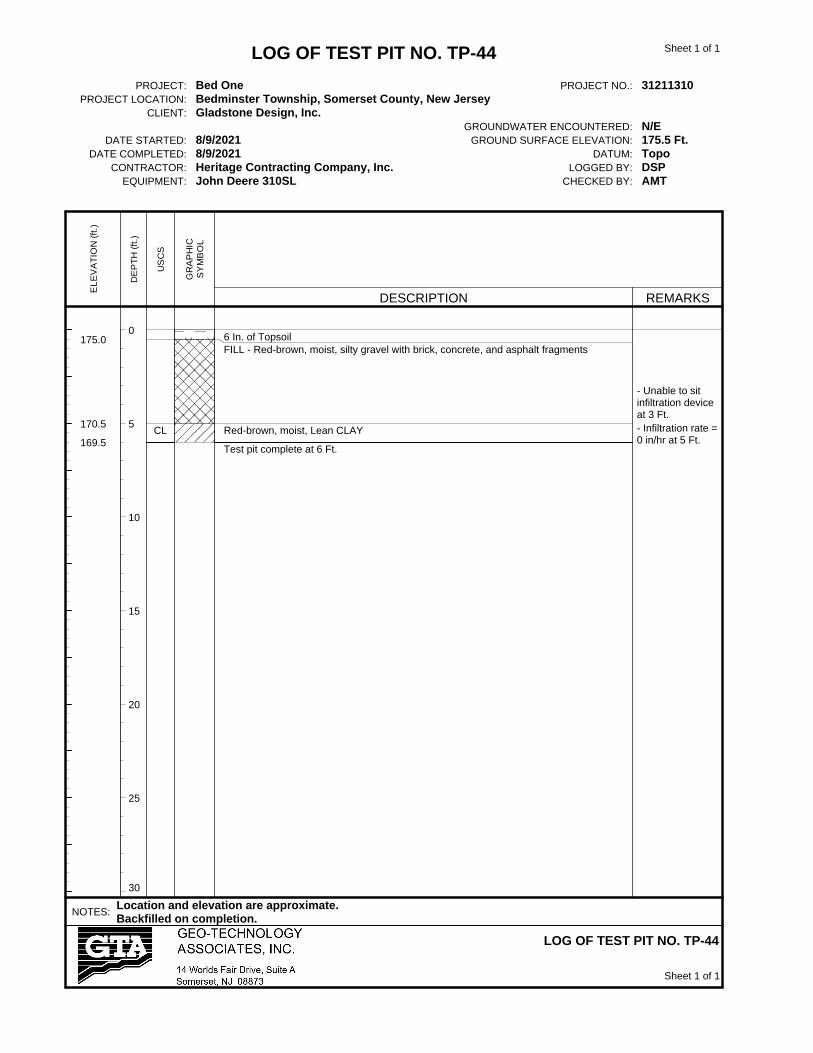
0
5
10
15
20
25
30
175.0
170.5
169.5CL
6 In. of TopsoilFILL - Red-brown, moist, silty gravel with brick, concrete, and asphalt fragments
Red-brown, moist, Lean CLAY
Test pit complete at 6 Ft.
- Unable to sitinfiltration deviceat 3 Ft.
- Infiltration rate =0 in/hr at 5 Ft.
LOG OF TEST PIT NO. TP-44
PROJECT: Bed One PROJECT NO.: 31211310PROJECT LOCATION: Bedminster Township, Somerset County, New Jersey
CLIENT: Gladstone Design, Inc.GROUNDWATER ENCOUNTERED: N/E
DATE STARTED: 8/9/2021 GROUND SURFACE ELEVATION: 175.5 Ft.DATE COMPLETED: 8/9/2021 DATUM: Topo
CONTRACTOR: Heritage Contracting Company, Inc. LOGGED BY: DSPEQUIPMENT: John Deere 310SL CHECKED BY: AMT
NOTES:Location and elevation are approximate.Backfilled on completion.
LOG OF TEST PIT NO. TP-44
EL
EV
AT
ION
(ft
.)
DE
PT
H (
ft.)
US
CS
GR
AP
HIC
SY
MB
OL
DESCRIPTION REMARKS
Sheet 1 of 1
Sheet 1 of 1

0
5
10
15
20
25
30
175.5
173.0
172.0CL
6 In. of TopsoilFILL - Red-brown, moist, sandy silt with twigs- with rubber tire at 1 Ft.
Red-brown, moist, Lean CLAY
Test pit complete at 4 Ft.
- Infiltration rate =0 in/hr at 3 Ft.
LOG OF TEST PIT NO. TP-45
PROJECT: Bed One PROJECT NO.: 31211310PROJECT LOCATION: Bedminster Township, Somerset County, New Jersey
CLIENT: Gladstone Design, Inc.GROUNDWATER ENCOUNTERED: N/E
DATE STARTED: 8/9/2021 GROUND SURFACE ELEVATION: 176 Ft.DATE COMPLETED: 8/9/2021 DATUM: Topo
CONTRACTOR: Heritage Contracting Company, Inc. LOGGED BY: DSPEQUIPMENT: John Deere 310SL CHECKED BY: AMT
NOTES:Location and elevation are approximate.Backfilled on completion.
LOG OF TEST PIT NO. TP-45
EL
EV
AT
ION
(ft
.)
DE
PT
H (
ft.)
US
CS
GR
AP
HIC
SY
MB
OL
DESCRIPTION REMARKS
Sheet 1 of 1
Sheet 1 of 1

0
5
10
15
20
25
30
174.5
171.5
CL
12 In. of Topsoil
Red-brown, moist, Lean CLAY
Test pit complete at 4 Ft.
- Infiltration rate =0 in/hr at 2 Ft.
LOG OF TEST PIT NO. TP-46
PROJECT: Bed One PROJECT NO.: 31211310PROJECT LOCATION: Bedminster Township, Somerset County, New Jersey
CLIENT: Gladstone Design, Inc.GROUNDWATER ENCOUNTERED: N/E
DATE STARTED: 8/9/2021 GROUND SURFACE ELEVATION: 175.5 Ft.DATE COMPLETED: 8/9/2021 DATUM: Topo
CONTRACTOR: Heritage Contracting Company, Inc. LOGGED BY: DSPEQUIPMENT: John Deere 310SL CHECKED BY: AMT
NOTES:Location and elevation are approximate.Backfilled on completion.
LOG OF TEST PIT NO. TP-46
EL
EV
AT
ION
(ft
.)
DE
PT
H (
ft.)
US
CS
GR
AP
HIC
SY
MB
OL
DESCRIPTION REMARKS
Sheet 1 of 1
Sheet 1 of 1

APPENDIX C
Laboratory Data
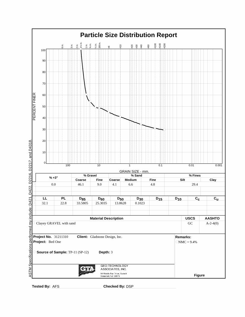
AS
TM
Sp
ecific
atio
ns p
erf
orm
ed
my in
clu
de
: D
42
1, D
42
2, D
22
16
, D
22
17
, a
nd
D4
31
8.
Tested By: AFS Checked By: DSP
LL PL D85 D60 D50 D30 D15 D10 Cc Cu
Material Description USCS AASHTO
Project No. Client: Remarks:
Project:
Source of Sample: TP-11 (SP-12) Depth: 3
Figure
32.1 22.8 33.5805 25.3035 13.8628 0.1023
Clayey GRAVEL with sand GC A-2-4(0)
31211310 Gladstone Design, Inc.
PE
RC
EN
T F
INE
R
0
10
20
30
40
50
60
70
80
90
100
GRAIN SIZE - mm.
0.0010.010.1110100
% +3"Coarse
% Gravel
Fine Coarse Medium
% Sand
Fine Silt
% Fines
Clay
0.0 46.1 9.0 4.1 6.6 4.8 29.4
6 in.
3 in.
2 in.
1½
in.
1 in.
¾ in.
½ in.
3/8
in.
#4
#10
#20
#30
#40
#60
#100
#140
#200
Particle Size Distribution Report
Bed One NMC = 9.4%

AS
TM
Sp
ecific
atio
ns p
erf
orm
ed
my in
clu
de
: D
42
1, D
42
2, D
22
16
, D
22
17
, a
nd
D4
31
8.
Tested By: AFS Checked By: DSP
LL PL D85 D60 D50 D30 D15 D10 Cc Cu
Material Description USCS AASHTO
Project No. Client: Remarks:
Project:
Source of Sample: TP-16 (SP4B-1) Depth: 4
Figure
NV NP 28.3534 12.8920 9.2941 0.7942
Silty GRAVEL with sand GM A-1-b
31211310 Gladstone Design, Inc.
PE
RC
EN
T F
INE
R
0
10
20
30
40
50
60
70
80
90
100
GRAIN SIZE - mm.
0.0010.010.1110100
% +3"Coarse
% Gravel
Fine Coarse Medium
% Sand
Fine Silt
% Fines
Clay
0.0 25.8 32.3 6.4 8.3 4.1 23.1
6 in.
3 in.
2 in.
1½
in.
1 in.
¾ in.
½ in.
3/8
in.
#4
#10
#20
#30
#40
#60
#100
#140
#200
Particle Size Distribution Report
Bed One NMC = 10.7%

AS
TM
Sp
ecific
atio
ns p
erf
orm
ed
my in
clu
de
: D
42
1, D
42
2, D
22
16
, D
22
17
, a
nd
D4
31
8.
Tested By: AFS Checked By: DSP
LL PL D85 D60 D50 D30 D15 D10 Cc Cu
Material Description USCS AASHTO
Project No. Client: Remarks:
Project:
Source of Sample: TP-17 (SP4C-1) Depth: 5
Figure
NV NP 43.9126 1.9999 0.4702
Silty GRAVEL with sand GM A-4(0)
31211310 Gladstone Design, Inc.
PE
RC
EN
T F
INE
R
0
10
20
30
40
50
60
70
80
90
100
GRAIN SIZE - mm.
0.0010.010.1110100
% +3"Coarse
% Gravel
Fine Coarse Medium
% Sand
Fine Silt
% Fines
Clay
0.0 29.9 3.2 6.9 10.6 6.9 42.5
6 in.
3 in.
2 in.
1½
in.
1 in.
¾ in.
½ in.
3/8
in.
#4
#10
#20
#30
#40
#60
#100
#140
#200
Particle Size Distribution Report
Bed One NMC = 8.7%

AS
TM
Sp
ecific
atio
ns p
erf
orm
ed
my in
clu
de
: D
42
1, D
42
2, D
22
16
, D
22
17
, a
nd
D4
31
8.
Tested By: AFS Checked By: DSP
LL PL D85 D60 D50 D30 D15 D10 Cc Cu
Material Description USCS AASHTO
Project No. Client: Remarks:
Project:
Source of Sample: TP-19 (SP4C-2) Depth: 3
Figure
NV NP 4.9205 0.7335 0.2959
Silty SAND with gravel SM A-4(0)
31211310 Gladstone Design, Inc.
PE
RC
EN
T F
INE
R
0
10
20
30
40
50
60
70
80
90
100
GRAIN SIZE - mm.
0.0010.010.1110100
% +3"Coarse
% Gravel
Fine Coarse Medium
% Sand
Fine Silt
% Fines
Clay
0.0 0.0 15.7 12.2 18.4 11.6 42.1
6 in.
3 in.
2 in.
1½
in.
1 in.
¾ in.
½ in.
3/8
in.
#4
#10
#20
#30
#40
#60
#100
#140
#200
Particle Size Distribution Report
Bed One NMC = 10.7%

AS
TM
Sp
ecific
atio
ns p
erf
orm
ed
my in
clu
de
: D
42
1, D
42
2, D
22
16
, D
22
17
, a
nd
D4
31
8.
Tested By: AFS Checked By: DSP
LL PL D85 D60 D50 D30 D15 D10 Cc Cu
Material Description USCS AASHTO
Project No. Client: Remarks:
Project:
Source of Sample: TP-23 (SP9-2) Depth: 4.5
Figure
33.6 22.2 0.4723
Lean CLAY with gravel CL A-6(9)
31211310 Gladstone Design, Inc.
PE
RC
EN
T F
INE
R
0
10
20
30
40
50
60
70
80
90
100
GRAIN SIZE - mm.
0.0010.010.1110100
% +3"Coarse
% Gravel
Fine Coarse Medium
% Sand
Fine Silt
% Fines
Clay
0.0 0.0 10.1 2.3 2.8 3.5 81.3
6 in.
3 in.
2 in.
1½
in.
1 in.
¾ in.
½ in.
3/8
in.
#4
#10
#20
#30
#40
#60
#100
#140
#200
Particle Size Distribution Report
Bed One NMC = 14.7%

AS
TM
Sp
ecific
atio
ns p
erf
orm
ed
my in
clu
de
: D
42
1, D
42
2, D
22
16
, D
22
17
, a
nd
D4
31
8.
Tested By: DSP Checked By: AMT
LL PL D85 D60 D50 D30 D15 D10 Cc Cu
Material Description USCS AASHTO
Project No. Client: Remarks:
Project:
Source of Sample: TP-33 Depth: 2
Figure
32.7 20.3 1.5149 0.2089
Sandy Lean CLAY CL A-6(5)
31211310 Gladstone Design, Inc.
PE
RC
EN
T F
INE
R
0
10
20
30
40
50
60
70
80
90
100
GRAIN SIZE - mm.
0.0010.010.1110100
% +3"Coarse
% Gravel
Fine Coarse Medium
% Sand
Fine Silt
% Fines
Clay
0.0 0.0 5.3 6.6 20.9 11.5 55.7
6 in.
3 in.
2 in.
1½
in.
1 in.
¾ in.
½ in.
3/8
in.
#4
#10
#20
#30
#40
#60
#100
#140
#200
Particle Size Distribution Report
Bed One NMC = 24.4%
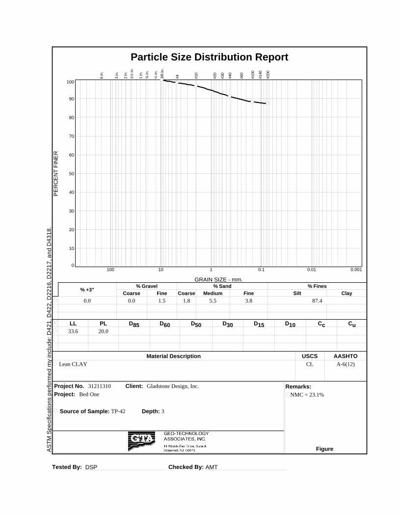
AS
TM
Sp
ecific
atio
ns p
erf
orm
ed
my in
clu
de
: D
42
1, D
42
2, D
22
16
, D
22
17
, a
nd
D4
31
8.
Tested By: DSP Checked By: AMT
LL PL D85 D60 D50 D30 D15 D10 Cc Cu
Material Description USCS AASHTO
Project No. Client: Remarks:
Project:
Source of Sample: TP-42 Depth: 3
Figure
33.6 20.0
Lean CLAY CL A-6(12)
31211310 Gladstone Design, Inc.
PE
RC
EN
T F
INE
R
0
10
20
30
40
50
60
70
80
90
100
GRAIN SIZE - mm.
0.0010.010.1110100
% +3"Coarse
% Gravel
Fine Coarse Medium
% Sand
Fine Silt
% Fines
Clay
0.0 0.0 1.5 1.8 5.5 3.8 87.4
6 in.
3 in.
2 in.
1½
in.
1 in.
¾ in.
½ in.
3/8
in.
#4
#10
#20
#30
#40
#60
#100
#140
#200
Particle Size Distribution Report
Bed One NMC = 23.1%

AS
TM
Sp
ecific
atio
ns p
erf
orm
ed
my in
clu
de
: D
42
1, D
42
2, D
22
16
, D
22
17
, a
nd
D4
31
8.
Tested By: AFS Checked By: AMT
LIQUID AND PLASTIC LIMITS TEST REPORT - ASTM D4318P
LA
ST
ICIT
Y IN
DE
X
0
10
20
30
40
50
60
LIQUID LIMIT0 10 20 30 40 50 60 70 80 90 100 110
CL-ML
CL o
r OL
CH o
r OH
ML or OL MH or OH
Dashed line indicates the approximateupper limit boundary for natural soils
4
7
SOIL DATA
SYMBOL SOURCE
NATURAL
USCSSAMPLE DEPTH WATER PLASTIC LIQUID PLASTICITY
NO. CONTENT LIMIT LIMIT INDEX(%) (%) (%) (%)
Client:
Project:
Project No.: Figure
Gladstone Design, Inc.
Bed One
31211310
TP-11 (SP-12) 3 9.4 22.8 32.1 9.3 GC

AS
TM
Sp
ecific
atio
ns p
erf
orm
ed
my in
clu
de
: D
42
1, D
42
2, D
22
16
, D
22
17
, a
nd
D4
31
8.
Tested By: AFS Checked By: AMT
LIQUID AND PLASTIC LIMITS TEST REPORT - ASTM D4318P
LA
ST
ICIT
Y IN
DE
X
0
10
20
30
40
50
60
LIQUID LIMIT0 10 20 30 40 50 60 70 80 90 100 110
CL-ML
CL o
r OL
CH o
r OH
ML or OL MH or OH
Dashed line indicates the approximateupper limit boundary for natural soils
4
7
SOIL DATA
SYMBOL SOURCE
NATURAL
USCSSAMPLE DEPTH WATER PLASTIC LIQUID PLASTICITY
NO. CONTENT LIMIT LIMIT INDEX(%) (%) (%) (%)
Client:
Project:
Project No.: Figure
Gladstone Design, Inc.
Bed One
31211310
TP-23 (SP9-2) 4.5 14.7 22.2 33.6 11.4 CL
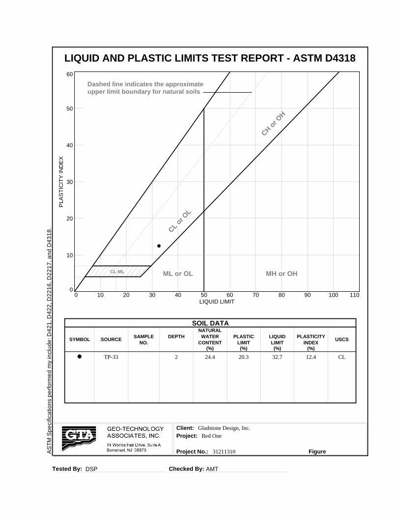
AS
TM
Sp
ecific
atio
ns p
erf
orm
ed
my in
clu
de
: D
42
1, D
42
2, D
22
16
, D
22
17
, a
nd
D4
31
8.
Tested By: DSP Checked By: AMT
LIQUID AND PLASTIC LIMITS TEST REPORT - ASTM D4318P
LA
ST
ICIT
Y IN
DE
X
0
10
20
30
40
50
60
LIQUID LIMIT0 10 20 30 40 50 60 70 80 90 100 110
CL-ML
CL o
r OL
CH o
r OH
ML or OL MH or OH
Dashed line indicates the approximateupper limit boundary for natural soils
4
7
SOIL DATA
SYMBOL SOURCE
NATURAL
USCSSAMPLE DEPTH WATER PLASTIC LIQUID PLASTICITY
NO. CONTENT LIMIT LIMIT INDEX(%) (%) (%) (%)
Client:
Project:
Project No.: Figure
Gladstone Design, Inc.
Bed One
31211310
TP-33 2 24.4 20.3 32.7 12.4 CL

AS
TM
Sp
ecific
atio
ns p
erf
orm
ed
my in
clu
de
: D
42
1, D
42
2, D
22
16
, D
22
17
, a
nd
D4
31
8.
Tested By: DSP Checked By: AMT
LIQUID AND PLASTIC LIMITS TEST REPORT - ASTM D4318P
LA
ST
ICIT
Y IN
DE
X
0
10
20
30
40
50
60
LIQUID LIMIT0 10 20 30 40 50 60 70 80 90 100 110
CL-ML
CL o
r OL
CH o
r OH
ML or OL MH or OH
Dashed line indicates the approximateupper limit boundary for natural soils
4
7
SOIL DATA
SYMBOL SOURCE
NATURAL
USCSSAMPLE DEPTH WATER PLASTIC LIQUID PLASTICITY
NO. CONTENT LIMIT LIMIT INDEX(%) (%) (%) (%)
Client:
Project:
Project No.: Figure
Gladstone Design, Inc.
Bed One
31211310
TP-42 3 23.1 20.0 33.6 13.6 CL
Related Documents