208281 N901-J u6 AGARD-AG-202 ° • < Q < < AGARDograph No. 202 on Store Separation by L.H.Schindel ROYAL AIRC&A ESTABLISH* 3UUl»v DISTRIBUTION AND AVAILABILITY ON BACK COVER •c

Welcome message from author
This document is posted to help you gain knowledge. Please leave a comment to let me know what you think about it! Share it to your friends and learn new things together.
Transcript
208281 N901-J
u 6
AGARD-AG-202
° •
< Q
<
<
AGARDograph No. 202
on
Store Separation by
L.H.Schindel ROYAL AIRC&A ESTABLISH*
3 U U l » v
DISTRIBUTION AND AVAILABILITY O N BACK COVER
•c

AGARD-AG-202
NORTH ATLANTIC TREATY ORGANIZATION
ADVISORY GROUP FOR AEROSPACE RESEARCH AND DEVELOPMENT
(ORGANISATION DU TRAITE DE L'ATLANTIQUE NORD)
AGARDograph No.202
STORE SEPARATION
by
Leon H.Schindel
Chief, Aerodynamics Department Naval Surface Weapons Center
White Oak Laboratory Silver Spring, Maryland 20910
USA
0 0 0 2 0 7 6 5
This AGARDograph was prepared at the request of the Fluid Dynamics Panel of AGARD.
THE MISSION OF AGARD
The mission of AGARD is to bring together the leading personalities of the NATO nations in the fields of science and technology relating to aerospace for the following purposes:
— Exchanging of scientific and technical information;
— Continuously stimulating advances in the aerospace sciences relevant to strengthening the common defence posture;
— Improving the co-operation among member nations in aerospace research and development;
Providing scientific and technical advice and assistance to the North Atlantic Military Committee in the field of aerospace research and development;
— Rendering scientific and technical assistance, as requested, to other NATO bodies and to member nations in connection with research and development problems in the aerospace field;
Providing assistance to member nations for the purpose of increasing their scientific and technical potential;
— Recommending effective ways for the member nations to use their research and development capabilities for the common benefit of the NATO community.
The highest authority within AGARD is the National Delegates Board consisting of officially appointed senior representatives from each member nation. The mission of AGARD is carried out through the Panels which are composed of experts appointed by the National Delegates, the Consultant and Exchange Program and the Aerospace Applications Studies Program. The results of AGARD work are reported to the member nations and the NATO Authorities through the AGARD series of publications of which this is one.
Participation in AGARD activities is by invitation only and is normally limited to citizens of the NATO nations.
The content of this publication has been reproduced directly from material supplied by AGARD or the author.
Published June 1975
Copyright © AGARD 1975
629.73.028.25:533.695.9
* Printed by Technical Editing and Reproduction Ltd
Harford House. 7-9 Charlotte St. London, W1P 1HD
SUMMARY
The problem of achieving safe, repeatable and predictable separation of stores from aircraft has received considerable attention in recent years. There are so many possible combinations of store and aircraft configurations, flight conditions and release parameters that some effective and reliable methods must be applied to ensure favorable separation characteristics. Since information on the subject Is contained In a large number of Independent sources, this report seeks to collect the results in an organized manner for the convenience of engineers and designers. In order to limit the scope of the problem somewhat, the report is concerned only with externally carried, unpowered, unguided stores.
A textbook approach would be desirable. In which each aspect of the subject is described physically and formulated mathematically. However, store trajectories are usually calculated by computer code. The computational programs are lengthy and are useless without voluminous Instructional material. Consequently, In the sections of this report dealing with store trajectories, the physical situation is described, the method of solution is indicated, and the final results are presented. Wherever feasible, the formulas, equations, or numerical procedures are provided, although in most Instances, a reader should obtain the original computer program and users' manual. If he Intends to carry out any computations.
The major emphasis in this report is on the motion of the store as it traverses the flow field In the vicinity of the parent aircraft. Criteria for safe separation are presented, as well as methods of calculating the flight path of the store. Wind tunnel test techniques are described and some Information on flight testing is also indicated. Furthermore, each analytical procedure Is checked by comparison with data from flight or wind tunnel test results.
Components of the ejection system. Including racks, ejectors, fire control systems, and connections are briefly mentioned. References to more detailed information are provided. Similarly, the effects of stores on aircraft performance, and resulting structural and design Implications are only outlined here. Sources of more detailed Information are indicated. Thus this report presents methods of obtaining trajectory information and a practical guide to related aspects of external store carriage and separation.
LIST OF SYMBOLS
To facilitate use of the various papers cited in this report, the notation follows that of the original authors. Consequently, the symbols take on different meanings In different sections of the report. Where a symbol has multiple definitions, the appropriate sections are indicated. Some symbols which are used at only one place and defined In the text nearby are not repeated in the nomenclature list.
AR aspect ratio
AR' aspect ratio of transonlcally similar configuration
a body radius
a,b,c components of store axis (Section ^)
aQ initial acceleration of a point on the store
an coefficient of spherical harmonic
b shock detachment distance parameter
C shock shape parameter
C^ axial force coefficient
Cc shock shape parameter for circular-nosed bodies
Cp force coefficient
Cp force coefficient on transonlcally similar configuration
C4 rolling moment coefficient
Cm pitching moment coefficient
CjJ, moment coefficient on transonlcally similar configuration (Section 5-8)
C^ pitching moment coefficient of store (Sections 3 and 4)
(Cm^Bv pitching moment coefficient due to buoyancy
(Cm^cF pitching moment coefficient due to crossflow
^ m ^ S B slender body pitching moment coefficient
Cjj normal force coefficient
Cfl average normal force coefficient over a store segment
Cjyj„ normal force coefficient per unit body length
(CJJ)R normal force coefficient due to buoyancy
(CJPCF normal force coefficient due to crossflow
(CN)SB slender body normal force coefficient
Cn yawing moment coefficient
^cn^Bv yawing moment coefficient due to buoyancy
(Cn-'n-a yawing moment coefficient due to crossflow n CF (C.) slender body yawing moment coefficient
SB
C_ pressure coefficient
Cy side force coefficient
^cY^Bv side force coefficient due to buoyancy
(Cv)cP side force coefficient due to crossflow
^CY^SB slender body side force coefficient
C* lift coefficient of store z
Cq0 shock shape parameter for flat-faced bodies
c slope of body doublet distribution
D body reference diameter (Section 5)
D aircraft drag Increment due to store installation (Section 3)
d store reference dimension
d1 diameter or thickness parameter for shock detachment
P ,F ,F force components acting on store x y z
g gravitational acceleration (Sections 4 and 5.3)
g slope of source strength distribution (Section 5.5)
gj_ slope of source strength distribution at section x^
E x>£y>8z gravity components acting on store
I total impulse Imparted to the store by the ejection system
^xx^yv^zz moments of inertia about x,y,z axes
Ixy,Ixz'Iyz products of inertia
1 moment of inertia of store about pitch axis
K scale factor
kxx,kyy,kzz radii of gyration
kxy product of gyration
L aircraft lift increment due to store installation
i moment arm from store center of gravity to ejector foot (Section 2)
i rolling moment (Section 4)
ic length of circular arc nose
if distance from store nose to fin 1/4 chord (Section 5-2)
4f fuselage length (Section 5.4)
lR reference length
l B store length
M Mach number
1%, flight Mach number
MX,MV,M„ moment components acting on store
m mass of store (Sections 2 and 5.3)
m angle to body tangent (Section 5.1)
N acceleration parameter
n aircraft acceleration In g's
p,q,r angular rates about store axes
Q(x) source strength distribution
Qk source strength at section xk
Qjjf non-dimensional source strength at Xy.
q dynamic pressure
q M flight dynamic pressure
q,,, flight dynamic pressure of store
R store base radius
Rj^ body radius at section x A
R(l,j) aerodynamic Influence coefficient
r,6 cylindrical coordinates
r fuselage radius (Section 5-4)
r maximum radius of body (Section 4)
rj body radius at section XJJ
rv:j_ radial distance to ith vortex
S cross-sectional area of body (Sections 5.1 and 5.6)
S store reference area (Section 4)
S R reference area
S „ e f reference area
S n semi-span of horizontal fin
S v semi-span of vertical fin
s wing semi-span (Sections 5.1 and 5.4)
s vortex semi-span (Section 5-1)
t time after release
t c critical time
tcjj characteristic time
U axial component of flow field velocity
U„ flight velocity
US,VS,WS flow field velocity components along store axis
u,v,w components of flow field velocity perturbations
u',v',w' flow field velocity components in equivalent Incompressible problem
u*,v*,w* non-dimensional flow field velocity components
u^ perturbation velocity 1th box
us» vs , ws flow field velocity components in store coordinates
u*,v*,w* non-dimensional velocity components In store coordinates s s s
u_,u velocity components in cylindrical coordinates r 6
Ug.v ,wc flow field velocity components in aircraft coordinates u£!»vn'wc components of equivalent incompressible flow field velocity in aircraft
coordinates
u. ,v. ,w. components at wing control point of flow field velocity perturbations l,v l,v* i,v ^
V Q initial velocity of store
V e 1 ejection velocity
V^ aircraft flight velocity
V ,V velocity components in cylindrical coordinates
V,,, store flight velocity
v ,v velocity components In cylindrical coordinates
v^ flight velocity of body
v' initial linear velocity of store
v',v' components of Initial linear velocity of store x y
W component of flow normal to body (Section 5)
store weight (Section 4)
upwash velocity at jth box
location of store forward of carriage position (Section 3)
flow field point Influenced by wing or pylon sources (Section 5)
distance along fuselage (Section 5. 1)
store-fixed coordinates (Sections 4, 5.1, 5.2, 5.3 and 5.6)
coordinates In wing flow field (Section 5.5)
transonic flow coordinates (Section 5-8)
points on shock wave scaled to body size (Section 5-5)
shock detechment distance (Section 5-5)
aircraft-fixed coordinates (Section h)
coordinates in equivalent Incompressible flow (Section 5.1)
coordinates in equivalent transonic flow (Section 5-8)
coordinates of center of pressure of pylon In store axes (Section h)
coordinates of store center of mass with respect to its moment center
store-fixed coordinates
coordinates of source points on supersonic wing
distance forward from aircraft center of gravity to point on store
locations of source and control points
non-dimensional cylindrical coordinates
coordinate of store center of gravity
vortex coordinates
non-dimensional coordinates of points on detached shock wave
x0,yo,z0 velocity components in store coordinates
y lateral position of store along wing
yf,zf fin coordinates
zQ coordinate of wing-body Junction
Az distance of store below carriage position
a aircraft or body angle of attack
c i . / c aircraft angle of attack
af aircraft angle of attack
as symmetric part of angle of attack
ou unsymmetrlc part of angle of attack
a1 angle of attack In equivalent Incompressible flow
a. angle of attack of 1th store cross section
o average angle of attack over a store segment
6 / |M2_il
(5j body slope at section x.
(J* transonic similarity parameter • /|„,2_T |
r vortex strength (Section 5.1)
WJ X
X,Y,Z
X
x , y , z
x , y , z
x , y , z
x . y
x '
x ' , y ' .
x ' . y ' .
x ' , y ' .
x , z
X,\7,2.
x s ' y s »
«1»*1»
x c g
x J ' x k
x « , r »
x s , m
x v ,w»y
x 1 , y ±
? . '
z '
z '
Z 3
Z l
V , W ' Z V , W
r«(y+l)M2 transonic similarity parameter (Section 5.8)
f1 = (-y+l)M'2 transonic similarity parameter
Y angle from body location vector to normal vector (Section 5-1)
Y ratio of specific heats (Section 5.8)
Yf aircraft flight path angle
Y 0 aircraft flight path angle
Al initial vertical velocity of a point on the store
&2 initial vertical acceleration of a point on the store
A3 initial lateral velocity of a point on the store
-\L\ initial lateral acceleration of a point on the store
6 slope of body nose
60 cone or wedge semi-apex angle
Sjjgt slope of body nose at incipient shock detachment
e oblique or conical shock wave angle
n angle to control line defining detached shock wave (Section 5-5)
6 angular coordinate of point on body (Section 5.1)
6 thickness angle (Section 5.1)
9 nose angle of cut sphere or cut cylinder (Section 5.5)
Q,i>,<t- pitch, yaw, roll angles between store axes and aircraft axes
9^ angular coordinate of 1th vortex
90,ti>0,<|>0 angular orientation of aircraft In pitch, yaw, roll
90 pitch angle of aircraft in level flight
\± sweepback of source strip
u Mach angle
v normal to body contour
C.n.C aircraft-fixed coordinates
T tangent to body contour (Section 5.1)
T thickness ratio (Section 5.8)
t' transonically similar thickness ratio
$ velocity potential (Sections 5.1 and 5-5)
41 wing dihedral angle (Section 5.1)
$ f angle of fin rotation
1J1 wing sweepback angle (Section 5-1)
Yl sweepback of source strip
^ v ^lv sweepback of vortex and image
(Dej angular velocity of store at ejection
UX,O)V,(JJZ angular velocity components of store about x,y,z axes
d)x,a)y,(Dz components of Initial angular velocity of store
TABLE OF CONTENTS Page
1 INTRODUCTION 10 2 THE STORE SEPARATION PROCESS 1?
2.1 Fire Control System 12 2.2 Pylon-Mounted Ejection Equipment 12
2.2.1 Pylon-ejector geometry 12 2.2.2 Electrical connections 12 2.2.3 Ejection or release mechanisms 14
2.3 Sources of Dispersion . '. '. '. '. '. 7~ lH 3 COMPATIBILITY i6
3.1 Geometric and Functional Compatibility 16 3.2 Aerodynamic Compatibility 17
3.2.1 Aircraft performance 17 3.2.2 Aircraft stability 21 3.2.3 Structural effects 21 3.2.4 Aerodynamic heating 21 3.2.5 Design considerations 21
4 SAFE SEPARATION 26 4.1 The Safe Separation Problem 26 4.2 Criteria for Safe Separation 26
4.2.1 Types of criteria 26 4.2.2 Assumptions 26 4.2.3 Coordinate system 27 4.2.4 Motion of a point 27 4.2.5 Vertical velocity-acceleration plane 27 4.2.6 Schoch's criterion 28 4.2.7 Safe lateral separation 29 4.2.8 Effects of aircraft maneuvers 30 4.2.9 Effect of roll maneuver 31
4.3 Pylon Jettison 31 4.3.1 Configuration 31 4.3.2 Separation characteristics 31 4.3.3 Coordinate geometry 31 4.3.4 Analysis 31
4.4 Determination of the Initial Velocities and Accelerations 32 4.4.1 Store aligned with aircraft 32 4.4.2 General store alignment 32
5 TRAJECTORY PREDICTION 33 5.1 Determination of Aircraft Flow Fields at Subsonic Speeds 33
5.1.1 Summary of methods 33 5.1.2 Flow field about a body of revolution 34 5.1.3 Non-circular fuselage 40 5.1.4 Wing and pylon flow fields 42
5.1.4.1 Flow field due to normal force 42 5.1.4.2 Wing and pylon thickness 47
5.1.5 Store and ejector rack flow models 51 5.2 Force and Moment Calculations at Subsonic Speeds 51
5.2.1 Forces on store body 51 5.2.2 Forces on store lifting surfaces 55
5.3 Calculation of Store Trajectory 58 5.4 Comparisons with Experiment 61
5.4.1 Flow field 61 5.4.2 Force distribution 65 5.4.3 Trajectory 65
5.5 Supersonic Flow Field 66 5.5-1 Introduction 66 5.5-2 Location of shock waves 66
5.5-2.1 Attached shock waves 66 5.5.2.2 Detachment distance 70 5.5.2.3 Shape of detached shocks 75
5.5.3 Supersonic flow field determination 77 5.5.3.1 Wing and pylon representation 77 5.5.3.2 Flow field due to wing and pylon 79 5.5.3.3 Flow field due to fuselage nose 81
5.6 Forces on Store in Nonuniform Supersonic Flow 83 5.6.1 Store body 83 5.6.2 Loading on low aspect ratio store fins 84 5.6.3 Loading on high aspect ratio store fins 85
5.7 Trajectory Calculation in Supersonic Flow 85 5.8 Transonic Flow Field 85 5.9 Forces on Store in Transonic Plow 86 5.10 Control of Trajectories 86
6 WIND TUNNEL TEST TECHNIQUES 8? 6.1 Introduction 87 6.2 Dynamic Drop 88
6.2.1 Scaling laws 88 6.2.1.1 Scaling problem 88 6.2.1.2 Length 88 6.2.1.3 Time and velocity 88 6.2.1.4 Air temperature 88
TABLE OF CONTENTS (continued)
Page
6.2.1.5 Weight scale 89 6.2.1.6 Moment of Inertia 89 6.2.1.7 Aerodynamic damping 89 6.2.1.8 Induced angle of attack 89 6.2.1.9 Choice of scaling laws 89
6.2.2 Comparison with flight test 90 6.2.3 Data reduction 90
6.3 Captive Trajectory 92 6.4 Grid Data Bank 92
7. FLIGHT TEST 92 7.1 Introduction 92 7.2 Safe Separation 96 7.3 Instrumentation 96 7.4 Data Reduction 97
8. CONCLUDING REMARKS 99 9. REFERENCES 100
FIGURES
Figure Title Page
1.1 Store Separation 10 1.2 A-7 Attack Airplane 11 1.3 Flutter Model and Stores 11 2.1 T-28 Airplane Showing Pylons and Stores 13 2.2 Triple Ejector Rack 13 2. 3. A Photograph of Harrier Ejector Release Unit, ERU-119 15 2.3.B Cutaway View of Harrier Ejector Release Unit, ERU-119 15 2.4 Hit Probability as a Function of Aim Error and Dispersion 16 3.1 Front View A-4 18 3.2 A-4 Side View 18 3.3 Clearance Lines for Various Aircraft 19 3.4 Rack Positions on A-4 19 3.5 Comparison of Predicted Versus Actual Incremental Drag 20 3.6 Comparison of Predicted Versus Actual Incremental Lift 20 3.7 Comparison of Theoretical Influence Coefficients with Experimental
Result - Pitching Moment at Outboard Pylon - Axial Traverse at Mach .8 - P-4 Aircraft 22
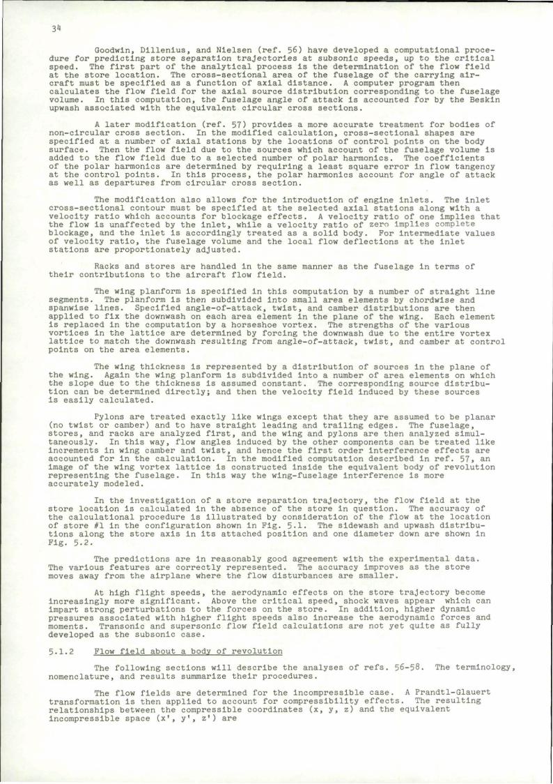
3.8 Aircraft and Store Geometry 22 3.9 Comparison Between Program Results and Test 23 3.10.A Advanced Design Airplane with Multiple Ejector Racks 24 3.10.B Advanced Design Airplane with Conforraal Carriage 24 3.11 P-4 Aircraft Configured for Conformal Carriage 25 3.12 Plight Envelope Extension with Conformal Carriage 25 4.1 Store and Aircraft Coordinate Systems 27 4.2 Velocity-Acceleration Diagram 27 4.3 Safe Separation Region 28 4.4 Safe Separation Boundaries In the Vertical Plane 28 4.5 Lateral Collision Boundaries 29 4.6 Safe Separation Boundaries in the Lateral Plane 30 4.7 Motion of Store Relative to Maneuvering Airplane 30 4.8 Missile Axis in Aircraft Coordinates 32 5.1 Large Stores with Cylindrical Afterbody in a TER Arrangement
Under the Wing 35 5.2 Effect of Vertical Position on Downwash and Sidewash Under TER
Configuration (Parent Aircraft - WBPTS2S3) 36 5.3 Coordinate System for an Axisymmetric Body 37 5.4 Comparison Between Actual and Calculated Shapes for Two
Axisymmetric Bodies 39 5.5 Cross Section of Non-Circular Body 40 5.6 Body Contour Slope 41 5.7 Wing-Pylon Vortex Lattice Representation 42 5.8 Horseshoe Vortex Imaging Method Drawn In Cross Section 43 5.9 Horseshoe Vortex Imaging Method Shown in Planform 44 5.10 Geometry of Typical Wing Vortex Element 46 5.11 Coordinate System for Wing Thickness Source Strips 48 5.12 Coordinate System for Pylon Thickness Source Strips 50 5.13 Coordinate Systems Fixed in Ejected Store and Used In Force and
Moment Calculation 52 5.14 Coordinate Systems Used in Trajectory Calculations 52 5.15 Coordinate Systems Used In Empennage Force and Moment Calculation. . . 56 5.16 Wing-Fuselage Combination : 62 5.17 Large Store with Cylindrical Afterbody Under Wing-Fuselage
Configuration 62 5.18 Large Store with Cylindrical Afterbody 63 5.19 Effect of Pylon on Flow Field of Wing-Body Combination at
Centerllne Location of Attached Store 63
TABLE OF CONTENTS (continued)
Figure Title Page
5.20 Effect of Pylon on Load Distribution 64 5.21 Comparison Between Calculated Trajectory and Captive-Store
Trajectory of Store Sc Released at One-Third Semi-Span Location; M^O . 4 65
5.22 Equivalent Body Concept for Improvement of Linear Theory Flow Field Calculations In Supersonic Flow 66
5.23 Variation of Shock-Wave Angle with Mach Number for Various Semi-Wedge Angles (Two-Dlmenslonal Turning) 68
5.24 Variation of Shock-Wave Angle with Mach Number for Various Semi-Apex Angles of Cones 68
5.25 Variation with M for Various Values of 6 69 5.26 Variation of M for Various Values of 6 69 5.27 Comparison of Predicted and Experimental Shock for Axisymmetric
Nose with Contour of the Form y=a - bx2 + cx3 - dx4 (with Origin for Nose Contour at Base of Nose) M=1.62; 6 = 28° 70
5.28 Detached Shock Geometry 70 5.29 Modified Geometry for Ogive-Cylinder Bodies 70 5.30 Compilation and General Correlation of Data on Detachment Distance
for Two-Dlmenslonal and Axisymmetric Nose Shapes In Air Y =1.4 . . . 72 5.31 Variation of Cc with Mach Number 72 5.32 Variation in Detachment Distance with Semi-Apex Angle for Cone-
Cylinders and Wedge-Slabs at Constant Mach Number 73 5.33 Cut Cylinder or Sphere with Detached Shock Wave 73 5.34 Prediction of Results at Moo =3-55 for a Sphere That Is
Effectively Cut (Diameter of Actual Models Held Constant and Radius of Nose Varied) 75
5.35 General Features of the Method of Moeckel Adopted in Present Analysis 76
5.36 Comparison of Variation of n with Mach Number Obtained in Present Analysis with Those Obtained in Other Analyses 76
5.37 Prediction of Shock Shape and Location for Axisymmetric Noses at M,,, -3-55 77
5.38 Order of Computing Mach Box Properties (U or W) on Wing and Diaphragm. 78 5-39 Values of Aerodynamic Influence Coefficients (AIC's) Versus Box
Location In Mach Forecone 79 5.40 Region of x-y Plane Influencing the Point x,y,z 79 5.41 Position of Mach Boxes with Respect to Forecone 80 5.42 Source Points for Circular Fuselage 81 5.43 Comparison of Theory with Experiment for Pressure Coefficient on
Axisymmetric Nose 82 5.44 Buoyancy Correction Diagram 83 5.45 Portion of Body with Low Aspect Ratio Fins 84 6.1 Correlation of Wind Tunnel and Free Flight Results 91 6.2 Comparison of Flight Test and Drop Model Prediction - Sweep-Wing
Carrier and Fin-Stabilized Free-Fail Bomb 91 6.3 Comparison with Plight Test of Vertical Displacement of Store Measured
by Captive Trajectory Technique 93 6.4 Comparison with Flight Test of Pitch Angle of Store Measured
by Captive Trajectory Technique 93 6.5 Comparison of Measured and Calculated Bomb Model Center of Gravity
Motion in the Pitch Plane 94 6.6 Comparison of Measured and Calculated Bomb Model Angle of Attack,
a. History 94 6.7 Comparison of Measured and Calculated Bomb Model Center of Gravity
Motion in the Yaw Plane 95 6.8 Comparison of Measured and Calculated Bomb Model Angle of Sideslip,
6, History 7.1 Actual Pitch Angle Vs. Computed Error (Camera 1) 7.2 Actual Z Displacement Vs. Computed Error (Camera 1) 98
Table
5.1
TABLE
Title
Values of K.
Page
67
10
1. INTRODUCTION
FIG. 1.1 STORE SEPARATION
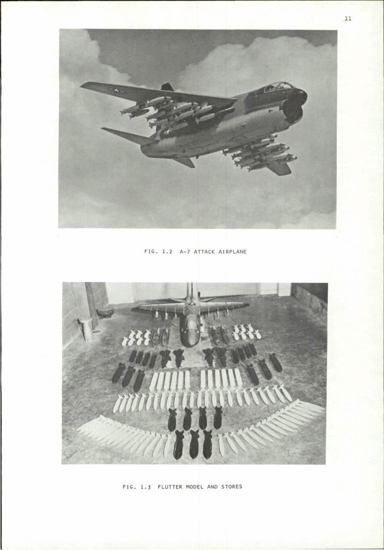
During World War I a pilot or bombardier could simply toss a bomb safely clear of his aircraft, and he might even hit something, if he flew close enough to it. Unfortunately, this technique became obsolete with the development of the enclosed cockpit, if not before. The pilot's hand has been replaced by a parade of different release mechanisms, and the simple small bomb has been succeeded by an awesome array of stores. Figure 1.2, for example, shows a typical attack airplane In its loaded condition; while Fig. 1.3 illustrates the variety of stores that are now being carried by one airplane.
All this versatility has not been achieved without penalty. Besides the obvious degradation in aircraft performance that Is Incurred by the weight and drag of the stores, other problems arise. If someone refers to a "store separation problem," he might be concerned with the repeatability of ejection cartridge Impulse, or the structural Integrity of the ejection mechanism; or he might be referring to the ingestion of rocket exhaust gases into aircraft engine inlets, or to a whole range of structural and aerodynamic effects. In this report, after a general description of the store ejection process, we will focus on the following requirements:
a. Compatibility - The stores must fit physically, electrically, and aerodynamically onto the allotted spaces on the aircraft.
b. Safe Separation - When released, a store must clear the airplane without colliding with It or interfering with its operation, and without colliding with another store.
c. Predictable Trajectory - The stores must follow a repeatable predictable path from the release point to the target.
We shall attempt to assemble the latest information on these subjects. Besides describing the problems, we will present analytical and experimental techniques available for their solutions. The treatment will focus primarily on methods of assuring the safe separation and predictable trajectory of aircraft-launched stores.
We will limit the discussion to unpowered, externally carried stores. Furthermore, we will be concerned primarily with the motion of the store relative to the launch aircraft. The effect of the store on the airplane performance will not be considered. Neither the structural loads on the configurations nor the aeroelastic and structural deformations of the airplane, the store, or the release mechanism will be described, although such considerations can be very Important from the point of view of the structural integrity of the system. Aeroelastic effects can result In flutter of the store-airplane combination, or other undesirable interactions. These broader aspects of store separation phenomena lie outside the scope of the present treatment. Even elastic deformations which directly affect the release conditions are not discussed in this report. The release process will be assumed to result in an initial position and in
11
FIG. 1.2 A-7 ATTACK AIRPLANE
FIG. 1.3 FLUTTER MODEL AND STORES
12
Initial linear and angular velocities of the store, and we will focus on Its progress as it traverses the flow field in the vicinity of the launch airplane.
Although operational constraints. Involving logistics, maintenance, handling, etc., are of considerable importance In the design of store separation systems, these aspects of the problem are also omitted from the current paper.
Several documents are available in which multi-faceted store separation data has been collected. Aircraft/Stores Compatibility Symposia have been held at Eglin Air Force Base, Florida, in 1969; at Dayton, Ohio, in 1971; and at Sacramento, California, in 1973. The proceedings of these symposia (refs. 1-3) contain a considerable body of information on all aspects of the problem. At the present time (January 1975) the next symposium in this series is scheduled for Arlington, Virginia, in September 1975. Another source of information on the aerodynamic aspects of the problem Is the Proceedings of the AGARD Conference on-Aerodynamic Interference of 1970 (ref. 4). The aerodynamics of store separation is briefly surveyed In ref. 5 which contains, in addition to a description of the latest applicable analytical and experimental techniques, an extensive bibliography with 286 entries.
The present paper begins with a brief description of the mechanical elements used In the carriage and separation of aircraft-mounted stores. Next we discuss some aspects of compatibility between aircraft and stores. In the following sections on "Safe separation" and "Trajectory prediction," methods are described for calculating the motions of the stores as they pass through the aircraft flow field. Finally, we will discuss experimental verification by wind tunnel and free-flight techniques.
2. THE STORE SEPARATION PROCESS
2.1 Fire Control System
In general terms a fire control system Is a specialized computer. Inputs are target direction and bearing, the launch airplane's position and flight condition, the aerodynamic and Inertial characteristics of the bomb, and initial forces Imparted by the launcher. The computer digests this information and generates signals directing the airplane to the proper position with respect to the target and indicating when to release the bomb.
The computer must continuously generate solutions In real time; but, since it Is carried in the aircraft, it is of restricted weight and size. Therefore, its speed and capacity are limited, and It cannot complete elaborate finite difference flow-field calculations. Hence, effects of the airplane's flow field on the trajectory of the bomb can only be represented in some simple form
2.2 Pylon-Mounted Ejection Equipment
2.2.1 Pylon-ejector geometry
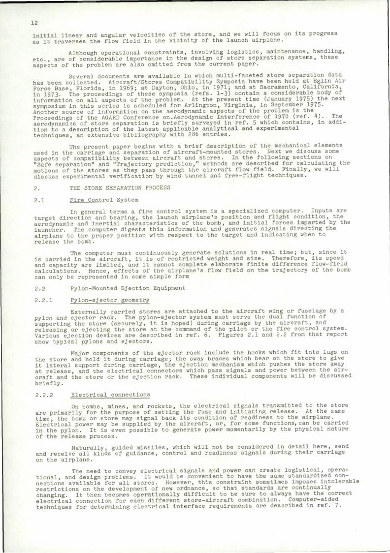
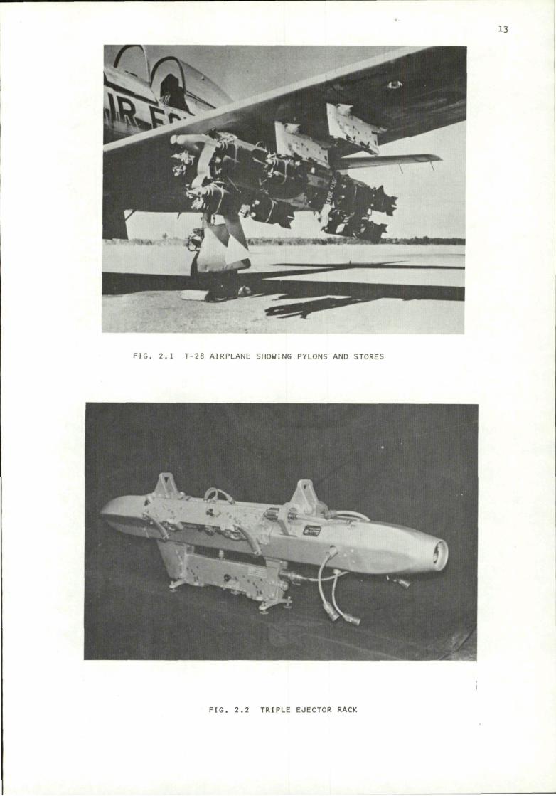
Externally carried stores are attached to the aircraft wing or fuselage by a pylon and ejector rack. The pylon-ejector system must serve the dual function of supporting the store (securely, it is hoped) during carriage by the aircraft, and releasing or ejecting the store at the command of the pilot or the fire control system. Various ejection devices are described in ref. 6. Figures 2.1 and 2.2 from that report show typical pylons and ejectors.
Major components of the ejector rack Include the hooks which fit Into lugs on the store and hold It during carriage; the sway braces which bear on the store to give it lateral support during carriage, the ejection mechanism which pushes the store away at release, and the electrical connectors which pass signals and power between the aircraft and the store or the ejection rack. These individual components will be discussed briefly.
2.2.2 Electrical connections
On bombs, mines, and rockets, the electrical signals transmitted to the store are primarily for the purpose of setting the fuze and initiating release. At the same time, the bomb or store may signal back Its condition of readiness to the airplane. Electrical power may be supplied by the aircraft, or, for some functions, can be carried in the pylon. It is even possible to generate power momentarily by the physical nature of the release process.
Naturally, guided missiles, which will not be considered in detail here, send and receive all kinds of guidance, control and readiness signals during their carriage on the airplane.
The need to convey electrical signals and power can create logistical, operational, and design problems. It would be convenient to have the same standardized connections available for all stores. However, this constraint sometimes Imposes Intolerable restrictions on the development of new ordnance, so that standards are continually changing. It then becomes operationally difficult to be sure to always have the correct electrical connection for each different store-aircraft combination. Computer-aided techniques for determining electrical Interface requirements are described in ref. 7.
13
FIG. 2.1 T-28 AIRPLANE SHOWING PYLONS AND STORES
FIG. 2.2 TRIPLE EJECTOR RACK
14
Good design can simplify the logistics requirements and at least prevent the possibility of Incorrect connections.
Connectors, themselves, can cause problems. Under combat conditions, it is easy to make the wrong connection or none at all. Therefore It is desirable to make the designs as simple and foolproof as possible. They must also retain their integrity In spite of adverse conditions that might be encountered during launch or carried flight. Some typical design information is available In ref. 8.
Arming wires and other pieces of connector hardware may break loose during store separation. Such debris may become entangled with aircraft control surfaces or Imbedded in other structures, or possibly ingested into aircraft engines with dangerous consequences (ref. 9).
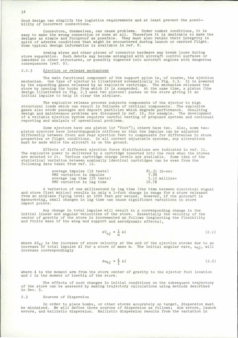
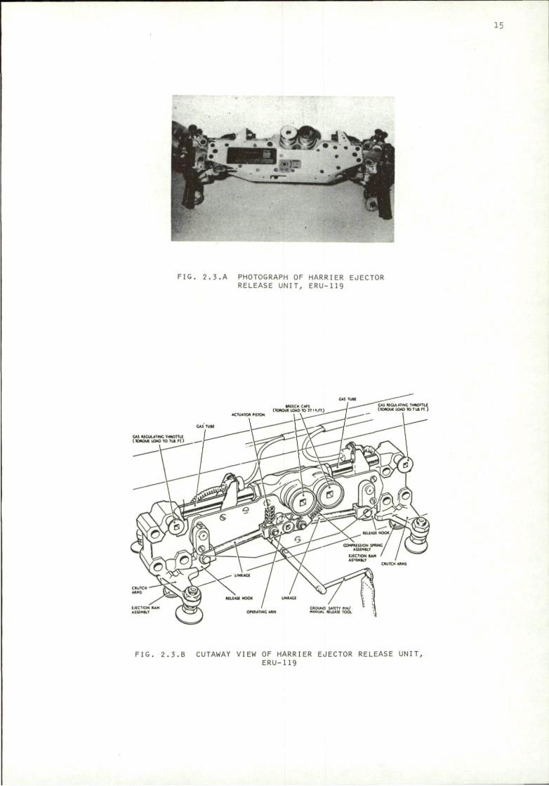
2.2.3 Ejection or release mechanisms
The main functional component of the support pylon Is, of course, the ejection mechanism. One type of ejector is Illustrated schematically In Fig. 2.3- It Is powered by the expanding gases released by an explosive cartridge. The mechanism releases the store by opening the hooks from which it is suspended. At the same time, a piston (the design illustrated In Fig. 2.3 uses two pistons) pushes on the store giving It an initial impulse to help It clear the airplane.
The explosive release process subjects components of the ejector to high structural loads which can result in failures of critical components. The explosive gases also erode passages and deposit particles which degrade performance. Resulting design and maintenance problems are discussed In ref. 10, for example. The development of a reliable ejection system requires careful testing of proposed systems and continual reporting and analysis of operational problems.
Some ejectors have one piston (or "foot"); others have two. Also, some two-piston ejectors have Interchangeable orifices so that the Impulse can be adjusted differently between front and rear ejection feet to compensate for differences in store properties or flight conditions. In all current adjustable systems, any alterations must be made while the aircraft is on the ground.
Effects of different ejection force distributions are indicated in ref. 11. The explosive power Is delivered by a cartridge Inserted into the rack when the stores are mounted to it. Various cartridge charge levels are available. Some Idea of the statistical variation between nominally identical cartridges can be seen from the following data taken from ref. 12.
average Impulse (19 tests) 81.31 lb-sec RMS variation in Impulse 7.8% average lag time (25 tests) 5.12 millisec RMS variation in lag time 16.7X
A variation of one millisecond in lag time (the time between electrical signal and store first motion) results in only a 1-foot change In range for a store released from an airplane flying level at 1000 feet per second. However, If the aircraft Is maneuvering, small changes In lag time can cause significant variations In store Impact points.
Any change in total impulse will result in a corresponding change In the initial linear and angular velocities of the store. Essentially the velocity of the center of gravity of the store is incremented as follows (neglecting the flexibility and finite mass of the wing and support and aerodynamic effects),
AV . - i AI (2.1) eJ m
where AVej is the increase of store velocity at the end of the ejection stroke due to an increase of total Impulse AI for a store of mass m. The initial angular rate, uej, will Increase correspondingly
AioeJ - 1 AI (2.2)
where I is the moment arm from the store center of gravity to the ejector foot location and 1 is the moment of inertia of the store.
The effects of such changes in Initial conditions on the subsequent trajectory of the store can be assessed by making trajectory calculations using methods described In Sec. 5-
2.3 Sources of Dispersion
In order to place bombs, or other stores accurately on target, dispersion must be minimized. We will define three sources of dispersion as follows; aim errors, launch errors, and ballistic dispersion. Ballistic dispersion results from the variation in
15
-• mm fjQk 4
F I G . 2 . 3 . A PHOTOGRAPH OF HARRIER EJECTOR RELEASE UNIT, ERU-119
*CTu*loa HitON
F I G . 2 . 3 . B CUTAWAY VIEW OF HARRIER EJECTOR RELEASE UNIT, ERU-119
16
flight path of different samples of the same store. In general, the ballistic dispersion of a well made stable store is small, on the order of 2-4 mils. However, certain factors can cause sizable Increases. For example, mounting lugs and other protuberances can cause the store to trim and then the trajectory becomes sensitive to the roll orientation of the store. Plight tests with wind tunnel and analytic comparisons, reported in refs. 13-15, Indicate the Importance of these items. Mass asymmetries could have similar effects.
Unstable flights were also observed in these tests. Unstable regimes can result from Magnus effects or pitch-roll resonance. It is desirable to cause the store to roll slowly (by canting the fins) to average out the effects of asymmetries caused by manufacturing variations. Too high a roll rate can cause Magnus instability, and a low roll rate must be carefully controlled to avoid pitch-roll resonance. Stability requirements and design implications are described in refs. 13-16.
Some limit-cycle types of resonance can be excited only if the store somehow reaches a high angle of attack. The launch flow-field Interference can excite nonlinear instabilities and result In anomalous trajectories. Bombs which experience ballistic instabilities can fall far short of predicted impact points, and endanger friendly areas while missing Intended targets. Therefore, smooth launch is required to reduce ballistic dispersion as well as to reduce dispersion due to mal-launch. Since a well designed bomb has low ballistic dispersion, the primary perturbations of the trajectory occur during its passage through the aircraft flow field. This launch-Induced dispersion is simply the variation in impact point that results from this portion of the trajectory. Even without excitation of unstable motion, launch disturbances can cause dispersions of from 5-40 mils. Assuming that two identical launches will result In two identical trajectories, the sensitivity to small variations in Initial ejection conditions, aircraft flight or loading conditions make predictable, repeatable trajectories difficult to achieve. At high aircraft speeds, where aerodynamic forces become large In comparison to inertial loads, the situation is especially difficult. Methods of reducing this sensitivity by adjusting the ejection system to produce a smooth launch are discussed In ref. 17.
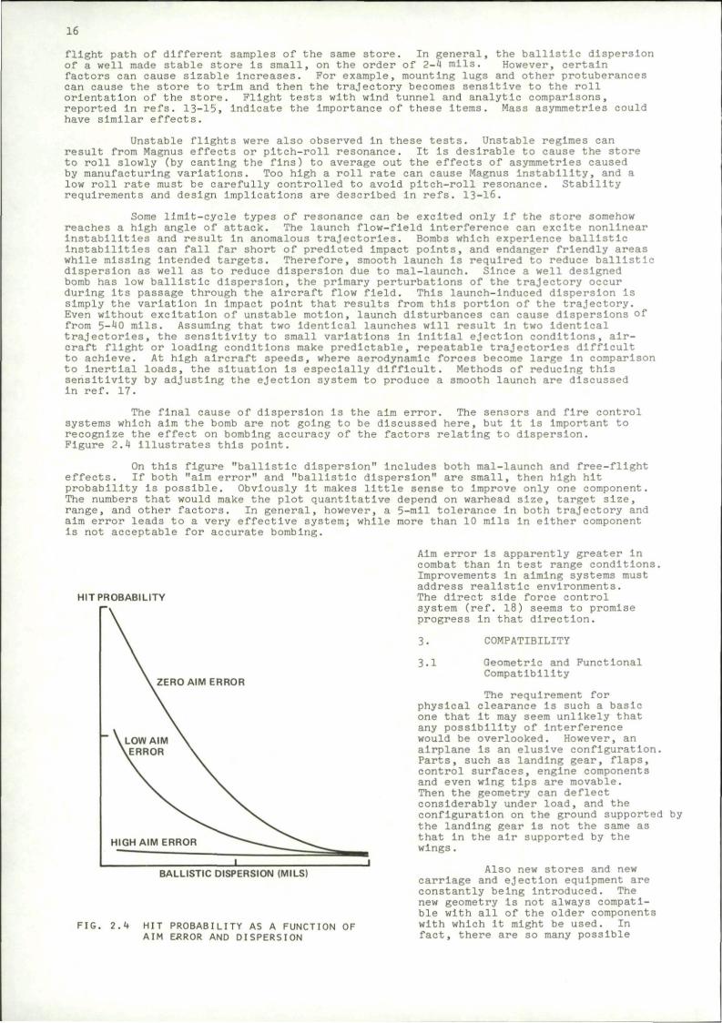
The final cause of dispersion is the aim error. The sensors and fire control systems which aim the bomb are not going to be discussed here, but It is important to recognize the effect on bombing accuracy of the factors relating to dispersion. Figure 2.4 illustrates this point.
On this figure "ballistic dispersion" Includes both mal-launch and free-flight effects. If both "aim error" and "ballistic dispersion" are small, then high hit probability is possible. Obviously it makes little sense to improve only one component. The numbers that would make the plot quantitative depend on warhead size, target size, range, and other factors. In general, however, a 5-mil tolerance in both trajectory and aim error leads to a very effective system; while more than 10 mils in either component is not acceptable for accurate bombing.
HIT PROBABILITY
ZERO AIM ERROR
FIG. 2.4
BALLISTIC DISPERSION (MILS)
HIT PROBABILITY AS A FUNCTION OF AIM ERROR AND DISPERSION
Aim error is apparently greater in combat than in test range conditions. Improvements in aiming systems must address realistic environments. The direct side force control system (ref. 18) seems to promise progress in that direction.
3. COMPATIBILITY
3.1 Geometric and Functional Compatibility
The requirement for physical clearance is such a basic one that it may seem unlikely that any possibility of interference would be overlooked. However, an airplane is an elusive configuration. Parts, such as landing gear, flaps, control surfaces, engine components and even wing tips are movable. Then the geometry can deflect considerably under load, and the configuration on the ground supported by the landing gear Is not the same as that in the air supported by the wings.
Also new stores and new carriage and ejection equipment are constantly being Introduced. The new geometry is not always compatible with all of the older components with which it might be used. In fact, there are so many possible
17
combinations of stores, racks and aircraft that It is not surprising that many of them are physically incompatible.
Naturally, It is desirable to check a new configuration on paper before building it; or to check the fit on the drawing board of a particular combination of components before trying It out with the actual hardware. Procedures have been developed for performing this non-trivial analysis. The one developed by Washmuth (refs. 19 and 20) will be described here.
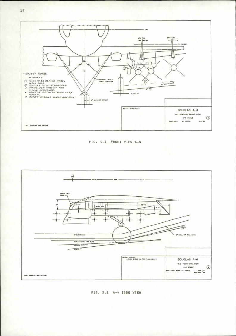
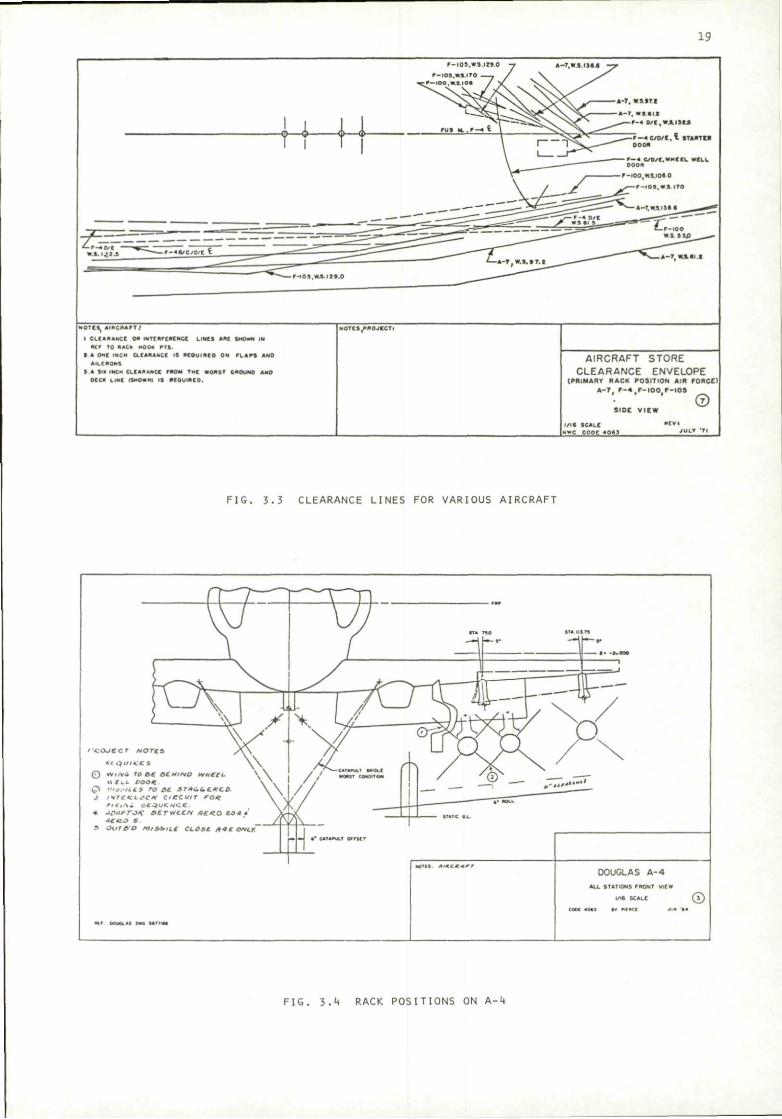
The first step is the assembly of three-view drawings showing aircraft, racks, and stores to the same scale. The aircraft drawings show cross sections at each pylon giving interference lines with wheel well doors, flaps, ailerons, ground lines, etc. Examples of such drawings for the Douglas A-4 aircraft are shown in Figs. 3-1 and 3.2 (from ref. 19). It Is sometimes convenient to superimpose the Interference lines of a number of aircraft on a single chart. Then they can be checked simultaneously for clearance problems with a new store. One such drawing is shown in Fig. 3-3.
The next step in the procedure is to lay the store and rack drawings on top of the aircraft layouts and identify possible interference in each view. Such a superposition is Illustrated in Fig. 3-4.
Finally, the rack-store interface is checked with drawings that show the locations of ejector feet, sway braces, electrical connections, and other Interfacing components.
In principle, the information could be stored in computer programs which would then quickly check for interference. In practice, however, using the procedure Is very simple; the hard part being the acquisition of the required drawings. The Naval Surface Weapons Center has an extensive collection of these interference test drawings of U.S. aircraft, racks, and stores. Many are available in ref. 20.
Besides fitting geometrically onto the aircraft, the store must mate with the systems that operate and release It. Electrical connections have been alluded to previously, and a computer-aided design technique Is described in ref. 7. Other hardware interfaces Include mounting lugs, sway braces and ejector mechanisms. Some requirements are established in ref. 8.
Software considerations are also Important. The fire control system must contain trajectory data for the particular store-aircraft configuration which it is controlling.
Elaboration of these points Is not the function of the present paper. However, while concentrating on store trajectories, it is necessary to remember that there are other parts of the system.
3.2 Aerodynamic Compatibility
3.2.1 Aircraft performance
A look at Fig. 1.2 will suggest that an airplane's performance Is going to suffer when it carries external stores. Several methods have been developed for calculating the drag penalty Imposed by the stores. A correlation procedure is described by Lacey In ref. 21. Essentially, he expresses the incremental drag In the form of a polynomial involving parameters that could affect the drag. Then the coefficients are determined by fitting experimental data.
For a single store, Lacey finds that lowering the store Increases the drag; interference effects are large at M = .9, but much smaller at M = .8. The trends are similar for clusters of stores.
Another correlation procedure Is described by Berry in refs. 22 and 23. It is based on the more detailed report of ref. 24. The trends predicted by this analysis are similar to those observed by Lacey.
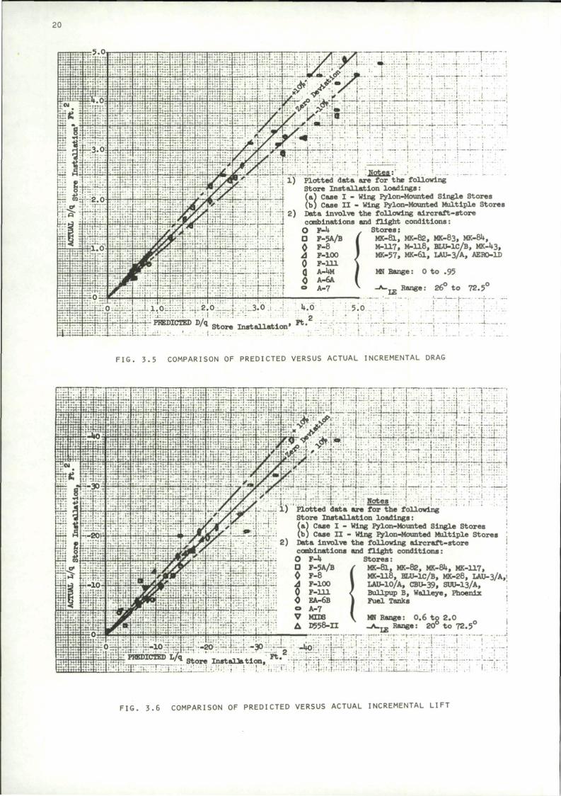
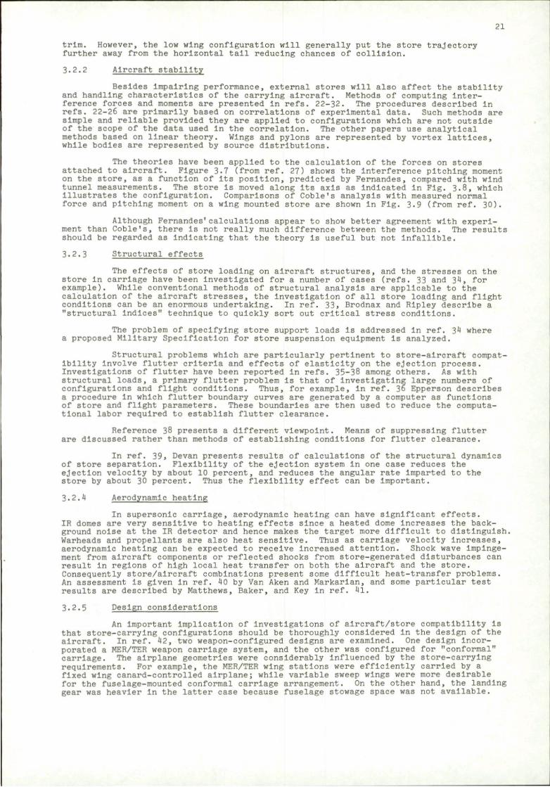
Gallagher and Dyer (ref. 25) have developed a somewhat more comprehensive technique, also based on correlation of data. Their procedure has been computerized, and covers subsonic, transonic, and supersonic speed ranges. Some comparisons between their predictions and experimental data are shown In Figs. 3-5 and 3-6
In addition to the incremental drag, external stores add weight thus further penalizing performance. The stores also will produce pitching moments which must be trimmed out, again penalizing performance. The stores can be distributed In such a way that their weight will not cause excessive shifts of the center of gravity of the airplane.
The drag force on the stores shown In Fig. 1.2 acts near the center of gravity. The relatively high wing of the A-7 airplane puts the stores In a favorable position with respect to the effect of their drag on the trim of the configuration. The drag on stores placed under a low-wing airplane will induce a moment requiring a change of
18
F I G . 3 . 1 FRONT VIEW A -4
• * M l t / i r - T*H. I
W J 0OUO4.U DIM M r r i M
DOUGLAS A-4 W.S. 75 OO S<DC V i C «
l / l * SCALE ©
F I G . 3 .2 A - 4 SIDE VIEW
19
F-IOS.WS.IiS.O
F — 4 C / 0 / E . I START IB
LINES Ami SHOWN IN
NOTES, A I R C R A F T /
I CLEARANCE ON INTf V M M
R E F r o R A C K M O O « P I S .
I A ONE INCH CLEARANCE IS REQUIRED ON F L A P S AND
AILERONS
5 A W INCH CLEARANCE FROM THE WORST GROUND ANO
DECK LINE (SHOWN} IS REQUIRED.
N O T C S , R R O J l C T i
AIRCRAFT STORE CLEARANCE ENVELOPE
(PRIMARY RACK POSITION AIR FORCE)
A - 7 . F - 4 . F - I 0 0 . r - I 0 5
SIDE VIEW ©
/ I C SCALE MWC COPE 4 0 6 3
R E V I
J U L * ' T l
FIG. 3.3 CLEARANCE LINES FOR VARIOUS AIRCRAFT
FIG. 3.** RACK POSITIONS ON A-4
20
tf\ - ^ • • 'm : i i . - . \ - . . . ' - i "T • • • • : • • | ; • • ! : J j ;
# S J ' •• ' • • • : I - r . 1
• • • • i
r f f e r O ^ .1.-i . l .0L:. ._:l Ui
1) Plotted data are for the following Store Installation loadings:
Case I - Wing Pylon-Mounted Single Stores ,, Case I I - Wing Pylon-Mounted Multiple Stores
1 i r - j - | -j 2) Data involve the following a i rc ra f t - s to re ' • : ' • ' • [ ' . ' . :•','• I combinations and f l igh t conditions:
i •( O F-l* . Stores: -4~-T-H-.--!•:• -r. • i a y»5A/B / MK-81, MK-82, MK-83, MK-8U,
lnF:":l':';r'ij 0 F _ 8 I M-H7 ( M-US, BLU-IC/B, MK-43,
MK-57, MK-&L, LAU-3/A, AER0-1D
MN Range: 0 t o .95
m as f - PREDICTED D/q Store Installation • F t .
JL i t i . j .m.:.
5.0 a
I
V
LE
.1 ri
Range: 26° t o 72.5°
-•• - ? • — 1 J
FIG. 3.5 COMPARISON OF PREDICTED VERSUS ACTUAL INCREMENTAL DRAG
T? Pfflp,- I •
* ".'-.Jt^m^y^ :r~-T'-'-H—.-r— ' ^ :• —-' -j-'-'r-
y " ^ i : -7^ •—•• ; . T M •
•- i" , ;i;- :;''4',."'' ; M I . _.- l ) Plotted data are for the following
Store Ins t a l l a t ion loadings
^TaVivf. i r i p i T i ~ " i ~1'."T • { - ; . | ; ;
_ ^ _ L _ L j £ L i-2 i ^ f e f a j M d. 1 ! ••••• • • i - ' : } - . - . * 4> •• I ' ' i . . : « - . . . . . . . . . . . . . ,-. i
-... ,. .. ... ! ; .• M I M
. . _, _ .... * • • :
i " ; ' L " J : . •'• • • i
:Tlr;-r^;]::-. • .:•.-'•
i a) Case I - Wing Pylon-Mounted Single Stores b) Case I I - Wing Pylon-Mounted Multiple Stores
Data involve the following a i r c ra f t - s to re combinations and f l igh t conditions: O F-h O F-5A/B 0 F-8 A F-100 0 F-na. 0 EA-6B o A-7 V MIDS A D558-H
Stores: MK-81, MK-82, MK-8U, MK-117, MK-118, HLU-1C/B, MK-28, LAU-3/A,! IAU-10/A, CBU-39, SUU-13/A, Bullpup B, Walleye, Phoenix : Fuel Tanks
rv-- • • " • • : j : . _ • • ; - : : \ • " - : :
- . : ! : • ' : ! . • ' T
-2o4 K-ao;;.^ v^>:-j;••;
0.6 te 2.0 I 7
MN Range: o.b to ^ A . ^ Range: 20° to 72.5°
:rr;*-.+
i
1 r l*."1 H"* i ' ' I I'I t ' " M I I 1 • i — — - • • , • - - . • • - . i • • • - • k . . » • . , mi . , . i . . • . . . , . . . t - J • ;
• a a S J S i l M J ••••S'l' -t- • • • y \ . 3:.'.••.-',- • : | - . M M . • i I . . ; , ;.i . t . M,• • : ! . , ; . ! M ' l M ^ - i r j U L . i . ' - lb..-! ,-l <• '*••••• !
F I G . 3 .6 COMPARISON OF PREDICTED VERSUS ACTUAL INCREMENTAL L IFT
21
trim. However, the low wing configuration will generally put the store trajectory further away from the horizontal tall reducing chances of collision.
3.2.2 Aircraft stability
Besides impairing performance, external stores will also affect the stability and handling characteristics of the carrying aircraft. Methods of computing interference forces and moments are presented in refs. 22-32. The procedures described in refs. 22-26 are primarily based on correlations of experimental data. Such methods are simple and reliable provided they are applied to configurations which are not outside of the scope of the data used in the correlation. The other papers use analytical methods based on linear theory. Wings and pylons are represented by vortex lattices, while bodies are represented by source distributions.
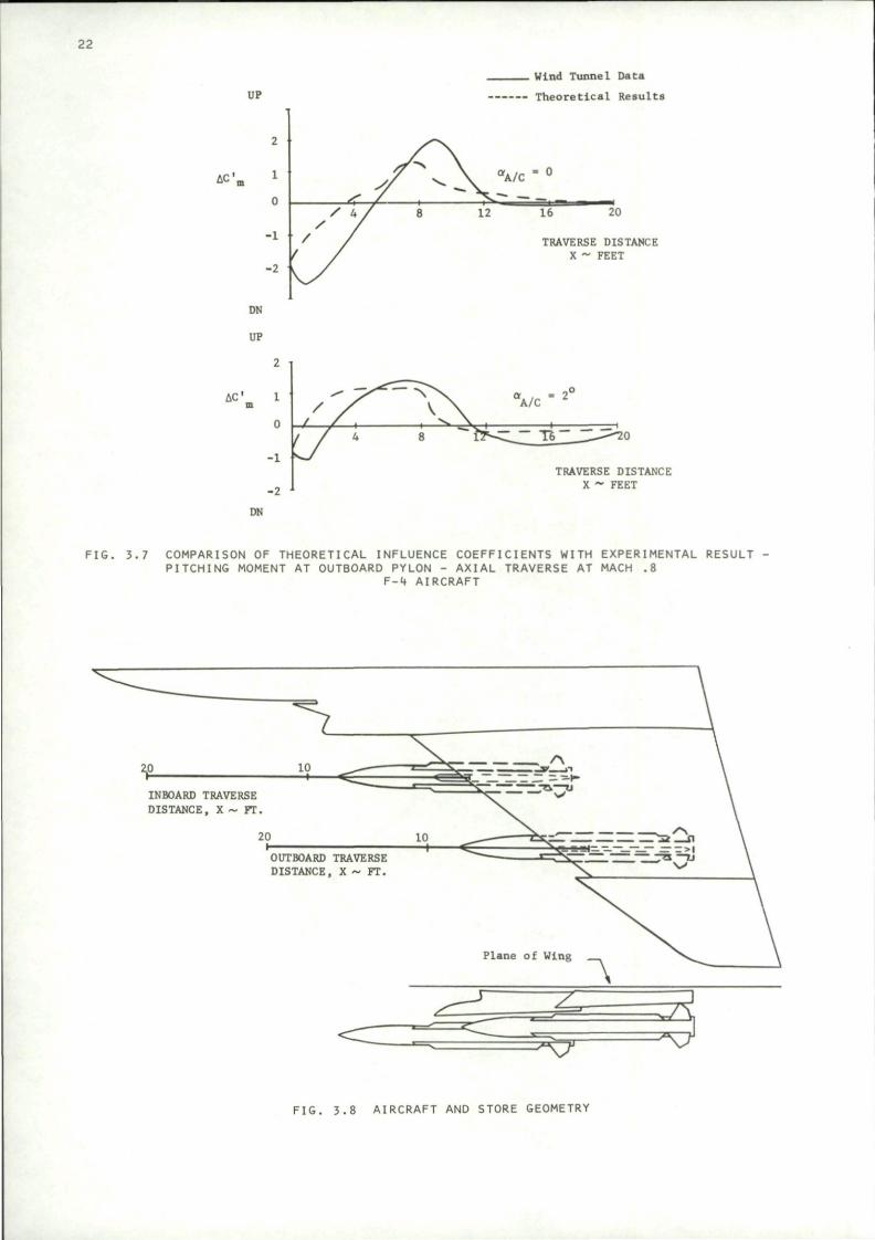
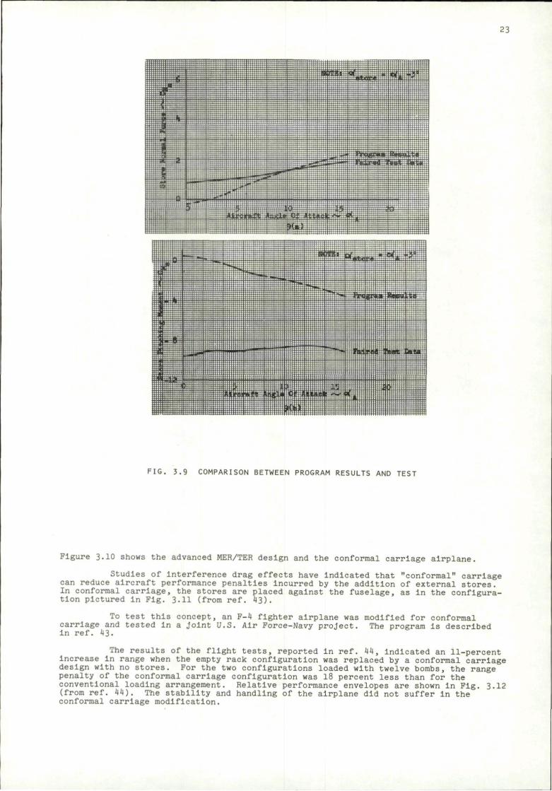
The theories have been applied to the calculation of the forces on stores attached to aircraft. Figure 3.7 (from ref. 27) shows the interference pitching moment on the store, as a function of its position, predicted by Fernandes, compared with wind tunnel measurements. The store is moved along its axis as indicated in Fig. 3.8, which illustrates the configuration. Comparisons of Coble's analysis with measured normal force and pitching moment on a wing mounted store are shown in Fig. 3.9 (from ref. 30).
Although Fernandes' calculations appear to show better agreement with experiment than Coble's, there is not really much difference between the methods. The results should be regarded as indicating that the theory is useful but not infallible.
3.2.3 Structural effects
The effects of store loading on aircraft structures, and the stresses on the store in carriage have been Investigated for a number of cases (refs. 33 and 34, for example). While conventional methods of structural analysis are applicable to the calculation of the aircraft stresses, the investigation of all store loading and flight conditions can be an enormous undertaking. In ref. 33, Brodnax and Ripley describe a "structural indices" technique to quickly sort out critical stress conditions.
The problem of specifying store support loads is addressed in ref. 34 where a proposed Military Specification for store suspension equipment is analyzed.
Structural problems which are particularly pertinent to store-aircraft compatibility involve flutter criteria and effects of elasticity on the ejection process. Investigations of flutter have been reported in refs. 35-38 among others. As with structural loads, a primary flutter problem is that of investigating large numbers of configurations and flight conditions. Thus, for example, in ref. 36 Epperson describes a procedure in which flutter boundary curves are generated by a computer as functions of store and flight parameters. These boundaries are then used to reduce the computational labor required to establish flutter clearance.
Reference 38 presents a different viewpoint. Means of suppressing flutter are discussed rather than methods of establishing conditions for flutter clearance.
In ref. 39, Devan presents results of calculations of the structural dynamics of store separation. Flexibility of the ejection system in one case reduces the ejection velocity by about 10 percent, and reduces the angular rate Imparted to the store by about 30 percent. Thus the flexibility effect can be Important.
3.2.4 Aerodynamic heating
In supersonic carriage, aerodynamic heating can have significant effects. IR domes are very sensitive to heating effects since a heated dome Increases the background noise at the IR detector and hence makes the target more difficult to distinguish. Warheads and propellants are also heat sensitive. Thus as carriage velocity increases, aerodynamic heating can be expected to receive Increased attention. Shock wave impingement from aircraft components or reflected shocks from store-generated disturbances can result in regions of high local heat transfer on both the aircraft and the store. Consequently store/aircraft combinations present some difficult heat-transfer problems. An assessment is given in ref. 40 by Van Aken and Markarlan, and some particular test results are described by Matthews, Baker, and Key in ref. 41.
3.2.5 Design considerations
An Important implication of investigations of aircraft/store compatibility is that store-carrying configurations should be thoroughly considered in the design of the aircraft. In ref. 42, two weapon-configured designs are examined. One design incorporated a MER/TER weapon carriage system, and the other was configured for "conformal" carriage. The airplane geometries were considerably Influenced by the store-carrying requirements. For example, the MER/TER wing stations were efficiently carried by a fixed wing canard-controlled airplane; while variable sweep wings were more desirable for the fuselage-mounted conformal carriage arrangement. On the other hand, the landing gear was heavier In the latter case because fuselage stowage space was not available.
22
UP
Wind Tunnel Data
T h e o r e t i c a l R e s u l t s
& \
2
1
n
1
2 •
/ u / s /
/ / f /
8 12
A/C
16 20
TRAVERSE DISTANCE X ~ FEET
DN
UP
AC'
TRAVERSE DISTANCE X ~ FEET
DN
FIG. 3.7 COMPARISON OF THEORETICAL INFLUENCE COEFFICIENTS WITH EXPERIMENTAL RESULT PITCHING MOMENT AT OUTBOARD PYLON - AXIAL TRAVERSE AT MACH .8
F-4 AIRCRAFT
*ST
FIG. 3.8 AIRCRAFT AND STORE GEOMETRY
23
FIG. 3.9 COMPARISON BETWEEN PROGRAM RESULTS AND TEST
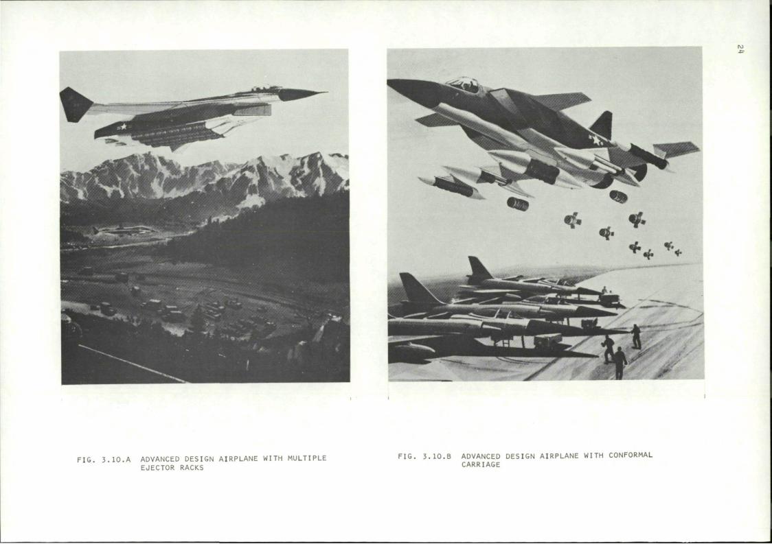
Figure 3.10 shows the advanced MER/TER design and the conformal carriage airplane.
Studies of interference drag effects have indicated that "conformal" carriage can reduce aircraft performance penalties incurred by the addition of external stores. In conformal carriage, the stores are placed against the fuselage, as in the configuration pictured in Fig. 3.11 (from ref. 43).
To test this concept, an F-4 fighter airplane was modified for conformal carriage and tested in a Joint U.S. Air Force-Navy project. The program is described in ref. 43.
The results of the flight tests, reported in ref. 44, indicated an 11-percent increase in range when the empty rack configuration was replaced by a conformal carriage design with no stores. For the two configurations loaded with twelve bombs, the range penalty of the conformal carriage configuration was 18 percent less than for the conventional loading arrangement. Relative performance envelopes are shown in Fig. 3.12 (from ref. 44). The stability and handling of the airplane did not suffer in the conformal carriage modification.
1 I
FIG. 3.10.A ADVANCED DESIGN AIRPLANE WITH MULTIPLE EJECTOR RACKS
FIG. 3.10.B ADVANCED DESIGN AIRPLANE WITH CONFORMAL CARRIAGE
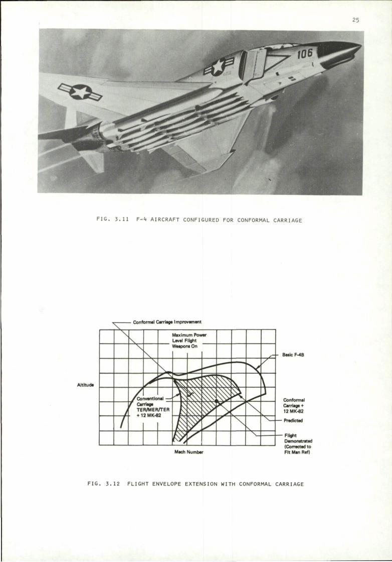
FIG, 3.11 F-4 AIRCRAFT CONFIGURED FOR CONFORMAL CARRIAGE
Conform*! Carriage Improvement
A l t i t ud *
- - Bai icF-4B
M i c h Number
Conformal Carriag* + 12 MK-82
Flight Demo nitrated (Cor-acted to Fi t Man Ref)
FIG. 3.12 FLIGHT ENVELOPE EXTENSION WITH CONFORMAL CARRIAGE
26
Subsonic and supersonic bomb release tests were included in the program. As reported in ref. 45, all releases were successful with dispersion no worse than that of the conventional configuration.
Besides conformal carriage, other Improvements in weapon-carrying aircraft design may be achievable. For example, stores can carry lift, and hence might be configured to reduce Induced drag. The entire aircraft-store system could be Improved by Integrated design techniques.
4. SAFE SEPARATION
4.1 The Safe Separation Problem
Whenever a store is released in flight. It is supposed to clear the carrying aircraft without hitting or damaging it. In many situations, the precise point at which the store impacts on the ground is not of interest; the only requirement of the separation process is that the store does not collide with the aircraft. Such conditions apply to Jettison of fuel tanks or other expendable containers, or to bombing of very broad areas.
Lightweight, unstable, low-drag stores are especially likely to present separation problems, particularly at high dive angles. Trouble-prone flight configurations are summarized by R. Davis as follows: (quoted In ref. 46).
"Any store fired forward or aft from airplanes having low set horizontal stablllzers/stabllators where the store is fired within or near the lateral dimension of the stablllzer/stabilator. . .
"Any store which exhibits low static stability or Is unstable, particularly when combined with a low moment of inertia. . .
"Any store which is marginally stable or unstable until fins pop out after release
"Stores which change configuration immediately upon release (finned bombs released in the retarded mode) particularly if hardware is released from the store at the configuration change. . .
"Ejected stores in which the ejector foot strikes the store at a position remote from the store center of gravity (empty rocket pod, partially loaded multiple ejection racks and SUU-40/44 flare dispensers). The seriousness of this situation is compounded by a low moment of inertia and poor static stability. . .
"Any store ejected from the Inboard shoulder statlon(s) of a multiple or triple ejection rack mounted on a pylon In close proximity to the aircraft fuselage. . ."
4.2 Criteria for Safe Separation
4.2.1 Types of criteria
It is unpleasant to discover by flight experience that a store collides with the launch aircraft during separation. It is desirable, therefore, to have some means of predicting safe separation boundaries. In principle these boundaries can be established by calculating the motion and trajectory of the store as it passes through the nonuniform flow field around the airplane, by making wind tunnel simulations of store separations, or by determining formulas which will distinguish safe conditions from unsafe ones.
Detailed trajectory calculations require enormous amounts of aircraft flow field and store characteristics data because of the large number of possible combinations of store-aircraft configurations and flight conditions. For the same reason establishing safe separation boundaries through wind tunnel tests is an expensive and time-consuming process. Therefore a simpler procedure is neede.d to establish approximate safe separation boundaries. Borderline cases can then be investigated in more detail if necessary. A simple reliable system developed by Covert (refs. 46-49) will be summarized here.
4.2.2 Assumptions
The first assumption is that an unsafe separation will manifest itself in the initial motion following ejection. Therefore, it is only necessary to characterize the trajectory during a very short time Interval after ejection. It is assumed, further, that in this critical initial period aerodynamic forces are constant.
27
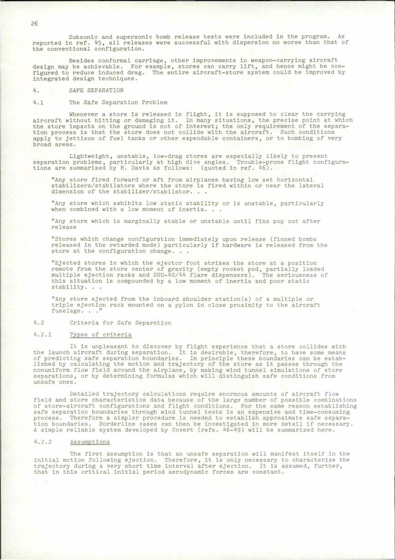
FIG. 4.1 STORE AND AIRCRAFT COORDINATE SYSTEMS
4.2.3 Coordinate system
Now let us take a look at the coordinate system which is shown in Fig. 4.1.
The analysis is carried out in the x', y', z' axis system.
Two important characteristics of the axis system should be identified:
a) The x'-y' plane contains a barrier (the pylon) and hence a store separation trajectory is considered unsafe if any part of the store threatens to pierce this plane.
b) The coordinate system is fixed to the airplane; the x'-z' plane being parallel to the aircraft plane of symmetry; the x' axis lies in the plane of the barrier (pylon support). Since we want to examine the possibility of store interaction with aircraft components, it is desirable to keep the axis system fixed with respect to those components, and hence fixed to the airplane.
In considering a pylon Jettison, the origin of the axis system can be moved up to the top of the pylon so that the x'-y' plane coincides with the bottom surface of the wing and, again, piercing this plane Is assumed to be disastrous.
4.2.4 Motion of a point
The procedure Is based on a consideration of the motion of a critical point on the store. Consider, for example, the vertical displacement (in the z or z' direction) of some point on the store:
^2 6z' = Vnt + ar (4.1)
where V0 Is the initial velocity and aD the initial acceleration of the point. The acceleration is assumed to be constant during the short time, t, of the separation process.
Separation will be safe (in the vertical plane) If 6z 2; 0 for all t at every point on the store. This condition will be satisfied if
V0 + a0 i. > 0
2 which will certainly follow If
and
(4.2)
V0 > 0 a0 > 0
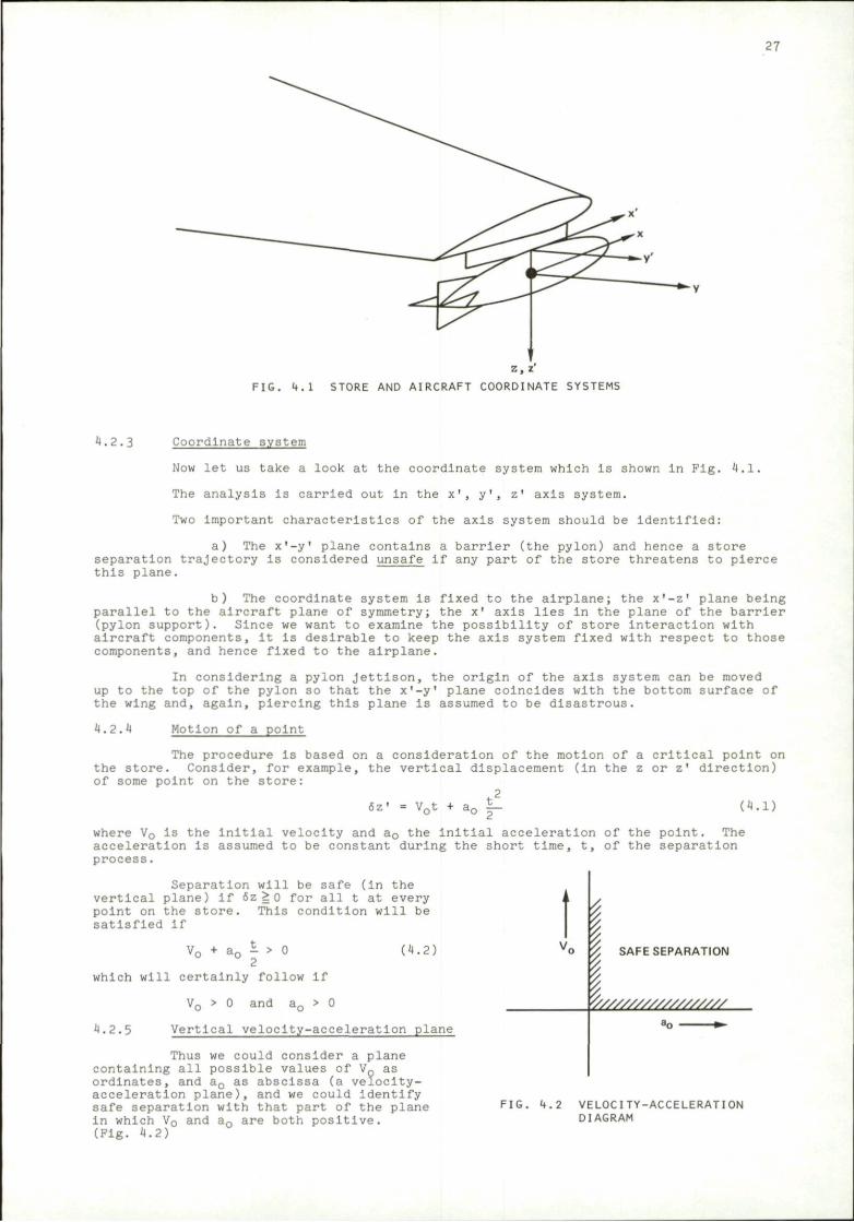
4.2.5 Vertical velocity-acceleration plane
Thus we could consider a plane containing all possible values of V0 as ordinates, and a0 as abscissa (a velocity-acceleration plane), and we could Identify safe separation with that part of the plane In which V0 and a0 are both positive. (Fig. 4.2)
I SAFE SEPARATION ' / / / / / / / / / / / / / / / / / / /
FIG. 4.2 VELOCITY-ACCELERATION DIAGRAM
28
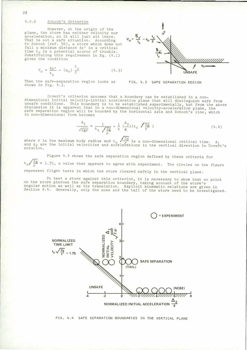
4.2.6 Schoch's Criterion
However, at the origin of the plane, the store has neither velocity nor acceleration, so it will Just sit there. That is not a safe situation. According to Schoch (ref. 50), a store which does not fall a minimum distance 6z' in a critical time t c is a potential source of trouble. Substituting this requirement in Eq. (4.1) gives the condition
vo = 6z' t. (a„) y (4.3]
vo = -T - V
V//////////////////// /
UNSAFE
Then the safe-separation region looks as shown in Fig. 4.3.
FIG. 4.3 SAFE SEPARATION REGION
Covert's criterion assumes that a boundary can be established In a non-dimensional initial velocity-initial acceleration plane that will distinguish safe from unsafe conditions. This boundary is to be established experimentally, but from the above discussion it is apparent that in a non-dimensional velocity-acceleration plane, the safe separation region will be bounded by the horizontal axis and Schoch's line, which in non-dimensional form becomes
/H \ Untt /H (4.4)
where r Is the maximum body radius and tc /—• is a non-dimensional critical time. A-, and t-2 are the initial velocities and accelerations In the vertical direction in 'Covert's notation.
Figure 4.4 shows the safe separation region defined by these criteria for
tc/p = l«75a a value that appears to agree with experiment. The circles on the figure
represent flight tests In which the store cleared safely In the vertical plane.
To test a store against this criterion, it is necessary to show that no point on the store pierces the safe separation boundary, taking account of the store's angular motion as well as Its translation. Explicit kinematic relations are given in Section 4.4. Generally, only the nose and the tail of the store need to be investigated.
NORMALIZED TIME LIMIT
t c T ^
• ""H 1.75
2 > 31-
O — J I Z i > 2
O EXPERIMENT
' jOOSAFE SEPARAT,ON
(TAIL)
NORMALIZED INITIAL ACCELERATION
FIG. 4.4 SAFE SEPARATION BOUNDARIES IN THE VERTICAL PLANE
29
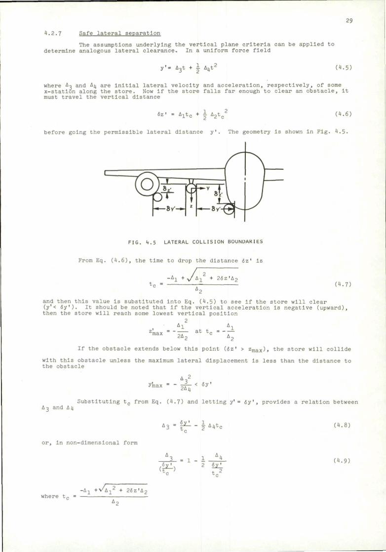
4.2.7 Safe lateral separation
The assumptions underlying the vertical plane criteria can be applied to determine analogous lateral clearance. In a uniform force field
y'= A 3t + | Imttt' (4.5)
where A^ and A;, are initial lateral velocity and acceleration, respectively, of some x-station along the store. Now if the store falls far enough to clear an obstacle. It must travel the vertical distance
oz' = 4-x t c + i A 2t c2 (4.6)
before going the permissible lateral distance y'. The geometry is shown in Fig. 4.5.
X ff- r
FIG. 4.5 LATERAL COLLISION BOUNDARIES
From Eq. (4.6), the time to drop the distance 6z' Is
-A1 + y L\1 + 26z'A2 (4.7)
and then this value is substituted into Eq. (4.5) to see if the store will clear (y'< <5y'). It should be noted that if the vertical acceleration is negative (upward), then the store will reach some lowest vertical position
2 , Al Al
2max = - — ^ tc - - -
If the obstacle extends below this point (6z* > z m a x ) , the store will collide
with this obstacle unless the maximum lateral displacement is less than the distance to the obstacle
y'max t l 2Ajj
< 6y'
A3 and A4 Substituting tc from Eq. (4.7) and letting y' = 6y', provides a relation between
"3 •f^-**«*. (4.8)
or, in non-dimensional form
1 A 4 6V ' 2 isJ_
4- 2
(4 .9)
where t . - i \ 1 + v , i 1
2 + 2 6 z ' A 2
30
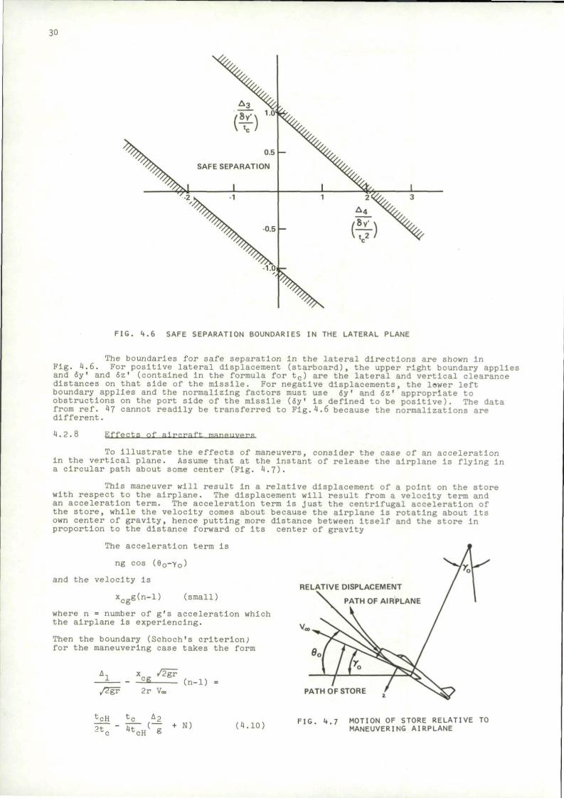
FIG. 4.6 SAFE SEPARATION BOUNDARIES IN THE LATERAL PLANE
The boundaries for safe separation in the lateral directions are shown in Fig. 4.6. For positive lateral displacement (starboard), the upper right boundary applies and 6y' and 6z' (contained in the formula for tc) are the lateral and vertical clearance distances on that side of the missile. For negative displacements, the lawer left boundary applies and the normalizing factors must use 6y' and 6z' appropriate to obstructions on the port side of the missile (6y' Is defined to be positive). The data from ref. 47 cannot readily be transferred to Pig.4.6 because the normalizations are different.
4.2.8 E f f e c t s of a i r c r a f t manpiiwi-s
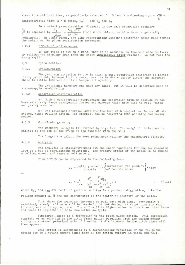
To Illustrate the effects of maneuvers, consider the case of an acceleration In the vertical plane. Assume that at the Instant of release the airplane is flying in a circular path about some center (Fig. 4.7).
This maneuver will result In a relative displacement of a point on the store with respect to the airplane. The displacement will result from a velocity term and an acceleration term. The acceleration term is just the centrifugal acceleration of the store, while the velocity comes about because the airplane Is rotating about its own center of gravity, hence putting more distance between Itself and the store In proportion to the distance forward of its center of gravity
The acceleration term Is
ng cos (e0-y0)
and the velocity is
*cgg(n-l) (small)
where n = number of g's acceleration which the airplane is experiencing.
Then the boundary (Schoch's criterion; for the maneuvering case takes the form
RELATIVE DISPLACEMENT
PATH OF AIRPLANE
/2gr 2r V, PATH OF STORE
tcH 2t„ 41, cH
+ N) (4.10) FIG. 4.7 MOTION OF STORE RELATIVE TO
MANEUVERING AIRPLANE
31
where tc = critical time, as previously selected for Schoch's criterion; tcp; = /27 = g
characteristic time; N = n COS(6 0-Y 0) - cos eo cos <fj0
In a velocity-acceleration diagram, on the safe separation boundary A2 A x yzg? — is replaced by — ± — - (n-1) where this correction term is generally g ^iF 2r V« negligible. In other words, the line representing Schoch's criterion moves more toward the origin as the pitch acceleration increases. 4.2.9 Effect of roll maneuver
If the store is out on a wing, then it is possible to Insure a safe delivery by rolling the airplane away from the store immediately after release. Do not roll the wrong way I!
4.3 Pylon Jettison
4.3.1 Configuration
The Jettison situation is one in which a safe separation criterion is particularly pertinent, because in this case, once the hardware safely clears the aircraft, there Is little interest in Its subsequent trajectory.
The Jettisoned hardware may have any shape, but It will be described here as a store-pylon combination.
4.3-2 Separation characteristics
a) Such a configuration complicates the separation problem because It can have relatively large aerodynamic forces and moments which give rise to roll, pitch and yawing moments.
b ) The principal Inertlal axes are Inclined with respect to the coordinate system, hence rolling motion, for example, can be converted into pitching and yawing motion.
4.3.3 Coordinate geometry
The geometry Is again illustrated by Fig. 4.1. The origin in this case is shifted to the top of the pylon at Its Junction with the wing.
The longer the pylon, the more pronounced will be the unsymmetric effects.
4.3.4 Analysis
The analysis is straightforward but the Euler equations for angular momentum lead to a set of simultaneous equations. The primary effect of the pylon Is to Induce a rolling moment and hence a roll rate u)x.
This effect can be expressed in the following form
)lling moment I correction for product I Inertia ' |of inertia terms \ time inertia I U I j.iieri/±£i HSIIIIB
or
k2 - i k2 I zz z Kxy
Ivv v2 Lxx k2 -(k4 /k2 ) i r r rv* ' (4-n)
where kxx and kzz are radii of gyration and kxy is a product of gyration; i Is the
rolling moment; Y. \z are the coordinates of the center of pressure of the pylon.
This shows the transient Increase of roll rate with time. Eventually a relatively steady roll rate will be reached, but not during the short time for which this expression is appropriate. The roll will be higher order in time than other terms and hence is neglected in this short-time analysis.
Similarly, there is a correction to the pitch plane motion. This correction consists of an addition to the pitch plane motion resulting from the yawing moment acting on a skewed principal axis of inertia. A displacement in the pitch plane will then appear.
This effect is accompanied by a corresponding reduction of the yaw plane motion due to a yawing moment since some of the motion appears in pitch and roll.
32
4.4
4.4.1
Determination of the Initial Velocities and Accelerations
Store aligned with aircraft
To test the safety of release, the motion of the quantity to be examined. To Illustrate the proce which the airplane is flying in a straight path (not the axis of the store aligned with the aircraft veloc ejector Imparts to the store, at the end of the eject ity v'and an angular velocity OJ with respect to the c ejector may push the store in any direction; as for e station of a multiple ejection rack. The velocities v'? and u'y, w'z, neglecting any axial motion that might with respect to aircraft-fixed coordinates, but they coordinates in this specialized case.
the store relative to the airplane Is dure, consider first the case in necessarily a horizontal one) with Ity vector. Then assume that the Ion stroke, an initial linear veloc-onstant aircraft flight path. The xample In the case of a shoulder may be resolved into components vy, have been applied. The motion is are the same as the initial store
The initial velocities at some point x along the store are then
Al = V Z - X(jjy (4.12)
A3 = + xor.
4.4.2 General store alignment
C*.13)
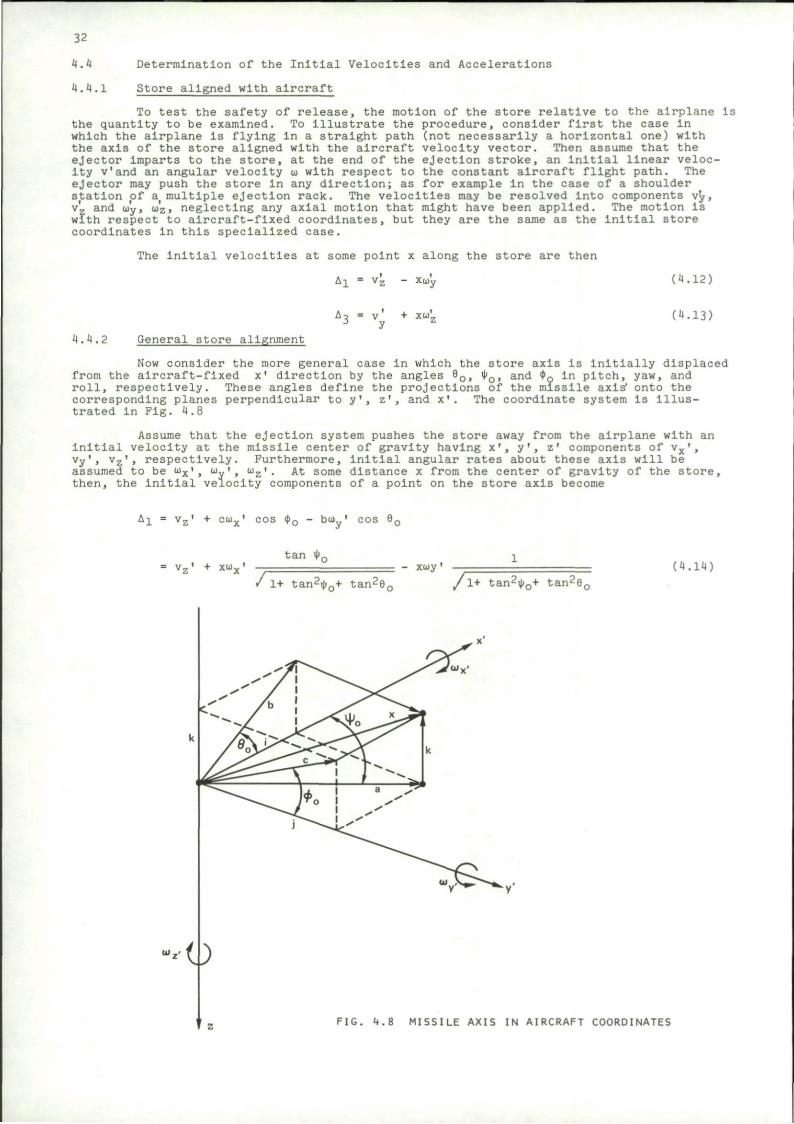
Now consider the more general case in which the store axis is initially displaced from the aircraft-fixed x' direction by the angles 9C * o > a n d <t>g l n pitch, yaw, and roll, respectively. These angles define the projections of the missile axis' onto the corresponding planes perpendicular to y' trated In Fig. 4.8
and x'. The coordinate system Is lllus-
Assume that the ejection system pushes the store away from the airplane with an initial velocity at the missile center of gravity having x', y', z' components of vx',
respectively. Furthermore, Initial angular rates about these axis will be assumed to be wx', At some distance x from the center of gravity of the store. then, the initial velocity components of a point on the store axis become
A^ = vz' + cux' cos <t>0 - bu ' cos 90
tan ^0 = vz' + xwx'
/ 1+ tan20o+ tan2(
xioy '
/ 1+ tan2i(j0+ t a n 2 6 0
(4.14)
MISSILE AXIS IN AIRCRAFT COORDINATES
33
A3 = vy' + a cos f0 o)z' + c sin <ji.
= vy' + xUz' X + x<V tan 90 („ 1 5 )
' 1+ tan2i()0+ tan290 /1+ tan2i|)0+ tan
26o
The Initial vertical and lateral accelerations are obtained by resolving the aerodynamic forces and moments and the weight along the z' and y' axes. The forces divided by the weight of the store give the non-dimensional accelerations of its center of gravity. The moments divided by the moments of Inertlal give the angular accelerations from which the components at a point x along the missile can be calculated. For example, in straight and level flight
A? ••*vj[v -^v] «- i 6> where 6' is the pitch angle of the aircraft coordinates with respect to a horizontal plane. °
The initial linear and angular velocities Imparted to the store are obtained, in principle, by applying the calibrated Impulse of the ejector cartridge and the aerodynamic forces acting during the ejector stroke to the Inertia of the store. However, the Impulse of the cartridge is generally a function of the force which it must overcome, so that the same cartridge develops a greater total impulse If it Is driving a heavier store or If it is pushing the store against a high in-carrlage aerodynamic load. Therefore the cartridge must be calibrated over a range of resistances. Essentially, the force Imparted by the explosive cartridge to an ejector piston is a function of the position and velocity of the piston. The force is larger and lasts longer if the piston is moving more slowly as would be the case for a heavy store.
As a final note, the flexibility and inertia of the ejection system may also affect significantly the initial velocities Imparted to the store. Devan's analysis (ref. 39) gives some idea of flexibility effects. In Covert's report (ref. 49), he points out that a heavy ejection system Imparts a larger fraction of its impulse to the store than does a lighter one.
5. TRAJECTORY PREDICTION
5.1 Determination of Aircraft Plow Fields at Subsonic Speeds
5.1.1 Summary of methods
The trajectory of a store is determined by the initial conditions and by the aerodynamic and gravitational forces which the store encounters. We would like to be able to specify airplane geometry, store geometry and inertia, flight conditions, and ejection forces, and then have a computing machine tell us what the trajectory will be. Such computer codes have been formulated and are continually being expanded and Improved. The first step is to describe the flow field about the carrying aircraft in terms of the airplane geometry and flight condition. Next, the forces on the store must be determined at each position in the disturbed flow field; and finally the trajectory of the store can be calculated with these known forces.
The aircraft flow field can be calculated or measured by probing the flow about a wind tunnel model. A complete set of experimental data would require flow surveys at a large number of flight conditions over appropriate ranges of aircraft angle of attack and Mach number. The parameter of primary interest is the local flow direction (upwash and sidewash) as a function of position in the flow. Complete surveys of this type are rare, but some flow data is available and can be used to test the accuracy of theoretical methods. In addition, there may be buoyant forces due to pressure gradients in the flow field.
Several analytical techniques have been developed In which the aircraft flow field is represented in some manner, and the passage of the store through the disturbed flow field is then calculated. Various approximate solutions are described, for example, in refs. 50-55. High-speed computing machines make feasible detailed representation of the aircraft flow field and step-by-step numerical calculations of the resulting forces and motion of a store. The analytical approximations are useful for rapidly estimating and comparing trajectories and for Investigating the effects of various geometrical and flight parameters. In this paper, however, we will examine in detail only the -complete numerical procedures for store trajectory calculation. Approximate methods are based on the same principles, but apply simplifying assumptions to reduce the computational requirements.
34
Goodwin, Dlllenlus, and Nielsen (ref. 56) have developed a computational procedure for predicting store separation trajectories at subsonic speeds, up to the critical speed. The first part of the analytical process is the determination of the flow field at the store location. The cross-sectional area of the fuselage of the carrying aircraft must be specified as a function of axial distance. A computer program then calculates the flow field for the axial source distribution corresponding to the fuselage volume. In this computation, the fuselage angle of attack is accounted for by the Beskln upwash associated with the equivalent circular cross sections.
A later modification (ref. 57) provides a more accurate treatment for bodies of non-circular cross section. In the modified calculation, cross-sectional shapes are specified at a number of axial stations by the locations of control points on the body surface. Then the flow field due to the sources which account of the fuselage volume is added to the flow field due to a selected number of polar harmonics. The coefficients of the polar harmonics are determined by requiring a least square error in flow tangency at the control points. In this process, the polar harmonics account for angle of attack as well as departures from circular cross section.
The modification also allows for the introduction of engine Inlets. The inlet cross-sectional contour must be specified at the selected axial stations along with a velocity ratio which accounts for blockage effects. A velocity ratio of one Implies that the flow is unaffected by the inlet, while a velocity ratio of zero implies complete blockage, and the Inlet Is accordingly treated as a solid body. For intermediate values of velocity ratio, the fuselage volume and the local flow deflections at the inlet stations are proportionately adjusted.
Racks and stores are handled in the same manner as the fuselage In terms of their contributions to the aircraft flow field.
The wing planform is specified in this computation by a number of straight line segments. The planform is then subdivided into small area elements by chordwise and spanwise lines. Specified angle-of-attack, twist, and camber distributions are then applied to fix the downwash on each area element in the plane of the wing. Each element is replaced In the computation by a horseshoe vortex. The strengths of the various vortices in the lattice are determined by forcing the downwash due to the entire vortex lattice to match the downwash resulting from angle-of-attack, twist, and camber at control points on the area elements.
The wing thickness is represented by a distribution of sources in the plane of the wing. Again the wing planform is subdivided into a number of area elements on which the slope due to the thickness Is assumed constant. The corresponding source distribution can be determined directly; and then the velocity field induced by these sources is easily calculated.
Pylons are treated exactly like wings except that they are assumed to be planar (no twist or camber) and to have straight leading and trailing edges. The fuselage, stores, and racks are analyzed first, and the wing and pylons are then analyzed simultaneously. In this way, flow angles Induced by the other components can be treated like Increments In wing camber and twist, and hence the first order interference effects are accounted for in the calculation. In the modified computation described in ref. 57, an image of the wing vortex lattice is constructed Inside the equivalent body of revolution representing the fuselage. In this way the wing-fuselage interference is more accurately modeled.
In the investigation of a store separation trajectory, the flow field at the store location is calculated in the absence of the store in question. The accuracy of the calculational procedure is illustrated by consideration of the flow at the location of store #1 in the configuration shown in Fig. 5.1. The sidewash and upwash distributions along the store axis in its attached position and one diameter down are shown in Fig. 5-2-
The predictions are In reasonably good agreement with the experimental data. The various features are correctly represented. The accuracy improves as the store moves away from the airplane where the flow disturbances are smaller.
At high flight speeds, the aerodynamic effects on the store trajectory become increasingly more significant. Above the critical speed, shock waves appear which can Impart strong perturbations to the forces on the store. In addition, higher dynamic pressures associated with higher flight speeds also increase the aerodynamic forces and moments. Transonic and supersonic flow field calculations are not yet quite as fully developed as the subsonic case.
5.1.2 Flow field about a body of revolution
The following sections will describe the analyses of refs. 56-58. The terminology, nomenclature, and results summarize their procedures.
The flow fields are determined for the Incompressible case. A Prandtl-Glauert transformation Is then applied to account for compressibility effects. The resulting relationships between the compressible coordinates (x, y, z) and the equivalent incompressible space (x', y', z') are
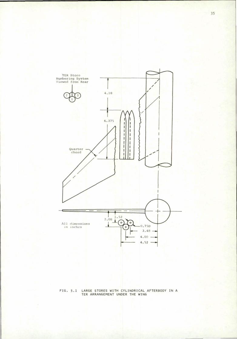
35
TER Store Numbering System Viewed from Roar
Al 1 dimensions in inches
2.08
I r - 3-48-L 4.00 a.
4.02
FIG. 5.1 LARGE STORES WITH CYLINDRICAL AFTERBODY IN A TER ARRANGEMENT UNDER THE WING
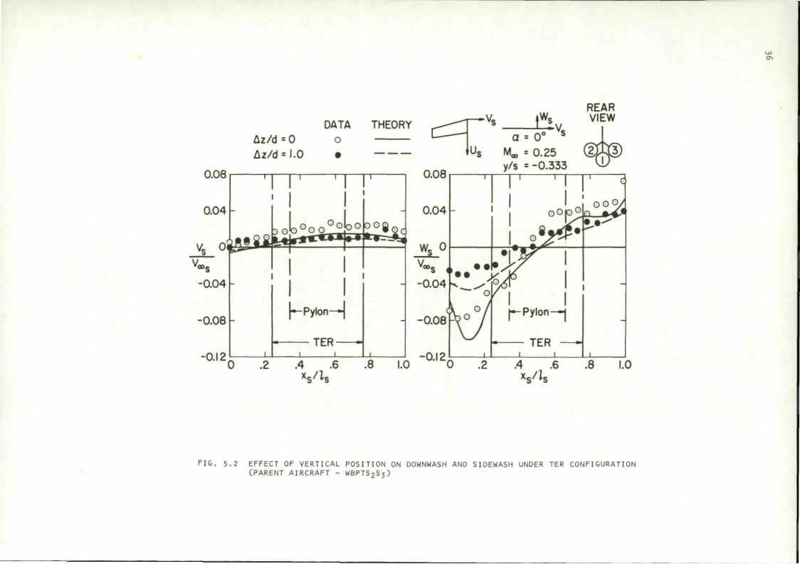
00 o.
DATA THEORY Az/d = 0 o Az/d = I.O •
We REAR VIEW
dgD
FIG. 5.2 EFFECT OF VERTICAL POSITION ON DOWNWASH AND SIDEWASH UNDER TER CONFIGURATION CPARENT AIRCRAFT - WBPTS2S3)
/ I-M£
37
(5.D
y' = y (5.2)
z' = z (5.3)
The corresponding flow velocities are related by the following expressions
I-M£ (5.4)
/ I-VLH (5.5)
and the angle of attack relationship is
w'
/ I-MS
/Tm M2 a
(5.6)
(5.7)
These transformations are applied to a given compressible flow problem to determine an equivalent incompressible flow configuration. The solution for the Incompressible flow Is then re-transformed to give the desired flow field In the compressible problem. Thus it is only necessary to determine solutions for the incompressible flow about configurations representative of transformed airplanes and stores.
Figure 5.3 illustrates the geometry of a body of revolution representing a store body or fuselage. The sources are distributed in such a manner that the boundary condition of flow tangency at the body surface Is satisfied. When the proper source distribution has been established, the resulting non-dimensional flow field velocities are calculated from the following equations.
u»(x»,r») = 0£(x*-xj, ;.'
k=l [(x«-x«)2 + r» 2] 3 / 2
k
(5.8)
FIG. 5.3 COORDINATE SYSTEM FOR AN AXISYMMETRIC BODY
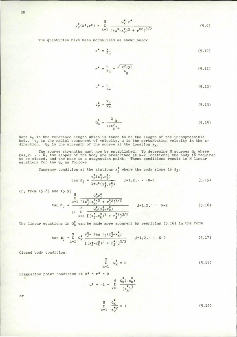
38
N Q« r-
v-(x».r«) = t (5.9) k=l r , * »\? . »2-i3/2 K *• [(x - x k ) ^ + r ^ Y
The quantities have been normalized as shown below
(5.10)
(5.11)
(5.12)
(5.13)
(5.14)
Here £ R I S the reference length which is taken to be the length of the incompressible body. v r is the radial component of velocity, u Is the perturbation velocity in the x-directlon. Q k is the strength of the source at the location x k.
The source strengths must now be established. To determine N sources Q k where k=l,2. • • N, the slopes of the body are prescribed at N-2 locations; the body is required to be closed, and the nose is a stagnation point. These conditions result in N linear equations for the Q k as follows.
Tangency condition at the stations x* where the body slope Is Bj:
X *
r"
u*
• v r
• Qk
=
=
=
=
X
r _ / *R
u Voo
v r v«,
Q k
4TTJ, 2V R °°
x 2 + y 2
la
R
* I * * \
tan i t . - -—- j-1.2,- • -N-2 (5-15) 3 l+u»(x*,r»)
or, from (5-8) and (5-9)
i. i+ i
tan Bj = ' * •> j-1.2,. • -N-2 (5.16) QkU.i-x k)
r e • »,? »2-iV2
k=l [(xj-xk)'f + r j d m i / d
The linear equations in Q k can be made more apparent by rewriting (5.16) in the form
N r?- tan HJ (x?-xk) tan Bj - Z Q £ — -—- J-1,2,- • -N-2 (5.17)
k = r [(xj-xj^ + rj*]-
Closed body condition:
Stagnation point condition at x*
N Z
k - 1
= 0
- 1 =
N Z
k = l
• Qk
N Z
k = l
• Qk_
• 2 xv
= 0
« « Q k ( - x k )
( x k ) 3
= 1
(5.18)
(5-19)
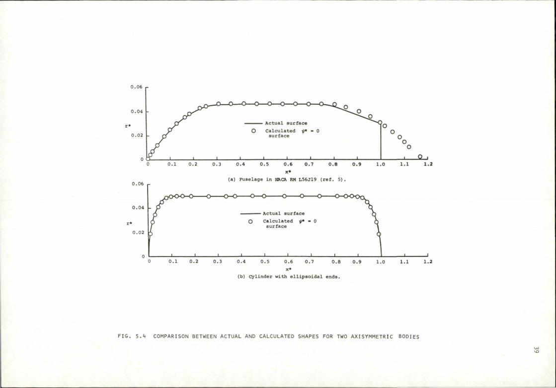
0.06 r-
0.04 -
0.02 -
0.06
0.04 -
0.02
0.6 0.7
x*
(b) cylinder with e l l ipso ida l ends.
F IG . 5 .4 COMPARISON BETWEEN ACTUAL AND CALCULATED SHAPES FOR TWO AXISYMMETRIC BODIES
LO VD
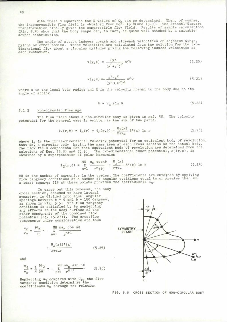
40
With these N equations the N values of Qk can be determined. Then, of course, the incompressible flow field is obtained from Eqs. (5-8) and (5-9). The Prandtl-Glauert transformation finally gives the compressible flow field. Results of sample calculations (Pig. 5.4) show that the body shape can, in fact, be quite well matched by a suitable source distribution.
The angle of attack Induces upwash and sidewash velocities on adjacent wings, pylons or other bodies. These velocities are calculated from the solution for the two-dimensional flow about a circular cylinder giving the following Induced velocities at each x-statlon.
v(y,z) = 2yz , 2 2 s 2
(y +z )
i2W (5.20)
„2 ,2
(y^+zO 2^2
a2w (5.21)
where a Is the local body radius and W is the velocity normal to the body due to Its angle of attack:
v sin a (5.22)
5.1-3 Non-circular fuselage
The flow field about a non-circular body Is given in ref. 58. The velocity potential for the general case is written as the sum of two parts.
*c(r,6) = «e(r) + <t>2(r,6) Ux(x) 2TrV„,
S'(x) In r (5.23)
where <J>e Is the three-dimensional velocity potential for an equivalent body of revolution, that Is, a circular body having the same area at each cross section as the actual body. The flow field components for this equivalent body of revolution are determined from the solutions of Eqs. (5.8) and (5.9). The two-dimensional inner potential, (r.e), is obtained by a superposition of polar harmonics
*2(r,6) MH an cosn6 U (x) I
n=l rn(6) 2TTV0 S' (x) In r (5.24)
MH is the number of harmonics in the series. The coefficients are obtained by applying flow tangency conditions at a number of angular positions equal to or greater than MH. A least squares fit at these points provides the coefficients an.
To carry out this process, the body cross section, assumed to have lateral symmetry, is divided into equal angular spacings between 6 = 0 and 6 = 180 degrees, as shown In Fig. 5-5. The flow tangency condition is satisfied by 4>2 neglecting any effects at the body surface of the other components of the combined flow potential (Eq. (5.23))- The crossflow components under consideration are thus
i i z
3r
MH na„ cos ne Z n
n=l „n+l
Ux(x)S'(x)
2TTVOOT
and
r 39
MH na sin n9 Z
n=l IH+T
(5.25)
(5.26)
Neglecting ux compared with Ux, the flow tangency condition determines the coefficients an through the relation
SYMMETRY^ PLANE
FIG. 5.5 CROSS SECTION OF NON-CIRCULAR BODY
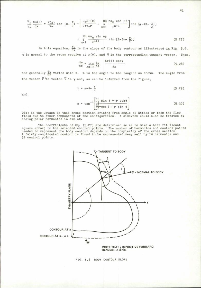
41
UX dv(6) W(X) . TT = • ' cos (m- —) +
v dx v« 2 L
UXS'(x) MH nan cos n9 - Z
2 m / n=l ,n+l I cos [e -(m- 2.)] J 2
MH nan sin ng Z - J [ L - r - sin [9-(m- £) ]
n=l ,n+l
dv
(5.27)
In this equation, —- Is the slope of the body contour as Illustrated In Fig. 5.6.
\J is normal to the cross section at r(9), and x Is the corresponding tangent vector. Then,
Ar(9) COSY
^ - 11m ^ dx Ax->- C AX Ax
(5.28)
dv and generally ^ varies with 9. m is the angle to the tangent as shown. The angle from
the vector r 'to vector v is y and, as can be inferred from the figure.
and
Y = m-9-
tan
dr sin 9 + r cos9
dr Ld6 cos 9 - r sin 9
(5.29)
(5-30)
W(x) is the upwash at this cross section arising from angle of attack or from the flow field due to other components of the configuration. A sidewash could also be treated by adding polar harmonics In sin n6.
The coefficients of Eq. (5-2?) are determined so as to make a best fit (least square error) to the selected control points. The number of harmonics and control points needed to represent the body contour depends on the complexity of the cross section. A fairly complicated contour is found to be represented very well by 14 harmonics and 32 control points.
r = TANGENT TO BODY
CONTOUR AT x
CONTOUR AT x- A x £
= NORMAL TO BODY
• V
(NOTE THAT x IS POSITIVE FORWARD, HENCEIx-Axl>|xl
FIG. 5.6 BODY CONTOUR SLOPE
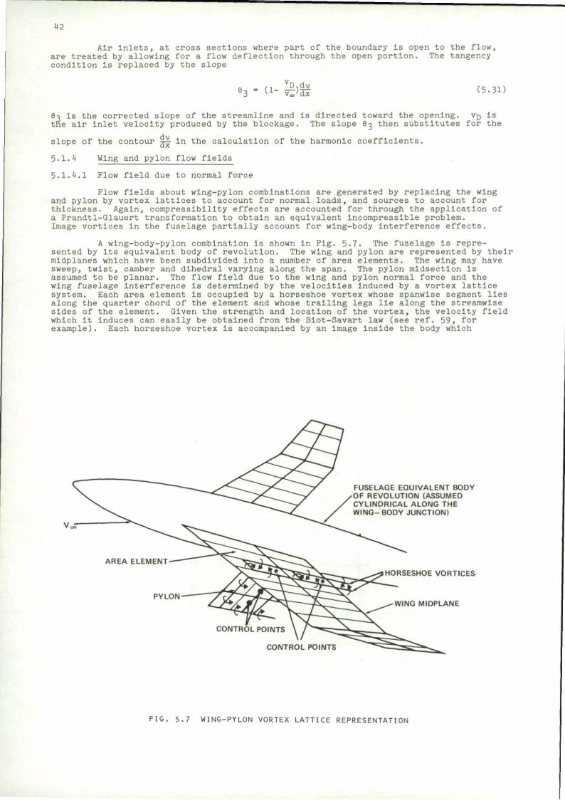
42
Air Inlets, at cross sections where part of the boundary is open to the flow, are treated by allowing for a flow deflection through the open portion. The tangency condition is replaced by the slope
(1- - S ) ^ lJi v„;dx (5.31)
9o is the corrected slope of the streamline and is directed toward the opening. vD Is the air inlet velocity produced by the blockage. The slope 9o then substitutes for the
slope of the contour S^ in the calculation of the harmonic coefficients.
5.1.4 Wing and pylon flow fields
5.1.4.1 Plow field due to normal force
Flow fields about wing-pylon combinations are generated by replacing the wing and pylon by vortex lattices to account for normal loads, and sources to account for thickness. Again, compressibility effects are accounted for through the application of a Prandtl-Glauert transformation to obtain an equivalent incompressible problem. Image vortices in the fuselage partially account for wing-body interference effects.
A wlng-body-pylon combination is shown in Fig. 5-7. The fuselage Is represented by its equivalent body of revolution. The wing and pylon are represented by their mldplanes which have been subdivided Into a number of area elements. The wing may have sweep, twist, camber and dihedral varying along the span. The pylon midsection is assumed to be planar. The flow field due to the wing and pylon normal force and the wing fuselage Interference is determined by the velocities Induced by a vortex lattice system. Each area element is occupied by a horseshoe vortex whose spanwise segment lies along the quarter chord of the element and whose trailing legs lie along the streamwise sides of the element. Given the strength and location of the vortex, the velocity field which it induces can easily be obtained from the Blot-Savart law (see ref. 59, for example). Each horseshoe vortex is accompanied by an image inside the body which
FUSELAGE EQUIVALENT BODY OF REVOLUTION (ASSUMED CYLINDRICAL ALONG THE WING- BODY JUNCTION)
PYLON
HORSESHOE VORTICES
WING MIDPLANE
CONTROL POINTS
CONTROL P(
FIG. 5.7 WING-PYLON VORTEX LATTICE REPRESENTATION
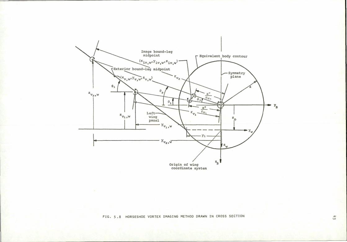
Origin of wing coordinate system
FIG, 5.8 HORSESHOE VORTEX IMAGING METHOD DRAWN IN CROSS SECTION s
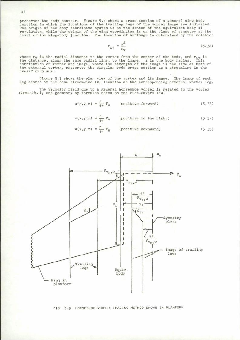
44
preserves the body contour. Figure 5.8 shows a cross section of a general wing-body junction in which the locations of the trailing legs of the vortex Image are indicated. The origin of the body coordinate system Is at the center of the equivalent body of revolution, while the origin of the wing coordinates Is on the plane of symmetry at the level of the wing-body junction. The location of an'image is determined by the relation
iv r. (5.32)
where rv Is the radial distance to the vortex from the center of the body, and riv is the distance, along the same radial line, to the image. a is the body radius. This combination of vortex and image, where the strength of the image Is the same as that of the external vortex, preserves the circular body cross section as a streamline in the crossflow plane.
Figure 5-9 shows the plan view of the vortex and its Image. The image of each leg starts at the same streamwise (x) location as the corresponding external vortex leg.
The velocity field due to a general horseshoe vortex is related to the vortex strength, r, and geometry by formulas based on the Blot-Savart law.
u(x,y,z) = ir— Pu (positive forward) (5.33)
v(x,y,z) = T j — F v (positive to the right) 4TT
w(x,y,z) = L- F„ (positive downward)
(5.310
(5.35)
Symmetry plane
Image of trailing legs
Wing in planform
FIG. 5.9 HORSESHOE VORTEX IMAGING METHOD SHOWN IN PLANFORM

45
The geometrical factors can be expressed as follows for a horseshoe vortex on the left wing panel.
p m (z cos <jt - y sin it) cos it u o ?
[x cos it - (y cos ty + z sin ty) sin tyY + (z cos it - y sin <t)
( (x + s tan i|i) sin ty + (v + s cos <t) cos it cos <t + (z + s s i n <t) cos it sin
[(x + s tan ty)2 + (y + s cos ty)2 + (z + s sin it)2]1/2
(x - S tan it) sin it + (y - s Cos n)) cos it cos it + (z - s sin it) cos | sin
(5-36
[(x - s tan i t ) 2 + (y - s cos <t)2 + (z - s s in * ) 2 ] 1 / 2 }
- z s in ty + x cos ty s in it P = ~ ? y~
v [x cos ty - (y cos it + z s i n <t) s in it] + (z cos it - y s in <t)
(x + s tan ty) s in ty + (y + s cos <t) cos ty cos <t + (z + s s in it) cos ty s in <t
[ (x + s tan ty)2 + (y + s cos <t)2 + (z + ss ln i t ) 2 ] 1 / 2
(x - s tan i|<) s in ty + (y - s cos it) cos ifr cos it + (z - s s in it) cos ty s 2 2 2 1/2
[(x - s tan ty) + (y - s cos it) + (z - s s in ty) ]
(z - s sin it)
i" t |
2 2 (y - s cos ty) + (z - s sin ty)
\ (x - s tan ty)
[(x - s tan ty)2 + (y - s cos it)2 + (z - s sin it)2]1/2
(z + s sin ty)
(y + s cos <t) + (z + s sin ty)
{ > • — { [(x +
(x + s tan ty)
a tan ty)2 + (y + s cos <t)2 + (z + s sin it)2]1 (5 .37)
- x cos it cos it + y s in ty Fw " "
[x cos ty - (y cos <t + z s in it) s in tyl + (z cos it - y s in it)'
j (x + s tan ty) sin ty + (y + s cosit ) cos ty cos ty + (z + s sin it) cos it sin
[(x + s tan ty)2 + (y +scos <t)2 + (z +ssin <t)2]1/2
(x - s tan it) sin ty + (v - s cos <t) cos ty cos ty + (z - s sin ty) c
[(x - s tan * ) 2 + (y - s cos *) + (z - s sin <l>)
cos'l' sin it I jl/2 J
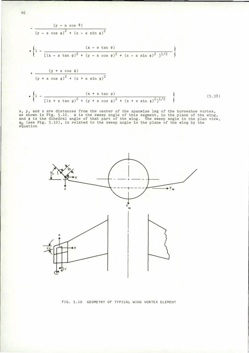
46
(y - s cos $ )
2 2 (y - s cos <t) + (z - s sin ty)
( [(x - s tan it)2 + (y
- s tan it) 1
- s cos ty)2 + (z - s sin <t)2 ] 1 / 2 )
(y + s cos it)
2 2 (y + s cos ty) + (z + s sin ty)
I 1 - -I [(x + s t
(x + s tan it)
an it)2 + (y + s cos <t)2 + (z + s sin it)2]1^2 (5.38)
x, y, and z are distances from the center of the spanwise leg of the horseshoe vortex, as shown in Fig. 5-10. it Is the sweep angle of this segment, in the plane of the wing, and it is the dihedral angle of that part of the wing. The sweep angle in the plan view, itp (see Pig. 5-10), is related to the sweep angle In the plane of the wing by the equation
FIG. 5.10 GEOMETRY OF TYPICAL WING VORTEX ELEMENT
47
tan it = tan it p cos 4> (5.39)
s Is the semi-span of the vortex pair as shown on Fig. 5.10.
The same expressions hold for the image vortices Inside the body, once their geometric layout has been established in accordance with Eq. (5.32). Similarly, the pylon contributions are determined in the same way with <(> = 90 degrees. It is necessary, however, to first determine the strengths of the vortices.
Vortex strengths are calculated by requiring no flow through the wing at a number of control points. The control points are located along the center span of each area element, three quarters of the distance from the leading edge of the element. The vortex goes through the quarter chord and the control point is at the three-quarter station because these conditions give the correct lift and pitching moment on a two-dimensional airfoil.
At each control point, the normal velocity due to angle of attack, wing twist and camber, and the velocity Induced by other components such as stores or fuselage. Is cancelled by the normal velocity Induced by all of the wing and pylon vortices and the body image vortices. For each of M area elements on the wing, these boundary conditions are given by
M r 1 [ ( F w + F l w > c o s *u " (pv + Flv ) sin M n
n - l wv,n l w v , n v v v , n l v v , n ' 4* vc
M+MP r
+ Z (Fw cos ty - F sin •„) _J2_ = (a + a, ) cos n«M+l v,n v vv,n lljv,, *v
+ -ii^ sin <tv- (—±y. ao + - J L 2 ~ ) cos <t (5-40) V a o Voo *V Voo T v
V = 1,2,. • -,M
For each of MP control points on the pylon, the boundary conditions can be written
M r M+MP v - z _J1_ (P + Flv ) - 1 -£S_ F - -i** (5-41) n-1 4TTV,,, v.n v,n n=M+l «HrV„ v.n
The symbols P., and F„ denote the geometrical factors from Eqs. (5.37) and vv,n wv,n (5.38) for the Influence of the horseshoe vortex n at the control point v. Flw and
v,n PJ,. are the functions for the corresponding image vortices, also obtainable from lvv,n
Eqs. (5.37) and (5.38). a is the angle of attack of the configuration and aj^is the
angle due to wing twist and camber at control point v. tyv Is the dihedral angle at the
control point, u, v, v. v, and w1 v, are the components of velocity perturbation at the control point Induced by wing and pylon thickness and from other components such as fuselage, rack, and stores. Solution of these M+MP relations determines the values of the vortex strengths, Fn. The velocity field can then be determined through Eqs. (5.36), (5.37). and (5-38).
5.1.4.2 Wing and pylon thickness
The velocity potential increment,t\ty, induced by an array of sources of uniform strength Is given by
ML = L. [ * * ( Ya t a n *t d Xl dYl
v« 2 7 r ^ x b A b / (X-pX)2 + (Y-Y1)2 + (Zx-
tan ty,. dXn dYn (5.42)
Z ) f
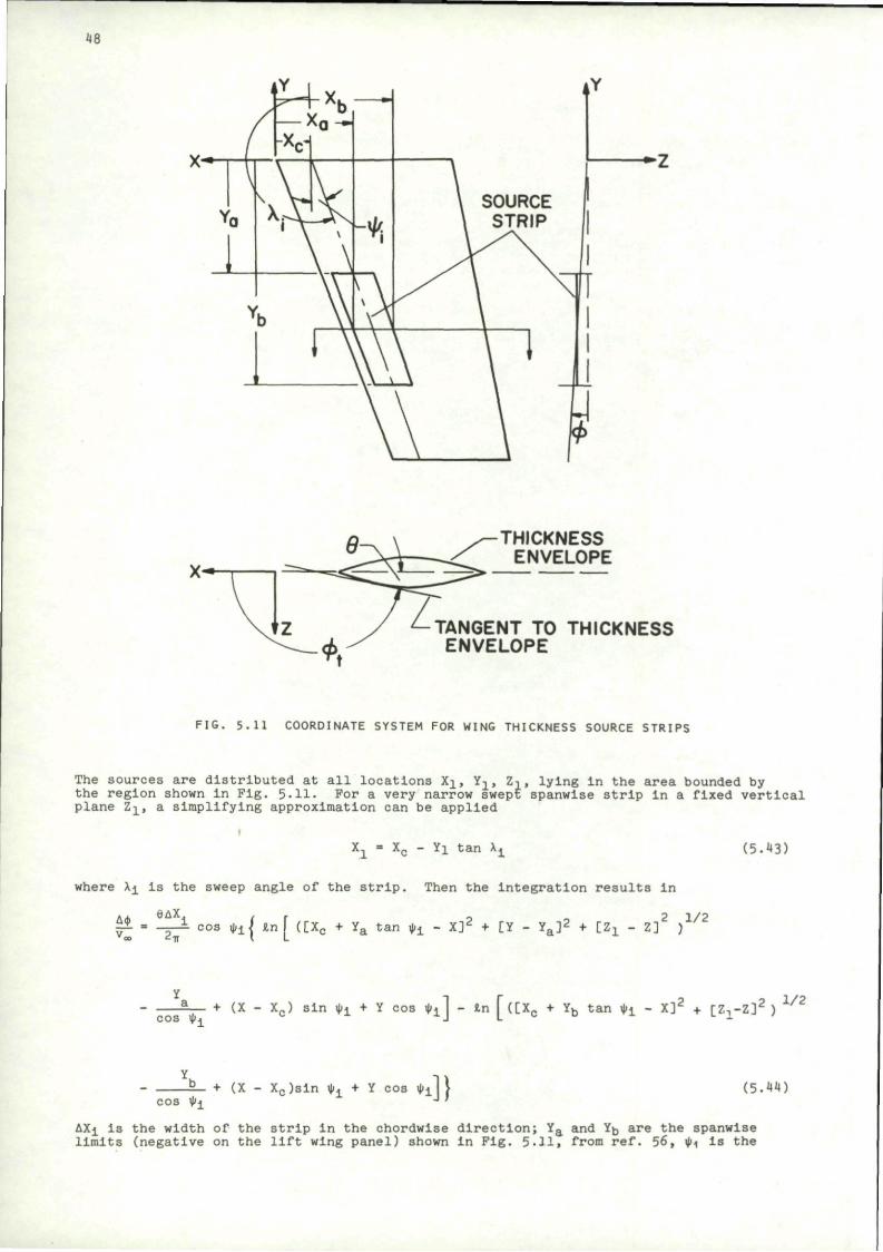
48
THICKNESS ENVELOPE
TANGENT TO THICKNESS ENVELOPE
FIG. 5.11 COORDINATE SYSTEM FOR WING THICKNESS SOURCE STRIPS
The sources are distributed at all locations Xj., Y1, Z-., lying in the area bounded by the region shown in Fig. 5.11. For a very narrow swept spanwise strip in a fixed vertical plane Zj_, a simplifying approximation can be applied
Xx - Xc - Yi tan X±
where Xi Is the sweep angle of the strip. Then the integration results In
., 9AX . . 2 1/2 £J = - — • cos ty]_<\ in I ([Xc + Ya tan ty± - X] Z + [Y - Y a ]
2 + [ZL - Z] )
(5 .43)
cos it - + (X - X c) s i n i t i + Y c o s tyA - t n f ( [ X c + Yb t a n i ^ - X ] 2 + [ 7 - , - Z ] 2 ) 1 J L
2 . V 2
cos iti + (X - X c ) s l n ty± + Y cos i t i 1 | (5.44)
AXi is the width of the strip in the chordwise direction; Ya and Yb are the spanwise limits (negative on the lift wing panel) shown in Fig. 5.31, from ref. 56, iti is the
49
sweepback angle of the strip; and 6 is the slope of the wing thickness at the middle of the strip.
The perturbation velocity components can be obtained by differentiating the velocity potential. The resulting perturbation velocities due to one strip are then
Au _ 3 ,Ait, 6 A Xi
^ ax (^ } = — cos *1
i -(Xc - X + Ya tan itj) + B sin iti -(Xc - X + Yb tan itj) + D sin iti )
( AB CD |
Av 3 ,A<t, 9 A X1 p - Ya + B cos •! Y - Yb + D cos * ± )
Vc= 3Y voo 2TT 1 ( AB CD (
A a A* B h x t l-(zl " Z) "(zl " z) )
£ • h ^ - y r »o- H J - 4 F — - -Jtfj—\ (5.45) where
A = /(Xc - X + Ya tan ty±)2 + (Y - Y ) 2 + (Zx - Z )2
*a
cos iti + (X - Xc) sin iti + Y cos it.
= / (X - X + Ya tan iti)2 + (Y - Y ) 2 + (Zi - Z) :
/ (Xc - X + Yb tan iti)2 + (Y ~ Yb ) 2 +( zi - Z);
*b cos iti
+ (X - Xc) sin iti + Y cos iti
D = / (Xc - X + Yb tan * i )2 + (Y - Y b )
2 + (Zi - Z ) 2 (5-46)
Similar expressions can be derived for the corresponding source strip on the right wing panel. The resulting expressions are identical to Eqs. (5.45) and (5.46) except that Ya and YD are interchanged, since Ya Is still the Inboard side of the strip, and tan iti is replaced by -tan <ti and cos iti Is replaced by -cos iti. On the right wing panel Ya and Yb are positive. At a field point (X,Y,Z) the perturbation velocity components
i!_, X_, *L_ induced by wing thickness are then given by Eqs. (5.**5) and (5.^6) summed Voo V„ Voo
over all wing source strips on both the left wing panel and right wing panel.
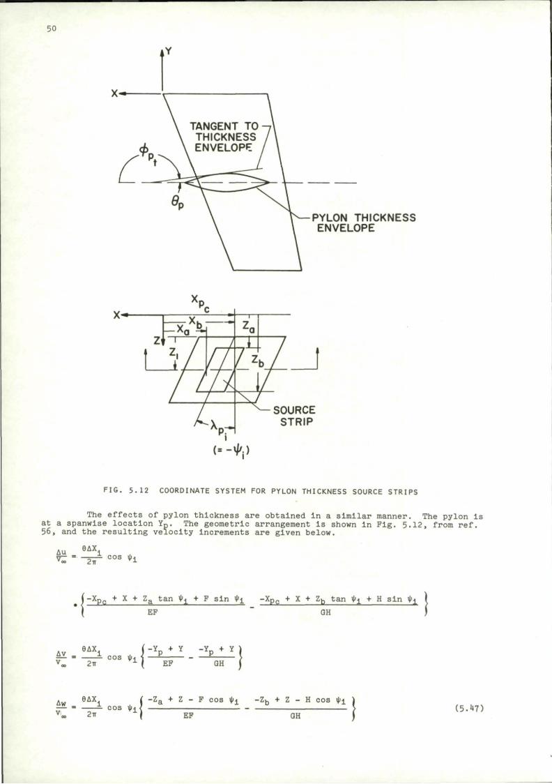
50
PYLON THICKNESS ENVELOPE
SOURCE STRIP
FIG. 5.12 COORDINATE SYSTEM FOR PYLON THICKNESS SOURCE STRIPS
The effects of pylon thickness are obtained in a similar manner. The pylon is at a spanwise location Yp. The geometric arrangement Is shown in Fig. 5.12, from ref. 56, and the resulting velocity Increments are given below.
Au 6AXi
*Z ' TiT cos *i
( - X p e + X + Z a t a n ^ j + F s i n tyj_ - X P c + X + Zb t a n ty± + H s i n ty± \
\ EF GH )
Av , 9 A X 1 v » 2ir
cos i t i | - Y p + Y -Y p + Y j
( EF GH J
A„ 9 A X l , ( ~Za +
= - COS tyi <
Z - F cos i t i ~ z b + Z - H cos i t i
EF GH (5 .47 )
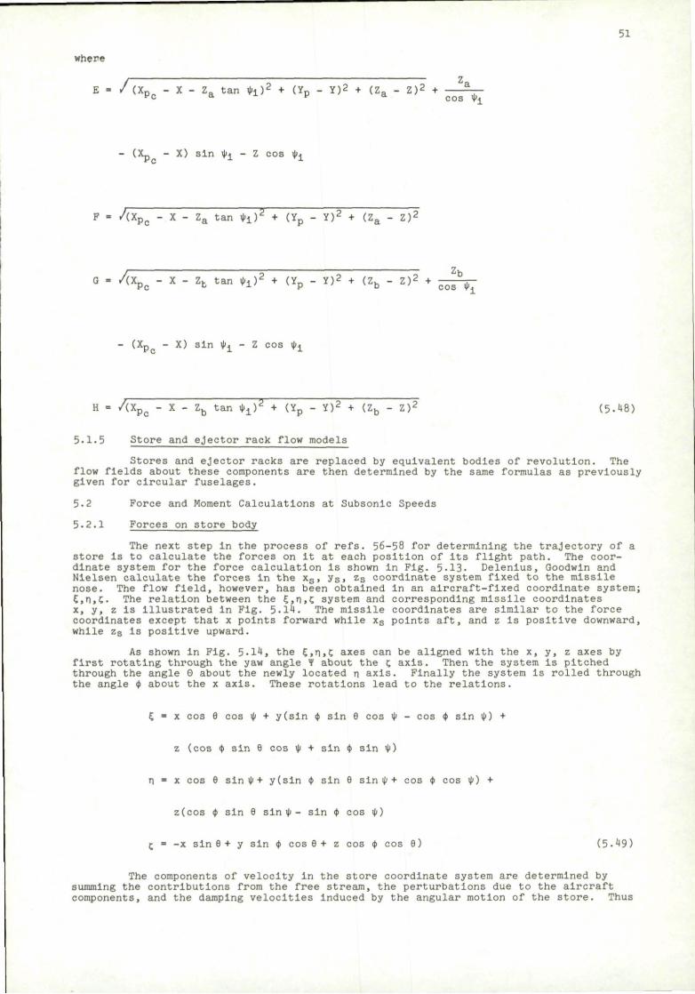
51
where
i Z , E = / (Xp„ - X - Z„ t a n <t i ) 2 + (Yp - Y ) 2 + ( Z a - Z ) 2 + 2 _
vc. * * v a cos iti
(Xp - X) s i n iti - Z c o s iti
F • / ( X P c - X - Z a t a n i t i ) 2 + (Yp - Y) 2 + (Z a - Z ) '
G = / ( X p - X - Zb t a n i t i ) 2 + <Yp - * ) 2 + < zb - Z ) 2 +
-b p 0 - * - -b " « • " i ' T ^ P ~ * ' T i a b " ' T cos • i
(Xp - X) s i n * i - Z cos it i
H = / ( X p c - X - Zb t a n i t i ) 2 + (Yp - Y ) 2 + (Z b - Z ) 2 ( 5 - 4 8 )
5.1.5 Store and ejector rack flow models
Stores and ejector racks are replaced by equivalent bodies of revolution. The flow fields about these components are then determined by the same formulas as previously given for circular fuselages.
5.2 Force and Moment Calculations at Subsonic Speeds
5.2.1 Forces on store body
The next step in the process of refs. 56-58 for determining the trajectory of a store is to calculate the forces on it at each position of its flight path. The coordinate system for the force calculation is shown in Fig. 5.13- Delenlus, Goodwin and Nielsen calculate the forces in the xs, ys, zs coordinate system fixed to the missile nose. The flow field, however, has been obtained In an aircraft-fixed coordinate system; E,n,C. The relation between the £,n,£ system and corresponding missile coordinates x, y, z Is illustrated in Fig. 5.14. The missile coordinates are similar to the force coordinates except that x points forward while xs points aft, and z is positive downward, while zs Is positive upward.
As shown in Fig. 5-14, the E.n.C axes can be aligned with the x, y, z axes by first rotating through the yaw angle f about the c axis. Then the system is pitched through the angle 0 about the newly located n axis. Finally the system is rolled through the angle it about the x axis. These rotations lead to the relations.
£ • x cos 9 cos it + y(sln <t sin 9 cos ty - cos it sin it) +
z (cos ty sin 9 cos it + sin it sin ty)
T\ = x cos 9 sin it + y(sln it sin 9 sin it + cos it cos it) +
z(cos <t sin 9 sin it - sin it cos it)
- = -x sin 9 + y sin <t cos 9 + z cos <t cos 9) (5.49)
The components of velocity in the store coordinate system are determined by summing the contributions from the free stream, the perturbations due to the aircraft components, and the damping velocities Induced by the angular motion of the store. Thus
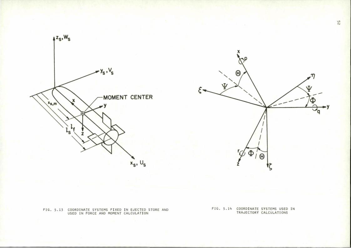
AZS»W! S»"S
Vs»Vs
MOMENT CENTER
y
x * .U s» ~s
FIG. 5.13 COORDINATE SYSTEMS FIXED IN EJECTED STORE AND USED IN FORCE AND MOMENT CALCULATION
M
FIG. 5.14 COORDINATE SYSTEMS USED IN TRAJECTORY CALCULATIONS
53
us " u« + u, • »s.xs s
V_ = Voo + v + r(x„ - x„ m ) s s,y s s s s.m'
be
Ws = W"s,z s + Ws + q ( xs - xs,m) (5.50)
The components of the free stream as seen In the store coordinate system will
Uoo = cos 9 cos it (V,,, cos a f + £) + n cos 6 sin it - sin 9 (V,,, sin a f + c) s,xs
V_„ = -(sin ty sin 9 cos it - cos it sin it)(V cos ar +E) s>.ys °°
-n (sin ty sin 9 sin it + cos <t cos it)
- sin ty cos 9 (V,,, sin a f + i )
Wo°„ ., = (Vco c o s ar + O(cos it sin 9 cos it + sin it sin it) s, zs
+ n(cos $ sin 9 sin it1 - sin <t cos it)
+ .V„, sin a f + c) cos ty cos 9 (5.51)
The notation, Uoo„ _ , denotes the component of free stream velocity in the x„ direction B , Jls °
of the store coordinate system. V,,, and W^ have analogous connotations. Of is s.Ys s.Ys
the angle of attack of the parent aircraft which is flying at the uniform speed Voo.
i , n, and c are the components of the angular rates of the missile In the aircraft-
oriented inertlal system. The terms u s, vs, and w s In Eq. (5-50) are the velocity perturbations Induced
by the fuselage, wing, pylon, rack, and other stores as calculated by the previously described methods. At each point in the trajectory all of the velocity perturbations are- summed in the fuselage coordinate system of the incompressible transformed space
giving u!, v', and w' in the 5, n, C coordinates. When transformed back into the
compressible space, these components become
u!
n B
w' - -C (5.52)
6
Then finally, in the missile coordinates
u = -ut cos 9 cos it - v_ cos 9 sin it + w_ sin 9 s 5 H C
v = Ur(sln ty sin 9 cos u> - cos ty sin ty)
+ v (sin ty sin 9 sin it + cos$ cos it) + w^ sin ty cos 6
54
w = -ur(oos ty sin 9 cos it + sin ty sin ty)
-v,-,(cos ty sin 9 sin it - sin ty cos it) - w, cos ty cos 9 (5.53)
The term r(xs - x„ m) in Eq. (5-50) accounts for the damping due to yaw, and the term q(xs - xs m) is th£ pitch damping term. The symbols are defined In Fig. 5.14.
In the force and moment calculations, the velocities are non-dlraenslonallzed by the free-stream velocity of the store. Thus
» Us U = ?T S Voos
v v» = J -5 V»s
w
_£
Vo
w! = r2- (5.54) °s
where
Vo„s = [(v. cos otf + k ) 2 + n2 + (Voo sin Bf + C )2] 1 / 2 (5-55)
Body forces and moments are calculated on the basis of slender body theory. The resulting expressions are
<CN>SB = p / X s ' ° ^ _ (a2w»)dxs (5.56) R J Q dx3
(CY)SB • Ir rx8.o-^- (a2v*)dxs (5.57) s n J 0 dxg
(Cm)SB " i V / ' 3 ' 0 (xs,m "
Xs ) ± ~ (a2w3)dxs (5-58) R R O S
(cn)SB = ^ T - f X a ' ° U*>™ - xs) 5J- (a»v|)dxs (5.59)
V R J° s
SR Is the reference area, and Up is the reference length on which the coefficients are based. The upper limit of the integration, xs 0 is the station at which vortex separation of the crossflow about the body begins, frora a correlation by Hopkins (ref. 60), this point can be chosen as follows
T * 2 = .378 + .527 V 1 (5.60)
Here £= is the body length, and xSji is the location on the body of the maximum negative rate of change (boattall) of cross-sectional area.
In the region of vortex separation a simple crossflow theory is used to provide the body forces and moments.
( C N ) C P = I T - C c . aV"Ws'dXs (5'61)
(C*>CF " / x ' S aV"V'dXs (5-62)
°* bR •/xs,o
(Cm>CP = S 2 ? f%* aV"W* (Xs.m " xs • **s «.63J R R XS,0
(OU) • ^ 2 , .* . /- 1
n ' C F V H ^ X S ]
55
/ ' av c v s (xs,m " *8> dx s (5.64)
where
v* = / (v*) 2 + (w»)2 (5.65)
and cd„ = cylinder drag coefficient = d r aK per unit length
2aq-s
Cdc = 1»2 for laminar crossfow; cdc = .4 for turbulent crossflow.
Because of pressure gradients In the flow field in which the store Is immersed, buoyant forces will also appear.
By assuming that the flow In planes perpendicular to the body obeys the Laplace equation, buoyant force terms can be derived. The following formulas result.
dw* (°N)By'^rS &2^dXs (5l66)
sir r *s -. d v s ( V B y - f e / a 2d3^ d X3 (5.67)
^ y ' V ^ T S ^ S <«•.• " xs> dxs (5.68)
d * Ccn) ' 4 ^ X ^a2 ^ ^.--^dx* (5-69) 5.2.2 Forces on store lifting surfaces
The forces on lifting surfaces are determined by assuming that the angle of attack at each spanwise station is constant and given by the value at the quarter-chord point. Then reverse flow theorems Indicate that the forces and moments can be calculated by integrating, across the span, the product of local flow angle times an appropriate Influence function. The influence functions are the spanwise distributions of force or moment for the wing in a reversed uniform flow field.
First it is necessary to obtain the component of velocity distribution normal to the lifting surface along the mean quarter chord. The velocities in the store coordinate system us, vs, ws are resolved to provide the components normal to the fins. The lifting surfaces are assumed to be rotated by an angle <tf with respect to the store coordinate system, as shown in Pig. 5.15 for a cruciform arrangement.
The velocity components normal to surfaces 1 to 4, respectively, are
w, • ws cos <tf + vg sin <tf
W2 " ws cos <tf + vs sin <tf
vi • -ws sin <tf + vs cos tyf
v2 " -ws sin tyf + va cos $f (5.70)
Pins FT and F2 are the rotated "horizontal" lifting surfaces, while F3 and F^ denote the rotated vertical ones.
The calculations are simplified by defining symmetric and unsymmetrlc components of the spanwise angle of attack distribution. Thus the symmetric component Is
*»l(yf) + w2(-yf) a = -=—- — (5.7D 8 2V„
OOg
and the unsymmetric part is
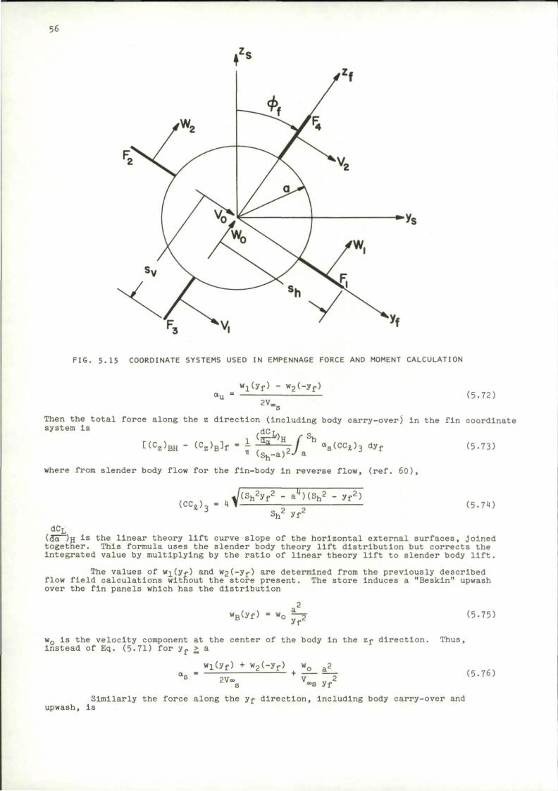
56
FIG. 5.15 COORDINATE SYSTEMS USED IN EMPENNAGE FORCE AND MOMENT CALCULATION
wx(yf) - w2(-yf)
2V„ (5-72)
Then the total force along the z direction (including body carry-over) in the fin coordinate system is Hr.
t(Cz)BH " « W f " \ T*-—;] h as(CC*)3 dyf
where from slender body flow for the fin-body in reverse flow, (ref. 60),
(5.73)
( C C t ) . J ( S n
2 y f2 - a^HSh2 - y f
2 7
s h2 yf2
(5.74)
dCL (3a~~)H 1 S t h e linear theory lift curve slope of the horizontal external surfaces. Joined together. This formula uses the slender body theory lift distribution but corrects the integrated value by multiplying by the ratio of linear theory lift to slender body lift.
The values of wi(y*.) and w2(-yf) are determined from the previously described flow field calculations without the store present. The store Induces a "Beskin" upwash over the fin panels which has the distribution
wB(yf> • wo ^ 2 (5.75)
wQ is the velocity component at the center of the body in the Zf direction. Thus, instead of Eq. (5-71) for yf £ a
Wj(yf) + w2(-yf) wQ a2
2V« V 2 °°s yf
(5.76)
Similarly the force along the yf direction. Including body carry-over and upwash, la
57
y)BV " (VB^f " J d° V . f S v Bs(CCt)j, dzf (5.77) (Bw-a)
v«
where
J(sv2zf
2 - a4)(sy2 - z ^ 7
Sv2 Z r2
( C C ^ = 4 1 (5.78) sv z r
and
v2Uf) + Vi(-zf) v0a2
.. — • — - , . z r i a « . „ ,
dCL S
Also, here (gn-^ l s t h e linear theory lift slope for the vertical fins and vQ is the lateral velocity (along the yf direction) at the body center.
The forces are assumed to act at the mean quarter chords of the exposed panels. Then the moment coefficients are
t(Cm)BH " (Cm)B]f = - C(CZ>BH " (
cz)B]f T 1 (5-80) R
[(Cn)BV " (Cn>B]f = " C(Cy)BV " (
Cy>B^f iJ (5-81)
where S-n and I are the distances from the moment center to the fin quarter chord positions (positive for the fin aft of the moment center); and ip is the reference dimension for pitching and yawing moments.
Rolling moments are derived for the planar wing case and the cruciform fin configuration in which all panels are of Identical geometry. The procedure is the same as for the other forces and moments, except that the load distribution corresponds to the slender body theory for an angle of attack distribution increasing linearly along the span. The results are, for the planar case:
dCr
(Ct)H - - ; d a 2 / h a
u ( c c * ) 5d y f ( 5 - 8 2 )
(Sh"a) *R a
In this formula,
wi(yf) - w2(-yf) py o,, = + (5.°3;
2Voo„ Voo„
& s where p Is the roll rate, and the last term in Eq. (5-83) accounts for the damping in roll.
Slender body theory for a linearly varying angle of attack (wing with linear twist) gives
L 2*S n w a2 J(Sh
2-yf2)(Sh
2yi
2-a") (CCi)5 • (1 + cos"1 )(yf
Sh2+a2 yf ' Sh
2yf2
? a2 „ , (yf2+a2)(Sh
2-a2)
+ 2 ( y si)2 cosh-i [ \ —V~r^ i 5 - m
* yf (yf2-a2)(Sn
2+a2)
For cruciform fins
, (^£L)H /-sh (CI)HV = - J ; * \ 2 L (°u + M<cc*) 6
d*f (5.85) v ( s - a ) ^ -/a
au is given In Eq. (5.35), and B is obtained from _ Vl(-Zf) - v2(zf) p,f ( 5 > 8 6 )
2V«s
58
The slender body result for the cruciform, derived in ref. 61 becomes
8R 1 /Sin 29 (CC,)fi = 2 2 - [cos 29 tanh_J- (axn go ) - cos 2y tanh_J- ( * ° TT sin 2Y
•1 /tan 29 tan 2Y
•)]
l|R + ^ - [K(k1) sin 49 - 2kx cos A1K(k1)Z(A1.k1) ] (5.87)
where
R- i V ^ 5" '°h Sh'
(5.88)
cos 29 = Sn
2 (a" + y/)
yf' (a4 + s^) (5.89)
cos 2y 2R2
(5.90)
ki - sin 2y (5.9D
K(kj_) = complete elliptic integral of the first kind
TT
dz K(ki) =/" ? i - ^ J 0 •l-k1
2sln2 (5.92)
8i„-l (sin 29 ) sin 2y
Z(A1,k1) = Jacobl zeta function
Z(A1,k1) K(k1)E(A1,k1) - E(| ,k1)F(A1.k1)
K(ki)
F(A1,k1) = Incomplete elliptic Integral of the first kind
/*A1 F(A1,k1) =/ i z
/ 1-ki2 sin2 z
E( - .k^) = complete elliptic integral of the second kind
E(| ,ki) =/ 2 / l-kL2 sin2 z dz
E(Ai,k1) = incomplete elliptic integral of the second kind
E(A1,k1) =/ /l-ki2 sin2 z dz \w O
At yf = a, the expression becomes indeterminate having the limit
(CCt)6 = — [- cos 2y log(cos 2y)+ .5K(kx) sin 49] y=a
5-3 Calculation of Store Trajectory
(5.93)
(5.94
(5.95)
(5.96)
(5.97)
(5.98)
The trajectory of the store is determined, in ref. 56, by integrating the equations of motion. The trajectory is determined with respect to the airplane (In the E, n, C coordinate system fixed to the fuselage). The parent aircraft is assumed to be flying at constant velocity, constant angle of attack and constant flight path angle with respect to the horizontal.
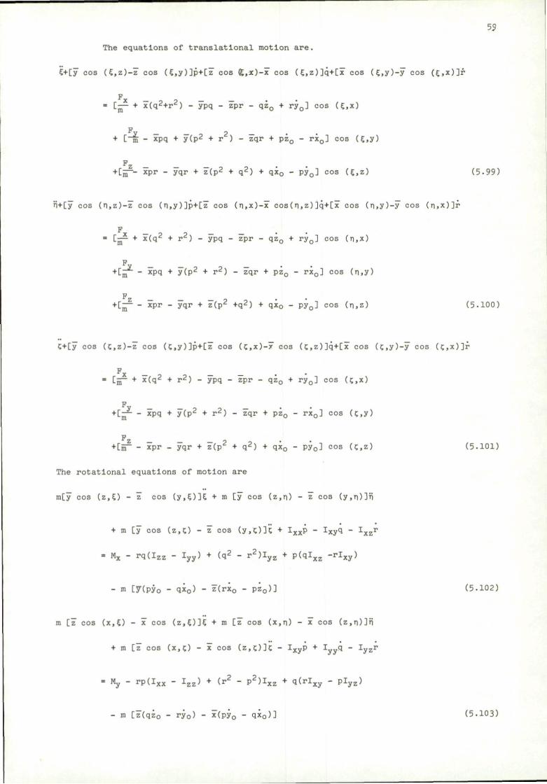
55
The equations of translatlonal motion are.
£+[y cos (£,z)-z" cos (£,y)]p+[z" cos (£,x)-x cos (E,z)]q+[x cos (E.y)-y cos (£,x)]r
F • [— + x(q2+r2) - ypq - zpr - qzQ + ryQ] cos (£,x)
y — _ 0 ? — • C m - xpq + y(p2 + r ) - zqr + pz0 - rx0] cos (£,y)
Pz
+ [j ~- xpr - yqr + z(p2 + q2) + qx0 - pyQ] cos (£,z) (5.99)
n+Cy cos (n,z)-z" cos (n,y)]p+[z' cos (n,x)-x cos(n,z)]q+[x cos (n,y)-y cos (n.x)]f
F • [jp + x(q2 + r2) - ypq - zpr - qz0 + ryQ] cos (n,x)
+[„ - xpq + y(p2 + r2) - zqr + pz0 - rx0] cos (n,y)
F + [— - xpr - yqr + z"(p2 +q2) + qx0 - py0] cos (n,z) (5.100)
C+[y cos (C,z)-z cos (C,y)]p+[z cos (c,x)-x cos (c,z)]q+[x cos (c,y)-y cos (c,x)]f
Fx _ _ " [jS- + x(q2 + r2) - ypq - zpr - qz0 + ry0] cos U,x)
P + [— - xpq + y(p^ + r d ) - zqr + pz0 - rx0] cos (c,y)
PZ _ _ _ 9 +[nT - xpr - yqr + z(p^ + q2) + qx0 - py0] cos (?,z) (5-101)
The rotational equations of motion are
m[y cos (z,£) - z" cos (y,£)]£ + m [y cos (z,n) - z cos (y,n)]fi
+ m [y cos (z,c) - z cos (y,c)]'c + IXXP - IxyQ - 1
X z T
= Mx - rq(Izz - Iyy) + (q2 - r2)Iyz + p(qlxz -rlxy)
- m [7(py0 - qx0) - z(rx0 - pz0)] (5.102)
m [7 cos (x,£) - x cos (z,£)]£ + m [z" cos (x,n) - x cos (z,n)]n
+ m [z" cos (x,c) - x cos (z,c)]c - Ixyp + Iyyq - Iyzr
- My - rp(Ixx - Izz) + (r2 - p2)Ixz + q(rlxy - plyz)
- m [z(qz0 - ry0) - x(py0 - qi0)] (5.103)
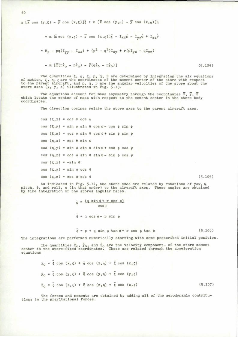
60
m [x cos (y,£) - y cos (x,£)]£ + m [x cos (y,n) - y cos (x,n)]?i
+ m Gccos (y,^) - y cos (x,c)]i; - Ixzp - Iyzq + Izzr
Mz - pq(Iyy - IXx) + (P2 " q2)IXy
+ r(plyz - qlxz)
m [x(rx0 - pz0) - y(qz0 - ry0)] (5-104)
The quantities E, n, c, p, q, r are determined by integrating the six equations of motion, £, n. care the coordinates of the moment center of the store with respect to the parent aircraft, and p, q, r are the angular velocities of the store about the store axes (x, y, z) illustrated In Pig. 5.13.
The equations account for mass asymmetry through the coordinates x, y", z" which locate the center of mass with respect to the moment center in the store body coordinates.
The direction cosines relate the store axes to the parent aircraft axes.
cos (£,x) • cos 9 cos it
cos (£,y) = sin ty sin 9 cos it - cos <t sin it
cos (£,z) = cos ty sin 9 cos ty + sin ty sin it
cos (n,x) » cos 9 sin it
cos (n,y) • sin ty sin 9 sin u> + cos ty cos it
cos (n,z) • cos ty sin 9 sin it - sin it cos it
cos (ex) = -sin 9
cos (C>y) = sin <t cos 9
cos (c,z) = cos <t cos 9 (5-105)
As indicated in Fig. 5.14, the store axes are related by rotations of yaw, ty, pitch, 9, and roll, ty (In that order) to the aircraft axes. These angles are obtained by time integration of the stores angular rates.
• m (q sin ty + r cos <p) cose
9 = q cos it - r sin it
ty • p + q sin ty tan 9+ r cos ty tan 9 (5-106)
The Integrations are performed numerically starting with some prescribed initial position.
The quantities x0, y0, and z0 are the velocity components of the store moment center in the store-fixed coordinates. These are related through the acceleration equations
x0 = E cos (x,E) + n cos (x,n) + C cos (x,!.)
y0 = i cos (y,£) + n cos (y,n) + c cos (y.O
z0 = i cos (z,£) + ri cos (z,n) + C cos (z,c) (5.107)
The forces and moments are obtained by adding all of the aerodynamic contributions to the gravitational forces.
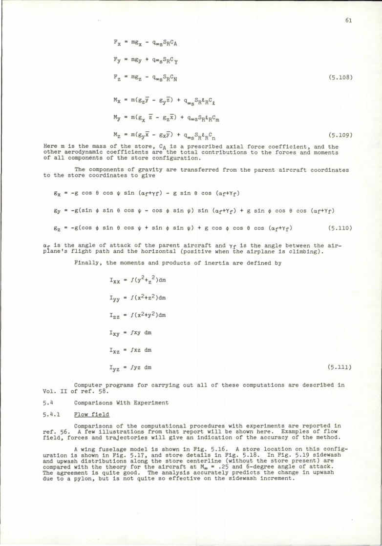
61
Fx - mgx - qoosSRCA
Py • mgy + qoogSpCy
Fz " m&z ~ ^ S S R C N (5.108)
Mx " m(gzy - gyz) + qooSVRC,i
My - m(gx z - gzx) + qooSSRJ,RCm
Mz - m(gyx - gxy") + qa>sSR«.RCn (5-109)
Here m is the mass of the store, CA is a prescribed axial force coefficient, and the other aerodynamic coefficients are the total contributions to the forces and moments of all components of the store configuration.
The components of gravity are transferred from the parent aircraft coordinates to the store coordinates to give
gx « -g cos 9 cos it sin (af+Yf) - g sin 9 cos (af+Yf)
gy " -g(sin it sin 9 cos it - cos ty sin it) sin (af+Yf) + g sin it cos 9 cos (af+Yf)
gz = -g(cos <t sin 9 cos it + sin <t sin it) + g cos ty cos 9 cos (af+Yf) (5.110)
af is the angle of attack of the parent aircraft and Yf is the angle between the airplane's flight path and the horizontal (positive when the airplane Is climbing).
Finally, the moments and products of inertia are defined by
Ixx = /(y2+z2)dm
I y y » /(x2+z2)dm
I z z - /(x2+y2)dm
I x y - /xy dm
I x z » fxz dm
I y z - /yz dm (5.111)
Computer programs for carrying out all of these computations are described In Vol. II of ref. 58.
5.4 Comparisons With Experiment
5.4.1 Flow field
Comparisons of the computational procedures with experiments are reported In ref. 56. A few illustrations from that report will be shown here. Examples of flow field, forces and trajectories will give an Indication of the accuracy of the method.
A wing fuselage model is shown in Fig. 5.16. A store location on this configuration is shown In Pig. 5-17, and store details in Fig. 5.18. In Fig. 5-19 sidewash and upwash distributions along the store centerllne (without the store present) are compared with the theory for the aircraft at M*, = .25 and 6-degree angle of attack. The agreement is quite good. The analysis accurately predicts the change in upwash due to a pylon, but Is not quite so effective on the sidewash Increment.
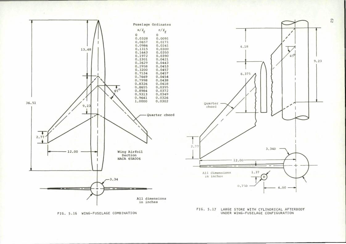
36.51
0 0 0 0 0 0 0. 0, 0, 0. 0, 0. 0, 0. 0, 0. 0. 0. 0. 1.
.0328
.0657 ,0986 .1315 .1643 .1972 ,2301 .2629 .2958 ,3200 ,7534 ,7669 ,7998 8326 ,8655 .8984 9313 9641 0000
0 0.0091 0.0171 0.0241 0.0300 0.0350 0.0390 0.0421 0.0443 0.0453 0.0457 0.0457 0.0454 0.0438 0.0418 0.0395 0.0372 0.0349 0.0326 0.0302
Fuselage Ordinates
r / t .
Quarter chord
All dimensions in inches
All dimensions in inches
().7'>D
FIG. 5.16 WING-FUSELAGE COMBINATION FIG. 5.17 LARGE STORE WITH CYLINDRICAL AFTERBODY
UNDER WING-FUSELAGE CONFIGURATION
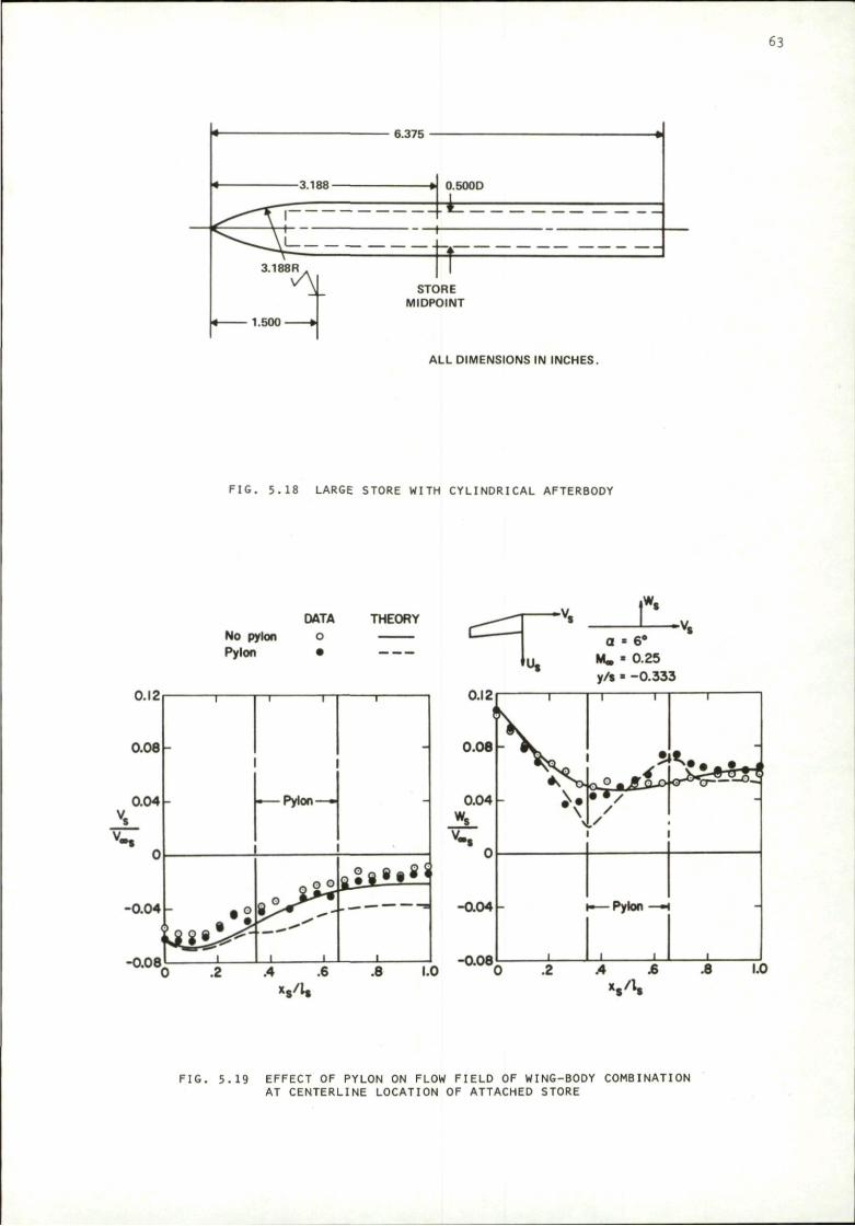
63
ALL DIMENSIONS IN INCHES.
FIG. 5.18 LARGE STORE WITH CYLINDRICAL AFTERBODY
0.12
0 . 0 8 -
0.04
-0.04 -
-0.08
No pylon Pylon
DATA
o THEORY
-
• 2
1
I 1
r—Pylon—-
Q ° °
i i
i
aJ j 8« 8*
• .2 .4 .6 .8 1.0
m\/k
-0.08
FIG. 5.19 EFFECT OF PYLON ON FLOW FIELD OF WING-BODY COMBINATION AT CENTERLINE LOCATION OF ATTACHED STORE
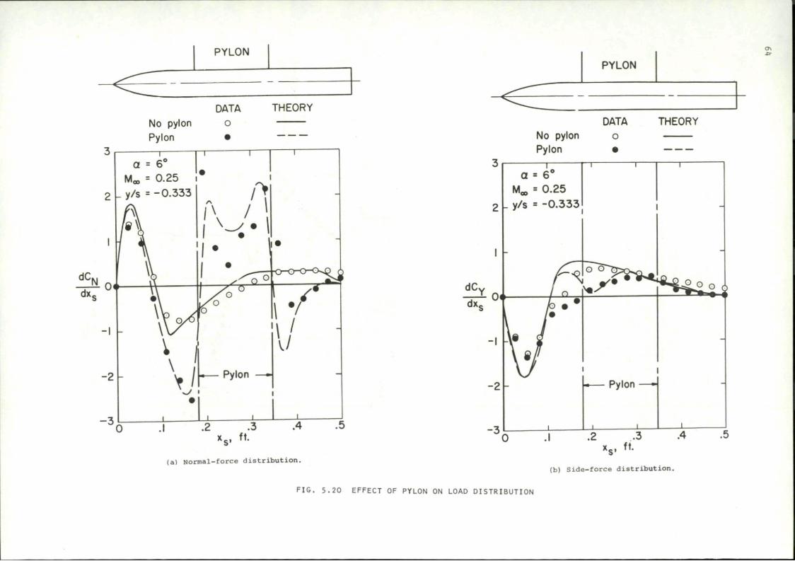
PYLON PYLON
DATA THEORY No pylon o Pylon •
— r a = 6°
Ma, = 0.25 i
I y/s = - 0 . 3 3 3
T
DATA No pylon o Pylon •
THEORY
a = 6
M,,, = 0.25
|_ y/s = -0 .333
(a) Normal-force d i s t r i b u t i o n .
F IG . 5 .20 EFFECT OF PYLON ON LOAD DISTRIBUTION
.1 .2 .3 .4 x s , ft.
(b) S ide- force d i s t r i b u t i o n .
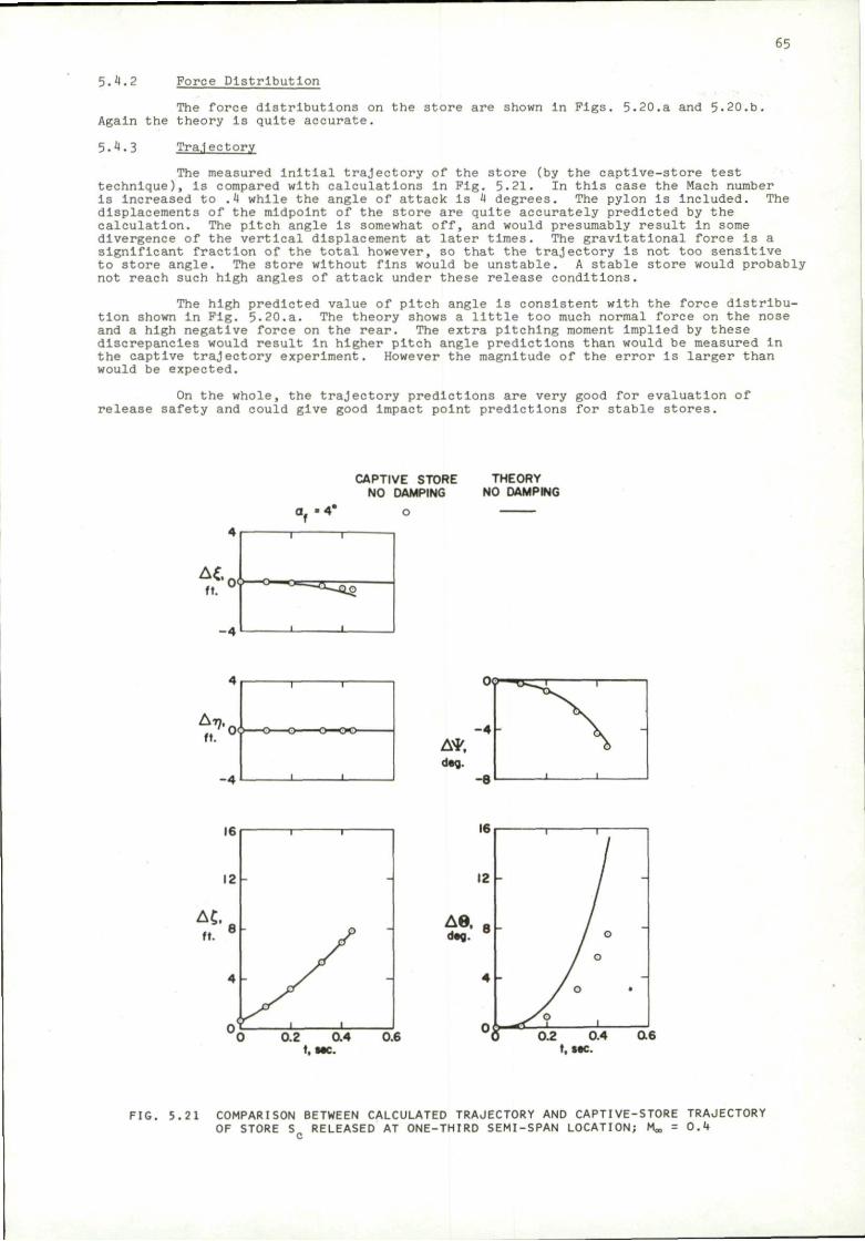
65
5.4.2 Force Distribution
The force distributions on the store are shown in Figs, Again the theory is quite accurate.
5.20.a and 5.20.b.
5.4.3 Trajectory
The measured initial trajectory of the store (by the captive-store test technique), is compared with calculations in Pig. 5.21. In this case the Mach number is increased to .4 while the angle of attack Is 4 degrees. The pylon Is included. The displacements of the midpoint of the store are quite accurately predicted by the calculation. The pitch angle Is somewhat off, and would presumably result in some divergence of the vertical displacement at later times. The gravitational force is a significant fraction of the total however, so that the trajectory Is not too sensitive to store angle. The store without fins would be unstable. A stable store would probably not reach such high angles of attack under these release conditions.
The high predicted value of pitch angle is consistent with the force distribution shown in Fig. 5.20.a. The theory shows a little too much normal force on the nose and a high negative force on the rear. The extra pitching moment implied by these discrepancies would result In higher pitch angle predictions than would be measured in the captive trajectory experiment. However the magnitude of the error is larger than would be expected.
On the whole, the trajectory predictions are very good for evaluation of release safety and could give good impact point predictions for stable stores.
CAPTIVE STORE THEORY NO DAMPING NO DAMPING
0 0.2 0.4 0.6 t, MC.
FIG. 5.21 COMPARISON BETWEEN CALCULATED TRAJECTORY AND CAPTIVE-STORE TRAJECTORY OF STORE S RELEASED AT ONE-THIRD SEMI-SPAN LOCATION; Moo = 0.4
c
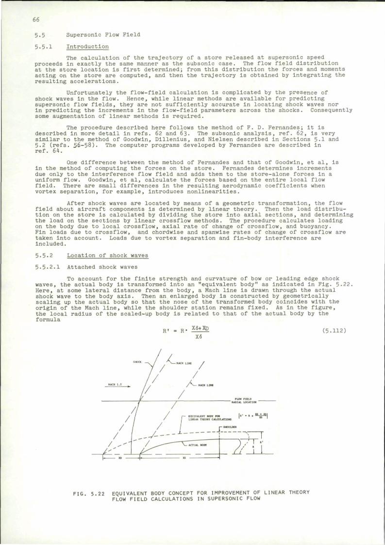
66
5-5
5.5.1
Supersonic Flow Field
Introduction
The calculation of the trajectory of a store released at supersonic speed proceeds in exactly the same manner as the subsonic case. The flow field distribution at the store location is first determined; from this distribution the forces and moments acting on the store are computed, and then the trajectory is obtained by integrating the resulting accelerations.
Unfortunately the flow-field calculation is complicated by the presence of shock waves In the flow. Hence, while linear methods are available for predicting supersonic flow fields, they are not sufficiently accurate In locating shock waves nor in predicting the Increments in the flow-field parameters across the shocks. Consequently some augmentation of linear methods Is required.
The procedure described here follows the method of F. D. Fernandes; It is described In more detail in refs. 62 and 63. The subsonic analysis, ref. 62, Is very similar to the method of Goodwin, Dlllenius, and Nielsen described in Sections 5.1 and 5.2 (refs. 56-58). The computer programs developed by Fernandes are described in ref. 64.
One difference between the method of Fernandes and that of Goodwin, et al. Is in the method of computing the forces on the store. Fernandes determines Increments due only to the Interference flow field and adds them to the store-alone forces in a uniform flow. Goodwin, et al, calculate the forces based on the entire local flow field. There are small differences in the resulting aerodynamic coefficients when vortex separation, for example. Introduces nonlinearities.
After shock waves are located by means of a geometric transformation, the flow field about aircraft components is determined by linear theory. Then the load distribution on the store is calculated by dividing the store into axial sections, and determining the load on the sections by linear crossflow methods. The procedure calculates loading on the body due to local crossflow, axial rate of change of crossflow, and buoyancy. Fin loads due to crossflow, and chordwise and spanwise rates of change of crossflow are taken into account. Loads due to vortex separation and fin-body interference are Included.
5.5.2 Location of shock waves
5.5.2.1 Attached shock waves
To account for the finite strength and curvature of bow or leading edge shock waves, the actual body is transformed Into an "equivalent body" as indicated in Fig. 5, Here, at some lateral distance from the body, a Mach line is drawn through the actual shock wave to the body axis. Then an enlarged body is constructed by geometrically scaling up the actual body so that the nose of the transformed body coincides with the origin of the Mach line, while the shoulder station remains fixed. As in the figure, the local radius of the scaled-up body is related to that of the actual body by the formula
22.
R' = R' X6+XD
X6 (5.112)
FIG. 5.22 EQUIVALENT BODY CONCEPT FOR IMPROVEMENT OF LINEAR THEORY FLOW FIELD CALCULATIONS IN SUPERSONIC FLOW
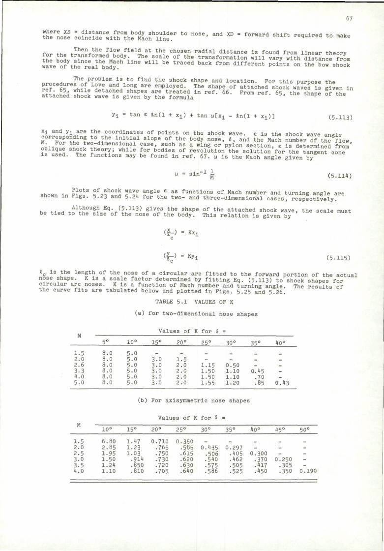
where XS = distance from body shoulder to nose, and XD the nose coincide with the Mach line.
67
forward shift required to make
for. «,- J!? eV h e £1?w„flell.at t h e c h o s e n radial distance Is found from linear theory for the transformed body. The scale of the transformation will vary with distance from
Sve 5ytSin«a5hSoS!h U n e W l 1 1 ^ t r a C 6 d b S C k f r ° m d l f f 6 r e n t P0l"tS °" tJfbCrshock
The problem is to find the shock shape and location. For this puroose the re?Ce6lf'w ° L L H V ? a"d
HL0"g a r e eraPloyed- T h e shape <" attached Lock waves is gKen in
I f l ' . l h W I d e t a c l? e d fhapes are treated in ref. 66. From ref. 65. the shape of the attached shock wave is given by the formula p
yi = tan E tn(l + x x ) + tan \ilx± - in(l + Xi)] (5.H3)
Xi and yi are the coordinates of points on the shook wave, e is the shock wave anKle corresponding to the initial slope of the body nose, 6, and the Mach number of the^ow, ;^ K two-dimensional case, such as a wing or pylon section, z is determined from
W\\ i£S THk r h e ° ^ ; W h l l e £°r b ° d l e S 0 f revolution the solution for the tangent cone Is used. The functions may be found In ref. 67. u is the Mach angle given by
= sln_1 h M
(5.114)
, Ll0tS ?f 3 h o c k wavf a n 8 l e e as functions of Mach number and turning ansle are shown In Figs. 5.23 and 5.24 for the two- and three-dimensional cases, resjfctlvely
h P H P „ n1^^!1? E q'r (h 1 1 3 ) 6 ± V ? S t h e s h a p e o f t h e attached shock wave, the scale must be tied to the size of the nose of the body. This relation Is given by
(f-) = KXl
(f-> - *! (5.115)
l c Is the length of the nose of a circular arc fitted to the forward portion of the actual ipe. K Is a scale factor determined by fitting Eq. (5.113) to shock shapes for
circular arc noses. K Is a function of Mach number and turning angle the curve fits are tabulated below and plotted in Figs. 5.25 and 5.26.
TABLE 5.1 VALUES OF K
(a) for two-dimensional nose shapes
The results of
Values of K for 6 = m
1.5 2.0 2.6 3.3 4.0 5.0
5°
8.0 8.0 8.0 8.0 8.0 8.0
10°
5.0 5.0 5-0 5.0 5-0 5.0
15°
— 3.0 3.0 3.0 3.0 3-0
20°
_
1.5 2.0 2.0 2.0 2.0
25°
_ -1.15 1.50 1.50 1.55
30°
_ _
0.50 1.10 1.10 1.20
35°
_ _ 0.45 .70 .85
40°
_ _ -_ 0.43
(b) For axisymmetric nose shapes
Values of K for 6
n
1.5 2.0 2.5 3.0 3.5 4.0
10°
6.80 2.85 1.95 1.50 1.24 1.10
15°
1.47 1.23 1.03 .914 .850 .810
20°
0.710 .765 .750 .730 .720 .705
25°
0.350 • 585 .615 .620 .630 .640
30°
_
0.435 .506 .540 • 575 .586
35°
^
0.297 .405 .462 .505 • 525
40°
_ -
0.300 .370 .417 .450
45°
_ --
0.250 .305 • 350
50°
_ ----
0.190
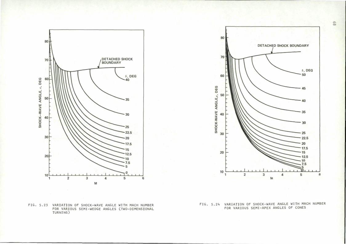
80
70
CJ 6 0 HI Q
O z <
> < 5
I
u o I in
50 k
40 h
30
20 h
10
V t DETACHED SHOCK
-1 1
-1 I
k /BOUNDARY
WrT^T I l l lU I l l l \ V «. DEG
ilUllWW \ \ ^ 4 0
- WWWWW N. —35
\ \ u \ \ \ \ \ \ '""""--SO
\ \vvv\s svsCv^^cr 25
\ v v x x ^ v ^ ^ ^ r ' — 2 2 - 5
\ \ \ \ \ , > \ > > ^ , ^ r "2° \ xvsN^^ 17-5
N / \ S \ , V ^ N ^ ! ^ ^ " 1 5 N. \ ^ \ ^ - ^ ^ - 1 2 . 5
\ ^^C^C^ IO \ . ^^--Cr^"75
^ ^ ^ ^ " 5
. 1 1 • 1 1 1 1 1 1 • • 1 1 1 1 1 1 L _ J 1 1 1 1
M
F I G . 5 .23 VARIATION OF SHOCK-WAVE ANGLE WITH MACH NUMBER FOR VARIOUS SEMI-WEDGE ANGLES (TWO-DIMENSIONAL TURNING)
ON OO
FIG. 5.24 VARIATION OF SHOCK-WAVE ANGLE WITH MACH NUMBER FOR VARIOUS SEMI-APEX ANGLES OF CONES
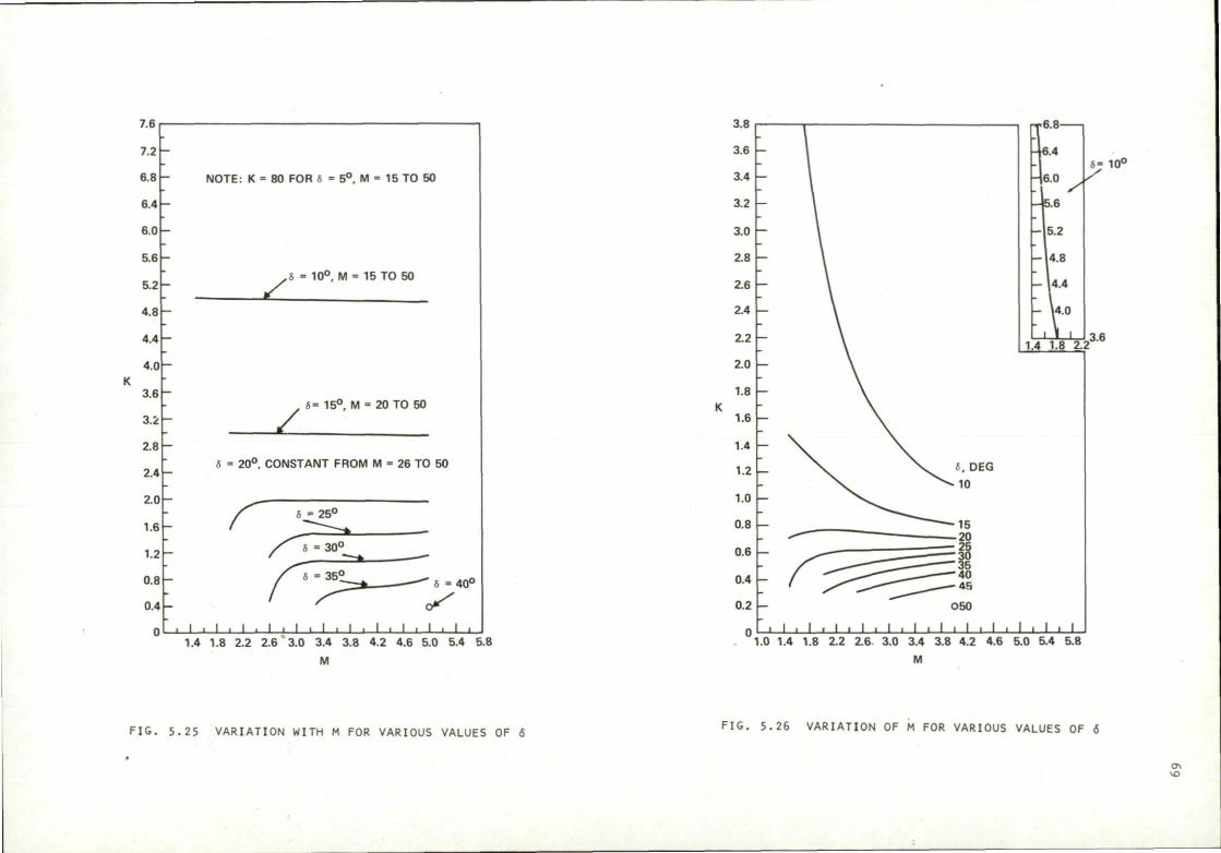
7.6
7.2
6.8
6.4
60
5.6
5.2
4.8
4.4
4.0
3.6
3.2
2.8
2.4
2.0
1.6
1.2
0.8
0.4
0
NOTE: K = 80 FOR 6 = 5°, M = 15 TO 50
z. h = 10° , M = 15 TO 50
z 5= 15° , M = 20 TO 50
6 = 20° . CONSTANT FROM M = 26 TO 50
6 • 25°
I . I . I - L _ l i l l l . I I I 1.4 1.8 2.2 2.6 3.0 3.4 3.8 4.2 4.6 5.0 5.4 5.8
M
FIG. 5.25 VARIATION WITH M FOR VARIOUS VALUES OF 6
3.8
3.6
3.4
3.2
3.0
2.8
2.6
2.4
2.2
2.0
1.8
1.6
1.4
1.2
1.0
0.8
0.6
0.4
0.2
0
6= 10°
1.4 1.8 2.
' I • I • I • I • I
O50
• I • I • I • I . I • I .0 1.4 1.8 2.2 2.6 3.0 3.4 3.8 4.2 4.6 5.0 5.4 5.8
M
FIG. 5.26 VARIATION OF M FOR VARIOUS VALUES OF 6
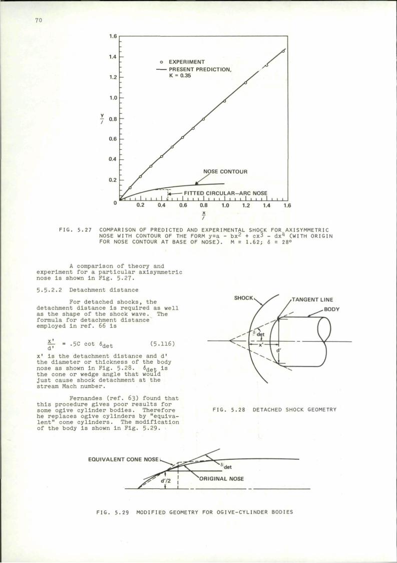
70
1.6
1.4 -o EXPERIMENT
PRESENT PREDICTION, K = 0.35
NOSE CONTOUR
FITTED CIRCULAR-ARC NOSE I i i i 1 i • i I i i i I i • i I i
1.0 1.2 1.4 1.6
FIG. 5.27 COMPARISON OF PREDICTED AND EXPERIMENTAL SHOCK FOR AXISYMMETRIC NOSE WITH CONTOUR OF THE FORM y=a - bx2 + cx3 - dx4 (WITH ORIGIN FOR NOSE CONTOUR AT BASE OF NOSE). M = 1.62; 6 = 28°
A comparison of theory and experiment for a particular axisymmetric nose is shown in Fig. 5.27.
5.5-2.2 Detachment distance
For detached shocks, the detachment distance is required as well as the shape of the shock wave. The formula for detachment distance employed in ref. 66 is
— « .5C d'
cot 6 det (5.116)
x1 is the detachment distance and d' the diameter or thickness of the body nose as shown In Fig. 5.28. det is
the cone or wedge angle that would Just cause shock detachment at the stream Mach number.
Fernandes (ref. 63) found that this procedure gives poor results for some ogive cylinder bodies. Therefore he replaces ogive cylinders by "equivalent" cone cylinders. The modification of the body is shown in Fig. 5.29.
SHOCK TANGENT LINE
BODY
FIG. 5.28 DETACHED SHOCK GEOMETRY
EQUIVALENT CONE NOSE i
T l "s
det
ORIGINAL NOSE
F I G . 5 .29 MODIFIED GEOMETRY FOR OGIVE-CYLINDER BODIES
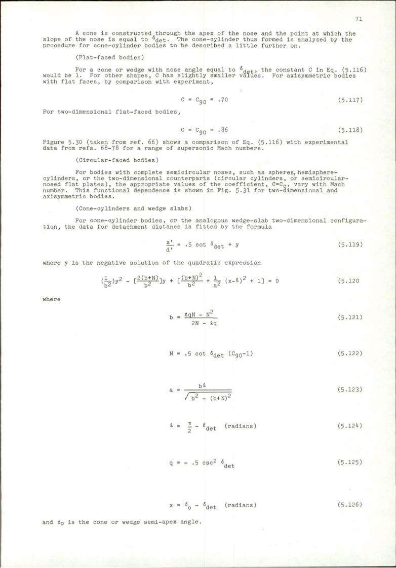
71
A cone is constructed through the apex of the nose and the point at which the slope of the nose Is equal to °det- The cone-cylinder thus formed is analyzed by the procedure for cone-cylinder bodies to be described a little further on.
(Flat-faced bodies)
For a cone or wedge with nose angle equal to g ^ , the constant C in Eq. (5-116) would be 1. For other shapes, C has slightly smaller values. For axisymmetric bodies with flat faces, by comparison with experiment,
C = C 9 Q = .70 (5.117)
For two-dimensional flat-faced bodies,
C = C9Q = .86 (5.118)
Figure 5-30 (taken from ref. 66) shows a comparison of Eq. (5-116) with experimental data from refs. 68-78 for a range of supersonic Mach numbers.
(Circular-faced bodies)
For bodies with complete semicircular noses, such as spheres, hemisphere-cylinders, or the two-dimensional counterparts (circular cylinders, or semicircular-nosed flat plates), the appropriate values of the coefficient, C=CC, vary with Mach number. This functional dependence is shown in Fig. 5-31 for two-dimensional and axisymmetric bodies.
(Cone-cylinders and wedge slabs)
For cone-cylinder bodies, or the analogous wedge-slab two-dimensional configuration, the data for detachment distance is fitted by the formula
il = .5 cot « d e t + y (5-119) d'
where y is the negative solution of the quadratic expression
( fey 2 - [ S ^ J y • 1 ^ ^ * K <*-*)2 m . o (5.120
where
b = ^ N - N2 ( 5 . 1 2 1 ) 2N - Iq
N = .5 c o t 6 d e t ( C 9 0 - l ) ( 5 . 1 2 2 )
a = b * ( 5 . 1 2 3 ) / b 2 - (b+N) 2
* = - - 6det (radians) (5.124)
.5 esc2 6 (5.125) det
x = 6o - 6det (radians) (5.126)
and 6Q Is the cone or wedge semi-apex angle.
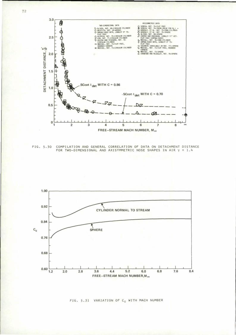
72
3.0
LU
u 2 < t -t/3
a t z UJ
I u < K LJJ
Q
0.5 I—
THO-01MENS10NAL M T * Cl DUKE". . REF. 68-ClRClR.AB. CYLINDER O GRIFFITH. REF. 69-WEDGES O UNPUBLISHED M T R , LANGLEY » • TS-
FLAT FACE C J ALPERIN, REF. 70-CIRCULAR CYLINDER 17 KIM. REF. 71-C1RCUUR CYLINDER V UCH1M UNO YASUHARA. REF. I ! -
CIRCULAR CYLINDER O MOECKEL, REF. 73-FLAT FACE,
ROUNDED CORNERS * MOECKEL. REF. 73-CIRCULAR CYLINDER
AXISYMMCTRIC MTA O 5EBRIN, REF. 74-FLAT FACE • SERBIN, REF. 74-THEOR.VALUE FOR H . - -D HEBERLE, ET AL , REF. 7S-C0ME-CYLIN0ER O HEBERLE, ET AL . REF. 75-SP1IERE i OLIVER. REF. 68-SPHERE a . COOPER ANO ROBINSON. LAMGLEY I t " HST-
FLAT FACE (UNPUBLISHED) C.MACCOLL. REF. 76-CONE-CYLIHOER ft UNPUBLISHED M T A , LANGLEY 9" TS-
FLAT FACE O SUGIHOIO (AVAILABLE IN REF. 77).SPHERE ^ ] MOECKEL. REF. 73-FLAT FACE. ROUNDED
CORNERS -q MOECKEL. REF. 73-SPHERE C, CRAWFORD AND McCAULEY. REF. 78-SPHERE
.5CcotSd e t WITH C = 0.86
.SCco t f i ^ , WITH C = 0.70
' - * - . - * * I L*2L
^?-%-o Q — 1 cm. & H ,
n r i i i i 1 1 • i i i • i • i i • • • • i • • • •—i i i i i i i — i i i i ' v — i 1 2 3 4 5 6 7 8
FREE-STREAM MACH NUMBER. M0
FIG. 5.30 COMPILATION AND GENERAL CORRELATION OF DATA ON DETACHMENT DISTANCE FOR TWO-DIMENSIONAL AND AXISYMMETRIC NOSE SHAPES IN AIR y = 1-4
1.00,
0.92 h
0.84
0.76
0.68
CYLINDER NORMAL TO STREAM
SPHERE
0.60 ' _L _ i _ _L j L 1.2 2.0 2.8 3.6 4.4 5.2 6.0
FREE-STREAM MACH NUMBER,Mc
6.8 7.6 8.4
FIG. 5.31 VARIATION OF Cc WITH MACH NUMBER
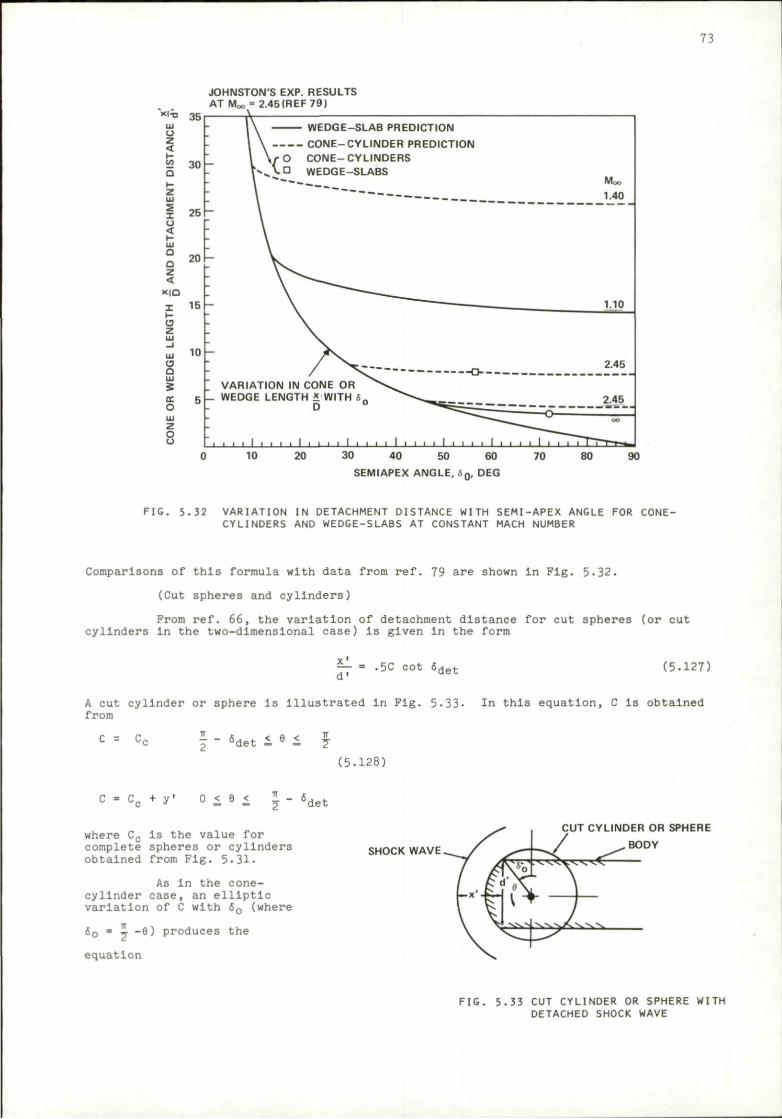
73
JOHNSTON'S EXP. RESULTS AT Moo" 2.45 (REF 79)
xiti 35 LU U Z < 52 30 a
z
LU
I o < I-LU
Q O z <
X | Q
C9 z
O LU
z 8
25
20
15 -
10
WEDGE-SLAB PREDICTION
VARIATION IN CONE OR WEDGE LENGTH * WITH 6
D
30 40 50
SEMIAPEX ANGLE, ,
FIG. 5.32 VARIATION IN DETACHMENT DISTANCE WITH SEMI-APEX ANGLE FOR CONE-CYLINDERS AND WEDGE-SLABS AT CONSTANT MACH NUMBER
Comparisons of this formula with data from ref. 79 are shown in Fig. 5-32.
(Cut spheres and cylinders)
Prom ref. 66, the variation of detachment distance for cut spheres (or cut cylinders In the two-dimensional case) Is given in the form
x' - = -5C cot 6det (5.127)
A cut cylinder or sphere is Illustrated In Fig. 5-33- In this equation, C Is obtained from
C = C, ^ - «,*»*• < e < >det - 7 (5.128)
cc + y' 0 < 6 < 1. Jdet
where Cc is the value for complete spheres or cylinders obtained from Fig. 5.31-
As in the cone-cylinder case, an elliptic variation of C with 60 (where
60 = i -6) produces the
equation
SHOCK WAVE
CUT CYLINDER OR SPHERE
BODY
FIG. 5.33 CUT CYLINDER OR SPHERE WITH DETACHED SHOCK WAVE
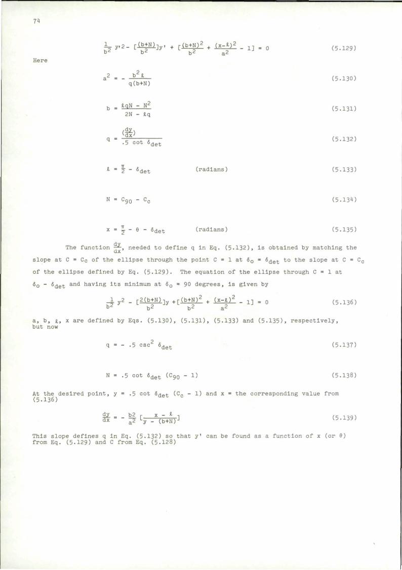
74
1 y.2_ [iJ|Hi]y. + [Ib±Nii + {x-*.)2 _ 13 . 0 (5.129) b^ b^ b2 a2
Here
2 a2 = - b * (5-130)
q(b+N)
b = W ~ N" (5.13D 2N - J,q
q = Z * . (5.132) •5 cot 6det
1 = 1 " 6det (radians) (5.133)
N = C90 - Cc (5.134)
x - j - 6 - 6det (radians) (5.135)
The function -*, needed to define q In Eq. (5-132), is obtained by matching the
slope at C = Cc of the ellipse through the point C = 1 at 60 = <5det to the slope at C = Cc
of the ellipse defined by Eq. (5.129). The equation of the ellipse through C = 1 at
60 - 6det an<* having its minimum at 60 = 90 degrees, is given by
1 y2 _ C2(b+Ni]y + [ ( b + ^ • iS=iii - 1] = 0 (5.136) b* b2 b2 a2
a, b, i , x are defined by Eqs. (5.130), (5.13D, (5-133) and (5.135), respectively, but now
q = - .5 esc2 6det (5.137)
N = .5 cot 6det (Cq0 - 1) (5.138)
At the desired point, y = .5 cot &JI~4- (C„ - 1) and x = the corresponding value from (5.136)
This slope defines q in Eq. (5.132) so that y' can be found as a function of x (or 9) from Eq. (5-129) and C from Eq. (5-128)
75
A comparison of predicted and measured shock detachment distances for cut spheres (attached to cylindrical afterbodies) Is shown in Pig. 5.34. The plot shows detachment distance measured by the parameter |> shown on the figure, which can be
related to the predicted values of £-1 through the relations d'
b = JLL + 1 D d' 2 tan 6 2 sin 9
0 < - 2 " 6det
b D
sin (* Met'
sin 6 * *
2 tan (| - 6det) 2 sin 6 | - 6det < 6 < 90°
5.5-2.3 Shape of detached shocks
(5.140)
The shape of the detached shock wave is determined In ref. 66 by a modification of Moeckel's method (ref. 80). The geometrical arrangement is shown in Fig. 5.35. The angle n, defining the control line is determined as a function of Mach number by correlating the results for known shock shapes. The functions for spheres and cylinders are shown in Fig. 5-36 along with functions used In other analyses.
0.32
< H LU
Q 0.08
0.04 -
— EXPERIMENT — PRESENT PREDICTION,
ELLIPTIC VARIATION OF C
PREDICTED KNEE AT 0 = 38.5°,
£ r = 0.158
O.DEGi
0 15 30 39 50 70 90
R P no
1.932 1.000 0.794 0.652 0.532 0.500
SHOCK
{Brl J L_L
10 20 30 40 50
a. DEG
60 70 80 90
F I G . 5 .34 PREDICTION OF RESULTS AT M» = 3 .55 FOR A SPHERE THAT IS EFFECTIVELY CUT CDIAMETER OF ACTUAL MODELS HELD CONSTANT AND RADIUS OF NOSE VARIED)
76
HYPERBOLIC SHOCK
SONIC POINT ON SHOCK
TsONIC LINE OF MOECKEL'S ANALYSIS 1 CONTROL LINE OF PRESENT ANALYSIS
BODY
FIG. 5 .35 GENERAL FEATURES OF THE METHOD OF MOECKEL ADOPTED IN PRESENT ANALYSIS
O LU Q
180
160
140
120
100
80
60
40
20
fl\ AT Mr
MAXIMUM TI —> = oo« FROM Cc ~
TANGENTIAL IJ-1
VARIATION OBTAINED IN PRESENT ANALYSIS (FROM AVERAGE VALUES, OF q)
1 2 3 4 5 6 7
FREE-STREAM MACH NUMBER, Mo
(a) SPHERE
[MAXIMUM P/3
ATMoo = «>< FROM C c^.
TANGENTIAL-?" TA
VARIATION OBTAINED IN PRESENT ANALYSIS (FROM AVERAGE VALUES OF T,)
1 2 3 4 5 6
FREE-STREAM MACH NUMBER, Mc
(b) CIRCULAR CYLINDER (TWO-DIMENSIONAL)
F I G . 5 .36 COMPARISON OF VARIATION OF n WITH MACH NUMBER OBTAINED IN PRESENT ANALYSIS WITH THOSE OBTAINED IN OTHER ANALYSES
77
With this point established, the shock shape Is given by
a i 6 d' )2 - (—) 2 (5.141)
The distances x and y are measured from the origin of the asymptote as shown in Fig. 5.35,
B= /M2-l; d' Is the diameter or width of the body at the point of tangency of the cone or wedge of incipient detachment.
The vertex of the shock is given by the formula (from Moeckel),
6 A 2 tan2 I" - 1 (j£ + ^ - a ) Xo
d1 2 ? e tan^ ea B / B 2 tan2 e.
(5.142) - 1 + tan n
where eg Is the shock wave angle that will Just give sonic flow behind the shock, x' Is the shock detachment distance determined previously for noses of various shapes.
Some comparisons with experiment are shown In Fig. 5.37 taken from ref. 66. In these plots, D is the diameter of the cylindrical body while F is the horizontal distance measured from the front of the flat-faced cylinder or the center of the hemlspherlcal-nosed body.
5.5.3 Supersonic flow field determination
5.5.3.1 Wing and pylon representation
With the shock shape established as indicated In the previous section, the supersonic flow field can now be obtained by application of linear theory to a body transformed to make Its shock wave match the more accurately determined location.
2.4
2.0 -
1.6 -
1.2
0.8
0.4
-0 .8 -0.4
O EXPERIMENT (RAINEY, 5" BLOWDOWN TUNNEL OF LANGLEY 9" TS)
— CONVERSION TO FLAT FACE OF PRESENT PREDICTION FOR HEMISPHERE
0.8 1.2
E D
(a) FLAT NOSE
1.6 2.0 2.4
2.0
1.6
1.2
0.8
0.4 -
0 - 0
LANGLEY 9" TS) PRESENT PREDICTION
8 -0.4 0 4 8 1.2 1.6
(b) HEMISPHERICAL NOSE
2.8
EXPERIMENT (RAINEY, 5" ° BLOWDOWN TUNNEL OF
2.0 2.4 2.8
FIG. 5.37 PREDICTION OF SHOCK SHAPE AND LOCATION FOR AXISYMMETRIC NOSES AT M„ = 3.55
78
The linear employed by Fernandes for a wing or pylon in a crossflow uses the "Mach box" method of Zartarian (ref. 81). The perturbation velocity potential due to a source distribution is given by
ty (x,y) - i f f w(x1,y1)dx1dy1
Mach forecone
y (x-x. (5.143.)
>' 62(y-y1)'
w(X]_,y-,) Is the distribution of downwash velocity in the region of the Mach forecone ahead of the point x, y.
'Kljyi) i
boxes whose diagonals are Mach lines, with w constant, the integration can be carried out and the velocity potential at x.y can be found for a Mach box centered at any position in the forecone. By shaping the rectangles according to Mach lines, the velocity potential function becomes independent of Mach number. The wing planform and the adjacent disturbed region of the flow field are subdivided into Mach boxes as shown In Pig. 5-38 for two sample configurations.
The numbers in the boxes designate the order in which they are treated. Since w is prescribed in box number 1 by the downwash distribution, and with no other boxes In its forecone, ty can be obtained explicitly. In boxes on the wing, the downwash Is known. In boxes in the "diaphragm" region, the pressure coefficient is zero since the diaphragm is a region of unknown downwash which deflects to balance the pressure.
The pressure coefficient, by linear theory, is proportional to the perturbation velocity in the streamwise direction
r 2u 2_ 3± 3x (5.144)
By differentiation of the velocity potential for a Mach box and summation over all Mach boxes. In the forecone of a given point, the perturbation velocities can be determined.
11 R(l.J) (5.145)
in Mach forecone
R ( i , j ) i s c a l l e d the aerodynamic Inf luence c o e f f i c i e n t , and i s a funct ion of the l o c a t i o n of Mach box j with r e s p e c t to the po in t a t 1. R(1 , J ) i s the d e r i v a t i v e of the v e l o c i t y p o t e n t i a l due to the J t h Mach box for u n i t downwash.
R(1 ,J ) - -TT
y i cos -lypZlL
fi ( « l - * j )
( 5 . 1 4 6 )
MACH LINES ACTUAL WING MACH BOX WING
SUPERSONIC LEADING
EDGE
15 10
20
25
r " i j ' l l ' • 1 2 l \ DIAPHI IZsJjTjj 7T12T7 { j} |£ [7s 26]~22| 18 • 13 8 j 4 '
l ^29T27T23Tf9 ' V
J Tseisa--{X/0)
24'
c L
7
fct h\ SUBSONIC LEADING
EDGE
| _ J _ 3 j _ A 3 j \ DIAPHRAGM
23 19 15VlOl 5 l \
{XI0)
FIG. 5.38 ORDER OF COMPUTING MACH BOX PROPERTIES CU OR W) ON WING AND DIAPHRAGM
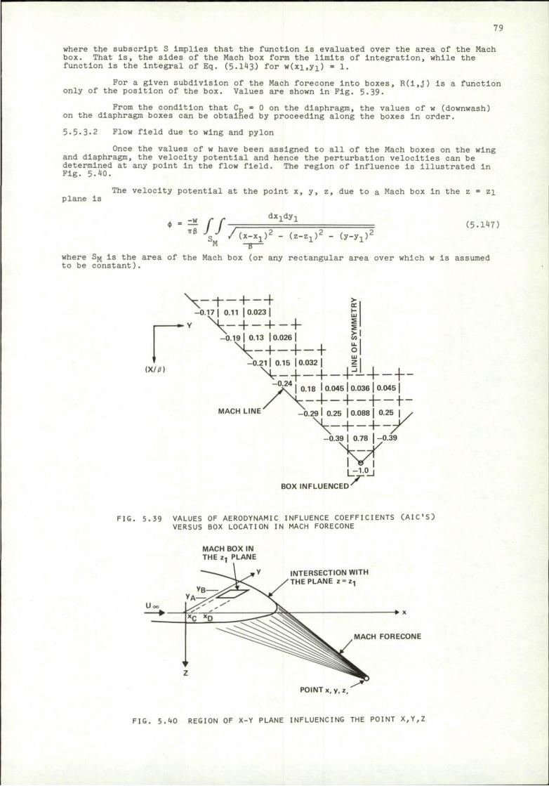
79
where the subscript S implies that the function Is evaluated over the area of the Mach box. That Is, the sides of the Mach box form the limits of integration, while the function Is the Integral of Eq. (5.143) for w(xi,y;i_) = 1.
For a given subdivision of the Mach forecone Into boxes, R(1,J) is a function only of the position of the box. Values are shown In Fig. 5.39.
Prom the condition that Cp = 0 on the diaphragm, the values of w (downwash) on the diaphragm boxes can be obtained by proceeding along the boxes In order.
5.5-3-2 Flow field due to wing and pylon
Once the values of w have been assigned to all of the Mach boxes on the wing and diaphragm, the velocity potential and hence the perturbation velocities can be determined at any point In the flow field. The region of Influence is Illustrated In Fig. 5-40.
plane is The velocity potential at the point x, y, z, due to a Mach box in the z = zi
nff dx-Ldy-L
/(x-x, ) 2 - (z-z,)2 (5-147)
(y-yj)'
where SJ,J Is the area of the Mach box (or any rectangular area over which w is assumed to be constant).
W t )
> QC r~ LU
I LL o LU z
\--h--h-H--0.17 | 0.11 | 0.023 |
-0.19 | 0.13 | 0.026 |
\-4—4—+ -0.21 | 0.15 | 0.032 I
^ r \ 4 J 0.18 I 0.045 | 0.036 | 0.045 |
MACH LINE _0.29 I 0.25 | 0.088 | 0.25 |
-0.39 0.78 -0.39
l_-J.°_J BOX INFLUENCED
FIG. 5.39 VALUES OF AERODYNAMIC INFLUENCE COEFFICIENTS CAIC'S) VERSUS BOX LOCATION IN MACH FORECONE
MACH BOX IN THE z-, PLANE
INTERSECTION WITH THE PLANE z = z.
*• x
MACH FORECONE
POINT x, y, z.
FIG, 5.40 REGION OF X-Y PLANE INFLUENCING THE POINT X,Y,Z
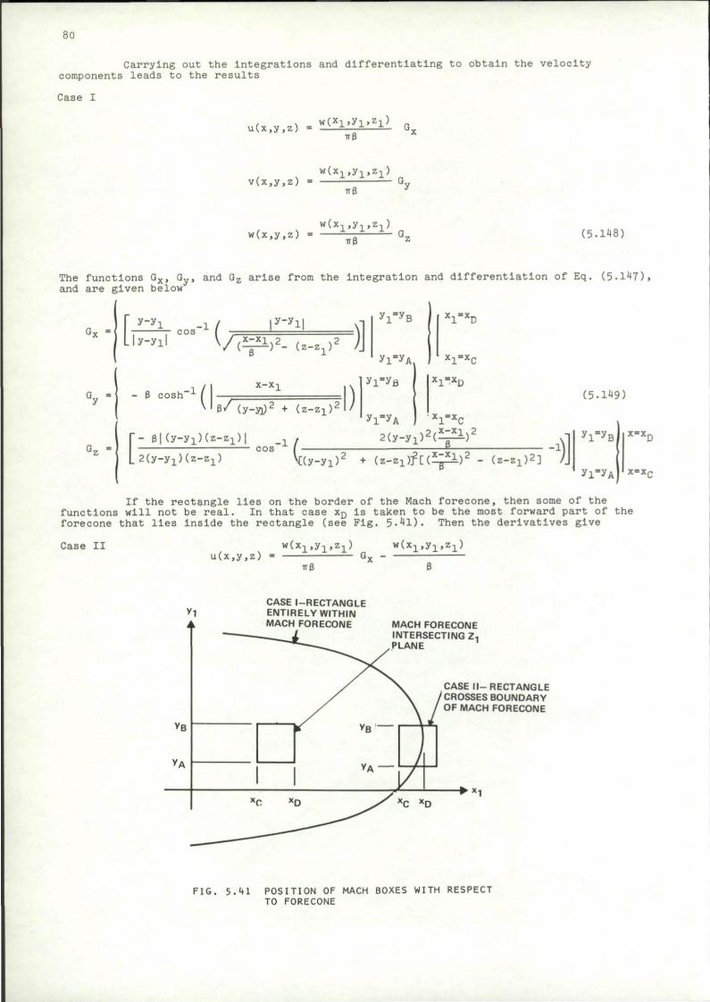
80
Carrying out the Integrations and differentiating to obtain the velocity components leads to the results
Case I
, , W(x1,y1,z1) u(x,y,z) = ±—±—±— G
v ( . x 1 , y 1 , z 1 ) v(x,y,z) = G
w(x.y.z) = — G2 (5.148)
The functions Gx, Gy, and Gz arise from the integration and differentiation of Eq. (5-147). and are given below
- f" 1 . ^ f , 'y"yi1 \ Lly-yil V / ( ^ i ) 2 - (z-Zl)
2 /
y,-y I ' B
y i ^ A .
' 1 AD
l l " A C
G y • : o s h _ 1 (
X-X- i
)
y i = y B
y ! - y A
X]_-x u
6 / ( y - y i ) 2 + ( z - Z l ) 2
r - e | (y-yi ) (z- 2 l ) | ^ ^ , 2(y-yi)*(. _ xll y i
L2(y-yi)(z-zi) ^(y-yi)2 + ( z - Z l ) f [ ( ^ i ) 2 - (z-zx)2] /J
( 5 . 1 ^ 9 )
• X ^ X g
t 2 l ^ z x l . 2
_ i :-> T
y . = y .
y i = y A
x=xr
x = x r
If the rectangle lies on the border of the Mach forecone, then some of the functions will not be real. In that case xD is taken to be the most forward part of the forecone that lies inside the rectangle (see Fig. 5-41). Then the derivatives give
Case II w(x1,y1,z1) w(x1,y1,z1) u(x,y,z) = Gx -
CASE l-RECTANGLE ENTIRELY WITHIN MACH FORECONE MACH FORECONE
INTERSECTING Z PLANE
CASE II-RECTANGLE CROSSES BOUNDARY OF MACH FORECONE
• * 1
FIG. 5.41 POSITION OF MACH BOXES WITH RESPECT TO FORECONE
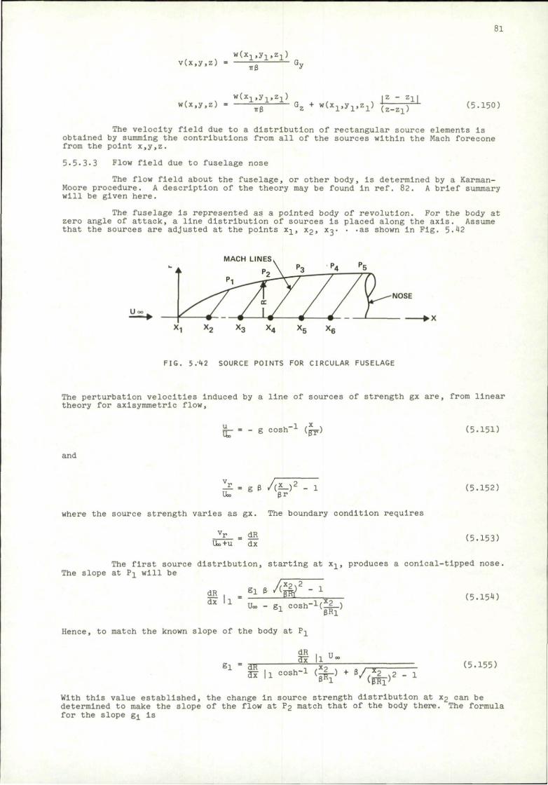
81
w(x1,y1,z1) v(x.y.z) Gj
w(x,y,z) w(x1,y1,z1) z - Z1J
*B I, + w(x1.y1.z1) f - - - - j (5.150)
The velocity field due to a distribution of rectangular source elements is obtained by summing the contributions from all of the sources within the Mach forecone from the point x,y,z.
5.5.3.3 Flow field due to fuselage nose
The flow field about the fuselage, or other body, is determined by a Karman-Moore procedure. A description of the theory may be found in ref. 82. A brief summary will be given here.
The fuselage Is represented as a pointed body of revolution. For the body at zero angle of attack, a line distribution of sources is placed along the axis. Assume that the sources are adjusted at the points x-±, x2, x^. • -as shown in Fig. 5.42
MACH LINES
NOSE
• X
FIG. 5/42 SOURCE POINTS FOR CIRCULAR FUSELAGE
The perturbation velocities Induced by a line of sources of strength gx are, from linear theory for axisymmetric flow.
u v-1 /X \ - g COSh * (pr) (5.15D
and
JL. = g B /(^_) 2 - 1 U» Br
(5.152)
where the source strength varies as gx. The boundary condition requires
vr _ dR U»+u dx (5.153)
The first source distribution, starting at xj_, produces a conical-tipped nose. The slope at ? i will be
dR . 81 B / Q 2 - 1
dx ll Uo. g-, cosh-^^iL-) 1 BRl
(5.154)
Hence, to match the known slope of the body at P-j_
EI • an"
dR . „ 3x ll U|
»i l~-Mft)*./Sc5-r (5.155)
With this value established, the change in source strength distribution at x2 can be determined to make the slope of the flow at P2 match that of the body there. The formula for the slope g^ is
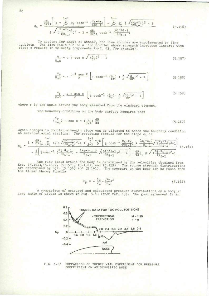
82
E l
dR 3x it1* IS gl coah"1 ' imS'j
1-1
B 71 zA^ii/^^ni
• X i ^ ) 2 . x + g BR I - I d x 1 ! cosh -1 , X j - « i - l ,
( PRi- i }
(5.156)
To account for angle of attack, the line sources are supplemented by line doublets. The flow field due to a line doublet whose strength Increases linearly with slope c results in velocity components (ref. 83, for example).
U«<* c B c o s 6 ra
w (5.157)
"r U„a
cos [ B cosh" 1 ( | p ) * ? / ' IF ) 2 - * ] (5.158)
_Ii , ^ _ s i ^ [B cosh.i (|F)_ p ^ F T T ] (5.159)
where e Is the angle around the body measured from the windward element,
The boundary condition on the body surface requires that
(TT—-) - cos 6 UooOt
/ u •. dR Ua,a dx (5.160)
Again changes In doublet strength slope can be adjusted to match the boundary condition at selected axial stations. The resulting formula for the slope c± is
1-1 i-l
(5.161)
The flow field around the body is determined by the velocities obtained from Eqs. (5.151),(5.152), (5-157), (5-158), and (5-159). The source strength distributions are determined by Eqs. (5.156) and (5.161). The pressure on the body can be found from the linear theory formula
C = _ 2u ,vrs2 CP u„-(
u-) (5-162)
A comparison of measured and calculated pressure distributions on a body at zero angle of attack Is shown in Fig. 5.43 (from ref. 63). The good agreement is an
TUNNEL DATA FOR TWO ROLL POSITIONS
o THEORETICAL PREDICTION
M = 1.25 a =0
FIG. 5.43 COMPARISON OF THEORY WITH EXPERIMENT FOR PRESSURE COEFFICIENT ON AXISYMMETRIC NOSE
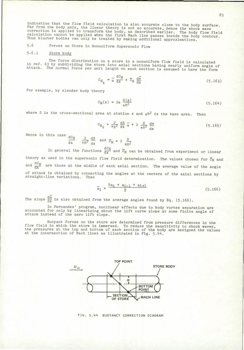
83
Indication that the flow field calculation is also accurate close to the body surface Far from the body axis, the linear theory is not so accurate, hence the shock wave correction is applied to transform the body, as described earlier. The body flow field calculation cannot be applied when the first Mach line passes Inside the body contour Thus blunter bodies can only be treated by making additional approximations.
5.6 Forces on Store in Nonuniform Supersonic Flow
5-6,1 Store body
,- jr-,Twe f o r c e distribution on a store in a nonuniform flow field is calculated ?. , " ,L y subdlvlding the store Into axial sections having nearly uniform angle of attack. The normal force per unit length on each section is assumed to have the form
- dCN _
« air + Cx 35 (5-163)
For example, by slender body theory
CN(x) - 2a ^ f ^ TTR2
where S is the cross-sectional area at station x and VR2 is the base area.
(5.164)
Then
- 2 d s - 4. o
h ^ P 7 53T a "* TTR' dc* dx
Hence In this case d C ^ dx
- ^ ^ and TT„ = 2 S_ ^ dx ^ 2
W R2
In general the functions dCN
(5.165)
and Cfl can be obtained from experiment or linear
theory as used In the supersonic flow field determination. The values chosen for CN and
a n d mT5r are t h o s e at the middle of each axial section. The average value of the angle
of attack Is obtained by connecting the angles at the centers of the axial sections by straight-line variations. Then
6ai + ai_i + ai+1 (5-166)
The slope ^- Is also obtained from the average angles found by Eq. (5.166).
In Fernandes' program, nonlinear effects due to body vortex separation are accounted for only by linearizing about the lift curve slope at some finite angle of attack Instead of the zero lift slope.
Buoyant forces on the store are determined from pressure differences In the flow field in which the store is Immersed. To reduce the sensitivity to shock waves, the pressures at the top and bottom of each section of the body are assigned the values at the Intersection of Mach lines as Illustrated In Fig. 5.44.
TOP POINT STORE BODY
MACH LINE
FIG. 5.44 BUOYANCY CORRECTION DIAGRAM
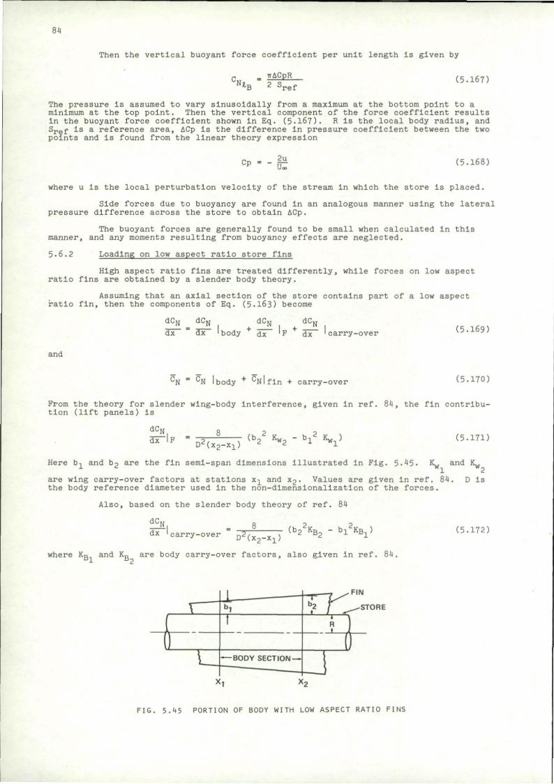
84
Then the vertical buoyant force coefficient per unit length is given by
'N* TrACpR
B 2 S ref (5.167)
The pressure is assumed to vary sinusoidally from a maximum at the bottom point to a minimum at the top point. Then the vertical component of the force coefficient results in the buoyant force coefficient shown In Eq. (5.167). R is the local body radius, and Srgf Is a reference area, ACp is the difference in pressure coefficient between the two points and is found from the linear theory expression
• --e (5.168)
where u is the local perturbation velocity of the stream In which the store is placed.
Side forces due to buoyancy are found in an analogous manner using the lateral pressure difference across the store to obtain ACp.
The buoyant forces are generally found to be small when calculated In this manner, and any moments resulting from buoyancy effects are neglected.
5.6.2 Loading on low aspect ratio store fins
High aspect ratio fins are treated differently, while forces on low aspect ratio fins are obtained by a slender body theory.
Assuming that an axial section of the store contains part of a low aspect ratio fin, then the components of Eq. (5.163) become
dCN
dT" dC
I body
dC>
'F dx carry-over (5.169)
and
CN = CN I body + cNlfln + carry-over (5.170)
Prom the theory for slender wing-body Interference, given In ref. 84, the fin contribution (lift panels) Is
dCN
dx~lF - 3 — " (b?2 Kw , "
b i 2 Kw,) D2(x2-x1)
2 w2 1 wi (5.17D
Here b- and b 2 are the fin semi-span dimensions illustrated in Fig. 5-45. 1^ and K ,
are wing carry-over factors at stations x_ and x2. Values are given in ref. 84. D Is the body reference diameter used In the non-dlmenslonallzation of the forces.
Also, based on the slender body theory of ref. 84
dCj
dx carry-over D2( x 2 _ X l )
(b22KB2 - b 1
2K B l) (5.172)
where KR and Kn are body carry-over factors, also given in ref. 84, Dl D2
FIG. 5.45 PORTION OF BODY WITH LOW ASPECT RATIO FINS
85
The same expression for slender wind lift gives, for two fins.
CN fin + body " ^ 2 2 * v 2 * H ^ - (5-173) carry-over
The fin is truncated after the axial station of maximum span.
5-6-3 Loading on high aspect ratio store fins
For a high aspect ratio wing, the force on two wing panels (body removed) Is obtained by linear theory. The coefficient per unit angle of attack is designated CN . The Incremental loading on the body due to wing carry-over is a
dCN , KBCN„ — = " " a (c T7in
dx ' c a r r y - o v e r . . . J - J - I ^ J ( X P - X T ) and
KwCN CNlfin + carry-over ,v v , da (5.175)
(x2"xl) ax Cfl is determined by linear theory as in the Mach box method, for example. By a similar
process TcTaT Is calculated by linear theory as the normal force coefficient for unit dx da
value of (QTX)• That Is, a varies linearly across the chord of the wing, being zero
at the center of the interval (x2-x1).
In Fernandes1 procedure, the forces on the store due to the Interference flow field are added to the forces due to store angle of attack and motion. This linear superposition works well unless the combined angles are large.
5.7 Trajectory Calculation In Supersonic Flow
The various steps can be carried out by the computer codes developed in refs. 62, 63, and 64. The flow field and force calculations can then be combined with a trajectory program to provide the store motion. The trajectory program part of the store separation code of ref. 56 might be adapted to this purpose.
5.8 Transonic Flow Field
Transonic flow field calculations are not yet as fully developed as the subsonic and supersonic cases. Two methods could be employed to approximate the transonic flow. One approach Is based on slender body theory; while the other makes use of transonic similarity laws.
The slender body theory philosophy Is based on the linearized expression for velocity potential
Pxx T fyy + tyzz = 0 (5-176)
For a slender body ty is small compared with the other terms and the flow must then satisfy the Laplace equation at each cross section. Since the Mach number Is no longer a parameter, formulas based on slender body theory can be applied at transonic speeds. The flow around wings and pylons, however, does not fit Into this category.
Transonic theories are primarily directed toward the prediction of forces in uniform flows. Transonic similarity laws can be applied, however, to adapt subsonic or supersonic theories to the transonic problem.
One possible approach would use slender body theory to obtain the flow field about bodies and similarity law to find the flow field about wings and pylons. Then the forces on the store could be determined from slender body theory; or. If the store is not sufficiently slender, from transonic similarity.
From the transonic similarity laws, which may be found in ref. 85, for example, a given configuration is transformed according to the relations
B'AR'= BAR (5-177)
86
Here (
B' _ B (r>T
,)1/3 (ft)1/3
)' denotes the transformed variable.
B • A l - M2! oo
AR • aspect ratio
x = angle of attack or thickness ratio
r = (Y+I)M£
Y = ratio of specific heats • 1.4 for air
(5.178a)
The upwash and sidewash angles in the transformed coordinates will scale with T. That is
ll T 1
F = T~ \] (5"l78b)
and
Vl . 11 I (5-179) U' T u
In order to determine a transonic flow field, a supersonic or subsonic solution is first obtained then transformed to the desired transonic flow. For example, suppose the flow field is desired at Mi = .9 about a wing at angle of attack a. Then the solution Is obtained for a subsonic case, say M,,, = .7, below the critical speed. The methods of Section 5-1 can be used for that purpose. Then B1 = /TT^ and B = /.51a Also r1 = 1.944 and r = 1.176. Hence, from Eq. (5-177) AR = AR' x fil = .61 AR' and
from Eq. (5-178)
r ,3
T - T« x i— X _S_ = .37 T" r 6-3
Then the subsonic solution for a configuration whose aspect ratio is .61 times the desired transonic configuration and whose thickness and angle of attack are .37 times the corresponding transonic case gives the required similar flow. The flow angle at corresponding points scale with I_p and the points themselves scale with B. That Is
T
ZL - fi- I (5-180) x- B' x
and
SL = fi- 2_ (5.181) x' B' x'
5.9 Forces on Store In Transonic Plow
The forces on the store in the transonic flow field can be calculated by slender body theory following procedures similar to those in Section 5.6.1 and 5-6.2. Transonic similarity laws can be applied also. From ref. 85
(xl)2/3 c F " I- W . CF C * ' . /0 , B'AR'J (5-182)
l " . X / - > (rl.l ll/3 (* r / J (r'x')-
(il)2/3 C- " TkyS Cm C 7 r T T V 3 ' B'AR'] (5"183)
where Cp and Cp represent force coefficients, and Cm and C j represent moment coefficients,
5.10 Control of Trajectories
Accurate procedures for calculating store trajectories can be used to investigate the safety of aircraft clearance and to provide predictions of impact points for fire control information. However, another means of achieving these ends would be to adjust the ejection process so as to keep the store on a ballistic trajectory.
87
In the pitch plane, the trajectory might be controlled by using a two-piston ejector, with the ejection forces adjusted to Impart Just the right amount of initial linear and angular velocity to the store. Then the store would emerge from the aircraft flow field nearly on a ballistic trajectory; that Is, with very small angle of attack and pitch rate. The store would then continue on a predictable ballistic trajectory to Impact.
Such a controlled launch would have several advantages over an ejection with larger pitch amplitudes. For one thing, the smooth trajectory would almost certainly result in an Improved safety margin with respect to avoidance of store-aircraft collision. It would also broaden the envelope of safe launch conditions to nearly fill the entire range of aircraft flight. Furthermore, Impact points would be relatively insensitive to variations in ejector cartridge Impulse or departures of other ejection parameters frora their nominal values. The low sensitivity would result from the fact that several degrees of maximum store angle of attack would have little effect on the trajectory of a stable store. A controlled ejection could also keep store angles of attack low enough to avoid nonlinear instabilities, such as catastrophic yaw.
The investigations reported in ref. 17 indicate that even in severe cases it Is possible to achieve initial angular rates that would keep the store on a ballistic trajectory. In fact, by applying initial yawing moments as well as pitching moments, the trajectory can be corrected in both planes as might be required for launch from a wing station Into a lateral flow field. A complete description of the experiments can be found in ref. 86.
In general, the distribution of ejection forces required to Insert the store on a ballistic trajectory is a function of the store-aircraft geometry and the flight conditions. Consequently, the ejection mechanism should be adjustable in flight to produce the desired store insertion characteristics. Several methods have been proposed for mechanizing the adjustment.
In ref. 17 an adjustable ejection system Is pictured with four pistons capable of applying both pitch and yaw corrections. The adjustment is accomplished by controlling the time over which high pressure is applied to each piston. A relief valve on each piston can be opened to cut the Impulse at that particular ejection foot. The timing of the valves. In turn, would be set from the fire control computer which would take account of the store location and flight conditions.
Several mechanisms have been constructed with two-piston ejectors in which the relative distribution of gas pressure to the pistons is controlled by an adjustable orifice. The orifice turns like a stopcock from full open to closed, letting proportionate amounts of high-pressure gas (from a cartridge) reach the controlled piston. In order to permit in-flight adjustment, it would be necessary to set the orifice opening via an output from the fire control computer.
It Is also possible to adjust the length of stroke of the pistons, and a device for accomplishing this has been constructed at the Naval Weapons Center, China Lake. This device uses auxiliary chambers with a hydraulic force transfer system. The volumes of the auxiliary chambers are adjustable so that portions of the hydraulic fluid can be directed to the piston or the auxiliary chamber. If all of the fluid Is directed to the piston. It is driven to its full extension. If the auxiliary chamber is partially open, then some of the fluid will not go to the ejection piston, and its stroke will be correspondingly reduced. As in the other systems, an in-flight adjustment of the auxiliary chamber volume could be set by the fire-control computer.
6. WIND TUNNEL TEST TECHNIQUES
6.1 Introduction
Three types of wind tunnel test are in use for determining store separation trajectories. In general, only the part of the store's flight in the vicinity of the aircraft is Investigated. Once the store leaves the effective region of Influence of the launch aircraft, it is simply an aerodynamic shape In a uniform flow whose motion can be determined by conventional means If the angle of attack is not excessive.
One type of test, obviously, is to perform a simulated drop in the wind tunnel. The scale is usually rather small, and compressibility effects cannot be correctly simulated because gravitational acceleration is fixed and dictates the time scale once the length scale has been chosen.
Another test method is the "captive trajectory" technique in which the store model is mounted on a balance and placed in its launch position near a model of the launch aircraft. The forces and moments on the store are measured. Then a computer calculates the motion of the store during a short time Interval taking account of the measured aerodynamic loads, the gravitational force, and damping forces. The store Is then moved to the next predicted location where the process Is repeated. Modern computers are fast enough to carry out a complete trajectory in a few seconds.
A third commonly used technique Is the "grid data bank" procedure. Here the aircraft flow field is surveyed using the store model as a probe, at every location the forces on the store due to its angle of attack and the aircraft flow field are measured
and stored In a computer memory. Then a trajectory can be computed for arbitrary initial conditions using Interpolations of the data to determine the forces at arbitrary locations. Gravitational and damping forces must be added in the trajectory program. In most cases, the forces due to aircraft flow field and store angle of attack can be linearly superimposed so that during the flow survey the store can be maintained at zero angle of attack. The store static and dynamic characteristics then are measured only once In a uniform stream.
A variation of the captive trajectory technique uses a flow angularity probe rather than a store model. The probe measures the flow field In the region that would be occupied by the store axis. Based on the survey data, a computer calculates the forces on a store and predicts an increment of its motion. The probe is then moved to the new location where the process is repeated until the trajectory Is traced out. Although cumbersome In some ways, this technique has the advantage of requiring only that a small probe be placed In the flow field, so that interference between the probe support and the aircraft model can be avoided.
6.2 Dynamic Drop
6.2.1 Scaling laws
6.2.1.1 Scaling problem
A simple direct technique for obtaining trajectory data is the ejection of a scale model in a wind tunnel. Special equipment Is required to eject the model In addition to high-speed photography, preferably capable of recording both pitch and yaw motions. Descriptions of tests of this type may be found in refs. 87-91. Since an airplane model is required in addition to the store, the scale of the test Is usually quite small. Consequently, scaling laws are of some significance and will be briefly reviewed here.
Assume that subscript ( )f refers to the full-scale condition and ( ) m denotes the wind tunnel model. The objective Is to obtain a trajectory in the wind tunnel which is in exact proportion to the full-scale case. That Is, the store model will trace the same path with respect to the airplane and will assume identical angular orientations.
6.2.1.2 Length
Define the length scale, then, by
Lf = NLm (6.1) -if = IHU„ i m
6.2.1.3 Time and velocity
In the absence of aerodynamic forces, the store will accelerate at the gravitational rate. To make the displacement of the model scale in the same manner as Its own length, the time will scale according to
bn i tf = (6-2)
and the velocity scale will be
^ = i - (6.3) vf /5
6.2.1.4 Air temperature
In order to correctly simulate compressibility effects, the Mach number must be matched
Mm = Mf (6.4)
Hence the velocity of sound is constrained as follows
(v m )
f™. = [V - 1_ (6.5)
Since, for a perfect gas the velocity of sound Is proportional to the square root of the absolute temperature
89
In most supersonic wind tunnels, this requirement cannot be realized. The model is so small that the air would condense. The consequences will be discussed later.
6.2.1.5 Weight scale
To make aerodynamic forces, F, scale In proportion to force of gravity,
w F — - -B- tt. 71 wf - P f (6-7)
The aerodynamic forces, in turn, are proportional to vehicle area and stream dynamic pressure. Hence, for a properly scaled test
*— = T T — (6.8) w f N3 Pf
where p f Is the density of the air In the free flight environment, and p m is the density of the air in the wind tunnel test section.
If Mach number Is matched, even if the wind tunnel velocity is not properly scaled, then the required weight scale becomes
"f ?P? (6-9)
where p^ and p m are the static pressures in free flight and the wind tunnel, respectively, This result is a consequence of the fact that dynamic pressure is related to static pressure in compressible flow of a perfect gas by
q = \ M2 p (6.10)
Y being the ratio of specific heats.
6.2.1.6 Moment of Inertia
In order to make the model turn through the same angle at the same point on the trajectory as the full-scale vehicle, the moments of Inertia must be related by
Im 1 Pm ,/„,
TF=JJ4?? (6-n)
By comparison with the weight scale from Eq. (6.9) the radii of gyration will have the ratio
\rr\ < 6 - 1 2 > 6.2.1.7 Aerodynamic damping
In order to properly scale the aerodynamic damping, the velocity of the stream should scale in the same ratio as the trajectory velocities as given by Eq. (6.3)- If the Mach numbers are matched, the wind tunnel stream will have too high a velocity, Um, and hence the model store will not have the correct damping.
6.2.1.8 Induced angle of attack
The supersonic wind tunnel with its Incorrect velocity will also have the wrong induced angle of attack.
6.2.1.9 Choice of scaling laws
Unless the tunnel is so large that nearly full-scale models can be tested, it is not possible to match all non-dimensional parameters. It is possible, however, to choose which parameter will not be properly scaled. The following table shows three sets of scaling laws.
90
Scaling Laws
Parameter I II III
Incorrect Incorrect Incorrect free-stream velocity Mach number gravity
bn
HB L_ L_ i [It *r /N /N N u m
!m 1_ 1_ Urn Vf 4% / S Uf
um /Tm 1_ Um
°? ^ f /rT Uf
w,
1 N
i _ •N
1_
tm Tf
1 N2
1
Pm
Pf
Pm
Pf
m 1 Pm i ra 1 Km
Incorrect Mach
1 N
1 /N
1
/&
1
1
N3
1
N5
1
number
Pm Pf
pm Pf
1m
1 Pn
M 3 p.
in i_ En l_ !JH i_ PH Jf N1* p f N5 Pf N5 Pf
Mf
The heavy-model scaling of set I produces a trajectory nearly geometrically similar to the free-flight trajectory and is generally preferred in supersonic tests unless the store acquires a large vertical velocity. In that case, the induced angle of attack will be too small In the model test and a noticeable, and usually unconserva-tlve, discrepancy in the trajectory may result.
Set II Is satisfactory at low speeds when Mach number is not a significant parameter. It is not reliable at supersonic speeds, however.
In set III the aerodynamic accelerations acting on the model would be different from the full scale, but gravity will not oblige by changing in the same ratio. Nevertheless, this set of scaling laws is appropriate for cases in which a substantial vertical ejection velocity is initially applied to the store so that the displacement due to gravity is not significant in the vicinity of the airplane. Corrections may be possible. The measured vertical displacement can be corrected to account for the discrepancy in gravity. Also, It is technically possible to adjust gravity by applying a suitable magnetic field (see ref. 92). It is also conceivable that the launch airplane might be moved vertically during the drop test in order to correct the relative displacement.
6.2.2 Comparison with flight test
A comparison of wind tunnel and flight test releases of an empty rocket pod is shown in Pig. 6.1 taken from ref. 93- Although the camera positions were different, it is apparent that the wind tunnel test gave a good representation of the store trajectory. Comparisons of vertical position and pitch angle for a fln-stablllzed bomb are shown in Fig. 6.2 taken from ref. 88.
In the dynamic drop test technique, one of the most difficult problems Is the calibration of the ejector system to cause it to provide the desired initial conditions. Eventually it must be calibrated by direct measurement of the Initial linear and angular velocity imparted to stores under actual wind-on conditions.
6.2.3 Data reduction
The dynamic drop data appears In the form of photographic coverage of the trajectory from high-speed movie film. Reading the film is a tedious process, and accuracy Is limited. Procedures have been developed which speed the process and improve accuracy.
The method reported in ref. 94 projects the photographic data on a television picture of a model of the store. The model orientation Is adjusted to match the
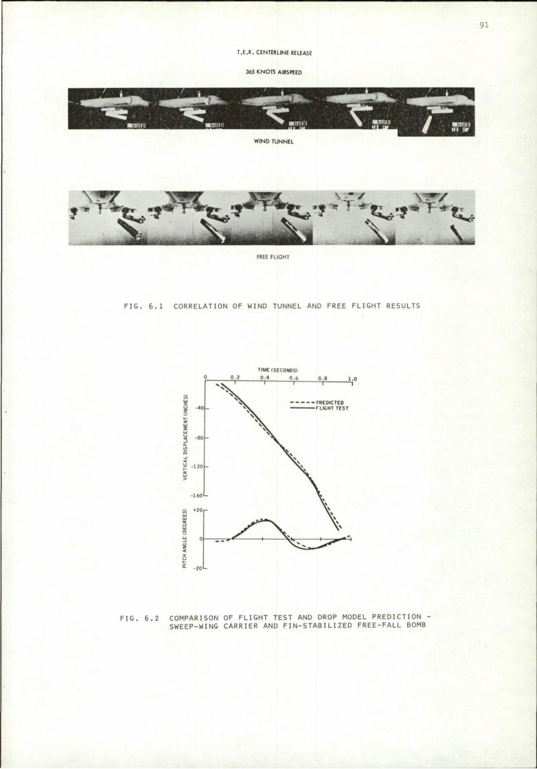
91
T.E.R. CENTERLINE RELEASE
36S KNOTS AIRSPEED
WIND TUNNEL
FREE FLIGHT
FIG. 6.1 CORRELATION OF WIND TUNNEL AND FREE FLIGHT RESULTS
TIME (SECONDS)
FIG. 6.2 COMPARISON OF FLIGHT TEST AND DROP MODEL PREDICTION -SWEEP-WING CARRIER AND FIN-STABILIZED FREE-FALL BOMB
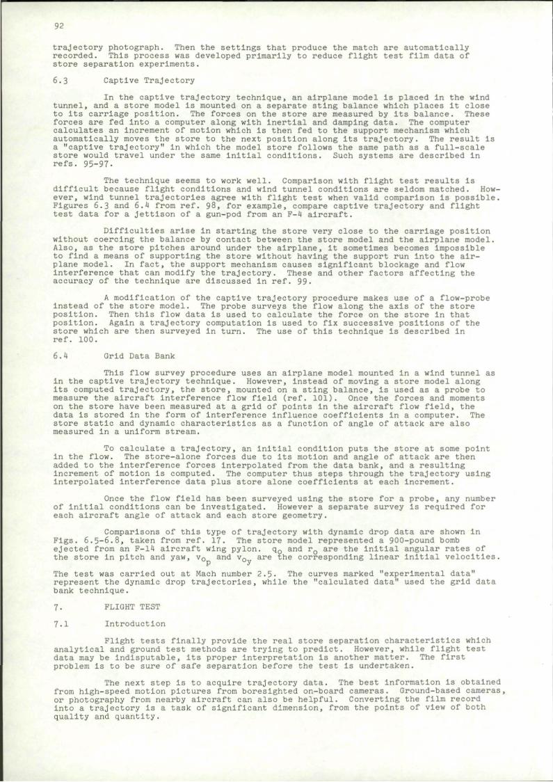
92
trajectory photograph. Then the settings that produce the match are automatically recorded. This process was developed primarily to reduce flight test film data of store separation experiments.
6.3 Captive Trajectory
In the captive trajectory technique, an airplane model Is placed in the wind tunnel, and a store model is mounted on a separate sting balance which places it close to its carriage position. The forces on the store are measured by its balance. These forces are fed into a computer along with Inertial and damping data. The computer calculates an increment of motion which Is then fed to the support mechanism which automatically moves the store to the next position along its trajectory. The result Is a "captive trajectory" in which the model store follows the same path as a full-scale store would travel under the same initial conditions. Such systems are described In refs. 95-97-
The technique seems to work well. Comparison with flight test results is difficult because flight conditions and wind tunnel conditions are seldom matched. However, wind tunnel trajectories agree with flight test when valid comparison Is possible. Figures 6.3 and 6.4 from ref. 98, for example, compare captive trajectory and flight test data for a jettison of a gun-pod from an F-4 aircraft.
Difficulties arise In starting the store very close to the carriage position without coercing the balance by contact between the store model and the airplane model. Also, as the store pitches around under the airplane. It sometimes becomes impossible to find a means of supporting the store without having the support run into the airplane model. In fact, the support mechanism causes significant blockage and flow interference that can modify the trajectory. These and other factors affecting the accuracy of the technique are discussed In ref. 99-
A modification of the captive trajectory procedure makes use of a flow-probe Instead of the store model. The probe surveys the flow along the axis of the store position. Then this flow data is used to calculate the force on the store in that position. Again a trajectory computation is used to fix successive positions of the store which are then surveyed in turn. The use of this technique is described in ref. 100.
6.4 Grid Data Bank
This flow survey procedure uses an airplane model mounted In a wind tunnel as in the captive trajectory technique. However, Instead of moving a store model along Its computed trajectory, the store, mounted on a sting balance, is used as a probe to measure the aircraft Interference flow field (ref. 101). Once the forces and moments on the store have been measured at a grid of points In the aircraft flow field, the data is stored in the form of Interference influence coefficients in a computer. The store static and dynamic characteristics as a function of angle of attack are also measured in a uniform stream.
To calculate a trajectory, an initial condition puts the store at some point in the flow. The store-alone forces due to its motion and angle of attack are then added to the interference forces interpolated from the data bank, and a resulting Increment of motion is computed. The computer thus steps through the trajectory using interpolated Interference data plus store alone coefficients at each increment.
Once the flow field has been surveyed using the store for a probe, any number of initial conditions can be Investigated. However a separate survey is required for each aircraft angle of attack and each store geometry.
Comparisons of this type of trajectory with dynamic drop data are shown in Figs. 6.5-6.8, taken from ref. 17. The store model represented a 900-pound bomb ejected from an F-14 aircraft wing pylon. q0 and rQ are the initial angular rates of the store In pitch and yaw, v0 and v0 are the corresponding linear initial velocities.
The test was carried out at Mach number 2.5- The curves marked "experimental data" represent the dynamic drop trajectories, while the "calculated data" used the grid data bank technique.
7. FLIGHT TEST
7.1 Introduction
Flight tests finally provide the real store separation characteristics which analytical and ground test methods are trying to predict. However, while flight test data may be indisputable, its proper interpretation Is another matter. The first problem is to be sure of safe separation before the test is undertaken.
The next step is to acquire trajectory data. The best information is obtained from high-speed motion pictures from boreslghted on-board cameras. Ground-based cameras, or photography from nearby aircraft can also be helpful. Converting the film record into a trajectory is a task of significant dimension, from the points of view of both quality and quantity.
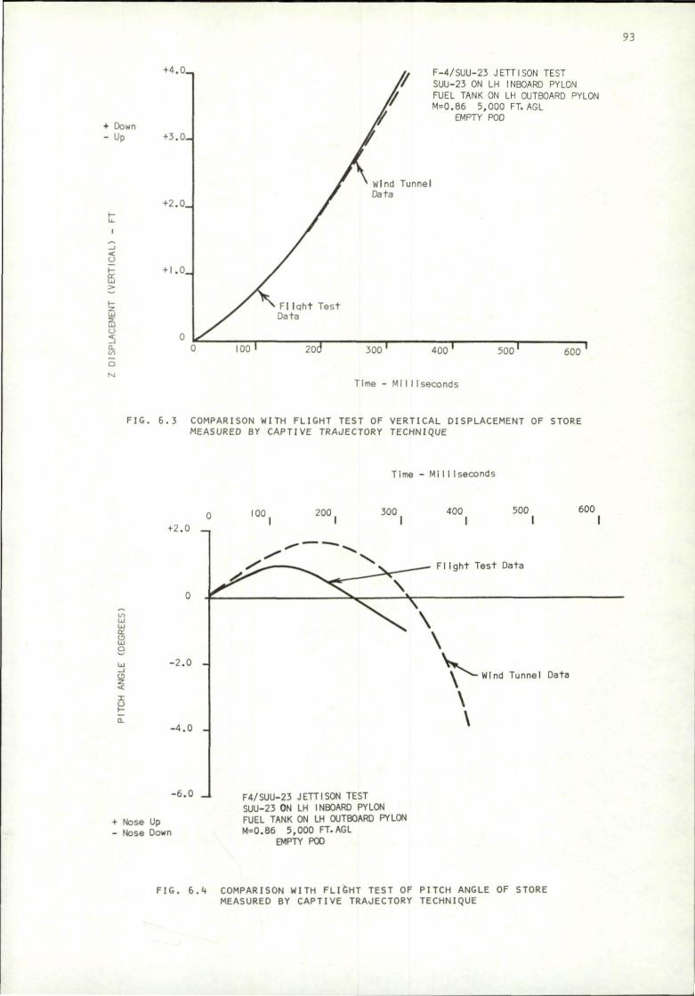
93
+ Down - Up
>
IS o 5 a. BS
+ 4 . 0 _
+3.0-
+2.0_
+ l.0_
F-4/SUU-23 JETTISON TEST SUU-23 ON LH INBOARD PYLON FUEL TANK ON LH OUTBOARD PYLON M=0.86 5,000 FT. AGL
EMPTY POD
400 500' 600
Time - Mi I I iseconds
F IG . 6 .3 COMPARISON WITH FLIGHT TEST OF VERTICAL DISPLACEMENT OF STORE MEASURED BY CAPTIVE TRAJECTORY TECHNIQUE
Time - M i l l 1 seconds
10 LJ LJ
g Q-
0 100 200 |
+2.0 _
- 2 . 0 -
-4 .0 -
-6.0
+ Nose Up - Nose Down
300 400 500 600 I l l l
F l I g h t Test Data
F4/SUU-23 JETTISON TEST SUU-23 ON LH INBOARD PYLON FUEL TANK ON LH OUTBOARD PYLON M=0.86 5,000 FT.AGL
EMPTY POO
\ ^ - Wind Tu nnel Data
\
\
FIG. 6.4 COMPARISON WITH FLIGHT TEST OF PITCH ANGLE OF STORE MEASURED BY CAPTIVE TRAJECTORY TECHNIQUE
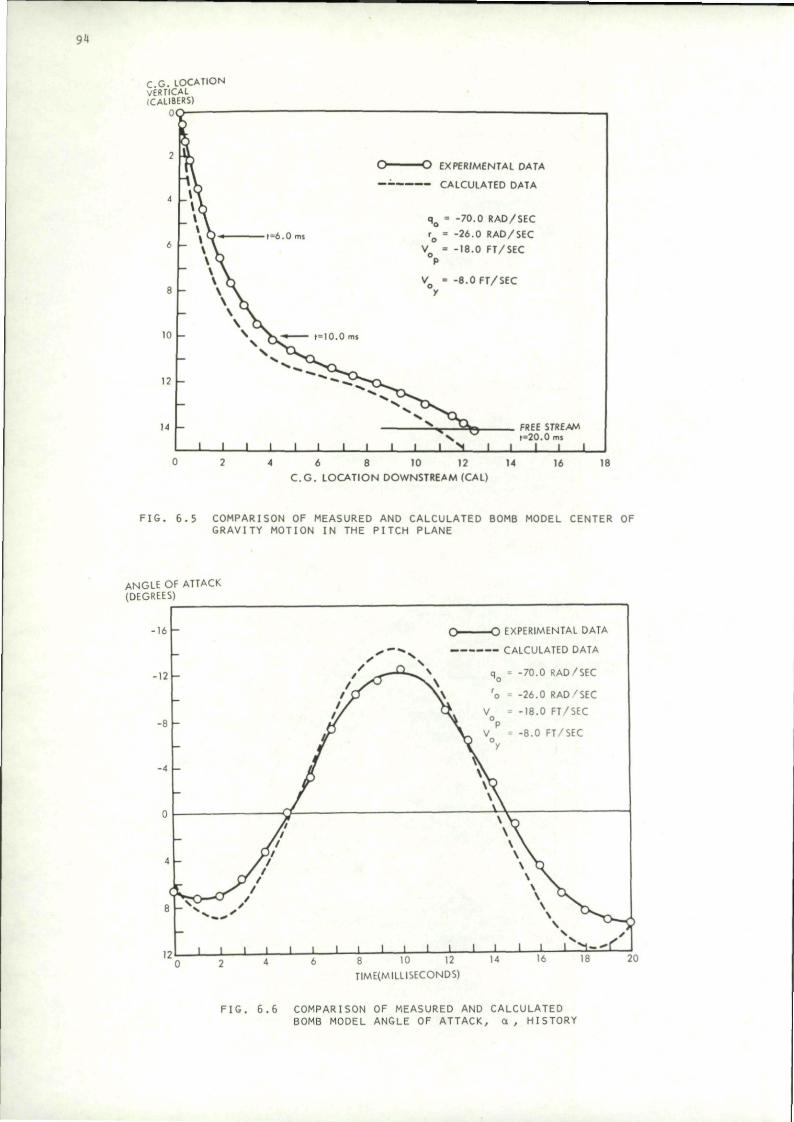
94
C G. LOCATION VERTICAL (CALIBERS)
2
4
.
H
IQ
1?
14
\ \ yJ KJ EXPERIMENTAL DATA
* h - • CALCULATED DATA
_ » \ q o = -70 .0 RAD/SEC
\ JS * ,-/. n ,„. r = -7ft 0 RAD/SET
" \ \ V . - -18 .0 FT/SEC \ Q p
\ V ) V = - 8 . 0 FT/SEC - \ A y
* \ \ OL
- ^ v OW* r^lO.O ms
x T C L _
V t=20.0ms 1 1 1 1 1 1 1 1 1 1 1 N 1 1 1 1 1
4 6 8 10 12 C . G . LOCATION DOWNSTREAM (CAL)
14 16 18
FIG. 6.5 COMPARISON OF MEASURED AND CALCULATED BOMB MODEL CENTER OF GRAVITY MOTION IN THE PITCH PLANE
ANGLE OF ATTACK (DEGREES)
• 1 6 -
-12
O EXPERIMENTAL DATA
CALCULATED DATA
q = -70 .0 RAD/SEC
-26 .0 RAD 'SEC
-18 .0 FT/SEC
-8 .0 FT/SEC
I I I i 1 I I I 1 1 1 10 12
TIME(MILLISECONDS)
FIG. 6.6 COMPARISON OF MEASURED AND CALCULATED BOMB MODEL ANGLE OF ATTACK, a , HISTORY
C.G. LOCATION HORIZONTAL (CALIBERS)
1P 1 V
t=20.0ms
a f = 1 0 . 0 m S a ^ a C r - * 0 " ^ ~ m i .
JTj^a? ~ " ^ y ^ "
6 - c y > t=6.0ms X '
\ y* \ / / q = -70.0 RAD/SEC O EXPERIMENTAL DATA
X / rQ = -26.0 RAD/SEC A CALCULATED DATA ff VQ = -18.0 FT/SEC
> f V = -8.0 FT/SEC z / / y
n » i i i i i i i i i i i i i i i i ml
ANGLE C (DEGREE!
8
4
°1
-4
-8
-12
-16
0 2 4 6 8 10 12 14 16
C.G. LOCATION DOWNSTREAM (CAL)
F I G . 6 .7 COMPARISON OF MEASURED AND CALCULATED BOMB MODEL CENTER OF GRAVITY MOTION IN THE YAW PLANE
)F SIDESLIP )
O O EXPERIMENTAL DATA
-yy, / qo - -70.0 RAD/SEC \ \ ' r / t - -26.0 RAD/SEC \ x x y P
V " -18.0 FT/SEC X ^ / o X J f
V - -8.0 FT/SEC \ JD
y u
1 1 1 1 1 1 1 1 1 1 I I 2 4 6 8 10 12 14 16 18
TIME (MILLISECONDS)
F I G . 6 . 8 COMPARISON OF MEASURED AND CALCULATED BOMB MODEL ANGLE OF S IDESLIP , B, HISTORY
95
1 18
20
—
96
The most difficult part of the flight test procedure, however, is maintaining and measuring aircraft flight conditions.
Each of these problem areas will be discussed briefly. New techniques are constantly being developed, but implementation is slow because of the cost and hazardous nature of flight hardware innovations.
7.2 Safe Separation
Safe separation may be assured by three methods. First, Covert's criterion (see Section 4) or other simple estimates of initial store motion (such as experience with similar cases) can be applied to distinguish safe from hazardous situations. The advantage of such procedures lies in the ability to rapidly select appropriate release conditions for further study. Next, full trajectory calculations can be made by use of the more detailed methods described in Section 5- Finally wind tunnel tests can be made and compared with the analytical predictions.
The first flight tests of a new store-aircraft combination naturally would be made at a very safe condition. That is one in which wind tunnel tests and analytical predictions are in agreement, and for which theory and experiment indicate a wide margin of safety In case flight or release conditions depart somewhat from the desired values.
Once flight test data becomes available. It can be compared to analytical and wind tunnel predictions. Any significant discrepancies must be resolved before flight tests are resumed. Assuming that the flight data can be accurately correlated with ground test and analysis, the flight program continues by safe Increments toward the boundaries of the safe-separation or airplane performance envelop. The number of possible store-aircraft flight-condition combinations is extremely large; hence it is not feasible to test every case. Therefore the extreme conditions are identified and tested, thus bounding a domain of safe separation.
7.3 Instrumentation
For proper interpretation of store separation data, it Is necessary, of course, to know the flight condition of the launch aircraft. This Information is obtained by the flight instrumentation conventionally available, but unusual accuracy Is required in some measurements. The information required to establish the flight condition of a particular test flight Includes
flight speed and Mach number altitude (air density and temperature) dive angle roll and yaw angles. If any angle of attack maneuver, if any
In cases of steady flight In a vertical plane (no yaw or roll), the various flight parameters can be obtained with conventional aircraft instruments. To assure steady flight, accelerometers can monitor Inadvertent maneuvers.
Since store separation trajectories are not critically sensitive to Mach number, dive angle, or altitude, measurement of these quantities is not difficult. Sudden aircraft maneuvers due to turbulence, for example, could disturb the store trajectory or impart motions to cameras photographing the store separation which might be Interpreted as store motion. Consequently, for determination of ballistics or basic separation characteristics, steady flight is essential.
The airplane angle of attack must be accurately known to fully define the separation data. It can be measured by a flow probe, but probably the most accurate determination would use known aircraft weight, flight speed, dive angle, altitude, and lift coefficient slope to calculate angle of attack (during zero acceleration).
Reference 102 briefly describes the use and calibration of aircraft flight Instrumentation. We are concerned here primarily with the problem of measuring the trajectory of the store with respect to the airplane. The Initial condition Imparted by the ejection system is required, as well as the resulting trajectory of the store. Such information as in-oarriage loads, structural and aeroelastic effects, and effects of the store on airplane performance may also be of Interest, but are not essential to the determination of the trajectory which is the item under consideration.
Exhaustive tests of ejector characteristics are described In ref. 103- They indicate surprisingly reliable and repeatable performance of cartridge-powered ejectors. However, because of occasional vagaries, detailed examination of store trajectories should make use of the observed Initial linear and angular rates Imparted to the store as well as the calibration of the ejection system.
Generally, then, the trajectory data of Interest is provided by photographic coverage from three sources. Ground-based theodolites provide accurate measurement of store and aircraft position as functions of time from well-established ground reference points. Unfortunately, the distance is too great to give good data on store orientation and position with respect to the airplane.
97
Photographic Information from chase planes Is of more quantitative value because the airplane can get close enough to the separation process to provide good data on the motion of the store relative to the launch aircraft. The chase plane camera, however. Is not accurately located with respect to the launch airplane, and hence the data reduction process Is only as accurate as the estimate of chase plane position. The chase plane can also be located by ground theodolites, and could even be photographed from fixed cameras on the launch airplane to triangulate its relative position. However, the ground coverage again suffers because of Its distance from the event. Triangulation of the chase plane from the launch aircraft is also Impractical unless the chase airplane lies within the predetermined field of view of triangulating cameras.
Consequently, the most accurate data on the separation process and the Initial store trajectory is obtained from carefully boreslghted cameras mounted on the launch airplane. The following accuracies are desired, but may not be required in all cases
a) position of points on the store to .1 foot with respect to aircraft coordinates
b) pitch, yaw, and roll attitude to 1 degree relative to aircraft coordinates
c) store control deflections to 1 degree
d) time reference data accurate to .001 second
A portion of the aircraft fuselage should be In the field of view to serve as a reference for aircraft structural deformation corrections .
Ejector-foot time history measurement in flight would also help to establish Initial conditions provided by the ejection process.
Accuracies actually achievable by a photographic system have been reported in ref. 104. In flight, the store, marked with special reference indicators, is released and photographed by on-board cameras. The film is later processed, frame by frame, and the locations of the reference marks are stored on computer cards. The data cards plus the camera and reference mark locations are fed Into a computer which is programmed to resolve the geometric relationships and calculate store trajectory Information.
To test the accuracy of the procedure, cameras were mounted on fixed platforms (on the ground) and a store was placed at various carefully measured locations. Photographic data was then processed in the same manner as flight test data, and the calculated store positions were compared with the measured ones. Samples of the resulting discrepancies are shown In Figs. 7.1 and 7-2 taken from ref. 104. From these results, it is apparent that the angular errors are more like 2 degrees than the desired 1 degree, and displacement error Is also several times as large as the desired .1 foot.
7.4 Data Reduction
Knowing the positions and optical axes of two aircraft-mounted cameras, it is possible to determine the precise location of points on a separating store seen by both cameras. Reducing the data normally requires tedious measurements of coordinates of the desired points from fiducial marks on frames of movie film. The data can be reduced by a computer once the positions have been recorded; however several sources of error limit the accuracy of the process. The resolution and repeatability of the film reading process provides a fundamental limitation on the accuracy. In addition, distortions produced by camera lenses and films can cause errors although corrections are possible. Another source of error is the displacement in time between the corresponding movie frames taken by two different cameras. As Indicated by the experiments of ref. 104, these errors are likely to produce Inaccuracy in angle measurements of about 2 degrees, and displacement discrepancies of several Inches. Structural deformation of the aircraft can cause camera motions that will Introduce additional errors.
Several procedures have been investigated to reduce the labor and Improve the accuracy of the data reduction process. A method called "Teledaq" (Television Data Acquisition) is proposed In ref. 105- In this scheme, television cameras are used Instead of movie cameras, so that the data is automatically available In the form of electrical signals on tape. To avoid the difficulties of pattern recognition, the store is to be painted red in certain areas, and a red filter on part of the camera system is used to make the red-painted areas particularly dominant. With this type of coding, the television tapes can be digitized and the store position and orientation determined by computerized operations on the data. Such a system could greatly facilitate data reduction. According to estimates given in ref. 105, the accuracy would be about the same as photographic methods, but advances being developed In data storage and resolution could lead to significantly improved versions.
Another procedure, described previously as being applicable to the reduction of wind tunnel data, has been developed at the Naval Missile Center (ref. 94). The PDAS (Photo Data Analysis System) uses aircraft-carried cameras to record the flight, but reads the film by superimposing the image of a store model viewed from a television camera and an aircraft camera frame showing the actual store. When the model has been correctly positioned with respect to the television camera so that it exactly coincides with the movie camera image, then the model position and orientation Is automatically
- 1 »
30.94-
a 3 00
ml • I "5
* 20.0 +
©
10.0 +
O
O
10.0 i®
.
j — i —
o
o ©
o o
o
G
Conputed Error - De (-©
G
8 •
+ 2 ®
©
+ 4
O
© ©
© © e
•J o © ©
© ©
20.0+ ® 0
©
30.0-L
©
0
"
. . .
0
Z D
ispl
acem
ent
(in
.)
i •
- 4
+60.0 i
•®50.0 l
^ | + 40.0 +
30.0 +
• 2O.0 +
+ 10.0 +
Conputed Ertror (in.)
©
O
e
9 ©
°0 °o
o
OG O ©
OO © ©
O 0
©
J*J © ©
©
©
© © ©o ©
9 « ©
0
© ©
o®° ©
© • Q 3
© © o ©
9 © ©,
0 L • ©
+ & • 4 + 6
FIG, 7.1 ACTUAL PITCH ANGLE VS. COMPUTED ERROR CAMERA l) FIG. 7.2 ACTUAL Z DISPLACEMENT VS. COMPUTED ERROR (CAMERA 1)
99
recorded. The trajectory data can be accurately obtained in this manner with only one on-board camera. However, accuracy Is Improved by statistically averaging data from two or more cameras.
By smoothing the data obtained by the PDAS system, it is possible to differentiate the position Information to obtain velocities and accelerations of the store. Consequently the forces on the store can be deduced for comparison with analytical predictions or wind tunnel measurements.
A procedure to Improve angular resolution of the store is proposed in ref. 106. The Idea is to place carefully oriented polarized reflectors on the store. When these are Illuminated with polarized light, the angle at which the reflected light is extinguished can be determined, and hence the orientation of the store at that Instant Is known. Other possible uses of polarized light sources are also Indicated In the report (ref. 106).
8. CONCLUDING REMARKS
The primary subject of this report has been the trajectories of external stores during their passage through the flow field of the carrying aircraft. Easily applied safe-separation criteria are described In Section 4, and methods of calculating trajectories are indicated in Section 5-
Detailed numerical calculations of subsonic trajectories can be carried out using the computer programs described in refs. 56-58. The analysis seems to be quite accurate and is capable of handling very general configurations and flight conditions. The main limitations are in angle of attack and Mach number. If the store angle is such that nonllnearltles due to body vortex separation become significant, then the approximate treatment given In refs. 56-58 may be Inadequate. Also, the compressibility correction procedure becomes unworkable at speeds above the critical Mach number.
The supersonic case is analyzed satisfactorily by Fernandes in refs. 62-64. However, he does not Include the trajectory calculations In his computer programs. His procedure may also be Inadequate for stores at high angles of attack where vortex separation becomes Important. At low supersonic Mach numbers, the procedure will break down because of the Inapplicability of the linearization of the flow equations.
Thus the transonic regime is the area that has been least developed. Some procedures are suggested in Sections 5-8 and 5-9, but comprehensive computer codes covering the transonic regime do not yet appear to be available.
Although the effect of external stores on airplane performance has been only briefly discussed in this report, the Implication seems clear that flight characteristics could be significantly Improved by better design and integration, as in the conformal carriage concept.
Supersonic release of stores has received relatively little attention to date. Not many aircraft can carry external stores at supersonic speeds, and the large aerodynamic forces make store trajectories difficult to control. However, improved aircraft performance and the need for high-speed attacks are likely to result In increasing release velocities. To assure aircraft safety and accurate placement of store trajectories, better ejection mechanisms will be needed at the higher speeds. Controlled releases, such as those described in Section 5-10, will probably be developed.
The major message of the considerable work in the field of store separation is that better integration of aircraft and stores is needed to improve the performance and reliability of both. Aircraft should be designed to carry stores. Instead of adding this capability almost as an afterthought. It should also be noted that if a new airplane must be capable of carrying all existing stores, and a new store must fit on all existing aircraft, improvements In performance of the aircraft-store combination will be extremely slow. Integrated store-aircraft systems must be conceived without such constraints to provide paths for far-reaching development.
100
9. REFERENCES
1. Aircraft/Stores Compatibility Symposium Proceedings Vols. I-VI, held at the Armament Development and Test Center, Eglin Air Force Base, Florida, November 1969 (Sponsored by Armament Development and Test Center, Air Force Armament Lab., and Air Force Flight Dynamics Laboratory)
2. Aircraft/Stores Compatibility Symposium Proceedings Vols. 1-3, held at Dayton Ohio, Dec 1971 (Sponsored by Joint Technical Coordinating Group for Air Launched Non-Nuclear Ordnance)
3- Aircraft/Stores Compatibility Symposium Proceedings Vols. 1-4. held at Sacramento, Calif., Sept 1973 (Sponsored by Joint Technical Coordinating Group for Air Launched Non-Nuclear Ordnance)
4. AGARD Conference Proceedings No. 71 on Aerodynamic Interference, held at Silver Spring, Maryland, Sept 1970
5. Ryan, B. M., Meeker, R. E., and Seeley, L. W. , Store Separation: State-of-the-Art. Naval Weapons Center Report NWC TP 5530, June 1573
6. Lockhart, J. W., "Multiple Suspension Developments," in Proceedings of the Aircraft/Stores Compatibility Symposium Vol. I. Eglin Air Force Base, Fla., 1969
7. Stuart, J. P., and Lauro, M. J., "A Computer-Aided Technique for Determining Aircraft/Stores Electrical Interface Requirements," in Proceedings of the Aircraft/ Stores Compatibility Symposium. Vol. 4. Sacramento, Calif., 1973
8. Military Specification: Airborne Stores and Associated Suspension Equipment; General Design Criteria for, MIL-A-8591E, Sept 1972
9. "Alrcraft/Store/Suspenslon Equipment Compatibility, Store/Handllng-Loadlng Equipment Compatibility, and Flight Operating Limitations for Aircraft Carrying Stores," NAVAIRINST 3710.7A AIR-530212, Nov 1974
10. Haldeman, J. W., "Pylon and Rack Problems and Solutions," In Proceedings of the Aircraft/Stores Compatibility Symposium Vol. 3, Dayton, Ohio, 1971
11. Dragowltz, C , Clark, J., and Johnson, R., "Systematic Study of the Effects of Various Parameters on Store Separation," in Proceedings of the Aircraft/Store Compatibility Symposium Vol. 2, Dayton, Ohio" 1971
12. Louck, C. M., Investigation of the Effects of Sway Brace Torque and MER-7 (Multiple Ejector, A/A37B-6, Bomb Rack) Compliance on Store Ejection Velocity for the MER-7, U. S. Naval Missile Center, Point Mugu Report, June 1969
13- Rhodes, C. W., and Shannon, J. H. W., Results and Conclusions of the Joint RAE/WRE Research on the Flight Dynamics and Ballistic Consistency of Freely Falling Missiles, Part I, Bombs Stabilized by Fixed Cruciform Fins. Royal Aircraft Establishment Report RAE TR 65200, also Weapons Research Establishment Report HSA 20, 1965
14. Regan, P. J., Shannon, J. H. W., and Tanner, F. J., The Joint NOL/RAE/WRE Research Program on Bomb Dynamics. Part II. A Low-Drag Bomb with Split-Skirt Stabilizers, Naval Ordnance Laboratory Report NOLTR 69-232, Royal Aircraft Establishment Report RAE TR 70038, Weapons Research Establishment Report HSA26, Nov 1969
15- Regan, F. J., Shannon, J. H. W., and Tanner, F. J., The Joint NOL/RAE/WRE Research Program on Bomb Dynamics, Part III. A Low-Drag Bomb with Freely Spinning Stabilizers, Naval Ordnance Laboratory Report NOLTR 73-77, Royal Aircraft Establishment Report RAE TR 73060, Weapons Research Establishment Report 904 June 1973
16. Regan, F. J., Shannon, J. H. W., and Tanner, F. J., The Joint NOL/RAE/WRE Research Program on Bomb Design, Part IV, The Exterior Ballistics of Bomb Design, Naval Surface Weapons Center Report NOLTR 74-58, Dec 1974
17. Maestri, R. R., "Self Compensating Store Ejection," in Proceedings of the Aircraft/Stores Compatibility Symposium, Vol. 2. Sacramento, Calif., 1973
18. Carlson, E. P., "Direct Sldeforce Control for Improved Weapon Delivery Accuracy," In Proceedings of the Aircraft/Stores Compatibility Symposium, Vol. 1. Sacramento, Calif., 1973
19. Washmuth, H. L., "Aircraft/Weapon Physical Interface Drawing System," In Proceedings of the Aircraft/Stores Compatibility Symposium. Vol. 1. Dayton, Ohio, Dec 1971
20. Aircraft Stores Interface Manual. Joint Technical Coordinating Group for Alr-Launched Non-Nuclear Ordnance Working Group for Aircraft/Stores Compatibility Report JTCG/ALNNO WP-12-1, Sept. 1973
101
21. Lacey, D. W., "Prediction of Incremental Aircraft Drag Due to Externally Carried Weapons," in Proceedings of the Aircraft/Stores Compatibility Symposium. Vol. V, Eglin Air Force Base, Florida, 1969
22. Berry, J. B., "Examples of Alrframe-Store Interference," in Proceedings of the AGARD Specialists Meeting on Aerodynamic Interference. Silver Spring, Md., 1970
23. Berry, J. B., "External Store Aerodynamics for Aircraft Performance Prediction," in AGARD Lecture Series on Prediction Methods for Aircraft Aerodynamic Characteristics, Brussels. 1974
24. Berry, J. B., Hutton, P. G., Haines, A. B., The Drag of External Stores - An Analysis of Some Experimental Data and Methods of Prediction, Aeronautical Research Council Report 31,222, 1969
25. Gallagher, R. D., and Dyer, R. D. , "Technique for Predicting External Store Aerodynamic Effects on Aircraft Performance," in Proceedings of the Aircraft/ Stores Compatibility Symposium, Vol. 1. Dayton, Ohio, 1971
26. Gallagher, R. D., "Approaches to External Store Airloads Prediction," in Proceedings of the Aircraft/Stores Compatibility Symposium, Vol. V, Eglin Air Force Base, Florida, 1969
27. Fernandes, F. D., "A Method of Predicting Interference Forces and Moments on Aircraft Stores at Subsonic Speeds," in Proceedings of the Aircraft/Stores Compatibility Symposium. Vol. V. Eglin Air Force Base, Florida, 1969
28. Grose, G. G., and Woodward, F. A., "Evaluation of the Prediction of Airplane/ Store Interference by Linear Theory," In Proceedings of the Aircraft/Stores Compatibility Symposium. Vol. V. Eglin Air Force Base, Florida, 1969
29. Grose, G. G., and Brlstow, D. R., "Evaluation of the Prediction of Aircraft/Store Interference by Linear Theory," In Proceedings of the AGARD Specialists' Meeting on Aerodynamic Interference, Silver Spring, Maryland 1970
30. Coble, D. F., "An Analytical Method for Solving the Aircraft - External Store Aerodynamic Interference Problem," in Proceedings of the Aircraft/Stores Compatibility Symposium, Vol. V, Eglin Air Force Base, Florida, 1969
31. Chadwlck, W. R., "The Application of Non-Planar Lifting Surface Theory to the Calculation of External-Store Loads," Paper No. 72-79 AIAA 2nd Atmospheric Plight Mechanics Conference. Sept. 1972
32. Carmlchael, R. L., and Woodward, F. A., An Integrated Approach to the Analysis and Design of Wings and Wing-Body Combinations in Supersonic Flow. NASA Tech Note D-3685 1966
33. Brodnax, H. W., and Ripley, G. R., "Structural Indices: A Technique for Using the Computer to Rapidly Assess the Structural Capability of Aircraft to Carry External Stores," In Proceedings of the Aircraft/Stores Compatibility Symposium, Vol. 1, Sacramento, Calif., 1973
34. Seidel, G. S., Jr., "External Store Loadings in the Proposed MIL-A-8591E," In Proceedings of the Aircraft/Stores Compatibility Symposium. Vol. 1. Sacramento, Calif., 1973
35. Storey, W. W., "A-7 Flutter Model Results, Comparison of Low Speed, High Speed, Pull Span, and Semi Span Results with Plight Test Results," In Proceedings of the Aircraft/Stores Compatibility Symposium. Vol. 3. Dayton, Ohio, 1971
36. Epperson, T. B., "A Different Approach to the Problem of Flutter of Aircraft with External Stores," in Proceedings of the Aircraft/Stores Compatibility Symposium, Vol. 3, Dayton, Ohio, 1971
37. Perman, M. A., and Unger, W. H., "A New Approach for Rapid Flutter Clearance of Aircraft with External Stores," in Proceedings of the Aircraft/Stores Compatibility Symposium, Vol. 4. Sacramento, Calif., 1973
38. Russell, H. L., Noll, T. E., Felt, L. R., and Mykytow, W. J., "Potential Application of Active Flutter Suppression to Future Fighter Attack Aircraft," in Proceedings of the Aircraft/Stores Compatibility Symposium. Vol. 4. Sacramento, Calif., 1973
39. Devan, L., "An Estimate of the Effect of MER Structural Dynamics on Store Separation," in Proceedings of the Aircraft/Stores Compatibility Symposium, Vol. 2, Sacramento, Calif., 1973
40. Van Aken, R. W., and Markarlan, C. F., "Thermal Considerations of Stores in Captive Flight," in Proceedings of the Aircraft/Stores Compatibility Symposium. Vol. 4. Sacramento, Calif., 1973
102
41. Matthews, R. K., Baker, S. S., and Key, J. C , Jr., "Wind Tunnel Heating Test of Aircraft Stores," in Proceedings of the Aircraft/Stores Compatibility Symposium. Vol. 4. Sacramento, Calif., 1973
42. Gilbert, W. N., and O'Neill, E. T., "Weapon Configured Vehicle Design for Advanced Tactical Aircraft," in Proceedings of the Aircraft/Stores Compatibility Symposium, Vol. 1. Sacramento, Calif., 1973
43. Nichols, J. H., Jr., "The Conformal Carriage Joint Service Development Program," In Proceedings of the Aircraft/Stores Compatibility Symposium, Vol. 1, Sacramento, Calif., 1973
44. Smith, D. L., "Flight Test Demonstrated Performance Improvements with a Conformal Weapons Carriage," In Proceedings of the Aircraft/Stores Compatibility Symposium. Vol. 3. Sacramento, Calif., 1973
45. Smith, R. E., "Conformal Carriage Separation Program," in Proceedings of the Aircraft/Stores Compatibility Symposium, Vol. 3. Sacramento. Calif., 1973
46. Covert, E. E., On the Definition of Safe Separation Criteria for External Stores and Pilot Escape Capsules, Mass. Inst, of Tech. Aerophysics Lab. Report TR 163, Dec 19&9
47. Covert, E. E., Definition of Safe-Separation Criteria for External Stores and Pilot Escape Capsules, Naval Weapons Center Report NWC TP 4995. June 1971
48. Covert, E. E., "On Safe Separation Criteria for Stores and Pilot Escape Capsules Part II," In Proceedings of the Aircraft/Stores Compatibility Symposium, Vol. 3. Dayton, Ohio, 1971
49. Covert, E. E., "On Safe Separation Criteria for External Stores and Pilot Escape Capsules (III); Effects of Aircraft Maneuver and Jettison of Pylon with Stores," in Proceedings of the Aircraft/Stores Compatibility Symposium, Vol. 3, Sacramento, Calif., 1973
50. Schoch, D. L. , "Store Separation from the McDonnell Douglas P-4 Aircraft," in Proceedings of the 8th Navy Symposium on Aeroballlstlcs. 6-8 May 1969. Vol- 4. Naval Weapons Center, Corona Labs., June 1969
51. Bamber, M. J., and Davidson, H. D., Equations for Computing Trajectories of a Store Launched from an Airplane, David Taylor Model Basin Aero Report 981, I960
52. Serbln, H., "An Analytical, Numerical Program for Calculating the Aerodynamic Forces External to Aircraft," In Proceedings of the 8th Navy Symposium on Aeroballlstlcs, Vol. 4. Naval Weapons Center, Corona, Calif., May 1969
53. Jones, D. A., "Estimation of Aircraft Store Separation Behavior on the Basis of Captive Load Data," in Proceedings of the 8th Navy Symposium on Aeroballistlcs, Vol. 4, Naval Weapons Center, Corona, Calif., May 1969
54. Smith, R. E., Prediction of Store-Separation Motion Using Initial Captive Loads. Naval Weapons Center Report NWC TP 4261, 1971
55- Netzer, J. V., "Prediction of Store Trajectories," in Proceedings of the Aircraft/ Stores Compatibility Symposium. Vol. 4, Sacramento, Calif., 1973
56. Goodwin, F. K., Dlllenlus, M. F. E., and Nielsen, J. N., Prediction of Six-Decree-of-Freedom Store Separation Trajectories at Speeds up to the Critical Speed, vol.I -Theoretical Methods and Comparisons with Experiment. Vol. II - Users Manual for the Computer Programs. Air Force Flight Dynamics Lab. Report APFDL-TR-72-8 3, Vol. I and II, Oct 1972
57- Dlllenlus, M. F. E., Goodwin, F. K., Nielsen, J. N., and Dyer, C. L., "Extensions to the Method for Prediction of Slx-Degree-of-Freedom Store Separation Trajectories at Speeds up to the Critical Speed, Including Interactive Graphics Applications and Bodies of Arbitrary Cross Section," in Proceedings of the Aircraft/Stores Compatibility Symposium, Vol. 2, Sacramento, California, 1973
58. Dlllenlus, M. P. E., Goodwin, F. K., and Nielsen, J. N., Extension of the Method for Predicting Six-Degree-of-Freedom Store Separation Trajectories at Speeds up to the Critical Speed to Include a Fuselage with Nonclrcular Cross Section. Vol.1 Theoretical Methods and Comparisons with Experiment. v°l j Users Manual for the Computer Programs. Air Force Flight Dynamics Lab. Report AFFDL-TR-74-130, Vol. I and II, March 1974
59. Glauert, H., The Elements of Airfoil and Airscrew Theory, MacMlllan Press, 1943, Chapter 12, pp 156-160
60. Nielsen, J. N. , Missile Aerodynamics. McGraw Hill, New York, I960
103
61. Adams, G. J., and Dugan, D. W., Theoretical Damping In Roll and Rolling Moment Due to Differential Wing Incidence for Slender Cruciform Wings and Wing-Body Combinations. NACA Report 1088, 1952
62. Fernandes, F. D., Theoretical Prediction of Interference Loading on Aircraft Stores; Part I - Subsonic Speeds. NASA Report CR 112065-1, June 1972
63. Fernandes, F. D., Theoretical Prediction of Interference Loading on Aircraft Stores; Part II - Supersonic Speeds, NASA Report CR 112065-2, June 1972
64. Fernandes, F. D., Theoretical Prediction of Interference Loading on Aircraft Stores; Part III - Programmers Manual, NASA Report CR 112065-3. June 1972
65. Love, E. S., and Long, R. H., A Rapid Method for Predicting Attached-Shock Shape, NACA Technical Note 4167, Oct 1957
66. Love, E. S., A Reexamination of the Use of Simple Concepts for Predicting the Shape and Location of Detached Shock Waves, NACA Technical Note 4170. Dec 1957
67. Ames Research Staff, Equations. Tables, and Charts for Compressible Flow, National Advisory Committee for Aeronautics Report 1135, 1953
68. Oliver, R. E., An Experimental Investigation of Flow Over Simple Blunt Bodies at a Nominal Mach Number of 5-8, GALCIT. memo no. 26, 1955
69. Griffith, W. C , Transonic Flow. Princeton Univ., Department of Physics, Tech Report II-7, 1950
70. Alperln, M., Experimental Information on Two-Dimenslonal Detached Shock Waves, Cal. Inst, of Tech., Jet Propulsion Lab. Progress Report No. 4-44, 1950
71. Kim, C-S., "Experimental Studies of Supersonic Flow Past a Circular Cylinder," Journal of the Physical Society of Japan. Vol 11, No. 4, April 1956, pp 439-445
72. Uohlda, S., and Yasuhara, M,, "The Rotational Flow Field Behind a Curved Shock Wave Calculated by the Method of Flux Analysis," Journal of the Aero Sci.. Vol. 23, No. 9, Sept 1956, pp 830-845
73- Moeckel, W. E., Experimental Investigation of Supersonic Flow with Detached Shock Waves for Mach Numbers Between 1.8 and 2.9, National Advisory Committee for Aeronautics RM E 50D05, 1950
74. Serbln, H., Hypersonic. Non-Viscous Flow Around a Circular Disc Normal to the Stream. RAND Corp., Research Memo RM-1713, 1956
75- Heberle, J. W., Wood, G. F., and Gooderum, P. B., Data on Shape and Location of Detached Shock Waves on Cones and Spheres. National Advisory Committee for Aeronautics Tech Note 2000, 1950
76. Maccoll, J. W., "The Conical Shock Wave Formed by a Cone Moving at High Speed," Proc. Roy. Soc. (London). Ser A. Vol. 159, No. 898, April 1937, PP 459-472
77- Vlncentl, W. G., and Wagoner, C. B., Transonic Flow Past a Wedge Profile with Detached Bow Wave, National Advisory Committee for Aeronautics Report 1095, 1952
78. Crawford, D. H., and McCauley, W. D., Investigation of the Laminar Aerodynamic Heat-Transfer Characteristics of a Hemisphere-Cylinder in the Langley 11-Inch Hypersonic Tunnel at a Mach Number of 6.8, National Advisory Committee for Aeronautics Tech. Note 3706, 1956
79. Johnston, G. W., An Investigation of the Flow About Cones and Wedges at and Beyond the Critical Angle". Univ. of Toronto Inst. Aerophysics Report UTIA Rep. No. 24, 1952
80. Moeckel, W. E., Approximate Method for Predicting Form and Location of Detached Shock Waves Ahead of Plane and Axially Symmetric Bodies, National Advisory Committee for Aeronautics, Tech. Note 1921, 1949
81. Zartarlan, G., Theoretical Studies on the Prediction of Unsteady Supersonic Airloads on Elastic Wings, Wright Air Development Center Technical Report 56-97, Part I -Dec 1955, Part II - Feb 1956
82. Llepmann, H. W., and Roshko, A., Elements of Gasdynamics, John Wiley & Sons, i960
83. Ferri, A., Elements of Aerodynamics of Supersonic Flows, McMillan, N.Y., 1949
84. Pitts, W. C , Nielsen, J.N., and Kaattari, G. E., Lift and Center of Pressure of Wing-Body-Tall Configurations at Subsonic. Transonic, and Supersonic Speeds. NACA Report 1307, 1957
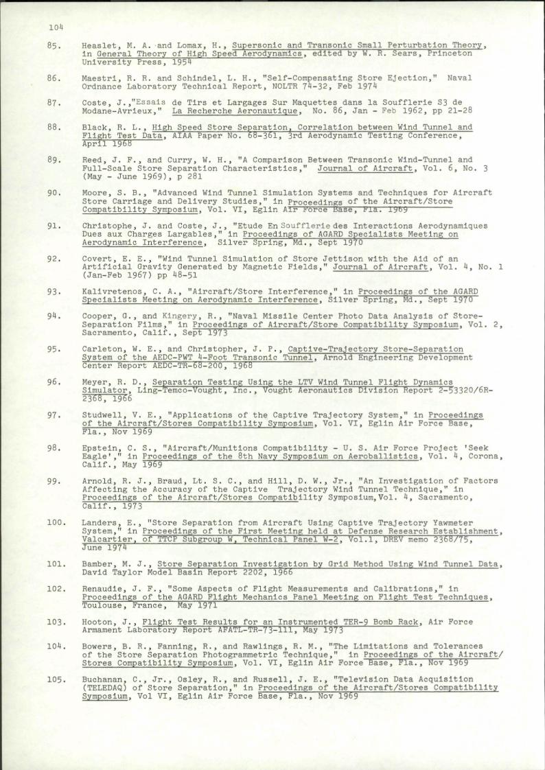
104
85. Heaslet, M. A. and Lomax, H., Supersonic and Transonic Small Perturbation Theory, In General Theory of High Speed Aerodynamics, edited by W. R. Sears, Princeton University Press, 1954
86. Maestri, R. R. and Schlndel, L. H., "Self-Compensating Store Ejection," Naval Ordnance Laboratory Technical Report, NOLTR 74-32, Feb 1974
87. Coste, J.,"Essais de Tlrs et Largages Sur Maquettes dans la Soufflerie S3 de Modane-Avrieux," La Recherche Aeronautique, No. 86, Jan - Feb 1962, pp 21-28
88. Black, R. L., High Speed Store Separation, Correlation between Wind Tunnel and Flight Test Data, AIAA Paper No. 68-361. 3rd Aerodynamic Testing Conference, April 1968
89. Reed, J. F., and Curry, W. H., "A Comparison Between Transonic Wind-Tunnel and Full-Scale Store Separation Characteristics," Journal of Aircraft, Vol. 6, No. 3 (May - June 1969). p 281
90. Moore, S. B., "Advanced Wind Tunnel Simulation Systems and Techniques for Aircraft Store Carriage and Delivery Studies," in Proceedings of the Aircraft/Store Compatibility Symposium. Vol. VI, Eglin Air Force Biise, Fla. l by
91. Chrlstophe, J. and Coste, J., "Etude En Soufflerie des Interactions Aerodynamiques Dues aux Charges Largables," In Proceedings of AGARD Specialists Meeting on Aerodynamic Interference, Silver Spring, Md., Sept 1970
92. Covert, E. E., "Wind Tunnel Simulation of Store Jettison with the Aid of an Artificial Gravity Generated by Magnetic Fields," Journal of Aircraft, Vol. 4, No. 1 (Jan-Feb 1967) pp 48-51
93- Kallvretenos, C. A., "Aircraft/Store Interference," in Proceedings of the AGARD Specialists Meeting on Aerodynamic Interference, Silver Spring, Md., Sept 1970
94. Cooper, G., and Kingery, R., "Naval Missile Center Photo Data Analysis of Store-Separation Films," In Proceedings of Aircraft/Store Compatibility Symposium. Vol. 2, Sacramento, Calif., Sept 1973
95. Carleton, W. E., and Christopher, J. P., Captive-Trajectory Store-Separation System of the AEDC-PWT 4-Foot Transonic Tunnel, Arnold Engineering Development Center Report AEDC-TR-68-200, 1968
96. Meyer, R. D., Separation Testing Using the LTV Wind Tunnel Flight Dynamics Simulator, Ling-Temco-Vought, Inc., Vought Aeronautics Division Report 2-53320/6R-2368, 1966
97. Studwell, V. E., "Applications of the Captive Trajectory System," in Proceedings of the Aircraft/Stores Compatibility Symposium, Vol. VI, Eglin Air Force Base, Fla., Nov 1969
98. Epstein, C. S., "Aircraft/Munitions Compatibility - U. S. Air Force Project 'Seek Eagle'," In Proceedings of the 8th Navy Symposium on Aeroballlstlcs, Vol. 4, Corona, Calif., May 15^9
99- Arnold, R. J., Braud, Lt. S. C , and Hill, D. W., Jr., "An Investigation of Factors Affecting the Accuracy of the Captive Trajectory Wind Tunnel Technique," in Proceedings of the Aircraft/Stores Compatibility Symposium, Vol. 4, Sacramento, Calif., 1973
100. Landers, E., "Store Separation from Aircraft Using Captive Trajectory Yawmeter System," in Proceedings of the First Meeting held at Defense Research Establishment, Valcartler, of TTCP Subgroup W. Technical Panel W-2. Vol.1. DREV memo 2368/75. June 1974
101. Bamber, M. J., Store Separation Investigation by Grid Method Using Wind Tunnel Data. David Taylor Model Basin Report 2202, 1966
102. Renaudle, J. P., "Some Aspects of Flight Measurements and Calibrations," in Proceedings of the AGARD Flight Mechanics Panel Meeting on Flight Test Techniques. Toulouse.France, May 1971
103. Hooton, J., Flight Test Results for an Instrumented TER-9 Bomb Rack. Air Force Armament Laboratory Report AFATL-TR-73-111, May 1973
104. Bowers, B. R., Fanning, R., and Rawllngs, R. M., "The Limitations and Tolerances of the Store Separation Photogrammetric Technique," in Proceedings of the Aircraft/ Stores Compatibility Symposium. Vol. VI, Eglin Air Force Base, Fla., Nov 1969
105. Buchanan, C , Jr., Osley, R., and Russell, J. E., "Television Data Acquisition (TELEDAQ) of Store Separation," In Proceedings of the Aircraft/Stores Compatibility Symposium. Vol VI, Eglin Air Force Base, Fla., Nov 1969

105
106. Cooper, G. F., "Use of Polarized Light in Photo-Instrumentation of Missile Separations," in Proceedings of the 9th Navy Symposium on Aeroballlstlcs, held at Johns Hopkins U., Applied Physics Lab., Howard County, Md., May 1972

REPORT DOCUMENTATION PAGE
1. Recipient's Reference 2.Originator's Reference
AGARD-AG-202
3. Further Reference 4. Security Classification of Document
UNCLASSIFIED
5. Originator Advisory Group for Aerospace Research and Development North Atlantic Treaty Organization 7 rue Ancelle, 92200 Neuilly sur Seine, France
6. Title
Store Separation
7.Presented at
8. Authors)
Leon H.Schindel
9. Date
June 1975
10. Author's Address Naval Surface Weapons Center White Oak Laboratory Silver Spring. Maryland 20910, USA
11.Pages
108
12.Distribution Statement This document is distributed in accordance with AGARD policies and regulations, which are outlined on the Outside Back Covers of all AGARD publications.
13. Key words/Descriptors External stores Separation Bomb trajectories Computation
Aviation safety Bomb ejectors Fire control
14.UDC
629.73.028.25:533.695.9
15. Abstract
This AGARDograph is a systematic collection of experimental results for use of engineers and designers, limited to externally carried, unpowered, unguided stores. In the sections dealing with store trajectories, the physical situation is described, the method of solution is indicated, and the final results are presented. Emphasis is on store motion in traversing the parent aircraft flowfield, with criteria for safe separation and methods of calculating flight path. Windtunnel test techniques are described, and some information on flight testing given. Analytical treatment is compared with flight and tunnel results. There are brief mentions of ejection systems and the effect of stores on aircraft performance.
AGARDograph No.202 Advisory Group for Aerospace Research and Development, NATO STORE SEPARATION Leon H.Schindel Published June 1975 108 pages
This AGARDograph is a systematic collection of experimental results for use of engineers and designers, limited to externally carried, unpowered, unguided stores. In the sections dealing with store trajectories, the physical situation is described, the method of solution is indicated, and the final results are presented. Emphasis is on store motion in traversing the parent aircraft flow-field, with criteria for safe separation and methods of
P.T.O.
AGARD-AG-202 629.73.028.25:533.695.9
External stores Separation Bomb trajectories Computation Aviation safety Bomb ejectors Fire control
AGARD-AG-202 629.73.028.25:533.695.9
External stores Separation Bomb trajectories Computation Aviation safety Bomb ejectors Fire control
AGARDograph No.202 Advisory Group for Aerospace Research and Development, NATO STORE SEPARATION Leon H.Schindel Published June 1975 108 pages
This AGARDograph is a systematic collection of experimental results for use of engineers and designers, limited to externally carried, unpowered, unguided stores. In the sections dealing with store trajectories, the physical situation is described, the method of solution is indicated, and the final results are presented. Emphasis is on store motion in traversing the parent aircraft flow-field, with criteria for safe separation and methods of
P.T.O.
AGARD-AG-202 629.73.028.25:533.695.9
External stores Separation Bomb trajectories Computation Aviation safety Bomb ejectors Fire control
AGARD-AG-202 629.73.028.25:533.695.9
External stores Separation Bomb trajectories Computation Aviation safety Bomb ejectors Fire control

calculating flight path. Windtunnel test techniques are described, and some information on flight testing given. Analytical treatment is compared with flight and tunnel results. There are brief mentions of ejection systems and the effect of stores on aircraft performance.
This AGARDograph was prepared at the request of the Fluid Dynamics Panel of AGARD.

NATO ~ $ j OTAN
7 RUE ANCELLE 92200 NEUILLY-SUR SEINE
FRANCE
Telephone 722.28.00 Telex 61176
DISTRIBUTION OF UNCLASSIFIED
AGARD PUBLICATIONS
AGARD does NOT hold stocks of AGARD publications at the above address for general distribution. Initial distribution of AGARD publications is made to AGARD Member Nations through the following National Distribution Centres. Further copies are sometimes available from these Centres, but if not may be purchased in Microfiche or Photocopy form from the Purchase Agencies listed below.
NATIONAL DISTRIBUTION CENTRES BELGIUM
Coordonnateur AGARD - VSL Etat-Major de la Force Aerienne Caserne Prince Baudouin Place Dailly, 1030 Bruxelles
CANADA Defence Scientific Information Service Department of National Defence Ottawa, Ontario KIA OZ2
DENMARK Danish Defence Research Board Qsterbrogades Kaserne Copenhagen O
FRANCE O.N.E.R.A. (Direction) 29 Avenue de la Division Leclerc 92 Chatillon sous Bagneux
GERMANY Zentralstcllc fiir Luft- und Raumfahrt-dokumentation und -information D-8 Munchen 86 Postfach 860880
GREECE Hellenic Armed Forces Command D Branch, Athens
ICELAND Director of Aviation c/o Flugrad Reykjavik
ITALY Aeronautica Militare Ufficio del Delegate Nazionale all'AGARD 3, Piazzale Adenauer Roma/EUR
LUXEMBOURG See Belgium
NETHERLANDS Netherlands Delegation to AGARD National Aerospace Laboratory, NLR P.O. Box 126 Delft
NORWAY Norwegian Defence Research Establishment Main Library P.O. Box 25 N-2007 Kjeller
PORTUGAL Direccao do Service de Material da Forca Aerea Rua de Escola Politecnica 42 Lisboa Attn: AGARD National Delegate
TURKEY Department of Research and Development (ARGE) Ministry of National Defence. Ankara
UNITED KINGDOM Defence Research Information Centre Station Square House St. Mary Cray Orpington, Kent BRS 3RE
UNITED STATES National Aeronautics and Space Administration (NASA), Langley Field, Virginia 23365 Attn: Report Distribution and Storage Unit
THE UNITED STATES NATIONAL DISTRIBUTION CENTRE (NASA) DOES NOT HOLD STOCKS OF AGARD PUBLICATIONS, AND APPLICATIONS FOR COPIES SHOULD BE MADE
DIRECT TO THE NATIONAL TECHNICAL INFORMATION SERVICE (NTIS) AT THE ADDRESS BELOW.
Microfiche or Photocopy National Technical Information Service (NTIS) 5285 Port Royal Road Springfield Virginia 22151, USA
PURCHASE AGENCIES
Microfiche ESRO/ELDO Space Documentation Service European Space Research Organization 114, Avenue Charles de Gaulle 92200 Neuilly sur Seine, France
Microfiche Technology Reports Centre (DTI) Station Square House St. Mary Cray Orpington, Kent BRS 3RF England
Requests for microfiche or photocopies of AGARD documents should include the AGARD serial number, title, author or editor, and publication date. Requests to NTIS should include the NASA accession report number. Full bibliographical references and abstracts
of AGARD publications are given in the following journals:
Scientific and Technical Aerospace Reports (STAR), published by NASA Scientific and Technical information Facility Post Office Box 8757 Baltimore/Washington International Airport Maryland 21240, USA
Government Reports Announcements (GRA), published by die National Technical information Services, Springfield Virginia 22151, USA
* Printed by Technical Editing and Reproduction Ltd Harford House. 7-9 Charlotte St. London W1P 1HD
Related Documents