ibm.com/redbooks Front cover Storage and Network Convergence Using FCoE and iSCSI Sangam Racherla Silvio Erdenberger Harish Rajagopal Kai Ruth Learn how to improve IT service performance and availability Simplify your storage and network infrastructure See how to reduce data center network costs

Welcome message from author
This document is posted to help you gain knowledge. Please leave a comment to let me know what you think about it! Share it to your friends and learn new things together.
Transcript

ibm.com/redbooks
Front cover
Storage and Network Convergence Using FCoE and iSCSI
Sangam RacherlaSilvio Erdenberger
Harish RajagopalKai Ruth
Learn how to improve IT service performance and availability
Simplify your storage and network infrastructure
See how to reduce data center network costs


International Technical Support Organization
Storage and Network Convergence Using FCoE and iSCSI
January 2014
SG24-7986-01

© Copyright International Business Machines Corporation 2012, 2014. All rights reserved.Note to U.S. Government Users Restricted Rights -- Use, duplication or disclosure restricted by GSA ADP ScheduleContract with IBM Corp.
Second Edition (January 2014)
This edition applies to the latest supported Converged Network Adapters and Switches in the IBM System Networking Portfolio of products.
Note: Before using this information and the product it supports, read the information in “Notices” on page xi.

Contents
Notices . . . . . . . . . . . . . . . . . . . . . . . . . . . . . . . . . . . . . . . . . . . . . . . . . . . . . . . . . . . . . . . . . xiTrademarks . . . . . . . . . . . . . . . . . . . . . . . . . . . . . . . . . . . . . . . . . . . . . . . . . . . . . . . . . . . . . . xii
Preface . . . . . . . . . . . . . . . . . . . . . . . . . . . . . . . . . . . . . . . . . . . . . . . . . . . . . . . . . . . . . . . . xiiiAuthors. . . . . . . . . . . . . . . . . . . . . . . . . . . . . . . . . . . . . . . . . . . . . . . . . . . . . . . . . . . . . . . . . xiiiNow you can become a published author, too! . . . . . . . . . . . . . . . . . . . . . . . . . . . . . . . . . . .xvComments welcome. . . . . . . . . . . . . . . . . . . . . . . . . . . . . . . . . . . . . . . . . . . . . . . . . . . . . . . .xvStay connected to IBM Redbooks . . . . . . . . . . . . . . . . . . . . . . . . . . . . . . . . . . . . . . . . . . . . xvi
Part 1. Overview of storage and network convergence . . . . . . . . . . . . . . . . . . . . . . . . . . . . . . . . . . . . . . 1
Chapter 1. Introduction to convergence . . . . . . . . . . . . . . . . . . . . . . . . . . . . . . . . . . . . . . 31.1 What convergence is. . . . . . . . . . . . . . . . . . . . . . . . . . . . . . . . . . . . . . . . . . . . . . . . . . . . 4
1.1.1 Calling it what it is . . . . . . . . . . . . . . . . . . . . . . . . . . . . . . . . . . . . . . . . . . . . . . . . . . 41.2 Vision of convergence in data centers . . . . . . . . . . . . . . . . . . . . . . . . . . . . . . . . . . . . . . 41.3 The interest in convergence now . . . . . . . . . . . . . . . . . . . . . . . . . . . . . . . . . . . . . . . . . . 51.4 Fibre Channel SANs today . . . . . . . . . . . . . . . . . . . . . . . . . . . . . . . . . . . . . . . . . . . . . . . 51.5 Ethernet-based storage today. . . . . . . . . . . . . . . . . . . . . . . . . . . . . . . . . . . . . . . . . . . . . 61.6 Benefits of convergence in storage and network . . . . . . . . . . . . . . . . . . . . . . . . . . . . . . 71.7 Challenge of convergence . . . . . . . . . . . . . . . . . . . . . . . . . . . . . . . . . . . . . . . . . . . . . . . 81.8 Conclusion . . . . . . . . . . . . . . . . . . . . . . . . . . . . . . . . . . . . . . . . . . . . . . . . . . . . . . . . . . 10
Chapter 2. Fibre Channel over Ethernet . . . . . . . . . . . . . . . . . . . . . . . . . . . . . . . . . . . . . 112.1 Background: Data Center Bridging . . . . . . . . . . . . . . . . . . . . . . . . . . . . . . . . . . . . . . . . 12
2.1.1 Priority-based Flow Control: IEEE 802.1Qbb . . . . . . . . . . . . . . . . . . . . . . . . . . . . 122.1.2 Enhanced Transmission Selection: IEEE 802.1Qaz. . . . . . . . . . . . . . . . . . . . . . . 132.1.3 Data Center Bridging Capabilities Exchange–IEEE 802.1Qaz . . . . . . . . . . . . . . . 142.1.4 Congestion Notification: IEEE 802.1Qau . . . . . . . . . . . . . . . . . . . . . . . . . . . . . . . 14
2.2 Standards work related to FCoE . . . . . . . . . . . . . . . . . . . . . . . . . . . . . . . . . . . . . . . . . . 152.2.1 Transparent Interconnection of Lots of Links . . . . . . . . . . . . . . . . . . . . . . . . . . . . 152.2.2 Shortest Path Bridging: IEEE 802.1aq . . . . . . . . . . . . . . . . . . . . . . . . . . . . . . . . . 15
2.3 FCoE concepts . . . . . . . . . . . . . . . . . . . . . . . . . . . . . . . . . . . . . . . . . . . . . . . . . . . . . . . 162.3.1 FCoE protocol stack . . . . . . . . . . . . . . . . . . . . . . . . . . . . . . . . . . . . . . . . . . . . . . . 162.3.2 Topology . . . . . . . . . . . . . . . . . . . . . . . . . . . . . . . . . . . . . . . . . . . . . . . . . . . . . . . . 182.3.3 FCoE Initialization Protocol and snooping bridges . . . . . . . . . . . . . . . . . . . . . . . . 202.3.4 MAC addresses used by end devices. . . . . . . . . . . . . . . . . . . . . . . . . . . . . . . . . . 212.3.5 FCFs, Fabric Mode, and NPIV . . . . . . . . . . . . . . . . . . . . . . . . . . . . . . . . . . . . . . . 212.3.6 Distributed FCF under development . . . . . . . . . . . . . . . . . . . . . . . . . . . . . . . . . . . 23
2.4 Technology comparison: FCoE with iSCSI . . . . . . . . . . . . . . . . . . . . . . . . . . . . . . . . . . 262.4.1 Similarities. . . . . . . . . . . . . . . . . . . . . . . . . . . . . . . . . . . . . . . . . . . . . . . . . . . . . . . 262.4.2 Differences . . . . . . . . . . . . . . . . . . . . . . . . . . . . . . . . . . . . . . . . . . . . . . . . . . . . . . 26
2.5 Summary of technology used . . . . . . . . . . . . . . . . . . . . . . . . . . . . . . . . . . . . . . . . . . . . 272.5.1 Initial cost at purchase . . . . . . . . . . . . . . . . . . . . . . . . . . . . . . . . . . . . . . . . . . . . . 272.5.2 Time to deploy . . . . . . . . . . . . . . . . . . . . . . . . . . . . . . . . . . . . . . . . . . . . . . . . . . . 272.5.3 Necessary skills . . . . . . . . . . . . . . . . . . . . . . . . . . . . . . . . . . . . . . . . . . . . . . . . . . 28
2.6 Conclusion . . . . . . . . . . . . . . . . . . . . . . . . . . . . . . . . . . . . . . . . . . . . . . . . . . . . . . . . . . 28
Chapter 3. Internet Small Computer System Interface . . . . . . . . . . . . . . . . . . . . . . . . . 293.1 Introduction to iSCSI . . . . . . . . . . . . . . . . . . . . . . . . . . . . . . . . . . . . . . . . . . . . . . . . . . . 30
© Copyright IBM Corp. 2012, 2014. All rights reserved. iii
3.1.1 iSCSI overview . . . . . . . . . . . . . . . . . . . . . . . . . . . . . . . . . . . . . . . . . . . . . . . . . . . 303.1.2 iSCSI protocol in depth . . . . . . . . . . . . . . . . . . . . . . . . . . . . . . . . . . . . . . . . . . . . . 31
3.2 iSCSI initiators. . . . . . . . . . . . . . . . . . . . . . . . . . . . . . . . . . . . . . . . . . . . . . . . . . . . . . . . 353.2.1 Software-only solutions. . . . . . . . . . . . . . . . . . . . . . . . . . . . . . . . . . . . . . . . . . . . . 353.2.2 Software with hardware assistance. . . . . . . . . . . . . . . . . . . . . . . . . . . . . . . . . . . . 363.2.3 Hardware-only solutions . . . . . . . . . . . . . . . . . . . . . . . . . . . . . . . . . . . . . . . . . . . . 36
3.3 Performance considerations . . . . . . . . . . . . . . . . . . . . . . . . . . . . . . . . . . . . . . . . . . . . . 373.3.1 Jumbo frames . . . . . . . . . . . . . . . . . . . . . . . . . . . . . . . . . . . . . . . . . . . . . . . . . . . . 373.3.2 Prioritization and bandwidth allocation . . . . . . . . . . . . . . . . . . . . . . . . . . . . . . . . . 38
3.4 Multipathing with iSCSI . . . . . . . . . . . . . . . . . . . . . . . . . . . . . . . . . . . . . . . . . . . . . . . . . 383.4.1 IEEE 802.3ad Link Aggregation Control Protocol and Etherchannel . . . . . . . . . . 383.4.2 Active-Active multipathing . . . . . . . . . . . . . . . . . . . . . . . . . . . . . . . . . . . . . . . . . . . 393.4.3 Multiconnection sessions . . . . . . . . . . . . . . . . . . . . . . . . . . . . . . . . . . . . . . . . . . . 39
Chapter 4. IBM products that support FCoE and iSCSI. . . . . . . . . . . . . . . . . . . . . . . . . 414.1 Converged Network Adapters (CNAs) . . . . . . . . . . . . . . . . . . . . . . . . . . . . . . . . . . . . . 42
4.1.1 IBM Flex System. . . . . . . . . . . . . . . . . . . . . . . . . . . . . . . . . . . . . . . . . . . . . . . . . . 424.1.2 BladeCenter . . . . . . . . . . . . . . . . . . . . . . . . . . . . . . . . . . . . . . . . . . . . . . . . . . . . . 434.1.3 IBM System x and IBM Power Systems . . . . . . . . . . . . . . . . . . . . . . . . . . . . . . . . 45
4.2 Switches . . . . . . . . . . . . . . . . . . . . . . . . . . . . . . . . . . . . . . . . . . . . . . . . . . . . . . . . . . . . 474.2.1 Flex Chassis . . . . . . . . . . . . . . . . . . . . . . . . . . . . . . . . . . . . . . . . . . . . . . . . . . . . . 474.2.2 BladeCenter . . . . . . . . . . . . . . . . . . . . . . . . . . . . . . . . . . . . . . . . . . . . . . . . . . . . . 494.2.3 Top-of-Rack (ToR) / End-of-Row (EoR) . . . . . . . . . . . . . . . . . . . . . . . . . . . . . . . . 53
4.3 Storage systems . . . . . . . . . . . . . . . . . . . . . . . . . . . . . . . . . . . . . . . . . . . . . . . . . . . . . . 574.3.1 IBM SAN Volume Controller . . . . . . . . . . . . . . . . . . . . . . . . . . . . . . . . . . . . . . . . . 574.3.2 IBM Storwize family. . . . . . . . . . . . . . . . . . . . . . . . . . . . . . . . . . . . . . . . . . . . . . . . 584.3.3 IBM Flex System V7000 Storage Node . . . . . . . . . . . . . . . . . . . . . . . . . . . . . . . . 614.3.4 IBM XIV Storage System . . . . . . . . . . . . . . . . . . . . . . . . . . . . . . . . . . . . . . . . . . . 614.3.5 IBM System Storage DS3500 Express . . . . . . . . . . . . . . . . . . . . . . . . . . . . . . . . . 624.3.6 IBM System Storage DCS3700. . . . . . . . . . . . . . . . . . . . . . . . . . . . . . . . . . . . . . . 63
4.4 Introduction to component management. . . . . . . . . . . . . . . . . . . . . . . . . . . . . . . . . . . . 644.4.1 IBM Flex System Chassis Management Module (CMM) . . . . . . . . . . . . . . . . . . . 644.4.2 IBM Flex System Manager (FSM). . . . . . . . . . . . . . . . . . . . . . . . . . . . . . . . . . . . . 654.4.3 IBM System Networking Switch Center . . . . . . . . . . . . . . . . . . . . . . . . . . . . . . . . 66
Part 2. Preparing Infrastructure for storage and network convergence . . . . . . . . . . . . . . . . . . . . . . . . 67
Chapter 5. Topologies and lab architecture . . . . . . . . . . . . . . . . . . . . . . . . . . . . . . . . . . 695.1 Typical topologies . . . . . . . . . . . . . . . . . . . . . . . . . . . . . . . . . . . . . . . . . . . . . . . . . . . . . 70
5.1.1 IBM Flex System topology with IBM Flex Systems CN4093 switch . . . . . . . . . . . 705.1.2 IBM Flex System topology with IBM Flex EN4093 switch to top-of-rack IBM System
Networking G8264CS switch . . . . . . . . . . . . . . . . . . . . . . . . . . . . . . . . . . . . . . . . 715.1.3 IBM Flex System topology with IBM Flex System EN4091 10Gb Ethernet Pass-thru
Module to IBM System Networking G8264CS switch. . . . . . . . . . . . . . . . . . . . . . 725.1.4 IBM BladeCenter topology with embedded FCF. . . . . . . . . . . . . . . . . . . . . . . . . . 735.1.5 IBM BladeCenter topology with BNT Virtual Fabric 10Gb Switch Module to
top-of-rack IBM System Networking G8264CS switch . . . . . . . . . . . . . . . . . . . . . 755.1.6 IBM Blade Center topology with 10Gb Ethernet Pass-Thru Module to a top-of-rack
IBM System Networking G8264CS switch . . . . . . . . . . . . . . . . . . . . . . . . . . . . . . 765.1.7 IBM rack server topology connected to a top-of-rack IBM System Networking
G8264CS switch . . . . . . . . . . . . . . . . . . . . . . . . . . . . . . . . . . . . . . . . . . . . . . . . . . 775.1.8 IBM rack server topology with intermediate switch to an IBM System Networking
G8264CS switch . . . . . . . . . . . . . . . . . . . . . . . . . . . . . . . . . . . . . . . . . . . . . . . . . . 785.2 Lab architecture . . . . . . . . . . . . . . . . . . . . . . . . . . . . . . . . . . . . . . . . . . . . . . . . . . . . . . 79
iv Storage and Network Convergence Using FCoE and iSCSI

5.2.1 Setup with IBM Flex Systems CN4093 switch inside IBM Flex System chassis. . 795.2.2 Setup with the IBM System Networking G8264CS switch and the IBM Flex EN4093
switch inside the Flex chassis. . . . . . . . . . . . . . . . . . . . . . . . . . . . . . . . . . . . . . . . 845.3 Equipment used in the lab. . . . . . . . . . . . . . . . . . . . . . . . . . . . . . . . . . . . . . . . . . . . . . . 895.4 Conclusion . . . . . . . . . . . . . . . . . . . . . . . . . . . . . . . . . . . . . . . . . . . . . . . . . . . . . . . . . . 90
Chapter 6. Using FCoE and iSCSI in a converged network. . . . . . . . . . . . . . . . . . . . . . 916.1 Keeping it isolated. . . . . . . . . . . . . . . . . . . . . . . . . . . . . . . . . . . . . . . . . . . . . . . . . . . . . 926.2 iSCSI and differences from FC/FCoE in a CEE world. . . . . . . . . . . . . . . . . . . . . . . . . . 92
6.2.1 Enabling CEE and iSCSI support . . . . . . . . . . . . . . . . . . . . . . . . . . . . . . . . . . . . . 926.2.2 Initiator to target relationship. . . . . . . . . . . . . . . . . . . . . . . . . . . . . . . . . . . . . . . . . 936.2.3 Mandatory security in real-world situations . . . . . . . . . . . . . . . . . . . . . . . . . . . . . . 93
6.3 FCoE commonalities and differences from FC in a CEE world. . . . . . . . . . . . . . . . . . . 956.3.1 Enabling FCoE support . . . . . . . . . . . . . . . . . . . . . . . . . . . . . . . . . . . . . . . . . . . . . 956.3.2 Understanding of the required fabric mode. . . . . . . . . . . . . . . . . . . . . . . . . . . . . . 966.3.3 Zoning . . . . . . . . . . . . . . . . . . . . . . . . . . . . . . . . . . . . . . . . . . . . . . . . . . . . . . . . . 100
6.4 Host mapping and multipathing. . . . . . . . . . . . . . . . . . . . . . . . . . . . . . . . . . . . . . . . . . 1016.5 Summary. . . . . . . . . . . . . . . . . . . . . . . . . . . . . . . . . . . . . . . . . . . . . . . . . . . . . . . . . . . 102
Chapter 7. Installing and enabling the Converged Network Adapter . . . . . . . . . . . . . 1037.1 Installing and enabling CN4054 10Gb Virtual Fabric Adapter on IBM Flex System . . 104
7.1.1 Updating the firmware. . . . . . . . . . . . . . . . . . . . . . . . . . . . . . . . . . . . . . . . . . . . . 1047.1.2 Checking and enabling FCoE settings . . . . . . . . . . . . . . . . . . . . . . . . . . . . . . . . 107
7.2 Installing and enabling the Emulex CNA. . . . . . . . . . . . . . . . . . . . . . . . . . . . . . . . . . . 1137.2.1 Loading the default settings on the Emulex CNA . . . . . . . . . . . . . . . . . . . . . . . . 113
7.3 Installing and enabling the Emulex 10GB Virtual Fabric Adapters I and II for iSCSI . 1167.3.1 Updating firmware. . . . . . . . . . . . . . . . . . . . . . . . . . . . . . . . . . . . . . . . . . . . . . . . 1167.3.2 Installing a driver in a Windows environment . . . . . . . . . . . . . . . . . . . . . . . . . . . 1197.3.3 Installing the iSCSI driver in a VMware environment . . . . . . . . . . . . . . . . . . . . . 1237.3.4 Installing OneCommand Manager in a Linux environment . . . . . . . . . . . . . . . . . 124
7.4 Installing the CNA software management tools . . . . . . . . . . . . . . . . . . . . . . . . . . . . . 1257.4.1 Installing OneCommand Manager in Windows. . . . . . . . . . . . . . . . . . . . . . . . . . 1257.4.2 Changing the personality of Emulex Virtual Fabric Adapter II. . . . . . . . . . . . . . . 1287.4.3 Configuring NIC teaming for the Emulex Virtual Fabric Adapter II . . . . . . . . . . . 1317.4.4 Installing the Emulex management application in VMware. . . . . . . . . . . . . . . . . 138
7.5 Installing and enabling the QLogic 2-port 10Gb Converged Network Adapter . . . . . . 1477.5.1 Updating the firmware. . . . . . . . . . . . . . . . . . . . . . . . . . . . . . . . . . . . . . . . . . . . . 1487.5.2 Installing drivers . . . . . . . . . . . . . . . . . . . . . . . . . . . . . . . . . . . . . . . . . . . . . . . . . 1537.5.3 Installing the management software . . . . . . . . . . . . . . . . . . . . . . . . . . . . . . . . . . 1567.5.4 Setting the adapter for iSCSI . . . . . . . . . . . . . . . . . . . . . . . . . . . . . . . . . . . . . . . 1657.5.5 Setting the adapter for FCoE . . . . . . . . . . . . . . . . . . . . . . . . . . . . . . . . . . . . . . . 1657.5.6 Configuring the VLAN on the network adapter . . . . . . . . . . . . . . . . . . . . . . . . . . 1667.5.7 Configuring network teaming and VLANs . . . . . . . . . . . . . . . . . . . . . . . . . . . . . . 166
7.6 Installing and enabling the Brocade 2-port 10GbE Converged Network Adapter . . . . 1737.6.1 Installing the drivers and management software. . . . . . . . . . . . . . . . . . . . . . . . . 1737.6.2 Updating the firmware. . . . . . . . . . . . . . . . . . . . . . . . . . . . . . . . . . . . . . . . . . . . . 1777.6.3 Setting the adapter for iSCSI . . . . . . . . . . . . . . . . . . . . . . . . . . . . . . . . . . . . . . . 1787.6.4 Setting the adapter for FCoE . . . . . . . . . . . . . . . . . . . . . . . . . . . . . . . . . . . . . . . 1787.6.5 Configuring VLAN . . . . . . . . . . . . . . . . . . . . . . . . . . . . . . . . . . . . . . . . . . . . . . . . 1797.6.6 Configuring network teaming and VLANs on the team . . . . . . . . . . . . . . . . . . . . 181
7.7 iSCSI connectors . . . . . . . . . . . . . . . . . . . . . . . . . . . . . . . . . . . . . . . . . . . . . . . . . . . . 1857.7.1 Hardware iSCSI initiators . . . . . . . . . . . . . . . . . . . . . . . . . . . . . . . . . . . . . . . . . . 1857.7.2 Software iSCSI initiators . . . . . . . . . . . . . . . . . . . . . . . . . . . . . . . . . . . . . . . . . . . 185
Contents v

Chapter 8. FC and FCoE zone configuration . . . . . . . . . . . . . . . . . . . . . . . . . . . . . . . . 1958.1 Why zoning is important . . . . . . . . . . . . . . . . . . . . . . . . . . . . . . . . . . . . . . . . . . . . . . . 1968.2 Zoning on the IBM Flex System . . . . . . . . . . . . . . . . . . . . . . . . . . . . . . . . . . . . . . . . . 196
8.2.1 Creating FCoE zoning with the GUI . . . . . . . . . . . . . . . . . . . . . . . . . . . . . . . . . . 1968.2.2 Creating FCoE zoning with the CLI. . . . . . . . . . . . . . . . . . . . . . . . . . . . . . . . . . . 205
8.3 Brocade zoning . . . . . . . . . . . . . . . . . . . . . . . . . . . . . . . . . . . . . . . . . . . . . . . . . . . . . . 2088.4 Cisco zoning . . . . . . . . . . . . . . . . . . . . . . . . . . . . . . . . . . . . . . . . . . . . . . . . . . . . . . . . 2118.5 QLogic zoning . . . . . . . . . . . . . . . . . . . . . . . . . . . . . . . . . . . . . . . . . . . . . . . . . . . . . . . 2148.6 Conclusion . . . . . . . . . . . . . . . . . . . . . . . . . . . . . . . . . . . . . . . . . . . . . . . . . . . . . . . . . 221
Part 3. Implementing storage and network convergence . . . . . . . . . . . . . . . . . . . . . . . . . . . . . . . . . . . 223
Chapter 9. Configuring iSCSI and FCoE cards for SAN boot . . . . . . . . . . . . . . . . . . . 2259.1 Preparing to set up a boot from SAN environment on a UEFI system . . . . . . . . . . . . 226
9.1.1 Scenario environment . . . . . . . . . . . . . . . . . . . . . . . . . . . . . . . . . . . . . . . . . . . . . 2279.1.2 Before you start. . . . . . . . . . . . . . . . . . . . . . . . . . . . . . . . . . . . . . . . . . . . . . . . . . 228
9.2 Optimizing UEFI for boot from SAN . . . . . . . . . . . . . . . . . . . . . . . . . . . . . . . . . . . . . . 2289.2.1 Loading the UEFI default settings. . . . . . . . . . . . . . . . . . . . . . . . . . . . . . . . . . . . 2289.2.2 Optional: Disabling the onboard SAS controller . . . . . . . . . . . . . . . . . . . . . . . . . 2299.2.3 Optional: Setting the CNA card as the first boot device in UEFI . . . . . . . . . . . . . 2309.2.4 Next steps . . . . . . . . . . . . . . . . . . . . . . . . . . . . . . . . . . . . . . . . . . . . . . . . . . . . . . 231
9.3 Configuring IBM Flex System CN4054 for iSCSI . . . . . . . . . . . . . . . . . . . . . . . . . . . . 2319.3.1 Configuring IBM Flex System CN4054 for boot from SAN . . . . . . . . . . . . . . . . . 2329.3.2 Configuring the IBM Flex System CN4054 . . . . . . . . . . . . . . . . . . . . . . . . . . . . . 2359.3.3 Loading the default settings on the IBM Flex System CN4054. . . . . . . . . . . . . . 2379.3.4 Configuring the IBM Flex System CN4054 settings . . . . . . . . . . . . . . . . . . . . . . 2389.3.5 Booting from SAN variations. . . . . . . . . . . . . . . . . . . . . . . . . . . . . . . . . . . . . . . . 2459.3.6 Troubleshooting . . . . . . . . . . . . . . . . . . . . . . . . . . . . . . . . . . . . . . . . . . . . . . . . . 245
9.4 Configuring IBM Flex System CN4054 for FCoE . . . . . . . . . . . . . . . . . . . . . . . . . . . . 2489.4.1 Configuring an IBM Flex System CN4054 for boot from SAN. . . . . . . . . . . . . . . 2489.4.2 Configuring the IBM Flex System CN4054 . . . . . . . . . . . . . . . . . . . . . . . . . . . . . 2509.4.3 Loading the default settings on the IBM Flex System CN4054. . . . . . . . . . . . . . 2529.4.4 Configuring the IBM Flex System CN4054 settings . . . . . . . . . . . . . . . . . . . . . . 2539.4.5 Booting from SAN variations. . . . . . . . . . . . . . . . . . . . . . . . . . . . . . . . . . . . . . . . 2569.4.6 Installing Windows 2012 in UEFI mode . . . . . . . . . . . . . . . . . . . . . . . . . . . . . . . 2579.4.7 Booting the Windows DVD in UEFI mode. . . . . . . . . . . . . . . . . . . . . . . . . . . . . . 2589.4.8 Installing SuSE Linux Enterprise Server 11 Servicepack 2. . . . . . . . . . . . . . . . . 2609.4.9 Booting the SLES 11 SP 2 DVD in UEFI mode . . . . . . . . . . . . . . . . . . . . . . . . . 2619.4.10 Installing Windows 2012 in legacy mode . . . . . . . . . . . . . . . . . . . . . . . . . . . . . 2739.4.11 Optimizing the boot for legacy operating systems . . . . . . . . . . . . . . . . . . . . . . 2749.4.12 Windows installation sequence. . . . . . . . . . . . . . . . . . . . . . . . . . . . . . . . . . . . . 2799.4.13 Troubleshooting . . . . . . . . . . . . . . . . . . . . . . . . . . . . . . . . . . . . . . . . . . . . . . . . 287
9.5 Configuring Emulex for iSCSI for the BladeCenter . . . . . . . . . . . . . . . . . . . . . . . . . . . 2909.5.1 Configuring Emulex card for boot from SAN. . . . . . . . . . . . . . . . . . . . . . . . . . . . 2909.5.2 Configuring the Emulex CNA . . . . . . . . . . . . . . . . . . . . . . . . . . . . . . . . . . . . . . . 2939.5.3 Loading the default settings on the Emulex CNA . . . . . . . . . . . . . . . . . . . . . . . . 2979.5.4 Configuring the Emulex settings . . . . . . . . . . . . . . . . . . . . . . . . . . . . . . . . . . . . . 2989.5.5 Booting from SAN variations. . . . . . . . . . . . . . . . . . . . . . . . . . . . . . . . . . . . . . . . 3089.5.6 Installing Windows 2008 x64 or Windows 2008 R2 (x64) in UEFI mode . . . . . . 3099.5.7 Booting the Windows DVD in UEFI mode. . . . . . . . . . . . . . . . . . . . . . . . . . . . . . 3109.5.8 Installing Windows 2008 x86 in legacy mode . . . . . . . . . . . . . . . . . . . . . . . . . . . 3209.5.9 Optimizing the boot for legacy operating systems . . . . . . . . . . . . . . . . . . . . . . . 3209.5.10 Troubleshooting . . . . . . . . . . . . . . . . . . . . . . . . . . . . . . . . . . . . . . . . . . . . . . . . 331
vi Storage and Network Convergence Using FCoE and iSCSI

9.6 Configuring Emulex for FCoE in the BladeCenter. . . . . . . . . . . . . . . . . . . . . . . . . . . . 3339.6.1 Configuring an Emulex card for boot from SAN . . . . . . . . . . . . . . . . . . . . . . . . . 3339.6.2 Configuring the Emulex CNA . . . . . . . . . . . . . . . . . . . . . . . . . . . . . . . . . . . . . . . 3359.6.3 Loading the default settings on the Emulex CNA . . . . . . . . . . . . . . . . . . . . . . . . 3379.6.4 Configuring the Emulex settings . . . . . . . . . . . . . . . . . . . . . . . . . . . . . . . . . . . . . 3389.6.5 Booting from SAN variations. . . . . . . . . . . . . . . . . . . . . . . . . . . . . . . . . . . . . . . . 3429.6.6 Installing Windows 2008 x64 or Windows 2008 R2 (x64) in UEFI mode . . . . . . 3439.6.7 Booting the Windows DVD in UEFI mode. . . . . . . . . . . . . . . . . . . . . . . . . . . . . . 3449.6.8 Installing Windows 2008 x86 in legacy mode . . . . . . . . . . . . . . . . . . . . . . . . . . . 3569.6.9 Optimizing the boot for legacy operating systems . . . . . . . . . . . . . . . . . . . . . . . 3569.6.10 Troubleshooting . . . . . . . . . . . . . . . . . . . . . . . . . . . . . . . . . . . . . . . . . . . . . . . . 367
9.7 Configuring QLogic for FCoE in the BladeCenter . . . . . . . . . . . . . . . . . . . . . . . . . . . . 3699.7.1 Configuring the QLogic card for boot from SAN . . . . . . . . . . . . . . . . . . . . . . . . . 3709.7.2 Configuring the QLogic CNA. . . . . . . . . . . . . . . . . . . . . . . . . . . . . . . . . . . . . . . . 3719.7.3 Adding a boot device . . . . . . . . . . . . . . . . . . . . . . . . . . . . . . . . . . . . . . . . . . . . . 3769.7.4 Booting from SAN variations. . . . . . . . . . . . . . . . . . . . . . . . . . . . . . . . . . . . . . . . 3789.7.5 Installing Windows 2008 x64 or Windows 2008 R2 (x64) in UEFI mode . . . . . . 3799.7.6 Booting the Windows DVD in UEFI mode. . . . . . . . . . . . . . . . . . . . . . . . . . . . . . 3809.7.7 Installing Windows 2008 x86 in legacy mode . . . . . . . . . . . . . . . . . . . . . . . . . . . 3919.7.8 Optimizing the boot for legacy operating systems . . . . . . . . . . . . . . . . . . . . . . . 3919.7.9 Troubleshooting . . . . . . . . . . . . . . . . . . . . . . . . . . . . . . . . . . . . . . . . . . . . . . . . . 402
9.8 Configuring Brocade for FCoE in the BladeCenter . . . . . . . . . . . . . . . . . . . . . . . . . . . 4059.8.1 Configuring the Brocade card for boot from SAN . . . . . . . . . . . . . . . . . . . . . . . . 4059.8.2 Configuring the Brocade CNA. . . . . . . . . . . . . . . . . . . . . . . . . . . . . . . . . . . . . . . 4069.8.3 Booting from SAN variations. . . . . . . . . . . . . . . . . . . . . . . . . . . . . . . . . . . . . . . . 4089.8.4 Installing Windows 2008 x64 or Windows 2008 R2 (x64) in UEFI mode . . . . . . 4089.8.5 Booting the Windows DVD in UEFI mode. . . . . . . . . . . . . . . . . . . . . . . . . . . . . . 4099.8.6 Installing Windows 2008 x86 in legacy mode . . . . . . . . . . . . . . . . . . . . . . . . . . . 4209.8.7 Optimizing the boot for legacy operating systems . . . . . . . . . . . . . . . . . . . . . . . 4219.8.8 Boot from SAN by using the First LUN option. . . . . . . . . . . . . . . . . . . . . . . . . . . 4279.8.9 Installing Windows in legacy BIOS mode . . . . . . . . . . . . . . . . . . . . . . . . . . . . . . 4289.8.10 Troubleshooting: Hardware does not support boot to disk . . . . . . . . . . . . . . . . 437
9.9 After the operating system is installed . . . . . . . . . . . . . . . . . . . . . . . . . . . . . . . . . . . . 4389.9.1 Installing the disk storage redundant driver on the blade . . . . . . . . . . . . . . . . . . 4389.9.2 Zoning other CNA ports on the switches. . . . . . . . . . . . . . . . . . . . . . . . . . . . . . . 4389.9.3 Mapping the LUN to the other CNA port on the SAN disk subsystem . . . . . . . . 4399.9.4 Optional: Verifying connectivity on server with CNA management tools . . . . . . 439
9.10 Common symptoms and tips. . . . . . . . . . . . . . . . . . . . . . . . . . . . . . . . . . . . . . . . . . . 4399.11 References about boot from SAN . . . . . . . . . . . . . . . . . . . . . . . . . . . . . . . . . . . . . . . 4409.12 Summary. . . . . . . . . . . . . . . . . . . . . . . . . . . . . . . . . . . . . . . . . . . . . . . . . . . . . . . . . . 441
Chapter 10. Approach with FCoE inside the BladeCenter . . . . . . . . . . . . . . . . . . . . . 44310.1 Implementing IBM BladeCenter enabled for FCoE with Virtual Fabric Switch and Virtual
Extension Module. . . . . . . . . . . . . . . . . . . . . . . . . . . . . . . . . . . . . . . . . . . . . . . . . . . . 44410.1.1 Defining the FCoE and FC fabric topology . . . . . . . . . . . . . . . . . . . . . . . . . . . . 44610.1.2 Configuring the BNT Virtual Fabric 10Gb Switch Modules . . . . . . . . . . . . . . . . 44710.1.3 Configuring the QLogic Virtual Extension Modules. . . . . . . . . . . . . . . . . . . . . . 45210.1.4 Switching the Virtual Fabric Extension Module to N-Port Virtualization mode if
connected to an existing FC fabric . . . . . . . . . . . . . . . . . . . . . . . . . . . . . . . . . . . 45610.1.5 Configuring the FCoE VLAN ID on the CNA. . . . . . . . . . . . . . . . . . . . . . . . . . . 45810.1.6 Configuring FCoE for the IBM Virtual Fabric Adapter in a virtual network interface
card. . . . . . . . . . . . . . . . . . . . . . . . . . . . . . . . . . . . . . . . . . . . . . . . . . . . . . . . . . . 45910.1.7 Summary assessment. . . . . . . . . . . . . . . . . . . . . . . . . . . . . . . . . . . . . . . . . . . . 462
Contents vii
10.2 Enabling FCoE host access by using the Brocade Converged 10G Switch Module solution . . . . . . . . . . . . . . . . . . . . . . . . . . . . . . . . . . . . . . . . . . . . . . . . . . . . . . . . . . . . 462
10.2.1 Configuring the Brocade Converged 10G Switch Module. . . . . . . . . . . . . . . . . 46310.2.2 Summary assessment. . . . . . . . . . . . . . . . . . . . . . . . . . . . . . . . . . . . . . . . . . . . 466
Chapter 11. Approach with FCoE between BladeCenter and a top-of-rack switch. . 46711.1 Overview of testing scenarios . . . . . . . . . . . . . . . . . . . . . . . . . . . . . . . . . . . . . . . . . . 46811.2 BNT Virtual Fabric 10Gb Switch Module utilizing the Nexus 5010 Fast Connection
Failover. . . . . . . . . . . . . . . . . . . . . . . . . . . . . . . . . . . . . . . . . . . . . . . . . . . . . . . . . . . . 46911.2.1 BNT Virtual Fabric 10Gb Switch Module configuration . . . . . . . . . . . . . . . . . . . 46911.2.2 BNT Virtual Fabric 10Gb Switch Module configuration with vNIC. . . . . . . . . . . 47111.2.3 Nexus 5010 configuration . . . . . . . . . . . . . . . . . . . . . . . . . . . . . . . . . . . . . . . . . 472
11.3 Cisco Nexus 4001i embedded switch with Nexus 5010 FCF . . . . . . . . . . . . . . . . . . 47211.3.1 Nexus 4001i configuration . . . . . . . . . . . . . . . . . . . . . . . . . . . . . . . . . . . . . . . . 47211.3.2 Nexus 5010 switch configuration . . . . . . . . . . . . . . . . . . . . . . . . . . . . . . . . . . . 473
11.4 Commands and pointers for FCoE . . . . . . . . . . . . . . . . . . . . . . . . . . . . . . . . . . . . . . 47311.4.1 Nexus 4001i Switch Module . . . . . . . . . . . . . . . . . . . . . . . . . . . . . . . . . . . . . . . 473
11.5 Full switch configurations . . . . . . . . . . . . . . . . . . . . . . . . . . . . . . . . . . . . . . . . . . . . . 47411.5.1 BNT Virtual Fabric 10Gb Switch Module configuration in pNIC mode . . . . . . . 47411.5.2 BNT Virtual Fabric 10Gb Switch Module configuration in vNIC mode . . . . . . . 47711.5.3 Nexus 5010 switch configuration . . . . . . . . . . . . . . . . . . . . . . . . . . . . . . . . . . . 48011.5.4 Nexus 4001i configuration . . . . . . . . . . . . . . . . . . . . . . . . . . . . . . . . . . . . . . . . 485
Chapter 12. Approach with FCoE inside the Flex Chassis . . . . . . . . . . . . . . . . . . . . . 48912.1 Implementing IBM Flex System Enterprise Chassis enabled for FCoE with IBM Flex
System Fabric CN4093 10Gb Converged Scalable Switch . . . . . . . . . . . . . . . . . . . . 49012.1.1 Overview of testing scenarios . . . . . . . . . . . . . . . . . . . . . . . . . . . . . . . . . . . . . . 492
12.2 Configuring the IBM Flex System Fabric CN4093. . . . . . . . . . . . . . . . . . . . . . . . . . . 49512.3 Commands and pointers for FCoE . . . . . . . . . . . . . . . . . . . . . . . . . . . . . . . . . . . . . . 499
12.3.1 Configuring the IBM Flex System Fabric CN4093 10Gb Converged Scalable Switch in a pNIC/vNIC and Full Fabric mode. . . . . . . . . . . . . . . . . . . . . . . . . . . . . . . . . 499
12.3.2 Configuring the IBM Flex System Fabric CN4093 10Gb Converged Scalable Switch in a pNIC/vNIC and NPV mode . . . . . . . . . . . . . . . . . . . . . . . . . . . . . . . . . . . . . 504
12.4 Full switch configurations . . . . . . . . . . . . . . . . . . . . . . . . . . . . . . . . . . . . . . . . . . . . . 51012.4.1 BNT Virtual Fabric 10Gb Switch Module for IBM BladeCenter . . . . . . . . . . . . . 51012.4.2 IBM Flex System Fabric CN4093 in pNIC and Full Fabric mode . . . . . . . . . . . 51112.4.3 IBM Flex System Fabric CN4093 in vNIC and Full Fabric mode . . . . . . . . . . . 51412.4.4 IBM Flex System Fabric CN4093 in pNIC and NPV mode . . . . . . . . . . . . . . . . 51712.4.5 IBM Flex System Fabric CN4093 in vNIC and NPV mode . . . . . . . . . . . . . . . . 519
12.5 Summary assessment. . . . . . . . . . . . . . . . . . . . . . . . . . . . . . . . . . . . . . . . . . . . . . . . 521
Chapter 13. Approach with FCoE between the IBM Flex Chassis and a top-of-rack switch. . . . . . . . . . . . . . . . . . . . . . . . . . . . . . . . . . . . . . . . . . . . . . . . . . . . . . . 523
13.1 Overview of testing scenarios . . . . . . . . . . . . . . . . . . . . . . . . . . . . . . . . . . . . . . . . . . 52413.1.1 Scenario with the IBM System Networking G8264CS switch in FCF mode . . . 52413.1.2 Scenario with the IBM System Networking G8264CS switch in NPV mode . . . 524
13.2 IBM System Networking G8264CS switch . . . . . . . . . . . . . . . . . . . . . . . . . . . . . . . . 52513.2.1 IBM System Networking G8264CS switch configuration FCF mode . . . . . . . . 52613.2.2 IBM System Networking G8264CS switch configuration NPV mode . . . . . . . . 52713.2.3 IBM EN4093 configuration with pNIC . . . . . . . . . . . . . . . . . . . . . . . . . . . . . . . . 52713.2.4 IBM EN4093 configuration with vNIC . . . . . . . . . . . . . . . . . . . . . . . . . . . . . . . . 529
13.3 Commands and pointers for FCoE . . . . . . . . . . . . . . . . . . . . . . . . . . . . . . . . . . . . . . 53013.3.1 IBM System Networking G8264CS switch commands for FCF mode . . . . . . . 53013.3.2 IBM System Networking G8264CS switch commands for NPV mode . . . . . . . 534
viii Storage and Network Convergence Using FCoE and iSCSI

13.3.3 IBM Flex System EN4093 switch commands for pNIC mode. . . . . . . . . . . . . . 53713.3.4 IBM Flex System EN4093 switch commands for vNIC mode . . . . . . . . . . . . . . 540
13.4 Full switch configurations . . . . . . . . . . . . . . . . . . . . . . . . . . . . . . . . . . . . . . . . . . . . . 54213.4.1 G8264CS FCF configuration. . . . . . . . . . . . . . . . . . . . . . . . . . . . . . . . . . . . . . . 54213.4.2 G8264CS NPV configuration . . . . . . . . . . . . . . . . . . . . . . . . . . . . . . . . . . . . . . 54513.4.3 IBM Flex System EN4093 switch configuration in pNIC mode . . . . . . . . . . . . . 54713.4.4 IBM Flex System EN4093 switch configuration in vNIC mode . . . . . . . . . . . . . 54813.4.5 BNT Virtual Fabric 10Gb Switch Module configuration in vNIC mode . . . . . . . 550
13.5 Summary assessment. . . . . . . . . . . . . . . . . . . . . . . . . . . . . . . . . . . . . . . . . . . . . . . . 552
Chapter 14. Approach with iSCSI . . . . . . . . . . . . . . . . . . . . . . . . . . . . . . . . . . . . . . . . . 55314.1 iSCSI implementation . . . . . . . . . . . . . . . . . . . . . . . . . . . . . . . . . . . . . . . . . . . . . . . . 554
14.1.1 Testing results. . . . . . . . . . . . . . . . . . . . . . . . . . . . . . . . . . . . . . . . . . . . . . . . . . 55414.1.2 Configuration details for vNIC mode . . . . . . . . . . . . . . . . . . . . . . . . . . . . . . . . . 55514.1.3 Configuration details for pNIC mode. . . . . . . . . . . . . . . . . . . . . . . . . . . . . . . . . 55914.1.4 Methods of sharing bandwidth . . . . . . . . . . . . . . . . . . . . . . . . . . . . . . . . . . . . . 563
14.2 Initiator and target configuration . . . . . . . . . . . . . . . . . . . . . . . . . . . . . . . . . . . . . . . . 56414.2.1 Emulex Virtual Fabric Adapters I and II. . . . . . . . . . . . . . . . . . . . . . . . . . . . . . . 56414.2.2 Microsoft iSCSI software initiator . . . . . . . . . . . . . . . . . . . . . . . . . . . . . . . . . . . 56514.2.3 VMware software initiator . . . . . . . . . . . . . . . . . . . . . . . . . . . . . . . . . . . . . . . . . 56514.2.4 Storage as iSCSI target . . . . . . . . . . . . . . . . . . . . . . . . . . . . . . . . . . . . . . . . . . 566
14.3 Summary. . . . . . . . . . . . . . . . . . . . . . . . . . . . . . . . . . . . . . . . . . . . . . . . . . . . . . . . . . 569
Appendix A. Solution comparison and test results . . . . . . . . . . . . . . . . . . . . . . . . . . . 571Solution comparison. . . . . . . . . . . . . . . . . . . . . . . . . . . . . . . . . . . . . . . . . . . . . . . . . . . . . . 572
iSCSI . . . . . . . . . . . . . . . . . . . . . . . . . . . . . . . . . . . . . . . . . . . . . . . . . . . . . . . . . . . . . . . 572FCoE. . . . . . . . . . . . . . . . . . . . . . . . . . . . . . . . . . . . . . . . . . . . . . . . . . . . . . . . . . . . . . . 572IBM Virtual Fabric 10Gb Switch Module with QLogic Fabric Extension Module . . . . . . 572IBM Virtual Fabric 10Gb Switch Module with Nexus 5000 . . . . . . . . . . . . . . . . . . . . . . 573Brocade Converged 10GbE Switch Module for IBM BladeCenter . . . . . . . . . . . . . . . . 573
Performance test results . . . . . . . . . . . . . . . . . . . . . . . . . . . . . . . . . . . . . . . . . . . . . . . . . . 574Network test . . . . . . . . . . . . . . . . . . . . . . . . . . . . . . . . . . . . . . . . . . . . . . . . . . . . . . . . . . . . 574Comparing the CNAs with FCoE . . . . . . . . . . . . . . . . . . . . . . . . . . . . . . . . . . . . . . . . . . . . 576Comparing iSCSI, FCOE, and FC . . . . . . . . . . . . . . . . . . . . . . . . . . . . . . . . . . . . . . . . . . . 578Comparing iSCSI Windows and VMware software and hardware . . . . . . . . . . . . . . . . . . . 581Comparing the Emulex CNA on different switches . . . . . . . . . . . . . . . . . . . . . . . . . . . . . . 583More real-life testing. . . . . . . . . . . . . . . . . . . . . . . . . . . . . . . . . . . . . . . . . . . . . . . . . . . . . . 585Summary of results . . . . . . . . . . . . . . . . . . . . . . . . . . . . . . . . . . . . . . . . . . . . . . . . . . . . . . 587
Related publications . . . . . . . . . . . . . . . . . . . . . . . . . . . . . . . . . . . . . . . . . . . . . . . . . . . . 589IBM Redbooks . . . . . . . . . . . . . . . . . . . . . . . . . . . . . . . . . . . . . . . . . . . . . . . . . . . . . . . . . . 589Other publications . . . . . . . . . . . . . . . . . . . . . . . . . . . . . . . . . . . . . . . . . . . . . . . . . . . . . . . 590Online resources . . . . . . . . . . . . . . . . . . . . . . . . . . . . . . . . . . . . . . . . . . . . . . . . . . . . . . . . 590Help from IBM . . . . . . . . . . . . . . . . . . . . . . . . . . . . . . . . . . . . . . . . . . . . . . . . . . . . . . . . . . 593
Contents ix

x Storage and Network Convergence Using FCoE and iSCSI

Notices
This information was developed for products and services offered in the U.S.A.
IBM may not offer the products, services, or features discussed in this document in other countries. Consult your local IBM representative for information on the products and services currently available in your area. Any reference to an IBM product, program, or service is not intended to state or imply that only that IBM product, program, or service may be used. Any functionally equivalent product, program, or service that does not infringe any IBM intellectual property right may be used instead. However, it is the user's responsibility to evaluate and verify the operation of any non-IBM product, program, or service.
IBM may have patents or pending patent applications covering subject matter described in this document. The furnishing of this document does not give you any license to these patents. You can send license inquiries, in writing, to: IBM Director of Licensing, IBM Corporation, North Castle Drive, Armonk, NY 10504-1785 U.S.A.
The following paragraph does not apply to the United Kingdom or any other country where such provisions are inconsistent with local law: INTERNATIONAL BUSINESS MACHINES CORPORATION PROVIDES THIS PUBLICATION "AS IS" WITHOUT WARRANTY OF ANY KIND, EITHER EXPRESS OR IMPLIED, INCLUDING, BUT NOT LIMITED TO, THE IMPLIED WARRANTIES OF NON-INFRINGEMENT, MERCHANTABILITY OR FITNESS FOR A PARTICULAR PURPOSE. Some states do not allow disclaimer of express or implied warranties in certain transactions, therefore, this statement may not apply to you.
This information could include technical inaccuracies or typographical errors. Changes are periodically made to the information herein; these changes will be incorporated in new editions of the publication. IBM may make improvements and/or changes in the product(s) and/or the program(s) described in this publication at any time without notice.
Any references in this information to non-IBM websites are provided for convenience only and do not in any manner serve as an endorsement of those websites. The materials at those websites are not part of the materials for this IBM product and use of those websites is at your own risk.
IBM may use or distribute any of the information you supply in any way it believes appropriate without incurring any obligation to you.
Information concerning non-IBM products was obtained from the suppliers of those products, their published announcements or other publicly available sources. IBM has not tested those products and cannot confirm the accuracy of performance, compatibility or any other claims related to non-IBM products. Questions on the capabilities of non-IBM products should be addressed to the suppliers of those products.
This information contains examples of data and reports used in daily business operations. To illustrate them as completely as possible, the examples include the names of individuals, companies, brands, and products. All of these names are fictitious and any similarity to the names and addresses used by an actual business enterprise is entirely coincidental.
COPYRIGHT LICENSE:
This information contains sample application programs in source language, which illustrate programming techniques on various operating platforms. You may copy, modify, and distribute these sample programs in any form without payment to IBM, for the purposes of developing, using, marketing or distributing application programs conforming to the application programming interface for the operating platform for which the sample programs are written. These examples have not been thoroughly tested under all conditions. IBM, therefore, cannot guarantee or imply reliability, serviceability, or function of these programs.
© Copyright IBM Corp. 2012, 2014. All rights reserved. xi

Trademarks
IBM, the IBM logo, and ibm.com are trademarks or registered trademarks of International Business Machines Corporation in the United States, other countries, or both. These and other IBM trademarked terms are marked on their first occurrence in this information with the appropriate symbol (® or ™), indicating US registered or common law trademarks owned by IBM at the time this information was published. Such trademarks may also be registered or common law trademarks in other countries. A current list of IBM trademarks is available on the Web at http://www.ibm.com/legal/copytrade.shtml
The following terms are trademarks of the International Business Machines Corporation in the United States, other countries, or both:
AIX®BladeCenter®BNT®DS4000®DS8000®Easy Tier®FlashCopy®Global Technology Services®IBM Flex System™
IBM Flex System Manager™IBM®Power Systems™PureFlex™RackSwitch™Real-time Compression™Redbooks®Redpaper™Redbooks (logo) ®
RETAIN®ServerProven®Storwize®System p®System Storage®System x®VMready®XIV®
The following terms are trademarks of other companies:
Adobe, the Adobe logo, and the PostScript logo are either registered trademarks or trademarks of Adobe Systems Incorporated in the United States, and/or other countries.
Intel Xeon, Intel, Intel logo, Intel Inside logo, and Intel Centrino logo are trademarks or registered trademarks of Intel Corporation or its subsidiaries in the United States and other countries.
Linux is a trademark of Linus Torvalds in the United States, other countries, or both.
Microsoft, Windows, and the Windows logo are trademarks of Microsoft Corporation in the United States, other countries, or both.
Other company, product, or service names may be trademarks or service marks of others.
xii Storage and Network Convergence Using FCoE and iSCSI

Preface
Along with servers and networking infrastructure, networked storage is one of the fundamental components of a modern data center. Because storage networking has evolved over the past two decades, the industry has settled on the basic storage networking technologies. These technologies are Fibre Channel (FC) storage area networks (SANs), Internet Small Computer System Interface (iSCSI)-based Ethernet attachment, and Ethernet-based network-attached storage (NAS). Today, lossless, low-latency, high-speed FC SANs are viewed as the high-performance option for networked storage. iSCSI and NAS are viewed as lower cost, lower performance technologies.
The advent of the 100 Gbps Ethernet and Data Center Bridging (DCB) standards for lossless Ethernet give Ethernet technology many of the desirable characteristics that make FC the preferred storage networking technology. These characteristics include comparable speed, low latency, and lossless behavior. Coupled with an ongoing industry drive toward better asset utilization and lower total cost of ownership, these advances open the door for organizations to consider consolidating and converging their networked storage infrastructures with their Ethernet data networks. Fibre Channel over Ethernet (FCoE) is one approach to this convergence, but 10-Gbps-enabled iSCSI also offers compelling options for many organizations with the hope that their performance can now rival that of FC.
This IBM® Redbooks® publication is written for experienced systems, storage, and network administrators who want to integrate the IBM System Networking and Storage technology successfully into new and existing networks. This book provides an overview of today’s options for storage networking convergence. It reviews the technology background for each of these options and then examines detailed scenarios for them by using IBM and IBM Business Partner convergence products.
Authors
This book was produced by a team of specialists from around the world working at the International Technical Support Organization (ITSO), San Jose Center.
Sangam Racherla was an IT Specialist and Project Leader working at the International Technical Support Organization (ITSO), San Jose Center, with a degree in Electronics and Communication Engineering and eleven years of experience in the IT field. Sangam was with the ITSO for the past nine years and had extensive experience installing and supporting the ITSO lab equipment for various IBM Redbooks publications projects. His areas of expertise included Microsoft Windows, Linux, IBM AIX®, IBM System x®, and IBM System p® servers, and various SAN and storage products.
Silvio Erdenberger is a Client Technical Sales expert in IBM Germany for IBM PureFlex™ and has been working in the IBM Systems and Technology Group for the past two years. Prior to this position, he was a Systems Engineer as well as an IBM System x and IBM BladeCenter® specialist in the System x Pre-Sales team in Germany. He has over 16 years of experience in support of computer systems and software. He holds a degree in Electrical Engineering from the Otto-von-Gueriecke Universitat in Magdeburg. His areas of expertise include System x, BladeCenter, IBM PureFlex, and management hardware. He is an IBM Certified Specialist for IBM PureFlex and IBM Certified Expert for IBM System x and IBM BladeCenter.
© Copyright IBM Corp. 2012, 2014. All rights reserved. xiii

Harish Rajagopal is a Master Certified IT Architect for IBM and The Open Group. He has 30 years of experience in the IT industry, with 14 of those years working with IBM Global Technology Services® in Australia. His areas of expertise include Systems, Networking, and Security. Harish has worked as an IT Architect over the past 9 years, in a pre-sales role, and also has been involved in many complex Transition and Transformation projects. He holds a Post Graduate Diploma in Computer Engineering.
Kai Ruth is an IT Architect and Storage Virtualization Specialist within the IBM European Storage Competence Center (ESCC) in Mainz, Germany. As part of the Advanced Technical Skills (ATS) Team, he is responsible for SVC and IBM Storwize® in the areas of second level pre-sales support, solution enablement, technical skill transfer, and new product introduction across Europe. Kai has more than 16 years of experience in IT Industry, over seven years in the areas of virtualization and SAN/Storage, with a number of certifications covering Linux and AIX systems. He holds a diploma in Computer Science from the Conservatoire National des Arts et Métiers, Paris.
Thanks to the following people for their contributions to this project:
Jon TateMegan GilgeAnn LundDavid WattsSteve Gaipa
ITSO San Jose Center
TJ ShaughnessySam MitaMeenakshi KaushikRex Yaojen ChangLachlan MasonDavid IlesLarkland R MorleyMin ZhuoVishal ShuklaNaveen KumarKishore KarolliRupal A KaneriyaBadri RamaswamyMohanraj KrishnarajKen CorkinsMike EasterlyDan EisenhauerRoger HathornBob LoudenSteve McKinneyJohn SingRichard ManciniKhalid AnsariDavid CainBob NevinsShawn RaessTorsten RothenwaldMathew SlavinDaniel GrubichScott Irwin
xiv Storage and Network Convergence Using FCoE and iSCSI

Scott LorditchIgor MartyKavish ShahThomas Vogel
Tom Boucher from Emulex Corporation
Brian Steffler and Silviano Gaona from Brocade Communication Systems
Thanks to the authors of the previous editions of this book.
Authors of the first edition, Storage and Network Convergence Using FCoE and iSCSI, published in June 2012, were:
Rufus CredleStephan FleckMartin GingrasScott LorditchJames MulhollandBob Nevins
Now you can become a published author, too!
Here’s an opportunity to spotlight your skills, grow your career, and become a published author—all at the same time! Join an ITSO residency project and help write a book in your area of expertise, while honing your experience using leading-edge technologies. Your efforts will help to increase product acceptance and customer satisfaction, as you expand your network of technical contacts and relationships. Residencies run from two to six weeks in length, and you can participate either in person or as a remote resident working from your home base.
Find out more about the residency program, browse the residency index, and apply online at:
ibm.com/redbooks/residencies.html
Comments welcome
Your comments are important to us!
We want our books to be as helpful as possible. Send us your comments about this book or other IBM Redbooks publications in one of the following ways:
� Use the online Contact us review Redbooks form found at:
ibm.com/redbooks
� Send your comments in an email to:
� Mail your comments to:
IBM Corporation, International Technical Support OrganizationDept. HYTD Mail Station P0992455 South RoadPoughkeepsie, NY 12601-5400
Preface xv

Stay connected to IBM Redbooks
� Find us on Facebook:
http://www.facebook.com/IBMRedbooks
� Follow us on Twitter:
http://twitter.com/ibmredbooks
� Look for us on LinkedIn:
http://www.linkedin.com/groups?home=&gid=2130806
� Explore new Redbooks publications, residencies, and workshops with the IBM Redbooks weekly newsletter:
https://www.redbooks.ibm.com/Redbooks.nsf/subscribe?OpenForm
� Stay current on recent Redbooks publications with RSS Feeds:
http://www.redbooks.ibm.com/rss.html
xvi Storage and Network Convergence Using FCoE and iSCSI
Part 1 Overview of storage and network convergence
This part of the book highlights the technology background for storage and networking convergence. It explores the motivation for convergence and two leading storage networking convergence technologies: Fibre Channel over Ethernet (FCoE) and Internet Small Computer System Interface (iSCSI).
This part includes the following chapters:
� Chapter 1, “Introduction to convergence” on page 3� Chapter 2, “Fibre Channel over Ethernet” on page 11� Chapter 3, “Internet Small Computer System Interface” on page 29� Chapter 4, “IBM products that support FCoE and iSCSI” on page 41
Part 1
© Copyright IBM Corp. 2012, 2014. All rights reserved. 1

2 Storage and Network Convergence Using FCoE and iSCSI

Chapter 1. Introduction to convergence
This chapter introduces storage and network convergence, highlighting the impact on data centers and the vision behind it.
This chapter includes the following sections:
� 1.1, “What convergence is” on page 4� 1.2, “Vision of convergence in data centers” on page 4� 1.3, “The interest in convergence now” on page 5� 1.4, “Fibre Channel SANs today” on page 5� 1.5, “Ethernet-based storage today” on page 6� 1.6, “Benefits of convergence in storage and network” on page 7� 1.7, “Challenge of convergence” on page 8� 1.8, “Conclusion” on page 10
1
© Copyright IBM Corp. 2012, 2014. All rights reserved. 3

1.1 What convergence is
Dictionaries describes convergence as follows:
� The degree or point at which lines, objects, and so on, converge1
� The merging of distinct technologies, industries, or devices into a unified whole2
In the context of this book, convergence addresses the fusion of local area networks (LANs) and storage area networks (SANs), including servers and storage systems, into a unified network.
1.1.1 Calling it what it is
Many terms and acronyms are used to describe convergence in a network environment. These terms are described in later chapters of this book. For a better understanding of the basics, let us start with the core.
Data Center Bridging (DCB)The Institute of Electrical and Electronics Engineers (IEEE) uses the term DCB to group the required extensions to enable an enhanced Ethernet that is capable of deploying a converged network where different applications, relying on different link layer technologies, can be run over a single physical infrastructure. The Data Center Bridging Task Group (DCB TG), part of the IEEE 802.1 Working Group, provided the required extensions to existing 802.1 bridge specifications in several projects.
Convergence Enhanced Ethernet (CEE)This is a trademark term that was registered by IBM in 2007 and was abandoned in 2008. Initially, it was planned to donate (transfer) this term to the industry (IEEE 802 or Ethernet Alliance) upon reception. Several vendors started using or referring to CEE in the meantime.
Data Center Ethernet (DCE)Cisco registered the trademark DCE for their initial activity in the converged network area.
Bringing it all togetherAll three terms describes more or less the same thing. Some of them were introduced before an industrial standard (or name) was available. Because manufacturers have used different command names and terms, different terms might be used in this book. This clarification that these terms can be interchanged should help prevent confusion.
It is preferred to use the open industry standards Data Center Bridging (DCB) terms.
1.2 Vision of convergence in data centers
The days when enterprises used to have very big data centers with rows and rows of equipment consuming mega power and required tower cooling are gone. The data center footprint is shrinking to much smaller space, and information technology is embracing infrastructure virtualization more rapidly than ever.
1 Dictionary.com. Retrieved July 08, 2013 from http://dictionary.reference.com/browse/convergence2 Merriam-Webster.com. Retrieved July 08, 2013 from http://www.merriam-webster.com/dictionary/convergence
4 Storage and Network Convergence Using FCoE and iSCSI

To reduce the storage and network infrastructure footprint requires convergence and doing more with less. Storage and network convergence has come a long way, and the technologies are maturing faster. Vendors are adopting industry standards when developing products.
Fiber Channel over Ethernet (FCoE) and iSCSI are two of the enablers of storage and network convergence. Enterprises can preserve investments in traditional Fiber Channel (FC) storage and at the same time adapt to higher Ethernet throughput demands by server virtualization. Most of the vendors in the market offer 10 Gbps Network Interface Cards as standard and also offer an option to choose 40/100 Gbps for uplink connections to the data center core network.
Convergence has long had a role in networking, but now it takes on a new significance. The following sections describe storage and networking in data centers today, explain what is changing, and highlight approaches to storage and network convergence that are explored in this book.
1.3 The interest in convergence now
Several factors are driving new interest in combining storage and data infrastructure. The Ethernet community has a history of continually moving to transmission speeds that were thought impossible only a few years earlier. Although a 100 Mbps Ethernet was once considered fast, a 10 Gbps Ethernet is widely available (although not yet widely implemented), and 40 Gbps Ethernet and 100 Gbps Ethernet are available today. From a simple data transmission speed perspective, Ethernet can now meet or exceed the speeds that are available by using FC.
The IEEE 802.3 work group is already working on the 400 Gbps standard (results are expected in 2017), so this will remain an ongoing journey.
A second factor that is enabling convergence is the addition of capabilities that make Ethernet lower latency and “lossless,” making it more similar to FC. The Data Center Bridging (DCB) protocols mentioned in Chapter 2, “Fibre Channel over Ethernet” on page 11, provide several capabilities that substantially enhance the performance of Ethernet and initially enable its usage for storage traffic.
One of the primary motivations for storage and networking convergence is improved asset utilization and cost of ownership, similar to the convergence of voice and data networks that occurred in previous years. By using a single infrastructure for multiple types of network traffic, the costs of procuring, installing, managing, and operating the data center infrastructure can be lowered. Where multiple types of adapters, switches, and cables were once required for separate networks, a single set of infrastructure will take its place, providing savings in equipment, cabling, and power requirements. The improved speeds and capabilities of a lossless 10 Gbps Ethernet offer the hope of such improvements.
1.4 Fibre Channel SANs today
Fibre Channel SANs are generally regarded as the high-performance approach to storage networking. With a Fibre Channel SAN, storage arrays are equipped with FC ports that connect to FC switches. Similarly, servers are equipped with Fibre Channel host bus adapters (HBAs) that also connect to Fibre Channel switches. Therefore, the Fibre Channel SAN, which is the set of FC switches, is a separate network for storage traffic.
Chapter 1. Introduction to convergence 5

Fibre Channel (FC) was standardized in the early 1990s and became the technology of choice for enterprise-class storage networks. Compared to its alternatives, FC offered relatively high-speed, low-latency, and back-pressure mechanisms that provide lossless behavior. That is, FC is designed not to drop packets during periods of network congestion.
FC has many desirable characteristics for a storage network, but with some considerations. First, because FC is a separate network from the enterprise data Ethernet network, additional cost and infrastructure are required.
Second, FC is a different technology from Ethernet. Therefore, the skill set required to design, install, operate and manage the FC SAN is different from the skill set required for Ethernet, which adds cost in terms of personnel requirements.
Third, despite many years of maturity in the FC marketplace, vendor interoperability within a SAN fabric is limited. Such technologies as N_Port Virtualization (NPV) or N_Port ID Virtualization (NPIV) allow the equipment of one vendor to attach at the edge of the SAN fabric of another vendor. However, interoperability over inter-switch links (ISLs; E_Port links) within a Fibre Channel SAN is generally viewed as problematic.
1.5 Ethernet-based storage today
Storage arrays can also be networked by using technologies based on Ethernet. Two major approaches are the Internet Small Computer System Interface (iSCSI) protocol and various NAS protocols.
iSCSI provides block-level access to data over IP networks. With iSCSI, the storage arrays and servers use Ethernet adapters. Servers and storage exchange SCSI commands over an Ethernet network to store and retrieve data.
iSCSI provides a similar capability to FC, but by using a native Ethernet network. For this reason, iSCSI is sometimes referred to as IP SAN. By using iSCSI, designers and administrators can take advantage of familiar Ethernet skills for designing and maintaining networks. Also, unlike FC devices, Ethernet devices are widely interoperable. Ethernet infrastructure can also be significantly less expensive than FC gear.
When compared to FC, iSCSI also has challenges. Recall that FC is lossless and provides low latency data transfer. However, an Ethernet drops packets when traffic congestion occurs, so that higher-layer protocols are required to ensure that no packets are lost. For iSCSI, TCP/IP is used above an Ethernet network to guarantee that no storage packets are lost. Therefore, iSCSI traffic undergoes a further layer of encapsulation as it is transmitted across an Ethernet network.
Furthermore, until recently, Ethernet technology was available only at speeds significantly lower than those speeds of FC. Although FC offered speeds of 2, 4, 8, or 16 Gbps, with 32 Gbps just arriving, Ethernet traditionally operated at 100 Mbps, 1 Gbps. Now, 10 Gbps is more common. iSCSI might offer a lower cost overall than an FC infrastructure, but it also tends to offer significantly lower performance because of its extra encapsulation and lower speeds. Therefore, iSCSI has been viewed as a lower cost, lower performance storage networking approach compared to FC.
6 Storage and Network Convergence Using FCoE and iSCSI

NAS also operates over Ethernet. NAS protocols, such as Network File System (NFS) and Common Internet File System (CIFS), provide file-level access to data, not block-level access. The server that accesses the NAS over a network detects a file system, not a disk. The operating system in the NAS device converts file-level commands that are received from the server to block-level commands. The operating system then accesses the data on its disks and returns information to the server.
NAS appliances are attractive because, similar to iSCSI, they use a traditional Ethernet infrastructure and offer a simple file-level access method. However, similar to iSCSI, they are limited by Ethernet capabilities. Also similar to iSCSI, NFS protocols are encapsulated in an upper layer protocol (such as TCP or RPC) to ensure no packet loss. While NAS is working on a file-level, there is the possibility of additional processing on the NAS device, because it is aware of the stored content (for example, deduplication or incremental backup). On the other hand, NAS systems require more processing power, because they are also in charge to handle all file-system related operations, which requires more resources than pure block-level handling.
1.6 Benefits of convergence in storage and network
The term convergence has had various meanings in the history of networking. Convergence is used generally to refer to the notion of combining or consolidating storage traffic and traditional data traffic on a single network (or fabric). Because Fibre Channel (FC) storage area networks (SANs) are generally called “fabrics,” the term fabric is now also commonly used for an Ethernet network that carries storage traffic.
Convergence of network and storage consolidates data and storage traffics into a single, highly scalable, highly available, high performance and highly reliable storage network infrastructure.
Converging storage and network brings lot of benefits which outweigh the initial investment. Here are some of the key benefits:
� Simplicity, cost savings, and reliability� Scalability and easier-to-move workloads in the virtual world� Low latency and higher throughput� One single, high-speed network infrastructure for both storage and network� Better utilization of server resources and simplified management
To get an idea how the differences between traditional and converged data centers can look like, see the following figures. Both figures include three major components: servers, storage, and the networks, to establish the connections. The required amount of switches in each network depends on the size of the environment.
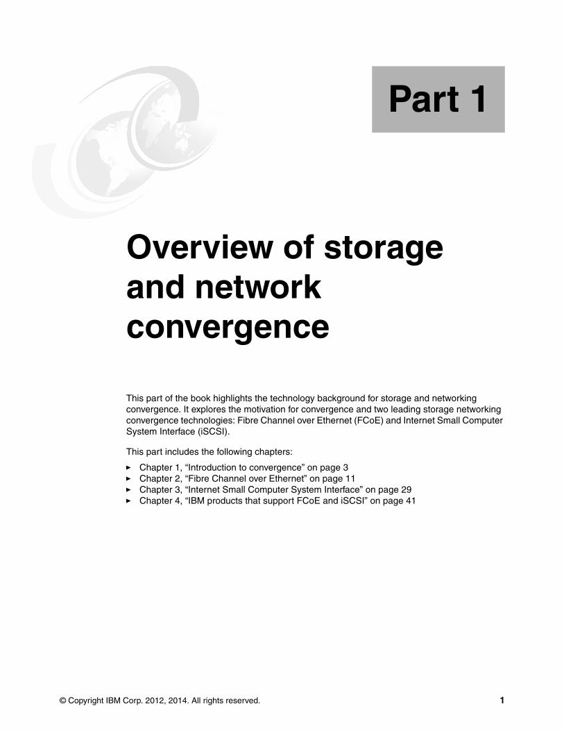
Figure 1-1 shows a simplified picture of a traditional data center without convergence. Either servers or storage devices might require multiple interfaces to connect to the different networks. In addition, each network requires dedicated switches, which leads to higher investments in multiple devices and more efforts for configuration and management.
Chapter 1. Introduction to convergence 7
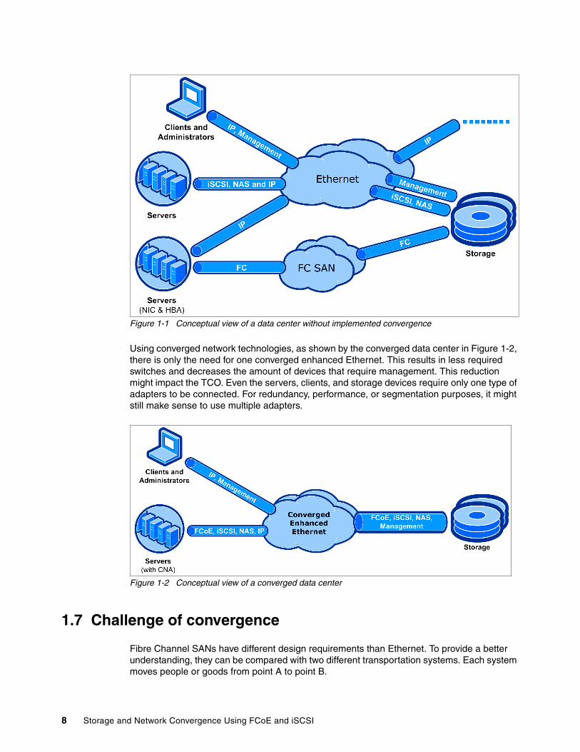
Figure 1-1 Conceptual view of a data center without implemented convergence
Using converged network technologies, as shown by the converged data center in Figure 1-2, there is only the need for one converged enhanced Ethernet. This results in less required switches and decreases the amount of devices that require management. This reduction might impact the TCO. Even the servers, clients, and storage devices require only one type of adapters to be connected. For redundancy, performance, or segmentation purposes, it might still make sense to use multiple adapters.
Figure 1-2 Conceptual view of a converged data center
1.7 Challenge of convergence
Fibre Channel SANs have different design requirements than Ethernet. To provide a better understanding, they can be compared with two different transportation systems. Each system moves people or goods from point A to point B.
8 Storage and Network Convergence Using FCoE and iSCSI

RailroadsTrains run on rails and tracks. This can be compared with Fibre Channel SAN.
Figure 1-3 Trains running on rails
Specific aspects for trains that even impact network traffic are as follows:
� The route is already defined by rails (shortest path first).
� All participating trains are registered and known (nameserver).
� The network is isolated, but accidents (dropped packages) have a huge impact.
� The amount of trains in one track segment is limited (buffer to buffer credit for a lossless connection).
� Signals and railway switches all over the tracks define the allowed routes (zoning).
� They have high capacity (payload 2148 bytes).
RoadsCars can use roads with paved or even unpaved lanes. This can be compared with traditional Ethernet traffic.
Figure 1-4 Cars using roads
Chapter 1. Introduction to convergence 9

Specific aspects for roads that even impact network traffic are as follows:
� An unknown number of participants may be using the road at the same time. Metering lights can only be used as a reactive method to slow down traffic (no confirmation for available receiving capacity in front of sending).
� Accidents are more or less common and expected (packet loss).
� All roads lead to Rome (no point-to-point topology).
� Navigation is required to prevent moving in circles (requirement of Trill/Spanning Tree/SDN).
� Everybody can join and hop on/off mostly everywhere (no zoning).
� They have limited capacity (payload 1500), while available bigger buses/trucks can carry more (jumbo frames).
Convergence approachesMaintaining two transportation infrastructure systems, with separate vehicles and different stations and routes, is complex to manage and expensive. Convergence for storage and networks can mean “running trains on the road”, to stay in the context. The two potential vehicles, which are enabled to run as trains on the road, are iSCSI and Fibre Channel over Ethernet (FCoE).
iSCSI can be used in existing (lossy) and new (lossless) Ethernet infrastructure, with different performance aspects. However, FCoE requires a lossless converged enhanced Ethernet network and it relies on additional functionality known from Fibre Channel (for example, nameserver, zoning).
The following chapters explore two primary approaches for network convergence. Each chapter explains the technology and the IBM products that are available to implement these technologies. Later, this book provides configuration examples that use IBM and partner products to implement these technologies.
1.8 Conclusion
Convergence is the future. Information technology convergence can reduce cost, simplify deployment, better leverage expensive resources, and have a smaller data center infrastructure footprint. The IT industry is adopting FCoE more rapidly because the technology is becoming more mature and offers higher throughput in terms of 40/100 Gbps. Sooner or later, the CIOs will realize the cost benefits and advantages of convergence and will adopt the storage and network convergence more rapidly.
The second edition of this book focuses on insights and capabilities of FCoE on IBM Flex Systems and introduces available IBM switches and storage solutions with support for converged networks. But most content of the initial book, which focused more on IBM BladeCenter converged solutions, is still valid and is an integrated part of the book.
10 Storage and Network Convergence Using FCoE and iSCSI

Chapter 2. Fibre Channel over Ethernet
Fibre Channel over Ethernet (FCoE) is a method of sending Fibre Channel frames directly over an Ethernet network. It relies on a new Ethernet transport with extensions that provide lossless transmission of storage data. This chapter examines these Ethernet extensions to provide you with background information. Then it explains FCoE technology and the selected IBM and IBM Business Partner products that support it.
This chapter includes the following sections:
� 2.1, “Background: Data Center Bridging” on page 12� 2.2, “Standards work related to FCoE” on page 15� 2.3, “FCoE concepts” on page 16� 2.4, “Technology comparison: FCoE with iSCSI” on page 26� 2.5, “Summary of technology used” on page 27� 2.6, “Conclusion” on page 28
2
© Copyright IBM Corp. 2012, 2014. All rights reserved. 11
2.1 Background: Data Center Bridging
The Fibre Channel - Backbone - 5 (FC-BB-5) standard specifies that FCoE is intended to operate over an Ethernet network that does not discard frames in the presence of congestion. Such an Ethernet network is called a lossless Ethernet in this standard.1
The Institute of Electrical and Electronics Engineers (IEEE) 802.1 Data Center Bridging (DCB) Task Group is working on a set of standards that enhance existing 802.1 bridge definitions. The enhancements provide a converged network that allows multiple applications to run over a single physical infrastructure. In fact, the DCB standards are intended to apply even more broadly for more types of traffic than just for FCoE.
The DCB standards include Priority-based Flow Control (PFC), Enhanced Transmission Selection (ETS), Congestion Notification (CN), and the Data Center Bridging Capabilities Exchange protocol. Various terms have been used to describe some or all of these DCB standards. An early term that was used by Cisco to describe certain elements was Data Center Ethernet (DCE). The term Converged Enhanced Ethernet (CEE) was later used by IBM and several other vendors in the T11 working group. The official IEEE 802 term is now Data Center Bridging.
2.1.1 Priority-based Flow Control: IEEE 802.1Qbb
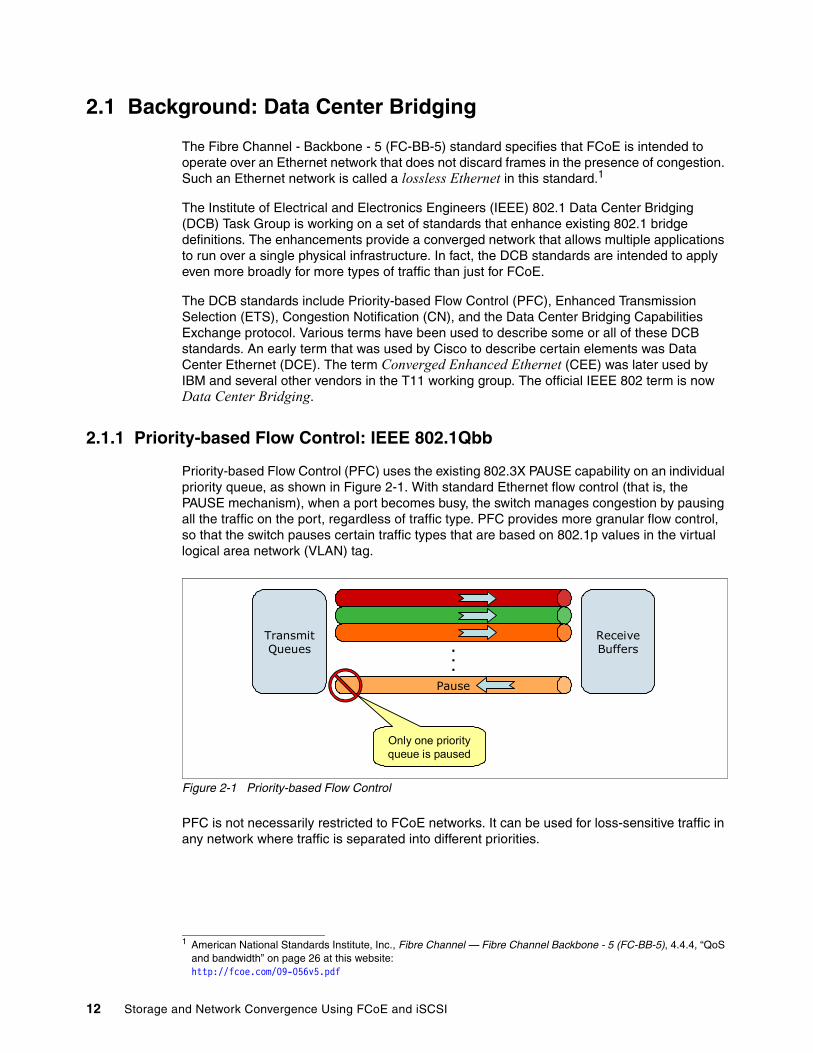
Priority-based Flow Control (PFC) uses the existing 802.3X PAUSE capability on an individual priority queue, as shown in Figure 2-1. With standard Ethernet flow control (that is, the PAUSE mechanism), when a port becomes busy, the switch manages congestion by pausing all the traffic on the port, regardless of traffic type. PFC provides more granular flow control, so that the switch pauses certain traffic types that are based on 802.1p values in the virtual logical area network (VLAN) tag.
Figure 2-1 Priority-based Flow Control
PFC is not necessarily restricted to FCoE networks. It can be used for loss-sensitive traffic in any network where traffic is separated into different priorities.
1 American National Standards Institute, Inc., Fibre Channel — Fibre Channel Backbone - 5 (FC-BB-5), 4.4.4, “QoS and bandwidth” on page 26 at this website:http://fcoe.com/09-056v5.pdf
Pause
.
.
.
TransmitQueues
ReceiveBuffers
Only one priority queue is paused
12 Storage and Network Convergence Using FCoE and iSCSI

In an FCoE context, the FCoE traffic is mapped to the priority level on which the selective pause is enabled. Therefore, if the receiving switch becomes congested, it does not continue receiving traffic that must not be dropped. Traffic with other priority values can continue but might be dropped if port buffers become full. This back-pressure mechanism on the FCoE traffic keeps it from being discarded by intermediate switches. Thus, the use of PFC with FCoE traffic provides a functional equivalent to the buffer-to-buffer credit mechanism of FC.
The FC-BB-5 standard does not require PFC itself. Rather, it indicates that FCoE is intended to run over lossless Ethernet and lists PFC as an option for implementing that capability. The suite of DCB protocols, including PFC, is the direction of the industry for implementing lossless Ethernet.
PFC works with Enhanced Transmission Selection, described next, which is used to split the bandwidth of the link between the traffic priority groups.
For more information about PFC, see 802.1Qbb - Priority-based Flow Control on the IEEE site at this website:
http://ieee802.org/1/pages/802.1bb.html
2.1.2 Enhanced Transmission Selection: IEEE 802.1Qaz
With Enhanced Transmission Selection (ETS), port bandwidth is allocated based on 802.1p priority values in the VLAN tag. You can combine multiple priority values into traffic groups or classes. You can then specify different amounts of link bandwidth for these different traffic groups. For example, you can assign a higher priority and a certain amount of guaranteed bandwidth to storage traffic. If a traffic group does not use its allocated bandwidth, other traffic is allowed to use that bandwidth. ETS allows multiple types of traffic to coexist on a converged link without imposing contrary handling requirements on each other.
Figure 2-2 illustrates ETS with various traffic types. By using a switch, the eight 802.1p priority levels can be mapped to bandwidth on the link as percentages of link bandwidth, as shown in this diagram. Over time, the actual link bandwidth that is used by a certain traffic class varies, based on demand and the defined bandwidth allocations.
Notes:
� A receiver using PFC must be able to predict when a PAUSE frame needs to be sent out before its receive buffers overflow. Timing is the key here because the receiver must take into account that the PAUSE package needs time to reach the sender and there might already be additional packets on the way that need to be handled. Sending out the PAUSE signal too late leads to dropped frames, which might be tolerable within traditional Ethernet, but definitely not in lossless communications (for example, FC and FCoE). However, sending out PAUSE signals too early decreases the performance significantly.
� As bits travel with a finite speed on the wire, this behavior limits the possible distance (latency) with respect to the available buffers, amount of devices, and lossless connection channels. For a more detailed technical analysis, see the Cisco white paper “Priority Flow Control: Build Reliable Layer 2 Infrastructure”, describing a maximum distance of 300 m.This white paper is available at the following website:
http://www.cisco.com/en/US/prod/collateral/switches/ps9441/ps9670/white_paper_c11-542809.html
Chapter 2. Fibre Channel over Ethernet 13

Figure 2-2 Enhanced Transmission Selection
Similar to PFC, ETS is not restricted to use with FCoE traffic. In general, ETS can be used to allocate link bandwidth among different traffic classes. In an FCoE context, ETS is used to give the FCoE traffic a certain priority level and bandwidth allocation.
For more information about ETS, see 802.1Qaz - Enhanced Transmission Selection on the IEEE website:
http://ieee802.org/1/pages/802.1az.html
2.1.3 Data Center Bridging Capabilities Exchange–IEEE 802.1Qaz
Data Center Bridging Capabilities Exchange (DCBX) protocol is a capabilities-exchange protocol that is used by DCB-capable switches to identify and communicate with each other. Neighboring devices use DCBX to exchange and negotiate configuration information and detect misconfigurations.
Among other tasks, devices use DCBX to exchange information about FCoE, information about whether PFC is enabled on the port, and ETS priority group information, including 802.1p priority values and bandwidth allocation percentages.
2.1.4 Congestion Notification: IEEE 802.1Qau
Congestion Notification (CN) provides end-to-end congestion management for protocols within a Layer 2 domain. Where PFC functions on a link-by-link basis, by using CN, switches can notify endpoints that congestion is occurring somewhere along the path from source to destination. The endpoint can then slow down or stop its transmission until the congestion clears.
Vendors have made different statements about to whether CN is required for FCoE deployments. However, IBM and many other vendors have taken the position that CN is a “nice to have” feature but is optional, at least for initial FCoE deployments. The applicability of CN is generally considered to be related to the size of the switched LAN over which FCoE transmission occurs.
Example:Email = best effortHTTP = 1 Gb min.HPC = 3 Gb min.FCoE = 5 Gb min.
10
9
8
7
6
5
4
3
2
1
0Assigned Bandwidth
(Percent of link bandwidth,in 10% increments)
10
9
8
7
6
5
4
3
2
1
0t1 t2 t3 t4
EmailHTTPHPCFCoE
14 Storage and Network Convergence Using FCoE and iSCSI

In an FCoE deployment, with a single or small number of intermediate DCB switches between source server and target FCoE or FCoE gateway device, PFC is most likely sufficient to ensure lossless behavior. In a larger network, with multiple DCB switches and multiple possible paths between source and destination of the FCoE flow, intermediate congestion might be possible despite PFC, increasing the need for CN.
FC and other technologies provide lossless transmission without end-to-end congestion notification.
For more information about CN, see 802.1Qau - Congestion Notification on the IEEE site at this website:
http://www.ieee802.org/1/pages/802.1au.html
2.2 Standards work related to FCoE
Two additional standards are often associated with FCoE, but are not required for FCoE deployments because the issues that they address can be solved in other ways.
2.2.1 Transparent Interconnection of Lots of Links
Transparent Interconnection of Lots of Links (TRILL) is a new Layer 2 interconnection technology that replaces spanning tree. With spanning tree, switches (Layer 2 bridges) form a loop-free topology to transmit frames through a L2 network. However, spanning tree leaves many potential paths unused, is inefficient, and can be slow to reconverge when problems occur.
TRILL was proposed as a project in 2004 by Radia Perlman, the inventor of spanning tree. The goal of TRILL is to provide safe forwarding of packets, Layer 2 multipathing technology, and more robust behavior than spanning tree. TRILL uses IS-IS link state routing. The base protocol specification is now an Internet Engineering Task Force (IETF) proposed standard that is documented in RFC 6325. Additional RFCs cover other aspects of TRILL behavior.
Although TRILL is of wide interest because of the benefits it can provide in large Layer 2 LANs, it is not required for FCoE deployments.
2.2.2 Shortest Path Bridging: IEEE 802.1aq
Shortest Path Bridging (SPB) is another approach under the auspices of IEEE, as opposed to TRILL from IETF, to solve the problems of Layer 2 Spanning Tree. It proposes an alternative method for providing a multipath capability at Layer 2. Both TRILL and 802.1aq rely on IS-IS as a routing protocol, but various differences exist beyond this protocol. Similar to TRILL, a Layer 2 multipath capability is desirable for many reasons, but it is not required for FCoE or for storage and networking convergence in general.
For more information about SPB, see 802.1aq - Shortest Path Bridging on the IEEE website:
http://www.ieee802.org/1/pages/802.1aq.html
More information: For more information about RFC 6325, see Routing Bridges (RBridges): Base Protocol Specification RFC 6325:
http://datatracker.ietf.org/doc/rfc6325
Chapter 2. Fibre Channel over Ethernet 15

2.3 FCoE concepts
FCoE assumes the existence of a lossless Ethernet, for example one that implements the DCB extensions to Ethernet described previously. This section provides an overview of the following concepts of FCoE as defined in FC-BB-5:
� FCoE protocol stack� Topology� FCoE Initialization Protocol and snooping bridges� MAC addresses used by end devices� FCFs, Fabric Mode, and NPIV
2.3.1 FCoE protocol stack
The basic notion of FCoE is that the upper layers of FC are mapped onto Ethernet, as shown in Figure 2-3. The upper layer protocols and services of FC remain the same in an FCoE deployment.
For example, zoning, fabric services, and similar functions still exist with FCoE. The difference is that the lower layers of FC are replaced by lossless Ethernet. Therefore, FC concepts, such as port types and lower-layer initialization protocols, must also be replaced by new constructs in FCoE. Such mappings are defined by the FC-BB-5 standard and are briefly reviewed here.
Figure 2-3 FCoE protocol mapping
FC-0
FC-1
FC-2P
FC-2M
FC-2V
FC-3
FC-4
Fibre ChannelProtocol Stack
Ethernet PHY
Ethernet MAC
FCoE Entity
FC-2V
FC-3
FC-4
FCoEProtocol Stack
16 Storage and Network Convergence Using FCoE and iSCSI

Figure 2-4 shows another perspective on FCoE layering compared to other storage networking technologies. The FC and FCoE layers are shown with the other storage networking protocols, including Small Computer System Interface (iSCSI).
Figure 2-4 Storage Network Protocol Layering
Figure 2-5 shows a conceptual view of an FCoE frame based on this protocol structure.
Figure 2-5 Conceptual view of an FCoE frame
Operating Systems / Applications
SCSI Layer
1, 2, 4, 8, 16Gbps
FCP FCP FCP FCiSCSI SRP
TCP TCP TCP
IP IP IP FCoE
FC IB
iFCPFCIP
Ethernet
1, 10, 40, 100... Gbps 10, 20, 40 Gbps
FC FCoE
Eth
ern
et
Head
er
FC
oE
Head
er
FC
S
EO
F
FC
Head
er
CR
C
FC Payload
Ethernet Frame, Ethertype = FCoE=8906h
Same as a physical FC frame
Control information: version, ordered sets (SOF, EOF)
Chapter 2. Fibre Channel over Ethernet 17
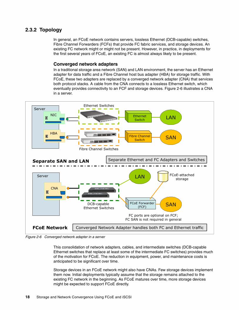
2.3.2 Topology
In general, an FCoE network contains servers, lossless Ethernet (DCB-capable) switches, Fibre Channel Forwarders (FCFs) that provide FC fabric services, and storage devices. An existing FC network might or might not be present. However, in practice, in deployments for the first several years of FCoE, an existing FC is almost always likely to be present.
Converged network adaptersIn a traditional storage area network (SAN) and LAN environment, the server has an Ethernet adapter for data traffic and a Fibre Channel host bus adapter (HBA) for storage traffic. With FCoE, these two adapters are replaced by a converged network adapter (CNA) that services both protocol stacks. A cable from the CNA connects to a lossless Ethernet switch, which eventually provides connectivity to an FCF and storage devices. Figure 2-6 illustrates a CNA in a server.
Figure 2-6 Converged network adapter in a server
This consolidation of network adapters, cables, and intermediate switches (DCB-capable Ethernet switches that replace at least some of the intermediate FC switches) provides much of the motivation for FCoE. The reduction in equipment, power, and maintenance costs is anticipated to be significant over time.
Storage devices in an FCoE network might also have CNAs. Few storage devices implement them now. Initial deployments typically assume that the storage remains attached to the existing FC network in the beginning. As FCoE matures over time, more storage devices might be expected to support FCoE directly.
Server
NICLAN
SAN
Separate Ethernet and FC Adapters and Switches
Converged Network Adapter handles both FC and Ethernet traffic
HBA
Server
EthernetSwitch
Fibre ChannelSwitch
DCB-capable Ethernet Switches
Separate SAN and LAN
FCoE Network
CNA
LAN
FCoE Forwarder (FCF)
FC ports are optional on FCF;FC SAN is not required in general
FCoE-attachedstorage
Ethernet Switches
Fibre Channel Switches
SAN
18 Storage and Network Convergence Using FCoE and iSCSI

FCoE port typesIn a traditional FC network, port types are defined to represent roles of devices in a network. These FC devices are connected over point-to-point links. In FCoE, because traffic is sent over Ethernet networks instead of point-to-point links, virtual port types are defined that are analogous to the traditional FC port types. Figure 2-7 illustrates these port types.
Figure 2-7 FC and FCoE port types
In a traditional FC network, the server might be an N_Port (node port), and its neighboring switch might be an F_Port (fabric port). Two FC switches connected over an inter-switch link (ISL) might be E_Ports (expansion ports).
In an FCoE network, virtual links are used across the lossless Ethernet network in place of the physical links in the FC network. The server negotiates a connection to the FCF device across the Ethernet network by using the FCoE Initialization Protocol (FIP). The server end of this connection is called a VN_Port. The FCF end is called the VF_Port. Two FCFs can also negotiate a connection across the Ethernet network, in which case the (virtual) ISL has VE_Ports at both ends.
DCB-capable switchesIntermediate Ethernet switches (between the server and FCF, for example) in an FCoE network are expected to provide lossless Ethernet service. In practice, they implement DCB Ethernet standards as described previously. For security reasons, they are also expected to implement FIP Snooping. An Ethernet switch that implements these capabilities is sometimes called an FCoE Transit Switch or a FIP-Snooping Bridge (FSB).
An FCoE network can consist of servers with CNAs connected directly to an FCF, in which case intermediate Ethernet switches might not be available.
LosslessEthernet
Server
FC SANHBA
Server
Fibre ChannelSwitch
Fibre Channel port types
FCoE port types
CNA
FC SANFCoE Forwarder (FCF)
Fibre ChannelSwitch
N-port
F-port
E-port
E-port
VN-port (blue link)
FCoE Forwarder (FCF) FC SAN
VE-ports (red)VE-ports (red linkbetween FCFs)
VF-port (blue link from server to FCF)
Chapter 2. Fibre Channel over Ethernet 19

Fibre Channel ForwardersThe Fibre Channel Forwarder is the FC switching element in an FCoE network. It provides functions that are analogous to the functions provided by the FC switch in a traditional FC network. The most basic function is the forwarding of FCoE frames received on one port to another port based on the destination address in the encapsulated FC frame. The FCF is also the entity that handles FC logins, routing, zoning, and other FC services. These FC services and functions still exist in an FCoE network. Remember that the lower layers of FC have changed with FCoE, but the upper layers are intact.
FCFs might also have existing FC ports that connect to traditional Fibre Channel SANs. In this case, the FCF provides a gateway function between FCoE and FC, transmitting frames between the two types of networks. In practice, this case applies to many or most early FCoE deployments, because they are used to provide connectivity to existing Fibre Channel SANs. However, FC ports are optional in an FCF that is used in a pure FCoE environment. The FCF function is still required, even in a pure FCoE network, because it provides the switching and fabric services functions.
Unlike with FC, no direct-attach (switchless) topology is defined for FC-BB-5 FCoE. This topology is addressed in FC-BB-6. For more information, see 2.3.6, “Distributed FCF under development” on page 23.
2.3.3 FCoE Initialization Protocol and snooping bridges
In a traditional FC network, with point-to-point links between an end device and an FC switch, the end device logs in to the fabric. The device exchanges information with the switch by using well-known addresses over its direct link to the switch. In an FCoE network, with intermediate Ethernet links and possibly switches, these login functions become more complicated. They are handled by a protocol called the FCoE Initialization Protocol (FIP).
For more information about FIP, see the FC-BB-5 standard at this website:
http://fcoe.com/09-056v5.pdf
FIP allows the end device (for example, the server with a CNA) to discover FCFs and the VLANs with which to connect to them. Then FIP allows the device to establish those connections, which are the VN_Port to VF_Port virtual links described previously.
FIP entails the following high-level steps:
1. The end device (called an ENode in the standard) broadcasts a FIP VLAN request to a well-known address for all FCFs.
2. FCFs that have VF_Ports reply with a VLAN Notification frame that lists VLANs that the end device can use.
3. The end device discovers FCFs that it can log into by broadcasting a Discovery Solicitation frame in the discovered VLAN.
4. FCFs respond with Discovery Advertisement frames. These frames contain such information as an FCF priority and the identifier of the fabric to which the FCF connects.
5. The end device determines which FCF it wants to connect to for fabric login and sends an FIP Fabric Login (FLOGI) request to the FCF to log in to the fabric.
6. The FCF replies with an FLOGI Accept frame, and then the login is complete. The VN_Port to VF_Port link is now established. The Accept frame also provides a mechanism for the FCF to indicate to the end device the MAC address to use for its VN_Port.
20 Storage and Network Convergence Using FCoE and iSCSI

Because these virtual links can be established over an arbitrary Ethernet network, they must now be given security that is equivalent to the security in a point-to-point FC network. This security is accomplished by having the intermediate DCB-capable switches “snoop” the FIP frames that they forward. By using the information that the switch sees during the FIP login sequence, the switch can determine which devices are connected by using a virtual link. Then the switch dynamically creates narrowly tailored access control lists (ACLs) that permit expected FCoE traffic to be exchanged between the appropriate devices and deny all other undesirable FCoE or FIP traffic.
This function is necessary for intermediate DCB-capable switches to enable a secure implementation of FCoE. For more information about this function, see Annex C of the FC-BB-5 standard at this website:
http://fcoe.com/09-056v5.pdf
2.3.4 MAC addresses used by end devices
End devices (ENodes in the FC-BB-5 standard) use virtual MAC addresses for their VN_Ports. The FC-BB-5 standard allows these MAC addresses to be assigned by the FCF during login, as described previously, or by the ENode. MAC addresses assigned by FCFs are called Fabric Provided MAC Addresses (FPMAs). MAC addresses assigned by the end devices are called Server Provided MAC Addresses (SPMAs). The CNAs and FCFs today implement only FPMAs.
2.3.5 FCFs, Fabric Mode, and NPIV
As mentioned previously, a Fibre Channel Forwarder is the FC switching element in an FCoE network. One of the characteristics of an FC switching element is that it joins the FC fabric as a domain. The number of FC switches (domains) that can join a single fabric has a theoretical limit of around 250. It also has practical limit generally in the range 50-75. The recommended limits vary by vendor.
In a mixed FC-FCoE fabric (the typical scenario in most early FCoE deployments), the FCF also often acts as the gateway device between FC and FCoE. Each FCF that operates in full-fabric mode or switch mode as an FC switch joins the existing FC fabric as a domain. If the total size of the fabric (number of FC switches plus the FCFs) is within the practical limit, it is appealing and acceptable to use FCFs in fabric mode. If an FCoE deployment has many edge FCFs that are planned to join an existing FC fabric, the number of domains can be problematic. Examples of such FCoE deployments include a network, with multiple BladeCenter chassis each having an edge FCF, and a number of racks each with an FCF at the top of the rack.
N_Port ID Virtualization (NPIV) technology is used in traditional Fibre Channel networks to reduce the number of domains in the overall fabric. NPIV technology can be used in the following ways:
� In a host. NPIV technology is used to allow multiple virtual machines (VMs) within the host to each receive N_Port IDs from the neighboring FC switch so that all the VMs can share a single physical N_Port.
� In a switch or gateway device on the edge of an FC fabric. NPIV technology is used to allow the gateway device to appear as a switch (F_Port) to connecting servers. This technology is also used to allow the gateway device to appear as a node (N_Port) to the edge FC switch to which it connects, acting as concentrator for multiple N_Port devices (servers). The gateway device allows attachment of multiple N_Ports but does not use a domain in the FC fabric (see Figure 2-8).
Chapter 2. Fibre Channel over Ethernet 21

NPIV technology used in a gateway device allows greater scaling of an FC fabric and is appealing in various situations. A common use is to attach a vendor X switch to a vendor Y FC fabric. The use of NPIV technology reduces the interoperability issues of mixing the FC switches, from multiple vendors, within a fabric by using E_Ports. Another use is to reduce the overall number of switches in a fabric. For example, a BladeCenter environment might use an FC switch in every chassis (more domain IDs used) or an NPIV gateway in every chassis (fewer domain IDs used).
Whether implemented in a host or in a gateway device, use of NPIV technology requires the FC switch (to which the NPIV device connects) to support NPIV and to enable that support on the appropriate ports.
A gateway device that uses NPIV technology might be referred to by various names, including NPort concentrator, NPort Aggregator, or NPIV Gateway. Vendors also use many terms to refer to such gateways. For example, Cisco uses the term N_Port Virtualization (NPV), Brocade uses the term Access Gateway, and QLogic uses the term Transparent Mode. These terms are explained in Part 3, “Implementing storage and network convergence” on page 223.
For more information about NPIV, see Implementing the Brocade Access Gateway for IBM BladeCenter, REDP-4343. Figure 2-8 illustrates the NPIV concept from this IBM Redpaper™ publication.
Figure 2-8 Brocade Access Gateway with NPIV technology
F2
F3
F4E
E
E
E
N
N
N
N
F1
Fabric
N
N
F13
F14E E
FabricSwitch
FCSM in Switch Mode
BladeServers
F2
F3
F4N15
N0
F
F
N
N
N
N
F1
Fabric
N
N
F13
F14N19 F
FabricSwitch
FCSM in AccessGateway Mode (NPIV)
BladeServers
22 Storage and Network Convergence Using FCoE and iSCSI

NPIV technology can also be used by FC-FCoE gateways. In some FCoE scenarios, it might be appealing to use a gateway in NPIV mode rather than in full-fabric FCF mode. In this case, the gateway provides the translation between FCoE and FC frames in addition to FCoE services. Other fabric services, such as zoning and Name Server, are supplied by the existing FC switch to which the NPIV device attaches.
In general, vendors might allow their FCF devices to operate in full FCF mode (fabric mode) or in NPIV mode. For another approach to dealing with proliferation of domain IDs in a mixed FC-FCoE network, see the following section.
2.3.6 Distributed FCF under development
Ongoing standards work is underway to address the issue of optimal routing in an FCoE fabric as it relates to the number of domain IDs required. This work is being done in consideration of the previous comments about FCFs and that each FCF uses a domain ID in a fabric. Figure 2-9 and Figure 2-10 illustrate two possible topologies for FCoE in a data center and the potential problems associated with each.
Figure 2-9 illustrates a data center with many FCFs in a locality and too many domain IDs.
Figure 2-9 Many FCFs in a locality and too many domain IDs
Storage
FCF
Storage
FCF
Storage
FCF
Storage
FCF
Storage
FCF
Upstream FC Network
Optimal routing but many domain IDs
Chapter 2. Fibre Channel over Ethernet 23

Figure 2-10 illustrates an end-of-row or centralized FCF with suboptimal routing in a data center.
Figure 2-10 End-of-row or centralized FCF with suboptimal routing in a data center
FCFs can be placed at the top of each rack, in each BladeCenter chassis, or otherwise close to servers and their nearby storage (which might help in providing optimal routing between server and storage). In these situations, many domain IDs are required, one per FCF. However, an FCF can be placed at the end of the row or in a similar centralized location to service many servers and their related storage (which might reduce the number of domain IDs required). In this case, traffic between servers and storage might have to follow suboptimal paths through the network (from the server all the way to FCF and back to local storage).
The FC-BB-6 project, which began in June 2009, is addressing these issues and other issues by working to define the concept of a distributed FCF. FC-BB-6, as currently conceived, separates the FCF control plane (cFCF) and the data plane (FDF) by defining the notion of an FCoE Data-plane Forwarder (FDF). An FDF provides data forwarding between FCoE endpoints but does not provide full fabric services, such as zoning and name serving. A set of FDFs is controlled by one or more cFCFs (multiple cFCFs to provide redundancy), which provide the FDFs with routing and other fabric information.
Storage
Switch
Storage
Switch
Storage
Switch
Storage
Switch
Storage
Switch
Upstream FC Network
Single domain ID but suboptimal routing
FCF
24 Storage and Network Convergence Using FCoE and iSCSI

A distributed FCF provides a single, virtual domain that allows optimal data flow between devices within a chassis or rack and limits the number of FC domain IDs that are required in the FCoE network (Figure 2-11).
Figure 2-11 Conceptual model of an FC-BB-6 distributed FCF
As of this writing, the FC-BB-6 work is still in progress. Therefore, the concepts and definitions are subject to change before final approval. For more information, see the FCoE site at this website:
http://www.fcoe.com
Storage
FDF
Storage
FDF
Storage
FDF
Storage
FDF
Storage
FDF
FC-BB-6 conceptual model of distributed FCF
Upstream FC Network
FCF
Chapter 2. Fibre Channel over Ethernet 25

2.4 Technology comparison: FCoE with iSCSI
This section compares the similarities and differences between different convergence technologies. Internet Small Computer System Interface (iSCSI) and Fibre Channel over Ethernet (FCoE) have several similarities and differences. As in most cases, considerations other than purely technical ones can also influence the decision about which protocol to choose.
2.4.1 Similarities
iSCSI and FCoE have the following similarities:
� iSCSI and FCoE are block-oriented storage protocols. That is, the file system logic for accessing storage with either of them is on the computer where the initiator is, not on the storage hardware. They are both different from typical network-attached storage (NAS) technologies, which are file-oriented.
� Both protocols implement attached storage with Ethernet.
� Both protocols can be implemented in hardware, which is seen by the operating system of the host as a host bus adapter.
� Both protocols can use the Converged Enhanced Ethernet (CEE), also referred to as Data Center Bridging (DCB) standards, to deliver lossless traffic over Ethernet.
� Both protocols are alternatives to traditional Fibre Channel (FC) storage and FC storage area networks (SANs).
2.4.2 Differences
iSCSI and FCoE have the following differences:
� iSCSI uses TCP/IP as its transport, and FCoE uses Ethernet. iSCSI can use media other than Ethernet, such as InfiniBand, and it can use Layer 3 routing in an IP network.
� Numerous vendors provide native iSCSI storage targets, some of which also support FC and other storage technologies. Now there are more native FCoE targets are available, and cost remains same for both iSCSI and FCoE.
� FCoE requires a gateway function, usually called an FC Forwarder (FCF). By using the FCF, FCoE can access traditional FC-attached storage. With this approach, FCoE and traditional FC storage access can coexist as a long-term approach or as part of a migration.
� iSCSI to FC gateways exist but are not required when a storage device that can accept iSCSI traffic directly is used. The DS5300 used in our tests is one such device.
� Except in the case of a native FCoE storage target, the last leg of the connection uses FC to reach the storage. FC uses 8b/10b encoding, which means that sending 8 bits of data requires a transmission of 10 bits over the wire or 25% payload that is transmitted over the network to prevent corruption of the data. The 10 Gbps Ethernet uses 64b/66b encoding, which has a much smaller payload.
� iSCSI includes IP headers and Ethernet (or other media) headers with every frame that adds payload.
� The largest payload that can be sent in an FCoE frame is 2112. iSCSI can use jumbo frame support on Ethernet and send 9 K or more in a single frame.
26 Storage and Network Convergence Using FCoE and iSCSI
� iSCSI has been on the market for several years longer than FCoE. Therefore, the iSCSI standards are more mature than FCoE. However, FCoE is also maturing faster and the industry is adopting this technology more rapidly to embrace convergence.
� Troubleshooting FCoE end-to-end requires Ethernet networking skills and FC SAN skills.
2.5 Summary of technology used
This section describes the performance of different brands of products and provides a comparison between them. However, the performance is not the only item to base your decision on. In addition, consider the initial cost time to deploy and the necessary skills.
2.5.1 Initial cost at purchase
The initial purchase price can be an important consideration in determining the solution for your environment. Here is the breakdown of each solution:
� Software iSCSI:
The iSCSI solution is likely to be the least expensive. Keep in mind that, if you use software iSCSI, you are likely to use your server processor even more. Therefore, make sure that you plan your processor speeds accordingly.
� Hardware iSCSI:
On some adapters, iSCSI hardware costs more than a regular adapter. If you want to boot from SAN with iSCSI, or if you want to plan to use processor-intensive applications, consider iSCSI hardware to free your system processors.
� FCoE:
The FCoE CNAs are more expensive than the iSCSI solution. You must also consider buying a switch FCoE license. The switches must be FCoE capable. You cannot use normal Ethernet switches. FCoE requires a lossless Ethernet. The initial purchase price is not as expensive as FC, but is more expensive than iSCSI.
� FC:
FC is the most expensive of the four technologies mentioned. However, it has other advantages as described in the next section, 2.5.2, “Time to deploy”.
2.5.2 Time to deploy
Most people have deadlines to deploy a new infrastructure. Trying to configure a new environment can cost money if staff is not familiar with the different configurations. Review the information provided for each technology to plan carefully.
iSCSISoftware iSCSI requires several steps to set up. In addition to the network adapter drivers and software, you must install the software initiator and configure it. Several steps are necessary if you have multiple servers to set up.
Hardware iSCSI setup time is similar to software iSCSI. Instead of setting up a software initiator, you set up your hardware iSCSI settings in F1 UEFI or by using the software management tool that is provided by the vendor.
Chapter 2. Fibre Channel over Ethernet 27

On the Ethernet switch side, the switches can function as regular Ethernet switches. However, isolate the network and iSCSI traffic with VLANs or use different hardware switches. If you are running both Ethernet and iSCSI traffic on the same port, enable CEE to guarantee a minimum quantity of bandwidth guaranteed for the disk traffic.
FCoEFCoE is maturing faster and the trend is moving towards adopting network convergence more rapidly to reduce the footprint of the switches within the data center. 40 Gb capable FCoE switches are more readily available in the market and the port count is increasing.
While FC is still there and growing, it is a minority compared to NFS + FCoE + iSCSI, all based on Ethernet and growing faster.
IBM supports all of these technologies, so you can select the right application and business justification. However, 10 and 40GE are growing area, especially with support for Lossless (DCB) iSCSI over 10GE and eventually 40GE.
Fibre ChannelFC is the easiest technology to set up. For the most part, it is easy to use and requires little configuration. However, ensure that you configure zoning for your environment.
2.5.3 Necessary skills
The following skills are necessary for an organization to successfully deploy the various converged storage and network technologies:
� iSCSI requires Ethernet skills to set up the switches and separate the iSCSI traffic from regular LAN traffic. Software iSCSI requires software skills on the operating system that you want to deploy. Hardware iSCSI requires knowledge about the hardware iSCSI card, but can be understood by most network teams.
� FCoE requires Ethernet skills and FC skills. In addition, with FCoE, many new terms and settings are added, which adds more complexity. FCoE requires an investment of time to learn the new terms, design, and commands that are proprietary to FCoE.
� FC requires that you have someone with knowledge about FC. It is not hard to set up, but if you plan a large environment, you need specialized resources.
2.6 Conclusion
Convergence is the way to go forward. Consider the factors that are outlined in this book carefully before choosing a solution. If resources allow it, separate network traffic and disk traffic by using FC, iSCSI, or FCoE. Although it is easier to set up FC for disk access, iSCSI and FCoE solutions are possible if you want to invest time and save money on the initial purchase. iSCSI and FCoE require you to invest extra time in doing the configuration. The Ethernet protocol has 10 Gbps and 40 Gbps accessible today and it is also available with most vendors. 100 Gbps technology is already available with some vendors. FC also recently moved to 16 Gbps. FC speeds are not progressing as fast as Ethernet speeds. Consider looking at the iSCSI and FCoE technologies.
28 Storage and Network Convergence Using FCoE and iSCSI
Chapter 3. Internet Small Computer System Interface
The Internet Small Computer System Interface (iSCSI) protocol is the encapsulation of the industry standard SCSI protocol within TCP/IP packets. The iSCSI protocol provides a block-level storage capability similar to Fibre Channel (FC) storage area network (SAN) technology, which is essentially the same system of encapsulating the SCSI protocol within an external “carrier.” The difference is that the iSCSI SAN uses Ethernet instead of FC transport technology.
This chapter presents an overview of the iSCSI protocol, describes its use, and provides an overview of the key IBM products that support iSCSI.
This chapter includes the following sections:
� 3.1, “Introduction to iSCSI” on page 30� 3.2, “iSCSI initiators” on page 35� 3.3, “Performance considerations” on page 37� 3.4, “Multipathing with iSCSI” on page 38
3
© Copyright IBM Corp. 2012, 2014. All rights reserved. 29

3.1 Introduction to iSCSI
With an iSCSI network, you can use an existing traditional Ethernet networking infrastructure, reducing the costs for specialized storage area networking devices, software, and licenses. iSCSI has a head start for many businesses because it already has a stable network infrastructure in place. iSCSI uses the reliable TCP protocol to transport SCSI I/O commands over a network, providing block-level data access without needing specialized hardware requirements. It can also operate with various peripheral devices.
The iSCSI protocol allows for longer distances between a server and its storage when compared to the traditionally restrictive parallel SCSI solutions or the newer serial-attached SCSI (SAS). iSCSI technology can use a hardware initiator, a host bus adapter (HBA), or a software initiator to issue requests to target devices. Within iSCSI storage terminology, the initiator is typically known as the client, and the target is known as the storage device. The iSCSI protocol encapsulates SCSI commands into protocol data units (PDUs) within the TCP/IP protocol, and then transports them over the network to the target device. The disk is presented locally to the client as shown in Figure 3-1.
Figure 3-1 iSCSI architecture overview
3.1.1 iSCSI overview
The iSCSI protocol is a transport for SCSI over TCP/IP. Figure 2-4 on page 17 illustrates a protocol stack comparison between FC and iSCSI. iSCSI provides block-level access to storage, as does FC, but uses TCP/IP over Ethernet instead of the FC protocol. iSCSI is defined in RFC 3720, which you can find at this website:
http://www.ietf.org/rfc/rfc3720.txt
Because iSCSI uses Ethernet-based TCP/IP rather than a dedicated (and different) SAN technology, it is attractive for its relative simplicity and uses widely available Ethernet skills. Its limitations, as explained in 1.5, “Ethernet-based storage today” on page 6, are the relatively lower speeds of Ethernet compared to FC and the extra TCP/IP encapsulation that is required. With lossless 10-Gbps Ethernet now becoming available, the attractiveness of iSCSI is expected to grow rapidly. TCP/IP encapsulation will still be used, but 10 Gbps Ethernet speeds will dramatically increase the appeal of iSCSI.
iSCSI transactions occur between an iSCSI initiator (hardware or software) that transmits a request (such as read/write) and an iSCSI target. This iSCSI target processes the request and responds with the appropriate information, such as data and sense.
iSCSI Initiator
Client
TCP Connection iSCSI Target
Client
Network
30 Storage and Network Convergence Using FCoE and iSCSI

iSCSI initiators are typically application servers or users, where iSCSI targets are typically SAN access points or actual storage controllers. Because an iSCSI request is an encapsulation of a SCSI request, the SCSI concept of command descriptor blocks (CDBs) is applicable to iSCSI. CDBs define the type of SCSI operation, the logical block address to start at, the length of data that is involved, and other control parameters.
Figure 3-2 shows a conceptual overview of the iSCSI protocol layers. As the diagram illustrates, the iSCSI solution requires an initiator (host), a target (generally a storage device), and a carrier network.
Figure 3-2 iSCSI protocol layers
3.1.2 iSCSI protocol in depth
As mentioned previously, the iSCSI protocol uses the TCP/IP protocol to transport iSCSI PDUs, which are the most basic forms of message exchange between the host and the storage controller. The PDU transports both information and SCSI CDBs between the initiator and target, where they receive the required data and response, which in turn might require a reply. The PDU also provides ordering and control information.
TCP/IP was chosen for the following reasons:
� It is field proven.� It can reliably traverse almost any physical network media.� It can deliver almost error free data and data in order.� It provides congestion control.� It acknowledges packets that are received and resends unacknowledged packets.� The benefits outweighed the use of alternative protocols.� iSCSI supports SCSI-3 command sets.
SCSI Cmd/Status/Data
SCSI CDB
iSCSI
TCP
IP
CDB
CDB
CDB
iSCSI Initiator
SCSI Cmd/Status/Data
SCSI CDB
iSCSI
TCP
IP
CDB
CDB
CDB
CDB Generic FormatiSCSI Target
IP Network
SCSI Opcode
Logical BlockAddress
Cmd Parameters
Transfer Length
Control Info
Chapter 3. Internet Small Computer System Interface 31
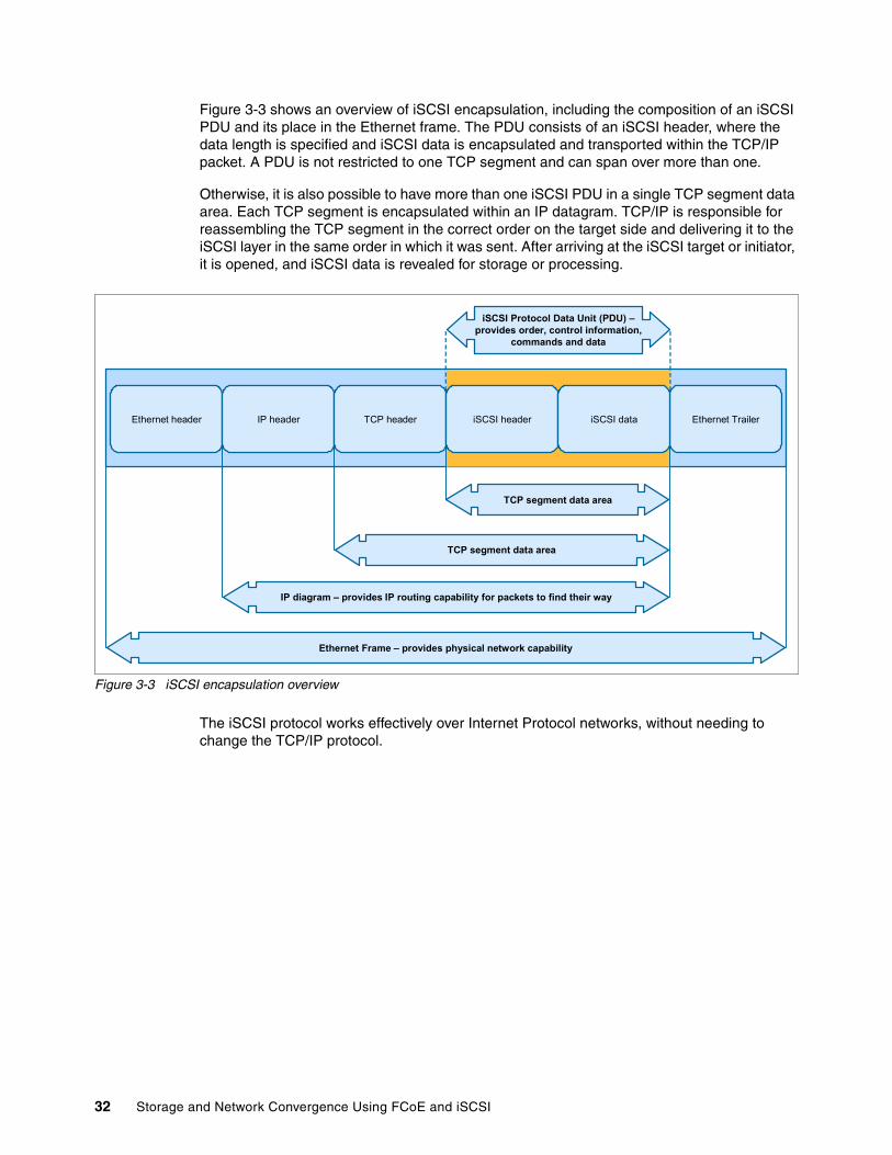
Figure 3-3 shows an overview of iSCSI encapsulation, including the composition of an iSCSI PDU and its place in the Ethernet frame. The PDU consists of an iSCSI header, where the data length is specified and iSCSI data is encapsulated and transported within the TCP/IP packet. A PDU is not restricted to one TCP segment and can span over more than one.
Otherwise, it is also possible to have more than one iSCSI PDU in a single TCP segment data area. Each TCP segment is encapsulated within an IP datagram. TCP/IP is responsible for reassembling the TCP segment in the correct order on the target side and delivering it to the iSCSI layer in the same order in which it was sent. After arriving at the iSCSI target or initiator, it is opened, and iSCSI data is revealed for storage or processing.
Figure 3-3 iSCSI encapsulation overview
The iSCSI protocol works effectively over Internet Protocol networks, without needing to change the TCP/IP protocol.
TCP segment data area
TCP segment data area
IP diagram – provides IP routing capability for packets to find their way
Ethernet Frame – provides physical network capability
Ethernet header IP header TCP header Ethernet Trailer
iSCSI Protocol Data Unit (PDU) –provides order, control information,
commands and data
iSCSI header iSCSI data
32 Storage and Network Convergence Using FCoE and iSCSI

The model in Figure 3-4 illustrates the full process and layers that occur from start to finish when a host tries to run an I/O operation. These layers show the underlying processes.
Figure 3-4 iSCSI layer model overview
The following sections summarize important components, key processes, and iSCSI terminology.
Initiator-target interaction processiSCSI consists of several components, including naming and addressing, session management, error handling, and security.
Naming and discoveryThe logical unit (LU) naming convention consists of the IP address or Domain Name System (DNS) and iSCSI device name. The iSCSI device name has the same name as the LU that has a unique target name.
iSCSI naming formatAn iSCSI naming structure was created to help manufacturers and customers have a uniquely defined worldwide iSCSI network entity for their SAN. An iSCSI name represents a worldwide unique naming scheme that is used to identify each initiator or target in the same way that worldwide node names (WWNNS) are used to identify devices in an FC fabric.
Host Target
ApplicationLayer
I/O Request
SCSI Interface
SCSI Protocol
Transport service interface
iSCSI Protocol
iSCSI transport interface
TCP/IP Protocol
iSCSI Session
SCSI Layer
iSCSIProtocol
Layer
TCP/IP
EthernetEthernetFrame
iSCSI CDB
iSCSI PDU
TCPSegments
in IPDiagrams
Application Logical Unit
SCSI Initiator SCSI Device
iSCSI ProtocoliSCSI Protocol
Services
TCP/IP
Physical & Data Link Data Link & Physical
TCP/IP
Ethernet
Chapter 3. Internet Small Computer System Interface 33
Communication between iSCSI devices uses IP, as noted previously. Therefore, the iSCSI session relies on IP addresses for the initiator and target. iSCSI names allow for name translation services to abstract the device from its IP address. They also allow for ease of network reconfiguration, such as the use of Dynamic Host Configuration Protocol (DHCP) that might change the IP address of a device.
Two name formats are defined in RFC3720 for use in the context of different naming authorities:
� iSCSI qualified name� Enterprise unique identifier
In general, a product might support one or both of these formats.
iSCSI qualified nameThe iSCSI qualified name (IQN), as shown in the following example, uses domain names to identify a naming authority:
iqn.1986-03.com.ibm:2145.system1.node1
The IQN is expected to be unique worldwide and in a recognizable human readable format for the initiator. It can be used by any organization that owns a domain name. It also includes a date code that indicates the point in time at which the domain name was registered. The final field of the IQN (after the colon) is a unique string that identifies the iSCSI device within the context of the domain owner.
The IQN can be up to 223 bytes long and has the following format:
iqn.yyyy-mm.dns_name_of_the_manufacturer_in_reverse:unique_name
Enterprise unique identifierThe Enterprise Unique Identifier (EUI), as shown in the following example, uses company IDs known as Organizationally Unique Identifiers (OUIs) that are assigned by the Institute of Electrical and Electronics Engineers (IEEE) to identify a naming authority:
eui.02004567A425678A
This identifier is also referred to as EUI-64 for identifying the targets. It includes an IEEE assigned OUI for the manufacturer, which is a specified value that is assigned by the IEEE registration authority. The EUI has the following format:
eui.112233AABBCCDDEE
The EUI format has 16 hex digits (64 bits). Those 64 bits are expected to be unique worldwide. The first 24 bits (112233 in the previous example) are the unique company ID (OUI). The subsequent 40 bits are generated exclusively by the manufacturer.
Internet Storage Name ServiceThe Internet Storage Name Service (iSNS) provides an option for iSCSI servers and clients to interact for discovery, management, and configuration information. iSNS is an option for iSCSI devices to reduce the need for manual configuration. iSCSI initiators use iSNS servers to discover targets and their IP addresses. The iSNS server can offer additional services, such as an explicit initiator to target mappings for security. Most operating systems and many storage arrays allow iSNS to be enabled. iSNS is defined in RFP 4171, which you can find at this website:
http://www.ietf.org/rfc/rfc4171.txt
34 Storage and Network Convergence Using FCoE and iSCSI

Session establishment and managementA session is the creation of a communication tunnel from the iSCSI initiator to the iSCSI target. An iSCSI session consists of an iSCSI login phase and a full feature phase. At least one session between the initiator and the target must be enabled through an iSCSI login process. A login PDU is used to negotiate any variable parameters between the two parties and can start a security routine to authenticate permissible connectivity. When the login is successful, the target issues a login success to the initiator. Otherwise, it issues an unsuccessful login. iSCSI can support multiple connections per session (MCS) to increase aggregate bandwidth or, for several links, to improve reliability.
PDU structureA protocol data unit (PDU) is the basic message packet that travels between a client and target. It consists of a basic header segment (BHS) and additional headers segments (AHS). It also includes optional parameters, such as cyclic redundancy check (CRC) data segments and data digests.
iSCSI error handlingAn IP network is susceptible to the high probability of errors in data delivery. The iSCSI protocol provides several measures to counter potential errors. The design requires iSCSI to perform its functions within a Internet Protocol network safely and use appropriate quality of service (QoS) procedures.
iSCSI securityThe iSCSI protocol can be used in networks where unauthorized data can be accessed, allowing for different security methods. Encoding means, such as IPSec, which use lower levels, do not require additional matching because they are transparent for higher levels, and for the iSCSI. Various solutions can be used for authentication, for example, CHAP, Kerberos, or private keys exchange. An iSNS server can be used as a repository of keys.
3.2 iSCSI initiators
iSCSI initiators can be implemented by software or hardware. Software initiators can be augmented by TCP-offload Ethernet adapters.
3.2.1 Software-only solutions
Software initiators and targets are virtual SCSI adapters that are written as part of the operating environment. They use the processor resources and network adapters of the host to transfer data. Software endpoints are easy to deploy and are low-cost or free with the host operating system.
Software implementations can drive higher throughput than other implementations if sufficient host processor resources are available. This higher throughput is especially true of cases where smaller block sizes are used. Integration with the host operating system usually works well, by using existing management tools and interfaces. Starting a host from an iSCSI device is not possible when using software initiators unless a pre-startup execution environment exists. At a minimum, a DHCP server and a file transfer protocol, such as Trivial File Transfer Protocol (TFTP), are required.
Chapter 3. Internet Small Computer System Interface 35
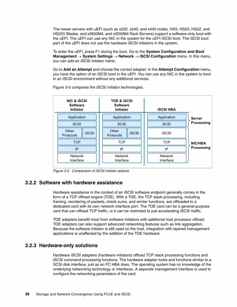
The newer servers with uEFI (such as x220, x240, and x440 nodes, HX5, HS23, HS22, and HS22V Blades, and x3650M4, and x3550M4 Rack Servers) support a software-only boot with the uEFI. The uEFI can use any NIC in the system for the uEFI iSCSI boot. The iSCSI boot part of the uEFI does not use the hardware iSCSI initiators in the system.
To enter the uEFI, press F1 during the boot. Go to the System Configuration and Boot Management System Settings Network iSCSI Configuration menu. In this menu, you can add an iSCSI initiator name.
Go to Add an Attempt and choose the correct adapter. In the Attempt Configuration menu, you have the option of an iSCSI boot in the uEFI. You can use any NIC in the system to boot in an iSCSI environment without any additional services.
Figure 3-5 compares the iSCSI initiator technologies.
Figure 3-5 Comparison of iSCSI initiator options
3.2.2 Software with hardware assistance
Hardware assistance in the context of an iSCSI software endpoint generally comes in the form of a TCP offload engine (TOE). With a TOE, the TCP stack processing, including framing, reordering of packets, check sums, and similar functions, are offloaded to a dedicated card with its own network interface port. The TOE card can be a general-purpose card that can offload TCP traffic, or it can be restricted to just accelerating iSCSI traffic.
TOE adapters benefit most from software initiators with additional host processor offload. TOE adapters can also support advanced networking features such as link aggregation. Because the software initiator is still used on the host, integration with layered management applications is unaffected by the addition of the TOE hardware.
3.2.3 Hardware-only solutions
Hardware iSCSI adapters (hardware initiators) offload TCP stack processing functions and iSCSI command processing functions. The hardware adapter looks and functions similar to a SCSI disk interface, just as an FC HBA does. The operating system has no knowledge of the underlying networking technology or interfaces. A separate management interface is used to configure the networking parameters of the card.
Application
SCSI
OtherProtocols
iSCSI
TCP
IP
NetworkInterface
Application
SCSI
OtherProtocols
iSCSI
TCP
IP
NetworkInterface
Application
SCSI
iSCSI
TCP
IP
NetworkInterface
NIC & iSCSISoftwareInitiator
TOE & iSCSISoftwareInitiator iSCSI HBA
ServerProcessing
NIC/HBAProcessing
36 Storage and Network Convergence Using FCoE and iSCSI
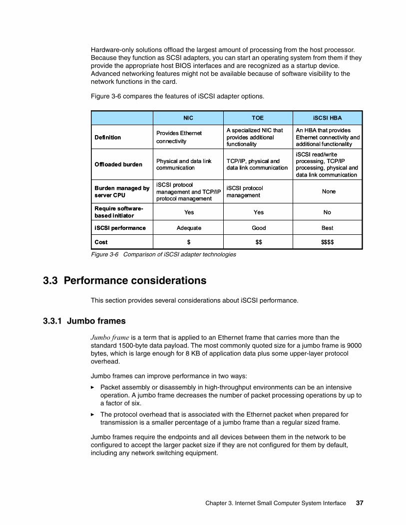
Hardware-only solutions offload the largest amount of processing from the host processor. Because they function as SCSI adapters, you can start an operating system from them if they provide the appropriate host BIOS interfaces and are recognized as a startup device. Advanced networking features might not be available because of software visibility to the network functions in the card.
Figure 3-6 compares the features of iSCSI adapter options.
Figure 3-6 Comparison of iSCSI adapter technologies
3.3 Performance considerations
This section provides several considerations about iSCSI performance.
3.3.1 Jumbo frames
Jumbo frame is a term that is applied to an Ethernet frame that carries more than the standard 1500-byte data payload. The most commonly quoted size for a jumbo frame is 9000 bytes, which is large enough for 8 KB of application data plus some upper-layer protocol overhead.
Jumbo frames can improve performance in two ways:
� Packet assembly or disassembly in high-throughput environments can be an intensive operation. A jumbo frame decreases the number of packet processing operations by up to a factor of six.
� The protocol overhead that is associated with the Ethernet packet when prepared for transmission is a smaller percentage of a jumbo frame than a regular sized frame.
Jumbo frames require the endpoints and all devices between them in the network to be configured to accept the larger packet size if they are not configured for them by default, including any network switching equipment.
$$$$$$$Cost
BestGoodAdequateiSCSI performance
NoYesYesRequire software-based initiator
NoneiSCSI protocol management
iSCSI protocol management and TCP/IP protocol management
Burden managed by server CPU
iSCSI read/write processing, TCP/IP processing, physical and data link communication
TCP/IP, physical and data link communication
Physical and data link communication
Offloaded burden
An HBA that provides Ethernet connectivity and additional functionality
A specialized NIC that provides additional functionality
Provides Ethernet
connectivityDefinition
iSCSI HBATOENIC
Chapter 3. Internet Small Computer System Interface 37

3.3.2 Prioritization and bandwidth allocation
Certain Ethernet traffic can be prioritized relative to other traffic. The 802.1p specification allows network frames to be tagged with one of eight priority levels. Switches that are 802.1p-compliant can give preferential treatment to priority values in terms of transmission scheduling.
Enhanced Transmission Selection (ETS), as described in 2.1.2, “Enhanced Transmission Selection: IEEE 802.1Qaz” on page 13, provides a mechanism to use 802.1p priority values to map traffic to defined bandwidth allocations on outbound switch links. Thus iSCSI traffic can be given a bandwidth allocation relative to other traffic.
3.4 Multipathing with iSCSI
You can choose from several technologies to improve the availability of iSCSI by using multiple network paths. Multipathing requires a software layer above the iSCSI layer to make sense of the multiple physical paths between the initiator and target and to manage them appropriately.
3.4.1 IEEE 802.3ad Link Aggregation Control Protocol and Etherchannel
IEEE standard 802.3ad Link Aggregation Control Protocol (LACP) and Etherchannel both specify a method by which multiple Ethernet links are aggregated to form a single network link. Packet traffic is distributed among the links by using a hash function that is based on various parameters, including source and destination Media Access Control (MAC) addresses. The paths are coalesced at the network interface card (NIC) driver layer or operating system interface layer. A single IP address is assigned to the set of links on the initiator and the target. Figure 3-7 illustrates a link aggregation enhancement.
Figure 3-7 iSCSI bandwidth enhancement with link aggregation
Because the hash function that is used always returns the same value for an initiator and target pair, the traffic distribution across an aggregated link might not be uniformly distributed. Link aggregation is best used to increase fan-in bandwidth to a target rather than to a large pipe between a single initiator and target pair. A round-robin algorithm might correct this problem, but it is not a valid algorithm according to the 802.3ad standard. Etherchannel and other nonstandard mechanisms allow for the use of round-robin distribution.
NICNIC
Disk Class Driver
SCSI Layer
iSCSI Initiator
TCP/IP
NIC Driver
38 Storage and Network Convergence Using FCoE and iSCSI

3.4.2 Active-Active multipathing
Active-Active multipathing requires a software multipathing layer to be inserted in the software stack above the SCSI layer. This layer of software takes the multiple device paths that are presented from the SCSI layer and coalesces them into single device paths, although multiple links go to each device (Figure 3-8). This process is accomplished by using SCSI inquiry commands to check for commonality in device paths, usually the LUN serial number. This abstraction prevents the operating system from trying to access multiple device paths as though they are individual devices, which most likely might result in data corruption.
Figure 3-8 iSCSI bandwidth enhancement with Active-Active multipathing
Active-Active multipathing can enhance the available bandwidth between an initiator and a target. However, this enhancement depends on the implementation of the load balancing algorithm. Because SCSI does not have a robust sequencing mechanism, SCSI exchanges must always be delivered in sequence, which generally means they must use a single path for the exchange. When the command frame is placed into an IP packet, ordering is guaranteed, but the software must properly handle command frames before encapsulation takes place. Active-Active multipathing is most useful for situations where multiple HBAs are used.
3.4.3 Multiconnection sessions
Multiconnection sessions (MCS) function as the name implies. For each iSCSI session, multiple connections are created (Figure 3-9). The number of allowed connections is negotiated during login and session creation. Although you can create multiple connections over a single physical interface, the bandwidth enhancement requires multiple physical interfaces to be employed.
Figure 3-9 iSCSI bandwidth enhancement with a multiconnection session
MCS must be implemented in both the initiator and the target. Distribution of iSCSI traffic over the connections is not defined and, therefore, is only as effective as the algorithm that is implemented.
TCP/IP
NIC Driver
NIC
iSCSI Initiator
TCP/IP
NIC Driver
NIC
iSCSI Initiator
Disk Class Driver
Multipathing Layer
SCSI Layer
TCP/IP
NIC Driver
NIC
TCP/IP
NIC Driver
NIC
Disk Class Driver
SCSI Layer
iSCSI Initiator
Chapter 3. Internet Small Computer System Interface 39

40 Storage and Network Convergence Using FCoE and iSCSI

Chapter 4. IBM products that support FCoE and iSCSI
This chapter introduces the IBM products that support lossless FCoE and iSCSI.
This chapter includes the following sections:
� 4.1, “Converged Network Adapters (CNAs)” on page 42� 4.2, “Switches” on page 47� 4.3, “Storage systems” on page 57� 4.4, “Introduction to component management” on page 64
4
© Copyright IBM Corp. 2012, 2014. All rights reserved. 41
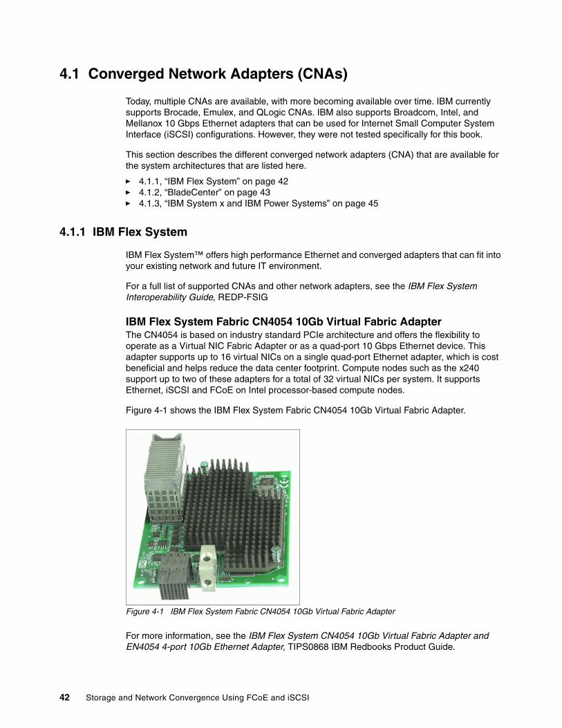
4.1 Converged Network Adapters (CNAs)
Today, multiple CNAs are available, with more becoming available over time. IBM currently supports Brocade, Emulex, and QLogic CNAs. IBM also supports Broadcom, Intel, and Mellanox 10 Gbps Ethernet adapters that can be used for Internet Small Computer System Interface (iSCSI) configurations. However, they were not tested specifically for this book.
This section describes the different converged network adapters (CNA) that are available for the system architectures that are listed here.
� 4.1.1, “IBM Flex System” on page 42� 4.1.2, “BladeCenter” on page 43� 4.1.3, “IBM System x and IBM Power Systems” on page 45
4.1.1 IBM Flex System
IBM Flex System™ offers high performance Ethernet and converged adapters that can fit into your existing network and future IT environment.
For a full list of supported CNAs and other network adapters, see the IBM Flex System Interoperability Guide, REDP-FSIG
IBM Flex System Fabric CN4054 10Gb Virtual Fabric AdapterThe CN4054 is based on industry standard PCIe architecture and offers the flexibility to operate as a Virtual NIC Fabric Adapter or as a quad-port 10 Gbps Ethernet device. This adapter supports up to 16 virtual NICs on a single quad-port Ethernet adapter, which is cost beneficial and helps reduce the data center footprint. Compute nodes such as the x240 support up to two of these adapters for a total of 32 virtual NICs per system. It supports Ethernet, iSCSI and FCoE on Intel processor-based compute nodes.
Figure 4-1 shows the IBM Flex System Fabric CN4054 10Gb Virtual Fabric Adapter.
Figure 4-1 IBM Flex System Fabric CN4054 10Gb Virtual Fabric Adapter
For more information, see the IBM Flex System CN4054 10Gb Virtual Fabric Adapter and EN4054 4-port 10Gb Ethernet Adapter, TIPS0868 IBM Redbooks Product Guide.
42 Storage and Network Convergence Using FCoE and iSCSI
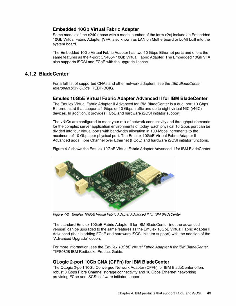
Embedded 10Gb Virtual Fabric AdapterSome models of the x240 (those with a model number of the form x2x) include an Embedded 10Gb Virtual Fabric Adapter (VFA, also known as LAN on Motherboard or LoM) built into the system board.
The Embedded 10Gb Virtual Fabric Adapter has two 10 Gbps Ethernet ports and offers the same features as the 4-port CN4054 10Gb Virtual Fabric Adapter. The Embedded 10Gb VFA also supports iSCSI and FCoE with the upgrade license.
4.1.2 BladeCenter
For a full list of supported CNAs and other network adapters, see the IBM BladeCenter Interoperability Guide, REDP-BCIG.
Emulex 10GbE Virtual Fabric Adapter Advanced II for IBM BladeCenterThe Emulex Virtual Fabric Adapter II Advanced for IBM BladeCenter is a dual-port 10 Gbps Ethernet card that supports 1 Gbps or 10 Gbps traffic and up to eight virtual NIC (vNIC) devices. In addition, it provides FCoE and hardware iSCSI initiator support.
The vNICs are configured to meet your mix of network connectivity and throughput demands for the complex server application environments of today. Each physical 10 Gbps port can be divided into four virtual ports with bandwidth allocation in 100-Mbps increments to the maximum of 10 Gbps per physical port. The Emulex 10GbE Virtual Fabric Adapter II Advanced adds Fibre Channel over Ethernet (FCoE) and hardware iSCSI initiator functions.
Figure 4-2 shows the Emulex 10GbE Virtual Fabric Adapter Advanced II for IBM BladeCenter.
Figure 4-2 Emulex 10GbE Virtual Fabric Adapter Advanced II for IBM BladeCenter
The standard Emulex 10GbE Fabric Adapter II for IBM BladeCenter (not the advanced version) can be upgraded to the same features as the Emulex 10GbE Virtual Fabric Adapter II Advanced (that is adding FCoE and hardware iSCSI initiator support) with the addition of the “Advanced Upgrade” option.
For more information, see the Emulex 10GbE Virtual Fabric Adapter II for IBM BladeCenter, TIPS0828 IBM Redbooks Product Guide.
QLogic 2-port 10Gb CNA (CFFh) for IBM BladeCenterThe QLogic 2-port 10Gb Converged Network Adapter (CFFh) for IBM BladeCenter offers robust 8 Gbps Fibre Channel storage connectivity and 10 Gbps Ethernet networking providing FCoe and iSCSI software initiator support.
Chapter 4. IBM products that support FCoE and iSCSI 43

Figure 4-3 shows the QLogic 2-port 10Gb Converged Network Adapter (CFFh).
Figure 4-3 The QLogic 2-port 10 Gb Converged Network Adapter (CFFh)
For more information, see the QLogic 2-port 10Gb Converged Network Adapter (CFFh) for IBM BladeCenter, TIPS0716 IBM Redbooks Product Guide.
Brocade 2-port 10GbE Converged Network Adapter for IBM BladeCenterThe Brocade 2-port 10GbE Converged Network Adapter with the Brocade Converged 10GbE Switch Module is a part of a leading Converged Ethernet solution for IBM BladeCenter. This solution offers existing Ethernet and Fibre Channel connectivity, maximum bandwidth and performance, and simplicity in a converged environment. This PCIe 2.0 x8 expansion card supports full FCoE support. FCoE and 10 Gbps CEE operations run simultaneously.
Figure 4-4 shows the Brocade 2-port 10GbE Converged Network Adapter. The card offers two network ports and two FCOE ports. To use iSCSI, you must use a software initiator.
Figure 4-4 Brocade 2-port 10GbE Converged Network Adapter
For more information, see the Brocade 2-port 10GbE Converged Network Adapter for IBM BladeCenter, TIPS0790 IBM Redbooks Product Guide.
44 Storage and Network Convergence Using FCoE and iSCSI

4.1.3 IBM System x and IBM Power Systems
For a full list of supported CNAs and other network adapters, see the following references:
� IBM System x Configuration and Options Guide:
http://www.ibm.com/systems/xbc/cog/index.html
� IBM Server Proven: Compatibility for hardware, applications, and middleware:
http://www.ibm.com/systems/info/x86servers/serverproven/compat/us/index.html
Emulex Virtual Fabric Adapter II for IBM System xThe Emulex Virtual Fabric Adapter II for IBM System x is a dual-port 10 Gbps Ethernet card that supports 1 Gbps or 10 Gbps traffic and up to eight virtual NIC (vNIC) devices. The Emulex Virtual Fabric Adapter II for IBM System x must be upgraded (this upgrade can be done in the field) to enable the FCoE and iSCSI hardware initiator. The adapter supports fiber-optic or twin-ax copper cabling to maximize flexibility.
The vNICs are configured to meet your mix of network connectivity and throughput demands for the complex server application environments of today. Each physical 10 Gbps port can be divided into four virtual ports with bandwidth allocation in 100-Mbps increments to the maximum of 10 Gbps per physical port.
Figure 4-5 shows the Emulex Virtual Fabric Adapter II for IBM System x.
Figure 4-5 Emulex Virtual Fabric Adapter II for IBM System x
For more information, see the following references:
� Emulex 10GbE Virtual Fabric Adapter II and III family for IBM System x, TIPS0844 IBM Redbooks Product Guide.
� Emulex Virtual Fabric Adapter II web page:
http://www.emulex.com/products/10gbe-network-adapters-nic/ibm-branded/49y7950/overview.html
Chapter 4. IBM products that support FCoE and iSCSI 45
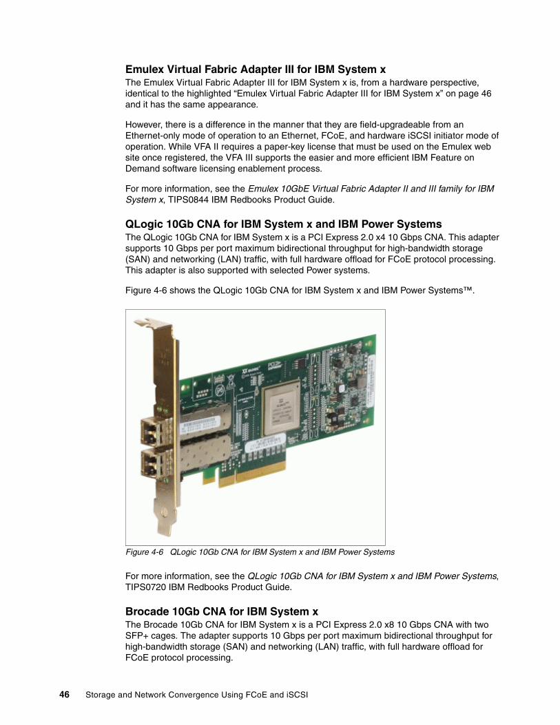
Emulex Virtual Fabric Adapter III for IBM System xThe Emulex Virtual Fabric Adapter III for IBM System x is, from a hardware perspective, identical to the highlighted “Emulex Virtual Fabric Adapter III for IBM System x” on page 46 and it has the same appearance.
However, there is a difference in the manner that they are field-upgradeable from an Ethernet-only mode of operation to an Ethernet, FCoE, and hardware iSCSI initiator mode of operation. While VFA II requires a paper-key license that must be used on the Emulex web site once registered, the VFA III supports the easier and more efficient IBM Feature on Demand software licensing enablement process.
For more information, see the Emulex 10GbE Virtual Fabric Adapter II and III family for IBM System x, TIPS0844 IBM Redbooks Product Guide.
QLogic 10Gb CNA for IBM System x and IBM Power SystemsThe QLogic 10Gb CNA for IBM System x is a PCI Express 2.0 x4 10 Gbps CNA. This adapter supports 10 Gbps per port maximum bidirectional throughput for high-bandwidth storage (SAN) and networking (LAN) traffic, with full hardware offload for FCoE protocol processing. This adapter is also supported with selected Power systems.
Figure 4-6 shows the QLogic 10Gb CNA for IBM System x and IBM Power Systems™.
Figure 4-6 QLogic 10Gb CNA for IBM System x and IBM Power Systems
For more information, see the QLogic 10Gb CNA for IBM System x and IBM Power Systems, TIPS0720 IBM Redbooks Product Guide.
Brocade 10Gb CNA for IBM System xThe Brocade 10Gb CNA for IBM System x is a PCI Express 2.0 x8 10 Gbps CNA with two SFP+ cages. The adapter supports 10 Gbps per port maximum bidirectional throughput for high-bandwidth storage (SAN) and networking (LAN) traffic, with full hardware offload for FCoE protocol processing.
46 Storage and Network Convergence Using FCoE and iSCSI

Figure 4-7 shows the Brocade 10Gb CNA for IBM System x.
Figure 4-7 Brocade 10Gb CNA for IBM System x
For more information, see the Brocade 10Gb CNA for IBM System x, TIPS0718 IBM Redbooks Product Guide.
4.2 Switches
Today, multiple SAN and Converged Network switches are available. IBM currently supports Brocade, Cisco, IBM System Networking, and QLogic switches with lossless FCoE / iSCSI capabilities. For more information, see the IBM System Networking site at this website:
http://www.ibm.com/systems/networking/switches/index.html
This section highlights the available IBM products that support FCoE and iSCSI. It includes the following subsections:
� 4.2.1, “Flex Chassis” on page 47� 4.2.2, “BladeCenter” on page 49� 4.2.3, “Top-of-Rack (ToR) / End-of-Row (EoR)” on page 53
The IBM System Networking 10 Gbps switches support DCB protocols (such as PFC, ETS, and DCBX) and FIP Snooping, so that they are fully capable FCoE transit switches.
4.2.1 Flex Chassis
IBM Flex System offers high performance Ethernet and converged networking switches that can fit into your existing network and future IT environment. These highly flexible products coupled with on-demand scalability features offer an easy way to scale as your IT requirements grow.
For a full list of supported network switches, see the following references:
� IBM Flex System Interoperability Guide, REDP-FSIG
� IBM System Networking Switches Flex System web page:
http://www.ibm.com/systems/networking/switches/flex.html
Chapter 4. IBM products that support FCoE and iSCSI 47
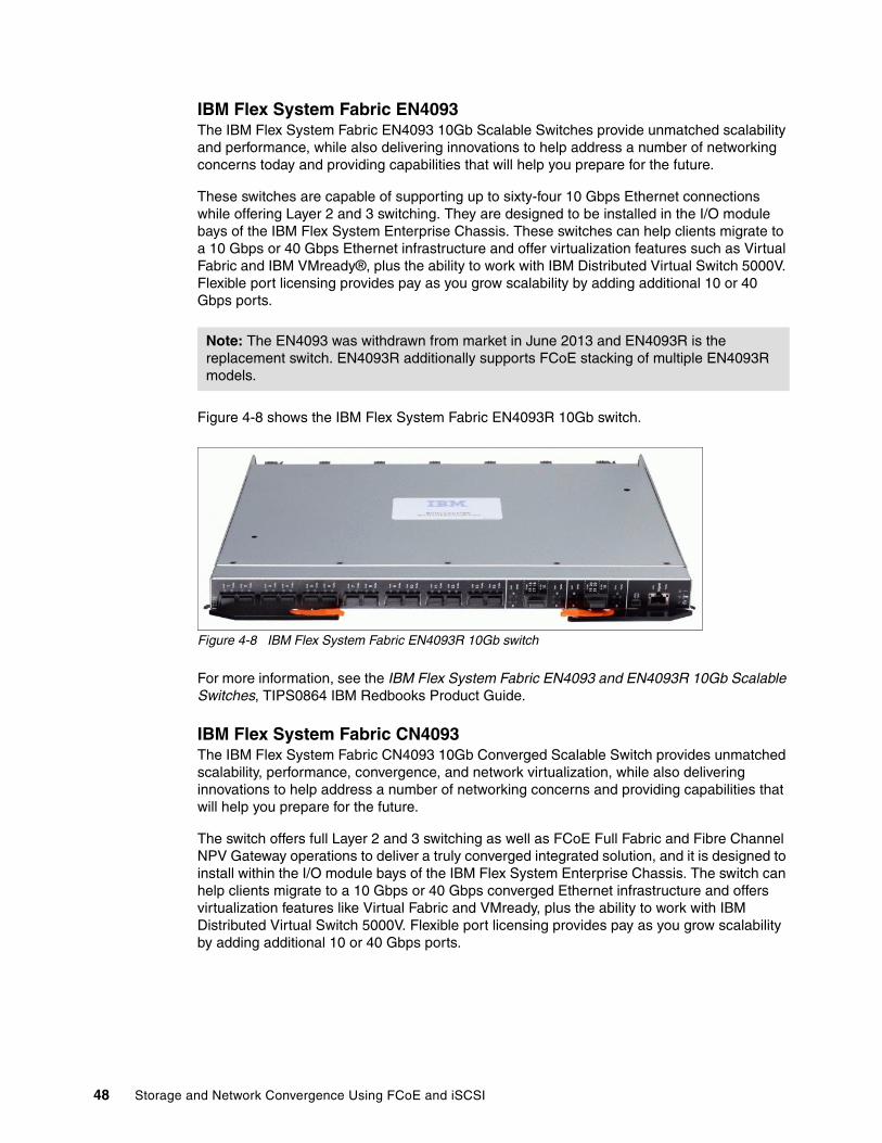
IBM Flex System Fabric EN4093The IBM Flex System Fabric EN4093 10Gb Scalable Switches provide unmatched scalability and performance, while also delivering innovations to help address a number of networking concerns today and providing capabilities that will help you prepare for the future.
These switches are capable of supporting up to sixty-four 10 Gbps Ethernet connections while offering Layer 2 and 3 switching. They are designed to be installed in the I/O module bays of the IBM Flex System Enterprise Chassis. These switches can help clients migrate to a 10 Gbps or 40 Gbps Ethernet infrastructure and offer virtualization features such as Virtual Fabric and IBM VMready®, plus the ability to work with IBM Distributed Virtual Switch 5000V. Flexible port licensing provides pay as you grow scalability by adding additional 10 or 40 Gbps ports.
Figure 4-8 shows the IBM Flex System Fabric EN4093R 10Gb switch.
Figure 4-8 IBM Flex System Fabric EN4093R 10Gb switch
For more information, see the IBM Flex System Fabric EN4093 and EN4093R 10Gb Scalable Switches, TIPS0864 IBM Redbooks Product Guide.
IBM Flex System Fabric CN4093The IBM Flex System Fabric CN4093 10Gb Converged Scalable Switch provides unmatched scalability, performance, convergence, and network virtualization, while also delivering innovations to help address a number of networking concerns and providing capabilities that will help you prepare for the future.
The switch offers full Layer 2 and 3 switching as well as FCoE Full Fabric and Fibre Channel NPV Gateway operations to deliver a truly converged integrated solution, and it is designed to install within the I/O module bays of the IBM Flex System Enterprise Chassis. The switch can help clients migrate to a 10 Gbps or 40 Gbps converged Ethernet infrastructure and offers virtualization features like Virtual Fabric and VMready, plus the ability to work with IBM Distributed Virtual Switch 5000V. Flexible port licensing provides pay as you grow scalability by adding additional 10 or 40 Gbps ports.
Note: The EN4093 was withdrawn from market in June 2013 and EN4093R is the replacement switch. EN4093R additionally supports FCoE stacking of multiple EN4093R models.
48 Storage and Network Convergence Using FCoE and iSCSI
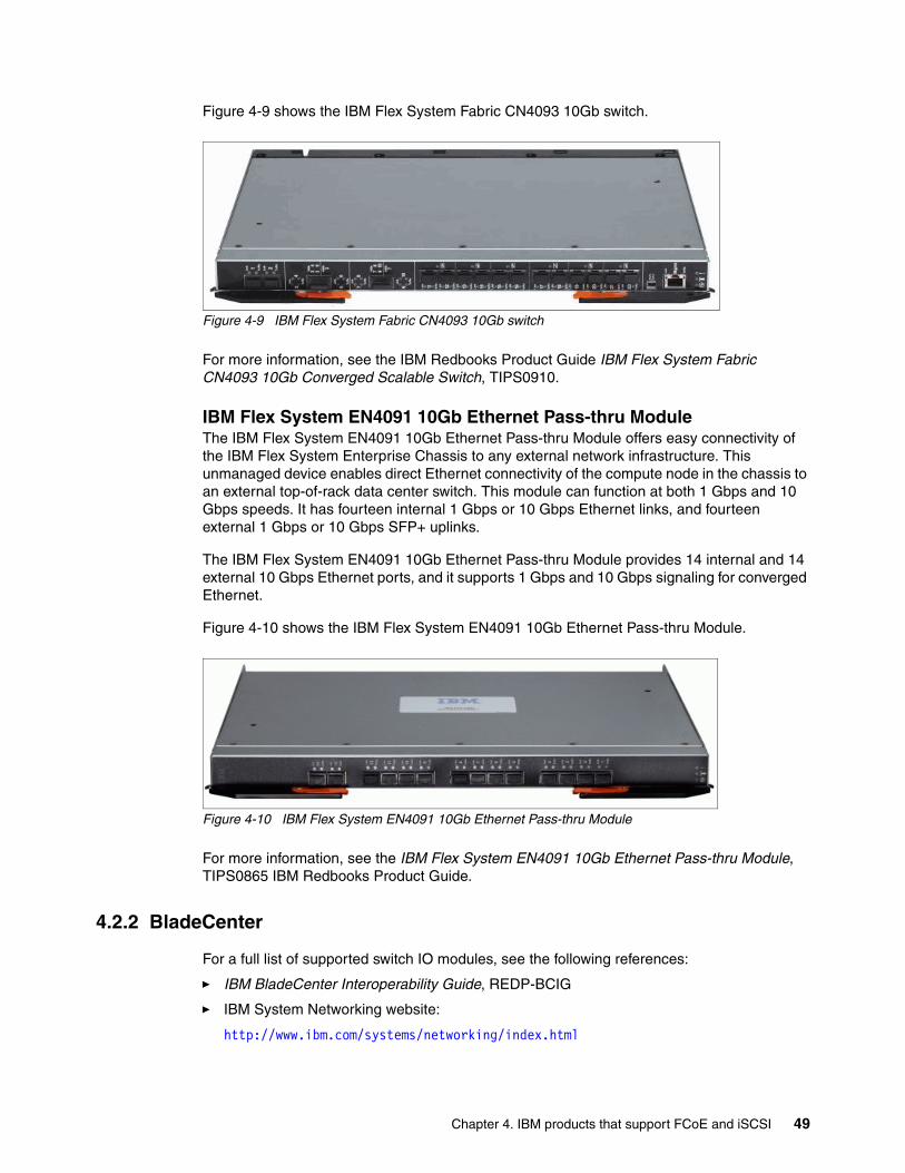
Figure 4-9 shows the IBM Flex System Fabric CN4093 10Gb switch.
Figure 4-9 IBM Flex System Fabric CN4093 10Gb switch
For more information, see the IBM Redbooks Product Guide IBM Flex System Fabric CN4093 10Gb Converged Scalable Switch, TIPS0910.
IBM Flex System EN4091 10Gb Ethernet Pass-thru ModuleThe IBM Flex System EN4091 10Gb Ethernet Pass-thru Module offers easy connectivity of the IBM Flex System Enterprise Chassis to any external network infrastructure. This unmanaged device enables direct Ethernet connectivity of the compute node in the chassis to an external top-of-rack data center switch. This module can function at both 1 Gbps and 10 Gbps speeds. It has fourteen internal 1 Gbps or 10 Gbps Ethernet links, and fourteen external 1 Gbps or 10 Gbps SFP+ uplinks.
The IBM Flex System EN4091 10Gb Ethernet Pass-thru Module provides 14 internal and 14 external 10 Gbps Ethernet ports, and it supports 1 Gbps and 10 Gbps signaling for converged Ethernet.
Figure 4-10 shows the IBM Flex System EN4091 10Gb Ethernet Pass-thru Module.
Figure 4-10 IBM Flex System EN4091 10Gb Ethernet Pass-thru Module
For more information, see the IBM Flex System EN4091 10Gb Ethernet Pass-thru Module, TIPS0865 IBM Redbooks Product Guide.
4.2.2 BladeCenter
For a full list of supported switch IO modules, see the following references:
� IBM BladeCenter Interoperability Guide, REDP-BCIG
� IBM System Networking website:
http://www.ibm.com/systems/networking/index.html
Chapter 4. IBM products that support FCoE and iSCSI 49
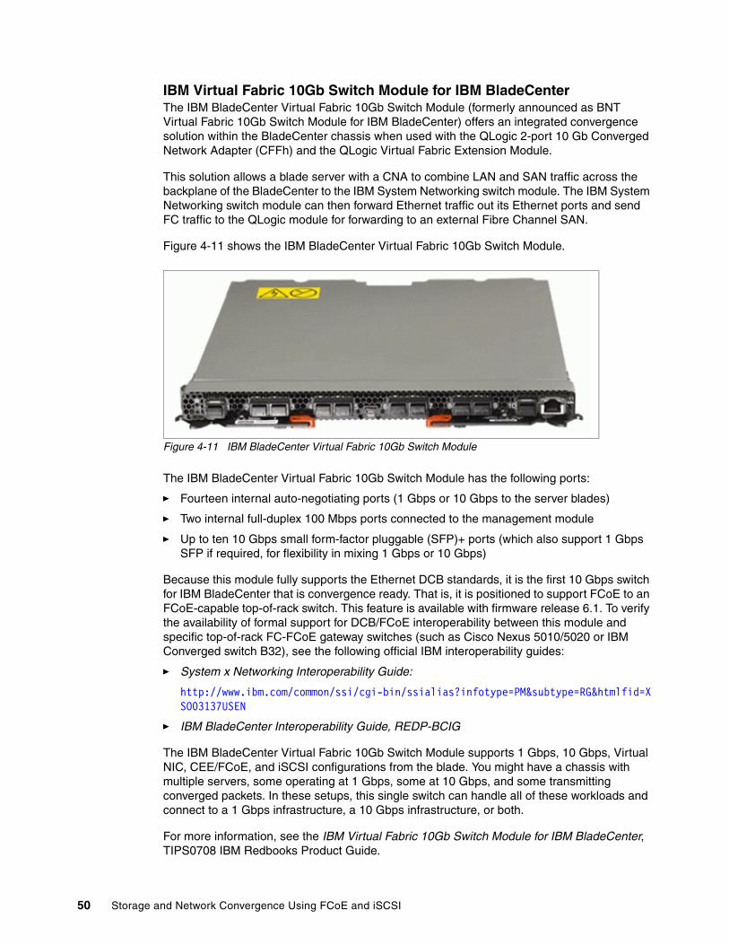
IBM Virtual Fabric 10Gb Switch Module for IBM BladeCenterThe IBM BladeCenter Virtual Fabric 10Gb Switch Module (formerly announced as BNT Virtual Fabric 10Gb Switch Module for IBM BladeCenter) offers an integrated convergence solution within the BladeCenter chassis when used with the QLogic 2-port 10 Gb Converged Network Adapter (CFFh) and the QLogic Virtual Fabric Extension Module.
This solution allows a blade server with a CNA to combine LAN and SAN traffic across the backplane of the BladeCenter to the IBM System Networking switch module. The IBM System Networking switch module can then forward Ethernet traffic out its Ethernet ports and send FC traffic to the QLogic module for forwarding to an external Fibre Channel SAN.
Figure 4-11 shows the IBM BladeCenter Virtual Fabric 10Gb Switch Module.
Figure 4-11 IBM BladeCenter Virtual Fabric 10Gb Switch Module
The IBM BladeCenter Virtual Fabric 10Gb Switch Module has the following ports:
� Fourteen internal auto-negotiating ports (1 Gbps or 10 Gbps to the server blades)
� Two internal full-duplex 100 Mbps ports connected to the management module
� Up to ten 10 Gbps small form-factor pluggable (SFP)+ ports (which also support 1 Gbps SFP if required, for flexibility in mixing 1 Gbps or 10 Gbps)
Because this module fully supports the Ethernet DCB standards, it is the first 10 Gbps switch for IBM BladeCenter that is convergence ready. That is, it is positioned to support FCoE to an FCoE-capable top-of-rack switch. This feature is available with firmware release 6.1. To verify the availability of formal support for DCB/FCoE interoperability between this module and specific top-of-rack FC-FCoE gateway switches (such as Cisco Nexus 5010/5020 or IBM Converged switch B32), see the following official IBM interoperability guides:
� System x Networking Interoperability Guide:
http://www.ibm.com/common/ssi/cgi-bin/ssialias?infotype=PM&subtype=RG&htmlfid=XSO03137USEN
� IBM BladeCenter Interoperability Guide, REDP-BCIG
The IBM BladeCenter Virtual Fabric 10Gb Switch Module supports 1 Gbps, 10 Gbps, Virtual NIC, CEE/FCoE, and iSCSI configurations from the blade. You might have a chassis with multiple servers, some operating at 1 Gbps, some at 10 Gbps, and some transmitting converged packets. In these setups, this single switch can handle all of these workloads and connect to a 1 Gbps infrastructure, a 10 Gbps infrastructure, or both.
For more information, see the IBM Virtual Fabric 10Gb Switch Module for IBM BladeCenter, TIPS0708 IBM Redbooks Product Guide.
50 Storage and Network Convergence Using FCoE and iSCSI

10Gb Ethernet Pass-Thru Module for IBM BladeCenterThe 10Gb Ethernet Pass-Thru Module for IBM BladeCenter is ideal for clients who want to enable end-to-end non-blocking 10 Gbps setup within the chassis. This device supports both Ethernet and CEE packets, so that clients can connect a BladeCenter Chassis to an FCoE-capable top-of-rack switch.
The fourteen 10 Gbps Uplink ports are based on optical small form-factor pluggable (SFP)+ technology to offer the highest performance and maintain industry standard connectivity. This offering also works with BladeCenter Open Fabric Manager, providing all the benefits of I/O virtualization at 10 Gbps speeds.
This module is ideal if you want to keep the networking outside of the chassis and use only external switches. It can also give you extra flexibility by providing one port per blade and low maintenance.
Figure 4-12 shows the 10 Gb Ethernet Pass-Thru Module for IBM BladeCenter.
Figure 4-12 10 Gb Ethernet Pass-Thru Module for IBM BladeCenter
For more information, see the10Gb Ethernet Pass-Thru Module for IBM BladeCenter, TIPS0715 IBM Redbooks Product Guide.
Brocade Converged 10GbE Switch Module for IBM BladeCenterThe Brocade Converged 10GbE Switch Module offers FC investment protection, maximum bandwidth and performance, and simplicity in a converged environment. There are 30 ports on the switch (eight 10 Gbps FCoE external ports, eight 8 Gbps FC external ports, and 14x 10 Gbps FCoE internal ports).
With the base model, you can enable 16 of the 30 ports by choosing your mix of internal, external FCoE, and external FC ports. If you purchase the Port Upgrade Key, you can enable all 30 ports on the switch module.
Figure 4-13 shows the Brocade Converged 10GbE Switch Module for IBM BladeCenter.
Figure 4-13 Brocade Converged 10GbE Switch Module for IBM BladeCenter
For more information, see the Brocade Converged 10GbE Switch Module for IBM BladeCenter, TIPS0789 IBM Redbooks Product Guide.
Chapter 4. IBM products that support FCoE and iSCSI 51
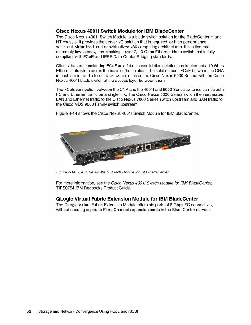
Cisco Nexus 4001I Switch Module for IBM BladeCenterThe Cisco Nexus 4001I Switch Module is a blade switch solution for the BladeCenter H and HT chassis. It provides the server I/O solution that is required for high-performance, scale-out, virtualized, and nonvirtualized x86 computing architectures. It is a line rate, extremely low-latency, non-blocking, Layer 2, 10 Gbps Ethernet blade switch that is fully compliant with FCoE and IEEE Data Center Bridging standards.
Clients that are considering FCoE as a fabric consolidation solution can implement a 10 Gbps Ethernet infrastructure as the basis of the solution. The solution uses FCoE between the CNA in each server and a top-of-rack switch, such as the Cisco Nexus 5000 Series, with the Cisco Nexus 4001I blade switch at the access layer between them.
The FCoE connection between the CNA and the 4001I and 5000 Series switches carries both FC and Ethernet traffic on a single link. The Cisco Nexus 5000 Series switch then separates LAN and Ethernet traffic to the Cisco Nexus 7000 Series switch upstream and SAN traffic to the Cisco MDS 9000 Family switch upstream.
Figure 4-14 shows the Cisco Nexus 4001I Switch Module for IBM BladeCenter.
Figure 4-14 Cisco Nexus 4001I Switch Module for IBM BladeCenter
For more information, see the Cisco Nexus 4001I Switch Module for IBM BladeCenter, TIPS0754 IBM Redbooks Product Guide.
QLogic Virtual Fabric Extension Module for IBM BladeCenterThe QLogic Virtual Fabric Extension Module offers six ports of 8 Gbps FC connectivity, without needing separate Fibre Channel expansion cards in the BladeCenter servers.
52 Storage and Network Convergence Using FCoE and iSCSI

Figure 4-15 shows the QLogic Virtual Fabric Extension Module for IBM BladeCenter.
Figure 4-15 QLogic Virtual Fabric Extension Module for IBM BladeCenter
For more information, see the QLogic Virtual Fabric Extension Module for IBM BladeCenter, TIPS0717 IBM Redbooks Product Guide.
4.2.3 Top-of-Rack (ToR) / End-of-Row (EoR)
For more information about available IBM System Networking top-of-rack and end-of-row switches, see the IBM System Networking IBM RackSwitch™ web page:
http://www.ibm.com/systems/networking/switches/rack.html
IBM System Networking RackSwitch G8316The RackSwitch G8316 provides low latency, lossless performance, and a feature-rich design with key virtualization features such as DCB, high availability, and enterprise class Layer 2 and Layer 3 functions. In addition, the RackSwitch G8316 also delivers cost savings as you consider acquisition costs, energy costs, operational expense, and ease of use and management for a 40 Gbps class switch. The IBM System Networking RackSwitch G8316 supports both 10 Gbps and 40 Gbps Ethernet.
The switch has 16 40 Gbps QSFP ports and provides 1.28 Tbps throughput at less than 1 ms latency. Any of the 40 Gbps ports can be split into four 10 Gbps ports by using optional cables.
Figure 4-16 shows the IBM System Networking RackSwitch G8316.
Figure 4-16 IBM System Networking RackSwitch G8316
For more information, see the IBM System Networking RackSwitch G8316, TIPS0842 IBM Redbooks Product Guide.
Chapter 4. IBM products that support FCoE and iSCSI 53
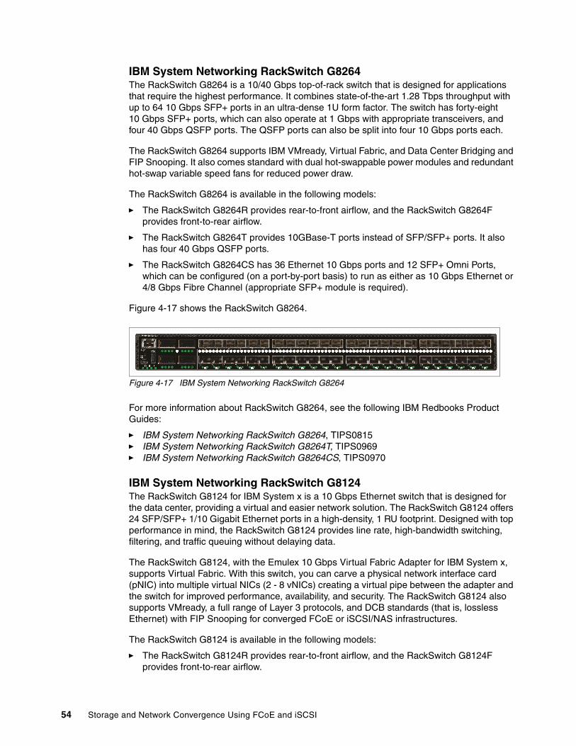
IBM System Networking RackSwitch G8264The RackSwitch G8264 is a 10/40 Gbps top-of-rack switch that is designed for applications that require the highest performance. It combines state-of-the-art 1.28 Tbps throughput with up to 64 10 Gbps SFP+ ports in an ultra-dense 1U form factor. The switch has forty-eight 10 Gbps SFP+ ports, which can also operate at 1 Gbps with appropriate transceivers, and four 40 Gbps QSFP ports. The QSFP ports can also be split into four 10 Gbps ports each.
The RackSwitch G8264 supports IBM VMready, Virtual Fabric, and Data Center Bridging and FIP Snooping. It also comes standard with dual hot-swappable power modules and redundant hot-swap variable speed fans for reduced power draw.
The RackSwitch G8264 is available in the following models:
� The RackSwitch G8264R provides rear-to-front airflow, and the RackSwitch G8264F provides front-to-rear airflow.
� The RackSwitch G8264T provides 10GBase-T ports instead of SFP/SFP+ ports. It also has four 40 Gbps QSFP ports.
� The RackSwitch G8264CS has 36 Ethernet 10 Gbps ports and 12 SFP+ Omni Ports, which can be configured (on a port-by-port basis) to run as either as 10 Gbps Ethernet or 4/8 Gbps Fibre Channel (appropriate SFP+ module is required).
Figure 4-17 shows the RackSwitch G8264.
Figure 4-17 IBM System Networking RackSwitch G8264
For more information about RackSwitch G8264, see the following IBM Redbooks Product Guides:
� IBM System Networking RackSwitch G8264, TIPS0815� IBM System Networking RackSwitch G8264T, TIPS0969� IBM System Networking RackSwitch G8264CS, TIPS0970
IBM System Networking RackSwitch G8124The RackSwitch G8124 for IBM System x is a 10 Gbps Ethernet switch that is designed for the data center, providing a virtual and easier network solution. The RackSwitch G8124 offers 24 SFP/SFP+ 1/10 Gigabit Ethernet ports in a high-density, 1 RU footprint. Designed with top performance in mind, the RackSwitch G8124 provides line rate, high-bandwidth switching, filtering, and traffic queuing without delaying data.
The RackSwitch G8124, with the Emulex 10 Gbps Virtual Fabric Adapter for IBM System x, supports Virtual Fabric. With this switch, you can carve a physical network interface card (pNIC) into multiple virtual NICs (2 - 8 vNICs) creating a virtual pipe between the adapter and the switch for improved performance, availability, and security. The RackSwitch G8124 also supports VMready, a full range of Layer 3 protocols, and DCB standards (that is, lossless Ethernet) with FIP Snooping for converged FCoE or iSCSI/NAS infrastructures.
The RackSwitch G8124 is available in the following models:
� The RackSwitch G8124R provides rear-to-front airflow, and the RackSwitch G8124F provides front-to-rear airflow.
54 Storage and Network Convergence Using FCoE and iSCSI

� The RackSwitch G8124ER and RackSwitch G8124EF provide similar airflow choices in addition to enhanced processing and memory to improve performance for larger Layer 3 networks, aggregation layer switching, high-end multicast applications, and rapid failover.
� The RackSwitch G8124DC uses dc power.
Figure 4-18 shows the top-of-rack IBM System Networking RackSwitch G8124.
Figure 4-18 IBM System Networking RackSwitch G8124
For more information, see the IBM System Networking RackSwitch G8124, TIPS0787 IBM Redbooks Product Guide.
Brocade VDX 6730 Converged Switch for IBMThe Brocade VDX 6730 Converged Switch for IBM is a 10 Gbps Ethernet fixed port switch with LAN and native Fibre Channel ports. It supports multiple connectivity options, including classic Top-of-Rack (ToR) server deployments, Ethernet storage connectivity for FCoE, and bridging Fibre Channel SANs and Ethernet LANs. This switch provides an FC-BB5 compliant Fibre Channel Forwarder (FCF) feature.
Two models of this switch are available:
� VDX 6730-76,which is a 2U switch with sixty 10 Gbps Ethernet ports and sixteen 8 Gbps native FC ports
� VDX 6730-32, which is a 1U switch with twenty four 10 Gbps Ethernet ports and eight 8 Gbps native FC ports
The VDX 6730-32 model is shown in Figure 4-19.
Figure 4-19 Brocade VDX 6730 Converged Switch for IBM
For more information, see the Brocade VDX 6730 Converged Switch for IBM, TIPS0895 IBM Redbooks Product Guide.
IBM Converged Switch B32IBM Converged Switch B32 is designed for data-center server I/O consolidation. The switch connects to servers through CNAs that support Fibre Channel SAN and Ethernet LAN protocols. The consolidated server SAN and LAN ports and corresponding cables simplify configuration and cabling in server cabinets to reduce acquisition costs. With fewer components by using power and requiring cooling, organizations can also save significant operating costs. The IBM Converged Switch B32 provides twenty-four 10 Gbps ports that support CEE and traditional Ethernet protocols and optional activation of eight 1 Gbps, 2 Gbps, 4 Gbps, and 8 Gbps Fibre Channel ports.
Chapter 4. IBM products that support FCoE and iSCSI 55

Figure 4-20 shows the IBM Converged Switch B32.
Figure 4-20 IBM Converged Switch B32
For more information, refer to IBM Converged Switch B32, SG24-7935.
Cisco Nexus 5000 familyThe Cisco Nexus 5000 family models are multiprotocol switches with the following features:
� 10 Gbps Fibre Channel over Ethernet (FCoE)� 10 Gbps Converged Enhanced Ethernet� Traditional 1 Gbps or 10 Gbps Ethernet ports� Optional 1 Gbps, 2 Gbps, and 4 Gbps Fibre Channel (FC) ports
Several models are available:
� Cisco Nexus 5020:
– Up to 56 ports– Forty 10 Gbps Ethernet and FCoE ports– Optional 16 FC ports
� Cisco Nexus 5010:
– Up to 28 ports– Twenty 10 Gbps Ethernet and FCoE ports– Optional 8 FC ports
Figure 4-21 shows the Cisco Nexus 5010 and Cisco Nexus 5020 without the optional FC modules installed.
Figure 4-21 Cisco Nexus 5010 and Cisco Nexus 5020
For more information, see the Cisco Nexus 5000 web page:
http://www.ibm.com/systems/hk/networking/hardware/ethernet/c-type/nexus/index.html
56 Storage and Network Convergence Using FCoE and iSCSI

4.3 Storage systems
IBM offers several storage arrays with local iSCSI support. Many of these storage arrays, including the IBM Storwize V7000, IBM System Storage® DS5000 series, and IBM System Storage DS3500 Express, support iSCSI at 10 Gbps Ethernet speeds.
This section describes the following storage products and families:
� 4.3.1, “IBM SAN Volume Controller” on page 57� 4.3.2, “IBM Storwize family” on page 58� 4.3.3, “IBM Flex System V7000 Storage Node” on page 61� 4.3.4, “IBM XIV Storage System” on page 61� 4.3.5, “IBM System Storage DS3500 Express” on page 62� 4.3.6, “IBM System Storage DCS3700” on page 63
4.3.1 IBM SAN Volume Controller
IBM System Storage SAN Volume Controller (SVC) is a storage virtualization system that enables a single point of control for storage resources to help support improved business application availability and greater resource utilization. It manages storage resources in your IT infrastructure and ensures that they are used to the advantage of your business quickly, efficiently, and in real time, while avoiding administrative cost.
SAN Volume Controller combines hardware and software into an integrated, modular solution that is highly scalable. An I/O group is formed by combining a redundant pair of storage engines named nodes (based on System x server technology). Each node comes with the following components:
� An Intel Xeon 5600 2.5 GHz quad-core processor� 24 GB of cache� Real-time compression (optional increase to 8 cores and 48 GB of cache for compression)� Four 8 Gbps FC ports (and the option to configure second HBA with four additional ports)� Two 1 Gbps iSCSI ports� Optionally two 10 Gbps Ethernet ports for iSCSI or FCoE usage� Metro Mirror and Global Mirror for replicating data synchronously or asynchronously
between systems
Highly available I/O groups are the basic configuration element of a SAN Volume Controller cluster. Adding I/O groups to the cluster increases cluster performance and bandwidth.
SAN Volume Controller supports attachment to servers by using Fibre Channel as well as iSCSI protocols over IP networks at 1 Gbps or 10 Gbps speeds as well as FCoE using lossless Ethernet.
SAN Volume Controller provides state-of-the-art capabilities for storage tiering, solid-state drive support, replication services, real-time compression capabilities and simplified management.
Chapter 4. IBM products that support FCoE and iSCSI 57

Figure 4-22 shows a pair of two nodes (forming one I/O group) of the IBM SAN Volume Controller.
Figure 4-22 IBM SAN Volume Controller
For more information, see the following references:
� IBM System Storage SAN Volume Controller website:
http://www.ibm.com/systems/storage/software/virtualization/svc/
� IBM System Storage SAN Volume Controller Best Practices and Performance Guidelines, SG24-7521
� Implementing the IBM System Storage SAN Volume Controller V6.3, SG24-7933
4.3.2 IBM Storwize family
The Storwize V7000 was the first member of the Storwize family and basically bundled the virtualization features of the SAN Volume Controller with internal disks. Over time, there have been several additions to the family. These additions are explained in the following section.
For more information, visit the Storwize family web page:
http://www.ibm.com/systems/storage/storwize/
Storwize V7000IBM Storwize V7000 is an innovative new storage offering. It delivers essential storage efficiency technologies and exceptional ease of use and performance, all integrated into a compact, modular design that is offered at a competitive, midrange price. By using Storwize V7000, you can virtualize and reuse existing disk systems, supporting a greater potential return on investment (ROI).
IBM Storwize V7000 is a virtualized storage system to complement virtualized server environments. It provides unmatched performance, availability, advanced functions, and highly scalable capacity never seen before in midrange disk systems. Storwize V7000 is a powerful midrange disk system that is easy to use and enables rapid deployment without additional resources. Storwize V7000 offers greater efficiency and flexibility through built-in solid-state drive (SSD) optimization and thin provisioning technologies. Storwize V7000 has advanced functions that enable non-disruptive migration of data from existing storage, simplifying implementation and minimizing disruption to users. By using Storwize V7000, you can also virtualize and reuse existing disk systems, supporting a greater potential ROI.
The IBM Storwize V7000 offers the following features:
� Capacity of up to 480 TB with 9 expansion enclosures� Up to 240 2.5” or 120 3.5” drives. It is possible to mix 2.5” and 3.5” expansion enclosures.� 8 Gbps FC host connectivity, 1 Gbps host connectivity, and optional 10 Gbps iSCSI host
connectivity
58 Storage and Network Convergence Using FCoE and iSCSI

� Sophisticated enterprise-class storage function (for example, IBM Easy Tier®, IBM Real-time Compression™, thin provisioning, and storage virtualization) for midsize businesses
� Metro Mirror and Global Mirror for replicating data synchronously or asynchronously between systems
Figure 4-23 shows the SFF (small form-factor) model of the IBM Storwize V7000 with 24 installed 2.5” drives.
Figure 4-23 IBM Storwize V7000
For more information about Storwize V7000, see the IBM Storwize V7000 and Storwize V7000 Unified Disk Systems web page:
http://www.ibm.com/systems/storage/disk/storwize_v7000/index.html
Storwize V7000 UnifiedThe Storwize V7000 Unified consolidates block and file storage in a single system for simplicity and greater efficiency. The Storwize V7000 Unified consists of a Storwize V7000 and additional Storwize File Modules providing the unified storage capability and management.
Figure 4-24 shows two Storwize File Modules, which provide unified storage capability and management, on top of the Storwize V7000. Together they form the Storwize V7000 Unified.
Figure 4-24 IBM Storwize V7000 Unified
Chapter 4. IBM products that support FCoE and iSCSI 59
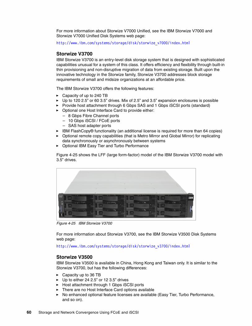
For more information about Storwize V7000 Unified, see the IBM Storwize V7000 and Storwize V7000 Unified Disk Systems web page:
http://www.ibm.com/systems/storage/disk/storwize_v7000/index.html
Storwize V3700IBM Storwize V3700 is an entry-level disk storage system that is designed with sophisticated capabilities unusual for a system of this class. It offers efficiency and flexibility through built-in thin provisioning and non-disruptive migration of data from existing storage. Built upon the innovative technology in the Storwize family, Storwize V3700 addresses block storage requirements of small and midsize organizations at an affordable price.
The IBM Storwize V3700 offers the following features:
� Capacity of up to 240 TB � Up to 120 2.5” or 60 3.5” drives. Mix of 2.5” and 3.5” expansion enclosures is possible� Provide host attachment through 6 Gbps SAS and 1 Gbps iSCSI ports (standard)� Optional one Host Interface Card to provide either:
– 8 Gbps Fibre Channel ports– 10 Gbps iSCSI / FCoE ports– SAS host adapter ports
� IBM FlashCopy® functionality (an additional license is required for more than 64 copies)� Optional remote copy capabilities (that is Metro Mirror and Global Mirror) for replicating
data synchronously or asynchronously between systems� Optional IBM Easy Tier and Turbo Performance
Figure 4-25 shows the LFF (large form-factor) model of the IBM Storwize V3700 model with 3.5” drives.
Figure 4-25 IBM Storwize V3700
For more information about Storwize V3700, see the IBM Storwize V3500 Disk Systems web page:
http://www.ibm.com/systems/storage/disk/storwize_v3700/index.html
Storwize V3500IBM Storwize V3500 is available in China, Hong Kong and Taiwan only. It is similar to the Storwize V3700, but has the following differences:
� Capacity up to 36 TB� Up to either 24 2.5” or 12 3.5” drives� Host attachment through 1 Gbps iSCSI ports� There are no Host Interface Card options available� No enhanced optional feature licenses are available (Easy Tier, Turbo Performance,
and so on).
60 Storage and Network Convergence Using FCoE and iSCSI
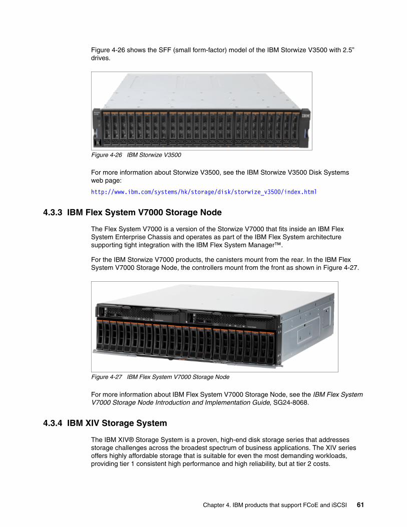
Figure 4-26 shows the SFF (small form-factor) model of the IBM Storwize V3500 with 2.5” drives.
Figure 4-26 IBM Storwize V3500
For more information about Storwize V3500, see the IBM Storwize V3500 Disk Systems web page:
http://www.ibm.com/systems/hk/storage/disk/storwize_v3500/index.html
4.3.3 IBM Flex System V7000 Storage Node
The Flex System V7000 is a version of the Storwize V7000 that fits inside an IBM Flex System Enterprise Chassis and operates as part of the IBM Flex System architecture supporting tight integration with the IBM Flex System Manager™.
For the IBM Storwize V7000 products, the canisters mount from the rear. In the IBM Flex System V7000 Storage Node, the controllers mount from the front as shown in Figure 4-27.
Figure 4-27 IBM Flex System V7000 Storage Node
For more information about IBM Flex System V7000 Storage Node, see the IBM Flex System V7000 Storage Node Introduction and Implementation Guide, SG24-8068.
4.3.4 IBM XIV Storage System
The IBM XIV® Storage System is a proven, high-end disk storage series that addresses storage challenges across the broadest spectrum of business applications. The XIV series offers highly affordable storage that is suitable for even the most demanding workloads, providing tier 1 consistent high performance and high reliability, but at tier 2 costs.
Chapter 4. IBM products that support FCoE and iSCSI 61

The IBM XIV Storage System provides hotspot-free performance without manual tuning through full exploitation of system resources, including disks, RAM, processors, and switches, combined with unique caching algorithms. It provides up to 8 Gbps of FC connectivity as well as 1 Gbps and 10 Gbps of iSCSI connectivity.
Figure 4-28 shows the IBM XIV Storage System Gen3 with opened front door.
Figure 4-28 IBM XIV Storage System
For more information about XIV, see the IBM XIV Storage System series web page:
http://www.ibm.com/systems/storage/disk/xiv/index.html
4.3.5 IBM System Storage DS3500 Express
The IBM System Storage DS3500 Express offers dual active hot-swappable controllers, up to 192 disk drives (high performance and nearline SAS, SSD and SED SAS drives), and four interface options for SAS, iSCSI/SAS, and FC/SAS:
� Four or eight 6 Gbps SAS ports� Eight 8 Gbps Fibre Channel ports and four 6 Gbps SAS ports� Eight 1 Gbps iSCSI ports and four 6 Gbps SAS ports� Four 10 Gbps iSCSI ports and four 6 Gbps SAS ports
Figure 4-29 shows the IBM System Storage DS3500 Express.
Figure 4-29 IBM System Storage DS3500 Express
62 Storage and Network Convergence Using FCoE and iSCSI

For more information about the DS3500, see the IBM System Storage DS3500 Express web page:
http://www.ibm.com/systems/storage/disk/ds3500/index.html
4.3.6 IBM System Storage DCS3700
The IBM System Storage DCS3700 storage system is ready to meet the challenge. Designed for applications with high-performance streaming data requirements, DCS3700 offers optimal space utilization, low power consumption and high performance. By combining proven IBM storage controllers with up to 60 drives in just 4U of rack space, DCS3700 can reduce operational costs for capacity-intensive applications.
DCS3700 provides a simple, efficient and flexible approach to storage that is based on seven generations of design knowledge and firmware development. DCS3700 can act as a cost-effective, fully integrated complement to IBM System x, IBM BladeCenter and IBM Power Systems servers for a wide variety of intensive computing environments.
DCS3700 has the following interface options to support server host attachment:
� Base DCS3700 storage system:
– Two 6 Gbps SAS host ports per controller are standard, with the option to add a daughter card with additional connectivity
– Two 6 Gbps SAS ports per optional host interface card
– Four 8 Gbps Fibre Channel ports per optional host interface card (includes eight 8 Gbps short-wave small form-factor pluggable transceivers)
– Two 10 Gbps iSCSI ports per optional host interface card
� DCS3700 with a Performance Module storage system:
– Four 8 Gbps Fibre Channel host ports per controller with the option to add daughter cards with additional connectivity
– Four 8 Gbps Fibre Channel ports per optional host interface card (includes eight 8 Gbps shortwave small form-factor pluggable transceivers)
– Four 6 Gbps SAS ports per optional host interface card
– Two 10 Gbps iSCSI ports per optional host interface card
iSCSI ports and Ethernet switches: The iSCSI ports on the DS3500 are 10GBase-T ports, not small form-factor pluggable (SFP)+ ports. IBM only offers one ToR Ethernet switch that supports 10GBase-T and QSFP+ ports. All other IBM System Networking 10 Gbps Ethernet switches support SFP+ ports instead.
Chapter 4. IBM products that support FCoE and iSCSI 63
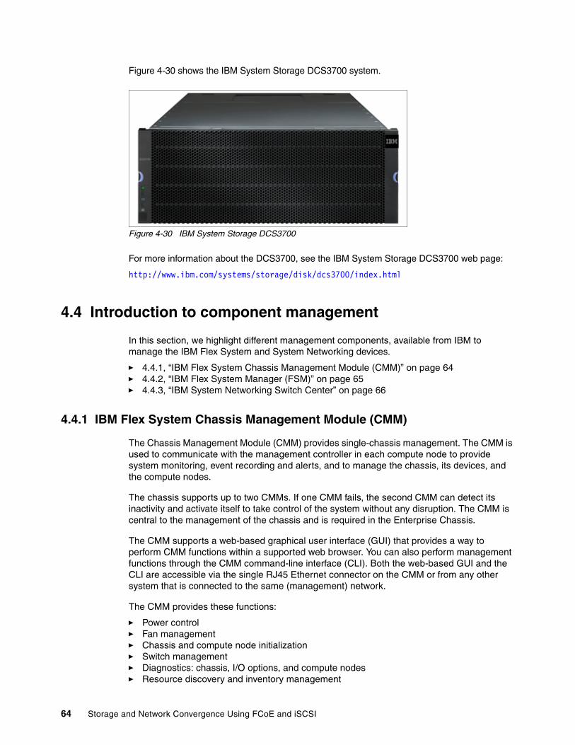
Figure 4-30 shows the IBM System Storage DCS3700 system.
Figure 4-30 IBM System Storage DCS3700
For more information about the DCS3700, see the IBM System Storage DCS3700 web page:
http://www.ibm.com/systems/storage/disk/dcs3700/index.html
4.4 Introduction to component management
In this section, we highlight different management components, available from IBM to manage the IBM Flex System and System Networking devices.
� 4.4.1, “IBM Flex System Chassis Management Module (CMM)” on page 64� 4.4.2, “IBM Flex System Manager (FSM)” on page 65� 4.4.3, “IBM System Networking Switch Center” on page 66
4.4.1 IBM Flex System Chassis Management Module (CMM)
The Chassis Management Module (CMM) provides single-chassis management. The CMM is used to communicate with the management controller in each compute node to provide system monitoring, event recording and alerts, and to manage the chassis, its devices, and the compute nodes.
The chassis supports up to two CMMs. If one CMM fails, the second CMM can detect its inactivity and activate itself to take control of the system without any disruption. The CMM is central to the management of the chassis and is required in the Enterprise Chassis.
The CMM supports a web-based graphical user interface (GUI) that provides a way to perform CMM functions within a supported web browser. You can also perform management functions through the CMM command-line interface (CLI). Both the web-based GUI and the CLI are accessible via the single RJ45 Ethernet connector on the CMM or from any other system that is connected to the same (management) network.
The CMM provides these functions:
� Power control� Fan management� Chassis and compute node initialization� Switch management� Diagnostics: chassis, I/O options, and compute nodes� Resource discovery and inventory management
64 Storage and Network Convergence Using FCoE and iSCSI

� Resource alerts and monitoring management� Chassis and compute node power management� Security policy management� Role-based access control
Figure 4-31 shows the CMM, which must be installed from the rear side into the chassis.
Figure 4-31 IBM Flex System Chassis Management Module (CMM)
For more information, see appropriate section of the IBM Flex System Enterprise Chassis, TIPS0863 IBM Redbooks Product Guide.
4.4.2 IBM Flex System Manager (FSM)
IBM Flex System Manager (FSM) is a systems management appliance that drives efficiency and cost savings in the data center. IBM Flex System Manager provides a pre-integrated and virtualized management environment across servers, storage, and networking that is easily managed from a single interface.
A single focus point for seamless multi-chassis management provides an instant and resource-oriented view of chassis and chassis resources for both IBM System x and IBM Power Systems compute nodes. You can reduce the number of interfaces, steps, and clicks it takes to manage IT resources, intelligently manage and deploy workloads based on resource availability and predefined policies, and manage events and alerts to increase system availability and reduce downtime while reducing operational costs.
Figure 4-32 shows the IBM Flex System Manager appliance, which is based on an x86 compute node that comes with pre-loaded management software. The management node comes standard without any entitlement licenses, so you must purchase a license to enable the required FSM functionality.
Figure 4-32 IBM Flex System Manager appliance
IBM Flex System Manager has the following key features:
� Optimizing your workload management through built-in expertise � Managing all of your resources with one solution (Compute, Storage, Networking and
Virtualization)
Chapter 4. IBM products that support FCoE and iSCSI 65

Figure 4-33 shows an example panel for the IBM Flex System Manager graphical user interface.
Figure 4-33 IBM Flex System Manager
For more information, see theIBM Flex System Manager, TIPS0862 IBM Redbooks Product Guide.
4.4.3 IBM System Networking Switch Center
IBM System Networking Switch Center provides remote monitoring and management of Ethernet and converged switches from IBM. It is designed to simplify and centralize the management of your IBM BladeCenter, Flex System and IBM RackSwitch Ethernet and converged switches. Switch Center supports VM migration across a data center in a multivendor environment (VMready) and is compliant with EVB IEEE 802.1Qbg standard.
For more information, see the IBM Networking Switch Center web page:
http://www.ibm.com/systems/networking/software/snsc/index.html
66 Storage and Network Convergence Using FCoE and iSCSI
Part 2 Preparing Infrastructure for storage and network convergence
This part of the book provides detailed implementation scenarios for network and storage convergence, including BladeCenter and Rack server scenarios for Fibre Channel over Ethernet (FCoE) and iSCSI. Today, true convergence of disparate networks requires enhancement of the Ethernet so that it can transport mission-critical data by running Fibre Channel (FC) over lossless Layer 2 Ethernet.
Convergence retains the benefit of a low-cost Ethernet everywhere while addressing the strength of FC as the dominant storage system interconnect in large data centers for the following purposes:
� Business continuity� Backup and disaster recovery operations� Ethernet for FC SAN connectivity and networking
This part includes the following chapters:
� Chapter 5, “Topologies and lab architecture” on page 69� Chapter 6, “Using FCoE and iSCSI in a converged network” on page 91� Chapter 7, “Installing and enabling the Converged Network Adapter” on page 103� Chapter 9, “Configuring iSCSI and FCoE cards for SAN boot” on page 225� Chapter 8, “FC and FCoE zone configuration” on page 195
Part 2
© Copyright IBM Corp. 2012, 2014. All rights reserved. 67

68 Storage and Network Convergence Using FCoE and iSCSI

Chapter 5. Topologies and lab architecture
This chapter describes common topologies that are valid for converged environments as well as the lab architecture and equipment that was used in our testing for updating this IBM Redbooks publication.
This chapter includes the following sections:
� 5.1, “Typical topologies” on page 70� 5.2, “Lab architecture” on page 79� 5.3, “Equipment used in the lab” on page 89� 5.4, “Conclusion” on page 90
5
© Copyright IBM Corp. 2012, 2014. All rights reserved. 69
5.1 Typical topologies
Several topologies are possible for using IBM products that enable FCoE. This section highlights the following typical topologies:
� 5.1.1, “IBM Flex System topology with IBM Flex Systems CN4093 switch” on page 70
� 5.1.2, “IBM Flex System topology with IBM Flex EN4093 switch to top-of-rack IBM System Networking G8264CS switch” on page 71
� 5.1.3, “IBM Flex System topology with IBM Flex System EN4091 10Gb Ethernet Pass-thru Module to IBM System Networking G8264CS switch” on page 72
� 5.1.4, “IBM BladeCenter topology with embedded FCF” on page 73
� 5.1.5, “IBM BladeCenter topology with BNT Virtual Fabric 10Gb Switch Module to top-of-rack IBM System Networking G8264CS switch” on page 75
� 5.1.6, “IBM Blade Center topology with 10Gb Ethernet Pass-Thru Module to a top-of-rack IBM System Networking G8264CS switch” on page 76
� 5.1.7, “IBM rack server topology connected to a top-of-rack IBM System Networking G8264CS switch” on page 77
� 5.1.8, “IBM rack server topology with intermediate switch to an IBM System Networking G8264CS switch” on page 78
For more information about the technology terms and the product devices that are used here, see the appropriate chapters in Part 1, “Overview of storage and network convergence” on page 1.
This list is not intended to be exhaustive. Combination and permutation, especially in complex environments, might be required. A detailed assessment of the requirements is required before defining the final topology.
5.1.1 IBM Flex System topology with IBM Flex Systems CN4093 switch
Figure 5-1 shows a Flex System convergence solution inside the chassis that uses an IBM Flex Systems CN4093 switch inside of the Flex Chassis with embedded FCF capability. Traffic flows from the Converged Network Adapter in the compute node through the IBM Flex Systems CN4093 switch in the chassis, which connects to both the upstream Ethernet and the upstream FC.
This topology provides a simple design, requires only a few devices, and might be a good choice for small to medium environments where it is planned to introduce Flex System and FCoE.
Note: For all the topologies shown in the following sections, storage connections are not included. However, storage can be connected either directly to an IBM Flex System (such as V7000) or directly to any of the FC or FCoE switches. For example, see 5.2, “Lab architecture” on page 79.
70 Storage and Network Convergence Using FCoE and iSCSI
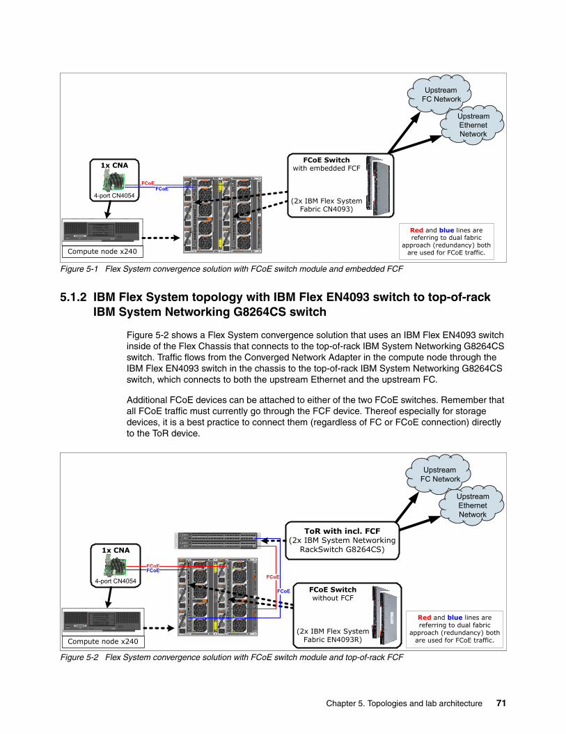
Figure 5-1 Flex System convergence solution with FCoE switch module and embedded FCF
5.1.2 IBM Flex System topology with IBM Flex EN4093 switch to top-of-rack IBM System Networking G8264CS switch
Figure 5-2 shows a Flex System convergence solution that uses an IBM Flex EN4093 switch inside of the Flex Chassis that connects to the top-of-rack IBM System Networking G8264CS switch. Traffic flows from the Converged Network Adapter in the compute node through the IBM Flex EN4093 switch in the chassis to the top-of-rack IBM System Networking G8264CS switch, which connects to both the upstream Ethernet and the upstream FC.
Additional FCoE devices can be attached to either of the two FCoE switches. Remember that all FCoE traffic must currently go through the FCF device. Thereof especially for storage devices, it is a best practice to connect them (regardless of FC or FCoE connection) directly to the ToR device.
Figure 5-2 Flex System convergence solution with FCoE switch module and top-of-rack FCF
45
41
CMM1
CMM2
LINK
TX/RX
CMMBay
6 3
10 3
4
5
6
1
2
3
PowerSupplyBays
543
21
1098
76
FanBays
6
5
4
3
2
1
I/O BayI/O BayI/O BayI/O Bay
PowerSupplyBay
FanBay
PowerSupplyBay
PowerSupplyBay
PowerSupplyBay
PowerSupplyBay
PowerSupplyBay
FanBay
FanBay
FanBay
FanBay
FanBay
FanBay
FanBay
21
1 2OUTIN200-240V
13,8A50/60Hz
OUTIN200-240V13,8A
50/60Hz
OUTIN200-240V13,8A
50/60Hz
OUTIN200-240 V13,8A
50/60Hz
OUTIN200-240 V13,8A
50/60Hz
OUTIN200-240 V13,8A
50/60Hz
LINK
TX/RX
Compute node x240
x240
0
1
1x CNA
4-port CN4054
Red and blue lines are referring to dual fabric
approach (redundancy) both are used for FCoE traffic.
UpstreamEthernetNetwork
UpstreamFC Network
Link
Tx/Rx
Tx/Rx
11
Link
Tx/Rx
12
Link
Tx/Rx
13
Link
Tx/Rx
14
Link
Tx/Rx
15
Link
Tx/Rx
16
Link
Tx/Rx
17
Link
Tx/Rx
18
Link
Tx/Rx
19
Link
Tx/Rx
20
Link
Tx/Rx
21
Link
Tx/Rx
22
Link
10 Gb
40 Gb
7
7 89 10
Link
Tx/ Rx
109
Link
Tx/ Rx
87
10 Gb
40 Gb
3
3 45 6
Link
Tx/ Rx
65
Link
Tx/ Rx
43
Tx/Rx
2Link
Tx/Rx
1Link
Mgmt
Link
Tx/Rx
Tx/Rx
11
Link
Tx/Rx
12
Link
Tx/Rx
13
Link
Tx/Rx
14
Link
Tx/Rx
15
Link
Tx/Rx
16
Link
Tx/Rx
17
Link
Tx/Rx
18
Link
Tx/Rx
19
Link
Tx/Rx
20
Link
Tx/Rx
21
Link
Tx/Rx
22
Link
10 Gb
40 Gb
7
7 89 10
Link
Tx/ Rx
109
Link
Tx/ Rx
87
10 Gb
40 Gb
3
3 45 6
Link
Tx/ Rx
65
Link
Tx/ Rx
43
Tx/ Rx
2Link
Tx/ Rx
1Link
Mgmt
FCoEFCoE
FCoE Switchwith embedded FCF
(2x IBM Flex SystemFabric CN4093)
45
41
CMM1
CMM2
LINK
TX/RX
CMMBay
6 3
10 3
4
5
6
1
2
3
PowerSupplyBays
54321
109876
FanBays
6
5
4
3
2
1
I/O BayI/O BayI/O BayI/O Bay
PowerSupplyBay
FanBay
PowerSupplyBay
PowerSupplyBay
PowerSupplyBay
PowerSupplyBay
PowerSupplyBay
FanBay
FanBay
FanBay
FanBay
FanBay
FanBay
FanBay
21
1 2OUTIN200-240 V
13,8A50/60Hz
OUTIN200-240 V13,8A
50/60Hz
OUTIN200-240 V13,8A
50/60Hz
OUTIN200-240 V13,8A
50/60Hz
OUTIN200-240 V13,8A
50/60Hz
OUTIN200-240 V13,8A
50/60Hz
Link
Tx/Rx
6
Link
Tx/Rx
5
Link
Tx/Rx
2
Link
Tx/Rx
1
Link
Tx/Rx
4
Link
Tx/Rx
3
Link
Tx/Rx
8
Link
Tx/Rx
7
Link
Tx/Rx
10
Link
Tx/Rx
9
Link
Tx/Rx
12
Link
Tx/Rx
11
Link
Tx/Rx
14
Link
Tx/Rx
13
Link
Tx/Rx15 16
Link
Tx/Rx17 18
15
15
171618
10 Gb
40 Gb
Link
Tx/Rx19 20
21 22
19
19
212022
10 Gb
40 Gb
Mgmt
Link
Tx/Rx
Link
Tx/Rx
6
Link
Tx/Rx
5
Link
Tx/Rx
2
Link
Tx/Rx
1
Link
Tx/Rx
4
Link
Tx/Rx
3
Link
Tx/Rx
8
Link
Tx/Rx
7
Link
Tx/Rx
10
Link
Tx/Rx
9
Link
Tx/Rx
12
Link
Tx/Rx
11
Link
Tx/Rx
14
Link
Tx/Rx
13
Link
Tx/Rx15 16
Link
Tx/Rx17 18
15
15
171618
10 Gb
40 Gb
Link
Tx/Rx19 20
21 22
19
19
212022
10 Gb
40 Gb
Mgmt
Link
Tx/ Rx
LINK
TX/RX
161514138765
4321 1211109
1S
Mgmt5
9
13
30 32 34 36 38 40
29 31 33 35 37 39
18 20 22 24 26 28
17 19 21 23 25 27
54 56 58 60 62 64
53 55 57 59 61 63
42 44 46 48 50 52
41 43 45 47 49 51
161514138765
4321 1211109
1S
Mgmt5
9
13
30 32 34 36 38 40
29 31 33 35 37 39
18 20 22 24 26 28
17 19 21 23 25 27
54 56 58 60 62 64
53 55 57 59 61 63
42 44 46 48 50 52
41 43 45 47 49 51
Compute node x240
x240
0
1
FCoE Switchwithout FCF
(2x IBM Flex SystemFabric EN4093R)
1x CNA
4-port CN4054
Red and blue lines are referring to dual fabric
approach (redundancy) both are used for FCoE traffic.
FCoE
FCoE
UpstreamEthernetNetwork
UpstreamFC Network
ToR with incl. FCF(2x IBM System Networking
RackSwitch G8264CS)
FCoEFCoE
Chapter 5. Topologies and lab architecture 71

5.1.3 IBM Flex System topology with IBM Flex System EN4091 10Gb Ethernet Pass-thru Module to IBM System Networking G8264CS switch
Figure 5-3 shows a Flex System convergence solution that uses an IBM Flex System EN4091 10Gb Ethernet Pass-thru Module inside of the Flex Chassis that connects to a top-of-rack IBM System Networking G8264CS switch. Traffic flows from the IBM Flex CN4054 in the compute node through the IBM Flex System EN4091 10Gb Ethernet Pass-thru Module to the top-of-rack IBM System Networking G8264CS switch, which forwards Ethernet traffic to the upstream Ethernet network and FC traffic to the upstream SAN.
Using IBM Flex System EN4091 10Gb Ethernet Pass-thru Module is a good approach if the FCoE infrastructure is already there because it is more affordable. In addition, there is no need of configuration or administration for IBM Flex System EN4091 10Gb Ethernet Pass-thru Module because it is not active in the data-path. You can use both ports of the LoM Converged Network Adapter.
Figure 5-3 Flex System convergence solution with pass-thru module and top-of-rack FCF
Note: The IBM Flex CN4054 has four ports. Two of them can be used with the IBM Flex System EN4091 10Gb Ethernet Pass-thru Module.
45
41
CMM1
CMM2
LINK
TX/RX
CMMBay
6 3
10 3
4
5
6
1
2
3
PowerSupplyBays
543
21
1098
76
FanBays
6
5
4
3
2
1
I/O BayI/O BayI/O BayI/O Bay
PowerSupplyBay
FanBay
PowerSupplyBay
PowerSupplyBay
PowerSupplyBay
PowerSupplyBay
PowerSupplyBay
FanBay
FanBay
FanBay
FanBay
FanBay
FanBay
FanBay
21
1 2OUTIN200-240 V
13,8A50/60Hz
OUTIN200-240 V13,8A
50/60Hz
OUTIN200-240 V13,8A
50/60Hz
OUTIN200-240 V13,8A
50/60Hz
OUTIN200-240 V13,8A
50/60Hz
OUTIN200-240 V13,8A
50/60Hz
LINK
TX/RX
161514138765
4321 1211109
1
S
Mgmt5
9
13
30 32 34 36 38 40
29 31 33 35 37 39
18 20 22 24 26 28
17 19 21 23 25 27
54 56 58 60 62 64
53 55 57 59 61 63
42 44 46 48 50 52
41 43 45 47 49 51
161514138765
4321 1211109
1
S
Mgmt5
9
13
30 32 34 36 38 40
29 31 33 35 37 39
18 20 22 24 26 28
17 19 21 23 25 27
54 56 58 60 62 64
53 55 57 59 61 63
42 44 46 48 50 52
41 43 45 47 49 51
Compute node x240
x240
0
1
Pass-thru
(2x IBM Flex SystemFabric EN4091)
1x CNA
4-port CN4054
Red and blue lines are referring to dual fabric
approach (redundancy) both are used for FCoE traffic.
UpstreamEthernetNetwork
UpstreamFC Network
ToR with incl. FCF(2x IBM System Networking
RackSwitch G8264CS)
Link
Tx/Rx
1
Link
Tx/Rx
2
Link
Tx/Rx
3
Link
Tx/Rx
4
Link
Tx/Rx
5
Link
Tx/Rx
6
Link
Tx/Rx
7
Link
Tx/Rx
8
Link
Tx/Rx
9
Link
Tx/Rx
10
Link
Tx/Rx
11
Link
Tx/Rx
12
Link
Tx/Rx
13
Link
Tx/Rx
14
Link
Tx/Rx
1
Link
Tx/Rx
2
Link
Tx/Rx
3
Link
Tx/Rx
4
Link
Tx/Rx
5
Link
Tx/Rx
6
Link
Tx/Rx
7
Link
Tx/Rx
8
Link
Tx/Rx
9
Link
Tx/Rx
10
Link
Tx/Rx
11
Link
Tx/Rx
12
Link
Tx/Rx
13
Link
Tx/Rx
14 FCoE
FCoE
FCoEFCoE
72 Storage and Network Convergence Using FCoE and iSCSI

5.1.4 IBM BladeCenter topology with embedded FCF
This topology provides a simple design, requires only a few devices, and might be a good choice for small to medium environments where it is planned to introduce FCoE and the amount of required ports is reasonable.
Using the Virtual FabricQLogic Virtual Fabric Extension Module as FCFFigure 5-4 shows a BladeCenter convergence solution inside the chassis. This topology shows the combination of the IBM BladeCenter Virtual Fabric 10Gb Switch Module and the QLogic Virtual Fabric Extension Module.
The best practise for storage is to connect via Fibre Channel on the QLogic Virtual Fabric Extension Module or the externally connected FC fabric.
Figure 5-4 BladeCenter convergence solution with IBM BladeCenter Virtual Fabric 10Gb Switch Module and QLogic VF Extension
BladeCenter H
HS22 Blade
FCoE
FCoE
Red and blue lines are referring to dual fabric
approach (redundancy) both are used for FCoE traffic.
FC
oE
FCoE
UpstreamEthernetNetwork
UpstreamFC Network
1x CNA Card
2-portQLogic 10 Gbps
2x FC Extensionmodules
6-port Qlogic VF Extension Module
2x 10 GbpsSwitch modules
10-portBNT VF 10 Gbps
Chapter 5. Topologies and lab architecture 73

Using the converged Brocade switch module as FCFFigure 5-5 shows a similar solution with the Brocade Converged 10GbE switch module. This solution provides more ports and the advantage that only one device needs to be configured and managed.
Figure 5-5 BladeCenter convergence solution that uses a Brocade Converged 10 Gbps switch module
BladeCenter H
HS22 Blade
Red and blue lines are referring to dual fabric
approach (redundancy) both are used for FCoE traffic.
FC
oE
FCoE
1x CNA Card
2-portQLogic 10 Gbps
UpstreamEthernetNetwork
UpstreamFC Network
2x 10 Gbps FCoESwitch modules
16 FCoE / FC port Brocade converged
Switch module
74 Storage and Network Convergence Using FCoE and iSCSI
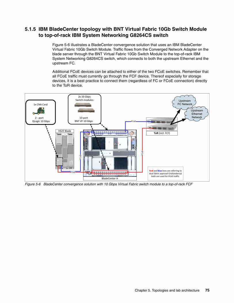
5.1.5 IBM BladeCenter topology with BNT Virtual Fabric 10Gb Switch Module to top-of-rack IBM System Networking G8264CS switch
Figure 5-6 illustrates a BladeCenter convergence solution that uses an IBM BladeCenter Virtual Fabric 10Gb Switch Module. Traffic flows from the Converged Network Adapter on the blade server through the BNT Virtual Fabric 10Gb Switch Module to the top-of-rack IBM System Networking G8264CS switch, which connects to both the upstream Ethernet and the upstream FC.
Additional FCoE devices can be attached to either of the two FCoE switches. Remember that all FCoE traffic must currently go through the FCF device. Thereof especially for storage devices, it is a best practice to connect them (regardless of FC or FCoE connection) directly to the ToR device.
Figure 5-6 BladeCenter convergence solution with 10 Gbps Virtual Fabric switch module to a top-of-rack FCF
BladeCenter H
HS22 Blade
2x 10 GbpsSwitch modules
10-portBNT VF 10 Gbps
1x CNA Card
2 - portQLogic 10 Gbps FCoE
FC
oE
ToR (incl. FCF)
Red and blue lines are referring to dual fabric approach (redundancy)
both are used for FCoE traffic.
FC
oE
FCoE
UpstreamEthernetNetwork
UpstreamFC Network
Chapter 5. Topologies and lab architecture 75

5.1.6 IBM Blade Center topology with 10Gb Ethernet Pass-Thru Module to a top-of-rack IBM System Networking G8264CS switch
Figure 5-7 shows a BladeCenter convergence solution that uses a 10Gb Ethernet Pass-Thru Module that connects to a top-of-rack IBM System Networking G8264CS switch. Traffic flows from the Converged Network Adapter in the blade server through the 10Gb Ethernet Pass-Thru Module to the top-of-rack IBM System Networking G8264CS switch, which forwards Ethernet traffic to the upstream Ethernet network and FC traffic to the upstream SAN. Certain FCF devices, like the IBM System Networking G8264CS switch, can allow direct connection of FC port based storage devices.
Using 10Gb Ethernet Pass-Thru Module is a good approach if the FCoE infrastructure is already there, because it is more affordable. In addition, there is no need of configuration or administration for pass-thru modules because they are not active in the data path.
Figure 5-7 BladeCenter convergence solution with pass-thru module to a top-of-rack FCF
BladeCenter H
HS22 Blade
2x 10 Gb Pass-thru
14-portIBM 10 Gb Pass-thru FCoE
FC
oE
ToR (incl. FCF)
Red and blue lines are referring to dual fabric
approach (redundancy) both are used for FCoE traffic.
FC
oE
FCoE
UpstreamEthernetNetwork
UpstreamFC Network
1x CNA Card
2-portQLogic 10 Gb CNA
76 Storage and Network Convergence Using FCoE and iSCSI

5.1.7 IBM rack server topology connected to a top-of-rack IBM System Networking G8264CS switch
Figure 5-8 shows a convergence solution for rack servers. In this example, the servers have Converged Network Adapter installed and connect directly to a top-of-rack IBM System Networking G8264CS switch, which in turn connects to the upstream Ethernet and Fibre Channel SAN.
Figure 5-8 Rack server convergence solution with servers connected to a top-of-rack FCF
161514138765
4321 1211109
1
S
Mgmt5
9
13
30 32 34 36 38 40
29 31 33 35 37 39
18 20 22 24 26 28
17 19 21 23 25 27
54 56 58 60 62 64
53 55 57 59 61 63
42 44 46 48 50 52
41 43 45 47 49 51
161514138765
4321 1211109
1
S
Mgmt5
9
13
30 32 34 36 38 40
29 31 33 35 37 39
18 20 22 24 26 28
17 19 21 23 25 27
54 56 58 60 62 64
53 55 57 59 61 63
42 44 46 48 50 52
41 43 45 47 49 51
1 IMM 2IMM
1PCI
2PCI
AC
DC750w
AC
AC
DC750w
AC
LIN
Kx/
Rx
LIN
Kx/
Rx
1 IMM 2IMM
1PCI
2PCI
AC
DC750w
AC
AC
DC750w
AC
LIN
Kx/
Rx
LIN
Kx/
Rx
6
PCI
5
PCI
4
3
PCI
1PCI
2
LIN
Kx/
Rx
LIN
Kx/
Rx
2
1
AC
DC
750wAC
AC
DC750w
AC
UpstreamEthernetNetwork
UpstreamFC Network
ToR with incl. FCF(2x IBM System Networking
RackSwitch G8264CS)FCoE FCoE
Red and blue lines are referring to dual fabric
approach (redundancy) both are used for FCoE traffic.
Servers with CNA(x3550 M4 and x3650 M4)
System x3550 M4543210 76
System x3650 M40 1 2 3 4 5 6 7 8 9 10 11 12 13 14 15
System x3550 M4543210 76
Chapter 5. Topologies and lab architecture 77

5.1.8 IBM rack server topology with intermediate switch to an IBM System Networking G8264CS switch
This is a possible topology. A better method is to connect the Converged Network Adapter to the IBM System Networking G8264CS switch. The IBM System Networking G8316 will be the backbone switch for the traffic aggregation. Figure 5-9 shows a rack server convergence solution with rack servers that connect through an intermediate FCoE transit switch to an FCF.
Remember that all FCoE traffic must currently go through the FCF device. In this case, all traffic must go through the external top-of-rack switch and come back that way, even if the target is inside the same rack. In addition, this solution adds a hop to the path. Only 1 hop is supported for FCoE traffic. There might be a situation where this design is applicable, but in general this approach should be considered carefully.
Figure 5-9 Rack server convergence solution with FCoE transit switches
1 2 3 4 9 10 11 12 17 18 19 20 25 26 27 28 33 34 35 36 41 42 43 44 49 50 51 52 57 58 59 60
5 6 7 8 1 3 14 15 16 21 22 23 24 29 30 31 32 37 38 39 40 45 46 47 48 53 54 55 56 61 62 63 64
S
Mgm t5
1
13
9
21
17
29
25
37
33
4 5
4 1
53
49
61
57
1 2 3 4 9 10 11 12 17 18 19 20 25 26 27 28 33 34 35 36 41 42 43 44 49 50 51 52 57 58 59 60
5 6 7 8 1 3 14 15 16 21 22 23 24 29 30 31 32 37 38 39 40 45 46 47 48 53 54 55 56 61 62 63 64
S
Mgm t5
1
13
9
21
17
29
25
37
33
4 5
4 1
53
49
61
57
1 IMM 2IMM
1PCI
2PCI
AC
DC750w
AC
AC
DC
750wAC
LIN
Kx/
Rx
LIN
Kx/
Rx
1 IMM 2IMM
1PCI
2PCI
AC
DC
750wAC
AC
DC
750wAC
LIN
Kx/
Rx
LIN
Kx/
Rx
6
PCI
5
PCI
4
3
PCI
1PCI
2
LIN
Kx/
Rx
LIN
Kx/
Rx
21
AC
DC
750wAC
AC
DC
750wAC
UpstreamEthernetNetwork
UpstreamFC Network
ToR(2x IBM System Networking
RackSwitch G8316)
Red and blue lines are referring to dual fabric
approach (redundancy) both are used for FCoE traffic.
Servers with CNA(x3550 M4 and x3650 M4)
System x3550 M4543210 76
System x3650 M40 1 2 3 4 5 6 7 8 9 10 11 12 13 14 15
System x3550 M4543210 76
ToR with incl. FCF(2x IBM System Networking
RackSwitch G8264CS)
161514138765
4321 1211109
1S
Mgmt5
9
13
30 32 34 36 38 40
29 31 33 35 37 39
18 20 22 24 26 28
17 19 21 23 25 27
54 56 58 60 62 64
53 55 57 59 61 63
42 44 46 48 50 52
41 43 45 47 49 51
FCoE FCoE
161514138765
4321 1211109
1
S
Mgmt5
9
13
30 32 34 36 38 40
29 31 33 35 37 39
18 20 22 24 26 28
17 19 21 23 25 27
54 56 58 60 62 64
53 55 57 59 61 63
42 44 46 48 50 52
41 43 45 47 49 51
FCoE
FCoE
78 Storage and Network Convergence Using FCoE and iSCSI

5.2 Lab architecture
In this section, we describe the different solutions for the architectures that are used in the lab during our testing.
5.2.1 Setup with IBM Flex Systems CN4093 switch inside IBM Flex System chassis
In this scenario, we installed and used the IBM Flex Systems CN4093 switch for interconnecting. IBM Flex System, IBM Blade Center, and IBM Storage system V3700 were interconnected using Ethernet connections. DS5000 products were interconnected using Fibre Channel connections.
This architecture is used to show the capability of the IBM Flex System connecting to both FCoE and FC systems in FCF and NPV mode. These modes need different setups, depending on the hardware that is used. The FC storage is in FCF mode connected directly to the IBM Flex Systems CN4093 switch. The NPV mode required an external Fibre Channel fabric.
For more information about switch configuration parameters and commands, see Chapter 12, “Approach with FCoE inside the Flex Chassis” on page 489.
In this scenario, we used the following systems:
� IBM Rack Switch G8264CS� IBM Flex System with 2 x240 Compute Nodes and CN4093 FCoE switches� IBM Blade Center - Type H with 2 HS 22 Blade servers� IBM V3700 storage system with 2 canisters� IBM DS5000 storage system with 2 controllers� Brocade Fibre Channel switch
Chapter 5. Topologies and lab architecture 79

The FCF mode configuration of IBM Flex Systems CN4093 switchFor this IBM Redbooks publication, we used this FCF mode configuration in our lab, as shown in Figure 5-10. It includes two IBM Flex System Fabric CN4093 10Gb Converged Scalable Switch to set up a fully redundant topology with two separate FCoE fabrics.
The IBM Flex Systems CN4093 switch provides support for direct-attach FCoE storage on the external ports.
FCoE goes internal and external to the IBM Flex Chassis. Virtual N_Ports (VN ports) are for the end node port of the FC and FCoE fabric and Virtual NF_Ports (VF ports) are the fabric ports on the switch side. All the FCoE connections are all running at 10 Gbps.
As shown in Figure 5-10, in this scenario, we connect the switch in bay 1 to the node and the controller A and B on external V3700 storage. We use the same connection for the switch in bay 2. In this configuration, each switch (CN4093) is connected to one node with 10 Gbps of bandwidth. Each of the blue lines in Figure 5-10 is 10 Gbps. The green lines are 8 Gbps Fibre Channel connections. The two 40 Gbps QSFP+ ports are able to run in 40 Gbps mode or 4x10 Gbps mode. We used one of these ports in 40 Gbps mode as a uplink port to our public (IBM) network (not shown). The DS5000 storage system is directly connected to the IBM Flex Systems CN4093 switch.
Figure 5-10 FCoE and FC fabric topology in FCF mode with embedded switch
CRTL A
CRTL B
Storage Controller
Flex Chassis
Nodes
Win2K8
ESXiCN4093
CN4093
Direct attached storage
NF
NFVN
VN
VN
VN
VN
bay1
bay2
NF
NF
Blade Chassis
Blades
Win2K8
SLESVFSM
VFSM
VN
VN
VN
bay7
bay9
CRTL A
CRTL B
Storage Controller
F
F
N
N
FCoE
native FC
DS5000
V3700
80 Storage and Network Convergence Using FCoE and iSCSI

Figure 5-11 shows a simplified picture of our lab architecture for this scenario. It shows how the systems were interconnected during our lab testing.
Figure 5-11 Physical connections when the devices are in FCF mode
Table 5-1 lists the wiring data for the switch in slot 1. The switch in slot 2 is connected in the same manner.
Table 5-1 Wiring diagram for components in FCF mode
CN4093 Speed Device Connection Description
P3...6 40 Gbps G8264CS_down P1...4 IBM Network connection
11 10 Gbps V3700 Ctrl A P1 FCoE
12 10 Gbps V3700 Ctrl B P2 FCoE
13 8 Gbps DS5300 Ctrl A Ch 0 FC
14 8 Gbps DS5300 Ctrl B Ch 1 FC
16 10 Gbps BCH Slot 7 P1 FCoE
Chapter 5. Topologies and lab architecture 81
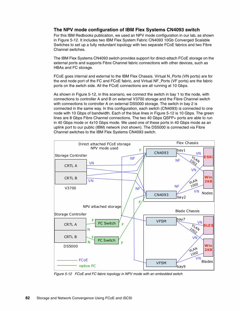
The NPV mode configuration of IBM Flex Systems CN4093 switchFor this IBM Redbooks publication, we used an NPV mode configuration in our lab, as shown in Figure 5-12. It includes two IBM Flex System Fabric CN4093 10Gb Converged Scalable Switches to set up a fully redundant topology with two separate FCoE fabrics and two Fibre Channel switches.
The IBM Flex Systems CN4093 switch provides support for direct-attach FCoE storage on the external ports and supports Fibre Channel fabric connections with other devices, such as HBAs and FC storage.
FCoE goes internal and external to the IBM Flex Chassis. Virtual N_Ports (VN ports) are for the end node port of the FC and FCoE fabric, and Virtual NF_Ports (VF ports) are the fabric ports on the switch side. All the FCoE connections are all running at 10 Gbps.
As shown in Figure 5-12, in this scenario, we connect the switch in bay 1 to the node, with connections to controller A and B on external V3700 storage and the Fibre Channel switch with connections to controller A on external DS5000 storage. The switch in bay 2 is connected in the same way. In this configuration, each switch (CN4093) is connected to one node with 10 Gbps of bandwidth. Each of the blue lines in Figure 5-12 is 10 Gbps. The green lines are 8 Gbps Fibre Channel connections. The two 40 Gbps QSFP+ ports are able to run in 40 Gbps mode or 4x10 Gbps mode. We used one of these ports in 40 Gbps mode as an uplink port to our public (IBM) network (not shown). The DS5000 is connected via Fibre Channel switches to the IBM Flex Systems CN4093 switch.
Figure 5-12 FCoE and FC fabric topology in NPV mode with an embedded switch
CRTL A
CRTL B
Storage Controller
Flex Chassis
Nodes
VLAN1002
VLAN
1002
Win2K8
ESXiCN4093
CN4093
Direct attached FCoE storageNPV mode used
NF
NFVN
VN
VN
VN
VN
bay1
bay2
NF
NF
Blade Chassis
Blades
VLAN1002
VLAN
1002
Win2K8
SLESVFSM
VFSM
VN
VN
VN
bay7
bay9
CRTL A
CRTL B
Storage Controller
F
F
FCoE
native FC
DS5000
V3700
FC Switch
FC Switch
F
F
F
N
N
F
NPV attached storage
82 Storage and Network Convergence Using FCoE and iSCSI

Figure 5-13 shows a simplified picture of our lab architecture for this scenario. It shows how the systems were interconnected during our lab testing.
Figure 5-13 Physical connections in NPV mode of the devices
Table 5-2 shows the wiring data for the switch in slot 1. The switch in slot 2 is connected in the same manner.
Table 5-2 Wiring diagram for components in FCF mode
CN4093 Speed Device Connection Description
P3...6 40 Gbps G8264CS_down P1...4 IBM Network connection
11 10 Gbps V3700 Ctrl A P1 FCoE
12 10 Gbps V3700 Ctrl B P2 FCoE
16 10 Gbps BCH Slot 7 P1 FCoE
20 8 Gbps Brocade FC switch P1 FC
Chapter 5. Topologies and lab architecture 83

5.2.2 Setup with the IBM System Networking G8264CS switch and the IBM Flex EN4093 switch inside the Flex chassis
In this scenario, we installed and used an IBM Flex EN4093 switch for interconnecting equipment via IBM System Networking G8264CS switch using Ethernet connections. All traffic in this setup went through IBM System Networking G8264CS switch. DS5000 storage systems were interconnected using Fibre Channel.
This architecture was to show the capability of the IBM System Networking G8264CS switch connecting to both FCoE and FC systems in FCF and NPV mode. These modes require different hardware configurations. The FC storage is in FCF mode connected directly to the IBM System Networking G8264CS switch. The NPV mode required an external Fibre Channel fabric.
For more information about switch configuration parameters and commands, see Chapter 13, “Approach with FCoE between the IBM Flex Chassis and a top-of-rack switch” on page 523.
In this scenario, we used the following systems:
� IBM Rack Switch G8264CS� IBM Flex System with 2 x240 Compute Nodes and an EN4093 FCoE switch� IBM Blade Center - Type H with 2 HS 22 Blade servers� IBM V3700 storage system with 2 canisters� IBM DS5000 storage system with two controllers� Brocade Fiber Channel switches
FCF mode configuration of IBM System Networking G8264CS switchFor this IBM Redbooks publication, we used this FCF mode configuration in our lab, as shown in Figure 5-14. It includes two IBM System Networking G8264CS switches and two IBM Flex EN4093 switches to set up a fully redundant topology with two separate FCoE fabrics.
Both switches provide support for direct-attach FCoE storage on the external ports. All the traffic must go through the FCF. The best practice is to connect the storage at the switch with the FCF.
FCoE goes internal and external to the IBM System Networking G8264CS switch. All the FCoE connections are all running at 10 Gbps. Except for the connection between the IBM Flex EN4093 switch and the IBM System Networking G8264CS switch, these connections use the 40 Gbps speed.
84 Storage and Network Convergence Using FCoE and iSCSI
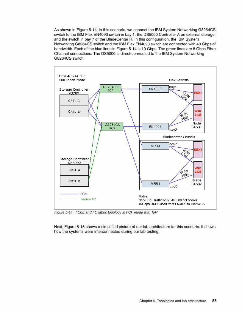
As shown in Figure 5-14, in this scenario, we connect the IBM System Networking G8264CS switch to the IBM Flex EN4093 switch in bay 1, the DS5000 Controller A on external storage, and the switch in bay 7 of the BladeCenter H. In this configuration, the IBM System Networking G8264CS switch and the IBM Flex EN4093 switch are connected with 40 Gbps of bandwidth. Each of the blue lines in Figure 5-14 is 10 Gbps. The green lines are 8 Gbps Fibre Channel connections. The DS5000 is direct-connected to the IBM System Networking G8264CS switch.
Figure 5-14 FCoE and FC fabric topology in FCF mode with ToR
Next, Figure 5-15 shows a simplified picture of our lab architecture for this scenario. It shows how the systems were interconnected during our lab testing.
Chapter 5. Topologies and lab architecture 85

Figure 5-15 physical connections in FCF mode of the devices with ToR switch
Table 5-3 shows the wiring data for the switch in slot 1. The switch in slot 2 is connected in the same manner.
Table 5-3 Wiring diagram for components in FCF mode
G8264CS_up Speed Device Connection Description
P1.4 40 Gbps EN4093 P15.18 FCoE & IBM-net
17 10 Gbps EN4093 P114 IBM net in vNIC
43 10 Gbps V3700 Ctrl B P1 FCoE
44 10 Gbps V3700 Ctrl A P2 FCoE
48 10 Gbps BCH Slot 7 P1 FCoE
51 1 Gbps IBM switch - IBM Network connection
55 8 Gbps DS5300 Ctrl B Ch 3 FC
86 Storage and Network Convergence Using FCoE and iSCSI
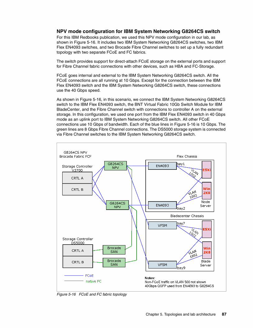
NPV mode configuration for IBM System Networking G8264CS switchFor this IBM Redbooks publication, we used this NPV mode configuration in our lab, as shown in Figure 5-16. It includes two IBM System Networking G8264CS switches, two IBM Flex EN4093 switches, and two Brocade Fibre Channel switches to set up a fully redundant topology with two separate FCoE and FC fabrics.
The switch provides support for direct-attach FCoE storage on the external ports and support for Fibre Channel fabric connections with other devices, such as HBA and FC-Storage.
FCoE goes internal and external to the IBM System Networking G8264CS switch. All the FCoE connections are all running at 10 Gbps. Except for the connection between the IBM Flex EN4093 switch and the IBM System Networking G8264CS switch, these connections use the 40 Gbps speed.
As shown in Figure 5-16, in this scenario, we connect the IBM System Networking G8264CS switch to the IBM Flex EN4093 switch, the BNT Virtual Fabric 10Gb Switch Module for IBM BladeCenter, and the Fibre Channel switch with connections to controller A on the external storage. In this configuration, we used one port from the IBM Flex EN4093 switch in 40 Gbps mode as an uplink port to IBM System Networking G8264CS switch. All other FCoE connections use 10 Gbps of bandwidth. Each of the blue lines in Figure 5-16 is 10 Gbps. The green lines are 8 Gbps Fibre Channel connections. The DS5000 storage system is connected via Fibre Channel switches to the IBM System Networking G8264CS switch.
Figure 5-16 FCoE and FC fabric topology
Chapter 5. Topologies and lab architecture 87

Figure 5-17 shows a simplified picture of our lab architecture for this scenario. It shows how the systems were interconnected during our lab testing.
Figure 5-17 Physical connections in NPV mode of the devices
88 Storage and Network Convergence Using FCoE and iSCSI

Table 5-4 shows the wiring data for the switch in slot 1. The switch in slot 2 is connected in the same manner.
Table 5-4 Wiring diagram for components in FCF mode
5.3 Equipment used in the lab
We used IBM Rack Switch G8264CS as the Top of Rack switch for connecting IBM Flex System, Blade Center, IBM Storage DS5000, and V3700 systems during our lab testing.
IBM Flex System Fabric CN4093 10Gb Converged Scalable SwitchIn this solution, the IBM Flex System Fabric CN4093 10 Gb Converged Scalable Switch was installed inside the IBM Flex System. A CN4093 10Gb Converged adapter was connected to the Top of Rack switch, IBM Rack Switch G8264CS, using native FCoE connections. CN4093 was also connected to the IBM Storage system via a Brocade Switch B32 using FC connections.
The setup of this implementation was not difficult on the IBM Flex System Fabric CN4093 converged Switch.
IBM Flex System Fabric CN4054 10Gb Virtual Fabric AdapterIn this solution, the IBM Flex System CN4054 10Gb Virtual Fabric Adapter was installed inside the x240 nodes on the Flex System.
IBM Rack Switch G8264CS - Top of Rack SwitchImplementing IBM Rack Switch G8264CS and connecting to IBM Flex System was easy and straightforward. We used only the base switch without any feature code or licensing upgrades. When connecting the devices to the switch ports, ensure that required switch feature upgrades are ordered and Omni ports are enabled.
IBM Flex System Fabric EN4093 and EN4093R 10Gb Scalable SwitchesWe also installed the IBM Flex System Fabric EN4093 Switches on the Flex System for another scenario during the lab testing. We connected EN4093, IBM Blade Center and IBM V3700 to the to the Top of Rack switch, IBM Rack Switch G8264CS, using Ethernet connections. The IBM Storage system DS5000 was connected to the IBM Rack Switch G8264CS Top of Rack switch using FC connections.
G8264CS_up Speed Device Connection Description
P1.4 40 Gbps EN4093 P15.18 FCoE & IBM-net
17 10 Gbps EN4093 P114 IBM net in vNIC
43 10 Gbps V3700 Ctrl B P1 FCoE
44 10 Gbps V3700 Ctrl A P2 FCoE
48 10 Gbps BCH Slot 7 P1 FCoE
51 1 Gbps IBM switch - IBM Network connection
64 8 Gbps Brocade FC switch P2 FC
Chapter 5. Topologies and lab architecture 89

Brocade B8000 Fibre Channel SwitchesWe also installed the Brocade B8000 Switch as a Fibre Channel switch for another scenario during the lab testing. We connected the Brocade B8000 Switch with the DS5300 storage using Fibre Channel, and the IBM System Networking G8264CS switch and IBM Flex Systems CN4093 switch using Ethernet connections.
5.4 Conclusion
The FCoE implementation for IBM System Networking switches requires minimal configuration effort. The solution is flexible and scalable in bandwidth. In our tests, we found only a minor issue with the automatic VLAN discovery, but did not experience any incompatibility issues with the external FC-attached storage.
No significant differences were detected between using Windows 2012, 2008R2, ESXi 5.0, or SLES_11SP2 Operating Systems with Converged Network Adapter.
The IBM Flex technology offers a fully integrated FCoE solution that is easy to set up and easy to integrate in a data center. The solution with RackSwitch G8316 as a 40 Gb top of rack aggregation switch shows the highest performance for applications.
90 Storage and Network Convergence Using FCoE and iSCSI
Chapter 6. Using FCoE and iSCSI in a converged network
Fibre Channel and iSCSI have both been around for several years. With converged networks, they both reach a new level. A lot of available best practices for Ethernet, Fibre Channel, and iSCSI remain unchanged. Some might become more important. This chapter offers insight into the different concepts and requirements and the commonalities and differences when converged networks are used. It discusses the most important best practices and gives the background to prove their necessity.
This chapter includes the following sections:
� 6.1, “Keeping it isolated” on page 92� 6.2, “iSCSI and differences from FC/FCoE in a CEE world” on page 92� 6.3, “FCoE commonalities and differences from FC in a CEE world” on page 95� 6.4, “Host mapping and multipathing” on page 101� 6.5, “Summary” on page 102
6
© Copyright IBM Corp. 2012, 2014. All rights reserved. 91

6.1 Keeping it isolated
A typical FC SAN is isolated from the outside, but presents a challenge for SANs that are Ethernet based. Isolation helps to improve performance and adds an additional level of security by splitting the traffic into different areas, which also improves the robustness of the network.
This principle is true for both storage and local area networks. Building different SANs and LANs is the most effective way to isolate network traffics. However, dedicated networks require additional hardware to be deployed. Therefore, a common approach is to establish a virtual LAN (VLAN) to divide the physical LAN into logical portions.
For SAN traffic, regardless of whether iSCSI or FCoE is used, it is a best practice to use a dedicated LAN or VLAN because it can have significant impact on the performance.
For iSCSI, another reason to implement a dedicated (V)LAN is to prevent the leak of plain text iSCSI SAN data over the user LAN.
With a dedicated (V)LAN, the administrators can tightly regulate and guard the traffic that the VLAN carries. This is a best practice for iSCSI and FCoE environments.
6.2 iSCSI and differences from FC/FCoE in a CEE world
The iSCSI protocol supports Gigabit Ethernet interfaces at the physical layer, so that systems that support iSCSI can connect directly to the traditional Gigabit Ethernet switches and IP routers.
The new features enhance the Ethernet protocol Converged Enhanced Ethernet (CEE), improve the performance characteristics of storage applications, and also contribute to improved performance for iSCSI storage traffic.
This section includes the following topics:
� 6.2.1, “Enabling CEE and iSCSI support” on page 92� 6.2.2, “Initiator to target relationship” on page 93� 6.2.3, “Mandatory security in real-world situations” on page 93
6.2.1 Enabling CEE and iSCSI support
In addition to the required converged network adapter configuration in the server system, the network must also enable CEE support in general and for iSCSI traffic handling. Example 6-1 shows the steps to enable CEE for iSCSI on an IBM Network System switch device (for example, as available for the IBM Flex System chassis).
Example 6-1 Enable CEE and iSCSI support using iscli mode on IBM Network System switch.
RS G8264FC#enableRS G8264FC#conf tEnter configuration commands, one per line. End with Ctrl/Z.RS G8264FC(config)#cee enableRS G8264FC(config)#cee iscsi enable
Note: The common “default” VLAN ID for FCoE traffic is 1002.
92 Storage and Network Convergence Using FCoE and iSCSI
RS G8264FC(config)#show cee iscsi ISCSI setting : EnabledRS G8264FC(config)#show cee
Current CEE Configuration:
CEE Features setting: OnISCSI setting: ena
...
6.2.2 Initiator to target relationship
In FC (and FCoE) SAN environments, logical relationships that define the allowed server and storage connections must be established. However, the requirements are different in an iSCSI context.
With iSCSI enabled on the switch device, a configured server system (initiator) is technically able to instantly query and connect to the available storage systems (target) and accesses the LUNs.
iSCSI is an IP-based standard for linking data storage devices over a network and transferring data by carrying SCSI commands over IP networks. iSCSI does not use zoning. Instead, it deals with “targets”. Therefore, it is only required to define LUN to host mapping on the storage (target) side.
6.2.3 Mandatory security in real-world situations
One of the most adverse design flaws for iSCSI was not designing security into the protocol. The control packets and data packets are vulnerable to attack because messages are sent and received in plain text. The iSCSI protocol also allows for configuration without any security measures. Security is left to the work of alternative protocols such as CHAP and Internet Protocol Security (IPSec).
As a result, authentication is important to iSCSI, which employs advanced authentication methods to establish security, such as the Challenge Handshake Authentication Protocol (CHAPv2).
Unfortunately, security engineering principles, such as “security by obscurity,” are frequently adapted into iSCSI solutions, incorporating inadvertent security vulnerabilities.
The Internet Engineering Task Force (IETF) considers security mandatory for iSCSI and mandates IPSec, as explained “Securing Block Storage Protocols over IP (RFC 3723). However, the appropriate method must to be chosen based on the given, specific surrounding parameters of the environment. Where possible, it is a best practice to use a combination of Authentication Header (AH) and Encapsulated Security Payload (ESP) to ensure reliable authentication, guaranteed integrity, and confidentiality.
Note: The best practice is to define these relationships with restrictions. Use zoning techniques to limit the visibility between the devices. For more information, see 6.3.3, “Zoning”.
Chapter 6. Using FCoE and iSCSI in a converged network 93

However, when using iSCSI in the real world, security requires utmost attention. iSCSI with added complements allows for varying levels and complexity of security, depending on the security practices of an organization:
� No security (not recommended)� Authentication� CRC checksums� Access control lists (ACL)� Firewall� Encryption� Isolation� Segregation� VLAN� Virtual private network (VPN) for remote access
Consider the viability of system usage when determining the correct security mechanisms for a solution. System usage and security must have a proportionate response. The more security a system has, the more complex a system becomes. The opposite also applies, where the less security a system has, the easier it is for a user to expose a system to security threats, increasing the potential for data theft, integrity issues, and confidentiality breeches. When security becomes inconvenient, it frequently leads to an unfeasible system and can then lead to circumvention.
A good iSCSI security solution must have relative security benefits and few inconveniences. Therefore, a well-rounded solution involves physical security, operating system security, application security, network security, effective policies, and practical procedures.
In reality, the implementation of any form of encryption mechanisms increases the overall performance overhead. To understand the performance overhead involved, it is a common approach to first test without security and then compare the results with a second test run, while selected security mechanisms are in place. FCoE might perform better than iSCSI when these securities are in place. However, with Fibre Channel Link Encryption becoming mainstream, this idea might change.
For more information about iSCSI, see the following references:
� IETF RFC 3720: MPLS Support of Differentiated Services:
http://www.ietf.org/rfc/rfc3720.txt
� IETF RFC 3723: Securing Block Storage Protocols over IP:
http://www.ietf.org/rfc/rfc3723.txt
� IP Storage Networking: IBM NAS and iSCSI Solutions, SG24-6240
� IBM BladeCenter iSCSI SAN Solution, REDP-4153
Note: Security mechanisms for iSCSI were excluded from the testing scenarios for this book. These mechanisms were excluded because there are different approaches and ambiguity when implementing iSCSI security. These factors allow pitfalls during and after implementation and add complexity, which draws the focus away from converged networks.
94 Storage and Network Convergence Using FCoE and iSCSI
6.3 FCoE commonalities and differences from FC in a CEE world
The Fibre Channel protocol depends on the reliability and stability of the transport layer underneath. This is a big difference from traditional Ethernet, and the convergence of SAN and LAN requires implementation of various services and protocols to connect the heterogeneous components.
FCoE is the proposed standard to enable FC communications to run directly over an Ethernet infrastructure and move across existing high-speed Ethernet infrastructures, which extends the reach and capability of traditional SANs.
However: “FC can be transported only over a lossless Ethernet network. The technology required to implement such a multi-hop lossless Ethernet network is not trivial or finalized.”1
The following sections explain the aspects of traditional FC that remain the same when configuring FCoE and the relatively new aspects requiring attention:
� 6.3.1, “Enabling FCoE support” on page 95� 6.3.2, “Understanding of the required fabric mode” on page 96� 6.3.3, “Zoning” on page 100
6.3.1 Enabling FCoE support
Successfully merging a SAN and a network requires a complex configuration of multiple components. Such components include servers, storage devices, software, FC and network interconnect components because they are the building blocks to construct, use and manage such an environment. Because of the complexity of heterogeneous, multiplatform environments, service and system integration are critical to the success of the overall implementation of FCoE.
Hardware and software requirements vary based on the platform that is used for FCoE connectivity. The following building blocks require some form of configuration change to successfully create a converged network configuration, but they vary in complexity:
� Servers� Operating systems� Storage, converged network adapters (CNAs), host bus adapters (HBAs), and other
options� Device configuration, tools, and management software� Network configuration� FC switch configuration� Storage management applications� Ability and interoperability of devices to use FCoE protocols
1 Source: “Unified Fabric White Paper —Fibre Channel over Ethernet (FCoE)”, Cisco Systems, Inc.
Chapter 6. Using FCoE and iSCSI in a converged network 95
More simply, there are two possible starting points to work with FCoE, with different methods:
1. Designing and implementing a new environment, starting on a green field:
– There is a high probability that almost all components are FCoE capable (that is server, switches, and storage).
2. Converging the existing Ethernet and FC networks, with many different choices for the granularity.
– Should converge capabilities only be available for new devices?
– Is it planned to replace/enable (probably only some) existing device to use FCoE?
– Implementing a new, top-level layer to interconnect both worlds (provide convergence)?
– Replacing core devices to enable convergence in the existing layout?
– Different understanding of the technology, depending on the reader’s angle (FC SAN or Ethernet LAN), new knowledge might be required.
These starting points might explain the way in which manufactures step into the “new world”. The second starting point is more frequent. The first available products were converged access-layer LAN and SAN switches and converged network adapters (CNA). In that time, the converged traffic was split again above the access-layer switches into traditional Ethernet and Fibre-Channel to stay compatible with the wider networks and storage systems, for example. As time passed, more and more FCoE capable devices (for example, storage systems) arrived in the market and provided end-to-end FCoE solutions.
This convergence has now reduced the number of physical devices and amount of cabling that are required, but they often add further complexity to the overall required configuration for a successful FCoE deployment. One reason is that, in general, it still needs to stay compatible to all three worlds (that is, traditional Ethernet, fibre-channel, and the converged FCoE).
Sticking to known FC protocol techniques while using FCoE helps to lower that complexity. Best practices such as zoning and storage partitioning and mapping remain mostly unchanged.
6.3.2 Understanding of the required fabric mode
The applied topology (for example, only FCoE components are connected or required to interconnect to a traditional FC fabric), plays an important role in identifying the appropriate required and supported fabric mode within the FCoE environment.
Fibre Channel servicesThe Fibre Channel protocol requires different services to be available in the fabric to ensure proper name services, zoning, and logins. All full fabric switches, that is, switches with a configured domain id, share this information in a fabric.
FCoE uses Ethernet as a transport layer and therefore does not have this service available by default. If there is an interconnection between the FCoE and the existing traditional FC network, these services will be provided outside of the traditional FC network. If no traditional FC network exists, something else needs to provide the interconnection. The provider is called the “Fibre Channel Forwarder (FCF)”.
Note: FCF is only required if services are not provided by interconnected traditional FC fabric.
96 Storage and Network Convergence Using FCoE and iSCSI

Fibre Channel Forwarder (FCF)As described in 2.3.5, “FCFs, Fabric Mode, and NPIV” on page 21, a FCF provides the required FC services (for example, name service, zoning, and logins) and is required to forward the FCoE packages. FCF needs to be enabled for the designated VLAN. It carries the FCoE traffic.
Within FCoE, it is a best practice that each server and storage talk to exactly one FCF instance, because both server and storage need to have a common FC service coordinating their communication. Otherwise, the server can try to talk through FCF A and storage through FCF B so no communication is possible (in case FCF does not share their configuration). This becomes even more important because most devices do not provide an option to select the FCF to be used.
Be aware that not every converged switch might be able to work as FCF. In some cases, it is possible that this feature can be enabled by adding a specific license key or feature.
Full Fabric modeA switch with enabled FCF mode is running in Full Fabric mode. Connecting a switch running this mode to a traditional FC fabric only works if both of the following requirements are met:
� Both devices support E_Ports.
� Both devices are from the same vendor, so they can become part of the same fabric and share the fabric controlling information, using E_Port connections.
If two switches in Full Fabric mode are interconnected, using an E_Port connection, they form a single fabric. Both devices use unique Domain IDs for identification, but share a single name server and login status databases.
A good example of where this might become a problem in the real world is bigger BladeCenter environments, where FC switches are installed in every chassis. The amount of devices can easily grow and impact the management complexity. In addition, the amount of available domain IDs per fabric is limited.
There is another aspect that requires attention. All switch manufacturers use their own proprietary extensions to the protocol. That is, they speak with different “accents”. Therefore an E_Port connection is only possible if both devices are talking with the same accent. Typically, this is only the case if they are from the same manufacturer.
To remedy these situations where there are too many devices or different vendors, it is sometimes possible to put the switches into the NPV mode.
Chapter 6. Using FCoE and iSCSI in a converged network 97

N_Port ID Virtualization (NPIV)The N_Port ID Virtualization (NPIV) must not be mixed with the NPV mode mentioned in the previous section. However, to understand the NPV mode, which is a virtualization enhancement for N_Ports, it is required to understand the generic Fibre Channel handling of N_Ports and the N_Port ID Virtualization (NPIV) first.
In a Fibre Channel fabric, ports with connected nodes (which can be server or storage devices) are called N_Port (node ports). During the Fabric Login (FLOGI) the node requests an address from the switch. This address is called N_Port ID2. In the next step, the N_Port ID is registered with the name server through the Port Login (PLOGI). Without NPIV, there is a one-to-one relationship between WWPNs and N_Port IDs per physical port.
NPIV allows a connected node to request multiple N_Port IDs and therefore register multiple WWPNs with one physical N_Port. After the regular FLOGI is performed, additional FDISC (Fabric Discovery Login Commands) are sent out to register all further WWPNs and retrieve the additional N_Port IDs. NPIV must be supported on both the node and the switch to work correctly.
The benefit of NPIV is the possibility to create a more granular LUN to host mapping, especially in virtualized server environments, as every virtual machine can be configured with a dedicated (virtual) WWPN and is able to see only the devices and LUN zoned to this specific WWPN.
N_Port Virtualization (NPV)A switch in NPV mode, also known as transparent mode, will not join the (existing FC) fabric as a switch device (which would require its own Domain ID). Instead, it will register the WWPNs of all devices that are connected to the NPV switch on a single physical N_Port of the upstream FC switch.
The NPV-enabled switch uses the NPIV semantic that was described earlier to act as a proxy for the nodes connected to its N_Ports. Because it “looks” as if there is just an NPIV-enabled host connected to the upstream FC switch, this mode is also known as transparent mode.
In this case, the upstream switch must support NPIV mode. Most recent switches support this mode, but the feature must be activated. Not every converged switch automatically supports the NPV mode, so be sure to verify the feature list.
The next section, “Switch mode”, describes the behavior of all other FCoE involved (DCB capable) switch devices that are either not configured or capable to run in NPV or Full Fabric mode.
2 N_Port ID must not to confused with the World Wide Port Name (WWPN). The (hardware bound) unique WWPN is registered to the name server during PLOGI.
Note: It is not possible to use channeling or trunking for NPV connections.
For additional descriptions explaining NPIV and NPV, see these websites:
� http://datacenteroverlords.com/2012/05/08/npv-and-npiv/� http://blog.scottlowe.org/2009/11/27/understanding-npiv-and-npv/
98 Storage and Network Convergence Using FCoE and iSCSI

Switch modeThis is the basic and default mode in which all FCoE (and therefore DCB) capable switches are operating. In this mode, all FCoE packets need to go through the FCF enabled switch first. The initiator cannot talk directly to a (local) target. This is important information, especially related to the defined connection point of storage devices.
Figure 6-1 describes the situation when a server and storage connect to a local switch with an upstream FCF enabled switch. In this case, all storage requests and responses have to go through the FCF uplink, which can fight congestion fairly quickly because it crosses two times.
Figure 6-1 Traffic flow Server and Storage connected to DCB switch with remote FCF
In Figure 6-2, the storage is connected directly to the FCF enabled switch. In this case, the traffic only crosses the uplink once. Utilization still needs to be planned and monitored appropriately, but it’s much more efficient than the first situation.
Figure 6-2 Traffic flow Server connected to DCB switch and storage to (remote) FCF
Note: It is a best practice to connect the storage directly to the FCF enabled device. This might change after the release of FC-BB-6 and the introduction of distributed FCF.
Chapter 6. Using FCoE and iSCSI in a converged network 99
6.3.3 Zoning
It is possible to allow every participating device (node) of a Fibre Channel SAN to talk to any other node in the fabric. However, this is not a desired behavior. There are various reasons why the visibility of nodes within a fabric should be planned and limited. Here are some examples:
� Security:
If server A has no possibility to talk to storage B, this lowers the risk that server A can access data on B without entitlement.
� Demarcation:
All nodes needs to know their available, potential communication partners. Therefore every join or leave of a node needs to be announced to every candidate3. With limited visibility, only the nodes needs to be informed which are defined to know each other. This can be compared with the announcement made on an airport, where most announcements have a limited audibility for the people waiting in a gate or area that is affected and is not heard by everyone on the premises.
� Stability:
If problems occur, nodes (probably nodes from different vendors) might take different approaches for error correction. For example, if one node sends out a SCSI reset in such a situation, this would impact more devices than are applicable.
� Operability:
There are situations where the number of visible objects or paths that a node can handle is limited.
It should now be clear why zoning is an important aspect of traditional SAN environments. Because FCoE contains encapsulated FC (and SCSI) commands, this already makes it applicable for FCoE as well.
Zoning becomes even more important for the converged network. In the converged network, in which storage and LAN traffic share the same infrastructure, the storage traffic must also be protected against anomalies in the Ethernet network. Traffic patterns that are caused by Ethernet broadcast storms must be quickly mitigated and segregated so that they do not cause loss or delay for intolerant storage traffic. Thus, the storage also must be protected from unauthorized modifications that can introduce instability into the network.
Zoning achieves the following benefits:
� Creates a barrier between different network environments. Only the members of the same zone can communicate within that zone, and all external communications are blocked.
� Isolates any single host bus adapter (HBA) for security and reliability reasons.
� Allows finer segmentation of the switched fabric.
The zoning information is applicable, enforced, and shared through a complete fabric. Most vendors define a zoneset as base unit. This zoneset contains the zones, with the defined members.
3 These notifications are part of the “Registered State Change Notification” (RSCN).
100 Storage and Network Convergence Using FCoE and iSCSI

There are multiple ways to define a member. The most common method is to use the World Wide Node Names (WWNN) as unique identifier of the nodes4. Another option is to use the switch ports as member objects5. To make it more human-readable, there is an option to define WWNNs and Ports which can be used as member in the zone. The use of aliases also adds an additional abstraction layer which makes it possible to change alias to WWNN or alias to port assignments without modifying the zones and zoneset.
In theory, a zone should only contain two members: one source and one target. In regards to the huge amount of zones, remember that most nodes today have multiple ports. This means that it has become common practice to have more members in a zone.
However, it is still a best practice to limit the members. Here are some possible approaches:
� Put a single initiator WWNN/port and all alternate WWNNs/ports of one target into one zone.
� Put all WWNN/ports of a single initiator and all WWNNs/ports of one target into one zone.
The steps and commands that are required to implement zoning depend on the switch manufacturer and are explained in detail for FCoE in Chapter 8, “FC and FCoE zone configuration” on page 195.
6.4 Host mapping and multipathing
Host mapping is the process of controlling which hosts have access to specific volumes in the system. It is similar in concept to logical unit number (LUN) mapping or masking. LUN mapping is the process of controlling which hosts have access to specific logical units (LUs) within the disk controllers.
The act of mapping a volume to a host makes the volume accessible to the WWPNs or iSCSI names such as iSCSI qualified names (IQNs) or extended-unique identifiers (EUIs) that are configured in the host object.
Each host mapping associates a volume with a host object and provides a way for all WWPNs and iSCSI names in the host object to access the volume. A volume can be mapped to multiple host objects. When a mapping is created, multiple paths might exist across the SAN fabric or Ethernet network from the hosts to the nodes that are presenting the volume. Without a multipathing device driver, most operating systems present each path to a volume as a separate storage device. The multipathing software manages the many paths that are available to the volume and presents a single storage device to the operating system.
4 This technique is commonly referred as “soft zoning”5 This technique is commonly referred as “hard zoning”
Note: In high-available/redundant iSCSI storage devices, the iSCSI names and associated IP addresses often can fail over between the redundant parts of the storage system, which negates the need for multipathing drivers in some configurations. To provide the highest availability, use multipathing drivers.
Chapter 6. Using FCoE and iSCSI in a converged network 101
The ability to use host mapping adds a high level of flexibility and security to storage systems because it provides the possibility to connect multiple and heterogeneous host systems to the same storage. More important than security is the protection offered by host mapping. If all servers can access every disk, this could lead to data corruption caused by misbehaving servers. The reason for corruption can be that the server accessing a disk is not able to identify a disk as currently used (for example, a different operating system) and might start writing its own volume label information on the disk. By only showing a server the volumes it is intended to use, via host mapping, this can be prevented because the host is not aware of the existence of any other volume.
Host mapping is strongly recommended in pure FC storage and this best practice also applies to iSCSI and FCoE. Depending on the products that are used and the standards that are required in the environment, the techniques of LUN masking (usually implemented in the device driver software on each host) or storage partitioning can be valid supplements or alternatives to host mapping.
6.5 Summary
During the testing that was performed for this book, the FCoE storage was presented to applications in the same manner as traditional FC technology. There was no difference when storage was attached through new FCoE or traditional FC connections.
FCoE uses the same operational model as native FC technology. Services such as discovery, WWN addressing, zoning, and LUN masking all operate the same way in FCoE as they do in native FC. As a result, it can be managed in the same traditional way as FC technology, applicable above the converged enhanced Ethernet transportation layer.
Today FCoE can be hosted on a 10 Gbps Enhanced Ethernet. It will be hosted on much faster networks in the future. This capability extends the reach of FC storage networks, allowing them to virtually connect every data center server to a centralized pool of storage. When using the FCoE protocol, FC traffic can now be mapped directly onto an enhanced Ethernet. The advantage is that FCoE allows storage and network traffic to be converged onto fewer cables, switches, and adapters, reducing excessive cabling, heat, and power consumption. Overall storage management when using an FCoE interface has the same look and feel as storage management with traditional FC interfaces.
There is still some distance to go. Here are two examples:
� Without distributed FCFs, distribution size and design of FCoE SANs are limited.
� Because of the current PAUSE handling, the distance is limited between initiator and target6.
All of this information needs to be taken into account and might influence decisions about if and how a migration or implementation of FCoE fits a specific environment. The upcoming implementation of the FC-BB-6 standard will probably be the next big step forward.
6 For details, see the description of Priority Flow Control in 2.1.1, “Priority-based Flow Control: IEEE 802.1Qbb” on page 12.
102 Storage and Network Convergence Using FCoE and iSCSI

Chapter 7. Installing and enabling the Converged Network Adapter
This chapter describes the installation and enablement of the Converged Network Adapters (CNA). It includes the three types of storage area networks: Fibre Channel (FC), iSCSI, and Fibre Channel over Ethernet (FCoE). To do this, we look at the enablement of the CN4054 10GB Virtual Fabric Adapter on IBM Flex System Enterprise Chassis.
Traditionally, servers typically have at least two adapters, Fibre Channel host bus adapter (FC HBA) and Ethernet network interface card (NIC), to connect to the storage network (FC) and computer network (Ethernet). Today, a CNA integrates the functions of both adapters into one. However, a CNA can be used as a stand-alone 10 Gbps NIC, if storage networking is not immediately required. FCoE and FC storage area network (SAN) functions can be added later when required. The installation of these adapters requires different management, drivers, and procedures to install and achieve the full functionality of the CNA as explained in this chapter.
Although CNA adapter installation is done on IBM Flex System Chassis and IBM Blade Servers, this procedure for installing adapters is similar for IBM System x servers by using Peripheral Component Interconnect Express (PCIe).
This chapter includes the following sections:
� 7.1, “Installing and enabling CN4054 10Gb Virtual Fabric Adapter on IBM Flex System” on page 104
� 7.2, “Installing and enabling the Emulex CNA” on page 113
� 7.3, “Installing and enabling the Emulex 10GB Virtual Fabric Adapters I and II for iSCSI” on page 116
� 7.4, “Installing the CNA software management tools” on page 125
� 7.5, “Installing and enabling the QLogic 2-port 10Gb Converged Network Adapter” on page 147
� 7.6, “Installing and enabling the Brocade 2-port 10GbE Converged Network Adapter” on page 173
� 7.7, “iSCSI connectors” on page 185
7
© Copyright IBM Corp. 2012, 2014. All rights reserved. 103

7.1 Installing and enabling CN4054 10Gb Virtual Fabric Adapter on IBM Flex System
Update the firmware to the latest supported version before proceeding with the configuration. Make sure to refer to the release notes to select the appropriate version of firmware as required for your installation.
7.1.1 Updating the firmware
You can choose from various methods to update the firmware on CN4054 10GB Virtual Fabric Adapters. To download the latest available firmware code for the adapters, go to the Fix Central site at this website:
http://www.ibm.com/support/fixcentral/
For example, you can use IBM UpdateXpress System Pack Installer to update drivers and firmware if the operating system is installed. Alternatively, you can also use IBM ToolsCenter Bootable Media Creator to update firmware on systems where the operating system is not installed. You can download these tools from the IBM ToolsCenter at this website:
http://www.ibm.com/support/entry/portal/docdisplay?brand=5000008&lndocid=TOOL-CENTER
You can also go to the IBM Information Center and follow the instructions to download firmware updates.
http://publib.boulder.ibm.com/infocenter/flexsys/information/index.jsp?topic=%2Fcom.ibm.acc.7895.doc%2Fupdating_firmware.html
In some circumstances where the adapter is already installed and operational, you must ensure that the appropriate driver update is installed before running the firmware updates.
The following sections explain how to update the firmware on CN4054 10 GB Virtual Fabric Adapters, depending on your environment.
Windows: Installing the stand-alone firmware packageFor the stand-alone package in a Windows environment, you can use the executable file that you downloaded from Fix Central or the IBM ToolsCenter in the following ways:
� To update the Emulex firmware on the local system� To copy or extract all files necessary for the update to the local hard disk drive or other
media
Updating the Emulex firmware on the local systemTo update the Emulex firmware on the local system, follow these steps:
1. Double-click the file icon to run it. Alternatively, at a command prompt, type:
elx_fw_cna_ibm1209-4.4.180.3-1_windows_32-64.exe
2. Select Perform Update, and then click Next.3. Click Update.4. Click Exit to exit the utility. If you must perform another function, click Back.
Attention: If the update process is interrupted (such as by a power failure) when the firmware is being updated, the adapter might become unusable.
104 Storage and Network Convergence Using FCoE and iSCSI

Extracting all files for the updateTo extract the files for update to the local hard disk drive or other media, follow these steps:
1. Double-click the file icon to run it. Alternatively, at a command prompt, type:
elx_fw_cna_ibm1209-4.4.180.3-1_windows_32-64.exe
2. Select Extract to Hard Drive, and then click Next.3. Select the desired destination directory or media, and then click OK.4. Click Exit to exit the utility. If you must perform another function, click Back.
Manually installing the updateTo manually install the update, follow these steps:
1. Extract the update files to a temporary directory.
2. From a command prompt, enter the following command:
Update.cmd
The update reports successful completion.
Windows, Linux, and VMware: Updating firmware using offline ISO firmware
For offline updates, go to the Emulex website to download the latest firmware code.
http://www.emulex.com/downloads/ibm/vfafc-software-kits/ocm628/ocm628-pflex-windows/management-and-utilities.html
After upgrading the adapter with this offline flash method, you can update all future firmware with the online flash utilities that are provided.
Windows, Linux, and VMware for CN4054 10GB Virtual Fabric AdapterThere are several utilities for updating the firmware for CN4054 10GB Virtual Fabric Adapter. See Table 7-1.
Table 7-1 Available methods for updating CN4054 10GB Virtual Fabric Adapter
Unattended mode: To run this package in unattended mode, enter the following command:
elx_fw_cna_ibm1209-4.4.180.3-1_windows_32-64.exe -s
Operating system
OneCommand Manager HBAnyware elxcfg iputil Offline utilities
Windows x x x x
Linux x x x x
VMware x x x
Chapter 7. Installing and enabling the Converged Network Adapter 105
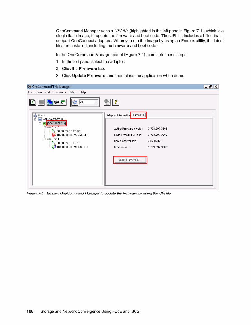
OneCommand Manager uses a UFI file (highlighted in the left pane in Figure 7-1), which is a single flash image, to update the firmware and boot code. The UFI file includes all files that support OneConnect adapters. When you run the image by using an Emulex utility, the latest files are installed, including the firmware and boot code.
In the OneCommand Manager panel (Figure 7-1), complete these steps:
1. In the left pane, select the adapter.
2. Click the Firmware tab.
3. Click Update Firmware, and then close the application when done.
Figure 7-1 Emulex OneCommand Manager to update the firmware by using the UFI file
106 Storage and Network Convergence Using FCoE and iSCSI
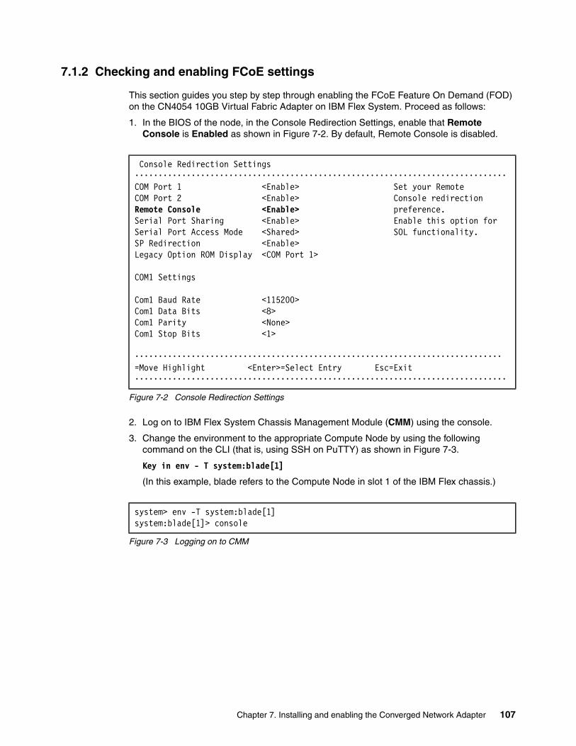
7.1.2 Checking and enabling FCoE settings
This section guides you step by step through enabling the FCoE Feature On Demand (FOD) on the CN4054 10GB Virtual Fabric Adapter on IBM Flex System. Proceed as follows:
1. In the BIOS of the node, in the Console Redirection Settings, enable that Remote Console is Enabled as shown in Figure 7-2. By default, Remote Console is disabled.
Figure 7-2 Console Redirection Settings
2. Log on to IBM Flex System Chassis Management Module (CMM) using the console.
3. Change the environment to the appropriate Compute Node by using the following command on the CLI (that is, using SSH on PuTTY) as shown in Figure 7-3.
Key in env - T system:blade[1]
(In this example, blade refers to the Compute Node in slot 1 of the IBM Flex chassis.)
Figure 7-3 Logging on to CMM
Console Redirection Settings •••••••••••••••••••••••••••••••••••••••••••••••••••••••••••••••••••••••••••••••COM Port 1 <Enable> Set your RemoteCOM Port 2 <Enable> Console redirectionRemote Console <Enable> preference.Serial Port Sharing <Enable> Enable this option forSerial Port Access Mode <Shared> SOL functionality.SP Redirection <Enable>Legacy Option ROM Display <COM Port 1>
COM1 Settings
Com1 Baud Rate <115200>Com1 Data Bits <8>Com1 Parity <None>Com1 Stop Bits <1> •••••••••••••••••••••••••••••••••••••••••••••••••••••••••••••••••••••••••••••• =Move Highlight <Enter>=Select Entry Esc=Exit•••••••••••••••••••••••••••••••••••••••••••••••••••••••••••••••••••••••••••••••
system> env -T system:blade[1]system:blade[1]> console
Chapter 7. Installing and enabling the Converged Network Adapter 107

4. Highlight System Settings and press Enter to go to system settings options as shown in Figure 7-4.
Figure 7-4 IBM Flex System CMM System Configuration Menu
5. Highlight Network and press Enter to go to Network configuration options as shown in Figure 7-5.
Figure 7-5 System Settings Options
System Configuration and Boot Management •••••••••••••••••••••••••••••••••••••••••••••••••••••••••••••••••••••••••••••••System Information This selection willSystem Settings take you to the SystemDate and Time Settings.
Start OptionsBoot Manager
System Event LogsUser Security
Save SettingsRestore SettingsLoad Default SettingsExit Setup
•••••••••••••••••••••••••••••••••••••••••••••••••••••••••••••••••••••••••••••• =Move Highlight <Enter>=Select Entry <ESC>=Exit Setup
System Settings •••••••••••••••••••••••••••••••••••••••••••••••••••••••••••••••••••••••••••••••Adapters and UEFI Drivers Select this option toProcessors see all the NetworkMemory Device options.Devices and I/O PortsPowerOperating ModesLegacy SupportSystem SecurityIntegrated Management ModuleRecoveryNetworkEmulex Configuration Utility Ver:5.10a5Driver Health
•••••••••••••••••••••••••••••••••••••••••••••••••••••••••••••••••••••••••••••• =Move Highlight <Enter>=Select Entry Esc=Exit•••••••••••••••••••••••••••••••••••••••••••••••••••••••••••••••••••••••••••••••
108 Storage and Network Convergence Using FCoE and iSCSI
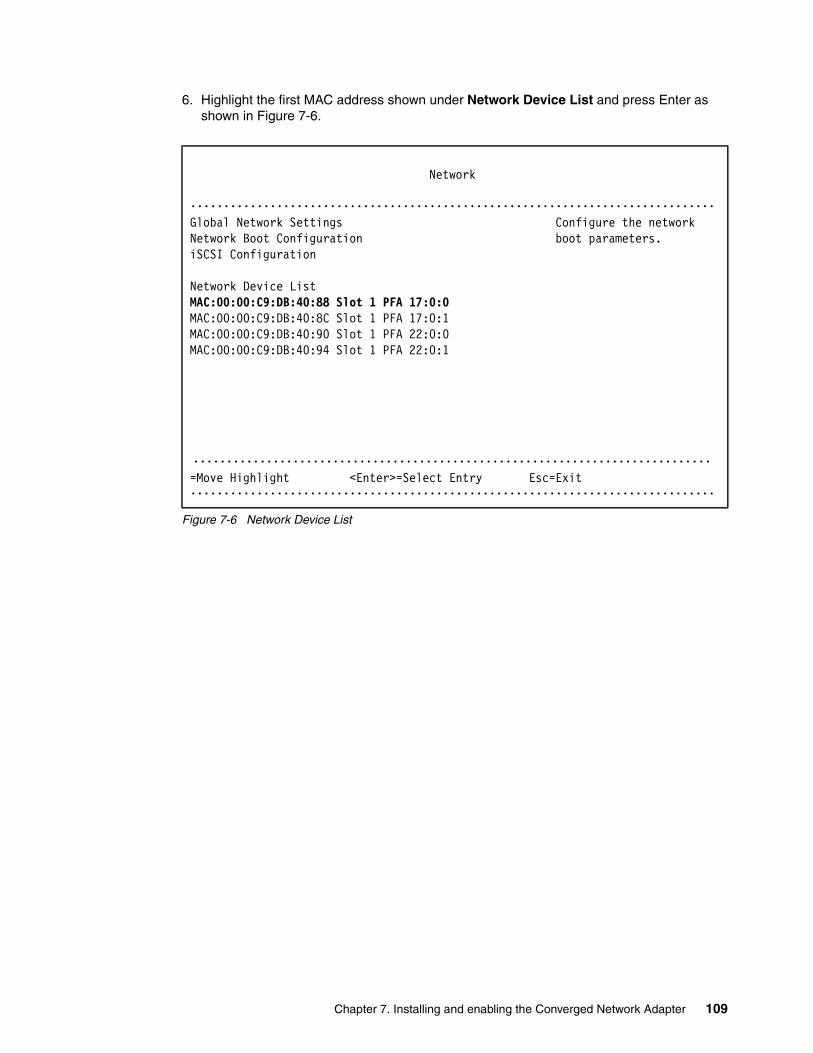
6. Highlight the first MAC address shown under Network Device List and press Enter as shown in Figure 7-6.
Figure 7-6 Network Device List
Network •••••••••••••••••••••••••••••••••••••••••••••••••••••••••••••••••••••••••••••••Global Network Settings Configure the networkNetwork Boot Configuration boot parameters.iSCSI Configuration
Network Device ListMAC:00:00:C9:DB:40:88 Slot 1 PFA 17:0:0MAC:00:00:C9:DB:40:8C Slot 1 PFA 17:0:1MAC:00:00:C9:DB:40:90 Slot 1 PFA 22:0:0MAC:00:00:C9:DB:40:94 Slot 1 PFA 22:0:1
•••••••••••••••••••••••••••••••••••••••••••••••••••••••••••••••••••••••••••••• =Move Highlight <Enter>=Select Entry Esc=Exit•••••••••••••••••••••••••••••••••••••••••••••••••••••••••••••••••••••••••••••••
Chapter 7. Installing and enabling the Converged Network Adapter 109

7. The screen shown in Figure 7-7 will appear on the console. Highlight Emulex 10G NIC: Bus:Dev:Func 11:0:0 - 00:00:C9:DB:40:88 and press Enter as shown in Figure 7-7.
Figure 7-7 Emulex 10G NIC Adapter
8. FCoE is enabled as shown in Figure 7-8.
Figure 7-8 Emulex NIC Selection
MAC:00:00:C9:DB:40:88 Slot 1 PFA 17:0:0 •••••••••••••••••••••••••••••••••••••••••••••••••••••••••••••••••••••••••••••••Emulex 10G NIC: Bus:Dev:Func 11:0:0 - Enter to Configure00:00:C9:DB:40:88 Emulex NICsIPv4 Network ConfigurationIPv6 Network Configuration
•••••••••••••••••••••••••••••••••••••••••••••••••••••••••••••••••••••••••••••• =Move Highlight <Enter>=Select Entry Esc=Exit•••••••••••••••••••••••••••••••••••••••••••••••••••••••••••••••••••••••••••••••
Emulex NIC Selection •••••••••••••••••••••••••••••••••••••••••••••••••••••••••••••••••••••••••••••••Emulex 90Y3556 Virtual Fabric Adapter (Fabric Emulex NIC Model NumberMezz)
Firmware Version : 4.4.180.0Bus:Device:Function : 11:0:0Link Speed : 10 GbpsAdvanced Mode <Disable>Personality <FCoE>Multichannel <Disable>Controller ConfigurationFeature On DemandEmulex Flash Update UtilityPort IdentificationErase Configuration
•••••••••••••••••••••••••••••••••••••••••••••••••••••••••••••••••••••••••••••• =Move Highlight Esc=Exit•••••••••••••••••••••••••••••••••••••••••••••••••••••••••••••••••••••••••••••••
110 Storage and Network Convergence Using FCoE and iSCSI
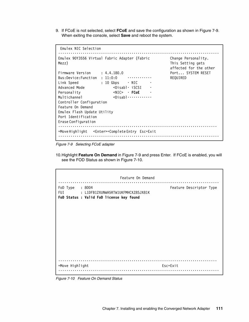
9. If FCoE is not selected, select FCoE and save the configuration as shown in Figure 7-9. When exiting the console, select Save and reboot the system.
Figure 7-9 Selecting FCoE adapter
10.Highlight Feature On Demand in Figure 7-9 and press Enter. If FCoE is enabled, you will see the FOD Status as shown in Figure 7-10.
Figure 7-10 Feature On Demand Status
Emulex NIC Selection •••••••••••••••••••••••••••••••••••••••••••••••••••••••••••••••••••••••••••••••Emulex 90Y3556 Virtual Fabric Adapter (Fabric Change Personality.Mezz) This Setting gets affected for the otherFirmware Version : 4.4.180.0 Port... SYSTEM RESETBus:Device:Function : 11:0:0 •••••••••••• REQUIREDLink Speed : 10 Gbps • NIC •Advanced Mode <Disabl• iSCSI •Personality <NIC> • FCoE •Multichannel <Disabl••••••••••••Controller ConfigurationFeature On DemandEmulex Flash Update UtilityPort Identification Erase Configuration •••••••••••••••••••••••••••••••••••••••••••••••••••••••••••••••••••••••••••••• =Move Highlight <Enter>=Complete Entry Esc=Exit •••••••••••••••••••••••••••••••••••••••••••••••••••••••••••••••••••••••••••••••
Feature On Demand •••••••••••••••••••••••••••••••••••••••••••••••••••••••••••••••••••••••••••••••FoD Type : 8004 Feature Descriptor TypeFUI : L1DFB12XUNWA5RTW1UKFMHCXZ8SJX81KFoD Status : Valid FoD license key found
•••••••••••••••••••••••••••••••••••••••••••••••••••••••••••••••••••••••••••••• =Move Highlight Esc=Exit•••••••••••••••••••••••••••••••••••••••••••••••••••••••••••••••••••••••••••••••
Chapter 7. Installing and enabling the Converged Network Adapter 111

11.If FCoE is not available, log on to IMM using the web interface. On the IMM Management menu, select Active Key Management as shown in Figure 7-11 and ensure that the appropriate keys to enable FCoE are installed.
Figure 7-11 IMM Active Key Management
– In Figure 7-11, the key is shown in the Feature Description column as IBM Flex System CN4054 Virtual Fabric Adapter Upgrade and Key installed is shown in the Status column.
– If the key is not installed, FCoE will not be enabled. Ensure that you get appropriate keys to enable FCoE.
For rest of the configuration and the steps to enable IBM Flex System CN4054 Virtual Fabric Adapter, follow the procedure as shown in 7.2, “Installing and enabling the Emulex CNA” on page 113.
112 Storage and Network Convergence Using FCoE and iSCSI

7.2 Installing and enabling the Emulex CNA
This section guides you step-by-step through the installation and configuration of the Emulex 10GB Convergence Network Adapter on IBM Flex System.
7.2.1 Loading the default settings on the Emulex CNA
To load the default settings on the Emulex CNA, follow these steps:
1. Clear any configuration. In the Controller Configuration Menu panel (Figure 7-12), highlight Erase Configuration and press Enter.
Figure 7-12 Controller Configuration Menu panel
2. When prompted by the message “Existing configuration will be overwritten by the default values” (Figure 7-13), press Enter to confirm.
Figure 7-13 Message about overwriting the existing configuration
Controller Configuration Menu ••••••••••••••••••••••••••••••••••••••••••••••••••••••••••••••••••••••••••••Emulex 90Y3556 Virtual Fabric Adapter (Fabric Erase the CurrentMezz) Configuration and Restore the DefaultBoot Support <Enable> ConfigurationSave Changes
Controller PropertiesNetwork ConfigurationiSCSI Target Configuration
Erase Configuration ••••••••••••••••••••••••••••••••••••••••••••••••••••••••••••••••••••••••••• =Move Highlight <Enter>=Select Entry Esc=Exit ••••••••••••••••••••••••••••••••••••••••••••••••••••••••••••••••••••••••••••
•••••••••••••••••••••••••••••••••••••••••••••••••••••••••••••••••••••••••••••••Existing Configuration will be overwritten by Default Values for both ports.•• Press ENTER to Continue, ESC to Abort •••••••••••••••••••••••••••••••••••••••••••••••••••••••••••••••••••••••••••••••
Chapter 7. Installing and enabling the Converged Network Adapter 113

To configure the Emulex CNA, follow these steps:
1. Press F1, and in the System Configuration and Boot Management panel, select System Settings Network Network Device List. Select the first entry, as shown in Figure 7-14.
Figure 7-14 Network settings
2. Select the first entry in the Emulex function as shown in Figure 7-15.
Figure 7-15 Emulex Function screen
Network ••••••••••••••••••••••••••••••••••••••••••••••••••••••••••••••••••••••••••••Global Network Settings Select this option toNetwork Boot Configuration see all the NetworkiSCSI Configuration Device options.
Network Device List PCI Function Address:MAC:00:00:C9:DB:40:88 Slot 1 PFA 17:0:0 Bus 17:Dev 0:Func 0MAC:00:00:C9:DB:40:8C Slot 1 PFA 17:0:1MAC:00:00:C9:DB:40:90 Slot 1 PFA 22:0:0MAC:00:00:C9:DB:40:94 Slot 1 PFA 22:0:1
•••••••••••••••••••••••••••••••••••••••••••••••••••••••••••••••••••••••••••• =Move Highlight <Enter>=Select Entry Esc=Exit••••••••••••••••••••••••••••••••••••••••••••••••••••••••••••••••••••••••••••
Note: It is only possible to change the personality at the first entry for the for the Emulex card. The second and third entries follow the first entry, and these entries cannot be changed.
MAC:00:00:C9:DB:40:88 Slot 1 PFA 17:0:0 •••••••••••••••••••••••••••••••••••••••••••••••••••••••••••••••••••••••••••••••Emulex 10G NIC: Bus:Dev:Func 11:0:0 - Enter to Configure00:00:C9:DB:40:88 Emulex NICsIPv4 Network ConfigurationIPv6 Network Configuration
•••••••••••••••••••••••••••••••••••••••••••••••••••••••••••••••••••••••••••••• =Move Highlight <Enter>=Select Entry Esc=Exit •••••••••••••••••••••••••••••••••••••••••••••••••••••••••••••••••••••••••••••••
114 Storage and Network Convergence Using FCoE and iSCSI
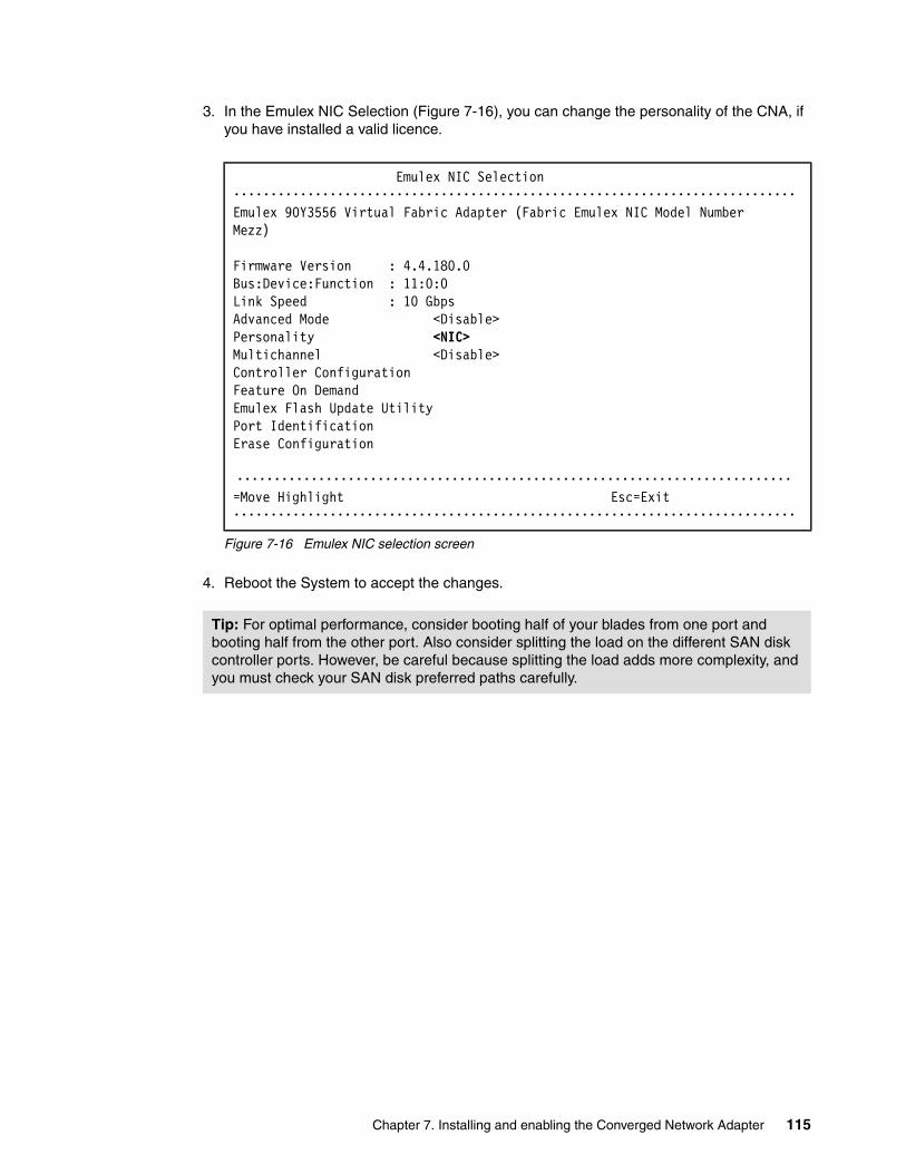
3. In the Emulex NIC Selection (Figure 7-16), you can change the personality of the CNA, if you have installed a valid licence.
Figure 7-16 Emulex NIC selection screen
4. Reboot the System to accept the changes.
Emulex NIC Selection ••••••••••••••••••••••••••••••••••••••••••••••••••••••••••••••••••••••••••••Emulex 90Y3556 Virtual Fabric Adapter (Fabric Emulex NIC Model NumberMezz)
Firmware Version : 4.4.180.0Bus:Device:Function : 11:0:0Link Speed : 10 GbpsAdvanced Mode <Disable>Personality <NIC>Multichannel <Disable>Controller ConfigurationFeature On DemandEmulex Flash Update UtilityPort IdentificationErase Configuration
••••••••••••••••••••••••••••••••••••••••••••••••••••••••••••••••••••••••••• =Move Highlight Esc=Exit ••••••••••••••••••••••••••••••••••••••••••••••••••••••••••••••••••••••••••••
Tip: For optimal performance, consider booting half of your blades from one port and booting half from the other port. Also consider splitting the load on the different SAN disk controller ports. However, be careful because splitting the load adds more complexity, and you must check your SAN disk preferred paths carefully.
Chapter 7. Installing and enabling the Converged Network Adapter 115

7.3 Installing and enabling the Emulex 10GB Virtual Fabric Adapters I and II for iSCSI
This section guides you step-by-step through the installation and configuration of the Emulex 10GB Virtual Fabric Adapters I and II for Internet Small Computer System Interface (iSCSI).
7.3.1 Updating firmware
You can choose from various methods to update the firmware on Emulex 10GB Virtual Fabric Adapters I and II. To download the latest available firmware code for the adapters, go to the Fix Central site at this website:
http://www.ibm.com/support/fixcentral/
For example, you can use IBM UpdateXpress System Pack Installer to update drivers and firmware if the operating system is installed. Alternatively, you can also use IBM ToolsCenter Bootable Media Creator to update firmware on systems where the operating system is not installed. You can download these tools from the IBM ToolsCenter at this website:
http://www.ibm.com/support/entry/portal/docdisplay?brand=5000008&lndocid=TOOL-CENTER
In some circumstances where the adapter is already installed and operational, you must ensure that the appropriate driver update is installed before running the firmware updates.
The following sections explain how to update the firmware for the Virtual Fabric Adapters I and II, depending on your environment.
Windows: Installing the stand-alone firmware packageFor the stand-alone package in a Windows environment, you can use the executable file that you downloaded from Fix Central or the IBM ToolsCenter in the following ways:
� To update the Emulex firmware on the local system� To copy or extract all files necessary for the update to the local hard disk drive or other
media
Updating the Emulex firmware on the local systemTo update the Emulex firmware on the local system, follow these steps:
1. Double-click the file icon to run it. Alternatively, at a command prompt, type:
elx_fw_ucna-2.103.397.3806_windows_32-64.exe
2. Select Perform Update, and then click Next.3. Click Update.4. Click Exit to exit the utility. If you must perform another function, click Back.
Attention: If the update process is interrupted (such as a power failure) when the firmware is being updated, the adapter might become unusable.
116 Storage and Network Convergence Using FCoE and iSCSI
Extracting all files for the updateTo extract the files for update to the local hard disk drive or other media, follow these steps:
1. Double-click the file icon to run it. Alternatively, at a command prompt, type:
elx_fw_ucna-2.103.397.3806_windows_32-64.exe
2. Select Extract to Hard Drive, and then click Next.3. Select the desired destination directory or media, and then click OK.4. Click Exit to exit the utility. If you must perform another function, click Back.
Manually installing the updateTo manually install the update, follow these steps:
1. Extract the update files to a temporary directory.
2. From a command prompt, enter the following command:
Update.cmd
The update reports successful completion.
Windows, Linux, and VMware: Updating firmware after using offline ISO firmwareThe Emulex Virtual Fabric Adapter (CFFh) for IBM BladeCenter required a specific update during revisions 2.103.411.7 and 2.101.411.7 to update the Field Programmable Gate Array (FPGA) and configuration regions on the adapter. To prevent problems, complete the following procedure before updating to the latest firmware.
If an adapter is currently running firmware revision 2.103.411.7 or was updated to revision 2.101.411.7 or later, complete the following steps:
1. Locate the latest International Organization for Standardization (ISO) firmware update image within this release, named OneConnect-Flash-2.103.397.3806.iso.
2. Burn this image to a CD, or mount the ISO with the Advanced Management Module Remote Control feature.
3. Load an abridged version of the Linux operating system, and mount the CD. To begin, power on the server and start the offline flash CD or Remote Control mounted ISO. After the server completes the startup process, the Emulex banner appears with a shell. The program might take some time to load completely.
4. After the program finishes loading, and you are prompted to reflash the firmware and boot the code image, type Y, and then press Enter. The flash process takes approximately 10 minutes. The flash memory is first erased and then rewritten.
After upgrading the adapter with this offline flash method, you can update all future firmware with the online flash utilities that are provided.
Unattended mode: To run this package in unattended mode, enter the following command:
elx_fw_ucna-2.103.397.3806_windows_32-64.exe -s
Online flash method: If the blade is not reseated since updating the firmware with the offline flash ISO, the online flash method will fail on the first attempt. If a failure occurs, you can run the online flash a second time for it to succeed.
Chapter 7. Installing and enabling the Converged Network Adapter 117

Windows, Linux, and VMware for Emulex Virtual Fabric Adapter I and II OneConnect adaptersEmulex offers several utilities for updating the firmware for Emulex VFA I and II as shown in Table 7-2.
Table 7-2 Available methods for updating Emulex Virtual Fabric Adapters I and II1
In this book, we install and use Emulex OneCommand Manager because of its ease of use for updating to the latest firmware and boot code. OneCommand Manager uses a UFI file (highlighted in the left pane in Figure 7-17), which is a single flash image, to update the firmware and boot code. The UFI file includes all files that support OneConnect adapters. When you run the image by using an Emulex utility, the latest files are installed, including the firmware and boot code.
In the OneCommand Manager panel (Figure 7-17), complete these steps:
1. In the left pane, select the adapter. 2. Click the Firmware tab.3. Click Update Firmware, and then close the application when done.
Figure 7-17 Emulex OneCommand Manager to update the firmware by using the UFI file
For more information, see the Emulex Firmware Update Manual for Emulex Adapters at:
http://cmw3wbp1.emulex.com//files/downloads/hardware/fwupdate.pdf
Operating system
OneCommand Manager HBAnyware elxcfg iputil Offline utilities
Windows x x x x
Linux x x x x
VMware x x
1 Adapted from the Update Utilities table on page 2 of the Emulex Firmware Update Manual for Emulex Adapters at:http://cmw3wbp1.emulex.com//files/downloads/hardware/fwupdate.pdf#search=%22UFI%22
118 Storage and Network Convergence Using FCoE and iSCSI

7.3.2 Installing a driver in a Windows environment
You can install a driver in a Windows environment by using the following methods:
� In a hardware-first installation, install at least one Emulex adapter before you install the Emulex drivers and utilities.
� In a software-first installation, you can install drivers and utilities by using AutoPilot Installer before installing any adapters. You do not need to specify the adapter models to be installed later. The appropriate drivers and utilities automatically load when you install the adapters.
For more information, see the following web references:
� Microsoft Windows Software Kit Emulex Virtual Fabric Adapters (CFFh) for IBM BladeCenter
http://www.emulex.com/downloads/ibm/vfa-software-kits/ocm5142-bc-windows/drivers.html
� Emulex Quick Installation Manual for Windows Drivers
http://www-dl.emulex.com/support/windows/windows/241002/driver_quick_install.pdf
Downloading the Emulex driver kitDownload the Microsoft Windows Software Kit Emulex Virtual Fabric Adapters (CFFh) for IBM BladeCenter driver kit installer from the following Emulex web page to your system:
http://www.emulex.com/downloads/ibm/vfa-software-kits/ocm5142-bc-windows/drivers.html
For more information, see the Emulex Quick Installation Manual for Windows Drivers at this website:
http://www-dl.emulex.com/support/windows/windows/241002/driver_quick_install.pdf
Installing the Emulex iSCSI driverAfter you download the driver kit installer, depending upon your needs, you can choose one of the following methods to install the Emulex driver kits:
� For an automatic interactive installation, run AutoPilot Installer.
Use this option, unless you have specific configuration needs. When you choose this option, you can install a driver kit and AutoPilot by using a few mouse clicks.
� For control of all interactive installation settings, run Run AutoPilot Installer Separately for the following purposes:
– Change installation settings for a limited number of systems.– Familiarize yourself with AutoPilot Installer configuration options.
To access these features, run AutoPilot Installer after the driver kit installation is complete so that you can change the configuration options supplied to AutoPilot Installer.
Chapter 7. Installing and enabling the Converged Network Adapter 119

The Emulex iSCSI driver kit installer is an executable file that self-extracts and copies the software onto your system.
After you download the Emulex iSCSI driver, install it:
1. Run the .exe file.
2. In the first window (Figure 7-18), click Next.
Figure 7-18 Emulex iSCSI Driver Kit installation
3. In the Installation options panel (Figure 7-19), select the installation option: Perform Installation of Drivers or Unpack All Drivers (for installation later). Then click Install.
Figure 7-19 Emulex iSCSI Driver Kit installation options
120 Storage and Network Convergence Using FCoE and iSCSI
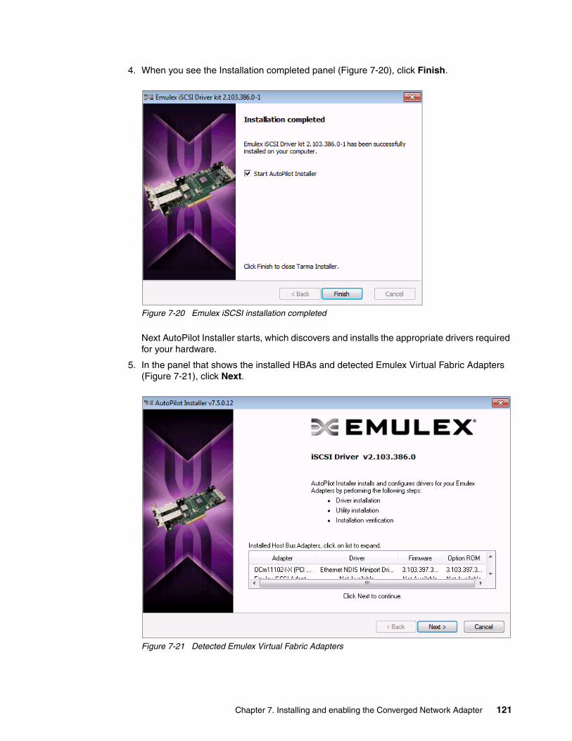
4. When you see the Installation completed panel (Figure 7-20), click Finish.
Figure 7-20 Emulex iSCSI installation completed
Next AutoPilot Installer starts, which discovers and installs the appropriate drivers required for your hardware.
5. In the panel that shows the installed HBAs and detected Emulex Virtual Fabric Adapters (Figure 7-21), click Next.
Figure 7-21 Detected Emulex Virtual Fabric Adapters
Chapter 7. Installing and enabling the Converged Network Adapter 121

6. If you see the Driver Installation Issue panel (Figure 7-22), select the Install drivers for only those adapters whose current driver versions differ check box, and then click Next.
Figure 7-22 Emulex Autopilot iSCSI driver installation
7. In the last panel (Figure 7-23), which shows the installation as complete, click Finish.
Figure 7-23 Installation completion
122 Storage and Network Convergence Using FCoE and iSCSI
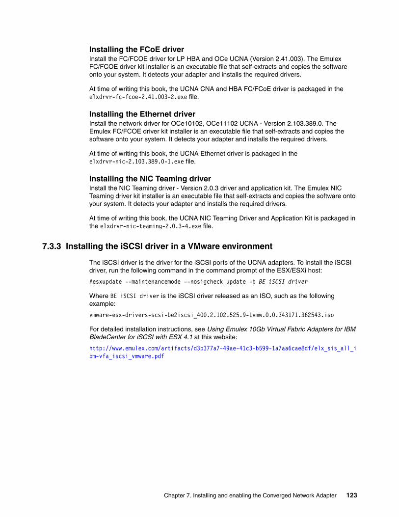
Installing the FCoE driverInstall the FC/FCOE driver for LP HBA and OCe UCNA (Version 2.41.003). The Emulex FC/FCOE driver kit installer is an executable file that self-extracts and copies the software onto your system. It detects your adapter and installs the required drivers.
At time of writing this book, the UCNA CNA and HBA FC/FCoE driver is packaged in the elxdrvr-fc-fcoe-2.41.003-2.exe file.
Installing the Ethernet driver Install the network driver for OCe10102, OCe11102 UCNA - Version 2.103.389.0. The Emulex FC/FCOE driver kit installer is an executable file that self-extracts and copies the software onto your system. It detects your adapter and installs the required drivers.
At time of writing this book, the UCNA Ethernet driver is packaged in the elxdrvr-nic-2.103.389.0-1.exe file.
Installing the NIC Teaming driver Install the NIC Teaming driver - Version 2.0.3 driver and application kit. The Emulex NIC Teaming driver kit installer is an executable file that self-extracts and copies the software onto your system. It detects your adapter and installs the required drivers.
At time of writing this book, the UCNA NIC Teaming Driver and Application Kit is packaged in the elxdrvr-nic-teaming-2.0.3-4.exe file.
7.3.3 Installing the iSCSI driver in a VMware environment
The iSCSI driver is the driver for the iSCSI ports of the UCNA adapters. To install the iSCSI driver, run the following command in the command prompt of the ESX/ESXi host:
#esxupdate --maintenancemode --nosigcheck update -b BE iSCSI driver
Where BE iSCSI driver is the iSCSI driver released as an ISO, such as the following example:
vmware-esx-drivers-scsi-be2iscsi_400.2.102.525.9-1vmw.0.0.343171.362543.iso
For detailed installation instructions, see Using Emulex 10Gb Virtual Fabric Adapters for IBM BladeCenter for iSCSI with ESX 4.1 at this website:
http://www.emulex.com/artifacts/d3b377a7-49ae-41c3-b599-1a7aa6cae8df/elx_sis_all_ibm-vfa_iscsi_vmware.pdf
Chapter 7. Installing and enabling the Converged Network Adapter 123

7.3.4 Installing OneCommand Manager in a Linux environment
Emulex OneCommand Manager provides centralized administration of Emulex adapters, enabling multiprotocol management across the Emulex family of Fibre Channel HBAs, FCoE CNAs, and iSCSI adapters. This section uses Emulex OneCommand Manager to load the Linux utilities to the system.
Before you can install the utilities, you must install the appropriate driver for your operating system:
� Linux driver version 8.2.0.33.3p or later (for Red Hat Enterprise Linux (RHEL) 5 and SUSE Linux Enterprise Server (SLES) 10 operating systems)
� Linux driver version 8.2.8.x or later (for SLES11 operating systems)
� Linux driver version 8.3.5.X or later (for RHEL 6 SLES 11 SP1 operation systems)
You must uninstall any previous versions of the Linux driver by running the uninstall script that ships with the version of the Linux driver.
To install the OneCommand Manager utility in Linux, follow these steps:
1. Log on as root.
2. Download the utilities from the Emulex website at the following address, or copy them to the system from the installation CD:
http://www.emulex.com/downloads/ibm.html
3. Copy the installation and uninstallation scripts to a known location for easy access by other users.
4. Copy the OneCommand elxocm-<Platform>-<AppsRev>.tgz file to a directory on the installation machine.
5. Use the cd command to change to the directory to which you copied the .tar file.
6. Untar the file:
– For RHEL 5 and RHEL 6, type the following command:
tar zxvf elxocm-rhel5-rhel6-<apps_ver>-<rel>.tgz
– For SLES 10 and SLES 11, type the following command:
tar zxvf elxocm-sles10-sles11-<apps_ver>-<rel>.tgz
7. Use the cd command to change to the elxocm directory created in step 6.
– For RHEL 5 and RHEL 6 type:
cd elxocm-rhel5-rhel6-<apps_ver>-<rel>
– For SLES 10 and SLES 11 type:
cd elxocm-sles10-sles11-<apps_ver>-<rel>
8. Run the install script:
./install.sh
Library installation for the RHEL 6 Enterprise kit: The RHEL 6 Enterprise kit requires installation of the libstdc++-5.so library. This library is available through the compat-libstdc++-33-3.2.3-68.<arch>.rpm file or a later version of this file. The PPC and x86_64 builds require installation of the 64-bit version, which is installed in the /usr/lib64 directory. The i386 build requires installation of the 32-bit version, which is installed in the /usr/lib directory.
124 Storage and Network Convergence Using FCoE and iSCSI

9. Select the type of management you want to use:
Local Mode HBAs on this platform can be managed by OneCommand clients on this platform only.
Managed Mode HBAs on this platform can be managed by local or remote OneCommand clients.
Remote Mode Same as Managed Mode, plus OneCommand clients on this platform can manage local and remote HBAs.
10.If you answered Local Mode or Managed Mode in step 9, when prompted if you want the OneCommand Manager application to operate in read-only mode, enter <y> for yes so that they user can perform these operations, or enter <n> for no if read-only mode is desired.
Read-only mode prevents users from performing certain operations, such as resetting adapters, updating the firmware of an adapter and changing adapter driver properties and bindings. It affects only the local OneCommand Manager application interface. These operations can still be performed by using remote management.
11.When prompted about allowing users to change the management mode after installation, enter <y> for yes, or <n> for no.
7.4 Installing the CNA software management tools
The following sections guide you through the instructions to install the CNA software management tools.
7.4.1 Installing OneCommand Manager in Windows
You can install the OneCommand Manager application in Windows by using either of the following methods:
� Attended installation by using a graphical user interface (GUI)� Unattended installation by using a command line
Attended installation by using a GUITo install the OneCommand Manager application in Windows by using a GUI, follow these steps:
1. From the Emulex website, download the x64 or x86 OneCommand Manager Enterprise Kit installation file to your system.
2. Navigate to the directory where you downloaded the file.
3. Double-click the elxocm<version>.exe file.
IA64 systems: For IA64 systems, use the x86 OneCommand Manager Enterprise installation file.
Chapter 7. Installing and enabling the Converged Network Adapter 125

4. In the Emulex OCManager Enterprise window (Figure 7-24), click Next.
Figure 7-24 Emulex OCManager Enterprise window
5. In the Installation options window (Figure 7-25), click Install.
Figure 7-25 Emulex OCManager Enterprise Installation options window
126 Storage and Network Convergence Using FCoE and iSCSI

6. After the installation process completes, in the Management Mode dialog box (Figure 7-26), choose the management mode you want. For our example, we selected Local Management Plus. Then click OK.
Figure 7-26 OneCommand Manager Management Mode options
7. When you see the Installation completed window (Figure 7-27), click Finish.
Figure 7-27 Emulex OCManager Installation completion
Optional: Allow users to change the management mode for the application at this stage.
Chapter 7. Installing and enabling the Converged Network Adapter 127

Unattended installation in WindowsTo perform an unattended installation of the OneCommand Manager application in Windows, follow these steps:
1. From the Emulex website, download the x64 or x86 OneCommand Manager Enterprise Kit installation file to your system.
The kit is activated with the optional switch /q or /q2. The /q switch displays progress reports. The /q2 switch does not display progress reports.
2. To activate the switch, at the command prompt, type either of the following example commands:
elxocm-windows-x86-5.1.42.4-1.exe /qelxocm-windows-x64-5.1.42.4-1.exe /q2
3. Select a Management Mode by adding the mode argument and the ability to change that Management Mode by adding the change argument with selected values as in the following example. For example, at the command prompt, type:
elxocm-windows-x86-5.1.42.4-1.exe mmode=3 achange=1 /q2
The following mode values are possible:
– Local Only Management Mode– Local Plus Management Mode– Full Management Mode– Local Plus Management Mode and Read Only– Full Management Mode and Read Only
The following change values are possible:
– Do not allow Management Mode to change– Allow Management Mode to change
7.4.2 Changing the personality of Emulex Virtual Fabric Adapter II
By using the Emulex OneConnect adapters, you can change the personality of Emulex Virtual Fabric Adapter II. You can reboot the host and have the adapter run by using the new personality. OneConnect adapters can currently run the NIC-only, NIC + FCoE, and NIC + iSCSI personalities.
In some cases, the adapters are preconfigured to support multiple personalities. In other cases, you must install a feature enablement license before the adapter can support multiple personalities. Also, the three personalities might not always be available on an adapter. For example, a NIC + FCoE adapter can change to a NIC-only or NIC + iSCSI adapter, but an iSCSI adapter cannot change to a NIC + FCoE adapter.
Drivers: If you install one or more driver kits for the current personality, and then change the personality, you will no longer have the necessary drivers to run the adapter. If you change personalities, you must then install the appropriate drivers. These drivers are available on the Emulex website at this website:
http://www.emulex.com/downloads/ibm.html
128 Storage and Network Convergence Using FCoE and iSCSI

You can change the personality, which was required for our test scenarios, by using the OneCommand Manager Utility as shown in Figure 7-28. To change the personality, follow these steps:
1. Open OneCommand Manager.
2. On the Adapter Information tab, in the Personality area, select the personality that you need. In this example, we selected iSCSI. Then click Apply (Figure 7-28).
Figure 7-28 OneCommand Manager choosing a personality
Chapter 7. Installing and enabling the Converged Network Adapter 129
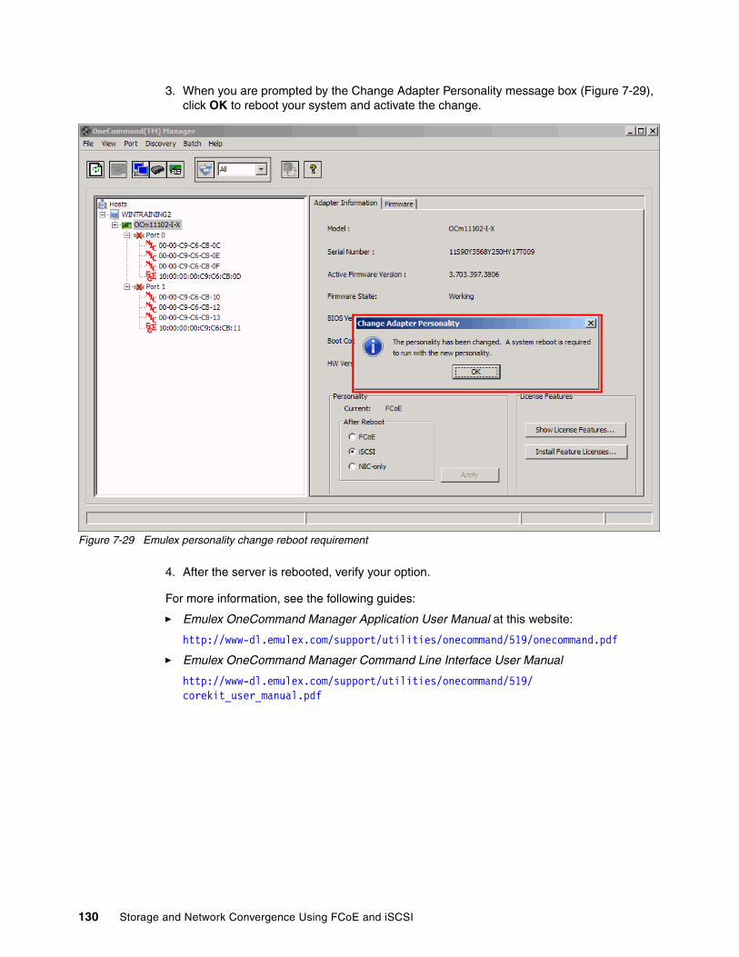
3. When you are prompted by the Change Adapter Personality message box (Figure 7-29), click OK to reboot your system and activate the change.
Figure 7-29 Emulex personality change reboot requirement
4. After the server is rebooted, verify your option.
For more information, see the following guides:
� Emulex OneCommand Manager Application User Manual at this website:
http://www-dl.emulex.com/support/utilities/onecommand/519/onecommand.pdf
� Emulex OneCommand Manager Command Line Interface User Manual
http://www-dl.emulex.com/support/utilities/onecommand/519/corekit_user_manual.pdf
130 Storage and Network Convergence Using FCoE and iSCSI

7.4.3 Configuring NIC teaming for the Emulex Virtual Fabric Adapter II
To increase throughput, bandwidth, and link availability, you can configure multiple network interfaces on one or more CNAs to be detected on the network as a single interface. This process is called NIC teaming or multilink trunking. By using NIC teaming, you can group multiple NICs as a single virtual device. Depending on the teaming mode, one or more interfaces can be active. Multiple NICs that are combined into a group are called a team.
NIC teaming offers the following advantages:
� Increased bandwidth. Two or more network interfaces are combined to share the load, increasing bandwidth.
� Load balancing. Link aggregation enables distribution of processing and communication across multiple links.
� Higher link availability. NIC teaming prevents a single link failure from disturbing traffic flow.
Teaming typesThe following types of teaming are possible:
� Switch independent:
– Failover. If configured for fault tolerance, the system provides only failover.– Smart load balancing. If configured for load balancing, failover is included.
� Switch dependent:
– Generic trunking (link aggregation static mode)– Link Aggregation Control Protocol (LACP) (802.3ad)
Configuring teams and VLANsA team of adapters functions as a single virtual network interface and appears the same as a non-teamed adapter to other network devices.
A protocol address, such as an IP address, is usually assigned to the physical adapter. However, when the OneCommand NIC Teaming and Multiple VLAN Manager is installed, the protocol address is assigned to the team adapter and not to the physical adapters that make up the team. The IPCONFIG /all command shows the IP and MAC addresses of the virtual adapter and not of the individual physical adapters.
Tip: Before using the OneCommand NIC Teaming and VLAN Manager for simple team or VLAN-over-team configurations, clear the following check boxes check boxes on the General tab in the Local Area Connection Properties window:
� Network Load Balancing and Emulex OneConnect NIC Teaming� Multiple VLAN Teaming
Chapter 7. Installing and enabling the Converged Network Adapter 131

The same configuration procedure applies for vNIC and pNIC mode. The only difference is that, in vNIC mode, you have more adapters to choose from as highlighted in Figure 7-30 and Figure 7-31.
Figure 7-30 Emulex PNIC mode as shown in Windows device manager
132 Storage and Network Convergence Using FCoE and iSCSI
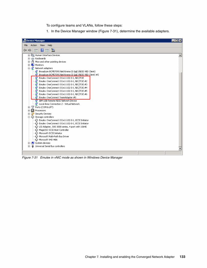
To configure teams and VLANs, follow these steps:
1. In the Device Manager window (Figure 7-31), determine the available adapters.
Figure 7-31 Emulex in vNIC mode as shown in Windows Device Manager
Chapter 7. Installing and enabling the Converged Network Adapter 133
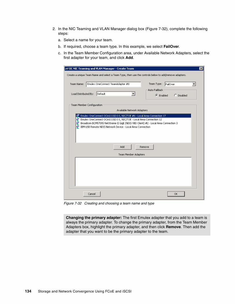
2. In the NIC Teaming and VLAN Manager dialog box (Figure 7-32), complete the following steps:
a. Select a name for your team.
b. If required, choose a team type. In this example, we select FailOver.
c. In the Team Member Configuration area, under Available Network Adapters, select the first adapter for your team, and click Add.
Figure 7-32 Creating and choosing a team name and type
Changing the primary adapter: The first Emulex adapter that you add to a team is always the primary adapter. To change the primary adapter, from the Team Member Adapters box, highlight the primary adapter, and then click Remove. Then add the adapter that you want to be the primary adapter to the team.
134 Storage and Network Convergence Using FCoE and iSCSI

Notice that the adapter moves down to the Team Member Adapters box as shown in Figure 7-33.
Figure 7-33 Adding team members
Chapter 7. Installing and enabling the Converged Network Adapter 135
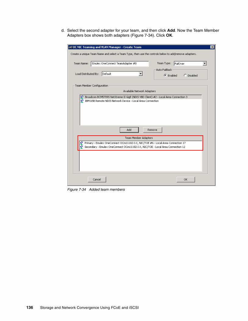
d. Select the second adapter for your team, and then click Add. Now the Team Member Adapters box shows both adapters (Figure 7-34). Click OK.
Figure 7-34 Added team members
136 Storage and Network Convergence Using FCoE and iSCSI
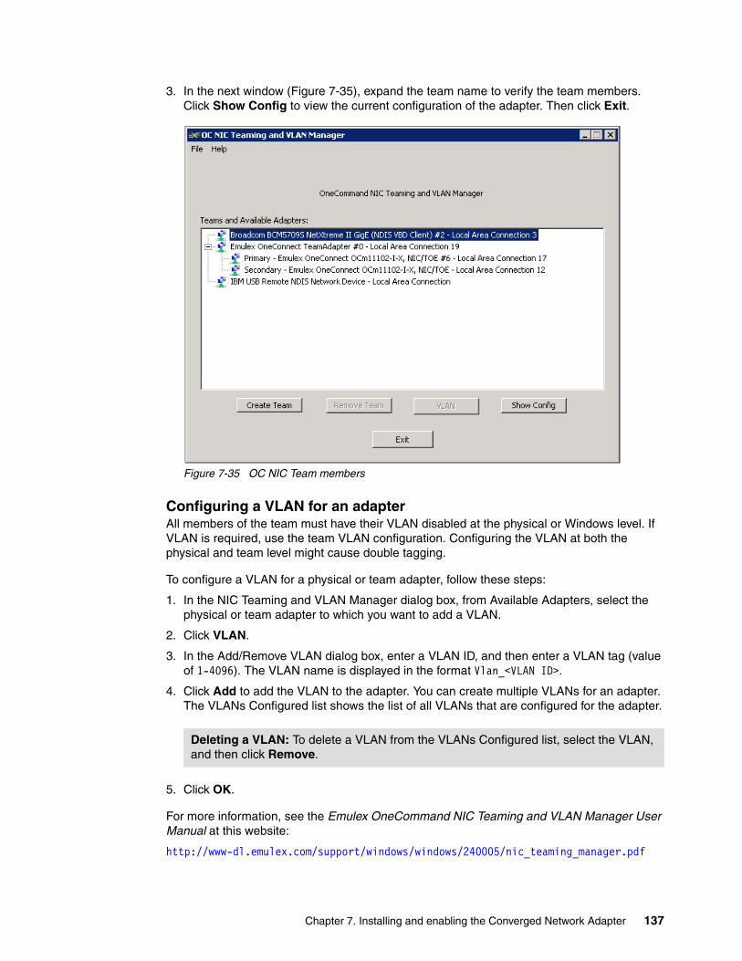
3. In the next window (Figure 7-35), expand the team name to verify the team members. Click Show Config to view the current configuration of the adapter. Then click Exit.
Figure 7-35 OC NIC Team members
Configuring a VLAN for an adapterAll members of the team must have their VLAN disabled at the physical or Windows level. If VLAN is required, use the team VLAN configuration. Configuring the VLAN at both the physical and team level might cause double tagging.
To configure a VLAN for a physical or team adapter, follow these steps:
1. In the NIC Teaming and VLAN Manager dialog box, from Available Adapters, select the physical or team adapter to which you want to add a VLAN.
2. Click VLAN.
3. In the Add/Remove VLAN dialog box, enter a VLAN ID, and then enter a VLAN tag (value of 1-4096). The VLAN name is displayed in the format Vlan_<VLAN ID>.
4. Click Add to add the VLAN to the adapter. You can create multiple VLANs for an adapter. The VLANs Configured list shows the list of all VLANs that are configured for the adapter.
5. Click OK.
For more information, see the Emulex OneCommand NIC Teaming and VLAN Manager User Manual at this website:
http://www-dl.emulex.com/support/windows/windows/240005/nic_teaming_manager.pdf
Deleting a VLAN: To delete a VLAN from the VLANs Configured list, select the VLAN, and then click Remove.
Chapter 7. Installing and enabling the Converged Network Adapter 137
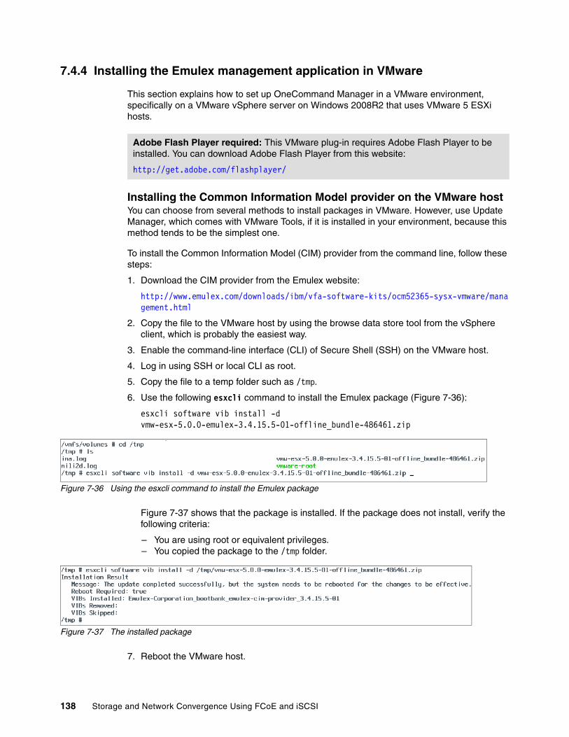
7.4.4 Installing the Emulex management application in VMware
This section explains how to set up OneCommand Manager in a VMware environment, specifically on a VMware vSphere server on Windows 2008R2 that uses VMware 5 ESXi hosts.
Installing the Common Information Model provider on the VMware hostYou can choose from several methods to install packages in VMware. However, use Update Manager, which comes with VMware Tools, if it is installed in your environment, because this method tends to be the simplest one.
To install the Common Information Model (CIM) provider from the command line, follow these steps:
1. Download the CIM provider from the Emulex website:
http://www.emulex.com/downloads/ibm/vfa-software-kits/ocm52365-sysx-vmware/management.html
2. Copy the file to the VMware host by using the browse data store tool from the vSphere client, which is probably the easiest way.
3. Enable the command-line interface (CLI) of Secure Shell (SSH) on the VMware host.
4. Log in using SSH or local CLI as root.
5. Copy the file to a temp folder such as /tmp.
6. Use the following esxcli command to install the Emulex package (Figure 7-36):
esxcli software vib install -d vmw-esx-5.0.0-emulex-3.4.15.5-01-offline_bundle-486461.zip
Figure 7-36 Using the esxcli command to install the Emulex package
Figure 7-37 shows that the package is installed. If the package does not install, verify the following criteria:
– You are using root or equivalent privileges.– You copied the package to the /tmp folder.
Figure 7-37 The installed package
7. Reboot the VMware host.
Adobe Flash Player required: This VMware plug-in requires Adobe Flash Player to be installed. You can download Adobe Flash Player from this website:
http://get.adobe.com/flashplayer/
138 Storage and Network Convergence Using FCoE and iSCSI
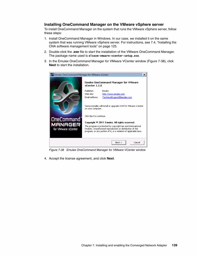
Installing OneCommand Manager on the VMware vSphere serverTo install OneCommand Manager on the system that runs the VMware vSphere server, follow these steps:
1. Install OneCommand Manager in Windows. In our case, we installed it on the same system that was running VMware vSphere server. For instructions, see 7.4, “Installing the CNA software management tools” on page 125.
2. Double-click the .exe file to start the installation of the VMware OneCommand Manager. The package name used is elxocm-vmware-vcenter-setup.exe.
3. In the Emulex OneCommand Manager for VMware VCenter window (Figure 7-38), click Next to start the installation.
Figure 7-38 Emulex OneCommand Manager for VMware VCenter window
4. Accept the license agreement, and click Next.
Chapter 7. Installing and enabling the Converged Network Adapter 139

5. In the Installation options panel (Figure 7-39), select the installation path, and then click Install.
Figure 7-39 Selecting the installation path
140 Storage and Network Convergence Using FCoE and iSCSI

6. In the OCM for VMware vCenter configuration panel (Figure 7-40), select the port numbers that you want to use for OneCommand Manager. If you want remote clients to use this plug-in, find the ports that are not in use and ensure that your firewall allows these ports.
Figure 7-40 Port numbers for the OCM for VMware vCenter
If the ports are in use, OneCommand Manager alerts you by displaying the message “Port in use” as shown in Figure 7-41. Click Next to continue.
Figure 7-41 ‘Port in use’ message
Tip: Select the available ports for OneCommand Manager. Remember to open these ports on your firewall.
Chapter 7. Installing and enabling the Converged Network Adapter 141
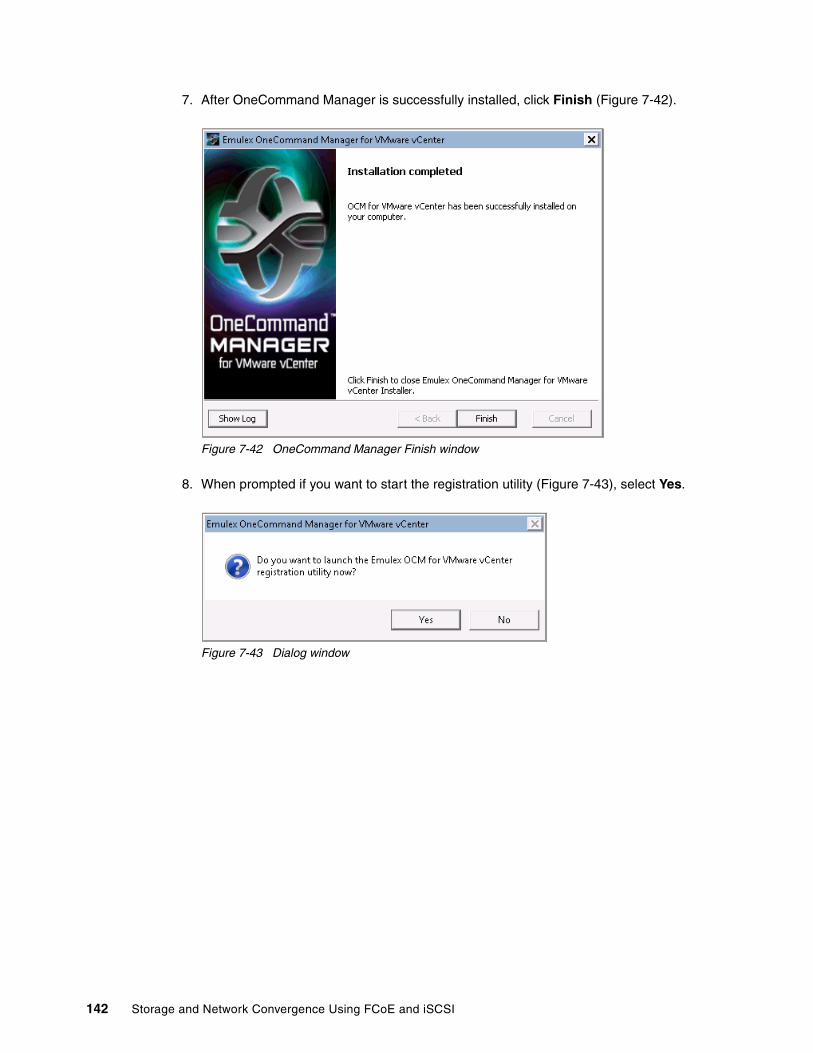
7. After OneCommand Manager is successfully installed, click Finish (Figure 7-42).
Figure 7-42 OneCommand Manager Finish window
8. When prompted if you want to start the registration utility (Figure 7-43), select Yes.
Figure 7-43 Dialog window
142 Storage and Network Convergence Using FCoE and iSCSI

9. Depending on your web browser settings, if you see a security warning message (Figure 7-44), click Continue to this website (not recommended).
Figure 7-44 Certificate error message
Chapter 7. Installing and enabling the Converged Network Adapter 143

10.Register the OneCommand Manager to the vSphere server. In the OneCommand Manager window (Figure 7-45), complete the following fields:
a. Enter the name of the system that has the vSphere Server installed. In this example, we used the local machine.
b. Enter the port number. We used the default host port 443.
c. Enter a user name for a user that has full access to the VMware ESXi host. We created a user, with the Administrator role.
d. For OCM Plug-in Server Name, enter the name of the system where your OneCommand for Windows is installed. In this example, it was installed on the local machine. We used the same system for the vSphere Server and for the OneCommand Manager.
e. Click Register.
Figure 7-45 vCenter Server registration window
11.When a message indicates that the registration was successful (Figure 7-46), click OK. If the registration is not successful, check the user name and server names that you used.
Figure 7-46 Registration is successful
144 Storage and Network Convergence Using FCoE and iSCSI

The user name that is used must have the Administrator role as shown for the mgingras user name in Figure 7-47.
Figure 7-47 Permissions window
Setting up the vSphere client for OneCommand ManagerTo set up the vSphere client, start the vSphere client and log in to the vSphere server:
1. Select Plug-ins Manage Plug-ins (Figure 7-48).
Figure 7-48 Selecting the Manage Plug-ins option
Chapter 7. Installing and enabling the Converged Network Adapter 145
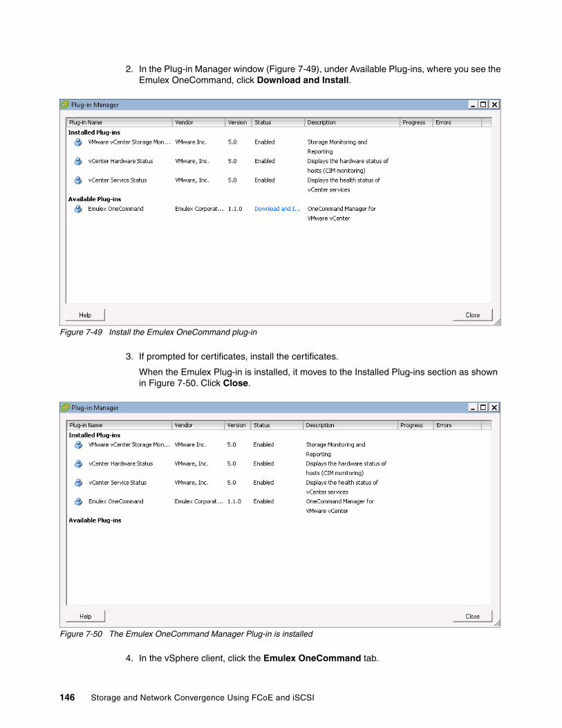
2. In the Plug-in Manager window (Figure 7-49), under Available Plug-ins, where you see the Emulex OneCommand, click Download and Install.
Figure 7-49 Install the Emulex OneCommand plug-in
3. If prompted for certificates, install the certificates.
When the Emulex Plug-in is installed, it moves to the Installed Plug-ins section as shown in Figure 7-50. Click Close.
Figure 7-50 The Emulex OneCommand Manager Plug-in is installed
4. In the vSphere client, click the Emulex OneCommand tab.
146 Storage and Network Convergence Using FCoE and iSCSI
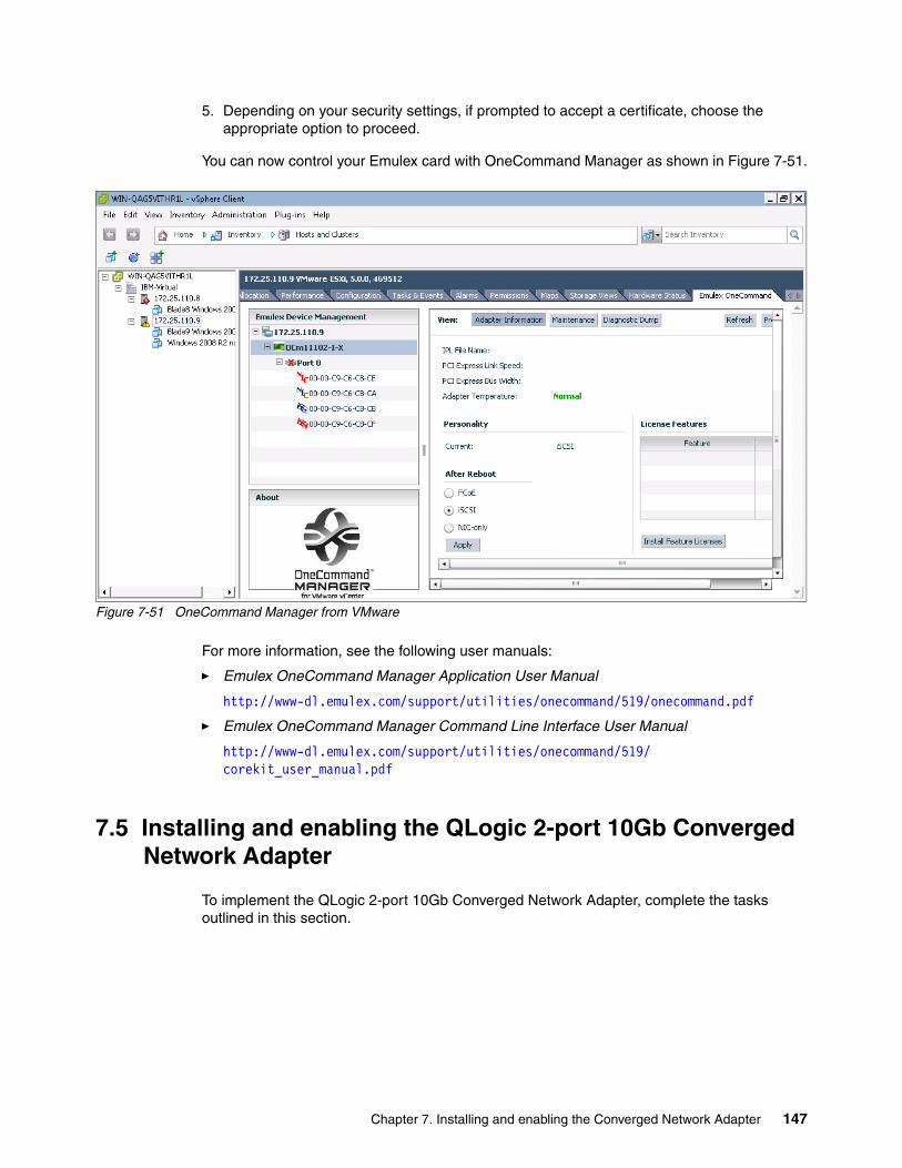
5. Depending on your security settings, if prompted to accept a certificate, choose the appropriate option to proceed.
You can now control your Emulex card with OneCommand Manager as shown in Figure 7-51.
Figure 7-51 OneCommand Manager from VMware
For more information, see the following user manuals:
� Emulex OneCommand Manager Application User Manual
http://www-dl.emulex.com/support/utilities/onecommand/519/onecommand.pdf
� Emulex OneCommand Manager Command Line Interface User Manual
http://www-dl.emulex.com/support/utilities/onecommand/519/corekit_user_manual.pdf
7.5 Installing and enabling the QLogic 2-port 10Gb Converged Network Adapter
To implement the QLogic 2-port 10Gb Converged Network Adapter, complete the tasks outlined in this section.
Chapter 7. Installing and enabling the Converged Network Adapter 147

7.5.1 Updating the firmware
You can choose from various methods to update the QLogic CNA firmware and drivers. For example, you can use IBM UpdateXpress System Pack Installer to update drivers and firmware if the operating system is installed. Alternatively, you can also use IBM ToolsCenter Bootable Media Creator to update firmware on systems where the operating system is not installed.
You can download these tools from the IBM ToolsCenter page at this website:
http://www.ibm.com/support/entry/portal/docdisplay?brand=5000008&lndocid=TOOL-CENTER
You can also use the firmware package as a stand-alone executable package. To use the package with one of the IBM update management tools, follow the instructions that came with your specific management tool.
One of the simplest ways to do the update is to use the stand-alone executable package from within the operating system. This package can be used in the following ways:
� Update the QLogic HBA firmware on the local system� Copy all files that are necessary for the update to the local hard disk drive or other media
Updating the firmware on the local systemTo update the firmware on the local system, follow these steps:
1. Double-click the executable file icon, or at a command prompt, type:
qlgc_fw_fc_qmi8142_1.01.92-bc_windows_32-64.exe
2. Select Perform Update, and then click Next.3. Click Update.
Extracting the files for use with other utilitiesTo extract the files for use with other utilities, follow these steps:
1. Double-click the executable file icon, or at a command prompt, type:
qlgc_fw_fc_qmi8142_1.01.92-bc_windows_32-64.exe
2. Select Extract to Hard Drive, and then click Next.3. Select the desired destination directory or media, and then click OK.4. To perform another function, click Back. Otherwise, click Exit to exit the utility.
Updating the firmware by using QLogic SANsurferYou can also update the firmware by using QLogic SANsurfer after the firmware is installed.
Note: The SANsurfer tool is available for download from Qlogic using the following link under Management Previous Versions.
http://driverdownloads.qlogic.com/QLogicDriverDownloads_UI/SearchByProduct.aspx?ProductCategory=322&Product=1104&Os=190
Qlogic also has a new tool for CNAs called QConvergeConsole and it is covered in this publication.
148 Storage and Network Convergence Using FCoE and iSCSI

To update the firmware by using SANsurfer, follow these steps:
1. Click the Connect icon under the menu bar.
2. In the Connect to Host dialog box, click Connect to accept the default setting of localhost (Figure 7-52).
Figure 7-52 Logging in to SANsurfer FC HBA Manager
3. When prompted to start the general configuration wizard, click Yes (Figure 7-53).
Figure 7-53 Adapter configuration
Chapter 7. Installing and enabling the Converged Network Adapter 149

4. From the left FC/CNA HBA tab, select the adapter you want to update (Figure 7-54).
Figure 7-54 SANsurfer Management window
150 Storage and Network Convergence Using FCoE and iSCSI

5. On the Utilities tab, in the Flash area, click Update Entire Image (Figure 7-55).
Figure 7-55 SANsurfer Utilities window
6. In the Open window, select the path to the required update (Figure 7-56), and then click Open.
Figure 7-56 Firmware update file location
Chapter 7. Installing and enabling the Converged Network Adapter 151
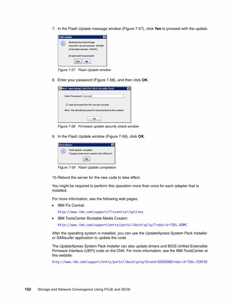
7. In the Flash Update message window (Figure 7-57), click Yes to proceed with the update.
Figure 7-57 Flash Update window
8. Enter your password (Figure 7-58), and then click OK.
Figure 7-58 Firmware update security check window
9. In the Flash Update window (Figure 7-59), click OK.
Figure 7-59 Flash Update completion
10.Reboot the server for the new code to take effect.
You might be required to perform this operation more than once for each adapter that is installed.
For more information, see the following web pages:
� IBM Fix Central:
http://www.ibm.com/support/fixcentral/options
� IBM ToolsCenter Bootable Media Creator:
http://www.ibm.com/support/entry/portal/docdisplay?lndocid=TOOL-BOMC
After the operating system is installed, you can use the UpdateXpress System Pack Installer or SANsurfer application to update the code.
The UpdateXpress System Pack Installer can also update drivers and BIOS Unified Extensible Firmware Interface (UEFI) code on the CNA. For more information, see the IBM ToolsCenter at this website:
http://www.ibm.com/support/entry/portal/docdisplay?brand=5000008&lndocid=TOOL-CENTER
152 Storage and Network Convergence Using FCoE and iSCSI

7.5.2 Installing drivers
Download the latest drivers and management tools. For best results, use the following IBM certified drivers and software:
� IBM BladeCenter downloads:
http://www.ibm.com/support/fixcentral/systemx/groupView?query.productGroup=ibm%2FBladeCenter
� QLogic IBM downloads:
http://driverdownloads.qlogic.com/QLogicDriverDownloads_UI/IBM.aspx?companyid=6
� UpdateXpress System Pack Installer:
http://www.ibm.com/support/entry/portal/docdisplay?brand=5000008&lndocid=TOOL-CENTER
Installing drivers in a Windows environmentMake sure you have the latest Storport driver for Microsoft Windows installed. Check the Microsoft website at the following address:
http://support.microsoft.com/kb/932755
Alternatively, use the latest Windows update. A network driver and a FCoE driver are required, which you can obtain from the websites listed in 7.5.2, “Installing drivers”.
In Device Manager, right-click the Unknown QLogic device, and point to the QLogic drivers. You see two network devices and two storage devices.
Chapter 7. Installing and enabling the Converged Network Adapter 153

Figure 7-60 shows the NIC and FCoE drivers installed in Windows Device Manager.
Figure 7-60 Device Manager view of the QLogic adapter
Installing VMware driversSee the following topics in the VMware Knowledge Base for information about installation guidelines:
� “Installing async drivers on ESX/ESXi 4.x”:
http://kb.vmware.com/selfservice/search.do?cmd=displayKC&docType=kc&externalId=1032936
� “Installing async drivers on ESXi 5.0”:
http://kb.vmware.com/selfservice/search.do?cmd=displayKC&docType=kc&externalId=2005205
In this Redbooks publication, we focused on VMware ESXi 5.0. The FC drivers were already part of the VMware 5 ESXi image. However, to ensure that everything worked as expected, we updated them to the latest levels.
The network driver was not part of the base image. If you plan to use the networking ports, you must install the drivers.
154 Storage and Network Convergence Using FCoE and iSCSI

Figure 7-61 shows the QLogic CNA network ports.
Figure 7-61 QLogic CNA network ports
Chapter 7. Installing and enabling the Converged Network Adapter 155

Figure 7-62 shows the QLogic CNA FC ports.
Figure 7-62 QLogic CNA FC ports
7.5.3 Installing the management software
The management tools are on the QLogic website in the IBM section:
http://driverdownloads.qlogic.com/QLogicDriverDownloads_UI/Product_detail_new.aspx?oemid=324&companyid=6
A SANsurfer for FCoE GUI and CLI are also available to manage the FCoE portion of the adapter. Also, a SANsurfer CNA networking CLI is available to manage the networking portion of the adapter. You can find both the GUI and CLIs at the previous QLogic web page.
156 Storage and Network Convergence Using FCoE and iSCSI
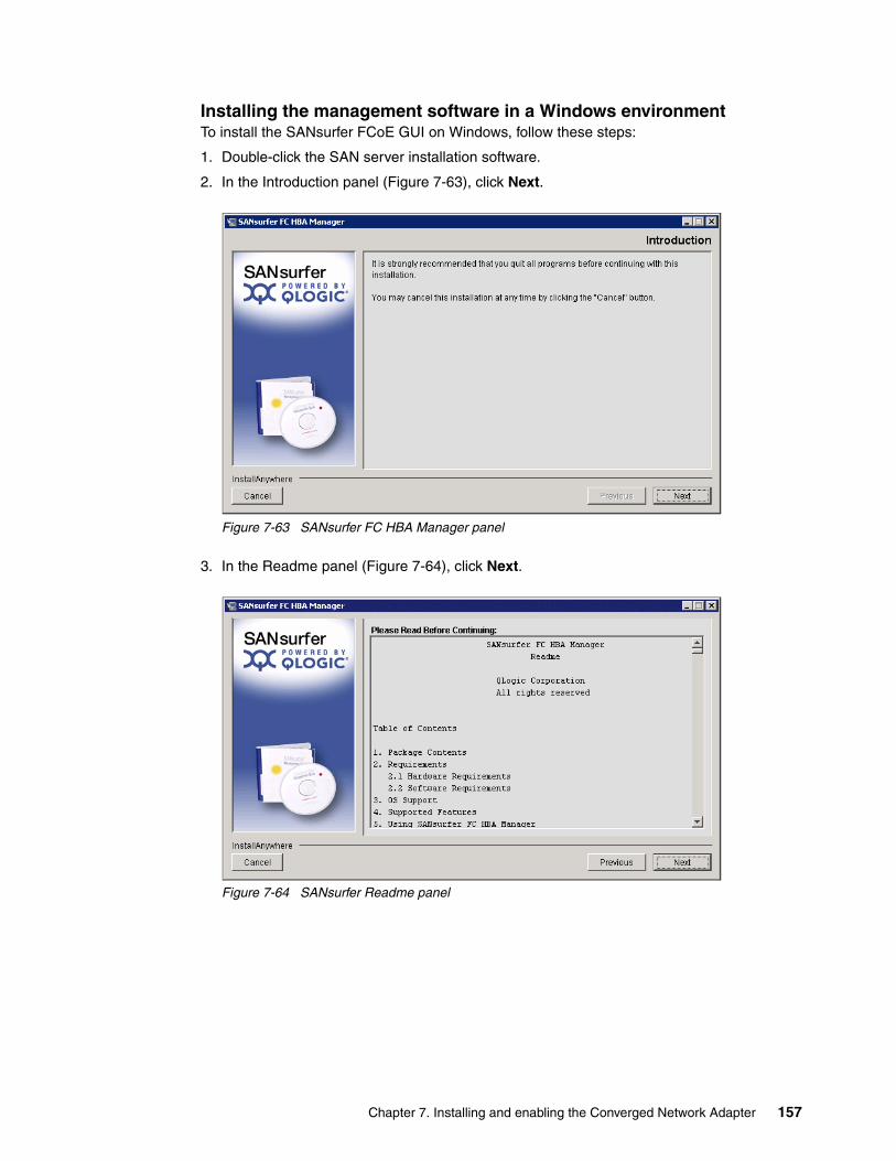
Installing the management software in a Windows environmentTo install the SANsurfer FCoE GUI on Windows, follow these steps:
1. Double-click the SAN server installation software.
2. In the Introduction panel (Figure 7-63), click Next.
Figure 7-63 SANsurfer FC HBA Manager panel
3. In the Readme panel (Figure 7-64), click Next.
Figure 7-64 SANsurfer Readme panel
Chapter 7. Installing and enabling the Converged Network Adapter 157

4. In the Choose Product Features panel (Figure 7-65), select the installation type. To manage the local CNA remotely, we selected FC HBA GUI and Agent. Then click Next.
Figure 7-65 Choose Product Features panel
5. In the Choose Install Folder panel (Figure 7-66), select the path to install SANsurfer, and then click Next.
Figure 7-66 Choose Install Folder panel
158 Storage and Network Convergence Using FCoE and iSCSI
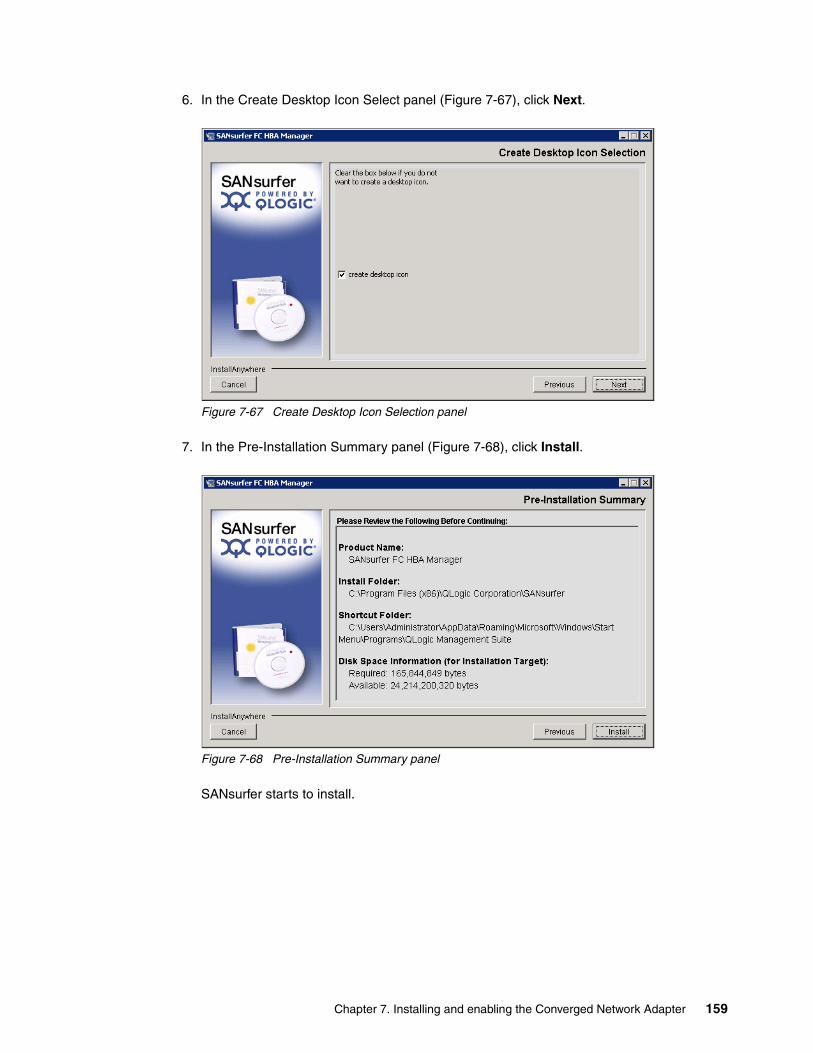
6. In the Create Desktop Icon Select panel (Figure 7-67), click Next.
Figure 7-67 Create Desktop Icon Selection panel
7. In the Pre-Installation Summary panel (Figure 7-68), click Install.
Figure 7-68 Pre-Installation Summary panel
SANsurfer starts to install.
Chapter 7. Installing and enabling the Converged Network Adapter 159

8. In the Default QLogic Failover Enable/Disable panel (Figure 7-69), do not select Enable QLogic Failover Configuration because most SAN vendors have their own redundant drivers. For more information about the redundant driver, see the documentation provided by your SAN vendor. Then click Next.
Figure 7-69 Default QLogic Failover Enable/Disable panel
9. In the Install Complete panel (Figure 7-70), click Done.
Figure 7-70 Installation completed
10.Click the SANsurfer icon to start it.
160 Storage and Network Convergence Using FCoE and iSCSI
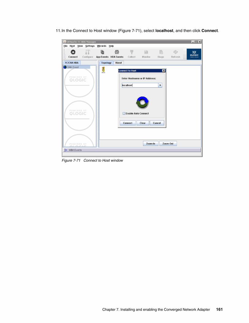
11.In the Connect to Host window (Figure 7-71), select localhost, and then click Connect.
Figure 7-71 Connect to Host window
Chapter 7. Installing and enabling the Converged Network Adapter 161

You can now view your adapter settings and the devices that the QLogic FCoE controller can access as shown in Figure 7-72.
Figure 7-72 Topology window
162 Storage and Network Convergence Using FCoE and iSCSI

Installing the SANsurfer CNA Networking CLIThe SANsurfer CNA Networking CLI is optional, but useful if you want to configure network teaming and perform advanced VLAN configurations. By using this CLI, you can manage the networking side of the CNA.
To install the SANsurfer CNA Networking CLI, follow these steps:
1. Double-click the Networking CLI.
2. In the Welcome panel (Figure 7-73), click Next.
Figure 7-73 Welcome window
3. In the Select Which Users panel (Figure 7-74), select Install for All Users, and then click Next.
Figure 7-74 Select Which Users window
Chapter 7. Installing and enabling the Converged Network Adapter 163

4. In the Destination Folder panel (Figure 7-75), confirm the default path, and then click Next.
Figure 7-75 Destination Folder panel
5. In the Ready to Install the Program panel (Figure 7-76), click Install.
Figure 7-76 Ready to Install the Program panel
164 Storage and Network Convergence Using FCoE and iSCSI
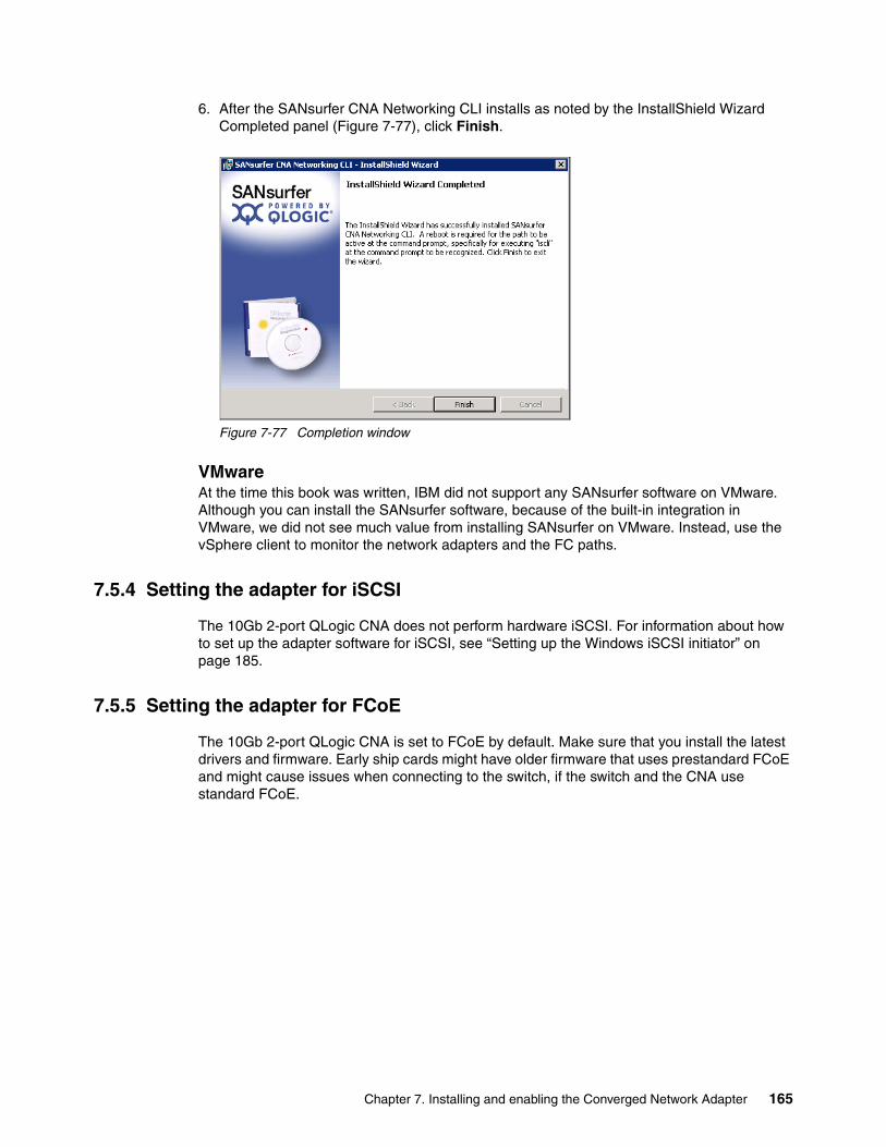
6. After the SANsurfer CNA Networking CLI installs as noted by the InstallShield Wizard Completed panel (Figure 7-77), click Finish.
Figure 7-77 Completion window
VMwareAt the time this book was written, IBM did not support any SANsurfer software on VMware. Although you can install the SANsurfer software, because of the built-in integration in VMware, we did not see much value from installing SANsurfer on VMware. Instead, use the vSphere client to monitor the network adapters and the FC paths.
7.5.4 Setting the adapter for iSCSI
The 10Gb 2-port QLogic CNA does not perform hardware iSCSI. For information about how to set up the adapter software for iSCSI, see “Setting up the Windows iSCSI initiator” on page 185.
7.5.5 Setting the adapter for FCoE
The 10Gb 2-port QLogic CNA is set to FCoE by default. Make sure that you install the latest drivers and firmware. Early ship cards might have older firmware that uses prestandard FCoE and might cause issues when connecting to the switch, if the switch and the CNA use standard FCoE.
Chapter 7. Installing and enabling the Converged Network Adapter 165
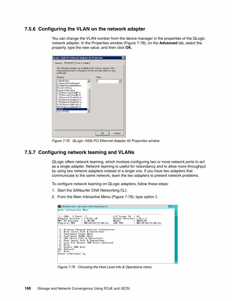
7.5.6 Configuring the VLAN on the network adapter
You can change the VLAN number from the device manager in the properties of the QLogic network adapter. In the Properties window (Figure 7-78), on the Advanced tab, select the property, type the new value, and then click OK.
Figure 7-78 QLogic 10Gb PCI Ethernet Adapter #2 Properties window
7.5.7 Configuring network teaming and VLANs
QLogic offers network teaming, which involves configuring two or more network ports to act as a single adapter. Network teaming is useful for redundancy and to allow more throughput by using two network adapters instead of a single one. If you have two adapters that communicate to the same network, team the two adapters to prevent network problems.
To configure network teaming on QLogic adapters, follow these steps:
1. Start the SANsurfer CNA Networking CLI.
2. From the Main Interactive Menu (Figure 7-79), type option 2.
Figure 7-79 Choosing the Host Level Info & Operations menu
166 Storage and Network Convergence Using FCoE and iSCSI

3. From the Host Level Info & Operations Menu (Figure 7-80), type option 2 to install or update the VLAN or QLogic teaming driver.
Figure 7-80 Installing or updating the VLAN or QLogic teaming driver
4. When prompted if you want to use the external source (Figure 7-81), type n for No.
Figure 7-81 Choosing not to use the external source for the VLAN/teaming driver
5. When prompted to proceed with the installation (Figure 7-82), type y and press Enter.
Figure 7-82 Proceeding with the installation
6. Type option 8 to exit and to return to the main menu.
Chapter 7. Installing and enabling the Converged Network Adapter 167

7. From the Main Interactive Menu (Figure 7-83), type option 3 to configure a team.
Figure 7-83 Choosing the Configure Teams Menu option
8. From the Configure Teams Menu (Figure 7-84), select option 3 to configure a new team.
Figure 7-84 Select option 3 to configure a new team window
168 Storage and Network Convergence Using FCoE and iSCSI

9. From the Configure Teams Menu (Figure 7-85), select the type of team you want to use. In this scenario, we type option 1 for Fail Over adapter.
Figure 7-85 Administration SANsurfer CNA Networking CLI window
10.Select the ports that will be part of the team (Figure 7-86). In this example, we typed 1, 2.
Figure 7-86 Select the ports window
Teaming types: For information about the teaming types, see the QLogic documentation. Some configurations might require you to configure the switches for the teaming to work properly. You can find the documentation at this website:
https://support.qlogic.com/app/answers/detail/a_id/578/kw/teaming%20types
See also “QLogic KnowHow: NIC Teaming on QLogic 10GbE Adapters for Windows Server” at this website:
http://www.youtube.com/watch?v=UEfGFqoz_Nc&feature
Chapter 7. Installing and enabling the Converged Network Adapter 169

11.Wait for the team to be created until you see a message that indicates that it was successfully created (Figure 7-87).
Figure 7-87 Team creation window
12.From the Configure Teams Menu (Figure 7-88), type option 6 to return to the previous menu.
Figure 7-88 Exit window
170 Storage and Network Convergence Using FCoE and iSCSI

From the Windows Network Connections window (Figure 7-89,) you can now see the two physical QLogic network ports and the QLogic virtual teamed port. Some functions are disabled on the physical ports. You must now use the teamed port for the IP address configurations.
Figure 7-89 Configure port window
13.Return to the SANsurfer CNA Networking CLI to configure VLANs on the teamed port. From the Main Interactive Menu (Figure 7-90), type option 4 for the VLAN menu.
Figure 7-90 Selecting the Configure VLANs Menu
Chapter 7. Installing and enabling the Converged Network Adapter 171
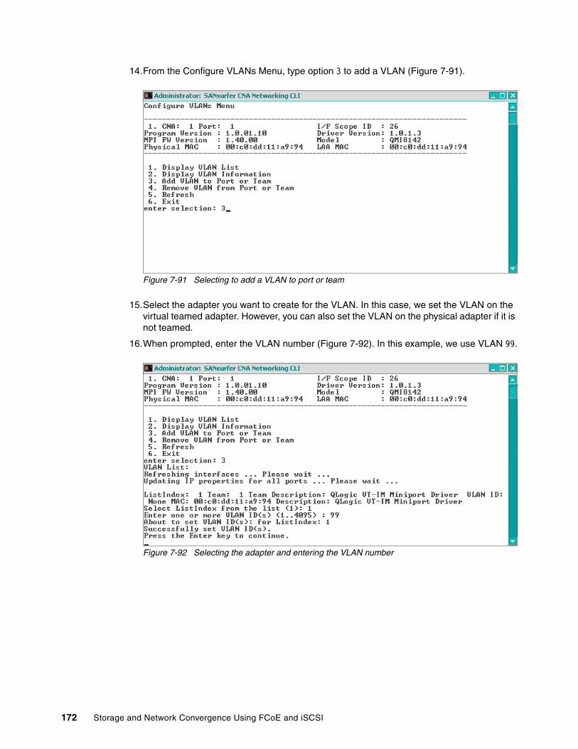
14.From the Configure VLANs Menu, type option 3 to add a VLAN (Figure 7-91).
Figure 7-91 Selecting to add a VLAN to port or team
15.Select the adapter you want to create for the VLAN. In this case, we set the VLAN on the virtual teamed adapter. However, you can also set the VLAN on the physical adapter if it is not teamed.
16.When prompted, enter the VLAN number (Figure 7-92). In this example, we use VLAN 99.
Figure 7-92 Selecting the adapter and entering the VLAN number
172 Storage and Network Convergence Using FCoE and iSCSI
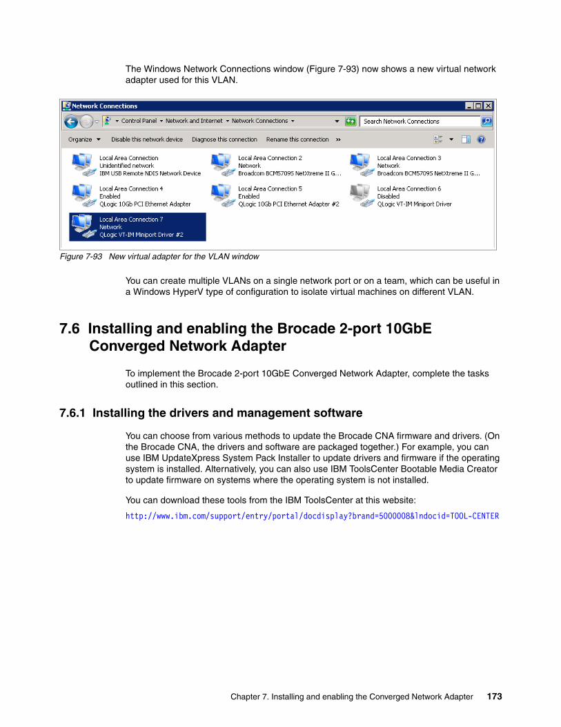
The Windows Network Connections window (Figure 7-93) now shows a new virtual network adapter used for this VLAN.
Figure 7-93 New virtual adapter for the VLAN window
You can create multiple VLANs on a single network port or on a team, which can be useful in a Windows HyperV type of configuration to isolate virtual machines on different VLAN.
7.6 Installing and enabling the Brocade 2-port 10GbE Converged Network Adapter
To implement the Brocade 2-port 10GbE Converged Network Adapter, complete the tasks outlined in this section.
7.6.1 Installing the drivers and management software
You can choose from various methods to update the Brocade CNA firmware and drivers. (On the Brocade CNA, the drivers and software are packaged together.) For example, you can use IBM UpdateXpress System Pack Installer to update drivers and firmware if the operating system is installed. Alternatively, you can also use IBM ToolsCenter Bootable Media Creator to update firmware on systems where the operating system is not installed.
You can download these tools from the IBM ToolsCenter at this website:
http://www.ibm.com/support/entry/portal/docdisplay?brand=5000008&lndocid=TOOL-CENTER
Chapter 7. Installing and enabling the Converged Network Adapter 173

To install the drivers and management software for the Brocade 2-port 10GbE Converged Network Adapter, follow these steps:
1. Start the driver and software installation.
2. In the Introduction panel (Figure 7-94), click Next.
Figure 7-94 Introduction panel
3. In the License Agreement panel (Figure 7-95), read the license agreement, and then click Next to accept it.
Figure 7-95 The license agreement panel
174 Storage and Network Convergence Using FCoE and iSCSI

4. Select the parts of the software you want to install (Figure 7-96). In this example, we select the default. Then click Next.
Figure 7-96 Selecting the parts of the software to install
5. In the Choose Install Folder panel (Figure 7-97), confirm the path to install the adapter, and then click Next.
Figure 7-97 Choose Install Folder panel
Chapter 7. Installing and enabling the Converged Network Adapter 175

6. In the Package Location panel (Figure 7-98), click Next.
Figure 7-98 Package Location panel
7. After the application finishes the installation, in the Install Complete panel (Figure 7-99), click Done.
Figure 7-99 Completion panel
176 Storage and Network Convergence Using FCoE and iSCSI

7.6.2 Updating the firmware
You can choose from various methods to update the BIOS and firmware. The BIOS and UEFI are important when booting and when performing preboot tasks such as boot from SAN. When the driver loads, the firmware is updated so that no driver and firmware mismatch occurs. To update the firmware, follow these steps:
1. Start the Brocade software. In the Host Connectivity Manager window (Figure 7-100), use the default login of Administrator and a password of password. Then click Login.
Figure 7-100 Host Connectivity Manager window
2. In the Host Connectivity Manager window (Figure 7-101), select Configure Adapter Software.
Figure 7-101 Host Connectivity Manager window
Chapter 7. Installing and enabling the Converged Network Adapter 177
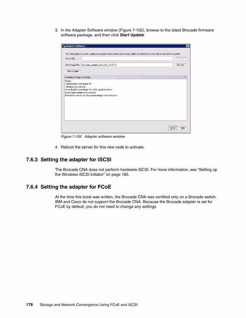
3. In the Adapter Software window (Figure 7-102), browse to the latest Brocade firmware software package, and then click Start Update.
Figure 7-102 Adapter software window
4. Reboot the server for this new code to activate.
7.6.3 Setting the adapter for iSCSI
The Brocade CNA does not perform hardware iSCSI. For more information, see “Setting up the Windows iSCSI initiator” on page 185.
7.6.4 Setting the adapter for FCoE
At the time this book was written, the Brocade CNA was certified only on a Brocade switch. IBM and Cisco do not support the Brocade CNA. Because the Brocade adapter is set for FCoE by default, you do not need to change any settings.
178 Storage and Network Convergence Using FCoE and iSCSI

7.6.5 Configuring VLAN
To set the VLAN ID from the Device Manager, open the Properties window (Figure 7-103) of the Brocade network adapter. On the Advanced tab, select the property, and enter a value. Then click OK.
Figure 7-103 Brocade 10G Ethernet Adapter #2 Properties window
Chapter 7. Installing and enabling the Converged Network Adapter 179

Alternatively, you can use the Host Connectivity Manager window (Figure 7-104):
1. Right-click the local host, and then select VLAN Configuration.
Figure 7-104 Setting the VLAN on a single network adapter
2. In the Add VLAN window (Figure 7-105), set the VLAN number and VLAN name. Then click OK.
Figure 7-105 Add VLAN window
180 Storage and Network Convergence Using FCoE and iSCSI

If you need a network adapter that uses the VLAN and still require a network adapter that uses no VLAN, you can select Create Passthru (Figure 7-106). Keep in mind that one adapter can have several virtual LANs configured.
Figure 7-106 Create Passthru option in the Add VLAN window
7.6.6 Configuring network teaming and VLANs on the team
Brocade offers network teaming, which refers to configuring two or more network ports to act as a single adapter. Network teaming is useful for redundancy and for allowing more throughput by using two network adapters instead of a single one. If you have two adapters that communicate to the same network, for best results, team the two adapters to prevent network problems.
To configure teaming on the Brocade adapter, follow these steps:
1. Start the Host Connectivity Manager.
2. In the Host Connectivity Manager window (Figure 7-107), make sure that localhost is highlighted, and then select Configure Teaming.
Figure 7-107 Host Connectivity Manager window
Chapter 7. Installing and enabling the Converged Network Adapter 181
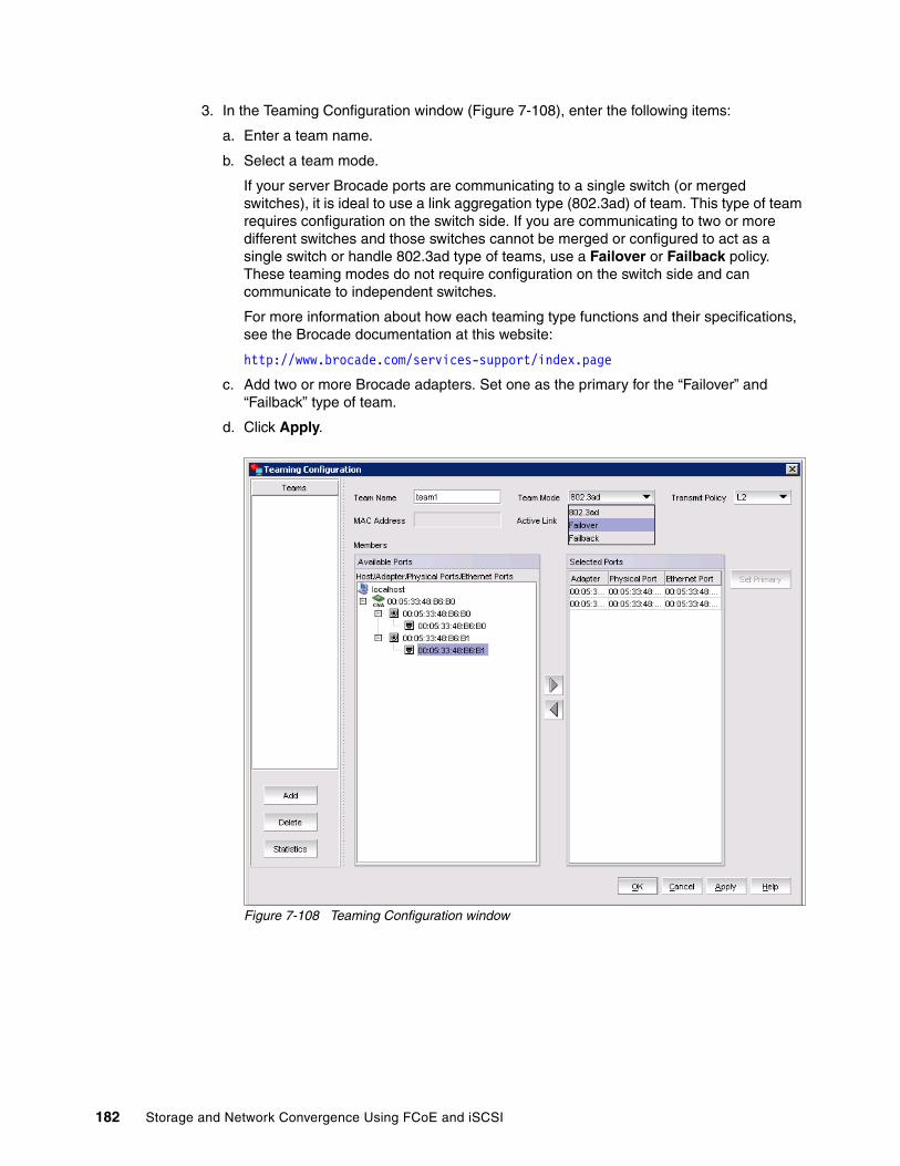
3. In the Teaming Configuration window (Figure 7-108), enter the following items:
a. Enter a team name.
b. Select a team mode.
If your server Brocade ports are communicating to a single switch (or merged switches), it is ideal to use a link aggregation type (802.3ad) of team. This type of team requires configuration on the switch side. If you are communicating to two or more different switches and those switches cannot be merged or configured to act as a single switch or handle 802.3ad type of teams, use a Failover or Failback policy. These teaming modes do not require configuration on the switch side and can communicate to independent switches.
For more information about how each teaming type functions and their specifications, see the Brocade documentation at this website:
http://www.brocade.com/services-support/index.page
c. Add two or more Brocade adapters. Set one as the primary for the “Failover” and “Failback” type of team.
d. Click Apply.
Figure 7-108 Teaming Configuration window
182 Storage and Network Convergence Using FCoE and iSCSI
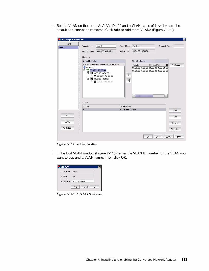
e. Set the VLAN on the team. A VLAN ID of 0 and a VLAN name of Passthru are the default and cannot be removed. Click Add to add more VLANs (Figure 7-109).
Figure 7-109 Adding VLANs
f. In the Edit VLAN window (Figure 7-110), enter the VLAN ID number for the VLAN you want to use and a VLAN name. Then click OK.
Figure 7-110 Edit VLAN window
Chapter 7. Installing and enabling the Converged Network Adapter 183
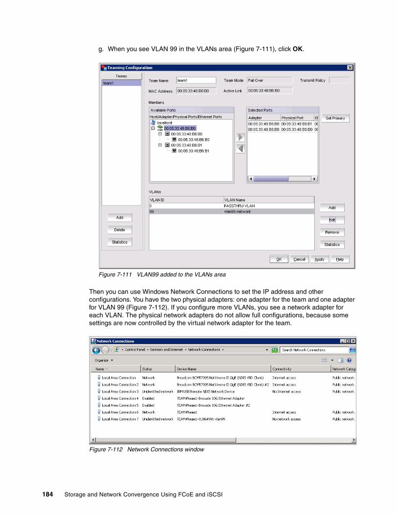
g. When you see VLAN 99 in the VLANs area (Figure 7-111), click OK.
Figure 7-111 VLAN99 added to the VLANs area
Then you can use Windows Network Connections to set the IP address and other configurations. You have the two physical adapters: one adapter for the team and one adapter for VLAN 99 (Figure 7-112). If you configure more VLANs, you see a network adapter for each VLAN. The physical network adapters do not allow full configurations, because some settings are now controlled by the virtual network adapter for the team.
Figure 7-112 Network Connections window
184 Storage and Network Convergence Using FCoE and iSCSI

7.7 iSCSI connectors
The Internet Small Computer System Interface (iSCSI) initiator that is required depends on the adapter that is used. Although you can use a hardware or software initiator, a much more popular approach is to use a software initiator. Software initiators depend on host server resources to process iSCSI traffic through standard network interface cards (NICs). Hardware initiators, such as iSCSI host bus adapters (HBAs), offload this protocol processing to the hardware itself. If you want to deploy iSCSI, the Emulex 10 GB Virtual Fabric Adapter I and II models are the only full iSCSI solution available in the IBM portfolio (at the time of writing). QLogic and Brocade offer software iSCSI only, which is important to know in your purchasing decision especially if you plan to boot from iSCSI at 10 Gbps.
7.7.1 Hardware iSCSI initiators
The Emulex 10GbE Virtual Fabric Adapter Advanced supports Fibre Channel over Ethernet (FCoE) and iSCSI hardware initiator functions, in addition to the features available on the standard card. You can enable virtual NIC (vNIC) mode on the Emulex 10GbE Virtual Fabric Adapter and use iSCSI on the same adapter.
7.7.2 Software iSCSI initiators
Software iSCSI initiators are available for Windows, Linux, and VMware. This section explains how to set up the Windows and Linux initiators and describes the VMware iSCSI initiator.
Setting up the Windows iSCSI initiatorThe iSCSI initiator is installed natively with Windows Server 2008.
To configure the iSCSI utility, follow these steps:
1. Click the iSCSI applet in the Windows Control Panel.
2. In the iSCSI Initiator Properties window (Figure 7-113), on the Discovery tab, click Add.
Figure 7-113 iSCSI Initiator Properties window
Chapter 7. Installing and enabling the Converged Network Adapter 185

3. In the Add Target Portal window (Figure 7-114), enter the IP address or DNS name and port number for the target portal that you want to log on to. Then click OK.
Figure 7-114 Add Target Portal window
4. Back on the Discovery tab (Figure 7-115), verify the Target Portals properties.
Figure 7-115 Details for Target Portal
186 Storage and Network Convergence Using FCoE and iSCSI
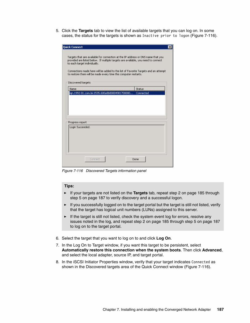
5. Click the Targets tab to view the list of available targets that you can log on. In some cases, the status for the targets is shown as Inactive prior to logon (Figure 7-116).
Figure 7-116 Discovered Targets information panel
6. Select the target that you want to log on to and click Log On.
7. In the Log On to Target window, if you want this target to be persistent, select Automatically restore this connection when the system boots. Then click Advanced, and select the local adapter, source IP, and target portal.
8. In the iSCSI Initiator Properties window, verify that your target indicates Connected as shown in the Discovered targets area of the Quick Connect window (Figure 7-116).
Tips:
� If your targets are not listed on the Targets tab, repeat step 2 on page 185 through step 5 on page 187 to verify discovery and a successful logon.
� If you successfully logged on to the target portal but the target is still not listed, verify that the target has logical unit numbers (LUNs) assigned to this server.
� If the target is still not listed, check the system event log for errors, resolve any issues noted in the log, and repeat step 2 on page 185 through step 5 on page 187 to log on to the target portal.
Chapter 7. Installing and enabling the Converged Network Adapter 187

9. On the Targets tab of the iSCSI Initiator Properties window (Figure 7-117), select the target that you logged on, and then click Properties to view the target properties.
Figure 7-117 ISCSI Initiator Properties window
10.To add a connection to a particular session, follow these steps:
a. On the Discovery tab, click Add.
b. In the Add Connections window, click Advanced.
c. In the Advanced Settings window, select a different Source IP, such as the Source IP for a different NIC. If the target has multiple portals, select a different Target Portal address. Then click OK.
d. In the Add Connections window, click OK.
11.In the Session Connections window, verify both connections.
12.To add additional connections, repeat steps 10 and 11.
188 Storage and Network Convergence Using FCoE and iSCSI

13.After adding all required connections, optimize the load between connections. Depending on your requirements, choose a Load Balance Policy that is appropriate for your environment. For example, choose Round Robin to evenly distribute incoming requests through all connections. Click OK.
14.In the Target Properties window, on the Devices tab, select the device, and click Advanced to view the device details. Notice the LUN displayed in the SCSI Address field. Click OK.
15.In the Target Properties window, click OK
16.In the Session Connections window, click OK.
17.Open Windows Services (Figure 7-118):
a. Select the service and verify its status. b. Right-click the service, and select Properties.
Figure 7-118 Verifying the Microsoft iSCSI Initiator Service
Chapter 7. Installing and enabling the Converged Network Adapter 189
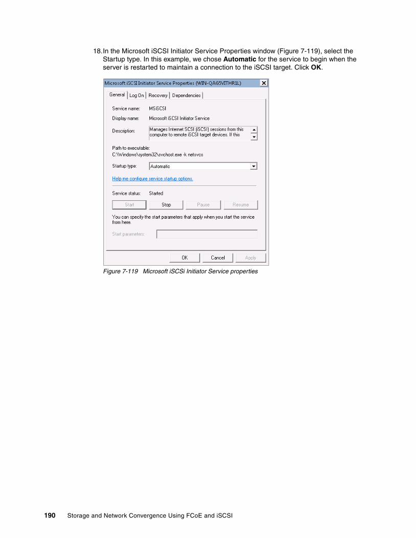
18.In the Microsoft iSCSI Initiator Service Properties window (Figure 7-119), select the Startup type. In this example, we chose Automatic for the service to begin when the server is restarted to maintain a connection to the iSCSI target. Click OK.
Figure 7-119 Microsoft iSCSi Initiator Service properties
190 Storage and Network Convergence Using FCoE and iSCSI
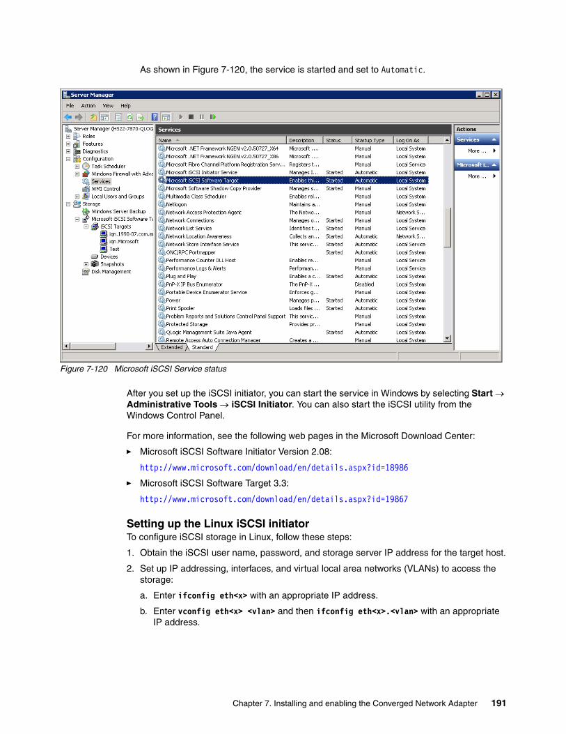
As shown in Figure 7-120, the service is started and set to Automatic.
Figure 7-120 Microsoft iSCSI Service status
After you set up the iSCSI initiator, you can start the service in Windows by selecting Start Administrative Tools iSCSI Initiator. You can also start the iSCSI utility from the Windows Control Panel.
For more information, see the following web pages in the Microsoft Download Center:
� Microsoft iSCSI Software Initiator Version 2.08:
http://www.microsoft.com/download/en/details.aspx?id=18986
� Microsoft iSCSI Software Target 3.3:
http://www.microsoft.com/download/en/details.aspx?id=19867
Setting up the Linux iSCSI initiatorTo configure iSCSI storage in Linux, follow these steps:
1. Obtain the iSCSI user name, password, and storage server IP address for the target host.
2. Set up IP addressing, interfaces, and virtual local area networks (VLANs) to access the storage:
a. Enter ifconfig eth<x> with an appropriate IP address.
b. Enter vconfig eth<x> <vlan> and then ifconfig eth<x>.<vlan> with an appropriate IP address.
Chapter 7. Installing and enabling the Converged Network Adapter 191

In our test, VLAN 99 is the local VLAN, and VLAN 100 carried the iSCSI traffic. Therefore, we used the following configuration:
ifconfig eth13 192.168.99.2 netmask 255.255.255.0 upvconfig eth13 100ifconfig eth13.100 192.168.1.2 netmask 255.255.255.0 up
We used the storage portal address of 192.168.1.100:3260.
3. If necessary, download and install the iSCSI initiator package (Example 7-1):
Example 7-1 iSCSI initiator installation
# yum install iscsi-initiator-utils$ sudo apt-get install open-iscsiLinux iSCSI initiator - RHEL 6
4. Edit the /etc/iscsi/iscsid.conf file to add security (Challenge-Handshake Authentication Protocol (CHAP)) credentials if security is configured (recommended):
node.session.auth.username = <name>node.session.auth.password = <password>discovery.sendtargets.auth.username = <name>discovery.sendtargets.auth.password = <password>
The security configuration on the targets must match these settings.
5. Start the iSCSI daemon:
/etc/init.d/iscsi start
6. Discover targets, which you can do in multiple ways, including usage of an iSCSI name server (iSNS) or statically typing the full iSCSI qualified names (IQNs) of the targets. The simplest way is to use the target portal discovery mechanism built into iSCSI, which sends a request to any known portal (IP address and port) on the storage array. In turn, it replies with a list of all available portals on the device.
iscsiadm -m discovery -t sendtargets -p <storage IP address:port>; port defaults to 3260.
For other options, see the man page for iscsiadm.
7. Restart the iSCSI daemon:
/etc/init.d/iscsi restart
8. Identify the LUN that is now available to the system. The storage device must be properly configured with the IQN of the initiator, which can be discovered or modified in the /etc/iscsi/initiatorname.iscsi file.
The newly attached disk is the next one. If the system has SDA, then it is SDB, SDC, and so on, which you can verify by looking at the system log or by using other means.
9. Format and mount the LUN:
a. Create one or more partitions by using the fdisk command.
b. Format the partitions by using mkfs or one of its variants.
c. Mount the partitions by using the mount command. You might need to create appropriate mount points if they do not exist.
10.Configure the system to attach the LUN as part of the startup process if desired. Enter the following command:
chkconfig iscsi on
192 Storage and Network Convergence Using FCoE and iSCSI

Then edit the /etc/fstab file and add the partitions and associated mount points at the end of the file.
Example 7-2 shows the commands to verify the storage devices and portals.
Example 7-2 Verifying the storage devices and portals
[root@localhost static]# iscsiadm -m sessiontcp: [1] 192.168.1.100:3260,1 iqn.1992-01.com.lsi:7091.600a0b80006e3920000000004e0c31bc[root@localhost static]# iscsiadm -m nodesTry `iscsiadm --help' for more information.[root@localhost static]# iscsiadm -m node192.168.2.100:3260,2 iqn.1992-01.com.lsi:7091.600a0b80006e3920000000004e0c31bc192.168.1.100:3260,1 iqn.1992-01.com.lsi:7091.600a0b80006e3920000000004e0c31bc[root@localhost static]# iscsiadm -m discoverydb192.168.1.100:3260 via sendtargets[root@localhost static]# cd /etc/iscsi[root@localhost iscsi]# lsinitiatorname.iscsi iscsid.conf[root@localhost iscsi]# cat initiatorname.iscsiInitiatorName=iqn.1994-05.com.redhat:c7e96ad9a84c[root@localhost iscsi]#
Example 7-3 shows the command to verify the iSCSI status.
Example 7-3 Verifying the service
[root@localhost iscsi]# service iscsi statusiSCSI Transport Class version 2.0-870version 2.0-872Target: iqn.1992-01.com.lsi:7091.600a0b80006e3920000000004e0c31bcCurrent Portal: 192.168.1.100:3260,1Persistent Portal: 192.168.1.100:3260,1**********Interface:**********Iface Name: defaultIface Transport: tcpIface Initiatorname: iqn.1994-05.com.redhat:c7e96ad9a84cIface IPaddress: 192.168.1.2Iface HWaddress: <empty>Iface Netdev: <empty>SID: 1iSCSI Connection State: TRANSPORT WAITiSCSI Session State: FREEInternal iscsid Session State: REOPEN************************Negotiated iSCSI params:************************HeaderDigest: NoneDataDigest: NoneMaxRecvDataSegmentLength: 262144MaxXmitDataSegmentLength: 65536FirstBurstLength: 8192MaxBurstLength: 65536
Chapter 7. Installing and enabling the Converged Network Adapter 193
ImmediateData: YesInitialR2T: YesMaxOutstandingR2T: 1************************Attached SCSI devices:************************Host Number: 5State: runningscsi5 Channel 00 Id 0 Lun: 0Attached scsi disk sdcState: running
For more information, see the following references:
� “Installing the Linux software iSCSI initiator” topic in the IBM SAN Volume Controller Information Center:
http://publib.boulder.ibm.com/infocenter/svc/ic/index.jsp?topic=%2Fcom.ibm.storage.svc.console.doc%2Fsvc_iscsilinuxinitiatorinstall_wb1gy2.html
� Red Hat Enterprise Linux 6 Storage Administration Guide:
http://docs.redhat.com/docs/en-US/Red_Hat_Enterprise_Linux/6/html/Installation_Guide/
VMware iSCSI initiatorWhen you want to use ESX/ESXi effectively with your storage area network (SAN), you must have a working knowledge of ESX/ESXi systems and SAN concepts. Also, when you set up ESX/ESXi hosts to use iSCSI SAN storage systems, you must be aware of special considerations.
ESX/ESXi supports both hardware-based and software-based iSCSI initiators:
� The hardware iSCSI initiator uses a specialized CNA or iSCSI adapter. In our case, it was the Emulex Virtual Fabric Adapter. The hardware iSCSI initiator is responsible for all iSCSI and network processing and management.
� The software iSCSI initiator code built into the VMkernel that allows an ESX/ESXi to connect to the iSCSI storage device through standard network adapters. The software initiator handles iSCSI processing when communicating with the network adapter. The installation and configuration details are well documented and available from the VMware website.
We found that iSCSI was easy to implement with VMware following the processes available in the links provided for all the adapters tested.
For more information, see the following references:
� VMware Documentation site:
http://www.vmware.com/support/pubs/
� iSCSI SAN Configuration Guide:
http://www.vmware.com/pdf/vsphere4/r41/vsp_41_iscsi_san_cfg.pdf
� iSCSI SAN Configuration Guide in the VMware VSphere Online Library:
http://pubs.vmware.com/vsp40_i/iscsi_san_config/esx_san_config_iscsi.1.1.html
� “Configuring and troubleshooting basic software iSCSI setup” topic in the VMware Knowledge Base:
http://kb.vmware.com/selfservice/microsites/search.do?language=en_US&cmd=displayKC&externalId=1008083
194 Storage and Network Convergence Using FCoE and iSCSI

Chapter 8. FC and FCoE zone configuration
Zoning in a storage network is basically the segregation of the fabric to restrict the cross talk (interference) between the fabrics. Zoning can be compared to the VLAN in the Ethernet world. Zoning allows you to create a smaller subsets, which assist in simplified management, enable security of the fabric, and exist only in the storage switch fabric.
This chapter describes the Fibre Channel (FC) and Fibre Channel over Ethernet (FCoE) zone configuration on the IBM Flex System Enterprise Chassis embedded switches and also other vendor specific implementation of zoning configuration.
This chapter includes the following sections:
� 8.1, “Why zoning is important” on page 196� 8.2, “Zoning on the IBM Flex System” on page 196� 8.3, “Brocade zoning” on page 208� 8.4, “Cisco zoning” on page 211� 8.5, “QLogic zoning” on page 214� 8.6, “Conclusion” on page 221
8
Note: The zoning configuration information from other vendors was available in the previous version of this book. This information has not been changed.
© Copyright IBM Corp. 2012, 2014. All rights reserved. 195
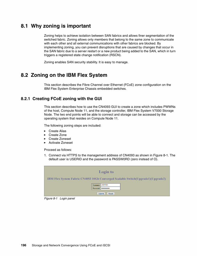
8.1 Why zoning is important
Zoning helps to achieve isolation between SAN fabrics and allows finer segmentation of the switched fabric. Zoning allows only members that belong to the same zone to communicate with each other and all external communications with other fabrics are blocked. By implementing zoning, you can prevent disruptions that are caused by changes that occur in the SAN fabric due to a server restart or a new product being added to the SAN, which in turn triggers a registered state change notification (RSCN).
Zoning enables SAN security stability. It is easy to manage.
8.2 Zoning on the IBM Flex System
This section describes the Fibre Channel over Ethernet (FCoE) zone configuration on the IBM Flex System Enterprise Chassis embedded switches.
8.2.1 Creating FCoE zoning with the GUI
This section describes how to use the CN4093 GUI to create a zone which includes PWWNs of the host, Compute Node 11, and the storage controller, IBM Flex System V7000 Storage Node. The two end points will be able to connect and storage can be accessed by the operating system that resides on Compute Node 11.
The following zoning steps are included:
� Create Alias� Create Zone� Create Zoneset� Activate Zoneset
Proceed as follows:
1. Connect via HTTPS to the management address of CN4093 as shown in Figure 8-1. The default user is USERID and the password is PASSW0RD (zero instead of O).
Figure 8-1 Login panel
196 Storage and Network Convergence Using FCoE and iSCSI

2. Click the switch Dashboard title on the left of the panel as shown in Figure 8-2.
Figure 8-2 Switch Dashboard
3. Click the Configure tab as shown in Figure 8-3.
Figure 8-3 Configure tab
Chapter 8. FC and FCoE zone configuration 197

4. Click the FC/FCoE folder on the left side of your panel as shown in Figure 8-4.
Figure 8-4 FC/FCoE folder
5. At this point you are redirected to a switch dashboard panel. Click the title as in Figure 8-5.
Figure 8-5 Switch Dashboard panel
6. Open the Zoning folder and click FC Alias as shown in Figure 8-6.
Figure 8-6 Zoning & FC Alias folders
198 Storage and Network Convergence Using FCoE and iSCSI

7. Click Add to create the new alias as shown in Figure 8-7.
Figure 8-7 Create new Alias
8. Add the name of the alias. In this example, it is A_FSV7K_N11 and the WWPN is shown in Figure 8-8. Click Submit.
Figure 8-8 Define the name and wwpn of the new Alias
Chapter 8. FC and FCoE zone configuration 199
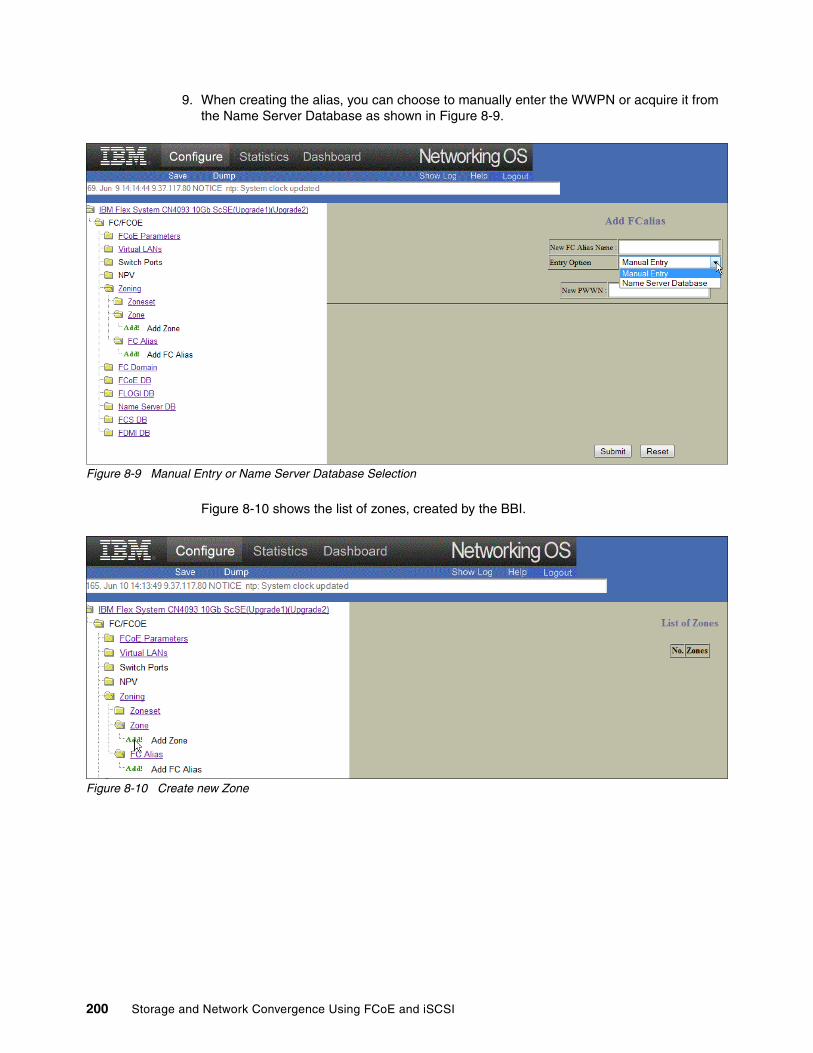
9. When creating the alias, you can choose to manually enter the WWPN or acquire it from the Name Server Database as shown in Figure 8-9.
Figure 8-9 Manual Entry or Name Server Database Selection
Figure 8-10 shows the list of zones, created by the BBI.
Figure 8-10 Create new Zone
200 Storage and Network Convergence Using FCoE and iSCSI

10.Add a new zone. In our example, this is Z_FSV7K_N11. Click Submit as shown in Figure 8-11.
Figure 8-11 Define Zone name
11.In the List of Zones, click on your new defined zone as shown in Figure 8-12.
Figure 8-12 List of Zones
Chapter 8. FC and FCoE zone configuration 201
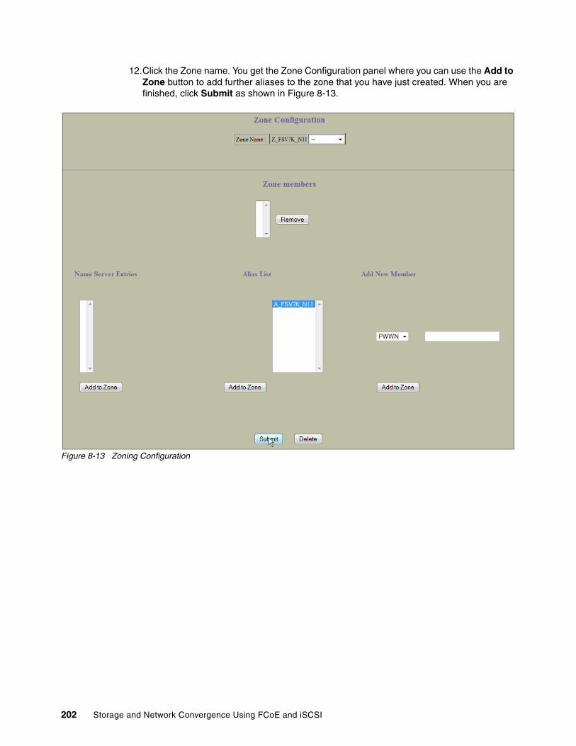
12.Click the Zone name. You get the Zone Configuration panel where you can use the Add to Zone button to add further aliases to the zone that you have just created. When you are finished, click Submit as shown in Figure 8-13.
Figure 8-13 Zoning Configuration
202 Storage and Network Convergence Using FCoE and iSCSI

13.Go to the Zoneset folder, expand it, and click Add to create a new Zoneset as shown in Figure 8-14.
Figure 8-14 Zoneset Configuration
14.Type the name of the new Zoneset (in our example, CN4093_1) and click Submit as shown in Figure 8-15.
Figure 8-15 Zoneset name
15.Click on the new Zoneset as shown in Figure 8-16.
Chapter 8. FC and FCoE zone configuration 203

Figure 8-16 List of Zoneset
16.A list of created zones is displayed. Highlight the zone you created and then click Add to add to the newly defined zoneset. See Figure 8-17.
Figure 8-17 Add Zone to a Zoneset
204 Storage and Network Convergence Using FCoE and iSCSI
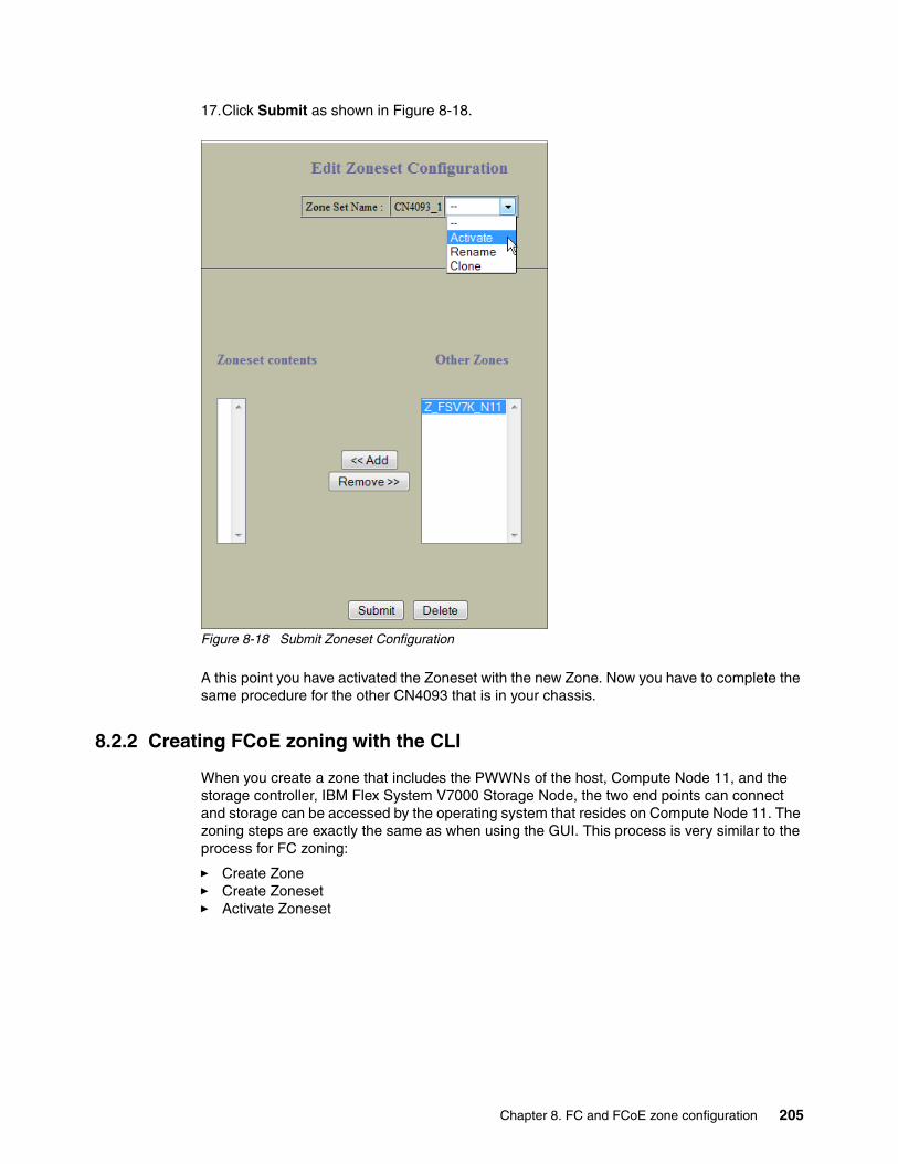
17.Click Submit as shown in Figure 8-18.
Figure 8-18 Submit Zoneset Configuration
A this point you have activated the Zoneset with the new Zone. Now you have to complete the same procedure for the other CN4093 that is in your chassis.
8.2.2 Creating FCoE zoning with the CLI
When you create a zone that includes the PWWNs of the host, Compute Node 11, and the storage controller, IBM Flex System V7000 Storage Node, the two end points can connect and storage can be accessed by the operating system that resides on Compute Node 11. The zoning steps are exactly the same as when using the GUI. This process is very similar to the process for FC zoning:
� Create Zone� Create Zoneset� Activate Zoneset
Chapter 8. FC and FCoE zone configuration 205
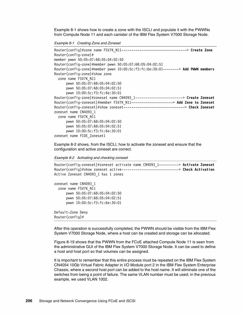
Example 8-1 shows how to create a zone with the ISCLI and populate it with the PWWNs from Compute Node 11 and each canister of the IBM Flex System V7000 Storage Node.
Example 8-1 Creating Zone and Zoneset
Router(config)#zone name FSV7K_N11---------------------------------> Create ZoneRouter(config-zone)#member pwwn 50:05:07:68:05:04:02:50Router(config-zone)#member pwwn 50:05:07:68:05:04:02:51Router(config-zone)#member pwwn 10:00:5c:f3:fc:6e:30:01--------> Add PWWN membersRouter(config-zone)#show zone zone name FSV7K_N11 pwwn 50:05:07:68:05:04:02:50 pwwn 50:05:07:68:05:04:02:51 pwwn 10:00:5c:f3:fc:6e:30:01Router(config-zone)#zoneset name CN4093_1------------------------> Create ZonesetRouter(config-zoneset)#member FSV7K_N11---------------------> Add Zone to ZonesetRouter(config-zoneset)#show zoneset-------------------------------> Check Zonesetzoneset name CN4093_1 zone name FSV7K_N11 pwwn 50:05:07:68:05:04:02:50 pwwn 50:05:07:68:05:04:02:51 pwwn 10:00:5c:f3:fc:6e:30:01zoneset name FCOE_Zoneset1
Example 8-2 shows, from the ISCLI, how to activate the zoneset and ensure that the configuration and active zoneset are correct.
Example 8-2 Activating and checking zoneset
Router(config-zoneset)#zoneset activate name CN4093_1----------> Activate ZonesetRouter(config)#show zoneset active-----------------------------> Check ActivationActive Zoneset CN4093_1 has 1 zones
zoneset name CN4093_1 zone name FSV7K_N11 pwwn 50:05:07:68:05:04:02:50 pwwn 50:05:07:68:05:04:02:51 pwwn 10:00:5c:f3:fc:6e:30:01
Default-Zone DenyRouter(config)#
After this operation is successfully completed, the PWWN should be visible from the IBM Flex System V7000 Storage Node, where a host can be created and storage can be allocated.
Figure 8-19 shows that the PWWN from the FCoE attached Compute Node 11 is seen from the administrative GUI of the IBM Flex System V7000 Storage Node. It can be used to define a host and host port so that volumes can be assigned.
It is important to remember that this entire process must be repeated on the IBM Flex System CN4054 10Gb Virtual Fabric Adapter in I/O Module port 2 in the IBM Flex System Enterprise Chassis, where a second host port can be added to the host name. It will eliminate one of the switches from being a point of failure. The same VLAN number must be used; in the previous example, we used VLAN 1002.
206 Storage and Network Convergence Using FCoE and iSCSI
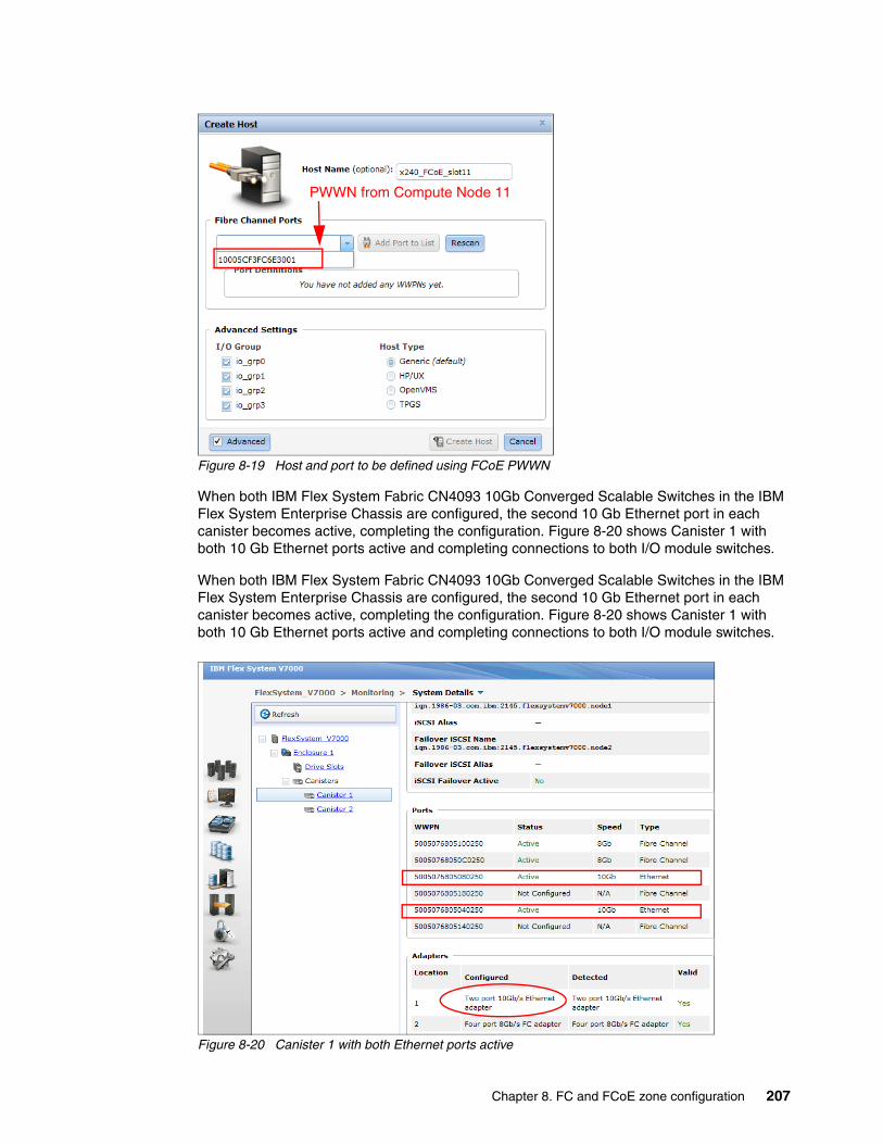
Figure 8-19 Host and port to be defined using FCoE PWWN
When both IBM Flex System Fabric CN4093 10Gb Converged Scalable Switches in the IBM Flex System Enterprise Chassis are configured, the second 10 Gb Ethernet port in each canister becomes active, completing the configuration. Figure 8-20 shows Canister 1 with both 10 Gb Ethernet ports active and completing connections to both I/O module switches.
When both IBM Flex System Fabric CN4093 10Gb Converged Scalable Switches in the IBM Flex System Enterprise Chassis are configured, the second 10 Gb Ethernet port in each canister becomes active, completing the configuration. Figure 8-20 shows Canister 1 with both 10 Gb Ethernet ports active and completing connections to both I/O module switches.
Figure 8-20 Canister 1 with both Ethernet ports active
PWWN from Compute Node 11
Chapter 8. FC and FCoE zone configuration 207

8.3 Brocade zoning
This section describes the zoning implementation from Brocade Systems. Brocade zoning includes Hardware-enforced zoning and Session-enforced zoning:
� Hardware-enforced zoning:
Hardware-enforced zoning is used by zones with all members defined by their domain ID, port, or all members defined by their WWN. Hardware-enforced zoning is the strongest form of enforcement. It blocks frames that compromise the zone from a device that is not a member of a zone, such as a bad citizen. The source device is denied access to the destination device if it is not defined in the same zone.
Hardware-enforced zoning is available through ASIC hardware logic checking at the destination port. It provides more secure zoning than session enforcement.
� Session-enforced zoning:
Session-enforced zoning guarantees that only members of the zone can complete a Port Login (PLOGI), which prevents any unauthorized access by devices that are not a member of the zone. The name server restricts PLOGIs.
Enforcement to a zone with WWN members and the domain, port changes from hardware enforced zoning to session-enforced zoning.
Enforcement is based on how members in a zone are defined. Devices that use session-enforced zoning cause any PLOGIs to the device to be rejected. Devices that use hardware-enforced zoning cause frames that do not comply with the effective zone configuration to be rejected. This blocking is performed at the transmit side of the port where the source device is located and is the highest level of protection for a device.
The decision for the type of enforcement that a device receives is based on how the members in a zone are defined.
You can use either of the following methods to determine which zone enforcement type to use for a port:
� The portZoneShow command� The filterPortShow -slot<slot> <port> command
Zoning enforcement includes the following methods:
� Session-enforced zoning:
This method is name-server assisted, in which the name server restricts visibility. It is always available when zoning is enabled. In addition, it does not have any reduction in performance.
� Hardware-enforced zoning:
This method is available when rule-checking criteria are met through hardware logic checking. It provides additional security in addition to session-enforced zoning. It prevents illegal access from bad citizens. It also has no reduction in performance with hard-port-level zoning.
Zone objects include the following types:
� Configurations, which allow one or more defined configurations, up to one effective configuration, and can consist of one or more zones
� Zones, which can consist of one or more zone members and can exist across multiple zone configurations
� Zone members, which can include a domain or port, WWN, or alias
208 Storage and Network Convergence Using FCoE and iSCSI
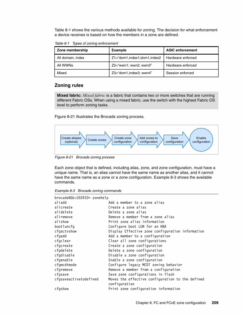
Table 8-1 shows the various methods available for zoning. The decision for what enforcement a device receives is based on how the members in a zone are defined.
Table 8-1 Types of zoning enforcement
Zoning rules
Figure 8-21 illustrates the Brocade zoning process.
Figure 8-21 Brocade zoning process
Each zone object that is defined, including alias, zone, and zone configuration, must have a unique name. That is, an alias cannot have the same name as another alias, and it cannot have the same name as a zone or a zone configuration. Example 8-3 shows the available commands.
Example 8-3 Brocade zoning commands
brocade8Gb:USERID> zonehelpaliadd Add a member to a zone aliasalicreate Create a zone aliasalidelete Delete a zone aliasaliremove Remove a member from a zone aliasalishow Print zone alias informationbootluncfg Configure boot LUN for an HBAcfgactvshow Display Effective zone configuration informationcfgadd Add a member to a configurationcfgclear Clear all zone configurationscfgcreate Create a zone configurationcfgdelete Delete a zone configurationcfgdisable Disable a zone configurationcfgenable Enable a zone configurationcfgmcdtmode Configure legacy MCDT zoning behaviorcfgremove Remove a member from a configurationcfgsave Save zone configurations in flashcfgsaveactivetodefined Moves the effective configuration to the defined configurationcfgshow Print zone configuration information
Zone membership Example ASIC enforcement
All domain, index Z1=“dom1,index1;dom1,index2 Hardware enforced
All WWNs Z2=“wwn1; wwn2; wwn3” Hardware enforced
Mixed Z3=“dom1,index3; wwn4” Session enforced
Mixed fabric: Mixed fabric is a fabric that contains two or more switches that are running different Fabric OSs. When using a mixed fabric, use the switch with the highest Fabric OS level to perform zoning tasks.
Enableconfiguration
Create aliases(optional)
Create zonesCreate zoneconfiguration
Add zones toconfiguration
Saveconfiguration
Chapter 8. FC and FCoE zone configuration 209

cfgsize Print size details of zone databasecfgtransabort Abort zone configuration transactioncfgtransshow Print zone configurations in transaction bufferdefzone Activates or deactivates a default zone configuration.msfr Create an MSFR Zonenszonemember Display the information of all the online devices that are zoned with the device.openfr Create an MSFR Zonezone Configure zone objectszoneadd Add a member to a zonezonecreate Create a zonezonedelete Delete a zonezonehelp Print zoning help infozoneobjectcopy Copies a zone objectzoneobjectexpunge Expunges a zone objectzoneobjectrename Rename a zoning Objectzoneremove Remove a member from a zonezoneshow Print zone informationbrocade8Gb:USERID>
When connecting Brocade switches to an IBM DS storage device, review the requirements for the portcfgfillword command for the storage device.
Brocade Access Gateway modeBrocade Access Gateway is a feature of Fabric OS that enables a Brocade SAN Switch Module to be configured in Brocade Access Gateway mode. This mode might be required for various FCoE configurations. When a Brocade SAN Switch Module is configured in Brocade Access Gateway mode, it no longer participates in the SAN fabric as an FC switch and is without FC services such as zoning, name server, and FC addressing.
The Brocade Access Gateway feature is a software-only extension of Fabric OS that addresses specific interoperability, scalability, and manageability concerns that might occur in FC SAN fabrics. For most IBM BladeCenter implementations, continue to use the Brocade SAN Switch Module in FC switch mode to provide the full suite of FC services that are available.
The benefits of the Brocade Access Gateway feature occur when connecting IBM BladeCenter to heterogeneous SAN fabrics, such as Cisco and McDATA. It provides a separation between the server and SAN administrative groups and increases scalability to ultra-large SAN fabrics.
You can change from the Fabric switch mode to the Brocade Access Gateway mode by using either of the following tools:
� Command-line interface (CLI)� Brocade Web Tools
IBM RETAIN® Tip: For more information, see the IBM RETAIN Tip H196488: DS3500/DS3950/DS5000 systems not working with Brocade on 8 Gbps host ports - IBM System Storage, at this website:
http://www.ibm.com/support/entry/portal/docdisplay?lndocid=MIGR-5083089
210 Storage and Network Convergence Using FCoE and iSCSI
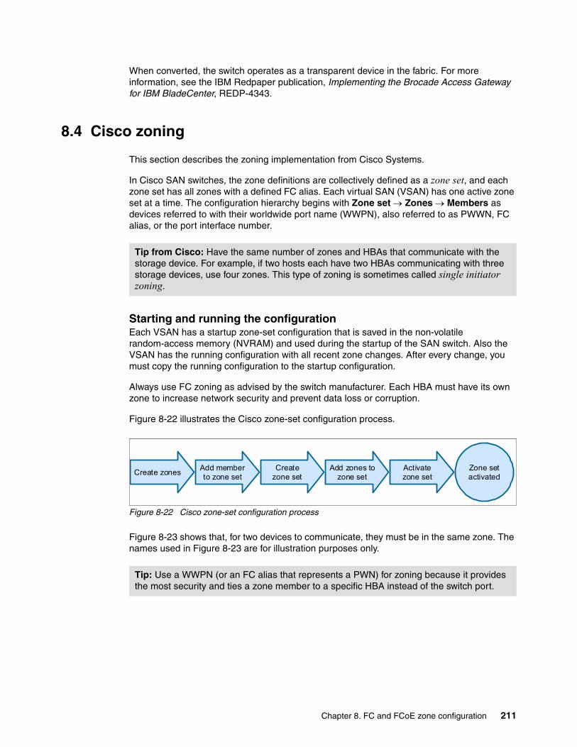
When converted, the switch operates as a transparent device in the fabric. For more information, see the IBM Redpaper publication, Implementing the Brocade Access Gateway for IBM BladeCenter, REDP-4343.
8.4 Cisco zoning
This section describes the zoning implementation from Cisco Systems.
In Cisco SAN switches, the zone definitions are collectively defined as a zone set, and each zone set has all zones with a defined FC alias. Each virtual SAN (VSAN) has one active zone set at a time. The configuration hierarchy begins with Zone set Zones Members as devices referred to with their worldwide port name (WWPN), also referred to as PWWN, FC alias, or the port interface number.
Starting and running the configurationEach VSAN has a startup zone-set configuration that is saved in the non-volatile random-access memory (NVRAM) and used during the startup of the SAN switch. Also the VSAN has the running configuration with all recent zone changes. After every change, you must copy the running configuration to the startup configuration.
Always use FC zoning as advised by the switch manufacturer. Each HBA must have its own zone to increase network security and prevent data loss or corruption.
Figure 8-22 illustrates the Cisco zone-set configuration process.
Figure 8-22 Cisco zone-set configuration process
Figure 8-23 shows that, for two devices to communicate, they must be in the same zone. The names used in Figure 8-23 are for illustration purposes only.
Tip from Cisco: Have the same number of zones and HBAs that communicate with the storage device. For example, if two hosts each have two HBAs communicating with three storage devices, use four zones. This type of zoning is sometimes called single initiator zoning.
Tip: Use a WWPN (or an FC alias that represents a PWN) for zoning because it provides the most security and ties a zone member to a specific HBA instead of the switch port.
Zone setactivated
Create zonesAdd memberto zone set
Createzone set
Add zones tozone set
Activatezone set
Chapter 8. FC and FCoE zone configuration 211

Figure 8-23 A simple zoning configuration
The name that you choose for the zone is important. Many environments use different zone names. However, all name formats must provide relevant information about their contents. For example, such names as Zone1 or TapeZone do not provide sufficient information about their contents.
In normal circumstances, a zone name must contain two members. Within the zone name, it must contain identifiers that are related to the two devices, such as exchange_nodeA_hba0 and Storwize_port1. The name must provide enough information about the contents so that users do not have to consult further documentation. In Figure 8-23, Zone 2 has more than two targets for Server 3, which might be required for data migration. However, the preferred method is to have one initiator and one target.
Zoning, as shown in Figure 8-23, can also be considered a security feature, and not just for separating environments. Zoning can also be used for test and maintenance purposes. For example, not many enterprises mix their test and maintenance environments with their production environment. Within a fabric, you can easily separate your test environment from your production bandwidth allocation on the same fabric by using zoning.
Figure 8-23 illustrates the following communication:
� Server 1 and Disk storage 1 can communicate with each other (Zone 1: Serv1, Stor1).
� Server 2 is not zoned.
� Server 3 can communicate with Storage 1 and 2, which might be required during a storage data migration (Zone 2: Serv3, Stor2, Stor 3).
� Server 4 and Disk Storage 4 can communicate with each other.
� Server 1 cannot communicate with Disk Storage 2, 3, and 4.
� Server 3 cannot communicate with Disk Storage 4.
Fabric
Zone 1
Zone 3
Stor2
Stor4
Stor3
Stor1
Serv2
Serv3
Serv4
Serv1
212 Storage and Network Convergence Using FCoE and iSCSI

Cisco SAN switches automatically support the following basic zone features, without any additional configuration:
� Zones are contained in a VSAN.
� Hard zoning cannot be disabled.
� Name server queries are soft zoned.
� Only active zone sets are distributed.
� Unzoned devices cannot access each other.
� A zone or zone set with the same name can exist in each VSAN.
� Each VSAN has a full database and an active database.
� Active zone sets cannot be changed without activating a full zone database.
� Active zone sets are preserved across switch reboots.
� Changes to the full database must be explicitly saved.
� Zone reactivation, where a zone set is active and you activate another zone set, does not disrupt existing traffic.
� You can propagate full zone sets to all switches on a per VSAN basis.
� You can change the default policy for unzoned members.
� You can interoperate with other vendors by configuring a VSAN in interop mode. You can also configure one VSAN in interop mode and another VSAN in basic mode in the same switch without disrupting each other.
� You can bring E ports out of isolation.
For more information, see the following guides from Cisco:
� Zones:
http://www.cisco.com/en/US/docs/storage/san_switches/mds9000/sw/rel_1_x/1_3/cookbook/CB_zone.html#wp1039557
� Configuring Zones and Zone Sets:
http://www.cisco.com/en/US/docs/storage/san_switches/mds9000/sw/san-os/quick/guide/qcg_zones.html
� Zone and zone-set issues:
http://www.cisco.com/en/US/products/ps5989/prod_troubleshooting_guide_chapter09186a008067a309.html#wp48042
� Cisco MDS 9000 Family Configuration Guide, Release 2.x:
http://www.cisco.com/en/US/docs/storage/san_switches/mds9000/sw/rel_2_x/san-os/configuration/guide/cli.pdf
� Using VSANs and Zoning with the Cisco MDS 9000 Family (white paper):
http://www.cisco.com/en/US/netsol/ns340/ns394/ns259/ns261/networking_solutions_white_paper09186a0080114c21.shtml
Chapter 8. FC and FCoE zone configuration 213
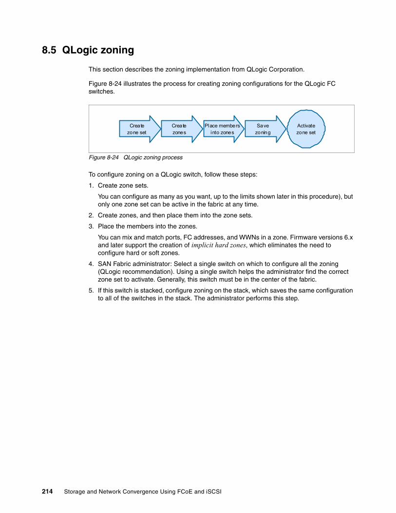
8.5 QLogic zoning
This section describes the zoning implementation from QLogic Corporation.
Figure 8-24 illustrates the process for creating zoning configurations for the QLogic FC switches.
Figure 8-24 QLogic zoning process
To configure zoning on a QLogic switch, follow these steps:
1. Create zone sets.
You can configure as many as you want, up to the limits shown later in this procedure), but only one zone set can be active in the fabric at any time.
2. Create zones, and then place them into the zone sets.
3. Place the members into the zones.
You can mix and match ports, FC addresses, and WWNs in a zone. Firmware versions 6.x and later support the creation of implicit hard zones, which eliminates the need to configure hard or soft zones.
4. SAN Fabric administrator: Select a single switch on which to configure all the zoning (QLogic recommendation). Using a single switch helps the administrator find the correct zone set to activate. Generally, this switch must be in the center of the fabric.
5. If this switch is stacked, configure zoning on the stack, which saves the same configuration to all of the switches in the stack. The administrator performs this step.
Activatezone set
Createzone set
Createzones
Place membersinto zones
Savezoning
214 Storage and Network Convergence Using FCoE and iSCSI

6. Select Zoning Edit Zoning (Figure 8-25).
Figure 8-25 QLogic zoning configuration
In the Edit Zoning window (Zoning Sets), to the left is the Zone Set Tree, which lists the configured zone sets, zones, and members that are in the database of this switch. The zone set named ORPHAN ZONES is always in the switch as a trash or recycle bin for zoning information. See Figure 8-26.
On the right side is the member information, which shows the devices that are currently connected to the fabric. The switches can be expanded to show the ports. The ports with devices logged in are green and have entry handles to expand or collapse the FC address and the worldwide PORT.
The FC address for each device is shown with the WWN. If nick names are assigned, the nick name is shown instead of the WWN.
QLogic tip: The SAN Fabric administrator must select a single switch on which to configure all the zoning.
Chapter 8. FC and FCoE zone configuration 215
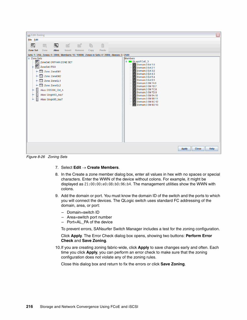
Figure 8-26 Zoning Sets
7. Select Edit Create Members.
8. In the Create a zone member dialog box, enter all values in hex with no spaces or special characters. Enter the WWN of the device without colons. For example, it might be displayed as 21:00:00:e0:08:b0:96:b4. The management utilities show the WWN with colons.
9. Add the domain or port. You must know the domain ID of the switch and the ports to which you will connect the devices. The QLogic switch uses standard FC addressing of the domain, area, or port:
– Domain=switch ID– Area=switch port number– Port=AL_PA of the device
To prevent errors, SANsurfer Switch Manager includes a test for the zoning configuration.
Click Apply. The Error Check dialog box opens, showing two buttons: Perform Error Check and Save Zoning.
10.If you are creating zoning fabric-wide, click Apply to save changes early and often. Each time you click Apply, you can perform an error check to make sure that the zoning configuration does not violate any of the zoning rules.
Close this dialog box and return to fix the errors or click Save Zoning.
216 Storage and Network Convergence Using FCoE and iSCSI
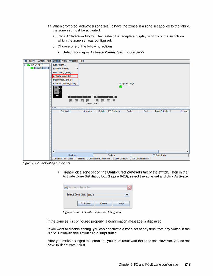
11.When prompted, activate a zone set. To have the zones in a zone set applied to the fabric, the zone set must be activated:
a. Click Activate Go to. Then select the faceplate display window of the switch on which the zone set was configured.
b. Choose one of the following actions:
• Select Zoning Activate Zoning Set (Figure 8-27).
Figure 8-27 Activating a zone set
• Right-click a zone set on the Configured Zonesets tab of the switch. Then in the Activate Zone Set dialog box (Figure 8-28), select the zone set and click Activate.
Figure 8-28 Activate Zone Set dialog box
If the zone set is configured properly, a confirmation message is displayed.
If you want to disable zoning, you can deactivate a zone set at any time from any switch in the fabric. However, this action can disrupt traffic.
After you make changes to a zone set, you must reactivate the zone set. However, you do not have to deactivate it first.
Chapter 8. FC and FCoE zone configuration 217
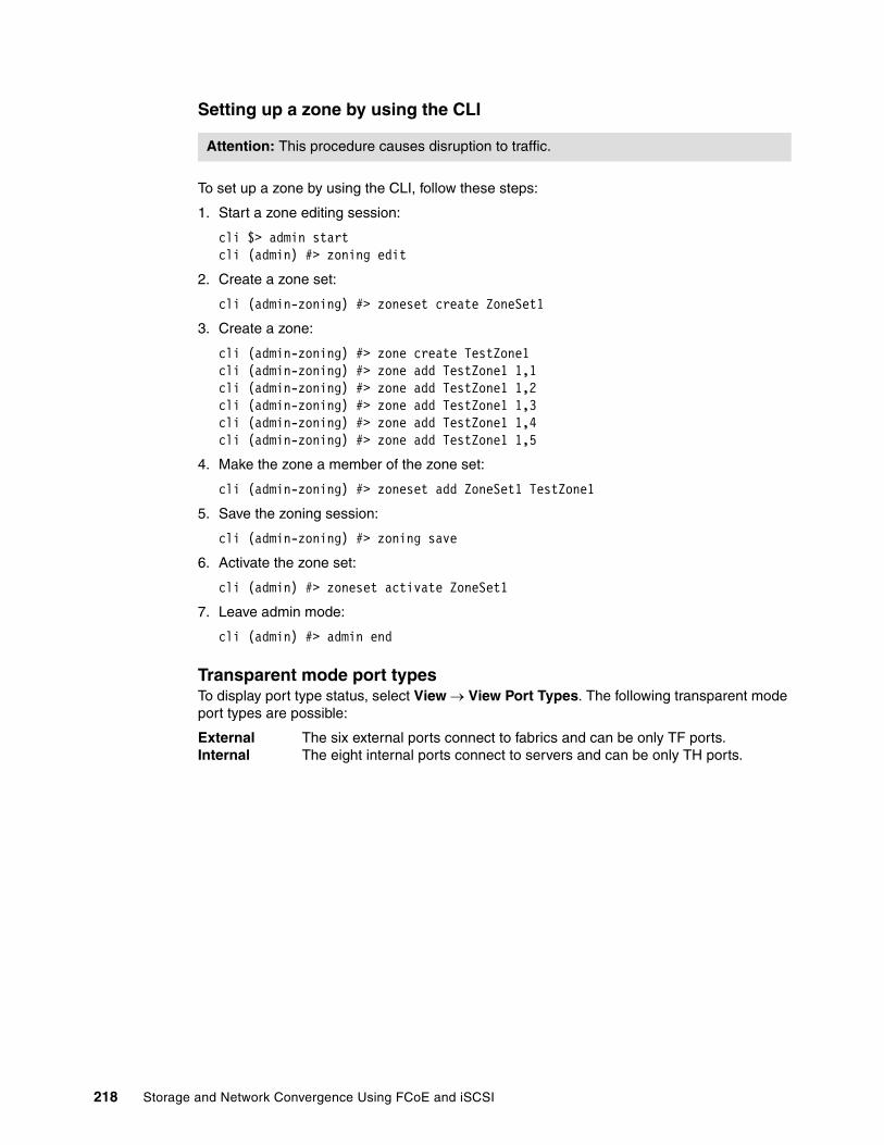
Setting up a zone by using the CLI
To set up a zone by using the CLI, follow these steps:
1. Start a zone editing session:
cli $> admin startcli (admin) #> zoning edit
2. Create a zone set:
cli (admin-zoning) #> zoneset create ZoneSet1
3. Create a zone:
cli (admin-zoning) #> zone create TestZone1cli (admin-zoning) #> zone add TestZone1 1,1cli (admin-zoning) #> zone add TestZone1 1,2cli (admin-zoning) #> zone add TestZone1 1,3cli (admin-zoning) #> zone add TestZone1 1,4cli (admin-zoning) #> zone add TestZone1 1,5
4. Make the zone a member of the zone set:
cli (admin-zoning) #> zoneset add ZoneSet1 TestZone1
5. Save the zoning session:
cli (admin-zoning) #> zoning save
6. Activate the zone set:
cli (admin) #> zoneset activate ZoneSet1
7. Leave admin mode:
cli (admin) #> admin end
Transparent mode port typesTo display port type status, select View View Port Types. The following transparent mode port types are possible:
External The six external ports connect to fabrics and can be only TF ports.Internal The eight internal ports connect to servers and can be only TH ports.
Attention: This procedure causes disruption to traffic.
218 Storage and Network Convergence Using FCoE and iSCSI
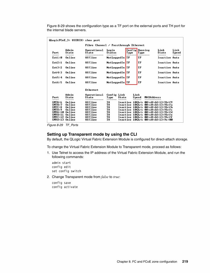
Figure 8-29 shows the configuration type as a TF port on the external ports and TH port for the internal blade servers.
Figure 8-29 TF_Ports
Setting up Transparent mode by using the CLIBy default, the QLogic Virtual Fabric Extension Module is configured for direct-attach storage.
To change the Virtual Fabric Extension Module to Transparent mode, proceed as follows:
1. Use Telnet to access the IP address of the Virtual Fabric Extension Module, and run the following commands:
admin startconfig editset config switch
2. Change Transparent mode from false to true:
config saveconfig activate
Chapter 8. FC and FCoE zone configuration 219
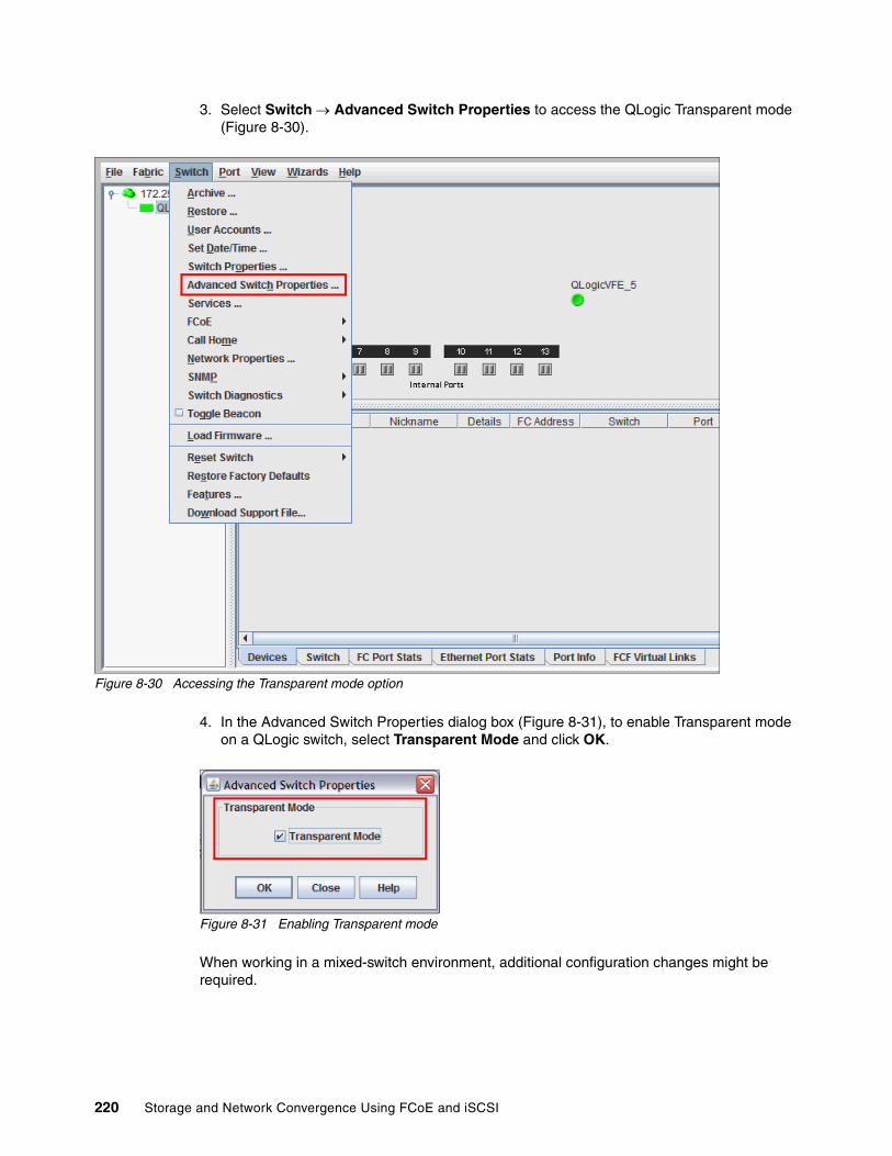
3. Select Switch Advanced Switch Properties to access the QLogic Transparent mode (Figure 8-30).
Figure 8-30 Accessing the Transparent mode option
4. In the Advanced Switch Properties dialog box (Figure 8-31), to enable Transparent mode on a QLogic switch, select Transparent Mode and click OK.
Figure 8-31 Enabling Transparent mode
When working in a mixed-switch environment, additional configuration changes might be required.
220 Storage and Network Convergence Using FCoE and iSCSI

8.6 Conclusion
Zoning is very important in a converged network to protect FC traffic from Ethernet broadcast domains. There are many approaches to creating FC zoning. The description shown below provides better understanding of the FC zoning.
The “single initiator zones” camp believes that you should create zones based on the initiator. This means that each zone will contain a single host, or initiator. Multiple storage array ports can be added to the zone without violating the single initiator rule; arrays are the targets. This method makes the most sense, because you can quickly see which arrays your host can access in the configuration.
Some people like to skip zoning altogether. For stability reasons alone, this is not recommended. A fabric reset will cause everyone to re-login at the same time, and fabric updates get sent to everyone. The potential for security issues exist as well, but in reality it is rookie mistakes that you must be most wary of.1
See the following link to learn more about FC zoning:
http://www.enterprisenetworkingplanet.com/netsp/article.php/3695836/Storage-Networking-101-Understanding-Fibre-Channel-Zones.htm
There are many best practices available for FC zone configuration. Some of the recommended best practices for creating FC zoning can be found on the following web pages:
http://www.brocade.com/downloads/documents/white_papers/Zoning_Best_Practices_WP-00.pdf
http://pic.dhe.ibm.com/infocenter/strhosts/ic/index.jsp?topic=%2Fcom.ibm.help.strghosts.doc%2FHAK%2F1.9.0%2FHAG%2Fhak_ug_ch2_overview_FC_zoning.html
The portCfgFillWord command: To ensure interoperability between Brocade and QLogic switches, use the portCfgFillWord command to set the fill word of the connecting port to option (ARBFF/ARBFF):
� Brocade: admin> portcfgfillword 0� Usage: portCfgFillWord Port Number mode� Mode:
0/-idle-idle IDLE in Link Init, IDLE as fill word (default)1/-arbff-arbff ARBFF in Link Init, ARBFF as fill word2/-idle-arbff IDLE in Link Init, ARBFF as fill word (SW)3/-aa-then-ia If ARBFF/ARBFF failed, then do IDLE/ARBFF
1 The information in this section was copied from the following website:http://www.enterprisenetworkingplanet.com/netsp/article.php/3695836/Storage-Networking-101-Understanding-Fibre-Channel-Zones.htm
Chapter 8. FC and FCoE zone configuration 221

222 Storage and Network Convergence Using FCoE and iSCSI
Part 3 Implementing storage and network convergence
This part of the book provides implementation scenarios for network and storage convergence for Fibre Channel over Ethernet (FCoE) and Internet Small Computer System Interface (iSCSI). Today, true convergence of disparate networks requires enhancement of the Ethernet so that it can transport critical data by running Fibre Channel (FC) over lossless Layer 2 Ethernet.
You can retain the benefit of a low-cost Ethernet and address the strength of FC as the dominant storage system interconnect in large data centers by using convergence. Convergence helps to meet the requirements of business continuity, backup, and disaster recovery operations, and Ethernet for FC SAN connectivity and networking.
This part includes the following chapters:
� Chapter 9, “Configuring iSCSI and FCoE cards for SAN boot” on page 225
� Chapter 10, “Approach with FCoE inside the BladeCenter” on page 443
� Chapter 11, “Approach with FCoE between BladeCenter and a top-of-rack switch” on page 467
� Chapter 12, “Approach with FCoE inside the Flex Chassis” on page 489
� Chapter 13, “Approach with FCoE between the IBM Flex Chassis and a top-of-rack switch” on page 523
� Chapter 14, “Approach with iSCSI” on page 553
Part 3
© Copyright IBM Corp. 2012, 2014. All rights reserved. 223

The configurations in this part were derived from supported IBM solutions. For details about the supported components, see the following resources:
� BladeCenter Interoperability Guide:
http://www.ibm.com/support/entry/portal/docdisplay?brand=5000020&lndocid=MIGR-5073016
� IBM ServerProven®: Compatibility for hardware, applications, and middleware:
http://www.ibm.com/systems/info/x86servers/serverproven/compat/us/
� System Storage Interoperation Center (SSIC):
http://www.ibm.com/systems/support/storage/ssic/interoperability.wss
� IBM System x Configuration and Options Guide:
http://www.ibm.com/systems/xbc/cog/
224 Storage and Network Convergence Using FCoE and iSCSI

Chapter 9. Configuring iSCSI and FCoE cards for SAN boot
This chapter explains how to configure the Internet Small Computer System Interface (iSCSI) and Fibre Channel over Ethernet (FCoE) cards for SAN boot.
This chapter includes the following sections:
� 9.1, “Preparing to set up a boot from SAN environment on a UEFI system” on page 226� 9.2, “Optimizing UEFI for boot from SAN” on page 228� 9.3, “Configuring IBM Flex System CN4054 for iSCSI” on page 231� 9.4, “Configuring IBM Flex System CN4054 for FCoE” on page 248� 9.5, “Configuring Emulex for iSCSI for the BladeCenter” on page 290� 9.6, “Configuring Emulex for FCoE in the BladeCenter” on page 333� 9.7, “Configuring QLogic for FCoE in the BladeCenter” on page 369� 9.8, “Configuring Brocade for FCoE in the BladeCenter” on page 405� 9.9, “After the operating system is installed” on page 438� 9.10, “Common symptoms and tips” on page 439� 9.11, “References about boot from SAN” on page 440� 9.12, “Summary” on page 441
9
© Copyright IBM Corp. 2012, 2014. All rights reserved. 225
9.1 Preparing to set up a boot from SAN environment on a UEFI system
Remote boot, boot from SAN, or SAN boot are the terms used when booting a system from disks on a SAN disk (also called storage subsystem). The server operating system is installed on a LUN or remote disk that is defined on the storage. This section explains how to prepare to set up a boot from SAN environment by using Unified Extensible Firmware Interface (UEFI)-based Flex Nodes such as x240 and blades such as HS22. Then, see 9.2, “Optimizing UEFI for boot from SAN” on page 228, and 9.3, “Configuring IBM Flex System CN4054 for iSCSI” on page 231, which explain how to set up the boot from SAN environment.
To prepare for this task, you must have some knowledge of SAN disks and SAN switches. This section provides only a brief explanation of these topics. Check for interoperability before proceeding with such a setup.
Before proceeding with setting up a boot from SAN, you must validate the following elements:
� On the server:
– Check that the operating system you want to install is supported.
– Check that the Converged Network Adapter is supported in your server.
– Check that your server was tested with your SAN disk device.
– Get the latest recommended drivers and firmware for the Converged Network Adapter.
� On the storage subsystem:
– Check that the operating system you want to install on the server is supported by your SAN disk device.
– Check that the Converged Network Adapter is supported on your SAN disk storage device.
� On the FCoE/SAN switches:
– Check that the Converged Network Adapter is supported on your SAN switch device.
– If you are interconnecting multiple switches together, ensure that your switches were tested to work together. Also check your firmware levels to make sure that they match the interoperability guides.
– Check that the SAN disk device supports your SAN switches.
To ensure that you have a fully supported configuration, every point must be supported. See the following web references for information about checking interoperability:
� IBM ServerProven compatibility for hardware, applications, and middleware:
http://www.ibm.com/servers/eserver/serverproven/compat/us/
� IBM Flex System Adapter / Switch Compatibility:
http://www.ibm.com/systems/info/x86servers/serverproven/compat/us/flexcombo/ascompat/asmatrix.html
� IBM BladeCenter Interoperability Guide:
http://www.ibm.com/support/entry/portal/docdisplay?brand=5000020&lndocid=MIGR-5073016
� System Storage Interoperation Center (SSIC):
http://www.ibm.com/systems/support/storage/ssic/interoperability.wss
226 Storage and Network Convergence Using FCoE and iSCSI
9.1.1 Scenario environment
The boot from SAN in the IBM Flex Chassis example was tested with the IBM Flex System Fabric CN4093 10Gb in the Flex Chassis and the G8264CS as a ToR Switch as access layer switch. The boot from SAN in this BladeCenter example was tested with the Brocade 8470 module, because it is the only module that supports all three CNA vendors.
This boot from SAN scenario used the following components:
� IBM Flex Chassis machine type 7893
� IBM Flex System x240 Compute Node machine type 8737
� IBM BladeCenter H machine type 8852
� IBM BladeCenter HS22 machine type 7870
– UEFI P9155A 1.15
– Blade System Management Processor YUOOC7E 1.30
– Emulex 10 GB Virtual Fabric Adapter Advanced (OCm10102-F-X), 49Y4277 FRU 49Y426
– QLogic 10Gb CNA (QLE8142), 42C1831 FRU 42C1832
– Brocade 10Gb CNA (xx10xx)
� Brocade 8470 switch with Firmware FOS v6.3.1_cee
Use the latest drivers and firmware that are certified by your SAN disk vendor. Do not use the versions that are documented here.
Although this section is built specifically for IBM BladeCenter HS22, the process for a boot from SAN on other systems, such as HS22v or HX5, x3550 m2, x3650 m2, x3550 m3, and x3650 m3, might be similar.
Important: When setting up boot from SAN, you must follow each step carefully to ensure that you do not miss any steps. Missing a step can lead to a failure in the setup. If you experience a failure, review each step again, one by one. Most of the issues encountered in boot from SAN are due to bad configuration and not to hardware issues.
Chapter 9. Configuring iSCSI and FCoE cards for SAN boot 227

9.1.2 Before you start
Before you begin setting up the boot from SAN environment, update to the latest firmware levels on the system. On the CNA, to avoid many known issues, review the level of firmware and driver that your SAN disk vendor certifies and ensure that you have the latest levels.
To simplify the update, use a tool such as the IBM ToolsCenter Bootable Media Creator to update your machine firmware. To obtain IBM ToolsCenter Bootable Media Creator, go to the IBM ToolsCenter:
http://www.ibm.com/support/entry/portal/docdisplay?brand=5000008&lndocid=TOOL-CENTER
Alternatively, obtain a prebuilt IBM ToolsCenter Bootable Media Creator ISO from this website:
ftp://testcase.boulder.ibm.com/eserver/fromibm/xseries/
Then select the file you need in the format BoMC_x.xx_DVD_latest_xxxxxxxx_xxxxxx.iso.
By default, IBM ToolsCenter Bootable Media Creator does not update the fiber HBA or CNA. Therefore, manually select your device in the list of items to be updated. This process is designed to ensure that the levels you are installing are validated with your SAN disk vendor.
Multiple known symptoms have been resolved with firmware, driver updates, and settings. Before proceeding, see the following documents:
� IBM RETAIN tip H196881: SAN BOOT configurations with Brocade HBA require external switch - IBM Servers, at this website:
http://www.ibm.com/support/entry/portal/docdisplay?lndocid=MIGR-5083905
� Search results for known issues on the IBM website
http://www.ibm.com/search/csass/search?q=cna+retain&co=us&lo=any&ibm-submit.x=0&ibm-submit.y=0&sn=mh&lang=en&cc=US&en=utf&hpp=
Update your disk storage subsystem and switches to the latest firmware levels to avoid running into issues that are already resolved.
9.2 Optimizing UEFI for boot from SAN
This section guides you through the implementation of a UEFI to boot from SAN.
9.2.1 Loading the UEFI default settings
To load the UEFI default settings, follow these steps:
1. Start or restart the system to load the UEFI (BIOS) default settings.
2. During start or POST, press the F1 key.
228 Storage and Network Convergence Using FCoE and iSCSI

3. In the System Configuration and Boot Management panel (Figure 9-1), highlight Load Default Settings, and press Enter.
Figure 9-1 Load Default Settings on the System Configuration and Boot Management panel
9.2.2 Optional: Disabling the onboard SAS controller
In most cases, you might want to disable the onboard planar serial-attached SCSI (SAS) controller because you are configuring boot from SAN instead of the local disks. Although this step is not mandatory, it saves time at boot if you do not use the built-in controller.
To disable the onboard SAS controller, follow these steps:
1. In the System Configuration and Boot Management panel (Figure 9-1), select System Settings, and then press Enter.
2. In the System Settings panel, select Devices and I/O Ports, and then press Enter.
3. In the Devices and I/O Ports panel, select Enable / Disable Onboard Device(s), and then press Enter.
Chapter 9. Configuring iSCSI and FCoE cards for SAN boot 229

4. In the Enable / Disable Onboard Device(s) panel (Figure 9-2), follow these steps:
a. Highlight Planar SAS, and then press Enter.b. Highlight Disabled, and then press Enter. Figure 9-2 shows the change.c. Press Esc.
Figure 9-2 Disabling the planar SAS
9.2.3 Optional: Setting the CNA card as the first boot device in UEFI
Although this step is not mandatory, it optimizes your boot sequence.
To place your boot device first in the list, follow these steps:
1. In the UEFI, select Set Option ROM Execution Order.
2. By using the using arrow keys and the plus (+) and minus (–) keys, place the card you want to boot from at the top.
– For a CFFH card, place the Blade Expander card at the top.– For a CIOV card, place the I/O Expander Card at the top.– For a Flex Mezzanine card, place the I/O Expander Card at the top.
Tip: For help in determining whether you have a CIOV or CFFH card, see your inventory by going to the advanced management module and selecting the hardware inventory. At the time of writing this IBM Redbooks publication, all CNA cards are CFFh. Therefore, you must place the Blade Expander card at the top.
230 Storage and Network Convergence Using FCoE and iSCSI

3. Press Enter when done. Figure 9-3 shows the results. Your window might vary based on the adapters that are installed in your system. Then press Esc.
Figure 9-3 The Blade Expander Card shown as first in the ROM execution order
9.2.4 Next steps
Continue with the following sections as appropriate for your environment:
� For Emulex for iSCSI, see 9.3, “Configuring IBM Flex System CN4054 for iSCSI” on page 231. and 9.5, “Configuring Emulex for iSCSI for the BladeCenter” on page 290.
� For Emulex for FCoE, see 9.4, “Configuring IBM Flex System CN4054 for FCoE” on page 248, and 9.6, “Configuring Emulex for FCoE in the BladeCenter” on page 333.
� For QLogic for FCoE, see 9.7, “Configuring QLogic for FCoE in the BladeCenter” on page 369.
� For Brocade for FCoE, see 9.8, “Configuring Brocade for FCoE in the BladeCenter” on page 405.
9.3 Configuring IBM Flex System CN4054 for iSCSI
This section explains how to configure the IBM Flex System CN4054 10Gb Virtual Fabric Adapter card PN 90Y3554; FRU P/N 90Y3557; Card P/N 90Y3556 (Emulex model OCm11104-N-X), which is referred to as IBM Flex System CN4054. The steps are similar for x240 LAN on Motherboard (Emulex model OCl11102-F-X). Firmware versions might vary.
This scenario entails the following components:
� Flex Chassis type 8721� x240 machine type 8737:
– UEFI B2E114A 1.00– IMM 1AOO40E 2.00
Chapter 9. Configuring iSCSI and FCoE cards for SAN boot 231

– IBM Flex System CN4054 10Gb Virtual Fabric Adapter:
• PN 90Y3554 FRU 90Y3557• Firmware: 2.703.397.3806• EFI Boot: 5.01a8• Driver: iSCSI-2.103.386.0-1• Adapter configured with an iSCSI/FCoE license• Adapter configured in iSCSI personality
– IBM Flex System Fabric CN4093 10Gb Converged Scalable Switch with Firmware 7.5.1
The I/O Expander Card at the top requires an iSCSI license to perform hardware iSCSI tasks. By default, the IBM Flex System CN4054 10Gb Virtual Fabric Adapter is a 10 GB network only card. You can order a license to upgrade an IBM Flex System CN4054 10Gb Virtual Fabric Adapter to support iSCSI and FCoE. The advanced version of the adapter comes with the iSCSI and FCoE license preinstalled. You change the personality of the card either in the uEFI of the node or with OneCommand Manager to NIC only, FCoE, or iSCSI. For more information, see 7.2, “Installing and enabling the Emulex CNA” on page 113.
This section is specifically for IBM x240 node. The process for configuring boot from SAN on other systems, such as x220 or x440, is similar. Use the latest drivers and firmware that are certified by the SAN disk vendor, and not the versions that are documented here.
9.3.1 Configuring IBM Flex System CN4054 for boot from SAN
The Emulex LoM is a dual port CNA with one ASIC. The add-on IBM Flex System CN4054 10Gb Virtual Fabric Adapter in the flex node is a quad-port Converged Network Adapter with two ASICs. You can boot from either port, but you can boot only from one port and one path at a time. You must perform the initial installation by using a single path, for all other operating systems than SLES 11 SP2, which recognize the multipath environment and activate the multipathing for the SLES11 SP2. The redundancy occurs later when the operating system is installed and when the multipath driver is installed.
At this stage, you must perform the following connections and configurations on the SAN:
� On the IBM Flex System CN4054:
– Make sure the BIOS, UEFI, or firmware is at the latest version supported on the SAN disk storage device.
– Use supported small form-factor pluggable (SFP) or SFP+ cabling.
– On the IBM Flex System CN4054, host port 0 and 1 might require a different IP subnet.
As a preferred practice, in any operating system, each NIC must have its own network, unless it is teamed with software or a configuration:
• Host port 0: 192.168.1.2 Subnet 255.255.255.0• Host port 1: 192.168.2.2 Subnet 255.255.255.0
– Do not use the default IP addresses. Duplicate network IP addresses on the same network can cause issues.
Peripheral Component Interconnect Express (PCIe) version: Although this section is written for a specific Emulex CNA, the steps for a PCIe version of this adapter are similar.
232 Storage and Network Convergence Using FCoE and iSCSI
� On the switches:
– Enable the ports.
– Ensure that the node has a connection to the disk storage subsystem.
– Optional: Configure a VLAN for disk traffic. If possible, completely isolate disk traffic from regular network traffic.
– Optional: Set a priority group in the CNA, storage, and switches, and turn on the Converged Enhanced Ethernet (CEE) for the switches to better manage the disk traffic.
– On the host ports, set rapid spanning tree or disable spanning tree on the host port and SAN disk ports.
– Try to minimize the quantity of switches between the host and the SAN, especially when setting up the first time. As a test, direct attach the SAN disk storage subsystem to the same switch as the server.
– Isolate your disk traffic from your network traffic by creating different VLANS. Ideally use one VLAN per SAN disk storage controller host port.
– Make sure that you are using supported SFP or SFP+ cables.
� On the SAN disk storage subsystem:
The storage subsystem and SAN disk must have a logical drive (LUN) created and mapped to the IQN of the IBM Flex System CN4054 of the node as LUN 0.
Configure the LUN as follows:
– Create one LUN for each server that you want to boot.
– Map the LUN to one IQN. Do not share the LUN to multiple hosts.
Later you will map it to both IQNs. At installation time, you must restrict the LUN to a single path. If you do not restrict the LUN to single path during the installation, you can experience a stop error (blue screen) or other installation issues.
– Map the LUN as LUN 0, which is required for most operating systems.
– Wait for the LUN to be fully initialized before you use it so that it can be synchronized.
When you create a LUN, normally a synchronization process starts. With some storage, you can work with this LUN when it is synchronizing. Other storage might require you to wait for the LUN to be fully initialized. See the storage documentation for your SAN disk storage for information about how it operates.
– Set the LUN on the correct path that you want to boot from, which applies to asymmetrical storage subsystems only.
Some SANs are asymmetrical storage subsystems, such as the IBM System Storage DS3000, IBM DS4000®, and DS5000 series. Others SANs are symmetrical storage subsystems, such as the V7000, V3700, SAN Volume Controller, and IBM System Storage DS8000®. The asymmetrical storage subsystem controllers set a preferred path. The preferred path must be set to communicate to your CNA (normally by using an IQN).
Chapter 9. Configuring iSCSI and FCoE cards for SAN boot 233
The LUN on most SANs is to one controller at a time. This LUN can move from controller A to controller B.
At installation time, most operating systems do not have the redundant driver loaded, and therefore, do not handle redundant paths. To work around this issue, you must provide a single path. For example, if you are booting through IBM Flex System CN4054 port 0 and this port 0 communicates to controller A1, your preferred path for your LUN must be A on the SAN disk. Likewise, if you are booting through IBM Flex System CN4054 port 0 and this port 0 communicates to controller B1, your preferred path for your LUN must be B on the SAN disk.
The preferred path is typically easy to change in the SAN disk settings.
Configure the host port as follows:
– You must have different IP addresses in different networks for each IP per host.
– As a preferred practice, in any operating system or storage controller, ensure that each NIC has its own network, unless it is teamed with software or a configuration.
– Configure the host ports of the disk storage subsystem the same way, which is the preferred configuration:
• Storage controller A Host port 0: 192.168.1.100 Subnet 255.255.255.0• Storage controller A Host port 1: 192.168.2.100 Subnet 255.255.255.0• Storage controller B Host port 0: 192.168.3.100 Subnet 255.255.255.0• Storage controller B Host port 1: 192.168.4.100 Subnet 255.255.255.0
– If you have single port hosts (servers) and require redundancy at the controller level, in some storage controllers, you can configure the host ports as follows:
• Storage controller A Host port 1: 192.168.1.100 Subnet 255.255.255.0• Storage controller A Host port 2: 192.168.2.100 Subnet 255.255.255.0• Storage controller B Host port 1: 192.168.1.101 Subnet 255.255.255.0• Storage controller B Host port 2: 192.168.2.101 Subnet 255.255.255.0
For information about best practices, instead of a preferred configuration, contact your storage subsystem vendor.
– Use supported SFP and SFP+ cables.
You must know your environment, cabling, and setup, which can be validated by checking cable connections, SAN disk configuration, or logs.
234 Storage and Network Convergence Using FCoE and iSCSI

9.3.2 Configuring the IBM Flex System CN4054
To configure the IBM Flex System CN4054, switch on or reboot the node. While the splash screen is displayed, follow these steps:
1. Press F1, and in the System Configuration and Boot Management panel, select System Settings.
2. In the System Settings panel (Figure 9-4), select Emulex iSCSI EFI Configuration Utility, and then press Enter.
Figure 9-4 Selecting Emulex iSCSI EFI Configuration Utility on the System Settings panel
If you do not see the Emulex Configuration Utility option, see “Unavailable Emulex Configuration Utility option” on page 246.
Then press Enter.
3. In the Emulex iSCSI EFI Configuration Utility panel (Figure 9-5), select Emulex Configuration Setup Utility and press Enter.
Figure 9-5 Emulex iSCSI EFI Configuration Utility panel
System Settings •••••••••••••••••••••••••••••••••••••••••••••••••••••••••••••••••••••••••••••••Adapters and UEFI Drivers Emulex iSCSI EFIProcessors Configuration UtilityMemoryDevices and I/O PortsPowerOperating ModesLegacy SupportSystem SecurityIntegrated Management ModuleRecoveryNetworkEmulex iSCSI EFI Configuration UtilityDriver Health
•••••••••••••••••••••••••••••••••••••••••••••••••••••••••••••••••••••••••••••• =Move Highlight <Enter>=Select Entry Esc=Exit •••••••••••••••••••••••••••••••••••••••••••••••••••••••••••••••••••••••••••••••
Emulex iSCSI EFI Configuration Utility •••••••••••••••••••••••••••••••••••••••••••••••••••••••••••••••••••••••••••••••Emulex Configuration Setup Utility Emulex iSCSI EFI Configuration Utility
•••••••••••••••••••••••••••••••••••••••••••••••••••••••••••••••••••••••••••••• =Move Highlight <Enter>=Select Entry Esc=Exit •••••••••••••••••••••••••••••••••••••••••••••••••••••••••••••••••••••••••••••••
Chapter 9. Configuring iSCSI and FCoE cards for SAN boot 235

4. In the iSCSI Initiator Configuration panel (Figure 9-6):
a. Notice the iSCSI Initiator Name parameter. If no IQN is set up, set up one. Sometimes it can simplify things to provide a simplified IQN for testing purposes. Each IQN you use in your environment must be unique to each host.
b. Change Boot Support to Enable.
c. Highlight Save Changes, and press Enter.
d. Select Controller Selection.
Figure 9-6 iSCSI Initiator Configuration panel
5. In the Controller Selection panel (Figure 9-7), where you now see two Emulex iSCSI ports, select the port you want to boot from. In this example, we select the first port. Then press Enter.
Figure 9-7 Controller Selection panel
iSCSI Initiator Configuration •••••••••••••••••••••••••••••••••••••••••••••••••••••••••••••••••••••••••••••••iSCSI Initiator Name: iqn.1990-07.com.emulex: Enter Initiator IQN 00-00-c9-db-40-89 NameSave Changes
Controller Selection
•••••••••••••••••••••••••••••••••••••••••••••••••••••••••••••••••••••••••••••• =Move Highlight <Enter>=Select Entry Esc=Exit •••••••••••••••••••••••••••••••••••••••••••••••••••••••••••••••••••••••••••••••
Controller Selection ••••••••••••••••••••••••••••••••••••••••••••••••••••••••••••••••••••••••••••List of Controllers Select the Controller to configureEmulex 90Y3556 Virtual Fabric Adapter (FabricMezz) Port# 0Emulex 90Y3556 Virtual Fabric Adapter (Fabric Bus# 17Mezz) Device# 0 Func# 2
••••••••••••••••••••••••••••••••••••••••••••••••••••••••••••••••••••••••••• =Move Highlight <Enter>=Select Entry Esc=Exit ••••••••••••••••••••••••••••••••••••••••••••••••••••••••••••••••••••••••••••
236 Storage and Network Convergence Using FCoE and iSCSI
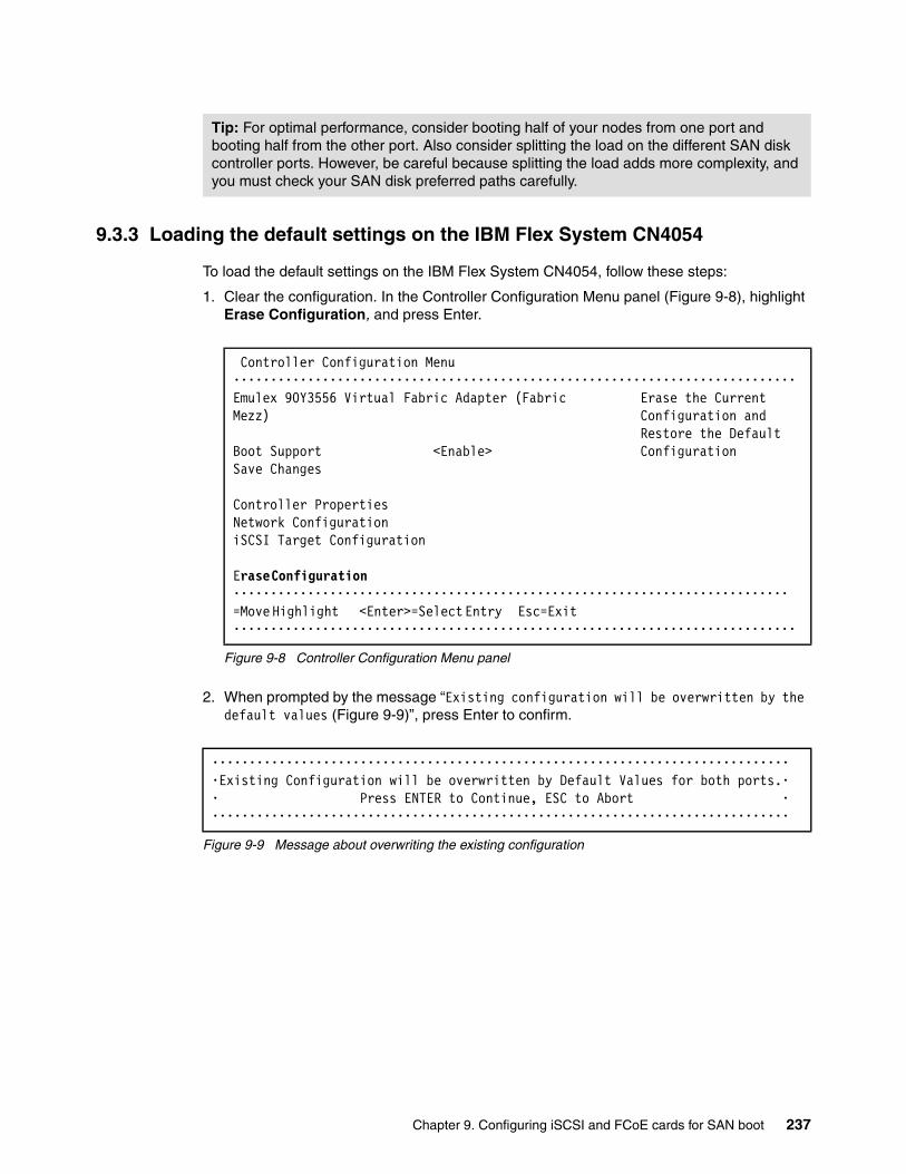
9.3.3 Loading the default settings on the IBM Flex System CN4054
To load the default settings on the IBM Flex System CN4054, follow these steps:
1. Clear the configuration. In the Controller Configuration Menu panel (Figure 9-8), highlight Erase Configuration, and press Enter.
Figure 9-8 Controller Configuration Menu panel
2. When prompted by the message “Existing configuration will be overwritten by the default values (Figure 9-9)”, press Enter to confirm.
Figure 9-9 Message about overwriting the existing configuration
Tip: For optimal performance, consider booting half of your nodes from one port and booting half from the other port. Also consider splitting the load on the different SAN disk controller ports. However, be careful because splitting the load adds more complexity, and you must check your SAN disk preferred paths carefully.
Controller Configuration Menu ••••••••••••••••••••••••••••••••••••••••••••••••••••••••••••••••••••••••••••Emulex 90Y3556 Virtual Fabric Adapter (Fabric Erase the CurrentMezz) Configuration and Restore the DefaultBoot Support <Enable> ConfigurationSave Changes
Controller PropertiesNetwork ConfigurationiSCSI Target Configuration
Erase Configuration ••••••••••••••••••••••••••••••••••••••••••••••••••••••••••••••••••••••••••• =Move Highlight <Enter>=Select Entry Esc=Exit ••••••••••••••••••••••••••••••••••••••••••••••••••••••••••••••••••••••••••••
•••••••••••••••••••••••••••••••••••••••••••••••••••••••••••••••••••••••••••••••Existing Configuration will be overwritten by Default Values for both ports.•• Press ENTER to Continue, ESC to Abort •••••••••••••••••••••••••••••••••••••••••••••••••••••••••••••••••••••••••••••••
Chapter 9. Configuring iSCSI and FCoE cards for SAN boot 237

9.3.4 Configuring the IBM Flex System CN4054 settings
To configure the IBM Flex System CN4054 settings, follow these steps:
1. In the Controller Configuration Menu panel (Figure 9-8 on page 237), select Controller Properties, and press Enter.
2. In the Controller Properties panel (Figure 9-10 here), verify the BIOS and firmware version. Make sure that you are using the latest supported version for your SAN device. Then press Esc.
Figure 9-10 Controller Properties panel
Controller Properties ••••••••••••••••••••••••••••••••••••••••••••••••••••••••••••••••••••••••••••Controller Model Number Emulex 90Y3556 Virtual Controller Model Number Fabric Adapter (Fabric Mezz)Controller Description Emulex 90Y3556 Virtual Fabric Adapter (Fabric Mezz)BIOS Version 4.4.180.0Firmware Version 4.4.180.0 Discover Boot Target via <Disable> DHCP Save Changes ••••••••••••••••••••••••••••••••••••••••••••••••••••••••••••••••••••••••••• =Move Highlight Esc=Exit ••••••••••••••••••••••••••••••••••••••••••••••••••••••••••••••••••••••••••••
238 Storage and Network Convergence Using FCoE and iSCSI

3. In the Controller Configuration Menu panel (Figure 9-8 on page 237), select Network Configuration, and press Enter.
4. In the Network Configuration panel (Figure 9-11 here), follow these steps:
a. Note the MAC address, which might be useful for troubleshooting.
b. Verify that Link Status is set to Link Up.
c. Optional: Select Configure VLAN ID/Priority, and then press Enter.
As a preferred practice, separate the network traffic and disk traffic, for example, by putting the port on its own VLAN.
Figure 9-11 Network Configuration panel
Network Configuration •••••••••••••••••••••••••••••••••••••••••••••••••••••••••••••••••••••••••••••••MAC Address 00-00-C9-DB-40-89 MAC AddressPort Speed 10 GbpsLink Status Link UpDHCP <Disable>
Configure VLAN ID/PrioritySave DHCP Settings Configure Static IP Address Ping •••••••••••••••••••••••••••••••••••••••••••••••••••••••••••••••••••••••••••••• =Move Highlight Esc=Exit •••••••••••••••••••••••••••••••••••••••••••••••••••••••••••••••••••••••••••••••
Chapter 9. Configuring iSCSI and FCoE cards for SAN boot 239
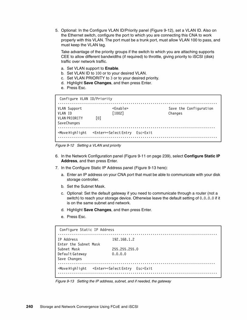
5. Optional: In the Configure VLAN ID/Priority panel (Figure 9-12), set a VLAN ID. Also on the Ethernet switch, configure the port to which you are connecting this CNA to work properly with this VLAN. The port must be a trunk port, must allow VLAN 100 to pass, and must keep the VLAN tag.
Take advantage of the priority groups if the switch to which you are attaching supports CEE to allow different bandwidths (if required) to throttle, giving priority to iSCSI (disk) traffic over network traffic.
a. Set VLAN support to Enable.b. Set VLAN ID to 100 or to your desired VLAN.c. Set VLAN PRIORITY to 3 or to your desired priority.d. Highlight Save Changes, and then press Enter.e. Press Esc.
Figure 9-12 Setting a VLAN and priority
6. In the Network Configuration panel (Figure 9-11 on page 239), select Configure Static IP Address, and then press Enter.
7. In the Configure Static IP Address panel (Figure 9-13 here):
a. Enter an IP address on your CNA port that must be able to communicate with your disk storage controller.
b. Set the Subnet Mask.
c. Optional: Set the default gateway if you need to communicate through a router (not a switch) to reach your storage device. Otherwise leave the default setting of 0.0.0.0 if it is on the same subnet and network.
d. Highlight Save Changes, and then press Enter.
e. Press Esc.
Figure 9-13 Setting the IP address, subnet, and if needed, the gateway
Configure VLAN ID/Priority •••••••••••••••••••••••••••••••••••••••••••••••••••••••••••••••••••••••••••••••VLAN Support <Enable> Save the ConfigurationVLAN ID [1002] Changes VLAN PRIORITY [0] Save Changes •••••••••••••••••••••••••••••••••••••••••••••••••••••••••••••••••••••••••••••• =Move Highlight <Enter>=Select Entry Esc=Exit •••••••••••••••••••••••••••••••••••••••••••••••••••••••••••••••••••••••••••••••
Configure Static IP Address ••••••••••••••••••••••••••••••••••••••••••••••••••••••••••••••••••••••••••••••• IP Address 192.168.1.2 Enter the Subnet Mask Subnet Mask 255.255.255.0 Default Gateway 0.0.0.0 Save Changes •••••••••••••••••••••••••••••••••••••••••••••••••••••••••••••••••••••••••••••• =Move Highlight <Enter>=Select Entry Esc=Exit •••••••••••••••••••••••••••••••••••••••••••••••••••••••••••••••••••••••••••••••
240 Storage and Network Convergence Using FCoE and iSCSI

8. Perform a ping test. In the Network Configuration panel (Figure 9-14), select Ping.
Figure 9-14 Selecting Ping from the Network Configuration panel
9. In the Ping panel (Figure 9-15), enter the IP address of your disk storage subsystem. If the connections are working correctly, a reply is displayed (inset in Figure 9-15) that shows the IP address and time.
Figure 9-15 Successful ping reply
Network Configuration •••••••••••••••••••••••••••••••••••••••••••••••••••••••••••••••••••••••••••••••MAC Address 00-00-C9-DB-40-89 PingPort Speed 10 GbpsLink Status Link UpDHCP <Disable>
Configure VLAN ID/PrioritySave DHCP SettingsConfigure Static IP AddressPing
•••••••••••••••••••••••••••••••••••••••••••••••••••••••••••••••••••••••••••••• =Move Highlight <Enter>=Select Entry Esc=Exit •••••••••••••••••••••••••••••••••••••••••••••••••••••••••••••••••••••••••••••••
Ping •••••••••••••••••••••••••••••••••••••••••••••••••••••••••••••••••••••••••••••••IP Address _ Enter the IP Address
•••••••••••••••••••••••••• • • •••••••••••••••••••••••••••••••••••••••••••• •Reply From 192.168.1.100: time 10ms TTL=0 • •••••••••••••••••••••••••••••••••••••••••••• ••••••••••••••••••••••••••
•••••••••••••••••••••••••••••••••••••••••••••••••••••••••••••••••••••••••••••• <Enter>=Complete Entry Esc=Exit •••••••••••••••••••••••••••••••••••••••••••••••••••••••••••••••••••••••••••••••
Chapter 9. Configuring iSCSI and FCoE cards for SAN boot 241
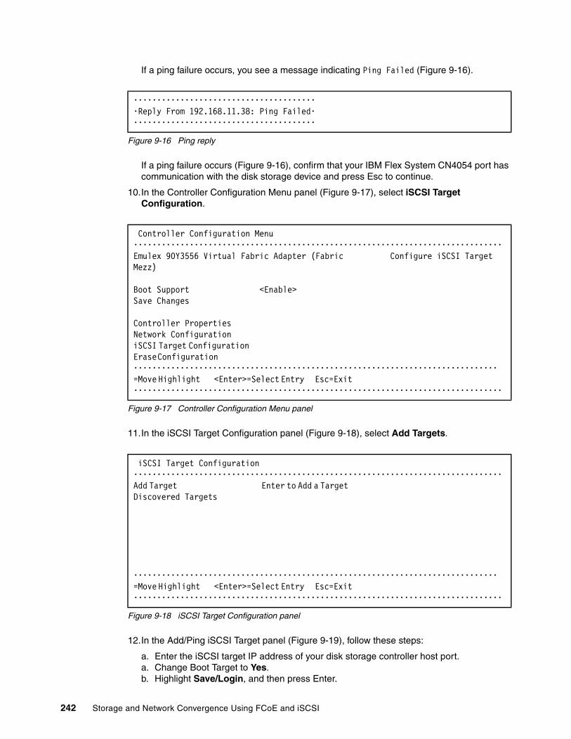
If a ping failure occurs, you see a message indicating Ping Failed (Figure 9-16).
Figure 9-16 Ping reply
If a ping failure occurs (Figure 9-16), confirm that your IBM Flex System CN4054 port has communication with the disk storage device and press Esc to continue.
10.In the Controller Configuration Menu panel (Figure 9-17), select iSCSI Target Configuration.
Figure 9-17 Controller Configuration Menu panel
11.In the iSCSI Target Configuration panel (Figure 9-18), select Add Targets.
Figure 9-18 iSCSI Target Configuration panel
12.In the Add/Ping iSCSI Target panel (Figure 9-19), follow these steps:
a. Enter the iSCSI target IP address of your disk storage controller host port.a. Change Boot Target to Yes.b. Highlight Save/Login, and then press Enter.
••••••••••••••••••••••••••••••••••••••••Reply From 192.168.11.38: Ping Failed••••••••••••••••••••••••••••••••••••••••
Controller Configuration Menu •••••••••••••••••••••••••••••••••••••••••••••••••••••••••••••••••••••••••••••••Emulex 90Y3556 Virtual Fabric Adapter (Fabric Configure iSCSI TargetMezz)
Boot Support <Enable>Save Changes
Controller PropertiesNetwork ConfigurationiSCSI Target Configuration Erase Configuration •••••••••••••••••••••••••••••••••••••••••••••••••••••••••••••••••••••••••••••• =Move Highlight <Enter>=Select Entry Esc=Exit •••••••••••••••••••••••••••••••••••••••••••••••••••••••••••••••••••••••••••••••
iSCSI Target Configuration ••••••••••••••••••••••••••••••••••••••••••••••••••••••••••••••••••••••••••••••• Add Target Enter to Add a Target Discovered Targets
•••••••••••••••••••••••••••••••••••••••••••••••••••••••••••••••••••••••••••••• =Move Highlight <Enter>=Select Entry Esc=Exit •••••••••••••••••••••••••••••••••••••••••••••••••••••••••••••••••••••••••••••••
242 Storage and Network Convergence Using FCoE and iSCSI

Figure 9-19 Add/Ping iSCSI Target window
The iSCSI Target Configuration panel now shows one discovered target (Figure 9-20), because the storage device has four host ports.
c. Highlight the host port of the disk storage subsystem that you want to boot from, and press the Space bar. Select a single target to boot from.
In this example, the IBM Flex System CN4054 iSCSI IP is 192.168.1.2. All of the host ports are on different subnets and VLANs. We booted from the disk storage subsystem host port that is in the same subnet as the IBM Flex System CN4054 port, 192.168.1.100.
If you do not see any storage devices in the iSCSI Target Configuration panel, see “Storage devices not shown” on page 246.
d. Using the arrow keys, move the cursor down to highlight Save Target, and then press Enter (Figure 9-20).
Figure 9-20 Discovered targets and Saving the discovered target
Add/Ping iSCSI Target •••••••••••••••••••••••••••••••••••••••••••••••••••••••••••••••••••••••••••••••iSCSI Target Name _ Boot From This TargetIP Version <IPV4>iSCSI Target IP Address 192.168.1.100TCP Port Number [3260]BladeEngine Port Number 0ISID Qualifier [1]Boot Target <Yes>Header Digest <No>Data Digest <No>Authentication Method <None>Ping Save/Login •••••••••••••••••••••••••••••••••••••••••••••••••••••••••••••••••••••••••••••• =Move Highlight <Enter>=Select Entry Esc=Exit •••••••••••••••••••••••••••••••••••••••••••••••••••••••••••••••••••••••••••••••
iSCSI Target Configuration •••••••••••••••••••••••••••••••••••••••••••••••••••••••••••••••••••••••••••••••Discovered Targets Select the Target toiqn.1986-03.com.ibm:2145.v [X] Edit the Configuration3700.node1 IP Address:Save Target 192.168.1.100 IP Version: IPV4 TCP Port: 3260 Boot Target: No Connection Status: No •••••••••••••••••••••••••••••••••••••••••••••••••••••••••••••••••••••••••••••• =Move Highlight <Spacebar>Toggle Checkbox Esc=Exit •••••••••••••••••••••••••••••••••••••••••••••••••••••••••••••••••••••••••••••••
Chapter 9. Configuring iSCSI and FCoE cards for SAN boot 243
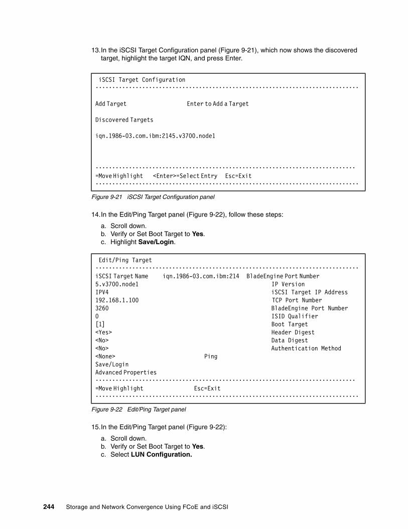
13.In the iSCSI Target Configuration panel (Figure 9-21), which now shows the discovered target, highlight the target IQN, and press Enter.
Figure 9-21 iSCSI Target Configuration panel
14.In the Edit/Ping Target panel (Figure 9-22), follow these steps:
a. Scroll down.b. Verify or Set Boot Target to Yes. c. Highlight Save/Login.
Figure 9-22 Edit/Ping Target panel
15.In the Edit/Ping Target panel (Figure 9-22):
a. Scroll down.b. Verify or Set Boot Target to Yes. c. Select LUN Configuration.
iSCSI Target Configuration •••••••••••••••••••••••••••••••••••••••••••••••••••••••••••••••••••••••••••••••
Add Target Enter to Add a Target
Discovered Targets
iqn.1986-03.com.ibm:2145.v3700.node1
•••••••••••••••••••••••••••••••••••••••••••••••••••••••••••••••••••••••••••••• =Move Highlight <Enter>=Select Entry Esc=Exit •••••••••••••••••••••••••••••••••••••••••••••••••••••••••••••••••••••••••••••••
Edit/Ping Target ••••••••••••••••••••••••••••••••••••••••••••••••••••••••••••••••••••••••••••••• iSCSI Target Name iqn.1986-03.com.ibm:214 BladeEngine Port Number 5.v3700.node1 IP Version IPV4 iSCSI Target IP Address 192.168.1.100 TCP Port Number 3260 BladeEngine Port Number 0 ISID Qualifier [1] Boot Target <Yes> Header Digest <No> Data Digest <No> Authentication Method <None> Ping Save/Login Advanced Properties •••••••••••••••••••••••••••••••••••••••••••••••••••••••••••••••••••••••••••••• =Move Highlight Esc=Exit •••••••••••••••••••••••••••••••••••••••••••••••••••••••••••••••••••••••••••••••
244 Storage and Network Convergence Using FCoE and iSCSI
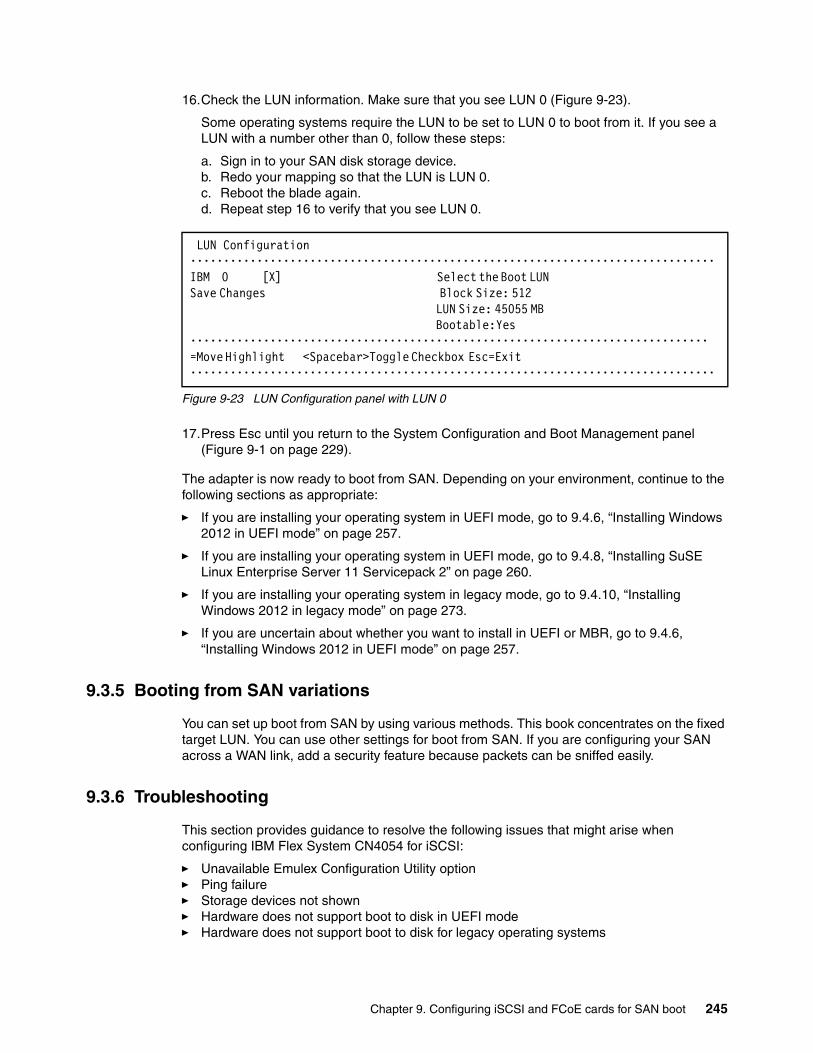
16.Check the LUN information. Make sure that you see LUN 0 (Figure 9-23).
Some operating systems require the LUN to be set to LUN 0 to boot from it. If you see a LUN with a number other than 0, follow these steps:
a. Sign in to your SAN disk storage device.b. Redo your mapping so that the LUN is LUN 0. c. Reboot the blade again.d. Repeat step 16 to verify that you see LUN 0.
Figure 9-23 LUN Configuration panel with LUN 0
17.Press Esc until you return to the System Configuration and Boot Management panel (Figure 9-1 on page 229).
The adapter is now ready to boot from SAN. Depending on your environment, continue to the following sections as appropriate:
� If you are installing your operating system in UEFI mode, go to 9.4.6, “Installing Windows 2012 in UEFI mode” on page 257.
� If you are installing your operating system in UEFI mode, go to 9.4.8, “Installing SuSE Linux Enterprise Server 11 Servicepack 2” on page 260.
� If you are installing your operating system in legacy mode, go to 9.4.10, “Installing Windows 2012 in legacy mode” on page 273.
� If you are uncertain about whether you want to install in UEFI or MBR, go to 9.4.6, “Installing Windows 2012 in UEFI mode” on page 257.
9.3.5 Booting from SAN variations
You can set up boot from SAN by using various methods. This book concentrates on the fixed target LUN. You can use other settings for boot from SAN. If you are configuring your SAN across a WAN link, add a security feature because packets can be sniffed easily.
9.3.6 Troubleshooting
This section provides guidance to resolve the following issues that might arise when configuring IBM Flex System CN4054 for iSCSI:
� Unavailable Emulex Configuration Utility option� Ping failure� Storage devices not shown� Hardware does not support boot to disk in UEFI mode� Hardware does not support boot to disk for legacy operating systems
LUN Configuration ••••••••••••••••••••••••••••••••••••••••••••••••••••••••••••••••••••••••••••••• IBM 0 [X] Select the Boot LUN Save Changes Block Size: 512
LUN Size: 45055 MB Bootable: Yes
•••••••••••••••••••••••••••••••••••••••••••••••••••••••••••••••••••••••••••••• =Move Highlight <Spacebar>Toggle Checkbox Esc=Exit •••••••••••••••••••••••••••••••••••••••••••••••••••••••••••••••••••••••••••••••
Chapter 9. Configuring iSCSI and FCoE cards for SAN boot 245

Unavailable Emulex Configuration Utility optionIn the procedure in 9.3.2, “Configuring the IBM Flex System CN4054” on page 235, if you do not see the Emulex Configuration Utility option, verify that the following items are correct before proceeding:
� Ensure that the BIOS or firmware on the CNA is at the correct level.
� Ensure that the card is seated firmly in the slot.
� Ensure that the system UEFI is at the current supported level.
� Ensure that the iSCSI or FCoE license is installed on the adapter. If the license is not installed, the adapter will not work. Therefore, you must contact your IBM marketing representative or vendor to obtain the license.
� The Virtual Fabric Adapter is set to NIC only or iSCSI. Both provide the same result.
Ping failureIn the procedure in 9.3.4, “Configuring the IBM Flex System CN4054 settings” on page 238, if a ping failure occurs, check whether you see the following items, and then perform the ping test again:
� Check for typographical errors in the following areas:
– IP address to ping– IP address, subnet, or gateway of the CNA port– IP address, subnet, or gateway of the disk storage subsystem host port
� Verify that the Ethernet cable is connected securely, or check pins to make sure that no pins are bent or missing.
� Recheck your configuration settings to ensure that you do not have a bad switch setup (VLAN, trunking, allowed VLAN, or VLAN down).
� Check the connectivity of the storage device and configuration settings if the disk storage device cannot answer an ICMP request on the host ports.
� Check firewall settings to ensure that access is not blocked.
Storage devices not shownFor you to see your storage devices, you must perform the steps as explained in 9.3.4, “Configuring the IBM Flex System CN4054 settings” on page 238. If you do not see your storage devices, see 9.3.1, “Configuring IBM Flex System CN4054 for boot from SAN” on page 232, to ensure that everything is in place on the SAN for the setup to work.
Hardware does not support boot to disk in UEFI modeIn the procedure in 9.4.7, “Booting the Windows DVD in UEFI mode” on page 258, you might receive a message that indicates that the hardware might not support boot to disk. If you see this message, review the setup instructions in 9.3.1, “Configuring IBM Flex System CN4054 for boot from SAN” on page 232, and then check the following settings:
� Verify that the boot device was added when you pressed F1 (go back and check).
� Verify that the BIOS is enabled on the IBM Flex System CN4054 port (go back and check).
Tip: Check the switch configuration, delete your mapping, and remap. When remapped, check the preferred path. These tasks take time, but often correct the error. Then reboot your system and check again if the storage devices are displayed.
246 Storage and Network Convergence Using FCoE and iSCSI

� Verify that the CNA from which you are trying to boot is on the preferred path of the SAN disk. The most common cause of an offline disk is that the preferred path is not assigned correctly. Check your SAN disk device configuration, and then reboot the server again on the Windows DVD.
� Verify that your SAN disk supports a UEFI boot.
� Verify that your SAN disk is updated to the latest firmware.
� Try to perform a legacy installation.
� If the disk is offline, see Windows KB 2345135, “Setup reports error ‘Windows cannot be installed to this disk...’ when booted from DVD” at this website:
http://support.microsoft.com/kb/2345135
� If setup reports the error message “Windows cannot be installed to this disk...” booted from DVD in UEFI mode, consider modifying the Windows installation media.
� Use Windows media that is bundled with the latest service pack.
� If you see a 20-MB disk, you most likely mapped the access LUN instead of the actual LUN. To correct this problem, log in to your disk storage subsystem.
� Make sure that your LUN is using LUN 0, which is defined in the SAN disk device.
� Make sure that you are using the latest Windows DVD with the latest service pack built-in.
� Verify that the path is on the preferred path. Check with your SAN configuration.
� Verify that zoning is correct or unchanged.
� Verify that LUN mapping is correct or unchanged.
Hardware does not support boot to disk for legacy operating systemsIn the procedure in 9.4.11, “Optimizing the boot for legacy operating systems” on page 274, you might receive a message that indicates that the hardware might not support boot to disk. If you see this message, review the setup instructions in 9.3.1, “Configuring IBM Flex System CN4054 for boot from SAN” on page 232, and then check the following settings:
� Verify that the boot device was added when you pressed F1 (go back and check).
� Verify that the BIOS was enabled on the Emulex port (go back and check).
� Verify that the CNA that you are trying to boot from is on the SAN disk preferred path. The most common cause of an offline disk is that the preferred path is not assigned correctly. Check your SAN disk device configuration, and then reboot the server again on the Windows DVD.
� Verify that your SAN disk is updated to the latest firmware.
� Use Windows media that is bundled with the latest service pack.
� If you see a 20-MB disk, you most likely mapped the access LUN instead of the actual LUN. You can fix this problem in your disk storage subsystem.
� Verify that your LUN is using LUN 0, which is defined in the SAN disk device.
� Verify that you are using the latest Windows DVD with the latest service pack built-in.
� Verify that the path is the preferred path. Check with your SAN configuration.
� Verify that LUN mapping is correct or unchanged.
Chapter 9. Configuring iSCSI and FCoE cards for SAN boot 247
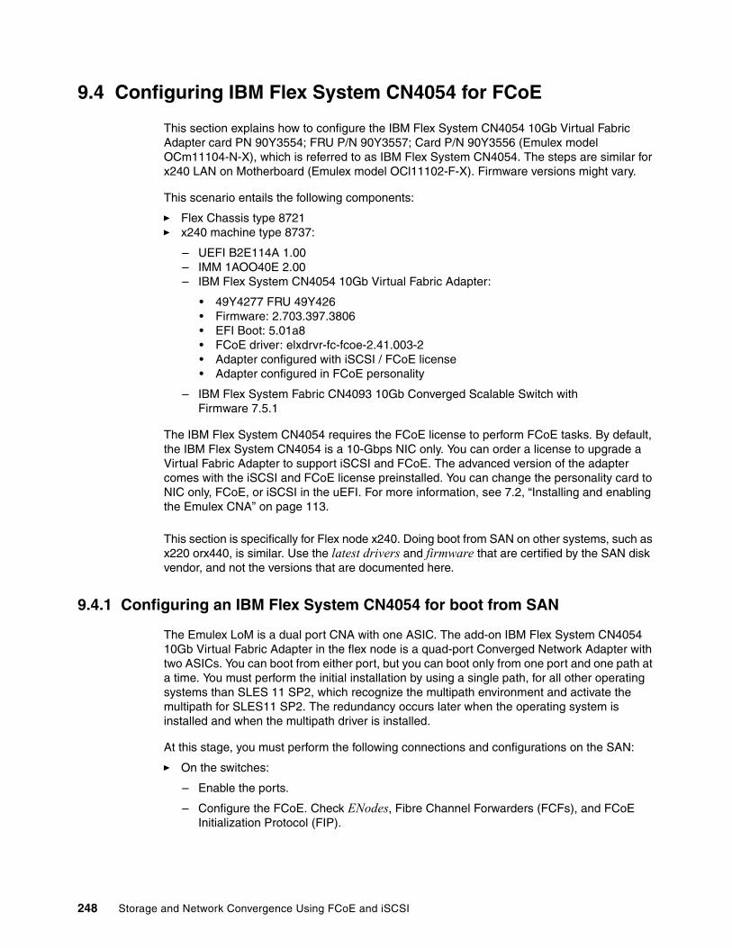
9.4 Configuring IBM Flex System CN4054 for FCoE
This section explains how to configure the IBM Flex System CN4054 10Gb Virtual Fabric Adapter card PN 90Y3554; FRU P/N 90Y3557; Card P/N 90Y3556 (Emulex model OCm11104-N-X), which is referred to as IBM Flex System CN4054. The steps are similar for x240 LAN on Motherboard (Emulex model OCl11102-F-X). Firmware versions might vary.
This scenario entails the following components:
� Flex Chassis type 8721� x240 machine type 8737:
– UEFI B2E114A 1.00– IMM 1AOO40E 2.00– IBM Flex System CN4054 10Gb Virtual Fabric Adapter:
• 49Y4277 FRU 49Y426• Firmware: 2.703.397.3806• EFI Boot: 5.01a8• FCoE driver: elxdrvr-fc-fcoe-2.41.003-2• Adapter configured with iSCSI / FCoE license• Adapter configured in FCoE personality
– IBM Flex System Fabric CN4093 10Gb Converged Scalable Switch with Firmware 7.5.1
The IBM Flex System CN4054 requires the FCoE license to perform FCoE tasks. By default, the IBM Flex System CN4054 is a 10-Gbps NIC only. You can order a license to upgrade a Virtual Fabric Adapter to support iSCSI and FCoE. The advanced version of the adapter comes with the iSCSI and FCoE license preinstalled. You can change the personality card to NIC only, FCoE, or iSCSI in the uEFI. For more information, see 7.2, “Installing and enabling the Emulex CNA” on page 113.
This section is specifically for Flex node x240. Doing boot from SAN on other systems, such as x220 orx440, is similar. Use the latest drivers and firmware that are certified by the SAN disk vendor, and not the versions that are documented here.
9.4.1 Configuring an IBM Flex System CN4054 for boot from SAN
The Emulex LoM is a dual port CNA with one ASIC. The add-on IBM Flex System CN4054 10Gb Virtual Fabric Adapter in the flex node is a quad-port Converged Network Adapter with two ASICs. You can boot from either port, but you can boot only from one port and one path at a time. You must perform the initial installation by using a single path, for all other operating systems than SLES 11 SP2, which recognize the multipath environment and activate the multipath for SLES11 SP2. The redundancy occurs later when the operating system is installed and when the multipath driver is installed.
At this stage, you must perform the following connections and configurations on the SAN:
� On the switches:
– Enable the ports.
– Configure the FCoE. Check ENodes, Fibre Channel Forwarders (FCFs), and FCoE Initialization Protocol (FIP).
248 Storage and Network Convergence Using FCoE and iSCSI

– Ensure that the node has a connection all the way to the disk storage subsystem.
– On the FC/FCoE side, ensure that the disk storage subsystem and the IBM Flex System CN4054 worldwide port name (WWPN) are present in the name server or Fabric Login (FLOGI) table.
– Configure zoning. The zone must contain one IBM Flex System CN4054 WWPN and one SAN disk controller WWPN. Zoning is done on the converged or fiber switch. Some people might decide to function with an open fabric, without any zoning. However, over time, this setup is likely to fail or cause problems.
You can zone the following switches:
• A Brocade switch by using the Zone Admin function• A QLogic switch by selecting Zoning Edit Zoning• A Cisco switch by using the Device Manager and selecting FC Quick Config
Wizard• A converged System Networking switch by selecting FC/FCoE Zoning
Use the command-line interface (CLI) for more advanced configurations.
� On the disk storage subsystem:
– Ensure that the storage subsystem and SAN disk have a logical drive (LUN) created and mapped to the WWPN of the IBM Flex System CN4054 of the nodes.
– The LUN might require you to wait for it to be fully initialized before using it.
– When you create a LUN normally, a synchronization process starts. With some storage, you can work with this LUN when it is synchronizing. Other storage might require you to wait for the LUN to be fully initialized. For information about how it operates, see your storage documentation for your SAN disk storage.
– Map the LUN to a single CNA WWPN. Do not map both WWPNs yet. You map it to both IBM Flex System CN4054 WWPNs later. At installation time, restrict this mapping to a single path. Otherwise, a stop error (blue screen) or other installation issues can occur.
– For an asymmetrical storage subsystem only, set the LUN on the correct path that you want to boot from.
Some SANs are asymmetrical storage subsystems, such as the IBM System Storage DS3000, DS4000, and DS5000 series. Other SANs are symmetrical storage subsystems, such as V7000, V3700, SAN Volume Controller and IBM System Storage DS8000. The asymmetrical storage subsystems controllers set a preferred path. The preferred path must be set to communicate to your IBM Flex System CN4054 WWPN.
– The LUN on most SANs is presented to a single controller at a time. This LUN can move from controller A to controller B.
– At installation time, the operating system does not have its redundant driver loaded and, therefore, does not handle redundant paths. To work around this issue, provide a single path.
ENodes: ENodes are the combination of FCoE termination functions and Fibre Channel stack on the CNAs. In that sense, they are equivalent to HBAs in native Fibre Channel networks.
Chapter 9. Configuring iSCSI and FCoE cards for SAN boot 249

– If you are booting through IBM Flex System CN4054 port 0, which has a WWPN, and port 0 communicates to controller A1, the preferred path for your LUN is A on the SAN disk. If you are booting through IBM Flex System CN4054 port 0, have a WWPN, and port 0 communicates to controller B1, the preferred path for your LUN is B on the SAN disk.
– The preferred path is normally easy to change in the SAN disk settings.
You must know your environment, cabling, and setup, which you can validate by checking cable connections, the SAN disk configuration, or logs.
9.4.2 Configuring the IBM Flex System CN4054
To configure the IBM Flex System CN4054, follow these steps:
1. During start or POST, press the F1 key.
2. In the System Configuration and Boot Management panel, select System Settings.
3. In the System Settings panel (Figure 9-24), select Emulex Configuration Utility Ver: x.xxxxx.
Figure 9-24 System Settings panel
If you do not see the Emulex Configuration Utility option, see “Unavailable Emulex Configuration Utility option” on page 367.
Then press Enter.
System Settings •••••••••••••••••••••••••••••••••••••••••••••••••••••••••••••••••••••••••••••••Adapters and UEFI Drivers This option is onlyProcessors for older generationMemory UEFI drivers toDevices and I/O Ports configure theirPower corresponding device.Operating ModesLegacy SupportSystem SecurityIntegrated Management ModuleRecoveryNetworkEmulex Configuration Utility Ver:5.10a5Driver Health
•••••••••••••••••••••••••••••••••••••••••••••••••••••••••••••••••••••••••••••• =Move Highlight <Enter>=Select Entry Esc=Exit
•••••••••••••••••••••••••••••••••••••••••••••••••••••••••••••••••••••••••••••••
250 Storage and Network Convergence Using FCoE and iSCSI

4. In the Adapter Selection panel (Figure 9-25), where you see two/four Emulex fiber ports, select the Emulex Configuration Setup Utility. If you do not see the entry, see 7.2, “Installing and enabling the Emulex CNA” on page 113.
Figure 9-25 Adapter Selection panel
5. Note the WWPN of the IBM Flex System CN4054. Select the port you want to boot from, and then press Enter.
Adapter Selection •••••••••••••••••••••••••••••••••••••••••••••••••••••••••••••••••••••••••••••••Emulex Adapters in this System: Port Name : 10000000C9DB4089Exit Emulex HBA Configuration Utility Node Name :001: 90Y3556 PCIe5.0Gb/s , x8 20000000C9DB4089002: 90Y3556 PCIe5.0Gb/s , x8 Seg#: 00 Bus#: 11003: 90Y3556 PCIe5.0Gb/s , x8 Dev#: 00 Func#: 02004: 90Y3556 PCIe5.0Gb/s , x8
•••••••••••••••••••••••••••••••••••••••••••••••••••••••••••••••••••••••••••••• =Move Highlight <Enter>=Select Entry Esc=Exit •••••••••••••••••••••••••••••••••••••••••••••••••••••••••••••••••••••••••••••••
Tip: For optimal performance, consider booting half of your blades from one port and booting half from the other port. Also consider splitting the load on the different SAN disk controller ports. However, be careful because splitting the load adds more complexity, and check your SAN disk preferred paths carefully.
Chapter 9. Configuring iSCSI and FCoE cards for SAN boot 251

9.4.3 Loading the default settings on the IBM Flex System CN4054
To load the default settings on the IBM Flex System CN4054, follow these steps:
1. In the Emulex Adapter Configuration Main Menu panel (Figure 9-26), select Set Emulex Adapter to Default Settings.
Figure 9-26 Emulex Adapter Configuration Main Menu panel
2. In the Set Emulex Adapter to Default Settings panel (Figure 9-27), select Set Adapter Defaults to load the default settings on all IBM Flex System CN4054 ports.
Figure 9-27 Set Emulex Adapter to the Default Settings panel
Emulex Adapter Configuration Main Menu •••••••••••••••••••••••••••••••••••••••••••••••••••••••••••••••••••••••••••••••Seg#: 00 Bus#: 11 Dev#: 00 Func#: 02 Set Emulex Adapter to90Y3556 Node Name : 20000000C9DB4089 Default Settings
Back to Display Adapters and RECONNECT DEVICESSet Boot from SAN <Enable>Configure DCBX Mode <CEE>Configure CEE FCF ParametersConfigure CIN FCF ParametersScan for Fibre DevicesAdd Boot DeviceDelete Boot DeviceChange Boot Device OrderConfigure HBA and Boot ParametersSet Emulex Adapter to Default Settings •••••••••••••••••••••••••••••••••••••••••••••••••••••••••••••••••••••••••••••• =Move Highlight <Enter>=Select Entry Esc=Exit •••••••••••••••••••••••••••••••••••••••••••••••••••••••••••••••••••••••••••••••
Set Emulex Adapter to Default Settings •••••••••••••••••••••••••••••••••••••••••••••••••••••••••••••••••••••••••••••••90Y3556 Node Name : 20000000C9DB4089 Set Adapter DefaultsSeg#: 00 Bus#: 11 Dev#: 00 Func#: 02
Set Adapter DefaultsCancel Set Defaults
•••••••••••••••••••••••••••••••••••••••••••••••••••••••••••••••••••••••••••••• =Move Highlight <Enter>=Select Entry Esc=Exit •••••••••••••••••••••••••••••••••••••••••••••••••••••••••••••••••••••••••••••••
252 Storage and Network Convergence Using FCoE and iSCSI

9.4.4 Configuring the IBM Flex System CN4054 settings
To configure the IBM Flex System CN4054 settings, follow these steps:
1. Select Edit Adapter Settings.
2. In the Emulex iSCSI EFI Configuration Utility panel, select Emulex Configuration Setup Utility.
3. In the Emulex Adapter Configuration Main Menu panel (Figure 9-28):
a. Select the port you want to use for boot from SAN.
b. Change Set Boot from SAN to Enable.
c. Change Configure DCBX Mode to CEE. Although CIN is pre-standard to FCoE, do not use it.
d. Click more to scroll down the page.
e. Click Display Adapter Info.
Figure 9-28 Emulex Adapter Configuration Main Menu panel
Emulex Adapter Configuration Main Menu •••••••••••••••••••••••••••••••••••••••••••••••••••••••••••••••••••••••••••••••Seg#: 00 Bus#: 11 Dev#: 00 Func#: 02 Set Emulex Adapter to90Y3556 Node Name : 20000000C9DB4089 Default Settings
Back to Display Adapters and RECONNECT DEVICESSet Boot from SAN <Enable>Configure DCBX Mode <CEE>Configure CEE FCF ParametersConfigure CIN FCF ParametersScan for Fibre DevicesAdd Boot DeviceDelete Boot DeviceChange Boot Device Order Configure HBA and Boot Parameters Set Emulex Adapter to Default Settings •••••••••••••••••••••••••••••••••••••••••••••••••••••••••••••••••••••••••••••• =Move Highlight <Enter>=Select Entry Esc=Exit •••••••••••••••••••••••••••••••••••••••••••••••••••••••••••••••••••••••••••••••
Chapter 9. Configuring iSCSI and FCoE cards for SAN boot 253

4. In the Controller Information panel (Figure 9-29), review the firmware information, and ensure that you are using the latest codes levels that are certified by your SAN vendor. Then press Esc.
Figure 9-29 Controller Information window
5. Press Esc until you return to the System Configuration and Boot Management panel (Figure 9-1 on page 229).
6. In the System Configuration and Boot Management panel, highlight Save Settings, and then press Enter.
7. In the System Configuration and Boot Management panel, select Boot Manager.
8. Select Reset System. The system reboots.
9. When prompted, press F1.
10.In the System Configuration and Boot Management panel, select System Settings.
11.In the System Settings panel, select Emulex Configuration Utility ver: x.xxxx.
12.Select Emulex Configuration Utility.
13.When you see two/four Emulex fiber ports, select the port you want to boot from. You must select the same port that you selected earlier. Then press Enter.
14.Select Add Boot Device. The IBM Flex System CN4054 adapter scans for SAN devices, which might take some time.
Controller Information •••••••••••••••••••••••••••••••••••••••••••••••••••••••••••••••••••••••••••••••001: 90Y3556 PCIe5.0Gb/s , x8 Go to ConfigurationSeg#: 00 Bus#: 11 Dev#: 00 Func#: 02 Main Menu
Go to Configuration Main MenuLink Status: Up VLANID: 03EABoot from SAN: EnabledFirmware : 4.4.180.0EFI Boot : 5.10a5Link Speed: NA •••••••••••••••••••••••••••••••••••••••••••••••••••••••••••••••••••••••••••••• =Move Highlight <Enter>=Select Entry Esc=Exit •••••••••••••••••••••••••••••••••••••••••••••••••••••••••••••••••••••••••••••••
Note: If you only have one Storage System and you have LUN0 as boot LUN, the following steps not necessary.
254 Storage and Network Convergence Using FCoE and iSCSI
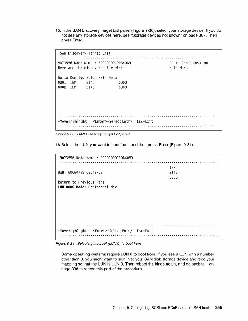
15.In the SAN Discovery Target List panel (Figure 9-30), select your storage device. If you do not see any storage devices here, see “Storage devices not shown” on page 367. Then press Enter.
Figure 9-30 SAN Discovery Target List panel
16.Select the LUN you want to boot from, and then press Enter (Figure 9-31).
Figure 9-31 Selecting the LUN (LUN 0) to boot from
Some operating systems require LUN 0 to boot from. If you see a LUN with a number other than 0, you might want to sign in to your SAN disk storage device and redo your mapping so that the LUN is LUN 0. Then reboot the blade again, and go back to 1 on page 338 to repeat this part of the procedure.
SAN Discovery Target List •••••••••••••••••••••••••••••••••••••••••••••••••••••••••••••••••••••••••••••••90Y3556 Node Name : 20000000C9DB4089 Go to ConfigurationHere are the discovered targets: Main Menu
Go to Configuration Main Menu0001: IBM 2145 00000002: IBM 2145 0000
•••••••••••••••••••••••••••••••••••••••••••••••••••••••••••••••••••••••••••••• =Move Highlight <Enter>=Select Entry Esc=Exit •••••••••••••••••••••••••••••••••••••••••••••••••••••••••••••••••••••••••••••••
90Y3556 Node Name : 20000000C9DB4089 ••••••••••••••••••••••••••••••••••••••••••••••••••••••••••••••••••••••••••••••• IBMWWN: 50050768 0304376B 2145 0000Return to Previous PageLUN:0000 Mode: Peripheral dev
•••••••••••••••••••••••••••••••••••••••••••••••••••••••••••••••••••••••••••••• =Move Highlight <Enter>=Select Entry Esc=Exit •••••••••••••••••••••••••••••••••••••••••••••••••••••••••••••••••••••••••••••••
Chapter 9. Configuring iSCSI and FCoE cards for SAN boot 255
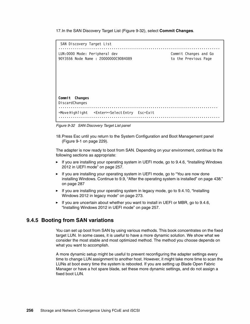
17.In the SAN Discovery Target List (Figure 9-32), select Commit Changes.
Figure 9-32 SAN Discovery Target List panel
18.Press Esc until you return to the System Configuration and Boot Management panel (Figure 9-1 on page 229).
The adapter is now ready to boot from SAN. Depending on your environment, continue to the following sections as appropriate:
� If you are installing your operating system in UEFI mode, go to 9.4.6, “Installing Windows 2012 in UEFI mode” on page 257.
� If you are installing your operating system in UEFI mode, go to “You are now done installing Windows. Continue to 9.9, “After the operating system is installed” on page 438.” on page 287
� If you are installing your operating system in legacy mode, go to 9.4.10, “Installing Windows 2012 in legacy mode” on page 273.
� If you are uncertain about whether you want to install in UEFI or MBR, go to 9.4.6, “Installing Windows 2012 in UEFI mode” on page 257.
9.4.5 Booting from SAN variations
You can set up boot from SAN by using various methods. This book concentrates on the fixed target LUN. In some cases, it is useful to have a more dynamic solution. We show what we consider the most stable and most optimized method. The method you choose depends on what you want to accomplish.
A more dynamic setup might be useful to prevent reconfiguring the adapter settings every time to change LUN assignment to another host. However, it might take more time to scan the LUNs at boot every time the system is rebooted. If you are setting up Blade Open Fabric Manager or have a hot spare blade, set these more dynamic settings, and do not assign a fixed boot LUN.
SAN Discovery Target List •••••••••••••••••••••••••••••••••••••••••••••••••••••••••••••••••••••••••••••••LUN:0000 Mode: Peripheral dev Commit Changes and Go90Y3556 Node Name : 20000000C9DB4089 to the Previous Page
Commit ChangesDiscard Changes •••••••••••••••••••••••••••••••••••••••••••••••••••••••••••••••••••••••••••••• =Move Highlight <Enter>=Select Entry Esc=Exit •••••••••••••••••••••••••••••••••••••••••••••••••••••••••••••••••••••••••••••••
256 Storage and Network Convergence Using FCoE and iSCSI
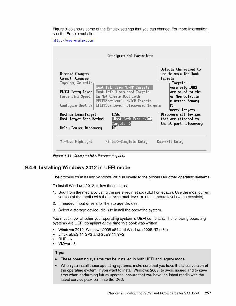
Figure 9-33 shows some of the Emulex settings that you can change. For more information, see the Emulex website:
http://www.emulex.com
Figure 9-33 Configure HBA Parameters panel
9.4.6 Installing Windows 2012 in UEFI mode
The process for installing Windows 2012 is similar to the process for other operating systems.
To install Windows 2012, follow these steps:
1. Boot from the media by using the preferred method (UEFI or legacy). Use the most current version of the media with the service pack level or latest update level (when possible).
2. If needed, input drivers for the storage devices.
3. Select a storage device (disk) to install the operating system.
You must know whether your operating system is UEFI-compliant. The following operating systems are UEFI-compliant at the time this book was written:
� Windows 2012, Windows 2008 x64 and Windows 2008 R2 (x64)� Linux SLES 11 SP2 and SLES 11 SP2� RHEL 6� VMware 5
Tips:
� These operating systems can be installed in both UEFI and legacy mode.
� When you install these operating systems, make sure that you have the latest version of the operating system. If you want to install Windows 2008, to avoid issues and to save time when performing future updates, ensure that you have the latest media with the latest service pack built into the DVD.
Chapter 9. Configuring iSCSI and FCoE cards for SAN boot 257
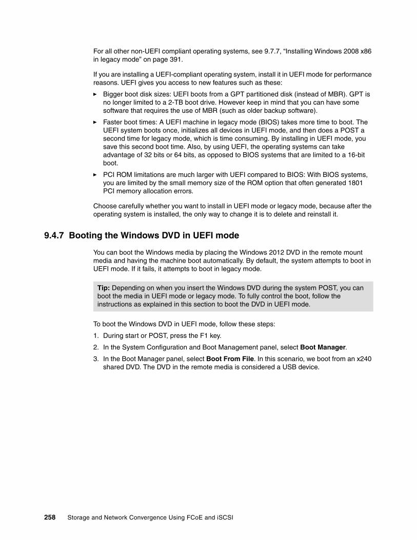
For all other non-UEFI compliant operating systems, see 9.7.7, “Installing Windows 2008 x86 in legacy mode” on page 391.
If you are installing a UEFI-compliant operating system, install it in UEFI mode for performance reasons. UEFI gives you access to new features such as these:
� Bigger boot disk sizes: UEFI boots from a GPT partitioned disk (instead of MBR). GPT is no longer limited to a 2-TB boot drive. However keep in mind that you can have some software that requires the use of MBR (such as older backup software).
� Faster boot times: A UEFI machine in legacy mode (BIOS) takes more time to boot. The UEFI system boots once, initializes all devices in UEFI mode, and then does a POST a second time for legacy mode, which is time consuming. By installing in UEFI mode, you save this second boot time. Also, by using UEFI, the operating systems can take advantage of 32 bits or 64 bits, as opposed to BIOS systems that are limited to a 16-bit boot.
� PCI ROM limitations are much larger with UEFI compared to BIOS: With BIOS systems, you are limited by the small memory size of the ROM option that often generated 1801 PCI memory allocation errors.
Choose carefully whether you want to install in UEFI mode or legacy mode, because after the operating system is installed, the only way to change it is to delete and reinstall it.
9.4.7 Booting the Windows DVD in UEFI mode
You can boot the Windows media by placing the Windows 2012 DVD in the remote mount media and having the machine boot automatically. By default, the system attempts to boot in UEFI mode. If it fails, it attempts to boot in legacy mode.
To boot the Windows DVD in UEFI mode, follow these steps:
1. During start or POST, press the F1 key.
2. In the System Configuration and Boot Management panel, select Boot Manager.
3. In the Boot Manager panel, select Boot From File. In this scenario, we boot from an x240 shared DVD. The DVD in the remote media is considered a USB device.
Tip: Depending on when you insert the Windows DVD during the system POST, you can boot the media in UEFI mode or legacy mode. To fully control the boot, follow the instructions as explained in this section to boot the DVD in UEFI mode.
258 Storage and Network Convergence Using FCoE and iSCSI

4. In the File Explorer panel (Figure 9-34), select EFISECTOR and the associated information and then press Enter.
If you do not see the CD, make sure that the media tray is assigned to the correct node and that you have a UEFI-bootable CD or DVD inserted or mounted. If your DVD is not UEFI bootable, it is not displayed in the list.
Figure 9-34 Selecting the CD
EFISECTOR,[PciRoot (0x0 /Pci (0xID,0x7) /USB(0x2.0x0) /USB (0x1.0x0 /USB(0x0,0x0) /CDROM (0x1,0x33C,0x13D94C)]Load File[PciRoot (0x0) /Pci (0x7,0x0 /Pci (0x0,0x0)/ MAC (E41F133A0B98,0x0)]Load File[PciRoot (0x0) /Pci (0x7,0x0) /Pci (0x0,0x1)/ MAC (E41F133A0B9A,0x0)]
File Explorer
Chapter 9. Configuring iSCSI and FCoE cards for SAN boot 259

5. Now that you are browsing the DVD, select EFI, select BOOT, and then select BOOTX64.EFI (Figure 9-35). This file name might be different if you are booting other versions of Windows, VMware, or Linux.
Figure 9-35 Selecting the BOOTX64.EFI file
6. When the DVD starts to load, if prompted to press any key (Figure 9-36), press a key so that the DVD starts to boot. If you do not press a key, you return to the UEFI setup window.
Figure 9-36 Prompt to press a key to boot from the CD or DVD
7. To see the full sequence, go to 9.4.12, “Windows installation sequence” on page 279.
You are now done installing Windows. Continue to 9.9, “After the operating system is installed” on page 438. You can install the Microsoft MPIO for the storage devices. See the Microsoft Multipath I/O (MPIO) Users Guide for Windows Server 2012 at this website: http://www.microsoft.com/en-us/download/details.aspx?id=30450
9.4.8 Installing SuSE Linux Enterprise Server 11 Servicepack 2
To install SuSE Linux Enterprise Server 11 Servicepack 2, follow these steps:
1. Boot from the media by using the preferred method (UEFI or legacy). Use the most current version of the media with the service pack level or latest update level (when possible).
2. If needed, input drivers for the storage devices. For the LoM and IBM Flex System CN4054 it is not necessary
3. Select a storage device (disk) to install the operating system.
<.><..>BOOTX64.EFI
File Explorer
Press any key to boot from CD or DVD.....
260 Storage and Network Convergence Using FCoE and iSCSI

You must know whether your operating system is UEFI-compliant. The following operating systems are UEFI-compliant at the time this book was written:
� Windows 2008 x64 and Windows 2008 R2 (x64)� Linux SLES 11 SP1 and SP2� RHEL 6� VMware 5
For all other non-UEFI compliant operating systems, see 9.7.7, “Installing Windows 2008 x86 in legacy mode” on page 391.
If you are installing a UEFI-compliant operating system, install it in UEFI mode for performance reasons. UEFI gives you access to new features such as these:
� Bigger boot disk sizes: UEFI boots from a GPT partitioned disk (instead of MBR). GPT is no longer limited to a 2-TB boot drive. However, keep in mind that you can have some software that requires the use of MBR (such as older backup software).
� Faster boot times: A UEFI machine in legacy mode (BIOS) takes more time to boot. The UEFI system boots once, initializes all devices in UEFI mode, and then does a POST a second time for legacy mode, which is time consuming. By installing in UEFI mode, you save this second boot time. Also, by using UEFI, operating systems can take advantage of 32 bits or 64 bits, as opposed to BIOS systems that are limited to a 16-bit boot.
� PCI ROM available space is much larger with UEFI compared to BIOS: With BIOS systems, you are limited by the small memory size of the ROM option that often generated 1801 PCI memory allocation errors.
Choose carefully whether you want to install in UEFI mode or legacy mode, because after the operating system is installed, the only way to change it is to delete and reinstall it.
9.4.9 Booting the SLES 11 SP 2 DVD in UEFI mode
You can boot the Windows media by placing the SLES 11 SP 2 DVD in the remote media and having the machine boot automatically. By default, the system attempts to boot in UEFI mode. If it fails, it attempts to boot in legacy mode.
To boot the Windows DVD in UEFI mode, follow these steps:
1. During start or POST, press the F1 key.
2. In the System Configuration and Boot Management panel, select Boot Manager.
3. In the Boot Manager panel, select Boot From File. In this scenario, we boot from an x240 remote media ISO DVD. The DVD in the remote media is considered a USB device.
Tips:
� Do not use the FCoE Initiator software that is new to SLES 11 SP2. Use the FCoE function in the IBM Flex System CN4054.
� These operating systems can be installed in both UEFI and legacy mode.
� When you install these operating systems, make sure that you have the latest version of your operating system. If you want to install SLES 11 SP2, to avoid issues and to save time when performing future updates, ensure that you have the latest media with the latest service pack built into the DVD.
Tip: Depending on when you insert the SLES 11 SP 2 DVD during the system POST, you can boot the media in UEFI mode or legacy mode. To fully control the boot, follow the instructions as explained in this section to boot the DVD in UEFI mode.
Chapter 9. Configuring iSCSI and FCoE cards for SAN boot 261
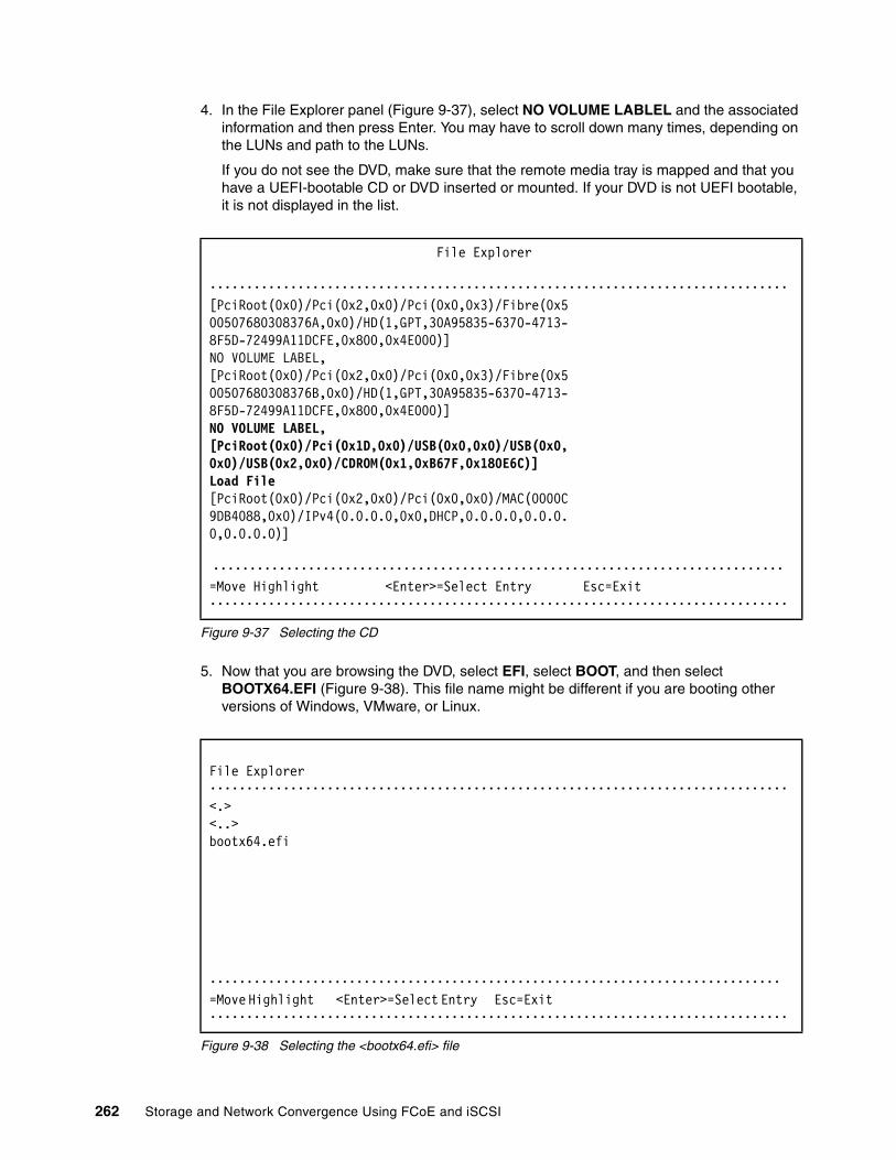
4. In the File Explorer panel (Figure 9-37), select NO VOLUME LABLEL and the associated information and then press Enter. You may have to scroll down many times, depending on the LUNs and path to the LUNs.
If you do not see the DVD, make sure that the remote media tray is mapped and that you have a UEFI-bootable CD or DVD inserted or mounted. If your DVD is not UEFI bootable, it is not displayed in the list.
Figure 9-37 Selecting the CD
5. Now that you are browsing the DVD, select EFI, select BOOT, and then select BOOTX64.EFI (Figure 9-38). This file name might be different if you are booting other versions of Windows, VMware, or Linux.
Figure 9-38 Selecting the <bootx64.efi> file
File Explorer •••••••••••••••••••••••••••••••••••••••••••••••••••••••••••••••••••••••••••••••[PciRoot(0x0)/Pci(0x2,0x0)/Pci(0x0,0x3)/Fibre(0x500507680308376A,0x0)/HD(1,GPT,30A95835-6370-4713-8F5D-72499A11DCFE,0x800,0x4E000)]NO VOLUME LABEL,[PciRoot(0x0)/Pci(0x2,0x0)/Pci(0x0,0x3)/Fibre(0x500507680308376B,0x0)/HD(1,GPT,30A95835-6370-4713-8F5D-72499A11DCFE,0x800,0x4E000)]NO VOLUME LABEL,[PciRoot(0x0)/Pci(0x1D,0x0)/USB(0x0,0x0)/USB(0x0,0x0)/USB(0x2,0x0)/CDROM(0x1,0xB67F,0x180E6C)]Load File[PciRoot(0x0)/Pci(0x2,0x0)/Pci(0x0,0x0)/MAC(0000C9DB4088,0x0)/IPv4(0.0.0.0,0x0,DHCP,0.0.0.0,0.0.0.0,0.0.0.0)]
•••••••••••••••••••••••••••••••••••••••••••••••••••••••••••••••••••••••••••••• =Move Highlight <Enter>=Select Entry Esc=Exit•••••••••••••••••••••••••••••••••••••••••••••••••••••••••••••••••••••••••••••••
File Explorer •••••••••••••••••••••••••••••••••••••••••••••••••••••••••••••••••••••••••••••••<.><..>bootx64.efi
•••••••••••••••••••••••••••••••••••••••••••••••••••••••••••••••••••••••••••••• =Move Highlight <Enter>=Select Entry Esc=Exit •••••••••••••••••••••••••••••••••••••••••••••••••••••••••••••••••••••••••••••••
262 Storage and Network Convergence Using FCoE and iSCSI

6. When the DVD starts to load, if prompted to ELILO boot, press TAB (Figure 9-39) to see the boot options and interrupt the timer for automatically booting from the DVD. If you do not press a key, you will boot the DVD and return to the UEFI setup window.
Figure 9-39 boot to the installation kernel
7. After SLES 11 SP2 loads, as shown in Figure 9-40, select your preferences, accept the license, and click Next.
Figure 9-40 Welcome panel
ELILO boot: ........Loading kernel linux... doneLoading file initrd...
Chapter 9. Configuring iSCSI and FCoE cards for SAN boot 263

8. In the Media Check installation window (Figure 9-41), click next.
Figure 9-41 Media check panel
264 Storage and Network Convergence Using FCoE and iSCSI
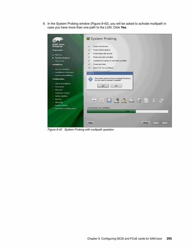
9. In the System Probing window (Figure 9-42), you will be asked to activate multipath in case you have more than one path to the LUN. Click Yes.
Figure 9-42 System Probing with multipath question
Chapter 9. Configuring iSCSI and FCoE cards for SAN boot 265
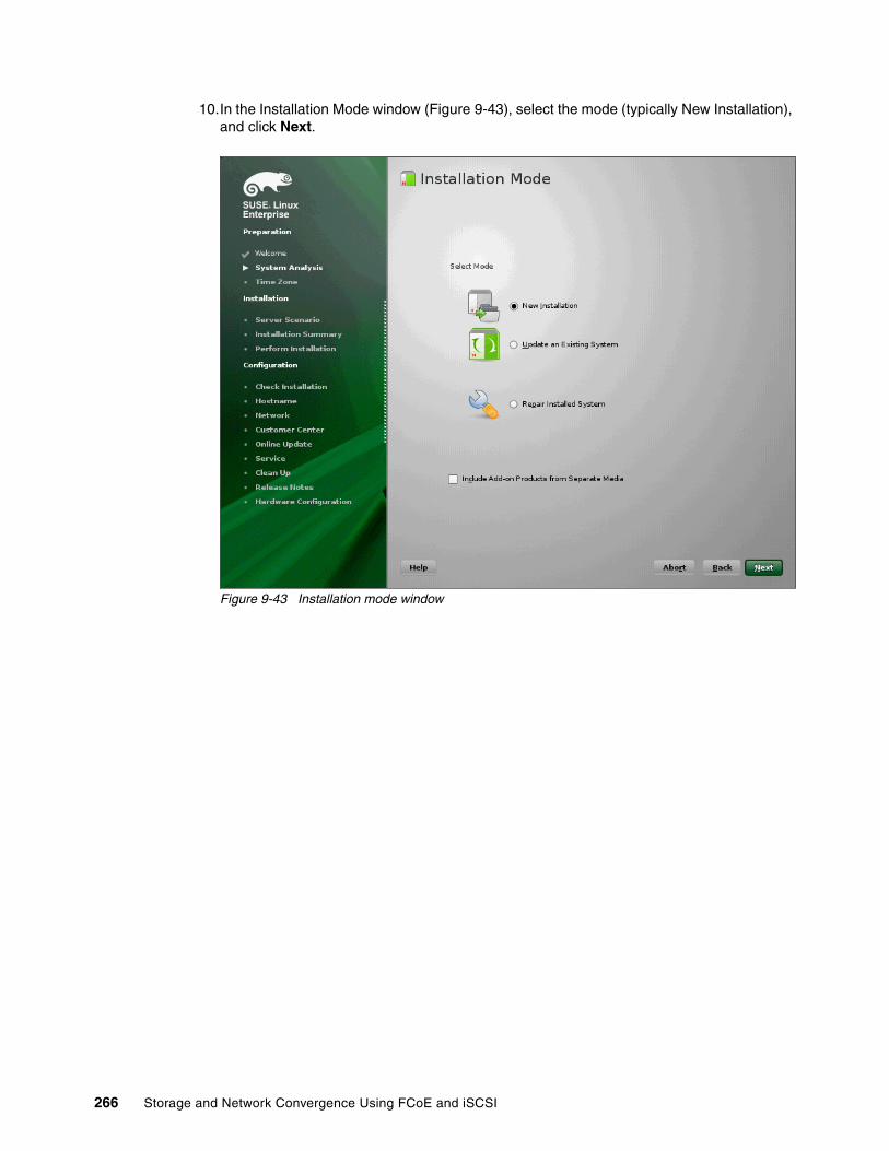
10.In the Installation Mode window (Figure 9-43), select the mode (typically New Installation), and click Next.
Figure 9-43 Installation mode window
266 Storage and Network Convergence Using FCoE and iSCSI

11.In the Clock and Time Zone panel (Figure 9-44), select the right time zone, and click Next.
Figure 9-44 Clock and Time Zone
Chapter 9. Configuring iSCSI and FCoE cards for SAN boot 267

12.In the Server Base Scenario (Figure 9-45), select the Physical Machine, and click Next.
Figure 9-45 Server Base Scenario
268 Storage and Network Convergence Using FCoE and iSCSI
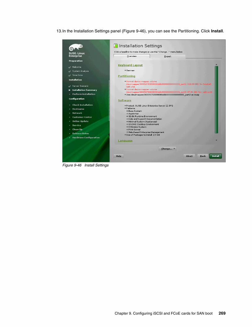
13.In the Installation Settings panel (Figure 9-46), you can see the Partitioning. Click Install.
Figure 9-46 Install Settings
Chapter 9. Configuring iSCSI and FCoE cards for SAN boot 269

14.In the additional windows, accept the license of the fonts (Figure 9-47) by clicking I agree.
Figure 9-47 Confirm the fonts license
Click Install to start the installation. This is the last point to cancel the installation without making any changes.
270 Storage and Network Convergence Using FCoE and iSCSI

In the next panel, Figure 9-48, you will see the package installation. After this, click Next.
Figure 9-48 Perform installation
Chapter 9. Configuring iSCSI and FCoE cards for SAN boot 271

15.If the server reboots, you are done installing SLES 11 SP2. The boot takes time. After a few minutes, the Password panel appears. See Figure 9-49.
Figure 9-49 Password panel
16.You are now done installing SLES 11 SP 2. The following configuration has nothing special for FC or FCoE.
17.Verify the multipath environment with the command shown in Figure 9-50.
Figure 9-50 verify multipath
N1x240:~ # multipath -l360050763008080ddb000000000000001 dm-0 IBM,2145size=40G features='1 queue_if_no_path' hwhandler='0' wp=rw|-+- policy='round-robin 0' prio=0 status=active| |- 0:0:1:0 sdb 8:16 active undef running| `- 1:0:0:0 sdc 8:32 active undef running`-+- policy='round-robin 0' prio=0 status=enabled |- 0:0:0:0 sda 8:0 active undef running `- 1:0:1:0 sdd 8:48 active undef runningN1x240:~ #
272 Storage and Network Convergence Using FCoE and iSCSI

18.You can verify your WWN with the command systool -av -c fc_host shown in Figure 9-51 on page 273.
Figure 9-51 verify the WWN for the IBM Flex System CN4054
9.4.10 Installing Windows 2012 in legacy mode
To install Windows 2012, follow these steps:
1. Boot from the media by using the desired method (UEFI or legacy). When possible, use the most current version of the media with the service pack level or latest update level.
2. If needed, input drivers for the storage devices.
3. Select a storage device (disk) to install the operating system.
If your operating system supports UEFI, install in UEFI to take advantage of the performance, faster POST time, and bigger boot disk size available through GPT.
N1x240:~ # systool -av -c fc_hostClass = "fc_host"
Class Device = "host0"<...............SNIP..............> dev_loss_tmo = "60" fabric_name = "0x1000749975258100" issue_lip = <store method only> max_npiv_vports = "255" maxframe_size = "2048 bytes" node_name = "0x20000000c9db4089" npiv_vports_inuse = "0" port_id = "0x010e01" port_name = "0x10000000c9db4089" port_state = "Online" port_type = "NPort (fabric via point-to-point)" speed = "10 Gbit"<...............SNIP..............> supported_speeds = "10 Gbit" symbolic_name = "Emulex 90Y3556 FV4.4.180.0 DV8.3.5.48.2p" tgtid_bind_type = "wwpn (World Wide Port Name)" uevent = vport_create = <store method only> vport_delete = <store method only>
Device = "host0" Device path = "/sys/devices/pci0000:00/0000:00:02.0/0000:11:00.2/host0" uevent = "DEVTYPE=scsi_host"
Chapter 9. Configuring iSCSI and FCoE cards for SAN boot 273

The following operating systems are UEFI-compliant at the time that this book is written:
� Windows 2012� Linux SLES 11 SP2 and SLES 11 SP1� RHEL 6� VMware 5
The following operating systems are some of the most popular legacy-compliant (BIOS) operating systems:
� Windows 2008 32-bit versions� Windows 2003, 2000, and earlier � VMware 4 and earlier � Linux RHEL 5 and earlier� SLES 10 and later� Novell NetWare
Check the operating system specifications to determine whether your operating system supports UEFI. For all other non-UEFI compliant operating systems, see this section to install in legacy mode.
9.4.11 Optimizing the boot for legacy operating systems
To optimize the boot for legacy operating systems, follow these steps:
1. During start or POST, press the F1 key.
2. In the System Configuration and Boot Management panel, select Boot Manager.
3. In the Boot Manager panel, select Add Boot Option.
4. In the Add Boot Option panel, select Generic Boot Option.
Installation mode: These operating systems can be installed in UEFI mode and legacy mode. Boot the media in UEFI to install in UEFI, or boot the media in legacy mode to install in legacy (BIOS) mode.
Tip: When you install these operating systems, make sure that you have the latest version of your operating system. If you want to install Windows 2008, to avoid issues and to save time when performing future updates, ensure that you have the latest media with the latest service pack built into the DVD.
274 Storage and Network Convergence Using FCoE and iSCSI

5. In the Generic Boot Option panel (Figure 9-52), highlight Legacy Only, and press Enter. Be sure you have also added the CD/DVD Rom.
Figure 9-52 File Explorer panel
6. In the Change Boot Order panel (Figure 9-53), follow these steps:
a. Select Change Boot Order, and press Enter.b. Move Legacy Only to the top by using + and – keys. Then press Enter.c. Move CD/DVD Rom to the near top by using + and – keys. Then press Enter.d. Highlight Commit Changes, and press Enter.
Figure 9-53 Change Boot Order panel
Generic Boot Option •••••••••••••••••••••••••••••••••••••••••••••••••••••••••••••••••••••••••••••••PXE Network VenMedia(0C588DB8-6AF4-1Hard Disk 1 1DD-A992-00197D890238,EEHard Disk 2 )Hard Disk 3Hard Disk 4USB StorageDiagnosticsiSCSIiSCSI CriticalLegacy OnlyEmbedded Hypervisor •••••••••••••••••••••••••••••••••••••••••••••••••••••••••••••••••••••••••••••• =Move Highlight <Enter>=Select Entry Esc=Exit •••••••••••••••••••••••••••••••••••••••••••••••••••••••••••••••••••••••••••••••
Change Boot Order •••••••••••••••••••••••••••••••••••••••••••••••••••••••••••••••••••••••••••••••Change the order <Legacy Only> Change the order <CD/DVD Rom> <SUSE Linux Enterprise Server 11 SP2> <PXE Network> <Floppy Disk> <Hard Disk 0>
Commit Changes
•••••••••••••••••••••••••••••••••••••••••••••••••••••••••••••••••••••••••••••• =Move Highlight <Enter>=Select Entry Esc=Exit •••••••••••••••••••••••••••••••••••••••••••••••••••••••••••••••••••••••••••••••
Chapter 9. Configuring iSCSI and FCoE cards for SAN boot 275

7. Go to Boot Manager. Select Boot From Device.
8. Select IMM1:CD/DVD - IMM Remote Mount in the Boot Device Manager shown in Figure 9-54. Be sure you also check the Legacy Only selection.
Figure 9-54 boot the remote mount CD
9. Press Enter to boot the CD or DVD for Windows 2012.
10.You see the message “UEFI Platform Initialization.” After some time, the system starts to boot in legacy mode. When you see the following message, you are now in the legacy BIOS section:
Please wait, initializing legacy usb devices...Done
11.Review the settings by pressing Ctrl+E. You will get the Emulex Adapters in the System panel shown in Figure 9-55. Select the Adapter and press Enter.
Figure 9-55 Emulex Adapters in the System
Boot Devices Manager •••••••••••••••••••••••••••••••••••••••••••••••••••••••••••••••••••••••••••• Legacy Only [X] If this item has been set, it will override Slot1:PXE0 - Mezzanine 1 Card the setting of the Slot1:PXE1 - Mezzanine 1 Card System Boot Mode in Slot1:PXE2 - Mezzanine 1 Device 2 Boot Modes page. Slot1:PXE3 - Mezzanine 1 Device 2 IMM1:CD/DVD - IMM Remote Mount DSA:Diagnostics - Diagnostics ••••••••••••••••••••••••••••••••••••••••••••••••••••••••••••••••••••••••••• =Move Highlight <Spacebar>Toggle Checkbox Esc=Exit ••••••••••••••••••••••••••••••••••••••••••••••••••••••••••••••••••••••••••••
****************************************************************************Emulex OneConnect FCoE BIOS Utility, XA4.03a4 ***************************************************************************** This utility displays and saves changes when selected.* You will be prompted to reboot for all changes to take effect.* * Emulex Adapters in the System: * * 1. 90Y3556: Bus:11 Dev:00 Func:02 WWPN:10000000C9DB4089 * 2. 90Y3556: Bus:11 Dev:00 Func:03 WWPN:10000000C9DB408D * 3. 90Y3556: Bus:16 Dev:00 Func:02 WWPN:10000000C9DB4091 * 4. 90Y3556: Bus:16 Dev:00 Func:03 WWPN:10000000C9DB4095 * * * Enter <Esc> to exit <PageDn> to Next Page * < / > to Highlight, <Enter> to Select Copyright (c) 1997*2012 Emulex. All rights reserved.
276 Storage and Network Convergence Using FCoE and iSCSI

12.In the Adapter settings menu, select the Enable/Disable Boot from SAN to verify that the setting is Enabled as shown in Figure 9-56.
Figure 9-56 Adapter settings
13.You can also verify the target devices by selecting the Scan for Target Devices, as shown in Figure 9-57.
Figure 9-57 Scan for Target Devices
***************************************************************************** Emulex OneConnect FCoE BIOS Utility, XA4.03a4 *****************************************************************************01: 90Y3556: Bus#: 11 Dev#: 00 Func#: 02 *Mem Base: 91D80000 Firmware Version: v4.4.180.0s when BIOS:tEnabled *Port Name: 10000000C9DB4089 Node Name: 20000000C9DB4089 *Vlan ID: 1002 DCBX mode: CEE mode ***************************************************************************** * Enable/Disable Boot from SAN * Scan for Target Devices * Reset Adapter Defaults * Configure Boot Devices * Configure DCBX mode * Configure FCF CEE Parameters * Configure FCF CIN Parameters * Configure Advanced Adapter Parameters * * Enter <Esc> to Previous Menu * < / > to Highlight, <Enter> to Select Copyright (c) 1997*2012 Emulex. All rights reserved. *
***************************************************************************** Emulex OneConnect FCoE BIOS Utility, XA4.03a4 *****************************************************************************01: 90Y3556: Bus#: 11 Dev#: 00 Func#: 02 *Mem Base: 91D80000 Firmware Version: v4.4.180.0s when BIOS:tEnabled *Port Name: 10000000C9DB4089 Node Name: 20000000C9DB4089 *Vlan ID: 1002 DCBX mode: CEE mode ***************************************************************************** * Devices Present on This Adapter: * * 01. DID:010200 WWPN:201700A0 B86E3920 LUN:00 IBM 1818 FAStT 0730 ** 02. DID:010E00 WWPN:50050768 0304376B LUN:00 IBM 2145 0000 ** 03. DID:010F00 WWPN:50050768 0304376A LUN:00 IBM 2145 0000 ** * * Enter <Esc> to Previous Menu Copyright (c) 1997*2012 Emulex. All rights reserved.
Chapter 9. Configuring iSCSI and FCoE cards for SAN boot 277

14.Press ESC and select the boot devices as shown in Figure 9-58.
Figure 9-58 List of saved boot devices
* Emulex OneConnect FCoE BIOS Utility, XA4.03a4 *********************************************************************************01: 90Y3556: Bus#: 11 Dev#: 00 Func#: 02 **Mem Base: 91D80000 Firmware Version: 4.4.180.0BIOS:Enabled **Port Name: 10000000C9DB4089 Node Name: 20000000C9DB4089 **Vlan ID: 1002 DCBX mode: CEE mode ********************************************************************************* * * List of Saved Boot Devices: * * 1. Unused DID:000000 WWPN:00000000 00000000 LUN:00 Primary Boot * 2. Unused DID:000000 WWPN:00000000 00000000 LUN:00 * 3. Unused DID:000000 WWPN:00000000 00000000 LUN:00 * 4. Unused DID:000000 WWPN:00000000 00000000 LUN:00 * 5. Unused DID:000000 WWPN:00000000 00000000 LUN:00 * 6. Unused DID:000000 WWPN:00000000 00000000 LUN:00 * 7. Unused DID:000000 WWPN:00000000 00000000 LUN:00 * 8. Unused DID:000000 WWPN:00000000 00000000 LUN:00 * * Enter <Esc> to Previous Menu ** ********************************************************************************
Copyright (c) 1997*2012 Emulex. All rights reserved.
278 Storage and Network Convergence Using FCoE and iSCSI

15.Select the first entry and press Enter to see the available boot devices (Figure 9-59).
Figure 9-59 list of boot devices
Leave all other configuration options untouched. These configurations were made in the uEFI setup. Press ESC ESC to leave the BIOS Configuration utility.
Make sure that you can see the disk that you want to boot from with the message “Emulex BIOS is Installed successfully”.
It takes a few minutes to start the DVD.
9.4.12 Windows installation sequence
To perform the Windows installation, follow these steps:
1. If prompted by the message “Press any key to boot from CD or DVD,” press a key so that the DVD starts to boot. If you do not press a key, the DVD fails to boot.
2. Select your preferences and click Next.
* Emulex OneConnect FCoE BIOS Utility, XA4.03a4 ****************************************************************************01: 90Y3556: Bus#: 11 Dev#: 00 Func#: 02 **Mem Base: 91D80000 Firmware Version: 4.4.180.0BIOS:Enabled **Port Name: 10000000C9DB4089 Node Name: 20000000C9DB4089 *Vlan ID: 1002 DCBX mode: CEE mode **************************************************************************** * * * 00. Clear selected boot entry!! * 01. DID:010200 WWPN:201700A0 B86E3920 LUN:00 IBM 1818 FAStT 0730* 02. DID:010E00 WWPN:50050768 0304376B LUN:00 IBM 2145 0000 * 03. DID:010F00 WWPN:50050768 0304376A LUN:00 IBM 2145 0000 * * * Enter <Esc> to Previous Menu * Enter <ESC> to Exit <PageDn> to NextPage *****************************************************************************Copyright (c) 1997*2012 Emulex. All rights reserved.
Chapter 9. Configuring iSCSI and FCoE cards for SAN boot 279

3. In the Install Windows panel (Figure 9-60), select Install now.
Figure 9-60 Install now button in the Install Windows panel
280 Storage and Network Convergence Using FCoE and iSCSI

4. Select the operating system that you want to install (Figure 9-61), and click Next.
Figure 9-61 Selecting the operating system
Chapter 9. Configuring iSCSI and FCoE cards for SAN boot 281

5. Read the license agreement, select I accept the license terms, and click Next (Figure 9-62).
Figure 9-62 License agreement window
282 Storage and Network Convergence Using FCoE and iSCSI

6. For the type of installation (Figure 9-63), select Custom (advanced) to install a clean copy of Windows. Then click Next.
Figure 9-63 Selecting to install a clean copy of Windows
Chapter 9. Configuring iSCSI and FCoE cards for SAN boot 283
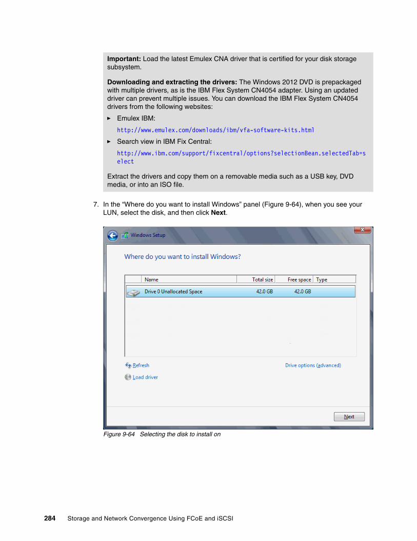
7. In the “Where do you want to install Windows” panel (Figure 9-64), when you see your LUN, select the disk, and then click Next.
Figure 9-64 Selecting the disk to install on
Important: Load the latest Emulex CNA driver that is certified for your disk storage subsystem.
Downloading and extracting the drivers: The Windows 2012 DVD is prepackaged with multiple drivers, as is the IBM Flex System CN4054 adapter. Using an updated driver can prevent multiple issues. You can download the IBM Flex System CN4054 drivers from the following websites:
� Emulex IBM:
http://www.emulex.com/downloads/ibm/vfa-software-kits.html
� Search view in IBM Fix Central:
http://www.ibm.com/support/fixcentral/options?selectionBean.selectedTab=select
Extract the drivers and copy them on a removable media such as a USB key, DVD media, or into an ISO file.
284 Storage and Network Convergence Using FCoE and iSCSI

If you see a warning message (Figure 9-65) indicating that the hardware might not support booting to the disk, either the disk is offline or another error might exist. Therefore, boot from SAN will not work.
Figure 9-65 Warning message about hardware not supporting boot to disk
Recheck all items as explained in “Hardware does not support boot to disk for legacy operating systems” on page 369, and then reboot the server on the Windows DVD. After you address all errors, click Next.
Chapter 9. Configuring iSCSI and FCoE cards for SAN boot 285
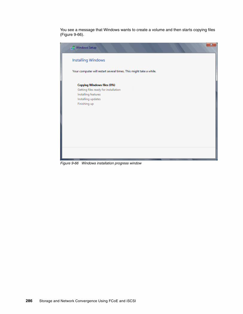
You see a message that Windows wants to create a volume and then starts copying files (Figure 9-66).
Figure 9-66 Windows installation progress window
286 Storage and Network Convergence Using FCoE and iSCSI
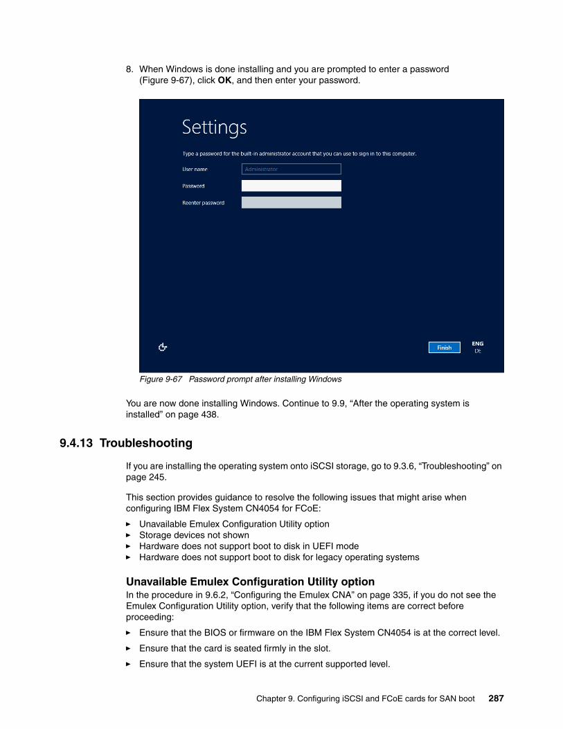
8. When Windows is done installing and you are prompted to enter a password (Figure 9-67), click OK, and then enter your password.
Figure 9-67 Password prompt after installing Windows
You are now done installing Windows. Continue to 9.9, “After the operating system is installed” on page 438.
9.4.13 Troubleshooting
If you are installing the operating system onto iSCSI storage, go to 9.3.6, “Troubleshooting” on page 245.
This section provides guidance to resolve the following issues that might arise when configuring IBM Flex System CN4054 for FCoE:
� Unavailable Emulex Configuration Utility option� Storage devices not shown� Hardware does not support boot to disk in UEFI mode� Hardware does not support boot to disk for legacy operating systems
Unavailable Emulex Configuration Utility optionIn the procedure in 9.6.2, “Configuring the Emulex CNA” on page 335, if you do not see the Emulex Configuration Utility option, verify that the following items are correct before proceeding:
� Ensure that the BIOS or firmware on the IBM Flex System CN4054 is at the correct level.
� Ensure that the card is seated firmly in the slot.
� Ensure that the system UEFI is at the current supported level.
Chapter 9. Configuring iSCSI and FCoE cards for SAN boot 287
� Ensure that the iSCSI or FCoE license is installed on the adapter. If the license is not installed, the adapter will not work. Therefore, you must contact your IBM marketing representative or vendor to obtain the license.
� The IBM Flex System CN4054 is set to NIC only or iSCSI. Both provide the same result.
Storage devices not shownIn the procedure in 9.6.4, “Configuring the Emulex settings” on page 338, if you do not see your storage devices, complete the steps as explained in 9.6.3, “Loading the default settings on the Emulex CNA” on page 337. Pay special attention to the following areas:
� You must zone your switches.� Verify that the zone contains one IBM Flex System CN4054 WWPN and one SAN disk
controller WWPN.� Ensure that the SAN disk has a logical drive (LUN) created.� The LUN might require you to wait for it to be fully initialized before using it.� Map the LUN to a single IBM Flex System CN4054 WWPN as LUN 0.� Set the LUN on the correct preferred path from which you want to boot.
After you complete these checks, and no devices are displayed, check the following areas:
� Ensure that your IBM Flex System CN4054 Firmware was updated.
� Have the switch initiate the port login:
a. Log in to the switch that connects to the host.b. Select the blade port.c. Shut down the blade port.d. Enter the no shutdown command to bring the blade port up.e. Wait 30 seconds, and make sure that the port is logged in.f. Add the boot device again from the blade.
� Reboot the blade, and press F1. If you made changes to the SAN disk storage during setup, reboot so that the UEFI can rescan the available disks.
� Change the fiber switch configuration.
If multiple switches are communicating with each other, set the Brocade switch to gateway mode, the QLogic switch to transparent mode, or the Cisco switch to NPV mode.
For more information, see the IBM Redpaper publication, Implementing the Brocade Access Gateway for IBM BladeCenter, REDP-4343.
� Confirm that the switch name server can detect the WWPN of your IBM Flex System CN4054 and the WWPN of your SAN disk storage. From the name server, some switches can show accessible devices. Make sure that the two devices that you are trying to access communicate and are displayed.
Go through the checklist again to ensure that everything is in place on the SAN for the setup to work.
Hardware does not support boot to disk in UEFI modeIn the procedure in 9.6.7, “Booting the Windows DVD in UEFI mode” on page 344, you might receive a message that indicates that the hardware might not support boot to disk. If you see this message, review the setup instructions in 9.6.1, “Configuring an Emulex card for boot from SAN” on page 333.
Tip: Check the zone, and re-create it. In addition, delete your mapping and remap. When remapped, check the preferred path. These tasks take time, but often correct the error. Then reboot your system and check again if the storage devices are displayed.
288 Storage and Network Convergence Using FCoE and iSCSI

Then check the following settings:
� Verify that the boot device was added when you pressed F1 (go back and check).
� Verify that the BIOS is enabled on the IBM Flex System CN4054 port (go back and check).
� Verify that the CNA from which you are trying to do the boot is on the preferred path of the SAN disk. The most common cause of an offline disk is that the preferred path is not assigned correctly. Check your SAN disk device configuration, and then reboot the server again on the Windows DVD.
� Verify that your SAN disk supports a UEFI boot.
� Verify that your SAN disk is updated to the latest firmware.
� Try to perform a legacy installation.
� If you see the disk as being offline, see Windows KB 2345135, “Setup reports error ‘Windows cannot be installed to this disk...’ when booted from DVD” at this website:
http://support.microsoft.com/kb/2345135
� If Setup reports the error message “Windows cannot be installed to this disk...” booted from DVD in UEFI mode, consider modifying the Windows installation media.
� Use Windows media that is bundled with the latest service pack.
� If you see a 20-MB disk, you most likely mapped the access LUN instead of the actual LUN. To correct this problem, log in to your disk storage subsystem.
� Verify that your LUN is using LUN 0, which is defined in the SAN disk device.
� Verify that you are using the latest Windows DVD with the latest service pack built-in.
� Verify that the path is on the preferred path. Check with your SAN configuration.
� Verify that zoning is correct or unchanged.
� Verify that LUN mapping is correct or unchanged.
Hardware does not support boot to disk for legacy operating systemsIn the procedure in 9.6.9, “Optimizing the boot for legacy operating systems” on page 356, you might receive a message that indicates that the hardware might not support boot to disk.
If you see this message, review the setup instructions in 9.6.1, “Configuring an Emulex card for boot from SAN” on page 333, and then check the following settings:
� Verify that the boot device was added when you pressed F1 (go back and check).
� Verify that the BIOS was enabled on the IBM Flex System CN4054 port (go back and check).
� Verify that the IBM Flex System CN4054 you are trying to boot from is on the SAN disk preferred path. The most common cause of an offline disk is that the preferred path is not assigned correctly. Check your SAN disk device configuration, and then reboot the server again on the Windows DVD.
� Verify that your SAN disk is updated to the latest firmware.
� Use Windows media that is bundled with the latest service pack.
� If you see a 20-MB disk, you most likely mapped the access LUN instead of the actual LUN. You can fix this problem in your disk storage subsystem.
� Verify that your LUN is using LUN 0, which is defined in the SAN disk device.
� Verify that you are using the latest Windows DVD with the latest service pack built-in.
� Verify that the path is on the preferred path. Check with your SAN configuration.
� Verify that zoning is correct or unchanged.
� Verify that LUN mapping is correct or unchanged.
Chapter 9. Configuring iSCSI and FCoE cards for SAN boot 289

9.5 Configuring Emulex for iSCSI for the BladeCenter
This section explains how to configure the Emulex Virtual Fabric Adapter I CFFh card PN 49Y4277 FRU 49Y4261 (OCm10102-F-X), which is referred to as Emulex CNA. The steps are similar for Virtual Fabric Adapter II. Firmware versions might vary.
This scenario entails the following components:
� BladeCenter H machine type 8852� HS22 machine type 7870
– UEFI P9155A 1.15– Blade System Management Processor YUOOC7E 1.30– Emulex 10 GB Virtual Fabric Adapter Advanced (OCm10102-F-X)
• 49Y4277 FRU 49Y426• Firmware: 2.703.397.3806• EFI Boot: 5.01a8• Driver: iSCSI-2.103.386.0-1• Adapter configured with an iSCSI/FCoE license• Adapter configured in iSCSI personality
– BNT Virtual Fabric 10Gb Switch Module with Firmware 6.8.2.0
The Emulex Virtual Fabric Adapter requires an iSCSI license to perform hardware iSCSI tasks. By default, the Emulex Virtual Fabric Adapter is a 10 GB network only card. You can order a license to upgrade a Virtual Fabric Adapter to support iSCSI and FCoE. The advanced version of the adapter comes with the iSCSI and FCoE license preinstalled. You need OneCommand Manager to change the personality card to NIC only, FCoE, or iSCSI. For more information, see 7.2, “Installing and enabling the Emulex CNA” on page 113.
This section is specifically for Blade HS22. Boot from SAN on other systems, such as HS22v or HX5, x3550 m2, x3650 m2, x3550 m3, and x3650 m3, is similar. Use the latest drivers and firmware that are certified by the SAN disk vendor, and not the versions that are documented here.
9.5.1 Configuring Emulex card for boot from SAN
The Emulex card in the blade server is a dual port CNA. You can boot from either port, but you can boot only from one port and path at a time. You must perform the initial installation with a single path. The redundancy occurs later when the operating system is installed and when the multipath driver is installed.
At this stage, you must perform the following connections and configurations on the SAN:
� On the CNA:
– Make sure the BIOS, UEFI, or firmware is at the latest version supported on the SAN disk storage device.
– Use supported small form-factor pluggable (SFP) or SFP+ cabling.
Peripheral Component Interconnect Express (PCIe) version: Although this section is written for a specific Emulex CNA, the steps for a PCIe version of this adapter are similar.
290 Storage and Network Convergence Using FCoE and iSCSI
– On the Emulex CNA, host port 0 and 1 require a different IP subnet.
As a preferred practice, in any operating system, each NIC must have its own network, unless it is teamed with software or a configuration.
• Host port 0: 192.168.1.2 Subnet 255.255.255.0• Host port 1: 192.168.2.2 Subnet 255.255.255.0
– Do not use the default IP addresses. Duplication of network IP addresses on the same network can cause issues.
– On System x servers, make sure that your cable is connected to a switch.
� On the switches:
– Enable the ports.
– Ensure that the Blade host has a connection all the way to the disk storage subsystem.
– Optional: Configure a VLAN for disk traffic. If possible, completely isolate disk traffic from regular network traffic.
– Optional: Set a priority group in the CNA, storage, and switches, and turn on the Converged Enhanced Ethernet (CEE) for the switches to better manage the disk traffic.
– On the host ports, set rapid spanning tree or disable spanning tree on the host port and SAN disk ports.
– Try to minimize the quantity of switches between the host and the SAN, specially when setting up the first time. As a test, direct attach the SAN disk storage subsystem to the same switch as the server.
– Set the speed to fixed speeds, not automatic speeds.
– Isolate your disk traffic from your network traffic by creating different VLANS. Ideally, use one VLAN per SAN disk storage controller host port.
– Make sure that you are using supported SFP or SFP+ cables.
� On the SAN disk storage subsystem:
The storage subsystem and SAN disk must have a logical drive (LUN) created and mapped to the IQN of the CNA of the blade server as LUN 0.
Configure the LUN as follows:
– Create one LUN for each server that you want to boot.
– Map the LUN to one IQN. Do not share the LUN to multiple hosts.
Later you will map it to both IQNs. At installation time, you must restrict the LUN to a single path. If you share the LUN, a stop error (blue screen) or other installation issues might occur.
– Map the LUN as LUN 0, which is required for most operating systems.
– Wait for the LUN to be fully initialized before you use it so that it can be synchronized.
When you create a LUN, normally a synchronization process starts. With some storage, you can work with this LUN when it is synchronizing. Other storage might require you to wait for the LUN to be fully initialized. See the storage documentation for your SAN disk storage for information about how it operates.
Chapter 9. Configuring iSCSI and FCoE cards for SAN boot 291
– Set the LUN on the correct path that you want to boot from, which applies to asymmetrical storage subsystems only.
Some SANs are asymmetrical storage subsystems, such as the IBM System Storage DS3000, DS4000, and DS5000 series. Others SANs are symmetrical storage subsystems, such as the SAN Volume Controller and IBM System Storage DS8000. The asymmetrical storage subsystems controllers set a preferred path. The preferred path must be set to communicate to your CNA (normally by using an IQN).
The LUN on most SANs is to one controller at a time. This LUN can move from controller A to controller B.
At installation time, the operating system does not have its redundant driver loaded and, therefore, does not handle redundant paths. To work around this issue, you must provide a single path. For example, if you are booting through CNA port 0 and this port 0 communicates to controller A1, the preferred path for your LUN must be A on the SAN disk. Likewise, if you are booting through CNA port 0 and this port 0 communicates to controller B1, your preferred path for your LUN must be B on the SAN disk.
The preferred path is typically easy to change in the SAN disk settings.
Configure the host port as follows:
– You must have different IP addresses in different networks for each IP per host.
– As a preferred practice, in any operating system or storage controller, ensure that each NIC has its own network, unless it is teamed with software or a configuration.
– Configure the host ports of the disk storage subsystem the same way, which is the preferred configuration:
• Storage controller A Host port 0: 192.168.1.100 Subnet 255.255.255.0• Storage controller A Host port 1: 192.168.2.100 Subnet 255.255.255.0• Storage controller B Host port 0: 192.168.3.100 Subnet 255.255.255.0• Storage controller B Host port 1: 192.168.4.100 Subnet 255.255.255.0
– If you have single port hosts (servers) and require redundancy at the controller level, in some storage controllers, you can configure the host ports as follows:
• Storage controller A Host port 1: 192.168.1.100 Subnet 255.255.255.0• Storage controller A Host port 2: 192.168.2.100 Subnet 255.255.255.0• Storage controller B Host port 1: 192.168.1.101 Subnet 255.255.255.0• Storage controller B Host port 2: 192.168.2.101 Subnet 255.255.255.0
For information about best practices, not a preferred configuration, contact your storage subsystem vendor.
– Use supported SFP and cables.
You must know your environment, cabling, and setup, which can all be validated by checking cable connections, SAN disk configuration, or logs.
292 Storage and Network Convergence Using FCoE and iSCSI

9.5.2 Configuring the Emulex CNA
To configure the Emulex CNA, follow these steps:
1. Press F1, and, in the System Configuration and Boot Management panel, select System Settings.
2. In the System Settings panel (Figure 9-68), select Emulex iSCSI EFI Configuration Utility, and then press Enter.
Figure 9-68 Selecting Emulex iSCSI EFI Configuration Utility on the System Settings panel
If you do not see the Emulex Configuration Utility option, see “Unavailable Emulex Configuration Utility option” on page 246.
Then press Enter.
Chapter 9. Configuring iSCSI and FCoE cards for SAN boot 293

3. In the Emulex iSCSI EFI Configuration Utility panel (Figure 9-69), select Emulex Configuration Setup Utility and press Enter.
Figure 9-69 Emulex iSCSI EFI Configuration Utility panel
294 Storage and Network Convergence Using FCoE and iSCSI
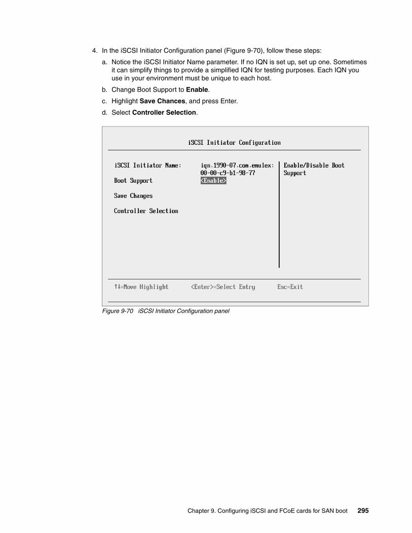
4. In the iSCSI Initiator Configuration panel (Figure 9-70), follow these steps:
a. Notice the iSCSI Initiator Name parameter. If no IQN is set up, set up one. Sometimes it can simplify things to provide a simplified IQN for testing purposes. Each IQN you use in your environment must be unique to each host.
b. Change Boot Support to Enable.
c. Highlight Save Chances, and press Enter.
d. Select Controller Selection.
Figure 9-70 iSCSI Initiator Configuration panel
Chapter 9. Configuring iSCSI and FCoE cards for SAN boot 295

5. In the Controller Selection panel (Figure 9-71), where you now see two Emulex fiber ports, select the port you want to boot from. In this example, we select the first port. Then press Enter.
Figure 9-71 Controller Selection panel
Tip: For optimal performance, consider booting half of your blades from one port and booting half from the other port. Also consider splitting the load on the different SAN disk controller ports. However, be careful because splitting the load adds more complexity, and you must check your SAN disk preferred paths carefully.
296 Storage and Network Convergence Using FCoE and iSCSI

9.5.3 Loading the default settings on the Emulex CNA
To load the default settings on the Emulex CNA, follow these steps:
1. Clear any configuration. In the Controller Configuration Menu panel (Figure 9-72), highlight Erase Configuration, and press Enter.
Figure 9-72 Controller Configuration Menu panel
2. When prompted by the message “Existing configuration will be overwritten by the default values (Figure 9-73)”, press Enter to confirm.
Figure 9-73 Message about overwriting the existing configuration
Chapter 9. Configuring iSCSI and FCoE cards for SAN boot 297

9.5.4 Configuring the Emulex settings
To configure the Emulex settings, follow these steps:
1. In the Controller Configuration Menu panel, select Controller Properties, and press Enter.
2. In the Controller Properties panel (Figure 9-74), verify the BIOS and firmware version. Make sure that you are using the latest supported version for your SAN device. Then press Esc.
Figure 9-74 Controller Properties panel
298 Storage and Network Convergence Using FCoE and iSCSI

3. In the Controller Configuration Menu panel (Figure 9-72 on page 297), select Network Configuration, and press Enter.
4. In the Network Configuration panel (Figure 9-75 here):
a. Note the MAC address, which might be useful for troubleshooting.
b. Verify that Link Status is set to Link Up.
c. Optional: Select Configure VLAN ID/Priority and press Enter.
As a preferred practice, separate the network traffic and disk traffic, for example, by putting the port on its own VLAN.
Figure 9-75 Network Configuration panel
Chapter 9. Configuring iSCSI and FCoE cards for SAN boot 299
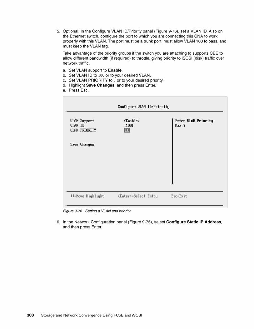
5. Optional: In the Configure VLAN ID/Priority panel (Figure 9-76), set a VLAN ID. Also on the Ethernet switch, configure the port to which you are connecting this CNA to work properly with this VLAN. The port must be a trunk port, must allow VLAN 100 to pass, and must keep the VLAN tag.
Take advantage of the priority groups if the switch you are attaching to supports CEE to allow different bandwidth (if required) to throttle, giving priority to iSCSI (disk) traffic over network traffic.
a. Set VLAN support to Enable.b. Set VLAN ID to 100 or to your desired VLAN.c. Set VLAN PRIORITY to 3 or to your desired priority.d. Highlight Save Changes, and then press Enter.e. Press Esc.
Figure 9-76 Setting a VLAN and priority
6. In the Network Configuration panel (Figure 9-75), select Configure Static IP Address, and then press Enter.
300 Storage and Network Convergence Using FCoE and iSCSI

7. In the Configure Static IP Address panel (Figure 9-77):
a. Enter an IP address on your CNA port that must be able to communicate with your disk storage controller.
b. Set the Subnet Mask.
c. Optional: Set the default gateway if you need to communicate through a router (not a switch) to reach your storage device. Otherwise leave the default setting 0.0.0.0 if it is on the same subnet and network.
d. Highlight Save Changes, and then press Enter.
e. Press Esc.
Figure 9-77 Setting the IP address, subnet, and if needed, the gateway
Chapter 9. Configuring iSCSI and FCoE cards for SAN boot 301

8. Perform a ping test. In the Network Configuration panel (Figure 9-78), select Ping.
Figure 9-78 Selecting Ping from the Network Configuration panel
9. In the Ping panel (Figure 9-79), enter the IP address of your disk storage subsystem. If the connections are working correctly, a reply is displayed (inset in Figure 9-79) that shows the IP address and time.
Figure 9-79 Successful ping reply
302 Storage and Network Convergence Using FCoE and iSCSI

If a ping failure occurs, you see a message indicating Ping Failed (Figure 9-80).
Figure 9-80 Failed ping reply
If a ping failure occurs, see “Ping failure” on page 246.
After you confirm that your CNA port has communication with the disk storage device, press Esc.
10.In the Controller Configuration Menu panel (Figure 9-81), select iSCSI Target Configuration.
Figure 9-81 Controller Configuration Menu panel
Chapter 9. Configuring iSCSI and FCoE cards for SAN boot 303

11.In the iSCSI Target Configuration panel (Figure 9-82), select Add Targets.
Figure 9-82 iSCSI Target Configuration panel
12.In the Add/Ping iSCSI Target panel (Figure 9-83), follow these steps:
a. Enter the iSCSI target IP address of your disk storage controller host port.a. Change Boot Target to Yes.b. Highlight Save/Login, and then press Enter.
Figure 9-83 Add/Ping iSCSI Target window
304 Storage and Network Convergence Using FCoE and iSCSI

The iSCSI Target Configuration panel now shows four discovered targets (Figure 9-84), because the storage device has four host ports.
c. Highlight the host port of the disk storage subsystem that you want to boot from, and press the Space bar. Select a single target to boot from.
In this example, the Emulex CNA iSCSI IP is 192.168.1.2. All of the host ports are on different subnets and VLANs. We booted from the disk storage subsystem host port that is in the same subnet as the CNA port, 192.168.1.100.
If you do not see any storage devices in the iSCSI Target Configuration panel, see “Storage devices not shown” on page 246.
Figure 9-84 Discovered targets
Chapter 9. Configuring iSCSI and FCoE cards for SAN boot 305

d. Using the arrow keys, move the cursor down to highlight Save Target, and then press Enter (Figure 9-85).
Figure 9-85 Saving the discovered target
13.In the iSCSI Target Configuration panel (Figure 9-86), which now shows the discovered target, highlight the target IQN, and press Enter.
Figure 9-86 iSCSI Target Configuration panel
306 Storage and Network Convergence Using FCoE and iSCSI

14.In the Edit/Ping Target panel (Figure 9-87), follow these steps:
a. Scroll down.b. Set Boot Target to Yes. c. Highlight Save/Login.
Figure 9-87 Edit/Ping Target panel
Chapter 9. Configuring iSCSI and FCoE cards for SAN boot 307

15.Check the LUN information. From your target IQN, select LUN Configuration, and make sure that you see LUN 0 (Figure 9-88).
Some operating systems require the LUN to be set to LUN 0 to boot from it. If you see a LUN with a number other than 0, follow these steps:
a. Sign in to your SAN disk storage device.b. Redo your mapping so that the LUN is LUN 0. c. Reboot the blade again.d. Repeat step 16 on page 245 to verify that you see LUN 0.
Figure 9-88 LUN Configuration panel with LUN 0
16.Press Esc until you return to the System Configuration and Boot Management panel (Figure 9-1 on page 229).
The adapter is now ready to boot from SAN. Depending on your environment, continue to the following sections as appropriate:
� If you are installing your operating system in UEFI mode, go to 9.3.6, “Troubleshooting” on page 245.
� If you are installing your operating system in legacy mode, go to 9.5.8, “Installing Windows 2008 x86 in legacy mode” on page 320.
� If you are uncertain about whether you want to install in UEFI or MBR, go to 9.3.6, “Troubleshooting” on page 245.
9.5.5 Booting from SAN variations
You can set up boot from SAN by using various methods. This book concentrates on the fixed target LUN. You can use other settings for boot from SAN. If you are configuring your SAN across a WAN link, add a security feature because packets can be sniffed easily.
308 Storage and Network Convergence Using FCoE and iSCSI
9.5.6 Installing Windows 2008 x64 or Windows 2008 R2 (x64) in UEFI mode
This section explains how to install Windows 2008 x64 (64 bit) with service pack 2. The procedure might be similar for other operating systems.
To install Windows 2008 x64 or Windows 2008 R2 (x64 in UEFI mode), follow these steps:
1. Boot from media by using the desired method (UEFI or legacy). When possible, use the most current version of the media with the service pack level or latest update level.
2. If needed, input drivers for the storage devices.
3. Select a storage device (disk) to install the operating system.
You must know whether your operating system is UEFI-compliant. The following operating systems were UEFI-compliant at the time this book was written:
� Windows 2008 x64 and Windows 2008 R2 (x64)� Linux SUSE Linux Enterprise Server (SLES) 11 SP1� Red Hat Enterprise Linux (RHEL) 6� VMware 5
For all other non-UEFI compliant operating systems, see 9.7.7, “Installing Windows 2008 x86 in legacy mode” on page 391.
If you are installing a UEFI-compliant operating system, install it in UEFI mode for performance reasons. UEFI gives you access to new features such as these:
� Bigger boot disk sizes: UEFI boots from a GUI Partition Table (GPT) partitioned disk (instead of Master Boot Record (MBR)). GPT is no longer limited to a 2-TB boot drive. However, keep in mind that you can have some software that requires the use of MBR (such as older backup software).
� Faster boot times: A UEFI machine in legacy mode (BIOS) takes more time to boot. The UEFI system boots once, initializes all devices in UEFI mode, and then does a POST a second time for legacy mode, which is time consuming. By installing in UEFI mode, you save this second boot time. Also, by using UEFI, the operating systems can take advantage of 32 bits or 64 bits, as opposed to BIOS systems that are limited to a 16-bit boot.
� PCI ROM limitations are much larger with UEFI compared to BIOS: With BIOS systems, you are limited by the small memory size of the ROM option that often generated 1801 PCI memory allocation errors.
Choose carefully whether you want to install in UEFI mode or legacy mode because, after the operating system is installed, the only way to change it back is to delete and reinstall it.
Installation mode: These operating systems can be installed in both UEFI and legacy mode.
Tip: When you install these operating systems, make sure that you have the latest version of your operating system. If you want to install Windows 2008 R2, to avoid issues and to save time when performing future updates, ensure that you have the latest media with the latest service pack built into the DVD.
Chapter 9. Configuring iSCSI and FCoE cards for SAN boot 309

9.5.7 Booting the Windows DVD in UEFI mode
You can boot the Windows media by placing the Windows 2008 x64 DVD in the DVD drive and having the machine boot automatically. By default, the system attempts to boot in UEFI mode. If it fails, it attempts to boot in legacy mode.
To boot the Windows DVD in UEFI mode, follow these steps:
1. During start or POST, press the F1 key.
2. In the System Configuration and Boot Management panel, select Boot Manager.
3. In the Boot Manager panel, select Boot From File. In this example, we boot from an HS22 shared DVD or CD. The DVD in the media tray is considered a USB device.
4. In the File Explorer panel (Figure 9-89), select EFISECTOR and the associated information, and then press Enter.
If you do not see the CD, make sure that the media tray is assigned to the correct blade and that you have a UEFI-bootable CD or DVD inserted or mounted. If your DVD is not UEFI bootable, it is not displayed in the list.
Figure 9-89 Selecting the CD
Tip: Depending on when you insert the Windows DVD during the system POST, you can boot the media in UEFI mode or legacy mode. To fully control the boot, follow the instructions as explained in this section to boot the DVD in UEFI mode.
EFISECTOR,[PciRoot (0x0 /Pci (0xID,0x7) /USB(0x2.0x0) /USB (0x1.0x0 /USB(0x0,0x0) /CDROM (0x1,0x33C,0x13D94C)]Load File[PciRoot (0x0) /Pci (0x7,0x0 /Pci (0x0,0x0)/ MAC (E41F133A0B98,0x0)]Load File[PciRoot (0x0) /Pci (0x7,0x0) /Pci (0x0,0x1)/ MAC (E41F133A0B9A,0x0)]
File Explorer
310 Storage and Network Convergence Using FCoE and iSCSI

5. Now that you are browsing the DVD, select EFI, select BOOT, and then select BOOTX64.EFI (Figure 9-90). This file name might be different if you are booting other versions of Windows, VMware, or Linux.
Figure 9-90 Selecting the BOOTX64.EFI file
6. When the DVD starts to load, if prompted to press any key (Figure 9-91), press a key so that the DVD starts to boot. If you do not press a key, you return to the UEFI setup window.
Figure 9-91 Prompt to press a key to boot from the CD or DVD
7. After Windows loads, select your preferences, and click Next.
<.><..>BOOTX64.EFI
File Explorer
Press any key to boot from CD or DVD.....
Chapter 9. Configuring iSCSI and FCoE cards for SAN boot 311

8. In the Windows installation window (Figure 9-92), click Install now.
Figure 9-92 Selecting Install now in the Windows installation window
9. In the Install Windows window (Figure 9-93), select your operating system and click Next.
Figure 9-93 Selecting the operating system
312 Storage and Network Convergence Using FCoE and iSCSI
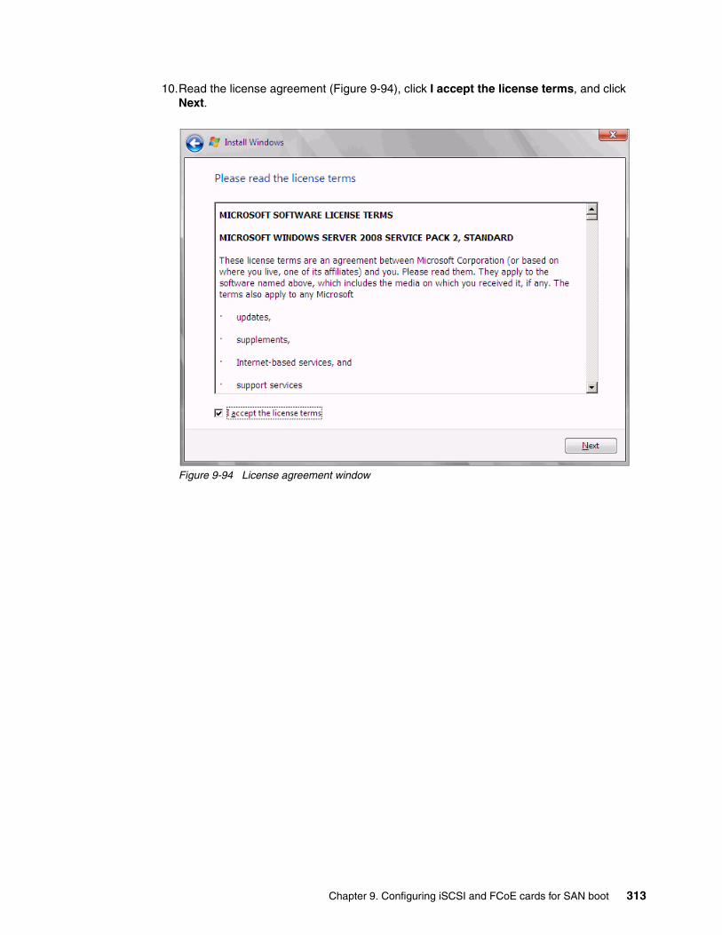
10.Read the license agreement (Figure 9-94), click I accept the license terms, and click Next.
Figure 9-94 License agreement window
Chapter 9. Configuring iSCSI and FCoE cards for SAN boot 313

11.In the installation type panel (Figure 9-95), select Custom (advanced) to install a clean copy of Windows.
Figure 9-95 Selecting to install a clean copy of Windows
314 Storage and Network Convergence Using FCoE and iSCSI
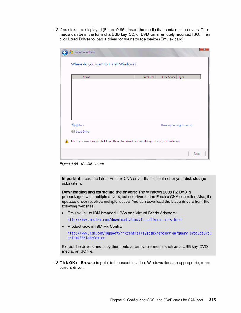
12.If no disks are displayed (Figure 9-96), insert the media that contains the drivers. The media can be in the form of a USB key, CD, or DVD, on a remotely mounted ISO. Then click Load Driver to load a driver for your storage device (Emulex card).
Figure 9-96 No disk shown
13.Click OK or Browse to point to the exact location. Windows finds an appropriate, more current driver.
Important: Load the latest Emulex CNA driver that is certified for your disk storage subsystem.
Downloading and extracting the drivers: The Windows 2008 R2 DVD is prepackaged with multiple drivers, but no driver for the Emulex CNA controller. Also, the updated driver resolves multiple issues. You can download the blade drivers from the following websites:
� Emulex link to IBM branded HBAs and Virtual Fabric Adapters:
http://www.emulex.com/downloads/ibm/vfa-software-kits.html
� Product view in IBM Fix Central:
http://www.ibm.com/support/fixcentral/systemx/groupView?query.productGroup=ibm%2FBladeCenter
Extract the drivers and copy them onto a removable media such as a USB key, DVD media, or ISO file.
Chapter 9. Configuring iSCSI and FCoE cards for SAN boot 315

14.In the “Select the driver to be installed” panel (Figure 9-97), select the driver, and click Next.
Figure 9-97 Selecting the storage driver
316 Storage and Network Convergence Using FCoE and iSCSI

15.In the “Where do you want to install Windows” panel (Figure 9-98), when you see your LUN, select the disk, and then click Next.
Figure 9-98 Selecting the LUN to install Windows
Chapter 9. Configuring iSCSI and FCoE cards for SAN boot 317

If you see a warning message (Figure 9-99) that indicates that the hardware might not support booting to the disk, the disk is offline or another error might exist. Therefore, boot from SAN will not work.
Figure 9-99 Warning message that hardware might not support booting to selected disk
Recheck all items as explained in “Hardware does not support boot to disk in UEFI mode” on page 246, and then reboot the server on the Windows DVD. After you address all errors, click Next.
318 Storage and Network Convergence Using FCoE and iSCSI

You see a message that Windows wants to create a volume and then starts copying files (Figure 9-100).
Figure 9-100 Windows installation progress window
16.When Windows is done installing and you are prompted to enter a password (Figure 9-101), click OK, and then enter your password.
Figure 9-101 Password prompt after installing Windows
You are now done installing Windows. Continue to 9.9, “After the operating system is installed” on page 438.
Chapter 9. Configuring iSCSI and FCoE cards for SAN boot 319
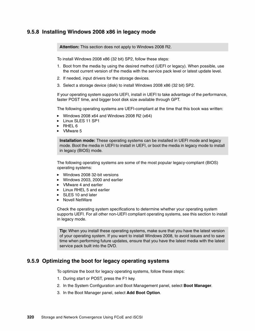
9.5.8 Installing Windows 2008 x86 in legacy mode
To install Windows 2008 x86 (32 bit) SP2, follow these steps:
1. Boot from the media by using the desired method (UEFI or legacy). When possible, use the most current version of the media with the service pack level or latest update level.
2. If needed, input drivers for the storage devices.
3. Select a storage device (disk) to install Windows 2008 x86 (32 bit) SP2.
If your operating system supports UEFI, install in UEFI to take advantage of the performance, faster POST time, and bigger boot disk size available through GPT.
The following operating systems are UEFI-compliant at the time that this book was written:
� Windows 2008 x64 and Windows 2008 R2 (x64)� Linux SLES 11 SP1� RHEL 6� VMware 5
The following operating systems are some of the most popular legacy-compliant (BIOS) operating systems:
� Windows 2008 32-bit versions� Windows 2003, 2000 and earlier � VMware 4 and earlier � Linux RHEL 5 and earlier� SLES 10 and later� Novell NetWare
Check the operating system specifications to determine whether your operating system supports UEFI. For all other non-UEFI compliant operating systems, see this section to install in legacy mode.
9.5.9 Optimizing the boot for legacy operating systems
To optimize the boot for legacy operating systems, follow these steps:
1. During start or POST, press the F1 key.
2. In the System Configuration and Boot Management panel, select Boot Manager.
3. In the Boot Manager panel, select Add Boot Option.
Attention: This section does not apply to Windows 2008 R2.
Installation mode: These operating systems can be installed in UEFI mode and legacy mode. Boot the media in UEFI to install in UEFI, or boot the media in legacy mode to install in legacy (BIOS) mode.
Tip: When you install these operating systems, make sure that you have the latest version of your operating system. If you want to install Windows 2008, to avoid issues and to save time when performing future updates, ensure that you have the latest media with the latest service pack built into the DVD.
320 Storage and Network Convergence Using FCoE and iSCSI

4. In the File Explorer panel (Figure 9-102), highlight Legacy Only, and press Enter.
Figure 9-102 File Explorer panel
5. Select Change Boot Order, and press Enter.
6. In the Change Boot Order panel (Figure 9-103), move Legacy Only to the top by using the + and – keys. Then press Enter.
Figure 9-103 Change Boot Order panel
33A0B98,0x0 ]Load File[PCiRoot (0x0) /Pci (0x7,0x0) /Pci (0x0,0x1)/MAC (E41F133A0B9A,0x0 ]Hard Disk 1Hard Disk 2Hard Disk 3Hard Disk 4USB StorageDiagnosticsiSCSIiSCSI CriticalLegacy OnlyEmbedded Hypervisor
File Explorer
Change the order <Legacy Only><CD/DVD Rom><Floppy Disk><Hard Disk 0><PXE Network>
Commit Changes
Change Boot Order
Commit Changes.
Chapter 9. Configuring iSCSI and FCoE cards for SAN boot 321

7. Highlight Commit Changes, and press Enter.
8. Exit Esc.
9. Type Y to save, and exit. You see the message “UEFI Platform Initialization.”
After some time, the system starts to boot in legacy mode. When you see the following message, you are now in the legacy BIOS section:
Please wait, initializing legacy usb devices...Done
If necessary, to review the settings, press Ctrl+S.
As shown in Figure 9-104, make sure that you can see the disk that you want to boot from with the message “BIOS Installed successfully.”
Figure 9-104 Message showing the LUN and indicating that the BIOS installed successfully
The DVD starts to load.
10.If prompted by the message “Press any key to boot from CD or DVD,” press a key so that the DVD starts to boot. If you do not press a key, the DVD fails to boot.
11.Select your preferences, and click Next.
322 Storage and Network Convergence Using FCoE and iSCSI

12.In the Install Windows window (Figure 9-105), select Install now.
Figure 9-105 reinstall now button on the Install Windows panel
13.Select the operating system that you want to install (Figure 9-106), and then click Next.
Figure 9-106 Selecting the operating system
Chapter 9. Configuring iSCSI and FCoE cards for SAN boot 323
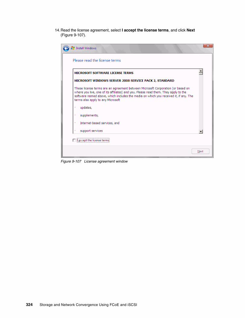
14.Read the license agreement, select I accept the license terms, and click Next (Figure 9-107).
Figure 9-107 License agreement window
324 Storage and Network Convergence Using FCoE and iSCSI

15.For the type of installation (Figure 9-108), select Custom (advanced) to install a clean copy of Windows. Then click Next.
Figure 9-108 Selecting a Custom (advanced) installation
Chapter 9. Configuring iSCSI and FCoE cards for SAN boot 325

16.If no disks are displayed (Figure 9-109), insert the media that contains the drivers. The media can be in the form of a USB key, CD, or DVD, on a remotely mounted ISO. Then click Load Driver to load a driver for your storage device (Emulex card).
Figure 9-109 No drives found message
17.Click OK or Browse to point to the exact location. Windows finds an appropriate, more current driver.
Important: Load the latest Emulex CNA driver that is certified for your disk storage subsystem.
Downloading and extracting the drivers: The Windows 2008 DVD is prepackaged with multiple drivers, but no driver for the Emulex CNA controller. Also the updated driver resolves multiple issues. You can download the blade drivers from the following websites:
� Emulex link to IBM branded HBAs and Virtual Fabric Adapters
http://www.emulex.com/downloads/ibm/vfa-software-kits.html
� IBM BladeCenter
http://www.ibm.com/support/fixcentral/systemx/groupView?query.productGroup=ibm%2FBladeCenter
Extract the drivers and copy them on a removable media such as a USB key, DVD media, or into an ISO file.
326 Storage and Network Convergence Using FCoE and iSCSI

18.In the “Select the driver to be installed” panel (Figure 9-110), select the driver and click Next.
Figure 9-110 Driver selection window
Chapter 9. Configuring iSCSI and FCoE cards for SAN boot 327

19.In the “Where do you want to install Windows” panel (Figure 9-111), when you see your LUN, select the disk, and click Next.
Figure 9-111 Selecting the disk
328 Storage and Network Convergence Using FCoE and iSCSI
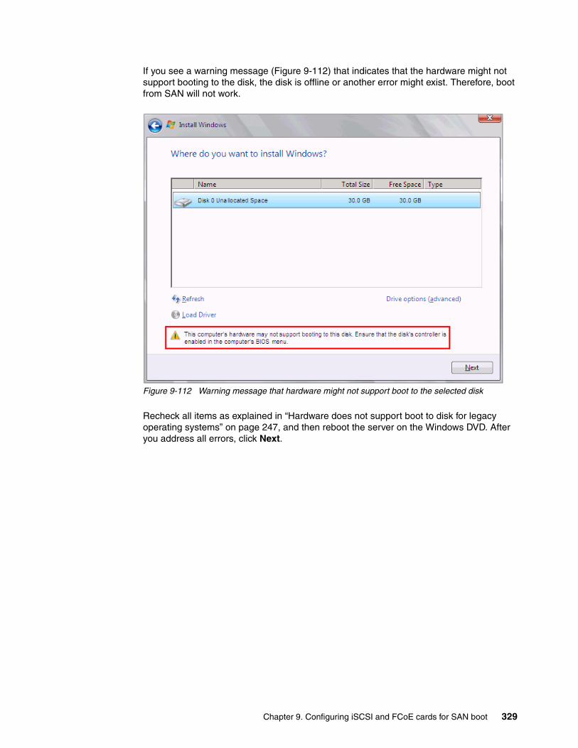
If you see a warning message (Figure 9-112) that indicates that the hardware might not support booting to the disk, the disk is offline or another error might exist. Therefore, boot from SAN will not work.
Figure 9-112 Warning message that hardware might not support boot to the selected disk
Recheck all items as explained in “Hardware does not support boot to disk for legacy operating systems” on page 247, and then reboot the server on the Windows DVD. After you address all errors, click Next.
Chapter 9. Configuring iSCSI and FCoE cards for SAN boot 329

You see a message that Windows wants to create a volume and then starts copying files (Figure 9-113).
Figure 9-113 Windows installation progress window
20.When Windows is done installing and you are prompted to enter a password (Figure 9-114), click OK, and then enter your password.
Figure 9-114 Password prompt after installing Windows
You are now done installing Windows. Continue to 9.9, “After the operating system is installed” on page 438.
330 Storage and Network Convergence Using FCoE and iSCSI
9.5.10 Troubleshooting
This section provides guidance to resolve the following issues that might arise when configuring Emulex for iSCSI:
� Unavailable Emulex Configuration Utility option� Ping failure� Storage devices not shown� Hardware does not support boot to disk in UEFI mode� Hardware does not support boot to disk for legacy operating systems
Unavailable Emulex Configuration Utility optionIn the procedure in 9.3.2, “Configuring the IBM Flex System CN4054” on page 235, if you do not see the Emulex Configuration Utility option, verify that the following items are correct before proceeding:
� Ensure that the BIOS or firmware on the CNA is at the correct level.
� Ensure that the card is seated firmly in the slot.
� Ensure that the system UEFI is at the current supported level.
� Ensure that the iSCSI or FCoE license is installed on the adapter. If the license is not installed, the adapter will not work. Therefore, you must contact your IBM marketing representative or vendor to obtain the license.
� The Virtual Fabric Adapter is set to NIC only or iSCSI. Both provide the same result.
Ping failureIn the procedure in 9.3.4, “Configuring the IBM Flex System CN4054 settings” on page 238, if a ping failure occurs, check whether you see the following items, and then perform the ping test again:
� Check for typographical errors in the following areas:
– IP address to ping– IP address, subnet, or gateway of the CNA port– IP address, subnet, or gateway of the disk storage subsystem host port
� Verify that the Ethernet cable is connected securely, or check pins to make sure that no pins or bent or missing.
� Recheck your configuration settings to ensure that you do not have a bad switch setup (VLAN, trunking, allowed VLAN, or VLAN down).
� Check the connectivity of the storage device and configuration settings if the disk storage device cannot answer an ICMP request on the host ports.
� Check firewall settings to ensure that access is not blocked.
Storage devices not shownFor you to see your storage devices, you must perform the steps as explained in 9.3.4, “Configuring the IBM Flex System CN4054 settings” on page 238. If you do not see your storage devices, see 9.3.1, “Configuring IBM Flex System CN4054 for boot from SAN” on page 232, to ensure that everything is in place on the SAN for the setup to work.
Tip: Check the switch configuration, delete your mapping, and remap. When remapped, check the preferred path. These tasks take time, but often correct the error. Then reboot your system and check again if the storage devices are displayed.
Chapter 9. Configuring iSCSI and FCoE cards for SAN boot 331

Hardware does not support boot to disk in UEFI modeIn the procedure in 9.4.7, “Booting the Windows DVD in UEFI mode” on page 258, you might receive a message that indicates that the hardware might not support boot to disk. If you see this message, review the setup instructions in 9.3.1, “Configuring IBM Flex System CN4054 for boot from SAN” on page 232, and then check the following settings:
� Verify that the boot device was added when you pressed F1 (go back and check).
� Verify that the BIOS is enabled on the Emulex port (go back and check).
� Verify that the CNA from which you are trying to do the boot is on the preferred path of the SAN disk. The most common cause of an offline disk is that the preferred path is not assigned correctly. Check your SAN disk device configuration, and then reboot the server again on the Windows DVD.
� Verify that your SAN disk supports a UEFI boot.
� Verify that your SAN disk is updated to the latest firmware.
� Try to perform a legacy installation.
� If the disk is offline, see Windows KB 2345135, “Setup reports error ‘Windows cannot be installed to this disk...’ when booted from DVD” at this website:
http://support.microsoft.com/kb/2345135
� If setup reports the error message “Windows cannot be installed to this disk...” booted from DVD in UEFI mode, consider modifying the Windows installation media.
� Use Windows media that is bundled with the latest service pack.
� If you see a 20-MB disk, you most likely mapped the access LUN instead of the LUN. To correct this problem, log in to your disk storage subsystem.
� Make sure that your LUN is using LUN 0, which is defined in the SAN disk device.
� Make sure that you are using the latest Windows DVD with the latest service pack built-in.
� Verify that the path is on the preferred path. Check your SAN configuration to verify the settings.
� Verify that zoning is correct or unchanged.
� Verify that LUN mapping is correct or unchanged.
Hardware does not support boot to disk for legacy operating systemsIn the procedure in 9.4.11, “Optimizing the boot for legacy operating systems” on page 274, you might receive a message that indicates that the hardware might not support boot to disk. If you see this message, review the setup instructions in 9.3.1, “Configuring IBM Flex System CN4054 for boot from SAN” on page 232, and then check the following settings:
� Verify that the boot device was added when you pressed F1 (go back and check).
� Verify that the BIOS was enabled on the Emulex port (go back and check).
� Verify that the CNA that you are trying to boot from is on the SAN disk preferred path. The most common cause of an offline disk is that the preferred path is not assigned correctly. Check your SAN disk device configuration, and then reboot the server again on the Windows DVD.
� Verify that your SAN disk is updated to the latest firmware.
� Use Windows media that is bundled with the latest service pack.
� If you see a 20-MB disk, you most likely mapped the access LUN instead of the LUN. You can fix this problem in your disk storage subsystem.
� Verify that your LUN is using LUN 0, which is defined in the SAN disk device.
332 Storage and Network Convergence Using FCoE and iSCSI

� Verify that you are using the latest Windows DVD with the latest service pack built-in.
� Verify that the path is the preferred path. Check with your SAN configuration.
� Verify that zoning is correct or unchanged.
� Verify that LUN mapping is correct or unchanged.
9.6 Configuring Emulex for FCoE in the BladeCenter
This section explains how to configure the Emulex Virtual Fabric Adapter I CFFh card PN 49Y4277 FRU 49Y4261 (OCm10102-F-X), which is referred to as Emulex CNA. The steps are similar for Virtual Fabric Adapter II. Firmware versions might vary.
This scenario entails the following components:
� BladeCenter H machine type 8852� HS22 machine type 7870
– UEFI P9155A 1.15– Blade System Management Processor YUOOC7E 1.30– Emulex 10 GB Virtual Fabric Adapter Advanced (OCm10102-F-X)
• 49Y4277 FRU 49Y426• Firmware: 2.703.397.3806• EFI Boot: 5.01a8• FCoE driver: elxdrvr-fc-fcoe-2.41.003-2• Adapter configured with iSCSI / FCoE license• Adapter configured in FCoE personality
– Brocade 8470 switch with Firmware FOS v6.3.1_cee
The Emulex Virtual Fabric Adapter requires the FCoE license to perform FCoE tasks. By default, the Emulex Virtual Fabric Adapter is a 10-Gbps NIC only. You can order a license to upgrade a Virtual Fabric Adapter to support iSCSI and FCoE. The advanced version of the adapter comes with the iSCSI and FCoE license preinstalled. You need OneCommand Manager to change the personality card to NIC only, FCoE, or iSCSI. For more information, see 7.2, “Installing and enabling the Emulex CNA” on page 113.
This section is specifically for Blade HS22. Doing boot from SAN on other systems, such as HS22v or HX5, x3550 m2, x3650 m2, x3550 m3, and x3650 m3, is similar. Use the latest drivers and firmware that are certified by the SAN disk vendor, and not the versions that are documented here.
9.6.1 Configuring an Emulex card for boot from SAN
The Emulex card in the blade server is a dual port CNA. You can boot from either port, but you can boot only from one port and one path at a time. You must perform the initial installation by using a single path. The redundancy occurs later when the operating system is installed and when the multipath driver is installed.
PCIe version: Although this section is written for a specific Emulex CNA, the steps for a PCIe version of this adapter are similar. At the time of writing this book, the license offering for the Virtual Fabric Adapter is not available, but work is being done to make it available.
Chapter 9. Configuring iSCSI and FCoE cards for SAN boot 333

At this stage, you must perform the following connections and configurations on the SAN:
� On the switches:
– Enable the ports.
– Configure the FCoE. Check ENodes, Fibre Channel Forwarders (FCFs), and FCoE Initialization Protocol (FIP).
– Ensure that the blade host has a connection all the way to the disk storage subsystem.
– On the FC side, ensure that the disk storage subsystem and the blade CNA worldwide port name (WWPN) are present in the name server or Fabric Login (FLOGI) table.
– Configure zoning. The zone must contain one CNA WWPN and one SAN disk controller WWPN. Zoning is done on the fiber switch. Some people might decide to function with an open fabric, without any zoning. However, over time, this setup is likely to fail or cause problems.
You can zone the following switches:
• A Brocade switch by using the Zone Admin function• A QLogic switch by selecting Zoning Edit Zoning• A Cisco switch by using the Device Manager and selecting FC Quick Config
Wizard
Use the command-line interface (CLI) for more advanced configurations.
� On the disk storage subsystem:
– Ensure that the storage subsystem and SAN disk have a logical drive (LUN) created and mapped to the WWPN of the CNA of the blade server.
– The LUN might require you to wait for it to be fully initialized before using it.
– When you create a LUN normally, a synchronization process starts. With some storage, you can work with this LUN when it is synchronizing. Other storage might require you to wait for the LUN to be fully initialized. For information about how it operates, see your storage documentation for your SAN disk storage.
– Map the LUN to a single CNA WWPN. Do not map both WWPNs yet. You map it to both CNA WWPNs later. At installation time, restrict this mapping to a single path. Otherwise, a stop error (blue screen) or other installation issues can occur.
– For an asymmetrical storage subsystem only, set the LUN on the correct path that you want to boot from.
Some SANs are asymmetrical storage subsystem, such as the IBM System Storage DS3000, DS4000, and DS5000 series. Other SANs are symmetrical storage subsystems, such as SAN Volume Controller and IBM System Storage DS8000. The asymmetrical storage subsystems controllers set a preferred path. The preferred path must be set to communicate to your CNA WWPN.
– The LUN on most SANs is presented to a single controller at a time. This LUN can move from controller A to controller B.
– At installation time, the operating system does not have its redundant driver loaded and, therefore, does not handle redundant paths. To work around this issue, provide a single path.
ENodes: ENodes are the combination of FCoE termination functions and Fibre Channel stack on the CNAs. In that sense, they are equivalent to HBAs in native Fibre Channel networks.
334 Storage and Network Convergence Using FCoE and iSCSI

– If you are booting through CNA port 0, which has a WWPN, and port 0 communicates to controller A1, your preferred path for your LUN is A on the SAN disk. If you are booting through CNA port 0, has a WWPN, and port 0 communicates to controller B1, your preferred path for your LUN is B on the SAN disk.
– The preferred path is normally easy to change in the SAN disk settings.
You must know your environment, cabling, and setup, which you can validate by checking cable connections, SAN disk configuration, or logs.
9.6.2 Configuring the Emulex CNA
To configure the Emulex CNA, follow these steps:
1. During start or POST, press the F1 key.
2. In the System Configuration and Boot Management panel, select System Settings.
3. In the System Settings panel (Figure 9-115), select Emulex Configuration Utility Ver: x.xxxxx.
Figure 9-115 System Settings panel
If you do not see the Emulex Configuration Utility option, see “Unavailable Emulex Configuration Utility option” on page 367.
Then press Enter.
Chapter 9. Configuring iSCSI and FCoE cards for SAN boot 335

4. In the Adapter Selection panel (Figure 9-116), where you see two Emulex fiber ports, select the Emulex Configuration Setup Utility.
Figure 9-116 Adapter Selection panel
5. Note the WWPN of the CNA. Select the port you want to boot from, and then press Enter.
Tip: For optimal performance, consider booting half of your blades from one port and booting half from the other port. Also consider splitting the load on the different SAN disk controller ports. However, be careful because splitting the load adds more complexity, and check your SAN disk preferred paths carefully.
336 Storage and Network Convergence Using FCoE and iSCSI

9.6.3 Loading the default settings on the Emulex CNA
To load the default settings on the Emulex CNA, follow these steps:
1. In the Emulex Adapter Configuration Main Menu panel (Figure 9-117), select Set Emulex Adapter to Default Settings.
Figure 9-117 Emulex Adapter Configuration Main Menu panel
Chapter 9. Configuring iSCSI and FCoE cards for SAN boot 337
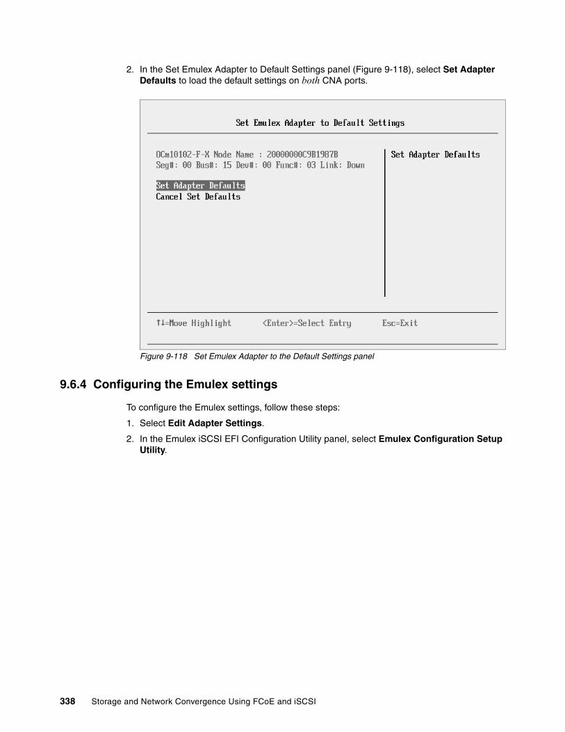
2. In the Set Emulex Adapter to Default Settings panel (Figure 9-118), select Set Adapter Defaults to load the default settings on both CNA ports.
Figure 9-118 Set Emulex Adapter to the Default Settings panel
9.6.4 Configuring the Emulex settings
To configure the Emulex settings, follow these steps:
1. Select Edit Adapter Settings.
2. In the Emulex iSCSI EFI Configuration Utility panel, select Emulex Configuration Setup Utility.
338 Storage and Network Convergence Using FCoE and iSCSI
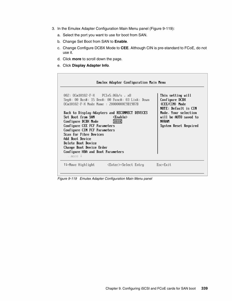
3. In the Emulex Adapter Configuration Main Menu panel (Figure 9-119):
a. Select the port you want to use for boot from SAN.
b. Change Set Boot from SAN to Enable.
c. Change Configure DCBX Mode to CEE. Although CIN is pre-standard to FCoE, do not use it.
d. Click more to scroll down the page.
e. Click Display Adapter Info.
Figure 9-119 Emulex Adapter Configuration Main Menu panel
Chapter 9. Configuring iSCSI and FCoE cards for SAN boot 339
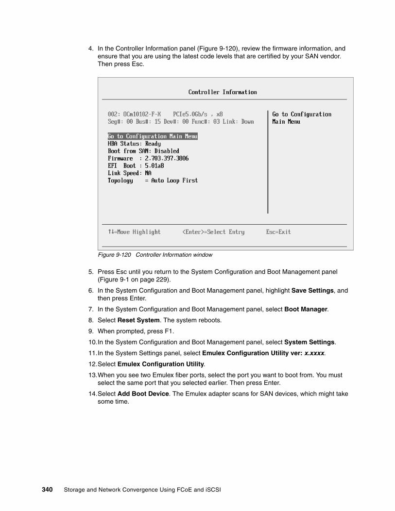
4. In the Controller Information panel (Figure 9-120), review the firmware information, and ensure that you are using the latest code levels that are certified by your SAN vendor. Then press Esc.
Figure 9-120 Controller Information window
5. Press Esc until you return to the System Configuration and Boot Management panel (Figure 9-1 on page 229).
6. In the System Configuration and Boot Management panel, highlight Save Settings, and then press Enter.
7. In the System Configuration and Boot Management panel, select Boot Manager.
8. Select Reset System. The system reboots.
9. When prompted, press F1.
10.In the System Configuration and Boot Management panel, select System Settings.
11.In the System Settings panel, select Emulex Configuration Utility ver: x.xxxx.
12.Select Emulex Configuration Utility.
13.When you see two Emulex fiber ports, select the port you want to boot from. You must select the same port that you selected earlier. Then press Enter.
14.Select Add Boot Device. The Emulex adapter scans for SAN devices, which might take some time.
340 Storage and Network Convergence Using FCoE and iSCSI
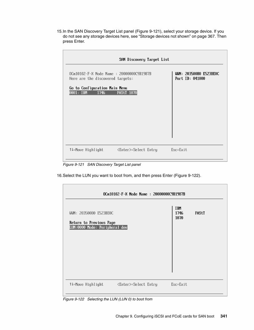
15.In the SAN Discovery Target List panel (Figure 9-121), select your storage device. If you do not see any storage devices here, see “Storage devices not shown” on page 367. Then press Enter.
Figure 9-121 SAN Discovery Target List panel
16.Select the LUN you want to boot from, and then press Enter (Figure 9-122).
Figure 9-122 Selecting the LUN (LUN 0) to boot from
Chapter 9. Configuring iSCSI and FCoE cards for SAN boot 341

Some operating systems require LUN 0 to boot from. If you see a LUN with a number other than 0, you might want to sign in to your SAN disk storage device and redo your mapping so that the LUN is LUN 0. Then reboot the blade again, and go back to 1 on page 338 to repeat this part of the procedure.
17.In the SAN Discovery Target List (Figure 9-123), select Commit Changes.
Figure 9-123 SAN Discovery Target List panel
18.Press Esc until you return to the System Configuration and Boot Management panel (Figure 9-1 on page 229).
The adapter is now ready to boot from SAN. Depending on your environment, continue to the following sections as appropriate:
� If you are installing your operating system in UEFI mode, go to 9.6.6, “Installing Windows 2008 x64 or Windows 2008 R2 (x64) in UEFI mode” on page 343.
� If you are installing your operating system in legacy mode, go to 9.6.8, “Installing Windows 2008 x86 in legacy mode” on page 356.
� If you are uncertain about whether you want to install in UEFI or MBR, go to 9.6.6, “Installing Windows 2008 x64 or Windows 2008 R2 (x64) in UEFI mode” on page 343.
9.6.5 Booting from SAN variations
You can set up boot from SAN by using various methods. This book concentrates on the fixed target LUN. In some cases, it is useful to have a more dynamic solution. We show what we consider the most stable and most optimized method. The method you choose depends on what you want to accomplish.
342 Storage and Network Convergence Using FCoE and iSCSI

A more dynamic setup can be useful to prevent a requirement to reconfigure the adapter settings every time to change LUN assignment to another host. However, it might take more time to scan the LUNs at boot every time the system is rebooted. If you are setting up Blade Open Fabric Manager or have a hot spare blade, set these more dynamic settings, and do not assign a fixed boot LUN.
Figure 9-124 shows some of the Emulex settings that you can change. For more information, see the Emulex website:
http://www.emulex.com
Figure 9-124 Configure HBA Parameters panel
9.6.6 Installing Windows 2008 x64 or Windows 2008 R2 (x64) in UEFI mode
Installing Windows 2008 R2 x64 (64 bit) with SP1 is similar for other operating systems.
To install Windows 2008 R2 x64 (64 bit) with SP1, follow these steps:
1. Boot from the media by using the preferred method (UEFI or legacy). Use the most current version of the media with the service pack level or latest update level (when possible).
2. If needed, input drivers for the storage devices.
3. Select a storage device (disk) to install the operating system.
You must know whether your operating system is UEFI-compliant. The following operating systems are UEFI-compliant at the time this book was written:
� Windows 2008 x64 and Windows 2008 R2 (x64)� Linux SLES 11 SP1� RHEL 6� VMware 5
Chapter 9. Configuring iSCSI and FCoE cards for SAN boot 343

For all other non-UEFI compliant operating systems, see 9.7.7, “Installing Windows 2008 x86 in legacy mode” on page 391.
If you are installing a UEFI-compliant operating system, install it in UEFI mode for performance reasons. UEFI gives you access to new features such as these:
� Bigger boot disk sizes: UEFI boots from a GPT partitioned disk (instead of MBR). GPT is no longer limited to a 2-TB boot drive. However keep in mind that you can have some software that requires the use of MBR (such as older backup software).
� Faster boot times: A UEFI machine in legacy mode (BIOS) takes more time to boot. The UEFI system boots once, initializes all devices in UEFI mode, and then does a POST a second time for legacy mode, which is time consuming. By installing in UEFI mode, you save this second boot time. Also, by using UEFI, the operating systems can take advantage of 32 bits or 64 bits, as opposed to BIOS systems that are limited to a 16-bit boot.
� PCI ROM limitations are much larger with UEFI compared to BIOS: With BIOS systems, you are limited by the small memory size of the ROM option that often generated 1801 PCI memory allocation errors.
Choose carefully whether you want to install in UEFI mode or legacy mode, because after the operating system is installed, the only way to change it is to delete and reinstall it.
9.6.7 Booting the Windows DVD in UEFI mode
You can boot the Windows media by placing the Windows 2008 x64 DVD in the DVD drive and having the machine boot automatically. By default, the system attempts to boot in UEFI mode. If it fails, it attempts to boot in legacy mode.
To boot the Windows DVD in UEFI mode, follow these steps:
1. During start or POST, press the F1 key.
2. In the System Configuration and Boot Management panel, select Boot Manager.
3. In the Boot Manager panel, select Boot From File. In this scenario, we boot from an HS22 shared DVD or CD. The DVD in the media tray is considered a USB device.
Tips:
� These operating systems can be installed in both UEFI and legacy mode.
� When you install these operating systems, make sure that you have the latest version of your operating system. If you want to install Windows 2008, to avoid issues and to save time when performing future updates, ensure that you have the latest media with the latest service pack built into the DVD.
Tip: Depending on when you insert the Windows DVD during the system POST, you can boot the media in UEFI mode or legacy mode. To fully control the boot, follow the instructions as explained in this section to boot the DVD in UEFI mode.
344 Storage and Network Convergence Using FCoE and iSCSI

4. In the File Explorer panel (Figure 9-125), select EFISECTOR and the associated information and then press Enter.
If you do not see the CD, make sure that the media tray is assigned to the correct blade and that you have a UEFI-bootable CD or DVD inserted or mounted. If your DVD is not UEFI bootable, it is not displayed in the list.
Figure 9-125 Selecting the CD
EFISECTOR,[PciRoot (0x0 /Pci (0xID,0x7) /USB(0x2.0x0) /USB (0x1.0x0 /USB(0x0,0x0) /CDROM (0x1,0x33C,0x13D94C)]Load File[PciRoot (0x0) /Pci (0x7,0x0 /Pci (0x0,0x0)/ MAC (E41F133A0B98,0x0)]Load File[PciRoot (0x0) /Pci (0x7,0x0) /Pci (0x0,0x1)/ MAC (E41F133A0B9A,0x0)]
File Explorer
Chapter 9. Configuring iSCSI and FCoE cards for SAN boot 345
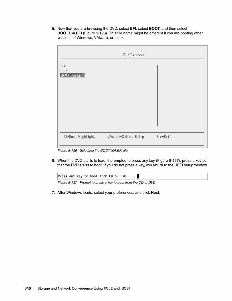
5. Now that you are browsing the DVD, select EFI, select BOOT, and then select BOOTX64.EFI (Figure 9-126). This file name might be different if you are booting other versions of Windows, VMware, or Linux.
Figure 9-126 Selecting the BOOTX64.EFI file
6. When the DVD starts to load, if prompted to press any key (Figure 9-127), press a key so that the DVD starts to boot. If you do not press a key, you return to the UEFI setup window.
Figure 9-127 Prompt to press a key to boot from the CD or DVD
7. After Windows loads, select your preferences, and click Next.
<.><..>BOOTX64.EFI
File Explorer
Press any key to boot from CD or DVD.....
346 Storage and Network Convergence Using FCoE and iSCSI
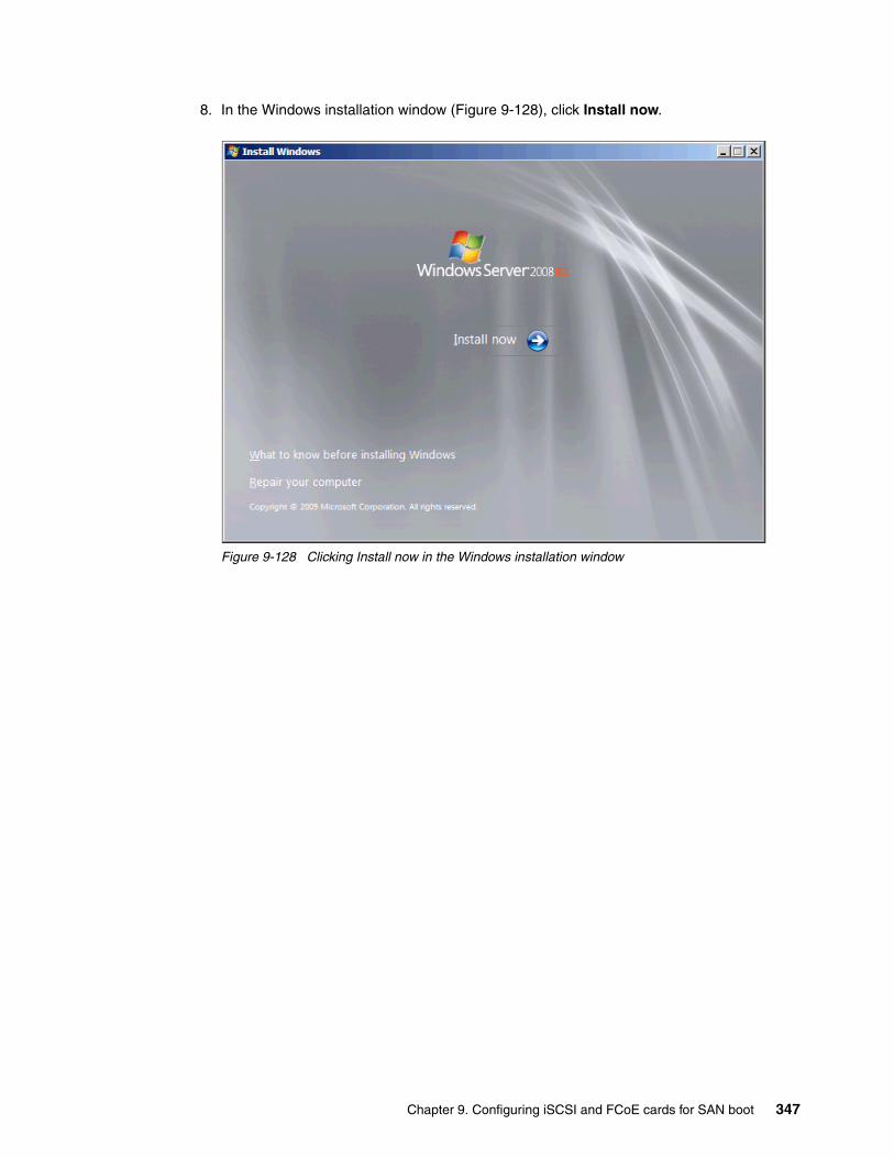
8. In the Windows installation window (Figure 9-128), click Install now.
Figure 9-128 Clicking Install now in the Windows installation window
Chapter 9. Configuring iSCSI and FCoE cards for SAN boot 347

9. In the Install Windows window (Figure 9-129), select your operating system, and click Next. Select your operating system.
Figure 9-129 Selecting the operating system to install
348 Storage and Network Convergence Using FCoE and iSCSI
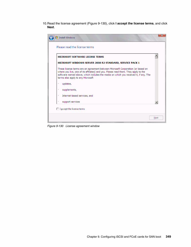
10.Read the license agreement (Figure 9-130), click I accept the license terms, and click Next.
Figure 9-130 License agreement window
Chapter 9. Configuring iSCSI and FCoE cards for SAN boot 349

11.In the installation type panel (Figure 9-131), select Custom (advanced) to install a clean copy of Windows.
Figure 9-131 Selecting to install a clean copy of Windows
350 Storage and Network Convergence Using FCoE and iSCSI
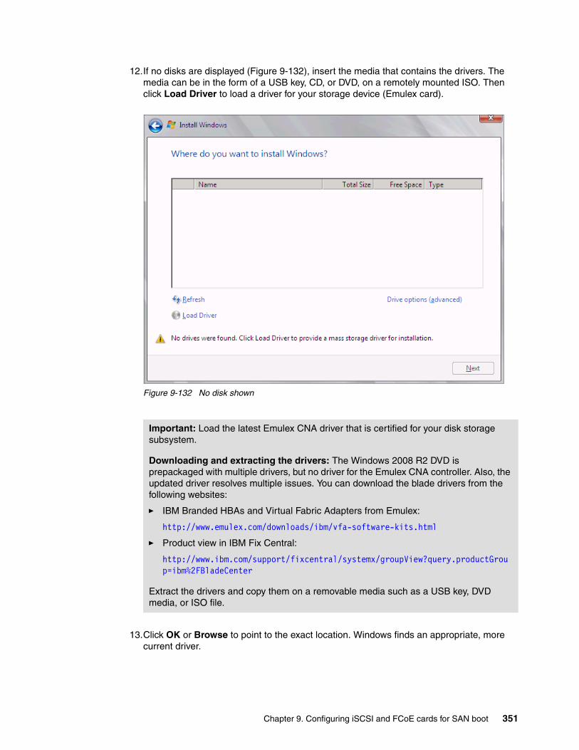
12.If no disks are displayed (Figure 9-132), insert the media that contains the drivers. The media can be in the form of a USB key, CD, or DVD, on a remotely mounted ISO. Then click Load Driver to load a driver for your storage device (Emulex card).
Figure 9-132 No disk shown
13.Click OK or Browse to point to the exact location. Windows finds an appropriate, more current driver.
Important: Load the latest Emulex CNA driver that is certified for your disk storage subsystem.
Downloading and extracting the drivers: The Windows 2008 R2 DVD is prepackaged with multiple drivers, but no driver for the Emulex CNA controller. Also, the updated driver resolves multiple issues. You can download the blade drivers from the following websites:
� IBM Branded HBAs and Virtual Fabric Adapters from Emulex:
http://www.emulex.com/downloads/ibm/vfa-software-kits.html
� Product view in IBM Fix Central:
http://www.ibm.com/support/fixcentral/systemx/groupView?query.productGroup=ibm%2FBladeCenter
Extract the drivers and copy them on a removable media such as a USB key, DVD media, or ISO file.
Chapter 9. Configuring iSCSI and FCoE cards for SAN boot 351

14.In the “Select the driver to be installed” panel (Figure 9-133), select the driver, and click Next.
Figure 9-133 Selecting the driver to be installed panel
352 Storage and Network Convergence Using FCoE and iSCSI

15.In the “Where do you want to install Windows” panel (Figure 9-134), when you see your LUN, select the disk, and then click Next.
Figure 9-134 Selecting the LUN to install Windows
Chapter 9. Configuring iSCSI and FCoE cards for SAN boot 353
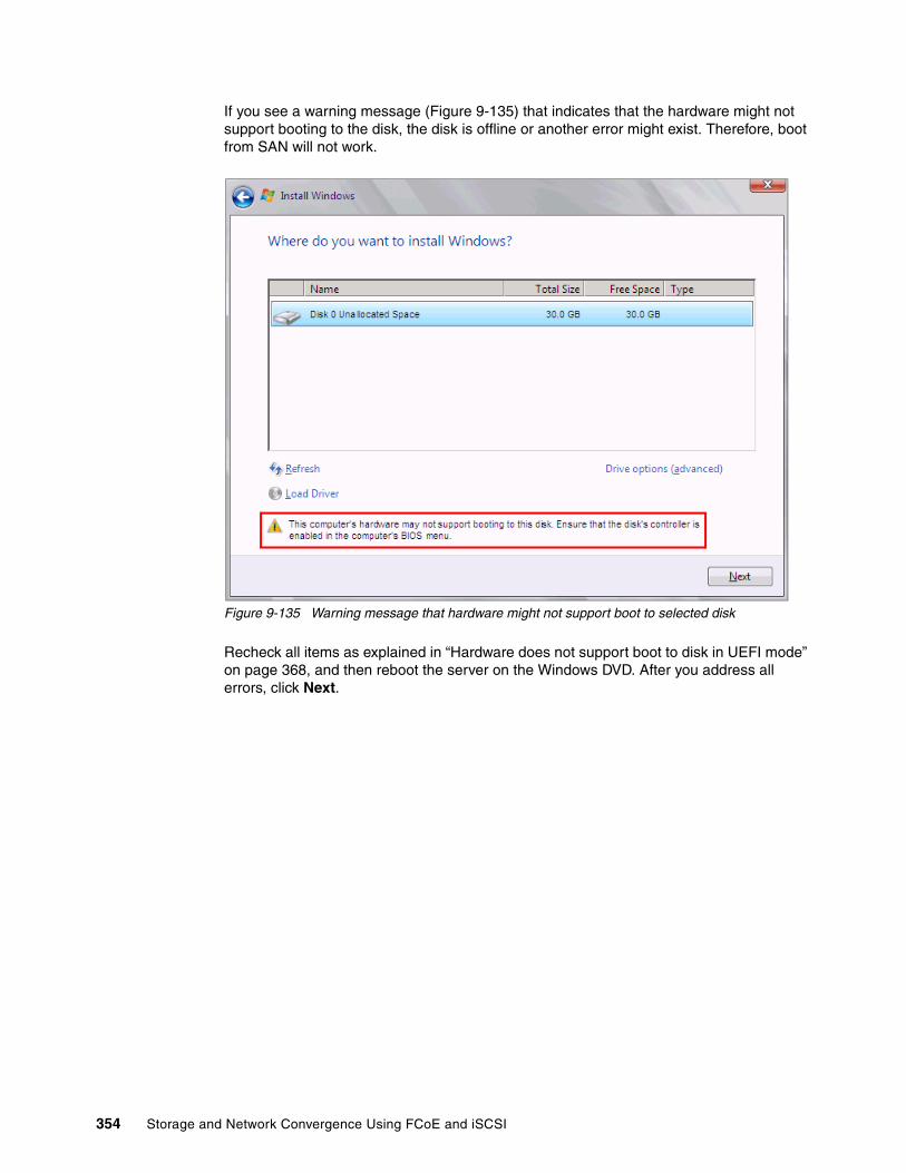
If you see a warning message (Figure 9-135) that indicates that the hardware might not support booting to the disk, the disk is offline or another error might exist. Therefore, boot from SAN will not work.
Figure 9-135 Warning message that hardware might not support boot to selected disk
Recheck all items as explained in “Hardware does not support boot to disk in UEFI mode” on page 368, and then reboot the server on the Windows DVD. After you address all errors, click Next.
354 Storage and Network Convergence Using FCoE and iSCSI
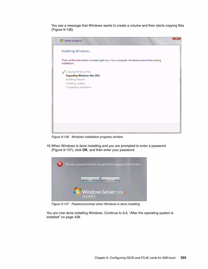
You see a message that Windows wants to create a volume and then starts copying files (Figure 9-136).
Figure 9-136 Windows installation progress window
16.When Windows is done installing and you are prompted to enter a password (Figure 9-137), click OK, and then enter your password.
Figure 9-137 Password prompt when Windows is done installing
You are now done installing Windows. Continue to 9.9, “After the operating system is installed” on page 438.
Chapter 9. Configuring iSCSI and FCoE cards for SAN boot 355
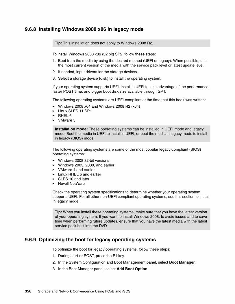
9.6.8 Installing Windows 2008 x86 in legacy mode
To install Windows 2008 x86 (32 bit) SP2, follow these steps:
1. Boot from the media by using the desired method (UEFI or legacy). When possible, use the most current version of the media with the service pack level or latest update level.
2. If needed, input drivers for the storage devices.
3. Select a storage device (disk) to install the operating system.
If your operating system supports UEFI, install in UEFI to take advantage of the performance, faster POST time, and bigger boot disk size available through GPT.
The following operating systems are UEFI-compliant at the time that this book was written:
� Windows 2008 x64 and Windows 2008 R2 (x64)� Linux SLES 11 SP1� RHEL 6� VMware 5
The following operating systems are some of the most popular legacy-compliant (BIOS) operating systems:
� Windows 2008 32-bit versions� Windows 2003, 2000, and earlier � VMware 4 and earlier � Linux RHEL 5 and earlier� SLES 10 and later� Novell NetWare
Check the operating system specifications to determine whether your operating system supports UEFI. For all other non-UEFI compliant operating systems, see this section to install in legacy mode.
9.6.9 Optimizing the boot for legacy operating systems
To optimize the boot for legacy operating systems, follow these steps:
1. During start or POST, press the F1 key.
2. In the System Configuration and Boot Management panel, select Boot Manager.
3. In the Boot Manager panel, select Add Boot Option.
Tip: This installation does not apply to Windows 2008 R2.
Installation mode: These operating systems can be installed in UEFI mode and legacy mode. Boot the media in UEFI to install in UEFI, or boot the media in legacy mode to install in legacy (BIOS) mode.
Tip: When you install these operating systems, make sure that you have the latest version of your operating system. If you want to install Windows 2008, to avoid issues and to save time when performing future updates, ensure that you have the latest media with the latest service pack built into the DVD.
356 Storage and Network Convergence Using FCoE and iSCSI

4. In the File Explorer panel (Figure 9-138), highlight Legacy Only, and press Enter.
Figure 9-138 File Explorer panel
5. In the Change Boot Order panel (Figure 9-139), follow these steps:
a. Select Change Boot Order, and press Enter.b. Move Legacy Only to the top by using + and – keys. Then press Enter.c. Highlight Commit Changes, and press Enter.
Figure 9-139 Change Boot Order panel
33A0B98,0x0 ]Load File[PCiRoot (0x0) /Pci (0x7,0x0) /Pci (0x0,0x1)/MAC (E41F133A0B9A,0x0 ]Hard Disk 1Hard Disk 2Hard Disk 3Hard Disk 4USB StorageDiagnosticsiSCSIiSCSI CriticalLegacy OnlyEmbedded Hypervisor
File Explorer
Change the order <Legacy Only><CD/DVD Rom><Floppy Disk><Hard Disk 0><PXE Network>
Commit Changes
Change Boot Order
Commit Changes.
Chapter 9. Configuring iSCSI and FCoE cards for SAN boot 357

6. Press Esc to exit Setup.
7. Type Y to save, and exit. You see the message “UEFI Platform Initialization.”
After some time, the system starts to boot in legacy mode. When you see the following message, you are now in the legacy BIOS section:
Please wait, initializing legacy usb devices...Done
If necessary, to review the settings, press Ctrl+E.
As shown in Figure 9-140, make sure that you can see the disk that you want to boot from with the message “Emulex BIOS is Installed successfully.”
Figure 9-140 Emulex OneConnect panel
The DVD starts to load.
8. If prompted by the message “Press any key to boot from CD or DVD,” press a key so that the DVD starts to boot. If you do not press a key, the DVD fails to boot.
9. Select your preferences, and click Next.
358 Storage and Network Convergence Using FCoE and iSCSI

10.In the Install Windows panel (Figure 9-141), select Install now.
Figure 9-141 Install now button in the Install Windows panel
11.Select the operating system that you want to install (Figure 9-142), and then click Next.
Figure 9-142 Selecting the operating system
Chapter 9. Configuring iSCSI and FCoE cards for SAN boot 359

12.Read the license agreement, select I accept the license terms, and click Next (Figure 9-143).
Figure 9-143 License agreement window
360 Storage and Network Convergence Using FCoE and iSCSI

13.For the type of installation (Figure 9-144), select Custom (advanced) to install a clean copy of Windows. Then click Next.
Figure 9-144 Selecting to install a clean copy of Windows
Chapter 9. Configuring iSCSI and FCoE cards for SAN boot 361

14.If no disks are displayed (Figure 9-145), insert the media that contains the drivers. The media can be in the form of a USB key, CD, or DVD, on a remotely mounted ISO. Then click Load Driver to load a driver for your storage device (Emulex card).
Figure 9-145 No drives found message
15.Click OK or Browse to point to the exact location. Windows finds an appropriate, more current driver.
Important: Load the latest Emulex CNA driver that is certified for your disk storage subsystem.
Downloading and extracting the drivers: The Windows 2008 DVD is prepackaged with multiple drivers, but no driver for the Emulex CNA controller. Also the updated driver resolves multiple issues. You can download the blade drivers from the following websites:
� Emulex IBM
http://www.emulex.com/downloads/ibm/vfa-software-kits.html
� IBM BladeCenter
http://www.ibm.com/support/fixcentral/systemx/groupView?query.productGroup=ibm%2FBladeCenter
Extract the drivers and copy them on a removable media such as a USB key, DVD media, or into an ISO file.
362 Storage and Network Convergence Using FCoE and iSCSI

16.In the “Select the driver to be installed” panel (Figure 9-146), select the driver, and then click Next.
Figure 9-146 Selecting the driver to be installed
Chapter 9. Configuring iSCSI and FCoE cards for SAN boot 363

17.In the “Where do you want to install Windows” panel (Figure 9-147), when you see your LUN, select the disk, and then click Next.
Figure 9-147 Selecting the disk to install on
364 Storage and Network Convergence Using FCoE and iSCSI

If you see a warning message (Figure 9-148) that indicates that the hardware might not support booting to the disk, the disk is offline or another error might exist. Therefore, boot from SAN will not work.
Figure 9-148 Warning message about hardware not supporting boot to disk
Recheck all items as explained in “Hardware does not support boot to disk for legacy operating systems” on page 369, and then reboot the server on the Windows DVD. After you address all errors, click Next.
Chapter 9. Configuring iSCSI and FCoE cards for SAN boot 365

You see a message that Windows wants to create a volume and then starts copying files (Figure 9-149).
Figure 9-149 Windows installation progress window
18.When Windows is done installing and you are prompted to enter a password (Figure 9-150), click OK, and then enter your password.
Figure 9-150 Password prompt after installing Windows
You are now done installing Windows. Continue to 9.9, “After the operating system is installed” on page 438.
366 Storage and Network Convergence Using FCoE and iSCSI

9.6.10 Troubleshooting
This section provides guidance to resolve the following issues that might arise when configuring Emulex for FCoE:
� Unavailable Emulex Configuration Utility option� Storage devices not shown� Hardware does not support boot to disk in UEFI mode� Hardware does not support boot to disk for legacy operating systems
Unavailable Emulex Configuration Utility optionIn the procedure in 9.6.2, “Configuring the Emulex CNA” on page 335, if you do not see the Emulex Configuration Utility option, verify that the following items are correct before proceeding:
� Ensure that the BIOS or firmware on the CNA is at the correct level.
� Ensure that the card is seated firmly in the slot.
� Ensure that the system UEFI is at the current supported level.
� Ensure that the iSCSI or FCoE license is installed on the adapter. If the license is not installed, the adapter will not work. Therefore, you must contact your IBM marketing representative or vendor to obtain the license.
� The Virtual Fabric Adapter is set to NIC only or iSCSI. Both provide the same result.
Storage devices not shownIn the procedure in 9.6.4, “Configuring the Emulex settings” on page 338, if you do not see your storage devices, complete the steps as explained in 9.6.3, “Loading the default settings on the Emulex CNA” on page 337. Pay special attention to the following areas:
� You must zone your switches.� Verify that the zone contains one CNA WWPN and one SAN disk controller WWPN.� Ensure that the SAN disk has a logical drive (LUN) created.� The LUN might require you to wait for it to be fully initialized before using it.� Map the LUN to a single CNA WWPN as LUN 0.� Set the LUN on the correct preferred path from which you want to boot.
After you complete these checks, and no devices are displayed, check the following areas:
� Ensure that your Emulex BIOS was updated.
� Have the switch initiate the port login:
a. Log in to the switch that connects to the host.b. Select the blade port.c. Shut down the blade port.d. Enter the no shutdown command to bring the blade port up.e. Wait 30 seconds, and make sure that the port is logged in.f. Add the boot device again from the blade.
� Reboot the blade, and press F1. If you made changes to the SAN disk storage during setup, reboot so that the UEFI can rescan the available disks.
� Change the fiber switch configuration.
If multiple switches are communicating with each other, set the Brocade switch to gateway mode, the QLogic switch to transparent mode, or the Cisco switch to NPV mode.
For more information, see the Brocade Access Gateway Administration guide or Implementing the Brocade Access Gateway for IBM BladeCenter, REDP-4343.
Chapter 9. Configuring iSCSI and FCoE cards for SAN boot 367

� Confirm that the switch name server can detect the WWPN of your CNA and the WWPN of your SAN disk storage. From the name server, some switches can show accessible devices. Make sure that the two devices that you are trying to access communicate and are displayed.
Go through the checklist again to ensure that everything is in place on the SAN for the setup to work.
Hardware does not support boot to disk in UEFI modeIn the procedure in 9.6.7, “Booting the Windows DVD in UEFI mode” on page 344, you might receive a message that indicates that the hardware might not support boot to disk. If you see this message, review the setup instructions in 9.6.1, “Configuring an Emulex card for boot from SAN” on page 333, and then check the following settings:
� Verify that the boot device was added when you pressed F1 (go back and check).
� Verify that the BIOS is enabled on the Emulex port (go back and check).
� Verify that the CNA from which you are trying to do the boot is on the preferred path of the SAN disk. The most common cause of an offline disk is that the preferred path is not assigned correctly. Check your SAN disk device configuration, and then reboot the server again on the Windows DVD.
� Verify that your SAN disk supports a UEFI boot.
� Verify that your SAN disk is updated to the latest firmware.
� Try to perform a legacy installation.
� If you see the disk as being offline, see Windows KB 2345135, “Setup reports error ‘Windows cannot be installed to this disk...’ when booted from DVD” at this website:
http://support.microsoft.com/kb/2345135
� If Setup reports the error message “Windows cannot be installed to this disk...” booted from DVD in UEFI mode, consider modifying the Windows installation media.
� Use Windows media that is bundled with the latest service pack.
� If you see a 20-MB disk, you most likely mapped the access LUN instead of the LUN. To correct this problem, log in to your disk storage subsystem.
� Verify that your LUN is using LUN 0, which is defined in the SAN disk device.
� Verify that you are using the latest Windows DVD with the latest service pack built-in.
� Verify that the path is on the preferred path. Check with your SAN configuration.
� Verify that zoning is correct or unchanged.
� Verify that LUN mapping is correct or unchanged.
Tip: Check the zone, and re-create it. In addition, delete your mapping and remap. When remapped, check the preferred path. These tasks take time, but often correct the error. Then reboot your system and check again if the storage devices are displayed.
368 Storage and Network Convergence Using FCoE and iSCSI

Hardware does not support boot to disk for legacy operating systemsIn the procedure in 9.6.9, “Optimizing the boot for legacy operating systems” on page 356, you might receive a message that indicates that the hardware might not support boot to disk.
If you see this message, review the setup instructions in 9.6.1, “Configuring an Emulex card for boot from SAN” on page 333, and then check the following settings:
� Verify that the boot device was added when you pressed F1 (go back and check).
� Verify that the BIOS was enabled on the Emulex port (go back and check).
� Verify that the CNA you are trying to boot from is on the SAN disk preferred path. The most common cause of an offline disk is that the preferred path is not assigned correctly. Check your SAN disk device configuration, and then reboot the server again on the Windows DVD.
� Verify that your SAN disk is updated to the latest firmware.
� Use Windows media that is bundled with the latest service pack.
� If you see a 20-MB disk, you most likely mapped the access LUN instead of the actual LUN. You can fix this problem in your disk storage subsystem.
� Verify that your LUN is using LUN 0, which is defined in the SAN disk device.
� Verify that you are using the latest Windows DVD with the latest service pack built-in.
� Verify that the path is on the preferred path. Check with your SAN configuration.
� Verify that zoning is correct or unchanged.
� Verify that LUN mapping is correct or unchanged.
9.7 Configuring QLogic for FCoE in the BladeCenter
This section explains how to configure the QLogic 10Gb CNA CFFh card PN 42C1831 FRU 42C1832 (QLE8142). This scenario entails the following components:
� BladeCenter H machine type 8852� HS22 machine type 7870
– UEFI P9155A 1.15– Blade System Management Processor YUOOC7E 1.30– QLogic 10Gb CNA (QLE8142)
• 42C1831 FRU 42C1832• MPI firmware version 1.40.00• UEFI Driver version 3.33• Adapter BIOS driver version 2.09• Adapter FCode driver version 3.09• Adapter Firmware version 5.03.05• FCoE / FC driver 9.1.8.26
– Brocade 8470 switch with Firmware FOS v6.3.1_cee
Although this section is written for a specific QLogic CNA, the PCIe version of this adapter is similar.
This section is specifically for Blade HS22. Doing boot from SAN on other systems, such as HS22v or HX5, x3550 m2, x3650 m2, x3550 m3, and x3650 m3, is similar. Use the latest drivers and firmware that are certified by the SAN disk vendor, and not the versions that are documented here.
Chapter 9. Configuring iSCSI and FCoE cards for SAN boot 369
9.7.1 Configuring the QLogic card for boot from SAN
The QLogic card in the blade server is a dual port CNA. You can boot from either port, but you can only boot from one port and one path at a time. You must do the initial installation with a single path. Redundancy occurs only later when the operating system is installed and when the multipath driver is installed.
At this stage, you must perform the following connections and configurations on the SAN:
� On the switches:
– Enable the ports.
– Configure the FCoE. Check ENodes, FCFs, and the FIP.
– Ensure that the blade host has a connection all the way to the disk storage subsystem.
– On the FC side, ensure that the disk storage subsystem and the blade CNA WWPN are present in the name server or FLOGI table.
– Configure zoning. The zone must contain one CNA WWPN and one SAN disk controller WWPN. Zoning is done on the fiber switch. Some people might decide to function with an open fabric, without any zoning. However, over time, this setup is likely to fail or cause problems.
You can zone the following switches:
• A Brocade switch by using the Zone Admin function• A QLogic switch by selecting Zoning Edit Zoning• A Cisco switch by using the Device Manager and selecting FC Quick Config
Wizard
Use the CLI for more advanced configurations.
� On the disk storage subsystem:
– Ensure that the storage subsystem and SAN disk have a logical drive (LUN) created and mapped to the WWPN of the CNA of the blade server.
– The LUN might require you to wait for it to be fully initialized before using it.
– When you create a LUN normally, a synchronization process starts. With some storage, you can work with this LUN when it is synchronizing. Other storage might require you to wait for the LUN to be fully initialized. For information about how it operates, see your storage documentation for your SAN disk storage.
– Map the LUN to a single CNA WWPN. Do not map both WWPNs yet. You map it to both CNA WWPNs later. At installation time, restrict this mapping to a single path. Otherwise, a stop error (blue screen) or other installation issues can occur.
– For an asymmetrical storage subsystem only, set the LUN on the correct path that you want to boot from.
Some SANs are asymmetrical storage subsystems, such as the IBM System Storage DS3000, DS4000, and DS5000 series. Other SANs are symmetrical storage subsystems, such as SAN Volume Controller and IBM System Storage DS8000. The asymmetrical storage subsystems controllers set a preferred path. The preferred path must be set to communicate to your CNA WWPN.
– The LUN on most SANs is presented to a single controller at a time. This LUN can move from controller A to controller B.
– At installation time, the operating system does not have its redundant driver loaded and, therefore, does not handle redundant paths. To work around this issue, provide a single path.
370 Storage and Network Convergence Using FCoE and iSCSI
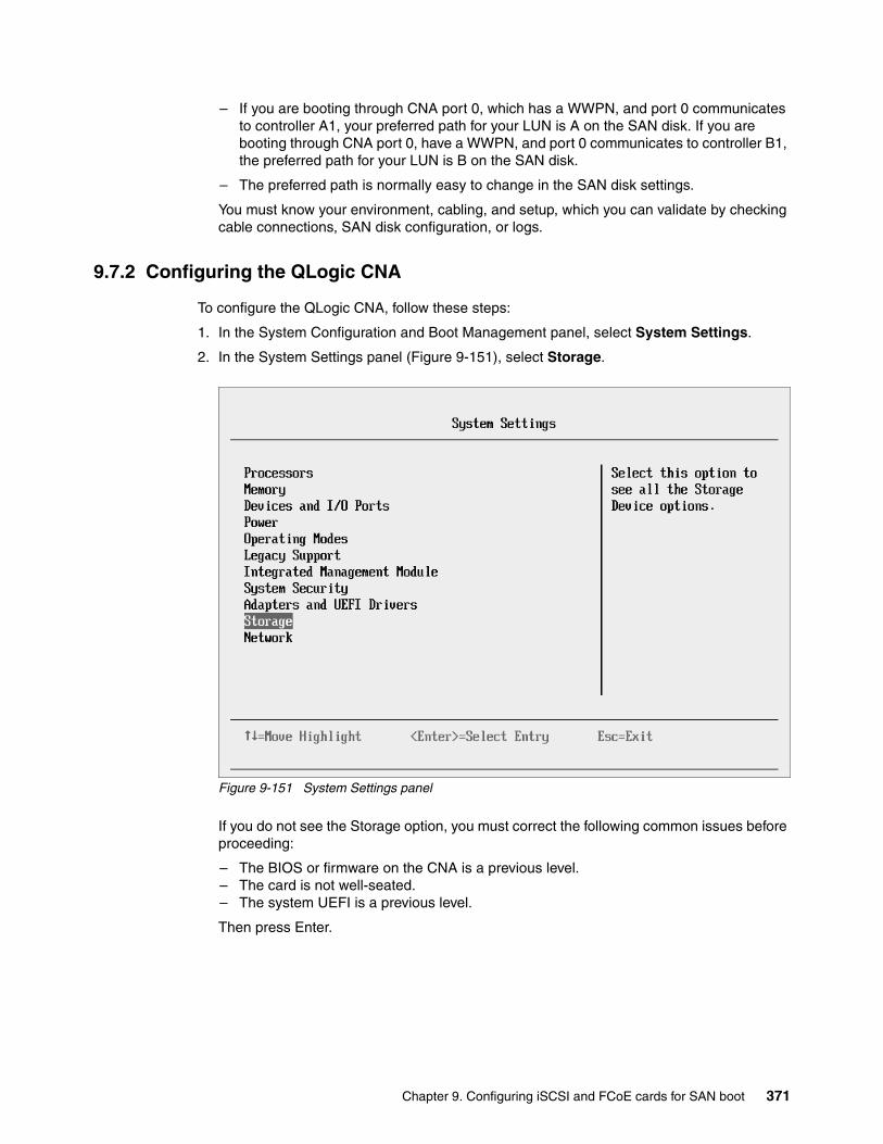
– If you are booting through CNA port 0, which has a WWPN, and port 0 communicates to controller A1, your preferred path for your LUN is A on the SAN disk. If you are booting through CNA port 0, have a WWPN, and port 0 communicates to controller B1, the preferred path for your LUN is B on the SAN disk.
– The preferred path is normally easy to change in the SAN disk settings.
You must know your environment, cabling, and setup, which you can validate by checking cable connections, SAN disk configuration, or logs.
9.7.2 Configuring the QLogic CNA
To configure the QLogic CNA, follow these steps:
1. In the System Configuration and Boot Management panel, select System Settings.
2. In the System Settings panel (Figure 9-151), select Storage.
Figure 9-151 System Settings panel
If you do not see the Storage option, you must correct the following common issues before proceeding:
– The BIOS or firmware on the CNA is a previous level.– The card is not well-seated.– The system UEFI is a previous level.
Then press Enter.
Chapter 9. Configuring iSCSI and FCoE cards for SAN boot 371

3. When you see the two QLogic fiber ports (Figure 9-152), select the port you want to boot from, and then press Enter.
Figure 9-152 Two QLogic CNA ports on the Storage panel
4. Select Edit Adapter Settings.
Tip: For optimal performance, consider booting half of your blades from one port and booting half from the other port. Also consider splitting the load on the different SAN disk controller ports. However, be careful because splitting the load adds more complexity, and you must check your SAN disk preferred paths carefully.
372 Storage and Network Convergence Using FCoE and iSCSI

5. In the Edit Adapter Settings panel (Figure 9-153), confirm the settings. In this case, we used the following settings:
– Loop Reset Delay = 5– FC Tape = Enabled– Frame Size = 2048
If you make changes, highlight Save Changes, and press Enter.
Figure 9-153 Edit Adapter Settings panel
6. Select Edit Advanced Settings.
Chapter 9. Configuring iSCSI and FCoE cards for SAN boot 373

7. In the Edit Advanced Settings panel (Figure 9-154), confirm the following settings:
a. For Operation Mode, select Interrupt for every I/O completion.
b. For Interrupt Delay Timer (dec), enter 0.
c. For Execution Throttle (dec), enter 65535.
d. For Login Retry Count (dec), enter 8.
e. For Port Down Retry Count (dec), enter 30.
f. For Link Down Timeout (dec), enter 5.
g. For LUNs per Target (dec), enter 128.
h. For Target Reset, select Enabled.
i. For Enable FCF VLAN ID, set to Disable in most cases. However, you might want to enable this setting if you plan to use a VLAN ID other than 1002 and you are using a QLogic Virtual Fabric switch. In this case, follow these steps:
i. Disable the setting.
ii. Make sure your QLogic Virtual Fabric Switch firmware is current.
iii. If problems persist, enable this option and enter the correct VLAN ID that you use for FCoE in the FCF VLAN ID field.
j. For FCF VLAN ID (dec), the default setting is 1002 for most operating systems. Otherwise, use the setting that your operating system requires.
k. If you make changes, highlight Save Changes, and then press Enter.
Figure 9-154 Edit Advanced Settings panel
8. Select Edit Boot Settings.
374 Storage and Network Convergence Using FCoE and iSCSI
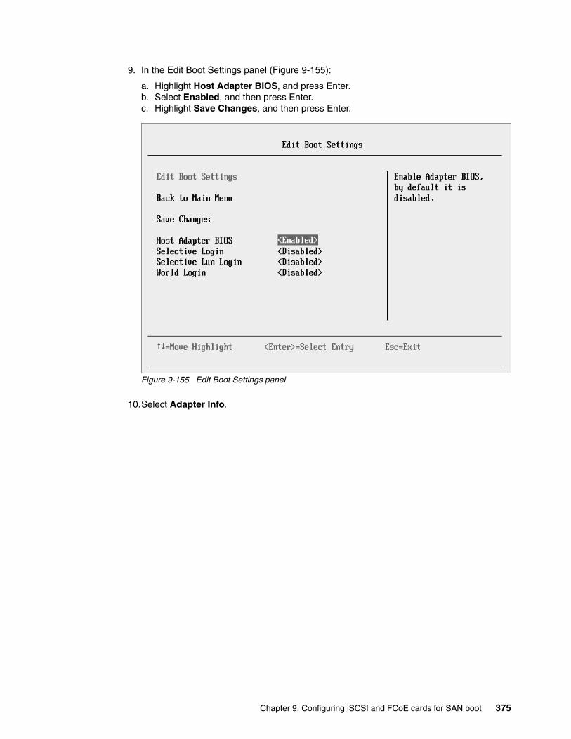
9. In the Edit Boot Settings panel (Figure 9-155):
a. Highlight Host Adapter BIOS, and press Enter. b. Select Enabled, and then press Enter.c. Highlight Save Changes, and then press Enter.
Figure 9-155 Edit Boot Settings panel
10.Select Adapter Info.
Chapter 9. Configuring iSCSI and FCoE cards for SAN boot 375

11.In the Adapter Info panel (Figure 9-156), note the WWPN and MAC address and view the revision levels of the adapter. Make sure that you are using the latest code levels that are certified by your SAN vendor. Then press Esc.
Figure 9-156 Adapter Info panel
12.Press Esc until you see the System Configuration and Boot Management panel (Figure 9-1 on page 229).
13.Highlight Save Settings, and press Enter.
14.In the System Configuration and Boot Management panel, select Boot Manager.
15.Highlight Reset System, and press Enter to reset the system. Although resetting the system is not always required, in many cases, it is helpful to get working again.
9.7.3 Adding a boot device
To add a boot device, follow these steps:
1. During start or POST, press the F1 key.
2. In the System Configuration and Boot Management panel, select System Settings.
3. In the System Settings panel, select Storage.
4. When you see two QLogic fiber ports, select the port you want to boot from. This port must be the same port that you selected earlier. Then press Enter.
5. Select Add Boot Device.
376 Storage and Network Convergence Using FCoE and iSCSI
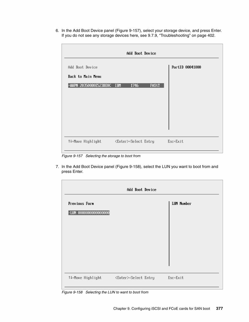
6. In the Add Boot Device panel (Figure 9-157), select your storage device, and press Enter. If you do not see any storage devices here, see 9.7.9, “Troubleshooting” on page 402.
Figure 9-157 Selecting the storage to boot from
7. In the Add Boot Device panel (Figure 9-158), select the LUN you want to boot from and press Enter.
Figure 9-158 Selecting the LUN to want to boot from
Chapter 9. Configuring iSCSI and FCoE cards for SAN boot 377

Some operating systems require LUN 0 to boot from. If you see a LUN with a number other than 0, you might want to sign in to your SAN disk storage device and redo your mapping so that the LUN is LUN 0. Then reboot the blade again, and go back to 1 on page 376 to repeat this part of the procedure.
8. Highlight Commit Changes, and press Enter (Figure 9-159).
Figure 9-159 Add Boot Device panel
9. Press Esc until you return to the System Configuration and Boot Management menu (Figure 9-1 on page 229).
The adapter is now ready to boot from SAN. Depending on your environment, continue to the following sections as appropriate:
� If you are installing your operating system in UEFI mode, go to 9.7.5, “Installing Windows 2008 x64 or Windows 2008 R2 (x64) in UEFI mode” on page 379.
� If you are installing your operating system in legacy mode, go to 9.7.7, “Installing Windows 2008 x86 in legacy mode” on page 391.
� If you are uncertain about whether you want to install in UEFI or MBR, go to 9.7.5, “Installing Windows 2008 x64 or Windows 2008 R2 (x64) in UEFI mode” on page 379.
9.7.4 Booting from SAN variations
You can set up boot from SAN by using various methods. This book focuses on the fixed target LUN. In some cases, it is useful to have a more dynamic solution. We show what we consider the most stable and most optimized method. The method you choose depends on what you want to accomplish.
378 Storage and Network Convergence Using FCoE and iSCSI

A more dynamic setup might be useful to prevent reconfiguring the adapter settings every time to change LUN assignment to another host. However, it might take more time to scan the LUNs at boot every time the system is rebooted. If you are setting up Blade Open Fabric Manager or have a hot spare blade, set these more dynamic settings, and do not assign a fixed boot LUN.
Figure 9-160 shows some of the QLogic settings that you can change. For more information, see the QLogic website:
http://www.qlogic.com
Figure 9-160 Edit Boot Settings panel
9.7.5 Installing Windows 2008 x64 or Windows 2008 R2 (x64) in UEFI mode
Installing Windows 2008 R2 x64 (64 bit) with service pack 1 is similar for other operating systems.
To install Windows 2008 x64 or Windows 2008 R2 (x64) in UEFI mode, follow these steps:
1. Boot from the media by using the preferred method (UEFI or legacy). Use the most current version of the media with the service pack level or latest update level (when possible).
2. If needed, input drivers for the storage devices.
3. Select a storage device (disk) to install the operating system.
You must know whether your operating system is UEFI-compliant. The following operating systems are UEFI-compliant at the time this book was written:
� Windows 2008 x64 and Windows 2008 R2 (x64)� Linux SLES 11 SP1� RHEL 6� VMware 5
Chapter 9. Configuring iSCSI and FCoE cards for SAN boot 379
For all other non-UEFI compliant operating systems, see 9.7.7, “Installing Windows 2008 x86 in legacy mode” on page 391.
If you are installing a UEFI-compliant operating system, install it in UEFI mode for performance reasons. UEFI gives you access to new features such as these:
� Bigger boot disk sizes. UEFI boots from a GPT partitioned disk (instead of MBR). GPT is no longer limited to a 2-TB boot drive. However, keep in mind that you can have some software that requires the use of MBR (such as older backup software).
� Faster boot times. A UEFI machine in legacy mode (BIOS) takes more time to boot. The UEFI system boots once, initializes all devices in UEFI mode, and then does a POST a second time for legacy mode, which is time consuming. By installing in UEFI mode, you save this second boot time. Also, by using UEFI, the operating systems can take advantage of 32 bits or 64 bits, as opposed to BIOS systems that are limited to a 16-bit boot.
� PCI ROM limitations are much larger with UEFI compared to BIOS. With BIOS systems, you are limited by the small memory size of the ROM option that often generated 1801 PCI memory allocation errors.
Choose carefully whether you want to install in UEFI mode or legacy mode, because after the operating system is installed, the only way to change it is to delete and reinstall it.
9.7.6 Booting the Windows DVD in UEFI mode
You can boot the Windows media by placing the Windows 2008 x64 DVD in the DVD drive and having the machine boot automatically. By default, the system attempts to boot in UEFI mode. If it fails, it attempts to boot in legacy mode.
To boot the Windows DVD in UEFI mode, follow these steps:
1. During start or POST, press the F1 key.
2. In the System Configuration and Boot Management panel, select Boot Manager.
3. In the Boot Manager panel, select Boot From File. In this scenario, we boot from an HS22 shared DVD or CD. The DVD in the media tray is considered a USB device.
4. In the File Explorer panel (Figure 9-161 on page 381), select EFISECTOR and the associated information.
If you do not see the CD, make sure that the media tray is assigned to the correct blade and that you have a UEFI-bootable CD or DVD inserted or mounted. If your DVD is not UEFI bootable, it is not displayed in the list.
Tips:
� These operating systems can be installed in both UEFI mode and legacy mode.
� When you install these operating systems, make sure that you have the latest version of your operating system. If you want to install Windows 2008 R2, to avoid issues and to save time when performing future updates, ensure that you have the latest media with the latest service pack built into the DVD.
Tip: Depending on when you insert the Windows DVD during the system POST, you can boot the media in UEFI mode or legacy mode. To fully control the boot, follow the instructions as explained in this section to boot the DVD in UEFI mode.
380 Storage and Network Convergence Using FCoE and iSCSI

Figure 9-161 File Explorer panel
5. Now that you are browsing the DVD, select EFI, select BOOT, and then select BOOTX64.EFI (Figure 9-162). This file name might be different if you are booting other versions of Windows, VMware, or Linux.
Figure 9-162 Selecting the BOOTX64.EFI file
EFISECTOR,[PciRoot (0x0 /Pci (0xID,0x7) /USB(0x2.0x0) /USB (0x1.0x0 /USB(0x0,0x0) /CDROM (0x1,0x33C,0x13D94C)]Load File[PciRoot (0x0) /Pci (0x7,0x0 /Pci (0x0,0x0)/ MAC (E41F133A0B98,0x0)]Load File[PciRoot (0x0) /Pci (0x7,0x0) /Pci (0x0,0x1)/ MAC (E41F133A0B9A,0x0)]
File Explorer
<.><..>BOOTX64.EFI
File Explorer
Chapter 9. Configuring iSCSI and FCoE cards for SAN boot 381

6. When the DVD starts to load, if prompted to press any key (Figure 9-163), press a key so that the DVD starts to boot. If you do not press a key, you return to the UEFI setup window.
Figure 9-163 Prompt to press a key to boot from the CD or DVD
7. After Windows loads, select your preferences, and click Next.
8. In the Windows installation window (Figure 9-164), select Install now.
Figure 9-164 Install now button
Press any key to boot from CD or DVD.....
382 Storage and Network Convergence Using FCoE and iSCSI

9. In the Install Windows window (Figure 9-165), select your operating system, and click Next.
Figure 9-165 Selecting the operating system
Chapter 9. Configuring iSCSI and FCoE cards for SAN boot 383

10.Read the license agreement (Figure 9-166), click I accept the license terms, and click Next.
Figure 9-166 License agreement window
384 Storage and Network Convergence Using FCoE and iSCSI
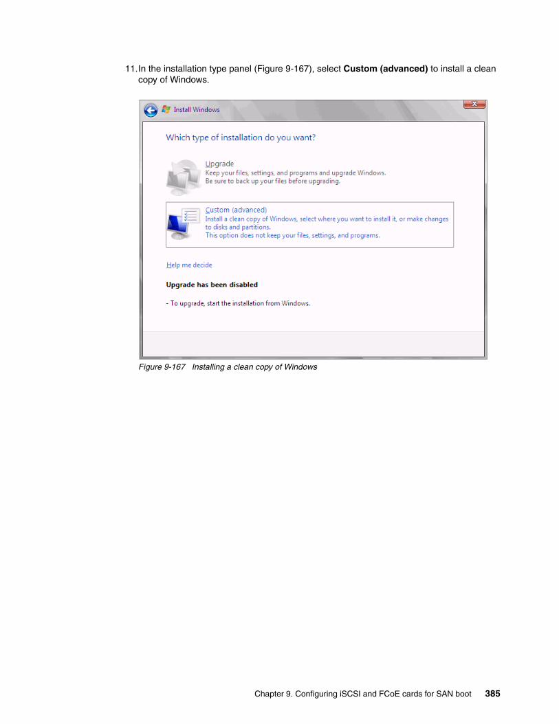
11.In the installation type panel (Figure 9-167), select Custom (advanced) to install a clean copy of Windows.
Figure 9-167 Installing a clean copy of Windows
Chapter 9. Configuring iSCSI and FCoE cards for SAN boot 385
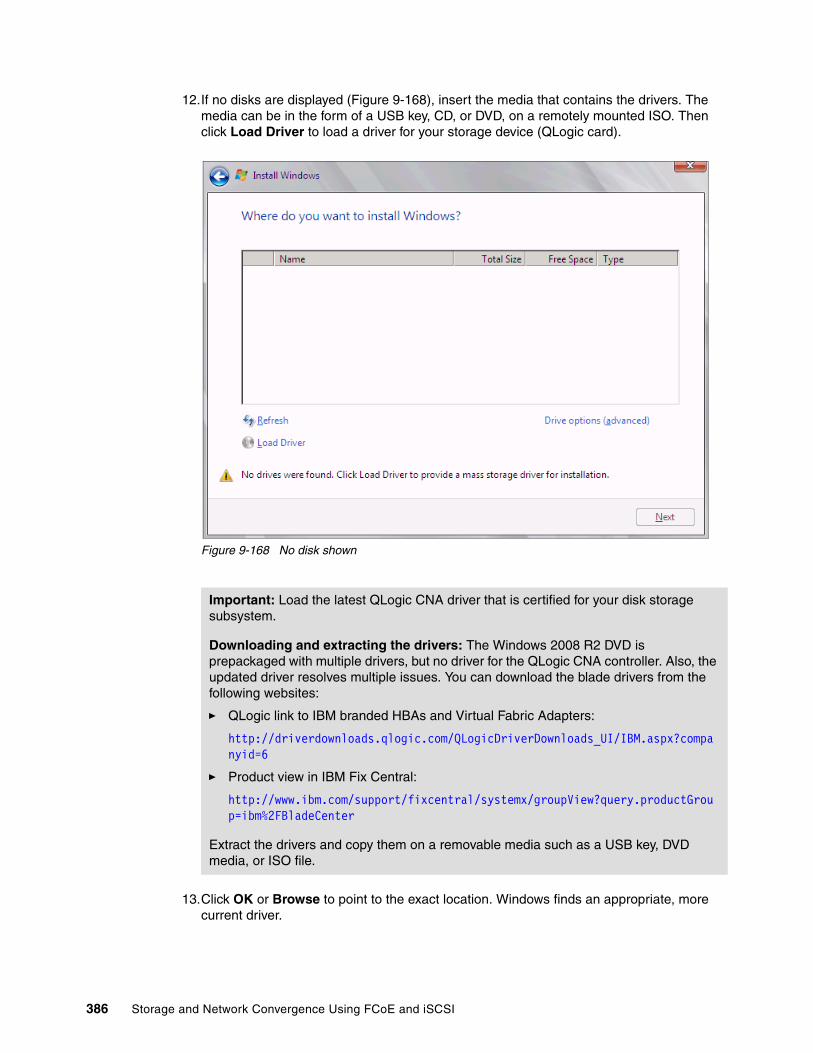
12.If no disks are displayed (Figure 9-168), insert the media that contains the drivers. The media can be in the form of a USB key, CD, or DVD, on a remotely mounted ISO. Then click Load Driver to load a driver for your storage device (QLogic card).
Figure 9-168 No disk shown
13.Click OK or Browse to point to the exact location. Windows finds an appropriate, more current driver.
Important: Load the latest QLogic CNA driver that is certified for your disk storage subsystem.
Downloading and extracting the drivers: The Windows 2008 R2 DVD is prepackaged with multiple drivers, but no driver for the QLogic CNA controller. Also, the updated driver resolves multiple issues. You can download the blade drivers from the following websites:
� QLogic link to IBM branded HBAs and Virtual Fabric Adapters:
http://driverdownloads.qlogic.com/QLogicDriverDownloads_UI/IBM.aspx?companyid=6
� Product view in IBM Fix Central:
http://www.ibm.com/support/fixcentral/systemx/groupView?query.productGroup=ibm%2FBladeCenter
Extract the drivers and copy them on a removable media such as a USB key, DVD media, or ISO file.
386 Storage and Network Convergence Using FCoE and iSCSI
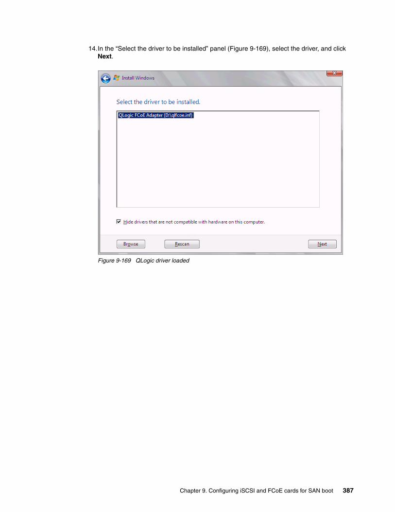
14.In the “Select the driver to be installed” panel (Figure 9-169), select the driver, and click Next.
Figure 9-169 QLogic driver loaded
Chapter 9. Configuring iSCSI and FCoE cards for SAN boot 387
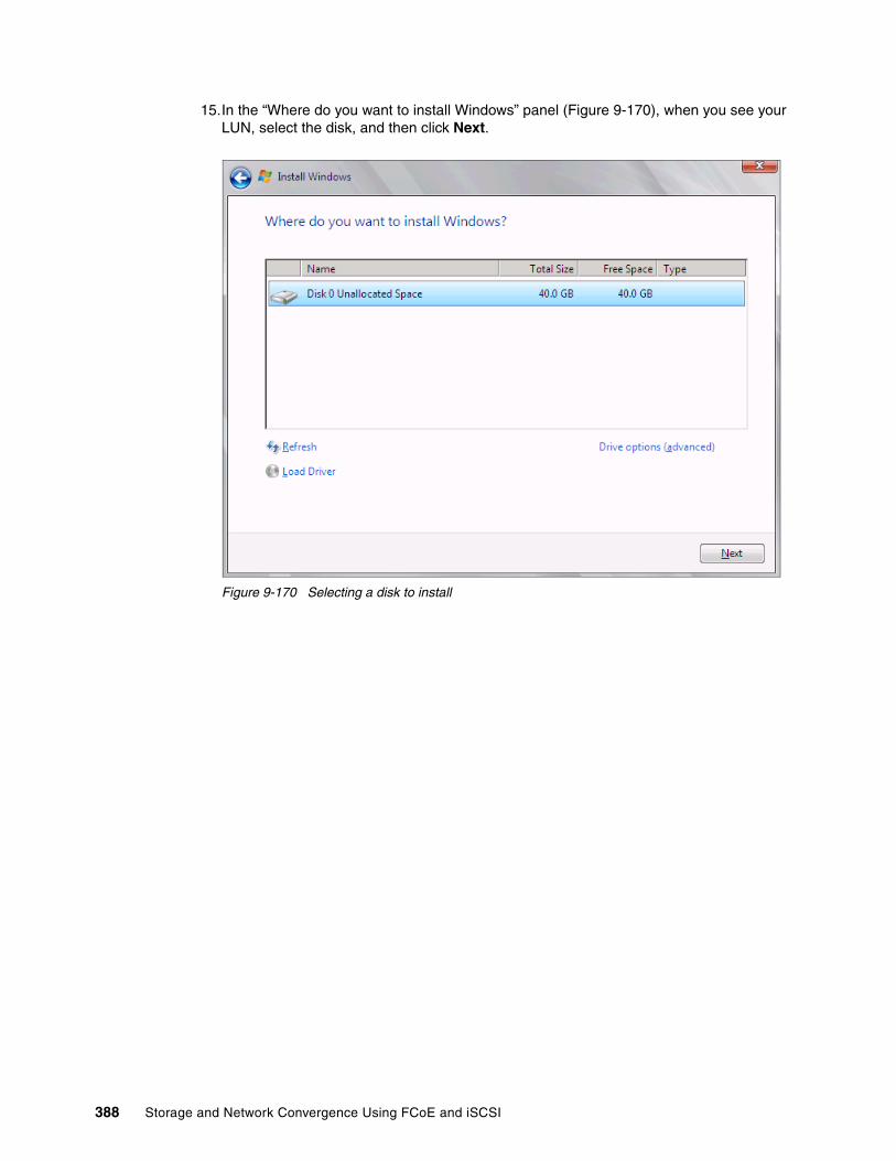
15.In the “Where do you want to install Windows” panel (Figure 9-170), when you see your LUN, select the disk, and then click Next.
Figure 9-170 Selecting a disk to install
388 Storage and Network Convergence Using FCoE and iSCSI

If you see a warning message (Figure 9-171) that indicates that the hardware might not support booting to the disk, the disk is offline or another error might exist. Therefore, boot from SAN will not work.
Figure 9-171 Warning message that hardware might not support boot to selected disk
Recheck all items as explained in “Hardware does not support boot to disk in UEFI mode” on page 403, and then reboot the server on the Windows DVD. After you address all errors, click Next.
Chapter 9. Configuring iSCSI and FCoE cards for SAN boot 389

You see a message that Windows wants to create a volume and then starts copying files (Figure 9-172).
Figure 9-172 Windows installation progress window
16.When Windows is done installing and you are prompted to enter a password (Figure 9-173), click OK, and then enter your password.
Figure 9-173 Prompt for password in Windows
You are now done installing Windows. Continue to 9.9, “After the operating system is installed” on page 438.
390 Storage and Network Convergence Using FCoE and iSCSI

9.7.7 Installing Windows 2008 x86 in legacy mode
To install Windows 2008 x86 (32 bit) SP2 in legacy mode, follow these steps:
1. Boot from the media by using the preferred method (UEFI or legacy). When possible, use the most current version of the media with the service pack level or latest update level.
2. If needed, input drivers for the storage devices.
3. Select a storage device (disk) to install the operating system.
If your operating system supports UEFI, install in UEFI to take advantage of the performance, faster POST time, and bigger boot disk size available through GPT.
The following operating systems are UEFI-compliant at the time that this book was written:
� Windows 2008 x64 and Windows 2008 R2 (x64)� Linux SLES 11 SP1� RHEL 6� VMware 5
The following operating systems are some of the most popular legacy-compliant (BIOS) operating systems:
� Windows 2008 32-bit versions� Windows 2003, 2000, and earlier � VMware 4 and earlier � Linux RHEL 5 and earlier� SLES 10 and earlier� Novell NetWare
Check the operating system specifications to determine whether your operating system supports UEFI. For all other non-UEFI compliant operating systems, see this section to install in legacy mode.
9.7.8 Optimizing the boot for legacy operating systems
To optimize the boot for legacy operating systems, follow these steps:
1. During start or POST, press the F1 key.
2. In the System Configuration and Boot Management panel, select Boot Manager.
3. Select Add Boot Option.
Tip: This installation does not apply to Windows 2008 R2.
Installation mode: These operating systems can be installed in UEFI mode and legacy mode. Boot the media in UEFI to install in UEFI, or boot the media in legacy mode to install in legacy (BIOS) mode.
Tip: When you install these operating systems, make sure that you have the latest version of your operating system. If you want to install Windows 2008, to avoid issues and to save time when performing future updates, ensure that you have the latest media with the latest service pack built into the DVD.
Chapter 9. Configuring iSCSI and FCoE cards for SAN boot 391
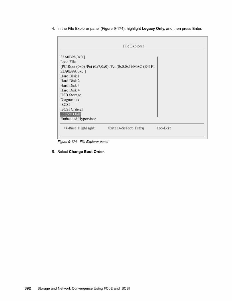
4. In the File Explorer panel (Figure 9-174), highlight Legacy Only, and then press Enter.
Figure 9-174 File Explorer panel
5. Select Change Boot Order.
33A0B98,0x0 ]Load File[PCiRoot (0x0) /Pci (0x7,0x0) /Pci (0x0,0x1)/MAC (E41F133A0B9A,0x0 ]Hard Disk 1Hard Disk 2Hard Disk 3Hard Disk 4USB StorageDiagnosticsiSCSIiSCSI CriticalLegacy OnlyEmbedded Hypervisor
File Explorer
392 Storage and Network Convergence Using FCoE and iSCSI
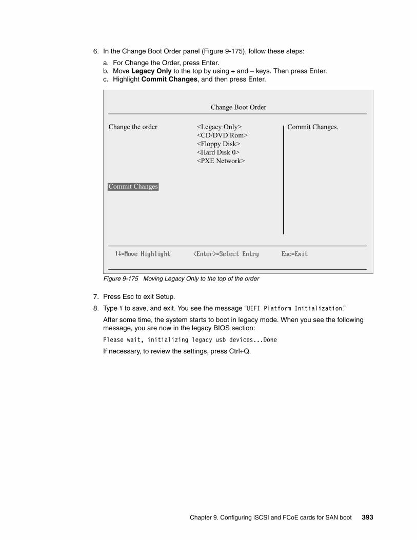
6. In the Change Boot Order panel (Figure 9-175), follow these steps:
a. For Change the Order, press Enter.b. Move Legacy Only to the top by using + and – keys. Then press Enter.c. Highlight Commit Changes, and then press Enter.
Figure 9-175 Moving Legacy Only to the top of the order
7. Press Esc to exit Setup.
8. Type Y to save, and exit. You see the message “UEFI Platform Initialization.”
After some time, the system starts to boot in legacy mode. When you see the following message, you are now in the legacy BIOS section:
Please wait, initializing legacy usb devices...Done
If necessary, to review the settings, press Ctrl+Q.
Change the order <Legacy Only><CD/DVD Rom><Floppy Disk><Hard Disk 0><PXE Network>
Commit Changes
Change Boot Order
Commit Changes.
Chapter 9. Configuring iSCSI and FCoE cards for SAN boot 393
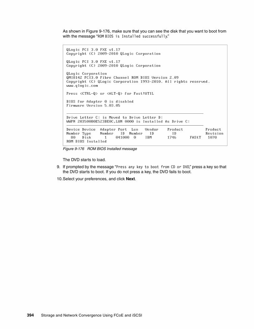
As shown in Figure 9-176, make sure that you can see the disk that you want to boot from with the message “ROM BIOS is Installed successfully.”
Figure 9-176 ROM BIOS Installed message
The DVD starts to load.
9. If prompted by the message “Press any key to boot from CD or DVD,” press a key so that the DVD starts to boot. If you do not press a key, the DVD fails to boot.
10.Select your preferences, and click Next.
394 Storage and Network Convergence Using FCoE and iSCSI

11.In the Install Windows panel (Figure 9-177), select Install now.
Figure 9-177 Install now button
12.Select the operating system that you want to install (Figure 9-178), and then click Next.
Figure 9-178 Selecting the operating system
Chapter 9. Configuring iSCSI and FCoE cards for SAN boot 395

13.Read the license agreement, select I accept the license terms, and click Next (Figure 9-179).
Figure 9-179 License agreement window
396 Storage and Network Convergence Using FCoE and iSCSI

14.For the type of installation (Figure 9-180), select Custom (advanced) to install a clean copy of Windows. Then click Next.
Figure 9-180 Selecting to install a clean copy of Windows
Chapter 9. Configuring iSCSI and FCoE cards for SAN boot 397

15.If no disks are displayed (Figure 9-181), insert the media that contains the drivers. The media can be in the form of a USB key, CD, or DVD, on a remotely mounted ISO. Then click Load Driver to load a driver for your storage device (QLogic card).
Figure 9-181 No drives found message
16.Click OK or Browse to point to the exact location. Windows finds an appropriate, more current driver.
Important: Load the latest QLogic CNA driver that is certified for your disk storage subsystem.
Downloading and extracting the drivers: The Windows 2008 DVD is prepackaged with multiple drivers, but no driver for the QLogic CNA controller. Also the updated driver resolves multiple issues. You can download the blade drivers from the following websites:
� QLogic IBM:
http://driverdownloads.qlogic.com/QLogicDriverDownloads_UI/IBM.aspx?companyid=6
� IBM BladeCenter:
http://www.ibm.com/support/fixcentral/systemx/groupView?query.productGroup=ibm%2FBladeCenter
Extract the drivers and copy them on a removable media such as a USB key, DVD media, or into an ISO file.
398 Storage and Network Convergence Using FCoE and iSCSI

17.In the “Select the driver to be installed” panel (Figure 9-182), select the driver, and then click Next.
Figure 9-182 Browsing to the QLogic FCoE driver
Chapter 9. Configuring iSCSI and FCoE cards for SAN boot 399
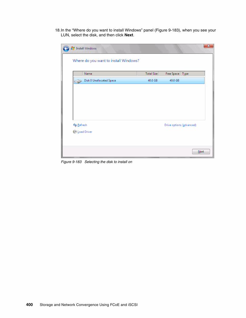
18.In the “Where do you want to install Windows” panel (Figure 9-183), when you see your LUN, select the disk, and then click Next.
Figure 9-183 Selecting the disk to install on
400 Storage and Network Convergence Using FCoE and iSCSI

If you see a warning message (Figure 9-184) that indicates that the hardware might not support booting to the disk, the disk is offline or another error might exist. Therefore, boot from SAN will not work.
Figure 9-184 Warning message about hardware unable to support boot to selected disk
Recheck all items as explained in “Hardware does not support boot to disk for legacy operating systems” on page 404, and then reboot the server on the Windows DVD. After you address all errors, click Next.
Chapter 9. Configuring iSCSI and FCoE cards for SAN boot 401
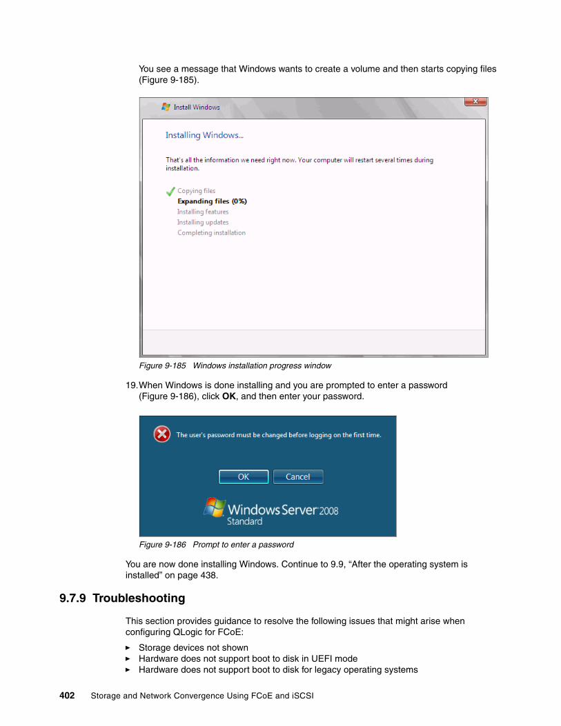
You see a message that Windows wants to create a volume and then starts copying files (Figure 9-185).
Figure 9-185 Windows installation progress window
19.When Windows is done installing and you are prompted to enter a password (Figure 9-186), click OK, and then enter your password.
Figure 9-186 Prompt to enter a password
You are now done installing Windows. Continue to 9.9, “After the operating system is installed” on page 438.
9.7.9 Troubleshooting
This section provides guidance to resolve the following issues that might arise when configuring QLogic for FCoE:
� Storage devices not shown� Hardware does not support boot to disk in UEFI mode� Hardware does not support boot to disk for legacy operating systems
402 Storage and Network Convergence Using FCoE and iSCSI
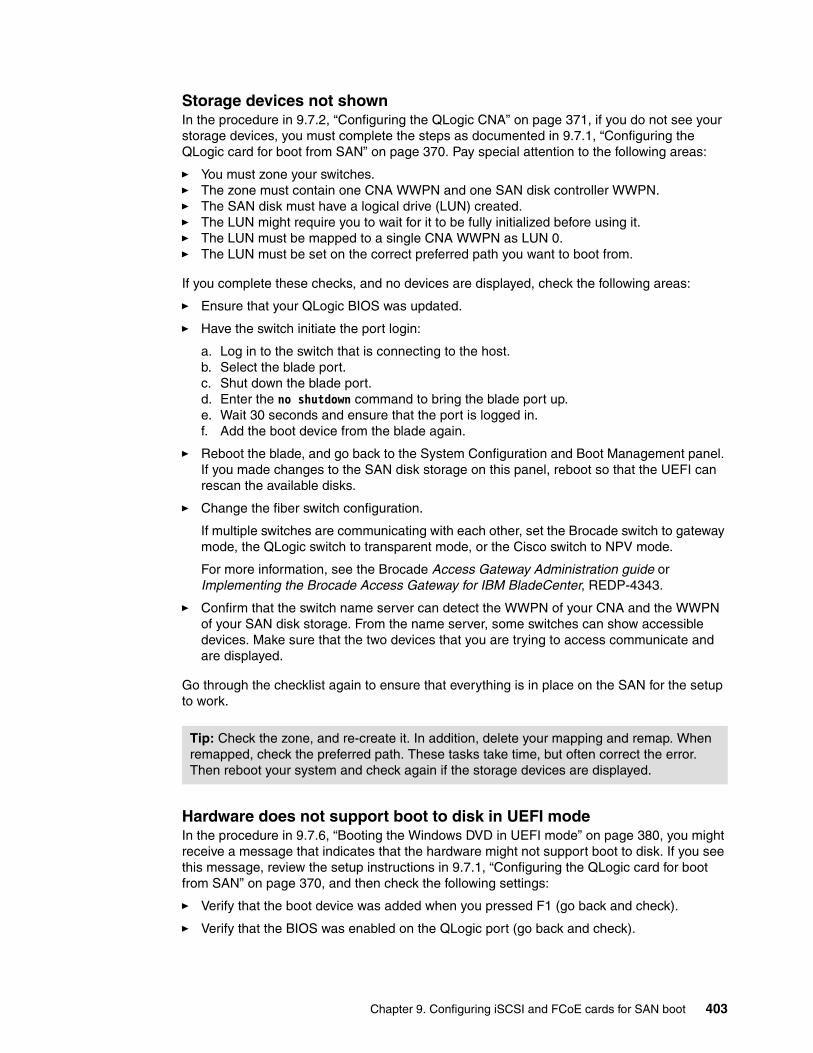
Storage devices not shownIn the procedure in 9.7.2, “Configuring the QLogic CNA” on page 371, if you do not see your storage devices, you must complete the steps as documented in 9.7.1, “Configuring the QLogic card for boot from SAN” on page 370. Pay special attention to the following areas:
� You must zone your switches.� The zone must contain one CNA WWPN and one SAN disk controller WWPN.� The SAN disk must have a logical drive (LUN) created.� The LUN might require you to wait for it to be fully initialized before using it.� The LUN must be mapped to a single CNA WWPN as LUN 0.� The LUN must be set on the correct preferred path you want to boot from.
If you complete these checks, and no devices are displayed, check the following areas:
� Ensure that your QLogic BIOS was updated.
� Have the switch initiate the port login:
a. Log in to the switch that is connecting to the host.b. Select the blade port.c. Shut down the blade port.d. Enter the no shutdown command to bring the blade port up.e. Wait 30 seconds and ensure that the port is logged in.f. Add the boot device from the blade again.
� Reboot the blade, and go back to the System Configuration and Boot Management panel. If you made changes to the SAN disk storage on this panel, reboot so that the UEFI can rescan the available disks.
� Change the fiber switch configuration.
If multiple switches are communicating with each other, set the Brocade switch to gateway mode, the QLogic switch to transparent mode, or the Cisco switch to NPV mode.
For more information, see the Brocade Access Gateway Administration guide or Implementing the Brocade Access Gateway for IBM BladeCenter, REDP-4343.
� Confirm that the switch name server can detect the WWPN of your CNA and the WWPN of your SAN disk storage. From the name server, some switches can show accessible devices. Make sure that the two devices that you are trying to access communicate and are displayed.
Go through the checklist again to ensure that everything is in place on the SAN for the setup to work.
Hardware does not support boot to disk in UEFI modeIn the procedure in 9.7.6, “Booting the Windows DVD in UEFI mode” on page 380, you might receive a message that indicates that the hardware might not support boot to disk. If you see this message, review the setup instructions in 9.7.1, “Configuring the QLogic card for boot from SAN” on page 370, and then check the following settings:
� Verify that the boot device was added when you pressed F1 (go back and check).
� Verify that the BIOS was enabled on the QLogic port (go back and check).
Tip: Check the zone, and re-create it. In addition, delete your mapping and remap. When remapped, check the preferred path. These tasks take time, but often correct the error. Then reboot your system and check again if the storage devices are displayed.
Chapter 9. Configuring iSCSI and FCoE cards for SAN boot 403

� Verify that the CNA from which you are trying to boot from is on the preferred path of the SAN disk. The most common cause of an offline disk is that the preferred path is not assigned correctly. Check your SAN disk device configuration, and then reboot the server again on the Windows DVD.
� Verify that your SAN disk supports a UEFI boot.
� Verify that your SAN disk is updated to the latest firmware.
� Try to perform a legacy installation.
� If the disk is offline, see Windows KB 2345135, “Setup reports error ‘Windows cannot be installed to this disk...’ when booted from DVD” at this website:
http://support.microsoft.com/kb/2345135
� If Setup reports the error message “Windows cannot be installed to this disk...” booted from DVD in UEFI mode, consider modifying the Windows installation media.
� Use Windows media that is bundled with the latest service pack.
� If you see a 20-MB disk, you most likely mapped the access LUN instead of the LUN. To correct this problem, log in to your disk storage subsystem.
� Verify that your LUN is using LUN 0, which is defined in the SAN disk device.
� Verify that you are using the latest Windows DVD with the latest service pack built-in.
� Verify that the path is on the preferred path. Check with your SAN configuration.
� Verify that zoning is correct or unchanged.
� Verify that LUN mapping is correct or unchanged.
Hardware does not support boot to disk for legacy operating systemsIn the procedure in 9.7.8, “Optimizing the boot for legacy operating systems” on page 391, you might receive a message that indicates that the hardware might not support boot to disk. If you see this message, review the setup instructions in 9.7.1, “Configuring the QLogic card for boot from SAN” on page 370, and then check the following settings:
� Verify that the boot device was added when you pressed F1 (go back and check).
� Verify that the BIOS was enabled on the QLogic port (go back and check).
� Verify that the CNA from which you are trying to boot is on the preferred path of the SAN disk. The most common cause of an offline disk is that the preferred path is not assigned correctly. Check your SAN disk device configuration, and then reboot the server again on the Windows DVD.
� Verify that your SAN disk is updated to the latest firmware.
� Use Windows media that is bundled with the latest service pack.
� If you see a 20-MB disk, you most likely mapped the access LUN instead of the actual LUN. You can fix this problem in your disk storage subsystem.
� Verify that your LUN is using LUN 0, which is defined in the SAN disk device.
� Verify that you are using the latest Windows DVD with the latest service pack built-in.
� Verify that the path is not on the preferred path. Check with your SAN configuration.
� Verify that zoning is correct or unchanged.
� Verify that LUN mapping is correct or unchanged.
404 Storage and Network Convergence Using FCoE and iSCSI

9.8 Configuring Brocade for FCoE in the BladeCenter
This section how to configure the Brocade 10Gb CNA CFFh card PN 81Y1650 FRU (Brocade 1007). This scenario entails the following components:
� BladeCenter H machine type 8852� HS22 machine type 7870:
– UEFI P9155A 1.15– Blade System Management Processor YUOOC7E 1.30– Brocade 10Gb CNA (Brocade 1007):
• PN 81Y1650
– Brocade 8470 switch with Firmware FOS v6.3.1_cee
Although this section is written for a specific BladeCenter Brocade CNA, the information is similar for the PCIe version of this adapter.
This section is specifically for Blade HS22. Doing boot from SAN on other systems, such as HS22v or HX5, x3550 m2, x3650 m2, x3550 m3, and x3650 m3, is similar. Use the latest drivers and firmware that are certified by the SAN disk vendor, and not the versions that are documented here.
9.8.1 Configuring the Brocade card for boot from SAN
The Brocade card in the blade server is a dual port CNA. You can boot from either port, but you can boot only from one port and one path at a time. You must do the initial installation with a single path. The redundancy occurs later only when the operating system is installed and when the multipath driver is installed.
At this stage, you must perform the following connections and configurations on the SAN:
� On the switches:
– Enable the ports.
– Configure the FCoE. Check ENodes, FCFs, and the FIP.
– Ensure that the blade host has a connection all the way to the disk storage subsystem.
– On the FC side, ensure that the disk storage subsystem and the blade CNA WWPN are present in the name server or FLOGI table.
– Configure zoning. The zone must contain one CNA WWPN and one SAN disk controller WWPN. Zoning is done on the fiber switch. Some people might decide to function with an open fabric, without any zoning. However, over time, this setup is likely to fail or cause problems.
You can zones the following switches:
• A Brocade switch by using the Zone Admin function• A QLogic switch by selecting Zoning Edit Zoning• A Cisco switch by using the Device Manager and selecting FC Quick Config
Wizard
Use the CLI for more advanced configurations.
Chapter 9. Configuring iSCSI and FCoE cards for SAN boot 405

� On the disk storage subsystem:
– Ensure that the storage subsystem and SAN disk have a logical drive (LUN) created and mapped to the WWPN of the CNA of the blade server.
– The LUN might require you to wait for it to be fully initialized before using it.
– When you create a LUN normally, a synchronization process starts. With some storage, you can work with this LUN when it is synchronizing. Other storage might require you to wait for the LUN to be fully initialized. For information about how it operates, see your storage documentation for your SAN disk storage.
– Map the LUN to a single CNA WWPN. Do not map both WWPNs yet. You map it to both CNA WWPNs later. At installation time, restrict this mapping to a single path. Otherwise, a stop error (blue screen) or other installation issues can occur.
– For an asymmetrical storage subsystem only, set the LUN on the correct path that you want to boot from.
Some SANs are asymmetrical storage subsystems, such as the IBM System Storage DS3000, DS4000, and DS5000 series. Other SANs are symmetrical storage subsystems, such as SAN Volume Controller and IBM System Storage DS8000. The asymmetrical storage subsystems controllers set a preferred path. The preferred path must be set to communicate to your CNA WWPN.
– The LUN on most SANs is presented to a single controller at a time. This LUN can move from controller A to controller B.
– At installation time, the operating system does not have its redundant driver loaded and, therefore, does not handle redundant paths. To work around this issue, provide a single path.
– If you are booting through CNA port 0, which has a WWPN, and port 0 communicates to controller A1, the preferred path for your LUN is A on the SAN disk. If you are booting through CNA port 0, has a WWPN, and port 0 communicates to controller B1, the preferred path for your LUN is B on the SAN disk.
– The preferred path is normally easy to change in the SAN disk settings.
You must know your environment, cabling, and setup, which you can validate by checking cable connections, SAN disk configuration, or logs.
9.8.2 Configuring the Brocade CNA
To configure the Brocade CNA, follow these steps:
1. In the System Configuration and Boot Management panel, select System Settings.
2. In the System Settings panel, select Adapters and UEFI Drivers.
3. In the Adapters and UEFI Drivers panel (Figure 9-187), select the Brocade port you want to boot from. The first port connects to the lower slot, and the second port connects to the higher numbered slot. The panel in this example shows the Brocade Fibre Channel Adapter Bus Driver. The second port is highlighted, which is a CFFh card that communicates to bay 9.
406 Storage and Network Convergence Using FCoE and iSCSI

Figure 9-187 Adapters and UEFI Drivers panel
4. From the Bfa FCoE Driver Configuration panel, note the Port PWWN, which is your WWPN and is useful when doing zoning and LUN mapping. Then type Y to enable the Brocade FCoE port, which enables the BIOS function and allows the adapter to boot (Figure 9-188).
Figure 9-188 WWPN enabling the port for boot
5. Press Esc until you reach the System Configuration and Boot Management menu.
The Brocade adapter is now ready to boot from SAN by using UEFI. The Brocade adapter has a few configurations and checks that you can do from the System Configuration and Boot Management panel. You can perform more troubleshooting in legacy BIOS mode. For more information, see 9.8.6, “Installing Windows 2008 x86 in legacy mode” on page 420.
Depending on your environment, continue to the following sections as appropriate:
� If you are installing your operating system in UEFI mode, continue to 9.8.4, “Installing Windows 2008 x64 or Windows 2008 R2 (x64) in UEFI mode” on page 408.
� If you are installing in legacy mode, continue to 9.8.6, “Installing Windows 2008 x86 in legacy mode” on page 420.
� If you are uncertain about whether you want to install in UEFI or MBR, continue to 9.8.4, “Installing Windows 2008 x64 or Windows 2008 R2 (x64) in UEFI mode” on page 408.
Chapter 9. Configuring iSCSI and FCoE cards for SAN boot 407

9.8.3 Booting from SAN variations
You can set up boot from SAN by using various methods. This book focuses on the fixed target LUN. In some cases, it is useful to have a more dynamic solution. We show what we consider the most stable and most optimized method. The method you choose depends on what you want to accomplish.
A more dynamic setup might be useful to prevent reconfiguring the adapter settings every time to change LUN assignment to another host. However, it might take more time to scan the LUNs at boot every time the system is rebooted. If you are setting up Blade Open Fabric Manager or have a hot spare blade, set these more dynamic settings, and do not assign a fixed boot LUN.
On the Brocade CNA, the UEFI boot is dynamic. In legacy BIOS mode, you can select different ways to boot the LUN. For more information, see 9.8.8, “Boot from SAN by using the First LUN option” on page 427.
9.8.4 Installing Windows 2008 x64 or Windows 2008 R2 (x64) in UEFI mode
Installing Windows 2008 R2 x64 (64 bit) with service pack 1 is similar for other operating systems.
To install Windows 2008 x64 or Windows 2008 R2 (x64) in UEFI mode, follow these steps:
1. Boot from the media by using the desired method (UEFI or legacy). Use the most current version of the media with the service pack level or latest update level (when possible).
2. If needed, input drivers for the storage devices.
3. Select a storage device (disk) to install the operating system.
You must know whether your operating system is UEFI-compliant. The following operating systems are UEFI-compliant at the time this book was written:
� Windows 2008 x64 and Windows 2008 R2 (x64)� Linux SLES 11 SP1� RHEL 6� VMware 5
For all other non-UEFI compliant operating systems, see 9.7.7, “Installing Windows 2008 x86 in legacy mode” on page 391.
Tips:
� These operating systems can be installed in both UEFI mode and legacy mode.
� When you install these operating systems, make sure that you have the latest version of your operating system. If you want to install Windows 2008 R2, to avoid issues and to save time when performing future updates, ensure that you have the latest media with the latest service pack built into the DVD.
408 Storage and Network Convergence Using FCoE and iSCSI

If you are installing a UEFI-compliant operating system, install it in UEFI mode for performance reasons. UEFI gives you access to new features such as these:
� Bigger boot disk sizes: UEFI boots from a GPT partitioned disk (instead of MBR). GPT is no longer limited to a 2-TB boot drive. However keep in mind that you can have some software that requires the use of MBR (such as older backup software).
� Faster boot times: A UEFI machine in legacy mode (BIOS) takes more time to boot. The UEFI system boots once, initializes all devices in UEFI mode, and then does a POST a second time for legacy mode, which is time consuming. By installing in UEFI mode, you save this second boot time. Also, by using UEFI, the operating systems can take advantage of 32 bits or 64 bits, as opposed to BIOS systems that are limited to a 16-bit boot.
� PCI ROM limitations are much larger with UEFI compared to BIOS: With BIOS systems, you are limited by the small memory size of the ROM option that often generated 1801 PCI memory allocation errors.
Choose carefully whether you want to install in UEFI mode or legacy mode, because after the operating system is installed, the only way to change it back is to delete and reinstall it.
9.8.5 Booting the Windows DVD in UEFI mode
You can boot the Windows media by placing the Windows 2008 x64 DVD in the DVD drive and letting the machine boot automatically. By default, the system attempts to boot in UEFI mode. If it fails, it attempts to boot in legacy mode.
To boot the Windows DVD in UEFI mode, follow these steps:
1. During start or POST, press the F1 key.
2. In the System Configuration and Boot Management panel, select Boot Manager.
3. In the Boot Manager panel, select Boot From File. In this scenario, we boot from an HS22 shared DVD or CD. The DVD in the media tray is considered a USB device.
4. In the File Explorer panel (Figure 9-189), select EFISECTOR and the associated information.
If you do not see the CD, make sure that the media tray is assigned to the correct blade and that you have a UEFI-bootable CD or DVD inserted or mounted. If your DVD is not UEFI bootable, it is not displayed in the list.
Tip: Depending on when you insert the Windows DVD during the system POST, you can boot the media in UEFI mode or legacy mode. To fully control the boot, follow the instructions as explained in this section to boot the DVD in UEFI mode.
Chapter 9. Configuring iSCSI and FCoE cards for SAN boot 409

Figure 9-189 Selecting the CD
5. Now that you are browsing the DVD, select EFI, select BOOT, and then select BOOTX64.EFI (Figure 9-190). This file name might be different if you are booting other versions of Windows, VMware, or Linux.
Figure 9-190 Selecting the BOOTX64.EFI file
EFISECTOR,[PciRoot (0x0 /Pci (0xID,0x7) /USB(0x2.0x0) /USB (0x1.0x0 /USB(0x0,0x0) /CDROM (0x1,0x33C,0x13D94C)]Load File[PciRoot (0x0) /Pci (0x7,0x0 /Pci (0x0,0x0)/ MAC (E41F133A0B98,0x0)]Load File[PciRoot (0x0) /Pci (0x7,0x0) /Pci (0x0,0x1)/ MAC (E41F133A0B9A,0x0)]
File Explorer
<.><..>BOOTX64.EFI
File Explorer
410 Storage and Network Convergence Using FCoE and iSCSI
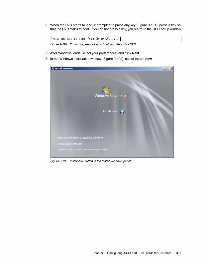
6. When the DVD starts to load, if prompted to press any key (Figure 9-191), press a key so that the DVD starts to boot. If you do not press a key, you return to the UEFI setup window.
Figure 9-191 Prompt to press a key to boot from the CD or DVD
7. After Windows loads, select your preferences, and click Next.
8. In the Windows installation window (Figure 9-192), select Install now.
Figure 9-192 Install now button in the Install Windows panel
Press any key to boot from CD or DVD.....
Chapter 9. Configuring iSCSI and FCoE cards for SAN boot 411
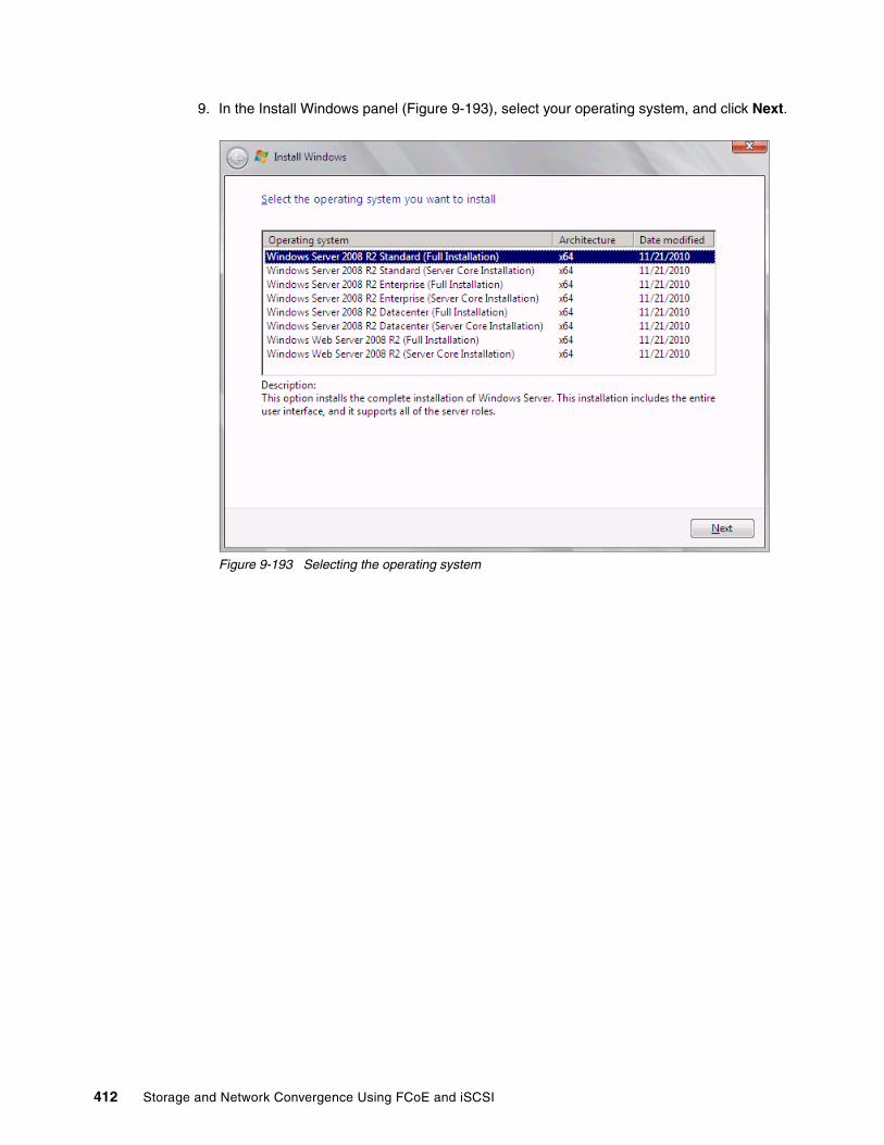
9. In the Install Windows panel (Figure 9-193), select your operating system, and click Next.
Figure 9-193 Selecting the operating system
412 Storage and Network Convergence Using FCoE and iSCSI

10.Read the license agreement (Figure 9-194), click I accept the license terms, and click Next.
Figure 9-194 License agreement window
Chapter 9. Configuring iSCSI and FCoE cards for SAN boot 413

11.In the installation type panel (Figure 9-195), select Custom (advanced) to install a clean copy of Windows.
Figure 9-195 Installing a clean copy of Windows
414 Storage and Network Convergence Using FCoE and iSCSI

12.If no disks are displayed (Figure 9-196), insert the media that contains the drivers. The media can be in the form of a USB key, CD, or DVD, on a remotely mounted ISO. Then click Load Driver to load a driver for your storage device (Brocade card).
Figure 9-196 No disk shown
Important: Load the latest Brocade CNA driver that is certified for your disk storage subsystem.
Downloading and extracting the drivers: The Windows 2008 R2 DVD is prepackaged with multiple drivers, but no driver for the Brocade CNA controller. Also, the updated driver resolves multiple issues. You can download the blade drivers from the following websites:
� IBM BladeCenter:
http://www.ibm.com/support/fixcentral/systemx/groupView?query.productGroup=ibm%2FBladeCenter
� Brocade link for IBM BladeCenter:
http://www.brocade.com/sites/dotcom/services-support/drivers-downloads/adapters/IBM_BLADECENTER.page
� Brocade link for System x:
http://www.brocade.com/sites/dotcom/services-support/drivers-downloads/adapters/IBM_SYSTEMX.page
Extract the drivers and copy them on a removable media such as a USB key, DVD media, or ISO file.
Chapter 9. Configuring iSCSI and FCoE cards for SAN boot 415

13.Click OK or Browse to point to the exact location. Windows finds an appropriate, more current driver.
14.In the “Select the driver to be installed” panel (Figure 9-197), select the driver, and click Next.
Figure 9-197 Loading the Brocade FCoE driver
416 Storage and Network Convergence Using FCoE and iSCSI

15.In the “Where do you want to install Windows” panel (Figure 9-198), when you see your LUN, select the disk, and then click Next.
Figure 9-198 Selecting a disk to install on
Chapter 9. Configuring iSCSI and FCoE cards for SAN boot 417

If you see a warning message (Figure 9-199) that indicates that the hardware might not support booting to the disk, the disk is offline or another error might exist. Therefore, boot from SAN will not work.
Figure 9-199 Warning message that hardware might not support boot to selected disk
Recheck all items as explained in “UEFI mode” on page 437, and then reboot the server on the Windows DVD. After you address all errors, click Next.
418 Storage and Network Convergence Using FCoE and iSCSI

You see a message that Windows wants to create a volume and then starts copying files (Figure 9-200).
Figure 9-200 Windows installation progress window
16.When Windows is done installing and you are prompted to enter a password (Figure 9-201), click OK, and then enter your password.
Figure 9-201 Password prompt after installing Windows
You are now done installing Windows. Continue to 9.9, “After the operating system is installed” on page 438.
Chapter 9. Configuring iSCSI and FCoE cards for SAN boot 419

9.8.6 Installing Windows 2008 x86 in legacy mode
This section explains how to install Windows 2008 x86 (32 bit) SP2.
To install Windows 2008 x86 in legacy mode, follow these steps:
1. Boot from the media by using the preferred method (UEFI or legacy). When possible, use the most current version of the media with the service pack level or latest update level.
2. If needed, input drivers for the storage devices.
3. Select a storage device (disk) to install the operating system.
If your operating system supports UEFI, install in UEFI to take advantage of the performance, faster POST time, and bigger boot disk size available through GPT.
The following operating systems are UEFI-compliant at the time that this book was written:
� Windows 2008 x64 and Windows 2008 R2 (x64)� Linux SLES 11 SP1� RHEL 6� VMware 5
The following operating systems are some of the most popular legacy-compliant (BIOS) operating systems:
� Windows 2008 32-bit versions� Windows 2003, 2000, and earlier � VMware 4 and earlier � Linux RHEL 5 and earlier� SLES 10 and earlier� Novell NetWare
Check the operating system specifications to determine whether your operating system supports UEFI. For all other non-UEFI compliant operating systems, see this section to install in legacy mode.
Tip: This installation does not apply to Windows 2008 R2.
Installation mode: These operating systems can be installed in UEFI mode and legacy mode. Boot the media in UEFI to install in UEFI, or boot the media in legacy mode to install in legacy (BIOS) mode.
Tip: When you install these operating systems, make sure that you have the latest version of your operating system. If you want to install Windows 2008, to avoid issues and to save time when performing future updates, ensure that you have the latest media with the latest service pack built into the DVD.
420 Storage and Network Convergence Using FCoE and iSCSI

9.8.7 Optimizing the boot for legacy operating systems
To optimize the boot for legacy operating systems, follow these steps:
1. During start or POST, press the F1 key.
2. In the System Configuration and Boot Management panel, select Boot Manager.
3. Select Add Boot Option.
4. In the File Explorer panel (Figure 9-202), highlight Legacy Only, and press Enter.
Figure 9-202 File Explorer panel
5. Select Change Boot Order.
33A0B98,0x0 ]Load File[PCiRoot (0x0) /Pci (0x7,0x0) /Pci (0x0,0x1)/MAC (E41F133A0B9A,0x0 ]Hard Disk 1Hard Disk 2Hard Disk 3Hard Disk 4USB StorageDiagnosticsiSCSIiSCSI CriticalLegacy OnlyEmbedded Hypervisor
File Explorer
Chapter 9. Configuring iSCSI and FCoE cards for SAN boot 421
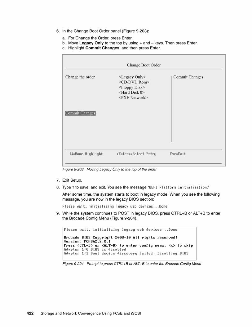
6. In the Change Boot Order panel (Figure 9-203):
a. For Change the Order, press Enter.b. Move Legacy Only to the top by using + and – keys. Then press Enter.c. Highlight Commit Changes, and then press Enter.
Figure 9-203 Moving Legacy Only to the top of the order
7. Exit Setup.
8. Type Y to save, and exit. You see the message “UEFI Platform Initialization.”
After some time, the system starts to boot in legacy mode. When you see the following message, you are now in the legacy BIOS section:
Please wait, initializing legacy usb devices...Done
9. While the system continues to POST in legacy BIOS, press CTRL+B or ALT+B to enter the Brocade Config Menu (Figure 9-204).
Figure 9-204 Prompt to press CTRL+B or ALT+B to enter the Brocade Config Menu
Change the order <Legacy Only><CD/DVD Rom><Floppy Disk><Hard Disk 0><PXE Network>
Commit Changes
Change Boot Order
Commit Changes.
422 Storage and Network Convergence Using FCoE and iSCSI

10.In the Brocade BIOS Config Menu panel (Figure 9-205), select an adapter port. In this example, we used the second port, Adapter 1 port 1.
Figure 9-205 Selecting an adapter port
11.Select Adapter Settings (Figure 9-206).
Figure 9-206 Selecting Adapter Settings
Chapter 9. Configuring iSCSI and FCoE cards for SAN boot 423
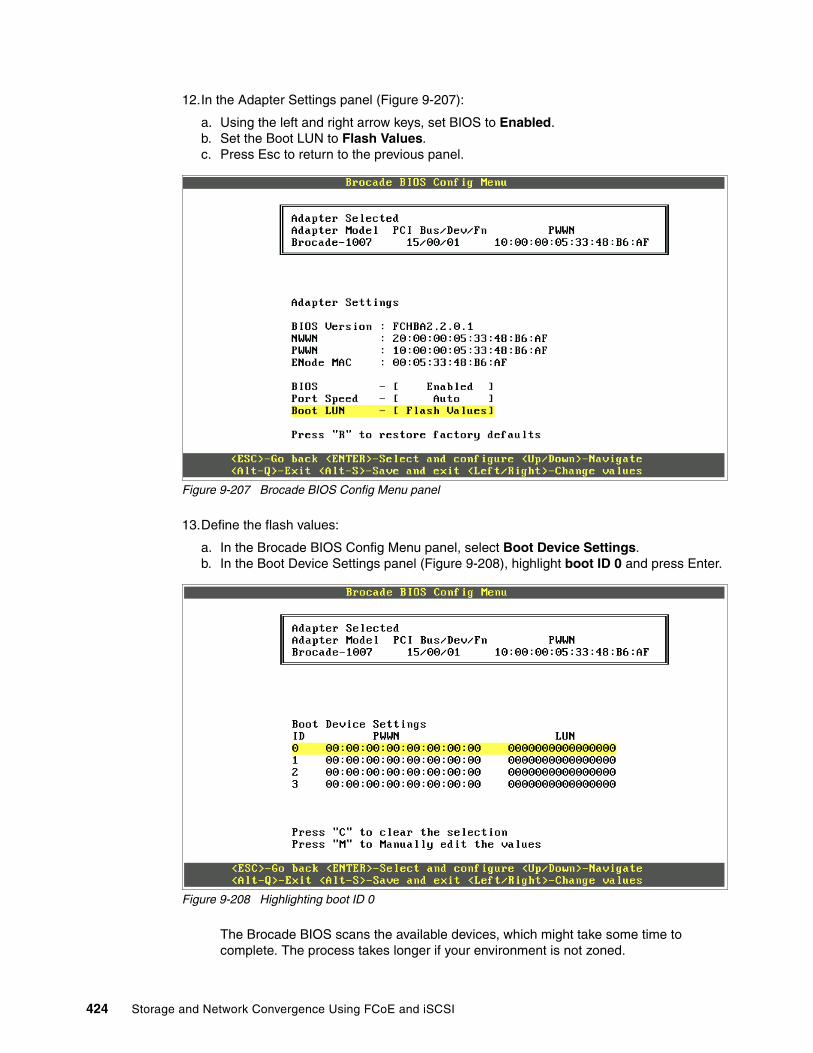
12.In the Adapter Settings panel (Figure 9-207):
a. Using the left and right arrow keys, set BIOS to Enabled.b. Set the Boot LUN to Flash Values. c. Press Esc to return to the previous panel.
Figure 9-207 Brocade BIOS Config Menu panel
13.Define the flash values:
a. In the Brocade BIOS Config Menu panel, select Boot Device Settings.b. In the Boot Device Settings panel (Figure 9-208), highlight boot ID 0 and press Enter.
Figure 9-208 Highlighting boot ID 0
The Brocade BIOS scans the available devices, which might take some time to complete. The process takes longer if your environment is not zoned.
424 Storage and Network Convergence Using FCoE and iSCSI

You see your disk storage subsystem as shown in the example in Figure 9-209.
Figure 9-209 Disk storage subsystem
14.Highlight the disk storage subsystem that you want to boot from, and then press Enter.
15.When you see the available LUN, select the LUN you want to boot from, and then press Enter (Figure 9-210).
The boot LUN must be one LUN with all 0s. Some operating systems require the LUN to be LUN 0 (as shown in Figure 9-210) to boot from. If you see a LUN with a number other than 0, sign in to your SAN disk storage device, and redo your mapping to ensure that the LUN is LUN 0. Then reboot the blade server again, and go back to 1 on page 421 to repeat this part of the procedure.
LUN versus LUN ID: This step refers to LUN in terms of a number, not a LUN ID (Figure 9-210 on page 426). The LUN ID is 1, but the LUN itself is 0000000000000000000, which is acceptable.
Chapter 9. Configuring iSCSI and FCoE cards for SAN boot 425

Figure 9-210 Selecting the LUN you want to boot from
You now return to the main panel (Figure 9-211).
Figure 9-211 Brocade BIOS Config Menu panel
16.Press Alt+S to save and exit.
426 Storage and Network Convergence Using FCoE and iSCSI

17.As shown in Figure 9-212, select Exit Brocade Config Menu.
Figure 9-212 Exiting the Brocade Config Menu panel
9.8.8 Boot from SAN by using the First LUN option
The Brocade CNA offers various ways to boot from SAN in legacy BIOS mode. Some of these options are dynamic on boot. The Brocade BIOS scans your LUN every time your server boots. Because of this behavior, you are not required to set a fixed boot LUN.
By using the First LUN option, you can dynamically boot a different LUN. This method might be easier or faster to use than a tool such as BladeCenter Open Fabric Manager, with less configuration when assigning a LUN to boot on another blade.
However, this method can take more time to scan the LUNs on every boot. It boots the first LUN that is detected. Therefore, the configuration must be perfect. Otherwise, boot issues can occur. This method might also be considered less secure.
This book provides information about how to perform the installation using First LUN. However, you can use alternative methods that are documented in the Brocade HBA manuals. Figure 9-213 shows the First LUN option.
Figure 9-213 First LUN boot option
Chapter 9. Configuring iSCSI and FCoE cards for SAN boot 427

9.8.9 Installing Windows in legacy BIOS mode
After exiting the Brocade BIOS Config Menu, the system continues the boot process:
1. When the DVD starts to load, if prompted to press any key (Figure 9-214), press a key so that the DVD starts to boot. If you do not press a key, the DVD fails to boot.
Figure 9-214 Prompt to press a key to boot from the CD or DVD
2. After Windows loads, select your preferences, and click Next.
3. In the Install Windows panel (Figure 9-215), select Install now.
Figure 9-215 Install now button
Press any key to boot from CD or DVD.....
428 Storage and Network Convergence Using FCoE and iSCSI

4. Select the operating system that you want to install (Figure 9-216), and then click Next.
Figure 9-216 Selecting the operating system
Chapter 9. Configuring iSCSI and FCoE cards for SAN boot 429

5. Read the license agreement, select I accept the license terms, and click Next (Figure 9-217).
Figure 9-217 The license agreement panel
430 Storage and Network Convergence Using FCoE and iSCSI

6. For the type of installation (Figure 9-218), select Custom (advanced) to install a clean copy of Windows. Then click Next.
Figure 9-218 Selecting the Custom (advanced) option to install a clean copy of Windows
Chapter 9. Configuring iSCSI and FCoE cards for SAN boot 431

7. If no disks are displayed (Figure 9-219), insert the media that contains the drivers. The media can be in the form of a USB key, CD, or DVD, on a remotely mounted ISO. Then click Load Driver to load a driver for your storage device (Brocade card).
Figure 9-219 No drives found message
8. Click OK or Browse to point to the exact location. Windows finds an appropriate, more current driver.
Important: Load the latest Brocade CNA driver that is certified for your disk storage subsystem.
Downloading and extracting the drivers: The Windows 2008 R2 DVD is prepackaged with multiple drivers, but no driver for the Brocade CNA controller. Also, the updated driver resolves multiple issues. You can download the blade drivers from the following websites:
� Brocade link for IBM BladeCenter:
http://www.brocade.com/sites/dotcom/services-support/drivers-downloads/adapters/IBM_BLADECENTER.page
� Brocade link for System x:
http://www.brocade.com/sites/dotcom/services-support/drivers-downloads/adapters/IBM_SYSTEMX.page
Extract the drivers and copy them on a removable media such as a USB key, DVD media, or ISO file.
432 Storage and Network Convergence Using FCoE and iSCSI
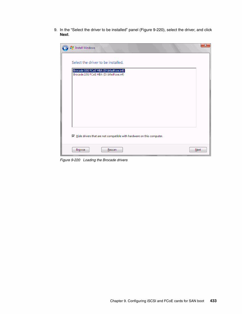
9. In the “Select the driver to be installed” panel (Figure 9-220), select the driver, and click Next.
Figure 9-220 Loading the Brocade drivers
Chapter 9. Configuring iSCSI and FCoE cards for SAN boot 433

10.In the “Where do you want to install Windows” panel (Figure 9-221), when you see your LUN, select the disk, and then click Next.
Figure 9-221 Selecting the disk to install on
434 Storage and Network Convergence Using FCoE and iSCSI

If you see a warning message (Figure 9-222) that indicates that the hardware might not support booting to the disk, the disk is offline or another error might exist. Therefore, boot from SAN will not work.
Figure 9-222 Check for warnings
11.Recheck all items as explained in “Legacy BIOS mode” on page 437, and then reboot the server on the Windows DVD. After you address all errors, click Next.
Chapter 9. Configuring iSCSI and FCoE cards for SAN boot 435
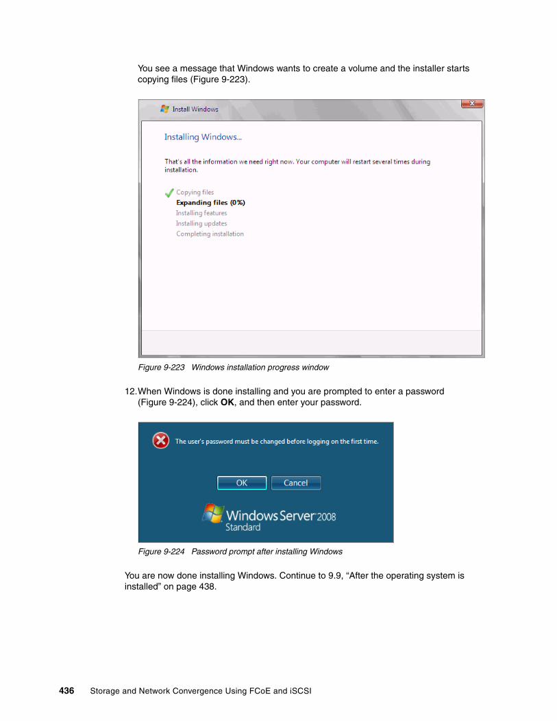
You see a message that Windows wants to create a volume and the installer starts copying files (Figure 9-223).
Figure 9-223 Windows installation progress window
12.When Windows is done installing and you are prompted to enter a password (Figure 9-224), click OK, and then enter your password.
Figure 9-224 Password prompt after installing Windows
You are now done installing Windows. Continue to 9.9, “After the operating system is installed” on page 438.
436 Storage and Network Convergence Using FCoE and iSCSI

9.8.10 Troubleshooting: Hardware does not support boot to disk
This section provides guidance when hardware does not support boot to disk in the following modes when configuring Brocade for FCoE:
� UEFI mode� Legacy BIOS mode
UEFI modeIn the procedure in 9.8.5, “Booting the Windows DVD in UEFI mode” on page 409, you might receive a message that indicates that the hardware might not support boot to disk. If you see this message, review the setup instructions in 9.8.1, “Configuring the Brocade card for boot from SAN” on page 405, and then check the following settings:
� Verify that the boot device was added when you pressed F1 (go back and check).
� Verify that the BIOS was enabled on the QLogic port (go back and check).
� Verify that the CNA from which you are trying to boot is not on the preferred path of the SAN disk. The most common cause of an offline disk is that the preferred path is not assigned correctly. Check your SAN disk device configuration, and then reboot the server again on the Windows DVD.
� Verify that your SAN disk supports a UEFI boot.
� Verify that your SAN disk is updated to the latest firmware.
� Try to perform a legacy installation.
� If the disk is offline, see Windows KB 2345135, “Setup reports error ‘Windows cannot be installed to this disk...’ when booted from DVD” at this website:
http://support.microsoft.com/kb/2345135
� Setup reports the error message “Windows cannot be installed to this disk...” booted from DVD in UEFI mode. You might modify the Windows installation media.
� Use Windows media that is bundled with the latest service pack.
� If you see a 20-MB disk, you most likely mapped the access LUN instead of the actual LUN. To correct this problem, log in to your disk storage subsystem.
� Verify that your LUN is using LUN 0, which is defined in the SAN disk device.
� Verify that you are using the latest Windows DVD with the latest service pack built-in.
� Verify that the path is on the preferred path. Check with your SAN configuration.
� Verify that zoning is correct or unchanged.
� Verify that LUN mapping is correct or unchanged.
Legacy BIOS modeIn the procedure in 9.8.9, “Installing Windows in legacy BIOS mode” on page 428, you might receive a message that indicates that the hardware might not support boot to disk. If you see this message, review the setup instructions in 9.8.1, “Configuring the Brocade card for boot from SAN” on page 405, and then check the following settings:
� Verify that the boot device was added when you pressed F1 (go back and check).
� Verify that the BIOS was enabled on the Brocade port (go back and check).
� Verify that the CNA from which you are booting is on the preferred path of the SAN disk. The most common cause of an offline disk is that the preferred path is not assigned correctly. Check your SAN disk device configuration, and then reboot the server again on the Windows DVD.
Chapter 9. Configuring iSCSI and FCoE cards for SAN boot 437

� Verify that your SAN disk is updated to the latest firmware.
� Use Windows media that is bundled with the latest service pack.
� If you see a 20-MB disk, you most likely mapped the access LUN instead of the LUN. To correct this problem, log in to your disk storage subsystem.
� Verify that your LUN is using LUN 0, which is defined in the SAN disk device.
� Verify that you are using the latest Windows DVD with the latest service pack built-in.
� Verify that the path is on the preferred path. Check with your SAN configuration.
� Verify that zoning is correct or unchanged.
� Verify that LUN mapping is correct or unchanged.
9.9 After the operating system is installed
After your operating system is successfully installed, complete the following tasks:
� Installing the disk storage redundant driver on the blade� Zoning other CNA ports on the switches� Mapping the LUN to the other CNA port on the SAN disk subsystem� Optional: Verifying connectivity on server with CNA management tools
9.9.1 Installing the disk storage redundant driver on the blade
The disk storage redundant driver is provided by your SAN disk vendor. See your SAN disk provider for the available documentation.
For example, you might have one of the following IBM drivers:
� Redundant Disk Array Controller (RDAC)� Multipath I/O (MPIO) driver� Subsystem Device Driver (SDD)
The driver installation procedure will most likely require a reboot after the driver is installed. Some redundant drivers also have dependencies on the Windows Storport driver. Therefore, you must also update that driver. Also update the latest Microsoft patches when performing a new installation.
Finish installing the drivers that are required in the operating system. With Windows, check the Device Manager for any unknown devices. If you require assistance, use IBM UpdateXpress System Pack Installer, which you can download from the IBM ToolsCenter:
http://www.ibm.com/support/entry/portal/docdisplay?brand=5000008&lndocid=TOOL-CENTER
9.9.2 Zoning other CNA ports on the switches
After you install the redundant driver, point the other WWPN of the CNA to the other disk subsystem redundant controller. You can also point your CNA WWPN to more than one storage WWPN.
438 Storage and Network Convergence Using FCoE and iSCSI
9.9.3 Mapping the LUN to the other CNA port on the SAN disk subsystem
Now that your zoning is done and the redundant driver is installed, complete the redundancy. From your storage subsystem, map your LUNs to the other host CNA WWPN so that, if a controller fails when your system is up and running, your host stays up and running.
9.9.4 Optional: Verifying connectivity on server with CNA management tools
Install the CNA management tools as explained in 7.4, “Installing the CNA software management tools” on page 125. By using the management tools, you can verify whether your CNA port sees the disk storage device and which LUN is seen on each side.
9.10 Common symptoms and tips
This section highlights several problems and provides guidance for correcting them:
� Symptom: You see two or more of the same disks in the operating system.
Solution: If you see two or more of the same disks in the operating system disk manager, your SAN disk redundant driver is not installed. Make sure that you install it. Contact your disk storage subsystem vendor for more information about the redundant driver.
� Symptom: You experience a stop error (blue screen) during installation.
Solution: Many SAN disk devices might have one preferred path active at one time. During installation, the path might switch back to its preferred path, which can cause a blue screen and point to loss of storage access. This situation is likely a software problem.
If you experience a stop error:
– Verify that only one path is presented during installation.– Verify that the LUN is on the preferred path.
� Symptom: After rebooting the system, it does not boot to Windows.
Solution: Follow these tips to ensure that the system boots to Windows:
– Make sure that you are booting the correct CNA port on the correct path.– Try changing the preferred path to the alternate path on the disk storage subsystem.– If you installed an operating system in legacy mode, make sure that you set Legacy
only as the first boot device.
� Symptom: When installing or after installation, you see an unexplained 20-MB disk.
Attention: Avoid having too much redundancy. One path per CNA is adequate. To optimize performance, minimize the number of paths and direct traffic among those paths. For example, boot half of the blades from controller A and boot the other half from controller B, without flooding each port. Place some of the hosts on controllers A1 and B1, and then place other hosts on controllers A2 and B2.
Some storage devices also have maximum limits that the redundant driver can handle. Follow the guidelines provided by your disk storage vendor.
Redundancy with redundant paths: Adding the redundant paths allows for redundancy within the operating system. The boot time remains non-redundant and will always be non-redundant. The solution becomes redundant only when the operating system loads the redundant driver and when you have logical redundant paths to your controllers.
Chapter 9. Configuring iSCSI and FCoE cards for SAN boot 439

Solution: A 20-MB disk is most likely your “access LUN” that is mapped. You can manage this disk from your SAN disk storage device and remove it from the mapped LUN. The access LUN is normally used for in-band management of the storage device, but it is not a requirement for boot from SAN.
9.11 References about boot from SAN
For more information about boot from SAN for scenarios other than FCoE, see the following references:
� IBM documents and Redbooks publications:
– SAN Boot Implementation and Best Practices Guide for IBM System Storage, SG24-7958
– Remote Storage Area Network (SAN) Boot - IBM BladeCenter HS20 and HS40:
http://www.ibm.com/support/entry/portal/docdisplay?lndocid=MIGR-57563&brandind=5000020
– IBM Midrange System Storage Implementation and Best Practices Guide, SG24-6363
– IBM BladeCenter 4Gb SAN Solution, SG24-7313
– IBM Flex System V7000 Storage Node Introduction and Implementation Guide, SG24-8068
– Implementing the IBM Storwize V7000 V6.3, SG24-7938
– IBM System Storage DS4000 and Storage Manager V10.30, SG24-7010
– IBM System Storage DS3000: Introduction and Implementation Guide, SG24-7065
� Microsoft:
– Microsoft Multipath I/O (MPIO) Users Guide for Windows Server 2012:
http://www.microsoft.com/en-us/download/details.aspx?id=30450
– Windows Boot from Fibre Channel SAN – An Executive Overview and Detailed Technical Instructions for the System Administrator:
http://www.microsoft.com/download/en/details.aspx?displaylang=en&id=2815
– Support for booting from a Storage Area Network (SAN):
http://support.microsoft.com/kb/305547
� Linux:
– Linux Enterprise Server 11 SP2 - Storage Administration Guide:
http://doc.opensuse.org/products/draft/SLES/SLES-storage_sd_draft/index.html
� VMware:
– Using Boot from SAN with ESX Server Systems:
http://pubs.vmware.com/vi3/sanconfig/wwhelp/wwhimpl/common/html/wwhelp.htm?context=sanconfig&file=esx_san_cfg_bootfromsan.8.1.html
– Fibre Channel SAN Configuration Guide - VMware:
http://www.vmware.com/pdf/vsphere4/r40/vsp_40_san_cfg.pdf
440 Storage and Network Convergence Using FCoE and iSCSI
9.12 Summary
Boot from SAN can be complex to install. However, after the procedure is completed, you can recover faster from hardware failures and quickly perform testing. On the IBM PureFlex Systems, Flex, System x, and blade server platforms, servers can support the installation of boot from SAN-attached disk.
By using the SAN for the operating system disks, it becomes easier to recover from a hardware failure of the processor, memory, buses, or any other system hardware component. Reduction of risk for extended system outages that occur in direct-attached storage environments is significant. By using FSM, IBM Fabric Manager, Blade Open Fabric Manager, and IBM Systems Director, you can automate a system crash to reboot on an alternate spare blade or nodes.
Chapter 9. Configuring iSCSI and FCoE cards for SAN boot 441

442 Storage and Network Convergence Using FCoE and iSCSI

Chapter 10. Approach with FCoE inside the BladeCenter
This chapter describes the implementation of Fibre Channel over Ethernet (FCoE) with IBM BladeCenter embedded switches.
To set up the variations of FCoE solutions, the scenarios for this chapter used the following hardware components:
� IBM Virtual Fabric components:
– BNT Virtual Fabric 10Gb Switch Module
– QLogic Virtual Fabric Extension Module providing Fibre Channel (FC) Gateway functions
– Converged network adapter (CNA) as a mezzanine card on the blade server:
• Emulex 10GbE Virtual Fabric Adapter II Advanced• QLogic 2-port 10GbE CNA
� Brocade Converged 10GbE Switch Module and 2-port 10GbE CNA
All tests were run on an IBM BladeCenter H chassis with the HS22 Blade Server and IBM System Storage DS5300. For the operating systems, Windows 2008R2, ESXi 5.0, and Red Hat Enterprise Linux (RHEL) 6.1 were used.
This chapter includes the following sections:
� 10.1, “Implementing IBM BladeCenter enabled for FCoE with Virtual Fabric Switch and Virtual Extension Module” on page 444
� 10.2, “Enabling FCoE host access by using the Brocade Converged 10G Switch Module solution” on page 462
10
© Copyright IBM Corp. 2012, 2014. All rights reserved. 443
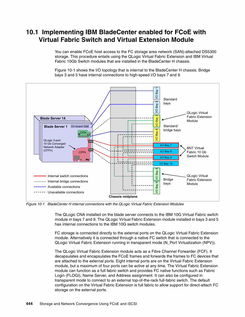
10.1 Implementing IBM BladeCenter enabled for FCoE with Virtual Fabric Switch and Virtual Extension Module
You can enable FCoE host access to the FC storage area network (SAN)-attached DS5300 storage. This procedure entails using the QLogic Virtual Fabric Extension and IBM Virtual Fabric 10Gb Switch modules that are installed in the BladeCenter H chassis.
Figure 10-1 shows the I/O topology that is internal to the BladeCenter H chassis. Bridge bays 3 and 5 have internal connections to high-speed I/O bays 7 and 9.
Figure 10-1 BladeCenter H internal connections with the QLogic Virtual Fabric Extension Modules
The QLogic CNA installed on the blade server connects to the IBM 10G Virtual Fabric switch module in bays 7 and 9. The QLogic Virtual Fabric Extension module installed in bays 3 and 5 has internal connections to the IBM 10G switch modules.
FC storage is connected directly to the external ports on the QLogic Virtual Fabric Extension module. Alternatively it is connected through a native FC switch that is connected to the QLogic Virtual Fabric Extension running in transparent mode (N_Port Virtualization (NPV)).
The QLogic Virtual Fabric Extension module acts as a Fibre Channel Forwarder (FCF). It decapsulates and encapsulates the FCoE frames and forwards the frames to FC devices that are attached to the external ports. Eight internal ports are on the Virtual Fabric Extension module, but a maximum of four ports can be active at any time. The Virtual Fabric Extension module can function as a full fabric switch and provides FC native functions such as Fabric Login (FLOGI), Name Server, and Address assignment. It can also be configured in transparent mode to connect to an external top-of-the-rack full-fabric switch. The default configuration on the Virtual Fabric Extension is full fabric to allow support for direct-attach FC storage on the external ports.
Blade Server 14
On-board GbE
CIOv
CFFh
I/O Bay 7
I/O Bay 9
I/O Bay 8
I/O Bay 10
I/O B
ay 5
I/O B
ay 6
I/O B
ay 3
I/O B
ay 4
I/O B
ay 2
I/O B
ay 1
Internal switch connections
Internal bridge connections
Available connections
Unavailable connectionsChassis midplane
Bridgebays
Standardbays
Standard/bridge bays
QLogic 2-port 10 Gb Converged Network Adapter (CFFh)
Blade Server 1
QLogic Virtual Fabric Extension Module
QLogic Virtual Fabric Extension Module
BNT Virtual Fabric 10 GbSwitch Module
444 Storage and Network Convergence Using FCoE and iSCSI

Table 10-1 lists the supported configurations with the Virtual Fabric Extension module and IBM 10G switch installed in the BladeCenter H chassis.
Table 10-1 Ethernet to bridge-port mapping
The maximum supported internal bandwidth between each Virtual Fabric Extension module and the IBM 10G switch module is 40 Gbps. It uses four 10 Gbps external ports on the high-speed switch module that is installed in bay 7 or 9. The minimum supported bandwidth between each Virtual Fabric Extension module and the IBM 10G switch module is 20 Gbps. It uses two 10-Gbps external ports on the high-speed switch module installed in bay 7 or 9.
The bridge ports on the Virtual Fabric Extension module use the same internal path as the external ports on the IBM 10 Gbps switch module. Thus after enabling the bridge ports, some of the external ports are made unavailable automatically on the IBM 10 Gbps switch module. If the bandwidth assigned for the bridge ports is 40 Gbps, four external ports are made unavailable. If the bandwidth assigned on the bridge ports is 20 Gbps, two external ports on the IBM 10 Gbps switch module are made unavailable.
To establish end-to-end FCoE connectivity, at a high level, follow these steps:
1. Ensure that the host has an FCoE adapter (CNA) installed and connected to the IBM Virtual Fabric 10G Switch Module switch module that is installed in bay 7 and 9.
2. Ensure that the Ethernet and FC device drivers are installed on the host.
3. Ensure that the FCoE host has a link on the 10 Gb CEE ports.
4. Ensure that the FC device driver on the host logs in to the Virtual Fabric Extension module as a VN_port.
5. Connect the FC storage device to the fabric.
6. Verify that the FC target devices are online as N-port devices.
7. Zone the FCoE host and FC Target worldwide port names (WWPNs).
8. Map the FC logical unit numbers (LUNs) to the host.
9. Verify that the host sees the LUNs from the disk manager.
Deployment of the Virtual Fabric FCoE solution needs minimum manual configuration because the solution handles most of the settings automatically.
Configuration Switch Bay-7
Switch Bay-9
Connects to Ports on the Virtual Fabric Switch Module
A 20/40 Gbps Bridge Bay-5 only BR5A-BR5D replaces EXT1-EXT4
B 20/40 Gbps Bridge Bay-3 (or Bay-5)
BR3D-BR3A replaces EXT7-EXT10
C 40 Gbps 40 Gbps Bridge Bay-5 and Bay-3
BR5A-D/BR3D-A replaces EXT1-4 and EXT7-10
D 20 Gbps 20 Gbps Bridge Bay-5 only BR5A-BR5B replaces EXT1 and EXT2
Configuration D: Configuration D in Table 10-1 has two Virtual Fabric Switch Modules and one Virtual Fabric Extension. For this configuration, you can configure two bridge ports for each switch module and achieve a total bandwidth of 40 Gbps by distributing it across the two switch modules.
Chapter 10. Approach with FCoE inside the BladeCenter 445
10.Configure the IBM Virtual Fabric 10G Switch Modules:
a. Create bridge interfaces:
i. Assign bandwidth.ii. Enable bridge interfaces.iii. Reboot the switch.
b. Enable Converged Enhanced Ethernet (CEE) mode. c. Enable the FCoE Initialization Protocol (FIP). d. Enable Logical Link Discovery Protocol (LLDP). e. Create the FCoE VLAN (1002):
i. Assign the FCoE VLAN to the appropriate server ports (internal interfaces).ii. Set FCoE VLAN as the Port VLAN ID (PVID) on the bridge interfaces.
f. Enable Tagging on bridge interfaces and tag the PVID.g. Disable spanning tree on bridge interfaces.
11.Configure the QLogic Virtual Fabric Extension modules:
a. Configure the FCoE VLAN if any other than VLAN 1002 is used.b. Configure and enable zoning or set to Transparent mode.
12.Configure the FC storage subsystem. Define the host and LUN masking on the storage.
13.Configure the blade server:
a. Install the Multipath I/O (MPIO) driver.b. Discover and configure the disks.
10.1.1 Defining the FCoE and FC fabric topology
For this Redbooks publication, we use configuration D in Table 10-1 on page 445. It includes two QLogic Virtual Fabric Extension Modules and two IBM Virtual Fabric Switch Modules to set up a fully redundant topology with two separate FCoE and FC SAN fabrics.
The following options are possible when configuring the Virtual Fabric Extension Module in this case (see Figure 10-2):
� You can configure it as a full fabric switch with its own domain ID to provide Fibre Channel native functions, including Name Server and zoning.
� You can configure it in Transparent mode to connect to an external FC fabric.
The full fabric switch provides support for direct-attach FC storage on the external ports. The Transparent mode can be used to avoid concerns about interoperability or to scale the FC fabric without adding domain IDs.
Transparent mode for the Virtual Fabric Extension Module is based on NPV so that the upstream FC switch must support NPIV. The reason is that the Transparent Fabric Port (TF_Port, which corresponds to the NP_Port in NPV) acts similar an NPIV-enabled host to the upstream F_Port.
In either case, FCoE remains internal to the IBM BladeCenter server. Virtual N_Ports (VN ports) are for the end node port of the FC and FCoE fabric, and Virtual F_Ports (VF ports) are the fabric ports on the switch side. The external FC connections are all running at 8 Gbps.
446 Storage and Network Convergence Using FCoE and iSCSI

Figure 10-2 FCoE and FC fabric topology
As shown in Figure 10-2, in this scenario, we connect the switch in bay 7 to the extension module in bay 5, and the switch in bay 9 to the extension module in bay 3. In this configuration, each switch (VFSM) is connected to one dedicated module (VFEM) with 40 Gbps of aggregated bandwidth. Each of the four parallel blue lines in Figure 10-2 is 10 Gbps, for a total of 40 Gbps.
In summary, 80 Gbps full duplex is available for FCoE traffic to the FC Gateway. When the IBM Virtual Fabric 10 Gb Switch Module has 10 external 10-Gb ports, this configuration allows usage of up to only six external ports on each Virtual Fabric Switch Module. The reason is that four external ports for each switch module are unavailable (ports EXT1-4 in bay 7 and ports EXT7-10 in bay 9). Those circuits are rerouted to each QLogic Virtual Fabric Extension Module as bridge ports BR5A-BR5D bay 7 and BR3D-BR3A in bay 9.
10.1.2 Configuring the BNT Virtual Fabric 10Gb Switch Modules
To configure the IBM Virtual Fabric 10Gb Switch Modules, follow these steps:
1. Connect the Virtual Fabric Switch Module to the Virtual Fabric Extension Module (also called the bridge module). You initiate this task from the Virtual Fabric Switch Module by selecting the options for bandwidth (20 Gbps or 40 Gbps) and the location of the Virtual Fabric Extension Module (bay 3 or bay 5).
Example 10-1 shows the configuration for a connection from Virtual Fabric Switch Module in bay 7 to Virtual Fabric Extension Module in bay 5 with the maximum bandwidth of 40 Gbps.
CRTL A
CRTL B
Storage Controller
BCH
BladeServer
VLAN1002
VLAN
1003
Win2K8
ESXi
VFE
M
VFE
M
VFSM
VFSM
FC Switch
FC Switch
CRTL A
CRTL B
Storage Controller
BCH
BladeServer
VLAN1002
VLAN
1003
Win2K8
ESXi
VFE
M
VFE
M
VFSM
VFSM
NPV-Mode (Transparent)
Direct attached storage
VF
VF
TFTF
VN
F
F
F
F
FF
VF
N
VN
VFN
VN
VN
N
N
VN
VN
FCoE
native FC
bay7
bay3
bay9
bay5
bay7
bay3
bay9
bay5
Chapter 10. Approach with FCoE inside the BladeCenter 447

Example 10-1 Connection configuration between Virtual Fabric Switch Module and Virtual Fabric Extension Module
bay-7>enablebay-7#conf tbay-7(config)#boot bridge-module 5 bandwidth 40Please disable spanning tree on the bridge module 5 ports BR5A, BR5B, BR5C and BR5D after the switch reboots.bay-7(config)#boot bridge-module 5 enableBridge module 5 is enabled. Reboot the switch in order for the settings to take effect.bay-7(config)#reload
2. After reloading the Virtual Fabric Switch Module, enter the following command to check the connectivity settings:
show bridge-module
3. List the active bridge ports in place of the corresponding external ports (Example 10-2) by entering the following command:
show interface link
Example 10-2 demonstrates usage of the commands shown in steps 2 and 3.
Example 10-2 Verifying Virtual Fabric Extension Module connectivity
bay-7#show bridge-moduleBridge module 5 is set to 40Gbs.Bridge module 3 is disabled.bay-7#bay-7#show interface link------------------------------------------------------------------Alias Port Speed Duplex Flow Ctrl Link------- ---- ----- -------- --TX-----RX-- ------[...]BR5A 17 10000 full no no upBR5B 18 10000 full no no upBR5C 19 10000 full no no upBR5D 20 10000 full no no upEXT5 21 10000 full no no upEXT6 22 10000 full no no up[...]------------------------------------------------------------------Alias Speed----- -----BR3 40Gbsbay-7#
4. Enter the cee enable command to enable the Ethernet enhancements summarized as Data Center Bridging (DCB) or CEE. This command enables automatically LLDP, which is required for the Data Center Bridging Capabilities Exchange (DCBX) protocol and disables the existing Ethernet flow control, because priority flow control (PFC) is used instead.
5. Leave the settings for the bandwidth management (Enhanced Transmission Selection (ETS)) and flow control (PFC) as the default values. That is, for FCoE traffic, use a 50% guaranteed bandwidth, and use priority flow control for Ethernet Class of Service 3.
These configuration parameters are transferred to the CNA by using the DCBX protocol. Therefore, no configuration is necessary on the CNA.
448 Storage and Network Convergence Using FCoE and iSCSI

6. Enable the FCoE part. FCoE relies on the following protocols:
– FCoE as the data plane protocol, which carries the FC command frames and the SCSI traffic
– FIP as the control plane protocol:
• VLAN Discovery• FCF Discovery• FLOGI or Fabric Discovery (FDISC)• KeepAlives
The Virtual Fabric Switch Module is passing only the FCoE frames. However, to control FCoE traffic by dynamically creating access control lists (ACL), you must have knowledge about the active FCoE session, what is obtained by snooping FIP, and what is configured by using the fc0e fips enable command.
For information about the configuration of the FC Gateway, see 10.1.4, “Switching the Virtual Fabric Extension Module to N-Port Virtualization mode if connected to an existing FC fabric” on page 456.
7. Configure a dedicated VLAN for FCoE. By default, 1002 is used with all the internal ports and all bridge ports as members. The FCoE VLAN is sent as tagged by the CNA, which corresponds to the default setup of the Virtual Fabric Switch Module.
8. Configure the bridge ports as tagged ports to ensure appropriate communication to the Virtual Fabric Extension Module. The tag-pvid command ensures that only tagged frames are transmitted.
Example 10-3 summarizes the commands for the Virtual Fabric Switch Module in bay 7.
Example 10-3 Enabling the Ethernet enhancements
bay-7bay-7(config)#cee enable### bay-7(config)#lldp enable - done automatically with “cee enable” ###bay-7(config)#fcoe fips enablebay-7(config)#vlan 1002bay-7(config-vlan)#member INT1-14,BR5A-BR5Dbay-7(config-vlan)#enablebay-7(config)#interface port BR5A-BR5Dbay-7(config-if)#pvid 1002bay-7(config-if)#taggingbay-7(config-if)#tag-pvidbay-7(config)#exit
9. As a good practice, configure the bridge interface:
a. Remove all bridge ports from all VLANs other than the FCoE VLAN as shown in Example 10-4.
Example 10-4 Removing bridge ports from VLAN 1
bay-7(config)#vlan 1bay-7(config-vlan)#no member BR5A-BR5Dbay-7(config)#exit
Chapter 10. Approach with FCoE inside the BladeCenter 449

b. Disable the Spanning Tree Protocol on all bridge ports as shown in Example 10-5.
Example 10-5 Disabling the Spanning Tree Protocol for all bridge ports
bay-7(config)#int port BR5A-BR5Dbay-7(config-if)#no spanning-tree stp 106 enablebay-7(config)#exit
You have now completed the necessary configuration tasks on the Virtual Fabric Switch Module in I/O bay 7.
Repeat this configuration procedure on the Virtual Fabric Switch Module in I/O bay 9 connecting to Virtual Fabric Extension Module I/O bay 3 instead of I/O bay 5 and VLAN 1003 instead of VLAN 1002 as FCoE VLAN. Example 10-6 shows the final running configuration from the Virtual Fabric Switch Module in bay 7.
Example 10-6 Configuration of the Virtual Fabric Switch Module
bay-9#sh runCurrent configuration:version "6.8.0.66"switch-type "IBM Networking OS Virtual Fabric 10Gb Switch Module for IBM BladeCenter"!snmp-server name "bay-9"hostname "bay-9"!interface port INT1pvid 99no flowcontrolexit!!! ### repeats for interface port INT2-INT13 ###!!interface port INT14pvid 99no flowcontrolexit!interface port BR3Dtaggingtag-pvidpvid 1003exit!interface port BR3Ctaggingtag-pvidpvid 1003exit!
Tip: To check the spanning tree instance that is used for the FCoE VLAN, use the show running | i stp command.
450 Storage and Network Convergence Using FCoE and iSCSI

interface port BR3Btaggingtag-pvidpvid 1003exit!interface port BR3Ataggingtag-pvidpvid 1003exit!vlan 1member INT1-INT14,EXT1-EXT6,EXT11no member BR3D-BR3A!vlan 99enablename "VLAN 99"member INT1-INT14!vlan 1003enablename "VLAN 1003"member INT1-INT14,BR3D-BR3A!spanning-tree stp 1 vlan 1spanning-tree stp 1 vlan 99
spanning-tree stp 107 vlan 1003
interface port BR3Dno spanning-tree stp 107 enableexitinterface port BR3Cno spanning-tree stp 107 enableexitinterface port BR3Bno spanning-tree stp 107 enableexitinterface port BR3Ano spanning-tree stp 107 enableexit!fcoe fips enablecee enablelldp enable!endbay-9#
Use the show interface links command to verify that the link status is UP for all the active host ports and bridge interfaces.
Chapter 10. Approach with FCoE inside the BladeCenter 451

10.1.3 Configuring the QLogic Virtual Extension Modules
By default, the Virtual Fabric Extension Module has the necessary Ethernet configuration built-in. It enables FCoE hosts to log in to the name server if the FCoE configuration on the Virtual Fabric Switch Modules was completed by using the default VLAN ID 1002 for FCoE.
Therefore, all basic configurations tasks are completed. Only the non-default FCoE VLAN ID 1003 must be configured on the Virtual Fabric Extension Module in bay 3. A different VLAN ID to 1002 might be necessary in case of redundant FC fabrics with separate VLANs used for the different FC fabrics. A violation of the customer’s compliance rules might be another reason for choosing a non-default VLAN ID.
To configure the Virtual Fabric Extension Module FCoE VLAN, follow these steps:
1. Open the browser and point to the IP address of the Virtual Fabric Extension Module. Enter the appropriate answers on the following windows (the default login is USERID and PASSW0RD with zero as “O”).
2. To access the VLAN Manager, select Switch FCoE VLAN Manager (Figure 10-3).
Figure 10-3 Virtual Fabric Extension Module GUI
452 Storage and Network Convergence Using FCoE and iSCSI
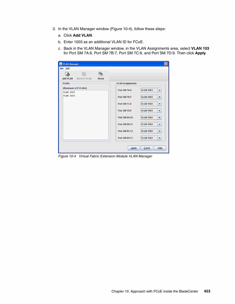
3. In the VLAN Manager window (Figure 10-4), follow these steps:
a. Click Add VLAN.
b. Enter 1003 as an additional VLAN ID for FCoE.
c. Back in the VLAN Manager window, in the VLAN Assignments area, select VLAN 103 for Port SM 7A:6, Port SM 7B:7, Port SM 7C:8, and Port SM 7D:9. Then click Apply.
Figure 10-4 Virtual Fabric Extension Module VLAN Manager
Chapter 10. Approach with FCoE inside the BladeCenter 453

4. Select Switch FCoE FCF Manager (Figure 10-3 on page 452).
5. In the FCF Configuration Manager window (Figure 10-5 here), change the FCoE mapping to VLAN 1003:
a. Select 0EFC00 and then click Edit.
Figure 10-5 Virtual Fabric Extension Module FCF Configuration Manager
b. In the FCF Editor window (Figure 10-6), follow these steps:
i. Select VLAN ID 1002, and click Remove. ii. From the VLAN menu, select VLAN 1003.iii. Click Add, and then click OK.
Figure 10-6 Virtual Fabric Extension Module FCF Editor
c. Back in the FCF Configuration Manager window, click Apply.
The change of the VLAN ID to 1003 is now completed.
454 Storage and Network Convergence Using FCoE and iSCSI

Changing the FC default configuration settings, such as the Domain ID or Zoning, is the only task that you might need to complete on the Virtual Fabric Extension Module. You can perform this task easily by using the GUI, but this task is not part of this Redbooks publication.
Another option without configuring the Domain ID or Zoning on the Virtual Fabric Extension Module is to run it in Transparent mode or by using N_Port Virtualization. For information about using N_Port Virtualization, see 10.1.4, “Switching the Virtual Fabric Extension Module to N-Port Virtualization mode if connected to an existing FC fabric” on page 456.
Figure 10-7 shows an active FCoE setup with Virtual Fabric Extension Module in FC Switch mode.
Figure 10-7 Virtual Fabric Extension Module in FC switch mode
To verify an active FCoE session, use the show fcoe fip fcf and show fcoe fip fcoe commands as shown in Example 10-7.
Example 10-7 Verifying an active FCoE session
bay-9#sh fcoe fip fcf FCF MAC Port Vlan-----------------------------------00:c0:dd:13:9b:fc BR3D 100300:c0:dd:13:9b:fb BR3C 100300:c0:dd:13:9b:fa BR3B 100300:c0:dd:13:9b:f9 BR3A 1003bay-9#bay-9#sh fcoe fips fcoe VN_PORT MAC FCF MAC Port Vlan------------------------------------------------------
Chapter 10. Approach with FCoE inside the BladeCenter 455

0e:fc:00:05:0a:00 00:c0:dd:18:d7:15 INT11 10030e:fc:00:05:0b:00 00:c0:dd:18:d7:16 INT13 1003bay-9#
10.1.4 Switching the Virtual Fabric Extension Module to N-Port Virtualization mode if connected to an existing FC fabric
If the storage is not connected directly to the Virtual Fabric Extension Module FC ports, use N_Port Virtualization to avoid interoperability issues and Domain ID usage. Additionally, NPV facilitates the setup of the Virtual Fabric Extension Module, because no specific FC configuration is necessary.
To switch the Virtual Fabric Extension Module to NPV mode (Transparent mode in QLogic), follow these steps:
1. In the main window of the Virtual Fabric Extension Module GUI (Figure 10-8), select Switch Advanced Switch Properties.
Figure 10-8 Virtual Fabric Extension Module GUI
456 Storage and Network Convergence Using FCoE and iSCSI

2. In the Advanced Switch Properties window (Figure 10-9), select Transparent Mode, then click OK.
Figure 10-9 Advanced Switch Properties window
3. Reboot the Virtual Fabric Extension Module. The switch to N-Port Virtualization is now completed.
Figure 10-10 shows an active FCoE setup with Virtual Fabric Extension Module in Transparent mode.
Figure 10-10 Virtual Fabric Extension Module in Transparent mode
Chapter 10. Approach with FCoE inside the BladeCenter 457

10.1.5 Configuring the FCoE VLAN ID on the CNA
In general, you do not need to configure the VLAN ID used for FCoE traffic on the CNA. It is part of the FCoE Initiation Protocol to automatically discover the FCoE VLAN ID advertised by the FCF.
If the VLAN ID is not advertised by the FCF or in case of incompatibilities, manually configure the FCoE VLAN ID as shown in this example for the QLogic CNA (8100 series). Choose either of the following configuration options:
� Enter the VLAN ID into the HBA Parameters file by using the QLogic SANsurfer GUI:
a. Start the SANsurfer GUI.
b. In the SANsurfer GUI:
i. Select the port for which the FCoE VLAN ID must be changed.
ii. On the Utilities tab, under HBA Parameters, click Save.
iii. Enter a file name and location to dump the HBA Parameters into a text file on your system.
c. After you see the “File saved successfully” message, open the saved file in a text editor, and search for the Primary FCF VLAN ID string.
d. Set Primary FCF VLAN ID Match = 1 and the FCoE VLAN ID. In this example, we set Primary FCF VLAN ID = 1003. Leave the other settings unchanged. Example 10-8 shows the modified parameters in bold.
Example 10-8 Modified FCoE VLAN settings for QLogic CNA 81xx HBA Parameters
[...];******************************************* ;Offset 0x080h version [0-65535] = 1Primary FCF VLAN ID Match [0-1] = 1Primary FCF Fabric Name Match [0-1] = 0reserved [0-63] = 0reserved [0-255] = 0reserved [0-65535] = 0Primary FCF VLAN ID [0-65535] = 1003Primary FCF Fabric Name 0 [0-255] = 0[...]
e. Return to SANsurfer.
f. In the SANsurfer GUI:
i. Ensure that the port for which the FCoE VLAN ID must be changed is selected.ii. On the Utilities tab, under HBA Parameters, click Update.iii. When you see the caution message, click Yes.
g. Open the edited file. When prompted, enter the configuration password. The default password is config.
The process is completed when you see the message “HBA Parameters Update Complete.” No reboot is necessary.
458 Storage and Network Convergence Using FCoE and iSCSI

� After booting the system, press F1 to access the UEFI configuration menu (Figure 10-11). Set Enable FCF VLAN ID to Enabled and then enter the VLAN ID.
Figure 10-11 Manual FCoE VLAN ID setting for QLogic CNA in UEFI
10.1.6 Configuring FCoE for the IBM Virtual Fabric Adapter in a virtual network interface card
When the Emulex CNAs Virtual Fabric Adapters I or II are used in virtual network interface card (vNIC) mode with FCoE personality, no additional configuration for FCoE is required on the Virtual Fabric Switch module. vNIC instances 1, 3, and 4 can be enabled for non-FCoE traffic. At least one instance is necessary if the operating system needs to detect an active NIC. Example 10-9 shows the configuration of vNIC instances 1 and 3 for an IBM BladeCenter server in slots 9 and 11.
vNIC instance 2 is fixed defined for FCoE traffic. No vNIC instance or vNIC Group must be configured for FCoE because there is no difference between the FCoE configuration in physical NIC (pNIC) or vNIC mode. For more information about vNIC and FCoE, see 11.2.2, “BNT Virtual Fabric 10Gb Switch Module configuration with vNIC” on page 471.
Example 10-9 Configuration of Virtual Fabric Switch Module with vNIC
bay-7#sh runCurrent configuration:version "6.8.0.1"switch-type "IBM Virtual Fabric 10Gb Switch Module for IBM BladeCenter"!! ### snip standard configuration and port INT1-INT8 ###
Tip: Automatic FCoE VLAN discovery, based on FIP, does not work after the FCoE VLAN ID is set manually.
Chapter 10. Approach with FCoE inside the BladeCenter 459

!!interface port INT9pvid 99no flowcontrolexit!interface port INT10pvid 99no flowcontrolexit!interface port INT11pvid 99no flowcontrolexit!! ### snip port INT12-EXT5 ###!interface port EXT6taggingexit!interface port BR5Ataggingtag-pvidpvid 1002exit!interface port BR5Btaggingtag-pvidpvid 1002exit!interface port BR5Ctaggingtag-pvidpvid 1002exit!interface port BR5Dtaggingtag-pvidpvid 1002exit!vlan 1member INT1-INT14,EXT1-EXT6,EXT11no member BR5A-BR5Dvlan 99enablename "VLAN 99"member INT1-INT14!
460 Storage and Network Convergence Using FCoE and iSCSI
vlan 1002enablename "VLAN 1002"member INT1-INT14,BR5A-BR5D!vnic enablevnic port INT9 index 1bandwidth 25enableexit!vnic port INT9 index 3bandwidth 25enableexit!vnic port INT11 index 1bandwidth 25enableexit!vnic port INT11 index 3bandwidth 25enableexit!vnic vnicgroup 1vlan 101enablemember INT9.1member INT11.1exit!vnic vnicgroup 3vlan 103enablemember INT9.3member INT11.3exit!spanning-tree stp 101 vlan 101spanning-tree stp 103 vlan 103spanning-tree stp 106 vlan 1002
interface port BR5Ano spanning-tree stp 106 enableexit!interface port BR5Bno spanning-tree stp 106 enableexit!interface port BR5Cno spanning-tree stp 106 enableexit
Chapter 10. Approach with FCoE inside the BladeCenter 461
!interface port BR5Dno spanning-tree stp 106 enableexit!fcoe fips enable!cee enable!lldp enable!endbay-7#
10.1.7 Summary assessment
The FCoE implementation for an IBM BladeCenter server with a Virtual Fabric 10G Switch and Virtual Fabric Extension Module requires minimal configuration effort. The solution is flexible and scalable in bandwidth and shows good performance. In our tests, we found only a minor issue with the automatic VLAN discovery, but did not experience any incompatibility issues with the external FC fabric or FC-attached storage.
No significant differences were detected between using Windows 2008R2, ESXi 5.0, or RHEL 6.1 with QLogic or Emulex CNAs.
The IBM BladeCenter Virtual Fabric technology offers a fully integrated FCoE solution that is easy to set up.
10.2 Enabling FCoE host access by using the Brocade Converged 10G Switch Module solution
Now you enable FCoE host access to the FC SAN-attached DS5300 storage by using the Brocade 10G Switch Module and CNA for IBM BladeCenter. For information about the CNA, see Chapter 9, “Configuring iSCSI and FCoE cards for SAN boot” on page 225.
The Brocade Converged 10G Switch Module (B8470) and Brocade 2-Port 10Gb Converged Network Adapter offer another option for an integrated Converged Ethernet solution for IBM BladeCenter. Contrary to the Virtual Fabric solution in 10.1, “Implementing IBM BladeCenter enabled for FCoE with Virtual Fabric Switch and Virtual Extension Module” on page 444, the BCS module features Dynamic Ports on Demand capability through the Port Upgrade Key. Ports must be enabled by a license key if more than 16 of the 30 ports on the switch are needed. Any combination of Fibre Channel and Ethernet ports is allowed, and purchasing the Port Upgrade Key enables all 30 ports on the switch module.
Another difference with the Virtual Fabric solution is that the Brocade 10G Switch Module has native FC and Ethernet ports built into a single switch module:
� Eight 10-Gb CEE external ports� Eight 8-Gb FC external ports� Fourteen 10Gb CEE internal ports
462 Storage and Network Convergence Using FCoE and iSCSI

In addition, the Brocade 10G Switch Module has an integrated FCF function. Similar to the Virtual Fabric Extension Module, it decapsulates and encapsulates the FCoE frames and forwards the frames to FC devices that are attached to the external FC ports. It also provides FC native functions such as FLOGI, Name Server, and Address assignment. Alternatively, it can be configured in Access Gateway Mode to save a Domain ID and to facilitate the FC configuration.
One Brocade Converged 10GbE Switch Module occupies two adjacent high-speed bays (7/8 or 9/10). The ports on CNA cards are physically routed to the bays 7 and 9.
Figure 10-12 illustrates the I/O topology that is internal to the BCH chassis. This figure shows the use of two Brocade 10G Switch Modules routed to two 10 Gb FCoE/CEE ports from a CNA installed into each server. Two Brocade Converged 10GbE Switch Modules are installed in bays 7/8 and bays 9/10 of the BladeCenter H chassis. All connections between the controller, card, and the switch modules are internal to the chassis. No internal cabling is needed.
Figure 10-12 BladeCenter H internal connections with the Brocade Converged 10G Switch Module
The switch supports the following fabric management. All management connections go through the management module except direct serial connection, which goes through the mini-USB port.
� Web interface through Brocade Web Tools� Command-line interface (CLI) through the Telnet program� A terminal emulation program connection to the mini-USB port interface� IBM System Storage Data Center Fabric Manager application� Simple Network Management Protocol (SNMP) agent of the switch
For the Ethernet configuration during our tests, the CLI (IOS, like the CISCO switch operating system) was the most appropriate management tool. For the FC part, the CLI and the web interface were applicable similar to the management of native Brocade FC switches.
10.2.1 Configuring the Brocade Converged 10G Switch Module
For our tests, we used only one Brocade 10G Switch Module installed in bays 7/8 of our BladeCenter H. To show the configuration of the FCoE VLAN, we use a non-default VLAN ID.
The deployment of the Brocade FCoE solution requires a comparable manual configuration to the Virtual Fabric solution, except the Bridge Interface configuration, because the Brocade 10G Switch Module has an integrated FCF.
IBM BladeCenter H chassis
IBM BladeCenter server
SAN LAN
1
2
3
4 5 6
5 64
Chapter 10. Approach with FCoE inside the BladeCenter 463

To configure the Brocade 10G Switch Module, follow these steps:
1. Enter the Ethernet CLI by entering cmsh on the CLI.
2. Map FCoE VLAN (1003) as follows only if non-default ID (1002) is used. You must do this step before the configuring the port.
B8470(config)#fcoe-map defaultB8470(conf-fcoe-map)#vlan 1003
3. Configure the port for CEE and FCoE (blade server slot 11):
B8470(config)#int int 0/11B8470(conf-if-int-0/11)#switchportB8470(conf-if-int-0/11)#switchport mode convergedB8470(conf-if-int-0/11)#fcoeportB8470(conf-if-int-0/11)#no shut
For CEE map, we use the default values. For example, for FCoE traffic, we chose bandwidth management (ETS) 40% guaranteed, and for priority flow control, we chose Ethernet Class of Service 3. These configuration parameters are transferred to the CNA by using the DCBX protocol, so that nothing must be configured on the CNA itself.
4. Configure LLDP or DCBX for FCoE:
B8470(config)#prtocol lldpB8470(conf-lldp)# advertise dcbx-fcoe-app-tlvB8470(conf-lldp)# dcbx-fcoe-logical-link-tlv
5. Configure the FC Fabric and storage subsystem:
a. Enable zoning or set to Access Gateway Mode.b. Define host and LUN masking on the storage.
6. Configure the blade server:
a. Install the MPIO driver. b. Discover and configure the disks.
You have now completed the necessary configuration tasks on the Brocade 10G Switch Module. Example 10-10 shows the output of the running Brocade 10G Switch Module configuration in bay 7.
Example 10-10 Configuring the Brocade 10G Switch Module
B8470#show running-config !protocol spanning-tree rstp bridge-priority 61440!cee-map default priority-group-table 1 weight 40 pfc priority-group-table 2 weight 60 priority-table 2 2 2 1 2 2 2 2!fcoe-map default fcoe-vlan 1003!interface Vlan 1 no shutdown!interface InTengigabitEthernet 0/1 switchport
464 Storage and Network Convergence Using FCoE and iSCSI

switchport mode access shutdown!! ### snip port InTengigabitEthernet 0/2-10!interface InTengigabitEthernet 0/11 fcoeport switchport switchport mode converged no shutdown!interface InTengigabitEthernet 0/12 switchport switchport mode access shutdown!interface InTengigabitEthernet 0/13 fcoeport switchport switchport mode converged no shutdown!interface InTengigabitEthernet 0/14 switchport switchport mode access shutdown!interface ExTengigabitEthernet 0/15 shutdown!! ### snip port InTengigabitEthernet 0/16-21!interface ExTengigabitEthernet 0/22 shutdown!interface Port-channel 1 shutdown!protocol lldp advertise dcbx-fcoe-app-tlv advertise dcbx-fcoe-logical-link-tlv!line console 0 login line vty 0 31 login!B8470#
Verify the CNA connection to the switch by using the fcoe --loginshow command to see the PWWN on the DOS command shell, or enter the fos nsshow -t command in a command shell (cmsh).
Chapter 10. Approach with FCoE inside the BladeCenter 465

10.2.2 Summary assessment
The Brocade Converged 10G Switch Module offers another option to set up a fully integrated FCoE solution with the IBM BladeCenter. The FCoE implementation of the Brocade Converged FCoE solution for the IBM BladeCenter entails a minimum configuration effort comparable to the Virtual Fabric FCoE solution. With the Brocade CNA and a Brocade FC fabric, a single-vendor solution can be deployed.
466 Storage and Network Convergence Using FCoE and iSCSI
Chapter 11. Approach with FCoE between BladeCenter and a top-of-rack switch
This chapter describes a Fibre Channel over Ethernet (FCoE) configuration by using a top-of-rack switch as a Fast Connection Failover. We tested only the Cisco Nexus 5010 Switch as a top-of-rack Fast Connection Failover. This switch requires an insertable hardware module with six Fibre Channel (FC) ports to be in place to provide the Fibre Channel Forwarder (FCF) function. Although our testing used only servers in a BladeCenter H chassis to access the storage, it is possible to use similar configurations with essentially the same configuration on the 5010 switch, as in the following examples:
� Rack mounted servers can be connected directly or indirectly to the Ethernet ports on the 5010 switch and pass FCoE traffic through the FCF function.
� Blade servers can be connected to the Ethernet ports on the 5010 switch with a 10-Gbps pass-through module instead of an embedded switch in the high-speed bays of the BladeCenter H chassis.
This chapter includes the following sections:
� 11.1, “Overview of testing scenarios” on page 468
� 11.2, “BNT Virtual Fabric 10Gb Switch Module utilizing the Nexus 5010 Fast Connection Failover” on page 469
� 11.3, “Cisco Nexus 4001i embedded switch with Nexus 5010 FCF” on page 472
� 11.4, “Commands and pointers for FCoE” on page 473
� 11.5, “Full switch configurations” on page 474
11
© Copyright IBM Corp. 2012, 2014. All rights reserved. 467

11.1 Overview of testing scenarios
We performed our testing by using a BNT Virtual Fabric 10Gb Switch Module and QLogic and Emulex converged network adapters (CNAs). Figure 11-1 illustrates our environment.
Figure 11-1 FCoE between a BladeCenter chassis and top-of-rack switch to storage
The same tests were performed by using a Cisco Nexus 4001i embedded switch module instead of the BNT Virtual Fabric 10Gb Switch Module. The configuration of the Nexus 5010 switch was essentially the same (Figure 11-2), regardless of the embedded switch that was used.
Figure 11-2 FCoE topology with the Nexus 5010 switch
1x CNA Card
2-portQLogic 10 Gb CNA
UpstreamFC Network
UpstreamEthernetNetwork
UpstreamFC Network
UpstreamEthernetNetwork
CNA with BNT 10 Gb VF Switch
Top-of-rack switch splits LAN and SAN traffic
2 x 10 Gb Switch
10-portBNT 10 Gb Switch
Storage Controller
BCH
BladeServer
VLAN1003
VLAN
1002
Win2K8
ESXiNexus 5K
FCF
Cisco Nexus 5010 as FCFNPV-Mode (Transparent)
FCoE
native FC
bay7
bay9
BrocadeFC switch
Notes:Non-FCoE traffic on VLAN 99 is not shown.Port-channel used is from Nexus4K to Nexus5K.
CRTL A
CRTL B
NX4K
VFSM
468 Storage and Network Convergence Using FCoE and iSCSI

11.2 BNT Virtual Fabric 10Gb Switch Module utilizing the Nexus 5010 Fast Connection Failover
The BNT Virtual Fabric 10Gb Switch Module configuration can be supported in the following ways with the Nexus 5010 Switch functioning as a Fast Connection Failover:
� Using any supported CNA, including the Emulex adapter in physical network interface card (pNIC) mode, where FCoE and other data traffic are transmitted from the same physical port
� Using Emulex Virtual Fabric Adapters I or II in virtual NIC (vNIC) mode
Differences in the switch configuration occur if vNIC support is used with FCoE traffic. Our testing set the Nexus Switch in N_Port Virtualization (NPV) mode (see 6.3.2, “Understanding of the required fabric mode” on page 96). Using NPV mode on the Nexus switch is equivalent to using Transparent mode on the QLogic Virtual Fabric Module and to using the Access Gateway mode on the Brocade Converged switch. In all cases, the hardware that provides the FCF function does not use a Fabric ID in the storage area network (SAN). The differences in the Nexus 5010 configuration for FCoE in NPV mode are minimal. However, enabling or disabling NPV (feature NPV or no feature NPV) causes the switch to require a reboot. After rebooting, it has the default configuration.
11.2.1 BNT Virtual Fabric 10Gb Switch Module configuration
The following key aspects of the configuration are required for FCoE to work:
� FCoE must be enabled by using the fcoe fips enable command.
� Converged Enhanced Ethernet (CEE, also known as Lossless Ethernet and Data Center Bridging (DCB)), is a prerequisite and must be enabled with the cee enable command. Configure the preferred Enhanced Transmission Selection (ETS) and priority flow control (PFC) attributes with the cee global ets priority-group and cee port <x> pfc commands. For more information about these commands, see “PFC and ETS configuration commands” on page 470.
� Because PFC is used, disable traditional Ethernet flow control on the initiator-facing and FCF-facing ports with the no flowcontrol command.
� Link Layer Discovery Protocol (LLDP) is used by CEE and is enabled by the lldp enable command.
� Ports that connect to the FCF can optionally be identified by turning fcf-mode to on; ports that connect to servers that access storage can be identified by turning fcf-mode to off. The default is for fcf to be checked automatically on all ports by using the following command:
fcoe fips port <x> fcf-mode on|off|auto
� The FCoE VLAN must be defined and both ports that connect to initiators and to the FCF must be members of that VLAN. The initiator-facing ports always require tagging so that FCoE traffic and other data traffic can be both accommodated and on different VLANs. They must be configured so that the FCoE VLAN traffic always has tags, by making a different VLAN the Port VLAN ID (PVID) or by using tag-pvid. The FCF-facing ports might need to carry other VLANs. However, the FCoE VLAN must always have the appropriate value in the tag field. Therefore, if the FCoE VLAN is the PVID (native VLAN), tag-pvid must be enabled.
� The selection of the FCoE VLAN is sent to the CNAs as part of the FCoE Initialization Protocol (FIP) initialization process. Configure the adapters to accept the VLAN ID in this way. Otherwise, they must be preconfigured to use the same VLAN ID as the FCF is configured to use. We experienced issues when configuring some of the adapters to use VLANs other than the FCoE default (1002).
Chapter 11. Approach with FCoE between BladeCenter and a top-of-rack switch 469

� You might need to configure initiator-facing ports with no lldp tlv portprot and no lldp tlv vlanname to avoid issues that occurred with FCoE. We did not experience these issues in our testing with the Nexus 5000.
� Configure ports that connect to neither initiators nor FCF by using the no fcoe fips port <x> enable command (not required).
� Disable the Spanning Tree Protocol (STP) for the STP instance that supports the FCoE VLAN. The topology of that VLAN must be loop free.
� The following commands are set by default, and therefore, are not displayed in a show run:
– fcoe fips port <x> enable is on by default for all ports if fcoe fips enable is entered.
– fcoe fips automatic-vlan is enabled by default and allows the switch to learn which VLANs will carry FCoE traffic.
The BNT Virtual Fabric 10Gb Switch Module does not currently support link aggregation on links that carry FCoE traffic. An example includes the links between BNT Virtual Fabric 10Gb Switch Module and the Nexus switch in our tests. Link aggregation can cause a significant constraint on the total amount of FCoE bandwidth available. A possible workaround that we did not test is to configure multiple virtual SANs (VSANs) and associated FCoE VLANs on the Nexus 5010 switch, allowing multiple links between the two switches, each carrying its own FCoE VLAN.
PFC and ETS configuration commandsUse the PFC and ETS configuration commands to set priority and bandwidth guarantees for FCoE and for other classes of traffic.
PFC and ETS functions PFC is defined in IEEE 802.1Qbb. It enhances the traditional use of pause frames to slow down traffic that exceeds the capacity of the receiver by enabling only traffic that is classified into a priority group to be paused. This capability is required for FCoE and has these objectives:
� Pause traffic that is competing with FCoE for bandwidth to allow the FCoE traffic to get through.
� Pause FCoE traffic to allow the receiver to catch up with the senders rather than dropping some traffic and requiring retransmission.
ETS is defined in IEEE 802.1Qaz. ETS divides traffic that flows over a link into priority groups. It allows for each priority group to be guaranteed a percentage of the bandwidth of the link and for some priority groups to be designated as lossless. The number of lossless priority groups varies between switching products. At least one must be supported for a switch to claim to support CEE.
For more information about PFC and ETS, see the official standards definitions at the following websites:
� The Internet Engineering Task Force (IETF)
http://www.ietf.org
� Institute of Electrical and Electronics Engineers (IEEE)
http://www.ieee.org
470 Storage and Network Convergence Using FCoE and iSCSI

Sample commandsA command such as the following example is used to set priority guarantees to the different classes of traffic:
cee global ets priority-group pgid 0 bandwidth 30 priority 4,5,6 pgid 1 bandwidth 70 pgid 2 bandwidth 0 pgid 15 priority 7
This command has the following effect:
� Default traffic is guaranteed 30% of the available bandwidth.� PGID 1 traffic, including FCoE, is guaranteed 70% of the available bandwidth.� PGID 2 traffic is best efforts traffic with no guarantees.� PGID 15 traffic is priority 7 and must be reserved for switch management, which can be
critical but is typically low volume.
If no command is issued to modify the default values, these values have the following priorities:
� 802.1p priority 0-2: PGID 0, 10% of bandwidth� 802.1p priority 3: PGID 1; 50% of bandwidth (use for SAN access)� 802.1p priority 4-7:PGID 2; 40% of bandwidth
Set priority 7 to PGID 15 for network control traffic. PGID 15 has no bandwidth limit.
PFC must be enabled for priority 3 traffic on all initiator or FCF-facing ports with a command of the following form:
cee port <x> pfc priority 3
An optional description can be supplied and is shown in 11.5, “Full switch configurations” on page 474. The BNT Virtual Fabric 10Gb Switch Module for IBM BladeCenter supports one lossless priority group that is set to 3 by default.
11.2.2 BNT Virtual Fabric 10Gb Switch Module configuration with vNIC
For information about vNIC configuration, see IBM BladeCenter Virtual Fabric Solutions, SG24-7966. This section focuses on the using vNIC with FCoE.
When the Emulex card is used in vNIC mode with the FCoE personality, the following additional configuration is required:
� Enable vNIC instances 1, 3, and 4 for non-FCoE traffic if they are to be used. At least one is necessary if the operating system must detect an active NIC. The instances that will be used must be enabled. The default bandwidth is 2.5 Gbps, but this value can be changed.
� Use vNIC instance 2 for FCoE traffic. Although you can specify a bandwidth for it, this specification has no effect. Bandwidth that is not allocated to one of the other instances is available for FCoE traffic. Unused bandwidth that is allocated to one of the other instances can also be used for FCoE traffic.
� Optionally configure vNIC instance 2 when it is used for FCoE. The Q-in-Q double tagging that is normally used by vNIC does not apply to FCoE traffic. The FCoE traffic flows on the VLANs are learned through FIP snooping, similarly to when pNIC (or other CNA hardware besides Emulex) is used. Similarly to pNIC mode, define the appropriate VLANs, and ensure that they have the appropriate membership.
Some servers can use vNIC and others might not, using the same switch, the same FCF, and the same storage. Information is conflicting about how PFC and ETS interact with vNIC. In our testing, we guaranteed a percentage of bandwidth to FCoE and saw the throughput of nonstorage traffic on a vNIC drop below the configured value when necessary to achieve the guarantee.
Chapter 11. Approach with FCoE between BladeCenter and a top-of-rack switch 471

The IBM System Networking switch does not currently support link aggregation on links that carry FCoE traffic such as the links between the BNT Virtual Fabric 10Gb Switch Module and the Nexus in our tests. This situation can cause a significant constraint on the total amount of FCoE bandwidth that is available. A possible workaround, which we did not test, is to configure multiple VSANs and associated FCoE VLANs on the Nexus 5010 switch. This solution allows multiple links between the two switches, each carrying its own FCoE VLAN. With vNIC in use, the servers must be spread across multiple vNIC groups. Each group can have its own uplink, which might map one-to-one to the FCoE VLANs and associated ports on the Nexus.
11.2.3 Nexus 5010 configuration
The Nexus 5010 configuration includes items that specify handling Ethernet traffic, prioritization for FCoE, and designation of the FCoE VLAN. It also includes items that describe the function of the FC ports and configuration of the VSANs that contain them. As mentioned previously, we tested the Nexus 5010 switch in NPV mode.
See 11.5.3, “Nexus 5010 switch configuration” on page 480, for the complete configuration. The following commands are critical for this configuration:
� The feature fcoe command is required to enable FCoE support.
� The feature npv command is required to use NPV mode. Entering this command requires a reboot. Therefore, enter the feature commands before completing other configuration work.
� The fips mode enable command is required. This command activates FIP snooping, which allows a switch to learn which VLANs and ports are supporting FCoE functions.
� The VLAN to be supplied to initiators from the FCF function of the Nexus must be specified and associated with a VSAN with the fcoe vsan <x> command.
� Create the specified VSAN by using the vsan database and vsan <x> commands. FC ports that are used to provide access to storage on behalf of FCoE initiators must be in the same VSAN as the one associated with the FCoE VLAN used by the initiators.
If preferred, multiple VSANs can be active concurrently, each VSAN with its own FC ports and with its own FCoE VLAN. A VLAN can be associated with only one FCoE VLAN at a time.
11.3 Cisco Nexus 4001i embedded switch with Nexus 5010 FCF
This section describes our testing of FCoE by using the Nexus 4001i inside a BladeCenter H chassis and an external Nexus 5010 switch providing FCF functions.
11.3.1 Nexus 4001i configuration
The Nexus 4001i configuration for use with the Nexus 5010 switch includes support for FIP snooping, much as the configuration of the BNT Virtual Fabric 10Gb Switch Module does. The configuration text includes the following key aspects:
� Configure FCF-facing and initiator-facing ports, including Port Channel interfaces if used, by using the priority-flow-control mode on command. Not configuring these ports can negatively affect performance.
� Define the VLANs on the Nexus 5010 for FCoE traffic on the 4001i and configure them by using the fip-snooping enable and fip-snooping fc-map 0xoefc00 commands. Other prefix values for the fc-map, including the value that is shown, are supported.
472 Storage and Network Convergence Using FCoE and iSCSI
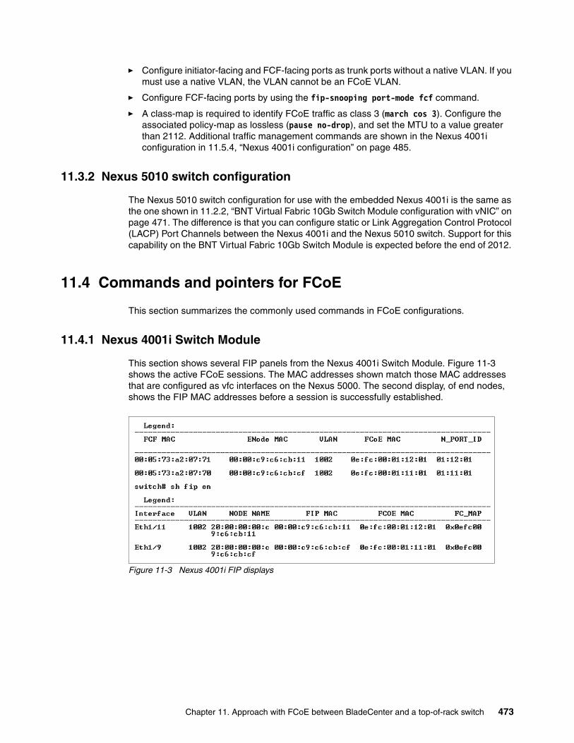
� Configure initiator-facing and FCF-facing ports as trunk ports without a native VLAN. If you must use a native VLAN, the VLAN cannot be an FCoE VLAN.
� Configure FCF-facing ports by using the fip-snooping port-mode fcf command.
� A class-map is required to identify FCoE traffic as class 3 (march cos 3). Configure the associated policy-map as lossless (pause no-drop), and set the MTU to a value greater than 2112. Additional traffic management commands are shown in the Nexus 4001i configuration in 11.5.4, “Nexus 4001i configuration” on page 485.
11.3.2 Nexus 5010 switch configuration
The Nexus 5010 switch configuration for use with the embedded Nexus 4001i is the same as the one shown in 11.2.2, “BNT Virtual Fabric 10Gb Switch Module configuration with vNIC” on page 471. The difference is that you can configure static or Link Aggregation Control Protocol (LACP) Port Channels between the Nexus 4001i and the Nexus 5010 switch. Support for this capability on the BNT Virtual Fabric 10Gb Switch Module is expected before the end of 2012.
11.4 Commands and pointers for FCoE
This section summarizes the commonly used commands in FCoE configurations.
11.4.1 Nexus 4001i Switch Module
This section shows several FIP panels from the Nexus 4001i Switch Module. Figure 11-3 shows the active FCoE sessions. The MAC addresses shown match those MAC addresses that are configured as vfc interfaces on the Nexus 5000. The second display, of end nodes, shows the FIP MAC addresses before a session is successfully established.
Figure 11-3 Nexus 4001i FIP displays
Chapter 11. Approach with FCoE between BladeCenter and a top-of-rack switch 473

Figure 11-4 shows the FLOGI table from the Nexus 5000. It shows the same sessions as the show fip sessions display in Figure 11-3.
Figure 11-4 Nexus 5010 FLOGI display
Figure 11-5 shows the NPV status display, which shows all pending and active FCoE sessions. This display also shows physical FC ports and vfc initiator-facing ports.
Figure 11-5 Nexus 5010 NPV status display
Figure 11-6 shows the FCoE session information of the BNT Virtual Fabric 10Gb Switch Module. This example has two FCoE VLANs configured.
Figure 11-6 FCoE sessions of the IBM Virtual Fabric 10Gb Switch Module
11.5 Full switch configurations
This section includes the complete configuration text files for the tests outlined in this chapter.
11.5.1 BNT Virtual Fabric 10Gb Switch Module configuration in pNIC mode
Example 11-1 shows the configuration used on the BNT Virtual Fabric 10Gb Switch Module in pNIC mode. The commands that are critical to FCoE are highlighted in bold.
Example 11-1 BNT Virtual Fabric 10Gb Switch Module configuration in pNIC
version "6.8.0.66"switch-type "IBM Networking OS Virtual Fabric 10Gb Switch Module for IBM BladeCenter"!!
474 Storage and Network Convergence Using FCoE and iSCSI

snmp-server name "bay-7"!hostname "bay-7"system idle 60!!access user administrator-password "35665f5801040a087627b6b3c2b4a9fa1db9b4a3072fb788bd32b1f91a7e2286"!!interface port INT1-INT14
pvid 99no flowcontrolexit
!interface port EXT1
shutdownexit
!interface port EXT2
shutdownexit
!interface port EXT3
shutdownexit
!interface port EXT5
taggingexit
!interface port EXT6
taggingexit
!interface port EXT7
taggingtag-pvidpvid 1002exit
!interface port EXT8
taggingtag-pvidpvid 1002exit
!interface port EXT9
taggingtag-pvidpvid 1002exit
!interface port EXT10
tagging
Chapter 11. Approach with FCoE between BladeCenter and a top-of-rack switch 475

tag-pvidpvid 1002exit
!vlan 1
member INT1-INT14,EXT1-EXT6,EXT11no member EXT7-EXT10
!vlan 99
enablename "VLAN 99"member INT1-INT14,EXT5-EXT6
!!vlan 100
enablename "VLAN 100"member INT1-INT14,EXT5-EXT6
!!vlan 1002
enablename "VLAN 1002"member INT1-INT14,EXT7-EXT10
!!portchannel 1 port EXT5portchannel 1 port EXT6no portchannel 1 enable!spanning-tree stp 1 vlan 1
spanning-tree stp 99 vlan 99
spanning-tree stp 100 vlan 100
spanning-tree stp 107 vlan 1002
interface port EXT7no spanning-tree stp 107 enableexit
!interface port EXT8
no spanning-tree stp 107 enableexit
!interface port EXT9
no spanning-tree stp 107 enableexit
!interface port EXT10
no spanning-tree stp 107 enableexit
!!
476 Storage and Network Convergence Using FCoE and iSCSI

!!fcoe fips enable!!cee enable!!cee global ets priority-group pgid 0 bandwidth 30 priority 4,5,6 pgid 1 bandwidth 70 pgid 2 bandwidth 0 pgid 15 priority 7cee global ets priority-group pgid 1 description "iSCSI_or_FCoE"!cee port INT1 pfc priority 3 description "iSCSI_or_FCoE"... SAME FOR ALL OTHER PORTS ... cee port EXT10 pfc priority 3 description "iSCSI_or_FCoE"!!!lldp enable!interface ip 1
ip address 192.168.1.254 255.255.255.0vlan 100enableexit
!interface ip 2
ip address 192.168.99.254 vlan 99enableexit
!!!!end
11.5.2 BNT Virtual Fabric 10Gb Switch Module configuration in vNIC mode
Example 11-2 shows the configuration for the BNT Virtual Fabric 10Gb Switch Module in vNIC mode. The critical commands are highlighted in bold.
Example 11-2 BNT Virtual Fabric 10Gb Switch Module configuration in vNIC
version "6.7.4"switch-type "IBM Virtual Fabric 10Gb Switch Module for IBM BladeCenter"!!
hostname "bay-7"!!access user administrator-password "f2c4b070e004a020bfadf3b323b403d2f0fc097036e20934f12feb2686ae0b65"!
Chapter 11. Approach with FCoE between BladeCenter and a top-of-rack switch 477
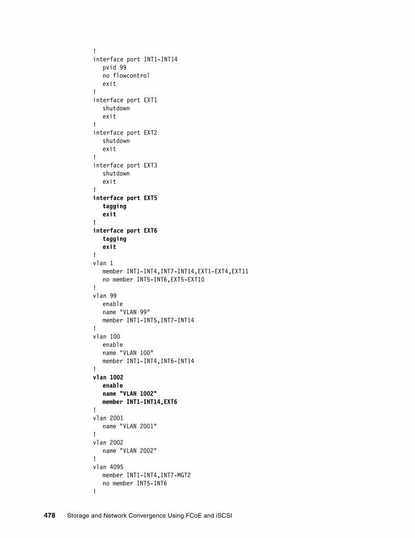
!interface port INT1-INT14
pvid 99no flowcontrolexit
!interface port EXT1
shutdownexit
!interface port EXT2
shutdownexit
!interface port EXT3
shutdownexit
!interface port EXT5
taggingexit
!interface port EXT6
taggingexit
!vlan 1
member INT1-INT4,INT7-INT14,EXT1-EXT4,EXT11no member INT5-INT6,EXT5-EXT10
!vlan 99
enablename "VLAN 99"member INT1-INT5,INT7-INT14
!vlan 100
enablename "VLAN 100"member INT1-INT4,INT6-INT14
!vlan 1002
enablename "VLAN 1002"member INT1-INT14,EXT6
!vlan 2001
name "VLAN 2001"!vlan 2002
name "VLAN 2002"!vlan 4095
member INT1-INT4,INT7-MGT2no member INT5-INT6
!
478 Storage and Network Convergence Using FCoE and iSCSI
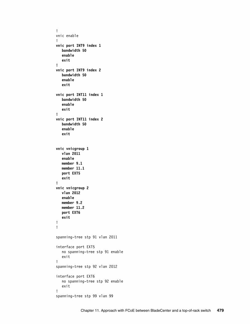
!vnic enable!vnic port INT9 index 1
bandwidth 50enableexit
!vnic port INT9 index 2
bandwidth 50enableexit
vnic port INT11 index 1bandwidth 50enableexit
!vnic port INT11 index 2
bandwidth 50enableexit
vnic vnicgroup 1vlan 2011enablemember 9.1member 11.1port EXT5exit
!vnic vnicgroup 2
vlan 2012enablemember 9.2member 11.2port EXT6exit
!!
spanning-tree stp 91 vlan 2011
interface port EXT5no spanning-tree stp 91 enableexit
!spanning-tree stp 92 vlan 2012
interface port EXT6no spanning-tree stp 92 enableexit
!spanning-tree stp 99 vlan 99
Chapter 11. Approach with FCoE between BladeCenter and a top-of-rack switch 479

spanning-tree stp 100 vlan 100
spanning-tree stp 107 vlan 1003
!snmp-server name "bay-7"!!!f!!cee enable!!cee global ets priority-group pgid 0 bandwidth 30 priority 4,5,6 pgid 1 bandwidth 70 pgid 2 bandwidth 0 pgid 15 priority 7cee global ets priority-group pgid 1 description "iSCSI_or_FCoE"
!!!lldp enable!interface ip 1
ip address 192.168.1.254 255.255.255.0vlan 100enableexit
!interface ip 99
ip address 192.168.99.253 vlan 99enableexit
!!!end
11.5.3 Nexus 5010 switch configuration
Example 11-3 shows the full configuration of the Nexus 5010 switch used in our test.
Example 11-3 Nexus 5010 switch configuration
!Command: show running-config!Time: Wed Oct 26 18:50:23 2011
version 5.0(3)N2(2)feature fcoe
feature telnetcfs ipv4 distributefeature interface-vlan
480 Storage and Network Convergence Using FCoE and iSCSI

feature lldp
role name default-role description This is a system defined role and applies to all users.username admin password 5 $1$udR.eObg$NZmMy/rJqdWnhremyh5Rm. role network-adminusername USERID password 5 $1$zUMfIP/f$syt7lY4dtD.9PRxuLM2oq. role network-adminfips mode enableip domain-lookuphostname NX5010class-map type qos class-fcoeclass-map type queuing class-all-flood match qos-group 2class-map type queuing class-ip-multicast match qos-group 2class-map type network-qos class-all-flood match qos-group 2class-map type network-qos class-ip-multicast match qos-group 2snmp-server user admin network-admin auth md5 0x6ea6288ac0e0babea0a6c4a6253106de priv 0x6ea6288ac0e0babea0a6c4a6253106de localizedkeysnmp-server user USERID network-admin auth md5 0x932f18a6efab3038000598d60f110613 priv 0x932f18a6efab3038000598d60f110613 localizedkeysnmp-server host 10.10.53.249 traps version 2c public udp-port 1163snmp-server enable traps entity fru
vrf context management ip route 0.0.0.0/0 172.25.1.1 ip route 172.25.0.0/16 mgmt0 172.25.1.1 ip route 172.25.110.199/32 172.25.1.1vlan 1,99vlan 1002 fcoe vsan 1002 vsan database vsan 1002
interface Vlan1
interface Vlan99 no shutdown ip address 192.168.99.50/24
interface port-channel1 shutdown switchport mode trunk priority-flow-control mode on switchport trunk native vlan 99 switchport trunk allowed vlan 99,1002
interface port-channel2 switchport mode trunk priority-flow-control mode on switchport trunk native vlan 99 switchport trunk allowed vlan 99,1002
Chapter 11. Approach with FCoE between BladeCenter and a top-of-rack switch 481

interface vfc2 bind mac-address 00:c0:dd:15:0e:6f switchport trunk allowed vsan 1002 no shutdown
interface vfc114 bind mac-address 00:c0:dd:12:20:03 switchport trunk allowed vsan 1002 no shutdown
vsan database vsan 1002 interface vfc2 vsan 1002 interface vfc114 vsan 1002 interface fc2/1 vsan 1002 interface fc2/2 vsan 1002 interface fc2/3 vsan 1002 interface fc2/4 vsan 1002 interface fc2/5 vsan 1002 interface fc2/6
feature npv
interface fc2/1 no shutdown
interface fc2/2 no shutdown
interface fc2/3
interface fc2/4
interface fc2/5
interface fc2/6
interface Ethernet1/1 priority-flow-control mode on switchport mode trunk switchport trunk native vlan 99 switchport trunk allowed vlan 99,1002 channel-group 1
interface Ethernet1/2 priority-flow-control mode on switchport mode trunk switchport trunk native vlan 99 switchport trunk allowed vlan 99,1002 channel-group 2
interface Ethernet1/3 priority-flow-control mode on switchport mode trunk switchport trunk native vlan 99
482 Storage and Network Convergence Using FCoE and iSCSI

switchport trunk allowed vlan 99,1002 channel-group 1
interface Ethernet1/4 priority-flow-control mode on switchport mode trunk switchport trunk native vlan 99 switchport trunk allowed vlan 99,1002 channel-group 2
interface Ethernet1/5 priority-flow-control mode on switchport mode trunk switchport trunk native vlan 99 switchport trunk allowed vlan 99,1002
interface Ethernet1/6 priority-flow-control mode on switchport mode trunk switchport trunk native vlan 99 switchport trunk allowed vlan 99,1002
interface Ethernet1/7 priority-flow-control mode on switchport mode trunk switchport trunk native vlan 99 switchport trunk allowed vlan 99,1002
interface Ethernet1/8 priority-flow-control mode on switchport mode trunk switchport trunk native vlan 99 switchport trunk allowed vlan 99,1002
interface Ethernet1/9 priority-flow-control mode on switchport mode trunk switchport trunk native vlan 99 switchport trunk allowed vlan 99,1002
interface Ethernet1/10 priority-flow-control mode on switchport mode trunk switchport trunk native vlan 99 switchport trunk allowed vlan 99,1002
interface Ethernet1/11 priority-flow-control mode on switchport mode trunk switchport trunk native vlan 99 switchport trunk allowed vlan 99,1002
interface Ethernet1/12 priority-flow-control mode on switchport mode trunk
Chapter 11. Approach with FCoE between BladeCenter and a top-of-rack switch 483

switchport trunk native vlan 99 switchport trunk allowed vlan 99,1002
interface Ethernet1/13 priority-flow-control mode on switchport mode trunk switchport trunk native vlan 99 switchport trunk allowed vlan 99,1002
interface Ethernet1/14 priority-flow-control mode on switchport mode trunk switchport trunk native vlan 99 switchport trunk allowed vlan 99,1002
interface Ethernet1/15 priority-flow-control mode on switchport mode trunk switchport trunk native vlan 99 switchport trunk allowed vlan 99,1002
interface Ethernet1/16 priority-flow-control mode on switchport mode trunk switchport trunk native vlan 99 switchport trunk allowed vlan 99,1002
interface Ethernet1/17 priority-flow-control mode on switchport mode trunk switchport trunk native vlan 99 switchport trunk allowed vlan 99,1002
interface Ethernet1/18 priority-flow-control mode on switchport mode trunk switchport trunk native vlan 99 switchport trunk allowed vlan 99,1002
interface Ethernet1/19 priority-flow-control mode on switchport mode trunk switchport trunk native vlan 99 switchport trunk allowed vlan 99,1002
interface Ethernet1/20 priority-flow-control mode on switchport mode trunk switchport trunk native vlan 99 switchport trunk allowed vlan 99,1002
interface mgmt0 ip address 172.25.110.199/16line consoleline vty
484 Storage and Network Convergence Using FCoE and iSCSI

boot kickstart bootflash:/n5000-uk9-kickstart.5.0.3.N2.2.binboot system bootflash:/n5000-uk9.5.0.3.N2.2.bin interface fc2/1 switchport mode NPinterface fc2/2 switchport mode NPinterface fc2/3 switchport mode NPinterface fc2/4 switchport mode NPinterface fc2/5 switchport mode NPinterface fc2/6 switchport mode NP
11.5.4 Nexus 4001i configuration
Example 11-4 shows the full configuration of the Nexus 4000i used in our tests. The critical commands are highlighted in bold.
Example 11-4 Nexus 4000i configuration
version 4.1(2)E1(1g)feature telnetfeature interface-vlanfeature fip-snooping
username admin password 5 ! role network-adminusername USERID password 5 $1$n.R4ZsPf$m4WEHN4482ENWZMB952ZP1 role network-adminip domain-lookupip host switch 172.25.101.9policy-map type queuing policy-fcoe-bandwidth class type queuing 1p7q4t-out-q-default bandwidth percent 12 class type queuing 1p7q4t-out-pq1 bandwidth percent 12 class type queuing 1p7q4t-out-q2 bandwidth percent 12 class type queuing 1p7q4t-out-q3 bandwidth percent 12 class type queuing 1p7q4t-out-q4 bandwidth percent 12 class type queuing 1p7q4t-out-q5 bandwidth percent 12 class type queuing 1p7q4t-out-q6 bandwidth percent 12 class type queuing 1p7q4t-out-q7 bandwidth percent 12class-map type network-qos class-fcoe match cos 3class-map type network-qos class-non-fcoe match cos 0-2,4-7
Chapter 11. Approach with FCoE between BladeCenter and a top-of-rack switch 485
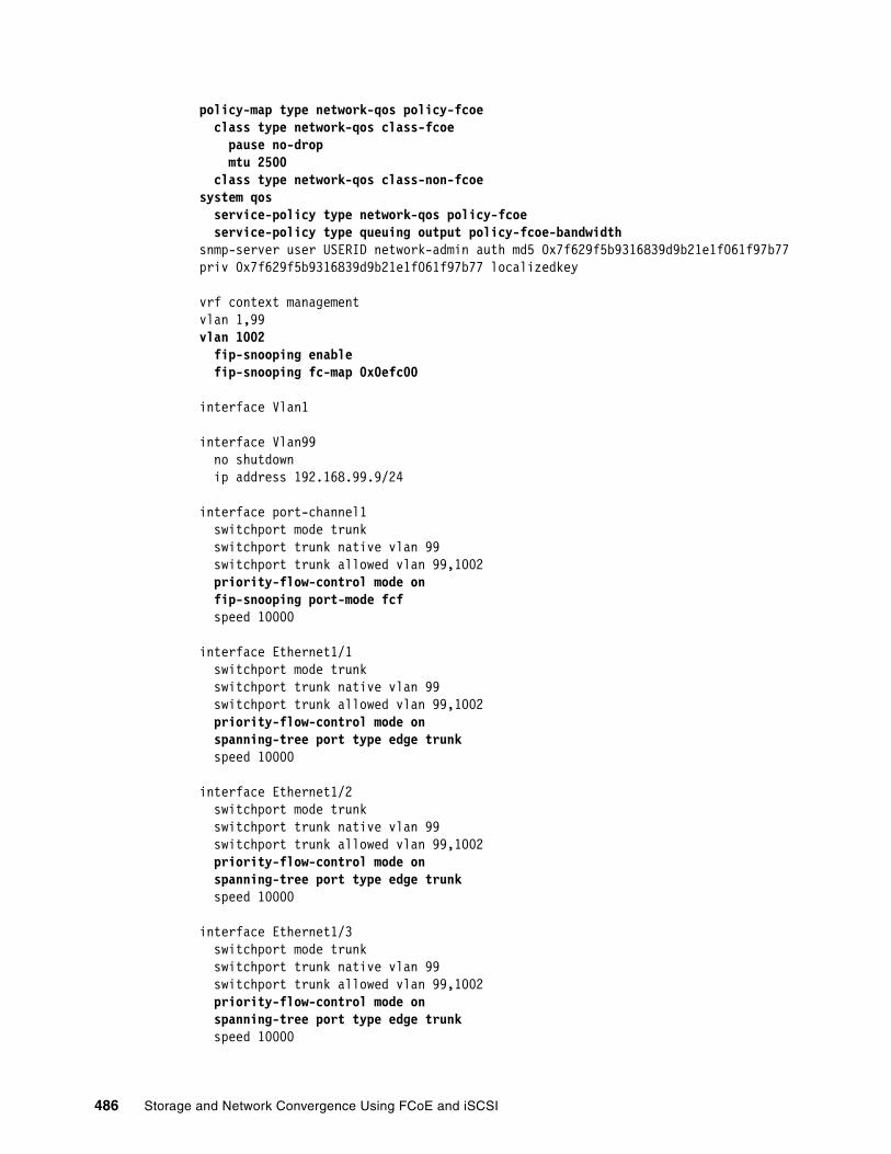
policy-map type network-qos policy-fcoe class type network-qos class-fcoe pause no-drop mtu 2500 class type network-qos class-non-fcoesystem qos service-policy type network-qos policy-fcoe service-policy type queuing output policy-fcoe-bandwidthsnmp-server user USERID network-admin auth md5 0x7f629f5b9316839d9b21e1f061f97b77 priv 0x7f629f5b9316839d9b21e1f061f97b77 localizedkey
vrf context managementvlan 1,99vlan 1002 fip-snooping enable fip-snooping fc-map 0x0efc00
interface Vlan1
interface Vlan99 no shutdown ip address 192.168.99.9/24
interface port-channel1 switchport mode trunk switchport trunk native vlan 99 switchport trunk allowed vlan 99,1002 priority-flow-control mode on fip-snooping port-mode fcf speed 10000
interface Ethernet1/1 switchport mode trunk switchport trunk native vlan 99 switchport trunk allowed vlan 99,1002 priority-flow-control mode on spanning-tree port type edge trunk speed 10000
interface Ethernet1/2 switchport mode trunk switchport trunk native vlan 99 switchport trunk allowed vlan 99,1002 priority-flow-control mode on spanning-tree port type edge trunk speed 10000
interface Ethernet1/3 switchport mode trunk switchport trunk native vlan 99 switchport trunk allowed vlan 99,1002 priority-flow-control mode on spanning-tree port type edge trunk speed 10000
486 Storage and Network Convergence Using FCoE and iSCSI

interface Ethernet1/4 switchport mode trunk switchport trunk native vlan 99 switchport trunk allowed vlan 99,1002 priority-flow-control mode on spanning-tree port type edge trunk speed 10000
... similarly for ports 1/5-1/14 ... speed 10000
interface Ethernet1/14 switchport mode trunk switchport trunk native vlan 99 switchport trunk allowed vlan 99,1002 priority-flow-control mode on spanning-tree port type edge trunk speed 10000
interface Ethernet1/15 switchport mode trunk switchport trunk native vlan 99 switchport trunk allowed vlan 99,1002 priority-flow-control mode on fip-snooping port-mode fcf speed 10000 channel-group 1
interface Ethernet1/16 switchport mode trunk switchport trunk native vlan 99 switchport trunk allowed vlan 99,1002 priority-flow-control mode on fip-snooping port-mode fcf speed 10000 channel-group 1
interface Ethernet1/17 switchport mode trunk switchport trunk native vlan 99 switchport trunk allowed vlan 1,99,1002 speed 10000
interface Ethernet1/18 switchport mode trunk switchport trunk native vlan 99 switchport trunk allowed vlan 1,99,1002 speed 10000
interface Ethernet1/19 switchport mode trunk switchport trunk native vlan 99 switchport trunk allowed vlan 1,99,1002 speed 10000
Chapter 11. Approach with FCoE between BladeCenter and a top-of-rack switch 487

interface Ethernet1/20 switchport mode trunk switchport trunk native vlan 99 switchport trunk allowed vlan 1,99,1002 speed 10000
interface mgmt0
interface mgmt1boot kickstart bootflash:/n4000-bk9-kickstart.4.1.2.E1.1g.binboot system bootflash:/n4000-bk9.4.1.2.E1.1g.bin system health loopback frequency 60
488 Storage and Network Convergence Using FCoE and iSCSI

Chapter 12. Approach with FCoE inside the Flex Chassis
This chapter describes the implementation of Fibre Channel over Ethernet (FCoE) with IBM Flex System Enterprise Chassis embedded switches. To set up the variations of FCoE solutions, the scenarios of this chapter used the following IBM FCoE Fabric hardware components:
� IBM Flex System Fabric CN4093 10Gb Converged Scalable Switch
� Converged network adapter (CNA) as a mezzanine card on the node:
– IBM Flex System CN4054 10Gb Virtual Fabric Adapter– LAN on Motherboard on the x240
� BNT Virtual Fabric 10Gb Switch Module
All tests were run on an IBM Flex System Enterprise Chassis with the IBM Flex System x240 Compute Node and IBM Storwize V3700. For the operating systems, Windows 2012, ESXi 5.0, and SLES 11 SP2 were used.
We added the following BladeCenter H components to show the easy use of the FCoE:
� Emulex 10GbE Virtual Fabric Adapter Advanced 2� BNT Virtual Fabric 10Gb Switch Module
This chapter includes the following sections:
� 12.1, “Implementing IBM Flex System Enterprise Chassis enabled for FCoE with IBM Flex System Fabric CN4093 10Gb Converged Scalable Switch” on page 490
� 12.2, “Configuring the IBM Flex System Fabric CN4093” on page 495
� 12.3, “Commands and pointers for FCoE” on page 499
� 12.4, “Full switch configurations” on page 510
� 12.5, “Summary assessment” on page 521
12
© Copyright IBM Corp. 2012, 2014. All rights reserved. 489

12.1 Implementing IBM Flex System Enterprise Chassis enabled for FCoE with IBM Flex System Fabric CN4093 10Gb Converged Scalable Switch
You can enable FCoE host access to the FCoE storage area network (SAN)-attached V3700 storage. This procedure entails using the IBM Flex System Fabric CN4093 10Gb Converged Scalable Switches that are installed in the IBM Flex System Enterprise Chassis.
Figure 12-1 shows the I/O topology that is internal to the IBM Flex System Enterprise Chassis.
Figure 12-1 IBM Flex chassis internal connections
The LoM or IBM Flex System CN4054 10Gb Virtual Fabric Adapter in server mezzanine card position 1 installed on the node server connects to the IBM Flex System Fabric CN4093 10Gb Converged Scalable Switch in switch bays 1and 2. The IBM Flex System CN4054 10Gb Virtual Fabric Adapter installed in mezzanine card position 2 on the node server connects to the IBM Flex System Fabric CN4093 10Gb Converged Scalable Switch in switch bays 3 and 4.
FCoE storage can be connected directly to the internal and external ports on the IBM Flex System Fabric CN4093 10Gb Converged Scalable Switch. FC storage can be connected directly to the external omniports pairs set to FC on the IBM Flex System Fabric CN4093 10Gb Converged Scalable Switch. Alternatively it is connected through a native FC switch connected to the IBM Flex System Fabric CN4093 10Gb Converged Scalable Switch running port pairs in transparent mode. The mode is named NPV (N_Port Virtualization).
The IBM Flex System Fabric CN4093 10Gb Converged Scalable Switch acts as a Fibre Channel Forwarder (FCF) in case of direct attached storage. It decapsulates and encapsulates the FCoE frames and forwards the frames to FC devices that are attached to the external ports or internal FCoE ports.
490 Storage and Network Convergence Using FCoE and iSCSI

The IBM Flex System Fabric CN4093 10Gb Converged Scalable Switch can function as a full fabric switch and provides FC native functions such as Fabric Login (FLOGI), Name Server, and Address assignment. It can also be configured in transparent mode to connect an external top-of-the-rack full-fabric FC switch with their FCF capabilities. This can be done by one of the omniports. The omniport default configuration on the IBM Flex System Fabric CN4093 10Gb Converged Scalable Switch is Ethernet fabric.
Table 12-1 lists the supported upgrades with the IBM Flex System Fabric CN4093 10Gb Converged Scalable Switch.
Table 12-1 CN4093 upgrades path
The maximum supported internal hardwired bandwidth between each node and one switch bay is theoretically 40 Gbps. The CN4093 switch supports up to 30 Gbps bandwidth between the switch bay and the node bay. With the available CN4054, up to 20 Gbps can be used between the switch and the node bay, depending on the Feature On Demand (FOD) set that is used by the CN4093 switch. The minimum supported bandwidth between each node and a switch bay is 10 Gbps for the CN4093 switch.
The omniports can be used for FC traffic or Ethernet traffic. The switch ports type can be changed in pairs. Each omniport port can be used in a different mode of FC traffic.
To establish end-to-end FCoE connectivity, at a high level, follow these steps:
1. For Bay 1 and 2 of the IBM Flex System Fabric CN4093 10Gb Converged Scalable Switch, ensure that the host has an FCoE adapter (CNA) installed in Mezzanine bay 1 or a LoM with Advanced feature enablement Key (FOD) is installed.
2. For Bay 3 and 4 of the IBM Flex System Fabric CN4093 10Gb Converged Scalable Switch, ensure that the host has an FCoE adapter (CNA) with Advanced feature enablement Key FOD) installed in Mezzanine bay 2.
3. Ensure that the Ethernet and FC device drivers are installed on the host.
4. Ensure that the FCoE host has a link on the 10Gb CEE ports.
5. Ensure that the FC device driver on the host logs in to the IBM Flex System Fabric CN4093 10Gb Converged Scalable Switch module as a VN_port.
Supported port combinations Base switch, 00D5823
Upgrade 1, 00D5845
Upgrade 2, 00D5847
- 14x internal 10 GbE ports- 2x external 10 GbE SFP+ ports- 6x external SFP+ Omni Ports
1 0 0
- 28x internal 10 GbE ports- 2x external 10 GbE SFP+ ports- 6x external SFP+ Omni Ports- 2x external 40 GbE QSFP+ ports
1 1 0
- 28x internal 10 GbE ports- 2x external 10 GbE SFP+ ports- 12x external SFP+ Omni Ports
1 0a
a. Upgrade 1 is not required to apply upgrade 2.
1
- 42x internal 10 GbE portsb
- 2x external 10 GbE SFP+ ports- 12x external SFP+ Omni Ports- 2x external 40 GbE QSFP+ ports
b. Leverages six of the eight ports on the CN4058 adapter available for IBM Power Systems compute nodes.
1 1 1
Chapter 12. Approach with FCoE inside the Flex Chassis 491
6. Connect the FCoE storage device to the FCoE port on the IBM Flex System Fabric CN4093 10Gb Converged Scalable Switch, or connect the FC storage device to the FC port type on the IBM Flex System Fabric CN4093 10Gb Converged Scalable Switch or both types of connections FC and FCoE.
7. Verify that the FC Switch port that is connected to the FC storage is a full fabric switch, and verify that the FC Switch port connected to an FC Fabric is an NPV connection.
8. Verify that the FC storage target devices are online as N-port devices.
9. Zone the FCoE host and FC Target worldwide port names (WWPNs).
10.Map the FC logical unit numbers (LUNs) to the host.
11.Verify that the host sees the LUNs from the disk manager.
Deployment of the IBM Flex System Fabric CN4093 10Gb Converged Scalable Switch solution needs minimum manual configuration because the solution handles most of the settings automatically.
12.Configure the IBM Flex System Fabric CN4093 10Gb Converged Scalable Switch:
a. Enable Converged Enhanced Ethernet (CEE) mode.
b. Enable the FCoE Initialization Protocol (FIP).
c. Enable Logical Link Discovery Protocol (LLDP).
d. Create the FCoE VLAN (default 1002):
i. Assign at least one port type FC of the IBM Flex System Fabric CN4093 10Gb Converged Scalable Switch
ii. Assign the FCoE VLAN to the appropriate server ports (internal interfaces).iii. Assign the FCoE VLAN to the appropriate switch/serverports (external interfaces).
e. Enable tagging on FCoE interfaces.
f. Disable spanning tree on storage interfaces.
13.Configure and enable zoning or set the zoning behavior to Permit mode in the IBM Flex System Fabric CN4093 10Gb Converged Scalable Switch.
14.Configure the FCoE storage subsystem. Define the host and host mapping on the storage.
15.Configure the node server:
a. Install the Multipath I/O (MPIO) driver, depending on the storage unit.
b. Discover and configure the disks.
12.1.1 Overview of testing scenarios
For this Redbooks publication, we use the configuration shown in Figure 12-2 for 12.3.1, “Configuring the IBM Flex System Fabric CN4093 10Gb Converged Scalable Switch in a pNIC/vNIC and Full Fabric mode” and 12.3.1, “Configuring the IBM Flex System Fabric CN4093 10Gb Converged Scalable Switch in a pNIC/vNIC and Full Fabric mode”. It includes two IBM Flex System Fabric CN4093 10Gb Converged Scalable Switches to set up a fully redundant topology with two separate FCoE fabrics. The uplink network connection follows normal network design for networking. You can use vLAG or link aggregation for these connections. The uplink connection is not shown in the figure.
The switch provides support for direct-attach FCoE storage on the internal and external ports in addition to direct or fabric connected FC storage.
492 Storage and Network Convergence Using FCoE and iSCSI

FCoE goes internal and external to the IBM Flex Chassis. Virtual N_Ports (VN ports) are for the end node port of the FC and FCoE fabric, and Virtual NF_Ports (VF ports) are the fabric ports on the switch side. All the FCoE connections are all running at 10 Gbps. The fibre connections to the DS5000 are using 8 Gbps with direct connections without a Fibre Channel fabric.
As shown in Figure 12-2, in this scenario, we connect the switch in bay 1 to the nodes and both storage controllers on external storage, and we connect the switch in bay 2 to the nodes and both storage controllers on external storage. We also connect a BladeCenter with two BNT Virtual Fabric 10Gb Switch Modules to the IBM Flex System Fabric CN4093 with the FCF. Each switch (IBM Flex System Fabric CN4093) is connected to all others with 10 Gbps of bandwidth. Each of the blue lines in Figure 12-2 is 10 Gbps. The green line is an 8 Gbps connection.
Figure 12-2 FCoE fabric topology
The IBM Flex System Fabric CN4093 has 14 external 10 Gbps ports, 2 running Ethernet only, Twelve ports can run 8 Gbps FC. The two remaining 40 Gbps QSFP+ ports are able to run in 40 Gbps mode or 4x10 Gbps mode. We use one of these 40 Gbps ports as an uplink port to our public (IBM) network.
CRTL A
CRTL B
Storage Controller
Flex Chassis
Nodes
VLAN1002
VLAN
1002
Win2K8
ESXiCN4093
CN4093
Direct attached storage
NF
NFVN
VN
VN
VN
VN
bay1
bay2
NF
NF
Blade Chassis
Blades
VLAN1002
VLAN
1002
Win2K8
SLESVFSM
VFSM
VN
VN
VN
bay7
bay9
CRTL A
CRTL B
Storage Controller
F
F
N
N
FCoE
native FC
DS5000
V3700
Chapter 12. Approach with FCoE inside the Flex Chassis 493

In 12.3.2, “Configuring the IBM Flex System Fabric CN4093 10Gb Converged Scalable Switch in a pNIC/vNIC and NPV mode”, we use the IBM Flex System Fabric CN4093 as an NPV gateway. It includes two IBM Flex System Fabric CN4093 switches to set up a fully redundant topology with two separate FCoE fabrics and two Brocade FC switches as a redundant FC fabric. The uplink network connection follows normal network design for networking. You can use vLAG or link aggregation for these connections. The uplink connections are not shown in Figure 12-3.
The switch provides support for direct-attach FCoE storage on the internal and external ports in addition to direct or fabric connected FC storage. All information is available on the FC fabric. You can see all the devices in the NameService of the FC switch.
FCoE goes internal and external to the IBM Flex Chassis. Virtual N_Ports (VN ports) are for the end node port of the FC and FCoE fabric, and Virtual NF_Ports (VF ports) are the fabric ports on the switch side. All the FCoE connections are all running at 10 Gbps. The fibre connections to the DS5000 are using 8 Gbps with connections through the Fibre Channel fabric.
Figure 12-3 FCoE and FC connected storage
The IBM Flex System Fabric CN4093 has 14 external 10 Gbps ports. Two ports can run only Ethernet. Twelve ports can run 8 Gbps FC. The two remaining 40 Gbps QSFP+ ports are able to run in 40 Gbps mode or 4x10 Gbps mode. We used one of these 40 Gbps ports as an uplink port to our public (IBM) network.
CRTL A
CRTL B
Storage Controller
Flex Chassis
Nodes
VLAN1002
VLAN
1002
Win2K8
ESXiCN4093
CN4093
Direct attached FCoE storageNPV mode used
NF
NFVN
VN
VN
VN
VN
bay1
bay2
NF
NF
Blade Chassis
Blades
VLAN1002
VLAN
1002
Win2K8
SLESVFSM
VFSM
VN
VN
VN
bay7
bay9
CRTL A
CRTL B
Storage Controller
F
F
FCoE
native FC
DS5000
V3700
FC Switch
FC Switch
F
F
F
N
N
F
NPV attached storage
494 Storage and Network Convergence Using FCoE and iSCSI

12.2 Configuring the IBM Flex System Fabric CN4093
This section guides you step by step through the installation and enablement of the IBM Flex System Fabric CN4093 adapter on the IBM Flex System.
For more information about the IBM Flex System Fabric CN4093 switch, see the following Redbooks publication.
� IBM Flex System Fabric CN4093 10Gb Converged Scalable Switch, TIPS0910
To learn more about FCoE architecture, protocol stacks, and functioning, see the chapter, “SAN connections and configuration” in the following Redbooks publication:
� IBM Flex System V7000 Storage Node Introduction and Implementation Guide, SG24-8068
To learn more about the IBM Storwize V3700, see the following Redbooks publication:
� Implementing the IBM Storwize V3700, SG24-8107
Administration Interface for IBM Flex System Fabric CN4093There are several methods of accessing IBM Flex System Fabric CN4093 in order to configure, view, or make changes:
1. Using a Telnet/SSH connection by the chassis management module2. Using a Telnet/SSH connection over the network3. Using the Browser-Based Interface (BBI) over the network4. Using a serial connection by the serial port on the IBM Flex System Fabric CN4093
The Telnet/SSH connection accesses two types of Command Line Interpreter (CLI); one of them is a text menu-based CLI, the other one is based on the international standard CLI (ISCLI). In this section, we use the ISCLI to display and enter commands on the IBM Flex System Fabric CN4093 10Gb Converged Scalable Switch.
For more information about the IBM Flex System Fabric CN4093 10Gb Converged Scalable Switch, see this website:
http://publib.boulder.ibm.com/infocenter/flexsys/information/topic/com.ibm.acc.networkdevices.doc/Io_module_compassFC.html
Configuring IBM Flex System Fabric CN4093 for FCoE connectivityThis section is specific to the IBM Flex System Fabric CN4093 10Gb Converged Scalable Switch I/O module because it has both FC and FCoE capability. There are other I/O module 10 Gb Ethernet switches that can be used for FCoE, such as the IBM Flex System Fabric EN4093 10Gb Scalable Switch. To configure FCoE on IBM Flex System Fabric CN4093 10Gb Converged Scalable Switch for connectivity to IBM V3700 Storage, it is necessary to understand the different ports and functions within the switch.
As previously mentioned, the IBM Flex System Fabric CN4093 has FC and FCoE functionality; the physical ports consist of internal and external types. The internal ports connect the IBM Flex System Enterprise Chassis node bays as shown in Table 12-2. The IBM V3700 Storage uses these external ports to connect to the IBM Flex System Fabric CN4093 10Gb Converged Scalable Switch. The omniports are the only external ports that can be attached by cable to external LAN and SAN network equipment, depending on whether they are configured for Ethernet or FC mode.
Chapter 12. Approach with FCoE inside the Flex Chassis 495

Table 12-2 lists the different types of ports in the IBM Flex System Fabric CN4093 10Gb Converged Scalable Switch.
Table 12-2 IBM Flex System CN4054 10Gb Virtual Fabric Adapter Ports)
The omniports are all in Ethernet mode by default and can carry Ethernet traffic in addition to FCoE. These ports can be configured as FC ports and attach to external storage controllers or servers. They must be configured in pairs for either Ethernet or FC mode, for example, port EXT13 and EXT14 must both be configured to be in the same mode and so are called paired ports. The port EXT13 and EXT14 can be used in different VLANs.
Fibre Channel VLANsThe ports that are used to connect with FCoE must be isolated into a separate VLAN on the IBM Flex System Fabric CN4093 10Gb Converged Scalable Switch. The VLAN, when defined, must have a VLAN number and the following components:
� Port Membership: Named ports, as listed in Table 12-2; the VLAN must include at least one FC defined port (paired FC omniports can reside in a separate FC VLAN).
� Switch Role: Either “Configuring for Fibre Channel Forwarding” on page 497 or “Configuring for NPV” on page 498.
The switch role mode for a VLAN determines whether it has the switching element, thus FCF capability; or has to pass all data to an external SAN switch for redirection, thus NPV capability. For a compute node to connect to IBM V3700 Storage and access storage, the VLAN must have FCF enabled. Thus, all storage data remains within the IBM Flex System Enterprise Chassis and does not have to rely on an external SAN switch for its switching or redirection in this VLAN. You can have more than one VLAN with FCoE traffic in NPV mode, but only one VLAN with FCF mode enabled.
Figure 12-4 shows VLAN 1002, which has been created and includes external ports EXT11 and EXT12 for the V3700 and external ports EXT13 and EXT14 for the DS5000. The port from Compute Node 1 and 2 (INTA1-INTA2) has also been included in the Fibre Channel VLAN. The port EXT16 is used to connect the BNT Virtual Fabric 10Gb Switch Module in the BladeCenter H.
Port type Port name / range Description
Ethernet Ports (Internal)
INTA1-INTA14 (ports 1-14), INTB1-INTB14 (15-28), INTC1-INTC14 (29-42)
These standard 10 Gb SFP+ Ethernet ports connect internally to compute nodes and storage in the system chassis.
Ethernet Ports (External)
EXT1-EXT2 (ports 43-44) These standard 10 Gb SFP+ Ethernet ports provide external connectors.
High-Capacity Ethernet Ports (External)
EXT3-EXT10 (ports 45-52) These 40 Gb QSFP+ Ethernet ports can be configured as either two 40 Gb Ethernet ports (EXT15 and EXT19), or as four 10 Gb Ethernet ports (EXT15-EXT18, EXT19-EXT22).
IBM Omni Ports (External)
EXT11-EXT22 (ports 53-64) These 10 Gb SFP+ hybrid ports can be configured to operate either in Ethernet mode (the default) or in Fibre Channel mode for direct connection to Fibre Channel devices.
496 Storage and Network Convergence Using FCoE and iSCSI

Figure 12-4 Internal and External port for FCF FCoE VLAN
With this VLAN created, FCoE zones can be configured to map Compute Nodes 1 and 2 to IBM V3700 Storage by ports EXT11-EXT12, and to external storage by ports EXT13 - EXT14. The connectivity between Compute Nodes 1 and 2 and IBM V3700 Storage is FCoE as shown in Figure 12-4, but any connection to external storage by ports EXT13 - EXT14 uses Fibre Channel. The IBM Flex System Fabric CN4093 10Gb Converged Scalable Switch with this VLAN configured and using FCF provides an example of an FCoE gateway for bridging FCoE and Fibre Channel networks. It is where Compute Nodes 1 and 2 using FCoE connectivity can attach to external storage, which is FC attached to the IBM Flex System Fabric CN4093 10Gb Converged Scalable Switch.
Configuring for Fibre Channel ForwardingIn this section, we create the VLAN as shown in Figure 12-4 before creating zones and allowing access from Compute Nodes 1 and 2 to the IBM V3700 Storage located external to the IBM Flex System Enterprise Chassis. Here, we summarize the steps:
1. Enter Enable to get the right privilege.2. Enter Configure Terminal to use ISCLI commands.1. Enable CEE and FIPS.2. Convert the omniports EXT12 and EXT13 to Fibre Channel ports.3. Create FCoE VLAN.4. Assign ports to FCoE VLAN.5. Enable FCF (must have at least one FC-Port to enable FCF).
Configuring for Fibre ZonesIn this section, we create the FC aliases. These are not required, but they make the output more human readable. The next step is to create the zones for the devices. Put all the required zones into a zoneset and activate the zoneset.
INTA2INTA1
EXT13 EXT14EXT12EXT11
FCoE
FC
VLAN 1002VLAN for FCoE
Node 1 Node 2
V3700 DS5000
EXT16
VFSM BC H
Chapter 12. Approach with FCoE inside the Flex Chassis 497

Example 12-4 on page 502 shows the commands. Here, we summarize the steps:
1. Enter Enable to get the right privilege.2. Enter Configure Terminal to use ISCLI commands.3. Create the FC aliases.4. Create the zones.5. Create the zoneset.6. Activate the zoneset.
Configuring for NPVFigure 12-4 shows VLAN 1002, which has been created and includes external ports EXT11 and EXT12 for the V3700 and external port EXT22 for the Brocade FC Switch. The port from Compute Node 1 and 2 (INTA1-INTA2) has also been included in the Fibre Channel VLAN. The port EXT16 is used to connect the BNT Virtual Fabric 10Gb Switch Module in the BladeCenter H.
Figure 12-5 Internal and External port for NPV FCoE VLAN
In this section, we create the VLAN as shown in Figure 12-5 before allowing access from Compute Node 1 and 2 to the IBM V3700 Storage located external to the IBM Flex System Enterprise Chassis. Here, we summarize the steps:
1. Enter Enable to get the right privilege.2. Enter Configure Terminal to use ISCLI commands.3. Enable CEE and FIPS.4. Convert the omniports EXT21 and EXT22 to Fibre Channel ports.5. Create the FCoE VLAN.
Note: Without activating the zone, there is no change made to the access. If you made changes in the zones, ensure that you remember this step.
INTA2INTA1
EXT22EXT12EXT11
FCoE
FC
VLAN 1002VLAN for FCoE
Node 1 Node 2
V3700 Brocade
EXT16
VFSM BC H
498 Storage and Network Convergence Using FCoE and iSCSI

6. Assign ports to the FCoE VLAN.7. Enable NPV.8. Create the NPV traffic map with the external ports.
12.3 Commands and pointers for FCoE
This section summarizes the commonly used commands in FCoE configurations.
12.3.1 Configuring the IBM Flex System Fabric CN4093 10Gb Converged Scalable Switch in a pNIC/vNIC and Full Fabric mode
Set up the IBM Flex System CN4054 10Gb Virtual Fabric Adapter in the appropriate mode.
When the IBM Flex System CN4054 10Gb Virtual Fabric Adapter is used in pNIC mode, you must skip steps 8 until 13. You have only two NIC interface on each port, which are shown in the OS.
When the IBM Flex System CN4054 10Gb Virtual Fabric Adapter is used in virtual Network Interface Card (vNIC) mode with FCoE personality, no additional configuration for FCoE is required on the IBM Flex System Fabric CN4093. vNIC instances 1, 3, and 4 can be enabled for non-FCoE traffic.
The vNIC instance 2 is fixed as defined for FCoE traffic. No vNIC instance or vNIC Group must be configured for FCoE because there is no difference between the FCoE configuration in physical NIC (pNIC) or virtual NIC (vNIC) mode.
To configure the IBM Flex System Fabric CN4093 10Gb Converged Scalable Switch, follow these steps:
1. The first step to enable the FCoE connection is to configure one or more of the omniport pairs to FC. We used EXT13 and EXT14 in our case.
Example 12-1 shows the configuration for a connection from IBM Flex System Fabric CN4093 10Gb Converged Scalable Switch to enable the FC on port EXT13-EXT14. This is required to enable the FCF in the IBM Flex System Fabric CN4093 10Gb Converged Scalable Switch.
Notes:
� Use only the Switch Independent Mode and IBM Virtual Fabric Mode in the IBM Flex System CN4054 10Gb Virtual Fabric Adapter settings at this time with the 7.5.1 Firmware for the IBM Flex System Fabric CN4093.
� Do not configure IBM Flex System CN4054 10Gb Virtual Fabric Adapter with any VLAN information. The Converged Network Adapter will receive these configuration parameters from the switch via the DCBX exchange protocol. The switch must have the right configuration. Ports must be in VLAN 1.
� All the configurations must be done in the ISCLI mode. The IBMNOS-CLI is not able to perform all the configuration possibilities.
Note: Without at least one port pair in type FC, you will not be able to enable FCF in the FCoE VLAN.
Chapter 12. Approach with FCoE inside the Flex Chassis 499

Example 12-1 enable and set port type FC
cn4093_1>enableEnable privilege granted.cn4093_1#conf tEnter configuration commands, one per line. End with Ctrl/Z.cn4093_1(config)#system port EXT13-EXT14 type fcJul 9 5:28:40 cn4093_1 NOTICE lldp: LLDP TX & RX are disabled on port EXT13Jul 9 5:28:40 cn4093_1 NOTICE lldp: LLDP TX & RX are disabled on port EXT14Jul 9 5:28:43 cn4093_1 NOTICE link: link up on port EXT13Jul 9 5:28:43 cn4093_1 NOTICE link: link up on port EXT14cn4093_1(config)#
2. After the IBM Flex System Fabric CN4093 10 Gb Converged Scalable Switch is enabled, enter the following command to check the connectivity settings. List the active ports in place of the corresponding external ports (Example 12-2) by entering the following command:
show interface link
Example 12-2 demonstrates usage of the commands that are shown in step 2. The comment after the table shows the connections. These connections do not display in the output.
Example 12-2 Verifying connectivity
CN4093_1(config)#show interface link------------------------------------------------------------------Alias Port Speed Duplex Flow Ctrl Link Name------- ---- ----- -------- --TX-----RX-- ------ ------INTA1 1 10000 full no no up INTA1INTA2 2 10000 full no no up INTA2INTA3 3 10000 full no no up INTA3------SNIP----EXT3 45 40000 full no no up EXT3 40$ QSFPEXT7 49 10000 full no no down EXT7EXT8 50 10000 full no no down EXT8EXT9 51 10000 full no no down EXT9EXT10 52 10000 full no no down EXT10EXT11 53 10000 full no no up EXT11 CTRL AEXT12 54 10000 full no no up EXT12 CTRL BEXT13 55 4000 full no no up EXT13 DS5000 FCEXT14 56 8000 full no no up EXT14 DS5000 FCEXT15 57 10000 full no no down EXT15EXT16 58 10000 full no no up EXT16 BCH Slot xEXT17 59 10000 full no no up EXT17 DS5000 10GBEXT18 60 10000 full no no down EXT18------SNIP----EXTM 65 1000 full yes yes down EXTMMGT1 66 1000 full yes yes up
3. Enter the cee enable command to enable the Ethernet enhancements summarized as Data Center Bridging (DCB) or CEE. This command enables LLDP automatically, which is required for the Data Center Bridging Capabilities Exchange (DCBX) protocol. It also disables the existing Ethernet flow control because priority flow control (PFC) is used instead.
500 Storage and Network Convergence Using FCoE and iSCSI

4. Leave the settings for the bandwidth management: Enhanced Transmission Selection (ETS) and Priority Flow Control (PFC) as the default values. That is, for FCoE traffic, use a 50% guaranteed bandwidth, and use priority flow control for Ethernet Class of Service 3.
These configuration parameters are transferred to the CNA by using the DCBX protocol. Therefore, no configuration is necessary on the CNA.
5. Enable the FCoE part. FCoE relies on the following protocols:
– FCoE as the data plane protocol, which carries the FC command frames and the SCSI traffic
– FIP as the control plane protocol:
• VLAN Discovery• FCF Discovery• FLOGI or Fabric Discovery (FDISC)• KeepAlives
However, to control FCoE traffic by dynamically creating access control lists (ACL), you must have knowledge about the active FCoE session. You can obtain this knowledge by snooping FIP and determine what is configured by using the fcoe fips enable command.
6. Configure a dedicated VLAN for FCoE. By default, 1002 is used with all the internal ports and all bridge ports as members. The FCoE VLAN is sent as tagged by the Converged Network Adapter, which corresponds to the default setup of the IBM Flex System Fabric CN4093.
7. Configure the ports as tagged ports to ensure appropriate communication to the IBM Flex System Fabric CN4093. The tag-pvid command ensures that only tagged frames are transmitted.
Example 12-3 summarizes the commands for the IBM Flex System Fabric CN4093.
Example 12-3 Enabling the Ethernet enhancements
cn4093_1(config)#cee enableJul 9 3:01:01 cn4093_1 NOTICE dcbx: Detected DCBX peer on port EXT11Jul 9 3:01:01 cn4093_1 NOTICE dcbx: Detected DCBX peer on port EXT12Jul 9 3:01:01 cn4093_1 NOTICE server: link down on port INTA1Jul 9 3:01:01 cn4093_1 NOTICE server: link down on port INTA2Jul 9 3:01:02 cn4093_1 NOTICE server: link up on port INTA1Jul 9 3:01:02 cn4093_1 NOTICE server: link up on port INTA2cn4093_1(config)#fcoe fips enaJul 9 3:01:24 cn4093_1 NOTICE dcbx: Detected DCBX peer on port EXT16blecn4093_1(config)#vlan 1002cn4093_1(config-vlan)#enablecn4093_1(config-vlan)#member INTA1,INTA2,EXT11,EXT12,EXT13,EXT14,EXT16Port EXT11 is an UNTAGGED port and its PVID is changed from 1 to 1002Port EXT12 is an UNTAGGED port and its PVID is changed from 1 to 1002Port EXT16 is an UNTAGGED port and its PVID is changed from 1 to 1002cn4093_1(config-vlan)#fcf enablecn4093_1(config-vlan)#Jul 9 5:38:27 cn4093_1 NOTICE fcoe: FCOE connection between VN_PORT 0e:fc:00:01:0f:00 and FCF 74:99:75:25:81:c6 has been established.Jul 9 5:38:33 cn4093_1 NOTICE fcoe: FCOE connection between VN_PORT 0e:fc:00:01:0f:01 and FCF 74:99:75:25:81:c6 has been established.Jul 9 5:38:35 cn4093_1 NOTICE fcoe: FCOE connection between VN_PORT 0e:fc:00:01:0f:02 and FCF 74:99:75:25:81:c6 has been established.Jul 9 5:38:35 cn4093_1 NOTICE fcoe: FCOE connection between VN_PORT 0e:fc:00:01:0e:00 and FCF 74:99:75:25:81:c5 has been established.
Chapter 12. Approach with FCoE inside the Flex Chassis 501
Jul 9 5:38:35 cn4093_1 NOTICE fcoe: FCOE connection between VN_PORT 0e:fc:00:01:0e:01 and FCF 74:99:75:25:81:c5 has been established.cn4093_1(config-vlan)#exit
8. If you are using pNIC mode, go to step 13.
9. To enable the vNIC functionality, the vNIC mode on the Converged Network Adapter must be configured in the Converged Network Adapter. After the node is rebooted, the possibility of the vNIC capability is recognized by the switch.
10.The vNIC Port is selected by the vnic port <interface> index <index 1,3,4> command. For the selected port, set the bandwidth with the vnic bandwith <10..100> command. Last, enable the vnic. Repeat this process for all the ports and indexes.
11.Create a vnic group to connect the ports by the vnicgroup <group 1..32> command. Make the vnic port a member in this vNIC group with the member command. For the external ports, use the port command. No VLAN on the external port is allowed. The spanning tree group will be automatically created.
12.Use the vnic enable command on the switch to ensure that the vNIC mode is enabled. At this time, the OS shows the NIC that is connected with the selected bandwidth.
13.Example 12-4 summarizes the commands for the IBM Flex System Fabric CN4093.
Example 12-4 Enabling the vNIC enhancements
cn4093_1(config)#vnic enablecn4093_1(config)#vnic port INTA1 index 3cn4093_1(vnic-config)#bandwidth 25cn4093_1(vnic-config)#enableWarning: vNIC INTA1.3 is not assigned to any vNIC groupcn4093_1(vnic-config)#vnic port INTA2 index 3cn4093_1(vnic-config)#bandwidth 33cn4093_1(vnic-config)#enableWarning: vNIC INTA2.3 is not assigned to any vNIC groupcn4093_1(vnic-config)#exitcn4093_1(config)#vnic vnicgroup 3cn4093_1(vnic-group-config)#vlan 103Warning: VLAN 103 was assigned to STG 103.cn4093_1(vnic-group-config)#enableWarning: vNIC group 3 has no vNICcn4093_1(vnic-group-config)#member INTA1.3cn4093_1(vnic-group-config)#member INTA2.3cn4093_1(vnic-group-config)#port EXT3Warning: STP will be turned off for port EXT3 in STG 103Warning: Changed the pvid of uplink port EXT3 in vNIC group 3 to 103Warning: Deleted port EXT3 from VLAN 1Warning: Deleted port EXT3 from VLAN 0Jul 9 6:50:15 cn4093_1 ALERT stg: STG 1, new root bridgecn4093_1(vnic-group-config)#exitcn4093_1(config)#
14.Configure the FC aliases, zones, and zonesets with the fcaliases, zone, and zoneset commands to ensure that initiators and targets can be connected. The default-zone behavior is Deny. This behavior means that nothing is seen until a zone is created and activated. Example 12-5 shows the commands on a Brocade switch.
Note: The external port in the vnic group can only carry untagged frames.
502 Storage and Network Convergence Using FCoE and iSCSI

Example 12-5 zone related commands on Brocade
cn4093_1(config)#fcalias N1_DS5000 wwn 20:17:00:a0:b8:6e:39:20cn4093_1(config)#fcalias C1_V3700 wwn 50:05:07:68:03:04:37:6acn4093_1(config)#fcalias C2_V3700 wwn 50:05:07:68:03:04:37:6bcn4093_1(config)#fcalias Blade2 wwn 10:00:00:00:c9:5b:7d:07cn4093_1(config)#fcalias N1_x240 wwn 10:00:00:00:c9:db:40:89cn4093_1(config)#fcalias N2_x240 wwn 10:00:34:40:b5:be:3f:21cn4093_1(config)#zone name V3700cn4093_1(config-zone)#member pwwn 50:05:07:68:03:04:37:6acn4093_1(config-zone)#member pwwn 50:05:07:68:03:04:37:6bcn4093_1(config-zone)#zone name N1-V3700cn4093_1(config-zone)#member pwwn 50:05:07:68:03:04:37:6acn4093_1(config-zone)#member pwwn 50:05:07:68:03:04:37:6bcn4093_1(config-zone)#member pwwn 10:00:00:00:c9:db:40:89cn4093_1(config-zone)#zone name N2-V3700cn4093_1(config-zone)#member pwwn 50:05:07:68:03:04:37:6acn4093_1(config-zone)#member pwwn 50:05:07:68:03:04:37:6bcn4093_1(config-zone)#member pwwn 10:00:34:40:b5:be:3f:21cn4093_1(config-zone)#zone name N1_DS5000cn4093_1(config-zone)#member pwwn 20:17:00:a0:b8:6e:39:20cn4093_1(config-zone)#member pwwn 10:00:00:00:c9:db:40:89cn4093_1(config-zone)#zone name N2_DS5000cn4093_1(config-zone)#member pwwn 10:00:34:40:b5:be:3f:21cn4093_1(config-zone)#member pwwn 20:17:00:a0:b8:6e:39:20cn4093_1(config-zone)#zone name Blade2-v3700cn4093_1(config-zone)#member pwwn 10:00:00:00:c9:5b:7d:07cn4093_1(config-zone)#member pwwn 50:05:07:68:03:04:37:6bcn4093_1(config-zone)#member pwwn 50:05:07:68:03:04:37:6acn4093_1(config-zone)#zone name Blade2-ds5000cn4093_1(config-zone)#member pwwn 10:00:00:00:c9:5b:7d:07cn4093_1(config-zone)#member pwwn 20:17:00:a0:b8:6e:39:20cn4093_1(config-zone)#member pwwn 20:36:00:a0:b8:6e:39:20n4093_1(config-zone)#zoneset name CN4093_1cn4093_1(config-zoneset)#member V3700cn4093_1(config-zoneset)#member N1-V3700cn4093_1(config-zoneset)#member N2-V3700cn4093_1(config-zoneset)#member N1_DS5000cn4093_1(config-zoneset)#member N2_DS5000cn4093_1(config-zoneset)#member Blade2-ds5000cn4093_1(config-zoneset)#member Blade2-v3700n4093_1(config-zoneset)#zoneset activate name CN4093_1cn4093_1(config)#
You have now completed the required configuration tasks on the IBM Flex System Fabric CN4093 in I/O bay 1.
Repeat this configuration procedure on the IBM Flex System Fabric CN4093 in I/O bay 2. Use the appropriate WWN in the zoning for this fabric.
Use the show interface links command as shown in Example 12-2 on page 500 to verify that the link status is UP for all the active host ports and bridge interfaces.
Chapter 12. Approach with FCoE inside the Flex Chassis 503

12.3.2 Configuring the IBM Flex System Fabric CN4093 10Gb Converged Scalable Switch in a pNIC/vNIC and NPV mode
Set up the IBM Flex System CN4054 10Gb Virtual Fabric Adapter in the appropriate mode.
When the IBM Flex System CN4054 10Gb Virtual Fabric Adapter is used in pNIC mode, skill steps 11 until 16, you have only one NIC interface that is shown in the OS.
When the IBM Flex System CN4054 10Gb Virtual Fabric Adapter is used in virtual Network Interface Card (vNIC) mode with FCoE personality, no additional configuration for FCoE is required on the IBM Flex System Fabric CN4093. The vNIC instances 1, 3, and 4 can be enabled for non-FCoE traffic.
The vNIC instance 2 is fixed as defined for FCoE traffic. No vNIC instance or vNIC Group must be configured for FCoE because there is no difference between the FCoE configuration in physical NIC (pNIC) or virtual NIC (vNIC) mode.
To configure the IBM Flex System Fabric CN4093 10Gb Converged Scalable Switch, follow these steps:
1. Enable the FCoE connection by configuring one or more of the omniport pairs to FC. We used EXT13 and EXT14.
Example 12-6 shows the configuration for a connection from IBM Flex System Fabric CN4093 to enable the FC on port EXT13-EXT14. This is required to enable the npv in the IBM Flex System Fabric CN4093 and for the connection of the FC fabric.
Example 12-6 Enable configuration mode and change the port type
cn4093_1>cn4093_1>enableEnable privilege granted.cn4093_1#conf tEnter configuration commands, one per line. End with Ctrl/Z.cn4093_1(config)#system port EXT21-EXT22 type fcJul 9 5:28:40 cn4093_1 NOTICE lldp: LLDP TX & RX are disabled on port EXT21Jul 9 5:28:40 cn4093_1 NOTICE lldp: LLDP TX & RX are disabled on port EXT22Jul 9 5:28:43 cn4093_1 NOTICE link: link up on port EXT22cn4093_1(config)#
2. After the IBM Flex System Fabric CN4093 10Gb Converged Scalable Switch is enabled, enter the following command to check the connectivity settings. List the active ports in place of the corresponding external ports (Example 12-7) by entering the following command:
show interface link
Example 12-7 demonstrates usage of the commands that are shown in step 2. The comment after the table shows the connections.
Example 12-7 Verifying connectivity
CN4093_1(config)#show interface link------------------------------------------------------------------
Note: Without at least one port pair in type FC, you will not be able to enable npv in the FCoE vlan.
504 Storage and Network Convergence Using FCoE and iSCSI

Alias Port Speed Duplex Flow Ctrl Link Name------- ---- ----- -------- --TX-----RX-- ------ ------INTA1 1 10000 full no no up INTA1INTA2 2 10000 full no no up INTA2INTA3 3 10000 full no no up INTA3------SNIP----EXT3 45 40000 full no no up EXT3 40$ QSFPEXT7 49 10000 full no no down EXT7EXT8 50 10000 full no no down EXT8EXT9 51 10000 full no no down EXT9EXT10 52 10000 full no no down EXT10EXT11 53 10000 full no no up EXT11 CTRL AEXT12 54 10000 full no no up EXT12 CTRL BEXT13 55 10000 full no no down EXT13EXT14 56 10000 full no no down EXT14EXT15 57 10000 full no no down EXT15EXT16 58 10000 full no no up EXT16 BCH Slot xEXT17 59 10000 full no no up EXT17 DS5000 10GBEXT18 60 10000 full no no down EXT18EXT19 61 10000 full no no down EXT19EXT20 62 10000 full no no down EXT20EXT21 63 Auto full no no down EXT21EXT22 64 8000 full no no up EXT22 Brocade FCEXTM 65 1000 full yes yes down EXTMMGT1 66 1000 full yes yes up
3. Enter the cee enable command to enable the Ethernet enhancements summarized as Data Center Bridging (DCB) or CEE. This command automatically enables LLDP, which is required for the Data Center Bridging Capabilities Exchange (DCBX) protocol and disables the existing Ethernet flow control because priority flow control (PFC) is used instead.
4. Leave the settings for the bandwidth management (Enhanced Transmission Selection (ETS)) and priority flow control (PFC) as the default values. That is, for FCoE traffic, use a 50% guaranteed bandwidth, and use priority flow control for the Service 3 Ethernet Class.
These configuration parameters are transferred to the Converged Network Adapter by using the DCBX protocol. Therefore, no configuration is necessary on the Converged Network Adapter.
5. Enable the FCoE part. FCoE relies on the following protocols:
– FCoE as the data plane protocol, which carries the FC command frames and the SCSI traffic
– FIP as the control plane protocol:
• VLAN Discovery• NPV enable• use a NPV traffic-map• FLOGI or Fabric Discovery (FDISC)• KeepAlives
However, to control FCoE traffic by dynamically creating access control lists (ACL), you must have knowledge about the active FCoE session, what is obtained by snooping FIP, and what is configured by using the fcoe fips enable command.
6. Configure a dedicated VLAN for FCoE. By default, 1002 is used with all the internal ports and all bridge ports as members. The FCoE VLAN is sent as tagged by the Converged Network Adapter, which corresponds to the default setup of the IBM Flex System Fabric CN4093.
Chapter 12. Approach with FCoE inside the Flex Chassis 505
7. Configure the ports as tagged ports to ensure appropriate communication to the IBM Flex System Fabric CN4093 The tag-pvid command ensures that only tagged frames are transmitted.
Example 12-8 summarizes the commands for the IBM Flex System Fabric CN4093.
Example 12-8 Enabling the Ethernet enhancements
cn4093_1(config)#cee enableJul 10 6:15:42 cn4093_1 NOTICE server: link down on port INTA1Jul 10 6:15:42 cn4093_1 NOTICE server: link down on port INTB1Jul 10 6:15:42 cn4093_1 NOTICE server: link down on port INTA2Jul 10 6:15:42 cn4093_1 NOTICE server: link down on port INTB2Jul 10 6:15:43 cn4093_1 NOTICE dcbx: Detected DCBX peer on port EXT11Jul 10 6:15:43 cn4093_1 NOTICE dcbx: Detected DCBX peer on port EXT12Jul 10 6:15:43 cn4093_1 NOTICE server: link up on port INTA1Jul 10 6:15:43 cn4093_1 NOTICE server: link up on port INTB1Jul 10 6:15:45 cn4093_1 NOTICE server: link up on port INTA2Jul 10 6:15:45 cn4093_1 NOTICE server: link up on port INTB2Jul 10 6:15:51 cn4093_1 NOTICE dcbx: Detected DCBX peer on port EXT16cn4093_1(config)#fcoe fips enablecn4093_1(config)#vlan 1002VLAN 1002 is created.Warning: VLAN 1002 was assigned to STG 113.cn4093_1(config-vlan)#enablecn4093_1(config-vlan)#member INTA1,INTA2,EXT11,EXT12,EXT16,EXT22Port INTA1 is an UNTAGGED port and its PVID is changed from 1 to 1002Port INTA2 is an UNTAGGED port and its PVID is changed from 1 to 1002Port EXT11 is an UNTAGGED port and its PVID is changed from 1 to 1002Port EXT12 is an UNTAGGED port and its PVID is changed from 1 to 1002Port EXT16 is an UNTAGGED port and its PVID is changed from 1 to 1002cn4093_1(config-vlan)#npv enableJul 10 6:17:40 cn4093_1 ALERT stg: STG 113, topology change detectedcn4093_1(config-vlan)#npv traffic-map external-interface EXT22Jul 10 6:18:13 cn4093_1 NOTICE link: link up on port EXT22Jul 10 6:18:19 cn4093_1 NOTICE fcoe: FCOE connection between VN_PORT 0e:fc:00:01:01:01 and FCF 74:99:75:25:81:ce has been established.Jul 10 6:18:19 cn4093_1 NOTICE fcoe: FCOE connection between VN_PORT 0e:fc:00:01:01:02 and FCF 74:99:75:25:81:ce has been established.Jul 10 6:18:19 cn4093_1 NOTICE fcoe: FCOE connection between VN_PORT 0e:fc:00:01:01:03 and FCF 74:99:75:25:81:ce has been established.Jul 10 6:18:19 cn4093_1 NOTICE fcoe: FCOE connection between VN_PORT 0e:fc:00:01:01:04 and FCF 74:99:75:25:81:ce has been established.Jul 10 6:18:19 cn4093_1 NOTICE fcoe: FCOE connection between VN_PORT 0e:fc:00:01:01:05 and FCF 74:99:75:25:81:ce has been established.cn4093_1(config-vlan)#
8. At this point, you can see the WWN from the nodes as well the storage in the Brocade FC switch. Use the command nsshow on the brocade switch. Example 12-9 shows the WWN of our environment. The bold text is the first login of the IBM Flex System Fabric CN4093 npv login with the physical port WWN.
Example 12-9 Brocade switch nsshow output
B8000-246:admin> nsshow{ Type Pid COS PortName NodeName TTL(sec)
506 Storage and Network Convergence Using FCoE and iSCSI
N 010100; 2,3;20:0b:74:99:75:25:81:c1;10:00:74:99:75:25:81:c1; na Fabric Port Name: 20:01:00:05:1e:76:fe:00 Permanent Port Name: 20:0b:74:99:75:25:81:c1 Port Index: 1 Share Area: No Device Shared in Other AD: No Redirect: No Partial: No N 010101; 2,3;50:05:07:68:03:04:37:6a;50:05:07:68:03:00:37:6a; na FC4s: FCP Fabric Port Name: 20:01:00:05:1e:76:fe:00 Permanent Port Name: 50:05:07:68:03:04:37:6a Port Index: 1 Share Area: No Device Shared in Other AD: No Redirect: No Partial: No------------------------SNIP other entrys-----------------------N 010600; 3;20:16:00:a0:b8:6e:39:20;20:06:00:a0:b8:6e:39:20; na FC4s: FCP [IBM 1818 FAStT 0730] Fabric Port Name: 20:06:00:05:1e:76:fe:00 Permanent Port Name: 20:16:00:a0:b8:6e:39:20 Port Index: 6 Share Area: No Device Shared in Other AD: No Redirect: No Partial: No N 010700; 3;20:27:00:a0:b8:6e:39:20;20:06:00:a0:b8:6e:39:20; na FC4s: FCP [IBM 1818 FAStT 0730] Fabric Port Name: 20:07:00:05:1e:76:fe:00 Permanent Port Name: 20:27:00:a0:b8:6e:39:20 Port Index: 7 Share Area: No Device Shared in Other AD: No Redirect: No Partial: NoThe Local Name Server has 9 entries }B8000-246:admin>
9. On the CN4093 switch, use the show npv flogi command to see the successful login of the devices. Example 12-10 shows the output of the command.
Example 12-10 npv flogi output
cn4093_1(config)#show npv flogi-table--------------------------------------------------------------------------------------------------------------------------------------VLAN: 1002 Port: 23 with 1 Virtual Links------------------------------------------------------------------- Port WWN MAC Login-------------------------------------------------------------------FCM-64 50:05:07:68:03:04:37:6b 0e:fc:00:01:01:05 FLOGI-------------------------------------------------------------------
-----------------SNIP other entrys----------------------------
Chapter 12. Approach with FCoE inside the Flex Chassis 507

-------------------------------------------------------------------VLAN: 1002 Port: 23 with 1 Virtual Links------------------------------------------------------------------- Port WWN MAC Login-------------------------------------------------------------------FCM-64 10:00:00:00:c9:5b:7d:07 0e:fc:00:01:01:02 FLOGIcn4093_1(config)#
10.For pNIC mode, go to Step 16 on page 509.
11.To enable the vNIC functionality, the vNIC mode on the CNA must be configured in the CNA. After the reboot of the node, the possibility of the vNIC capability will be recognized by the switch.
12.The vNIC Port is selected by the vnic port <interface> index <index 1,3,4> command. For the selected port, now set the bandwidth with the vnic bandwith <10..100> command. Last, enable the vnic. Repeat this for all the ports and indexes.
13.Create a vnic group to connect the ports by the vnicgroup <group 1..32> command. Make the vnic port a member in this vNIC group with the member command. For the external ports, use the port command. No VLAN on the external port is allowed. The spanning tree group is automatically created.
14.The vNIC mode is enabled on the switch with the vnic enable command. At this time, the OS shows the NIC connected with the selected bandwidth.
15.Example 12-11 summarizes the commands for the CN4093 Switch Module in bay 1.
Example 12-11 Enabling the vNIC enhancements
cn4093_1(config)#vnic enablecn4093_1(config)#vnic port INTA1 index 3cn4093_1(vnic-config)#bandwidth 25cn4093_1(vnic-config)#enableWarning: vNIC INTA1.3 is not assigned to any vNIC groupcn4093_1(vnic-config)#vnic port INTA2 index 3cn4093_1(vnic-config)#bandwidth 33cn4093_1(vnic-config)#enableWarning: vNIC INTA2.3 is not assigned to any vNIC groupcn4093_1(vnic-config)#exitcn4093_1(config)#vnic vnicgroup 3cn4093_1(vnic-group-config)#vlan 103Warning: VLAN 103 was assigned to STG 103.cn4093_1(vnic-group-config)#enableWarning: vNIC group 3 has no vNICcn4093_1(vnic-group-config)#member INTA1.3cn4093_1(vnic-group-config)#member INTA2.3cn4093_1(vnic-group-config)#port EXT3Warning: STP will be turned off for port EXT3 in STG 103Warning: Changed the pvid of uplink port EXT3 in vNIC group 3 to 103Warning: Deleted port EXT3 from VLAN 1Warning: Deleted port EXT3 from VLAN 0Jul 9 6:50:15 cn4093_1 ALERT stg: STG 1, new root bridgecn4093_1(vnic-group-config)#exitcn4093_1(config)#
Note: The external port in the vnic group can only carry untagged frames.
508 Storage and Network Convergence Using FCoE and iSCSI
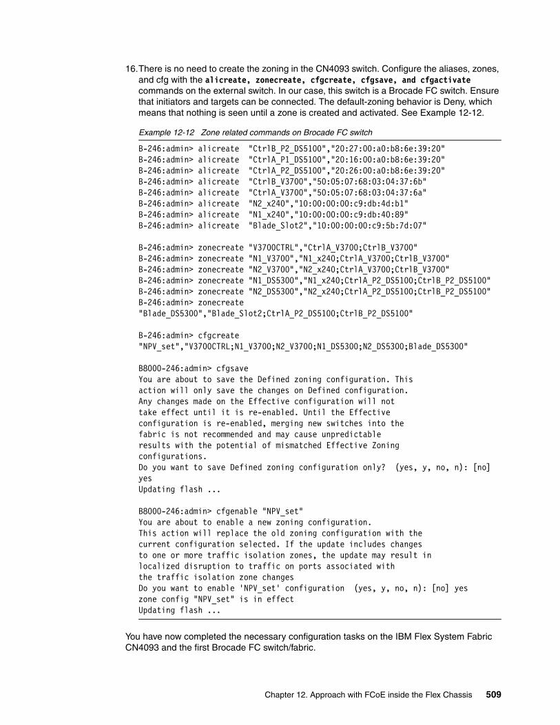
16.There is no need to create the zoning in the CN4093 switch. Configure the aliases, zones, and cfg with the alicreate, zonecreate, cfgcreate, cfgsave, and cfgactivate commands on the external switch. In our case, this switch is a Brocade FC switch. Ensure that initiators and targets can be connected. The default-zoning behavior is Deny, which means that nothing is seen until a zone is created and activated. See Example 12-12.
Example 12-12 Zone related commands on Brocade FC switch
B-246:admin> alicreate "CtrlB_P2_DS5100","20:27:00:a0:b8:6e:39:20"B-246:admin> alicreate "CtrlA_P1_DS5100","20:16:00:a0:b8:6e:39:20"B-246:admin> alicreate "CtrlA_P2_DS5100","20:26:00:a0:b8:6e:39:20"B-246:admin> alicreate "CtrlB_V3700","50:05:07:68:03:04:37:6b"B-246:admin> alicreate "CtrlA_V3700","50:05:07:68:03:04:37:6a"B-246:admin> alicreate "N2_x240","10:00:00:00:c9:db:4d:b1"B-246:admin> alicreate "N1_x240","10:00:00:00:c9:db:40:89"B-246:admin> alicreate "Blade_Slot2","10:00:00:00:c9:5b:7d:07"
B-246:admin> zonecreate "V3700CTRL","CtrlA_V3700;CtrlB_V3700"B-246:admin> zonecreate "N1_V3700","N1_x240;CtrlA_V3700;CtrlB_V3700"B-246:admin> zonecreate "N2_V3700","N2_x240;CtrlA_V3700;CtrlB_V3700"B-246:admin> zonecreate "N1_DS5300","N1_x240;CtrlA_P2_DS5100;CtrlB_P2_DS5100"B-246:admin> zonecreate "N2_DS5300","N2_x240;CtrlA_P2_DS5100;CtrlB_P2_DS5100"B-246:admin> zonecreate "Blade_DS5300","Blade_Slot2;CtrlA_P2_DS5100;CtrlB_P2_DS5100"
B-246:admin> cfgcreate "NPV_set","V3700CTRL;N1_V3700;N2_V3700;N1_DS5300;N2_DS5300;Blade_DS5300"
B8000-246:admin> cfgsaveYou are about to save the Defined zoning configuration. Thisaction will only save the changes on Defined configuration.Any changes made on the Effective configuration will nottake effect until it is re-enabled. Until the Effectiveconfiguration is re-enabled, merging new switches into thefabric is not recommended and may cause unpredictableresults with the potential of mismatched Effective Zoningconfigurations.Do you want to save Defined zoning configuration only? (yes, y, no, n): [no] yesUpdating flash ...
B8000-246:admin> cfgenable "NPV_set"You are about to enable a new zoning configuration.This action will replace the old zoning configuration with thecurrent configuration selected. If the update includes changesto one or more traffic isolation zones, the update may result inlocalized disruption to traffic on ports associated withthe traffic isolation zone changesDo you want to enable 'NPV_set' configuration (yes, y, no, n): [no] yeszone config "NPV_set" is in effectUpdating flash ...
You have now completed the necessary configuration tasks on the IBM Flex System Fabric CN4093 and the first Brocade FC switch/fabric.
Chapter 12. Approach with FCoE inside the Flex Chassis 509

Repeat this configuration procedure on the IBM Flex System Fabric CN4093 in I/O bay 2 and the second Brocade FC switch/fabric.
Use the show interface links command as shown in Example 12-2 on page 500 to verify that the link status is UP for all the active host ports and bridge interfaces.
12.4 Full switch configurations
This section includes the complete configuration text files for the tests outlined in this chapter. The first section is the BNT Virtual Fabric 10Gb Switch Module for the BladeCenter H. The configuration for all IBM Flex System Fabric CN4093 configurations is identical. The connection is the port EXT1 of the BNT Virtual Fabric 10Gb Switch Moduleto EXT16 in the IBM Flex System Fabric CN4093.
12.4.1 BNT Virtual Fabric 10Gb Switch Module for IBM BladeCenter
Example 12-13 shows the final configuration that is used for the BNT Virtual Fabric 10Gb Switch Module. The Converged Network Adapter must be configured to the pNIC mode for this example.
Example 12-13 Configuration dump of the BNT Virtual Fabric 10Gb Switch Module
version "7.7.1"switch-type "IBM Networking OS Virtual Fabric 10Gb Switch Module for IBM BladeCenter"iscli-new!!ssh enable!
snmp-server name "BCH_slot7"!hostname "BCH_slot7"!!interface port INT1
description "Blade1_Slot1"switchport trunk allowed vlan 1,1002,4095flowcontrol send offflowcontrol receive offexit
!interface port INT2
description "Blade2_Slot2"switchport trunk allowed vlan 1,1002,4095flowcontrol send offflowcontrol receive offexit
!interface port INT3
description "Blade3_Slot3"flowcontrol send offflowcontrol receive off
510 Storage and Network Convergence Using FCoE and iSCSI

exit!! Configuration INT4 to INT14 same as INT14interface port INT14
flowcontrol send offflowcontrol receive offexit
!interface port EXT1
description "CN4093_1_EXT16"switchport mode trunkswitchport trunk allowed vlan 1002switchport trunk native vlan 1002exit
!vlan 1002
name "FCoE"!!spanning-tree stp 113 vlan 1002!!fcoe fips enable!fcoe fips port INT1 fcf-mode onfcoe fips port INT2 fcf-mode onfcoe fips port EXT1 fcf-mode on!!cee enable!!!end
12.4.2 IBM Flex System Fabric CN4093 in pNIC and Full Fabric mode
Example 12-14 shows the final running configuration from the IBM Flex System Fabric CN4093 10Gb Converged Scalable Switch. In our lab environment, the VLAN 500 is the connectivity for the public (IBM) network. The bold lines are related to the FCoE configuration. The Converged Network Adapter must be configured to the pNIC mode.
Example 12-14 Configuration dump of the IBM Flex System Fabric CN4093 in pNIC
version "7.5.1"switch-type "IBM Flex System Fabric CN4093 10Gb Converged Scalable Switch(Upgrade1)(Upgrade2)"!!snmp-server name "CN4093_1"!!system port EXT13-EXT14 type fchostname "CN4093_1"!
Chapter 12. Approach with FCoE inside the Flex Chassis 511
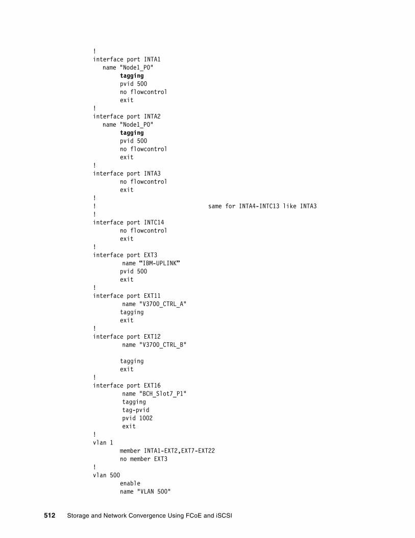
!interface port INTA1
name "Node1_P0" tagging pvid 500 no flowcontrol exit!interface port INTA2
name "Node1_P0" tagging pvid 500 no flowcontrol exit!interface port INTA3 no flowcontrol exit!! same for INTA4-INTC13 like INTA3!interface port INTC14 no flowcontrol exit!interface port EXT3
name “IBM-UPLINK” pvid 500 exit!interface port EXT11
name "V3700_CTRL_A" tagging exit!interface port EXT12
name "V3700_CTRL_B"
tagging exit!interface port EXT16
name "BCH_Slot7_P1"taggingtag-pvidpvid 1002exit
!vlan 1 member INTA1-EXT2,EXT7-EXT22 no member EXT3!vlan 500 enable name "VLAN 500"
512 Storage and Network Convergence Using FCoE and iSCSI
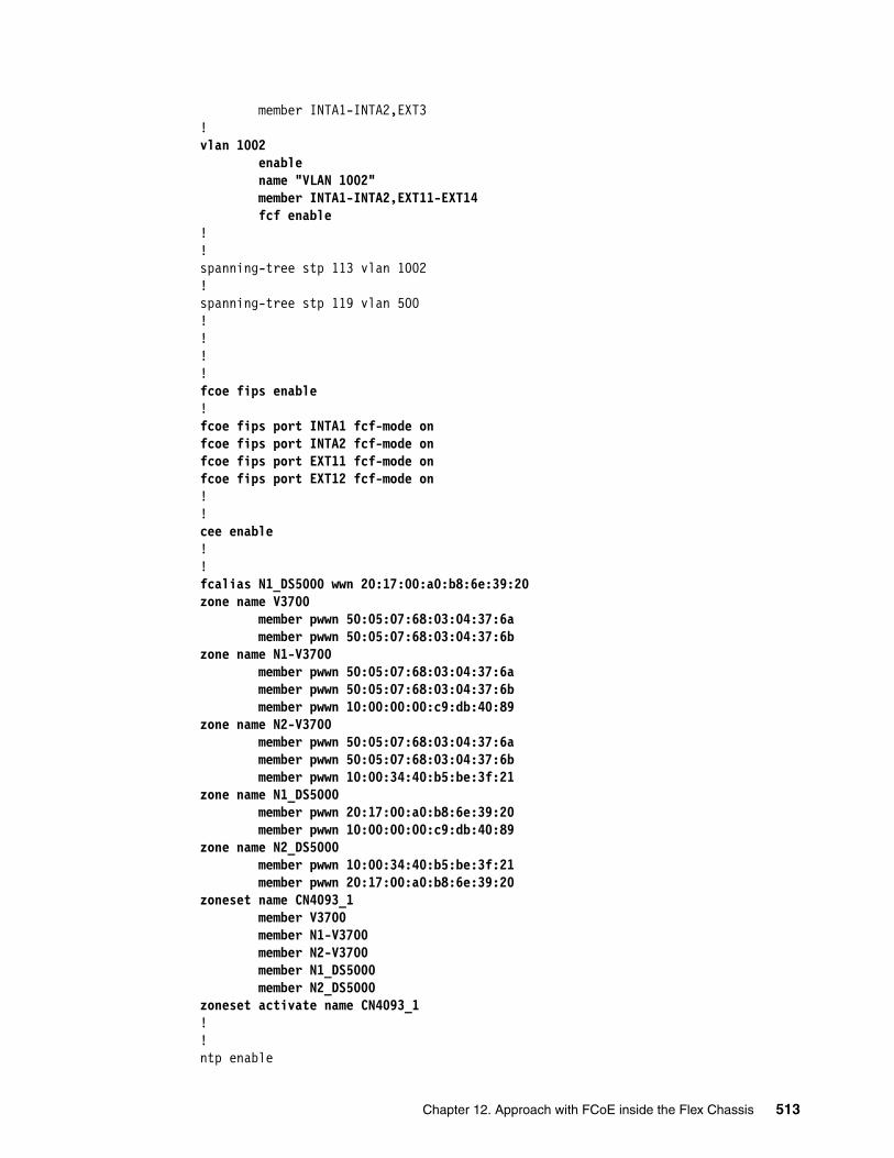
member INTA1-INTA2,EXT3!vlan 1002 enable name "VLAN 1002" member INTA1-INTA2,EXT11-EXT14
fcf enable!!spanning-tree stp 113 vlan 1002!spanning-tree stp 119 vlan 500!!!!fcoe fips enable!fcoe fips port INTA1 fcf-mode onfcoe fips port INTA2 fcf-mode onfcoe fips port EXT11 fcf-mode onfcoe fips port EXT12 fcf-mode on!!cee enable!!fcalias N1_DS5000 wwn 20:17:00:a0:b8:6e:39:20zone name V3700 member pwwn 50:05:07:68:03:04:37:6a member pwwn 50:05:07:68:03:04:37:6bzone name N1-V3700 member pwwn 50:05:07:68:03:04:37:6a member pwwn 50:05:07:68:03:04:37:6b member pwwn 10:00:00:00:c9:db:40:89zone name N2-V3700 member pwwn 50:05:07:68:03:04:37:6a member pwwn 50:05:07:68:03:04:37:6b member pwwn 10:00:34:40:b5:be:3f:21zone name N1_DS5000 member pwwn 20:17:00:a0:b8:6e:39:20 member pwwn 10:00:00:00:c9:db:40:89zone name N2_DS5000 member pwwn 10:00:34:40:b5:be:3f:21 member pwwn 20:17:00:a0:b8:6e:39:20zoneset name CN4093_1 member V3700 member N1-V3700 member N2-V3700 member N1_DS5000 member N2_DS5000zoneset activate name CN4093_1!!ntp enable
Chapter 12. Approach with FCoE inside the Flex Chassis 513

ntp ipv6 primary-server fe80::211:25ff:fec3:8ba9 MGTntp interval 15ntp authenticatentp primary-key 2081!ntp message-digest-key 2081 md5-ekey "391ecbdb190e8a8af6d6a2b2dabe2978f2e5bd72079bee41cfb02cb65aaa9169b9a6f6b77ea511dc9482d32dbdd8375841e2f60898d2cf0b45cff719580e566e"!ntp trusted-key 2081!end
12.4.3 IBM Flex System Fabric CN4093 in vNIC and Full Fabric mode
Example 12-15 shows the configuration of vNIC instance 3 for an IBM Flex node server in slots 1 and 2. The bold lines are related to the vNIC configuration. These lines are the only differences from the pNIC mode on the switch. The IBM Flex System CN4054 10Gb Virtual Fabric Adapter must be configured to the pNIC mode.
Example 12-15 Configuration of IBM Flex System Fabric CN4093 with vNIC
version "7.5.1"switch-type "IBM Flex System Fabric CN4093 10Gb Converged Scalable Switch(Upgrade1)(Upgrade2)"!!snmp-server name "CN4093_1"!!system port EXT13-EXT14 type fchostname "CN4093_1"!!interface port INTA1
name "Node1_P0" tagging pvid 500 no flowcontrol exit!interface port INTA2
name "Node2_P0" tagging pvid 500 no flowcontrol exit!interface port INTA3 no flowcontrol exit! same for INTA4 to INTC13 like INTA3!interface port INTC14 no flowcontrol
514 Storage and Network Convergence Using FCoE and iSCSI

exit!interface port EXT3
name “IBM-UPLINK” pvid 500 exit!interface port EXT11
name "V3700_CTRL_A" tagging exit!interface port EXT12
name "V3700_CTRL_B" tagging exit!interface port EXT16
name "BCH_Slot7_P1"taggingtag-pvidpvid 1002exit
!vlan 1 member INTA1-INTC14,EXT2,EXT7-EXT22 no member EXT1,EXT3!vlan 500 enable name "VLAN 500" member INTA1-INTA2,EXT3!vlan 1002 enable name "VLAN 1002" member INTA1-INTA2,EXT11-EXT14 fcf enable!!vnic enablevnic port INTA1 index 3 bandwidth 25 enable exit!vnic port INTA2 index 3 bandwidth 25 enable exit!vnic vnicgroup 3 vlan 103 enable member INTA1.3
Chapter 12. Approach with FCoE inside the Flex Chassis 515

member INTA2.3 port EXT1 exit!spanning-tree stp 103 vlan 103!interface port EXT1 no spanning-tree stp 103 enable exit!spanning-tree stp 113 vlan 1002!spanning-tree stp 119 vlan 500!!fcoe fips enable!fcoe fips port INTA1 fcf-mode onfcoe fips port INTA2 fcf-mode onfcoe fips port EXT11 fcf-mode onfcoe fips port EXT12 fcf-mode on!!cee enable!!fcalias N1_DS5000 wwn 20:17:00:a0:b8:6e:39:20zone name V3700 member pwwn 50:05:07:68:03:04:37:6a member pwwn 50:05:07:68:03:04:37:6bzone name N1-V3700 member pwwn 50:05:07:68:03:04:37:6a member pwwn 50:05:07:68:03:04:37:6b member pwwn 10:00:00:00:c9:db:40:89zone name N2-V3700 member pwwn 50:05:07:68:03:04:37:6a member pwwn 50:05:07:68:03:04:37:6b member pwwn 10:00:34:40:b5:be:3f:21zone name N1_DS5000 member pwwn 20:17:00:a0:b8:6e:39:20 member pwwn 10:00:00:00:c9:db:40:89zone name N2_DS5000 member pwwn 10:00:34:40:b5:be:3f:21 member pwwn 20:17:00:a0:b8:6e:39:20zoneset name CN4093_1 member V3700 member N1-V3700 member N2-V3700 member N1_DS5000 member N2_DS5000zoneset activate name CN4093_1!ntp enablentp ipv6 primary-server fe80::211:25ff:fec3:8ba9 MGTntp interval 15
516 Storage and Network Convergence Using FCoE and iSCSI
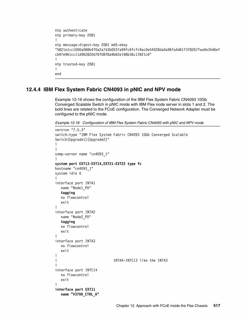
ntp authenticatentp primary-key 2081!ntp message-digest-key 2081 md5-ekey "5821e1cc1000a088b4f0a2a7d3b0037a99fc6fcfc9ac0e54428da0a96fa4d61f3f8267faa9e34d6efcb97e961cc11d962820d76f08f8a9b62e198b36c13921c6"!ntp trusted-key 2081!end
12.4.4 IBM Flex System Fabric CN4093 in pNIC and NPV mode
Example 12-16 shows the configuration of the IBM Flex System Fabric CN4093 10Gb Converged Scalable Switch in pNIC mode with IBM Flex node server in slots 1 and 2. The bold lines are related to the FCoE configuration. The Converged Network Adapter must be configured to the pNIC mode.
Example 12-16 Configuration of IBM Flex System Fabric CN4093 with pNIC and NPV mode
version "7.5.3"switch-type "IBM Flex System Fabric CN4093 10Gb Converged Scalable Switch(Upgrade1)(Upgrade2)"!!snmp-server name "cn4093_1"!system port EXT13-EXT14,EXT21-EXT22 type fchostname "cn4093_1"system idle 0!interface port INTA1
name "Node1_P0"taggingno flowcontrolexit
!interface port INTA2
name "Node2_P0"taggingno flowcontrolexit
!interface port INTA3
no flowcontrolexit
!! INTA4-INTC13 like the INTA3!interface port INTC14
no flowcontrolexit
!interface port EXT11
name "V3700_CTRL_A"
Chapter 12. Approach with FCoE inside the Flex Chassis 517

pvid 1002exit
!interface port EXT12
name "V3700_CTRL_B"pvid 1002exit
!interface port EXT16
name "BCH_Slot7_P1"taggingtag-pvidpvid 1002exit
!vlan 1
member INTA1-EXT3,EXT7-EXT10,EXT13-EXT15,EXT17-EXT22no member EXT11-EXT12,EXT16
!vlan 500
name "VLAN 500"member INTA1-INTA2
!vlan 1002
enablename "VLAN 1002"member INTA1-INTA2,EXT11-EXT12,EXT16,EXT22npv enablenpv traffic-map external-interface EXT22
!spanning-tree stp 113 vlan 1002!spanning-tree stp 119 vlan 500!fcoe fips enable!cee enable!ntp enablentp ipv6 primary-server fe80::211:25ff:fec3:5f3d MGTntp interval 15ntp authenticatentp primary-key 10584!ntp message-digest-key 10584 md5-ekey "dabd89e8d8bc88a896f4e2a31b0c2b5a6a26c293d6449a0f651a374ad8e0f09479f60f96d7b7685e53706d27bce22044b3a476436c28a0647d819dce4aab8fc8"!ntp trusted-key 10584!end
518 Storage and Network Convergence Using FCoE and iSCSI

12.4.5 IBM Flex System Fabric CN4093 in vNIC and NPV mode
Example 12-17 shows the configuration of IBM Flex System Fabric CN4093 10Gb Converged Scalable Switch in vNIC mode and instance 3 for an IBM Flex node server in slots 1 and 2. The bold lines are related to the FCoE configuration. These configurations are the only difference from the pNIC mode on the switch. The Converged Network Adapter must be configured to the vNIC mode.
Example 12-17 Configuration of CN4093 Switch with vNIC and NPV mode
version "7.5.3"switch-type "IBM Flex System Fabric CN4093 10Gb Converged Scalable Switch(Upgrade1)(Upgrade2)"!!snmp-server name "cn4093_1"!system port EXT13-EXT14,EXT21-EXT22 type fchostname "cn4093_1"system idle 0!interface port INTA1
name "Node1_P0"taggingno flowcontrolexit
!interface port INTA2
name "Node2_P0"taggingno flowcontrolexit
!interface port INTA3
no flowcontrolexit
!! INTA4-INTC13 like the INTA3!interface port INTC14
no flowcontrolexit
!interface port EXT3
name “IBM-UPLINK”taggingexit
!interface port EXT11
name "V3700_CTRL_A"pvid 1002exit
!interface port EXT12
name "V3700_CTRL_B"pvid 1002
Chapter 12. Approach with FCoE inside the Flex Chassis 519

exit!interface port EXT16
name "BCH_Slot7_P1"taggingtag-pvidpvid 1002exit
!vlan 1
member INTA1-EXT2,EXT7-EXT10,EXT13-EXT15,EXT17-EXT22no member EXT3,EXT11-EXT12,EXT16
!vlan 500
name "VLAN 500"member INTA1-INTA2
!vlan 1002
enablename "VLAN 1002"member INTA1-INTA2,EXT11-EXT12,EXT16,EXT22npv enablenpv traffic-map external-interface EXT22
!!vnic enablevnic port INTA1 index 3
bandwidth 25enableexit
!vnic port INTA2 index 3
bandwidth 33enableexit
!vnic vnicgroup 3
vlan 103enablemember INTA1.3member INTA2.3port EXT3exit
!spanning-tree stp 103 vlan 103!interface port EXT3
name “IBM-UPLINK”no spanning-tree stp 103 enableexit
!spanning-tree stp 113 vlan 1002!spanning-tree stp 119 vlan 500!
520 Storage and Network Convergence Using FCoE and iSCSI

fcoe fips enable!cee enable!ntp enablentp ipv6 primary-server fe80::211:25ff:fec3:5f3d MGTntp interval 15ntp authenticatentp primary-key 10584!ntp message-digest-key 10584 md5-ekey "dabd89e8d8bc88a896f4e2a31b0c2b5a6a26c293d6449a0f651a374ad8e0f09479f60f96d7b7685e53706d27bce22044b3a476436c28a0647d819dce4aab8fc8"!ntp trusted-key 10584!end
12.5 Summary assessment
The FCoE implementation for an IBM Flex node with an IBM Flex System Fabric CN4093 requires minimal configuration effort. The solution is flexible and scalable in bandwidth and shows good performance. In our tests, we found no issue with the automatic VLAN discovery and no incompatibility issues with the external FC-attached storage.
No significant differences were detected between using Windows 2012, 2008R2, ESXi 5.0, or SLES_11SP2 with Converged Network Adapter.
The IBM Flex technology offers a fully integrated FCoE solution that is easy to set up.
Chapter 12. Approach with FCoE inside the Flex Chassis 521

522 Storage and Network Convergence Using FCoE and iSCSI

Chapter 13. Approach with FCoE between the IBM Flex Chassis and a top-of-rack switch
This chapter describes a Fibre Channel over Ethernet (FCoE) configuration that uses a top-of-rack switch as a Fibre Channel Forwarder (FCF). We tested the IBM System Networking G8264CS switch as a top-of-rack FCF. This switch contains twelve Fibre Channel (FC) ports to be in place to provide the FCF function. The second possibility for the IBM System Networking G8264CS switch is the use as an NPV device to connect one or more FC fabrics. Although our testing used nodes in an IBM Flex chassis in addition to nodes in a BladeCenter to access the storage, it is possible to use similar configurations with essentially the same configuration on the G8264CS switch, as in the following examples:
� Rack mounted servers can be connected directly or indirectly to the Ethernet ports on the G8264CS switch and pass FCoE traffic through the FCF function to the direct-connected storage device.
� Rack mounted servers can be connected directly or indirectly to the Ethernet ports on the G8264CS switch and pass FCoE traffic through the NPV function via the FC fabrics to the FC connected storage device.
� IBM Flex chassis nodes can be connected to the Ethernet ports on the G8264CS switch with an IBM Flex System EN4093 switch in the bays of the IBM Flex Chassis or an EN4091 10-Gbps pass-through modules.
� IBM BladeCenter blades can be connected to the Ethernet ports on the G8264CS switch with a BNT Virtual Fabric 10Gb Switch Module in the bays of the IBM BladeCenter chassis.
This chapter includes the following sections:
� 13.1, “Overview of testing scenarios” on page 524� 13.2, “IBM System Networking G8264CS switch” on page 525� 13.3, “Commands and pointers for FCoE” on page 530� 13.4, “Full switch configurations” on page 542� 13.5, “Summary assessment” on page 552
13
© Copyright IBM Corp. 2012, 2014. All rights reserved. 523
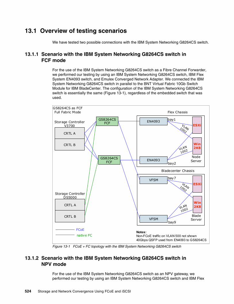
13.1 Overview of testing scenarios
We have tested two possible connections with the IBM System Networking G8264CS switch.
13.1.1 Scenario with the IBM System Networking G8264CS switch in FCF mode
For the use of the IBM System Networking G8264CS switch as a Fibre Channel Forwarder, we performed our testing by using an IBM System Networking G8264CS switch, IBM Flex System EN4093 switch, and Emulex Converged Network Adapter. We connected the IBM System Networking G8264CS switch in parallel to the BNT Virtual Fabric 10Gb Switch Module for IBM BladeCenter. The configuration of the IBM System Networking G8264CS switch is essentially the same (Figure 13-1), regardless of the embedded switch that was used.
Figure 13-1 FCoE + FC topology with the IBM System Networking G8264CS switch
13.1.2 Scenario with the IBM System Networking G8264CS switch in NPV mode
For the use of the IBM System Networking G8264CS switch as an NPV gateway, we performed our testing by using an IBM System Networking G8264CS switch and IBM Flex
Storage ControllerV3700
Flex Chassis
NodeServer
VLAN1002
VLAN
1002
Win2K8
ESXi
GS8264CSFCF
GS8264CS as FCFFull Fabric Mode
FCoE
native FC
bay1
bay2
CRTL A
CRTL B
EN4093
EN4093
GS8264CSFCF
Bladecenter Chassis
BladeServer
VLAN1002
VLAN
1002
Win2K8
ESXi
bay7
bay9
Notes:Non-FCoE traffic on VLAN 500 not shown40Gbps QSFP used from EN4093 to GS8264CS
VFSM
VFSM
Storage ControllerDS5000
CRTL A
CRTL B
524 Storage and Network Convergence Using FCoE and iSCSI
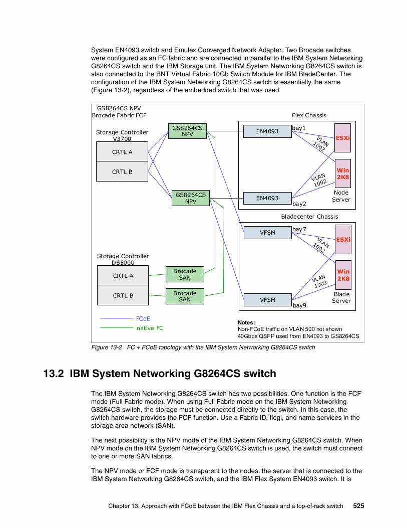
System EN4093 switch and Emulex Converged Network Adapter. Two Brocade switches were configured as an FC fabric and are connected in parallel to the IBM System Networking G8264CS switch and the IBM Storage unit. The IBM System Networking G8264CS switch is also connected to the BNT Virtual Fabric 10Gb Switch Module for IBM BladeCenter. The configuration of the IBM System Networking G8264CS switch is essentially the same (Figure 13-2), regardless of the embedded switch that was used.
Figure 13-2 FC + FCoE topology with the IBM System Networking G8264CS switch
13.2 IBM System Networking G8264CS switch
The IBM System Networking G8264CS switch has two possibilities. One function is the FCF mode (Full Fabric mode). When using Full Fabric mode on the IBM System Networking G8264CS switch, the storage must be connected directly to the switch. In this case, the switch hardware provides the FCF function. Use a Fabric ID, flogi, and name services in the storage area network (SAN).
The next possibility is the NPV mode of the IBM System Networking G8264CS switch. When NPV mode on the IBM System Networking G8264CS switch is used, the switch must connect to one or more SAN fabrics.
The NPV mode or FCF mode is transparent to the nodes, the server that is connected to the IBM System Networking G8264CS switch, and the IBM Flex System EN4093 switch. It is
Storage ControllerV3700
Flex Chassis
NodeServer
VLAN1002
VLAN
1002
Win2K8
ESXi
GS8264CSNPV
GS8264CS NPVBrocade Fabric FCF
bay1
bay2
CRTL A
CRTL B
EN4093
EN4093
GS8264CSNPV
Bladecenter Chassis
BladeServer
VLAN1002
VLAN
1002
Win2K8
ESXi
bay7
bay9
Notes:Non-FCoE traffic on VLAN 500 not shown40Gbps QSFP used from EN4093 to GS8264CS
VFSM
VFSM
Storage ControllerDS5000
CRTL A
CRTL B
BrocadeSAN
BrocadeSAN
FCoE
native FC
Chapter 13. Approach with FCoE between the IBM Flex Chassis and a top-of-rack switch 525

easy to reconfigure the switch from one mode to the other mode. Be aware that there is an interrupt of the path when the FC connection moves from one switch to the other switch.
The Converged Network Adapter configuration can be supported in the following ways directly or via the IBM Flex System EN4093 switch:
� Using a Converged Network Adapter in physical NIC (pNIC) mode:
– QLogic 10Gb CNA for IBM System x and IBM Power Systems– Brocade 10Gb CNA for IBM System x– Emulex 10Gb Virtual Fabric Adapter for IBM System x– IBM Flex CN4054 Converged Network Adapter– IBM Flex Node Lan on Motherboard
� Using a Converged Network Adapter in virtual NIC (vNIC) mode:
– QLogic 10Gb CNA for IBM System x and IBM Power Systems– Brocade 10Gb CNA for IBM System x– Emulex 10Gb Virtual Fabric Adapter for IBM System x– IBM Flex CN4054 Converged Network Adapter– IBM Flex Node Lan on Motherboard
Differences in the IBM Flex System EN4093 switch configuration occur if vNIC support is used with FCoE traffic. The configuration of the IBM System Networking G8264CS switch for FCoE is independent of the IBM Flex System EN4093 switch configuration using pNIC or vNIC.
13.2.1 IBM System Networking G8264CS switch configuration FCF mode
The IBM System Networking G8264CS switch configuration includes items that specify handling Ethernet traffic, prioritization for FCoE, and designation of the FCoE VLAN. It also includes items that describe the function of the FC ports. As mentioned previously, we tested the IBM System Networking G8264CS switch in Fibre Channel Forwarder mode.
See 13.4.1, “G8264CS FCF configuration” on page 542 for the complete configuration. The following commands are critical for this configuration:
� The cee enable command is required to enable CEE support.
� The fcoe fips enable command is required. This command activates FIP snooping, which allows a switch to learn which VLANs and ports are supporting FCoE functions.
� The system port 53-54 type fc command is required to use Fibre Channel Forwarder mode.
� The VLAN that carrier the FCoE traffic must be created and the member must be added with the vlan 1002 command followed by the member command.
� The VLAN to be supplied to initiators from the FCF function of the IBM System Networking G8264CS switch must be specified with the fcf enable command.
� The fcalias, zone, and zoneset commands must be used for the Fibre Channel zoning of the switch.
Note: No vLAG or Link aggregation modes are allowed on the links that carry FCoE traffic at this time.
Note: Only one VLAN per switch can contain a FCF. A switch in NPV mode can have multiple VLANs that contain NPV connections. Both modes can be used at the same time.
526 Storage and Network Convergence Using FCoE and iSCSI

13.2.2 IBM System Networking G8264CS switch configuration NPV mode
The IBM System Networking G8264CS switch configuration includes items that specify handling Ethernet traffic, prioritization for FCoE, and designation of the FCoE VLAN. It also includes items that describe the function of the FC ports. As mentioned previously, we tested the IBM System Networking G8264CS switch in Fibre Channel Forwarder mode.
See 13.4.2, “G8264CS NPV configuration” on page 545, for the complete configuration. The following commands are critical for this configuration:
� The cee enable command is required to enable CEE support.
� The fcoe fips enable command is required. This command activates FIP snooping, which allows a switch to learn which VLANs and ports are supporting FCoE functions.
� The system port 61-64 type fc command is required to use NPV mode.
� The VLAN that carries the FCoE traffic must be created and the member must added with the vlan 1002 command followed by the member command.
� The VLAN to be supplied to initiators from the FCF function of the IBM System Networking G8264CS switch must be specified with the npv enable command.
� The VLAN to be supplied to the external switch for the NPV function of the IBM System Networking G8264CS switch must be specified with the npv traffic-map external-interface 62 command.
� The zoning must be done by the external FC fabric.
13.2.3 IBM EN4093 configuration with pNIC
The following key aspects of the configuration are required for FCoE to work:
� Converged Enhanced Ethernet (CEE, also known as Lossless Ethernet and Data Center Bridging (DCB)), is a prerequisite and must be enabled with the cee enable command.
� Configure the preferred Enhanced Transmission Selection (ETS) and priority flow control (PFC) attributes with the cee global ets priority-group and cee port <x> pfc commands. For more information about these commands, see “PFC and ETS configuration commands” on page 528 (not required).
� Because PFC is used, it will disable traditional Ethernet flow control on the initiator-facing and FCF-facing ports automatically with the no flowcontrol command (not required).
� FCoE must be enabled by using the fcoe fips enable command.
� Link Layer Discovery Protocol (LLDP) is used by CEE and is enabled by the lldp enable command (it is automatically enabled).
� Ports that connect to the FCF can optionally be identified by turning fcf-mode to on; ports that connect to servers that access storage can be identified by turning fcf-mode to off. The default is for fcf to be checked automatically on all ports by using the following command:
fcoe fips port <x> fcf-mode on|off|auto
� The FCoE VLAN must be defined and both ports that connect to initiators and to the FCF must be members of that VLAN. The initiator-facing ports always require tagging so that FCoE traffic and other data traffic can be both accommodated and on different VLANs. They must be configured so that the FCoE VLAN traffic always has tags, by making a
Note: Only one VLAN per switch can contain an FCF. A switch in NPV mode can have multiple VLANs that contain NPV connections. Both modes can be used at the same time.
Chapter 13. Approach with FCoE between the IBM Flex Chassis and a top-of-rack switch 527

different VLAN the Port VLAN ID (PVID), or by using tag-pvid. The FCF-facing ports might need to carry other VLANs. However, the FCoE VLAN must always have the appropriate value in the tag field. Therefore, if the FCoE VLAN is the PVID (native VLAN), tag-pvid must be enabled.
� The selection of the FCoE VLAN is sent to the CNAs as part of the FCoE Initialization Protocol (FIP) initialization process. Configure the adapters to accept the VLAN ID in this way. Otherwise, they must be preconfigured to use the same VLAN ID as the FCF is configured to use. We experienced issues when configuring some of the adapters to use VLANs other than the FCoE default (1002).
� You might need to configure initiator-facing ports with no lldp tlv portprot and no lldp tlv vlanname to avoid issues that occurred with FCoE. We did not experience these issues in our testing with the G8264CS together with the EN4093 (not required).
� Configure ports that connect to neither initiators nor FCF by using the no fcoe fips port <x> enable command (not required).
� Disable the Spanning Tree Protocol (STP) for the STP instance that supports the FCoE VLAN. The topology of that VLAN must be loop free.
� The following commands are set by default, and therefore, are not displayed in a show run:
– fcoe fips port <x> enable is on by default for all ports if fcoe fips enable is entered.
– fcoe fips automatic-vlan is enabled by default and allows the switch to learn which VLANs will carry FCoE traffic.
Link aggregation can cause a significant constraint on the total amount of FCoE bandwidth available. In our lab example the links between EN4093 and the G8264CS is a 40 Gbps QSFP link. This is a good practice, so that we do not need the link aggregation or VLAG modes.
PFC and ETS configuration commandsUse the PFC and ETS configuration commands to set priority and bandwidth guarantees for FCoE and for other classes of traffic.
PFC and ETS functions PFC is defined in IEEE 802.1Qbb. It enhances the traditional use of pause frames to slow down traffic that exceeds the capacity of the receiver by enabling only traffic classified into a priority group to be paused. This capability is required for FCoE and has these objectives:
� Pause traffic that is competing with FCoE for bandwidth to allow the FCoE traffic to get through.
� Pause FCoE traffic to allow the receiver to catch up with the senders instead of dropping some traffic and requiring retransmission.
ETS is defined in IEEE 802.1Qaz. ETS divides traffic that flows over a link into priority groups. It allows for each priority group to be guaranteed a percentage of the bandwidth of the link and for some priority groups to be designated as lossless. The number of lossless priority groups varies between switching products. At least one must be supported for a switch to claim to support CEE.
For more information about PFC and ETS, see the official standards definitions at the following websites:
Note: No vLAG or Link aggregation modes are allowed on the links that carry FCoE traffic at this time.
528 Storage and Network Convergence Using FCoE and iSCSI

� The Internet Engineering Task Force (IETF):
http://www.ietf.org
� Institute of Electrical and Electronics Engineers (IEEE):
http://www.ieee.org
13.2.4 IBM EN4093 configuration with vNIC
For information about vNIC configuration and functionality, see IBM BladeCenter Virtual Fabric Solutions, SG24-7966. The same applies to the IBM Flex System. This section focuses on the using vNIC with FCoE.
When the IBM Flex CN4054 Converged Network Adapter is used in vNIC mode with the FCoE personality, the following additional configuration is required:
� Enable vNIC instances 1, 3, and 4 for non-FCoE traffic if they are to be used. At least one is necessary if the operating system must detect an active NIC. The instances that will be used must be enabled. The default bandwidth is 2.5 Gbps, but this value can be changed.
� Use vNIC instance 2 for FCoE traffic. Although you can specify a bandwidth for it, this specification has no effect. FCoE traffic always has the highest priority. Bandwidth that is allocated to one of the other instances will be used if required for FCoE traffic.
� Optionally configure vNIC instance 2 when it is used for FCoE. The Q-in-Q double tagging that is normally used by vNIC does not apply to FCoE traffic. The FCoE traffic flows on the VLANs learned through FIP snooping, similar to when pNIC (or other CNA hardware besides Emulex) is used. Similarly to pNIC mode, define the appropriate VLANs and ensure that they have the appropriate membership.
Some servers can use vNIC and others might not, even when they use the same switch, the same FCF, and the same storage. Information is conflicting about how PFC and ETS interact with vNIC. In our testing, we guaranteed a percentage of bandwidth to FCoE and saw the throughput of nonstorage traffic on a vNIC drop below the configured value when necessary to achieve the guarantee.
Link aggregation can cause a significant constraint on the total amount of FCoE bandwidth available. In our lab example, the link between the IBM Flex System EN4093 switch and the IBM System Networking G8264CS switch is a 40 Gbps QSFP link. This is a good practice, so that we do not need the link aggregation or VLAG modes.
Note: No vLAG or Link aggregation modes are allowed on the links that carry FCoE traffic at this time.
Chapter 13. Approach with FCoE between the IBM Flex Chassis and a top-of-rack switch 529

13.3 Commands and pointers for FCoE
This section summarizes the commonly used commands in FCoE configurations.
13.3.1 IBM System Networking G8264CS switch commands for FCF mode
The first step is to set up the IBM System Networking G8264CS switch for FCoE traffic in a Full Fabric mode. Example 13-1 shows the basic command for the IBM System Networking G8264CS switch to enable the configuration.
Example 13-1 Enable the FCF on the IBM System Networking G8264CS switch
Select Command Line Interface mode (ibmnos-cli/iscli): iscli
G8264CS-up>enable
Enable privilege granted.G8264CS-up#conf tEnter configuration commands, one per line. End with Ctrl/Z.
Enable the converged network capabilities with the command in Example 13-2. As you can see, the system port command changes the pair of interfaces to the type Fibre Channel. The switch will automatically disable the LLDP TX and RD.
Example 13-2 Enable CEE on the switch
G8624CS-up(config)#cee enableG8624CS-up(config)#fcoe fips enableG8624CS-up(config)#system port 53-54 type fcG8624CS-up(config)#Jan 30 1:27:04 G8624CS-up NOTICE lldp: LLDP TX & RX are disabled on port 53
Jan 30 1:27:04 G8624CS-up NOTICE lldp: LLDP TX & RX are disabled on port 54
Jan 30 1:27:06 G8624CS-up NOTICE link: link up on port 53
The next step is to show the creation of the VLAN for FCoE in Example 13-3. You can see that the pvid is changed for the interface. This does not happen if you already have a valid VLAN configuration. The FCoE VLAN will be transferred to the IBM Flex CN4054 Converged Network Adapter with DCBX.
Note: In case of using more than one VLAN or a VLAN other than 1002, ensure that the IBM Flex System EN4093 switch has the no fcoe fips automatic-vlan command applied. This prevents the addition of all FCoE ports in all FCF and NPV VLANs. In the IBM System Networking G8264CS switch and the IBM Flex System CN4093 switch, this setting is standard.
Note: Do not configure an IBM Flex CN4054 Converged Network Adapter with any VLAN information.
530 Storage and Network Convergence Using FCoE and iSCSI
For a default configured adapter, this is VLAN 1002. When the FCF is enabled, a name service and a flogi is started for each configured adapter. If you do not work with the default VLAN, ensure that the switch has applied the no fcoe fips automatic-vlan command. If the fcoe fips automatic-vlan is active, the switch will automatically add all the ports with FCoE traffic to all VLANs that contain a NPV and FCF.
Example 13-3 Create the vlan 1002
G8624CS-up(config)#vlan 1002
VLAN 1002 is created.
Warning: VLAN 1002 was assigned to STG 113.G8624CS-up(config-vlan)#enableG8624CS-up(config-vlan)#name "VLAN 1002"G8624CS-up(config-vlan)#member 1,43-44,48,53-54Port 1 is an UNTAGGED port and its PVID is changed from 1 to 1002Port 43 is an UNTAGGED port and its PVID is changed from 1 to 1002Port 44 is an UNTAGGED port and its PVID is changed from 1 to 1002Port 48 is an UNTAGGED port and its PVID is changed from 1 to 1002G8624CS-up(config-vlan)#Jan 30 1:28:26 G8624CS-up ALERT stg: STG 113, topology change detected
G8624CS-up(config-vlan)#fcf enableG8624CS-up(config-vlan)#Jan 30 1:28:55 G8624CS-up ALERT stg: STG 113, topology change detected
Jan 30 1:28:55 G8624CS-up NOTICE fcoe: FCOE connection between VN_PORT 0e:fc:00:01:0c:00 and FCF 74:99:75:88:1c:c3 has been established.
Jan 30 1:29:04 G8624CS-up NOTICE fcoe: FCOE connection between VN_PORT 0e:fc:00:01:0d:00 and FCF 74:99:75:88:1c:c4 has been established.
Jan 30 1:29:04 G8624CS-up NOTICE fcoe: FCOE connection between VN_PORT 0e:fc:00:01:0d:01 and FCF 74:99:75:88:1c:c4 has been established.
Jan 30 1:29:04 G8624CS-up NOTICE fcoe: FCOE connection between VN_PORT 0e:fc:00:01:0c:01 and FCF 74:99:75:88:1c:c3 has been established.
Jan 30 1:29:12 G8624CS-up NOTICE fcoe: FCOE connection between VN_PORT 0e:fc:00:01:0c:02 and FCF 74:99:75:88:1c:c3 has been established.
G8624CS-up(config-vlan)#exit
In the following steps, shown in Example 13-4, tagging is required for all Ethernet frames on the FCoE VLAN 1002.
Example 13-4 Enable tagging on all interfaces
G8624CS-up(config)#interface port 1G8624CS-up(config-if)#taggingG8624CS-up(config-if)#tag-pvidG8624CS-up(config-if)#pvid 1002G8624CS-up(config-if)#exitG8624CS-up(config)#interface port 43G8624CS-up(config-if)#tagging
Chapter 13. Approach with FCoE between the IBM Flex Chassis and a top-of-rack switch 531

G8624CS-up(config-if)#tag-pvidG8624CS-up(config-if)#pvid 1002G8624CS-up(config-if)#exitG8624CS-up(config)#interface port 44G8624CS-up(config-if)#taggingG8624CS-up(config-if)#tag-pvidG8624CS-up(config-if)#pvid 1002G8624CS-up(config-if)#exitG8624CS-up(config)#
Use the show fcf command to verify that an FCF is running on the IBM System Networking G8264CS switch as shown in Example 13-5.
Example 13-5 Show fcf to verify that the FCF is running
G8264CS-up(config)#show fcf====================================================FCF:1 in VLAN: 1002 Fabric FC-MAP : 0x0efc00 Priority : 128 FKA-Adv : 8
FC Port : 53 54G8264CS-up(config)#
This section shows several FIP panels from the IBM System Networking G8264CS switch. Example 13-6 shows the active FCF map. The MAC addresses shown match those MAC addresses that are configured as FCF interfaces on the G8624CS. The second command displays the MAC addresses and VLANs that are related to the ports of the switch.
Example 13-6 Fips related commands
G8264CS-up#show fcoe fips fcfTotal number of FCFs detected: 2
FCF MAC Port Vlan-----------------------------------74:99:75:88:1c:c3 53 100274:99:75:88:1c:c4 54 1002G8264CS-up#show fcoe fips fcoeTotal number of FCoE connections: 6
VN_PORT MAC FCF MAC Port Vlan------------------------------------------------------0e:fc:00:01:0d:00 74:99:75:88:1c:c4 1 10020e:fc:00:01:0d:01 74:99:75:88:1c:c4 1 10020e:fc:00:01:0c:02 74:99:75:88:1c:c3 43 10020e:fc:00:01:0d:02 74:99:75:88:1c:c4 44 10020e:fc:00:01:0c:00 74:99:75:88:1c:c3 48 10020e:fc:00:01:0c:01 74:99:75:88:1c:c3 48 1002G8264CS-up#show fcoe fips port 43
Port 43 FIP Snooping Configuration:FIP snooping: enabled, FCF mode: on
532 Storage and Network Convergence Using FCoE and iSCSI

Use the show flogi database command that is shown in Example 13-7 to get information about the fabric logins in the IBM System Networking G8264CS switch. These logins should be the same logins as shown in the show fcns database command in Example 13-8.
Example 13-7 fabric logins in the switch
G8264CS-up(config)#show flogi database---------------------------------------------------------------------- Port FCID Port-WWN Node-WWN---------------------------------------------------------------------- 53 010000 20:37:00:a0:b8:6e:39:20 20:06:00:a0:b8:6e:39:20 48 010c00 10:00:00:00:c9:e4:d9:3f 20:00:00:00:c9:e4:d9:3f 48 010c01 10:00:00:00:c9:5b:7d:0b 20:00:00:00:c9:5b:7d:0b 43 010c02 50:05:07:68:03:08:37:6b 50:05:07:68:03:00:37:6b 1 010d00 10:00:00:00:c9:db:40:8d 20:00:00:00:c9:db:40:8d 1 010d01 10:00:34:40:b5:be:3f:25 20:00:34:40:b5:be:3f:25 44 010d02 50:05:07:68:03:08:37:6a 50:05:07:68:03:00:37:6a
Total number of entries = 7G8264CS-up(config)#
Example 13-8 shows the command show fcoe database and the command show fcns database for the switch. The differences between fcoe and fcns are shown in bold. This WWN comes from port 53, a real FC device, which in our case is the DS5300 FC WWN.
Example 13-8 fcoe and fcns database
G8264CS-up#show fcoe database----------------------------------------------------------------------- VLAN FCID WWN MAC Port----------------------------------------------------------------------- 1002 010c00 10:00:00:00:c9:e4:d9:3f 0e:fc:00:01:0c:00 48 1002 010c01 10:00:00:00:c9:5b:7d:0b 0e:fc:00:01:0c:01 48 1002 010d01 10:00:34:40:b5:be:3f:25 0e:fc:00:01:0d:01 1 1002 010d02 50:05:07:68:03:08:37:6a 0e:fc:00:01:0d:02 44 1002 010c02 50:05:07:68:03:08:37:6b 0e:fc:00:01:0c:02 43 1002 010d00 10:00:00:00:c9:db:40:8d 0e:fc:00:01:0d:00 1
Total number of entries = 6-----------------------------------------------------------------------G8264CS-up#show fcns database-------------------------------------------- FCID TYPE PWWN-------------------------------------------- 010000 N 20:37:00:a0:b8:6e:39:20 010c00 N 10:00:00:00:c9:e4:d9:3f 010c01 N 10:00:00:00:c9:5b:7d:0b 010c02 N 50:05:07:68:03:08:37:6b 010d00 N 10:00:00:00:c9:db:40:8d 010d01 N 10:00:34:40:b5:be:3f:25 010d02 N 50:05:07:68:03:08:37:6a
Total number of entries = 7G8264CS-up#
Chapter 13. Approach with FCoE between the IBM Flex Chassis and a top-of-rack switch 533

13.3.2 IBM System Networking G8264CS switch commands for NPV mode
The first step is to set up the IBM System Networking G8264CS switch for FCoE traffic in a Full Fabric mode. Example 13-9 shows the basic command for the G8624CS switch to enable the configuration.
Example 13-9 Enable the NPV on the IBM System Networking G8264CS switch
Select Command Line Interface mode (ibmnos-cli/iscli): iscli
G8624CS-up>enable
Enable privilege granted.G8624CS-up#conf tEnter configuration commands, one per line. End with Ctrl/Z.
Enable the converged network capabilities with the command in Example 13-10. As you can see, the system port command changes the pair of interfaces to the type Fibre Channel. The switch automatically disables the LLDP TX and RD.
Example 13-10 Enable CEE on the switch
G8624CS-up(config)#cee enableG8624CS-up(config)#fcoe fips enableG8624CS-up(config)#system port 63-64 type fcG8624CS-up(config)#Feb 3 21:55:42 G8624CS-up NOTICE lldp: LLDP TX & RX are disabled on port 63
Feb 3 21:55:42 G8624CS-up NOTICE lldp: LLDP TX & RX are disabled on port 64
Feb 3 21:55:42 G8624CS-up NOTICE link: link up on port 64
The next step shows the creation of the VLAN for FCoE in Example 13-11. You can see that the pvid is changed for the interface. This does not happen if you have already a valid VLAN configuration. The FCoE VLAN is transferred with DCBX to the IBM Flex CN4054 Converged Network Adapter.
For a default configured adapter, this is VLAN 1002. When the FCF is enabled, a name service and a flogi is started for each configured adapter. If you do not work with the default VLAN, ensure that the switch has applied the no fcoe fips automatic-vlan command. If the fcoe fips automatic-vlan command is active, the switch automatically adds all the ports with FCoE traffic to all VLANs that contain an NPV and FCF.
Example 13-11 Create the VLAN 1002
G8624CS-up(config)#vlan 1002
VLAN 1002 is created.
Warning: VLAN 1002 was assigned to STG 113.G8624CS-up(config-vlan)#enableG8624CS-up(config-vlan)#name "VLAN 1002"G8624CS-up(config-vlan)#member 1,43-44,48,61-64
Note: Do not configure an IBM Flex CN4054 Converged Network Adapter with any VLAN information.
534 Storage and Network Convergence Using FCoE and iSCSI

Port 1 is an UNTAGGED port and its PVID is changed from 1 to 1002Port 43 is an UNTAGGED port and its PVID is changed from 1 to 1002Port 44 is an UNTAGGED port and its PVID is changed from 1 to 1002Port 48 is an UNTAGGED port and its PVID is changed from 1 to 1002G8624CS-up(config-vlan)#Feb 3 21:55:42 G8624CS-up ALERT stg: STG 113, topology change detected
G8624CS-up(config-vlan)#npv enableG8624CS-up(config-vlan)#npv traffic-map external-interface 64G8264-up(config-vlan)#npv traffic-map external-interface 62G8264-up(config-vlan)#Feb 3 21:55:42 G8264-up NOTICE link: link up on port 62
Feb 3 21:55:48 G8264-up NOTICE fcoe: FCOE connection between VN_PORT 0e:fc:00:89:00:01 and FCF 74:99:75:88:1c:cc has been established.
Feb 3 21:55:48 G8264-up NOTICE fcoe: FCOE connection between VN_PORT 0e:fc:00:89:00:02 and FCF 74:99:75:88:1c:cc has been established.
Feb 3 21:55:48 G8264-up NOTICE fcoe: FCOE connection between VN_PORT 0e:fc:00:89:00:03 and FCF 74:99:75:88:1c:cc has been established.
Feb 3 21:55:48 G8264-up NOTICE fcoe: FCOE connection between VN_PORT 0e:fc:00:89:00:04 and FCF 74:99:75:88:1c:cc has been established.
Feb 3 21:55:48 G8264-up NOTICE fcoe: FCOE connection between VN_PORT 0e:fc:00:89:00:05 and FCF 74:99:75:88:1c:cc has been established.
Feb 3 21:55:50 G8264-up NOTICE fcoe: FCOE connection between VN_PORT 0e:fc:00:89:00:06 and FCF 74:99:75:88:1c:cc has been established.
Feb 3 21:55:50 G8264-up NOTICE fcoe: FCOE connection between VN_PORT 0e:fc:00:89:00:07 and FCF 74:99:75:88:1c:cc has been established.
Feb 3 21:55:58 G8264-up NOTICE fcoe: FCOE connection between VN_PORT 0e:fc:00:89:00:08 and FCF 74:99:75:88:1c:cc has been established.G8624CS-up(config-vlan)#exit
The steps in Example 13-12 show how to require tagging for all the Ethernet frames on the FCoE VLAN 1002.
Example 13-12 Enable tagging on all interfaces
G8624CS-up(config)#interface port 1G8624CS-up(config-if)#taggingG8624CS-up(config-if)#tag-pvidG8624CS-up(config-if)#pvid 1002G8624CS-up(config-if)#exitG8624CS-up(config)#interface port 43G8624CS-up(config-if)#taggingG8624CS-up(config-if)#tag-pvidG8624CS-up(config-if)#pvid 1002G8624CS-up(config-if)#exitG8624CS-up(config)#interface port 44G8624CS-up(config-if)#taggingG8624CS-up(config-if)#tag-pvid
Chapter 13. Approach with FCoE between the IBM Flex Chassis and a top-of-rack switch 535
G8624CS-up(config-if)#pvid 1002G8624CS-up(config-if)#exitG8624CS-up(config)#
Use the show npv status command to verify that the npv is running on the IBM System Networking G8264CS switch as shown in Example 13-13.
Example 13-13 Show npv to verify that the fcf is running
G8264-up(config)#show npv statusVLAN: 1002 NPV enabledG8264-up(config)#
This section shows several FIP panels from the IBM System Networking G8264CS switch. Example 13-14 shows the active FCF map. The MAC addresses shown match the MAC addresses that are configured as NPV interfaces on the G8624CS switch. The second command displays the MAC addresses and VLANs that are related to the ports of the switch.
Example 13-14 Fips related commands
G8264-up(config)#show fcoe fips fcfTotal number of FCFs detected: 1
FCF MAC Port Vlan-----------------------------------74:99:75:88:1c:cc 62 1002
G8264-up(config)#show fcoe fips fcoeTotal number of FCoE connections: 7
VN_PORT MAC FCF MAC Port Vlan------------------------------------------------------0e:fc:01:89:00:1c 74:99:75:88:1c:cc 1 10020e:fc:01:89:00:1b 74:99:75:88:1c:cc 1 10020e:fc:01:89:00:1d 74:99:75:88:1c:cc 44 10020e:fc:01:89:00:1e 74:99:75:88:1c:cc 48 10020e:fc:01:89:00:1f 74:99:75:88:1c:cc 48 10020e:fc:01:89:00:1a 74:99:75:88:1c:cc 48 10020e:fc:01:89:00:19 74:99:75:88:1c:cc 48 1002G8264-up(config)#
Use the show npv flogi-table, which is shown in Example 13-15, to get information about the fabric logins to the external FCF in the IBM System Networking G8264CS switch.
Example 13-15 Fabric logins in the switch
G8264-up(config-vlan)#show npv flogi-table ------------------------------------------------------------------- ------------------------------------------------------------------- VLAN: 1002 Port: 21 with 1 Virtual Links------------------------------------------------------------------- Port WWN MAC Login------------------------------------------------------------------- FCM-62 10:00:00:00:c9:db:40:8d 0e:fc:00:89:00:01 FLOGI------------------------------------------------------------------- VLAN: 1002 Port: 21 with 1 Virtual Links
536 Storage and Network Convergence Using FCoE and iSCSI
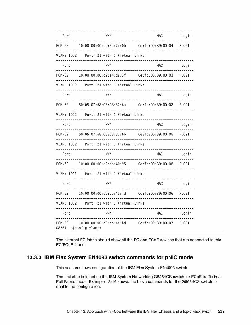
------------------------------------------------------------------- Port WWN MAC Login------------------------------------------------------------------- FCM-62 10:00:00:00:c9:5b:7d:0b 0e:fc:00:89:00:04 FLOGI------------------------------------------------------------------- VLAN: 1002 Port: 21 with 1 Virtual Links------------------------------------------------------------------- Port WWN MAC Login------------------------------------------------------------------- FCM-62 10:00:00:00:c9:e4:d9:3f 0e:fc:00:89:00:03 FLOGI------------------------------------------------------------------- VLAN: 1002 Port: 21 with 1 Virtual Links------------------------------------------------------------------- Port WWN MAC Login------------------------------------------------------------------- FCM-62 50:05:07:68:03:08:37:6a 0e:fc:00:89:00:02 FLOGI------------------------------------------------------------------- VLAN: 1002 Port: 21 with 1 Virtual Links------------------------------------------------------------------- Port WWN MAC Login------------------------------------------------------------------- FCM-62 50:05:07:68:03:08:37:6b 0e:fc:00:89:00:05 FLOGI------------------------------------------------------------------- VLAN: 1002 Port: 21 with 1 Virtual Links------------------------------------------------------------------- Port WWN MAC Login------------------------------------------------------------------- FCM-62 10:00:00:00:c9:db:40:95 0e:fc:00:89:00:08 FLOGI------------------------------------------------------------------- VLAN: 1002 Port: 21 with 1 Virtual Links------------------------------------------------------------------- Port WWN MAC Login------------------------------------------------------------------- FCM-62 10:00:00:00:c9:db:43:fd 0e:fc:00:89:00:06 FLOGI------------------------------------------------------------------- VLAN: 1002 Port: 21 with 1 Virtual Links------------------------------------------------------------------- Port WWN MAC Login------------------------------------------------------------------- FCM-62 10:00:00:00:c9:db:4d:bd 0e:fc:00:89:00:07 FLOGIG8264-up(config-vlan)#
The external FC fabric should show all the FC and FCoE devices that are connected to this FC/FCoE fabric.
13.3.3 IBM Flex System EN4093 switch commands for pNIC mode
This section shows configuration of the IBM Flex System EN4093 switch.
The first step is to set up the IBM System Networking G8264CS switch for FCoE traffic in a Full Fabric mode. Example 13-16 shows the basic commands for the G8624CS switch to enable the configuration.
Chapter 13. Approach with FCoE between the IBM Flex Chassis and a top-of-rack switch 537

Example 13-16 enable the FCoE on the IBM System Networking G8264CS switch
Select Command Line Interface mode (ibmnos-cli/iscli): isclien4093_2>
en4093_2>enable
Enable privilege granted.en4093_2#conf tEnter configuration commands, one per line. End with Ctrl/Z.
Enable the converged network capabilities with the command in Example 13-17. As you can see, the system port command changes the pair of interfaces to the type Fibre Channel. The switch automatically disables the LLDP TX and RD.
Example 13-17 Enable CEE on the switch
en4093_2(config)#cee enableen4093_2(config)#fcoe fips enable
The next step shows the creation of the VLAN for FCoE (Example 13-18). The pvid is changed for the interface. This process does not happen if you already have a valid VLAN configuration. The FCoE VLAN is transferred with DCBX to the IBM Flex CN4054 Converged Network Adapter.
For a default configured adapter, this is VLAN 1002. When the FCF is enabled, a name service and a flogi are started for each configured adapter.
Example 13-18 Create the VLAN 1002
en4093_2(config)#vlan 1002
VLAN 1002 is created.
Warning: VLAN 1002 was assigned to STG 113.en4093_2(config-vlan)#enableen4093_2(config-vlan)#name "VLAN 1002"en4093_2(config-vlan)#member INTA1-INTA2,EXT15Port INTA1 is an Untagged port and its PVID is changed from 1 to 1002Port INTA2 is an Untagged port and its PVID is changed from 1 to 1002Port EXT15 is an Untagged port and its PVID is changed from 1 to 1002
Jul 6 11:49:43 en4093_2 ALERT stg: STG 1, new root bridge
Jul 6 11:49:43 en4093_2 NOTICE fcoe: FCF 74:99:75:88:1c:c3 is now operational.
Jul 6 11:49:45 en4093_2 NOTICE fcoe: FCF 74:99:75:88:1c:c4 is now operational.
Jul 6 11:49:45 en4093_2 NOTICE fcoe: FCOE connection between VN_PORT 0e:fc:00:01:0c:01 and FCF 74:99:75:88:1c:c3 has been established.
Jul 6 11:49:45 en4093_2 NOTICE fcoe: FCOE connection between VN_PORT 0e:fc:00:01:0d:01 and FCF 74:99:75:88:1c:c4 has been established.
Note: Do not configure a IBM Flex CN4054 Converged Network Adapter with any VLAN information.
538 Storage and Network Convergence Using FCoE and iSCSI

en4093_2(config-vlan)#exiten4093_2(config)#
In the following steps, which are shown in Example 13-19, tagging is required for all the Ethernet frames on the FCoE VLAN 1002.
Example 13-19 Enable tagging on all interfaces
en4093_2(config)#interface port INTA1en4093_2(config-if)#taggingen4093_2(config-if)#tag-pviden4093_2(config-if)#exiten4093_2(config)#interface port INT2en4093_2(config-if)#taggingen4093_2(config-if)#tag-pviden4093_2(config-if)#exiten4093_2(config)#interface port EXT1en4093_2(config-if)#taggingen4093_2(config-if)#tag-pviden4093_2(config-if)#exit
Example 13-20 shows the FCoE connections that are established on the switch. The MAC addresses that are shown match those MAC addresses that are configured as FC interfaces on the IBM Flex System EN4093 switch.
Example 13-20 FCoE connections that are established on the switch
EN4093_2(config-vlan)#show fcoe fips fcfTotal number of FCFs detected: 2
FCF MAC Port Vlan-----------------------------------74:99:75:88:1c:c3 EXT15 100274:99:75:88:1c:c4 EXT15 1002EN4093_2(config-vlan)#
Example 13-21 shows the FCoE session information for the IBM Flex System EN4093 switch. This example has one FCoE VLAN configured.
Example 13-21 FCoE sessions on the EN4093 switch
EN4093_2(config-vlan)#show fcoe fips fcoeTotal number of FCoE connections: 2
VN_PORT MAC FCF MAC Port Vlan------------------------------------------------------0e:fc:00:01:0d:00 74:99:75:88:1c:c4 INTA1 10020e:fc:00:01:0d:01 74:99:75:88:1c:c4 INTA2 1002
Chapter 13. Approach with FCoE between the IBM Flex Chassis and a top-of-rack switch 539

13.3.4 IBM Flex System EN4093 switch commands for vNIC mode
This section shows the configuration of the IBM Flex System EN4093 switch. Be aware that the CNA must be also configured in the vNIC mode.
The first step is to set up the IBM System Networking G8264CS switch for FCoE traffic in a Full Fabric mode. Example 13-22 shows the basic command for the IBM Flex System EN4093 switch to enable the configuration.
Example 13-22 Enable the FCoE on the IBM System Networking G8264CS switch
Select Command Line Interface mode (ibmnos-cli/iscli): isclien4093_2>
en4093_2>enable
Enable privilege granted.en4093_2#conf tEnter configuration commands, one per line. End with Ctrl/Z.
Enable the converged network capabilities with the command in Example 13-23. As you can see, the system port command changes the pair of interfaces to the type Fibre Channel. The switch automatically disables the LLDP TX and RD.
Example 13-23 Enable CEE on the switch
en4093_2(config)#cee enableen4093_2(config)#fcoe fips enable
The next step is to show the creation of the VLAN for FCoE as shown in Example 13-24. You can see that the pvid is changed for the interfaces. The VLAN should be the same as for the adapter that is used. For a non-configured adapter, this is VLAN 1002. When the FCF is enabled, a name service and a flogi is started for each configured adapter.
Example 13-24 create the vlan 1002
en4093_2(config)#vlan 1002
VLAN 1002 is created.
Warning: VLAN 1002 was assigned to STG 113.en4093_2(config-vlan)#enableen4093_2(config-vlan)#name "VLAN 1002"en4093_2(config-vlan)#member INTA1-INTA2,EXT15Port INTA1 is an Untagged port and its PVID is changed from 1 to 1002Port INTA2 is an Untagged port and its PVID is changed from 1 to 1002Port EXT15 is an Untagged port and its PVID is changed from 1 to 1002
Jul 6 11:49:43 en4093_2 ALERT stg: STG 1, new root bridge
Jul 6 11:49:43 en4093_2 NOTICE fcoe: FCF 74:99:75:88:1c:c3 is now operational.
Jul 6 11:49:45 en4093_2 NOTICE fcoe: FCF 74:99:75:88:1c:c4 is now operational.
Note: The vlan 1002 can now be changed and is no longer mandatory.
540 Storage and Network Convergence Using FCoE and iSCSI
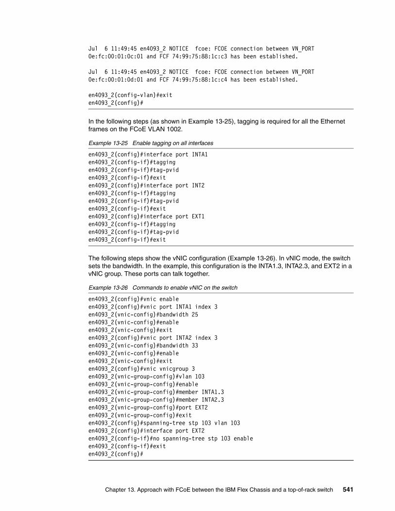
Jul 6 11:49:45 en4093_2 NOTICE fcoe: FCOE connection between VN_PORT 0e:fc:00:01:0c:01 and FCF 74:99:75:88:1c:c3 has been established.
Jul 6 11:49:45 en4093_2 NOTICE fcoe: FCOE connection between VN_PORT 0e:fc:00:01:0d:01 and FCF 74:99:75:88:1c:c4 has been established.
en4093_2(config-vlan)#exiten4093_2(config)#
In the following steps (as shown in Example 13-25), tagging is required for all the Ethernet frames on the FCoE VLAN 1002.
Example 13-25 Enable tagging on all interfaces
en4093_2(config)#interface port INTA1en4093_2(config-if)#taggingen4093_2(config-if)#tag-pviden4093_2(config-if)#exiten4093_2(config)#interface port INT2en4093_2(config-if)#taggingen4093_2(config-if)#tag-pviden4093_2(config-if)#exiten4093_2(config)#interface port EXT1en4093_2(config-if)#taggingen4093_2(config-if)#tag-pviden4093_2(config-if)#exit
The following steps show the vNIC configuration (Example 13-26). In vNIC mode, the switch sets the bandwidth. In the example, this configuration is the INTA1.3, INTA2.3, and EXT2 in a vNIC group. These ports can talk together.
Example 13-26 Commands to enable vNIC on the switch
en4093_2(config)#vnic enableen4093_2(config)#vnic port INTA1 index 3en4093_2(vnic-config)#bandwidth 25en4093_2(vnic-config)#enableen4093_2(vnic-config)#exiten4093_2(config)#vnic port INTA2 index 3en4093_2(vnic-config)#bandwidth 33en4093_2(vnic-config)#enableen4093_2(vnic-config)#exiten4093_2(config)#vnic vnicgroup 3en4093_2(vnic-group-config)#vlan 103en4093_2(vnic-group-config)#enableen4093_2(vnic-group-config)#member INTA1.3en4093_2(vnic-group-config)#member INTA2.3en4093_2(vnic-group-config)#port EXT2en4093_2(vnic-group-config)#exiten4093_2(config)#spanning-tree stp 103 vlan 103en4093_2(config)#interface port EXT2en4093_2(config-if)#no spanning-tree stp 103 enableen4093_2(config-if)#exiten4093_2(config)#
Chapter 13. Approach with FCoE between the IBM Flex Chassis and a top-of-rack switch 541

The vNIC mode does not change anything in the FCoE setup. The setup is the same as for pNIC mode. Example 13-27 shows the FCoE connections that are established on the switch. The MAC addresses shown match those MAC addresses that are configured as FC interfaces on the IBM Flex System EN4093 switch.
Example 13-27 FCoE connections that are established on the switch
EN4093_2(config-vlan)#show fcoe fips fcfTotal number of FCFs detected: 2
FCF MAC Port Vlan-----------------------------------74:99:75:88:1c:c3 EXT15 100274:99:75:88:1c:c4 EXT15 1002EN4093_2(config-vlan)#
Example 13-28 shows the FCoE session information for the IBM Flex System EN4093 switch. This example has one FCoE VLAN configured.
Example 13-28 FCoE sessions of the EN4093
EN4093_2(config-vlan)#show fcoe fips fcoeTotal number of FCoE connections: 2
VN_PORT MAC FCF MAC Port Vlan------------------------------------------------------0e:fc:00:01:0d:00 74:99:75:88:1c:c4 INTA1 10020e:fc:00:01:0d:01 74:99:75:88:1c:c4 INTA2 1002
13.4 Full switch configurations
This section includes the complete configuration text files for the tests that are outlined in this chapter. We have a G8264CS switch in full fabric and NPV mode. Neither mode impacts the IBM Flex System EN4093 switch or BNT Virtual Fabric 10Gb Switch Module configuration.
13.4.1 G8264CS FCF configuration
Example 13-29 shows the full configuration of the G8264CS switch in the full fabric configuration that we used in our test.
Example 13-29 IBM G8264CS switch configuration fcf
version "7.1.3"switch-type "IBM Networking Operating System RackSwitch G8264CS"!!ssh enable!!system port 53-54 type fcno system bootphostname "G8264CS-up"!!
542 Storage and Network Convergence Using FCoE and iSCSI

interface port 1name "EN4093_2_P15_QSFP"taggingtag-pvidpvid 1002exit
!interface port 17
name "EN4093_vNIC"taggingpvid 500exit
!interface port 43
name "V3700_Ctrl_B"pvid 1002exit
!interface port 44
name "V3700_Ctrl_A"pvid 1002exit
!interface port 48
name "BCH_Slot9_P1"taggingpvid 500exit
!vlan 1
member 2-42,45-47,49-64no member 1,43-44,48
!vlan 500
enablename "VLAN 500"member 48
!vlan 1002
enablename "VLAN 1002"member 1,43-44,48,53-54fcf enable
!!spanning-tree stp 113 vlan 1002!spanning-tree stp 119 vlan 500!!fcoe fips enable!fcoe fips port 1 fcf-mode onfcoe fips port 43 fcf-mode onfcoe fips port 44 fcf-mode on
Chapter 13. Approach with FCoE between the IBM Flex Chassis and a top-of-rack switch 543

fcoe fips port 48 fcf-mode onfcoe fips port 54 fcf-mode on!!cee enable!!fcalias N2_x240 wwn 10:00:34:40:b5:be:3f:25fcalias C1_V3700 wwn 50:05:07:68:03:08:37:6afcalias C2_V3700 wwn 50:05:07:68:03:08:37:6bfcalias Blade1 wwn 10:00:00:00:c9:e4:d9:3ffcalias Blade2 wwn 10:00:00:00:c9:5b:7d:0bfcalias N1_x240 wwn 10:00:00:00:C9:DB:40:8Dzone name V3700
member pwwn 50:05:07:68:03:08:37:6bmember pwwn 50:05:07:68:03:08:37:6a
zone name N2-V3700member pwwn 50:05:07:68:03:08:37:6amember pwwn 50:05:07:68:03:08:37:6bmember pwwn 10:00:34:40:b5:be:3f:25
zone name N2-DS5000member pwwn 10:00:34:40:b5:be:3f:25member pwwn 20:37:00:a0:b8:6e:39:20
zone name N1-V3700member pwwn 50:05:07:68:03:08:37:6amember pwwn 50:05:07:68:03:08:37:6bmember pwwn 10:00:00:00:C9:DB:40:8D
zone name N1-DS5000member pwwn 10:00:00:00:c9:db:40:8dmember pwwn 20:37:00:a0:b8:6e:39:20
zone name Blade2-DS5000member pwwn 10:00:00:00:c9:5b:7d:0bmember pwwn 20:37:00:a0:b8:6e:39:20
zone name Blade2-V3700member pwwn 10:00:00:00:c9:5b:7d:0bmember pwwn 50:05:07:68:03:08:37:6amember pwwn 50:05:07:68:03:08:37:6b
zoneset name G8264upmember N2-V3700member N2-DS5000member V3700member N1-V3700member N1-DS5000member Blade2-V3700member Blade2-DS5000
zoneset activate name G8264up!!lldp enable!!interface ip 128! addr <dhcp>!!ip gateway 4 addr <dhcp>!ip gateway 4 enable
544 Storage and Network Convergence Using FCoE and iSCSI
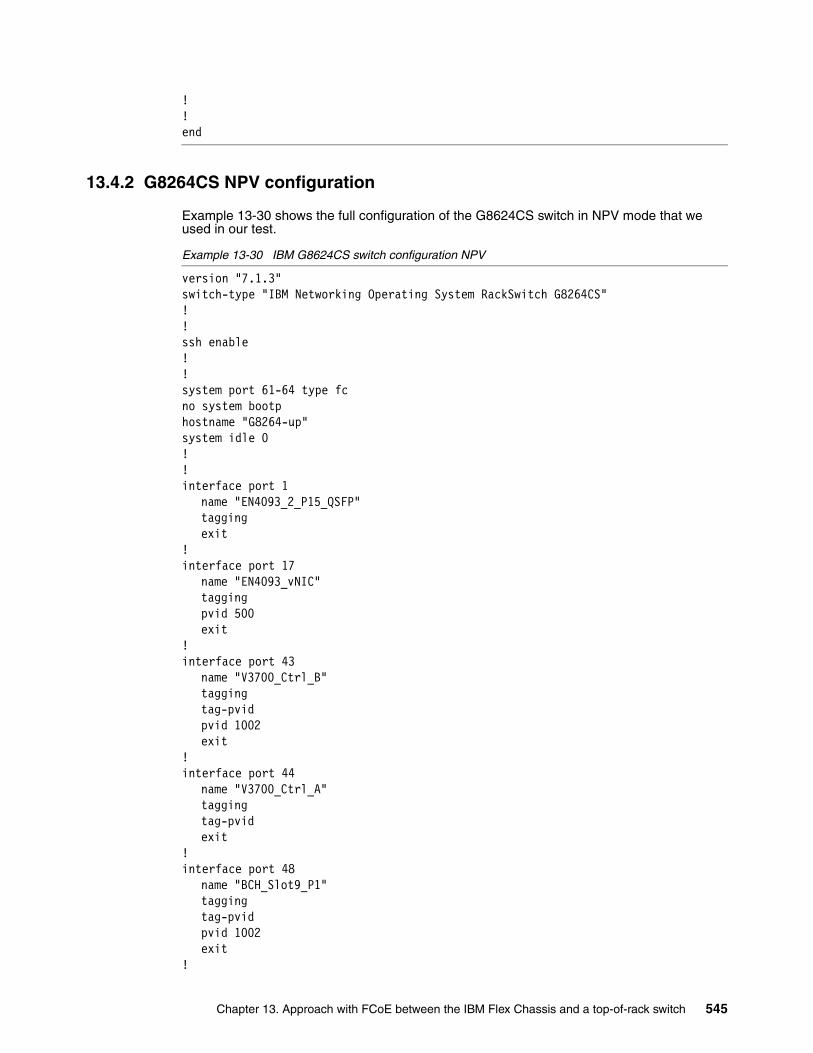
!!end
13.4.2 G8264CS NPV configuration
Example 13-30 shows the full configuration of the G8624CS switch in NPV mode that we used in our test.
Example 13-30 IBM G8624CS switch configuration NPV
version "7.1.3"switch-type "IBM Networking Operating System RackSwitch G8264CS"!!ssh enable!!system port 61-64 type fcno system bootphostname "G8264-up"system idle 0!!interface port 1
name "EN4093_2_P15_QSFP"taggingexit
!interface port 17
name "EN4093_vNIC"taggingpvid 500exit
!interface port 43
name "V3700_Ctrl_B"taggingtag-pvidpvid 1002exit
!interface port 44
name "V3700_Ctrl_A"taggingtag-pvidexit
!interface port 48
name "BCH_Slot9_P1"taggingtag-pvidpvid 1002exit
!
Chapter 13. Approach with FCoE between the IBM Flex Chassis and a top-of-rack switch 545

interface port 51name "IBM_uplink_1Gb"pvid 500exit
!vlan 1
member 1-50,52-64no member 51
!vlan 500
enablename "VLAN 500"member 1,17,48,51
!vlan 1002
enablename "VLAN 1002"member 1,43,44,48,62,64npv enablenpv traffic-map external-interface 62
!!spanning-tree stp 113 vlan 1002!spanning-tree stp 119 vlan 500!!fcoe fips enable!!cee enable!!fcalias N2_x240 wwn 10:00:34:40:b5:be:3f:25fcalias C1_V3700 wwn 50:05:07:68:03:08:37:6afcalias C2_V3700 wwn 50:05:07:68:03:08:37:6bfcalias Blade1 wwn 10:00:00:00:c9:e4:d9:3ffcalias Blade2 wwn 10:00:00:00:c9:5b:7d:0bfcalias N1_x240 wwn 10:00:00:00:c9:db:4d:b5!!lldp enable!!interface ip 128! addr <dhcp>!!ip gateway 4 addr <dhcp>!ip gateway 4 enable!!!end
546 Storage and Network Convergence Using FCoE and iSCSI

13.4.3 IBM Flex System EN4093 switch configuration in pNIC mode
Example 13-31 shows the configuration used on the IBM Flex System EN4093 switch in pNIC mode. The commands that are critical to FCoE are highlighted in bold.
Example 13-31 IBM Flex System EN4093 switch configuration in pNIC
version "7.7.1.12"switch-type "IBM Flex System Fabric EN4093 10Gb Scalable Switch(Upgrade2)"!!
snmp-server name "EN4093_2"!!!hostname "EN4093_2"system idle 60!!interface port INTA1
name "Node1_x240"taggingno flowcontrolexit
!interface port INTA2
name "Node2_x240"taggingno flowcontrolexit
!interface port INTA3
no flowcontrolexit
! SNIP port INTA3 to INTC14 as the same as INTA3exit!interface port INTC14
no flowcontrolexit
!interface port EXT15
name "G8624CS-up"taggingtag-pvidexit
!vlan 500
enablename "VLAN 500"member INTA1-INTA2,EXT15
!vlan 1002
enablename "VLAN 1002"
Chapter 13. Approach with FCoE between the IBM Flex Chassis and a top-of-rack switch 547
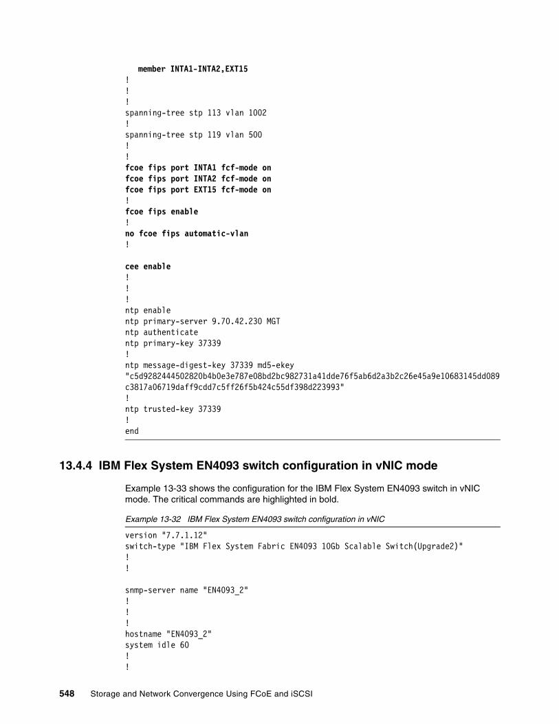
member INTA1-INTA2,EXT15!!!spanning-tree stp 113 vlan 1002!spanning-tree stp 119 vlan 500!!fcoe fips port INTA1 fcf-mode onfcoe fips port INTA2 fcf-mode onfcoe fips port EXT15 fcf-mode on!fcoe fips enable!no fcoe fips automatic-vlan!
cee enable!!!ntp enablentp primary-server 9.70.42.230 MGTntp authenticatentp primary-key 37339!ntp message-digest-key 37339 md5-ekey "c5d9282444502820b4b0e3e787e08bd2bc982731a41dde76f5ab6d2a3b2c26e45a9e10683145dd089c3817a06719daff9cdd7c5ff26f5b424c55df398d223993"!ntp trusted-key 37339!end
13.4.4 IBM Flex System EN4093 switch configuration in vNIC mode
Example 13-33 shows the configuration for the IBM Flex System EN4093 switch in vNIC mode. The critical commands are highlighted in bold.
Example 13-32 IBM Flex System EN4093 switch configuration in vNIC
version "7.7.1.12"switch-type "IBM Flex System Fabric EN4093 10Gb Scalable Switch(Upgrade2)"!!
snmp-server name "EN4093_2"!!!hostname "EN4093_2"system idle 60!!
548 Storage and Network Convergence Using FCoE and iSCSI

interface port INTA1name "Node1_x240"taggingno flowcontrolexit
!interface port INTA2
name "Node2_x240"taggingno flowcontrolexit
!interface port INTA3
no flowcontrolexit
! SNIP port INTA3 to INTC14 as the same as INTA3exit!interface port INTC14
no flowcontrolexit
!interface port EXT14
name "G8624CS-up_P17"taggingexit
!interface port EXT15
name "G8624CS-up_P1"taggingtag-pvidexit
!vlan 500
enablename "VLAN 500"member INTA1-INTA2,EXT15
!vlan 1002
enablename "VLAN 1002"member INTA1-INTA2,EXT15
!!vnic enablevnic port INTA1 index 3 bandwidth 25 enable exit!vnic port INTA2 index 3 bandwidth 33 enable exit!
Chapter 13. Approach with FCoE between the IBM Flex Chassis and a top-of-rack switch 549

vnic vnicgroup 3 vlan 103 enable member INTA1.3 member INTA2.3 port EXT14 exit!spanning-tree stp 103 vlan 103!interface port EXT2 no spanning-tree stp 103 enable exit!!spanning-tree stp 113 vlan 1002!spanning-tree stp 119 vlan 500!!fcoe fips port INTA1 fcf-mode onfcoe fips port INTA2 fcf-mode onfcoe fips port EXT15 fcf-mode on!fcoe fips enable!no fcoe fips automatic-vlan!cee enable!!!ntp enablentp primary-server 9.70.42.230 MGTntp authenticatentp primary-key 37339!ntp message-digest-key 37339 md5-ekey "c5d9282444502820b4b0e3e787e08bd2bc982731a41dde76f5ab6d2a3b2c26e45a9e10683145dd089c3817a06719daff9cdd7c5ff26f5b424c55df398d223993"!ntp trusted-key 37339!end
13.4.5 BNT Virtual Fabric 10Gb Switch Module configuration in vNIC mode
Example 13-33 shows the configuration for the eBNT Virtual Fabric 10Gb Switch Module in vNIC mode. The critical commands are highlighted in bold.
Example 13-33 BNT Virtual Fabric 10Gb Switch Module configuration in vNIC
version "7.7.1"switch-type "IBM Networking OS Virtual Fabric 10Gb Switch Module for IBM BladeCenter"
550 Storage and Network Convergence Using FCoE and iSCSI

iscli-new!!ssh enable!
snmp-server name "BCH_slot9"!hostname "BCH_slot9"!!interface port INT1
description "Blade1_Slot1"switchport trunk allowed vlan 1,1002,4095flowcontrol send offflowcontrol receive offexit
!interface port INT2
description "Blade2_Slot2"switchport trunk allowed vlan 1,1002,4095flowcontrol send offflowcontrol receive offexit
!interface port INT3
description "Blade3_Slot3"flowcontrol send offflowcontrol receive offexit
!interface port INT4
flowcontrol send offflowcontrol receive offexit
!!--------------------------SNIP INT5 - INT 13 same as INT4--------------------!interface port INT14
flowcontrol send offflowcontrol receive offexit
!interface port EXT1
description "G8624CS_up_1_P48"switchport mode trunkswitchport trunk allowed vlan 1,1002exit
!interface port EXT4
description "BCH_slot7_EXT5_for_VNIC"exit
!interface port EXT5
description "BCH_slot7_EXT4_for_VNIC"
Chapter 13. Approach with FCoE between the IBM Flex Chassis and a top-of-rack switch 551

exit!interface port EXT6
description "BCH_slot7_EXT7_for_VNIC"exit
!interface port EXT7
description "BCH_slot7_EXT6_for_VNIC"exit
!interface port EXT8
description "BCH_slot7_EXT9_for_VNIC"exit
!interface port EXT9
description "BCH_slot7_EXT8_for_VNIC"exit
!vlan 1002
name "VLAN 1002"!!spanning-tree stp 113 vlan 1002!!fcoe fips enable!fcoe fips port INT1 fcf-mode onfcoe fips port INT2 fcf-mode onfcoe fips port EXT1 fcf-mode on!!cee enable!!end
13.5 Summary assessment
The FCoE implementation for an IBM Flex node with an IBM EN4093 10G Switch together with the G8624CS switch requires minimal configuration effort. The same statement is true for BladeCenter H with the BNT Virtual Fabric 10Gb Switch Module. The solution is flexible and very scalable in bandwidth and shows good performance. In our tests, we found no issue with the automatic VLAN discovery, but we did experience some issues with automatic FCoE VLAN creation on the IBM Flex System EN4093 switch. We did not find any incompatibility issues with the external FC-attached storage or FC-switches.
No significant differences were detected between using Windows 2012, 2008R2, ESXi 5.0, or SLES_11SP2 with Emulex CNAs.
The IBM Flex technology together with the IBM System Networking G8624CS offers a fully scalable FCoE solution that is easy to set up. You can easily start with an integrated solution in the IBM Flex chassis and scale up.
552 Storage and Network Convergence Using FCoE and iSCSI

Chapter 14. Approach with iSCSI
This chapter describes the available iSCSI technologies. It explains how to enable converged networking with Internet Small Computer System Interface (iSCSI) over Data Center Bridging (DCB) in a data center by using practical implementation examples. The technologies that are highlighted in this chapter consist of converged network adapters (CNA), converged switches, and storage devices.
Although many other products are available, this chapter focuses on the following products because they were already part of the implementation scenarios in the initial release of this book and remained unchanged.
� IBM Virtual Fabric 10Gb Switch Module for IBM BladeCenter� Emulex Virtual Fabric Adapters I and II CNAs� IBM System Storage DS5300 with 10 Gbps iSCSI support
Although the scenarios were based on the IBM BladeCenter technology, they also apply to the IBM Flex System because most of the settings are related to the IBM System Networking switches and Emulex CNAs.
For more information and a list of available iSCSI and Fibre Channel over Ethernet (FCoE) capable IBM products, see Chapter 4, “IBM products that support FCoE and iSCSI” on page 41.
This chapter includes the following sections:
� 14.1, “iSCSI implementation” on page 554� 14.2, “Initiator and target configuration” on page 564� 14.3, “Summary” on page 569
14
© Copyright IBM Corp. 2012, 2014. All rights reserved. 553
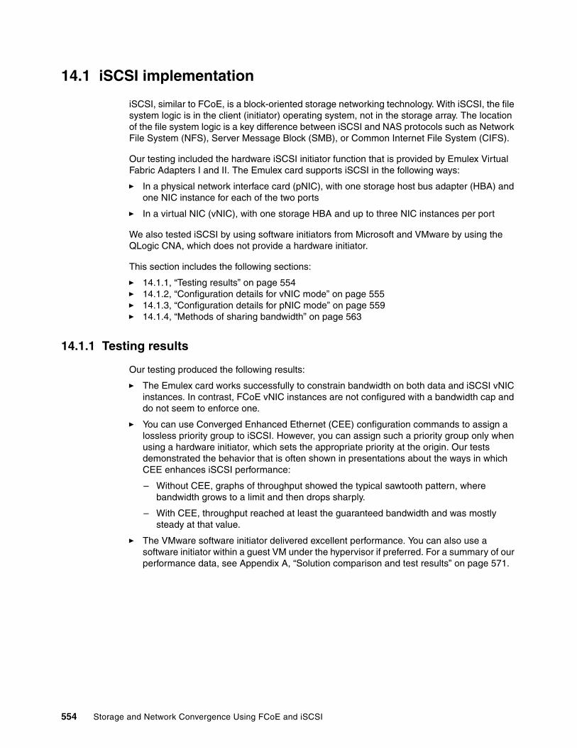
14.1 iSCSI implementation
iSCSI, similar to FCoE, is a block-oriented storage networking technology. With iSCSI, the file system logic is in the client (initiator) operating system, not in the storage array. The location of the file system logic is a key difference between iSCSI and NAS protocols such as Network File System (NFS), Server Message Block (SMB), or Common Internet File System (CIFS).
Our testing included the hardware iSCSI initiator function that is provided by Emulex Virtual Fabric Adapters I and II. The Emulex card supports iSCSI in the following ways:
� In a physical network interface card (pNIC), with one storage host bus adapter (HBA) and one NIC instance for each of the two ports
� In a virtual NIC (vNIC), with one storage HBA and up to three NIC instances per port
We also tested iSCSI by using software initiators from Microsoft and VMware by using the QLogic CNA, which does not provide a hardware initiator.
This section includes the following sections:
� 14.1.1, “Testing results” on page 554� 14.1.2, “Configuration details for vNIC mode” on page 555� 14.1.3, “Configuration details for pNIC mode” on page 559� 14.1.4, “Methods of sharing bandwidth” on page 563
14.1.1 Testing results
Our testing produced the following results:
� The Emulex card works successfully to constrain bandwidth on both data and iSCSI vNIC instances. In contrast, FCoE vNIC instances are not configured with a bandwidth cap and do not seem to enforce one.
� You can use Converged Enhanced Ethernet (CEE) configuration commands to assign a lossless priority group to iSCSI. However, you can assign such a priority group only when using a hardware initiator, which sets the appropriate priority at the origin. Our tests demonstrated the behavior that is often shown in presentations about the ways in which CEE enhances iSCSI performance:
– Without CEE, graphs of throughput showed the typical sawtooth pattern, where bandwidth grows to a limit and then drops sharply.
– With CEE, throughput reached at least the guaranteed bandwidth and was mostly steady at that value.
� The VMware software initiator delivered excellent performance. You can also use a software initiator within a guest VM under the hypervisor if preferred. For a summary of our performance data, see Appendix A, “Solution comparison and test results” on page 571.
554 Storage and Network Convergence Using FCoE and iSCSI
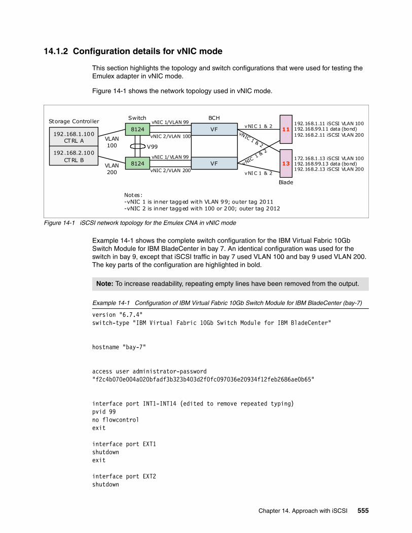
14.1.2 Configuration details for vNIC mode
This section highlights the topology and switch configurations that were used for testing the Emulex adapter in vNIC mode.
Figure 14-1 shows the network topology used in vNIC mode.
Figure 14-1 iSCSI network topology for the Emulex CNA in vNIC mode
Example 14-1 shows the complete switch configuration for the IBM Virtual Fabric 10Gb Switch Module for IBM BladeCenter in bay 7. An identical configuration was used for the switch in bay 9, except that iSCSI traffic in bay 7 used VLAN 100 and bay 9 used VLAN 200. The key parts of the configuration are highlighted in bold.
Example 14-1 Configuration of IBM Virtual Fabric 10Gb Switch Module for IBM BladeCenter (bay-7)
version "6.7.4"switch-type "IBM Virtual Fabric 10Gb Switch Module for IBM BladeCenter"
hostname "bay-7"
access user administrator-password "f2c4b070e004a020bfadf3b323b403d2f0fc097036e20934f12feb2686ae0b65"
interface port INT1-INT14 (edited to remove repeated typing)pvid 99no flowcontrolexit
interface port EXT1shutdownexit
interface port EXT2shutdown
VLAN100
192.168.1.100CTRL A
192.168.2.100CTRL B
VLAN200
Storage Control lerSwitch BCH
Blade
192.168.1.11 iSCSI VLAN 100192.168.99.11 data (bond)192.168.2.11 iSCSI VLAN 200
172.168.1.13 iSCSI VLAN 100192.168.99.13 data (bond)192.168.2.13 iSCSI VLAN 200
V99
vNIC 1 & 2vNIC 1 & 2
vNIC1 &
2
vNIC 1 & 2
13
118124
8124
VF
VF
vNIC 1/VLAN 99
vNIC 2/VLAN 100
vNIC 1/VLAN 99
vNIC 2/VLAN 200
Notes:-vNIC 1 is inner tagged with VLAN 99; outer tag 2011-vNIC 2 is inner tagged with 100 or 200; outer tag 2012
Note: To increase readability, repeating empty lines have been removed from the output.
Chapter 14. Approach with iSCSI 555
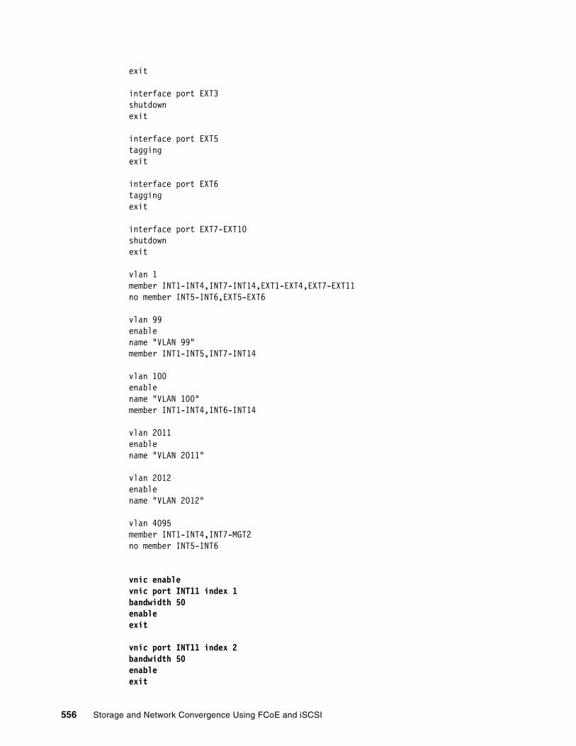
exit
interface port EXT3shutdownexit
interface port EXT5taggingexit
interface port EXT6taggingexit
interface port EXT7-EXT10shutdownexit
vlan 1member INT1-INT4,INT7-INT14,EXT1-EXT4,EXT7-EXT11no member INT5-INT6,EXT5-EXT6
vlan 99enablename "VLAN 99"member INT1-INT5,INT7-INT14
vlan 100enablename "VLAN 100"member INT1-INT4,INT6-INT14
vlan 2011enablename "VLAN 2011"
vlan 2012enablename "VLAN 2012"
vlan 4095member INT1-INT4,INT7-MGT2no member INT5-INT6
vnic enablevnic port INT11 index 1bandwidth 50enableexit
vnic port INT11 index 2bandwidth 50enableexit
556 Storage and Network Convergence Using FCoE and iSCSI

vnic port INT13 index 1bandwidth 50enableexit
vnic port INT13 index 2bandwidth 50enableexit
vnic vnicgroup 1vlan 2011enablemember INT11.1member INT13.1port EXT5exit
vnic vnicgroup 2vlan 2012enablemember INT11.2member INT13.2port EXT6exit
spanning-tree stp 91 vlan 2011
interface port EXT5no spanning-tree stp 91 enableexit
spanning-tree stp 92 vlan 2012
interface port EXT6no spanning-tree stp 92 enableexit
spanning-tree stp 99 vlan 99
spanning-tree stp 100 vlan 100
spanning-tree stp 107 vlan 1003
snmp-server name "bay-7"
cee enable
access-control list 1 tcp-udp destination-port 3260 0xffffaccess-control list 1 action set-priority 3
Chapter 14. Approach with iSCSI 557
access-control list 2 tcp-udp source-port 3260 0xffffaccess-control list 2 action set-priority 3
interface port INT1-INT14 (edited to remove redundant display)access-control list 1access-control list 2
interface port EXT1-EXT6 (edited to remove redundant display)access-control list 1access-control list 2
lldp enable
interface ip 1ip address 192.168.1.254 255.255.255.0vlan 100enableexit
interface ip 99ip address 192.168.99.253 vlan 99enableexit
end
Emulex Virtual Fabric Adapters I and II support vNICs. These vNICs are not the same ones that are used in hypervisor environments. Those vNICs are virtualized hardware NICs or paravirtualized software NICs seen by the software switching logic included in most hypervisors. Emulex vNICs are discovered by the operating system on the server (hypervisors and conventional OSs) by using Peripheral Component Interconnect (PCI). Each vNIC corresponds one-to-one with a PCI function code associated with the Emulex card.
vNICs are configured on an IBM Virtual Fabric 10Gb Switch Module for IBM BladeCenter and communicated to the Emulex card by using the Data Center Bridging Capabilities Exchange (DCBX) protocol (in vNIC mode). Alternatively, vNICs are configured in the UEFI interface of the system in switch agnostic mode (vNIC2 mode), which works with any upstream switch. In the testing done for this book, we used vNIC mode. In either case, the configuration allows specification of the vNIC instances that are active and the amount of bandwidth that is allocated to each of them.
iSCSI vNIC instances are configured in the same way as data instances. Storage vNIC instances (iSCSI and FCoE) are always assigned vNIC index 2 by convention when configuring them by using the switch. When the Emulex adapter is set to a personality that includes storage functions, as part of the DCBX communication with the switch, the adapter indicates the presence of the storage function (either iSCSI or FCoE). Then the adapter assigns the function to vNIC instance 2 on each port.
558 Storage and Network Convergence Using FCoE and iSCSI

Treatment of VLANs in vNIC mode is unusual in that the VLANs that are carried on the vNICs are not configured on the switch. For example, VLAN 99 was used in our testing to carry non-iSCSI traffic and VLAN 100 was used to carry iSCSI traffic. In vNIC mode, both classes of traffic were carried through vNIC groups 1 and 2. A vNIC group uses 802.1 Q-in-Q double tagging with an outer tag VLAN (2011 and 2012 in this test) on all traffic it carries through the switch. The VLANs configured on the operating system of the server and on upstream switches are inner-tag VLANs that are invisible to the switch. Double tagging is applied on ingress to the switch and removed on egress.
The use of vNIC mode had the following consequences in our testing:
� The configuration of VLANs 99 and 100 on the bay-7 switch had no effect. The same was true for VLANs 99 and 200 on the bay-9 switch whose configuration is not shown. The external ports used in this test, EXT5 and EXT6, are not members of those VLANs because they are members of vNIC groups 1 and 2.
� The access control list (ACL) shown in bold in Example 14-1 on page 555 in the configuration was ineffective partly because the priority field is part of the same field in the header where tagging is applied. Bandwidth management in vNIC mode is achieved by assigning bandwidth to the individual vNIC instances.
14.1.3 Configuration details for pNIC mode
The same tests that were performed in vNIC mode with the Emulex adapter were also performed in pNIC mode as illustrated in Figure 14-2. pNIC mode with iSCSI presents the adapter to the operating system of the server as two 10 Gbps Ethernet NIC ports and two iSCSI HBA ports.
Figure 14-2 iSCSI topology used in pNIC mode
Example 14-2 shows the switch configuration for the pNIC mode tests. Critical portions of the configuration are highlighted in bold. As in the previous section, only the configuration of the IBM Virtual Fabric 10Gb Switch Module for IBM BladeCenter in bay 7 is shown. The switch in bay 9 has an identical configuration, except that the bay 7 switch uses VLAN 100 for iSCSI traffic and bay 9 uses VLAN 200.
Example 14-2 IBM System Networking configuration in pNIC mode in bay-7
version "6.8.0.66"switch-type "IBM Networking OS Virtual Fabric 10Gb Switch Module for IBM BladeCenter"
VLAN100192.168.1.100
CRTL A
192.168.2.100CRTL B VLAN
200
Storage ControllerSwitch
BCH
VF
VF
Blade
192.168.1.11 iSCSIV100V99 99.11 – from /IP192.168.2.11 iSCSIV200
172.168.1.13 SCSIV100V99 99.13 – from /IP192.168.2.13 iSCSIVLAN 200
8124
8124
V99
VLAN99-100
VLAN100+99
VLAN
99+200
VLAN99+200
VLAN 100
VLAN 99
VLAN 99
VLAN 20013
11
Note: To increase readability, repeating empty lines have been removed from the output.
Chapter 14. Approach with iSCSI 559

snmp-server name "bay-7"
hostname "bay-7"system idle 60
access user administrator-password "35665f5801040a087627b6b3c2b4a9fa1db9b4a3072fb788bd32b1f91a7e2286"
interface port INT1-INT14 (edited to remove redundant display)pvid 99no flowcontrolexit
interface port EXT1shutdownexit
interface port EXT2shutdownexit
interface port EXT3shutdownexit
interface port EXT5taggingexit
interface port EXT6taggingexit
interface port EXT7-EXT10shutdown
vlan 1member INT1-INT14,EXT1-EXT10,EXT11
vlan 99enablename "VLAN 99"member INT1-INT14,EXT5-EXT6
vlan 100enablename "VLAN 100"member INT1-INT14,EXT5-EXT6
portchannel 1 port EXT5
560 Storage and Network Convergence Using FCoE and iSCSI
portchannel 1 port EXT6portchannel 1 enable
spanning-tree stp 1 vlan 1
spanning-tree stp 99 vlan 99
spanning-tree stp 100 vlan 100
cee enable
cee global ets priority-group pgid 0 bandwidth 30 priority 4,5,6 pgid 1 bandwidth 70 pgid 2 bandwidth 0 pgid 15 priority 7cee global ets priority-group pgid 1 description "iSCSI_or_FCoE"
cee port INT1 pfc priority 3 description "iSCSI_or_FCoE"... similarly for INT2-13 ... cee port INT14 pfc priority 3 description "iSCSI_or_FCoE"cee port EXT1 pfc priority 3 description "iSCSI_or_FCoE"... similarly for the remaining EXT ports ...
lldp enable
interface ip 1ip address 192.168.1.254 255.255.255.0vlan 100enableexit
interface ip 2ip address 192.168.99.254 vlan 99enableexit
end
In pNIC mode, we tested the influence of CEE or lossless Ethernet on iSCSI. First, we used an ACL to assign priority 3 (the same as used by FCoE) to iSCSI traffic (origin or destination port 3264) as shown in Example 14-3.
Example 14-3 ACL definition to assign port priority 3
access-control list 1 tcp-udp destination-port 3260 0xffffaccess-control list 1 action set-priority 3access-control list 2 tcp-udp source-port 3260 0xffffaccess-control list 2 action set-priority 3
This approach did not influence the test results. However, configuring the Emulex card to send iSCSI traffic with priority 3 improved iSCSI performance.
Chapter 14. Approach with iSCSI 561

We used the following command (Example 14-4) to configure the switch to use the Enhanced Transmission Selection (ETS) function to prioritize iSCSI traffic.
Example 14-4 Enable ETS to prioritize iSCSI traffic
cee global ets priority-group pgid 0 bandwidth 30 priority 4,5,6 pgid 1 bandwidth 70 pgid 2 bandwidth 0 pgid 15 priority 7
This command guarantees no less than 70% of the available bandwidth for use for iSCSI traffic (priority group 1). It also guarantees no less than 30% of the available bandwidth for other data traffic set to use priority group 0 (default). In both instances, the switch was configured with CEE enabled (cee enable and lldp enable). The cee iscsi enable command causes the switch to use DCBX to support iSCSI when communicating with peers. However, it is not currently supported by the Emulex card.
The VLAN priority field in the Modify TCP/IP Configuration window (Figure 14-3) was set to 3 to enable CEE for VLAN ID 100. In addition, the VLAN Enabled check box must be marked.
Figure 14-3 Emulex One Command dialog pane for TCP/IP properties of the iSCSI HBA
562 Storage and Network Convergence Using FCoE and iSCSI

You can also set these properties by using the Emulex UEFI Configure VLAN ID/Priority panel (Figure 14-4). Here you set VLAN Support to Enable, set VLAN ID to 100 and set VLAN PRIORITY to 3.
Figure 14-4 Emulex UEFI panel for setting VLAN properties
14.1.4 Methods of sharing bandwidth
With the Emulex card, you can share bandwidth between iSCSI traffic and other data traffic in two ways. These methods use the vNIC functions, which are proprietary to Emulex and to IBM and use CEE, which is a published set of standards that are implemented by multiple vendors. It is not currently possible to use them together, such as on the same port on the switch, at the same time.
Bandwidth allocation with vNICThe current implementation of vNIC, including switch agnostic mode, provides hard limits on the bandwidth that is allocated to each vNIC instance on the Emulex CNA. For example, iSCSI is running on vNIC index 2 on the port that attaches a system to a switch. That vNIC is set to a bandwidth of 40 (40% of 10 Gbps or 40 increments of 100 Mbps, which both equal 4 Gbps). In this example, that vNIC is guaranteed 4 Gbps of bandwidth and is limited to no more than 4 Gbps. Even if unused bandwidth is on other vNICs, a vNIC instance cannot exceed its bandwidth allocation. Forthcoming versions of vNIC will enable this unused bandwidth to be used.
When FCoE is used to provide a storage vNIC, its bandwidth is configured and functions differently from an iSCSI vNIC.
VLAN Support <Enable>VLAN ID [100]VLAN PRIORITY [3]
Save Changes
Configure VLAN ID/Priority
Enable/Disable VirtualLAN Support
Chapter 14. Approach with iSCSI 563

Bandwidth allocation with CEECEE provides for traffic of different types to be assigned to different priority groups. Although FCoE is automatically assigned to priority group 3 on many devices, which are set by default to provide lossless transmission, this case is not always possible with iSCSI. Therefore, you must configure this setting explicitly. For information about the techniques that can be used on some devices, see 14.2, “Initiator and target configuration” on page 564.
Unlike vNIC, CEE does not set an explicit ceiling on the amount of bandwidth that traffic in a priority group can use. Instead, it provides a guaranteed minimum bandwidth that is available to each class of traffic that is configured. For example, you can configure a switch to guarantee 40% of the bandwidth of a port for use by iSCSI. Other traffic might have guarantees that add up to 60% of the port. However, if iSCSI traffic is not using its full guaranteed bandwidth, other traffic might use it. Similarly, iSCSI can use more than 40% of the port if unused bandwidth is available.
14.2 Initiator and target configuration
To implement CEE with iSCSI, configure the initiator to enable CEE and implicitly, DCBX, which is used to communicate with the adjacent switch. You implement CEE this way as part of the installation or configuration of the initiator or target.
In addition, one of the advantages of iSCSI is its ability to use jumbo Ethernet frames, which are typically over 9000 bytes in size. They are significantly larger than the 2112-byte size limit that is found when using FCoE. However, you must configure this setting on the initiator (or on the NIC detected by the OS if using a software initiator), the target and on every switch on the path between them.
The IBM System Networking switches support jumbo frames. No command is available to enable or disable support for jumbo frames. Other switches might require the maximum transmission unit (MTU) to be configured explicitly.
This section includes the following sections:
� 14.2.1, “Emulex Virtual Fabric Adapters I and II” on page 564� 14.2.2, “Microsoft iSCSI software initiator” on page 565� 14.2.3, “VMware software initiator” on page 565� 14.2.4, “Storage as iSCSI target” on page 566
14.2.1 Emulex Virtual Fabric Adapters I and II
For the configuration of the iSCSI hardware initiator function of the Emulex VFA, see 14.1.4, “Methods of sharing bandwidth” on page 563. For information about enabling the storage personalities of the Emulex card, see 7.4.2, “Changing the personality of Emulex Virtual Fabric Adapter II” on page 128.
Note: Any switch within the data path that has no jumbo frame support (or it is not enabled) drops jumbo frames. Routers in the data path (without enabled jumbo frame support) drop the packages or start fragmentation of the frames, which increases the overhead and has a massive impact on end-to-end performance.
564 Storage and Network Convergence Using FCoE and iSCSI
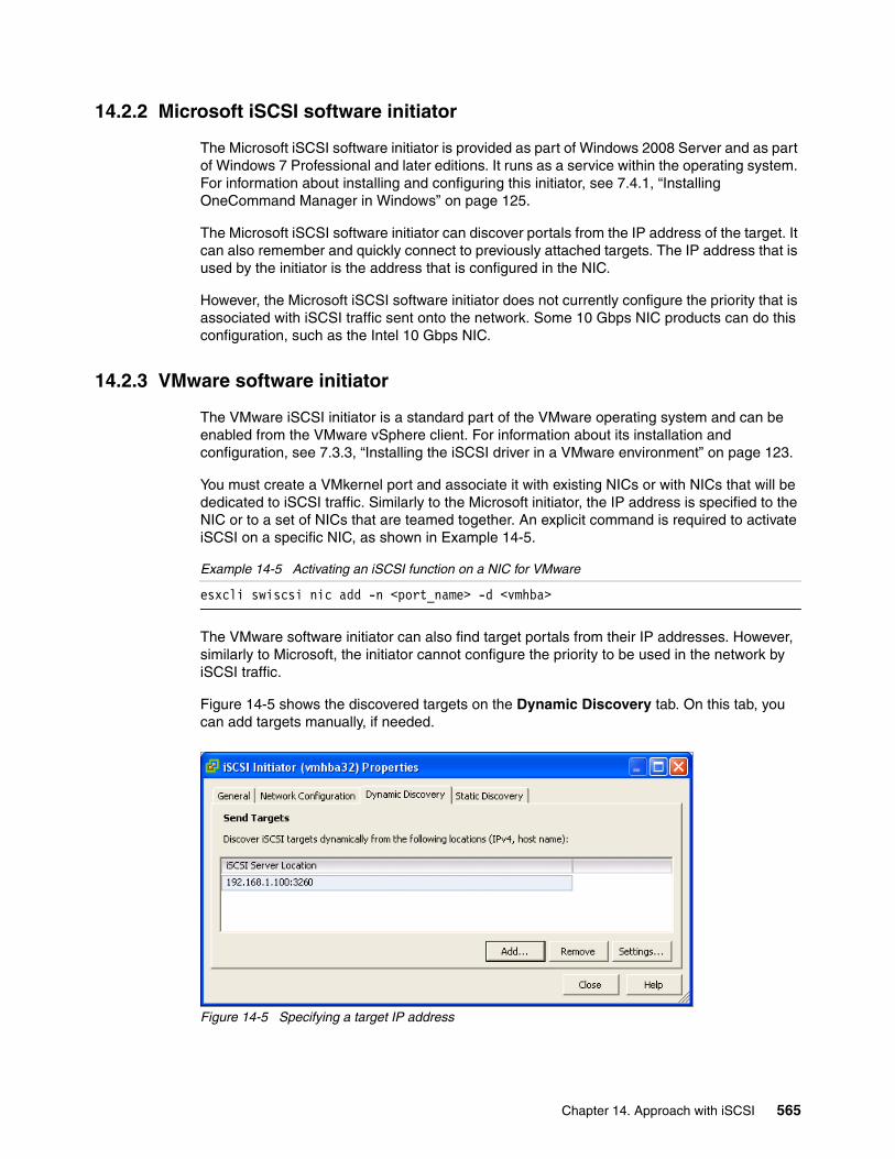
14.2.2 Microsoft iSCSI software initiator
The Microsoft iSCSI software initiator is provided as part of Windows 2008 Server and as part of Windows 7 Professional and later editions. It runs as a service within the operating system. For information about installing and configuring this initiator, see 7.4.1, “Installing OneCommand Manager in Windows” on page 125.
The Microsoft iSCSI software initiator can discover portals from the IP address of the target. It can also remember and quickly connect to previously attached targets. The IP address that is used by the initiator is the address that is configured in the NIC.
However, the Microsoft iSCSI software initiator does not currently configure the priority that is associated with iSCSI traffic sent onto the network. Some 10 Gbps NIC products can do this configuration, such as the Intel 10 Gbps NIC.
14.2.3 VMware software initiator
The VMware iSCSI initiator is a standard part of the VMware operating system and can be enabled from the VMware vSphere client. For information about its installation and configuration, see 7.3.3, “Installing the iSCSI driver in a VMware environment” on page 123.
You must create a VMkernel port and associate it with existing NICs or with NICs that will be dedicated to iSCSI traffic. Similarly to the Microsoft initiator, the IP address is specified to the NIC or to a set of NICs that are teamed together. An explicit command is required to activate iSCSI on a specific NIC, as shown in Example 14-5.
Example 14-5 Activating an iSCSI function on a NIC for VMware
esxcli swiscsi nic add -n <port_name> -d <vmhba>
The VMware software initiator can also find target portals from their IP addresses. However, similarly to Microsoft, the initiator cannot configure the priority to be used in the network by iSCSI traffic.
Figure 14-5 shows the discovered targets on the Dynamic Discovery tab. On this tab, you can add targets manually, if needed.
Figure 14-5 Specifying a target IP address
Chapter 14. Approach with iSCSI 565

Figure 14-6 shows the Static Discovery tab. This tab shows the discovered or manually entered iSCSI targets. You can also add targets from this tab.
Figure 14-6 Available targets for VMware
14.2.4 Storage as iSCSI target
Similar to the iSCSI initiator configuration, it is required to configure the storage that is used as iSCSI target properly. Specific settings depend mainly on the storage system that is used as a target.
This section shows the CEE iSCSI traffic-related configuration settings for a DS5300, SAN Volume Controller, and Storwize storage system as an example.
Additional configuration on both the initiators and target is required if IP Security (IPSec) or Challenge Handshake Authentication Protocol (CHAP) is used to provide a secure or encrypted connection.
DS5300 (target)Similar to the initiators, you must configure the target for priority 3 and enable it for DCB or CEE. This configuration ensures that traffic that is sent by the DS5300 back to an initiator is also prioritized and treated as lossless. The priority setting is applied in the Advanced Settings panel (Figure 14-7). In the Ethernet Priority area, you select Enable Ethernet priority and then adjust the Ethernet priority slider to the appropriate level.
566 Storage and Network Convergence Using FCoE and iSCSI

Figure 14-7 Enabling priority on the DS5300
In addition, you must configure this target with the iSCSI qualified names (IQN) of the initiators from which it will accept connections. You perform this configuration in the Add Host Port Identifier window (Figure 14-8). You select ISCSI for the host interface type. Then you select Add by creating a new host port identifier and enter the name of the identifier. Next you enter a user label and click Add.
Figure 14-8 Specifying the IQN of an initiator to be allowed to connect to the DS5300
Chapter 14. Approach with iSCSI 567

You set the MTU to enable support for jumbo frames in the Advanced Host Port Settings (Figure 14-9). Although this step is not required, not enabling this support can hurt performance.
Figure 14-9 Configuration of the MTU on the DS5300
SAN Volume Controller and Storwize family productsAll SAN Volume Controller based storage products, including the different available Storwize family members and the Flex System V7000 Storage Node, are capable of iSCSI host attachments (at least using 1 Gbps classical Ethernet).
As of writing this book, there are 10 Gbps iSCSI and FCoE host interface cards available for SAN Volume Controller, Storwize V3700 and the Flex System V7000 that can benefit from lossless Ethernet. The iSCSI required configuration steps are identical for all these products.
MTU size is set to 1500 by default but can be changed up to 9000 (jumbo frames) as shown in Example 14-6 for port id 3. To improve readability, only one set of port parameters are shown in the example.
Example 14-6 Show configured MTU size for port id 3, change it to 9000 and verify
IBM_Storwize:V3700:superuser>lsportip...id 3node_id 1node_name node1IP_address 192.168.11.37mask 255.255.255.0gateway 192.168.11.1IP_address_6prefix_6gateway_6MAC 00:90:fa:0e:5a:20duplex Full
568 Storage and Network Convergence Using FCoE and iSCSI

state configuredspeed 10Gb/sfailover nomtu 1500link_state active
IBM_Storwize:V3700:superuser>cfgportip -mtu 9000 3id 3node_id 1node_name node1IP_address 192.168.11.37mask 255.255.255.0gateway 192.168.11.1IP_address_6prefix_6gateway_6MAC 00:90:fa:0e:5a:20duplex Fullstate configuredspeed 10Gb/sfailover nomtu 9000link_state active
Consider that the iSCSI stack is implemented in software, which means that the CPU of the system has additional load to handle. This must be considered during the sizing phase.
For more information and limitations, see IBM System Storage SAN Volume Controller Best Practices and Performance Guidelines, SG24-7521.
14.3 Summary
iSCSI relies on CEE to give it priority and to pause iSCSI and non-iSCSI traffic as needed. iSCSI also relies on CEE to ensure that it receives sufficient bandwidth and to keep the endpoints of the connection in sync. For this benefit to be effective, the priorities must be set at the endpoints of the iSCSI connection, which are the initiator and the target.
The Emulex hardware iSCSI initiator, included in the Virtual Fabric Adapters I and II, has the necessary functions to use CEE. Historically, the prevailing practice was to implement iSCSI by using a dedicated NIC on the client (initiator) if not an entirely dedicated network. In the absence of CEE “lossless Ethernet” enhancements, this practice is advisable. The enhancements make it possible to converge Ethernet networks that are used for storage with those networks that are used for conventional data traffic.
The software initiators, and the NICs that we tested in our lab do not have the capacity to set the priority.
Chapter 14. Approach with iSCSI 569

570 Storage and Network Convergence Using FCoE and iSCSI
Appendix A. Solution comparison and test results
This appendix includes the following sections:
� “Solution comparison” on page 572� “Performance test results” on page 574� “Network test” on page 574� “Comparing the CNAs with FCoE” on page 576� “Comparing iSCSI, FCOE, and FC” on page 578� “Comparing iSCSI Windows and VMware software and hardware” on page 581� “Comparing the Emulex CNA on different switches” on page 583� “More real-life testing” on page 585� “Summary of results” on page 587
A
Note: No performance tests were conducted as part of the update to this release of the book. The results presented here are simply carried over from the previous edition of the book.
© Copyright IBM Corp. 2012, 2014. All rights reserved. 571

Solution comparison
iSCSI and FCoE each offer several solutions.
iSCSI
Only one iSCSI hardware initiator, the Emulex Virtual Fabric Adapters I and II, was available for our testing. All of the other solutions involved the use of a software initiator.
We tested the following software initiators:
� Microsoft iSCSI initiator� VMware iSCSI initiator � Microsoft initiator that is running in a Windows guest under VMware
The best performance was obtained with the Emulex hardware solution, which was also the only one we tested that can use a lossless Ethernet (CEE). We suspect, but did not test, that this solution also placed the least load on the host processor because the iSCSI functions and the IP stack were offloaded to run on the Emulex converged network adapter (CNA).
Among the software initiators, the VMware initiator had the best performance. Windows on a stand-alone system or a guest had acceptable performance, but without a CEE. For detailed performance comparisons, see “Comparing iSCSI Windows and VMware software and hardware” on page 581.
FCoE
We tested multiple FCoE solutions by using the following CNAs, switches, and operating systems:
� Operating systems:
– Microsoft Windows– Linux– VMware
� CNAs:
– Brocade– Emulex– QLogic
� Switches:
– Brocade– Cisco– QLogic Virtual Fabric
IBM Virtual Fabric 10Gb Switch Module with QLogic Fabric Extension Module
In this solution, the QLogic Virtual Fabric Extension Module is installed inside the BladeCenter chassis as the FCF. Either 20 Gbps or 40 Gbps of upstream bandwidth from the BNT Virtual Fabric 10Gb Switch Module is diverted across the midplane of the chassis toward the QLogic module. The QLogic module has six external 8 Gbps FC ports that are intended to be connected upstream to an FC switch. This approach reduces the number of mezzanine cards that must be acquired and installed on the server blades. This method is similar to a case where a native FC switch is used in which the chassis still uses dedicated FC fiber connections to the FC fabric.
572 Storage and Network Convergence Using FCoE and iSCSI

IBM and QLogic have supported this solution since late 2009.
Setup of this solution was easy, requiring only a few steps. This solution resulted in good performance.
IBM Virtual Fabric 10Gb Switch Module with Nexus 5000
This solution uses a 1U or 2U Nexus 5000 switch with an FC module as the FCF. Because this switch is freestanding, it can support multiple BladeCenter chassis. The Nexus 5000 is intended to be connected to an upstream FC switch and then to storage devices.
Refer to the following IBM interoperability guides before deploying this solution:
� BladeCenter Interoperability Guide � System Storage Interoperation Center (SSIC)� IBM ServerProven: Compatibility for hardware, applications, and middleware
Setup of this implementation was not difficult on the IBM Virtual Fabric 10Gb Switch Module side (turning on CEE), but required some work on the Cisco side. This solution resulted in good performance.
Nexus 4000 to Nexus 5000Setting up this environment was the most complicated of all the solutions. Although the environment performance was satisfactory, when it was subject to more intensive traffic, the ports went error-disable (message on Cisco switches). Therefore, we are unable to provide adequate performance testing.
In this scenario, Cisco supports PortChannel allowing multiple links to the FCF. This setup did not function as well as connecting a BNT Virtual Fabric 10Gb Switch Module to the Cisco Nexus 5000. When we stressed the environment, we ran into multiple delays, causing the performance test to end. When evaluating cost per port, this solution was one of the most expensive.
Brocade Converged 10GbE Switch Module for IBM BladeCenter
Implementing this setup with FCoE was the simplest of all evaluated solutions. The command-line interface (CLI) is similar to a Cisco type of command line. This switch acts as an FCF and was fast to deploy.
Although performance was adequate, the solution worked well with various CNAs. It is the only switch that certified all three CNA.
This configuration required switchport converged and an FCoE port for server-facing ports. We used two sets of commands: an FC-oriented set and an Ethernet-oriented set similar to Cisco IOS. We used the cmsh command to enter the Ethernet configuration, which is saved separately from the FC configuration.
Tip: If you want to change the default FCoE virtual local LAN (VLAN) on the QLogic Virtual Fabric Module, for example, from 1002 to another VLAN, you might have to force the VLAN ID on the individual adapters.
Upstream bandwidth limit: At the time of writing this book, no support is available for PortChannel that can limit the upstream bandwidth to the Ethernet switch that is acting as the FCF.
Appendix A. Solution comparison and test results 573

Performance test results
Two types of performance tests were run on the configurations that were tested during the first release of this book.
� iPerf is a public domain testing tool that generates traffic streams between two systems that are configured as a sender and a receiver.
This tool does not exercise any of the storage technologies under test, but it was used to generate traffic that might compete with iSCSI traffic or FCoE traffic for available bandwidth. The results of the iPerf are shown in Gbps.
� IOMeter is a public domain testing tool that generates I/O requests against storage devices.
We targeted this tool on storage that is attached to the systems by using iSCSI or FCoE, running it in isolation and sometimes simultaneously with iPerf. The results show the amount of Input/Output Operations per Second (IOPS) and megabytes per second (MBps).
Performance testing is a broad subject, and the results can be questionable. The methods used to analyze performance can vary and is a subject that not everyone agrees on. The type of workloads can vary from one application to another without modifying or tweaking the counters and settings on the CNAs and switches. Our tests were limited because we used a traffic generator rather than actual workloads. Most customers are likely to use default settings for many configurable parameters unless they need to improve performance in their environment. By tweaking different settings, we can achieve different results.
We used simple configurations in our performance testing. One or two blades communicated with each other or to storage, and no other traffic was present. The testing is questionable, because in a production environment, you will always have more than one or two hosts.
Our goal with this testing was to determine any notable differences and to see whether the different switch settings had a large effect or small effect. Through this testing, we were able to compare technologies and brands.
We used IBM HS22 blades to perform our testing. In some cases, the processors and memory varied, which seemed to have only a minor impact on most tests. When comparing different brands, we ensured that the blades used were identical.
For information about the exact adapter that we used, see Chapter 9, “Configuring iSCSI and FCoE cards for SAN boot” on page 225.
Network test
This test was used to determine network speeds with a CNA between two blades with the following specifications:
� HS22 MT 7870 UEFI 1.15 (build P9E155AUS) IMM 1.30 (buildYUOOC7E)� Windows 2008 R2 x64 SP1 (installed in UEFI mode)� One Intel Xeon CPU E5520 2.27 GHz (quad core)� Three 4-Gb memory (12 Gb total)� Brocade CNA� Emulex Virtual Fabric Adapter II CNA� QLogic CNA
574 Storage and Network Convergence Using FCoE and iSCSI
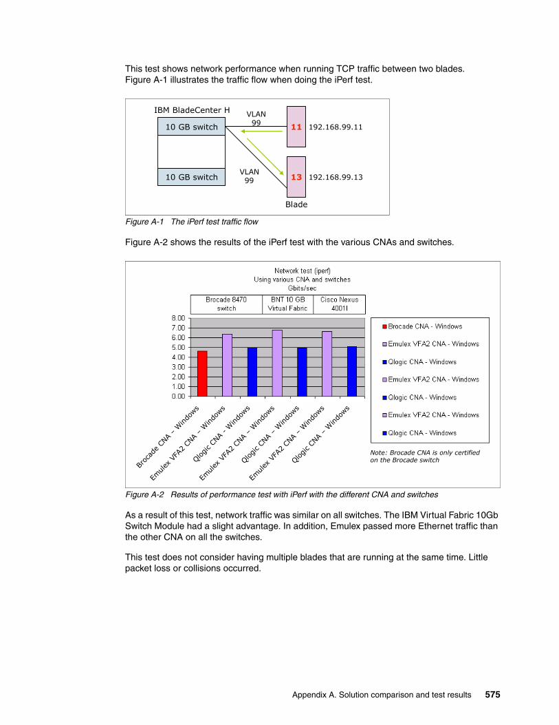
This test shows network performance when running TCP traffic between two blades. Figure A-1 illustrates the traffic flow when doing the iPerf test.
Figure A-1 The iPerf test traffic flow
Figure A-2 shows the results of the iPerf test with the various CNAs and switches.
Figure A-2 Results of performance test with iPerf with the different CNA and switches
As a result of this test, network traffic was similar on all switches. The IBM Virtual Fabric 10Gb Switch Module had a slight advantage. In addition, Emulex passed more Ethernet traffic than the other CNA on all the switches.
This test does not consider having multiple blades that are running at the same time. Little packet loss or collisions occurred.
IBM BladeCenter H
10 GB switch
10 GB switch
Blade
192.168.99.11
192.168.99.13
VLAN99
VLAN99 13
11
Broc
ade CN
A –Windo
ws
Emulex
VFA
2 CN
A –W
indo
ws
Qlogic C
NA -
Windo
ws
Emulex
VFA
2 CN
A –W
indo
ws
Qlogic C
NA –
Windo
ws
Emulex
VFA
2 CN
A –W
indo
ws
Qlogic C
NA –
Windo
ws
Note: Brocade CNA is only certifiedon the Brocade switch
Appendix A. Solution comparison and test results 575
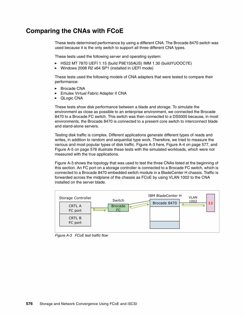
Comparing the CNAs with FCoE
These tests determined performance by using a different CNA. The Brocade 8470 switch was used because it is the only switch to support all three different CNA types.
These tests used the following server and operating system:
� HS22 MT 7870 UEFI 1.15 (build P9E155AUS) IMM 1.30 (buildYUOOC7E)� Windows 2008 R2 x64 SP1 (installed in UEFI mode)
These tests used the following models of CNA adapters that were tested to compare their performance:
� Brocade CNA� Emulex Virtual Fabric Adapter II CNA� QLogic CNA
These tests show disk performance between a blade and storage. To simulate the environment as close as possible to an enterprise environment, we connected the Brocade 8470 to a Brocade FC switch. This switch was then connected to a DS5000 because, in most environments, the Brocade 8470 is connected to a present core switch to interconnect blade and stand-alone servers.
Testing disk traffic is complex. Different applications generate different types of reads and writes, in addition to random and sequential type work. Therefore, we tried to measure the various and most popular types of disk traffic. Figure A-3 here, Figure A-4 on page 577, and Figure A-5 on page 578 illustrate these tests with the simulated workloads, which were not measured with the true applications.
Figure A-3 shows the topology that was used to test the three CNAs listed at the beginning of this section. An FC port on a storage controller is connected to a Brocade FC switch, which is connected to a Brocade 8470 embedded switch module in a BladeCenter H chassis. Traffic is forwarded across the midplane of the chassis as FCoE by using VLAN 1002 to the CNA installed on the server blade.
Figure A-3 FCoE test traffic flow
CRTL AFC port
CRTL BFC port
Storage ControllerSwitch
IBM BladeCenter H
Brocade 8470Brocade
FC
VLAN1002 11
576 Storage and Network Convergence Using FCoE and iSCSI
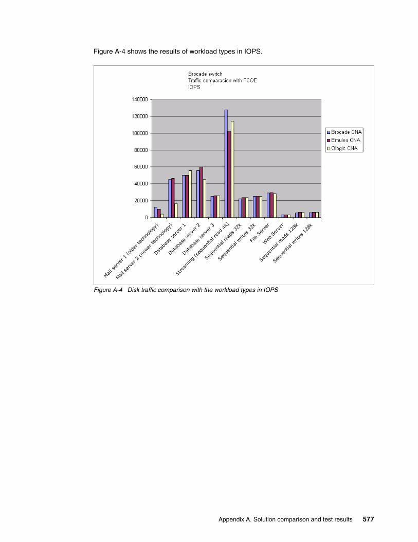
Figure A-4 shows the results of workload types in IOPS.
Figure A-4 Disk traffic comparison with the workload types in IOPS
Mail s
erve
r 1 (o
lder
tech
nology
)
Mail s
erve
r 2 (n
ewer
tech
nology
)
Datab
ase se
rver
1
Datab
ase se
rver
2
Datab
ase se
rver
3
Stre
aming (seq
uent
ial r
ead 4k
)
Sequ
entia
l writ
es 32k
Sequ
entia
l rea
ds 32k
File Se
rver
Web
Ser
ver
Sequ
entia
l rea
ds 128
k
Sequ
entia
l writ
es 128
k
Appendix A. Solution comparison and test results 577

Figure A-5 shows the results of the workload types in MBPS.
Figure A-5 Disk traffic comparison with the types of workloads in MBPS
As a result of this test, all CNAs performed about the same, depending on whether you are looking for IOPS or more MBps transfers.
This test does not consider having multiple blades that are running at the same time. Little packet loss or collisions occurred. Testing was run with ideal conditions.
Comparing iSCSI, FCOE, and FC
This test was used to determine performance by using a different CNA. For this test, we used the IBM Virtual Fabric 10Gb Switch Module.
� HS22 MT 7870 UEFI 1.15 (build P9E155AUS) IMM 1.30 (buildYUOOC7E)� Windows 2008 R2 x64 sp1 (installed in UEFI mode)� Emulex Virtual Fabric Adapter2 CNA� QLogic CNA
This test shows us disk performance between a blade and storage.
Mail s
erve
r 1 (o
lder
tech
nology
)
Mail s
erve
r 2 (n
ewer
tech
nology
)
Datab
ase se
rver
1
Datab
ase se
rver
2
Datab
ase se
rver
3
Stre
aming (seq
uent
ial r
ead 4k
)
Sequ
entia
l writ
es 32k
Sequ
entia
l rea
ds 32k
File Se
rver
Web
Ser
ver
Sequ
entia
l rea
ds 128
k
Sequ
entia
l writ
es 128
k
Brocade CNA: The Brocade CNA was not used because it is not certified on the BNT Virtual Fabric 10Gb Switch Module.
578 Storage and Network Convergence Using FCoE and iSCSI

Figure A-6 shows the traffic flow of the iSCSI test. To simulate the environment as close as possible to an enterprise environment, we connected the BNT Virtual Fabric 10Gb Switch Module for IBM BladeCenter to an external switch.
Figure A-6 iSCSI test
Figure A-7 shows the traffic flow of the FCoE test. To simulate the environment as close as possible to an enterprise environment, we connected the FC forwarding switch (QLogic Virtual Fabric) to a Brocade core switch.
Figure A-7 FCoE test
The FC test (Figure A-8) was run with a QLogic 8 Gbps combo card connected to an 8 Gbps Brocade FC switch. This test involved only one switch and hardware availability.
Figure A-8 Fibre Channel test
All tests were connected to the DS5000. We ran this test against multiple workloads and different adapters and switches. Figure A-9 on page 580 and Figure A-10 on page 581 show the performance results of the different storage technologies with several different simulated network workloads.
VLAN100192.168.1.100
CRTL A
192.168.2.100CRTL B
Storage Controller
Priority →3 iSCSI
SwitchIBM BladeCenter H
Priority →3 iSCSI
VF
VF
192.168.1.11 iSCSIVLAN 100
8124
VLAN99-100VLAN 100
11
CRTL AFC port
CRTL BFC port
Storage ControllerSwitch
IBM BladeCenter H
BNT Virtual FabricBrocade
FC
VLAN1002 11
Qlogic Virtual Fabric
CRTL AFC port
CRTL BFC port
Storage ControllerIBM BladeCenter H
Brocade FC 11FC
Appendix A. Solution comparison and test results 579

Figure A-9 compares the technologies in IOPS.
Figure A-9 Comparison of the technologies in IOPS
Mail s
erve
r 1 (o
lder
tech
nolo
gy)
Mail s
erve
r 2 (n
ewer
tech
nolo
gy)
Datab
ase
serv
er 1
Datab
ase
serv
er 2
Datab
ase
serv
er 3
Stre
amin
g (s
eque
ntial
read
4k)
Sequ
entia
l writ
es 3
2k
Sequ
entia
l rea
ds 3
2k
File
Serve
r
Web
Ser
ver
Sequ
entia
l rea
ds 1
28k
Seque
ntial
writ
es 1
28k
580 Storage and Network Convergence Using FCoE and iSCSI

Figure A-10 compares the technologies in MBPS.
Figure A-10 Comparison of the technologies in MBPS
This test showed that the software iSCSI behaved poorly compared to the hardware solutions. Hardware iSCSI, FCoE, and FC behaved about the same. The Mail server 1 traffic type was the exception. We cannot explain the significant difference. We suspect that most customers today use the mail server 2 type of workloads more.
Comparing iSCSI Windows and VMware software and hardware
This test compares hardware iSCSI and software iSCSI by using a different operating system. We used the same setup as shown in Figure A-6 on page 579. The VMware setup had a single Windows 2008 R2 x64 SP 1 virtual machine. It had access to a data disk that was managed by VMware software iSCSI. Figure A-11 on page 582 and Figure A-12 on page 582 present comparative iSCSI performance results of the Emulex and Qlogic CNA adapters by using VMware and the Windows 2008 software initiator.
Mail s
erve
r 1 (o
lder
tech
nology
)
Mail s
erve
r 2 (n
ewer
tech
nology
)
Datab
ase se
rver
1
Datab
ase se
rver
2
Datab
ase se
rver
3
Stre
aming (seq
uent
ial r
ead 4k
)
Sequ
entia
l writ
es 3
2k
Sequ
entia
l rea
ds 3
2k
File Se
rver
Web
Ser
ver
Sequ
entia
l rea
ds 1
28k
Sequ
entia
l writ
es 1
28k
Appendix A. Solution comparison and test results 581

Figure A-11 shows results in IOPS.
Figure A-11 iSCSI comparison with software and hardware initiator IOPS
Figure A-12 shows the results in MBPS.
Figure A-12 iSCSI comparison with software and hardware initiator MBPS
The results of this test showed that VMware software iSCSI outperformed the Microsoft software iSCSI. QLogic software iSCSI performance was about the same as Emulex hardware iSCSI performance.
Mail s
erve
r 1 (o
lder
tech
nology
)
Mail s
erve
r 2 (n
ewer
tech
nology
)
Datab
ase se
rver 1
Datab
ase se
rver 2
Datab
ase se
rver
3
Stre
aming (seq
uent
ial r
ead 4k
)
Sequ
entia
l writ
es 32k
Sequ
entia
l rea
ds 32k
File S
erve
r
Web
Ser
ver
Sequ
entia
l rea
ds 1
28k
Sequ
entia
l writ
es 128
k
582 Storage and Network Convergence Using FCoE and iSCSI
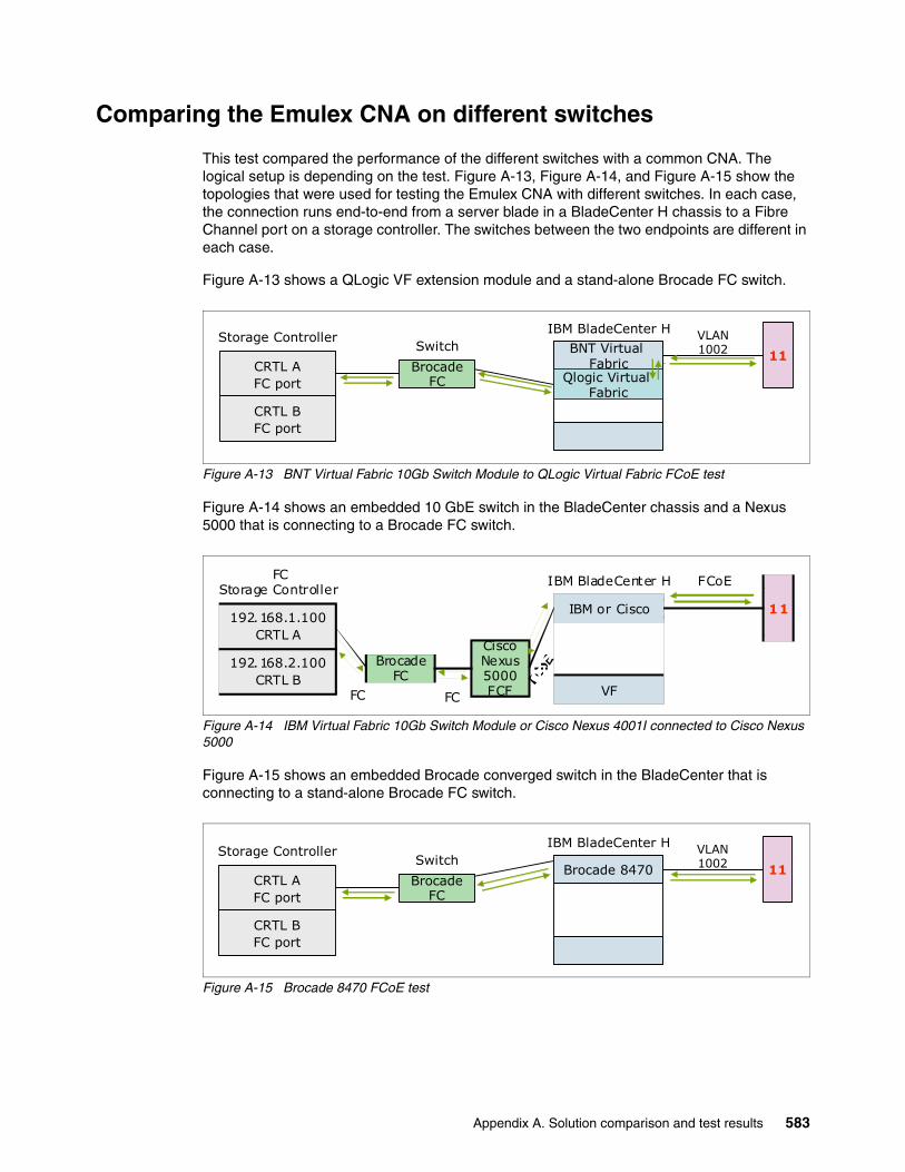
Comparing the Emulex CNA on different switches
This test compared the performance of the different switches with a common CNA. The logical setup is depending on the test. Figure A-13, Figure A-14, and Figure A-15 show the topologies that were used for testing the Emulex CNA with different switches. In each case, the connection runs end-to-end from a server blade in a BladeCenter H chassis to a Fibre Channel port on a storage controller. The switches between the two endpoints are different in each case.
Figure A-13 shows a QLogic VF extension module and a stand-alone Brocade FC switch.
Figure A-13 BNT Virtual Fabric 10Gb Switch Module to QLogic Virtual Fabric FCoE test
Figure A-14 shows an embedded 10 GbE switch in the BladeCenter chassis and a Nexus 5000 that is connecting to a Brocade FC switch.
Figure A-14 IBM Virtual Fabric 10Gb Switch Module or Cisco Nexus 4001I connected to Cisco Nexus 5000
Figure A-15 shows an embedded Brocade converged switch in the BladeCenter that is connecting to a stand-alone Brocade FC switch.
Figure A-15 Brocade 8470 FCoE test
CRTL AFC port
CRTL BFC port
Storage ControllerSwitch
IBM BladeCenter H
BNT Virtual FabricBrocade
FC
VLAN1002 11
Qlogic Virtual Fabric
192.168.1.100CRTL A
192.168.2.100CRTL B
Storage ControllerFC IBM BladeCenter H FCoE
IBM or Cisco
VF
11
Cisco Nexus5000FCF
Brocade FC
FC FC
CRTL AFC port
CRTL BFC port
Storage ControllerSwitch
IBM BladeCenter H
Brocade 8470Brocade
FC
VLAN1002 11
Appendix A. Solution comparison and test results 583
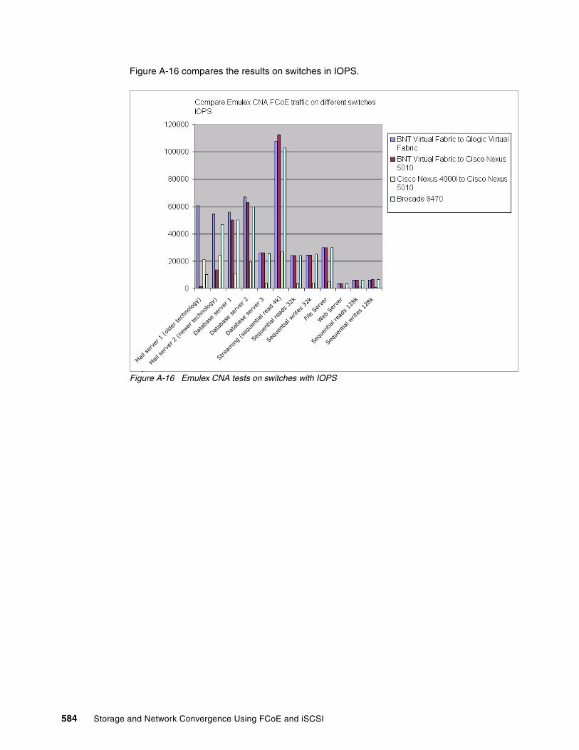
Figure A-16 compares the results on switches in IOPS.
Figure A-16 Emulex CNA tests on switches with IOPS
Mail s
erve
r 1 (o
lder
tech
nology
)
Mail s
erve
r 2 (n
ewer
tech
nology
)
Datab
ase se
rver
1
Datab
ase se
rver
2
Datab
ase se
rver
3
Stre
aming (seq
uent
ial r
ead 4k
)
Sequ
entia
l writ
es 32k
Sequ
entia
l rea
ds 32k
File Se
rver
Web
Ser
ver
Sequ
entia
l rea
ds 128
k
Sequ
entia
l writ
es 128
k
584 Storage and Network Convergence Using FCoE and iSCSI
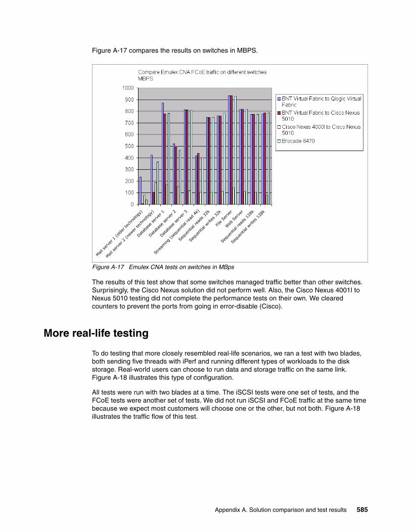
Figure A-17 compares the results on switches in MBPS.
Figure A-17 Emulex CNA tests on switches in MBps
The results of this test show that some switches managed traffic better than other switches. Surprisingly, the Cisco Nexus solution did not perform well. Also, the Cisco Nexus 4001I to Nexus 5010 testing did not complete the performance tests on their own. We cleared counters to prevent the ports from going in error-disable (Cisco).
More real-life testing
To do testing that more closely resembled real-life scenarios, we ran a test with two blades, both sending five threads with iPerf and running different types of workloads to the disk storage. Real-world users can choose to run data and storage traffic on the same link. Figure A-18 illustrates this type of configuration.
All tests were run with two blades at a time. The iSCSI tests were one set of tests, and the FCoE tests were another set of tests. We did not run iSCSI and FCoE traffic at the same time because we expect most customers will choose one or the other, but not both. Figure A-18 illustrates the traffic flow of this test.
Mail s
erve
r 1 (o
lder
tech
nology
)
Mail s
erve
r 2 (n
ewer
tech
nology
)
Datab
ase se
rver
1
Datab
ase se
rver
2
Datab
ase se
rver
3
Stre
aming (seq
uent
ial r
ead 4k
)
Sequ
entia
l writ
es 32k
Sequ
entia
l rea
ds 32k
File Se
rver
Web
Ser
ver
Sequ
entia
l rea
ds 128
k
Sequ
entia
l writ
es 128
k
Appendix A. Solution comparison and test results 585
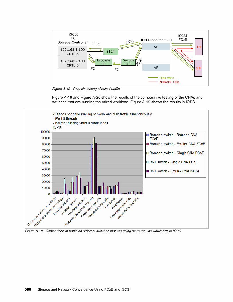
Figure A-18 Real-life testing of mixed traffic
Figure A-19 and Figure A-20 show the results of the comparative testing of the CNAs and switches that are running the mixed workload. Figure A-19 shows the results in IOPS.
Figure A-19 Comparison of traffic on different switches that are using more real-life workloads in IOPS
192.168.1.100CRTL A
192.168.2.100CRTL B
Storage Controller
iSCSIFC IBM BladeCenter H
iSCSIFCoE
VF
VF
8124
iSCSI11
13
Disk traficNetwork trafic
iSCSI
SwitchFCF
Brocade FC FC
oE
FC FC
586 Storage and Network Convergence Using FCoE and iSCSI

Figure A-20 shows the results in MBPS.
Figure A-20 Comparison of traffic on different switches that are using more real-life workloads in MBps
The results of this test were similar from one switch to the other. However, iSCSI had the advantage of using 10 Gbps as opposed to FCoE, which was using 8 Gbps.
Summary of results
At a high level, the tests had the following results:
� iSCSI at 10 Gbps and FCoE performance were roughly equal when an iSCSI hardware initiator was used.
� iSCSI performance when using a software initiator was not comparable to the performance with a hardware initiator. It was unclear whether this result was due to the processor load generated by the software initiators, the inability to enable the CEE features with the software initiators, or both.
� The VMware software initiator significantly outperformed the Windows software initiator.
� Performance of traditional FC was roughly equal to performance of FCoE.
� The various combinations of CNAs and FCFs showed differences in performance. The performance was about the same across the various tests run with IOMeter.
Appendix A. Solution comparison and test results 587

588 Storage and Network Convergence Using FCoE and iSCSI

Related publications
The publications listed in this section are considered particularly suitable for a more detailed discussion of the topics covered in this book.
IBM Redbooks
The following IBM Redbooks publications provide additional information about the topic in this document. Note that some publications referenced in this list might be available in softcopy only.
� Implementing IBM System Networking 10Gb Ethernet Switches, SG24-7960
� An Introduction to Fibre Channel over Ethernet, and Fibre Channel over Convergence Enhanced Ethernet, REDP-4493
� IBM Virtual Fabric 10Gb Switch Module for IBM BladeCenter, TIPS0708
� Brocade 2-port 10GbE Converged Network Adapter for IBM BladeCenter, TIPS0790
� Brocade 10Gb CNA for IBM System x, TIPS0718
� Brocade Converged 10GbE Switch Module for IBM BladeCenter, TIPS0789
� Cisco Nexus 4001I Switch Module for IBM BladeCenter, TIPS0754
� Emulex 10GbE Virtual Fabric Adapter II for IBM BladeCenter, TIPS0828
� Emulex 10GbE Virtual Fabric Adapter and Virtual Fabric Adapter Advanced for IBM BladeCenter, TIPS0748
� IBM BladeCenter iSCSI SAN Solution, REDP-4153
� IBM BladeCenter Products and Technology, SG24-7523
� IBM Midrange System Storage Hardware Guide, SG24-7676
� IBM SAN Survival Guide, SG24-6143
� IBM Scale Out Network Attached Storage Concepts, SG24-7874
� IBM Scale Out Network Attached Storage: Architecture, Planning, and Implementation Basics, SG24-7875
� IBM System Networking RackSwitch G8124E, TIPS0787
� IBM System Networking RackSwitch G8264, TIPS0815
� IBM System Storage N series: An iSCSI Performance Overview, REDP-4271
� IBM System Storage Solutions Handbook, SG24-5250
� Implementing a VM-Aware Network Using VMready, SG24-7985
� Implementing the Brocade Access Gateway for IBM BladeCenter, REDP-4343
� Implementing the IBM Storwize V7000 V6.3, SG24-7938
� QLogic 2-port 10Gb CNA (CFFh) for IBM BladeCenter, TIPS0716
� QLogic Virtual Fabric Extension Module for IBM BladeCenter, TIPS0717
� TCP/IP Tutorial and Technical Overview, GG24-3376
� The IBM eServer BladeCenter JS20, SG24-6342
© Copyright IBM Corp. 2012, 2014. All rights reserved. 589

� Windows Multipathing Options with System Storage N series, REDP-4753
� IBM Flex System Interoperability Guide, REDP-FSIG
� IBM Flex System CN4054 10Gb Virtual Fabric Adapter and EN4054 4-port 10Gb Ethernet Adapter, TIPS0868
� IBM Flex System Fabric EN4093 and EN4093R 10Gb Scalable Switches, TIPS0864
� IBM Flex System Fabric CN4093 10Gb Converged Scalable Switch, TIPS0910
� IBM Flex System EN4091 10Gb Ethernet Pass-thru Module, TIPS0865
You can search for, view, download or order these documents and other Redbooks, Redpapers, Web Docs, draft and additional materials, at the following website:
ibm.com/redbooks
Other publications
Implementing Fibre Channel over Ethernet (FCoE) Solution with IBM BladeCenter using IBM BNT® Virtual Fabric Switch and QLogic Virtual Fabric Extension Module, by Khalid Ansari is also relevant as a further information source:
http://www.ibm.com/support/techdocs/atsmastr.nsf/WebIndex/WP101663
Online resources
These websites and documents are also relevant as further information sources:
� 802.1aq - Shortest Path Bridging:
http://www.ieee802.org/1/pages/802.1aq.html
� 802.1Qaz - Enhanced Transmission Selection:
http://ieee802.org/1/pages/802.1az.html
� 802.1Qau - Congestion Notification:
http://www.ieee802.org/1/pages/802.1au.html
� 802.1Qbb - Priority-based Flow Control:
http://ieee802.org/1/pages/802.1bb.html
� Brocade FCoE Handbook:
http://www.brocade.com/dg/brocade-one/book-fcoe-summary.html
� Brocade IP Primer:
http://www.brocade.com/downloads/documents/books/Brocade_IP_Primer_eBook.pdf
� Cisco Nexus 5000:
ftp://ftp.software.ibm.com/common/ssi/pm/sp/n/tsd03080usen/TSD03080USEN.PDF
� Cisco white paper: Using VSANs and Zoning in the Cisco MDS 9000 Family of Multilayer Fibre Channel Switches:
http://www.cisco.com/en/US/netsol/ns340/ns394/ns259/ns261/networking_solutions_white_paper09186a0080114c21.shtml
590 Storage and Network Convergence Using FCoE and iSCSI

� Cisco zoning guides:
– Cisco MDS 9000 Family Cookbook, Release 1.x:
http://www.cisco.com/en/US/docs/storage/san_switches/mds9000/sw/rel_1_x/1_3/cookbook/CB_zone.html#wp1039557
– Cisco MDS 9000 Family CLI Quick Configuration Guide:
http://www.cisco.com/en/US/docs/storage/san_switches/mds9000/sw/san-os/quick/guide/qcg_zones.html
– “Troubleshooting Zones and Zone Sets”:
http://www.cisco.com/en/US/products/ps5989/prod_troubleshooting_guide_chapter09186a008067a309.html#wp48042
– Cisco MDS 9000 Family Configuration Guide, Release 2.x:
http://www.cisco.com/en/US/docs/storage/san_switches/mds9000/sw/rel_2_x/san-os/configuration/guide/cli.pdf
� Emulex 10GbE Virtual Fabric Adapter Advanced II:
http://www.emulex.com/products/10gbe-iscsi-adapters/ibm-branded/90y3566/overview.html
� Emulex IBM link:
http://www.emulex.com/downloads/ibm/vfa-software-kits.html
� Using Emulex 10Gb Virtual Fabric Adapters for IBM BladeCenter for iSCSI with ESX 4.1:
http://www.emulex.com/artifacts/d3b377a7-49ae-41c3-b599-1a7aa6cae8df/elx_sis_all_ibm-vfa_iscsi_vmware.pdf
� FC-BB-5 standard:
http://fcoe.com/09-056v5.pdf
� FCoE website, including links to articles, meeting minutes, standards, and drafts:
http://fcoe.com
� Fibre Channel Security Protocols:
http://www.t10.org/ftp/t11/document.06/06-157v0.pdf
� H196488: DS3500/DS3950/DS5000 systems not working with Brocade on 8 Gbps host ports - IBM System Storage:
http://www.ibm.com/support/entry/portal/docdisplay?lndocid=MIGR-5083089
� IBM Converged Switch B32:
ftp://ftp.software.ibm.com/common/ssi/pm/sp/n/tsd03094usen/TSD03094USEN.PDF
� IBM Storwize V7000 Unified Storage:
http://www.ibm.com/systems/storage/disk/storwize_v7000/index.html
� IBM System Storage DS3500 Express:
http://www.ibm.com/systems/storage/disk/ds3500/index.html
� IBM System Storage DS5000 Series:
http://www.ibm.com/systems/storage/disk/ds5000/index.html
� IBM ToolsCenter:
http://www.ibm.com/support/entry/portal/docdisplay?brand=5000008&lndocid=TOOL-CENTER
Related publications 591
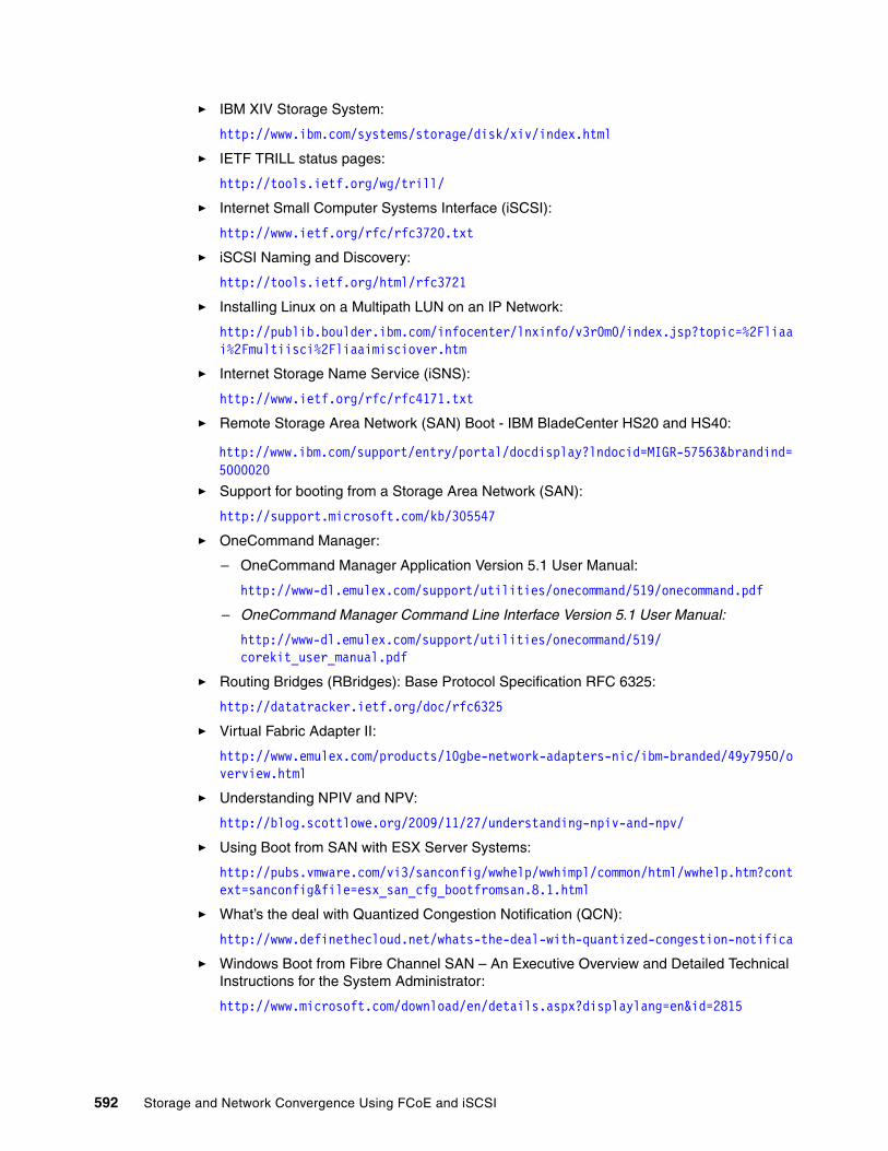
� IBM XIV Storage System:
http://www.ibm.com/systems/storage/disk/xiv/index.html
� IETF TRILL status pages:
http://tools.ietf.org/wg/trill/
� Internet Small Computer Systems Interface (iSCSI):
http://www.ietf.org/rfc/rfc3720.txt
� iSCSI Naming and Discovery:
http://tools.ietf.org/html/rfc3721
� Installing Linux on a Multipath LUN on an IP Network:
http://publib.boulder.ibm.com/infocenter/lnxinfo/v3r0m0/index.jsp?topic=%2Fliaai%2Fmultiisci%2Fliaaimisciover.htm
� Internet Storage Name Service (iSNS):
http://www.ietf.org/rfc/rfc4171.txt
� Remote Storage Area Network (SAN) Boot - IBM BladeCenter HS20 and HS40:
http://www.ibm.com/support/entry/portal/docdisplay?lndocid=MIGR-57563&brandind=5000020
� Support for booting from a Storage Area Network (SAN):
http://support.microsoft.com/kb/305547
� OneCommand Manager:
– OneCommand Manager Application Version 5.1 User Manual:
http://www-dl.emulex.com/support/utilities/onecommand/519/onecommand.pdf
– OneCommand Manager Command Line Interface Version 5.1 User Manual:
http://www-dl.emulex.com/support/utilities/onecommand/519/corekit_user_manual.pdf
� Routing Bridges (RBridges): Base Protocol Specification RFC 6325:
http://datatracker.ietf.org/doc/rfc6325
� Virtual Fabric Adapter II:
http://www.emulex.com/products/10gbe-network-adapters-nic/ibm-branded/49y7950/overview.html
� Understanding NPIV and NPV:
http://blog.scottlowe.org/2009/11/27/understanding-npiv-and-npv/
� Using Boot from SAN with ESX Server Systems:
http://pubs.vmware.com/vi3/sanconfig/wwhelp/wwhimpl/common/html/wwhelp.htm?context=sanconfig&file=esx_san_cfg_bootfromsan.8.1.html
� What’s the deal with Quantized Congestion Notification (QCN):
http://www.definethecloud.net/whats-the-deal-with-quantized-congestion-notifica
� Windows Boot from Fibre Channel SAN – An Executive Overview and Detailed Technical Instructions for the System Administrator:
http://www.microsoft.com/download/en/details.aspx?displaylang=en&id=2815
592 Storage and Network Convergence Using FCoE and iSCSI

Help from IBM
IBM Support and downloads:
ibm.com/support
IBM Global Services:
ibm.com/services
Related publications 593

594 Storage and Network Convergence Using FCoE and iSCSI

(1.0” spine)0.875”<
->1.498”
460 <->
788 pages
Storage and Network Convergence Using FCoE and iSCSI
Storage and Network Convergence
Using FCoE and iSCSI
Storage and Network Convergence
Using FCoE and iSCSI
Storage and Network Convergence Using FCoE and iSCSI

Storage and Network Convergence
Using FCoE and iSCSI
Storage and Network Convergence
Using FCoE and iSCSI


®
SG24-7986-01 ISBN 0738438995
INTERNATIONAL TECHNICALSUPPORTORGANIZATION
BUILDING TECHNICAL INFORMATION BASED ON PRACTICAL EXPERIENCE
IBM Redbooks are developed by the IBM International Technical Support Organization. Experts from IBM, Customers and Partners from around the world create timely technical information based on realistic scenarios. Specific recommendations are provided to help you implement IT solutions more effectively in your environment.
For more information:ibm.com/redbooks
®
Storage and Network Convergence Using FCoE and iSCSILearn how to improve IT service performance and availability
Simplify your storage and network infrastructure
See how to reduce data center network costs
Along with servers and networking infrastructure, networked storage is one of the fundamental components of a modern data center. Because storage networking has evolved over the past two decades, the industry has settled on the basic storage networking technologies. These technologies are Fibre Channel (FC) storage area networks (SANs), Internet Small Computer System Interface (iSCSI)-based Ethernet attachment, and Ethernet-based network-attached storage (NAS). Today, lossless, low-latency, high-speed FC SANs are viewed as the high-performance option for networked storage. iSCSI and NAS are viewed as lower cost, lower performance technologies.
The advent of the 100 Gbps Ethernet and Data Center Bridging (DCB) standards for lossless Ethernet give Ethernet technology many of the desirable characteristics that make FC the preferred storage networking technology. These characteristics include comparable speed, low latency, and lossless behavior. Coupled with an ongoing industry drive toward better asset utilization and lower total cost of ownership, these advances open the door for organizations to consider consolidating and converging their networked storage infrastructures with their Ethernet data networks. Fibre Channel over Ethernet (FCoE) is one approach to this convergence, but 10-Gbps-enabled iSCSI also offers compelling options for many organizations with the hope that their performance can now rival that of FC.
This IBM Redbooks publication is written for experienced systems, storage, and network administrators who want to integrate the IBM System Networking and Storage technology successfully into new and existing networks. This book provides an overview of today’s options for storage networking convergence. It reviews the technology background for each of these options and then examines detailed scenarios for them by using IBM and IBM Business Partner convergence products.
Back cover
Related Documents