Stirling Engine System for Solar Thermal Generation and Energy Storage LoCal Retreat, June 8-9 2009

Stirling Engine System for Solar Thermal Generation and Energy Storage LoCal Retreat, June 8-9 2009.
Dec 22, 2015
Welcome message from author
This document is posted to help you gain knowledge. Please leave a comment to let me know what you think about it! Share it to your friends and learn new things together.
Transcript

Stirling Engine System for Solar Thermal Generation and Energy Storage
LoCal Retreat, June 8-9 2009

Outline
Overview/Motivation System Description Early Prototypes Higher Power Engine Design

Thermal Energy Applications Solar Thermal
Dispatchable Generation Low cost, simple manufacturing
Thermal Storage Dispatchable Resource Low capital cost
Waste Heat Recovery Free energy source – Industrial Processes,
Combined Cycle Low Temperature

Renewable Energy Challenges
Cost
Intermittency
Production
bottlenecks
Lower Cost
Inherent Storage
Simple
Manufacturing
Versatility
Renewable Energy Challenges
Solar Thermal Advantages

Intermittency and Energy Storage
1.5 MW Wind Turbine4.6 MW Solar Installation
Source: J. Apt, A. Curtright, “The Spectrum of Power from Utility-Scale Wind Farms and Solar Photovoltaic Arrays”, CEIC 2008

Cost Comparison
Component $/WCollector 0.34Engine 0.5Balance of System 3.6Total 4.44
Energy Storage $/kWhThermal 20
Component $/WPV Module 4.70Inverter 0.72Balance of System 3.6Total 9.02
Energy Storage $/kWhBatteries 2030
Solar Thermal Photovoltaic
Source: PV data from Solarbuzz

Solar System Schematic

Stirling Engine
Can achieve large fraction (60-70%) of Carnot efficiency
Low cost, simple components Fuel Flexible Reversible Scalable engine and storage capacity

1
2
3
4
Stirling Cycle Overview

Research
Designed, built, tested two low power prototypes Single phase and multiphase machines Low power Verified engineering models
Design of high power prototype Improved simulation and design Heat exchanger design Optimization of geometry, parameters

Prototype 1: Single Phase
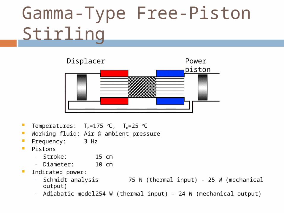
Temperatures: Th=175 oC, Tk=25 oC Working fluid: Air @ ambient pressure Frequency: 3 Hz Pistons
– Stroke: 15 cm– Diameter: 10 cm
Indicated power:– Schmidt analysis 75 W (thermal input) - 25 W (mechanical output)– Adiabatic model 254 W (thermal input) - 24 W (mechanical output)
Displacer Power piston
Gamma-Type Free-Piston Stirling
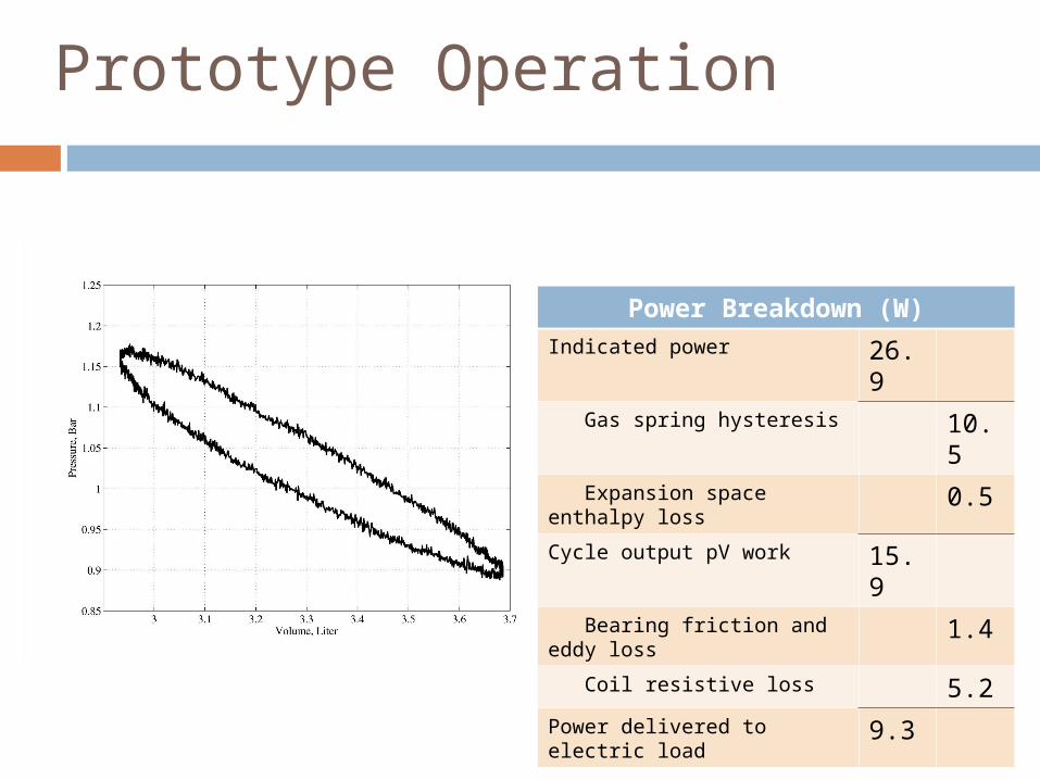
Prototype Operation
Power Breakdown (W)
Indicated power 26.9
Gas spring hysteresis 10.5
Expansion space enthalpy loss 0.5
Cycle output pV work 15.9
Bearing friction and eddy loss 1.4
Coil resistive loss 5.2
Power delivered to electric load 9.3

Piston Systems

Prototype 2: Multi-phase
Nylon flexure (cantilever spring)
HeaterCooler
Cold side piston plate
Actuator mounting jaw
Axis of rotation
Diaphragm
Sealed clearance

Components

Parameter Value
Working fluid Ambient air
Frequency ~30 Hz
Hot side temperature 147 oC
Cold side temperature 27 oC
Power (per phase) 12.7 W
Calculated damping (per phase)
19.5 W
Dominant damping (per phase) Gas hysteresis (10.8 W)
Experimental Data

Gas Compression Loss

More Phases => Less Compression
Reverser
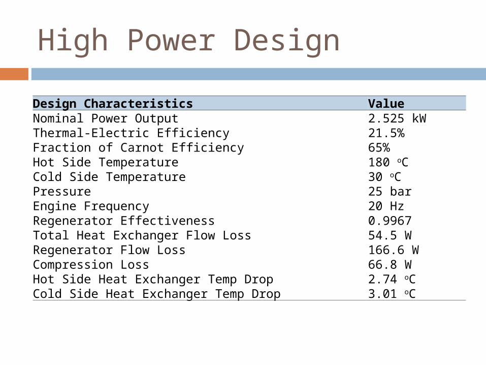
High Power Design
Design Characteristics Value Nominal Power Output 2.525 kW Thermal-Electric Efficiency 21.5% Fraction of Carnot Efficiency 65% Hot Side Temperature 180 oC Cold Side Temperature 30 oC Pressure 25 bar Engine Frequency 20 Hz Regenerator Effectiveness 0.9967 Total Heat Exchanger Flow Loss 54.5 WRegenerator Flow Loss 166.6 WCompression Loss 66.8 WHot Side Heat Exchanger Temp Drop 2.74 oCCold Side Heat Exchanger Temp Drop 3.01 oC

Energy Flows and Losses
Ideal Stirling Cycle
Heat In Heater CoolerRejected Heat
Heat Transfer Leakages
Regenerator Ineffectiveness
PV Work Out
Heater and ½ Regenerator Flow Loss
Cooler and ½ Regenerator Flow Loss
Gas Hysteresis Loss
Alternator Inefficiency, Bearing Losses
Electrical
Output
Internal Bearing & Motion Losses

Differences from prototypes
Design Improvements Improved heat exchanger design Refined simulation and models Extensive optimization
Scaling Increased pressure Increased frequency Increased volume Relatively smaller losses

Efficiency and Power Output Contour Plot
20Hz, 25bar Air
0.190.195
0.2
0.2
0.20
5
0.205
0.205
0.21
0.21
0.21
0.21
0.21
0.215
0.215
0.21
5
0.215
1000 1500
1500
1500
1500
2000
20002000
2000
2500
2500
2500
3000
3000
3500
Displacer Stroke (m)
Pow
er P
isto
n S
trok
e (m
)
Efficiency and Power (W)
0.008 0.009 0.01 0.011 0.012 0.013 0.014 0.015 0.016 0.017 0.0180.03
0.035
0.04
0.045
0.05
0.055
0.06
0.065
0.07

What’s Next?
Finalize designs Fabrication and testing of high power
prototype Design/experimental work with thermal
storage Explore waste heat electric generation Economic analysis of cogen, energy
storage opportunities


Residential Example
30-50 sqm collector => 3-5 kWe peak at 10%eff
Reject 12-20 kW thermal power at peak. Much larger than normal residential hot water systems – would provide year round hot water, and perhaps space heating
Hot side thermal storage can use insulated (pressurized) hot water storage tank. Enables 24 hr electric generation on demand.
Another mode: heat engine is bilateral – can store energy when low cost electricity is available
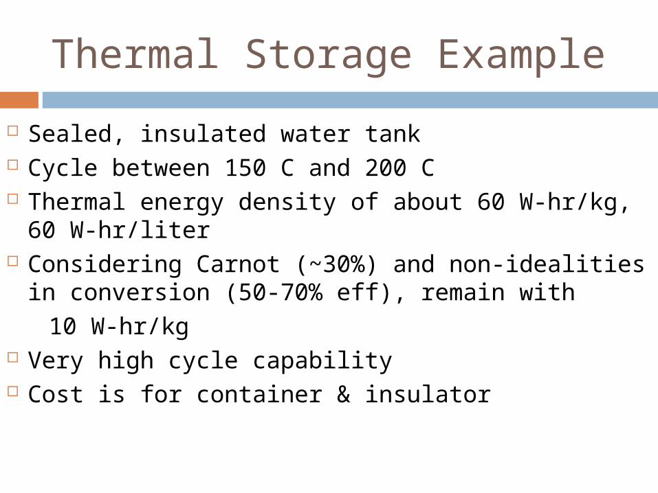
Thermal Storage Example
Sealed, insulated water tank Cycle between 150 C and 200 C Thermal energy density of about 60 W-hr/kg, 60
W-hr/liter Considering Carnot (~30%) and non-idealities in
conversion (50-70% eff), remain with 10 W-hr/kg Very high cycle capability Cost is for container & insulator

G = 1000 W/m2 (PV standard)
Schott ETC-16 collector
Engine: 2/3 of Carnot eff.
Collector and Engine Efficiency

Energy Storage Comparison
Storage Technology Energy Density Cost Self-discharge Round Trip Efficiency Lifetime
Thermal (various media) 20-80 kWh/m3 $40-65/ kWh 1-2% per day 70-80% Unlimited
Flywheel 0.2 Wh/kg $300/kWh Minimal 80-90% ~20 yearsCompressed Air 2 kWh/m3 $1-5/kWh
(storage only)None 80% Unlimited
Superconducting Magnetic Energy Storage
1-10 Wh/m3 $54,000/kWh None with cooling 90-95% Unlimited
Pumped Hydro 0.3 kWh/m3 @ 100m $10-45/kWh None 75% Unlimited
NiMH Battery 30–80 Wh/kg $364/kWh 30%/month 66% 500-1000 cyclesNiCad Battery 40-60 Wh/kg $400/kWh 20%/month 70-90% 1500 cyclesLithium Ion Battery 160 Wh/kg $300/kWh 5%/month 99.90% 1200 cycles
Lithum Polymer Battery 130-200 Wh/kg $500/kWh 10%/month 99.50% 1000 cycles
Lead Acid Battery 30-40 Wh/kg $100-200/kWh 3%-4%/month 70%-92% 500-800 cycles
Related Documents