Stimulation wellbore • Bottomhole frac pressure = surface pressure+ hydrostatic – friction terms • Fracture gradient • Instantaneous shutin pressure © Copyright, 2011 p r P pf -perf friction pressure P h -hydrostatic pressure P tf -tubing friction pressure P w -total surface pressure pf p tf p h p w p f p D pf p tf p h p w p FG h p ) D ( FG h p f p surface) (at isip P

Welcome message from author
This document is posted to help you gain knowledge. Please leave a comment to let me know what you think about it! Share it to your friends and learn new things together.
Transcript
Stimulation wellbore
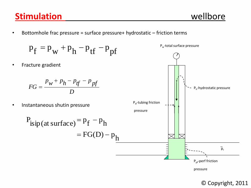
• Bottomhole frac pressure = surface pressure+ hydrostatic – friction terms
• Fracture gradient
• Instantaneous shutin pressure
© Copyright, 2011
pr pf
Ppf-perf friction
pressure
Ph-hydrostatic pressure
Ptf-tubing friction
pressure
Pw-total surface pressure
pfp
tfp
hp
wp
fp
D
pfptfphpwpFG
hp)D(FG
hp
fp
surface)(at isipP

Stimulation wellbore
Fracture down tubing with packer • Why?
– Integrity of casing – Higher burst rating, 2 7/8”, 6.5#, N-80 pburst = 10,570 psi
5 ½ ”, 15.5#, J-55 pburst = 5,320 psi • Disadvantage: Higher frictional effects – important in surface injection pressures and allowable rates • Considerations: burst of tubing, force and length changes on packer
and tubing.
© Copyright, 2011
pr p
f
Ph-hydrostatic pressure Ptf-tubing
friction
pressure
Pw-total surface pressure

Stimulation wellbore
Fracture down casing Why?
– Allows higher injection rates (>25 bpm) at
lower surface injection pressures
• Disadvantage:
burst rating of casing, integrity
• Considerations: burst of casing at breakdown and screenout
© Copyright, 2011
pr p
f
Ph-hydrostatic pressure Ptf-casing
friction pressure
Pw-total surface pressure

Stimulation wellbore
Fracture treatment with live annulus (*Preferred)
• How?
• Pump through tubing, monitor bottomhole
pressure through annulus
– Annulus full of fluid of known density
– Measure surface annulus pressure
• Considerations:
Burst of tubing
© Copyright, 2011
pr p
f
Ph-hydrostatic pressure Ptf-tubing
friction
pressure
Pw-total surface pressure

Stimulation wellbore
Fracture treatment with live tubing (*Preferred)
• How?
• Pump through annulus, monitor bottomhole
pressure through tubing
– tubing full of fluid of known density
– Measure surface tubing pressure
• Considerations:
collapse of tubing, burst of casing
© Copyright, 2011
pr p
f
Ph-hydrostatic pressure Pcf-casing
friction pressure
Pw-total surface pressure

Stimulation wellbore
Hydrostatic pressure • Fundamental equation:
• In field units: ph = 0.052rfh {psi}
• Where h is TVD in ft and rf is fluid/slurry density
• Calculate density from:
© Copyright, 2011
gh
z
z
gdzhp rr 2
1
p
x
xff
r
34.81
34.8
pr p
f Ppf-perf friction pressure
Ph-hydrostatic pressure
Ptf-tubing friction pressure
Pw-total surface pressure

Stimulation wellbore
Hydrostatic pressure Calculate density from:
rf - density of frac fluid {ppg}
f - specific gravity of frac fluid
Fresh water, 8.34 ppg, f = 1.00
2% Kcl water, 8.43 ppg, f = 1.01
43 API oil, 6.76 ppg, f = 0.81
p - specific gravity of propping agent
sand 2.65
resin-coated sand 2.55
ceramic proppants 2.7 to 3.3
bauxite 3.4
x - concentration of propping agent {ppg}
© Copyright, 2011
p
x
xff
r
34.81
34.8
pr p
f Ppf-perf friction pressure
Ph-hydrostatic pressure
Ptf-tubing friction pressure
Pw-total surface pressure

Stimulation wellbore
Hydrostatic pressure
© Copyright, 2011
Stimulation friction
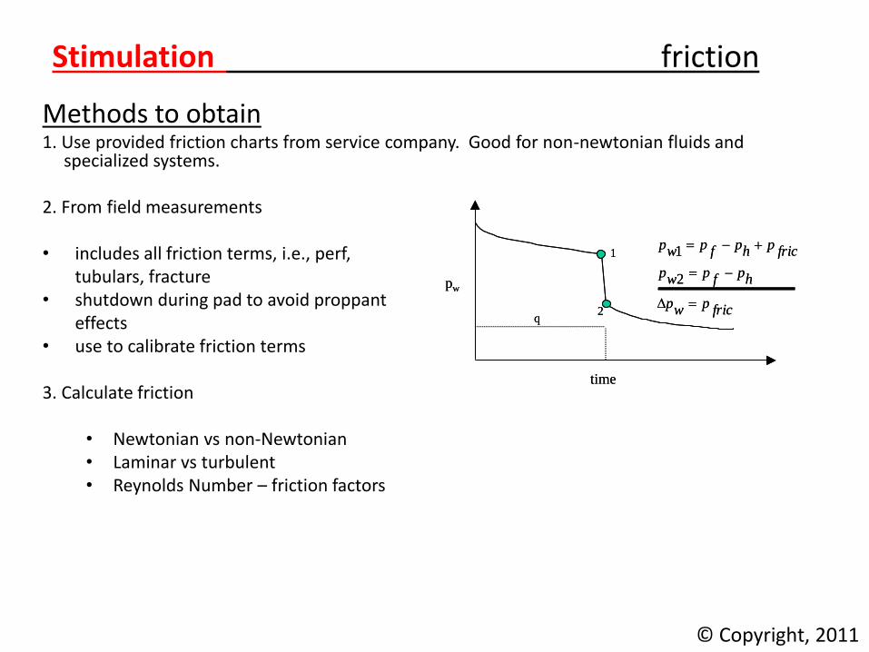
Methods to obtain 1. Use provided friction charts from service company. Good for non-newtonian fluids and
specialized systems. 2. From field measurements • includes all friction terms, i.e., perf, tubulars, fracture • shutdown during pad to avoid proppant effects • use to calibrate friction terms 3. Calculate friction
• Newtonian vs non-Newtonian • Laminar vs turbulent • Reynolds Number – friction factors
© Copyright, 2011
1
2
time
pw
qfricpwp
hpfpwp
fricphpfpwp
2
11
2
time
pw
qfricpwp
hpfpwp
fricphpfpwp
2
1

Stimulation friction
Example Well Data Depth: 6,650 ft ISIP data on offset wells: Well 1: pisip = 1,870 psi with proppant-free fresh water in hole Well 2: pisip = 2,300 psi with proppant-free 36 API oil in hole 41/2 -in. casing set on top of pay zone. Working pressure limit: 3,900 psi on casing The breakdown pressure is within the 3,900 psi casing working pressure limit. Determine: Hydraulic horsepower required for treatment of 25 bbl/min using un-treated fresh water
with 1 lb/gal sand. Injection rate and hhp for treatment at maximum rate without exceeding casing working
pressure while pumping untreated fresh water with no sand.
© Copyright, 2011
Stimulation friction
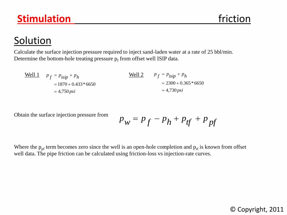
Solution Calculate the surface injection pressure required to inject sand-laden water at a rate of 25 bbl/min.
Determine the bottom-hole treating pressure pf from offset well ISIP data.
Well 1 Well 2
Obtain the surface injection pressure from
Where the ppf term becomes zero since the well is an open-hole completion and ptf is known from offset
well data. The pipe friction can be calculated using friction-loss vs injection-rate curves.
© Copyright, 2011
psi
hpisippfp
750,4
6650*433.01870
psi
hpisippfp
730,4
6650*365.02300
pfptfphpfpwp

Stimulation friction
Solution For water displaced through 4 1/2 -in. OD casing the friction pressure is 200 psi/1,000 ft of casing while pumping water at 25 bbl/ min. However, this friction pressure must also be adjusted for the effect of sand concentration. The correction factor is 1.10 for water containing 1 lb of sand/gal (see Figure 1). The hydrostatic pressure of fresh water containing 1 lb/gal sand is 465 psi/ 1,000 ft of hole. Hence:
© Copyright, 2011
psiftft
psitfp 146310.1*6650*
1000
200
ftftft
psihp 30906650*
1000
465
Figure 1. Effect of Sand Concentration on friction pressure
Stimulation friction
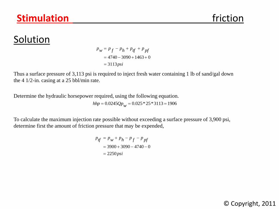
Solution
Thus a surface pressure of 3,113 psi is required to inject fresh water containing 1 lb of sand/gal down
the 4 1/2-in. casing at a 25 bbl/min rate.
Determine the hydraulic horsepower required, using the following equation.
To calculate the maximum injection rate possible without exceeding a surface pressure of 3,900 psi,
determine first the amount of friction pressure that may be expended,
© Copyright, 2011
psi
pfptfphpfpwp
3113
0146330904740
19063113*25*025.00245.0 wQphhp
psi
pfpfphpwptfp
2250
0474030903900
Stimulation friction
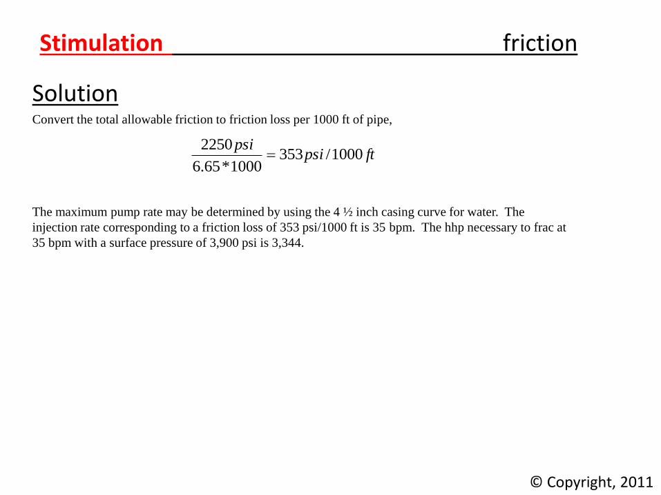
Solution Convert the total allowable friction to friction loss per 1000 ft of pipe,
The maximum pump rate may be determined by using the 4 ½ inch casing curve for water. The
injection rate corresponding to a friction loss of 353 psi/1000 ft is 35 bpm. The hhp necessary to frac at
35 bpm with a surface pressure of 3,900 psi is 3,344.
© Copyright, 2011
ftpsipsi
1000/3531000*65.6
2250

Stimulation friction
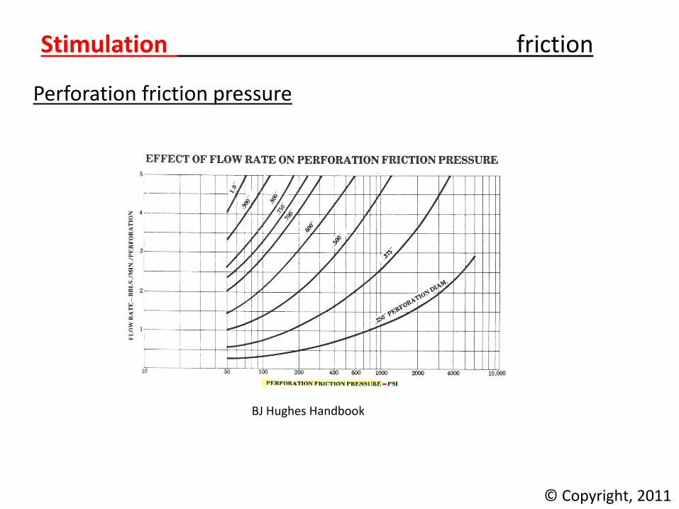
Perforation friction pressure • Important in fracture design and pressure analysis
• Semi-empirical model
based on similarity to orifice equation
f(flow rate, slurry density, perforation density and number)
where,
q = flow rate, bpm
rf = fracture fluid density, ppg
dp = perforation diameter, in.
np = perforation number
kd = discharge coefficient, measure of the perfs efficiency at passing fluid
kd 0.60 for new perfs
kd 0.85 for eroded perfs
© Copyright, 2011
2
dk
4
pd
2
pn
f
2q2369.
pfp
r
Stimulation friction
Perforation friction pressure
© Copyright, 2011
BJ Hughes Handbook
Stimulation friction
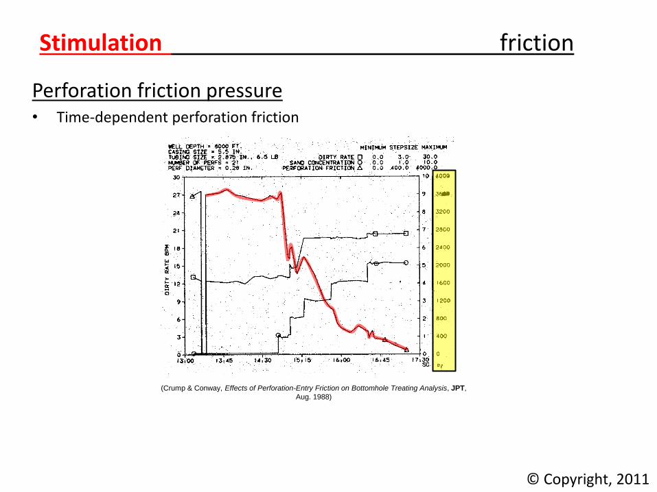
Perforation friction pressure • Time-dependent perforation friction
© Copyright, 2011
(Crump & Conway, Effects of Perforation-Entry Friction on Bottomhole Treating Analysis, JPT,
Aug. 1988)
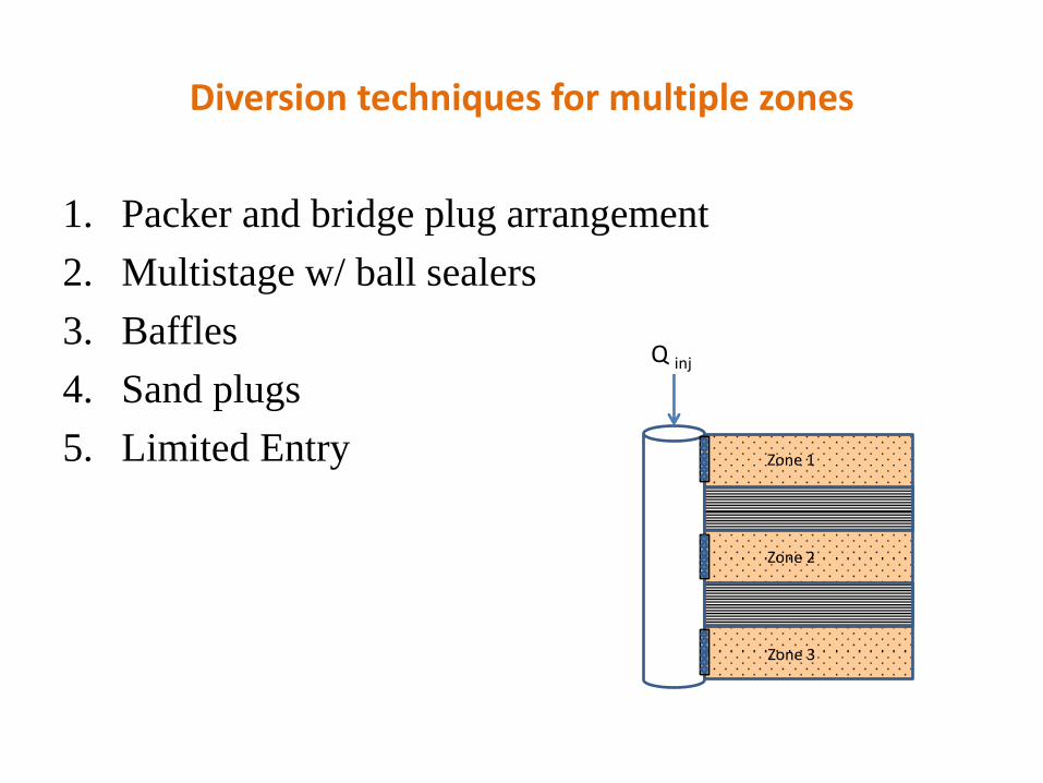
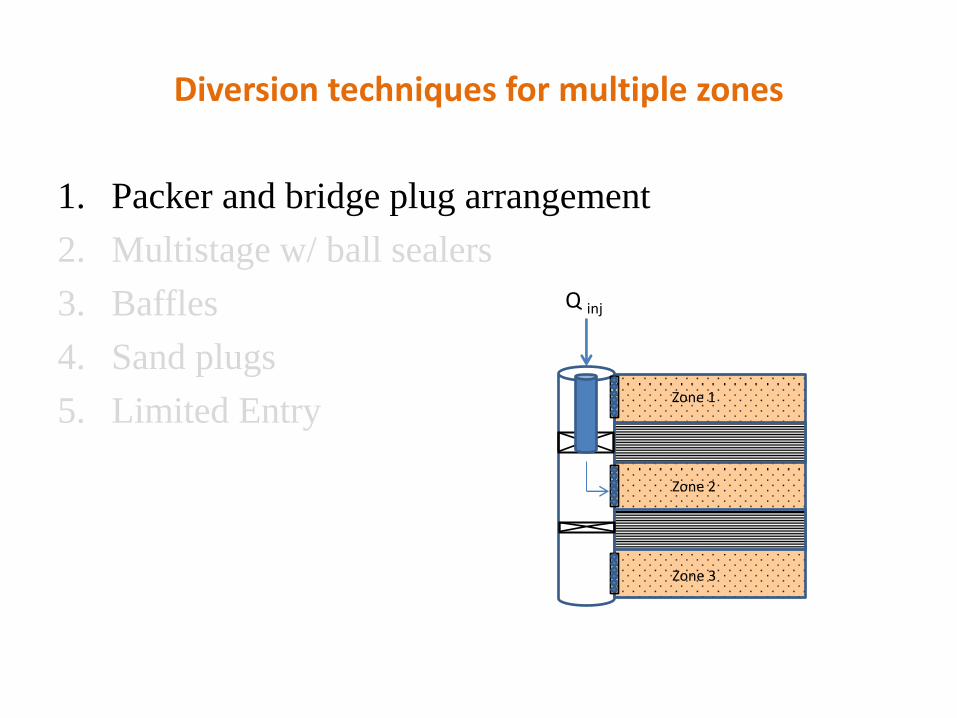
Diversion techniques for multiple zones
1. Packer and bridge plug arrangement
2. Multistage w/ ball sealers
3. Baffles
4. Sand plugs
5. Limited Entry
Q inj
Zone 1
Zone 2
Zone 3
Diversion techniques for multiple zones
1. Packer and bridge plug arrangement
2. Multistage w/ ball sealers
3. Baffles
4. Sand plugs
5. Limited Entry
Q inj
Zone 1
Zone 2
Zone 3

Diversion techniques for multiple zones
1. Packer and bridge plug arrangement
2. Multistage w/ ball sealers
3. Baffles
4. Sand plugs
5. Limited Entry
Q inj
Zone 1
Zone 2
Zone 3

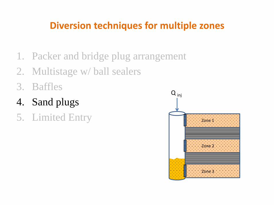
Diversion techniques for multiple zones
1. Packer and bridge plug arrangement
2. Multistage w/ ball sealers
3. Baffles
4. Sand plugs
5. Limited Entry
Diversion techniques for multiple zones
1. Packer and bridge plug arrangement
2. Multistage w/ ball sealers
3. Baffles
4. Sand plugs
5. Limited Entry
Q inj
Zone 1
Zone 2
Zone 3
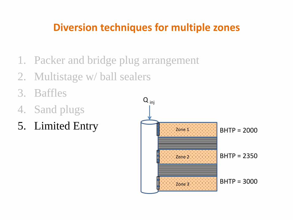
Diversion techniques for multiple zones
1. Packer and bridge plug arrangement
2. Multistage w/ ball sealers
3. Baffles
4. Sand plugs
5. Limited Entry
Q inj
Zone 1
Zone 2
Zone 3
BHTP = 2000
BHTP = 2350
BHTP = 3000
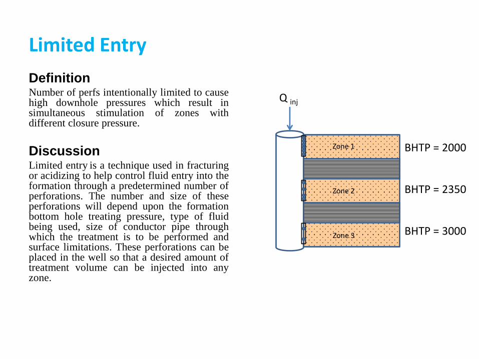
Limited Entry
Definition Number of perfs intentionally limited to cause high downhole pressures which result in simultaneous stimulation of zones with different closure pressure.
Discussion Limited entry is a technique used in fracturing or acidizing to help control fluid entry into the formation through a predetermined number of perforations. The number and size of these perforations will depend upon the formation bottom hole treating pressure, type of fluid being used, size of conductor pipe through which the treatment is to be performed and surface limitations. These perforations can be placed in the well so that a desired amount of treatment volume can be injected into any zone.
Q inj
Zone 1
Zone 2
Zone 3
BHTP = 2000
BHTP = 2350
BHTP = 3000
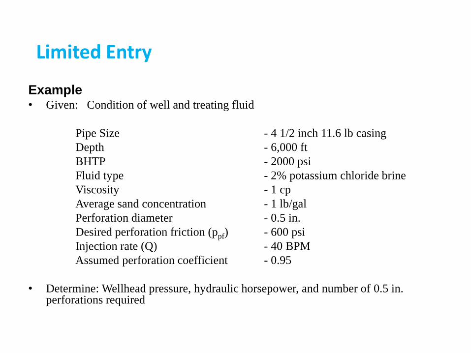
Example • Given: Condition of well and treating fluid
Pipe Size - 4 1/2 inch 11.6 lb casing
Depth - 6,000 ft
BHTP - 2000 psi
Fluid type - 2% potassium chloride brine
Viscosity - 1 cp
Average sand concentration - 1 lb/gal
Perforation diameter - 0.5 in.
Desired perforation friction (ppf) - 600 psi
Injection rate (Q) - 40 BPM
Assumed perforation coefficient - 0.95
• Determine: Wellhead pressure, hydraulic horsepower, and number of 0.5 in. perforations required
Limited Entry

Solution:
Hydrostatic pressure:
Pressure gradient for 2% KC1 water with 1 ppg = 47.0 psi/100 ft
ph = (47)(60) = 2820 psi
Friction pressure:
Friction loss for a 1 cp fluid in 4 1/2 inch, 11.6 lb casing at 40 BPM= 52 psi/100 ft
ptf = (52)(60) = 3120 psi
Therefore:
Wellhead pressure:
Hydraulic horsepower:
Number of perforations:
tfphp
tfphpwp
2600
6002000
psitfphpwp 29002600
hpwpQ2842
81.40
*
ppg
p
x
xff 016.9
65.2*34.8
11
101.1*34.8
34.81
34.8
r
Limited Entry
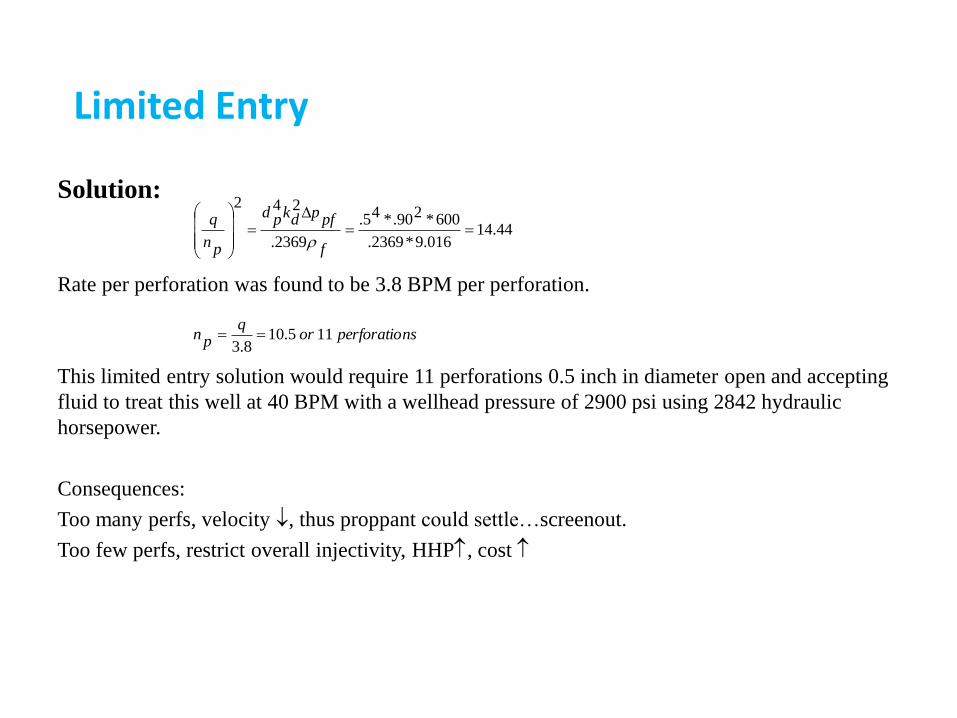
Solution:
Rate per perforation was found to be 3.8 BPM per perforation.
This limited entry solution would require 11 perforations 0.5 inch in diameter open and accepting
fluid to treat this well at 40 BPM with a wellhead pressure of 2900 psi using 2842 hydraulic
horsepower.
Consequences:
Too many perfs, velocity , thus proppant could settle…screenout.
Too few perfs, restrict overall injectivity, HHP, cost
nsperforatioorq
pn 115.108.3
44.14016.9*2369.
600*290.*45.
2369.
242
f
pfpdkpd
pn
q
r
Limited Entry
Related Documents