DOCTORAL THESIS Stiffness of Reverse Channel Connections at Room and Elevated Temperatures Tim Heistermann

Welcome message from author
This document is posted to help you gain knowledge. Please leave a comment to let me know what you think about it! Share it to your friends and learn new things together.
Transcript
DOCTORA L T H E S I S
Department of Civil, Environmental and Natural Resources EngineeringDivision of Structural and Construction Engineering
Stiffness of Reverse Channel Connections at Room and
Elevated Temperatures
Tim Heistermann
ISSN: 1402-1544ISBN 978-91-7439-768-0 (print)ISBN 978-91-7439-769-7 (pdf)
Luleå University of Technology 2013
Tim
Heisterm
ann Stiffness of Reverse C
hannel Connections at R
oom and E
levated Temperatures
ISSN: 1402-1544 ISBN 978-91-7439-XXX-X Se i listan och fyll i siffror där kryssen är

Division of Structural and Construction Engineering Department of Civil, Environmental and Natural Resources Engineering
Luleå University of Technology SE - 971 87 LULEÅ
www.ltu.se/sbn
DOCTORAL THESIS
STIFFNESS OF REVERSE CHANNEL CONNECTIONS AT ROOM AND ELEVATED
TEMPERATURES
Tim Heistermann
Luleå, October 2013

Printed by Universitetstryckeriet, Luleå 2013
ISSN: 1402-1544 ISBN 978-91-7439-768-0 (print)ISBN 978-91-7439-769-7 (pdf)
Luleå 2013
www.ltu.se
Abstract
I
ABSTRACT
A frame structure exposed to fire undergoes two types of changes due to the resulting temperature fields. The first is the thermal expansion of the structural members and the second is the degradation of the material strength and stiffness as temperature rises. Initially the thermal expansion dominates the response and the structural member (beam) is exposed to compressive forces due to restrained expansion, thus precipitating flexural buckling.
At higher temperatures the mechanical material properties degrade. This fact, together with the high compressive forces in the bottom flanges of the beam often results in local buckling, followed by the formation of a plastic hinge close to the support region. The combination of transverse loads and the rising temperature leads to the development of excessive deflections in the beam. When temperature rises enough for the bending resistance of the beam to become insufficient, catenary action is introduced. The result is that the beam transitions to a stage where tensile forces appear due to the catenary action. In these different stages of the response of the structure the beam-to-column connection plays a crucial role and its robustness will determine if the structure will be able to maintain its integrity.
The robustness of a structure in a fire situation greatly depends on the rotational capacity of the connection region. High rotational capacity is required at elevated temperatures since the steel beams lose their bending stiffness and exhibit increasingly large deflections under constant load. Beam deflections result in increasing rotations at the supports and may lead to collapse due to connection failure. Other possible failure modes may occur in the structural members, for example due to yielding in tension of the beam. The reverse channel has been proposed as a practical alternative to assemble
Stiffness of Reverse Channel Connections at Room and Elevated Temperatures
II
beams to tubular columns. In a simple implementation, the bending moment generated in the joint due to rotation of the beam may be neglected; however, research efforts are being attempted to quantify the level of constraint. The typical arrangement of the connection type consists of a reverse channel with its flanges welded onto the face of concrete-filled tubular columns and the web bolted to the endplate of a beam. Thicknesses and depths of the reverse channel determine the level of rotational restraint at high temperature. The reverse channel has the ability to undergo catenary deformation in the tensile zone due to the applied rotation at the support and similarly it is relatively ductile in the compression zone. Overall, the reverse channel connection response is rather ductile in terms of its ability to undergo large rotational deformation as long as bolt failure is avoided through proper design.
Various tests have been performed to study the behaviour of this type of connection such as full scale buildings, sub-frames, isolated joints and individual sections. The aim of these tests was to capture the connection behaviour in relation to other structural components in fire. This thesis focuses on the tests carried out on the connection components and their finite element modelling. A comprehensive parametric study was performed to assess the influence of different parameters on the behaviour of the connection component at elevated temperatures. The results from the finite element analyses have been utilized to validate analytical models that describe the behaviour of this type of connection at ambient and elevated temperature. Insight into the analytical models provides proper background to a structural designer to estimate the initial stiffness and understand the behaviour of the reverse channel in the connection.
Abstract in Swedish
III
ABSTRACT IN SWEDISH
En ramkonstruktion utsatt för brand påverkas på två olika sätt av temperaturhöjningen. För det första blir det en längdutvidgning av temperaturhöjningen och för det andra tappar materialet styrka och styvhet med ökande temperatur. Inledningsvis dominerar effekten av temperatur-utvidgningen. Denna leder till tryckande tvångskrafter i konstruktionen vilka kan leda till knäckning.
Vid höga temperaturer sjunker materialets styvhet och styrka. Detta kan tillsammans med de höga tryckkrafterna leda till att flytleder bildas vid stöd. De stora tryckkrafterna kan också orsaka knäckning i balken och transversallasterna kan med den minskade styvheten på grund av temperaturhöjning ge upphov till mycket stora deformationer och balkens bärförmåga blir vid tillräckligt höga temperaturer otillräcklig. Vid tillräckligt stora deformationer övergår det statiska verkningssättet från böjning till linverkan. Under denna övergång spelar förbanden mellan balkar och pelare en central roll, och hur dessa klarar att hantera laster och deformationer avgör om hela konstruktionen kan klara belastningen.
Hur en konstruktion klarar en brandbelastning beror i hög grad på hur förbanden mellan balkar och pelare klarar rotationer. En stor rotationskapacitet krävs vid höga temperaturer eftersom stålbalkar då har låg bärförmåga och deformationerna kan bli mycket stora även om lasterna är oförändrade. Stora deformationer i balkarna leder till stora rotationer i knutpunkterna vilket kan leda till att förbanden brister och hela konstruktionen kollapsar. Andra möjliga brottmoder kan vara kollaps av balkarna på grund av plasticering under drag. U-profilen har föreslagits som ett praktiskt alternativ för att ansluta balk till pelare. Rotationskapaciteten för ett sådant förband kan bedömas som
Stiffness of Reverse Channel Connections at Room and Elevated Temperatures
IV
försumbar, men forskningsinsatser görs för att bestämma den. En föreslagen utformning är att svetsa U-profilens flänsar till den betongfyllda pelaren med slutet tvärsnitt och livet fäst med skruvar i ändplåten på en balk. Rotationsstyvheten vid höga temperaturer kommer att bero på dimensioner på U-profilen. En U-profil har möjligheten att genomgå omvandlingen till linverkan i den dragna delen när den utsätts för ändrotation med den tryckta delen intakt. I allmänhet har ett förband med en U-profil möjlighet att klara stora rotationer under förutsättning att skruvförbandet är utformat på rätt sätt.
Ett antal försök har genomförts för att studera hur föreliggande förband kan fungera i en byggnad, en del av en ram, enskilda förband och i tvärsnitt. Försöken har gjorts för att nå förståelse för hur förbandet fungerar tillsammans med andra konstruktionsdetaljer när de utsätts för brandbelastning. Denna avhandling fokuserar på försöken med delar ur förbandet och finit element modellering. En omfattande parameterstudie har gjorts för att förstå hur olika parametrar påverkar förbandets egenskaper vid förhöjd temperatur. Från FE-beräkningarna har analytiska modeller tagits fram som beskriver förbandets egenskaper vid medelhöga och höga temperaturer och dessa ger konstruktören möjlighet att uppskatta den ursprungliga styvheten hos förbandet med U-profil och förståelse för dess uppträdande.

Abstract in Portuguese
V
ABSTRACT IN PORTUGUESE
Quando uma estrutura em pórtico é exposta ao fogo, fica submetida a dois tipos diferentes de alterações devido à influência da temperatura. A primeira devido à expansão térmica das componentes estruturais e a segunda como consequência da degradação da resistência e rigidez, a par com o aumento da temperatura. Inicialmente apenas se constata o fenómeno de expansão térmica ficando o elemento estrutural (a viga) sujeito a altas forças de compressão devidas ao impedimento desta em se alongar, precipitando a encurvadura global.
A temperaturas consideravelmente mais altas, as propriedades do material começam a degradar-se. Este facto, juntamente com as elevadas forças de compressão desenvolvidas no banzo inferior da viga, resultam geralmente em encurvadura local, seguida da formação de rótulas plásticas na zona dos apoios. A combinação de cargas transversais e o aumento da temperatura tem como resultado, excessivas deformações na viga. Quando a temperatura sobe o suficiente para a resistência à flexão da viga se tornar insuficiente, a acção de catenária é iniciada. Como resultado, a viga transita para uma fase onde a forças de tensão se geram em resultado do desenvolvimento da acção de catenária. Nestas diferentes fases de resposta da estrutura, a ligação viga-pilar desempenha um papel crucial, sendo que a sua robustez determinará se a estrutura será capaz de manter a sua integridade.
A robustez de uma estrutura em situação de fogo depende grandemente da capacidade de rotação das componentes da ligação. A grande capacidade de rotação é necessária a elevada temperatura uma vez que as vigas perdem a sua rigidez de flexão, apresentando um aumento crescente deformação sob a acção de cargas constantes. A deformação da viga resulta numa excessiva rotação nos
Stiffness of Reverse Channel Connections at Room and Elevated Temperatures
VI
apoios podendo originar o colapso devido à rotura pela ligação. Outros modos de rotura poderão ocorrer nos elementos estruturais, como por exemplo os originados por cedência da viga em tensão. O reverse channel tem sido proposto como uma alternativa na ligação de vigas a pilares com perfil tubular. Numa simples abordagem, o momento flector gerado na ligação devido à rotação da viga poderá ser negligenciado, no entanto, têm sido desenvolvidos eforços no sentido de quantificação do seu nível de amarração. Numa ligação típica de reverse channel, os banzos são soldadas na face de pilares tubulares preenchidos com betão e a alma aparafusada à chapa de topo da viga. A espessura e profundidade do reverse channel determinam o grau de rotação da ligação a temperaturas elevadas. O reverse channel é susceptível de sofrer deformações do tipo catenária na zona de tracção devido à rotação induzida, revelando-se igualmente dúctil na zona de compressão. Geralmente, o comportamento do reverse channel mostra-se bastante dúctil, em termos da sua capacidade de sofrer grandes deformações de rotação, isto apenas quando a rotura pelos parafusos é tida em conta em fase de projecto.
Vários testes foram levados a cabo para o estudo do comportamento deste tipo de ligação: ao nível do edifício, no seu conjunto, em pórticos isolados, em ligações isoladas e elementos estruturais per si. O objectivo destes testes foi compreender o comportamento da ligação na relação com outras componentes estruturais em situação de incêndio. A presente tese debruça-se sobre os testes efectuados às componentes de ligação e a sua modelação numérica por elementos finitos. Para tal, foi levado a cabo um intensivo estudo paramétrico, com o intuito de avaliar a influência dos vários parâmetros da ligação no comportamento da ligação quando sujeitos a elevadas temperaturas. Os resultados obtidos da modelação numérica foram utilizados com o intuito de validar os modelos analíticos que descrevem o comportamento da ligação a altas temperaturas. Os modelos analíticos fornecem a informação necessária ao projectista no sentido de estimar a rigidez inicial e compreender o comportamento do reverse channel na ligação.
1
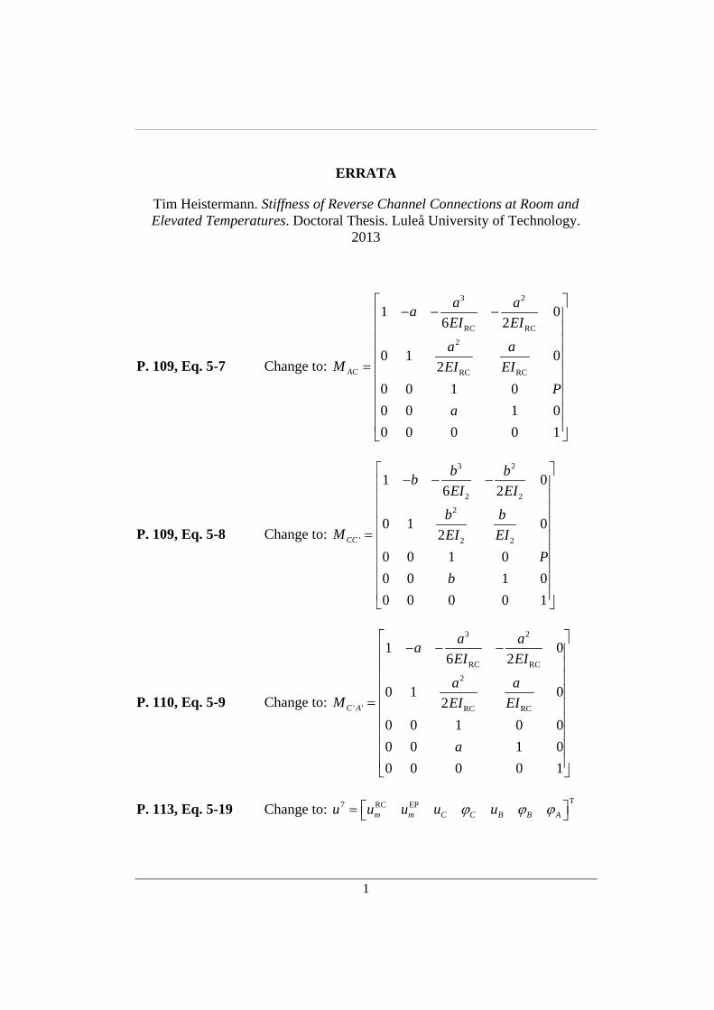
ERRATA
Tim Heistermann. Stiffness of Reverse Channel Connections at Room and Elevated Temperatures. Doctoral Thesis. Luleå University of Technology.
2013
P. 109, Eq. 5-7 Change to:
3 2
RC RC
2
RC RC
1 06 2
0 1 02
0 0 1 0
0 0 1 0
0 0 0 0 1
AC
a aa
EI EI
a aM EI EI
P
a
P. 109, Eq. 5-8 Change to:
3 2
2 2
2
' 2 2
1 06 2
0 1 02
0 0 1 0
0 0 1 0
0 0 0 0 1
CC
b bb
EI EI
b bM EI EI
P
b
P. 110, Eq. 5-9 Change to:
3 2
RC RC
2
' ' RC RC
1 06 2
0 1 02
0 0 1 0 0
0 0 1 0
0 0 0 0 1
C A
a aa
EI EI
a aM EI EI
a
P. 113, Eq. 5-19 Change to: T7 RC EP
m m C C B B Au u u u u

Table of contents
VII
TABLE OF CONTENTS
ABSTRACT ......................................................................................................... I
ABSTRACT IN SWEDISH .............................................................................. III
ABSTRACT IN PORTUGUESE ....................................................................... V
TABLE OF CONTENTS ................................................................................ VII
PREFACE ......................................................................................................... XI
ABBREVIATIONS ....................................................................................... XIII
1 INTRODUCTION ..................................................................................... 11.1 Background ...................................................................................... 11.2 Objectives and expected research achievements .............................. 21.3 Limitations ....................................................................................... 31.4 Methodology .................................................................................... 31.5 Structure of the thesis ....................................................................... 41.6 List of publications ........................................................................... 6
1.6.1 Thesis related publications ................................................... 61.6.2 Additional publications ........................................................ 8
2 STATE OF THE ART ............................................................................... 92.1 Component method at ambient temperature .................................... 9
2.1.1 Introduction .......................................................................... 92.1.2 Joint evaluation ................................................................... 112.1.3 Resistance evaluation ......................................................... 122.1.4 Rotational stiffness evaluation ........................................... 122.1.5 Some developments not included in Eurocode 3 ............... 14
Stiffness of Reverse Channel Connections at Room and Elevated Temperatures
VIII
2.2 Behaviour of beam-to-column joints in fire ................................... 142.2.1 Introduction ........................................................................ 142.2.2 Experiments on isolated joints ........................................... 152.2.3 Sub-frame and full-building tests ....................................... 172.2.4 Analytical procedures......................................................... 19
2.3 Reverse channel connections ......................................................... 222.4 Component method at elevated temperatures ................................ 342.5 Reverse channel/endplate related connections: analytical models 36
2.5.1 Initial stiffness of RHS columns ........................................ 372.5.2 Initial stiffness of combined reverse channel/angle
connections ......................................................................... 382.5.3 Initial stiffness of reverse channel/endplate connections ... 40
3 EXPERIMENTAL WORK ON REVERSE CHANNEL CONNECTIONS ..................................................................................... 413.1 Introduction .................................................................................... 41
3.1.1 Tests on reverse channels at the University of Coimbra .... 423.1.2 Tests on reverse channels at the University of Manchester 453.1.3 Tests on isolated joints at the University of Sheffield ....... 47
4 FINITE ELEMENT MODELLING OF REVERSE CHANNEL CONNECTIONS ..................................................................................... 534.1 Description of 3D finite element models ....................................... 53
4.1.1 Mechanical properties of materials .................................... 534.1.2 Contact interactions ............................................................ 584.1.3 Element types ..................................................................... 594.1.4 Numerical procedures ........................................................ 604.1.5 Load and boundary conditions ........................................... 61
4.2 Validation of 3D models with experiments ................................... 634.2.1 Tests on reverse channels at the University of Coimbra .... 634.2.2 Tests on reverse channels at the University of Manchester 794.2.3 Tests on isolated joints at the University of Sheffield ....... 79
4.3 Parametric study – 3D finite element simulations ......................... 914.3.1 Influence of the reverse channel leg length........................ 934.3.2 Influence of the bolt spacing .............................................. 944.3.3 Influence of the endplate thickness .................................... 954.3.4 Influence of the reverse channel thickness ......................... 974.3.5 Comparison of rolled channels (PFC) with constant
thickness channel cuts from tubes ...................................... 994.3.6 Influence of temperature .................................................. 100
Table of contents
IX
5 ANALYTICAL MODELS FOR THE INITIAL STIFFNESS OF THE REVERSE CHANNEL ......................................................................... 1035.1 The two dimensional structural system ........................................ 1035.2 Contact forces with respect to bolt position – case of tension ..... 105
5.2.1 Contact type A: contact between the bolts ....................... 1075.2.2 Contact type B: contact on the outside of the bolts .......... 112
5.3 Contact forces with respect to the bolt position – case of compression .................................................................................. 120
5.4 Numerical verification of the analytical expressions ................... 1245.4.1 Case of tension – analytical results vs. 2D FEA .............. 1245.4.2 Case of compression – analytical results vs. 2D FEA ...... 1295.4.3 Case of tension – analytical results vs. 3D FEA .............. 1305.4.4 Case of compression – analytical results vs. 3D FEA ...... 1315.4.5 Validation of plane-stress assumption .............................. 132
6 DISCUSSION AND CONCLUSIONS ................................................. 1356.1 Discussion .................................................................................... 1356.2 Research questions ....................................................................... 1386.3 Conclusions .................................................................................. 140
7 FUTURE RESEARCH .......................................................................... 141
REFERENCES ................................................................................................ 143
ANNEXES ...................................................................................................... 153
A. SIMULATIONS FOR EXPERIMENTS DONE AT THE UNIVERSITY OF COIMBRA ...................................................................................... 155
B. SIMULATIONS FOR EXPERIMENTS DONE AT THE UNIVERSITY OF SHEFFIELD .................................................................................... 167
C. 3D FINITE ELEMENT SIMULATIONS: PARAMETRIC STUDY ... 179

Preface
XI
PREFACE
The research presented in this thesis was carried out in the research group of Steel Structures at the Department of Civil, Environmental and Natural Resources Engineering, Luleå University of Technology under joint supervision with University of Coimbra, Portugal. The joint doctoral supervision aimed to integrate large experimental and numerical programmes and to obtain a double degree. The research collaboration was conducted within a European project: COMPFIRE – Design of composite joints for improved fire robustness. The main objective of the project was to develop a comprehensive component based methodology for joints between steel beams and concrete filled tubular (CFT) steel columns using reverse channels. Several experiments have been conducted at the universities of Coimbra, Manchester and Sheffield in order to establish force-deflection-temperature relationships of different reverse channel sections. The focus of this thesis is to numerically validate the experimental results and perform parametric studies to identify different mechanisms relevant for the initial stiffness response. Based on those results, analytical models for the initial stiffness estimation of the reverse channel in compression and tension are proposed.
Thanks are due to the European Research Fund for Coal and Steel (RFCS) that supported this work under grant agreement number RFSR-CT-2009-00021, as well as the European Development Fund (NSS – Nordic Safety and Security).
Primarily, I would like to thank my supervisor Prof. Milan Veljkovic, who gave me the opportunity (not only financially but also in terms of support and guidance) to conduct this doctoral thesis and who always believed in me and my work. I would like to extend my gratitude to my assistant supervisors Prof. Luís Simões da Silva, who was also project coordinator of the COMPFIRE
Stiffness of Reverse Channel Connections at Room and Elevated Temperatures
XII
project, and Efthymios “Mimis” Koltsakis, who was of great help during the last six months of my studies.
Many thanks are also due to my colleagues at the University of Coimbra, namely Fernanda Lopes and Prof. Aldina Santiago for performing the experiments and sharing all necessary information with me. It was always a pleasure to collaborate with you.
I would also like to thank my colleagues and friends at Luleå University of Technology, who made me enjoy the last five years; especially my colleagues at the research group of Steel Structures should be mentioned with whom I frequently exchanged opinions and ideas and who took over some of my work during the last months.
I am also very grateful for the support of my family up to the present, especially for all the opportunities I was given by my mother, who abstained from many things during her life to provide me with the best prospects. This thesis is also your work.
Finally, I would like to thank my lovely wife Christine and my wonderful son Jonas for their love, always being there and especially for their support during the last months. I am looking forward to soon spend more enjoyable time with you again!
Luleå, October 2013
Tim Heistermann
Abbreviations
XIII
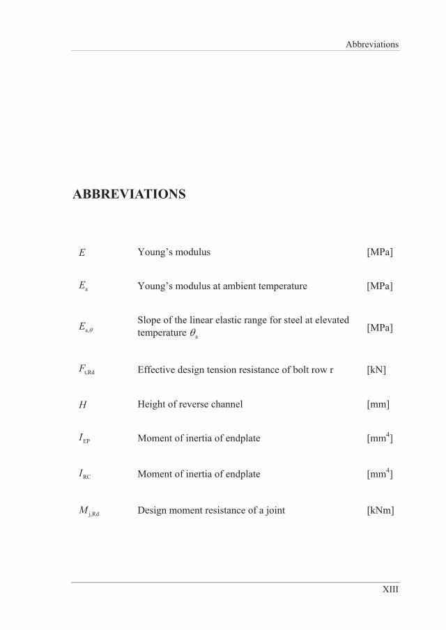
ABBREVIATIONS
E Young’s modulus [MPa]
aE Young’s modulus at ambient temperature [MPa]
a,E Slope of the linear elastic range for steel at elevated temperature a [MPa]
t,RdF Effective design tension resistance of bolt row r [kN]
H Height of reverse channel [mm]
EPI Moment of inertia of endplate [mm4]
RCI Moment of inertia of endplate [mm4]
j,RdM Design moment resistance of a joint [kNm]
Stiffness of Reverse Channel Connections at Room and Elevated Temperatures
XIV
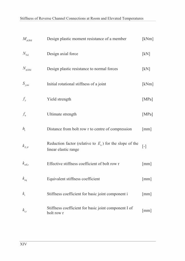
pl,RdM Design plastic moment resistance of a member [kNm]
EdN Design axial force [kN]
pl,RdN Design plastic resistance to normal forces [kN]
j,iniS Initial rotational stiffness of a joint [kNm]
yf Yield strength [MPa]
uf Ultimate strength [MPa]
rh Distance from bolt row r to centre of compression [mm]
,Ek Reduction factor (relative to aE ) for the slope of the linear elastic range
[-]
eff,rk Effective stiffness coefficient of bolt row r [mm]
eqk Equivalent stiffness coefficient [mm]
ik Stiffness coefficient for basic joint component i [mm]
i,rk Stiffness coefficient for basic joint component I of bolt row r [mm]
Abbreviations
XV
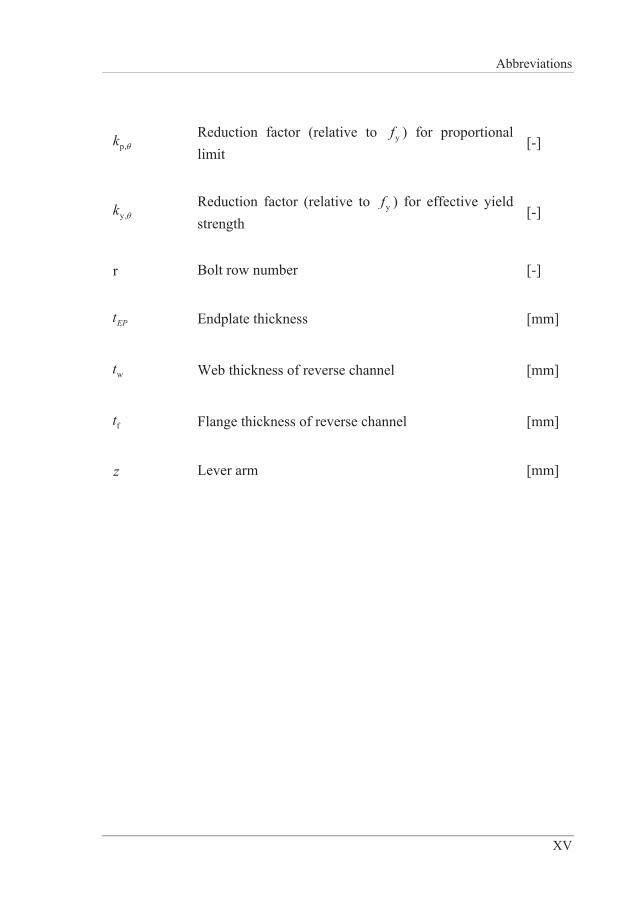
p,k Reduction factor (relative to yf ) for proportional limit
[-]
y,k Reduction factor (relative to yf ) for effective yield strength
[-]
r Bolt row number [-]
EPt Endplate thickness [mm]
wt Web thickness of reverse channel [mm]
ft Flange thickness of reverse channel [mm]
z Lever arm [mm]

Introduction
1
1 INTRODUCTION
1.1 Background
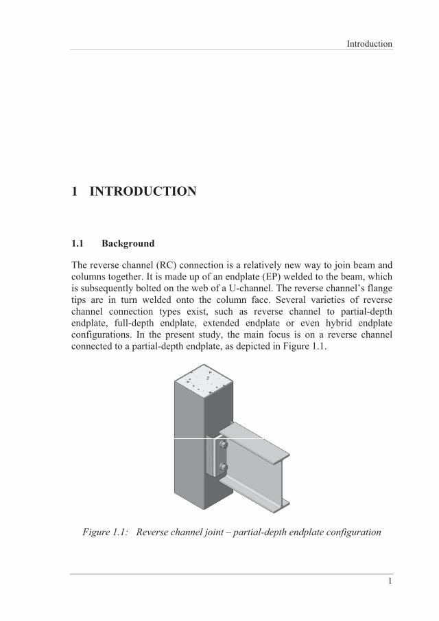
The reverse channel (RC) connection is a relatively new way to join beam and columns together. It is made up of an endplate (EP) welded to the beam, which is subsequently bolted on the web of a U-channel. The reverse channel’s flange tips are in turn welded onto the column face. Several varieties of reverse channel connection types exist, such as reverse channel to partial-depth endplate, full-depth endplate, extended endplate or even hybrid endplate configurations. In the present study, the main focus is on a reverse channel connected to a partial-depth endplate, as depicted in Figure 1.1.
Figure 1.1: Reverse channel joint – partial-depth endplate configuration
Stiffness of Reverse Channel Connections at Room and Elevated Temperatures
2
The present design codes [1,2] provide relatively little information on the behaviour of connections at elevated temperatures. However, observations made in real fire situations, such as for the collapse of the World Trade Center [3,4] and during a full-scale fire test at Cardington [5] have clearly shown the importance of joints with respect to the robustness. During a fire the structure undergoes essential changes due to degradation of material properties and internal forces, which may change rapidly due to restrained thermal deformations. In the heating phase of a fire, the affected beams naturally try to expand. If this thermal expansion is restrained due to columns connected to the beam, a relatively high axial force may be induced in the beam. However, the reverse channel provides longitudinal flexibility, mainly because of its web, and therefore can accommodate thermal expansion of the beam. Thus, a possible flexural buckling of the beam during the heating phase may be delayed or even avoided. Following this initial stage of a fire where thermal expansion dominates, at later stages of the fire mechanical properties of the material start to significantly degrade and may lead together with high compressive forces to local buckling in the bottom flange of a beam. Thereafter, the beam transitions to a stage where it experiences tensile forces, due to extensive vertical deflection of the beam. This stage is called the catenary stage. This transition is also crucial for the connection. The reverse channel has good capabilities to accommodate for this change as its web is able to significantly bend and after a while provides membrane stiffening. This means, the web deflects to such an extent that is doesn’t act in bending anymore but rather in tension. Basically the reverse channel provides local catenary action of the web.
1.2 Objectives and expected research achievements
Structural joints are characterized by means of their resistance, stiffness and rotation capacity. The main objective of this thesis is to study the response of reverse channel connections subject to compression or tension at ambient and elevated temperatures. The overall aim is to provide analytical models to predict the initial stiffness response of a reverse channel under the aforementioned conditions. The resistance part is carried out by one of the project partners, University of Sheffield, in co-operation with the author. The main contribution of the author was performing an extensive numerical parametric study to identify yield line mechanisms.
Introduction
3
The following key research questions are addressed:
1. Are the existing analytical models for combined reverse channel/angle connections suitable for predicting the initial stiffness of a reverse channel/partial-depth endplate connection?
2. Are the existing analytical models for the initial stiffness of rectangular hollow section (RHS) columns applicable to the reverse channel?
3. Is it possible to accurately predict the behaviour of reverse channel connections by means of Finite Element Methods (FEM) at ambient and elevated temperatures?
4. Can the initial stiffness of a reverse channel section in tension or compression be accurately predicted with a 2D finite element model?
5. Is it possible to predict the initial stiffness of a reverse channel by means of an analytical model based on simple beam theory? What are possible limitations of such an approach?
1.3 Limitations
The present thesis mainly deals with reverse channel connections. In the numerical analyses, different types of reverse channel/endplate configurations have been considered. However, the main focus was on a reverse channel bolted to a partial-depth endplate. Thus, the analytical approaches are limited to this specific configuration.
Furthermore, the analytical models are restricted to the initial elastic response; the influence of geometrical non-linearity is not considered. The model is limited to uniform compression and tension.
Both numerical as well as analytical solutions are restricted to constant temperature fields.
1.4 Methodology
The following research methodology has been adopted in order to achieve the objectives and provide suitable answers to the research questions identified in Section 1.2.
Stiffness of Reverse Channel Connections at Room and Elevated Temperatures
4
In the first step, a literature review has been carried out to identify the status of existing research work related to steel beam-to-column connections at ambient and elevated temperatures. The existing rules according to Eurocode 3 are briefly presented. A particular focus was on connections using reverse channels.
Thereafter, experimental work, which was carried out by other partners within the joint project COMPFIRE [6] and influenced the outcome of this thesis significantly, has been highlighted and described in detail.
This experimental work was used to validate 3D finite element models aiming to numerically extend the studies and investigate the influence of different parameters on the response of the reverse channel. It is the crucial part of the research as tests are expensive and therefore limited information may lead to incorrect conclusions. After evaluating the 3D results the focus is shifted to the initial stiffness calculation for the considered reverse channel connection in tension and compression. The main reason is to exercise a rather unconventional approach using analytical tools to gain complete understanding of the complex problems of interaction of surfaces in contact. An attempt is made to reduce the problem to 2D investigations and to establish analytical expressions for various situations. The analytical expressions that were developed were verified by extensive parametric studies where use was made of 2D/3D elastic Finite Element (FE) simulations in order to obtain the initial stiffness response.
However, before developing this new analytical approach, other existing approaches in the literature have been assessed. As discussed in the text, these were developed for similar categories of problems and fail to provide acceptably accurate results for the particular case at hand.
1.5 Structure of the thesis
The thesis consists of seven chapters excluding annexes. A brief summary of the content of each chapter is presented below:
Chapter 1 presents a brief introduction of the subject’s background. Objectives and expected research achievements, limitations, research methodology, structure of the thesis and a list of publications are described in short.
Chapter 2 provides a state of the art review. It starts with an overview of the component method for beam-to-column joints as presented in Eurocode 3. In
Introduction
5
addition, the behaviour of beam-to-column joints in fire, with a specific focus on reverse channel connections, is given. Finally, design aspects on the use of the component method at elevated temperatures are covered.
Chapter 3 describes the details and results of the experimental work on reverse channel connections, which have been used to validate numerical and analytical results.
Chapter 4 discusses details of the finite element models and simulations of reverse channel connections used in this study. 3D models are validated with experimental results, as presented in Chapter 3, and then used for parametric studies. Furthermore, 2D finite element models are compared to 3D models and used for more extensive parametric studies.
Chapter 5 provides the derivation of analytical models for the initial stiffness of the reverse channel component in tension and compression and verifies them with the results obtained by finite element methods.
Chapter 6 sums up the main conclusions achieved. The relevant research questions are discussed and answered.
Chapter 7 is the last chapter of the thesis and provides some suggestions for future work related to the research presented in this thesis.
Annex A compares the numerical and experimental work for tests performed at the University of Coimbra (Section 3.1.1).
Annex B provides the comparison of finite element simulations and tests performed at the University of Sheffield on isolated joints (Section 3.1.3).
Annex C presents detailed and complete results for all 3D finite element simulations based on the parametric study discussed in Section 4.3.
Stiffness of Reverse Channel Connections at Room and Elevated Temperatures
6
1.6 List of publications
The doctoral thesis is one part of the research work necessary to accomplish the Ph.D. studies in Steel Structures. Other parts consist of courses at Ph.D. level and publications. The following publications have been achieved during a five year period of Ph.D. studies.
1.6.1 Thesis related publications
Conference papers
Iqbal N, Heistermann T, Veljkovic M, Lopes F, Santiago A, Simões da Silva, L. Numerical study of steel beams in sub-frame assembly: Validation of existing hand calculation procedure. Proceedings of International Conference on Applications of Structural Fire Engineering, Prague, Czech Republic, 19-20 April 2013; p. 272-277
Lopes F, Santiago A, Simões da Silva L, Heistermann T, Veljkovic M, Guilherme da Silva J. Behaviour of the Reverse Channel Joint Component at Elevated Temperature. Tubular Structures XIV: proceedings of the 14th international symposium on tubular structures, London, United Kingdom, 12-14 September 2012; p. 645-651.
Heistermann T, Iqbal N, Veljkovic M, Lopes F, Santiago A, Simões da Silva L. Reverse channel connections at elevated temperature: Finite element modelling. Proceedings of the 6th European Conference on Steel and Composite Structures: Eurosteel 2011, Budapest, Hungary, August 31-September 2 2011; p. 1587-1592.
Journal papers
Lopes F, Santiago A, Simões da Silva L, Heistermann T, Veljkovic M, Guilherme da Silva J. Experimental Behaviour of the Reverse Channel Joint Component at Elevated and Ambient Temperatures. International Journal of Steel Structures 2013;13 (3), p. 459-472.
Heistermann T, Iqbal N, Veljkovic M, Lopes F, Santiago A, Simões da Silva, L. Finite Element Modelling of Reverse Channel Sections at Ambient and Elevated Temperatures. Submitted to Journal of Constructional Steel Research, May 2013
Introduction
7
Technical reports
Simões da Silva L, et al. COMPFIRE – Design of composite joints for improved fire robustness, Final Report – Technical report No. 4, Grant agreement no. RFSR-CR-2009-00021. Brussels: 2013.
Heistermann T, et al. COMPFIRE – Design of composite joints for improved fire robustness, Deliverable D3 – Report on simplified structural behaviour of components, Grant agreement no. RFSR-CR-2009-00021. Brussels: 2013.
Santiago A, et al. COMPFIRE – Design of composite joints for improved fire robustness, Deliverable D5 – Report on experimental force distribution and deformations in joints, Grant agreement no. RFSR-CR-2009-00021. Brussels: 2013.
Huang S-S, et al. COMPFIRE – Design of composite joints for improved fire robustness, Deliverable D6 – Guide on “Recommendations on accurate and efficient FE modelling of composite structures under fire loading incorporating realistic joint behaviour”, Grant agreement no. RFSR-CR-2009-00021. Brussels: 2013.
Koutlas G, et al. COMPFIRE – Design of composite joints for improved fire robustness, Deliverable D9 – “Practical method for assessing structural fire robustness incorporating joint behaviour”, Grant agreement no. RFSR-CR-2009-00021. Brussels: 2013.
Simões da Silva L, et al. COMPFIRE – Design of composite joints for improved fire robustness, Annual Technical Implementation Report – Technical report No. 3, Grant agreement no. RFSR-CR-2009-00021. Brussels: 2012.
Simões da Silva L, et al. COMPFIRE – Design of composite joints for improved fire robustness, Mid-term Technical Implementation Report – Technical report No. 2, Grant agreement no. RFSR-CR-2009-00021. Brussels: 2011.
Simões da Silva L, et al. COMPFIRE – Design of composite joints for improved fire robustness, Six-monthly Report – Technical report No. 1, Grant agreement no. RFSR-CR-2009-00021. Brussels: 2010.
Stiffness of Reverse Channel Connections at Room and Elevated Temperatures
8
1.6.2 Additional publications
Conference papers
Heistermann C, Heistermann T, Limam M, Veljkovic M. Finite element analysis of a single lap joint. Proceedings of Nordic Steel Construction Conference 2012, Oslo, Norway, 5-7 September 2012; p. 673-682.
Garzon O, Heistermann T, Veljkovic M. A study of an axially compressed cold-formed folded plate. Proceedings of the 6th International Conference on Thin-Walled Structures: Recent Research Advances and Trends, Timisoara, Romania, 5-7 September 2011; p. 297-304.
Sandström J, Cheng X, Veljkovic M, Wickström U, Heistermann T. Travelling fires for CFD. Fire safety science: proceedings of the 10th international symposium, College Park, MD, United States, 19-24 June 2011; p. 1479-1488
Heistermann C, Heistermann T, Veljkovic M. Remaining pretension force in friction connections. Proceedings of the 4th International Conference on Steel and Composite Structures, Sydney, Australia, 21-23 July 2010; p. 275-278
Manthey C, Guenther E, Heiduschke A, Haller P, Heistermann T, Veljkovic M, Hajek P. Proceedings of Workshop: COST Action C25: Sustainability of Constructions – Integrated Approach to Life-time Structural Engineering, Timisoara, Romania, 23-24 October 2009; p. 275-289
Journal papers
Garzon O, Heistermann T, Bernspång L, Veljkovic M, Rebelo C. Structural Behaviour of an Axially Compressed Cold-Formed Folded Plate. Submitted to Advanced Steel Construction, July 2013
Technical reports
Veljkovic M, et al. FRAMEUP – Optimization of frames for effective assembling, Mid-term Technical Implementation Report – Technical report No. 2, Grant agreement no. RFSR-CT-2011-00035. Brussels: 2013.
Veljkovic M, et al. FRAMEUP – Optimization of frames for effective assembling, Annual Report – Technical report No. 1, Grant agreement no. RFSR-CT-2011-00035. Brussels: 2012.
State of the art
9
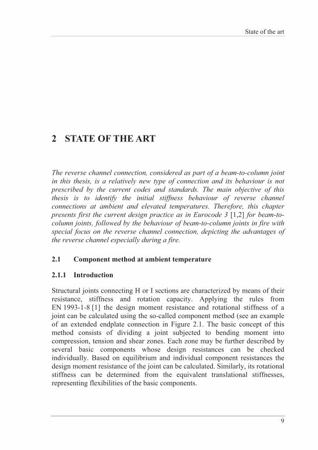
2 STATE OF THE ART
The reverse channel connection, considered as part of a beam-to-column joint in this thesis, is a relatively new type of connection and its behaviour is not prescribed by the current codes and standards. The main objective of this thesis is to identify the initial stiffness behaviour of reverse channel connections at ambient and elevated temperatures. Therefore, this chapter presents first the current design practice as in Eurocode 3 [1,2] for beam-to-column joints, followed by the behaviour of beam-to-column joints in fire with special focus on the reverse channel connection, depicting the advantages of the reverse channel especially during a fire.
2.1 Component method at ambient temperature
2.1.1 Introduction
Structural joints connecting H or I sections are characterized by means of their resistance, stiffness and rotation capacity. Applying the rules from EN 1993-1-8 [1] the design moment resistance and rotational stiffness of a joint can be calculated using the so-called component method (see an example of an extended endplate connection in Figure 2.1. The basic concept of this method consists of dividing a joint subjected to bending moment into compression, tension and shear zones. Each zone may be further described by several basic components whose design resistances can be checked individually. Based on equilibrium and individual component resistances the design moment resistance of the joint can be calculated. Similarly, its rotational stiffness can be determined from the equivalent translational stiffnesses, representing flexibilities of the basic components.
Stiffness of Reverse Channel Connections at Room and Elevated Temperatures
10
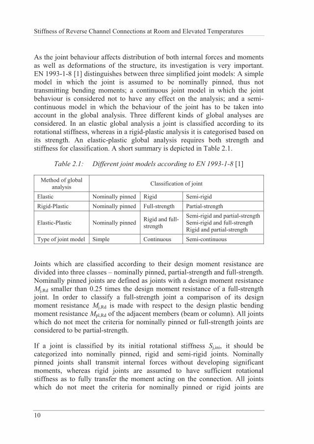
As the joint behaviour affects distribution of both internal forces and moments as well as deformations of the structure, its investigation is very important. EN 1993-1-8 [1] distinguishes between three simplified joint models: A simple model in which the joint is assumed to be nominally pinned, thus not transmitting bending moments; a continuous joint model in which the joint behaviour is considered not to have any effect on the analysis; and a semi-continuous model in which the behaviour of the joint has to be taken into account in the global analysis. Three different kinds of global analyses are considered. In an elastic global analysis a joint is classified according to its rotational stiffness, whereas in a rigid-plastic analysis it is categorised based on its strength. An elastic-plastic global analysis requires both strength and stiffness for classification. A short summary is depicted in Table 2.1.
Table 2.1: Different joint models according to EN 1993-1-8 [1]
Method of global analysis Classification of joint
Elastic Nominally pinned Rigid Semi-rigid Rigid-Plastic Nominally pinned Full-strength Partial-strength
Elastic-Plastic Nominally pinned Rigid and full-strength
Semi-rigid and partial-strength Semi-rigid and full-strength Rigid and partial-strength
Type of joint model Simple Continuous Semi-continuous
Joints which are classified according to their design moment resistance are divided into three classes – nominally pinned, partial-strength and full-strength. Nominally pinned joints are defined as joints with a design moment resistance Mj,Rd smaller than 0.25 times the design moment resistance of a full-strength joint. In order to classify a full-strength joint a comparison of its design moment resistance Mj,Rd is made with respect to the design plastic bending moment resistance Mpl,Rd of the adjacent members (beam or column). All joints which do not meet the criteria for nominally pinned or full-strength joints are considered to be partial-strength.
If a joint is classified by its initial rotational stiffness Sj,ini, it should be categorized into nominally pinned, rigid and semi-rigid joints. Nominally pinned joints shall transmit internal forces without developing significant moments, whereas rigid joints are assumed to have sufficient rotational stiffness as to fully transfer the moment acting on the connection. All joints which do not meet the criteria for nominally pinned or rigid joints are
State of the art
11
considered to be semi-rigid. Rules for determination of Sj,ini of joints connecting H or I sections are provided in EN 1993-1-8 [1]. Weynand et al. [7] offer solutions for joints connecting hollow sections.
2.1.2 Joint evaluation
Moment-rotation (M- ) curves can be characterized by means of experimental testing or mathematical models. The latter ones shall consider both geometrical and mechanical properties of the respective joint. Mathematical models can be described by different methods: curve fitting to experimental results by regression analysis, numerical or simplified analytical results and mechanical models that take into account the joint deformability [8].
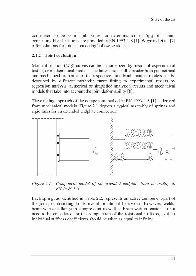
The existing approach of the component method in EN 1993-1-8 [1] is derived from mechanical models. Figure 2.1 depicts a typical assembly of springs and rigid links for an extended endplate connection.
Figure 2.1: Component model of an extended endplate joint according to EN 1993-1-8 [1]
Each spring, as identified in Table 2.2, represents an active component/part of the joint, contributing to its overall rotational behaviour. However, welds, beam web and flange in compression as well as beam web in tension do not need to be considered for the computation of the rotational stiffness, as their individual stiffness coefficients should be taken as equal to infinity.
Stiffness of Reverse Channel Connections at Room and Elevated Temperatures
12
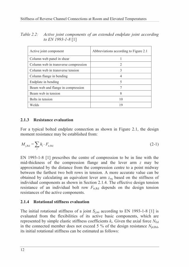
Table 2.2: Active joint components of an extended endplate joint according to EN 1993-1-8 [1]
Active joint component Abbreviations according to Figure 2.1
Column web panel in shear 1 Column web in transverse compression 2 Column web in transverse tension 3 Column flange in bending 4 Endplate in bending 5 Beam web and flange in compression 7 Beam web in tension 8 Bolts in tension 10 Welds 19
2.1.3 Resistance evaluation
For a typical bolted endplate connection as shown in Figure 2.1, the design moment resistance may be established from:
j,Rd r tr,Rd=r
M h F (2-1)
EN 1993-1-8 [1] prescribes the centre of compression to be in line with the mid-thickness of the compression flange and the lever arm z may be approximated by the distance from the compression centre to a point midway between the farthest two bolt rows in tension. A more accurate value can be obtained by calculating an equivalent lever arm zeq based on the stiffness of individual components as shown in Section 2.1.4. The effective design tension resistance of an individual bolt row Ftr,Rd depends on the design tension resistances of the active components.
2.1.4 Rotational stiffness evaluation
The initial rotational stiffness of a joint Sj,ini according to EN 1993-1-8 [1] is evaluated from the flexibilities of its active basic components, which are represented by simple elastic stiffness coefficients ki. Given the axial force NEd in the connected member does not exceed 5 % of the design resistance Npl,Rd, its initial rotational stiffness can be estimated as follows:
State of the art
13
j,ini
i i
= 1E zS
k
(2-2)
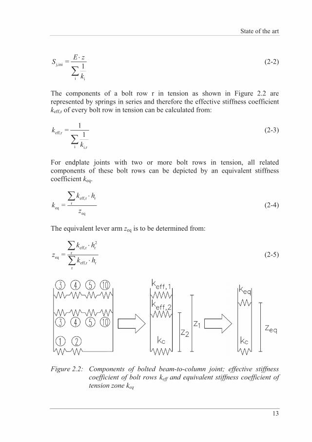
The components of a bolt row r in tension as shown in Figure 2.2 are represented by springs in series and therefore the effective stiffness coefficient keff,r of every bolt row in tension can be calculated from:
eff,r
i i,r
1= 1k
k
(2-3)
For endplate joints with two or more bolt rows in tension, all related components of these bolt rows can be depicted by an equivalent stiffness coefficient keq.
eff,r rr
eqeq
=k h
kz
(2-4)
The equivalent lever arm zeq is to be determined from:
2eff,r r
req
eff,r rr
=k h
zk h
(2-5)
Figure 2.2: Components of bolted beam-to-column joint; effective stiffness coefficient of bolt rows keff and equivalent stiffness coefficient of tension zone keq
Stiffness of Reverse Channel Connections at Room and Elevated Temperatures
14
2.1.5 Some developments not included in Eurocode 3
In the context of the component method, EN 1993-1-8 [1] has certain limitations with respect to the considered joint configurations. Two major drawbacks that are of relevance for the present thesis are the negligence of axial force, which is a significant thermal action at elevated temperatures, and the restriction of their application to joints between hot-rolled or built-up H or I profiles.
However, several researchers have dealt with the interaction of bending moment and axial force at ambient temperature. Accordingly, models have been proposed by Simões da Silva and Girão Coelho [9], Simões da Silva et al. [10], Sokol et al. [11] and Del Savio et al. [12].
Jaspart et al. [13] extended the component method to joints connecting RHS or CHS tubular hollow sections. Present rules, e.g. rules according to EN 1993-1-8 [1], Chapter 7 or design rules from literature, have been collected and adapted to a consistent component format.
2.2 Behaviour of beam-to-column joints in fire
2.2.1 Introduction
In the past, research studies have mostly neglected the actual behaviour of steel and composite joints motivated by the increased massivity of the joint area. Consequently, this is reflected in EN 1993-1-2 [2] which just provides an informative annex for connections, dealing solely with the design resistance of bolts in shear or tension, fillet welds and some guidance on how to determine the temperature of connections in fire. However, several real fire scenarios, as e.g. the collapse of the World Trade Center [3,4] and the full-scale fire tests at Cardington [5], depict that steel joints may fail and the behaviour of steel joints in fire is very complex. During a fire the structure undergoes essential changes due to degradation of material properties and internal forces, which may change its response rapidly due to restrained thermal deformations. Connections have to provide a high rotational capacity to accommodate e.g. large deformations of a beam. Particularly, tensile components such as bolts or endplates are prone to failure during cooling as high strains are induced by the distortional deformation of the connected members [14–16].
For characterization of steel joints under fire loading, the following aspects have to be accounted for [17]:
State of the art
15
a) Time dependent temperature distribution around and within joint area
b) Structural response of joints induced by high temperatures
c) Global behaviour of the structure with time leads to redistribution of internal forces acting on the joint
2.2.2 Experiments on isolated joints
In the following, a short literature review is presented regarding experiments on isolated joints. The reader with further interest should also refer to state-of-the-art papers written by Simões da Silva et al. [17] and Al-Jabri et al. [18].
The first experimental fire tests on beam-to-column joints were reported by Kruppa [19] in 1976 and British Steel [20], focusing on the performance of high-strength bolts at elevated temperatures. “Flexible” to “rigid” joint types were analysed. Lawson [21] was the first to measure the structural continuity of beam-to-column connections in fire. Three different types of joints were tested: extended endplate, flush endplate and double-sided web cleats. It was shown that significant moments could be sustained in fire and simple rules were proposed for the design of simply supported beams in fire.
In order to characterize the moment-rotation behaviour of commonly used connections at high temperatures, a collaborative programme was established involving the Building Research Institute, The University of Sheffield and the Steel Construction Institute. The experiments on flush-endplate joints conducted by Leston-Jones et al. [22] demonstrated that both stiffness and moment capacity decreased with increased temperature. Al-Jabri et al. [23] extended the experimental programme to investigate the effect of additional parameters such as member size, endplate type and thickness on the joint performance in fire.
In 2004, Spyrou et al. [24,25] investigated the performance of tension (T-stub tests) and compression zones (column web transverse compression tests) of endplate connections at high temperatures. This study highlighted the utility of the component method for steel joints at elevated temperature and the consideration of large axial forces generated in the beam during a fire.
Qian et al. [26] report on extended endplate connections with and without thermal restraint effects at elevated temperatures. A significant effect on the joint moment capacity due to the axial restraint force has been noticed.
Stiffness of Reverse Channel Connections at Room and Elevated Temperatures
16
In [27], Wang et al. investigated the behaviour of extended endplate connections at elevated temperature. They concluded that this type of joint is typically semi-rigid and provides good rotation ability at high temperatures. It is shown that the thicker the endplate and rib stiffener, higher the critical temperature of the joint that can be achieved.
Yu [28] experimentally studied the behaviour of fin plate connections subjected to combinations of shear and tying forces at ambient and elevated temperatures. It was observed that bolt shear fracture tends to govern the failure of fin plate connections at elevated temperatures. Therefore, fin plate connections do not seem to be a suitable option where connections undergo large rotations, which is the case in fire. Furthermore, tests on flush endplates have shown a relatively stiff response in comparison to other simple connection types [29]. The failure mode of the connection was considerably dependent on the temperature; at lower temperatures the endplate governed failure whereas at high temperatures failure occurred in the bolts. In another paper Yu et al. [30] report on the tying capacity of web cleat connections in fire. It was observed that web cleat connections have a considerably high rotational capacity in comparison to alternative types.
Saedi Daryan and Yahyai [31] report on the behaviour of bolted top-seat angle connections in fire. Results show that bolts are one of the most crucial components at elevated temperatures. However, temperature-resistant bolts and increased thickness of angles showed to increase the temperature dependent strength of the connection.
Strej ek et al. [32] carried out experiments to investigate the behaviour of a column web component in shear at elevated temperature on an extended endplate joint. They numerically extended it across a range of different temperatures in order to validate an analytical model.
Huang et al. [33] present results of an experimental investigation of the robustness of connections at elevated temperatures. Flush endplate to partially-encased H-section columns connections have been tested. It was shown that double nuts for the bolts at high temperature were necessary in order to avoid thread-stripping, leading then to bolt fracture since a relatively thick (20 mm) endplate was used. Furthermore, experiments on fin plates have been carried out [34]. Results depict fracture of the concrete-filled steel tube near where the fin plate is welded onto the square column face, and shearing of bolts for circular columns.
State of the art
17
2.2.3 Sub-frame and full-building tests
Isolated joint tests cannot truly reflect the real behaviour of connections, especially under fire conditions. Highly redundant structural systems are capable of force redistribution as its members interact with each other [35]. In fire situations the structural members exposed to fire inside the fire compartment tend to undergo thermal expansion, which is restrained by the structural members from the adjacent cooler compartments. Thus, thermal expansion in the heat-affected member may cause column instability in exterior compartments and local buckling of the bottom flanges in the beams in much more restrained situation of the interior compartments [36]. However, in full-building tests it is relatively difficult to measure and quantify parameters that control the mechanical response of individual members. Therefore, sub-frame tests represent a good compromise as they, for example, allow a better observation of redistributions of forces throughout the fire including cooling phase.
Relatively little research on the behaviour of full-scale buildings or sub-structures in fire has been done until the 1990’s. The first tests to assess structural behaviour under fire load were reported in 1977 by Witteveen et al. [37]. For a complete state-of-the-art description of experimental observations until the 1990’s the interested reader may be referred to Wang [38]. A shorter summary could also be found in Wald et al. [16].
During the late 1990’s the universities of Manchester and Sheffield established a collaborative research project to investigate the effects of restraints to thermal expansion of unprotected beams, offered by protected columns and adjacent cooler beams [39]. Flush endplates and web cleats have been used to connect beams with columns. For experiments with high axial restraint and lower load levels, catenary action at large deflections was observed. One of the main failure modes noticed was the local buckling of the flange near the joint.
The commonly known Cardington tests are a series of 7 full-scale tests in an eight-storey steel building, carried out at the Cardington Laboratory of the Building Research Establishment, UK, aiming to assess the behaviour of structural elements under real restraint conditions subjected to natural fire. A more detailed description can be found in [16]. Among others, a structural integrity fire test with a high level of mechanical load was performed. For beam-to-column joints flexible endplates, which are usually considered as pinned, have been used. It was observed that the endplates fractured on one side only as a result of the high tensile forces induced during cooling of the
Stiffness of Reverse Channel Connections at Room and Elevated Temperatures
18
beam. Fine plate connections have been used for beam-to-beam joints. The bolts connecting the fin plate with the web of the beam failed in shear, also during the cooling phase. Other than the aforementioned failure modes, buckling of the beam lower flange, shear of the beam web, buckling of column flange in compression, fracture in the concrete slab and slippage of the steel reinforcement (mesh) were observed [16].
Ding and Wang [40] report on 10 experiments with steel beams connected to concrete-filled tubular columns. Those experiments depict the impracticality of using fin plate joints to resist axial forces during fire and the possibility of using catenary action to prevent progressive collapse in fire.
Santiago et al. [41] experimentally investigated the influence of connection typology on the behaviour of a steel sub-frame under fire. It was shown that different joint typologies affect the overall response of the sub-frame and that large tensile forces and reversal of bending moment during cooling may result in failure of the joint. It was proposed that failure of the tensile components (T-stub) shall be governed by failure of its ductile component (endplate) rather than by the bolts.
Further 10 sub-frame tests, though medium-scale, have been reported by Wang et al. [42]. Those experiments were designed with fin plate, partial-depth and flush endplates, as well as web cleat connections and revealed the following joint failure modes: weld tearing, beam web fracture and bolt thread stripping.
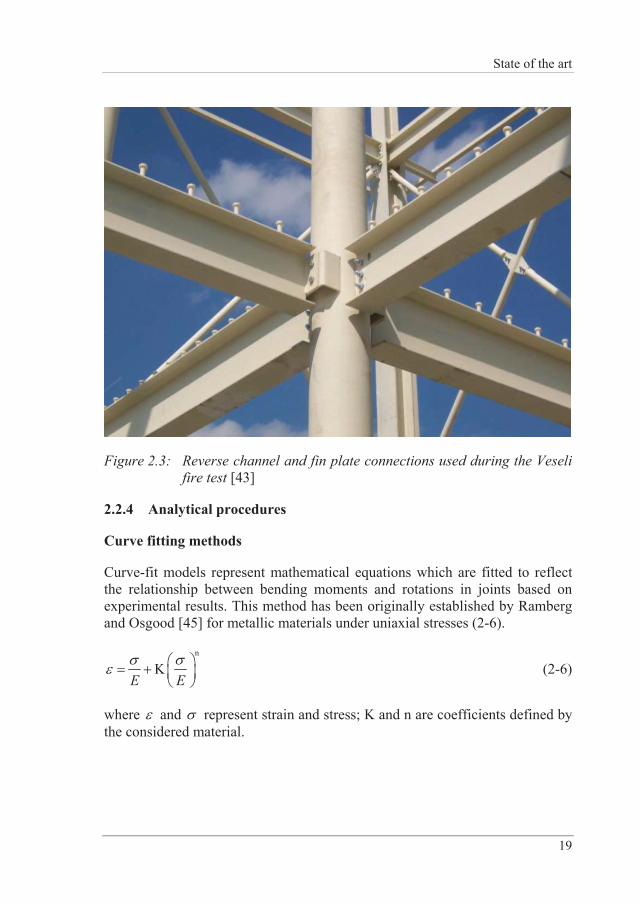
In 2011, a two-storey composite steel-concrete structure has been tested in a fire situation [34,43] in Veselí, Czech Republic. Fin plate and reverse channel connections, as depicted in Figure 2.3, were utilized and designed to resist only shear forces at ambient temperature. The main focus during this test was on temperature distributions. Jana and Wald [44] compared temperatures of the reverse channel connection for two different cases of protected and unprotected connection regions and based on those measurements. It is concluded that using a fire protected connection along with an unprotected beam allows for utilization of the membrane action in a composite ceiling without having to worry about the connection failure.
State of the art
19
Figure 2.3: Reverse channel and fin plate connections used during the Veseli fire test [43]
2.2.4 Analytical procedures
Curve fitting methods
Curve-fit models represent mathematical equations which are fitted to reflect the relationship between bending moments and rotations in joints based on experimental results. This method has been originally established by Ramberg and Osgood [45] for metallic materials under uniaxial stresses (2-6).
n
KE E
(2-6)
where and represent strain and stress; K and n are coefficients defined by the considered material.
Stiffness of Reverse Channel Connections at Room and Elevated Temperatures
20
In order to describe the moment-rotation characteristics, this equation has been adapted by Ang and Morris [46] for ambient temperature (2-7) and then extended to joints at high temperatures by El-Rimawi [47].
n
0.01A BM M (2-7)
with being the joint rotation at a given temperature and M the applied bending moment. The temperature dependent parameters A and B are dependent on the joint stiffness and capacity, respectively. n defines the non-linear shape of the curve that is related to the connection. El-Rimawi et al. [48,49] calibrated those parameters with experimental data depicted by Lawson [21] and introduced an additional parameter (2-8), which accounts for different section sizes under the assumption that the moment capacity of a joint is proportional to the lever arm D (distance between internal tensile and compressive forces).
50303.8 50
D (2-8)
Introducing (2-8) into (2-7) yields a more general Ramberg-Osgood Equation (2-9).
n
2 0.01A B
M M (2-9)
However, although this model is considered to be easily implementable into a frame analysis, it needs a wide range of experimental results to be calibrated. Due to the dependency on the connection configuration as well as temperature, curve fitting methods are not common practice.
Mechanical models
The global response of a joint in a mechanical model is characterised by a combination of individual components which get activated when loaded. Individual springs, which are represented by their force-displacement relationship, substitute individual joint components. For commonly used joints EN 1993-1-8 [1] provides both strength and initial stiffness formulae for their main components. This method, also known as Component Method, is described in Section 2.1 for ambient temperature.
State of the art
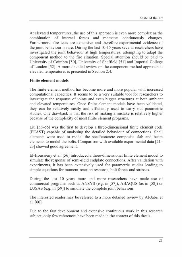
21
At elevated temperatures, the use of this approach is even more complex as the combination of internal forces and moments continuously changes. Furthermore, fire tests are expensive and therefore experimental evidence of the joint behaviour is rare. During the last 10-15 years several researchers have investigated the joint behaviour at high temperatures, attempting to adapt the component method to the fire situation. Special attention should be paid to University of Coimbra [50], University of Sheffield [51] and Imperial College of London [52]. A more detailed review on the component method approach at elevated temperatures is presented in Section 2.4.
Finite element models
The finite element method has become more and more popular with increased computational capacities. It seems to be a very suitable tool for researchers to investigate the response of joints and even bigger structures at both ambient and elevated temperatures. Once finite element models have been validated, they can be relatively easily and efficiently used to carry out parametric studies. One drawback is that the risk of making a mistake is relatively higher because of the complexity of most finite element programs.
Liu [53–55] was the first to develop a three-dimensional finite element code (FEAST) capable of analysing the detailed behaviour of connections. Shell elements were used to model the steel/concrete composite slab and beam elements to model the bolts. Comparison with available experimental data [21–23] showed good agreement.
El-Houssieny et al. [56] introduced a three-dimensional finite element model to simulate the response of semi-rigid endplate connections. After validation with experiments, it has been extensively used for parametric studies leading to simple equations for moment-rotation response, bolt forces and stresses.
During the last 10 years more and more researchers have made use of commercial programs such as ANSYS (e.g. in [57]), ABAQUS (as in [58]) or LUSAS (e.g. in [59]) to simulate the complete joint behaviour.
The interested reader may be referred to a more detailed review by Al-Jabri et al. [60].
Due to the fast development and extensive continuous work in this research subject, only few references have been made in the context of this thesis.
Stiffness of Reverse Channel Connections at Room and Elevated Temperatures
22
2.3 Reverse channel connections
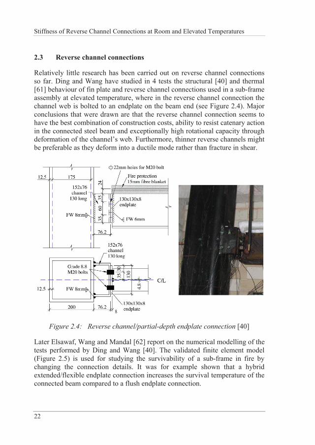
Relatively little research has been carried out on reverse channel connections so far. Ding and Wang have studied in 4 tests the structural [40] and thermal [61] behaviour of fin plate and reverse channel connections used in a sub-frame assembly at elevated temperature, where in the reverse channel connection the channel web is bolted to an endplate on the beam end (see Figure 2.4). Major conclusions that were drawn are that the reverse channel connection seems to have the best combination of construction costs, ability to resist catenary action in the connected steel beam and exceptionally high rotational capacity through deformation of the channel’s web. Furthermore, thinner reverse channels might be preferable as they deform into a ductile mode rather than fracture in shear.
Figure 2.4: Reverse channel/partial-depth endplate connection [40]
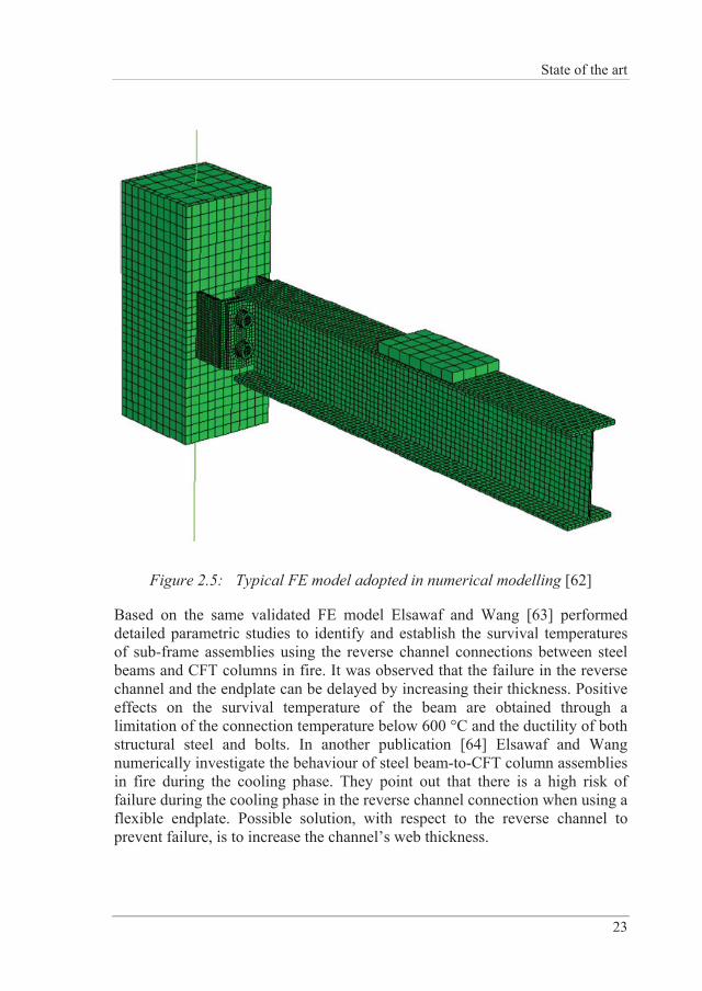
Later Elsawaf, Wang and Mandal [62] report on the numerical modelling of the tests performed by Ding and Wang [40]. The validated finite element model (Figure 2.5) is used for studying the survivability of a sub-frame in fire by changing the connection details. It was for example shown that a hybrid extended/flexible endplate connection increases the survival temperature of the connected beam compared to a flush endplate connection.
State of the art
23
Figure 2.5: Typical FE model adopted in numerical modelling [62]
Based on the same validated FE model Elsawaf and Wang [63] performed detailed parametric studies to identify and establish the survival temperatures of sub-frame assemblies using the reverse channel connections between steel beams and CFT columns in fire. It was observed that the failure in the reverse channel and the endplate can be delayed by increasing their thickness. Positive effects on the survival temperature of the beam are obtained through a limitation of the connection temperature below 600 °C and the ductility of both structural steel and bolts. In another publication [64] Elsawaf and Wang numerically investigate the behaviour of steel beam-to-CFT column assemblies in fire during the cooling phase. They point out that there is a high risk of failure during the cooling phase in the reverse channel connection when using a flexible endplate. Possible solution, with respect to the reverse channel to prevent failure, is to increase the channel’s web thickness.
Stiffness of Reverse Channel Connections at Room and Elevated Temperatures
24
Jones [65] did four experiments on an isolated reverse channel/column assembly at ambient and high temperature in order to identify the failure mechanisms of the connected members. No special attention was paid to the behaviour of the reverse channel itself.
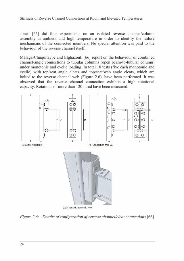
Málaga-Chuquitaype and Elghazouli [66] report on the behaviour of combined channel/angle connections to tubular columns (open beam-to-tubular column) under monotonic and cyclic loading. In total 10 tests (five each monotonic and cyclic) with top/seat angle cleats and top/seat/web angle cleats, which are bolted to the reverse channel web (Figure 2.6), have been performed. It was observed that the reverse channel connection exhibits a high rotational capacity. Rotations of more than 120 mrad have been measured.
Figure 2.6: Details of configuration of reverse channel/cleat connections [66]
State of the art
25
Furthermore, a plastic mechanism of the reverse channel in tension is identified and design recommendations for the plastic capacity and initial stiffness, originally derived for a blind-bolted angle connection [67], are presented.
Liu, Málaga-Chuquitaype and Elghazouli [68] carried out three experiments on combined channel/angle connections under shear loads. A finite element model has been successfully introduced. It was concluded that the thickness of the reverse channel has a direct influence on the connection stiffness and its capacity. Furthermore, stiffness and resistance of the reverse channel connection with double web angles was significantly higher than those of the connections with top and seat angles only.
In [69] Liu, Málaga-Chuquitaype and Elghazouli studied, in each of the three tests in tension and compression, the response of combined channel/angle connections. Yielding mechanisms for both tension and compression are shown in order to calculate the resistance accordingly. The derived initial stiffness from [67] is modified with the help of finite element simulations.
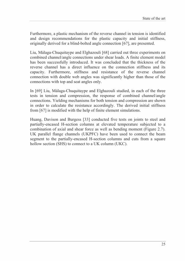
Huang, Davison and Burgess [33] conducted five tests on joints to steel and partially-encased H-section columns at elevated temperature subjected to a combination of axial and shear force as well as bending moment (Figure 2.7). UK parallel flange channels (UKPFC) have been used to connect the beam segment to the partially-encased H-section columns and cuts from a square hollow section (SHS) to connect to a UK column (UKC).
Stiffness of Reverse Channel Connections at Room and Elevated Temperatures
26
Figure 2.7: Setup for isolated joint tests at University of Sheffield [33]
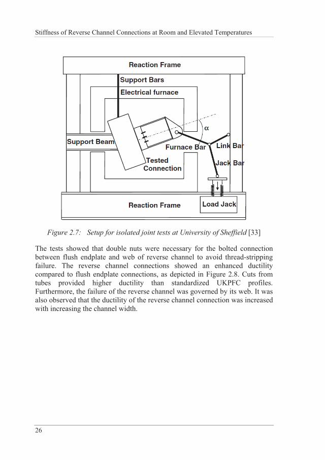
The tests showed that double nuts were necessary for the bolted connection between flush endplate and web of reverse channel to avoid thread-stripping failure. The reverse channel connections showed an enhanced ductility compared to flush endplate connections, as depicted in Figure 2.8. Cuts from tubes provided higher ductility than standardized UKPFC profiles. Furthermore, the failure of the reverse channel was governed by its web. It was also observed that the ductility of the reverse channel connection was increased with increasing the channel width.
State of the art
27
Figure 2.8: Force-rotation relationships of connections to partially-encased columns [33]
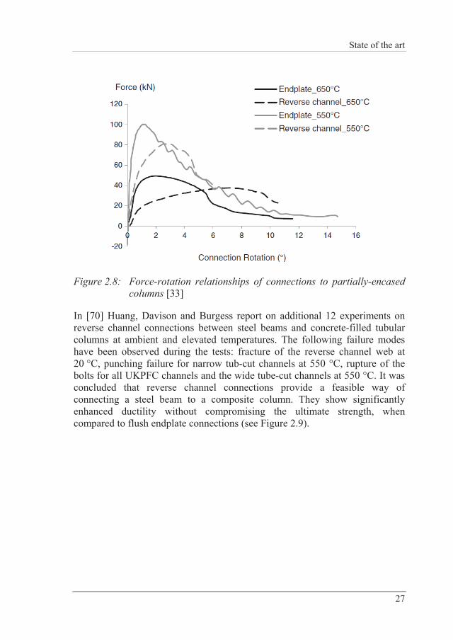
In [70] Huang, Davison and Burgess report on additional 12 experiments on reverse channel connections between steel beams and concrete-filled tubular columns at ambient and elevated temperatures. The following failure modes have been observed during the tests: fracture of the reverse channel web at 20 °C, punching failure for narrow tub-cut channels at 550 °C, rupture of the bolts for all UKPFC channels and the wide tube-cut channels at 550 °C. It was concluded that reverse channel connections provide a feasible way of connecting a steel beam to a composite column. They show significantly enhanced ductility without compromising the ultimate strength, when compared to flush endplate connections (see Figure 2.9).
Stiffness of Reverse Channel Connections at Room and Elevated Temperatures
28
Figure 2.9: Force-rotation relationships of reverse channel connections to square CFT columns [70]
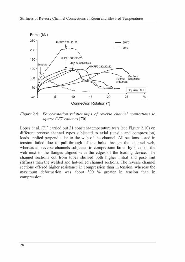
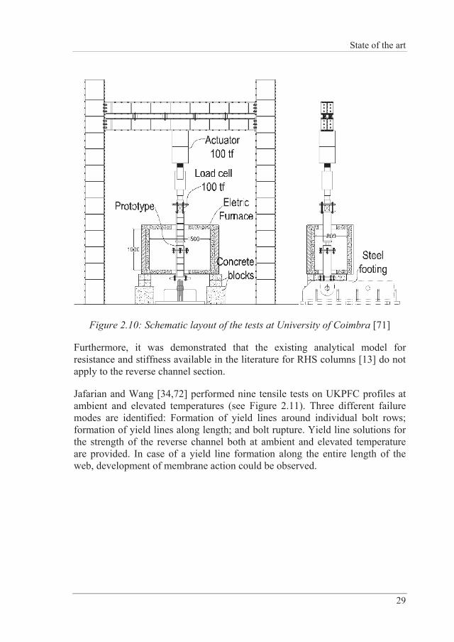
Lopes et al. [71] carried out 21 constant-temperature tests (see Figure 2.10) on different reverse channel types subjected to axial (tensile and compression) loads applied perpendicular to the web of the channel. All sections tested in tension failed due to pull-through of the bolts through the channel web, whereas all reverse channels subjected to compression failed by shear on the web next to the flanges aligned with the edges of the loading device. The channel sections cut from tubes showed both higher initial and post-limit stiffness than the welded and hot-rolled channel sections. The reverse channel sections offered higher resistance in compression than in tension, whereas the maximum deformation was about 300 % greater in tension than in compression.
State of the art
29
Figure 2.10: Schematic layout of the tests at University of Coimbra [71]
Furthermore, it was demonstrated that the existing analytical model for resistance and stiffness available in the literature for RHS columns [13] do not apply to the reverse channel section.
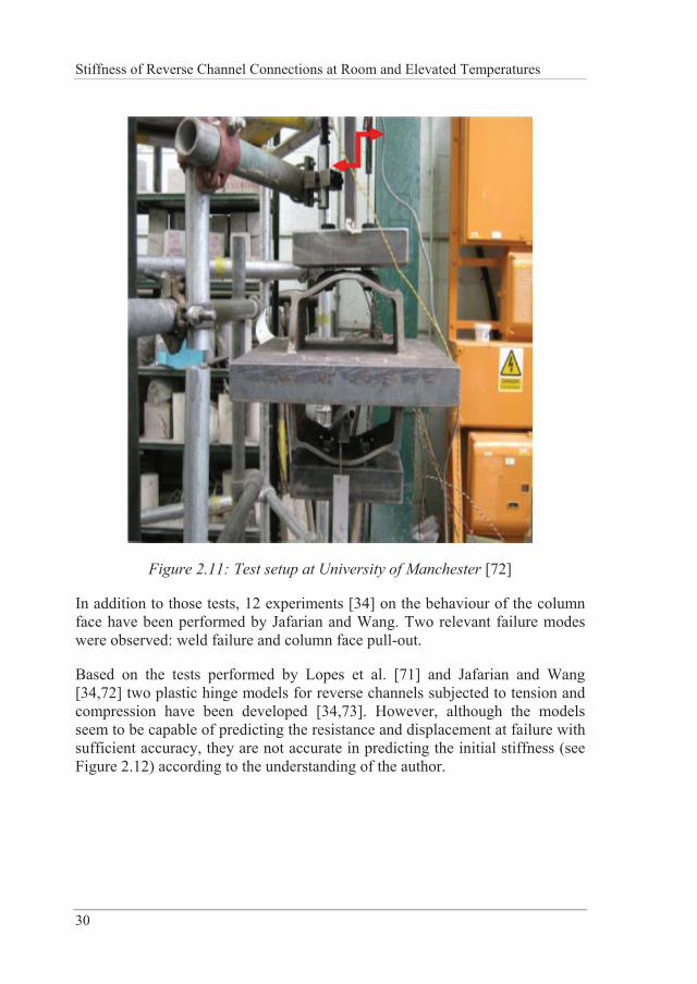
Jafarian and Wang [34,72] performed nine tensile tests on UKPFC profiles at ambient and elevated temperatures (see Figure 2.11). Three different failure modes are identified: Formation of yield lines around individual bolt rows; formation of yield lines along length; and bolt rupture. Yield line solutions for the strength of the reverse channel both at ambient and elevated temperature are provided. In case of a yield line formation along the entire length of the web, development of membrane action could be observed.
Stiffness of Reverse Channel Connections at Room and Elevated Temperatures
30
Figure 2.11: Test setup at University of Manchester [72]
In addition to those tests, 12 experiments [34] on the behaviour of the column face have been performed by Jafarian and Wang. Two relevant failure modes were observed: weld failure and column face pull-out.
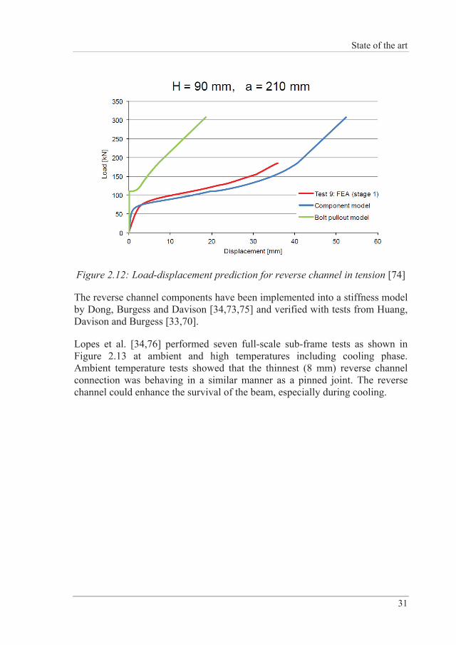
Based on the tests performed by Lopes et al. [71] and Jafarian and Wang [34,72] two plastic hinge models for reverse channels subjected to tension and compression have been developed [34,73]. However, although the models seem to be capable of predicting the resistance and displacement at failure with sufficient accuracy, they are not accurate in predicting the initial stiffness (see Figure 2.12) according to the understanding of the author.
State of the art
31
Figure 2.12: Load-displacement prediction for reverse channel in tension [74]
The reverse channel components have been implemented into a stiffness model by Dong, Burgess and Davison [34,73,75] and verified with tests from Huang, Davison and Burgess [33,70].
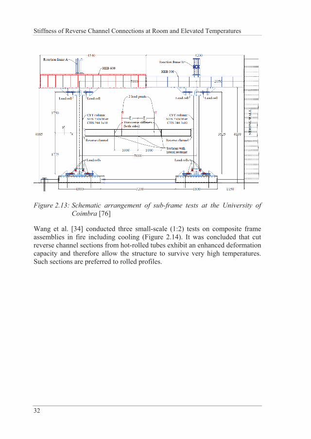
Lopes et al. [34,76] performed seven full-scale sub-frame tests as shown in Figure 2.13 at ambient and high temperatures including cooling phase. Ambient temperature tests showed that the thinnest (8 mm) reverse channel connection was behaving in a similar manner as a pinned joint. The reverse channel could enhance the survival of the beam, especially during cooling.
Stiffness of Reverse Channel Connections at Room and Elevated Temperatures
32
Figure 2.13: Schematic arrangement of sub-frame tests at the University of Coimbra [76]
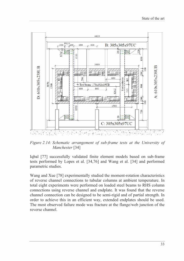
Wang et al. [34] conducted three small-scale (1:2) tests on composite frame assemblies in fire including cooling (Figure 2.14). It was concluded that cut reverse channel sections from hot-rolled tubes exhibit an enhanced deformation capacity and therefore allow the structure to survive very high temperatures. Such sections are preferred to rolled profiles.
State of the art
33
Figure 2.14: Schematic arrangement of sub-frame tests at the University of Manchester [34]
Iqbal [77] successfully validated finite element models based on sub-frame tests performed by Lopes et al. [34,76] and Wang et al. [34] and performed parametric studies.
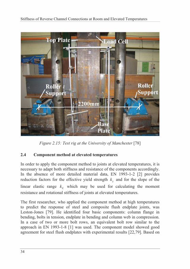
Wang and Xue [78] experimentally studied the moment-rotation characteristics of reverse channel connections to tubular columns at ambient temperature. In total eight experiments were performed on loaded steel beams to RHS column connections using reverse channel and endplate. It was found that the reverse channel connection can be designed to be semi-rigid and of partial strength. In order to achieve this in an efficient way, extended endplates should be used. The most observed failure mode was fracture at the flange/web junction of the reverse channel.
Stiffness of Reverse Channel Connections at Room and Elevated Temperatures
34
Figure 2.15: Test rig at the University of Manchester [78]
2.4 Component method at elevated temperatures
In order to apply the component method to joints at elevated temperatures, it is necessary to adapt both stiffness and resistance of the components accordingly. In the absence of more detailed material data, EN 1993-1-2 [2] provides reduction factors for the effective yield strength yk and for the slope of the linear elastic range Ek which may be used for calculating the moment resistance and rotational stiffness of joints at elevated temperatures.
The first researcher, who applied the component method at high temperatures to predict the response of steel and composite flush endplate joints, was Leston-Jones [79]. He identified four basic components: column flange in bending, bolts in tension, endplate in bending and column web in compression. In a case of two or more bolt rows, an equivalent bolt row similar to the approach in EN 1993-1-8 [1] was used. The component model showed good agreement for steel flush endplates with experimental results [22,79]. Based on
State of the art
35
the same experiments, Al-Jabri [80,81] proposed another component-based model, which could predict the moment-rotation response pretty well in the elastic region.
Spyrou et al. [24,25] continued the work initiated by Leston-Jones and developed component models for the same four components. Those models were combined into a simple model, connecting two rigid bars with two non-linear springs for the compression and tension zones. Those springs are directly included in a frame analysis, thus predicting moment-rotation curves and axial forces induced during fire. However, shear forces are for example not considered in this analysis. Block et al. [51,82] continued the work on the component model started by Spyrou and integrated it into the software Vulcan. Additionally, the effect of cooling has been considered. Qian et al. [83] extended this model with a web shear component of the beam.
Heidarpour and Bradford [84] report on the behaviour of a T-stub assembly in beam-to-column connections at elevated temperatures. The analytical approach is based on simple beam theory to capture the force-deflection response. The analytical results are compared with experimental data in literature and show good agreement.
Simões da Silva et al. [50] developed a global methodology to apply the component method to steel joints subjected to bending and an arbitrary temperature. They present an approach that allows assessing a joint at ambient temperature and then applying the material reduction factors according to EN 1993-1-2 for yield stress and Young’s modulus to predict its elevated temperature behaviour. This method was then extended to the post-limit component stiffness [85] and worked well for both isothermal and anisothermal conditions.
Wang et al. [27] depict a spring-component model for extended endplate connections and validate it with experiments at elevated temperature, neglecting the effect of axial force which arises from restrain to thermal expansion.
Ramli Sulong et al. [52,86] integrated the component models for endplate, extended endplate, double web cleats, top and seat angles and fin plate connections into the finite element program Adaptic. All components are represented with tri-linear force-displacement relationships. This model was validated against experimental data for the rotational behaviour at high
Stiffness of Reverse Channel Connections at Room and Elevated Temperatures
36
temperatures [80,87] and the combined bending and axial effect at ambient temperature [10,88].
Santiago [59] developed four partial models for flush endplate and extended endplate connections, where each model is valid for a combination of axial force and bending moments. Once the axial force passes from compression to tension or the bending moment changes from hogging to sagging, the partial model is changed.
Strejcek et al. [32] report on the behaviour of the column web component in shear of extended endplate connections at elevated temperatures. Interaction between bending moment and axial force has been considered and reasonably good agreement between numerical and analytical models is achieved, though the accuracy decreases with increasing temperature.
Yu et al. depicted component-based models for web cleat connections [89], fin plate connections [28,90] and flush endplate connections [91]. All experiments were carried out under isothermal conditions.
Huang [92] presented a 2-noded connection element for bolted endplate connections between beam and columns at elevated temperatures. The model considers the following connection failure modes: bending, axial tension, compression and vertical shear. Lin et al. [93] incorporated additional developments in order to more precisely determine the behaviour of endplate connections in fire. The model has been validated with 22 tests and reveals accurate predictions.
Taib and Burgess [94] recently developed a component model for fin plate connections in fire, which allows the lower beam flange to come into contact with the column face when the connection has undergone large rotations. Furthermore, this element has been integrated into Vulcan.
2.5 Reverse channel/endplate related connections: analytical models
As mentioned in the previous sections, different analytical models currently exist which have similarities with the reverse channel/endplate connection. They will be shortly presented in this chapter.
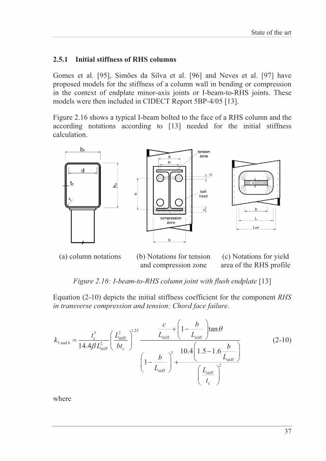
State of the art
37
2.5.1 Initial stiffness of RHS columns
Gomes et al. [95], Simões da Silva et al. [96] and Neves et al. [97] have proposed models for the stiffness of a column wall in bending or compression in the context of endplate minor-axis joints or I-beam-to-RHS joints. These models were then included in CIDECT Report 5BP-4/05 [13].
Figure 2.16 shows a typical I-beam bolted to the face of a RHS column and the according notations according to [13] needed for the initial stiffness calculation.
(a) column notations (b) Notations for tension and compression zone
(c) Notations for yield area of the RHS profile
Figure 2.16: I-beam-to-RHS column joint with flush endplate [13]
Equation (2-10) depicts the initial stiffness coefficient for the component RHS in transverse compression and tension: Chord face failure.
1.253 2stiff stiffc stiff
5 and 6 2stiff c
3stiff
2stiff stiff
c
1 tan
14.410.4 1.5 1.6
1
c bL Lt Lk
L bt bLb
L Lt
(2-10)
where
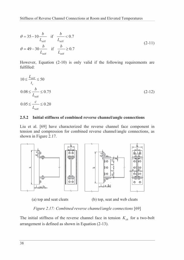
Stiffness of Reverse Channel Connections at Room and Elevated Temperatures
38
stiff stiff
stiff stiff
35 10 if 0.7
49 30 if 0.7
b bL L
b bL L
(2-11)
However, Equation (2-10) is only valid if the following requirements are fulfilled:
stiff
c
stiff
stiff
10 50
0.08 0.75
0.05 0.20
Lt
bL
cL
(2-12)
2.5.2 Initial stiffness of combined reverse channel/angle connections
Liu et al. [69] have characterized the reverse channel face component in tension and compression for combined reverse channel/angle connections, as shown in Figure 2.17.
(a) top and seat cleats (b) top, seat and web cleats
Figure 2.17: Combined reverse channel/angle connections [69]
The initial stiffness of the reverse channel face in tension cftK for a two-bolt arrangement is defined as shown in Equation (2-13).
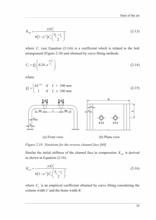
State of the art
39
3c
cft 22 c c
t6 12
EtKb tC
(2-13)
where tC (see Equation (2-14)) is a coefficient which is related to the bolt arrangement (Figure 2.18) and obtained by curve fitting methods.
c
0.3
t t 0.24 ei
mC Q (2-14)
where
0.4
t6 if 100 mm
1 if 100 mmL L <
QL
(2-15)
(a) Front view (b) Plane view
Figure 2.18: Notations for the reverse channel face [69]
Similar the initial stiffness of the channel face in compression cfcK is derived as shown in Equation (2-16).
3c
cfc 22 c c
c6 12
EtKb tC
(2-16)
where cC is an empirical coefficient obtained by curve fitting considering the column width C and the beam width B.
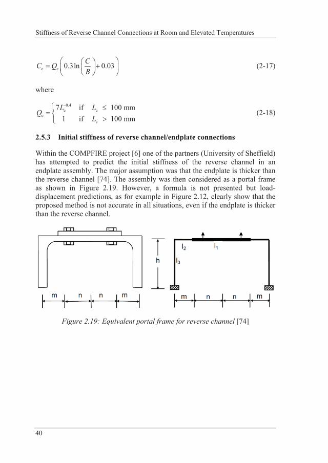
Stiffness of Reverse Channel Connections at Room and Elevated Temperatures
40
c c 0.3ln 0.03CC QB
(2-17)
where
0.4c c
cc
7 if 100 mm1 if 100 mm
L LQ
L (2-18)
2.5.3 Initial stiffness of reverse channel/endplate connections
Within the COMPFIRE project [6] one of the partners (University of Sheffield) has attempted to predict the initial stiffness of the reverse channel in an endplate assembly. The major assumption was that the endplate is thicker than the reverse channel [74]. The assembly was then considered as a portal frame as shown in Figure 2.19. However, a formula is not presented but load-displacement predictions, as for example in Figure 2.12, clearly show that the proposed method is not accurate in all situations, even if the endplate is thicker than the reverse channel.
Figure 2.19: Equivalent portal frame for reverse channel [74]
Experimental work on reverse channel connections
41
3 EXPERIMENTAL WORK ON REVERSE CHANNEL CONNECTIONS
In order to establish force-deflection-temperature relationships of reverse channel connections, it is necessary to carry out experiments to identify the structural response and the influence of different parameters. As experiments – especially at elevated temperatures – are expensive and time-consuming, only a limited number usually can be performed. This chapter describes the experiments carried out within the COMPFIRE project [6] on reverse channel sections and isolated joints. Those experiments have been conducted at the universities of Coimbra, Manchester and Sheffield.
3.1 Introduction
The experimental work described in this chapter has not been carried out by the author himself, but contributed significantly to the results of the present thesis. Therefore, the set-up and results of those experiments are repeated here in more detail, although already shortly described in Section 2.3. However, the author contributed in evaluation of test results obtained for reverse channel sections tested at the University of Coimbra [71].
The results depicted in the following sections are then further used for comparison with finite element simulations (see Chapter 4).
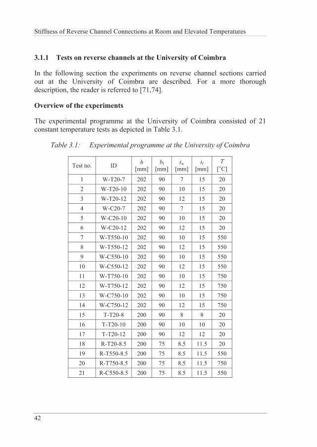
Stiffness of Reverse Channel Connections at Room and Elevated Temperatures
42
3.1.1 Tests on reverse channels at the University of Coimbra
In the following section the experiments on reverse channel sections carried out at the University of Coimbra are described. For a more thorough description, the reader is referred to [71,74].
Overview of the experiments
The experimental programme at the University of Coimbra consisted of 21 constant temperature tests as depicted in Table 3.1.
Table 3.1: Experimental programme at the University of Coimbra
Test no. ID h [mm]
bf [mm]
tw [mm]
tf [mm]
T [°C]
1 W-T20-7 202 90 7 15 20 2 W-T20-10 202 90 10 15 20 3 W-T20-12 202 90 12 15 20 4 W-C20-7 202 90 7 15 20 5 W-C20-10 202 90 10 15 20 6 W-C20-12 202 90 12 15 20 7 W-T550-10 202 90 10 15 550 8 W-T550-12 202 90 12 15 550 9 W-C550-10 202 90 10 15 550
10 W-C550-12 202 90 12 15 550 11 W-T750-10 202 90 10 15 750 12 W-T750-12 202 90 12 15 750 13 W-C750-10 202 90 10 15 750 14 W-C750-12 202 90 12 15 750 15 T-T20-8 200 90 8 8 20 16 T-T20-10 200 90 10 10 20 17 T-T20-12 200 90 12 12 20 18 R-T20-8.5 200 75 8.5 11.5 20 19 R-T550-8.5 200 75 8.5 11.5 550 20 R-T750-8.5 200 75 8.5 11.5 750 21 R-C550-8.5 200 75 8.5 11.5 550
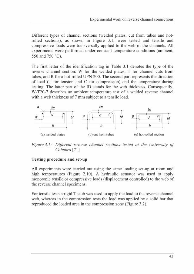
Experimental work on reverse channel connections
43
Different types of channel sections (welded plates, cut from tubes and hot-rolled sections), as shown in Figure 3.1, were tested and tensile and compressive loads were transversally applied to the web of the channels. All experiments were performed under constant temperature conditions (ambient, 550 and 750 °C).
The first letter of the identification tag in Table 3.1 denotes the type of the reverse channel section: W for the welded plates, T for channel cuts from tubes, and R for a hot-rolled UPN 200. The second part represents the direction of load (T for tension and C for compression) and the temperature during testing. The latter part of the ID stands for the web thickness. Consequently, W-T20-7 describes an ambient temperature test of a welded reverse channel with a web thickness of 7 mm subject to a tensile load.
Figure 3.1: Different reverse channel sections tested at the University of Coimbra [71]
Testing procedure and set-up
All experiments were carried out using the same loading set-up at room and high temperatures (Figure 2.10). A hydraulic actuator was used to apply monotonic tensile or compressive loads (displacement controlled) to the web of the reverse channel specimens.
For tensile tests a rigid T-stub was used to apply the load to the reverse channel web, whereas in the compression tests the load was applied by a solid bar that reproduced the loaded area in the compression zone (Figure 3.2).
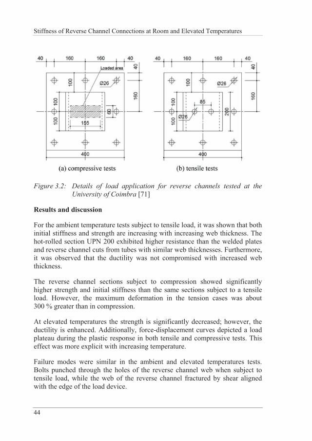
Stiffness of Reverse Channel Connections at Room and Elevated Temperatures
44
Figure 3.2: Details of load application for reverse channels tested at the University of Coimbra [71]
Results and discussion
For the ambient temperature tests subject to tensile load, it was shown that both initial stiffness and strength are increasing with increasing web thickness. The hot-rolled section UPN 200 exhibited higher resistance than the welded plates and reverse channel cuts from tubes with similar web thicknesses. Furthermore, it was observed that the ductility was not compromised with increased web thickness.
The reverse channel sections subject to compression showed significantly higher strength and initial stiffness than the same sections subject to a tensile load. However, the maximum deformation in the tension cases was about 300 % greater than in compression.
At elevated temperatures the strength is significantly decreased; however, the ductility is enhanced. Additionally, force-displacement curves depicted a load plateau during the plastic response in both tensile and compressive tests. This effect was more explicit with increasing temperature.
Failure modes were similar in the ambient and elevated temperatures tests. Bolts punched through the holes of the reverse channel web when subject to tensile load, while the web of the reverse channel fractured by shear aligned with the edge of the load device.
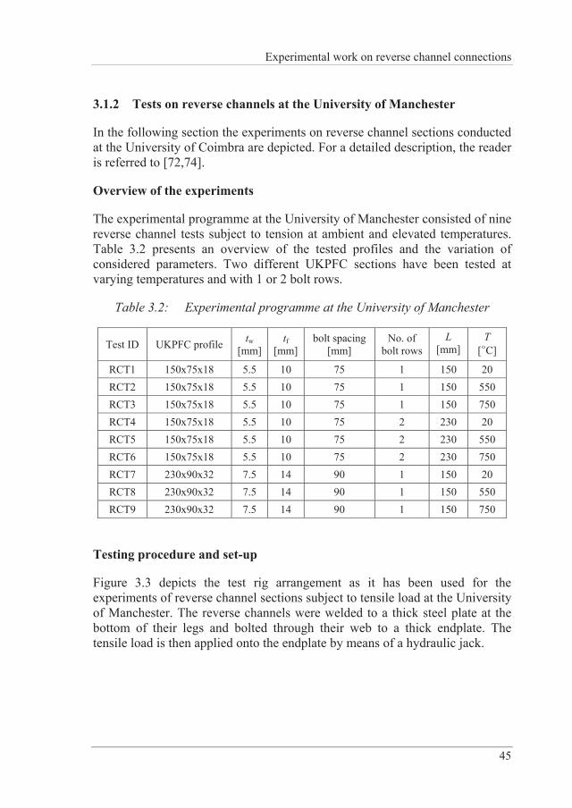
Experimental work on reverse channel connections
45
3.1.2 Tests on reverse channels at the University of Manchester
In the following section the experiments on reverse channel sections conducted at the University of Coimbra are depicted. For a detailed description, the reader is referred to [72,74].
Overview of the experiments
The experimental programme at the University of Manchester consisted of nine reverse channel tests subject to tension at ambient and elevated temperatures. Table 3.2 presents an overview of the tested profiles and the variation of considered parameters. Two different UKPFC sections have been tested at varying temperatures and with 1 or 2 bolt rows.
Table 3.2: Experimental programme at the University of Manchester
Test ID UKPFC profile tw [mm]
tf [mm]
bolt spacing[mm]
No. of bolt rows
L [mm]
T [°C]
RCT1 150x75x18 5.5 10 75 1 150 20 RCT2 150x75x18 5.5 10 75 1 150 550 RCT3 150x75x18 5.5 10 75 1 150 750 RCT4 150x75x18 5.5 10 75 2 230 20 RCT5 150x75x18 5.5 10 75 2 230 550 RCT6 150x75x18 5.5 10 75 2 230 750 RCT7 230x90x32 7.5 14 90 1 150 20 RCT8 230x90x32 7.5 14 90 1 150 550 RCT9 230x90x32 7.5 14 90 1 150 750
Testing procedure and set-up
Figure 3.3 depicts the test rig arrangement as it has been used for the experiments of reverse channel sections subject to tensile load at the University of Manchester. The reverse channels were welded to a thick steel plate at the bottom of their legs and bolted through their web to a thick endplate. The tensile load is then applied onto the endplate by means of a hydraulic jack.
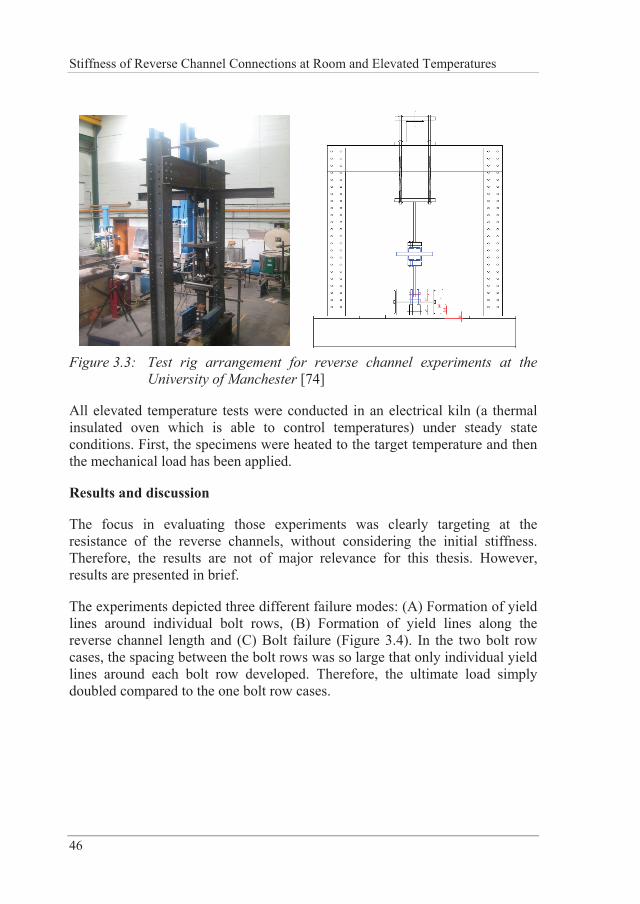
Stiffness of Reverse Channel Connections at Room and Elevated Temperatures
46
Figure 3.3: Test rig arrangement for reverse channel experiments at the
University of Manchester [74]
All elevated temperature tests were conducted in an electrical kiln (a thermal insulated oven which is able to control temperatures) under steady state conditions. First, the specimens were heated to the target temperature and then the mechanical load has been applied.
Results and discussion
The focus in evaluating those experiments was clearly targeting at the resistance of the reverse channels, without considering the initial stiffness. Therefore, the results are not of major relevance for this thesis. However, results are presented in brief.
The experiments depicted three different failure modes: (A) Formation of yield lines around individual bolt rows, (B) Formation of yield lines along the reverse channel length and (C) Bolt failure (Figure 3.4). In the two bolt row cases, the spacing between the bolt rows was so large that only individual yield lines around each bolt row developed. Therefore, the ultimate load simply doubled compared to the one bolt row cases.
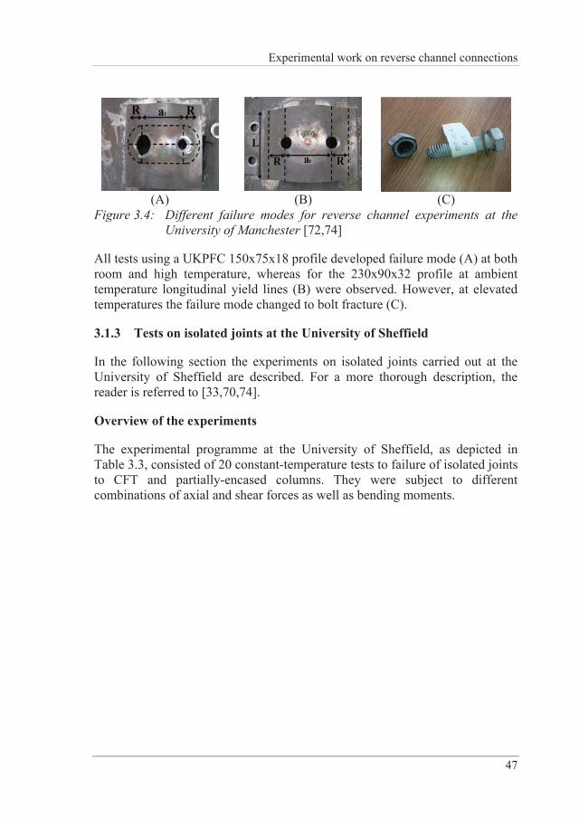
Experimental work on reverse channel connections
47
(A) (B) (C)
Figure 3.4: Different failure modes for reverse channel experiments at the University of Manchester [72,74]
All tests using a UKPFC 150x75x18 profile developed failure mode (A) at both room and high temperature, whereas for the 230x90x32 profile at ambient temperature longitudinal yield lines (B) were observed. However, at elevated temperatures the failure mode changed to bolt fracture (C).
3.1.3 Tests on isolated joints at the University of Sheffield
In the following section the experiments on isolated joints carried out at the University of Sheffield are described. For a more thorough description, the reader is referred to [33,70,74].
Overview of the experiments
The experimental programme at the University of Sheffield, as depicted in Table 3.3, consisted of 20 constant-temperature tests to failure of isolated joints to CFT and partially-encased columns. They were subject to different combinations of axial and shear forces as well as bending moments.
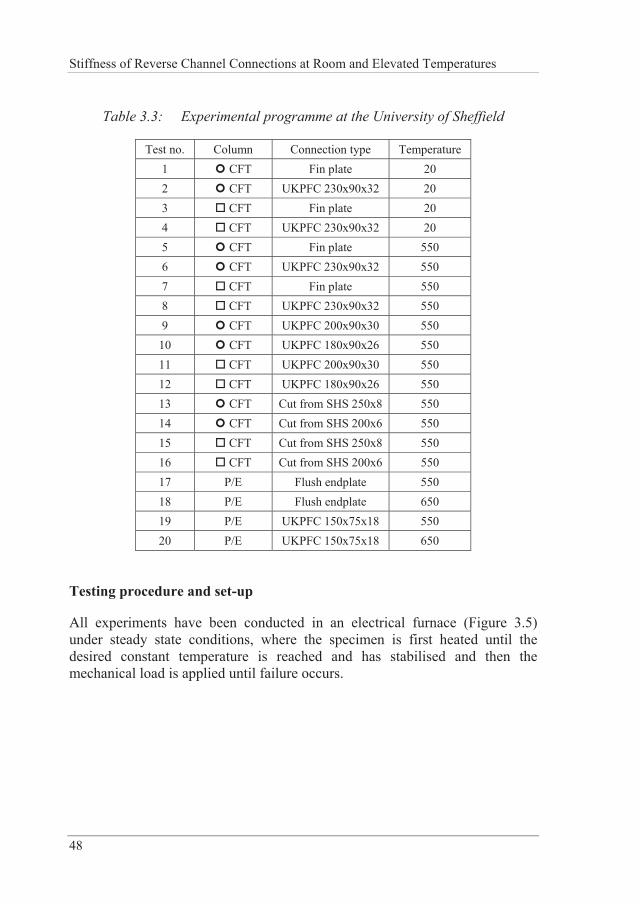
Stiffness of Reverse Channel Connections at Room and Elevated Temperatures
48
Table 3.3: Experimental programme at the University of Sheffield
Test no. Column Connection type Temperature 1 CFT Fin plate 20 2 CFT UKPFC 230x90x32 20 3 CFT Fin plate 20 4 CFT UKPFC 230x90x32 20 5 CFT Fin plate 550 6 CFT UKPFC 230x90x32 550 7 CFT Fin plate 550 8 CFT UKPFC 230x90x32 550 9 CFT UKPFC 200x90x30 550
10 CFT UKPFC 180x90x26 550 11 CFT UKPFC 200x90x30 550 12 CFT UKPFC 180x90x26 550 13 CFT Cut from SHS 250x8 550 14 CFT Cut from SHS 200x6 550 15 CFT Cut from SHS 250x8 550 16 CFT Cut from SHS 200x6 550 17 P/E Flush endplate 550 18 P/E Flush endplate 650 19 P/E UKPFC 150x75x18 550 20 P/E UKPFC 150x75x18 650
Testing procedure and set-up
All experiments have been conducted in an electrical furnace (Figure 3.5) under steady state conditions, where the specimen is first heated until the desired constant temperature is reached and has stabilised and then the mechanical load is applied until failure occurs.
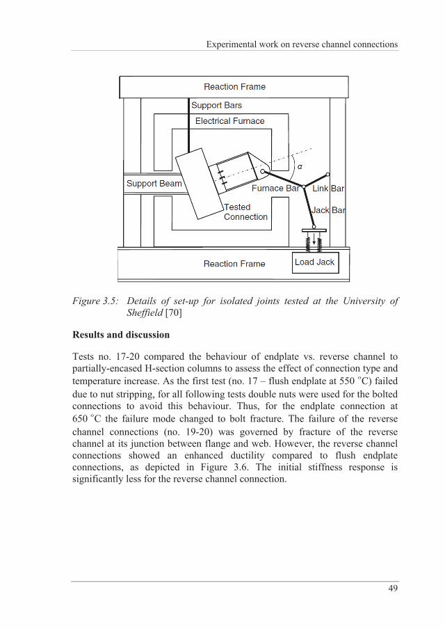
Experimental work on reverse channel connections
49
Figure 3.5: Details of set-up for isolated joints tested at the University of Sheffield [70]
Results and discussion
Tests no. 17-20 compared the behaviour of endplate vs. reverse channel to partially-encased H-section columns to assess the effect of connection type and temperature increase. As the first test (no. 17 – flush endplate at 550 °C) failed due to nut stripping, for all following tests double nuts were used for the bolted connections to avoid this behaviour. Thus, for the endplate connection at 650 °C the failure mode changed to bolt fracture. The failure of the reverse channel connections (no. 19-20) was governed by fracture of the reverse channel at its junction between flange and web. However, the reverse channel connections showed an enhanced ductility compared to flush endplate connections, as depicted in Figure 3.6. The initial stiffness response is significantly less for the reverse channel connection.
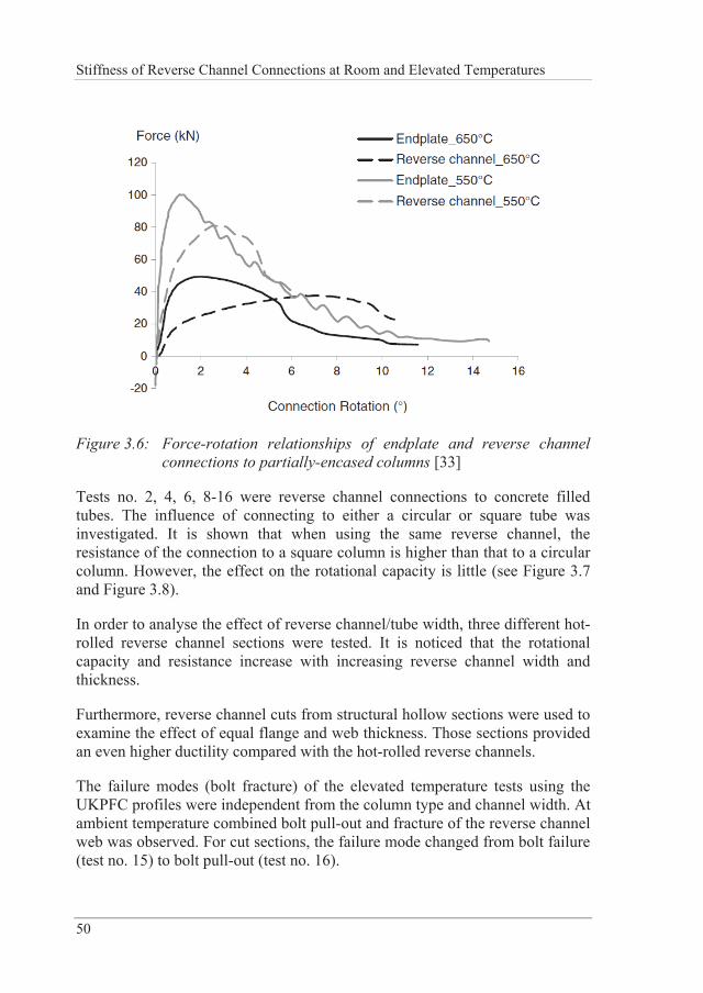
Stiffness of Reverse Channel Connections at Room and Elevated Temperatures
50
Figure 3.6: Force-rotation relationships of endplate and reverse channel connections to partially-encased columns [33]
Tests no. 2, 4, 6, 8-16 were reverse channel connections to concrete filled tubes. The influence of connecting to either a circular or square tube was investigated. It is shown that when using the same reverse channel, the resistance of the connection to a square column is higher than that to a circular column. However, the effect on the rotational capacity is little (see Figure 3.7 and Figure 3.8).
In order to analyse the effect of reverse channel/tube width, three different hot-rolled reverse channel sections were tested. It is noticed that the rotational capacity and resistance increase with increasing reverse channel width and thickness.
Furthermore, reverse channel cuts from structural hollow sections were used to examine the effect of equal flange and web thickness. Those sections provided an even higher ductility compared with the hot-rolled reverse channels.
The failure modes (bolt fracture) of the elevated temperature tests using the UKPFC profiles were independent from the column type and channel width. At ambient temperature combined bolt pull-out and fracture of the reverse channel web was observed. For cut sections, the failure mode changed from bolt failure (test no. 15) to bolt pull-out (test no. 16).
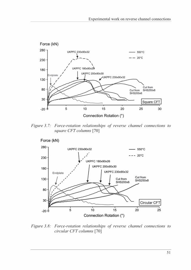
Experimental work on reverse channel connections
51
Figure 3.7: Force-rotation relationships of reverse channel connections to square CFT columns [70]
Figure 3.8: Force-rotation relationships of reverse channel connections to circular CFT columns [70]
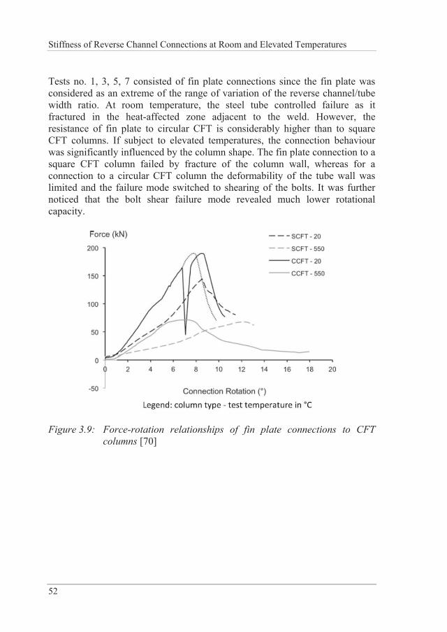
Stiffness of Reverse Channel Connections at Room and Elevated Temperatures
52
Tests no. 1, 3, 5, 7 consisted of fin plate connections since the fin plate was considered as an extreme of the range of variation of the reverse channel/tube width ratio. At room temperature, the steel tube controlled failure as it fractured in the heat-affected zone adjacent to the weld. However, the resistance of fin plate to circular CFT is considerably higher than to square CFT columns. If subject to elevated temperatures, the connection behaviour was significantly influenced by the column shape. The fin plate connection to a square CFT column failed by fracture of the column wall, whereas for a connection to a circular CFT column the deformability of the tube wall was limited and the failure mode switched to shearing of the bolts. It was further noticed that the bolt shear failure mode revealed much lower rotational capacity.
Figure 3.9: Force-rotation relationships of fin plate connections to CFT columns [70]
Finite element modelling of reverse channel connections
53
4 FINITE ELEMENT MODELLING OF REVERSE CHANNEL CONNECTIONS
Finite Element (FE) modelling is a very powerful tool to study the behaviour of structures or details as for example joints/connections. It is relatively cheap if compared to laboratory testing especially at elevated temperatures. Furthermore, compared to experiments, it easily offers the possibility to analyse details, as for example contact pressure distributions or development of yield lines. Once the FE model is calibrated against existing test data, it can be utilized to perform a large number of parametric studies in order to investigate the influence of different parameters on the structural response. During the past years the increased performance of computers and the existence of high performance clusters have led to an even bigger benefit. However, it is crucial to point out the importance of accurate model input data such as material properties and structural dimensions. This chapter provides a detailed description and verification of the FE models of the reverse channel connections and provides a wide range of parametric studies.
4.1 Description of 3D finite element models
4.1.1 Mechanical properties of materials
Steel
In order to reproduce the results of a test through a finite element model to a sufficient degree of accuracy, it is crucial to have knowledge about the behaviour of the material itself. Therefore, for most of the experiments discussed in this study coupon tests at ambient temperature were carried out [74]. Where tests were not available, an elastic-plastic stress-strain curve
Stiffness of Reverse Channel Connections at Room and Elevated Temperatures
54
including strain hardening based on nominal steel properties ( yf , uf , E ) was assumed for ambient temperature.
Tensile test data of ductile materials typically show nominal stress and strain relationships, where stress is defined as force per undeformed area of the cross-section of the specimen and strain as change in length divided by the original length of the specimen. A conversion into true stress and strain has to be done in order to correctly define non-linear material properties in the finite element software. Equation (4-1) describes the relationship used to convert nominal strain to true strain.
true nomln 1 (4-1)
The relationship between true stress and nominal stress is established by considering the incompressible nature of metal plasticity and assuming an incompressible elastic response, which then leads to the relationship written in Equation (4-2).
true nom nom1 (4-2)
However, these values are just valid until necking of the material starts and will consequently lead to wrong post-necking relations. In order to obtain uniaxial true stress-strain relations after necking, Bridgman’s correction method [98] is commonly used for rods.
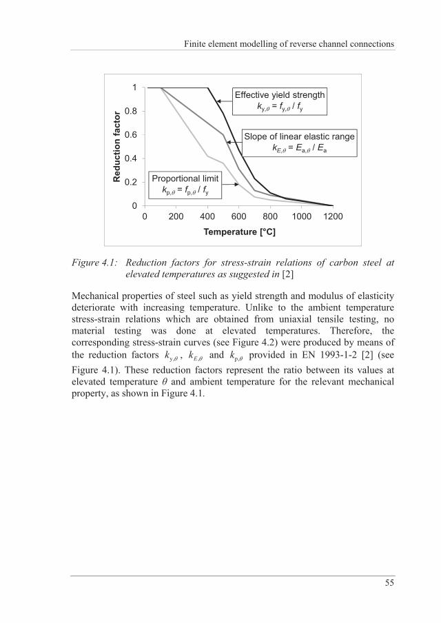
Finite element modelling of reverse channel connections
55
0
0.2
0.4
0.6
0.8
1
0 200 400 600 800 1000 1200
Red
uctio
n fa
ctor
Temperature [°C]
Effective yield strengthky, = fy, / fy
Proportional limitkp, = fp, / fy
Slope of linear elastic rangekE, = Ea, / Ea
Figure 4.1: Reduction factors for stress-strain relations of carbon steel at elevated temperatures as suggested in [2]
Mechanical properties of steel such as yield strength and modulus of elasticity deteriorate with increasing temperature. Unlike to the ambient temperature stress-strain relations which are obtained from uniaxial tensile testing, no material testing was done at elevated temperatures. Therefore, the corresponding stress-strain curves (see Figure 4.2) were produced by means of the reduction factors y,k , ,Ek and p,k provided in EN 1993-1-2 [2] (see Figure 4.1). These reduction factors represent the ratio between its values at elevated temperature and ambient temperature for the relevant mechanical property, as shown in Figure 4.1.
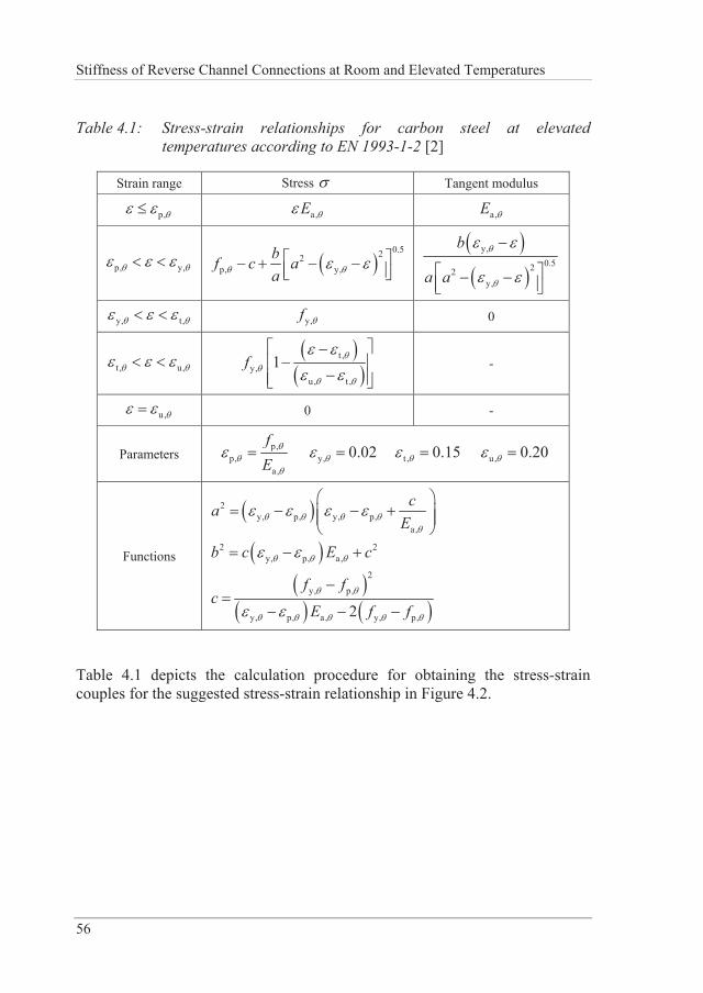
Stiffness of Reverse Channel Connections at Room and Elevated Temperatures
56
Table 4.1: Stress-strain relationships for carbon steel at elevated temperatures according to EN 1993-1-2 [2]
Strain range Stress Tangent modulus
p, a,E a,E
p, y, 0.522
p, y,bf c aa
y,
0.522y,
b
a a
y, t , y,f 0
t , u, t ,y,
u, t ,
1f -
u, 0 -
Parameters p,
p,a,
fE
y, 0.02 t, 0.15 u, 0.20
Functions
2y, p, y, p,
a,
caE
2 2y, p, a,b c E c
2
y, p,
y, p, a , y, p,2
f fc
E f f
Table 4.1 depicts the calculation procedure for obtaining the stress-strain couples for the suggested stress-strain relationship in Figure 4.2.
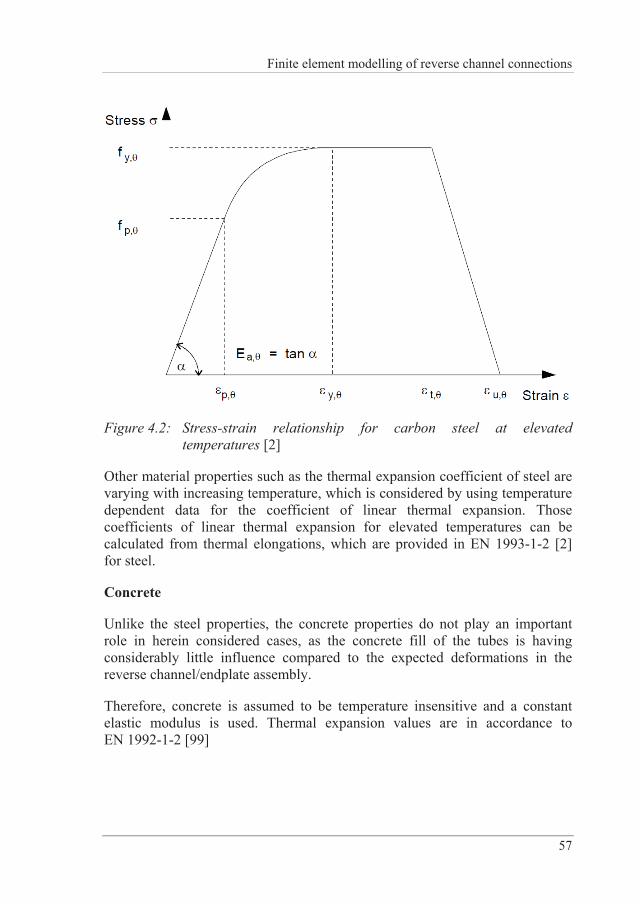
Finite element modelling of reverse channel connections
57
Figure 4.2: Stress-strain relationship for carbon steel at elevated temperatures [2]
Other material properties such as the thermal expansion coefficient of steel are varying with increasing temperature, which is considered by using temperature dependent data for the coefficient of linear thermal expansion. Those coefficients of linear thermal expansion for elevated temperatures can be calculated from thermal elongations, which are provided in EN 1993-1-2 [2] for steel.
Concrete
Unlike the steel properties, the concrete properties do not play an important role in herein considered cases, as the concrete fill of the tubes is having considerably little influence compared to the expected deformations in the reverse channel/endplate assembly.
Therefore, concrete is assumed to be temperature insensitive and a constant elastic modulus is used. Thermal expansion values are in accordance to EN 1992-1-2 [99]
Stiffness of Reverse Channel Connections at Room and Elevated Temperatures
58
4.1.2 Contact interactions
Many different possible interactions need to be considered in a connection, which leads to a complex numerical problem.
In the present study, modelling of welds has normally been neglected as not affecting the overall numerical response. However, when simulating the experiments carried out at the University of Coimbra (see sections 3.1.1 and 4.2.1), the welds between web and flanges of the reverse channel have shown a significant contribution to the overall behaviour of the tested specimens and therefore have been considered. By using “tie constraints” between the connected plates and the weld the surfaces are rigidly connected. That translates into displacement values of the connected parts being equal.
For the remaining interactions in the connection, contact elements are considered. A standard “surface to surface” contact interaction is used. As tangential behaviour a friction coefficient equal to 0.25 is assumed using the basic Coulomb friction model. However, the overall effect of this coefficient is negligible in this type of connection. For normal behaviour “hard contact” is introduced, which means that contact pressure can be transferred if surfaces are in contact, but also a separation of contact surfaces is allowed.
Finite element models including contact problems are very sensitive to applied loads and may cause problems to numerically converge at the beginning of a static calculation. The reason is that the contact is not fully established as long as there is zero force in the model and therefore, depending on boundary conditions, rigid body modes may exist. Convergence may be achieved by introducing a small load before the actual load is applied. It may be necessary to stabilize the model by activating damping in normal and/or tangential direction. For bolted connections, the author found out that the pre-tensioning of bolts is a suitable method to initialize contact; a small preload, comparable to tightening of bolts by hand, seems to be a reasonable value. After applying the pre-tensioning force the bolt length is fixed at its current length so that the force in the bolt changes according to the response of the model in the subsequent analysis.
For all surface interactions it is crucial to choose appropriate master and slave surfaces. Usually the master surface should be the surface of the stiffer body or should have a coarser mesh than the slave surface. If this recommendation is not followed, the solution can become time consuming [100].
Finite element modelling of reverse channel connections
59
In recent ABAQUS versions a so called “general contact” option has been introduced, where a general non-penetration condition for all surfaces can be specified, thus being very user friendly and computationally effective. A manual choice of possible contact faces is not necessary.
4.1.3 Element types
Mainly one type of elements has been chosen to model the different parts of the models. These element types are C3D8R, which is a first order reduced integration continuum element (brick).
The reduced integration element C3D8R is chosen because it uses a lower order integration scheme to define the stiffness matrix and thus reduces the overall computation time especially in three dimensions. The downside to these elements, however, is that they are prone to hourglassing due to the presence of only one integration point. These elements can therefore deform in such a manner that the strain calculated at the integration point is equal to zero, which further leads to uncontrolled distortion. This behaviour can be avoided by using a reasonably fine mesh; at least four elements through the thickness are recommended.
Hourglassing can normally be recognized in deformed shape plots or the Abaqus in-built hourglass control can be used. It has to be verified that the artificial energy used is small (< 1 %) relative to the internal energy [100].
To model the bending behaviour, a cost effective option is to use incompatible mode elements such as C3D8I, which is a first order incompatible mode continuum element. In addition to the standard degrees of freedom these elements possess internally added incompatible deformation modes. These elements eliminate the causes for the very stiff bending response seen in regular first order displacement elements. They can also be used to model bending with only one element through the thickness without hourglassing. Incompatible modes can be used together in a mesh with other regular solid elements. They should be used in regions where bending is dominating in order to accurately model the bending behaviour. Those elements have been used for the reverse channel when simulating the isolated joints tests performed at the University of Sheffield (see sections 3.1.3 and 4.2.3).
Whenever welds have been introduced into models, C3D6R (6-node linear triangular prism) elements are considered.
Stiffness of Reverse Channel Connections at Room and Elevated Temperatures
60
4.1.4 Numerical procedures
Within the context of this thesis, the finite element program ABAQUS was used for 3D simulations. Initially, the static solver ABAQUS/Standard has been applied for some simulations, yielding in accurate results.
However, later on ABAQUS/Explicit was adopted and found to produce faster results for complicated contact situations without compromising the accuracy. In order to use the explicit dynamics procedure for modelling quasi-static events, some special considerations are required. The speed of the process in the simulation needs to be artificially increased to reduce the number of required time increments, thus obtaining an economical solution. This can be either done by increasing the load rates or by mass scaling [100].
In order to evaluate whether a simulation yields an appropriate quasi-static response, energy balance can be used. Typically, the kinetic energy of the deforming material is to be compared to its internal energy. If throughout the majority of a quasi-static analysis a small fraction (1-5 %) is not exceeded, the results from the ABAQUS/Explicit simulation reflect a quasi-static solution [100]. Furthermore, validations with static analyses (ABAQUS/Standard) have been carried out.
All analyses are performed in sequential steps following the test procedure:
1. Temperature application
In this step the temperature is applied as a “predefined field” with respective magnitudes for each part of the connection. The magnitudes of these temperature fields are obtained from either furnace tests or chosen manually for parametric studies and are applied as approximate values uniformly throughout that respective part. This simplification seems to be reasonable since the conditions in the furnace during testing can be assumed to be steady-state.
2. Mechanical load
In a second step the mechanical load is applied. A detailed description for the individual experimental setups can be found in Section 4.1.5.
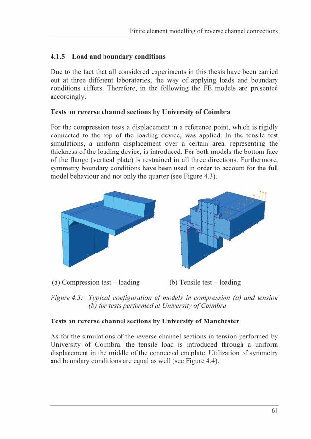
Finite element modelling of reverse channel connections
61
4.1.5 Load and boundary conditions
Due to the fact that all considered experiments in this thesis have been carried out at three different laboratories, the way of applying loads and boundary conditions differs. Therefore, in the following the FE models are presented accordingly.
Tests on reverse channel sections by University of Coimbra
For the compression tests a displacement in a reference point, which is rigidly connected to the top of the loading device, was applied. In the tensile test simulations, a uniform displacement over a certain area, representing the thickness of the loading device, is introduced. For both models the bottom face of the flange (vertical plate) is restrained in all three directions. Furthermore, symmetry boundary conditions have been used in order to account for the full model behaviour and not only the quarter (see Figure 4.3).
(a) Compression test – loading (b) Tensile test – loading
Figure 4.3: Typical configuration of models in compression (a) and tension (b) for tests performed at University of Coimbra
Tests on reverse channel sections by University of Manchester
As for the simulations of the reverse channel sections in tension performed by University of Coimbra, the tensile load is introduced through a uniform displacement in the middle of the connected endplate. Utilization of symmetry and boundary conditions are equal as well (see Figure 4.4).
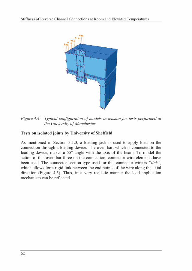
Stiffness of Reverse Channel Connections at Room and Elevated Temperatures
62
Figure 4.4: Typical configuration of models in tension for tests performed at the University of Manchester
Tests on isolated joints by University of Sheffield
As mentioned in Section 3.1.3, a loading jack is used to apply load on the connection through a loading device. The oven bar, which is connected to the loading device, makes a 55° angle with the axis of the beam. To model the action of this oven bar force on the connection, connector wire elements have been used. The connector section type used for this connector wire is “link”, which allows for a rigid link between the end points of the wire along the axial direction (Figure 4.5). Thus, in a very realistic manner the load application mechanism can be reflected.
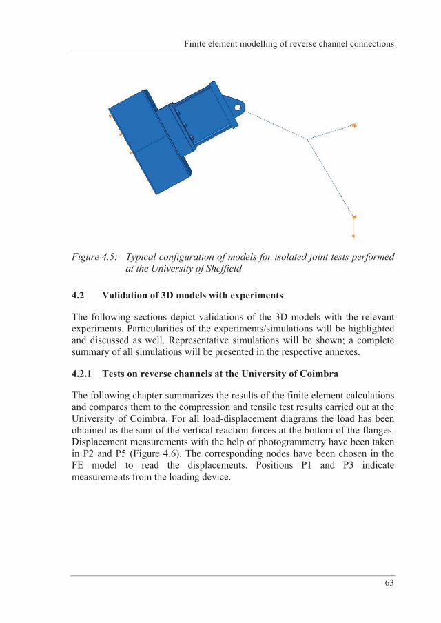
Finite element modelling of reverse channel connections
63
Figure 4.5: Typical configuration of models for isolated joint tests performed at the University of Sheffield
4.2 Validation of 3D models with experiments
The following sections depict validations of the 3D models with the relevant experiments. Particularities of the experiments/simulations will be highlighted and discussed as well. Representative simulations will be shown; a complete summary of all simulations will be presented in the respective annexes.
4.2.1 Tests on reverse channels at the University of Coimbra
The following chapter summarizes the results of the finite element calculations and compares them to the compression and tensile test results carried out at the University of Coimbra. For all load-displacement diagrams the load has been obtained as the sum of the vertical reaction forces at the bottom of the flanges. Displacement measurements with the help of photogrammetry have been taken in P2 and P5 (Figure 4.6). The corresponding nodes have been chosen in the FE model to read the displacements. Positions P1 and P3 indicate measurements from the loading device.
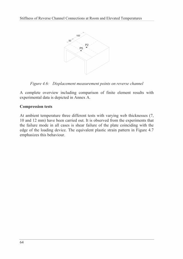
Stiffness of Reverse Channel Connections at Room and Elevated Temperatures
64
P250
100
P5
Figure 4.6: Displacement measurement points on reverse channel
A complete overview including comparison of finite element results with experimental data is depicted in Annex A.
Compression tests
At ambient temperature three different tests with varying web thicknesses (7, 10 and 12 mm) have been carried out. It is observed from the experiments that the failure mode in all cases is shear failure of the plate coinciding with the edge of the loading device. The equivalent plastic strain pattern in Figure 4.7 emphasizes this behaviour.
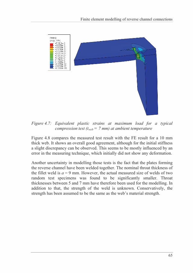
Finite element modelling of reverse channel connections
65
Figure 4.7: Equivalent plastic strains at maximum load for a typical compression test (tweb = 7 mm) at ambient temperature
Figure 4.8 compares the measured test result with the FE result for a 10 mm thick web. It shows an overall good agreement, although for the initial stiffness a slight discrepancy can be observed. This seems to be mostly influenced by an error in the measuring technique, which initially did not show any deformation.
Another uncertainty in modelling those tests is the fact that the plates forming the reverse channel have been welded together. The nominal throat thickness of the fillet weld is a = 9 mm. However, the actual measured size of welds of two random test specimens was found to be significantly smaller. Throat thicknesses between 5 and 7 mm have therefore been used for the modelling. In addition to that, the strength of the weld is unknown. Conservatively, the strength has been assumed to be the same as the web’s material strength.
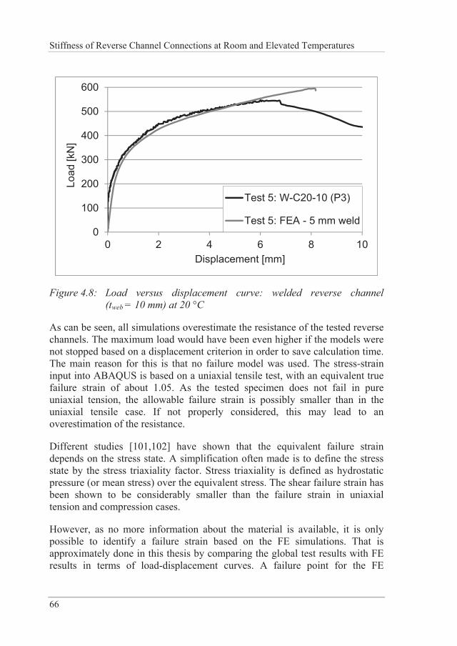
Stiffness of Reverse Channel Connections at Room and Elevated Temperatures
66
0
100
200
300
400
500
600
0 2 4 6 8 10
Load
[kN
]
Displacement [mm]
Test 5: W-C20-10 (P3)
Test 5: FEA - 5 mm weld
Figure 4.8: Load versus displacement curve: welded reverse channel (tweb = 10 mm) at 20 °C
As can be seen, all simulations overestimate the resistance of the tested reverse channels. The maximum load would have been even higher if the models were not stopped based on a displacement criterion in order to save calculation time. The main reason for this is that no failure model was used. The stress-strain input into ABAQUS is based on a uniaxial tensile test, with an equivalent true failure strain of about 1.05. As the tested specimen does not fail in pure uniaxial tension, the allowable failure strain is possibly smaller than in the uniaxial tensile case. If not properly considered, this may lead to an overestimation of the resistance.
Different studies [101,102] have shown that the equivalent failure strain depends on the stress state. A simplification often made is to define the stress state by the stress triaxiality factor. Stress triaxiality is defined as hydrostatic pressure (or mean stress) over the equivalent stress. The shear failure strain has been shown to be considerably smaller than the failure strain in uniaxial tension and compression cases.
However, as no more information about the material is available, it is only possible to identify a failure strain based on the FE simulations. That is approximately done in this thesis by comparing the global test results with FE results in terms of load-displacement curves. A failure point for the FE
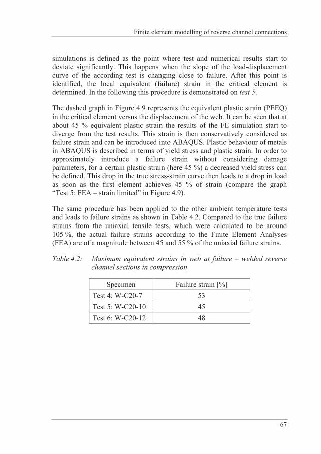
Finite element modelling of reverse channel connections
67
simulations is defined as the point where test and numerical results start to deviate significantly. This happens when the slope of the load-displacement curve of the according test is changing close to failure. After this point is identified, the local equivalent (failure) strain in the critical element is determined. In the following this procedure is demonstrated on test 5.
The dashed graph in Figure 4.9 represents the equivalent plastic strain (PEEQ) in the critical element versus the displacement of the web. It can be seen that at about 45 % equivalent plastic strain the results of the FE simulation start to diverge from the test results. This strain is then conservatively considered as failure strain and can be introduced into ABAQUS. Plastic behaviour of metals in ABAQUS is described in terms of yield stress and plastic strain. In order to approximately introduce a failure strain without considering damage parameters, for a certain plastic strain (here 45 %) a decreased yield stress can be defined. This drop in the true stress-strain curve then leads to a drop in load as soon as the first element achieves 45 % of strain (compare the graph “Test 5: FEA – strain limited” in Figure 4.9).
The same procedure has been applied to the other ambient temperature tests and leads to failure strains as shown in Table 4.2. Compared to the true failure strains from the uniaxial tensile tests, which were calculated to be around 105 %, the actual failure strains according to the Finite Element Analyses (FEA) are of a magnitude between 45 and 55 % of the uniaxial failure strains.
Table 4.2: Maximum equivalent strains in web at failure – welded reverse channel sections in compression
Specimen Failure strain [%] Test 4: W-C20-7 53 Test 5: W-C20-10 45 Test 6: W-C20-12 48
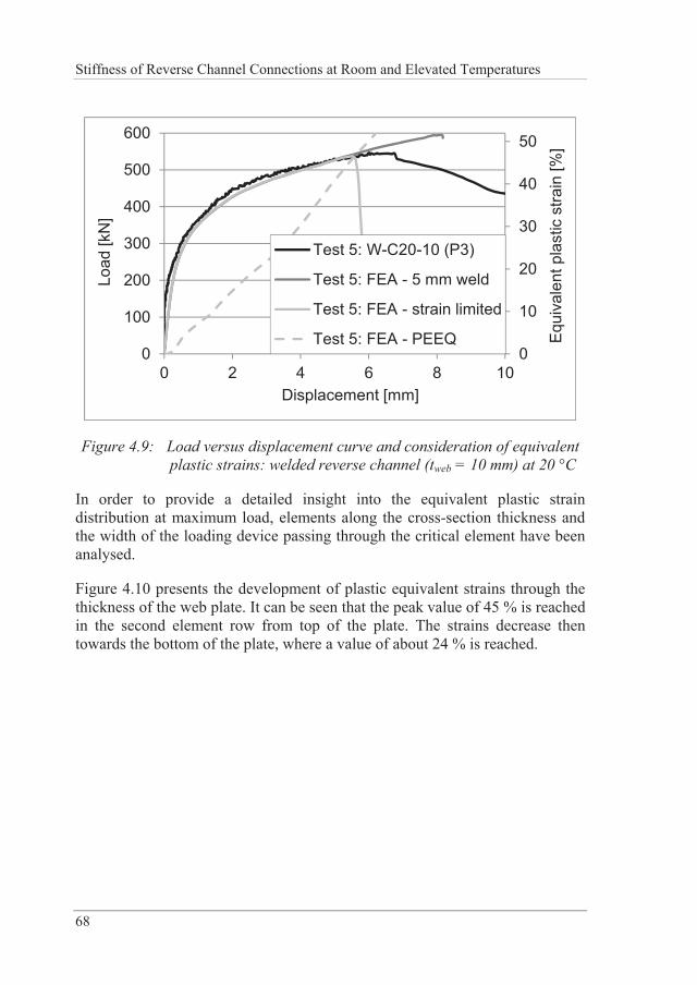
Stiffness of Reverse Channel Connections at Room and Elevated Temperatures
68
0
10
20
30
40
50
0
100
200
300
400
500
600
0 2 4 6 8 10
Equ
ival
ent p
last
ic s
train
[%]
Load
[kN
]
Displacement [mm]
Test 5: W-C20-10 (P3)
Test 5: FEA - 5 mm weld
Test 5: FEA - strain limited
Test 5: FEA - PEEQ
Figure 4.9: Load versus displacement curve and consideration of equivalent plastic strains: welded reverse channel (tweb = 10 mm) at 20 °C
In order to provide a detailed insight into the equivalent plastic strain distribution at maximum load, elements along the cross-section thickness and the width of the loading device passing through the critical element have been analysed.
Figure 4.10 presents the development of plastic equivalent strains through the thickness of the web plate. It can be seen that the peak value of 45 % is reached in the second element row from top of the plate. The strains decrease then towards the bottom of the plate, where a value of about 24 % is reached.
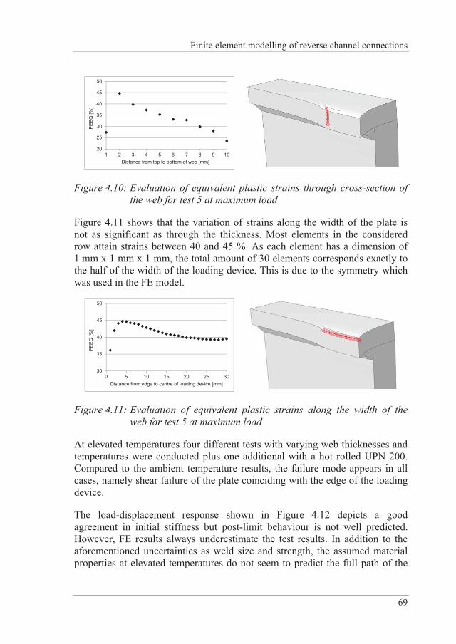
Finite element modelling of reverse channel connections
69
20
25
30
35
40
45
50
1 2 3 4 5 6 7 8 9 10
PE
EQ
[%]
Distance from top to bottom of web [mm]
Figure 4.10: Evaluation of equivalent plastic strains through cross-section of the web for test 5 at maximum load
Figure 4.11 shows that the variation of strains along the width of the plate is not as significant as through the thickness. Most elements in the considered row attain strains between 40 and 45 %. As each element has a dimension of 1 mm x 1 mm x 1 mm, the total amount of 30 elements corresponds exactly to the half of the width of the loading device. This is due to the symmetry which was used in the FE model.
30
35
40
45
50
0 5 10 15 20 25 30
PE
EQ
[%]
Distance from edge to centre of loading device [mm]
Figure 4.11: Evaluation of equivalent plastic strains along the width of the web for test 5 at maximum load
At elevated temperatures four different tests with varying web thicknesses and temperatures were conducted plus one additional with a hot rolled UPN 200. Compared to the ambient temperature results, the failure mode appears in all cases, namely shear failure of the plate coinciding with the edge of the loading device.
The load-displacement response shown in Figure 4.12 depicts a good agreement in initial stiffness but post-limit behaviour is not well predicted. However, FE results always underestimate the test results. In addition to the aforementioned uncertainties as weld size and strength, the assumed material properties at elevated temperatures do not seem to predict the full path of the
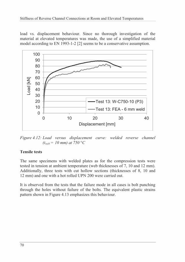
Stiffness of Reverse Channel Connections at Room and Elevated Temperatures
70
load vs. displacement behaviour. Since no thorough investigation of the material at elevated temperatures was made, the use of a simplified material model according to EN 1993-1-2 [2] seems to be a conservative assumption.
0102030405060708090
100
0 10 20 30 40
Load
[kN
]
Displacement [mm]
Test 13: W-C750-10 (P3)
Test 13: FEA - 6 mm weld
Figure 4.12: Load versus displacement curve: welded reverse channel (tweb = 10 mm) at 750 °C
Tensile tests
The same specimens with welded plates as for the compression tests were tested in tension at ambient temperature (web thicknesses of 7, 10 and 12 mm). Additionally, three tests with cut hollow sections (thicknesses of 8, 10 and 12 mm) and one with a hot rolled UPN 200 were carried out.
It is observed from the tests that the failure mode in all cases is bolt punching through the holes without failure of the bolts. The equivalent plastic strains pattern shown in Figure 4.13 emphasizes this behaviour.
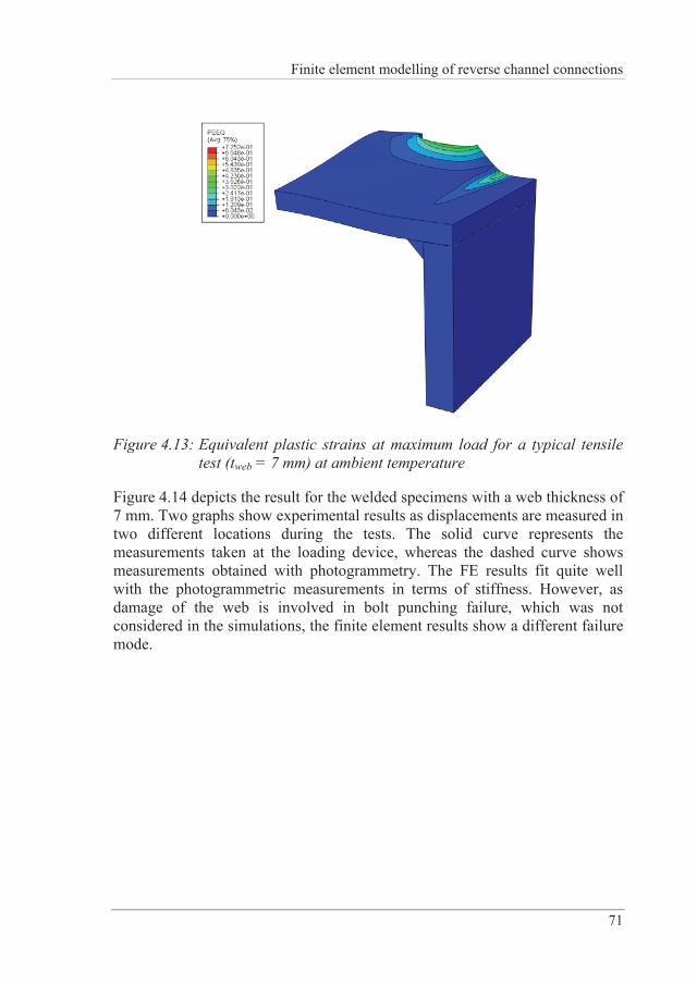
Finite element modelling of reverse channel connections
71
Figure 4.13: Equivalent plastic strains at maximum load for a typical tensile test (tweb = 7 mm) at ambient temperature
Figure 4.14 depicts the result for the welded specimens with a web thickness of 7 mm. Two graphs show experimental results as displacements are measured in two different locations during the tests. The solid curve represents the measurements taken at the loading device, whereas the dashed curve shows measurements obtained with photogrammetry. The FE results fit quite well with the photogrammetric measurements in terms of stiffness. However, as damage of the web is involved in bolt punching failure, which was not considered in the simulations, the finite element results show a different failure mode.
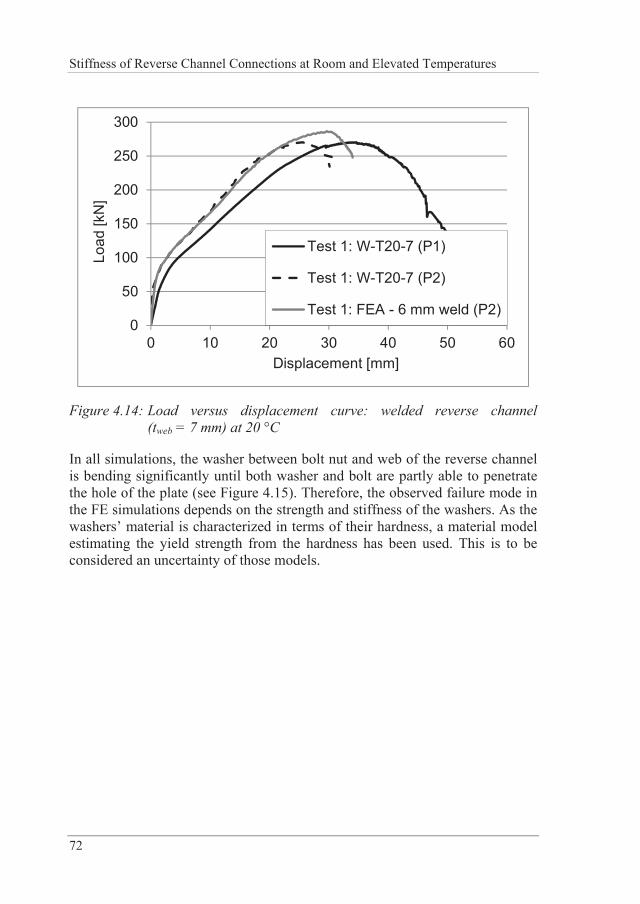
Stiffness of Reverse Channel Connections at Room and Elevated Temperatures
72
0
50
100
150
200
250
300
0 10 20 30 40 50 60
Load
[kN
]
Displacement [mm]
Test 1: W-T20-7 (P1)
Test 1: W-T20-7 (P2)
Test 1: FEA - 6 mm weld (P2)
Figure 4.14: Load versus displacement curve: welded reverse channel (tweb = 7 mm) at 20 °C
In all simulations, the washer between bolt nut and web of the reverse channel is bending significantly until both washer and bolt are partly able to penetrate the hole of the plate (see Figure 4.15). Therefore, the observed failure mode in the FE simulations depends on the strength and stiffness of the washers. As the washers’ material is characterized in terms of their hardness, a material model estimating the yield strength from the hardness has been used. This is to be considered an uncertainty of those models.
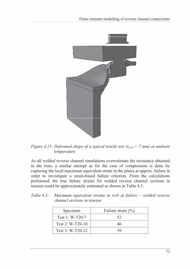
Finite element modelling of reverse channel connections
73
Figure 4.15: Deformed shape of a typical tensile test (tweb = 7 mm) at ambient temperature
As all welded reverse channel simulations overestimate the resistance obtained in the tests, a similar attempt as for the case of compression is done by capturing the local maximum equivalent strain in the plates at approx. failure in order to investigate a strain-based failure criterion. From the calculations performed, the true failure strains for welded reverse channel sections in tension could be approximately estimated as shown in Table 4.3.
Table 4.3: Maximum equivalent strains in web at failure – welded reverse channel sections in tension
Specimen Failure strain [%] Test 1: W-T20-7 52 Test 2: W-T20-10 46 Test 3: W-T20-12 59
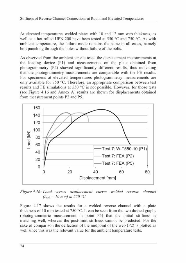
Stiffness of Reverse Channel Connections at Room and Elevated Temperatures
74
At elevated temperatures welded plates with 10 and 12 mm web thickness, as well as a hot rolled UPN 200 have been tested at 550 °C and 750 °C. As with ambient temperature, the failure mode remains the same in all cases, namely bolt punching through the holes without failure of the bolts.
As observed from the ambient tensile tests, the displacement measurements at the loading device (P1) and measurements on the plate obtained from photogrammetry (P2) showed significantly different results, thus indicating that the photogrammetry measurements are comparable with the FE results. For specimens at elevated temperatures photogrammetry measurements are only available for 750 °C. Therefore, an appropriate comparison between test results and FE simulations at 550 °C is not possible. However, for those tests (see Figure 4.16 and Annex A) results are shown for displacements obtained from measurement points P2 and P5.
0
20
40
60
80
100
120
140
160
0 20 40 60 80
Load
[kN
]
Displacement [mm]
Test 7: W-T550-10 (P1)
Test 7: FEA (P2)
Test 7: FEA (P5)
Figure 4.16: Load versus displacement curve: welded reverse channel (tweb = 10 mm) at 550 °C
Figure 4.17 shows the results for a welded reverse channel with a plate thickness of 10 mm tested at 750 °C. It can be seen from the two dashed graphs (photogrammetric measurement in point P5) that the initial stiffness is matching well, whereas the post-limit stiffness cannot be predicted. For the sake of comparison the deflection of the midpoint of the web (P2) is plotted as well since this was the relevant value for the ambient temperature tests.
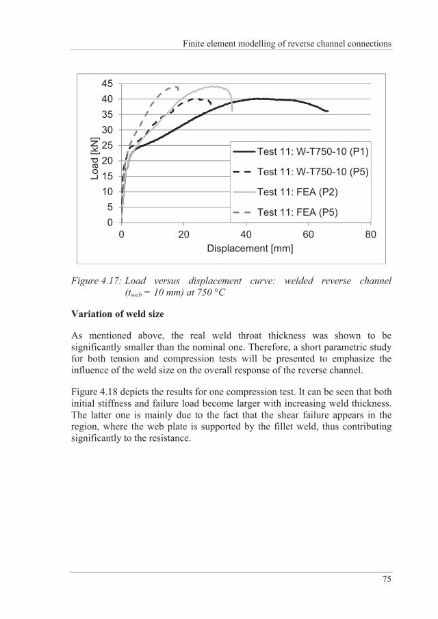
Finite element modelling of reverse channel connections
75
05
1015202530354045
0 20 40 60 80
Load
[kN
]
Displacement [mm]
Test 11: W-T750-10 (P1)
Test 11: W-T750-10 (P5)
Test 11: FEA (P2)
Test 11: FEA (P5)
Figure 4.17: Load versus displacement curve: welded reverse channel (tweb = 10 mm) at 750 °C
Variation of weld size
As mentioned above, the real weld throat thickness was shown to be significantly smaller than the nominal one. Therefore, a short parametric study for both tension and compression tests will be presented to emphasize the influence of the weld size on the overall response of the reverse channel.
Figure 4.18 depicts the results for one compression test. It can be seen that both initial stiffness and failure load become larger with increasing weld thickness. The latter one is mainly due to the fact that the shear failure appears in the region, where the web plate is supported by the fillet weld, thus contributing significantly to the resistance.
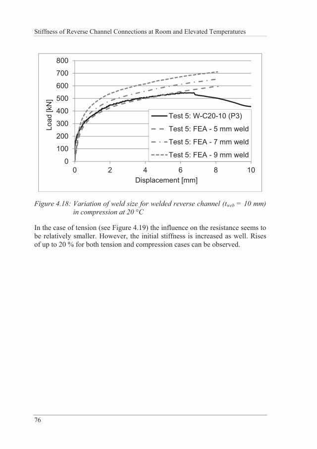
Stiffness of Reverse Channel Connections at Room and Elevated Temperatures
76
0
100
200
300
400
500
600
700
800
0 2 4 6 8 10
Load
[kN
]
Displacement [mm]
Test 5: W-C20-10 (P3)
Test 5: FEA - 5 mm weld
Test 5: FEA - 7 mm weld
Test 5: FEA - 9 mm weld
Figure 4.18: Variation of weld size for welded reverse channel (tweb = 10 mm) in compression at 20 °C
In the case of tension (see Figure 4.19) the influence on the resistance seems to be relatively smaller. However, the initial stiffness is increased as well. Rises of up to 20 % for both tension and compression cases can be observed.
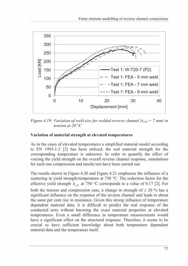
Finite element modelling of reverse channel connections
77
0
50
100
150
200
250
300
350
0 10 20 30 40
Load
[kN
]
Displacement [mm]
Test 1: W-T20-7 (P2)
Test 1: FEA - 5 mm weld
Test 1: FEA - 7 mm weld
Test 1: FEA - 9 mm weld
Figure 4.19: Variation of weld size for welded reverse channel (tweb = 7 mm) in tension at 20 °C
Variation of material strength at elevated temperatures
As in the cases of elevated temperatures a simplified material model according to EN 1993-1-2 [2] has been utilized, the real material strength for the corresponding temperature is unknown. In order to quantify the effect of varying the yield strength on the overall reverse channel response, simulations for each one compression and tensile test have been carried out.
The results shown in Figure 4.20 and Figure 4.21 emphasize the influence of a scattering in yield strength/temperature at 750 °C. The reduction factor for the effective yield strength y,k at 750 °C corresponds to a value of 0.17 [2]. For both the tension and compression case, a change in strength of ± 20 % has a significant influence on the response of the reverse channel and leads to about the same per cent rise in resistance. Given this strong influence of temperature dependent material data, it is difficult to predict the real response of the conducted tests without knowing the exact material properties at elevated temperatures. Even a small difference in temperature measurements would have a significant effect on the structural response. Therefore, it seems to be crucial to have sufficient knowledge about both temperature dependent material data and the temperature itself.
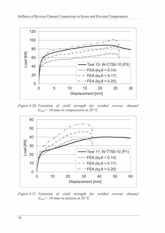
Stiffness of Reverse Channel Connections at Room and Elevated Temperatures
78
0
20
40
60
80
100
120
0 5 10 15 20 25 30
Load
[kN
]
Displacement [mm]
Test 13: W-C750-10 (P3)FEA (ky, = 0.14)FEA (ky, = 0.17)FEA (ky, = 0.20)
Figure 4.20: Variation of yield strength for welded reverse channel (tweb = 10 mm) in compression at 20 °C
0
10
20
30
40
50
60
0 10 20 30 40 50 60
Load
[kN
]
Displacement [mm]
Test 11: W-T750-10 (P1)FEA (ky, = 0.14)FEA (ky, = 0.17)FEA (ky, = 0.20)
Figure 4.21: Variation of yield strength for welded reverse channel (tweb = 10 mm) in tension at 20 °C
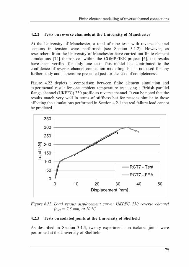
Finite element modelling of reverse channel connections
79
4.2.2 Tests on reverse channels at the University of Manchester
At the University of Manchester, a total of nine tests with reverse channel sections in tension were performed (see Section 3.1.2). However, as researchers from the University of Manchester have carried out finite element simulations [74] themselves within the COMPFIRE project [6], the results have been verified for only one test. This model has contributed to the confidence of reverse channel connection modelling, but is not used for any further study and is therefore presented just for the sake of completeness.
Figure 4.22 depicts a comparison between finite element simulation and experimental result for one ambient temperature test using a British parallel flange channel (UKPFC) 230 profile as reverse channel. It can be noted that the results match very well in terms of stiffness but for reasons similar to those affecting the simulations performed in Section 4.2.1 the real failure load cannot be predicted.
0
50
100
150
200
250
300
350
0 10 20 30 40 50
Load
[kN
]
Displacement [mm]
RCT7 - Test
RCT7 - FEA
Figure 4.22: Load versus displacement curve: UKPFC 230 reverse channel (tweb = 7.5 mm) at 20 °C
4.2.3 Tests on isolated joints at the University of Sheffield
As described in Section 3.1.3, twenty experiments on isolated joints were performed at the University of Sheffield.
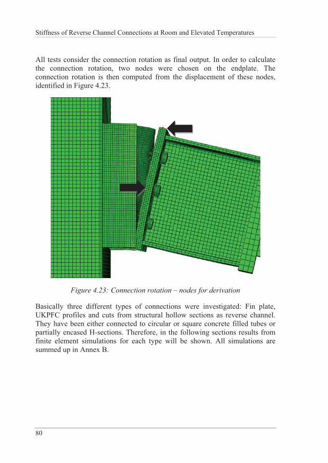
Stiffness of Reverse Channel Connections at Room and Elevated Temperatures
80
All tests consider the connection rotation as final output. In order to calculate the connection rotation, two nodes were chosen on the endplate. The connection rotation is then computed from the displacement of these nodes, identified in Figure 4.23.
Figure 4.23: Connection rotation – nodes for derivation
Basically three different types of connections were investigated: Fin plate, UKPFC profiles and cuts from structural hollow sections as reverse channel. They have been either connected to circular or square concrete filled tubes or partially encased H-sections. Therefore, in the following sections results from finite element simulations for each type will be shown. All simulations are summed up in Annex B.
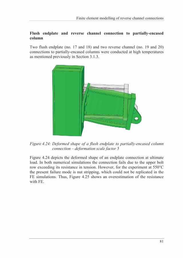
Finite element modelling of reverse channel connections
81
Flush endplate and reverse channel connection to partially-encased column
Two flush endplate (no. 17 and 18) and two reverse channel (no. 19 and 20) connections to partially-encased columns were conducted at high temperatures as mentioned previously in Section 3.1.3.
Figure 4.24: Deformed shape of a flush endplate to partially-encased column connection – deformation scale factor 5
Figure 4.24 depicts the deformed shape of an endplate connection at ultimate load. In both numerical simulations the connection fails due to the upper bolt row exceeding its resistance in tension. However, for the experiment at 550°C the present failure mode is nut stripping, which could not be replicated in the FE simulations. Thus, Figure 4.25 shows an overestimation of the resistance with FE.
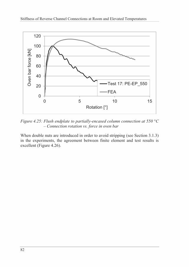
Stiffness of Reverse Channel Connections at Room and Elevated Temperatures
82
0
20
40
60
80
100
120
0 5 10 15
Ove
n ba
r for
ce [k
N]
Rotation [°]
Test 17: PE-EP_550
FEA
Figure 4.25: Flush endplate to partially-encased column connection at 550 °C – Connection rotation vs. force in oven bar
When double nuts are introduced in order to avoid stripping (see Section 3.1.3) in the experiments, the agreement between finite element and test results is excellent (Figure 4.26).
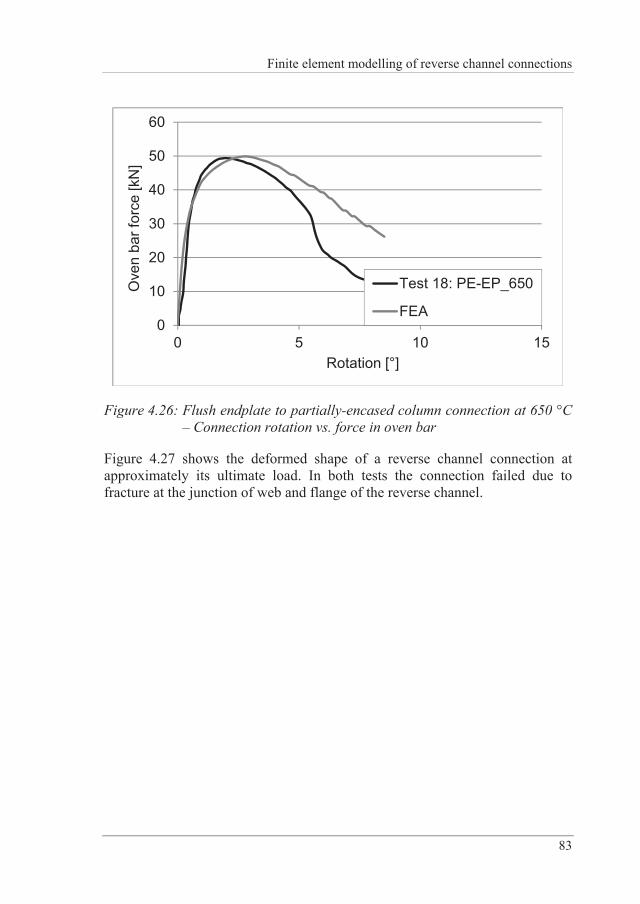
Finite element modelling of reverse channel connections
83
0
10
20
30
40
50
60
0 5 10 15
Ove
n ba
r for
ce [k
N]
Rotation [°]
Test 18: PE-EP_650
FEA
Figure 4.26: Flush endplate to partially-encased column connection at 650 °C – Connection rotation vs. force in oven bar
Figure 4.27 shows the deformed shape of a reverse channel connection at approximately its ultimate load. In both tests the connection failed due to fracture at the junction of web and flange of the reverse channel.
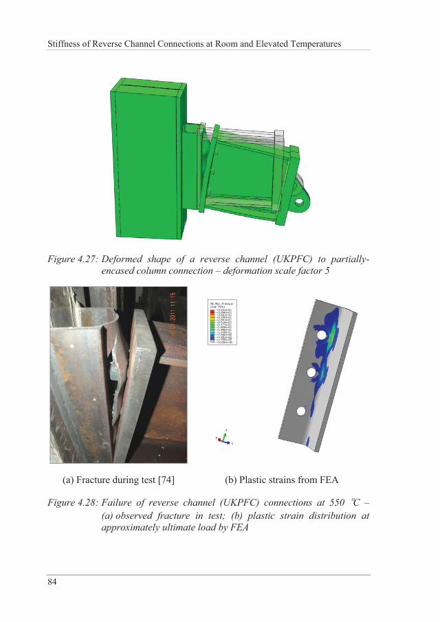
Stiffness of Reverse Channel Connections at Room and Elevated Temperatures
84
Figure 4.27: Deformed shape of a reverse channel (UKPFC) to partially-encased column connection – deformation scale factor 5
(a) Fracture during test [74] (b) Plastic strains from FEA
Figure 4.28: Failure of reverse channel (UKPFC) connections at 550 °C – (a) observed fracture in test; (b) plastic strain distribution at approximately ultimate load by FEA
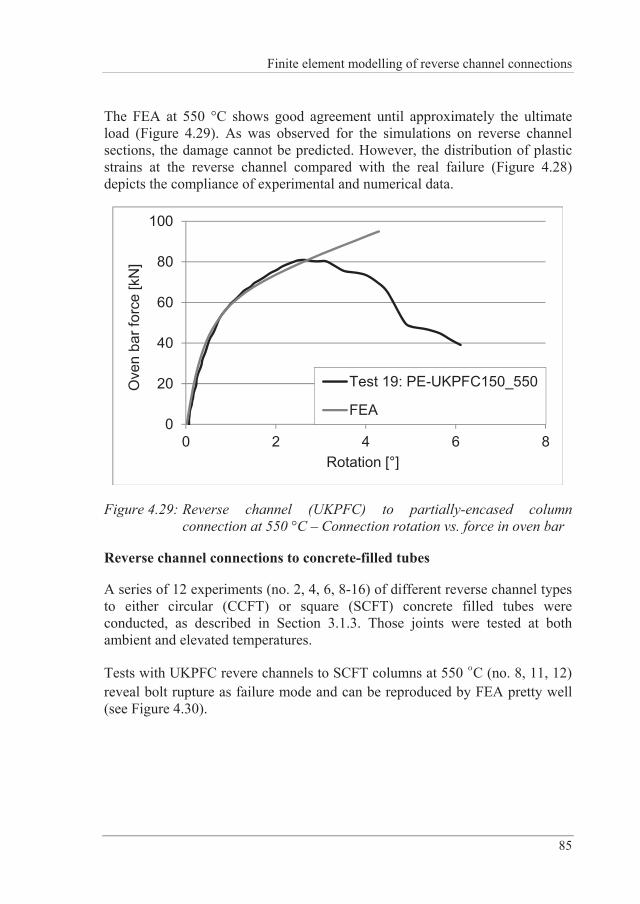
Finite element modelling of reverse channel connections
85
The FEA at 550 °C shows good agreement until approximately the ultimate load (Figure 4.29). As was observed for the simulations on reverse channel sections, the damage cannot be predicted. However, the distribution of plastic strains at the reverse channel compared with the real failure (Figure 4.28) depicts the compliance of experimental and numerical data.
0
20
40
60
80
100
0 2 4 6 8
Ove
n ba
r for
ce [k
N]
Rotation [°]
Test 19: PE-UKPFC150_550
FEA
Figure 4.29: Reverse channel (UKPFC) to partially-encased column connection at 550 °C – Connection rotation vs. force in oven bar
Reverse channel connections to concrete-filled tubes
A series of 12 experiments (no. 2, 4, 6, 8-16) of different reverse channel types to either circular (CCFT) or square (SCFT) concrete filled tubes were conducted, as described in Section 3.1.3. Those joints were tested at both ambient and elevated temperatures.
Tests with UKPFC revere channels to SCFT columns at 550 °C (no. 8, 11, 12) reveal bolt rupture as failure mode and can be reproduced by FEA pretty well (see Figure 4.30).
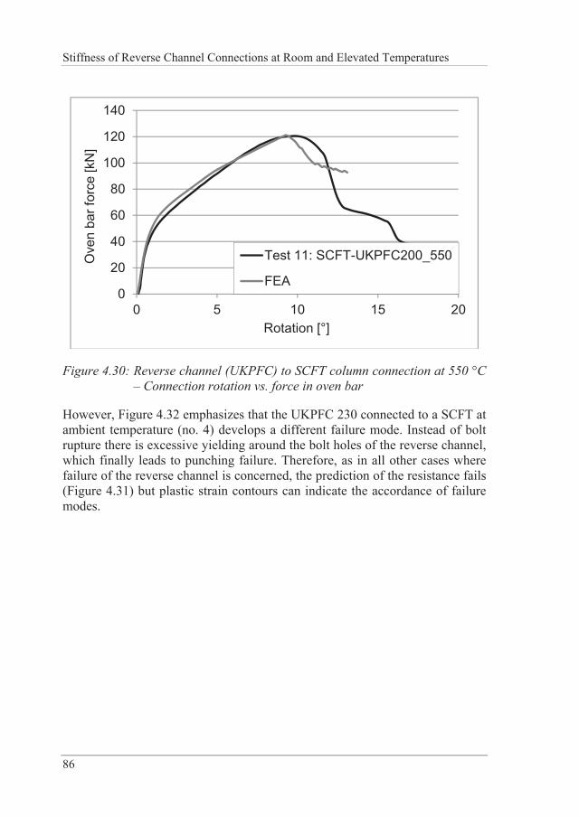
Stiffness of Reverse Channel Connections at Room and Elevated Temperatures
86
0
20
40
60
80
100
120
140
0 5 10 15 20
Ove
n ba
r for
ce [k
N]
Rotation [°]
Test 11: SCFT-UKPFC200_550
FEA
Figure 4.30: Reverse channel (UKPFC) to SCFT column connection at 550 °C – Connection rotation vs. force in oven bar
However, Figure 4.32 emphasizes that the UKPFC 230 connected to a SCFT at ambient temperature (no. 4) develops a different failure mode. Instead of bolt rupture there is excessive yielding around the bolt holes of the reverse channel, which finally leads to punching failure. Therefore, as in all other cases where failure of the reverse channel is concerned, the prediction of the resistance fails (Figure 4.31) but plastic strain contours can indicate the accordance of failure modes.
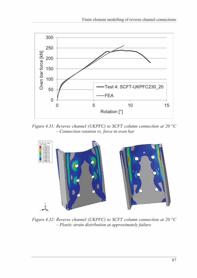
Finite element modelling of reverse channel connections
87
0
50
100
150
200
250
300
0 5 10 15
Ove
n ba
r for
ce [k
N]
Rotation [°]
Test 4: SCFT-UKPFC230_20
FEA
Figure 4.31: Reverse channel (UKPFC) to SCFT column connection at 20 °C – Connection rotation vs. force in oven bar
Figure 4.32: Reverse channel (UKPFC) to SCFT column connection at 20 °C – Plastic strain distribution at approximately failure
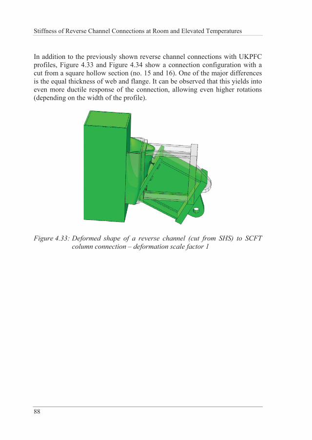
Stiffness of Reverse Channel Connections at Room and Elevated Temperatures
88
In addition to the previously shown reverse channel connections with UKPFC profiles, Figure 4.33 and Figure 4.34 show a connection configuration with a cut from a square hollow section (no. 15 and 16). One of the major differences is the equal thickness of web and flange. It can be observed that this yields into even more ductile response of the connection, allowing even higher rotations (depending on the width of the profile).
Figure 4.33: Deformed shape of a reverse channel (cut from SHS) to SCFT column connection – deformation scale factor 1
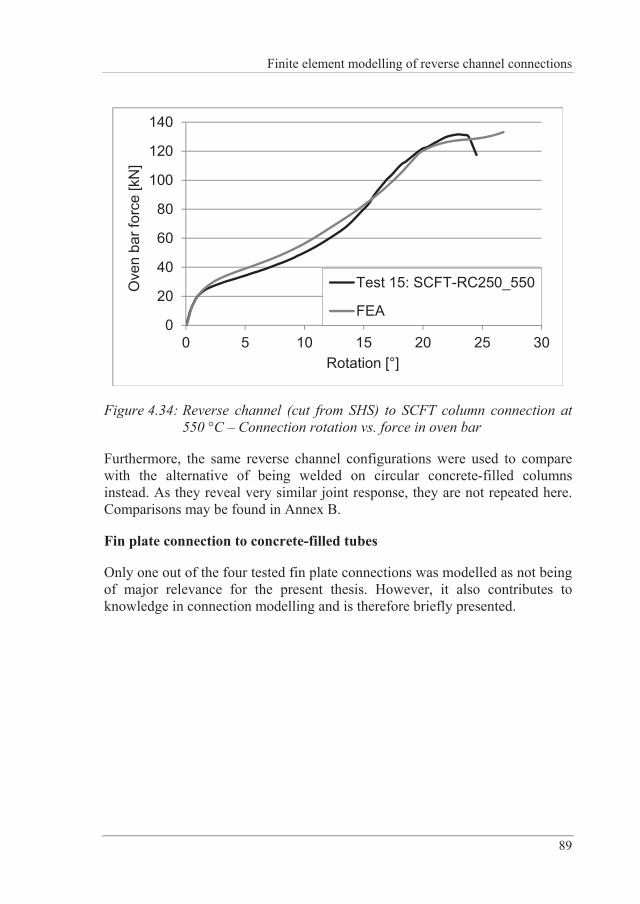
Finite element modelling of reverse channel connections
89
0
20
40
60
80
100
120
140
0 5 10 15 20 25 30
Ove
n ba
r for
ce [k
N]
Rotation [°]
Test 15: SCFT-RC250_550
FEA
Figure 4.34: Reverse channel (cut from SHS) to SCFT column connection at 550 °C – Connection rotation vs. force in oven bar
Furthermore, the same reverse channel configurations were used to compare with the alternative of being welded on circular concrete-filled columns instead. As they reveal very similar joint response, they are not repeated here. Comparisons may be found in Annex B.
Fin plate connection to concrete-filled tubes
Only one out of the four tested fin plate connections was modelled as not being of major relevance for the present thesis. However, it also contributes to knowledge in connection modelling and is therefore briefly presented.
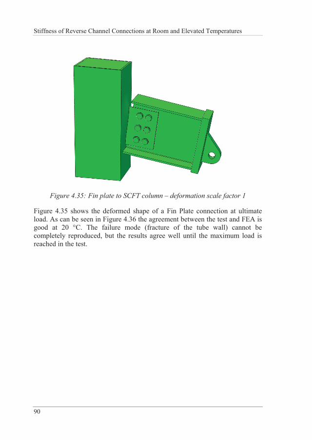
Stiffness of Reverse Channel Connections at Room and Elevated Temperatures
90
Figure 4.35: Fin plate to SCFT column – deformation scale factor 1
Figure 4.35 shows the deformed shape of a Fin Plate connection at ultimate load. As can be seen in Figure 4.36 the agreement between the test and FEA is good at 20 °C. The failure mode (fracture of the tube wall) cannot be completely reproduced, but the results agree well until the maximum load is reached in the test.
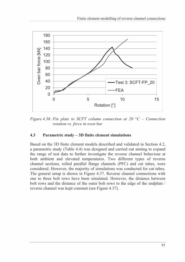
Finite element modelling of reverse channel connections
91
020406080
100120140160180
0 5 10 15
Ove
n ba
r for
ce [k
N]
Rotation [°]
Test 3: SCFT-FP_20
FEA
Figure 4.36: Fin plate to SCFT column connection at 20 °C – Connection rotation vs. force in oven bar
4.3 Parametric study – 3D finite element simulations
Based on the 3D finite element models described and validated in Section 4.2, a parametric study (Table 4.4) was designed and carried out aiming to expand the range of test data to further investigate the reverse channel behaviour at both ambient and elevated temperatures. Two different types of reverse channel sections, rolled parallel flange channels (PFC) and cut tubes, were considered. However, the majority of simulations was conducted for cut tubes. The general setup is shown in Figure 4.37. Reverse channel connections with one to three bolt rows have been simulated. However, the distance between bolt rows and the distance of the outer bolt rows to the edge of the endplate / reverse channel was kept constant (see Figure 4.37).
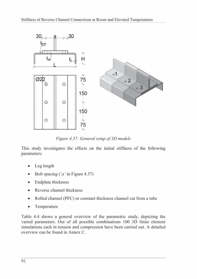
Stiffness of Reverse Channel Connections at Room and Elevated Temperatures
92
Figure 4.37: General setup of 3D models
This study investigates the effects on the initial stiffness of the following parameters:
Leg length
Bolt spacing (‘a’ in Figure 4.37)
Endplate thickness
Reverse channel thickness
Rolled channel (PFC) or constant thickness channel cut from a tube
Temperature
Table 4.4 shows a general overview of the parametric study, depicting the varied parameters. Out of all possible combinations 100 3D finite element simulations each in tension and compression have been carried out. A detailed overview can be found in Annex C.
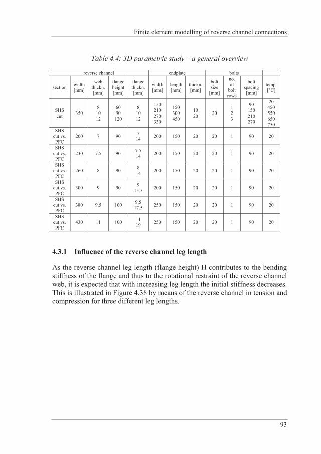
Finite element modelling of reverse channel connections
93
Table 4.4: 3D parametric study – a general overview
reverse channel endplate bolts
section width [mm]
web thickn. [mm]
flange height [mm]
flange thickn.[mm]
width[mm]
length[mm]
thickn.[mm]
bolt size
[mm]
no. of
bolt rows
bolt spacing [mm]
temp. [°C]
SHS cut 350
8 10 12
60 90 120
8 10 12
150 210 270 330
150 300 450
10 20 20
1 2 3
90 150 210 270
20 450 550 650 750
SHS cut vs. PFC
200 7 90 7 14 200 150 20 20 1 90 20
SHS cut vs. PFC
230 7.5 90 7.5 14 200 150 20 20 1 90 20
SHS cut vs. PFC
260 8 90 8 14 200 150 20 20 1 90 20
SHS cut vs. PFC
300 9 90 9 15.5 200 150 20 20 1 90 20
SHS cut vs. PFC
380 9.5 100 9.5 17.5 250 150 20 20 1 90 20
SHS cut vs. PFC
430 11 100 11 19 250 150 20 20 1 90 20
4.3.1 Influence of the reverse channel leg length
As the reverse channel leg length (flange height) H contributes to the bending stiffness of the flange and thus to the rotational restraint of the reverse channel web, it is expected that with increasing leg length the initial stiffness decreases. This is illustrated in Figure 4.38 by means of the reverse channel in tension and compression for three different leg lengths.
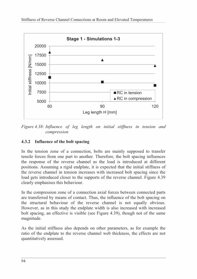
Stiffness of Reverse Channel Connections at Room and Elevated Temperatures
94
5000
7500
10000
12500
15000
17500
20000
60 90 120
Initi
al s
tiffn
ess
[N/m
m]
Leg length H [mm]
Stage 1 - Simulations 1-3
RC in tensionRC in compression
Figure 4.38: Influence of leg length on initial stiffness in tension and compression
4.3.2 Influence of the bolt spacing
In the tension zone of a connection, bolts are mainly supposed to transfer tensile forces from one part to another. Therefore, the bolt spacing influences the response of the reverse channel as the load is introduced at different positions. Assuming a rigid endplate, it is expected that the initial stiffness of the reverse channel in tension increases with increased bolt spacing since the load gets introduced closer to the supports of the reverse channel. Figure 4.39 clearly emphasises this behaviour.
In the compression zone of a connection axial forces between connected parts are transferred by means of contact. Thus, the influence of the bolt spacing on the structural behaviour of the reverse channel is not equally obvious. However, as in this study the endplate width is also increased with increased bolt spacing, an effective is visible (see Figure 4.39), though not of the same magnitude.
As the initial stiffness also depends on other parameters, as for example the ratio of the endplate to the reverse channel web thickness, the effects are not quantitatively assessed.
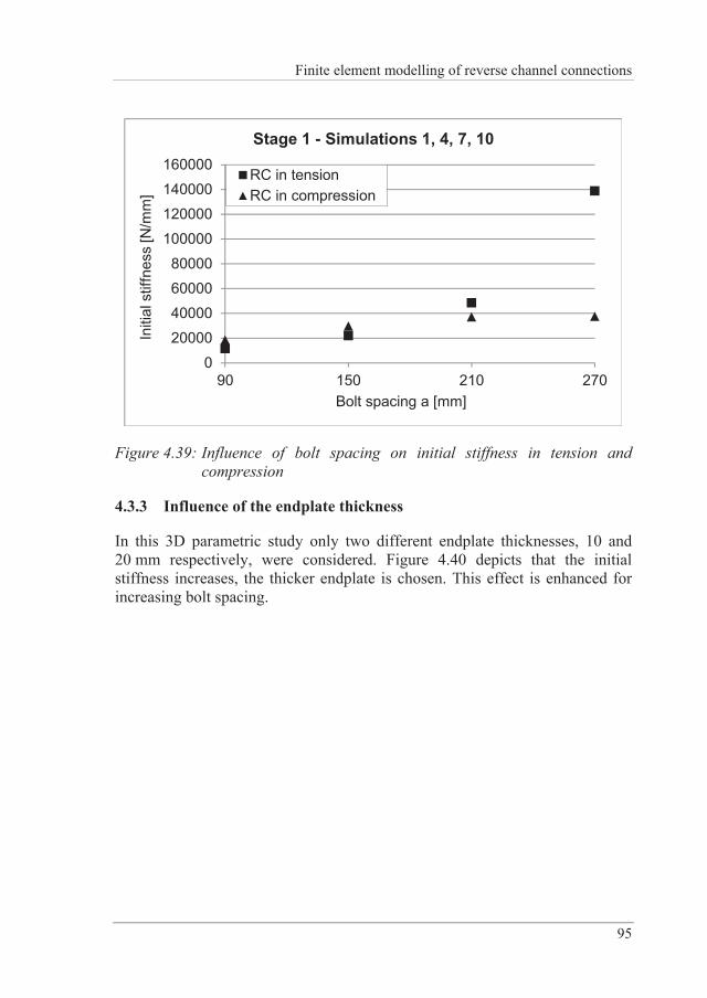
Finite element modelling of reverse channel connections
95
0
20000
4000060000
80000
100000
120000140000
160000
90 150 210 270
Initi
al s
tiffn
ess
[N/m
m]
Bolt spacing a [mm]
Stage 1 - Simulations 1, 4, 7, 10
RC in tensionRC in compression
Figure 4.39: Influence of bolt spacing on initial stiffness in tension and compression
4.3.3 Influence of the endplate thickness
In this 3D parametric study only two different endplate thicknesses, 10 and 20 mm respectively, were considered. Figure 4.40 depicts that the initial stiffness increases, the thicker endplate is chosen. This effect is enhanced for increasing bolt spacing.
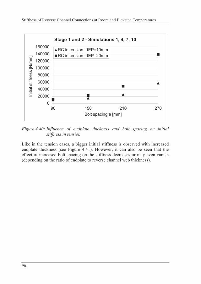
Stiffness of Reverse Channel Connections at Room and Elevated Temperatures
96
0
2000040000
60000
80000100000
120000140000
160000
90 150 210 270
Initi
al s
tiffn
ess
[N/m
m]
Bolt spacing a [mm]
Stage 1 and 2 - Simulations 1, 4, 7, 10
RC in tension - tEP=10mmRC in tension - tEP=20mm
Figure 4.40: Influence of endplate thickness and bolt spacing on initial stiffness in tension
Like in the tension cases, a bigger initial stiffness is observed with increased endplate thickness (see Figure 4.41). However, it can also be seen that the effect of increased bolt spacing on the stiffness decreases or may even vanish (depending on the ratio of endplate to reverse channel web thickness).
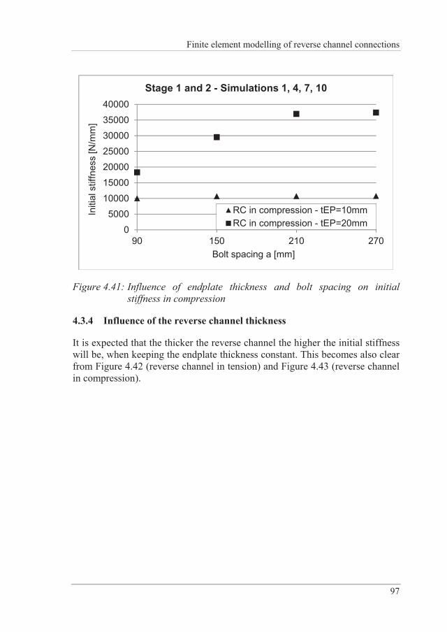
Finite element modelling of reverse channel connections
97
0
500010000
15000
2000025000
3000035000
40000
90 150 210 270
Initi
al s
tiffn
ess
[N/m
m]
Bolt spacing a [mm]
Stage 1 and 2 - Simulations 1, 4, 7, 10
RC in compression - tEP=10mmRC in compression - tEP=20mm
Figure 4.41: Influence of endplate thickness and bolt spacing on initial stiffness in compression
4.3.4 Influence of the reverse channel thickness
It is expected that the thicker the reverse channel the higher the initial stiffness will be, when keeping the endplate thickness constant. This becomes also clear from Figure 4.42 (reverse channel in tension) and Figure 4.43 (reverse channel in compression).
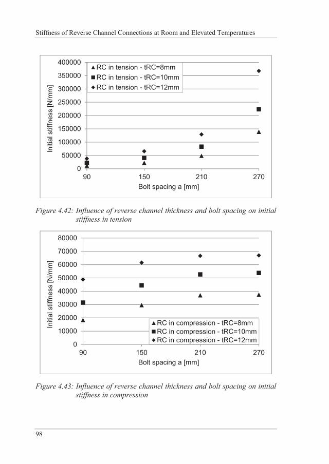
Stiffness of Reverse Channel Connections at Room and Elevated Temperatures
98
0
50000
100000
150000
200000
250000
300000
350000
400000
90 150 210 270
Initi
al s
tiffn
ess
[N/m
m]
Bolt spacing a [mm]
RC in tension - tRC=8mmRC in tension - tRC=10mmRC in tension - tRC=12mm
Figure 4.42: Influence of reverse channel thickness and bolt spacing on initial stiffness in tension
0
10000
20000
30000
40000
50000
60000
70000
80000
90 150 210 270
Initi
al s
tiffn
ess
[N/m
m]
Bolt spacing a [mm]
RC in compression - tRC=8mmRC in compression - tRC=10mmRC in compression - tRC=12mm
Figure 4.43: Influence of reverse channel thickness and bolt spacing on initial stiffness in compression
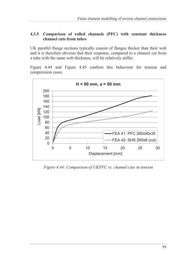
Finite element modelling of reverse channel connections
99
4.3.5 Comparison of rolled channels (PFC) with constant thickness channel cuts from tubes
UK parallel flange sections typically consist of flanges thicker than their web and it is therefore obvious that their response, compared to a channel cut from a tube with the same web thickness, will be relatively stiffer.
Figure 4.44 and Figure 4.45 confirm this behaviour for tension and compression cases.
020406080
100120140160180200
0 5 10 15 20 25 30
Load
[kN
]
Displacement [mm]
H = 90 mm, a = 90 mm
FEA 41: PFC 260x90x35FEA 42: SHS 260x8 (cut)
Figure 4.44: Comparison of UKPFC vs. channel cuts in tension
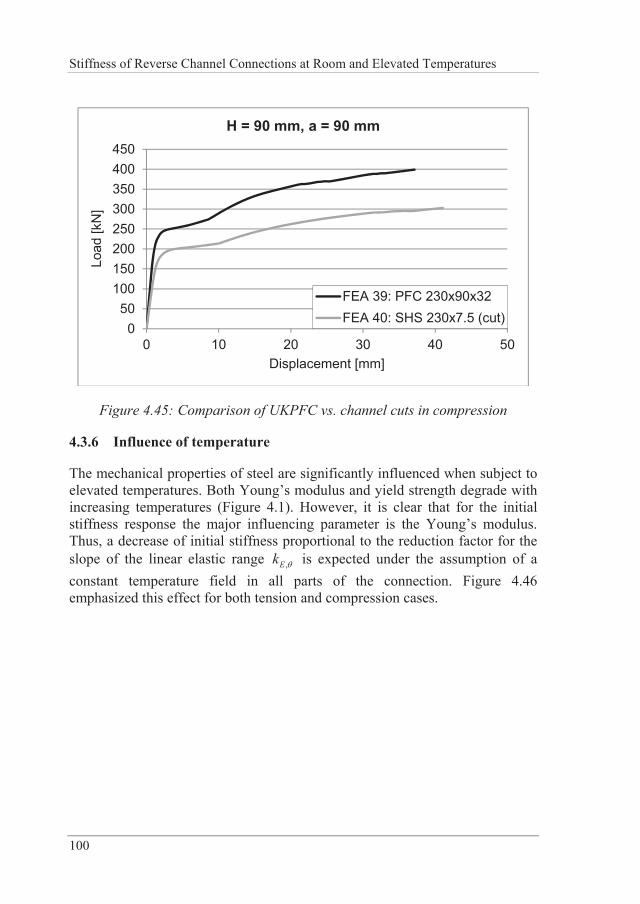
Stiffness of Reverse Channel Connections at Room and Elevated Temperatures
100
050
100150200250300350400450
0 10 20 30 40 50
Load
[kN
]
Displacement [mm]
H = 90 mm, a = 90 mm
FEA 39: PFC 230x90x32FEA 40: SHS 230x7.5 (cut)
Figure 4.45: Comparison of UKPFC vs. channel cuts in compression
4.3.6 Influence of temperature
The mechanical properties of steel are significantly influenced when subject to elevated temperatures. Both Young’s modulus and yield strength degrade with increasing temperatures (Figure 4.1). However, it is clear that for the initial stiffness response the major influencing parameter is the Young’s modulus. Thus, a decrease of initial stiffness proportional to the reduction factor for the slope of the linear elastic range ,Ek is expected under the assumption of a constant temperature field in all parts of the connection. Figure 4.46 emphasized this effect for both tension and compression cases.
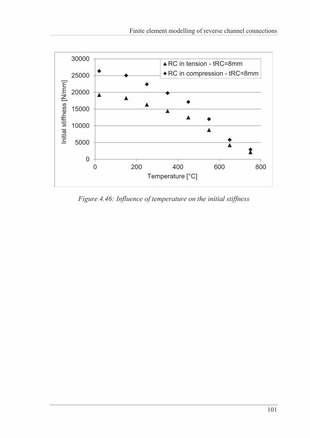
Finite element modelling of reverse channel connections
101
0
5000
10000
15000
20000
25000
30000
0 200 400 600 800
Initi
al s
tiffn
ess
[N/m
m]
Temperature [°C]
RC in tension - tRC=8mmRC in compression - tRC=8mm
Figure 4.46: Influence of temperature on the initial stiffness

Analytical models for the initial stiffness of the reverse channel
103
5 ANALYTICAL MODELS FOR THE INITIAL STIFFNESS OF THE REVERSE CHANNEL
In the present section the derivation of analytical expressions for the initial stiffness of a reverse channel connection with a partial-depth endplate will be presented. The particular case of partial-depth endplates lends itself to an elementary beam theory based approach provided that the issue of the unilateral contact between the reverse channel and the endplate of the beam has been dealt with. Although rigorous unilateral contact theory strictly precludes the a priori knowledge of the contact zones, the work of the present section focuses on the categorisation of the contact zones for the problem at hand. As will be shown, this approach leads to a small number of elementary structural systems for which analytical expressions for the displacements are relatively easy to derive.
The resulting analytical expressions are subsequently validated against plane stress and three dimensional finite element models.
5.1 The two dimensional structural system
A reverse channel (RC) connection is one connecting a beam to a column. In Figure 5.1 a section of the reverse channel – endplate (EP) system on a plane normal to the column axis is depicted. The axis of the column, whereupon the reverse channel is attached, is taken to define the z-axis. The resulting two dimensional structural system is characterised by
the 2D-frame “legs” AE and A’F i.e. the flanges of the channel section EAA’F, welded against the column at points E and F,
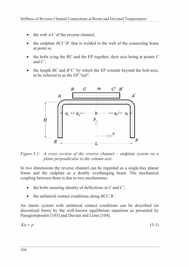
Stiffness of Reverse Channel Connections at Room and Elevated Temperatures
104
the web AA’ of the reverse channel,
the endplate BCC’B’ that is welded to the web of the connecting beam at point m,
the bolts tying the RC and the EP together, their axis being at points C and C’,
the length BC and B’C’ by which the EP extends beyond the bolt-axis, to be referred to as the EP “tail”.
Figure 5.1: A cross section of the reverse channel – endplate system on a plane perpendicular to the column axis
In two dimensions the reverse channel can be regarded as a single-bay planar frame and the endplate as a doubly overhanging beam. The mechanical coupling between them is due to two mechanisms:
the bolts ensuring identity of deflections at C and C’,
the unilateral contact conditions along BCC’B’.
An elastic system with unilateral contact conditions can be described (in discretized form) by the well-known equilibrium equations as presented by Panagiotopoulos [103] and Duvaut and Lions [104].
Ku p (5-1)
Analytical models for the initial stiffness of the reverse channel
105
subjected to the unilateral contact inequality constraints
Bu c (5-2)
where u is the displacement vector, K the stiffness matrix, p the load vector of the system and B, c respectively are a matrix and a vector associated to the unilateral constraints. After the application of the loads, equilibrium is attained: some of the inequality constraints are fulfilled as equalities (activated constraints). Instead of solving an inequality-constrained equilibrium problem one can introduce the activated constraints from Equation (5-2) to the equilibrium Equations (5-1) and solve an unconstrained problem. However, this would entail knowing the contact area (i.e. the activated constraints) a priori. This is mathematically infeasible but making informed guesses for the contact area constitutes the basis of a class of algorithms used for inequality constrained problems (active set algorithms). In the present case, the goal is not to solve the contact problem with arbitrary accuracy but to make assumptions about the contact that will lead to simple structural systems. The accuracy of the assumed simple structural systems with respect to the contact problem will be verified numerically. Fortunately, the accuracy required for engineering applications (10-1) is rather crude in comparison to that required in the context of applied numerical methods (10-4); hence the possibility for the present approach.
In what follows, observations concerning the contact forces patterns between the reverse channel and the endplate will be presented for two dimensional cases and are verified by three dimensional cases. The study of the arising contact patterns provides a rational way to actually make reliable assumptions that allow the transition from the inequality-constrained problem to a classical one.
5.2 Contact forces with respect to bolt position – case of tension
In Figure 5.2 below, the contact forces resulting from the two dimensional FE analyses (plane-stress) are shown for varying bolt positions. The reverse channel used in this example has a thickness 10RCt mm; the endplate thickness is 12.5EPt mm and 340L mm, 115H mm, 2 18a mm.
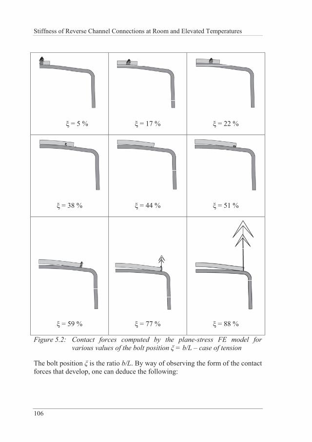
Stiffness of Reverse Channel Connections at Room and Elevated Temperatures
106
= 5 %
= 17 %
= 22 %
= 38 %
= 44 %
= 51 %
= 59 %
= 77 %
= 88 %
Figure 5.2: Contact forces computed by the plane-stress FE model for various values of the bolt position = b/L – case of tension
The bolt position is the ratio b/L. By way of observing the form of the contact forces that develop, one can deduce the following:
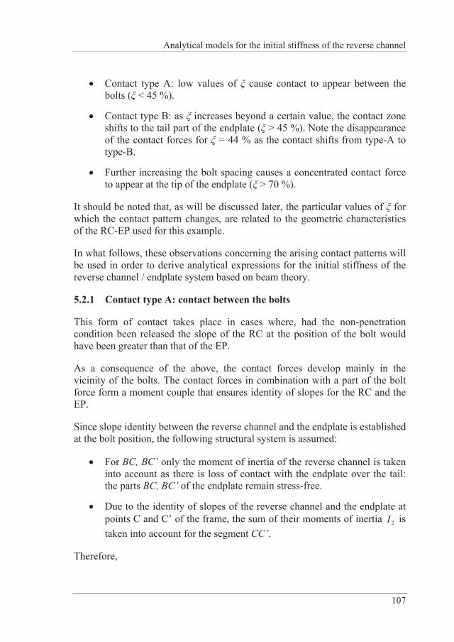
Analytical models for the initial stiffness of the reverse channel
107
Contact type A: low values of cause contact to appear between the bolts ( < 45 %).
Contact type B: as increases beyond a certain value, the contact zone shifts to the tail part of the endplate ( > 45 %). Note the disappearance of the contact forces for = 44 % as the contact shifts from type-A to type-B.
Further increasing the bolt spacing causes a concentrated contact force to appear at the tip of the endplate ( > 70 %).
It should be noted that, as will be discussed later, the particular values of for which the contact pattern changes, are related to the geometric characteristics of the RC-EP used for this example.
In what follows, these observations concerning the arising contact patterns will be used in order to derive analytical expressions for the initial stiffness of the reverse channel / endplate system based on beam theory.
5.2.1 Contact type A: contact between the bolts
This form of contact takes place in cases where, had the non-penetration condition been released the slope of the RC at the position of the bolt would have been greater than that of the EP.
As a consequence of the above, the contact forces develop mainly in the vicinity of the bolts. The contact forces in combination with a part of the bolt force form a moment couple that ensures identity of slopes for the RC and the EP.
Since slope identity between the reverse channel and the endplate is established at the bolt position, the following structural system is assumed:
For BC, BC’ only the moment of inertia of the reverse channel is taken into account as there is loss of contact with the endplate over the tail: the parts BC, BC’ of the endplate remain stress-free.
Due to the identity of slopes of the reverse channel and the endplate at points C and C’ of the frame, the sum of their moments of inertia 2I is taken into account for the segment CC’.
Therefore,
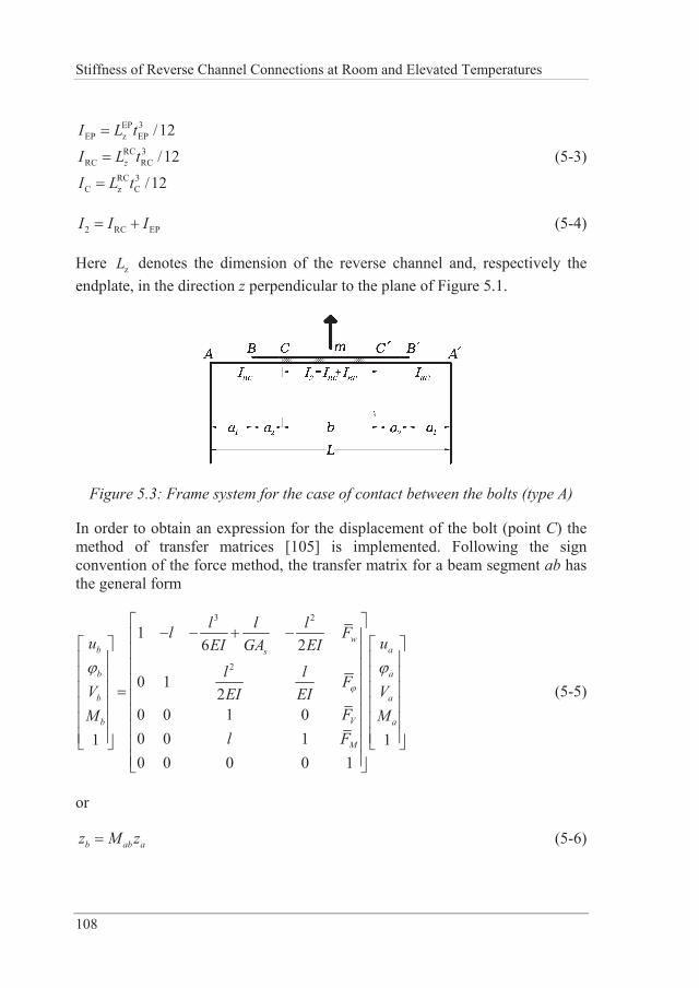
Stiffness of Reverse Channel Connections at Room and Elevated Temperatures
108
EP 3EP z EP
RC 3RC RC
RC 3C z C
/12
/12
/12z
I L tI L t
I L t
(5-3)
2 RC EPI I I (5-4)
Here zL denotes the dimension of the reverse channel and, respectively the endplate, in the direction z perpendicular to the plane of Figure 5.1.
Figure 5.3: Frame system for the case of contact between the bolts (type A)
In order to obtain an expression for the displacement of the bolt (point C) the method of transfer matrices [105] is implemented. Following the sign convention of the force method, the transfer matrix for a beam segment ab has the general form
3 2
2
16 2
0 12
0 0 1 00 0 11 10 0 0 0 1
wb as
b a
b a
Vb a
M
l l ll Fu uEI GA EI
l l FV VEI EIFM M
l F
(5-5)
or
b ab az M z (5-6)
Analytical models for the initial stiffness of the reverse channel
109
that is, the status vector bz at the end b of the beam, can be expressed as the product of the status vector at the end a of the beam az times the transfer matrix abM . The transfer matrix method is suited for dendroid structures.
The transfer matrix for the beam between points A and C reads
3 2
EP EP2
EP EP
1 06 6
0 1 02 2
0 0 1 00 0 1 00 0 0 0 1
AC
a aaEI EIa a
M EI EIP
a
(5-7)
where 1 2a a a .
The transfer matrix for the beam CC’ respectively reads
3 2
2 22
' 2 2
1 06 6
0 1 02 2
0 0 1 00 0 1 00 0 0 0 1
CC
b bbEI EI
b bM EI EI
Pb
(5-8)
And last, the transfer matrix for the segment C’A’ has the form
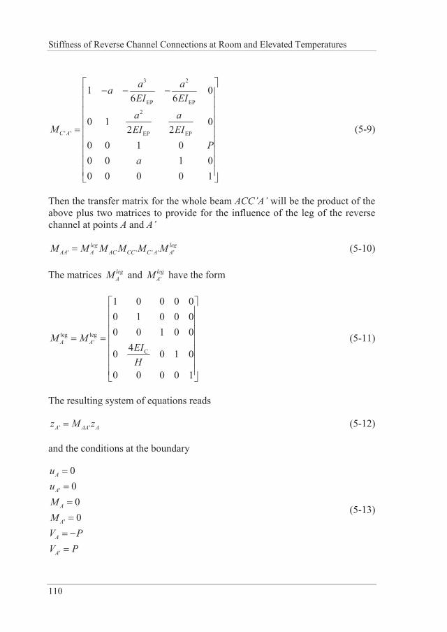
Stiffness of Reverse Channel Connections at Room and Elevated Temperatures
110
3 2
EP EP2
' ' EP EP
1 06 6
0 1 02 2
0 0 1 00 0 1 00 0 0 0 1
C A
a aaEI EIa a
M EI EIP
a
(5-9)
Then the transfer matrix for the whole beam ACC’A’ will be the product of the above plus two matrices to provide for the influence of the leg of the reverse channel at points A and A’
' ' ' ' 'leg leg
AA A AC CC C A AM M M M M M (5-10)
The matrices legAM and '
legAM have the form
leg leg'
C
1 0 0 0 00 1 0 0 00 0 1 0 0
40 0 1 0
0 0 0 0 1
A AM MEIH
(5-11)
The resulting system of equations reads
' 'A AA Az M z (5-12)
and the conditions at the boundary
'
'
'
0000
A
A
A
A
A
A
uuMMV PV P
(5-13)
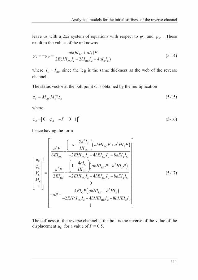
Analytical models for the initial stiffness of the reverse channel
111
leave us with a 2x2 system of equations with respect to A and 'A . These result to the values of the unknowns
RC 2'
RC 2 RC C 2 C
( )2 ( 2 4 )A A
ah bI aI PE HI I bI I aI I
(5-14)
where C RCI I since the leg is the same thickness as the web of the reverse channel.
The status vector at the bolt point C is obtained by the multiplication
legC AC A Az M M z (5-15)
where
0 0 1 TA Az P (5-16)
hence having the form
22C
RC 23RC
RC RC 2 RC C 2 C
2CRC 22
RC
RC RC 2 RC C 2 C
2C RC 2
2RC 2 RC C
2
6 2 4 8
41
2 2 4 80
14
2 4
C
C
C
C
a Ia abHI P a HI PHIa P
EI EHI I bEI I aEI Iu
aI abHI P a HI PHIa P
VEI EHI I bEI I aEI I
M
EI P abHI a HIaP
EH I I bHEI I 2 C81
aHEI I
(5-17)
The stiffness of the reverse channel at the bolt is the inverse of the value of the displacement Cu for a value of P = 0.5.
Stiffness of Reverse Channel Connections at Room and Elevated Temperatures
112
For the extreme case of an infinitely stiff endplate, i.e. for EPI the expression for the displacement at C takes the form
3 4RC C
2RC RC C3 12C
a HI a IPuE HI aI I
(5-18)
5.2.2 Contact type B: contact on the outside of the bolts
When the contact zone develops on the outside of the bolts (segments BC, B’C’), the static model changes. This situation is characterised by the following:
Loss of contact develops along segment CC’,
Contact developing along segments BC and B’C’. Following the contact force patterns observed in the numerical simulations two possibilities were considered:
- Contact extends relatively evenly along a substantial part of BC, B’C’ thus forcing the endplate and the reverse channel to develop identical deflections and slopes along this segment. This type of contact gives rise to relatively mild contact forces as shown in Figure 5.2 for = 51 %, = 59 % and will thus be henceforth referred to as “mild” contact or type-B1 contact.
- Contact takes place mainly near the endplate edge points C and C’ giving rise to a distinctive prying force appearing at the end points B, B’ of the endplate. This type of contact will respectively be referred to as “prying” or type-B2 contact.
Obviously, the two types of prying contact give rise to different static systems and are therefore treated separately.
Another trait is that these static systems, although they constitute dendroid structures, are more complicated than the one of the contact type A. Therefore the displacement method shall be implemented instead of the transfer matrix method.
Contact with mild prying forces (type B1)
The frame system of the mild prying contact is given in Figure 5.4 below.
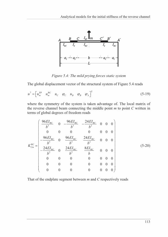
Analytical models for the initial stiffness of the reverse channel
113
Figure 5.4: The mild prying forces static system
The global displacement vector of the structural system of Figure 5.4 reads
T7 EP RCm m C C B B Au u u u u (5-19)
where the symmetry of the system is taken advantage of. The local matrix of the reverse channel beam connecting the middle point m to point C written in terms of global degrees of freedom reads
RC RC RC3 3 2
RC RC RC3 3 2
RC
RC RC RC2 2
96 96 240 0 0 0
0 0 0 0 0 0 096 96 240 0 0 0
24 24 80 0 0 0
0 0 0 0 0 0 00 0 0 0 0 0 00 0 0 0 0 0 0
Cm
EI EI EIb b b
EI EI EIb b b
K EI EI EIb b b
(5-20)
That of the endplate segment between m and C respectively reads
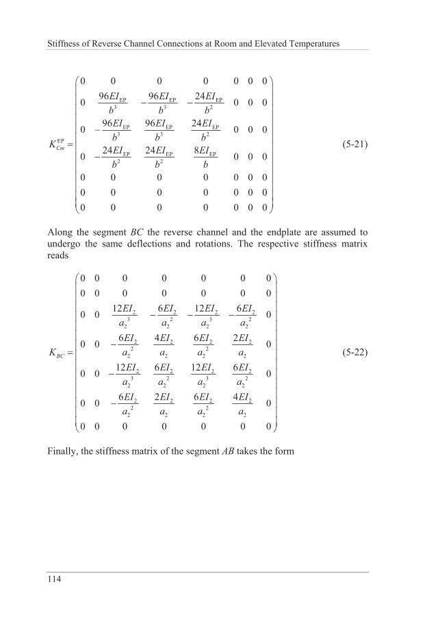
Stiffness of Reverse Channel Connections at Room and Elevated Temperatures
114
EP EP EP3 3 2
EP EP EP3 3 2
EP
EP EP EP2 2
0 0 0 0 0 0 096 96 240 0 0 0
96 96 240 0 0 0
24 24 80 0 0 0
0 0 0 0 0 0 00 0 0 0 0 0 00 0 0 0 0 0 0
Cm
EI EI EIb b bEI EI EIb b b
K EI EI EIb b b
(5-21)
Along the segment BC the reverse channel and the endplate are assumed to undergo the same deflections and rotations. The respective stiffness matrix reads
2 2 2 23 2 3 2
2 2 2 2
2 2 2 22 2
2 2 2 2
2 2 2 23 2 3 2
2 2 2 2
2 2 2 22 2
2 2 2 2
0 0 0 0 0 0 00 0 0 0 0 0 0
12 6 12 60 0 0
6 4 6 20 0 0
12 6 12 60 0 0
6 2 6 40 0 0
0 0 0 0 0 0 0
BC
EI EI EI EIa a a a
EI EI EI EIa a a aKEI EI EI EI
a a a aEI EI EI EIa a a a
(5-22)
Finally, the stiffness matrix of the segment AB takes the form
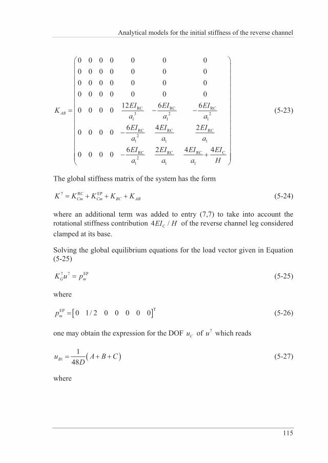
Analytical models for the initial stiffness of the reverse channel
115
RC RC RC3 2 2
1 1 1
RC RC RC2
1 1 1
RC RC RC2
1 1 1
C
0 0 0 0 0 0 00 0 0 0 0 0 00 0 0 0 0 0 00 0 0 0 0 0 0
12 6 60 0 0 0
6 4 20 0 0 0
6 2 4 40 0 0 0
ABEI EI EIKa a aEI EI EIa a aEI EI E EIa
IHa a
(5-23)
The global stiffness matrix of the system has the form
7 RC EPCm Cm BC ABK K K K K (5-24)
where an additional term was added to entry (7,7) to take into account the rotational stiffness contribution C4 /EI H of the reverse channel leg considered clamped at its base.
Solving the global equilibrium equations for the load vector given in Equation (5-25)
7 7 EPG mK u p (5-25)
where
TEP 0 1/ 2 0 0 0 0 0mp (5-26)
one may obtain the expression for the DOF Cu of 7u which reads
11
48Bu A B CD
(5-27)
where
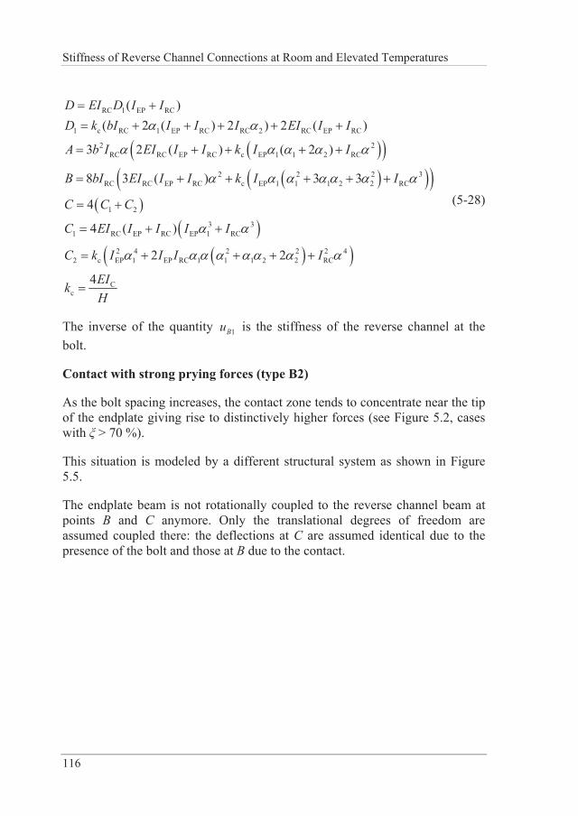
Stiffness of Reverse Channel Connections at Room and Elevated Temperatures
116
RC 1 EP RC
1 c RC 1 EP RC RC 2 RC EP RC
2 2RC RC EP RC c EP 1 1 2 RC
2 2 2 3RC RC EP RC c EP 1 1 1 2 2 RC
1 2
3 31 RC EP RC EP 1 RC
2
( )( 2 ( ) 2 ) 2 ( )
3 2 ( ) ( 2 )
8 3 ( ) 3 3
4
4 ( )
D EI I ID k bI I I I EI I I
A b I EI I I k I I
B bI EI I I k I I
C C C
C
D
EI I I I I
C k 2 4 2 2 2 4c EP 1 EP RC 1 1 1 2 2 RC
Cc
2 2
4
I I I I
EIkH
(5-28)
The inverse of the quantity 1Bu is the stiffness of the reverse channel at the bolt.
Contact with strong prying forces (type B2)
As the bolt spacing increases, the contact zone tends to concentrate near the tip of the endplate giving rise to distinctively higher forces (see Figure 5.2, cases with > 70 %).
This situation is modeled by a different structural system as shown in Figure 5.5.
The endplate beam is not rotationally coupled to the reverse channel beam at points B and C anymore. Only the translational degrees of freedom are assumed coupled there: the deflections at C are assumed identical due to the presence of the bolt and those at B due to the contact.
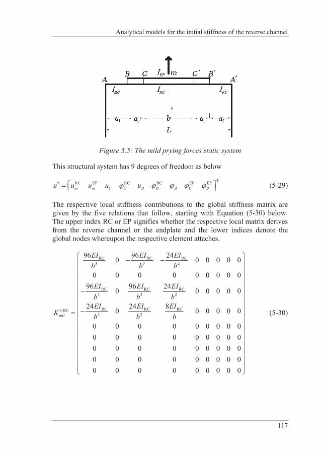
Analytical models for the initial stiffness of the reverse channel
117
Figure 5.5: The mild prying forces static system
This structural system has 9 degrees of freedom as below
T9 RC EP RC RC EP EPm m C C B B A C Bu u u u u (5-29)
The respective local stiffness contributions to the global stiffness matrix are given by the five relations that follow, starting with Equation (5-30) below. The upper index RC or EP signifies whether the respective local matrix derives from the reverse channel or the endplate and the lower indices denote the global nodes whereupon the respective element attaches.
RC RC RC3 3 2
RC RC RC3 3 2
RC RC RC9,RC2 2
96 96 240 0 0 0 0 0
0 0 0 0 0 0 0 0 096 96 240 0 0 0 0 0
24 24 80 0 0 0 0 0
0 0 0 0 0 0 0 0 00 0 0 0 0 0 0 0 00 0 0 0 0 0 0 0 00 0 0 0 0 0 0 0 00 0 0 0 0 0 0 0 0
mC
EI EI EIb b b
EI EI EIb b bEI EI EI
K b b b (5-30)
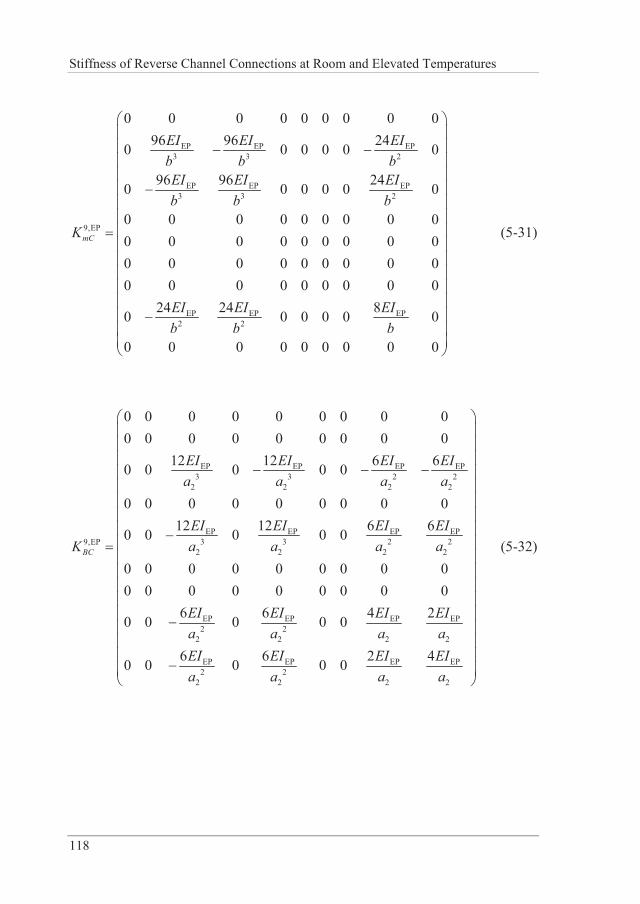
Stiffness of Reverse Channel Connections at Room and Elevated Temperatures
118
EP EP EP3 3 2
EP EP EP3 3 2
9,EP
EP EP EP2 2
0 0 0 0 0 0 0 0 096 96 240 0 0 0 0 0
96 96 240 0 0 0 0 0
0 0 0 0 0 0 0 0 00 0 0 0 0 0 0 0 00 0 0 0 0 0 0 0 00 0 0 0 0 0 0 0 0
24 24 80 0 0 0 0 0
0 0 0 0 0 0 0 0 0
mC
EI EI EIb b bEI EI EIb b b
K
EI EI EIb b b
(5-31)
EP EP EP EP3 3 2 2
2 2 2 2
EP EP EP EP3 3 2 29,EP
2 2 2 2
EP EP EP EP2 2
2 2 2 2
EP EP EP2 2
2 2 2
0 0 0 0 0 0 0 0 00 0 0 0 0 0 0 0 0
12 12 6 60 0 0 0 0
0 0 0 0 0 0 0 0 012 12 6 60 0 0 0 0
0 0 0 0 0 0 0 0 00 0 0 0 0 0 0 0 0
6 6 4 20 0 0 0 0
6 6 20 0 0 0 0
BC
EI EI EI EIa a a a
EI EI EI EIa a a aK
EI EI EI EIa a a aEI EI EIa a a
EP
2
4EIa
(5-32)
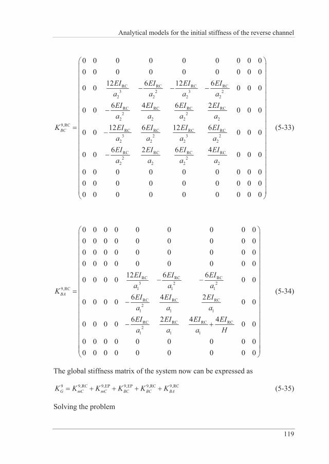
Analytical models for the initial stiffness of the reverse channel
119
RC RC RC RC3 2 3 2
2 2 2 2
RC RC RC RC2 2
2 2 2 29,RC
RC RC RC RC3 2 3 2
2 2 2 2
RC RC RC RC2 2
2 2 2 2
0 0 0 0 0 0 0 0 00 0 0 0 0 0 0 0 0
12 6 12 60 0 0 0 0
6 4 6 20 0 0 0 0
12 6 12 60 0 0 0 0
6 2 6 40 0 0 0 0
0 0 0 0 0 0 0 0 00 0 0 0 0 0 0 0 00 0
BC
EI EI EI EIa a a aEI EI EI EIa a a a
K EI EI EI EIa a a aEI EI EI EIa a a a
0 0 0 0 0 0 0
(5-33)
RC RC RC3 2 2
1 1
RC
19,RC
RC RC RC2
1 1 1
RC RC RC2
1 1 1
0 0 0 0 0 0 0 0 00 0 0 0 0 0 0 0 00 0 0 0 0 0 0 0 00 0 0 0 0 0 0 0 0
12 6 60 0 0 0 0 0
6 4 20 0 0 0 0 0
6 2 40 0 0 0 0 0
0 0 0 0 0 0 0 0 00 0 0 0 00
4
0 0 0
BA
EI EI EIa a a
KEI EI EIa a
EIa
EI EI EIa Ha a
(5-34)
The global stiffness matrix of the system now can be expressed as
9 9,RC 9,EP 9,EP 9,RC 9,RCmC mC BCG BC BAK K K K K K (5-35)
Solving the problem
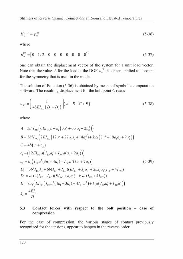
Stiffness of Reverse Channel Connections at Room and Elevated Temperatures
120
9 9 EPG mK u p (5-36)
where
TEP 0 1/ 2 0 0 0 0 0 0 0mp (5-37)
one can obtain the displacement vector of the system for a unit load vector. Note that the value ½ for the load at the DOF EP
mu has been applied to account for the symmetry that is used in the model.
The solution of Equation (5-36) is obtained by means of symbolic computation software. The resulting displacement for the bolt point C reads
2RC 1 2
148Bu A B C E
EI D D (5-38)
where
3 2 2RC RC c 1 1 2 2
2 2 2 2 2RC RC 1 1 2 2 c 1 1 2 2
1 2
21 RC EP 1 RC 1 2
3 32 c EP 1 1 2 RC 1 2
21 RC c EP RC RC 1 c 2 E
3 6 3 6 2
3 2 12 27 14 8 19 9
4
12 ( 2 )
(3 4 ) (3 7 )
3 6 ( )( ) 2 (c
A a a
B a a
a a a a a
a a a a a a
a
b I EI k a a a
b I EI a a a k a a a
C b c c
c EI I I
c k I I
D b I k b I I EI k bk a I P RC
2 2 EP RC RC c 1 c 2 EP RC
2 3 3 32 RC EP 1 1 2 RC c EP 1 RC
Cc
4 )(4( )( ) ( 4 ))
8 (4 3 ) 4
4
a a a
a a a a a
ID I I E
a a a
I k k I I
E EI I I k I I
EIkH
(5-39)
5.3 Contact forces with respect to the bolt position – case of compression
For the case of compression, the various stages of contact previously recognized for the tensions, appear to happen in the reverse order.
Analytical models for the initial stiffness of the reverse channel
121
The B2-type of contact, associated with a string prying force, happens for the smallest of the possible bolt spacing values.
For values of in the range from 45 % to 65 % the milder type-B1 contact appears.
Finally, for bolt spacing values over 65 %, the contact pattern shifts to type-A.
It should be noted that the precise values of associated to each particular contact type are not universal but are derived from the geometric characteristics of the RC-EP used. For the generation of the sequence of contact forces shown in Figure 5.6, the same parameters as those used for Figure 5.2 were, in fact, used.
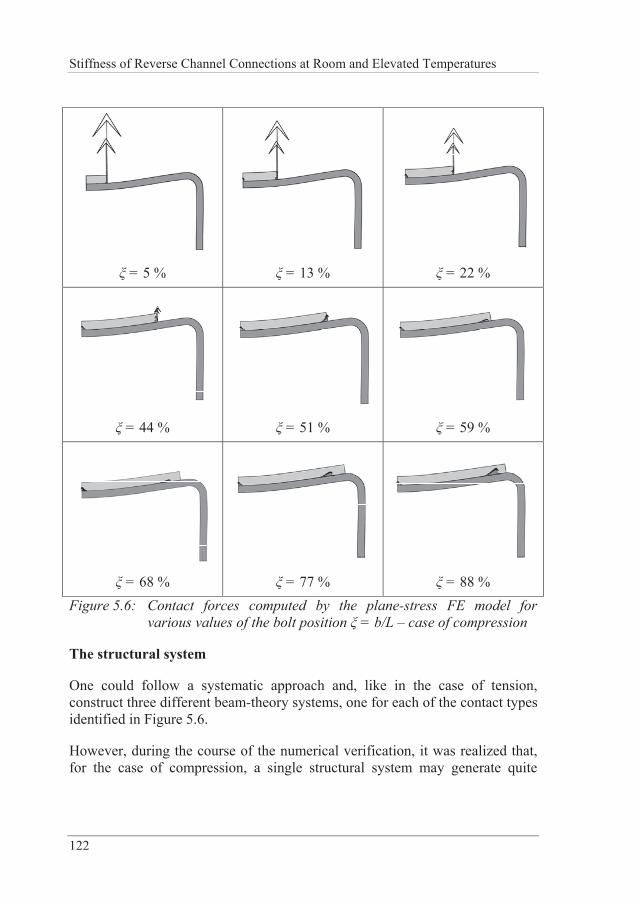
Stiffness of Reverse Channel Connections at Room and Elevated Temperatures
122
= 5 %
= 13 %
= 22 %
= 44 %
= 51 %
= 59 %
= 68 %
= 77 %
= 88 %
Figure 5.6: Contact forces computed by the plane-stress FE model for various values of the bolt position = b/L – case of compression
The structural system
One could follow a systematic approach and, like in the case of tension, construct three different beam-theory systems, one for each of the contact types identified in Figure 5.6.
However, during the course of the numerical verification, it was realized that, for the case of compression, a single structural system may generate quite
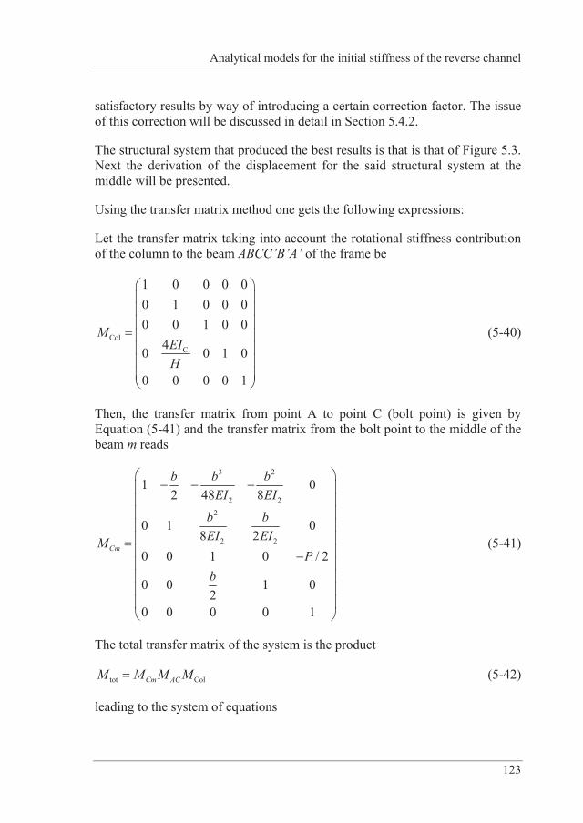
Analytical models for the initial stiffness of the reverse channel
123
satisfactory results by way of introducing a certain correction factor. The issue of this correction will be discussed in detail in Section 5.4.2.
The structural system that produced the best results is that is that of Figure 5.3. Next the derivation of the displacement for the said structural system at the middle will be presented.
Using the transfer matrix method one gets the following expressions:
Let the transfer matrix taking into account the rotational stiffness contribution of the column to the beam ABCC’B’A’ of the frame be
ColC
1 0 0 0 00 1 0 0 00 0 1 0 0
40 0 1 0
0 0 0 0 1
MEIH
(5-40)
Then, the transfer matrix from point A to point C (bolt point) is given by Equation (5-41) and the transfer matrix from the bolt point to the middle of the beam m reads
3 2
2 22
2 2
1 02 48 8
0 1 08 2
0 0 1 0 / 2
0 0 1 02
0 0 0 0 1
Cm
b b bEI EI
b bEI EIM
Pb
(5-41)
The total transfer matrix of the system is the product
tot ColCm ACM M M M (5-42)
leading to the system of equations
Stiffness of Reverse Channel Connections at Room and Elevated Temperatures
124
totm Az M z (5-43)
where z is the system state vector. The symmetry and the boundary conditions are
00/ 2
0
A
A
m
m
uMV P
(5-44)
The unknowns are the quantities , ,A m mu M . Solving (5-43) one obtains the resulting displacement of the beam at the midpoint as following
2 2 31 2 1 1 2 1 2 2 1 2
4 2 2 2 4 21 1 2 1 2 1 2 1 2 1 2 2
1 2 1 2 1 2 1 2
compr
2 ( (12 ( ) + 6 ( ) + )+8 ( ) )
( 8 ( )(4( ) 3 ( )+ ) 16( ) )48 ( 2 ( 2 ( )))
( )4
c
c
m
A hI I bI a a b a a b I a aB I b I bI I a a a a b a a b a a IC EI I hI I I bI I a a
A B PuC
(5-45)
where
1 RCI I (5-46)
5.4 Numerical verification of the analytical expressions
The numerical verification will be done in two stages. First the results of the analytical expressions will be compared against a set of plane-stress FE and 3D FE analysis results. Second, the plane-stress results will be compared with 3D results. All analyses are done in the context of small displacements, linear elastic material and contact being taken into account.
5.4.1 Case of tension – analytical results vs. 2D FEA
In the present section formulae (5-17), (5-27) and (5-38) are validated against results obtained through linear elastic plane stress FEA where contact was taken into consideration. All possible combinations of the geometric parameters shown in Table 5.1 were considered. For each combination of geometric parameters 12 different positions of the bolt along the width of the
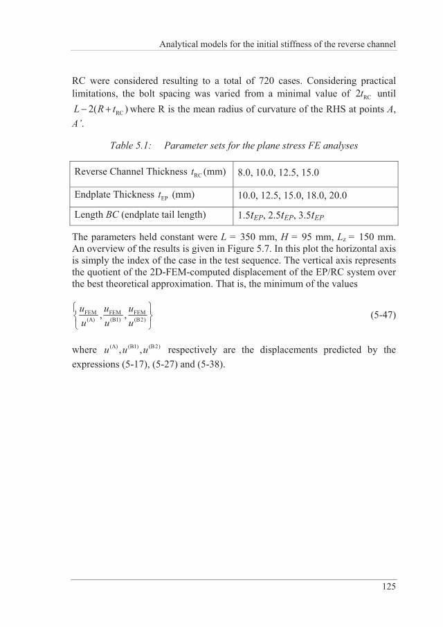
Analytical models for the initial stiffness of the reverse channel
125
RC were considered resulting to a total of 720 cases. Considering practical limitations, the bolt spacing was varied from a minimal value of RC2t until
RC2( )L R t where R is the mean radius of curvature of the RHS at points A, A’.
Table 5.1: Parameter sets for the plane stress FE analyses
Reverse Channel Thickness RCt (mm) 8.0, 10.0, 12.5, 15.0
Endplate Thickness EPt (mm) 10.0, 12.5, 15.0, 18.0, 20.0
Length BC (endplate tail length) 1.5tEP, 2.5tEP, 3.5tEP
The parameters held constant were L = 350 mm, H = 95 mm, Lz = 150 mm. An overview of the results is given in Figure 5.7. In this plot the horizontal axis is simply the index of the case in the test sequence. The vertical axis represents the quotient of the 2D-FEM-computed displacement of the EP/RC system over the best theoretical approximation. That is, the minimum of the values
FEM FEM FEM(A) (B1) (B2), ,u u u
u u u (5-47)
where (A) (B1) (B2), ,u u u respectively are the displacements predicted by the expressions (5-17), (5-27) and (5-38).
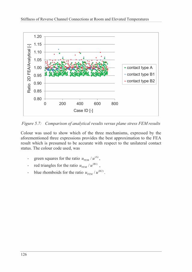
Stiffness of Reverse Channel Connections at Room and Elevated Temperatures
126
0.80
0.85
0.90
0.95
1.00
1.05
1.10
1.15
1.20
0 200 400 600 800
Rat
io 2
D F
EA/A
naly
tical
[-]
Case ID [-]
contact type Acontact type B1contact type B2
Figure 5.7: Comparison of analytical results versus plane stress FEM results
Colour was used to show which of the three mechanisms, expressed by the aforementioned three expressions provides the best approximation to the FEA result which is presumed to be accurate with respect to the unilateral contact status. The colour code used, was
- green squares for the ratio (A)FEM /u u ,
- red triangles for the ratio (B1)FEM /u u ,
- blue rhomboids for the ratio (B2)FEM /u u .
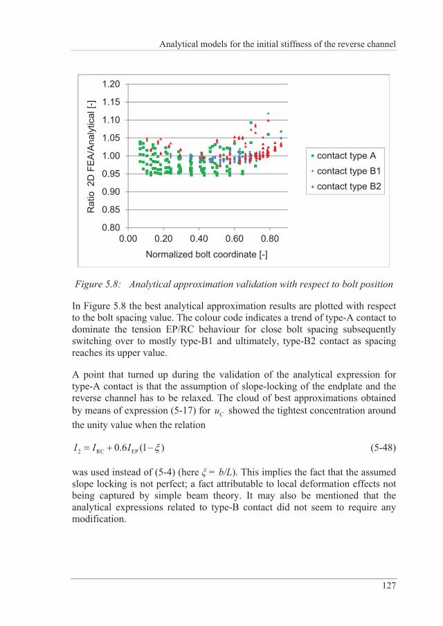
Analytical models for the initial stiffness of the reverse channel
127
0.80
0.85
0.90
0.95
1.00
1.05
1.10
1.15
1.20
0.00 0.20 0.40 0.60 0.80
Rat
io 2
D F
EA/A
naly
tical
[-]
Normalized bolt coordinate [-]
contact type Acontact type B1contact type B2
Figure 5.8: Analytical approximation validation with respect to bolt position
In Figure 5.8 the best analytical approximation results are plotted with respect to the bolt spacing value. The colour code indicates a trend of type-A contact to dominate the tension EP/RC behaviour for close bolt spacing subsequently switching over to mostly type-B1 and ultimately, type-B2 contact as spacing reaches its upper value.
A point that turned up during the validation of the analytical expression for type-A contact is that the assumption of slope-locking of the endplate and the reverse channel has to be relaxed. The cloud of best approximations obtained by means of expression (5-17) for Cu showed the tightest concentration around the unity value when the relation
2 RC EP0.6 (1 )I I I (5-48)
was used instead of (5-4) (here = b/L). This implies the fact that the assumed slope locking is not perfect; a fact attributable to local deformation effects not being captured by simple beam theory. It may also be mentioned that the analytical expressions related to type-B contact did not seem to require any modification.
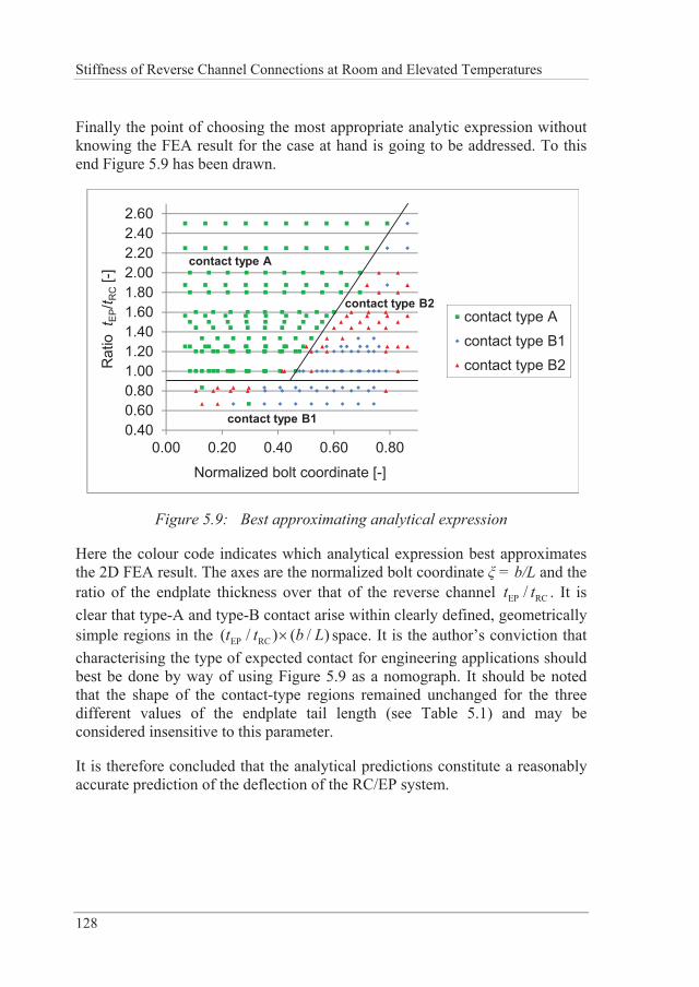
Stiffness of Reverse Channel Connections at Room and Elevated Temperatures
128
Finally the point of choosing the most appropriate analytic expression without knowing the FEA result for the case at hand is going to be addressed. To this end Figure 5.9 has been drawn.
0.400.600.801.001.201.401.601.802.002.202.402.60
0.00 0.20 0.40 0.60 0.80
Rat
io t
EP/t R
C[-]
Normalized bolt coordinate [-]
contact type Acontact type B1contact type B2
contact type B2
contact type B1
contact type A
Figure 5.9: Best approximating analytical expression
Here the colour code indicates which analytical expression best approximates the 2D FEA result. The axes are the normalized bolt coordinate = b/L and the ratio of the endplate thickness over that of the reverse channel EP RC/t t . It is clear that type-A and type-B contact arise within clearly defined, geometrically simple regions in the EP RC( / ) ( / )t t b L space. It is the author’s conviction that characterising the type of expected contact for engineering applications should best be done by way of using Figure 5.9 as a nomograph. It should be noted that the shape of the contact-type regions remained unchanged for the three different values of the endplate tail length (see Table 5.1) and may be considered insensitive to this parameter.
It is therefore concluded that the analytical predictions constitute a reasonably accurate prediction of the deflection of the RC/EP system.
Analytical models for the initial stiffness of the reverse channel
129
5.4.2 Case of compression – analytical results vs. 2D FEA
The behaviour of the reverse channel in compression will be approximated by means of the relation (5-45). As said in Section 5.3 the result of the frame model used for the approximation was found to comply much better with the plane-stress FE results if a shifting of the bolt position is introduced. Let the shifting length be
2 (1 ),2baS (5-49)
where = b/L. Then modified lengths 1, s sb a are used in Equation (5-45).
1 1
2s b
s b
b b Sa a S
(5-50)
The shifting parameter was calibrated numerically. Through the use of it, it was possible to obtain a simpler (single formula) approximation for all types of contact. The result of the compliance of (5-45) together with (5-50) to the 2D FEM analyses are shown in Figure 5.10. It can be seen that they mostly fall inside the ± 5 % zone.
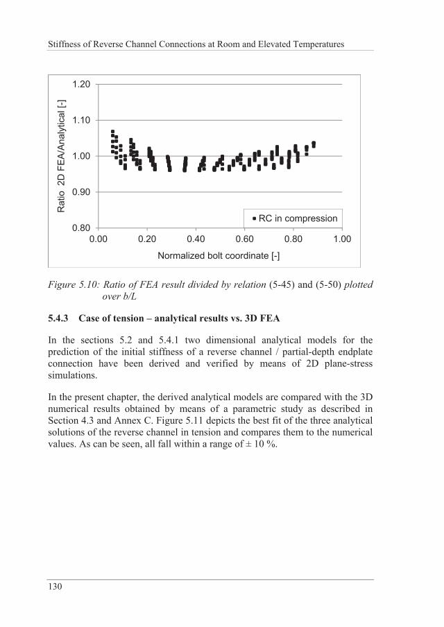
Stiffness of Reverse Channel Connections at Room and Elevated Temperatures
130
0.80
0.90
1.00
1.10
1.20
0.00 0.20 0.40 0.60 0.80 1.00
Rat
io 2
D F
EA/A
naly
tical
[-]
Normalized bolt coordinate [-]
RC in compression
Figure 5.10: Ratio of FEA result divided by relation (5-45) and (5-50) plotted over b/L
5.4.3 Case of tension – analytical results vs. 3D FEA
In the sections 5.2 and 5.4.1 two dimensional analytical models for the prediction of the initial stiffness of a reverse channel / partial-depth endplate connection have been derived and verified by means of 2D plane-stress simulations.
In the present chapter, the derived analytical models are compared with the 3D numerical results obtained by means of a parametric study as described in Section 4.3 and Annex C. Figure 5.11 depicts the best fit of the three analytical solutions of the reverse channel in tension and compares them to the numerical values. As can be seen, all fall within a range of ± 10 %.
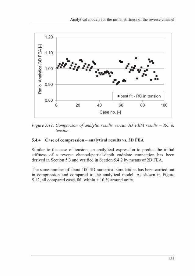
Analytical models for the initial stiffness of the reverse channel
131
0.80
0.90
1.00
1.10
1.20
0 20 40 60 80 100
Rat
io A
naly
tical
/3D
FEA
[-]
Case no. [-]
best fit - RC in tension
Figure 5.11: Comparison of analytic results versus 3D FEM results – RC in tension
5.4.4 Case of compression – analytical results vs. 3D FEA
Similar to the case of tension, an analytical expression to predict the initial stiffness of a reverse channel/partial-depth endplate connection has been derived in Section 5.3 and verified in Section 5.4.2 by means of 2D FEA.
The same number of about 100 3D numerical simulations has been carried out in compression and compared to the analytical model. As shown in Figure 5.12, all compared cases fall within ± 10 % around unity.
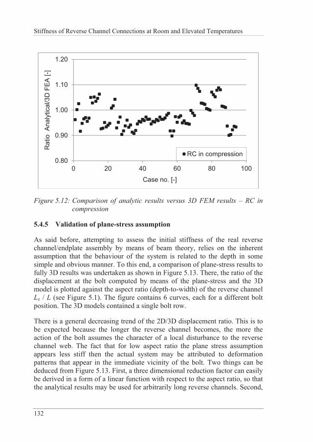
Stiffness of Reverse Channel Connections at Room and Elevated Temperatures
132
0.80
0.90
1.00
1.10
1.20
0 20 40 60 80 100
Rat
io A
naly
tical
/3D
FEA
[-]
Case no. [-]
RC in compression
Figure 5.12: Comparison of analytic results versus 3D FEM results – RC in compression
5.4.5 Validation of plane-stress assumption
As said before, attempting to assess the initial stiffness of the real reverse channel/endplate assembly by means of beam theory, relies on the inherent assumption that the behaviour of the system is related to the depth in some simple and obvious manner. To this end, a comparison of plane-stress results to fully 3D results was undertaken as shown in Figure 5.13. There, the ratio of the displacement at the bolt computed by means of the plane-stress and the 3D model is plotted against the aspect ratio (depth-to-width) of the reverse channel Lz / L (see Figure 5.1). The figure contains 6 curves, each for a different bolt position. The 3D models contained a single bolt row.
There is a general decreasing trend of the 2D/3D displacement ratio. This is to be expected because the longer the reverse channel becomes, the more the action of the bolt assumes the character of a local disturbance to the reverse channel web. The fact that for low aspect ratio the plane stress assumption appears less stiff then the actual system may be attributed to deformation patterns that appear in the immediate vicinity of the bolt. Two things can be deduced from Figure 5.13. First, a three dimensional reduction factor can easily be derived in a form of a linear function with respect to the aspect ratio, so that the analytical results may be used for arbitrarily long reverse channels. Second,
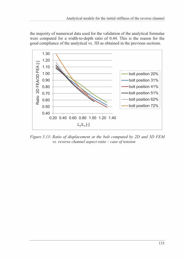
Analytical models for the initial stiffness of the reverse channel
133
the majority of numerical data used for the validation of the analytical formulae were computed for a width-to-depth ratio of 0.44. This is the reason for the good compliance of the analytical vs. 3D as obtained in the previous sections.
0.40
0.50
0.60
0.70
0.80
0.90
1.00
1.10
1.20
1.30
0.20 0.40 0.60 0.80 1.00 1.20 1.40
Rat
io 2
D F
EA/3
D F
EA [-
]
Lz/Lx [-]
bolt position 20%bolt position 31%bolt position 41%bolt position 51%bolt position 62%bolt position 72%
Figure 5.13: Ratio of displacement at the bolt computed by 2D and 3D FEM vs. reverse channel aspect ratio – case of tension

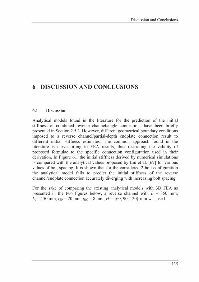
Discussion and Conclusions
135
6 DISCUSSION AND CONCLUSIONS
6.1 Discussion
Analytical models found in the literature for the prediction of the initial stiffness of combined reverse channel/angle connections have been briefly presented in Section 2.5.2. However, different geometrical boundary conditions imposed to a reverse channel/partial-depth endplate connection result to different initial stiffness estimates. The common approach found in the literature is curve fitting to FEA results, thus restricting the validity of proposed formulae to the specific connection configuration used in their derivation. In Figure 6.1 the initial stiffness derived by numerical simulations is compared with the analytical values proposed by Liu et al. [69] for various values of bolt spacing. It is shown that for the considered 2-bolt configuration the analytical model fails to predict the initial stiffness of the reverse channel/endplate connection accurately diverging with increasing bolt spacing.
For the sake of comparing the existing analytical models with 3D FEA as presented in the two figures below, a reverse channel with L = 350 mm, Lz = 150 mm, tEP = 20 mm, tRC = 8 mm, H = {60, 90, 120} mm was used.
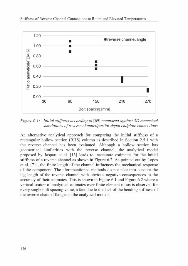
Stiffness of Reverse Channel Connections at Room and Elevated Temperatures
136
0.00
0.20
0.40
0.60
0.80
1.00
1.20
30 90 150 210 270
Rat
io a
naly
tical
/FEM
[-]
Bolt spacing [mm]
reverse channel/angle
Figure 6.1: Initial stiffness according to [69] compared against 3D numerical simulations of reverse channel/partial-depth endplate connections
An alternative analytical approach for comparing the initial stiffness of a rectangular hollow section (RHS) column as described in Section 2.5.1 with the reverse channel has been evaluated. Although a hollow section has geometrical similarities with the reverse channel, the analytical model proposed by Jaspart et al. [13] leads to inaccurate estimates for the initial stiffness of a reverse channel as shown in Figure 6.2. As pointed out by Lopes et al. [71], the finite length of the channel influences the mechanical response of the component. The aforementioned methods do not take into account the leg length of the reverse channel with obvious negative consequences to the accuracy of their estimates. This is shown in Figure 6.1 and Figure 6.2 where a vertical scatter of analytical estimates over finite element ratios is observed for every single bolt spacing value, a fact due to the lack of the bending stiffness of the reverse channel flanges in the analytical models.
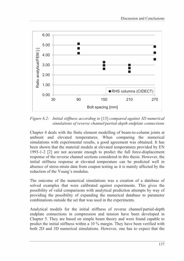
Discussion and Conclusions
137
0.00
1.00
2.00
3.00
4.00
5.00
6.00
30 90 150 210 270
Rat
io a
naly
tical
/FEM
[-]
Bolt spacing [mm]
RHS columns (CIDECT)
Figure 6.2: Initial stiffness according to [13] compared against 3D numerical simulations of reverse channel/partial-depth endplate connections
Chapter 4 deals with the finite element modelling of beam-to-column joints at ambient and elevated temperatures. When comparing the numerical simulations with experimental results, a good agreement was obtained. It has been shown that the material models at elevated temperatures provided by EN 1993-1-2 [2] are not accurate enough to predict the full force-displacement response of the reverse channel sections considered in this thesis. However, the initial stiffness response at elevated temperature can be predicted well in absence of stress-strain data from coupon testing as it is mainly affected by the reduction of the Young’s modulus.
The outcome of the numerical simulations was a creation of a datebase of solved examples that were calibrated against experiments. This gives the possibility of valid comparisons with analytical prediction attempts by way of providing the possibility of expanding the numerical database to parameter combinations outside the set that was used in the experiments.
Analytical models for the initial stiffness of reverse channel/partial-depth endplate connections in compression and tension have been developed in Chapter 5. They are based on simple beam theory and were found capable to predict the initial stiffness within a 10 % margin. They have been verified with both 2D and 3D numerical simulations. However, one has to expect that the
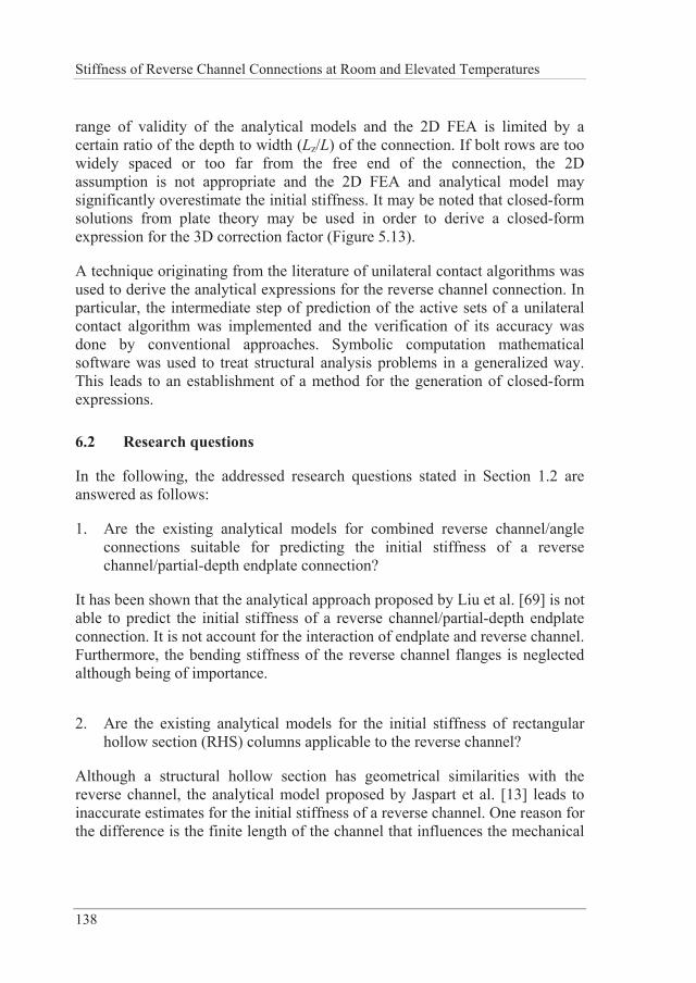
Stiffness of Reverse Channel Connections at Room and Elevated Temperatures
138
range of validity of the analytical models and the 2D FEA is limited by a certain ratio of the depth to width (Lz/L) of the connection. If bolt rows are too widely spaced or too far from the free end of the connection, the 2D assumption is not appropriate and the 2D FEA and analytical model may significantly overestimate the initial stiffness. It may be noted that closed-form solutions from plate theory may be used in order to derive a closed-form expression for the 3D correction factor (Figure 5.13).
A technique originating from the literature of unilateral contact algorithms was used to derive the analytical expressions for the reverse channel connection. In particular, the intermediate step of prediction of the active sets of a unilateral contact algorithm was implemented and the verification of its accuracy was done by conventional approaches. Symbolic computation mathematical software was used to treat structural analysis problems in a generalized way. This leads to an establishment of a method for the generation of closed-form expressions.
6.2 Research questions
In the following, the addressed research questions stated in Section 1.2 are answered as follows:
1. Are the existing analytical models for combined reverse channel/angle connections suitable for predicting the initial stiffness of a reverse channel/partial-depth endplate connection?
It has been shown that the analytical approach proposed by Liu et al. [69] is not able to predict the initial stiffness of a reverse channel/partial-depth endplate connection. It is not account for the interaction of endplate and reverse channel. Furthermore, the bending stiffness of the reverse channel flanges is neglected although being of importance.
2. Are the existing analytical models for the initial stiffness of rectangular hollow section (RHS) columns applicable to the reverse channel?
Although a structural hollow section has geometrical similarities with the reverse channel, the analytical model proposed by Jaspart et al. [13] leads to inaccurate estimates for the initial stiffness of a reverse channel. One reason for the difference is the finite length of the channel that influences the mechanical
Discussion and Conclusions
139
response of the component as well as the interaction of reverse channel and endplate.
3. Is it possible to accurately predict the behaviour of reverse channel connections by means of Finite Element Methods (FEM) at ambient and elevated temperatures?
The finite element method is a powerful tool which can accurately predict the behaviour of reverse channel connections at different stages at both ambient and elevated temperatures. However, 3D FE models, utilizing contact elements, and a certain degree of experience of the user are needed as a small difference in input data significantly changes the results. In addition, it is crucial to have exact knowledge of geometry, boundary conditions and material properties for a reliable evaluation of experiments.
4. Can the initial stiffness of a reverse channel section in tension or compression be accurately predicted with a 2D finite element model?
The range of validity for a 2D FE model is limited to a certain depth to width ratio of the reverse channel. When the reverse channel is long compared to its width, 3D behaviour will govern the response and 2D FE simulations will overestimate the initial stiffness. For an aspect ratio of 0.4-0.5, there is no need for a correction of the plane-stress analytical results caused by 3D effects.
5. Is it possible to predict the initial stiffness of a reverse channel by means of an analytical model based on simple beam theory? What are possible limitations of such an approach?
It has been shown that it is possible to predict the initial stiffness of a reverse channel by means of an analytical model based on beam theory. However, it is also limited by 2D assumptions. As said above, aspect ratio of 0.4-0.5 eliminates the necessity for 3D correction also for the analytical approach.
Stiffness of Reverse Channel Connections at Room and Elevated Temperatures
140
6.3 Conclusions
The major conclusions of this thesis are highlighted below:
1. 3D finite element modelling is a reliable and powerful method to predict the behaviour of reverse channel connections at ambient and elevated temperatures. If experimental uncertainties are small, excellent agreement with test results are achieved.
2. Three different analytical models for the initial stiffness of reverse channel/partial-depth endplate connections subject to tension have been derived. They account for different types of contact interactions of the reverse channel and endplate, yielding to three formulae:
a. Contact type A (contact between the bolts, 1 DOF system) as in Equation (5-17)
b. Contact type B1 (mild contact outside the bolts, 7 DOF system) as in Equation (5-27)
c. Contact type B2 (prying contact outside the bolts, 9 DOF system) as in Equation (5-38)
3. For reverse channel/partial-depth endplate connections subject to compression Equation (5-45) is proposed for evaluating the stiffness.
4. All analytical models derived for predicting the initial stiffness of reverse channel/partial-depth endplate connections in compression and tension show accuracy of ± 10 %.
5. A database of about 220 three dimensional and 1400 two dimensional numerical results has been created and will be used in further research.
6. The technique of unilateral contact algorithms was found useful to derive the analytical expressions. Symbolic computation mathematical software enables to treat structural analysis problems in generalized way, thus leading to closed-form expressions.
Future research
141
7 FUTURE RESEARCH
The analytical models provided in Chapter 5 are derived for partial-depth endplate/reverse channel connections and are based on 2D assumptions. In case of different endplate configurations such as a full-depth endplate, a different response of the reverse channel assembly should be expected as the endplate would deflect differently due to the beam flanges being welded onto it. This would affect the contact assumptions of the analytical models. An immediate step to complete the present research would be to use closed-form solutions from plate theory to derive the 3D correction factor. The enrichment of the 2D/3D comparison database for more complete understanding of the role of the depth effect is currently under way. As the analytical models derived in this thesis are rather detailed, efforts should be undertaken to simplify them, thus allowing integration into design practice.
The second issue is to point out that the partial-depth endplate/reverse channel connection clearly is a pinned connection and thus does not need a characterization in terms of moment-rotational behaviour in the context of the component method [1]. However, if the reverse channel is used with a full-depth or even extended endplate, it is expected that it can be designed for some moment resistance, as indicated in an on-going RFCS-funded project named FRAMEUP [106]. The present work opens the way for the analytical derivation of the unknown stiffness terms of the reverse channel in bending. In order to achieve this it is expected that a 3D analytical approach based on plate theory is needed. The work in its present form is much more suited for the case of extended-stiffened endplates/reverse channel connections.
The existence of transient temperature fields is a situation that turns up in practice as connections heat up slower than structural elements. Studying the

Stiffness of Reverse Channel Connections at Room and Elevated Temperatures
142
response of the reverse channel connection under transient loading situations can provide more accurate results for the structural response of buildings where these are used.
References
143
REFERENCES
[1] European Committee for Standardization. EN 1993-1-8: Eurocode 3 - Design of steel structures, Part 1-8: Design of joints. Brussels: 2005.
[2] European Committee for Standardization. EN 1993-1-2: Eurocode 3 - Design of steel structures, Part 1-2: General rules - Structural fire design. 2005.
[3] Gann RG, Grosshandler WL, Lew HS, Bukowski RW, Sadek F, Gayle FW, et al. Federal Building and Fire Safety Investigation of the World Trade Center Disaster: Structural Fire Response and Probable Collapse Sequence of World Trade Center Building 7. Washington: 2008.
[4] Federal Emergency Management Authority F. World Trade Center Building Performance Study. Washington: 2002.
[5] Newman GM, Robinson JT, Bailey CG. Fire safe design: a new approch to multi-storey steel-framed buildings. 2nd ed. Ascot: Steel Construction Institute; 2006.
[6] Research Fund for Coal and Steel. COMPFIRE - Design of joints to composite columns for improved fire robustness. Grant agreement n° RFSR-CT-2009-00021 2009.
[7] Weynand K, Jaspart J-P, Ly L. Application of the Component Method to Joints between Hollow and Open Sections. 2003.
Stiffness of Reverse Channel Connections at Room and Elevated Temperatures
144
[8] Nethercot DA, Zandonini R. Methods of Prediction of Joint Behaviour: Beam-to-Column Connections. In: Narayanan R, editor. Struct. Connect. Stab. Strength, London: Jasons Consultants SA; 1989, p. 23–62.
[9] Girão Coelho AM, Simões da Silva L. An analytical evaluation of the response of steel joints under bending and axial force 2001;79:873–81.
[10] Simões da Silva L, de Lima LRO, da S. Vellasco PCG, de Andrade SAL. Behaviour of flush end-plate beam-to-column joints under bending and axial force. Steel Compos Struct 2004;4:77–94.
[11] Sokol Z, Wald F, Delabre V, Muzeau JP, Svarc M. Design of endplate joints subject to moment and normal force. Third Eur. Conf. Steel Struct. - Eurosteel 2002, Coimbra: 2002, p. 1219–28.
[12] Del Savio AA, Nethercot DA, Vellasco PCGS, Andrade SAL, Martha LF. Generalised component-based model for beam-to-column connections including axial versus moment interaction. J Constr Steel Res 2009;65:1876–95.
[13] Jaspart JP, Pietrapertosa C, Weynand K, Busse E, Klinkhammer R. Development of a full consistent design approach for bolted and welded joints in building frames and trusses between steel members made of hollow and / or open sections - Application of the component method. 2005.
[14] Buchanan AH. Structural Design for Fire Safety. John Wiley & Sons Ltd.; 2001.
[15] Bailey CG, Lennon T, Moore DB. The behaviour of full-scale steel-framed buildings subjected to compartment fires. Struct Eng 1999;77:15–21.
[16] Wald F, Simões da Silva L, Moore DB, Lennon T, Chladná M, Santiago a., et al. Experimental behaviour of a steel structure under natural fire. Fire Saf J 2006;41:509–22.
[17] Simões da Silva L, Santiago A, Real P V, Moore D. Behaviour of steel joints under fire loading. Steel Compos Struct 2005;5:485–513.
[18] Al-Jabri KS, Davison JB, Burgess IW. Performance of beam-to-column joints in fire—A review. Fire Saf J 2008;43:50–62.
References
145
[19] Kruppa J. Résistance en feu des assemblages par boulous. Document No. 1013-1. St. Rémy Les Chevreuse, France: 1976.
[20] British Steel. The performance of beam/column/beam connections in the BS 5950: Part 8 fire tests. Reports T/RS/1380/33/82D and T/RS/1380/34/82D. Rotherham, UK: 1982.
[21] Lawson RM. Behaviour of steel beam-to-column connections in fire. Struct Eng 1990;68:263–71.
[22] Leston-Jones LC, Burgess IW, Lennon T, Plank RJ. Elevated-temperature moment-rotation tests on steelwork connections. Proc Inst Civ Eng Struct Build 1997;122:410–9.
[23] Al-Jabri KS, Lennon T, Burgess IW, Plank RJ. Behaviour of steel and composite beam-column connections in fire. J Constr Steel Res 1998;46:308–9.
[24] Spyrou S, Davison JB, Burgess IW, Plank RJ. Experimental and analytical investigation of the “tension zone” components within a steel joint at elevated temperatures. J Constr Steel Res 2004;60:867–96.
[25] Spyrou S, Davison JB, Burgess IW, Plank RJ. Experimental and analytical investigation of the “compression zone” component within a steel joint at elevated temperatures. J Constr Steel Res 2004;60:841–65.
[26] Qian ZH, Tan KH, Burgess IW. Behavior of Steel Beam-to-Column Joints at Elevated Temperature: Experimental Investigation. J Struct Eng 2008;134:713–26.
[27] Wang W-Y, Li G-Q, Dong Y-L. Experimental study and spring-component modelling of extended end-plate joints in fire. J Constr Steel Res 2007;63:1127–37.
[28] Yu H, Burgess IW, Davison JB, Plank RJ. Experimental investigation of the behaviour of fin plate connections in fire. J Constr Steel Res 2009;65:723–36.
[29] Yu H, Burgess IW, Davison JB, Plank RJ. Experimental and Numerical Investigations of the Behavior of Flush End Plate Connections at Elevated Temperatures. J Struct Eng 2011:80–7.
Stiffness of Reverse Channel Connections at Room and Elevated Temperatures
146
[30] Yu H, Burgess IW, Davison JB, Plank RJ. Tying capacity of web cleat connections in fire, Part 1: Test and finite element simulation. Eng Struct 2009;31:651–63.
[31] Saedi Daryan A, Yahyai M. Behavior of bolted top-seat angle connections in fire. J Constr Steel Res 2009;65:531–41.
[32] Strej ek M, ezní ek J, Tan K-H, Wald F. Behaviour of column web component of steel beam-to-column joints at elevated temperatures. J Constr Steel Res 2011;67:1890–9.
[33] Huang S-S, Davison B, Burgess IW. High-temperature tests on joints to steel and partially-encased H-section columns. J Constr Steel Res 2013;80:243–51.
[34] Simões da Silva L, Santiago A, Lopes F, Veljkovic M, Heistermann T, Iqbal N, et al. COMPFIRE - Design of composite joints for improved fire robustness, Final Report, Grant agreement n° RFSR-CR-2009-00021. Brussels: 2013.
[35] Armer GST, Moore DB. Full-scale testing on complete multistorey structures. Struct Eng London 1994;72:30–1.
[36] Bailey CG, Burgess IW, Plank RJ. Computer simulation of a full-scale structural fire test. Struct Eng 1996;74:93–100.
[37] Witteveen J, Twilt L, Bijlaard FS. The stability of braced and unbraced frames at elevated temperatures. Int. Symp. Stab. steel Struct., Liège: 1977.
[38] Wang YC. Steel and Composite Structures: Behaviour and Design for Fire Safety. Taylor & Francis; 2002.
[39] Liu TC., Fahad M., Davies J. Experimental investigation of behaviour of axially restrained steel beams in fire. J Constr Steel Res 2002;58:1211–30.
[40] Ding J, Wang YC. Experimental study of structural fire behaviour of steel beam to concrete filled tubular column assemblies with different types of joints. Eng Struct 2007;29:3485–502.
References
147
[41] Santiago A, Simões da Silva L, Vila Real P, Vaz G, Gamerio Lopes A. Experimental Evaluation of the Influence of Connection Typology on the Behavior of Steel Structures Under Fire. Eng J 2009;81.
[42] Wang YC, Dai XH, Bailey CG. An experimental study of relative structural fire behaviour and robustness of different types of steel joint in restrained steel frames. J Constr Steel Res 2011;67:1149–63.
[43] Jána T, Jirku J, Wald F, Wang Y, Hu Y, Mandal P, et al. COMPFIRE - Design of composite joints for improved fire robustness, Deliverable D7, Grant agreement n° RFSR-CR-2009-00021. 2013.
[44] Jána T, Wald F. Reduction of Connection Resistance during Veselí Fire Tests. Appl. Struct. Fire Eng., Prague: 2013, p. 278–83.
[45] Ramberg W, Osgood WR. Description of Stress-Strain Curves by Three Parameters. Washington D.C.: 1943.
[46] Ang KM, Morris GA. Analysis of 3-Dimensional Frames with Flexible Beam-Column Connections. Can J Civ Eng 1984;11:245–54.
[47] El-Rimawi JA. The Behaviour of Flexural Members under Fire Conditions. Doctoral Thesis: University of Sheffield; 1989.
[48] El-Rimawi JA, Burgess IW, Plank RJ. The influence of connection stiffness on the behaviour of steel beams in fire. J Constr Steel Res 1997;43:1–15.
[49] El-Rimawi JA, Burgess IW, Plank RJ. Studies of the behaviour of steel subframes with semi-rigid connections in fire. J Constr Steel Res 1999;49:83–98.
[50] Simões da Silva L, Santiago A, Vila Real P. A component model for the behaviour of steel joints at elevated temperatures. J Constr Steel Res 2001;57:1169–95.
[51] Block FM, Burgess IW, Davison JB, Plank RJ. The development of a component-based connection element for endplate connections in fire. Fire Saf J 2007;42:498–506.
Stiffness of Reverse Channel Connections at Room and Elevated Temperatures
148
[52] Ramli-Sulong NH, Elghazouli a. Y, Izzuddin B a. Behaviour and design of beam-to-column connections under fire conditions. Fire Saf J 2007;42:437–51.
[53] Liu TCH. Finite element modelling of behaviours of steel beams and connections in fire. J Constr Steel Res 1996;36:181–99.
[54] Liu TCH. Three-dimensional Modelling of Steel/Concrete Composite Connection Behaviour in Fire. J Constr Steel Res 1998;46:319–20.
[55] Liu TCH. Moment-rotation-temperature characteristics of steel/composite connections. J Struct Eng 1999;125:1188–97.
[56] El-Houssieny OM, Abdek Salam S, Attia GAM, Saad AM. Behavior of Extended End Plate Connections at High Temperature. J Constr Steel Res 1998;46:1998.
[57] Li G-Q, Chen L-Z, Li J-T, Lou G-B. Modeling of end-plate bolted composite connection in fire considering axial force effects. J Constr Steel Res 2012;76:133–43.
[58] Al-Jabri KS, Seibi A, Karrech A. Modelling of unstiffened flush end-plate bolted connections in fire. J Constr Steel Res 2006;62:151–9.
[59] Santiago A. Behaviour of beam-to-column steel joints under natural fire. Doctoral Thesis: University of Coimbra; 2008.
[60] Al-Jabri KS. Modelling and simulation of beam-to-column joints at elevated temperature: A review. J Franklin Inst 2011;348:1695–716.
[61] Ding J, Wang YC. Temperatures in unprotected joints between steel beams and concrete-filled tubular columns in fire. Fire Saf J 2009;44:16–32.
[62] Elsawaf S, Wang YC, Mandal P. Numerical modelling of restrained structural subassemblies of steel beam and CFT columns connected using reverse channels in fire. Eng Struct 2011;33:1217–31.
[63] Elsawaf S, Wang YC. Methods of improving the survival temperature in fire of steel beam connected to CFT column using reverse channel connection. Eng Struct 2012;34:132–46.
References
149
[64] Elsawaf S, Wang YC. Behaviour of restrained structural subassemblies of steel beam to CFT column in fire during cooling stage. Eng Struct 2013;46:471–92.
[65] Jones MH. Tensile and Shear Behaviour of Fin-Plate Connections to Hollow and Concrete-Filled Steel Tubular Columns at Ambient and Elevated Temperatures. Doctoral Thesis: University of Manchester; 2008.
[66] Málaga-Chuquitaype C, Elghazouli a. Y. Behaviour of combined channel/angle connections to tubular columns under monotonic and cyclic loading. Eng Struct 2010;32:1600–16.
[67] Elghazouli AY, Málaga-Chuquitaype C, Castro JM, Orton AH. Experimental monotonic and cyclic behaviour of blind-bolted angle connections. Eng Struct 2009;31:2540–53.
[68] Liu Y, Málaga-Chuquitaype C, Elghazouli a. Y. Behaviour of beam-to-tubular column angle connections under shear loads. Eng Struct 2012;42:434–56.
[69] Liu Y, Málaga-Chuquitaype C, Elghazouli a. Y. Response and component characterisation of semi-rigid connections to tubular columns under axial loads. Eng Struct 2012;41:510–32.
[70] Huang S-S, Davison B, Burgess IW. Experiments on reverse-channel connections at elevated temperatures. Eng Struct 2013;49:973–82.
[71] Lopes F, Santiago A, Simões da Silva L, Heistermann T, Veljkovic M, Guilherme da Silva J. Experimental Behaviour of the Reverse Channel Joint Component at Elevated and Ambient Temperatures. Int J Steel Struct 2013;13:459–72.
[72] Jafarian M, Wang YC. Experimental behaviour of reverse channel connection component under bolt tension at elevated temperatures. In: Gardner, editor. Tubul. Struct. XIV, 2012, p. 623–9.
[73] Dong G, Burgess I, Davison B. Application of a general component-based connection element in structural fire analysis. 11th Int. Conf. Steel, Sp. Compos. Struct., Qingdao: 2012.
Stiffness of Reverse Channel Connections at Room and Elevated Temperatures
150
[74] Heistermann T, Iqbal N, Veljkovic M, Lopes F, Santiago A, Simões da Silva L, et al. COMPFIRE - Design of composite joints for improved fire robustness, Deliverable D3, Grant agreement n° RFSR-CR-2009-00021. Brussels: 2013.
[75] Dong G, Burgess I, Davison B, Sun R. Development of a general component-based connection element for structural fire engineering analysis. Appl. Struct. Fire Eng., vol. 1, 2013.
[76] Lopes F, Santiago A, Simões da Silva L, Silva JGS, Iqbal N, Veljkovic M. Full-Scale Fire Tests on Composite Sub-Frames with Reverse Channel Connection to CFT Columns. Compos. Constr. VII, Palm Cove: 2013.
[77] Iqbal N. Restrained Behaviour of Beams in a Steel Frame Exposed to Fire. Licentiate Thesis: Luleå University of Technology; 2013.
[78] Wang YC, Xue L. Experimental study of moment–rotation characteristics of reverse channel connections to tubular columns. J Constr Steel Res 2013;85:92–104.
[79] Leston-Jones LC. The Influence of Semi-Rigid Connections on the Performance of Steel Framed Structures in Fire. Doctoral Thesis: University of Sheffield; 1997.
[80] Al-Jabri KS. The behaviour of steel and composite beam-to-column connections in fire. Doctoral Thesis: University of Sheffield; 1999.
[81] Al-Jabri KS. Component-based model of the behaviour of flexible end-plate connections at elevated temperatures. Compos Struct 2004;66:215–21.
[82] Block FM. Development of a component-based finite element for steel beam-to-column connections at elevated temperature. Doctoral Thesis: University of Sheffield; 2006.
[83] Qian Z-H, Tan K-H, Burgess IW. Numerical and analytical investigations of steel beam-to-column joints at elevated temperatures. J Constr Steel Res 2009;65:1043–54.
References
151
[84] Heidarpour A, Bradford M a. Behaviour of a T-stub assembly in steel beam-to-column connections at elevated temperatures. Eng Struct 2008;30:2893–9.
[85] Simões da Silva L, Santiago A, Vila Real P. Post-limit stiffness and ductility of end-plate beam-to-column steel joints 2002;80:515–31.
[86] Sulong NHR. Behaviour of steel connections at elevated temperatures. Doctoral Thesis: Imperial College London; 2005.
[87] Spyrou S. Development of a component-based model of steel beam-to-column joints at elevated temperature. Doctoral Thesis: University of Sheffield; 2002.
[88] De Lima LRO, Simões Da Silva L, Vellasco PCGDS, De Andrade S a L. Experimental evaluation of extended endplate beam-to-column joints subjected to bending and axial force. Eng Struct 2004;26:1333–47.
[89] Yu H, Burgess IW, Davison JB, Plank RJ. Tying capacity of web cleat connections in fire, Part 2: Development of component-based model. Eng Struct 2009;31:697–708.
[90] Sarraj M. The Behaviour of Steel Fin Plate Connections in Fire. Doctoral Thesis: University of Sheffield; 2007.
[91] Yu H, Burgess IW, Davison JB, Plank RJ. Development of a yield-line model for endplate connections in fire. J Constr Steel Res 2009;65:1279–89.
[92] Huang Z. A Simplified Model for Analysis of End-plate Connections Subjected to Fire. J Struct Fire Eng 2011;2:269–88.
[93] Lin S, Huanga Z, Fanb M. Analysis of end-plate connections at elevated temperatures. Steel Compos Struct 2013;15:81–101.
[94] Taib M, Burgess IW. A Component-Based Model for Fin-Plate Connections in Fire. Appl. Struct. Fire Eng., 2011, p. 225–30.
[95] Gomes FCT, Jaspart JP, Maquoi R. Moment capacity of beam-to-column minor-axis joints. In: Engineering IA for B and S, editor. Int. Colloq. Semi-Rigid Struct. Connect., Istanbul, Turkey: 1996, p. 319–26.
Stiffness of Reverse Channel Connections at Room and Elevated Temperatures
152
[96] Simões da Silva L, Neves LFN, Gomes FCT. Rotational Stiffness of Rectangular Hollow Sections Composite Joints. J Struct Eng 2003;129:487–94.
[97] Neves LC, Simões da Silva L, da S. Vellasco PCG. A model for predicting the stiffness of beam to concrete filled column and minor axis joints under static monotonic loading. In: Steelwork TEC for C, editor. 4th Eur. Conf. Steel Compos. Struct. Vol. C, Maastricht, Netherlands: 2005, p. 4.10.131–4.10.138.
[98] Bridgman PW. Studies in Large Plastic Flow and Fracture: With Special Emphasis on the Effects of Hydrostatic Pressure. New York: McGraw-Hill; 1952.
[99] European Committee for Standardization. EN 1992-1-2: Eurocode 2 - Design of concrete structures, Part 1-2: General rules - Structural fire design. 2004.
[100] Dassault Systèmes Simulia Corp. Abaqus Analysis User’s manual version 6.11. 2011.
[101] Johnson GR, Cook WH. Fracture characteristics of three metals subjected to various strains, strain rates, temperatures and pressures. Eng Fract Mech 1985;21:31–48.
[102] Bao Y. Prediction of Ductile Crack Formation in Uncracked Bodies. Doctoral Thesis: Massachusetts Institute of Technology; 2003.
[103] Panagiotopoulos PD. Inequality Problems in Mechanics and Applications. Springer; 1985.
[104] Duvaut G, Lions JL. Inequalities in Mechanics and Physics. London: Springer; 2011.
[105] Pilkey WD. Formulas for stress, strain and structural matrices. John Wiley & Sons Ltd.; 2005.
[106] Research Fund for Coal and Steel. FRAMEUP - Optimization of frames for effective assembling. Grant agreement n° RFSR-CT-2011-00035. Brussels: 2011.
Annexes
153
ANNEXES
A. Simulations for experiments done at the University of Coimbra
B. Simulations for experiments done at the University of Sheffield
C. 3D finite element simulations: parametric study

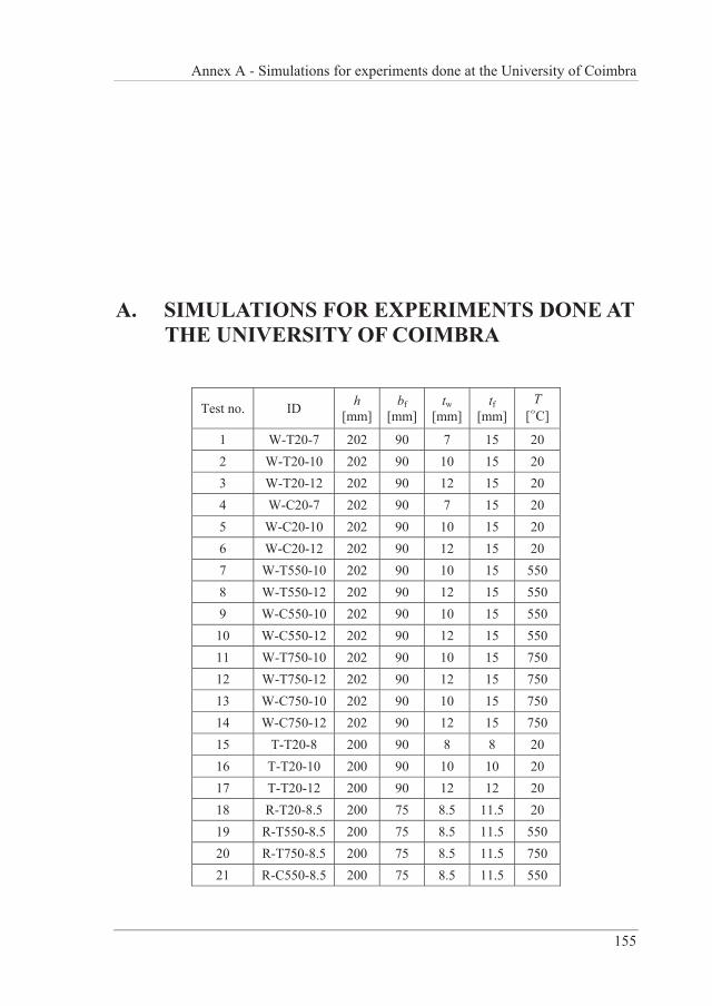
Annex A - Simulations for experiments done at the University of Coimbra
155
A. SIMULATIONS FOR EXPERIMENTS DONE AT THE UNIVERSITY OF COIMBRA
Test no. ID h [mm]
bf [mm]
tw [mm]
tf [mm]
T [°C]
1 W-T20-7 202 90 7 15 20 2 W-T20-10 202 90 10 15 20 3 W-T20-12 202 90 12 15 20 4 W-C20-7 202 90 7 15 20 5 W-C20-10 202 90 10 15 20 6 W-C20-12 202 90 12 15 20 7 W-T550-10 202 90 10 15 550 8 W-T550-12 202 90 12 15 550 9 W-C550-10 202 90 10 15 550
10 W-C550-12 202 90 12 15 550 11 W-T750-10 202 90 10 15 750 12 W-T750-12 202 90 12 15 750 13 W-C750-10 202 90 10 15 750 14 W-C750-12 202 90 12 15 750 15 T-T20-8 200 90 8 8 20 16 T-T20-10 200 90 10 10 20 17 T-T20-12 200 90 12 12 20 18 R-T20-8.5 200 75 8.5 11.5 20 19 R-T550-8.5 200 75 8.5 11.5 550 20 R-T750-8.5 200 75 8.5 11.5 750 21 R-C550-8.5 200 75 8.5 11.5 550
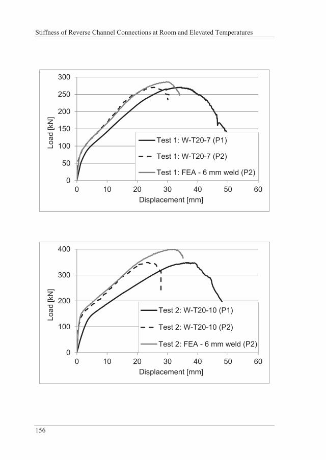
Stiffness of Reverse Channel Connections at Room and Elevated Temperatures
156
0
50
100
150
200
250
300
0 10 20 30 40 50 60
Load
[kN
]
Displacement [mm]
Test 1: W-T20-7 (P1)
Test 1: W-T20-7 (P2)
Test 1: FEA - 6 mm weld (P2)
0
100
200
300
400
0 10 20 30 40 50 60
Load
[kN
]
Displacement [mm]
Test 2: W-T20-10 (P1)
Test 2: W-T20-10 (P2)
Test 2: FEA - 6 mm weld (P2)
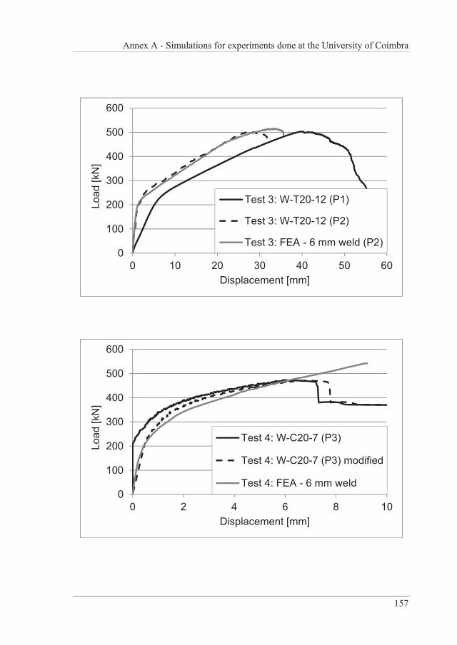
Annex A - Simulations for experiments done at the University of Coimbra
157
0
100
200
300
400
500
600
0 10 20 30 40 50 60
Load
[kN
]
Displacement [mm]
Test 3: W-T20-12 (P1)
Test 3: W-T20-12 (P2)
Test 3: FEA - 6 mm weld (P2)
0
100
200
300
400
500
600
0 2 4 6 8 10
Load
[kN
]
Displacement [mm]
Test 4: W-C20-7 (P3)
Test 4: W-C20-7 (P3) modified
Test 4: FEA - 6 mm weld
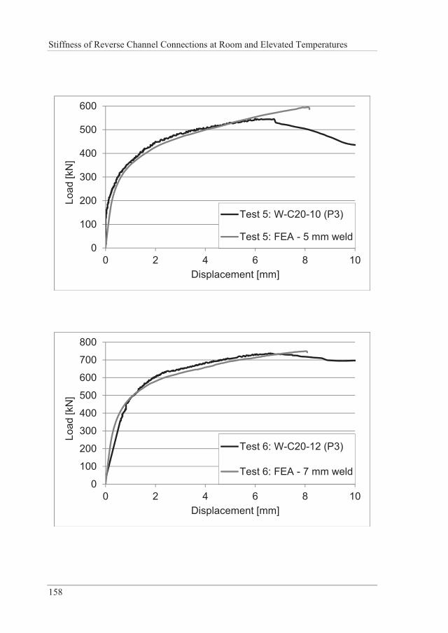
Stiffness of Reverse Channel Connections at Room and Elevated Temperatures
158
0
100
200
300
400
500
600
0 2 4 6 8 10
Load
[kN
]
Displacement [mm]
Test 5: W-C20-10 (P3)
Test 5: FEA - 5 mm weld
0
100
200
300
400
500
600
700
800
0 2 4 6 8 10
Load
[kN
]
Displacement [mm]
Test 6: W-C20-12 (P3)
Test 6: FEA - 7 mm weld
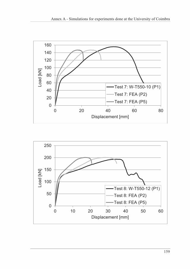
Annex A - Simulations for experiments done at the University of Coimbra
159
0
20
40
60
80
100
120
140
160
0 20 40 60 80
Load
[kN
]
Displacement [mm]
Test 7: W-T550-10 (P1)
Test 7: FEA (P2)
Test 7: FEA (P5)
0
50
100
150
200
250
0 10 20 30 40 50 60
Load
[kN
]
Displacement [mm]
Test 8: W-T550-12 (P1)Test 8: FEA (P2)Test 8: FEA (P5)
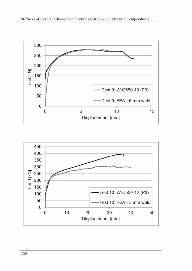
Stiffness of Reverse Channel Connections at Room and Elevated Temperatures
160
0
50
100
150
200
250
300
0 5 10 15
Load
[kN
]
Displacement [mm]
Test 9: W-C550-10 (P3)
Test 9: FEA - 6 mm weld
050
100150200250300350400450
0 10 20 30 40 50
Load
[kN
]
Displacement [mm]
Test 10: W-C550-12 (P3)
Test 10: FEA - 5 mm weld
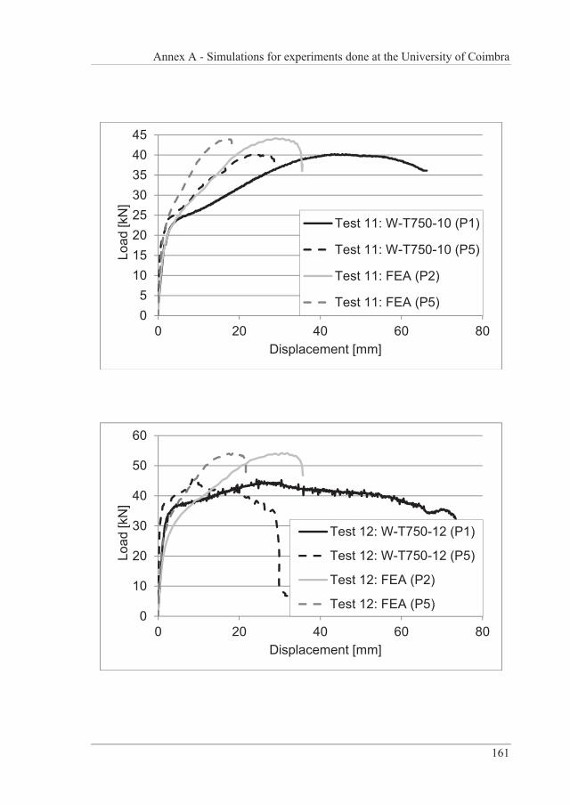
Annex A - Simulations for experiments done at the University of Coimbra
161
05
1015202530354045
0 20 40 60 80
Load
[kN
]
Displacement [mm]
Test 11: W-T750-10 (P1)
Test 11: W-T750-10 (P5)
Test 11: FEA (P2)
Test 11: FEA (P5)
0
10
20
30
40
50
60
0 20 40 60 80
Load
[kN
]
Displacement [mm]
Test 12: W-T750-12 (P1)
Test 12: W-T750-12 (P5)
Test 12: FEA (P2)
Test 12: FEA (P5)
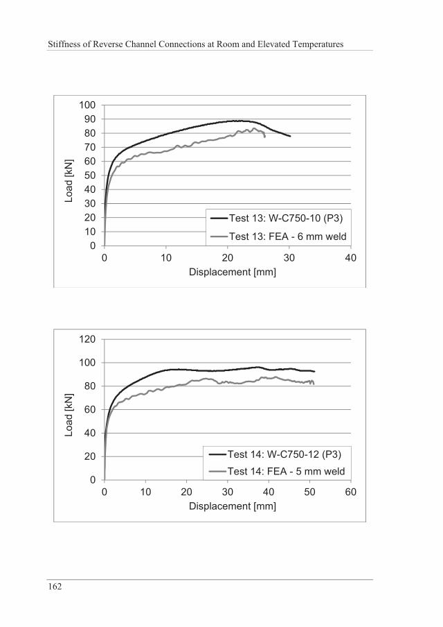
Stiffness of Reverse Channel Connections at Room and Elevated Temperatures
162
0102030405060708090
100
0 10 20 30 40
Load
[kN
]
Displacement [mm]
Test 13: W-C750-10 (P3)
Test 13: FEA - 6 mm weld
0
20
40
60
80
100
120
0 10 20 30 40 50 60
Load
[kN
]
Displacement [mm]
Test 14: W-C750-12 (P3)
Test 14: FEA - 5 mm weld
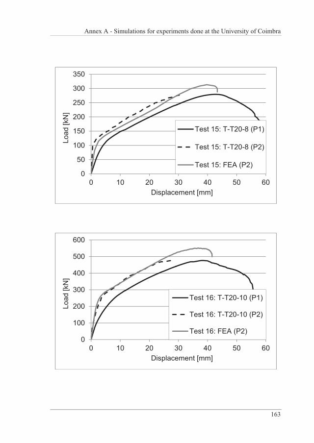
Annex A - Simulations for experiments done at the University of Coimbra
163
0
50
100
150
200
250
300
350
0 10 20 30 40 50 60
Load
[kN
]
Displacement [mm]
Test 15: T-T20-8 (P1)
Test 15: T-T20-8 (P2)
Test 15: FEA (P2)
0
100
200
300
400
500
600
0 10 20 30 40 50 60
Load
[kN
]
Displacement [mm]
Test 16: T-T20-10 (P1)
Test 16: T-T20-10 (P2)
Test 16: FEA (P2)
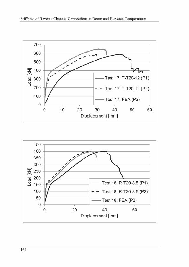
Stiffness of Reverse Channel Connections at Room and Elevated Temperatures
164
0
100
200
300
400
500
600
700
0 10 20 30 40 50 60
Load
[kN
]
Displacement [mm]
Test 17: T-T20-12 (P1)
Test 17: T-T20-12 (P2)
Test 17: FEA (P2)
050
100150200250300350400450
0 20 40 60
Load
[kN
]
Displacement [mm]
Test 18: R-T20-8.5 (P1)
Test 18: R-T20-8.5 (P2)
Test 18: FEA (P2)
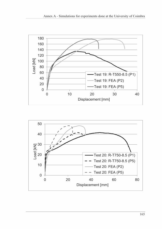
Annex A - Simulations for experiments done at the University of Coimbra
165
020406080
100120140160180
0 10 20 30 40
Load
[kN
]
Displacement [mm]
Test 19: R-T550-8.5 (P1)Test 19: FEA (P2)Test 19: FEA (P5)
0
10
20
30
40
50
0 20 40 60 80
Load
[kN
]
Displacement [mm]
Test 20: R-T750-8.5 (P1)Test 20: R-T750-8.5 (P5)Test 20: FEA (P2)Test 20: FEA (P5)
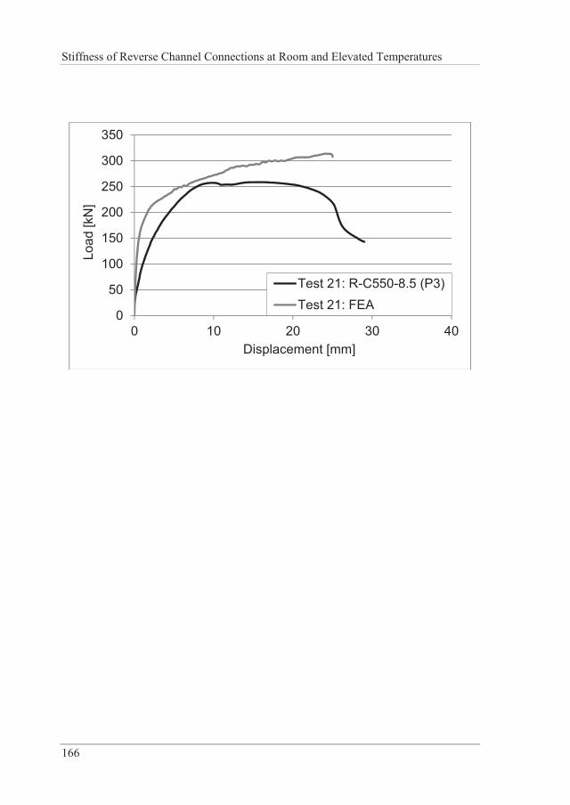
Stiffness of Reverse Channel Connections at Room and Elevated Temperatures
166
0
50
100
150
200
250
300
350
0 10 20 30 40
Load
[kN
]
Displacement [mm]
Test 21: R-C550-8.5 (P3)Test 21: FEA
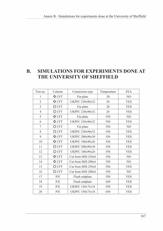
Annex B - Simulations for experiments done at the University of Sheffield
167
B. SIMULATIONS FOR EXPERIMENTS DONE AT THE UNIVERSITY OF SHEFFIELD
Test no. Column Connection type Temperature FEA 1 CFT Fin plate 20 NO 2 CFT UKPFC 230x90x32 20 YES 3 CFT Fin plate 20 YES 4 CFT UKPFC 230x90x32 20 YES 5 CFT Fin plate 550 NO 6 CFT UKPFC 230x90x32 550 YES 7 CFT Fin plate 550 NO 8 CFT UKPFC 230x90x32 550 YES 9 CFT UKPFC 200x90x30 550 YES
10 CFT UKPFC 180x90x26 550 YES 11 CFT UKPFC 200x90x30 550 YES 12 CFT UKPFC 180x90x26 550 YES 13 CFT Cut from SHS 250x8 550 NO 14 CFT Cut from SHS 200x6 550 NO 15 CFT Cut from SHS 250x8 550 YES 16 CFT Cut from SHS 200x6 550 NO 17 P/E Flush endplate 550 YES 18 P/E Flush endplate 650 YES 19 P/E UKPFC 150x75x18 550 YES 20 P/E UKPFC 150x75x18 650 YES

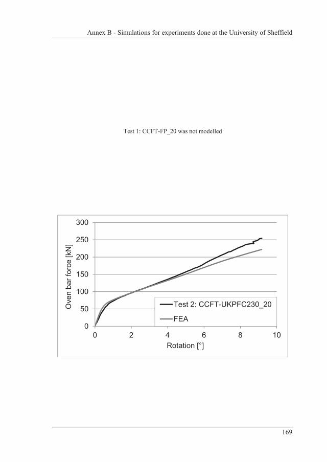
Annex B - Simulations for experiments done at the University of Sheffield
169
Test 1: CCFT-FP_20 was not modelled
0
50
100
150
200
250
300
0 2 4 6 8 10
Ove
n ba
r for
ce [k
N]
Rotation [°]
Test 2: CCFT-UKPFC230_20
FEA
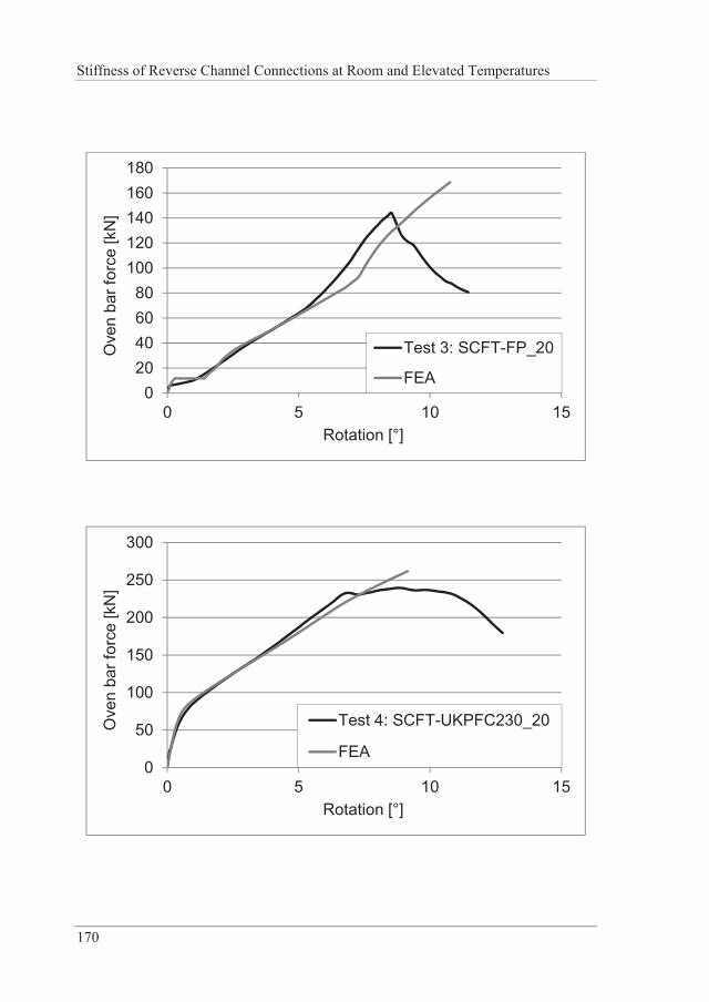
Stiffness of Reverse Channel Connections at Room and Elevated Temperatures
170
020406080
100120140160180
0 5 10 15
Ove
n ba
r for
ce [k
N]
Rotation [°]
Test 3: SCFT-FP_20
FEA
0
50
100
150
200
250
300
0 5 10 15
Ove
n ba
r for
ce [k
N]
Rotation [°]
Test 4: SCFT-UKPFC230_20
FEA
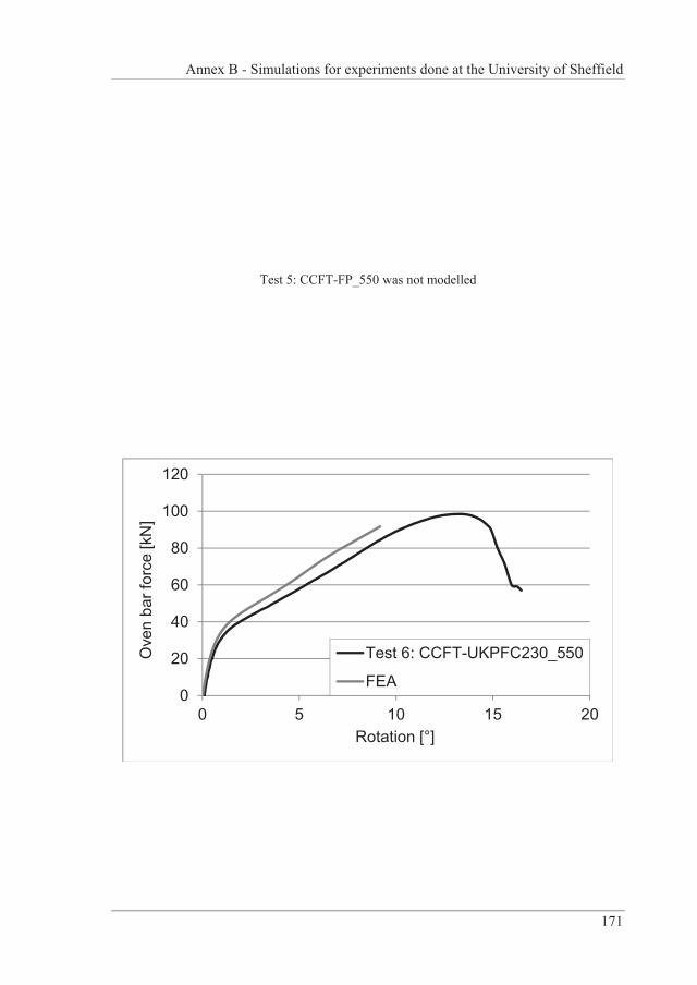
Annex B - Simulations for experiments done at the University of Sheffield
171
Test 5: CCFT-FP_550 was not modelled
0
20
40
60
80
100
120
0 5 10 15 20
Ove
n ba
r for
ce [k
N]
Rotation [°]
Test 6: CCFT-UKPFC230_550
FEA
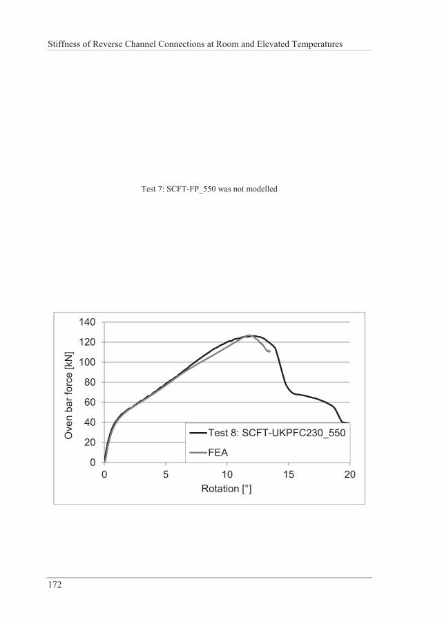
Stiffness of Reverse Channel Connections at Room and Elevated Temperatures
172
Test 7: SCFT-FP_550 was not modelled
0
20
40
60
80
100
120
140
0 5 10 15 20
Ove
n ba
r for
ce [k
N]
Rotation [°]
Test 8: SCFT-UKPFC230_550
FEA
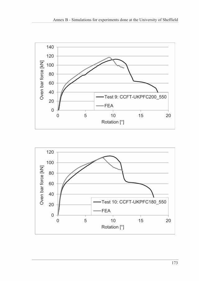
Annex B - Simulations for experiments done at the University of Sheffield
173
0
20
40
60
80
100
120
140
0 5 10 15 20
Ove
n ba
r for
ce [k
N]
Rotation [°]
Test 9: CCFT-UKPFC200_550
FEA
0
20
40
60
80
100
120
0 5 10 15 20
Ove
n ba
r for
ce [k
N]
Rotation [°]
Test 10: CCFT-UKPFC180_550
FEA
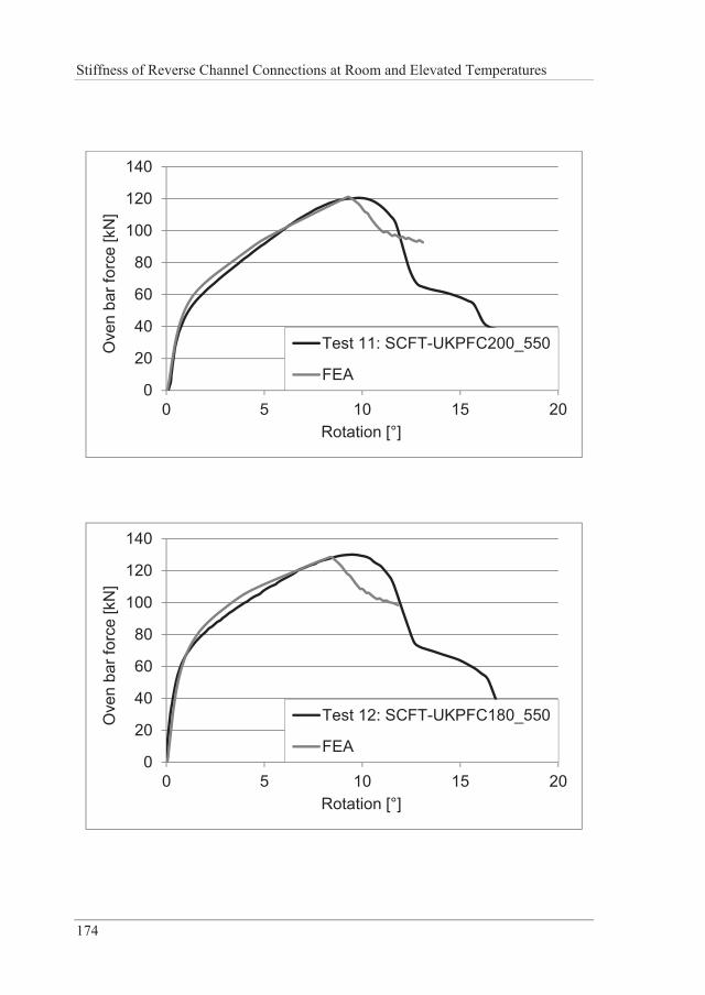
Stiffness of Reverse Channel Connections at Room and Elevated Temperatures
174
0
20
40
60
80
100
120
140
0 5 10 15 20
Ove
n ba
r for
ce [k
N]
Rotation [°]
Test 11: SCFT-UKPFC200_550
FEA
0
20
40
60
80
100
120
140
0 5 10 15 20
Ove
n ba
r for
ce [k
N]
Rotation [°]
Test 12: SCFT-UKPFC180_550
FEA
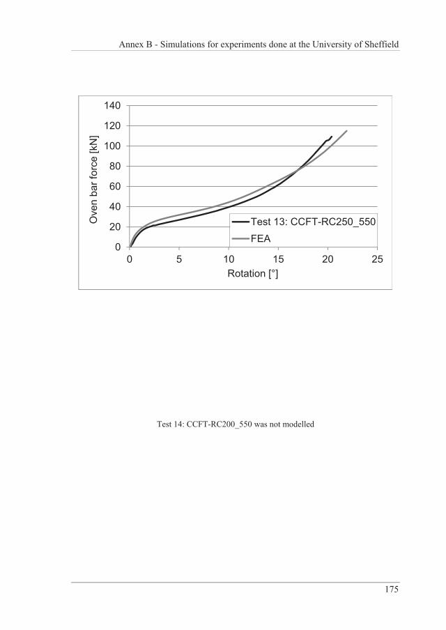
Annex B - Simulations for experiments done at the University of Sheffield
175
0
20
40
60
80
100
120
140
0 5 10 15 20 25
Ove
n ba
r for
ce [k
N]
Rotation [°]
Test 13: CCFT-RC250_550FEA
Test 14: CCFT-RC200_550 was not modelled
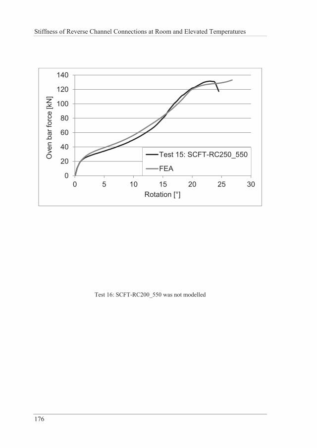
Stiffness of Reverse Channel Connections at Room and Elevated Temperatures
176
0
20
40
60
80
100
120
140
0 5 10 15 20 25 30
Ove
n ba
r for
ce [k
N]
Rotation [°]
Test 15: SCFT-RC250_550
FEA
Test 16: SCFT-RC200_550 was not modelled
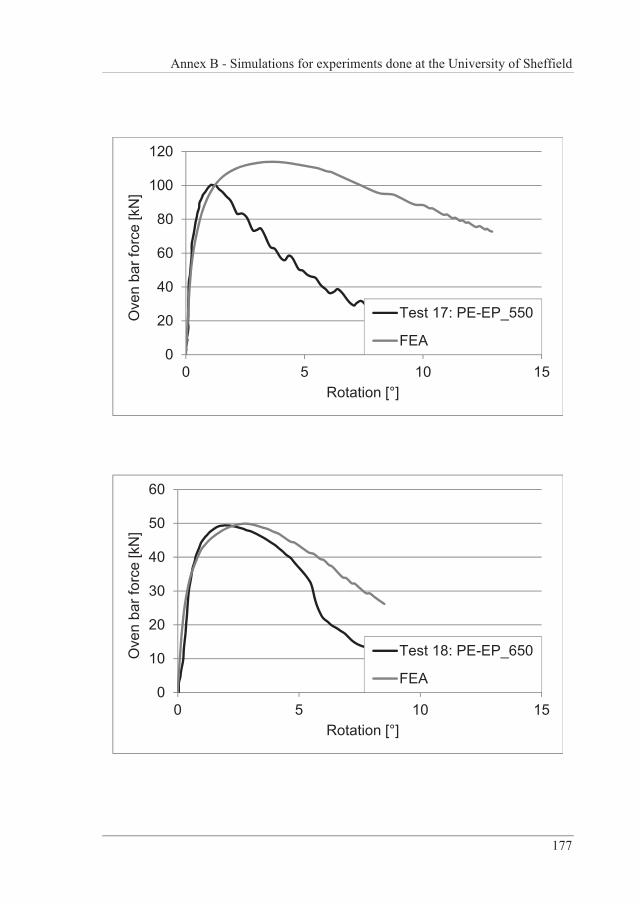
Annex B - Simulations for experiments done at the University of Sheffield
177
0
20
40
60
80
100
120
0 5 10 15
Ove
n ba
r for
ce [k
N]
Rotation [°]
Test 17: PE-EP_550
FEA
0
10
20
30
40
50
60
0 5 10 15
Ove
n ba
r for
ce [k
N]
Rotation [°]
Test 18: PE-EP_650
FEA
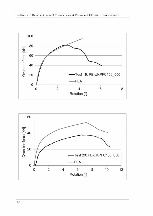
Stiffness of Reverse Channel Connections at Room and Elevated Temperatures
178
0
20
40
60
80
100
0 2 4 6 8
Ove
n ba
r for
ce [k
N]
Rotation [°]
Test 19: PE-UKPFC150_550
FEA
0
20
40
60
0 2 4 6 8 10 12
Ove
n ba
r for
ce [k
N]
Rotation [°]
Test 20: PE-UKPFC150_650
FEA
Annex C - 3D finite element simulations: parametric study
179
C. 3D FINITE ELEMENT SIMULATIONS: PARAMETRIC STUDY
The following two tables depict the full overview of the parametric study described in Section 4.3 and carried out with 3D FE models. For the sake of clarity, it has been divided into Stage 1 and Stage 2. All presented cases have been both simulated under tensile or compressive load.
Typically, 2 or 3 simulations are grouped and highlighted in terms of different colours. Within a group, normally only one variable at a time is varied.
Following the overview, a summary of all simulations (load vs. displacement diagrams) is presented.


Annex C - 3D finite element simulations: parametric study
181
1 350X8 (cut) 350 8 60 8 12/8 150 150 20 1 90 150 202 350X8 (cut) 350 8 90 8 12/8 150 150 20 1 90 150 203 350X8 (cut) 350 8 120 8 12/8 150 150 20 1 90 150 204 350X8 (cut) 350 8 60 8 12/8 210 150 20 1 150 150 205 350X8 (cut) 350 8 90 8 12/8 210 150 20 1 150 150 206 350X8 (cut) 350 8 120 8 12/8 210 150 20 1 150 150 207 350X8 (cut) 350 8 60 8 12/8 270 150 20 1 210 150 208 350X8 (cut) 350 8 90 8 12/8 270 150 20 1 210 150 209 350X8 (cut) 350 8 120 8 12/8 270 150 20 1 210 150 2010 350X8 (cut) 350 8 60 8 12/8 330 150 20 1 270 150 2011 350X8 (cut) 350 8 90 8 12/8 330 150 20 1 270 150 2012 350X8 (cut) 350 8 120 8 12/8 330 150 20 1 270 150 2013 350X8 (cut) 350 8 60 8 12/8 150 300 20 2 90 150 2014 350X8 (cut) 350 8 90 8 12/8 150 300 20 2 90 150 2015 350X8 (cut) 350 8 120 8 12/8 150 300 20 2 90 150 2016 350X8 (cut) 350 8 60 8 12/8 210 300 20 2 150 150 2017 350X8 (cut) 350 8 90 8 12/8 210 300 20 2 150 150 2018 350X8 (cut) 350 8 120 8 12/8 210 300 20 2 150 150 2019 350X8 (cut) 350 8 60 8 12/8 270 300 20 2 210 150 2020 350X8 (cut) 350 8 90 8 12/8 270 300 20 2 210 150 2021 350X8 (cut) 350 8 120 8 12/8 270 300 20 2 210 150 2022 350X8 (cut) 350 8 60 8 12/8 330 300 20 2 270 150 2023 350X8 (cut) 350 8 90 8 12/8 330 300 20 2 270 150 2024 350X8 (cut) 350 8 120 8 12/8 330 300 20 2 270 150 2025 350X8 (cut) 350 8 60 8 12/8 150 450 20 3 90 150 2026 350X8 (cut) 350 8 90 8 12/8 150 450 20 3 90 150 2027 350X8 (cut) 350 8 120 8 12/8 150 450 20 3 90 150 2028 350X8 (cut) 350 8 60 8 12/8 210 450 20 3 150 150 2029 350X8 (cut) 350 8 90 8 12/8 210 450 20 3 150 150 2030 350X8 (cut) 350 8 120 8 12/8 210 450 20 3 150 150 2031 350X8 (cut) 350 8 60 8 12/8 270 450 20 3 210 150 2032 350X8 (cut) 350 8 90 8 12/8 270 450 20 3 210 150 2033 350X8 (cut) 350 8 120 8 12/8 270 450 20 3 210 150 2034 350X8 (cut) 350 8 60 8 12/8 330 450 20 3 270 150 2035 350X8 (cut) 350 8 90 8 12/8 330 450 20 3 270 150 2036 350X8 (cut) 350 8 120 8 12/8 330 450 20 3 270 150 2037 350X8 (cut) 350 8 90 8 12/8 210 150 20 1 150 150 45038 350X8 (cut) 350 8 90 8 12/8 270 150 20 1 210 150 45039 350X8 (cut) 350 8 90 8 12/8 210 150 20 1 150 150 55040 350X8 (cut) 350 8 90 8 12/8 270 150 20 1 210 150 55041 350X8 (cut) 350 8 90 8 12/8 210 150 20 1 150 150 65042 350X8 (cut) 350 8 90 8 12/8 270 150 20 1 210 150 65043 350X8 (cut) 350 8 90 8 12/8 210 150 20 1 150 150 75044 350X8 (cut) 350 8 90 8 12/8 270 150 20 1 210 150 75045 350X8 (cut) 350 8 90 8 12/8 210 450 20 3 150 150 45046 350X8 (cut) 350 8 90 8 12/8 270 450 20 3 210 150 45047 350X8 (cut) 350 8 90 8 12/8 210 450 20 3 150 150 55048 350X8 (cut) 350 8 90 8 12/8 270 450 20 3 210 150 55049 350X8 (cut) 350 8 90 8 12/8 210 450 20 3 150 150 65050 350X8 (cut) 350 8 90 8 12/8 270 450 20 3 210 150 65051 350X8 (cut) 350 8 90 8 12/8 210 450 20 3 150 150 75052 350X8 (cut) 350 8 90 8 12/8 270 450 20 3 210 150 750
one boltrow at
elevatedtemp.
threebolt rows
atelevatedtemp.
threebolt rows
NO.Section
FlangeLength
L(mm)
WebThickness
tw(mm)
LegLength
h(mm)
LegThickness
tf(mm)
Root
(mm)
Width
(mm)
Length
(mm)
Thickness
(mm)
two boltrows
distancebetweenbolt rows(mm)
note
temp
( C)
Endplate Size
Bolt rows
Boltspacing
a(mm)
one boltrow
Reverse ChannelReverse Channel Parametric Study List Stage 1
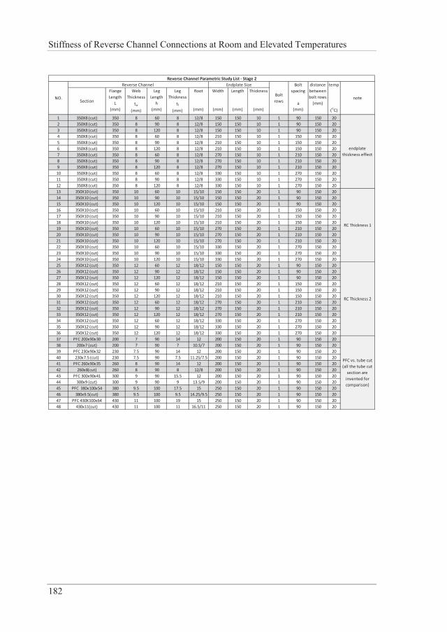
Stiffness of Reverse Channel Connections at Room and Elevated Temperatures
182
1 350X8 (cut) 350 8 60 8 12/8 150 150 10 1 90 150 202 350X8 (cut) 350 8 90 8 12/8 150 150 10 1 90 150 203 350X8 (cut) 350 8 120 8 12/8 150 150 10 1 90 150 204 350X8 (cut) 350 8 60 8 12/8 210 150 10 1 150 150 205 350X8 (cut) 350 8 90 8 12/8 210 150 10 1 150 150 206 350X8 (cut) 350 8 120 8 12/8 210 150 10 1 150 150 207 350X8 (cut) 350 8 60 8 12/8 270 150 10 1 210 150 208 350X8 (cut) 350 8 90 8 12/8 270 150 10 1 210 150 209 350X8 (cut) 350 8 120 8 12/8 270 150 10 1 210 150 2010 350X8 (cut) 350 8 60 8 12/8 330 150 10 1 270 150 2011 350X8 (cut) 350 8 90 8 12/8 330 150 10 1 270 150 2012 350X8 (cut) 350 8 120 8 12/8 330 150 10 1 270 150 2013 350X10 (cut) 350 10 60 10 15/10 150 150 20 1 90 150 2014 350X10 (cut) 350 10 90 10 15/10 150 150 20 1 90 150 2015 350X10 (cut) 350 10 120 10 15/10 150 150 20 1 90 150 2016 350X10 (cut) 350 10 60 10 15/10 210 150 20 1 150 150 2017 350X10 (cut) 350 10 90 10 15/10 210 150 20 1 150 150 2018 350X10 (cut) 350 10 120 10 15/10 210 150 20 1 150 150 2019 350X10 (cut) 350 10 60 10 15/10 270 150 20 1 210 150 2020 350X10 (cut) 350 10 90 10 15/10 270 150 20 1 210 150 2021 350X10 (cut) 350 10 120 10 15/10 270 150 20 1 210 150 2022 350X10 (cut) 350 10 60 10 15/10 330 150 20 1 270 150 2023 350X10 (cut) 350 10 90 10 15/10 330 150 20 1 270 150 2024 350X10 (cut) 350 10 120 10 15/10 330 150 20 1 270 150 2025 350X12 (cut) 350 12 60 12 18/12 150 150 20 1 90 150 2026 350X12 (cut) 350 12 90 12 18/12 150 150 20 1 90 150 2027 350X12 (cut) 350 12 120 12 18/12 150 150 20 1 90 150 2028 350X12 (cut) 350 12 60 12 18/12 210 150 20 1 150 150 2029 350X12 (cut) 350 12 90 12 18/12 210 150 20 1 150 150 2030 350X12 (cut) 350 12 120 12 18/12 210 150 20 1 150 150 2031 350X12 (cut) 350 12 60 12 18/12 270 150 20 1 210 150 2032 350X12 (cut) 350 12 90 12 18/12 270 150 20 1 210 150 2033 350X12 (cut) 350 12 120 12 18/12 270 150 20 1 210 150 2034 350X12 (cut) 350 12 60 12 18/12 330 150 20 1 270 150 2035 350X12 (cut) 350 12 90 12 18/12 330 150 20 1 270 150 2036 350X12 (cut) 350 12 120 12 18/12 330 150 20 1 270 150 2037 PFC 200x90x30 200 7 90 14 12 200 150 20 1 90 150 2038 200x7 (cut) 200 7 90 7 10.5/7 200 150 20 1 90 150 2039 PFC 230x90x32 230 7.5 90 14 12 200 150 20 1 90 150 2040 230x7.5 (cut) 230 7.5 90 7.5 11.25/7.5 200 150 20 1 90 150 2041 PFC 260x90x35 260 8 90 14 12 200 150 20 1 90 150 2042 260x8(cut) 260 8 90 8 12/8 200 150 20 1 90 150 2043 PFC 300x90x41 300 9 90 15.5 12 200 150 20 1 90 150 2044 300x9 (cut) 300 9 90 9 13.5/9 200 150 20 1 90 150 2045 PFC 380x100x54 380 9.5 100 17.5 15 250 150 20 1 90 150 2046 380x9.5(cut) 380 9.5 100 9.5 14.25/9.5 250 150 20 1 90 150 2047 PFC 430X100x64 430 11 100 19 15 250 150 20 1 90 150 2048 430x11(cut) 430 11 100 11 16.5/11 250 150 20 1 90 150 20
Reverse Channel Parametric Study List Stage 2
Width
(mm)
Root
(mm)
temp
( C)
note
endplatethickness effect
Reverse Channel Endplate Size
PFC vs. tube cut(all the tube cutsection areinvented forcomparison)
RC Thickness 1
RC Thickness 2
NO.Boltrows
Boltspacing
a(mm)
distancebetweenbolt rows(mm)
Length
(mm)
Thickness
(mm)
Section
FlangeLength
L(mm)
WebThickness
tw(mm)
LegLength
h(mm)
LegThickness
tf(mm)
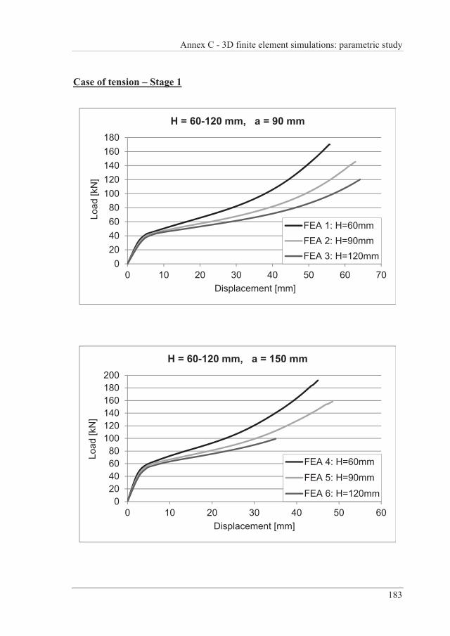
Annex C - 3D finite element simulations: parametric study
183
Case of tension – Stage 1
020406080
100120140160180
0 10 20 30 40 50 60 70
Load
[kN
]
Displacement [mm]
H = 60-120 mm, a = 90 mm
FEA 1: H=60mmFEA 2: H=90mmFEA 3: H=120mm
020406080
100120140160180200
0 10 20 30 40 50 60
Load
[kN
]
Displacement [mm]
H = 60-120 mm, a = 150 mm
FEA 4: H=60mm
FEA 5: H=90mm
FEA 6: H=120mm
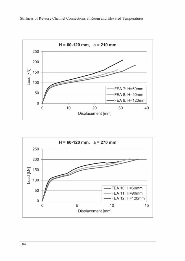
Stiffness of Reverse Channel Connections at Room and Elevated Temperatures
184
0
50
100
150
200
250
0 10 20 30 40
Load
[kN
]
Displacement [mm]
H = 60-120 mm, a = 210 mm
FEA 7: H=60mmFEA 8: H=90mmFEA 9: H=120mm
0
50
100
150
200
250
0 5 10 15
Load
[kN
]
Displacement [mm]
H = 60-120 mm, a = 270 mm
FEA 10: H=60mmFEA 11: H=90mmFEA 12: H=120mm
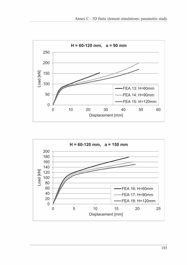
Annex C - 3D finite element simulations: parametric study
185
0
50
100
150
200
250
0 10 20 30 40 50 60
Load
[kN
]
Displacement [mm]
H = 60-120 mm, a = 90 mm
FEA 13: H=60mm
FEA 14: H=90mm
FEA 15: H=120mm
020406080
100120140160180200
0 5 10 15 20 25
Load
[kN
]
Displacement [mm]
H = 60-120 mm, a = 150 mm
FEA 16: H=60mmFEA 17: H=90mmFEA 18: H=120mm
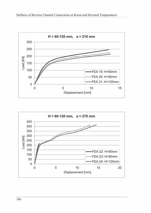
Stiffness of Reverse Channel Connections at Room and Elevated Temperatures
186
0
50
100
150
200
250
300
0 5 10 15
Load
[kN
]
Displacement [mm]
H = 60-120 mm, a = 210 mm
FEA 19: H=60mmFEA 20: H=90mmFEA 21: H=120mm
050
100150200250300350400450
0 5 10 15 20
Load
[kN
]
Displacement [mm]
H = 60-120 mm, a = 270 mm
FEA 22: H=60mmFEA 23: H=90mmFEA 24: H=120mm
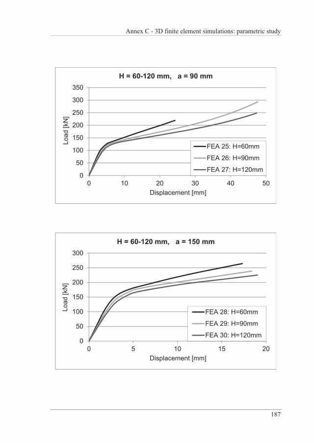
Annex C - 3D finite element simulations: parametric study
187
0
50
100
150
200
250
300
350
0 10 20 30 40 50
Load
[kN
]
Displacement [mm]
H = 60-120 mm, a = 90 mm
FEA 25: H=60mm
FEA 26: H=90mm
FEA 27: H=120mm
0
50
100
150
200
250
300
0 5 10 15 20
Load
[kN
]
Displacement [mm]
H = 60-120 mm, a = 150 mm
FEA 28: H=60mm
FEA 29: H=90mm
FEA 30: H=120mm
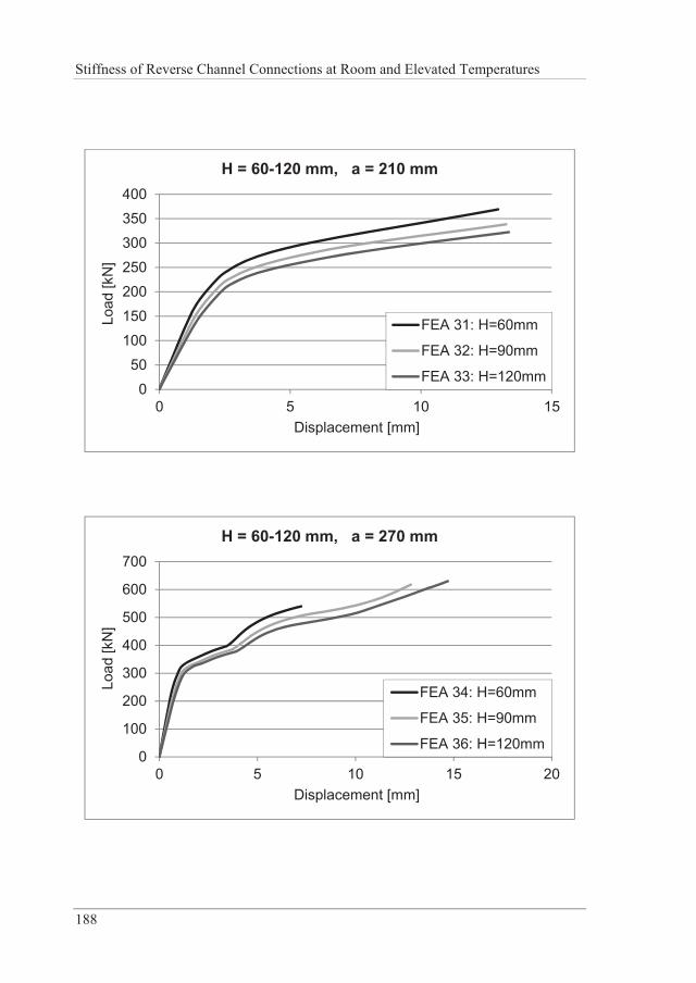
Stiffness of Reverse Channel Connections at Room and Elevated Temperatures
188
0
50100
150
200250
300350
400
0 5 10 15
Load
[kN
]
Displacement [mm]
H = 60-120 mm, a = 210 mm
FEA 31: H=60mm
FEA 32: H=90mm
FEA 33: H=120mm
0
100
200
300
400
500
600
700
0 5 10 15 20
Load
[kN
]
Displacement [mm]
H = 60-120 mm, a = 270 mm
FEA 34: H=60mm
FEA 35: H=90mm
FEA 36: H=120mm
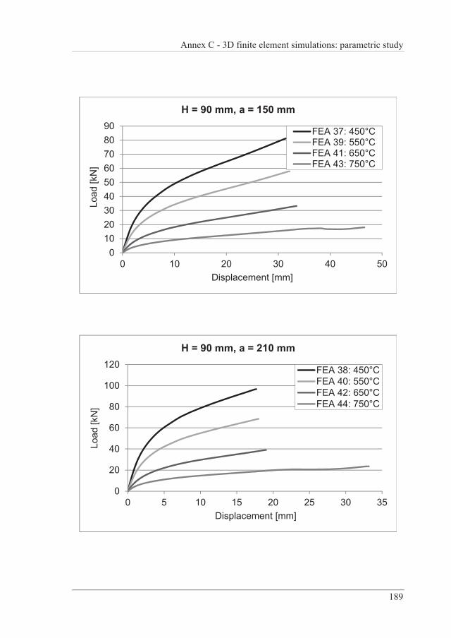
Annex C - 3D finite element simulations: parametric study
189
0102030405060708090
0 10 20 30 40 50
Load
[kN
]
Displacement [mm]
H = 90 mm, a = 150 mm
FEA 37: 450°CFEA 39: 550°CFEA 41: 650°CFEA 43: 750°C
0
20
40
60
80
100
120
0 5 10 15 20 25 30 35
Load
[kN
]
Displacement [mm]
H = 90 mm, a = 210 mm
FEA 38: 450°CFEA 40: 550°CFEA 42: 650°CFEA 44: 750°C
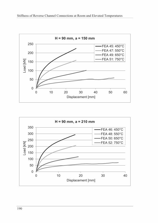
Stiffness of Reverse Channel Connections at Room and Elevated Temperatures
190
0
50
100
150
200
250
0 10 20 30 40 50 60
Load
[kN
]
Displacement [mm]
H = 90 mm, a = 150 mm
FEA 45: 450°CFEA 47: 550°CFEA 49: 650°CFEA 51: 750°C
0
50
100
150
200
250
300
350
0 10 20 30 40
Load
[kN
]
Displacement [mm]
H = 90 mm, a = 210 mm
FEA 46: 450°CFEA 48: 550°CFEA 50: 650°CFEA 52: 750°C
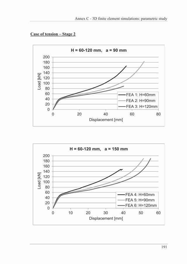
Annex C - 3D finite element simulations: parametric study
191
Case of tension – Stage 2
020406080
100120140160180200
0 20 40 60 80
Load
[kN
]
Displacement [mm]
H = 60-120 mm, a = 90 mm
FEA 1: H=60mmFEA 2: H=90mmFEA 3: H=120mm
020406080
100120140160180200
0 10 20 30 40 50 60
Load
[kN
]
Displacement [mm]
H = 60-120 mm, a = 150 mm
FEA 4: H=60mmFEA 5: H=90mmFEA 6: H=120mm
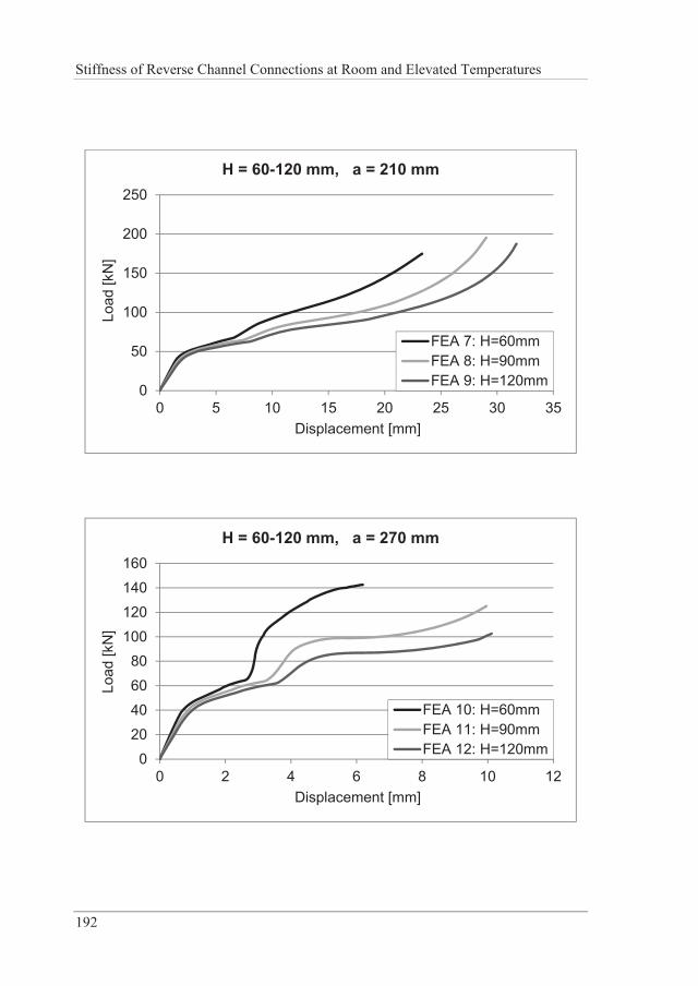
Stiffness of Reverse Channel Connections at Room and Elevated Temperatures
192
0
50
100
150
200
250
0 5 10 15 20 25 30 35
Load
[kN
]
Displacement [mm]
H = 60-120 mm, a = 210 mm
FEA 7: H=60mmFEA 8: H=90mmFEA 9: H=120mm
0
2040
60
80100
120140
160
0 2 4 6 8 10 12
Load
[kN
]
Displacement [mm]
H = 60-120 mm, a = 270 mm
FEA 10: H=60mmFEA 11: H=90mmFEA 12: H=120mm
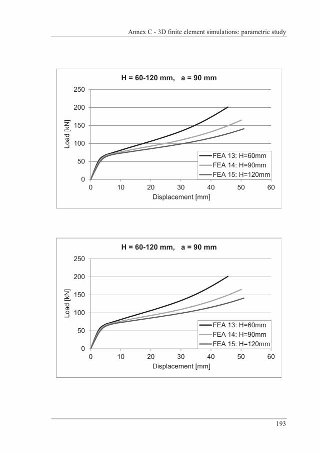
Annex C - 3D finite element simulations: parametric study
193
0
50
100
150
200
250
0 10 20 30 40 50 60
Load
[kN
]
Displacement [mm]
H = 60-120 mm, a = 90 mm
FEA 13: H=60mmFEA 14: H=90mmFEA 15: H=120mm
0
50
100
150
200
250
0 10 20 30 40 50 60
Load
[kN
]
Displacement [mm]
H = 60-120 mm, a = 90 mm
FEA 13: H=60mmFEA 14: H=90mmFEA 15: H=120mm
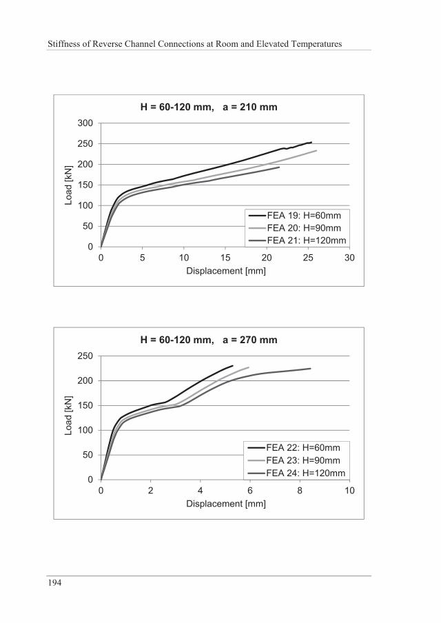
Stiffness of Reverse Channel Connections at Room and Elevated Temperatures
194
0
50
100
150
200
250
300
0 5 10 15 20 25 30
Load
[kN
]
Displacement [mm]
H = 60-120 mm, a = 210 mm
FEA 19: H=60mmFEA 20: H=90mmFEA 21: H=120mm
0
50
100
150
200
250
0 2 4 6 8 10
Load
[kN
]
Displacement [mm]
H = 60-120 mm, a = 270 mm
FEA 22: H=60mmFEA 23: H=90mmFEA 24: H=120mm
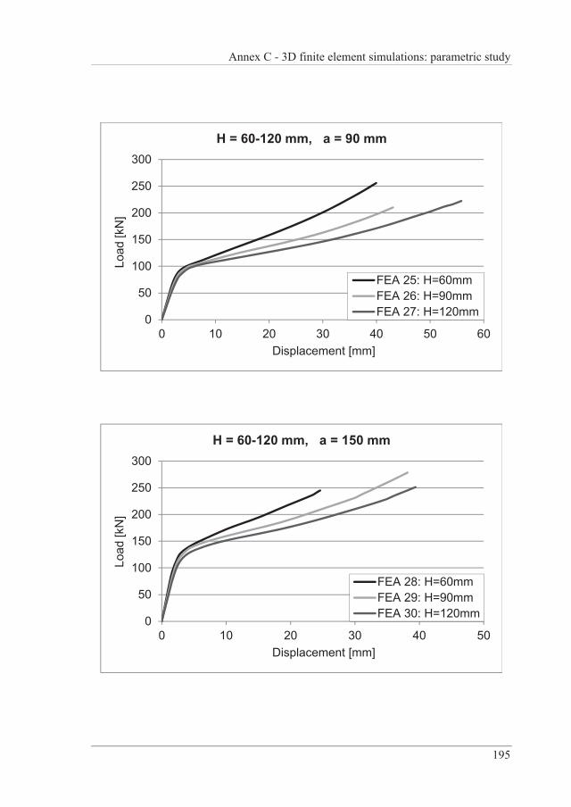
Annex C - 3D finite element simulations: parametric study
195
0
50
100
150
200
250
300
0 10 20 30 40 50 60
Load
[kN
]
Displacement [mm]
H = 60-120 mm, a = 90 mm
FEA 25: H=60mmFEA 26: H=90mmFEA 27: H=120mm
0
50
100
150
200
250
300
0 10 20 30 40 50
Load
[kN
]
Displacement [mm]
H = 60-120 mm, a = 150 mm
FEA 28: H=60mmFEA 29: H=90mmFEA 30: H=120mm
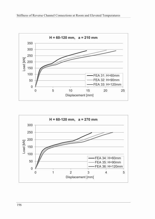
Stiffness of Reverse Channel Connections at Room and Elevated Temperatures
196
0
50
100
150
200
250
300
350
0 5 10 15 20 25
Load
[kN
]
Displacement [mm]
H = 60-120 mm, a = 210 mm
FEA 31: H=60mmFEA 32: H=90mmFEA 33: H=120mm
0
50
100
150
200
250
300
0 1 2 3 4 5
Load
[kN
]
Displacement [mm]
H = 60-120 mm, a = 270 mm
FEA 34: H=60mmFEA 35: H=90mmFEA 36: H=120mm
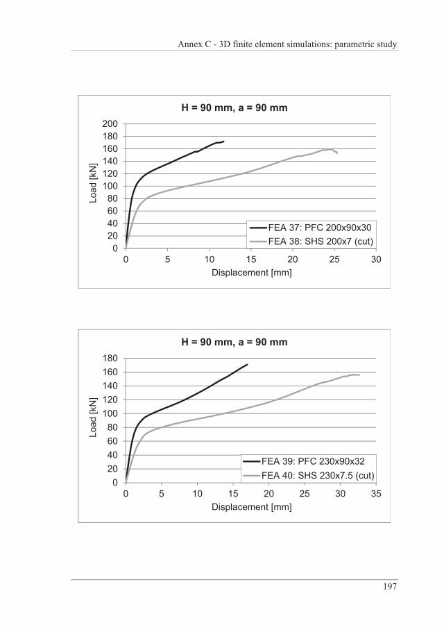
Annex C - 3D finite element simulations: parametric study
197
020406080
100120140160180200
0 5 10 15 20 25 30
Load
[kN
]
Displacement [mm]
H = 90 mm, a = 90 mm
FEA 37: PFC 200x90x30FEA 38: SHS 200x7 (cut)
020406080
100120140160180
0 5 10 15 20 25 30 35
Load
[kN
]
Displacement [mm]
H = 90 mm, a = 90 mm
FEA 39: PFC 230x90x32FEA 40: SHS 230x7.5 (cut)
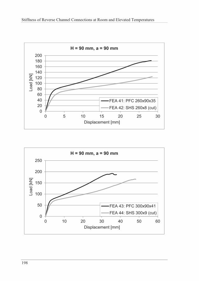
Stiffness of Reverse Channel Connections at Room and Elevated Temperatures
198
020406080
100120140160180200
0 5 10 15 20 25 30
Load
[kN
]
Displacement [mm]
H = 90 mm, a = 90 mm
FEA 41: PFC 260x90x35FEA 42: SHS 260x8 (cut)
0
50
100
150
200
250
0 10 20 30 40 50 60
Load
[kN
]
Displacement [mm]
H = 90 mm, a = 90 mm
FEA 43: PFC 300x90x41FEA 44: SHS 300x9 (cut)
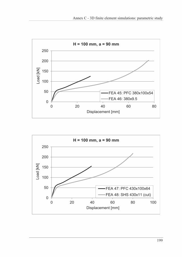
Annex C - 3D finite element simulations: parametric study
199
0
50
100
150
200
250
0 20 40 60 80
Load
[kN
]
Displacement [mm]
H = 100 mm, a = 90 mm
FEA 45: PFC 380x100x54FEA 46: 380x9.5
0
50
100
150
200
250
0 20 40 60 80 100
Load
[kN
]
Displacement [mm]
H = 100 mm, a = 90 mm
FEA 47: PFC 430x100x64FEA 48: SHS 430x11 (cut)
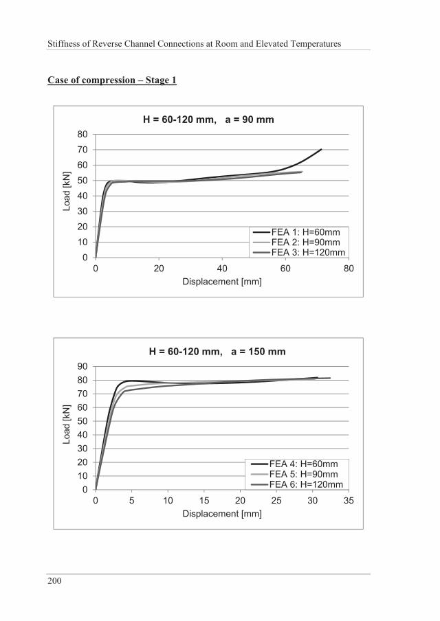
Stiffness of Reverse Channel Connections at Room and Elevated Temperatures
200
Case of compression – Stage 1
0
1020
30
4050
6070
80
0 20 40 60 80
Load
[kN
]
Displacement [mm]
H = 60-120 mm, a = 90 mm
FEA 1: H=60mmFEA 2: H=90mmFEA 3: H=120mm
0102030405060708090
0 5 10 15 20 25 30 35
Load
[kN
]
Displacement [mm]
H = 60-120 mm, a = 150 mm
FEA 4: H=60mmFEA 5: H=90mmFEA 6: H=120mm
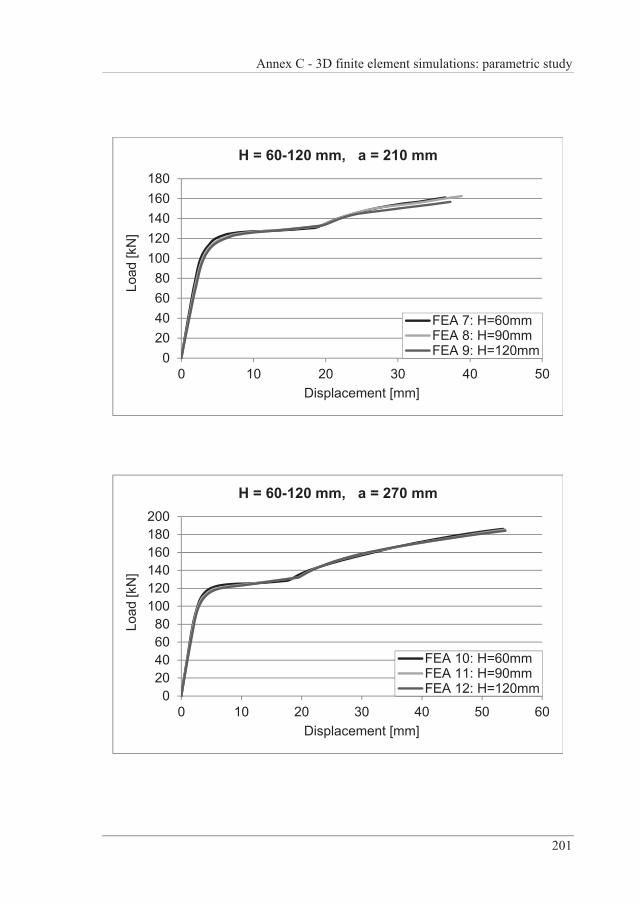
Annex C - 3D finite element simulations: parametric study
201
020406080
100120140160180
0 10 20 30 40 50
Load
[kN
]
Displacement [mm]
H = 60-120 mm, a = 210 mm
FEA 7: H=60mmFEA 8: H=90mmFEA 9: H=120mm
020406080
100120140160180200
0 10 20 30 40 50 60
Load
[kN
]
Displacement [mm]
H = 60-120 mm, a = 270 mm
FEA 10: H=60mmFEA 11: H=90mmFEA 12: H=120mm
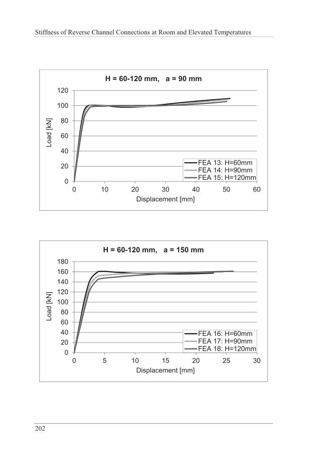
Stiffness of Reverse Channel Connections at Room and Elevated Temperatures
202
0
20
40
60
80
100
120
0 10 20 30 40 50 60
Load
[kN
]
Displacement [mm]
H = 60-120 mm, a = 90 mm
FEA 13: H=60mmFEA 14: H=90mmFEA 15: H=120mm
020406080
100120140160180
0 5 10 15 20 25 30
Load
[kN
]
Displacement [mm]
H = 60-120 mm, a = 150 mm
FEA 16: H=60mmFEA 17: H=90mmFEA 18: H=120mm
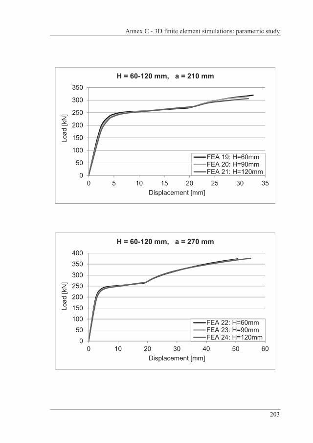
Annex C - 3D finite element simulations: parametric study
203
0
50
100
150
200
250
300
350
0 5 10 15 20 25 30 35
Load
[kN
]
Displacement [mm]
H = 60-120 mm, a = 210 mm
FEA 19: H=60mmFEA 20: H=90mmFEA 21: H=120mm
0
50100
150
200250
300350
400
0 10 20 30 40 50 60
Load
[kN
]
Displacement [mm]
H = 60-120 mm, a = 270 mm
FEA 22: H=60mmFEA 23: H=90mmFEA 24: H=120mm
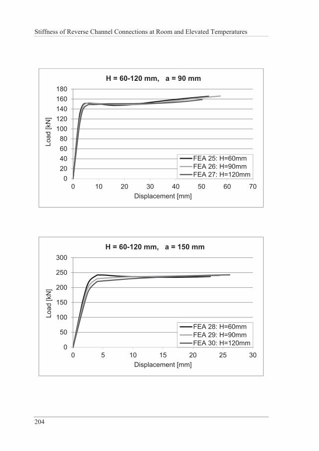
Stiffness of Reverse Channel Connections at Room and Elevated Temperatures
204
020406080
100120140160180
0 10 20 30 40 50 60 70
Load
[kN
]
Displacement [mm]
H = 60-120 mm, a = 90 mm
FEA 25: H=60mmFEA 26: H=90mmFEA 27: H=120mm
0
50
100
150
200
250
300
0 5 10 15 20 25 30
Load
[kN
]
Displacement [mm]
H = 60-120 mm, a = 150 mm
FEA 28: H=60mmFEA 29: H=90mmFEA 30: H=120mm
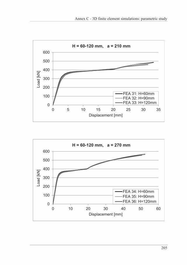
Annex C - 3D finite element simulations: parametric study
205
0
100
200
300
400
500
600
0 5 10 15 20 25 30 35
Load
[kN
]
Displacement [mm]
H = 60-120 mm, a = 210 mm
FEA 31: H=60mmFEA 32: H=90mmFEA 33: H=120mm
0
100
200
300
400
500
600
0 10 20 30 40 50 60
Load
[kN
]
Displacement [mm]
H = 60-120 mm, a = 270 mm
FEA 34: H=60mmFEA 35: H=90mmFEA 36: H=120mm
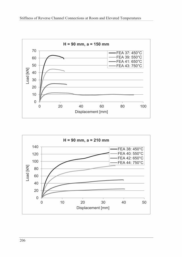
Stiffness of Reverse Channel Connections at Room and Elevated Temperatures
206
0
10
20
30
40
50
60
70
0 20 40 60 80 100
Load
[kN
]
Displacement [mm]
H = 90 mm, a = 150 mm
FEA 37: 450°CFEA 39: 550°CFEA 41: 650°CFEA 43: 750°C
0
20
40
60
80
100
120
140
0 10 20 30 40 50
Load
[kN
]
Displacement [mm]
H = 90 mm, a = 210 mm
FEA 38: 450°CFEA 40: 550°CFEA 42: 650°CFEA 44: 750°C
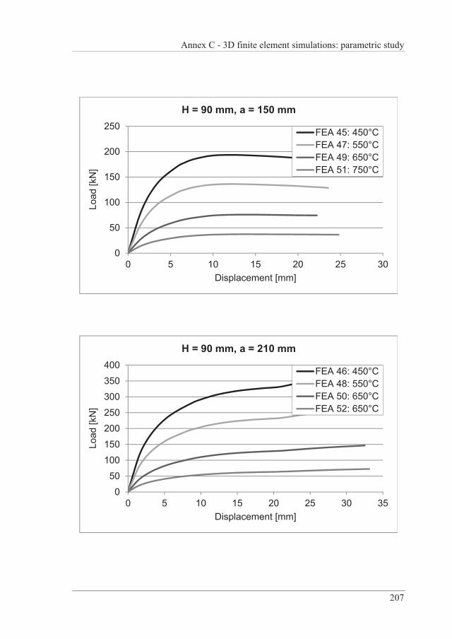
Annex C - 3D finite element simulations: parametric study
207
0
50
100
150
200
250
0 5 10 15 20 25 30
Load
[kN
]
Displacement [mm]
H = 90 mm, a = 150 mm
FEA 45: 450°CFEA 47: 550°CFEA 49: 650°CFEA 51: 750°C
0
50100
150
200250
300350
400
0 5 10 15 20 25 30 35
Load
[kN
]
Displacement [mm]
H = 90 mm, a = 210 mm
FEA 46: 450°CFEA 48: 550°CFEA 50: 650°CFEA 52: 650°C
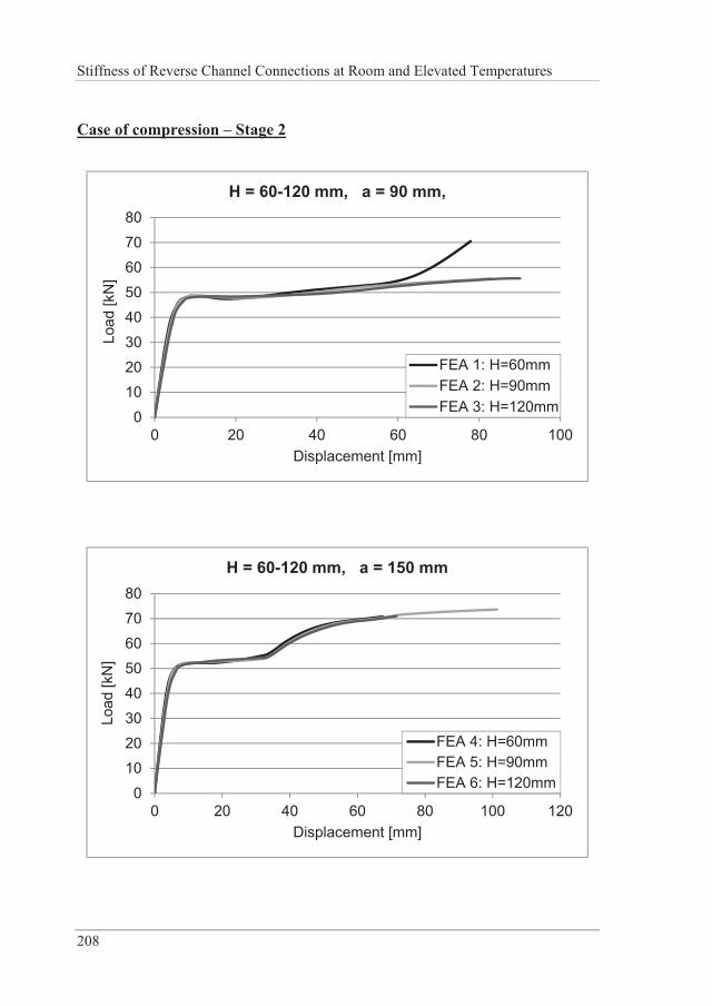
Stiffness of Reverse Channel Connections at Room and Elevated Temperatures
208
Case of compression – Stage 2
0
1020
30
4050
6070
80
0 20 40 60 80 100
Load
[kN
]
Displacement [mm]
H = 60-120 mm, a = 90 mm,
FEA 1: H=60mmFEA 2: H=90mmFEA 3: H=120mm
0
1020
30
4050
6070
80
0 20 40 60 80 100 120
Load
[kN
]
Displacement [mm]
H = 60-120 mm, a = 150 mm
FEA 4: H=60mmFEA 5: H=90mmFEA 6: H=120mm
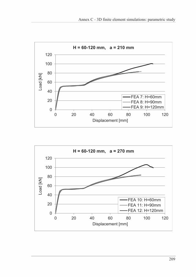
Annex C - 3D finite element simulations: parametric study
209
0
20
40
60
80
100
120
0 20 40 60 80 100 120
Load
[kN
]
Displacement [mm]
H = 60-120 mm, a = 210 mm
FEA 7: H=60mmFEA 8: H=90mmFEA 9: H=120mm
0
20
40
60
80
100
120
0 20 40 60 80 100 120
Load
[kN
]
Displacement [mm]
H = 60-120 mm, a = 270 mm
FEA 10: H=60mmFEA 11: H=90mmFEA 12: H=120mm
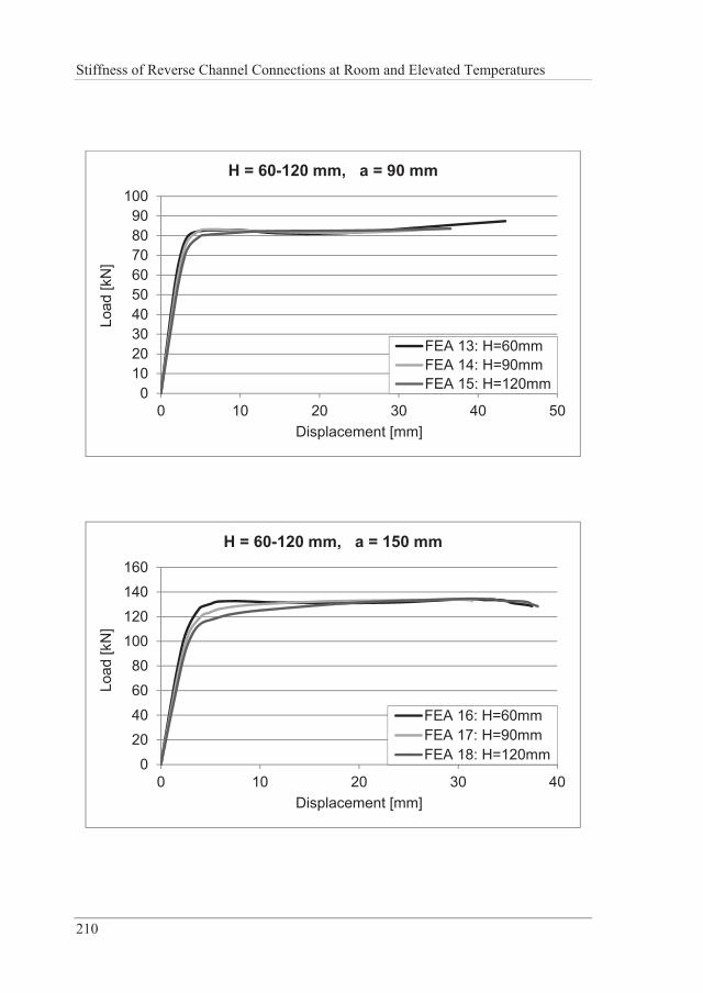
Stiffness of Reverse Channel Connections at Room and Elevated Temperatures
210
0102030405060708090
100
0 10 20 30 40 50
Load
[kN
]
Displacement [mm]
H = 60-120 mm, a = 90 mm
FEA 13: H=60mmFEA 14: H=90mmFEA 15: H=120mm
0
2040
60
80100
120140
160
0 10 20 30 40
Load
[kN
]
Displacement [mm]
H = 60-120 mm, a = 150 mm
FEA 16: H=60mmFEA 17: H=90mmFEA 18: H=120mm
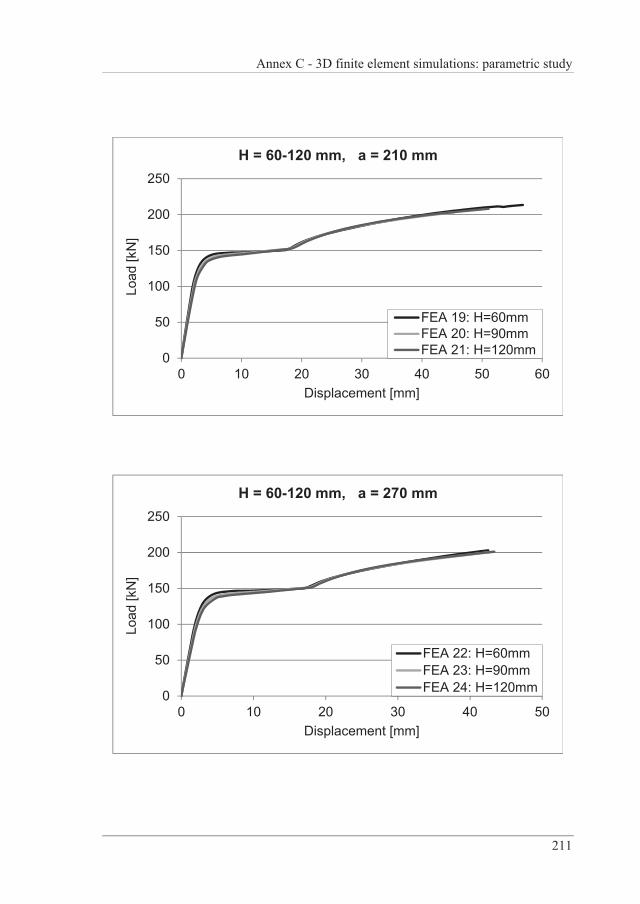
Annex C - 3D finite element simulations: parametric study
211
0
50
100
150
200
250
0 10 20 30 40 50 60
Load
[kN
]
Displacement [mm]
H = 60-120 mm, a = 210 mm
FEA 19: H=60mmFEA 20: H=90mmFEA 21: H=120mm
0
50
100
150
200
250
0 10 20 30 40 50
Load
[kN
]
Displacement [mm]
H = 60-120 mm, a = 270 mm
FEA 22: H=60mmFEA 23: H=90mmFEA 24: H=120mm
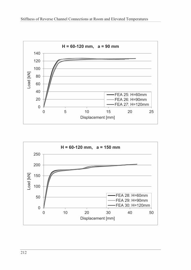
Stiffness of Reverse Channel Connections at Room and Elevated Temperatures
212
0
20
40
60
80
100
120
140
0 5 10 15 20 25
Load
[kN
]
Displacement [mm]
H = 60-120 mm, a = 90 mm
FEA 25: H=60mmFEA 26: H=90mmFEA 27: H=120mm
0
50
100
150
200
250
0 10 20 30 40 50
Load
[kN
]
Displacement [mm]
H = 60-120 mm, a = 150 mm
FEA 28: H=60mmFEA 29: H=90mmFEA 30: H=120mm
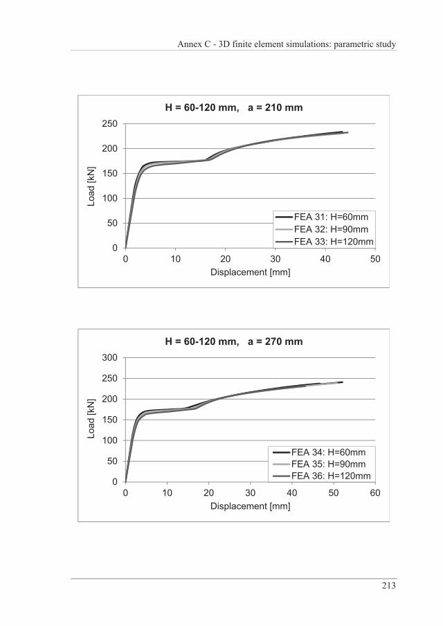
Annex C - 3D finite element simulations: parametric study
213
0
50
100
150
200
250
0 10 20 30 40 50
Load
[kN
]
Displacement [mm]
H = 60-120 mm, a = 210 mm
FEA 31: H=60mmFEA 32: H=90mmFEA 33: H=120mm
0
50
100
150
200
250
300
0 10 20 30 40 50 60
Load
[kN
]
Displacement [mm]
H = 60-120 mm, a = 270 mm
FEA 34: H=60mmFEA 35: H=90mmFEA 36: H=120mm
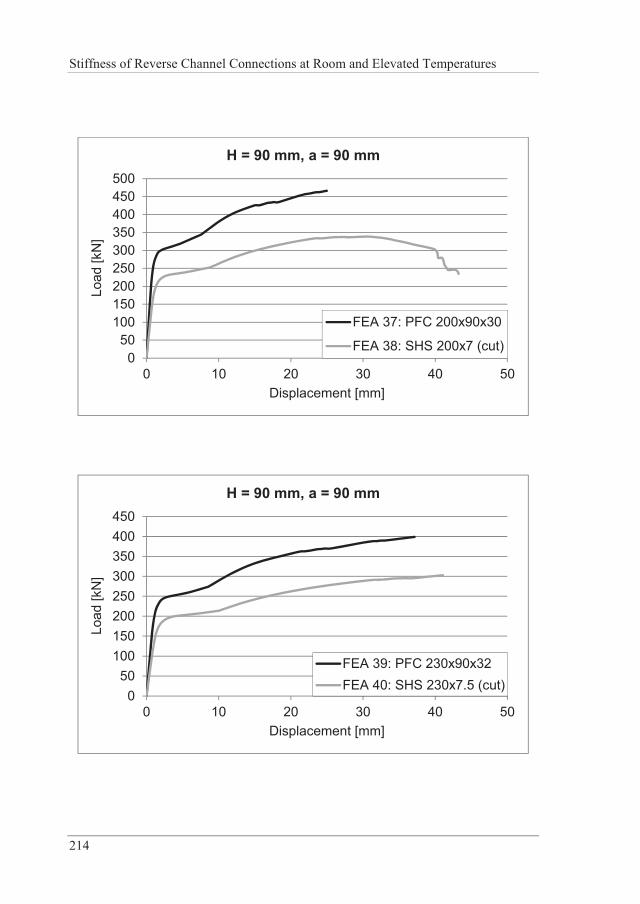
Stiffness of Reverse Channel Connections at Room and Elevated Temperatures
214
050
100150200250300350400450500
0 10 20 30 40 50
Load
[kN
]
Displacement [mm]
H = 90 mm, a = 90 mm
FEA 37: PFC 200x90x30
FEA 38: SHS 200x7 (cut)
050
100150200250300350400450
0 10 20 30 40 50
Load
[kN
]
Displacement [mm]
H = 90 mm, a = 90 mm
FEA 39: PFC 230x90x32FEA 40: SHS 230x7.5 (cut)
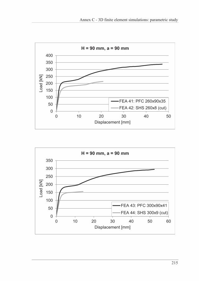
Annex C - 3D finite element simulations: parametric study
215
0
50100
150
200250
300350
400
0 10 20 30 40 50
Load
[kN
]
Displacement [mm]
H = 90 mm, a = 90 mm
FEA 41: PFC 260x90x35FEA 42: SHS 260x8 (cut)
0
50
100
150
200
250
300
350
0 10 20 30 40 50 60
Load
[kN
]
Displacement [mm]
H = 90 mm, a = 90 mm
FEA 43: PFC 300x90x41
FEA 44: SHS 300x9 (cut)
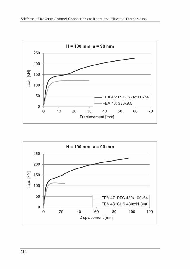
Stiffness of Reverse Channel Connections at Room and Elevated Temperatures
216
0
50
100
150
200
250
0 10 20 30 40 50 60 70
Load
[kN
]
Displacement [mm]
H = 100 mm, a = 90 mm
FEA 45: PFC 380x100x54FEA 46: 380x9.5
0
50
100
150
200
250
0 20 40 60 80 100 120
Load
[kN
]
Displacement [mm]
H = 100 mm, a = 90 mm
FEA 47: PFC 430x100x64FEA 48: SHS 430x11 (cut)


Related Documents