Stevens Institute of Technology Construction Documentation Project Manual 08-17-15

Welcome message from author
This document is posted to help you gain knowledge. Please leave a comment to let me know what you think about it! Share it to your friends and learn new things together.
Transcript

1
Stevens Institute of Technology
August 17th,2015U.S.D.O.E Solar Decathlon 2015As-Built Documentation Project Manual
Stevens Institute of Technology Construction DocumentationProject Manual
08-17-15
Sustainable Resilient

3
Stevens Institute of Technology
August 17th,2015U.S.D.O.E Solar Decathlon 2015As-Built Documentation Project Manual
U.S Department Of Energy Solar Decathlon 2015
Stevens Institute of Technology
Faculty Contact:
John NastasiStevens Institute of TechnologyHoboken, NJ, [email protected](917) - 579 - 1814
Faculty Project Manager:
Ed MayStevens Institute of TechnologyHoboken, NJ, [email protected](510) - 499 - 5191
Construction Documentation SubmissionFebruary 12 2015August 17 2015

4
Stevens Institute of Technology
August 17th,2015U.S.D.O.E Solar Decathlon 2015As-Built Documentation Project Manual
U.S Department Of Energy Solar Decathlon 2015
Stevens Institute of Technology
Construction Documentation SubmissionFebruary 12 2015
Student Team Leaders
Alex GuimaraesMichael SignorileChris HammChristine HeckerAJ ElliottAllison OutwaterJuan AlicanteGrace Gallagher
Sarah GleasonAJ ElliottEd May
Project Manager :Architectural Project Manager :Construction Manager :Project Engineer :Electrical Engineer :Health and Safety Officer :Measured Contest Captain :Instrumentation Contact :
Sponsorship Manager :Public Relations Contact :Faculty Advisor :
August 17 2015
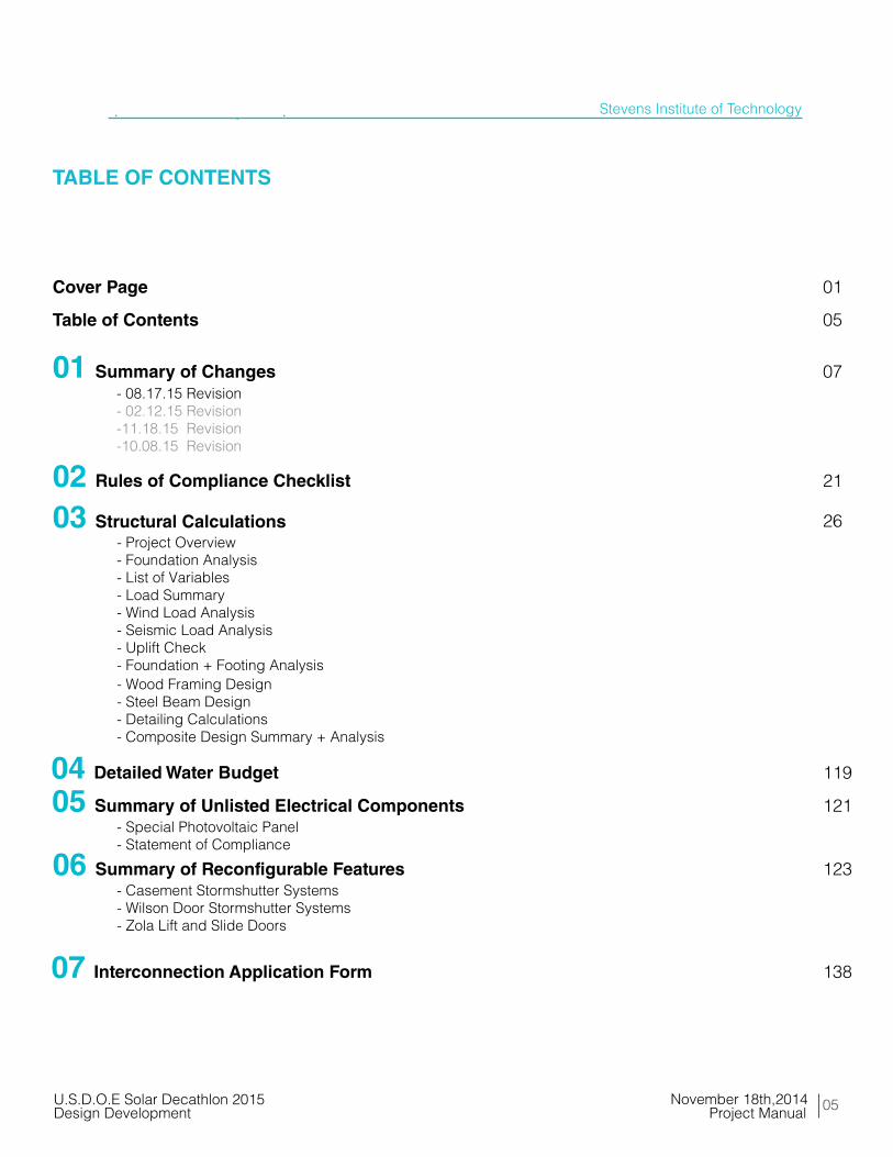
TABLE OF CONTENTS
Cover Page 01
Table of Contents 05
01 Summary of Changes - 08.17.15 Revision - 02.12.15 Revision -11.18.15 Revision -10.08.15 Revision
07
02 Rules of Compliance Checklist 21
03 Structural Calculations 26
04 Detailed Water Budget 119
05 Summary of Unlisted Electrical Components 121
07 Interconnection Application Form
123
138
- Project Overview- Foundation Analysis- List of Variables- Load Summary- Wind Load Analysis- Seismic Load Analysis- Uplift Check- Foundation + Footing Analysis- Wood Framing Design- Steel Beam Design- Detailing Calculations- Composite Design Summary + Analysis
- Special Photovoltaic Panel- Statement of Compliance
06 Summary of Reconfigurable Features- Casement Stormshutter Systems- Wilson Door Stormshutter Systems- Zola Lift and Slide Doors
05
Stevens Institute of Technology
November 18th,2014U.S.D.O.E Solar Decathlon 2015Design Development Project Manual
06
Stevens Institute of Technology
August 17th,2015U.S.D.O.E Solar Decathlon 2015As-Built Documentation Project Manual
TABLE OF CONTENTS (cont’d)
11 Product Cut Sheets 562
- Division 01 - General Requirements- Division 02 - Existing Conditions- Division 05 - Metals- Division 06 - Wood,Plastics,and Composites- Division 07 - Thermal and Moisture Protection- Division 08 - Openings- Division 09 - Finishes- Division 10 - Specialties- Division 11 - Equipment- Division 12 - Furnishings- Division 21 - Fire Suppression- Division 22 - Plumbing- Division 23 - Heating, Ventilating, and Air Conditioning- Division 25 - Integrated Automation- Division 26 - Electrical- Division 27 - Communications- Division 28 - Electronic Safety and Security- Division 31 - Earthwork- Division 41 - Material Processing and Handling- Division 48 - Electrical Power Generation
09 Quantity Takeoff of Competition Prototype 142
10 Construction Specifications 160
08 Energy Code Compliance 140

CHANGES01
ofSUMMARY

08
Stevens Institute of Technology
August 17th,2015U.S.D.O.E Solar Decathlon 2015As-Built Documentation Project Manual
Significant Design Change Overview
SURE HOUSE’s structure has changed significantly since the Construction Drawing Submission. The main structural components of SURE HOUSE are now comprised of standard wood framing. Floors are framed with 9 ½” TJI in modules 1 and 2, and 9 ½” LVL in module 3. Walls are comprised of a 2x6 stud wall assembly, with both interior and exterior cavities for additional insulation. The roof is framed with 9 ½” TJI which are held down with Simpson Strong Tie Hurricane clips. Flood proofing is achieved with a plastic 1/8” sheathing that wraps the house below a design flood elevation (DFE) of five feet. Decks of the house are designed with a combination of PSL (+), pressure treated 2x8s, and 2x10s. Decks are split into panels that can ship flat-packed for ease of reconstruction. A steel frame wraps the deck to provide uplift resistance for the shutters, stability for louvers, and privacy.
SUMMARY OF CHANGES
1 2 3 4 5 6 7
A
B
C
D
E
1 2 3 4 5 6 7
SHEET TITLE
LOT NUMBER:
COPYRIGHT:
CLIENT
U.S. DEPARTMENT OF ENERGY
SOLAR DECATHLON 2015
WWW.SOLARDECATHLON.GOV
TEAM NAME:
ADDRESS:
CONTACT:
NASTASI ARCHITECTS
CONSULTANTS
BLDG TYP LLC
STEVENS DEPT. OF HEALTH & SAFETY
NONE: PROJECT ISPUBLIC DOMAIN
SURE HOUSE
600 FRANK SINATRA DRIVEHOBOKEN, NJ 07030
HTTP://SUREHOUSE.ORG/[email protected]
LOT #110
01 10-09-2014 80% DD SET02 11-18-2014 80% DD SET R103 12-18-2014 80% CD SET04 02-11-2015 100% CD SET05 04-05-2015 FRAMING SET
CHRISTIE ENGINEERING, P.C.
06 05-04-2015 CONSTRUCTION SET07 08-17-2015 AS-BUILT DRAWINGS
STEVENS INSTITUTE OF TECHNOLOGY
8/13
/201
5 9:
30:0
7 AM O-402
MODULE 3DDIMENSIONS
A1 MODULES
1
2
3
0 2' 4' 8'
GENERAL SHEET NOTES:
REFERENCE KEYNOTES:
SHEET KEYNOTES:
1. MODULE 1:
WIDTH: 14' 10"LENGTH: 29' 0"HEIGHT: 12' 8"WEIGHT: 15,430 LBS
INCLUDES: MECH. ROOM, BATHROOM, KITCHEN
2. MODULE 2:
WIDTH: 14' 10"LENGTH: 29' 0"HEIGHT: 12' 8"WEIGHT: 13,480 LBS
INCLUDES: KID'S BEDROOM, LIVING ROOM
3. MODULE 3:
WIDTH: 14' 10"LENGTH: 29' 0"HEIGHT: 12' 8"WEIGHT: 4,980 LBS
INCLUDES: MASTER BEDROOM, LIVING ROOM,ENTERTAINMENT CENTER, EAST PORCH
DRAWING KEY
MARK DATE DESCRIPTION
08.17.15 Revision
Fig 1.1 MODULE CONNECTIONS

09
Stevens Institute of Technology
August 17th,2015U.S.D.O.E Solar Decathlon 2015As-Built Documentation Project Manual
Significant changes to the Construction Drawing Set that have occurred between submissions have been outlined below. The Construction Drawings should be reviewed for revisions.
General Sheets
Hazard Sheets
- H-101 - Changed to Reflect New Design
Landscape Sheets
- L-101 - Landscape Locations Updated - Vegetation Schedules Added
Structure Sheets
-
-
SIGNIFICANT CHANGES HAVE BEEN MADE TO S SHEETS REGARD ALL AS UPDATED
- SIGNIFICANT CHANGES HAVE BEEN MADE TO S SHEETS REGARD ALL AS UPDATED
SIGNIFICANT CHANGES HAVE BEEN MADE TO S SHEETS REGARD ALL AS UPDATED
Operations Sheets
SUMMARY OF CHANGES
08.17.15 Construction Drawing Documentation Summary

10
Stevens Institute of Technology
August 17th,2015U.S.D.O.E Solar Decathlon 2015As-Built Documentation Project Manual
Architecture Sheets
- A-113 - First Floor Plan Updated To Reflect New Design Scheme - A-121 - RCP Updated To Reflect New Design Scheme - A-201,02 - Exterior Elevations Updated - A-311,12,13,14,15,16,17,21,23,24 - Updated To Reflect New Construction Assembly - A-405 - Shutter Plan Section Cut View Added - A-411 - Enlarged South Facade Plan + Elevation Updated - A-501 - Updated To Reflect New Construction Assembly - A-525,26,27,28 - Bathroom Details Updated - A-512,13,14,15,16,17,18,19 - Updated To Reflect New Construction Assembly - A-541,42,43 - Ramp and Handrail Details Added - A-552,53,54,55,56 - Updated To Reflect New Construction Assembly - A-591 - Ramp Details Added - A-601 - Updated To Reflect New Construction Assembly - A-605 - Wall Types Conductivity Added
Interior Sheets
- I-201,02 - Interior Elevations Updated - I-401,501,503,504,505 - Lighting and Drop Ceiling Assembly Details Added
Fire Detection and Suppression Sheets
- F-101 - Updated To Reflect New Construction Assembly - F-102 - Sprinkler Riser Details Added - F-103 - Updated To Reflect New Construction Assembly
Plumbing Sheets
- P-101 - Updated To Reflect New Construction Assembly - P-102 - Updated To Reflect New Construction Assembly - P-601,02 - Updated To Reflect New Construction Assembly
Mechanical Sheets
Electrical Sheets
- E-101 - Changed To Reflect New Design
- E-102 - Updated to New Roof + Shutter Scheme
- E-103 - Changed To Reflect New Design
- E-601 - Detailed One Line + Updated Panel Schedule + Updated Load Calculations
- E-602,03 - Updated To Reflect New PV Scheme
SUMMARY OF CHANGES
08.17.15 Construction Drawing Documentation Summary
- SIGNIFICANT CHANGES HAVE BEEN MADE TO M SHEETS REGARD ALL AS UPDATED
11
Stevens Institute of Technology
August 17th,2015U.S.D.O.E Solar Decathlon 2015As-Built Documentation Project Manual
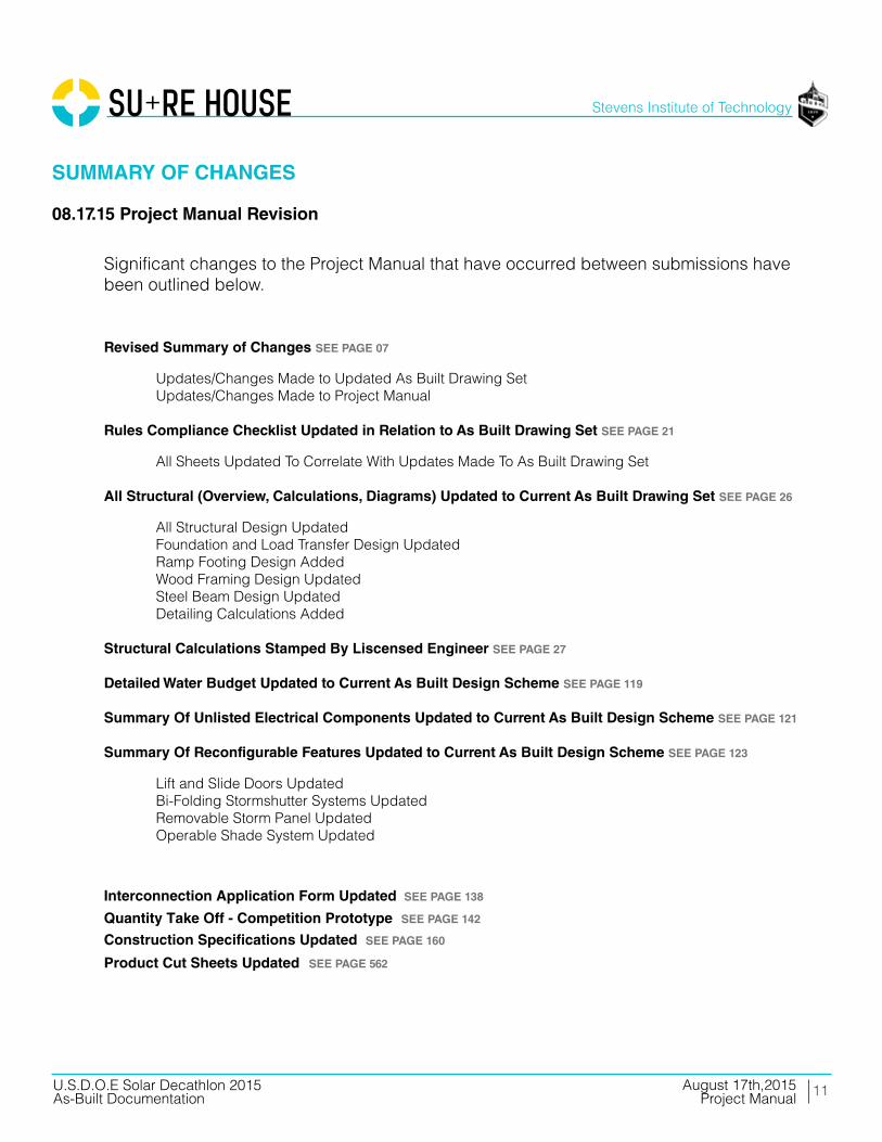
08.17.15 Project Manual Revision
Significant changes to the Project Manual that have occurred between submissions have been outlined below.
Revised Summary of Changes SEE PAGE 07
Updates/Changes Made to Updated As Built Drawing Set Updates/Changes Made to Project Manual Rules Compliance Checklist Updated in Relation to As Built Drawing Set SEE PAGE 21
All Sheets Updated To Correlate With Updates Made To As Built Drawing Set
All Structural (Overview, Calculations, Diagrams) Updated to Current As Built Drawing Set SEE PAGE 26
All Structural Design Updated Foundation and Load Transfer Design Updated Ramp Footing Design Added Wood Framing Design Updated Steel Beam Design Updated Detailing Calculations Added Structural Calculations Stamped By Liscensed Engineer SEE PAGE 27
Detailed Water Budget Updated to Current As Built Design Scheme SEE PAGE 119
Summary Of Unlisted Electrical Components Updated to Current As Built Design Scheme SEE PAGE 121
Summary Of Reconfigurable Features Updated to Current As Built Design Scheme SEE PAGE 123
Interconnection Application Form Updated SEE PAGE 138
Quantity Take Off - Competition Prototype SEE PAGE 142
Construction Specifications Updated SEE PAGE 160
Product Cut Sheets Updated SEE PAGE 562
Lift and Slide Doors Updated Bi-Folding Stormshutter Systems Updated Removable Storm Panel Updated Operable Shade System Updated
SUMMARY OF CHANGES

12
Stevens Institute of Technology
August 17th,2015U.S.D.O.E Solar Decathlon 2015As-Built Documentation Project Manual
08.17.15 Project Manual Revision
Energy Code Compliance
Section Updated to Project Manual
Construction Specifications Updated to Current As Built Design Scheme
All CSI Division Specifications Applicable Updated To Project Manual In-Depth Quantity Takeoff to Current As Built Design Scheme
Quantity Takeoff Updated to Reflect Current Design Scheme
Product Cut Sheets Updated to Current As Built Design Scheme
All CSI Division Specifications Applicable Updated To Project Manual
SUMMARY OF CHANGES
13
Stevens Institute of Technology
August 17th,2015U.S.D.O.E Solar Decathlon 2015As-Built Documentation Project Manual
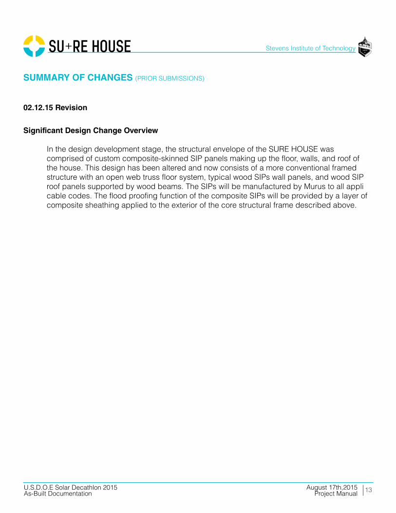
Significant Design Change Overview
In the design development stage, the structural envelope of the SURE HOUSE was comprised of custom composite-skinned SIP panels making up the floor, walls, and roof of the house. This design has been altered and now consists of a more conventional framed structure with an open web truss floor system, typical wood SIPs wall panels, and wood SIP roof panels supported by wood beams. The SIPs will be manufactured by Murus to all appli cable codes. The flood proofing function of the composite SIPs will be provided by a layer of composite sheathing applied to the exterior of the core structural frame described above.
SUMMARY OF CHANGES (PRIOR SUBMISSIONS)
02.12.15 Revision
14
Stevens Institute of Technology
August 17th,2015U.S.D.O.E Solar Decathlon 2015As-Built Documentation Project Manual
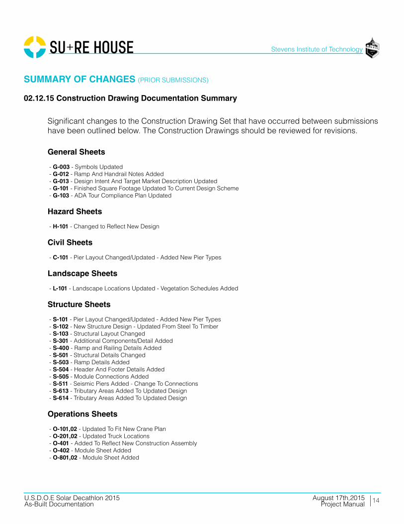
Significant changes to the Construction Drawing Set that have occurred between submissions have been outlined below. The Construction Drawings should be reviewed for revisions.
General Sheets
- G-003 - Symbols Updated - G-012 - Ramp And Handrail Notes Added - G-013 - Design Intent And Target Market Description Updated - G-101 - Finished Square Footage Updated To Current Design Scheme - G-103 - ADA Tour Compliance Plan Updated
Hazard Sheets
- H-101 - Changed to Reflect New Design
Civil Sheets
- C-101 - Pier Layout Changed/Updated - Added New Pier Types
Landscape Sheets
- L-101 - Landscape Locations Updated - Vegetation Schedules Added
Structure Sheets
- S-101 - Pier Layout Changed/Updated - Added New Pier Types - S-102 - New Structure Design - Updated From Steel To Timber - S-103 - Structural Layout Changed - S-301 - Additional Components/Detail Added - S-400 - Ramp and Railing Details Added - S-501 - Structural Details Changed - S-503 - Ramp Details Added - S-504 - Header And Footer Details Added - S-505 - Module Connections Added - S-511 - Seismic Piers Added - Change To Connections - S-613 - Tributary Areas Added To Updated Design - S-614 - Tributary Areas Added To Updated Design
Operations Sheets
- O-101,02 - Updated To Fit New Crane Plan - O-201,02 - Updated Truck Locations - O-401 - Added To Reflect New Construction Assembly - O-402 - Module Sheet Added - O-801,02 - Module Sheet Added
02.12.15 Construction Drawing Documentation Summary
SUMMARY OF CHANGES (PRIOR SUBMISSIONS)

15
Stevens Institute of Technology
August 17th,2015U.S.D.O.E Solar Decathlon 2015As-Built Documentation Project Manual
Architecture Sheets
- A-112 - Roof Slope And Drainage Plan Added - A-113 - First Floor Plan Updated To Reflect New Design Scheme - A-121 - RCP Updated To Reflect New Design Scheme - A-311,12,13,14,15,16,17,21,23,24 - Updated To Reflect New Construction Assembly - A-405 - Shutter Plan Section Cut View Added - A-411 - Enlarged South Facade Plan + Elevation Added - A-421,22 - Enlarged Casework Plan + Elevations Added - A-501 - Updated To Reflect New Construction Assembly - A-502 - Bathroom Details Added - A-512,13,14,15,16,17,18,19 - Updated To Reflect New Construction Assembly - A-552,54,55,56,57 - Updated To Reflect New Construction Assembly - A-591 - Ramp Details Added - A-601 - Updated To Reflect New Construction Assembly - A-605 - Wall Types Conductivity Added
Fire Detection and Suppression Sheets
- F-101 - Updated To Reflect New Construction Assembly - F-102 - Sprinkler Riser Details Added - F-103 - Updated To Reflect New Construction Assembly
Plumbing Sheets
- P-101 - Updated To Reflect New Construction Assembly - P-102 - Updated To Reflect New Construction Assembly - P-602 - Updated To Reflect New Construction Assembly
Mechanical Sheets
- M-101 - Changed To Reflect New Design - New ERV -AHU + Zoning Kit Added - M-201 - Desiccant System Removed- Changed to Reflect New Design - P-602 - Changed To Reflect New Design - New ERV -AHU + Zoning Kit Added
Electrical Sheets
- E-101 - Changed To Reflect New Design - E-102 - Updated to New Roof + Shutter Scheme - E-103 - Changed To Reflect New Design - E-601 - Detailed One Line + Updated Panel Schedule + Updated Load Calculations - E-602,03 - Updated To Reflect New PV Scheme
02.12.15 Construction Drawing Documentation Summary
SUMMARY OF CHANGES (PRIOR SUBMISSIONS)

16
Stevens Institute of Technology
August 17th,2015U.S.D.O.E Solar Decathlon 2015As-Built Documentation Project Manual
02.12.15 Project Manual Revision
Significant changes to the Project Manual that have occurred between submissions have been outlined below.
Updated Project Summary
Updates to Overall Concept Revisions To Sequence Diagrams Updates to Post Solar Decathlon Location
Revised Summary of Changes
Updates/Changes Made to Construction Drawing Set Updates/Changes Made to Project Manual Rules Compliance Checklist Updated in Relation to CD Drawing Set
All Sheets Updated To Correlate With Updates Made To CD Drawing Set
All Structural (Overview, Calculations, Diagrams) Updated to Current CD Design Scheme
All Structural Design Updated Foundation and Load Transfer Design Added Ramp Footing Design Added Wood Framing Design Updated Steel Beam Design Updated Detailing Calculations Added Structural Calculations Stamped By Liscensed Engineer
Detailed Water Budget Updated to Current CD Design Scheme Summary Of Unlisted Electrical Components Updated to Current CD Design Scheme Summary Of Reconfigurable Features Updated to Current CD Design Scheme
Lift and Slide Doors Updated Bi-Folding Stormshutter Systems Updated Removable Storm Panel Added Mecho Shade System Added Movable Exterior Electric Grill Dock Added
SUMMARY OF CHANGES (PRIOR SUBMISSIONS)

17
Stevens Institute of Technology
August 17th,2015U.S.D.O.E Solar Decathlon 2015As-Built Documentation Project Manual
02.12.15 Project Manual Revision
In-Depth Energy Analysis Updated to Current CD Design Scheme
Trnsys Analysis Added DIVA Shading Analysis Added PHPP Calculations Added THERM Analysis Added Solar Array Updated
Construction Specifications Added to Current CD Design Scheme
All CSI Division Specifications Applicable Added To Project Manual In-Depth Quantity Takeoff to Current CD Design Scheme
Quantity Takeoff Updated to Reflect Current Design Scheme
Product Cut Sheets Updated to Current CD Design Scheme
All CSI Division Specifications Applicable Added To Project Manual
SUMMARY OF CHANGES (PRIOR SUBMISSIONS)
18
Stevens Institute of Technology
August 17th,2015U.S.D.O.E Solar Decathlon 2015As-Built Documentation Project Manual
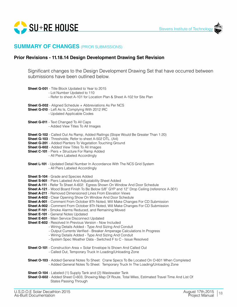
Prior Revisions - 11.18.14 Design Development Drawing Set Revision
Significant changes to the Design Development Drawing Set that have occurred between submissions have been outlined below.
Sheet G-001 - Title Block Updated to Year to 2015 Sheet G-001 - Lot Number Updated to 110 Sheet G-001 - Refer to sheet A-101 for Location Plan & Sheet A-102 for Site Plan Sheet G-002 - Aligned Schedule + Abbreviations As Per NCS Sheet G-010 - Left As Is, Complying With 2012 IRC Sheet G-010 - Updated Applicable Codes Sheet G-011 - Text Changed To All Caps Sheet G-002 - Added View Titles To All Images
Sheet G-102 - Called Out As Ramp, Added Railings (Slope Would Be Greater Than 1:20) Sheet G-103 - Thresholds; Refer to sheet A-502 DTL. (A4) Sheet G-201 - Added Planters To Vegetation Touching Ground Sheet G-602 - Added View Titles To All Images Sheet C-101 - Piers + Structure For Ramp Added Sheet C-101 - All Piers Labeled Accordingly
Sheet L-101 - Updated Detail Number In Accordance With The NCS Grid System Sheet C-101 - All Piers Labeled Accordingly
Sheet S-104 - Grade and Species Added Sheet S-901 - Piers Labeled And Adjustability Sheet Added Sheet A-111 - Refer To Sheet A-602: Egress Shown On Window And Door Schedule Sheet A-121 - Wood Board Finish To Be Below 5/8” GYP and 12” Drop Ceiling (reference A-301) Sheet A-211 - Removed Dimensioned Lines From Elevation Views Sheet A-602 - Clear Opening Show On Window And Door Schedule Sheet A-901 - Comment From October 8Th Noted, Will Make Changes For CD Submission Sheet A-902 - Comment From October 8Th Noted, Will Make Changes For CD Submission Sheet F-101 - Smoke Alarms Reduced, and Remaining Moved Sheet E-101 - General Notes Updated Sheet E-601 - Main Service Disconnect Updated Sheet E-602 - Resolved In Previous Version - Now Included Sheet E-602 - Wiring Details Added - Type And Sizing And Conduit Sheet E-602 - Output Currents Verified - Breaker Amperage Calculations In Progress Sheet E-602 - Wiring Details Added - Type And Sizing And Conduit Sheet E-602 - System Spec Weather Data - Switched F to C - Issue Resolved
Sheet O-101 - Construction Area + Solar Envelope Is Shown And Called Out Sheet O-101 - Called Out, Temporary Truck In Loading/Unloading Zone
Sheet O-103 - Added General Notes To Sheet: Crane Specs To Be Located On O-601 When Completed Sheet O-101 - Added General Notes To Sheet: Temporary Truck In The Loading/Unloading Zone
Sheet O-104 - Labeled (1) Supply Tank and (2) Wastewater Tank Sheet O-602 - Added Sheet O-603, Showing Map Of Route, Total Miles, Estimated Travel Time And List Of States Passing Through
SUMMARY OF CHANGES (PRIOR SUBMISSIONS)

19
Stevens Institute of Technology
August 17th,2015U.S.D.O.E Solar Decathlon 2015As-Built Documentation Project Manual
Prior Revisions - 11.18.14 Project Manual Revision
Significant changes to the Project Manual that have occurred between submissions have been outlined below.
Text Updated in Compliance with Communication Standards
Jury/Architecture/Engineering Narratives : Comment From October 8Th Noted, Will Make Changes For Final Submission
Text Updated in Compliance To Solar Decathlon Lot Sizing
Site Locations : : Comment From October 8Th Noted, Specific Location To Be Added, Will Make Changes For Final Submission
In Depth Discussion On Composite SIP Panel Usage/Manufacturing/Structural Description Added
In Depth Explanation Of Steel Moment Frame Added Additional Details Added On Solar Hot Water System Location/Description of LUMOS LSX200 Series Added - See Stormshutter System Product Cut Sheets Updated + Division 26 - Electrical Added
SUMMARY OF CHANGES (PRIOR SUBMISSIONS)

20
Stevens Institute of Technology
August 17th,2015U.S.D.O.E Solar Decathlon 2015As-Built Documentation Project Manual
Prior Revisions - 10.08.14 Design Development Drawing Set
The changes to the SURE HOUSE project have been so significant since the Schematic Design Summary submission that a bulleted change list would be unruly and would describe a huge portion of the project. Therefore, the Design Development drawings and Project Manual should be reviewed in toto essentially as the summary of changes.
SUMMARY OF CHANGES (PRIOR SUBMISSIONS)

CHECKLIST
02RULES COMPLIANCE

22
Stevens Institute of Technology
August 17th,2015U.S.D.O.E Solar Decathlon 2015As-Built Documentation Project Manual
RULES COMPLIANCE CHECKLIST
RULERule 4-2
Rule 4-2
Rule 4-3
Rule 4-4
Rule 4-5
Rule 4-6
Rule 4-7
Rule 4-8
Rule 5-1
Rule 5-2
Rule 5-2
RULE DESCRIPTION Construction Equipment
Construction Equipment
Ground Penetration
Impact on the Competition Site
Generators
Spill Containment
Lot Conditions
Electric Vehicles
Lot Sizes
Solar Envelope Dimensions
Solar Envelope Dimensions
LOCATION DESCRIPTIONDrawing(s) showing the assembly and disassembly sequences and the movement ofheavy machinery on the competition site
Specifications for heavy machinery
Drawing(s) showing the locations and depthsof all ground penetrations on the competitionsite
Drawing(s) showing the locations of all low impact footings that shall be used to support all house and site components
Specifications for generators (including soundrating)
Drawings for all equipment, containers, and pipes that will contain liquids at any point during the event
Calculations showing that the structural designremains compliant even if 18 in. (45.7 cm) ofvertical elevation change exists
Drawings showing electric vehicles are compliant with solar envelope lot limits
Drawings showing lot dimensions within the solar envelope
Drawing(s) showing the location of all houseand site components relative to the solar envelope
List of solar envelope exemption requestsaccompanied by justifications and drawing references
LOCATION
O-901
O-101
S-101S-522
C-101
N/A
H-101
S-101
A-102
G-101,201,202
G-201,202
N/A
23
Stevens Institute of Technology
August 17th,2015U.S.D.O.E Solar Decathlon 2015As-Built Documentation Project Manual
RULES COMPLIANCE CHECKLIST
RULERule 6-1
Rule 6-2
Rule 6-2
Rule 6-3
Rule 6-4
Rule 7-1
Rule 7-2
Rule 8-1
Rule 8-2
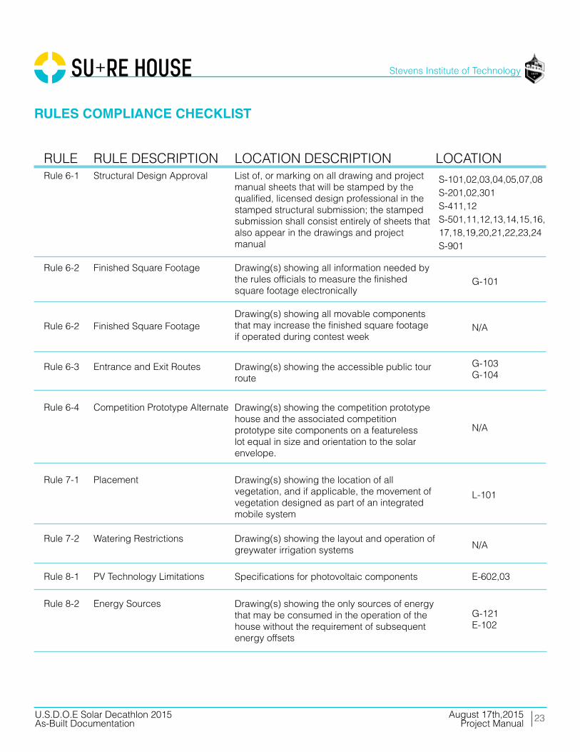
RULE DESCRIPTION Structural Design Approval
Finished Square Footage
Finished Square Footage
Entrance and Exit Routes
Competition Prototype Alternate
Placement
Watering Restrictions
PV Technology Limitations
Energy Sources
LOCATION DESCRIPTIONList of, or marking on all drawing and projectmanual sheets that will be stamped by the qualified, licensed design professional in thestamped structural submission; the stampedsubmission shall consist entirely of sheets thatalso appear in the drawings and project manual
Drawing(s) showing all information needed by the rules officials to measure the finished square footage electronically
Drawing(s) showing all movable componentsthat may increase the finished square footage if operated during contest week
Drawing(s) showing the accessible public tourroute
Drawing(s) showing the competition prototype house and the associated competition prototype site components on a featureless lot equal in size and orientation to the solar envelope.
Drawing(s) showing the location of all vegetation, and if applicable, the movement ofvegetation designed as part of an integratedmobile system
Drawing(s) showing the layout and operation ofgreywater irrigation systems
Specifications for photovoltaic components
Drawing(s) showing the only sources of energy that may be consumed in the operation of the house without the requirement of subsequent energy offsets
LOCATION
G-101
S-101,02,03,04,05,07,08S-201,02,301S-411,12S-501,11,12,13,14,15,16,17,18,19,20,21,22,23,24S-901
N/A
G-103G-104
N/A
L-101
N/A
E-602,03
G-121E-102
24
Stevens Institute of Technology
August 17th,2015U.S.D.O.E Solar Decathlon 2015As-Built Documentation Project Manual
RULE
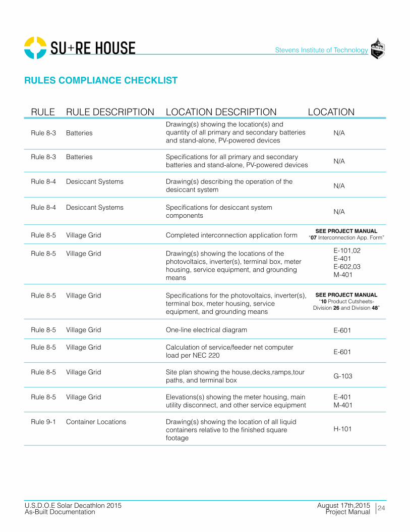
Rule 8-3
Rule 8-3
Rule 8-4
Rule 8-4
Rule 8-5
Rule 8-5
Rule 8-5
Rule 8-5
Rule 8-5
Rule 8-5
Rule 8-5
Rule 9-1
RULE DESCRIPTION
Batteries
Batteries
Desiccant Systems
Desiccant Systems
Village Grid
Village Grid
Village Grid
Village Grid
Village Grid
Village Grid
Village Grid
Container Locations
LOCATION DESCRIPTIONDrawing(s) showing the location(s) and quantity of all primary and secondary batteries and stand-alone, PV-powered devices
Specifications for all primary and secondary batteries and stand-alone, PV-powered devices
Drawing(s) describing the operation of the desiccant system
Specifications for desiccant system components
Completed interconnection application form
Drawing(s) showing the locations of the photovoltaics, inverter(s), terminal box, meter housing, service equipment, and grounding means
Specifications for the photovoltaics, inverter(s), terminal box, meter housing, service equipment, and grounding means
One-line electrical diagram
Calculation of service/feeder net computer load per NEC 220
Site plan showing the house,decks,ramps,tour paths, and terminal box
Elevations(s) showing the meter housing, main utility disconnect, and other service equipment
Drawing(s) showing the location of all liquid containers relative to the finished square footage
LOCATION
N/A
N/A
N/A
N/A
SEE PROJECT MANUAL“07 Interconnection App. Form”
SEE PROJECT MANUAL“10 Product Cutsheets-
Division 26 and Division 48”
E-101,02E-401E-602,03M-401
E-601
E-601
G-103
E-401M-401
H-101
RULES COMPLIANCE CHECKLIST
25
Stevens Institute of Technology
August 17th,2015U.S.D.O.E Solar Decathlon 2015As-Built Documentation Project Manual
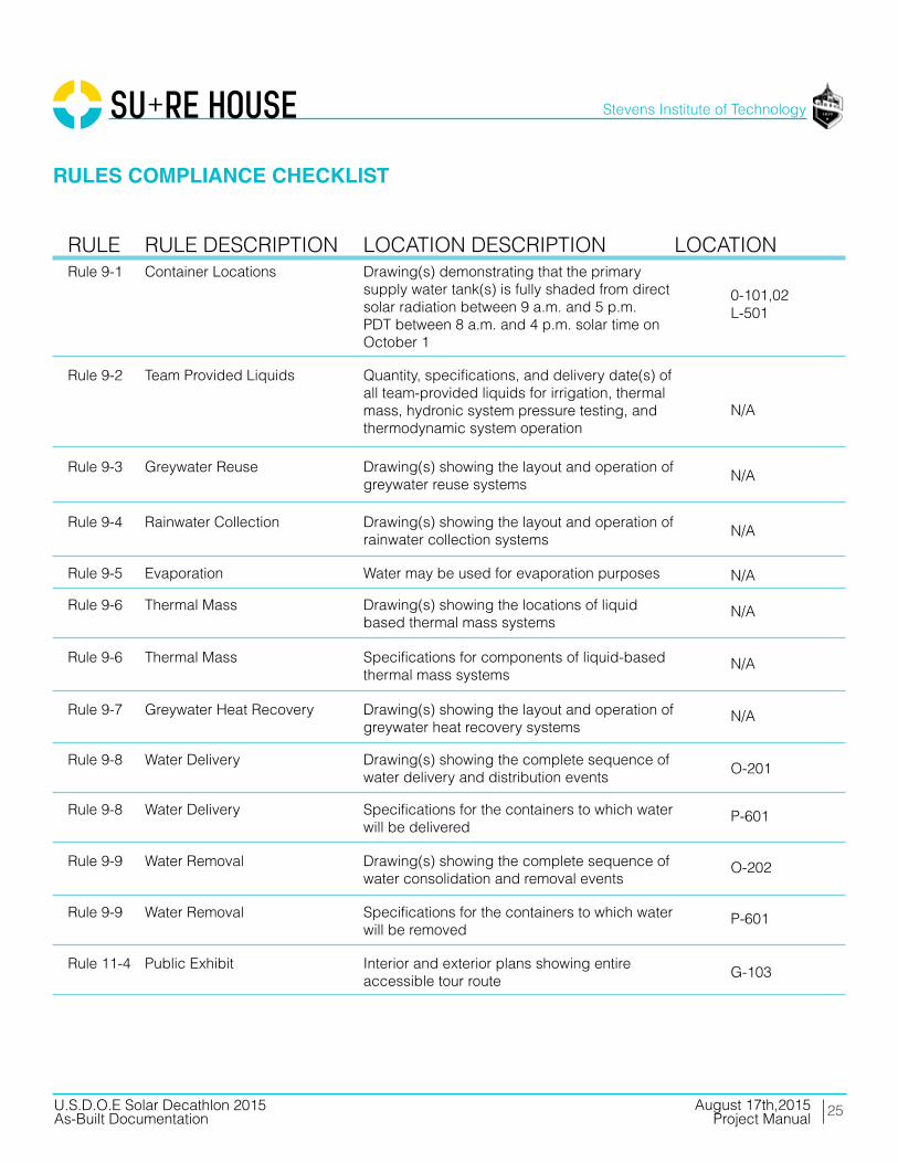
RULERule 9-1
Rule 9-2
Rule 9-3
Rule 9-4
Rule 9-5
Rule 9-6
Rule 9-6
Rule 9-7
Rule 9-8
Rule 9-8
Rule 9-9
Rule 9-9
Rule 11-4
RULE DESCRIPTION Container Locations
Team Provided Liquids
Greywater Reuse
Rainwater Collection
Evaporation
Thermal Mass
Thermal Mass
Greywater Heat Recovery
Water Delivery
Water Delivery
Water Removal
Water Removal
Public Exhibit
LOCATION DESCRIPTIONDrawing(s) demonstrating that the primary supply water tank(s) is fully shaded from direct solar radiation between 9 a.m. and 5 p.m. PDT between 8 a.m. and 4 p.m. solar time on October 1
Quantity, specifications, and delivery date(s) of all team-provided liquids for irrigation, thermal mass, hydronic system pressure testing, and thermodynamic system operation
Drawing(s) showing the layout and operation of greywater reuse systems
Drawing(s) showing the layout and operation of rainwater collection systems
Water may be used for evaporation purposes
Drawing(s) showing the locations of liquid based thermal mass systems
Specifications for components of liquid-based thermal mass systems
Drawing(s) showing the layout and operation of greywater heat recovery systems
Drawing(s) showing the complete sequence ofwater delivery and distribution events
Specifications for the containers to which water will be delivered
Drawing(s) showing the complete sequence ofwater consolidation and removal events
Specifications for the containers to which water will be removed
Interior and exterior plans showing entire accessible tour route
LOCATION
0-101,02L-501
N/A
N/A
N/A
N/A
N/A
N/A
N/A
O-201
P-601
O-202
P-601
G-103
RULES COMPLIANCE CHECKLIST

STRUCTURALCALCULATIONS03

27
Stevens Institute of Technology
August 17th,2015U.S.D.O.E Solar Decathlon 2015As-Built Documentation Project Manual
STRUCTURAL CALCULATIONS
____________________________________________________________________________ U.S. D.O.E SOLAR DECATHLON 2015 AUGUST 17, 2015 CONSTRUCTION DOCUMENTATION: STAMPED STRUCTURAL CALCULATIONS PAGE 1
Stamped Structural Calculations
Stevens Institute of Technology U.S. Department of Energy Solar Decathlon 2015
Final Submission: August 17, 2015
Student Team Leaders
Project Manager: Alex Guimaraes Architectural Project Manager: Michael Signorile Construction Manager: Chris Hamm Project Engineer: Christine Hecker Electrical Engineer: AJ Elliott Health and Safety Officer: Allison Outwater Measured Contest Captain: Juan Alicante Instrumentation Contact: Grace Gallagher Public Relations Contact: AJ Elliott Faculty Advisor: Ed May
Stamping Engineer: Richard Christie Richard N. Christie, P.E.
CA PE 76312
28
Stevens Institute of Technology
August 17th,2015U.S.D.O.E Solar Decathlon 2015As-Built Documentation Project Manual
____________________________________________________________________________ U.S. D.O.E SOLAR DECATHLON 2015 AUGUST 17, 2015 CONSTRUCTION DOCUMENTATION: STAMPED STRUCTURAL CALCULATIONS PAGE 1
STRUCTURAL CALCULATIONS
This project manual provides an evaluation of construction methods and
structural calculations as stipulated by ASCE 7-10 and the Department of Energy for
the 2015 Solar Decathlon. The objective of the Stevens Structural Team is to create a
safe and sensible structural system that maximizes efficiency and minimizes the use of
materials that require high energy during production while taking structural integrity
into consideration in a coastal environment. Additionally, a core design goal was
creating a flood proof building which could seal from the outside.
The group designed a typical wood construction house to handle all standard
load conditions with an additional fiberglass cladding to take on the flood loads only.
Storm shutters cover all doors and windows to complete the seal in any openings not
covered by the cladding. A steel exoskeleton that wraps around the house and deck
transfers all shading and louver uplift loads to foundation. The steel columns on the
south side of the house (Grid B) support the living room roof load and columns on the
east side support the roof load from the overhang. Other than these specific locations,
the steel does not support the house in any way. The wood framing takes all remaining
house loads. The deck is its own standing structure structurally independent from the
house and is supported on its own seismic piers. All of the loads for the house, deck,
and exoskeleton are transferred to temporary pier foundations designed to meet
applicable California and Solar Decathlon structural codes.
The dimensions of the house were constrained by practical transportation
concerns and additional structural analysis was performed for the connection between
the modules and the flood proofing shutter system on the southern facade. The
majority of the calculations were done in Microsoft Excel to provide the designers with
flexibility throughout the process to make alterations easy to implement and check.
The structural design must accommodate multiple phases of loading including
construction, transportation, and reassembly. Because of the nature of the competition
and transportation logistics, the house was designed in three modular components,
ays from Hoboken,
New Jersey to Irvine, California. The loading conditions for the structurally stamped
house are for DOE requirements and Southern California requirements. Any additional
structural design considerations such as for flood loading were undertaken in addition
to state and government requirements and will not violate the validity of the stamped
structural design for California, but are included in the stamped calculation set and

29
Stevens Institute of Technology
August 17th,2015U.S.D.O.E Solar Decathlon 2015As-Built Documentation Project Manual
____________________________________________________________________________ U.S. D.O.E SOLAR DECATHLON 2015 AUGUST 17, 2015 CONSTRUCTION DOCUMENTATION: STAMPED STRUCTURAL CALCULATIONS PAGE 2
STRUCTURAL CALCULATIONS
were taken into consideration for design. In some cases, the team used larger load
conditions in design (such as snow and wind) corresponding to the house s permanent
upon completion. In all cases, these loads were calculated in addition to CA and Solar
Decathlon requirements to ensure design was conservative enough to be valid in both
locations.
____________________________________________________________________________ U.S. D.O.E SOLAR DECATHLON 2015 AUGUST 17, 2015 CONSTRUCTION DOCUMENTATION: STAMPED STRUCTURAL CALCULATIONS PAGE 1
STRUCTURAL CALCULATIONS
This project manual provides an evaluation of construction methods and
structural calculations as stipulated by ASCE 7-10 and the Department of Energy for
the 2015 Solar Decathlon. The objective of the Stevens Structural Team is to create a
safe and sensible structural system that maximizes efficiency and minimizes the use of
materials that require high energy during production while taking structural integrity
into consideration in a coastal environment. Additionally, a core design goal was
creating a flood proof building which could seal from the outside.
The group designed a typical wood construction house to handle all standard
load conditions with an additional fiberglass cladding to take on the flood loads only.
Storm shutters cover all doors and windows to complete the seal in any openings not
covered by the cladding. A steel exoskeleton that wraps around the house and deck
transfers all shading and louver uplift loads to foundation. The steel columns on the
south side of the house (Grid B) support the living room roof load and columns on the
east side support the roof load from the overhang. Other than these specific locations,
the steel does not support the house in any way. The wood framing takes all remaining
house loads. The deck is its own standing structure structurally independent from the
house and is supported on its own seismic piers. All of the loads for the house, deck,
and exoskeleton are transferred to temporary pier foundations designed to meet
applicable California and Solar Decathlon structural codes.
The dimensions of the house were constrained by practical transportation
concerns and additional structural analysis was performed for the connection between
the modules and the flood proofing shutter system on the southern facade. The
majority of the calculations were done in Microsoft Excel to provide the designers with
flexibility throughout the process to make alterations easy to implement and check.
The structural design must accommodate multiple phases of loading including
construction, transportation, and reassembly. Because of the nature of the competition
and transportation logistics, the house was designed in three modular components,
ays from Hoboken,
New Jersey to Irvine, California. The loading conditions for the structurally stamped
house are for DOE requirements and Southern California requirements. Any additional
structural design considerations such as for flood loading were undertaken in addition
to state and government requirements and will not violate the validity of the stamped
structural design for California, but are included in the stamped calculation set and
____________________________________________________________________________ U.S. D.O.E SOLAR DECATHLON 2015 AUGUST 17, 2015 CONSTRUCTION DOCUMENTATION: STAMPED STRUCTURAL CALCULATIONS PAGE 2
STRUCTURAL CALCULATIONS
were taken into consideration for design. In some cases, the team used larger load
conditions in design (such as snow and wind) corresponding to the house s permanent
upon completion. In all cases, these loads were calculated in addition to CA and Solar
Decathlon requirements to ensure design was conservative enough to be valid in both
locations.
30
Stevens Institute of Technology
August 17th,2015U.S.D.O.E Solar Decathlon 2015As-Built Documentation Project Manual
____________________________________________________________________________ U.S. D.O.E SOLAR DECATHLON 2015 AUGUST 17, 2015 CONSTRUCTION DOCUMENTATION: STAMPED STRUCTURAL CALCULATIONS PAGE 3
FOUNDATION The foundation represented in this report was designed as a temporary
structure solely for use during the competition. A new structural analysis will be
completed after the competition to consider loading and soil bearing conditions at the
permanent site. With this information, a permanent foundation will be designed to
withstand all buoyant forces associated with a hurricane.
DESIGN METHOD
All steel and wood design was completed using Load Resistance Factor
Design, or LRFD, unless otherwise stated.
APPLICABLE CODES
● AISC Steel Construction Manual 14th edition
● Solar Decathlon Building Code 2015
● 2012 International Residential Code (IRC)
● ASCE 7: Minimum Design Loads for Buildings and Other Structures
● Wood Design Package
○ National Design Specification (NDS) for Wood Construction
○ Special Design Provisions for Wind and Seismic
○ Manual for Engineered Wood Construction
STRUCTURAL INFORMATION Type of Steel:
● A500 Grade B with Fy = 46 ksi and Fu = 58 ksi for HSS Sections
● A992 with Fy = 50 ksi and Fu = 65 ksi for W Sections
● A36 with Fy = 36 ksi and Fu = 58 ksi for C Sections

31
Stevens Institute of Technology
August 17th,2015U.S.D.O.E Solar Decathlon 2015As-Built Documentation Project Manual
____________________________________________________________________________ U.S. D.O.E SOLAR DECATHLON 2015 AUGUST 17, 2015 CONSTRUCTION DOCUMENTATION: STAMPED STRUCTURAL CALCULATIONS PAGE 4
DESIGN LOADS: Building Loads
1. Structural design of the building is in accordance with the 2012 international
building code and solar decathlon 2015 building code.
a. Live Load
i. Floor = 50 psf
ii. Roof = 20 psf
iii. Deck = 100 psf
b. Dead Load
i. Floor = 15 psf
ii. Roof = 17 psf
iii. Deck = 16 psf
c. Wind Load
i. Basic wind speed = 130 mph
ii. Exposure c
d. Snow Load
i. 25 psf where applicable, 5 psf on ramps
e. Seismic Load
i. Do zone
2. For temporary pad footings at temporary location in Irvine, CA notify engineer of
any change of site location.
All dead loads were determined through assumptions from a professional engineer. All live
loads are based upon the required loads in the solar decathlon 2015 building code.
Table 3.1 LIVE + DEAD LOADS
32
Stevens Institute of Technology
August 17th,2015U.S.D.O.E Solar Decathlon 2015As-Built Documentation Project Manual
____________________________________________________________________________ U.S. D.O.E SOLAR DECATHLON 2015 AUGUST 17, 2015 CONSTRUCTION DOCUMENTATION: STAMPED STRUCTURAL CALCULATIONS PAGE 5
WOOD:
1. All framing lumber and details of wood construction shall conform to the
National Design Specification for Stress Grade Lumber and Its Fastenings
(including supplements) or related documents.
2. All engineered wood products are to be provided by Nordic and West Fraser
and are to meet all specifications of "Westfraser LVL user's guide" and "Nordic
Engineered Wood Residential Design Construction Guide" or approved equal.
3. Refer to "WestFraser LVLUser's Guide" and "Nordic Engineered Wood
for all information including, but not
limited to:
a. Penetration allowances in wood members
b. Bearing requirements of joists
c. Connection/blocking details
4. Typical lumber shall be the following minimum grade and shall be grade
stamped by a recognized grading agency, shall be surface dry, and shall be
used at a maximum of 19% moisture content. If a different grade is specified in
the structural drawings, that grade must be used.
a. Species
i. Douglas fir-larch
b. Grade
i. No. 2
5. Plywood sheathing shall be APA grade stamped for the specified span, and
shall be made with exterior glue, and shall be of the following grade:
a. Floors/roofs: APA rated sheathing exposure 1
b. Non-shear walls: APA rated sheathing exposure 1
c. Shear walls: APA rated structural sheathing grade 1
6. All plywood sheathing shall be glue and nailed to floor joists using APA
approved elastomeric construction adhesive and code required nailing.
7. Details of wood framing such as nailing, blocking, bridging, etc. Shall conform
to the 2012 international building code or the "WestFraser LVL User's Guide"
and "Nordic Engineered Wood Residential Design Construction Guide" or
approved equal unless greater requirements are shown in drawing details.
8. Where beams are flush framed to header, use approved type beam hanger.
33
Stevens Institute of Technology
August 17th,2015U.S.D.O.E Solar Decathlon 2015As-Built Documentation Project Manual
____________________________________________________________________________ U.S. D.O.E SOLAR DECATHLON 2015 AUGUST 17, 2015 CONSTRUCTION DOCUMENTATION: STAMPED STRUCTURAL CALCULATIONS PAGE 6
9. No beams, except as shown in details, shall be cut or notched without approval
from the structural engineer.
10. All structural wood exposed to external environments shall be pressure treated.
STEEL:
1. Fabrication and erection of structural steel shall be in accordance with the
2. Materials:
a. W Shapes
i. ASTM A992
b. HSS Shapes
i. ASTM A500 GRADE B
3. Bolts: unless otherwise noted on drawings
a. High strength bolts:
i. ASTM A325-N
b. Machine Bolts:
i. ASTM A307
4. Bolt holes in steel shall be 1/16 inch larger diameter than nominal size of bolt
used, unless otherwise noted or approved by structural engineer.
5. For bolted connections, provide 1 ½ inch edge and end distance, unless
otherwise noted.
6. - American Welding Society. Minimum tensile strength
of weld metal shall be 70 ksi typical unless otherwise noted. Welding electrodes
shall be as recommended by their manufacturer for the position and other
conditions of actual use.

WINDLOADS
STRUCTURAL CALCULATIONS

35
Stevens Institute of Technology
August 17th,2015U.S.D.O.E Solar Decathlon 2015As-Built Documentation Project Manual
____________________________________________________________________________ U.S. D.O.E SOLAR DECATHLON 2015 AUGUST 17, 2015 CONSTRUCTION DOCUMENTATION: STAMPED STRUCTURAL CALCULATIONS PAGE 8
LATERAL WIND DESCRIPTION: These calculations provide the extreme case of lateral wind loading on the leeward and windward sides of the house. REFERENCE: Minimum design loads for buildings and other structures, ASCE/SEI 7-10. Reston, VA: American Society Of Civil Engineers/Structural Engineering Institute, 2006. Print. ASSUMPTIONS:
1. Flat roof 2. Enclosed, partially enclosed building (internal pressure coefficients for buildings, table 6-
7) 3. Hurricane prone region, category ii (importance factor, table 6-1) 4. Exposure c (open terrain with scattered obstructions…) 5. Basic wind speed: 130 mph (increased from 120 for conservation, Figure 6-1) 6. Wind load parameters (table 6-6)
a. K2 = 0.85 b. K2T = 1 c. I = 1.00 d. KD = 0.85 e. GCPI = 0.18 f. GCPF (MAX) = -1.07
7. Case B with wind direction from east side of house. Maximum positive and maximum negative wind cases assumed for all sides of house. (Figure 6-4)
EQUATION: 28.4.1 Design Wind Pressure for Low-Rise Buildings – EQ. (28.4-1) P = QH[(GCPF) – (GCPI)] (LB/FT2) 28.3.2 Velocity Pressure – EQ. (28.3-1) QZ = 0.00256KZKZTKDV2I (LB/FT2) VARIABLES: KD = Wind Directionality Factor KZ = Velocity Pressure Exposure Coefficient KZT = Topographic Factor V = Basic Wind Speed QH = Velocity Pressure Qz Calculated At Mean Roof Height H

36
Stevens Institute of Technology
August 17th,2015U.S.D.O.E Solar Decathlon 2015As-Built Documentation Project Manual
____________________________________________________________________________ U.S. D.O.E SOLAR DECATHLON 2015 AUGUST 17, 2015 CONSTRUCTION DOCUMENTATION: STAMPED STRUCTURAL CALCULATIONS PAGE 9
(GCPF-) = External Pressure Coefficient (GCPI) = Internal Pressure Coefficient I = Importance Factor
Risk Category 2Basic Wind Speed (mph) 130 mph
Kz 0.85 Exposure C
Kzt 1Kd 0.85
Importance Factor (I) 1Load Case B
Degree of Roof Angle 0.0830.18
-0.18
qz = 31.25824
WIND LOADS:
Gcpi ( + )
qz = 0.00256 K z K zt K d V 2 I
Velocity Pressure External Pressure Coeff
Building Zone qz GCpf (+) GCpi (-) GCpi
1 31.25824 -0.45 -19.6926912 -8.43972482 31.25824 -0.69 -27.1946688 -15.94170243 31.25824 -0.37 -17.192032 -5.93906564 31.25824 -0.45 -19.6926912 -8.43972485 31.25824 0.4 6.8768128 18.12977926 31.25824 -0.29 -14.6913728 -3.43840641E 31.25824 -0.48 -20.6304384 -9.3774722E 31.25824 -1.07 -39.0728 -27.81983363E 31.25824 -0.53 -22.1933504 -10.9403844E 31.25824 -0.48 -20.6304384 -9.3774725E 31.25824 0.61 13.4410432 24.69400966E 31.25824 -0.43 -19.0675264 -7.81456
MAX -39.0728 -27.8198336
MWFRS Design Pressures P = q z (GC pf -( +Gc pi ))
Design Pressures (P) psf
Table 3.2 WIND LOADS
Table 3.3 DESIGN PRESSURES

37
Stevens Institute of Technology
August 17th,2015U.S.D.O.E Solar Decathlon 2015As-Built Documentation Project Manual
____________________________________________________________________________ U.S. D.O.E SOLAR DECATHLON 2015 AUGUST 17, 2015 CONSTRUCTION DOCUMENTATION: STAMPED STRUCTURAL CALCULATIONS PAGE 10
SHUTTER WIND LOADS DESCRIPTION:
These calculations provide the extreme case of lateral wind loading on the leeward
and windward sides of the house.
REFERENCE:
Minimum design loads for buildings and other structures, ASCE/SEI 7-10. Reston, VA:
American Society of Civil Engineers/Structural Engineering Institute, 2006. PRINT.
Assumptions:
1. Overhang
2. Uplift is formed when shutter is in the up position.
EQUATION:
28.4.1 Design Wind Pressure for Low-Rise Buildings EQ. (28.4-1)
P = QH[(GCPF) (GCPI)] (LB/FT2)
28.3.2 Velocity Pressure EQ. (28.3-1)
QZ = 0.00256KZKZTKDV2I (LB/FT2)
VARIABLES:
KD = Wind Directionality Factor
KZ = Velocity Pressure Exposure Coefficient
KZT = Topographic Factor
V = Basic Wind Speed
QH = Velocity Pressure Qz Calculated At Mean Roof Height H
(GCPF-) = External Pressure Coefficient
(GCPI) = Internal Pressure Coefficient
I = Importance Factor
Calculations:
First, QZ was calculated using the following equation:
QZ = 0.00256KZKZTKDV2I (LB/FT2)
38
Stevens Institute of Technology
August 17th,2015U.S.D.O.E Solar Decathlon 2015As-Built Documentation Project Manual
____________________________________________________________________________ U.S. D.O.E SOLAR DECATHLON 2015 AUGUST 17, 2015 CONSTRUCTION DOCUMENTATION: STAMPED STRUCTURAL CALCULATIONS PAGE 11
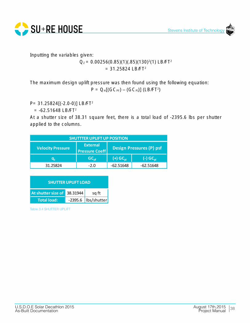
Inputting the variables given:
QZ = 0.00256(0.85)(1)(.85)(130)2(1) LB/FT2
= 31.25824 LB/FT2
The maximum design uplift pressure was then found using the following equation:
P = QH[(GCPF) (GCPI)] (LB/FT2)
P= 31.25824[(-2.0-0)] LB/FT2
= -62.51648 LB/FT2
At a shutter size of 38.31 square feet, there is a total load of -2395.6 lbs per shutter
applied to the columns.
Velocity Pressure External Pressure Coeff
qz GCpf (+) GCpi (-) GCpi
31.25824 -2.0 -62.51648 -62.51648
Design Pressures (P) psf
SHUTTTER UPLIFT UP POSITION
At shutter size of 38.31944 sq ftTotal load: -2395.6 lbs/shutter
SHUTTER UPLIFT LOAD
Table 3.4 SHUTTER UPLIFT

39
Stevens Institute of Technology
August 17th,2015U.S.D.O.E Solar Decathlon 2015As-Built Documentation Project Manual
____________________________________________________________________________ U.S. D.O.E SOLAR DECATHLON 2015 AUGUST 17, 2015 CONSTRUCTION DOCUMENTATION: STAMPED STRUCTURAL CALCULATIONS PAGE 12
SOLAR PANEL UPLIFT
Velocity Pressure GCqh GCr
31.25824 1
SOLAR PANELS UPLIFT: Open Building
Width: 38 inLength: 66 inAngle: 10 degrees
Angle Height 6.60 inProjected Area Af 3.02 ft2
Number of Solar Panels 36Total Af 108.8774074 ft2
Af Fv Uplift (lbs)108.8774074 3403.316131
Table 3.5 PV UPLIFT
40
Stevens Institute of Technology
August 17th,2015U.S.D.O.E Solar Decathlon 2015As-Built Documentation Project Manual
____________________________________________________________________________ U.S. D.O.E SOLAR DECATHLON 2015 AUGUST 17, 2015 CONSTRUCTION DOCUMENTATION: STAMPED STRUCTURAL CALCULATIONS PAGE 13
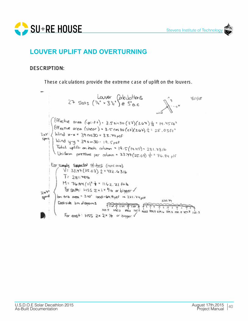
LOUVER UPLIFT AND OVERTURNING DESCRIPTION:
These calculations provide the extreme case of uplift on the louvers.

41
Stevens Institute of Technology
August 17th,2015U.S.D.O.E Solar Decathlon 2015As-Built Documentation Project Manual
____________________________________________________________________________ U.S. D.O.E SOLAR DECATHLON 2015 AUGUST 17, 2015 CONSTRUCTION DOCUMENTATION: STAMPED STRUCTURAL CALCULATIONS PAGE 14

SEISMIC LOADS
STRUCTURAL CALCULATIONS
43
Stevens Institute of Technology
August 17th,2015U.S.D.O.E Solar Decathlon 2015As-Built Documentation Project Manual
____________________________________________________________________________ U.S. D.O.E SOLAR DECATHLON 2015 AUGUST 17, 2015 CONSTRUCTION DOCUMENTATION: STAMPED STRUCTURAL CALCULATIONS PAGE 16
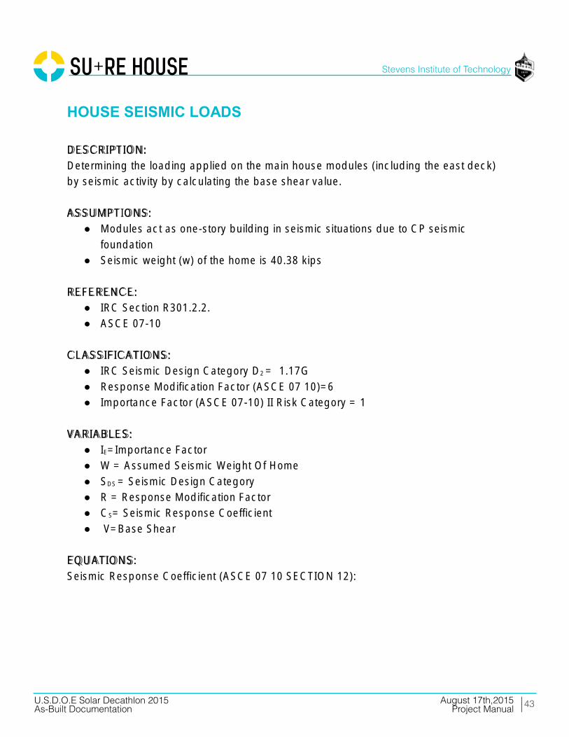
HOUSE SEISMIC LOADS DESCRIPTION:
Determining the loading applied on the main house modules (including the east deck)
by seismic activity by calculating the base shear value.
ASSUMPTIONS:
● Modules act as one-story building in seismic situations due to CP seismic
foundation
● Seismic weight (w) of the home is 40.38 kips
REFERENCE:
● IRC Section R301.2.2.
● ASCE 07-10
CLASSIFICATIONS:
● IRC Seismic Design Category D2 = 1.17G
● Response Modification Factor (ASCE 07 10)=6
● Importance Factor (ASCE 07-10) II Risk Category = 1
VARIABLES:
● IE=Importance Factor
● W = Assumed Seismic Weight Of Home
● SDS = Seismic Design Category
● R = Response Modification Factor
● CS= Seismic Response Coefficient
● V=Base Shear
EQUATIONS:
Seismic Response Coefficient (ASCE 07 10 SECTION 12):

44
Stevens Institute of Technology
August 17th,2015U.S.D.O.E Solar Decathlon 2015As-Built Documentation Project Manual
____________________________________________________________________________ U.S. D.O.E SOLAR DECATHLON 2015 AUGUST 17, 2015 CONSTRUCTION DOCUMENTATION: STAMPED STRUCTURAL CALCULATIONS PAGE 17
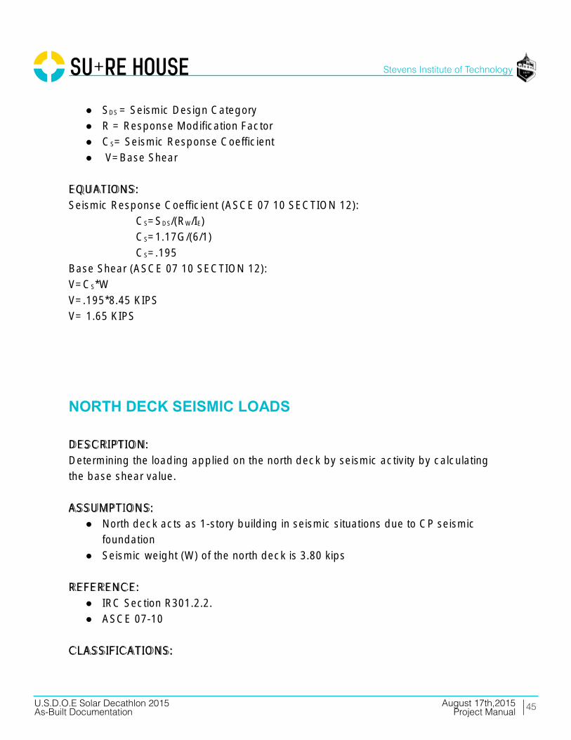
CS=SDS/(RW/IE)
CS=1.17G/(6/1)
CS=.195
Base Shear (ASCE 07 10 SECTION 12):
V=CS*W
V=.195*40.38KIPS
V= 7.87 KIPS
SOUTH DECK SEISMIC LOADS DESCRIPTION:
Determining the loading applied on the south deck by seismic activity by calculating
the base shear value.
ASSUMPTIONS:
● South deck acts as 1 story building in seismic situations due to CP seismic
foundation
● Seismic weight (W) of the south deck is 8.45 kips
REFERENCE:
● IRC Section R301.2.2.
● ASCE 07-10
CLASSIFICATIONS:
● IRC Seismic Design Category D2 = 1.17G
● Response Modification Factor (ASCE 07 10)= 6
● Importance Factor (ASCE 07 10) II RISK CATEGORY = 1
VARIABLES:
● IE=Importance Factor
● W = Assumed Seismic Weight Of Home
45
Stevens Institute of Technology
August 17th,2015U.S.D.O.E Solar Decathlon 2015As-Built Documentation Project Manual
____________________________________________________________________________ U.S. D.O.E SOLAR DECATHLON 2015 AUGUST 17, 2015 CONSTRUCTION DOCUMENTATION: STAMPED STRUCTURAL CALCULATIONS PAGE 18
● SDS = Seismic Design Category
● R = Response Modification Factor
● CS= Seismic Response Coefficient
● V=Base Shear
EQUATIONS:
Seismic Response Coefficient (ASCE 07 10 SECTION 12):
CS=SDS/(RW/IE)
CS=1.17G/(6/1)
CS=.195
Base Shear (ASCE 07 10 SECTION 12):
V=CS*W
V=.195*8.45 KIPS
V= 1.65 KIPS
NORTH DECK SEISMIC LOADS DESCRIPTION:
Determining the loading applied on the north deck by seismic activity by calculating
the base shear value.
ASSUMPTIONS:
● North deck acts as 1-story building in seismic situations due to CP seismic
foundation
● Seismic weight (W) of the north deck is 3.80 kips
REFERENCE:
● IRC Section R301.2.2.
● ASCE 07-10
CLASSIFICATIONS:

46
Stevens Institute of Technology
August 17th,2015U.S.D.O.E Solar Decathlon 2015As-Built Documentation Project Manual
____________________________________________________________________________ U.S. D.O.E SOLAR DECATHLON 2015 AUGUST 17, 2015 CONSTRUCTION DOCUMENTATION: STAMPED STRUCTURAL CALCULATIONS PAGE 19
● IRC Seismic Design Category D2 = 1.17G
● Response Modification Factor (ASCE 07 10) = 6
● Importance Factor (ASCE 07-10) II RISK CATEGORY = 1
VARIABLES:
● IE=Importance Factor
● W = Assumed Seismic Weight Of Home
● SDS = Seismic Design Category
● R = Response Modification Factor
● CS= Seismic Response Coefficient
● V=Base Shear
EQUATIONS:
Seismic Response Coefficient (ASCE 07 10 Section 12):
CS=SDS/(RW/IE)
CS=1.17G/(6/1)
CS=.195
Base Shear (ASCE 07 10 Section 12):
V=CS*W
V=.195*3.80KIPS
V= .74 KIPS
RAMP SEISMIC LOADS DESCRIPTION:
Determining the loading applied on the ramp by seismic activity by calculating the
base shear value.
ASSUMPTIONS:
● Ramp acts as 1-story building in seismic situations due to CP seismic
foundation
● Seismic weight (W) of the ramp is 3.91 kips
REFERENCE:

47
Stevens Institute of Technology
August 17th,2015U.S.D.O.E Solar Decathlon 2015As-Built Documentation Project Manual
____________________________________________________________________________ U.S. D.O.E SOLAR DECATHLON 2015 AUGUST 17, 2015 CONSTRUCTION DOCUMENTATION: STAMPED STRUCTURAL CALCULATIONS PAGE 20
● IRC Section R301.2.2.
● ASCE 07-10
CLASSIFICATIONS:
● IRC Seismic Design Category D2 = 1.17G
● Response Modification Factor (ASCE 07 10) = 6
● Importance Factor (ASCE 07 10) II RISK CATEGORY = 1
VARIABLES:
● IE=Importance Factor
● W = Assumed Seismic Weight Of Home
● SDS = Seismic Design Category
● R = Response Modification Factor
● CS= Seismic Response Coefficient
● V=Base Shear
EQUATIONS:
Seismic Response Coefficient (ASCE 07 10 Section 12):
CS=SDS/(RW/IE)
CS=1.17G/(6/1)
CS=.195
Base Shear (ASCE 07 10 Section 12):
V=CS*W
V=.195*3.91KIPS
V= .76 KIPS

SHEAR WALLDESIGN
STRUCTURAL CALCULATIONS

49
Stevens Institute of Technology
August 17th,2015U.S.D.O.E Solar Decathlon 2015As-Built Documentation Project Manual
____________________________________________________________________________ U.S. D.O.E SOLAR DECATHLON 2015 AUGUST 17, 2015 CONSTRUCTION DOCUMENTATION: STAMPED STRUCTURAL CALCULATIONS PAGE 22
SHEAR WALL DESIGN Shear wall design must be compliant with the 2012 International Residential Code
Section R602.10.
For our application choose the wall braced panel (WBP) method.
Design Length (R602.10.1.2)
1. Wind (<110 MPH)
a.
I.
Ii. Exposure Factor = 1.2
Iii. Roof Eave/Ridge Factor = .7
Iv. Method Factor = 1.4
b. E/W Lines:
2. Seismic (D2 FOR CA)
a. N/S Lines:
Ii. Story Height Factored = 1.2
Iii. Roof Dead Load Factor = 1.2
b. E/W Lines: Use Line Length
h Required Unfactored
Ii. Same Factors As Above
To meet WBP specifications the following requirements must be met:
50
Stevens Institute of Technology
August 17th,2015U.S.D.O.E Solar Decathlon 2015As-Built Documentation Project Manual
____________________________________________________________________________ U.S. D.O.E SOLAR DECATHLON 2015 AUGUST 17, 2015 CONSTRUCTION DOCUMENTATION: STAMPED STRUCTURAL CALCULATIONS PAGE 23
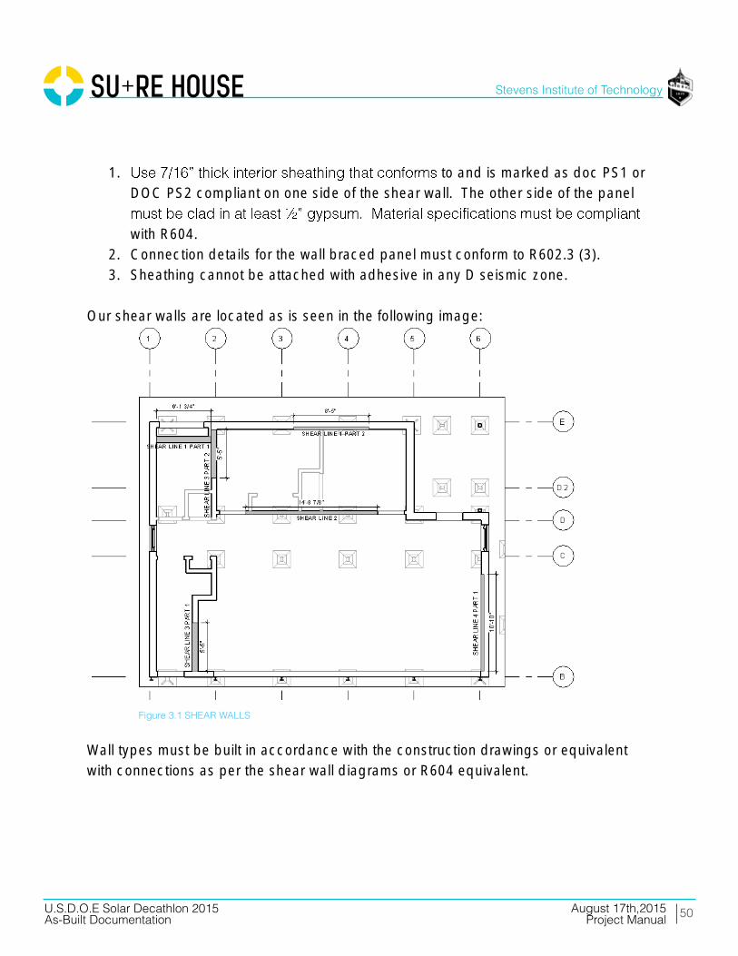
1. to and is marked as doc PS1 or
DOC PS2 compliant on one side of the shear wall. The other side of the panel
with R604.
2. Connection details for the wall braced panel must conform to R602.3 (3).
3. Sheathing cannot be attached with adhesive in any D seismic zone.
Our shear walls are located as is seen in the following image:
Wall types must be built in accordance with the construction drawings or equivalent
with connections as per the shear wall diagrams or R604 equivalent.
Figure 3.1 SHEAR WALLS

UPLIFTCHECK
STRUCTURAL CALCULATIONS

52
Stevens Institute of Technology
August 17th,2015U.S.D.O.E Solar Decathlon 2015As-Built Documentation Project Manual
____________________________________________________________________________ U.S. D.O.E SOLAR DECATHLON 2015 AUGUST 17, 2015 CONSTRUCTION DOCUMENTATION: STAMPED STRUCTURAL CALCULATIONS PAGE 25
HOUSE MODULES UPLIFT CHECK DESCRIPTION:
These calculations provide the extreme case of overall uplift on the house modules
(including the east porch).
REFERENCE:
Minimum Design Loads for Buildings and Other Structures, ASCE/SEI 7-10. Reston,
VA: American Society of Civil Engineers/Structural Engineering Institute, 2006. Print.
EQUATIONS:
28.4.1 DESIGN WIND PRESSURE FOR LOW-RISE BUILDINGS EQ. (28.4-1)
P = Qz[(GCPF) (GCPI)] (LB/FT2)
VARIABLES:
KD = Wind Directionality Factor
KZ = Velocity Pressure Exposure Coefficient
KZT = Topographic Factor
V = Basic Wind Speed
QH = Velocity Pressure Qz Calculated At Mean Roof Height H
(GCPF-) = External Pressure Coefficient
(GCPI) = Internal Pressure Coefficient
I = Importance Factor
CALCULATIONS:
First, QZ was calculated using the following equation:
QZ = 0.00256KZKZTKDV2I (LB/FT2)
Inputting the variables given:
QZ= 0.00256(0.85)(1)(.85)(130)2(1) LB/FT2
= 31.25824 LB/FT2
The maximum design pressure was then found using the following equation:
P = QH[(GCPF) (GCPI)] (LB/FT2)

53
Stevens Institute of Technology
August 17th,2015U.S.D.O.E Solar Decathlon 2015As-Built Documentation Project Manual
Table 3.6 UPLIFT FORCES

54
Stevens Institute of Technology
August 17th,2015U.S.D.O.E Solar Decathlon 2015As-Built Documentation Project Manual
SOUTH DECK UPLIFT CHECK

SLIDINGCHECK
STRUCTURAL CALCULATIONS
56
Stevens Institute of Technology
August 17th,2015U.S.D.O.E Solar Decathlon 2015As-Built Documentation Project Manual
____________________________________________________________________________ U.S. D.O.E SOLAR DECATHLON 2015 AUGUST 17, 2015 CONSTRUCTION DOCUMENTATION: STAMPED STRUCTURAL CALCULATIONS PAGE 6
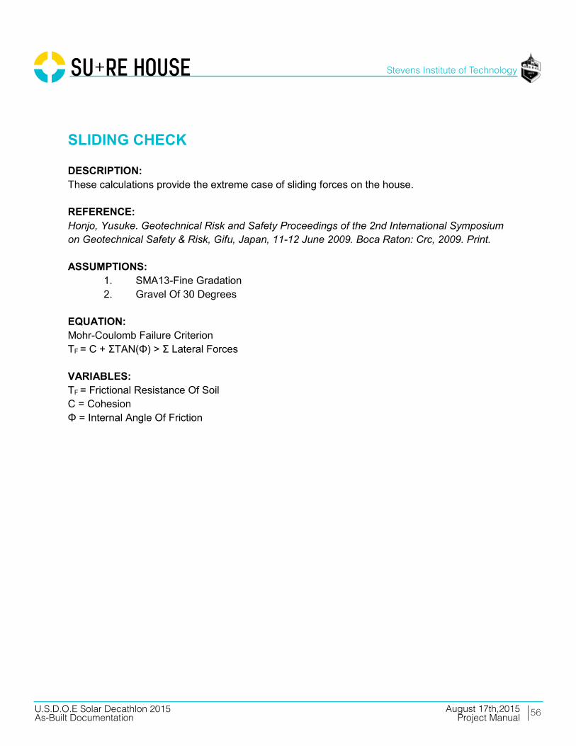
SLIDING CHECK DESCRIPTION: These calculations provide the extreme case of sliding forces on the house. REFERENCE: Honjo, Yusuke. Geotechnical Risk and Safety Proceedings of the 2nd International Symposium on Geotechnical Safety & Risk, Gifu, Japan, 11-12 June 2009. Boca Raton: Crc, 2009. Print. ASSUMPTIONS:
1. SMA13-Fine Gradation 2. Gravel Of 30 Degrees
EQUATION: Mohr-Coulomb Failure Criterion ΤF = C + ΣTAN(Φ) > Σ Lateral Forces VARIABLES: ΤF = Frictional Resistance Of Soil C = Cohesion Φ = Internal Angle Of Friction

57
Stevens Institute of Technology
August 17th,2015U.S.D.O.E Solar Decathlon 2015As-Built Documentation Project Manual
____________________________________________________________________________ U.S. D.O.E SOLAR DECATHLON 2015 AUGUST 17, 2015 CONSTRUCTION DOCUMENTATION: STAMPED STRUCTURAL CALCULATIONS PAGE 7
HOUSE MODULES SLIDING CHECK
44.750
12.670566.98339.000
22112.3187870.000
22112.318
40382.0006858.0002182.37031341.630
30.000
0.524
18095.095
<
Number of anchors needed 18.000Amount to account for in anchorage design (lb) 26129.540
Raw Dead Load of SURE House (lbs)Uplift from Roof (lb)
Uplift from Louvers (lb) (determined in louver calcs)(determined in wind loads)
NORTH DIRECTION - CRITICAL CASE
Length of Wall (ft)
Height of Wall (including parapet) (ft)Area of North Wall (ft^2)
Windward Pressure on Wall (psf) (determined in wind loads)Wind Load in North Direction (lbs)
Seismic Base Shear (lbs) (from seismic load calculations)
Worst Case Lateral Force in North Direction (lbs)
Modified Dead Load of SURE House Modules (lbs) (determined in seismic calcs)
Internal Angle of Friction for Asphalt, φ (degrees)
Internal Angle of Friction for Asphalt, φ (radians)
Frictional Resistance of Soil (lbs) = tan(φ)*[Dead Load]
Since, frictonal resistance of the soil isthan 2x the total lateral force,
the house WILL slide - REDESIGN.
Table 3.7 SLIDING FORCES

58
Stevens Institute of Technology
August 17th,2015U.S.D.O.E Solar Decathlon 2015As-Built Documentation Project Manual
____________________________________________________________________________ U.S. D.O.E SOLAR DECATHLON 2015 AUGUST 17, 2015 CONSTRUCTION DOCUMENTATION: STAMPED STRUCTURAL CALCULATIONS PAGE 8
SOUTH DECK SLIDING CHECK
12.670209.3502652.465
1650.000
2652.4658448.0002483.3905964.610
30.000
0.524
3443.669
<
Amount to account for in anchorage design (lb) 1861.260Number of anchors needed 2.000
Raw Dead Load of North Deck (lbs)Uplift from Louvers
Worst Case Lateral Force in West Direction
WEST DIRECTION: GOVERNING CASELength of West Wall (ft)
Windward Pressure on Wall (plf) (from louver load calculations)Wind Load in West Direction (lbs)
Seismic Base Shear (lbs) (from seismic load calculations)
than 2x the total lateral force, the house WILL slide -
REDESIGN.
Modiified Dead Load of North Deck (lbs) (determined in seismic calcs)Internal Angle of Friction for Asphalt, φ
(degrees)Internal Angle of Friction for Asphalt, φ
(radians)Frictional Resistance of Soil (lbs) =
tan(φ)*[Dead Load]
Since, frictonal resistance of the soil is
Table 3.8 S. DECK SLIDING FORCES
59
Stevens Institute of Technology
August 17th,2015U.S.D.O.E Solar Decathlon 2015As-Built Documentation Project Manual
____________________________________________________________________________ U.S. D.O.E SOLAR DECATHLON 2015 AUGUST 17, 2015 CONSTRUCTION DOCUMENTATION: STAMPED STRUCTURAL CALCULATIONS PAGE 9
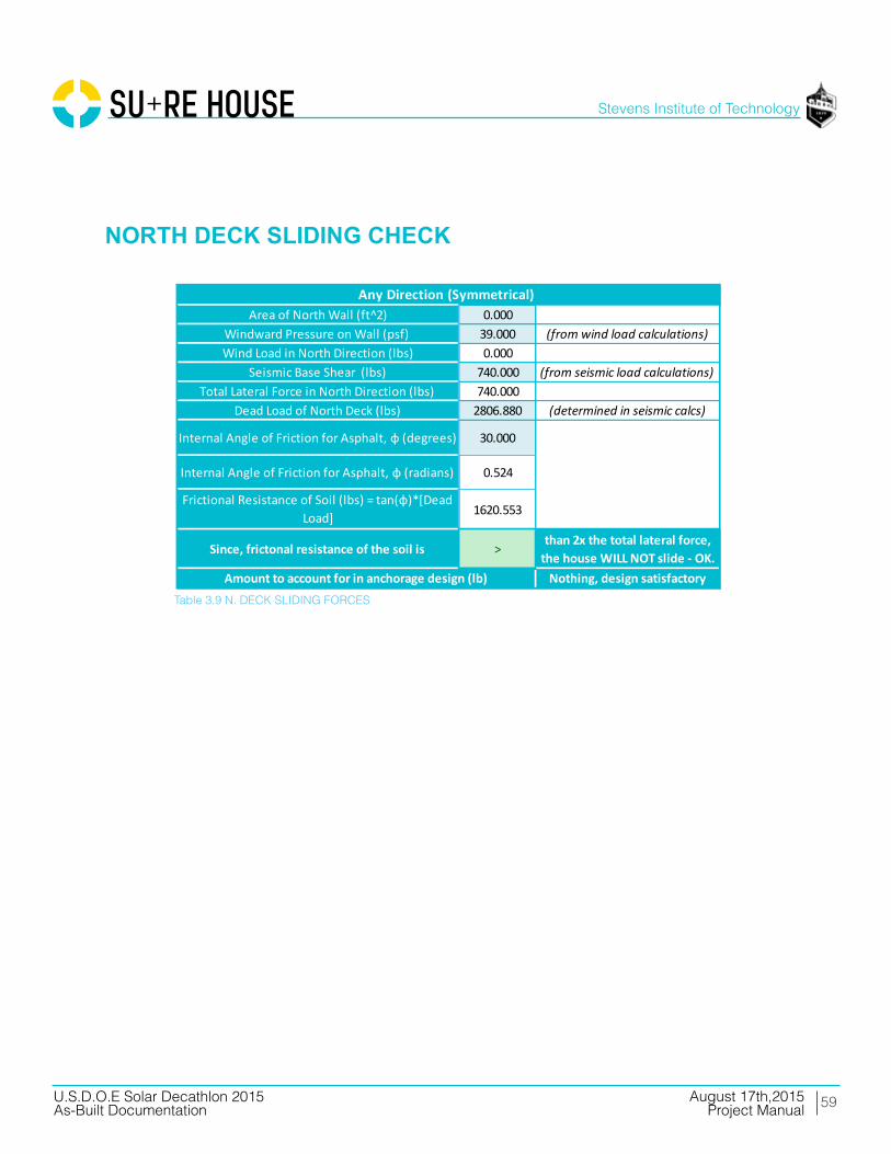
NORTH DECK SLIDING CHECK
0.00039.0000.000
740.000740.000
2806.880
30.000
0.524
1620.553
>
Amount to account for in anchorage design (lb) Nothing, design satisfactory
Any Direction (Symmetrical) Area of North Wall (ft^2)
Windward Pressure on Wall (psf) (from wind load calculations)Wind Load in North Direction (lbs)
Seismic Base Shear (lbs) (from seismic load calculations)Total Lateral Force in North Direction (lbs)
Dead Load of North Deck (lbs) (determined in seismic calcs)
Internal Angle of Friction for Asphalt, φ (degrees)
Internal Angle of Friction for Asphalt, φ (radians)
Frictional Resistance of Soil (lbs) = tan(φ)*[Dead Load]
Since, frictonal resistance of the soil is than 2x the total lateral force, the house WILL NOT slide - OK.
Table 3.9 N. DECK SLIDING FORCES
60
Stevens Institute of Technology
August 17th,2015U.S.D.O.E Solar Decathlon 2015As-Built Documentation Project Manual
____________________________________________________________________________ U.S. D.O.E SOLAR DECATHLON 2015 AUGUST 17, 2015 CONSTRUCTION DOCUMENTATION: STAMPED STRUCTURAL CALCULATIONS PAGE 10
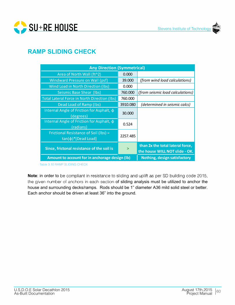
RAMP SLIDING CHECK
Note: in order to
of sliding analysis must be utilized to anchor the house and surrounding decks/ramps. Rods should be 1” diameter A36 mild solid steel or better. Each anchor should be driven at least 36” into the ground.
0.00039.0000.000
760.000760.0003910.080
30.000
0.524
2257.485
>
Any Direction (Symmetrical)
Amount to account for in anchorage design (lb) Nothing, design satisfactory
Area of North Wall (ft^2)Windward Pressure on Wall (psf) (from wind load calculations)Wind Load in North Direction (lbs)
Seismic Base Shear (lbs) (from seismic load calculations)Total Lateral Force in North Direction (lbs)
than 2x the total lateral force, the house WILL NOT slide - OK.
Dead Load of Ramp (lbs) (determined in seismic calcs)Internal Angle of Friction for Asphalt, φ
(degrees)Internal Angle of Friction for Asphalt, φ
(radians)Frictional Resistance of Soil (lbs) =
tan(φ)*[Dead Load]
Since, frictonal resistance of the soil is
Table 3.10 RAMP SLIDING CHECK

OVERTURNINGCHECK
STRUCTURAL CALCULATIONS
62
Stevens Institute of Technology
August 17th,2015U.S.D.O.E Solar Decathlon 2015As-Built Documentation Project Manual
____________________________________________________________________________ U.S. D.O.E SOLAR DECATHLON 2015 AUGUST 17, 2015 CONSTRUCTION DOCUMENTATION: STAMPED STRUCTURAL CALCULATIONS PAGE 12
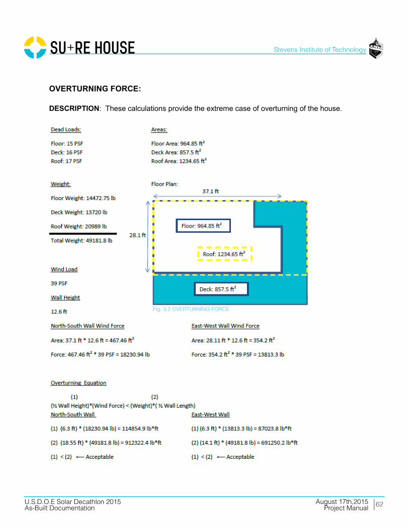
OVERTURNING FORCE: DESCRIPTION: These calculations provide the extreme case of overturning of the house.
Fig. 3.2 OVERTURNING FORCE

WOOD HOUSEROOF DESIGN
STRUCTURAL CALCULATIONS

64
Stevens Institute of Technology
August 17th,2015U.S.D.O.E Solar Decathlon 2015As-Built Documentation Project Manual
____________________________________________________________________________ U.S. D.O.E SOLAR DECATHLON 2015 AUGUST 17, 2015 CONSTRUCTION DOCUMENTATION: STAMPED STRUCTURAL CALCULATIONS PAGE 14
FRJ-1
Table. 3.11 ROOF JOISTS

65
Stevens Institute of Technology
August 17th,2015U.S.D.O.E Solar Decathlon 2015As-Built Documentation Project Manual
____________________________________________________________________________ U.S. D.O.E SOLAR DECATHLON 2015 AUGUST 17, 2015 CONSTRUCTION DOCUMENTATION: STAMPED STRUCTURAL CALCULATIONS PAGE 15

WOOD HOUSEFLOOR DESIGN
STRUCTURAL CALCULATIONS

67
Stevens Institute of Technology
August 17th,2015U.S.D.O.E Solar Decathlon 2015As-Built Documentation Project Manual
____________________________________________________________________________ U.S. D.O.E SOLAR DECATHLON 2015 AUGUST 17, 2015 CONSTRUCTION DOCUMENTATION: STAMPED STRUCTURAL CALCULATIONS PAGE 17

68
Stevens Institute of Technology
August 17th,2015U.S.D.O.E Solar Decathlon 2015As-Built Documentation Project Manual
____________________________________________________________________________ U.S. D.O.E SOLAR DECATHLON 2015 AUGUST 17, 2015 CONSTRUCTION DOCUMENTATION: STAMPED STRUCTURAL CALCULATIONS PAGE 18
69
Stevens Institute of Technology
August 17th,2015U.S.D.O.E Solar Decathlon 2015As-Built Documentation Project Manual
____________________________________________________________________________ U.S. D.O.E SOLAR DECATHLON 2015 AUGUST 17, 2015 CONSTRUCTION DOCUMENTATION: STAMPED STRUCTURAL CALCULATIONS PAGE 19
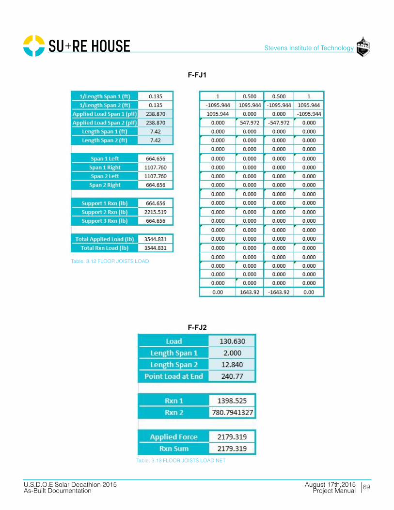
F-FJ1
F-FJ2
Table. 3.12 FLOOR JOISTS LOAD
Table. 3.13 FLOOR JOISTS LOAD NET
70
Stevens Institute of Technology
August 17th,2015U.S.D.O.E Solar Decathlon 2015As-Built Documentation Project Manual
____________________________________________________________________________ U.S. D.O.E SOLAR DECATHLON 2015 AUGUST 17, 2015 CONSTRUCTION DOCUMENTATION: STAMPED STRUCTURAL CALCULATIONS PAGE 20
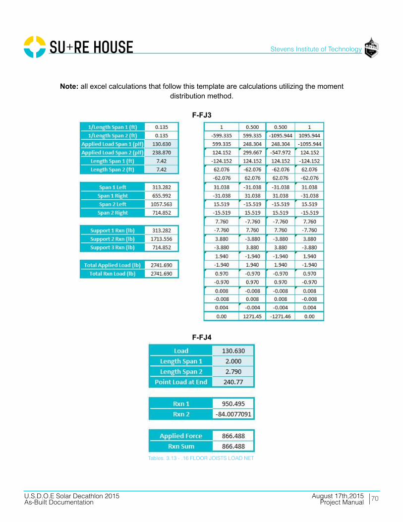
Note: all excel calculations that follow this template are calculations utilizing the moment
distribution method.
F-FJ3
F-FJ4
Tables. 3.13 - .16 FLOOR JOISTS LOAD NET

71
Stevens Institute of Technology
August 17th,2015U.S.D.O.E Solar Decathlon 2015As-Built Documentation Project Manual
____________________________________________________________________________ U.S. D.O.E SOLAR DECATHLON 2015 AUGUST 17, 2015 CONSTRUCTION DOCUMENTATION: STAMPED STRUCTURAL CALCULATIONS PAGE 21
72
Stevens Institute of Technology
August 17th,2015U.S.D.O.E Solar Decathlon 2015As-Built Documentation Project Manual
____________________________________________________________________________ U.S. D.O.E SOLAR DECATHLON 2015 AUGUST 17, 2015 CONSTRUCTION DOCUMENTATION: STAMPED STRUCTURAL CALCULATIONS PAGE 22
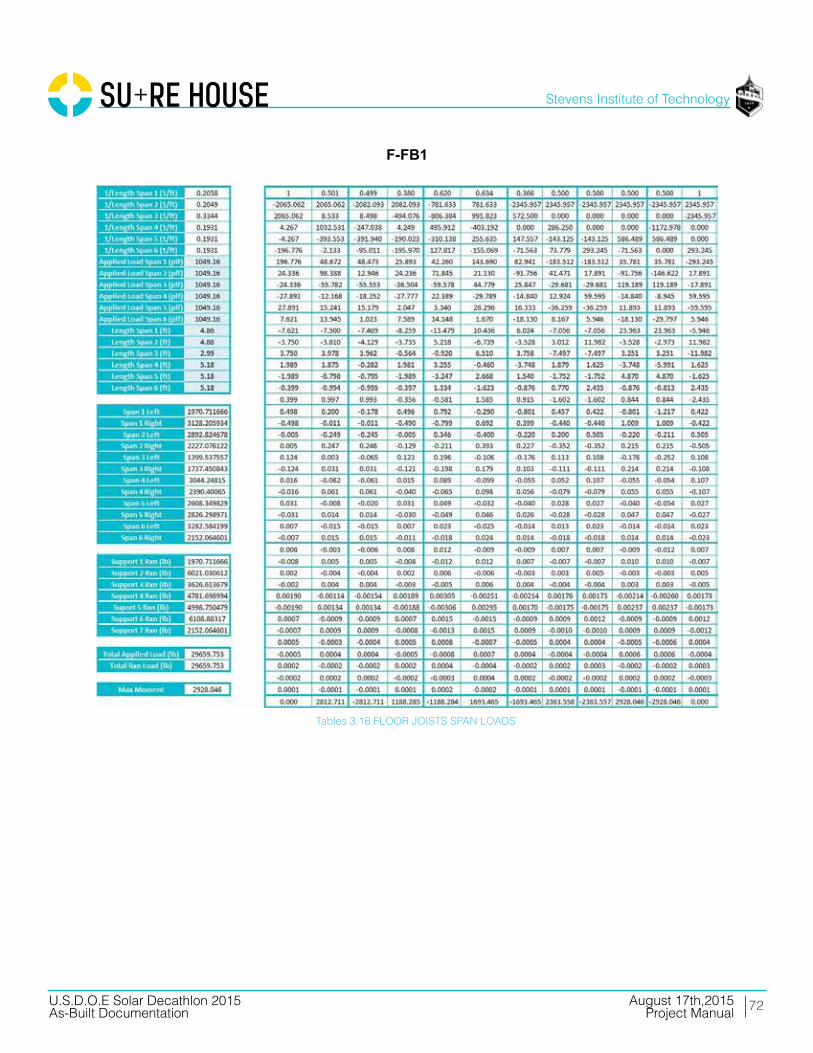
F-FB1
Tables 3.16 FLOOR JOISTS SPAN LOADS

73
Stevens Institute of Technology
August 17th,2015U.S.D.O.E Solar Decathlon 2015As-Built Documentation Project Manual
____________________________________________________________________________ U.S. D.O.E SOLAR DECATHLON 2015 AUGUST 17, 2015 CONSTRUCTION DOCUMENTATION: STAMPED STRUCTURAL CALCULATIONS PAGE 23
F-FB2
Tables 3.17 FLOOR JOISTS SPAN LOADS

74
Stevens Institute of Technology
August 17th,2015U.S.D.O.E Solar Decathlon 2015As-Built Documentation Project Manual
____________________________________________________________________________ U.S. D.O.E SOLAR DECATHLON 2015 AUGUST 17, 2015 CONSTRUCTION DOCUMENTATION: STAMPED STRUCTURAL CALCULATIONS PAGE 24
F-FB3
Tables 3.18 FLOOR JOISTS SPAN LOADS

75
Stevens Institute of Technology
August 17th,2015U.S.D.O.E Solar Decathlon 2015As-Built Documentation Project Manual
____________________________________________________________________________ U.S. D.O.E SOLAR DECATHLON 2015 AUGUST 17, 2015 CONSTRUCTION DOCUMENTATION: STAMPED STRUCTURAL CALCULATIONS PAGE 25
F-FB4
Tables 3.19 FLOOR JOISTS SPAN LOADS

WOOD COLUMNDESIGN
STRUCTURAL CALCULATIONS

77
Stevens Institute of Technology
August 17th,2015U.S.D.O.E Solar Decathlon 2015As-Built Documentation Project Manual
____________________________________________________________________________ U.S. D.O.E SOLAR DECATHLON 2015 AUGUST 17, 2015 CONSTRUCTION DOCUMENTATION: STAMPED STRUCTURAL CALCULATIONS PAGE 27

WOOD DECKDESIGN
STRUCTURAL CALCULATIONS

79
Stevens Institute of Technology
August 17th,2015U.S.D.O.E Solar Decathlon 2015As-Built Documentation Project Manual
____________________________________________________________________________ U.S. D.O.E SOLAR DECATHLON 2015 AUGUST 17, 2015 CONSTRUCTION DOCUMENTATION: STAMPED STRUCTURAL CALCULATIONS PAGE 29

80
Stevens Institute of Technology
August 17th,2015U.S.D.O.E Solar Decathlon 2015As-Built Documentation Project Manual
____________________________________________________________________________ U.S. D.O.E SOLAR DECATHLON 2015 AUGUST 17, 2015 CONSTRUCTION DOCUMENTATION: STAMPED STRUCTURAL CALCULATIONS PAGE 30

81
Stevens Institute of Technology
August 17th,2015U.S.D.O.E Solar Decathlon 2015As-Built Documentation Project Manual
____________________________________________________________________________ U.S. D.O.E SOLAR DECATHLON 2015 AUGUST 17, 2015 CONSTRUCTION DOCUMENTATION: STAMPED STRUCTURAL CALCULATIONS PAGE 31
D-1
Tables 3.20 DECK LOADS
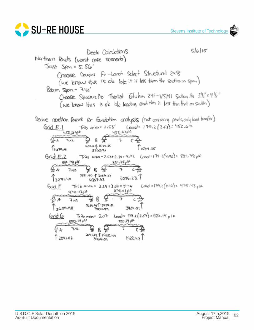
82
Stevens Institute of Technology
August 17th,2015U.S.D.O.E Solar Decathlon 2015As-Built Documentation Project Manual
____________________________________________________________________________ U.S. D.O.E SOLAR DECATHLON 2015 AUGUST 17, 2015 CONSTRUCTION DOCUMENTATION: STAMPED STRUCTURAL CALCULATIONS PAGE 32

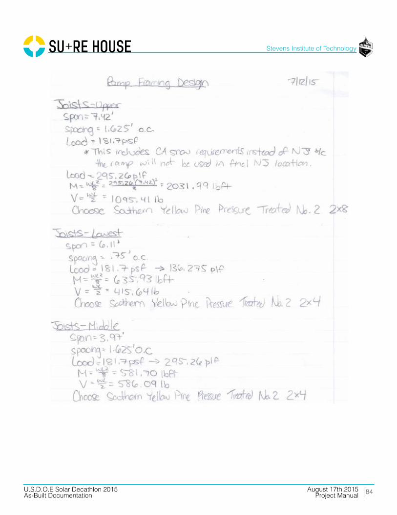
RAMPDESIGN
STRUCTURAL CALCULATIONS
84
Stevens Institute of Technology
August 17th,2015U.S.D.O.E Solar Decathlon 2015As-Built Documentation Project Manual
____________________________________________________________________________ U.S. D.O.E SOLAR DECATHLON 2015 AUGUST 17, 2015 CONSTRUCTION DOCUMENTATION: STAMPED STRUCTURAL CALCULATIONS PAGE 34

85
Stevens Institute of Technology
August 17th,2015U.S.D.O.E Solar Decathlon 2015As-Built Documentation Project Manual
____________________________________________________________________________ U.S. D.O.E SOLAR DECATHLON 2015 AUGUST 17, 2015 CONSTRUCTION DOCUMENTATION: STAMPED STRUCTURAL CALCULATIONS PAGE 35

86
Stevens Institute of Technology
August 17th,2015U.S.D.O.E Solar Decathlon 2015As-Built Documentation Project Manual
____________________________________________________________________________ U.S. D.O.E SOLAR DECATHLON 2015 AUGUST 17, 2015 CONSTRUCTION DOCUMENTATION: STAMPED STRUCTURAL CALCULATIONS PAGE 36
R-RB1
Tables 3.21 DECK SPAN
87
Stevens Institute of Technology
August 17th,2015U.S.D.O.E Solar Decathlon 2015As-Built Documentation Project Manual
____________________________________________________________________________ U.S. D.O.E SOLAR DECATHLON 2015 AUGUST 17, 2015 CONSTRUCTION DOCUMENTATION: STAMPED STRUCTURAL CALCULATIONS PAGE 37
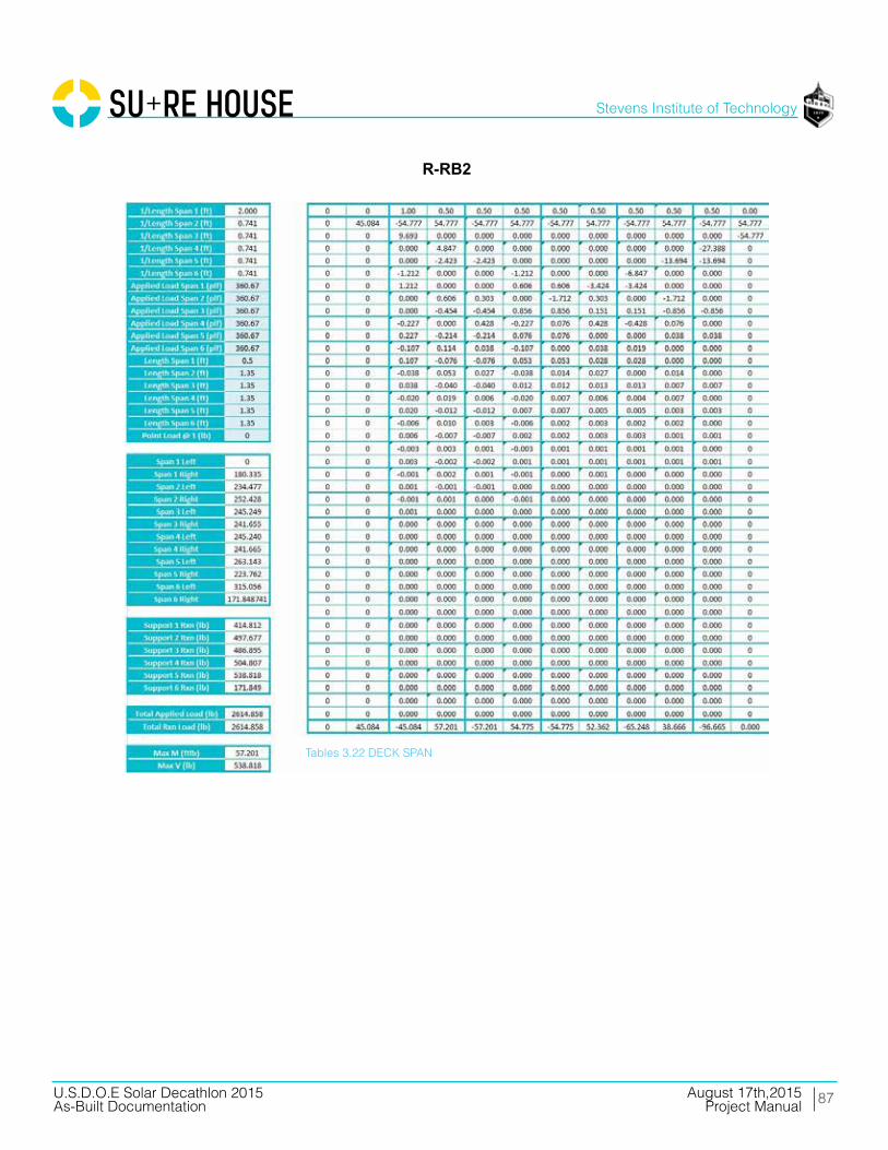
R-RB2
Tables 3.22 DECK SPAN

88
Stevens Institute of Technology
August 17th,2015U.S.D.O.E Solar Decathlon 2015As-Built Documentation Project Manual
____________________________________________________________________________ U.S. D.O.E SOLAR DECATHLON 2015 AUGUST 17, 2015 CONSTRUCTION DOCUMENTATION: STAMPED STRUCTURAL CALCULATIONS PAGE 38
R-RB3
Tables 3.23 DECK SPAN

FOUNDATIONDESIGN
STRUCTURAL CALCULATIONS
90
Stevens Institute of Technology
August 17th,2015U.S.D.O.E Solar Decathlon 2015As-Built Documentation Project Manual
____________________________________________________________________________ U.S. D.O.E SOLAR DECATHLON 2015 AUGUST 17, 2015 CONSTRUCTION DOCUMENTATION: STAMPED STRUCTURAL CALCULATIONS PAGE 40
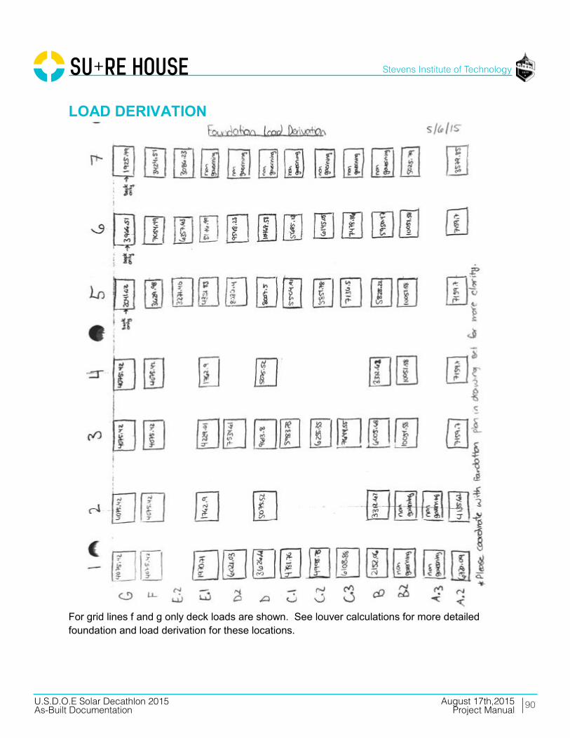
LOAD DERIVATION
For grid lines f and g only deck loads are shown. See louver calculations for more detailed foundation and load derivation for these locations.

91
Stevens Institute of Technology
August 17th,2015U.S.D.O.E Solar Decathlon 2015As-Built Documentation Project Manual
____________________________________________________________________________ U.S. D.O.E SOLAR DECATHLON 2015 AUGUST 17, 2015 CONSTRUCTION DOCUMENTATION: STAMPED STRUCTURAL CALCULATIONS PAGE 41
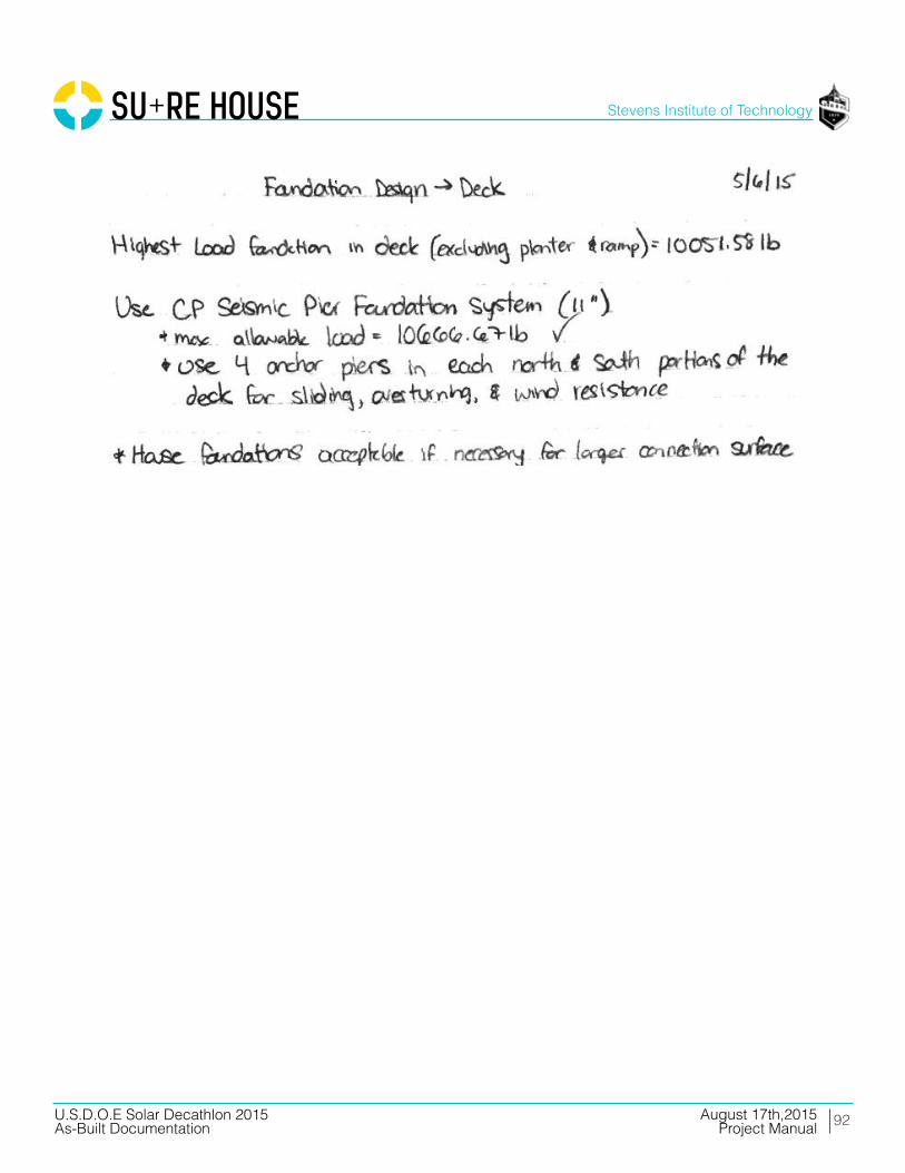
HOUSE & DECK
92
Stevens Institute of Technology
August 17th,2015U.S.D.O.E Solar Decathlon 2015As-Built Documentation Project Manual
____________________________________________________________________________ U.S. D.O.E SOLAR DECATHLON 2015 AUGUST 17, 2015 CONSTRUCTION DOCUMENTATION: STAMPED STRUCTURAL CALCULATIONS PAGE 42

93
Stevens Institute of Technology
August 17th,2015U.S.D.O.E Solar Decathlon 2015As-Built Documentation Project Manual
____________________________________________________________________________ U.S. D.O.E SOLAR DECATHLON 2015 AUGUST 17, 2015 CONSTRUCTION DOCUMENTATION: STAMPED STRUCTURAL CALCULATIONS PAGE 43
RAMP

HSS STEELLEGEND
STRUCTURAL CALCULATIONS

95
Stevens Institute of Technology
August 17th,2015U.S.D.O.E Solar Decathlon 2015As-Built Documentation Project Manual
____________________________________________________________________________ U.S. D.O.E SOLAR DECATHLON 2015 AUGUST 17, 2015 CONSTRUCTION DOCUMENTATION: STAMPED STRUCTURAL CALCULATIONS PAGE 45

96
Stevens Institute of Technology
August 17th,2015U.S.D.O.E Solar Decathlon 2015As-Built Documentation Project Manual
____________________________________________________________________________ U.S. D.O.E SOLAR DECATHLON 2015 AUGUST 17, 2015 CONSTRUCTION DOCUMENTATION: STAMPED STRUCTURAL CALCULATIONS PAGE 46
____________________________________________________________________________ U.S. D.O.E SOLAR DECATHLON 2015 AUGUST 17, 2015 CONSTRUCTION DOCUMENTATION: STAMPED STRUCTURAL CALCULATIONS PAGE 47

HSS COLUMNDESIGN
STRUCTURAL CALCULATIONS

98
Stevens Institute of Technology
August 17th,2015U.S.D.O.E Solar Decathlon 2015As-Built Documentation Project Manual
____________________________________________________________________________ U.S. D.O.E SOLAR DECATHLON 2015 AUGUST 17, 2015 CONSTRUCTION DOCUMENTATION: STAMPED STRUCTURAL CALCULATIONS PAGE 49
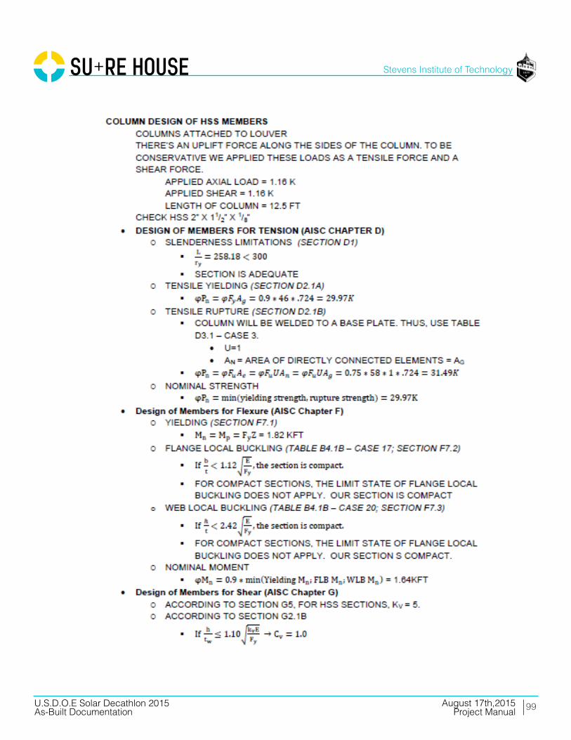
99
Stevens Institute of Technology
August 17th,2015U.S.D.O.E Solar Decathlon 2015As-Built Documentation Project Manual
____________________________________________________________________________ U.S. D.O.E SOLAR DECATHLON 2015 AUGUST 17, 2015 CONSTRUCTION DOCUMENTATION: STAMPED STRUCTURAL CALCULATIONS PAGE 50

100
Stevens Institute of Technology
August 17th,2015U.S.D.O.E Solar Decathlon 2015As-Built Documentation Project Manual
____________________________________________________________________________ U.S. D.O.E SOLAR DECATHLON 2015 AUGUST 17, 2015 CONSTRUCTION DOCUMENTATION: STAMPED STRUCTURAL CALCULATIONS PAGE 51
Example from above analysis is purely for example purposes-it is not for any beam in the house. Process is the same for sure house design.
COLUMN UPLIFT
Steel Member
Column Name Max Axial Load (kips) Max Shear (kips) Mz (k-ft) My (k-ft) L (ft) AISC Section E (ksi) Fy (ksi) Fu (ksi) G (ksi)Southern Louver Column - Type A 0.28178 0.423 0 1.162 11.00 HSS4X2X1/8 29000 46 58 11200Southern Louver Column - Type B 0.28178 0.423 0 1.162 11.00 HSS4X4X3/16 29000 46 58 11200
Southern Column 3.02 3.02 0 0 11.27 HSS4X4X3/16 29000 46 58 11200East Column - Type D 0.01518 0.423 0 1.162 11.00 HSS4X2X5/16 29000 46 58 11200
Cantilever Column - Type A 0.28178 0.922 0 5.53 12.00 HSS4X4X3/16 29000 46 58 11200Cantilever Column - Type B 0.28178 0.922 0 5.53 12.00 HSS4X2X3/16 29000 46 58 11200
General Steel Properties Input Values
Column Name K b/t Cw J Ix Iy Ag (in2) Zx (in3) Zy (in3) Sx (in3) Sy (in3) h/t tdes (in) tnom (in) h (in) ry (in) Southern Louver Column - Type A 1 14.2 1.69 2.2 2.65 0.898 1.3 1.66 1.02 1.32 0.898 31.5 0.116 0.125 4 0.83Southern Louver Column - Type B 1 20 5.07 10 6.21 6.21 2.58 3.67 3.67 3.1 3.1 20 0.174 0.1875 4 1.55
Southern Column 1 20 5.07 10 6.21 6.21 2.58 3.67 3.67 3.1 3.1 20 0.174 0.1875 4 1.55East Column - Type D 1 3.87 3.59 4.4 5.13 1.67 2.94 3.43 2.08 2.56 1.67 10.7 0.291 0.3125 4 0.754
Cantilever Column - Type A 2.1 20 5.07 10 6.21 6.21 2.58 3.67 3.67 3.1 3.1 20 0.174 0.1875 4 1.55Cantilever Column - Type B 2.1 8.49 2.41 3.08 3.66 1.22 1.89 2.34 1.43 1.83 1.22 20 0.174 0.1875 4 0.804
Member Properties
Column Name L/r AISC E2 CheckNominal Yielding Tensile Strength U An Ae
Nominal Rupture Tensile Strength Tensile Strength (kips)
Southern Louver Column - Type A 159.04 OK 53.82 1 1.30 1.30 56.55 53.82Southern Louver Column - Type B 85.16 OK 106.81 1 2.58 2.58 112.23 106.81
Southern Column 87.25 OK 106.81 1 2.58 2.58 112.23 106.81East Column - Type D 175.07 OK 121.72 1 2.94 2.94 127.89 121.72
Cantilever Column - Type A 92.90 OK 106.81 1 2.58 2.58 112.23 106.81Cantilever Column - Type B 179.10 OK 78.25 1 1.89 1.89 82.22 78.25
DESIGN OF MEMBERS FOR TENSION (AISC Chapter D)
Column Name Yielding Mn (k-ft) Flange λp Flange λr Flange PropertyFlange Local
Buckling Mn (kft)Web λp Web λr Web Property
Web Local Buckling Mn
(kft)φMn
Southern Louver Column - Type A 6.36 28.12 35.15 Compact N/A 60.76 143.12 Compact N/A 5.73Southern Louver Column - Type B 14.07 28.12 35.15 Compact N/A 60.76 143.12 Compact N/A 12.66
Southern Column 14.07 28.12 35.15 Compact N/A 60.76 143.12 Compact N/A 12.66East Column - Type D 7.97 28.12 35.15 Compact N/A 60.76 143.12 Compact N/A 7.18
Cantilever Column - Type A 14.07 28.12 35.15 Compact N/A 60.76 143.12 Compact N/A 12.66Cantilever Column - Type B 8.97 28.12 35.15 Compact N/A 60.76 143.12 Compact N/A 8.07
DESIGN OF MEMBERS FOR FLEXURE (AISC Chapter F)
Table 3.24 COLUMN UPLIFT

101
Stevens Institute of Technology
August 17th,2015U.S.D.O.E Solar Decathlon 2015As-Built Documentation Project Manual
____________________________________________________________________________ U.S. D.O.E SOLAR DECATHLON 2015 AUGUST 17, 2015 CONSTRUCTION DOCUMENTATION: STAMPED STRUCTURAL CALCULATIONS PAGE 52
COLUMN COMPRESSION
Steel Member
Column Name Max Axial Load (kips) Max Shear (kips) Mz (k-ft) My (k-ft) L (ft) AISC Section E (ksi) Fy (ksi) Fu (ksi) G (ksi)
East Column - Type A 2.312 2.312 0 0 11.00 HSS4X4X3/16 29000 46 58 11200East Column - Type B 0.36852 0.423 0 1.162 11.00 HSS4X4X3/16 29000 46 58 11200East Column - Type C 0.48552 0.423 0 1.162 11.00 HSS4X2X1/8 29000 46 58 11200
Double Column - Worst Case 3.51 5.475 0 7.53 10.50 HSS4X2X5/16 29000 46 58 11200
General Steel PropertiesInput Values
Column Name K b/t Cw J Ix Iy Ag Zx Sx h/t tdes tnom h ryEast Column - Type A 1 20 5.07 10 6.21 6.21 2.58 3.67 3.1 20 0.174 0.1875 4 1.55East Column - Type B 1 20 5.07 10 6.21 6.21 2.58 3.67 3.1 20 0.174 0.1875 4 1.55East Column - Type C 1 14.2 1.69 2.2 2.65 0.898 1.3 1.66 1.32 31.5 0.116 0.125 4 0.83
Double Column - Worst Case 1 3.87 3.59 4.4 5.13 1.67 2.94 3.43 2.56 10.7 0.291 0.3125 4 0.754
Member Properties
Column Name KL/r AISC E2 Check λr Slenderness FB Fe FB, Fcr φPnEast Column - Type A 85.16 OK 35.15 Nonslender 39.47 28.24 65.58East Column - Type B 85.16 OK 35.15 Nonslender 39.47 28.24 65.58East Column - Type C 159.04 OK 35.15 Nonslender 11.32 9.92 11.61
Double Column - Worst Case 167.11 OK 35.15 Nonslender 10.25 8.99 23.78
DESIGN OF MEMBERS FOR COMPRESSION (AISC Chapter E)
Column Name Yielding Mn (k-ft) Flange λp Flange λr Flange PropertyFlange Local Buckling Mn
(kft) Web λp Web λr Web PropertyWeb Local Buckling Mn
(kft) φMn
East Column - Type A 14.07 28.12 35.15 Compact N/A 60.76 143.12 Compact N/A 12.66East Column - Type B 14.07 28.12 35.15 Compact N/A 60.76 143.12 Compact N/A 12.66East Column - Type C 6.36 28.12 35.15 Compact N/A 60.76 143.12 Compact N/A 5.73
Double Column - Worst Case 13.15 28.12 35.15 Compact N/A 60.76 143.12 Compact N/A 11.83
DESIGN OF MEMBERS FOR FLEXURE (AISC Chapter F)
Column Name Cv t (in) shear h (in) Aw (in2) φVn (kips)East Column - Type A 1.00 0.17 2.50 0.87 21.61East Column - Type B 1.00 0.17 2.50 0.87 21.61East Column - Type C 1.00 0.12 3.00 0.70 17.29
Double Column - Worst Case 1.00 0.29 1.50 0.87 21.69
DESIGN OF MEMBERS FOR SHEAR (AISC Chapter G)
Column Name Interaction Equation Combined Forces < 1?East Column - Type A 0.05 OK
INTERACTION CHECK -- AISC H3.2
Pr 0.36852 kips = from hand calcPcy 65.58 kips = from Cell I20
Mrx = Mmax 1.162 k-ft = from hand calcMcx 12.66 k-ft = from Cell L27Ma 0.872 k-ft = from hand calcMb 1.162 k-ft = from hand calcMc 0.872 k-ft = from hand calcCb 1.136 = AISC Eq C-F1-2
Interaction Eq 0.015 = AISC Eq H1-2Combined Forces <1? OK
East Column Type B Interaction Check -- AISC H1.3
Table 3.25 COLUMN COMPRESSION

102
Stevens Institute of Technology
August 17th,2015U.S.D.O.E Solar Decathlon 2015As-Built Documentation Project Manual
____________________________________________________________________________ U.S. D.O.E SOLAR DECATHLON 2015 AUGUST 17, 2015 CONSTRUCTION DOCUMENTATION: STAMPED STRUCTURAL CALCULATIONS PAGE 53
Pr 0.48552 kips = from hand calcPcy 11.61 kips = from Cell I21
Mrx = Mmax 1.162 k-ft = from hand calcMcx 5.73 k-ft = from Cell L28Ma 0.872 k-ft = from hand calcMb 1.162 k-ft = from hand calcMc 0.872 k-ft = from hand calcCb 1.136 = AISC Eq C-F1-2
Interaction Eq 0.094 = AISC Eq H1-2Combined Forces <1? OK
East Column Type C Interaction Check -- AISC H1.3
Pr 3.51 kips = from hand calcPcy 23.78 kips = from Cell I22
Mrx = Mmax 7.53 k-ft = from hand calcMcx 11.83 k-ft = from Cell L29Ma 2.17 k-ft = from hand calcMb 4.33 k-ft = from hand calcMc 6.5 k-ft = from hand calcCb 1.514 = AISC Eq C-F1-2
Interaction Eq 0.387 = AISC Eq H1-2Combined Forces <1? OK
East Column Type C Interaction Check -- AISC H1.3
Column Name AISC Section Axial Axial Utilization (%) Shear Shear Utilization (%) MomentFlexural Moment
Utilization (%)East Column - Type A HSS4X4X3/16 OK 3.53% OK 10.70% OK 0.00%East Column - Type B HSS4X4X3/16 OK 0.56% OK 1.96% OK 9.18%East Column - Type C HSS4X2X1/8 OK 4.18% OK 2.45% OK 20.29%
Double Column - Worst Case HSS4X2X5/16 OK 14.76% OK 25.25% OK 63.63%
COLUMN DESIGN CHECKS
Table 3.25 COLUMN CHECK
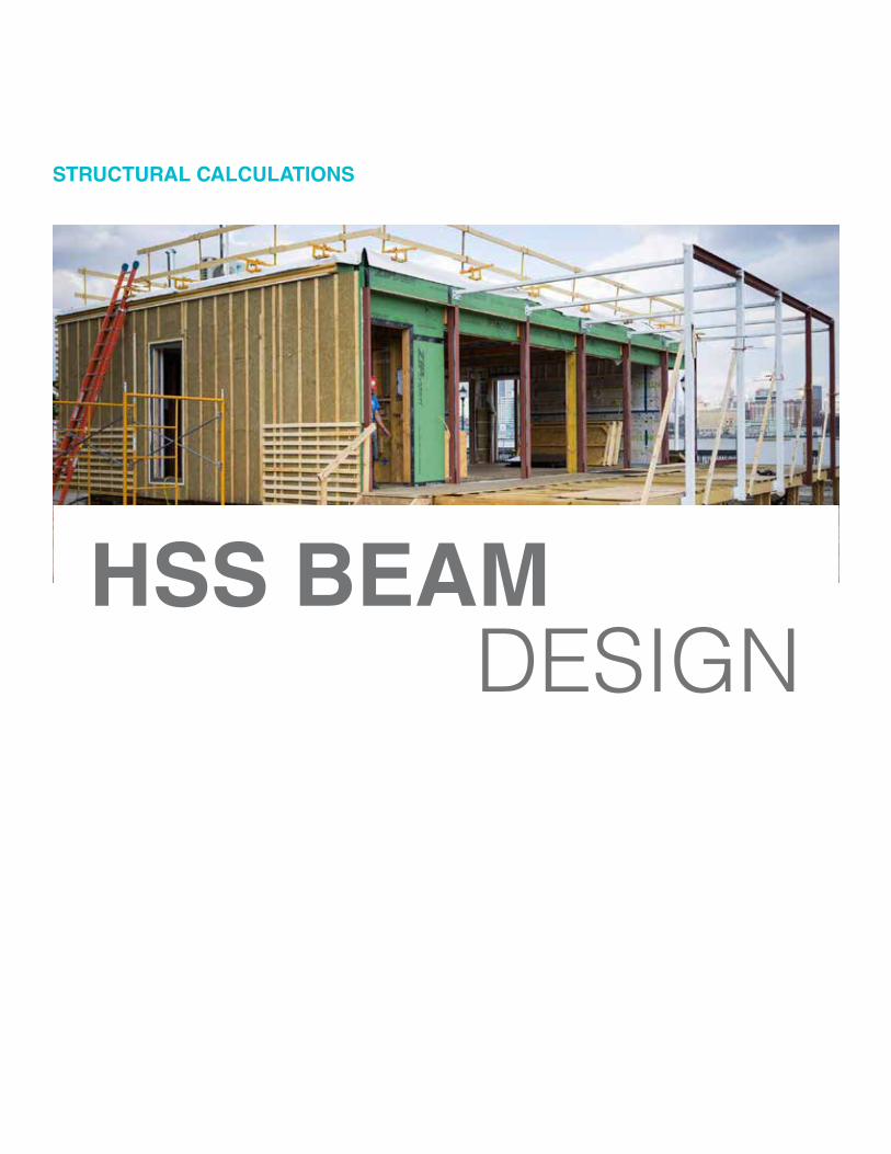
HSS BEAMDESIGN
STRUCTURAL CALCULATIONS

104
Stevens Institute of Technology
August 17th,2015U.S.D.O.E Solar Decathlon 2015As-Built Documentation Project Manual
____________________________________________________________________________ U.S. D.O.E SOLAR DECATHLON 2015 AUGUST 17, 2015 CONSTRUCTION DOCUMENTATION: STAMPED STRUCTURAL CALCULATIONS PAGE 55
Example from above analysis is purely for example purposes-it is not for any beam in the house. Process is the same for sure house design.

105
Stevens Institute of Technology
August 17th,2015U.S.D.O.E Solar Decathlon 2015As-Built Documentation Project Manual
____________________________________________________________________________ U.S. D.O.E SOLAR DECATHLON 2015 AUGUST 17, 2015 CONSTRUCTION DOCUMENTATION: STAMPED STRUCTURAL CALCULATIONS PAGE 56
Steel Member
Beam Unsupported
Length (ft)Shear (k) Moment (kft) Section Choice
Roof Beam 13.000 3.020 9.815 HSS3X3X3/8
Input Values
Beam E (ksi) Fy (ksi) Fu (ksi) b (in) tdes (in) Ix (in4) Sx (in3) Zx (in3) kv h/t b/t h tnom
Roof Beam 29000 46 58 3 0.349 3.78 2.52 3.25 5 5.6 5.6 3 0.375
Member PropertiesGeneral Steel Properties
Beam Mp (k-ft) λflange λp, flange λr, flange λweb λp, web λr, webϕMn Yielding
(kft)ϕMn FLB
(kft)ϕMn WLB
(kft)
ϕMn Controlling
(kft)Cv ϕV (k)
Roof Beam 12.458 5.600 28.121 35.152 5.600 60.762 143.118 11.213 N/A N/A 11.213 1.000 13.004
Structural Calcs
BeamStrength Check (∅Mn>Mu?)
Flange State Web State Shear Check Moment Utiliation (%) Shear Utilization (%)
Roof Beam Ok Compact Compact Ok 88% 23%
Results
Table 3.26 HSS BEAM CHECK
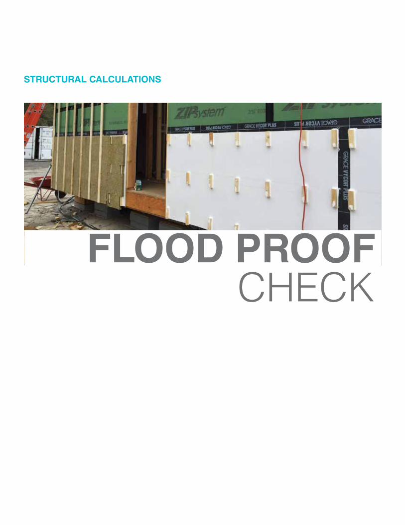
FLOOD PROOFCHECK
STRUCTURAL CALCULATIONS

107
Stevens Institute of Technology
August 17th,2015U.S.D.O.E Solar Decathlon 2015As-Built Documentation Project Manual
____________________________________________________________________________ U.S. D.O.E SOLAR DECATHLON 2015 AUGUST 17, 2015 CONSTRUCTION DOCUMENTATION: STAMPED STRUCTURAL CALCULATIONS PAGE 58
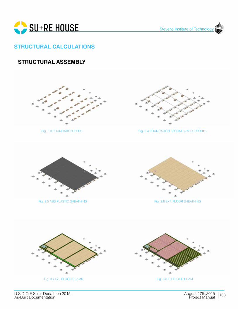
108
Stevens Institute of Technology
August 17th,2015U.S.D.O.E Solar Decathlon 2015As-Built Documentation Project Manual
STRUCTURAL CALCULATIONS
STRUCTURAL ASSEMBLY
Fig. 3.3 FOUNDATION PIERS Fig. 3.4 FOUNDATION SECONDARY SUPPORTS
Fig. 3.5 ABS PLASTIC SHEATHING Fig. 3.6 EXT. FLOOR SHEATHING
Fig. 3.7 LVL FLOOR BEAMS Fig. 3.8 TJI FLOOR BEAM

109
Stevens Institute of Technology
August 17th,2015U.S.D.O.E Solar Decathlon 2015As-Built Documentation Project Manual
STRUCTURAL CALCULATIONS
STRUCTURAL ASSEMBLY
Fig. 3.9 ADDITIONAL BLOCKING
Fig. 3.11 WOOD WALL STUDS
Fig. 3.13 ADDITIONAL PERIMETER BEAMS Fig. 3.14 ROOF TJI BEAMS
Fig. 3.12 WOOD TOP PLATES + LVL ROOF BEAMS
Fig. 3.10 SUBFLOOR SHEATHING
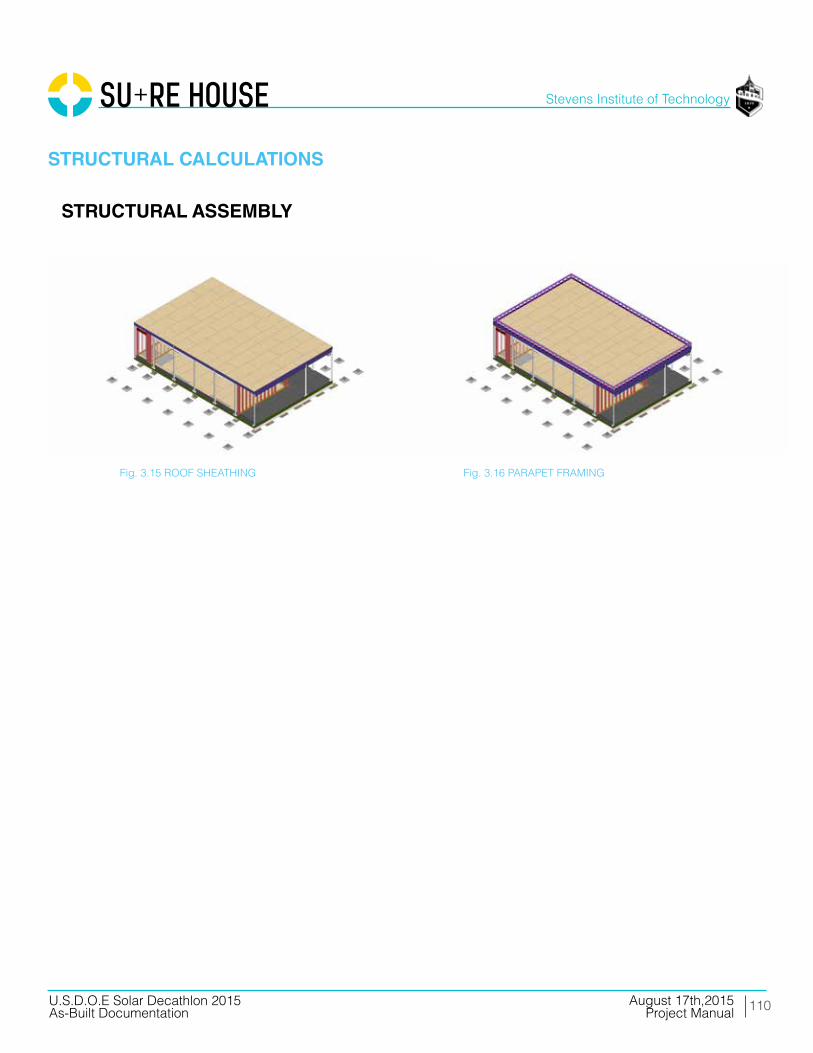
110
Stevens Institute of Technology
August 17th,2015U.S.D.O.E Solar Decathlon 2015As-Built Documentation Project Manual
STRUCTURAL CALCULATIONS
STRUCTURAL ASSEMBLY
Fig. 3.15 ROOF SHEATHING Fig. 3.16 PARAPET FRAMING
111
Stevens Institute of Technology
August 17th,2015U.S.D.O.E Solar Decathlon 2015As-Built Documentation Project Manual
STRUCTURAL CALCULATIONS
COMPOSITE PANEL MANUFACTURING
Composite panels developed as the flood shutters, window plugs and north facade of the SURE HOUSE have been manufactured by the team under engineering supervision of Gurit and professional composite builders from the International Yacht Restoration School (IYRS).
The SURE HOUSE produced panels using a low energy process known as vacuum infusion. A current Stevens graduate student and team member is an alum of IYRS, certified in Vacuum Infusion processes through the American Composites Manufacturing Association (ACMA), and has been in the fiber composite construction industry for 2 years.
The procedure of vacuum infusion has been developed by the marine industry to maximize control of production, including fiber layup and orientation, resin content within each part as well as reducing emissions.
112
Stevens Institute of Technology
August 17th,2015U.S.D.O.E Solar Decathlon 2015As-Built Documentation Project Manual
MOULD PRODUCTION AND PART LAYUP:
Flat panel composite construction is a relatively straightforward process. A large, flat vacuum tight surface acts as the mould for the production of our panels. This can be as simple as a heated concrete floor or more complex such as CNC cut patterns to produce exterior finishes. Built off this surface will be a series of removable detail jigs to account for edge conditions specific to each panel where required. The jigs can be constructed from stock lumber sec-tions, 2x4, 2x10, etc. See Fig 3.17.
After the mould is assembled, a finishing paint will be applied, known as gel coat, and outer layers of fiberglass reinforcement is placed on the surface followed by high strength engineered PVC foam core and finally by the inner fiberglass skin. See Division 6 of the Construction Specifications and Cut Sheets for further detail on material choices. The structural skins is laid in place, taking special care to align fibers into the correct orientation. Our composite structural engineering partner, Gurit, has assisted in specifying the correct core density, fiber orientation and material weight to maximize stiffness and strength while reducing waste and unnecessary components. See Fig 3.18.
STRUCTURAL CALCULATIONS
COMPOSITE MANUFACTURING

113
Stevens Institute of Technology
August 17th,2015U.S.D.O.E Solar Decathlon 2015As-Built Documentation Project Manual
STRUCTURAL CALCULATIONS
Mould Surface
Removable Jig
Outer Structural Skin
PET Core
Inner Structural Skin
Mould and Laminate Assembly
Fiber Orientation
MOULD AND LAMINATE ASSEMBLY
Inner Structural Skin
PET Core
Outer Structural Skin
Mould Surface
Removable Jig
Laminate Orientation
Fig 3.17
COMPOSITE MANUFACTURING

114
Stevens Institute of Technology
August 17th,2015U.S.D.O.E Solar Decathlon 2015As-Built Documentation Project Manual
STRUCTURAL CALCULATIONS
Structural Core and FR Systems
Intumescent Film:Applied to the interior of panels to increse fire rating on wall system behind gypsum board.
Structural Fiberglass Skin:Infused with fire retardant resin as per ASTM standards where rquired.
Structural Fiberglass Skin:Infused with fire retardant resin as per ASTM standards where rquired.
High R Value (low density) Core:Standard in all systems. Vairies in thickness as re-quired.
High Density (low R value) Core:Spliced in before infusion to create a continuos core and skin for drilling and bolting. Eliminates the requirement for post process secondary bonding on panels.
Structural Core and FR Systems
Fig 3.18
COMPOSITE MANUFACTURING

115
Stevens Institute of Technology
August 17th,2015U.S.D.O.E Solar Decathlon 2015As-Built Documentation Project Manual
VACUUM INFUSION
A clean, temperature controlled shop was required for this process, the SURE HOUSE team had access to such a facility with the coorcination of IYRS, who had space available for prototype construction and testing in Bristol, RI.
The above noted structural materials have been placed into the mould dry, or without a resin system. This greatly diminished outgassing caused by the curing resin matrix and made for a safe working environment. Various processing materials were then be applied to the panel layup. These possibly included: peel ply, flow media, resin and vacuum lines, resin and vacuum ports, vacuum bags, sealing gaskets, etc. See Fig 3.19
Before resin infusion took place, a series of industry testing procedures have been performed on each part. These include vacuum strength and leak down tests measured by calibrated gauge. The aim was to eliminate all vacuum leaks before the resin matrix is introduced. Air intrusion into the laminate during and after the infusion process have the potential to fail the part structurally. A decision was made post production with thorough industry inspection techniques, including combination of visual, auditory and thermal imaging tests. Resin matrix selection was crucial for proper mechanical properties of the panel. Design considerations such as fire retardancy, compression strength and elasticity are among the physical proper-ties used to determine the most efficient system.
This choice was made by Gurit, and followed by the manufacture team.
STRUCTURAL CALCULATIONS
COMPOSITE MANUFACTURING

116
Stevens Institute of Technology
August 17th,2015U.S.D.O.E Solar Decathlon 2015As-Built Documentation Project Manual
STRUCTURAL CALCULATIONS
Process StackProcess Stack
Mould
Laminate
Peel Ply1
Flow Media3
Resin Feed4
Vacuum Line2
Gasket5
Vacuum Bag6
1. Peel Ply is a thin release fabric that is placed directly against the laminate surface. This prevents any additional process material from becoming bonded to the laminate.2. Vacuum Line is connected to a low volume, high pressure vacuum pump to evacuate all air from the bag before infusion.3. Flow Media is connected ot the resin feed line and assists whith the rate at which the resin front flows.4.4. Resin Feed lines attach to external sources of resin to pull the matrix through the laminate during infusion at a designed interval.5. Gasket material surrounds the edge of the vacuum bag for an air tight seal. 6. Vacuum Bag material is lastly applied to the entire structural and process stack.
Vacuum Bag 6
Gasket 5
Resin Feed 4
Flow Media 3
Vacuum Line 2
Peel Ply 1
Laminate
Mould
Process Stack
Mould
Laminate
Peel Ply1
Flow Media3
Resin Feed4
Vacuum Line2
Gasket5
Vacuum Bag6
1. Peel Ply is a thin release fabric that is placed directly against the laminate surface. This prevents any additional process material from becoming bonded to the laminate.2. Vacuum Line is connected to a low volume, high pressure vacuum pump to evacuate all air from the bag before infusion.3. Flow Media is connected ot the resin feed line and assists whith the rate at which the resin front flows.4.4. Resin Feed lines attach to external sources of resin to pull the matrix through the laminate during infusion at a designed interval.5. Gasket material surrounds the edge of the vacuum bag for an air tight seal. 6. Vacuum Bag material is lastly applied to the entire structural and process stack.
Fig 3.19
VACUUM INFUSIONCOMPOSITE MANUFACTURING

117
Stevens Institute of Technology
August 17th,2015U.S.D.O.E Solar Decathlon 2015As-Built Documentation Project Manual
VACUUM INFUSION PROCESS
STRUCTURAL CALCULATIONS
COMPOSITE MANUFACTURING
Fig 3.20 Mould PrePared and Waxed
Fig 3.22 outer Structural laMinate and core
Fig 3.24 reSin infuSion
Fig 3.21 Gelcoat Paint finiSh
Fig 3.23 VacuuM infuSion ProceSS MaterialS
Fig 3.25 toP and BottoM coMPlete
118
Stevens Institute of Technology
August 17th,2015U.S.D.O.E Solar Decathlon 2015As-Built Documentation Project Manual
Gasketing
STRUCTURAL CALCULATIONS
Gaskets are designed to seal many types of media, including water, air, dust, and oil. Water was used in Rogers’ evaluations because it is the most common test media recognized by NEMA, UL, and IEC.
Not all liquids will penetrate a gasket with the same effectiveness; however, most of the gen-eral variables affecting sealing, including gasket width, gasket compression, and pressure of the liquid, are the same regardless of the liquid. Correlations can be drawn between water and other substances, but application testing is always recommended.
Finishing and Installation
Serious design consideration has been implemented to minimize hand finishing work required for assembly of our panels. High density potting and fastening core will be spliced into the typical PVC core for drilling and attachment points during part layup. This reduces secondary bonding requirements and creates a single uniform component minimizing field work required for construction and allows for precise location of structural and core components. Fig 3.6
Secondary bonding operations such as hardware and PV installation require cleanliness and a minimum temperature 60˚F for the adhesive to cure properly. Edge conditions will be be moulded to each corresponding panel to maximize efficiency. This bond between panels, where required, is structural and waterproof. Fasteners will also be used to satisfy sheathing code requirements where appropriate. The SURE HOUSE Structural and Composite manu-facture teams are collaborating on a weekly basis with Guirt engineers and professionals at IYRS to ensure that our connection and hardware details, both bonded and bolted, are spec-ified properly to exceed our intended design loads.
COMPOSITE MANUFACTURING

DETAILED WATER BUDGET
04
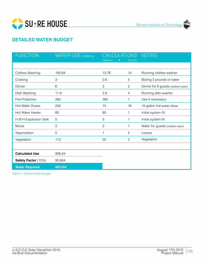
120
Stevens Institute of Technology
August 17th,2015U.S.D.O.E Solar Decathlon 2015As-Built Documentation Project Manual
DETAILED WATER BUDGET
FUNCTION
Clothes Washing
Cooking
Dinner
Dish Washing
Fire Protection
Hot Water Draws
Hot Water Heater
Movie
H.W.H Expansion Tank
Vaporization
Vegetation
Calculated Use
Safety Factor (10%)
Water Required
192.64
3
6
11.6
260
240
80
2
5
5
110
906.64
90.664
997.304
13.76
0.6
3
2.9
260
15
80
2
5
1
55
14
5
2
4
1
16
1
1
1
5
2
Running clothes washer
Boiling 5 pounds of water
Dinner for 8 guests (bottled water)
Running dish washer
Use if necessary
15 gallon hot water draw
Initial system fill
Water for guests (bottled water)
Initial system fill
Losses
Vegetation
CALCULATIONS NOTESWATER USE (Gallons)Gallons Eventsx
Table 4.1 Detailed Water Budget

UNLISTED 05
ofSUMMARY
ELECTRICALCOMPONENTS

122
Stevens Institute of Technology
August 17th,2015U.S.D.O.E Solar Decathlon 2015As-Built Documentation Project Manual
SUMMARY OF UNLISTED ELECTRICAL COMPONENTS
All electrical components carry an approved testing agency’s listing per Section 6-7 of the SD 2015 Building Code. However, we would like to point out that our Advanced Energy AV PV heater is not readily available in the US. It is CE listed and well documented. A cut sheet for this product is located in Division 23 of the Product Cut Sheets section of this manual. See “23 56 00 SOLAR HEATING COLLECTORS”.
Additional information and certificates are located below :

SUMMARYRECONFIGURABLE
FEATURES
06of
124
Stevens Institute of Technology
August 17th,2015U.S.D.O.E Solar Decathlon 2015As-Built Documentation Project Manual
SUMMARY OF RECONFIGURABLE FEATURES
The design incorporates four reconfigurable components.
A. REMOVABLE STORM PANELS
1. The casement stormshutter systems incorporate a protective layer to the casement windows located in the bedrooms. Operable for jurors only. See drawing(s) A-515, A-516,
B. BI-FOLDING STORMSHUTTER SYSTEMS
1. The bi-folding stormshutter systems incorporate a protective layer to the perimeter of the living room. The stormshutter system acknowl- edges various scenarios/modes the user or natural environment may have. Operable for jurors only. See drawing(s) A-552-53,54,55,56.
C. SCHUCO LIFT AND SLIDE DOORS
1. The Schuco Lift and Slide Doors have various qualities that enhance the experience, space, and aesthetics of SURE HOUSE. This feature allows for the blending of interior and exterior space.Operable for jurors only. See drawing(s) A-512-513.
D. MANUAL SHADE SYSTEM
1. This feature allows for the shading of interior space on the south facade. Operable for jurors only. See drawing(s) A-513.

125
Stevens Institute of Technology
August 17th,2015U.S.D.O.E Solar Decathlon 2015As-Built Documentation Project Manual
SUMMARY OF RECONFIGURABLE FEATURES
A. REMOVABLE STORM PANELS Introduction
SURE HOUSE features a set of removable glass fiber composite storm panels that can be installed over fixed windows during a high wind or flood event. The panels remain tucked away in storage until needed and can be fitted over the windows to protect glass from debris as well as providing a defense against water infiltration. EPDM gaskets create the waterproof seal.
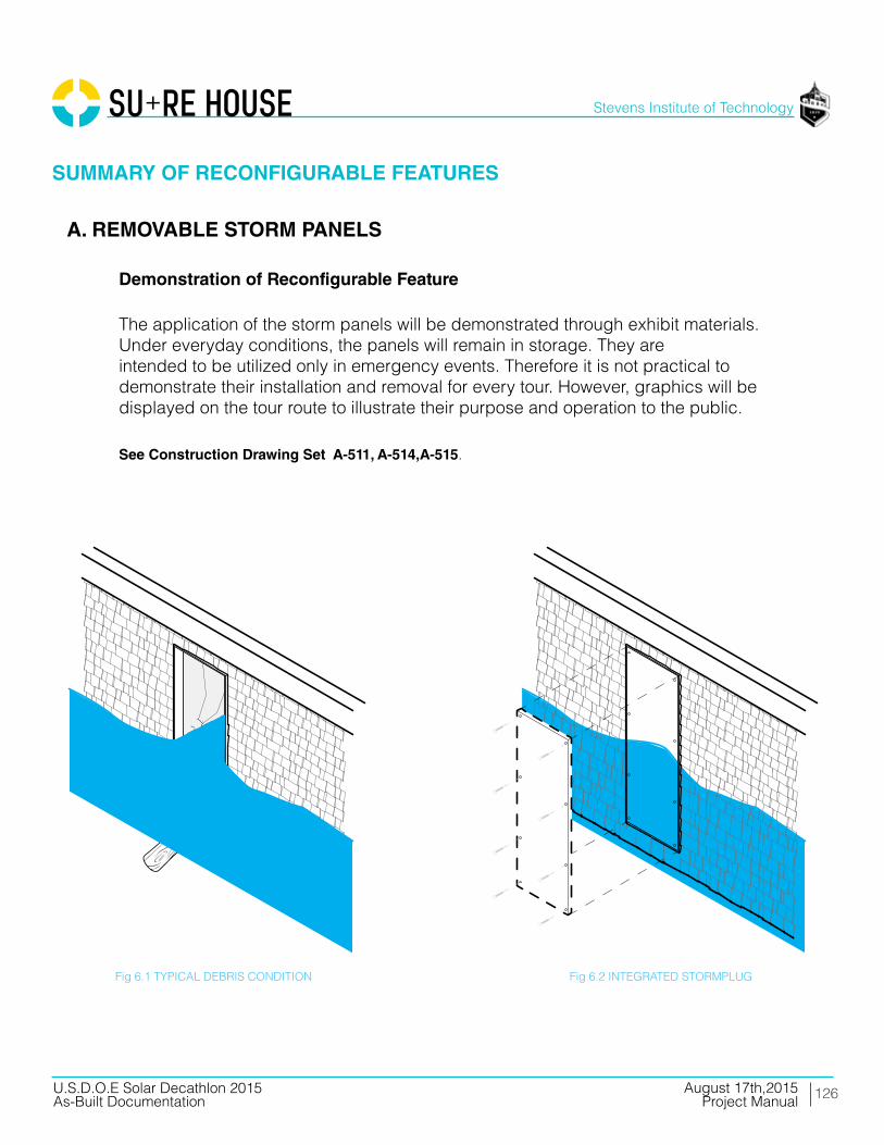
126
Stevens Institute of Technology
August 17th,2015U.S.D.O.E Solar Decathlon 2015As-Built Documentation Project Manual
Demonstration of Reconfigurable Feature
The application of the storm panels will be demonstrated through exhibit materials. Under everyday conditions, the panels will remain in storage. They are intended to be utilized only in emergency events. Therefore it is not practical to demonstrate their installation and removal for every tour. However, graphics will be displayed on the tour route to illustrate their purpose and operation to the public.
See Construction Drawing Set A-511, A-514,A-515.
A. REMOVABLE STORM PANELS
SUMMARY OF RECONFIGURABLE FEATURES
Fig 6.1 TYPICAL DEBRIS CONDITION Fig 6.2 INTEGRATED STORMPLUG

127
Stevens Institute of Technology
August 17th,2015U.S.D.O.E Solar Decathlon 2015As-Built Documentation Project Manual
B. BI-FOLDING STORMSHUTTER SYSTEMS
Introduction
SURE HOUSE has been designed with a durable resiliency program. To protect during high wind and flood events, the home will incorporate a storm shutter system. The bi folding shutter doors are a multi-purposed system, acting as a protection against storms, passive shading over the South glazing, and as solar collection for the DC hot water system.
Fig 6.3 Stormshutters in a Shade + Flood Scenario
SUMMARY OF RECONFIGURABLE FEATURES
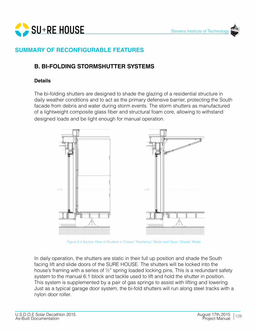
128
Stevens Institute of Technology
August 17th,2015U.S.D.O.E Solar Decathlon 2015As-Built Documentation Project Manual
Details
The bi-folding shutters are designed to shade the glazing of a residential structure in daily weather conditions and to act as the primary defensive barrier, protecting the South facade from debris and water during storm events. The storm shutters as manufactured of a lightweight composite glass fiber and structural foam core, allowing to withstand designed loads and be light enough for manual operation.
In daily operation, the shutters are static in their full up position and shade the South facing lift and slide doors of the SURE HOUSE. The shutters will be locked into the house’s framing with a series of ½” spring loaded locking pins, This is a redundant safety system to the manual 6:1 block and tackle used to lift and hold the shutter in position. This system is supplemented by a pair of gas springs to assist with lifting and lowering. Just as a typical garage door system, the bi-fold shutters will run along steel tracks with a nylon door roller.
Figure 6.4 Section View of Shutters in Closed “Resiliency” Mode and Open “Shade” Mode
B. BI-FOLDING STORMSHUTTER SYSTEMS
SUMMARY OF RECONFIGURABLE FEATURES

129
Stevens Institute of Technology
August 17th,2015U.S.D.O.E Solar Decathlon 2015As-Built Documentation Project Manual
B. BI-FOLDING STORMSHUTTER SYSTEMS
SUMMARY OF RECONFIGURABLE FEATURES
Details
Before a storm hits the shutters will be lowered as part of an evacuation procedure and locked into place using a series of latches attached to the shutters. Final storm sealing of the SURE HOUSE cannot be done from within. The shutters rest against weather- resistant EPDM rubber seals. This creates a continuous gasketed membrane up to the Designed Flood Elevation (DFE) or five feet above grade.
Adhered to the upper shutter panel are two sixty cell photovoltaic modules that supplement the heat pump hot water system with a DC electric heating coil inserted into the tank. Hot water is being created so long as the panels are operational. If the tank is up to temperature, the system switches to open circuit mode so it does not overheat.
Figure 6.7 Plan View of Shutters in Closed “Resiliency” Mode
Figure 6.6 Shutter Rigging
Figure 6.5 Shutter Axle

130
Stevens Institute of Technology
August 17th,2015U.S.D.O.E Solar Decathlon 2015As-Built Documentation Project Manual
B. BI-FOLDING STORMSHUTTER SYSTEMS
SUMMARY OF RECONFIGURABLE FEATURES
Figure 6.8 Shutter Open “Summer Mode”
Figure 6.9 Shutter Panel Operation Diagram
Figure 6.10 Shutter Panel Closed “Resilient Mode”

131
Stevens Institute of Technology
August 17th,2015U.S.D.O.E Solar Decathlon 2015As-Built Documentation Project Manual
B. BI-FOLDING STORMSHUTTER SYSTEMS
SUMMARY OF RECONFIGURABLE FEATURES
Figure 6.11 Shutter Panel Operation Series

132
Stevens Institute of Technology
August 17th,2015U.S.D.O.E Solar Decathlon 2015As-Built Documentation Project Manual
Demonstration Of Reconfigurable Feature
During public tours, the shutters will remain in their open and locked position to simulate daily operation. It is not reasonable to demonstrate the reconfiguration of these features for every tour throughout the competition. However, this capability will be clearly presented in video, photo, and rendering submissions and in the literature distributed at the competition.
Operation of at least one shutter will be shown to the jury during the engineering walkthroughs. This will include lowering the shutter into its storm and flood position, latching, and raising back to daily operation position.
See drawing(s) A-552-53,54,55,56.
B. BI-FOLDING STORMSHUTTER SYSTEMS
SUMMARY OF RECONFIGURABLE FEATURES

133
Stevens Institute of Technology
August 17th,2015U.S.D.O.E Solar Decathlon 2015As-Built Documentation Project Manual
B. BI-FOLDING STORMSHUTTER SYSTEMS
Fig 6.12 Solidworks Shutter Analysis w/ Components
SUMMARY OF RECONFIGURABLE FEATURES
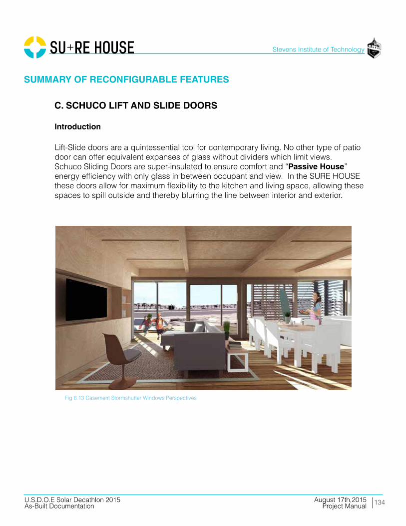
134
Stevens Institute of Technology
August 17th,2015U.S.D.O.E Solar Decathlon 2015As-Built Documentation Project Manual
C. SCHUCO LIFT AND SLIDE DOORS
Introduction
Lift-Slide doors are a quintessential tool for contemporary living. No other type of patio door can offer equivalent expanses of glass without dividers which limit views. Schuco Sliding Doors are super-insulated to ensure comfort and “Passive House” energy efficiency with only glass in between occupant and view. In the SURE HOUSE these doors allow for maximum flexibility to the kitchen and living space, allowing these spaces to spill outside and thereby blurring the line between interior and exterior.
Fig 6.13 Casement Stormshutter Windows Perspectives
SUMMARY OF RECONFIGURABLE FEATURES

135
Stevens Institute of Technology
August 17th,2015U.S.D.O.E Solar Decathlon 2015As-Built Documentation Project Manual
Demonstrations of Reconfigurable Features for the Jury
During the competition, the lift and slide doors will primarily be closed in the mornings and open in the afternoons to demonstrate the continuity of the space in both configurations. During the jury walk-through, lift and slides will be operated to demonstrate their ease of use.
Fig 6.14 Closed Bi-Fold Door Mode - Enclosed Space
Fig 6.16 Deck Perspective
C. SCHUCO LIFT AND SLIDE DOORS
SUMMARY OF RECONFIGURABLE FEATURES
Fig 6.15 Open Bi-Fold Door Mode - Continuous Space

136
Stevens Institute of Technology
August 17th,2015U.S.D.O.E Solar Decathlon 2015As-Built Documentation Project Manual
SUMMARY OF RECONFIGURABLE FEATURES
D. MANUAL SHADING SYSTEM
Introduction
Chain-driven roller screens are manual solar protection and room- darkening shading systems. They feature visually-transparent sunscreens and room- darkening shades. Shading, Interior Comfort, and Energy Balance are extremely important in the SURE HOUSE, therefore, a unique manual system allows the user to vary the space to their desire.
137
Stevens Institute of Technology
August 17th,2015U.S.D.O.E Solar Decathlon 2015As-Built Documentation Project Manual
SUMMARY OF RECONFIGURABLE FEATURES
D. MANUAL SHADING SYSTEM
Demonstrations of Reconfigurable Features for the Jury
During the competition, the shades, located on the south lift and slide doors will primarily be concealed. Depending on weather or changes in interior comfort, the shades will be deployed. This feature will be presented in the video, photo, and rendering submissions and in the literature distributed at the competition.
See drawing(s) A-513.

INTERCONNECTIONAPPLICATIONFORM
07

139
Stevens Institute of Technology
August 17th,2015U.S.D.O.E Solar Decathlon 2015As-Built Documentation Project Manual
INTERCONNECTION APPLICATION FORM
SURE HOUSE - Lot #101
SURE HOUSE Team Electrical Engineer - Armando [email protected]
PV SYSTEMS
INVERTERS
REQUIRED INFORMATION
MODULEMANUFACTURER
INVERTERMANUFACTURER
LG MONO - X 280 W
SMA America
Calculations Of Service / Feeder Net Computed Load And Neutral Load (Nec 220)
One - Line Electrical Schematic
LG MONO - X 280 W
SMA America
Plan View Of The Lot Showing The House, Decks, Ramps, Tour Paths, The Service Point, And The Distribution Panel Or Load Center
Total DC Power Of All Arrays is 8.96 kW
Inverter “I1”: One (I) string of twelve (12) modules
Inverter “I2”: Two (2) strings of ten (10) modules
SB 3000TL-US 240 V 3 kVA
SB 5000TL-US 240 V 5 kVA
3,360
1
E - 601
G - 121G - 103
E - 601
5,600
1
SHORT DESCRIPTIONOF ARRAY
MODEL NUMBER
VOLT-AGE
RATING (KVA OR KW)
DC RATING OF ARRAY (W)
QUANTITY
LOCATION

CODECOMPLIANCE
08 ENERGY

141
Stevens Institute of Technology
August 17th,2015U.S.D.O.E Solar Decathlon 2015As-Built Documentation Project Manual
ENERGY CODE COMPLIANCE
BACKGROUND
Using an array of software platforms including PHPP, designPH, THERM, TRNSYS, and various Grasshopper plugins, the SURE HOUSE has been extensively energy modeled as part of an iterative design process. Based on this methodology and analysis, our project exceeds the New Jersey Energy Code which is based on the 2009 International Energy Conservation Code, as shown in Table 8.1.
CLIMATE ZONE
CEILINGR-VALUE(H FT2 F/bTU)
WOODFRAME WALL(H FT2 F/bTU)
FLOORR-VALUE(H FT2 F/bTU)
2009 ieccnj code
0.35 nr 38 13 19
0.1254
4
>0.5 50 37 31SurehouSe
excePt
Marine
excePt
Marine
FENESTRATIONU - FACTOR (bTU/H FT2 F)
GLAZE FENESTRATION SHGC (-)
Table 8.1 SURE HOUSE Comparison With 2009 IECC Insulation And Fenestration Requirements
Table 8.2 SURE HOUSE Passive House Certification Criteria
SPACEHEATING
SPACECOOLING
SURE HOUSE Heating Demand
SURE HOUSE Cooling Demand
PASSIVE HOUSE Heating Demand
PASSIVE HOUSE Cooling Demand
14.5 kWh/(m2a)
kWh/(m2a)
kWh/(m2a)
kWh/(m2a)
15
16
16.5

09QUANTITY
COMPETITIONPROTOTYPE
TAKE OFF

143
Stevens Institute of Technology
August 17th,2015U.S.D.O.E Solar Decathlon 2015As-Built Documentation Project Manual
QUANTITY TAKEOFF OF COMPETITION PROTOTYPE
COLLECTIVE TOTALS
QUANTITY TAKEOFF OF COMPETITION PROTOTYPE
COLLECTIVE TOTALS
Brief deScriPtioncSi # detailed deScriPtion
diViSion 5 cont.
QtY. unit
01 54 16 lull/forklift setting steel and decks 2 days
01 54 19 90 ton hydraulic truck crane setting modules 1 day
05 05 23 1 1/2"x3" 12-gauge L-angle beam to floor framing connectors 100 ea
05 05 23 6" x 3" 12-gauge L-angle pier to beam connectors 25 ea.
05 12 13 HSS 4x2x5/16 southern steel columns 0.63 tons
05 12 13 HSS 4x4x3/16 north and east porch columns 0.34 tons
05 12 13 HSS 4x4, 3/16 shade structure steel columns 0.47 tons
05 12 13 HSS 4x2, 3/16 shade structure steel columns 0.08 tons
05 12 13 HSS 3x3, 3/8 shade structure steel beams 0.54 tons
05 12 13 WT4X7.5 lover steel columns 45 lf
05 13 00 stainless steel cable southern diagonal supports 25 lf
05 14 00 Roof Anchors PV racking roof array 32 ea
05 14 00 Strut Channel and Hardware PV racking roof array 120 lf
05 52 13 HSS 1X1, 1/4 ramp railing 100 lf
05 53 00 1/4 plate steel ramp to ground transition 45 sf
06 11 16 2x4 SPF interior partition framing 715lf
06 11 16 2x6 SPF interior partition framing 180lf
06 11 16 2x6 SPF bedroom drop ceiling 106 sf
06 11 16 2x4 SPF kitchen island 55 lf
06 11 16 2x4 SPF foundation beam top plates to createspace for crane straps 315 lf
06 11 16 2x8 SPF foundation beams attached to piers,supporting floor 171 lf
01 - GENERAL REQUIREMENTS
05 - METALS
06 - WOODS, PLASTICS, COMPOSITES
06 11 16 2x10 SPF south dropdown floor framing +blocking 90 lf
06 11 16 2x10 SPF roof framing blocking 250 lf
06 11 16 2x4 SPF ledgers for roof joist support atmodule seams 90 lf
06 11 16 2x4 SPF south shadestructure "sweatband"framing 70 lf
06 11 16 2x6 SPF exterior wall and parapet framing 1880 lf
06 11 16 1x3 SPF exterior rainscreen battens 3345 lf
06 11 16 2x3 SPF interior service cavity battens 600 lf
06 11 16 2x10 PT south deck framing 270 lf
06 11 16 2x8 PT south deck framing 40 lf
06 11 16 2x4 PT south deck framing 325 lf
06 11 16 2x10 PT north deck framing 50 lf
06 11 16 2x8 PT north deck framing 204 lf
06 11 16 2x8 PT ramp framing 30 lf
06 11 16 2x4 PT ramp framing 30 lf
06 11 16 2x4 PT ramp platform framing 100 sf
06 11 16 2x4 PT electrical platform framing 40 lf
06 11 13 1 3/4 x 7 1/4 LVL beams attached to piers, supportingfloor 115 lf
06 11 13 1 3/4 x 9 1/2 LVL module three floor joists 320 lf
06 11 13 1 3/4 x 7 1/4 LVL shower pan framing 10 lf
06 11 13 1 3/4 x 9 1/2 LSL plumber waste header 10 lf
06 11 13 1 3/4 x 9 1/2 LVL floor beam at module perimeters 171 lf
06 11 13 1 1/2 x 9 1/2 rim joist 102 lf
06 11 13 3 1/2 x 11 7/8 LVL living room and east porch beams 11 lf
06 11 13 3 1/2 x 11 7/8 LVL kitchen beams 24 lf
06 11 13 1 3/4 x 7 1/4 LVL bedroom beams 37 lf
06 11 13 3 1/2 x 9 1/2 LVL north porch beams 27 lf
06 11 13 3 1/2 x 9 1/2 LSL east porch beam 19 lf
06 11 13 1 1/8 x 9 1/2 rimboard rim joists, doubled at module seams 218 lf
06 11 13 1 3/4 x 9 1/2 PSL southern perimeter beam for shutterlateral loads 44 lf
06 11 13 3 1/2 x 9 1/2 LVL southern perimeter beam for shutterlateral loads 44 lf
06 11 16 1 3/4 x 9 1/2 LVL column between southern lift andslide doors 10 lf
06 11 16 3 1/2 x 9 PSL south deck framing 130 lf
06 11 16 3 1/2 x 9 PSL north deck framing 87 lf
06 16 23 3/4 OSB sheathing uder floorjoists allow forfloodproofing 1000 sf
06 16 23 3/4 T & G OSB subfloor 1000 sf
06 16 26 3/4 T&G OSB roof sheathing 1240 sf
06 16 36 3/4 CDX ply
Material component for 12" x 24" and6" x 10" foundation piers consisting of
glued and screwed plywood,combination of 3/4", 5/8", 1/2", and
1/4" as required by site contour
36 ea
06 16 36 5/8 CDX ply
Material component for 12" x 24" and6" x 10" foundation piers consisting of
glued and screwed plywood,combination of 3/4", 5/8", 1/2", and
1/4" as required by site contour
3 ea
06 16 36 1/2 CDX ply
Material component for 12" x 24" and6" x 10" foundation piers consisting of
glued and screwed plywood,combination of 3/4", 5/8", 1/2", and
1/4" as required by site contour
3 ea
06 16 36 1/4 CDX ply
Material component for 12" x 24" and6" x 10" foundation piers consisting of
glued and screwed plywood,combination of 3/4", 5/8", 1/2", and
1/4" as required by site contour
3 ea
06 16 36 7/16 zip sheathing system exterior sheathing 1365 sf
06 16 36 1/4 ply fascia over southern shutters 45 sf
06 16 36 1/2 CDX ply interior shear wall sheathing 270sf
06 16 36 1/2 CDX ply north planter box framing 190 sf
06 16 36 1/2 CDX ply electrical platform framing 28 sf
06 16 36 1/2 CDX ply south shadestructure "sweatband"framing 70 lf
06 16 53 1/8" ABS sheet plastic glued and screwed to 3/4" sheathingunder floor joists 1000 sf
06 16 53 1/8" ABS sheet plastic wraps first 4' feet of exterior wall 400 sf
06 17 33 2 1/2 x 9 1/2 I-Joist modules 1 and 2 floor joists, 16" OC 610 lf
06 17 33 2 1/16 x 9 1/2 I-Joist roof joists 928 lf
06 20 13 1x8 #3 cedar north planter box trim 60 lf
06 20 13 1x6 T&G cedar porch ceiling 250 sf
06 25 00 MDF face panels fridge, dishwasher, pantry 50 sf
06 20 13 1/2 birch ply south shadestructure "sweatband"finish 70 sf
06 40 23 3/4 AB ply mechanical room sheathing 190sf
06 40 23 3/4 birch ply hallway walls 64sf
06 40 23 1/2 birch ply drop ceiling living room 506 sf
06 40 23 1/2 birch ply drop ceiling hall 25 sf
06 40 23 3/4 AB ply mechanical room 42 sf
06 40 23 1/2 birch ply living room beam wrap 100 sf
06 40 23 3/4 birch ply living room and entertainment centerbuilt-in shelving 220 sf
06 46 13 1x4 finger-jointed paintgrade pine door and window trim for bedrooms 75 lf
06 46 19 1x4 finger-jointed paintgrade pine bedroom baseboard 78 lf
06 65 00 1x6 PVC trim porch ceiling edges 45 lf
06 73 00 1x6 TruGrain compositelumber door and window trim 150 lf
06 73 00 3/4" TruGraincompositelumber shower 22 sf
06 73 00 5/4x6 TruGrain compositedecking decking 1120 sf
06 73 00 1x6 TruGrain compositelumber ramp and deck trim 170 lf
06 73 00 5/4x6 TruGrain compositedecking ramp decking 190 sf
06 73 00 5/4x6 TruGrain compositedecking electrical platform decking 15 sf
06 73 00 1x6 TruGrain compositelumber electrical platform finish 28 sf
06 73 00 1x6 TruGrain compositelumber louver verticals 88 lf
06 73 00 1x4 TruGrain compositelumber louvers 1160 lf
07 13 26 Grace Ice and Water Sheild exterior floor to wall joint 120 lf
07 21 16 8" mineral wool batts floor cavity insulation 1000 sf
07 21 16 12" mineral wool batts roof cavity insulation 1000 sf
07 21 16 5.5" mineral wool batts wall cavity insulation 980 sf
07 21 16 2.5" mineral wool batts service cavity insulation 980 sf
07 21 16 1 1/4" mineral wool boardinsulation insulation over sheathing 920 sf
07 21 16 3.5" mineral wool batts interior acoustic insualtion 290 sf
07 22 22 tapered polyisocyanuraterigid insulation
roof deck insulation; 6" at westtapered to 1" at east 1240 sf
07 27 00 ProClima Intello interior primary air barrier 3260 sf
07 46 23 cedar shakes east, north, west finish 983 sf
07 46 23 primed cedar shakes north planter box finish 165 sf
07 46 46 3/16" fibercement board south bathroom facade 70 sf
07 46 46 3/16" fibercement board south shadestructure "sweatband"finish 70 sf
07 54 00 SikaSarnafil G410 PVC, 60mil roofing membrane 1240 sf
07 62 00 coping cap membrane seal at parapet edge 160 sf
07 70 00 vent strip cap top and bottom of rainscreencavity 160 lf
07 71 00 retrodrain scuppers scupper drains 2 ea
07 92 13 10oz marine sealant floodproofing joint sealant 20 ea.
07 92 13 4" x 75' self-healing jointtape (Grace Vycor) floodproofing joint flashing tape 5 ea.
07 - THERMAL AND MOISTURE PROTECTION
08 14 16 3'-0" x 7'-0" Interior doors 3 ea
08 14 16 2'-8" x 7--0" Interior doors 1 ea
08 14 16 2'-8" x 7'-0" Interior doors bifold 1 ea
08 15 00 Schuco SL82, 7'-0" x 3'-2" swinging entry doors 2 ea.
08 32 16Schuco thermoslide, triplepane, low-E,safety glazing,
8'-5" x 14'-10"sliding patio doors 2 ea.
08 53 00Schuco tilt and turn, triplepane, low-E, safety glazing,
3 'x 5'-1 1/2"tilt/turnwindow (bedroom) 30 sf
08 53 00Schuco tilt and turn, triplepane, low-E, safety glazing,
2' x 5'-3"tilt/turn window (bedroom) 10.5 sf
08 53 00Schuco fixed triple pane,low-E, safety glazing, 3' x 7'-
11"fixed windows (east + west) 48 sf
09 22 16 2x4 metal stud framing bathroom drop ceiling 42 sf
09 29 00 5/8" type X gypsum bedroom walls 670sf
09 29 00 5/8" type X gypsum bedroom drop ceiling 106 sf
09 29 00 5/8" type X gypsum bathroom drop ceiling 42 sf
09 30 13 ceramic wood pattern tile bathroom walls 200 sf
09 30 13 ceramic white tile bathroom walls 32 sf
09 62 19 aquastep laminate flooring mechanical room 42 sf
09 65 13 prefinished 3/4" maple plank living and bedroom floor 710 sf
09 91 13 paint: gypsum board bedrooms 670 sf
09 91 13 paint: wood trim bedrooms 25 sf
09 91 13 paint: birch plywood hallway 64 sf
09 91 13 paint: wood trim bedroom baseboard78
lf
09 91 13 paint: plywood hallway and living room beam wrap 25 lf
09 91 13 paint: gyp bedrooms and bathroom 148 lf
08 - OPENINGS
09 - FINISHES
09 93 23 polyurethane: interiorplywood surfaces living room built-ins 515 sf
09 93 23 polyurethane: plywood living room 506 sf
10 28 16 3' x 5' mirror vanity mirror 1 ea
10 28 16 Ikea: Grundtal towel hanger 1 ea
10 28 16 Ikea: Grundtal toilet paper roll 1 ea
10 28 16 Ikea: Grundtal small hanger 1 ea
10 71 1611'-0 x 7'-6" fiberglasscomposite panels withhardware and rigging
manually operable shutters 6 ea
10 71 16 1.5" fiberglass compositepanels storm plugs for windows and doors 115 sf
11 30 13 Thermador UCVM36FS recirculating range hood 1 ea
11 31 13 GE JP656DDBB cooktop 1 ea
11 31 13 GE JT5000DF wall oven 1 ea
11 31 13 Liebherr HC1030 refrigerator1
ea
11 31 13 Bloomberg DW 551100 dishwasher 1 ea
11 31 23 LG WM4070H_A washer 1 ea
11 31 23 LG DLHX4072 dryer 1 ea
12 24 13 rolling shades manual solar protection 290 sf
12 32 13 Ikea casework: lowercabinets lower cabinets 5.5 lf
12 32 13 Ikea casework: uppercabinets upper cabinets 7.5 lf
12 36 61 Hi-Macs composite bathroom vanity; 2 shelves and sinkenclosure 1 ea
12 36 61 HI-Macs composite kitchen counter 9 lf
12 36 61 HI-Macs composite backsplash 18 sf
10 - SPECIALTIES
11 - EQUIPMENT
12 - FURNISHINGS
21 13 13 fire sprinkler head 6 ea
21 13 13 1" Fire Protection Pipe 90 lf
21 13 13 fitting elbow 10 ea
21 13 13 fitting tee 2 wa
21 13 13 valve assembly 1 ea
21 13 13 pressure release valve 1 ea
21 30 00 fire pump 1 ea
22 11 13 plumbing manifold mech room 1 ea
22 11 16 1/2" PEX pipe domestic supply 70 lf
22 11 16 misc. valves and fittings domestic supply 1 ls
22 11 23 pump domestic supply; under planter
22 12 23 pressure tank domestic supply; under planter 1 ea
22 12 19 1000 gallon water tank domestic supply; under planter 1 ea
22 13 16 4" PVC gutter downspout, along west exteriorwall behind finish 40 lf
22 13 16 4" corrugated drain pipe to direct downspout water from underhouse to daylight 20 lf
22 13 16 waste and vent piping: PVC 80 lf
22 13 53 400 gallon water tank waste; planter 1 ea
22 14 29 sump pump to waste tank; outside house underelectrical platform 1 ea
22 30 3080 gallon heat pump waterheater w/ 2nd electricalelement circuited to shutterPV
domestic hot water; mech room 1 ea
22 41 00 expansion tank mech room 1 ea
22 41 13 residential water closet bathroom 1 ea
21 - FIRE SUPRESSION
22 - PLUMBING
22 41 13 shower pan bathroom 1 ea
22 41 16 shower drain/faucet bathroom 1 ea
22 41 16 double bowl sink kitchen 1 ea
22 41 39 faucet bathroom 1 ea
22 41 39 clothes washer connection laundry 1 ea
22 41 39 faucet kitchen 1 ea
22 41 39 dishwasher connection kitchen 1 ea
23 09 13 Daikin DZK030E5 zoning kit 1 ea
23 09 13 Daikin DZK-MTS-1 Main Thermostat 1 ls
23 09 13 Daikin DZK-ZTS-1 Wireless Thermostat 4 ls
23 09 13 Daikin BRC1E73 AHU Thermostat 1 ls
23 23 00 Copper Piping refrigerant piping 15 lf
23 31 16 Zehnder comfopipe insulatedrigid ductwork heating and cooling (heat pump) 130 lf
23 31 16 Zehnder comfotube flexibleductwork ventilation (ERV) 50 lf
23 33 13 Tuttle and Bailey MA, 4000,DXFR, and T75D grilles, registers, diffusers 12 ea
23 34 00 Daikin FBQ24PVJU air handler 1 ea
23 72 00 Zehnder Comfowell 220 ventilation manifold 2 ea
23 72 00 Zehnder NOVUS 300 ERV 10 lf
23 82 19 Daikin RDZQ24PVJU9 condensing unit 1 ea
25 37 00 data opening 2 ea
25 37 00 tv opening 2 ea
25 38 00 smoke detector 3 ea
23 - HVAC
25 - INTEGRATED AUTOMATION
25 50 00 exterior south deckuplighting: LED 6 ea
25 50 00 exterior east porchdownlighting: LED 6 ea
26 05 19 200A panel including AFCIbreakers 1 ea
26 05 19 electrical meter 1 ea
26 05 19 service entrance conductors;(3) 2/0 THHN (1) #4 ground 15 lf
26 05 19 #8 AWG THWN-2 0 lf
26 05 19 #10 AWG THWN-2 50 lf
26 05 19 #12 AWG THWN-2 100 lf
26 05 19 #12/2 NM-B 500 lf
26 05 19 #10/3 NM-B 100 lf
26 05 19 #8/3 NM-B 100 lf
26 05 19 #10 AWG PV Wire 400 lf
26 05 19 #8 AWG PV Wire 100 lf
26 05 19 #10 AWG THWN-2 250 lf
26 05 19 #8 AWG THWN-2 100 lf
26 21 00 200A SE cable 80 lf
26 27 26 20A 125V duplex receptacle 10 ea
26 27 26 20A 125V duplex receptacle- GFCI 15 ea
26 27 26 20A 125V duplex receptacle- WP 5 ea
26 27 26 duplex receptacle cover In-Use 3 ea
26 27 26 50A 240V single receptacle 4 ea
26 27 26 15A 125V duplex receptacle- Floor 2 ea
26 27 26 20A 120/277V Switch 8 ea
26 - ELECTRICAL
26 27 26 20A 120/277V 3-Way Switch 4 ea
26 27 26 domestic water pump stationconnection 1 ea
26 27 26 dishwasher connection 1 ea
26 27 26 heat pump water heaterconnection 1 ea
26 27 26 sump pump connection 1 ea
26 27 26 air handler connection 1 ea
26 27 26 heat pump; 2-ton outdoorunit connection 1 ea
26 27 26 energy recovery ventilatorconnection 1 ea
26 27 26 combiner Box 3 ea
26 27 26 transition/junction box 2 ea
26 28 16 disconnect wwitch 2 ea
26 31 00 module 60-cell mSi 280WFramed PV Roof Array 32 ea
26 31 00 module 60-cell mSi 180WFlexible PV Flood Shutters 10 ea
26 31 00 Renusol CS60 ballastedracking trays PV Racking Roof Array 32 ea
26 50 00 drivers/pwr supply andacc'ys (Exterior) 2 ea
26 51 13 interior linear LED fixtures 36 ft
26 51 13 interior track LED fixtures 21 ea
26 51 13 interior recessed LEDdownlight fixtures 2 ea
26 51 13 drivers/pwr supply andacc'ys (Interior) 6 ea
31 66 00 concrete and steel pier 11" seismic piers for deck 16 ea
31 66 00 concrete and steel pier 7" seismic piers for deck 4 ea
31 - EARTHWORK
32 93 00
ornamental grasses and fallperrenials: Muhlenbergia,Capillaris, MuhlenbergiaCapillarisFestuca Rubra, Kniphofiauvaria,Solidage Californica
ornamental plants 220 sf
32 94 00 standard 1 Ga. Containersfrom Nursery planter boxes 40 ea.
32 94 00 lightweight infill gravel soil 130 cu. ft
48 19 16 inverter grid-tied 5000W240Vac 1 ea
48 19 16 inverter grid-tied 3000W240Vac 1 ea
48 19 16 network interface inverter 2 ea
48 - ELECTRICAL POWER GENERATION
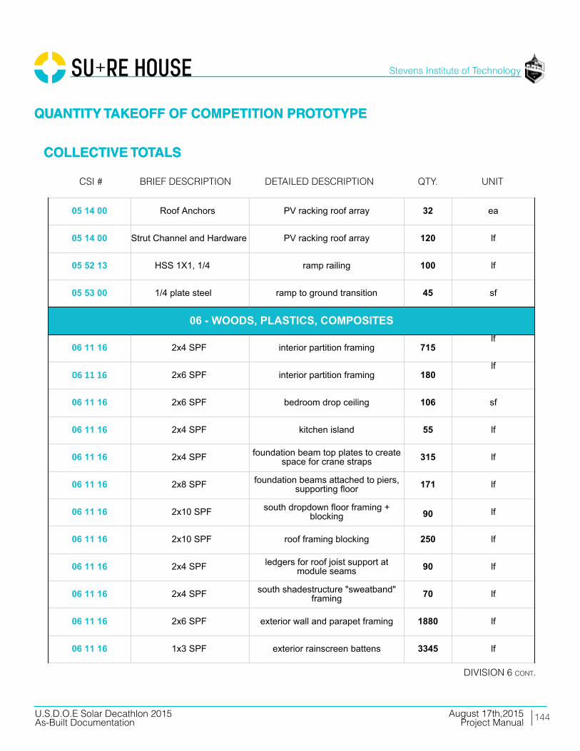
144
Stevens Institute of Technology
August 17th,2015U.S.D.O.E Solar Decathlon 2015As-Built Documentation Project Manual
QUANTITY TAKEOFF OF COMPETITION PROTOTYPE
COLLECTIVE TOTALS
QUANTITY TAKEOFF OF COMPETITION PROTOTYPE
COLLECTIVE TOTALS
Brief deScriPtioncSi # detailed deScriPtion
diViSion 6 cont.
QtY. unit
01 54 16 lull/forklift setting steel and decks 2 days
01 54 19 90 ton hydraulic truck crane setting modules 1 day
05 05 23 1 1/2"x3" 12-gauge L-angle beam to floor framing connectors 100 ea
05 05 23 6" x 3" 12-gauge L-angle pier to beam connectors 25 ea.
05 12 13 HSS 4x2x5/16 southern steel columns 0.63 tons
05 12 13 HSS 4x4x3/16 north and east porch columns 0.34 tons
05 12 13 HSS 4x4, 3/16 shade structure steel columns 0.47 tons
05 12 13 HSS 4x2, 3/16 shade structure steel columns 0.08 tons
05 12 13 HSS 3x3, 3/8 shade structure steel beams 0.54 tons
05 12 13 WT4X7.5 lover steel columns 45 lf
05 13 00 stainless steel cable southern diagonal supports 25 lf
05 14 00 Roof Anchors PV racking roof array 32 ea
05 14 00 Strut Channel and Hardware PV racking roof array 120 lf
05 52 13 HSS 1X1, 1/4 ramp railing 100 lf
05 53 00 1/4 plate steel ramp to ground transition 45 sf
06 11 16 2x4 SPF interior partition framing 715lf
06 11 16 2x6 SPF interior partition framing 180lf
06 11 16 2x6 SPF bedroom drop ceiling 106 sf
06 11 16 2x4 SPF kitchen island 55 lf
06 11 16 2x4 SPF foundation beam top plates to createspace for crane straps 315 lf
06 11 16 2x8 SPF foundation beams attached to piers,supporting floor 171 lf
01 - GENERAL REQUIREMENTS
05 - METALS
06 - WOODS, PLASTICS, COMPOSITES
06 11 16 2x10 SPF south dropdown floor framing +blocking 90 lf
06 11 16 2x10 SPF roof framing blocking 250 lf
06 11 16 2x4 SPF ledgers for roof joist support atmodule seams 90 lf
06 11 16 2x4 SPF south shadestructure "sweatband"framing 70 lf
06 11 16 2x6 SPF exterior wall and parapet framing 1880 lf
06 11 16 1x3 SPF exterior rainscreen battens 3345 lf
06 11 16 2x3 SPF interior service cavity battens 600 lf
06 11 16 2x10 PT south deck framing 270 lf
06 11 16 2x8 PT south deck framing 40 lf
06 11 16 2x4 PT south deck framing 325 lf
06 11 16 2x10 PT north deck framing 50 lf
06 11 16 2x8 PT north deck framing 204 lf
06 11 16 2x8 PT ramp framing 30 lf
06 11 16 2x4 PT ramp framing 30 lf
06 11 16 2x4 PT ramp platform framing 100 sf
06 11 16 2x4 PT electrical platform framing 40 lf
06 11 13 1 3/4 x 7 1/4 LVL beams attached to piers, supportingfloor 115 lf
06 11 13 1 3/4 x 9 1/2 LVL module three floor joists 320 lf
06 11 13 1 3/4 x 7 1/4 LVL shower pan framing 10 lf
06 11 13 1 3/4 x 9 1/2 LSL plumber waste header 10 lf
06 11 13 1 3/4 x 9 1/2 LVL floor beam at module perimeters 171 lf
06 11 13 1 1/2 x 9 1/2 rim joist 102 lf
06 11 13 3 1/2 x 11 7/8 LVL living room and east porch beams 11 lf
06 11 13 3 1/2 x 11 7/8 LVL kitchen beams 24 lf
06 11 13 1 3/4 x 7 1/4 LVL bedroom beams 37 lf
06 11 13 3 1/2 x 9 1/2 LVL north porch beams 27 lf
06 11 13 3 1/2 x 9 1/2 LSL east porch beam 19 lf
06 11 13 1 1/8 x 9 1/2 rimboard rim joists, doubled at module seams 218 lf
06 11 13 1 3/4 x 9 1/2 PSL southern perimeter beam for shutterlateral loads 44 lf
06 11 13 3 1/2 x 9 1/2 LVL southern perimeter beam for shutterlateral loads 44 lf
06 11 16 1 3/4 x 9 1/2 LVL column between southern lift andslide doors 10 lf
06 11 16 3 1/2 x 9 PSL south deck framing 130 lf
06 11 16 3 1/2 x 9 PSL north deck framing 87 lf
06 16 23 3/4 OSB sheathing uder floorjoists allow forfloodproofing 1000 sf
06 16 23 3/4 T & G OSB subfloor 1000 sf
06 16 26 3/4 T&G OSB roof sheathing 1240 sf
06 16 36 3/4 CDX ply
Material component for 12" x 24" and6" x 10" foundation piers consisting of
glued and screwed plywood,combination of 3/4", 5/8", 1/2", and
1/4" as required by site contour
36 ea
06 16 36 5/8 CDX ply
Material component for 12" x 24" and6" x 10" foundation piers consisting of
glued and screwed plywood,combination of 3/4", 5/8", 1/2", and
1/4" as required by site contour
3 ea
06 16 36 1/2 CDX ply
Material component for 12" x 24" and6" x 10" foundation piers consisting of
glued and screwed plywood,combination of 3/4", 5/8", 1/2", and
1/4" as required by site contour
3 ea
06 16 36 1/4 CDX ply
Material component for 12" x 24" and6" x 10" foundation piers consisting of
glued and screwed plywood,combination of 3/4", 5/8", 1/2", and
1/4" as required by site contour
3 ea
06 16 36 7/16 zip sheathing system exterior sheathing 1365 sf
06 16 36 1/4 ply fascia over southern shutters 45 sf
06 16 36 1/2 CDX ply interior shear wall sheathing 270sf
06 16 36 1/2 CDX ply north planter box framing 190 sf
06 16 36 1/2 CDX ply electrical platform framing 28 sf
06 16 36 1/2 CDX ply south shadestructure "sweatband"framing 70 lf
06 16 53 1/8" ABS sheet plastic glued and screwed to 3/4" sheathingunder floor joists 1000 sf
06 16 53 1/8" ABS sheet plastic wraps first 4' feet of exterior wall 400 sf
06 17 33 2 1/2 x 9 1/2 I-Joist modules 1 and 2 floor joists, 16" OC 610 lf
06 17 33 2 1/16 x 9 1/2 I-Joist roof joists 928 lf
06 20 13 1x8 #3 cedar north planter box trim 60 lf
06 20 13 1x6 T&G cedar porch ceiling 250 sf
06 25 00 MDF face panels fridge, dishwasher, pantry 50 sf
06 20 13 1/2 birch ply south shadestructure "sweatband"finish 70 sf
06 40 23 3/4 AB ply mechanical room sheathing 190sf
06 40 23 3/4 birch ply hallway walls 64sf
06 40 23 1/2 birch ply drop ceiling living room 506 sf
06 40 23 1/2 birch ply drop ceiling hall 25 sf
06 40 23 3/4 AB ply mechanical room 42 sf
06 40 23 1/2 birch ply living room beam wrap 100 sf
06 40 23 3/4 birch ply living room and entertainment centerbuilt-in shelving 220 sf
06 46 13 1x4 finger-jointed paintgrade pine door and window trim for bedrooms 75 lf
06 46 19 1x4 finger-jointed paintgrade pine bedroom baseboard 78 lf
06 65 00 1x6 PVC trim porch ceiling edges 45 lf
06 73 00 1x6 TruGrain compositelumber door and window trim 150 lf
06 73 00 3/4" TruGraincompositelumber shower 22 sf
06 73 00 5/4x6 TruGrain compositedecking decking 1120 sf
06 73 00 1x6 TruGrain compositelumber ramp and deck trim 170 lf
06 73 00 5/4x6 TruGrain compositedecking ramp decking 190 sf
06 73 00 5/4x6 TruGrain compositedecking electrical platform decking 15 sf
06 73 00 1x6 TruGrain compositelumber electrical platform finish 28 sf
06 73 00 1x6 TruGrain compositelumber louver verticals 88 lf
06 73 00 1x4 TruGrain compositelumber louvers 1160 lf
07 13 26 Grace Ice and Water Sheild exterior floor to wall joint 120 lf
07 21 16 8" mineral wool batts floor cavity insulation 1000 sf
07 21 16 12" mineral wool batts roof cavity insulation 1000 sf
07 21 16 5.5" mineral wool batts wall cavity insulation 980 sf
07 21 16 2.5" mineral wool batts service cavity insulation 980 sf
07 21 16 1 1/4" mineral wool boardinsulation insulation over sheathing 920 sf
07 21 16 3.5" mineral wool batts interior acoustic insualtion 290 sf
07 22 22 tapered polyisocyanuraterigid insulation
roof deck insulation; 6" at westtapered to 1" at east 1240 sf
07 27 00 ProClima Intello interior primary air barrier 3260 sf
07 46 23 cedar shakes east, north, west finish 983 sf
07 46 23 primed cedar shakes north planter box finish 165 sf
07 46 46 3/16" fibercement board south bathroom facade 70 sf
07 46 46 3/16" fibercement board south shadestructure "sweatband"finish 70 sf
07 54 00 SikaSarnafil G410 PVC, 60mil roofing membrane 1240 sf
07 62 00 coping cap membrane seal at parapet edge 160 sf
07 70 00 vent strip cap top and bottom of rainscreencavity 160 lf
07 71 00 retrodrain scuppers scupper drains 2 ea
07 92 13 10oz marine sealant floodproofing joint sealant 20 ea.
07 92 13 4" x 75' self-healing jointtape (Grace Vycor) floodproofing joint flashing tape 5 ea.
07 - THERMAL AND MOISTURE PROTECTION
08 14 16 3'-0" x 7'-0" Interior doors 3 ea
08 14 16 2'-8" x 7--0" Interior doors 1 ea
08 14 16 2'-8" x 7'-0" Interior doors bifold 1 ea
08 15 00 Schuco SL82, 7'-0" x 3'-2" swinging entry doors 2 ea.
08 32 16Schuco thermoslide, triplepane, low-E,safety glazing,
8'-5" x 14'-10"sliding patio doors 2 ea.
08 53 00Schuco tilt and turn, triplepane, low-E, safety glazing,
3 'x 5'-1 1/2"tilt/turnwindow (bedroom) 30 sf
08 53 00Schuco tilt and turn, triplepane, low-E, safety glazing,
2' x 5'-3"tilt/turn window (bedroom) 10.5 sf
08 53 00Schuco fixed triple pane,low-E, safety glazing, 3' x 7'-
11"fixed windows (east + west) 48 sf
09 22 16 2x4 metal stud framing bathroom drop ceiling 42 sf
09 29 00 5/8" type X gypsum bedroom walls 670sf
09 29 00 5/8" type X gypsum bedroom drop ceiling 106 sf
09 29 00 5/8" type X gypsum bathroom drop ceiling 42 sf
09 30 13 ceramic wood pattern tile bathroom walls 200 sf
09 30 13 ceramic white tile bathroom walls 32 sf
09 62 19 aquastep laminate flooring mechanical room 42 sf
09 65 13 prefinished 3/4" maple plank living and bedroom floor 710 sf
09 91 13 paint: gypsum board bedrooms 670 sf
09 91 13 paint: wood trim bedrooms 25 sf
09 91 13 paint: birch plywood hallway 64 sf
09 91 13 paint: wood trim bedroom baseboard78
lf
09 91 13 paint: plywood hallway and living room beam wrap 25 lf
09 91 13 paint: gyp bedrooms and bathroom 148 lf
08 - OPENINGS
09 - FINISHES
09 93 23 polyurethane: interiorplywood surfaces living room built-ins 515 sf
09 93 23 polyurethane: plywood living room 506 sf
10 28 16 3' x 5' mirror vanity mirror 1 ea
10 28 16 Ikea: Grundtal towel hanger 1 ea
10 28 16 Ikea: Grundtal toilet paper roll 1 ea
10 28 16 Ikea: Grundtal small hanger 1 ea
10 71 1611'-0 x 7'-6" fiberglasscomposite panels withhardware and rigging
manually operable shutters 6 ea
10 71 16 1.5" fiberglass compositepanels storm plugs for windows and doors 115 sf
11 30 13 Thermador UCVM36FS recirculating range hood 1 ea
11 31 13 GE JP656DDBB cooktop 1 ea
11 31 13 GE JT5000DF wall oven 1 ea
11 31 13 Liebherr HC1030 refrigerator1
ea
11 31 13 Bloomberg DW 551100 dishwasher 1 ea
11 31 23 LG WM4070H_A washer 1 ea
11 31 23 LG DLHX4072 dryer 1 ea
12 24 13 rolling shades manual solar protection 290 sf
12 32 13 Ikea casework: lowercabinets lower cabinets 5.5 lf
12 32 13 Ikea casework: uppercabinets upper cabinets 7.5 lf
12 36 61 Hi-Macs composite bathroom vanity; 2 shelves and sinkenclosure 1 ea
12 36 61 HI-Macs composite kitchen counter 9 lf
12 36 61 HI-Macs composite backsplash 18 sf
10 - SPECIALTIES
11 - EQUIPMENT
12 - FURNISHINGS
21 13 13 fire sprinkler head 6 ea
21 13 13 1" Fire Protection Pipe 90 lf
21 13 13 fitting elbow 10 ea
21 13 13 fitting tee 2 wa
21 13 13 valve assembly 1 ea
21 13 13 pressure release valve 1 ea
21 30 00 fire pump 1 ea
22 11 13 plumbing manifold mech room 1 ea
22 11 16 1/2" PEX pipe domestic supply 70 lf
22 11 16 misc. valves and fittings domestic supply 1 ls
22 11 23 pump domestic supply; under planter
22 12 23 pressure tank domestic supply; under planter 1 ea
22 12 19 1000 gallon water tank domestic supply; under planter 1 ea
22 13 16 4" PVC gutter downspout, along west exteriorwall behind finish 40 lf
22 13 16 4" corrugated drain pipe to direct downspout water from underhouse to daylight 20 lf
22 13 16 waste and vent piping: PVC 80 lf
22 13 53 400 gallon water tank waste; planter 1 ea
22 14 29 sump pump to waste tank; outside house underelectrical platform 1 ea
22 30 3080 gallon heat pump waterheater w/ 2nd electricalelement circuited to shutterPV
domestic hot water; mech room 1 ea
22 41 00 expansion tank mech room 1 ea
22 41 13 residential water closet bathroom 1 ea
21 - FIRE SUPRESSION
22 - PLUMBING
22 41 13 shower pan bathroom 1 ea
22 41 16 shower drain/faucet bathroom 1 ea
22 41 16 double bowl sink kitchen 1 ea
22 41 39 faucet bathroom 1 ea
22 41 39 clothes washer connection laundry 1 ea
22 41 39 faucet kitchen 1 ea
22 41 39 dishwasher connection kitchen 1 ea
23 09 13 Daikin DZK030E5 zoning kit 1 ea
23 09 13 Daikin DZK-MTS-1 Main Thermostat 1 ls
23 09 13 Daikin DZK-ZTS-1 Wireless Thermostat 4 ls
23 09 13 Daikin BRC1E73 AHU Thermostat 1 ls
23 23 00 Copper Piping refrigerant piping 15 lf
23 31 16 Zehnder comfopipe insulatedrigid ductwork heating and cooling (heat pump) 130 lf
23 31 16 Zehnder comfotube flexibleductwork ventilation (ERV) 50 lf
23 33 13 Tuttle and Bailey MA, 4000,DXFR, and T75D grilles, registers, diffusers 12 ea
23 34 00 Daikin FBQ24PVJU air handler 1 ea
23 72 00 Zehnder Comfowell 220 ventilation manifold 2 ea
23 72 00 Zehnder NOVUS 300 ERV 10 lf
23 82 19 Daikin RDZQ24PVJU9 condensing unit 1 ea
25 37 00 data opening 2 ea
25 37 00 tv opening 2 ea
25 38 00 smoke detector 3 ea
23 - HVAC
25 - INTEGRATED AUTOMATION
25 50 00 exterior south deckuplighting: LED 6 ea
25 50 00 exterior east porchdownlighting: LED 6 ea
26 05 19 200A panel including AFCIbreakers 1 ea
26 05 19 electrical meter 1 ea
26 05 19 service entrance conductors;(3) 2/0 THHN (1) #4 ground 15 lf
26 05 19 #8 AWG THWN-2 0 lf
26 05 19 #10 AWG THWN-2 50 lf
26 05 19 #12 AWG THWN-2 100 lf
26 05 19 #12/2 NM-B 500 lf
26 05 19 #10/3 NM-B 100 lf
26 05 19 #8/3 NM-B 100 lf
26 05 19 #10 AWG PV Wire 400 lf
26 05 19 #8 AWG PV Wire 100 lf
26 05 19 #10 AWG THWN-2 250 lf
26 05 19 #8 AWG THWN-2 100 lf
26 21 00 200A SE cable 80 lf
26 27 26 20A 125V duplex receptacle 10 ea
26 27 26 20A 125V duplex receptacle- GFCI 15 ea
26 27 26 20A 125V duplex receptacle- WP 5 ea
26 27 26 duplex receptacle cover In-Use 3 ea
26 27 26 50A 240V single receptacle 4 ea
26 27 26 15A 125V duplex receptacle- Floor 2 ea
26 27 26 20A 120/277V Switch 8 ea
26 - ELECTRICAL
26 27 26 20A 120/277V 3-Way Switch 4 ea
26 27 26 domestic water pump stationconnection 1 ea
26 27 26 dishwasher connection 1 ea
26 27 26 heat pump water heaterconnection 1 ea
26 27 26 sump pump connection 1 ea
26 27 26 air handler connection 1 ea
26 27 26 heat pump; 2-ton outdoorunit connection 1 ea
26 27 26 energy recovery ventilatorconnection 1 ea
26 27 26 combiner Box 3 ea
26 27 26 transition/junction box 2 ea
26 28 16 disconnect wwitch 2 ea
26 31 00 module 60-cell mSi 280WFramed PV Roof Array 32 ea
26 31 00 module 60-cell mSi 180WFlexible PV Flood Shutters 10 ea
26 31 00 Renusol CS60 ballastedracking trays PV Racking Roof Array 32 ea
26 50 00 drivers/pwr supply andacc'ys (Exterior) 2 ea
26 51 13 interior linear LED fixtures 36 ft
26 51 13 interior track LED fixtures 21 ea
26 51 13 interior recessed LEDdownlight fixtures 2 ea
26 51 13 drivers/pwr supply andacc'ys (Interior) 6 ea
31 66 00 concrete and steel pier 11" seismic piers for deck 16 ea
31 66 00 concrete and steel pier 7" seismic piers for deck 4 ea
31 - EARTHWORK
32 93 00
ornamental grasses and fallperrenials: Muhlenbergia,Capillaris, MuhlenbergiaCapillarisFestuca Rubra, Kniphofiauvaria,Solidage Californica
ornamental plants 220 sf
32 94 00 standard 1 Ga. Containersfrom Nursery planter boxes 40 ea.
32 94 00 lightweight infill gravel soil 130 cu. ft
48 19 16 inverter grid-tied 5000W240Vac 1 ea
48 19 16 inverter grid-tied 3000W240Vac 1 ea
48 19 16 network interface inverter 2 ea
48 - ELECTRICAL POWER GENERATION
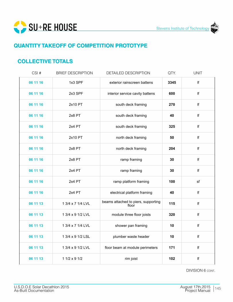
145
Stevens Institute of Technology
August 17th,2015U.S.D.O.E Solar Decathlon 2015As-Built Documentation Project Manual
01 54 16 lull/forklift setting steel and decks 2 days
01 54 19 90 ton hydraulic truck crane setting modules 1 day
05 05 23 1 1/2"x3" 12-gauge L-angle beam to floor framing connectors 100 ea
05 05 23 6" x 3" 12-gauge L-angle pier to beam connectors 25 ea.
05 12 13 HSS 4x2x5/16 southern steel columns 0.63 tons
05 12 13 HSS 4x4x3/16 north and east porch columns 0.34 tons
05 12 13 HSS 4x4, 3/16 shade structure steel columns 0.47 tons
05 12 13 HSS 4x2, 3/16 shade structure steel columns 0.08 tons
05 12 13 HSS 3x3, 3/8 shade structure steel beams 0.54 tons
05 12 13 WT4X7.5 lover steel columns 45 lf
05 13 00 stainless steel cable southern diagonal supports 25 lf
05 14 00 Roof Anchors PV racking roof array 32 ea
05 14 00 Strut Channel and Hardware PV racking roof array 120 lf
05 52 13 HSS 1X1, 1/4 ramp railing 100 lf
05 53 00 1/4 plate steel ramp to ground transition 45 sf
06 11 16 2x4 SPF interior partition framing 715lf
06 11 16 2x6 SPF interior partition framing 180lf
06 11 16 2x6 SPF bedroom drop ceiling 106 sf
06 11 16 2x4 SPF kitchen island 55 lf
06 11 16 2x4 SPF foundation beam top plates to createspace for crane straps 315 lf
06 11 16 2x8 SPF foundation beams attached to piers,supporting floor 171 lf
01 - GENERAL REQUIREMENTS
05 - METALS
06 - WOODS, PLASTICS, COMPOSITES
06 11 16 2x10 SPF south dropdown floor framing +blocking 90 lf
06 11 16 2x10 SPF roof framing blocking 250 lf
06 11 16 2x4 SPF ledgers for roof joist support atmodule seams 90 lf
06 11 16 2x4 SPF south shadestructure "sweatband"framing 70 lf
06 11 16 2x6 SPF exterior wall and parapet framing 1880 lf
06 11 16 1x3 SPF exterior rainscreen battens 3345 lf
06 11 16 2x3 SPF interior service cavity battens 600 lf
06 11 16 2x10 PT south deck framing 270 lf
06 11 16 2x8 PT south deck framing 40 lf
06 11 16 2x4 PT south deck framing 325 lf
06 11 16 2x10 PT north deck framing 50 lf
06 11 16 2x8 PT north deck framing 204 lf
06 11 16 2x8 PT ramp framing 30 lf
06 11 16 2x4 PT ramp framing 30 lf
06 11 16 2x4 PT ramp platform framing 100 sf
06 11 16 2x4 PT electrical platform framing 40 lf
06 11 13 1 3/4 x 7 1/4 LVL beams attached to piers, supportingfloor 115 lf
06 11 13 1 3/4 x 9 1/2 LVL module three floor joists 320 lf
06 11 13 1 3/4 x 7 1/4 LVL shower pan framing 10 lf
06 11 13 1 3/4 x 9 1/2 LSL plumber waste header 10 lf
06 11 13 1 3/4 x 9 1/2 LVL floor beam at module perimeters 171 lf
06 11 13 1 1/2 x 9 1/2 rim joist 102 lf
06 11 13 3 1/2 x 11 7/8 LVL living room and east porch beams 11 lf
06 11 13 3 1/2 x 11 7/8 LVL kitchen beams 24 lf
06 11 13 1 3/4 x 7 1/4 LVL bedroom beams 37 lf
06 11 13 3 1/2 x 9 1/2 LVL north porch beams 27 lf
06 11 13 3 1/2 x 9 1/2 LSL east porch beam 19 lf
06 11 13 1 1/8 x 9 1/2 rimboard rim joists, doubled at module seams 218 lf
06 11 13 1 3/4 x 9 1/2 PSL southern perimeter beam for shutterlateral loads 44 lf
06 11 13 3 1/2 x 9 1/2 LVL southern perimeter beam for shutterlateral loads 44 lf
06 11 16 1 3/4 x 9 1/2 LVL column between southern lift andslide doors 10 lf
06 11 16 3 1/2 x 9 PSL south deck framing 130 lf
06 11 16 3 1/2 x 9 PSL north deck framing 87 lf
06 16 23 3/4 OSB sheathing uder floorjoists allow forfloodproofing 1000 sf
06 16 23 3/4 T & G OSB subfloor 1000 sf
06 16 26 3/4 T&G OSB roof sheathing 1240 sf
06 16 36 3/4 CDX ply
Material component for 12" x 24" and6" x 10" foundation piers consisting of
glued and screwed plywood,combination of 3/4", 5/8", 1/2", and
1/4" as required by site contour
36 ea
06 16 36 5/8 CDX ply
Material component for 12" x 24" and6" x 10" foundation piers consisting of
glued and screwed plywood,combination of 3/4", 5/8", 1/2", and
1/4" as required by site contour
3 ea
06 16 36 1/2 CDX ply
Material component for 12" x 24" and6" x 10" foundation piers consisting of
glued and screwed plywood,combination of 3/4", 5/8", 1/2", and
1/4" as required by site contour
3 ea
06 16 36 1/4 CDX ply
Material component for 12" x 24" and6" x 10" foundation piers consisting of
glued and screwed plywood,combination of 3/4", 5/8", 1/2", and
1/4" as required by site contour
3 ea
06 16 36 7/16 zip sheathing system exterior sheathing 1365 sf
06 16 36 1/4 ply fascia over southern shutters 45 sf
06 16 36 1/2 CDX ply interior shear wall sheathing 270sf
06 16 36 1/2 CDX ply north planter box framing 190 sf
06 16 36 1/2 CDX ply electrical platform framing 28 sf
06 16 36 1/2 CDX ply south shadestructure "sweatband"framing 70 lf
06 16 53 1/8" ABS sheet plastic glued and screwed to 3/4" sheathingunder floor joists 1000 sf
06 16 53 1/8" ABS sheet plastic wraps first 4' feet of exterior wall 400 sf
06 17 33 2 1/2 x 9 1/2 I-Joist modules 1 and 2 floor joists, 16" OC 610 lf
06 17 33 2 1/16 x 9 1/2 I-Joist roof joists 928 lf
06 20 13 1x8 #3 cedar north planter box trim 60 lf
06 20 13 1x6 T&G cedar porch ceiling 250 sf
06 25 00 MDF face panels fridge, dishwasher, pantry 50 sf
06 20 13 1/2 birch ply south shadestructure "sweatband"finish 70 sf
06 40 23 3/4 AB ply mechanical room sheathing 190sf
06 40 23 3/4 birch ply hallway walls 64sf
06 40 23 1/2 birch ply drop ceiling living room 506 sf
06 40 23 1/2 birch ply drop ceiling hall 25 sf
06 40 23 3/4 AB ply mechanical room 42 sf
06 40 23 1/2 birch ply living room beam wrap 100 sf
06 40 23 3/4 birch ply living room and entertainment centerbuilt-in shelving 220 sf
06 46 13 1x4 finger-jointed paintgrade pine door and window trim for bedrooms 75 lf
06 46 19 1x4 finger-jointed paintgrade pine bedroom baseboard 78 lf
06 65 00 1x6 PVC trim porch ceiling edges 45 lf
06 73 00 1x6 TruGrain compositelumber door and window trim 150 lf
06 73 00 3/4" TruGraincompositelumber shower 22 sf
06 73 00 5/4x6 TruGrain compositedecking decking 1120 sf
06 73 00 1x6 TruGrain compositelumber ramp and deck trim 170 lf
06 73 00 5/4x6 TruGrain compositedecking ramp decking 190 sf
06 73 00 5/4x6 TruGrain compositedecking electrical platform decking 15 sf
06 73 00 1x6 TruGrain compositelumber electrical platform finish 28 sf
06 73 00 1x6 TruGrain compositelumber louver verticals 88 lf
06 73 00 1x4 TruGrain compositelumber louvers 1160 lf
07 13 26 Grace Ice and Water Sheild exterior floor to wall joint 120 lf
07 21 16 8" mineral wool batts floor cavity insulation 1000 sf
07 21 16 12" mineral wool batts roof cavity insulation 1000 sf
07 21 16 5.5" mineral wool batts wall cavity insulation 980 sf
07 21 16 2.5" mineral wool batts service cavity insulation 980 sf
07 21 16 1 1/4" mineral wool boardinsulation insulation over sheathing 920 sf
07 21 16 3.5" mineral wool batts interior acoustic insualtion 290 sf
07 22 22 tapered polyisocyanuraterigid insulation
roof deck insulation; 6" at westtapered to 1" at east 1240 sf
07 27 00 ProClima Intello interior primary air barrier 3260 sf
07 46 23 cedar shakes east, north, west finish 983 sf
07 46 23 primed cedar shakes north planter box finish 165 sf
07 46 46 3/16" fibercement board south bathroom facade 70 sf
07 46 46 3/16" fibercement board south shadestructure "sweatband"finish 70 sf
07 54 00 SikaSarnafil G410 PVC, 60mil roofing membrane 1240 sf
07 62 00 coping cap membrane seal at parapet edge 160 sf
07 70 00 vent strip cap top and bottom of rainscreencavity 160 lf
07 71 00 retrodrain scuppers scupper drains 2 ea
07 92 13 10oz marine sealant floodproofing joint sealant 20 ea.
07 92 13 4" x 75' self-healing jointtape (Grace Vycor) floodproofing joint flashing tape 5 ea.
07 - THERMAL AND MOISTURE PROTECTION
08 14 16 3'-0" x 7'-0" Interior doors 3 ea
08 14 16 2'-8" x 7--0" Interior doors 1 ea
08 14 16 2'-8" x 7'-0" Interior doors bifold 1 ea
08 15 00 Schuco SL82, 7'-0" x 3'-2" swinging entry doors 2 ea.
08 32 16Schuco thermoslide, triplepane, low-E,safety glazing,
8'-5" x 14'-10"sliding patio doors 2 ea.
08 53 00Schuco tilt and turn, triplepane, low-E, safety glazing,
3 'x 5'-1 1/2"tilt/turnwindow (bedroom) 30 sf
08 53 00Schuco tilt and turn, triplepane, low-E, safety glazing,
2' x 5'-3"tilt/turn window (bedroom) 10.5 sf
08 53 00Schuco fixed triple pane,low-E, safety glazing, 3' x 7'-
11"fixed windows (east + west) 48 sf
09 22 16 2x4 metal stud framing bathroom drop ceiling 42 sf
09 29 00 5/8" type X gypsum bedroom walls 670sf
09 29 00 5/8" type X gypsum bedroom drop ceiling 106 sf
09 29 00 5/8" type X gypsum bathroom drop ceiling 42 sf
09 30 13 ceramic wood pattern tile bathroom walls 200 sf
09 30 13 ceramic white tile bathroom walls 32 sf
09 62 19 aquastep laminate flooring mechanical room 42 sf
09 65 13 prefinished 3/4" maple plank living and bedroom floor 710 sf
09 91 13 paint: gypsum board bedrooms 670 sf
09 91 13 paint: wood trim bedrooms 25 sf
09 91 13 paint: birch plywood hallway 64 sf
09 91 13 paint: wood trim bedroom baseboard78
lf
09 91 13 paint: plywood hallway and living room beam wrap 25 lf
09 91 13 paint: gyp bedrooms and bathroom 148 lf
08 - OPENINGS
09 - FINISHES
09 93 23 polyurethane: interiorplywood surfaces living room built-ins 515 sf
09 93 23 polyurethane: plywood living room 506 sf
10 28 16 3' x 5' mirror vanity mirror 1 ea
10 28 16 Ikea: Grundtal towel hanger 1 ea
10 28 16 Ikea: Grundtal toilet paper roll 1 ea
10 28 16 Ikea: Grundtal small hanger 1 ea
10 71 1611'-0 x 7'-6" fiberglasscomposite panels withhardware and rigging
manually operable shutters 6 ea
10 71 16 1.5" fiberglass compositepanels storm plugs for windows and doors 115 sf
11 30 13 Thermador UCVM36FS recirculating range hood 1 ea
11 31 13 GE JP656DDBB cooktop 1 ea
11 31 13 GE JT5000DF wall oven 1 ea
11 31 13 Liebherr HC1030 refrigerator1
ea
11 31 13 Bloomberg DW 551100 dishwasher 1 ea
11 31 23 LG WM4070H_A washer 1 ea
11 31 23 LG DLHX4072 dryer 1 ea
12 24 13 rolling shades manual solar protection 290 sf
12 32 13 Ikea casework: lowercabinets lower cabinets 5.5 lf
12 32 13 Ikea casework: uppercabinets upper cabinets 7.5 lf
12 36 61 Hi-Macs composite bathroom vanity; 2 shelves and sinkenclosure 1 ea
12 36 61 HI-Macs composite kitchen counter 9 lf
12 36 61 HI-Macs composite backsplash 18 sf
10 - SPECIALTIES
11 - EQUIPMENT
12 - FURNISHINGS
21 13 13 fire sprinkler head 6 ea
21 13 13 1" Fire Protection Pipe 90 lf
21 13 13 fitting elbow 10 ea
21 13 13 fitting tee 2 wa
21 13 13 valve assembly 1 ea
21 13 13 pressure release valve 1 ea
21 30 00 fire pump 1 ea
22 11 13 plumbing manifold mech room 1 ea
22 11 16 1/2" PEX pipe domestic supply 70 lf
22 11 16 misc. valves and fittings domestic supply 1 ls
22 11 23 pump domestic supply; under planter
22 12 23 pressure tank domestic supply; under planter 1 ea
22 12 19 1000 gallon water tank domestic supply; under planter 1 ea
22 13 16 4" PVC gutter downspout, along west exteriorwall behind finish 40 lf
22 13 16 4" corrugated drain pipe to direct downspout water from underhouse to daylight 20 lf
22 13 16 waste and vent piping: PVC 80 lf
22 13 53 400 gallon water tank waste; planter 1 ea
22 14 29 sump pump to waste tank; outside house underelectrical platform 1 ea
22 30 3080 gallon heat pump waterheater w/ 2nd electricalelement circuited to shutterPV
domestic hot water; mech room 1 ea
22 41 00 expansion tank mech room 1 ea
22 41 13 residential water closet bathroom 1 ea
21 - FIRE SUPRESSION
22 - PLUMBING
22 41 13 shower pan bathroom 1 ea
22 41 16 shower drain/faucet bathroom 1 ea
22 41 16 double bowl sink kitchen 1 ea
22 41 39 faucet bathroom 1 ea
22 41 39 clothes washer connection laundry 1 ea
22 41 39 faucet kitchen 1 ea
22 41 39 dishwasher connection kitchen 1 ea
23 09 13 Daikin DZK030E5 zoning kit 1 ea
23 09 13 Daikin DZK-MTS-1 Main Thermostat 1 ls
23 09 13 Daikin DZK-ZTS-1 Wireless Thermostat 4 ls
23 09 13 Daikin BRC1E73 AHU Thermostat 1 ls
23 23 00 Copper Piping refrigerant piping 15 lf
23 31 16 Zehnder comfopipe insulatedrigid ductwork heating and cooling (heat pump) 130 lf
23 31 16 Zehnder comfotube flexibleductwork ventilation (ERV) 50 lf
23 33 13 Tuttle and Bailey MA, 4000,DXFR, and T75D grilles, registers, diffusers 12 ea
23 34 00 Daikin FBQ24PVJU air handler 1 ea
23 72 00 Zehnder Comfowell 220 ventilation manifold 2 ea
23 72 00 Zehnder NOVUS 300 ERV 10 lf
23 82 19 Daikin RDZQ24PVJU9 condensing unit 1 ea
25 37 00 data opening 2 ea
25 37 00 tv opening 2 ea
25 38 00 smoke detector 3 ea
23 - HVAC
25 - INTEGRATED AUTOMATION
25 50 00 exterior south deckuplighting: LED 6 ea
25 50 00 exterior east porchdownlighting: LED 6 ea
26 05 19 200A panel including AFCIbreakers 1 ea
26 05 19 electrical meter 1 ea
26 05 19 service entrance conductors;(3) 2/0 THHN (1) #4 ground 15 lf
26 05 19 #8 AWG THWN-2 0 lf
26 05 19 #10 AWG THWN-2 50 lf
26 05 19 #12 AWG THWN-2 100 lf
26 05 19 #12/2 NM-B 500 lf
26 05 19 #10/3 NM-B 100 lf
26 05 19 #8/3 NM-B 100 lf
26 05 19 #10 AWG PV Wire 400 lf
26 05 19 #8 AWG PV Wire 100 lf
26 05 19 #10 AWG THWN-2 250 lf
26 05 19 #8 AWG THWN-2 100 lf
26 21 00 200A SE cable 80 lf
26 27 26 20A 125V duplex receptacle 10 ea
26 27 26 20A 125V duplex receptacle- GFCI 15 ea
26 27 26 20A 125V duplex receptacle- WP 5 ea
26 27 26 duplex receptacle cover In-Use 3 ea
26 27 26 50A 240V single receptacle 4 ea
26 27 26 15A 125V duplex receptacle- Floor 2 ea
26 27 26 20A 120/277V Switch 8 ea
26 - ELECTRICAL
26 27 26 20A 120/277V 3-Way Switch 4 ea
26 27 26 domestic water pump stationconnection 1 ea
26 27 26 dishwasher connection 1 ea
26 27 26 heat pump water heaterconnection 1 ea
26 27 26 sump pump connection 1 ea
26 27 26 air handler connection 1 ea
26 27 26 heat pump; 2-ton outdoorunit connection 1 ea
26 27 26 energy recovery ventilatorconnection 1 ea
26 27 26 combiner Box 3 ea
26 27 26 transition/junction box 2 ea
26 28 16 disconnect wwitch 2 ea
26 31 00 module 60-cell mSi 280WFramed PV Roof Array 32 ea
26 31 00 module 60-cell mSi 180WFlexible PV Flood Shutters 10 ea
26 31 00 Renusol CS60 ballastedracking trays PV Racking Roof Array 32 ea
26 50 00 drivers/pwr supply andacc'ys (Exterior) 2 ea
26 51 13 interior linear LED fixtures 36 ft
26 51 13 interior track LED fixtures 21 ea
26 51 13 interior recessed LEDdownlight fixtures 2 ea
26 51 13 drivers/pwr supply andacc'ys (Interior) 6 ea
31 66 00 concrete and steel pier 11" seismic piers for deck 16 ea
31 66 00 concrete and steel pier 7" seismic piers for deck 4 ea
31 - EARTHWORK
32 93 00
ornamental grasses and fallperrenials: Muhlenbergia,Capillaris, MuhlenbergiaCapillarisFestuca Rubra, Kniphofiauvaria,Solidage Californica
ornamental plants 220 sf
32 94 00 standard 1 Ga. Containersfrom Nursery planter boxes 40 ea.
32 94 00 lightweight infill gravel soil 130 cu. ft
48 19 16 inverter grid-tied 5000W240Vac 1 ea
48 19 16 inverter grid-tied 3000W240Vac 1 ea
48 19 16 network interface inverter 2 ea
48 - ELECTRICAL POWER GENERATION
QUANTITY TAKEOFF OF COMPETITION PROTOTYPE
COLLECTIVE TOTALS
QUANTITY TAKEOFF OF COMPETITION PROTOTYPE
COLLECTIVE TOTALS
Brief deScriPtioncSi # detailed deScriPtion QtY. unit
diViSion 6 cont.
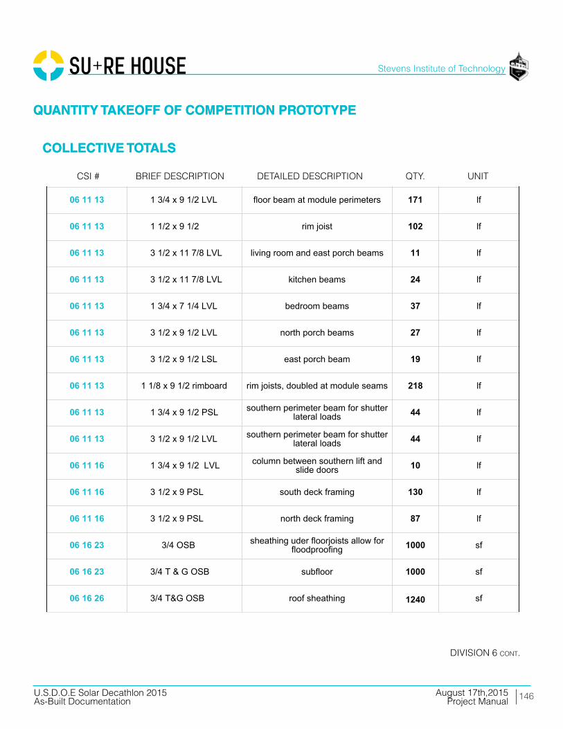
146
Stevens Institute of Technology
August 17th,2015U.S.D.O.E Solar Decathlon 2015As-Built Documentation Project Manual
01 54 16 lull/forklift setting steel and decks 2 days
01 54 19 90 ton hydraulic truck crane setting modules 1 day
05 05 23 1 1/2"x3" 12-gauge L-angle beam to floor framing connectors 100 ea
05 05 23 6" x 3" 12-gauge L-angle pier to beam connectors 25 ea.
05 12 13 HSS 4x2x5/16 southern steel columns 0.63 tons
05 12 13 HSS 4x4x3/16 north and east porch columns 0.34 tons
05 12 13 HSS 4x4, 3/16 shade structure steel columns 0.47 tons
05 12 13 HSS 4x2, 3/16 shade structure steel columns 0.08 tons
05 12 13 HSS 3x3, 3/8 shade structure steel beams 0.54 tons
05 12 13 WT4X7.5 lover steel columns 45 lf
05 13 00 stainless steel cable southern diagonal supports 25 lf
05 14 00 Roof Anchors PV racking roof array 32 ea
05 14 00 Strut Channel and Hardware PV racking roof array 120 lf
05 52 13 HSS 1X1, 1/4 ramp railing 100 lf
05 53 00 1/4 plate steel ramp to ground transition 45 sf
06 11 16 2x4 SPF interior partition framing 715lf
06 11 16 2x6 SPF interior partition framing 180lf
06 11 16 2x6 SPF bedroom drop ceiling 106 sf
06 11 16 2x4 SPF kitchen island 55 lf
06 11 16 2x4 SPF foundation beam top plates to createspace for crane straps 315 lf
06 11 16 2x8 SPF foundation beams attached to piers,supporting floor 171 lf
01 - GENERAL REQUIREMENTS
05 - METALS
06 - WOODS, PLASTICS, COMPOSITES
06 11 16 2x10 SPF south dropdown floor framing +blocking 90 lf
06 11 16 2x10 SPF roof framing blocking 250 lf
06 11 16 2x4 SPF ledgers for roof joist support atmodule seams 90 lf
06 11 16 2x4 SPF south shadestructure "sweatband"framing 70 lf
06 11 16 2x6 SPF exterior wall and parapet framing 1880 lf
06 11 16 1x3 SPF exterior rainscreen battens 3345 lf
06 11 16 2x3 SPF interior service cavity battens 600 lf
06 11 16 2x10 PT south deck framing 270 lf
06 11 16 2x8 PT south deck framing 40 lf
06 11 16 2x4 PT south deck framing 325 lf
06 11 16 2x10 PT north deck framing 50 lf
06 11 16 2x8 PT north deck framing 204 lf
06 11 16 2x8 PT ramp framing 30 lf
06 11 16 2x4 PT ramp framing 30 lf
06 11 16 2x4 PT ramp platform framing 100 sf
06 11 16 2x4 PT electrical platform framing 40 lf
06 11 13 1 3/4 x 7 1/4 LVL beams attached to piers, supportingfloor 115 lf
06 11 13 1 3/4 x 9 1/2 LVL module three floor joists 320 lf
06 11 13 1 3/4 x 7 1/4 LVL shower pan framing 10 lf
06 11 13 1 3/4 x 9 1/2 LSL plumber waste header 10 lf
06 11 13 1 3/4 x 9 1/2 LVL floor beam at module perimeters 171 lf
06 11 13 1 1/2 x 9 1/2 rim joist 102 lf
06 11 13 3 1/2 x 11 7/8 LVL living room and east porch beams 11 lf
06 11 13 3 1/2 x 11 7/8 LVL kitchen beams 24 lf
06 11 13 1 3/4 x 7 1/4 LVL bedroom beams 37 lf
06 11 13 3 1/2 x 9 1/2 LVL north porch beams 27 lf
06 11 13 3 1/2 x 9 1/2 LSL east porch beam 19 lf
06 11 13 1 1/8 x 9 1/2 rimboard rim joists, doubled at module seams 218 lf
06 11 13 1 3/4 x 9 1/2 PSL southern perimeter beam for shutterlateral loads 44 lf
06 11 13 3 1/2 x 9 1/2 LVL southern perimeter beam for shutterlateral loads 44 lf
06 11 16 1 3/4 x 9 1/2 LVL column between southern lift andslide doors 10 lf
06 11 16 3 1/2 x 9 PSL south deck framing 130 lf
06 11 16 3 1/2 x 9 PSL north deck framing 87 lf
06 16 23 3/4 OSB sheathing uder floorjoists allow forfloodproofing 1000 sf
06 16 23 3/4 T & G OSB subfloor 1000 sf
06 16 26 3/4 T&G OSB roof sheathing 1240 sf
06 16 36 3/4 CDX ply
Material component for 12" x 24" and6" x 10" foundation piers consisting of
glued and screwed plywood,combination of 3/4", 5/8", 1/2", and
1/4" as required by site contour
36 ea
06 16 36 5/8 CDX ply
Material component for 12" x 24" and6" x 10" foundation piers consisting of
glued and screwed plywood,combination of 3/4", 5/8", 1/2", and
1/4" as required by site contour
3 ea
06 16 36 1/2 CDX ply
Material component for 12" x 24" and6" x 10" foundation piers consisting of
glued and screwed plywood,combination of 3/4", 5/8", 1/2", and
1/4" as required by site contour
3 ea
06 16 36 1/4 CDX ply
Material component for 12" x 24" and6" x 10" foundation piers consisting of
glued and screwed plywood,combination of 3/4", 5/8", 1/2", and
1/4" as required by site contour
3 ea
06 16 36 7/16 zip sheathing system exterior sheathing 1365 sf
06 16 36 1/4 ply fascia over southern shutters 45 sf
06 16 36 1/2 CDX ply interior shear wall sheathing 270sf
06 16 36 1/2 CDX ply north planter box framing 190 sf
06 16 36 1/2 CDX ply electrical platform framing 28 sf
06 16 36 1/2 CDX ply south shadestructure "sweatband"framing 70 lf
06 16 53 1/8" ABS sheet plastic glued and screwed to 3/4" sheathingunder floor joists 1000 sf
06 16 53 1/8" ABS sheet plastic wraps first 4' feet of exterior wall 400 sf
06 17 33 2 1/2 x 9 1/2 I-Joist modules 1 and 2 floor joists, 16" OC 610 lf
06 17 33 2 1/16 x 9 1/2 I-Joist roof joists 928 lf
06 20 13 1x8 #3 cedar north planter box trim 60 lf
06 20 13 1x6 T&G cedar porch ceiling 250 sf
06 25 00 MDF face panels fridge, dishwasher, pantry 50 sf
06 20 13 1/2 birch ply south shadestructure "sweatband"finish 70 sf
06 40 23 3/4 AB ply mechanical room sheathing 190sf
06 40 23 3/4 birch ply hallway walls 64sf
06 40 23 1/2 birch ply drop ceiling living room 506 sf
06 40 23 1/2 birch ply drop ceiling hall 25 sf
06 40 23 3/4 AB ply mechanical room 42 sf
06 40 23 1/2 birch ply living room beam wrap 100 sf
06 40 23 3/4 birch ply living room and entertainment centerbuilt-in shelving 220 sf
06 46 13 1x4 finger-jointed paintgrade pine door and window trim for bedrooms 75 lf
06 46 19 1x4 finger-jointed paintgrade pine bedroom baseboard 78 lf
06 65 00 1x6 PVC trim porch ceiling edges 45 lf
06 73 00 1x6 TruGrain compositelumber door and window trim 150 lf
06 73 00 3/4" TruGraincompositelumber shower 22 sf
06 73 00 5/4x6 TruGrain compositedecking decking 1120 sf
06 73 00 1x6 TruGrain compositelumber ramp and deck trim 170 lf
06 73 00 5/4x6 TruGrain compositedecking ramp decking 190 sf
06 73 00 5/4x6 TruGrain compositedecking electrical platform decking 15 sf
06 73 00 1x6 TruGrain compositelumber electrical platform finish 28 sf
06 73 00 1x6 TruGrain compositelumber louver verticals 88 lf
06 73 00 1x4 TruGrain compositelumber louvers 1160 lf
07 13 26 Grace Ice and Water Sheild exterior floor to wall joint 120 lf
07 21 16 8" mineral wool batts floor cavity insulation 1000 sf
07 21 16 12" mineral wool batts roof cavity insulation 1000 sf
07 21 16 5.5" mineral wool batts wall cavity insulation 980 sf
07 21 16 2.5" mineral wool batts service cavity insulation 980 sf
07 21 16 1 1/4" mineral wool boardinsulation insulation over sheathing 920 sf
07 21 16 3.5" mineral wool batts interior acoustic insualtion 290 sf
07 22 22 tapered polyisocyanuraterigid insulation
roof deck insulation; 6" at westtapered to 1" at east 1240 sf
07 27 00 ProClima Intello interior primary air barrier 3260 sf
07 46 23 cedar shakes east, north, west finish 983 sf
07 46 23 primed cedar shakes north planter box finish 165 sf
07 46 46 3/16" fibercement board south bathroom facade 70 sf
07 46 46 3/16" fibercement board south shadestructure "sweatband"finish 70 sf
07 54 00 SikaSarnafil G410 PVC, 60mil roofing membrane 1240 sf
07 62 00 coping cap membrane seal at parapet edge 160 sf
07 70 00 vent strip cap top and bottom of rainscreencavity 160 lf
07 71 00 retrodrain scuppers scupper drains 2 ea
07 92 13 10oz marine sealant floodproofing joint sealant 20 ea.
07 92 13 4" x 75' self-healing jointtape (Grace Vycor) floodproofing joint flashing tape 5 ea.
07 - THERMAL AND MOISTURE PROTECTION
08 14 16 3'-0" x 7'-0" Interior doors 3 ea
08 14 16 2'-8" x 7--0" Interior doors 1 ea
08 14 16 2'-8" x 7'-0" Interior doors bifold 1 ea
08 15 00 Schuco SL82, 7'-0" x 3'-2" swinging entry doors 2 ea.
08 32 16Schuco thermoslide, triplepane, low-E,safety glazing,
8'-5" x 14'-10"sliding patio doors 2 ea.
08 53 00Schuco tilt and turn, triplepane, low-E, safety glazing,
3 'x 5'-1 1/2"tilt/turnwindow (bedroom) 30 sf
08 53 00Schuco tilt and turn, triplepane, low-E, safety glazing,
2' x 5'-3"tilt/turn window (bedroom) 10.5 sf
08 53 00Schuco fixed triple pane,low-E, safety glazing, 3' x 7'-
11"fixed windows (east + west) 48 sf
09 22 16 2x4 metal stud framing bathroom drop ceiling 42 sf
09 29 00 5/8" type X gypsum bedroom walls 670sf
09 29 00 5/8" type X gypsum bedroom drop ceiling 106 sf
09 29 00 5/8" type X gypsum bathroom drop ceiling 42 sf
09 30 13 ceramic wood pattern tile bathroom walls 200 sf
09 30 13 ceramic white tile bathroom walls 32 sf
09 62 19 aquastep laminate flooring mechanical room 42 sf
09 65 13 prefinished 3/4" maple plank living and bedroom floor 710 sf
09 91 13 paint: gypsum board bedrooms 670 sf
09 91 13 paint: wood trim bedrooms 25 sf
09 91 13 paint: birch plywood hallway 64 sf
09 91 13 paint: wood trim bedroom baseboard78
lf
09 91 13 paint: plywood hallway and living room beam wrap 25 lf
09 91 13 paint: gyp bedrooms and bathroom 148 lf
08 - OPENINGS
09 - FINISHES
09 93 23 polyurethane: interiorplywood surfaces living room built-ins 515 sf
09 93 23 polyurethane: plywood living room 506 sf
10 28 16 3' x 5' mirror vanity mirror 1 ea
10 28 16 Ikea: Grundtal towel hanger 1 ea
10 28 16 Ikea: Grundtal toilet paper roll 1 ea
10 28 16 Ikea: Grundtal small hanger 1 ea
10 71 1611'-0 x 7'-6" fiberglasscomposite panels withhardware and rigging
manually operable shutters 6 ea
10 71 16 1.5" fiberglass compositepanels storm plugs for windows and doors 115 sf
11 30 13 Thermador UCVM36FS recirculating range hood 1 ea
11 31 13 GE JP656DDBB cooktop 1 ea
11 31 13 GE JT5000DF wall oven 1 ea
11 31 13 Liebherr HC1030 refrigerator1
ea
11 31 13 Bloomberg DW 551100 dishwasher 1 ea
11 31 23 LG WM4070H_A washer 1 ea
11 31 23 LG DLHX4072 dryer 1 ea
12 24 13 rolling shades manual solar protection 290 sf
12 32 13 Ikea casework: lowercabinets lower cabinets 5.5 lf
12 32 13 Ikea casework: uppercabinets upper cabinets 7.5 lf
12 36 61 Hi-Macs composite bathroom vanity; 2 shelves and sinkenclosure 1 ea
12 36 61 HI-Macs composite kitchen counter 9 lf
12 36 61 HI-Macs composite backsplash 18 sf
10 - SPECIALTIES
11 - EQUIPMENT
12 - FURNISHINGS
21 13 13 fire sprinkler head 6 ea
21 13 13 1" Fire Protection Pipe 90 lf
21 13 13 fitting elbow 10 ea
21 13 13 fitting tee 2 wa
21 13 13 valve assembly 1 ea
21 13 13 pressure release valve 1 ea
21 30 00 fire pump 1 ea
22 11 13 plumbing manifold mech room 1 ea
22 11 16 1/2" PEX pipe domestic supply 70 lf
22 11 16 misc. valves and fittings domestic supply 1 ls
22 11 23 pump domestic supply; under planter
22 12 23 pressure tank domestic supply; under planter 1 ea
22 12 19 1000 gallon water tank domestic supply; under planter 1 ea
22 13 16 4" PVC gutter downspout, along west exteriorwall behind finish 40 lf
22 13 16 4" corrugated drain pipe to direct downspout water from underhouse to daylight 20 lf
22 13 16 waste and vent piping: PVC 80 lf
22 13 53 400 gallon water tank waste; planter 1 ea
22 14 29 sump pump to waste tank; outside house underelectrical platform 1 ea
22 30 3080 gallon heat pump waterheater w/ 2nd electricalelement circuited to shutterPV
domestic hot water; mech room 1 ea
22 41 00 expansion tank mech room 1 ea
22 41 13 residential water closet bathroom 1 ea
21 - FIRE SUPRESSION
22 - PLUMBING
22 41 13 shower pan bathroom 1 ea
22 41 16 shower drain/faucet bathroom 1 ea
22 41 16 double bowl sink kitchen 1 ea
22 41 39 faucet bathroom 1 ea
22 41 39 clothes washer connection laundry 1 ea
22 41 39 faucet kitchen 1 ea
22 41 39 dishwasher connection kitchen 1 ea
23 09 13 Daikin DZK030E5 zoning kit 1 ea
23 09 13 Daikin DZK-MTS-1 Main Thermostat 1 ls
23 09 13 Daikin DZK-ZTS-1 Wireless Thermostat 4 ls
23 09 13 Daikin BRC1E73 AHU Thermostat 1 ls
23 23 00 Copper Piping refrigerant piping 15 lf
23 31 16 Zehnder comfopipe insulatedrigid ductwork heating and cooling (heat pump) 130 lf
23 31 16 Zehnder comfotube flexibleductwork ventilation (ERV) 50 lf
23 33 13 Tuttle and Bailey MA, 4000,DXFR, and T75D grilles, registers, diffusers 12 ea
23 34 00 Daikin FBQ24PVJU air handler 1 ea
23 72 00 Zehnder Comfowell 220 ventilation manifold 2 ea
23 72 00 Zehnder NOVUS 300 ERV 10 lf
23 82 19 Daikin RDZQ24PVJU9 condensing unit 1 ea
25 37 00 data opening 2 ea
25 37 00 tv opening 2 ea
25 38 00 smoke detector 3 ea
23 - HVAC
25 - INTEGRATED AUTOMATION
25 50 00 exterior south deckuplighting: LED 6 ea
25 50 00 exterior east porchdownlighting: LED 6 ea
26 05 19 200A panel including AFCIbreakers 1 ea
26 05 19 electrical meter 1 ea
26 05 19 service entrance conductors;(3) 2/0 THHN (1) #4 ground 15 lf
26 05 19 #8 AWG THWN-2 0 lf
26 05 19 #10 AWG THWN-2 50 lf
26 05 19 #12 AWG THWN-2 100 lf
26 05 19 #12/2 NM-B 500 lf
26 05 19 #10/3 NM-B 100 lf
26 05 19 #8/3 NM-B 100 lf
26 05 19 #10 AWG PV Wire 400 lf
26 05 19 #8 AWG PV Wire 100 lf
26 05 19 #10 AWG THWN-2 250 lf
26 05 19 #8 AWG THWN-2 100 lf
26 21 00 200A SE cable 80 lf
26 27 26 20A 125V duplex receptacle 10 ea
26 27 26 20A 125V duplex receptacle- GFCI 15 ea
26 27 26 20A 125V duplex receptacle- WP 5 ea
26 27 26 duplex receptacle cover In-Use 3 ea
26 27 26 50A 240V single receptacle 4 ea
26 27 26 15A 125V duplex receptacle- Floor 2 ea
26 27 26 20A 120/277V Switch 8 ea
26 - ELECTRICAL
26 27 26 20A 120/277V 3-Way Switch 4 ea
26 27 26 domestic water pump stationconnection 1 ea
26 27 26 dishwasher connection 1 ea
26 27 26 heat pump water heaterconnection 1 ea
26 27 26 sump pump connection 1 ea
26 27 26 air handler connection 1 ea
26 27 26 heat pump; 2-ton outdoorunit connection 1 ea
26 27 26 energy recovery ventilatorconnection 1 ea
26 27 26 combiner Box 3 ea
26 27 26 transition/junction box 2 ea
26 28 16 disconnect wwitch 2 ea
26 31 00 module 60-cell mSi 280WFramed PV Roof Array 32 ea
26 31 00 module 60-cell mSi 180WFlexible PV Flood Shutters 10 ea
26 31 00 Renusol CS60 ballastedracking trays PV Racking Roof Array 32 ea
26 50 00 drivers/pwr supply andacc'ys (Exterior) 2 ea
26 51 13 interior linear LED fixtures 36 ft
26 51 13 interior track LED fixtures 21 ea
26 51 13 interior recessed LEDdownlight fixtures 2 ea
26 51 13 drivers/pwr supply andacc'ys (Interior) 6 ea
31 66 00 concrete and steel pier 11" seismic piers for deck 16 ea
31 66 00 concrete and steel pier 7" seismic piers for deck 4 ea
31 - EARTHWORK
32 93 00
ornamental grasses and fallperrenials: Muhlenbergia,Capillaris, MuhlenbergiaCapillarisFestuca Rubra, Kniphofiauvaria,Solidage Californica
ornamental plants 220 sf
32 94 00 standard 1 Ga. Containersfrom Nursery planter boxes 40 ea.
32 94 00 lightweight infill gravel soil 130 cu. ft
48 19 16 inverter grid-tied 5000W240Vac 1 ea
48 19 16 inverter grid-tied 3000W240Vac 1 ea
48 19 16 network interface inverter 2 ea
48 - ELECTRICAL POWER GENERATION
QUANTITY TAKEOFF OF COMPETITION PROTOTYPE
COLLECTIVE TOTALS
QUANTITY TAKEOFF OF COMPETITION PROTOTYPE
COLLECTIVE TOTALS
Brief deScriPtioncSi # detailed deScriPtion QtY. unit
diViSion 6 cont.
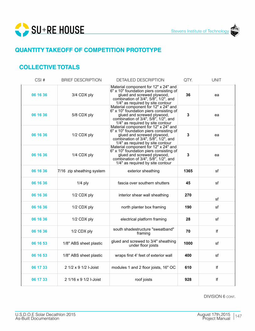
147
Stevens Institute of Technology
August 17th,2015U.S.D.O.E Solar Decathlon 2015As-Built Documentation Project Manual
01 54 16 lull/forklift setting steel and decks 2 days
01 54 19 90 ton hydraulic truck crane setting modules 1 day
05 05 23 1 1/2"x3" 12-gauge L-angle beam to floor framing connectors 100 ea
05 05 23 6" x 3" 12-gauge L-angle pier to beam connectors 25 ea.
05 12 13 HSS 4x2x5/16 southern steel columns 0.63 tons
05 12 13 HSS 4x4x3/16 north and east porch columns 0.34 tons
05 12 13 HSS 4x4, 3/16 shade structure steel columns 0.47 tons
05 12 13 HSS 4x2, 3/16 shade structure steel columns 0.08 tons
05 12 13 HSS 3x3, 3/8 shade structure steel beams 0.54 tons
05 12 13 WT4X7.5 lover steel columns 45 lf
05 13 00 stainless steel cable southern diagonal supports 25 lf
05 14 00 Roof Anchors PV racking roof array 32 ea
05 14 00 Strut Channel and Hardware PV racking roof array 120 lf
05 52 13 HSS 1X1, 1/4 ramp railing 100 lf
05 53 00 1/4 plate steel ramp to ground transition 45 sf
06 11 16 2x4 SPF interior partition framing 715lf
06 11 16 2x6 SPF interior partition framing 180lf
06 11 16 2x6 SPF bedroom drop ceiling 106 sf
06 11 16 2x4 SPF kitchen island 55 lf
06 11 16 2x4 SPF foundation beam top plates to createspace for crane straps 315 lf
06 11 16 2x8 SPF foundation beams attached to piers,supporting floor 171 lf
01 - GENERAL REQUIREMENTS
05 - METALS
06 - WOODS, PLASTICS, COMPOSITES
06 11 16 2x10 SPF south dropdown floor framing +blocking 90 lf
06 11 16 2x10 SPF roof framing blocking 250 lf
06 11 16 2x4 SPF ledgers for roof joist support atmodule seams 90 lf
06 11 16 2x4 SPF south shadestructure "sweatband"framing 70 lf
06 11 16 2x6 SPF exterior wall and parapet framing 1880 lf
06 11 16 1x3 SPF exterior rainscreen battens 3345 lf
06 11 16 2x3 SPF interior service cavity battens 600 lf
06 11 16 2x10 PT south deck framing 270 lf
06 11 16 2x8 PT south deck framing 40 lf
06 11 16 2x4 PT south deck framing 325 lf
06 11 16 2x10 PT north deck framing 50 lf
06 11 16 2x8 PT north deck framing 204 lf
06 11 16 2x8 PT ramp framing 30 lf
06 11 16 2x4 PT ramp framing 30 lf
06 11 16 2x4 PT ramp platform framing 100 sf
06 11 16 2x4 PT electrical platform framing 40 lf
06 11 13 1 3/4 x 7 1/4 LVL beams attached to piers, supportingfloor 115 lf
06 11 13 1 3/4 x 9 1/2 LVL module three floor joists 320 lf
06 11 13 1 3/4 x 7 1/4 LVL shower pan framing 10 lf
06 11 13 1 3/4 x 9 1/2 LSL plumber waste header 10 lf
06 11 13 1 3/4 x 9 1/2 LVL floor beam at module perimeters 171 lf
06 11 13 1 1/2 x 9 1/2 rim joist 102 lf
06 11 13 3 1/2 x 11 7/8 LVL living room and east porch beams 11 lf
06 11 13 3 1/2 x 11 7/8 LVL kitchen beams 24 lf
06 11 13 1 3/4 x 7 1/4 LVL bedroom beams 37 lf
06 11 13 3 1/2 x 9 1/2 LVL north porch beams 27 lf
06 11 13 3 1/2 x 9 1/2 LSL east porch beam 19 lf
06 11 13 1 1/8 x 9 1/2 rimboard rim joists, doubled at module seams 218 lf
06 11 13 1 3/4 x 9 1/2 PSL southern perimeter beam for shutterlateral loads 44 lf
06 11 13 3 1/2 x 9 1/2 LVL southern perimeter beam for shutterlateral loads 44 lf
06 11 16 1 3/4 x 9 1/2 LVL column between southern lift andslide doors 10 lf
06 11 16 3 1/2 x 9 PSL south deck framing 130 lf
06 11 16 3 1/2 x 9 PSL north deck framing 87 lf
06 16 23 3/4 OSB sheathing uder floorjoists allow forfloodproofing 1000 sf
06 16 23 3/4 T & G OSB subfloor 1000 sf
06 16 26 3/4 T&G OSB roof sheathing 1240 sf
06 16 36 3/4 CDX ply
Material component for 12" x 24" and6" x 10" foundation piers consisting of
glued and screwed plywood,combination of 3/4", 5/8", 1/2", and
1/4" as required by site contour
36 ea
06 16 36 5/8 CDX ply
Material component for 12" x 24" and6" x 10" foundation piers consisting of
glued and screwed plywood,combination of 3/4", 5/8", 1/2", and
1/4" as required by site contour
3 ea
06 16 36 1/2 CDX ply
Material component for 12" x 24" and6" x 10" foundation piers consisting of
glued and screwed plywood,combination of 3/4", 5/8", 1/2", and
1/4" as required by site contour
3 ea
06 16 36 1/4 CDX ply
Material component for 12" x 24" and6" x 10" foundation piers consisting of
glued and screwed plywood,combination of 3/4", 5/8", 1/2", and
1/4" as required by site contour
3 ea
06 16 36 7/16 zip sheathing system exterior sheathing 1365 sf
06 16 36 1/4 ply fascia over southern shutters 45 sf
06 16 36 1/2 CDX ply interior shear wall sheathing 270sf
06 16 36 1/2 CDX ply north planter box framing 190 sf
06 16 36 1/2 CDX ply electrical platform framing 28 sf
06 16 36 1/2 CDX ply south shadestructure "sweatband"framing 70 lf
06 16 53 1/8" ABS sheet plastic glued and screwed to 3/4" sheathingunder floor joists 1000 sf
06 16 53 1/8" ABS sheet plastic wraps first 4' feet of exterior wall 400 sf
06 17 33 2 1/2 x 9 1/2 I-Joist modules 1 and 2 floor joists, 16" OC 610 lf
06 17 33 2 1/16 x 9 1/2 I-Joist roof joists 928 lf
06 20 13 1x8 #3 cedar north planter box trim 60 lf
06 20 13 1x6 T&G cedar porch ceiling 250 sf
06 25 00 MDF face panels fridge, dishwasher, pantry 50 sf
06 20 13 1/2 birch ply south shadestructure "sweatband"finish 70 sf
06 40 23 3/4 AB ply mechanical room sheathing 190sf
06 40 23 3/4 birch ply hallway walls 64sf
06 40 23 1/2 birch ply drop ceiling living room 506 sf
06 40 23 1/2 birch ply drop ceiling hall 25 sf
06 40 23 3/4 AB ply mechanical room 42 sf
06 40 23 1/2 birch ply living room beam wrap 100 sf
06 40 23 3/4 birch ply living room and entertainment centerbuilt-in shelving 220 sf
06 46 13 1x4 finger-jointed paintgrade pine door and window trim for bedrooms 75 lf
06 46 19 1x4 finger-jointed paintgrade pine bedroom baseboard 78 lf
06 65 00 1x6 PVC trim porch ceiling edges 45 lf
06 73 00 1x6 TruGrain compositelumber door and window trim 150 lf
06 73 00 3/4" TruGraincompositelumber shower 22 sf
06 73 00 5/4x6 TruGrain compositedecking decking 1120 sf
06 73 00 1x6 TruGrain compositelumber ramp and deck trim 170 lf
06 73 00 5/4x6 TruGrain compositedecking ramp decking 190 sf
06 73 00 5/4x6 TruGrain compositedecking electrical platform decking 15 sf
06 73 00 1x6 TruGrain compositelumber electrical platform finish 28 sf
06 73 00 1x6 TruGrain compositelumber louver verticals 88 lf
06 73 00 1x4 TruGrain compositelumber louvers 1160 lf
07 13 26 Grace Ice and Water Sheild exterior floor to wall joint 120 lf
07 21 16 8" mineral wool batts floor cavity insulation 1000 sf
07 21 16 12" mineral wool batts roof cavity insulation 1000 sf
07 21 16 5.5" mineral wool batts wall cavity insulation 980 sf
07 21 16 2.5" mineral wool batts service cavity insulation 980 sf
07 21 16 1 1/4" mineral wool boardinsulation insulation over sheathing 920 sf
07 21 16 3.5" mineral wool batts interior acoustic insualtion 290 sf
07 22 22 tapered polyisocyanuraterigid insulation
roof deck insulation; 6" at westtapered to 1" at east 1240 sf
07 27 00 ProClima Intello interior primary air barrier 3260 sf
07 46 23 cedar shakes east, north, west finish 983 sf
07 46 23 primed cedar shakes north planter box finish 165 sf
07 46 46 3/16" fibercement board south bathroom facade 70 sf
07 46 46 3/16" fibercement board south shadestructure "sweatband"finish 70 sf
07 54 00 SikaSarnafil G410 PVC, 60mil roofing membrane 1240 sf
07 62 00 coping cap membrane seal at parapet edge 160 sf
07 70 00 vent strip cap top and bottom of rainscreencavity 160 lf
07 71 00 retrodrain scuppers scupper drains 2 ea
07 92 13 10oz marine sealant floodproofing joint sealant 20 ea.
07 92 13 4" x 75' self-healing jointtape (Grace Vycor) floodproofing joint flashing tape 5 ea.
07 - THERMAL AND MOISTURE PROTECTION
08 14 16 3'-0" x 7'-0" Interior doors 3 ea
08 14 16 2'-8" x 7--0" Interior doors 1 ea
08 14 16 2'-8" x 7'-0" Interior doors bifold 1 ea
08 15 00 Schuco SL82, 7'-0" x 3'-2" swinging entry doors 2 ea.
08 32 16Schuco thermoslide, triplepane, low-E,safety glazing,
8'-5" x 14'-10"sliding patio doors 2 ea.
08 53 00Schuco tilt and turn, triplepane, low-E, safety glazing,
3 'x 5'-1 1/2"tilt/turnwindow (bedroom) 30 sf
08 53 00Schuco tilt and turn, triplepane, low-E, safety glazing,
2' x 5'-3"tilt/turn window (bedroom) 10.5 sf
08 53 00Schuco fixed triple pane,low-E, safety glazing, 3' x 7'-
11"fixed windows (east + west) 48 sf
09 22 16 2x4 metal stud framing bathroom drop ceiling 42 sf
09 29 00 5/8" type X gypsum bedroom walls 670sf
09 29 00 5/8" type X gypsum bedroom drop ceiling 106 sf
09 29 00 5/8" type X gypsum bathroom drop ceiling 42 sf
09 30 13 ceramic wood pattern tile bathroom walls 200 sf
09 30 13 ceramic white tile bathroom walls 32 sf
09 62 19 aquastep laminate flooring mechanical room 42 sf
09 65 13 prefinished 3/4" maple plank living and bedroom floor 710 sf
09 91 13 paint: gypsum board bedrooms 670 sf
09 91 13 paint: wood trim bedrooms 25 sf
09 91 13 paint: birch plywood hallway 64 sf
09 91 13 paint: wood trim bedroom baseboard78
lf
09 91 13 paint: plywood hallway and living room beam wrap 25 lf
09 91 13 paint: gyp bedrooms and bathroom 148 lf
08 - OPENINGS
09 - FINISHES
09 93 23 polyurethane: interiorplywood surfaces living room built-ins 515 sf
09 93 23 polyurethane: plywood living room 506 sf
10 28 16 3' x 5' mirror vanity mirror 1 ea
10 28 16 Ikea: Grundtal towel hanger 1 ea
10 28 16 Ikea: Grundtal toilet paper roll 1 ea
10 28 16 Ikea: Grundtal small hanger 1 ea
10 71 1611'-0 x 7'-6" fiberglasscomposite panels withhardware and rigging
manually operable shutters 6 ea
10 71 16 1.5" fiberglass compositepanels storm plugs for windows and doors 115 sf
11 30 13 Thermador UCVM36FS recirculating range hood 1 ea
11 31 13 GE JP656DDBB cooktop 1 ea
11 31 13 GE JT5000DF wall oven 1 ea
11 31 13 Liebherr HC1030 refrigerator1
ea
11 31 13 Bloomberg DW 551100 dishwasher 1 ea
11 31 23 LG WM4070H_A washer 1 ea
11 31 23 LG DLHX4072 dryer 1 ea
12 24 13 rolling shades manual solar protection 290 sf
12 32 13 Ikea casework: lowercabinets lower cabinets 5.5 lf
12 32 13 Ikea casework: uppercabinets upper cabinets 7.5 lf
12 36 61 Hi-Macs composite bathroom vanity; 2 shelves and sinkenclosure 1 ea
12 36 61 HI-Macs composite kitchen counter 9 lf
12 36 61 HI-Macs composite backsplash 18 sf
10 - SPECIALTIES
11 - EQUIPMENT
12 - FURNISHINGS
21 13 13 fire sprinkler head 6 ea
21 13 13 1" Fire Protection Pipe 90 lf
21 13 13 fitting elbow 10 ea
21 13 13 fitting tee 2 wa
21 13 13 valve assembly 1 ea
21 13 13 pressure release valve 1 ea
21 30 00 fire pump 1 ea
22 11 13 plumbing manifold mech room 1 ea
22 11 16 1/2" PEX pipe domestic supply 70 lf
22 11 16 misc. valves and fittings domestic supply 1 ls
22 11 23 pump domestic supply; under planter
22 12 23 pressure tank domestic supply; under planter 1 ea
22 12 19 1000 gallon water tank domestic supply; under planter 1 ea
22 13 16 4" PVC gutter downspout, along west exteriorwall behind finish 40 lf
22 13 16 4" corrugated drain pipe to direct downspout water from underhouse to daylight 20 lf
22 13 16 waste and vent piping: PVC 80 lf
22 13 53 400 gallon water tank waste; planter 1 ea
22 14 29 sump pump to waste tank; outside house underelectrical platform 1 ea
22 30 3080 gallon heat pump waterheater w/ 2nd electricalelement circuited to shutterPV
domestic hot water; mech room 1 ea
22 41 00 expansion tank mech room 1 ea
22 41 13 residential water closet bathroom 1 ea
21 - FIRE SUPRESSION
22 - PLUMBING
22 41 13 shower pan bathroom 1 ea
22 41 16 shower drain/faucet bathroom 1 ea
22 41 16 double bowl sink kitchen 1 ea
22 41 39 faucet bathroom 1 ea
22 41 39 clothes washer connection laundry 1 ea
22 41 39 faucet kitchen 1 ea
22 41 39 dishwasher connection kitchen 1 ea
23 09 13 Daikin DZK030E5 zoning kit 1 ea
23 09 13 Daikin DZK-MTS-1 Main Thermostat 1 ls
23 09 13 Daikin DZK-ZTS-1 Wireless Thermostat 4 ls
23 09 13 Daikin BRC1E73 AHU Thermostat 1 ls
23 23 00 Copper Piping refrigerant piping 15 lf
23 31 16 Zehnder comfopipe insulatedrigid ductwork heating and cooling (heat pump) 130 lf
23 31 16 Zehnder comfotube flexibleductwork ventilation (ERV) 50 lf
23 33 13 Tuttle and Bailey MA, 4000,DXFR, and T75D grilles, registers, diffusers 12 ea
23 34 00 Daikin FBQ24PVJU air handler 1 ea
23 72 00 Zehnder Comfowell 220 ventilation manifold 2 ea
23 72 00 Zehnder NOVUS 300 ERV 10 lf
23 82 19 Daikin RDZQ24PVJU9 condensing unit 1 ea
25 37 00 data opening 2 ea
25 37 00 tv opening 2 ea
25 38 00 smoke detector 3 ea
23 - HVAC
25 - INTEGRATED AUTOMATION
25 50 00 exterior south deckuplighting: LED 6 ea
25 50 00 exterior east porchdownlighting: LED 6 ea
26 05 19 200A panel including AFCIbreakers 1 ea
26 05 19 electrical meter 1 ea
26 05 19 service entrance conductors;(3) 2/0 THHN (1) #4 ground 15 lf
26 05 19 #8 AWG THWN-2 0 lf
26 05 19 #10 AWG THWN-2 50 lf
26 05 19 #12 AWG THWN-2 100 lf
26 05 19 #12/2 NM-B 500 lf
26 05 19 #10/3 NM-B 100 lf
26 05 19 #8/3 NM-B 100 lf
26 05 19 #10 AWG PV Wire 400 lf
26 05 19 #8 AWG PV Wire 100 lf
26 05 19 #10 AWG THWN-2 250 lf
26 05 19 #8 AWG THWN-2 100 lf
26 21 00 200A SE cable 80 lf
26 27 26 20A 125V duplex receptacle 10 ea
26 27 26 20A 125V duplex receptacle- GFCI 15 ea
26 27 26 20A 125V duplex receptacle- WP 5 ea
26 27 26 duplex receptacle cover In-Use 3 ea
26 27 26 50A 240V single receptacle 4 ea
26 27 26 15A 125V duplex receptacle- Floor 2 ea
26 27 26 20A 120/277V Switch 8 ea
26 - ELECTRICAL
26 27 26 20A 120/277V 3-Way Switch 4 ea
26 27 26 domestic water pump stationconnection 1 ea
26 27 26 dishwasher connection 1 ea
26 27 26 heat pump water heaterconnection 1 ea
26 27 26 sump pump connection 1 ea
26 27 26 air handler connection 1 ea
26 27 26 heat pump; 2-ton outdoorunit connection 1 ea
26 27 26 energy recovery ventilatorconnection 1 ea
26 27 26 combiner Box 3 ea
26 27 26 transition/junction box 2 ea
26 28 16 disconnect wwitch 2 ea
26 31 00 module 60-cell mSi 280WFramed PV Roof Array 32 ea
26 31 00 module 60-cell mSi 180WFlexible PV Flood Shutters 10 ea
26 31 00 Renusol CS60 ballastedracking trays PV Racking Roof Array 32 ea
26 50 00 drivers/pwr supply andacc'ys (Exterior) 2 ea
26 51 13 interior linear LED fixtures 36 ft
26 51 13 interior track LED fixtures 21 ea
26 51 13 interior recessed LEDdownlight fixtures 2 ea
26 51 13 drivers/pwr supply andacc'ys (Interior) 6 ea
31 66 00 concrete and steel pier 11" seismic piers for deck 16 ea
31 66 00 concrete and steel pier 7" seismic piers for deck 4 ea
31 - EARTHWORK
32 93 00
ornamental grasses and fallperrenials: Muhlenbergia,Capillaris, MuhlenbergiaCapillarisFestuca Rubra, Kniphofiauvaria,Solidage Californica
ornamental plants 220 sf
32 94 00 standard 1 Ga. Containersfrom Nursery planter boxes 40 ea.
32 94 00 lightweight infill gravel soil 130 cu. ft
48 19 16 inverter grid-tied 5000W240Vac 1 ea
48 19 16 inverter grid-tied 3000W240Vac 1 ea
48 19 16 network interface inverter 2 ea
48 - ELECTRICAL POWER GENERATION
QUANTITY TAKEOFF OF COMPETITION PROTOTYPE
COLLECTIVE TOTALS
QUANTITY TAKEOFF OF COMPETITION PROTOTYPE
COLLECTIVE TOTALS
Brief deScriPtioncSi # detailed deScriPtion QtY. unit
diViSion 6 cont.
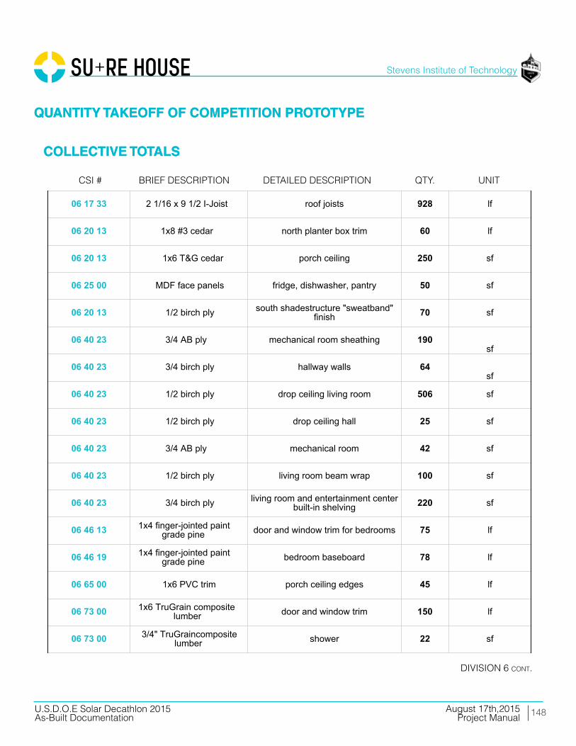
148
Stevens Institute of Technology
August 17th,2015U.S.D.O.E Solar Decathlon 2015As-Built Documentation Project Manual
01 54 16 lull/forklift setting steel and decks 2 days
01 54 19 90 ton hydraulic truck crane setting modules 1 day
05 05 23 1 1/2"x3" 12-gauge L-angle beam to floor framing connectors 100 ea
05 05 23 6" x 3" 12-gauge L-angle pier to beam connectors 25 ea.
05 12 13 HSS 4x2x5/16 southern steel columns 0.63 tons
05 12 13 HSS 4x4x3/16 north and east porch columns 0.34 tons
05 12 13 HSS 4x4, 3/16 shade structure steel columns 0.47 tons
05 12 13 HSS 4x2, 3/16 shade structure steel columns 0.08 tons
05 12 13 HSS 3x3, 3/8 shade structure steel beams 0.54 tons
05 12 13 WT4X7.5 lover steel columns 45 lf
05 13 00 stainless steel cable southern diagonal supports 25 lf
05 14 00 Roof Anchors PV racking roof array 32 ea
05 14 00 Strut Channel and Hardware PV racking roof array 120 lf
05 52 13 HSS 1X1, 1/4 ramp railing 100 lf
05 53 00 1/4 plate steel ramp to ground transition 45 sf
06 11 16 2x4 SPF interior partition framing 715lf
06 11 16 2x6 SPF interior partition framing 180lf
06 11 16 2x6 SPF bedroom drop ceiling 106 sf
06 11 16 2x4 SPF kitchen island 55 lf
06 11 16 2x4 SPF foundation beam top plates to createspace for crane straps 315 lf
06 11 16 2x8 SPF foundation beams attached to piers,supporting floor 171 lf
01 - GENERAL REQUIREMENTS
05 - METALS
06 - WOODS, PLASTICS, COMPOSITES
06 11 16 2x10 SPF south dropdown floor framing +blocking 90 lf
06 11 16 2x10 SPF roof framing blocking 250 lf
06 11 16 2x4 SPF ledgers for roof joist support atmodule seams 90 lf
06 11 16 2x4 SPF south shadestructure "sweatband"framing 70 lf
06 11 16 2x6 SPF exterior wall and parapet framing 1880 lf
06 11 16 1x3 SPF exterior rainscreen battens 3345 lf
06 11 16 2x3 SPF interior service cavity battens 600 lf
06 11 16 2x10 PT south deck framing 270 lf
06 11 16 2x8 PT south deck framing 40 lf
06 11 16 2x4 PT south deck framing 325 lf
06 11 16 2x10 PT north deck framing 50 lf
06 11 16 2x8 PT north deck framing 204 lf
06 11 16 2x8 PT ramp framing 30 lf
06 11 16 2x4 PT ramp framing 30 lf
06 11 16 2x4 PT ramp platform framing 100 sf
06 11 16 2x4 PT electrical platform framing 40 lf
06 11 13 1 3/4 x 7 1/4 LVL beams attached to piers, supportingfloor 115 lf
06 11 13 1 3/4 x 9 1/2 LVL module three floor joists 320 lf
06 11 13 1 3/4 x 7 1/4 LVL shower pan framing 10 lf
06 11 13 1 3/4 x 9 1/2 LSL plumber waste header 10 lf
06 11 13 1 3/4 x 9 1/2 LVL floor beam at module perimeters 171 lf
06 11 13 1 1/2 x 9 1/2 rim joist 102 lf
06 11 13 3 1/2 x 11 7/8 LVL living room and east porch beams 11 lf
06 11 13 3 1/2 x 11 7/8 LVL kitchen beams 24 lf
06 11 13 1 3/4 x 7 1/4 LVL bedroom beams 37 lf
06 11 13 3 1/2 x 9 1/2 LVL north porch beams 27 lf
06 11 13 3 1/2 x 9 1/2 LSL east porch beam 19 lf
06 11 13 1 1/8 x 9 1/2 rimboard rim joists, doubled at module seams 218 lf
06 11 13 1 3/4 x 9 1/2 PSL southern perimeter beam for shutterlateral loads 44 lf
06 11 13 3 1/2 x 9 1/2 LVL southern perimeter beam for shutterlateral loads 44 lf
06 11 16 1 3/4 x 9 1/2 LVL column between southern lift andslide doors 10 lf
06 11 16 3 1/2 x 9 PSL south deck framing 130 lf
06 11 16 3 1/2 x 9 PSL north deck framing 87 lf
06 16 23 3/4 OSB sheathing uder floorjoists allow forfloodproofing 1000 sf
06 16 23 3/4 T & G OSB subfloor 1000 sf
06 16 26 3/4 T&G OSB roof sheathing 1240 sf
06 16 36 3/4 CDX ply
Material component for 12" x 24" and6" x 10" foundation piers consisting of
glued and screwed plywood,combination of 3/4", 5/8", 1/2", and
1/4" as required by site contour
36 ea
06 16 36 5/8 CDX ply
Material component for 12" x 24" and6" x 10" foundation piers consisting of
glued and screwed plywood,combination of 3/4", 5/8", 1/2", and
1/4" as required by site contour
3 ea
06 16 36 1/2 CDX ply
Material component for 12" x 24" and6" x 10" foundation piers consisting of
glued and screwed plywood,combination of 3/4", 5/8", 1/2", and
1/4" as required by site contour
3 ea
06 16 36 1/4 CDX ply
Material component for 12" x 24" and6" x 10" foundation piers consisting of
glued and screwed plywood,combination of 3/4", 5/8", 1/2", and
1/4" as required by site contour
3 ea
06 16 36 7/16 zip sheathing system exterior sheathing 1365 sf
06 16 36 1/4 ply fascia over southern shutters 45 sf
06 16 36 1/2 CDX ply interior shear wall sheathing 270sf
06 16 36 1/2 CDX ply north planter box framing 190 sf
06 16 36 1/2 CDX ply electrical platform framing 28 sf
06 16 36 1/2 CDX ply south shadestructure "sweatband"framing 70 lf
06 16 53 1/8" ABS sheet plastic glued and screwed to 3/4" sheathingunder floor joists 1000 sf
06 16 53 1/8" ABS sheet plastic wraps first 4' feet of exterior wall 400 sf
06 17 33 2 1/2 x 9 1/2 I-Joist modules 1 and 2 floor joists, 16" OC 610 lf
06 17 33 2 1/16 x 9 1/2 I-Joist roof joists 928 lf
06 20 13 1x8 #3 cedar north planter box trim 60 lf
06 20 13 1x6 T&G cedar porch ceiling 250 sf
06 25 00 MDF face panels fridge, dishwasher, pantry 50 sf
06 20 13 1/2 birch ply south shadestructure "sweatband"finish 70 sf
06 40 23 3/4 AB ply mechanical room sheathing 190sf
06 40 23 3/4 birch ply hallway walls 64sf
06 40 23 1/2 birch ply drop ceiling living room 506 sf
06 40 23 1/2 birch ply drop ceiling hall 25 sf
06 40 23 3/4 AB ply mechanical room 42 sf
06 40 23 1/2 birch ply living room beam wrap 100 sf
06 40 23 3/4 birch ply living room and entertainment centerbuilt-in shelving 220 sf
06 46 13 1x4 finger-jointed paintgrade pine door and window trim for bedrooms 75 lf
06 46 19 1x4 finger-jointed paintgrade pine bedroom baseboard 78 lf
06 65 00 1x6 PVC trim porch ceiling edges 45 lf
06 73 00 1x6 TruGrain compositelumber door and window trim 150 lf
06 73 00 3/4" TruGraincompositelumber shower 22 sf
06 73 00 5/4x6 TruGrain compositedecking decking 1120 sf
06 73 00 1x6 TruGrain compositelumber ramp and deck trim 170 lf
06 73 00 5/4x6 TruGrain compositedecking ramp decking 190 sf
06 73 00 5/4x6 TruGrain compositedecking electrical platform decking 15 sf
06 73 00 1x6 TruGrain compositelumber electrical platform finish 28 sf
06 73 00 1x6 TruGrain compositelumber louver verticals 88 lf
06 73 00 1x4 TruGrain compositelumber louvers 1160 lf
07 13 26 Grace Ice and Water Sheild exterior floor to wall joint 120 lf
07 21 16 8" mineral wool batts floor cavity insulation 1000 sf
07 21 16 12" mineral wool batts roof cavity insulation 1000 sf
07 21 16 5.5" mineral wool batts wall cavity insulation 980 sf
07 21 16 2.5" mineral wool batts service cavity insulation 980 sf
07 21 16 1 1/4" mineral wool boardinsulation insulation over sheathing 920 sf
07 21 16 3.5" mineral wool batts interior acoustic insualtion 290 sf
07 22 22 tapered polyisocyanuraterigid insulation
roof deck insulation; 6" at westtapered to 1" at east 1240 sf
07 27 00 ProClima Intello interior primary air barrier 3260 sf
07 46 23 cedar shakes east, north, west finish 983 sf
07 46 23 primed cedar shakes north planter box finish 165 sf
07 46 46 3/16" fibercement board south bathroom facade 70 sf
07 46 46 3/16" fibercement board south shadestructure "sweatband"finish 70 sf
07 54 00 SikaSarnafil G410 PVC, 60mil roofing membrane 1240 sf
07 62 00 coping cap membrane seal at parapet edge 160 sf
07 70 00 vent strip cap top and bottom of rainscreencavity 160 lf
07 71 00 retrodrain scuppers scupper drains 2 ea
07 92 13 10oz marine sealant floodproofing joint sealant 20 ea.
07 92 13 4" x 75' self-healing jointtape (Grace Vycor) floodproofing joint flashing tape 5 ea.
07 - THERMAL AND MOISTURE PROTECTION
08 14 16 3'-0" x 7'-0" Interior doors 3 ea
08 14 16 2'-8" x 7--0" Interior doors 1 ea
08 14 16 2'-8" x 7'-0" Interior doors bifold 1 ea
08 15 00 Schuco SL82, 7'-0" x 3'-2" swinging entry doors 2 ea.
08 32 16Schuco thermoslide, triplepane, low-E,safety glazing,
8'-5" x 14'-10"sliding patio doors 2 ea.
08 53 00Schuco tilt and turn, triplepane, low-E, safety glazing,
3 'x 5'-1 1/2"tilt/turnwindow (bedroom) 30 sf
08 53 00Schuco tilt and turn, triplepane, low-E, safety glazing,
2' x 5'-3"tilt/turn window (bedroom) 10.5 sf
08 53 00Schuco fixed triple pane,low-E, safety glazing, 3' x 7'-
11"fixed windows (east + west) 48 sf
09 22 16 2x4 metal stud framing bathroom drop ceiling 42 sf
09 29 00 5/8" type X gypsum bedroom walls 670sf
09 29 00 5/8" type X gypsum bedroom drop ceiling 106 sf
09 29 00 5/8" type X gypsum bathroom drop ceiling 42 sf
09 30 13 ceramic wood pattern tile bathroom walls 200 sf
09 30 13 ceramic white tile bathroom walls 32 sf
09 62 19 aquastep laminate flooring mechanical room 42 sf
09 65 13 prefinished 3/4" maple plank living and bedroom floor 710 sf
09 91 13 paint: gypsum board bedrooms 670 sf
09 91 13 paint: wood trim bedrooms 25 sf
09 91 13 paint: birch plywood hallway 64 sf
09 91 13 paint: wood trim bedroom baseboard78
lf
09 91 13 paint: plywood hallway and living room beam wrap 25 lf
09 91 13 paint: gyp bedrooms and bathroom 148 lf
08 - OPENINGS
09 - FINISHES
09 93 23 polyurethane: interiorplywood surfaces living room built-ins 515 sf
09 93 23 polyurethane: plywood living room 506 sf
10 28 16 3' x 5' mirror vanity mirror 1 ea
10 28 16 Ikea: Grundtal towel hanger 1 ea
10 28 16 Ikea: Grundtal toilet paper roll 1 ea
10 28 16 Ikea: Grundtal small hanger 1 ea
10 71 1611'-0 x 7'-6" fiberglasscomposite panels withhardware and rigging
manually operable shutters 6 ea
10 71 16 1.5" fiberglass compositepanels storm plugs for windows and doors 115 sf
11 30 13 Thermador UCVM36FS recirculating range hood 1 ea
11 31 13 GE JP656DDBB cooktop 1 ea
11 31 13 GE JT5000DF wall oven 1 ea
11 31 13 Liebherr HC1030 refrigerator1
ea
11 31 13 Bloomberg DW 551100 dishwasher 1 ea
11 31 23 LG WM4070H_A washer 1 ea
11 31 23 LG DLHX4072 dryer 1 ea
12 24 13 rolling shades manual solar protection 290 sf
12 32 13 Ikea casework: lowercabinets lower cabinets 5.5 lf
12 32 13 Ikea casework: uppercabinets upper cabinets 7.5 lf
12 36 61 Hi-Macs composite bathroom vanity; 2 shelves and sinkenclosure 1 ea
12 36 61 HI-Macs composite kitchen counter 9 lf
12 36 61 HI-Macs composite backsplash 18 sf
10 - SPECIALTIES
11 - EQUIPMENT
12 - FURNISHINGS
21 13 13 fire sprinkler head 6 ea
21 13 13 1" Fire Protection Pipe 90 lf
21 13 13 fitting elbow 10 ea
21 13 13 fitting tee 2 wa
21 13 13 valve assembly 1 ea
21 13 13 pressure release valve 1 ea
21 30 00 fire pump 1 ea
22 11 13 plumbing manifold mech room 1 ea
22 11 16 1/2" PEX pipe domestic supply 70 lf
22 11 16 misc. valves and fittings domestic supply 1 ls
22 11 23 pump domestic supply; under planter
22 12 23 pressure tank domestic supply; under planter 1 ea
22 12 19 1000 gallon water tank domestic supply; under planter 1 ea
22 13 16 4" PVC gutter downspout, along west exteriorwall behind finish 40 lf
22 13 16 4" corrugated drain pipe to direct downspout water from underhouse to daylight 20 lf
22 13 16 waste and vent piping: PVC 80 lf
22 13 53 400 gallon water tank waste; planter 1 ea
22 14 29 sump pump to waste tank; outside house underelectrical platform 1 ea
22 30 3080 gallon heat pump waterheater w/ 2nd electricalelement circuited to shutterPV
domestic hot water; mech room 1 ea
22 41 00 expansion tank mech room 1 ea
22 41 13 residential water closet bathroom 1 ea
21 - FIRE SUPRESSION
22 - PLUMBING
22 41 13 shower pan bathroom 1 ea
22 41 16 shower drain/faucet bathroom 1 ea
22 41 16 double bowl sink kitchen 1 ea
22 41 39 faucet bathroom 1 ea
22 41 39 clothes washer connection laundry 1 ea
22 41 39 faucet kitchen 1 ea
22 41 39 dishwasher connection kitchen 1 ea
23 09 13 Daikin DZK030E5 zoning kit 1 ea
23 09 13 Daikin DZK-MTS-1 Main Thermostat 1 ls
23 09 13 Daikin DZK-ZTS-1 Wireless Thermostat 4 ls
23 09 13 Daikin BRC1E73 AHU Thermostat 1 ls
23 23 00 Copper Piping refrigerant piping 15 lf
23 31 16 Zehnder comfopipe insulatedrigid ductwork heating and cooling (heat pump) 130 lf
23 31 16 Zehnder comfotube flexibleductwork ventilation (ERV) 50 lf
23 33 13 Tuttle and Bailey MA, 4000,DXFR, and T75D grilles, registers, diffusers 12 ea
23 34 00 Daikin FBQ24PVJU air handler 1 ea
23 72 00 Zehnder Comfowell 220 ventilation manifold 2 ea
23 72 00 Zehnder NOVUS 300 ERV 10 lf
23 82 19 Daikin RDZQ24PVJU9 condensing unit 1 ea
25 37 00 data opening 2 ea
25 37 00 tv opening 2 ea
25 38 00 smoke detector 3 ea
23 - HVAC
25 - INTEGRATED AUTOMATION
25 50 00 exterior south deckuplighting: LED 6 ea
25 50 00 exterior east porchdownlighting: LED 6 ea
26 05 19 200A panel including AFCIbreakers 1 ea
26 05 19 electrical meter 1 ea
26 05 19 service entrance conductors;(3) 2/0 THHN (1) #4 ground 15 lf
26 05 19 #8 AWG THWN-2 0 lf
26 05 19 #10 AWG THWN-2 50 lf
26 05 19 #12 AWG THWN-2 100 lf
26 05 19 #12/2 NM-B 500 lf
26 05 19 #10/3 NM-B 100 lf
26 05 19 #8/3 NM-B 100 lf
26 05 19 #10 AWG PV Wire 400 lf
26 05 19 #8 AWG PV Wire 100 lf
26 05 19 #10 AWG THWN-2 250 lf
26 05 19 #8 AWG THWN-2 100 lf
26 21 00 200A SE cable 80 lf
26 27 26 20A 125V duplex receptacle 10 ea
26 27 26 20A 125V duplex receptacle- GFCI 15 ea
26 27 26 20A 125V duplex receptacle- WP 5 ea
26 27 26 duplex receptacle cover In-Use 3 ea
26 27 26 50A 240V single receptacle 4 ea
26 27 26 15A 125V duplex receptacle- Floor 2 ea
26 27 26 20A 120/277V Switch 8 ea
26 - ELECTRICAL
26 27 26 20A 120/277V 3-Way Switch 4 ea
26 27 26 domestic water pump stationconnection 1 ea
26 27 26 dishwasher connection 1 ea
26 27 26 heat pump water heaterconnection 1 ea
26 27 26 sump pump connection 1 ea
26 27 26 air handler connection 1 ea
26 27 26 heat pump; 2-ton outdoorunit connection 1 ea
26 27 26 energy recovery ventilatorconnection 1 ea
26 27 26 combiner Box 3 ea
26 27 26 transition/junction box 2 ea
26 28 16 disconnect wwitch 2 ea
26 31 00 module 60-cell mSi 280WFramed PV Roof Array 32 ea
26 31 00 module 60-cell mSi 180WFlexible PV Flood Shutters 10 ea
26 31 00 Renusol CS60 ballastedracking trays PV Racking Roof Array 32 ea
26 50 00 drivers/pwr supply andacc'ys (Exterior) 2 ea
26 51 13 interior linear LED fixtures 36 ft
26 51 13 interior track LED fixtures 21 ea
26 51 13 interior recessed LEDdownlight fixtures 2 ea
26 51 13 drivers/pwr supply andacc'ys (Interior) 6 ea
31 66 00 concrete and steel pier 11" seismic piers for deck 16 ea
31 66 00 concrete and steel pier 7" seismic piers for deck 4 ea
31 - EARTHWORK
32 93 00
ornamental grasses and fallperrenials: Muhlenbergia,Capillaris, MuhlenbergiaCapillarisFestuca Rubra, Kniphofiauvaria,Solidage Californica
ornamental plants 220 sf
32 94 00 standard 1 Ga. Containersfrom Nursery planter boxes 40 ea.
32 94 00 lightweight infill gravel soil 130 cu. ft
48 19 16 inverter grid-tied 5000W240Vac 1 ea
48 19 16 inverter grid-tied 3000W240Vac 1 ea
48 19 16 network interface inverter 2 ea
48 - ELECTRICAL POWER GENERATION
QUANTITY TAKEOFF OF COMPETITION PROTOTYPE
COLLECTIVE TOTALS
QUANTITY TAKEOFF OF COMPETITION PROTOTYPE
COLLECTIVE TOTALS
Brief deScriPtioncSi # detailed deScriPtion QtY. unit
diViSion 6 cont.

149
Stevens Institute of Technology
August 17th,2015U.S.D.O.E Solar Decathlon 2015As-Built Documentation Project Manual
01 54 16 lull/forklift setting steel and decks 2 days
01 54 19 90 ton hydraulic truck crane setting modules 1 day
05 05 23 1 1/2"x3" 12-gauge L-angle beam to floor framing connectors 100 ea
05 05 23 6" x 3" 12-gauge L-angle pier to beam connectors 25 ea.
05 12 13 HSS 4x2x5/16 southern steel columns 0.63 tons
05 12 13 HSS 4x4x3/16 north and east porch columns 0.34 tons
05 12 13 HSS 4x4, 3/16 shade structure steel columns 0.47 tons
05 12 13 HSS 4x2, 3/16 shade structure steel columns 0.08 tons
05 12 13 HSS 3x3, 3/8 shade structure steel beams 0.54 tons
05 12 13 WT4X7.5 lover steel columns 45 lf
05 13 00 stainless steel cable southern diagonal supports 25 lf
05 14 00 Roof Anchors PV racking roof array 32 ea
05 14 00 Strut Channel and Hardware PV racking roof array 120 lf
05 52 13 HSS 1X1, 1/4 ramp railing 100 lf
05 53 00 1/4 plate steel ramp to ground transition 45 sf
06 11 16 2x4 SPF interior partition framing 715lf
06 11 16 2x6 SPF interior partition framing 180lf
06 11 16 2x6 SPF bedroom drop ceiling 106 sf
06 11 16 2x4 SPF kitchen island 55 lf
06 11 16 2x4 SPF foundation beam top plates to createspace for crane straps 315 lf
06 11 16 2x8 SPF foundation beams attached to piers,supporting floor 171 lf
01 - GENERAL REQUIREMENTS
05 - METALS
06 - WOODS, PLASTICS, COMPOSITES
06 11 16 2x10 SPF south dropdown floor framing +blocking 90 lf
06 11 16 2x10 SPF roof framing blocking 250 lf
06 11 16 2x4 SPF ledgers for roof joist support atmodule seams 90 lf
06 11 16 2x4 SPF south shadestructure "sweatband"framing 70 lf
06 11 16 2x6 SPF exterior wall and parapet framing 1880 lf
06 11 16 1x3 SPF exterior rainscreen battens 3345 lf
06 11 16 2x3 SPF interior service cavity battens 600 lf
06 11 16 2x10 PT south deck framing 270 lf
06 11 16 2x8 PT south deck framing 40 lf
06 11 16 2x4 PT south deck framing 325 lf
06 11 16 2x10 PT north deck framing 50 lf
06 11 16 2x8 PT north deck framing 204 lf
06 11 16 2x8 PT ramp framing 30 lf
06 11 16 2x4 PT ramp framing 30 lf
06 11 16 2x4 PT ramp platform framing 100 sf
06 11 16 2x4 PT electrical platform framing 40 lf
06 11 13 1 3/4 x 7 1/4 LVL beams attached to piers, supportingfloor 115 lf
06 11 13 1 3/4 x 9 1/2 LVL module three floor joists 320 lf
06 11 13 1 3/4 x 7 1/4 LVL shower pan framing 10 lf
06 11 13 1 3/4 x 9 1/2 LSL plumber waste header 10 lf
06 11 13 1 3/4 x 9 1/2 LVL floor beam at module perimeters 171 lf
06 11 13 1 1/2 x 9 1/2 rim joist 102 lf
06 11 13 3 1/2 x 11 7/8 LVL living room and east porch beams 11 lf
06 11 13 3 1/2 x 11 7/8 LVL kitchen beams 24 lf
06 11 13 1 3/4 x 7 1/4 LVL bedroom beams 37 lf
06 11 13 3 1/2 x 9 1/2 LVL north porch beams 27 lf
06 11 13 3 1/2 x 9 1/2 LSL east porch beam 19 lf
06 11 13 1 1/8 x 9 1/2 rimboard rim joists, doubled at module seams 218 lf
06 11 13 1 3/4 x 9 1/2 PSL southern perimeter beam for shutterlateral loads 44 lf
06 11 13 3 1/2 x 9 1/2 LVL southern perimeter beam for shutterlateral loads 44 lf
06 11 16 1 3/4 x 9 1/2 LVL column between southern lift andslide doors 10 lf
06 11 16 3 1/2 x 9 PSL south deck framing 130 lf
06 11 16 3 1/2 x 9 PSL north deck framing 87 lf
06 16 23 3/4 OSB sheathing uder floorjoists allow forfloodproofing 1000 sf
06 16 23 3/4 T & G OSB subfloor 1000 sf
06 16 26 3/4 T&G OSB roof sheathing 1240 sf
06 16 36 3/4 CDX ply
Material component for 12" x 24" and6" x 10" foundation piers consisting of
glued and screwed plywood,combination of 3/4", 5/8", 1/2", and
1/4" as required by site contour
36 ea
06 16 36 5/8 CDX ply
Material component for 12" x 24" and6" x 10" foundation piers consisting of
glued and screwed plywood,combination of 3/4", 5/8", 1/2", and
1/4" as required by site contour
3 ea
06 16 36 1/2 CDX ply
Material component for 12" x 24" and6" x 10" foundation piers consisting of
glued and screwed plywood,combination of 3/4", 5/8", 1/2", and
1/4" as required by site contour
3 ea
06 16 36 1/4 CDX ply
Material component for 12" x 24" and6" x 10" foundation piers consisting of
glued and screwed plywood,combination of 3/4", 5/8", 1/2", and
1/4" as required by site contour
3 ea
06 16 36 7/16 zip sheathing system exterior sheathing 1365 sf
06 16 36 1/4 ply fascia over southern shutters 45 sf
06 16 36 1/2 CDX ply interior shear wall sheathing 270sf
06 16 36 1/2 CDX ply north planter box framing 190 sf
06 16 36 1/2 CDX ply electrical platform framing 28 sf
06 16 36 1/2 CDX ply south shadestructure "sweatband"framing 70 lf
06 16 53 1/8" ABS sheet plastic glued and screwed to 3/4" sheathingunder floor joists 1000 sf
06 16 53 1/8" ABS sheet plastic wraps first 4' feet of exterior wall 400 sf
06 17 33 2 1/2 x 9 1/2 I-Joist modules 1 and 2 floor joists, 16" OC 610 lf
06 17 33 2 1/16 x 9 1/2 I-Joist roof joists 928 lf
06 20 13 1x8 #3 cedar north planter box trim 60 lf
06 20 13 1x6 T&G cedar porch ceiling 250 sf
06 25 00 MDF face panels fridge, dishwasher, pantry 50 sf
06 20 13 1/2 birch ply south shadestructure "sweatband"finish 70 sf
06 40 23 3/4 AB ply mechanical room sheathing 190sf
06 40 23 3/4 birch ply hallway walls 64sf
06 40 23 1/2 birch ply drop ceiling living room 506 sf
06 40 23 1/2 birch ply drop ceiling hall 25 sf
06 40 23 3/4 AB ply mechanical room 42 sf
06 40 23 1/2 birch ply living room beam wrap 100 sf
06 40 23 3/4 birch ply living room and entertainment centerbuilt-in shelving 220 sf
06 46 13 1x4 finger-jointed paintgrade pine door and window trim for bedrooms 75 lf
06 46 19 1x4 finger-jointed paintgrade pine bedroom baseboard 78 lf
06 65 00 1x6 PVC trim porch ceiling edges 45 lf
06 73 00 1x6 TruGrain compositelumber door and window trim 150 lf
06 73 00 3/4" TruGraincompositelumber shower 22 sf
06 73 00 5/4x6 TruGrain compositedecking decking 1120 sf
06 73 00 1x6 TruGrain compositelumber ramp and deck trim 170 lf
06 73 00 5/4x6 TruGrain compositedecking ramp decking 190 sf
06 73 00 5/4x6 TruGrain compositedecking electrical platform decking 15 sf
06 73 00 1x6 TruGrain compositelumber electrical platform finish 28 sf
06 73 00 1x6 TruGrain compositelumber louver verticals 88 lf
06 73 00 1x4 TruGrain compositelumber louvers 1160 lf
07 13 26 Grace Ice and Water Sheild exterior floor to wall joint 120 lf
07 21 16 8" mineral wool batts floor cavity insulation 1000 sf
07 21 16 12" mineral wool batts roof cavity insulation 1000 sf
07 21 16 5.5" mineral wool batts wall cavity insulation 980 sf
07 21 16 2.5" mineral wool batts service cavity insulation 980 sf
07 21 16 1 1/4" mineral wool boardinsulation insulation over sheathing 920 sf
07 21 16 3.5" mineral wool batts interior acoustic insualtion 290 sf
07 22 22 tapered polyisocyanuraterigid insulation
roof deck insulation; 6" at westtapered to 1" at east 1240 sf
07 27 00 ProClima Intello interior primary air barrier 3260 sf
07 46 23 cedar shakes east, north, west finish 983 sf
07 46 23 primed cedar shakes north planter box finish 165 sf
07 46 46 3/16" fibercement board south bathroom facade 70 sf
07 46 46 3/16" fibercement board south shadestructure "sweatband"finish 70 sf
07 54 00 SikaSarnafil G410 PVC, 60mil roofing membrane 1240 sf
07 62 00 coping cap membrane seal at parapet edge 160 sf
07 70 00 vent strip cap top and bottom of rainscreencavity 160 lf
07 71 00 retrodrain scuppers scupper drains 2 ea
07 92 13 10oz marine sealant floodproofing joint sealant 20 ea.
07 92 13 4" x 75' self-healing jointtape (Grace Vycor) floodproofing joint flashing tape 5 ea.
07 - THERMAL AND MOISTURE PROTECTION
08 14 16 3'-0" x 7'-0" Interior doors 3 ea
08 14 16 2'-8" x 7--0" Interior doors 1 ea
08 14 16 2'-8" x 7'-0" Interior doors bifold 1 ea
08 15 00 Schuco SL82, 7'-0" x 3'-2" swinging entry doors 2 ea.
08 32 16Schuco thermoslide, triplepane, low-E,safety glazing,
8'-5" x 14'-10"sliding patio doors 2 ea.
08 53 00Schuco tilt and turn, triplepane, low-E, safety glazing,
3 'x 5'-1 1/2"tilt/turnwindow (bedroom) 30 sf
08 53 00Schuco tilt and turn, triplepane, low-E, safety glazing,
2' x 5'-3"tilt/turn window (bedroom) 10.5 sf
08 53 00Schuco fixed triple pane,low-E, safety glazing, 3' x 7'-
11"fixed windows (east + west) 48 sf
09 22 16 2x4 metal stud framing bathroom drop ceiling 42 sf
09 29 00 5/8" type X gypsum bedroom walls 670sf
09 29 00 5/8" type X gypsum bedroom drop ceiling 106 sf
09 29 00 5/8" type X gypsum bathroom drop ceiling 42 sf
09 30 13 ceramic wood pattern tile bathroom walls 200 sf
09 30 13 ceramic white tile bathroom walls 32 sf
09 62 19 aquastep laminate flooring mechanical room 42 sf
09 65 13 prefinished 3/4" maple plank living and bedroom floor 710 sf
09 91 13 paint: gypsum board bedrooms 670 sf
09 91 13 paint: wood trim bedrooms 25 sf
09 91 13 paint: birch plywood hallway 64 sf
09 91 13 paint: wood trim bedroom baseboard78
lf
09 91 13 paint: plywood hallway and living room beam wrap 25 lf
09 91 13 paint: gyp bedrooms and bathroom 148 lf
08 - OPENINGS
09 - FINISHES
09 93 23 polyurethane: interiorplywood surfaces living room built-ins 515 sf
09 93 23 polyurethane: plywood living room 506 sf
10 28 16 3' x 5' mirror vanity mirror 1 ea
10 28 16 Ikea: Grundtal towel hanger 1 ea
10 28 16 Ikea: Grundtal toilet paper roll 1 ea
10 28 16 Ikea: Grundtal small hanger 1 ea
10 71 1611'-0 x 7'-6" fiberglasscomposite panels withhardware and rigging
manually operable shutters 6 ea
10 71 16 1.5" fiberglass compositepanels storm plugs for windows and doors 115 sf
11 30 13 Thermador UCVM36FS recirculating range hood 1 ea
11 31 13 GE JP656DDBB cooktop 1 ea
11 31 13 GE JT5000DF wall oven 1 ea
11 31 13 Liebherr HC1030 refrigerator1
ea
11 31 13 Bloomberg DW 551100 dishwasher 1 ea
11 31 23 LG WM4070H_A washer 1 ea
11 31 23 LG DLHX4072 dryer 1 ea
12 24 13 rolling shades manual solar protection 290 sf
12 32 13 Ikea casework: lowercabinets lower cabinets 5.5 lf
12 32 13 Ikea casework: uppercabinets upper cabinets 7.5 lf
12 36 61 Hi-Macs composite bathroom vanity; 2 shelves and sinkenclosure 1 ea
12 36 61 HI-Macs composite kitchen counter 9 lf
12 36 61 HI-Macs composite backsplash 18 sf
10 - SPECIALTIES
11 - EQUIPMENT
12 - FURNISHINGS
21 13 13 fire sprinkler head 6 ea
21 13 13 1" Fire Protection Pipe 90 lf
21 13 13 fitting elbow 10 ea
21 13 13 fitting tee 2 wa
21 13 13 valve assembly 1 ea
21 13 13 pressure release valve 1 ea
21 30 00 fire pump 1 ea
22 11 13 plumbing manifold mech room 1 ea
22 11 16 1/2" PEX pipe domestic supply 70 lf
22 11 16 misc. valves and fittings domestic supply 1 ls
22 11 23 pump domestic supply; under planter
22 12 23 pressure tank domestic supply; under planter 1 ea
22 12 19 1000 gallon water tank domestic supply; under planter 1 ea
22 13 16 4" PVC gutter downspout, along west exteriorwall behind finish 40 lf
22 13 16 4" corrugated drain pipe to direct downspout water from underhouse to daylight 20 lf
22 13 16 waste and vent piping: PVC 80 lf
22 13 53 400 gallon water tank waste; planter 1 ea
22 14 29 sump pump to waste tank; outside house underelectrical platform 1 ea
22 30 3080 gallon heat pump waterheater w/ 2nd electricalelement circuited to shutterPV
domestic hot water; mech room 1 ea
22 41 00 expansion tank mech room 1 ea
22 41 13 residential water closet bathroom 1 ea
21 - FIRE SUPRESSION
22 - PLUMBING
22 41 13 shower pan bathroom 1 ea
22 41 16 shower drain/faucet bathroom 1 ea
22 41 16 double bowl sink kitchen 1 ea
22 41 39 faucet bathroom 1 ea
22 41 39 clothes washer connection laundry 1 ea
22 41 39 faucet kitchen 1 ea
22 41 39 dishwasher connection kitchen 1 ea
23 09 13 Daikin DZK030E5 zoning kit 1 ea
23 09 13 Daikin DZK-MTS-1 Main Thermostat 1 ls
23 09 13 Daikin DZK-ZTS-1 Wireless Thermostat 4 ls
23 09 13 Daikin BRC1E73 AHU Thermostat 1 ls
23 23 00 Copper Piping refrigerant piping 15 lf
23 31 16 Zehnder comfopipe insulatedrigid ductwork heating and cooling (heat pump) 130 lf
23 31 16 Zehnder comfotube flexibleductwork ventilation (ERV) 50 lf
23 33 13 Tuttle and Bailey MA, 4000,DXFR, and T75D grilles, registers, diffusers 12 ea
23 34 00 Daikin FBQ24PVJU air handler 1 ea
23 72 00 Zehnder Comfowell 220 ventilation manifold 2 ea
23 72 00 Zehnder NOVUS 300 ERV 10 lf
23 82 19 Daikin RDZQ24PVJU9 condensing unit 1 ea
25 37 00 data opening 2 ea
25 37 00 tv opening 2 ea
25 38 00 smoke detector 3 ea
23 - HVAC
25 - INTEGRATED AUTOMATION
25 50 00 exterior south deckuplighting: LED 6 ea
25 50 00 exterior east porchdownlighting: LED 6 ea
26 05 19 200A panel including AFCIbreakers 1 ea
26 05 19 electrical meter 1 ea
26 05 19 service entrance conductors;(3) 2/0 THHN (1) #4 ground 15 lf
26 05 19 #8 AWG THWN-2 0 lf
26 05 19 #10 AWG THWN-2 50 lf
26 05 19 #12 AWG THWN-2 100 lf
26 05 19 #12/2 NM-B 500 lf
26 05 19 #10/3 NM-B 100 lf
26 05 19 #8/3 NM-B 100 lf
26 05 19 #10 AWG PV Wire 400 lf
26 05 19 #8 AWG PV Wire 100 lf
26 05 19 #10 AWG THWN-2 250 lf
26 05 19 #8 AWG THWN-2 100 lf
26 21 00 200A SE cable 80 lf
26 27 26 20A 125V duplex receptacle 10 ea
26 27 26 20A 125V duplex receptacle- GFCI 15 ea
26 27 26 20A 125V duplex receptacle- WP 5 ea
26 27 26 duplex receptacle cover In-Use 3 ea
26 27 26 50A 240V single receptacle 4 ea
26 27 26 15A 125V duplex receptacle- Floor 2 ea
26 27 26 20A 120/277V Switch 8 ea
26 - ELECTRICAL
26 27 26 20A 120/277V 3-Way Switch 4 ea
26 27 26 domestic water pump stationconnection 1 ea
26 27 26 dishwasher connection 1 ea
26 27 26 heat pump water heaterconnection 1 ea
26 27 26 sump pump connection 1 ea
26 27 26 air handler connection 1 ea
26 27 26 heat pump; 2-ton outdoorunit connection 1 ea
26 27 26 energy recovery ventilatorconnection 1 ea
26 27 26 combiner Box 3 ea
26 27 26 transition/junction box 2 ea
26 28 16 disconnect wwitch 2 ea
26 31 00 module 60-cell mSi 280WFramed PV Roof Array 32 ea
26 31 00 module 60-cell mSi 180WFlexible PV Flood Shutters 10 ea
26 31 00 Renusol CS60 ballastedracking trays PV Racking Roof Array 32 ea
26 50 00 drivers/pwr supply andacc'ys (Exterior) 2 ea
26 51 13 interior linear LED fixtures 36 ft
26 51 13 interior track LED fixtures 21 ea
26 51 13 interior recessed LEDdownlight fixtures 2 ea
26 51 13 drivers/pwr supply andacc'ys (Interior) 6 ea
31 66 00 concrete and steel pier 11" seismic piers for deck 16 ea
31 66 00 concrete and steel pier 7" seismic piers for deck 4 ea
31 - EARTHWORK
32 93 00
ornamental grasses and fallperrenials: Muhlenbergia,Capillaris, MuhlenbergiaCapillarisFestuca Rubra, Kniphofiauvaria,Solidage Californica
ornamental plants 220 sf
32 94 00 standard 1 Ga. Containersfrom Nursery planter boxes 40 ea.
32 94 00 lightweight infill gravel soil 130 cu. ft
48 19 16 inverter grid-tied 5000W240Vac 1 ea
48 19 16 inverter grid-tied 3000W240Vac 1 ea
48 19 16 network interface inverter 2 ea
48 - ELECTRICAL POWER GENERATION
QUANTITY TAKEOFF OF COMPETITION PROTOTYPE
COLLECTIVE TOTALS
QUANTITY TAKEOFF OF COMPETITION PROTOTYPE
COLLECTIVE TOTALS
Brief deScriPtioncSi # detailed deScriPtion QtY. unit
diViSion 07 cont.

150
Stevens Institute of Technology
August 17th,2015U.S.D.O.E Solar Decathlon 2015As-Built Documentation Project Manual
01 54 16 lull/forklift setting steel and decks 2 days
01 54 19 90 ton hydraulic truck crane setting modules 1 day
05 05 23 1 1/2"x3" 12-gauge L-angle beam to floor framing connectors 100 ea
05 05 23 6" x 3" 12-gauge L-angle pier to beam connectors 25 ea.
05 12 13 HSS 4x2x5/16 southern steel columns 0.63 tons
05 12 13 HSS 4x4x3/16 north and east porch columns 0.34 tons
05 12 13 HSS 4x4, 3/16 shade structure steel columns 0.47 tons
05 12 13 HSS 4x2, 3/16 shade structure steel columns 0.08 tons
05 12 13 HSS 3x3, 3/8 shade structure steel beams 0.54 tons
05 12 13 WT4X7.5 lover steel columns 45 lf
05 13 00 stainless steel cable southern diagonal supports 25 lf
05 14 00 Roof Anchors PV racking roof array 32 ea
05 14 00 Strut Channel and Hardware PV racking roof array 120 lf
05 52 13 HSS 1X1, 1/4 ramp railing 100 lf
05 53 00 1/4 plate steel ramp to ground transition 45 sf
06 11 16 2x4 SPF interior partition framing 715lf
06 11 16 2x6 SPF interior partition framing 180lf
06 11 16 2x6 SPF bedroom drop ceiling 106 sf
06 11 16 2x4 SPF kitchen island 55 lf
06 11 16 2x4 SPF foundation beam top plates to createspace for crane straps 315 lf
06 11 16 2x8 SPF foundation beams attached to piers,supporting floor 171 lf
01 - GENERAL REQUIREMENTS
05 - METALS
06 - WOODS, PLASTICS, COMPOSITES
06 11 16 2x10 SPF south dropdown floor framing +blocking 90 lf
06 11 16 2x10 SPF roof framing blocking 250 lf
06 11 16 2x4 SPF ledgers for roof joist support atmodule seams 90 lf
06 11 16 2x4 SPF south shadestructure "sweatband"framing 70 lf
06 11 16 2x6 SPF exterior wall and parapet framing 1880 lf
06 11 16 1x3 SPF exterior rainscreen battens 3345 lf
06 11 16 2x3 SPF interior service cavity battens 600 lf
06 11 16 2x10 PT south deck framing 270 lf
06 11 16 2x8 PT south deck framing 40 lf
06 11 16 2x4 PT south deck framing 325 lf
06 11 16 2x10 PT north deck framing 50 lf
06 11 16 2x8 PT north deck framing 204 lf
06 11 16 2x8 PT ramp framing 30 lf
06 11 16 2x4 PT ramp framing 30 lf
06 11 16 2x4 PT ramp platform framing 100 sf
06 11 16 2x4 PT electrical platform framing 40 lf
06 11 13 1 3/4 x 7 1/4 LVL beams attached to piers, supportingfloor 115 lf
06 11 13 1 3/4 x 9 1/2 LVL module three floor joists 320 lf
06 11 13 1 3/4 x 7 1/4 LVL shower pan framing 10 lf
06 11 13 1 3/4 x 9 1/2 LSL plumber waste header 10 lf
06 11 13 1 3/4 x 9 1/2 LVL floor beam at module perimeters 171 lf
06 11 13 1 1/2 x 9 1/2 rim joist 102 lf
06 11 13 3 1/2 x 11 7/8 LVL living room and east porch beams 11 lf
06 11 13 3 1/2 x 11 7/8 LVL kitchen beams 24 lf
06 11 13 1 3/4 x 7 1/4 LVL bedroom beams 37 lf
06 11 13 3 1/2 x 9 1/2 LVL north porch beams 27 lf
06 11 13 3 1/2 x 9 1/2 LSL east porch beam 19 lf
06 11 13 1 1/8 x 9 1/2 rimboard rim joists, doubled at module seams 218 lf
06 11 13 1 3/4 x 9 1/2 PSL southern perimeter beam for shutterlateral loads 44 lf
06 11 13 3 1/2 x 9 1/2 LVL southern perimeter beam for shutterlateral loads 44 lf
06 11 16 1 3/4 x 9 1/2 LVL column between southern lift andslide doors 10 lf
06 11 16 3 1/2 x 9 PSL south deck framing 130 lf
06 11 16 3 1/2 x 9 PSL north deck framing 87 lf
06 16 23 3/4 OSB sheathing uder floorjoists allow forfloodproofing 1000 sf
06 16 23 3/4 T & G OSB subfloor 1000 sf
06 16 26 3/4 T&G OSB roof sheathing 1240 sf
06 16 36 3/4 CDX ply
Material component for 12" x 24" and6" x 10" foundation piers consisting of
glued and screwed plywood,combination of 3/4", 5/8", 1/2", and
1/4" as required by site contour
36 ea
06 16 36 5/8 CDX ply
Material component for 12" x 24" and6" x 10" foundation piers consisting of
glued and screwed plywood,combination of 3/4", 5/8", 1/2", and
1/4" as required by site contour
3 ea
06 16 36 1/2 CDX ply
Material component for 12" x 24" and6" x 10" foundation piers consisting of
glued and screwed plywood,combination of 3/4", 5/8", 1/2", and
1/4" as required by site contour
3 ea
06 16 36 1/4 CDX ply
Material component for 12" x 24" and6" x 10" foundation piers consisting of
glued and screwed plywood,combination of 3/4", 5/8", 1/2", and
1/4" as required by site contour
3 ea
06 16 36 7/16 zip sheathing system exterior sheathing 1365 sf
06 16 36 1/4 ply fascia over southern shutters 45 sf
06 16 36 1/2 CDX ply interior shear wall sheathing 270sf
06 16 36 1/2 CDX ply north planter box framing 190 sf
06 16 36 1/2 CDX ply electrical platform framing 28 sf
06 16 36 1/2 CDX ply south shadestructure "sweatband"framing 70 lf
06 16 53 1/8" ABS sheet plastic glued and screwed to 3/4" sheathingunder floor joists 1000 sf
06 16 53 1/8" ABS sheet plastic wraps first 4' feet of exterior wall 400 sf
06 17 33 2 1/2 x 9 1/2 I-Joist modules 1 and 2 floor joists, 16" OC 610 lf
06 17 33 2 1/16 x 9 1/2 I-Joist roof joists 928 lf
06 20 13 1x8 #3 cedar north planter box trim 60 lf
06 20 13 1x6 T&G cedar porch ceiling 250 sf
06 25 00 MDF face panels fridge, dishwasher, pantry 50 sf
06 20 13 1/2 birch ply south shadestructure "sweatband"finish 70 sf
06 40 23 3/4 AB ply mechanical room sheathing 190sf
06 40 23 3/4 birch ply hallway walls 64sf
06 40 23 1/2 birch ply drop ceiling living room 506 sf
06 40 23 1/2 birch ply drop ceiling hall 25 sf
06 40 23 3/4 AB ply mechanical room 42 sf
06 40 23 1/2 birch ply living room beam wrap 100 sf
06 40 23 3/4 birch ply living room and entertainment centerbuilt-in shelving 220 sf
06 46 13 1x4 finger-jointed paintgrade pine door and window trim for bedrooms 75 lf
06 46 19 1x4 finger-jointed paintgrade pine bedroom baseboard 78 lf
06 65 00 1x6 PVC trim porch ceiling edges 45 lf
06 73 00 1x6 TruGrain compositelumber door and window trim 150 lf
06 73 00 3/4" TruGraincompositelumber shower 22 sf
06 73 00 5/4x6 TruGrain compositedecking decking 1120 sf
06 73 00 1x6 TruGrain compositelumber ramp and deck trim 170 lf
06 73 00 5/4x6 TruGrain compositedecking ramp decking 190 sf
06 73 00 5/4x6 TruGrain compositedecking electrical platform decking 15 sf
06 73 00 1x6 TruGrain compositelumber electrical platform finish 28 sf
06 73 00 1x6 TruGrain compositelumber louver verticals 88 lf
06 73 00 1x4 TruGrain compositelumber louvers 1160 lf
07 13 26 Grace Ice and Water Sheild exterior floor to wall joint 120 lf
07 21 16 8" mineral wool batts floor cavity insulation 1000 sf
07 21 16 12" mineral wool batts roof cavity insulation 1000 sf
07 21 16 5.5" mineral wool batts wall cavity insulation 980 sf
07 21 16 2.5" mineral wool batts service cavity insulation 980 sf
07 21 16 1 1/4" mineral wool boardinsulation insulation over sheathing 920 sf
07 21 16 3.5" mineral wool batts interior acoustic insualtion 290 sf
07 22 22 tapered polyisocyanuraterigid insulation
roof deck insulation; 6" at westtapered to 1" at east 1240 sf
07 27 00 ProClima Intello interior primary air barrier 3260 sf
07 46 23 cedar shakes east, north, west finish 983 sf
07 46 23 primed cedar shakes north planter box finish 165 sf
07 46 46 3/16" fibercement board south bathroom facade 70 sf
07 46 46 3/16" fibercement board south shadestructure "sweatband"finish 70 sf
07 54 00 SikaSarnafil G410 PVC, 60mil roofing membrane 1240 sf
07 62 00 coping cap membrane seal at parapet edge 160 sf
07 70 00 vent strip cap top and bottom of rainscreencavity 160 lf
07 71 00 retrodrain scuppers scupper drains 2 ea
07 92 13 10oz marine sealant floodproofing joint sealant 20 ea.
07 92 13 4" x 75' self-healing jointtape (Grace Vycor) floodproofing joint flashing tape 5 ea.
07 - THERMAL AND MOISTURE PROTECTION
08 14 16 3'-0" x 7'-0" Interior doors 3 ea
08 14 16 2'-8" x 7--0" Interior doors 1 ea
08 14 16 2'-8" x 7'-0" Interior doors bifold 1 ea
08 15 00 Schuco SL82, 7'-0" x 3'-2" swinging entry doors 2 ea.
08 32 16Schuco thermoslide, triplepane, low-E,safety glazing,
8'-5" x 14'-10"sliding patio doors 2 ea.
08 53 00Schuco tilt and turn, triplepane, low-E, safety glazing,
3 'x 5'-1 1/2"tilt/turnwindow (bedroom) 30 sf
08 53 00Schuco tilt and turn, triplepane, low-E, safety glazing,
2' x 5'-3"tilt/turn window (bedroom) 10.5 sf
08 53 00Schuco fixed triple pane,low-E, safety glazing, 3' x 7'-
11"fixed windows (east + west) 48 sf
09 22 16 2x4 metal stud framing bathroom drop ceiling 42 sf
09 29 00 5/8" type X gypsum bedroom walls 670sf
09 29 00 5/8" type X gypsum bedroom drop ceiling 106 sf
09 29 00 5/8" type X gypsum bathroom drop ceiling 42 sf
09 30 13 ceramic wood pattern tile bathroom walls 200 sf
09 30 13 ceramic white tile bathroom walls 32 sf
09 62 19 aquastep laminate flooring mechanical room 42 sf
09 65 13 prefinished 3/4" maple plank living and bedroom floor 710 sf
09 91 13 paint: gypsum board bedrooms 670 sf
09 91 13 paint: wood trim bedrooms 25 sf
09 91 13 paint: birch plywood hallway 64 sf
09 91 13 paint: wood trim bedroom baseboard78
lf
09 91 13 paint: plywood hallway and living room beam wrap 25 lf
09 91 13 paint: gyp bedrooms and bathroom 148 lf
08 - OPENINGS
09 - FINISHES
09 93 23 polyurethane: interiorplywood surfaces living room built-ins 515 sf
09 93 23 polyurethane: plywood living room 506 sf
10 28 16 3' x 5' mirror vanity mirror 1 ea
10 28 16 Ikea: Grundtal towel hanger 1 ea
10 28 16 Ikea: Grundtal toilet paper roll 1 ea
10 28 16 Ikea: Grundtal small hanger 1 ea
10 71 1611'-0 x 7'-6" fiberglasscomposite panels withhardware and rigging
manually operable shutters 6 ea
10 71 16 1.5" fiberglass compositepanels storm plugs for windows and doors 115 sf
11 30 13 Thermador UCVM36FS recirculating range hood 1 ea
11 31 13 GE JP656DDBB cooktop 1 ea
11 31 13 GE JT5000DF wall oven 1 ea
11 31 13 Liebherr HC1030 refrigerator1
ea
11 31 13 Bloomberg DW 551100 dishwasher 1 ea
11 31 23 LG WM4070H_A washer 1 ea
11 31 23 LG DLHX4072 dryer 1 ea
12 24 13 rolling shades manual solar protection 290 sf
12 32 13 Ikea casework: lowercabinets lower cabinets 5.5 lf
12 32 13 Ikea casework: uppercabinets upper cabinets 7.5 lf
12 36 61 Hi-Macs composite bathroom vanity; 2 shelves and sinkenclosure 1 ea
12 36 61 HI-Macs composite kitchen counter 9 lf
12 36 61 HI-Macs composite backsplash 18 sf
10 - SPECIALTIES
11 - EQUIPMENT
12 - FURNISHINGS
21 13 13 fire sprinkler head 6 ea
21 13 13 1" Fire Protection Pipe 90 lf
21 13 13 fitting elbow 10 ea
21 13 13 fitting tee 2 wa
21 13 13 valve assembly 1 ea
21 13 13 pressure release valve 1 ea
21 30 00 fire pump 1 ea
22 11 13 plumbing manifold mech room 1 ea
22 11 16 1/2" PEX pipe domestic supply 70 lf
22 11 16 misc. valves and fittings domestic supply 1 ls
22 11 23 pump domestic supply; under planter
22 12 23 pressure tank domestic supply; under planter 1 ea
22 12 19 1000 gallon water tank domestic supply; under planter 1 ea
22 13 16 4" PVC gutter downspout, along west exteriorwall behind finish 40 lf
22 13 16 4" corrugated drain pipe to direct downspout water from underhouse to daylight 20 lf
22 13 16 waste and vent piping: PVC 80 lf
22 13 53 400 gallon water tank waste; planter 1 ea
22 14 29 sump pump to waste tank; outside house underelectrical platform 1 ea
22 30 3080 gallon heat pump waterheater w/ 2nd electricalelement circuited to shutterPV
domestic hot water; mech room 1 ea
22 41 00 expansion tank mech room 1 ea
22 41 13 residential water closet bathroom 1 ea
21 - FIRE SUPRESSION
22 - PLUMBING
22 41 13 shower pan bathroom 1 ea
22 41 16 shower drain/faucet bathroom 1 ea
22 41 16 double bowl sink kitchen 1 ea
22 41 39 faucet bathroom 1 ea
22 41 39 clothes washer connection laundry 1 ea
22 41 39 faucet kitchen 1 ea
22 41 39 dishwasher connection kitchen 1 ea
23 09 13 Daikin DZK030E5 zoning kit 1 ea
23 09 13 Daikin DZK-MTS-1 Main Thermostat 1 ls
23 09 13 Daikin DZK-ZTS-1 Wireless Thermostat 4 ls
23 09 13 Daikin BRC1E73 AHU Thermostat 1 ls
23 23 00 Copper Piping refrigerant piping 15 lf
23 31 16 Zehnder comfopipe insulatedrigid ductwork heating and cooling (heat pump) 130 lf
23 31 16 Zehnder comfotube flexibleductwork ventilation (ERV) 50 lf
23 33 13 Tuttle and Bailey MA, 4000,DXFR, and T75D grilles, registers, diffusers 12 ea
23 34 00 Daikin FBQ24PVJU air handler 1 ea
23 72 00 Zehnder Comfowell 220 ventilation manifold 2 ea
23 72 00 Zehnder NOVUS 300 ERV 10 lf
23 82 19 Daikin RDZQ24PVJU9 condensing unit 1 ea
25 37 00 data opening 2 ea
25 37 00 tv opening 2 ea
25 38 00 smoke detector 3 ea
23 - HVAC
25 - INTEGRATED AUTOMATION
25 50 00 exterior south deckuplighting: LED 6 ea
25 50 00 exterior east porchdownlighting: LED 6 ea
26 05 19 200A panel including AFCIbreakers 1 ea
26 05 19 electrical meter 1 ea
26 05 19 service entrance conductors;(3) 2/0 THHN (1) #4 ground 15 lf
26 05 19 #8 AWG THWN-2 0 lf
26 05 19 #10 AWG THWN-2 50 lf
26 05 19 #12 AWG THWN-2 100 lf
26 05 19 #12/2 NM-B 500 lf
26 05 19 #10/3 NM-B 100 lf
26 05 19 #8/3 NM-B 100 lf
26 05 19 #10 AWG PV Wire 400 lf
26 05 19 #8 AWG PV Wire 100 lf
26 05 19 #10 AWG THWN-2 250 lf
26 05 19 #8 AWG THWN-2 100 lf
26 21 00 200A SE cable 80 lf
26 27 26 20A 125V duplex receptacle 10 ea
26 27 26 20A 125V duplex receptacle- GFCI 15 ea
26 27 26 20A 125V duplex receptacle- WP 5 ea
26 27 26 duplex receptacle cover In-Use 3 ea
26 27 26 50A 240V single receptacle 4 ea
26 27 26 15A 125V duplex receptacle- Floor 2 ea
26 27 26 20A 120/277V Switch 8 ea
26 - ELECTRICAL
26 27 26 20A 120/277V 3-Way Switch 4 ea
26 27 26 domestic water pump stationconnection 1 ea
26 27 26 dishwasher connection 1 ea
26 27 26 heat pump water heaterconnection 1 ea
26 27 26 sump pump connection 1 ea
26 27 26 air handler connection 1 ea
26 27 26 heat pump; 2-ton outdoorunit connection 1 ea
26 27 26 energy recovery ventilatorconnection 1 ea
26 27 26 combiner Box 3 ea
26 27 26 transition/junction box 2 ea
26 28 16 disconnect wwitch 2 ea
26 31 00 module 60-cell mSi 280WFramed PV Roof Array 32 ea
26 31 00 module 60-cell mSi 180WFlexible PV Flood Shutters 10 ea
26 31 00 Renusol CS60 ballastedracking trays PV Racking Roof Array 32 ea
26 50 00 drivers/pwr supply andacc'ys (Exterior) 2 ea
26 51 13 interior linear LED fixtures 36 ft
26 51 13 interior track LED fixtures 21 ea
26 51 13 interior recessed LEDdownlight fixtures 2 ea
26 51 13 drivers/pwr supply andacc'ys (Interior) 6 ea
31 66 00 concrete and steel pier 11" seismic piers for deck 16 ea
31 66 00 concrete and steel pier 7" seismic piers for deck 4 ea
31 - EARTHWORK
32 93 00
ornamental grasses and fallperrenials: Muhlenbergia,Capillaris, MuhlenbergiaCapillarisFestuca Rubra, Kniphofiauvaria,Solidage Californica
ornamental plants 220 sf
32 94 00 standard 1 Ga. Containersfrom Nursery planter boxes 40 ea.
32 94 00 lightweight infill gravel soil 130 cu. ft
48 19 16 inverter grid-tied 5000W240Vac 1 ea
48 19 16 inverter grid-tied 3000W240Vac 1 ea
48 19 16 network interface inverter 2 ea
48 - ELECTRICAL POWER GENERATION
QUANTITY TAKEOFF OF COMPETITION PROTOTYPE
COLLECTIVE TOTALS
QUANTITY TAKEOFF OF COMPETITION PROTOTYPE
COLLECTIVE TOTALS
Brief deScriPtioncSi # detailed deScriPtion QtY. unit
diViSion 08 cont.

151
Stevens Institute of Technology
August 17th,2015U.S.D.O.E Solar Decathlon 2015As-Built Documentation Project Manual
01 54 16 lull/forklift setting steel and decks 2 days
01 54 19 90 ton hydraulic truck crane setting modules 1 day
05 05 23 1 1/2"x3" 12-gauge L-angle beam to floor framing connectors 100 ea
05 05 23 6" x 3" 12-gauge L-angle pier to beam connectors 25 ea.
05 12 13 HSS 4x2x5/16 southern steel columns 0.63 tons
05 12 13 HSS 4x4x3/16 north and east porch columns 0.34 tons
05 12 13 HSS 4x4, 3/16 shade structure steel columns 0.47 tons
05 12 13 HSS 4x2, 3/16 shade structure steel columns 0.08 tons
05 12 13 HSS 3x3, 3/8 shade structure steel beams 0.54 tons
05 12 13 WT4X7.5 lover steel columns 45 lf
05 13 00 stainless steel cable southern diagonal supports 25 lf
05 14 00 Roof Anchors PV racking roof array 32 ea
05 14 00 Strut Channel and Hardware PV racking roof array 120 lf
05 52 13 HSS 1X1, 1/4 ramp railing 100 lf
05 53 00 1/4 plate steel ramp to ground transition 45 sf
06 11 16 2x4 SPF interior partition framing 715lf
06 11 16 2x6 SPF interior partition framing 180lf
06 11 16 2x6 SPF bedroom drop ceiling 106 sf
06 11 16 2x4 SPF kitchen island 55 lf
06 11 16 2x4 SPF foundation beam top plates to createspace for crane straps 315 lf
06 11 16 2x8 SPF foundation beams attached to piers,supporting floor 171 lf
01 - GENERAL REQUIREMENTS
05 - METALS
06 - WOODS, PLASTICS, COMPOSITES
06 11 16 2x10 SPF south dropdown floor framing +blocking 90 lf
06 11 16 2x10 SPF roof framing blocking 250 lf
06 11 16 2x4 SPF ledgers for roof joist support atmodule seams 90 lf
06 11 16 2x4 SPF south shadestructure "sweatband"framing 70 lf
06 11 16 2x6 SPF exterior wall and parapet framing 1880 lf
06 11 16 1x3 SPF exterior rainscreen battens 3345 lf
06 11 16 2x3 SPF interior service cavity battens 600 lf
06 11 16 2x10 PT south deck framing 270 lf
06 11 16 2x8 PT south deck framing 40 lf
06 11 16 2x4 PT south deck framing 325 lf
06 11 16 2x10 PT north deck framing 50 lf
06 11 16 2x8 PT north deck framing 204 lf
06 11 16 2x8 PT ramp framing 30 lf
06 11 16 2x4 PT ramp framing 30 lf
06 11 16 2x4 PT ramp platform framing 100 sf
06 11 16 2x4 PT electrical platform framing 40 lf
06 11 13 1 3/4 x 7 1/4 LVL beams attached to piers, supportingfloor 115 lf
06 11 13 1 3/4 x 9 1/2 LVL module three floor joists 320 lf
06 11 13 1 3/4 x 7 1/4 LVL shower pan framing 10 lf
06 11 13 1 3/4 x 9 1/2 LSL plumber waste header 10 lf
06 11 13 1 3/4 x 9 1/2 LVL floor beam at module perimeters 171 lf
06 11 13 1 1/2 x 9 1/2 rim joist 102 lf
06 11 13 3 1/2 x 11 7/8 LVL living room and east porch beams 11 lf
06 11 13 3 1/2 x 11 7/8 LVL kitchen beams 24 lf
06 11 13 1 3/4 x 7 1/4 LVL bedroom beams 37 lf
06 11 13 3 1/2 x 9 1/2 LVL north porch beams 27 lf
06 11 13 3 1/2 x 9 1/2 LSL east porch beam 19 lf
06 11 13 1 1/8 x 9 1/2 rimboard rim joists, doubled at module seams 218 lf
06 11 13 1 3/4 x 9 1/2 PSL southern perimeter beam for shutterlateral loads 44 lf
06 11 13 3 1/2 x 9 1/2 LVL southern perimeter beam for shutterlateral loads 44 lf
06 11 16 1 3/4 x 9 1/2 LVL column between southern lift andslide doors 10 lf
06 11 16 3 1/2 x 9 PSL south deck framing 130 lf
06 11 16 3 1/2 x 9 PSL north deck framing 87 lf
06 16 23 3/4 OSB sheathing uder floorjoists allow forfloodproofing 1000 sf
06 16 23 3/4 T & G OSB subfloor 1000 sf
06 16 26 3/4 T&G OSB roof sheathing 1240 sf
06 16 36 3/4 CDX ply
Material component for 12" x 24" and6" x 10" foundation piers consisting of
glued and screwed plywood,combination of 3/4", 5/8", 1/2", and
1/4" as required by site contour
36 ea
06 16 36 5/8 CDX ply
Material component for 12" x 24" and6" x 10" foundation piers consisting of
glued and screwed plywood,combination of 3/4", 5/8", 1/2", and
1/4" as required by site contour
3 ea
06 16 36 1/2 CDX ply
Material component for 12" x 24" and6" x 10" foundation piers consisting of
glued and screwed plywood,combination of 3/4", 5/8", 1/2", and
1/4" as required by site contour
3 ea
06 16 36 1/4 CDX ply
Material component for 12" x 24" and6" x 10" foundation piers consisting of
glued and screwed plywood,combination of 3/4", 5/8", 1/2", and
1/4" as required by site contour
3 ea
06 16 36 7/16 zip sheathing system exterior sheathing 1365 sf
06 16 36 1/4 ply fascia over southern shutters 45 sf
06 16 36 1/2 CDX ply interior shear wall sheathing 270sf
06 16 36 1/2 CDX ply north planter box framing 190 sf
06 16 36 1/2 CDX ply electrical platform framing 28 sf
06 16 36 1/2 CDX ply south shadestructure "sweatband"framing 70 lf
06 16 53 1/8" ABS sheet plastic glued and screwed to 3/4" sheathingunder floor joists 1000 sf
06 16 53 1/8" ABS sheet plastic wraps first 4' feet of exterior wall 400 sf
06 17 33 2 1/2 x 9 1/2 I-Joist modules 1 and 2 floor joists, 16" OC 610 lf
06 17 33 2 1/16 x 9 1/2 I-Joist roof joists 928 lf
06 20 13 1x8 #3 cedar north planter box trim 60 lf
06 20 13 1x6 T&G cedar porch ceiling 250 sf
06 25 00 MDF face panels fridge, dishwasher, pantry 50 sf
06 20 13 1/2 birch ply south shadestructure "sweatband"finish 70 sf
06 40 23 3/4 AB ply mechanical room sheathing 190sf
06 40 23 3/4 birch ply hallway walls 64sf
06 40 23 1/2 birch ply drop ceiling living room 506 sf
06 40 23 1/2 birch ply drop ceiling hall 25 sf
06 40 23 3/4 AB ply mechanical room 42 sf
06 40 23 1/2 birch ply living room beam wrap 100 sf
06 40 23 3/4 birch ply living room and entertainment centerbuilt-in shelving 220 sf
06 46 13 1x4 finger-jointed paintgrade pine door and window trim for bedrooms 75 lf
06 46 19 1x4 finger-jointed paintgrade pine bedroom baseboard 78 lf
06 65 00 1x6 PVC trim porch ceiling edges 45 lf
06 73 00 1x6 TruGrain compositelumber door and window trim 150 lf
06 73 00 3/4" TruGraincompositelumber shower 22 sf
06 73 00 5/4x6 TruGrain compositedecking decking 1120 sf
06 73 00 1x6 TruGrain compositelumber ramp and deck trim 170 lf
06 73 00 5/4x6 TruGrain compositedecking ramp decking 190 sf
06 73 00 5/4x6 TruGrain compositedecking electrical platform decking 15 sf
06 73 00 1x6 TruGrain compositelumber electrical platform finish 28 sf
06 73 00 1x6 TruGrain compositelumber louver verticals 88 lf
06 73 00 1x4 TruGrain compositelumber louvers 1160 lf
07 13 26 Grace Ice and Water Sheild exterior floor to wall joint 120 lf
07 21 16 8" mineral wool batts floor cavity insulation 1000 sf
07 21 16 12" mineral wool batts roof cavity insulation 1000 sf
07 21 16 5.5" mineral wool batts wall cavity insulation 980 sf
07 21 16 2.5" mineral wool batts service cavity insulation 980 sf
07 21 16 1 1/4" mineral wool boardinsulation insulation over sheathing 920 sf
07 21 16 3.5" mineral wool batts interior acoustic insualtion 290 sf
07 22 22 tapered polyisocyanuraterigid insulation
roof deck insulation; 6" at westtapered to 1" at east 1240 sf
07 27 00 ProClima Intello interior primary air barrier 3260 sf
07 46 23 cedar shakes east, north, west finish 983 sf
07 46 23 primed cedar shakes north planter box finish 165 sf
07 46 46 3/16" fibercement board south bathroom facade 70 sf
07 46 46 3/16" fibercement board south shadestructure "sweatband"finish 70 sf
07 54 00 SikaSarnafil G410 PVC, 60mil roofing membrane 1240 sf
07 62 00 coping cap membrane seal at parapet edge 160 sf
07 70 00 vent strip cap top and bottom of rainscreencavity 160 lf
07 71 00 retrodrain scuppers scupper drains 2 ea
07 92 13 10oz marine sealant floodproofing joint sealant 20 ea.
07 92 13 4" x 75' self-healing jointtape (Grace Vycor) floodproofing joint flashing tape 5 ea.
07 - THERMAL AND MOISTURE PROTECTION
08 14 16 3'-0" x 7'-0" Interior doors 3 ea
08 14 16 2'-8" x 7--0" Interior doors 1 ea
08 14 16 2'-8" x 7'-0" Interior doors bifold 1 ea
08 15 00 Schuco SL82, 7'-0" x 3'-2" swinging entry doors 2 ea.
08 32 16Schuco thermoslide, triplepane, low-E,safety glazing,
8'-5" x 14'-10"sliding patio doors 2 ea.
08 53 00Schuco tilt and turn, triplepane, low-E, safety glazing,
3 'x 5'-1 1/2"tilt/turnwindow (bedroom) 30 sf
08 53 00Schuco tilt and turn, triplepane, low-E, safety glazing,
2' x 5'-3"tilt/turn window (bedroom) 10.5 sf
08 53 00Schuco fixed triple pane,low-E, safety glazing, 3' x 7'-
11"fixed windows (east + west) 48 sf
09 22 16 2x4 metal stud framing bathroom drop ceiling 42 sf
09 29 00 5/8" type X gypsum bedroom walls 670sf
09 29 00 5/8" type X gypsum bedroom drop ceiling 106 sf
09 29 00 5/8" type X gypsum bathroom drop ceiling 42 sf
09 30 13 ceramic wood pattern tile bathroom walls 200 sf
09 30 13 ceramic white tile bathroom walls 32 sf
09 62 19 aquastep laminate flooring mechanical room 42 sf
09 65 13 prefinished 3/4" maple plank living and bedroom floor 710 sf
09 91 13 paint: gypsum board bedrooms 670 sf
09 91 13 paint: wood trim bedrooms 25 sf
09 91 13 paint: birch plywood hallway 64 sf
09 91 13 paint: wood trim bedroom baseboard78
lf
09 91 13 paint: plywood hallway and living room beam wrap 25 lf
09 91 13 paint: gyp bedrooms and bathroom 148 lf
08 - OPENINGS
09 - FINISHES
09 93 23 polyurethane: interiorplywood surfaces living room built-ins 515 sf
09 93 23 polyurethane: plywood living room 506 sf
10 28 16 3' x 5' mirror vanity mirror 1 ea
10 28 16 Ikea: Grundtal towel hanger 1 ea
10 28 16 Ikea: Grundtal toilet paper roll 1 ea
10 28 16 Ikea: Grundtal small hanger 1 ea
10 71 1611'-0 x 7'-6" fiberglasscomposite panels withhardware and rigging
manually operable shutters 6 ea
10 71 16 1.5" fiberglass compositepanels storm plugs for windows and doors 115 sf
11 30 13 Thermador UCVM36FS recirculating range hood 1 ea
11 31 13 GE JP656DDBB cooktop 1 ea
11 31 13 GE JT5000DF wall oven 1 ea
11 31 13 Liebherr HC1030 refrigerator1
ea
11 31 13 Bloomberg DW 551100 dishwasher 1 ea
11 31 23 LG WM4070H_A washer 1 ea
11 31 23 LG DLHX4072 dryer 1 ea
12 24 13 rolling shades manual solar protection 290 sf
12 32 13 Ikea casework: lowercabinets lower cabinets 5.5 lf
12 32 13 Ikea casework: uppercabinets upper cabinets 7.5 lf
12 36 61 Hi-Macs composite bathroom vanity; 2 shelves and sinkenclosure 1 ea
12 36 61 HI-Macs composite kitchen counter 9 lf
12 36 61 HI-Macs composite backsplash 18 sf
10 - SPECIALTIES
11 - EQUIPMENT
12 - FURNISHINGS
21 13 13 fire sprinkler head 6 ea
21 13 13 1" Fire Protection Pipe 90 lf
21 13 13 fitting elbow 10 ea
21 13 13 fitting tee 2 wa
21 13 13 valve assembly 1 ea
21 13 13 pressure release valve 1 ea
21 30 00 fire pump 1 ea
22 11 13 plumbing manifold mech room 1 ea
22 11 16 1/2" PEX pipe domestic supply 70 lf
22 11 16 misc. valves and fittings domestic supply 1 ls
22 11 23 pump domestic supply; under planter
22 12 23 pressure tank domestic supply; under planter 1 ea
22 12 19 1000 gallon water tank domestic supply; under planter 1 ea
22 13 16 4" PVC gutter downspout, along west exteriorwall behind finish 40 lf
22 13 16 4" corrugated drain pipe to direct downspout water from underhouse to daylight 20 lf
22 13 16 waste and vent piping: PVC 80 lf
22 13 53 400 gallon water tank waste; planter 1 ea
22 14 29 sump pump to waste tank; outside house underelectrical platform 1 ea
22 30 3080 gallon heat pump waterheater w/ 2nd electricalelement circuited to shutterPV
domestic hot water; mech room 1 ea
22 41 00 expansion tank mech room 1 ea
22 41 13 residential water closet bathroom 1 ea
21 - FIRE SUPRESSION
22 - PLUMBING
22 41 13 shower pan bathroom 1 ea
22 41 16 shower drain/faucet bathroom 1 ea
22 41 16 double bowl sink kitchen 1 ea
22 41 39 faucet bathroom 1 ea
22 41 39 clothes washer connection laundry 1 ea
22 41 39 faucet kitchen 1 ea
22 41 39 dishwasher connection kitchen 1 ea
23 09 13 Daikin DZK030E5 zoning kit 1 ea
23 09 13 Daikin DZK-MTS-1 Main Thermostat 1 ls
23 09 13 Daikin DZK-ZTS-1 Wireless Thermostat 4 ls
23 09 13 Daikin BRC1E73 AHU Thermostat 1 ls
23 23 00 Copper Piping refrigerant piping 15 lf
23 31 16 Zehnder comfopipe insulatedrigid ductwork heating and cooling (heat pump) 130 lf
23 31 16 Zehnder comfotube flexibleductwork ventilation (ERV) 50 lf
23 33 13 Tuttle and Bailey MA, 4000,DXFR, and T75D grilles, registers, diffusers 12 ea
23 34 00 Daikin FBQ24PVJU air handler 1 ea
23 72 00 Zehnder Comfowell 220 ventilation manifold 2 ea
23 72 00 Zehnder NOVUS 300 ERV 10 lf
23 82 19 Daikin RDZQ24PVJU9 condensing unit 1 ea
25 37 00 data opening 2 ea
25 37 00 tv opening 2 ea
25 38 00 smoke detector 3 ea
23 - HVAC
25 - INTEGRATED AUTOMATION
25 50 00 exterior south deckuplighting: LED 6 ea
25 50 00 exterior east porchdownlighting: LED 6 ea
26 05 19 200A panel including AFCIbreakers 1 ea
26 05 19 electrical meter 1 ea
26 05 19 service entrance conductors;(3) 2/0 THHN (1) #4 ground 15 lf
26 05 19 #8 AWG THWN-2 0 lf
26 05 19 #10 AWG THWN-2 50 lf
26 05 19 #12 AWG THWN-2 100 lf
26 05 19 #12/2 NM-B 500 lf
26 05 19 #10/3 NM-B 100 lf
26 05 19 #8/3 NM-B 100 lf
26 05 19 #10 AWG PV Wire 400 lf
26 05 19 #8 AWG PV Wire 100 lf
26 05 19 #10 AWG THWN-2 250 lf
26 05 19 #8 AWG THWN-2 100 lf
26 21 00 200A SE cable 80 lf
26 27 26 20A 125V duplex receptacle 10 ea
26 27 26 20A 125V duplex receptacle- GFCI 15 ea
26 27 26 20A 125V duplex receptacle- WP 5 ea
26 27 26 duplex receptacle cover In-Use 3 ea
26 27 26 50A 240V single receptacle 4 ea
26 27 26 15A 125V duplex receptacle- Floor 2 ea
26 27 26 20A 120/277V Switch 8 ea
26 - ELECTRICAL
26 27 26 20A 120/277V 3-Way Switch 4 ea
26 27 26 domestic water pump stationconnection 1 ea
26 27 26 dishwasher connection 1 ea
26 27 26 heat pump water heaterconnection 1 ea
26 27 26 sump pump connection 1 ea
26 27 26 air handler connection 1 ea
26 27 26 heat pump; 2-ton outdoorunit connection 1 ea
26 27 26 energy recovery ventilatorconnection 1 ea
26 27 26 combiner Box 3 ea
26 27 26 transition/junction box 2 ea
26 28 16 disconnect wwitch 2 ea
26 31 00 module 60-cell mSi 280WFramed PV Roof Array 32 ea
26 31 00 module 60-cell mSi 180WFlexible PV Flood Shutters 10 ea
26 31 00 Renusol CS60 ballastedracking trays PV Racking Roof Array 32 ea
26 50 00 drivers/pwr supply andacc'ys (Exterior) 2 ea
26 51 13 interior linear LED fixtures 36 ft
26 51 13 interior track LED fixtures 21 ea
26 51 13 interior recessed LEDdownlight fixtures 2 ea
26 51 13 drivers/pwr supply andacc'ys (Interior) 6 ea
31 66 00 concrete and steel pier 11" seismic piers for deck 16 ea
31 66 00 concrete and steel pier 7" seismic piers for deck 4 ea
31 - EARTHWORK
32 93 00
ornamental grasses and fallperrenials: Muhlenbergia,Capillaris, MuhlenbergiaCapillarisFestuca Rubra, Kniphofiauvaria,Solidage Californica
ornamental plants 220 sf
32 94 00 standard 1 Ga. Containersfrom Nursery planter boxes 40 ea.
32 94 00 lightweight infill gravel soil 130 cu. ft
48 19 16 inverter grid-tied 5000W240Vac 1 ea
48 19 16 inverter grid-tied 3000W240Vac 1 ea
48 19 16 network interface inverter 2 ea
48 - ELECTRICAL POWER GENERATION
QUANTITY TAKEOFF OF COMPETITION PROTOTYPE
COLLECTIVE TOTALS
QUANTITY TAKEOFF OF COMPETITION PROTOTYPE
COLLECTIVE TOTALS
Brief deScriPtioncSi # detailed deScriPtion QtY. unit
diViSion 09 cont.

152
Stevens Institute of Technology
August 17th,2015U.S.D.O.E Solar Decathlon 2015As-Built Documentation Project Manual
01 54 16 lull/forklift setting steel and decks 2 days
01 54 19 90 ton hydraulic truck crane setting modules 1 day
05 05 23 1 1/2"x3" 12-gauge L-angle beam to floor framing connectors 100 ea
05 05 23 6" x 3" 12-gauge L-angle pier to beam connectors 25 ea.
05 12 13 HSS 4x2x5/16 southern steel columns 0.63 tons
05 12 13 HSS 4x4x3/16 north and east porch columns 0.34 tons
05 12 13 HSS 4x4, 3/16 shade structure steel columns 0.47 tons
05 12 13 HSS 4x2, 3/16 shade structure steel columns 0.08 tons
05 12 13 HSS 3x3, 3/8 shade structure steel beams 0.54 tons
05 12 13 WT4X7.5 lover steel columns 45 lf
05 13 00 stainless steel cable southern diagonal supports 25 lf
05 14 00 Roof Anchors PV racking roof array 32 ea
05 14 00 Strut Channel and Hardware PV racking roof array 120 lf
05 52 13 HSS 1X1, 1/4 ramp railing 100 lf
05 53 00 1/4 plate steel ramp to ground transition 45 sf
06 11 16 2x4 SPF interior partition framing 715lf
06 11 16 2x6 SPF interior partition framing 180lf
06 11 16 2x6 SPF bedroom drop ceiling 106 sf
06 11 16 2x4 SPF kitchen island 55 lf
06 11 16 2x4 SPF foundation beam top plates to createspace for crane straps 315 lf
06 11 16 2x8 SPF foundation beams attached to piers,supporting floor 171 lf
01 - GENERAL REQUIREMENTS
05 - METALS
06 - WOODS, PLASTICS, COMPOSITES
06 11 16 2x10 SPF south dropdown floor framing +blocking 90 lf
06 11 16 2x10 SPF roof framing blocking 250 lf
06 11 16 2x4 SPF ledgers for roof joist support atmodule seams 90 lf
06 11 16 2x4 SPF south shadestructure "sweatband"framing 70 lf
06 11 16 2x6 SPF exterior wall and parapet framing 1880 lf
06 11 16 1x3 SPF exterior rainscreen battens 3345 lf
06 11 16 2x3 SPF interior service cavity battens 600 lf
06 11 16 2x10 PT south deck framing 270 lf
06 11 16 2x8 PT south deck framing 40 lf
06 11 16 2x4 PT south deck framing 325 lf
06 11 16 2x10 PT north deck framing 50 lf
06 11 16 2x8 PT north deck framing 204 lf
06 11 16 2x8 PT ramp framing 30 lf
06 11 16 2x4 PT ramp framing 30 lf
06 11 16 2x4 PT ramp platform framing 100 sf
06 11 16 2x4 PT electrical platform framing 40 lf
06 11 13 1 3/4 x 7 1/4 LVL beams attached to piers, supportingfloor 115 lf
06 11 13 1 3/4 x 9 1/2 LVL module three floor joists 320 lf
06 11 13 1 3/4 x 7 1/4 LVL shower pan framing 10 lf
06 11 13 1 3/4 x 9 1/2 LSL plumber waste header 10 lf
06 11 13 1 3/4 x 9 1/2 LVL floor beam at module perimeters 171 lf
06 11 13 1 1/2 x 9 1/2 rim joist 102 lf
06 11 13 3 1/2 x 11 7/8 LVL living room and east porch beams 11 lf
06 11 13 3 1/2 x 11 7/8 LVL kitchen beams 24 lf
06 11 13 1 3/4 x 7 1/4 LVL bedroom beams 37 lf
06 11 13 3 1/2 x 9 1/2 LVL north porch beams 27 lf
06 11 13 3 1/2 x 9 1/2 LSL east porch beam 19 lf
06 11 13 1 1/8 x 9 1/2 rimboard rim joists, doubled at module seams 218 lf
06 11 13 1 3/4 x 9 1/2 PSL southern perimeter beam for shutterlateral loads 44 lf
06 11 13 3 1/2 x 9 1/2 LVL southern perimeter beam for shutterlateral loads 44 lf
06 11 16 1 3/4 x 9 1/2 LVL column between southern lift andslide doors 10 lf
06 11 16 3 1/2 x 9 PSL south deck framing 130 lf
06 11 16 3 1/2 x 9 PSL north deck framing 87 lf
06 16 23 3/4 OSB sheathing uder floorjoists allow forfloodproofing 1000 sf
06 16 23 3/4 T & G OSB subfloor 1000 sf
06 16 26 3/4 T&G OSB roof sheathing 1240 sf
06 16 36 3/4 CDX ply
Material component for 12" x 24" and6" x 10" foundation piers consisting of
glued and screwed plywood,combination of 3/4", 5/8", 1/2", and
1/4" as required by site contour
36 ea
06 16 36 5/8 CDX ply
Material component for 12" x 24" and6" x 10" foundation piers consisting of
glued and screwed plywood,combination of 3/4", 5/8", 1/2", and
1/4" as required by site contour
3 ea
06 16 36 1/2 CDX ply
Material component for 12" x 24" and6" x 10" foundation piers consisting of
glued and screwed plywood,combination of 3/4", 5/8", 1/2", and
1/4" as required by site contour
3 ea
06 16 36 1/4 CDX ply
Material component for 12" x 24" and6" x 10" foundation piers consisting of
glued and screwed plywood,combination of 3/4", 5/8", 1/2", and
1/4" as required by site contour
3 ea
06 16 36 7/16 zip sheathing system exterior sheathing 1365 sf
06 16 36 1/4 ply fascia over southern shutters 45 sf
06 16 36 1/2 CDX ply interior shear wall sheathing 270sf
06 16 36 1/2 CDX ply north planter box framing 190 sf
06 16 36 1/2 CDX ply electrical platform framing 28 sf
06 16 36 1/2 CDX ply south shadestructure "sweatband"framing 70 lf
06 16 53 1/8" ABS sheet plastic glued and screwed to 3/4" sheathingunder floor joists 1000 sf
06 16 53 1/8" ABS sheet plastic wraps first 4' feet of exterior wall 400 sf
06 17 33 2 1/2 x 9 1/2 I-Joist modules 1 and 2 floor joists, 16" OC 610 lf
06 17 33 2 1/16 x 9 1/2 I-Joist roof joists 928 lf
06 20 13 1x8 #3 cedar north planter box trim 60 lf
06 20 13 1x6 T&G cedar porch ceiling 250 sf
06 25 00 MDF face panels fridge, dishwasher, pantry 50 sf
06 20 13 1/2 birch ply south shadestructure "sweatband"finish 70 sf
06 40 23 3/4 AB ply mechanical room sheathing 190sf
06 40 23 3/4 birch ply hallway walls 64sf
06 40 23 1/2 birch ply drop ceiling living room 506 sf
06 40 23 1/2 birch ply drop ceiling hall 25 sf
06 40 23 3/4 AB ply mechanical room 42 sf
06 40 23 1/2 birch ply living room beam wrap 100 sf
06 40 23 3/4 birch ply living room and entertainment centerbuilt-in shelving 220 sf
06 46 13 1x4 finger-jointed paintgrade pine door and window trim for bedrooms 75 lf
06 46 19 1x4 finger-jointed paintgrade pine bedroom baseboard 78 lf
06 65 00 1x6 PVC trim porch ceiling edges 45 lf
06 73 00 1x6 TruGrain compositelumber door and window trim 150 lf
06 73 00 3/4" TruGraincompositelumber shower 22 sf
06 73 00 5/4x6 TruGrain compositedecking decking 1120 sf
06 73 00 1x6 TruGrain compositelumber ramp and deck trim 170 lf
06 73 00 5/4x6 TruGrain compositedecking ramp decking 190 sf
06 73 00 5/4x6 TruGrain compositedecking electrical platform decking 15 sf
06 73 00 1x6 TruGrain compositelumber electrical platform finish 28 sf
06 73 00 1x6 TruGrain compositelumber louver verticals 88 lf
06 73 00 1x4 TruGrain compositelumber louvers 1160 lf
07 13 26 Grace Ice and Water Sheild exterior floor to wall joint 120 lf
07 21 16 8" mineral wool batts floor cavity insulation 1000 sf
07 21 16 12" mineral wool batts roof cavity insulation 1000 sf
07 21 16 5.5" mineral wool batts wall cavity insulation 980 sf
07 21 16 2.5" mineral wool batts service cavity insulation 980 sf
07 21 16 1 1/4" mineral wool boardinsulation insulation over sheathing 920 sf
07 21 16 3.5" mineral wool batts interior acoustic insualtion 290 sf
07 22 22 tapered polyisocyanuraterigid insulation
roof deck insulation; 6" at westtapered to 1" at east 1240 sf
07 27 00 ProClima Intello interior primary air barrier 3260 sf
07 46 23 cedar shakes east, north, west finish 983 sf
07 46 23 primed cedar shakes north planter box finish 165 sf
07 46 46 3/16" fibercement board south bathroom facade 70 sf
07 46 46 3/16" fibercement board south shadestructure "sweatband"finish 70 sf
07 54 00 SikaSarnafil G410 PVC, 60mil roofing membrane 1240 sf
07 62 00 coping cap membrane seal at parapet edge 160 sf
07 70 00 vent strip cap top and bottom of rainscreencavity 160 lf
07 71 00 retrodrain scuppers scupper drains 2 ea
07 92 13 10oz marine sealant floodproofing joint sealant 20 ea.
07 92 13 4" x 75' self-healing jointtape (Grace Vycor) floodproofing joint flashing tape 5 ea.
07 - THERMAL AND MOISTURE PROTECTION
08 14 16 3'-0" x 7'-0" Interior doors 3 ea
08 14 16 2'-8" x 7--0" Interior doors 1 ea
08 14 16 2'-8" x 7'-0" Interior doors bifold 1 ea
08 15 00 Schuco SL82, 7'-0" x 3'-2" swinging entry doors 2 ea.
08 32 16Schuco thermoslide, triplepane, low-E,safety glazing,
8'-5" x 14'-10"sliding patio doors 2 ea.
08 53 00Schuco tilt and turn, triplepane, low-E, safety glazing,
3 'x 5'-1 1/2"tilt/turnwindow (bedroom) 30 sf
08 53 00Schuco tilt and turn, triplepane, low-E, safety glazing,
2' x 5'-3"tilt/turn window (bedroom) 10.5 sf
08 53 00Schuco fixed triple pane,low-E, safety glazing, 3' x 7'-
11"fixed windows (east + west) 48 sf
09 22 16 2x4 metal stud framing bathroom drop ceiling 42 sf
09 29 00 5/8" type X gypsum bedroom walls 670sf
09 29 00 5/8" type X gypsum bedroom drop ceiling 106 sf
09 29 00 5/8" type X gypsum bathroom drop ceiling 42 sf
09 30 13 ceramic wood pattern tile bathroom walls 200 sf
09 30 13 ceramic white tile bathroom walls 32 sf
09 62 19 aquastep laminate flooring mechanical room 42 sf
09 65 13 prefinished 3/4" maple plank living and bedroom floor 710 sf
09 91 13 paint: gypsum board bedrooms 670 sf
09 91 13 paint: wood trim bedrooms 25 sf
09 91 13 paint: birch plywood hallway 64 sf
09 91 13 paint: wood trim bedroom baseboard78
lf
09 91 13 paint: plywood hallway and living room beam wrap 25 lf
09 91 13 paint: gyp bedrooms and bathroom 148 lf
08 - OPENINGS
09 - FINISHES
09 93 23 polyurethane: interiorplywood surfaces living room built-ins 515 sf
09 93 23 polyurethane: plywood living room 506 sf
10 28 16 3' x 5' mirror vanity mirror 1 ea
10 28 16 Ikea: Grundtal towel hanger 1 ea
10 28 16 Ikea: Grundtal toilet paper roll 1 ea
10 28 16 Ikea: Grundtal small hanger 1 ea
10 71 1611'-0 x 7'-6" fiberglasscomposite panels withhardware and rigging
manually operable shutters 6 ea
10 71 16 1.5" fiberglass compositepanels storm plugs for windows and doors 115 sf
11 30 13 Thermador UCVM36FS recirculating range hood 1 ea
11 31 13 GE JP656DDBB cooktop 1 ea
11 31 13 GE JT5000DF wall oven 1 ea
11 31 13 Liebherr HC1030 refrigerator1
ea
11 31 13 Bloomberg DW 551100 dishwasher 1 ea
11 31 23 LG WM4070H_A washer 1 ea
11 31 23 LG DLHX4072 dryer 1 ea
12 24 13 rolling shades manual solar protection 290 sf
12 32 13 Ikea casework: lowercabinets lower cabinets 5.5 lf
12 32 13 Ikea casework: uppercabinets upper cabinets 7.5 lf
12 36 61 Hi-Macs composite bathroom vanity; 2 shelves and sinkenclosure 1 ea
12 36 61 HI-Macs composite kitchen counter 9 lf
12 36 61 HI-Macs composite backsplash 18 sf
10 - SPECIALTIES
11 - EQUIPMENT
12 - FURNISHINGS
21 13 13 fire sprinkler head 6 ea
21 13 13 1" Fire Protection Pipe 90 lf
21 13 13 fitting elbow 10 ea
21 13 13 fitting tee 2 wa
21 13 13 valve assembly 1 ea
21 13 13 pressure release valve 1 ea
21 30 00 fire pump 1 ea
22 11 13 plumbing manifold mech room 1 ea
22 11 16 1/2" PEX pipe domestic supply 70 lf
22 11 16 misc. valves and fittings domestic supply 1 ls
22 11 23 pump domestic supply; under planter
22 12 23 pressure tank domestic supply; under planter 1 ea
22 12 19 1000 gallon water tank domestic supply; under planter 1 ea
22 13 16 4" PVC gutter downspout, along west exteriorwall behind finish 40 lf
22 13 16 4" corrugated drain pipe to direct downspout water from underhouse to daylight 20 lf
22 13 16 waste and vent piping: PVC 80 lf
22 13 53 400 gallon water tank waste; planter 1 ea
22 14 29 sump pump to waste tank; outside house underelectrical platform 1 ea
22 30 3080 gallon heat pump waterheater w/ 2nd electricalelement circuited to shutterPV
domestic hot water; mech room 1 ea
22 41 00 expansion tank mech room 1 ea
22 41 13 residential water closet bathroom 1 ea
21 - FIRE SUPRESSION
22 - PLUMBING
22 41 13 shower pan bathroom 1 ea
22 41 16 shower drain/faucet bathroom 1 ea
22 41 16 double bowl sink kitchen 1 ea
22 41 39 faucet bathroom 1 ea
22 41 39 clothes washer connection laundry 1 ea
22 41 39 faucet kitchen 1 ea
22 41 39 dishwasher connection kitchen 1 ea
23 09 13 Daikin DZK030E5 zoning kit 1 ea
23 09 13 Daikin DZK-MTS-1 Main Thermostat 1 ls
23 09 13 Daikin DZK-ZTS-1 Wireless Thermostat 4 ls
23 09 13 Daikin BRC1E73 AHU Thermostat 1 ls
23 23 00 Copper Piping refrigerant piping 15 lf
23 31 16 Zehnder comfopipe insulatedrigid ductwork heating and cooling (heat pump) 130 lf
23 31 16 Zehnder comfotube flexibleductwork ventilation (ERV) 50 lf
23 33 13 Tuttle and Bailey MA, 4000,DXFR, and T75D grilles, registers, diffusers 12 ea
23 34 00 Daikin FBQ24PVJU air handler 1 ea
23 72 00 Zehnder Comfowell 220 ventilation manifold 2 ea
23 72 00 Zehnder NOVUS 300 ERV 10 lf
23 82 19 Daikin RDZQ24PVJU9 condensing unit 1 ea
25 37 00 data opening 2 ea
25 37 00 tv opening 2 ea
25 38 00 smoke detector 3 ea
23 - HVAC
25 - INTEGRATED AUTOMATION
25 50 00 exterior south deckuplighting: LED 6 ea
25 50 00 exterior east porchdownlighting: LED 6 ea
26 05 19 200A panel including AFCIbreakers 1 ea
26 05 19 electrical meter 1 ea
26 05 19 service entrance conductors;(3) 2/0 THHN (1) #4 ground 15 lf
26 05 19 #8 AWG THWN-2 0 lf
26 05 19 #10 AWG THWN-2 50 lf
26 05 19 #12 AWG THWN-2 100 lf
26 05 19 #12/2 NM-B 500 lf
26 05 19 #10/3 NM-B 100 lf
26 05 19 #8/3 NM-B 100 lf
26 05 19 #10 AWG PV Wire 400 lf
26 05 19 #8 AWG PV Wire 100 lf
26 05 19 #10 AWG THWN-2 250 lf
26 05 19 #8 AWG THWN-2 100 lf
26 21 00 200A SE cable 80 lf
26 27 26 20A 125V duplex receptacle 10 ea
26 27 26 20A 125V duplex receptacle- GFCI 15 ea
26 27 26 20A 125V duplex receptacle- WP 5 ea
26 27 26 duplex receptacle cover In-Use 3 ea
26 27 26 50A 240V single receptacle 4 ea
26 27 26 15A 125V duplex receptacle- Floor 2 ea
26 27 26 20A 120/277V Switch 8 ea
26 - ELECTRICAL
26 27 26 20A 120/277V 3-Way Switch 4 ea
26 27 26 domestic water pump stationconnection 1 ea
26 27 26 dishwasher connection 1 ea
26 27 26 heat pump water heaterconnection 1 ea
26 27 26 sump pump connection 1 ea
26 27 26 air handler connection 1 ea
26 27 26 heat pump; 2-ton outdoorunit connection 1 ea
26 27 26 energy recovery ventilatorconnection 1 ea
26 27 26 combiner Box 3 ea
26 27 26 transition/junction box 2 ea
26 28 16 disconnect wwitch 2 ea
26 31 00 module 60-cell mSi 280WFramed PV Roof Array 32 ea
26 31 00 module 60-cell mSi 180WFlexible PV Flood Shutters 10 ea
26 31 00 Renusol CS60 ballastedracking trays PV Racking Roof Array 32 ea
26 50 00 drivers/pwr supply andacc'ys (Exterior) 2 ea
26 51 13 interior linear LED fixtures 36 ft
26 51 13 interior track LED fixtures 21 ea
26 51 13 interior recessed LEDdownlight fixtures 2 ea
26 51 13 drivers/pwr supply andacc'ys (Interior) 6 ea
31 66 00 concrete and steel pier 11" seismic piers for deck 16 ea
31 66 00 concrete and steel pier 7" seismic piers for deck 4 ea
31 - EARTHWORK
32 93 00
ornamental grasses and fallperrenials: Muhlenbergia,Capillaris, MuhlenbergiaCapillarisFestuca Rubra, Kniphofiauvaria,Solidage Californica
ornamental plants 220 sf
32 94 00 standard 1 Ga. Containersfrom Nursery planter boxes 40 ea.
32 94 00 lightweight infill gravel soil 130 cu. ft
48 19 16 inverter grid-tied 5000W240Vac 1 ea
48 19 16 inverter grid-tied 3000W240Vac 1 ea
48 19 16 network interface inverter 2 ea
48 - ELECTRICAL POWER GENERATION
QUANTITY TAKEOFF OF COMPETITION PROTOTYPE
COLLECTIVE TOTALS
QUANTITY TAKEOFF OF COMPETITION PROTOTYPE
COLLECTIVE TOTALS
Brief deScriPtioncSi # detailed deScriPtion QtY. unit
diViSion 11 cont.

153
Stevens Institute of Technology
August 17th,2015U.S.D.O.E Solar Decathlon 2015As-Built Documentation Project Manual
01 54 16 lull/forklift setting steel and decks 2 days
01 54 19 90 ton hydraulic truck crane setting modules 1 day
05 05 23 1 1/2"x3" 12-gauge L-angle beam to floor framing connectors 100 ea
05 05 23 6" x 3" 12-gauge L-angle pier to beam connectors 25 ea.
05 12 13 HSS 4x2x5/16 southern steel columns 0.63 tons
05 12 13 HSS 4x4x3/16 north and east porch columns 0.34 tons
05 12 13 HSS 4x4, 3/16 shade structure steel columns 0.47 tons
05 12 13 HSS 4x2, 3/16 shade structure steel columns 0.08 tons
05 12 13 HSS 3x3, 3/8 shade structure steel beams 0.54 tons
05 12 13 WT4X7.5 lover steel columns 45 lf
05 13 00 stainless steel cable southern diagonal supports 25 lf
05 14 00 Roof Anchors PV racking roof array 32 ea
05 14 00 Strut Channel and Hardware PV racking roof array 120 lf
05 52 13 HSS 1X1, 1/4 ramp railing 100 lf
05 53 00 1/4 plate steel ramp to ground transition 45 sf
06 11 16 2x4 SPF interior partition framing 715lf
06 11 16 2x6 SPF interior partition framing 180lf
06 11 16 2x6 SPF bedroom drop ceiling 106 sf
06 11 16 2x4 SPF kitchen island 55 lf
06 11 16 2x4 SPF foundation beam top plates to createspace for crane straps 315 lf
06 11 16 2x8 SPF foundation beams attached to piers,supporting floor 171 lf
01 - GENERAL REQUIREMENTS
05 - METALS
06 - WOODS, PLASTICS, COMPOSITES
06 11 16 2x10 SPF south dropdown floor framing +blocking 90 lf
06 11 16 2x10 SPF roof framing blocking 250 lf
06 11 16 2x4 SPF ledgers for roof joist support atmodule seams 90 lf
06 11 16 2x4 SPF south shadestructure "sweatband"framing 70 lf
06 11 16 2x6 SPF exterior wall and parapet framing 1880 lf
06 11 16 1x3 SPF exterior rainscreen battens 3345 lf
06 11 16 2x3 SPF interior service cavity battens 600 lf
06 11 16 2x10 PT south deck framing 270 lf
06 11 16 2x8 PT south deck framing 40 lf
06 11 16 2x4 PT south deck framing 325 lf
06 11 16 2x10 PT north deck framing 50 lf
06 11 16 2x8 PT north deck framing 204 lf
06 11 16 2x8 PT ramp framing 30 lf
06 11 16 2x4 PT ramp framing 30 lf
06 11 16 2x4 PT ramp platform framing 100 sf
06 11 16 2x4 PT electrical platform framing 40 lf
06 11 13 1 3/4 x 7 1/4 LVL beams attached to piers, supportingfloor 115 lf
06 11 13 1 3/4 x 9 1/2 LVL module three floor joists 320 lf
06 11 13 1 3/4 x 7 1/4 LVL shower pan framing 10 lf
06 11 13 1 3/4 x 9 1/2 LSL plumber waste header 10 lf
06 11 13 1 3/4 x 9 1/2 LVL floor beam at module perimeters 171 lf
06 11 13 1 1/2 x 9 1/2 rim joist 102 lf
06 11 13 3 1/2 x 11 7/8 LVL living room and east porch beams 11 lf
06 11 13 3 1/2 x 11 7/8 LVL kitchen beams 24 lf
06 11 13 1 3/4 x 7 1/4 LVL bedroom beams 37 lf
06 11 13 3 1/2 x 9 1/2 LVL north porch beams 27 lf
06 11 13 3 1/2 x 9 1/2 LSL east porch beam 19 lf
06 11 13 1 1/8 x 9 1/2 rimboard rim joists, doubled at module seams 218 lf
06 11 13 1 3/4 x 9 1/2 PSL southern perimeter beam for shutterlateral loads 44 lf
06 11 13 3 1/2 x 9 1/2 LVL southern perimeter beam for shutterlateral loads 44 lf
06 11 16 1 3/4 x 9 1/2 LVL column between southern lift andslide doors 10 lf
06 11 16 3 1/2 x 9 PSL south deck framing 130 lf
06 11 16 3 1/2 x 9 PSL north deck framing 87 lf
06 16 23 3/4 OSB sheathing uder floorjoists allow forfloodproofing 1000 sf
06 16 23 3/4 T & G OSB subfloor 1000 sf
06 16 26 3/4 T&G OSB roof sheathing 1240 sf
06 16 36 3/4 CDX ply
Material component for 12" x 24" and6" x 10" foundation piers consisting of
glued and screwed plywood,combination of 3/4", 5/8", 1/2", and
1/4" as required by site contour
36 ea
06 16 36 5/8 CDX ply
Material component for 12" x 24" and6" x 10" foundation piers consisting of
glued and screwed plywood,combination of 3/4", 5/8", 1/2", and
1/4" as required by site contour
3 ea
06 16 36 1/2 CDX ply
Material component for 12" x 24" and6" x 10" foundation piers consisting of
glued and screwed plywood,combination of 3/4", 5/8", 1/2", and
1/4" as required by site contour
3 ea
06 16 36 1/4 CDX ply
Material component for 12" x 24" and6" x 10" foundation piers consisting of
glued and screwed plywood,combination of 3/4", 5/8", 1/2", and
1/4" as required by site contour
3 ea
06 16 36 7/16 zip sheathing system exterior sheathing 1365 sf
06 16 36 1/4 ply fascia over southern shutters 45 sf
06 16 36 1/2 CDX ply interior shear wall sheathing 270sf
06 16 36 1/2 CDX ply north planter box framing 190 sf
06 16 36 1/2 CDX ply electrical platform framing 28 sf
06 16 36 1/2 CDX ply south shadestructure "sweatband"framing 70 lf
06 16 53 1/8" ABS sheet plastic glued and screwed to 3/4" sheathingunder floor joists 1000 sf
06 16 53 1/8" ABS sheet plastic wraps first 4' feet of exterior wall 400 sf
06 17 33 2 1/2 x 9 1/2 I-Joist modules 1 and 2 floor joists, 16" OC 610 lf
06 17 33 2 1/16 x 9 1/2 I-Joist roof joists 928 lf
06 20 13 1x8 #3 cedar north planter box trim 60 lf
06 20 13 1x6 T&G cedar porch ceiling 250 sf
06 25 00 MDF face panels fridge, dishwasher, pantry 50 sf
06 20 13 1/2 birch ply south shadestructure "sweatband"finish 70 sf
06 40 23 3/4 AB ply mechanical room sheathing 190sf
06 40 23 3/4 birch ply hallway walls 64sf
06 40 23 1/2 birch ply drop ceiling living room 506 sf
06 40 23 1/2 birch ply drop ceiling hall 25 sf
06 40 23 3/4 AB ply mechanical room 42 sf
06 40 23 1/2 birch ply living room beam wrap 100 sf
06 40 23 3/4 birch ply living room and entertainment centerbuilt-in shelving 220 sf
06 46 13 1x4 finger-jointed paintgrade pine door and window trim for bedrooms 75 lf
06 46 19 1x4 finger-jointed paintgrade pine bedroom baseboard 78 lf
06 65 00 1x6 PVC trim porch ceiling edges 45 lf
06 73 00 1x6 TruGrain compositelumber door and window trim 150 lf
06 73 00 3/4" TruGraincompositelumber shower 22 sf
06 73 00 5/4x6 TruGrain compositedecking decking 1120 sf
06 73 00 1x6 TruGrain compositelumber ramp and deck trim 170 lf
06 73 00 5/4x6 TruGrain compositedecking ramp decking 190 sf
06 73 00 5/4x6 TruGrain compositedecking electrical platform decking 15 sf
06 73 00 1x6 TruGrain compositelumber electrical platform finish 28 sf
06 73 00 1x6 TruGrain compositelumber louver verticals 88 lf
06 73 00 1x4 TruGrain compositelumber louvers 1160 lf
07 13 26 Grace Ice and Water Sheild exterior floor to wall joint 120 lf
07 21 16 8" mineral wool batts floor cavity insulation 1000 sf
07 21 16 12" mineral wool batts roof cavity insulation 1000 sf
07 21 16 5.5" mineral wool batts wall cavity insulation 980 sf
07 21 16 2.5" mineral wool batts service cavity insulation 980 sf
07 21 16 1 1/4" mineral wool boardinsulation insulation over sheathing 920 sf
07 21 16 3.5" mineral wool batts interior acoustic insualtion 290 sf
07 22 22 tapered polyisocyanuraterigid insulation
roof deck insulation; 6" at westtapered to 1" at east 1240 sf
07 27 00 ProClima Intello interior primary air barrier 3260 sf
07 46 23 cedar shakes east, north, west finish 983 sf
07 46 23 primed cedar shakes north planter box finish 165 sf
07 46 46 3/16" fibercement board south bathroom facade 70 sf
07 46 46 3/16" fibercement board south shadestructure "sweatband"finish 70 sf
07 54 00 SikaSarnafil G410 PVC, 60mil roofing membrane 1240 sf
07 62 00 coping cap membrane seal at parapet edge 160 sf
07 70 00 vent strip cap top and bottom of rainscreencavity 160 lf
07 71 00 retrodrain scuppers scupper drains 2 ea
07 92 13 10oz marine sealant floodproofing joint sealant 20 ea.
07 92 13 4" x 75' self-healing jointtape (Grace Vycor) floodproofing joint flashing tape 5 ea.
07 - THERMAL AND MOISTURE PROTECTION
08 14 16 3'-0" x 7'-0" Interior doors 3 ea
08 14 16 2'-8" x 7--0" Interior doors 1 ea
08 14 16 2'-8" x 7'-0" Interior doors bifold 1 ea
08 15 00 Schuco SL82, 7'-0" x 3'-2" swinging entry doors 2 ea.
08 32 16Schuco thermoslide, triplepane, low-E,safety glazing,
8'-5" x 14'-10"sliding patio doors 2 ea.
08 53 00Schuco tilt and turn, triplepane, low-E, safety glazing,
3 'x 5'-1 1/2"tilt/turnwindow (bedroom) 30 sf
08 53 00Schuco tilt and turn, triplepane, low-E, safety glazing,
2' x 5'-3"tilt/turn window (bedroom) 10.5 sf
08 53 00Schuco fixed triple pane,low-E, safety glazing, 3' x 7'-
11"fixed windows (east + west) 48 sf
09 22 16 2x4 metal stud framing bathroom drop ceiling 42 sf
09 29 00 5/8" type X gypsum bedroom walls 670sf
09 29 00 5/8" type X gypsum bedroom drop ceiling 106 sf
09 29 00 5/8" type X gypsum bathroom drop ceiling 42 sf
09 30 13 ceramic wood pattern tile bathroom walls 200 sf
09 30 13 ceramic white tile bathroom walls 32 sf
09 62 19 aquastep laminate flooring mechanical room 42 sf
09 65 13 prefinished 3/4" maple plank living and bedroom floor 710 sf
09 91 13 paint: gypsum board bedrooms 670 sf
09 91 13 paint: wood trim bedrooms 25 sf
09 91 13 paint: birch plywood hallway 64 sf
09 91 13 paint: wood trim bedroom baseboard78
lf
09 91 13 paint: plywood hallway and living room beam wrap 25 lf
09 91 13 paint: gyp bedrooms and bathroom 148 lf
08 - OPENINGS
09 - FINISHES
09 93 23 polyurethane: interiorplywood surfaces living room built-ins 515 sf
09 93 23 polyurethane: plywood living room 506 sf
10 28 16 3' x 5' mirror vanity mirror 1 ea
10 28 16 Ikea: Grundtal towel hanger 1 ea
10 28 16 Ikea: Grundtal toilet paper roll 1 ea
10 28 16 Ikea: Grundtal small hanger 1 ea
10 71 1611'-0 x 7'-6" fiberglasscomposite panels withhardware and rigging
manually operable shutters 6 ea
10 71 16 1.5" fiberglass compositepanels storm plugs for windows and doors 115 sf
11 30 13 Thermador UCVM36FS recirculating range hood 1 ea
11 31 13 GE JP656DDBB cooktop 1 ea
11 31 13 GE JT5000DF wall oven 1 ea
11 31 13 Liebherr HC1030 refrigerator1
ea
11 31 13 Bloomberg DW 551100 dishwasher 1 ea
11 31 23 LG WM4070H_A washer 1 ea
11 31 23 LG DLHX4072 dryer 1 ea
12 24 13 rolling shades manual solar protection 290 sf
12 32 13 Ikea casework: lowercabinets lower cabinets 5.5 lf
12 32 13 Ikea casework: uppercabinets upper cabinets 7.5 lf
12 36 61 Hi-Macs composite bathroom vanity; 2 shelves and sinkenclosure 1 ea
12 36 61 HI-Macs composite kitchen counter 9 lf
12 36 61 HI-Macs composite backsplash 18 sf
10 - SPECIALTIES
11 - EQUIPMENT
12 - FURNISHINGS
21 13 13 fire sprinkler head 6 ea
21 13 13 1" Fire Protection Pipe 90 lf
21 13 13 fitting elbow 10 ea
21 13 13 fitting tee 2 wa
21 13 13 valve assembly 1 ea
21 13 13 pressure release valve 1 ea
21 30 00 fire pump 1 ea
22 11 13 plumbing manifold mech room 1 ea
22 11 16 1/2" PEX pipe domestic supply 70 lf
22 11 16 misc. valves and fittings domestic supply 1 ls
22 11 23 pump domestic supply; under planter
22 12 23 pressure tank domestic supply; under planter 1 ea
22 12 19 1000 gallon water tank domestic supply; under planter 1 ea
22 13 16 4" PVC gutter downspout, along west exteriorwall behind finish 40 lf
22 13 16 4" corrugated drain pipe to direct downspout water from underhouse to daylight 20 lf
22 13 16 waste and vent piping: PVC 80 lf
22 13 53 400 gallon water tank waste; planter 1 ea
22 14 29 sump pump to waste tank; outside house underelectrical platform 1 ea
22 30 3080 gallon heat pump waterheater w/ 2nd electricalelement circuited to shutterPV
domestic hot water; mech room 1 ea
22 41 00 expansion tank mech room 1 ea
22 41 13 residential water closet bathroom 1 ea
21 - FIRE SUPRESSION
22 - PLUMBING
22 41 13 shower pan bathroom 1 ea
22 41 16 shower drain/faucet bathroom 1 ea
22 41 16 double bowl sink kitchen 1 ea
22 41 39 faucet bathroom 1 ea
22 41 39 clothes washer connection laundry 1 ea
22 41 39 faucet kitchen 1 ea
22 41 39 dishwasher connection kitchen 1 ea
23 09 13 Daikin DZK030E5 zoning kit 1 ea
23 09 13 Daikin DZK-MTS-1 Main Thermostat 1 ls
23 09 13 Daikin DZK-ZTS-1 Wireless Thermostat 4 ls
23 09 13 Daikin BRC1E73 AHU Thermostat 1 ls
23 23 00 Copper Piping refrigerant piping 15 lf
23 31 16 Zehnder comfopipe insulatedrigid ductwork heating and cooling (heat pump) 130 lf
23 31 16 Zehnder comfotube flexibleductwork ventilation (ERV) 50 lf
23 33 13 Tuttle and Bailey MA, 4000,DXFR, and T75D grilles, registers, diffusers 12 ea
23 34 00 Daikin FBQ24PVJU air handler 1 ea
23 72 00 Zehnder Comfowell 220 ventilation manifold 2 ea
23 72 00 Zehnder NOVUS 300 ERV 10 lf
23 82 19 Daikin RDZQ24PVJU9 condensing unit 1 ea
25 37 00 data opening 2 ea
25 37 00 tv opening 2 ea
25 38 00 smoke detector 3 ea
23 - HVAC
25 - INTEGRATED AUTOMATION
25 50 00 exterior south deckuplighting: LED 6 ea
25 50 00 exterior east porchdownlighting: LED 6 ea
26 05 19 200A panel including AFCIbreakers 1 ea
26 05 19 electrical meter 1 ea
26 05 19 service entrance conductors;(3) 2/0 THHN (1) #4 ground 15 lf
26 05 19 #8 AWG THWN-2 0 lf
26 05 19 #10 AWG THWN-2 50 lf
26 05 19 #12 AWG THWN-2 100 lf
26 05 19 #12/2 NM-B 500 lf
26 05 19 #10/3 NM-B 100 lf
26 05 19 #8/3 NM-B 100 lf
26 05 19 #10 AWG PV Wire 400 lf
26 05 19 #8 AWG PV Wire 100 lf
26 05 19 #10 AWG THWN-2 250 lf
26 05 19 #8 AWG THWN-2 100 lf
26 21 00 200A SE cable 80 lf
26 27 26 20A 125V duplex receptacle 10 ea
26 27 26 20A 125V duplex receptacle- GFCI 15 ea
26 27 26 20A 125V duplex receptacle- WP 5 ea
26 27 26 duplex receptacle cover In-Use 3 ea
26 27 26 50A 240V single receptacle 4 ea
26 27 26 15A 125V duplex receptacle- Floor 2 ea
26 27 26 20A 120/277V Switch 8 ea
26 - ELECTRICAL
26 27 26 20A 120/277V 3-Way Switch 4 ea
26 27 26 domestic water pump stationconnection 1 ea
26 27 26 dishwasher connection 1 ea
26 27 26 heat pump water heaterconnection 1 ea
26 27 26 sump pump connection 1 ea
26 27 26 air handler connection 1 ea
26 27 26 heat pump; 2-ton outdoorunit connection 1 ea
26 27 26 energy recovery ventilatorconnection 1 ea
26 27 26 combiner Box 3 ea
26 27 26 transition/junction box 2 ea
26 28 16 disconnect wwitch 2 ea
26 31 00 module 60-cell mSi 280WFramed PV Roof Array 32 ea
26 31 00 module 60-cell mSi 180WFlexible PV Flood Shutters 10 ea
26 31 00 Renusol CS60 ballastedracking trays PV Racking Roof Array 32 ea
26 50 00 drivers/pwr supply andacc'ys (Exterior) 2 ea
26 51 13 interior linear LED fixtures 36 ft
26 51 13 interior track LED fixtures 21 ea
26 51 13 interior recessed LEDdownlight fixtures 2 ea
26 51 13 drivers/pwr supply andacc'ys (Interior) 6 ea
31 66 00 concrete and steel pier 11" seismic piers for deck 16 ea
31 66 00 concrete and steel pier 7" seismic piers for deck 4 ea
31 - EARTHWORK
32 93 00
ornamental grasses and fallperrenials: Muhlenbergia,Capillaris, MuhlenbergiaCapillarisFestuca Rubra, Kniphofiauvaria,Solidage Californica
ornamental plants 220 sf
32 94 00 standard 1 Ga. Containersfrom Nursery planter boxes 40 ea.
32 94 00 lightweight infill gravel soil 130 cu. ft
48 19 16 inverter grid-tied 5000W240Vac 1 ea
48 19 16 inverter grid-tied 3000W240Vac 1 ea
48 19 16 network interface inverter 2 ea
48 - ELECTRICAL POWER GENERATION
QUANTITY TAKEOFF OF COMPETITION PROTOTYPE
COLLECTIVE TOTALS
QUANTITY TAKEOFF OF COMPETITION PROTOTYPE
COLLECTIVE TOTALS
Brief deScriPtioncSi # detailed deScriPtion QtY. unit
diViSion 21 cont.

154
Stevens Institute of Technology
August 17th,2015U.S.D.O.E Solar Decathlon 2015As-Built Documentation Project Manual
01 54 16 lull/forklift setting steel and decks 2 days
01 54 19 90 ton hydraulic truck crane setting modules 1 day
05 05 23 1 1/2"x3" 12-gauge L-angle beam to floor framing connectors 100 ea
05 05 23 6" x 3" 12-gauge L-angle pier to beam connectors 25 ea.
05 12 13 HSS 4x2x5/16 southern steel columns 0.63 tons
05 12 13 HSS 4x4x3/16 north and east porch columns 0.34 tons
05 12 13 HSS 4x4, 3/16 shade structure steel columns 0.47 tons
05 12 13 HSS 4x2, 3/16 shade structure steel columns 0.08 tons
05 12 13 HSS 3x3, 3/8 shade structure steel beams 0.54 tons
05 12 13 WT4X7.5 lover steel columns 45 lf
05 13 00 stainless steel cable southern diagonal supports 25 lf
05 14 00 Roof Anchors PV racking roof array 32 ea
05 14 00 Strut Channel and Hardware PV racking roof array 120 lf
05 52 13 HSS 1X1, 1/4 ramp railing 100 lf
05 53 00 1/4 plate steel ramp to ground transition 45 sf
06 11 16 2x4 SPF interior partition framing 715lf
06 11 16 2x6 SPF interior partition framing 180lf
06 11 16 2x6 SPF bedroom drop ceiling 106 sf
06 11 16 2x4 SPF kitchen island 55 lf
06 11 16 2x4 SPF foundation beam top plates to createspace for crane straps 315 lf
06 11 16 2x8 SPF foundation beams attached to piers,supporting floor 171 lf
01 - GENERAL REQUIREMENTS
05 - METALS
06 - WOODS, PLASTICS, COMPOSITES
06 11 16 2x10 SPF south dropdown floor framing +blocking 90 lf
06 11 16 2x10 SPF roof framing blocking 250 lf
06 11 16 2x4 SPF ledgers for roof joist support atmodule seams 90 lf
06 11 16 2x4 SPF south shadestructure "sweatband"framing 70 lf
06 11 16 2x6 SPF exterior wall and parapet framing 1880 lf
06 11 16 1x3 SPF exterior rainscreen battens 3345 lf
06 11 16 2x3 SPF interior service cavity battens 600 lf
06 11 16 2x10 PT south deck framing 270 lf
06 11 16 2x8 PT south deck framing 40 lf
06 11 16 2x4 PT south deck framing 325 lf
06 11 16 2x10 PT north deck framing 50 lf
06 11 16 2x8 PT north deck framing 204 lf
06 11 16 2x8 PT ramp framing 30 lf
06 11 16 2x4 PT ramp framing 30 lf
06 11 16 2x4 PT ramp platform framing 100 sf
06 11 16 2x4 PT electrical platform framing 40 lf
06 11 13 1 3/4 x 7 1/4 LVL beams attached to piers, supportingfloor 115 lf
06 11 13 1 3/4 x 9 1/2 LVL module three floor joists 320 lf
06 11 13 1 3/4 x 7 1/4 LVL shower pan framing 10 lf
06 11 13 1 3/4 x 9 1/2 LSL plumber waste header 10 lf
06 11 13 1 3/4 x 9 1/2 LVL floor beam at module perimeters 171 lf
06 11 13 1 1/2 x 9 1/2 rim joist 102 lf
06 11 13 3 1/2 x 11 7/8 LVL living room and east porch beams 11 lf
06 11 13 3 1/2 x 11 7/8 LVL kitchen beams 24 lf
06 11 13 1 3/4 x 7 1/4 LVL bedroom beams 37 lf
06 11 13 3 1/2 x 9 1/2 LVL north porch beams 27 lf
06 11 13 3 1/2 x 9 1/2 LSL east porch beam 19 lf
06 11 13 1 1/8 x 9 1/2 rimboard rim joists, doubled at module seams 218 lf
06 11 13 1 3/4 x 9 1/2 PSL southern perimeter beam for shutterlateral loads 44 lf
06 11 13 3 1/2 x 9 1/2 LVL southern perimeter beam for shutterlateral loads 44 lf
06 11 16 1 3/4 x 9 1/2 LVL column between southern lift andslide doors 10 lf
06 11 16 3 1/2 x 9 PSL south deck framing 130 lf
06 11 16 3 1/2 x 9 PSL north deck framing 87 lf
06 16 23 3/4 OSB sheathing uder floorjoists allow forfloodproofing 1000 sf
06 16 23 3/4 T & G OSB subfloor 1000 sf
06 16 26 3/4 T&G OSB roof sheathing 1240 sf
06 16 36 3/4 CDX ply
Material component for 12" x 24" and6" x 10" foundation piers consisting of
glued and screwed plywood,combination of 3/4", 5/8", 1/2", and
1/4" as required by site contour
36 ea
06 16 36 5/8 CDX ply
Material component for 12" x 24" and6" x 10" foundation piers consisting of
glued and screwed plywood,combination of 3/4", 5/8", 1/2", and
1/4" as required by site contour
3 ea
06 16 36 1/2 CDX ply
Material component for 12" x 24" and6" x 10" foundation piers consisting of
glued and screwed plywood,combination of 3/4", 5/8", 1/2", and
1/4" as required by site contour
3 ea
06 16 36 1/4 CDX ply
Material component for 12" x 24" and6" x 10" foundation piers consisting of
glued and screwed plywood,combination of 3/4", 5/8", 1/2", and
1/4" as required by site contour
3 ea
06 16 36 7/16 zip sheathing system exterior sheathing 1365 sf
06 16 36 1/4 ply fascia over southern shutters 45 sf
06 16 36 1/2 CDX ply interior shear wall sheathing 270sf
06 16 36 1/2 CDX ply north planter box framing 190 sf
06 16 36 1/2 CDX ply electrical platform framing 28 sf
06 16 36 1/2 CDX ply south shadestructure "sweatband"framing 70 lf
06 16 53 1/8" ABS sheet plastic glued and screwed to 3/4" sheathingunder floor joists 1000 sf
06 16 53 1/8" ABS sheet plastic wraps first 4' feet of exterior wall 400 sf
06 17 33 2 1/2 x 9 1/2 I-Joist modules 1 and 2 floor joists, 16" OC 610 lf
06 17 33 2 1/16 x 9 1/2 I-Joist roof joists 928 lf
06 20 13 1x8 #3 cedar north planter box trim 60 lf
06 20 13 1x6 T&G cedar porch ceiling 250 sf
06 25 00 MDF face panels fridge, dishwasher, pantry 50 sf
06 20 13 1/2 birch ply south shadestructure "sweatband"finish 70 sf
06 40 23 3/4 AB ply mechanical room sheathing 190sf
06 40 23 3/4 birch ply hallway walls 64sf
06 40 23 1/2 birch ply drop ceiling living room 506 sf
06 40 23 1/2 birch ply drop ceiling hall 25 sf
06 40 23 3/4 AB ply mechanical room 42 sf
06 40 23 1/2 birch ply living room beam wrap 100 sf
06 40 23 3/4 birch ply living room and entertainment centerbuilt-in shelving 220 sf
06 46 13 1x4 finger-jointed paintgrade pine door and window trim for bedrooms 75 lf
06 46 19 1x4 finger-jointed paintgrade pine bedroom baseboard 78 lf
06 65 00 1x6 PVC trim porch ceiling edges 45 lf
06 73 00 1x6 TruGrain compositelumber door and window trim 150 lf
06 73 00 3/4" TruGraincompositelumber shower 22 sf
06 73 00 5/4x6 TruGrain compositedecking decking 1120 sf
06 73 00 1x6 TruGrain compositelumber ramp and deck trim 170 lf
06 73 00 5/4x6 TruGrain compositedecking ramp decking 190 sf
06 73 00 5/4x6 TruGrain compositedecking electrical platform decking 15 sf
06 73 00 1x6 TruGrain compositelumber electrical platform finish 28 sf
06 73 00 1x6 TruGrain compositelumber louver verticals 88 lf
06 73 00 1x4 TruGrain compositelumber louvers 1160 lf
07 13 26 Grace Ice and Water Sheild exterior floor to wall joint 120 lf
07 21 16 8" mineral wool batts floor cavity insulation 1000 sf
07 21 16 12" mineral wool batts roof cavity insulation 1000 sf
07 21 16 5.5" mineral wool batts wall cavity insulation 980 sf
07 21 16 2.5" mineral wool batts service cavity insulation 980 sf
07 21 16 1 1/4" mineral wool boardinsulation insulation over sheathing 920 sf
07 21 16 3.5" mineral wool batts interior acoustic insualtion 290 sf
07 22 22 tapered polyisocyanuraterigid insulation
roof deck insulation; 6" at westtapered to 1" at east 1240 sf
07 27 00 ProClima Intello interior primary air barrier 3260 sf
07 46 23 cedar shakes east, north, west finish 983 sf
07 46 23 primed cedar shakes north planter box finish 165 sf
07 46 46 3/16" fibercement board south bathroom facade 70 sf
07 46 46 3/16" fibercement board south shadestructure "sweatband"finish 70 sf
07 54 00 SikaSarnafil G410 PVC, 60mil roofing membrane 1240 sf
07 62 00 coping cap membrane seal at parapet edge 160 sf
07 70 00 vent strip cap top and bottom of rainscreencavity 160 lf
07 71 00 retrodrain scuppers scupper drains 2 ea
07 92 13 10oz marine sealant floodproofing joint sealant 20 ea.
07 92 13 4" x 75' self-healing jointtape (Grace Vycor) floodproofing joint flashing tape 5 ea.
07 - THERMAL AND MOISTURE PROTECTION
08 14 16 3'-0" x 7'-0" Interior doors 3 ea
08 14 16 2'-8" x 7--0" Interior doors 1 ea
08 14 16 2'-8" x 7'-0" Interior doors bifold 1 ea
08 15 00 Schuco SL82, 7'-0" x 3'-2" swinging entry doors 2 ea.
08 32 16Schuco thermoslide, triplepane, low-E,safety glazing,
8'-5" x 14'-10"sliding patio doors 2 ea.
08 53 00Schuco tilt and turn, triplepane, low-E, safety glazing,
3 'x 5'-1 1/2"tilt/turnwindow (bedroom) 30 sf
08 53 00Schuco tilt and turn, triplepane, low-E, safety glazing,
2' x 5'-3"tilt/turn window (bedroom) 10.5 sf
08 53 00Schuco fixed triple pane,low-E, safety glazing, 3' x 7'-
11"fixed windows (east + west) 48 sf
09 22 16 2x4 metal stud framing bathroom drop ceiling 42 sf
09 29 00 5/8" type X gypsum bedroom walls 670sf
09 29 00 5/8" type X gypsum bedroom drop ceiling 106 sf
09 29 00 5/8" type X gypsum bathroom drop ceiling 42 sf
09 30 13 ceramic wood pattern tile bathroom walls 200 sf
09 30 13 ceramic white tile bathroom walls 32 sf
09 62 19 aquastep laminate flooring mechanical room 42 sf
09 65 13 prefinished 3/4" maple plank living and bedroom floor 710 sf
09 91 13 paint: gypsum board bedrooms 670 sf
09 91 13 paint: wood trim bedrooms 25 sf
09 91 13 paint: birch plywood hallway 64 sf
09 91 13 paint: wood trim bedroom baseboard78
lf
09 91 13 paint: plywood hallway and living room beam wrap 25 lf
09 91 13 paint: gyp bedrooms and bathroom 148 lf
08 - OPENINGS
09 - FINISHES
09 93 23 polyurethane: interiorplywood surfaces living room built-ins 515 sf
09 93 23 polyurethane: plywood living room 506 sf
10 28 16 3' x 5' mirror vanity mirror 1 ea
10 28 16 Ikea: Grundtal towel hanger 1 ea
10 28 16 Ikea: Grundtal toilet paper roll 1 ea
10 28 16 Ikea: Grundtal small hanger 1 ea
10 71 1611'-0 x 7'-6" fiberglasscomposite panels withhardware and rigging
manually operable shutters 6 ea
10 71 16 1.5" fiberglass compositepanels storm plugs for windows and doors 115 sf
11 30 13 Thermador UCVM36FS recirculating range hood 1 ea
11 31 13 GE JP656DDBB cooktop 1 ea
11 31 13 GE JT5000DF wall oven 1 ea
11 31 13 Liebherr HC1030 refrigerator1
ea
11 31 13 Bloomberg DW 551100 dishwasher 1 ea
11 31 23 LG WM4070H_A washer 1 ea
11 31 23 LG DLHX4072 dryer 1 ea
12 24 13 rolling shades manual solar protection 290 sf
12 32 13 Ikea casework: lowercabinets lower cabinets 5.5 lf
12 32 13 Ikea casework: uppercabinets upper cabinets 7.5 lf
12 36 61 Hi-Macs composite bathroom vanity; 2 shelves and sinkenclosure 1 ea
12 36 61 HI-Macs composite kitchen counter 9 lf
12 36 61 HI-Macs composite backsplash 18 sf
10 - SPECIALTIES
11 - EQUIPMENT
12 - FURNISHINGS
21 13 13 fire sprinkler head 6 ea
21 13 13 1" Fire Protection Pipe 90 lf
21 13 13 fitting elbow 10 ea
21 13 13 fitting tee 2 wa
21 13 13 valve assembly 1 ea
21 13 13 pressure release valve 1 ea
21 30 00 fire pump 1 ea
22 11 13 plumbing manifold mech room 1 ea
22 11 16 1/2" PEX pipe domestic supply 70 lf
22 11 16 misc. valves and fittings domestic supply 1 ls
22 11 23 pump domestic supply; under planter
22 12 23 pressure tank domestic supply; under planter 1 ea
22 12 19 1000 gallon water tank domestic supply; under planter 1 ea
22 13 16 4" PVC gutter downspout, along west exteriorwall behind finish 40 lf
22 13 16 4" corrugated drain pipe to direct downspout water from underhouse to daylight 20 lf
22 13 16 waste and vent piping: PVC 80 lf
22 13 53 400 gallon water tank waste; planter 1 ea
22 14 29 sump pump to waste tank; outside house underelectrical platform 1 ea
22 30 3080 gallon heat pump waterheater w/ 2nd electricalelement circuited to shutterPV
domestic hot water; mech room 1 ea
22 41 00 expansion tank mech room 1 ea
22 41 13 residential water closet bathroom 1 ea
21 - FIRE SUPRESSION
22 - PLUMBING
22 41 13 shower pan bathroom 1 ea
22 41 16 shower drain/faucet bathroom 1 ea
22 41 16 double bowl sink kitchen 1 ea
22 41 39 faucet bathroom 1 ea
22 41 39 clothes washer connection laundry 1 ea
22 41 39 faucet kitchen 1 ea
22 41 39 dishwasher connection kitchen 1 ea
23 09 13 Daikin DZK030E5 zoning kit 1 ea
23 09 13 Daikin DZK-MTS-1 Main Thermostat 1 ls
23 09 13 Daikin DZK-ZTS-1 Wireless Thermostat 4 ls
23 09 13 Daikin BRC1E73 AHU Thermostat 1 ls
23 23 00 Copper Piping refrigerant piping 15 lf
23 31 16 Zehnder comfopipe insulatedrigid ductwork heating and cooling (heat pump) 130 lf
23 31 16 Zehnder comfotube flexibleductwork ventilation (ERV) 50 lf
23 33 13 Tuttle and Bailey MA, 4000,DXFR, and T75D grilles, registers, diffusers 12 ea
23 34 00 Daikin FBQ24PVJU air handler 1 ea
23 72 00 Zehnder Comfowell 220 ventilation manifold 2 ea
23 72 00 Zehnder NOVUS 300 ERV 10 lf
23 82 19 Daikin RDZQ24PVJU9 condensing unit 1 ea
25 37 00 data opening 2 ea
25 37 00 tv opening 2 ea
25 38 00 smoke detector 3 ea
23 - HVAC
25 - INTEGRATED AUTOMATION
25 50 00 exterior south deckuplighting: LED 6 ea
25 50 00 exterior east porchdownlighting: LED 6 ea
26 05 19 200A panel including AFCIbreakers 1 ea
26 05 19 electrical meter 1 ea
26 05 19 service entrance conductors;(3) 2/0 THHN (1) #4 ground 15 lf
26 05 19 #8 AWG THWN-2 0 lf
26 05 19 #10 AWG THWN-2 50 lf
26 05 19 #12 AWG THWN-2 100 lf
26 05 19 #12/2 NM-B 500 lf
26 05 19 #10/3 NM-B 100 lf
26 05 19 #8/3 NM-B 100 lf
26 05 19 #10 AWG PV Wire 400 lf
26 05 19 #8 AWG PV Wire 100 lf
26 05 19 #10 AWG THWN-2 250 lf
26 05 19 #8 AWG THWN-2 100 lf
26 21 00 200A SE cable 80 lf
26 27 26 20A 125V duplex receptacle 10 ea
26 27 26 20A 125V duplex receptacle- GFCI 15 ea
26 27 26 20A 125V duplex receptacle- WP 5 ea
26 27 26 duplex receptacle cover In-Use 3 ea
26 27 26 50A 240V single receptacle 4 ea
26 27 26 15A 125V duplex receptacle- Floor 2 ea
26 27 26 20A 120/277V Switch 8 ea
26 - ELECTRICAL
26 27 26 20A 120/277V 3-Way Switch 4 ea
26 27 26 domestic water pump stationconnection 1 ea
26 27 26 dishwasher connection 1 ea
26 27 26 heat pump water heaterconnection 1 ea
26 27 26 sump pump connection 1 ea
26 27 26 air handler connection 1 ea
26 27 26 heat pump; 2-ton outdoorunit connection 1 ea
26 27 26 energy recovery ventilatorconnection 1 ea
26 27 26 combiner Box 3 ea
26 27 26 transition/junction box 2 ea
26 28 16 disconnect wwitch 2 ea
26 31 00 module 60-cell mSi 280WFramed PV Roof Array 32 ea
26 31 00 module 60-cell mSi 180WFlexible PV Flood Shutters 10 ea
26 31 00 Renusol CS60 ballastedracking trays PV Racking Roof Array 32 ea
26 50 00 drivers/pwr supply andacc'ys (Exterior) 2 ea
26 51 13 interior linear LED fixtures 36 ft
26 51 13 interior track LED fixtures 21 ea
26 51 13 interior recessed LEDdownlight fixtures 2 ea
26 51 13 drivers/pwr supply andacc'ys (Interior) 6 ea
31 66 00 concrete and steel pier 11" seismic piers for deck 16 ea
31 66 00 concrete and steel pier 7" seismic piers for deck 4 ea
31 - EARTHWORK
32 93 00
ornamental grasses and fallperrenials: Muhlenbergia,Capillaris, MuhlenbergiaCapillarisFestuca Rubra, Kniphofiauvaria,Solidage Californica
ornamental plants 220 sf
32 94 00 standard 1 Ga. Containersfrom Nursery planter boxes 40 ea.
32 94 00 lightweight infill gravel soil 130 cu. ft
48 19 16 inverter grid-tied 5000W240Vac 1 ea
48 19 16 inverter grid-tied 3000W240Vac 1 ea
48 19 16 network interface inverter 2 ea
48 - ELECTRICAL POWER GENERATION
QUANTITY TAKEOFF OF COMPETITION PROTOTYPE
COLLECTIVE TOTALS
QUANTITY TAKEOFF OF COMPETITION PROTOTYPE
COLLECTIVE TOTALS
Brief deScriPtioncSi # detailed deScriPtion QtY. unit
diViSion 22 cont.

155
Stevens Institute of Technology
August 17th,2015U.S.D.O.E Solar Decathlon 2015As-Built Documentation Project Manual
01 54 16 lull/forklift setting steel and decks 2 days
01 54 19 90 ton hydraulic truck crane setting modules 1 day
05 05 23 1 1/2"x3" 12-gauge L-angle beam to floor framing connectors 100 ea
05 05 23 6" x 3" 12-gauge L-angle pier to beam connectors 25 ea.
05 12 13 HSS 4x2x5/16 southern steel columns 0.63 tons
05 12 13 HSS 4x4x3/16 north and east porch columns 0.34 tons
05 12 13 HSS 4x4, 3/16 shade structure steel columns 0.47 tons
05 12 13 HSS 4x2, 3/16 shade structure steel columns 0.08 tons
05 12 13 HSS 3x3, 3/8 shade structure steel beams 0.54 tons
05 12 13 WT4X7.5 lover steel columns 45 lf
05 13 00 stainless steel cable southern diagonal supports 25 lf
05 14 00 Roof Anchors PV racking roof array 32 ea
05 14 00 Strut Channel and Hardware PV racking roof array 120 lf
05 52 13 HSS 1X1, 1/4 ramp railing 100 lf
05 53 00 1/4 plate steel ramp to ground transition 45 sf
06 11 16 2x4 SPF interior partition framing 715lf
06 11 16 2x6 SPF interior partition framing 180lf
06 11 16 2x6 SPF bedroom drop ceiling 106 sf
06 11 16 2x4 SPF kitchen island 55 lf
06 11 16 2x4 SPF foundation beam top plates to createspace for crane straps 315 lf
06 11 16 2x8 SPF foundation beams attached to piers,supporting floor 171 lf
01 - GENERAL REQUIREMENTS
05 - METALS
06 - WOODS, PLASTICS, COMPOSITES
06 11 16 2x10 SPF south dropdown floor framing +blocking 90 lf
06 11 16 2x10 SPF roof framing blocking 250 lf
06 11 16 2x4 SPF ledgers for roof joist support atmodule seams 90 lf
06 11 16 2x4 SPF south shadestructure "sweatband"framing 70 lf
06 11 16 2x6 SPF exterior wall and parapet framing 1880 lf
06 11 16 1x3 SPF exterior rainscreen battens 3345 lf
06 11 16 2x3 SPF interior service cavity battens 600 lf
06 11 16 2x10 PT south deck framing 270 lf
06 11 16 2x8 PT south deck framing 40 lf
06 11 16 2x4 PT south deck framing 325 lf
06 11 16 2x10 PT north deck framing 50 lf
06 11 16 2x8 PT north deck framing 204 lf
06 11 16 2x8 PT ramp framing 30 lf
06 11 16 2x4 PT ramp framing 30 lf
06 11 16 2x4 PT ramp platform framing 100 sf
06 11 16 2x4 PT electrical platform framing 40 lf
06 11 13 1 3/4 x 7 1/4 LVL beams attached to piers, supportingfloor 115 lf
06 11 13 1 3/4 x 9 1/2 LVL module three floor joists 320 lf
06 11 13 1 3/4 x 7 1/4 LVL shower pan framing 10 lf
06 11 13 1 3/4 x 9 1/2 LSL plumber waste header 10 lf
06 11 13 1 3/4 x 9 1/2 LVL floor beam at module perimeters 171 lf
06 11 13 1 1/2 x 9 1/2 rim joist 102 lf
06 11 13 3 1/2 x 11 7/8 LVL living room and east porch beams 11 lf
06 11 13 3 1/2 x 11 7/8 LVL kitchen beams 24 lf
06 11 13 1 3/4 x 7 1/4 LVL bedroom beams 37 lf
06 11 13 3 1/2 x 9 1/2 LVL north porch beams 27 lf
06 11 13 3 1/2 x 9 1/2 LSL east porch beam 19 lf
06 11 13 1 1/8 x 9 1/2 rimboard rim joists, doubled at module seams 218 lf
06 11 13 1 3/4 x 9 1/2 PSL southern perimeter beam for shutterlateral loads 44 lf
06 11 13 3 1/2 x 9 1/2 LVL southern perimeter beam for shutterlateral loads 44 lf
06 11 16 1 3/4 x 9 1/2 LVL column between southern lift andslide doors 10 lf
06 11 16 3 1/2 x 9 PSL south deck framing 130 lf
06 11 16 3 1/2 x 9 PSL north deck framing 87 lf
06 16 23 3/4 OSB sheathing uder floorjoists allow forfloodproofing 1000 sf
06 16 23 3/4 T & G OSB subfloor 1000 sf
06 16 26 3/4 T&G OSB roof sheathing 1240 sf
06 16 36 3/4 CDX ply
Material component for 12" x 24" and6" x 10" foundation piers consisting of
glued and screwed plywood,combination of 3/4", 5/8", 1/2", and
1/4" as required by site contour
36 ea
06 16 36 5/8 CDX ply
Material component for 12" x 24" and6" x 10" foundation piers consisting of
glued and screwed plywood,combination of 3/4", 5/8", 1/2", and
1/4" as required by site contour
3 ea
06 16 36 1/2 CDX ply
Material component for 12" x 24" and6" x 10" foundation piers consisting of
glued and screwed plywood,combination of 3/4", 5/8", 1/2", and
1/4" as required by site contour
3 ea
06 16 36 1/4 CDX ply
Material component for 12" x 24" and6" x 10" foundation piers consisting of
glued and screwed plywood,combination of 3/4", 5/8", 1/2", and
1/4" as required by site contour
3 ea
06 16 36 7/16 zip sheathing system exterior sheathing 1365 sf
06 16 36 1/4 ply fascia over southern shutters 45 sf
06 16 36 1/2 CDX ply interior shear wall sheathing 270sf
06 16 36 1/2 CDX ply north planter box framing 190 sf
06 16 36 1/2 CDX ply electrical platform framing 28 sf
06 16 36 1/2 CDX ply south shadestructure "sweatband"framing 70 lf
06 16 53 1/8" ABS sheet plastic glued and screwed to 3/4" sheathingunder floor joists 1000 sf
06 16 53 1/8" ABS sheet plastic wraps first 4' feet of exterior wall 400 sf
06 17 33 2 1/2 x 9 1/2 I-Joist modules 1 and 2 floor joists, 16" OC 610 lf
06 17 33 2 1/16 x 9 1/2 I-Joist roof joists 928 lf
06 20 13 1x8 #3 cedar north planter box trim 60 lf
06 20 13 1x6 T&G cedar porch ceiling 250 sf
06 25 00 MDF face panels fridge, dishwasher, pantry 50 sf
06 20 13 1/2 birch ply south shadestructure "sweatband"finish 70 sf
06 40 23 3/4 AB ply mechanical room sheathing 190sf
06 40 23 3/4 birch ply hallway walls 64sf
06 40 23 1/2 birch ply drop ceiling living room 506 sf
06 40 23 1/2 birch ply drop ceiling hall 25 sf
06 40 23 3/4 AB ply mechanical room 42 sf
06 40 23 1/2 birch ply living room beam wrap 100 sf
06 40 23 3/4 birch ply living room and entertainment centerbuilt-in shelving 220 sf
06 46 13 1x4 finger-jointed paintgrade pine door and window trim for bedrooms 75 lf
06 46 19 1x4 finger-jointed paintgrade pine bedroom baseboard 78 lf
06 65 00 1x6 PVC trim porch ceiling edges 45 lf
06 73 00 1x6 TruGrain compositelumber door and window trim 150 lf
06 73 00 3/4" TruGraincompositelumber shower 22 sf
06 73 00 5/4x6 TruGrain compositedecking decking 1120 sf
06 73 00 1x6 TruGrain compositelumber ramp and deck trim 170 lf
06 73 00 5/4x6 TruGrain compositedecking ramp decking 190 sf
06 73 00 5/4x6 TruGrain compositedecking electrical platform decking 15 sf
06 73 00 1x6 TruGrain compositelumber electrical platform finish 28 sf
06 73 00 1x6 TruGrain compositelumber louver verticals 88 lf
06 73 00 1x4 TruGrain compositelumber louvers 1160 lf
07 13 26 Grace Ice and Water Sheild exterior floor to wall joint 120 lf
07 21 16 8" mineral wool batts floor cavity insulation 1000 sf
07 21 16 12" mineral wool batts roof cavity insulation 1000 sf
07 21 16 5.5" mineral wool batts wall cavity insulation 980 sf
07 21 16 2.5" mineral wool batts service cavity insulation 980 sf
07 21 16 1 1/4" mineral wool boardinsulation insulation over sheathing 920 sf
07 21 16 3.5" mineral wool batts interior acoustic insualtion 290 sf
07 22 22 tapered polyisocyanuraterigid insulation
roof deck insulation; 6" at westtapered to 1" at east 1240 sf
07 27 00 ProClima Intello interior primary air barrier 3260 sf
07 46 23 cedar shakes east, north, west finish 983 sf
07 46 23 primed cedar shakes north planter box finish 165 sf
07 46 46 3/16" fibercement board south bathroom facade 70 sf
07 46 46 3/16" fibercement board south shadestructure "sweatband"finish 70 sf
07 54 00 SikaSarnafil G410 PVC, 60mil roofing membrane 1240 sf
07 62 00 coping cap membrane seal at parapet edge 160 sf
07 70 00 vent strip cap top and bottom of rainscreencavity 160 lf
07 71 00 retrodrain scuppers scupper drains 2 ea
07 92 13 10oz marine sealant floodproofing joint sealant 20 ea.
07 92 13 4" x 75' self-healing jointtape (Grace Vycor) floodproofing joint flashing tape 5 ea.
07 - THERMAL AND MOISTURE PROTECTION
08 14 16 3'-0" x 7'-0" Interior doors 3 ea
08 14 16 2'-8" x 7--0" Interior doors 1 ea
08 14 16 2'-8" x 7'-0" Interior doors bifold 1 ea
08 15 00 Schuco SL82, 7'-0" x 3'-2" swinging entry doors 2 ea.
08 32 16Schuco thermoslide, triplepane, low-E,safety glazing,
8'-5" x 14'-10"sliding patio doors 2 ea.
08 53 00Schuco tilt and turn, triplepane, low-E, safety glazing,
3 'x 5'-1 1/2"tilt/turnwindow (bedroom) 30 sf
08 53 00Schuco tilt and turn, triplepane, low-E, safety glazing,
2' x 5'-3"tilt/turn window (bedroom) 10.5 sf
08 53 00Schuco fixed triple pane,low-E, safety glazing, 3' x 7'-
11"fixed windows (east + west) 48 sf
09 22 16 2x4 metal stud framing bathroom drop ceiling 42 sf
09 29 00 5/8" type X gypsum bedroom walls 670sf
09 29 00 5/8" type X gypsum bedroom drop ceiling 106 sf
09 29 00 5/8" type X gypsum bathroom drop ceiling 42 sf
09 30 13 ceramic wood pattern tile bathroom walls 200 sf
09 30 13 ceramic white tile bathroom walls 32 sf
09 62 19 aquastep laminate flooring mechanical room 42 sf
09 65 13 prefinished 3/4" maple plank living and bedroom floor 710 sf
09 91 13 paint: gypsum board bedrooms 670 sf
09 91 13 paint: wood trim bedrooms 25 sf
09 91 13 paint: birch plywood hallway 64 sf
09 91 13 paint: wood trim bedroom baseboard78
lf
09 91 13 paint: plywood hallway and living room beam wrap 25 lf
09 91 13 paint: gyp bedrooms and bathroom 148 lf
08 - OPENINGS
09 - FINISHES
09 93 23 polyurethane: interiorplywood surfaces living room built-ins 515 sf
09 93 23 polyurethane: plywood living room 506 sf
10 28 16 3' x 5' mirror vanity mirror 1 ea
10 28 16 Ikea: Grundtal towel hanger 1 ea
10 28 16 Ikea: Grundtal toilet paper roll 1 ea
10 28 16 Ikea: Grundtal small hanger 1 ea
10 71 1611'-0 x 7'-6" fiberglasscomposite panels withhardware and rigging
manually operable shutters 6 ea
10 71 16 1.5" fiberglass compositepanels storm plugs for windows and doors 115 sf
11 30 13 Thermador UCVM36FS recirculating range hood 1 ea
11 31 13 GE JP656DDBB cooktop 1 ea
11 31 13 GE JT5000DF wall oven 1 ea
11 31 13 Liebherr HC1030 refrigerator1
ea
11 31 13 Bloomberg DW 551100 dishwasher 1 ea
11 31 23 LG WM4070H_A washer 1 ea
11 31 23 LG DLHX4072 dryer 1 ea
12 24 13 rolling shades manual solar protection 290 sf
12 32 13 Ikea casework: lowercabinets lower cabinets 5.5 lf
12 32 13 Ikea casework: uppercabinets upper cabinets 7.5 lf
12 36 61 Hi-Macs composite bathroom vanity; 2 shelves and sinkenclosure 1 ea
12 36 61 HI-Macs composite kitchen counter 9 lf
12 36 61 HI-Macs composite backsplash 18 sf
10 - SPECIALTIES
11 - EQUIPMENT
12 - FURNISHINGS
21 13 13 fire sprinkler head 6 ea
21 13 13 1" Fire Protection Pipe 90 lf
21 13 13 fitting elbow 10 ea
21 13 13 fitting tee 2 wa
21 13 13 valve assembly 1 ea
21 13 13 pressure release valve 1 ea
21 30 00 fire pump 1 ea
22 11 13 plumbing manifold mech room 1 ea
22 11 16 1/2" PEX pipe domestic supply 70 lf
22 11 16 misc. valves and fittings domestic supply 1 ls
22 11 23 pump domestic supply; under planter
22 12 23 pressure tank domestic supply; under planter 1 ea
22 12 19 1000 gallon water tank domestic supply; under planter 1 ea
22 13 16 4" PVC gutter downspout, along west exteriorwall behind finish 40 lf
22 13 16 4" corrugated drain pipe to direct downspout water from underhouse to daylight 20 lf
22 13 16 waste and vent piping: PVC 80 lf
22 13 53 400 gallon water tank waste; planter 1 ea
22 14 29 sump pump to waste tank; outside house underelectrical platform 1 ea
22 30 3080 gallon heat pump waterheater w/ 2nd electricalelement circuited to shutterPV
domestic hot water; mech room 1 ea
22 41 00 expansion tank mech room 1 ea
22 41 13 residential water closet bathroom 1 ea
21 - FIRE SUPRESSION
22 - PLUMBING
22 41 13 shower pan bathroom 1 ea
22 41 16 shower drain/faucet bathroom 1 ea
22 41 16 double bowl sink kitchen 1 ea
22 41 39 faucet bathroom 1 ea
22 41 39 clothes washer connection laundry 1 ea
22 41 39 faucet kitchen 1 ea
22 41 39 dishwasher connection kitchen 1 ea
23 09 13 Daikin DZK030E5 zoning kit 1 ea
23 09 13 Daikin DZK-MTS-1 Main Thermostat 1 ls
23 09 13 Daikin DZK-ZTS-1 Wireless Thermostat 4 ls
23 09 13 Daikin BRC1E73 AHU Thermostat 1 ls
23 23 00 Copper Piping refrigerant piping 15 lf
23 31 16 Zehnder comfopipe insulatedrigid ductwork heating and cooling (heat pump) 130 lf
23 31 16 Zehnder comfotube flexibleductwork ventilation (ERV) 50 lf
23 33 13 Tuttle and Bailey MA, 4000,DXFR, and T75D grilles, registers, diffusers 12 ea
23 34 00 Daikin FBQ24PVJU air handler 1 ea
23 72 00 Zehnder Comfowell 220 ventilation manifold 2 ea
23 72 00 Zehnder NOVUS 300 ERV 10 lf
23 82 19 Daikin RDZQ24PVJU9 condensing unit 1 ea
25 37 00 data opening 2 ea
25 37 00 tv opening 2 ea
25 38 00 smoke detector 3 ea
23 - HVAC
25 - INTEGRATED AUTOMATION
25 50 00 exterior south deckuplighting: LED 6 ea
25 50 00 exterior east porchdownlighting: LED 6 ea
26 05 19 200A panel including AFCIbreakers 1 ea
26 05 19 electrical meter 1 ea
26 05 19 service entrance conductors;(3) 2/0 THHN (1) #4 ground 15 lf
26 05 19 #8 AWG THWN-2 0 lf
26 05 19 #10 AWG THWN-2 50 lf
26 05 19 #12 AWG THWN-2 100 lf
26 05 19 #12/2 NM-B 500 lf
26 05 19 #10/3 NM-B 100 lf
26 05 19 #8/3 NM-B 100 lf
26 05 19 #10 AWG PV Wire 400 lf
26 05 19 #8 AWG PV Wire 100 lf
26 05 19 #10 AWG THWN-2 250 lf
26 05 19 #8 AWG THWN-2 100 lf
26 21 00 200A SE cable 80 lf
26 27 26 20A 125V duplex receptacle 10 ea
26 27 26 20A 125V duplex receptacle- GFCI 15 ea
26 27 26 20A 125V duplex receptacle- WP 5 ea
26 27 26 duplex receptacle cover In-Use 3 ea
26 27 26 50A 240V single receptacle 4 ea
26 27 26 15A 125V duplex receptacle- Floor 2 ea
26 27 26 20A 120/277V Switch 8 ea
26 - ELECTRICAL
26 27 26 20A 120/277V 3-Way Switch 4 ea
26 27 26 domestic water pump stationconnection 1 ea
26 27 26 dishwasher connection 1 ea
26 27 26 heat pump water heaterconnection 1 ea
26 27 26 sump pump connection 1 ea
26 27 26 air handler connection 1 ea
26 27 26 heat pump; 2-ton outdoorunit connection 1 ea
26 27 26 energy recovery ventilatorconnection 1 ea
26 27 26 combiner Box 3 ea
26 27 26 transition/junction box 2 ea
26 28 16 disconnect wwitch 2 ea
26 31 00 module 60-cell mSi 280WFramed PV Roof Array 32 ea
26 31 00 module 60-cell mSi 180WFlexible PV Flood Shutters 10 ea
26 31 00 Renusol CS60 ballastedracking trays PV Racking Roof Array 32 ea
26 50 00 drivers/pwr supply andacc'ys (Exterior) 2 ea
26 51 13 interior linear LED fixtures 36 ft
26 51 13 interior track LED fixtures 21 ea
26 51 13 interior recessed LEDdownlight fixtures 2 ea
26 51 13 drivers/pwr supply andacc'ys (Interior) 6 ea
31 66 00 concrete and steel pier 11" seismic piers for deck 16 ea
31 66 00 concrete and steel pier 7" seismic piers for deck 4 ea
31 - EARTHWORK
32 93 00
ornamental grasses and fallperrenials: Muhlenbergia,Capillaris, MuhlenbergiaCapillarisFestuca Rubra, Kniphofiauvaria,Solidage Californica
ornamental plants 220 sf
32 94 00 standard 1 Ga. Containersfrom Nursery planter boxes 40 ea.
32 94 00 lightweight infill gravel soil 130 cu. ft
48 19 16 inverter grid-tied 5000W240Vac 1 ea
48 19 16 inverter grid-tied 3000W240Vac 1 ea
48 19 16 network interface inverter 2 ea
48 - ELECTRICAL POWER GENERATION
QUANTITY TAKEOFF OF COMPETITION PROTOTYPE
COLLECTIVE TOTALS
QUANTITY TAKEOFF OF COMPETITION PROTOTYPE
COLLECTIVE TOTALS
Brief deScriPtioncSi # detailed deScriPtion QtY. unit
diViSion 23 cont.

156
Stevens Institute of Technology
August 17th,2015U.S.D.O.E Solar Decathlon 2015As-Built Documentation Project Manual
01 54 16 lull/forklift setting steel and decks 2 days
01 54 19 90 ton hydraulic truck crane setting modules 1 day
05 05 23 1 1/2"x3" 12-gauge L-angle beam to floor framing connectors 100 ea
05 05 23 6" x 3" 12-gauge L-angle pier to beam connectors 25 ea.
05 12 13 HSS 4x2x5/16 southern steel columns 0.63 tons
05 12 13 HSS 4x4x3/16 north and east porch columns 0.34 tons
05 12 13 HSS 4x4, 3/16 shade structure steel columns 0.47 tons
05 12 13 HSS 4x2, 3/16 shade structure steel columns 0.08 tons
05 12 13 HSS 3x3, 3/8 shade structure steel beams 0.54 tons
05 12 13 WT4X7.5 lover steel columns 45 lf
05 13 00 stainless steel cable southern diagonal supports 25 lf
05 14 00 Roof Anchors PV racking roof array 32 ea
05 14 00 Strut Channel and Hardware PV racking roof array 120 lf
05 52 13 HSS 1X1, 1/4 ramp railing 100 lf
05 53 00 1/4 plate steel ramp to ground transition 45 sf
06 11 16 2x4 SPF interior partition framing 715lf
06 11 16 2x6 SPF interior partition framing 180lf
06 11 16 2x6 SPF bedroom drop ceiling 106 sf
06 11 16 2x4 SPF kitchen island 55 lf
06 11 16 2x4 SPF foundation beam top plates to createspace for crane straps 315 lf
06 11 16 2x8 SPF foundation beams attached to piers,supporting floor 171 lf
01 - GENERAL REQUIREMENTS
05 - METALS
06 - WOODS, PLASTICS, COMPOSITES
06 11 16 2x10 SPF south dropdown floor framing +blocking 90 lf
06 11 16 2x10 SPF roof framing blocking 250 lf
06 11 16 2x4 SPF ledgers for roof joist support atmodule seams 90 lf
06 11 16 2x4 SPF south shadestructure "sweatband"framing 70 lf
06 11 16 2x6 SPF exterior wall and parapet framing 1880 lf
06 11 16 1x3 SPF exterior rainscreen battens 3345 lf
06 11 16 2x3 SPF interior service cavity battens 600 lf
06 11 16 2x10 PT south deck framing 270 lf
06 11 16 2x8 PT south deck framing 40 lf
06 11 16 2x4 PT south deck framing 325 lf
06 11 16 2x10 PT north deck framing 50 lf
06 11 16 2x8 PT north deck framing 204 lf
06 11 16 2x8 PT ramp framing 30 lf
06 11 16 2x4 PT ramp framing 30 lf
06 11 16 2x4 PT ramp platform framing 100 sf
06 11 16 2x4 PT electrical platform framing 40 lf
06 11 13 1 3/4 x 7 1/4 LVL beams attached to piers, supportingfloor 115 lf
06 11 13 1 3/4 x 9 1/2 LVL module three floor joists 320 lf
06 11 13 1 3/4 x 7 1/4 LVL shower pan framing 10 lf
06 11 13 1 3/4 x 9 1/2 LSL plumber waste header 10 lf
06 11 13 1 3/4 x 9 1/2 LVL floor beam at module perimeters 171 lf
06 11 13 1 1/2 x 9 1/2 rim joist 102 lf
06 11 13 3 1/2 x 11 7/8 LVL living room and east porch beams 11 lf
06 11 13 3 1/2 x 11 7/8 LVL kitchen beams 24 lf
06 11 13 1 3/4 x 7 1/4 LVL bedroom beams 37 lf
06 11 13 3 1/2 x 9 1/2 LVL north porch beams 27 lf
06 11 13 3 1/2 x 9 1/2 LSL east porch beam 19 lf
06 11 13 1 1/8 x 9 1/2 rimboard rim joists, doubled at module seams 218 lf
06 11 13 1 3/4 x 9 1/2 PSL southern perimeter beam for shutterlateral loads 44 lf
06 11 13 3 1/2 x 9 1/2 LVL southern perimeter beam for shutterlateral loads 44 lf
06 11 16 1 3/4 x 9 1/2 LVL column between southern lift andslide doors 10 lf
06 11 16 3 1/2 x 9 PSL south deck framing 130 lf
06 11 16 3 1/2 x 9 PSL north deck framing 87 lf
06 16 23 3/4 OSB sheathing uder floorjoists allow forfloodproofing 1000 sf
06 16 23 3/4 T & G OSB subfloor 1000 sf
06 16 26 3/4 T&G OSB roof sheathing 1240 sf
06 16 36 3/4 CDX ply
Material component for 12" x 24" and6" x 10" foundation piers consisting of
glued and screwed plywood,combination of 3/4", 5/8", 1/2", and
1/4" as required by site contour
36 ea
06 16 36 5/8 CDX ply
Material component for 12" x 24" and6" x 10" foundation piers consisting of
glued and screwed plywood,combination of 3/4", 5/8", 1/2", and
1/4" as required by site contour
3 ea
06 16 36 1/2 CDX ply
Material component for 12" x 24" and6" x 10" foundation piers consisting of
glued and screwed plywood,combination of 3/4", 5/8", 1/2", and
1/4" as required by site contour
3 ea
06 16 36 1/4 CDX ply
Material component for 12" x 24" and6" x 10" foundation piers consisting of
glued and screwed plywood,combination of 3/4", 5/8", 1/2", and
1/4" as required by site contour
3 ea
06 16 36 7/16 zip sheathing system exterior sheathing 1365 sf
06 16 36 1/4 ply fascia over southern shutters 45 sf
06 16 36 1/2 CDX ply interior shear wall sheathing 270sf
06 16 36 1/2 CDX ply north planter box framing 190 sf
06 16 36 1/2 CDX ply electrical platform framing 28 sf
06 16 36 1/2 CDX ply south shadestructure "sweatband"framing 70 lf
06 16 53 1/8" ABS sheet plastic glued and screwed to 3/4" sheathingunder floor joists 1000 sf
06 16 53 1/8" ABS sheet plastic wraps first 4' feet of exterior wall 400 sf
06 17 33 2 1/2 x 9 1/2 I-Joist modules 1 and 2 floor joists, 16" OC 610 lf
06 17 33 2 1/16 x 9 1/2 I-Joist roof joists 928 lf
06 20 13 1x8 #3 cedar north planter box trim 60 lf
06 20 13 1x6 T&G cedar porch ceiling 250 sf
06 25 00 MDF face panels fridge, dishwasher, pantry 50 sf
06 20 13 1/2 birch ply south shadestructure "sweatband"finish 70 sf
06 40 23 3/4 AB ply mechanical room sheathing 190sf
06 40 23 3/4 birch ply hallway walls 64sf
06 40 23 1/2 birch ply drop ceiling living room 506 sf
06 40 23 1/2 birch ply drop ceiling hall 25 sf
06 40 23 3/4 AB ply mechanical room 42 sf
06 40 23 1/2 birch ply living room beam wrap 100 sf
06 40 23 3/4 birch ply living room and entertainment centerbuilt-in shelving 220 sf
06 46 13 1x4 finger-jointed paintgrade pine door and window trim for bedrooms 75 lf
06 46 19 1x4 finger-jointed paintgrade pine bedroom baseboard 78 lf
06 65 00 1x6 PVC trim porch ceiling edges 45 lf
06 73 00 1x6 TruGrain compositelumber door and window trim 150 lf
06 73 00 3/4" TruGraincompositelumber shower 22 sf
06 73 00 5/4x6 TruGrain compositedecking decking 1120 sf
06 73 00 1x6 TruGrain compositelumber ramp and deck trim 170 lf
06 73 00 5/4x6 TruGrain compositedecking ramp decking 190 sf
06 73 00 5/4x6 TruGrain compositedecking electrical platform decking 15 sf
06 73 00 1x6 TruGrain compositelumber electrical platform finish 28 sf
06 73 00 1x6 TruGrain compositelumber louver verticals 88 lf
06 73 00 1x4 TruGrain compositelumber louvers 1160 lf
07 13 26 Grace Ice and Water Sheild exterior floor to wall joint 120 lf
07 21 16 8" mineral wool batts floor cavity insulation 1000 sf
07 21 16 12" mineral wool batts roof cavity insulation 1000 sf
07 21 16 5.5" mineral wool batts wall cavity insulation 980 sf
07 21 16 2.5" mineral wool batts service cavity insulation 980 sf
07 21 16 1 1/4" mineral wool boardinsulation insulation over sheathing 920 sf
07 21 16 3.5" mineral wool batts interior acoustic insualtion 290 sf
07 22 22 tapered polyisocyanuraterigid insulation
roof deck insulation; 6" at westtapered to 1" at east 1240 sf
07 27 00 ProClima Intello interior primary air barrier 3260 sf
07 46 23 cedar shakes east, north, west finish 983 sf
07 46 23 primed cedar shakes north planter box finish 165 sf
07 46 46 3/16" fibercement board south bathroom facade 70 sf
07 46 46 3/16" fibercement board south shadestructure "sweatband"finish 70 sf
07 54 00 SikaSarnafil G410 PVC, 60mil roofing membrane 1240 sf
07 62 00 coping cap membrane seal at parapet edge 160 sf
07 70 00 vent strip cap top and bottom of rainscreencavity 160 lf
07 71 00 retrodrain scuppers scupper drains 2 ea
07 92 13 10oz marine sealant floodproofing joint sealant 20 ea.
07 92 13 4" x 75' self-healing jointtape (Grace Vycor) floodproofing joint flashing tape 5 ea.
07 - THERMAL AND MOISTURE PROTECTION
08 14 16 3'-0" x 7'-0" Interior doors 3 ea
08 14 16 2'-8" x 7--0" Interior doors 1 ea
08 14 16 2'-8" x 7'-0" Interior doors bifold 1 ea
08 15 00 Schuco SL82, 7'-0" x 3'-2" swinging entry doors 2 ea.
08 32 16Schuco thermoslide, triplepane, low-E,safety glazing,
8'-5" x 14'-10"sliding patio doors 2 ea.
08 53 00Schuco tilt and turn, triplepane, low-E, safety glazing,
3 'x 5'-1 1/2"tilt/turnwindow (bedroom) 30 sf
08 53 00Schuco tilt and turn, triplepane, low-E, safety glazing,
2' x 5'-3"tilt/turn window (bedroom) 10.5 sf
08 53 00Schuco fixed triple pane,low-E, safety glazing, 3' x 7'-
11"fixed windows (east + west) 48 sf
09 22 16 2x4 metal stud framing bathroom drop ceiling 42 sf
09 29 00 5/8" type X gypsum bedroom walls 670sf
09 29 00 5/8" type X gypsum bedroom drop ceiling 106 sf
09 29 00 5/8" type X gypsum bathroom drop ceiling 42 sf
09 30 13 ceramic wood pattern tile bathroom walls 200 sf
09 30 13 ceramic white tile bathroom walls 32 sf
09 62 19 aquastep laminate flooring mechanical room 42 sf
09 65 13 prefinished 3/4" maple plank living and bedroom floor 710 sf
09 91 13 paint: gypsum board bedrooms 670 sf
09 91 13 paint: wood trim bedrooms 25 sf
09 91 13 paint: birch plywood hallway 64 sf
09 91 13 paint: wood trim bedroom baseboard78
lf
09 91 13 paint: plywood hallway and living room beam wrap 25 lf
09 91 13 paint: gyp bedrooms and bathroom 148 lf
08 - OPENINGS
09 - FINISHES
09 93 23 polyurethane: interiorplywood surfaces living room built-ins 515 sf
09 93 23 polyurethane: plywood living room 506 sf
10 28 16 3' x 5' mirror vanity mirror 1 ea
10 28 16 Ikea: Grundtal towel hanger 1 ea
10 28 16 Ikea: Grundtal toilet paper roll 1 ea
10 28 16 Ikea: Grundtal small hanger 1 ea
10 71 1611'-0 x 7'-6" fiberglasscomposite panels withhardware and rigging
manually operable shutters 6 ea
10 71 16 1.5" fiberglass compositepanels storm plugs for windows and doors 115 sf
11 30 13 Thermador UCVM36FS recirculating range hood 1 ea
11 31 13 GE JP656DDBB cooktop 1 ea
11 31 13 GE JT5000DF wall oven 1 ea
11 31 13 Liebherr HC1030 refrigerator1
ea
11 31 13 Bloomberg DW 551100 dishwasher 1 ea
11 31 23 LG WM4070H_A washer 1 ea
11 31 23 LG DLHX4072 dryer 1 ea
12 24 13 rolling shades manual solar protection 290 sf
12 32 13 Ikea casework: lowercabinets lower cabinets 5.5 lf
12 32 13 Ikea casework: uppercabinets upper cabinets 7.5 lf
12 36 61 Hi-Macs composite bathroom vanity; 2 shelves and sinkenclosure 1 ea
12 36 61 HI-Macs composite kitchen counter 9 lf
12 36 61 HI-Macs composite backsplash 18 sf
10 - SPECIALTIES
11 - EQUIPMENT
12 - FURNISHINGS
21 13 13 fire sprinkler head 6 ea
21 13 13 1" Fire Protection Pipe 90 lf
21 13 13 fitting elbow 10 ea
21 13 13 fitting tee 2 wa
21 13 13 valve assembly 1 ea
21 13 13 pressure release valve 1 ea
21 30 00 fire pump 1 ea
22 11 13 plumbing manifold mech room 1 ea
22 11 16 1/2" PEX pipe domestic supply 70 lf
22 11 16 misc. valves and fittings domestic supply 1 ls
22 11 23 pump domestic supply; under planter
22 12 23 pressure tank domestic supply; under planter 1 ea
22 12 19 1000 gallon water tank domestic supply; under planter 1 ea
22 13 16 4" PVC gutter downspout, along west exteriorwall behind finish 40 lf
22 13 16 4" corrugated drain pipe to direct downspout water from underhouse to daylight 20 lf
22 13 16 waste and vent piping: PVC 80 lf
22 13 53 400 gallon water tank waste; planter 1 ea
22 14 29 sump pump to waste tank; outside house underelectrical platform 1 ea
22 30 3080 gallon heat pump waterheater w/ 2nd electricalelement circuited to shutterPV
domestic hot water; mech room 1 ea
22 41 00 expansion tank mech room 1 ea
22 41 13 residential water closet bathroom 1 ea
21 - FIRE SUPRESSION
22 - PLUMBING
22 41 13 shower pan bathroom 1 ea
22 41 16 shower drain/faucet bathroom 1 ea
22 41 16 double bowl sink kitchen 1 ea
22 41 39 faucet bathroom 1 ea
22 41 39 clothes washer connection laundry 1 ea
22 41 39 faucet kitchen 1 ea
22 41 39 dishwasher connection kitchen 1 ea
23 09 13 Daikin DZK030E5 zoning kit 1 ea
23 09 13 Daikin DZK-MTS-1 Main Thermostat 1 ls
23 09 13 Daikin DZK-ZTS-1 Wireless Thermostat 4 ls
23 09 13 Daikin BRC1E73 AHU Thermostat 1 ls
23 23 00 Copper Piping refrigerant piping 15 lf
23 31 16 Zehnder comfopipe insulatedrigid ductwork heating and cooling (heat pump) 130 lf
23 31 16 Zehnder comfotube flexibleductwork ventilation (ERV) 50 lf
23 33 13 Tuttle and Bailey MA, 4000,DXFR, and T75D grilles, registers, diffusers 12 ea
23 34 00 Daikin FBQ24PVJU air handler 1 ea
23 72 00 Zehnder Comfowell 220 ventilation manifold 2 ea
23 72 00 Zehnder NOVUS 300 ERV 10 lf
23 82 19 Daikin RDZQ24PVJU9 condensing unit 1 ea
25 37 00 data opening 2 ea
25 37 00 tv opening 2 ea
25 38 00 smoke detector 3 ea
23 - HVAC
25 - INTEGRATED AUTOMATION
25 50 00 exterior south deckuplighting: LED 6 ea
25 50 00 exterior east porchdownlighting: LED 6 ea
26 05 19 200A panel including AFCIbreakers 1 ea
26 05 19 electrical meter 1 ea
26 05 19 service entrance conductors;(3) 2/0 THHN (1) #4 ground 15 lf
26 05 19 #8 AWG THWN-2 0 lf
26 05 19 #10 AWG THWN-2 50 lf
26 05 19 #12 AWG THWN-2 100 lf
26 05 19 #12/2 NM-B 500 lf
26 05 19 #10/3 NM-B 100 lf
26 05 19 #8/3 NM-B 100 lf
26 05 19 #10 AWG PV Wire 400 lf
26 05 19 #8 AWG PV Wire 100 lf
26 05 19 #10 AWG THWN-2 250 lf
26 05 19 #8 AWG THWN-2 100 lf
26 21 00 200A SE cable 80 lf
26 27 26 20A 125V duplex receptacle 10 ea
26 27 26 20A 125V duplex receptacle- GFCI 15 ea
26 27 26 20A 125V duplex receptacle- WP 5 ea
26 27 26 duplex receptacle cover In-Use 3 ea
26 27 26 50A 240V single receptacle 4 ea
26 27 26 15A 125V duplex receptacle- Floor 2 ea
26 27 26 20A 120/277V Switch 8 ea
26 - ELECTRICAL
26 27 26 20A 120/277V 3-Way Switch 4 ea
26 27 26 domestic water pump stationconnection 1 ea
26 27 26 dishwasher connection 1 ea
26 27 26 heat pump water heaterconnection 1 ea
26 27 26 sump pump connection 1 ea
26 27 26 air handler connection 1 ea
26 27 26 heat pump; 2-ton outdoorunit connection 1 ea
26 27 26 energy recovery ventilatorconnection 1 ea
26 27 26 combiner Box 3 ea
26 27 26 transition/junction box 2 ea
26 28 16 disconnect wwitch 2 ea
26 31 00 module 60-cell mSi 280WFramed PV Roof Array 32 ea
26 31 00 module 60-cell mSi 180WFlexible PV Flood Shutters 10 ea
26 31 00 Renusol CS60 ballastedracking trays PV Racking Roof Array 32 ea
26 50 00 drivers/pwr supply andacc'ys (Exterior) 2 ea
26 51 13 interior linear LED fixtures 36 ft
26 51 13 interior track LED fixtures 21 ea
26 51 13 interior recessed LEDdownlight fixtures 2 ea
26 51 13 drivers/pwr supply andacc'ys (Interior) 6 ea
31 66 00 concrete and steel pier 11" seismic piers for deck 16 ea
31 66 00 concrete and steel pier 7" seismic piers for deck 4 ea
31 - EARTHWORK
32 93 00
ornamental grasses and fallperrenials: Muhlenbergia,Capillaris, MuhlenbergiaCapillarisFestuca Rubra, Kniphofiauvaria,Solidage Californica
ornamental plants 220 sf
32 94 00 standard 1 Ga. Containersfrom Nursery planter boxes 40 ea.
32 94 00 lightweight infill gravel soil 130 cu. ft
48 19 16 inverter grid-tied 5000W240Vac 1 ea
48 19 16 inverter grid-tied 3000W240Vac 1 ea
48 19 16 network interface inverter 2 ea
48 - ELECTRICAL POWER GENERATION
QUANTITY TAKEOFF OF COMPETITION PROTOTYPE
COLLECTIVE TOTALS
QUANTITY TAKEOFF OF COMPETITION PROTOTYPE
COLLECTIVE TOTALS
Brief deScriPtioncSi # detailed deScriPtion QtY. unit
diViSion 26 cont.

157
Stevens Institute of Technology
August 17th,2015U.S.D.O.E Solar Decathlon 2015As-Built Documentation Project Manual
01 54 16 lull/forklift setting steel and decks 2 days
01 54 19 90 ton hydraulic truck crane setting modules 1 day
05 05 23 1 1/2"x3" 12-gauge L-angle beam to floor framing connectors 100 ea
05 05 23 6" x 3" 12-gauge L-angle pier to beam connectors 25 ea.
05 12 13 HSS 4x2x5/16 southern steel columns 0.63 tons
05 12 13 HSS 4x4x3/16 north and east porch columns 0.34 tons
05 12 13 HSS 4x4, 3/16 shade structure steel columns 0.47 tons
05 12 13 HSS 4x2, 3/16 shade structure steel columns 0.08 tons
05 12 13 HSS 3x3, 3/8 shade structure steel beams 0.54 tons
05 12 13 WT4X7.5 lover steel columns 45 lf
05 13 00 stainless steel cable southern diagonal supports 25 lf
05 14 00 Roof Anchors PV racking roof array 32 ea
05 14 00 Strut Channel and Hardware PV racking roof array 120 lf
05 52 13 HSS 1X1, 1/4 ramp railing 100 lf
05 53 00 1/4 plate steel ramp to ground transition 45 sf
06 11 16 2x4 SPF interior partition framing 715lf
06 11 16 2x6 SPF interior partition framing 180lf
06 11 16 2x6 SPF bedroom drop ceiling 106 sf
06 11 16 2x4 SPF kitchen island 55 lf
06 11 16 2x4 SPF foundation beam top plates to createspace for crane straps 315 lf
06 11 16 2x8 SPF foundation beams attached to piers,supporting floor 171 lf
01 - GENERAL REQUIREMENTS
05 - METALS
06 - WOODS, PLASTICS, COMPOSITES
06 11 16 2x10 SPF south dropdown floor framing +blocking 90 lf
06 11 16 2x10 SPF roof framing blocking 250 lf
06 11 16 2x4 SPF ledgers for roof joist support atmodule seams 90 lf
06 11 16 2x4 SPF south shadestructure "sweatband"framing 70 lf
06 11 16 2x6 SPF exterior wall and parapet framing 1880 lf
06 11 16 1x3 SPF exterior rainscreen battens 3345 lf
06 11 16 2x3 SPF interior service cavity battens 600 lf
06 11 16 2x10 PT south deck framing 270 lf
06 11 16 2x8 PT south deck framing 40 lf
06 11 16 2x4 PT south deck framing 325 lf
06 11 16 2x10 PT north deck framing 50 lf
06 11 16 2x8 PT north deck framing 204 lf
06 11 16 2x8 PT ramp framing 30 lf
06 11 16 2x4 PT ramp framing 30 lf
06 11 16 2x4 PT ramp platform framing 100 sf
06 11 16 2x4 PT electrical platform framing 40 lf
06 11 13 1 3/4 x 7 1/4 LVL beams attached to piers, supportingfloor 115 lf
06 11 13 1 3/4 x 9 1/2 LVL module three floor joists 320 lf
06 11 13 1 3/4 x 7 1/4 LVL shower pan framing 10 lf
06 11 13 1 3/4 x 9 1/2 LSL plumber waste header 10 lf
06 11 13 1 3/4 x 9 1/2 LVL floor beam at module perimeters 171 lf
06 11 13 1 1/2 x 9 1/2 rim joist 102 lf
06 11 13 3 1/2 x 11 7/8 LVL living room and east porch beams 11 lf
06 11 13 3 1/2 x 11 7/8 LVL kitchen beams 24 lf
06 11 13 1 3/4 x 7 1/4 LVL bedroom beams 37 lf
06 11 13 3 1/2 x 9 1/2 LVL north porch beams 27 lf
06 11 13 3 1/2 x 9 1/2 LSL east porch beam 19 lf
06 11 13 1 1/8 x 9 1/2 rimboard rim joists, doubled at module seams 218 lf
06 11 13 1 3/4 x 9 1/2 PSL southern perimeter beam for shutterlateral loads 44 lf
06 11 13 3 1/2 x 9 1/2 LVL southern perimeter beam for shutterlateral loads 44 lf
06 11 16 1 3/4 x 9 1/2 LVL column between southern lift andslide doors 10 lf
06 11 16 3 1/2 x 9 PSL south deck framing 130 lf
06 11 16 3 1/2 x 9 PSL north deck framing 87 lf
06 16 23 3/4 OSB sheathing uder floorjoists allow forfloodproofing 1000 sf
06 16 23 3/4 T & G OSB subfloor 1000 sf
06 16 26 3/4 T&G OSB roof sheathing 1240 sf
06 16 36 3/4 CDX ply
Material component for 12" x 24" and6" x 10" foundation piers consisting of
glued and screwed plywood,combination of 3/4", 5/8", 1/2", and
1/4" as required by site contour
36 ea
06 16 36 5/8 CDX ply
Material component for 12" x 24" and6" x 10" foundation piers consisting of
glued and screwed plywood,combination of 3/4", 5/8", 1/2", and
1/4" as required by site contour
3 ea
06 16 36 1/2 CDX ply
Material component for 12" x 24" and6" x 10" foundation piers consisting of
glued and screwed plywood,combination of 3/4", 5/8", 1/2", and
1/4" as required by site contour
3 ea
06 16 36 1/4 CDX ply
Material component for 12" x 24" and6" x 10" foundation piers consisting of
glued and screwed plywood,combination of 3/4", 5/8", 1/2", and
1/4" as required by site contour
3 ea
06 16 36 7/16 zip sheathing system exterior sheathing 1365 sf
06 16 36 1/4 ply fascia over southern shutters 45 sf
06 16 36 1/2 CDX ply interior shear wall sheathing 270sf
06 16 36 1/2 CDX ply north planter box framing 190 sf
06 16 36 1/2 CDX ply electrical platform framing 28 sf
06 16 36 1/2 CDX ply south shadestructure "sweatband"framing 70 lf
06 16 53 1/8" ABS sheet plastic glued and screwed to 3/4" sheathingunder floor joists 1000 sf
06 16 53 1/8" ABS sheet plastic wraps first 4' feet of exterior wall 400 sf
06 17 33 2 1/2 x 9 1/2 I-Joist modules 1 and 2 floor joists, 16" OC 610 lf
06 17 33 2 1/16 x 9 1/2 I-Joist roof joists 928 lf
06 20 13 1x8 #3 cedar north planter box trim 60 lf
06 20 13 1x6 T&G cedar porch ceiling 250 sf
06 25 00 MDF face panels fridge, dishwasher, pantry 50 sf
06 20 13 1/2 birch ply south shadestructure "sweatband"finish 70 sf
06 40 23 3/4 AB ply mechanical room sheathing 190sf
06 40 23 3/4 birch ply hallway walls 64sf
06 40 23 1/2 birch ply drop ceiling living room 506 sf
06 40 23 1/2 birch ply drop ceiling hall 25 sf
06 40 23 3/4 AB ply mechanical room 42 sf
06 40 23 1/2 birch ply living room beam wrap 100 sf
06 40 23 3/4 birch ply living room and entertainment centerbuilt-in shelving 220 sf
06 46 13 1x4 finger-jointed paintgrade pine door and window trim for bedrooms 75 lf
06 46 19 1x4 finger-jointed paintgrade pine bedroom baseboard 78 lf
06 65 00 1x6 PVC trim porch ceiling edges 45 lf
06 73 00 1x6 TruGrain compositelumber door and window trim 150 lf
06 73 00 3/4" TruGraincompositelumber shower 22 sf
06 73 00 5/4x6 TruGrain compositedecking decking 1120 sf
06 73 00 1x6 TruGrain compositelumber ramp and deck trim 170 lf
06 73 00 5/4x6 TruGrain compositedecking ramp decking 190 sf
06 73 00 5/4x6 TruGrain compositedecking electrical platform decking 15 sf
06 73 00 1x6 TruGrain compositelumber electrical platform finish 28 sf
06 73 00 1x6 TruGrain compositelumber louver verticals 88 lf
06 73 00 1x4 TruGrain compositelumber louvers 1160 lf
07 13 26 Grace Ice and Water Sheild exterior floor to wall joint 120 lf
07 21 16 8" mineral wool batts floor cavity insulation 1000 sf
07 21 16 12" mineral wool batts roof cavity insulation 1000 sf
07 21 16 5.5" mineral wool batts wall cavity insulation 980 sf
07 21 16 2.5" mineral wool batts service cavity insulation 980 sf
07 21 16 1 1/4" mineral wool boardinsulation insulation over sheathing 920 sf
07 21 16 3.5" mineral wool batts interior acoustic insualtion 290 sf
07 22 22 tapered polyisocyanuraterigid insulation
roof deck insulation; 6" at westtapered to 1" at east 1240 sf
07 27 00 ProClima Intello interior primary air barrier 3260 sf
07 46 23 cedar shakes east, north, west finish 983 sf
07 46 23 primed cedar shakes north planter box finish 165 sf
07 46 46 3/16" fibercement board south bathroom facade 70 sf
07 46 46 3/16" fibercement board south shadestructure "sweatband"finish 70 sf
07 54 00 SikaSarnafil G410 PVC, 60mil roofing membrane 1240 sf
07 62 00 coping cap membrane seal at parapet edge 160 sf
07 70 00 vent strip cap top and bottom of rainscreencavity 160 lf
07 71 00 retrodrain scuppers scupper drains 2 ea
07 92 13 10oz marine sealant floodproofing joint sealant 20 ea.
07 92 13 4" x 75' self-healing jointtape (Grace Vycor) floodproofing joint flashing tape 5 ea.
07 - THERMAL AND MOISTURE PROTECTION
08 14 16 3'-0" x 7'-0" Interior doors 3 ea
08 14 16 2'-8" x 7--0" Interior doors 1 ea
08 14 16 2'-8" x 7'-0" Interior doors bifold 1 ea
08 15 00 Schuco SL82, 7'-0" x 3'-2" swinging entry doors 2 ea.
08 32 16Schuco thermoslide, triplepane, low-E,safety glazing,
8'-5" x 14'-10"sliding patio doors 2 ea.
08 53 00Schuco tilt and turn, triplepane, low-E, safety glazing,
3 'x 5'-1 1/2"tilt/turnwindow (bedroom) 30 sf
08 53 00Schuco tilt and turn, triplepane, low-E, safety glazing,
2' x 5'-3"tilt/turn window (bedroom) 10.5 sf
08 53 00Schuco fixed triple pane,low-E, safety glazing, 3' x 7'-
11"fixed windows (east + west) 48 sf
09 22 16 2x4 metal stud framing bathroom drop ceiling 42 sf
09 29 00 5/8" type X gypsum bedroom walls 670sf
09 29 00 5/8" type X gypsum bedroom drop ceiling 106 sf
09 29 00 5/8" type X gypsum bathroom drop ceiling 42 sf
09 30 13 ceramic wood pattern tile bathroom walls 200 sf
09 30 13 ceramic white tile bathroom walls 32 sf
09 62 19 aquastep laminate flooring mechanical room 42 sf
09 65 13 prefinished 3/4" maple plank living and bedroom floor 710 sf
09 91 13 paint: gypsum board bedrooms 670 sf
09 91 13 paint: wood trim bedrooms 25 sf
09 91 13 paint: birch plywood hallway 64 sf
09 91 13 paint: wood trim bedroom baseboard78
lf
09 91 13 paint: plywood hallway and living room beam wrap 25 lf
09 91 13 paint: gyp bedrooms and bathroom 148 lf
08 - OPENINGS
09 - FINISHES
09 93 23 polyurethane: interiorplywood surfaces living room built-ins 515 sf
09 93 23 polyurethane: plywood living room 506 sf
10 28 16 3' x 5' mirror vanity mirror 1 ea
10 28 16 Ikea: Grundtal towel hanger 1 ea
10 28 16 Ikea: Grundtal toilet paper roll 1 ea
10 28 16 Ikea: Grundtal small hanger 1 ea
10 71 1611'-0 x 7'-6" fiberglasscomposite panels withhardware and rigging
manually operable shutters 6 ea
10 71 16 1.5" fiberglass compositepanels storm plugs for windows and doors 115 sf
11 30 13 Thermador UCVM36FS recirculating range hood 1 ea
11 31 13 GE JP656DDBB cooktop 1 ea
11 31 13 GE JT5000DF wall oven 1 ea
11 31 13 Liebherr HC1030 refrigerator1
ea
11 31 13 Bloomberg DW 551100 dishwasher 1 ea
11 31 23 LG WM4070H_A washer 1 ea
11 31 23 LG DLHX4072 dryer 1 ea
12 24 13 rolling shades manual solar protection 290 sf
12 32 13 Ikea casework: lowercabinets lower cabinets 5.5 lf
12 32 13 Ikea casework: uppercabinets upper cabinets 7.5 lf
12 36 61 Hi-Macs composite bathroom vanity; 2 shelves and sinkenclosure 1 ea
12 36 61 HI-Macs composite kitchen counter 9 lf
12 36 61 HI-Macs composite backsplash 18 sf
10 - SPECIALTIES
11 - EQUIPMENT
12 - FURNISHINGS
21 13 13 fire sprinkler head 6 ea
21 13 13 1" Fire Protection Pipe 90 lf
21 13 13 fitting elbow 10 ea
21 13 13 fitting tee 2 wa
21 13 13 valve assembly 1 ea
21 13 13 pressure release valve 1 ea
21 30 00 fire pump 1 ea
22 11 13 plumbing manifold mech room 1 ea
22 11 16 1/2" PEX pipe domestic supply 70 lf
22 11 16 misc. valves and fittings domestic supply 1 ls
22 11 23 pump domestic supply; under planter
22 12 23 pressure tank domestic supply; under planter 1 ea
22 12 19 1000 gallon water tank domestic supply; under planter 1 ea
22 13 16 4" PVC gutter downspout, along west exteriorwall behind finish 40 lf
22 13 16 4" corrugated drain pipe to direct downspout water from underhouse to daylight 20 lf
22 13 16 waste and vent piping: PVC 80 lf
22 13 53 400 gallon water tank waste; planter 1 ea
22 14 29 sump pump to waste tank; outside house underelectrical platform 1 ea
22 30 3080 gallon heat pump waterheater w/ 2nd electricalelement circuited to shutterPV
domestic hot water; mech room 1 ea
22 41 00 expansion tank mech room 1 ea
22 41 13 residential water closet bathroom 1 ea
21 - FIRE SUPRESSION
22 - PLUMBING
22 41 13 shower pan bathroom 1 ea
22 41 16 shower drain/faucet bathroom 1 ea
22 41 16 double bowl sink kitchen 1 ea
22 41 39 faucet bathroom 1 ea
22 41 39 clothes washer connection laundry 1 ea
22 41 39 faucet kitchen 1 ea
22 41 39 dishwasher connection kitchen 1 ea
23 09 13 Daikin DZK030E5 zoning kit 1 ea
23 09 13 Daikin DZK-MTS-1 Main Thermostat 1 ls
23 09 13 Daikin DZK-ZTS-1 Wireless Thermostat 4 ls
23 09 13 Daikin BRC1E73 AHU Thermostat 1 ls
23 23 00 Copper Piping refrigerant piping 15 lf
23 31 16 Zehnder comfopipe insulatedrigid ductwork heating and cooling (heat pump) 130 lf
23 31 16 Zehnder comfotube flexibleductwork ventilation (ERV) 50 lf
23 33 13 Tuttle and Bailey MA, 4000,DXFR, and T75D grilles, registers, diffusers 12 ea
23 34 00 Daikin FBQ24PVJU air handler 1 ea
23 72 00 Zehnder Comfowell 220 ventilation manifold 2 ea
23 72 00 Zehnder NOVUS 300 ERV 10 lf
23 82 19 Daikin RDZQ24PVJU9 condensing unit 1 ea
25 37 00 data opening 2 ea
25 37 00 tv opening 2 ea
25 38 00 smoke detector 3 ea
23 - HVAC
25 - INTEGRATED AUTOMATION
25 50 00 exterior south deckuplighting: LED 6 ea
25 50 00 exterior east porchdownlighting: LED 6 ea
26 05 19 200A panel including AFCIbreakers 1 ea
26 05 19 electrical meter 1 ea
26 05 19 service entrance conductors;(3) 2/0 THHN (1) #4 ground 15 lf
26 05 19 #8 AWG THWN-2 0 lf
26 05 19 #10 AWG THWN-2 50 lf
26 05 19 #12 AWG THWN-2 100 lf
26 05 19 #12/2 NM-B 500 lf
26 05 19 #10/3 NM-B 100 lf
26 05 19 #8/3 NM-B 100 lf
26 05 19 #10 AWG PV Wire 400 lf
26 05 19 #8 AWG PV Wire 100 lf
26 05 19 #10 AWG THWN-2 250 lf
26 05 19 #8 AWG THWN-2 100 lf
26 21 00 200A SE cable 80 lf
26 27 26 20A 125V duplex receptacle 10 ea
26 27 26 20A 125V duplex receptacle- GFCI 15 ea
26 27 26 20A 125V duplex receptacle- WP 5 ea
26 27 26 duplex receptacle cover In-Use 3 ea
26 27 26 50A 240V single receptacle 4 ea
26 27 26 15A 125V duplex receptacle- Floor 2 ea
26 27 26 20A 120/277V Switch 8 ea
26 - ELECTRICAL
26 27 26 20A 120/277V 3-Way Switch 4 ea
26 27 26 domestic water pump stationconnection 1 ea
26 27 26 dishwasher connection 1 ea
26 27 26 heat pump water heaterconnection 1 ea
26 27 26 sump pump connection 1 ea
26 27 26 air handler connection 1 ea
26 27 26 heat pump; 2-ton outdoorunit connection 1 ea
26 27 26 energy recovery ventilatorconnection 1 ea
26 27 26 combiner Box 3 ea
26 27 26 transition/junction box 2 ea
26 28 16 disconnect wwitch 2 ea
26 31 00 module 60-cell mSi 280WFramed PV Roof Array 32 ea
26 31 00 module 60-cell mSi 180WFlexible PV Flood Shutters 10 ea
26 31 00 Renusol CS60 ballastedracking trays PV Racking Roof Array 32 ea
26 50 00 drivers/pwr supply andacc'ys (Exterior) 2 ea
26 51 13 interior linear LED fixtures 36 ft
26 51 13 interior track LED fixtures 21 ea
26 51 13 interior recessed LEDdownlight fixtures 2 ea
26 51 13 drivers/pwr supply andacc'ys (Interior) 6 ea
31 66 00 concrete and steel pier 11" seismic piers for deck 16 ea
31 66 00 concrete and steel pier 7" seismic piers for deck 4 ea
31 - EARTHWORK
32 93 00
ornamental grasses and fallperrenials: Muhlenbergia,Capillaris, MuhlenbergiaCapillarisFestuca Rubra, Kniphofiauvaria,Solidage Californica
ornamental plants 220 sf
32 94 00 standard 1 Ga. Containersfrom Nursery planter boxes 40 ea.
32 94 00 lightweight infill gravel soil 130 cu. ft
48 19 16 inverter grid-tied 5000W240Vac 1 ea
48 19 16 inverter grid-tied 3000W240Vac 1 ea
48 19 16 network interface inverter 2 ea
48 - ELECTRICAL POWER GENERATION
QUANTITY TAKEOFF OF COMPETITION PROTOTYPE
COLLECTIVE TOTALS
QUANTITY TAKEOFF OF COMPETITION PROTOTYPE
COLLECTIVE TOTALS
Brief deScriPtioncSi # detailed deScriPtion QtY. unit
diViSion 26 cont.

158
Stevens Institute of Technology
August 17th,2015U.S.D.O.E Solar Decathlon 2015As-Built Documentation Project Manual
01 54 16 lull/forklift setting steel and decks 2 days
01 54 19 90 ton hydraulic truck crane setting modules 1 day
05 05 23 1 1/2"x3" 12-gauge L-angle beam to floor framing connectors 100 ea
05 05 23 6" x 3" 12-gauge L-angle pier to beam connectors 25 ea.
05 12 13 HSS 4x2x5/16 southern steel columns 0.63 tons
05 12 13 HSS 4x4x3/16 north and east porch columns 0.34 tons
05 12 13 HSS 4x4, 3/16 shade structure steel columns 0.47 tons
05 12 13 HSS 4x2, 3/16 shade structure steel columns 0.08 tons
05 12 13 HSS 3x3, 3/8 shade structure steel beams 0.54 tons
05 12 13 WT4X7.5 lover steel columns 45 lf
05 13 00 stainless steel cable southern diagonal supports 25 lf
05 14 00 Roof Anchors PV racking roof array 32 ea
05 14 00 Strut Channel and Hardware PV racking roof array 120 lf
05 52 13 HSS 1X1, 1/4 ramp railing 100 lf
05 53 00 1/4 plate steel ramp to ground transition 45 sf
06 11 16 2x4 SPF interior partition framing 715lf
06 11 16 2x6 SPF interior partition framing 180lf
06 11 16 2x6 SPF bedroom drop ceiling 106 sf
06 11 16 2x4 SPF kitchen island 55 lf
06 11 16 2x4 SPF foundation beam top plates to createspace for crane straps 315 lf
06 11 16 2x8 SPF foundation beams attached to piers,supporting floor 171 lf
01 - GENERAL REQUIREMENTS
05 - METALS
06 - WOODS, PLASTICS, COMPOSITES
06 11 16 2x10 SPF south dropdown floor framing +blocking 90 lf
06 11 16 2x10 SPF roof framing blocking 250 lf
06 11 16 2x4 SPF ledgers for roof joist support atmodule seams 90 lf
06 11 16 2x4 SPF south shadestructure "sweatband"framing 70 lf
06 11 16 2x6 SPF exterior wall and parapet framing 1880 lf
06 11 16 1x3 SPF exterior rainscreen battens 3345 lf
06 11 16 2x3 SPF interior service cavity battens 600 lf
06 11 16 2x10 PT south deck framing 270 lf
06 11 16 2x8 PT south deck framing 40 lf
06 11 16 2x4 PT south deck framing 325 lf
06 11 16 2x10 PT north deck framing 50 lf
06 11 16 2x8 PT north deck framing 204 lf
06 11 16 2x8 PT ramp framing 30 lf
06 11 16 2x4 PT ramp framing 30 lf
06 11 16 2x4 PT ramp platform framing 100 sf
06 11 16 2x4 PT electrical platform framing 40 lf
06 11 13 1 3/4 x 7 1/4 LVL beams attached to piers, supportingfloor 115 lf
06 11 13 1 3/4 x 9 1/2 LVL module three floor joists 320 lf
06 11 13 1 3/4 x 7 1/4 LVL shower pan framing 10 lf
06 11 13 1 3/4 x 9 1/2 LSL plumber waste header 10 lf
06 11 13 1 3/4 x 9 1/2 LVL floor beam at module perimeters 171 lf
06 11 13 1 1/2 x 9 1/2 rim joist 102 lf
06 11 13 3 1/2 x 11 7/8 LVL living room and east porch beams 11 lf
06 11 13 3 1/2 x 11 7/8 LVL kitchen beams 24 lf
06 11 13 1 3/4 x 7 1/4 LVL bedroom beams 37 lf
06 11 13 3 1/2 x 9 1/2 LVL north porch beams 27 lf
06 11 13 3 1/2 x 9 1/2 LSL east porch beam 19 lf
06 11 13 1 1/8 x 9 1/2 rimboard rim joists, doubled at module seams 218 lf
06 11 13 1 3/4 x 9 1/2 PSL southern perimeter beam for shutterlateral loads 44 lf
06 11 13 3 1/2 x 9 1/2 LVL southern perimeter beam for shutterlateral loads 44 lf
06 11 16 1 3/4 x 9 1/2 LVL column between southern lift andslide doors 10 lf
06 11 16 3 1/2 x 9 PSL south deck framing 130 lf
06 11 16 3 1/2 x 9 PSL north deck framing 87 lf
06 16 23 3/4 OSB sheathing uder floorjoists allow forfloodproofing 1000 sf
06 16 23 3/4 T & G OSB subfloor 1000 sf
06 16 26 3/4 T&G OSB roof sheathing 1240 sf
06 16 36 3/4 CDX ply
Material component for 12" x 24" and6" x 10" foundation piers consisting of
glued and screwed plywood,combination of 3/4", 5/8", 1/2", and
1/4" as required by site contour
36 ea
06 16 36 5/8 CDX ply
Material component for 12" x 24" and6" x 10" foundation piers consisting of
glued and screwed plywood,combination of 3/4", 5/8", 1/2", and
1/4" as required by site contour
3 ea
06 16 36 1/2 CDX ply
Material component for 12" x 24" and6" x 10" foundation piers consisting of
glued and screwed plywood,combination of 3/4", 5/8", 1/2", and
1/4" as required by site contour
3 ea
06 16 36 1/4 CDX ply
Material component for 12" x 24" and6" x 10" foundation piers consisting of
glued and screwed plywood,combination of 3/4", 5/8", 1/2", and
1/4" as required by site contour
3 ea
06 16 36 7/16 zip sheathing system exterior sheathing 1365 sf
06 16 36 1/4 ply fascia over southern shutters 45 sf
06 16 36 1/2 CDX ply interior shear wall sheathing 270sf
06 16 36 1/2 CDX ply north planter box framing 190 sf
06 16 36 1/2 CDX ply electrical platform framing 28 sf
06 16 36 1/2 CDX ply south shadestructure "sweatband"framing 70 lf
06 16 53 1/8" ABS sheet plastic glued and screwed to 3/4" sheathingunder floor joists 1000 sf
06 16 53 1/8" ABS sheet plastic wraps first 4' feet of exterior wall 400 sf
06 17 33 2 1/2 x 9 1/2 I-Joist modules 1 and 2 floor joists, 16" OC 610 lf
06 17 33 2 1/16 x 9 1/2 I-Joist roof joists 928 lf
06 20 13 1x8 #3 cedar north planter box trim 60 lf
06 20 13 1x6 T&G cedar porch ceiling 250 sf
06 25 00 MDF face panels fridge, dishwasher, pantry 50 sf
06 20 13 1/2 birch ply south shadestructure "sweatband"finish 70 sf
06 40 23 3/4 AB ply mechanical room sheathing 190sf
06 40 23 3/4 birch ply hallway walls 64sf
06 40 23 1/2 birch ply drop ceiling living room 506 sf
06 40 23 1/2 birch ply drop ceiling hall 25 sf
06 40 23 3/4 AB ply mechanical room 42 sf
06 40 23 1/2 birch ply living room beam wrap 100 sf
06 40 23 3/4 birch ply living room and entertainment centerbuilt-in shelving 220 sf
06 46 13 1x4 finger-jointed paintgrade pine door and window trim for bedrooms 75 lf
06 46 19 1x4 finger-jointed paintgrade pine bedroom baseboard 78 lf
06 65 00 1x6 PVC trim porch ceiling edges 45 lf
06 73 00 1x6 TruGrain compositelumber door and window trim 150 lf
06 73 00 3/4" TruGraincompositelumber shower 22 sf
06 73 00 5/4x6 TruGrain compositedecking decking 1120 sf
06 73 00 1x6 TruGrain compositelumber ramp and deck trim 170 lf
06 73 00 5/4x6 TruGrain compositedecking ramp decking 190 sf
06 73 00 5/4x6 TruGrain compositedecking electrical platform decking 15 sf
06 73 00 1x6 TruGrain compositelumber electrical platform finish 28 sf
06 73 00 1x6 TruGrain compositelumber louver verticals 88 lf
06 73 00 1x4 TruGrain compositelumber louvers 1160 lf
07 13 26 Grace Ice and Water Sheild exterior floor to wall joint 120 lf
07 21 16 8" mineral wool batts floor cavity insulation 1000 sf
07 21 16 12" mineral wool batts roof cavity insulation 1000 sf
07 21 16 5.5" mineral wool batts wall cavity insulation 980 sf
07 21 16 2.5" mineral wool batts service cavity insulation 980 sf
07 21 16 1 1/4" mineral wool boardinsulation insulation over sheathing 920 sf
07 21 16 3.5" mineral wool batts interior acoustic insualtion 290 sf
07 22 22 tapered polyisocyanuraterigid insulation
roof deck insulation; 6" at westtapered to 1" at east 1240 sf
07 27 00 ProClima Intello interior primary air barrier 3260 sf
07 46 23 cedar shakes east, north, west finish 983 sf
07 46 23 primed cedar shakes north planter box finish 165 sf
07 46 46 3/16" fibercement board south bathroom facade 70 sf
07 46 46 3/16" fibercement board south shadestructure "sweatband"finish 70 sf
07 54 00 SikaSarnafil G410 PVC, 60mil roofing membrane 1240 sf
07 62 00 coping cap membrane seal at parapet edge 160 sf
07 70 00 vent strip cap top and bottom of rainscreencavity 160 lf
07 71 00 retrodrain scuppers scupper drains 2 ea
07 92 13 10oz marine sealant floodproofing joint sealant 20 ea.
07 92 13 4" x 75' self-healing jointtape (Grace Vycor) floodproofing joint flashing tape 5 ea.
07 - THERMAL AND MOISTURE PROTECTION
08 14 16 3'-0" x 7'-0" Interior doors 3 ea
08 14 16 2'-8" x 7--0" Interior doors 1 ea
08 14 16 2'-8" x 7'-0" Interior doors bifold 1 ea
08 15 00 Schuco SL82, 7'-0" x 3'-2" swinging entry doors 2 ea.
08 32 16Schuco thermoslide, triplepane, low-E,safety glazing,
8'-5" x 14'-10"sliding patio doors 2 ea.
08 53 00Schuco tilt and turn, triplepane, low-E, safety glazing,
3 'x 5'-1 1/2"tilt/turnwindow (bedroom) 30 sf
08 53 00Schuco tilt and turn, triplepane, low-E, safety glazing,
2' x 5'-3"tilt/turn window (bedroom) 10.5 sf
08 53 00Schuco fixed triple pane,low-E, safety glazing, 3' x 7'-
11"fixed windows (east + west) 48 sf
09 22 16 2x4 metal stud framing bathroom drop ceiling 42 sf
09 29 00 5/8" type X gypsum bedroom walls 670sf
09 29 00 5/8" type X gypsum bedroom drop ceiling 106 sf
09 29 00 5/8" type X gypsum bathroom drop ceiling 42 sf
09 30 13 ceramic wood pattern tile bathroom walls 200 sf
09 30 13 ceramic white tile bathroom walls 32 sf
09 62 19 aquastep laminate flooring mechanical room 42 sf
09 65 13 prefinished 3/4" maple plank living and bedroom floor 710 sf
09 91 13 paint: gypsum board bedrooms 670 sf
09 91 13 paint: wood trim bedrooms 25 sf
09 91 13 paint: birch plywood hallway 64 sf
09 91 13 paint: wood trim bedroom baseboard78
lf
09 91 13 paint: plywood hallway and living room beam wrap 25 lf
09 91 13 paint: gyp bedrooms and bathroom 148 lf
08 - OPENINGS
09 - FINISHES
09 93 23 polyurethane: interiorplywood surfaces living room built-ins 515 sf
09 93 23 polyurethane: plywood living room 506 sf
10 28 16 3' x 5' mirror vanity mirror 1 ea
10 28 16 Ikea: Grundtal towel hanger 1 ea
10 28 16 Ikea: Grundtal toilet paper roll 1 ea
10 28 16 Ikea: Grundtal small hanger 1 ea
10 71 1611'-0 x 7'-6" fiberglasscomposite panels withhardware and rigging
manually operable shutters 6 ea
10 71 16 1.5" fiberglass compositepanels storm plugs for windows and doors 115 sf
11 30 13 Thermador UCVM36FS recirculating range hood 1 ea
11 31 13 GE JP656DDBB cooktop 1 ea
11 31 13 GE JT5000DF wall oven 1 ea
11 31 13 Liebherr HC1030 refrigerator1
ea
11 31 13 Bloomberg DW 551100 dishwasher 1 ea
11 31 23 LG WM4070H_A washer 1 ea
11 31 23 LG DLHX4072 dryer 1 ea
12 24 13 rolling shades manual solar protection 290 sf
12 32 13 Ikea casework: lowercabinets lower cabinets 5.5 lf
12 32 13 Ikea casework: uppercabinets upper cabinets 7.5 lf
12 36 61 Hi-Macs composite bathroom vanity; 2 shelves and sinkenclosure 1 ea
12 36 61 HI-Macs composite kitchen counter 9 lf
12 36 61 HI-Macs composite backsplash 18 sf
10 - SPECIALTIES
11 - EQUIPMENT
12 - FURNISHINGS
21 13 13 fire sprinkler head 6 ea
21 13 13 1" Fire Protection Pipe 90 lf
21 13 13 fitting elbow 10 ea
21 13 13 fitting tee 2 wa
21 13 13 valve assembly 1 ea
21 13 13 pressure release valve 1 ea
21 30 00 fire pump 1 ea
22 11 13 plumbing manifold mech room 1 ea
22 11 16 1/2" PEX pipe domestic supply 70 lf
22 11 16 misc. valves and fittings domestic supply 1 ls
22 11 23 pump domestic supply; under planter
22 12 23 pressure tank domestic supply; under planter 1 ea
22 12 19 1000 gallon water tank domestic supply; under planter 1 ea
22 13 16 4" PVC gutter downspout, along west exteriorwall behind finish 40 lf
22 13 16 4" corrugated drain pipe to direct downspout water from underhouse to daylight 20 lf
22 13 16 waste and vent piping: PVC 80 lf
22 13 53 400 gallon water tank waste; planter 1 ea
22 14 29 sump pump to waste tank; outside house underelectrical platform 1 ea
22 30 3080 gallon heat pump waterheater w/ 2nd electricalelement circuited to shutterPV
domestic hot water; mech room 1 ea
22 41 00 expansion tank mech room 1 ea
22 41 13 residential water closet bathroom 1 ea
21 - FIRE SUPRESSION
22 - PLUMBING
22 41 13 shower pan bathroom 1 ea
22 41 16 shower drain/faucet bathroom 1 ea
22 41 16 double bowl sink kitchen 1 ea
22 41 39 faucet bathroom 1 ea
22 41 39 clothes washer connection laundry 1 ea
22 41 39 faucet kitchen 1 ea
22 41 39 dishwasher connection kitchen 1 ea
23 09 13 Daikin DZK030E5 zoning kit 1 ea
23 09 13 Daikin DZK-MTS-1 Main Thermostat 1 ls
23 09 13 Daikin DZK-ZTS-1 Wireless Thermostat 4 ls
23 09 13 Daikin BRC1E73 AHU Thermostat 1 ls
23 23 00 Copper Piping refrigerant piping 15 lf
23 31 16 Zehnder comfopipe insulatedrigid ductwork heating and cooling (heat pump) 130 lf
23 31 16 Zehnder comfotube flexibleductwork ventilation (ERV) 50 lf
23 33 13 Tuttle and Bailey MA, 4000,DXFR, and T75D grilles, registers, diffusers 12 ea
23 34 00 Daikin FBQ24PVJU air handler 1 ea
23 72 00 Zehnder Comfowell 220 ventilation manifold 2 ea
23 72 00 Zehnder NOVUS 300 ERV 10 lf
23 82 19 Daikin RDZQ24PVJU9 condensing unit 1 ea
25 37 00 data opening 2 ea
25 37 00 tv opening 2 ea
25 38 00 smoke detector 3 ea
23 - HVAC
25 - INTEGRATED AUTOMATION
25 50 00 exterior south deckuplighting: LED 6 ea
25 50 00 exterior east porchdownlighting: LED 6 ea
26 05 19 200A panel including AFCIbreakers 1 ea
26 05 19 electrical meter 1 ea
26 05 19 service entrance conductors;(3) 2/0 THHN (1) #4 ground 15 lf
26 05 19 #8 AWG THWN-2 0 lf
26 05 19 #10 AWG THWN-2 50 lf
26 05 19 #12 AWG THWN-2 100 lf
26 05 19 #12/2 NM-B 500 lf
26 05 19 #10/3 NM-B 100 lf
26 05 19 #8/3 NM-B 100 lf
26 05 19 #10 AWG PV Wire 400 lf
26 05 19 #8 AWG PV Wire 100 lf
26 05 19 #10 AWG THWN-2 250 lf
26 05 19 #8 AWG THWN-2 100 lf
26 21 00 200A SE cable 80 lf
26 27 26 20A 125V duplex receptacle 10 ea
26 27 26 20A 125V duplex receptacle- GFCI 15 ea
26 27 26 20A 125V duplex receptacle- WP 5 ea
26 27 26 duplex receptacle cover In-Use 3 ea
26 27 26 50A 240V single receptacle 4 ea
26 27 26 15A 125V duplex receptacle- Floor 2 ea
26 27 26 20A 120/277V Switch 8 ea
26 - ELECTRICAL
26 27 26 20A 120/277V 3-Way Switch 4 ea
26 27 26 domestic water pump stationconnection 1 ea
26 27 26 dishwasher connection 1 ea
26 27 26 heat pump water heaterconnection 1 ea
26 27 26 sump pump connection 1 ea
26 27 26 air handler connection 1 ea
26 27 26 heat pump; 2-ton outdoorunit connection 1 ea
26 27 26 energy recovery ventilatorconnection 1 ea
26 27 26 combiner Box 3 ea
26 27 26 transition/junction box 2 ea
26 28 16 disconnect wwitch 2 ea
26 31 00 module 60-cell mSi 280WFramed PV Roof Array 32 ea
26 31 00 module 60-cell mSi 180WFlexible PV Flood Shutters 10 ea
26 31 00 Renusol CS60 ballastedracking trays PV Racking Roof Array 32 ea
26 50 00 drivers/pwr supply andacc'ys (Exterior) 2 ea
26 51 13 interior linear LED fixtures 36 ft
26 51 13 interior track LED fixtures 21 ea
26 51 13 interior recessed LEDdownlight fixtures 2 ea
26 51 13 drivers/pwr supply andacc'ys (Interior) 6 ea
31 66 00 concrete and steel pier 11" seismic piers for deck 16 ea
31 66 00 concrete and steel pier 7" seismic piers for deck 4 ea
31 - EARTHWORK
32 93 00
ornamental grasses and fallperrenials: Muhlenbergia,Capillaris, MuhlenbergiaCapillarisFestuca Rubra, Kniphofiauvaria,Solidage Californica
ornamental plants 220 sf
32 94 00 standard 1 Ga. Containersfrom Nursery planter boxes 40 ea.
32 94 00 lightweight infill gravel soil 130 cu. ft
48 19 16 inverter grid-tied 5000W240Vac 1 ea
48 19 16 inverter grid-tied 3000W240Vac 1 ea
48 19 16 network interface inverter 2 ea
48 - ELECTRICAL POWER GENERATION
QUANTITY TAKEOFF OF COMPETITION PROTOTYPE
COLLECTIVE TOTALS
QUANTITY TAKEOFF OF COMPETITION PROTOTYPE
COLLECTIVE TOTALS
Brief deScriPtioncSi # detailed deScriPtion QtY. unit
diViSion 26 cont.
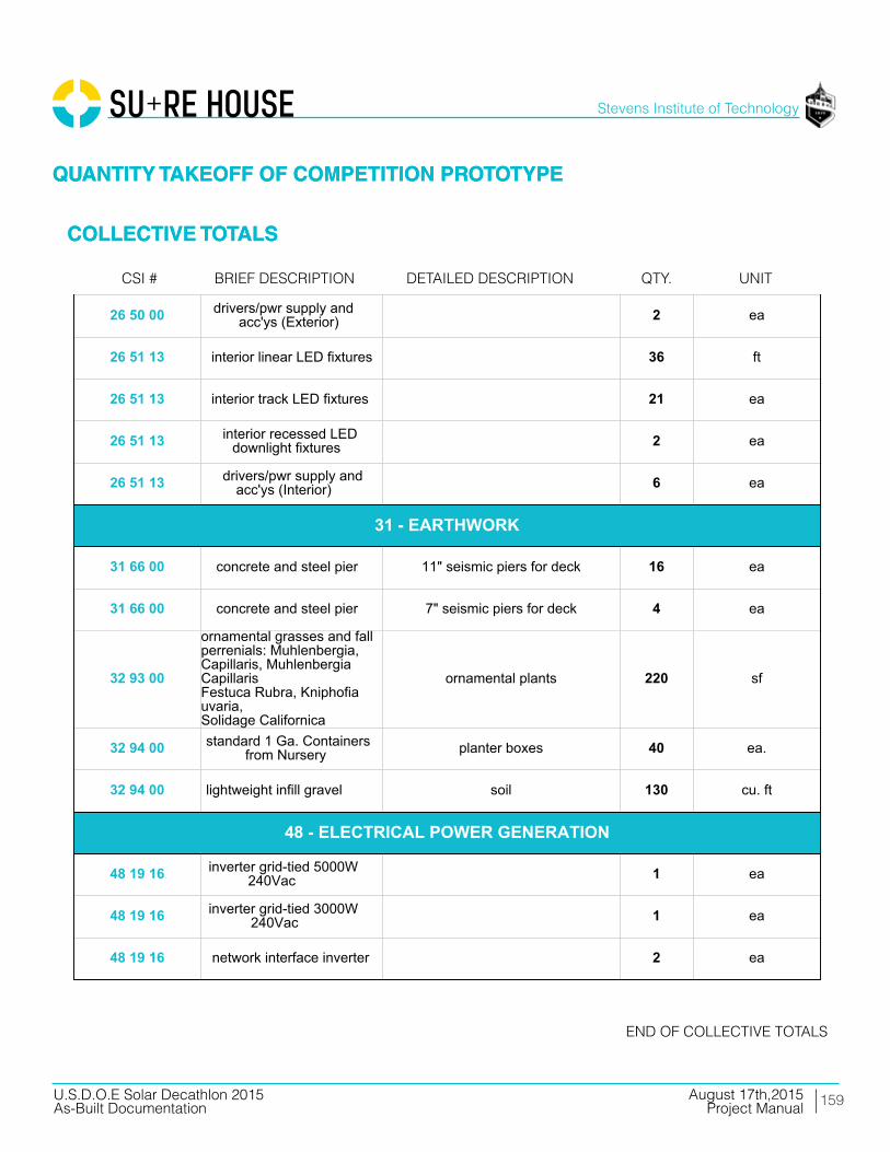
159
Stevens Institute of Technology
August 17th,2015U.S.D.O.E Solar Decathlon 2015As-Built Documentation Project Manual
01 54 16 lull/forklift setting steel and decks 2 days
01 54 19 90 ton hydraulic truck crane setting modules 1 day
05 05 23 1 1/2"x3" 12-gauge L-angle beam to floor framing connectors 100 ea
05 05 23 6" x 3" 12-gauge L-angle pier to beam connectors 25 ea.
05 12 13 HSS 4x2x5/16 southern steel columns 0.63 tons
05 12 13 HSS 4x4x3/16 north and east porch columns 0.34 tons
05 12 13 HSS 4x4, 3/16 shade structure steel columns 0.47 tons
05 12 13 HSS 4x2, 3/16 shade structure steel columns 0.08 tons
05 12 13 HSS 3x3, 3/8 shade structure steel beams 0.54 tons
05 12 13 WT4X7.5 lover steel columns 45 lf
05 13 00 stainless steel cable southern diagonal supports 25 lf
05 14 00 Roof Anchors PV racking roof array 32 ea
05 14 00 Strut Channel and Hardware PV racking roof array 120 lf
05 52 13 HSS 1X1, 1/4 ramp railing 100 lf
05 53 00 1/4 plate steel ramp to ground transition 45 sf
06 11 16 2x4 SPF interior partition framing 715lf
06 11 16 2x6 SPF interior partition framing 180lf
06 11 16 2x6 SPF bedroom drop ceiling 106 sf
06 11 16 2x4 SPF kitchen island 55 lf
06 11 16 2x4 SPF foundation beam top plates to createspace for crane straps 315 lf
06 11 16 2x8 SPF foundation beams attached to piers,supporting floor 171 lf
01 - GENERAL REQUIREMENTS
05 - METALS
06 - WOODS, PLASTICS, COMPOSITES
06 11 16 2x10 SPF south dropdown floor framing +blocking 90 lf
06 11 16 2x10 SPF roof framing blocking 250 lf
06 11 16 2x4 SPF ledgers for roof joist support atmodule seams 90 lf
06 11 16 2x4 SPF south shadestructure "sweatband"framing 70 lf
06 11 16 2x6 SPF exterior wall and parapet framing 1880 lf
06 11 16 1x3 SPF exterior rainscreen battens 3345 lf
06 11 16 2x3 SPF interior service cavity battens 600 lf
06 11 16 2x10 PT south deck framing 270 lf
06 11 16 2x8 PT south deck framing 40 lf
06 11 16 2x4 PT south deck framing 325 lf
06 11 16 2x10 PT north deck framing 50 lf
06 11 16 2x8 PT north deck framing 204 lf
06 11 16 2x8 PT ramp framing 30 lf
06 11 16 2x4 PT ramp framing 30 lf
06 11 16 2x4 PT ramp platform framing 100 sf
06 11 16 2x4 PT electrical platform framing 40 lf
06 11 13 1 3/4 x 7 1/4 LVL beams attached to piers, supportingfloor 115 lf
06 11 13 1 3/4 x 9 1/2 LVL module three floor joists 320 lf
06 11 13 1 3/4 x 7 1/4 LVL shower pan framing 10 lf
06 11 13 1 3/4 x 9 1/2 LSL plumber waste header 10 lf
06 11 13 1 3/4 x 9 1/2 LVL floor beam at module perimeters 171 lf
06 11 13 1 1/2 x 9 1/2 rim joist 102 lf
06 11 13 3 1/2 x 11 7/8 LVL living room and east porch beams 11 lf
06 11 13 3 1/2 x 11 7/8 LVL kitchen beams 24 lf
06 11 13 1 3/4 x 7 1/4 LVL bedroom beams 37 lf
06 11 13 3 1/2 x 9 1/2 LVL north porch beams 27 lf
06 11 13 3 1/2 x 9 1/2 LSL east porch beam 19 lf
06 11 13 1 1/8 x 9 1/2 rimboard rim joists, doubled at module seams 218 lf
06 11 13 1 3/4 x 9 1/2 PSL southern perimeter beam for shutterlateral loads 44 lf
06 11 13 3 1/2 x 9 1/2 LVL southern perimeter beam for shutterlateral loads 44 lf
06 11 16 1 3/4 x 9 1/2 LVL column between southern lift andslide doors 10 lf
06 11 16 3 1/2 x 9 PSL south deck framing 130 lf
06 11 16 3 1/2 x 9 PSL north deck framing 87 lf
06 16 23 3/4 OSB sheathing uder floorjoists allow forfloodproofing 1000 sf
06 16 23 3/4 T & G OSB subfloor 1000 sf
06 16 26 3/4 T&G OSB roof sheathing 1240 sf
06 16 36 3/4 CDX ply
Material component for 12" x 24" and6" x 10" foundation piers consisting of
glued and screwed plywood,combination of 3/4", 5/8", 1/2", and
1/4" as required by site contour
36 ea
06 16 36 5/8 CDX ply
Material component for 12" x 24" and6" x 10" foundation piers consisting of
glued and screwed plywood,combination of 3/4", 5/8", 1/2", and
1/4" as required by site contour
3 ea
06 16 36 1/2 CDX ply
Material component for 12" x 24" and6" x 10" foundation piers consisting of
glued and screwed plywood,combination of 3/4", 5/8", 1/2", and
1/4" as required by site contour
3 ea
06 16 36 1/4 CDX ply
Material component for 12" x 24" and6" x 10" foundation piers consisting of
glued and screwed plywood,combination of 3/4", 5/8", 1/2", and
1/4" as required by site contour
3 ea
06 16 36 7/16 zip sheathing system exterior sheathing 1365 sf
06 16 36 1/4 ply fascia over southern shutters 45 sf
06 16 36 1/2 CDX ply interior shear wall sheathing 270sf
06 16 36 1/2 CDX ply north planter box framing 190 sf
06 16 36 1/2 CDX ply electrical platform framing 28 sf
06 16 36 1/2 CDX ply south shadestructure "sweatband"framing 70 lf
06 16 53 1/8" ABS sheet plastic glued and screwed to 3/4" sheathingunder floor joists 1000 sf
06 16 53 1/8" ABS sheet plastic wraps first 4' feet of exterior wall 400 sf
06 17 33 2 1/2 x 9 1/2 I-Joist modules 1 and 2 floor joists, 16" OC 610 lf
06 17 33 2 1/16 x 9 1/2 I-Joist roof joists 928 lf
06 20 13 1x8 #3 cedar north planter box trim 60 lf
06 20 13 1x6 T&G cedar porch ceiling 250 sf
06 25 00 MDF face panels fridge, dishwasher, pantry 50 sf
06 20 13 1/2 birch ply south shadestructure "sweatband"finish 70 sf
06 40 23 3/4 AB ply mechanical room sheathing 190sf
06 40 23 3/4 birch ply hallway walls 64sf
06 40 23 1/2 birch ply drop ceiling living room 506 sf
06 40 23 1/2 birch ply drop ceiling hall 25 sf
06 40 23 3/4 AB ply mechanical room 42 sf
06 40 23 1/2 birch ply living room beam wrap 100 sf
06 40 23 3/4 birch ply living room and entertainment centerbuilt-in shelving 220 sf
06 46 13 1x4 finger-jointed paintgrade pine door and window trim for bedrooms 75 lf
06 46 19 1x4 finger-jointed paintgrade pine bedroom baseboard 78 lf
06 65 00 1x6 PVC trim porch ceiling edges 45 lf
06 73 00 1x6 TruGrain compositelumber door and window trim 150 lf
06 73 00 3/4" TruGraincompositelumber shower 22 sf
06 73 00 5/4x6 TruGrain compositedecking decking 1120 sf
06 73 00 1x6 TruGrain compositelumber ramp and deck trim 170 lf
06 73 00 5/4x6 TruGrain compositedecking ramp decking 190 sf
06 73 00 5/4x6 TruGrain compositedecking electrical platform decking 15 sf
06 73 00 1x6 TruGrain compositelumber electrical platform finish 28 sf
06 73 00 1x6 TruGrain compositelumber louver verticals 88 lf
06 73 00 1x4 TruGrain compositelumber louvers 1160 lf
07 13 26 Grace Ice and Water Sheild exterior floor to wall joint 120 lf
07 21 16 8" mineral wool batts floor cavity insulation 1000 sf
07 21 16 12" mineral wool batts roof cavity insulation 1000 sf
07 21 16 5.5" mineral wool batts wall cavity insulation 980 sf
07 21 16 2.5" mineral wool batts service cavity insulation 980 sf
07 21 16 1 1/4" mineral wool boardinsulation insulation over sheathing 920 sf
07 21 16 3.5" mineral wool batts interior acoustic insualtion 290 sf
07 22 22 tapered polyisocyanuraterigid insulation
roof deck insulation; 6" at westtapered to 1" at east 1240 sf
07 27 00 ProClima Intello interior primary air barrier 3260 sf
07 46 23 cedar shakes east, north, west finish 983 sf
07 46 23 primed cedar shakes north planter box finish 165 sf
07 46 46 3/16" fibercement board south bathroom facade 70 sf
07 46 46 3/16" fibercement board south shadestructure "sweatband"finish 70 sf
07 54 00 SikaSarnafil G410 PVC, 60mil roofing membrane 1240 sf
07 62 00 coping cap membrane seal at parapet edge 160 sf
07 70 00 vent strip cap top and bottom of rainscreencavity 160 lf
07 71 00 retrodrain scuppers scupper drains 2 ea
07 92 13 10oz marine sealant floodproofing joint sealant 20 ea.
07 92 13 4" x 75' self-healing jointtape (Grace Vycor) floodproofing joint flashing tape 5 ea.
07 - THERMAL AND MOISTURE PROTECTION
08 14 16 3'-0" x 7'-0" Interior doors 3 ea
08 14 16 2'-8" x 7--0" Interior doors 1 ea
08 14 16 2'-8" x 7'-0" Interior doors bifold 1 ea
08 15 00 Schuco SL82, 7'-0" x 3'-2" swinging entry doors 2 ea.
08 32 16Schuco thermoslide, triplepane, low-E,safety glazing,
8'-5" x 14'-10"sliding patio doors 2 ea.
08 53 00Schuco tilt and turn, triplepane, low-E, safety glazing,
3 'x 5'-1 1/2"tilt/turnwindow (bedroom) 30 sf
08 53 00Schuco tilt and turn, triplepane, low-E, safety glazing,
2' x 5'-3"tilt/turn window (bedroom) 10.5 sf
08 53 00Schuco fixed triple pane,low-E, safety glazing, 3' x 7'-
11"fixed windows (east + west) 48 sf
09 22 16 2x4 metal stud framing bathroom drop ceiling 42 sf
09 29 00 5/8" type X gypsum bedroom walls 670sf
09 29 00 5/8" type X gypsum bedroom drop ceiling 106 sf
09 29 00 5/8" type X gypsum bathroom drop ceiling 42 sf
09 30 13 ceramic wood pattern tile bathroom walls 200 sf
09 30 13 ceramic white tile bathroom walls 32 sf
09 62 19 aquastep laminate flooring mechanical room 42 sf
09 65 13 prefinished 3/4" maple plank living and bedroom floor 710 sf
09 91 13 paint: gypsum board bedrooms 670 sf
09 91 13 paint: wood trim bedrooms 25 sf
09 91 13 paint: birch plywood hallway 64 sf
09 91 13 paint: wood trim bedroom baseboard78
lf
09 91 13 paint: plywood hallway and living room beam wrap 25 lf
09 91 13 paint: gyp bedrooms and bathroom 148 lf
08 - OPENINGS
09 - FINISHES
09 93 23 polyurethane: interiorplywood surfaces living room built-ins 515 sf
09 93 23 polyurethane: plywood living room 506 sf
10 28 16 3' x 5' mirror vanity mirror 1 ea
10 28 16 Ikea: Grundtal towel hanger 1 ea
10 28 16 Ikea: Grundtal toilet paper roll 1 ea
10 28 16 Ikea: Grundtal small hanger 1 ea
10 71 1611'-0 x 7'-6" fiberglasscomposite panels withhardware and rigging
manually operable shutters 6 ea
10 71 16 1.5" fiberglass compositepanels storm plugs for windows and doors 115 sf
11 30 13 Thermador UCVM36FS recirculating range hood 1 ea
11 31 13 GE JP656DDBB cooktop 1 ea
11 31 13 GE JT5000DF wall oven 1 ea
11 31 13 Liebherr HC1030 refrigerator1
ea
11 31 13 Bloomberg DW 551100 dishwasher 1 ea
11 31 23 LG WM4070H_A washer 1 ea
11 31 23 LG DLHX4072 dryer 1 ea
12 24 13 rolling shades manual solar protection 290 sf
12 32 13 Ikea casework: lowercabinets lower cabinets 5.5 lf
12 32 13 Ikea casework: uppercabinets upper cabinets 7.5 lf
12 36 61 Hi-Macs composite bathroom vanity; 2 shelves and sinkenclosure 1 ea
12 36 61 HI-Macs composite kitchen counter 9 lf
12 36 61 HI-Macs composite backsplash 18 sf
10 - SPECIALTIES
11 - EQUIPMENT
12 - FURNISHINGS
21 13 13 fire sprinkler head 6 ea
21 13 13 1" Fire Protection Pipe 90 lf
21 13 13 fitting elbow 10 ea
21 13 13 fitting tee 2 wa
21 13 13 valve assembly 1 ea
21 13 13 pressure release valve 1 ea
21 30 00 fire pump 1 ea
22 11 13 plumbing manifold mech room 1 ea
22 11 16 1/2" PEX pipe domestic supply 70 lf
22 11 16 misc. valves and fittings domestic supply 1 ls
22 11 23 pump domestic supply; under planter
22 12 23 pressure tank domestic supply; under planter 1 ea
22 12 19 1000 gallon water tank domestic supply; under planter 1 ea
22 13 16 4" PVC gutter downspout, along west exteriorwall behind finish 40 lf
22 13 16 4" corrugated drain pipe to direct downspout water from underhouse to daylight 20 lf
22 13 16 waste and vent piping: PVC 80 lf
22 13 53 400 gallon water tank waste; planter 1 ea
22 14 29 sump pump to waste tank; outside house underelectrical platform 1 ea
22 30 3080 gallon heat pump waterheater w/ 2nd electricalelement circuited to shutterPV
domestic hot water; mech room 1 ea
22 41 00 expansion tank mech room 1 ea
22 41 13 residential water closet bathroom 1 ea
21 - FIRE SUPRESSION
22 - PLUMBING
22 41 13 shower pan bathroom 1 ea
22 41 16 shower drain/faucet bathroom 1 ea
22 41 16 double bowl sink kitchen 1 ea
22 41 39 faucet bathroom 1 ea
22 41 39 clothes washer connection laundry 1 ea
22 41 39 faucet kitchen 1 ea
22 41 39 dishwasher connection kitchen 1 ea
23 09 13 Daikin DZK030E5 zoning kit 1 ea
23 09 13 Daikin DZK-MTS-1 Main Thermostat 1 ls
23 09 13 Daikin DZK-ZTS-1 Wireless Thermostat 4 ls
23 09 13 Daikin BRC1E73 AHU Thermostat 1 ls
23 23 00 Copper Piping refrigerant piping 15 lf
23 31 16 Zehnder comfopipe insulatedrigid ductwork heating and cooling (heat pump) 130 lf
23 31 16 Zehnder comfotube flexibleductwork ventilation (ERV) 50 lf
23 33 13 Tuttle and Bailey MA, 4000,DXFR, and T75D grilles, registers, diffusers 12 ea
23 34 00 Daikin FBQ24PVJU air handler 1 ea
23 72 00 Zehnder Comfowell 220 ventilation manifold 2 ea
23 72 00 Zehnder NOVUS 300 ERV 10 lf
23 82 19 Daikin RDZQ24PVJU9 condensing unit 1 ea
25 37 00 data opening 2 ea
25 37 00 tv opening 2 ea
25 38 00 smoke detector 3 ea
23 - HVAC
25 - INTEGRATED AUTOMATION
25 50 00 exterior south deckuplighting: LED 6 ea
25 50 00 exterior east porchdownlighting: LED 6 ea
26 05 19 200A panel including AFCIbreakers 1 ea
26 05 19 electrical meter 1 ea
26 05 19 service entrance conductors;(3) 2/0 THHN (1) #4 ground 15 lf
26 05 19 #8 AWG THWN-2 0 lf
26 05 19 #10 AWG THWN-2 50 lf
26 05 19 #12 AWG THWN-2 100 lf
26 05 19 #12/2 NM-B 500 lf
26 05 19 #10/3 NM-B 100 lf
26 05 19 #8/3 NM-B 100 lf
26 05 19 #10 AWG PV Wire 400 lf
26 05 19 #8 AWG PV Wire 100 lf
26 05 19 #10 AWG THWN-2 250 lf
26 05 19 #8 AWG THWN-2 100 lf
26 21 00 200A SE cable 80 lf
26 27 26 20A 125V duplex receptacle 10 ea
26 27 26 20A 125V duplex receptacle- GFCI 15 ea
26 27 26 20A 125V duplex receptacle- WP 5 ea
26 27 26 duplex receptacle cover In-Use 3 ea
26 27 26 50A 240V single receptacle 4 ea
26 27 26 15A 125V duplex receptacle- Floor 2 ea
26 27 26 20A 120/277V Switch 8 ea
26 - ELECTRICAL
26 27 26 20A 120/277V 3-Way Switch 4 ea
26 27 26 domestic water pump stationconnection 1 ea
26 27 26 dishwasher connection 1 ea
26 27 26 heat pump water heaterconnection 1 ea
26 27 26 sump pump connection 1 ea
26 27 26 air handler connection 1 ea
26 27 26 heat pump; 2-ton outdoorunit connection 1 ea
26 27 26 energy recovery ventilatorconnection 1 ea
26 27 26 combiner Box 3 ea
26 27 26 transition/junction box 2 ea
26 28 16 disconnect wwitch 2 ea
26 31 00 module 60-cell mSi 280WFramed PV Roof Array 32 ea
26 31 00 module 60-cell mSi 180WFlexible PV Flood Shutters 10 ea
26 31 00 Renusol CS60 ballastedracking trays PV Racking Roof Array 32 ea
26 50 00 drivers/pwr supply andacc'ys (Exterior) 2 ea
26 51 13 interior linear LED fixtures 36 ft
26 51 13 interior track LED fixtures 21 ea
26 51 13 interior recessed LEDdownlight fixtures 2 ea
26 51 13 drivers/pwr supply andacc'ys (Interior) 6 ea
31 66 00 concrete and steel pier 11" seismic piers for deck 16 ea
31 66 00 concrete and steel pier 7" seismic piers for deck 4 ea
31 - EARTHWORK
32 93 00
ornamental grasses and fallperrenials: Muhlenbergia,Capillaris, MuhlenbergiaCapillarisFestuca Rubra, Kniphofiauvaria,Solidage Californica
ornamental plants 220 sf
32 94 00 standard 1 Ga. Containersfrom Nursery planter boxes 40 ea.
32 94 00 lightweight infill gravel soil 130 cu. ft
48 19 16 inverter grid-tied 5000W240Vac 1 ea
48 19 16 inverter grid-tied 3000W240Vac 1 ea
48 19 16 network interface inverter 2 ea
48 - ELECTRICAL POWER GENERATION
QUANTITY TAKEOFF OF COMPETITION PROTOTYPE
COLLECTIVE TOTALS
QUANTITY TAKEOFF OF COMPETITION PROTOTYPE
COLLECTIVE TOTALS
Brief deScriPtioncSi # detailed deScriPtion QtY. unit
end of collectiVe totalS

10 CONSTRUCTIONSPECIFICATIONS
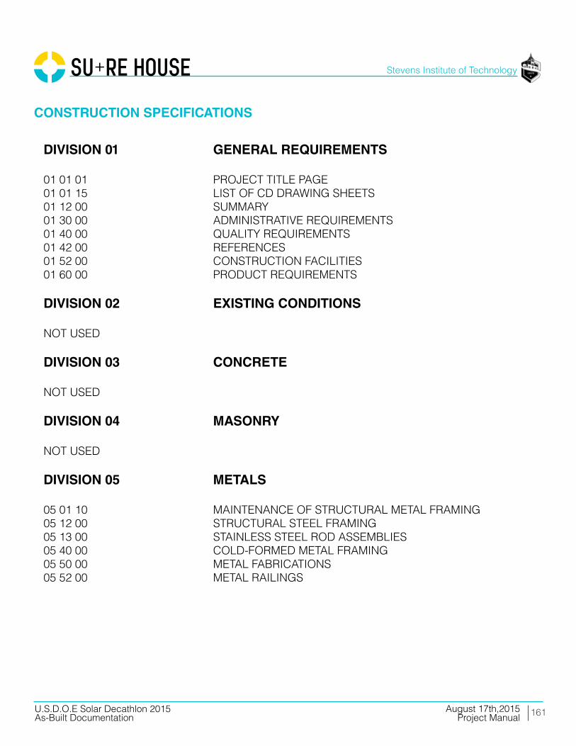
161
Stevens Institute of Technology
August 17th,2015U.S.D.O.E Solar Decathlon 2015As-Built Documentation Project Manual
CONSTRUCTION SPECIFICATIONS
DIVISION 01 GENERAL REQUIREMENTS
01 01 01 PROJECT TITLE PAGE 01 01 15 LIST OF CD DRAWING SHEETS01 12 00 SUMMARY01 30 00 ADMINISTRATIVE REQUIREMENTS01 40 00 QUALITY REQUIREMENTS01 42 00 REFERENCES01 52 00 CONSTRUCTION FACILITIES01 60 00 PRODUCT REQUIREMENTS
DIVISION 02 EXISTING CONDITIONS
NOT USED
DIVISION 03 CONCRETE
NOT USED
DIVISION 04 MASONRY
NOT USED
DIVISION 05 METALS
05 01 10 MAINTENANCE OF STRUCTURAL METAL FRAMING05 12 00 STRUCTURAL STEEL FRAMING05 13 00 STAINLESS STEEL ROD ASSEMBLIES 05 40 00 COLD-FORMED METAL FRAMING05 50 00 METAL FABRICATIONS05 52 00 METAL RAILINGS
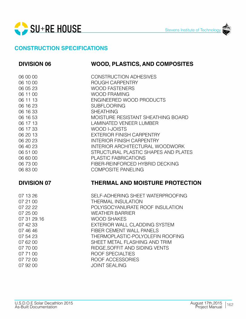
162
Stevens Institute of Technology
August 17th,2015U.S.D.O.E Solar Decathlon 2015As-Built Documentation Project Manual
CONSTRUCTION SPECIFICATIONS
DIVISION 06 WOOD, PLASTICS, AND COMPOSITES
06 00 00 CONSTRUCTION ADHESIVES06 10 00 ROUGH CARPENTRY06 05 23 WOOD FASTENERS06 11 00 WOOD FRAMING06 11 13 ENGINEERED WOOD PRODUCTS06 16 23 SUBFLOORING06 16 33 SHEATHING06 16 53 MOISTURE RESISTANT SHEATHING BOARD06 17 13 LAMINATED VENEER LUMBER06 17 33 WOOD I-JOISTS 06 20 13 EXTERIOR FINISH CARPENTRY06 20 23 INTERIOR FINISH CARPENTRY06 40 23 INTERIOR ARCHITECTURAL WOODWORK06 51 00 STRUCTURAL PLASTIC SHAPES AND PLATES06 60 00 PLASTIC FABRICATIONS06 73 00 FIBER-REINFORCED HYBRID DECKING 06 83 00 COMPOSITE PANELING
DIVISION 07 THERMAL AND MOISTURE PROTECTION
07 13 26 SELF-ADHERING SHEET WATERPROOFING07 21 00 THERMAL INSULATION07 22 22 POLYISOCYANURATE ROOF INSULATION07 25 00 WEATHER BARRIER07 31 29.16 WOOD SHAKES07 42 33 EXTERIOR WALL CLADDING SYSTEM07 46 46 FIBER CEMENT WALL PANELS07 54 23 THERMOPLASTIC-POLYOLEFIN ROOFING07 62 00 SHEET METAL FLASHING AND TRIM07 70 00 RIDGE,SOFFIT AND SIDING VENTS07 71 00 ROOF SPECIALTIES07 72 00 ROOF ACCESSORIES07 92 00 JOINT SEALING
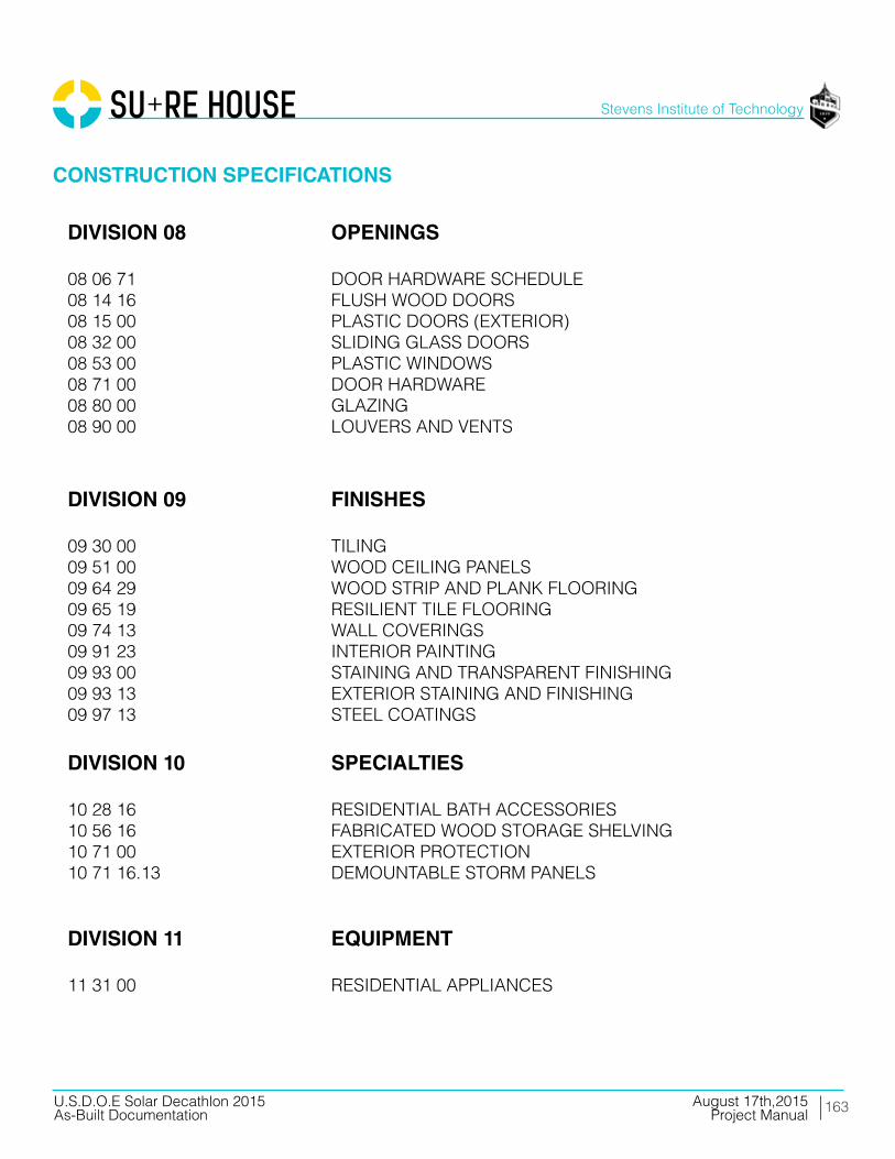
163
Stevens Institute of Technology
August 17th,2015U.S.D.O.E Solar Decathlon 2015As-Built Documentation Project Manual
CONSTRUCTION SPECIFICATIONS
DIVISION 08 OPENINGS
08 06 71 DOOR HARDWARE SCHEDULE08 14 16 FLUSH WOOD DOORS08 15 00 PLASTIC DOORS (EXTERIOR)08 32 00 SLIDING GLASS DOORS08 53 00 PLASTIC WINDOWS08 71 00 DOOR HARDWARE08 80 00 GLAZING08 90 00 LOUVERS AND VENTS
DIVISION 09 FINISHES
09 30 00 TILING09 51 00 WOOD CEILING PANELS09 64 29 WOOD STRIP AND PLANK FLOORING09 65 19 RESILIENT TILE FLOORING09 74 13 WALL COVERINGS09 91 23 INTERIOR PAINTING09 93 00 STAINING AND TRANSPARENT FINISHING09 93 13 EXTERIOR STAINING AND FINISHING09 97 13 STEEL COATINGS
DIVISION 10 SPECIALTIES
10 28 16 RESIDENTIAL BATH ACCESSORIES10 56 16 FABRICATED WOOD STORAGE SHELVING 10 71 00 EXTERIOR PROTECTION10 71 16.13 DEMOUNTABLE STORM PANELS
DIVISION 11 EQUIPMENT
11 31 00 RESIDENTIAL APPLIANCES

164
Stevens Institute of Technology
August 17th,2015U.S.D.O.E Solar Decathlon 2015As-Built Documentation Project Manual
CONSTRUCTION SPECIFICATIONS
DIVISION 12 FURNISHINGS
12 21 23 ROLL DOWN BLINDS12 35 00 SPECIALTY CASEWORK12 36 61 SIMULATED STONE COUNTERTOPS DIVISIONS 13 - 20
NOT USED
DIVISION 21 FIRE SUPPRESSION
21 13 13 WET PIPE SPRINKLER SYSTEM
DIVISION 22 PLUMBING
22 11 16 DOMESTIC WATER PIPING22 11 19 DOMESTIC WATER PIPING SPECIALTIES22 11 23 DOMESTIC WATER PUMP22 12 19 FACILITY POTABLE-WATER STORAGE TANKS22 13 16 SANITARY WASTE AND VENT PIPING22 14 29 SUMP PUMP22 33 01 DOMESTIC WATER HEATER ELECTRIC RESIDENTIAL22 41 00 RESIDENTIAL PLUMBING FIXTURES22 41 23 RESIDENTIAL SHOWERS
DIVISION 23 HEATING, VENTILATING AND AIR CONDITIONING
23 07 00 HVAC INSULATION23 20 00 HVAC PIPING AND PUMPS23 23 00 REFRIGERANT PIPING23 23 23 REFRIGERANTS23 31 00 HVAC DUCTS AND CASINGS23 33 00 DIFFUSERS, REGISTERS AND GRILLES23 56 00 SOLAR ENERGY HEATING EQUIPMENT23 72 00 AIR-TO-AIR ENERGY RECOVERY EQUIPMENT23 74 00 AIR COOLED CONDENSING UNIT

165
Stevens Institute of Technology
August 17th,2015U.S.D.O.E Solar Decathlon 2015As-Built Documentation Project Manual
CONSTRUCTION SPECIFICATIONS
DIVISION 25 INTEGRATED AUTOMATON
25 10 00 INTEGRATED AUTOMATION NETWORK EQUIPMENT
DIVISION 26 ELECTRICAL
26 05 19 LOW-VOLTAGE ELECTRICAL POWER CONDUCTORS26 05 26 GROUNDING FOR ELECTRICAL SYSTEMS26 05 33 RACEWAYS FOR ELECTRICAL SYSTEMS26 05 00 COMMON WORK RESULTS FOR ELECTRICAL26 08 13 STARTING OF EQUIPMENT AND SYSTEMS26 08 19 TESTING, ADJUSTING AND BALANCING OF ELECTRICAL EQUIPMENT AND SYSTEMS26 08 23 STARTING,TESTING BY QUALIFIED TEAM MEMBER26 24 16 PANELBOARDS26 27 26 WIRING DEVICES26 31 00 PHOTOVOLTAIC COLLECTORS28 31 46 SMOKE DETECTOR SENSORS28 40 00 ELECTRONIC MONITORING AND CONTROL
DIVISION 26 COMMUNICATIONS
NOT USED
DIVISION 28 ELECTRONIC SAFETY AND SECURITY
28 31 46 SMOKE DETECTOR SENSORS
DIVISIONS 29 - 48
NOT USED ; SEE PRODUCT CUT SHEETS
166
Stevens Institute of Technology
August 17th,2015U.S.D.O.E Solar Decathlon 2015As-Built Documentation Project Manual
CONSTRUCTION SPECIFICATIONS
SECTION 01 01 01 - PROJECT TITLE PAGE
TITLE : TEAM SIT SOLAR DECATHLON 2015 : The SU+RE HOUSE
Stevens Institute of Technology
Projected Completion Date : October 2015
Team Headquarters : 1 Castle Point Terrace, Hoboken, NJ 07030T : (201) 216-5000
Project Leaders / Faculty Advisors : John Nastasi and Ed May
Team SIT Website : www.surehouse.org
Team SIT Contact : [email protected]
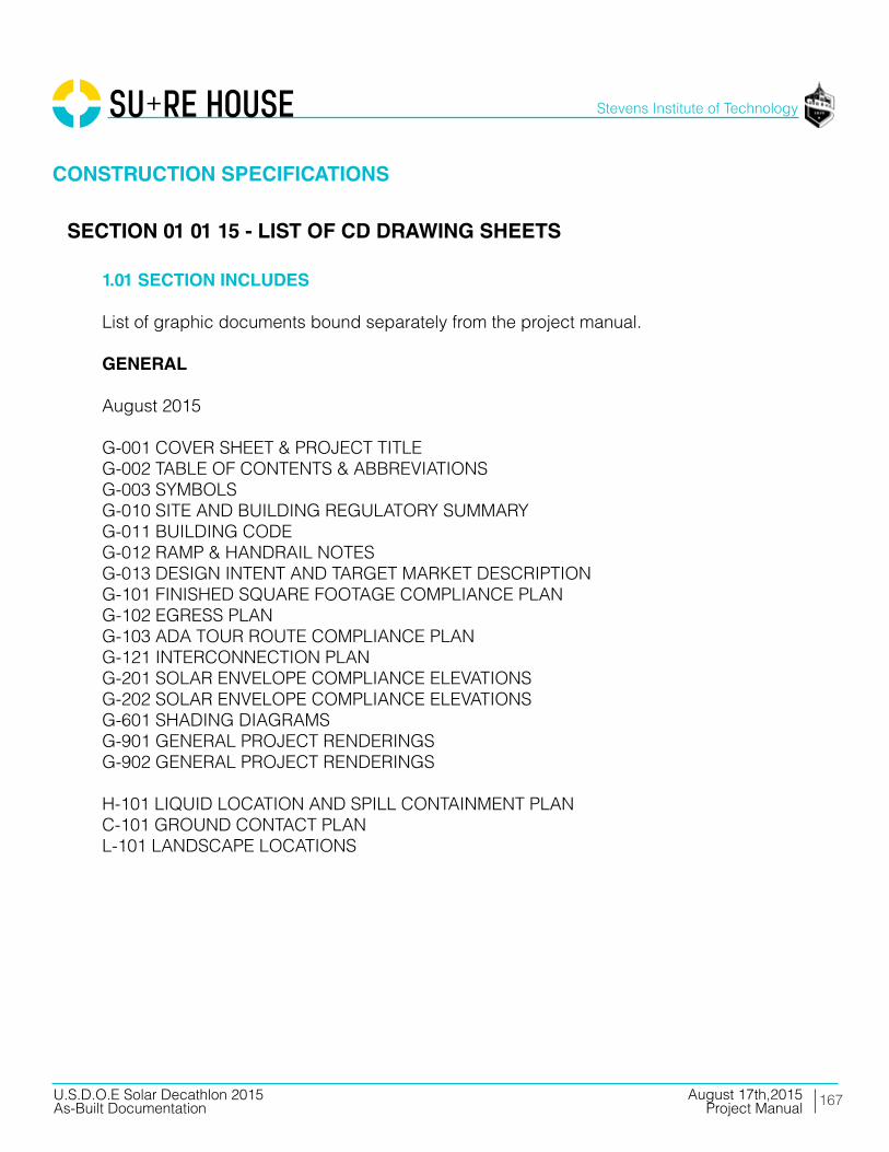
167
Stevens Institute of Technology
August 17th,2015U.S.D.O.E Solar Decathlon 2015As-Built Documentation Project Manual
CONSTRUCTION SPECIFICATIONS
SECTION 01 01 15 - LIST OF CD DRAWING SHEETS
1.01 SECTION INCLUDES
List of graphic documents bound separately from the project manual.
GENERAL August 2015
G-001 COVER SHEET & PROJECT TITLEG-002 TABLE OF CONTENTS & ABBREVIATIONSG-003 SYMBOLSG-010 SITE AND BUILDING REGULATORY SUMMARYG-011 BUILDING CODEG-012 RAMP & HANDRAIL NOTESG-013 DESIGN INTENT AND TARGET MARKET DESCRIPTIONG-101 FINISHED SQUARE FOOTAGE COMPLIANCE PLANG-102 EGRESS PLANG-103 ADA TOUR ROUTE COMPLIANCE PLANG-121 INTERCONNECTION PLANG-201 SOLAR ENVELOPE COMPLIANCE ELEVATIONSG-202 SOLAR ENVELOPE COMPLIANCE ELEVATIONSG-601 SHADING DIAGRAMSG-901 GENERAL PROJECT RENDERINGSG-902 GENERAL PROJECT RENDERINGS
H-101 LIQUID LOCATION AND SPILL CONTAINMENT PLANC-101 GROUND CONTACT PLANL-101 LANDSCAPE LOCATIONS

168
Stevens Institute of Technology
August 17th,2015U.S.D.O.E Solar Decathlon 2015As-Built Documentation Project Manual
CONSTRUCTION SPECIFICATIONS
SECTION 01 01 15 - LIST OF CD DRAWING SHEETS
1.01 SECTION INCLUDES
List of graphic documents bound separately from the project manual.
GENERAL August 2015
S-001 STRUCTURAL NOTES AND SYMBOLSS-101 FOUNDATION PLANS-102 FLOOR STRUCTURAL PLANS-103 ROOF STRUCTURAL PLANS-201 STRUCTURAL SECTIONSS-301 FRAMING SECTIONSS-400 RAMP & RAILINGS DETAILSS-501 TYP. & STRUCTURAL DETAILSS-502 ROOF BEAM CONNECTION DETAILSS-503 RAMP DETAILSS-504 HEADER DETAILSS-505 MODULE CONNECTIONSS-511 SEISMIC PIER DETAILSS-512 FOUNDATION TYPES AND ADJUSTMENTSS-601 STRUCTURAL SCHEDULESS-611 LOAD DIAGRAMSS-612 PANEL LOAD DIAGRAMS-613 FLOOR TRIBUTARY AREA DIAGRAMS-614 ROOF TRIBUTARY AREA DIAGRAMS-901 FRAMING ISOMETRICSS-902 STRUCTURAL WALL ISOMETRICS
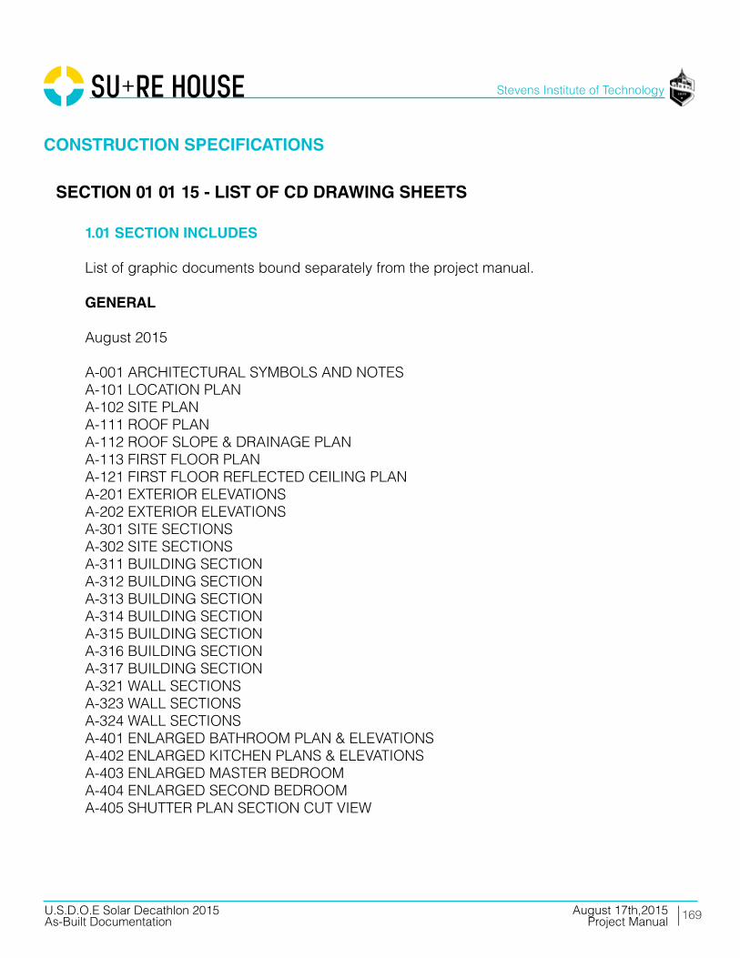
169
Stevens Institute of Technology
August 17th,2015U.S.D.O.E Solar Decathlon 2015As-Built Documentation Project Manual
CONSTRUCTION SPECIFICATIONS
SECTION 01 01 15 - LIST OF CD DRAWING SHEETS
1.01 SECTION INCLUDES
List of graphic documents bound separately from the project manual.
GENERAL August 2015
A-001 ARCHITECTURAL SYMBOLS AND NOTESA-101 LOCATION PLANA-102 SITE PLANA-111 ROOF PLANA-112 ROOF SLOPE & DRAINAGE PLANA-113 FIRST FLOOR PLANA-121 FIRST FLOOR REFLECTED CEILING PLANA-201 EXTERIOR ELEVATIONSA-202 EXTERIOR ELEVATIONSA-301 SITE SECTIONSA-302 SITE SECTIONSA-311 BUILDING SECTIONA-312 BUILDING SECTIONA-313 BUILDING SECTIONA-314 BUILDING SECTIONA-315 BUILDING SECTIONA-316 BUILDING SECTIONA-317 BUILDING SECTIONA-321 WALL SECTIONSA-323 WALL SECTIONSA-324 WALL SECTIONSA-401 ENLARGED BATHROOM PLAN & ELEVATIONSA-402 ENLARGED KITCHEN PLANS & ELEVATIONSA-403 ENLARGED MASTER BEDROOMA-404 ENLARGED SECOND BEDROOMA-405 SHUTTER PLAN SECTION CUT VIEW

170
Stevens Institute of Technology
August 17th,2015U.S.D.O.E Solar Decathlon 2015As-Built Documentation Project Manual
CONSTRUCTION SPECIFICATIONS
SECTION 01 01 15 - LIST OF CD DRAWING SHEETS
1.01 SECTION INCLUDES
List of graphic documents bound separately from the project manual.
GENERAL August 2015
A-421 ENLARGED CASEWORK PLAN & ELEVATIONSA-422 ENLARGED CASEWORK PLAN & ELEVATIONA-501 TYP. DETAILSA-502 BATHROOM DETAILSA-512 LIFT AND SLIDE DOOR JAMB DETAILSA-513 LIFT AND SLIDE HEADER AND SILLA-514 FIXED WINDOW WEST SIDEA-515 FIXED WINDOW EAST SIDEA-516 TILT AND TURN DETAILSA-517 SOUTH ENTRY BATHROOM DOORA-518 SOUTH ENTRY BATHROOM DOOR JAMBSA-519 ENTRY DOOR DETAILA-520 MECH ROOM DETAILSA-552 SHUTTER SECTION AND ELEVATIONA-554 SHUTTER DECK DETAILSA-555 SOUTH SHUTTER PLAN DETAILSA-556 SHUTTER ELEVATION DETAILSA-557 SHUTTER SECTION DETAILSA-591 RAMP DETAILSA-601 WALL TYPESA-602 WINDOW TYPESA-603 DOOR TYPESA-604 CEILING & ROOF PANELSA-605 WALL TYPES CONDUCTIVITYA-901 ARCHITECTURAL RENDERINGSA-902 ARCHITECTURAL RENDERINGS

171
Stevens Institute of Technology
August 17th,2015U.S.D.O.E Solar Decathlon 2015As-Built Documentation Project Manual
CONSTRUCTION SPECIFICATIONS
SECTION 01 01 15 - LIST OF CD DRAWING SHEETS
1.01 SECTION INCLUDES
List of graphic documents bound separately from the project manual.
GENERAL August 2015
I-001 INTERIOR SYMBOLS AND NOTESI-101 INTERIOR DESIGN PLANI-102 INTERIOR FURNISHING PLANI-103 INTERIOR DESIGN RCPI-201 INTERIOR ELEVATIONSI-202 INTERIOR ELEVATIONSI-401 LARGE SCALE INTERIOR DESIGN PLANSI-501 TYP DROP CEILING DETAILSI-503 DROP CEILING AT MECH ROOMI-504 BEDROOM DROP CEILING DETAILSI-505 HALLWAYS CEILING LIGHTI-601 INTERIOR DESIGN SCHEDULES
F-001 FIRE PROTECTION NOTES AND SYMBOLSF-101 FIRE DETECTION AND ALARMF-102 FIRE SUPPRESSION COVERAGE PLAN
P-102 DOMESTIC SUPPLYP-103 DOMESTIC RETURNP-602 DOMESTIC SUPPLY AND RETURN DIAGRAMS
M-001 MECHANICAL SYMBOLS AND NOTESM-101 HVAC EQUIPMENT AND DISTRIBUTION PLANM-201 MECHANICAL ELEVATIONSM-601 SCHEDULESM-602 HVAC RISERSM-603 HVAC RISERS - CTD

172
Stevens Institute of Technology
August 17th,2015U.S.D.O.E Solar Decathlon 2015As-Built Documentation Project Manual
CONSTRUCTION SPECIFICATIONS
SECTION 01 01 15 - LIST OF CD DRAWING SHEETS
1.01 SECTION INCLUDES
List of graphic documents bound separately from the project manual.
GENERAL August 2015
E-001 ELECTRICAL SYMBOLS AND NOTESE-101 ELECTRICAL DISTRIBUTION PLANE-102 PV WIRING PLANE-103 LIGHTING PLANE-201 ELECTRICAL ELEVATIONSE-601 ONE-LINE DIAGRAME-602 THREE-LINE DIAGRAM ACE-603 THREE-LINE DIAGRAM DCE-604 SCHEDULES
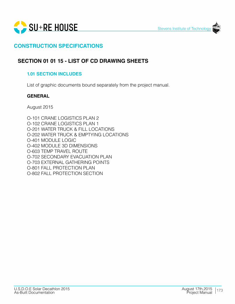
173
Stevens Institute of Technology
August 17th,2015U.S.D.O.E Solar Decathlon 2015As-Built Documentation Project Manual
CONSTRUCTION SPECIFICATIONS
SECTION 01 01 15 - LIST OF CD DRAWING SHEETS
1.01 SECTION INCLUDES
List of graphic documents bound separately from the project manual.
GENERAL August 2015
O-101 CRANE LOGISTICS PLAN 2O-102 CRANE LOGISTICS PLAN 1O-201 WATER TRUCK & FILL LOCATIONSO-202 WATER TRUCK & EMPTYING LOCATIONSO-401 MODULE LOGICO-402 MODULE 3D DIMENSIONSO-603 TEMP TRAVEL ROUTEO-702 SECONDARY EVACUATION PLANO-703 EXTERNAL GATHERING POINTSO-801 FALL PROTECTION PLANO-802 FALL PROTECTION SECTION

174
Stevens Institute of Technology
August 17th,2015U.S.D.O.E Solar Decathlon 2015As-Built Documentation Project Manual
CONSTRUCTION SPECIFICATIONS
SECTION 01 12 00 - SUMMARY
PART 1 - GENERAL
1.01 PROJECT INFORMATION SUMMARY
A. This Section includes the following:
1. Work covered by the Documents. 2. Specification formats and conventions. B. This set of documents, including the Drawings, Specifications, and other data provided, is an incomplete representation of the project. Pricing the project using these documents will result in an estimate that may be more or less than the price for the project when the documents are complete. Commencing or pursuing construction activities using these documents, including ordering of materials or systems, is not permitted.
1.02 WORK COVERED BY CONTRACT DOCUMENTS
A. Project Identification : SURE HOUSE, a project of the Stevens Institute of Technology
B. Owner: Board of Trustees, Stevens Institute of Technology
C. The Work consists of the following:
1. The Work includes a single-family home, newly-constructed on a portable module,designed for highway transport in 3 main sections, and for reassembly on another site. Work includes structure, interior and exterior finishes, fixtures, appliances, and electrical, mechanical, and plumbing systems. Work also includes some exterior work that is also transportable, and which serves to complete the utility systems and provide access to the home.
2. The Owner desires to have a minimal impact on the environment resulting from this Work, and therefore has established a goal of recycling 50-percent of the demolition and construction waste that is removed from the site.

175
Stevens Institute of Technology
August 17th,2015U.S.D.O.E Solar Decathlon 2015As-Built Documentation Project Manual
CONSTRUCTION SPECIFICATIONS
SECTION 01 12 00 - SUMMARY
PART 1 - GENERAL
1.03 SPECIFICATION FORMATS AND CONVENTIONS
A. Specification Format : The Specifications are organized into Divisions and Sections using the 50-division format and CSI’s “MasterFormat 2014 Update” numbering system.
PART 2 - PRODUCTS (NOT USED)
PART 3 - EXECUTION (NOT USED)
END OF SECTION 01 12 00

176
Stevens Institute of Technology
August 17th,2015U.S.D.O.E Solar Decathlon 2015As-Built Documentation Project Manual
CONSTRUCTION SPECIFICATIONS
SECTION 01 30 00 - ADMINISTRATIVE REQUIREMENTS
PART 1 - GENERAL
1.01 PROJECT MANAGEMENT AND COORDINATION
A. Key Personnel Names: Within 15 days of starting construction operations, submit a list of key personnel assignments, including superintendent and other personnel in attendance at Project site. List e‐mail addresses and telephone numbers.
B. Coordinate construction operations included in different Sections of the Specifications to ensure efficient and orderly installation of each part of the Work.
C. Requests for Information (RFIs): On discovery of the need for additional information or interpretation of the Contract Documents, Contractor shall prepare and submit an RFI. Use forms acceptable to Architect and Owner.
D. Schedule and conduct progress meetings at Project site at weekly intervals. Notify Owner and Architect of meeting dates and times. Require attendance of each subcontractor or other entity concerned with current progress or involved in planning, coordination, or performance of future activities.
1. Record minutes and distribute to everyone concerned, including Owner and Architect.

177
Stevens Institute of Technology
August 17th,2015U.S.D.O.E Solar Decathlon 2015As-Built Documentation Project Manual
CONSTRUCTION SPECIFICATIONS
SECTION 01 30 00 - ADMINISTRATIVE REQUIREMENTS
PART 1 - GENERAL
1.02 SUBMITTAL ADMINISTRATIVE REQUIREMENTS
A. Architect’s Digital Data Files: Electronic digital data files of the Contract Drawings will be provided by Architect for Contractor’s use in preparing submittals.
1. Architect will furnish Contractor one set of digital data drawing files of the Contract Drawings for use in preparing Shop Drawings and Project record drawings.
a. Architect makes no representations as to the accuracy or completeness of digital data drawing files as they relate to the Contract Drawings.
b. Contractor shall execute a data licensing agreement in the form of Agreement form acceptable to Owner and Architect.
B. Coordinate each submittal with fabrication, purchasing, testing, delivery, other submittals, and related activities that require sequential activity.
1. No extension of the Contract Time will be authorized because of failure to transmit submittals enough in advance of the Work to permit processing, including resubmittals. 2. Submit three copies of each action submittal. Architect will return two copies. 3. Submit two copies of each informational submittal. Architect will not return copies. 4. Architect will return submittals, without review, received from sources other than Contractor.

178
Stevens Institute of Technology
August 17th,2015U.S.D.O.E Solar Decathlon 2015As-Built Documentation Project Manual
CONSTRUCTION SPECIFICATIONS
SECTION 01 30 00 - ADMINISTRATIVE REQUIREMENTS
PART 1 - GENERAL
1.02 SUBMITTAL ADMINISTRATIVE REQUIREMENTS
C. Electronic Submittals: Identify and incorporate information in each electronic submittal file as follows:
1. Assemble complete submittal package into a single indexed file incorporating submittal requirements of a single Specification Section and transmittal form with links enabling navigation to each item. 2. Name file with unique identifier, including project identifier, Specification Section number, and revision identifier. 3. Provide means for insertion to permanently record Contractor’s review and approval markings and action taken by Architect.
D. Identify options requiring selection by Architect.
E. Identify deviations from the Contract Documents on submittals.
F. Identify deviations from the Contract Documents on submittals.
PART 2 - PRODUCTS
2.01 SUBMITTAL PROCEDURES
B. Product Data: Mark each copy to show applicable products and options. Include the following:
1. Manufacturer’s written recommendations, product specifications, and installation instructions. 2. Wiring diagrams showing factory‐installed wiring. 3. Printed performance curves and operational range diagrams. 4. Testing by recognized testing agency. 5. Compliance with specified standards and requirements.
179
Stevens Institute of Technology
August 17th,2015U.S.D.O.E Solar Decathlon 2015As-Built Documentation Project Manual
CONSTRUCTION SPECIFICATIONS
SECTION 01 30 00 - ADMINISTRATIVE REQUIREMENTS
PART 2 - PRODUCTS
2.01 SUBMITTAL PROCEDURES
C. Electronic Submittals: Identify and incorporate information in each electronic submittal file as follows:
1. Assemble complete submittal package into a single indexed file incorporating submittal requirements of a single Specification Section and transmittal form with links enabling navigation to each item. 2. Name file with unique identifier, including project identifier, Specification Section number, and revision identifier. 3. Provide means for insertion to permanently record Contractor’s review and approval markings and action taken by Architect.
D. Samples : Submit Samples for review of kind, color, pattern, and texture and for a comparison of these characteristics between submittal and actual component as delivered and installed. Include name of manufacturer and product name on label.
1. If variation is inherent in material or product, submit at least three sets of paired units that show variations.
2.02 INFORMATIONAL PROCEDURES
A. Informational Submittals: Submit two paper copies of each submittal unless otherwise indicated. Architect will not return copies.
B. Qualification Data: Include lists of completed projects with project names and addresses, names and addresses of architects and owners, and other information specified.
C. Product Certificates: Prepare written statements on manufacturer’s letterhead certifying that product complies with requirements in the Contract Documents.
180
Stevens Institute of Technology
August 17th,2015U.S.D.O.E Solar Decathlon 2015As-Built Documentation Project Manual
CONSTRUCTION SPECIFICATIONS
SECTION 01 30 00 - ADMINISTRATIVE REQUIREMENTS
PART 2 - PRODUCTS
2.03 DELEGATED DESIGN SERVICES
A. Performance and Design Criteria: Where professional design services or certifications by a design professional are specifically required of Contractor by the Contract Documents, provide products and systems complying with specific performance and design criteria indicated. B. Delegated‐Design Submittal: In addition to Shop Drawings, Product Data, and other required submittals, submit three copies of a statement, signed and sealed by the responsible design professional, for each product and system specifically assigned to Contractor to be designed or certified by a design professional.
1. Indicate that products and systems comply with performance and design criteria in the Contract Documents. Include list of codes, loads, and other factors used in performing these services.
2.04 CONTRACTOR’S CONSTRUCTION SCHEDULE
A. Gantt‐Chart Schedule: Submit a comprehensive, fully developed, horizontal Gantt‐chart‐type schedule within 30 days of date established for commencement of the Work.
B. Preparation: Indicate each significant construction activity separately. Identify first workday of each week with a continuous vertical line.
C. Cost Correlation: Superimpose a cost correlation timeline, indicating planned and actual costs. On the line, show planned and actual dollar volume of the Work performed as of planned and actual dates used for preparation of payment requests.
181
Stevens Institute of Technology
August 17th,2015U.S.D.O.E Solar Decathlon 2015As-Built Documentation Project Manual
CONSTRUCTION SPECIFICATIONS
SECTION 01 30 00 - ADMINISTRATIVE REQUIREMENTS
PART 3 - EXECUTION
3.01 SUBMITTAL REVIEW
A. Review each submittal and check for coordination with other Work of the Contract and for compliance with the Contract Documents. Note corrections and field dimensions. Mark with approval stamp before submitting to Architect.
B. Architect will review each action submittal, make marks to indicate corrections or modifications required, will stamp each submittal with an action stamp, and will mark stamp appropriately to indicate action.
C. Informational Submittals: Architect will review each submittal and will not return it, or will return it if it does not comply with requirements. Architect will forward each submittal to appropriate party.
D. Submittals not required by the Contract Documents may not be reviewed and may be discarded.
3.02 CONTRACTOR’S CONSTRUCTION SCHEDULE
A. Updating: At daily intervals, update schedule to reflect actual construction progress and activities. Issue schedule daily before each regularly scheduled progress meeting.
1. As the Work progresses, indicate Actual Completion percentage for each activity.
B. Distribute copies of approved schedule to Owner, Architect, subcontractors, testing and inspecting agencies, and parties identified by Contractor with a need‐to‐know schedule responsibility. When revisions are made, distribute updated schedules to the same parties.
END OF SECTION 01 30 00

182
Stevens Institute of Technology
August 17th,2015U.S.D.O.E Solar Decathlon 2015As-Built Documentation Project Manual
CONSTRUCTION SPECIFICATIONS
SECTION 01 40 00 - QUALITY REQUIREMENTS
PART 1 - GENERAL
1.01 SECTION REQUIREMENTS
A. Testing and inspecting services are required to verify compliance with requirements specified or indicated. These services do not relieve Contractor of responsibility for compliance with the Contract Document requirements.
B. Referenced Standards: If compliance with two or more standards is specified and the standards establish different or conflicting requirements, comply with the most stringent requirement. Refer uncertainties to Architect for a decision.
C. Minimum Quantity or Quality Levels: The quantity or quality level shown or specified shall be the minimum. The actual installation may exceed the minimum within reasonable limits. Indicated numeric values are minimum or maximum, as appropriate, for the context of requirements. Refer uncertainties to Architect for a decision.
D. Contractor’s Statement of Responsibility: When required by authorities having jurisdiction, submit copy of written statement of responsibility sent to authorities having jurisdiction before starting work on the following systems:
1. Seismic‐force‐resisting system, designated seismic system, or component listed in the designated seismic system quality‐assurance plan prepared by Architect. 2. Main wind‐force‐resisting system or a wind‐resisting component listed in the wind‐force‐resisting system quality‐assurance plan prepared by Architect.
E. Test and Inspection Reports: Prepare and submit certified written reports specified in other Sections. Include the following:
1. Date of issue. 2. Project title and number. 3. Name, address, and telephone number of testing agency. 4. Dates and locations of samples and tests or inspections.

183
Stevens Institute of Technology
August 17th,2015U.S.D.O.E Solar Decathlon 2015As-Built Documentation Project Manual
CONSTRUCTION SPECIFICATIONS
SECTION 01 40 00 - QUALITY REQUIREMENTS
PART 1 - GENERAL
1.01 SECTION REQUIREMENTS
E. Test and Inspection Reports: Prepare and submit certified written reports specified in other Sections. Include the following:
5. Names of individuals making tests and inspections. 6. Description of the Work and test and inspection method. 7. Identification of product and Specification Section. 8. Complete test or inspection data. 9. Test and inspection results and an interpretation of test results. 10. Record of temperature and weather conditions at time of sample taking and testing and inspecting. 11. Comments or professional opinion on whether tested or inspected Work complies with the Contract Document requirements. 12. Name and signature of laboratory inspector. 13. Recommendations on retesting and reinspecting.
F. Permits, Licenses, and Certificates: For Owner’s records, submit copies of permits, licenses, certifications, inspection reports, notices, receipts for fee payments, and similar documents, established for compliance with standards and regulations bearing on performance of the Work.
G. Professional Engineer Qualifications: A professional engineer who is legally qualified to practice in jurisdiction where Project is located and who is experienced in providing engineering services of the kind indicated.
H. Testing Agency Qualifications: An independent agency with the experience and capability to conduct testing and inspecting indicated; and where required by authorities having jurisdiction, that is acceptable to authorities.
I. Retesting/Reinspecting: Regardless of whether original tests or inspections were Contractor’s responsibility, provide quality‐control services, including retesting and reinspecting, for construction that replaced Work that failed to comply with the Contract Documents.

184
Stevens Institute of Technology
August 17th,2015U.S.D.O.E Solar Decathlon 2015As-Built Documentation Project Manual
CONSTRUCTION SPECIFICATIONS
SECTION 01 40 00 - QUALITY REQUIREMENTS
PART 1 - GENERAL
1.01 SECTION REQUIREMENTS
J. Coordination: Coordinate sequence of activities to accommodate required quality‐assurance and ‐control services with a minimum of delay and to avoid necessity of removing and replacing construction to accommodate testing and inspecting.
K. Special Tests and Inspections: Engage a qualified testing agency, or special inspector to conduct special tests and inspections required by authorities having jurisdiction.
L. Special Tests and Inspections: Conducted by a qualified testing agency, or special inspector as required by authorities having jurisdiction, as indicated in individual Specification Sections.
PART 2 - PRODUCTS (NOT USED)
PART 3 - EXECUTION
A. General: On completion of testing, inspecting, sample taking, and similar services, repair damaged construction and restore substrates and finishes.
B. Repair and protection are Contractor’s responsibility, regardless of the assignment of responsibility for quality control services.
END OF SECTION 01 40 00

185
Stevens Institute of Technology
August 17th,2015U.S.D.O.E Solar Decathlon 2015As-Built Documentation Project Manual
CONSTRUCTION SPECIFICATIONS
PART 1 - GENERAL
1.01 SECTION REQUIREMENTS
A. Publication Dates: Comply with standards in effect as of date of the Contract Documents unless otherwise indicated.
B. Abbreviations and Acronyms: Where abbreviations and acronyms are used in Specifications or other Contract Documents, they shall mean the recognized name of the entities in the following list. Names are subject to change and are believed to be accurate and up‐to‐date as of the date of the Contract Documents.
AA Aluminum Association, Inc. AAADM American Association of Automatic Door Manufacturers AABC Associated Air Balance Council AAMA American Architectural Manufacturers Association AASHTO American Association of State Highway and Transportation Officials AATCC American Association of Textile Chemists and Colorists ABAA Air Barrier Association of America ABMA American Bearing Manufacturers Association ACI American Concrete Institute ACPA American Concrete Pipe Association AEIC Association of Edison Illuminating Companies, Inc. AGA American Gas Association AHAM Association of Home Appliance Manufacturers AHRI Air‐Conditioning, Heating, and Refrigeration Institute, The AI Asphalt Institute AIA American Institute of Architects (The) AISC American Institute of Steel Construction AISI American Iron and Steel Institute AITC American Institute of Timber Construction ALSC American Lumber Standard Committee, Incorporated AMCA Air Movement and Control Association International, Inc. ANSI American National Standards Institute AOSA Association of Official Seed Analysts, Inc. APA APA ‐ The Engineered Wood Association
SECTION 01 42 00 - REFERENCES

186
Stevens Institute of Technology
August 17th,2015U.S.D.O.E Solar Decathlon 2015As-Built Documentation Project Manual
CONSTRUCTION SPECIFICATIONS
PART 1 - GENERAL
1.01 SECTION REQUIREMENTS
B. Abbreviations and Acronyms: Where abbreviations and acronyms are used in Specifications or other Contract Documents, they shall mean the recognized name of the entities in the following list. Names are subject to change and are believed to be accurate and up‐to‐date as of the date of the Contract Documents.
API American Petroleum Institute ARI Air‐Conditioning & Refrigeration Institute ARMA Asphalt Roofing Manufacturers Association ASCE American Society of Civil Engineers ASHRAE American Society of Heating, Refrigerating and Air‐Conditioning Engineers ASME ASME International ASTM ASTM International(American Society for Testing and Materials International) AWI Architectural Woodwork Institute AWPA American Wood Protection Association AWS American Welding Society AWWA American Water Works Association BHMA Builders Hardware Manufacturers Association BIA Brick Industry Association BIFMA BIFMA International BISSC Baking Industry Sanitation Standards Committee CCC Carpet Cushion Council CDA Copper Development Association CFFA Chemical Fabrics & Film Association, Inc. CGA Compressed Gas Association CIMA Cellulose Insulation Manufacturers Association CISCA Ceilings & Interior Systems Construction Association CISPI Cast Iron Soil Pipe Institute CLFMI Chain Link Fence Manufacturers Institute CPA Composite Panel Association CPPA Corrugated Polyethylene Pipe Association CRI Carpet and Rug Institute (The) CRRC Cool Roof Rating Council CRSI Concrete Reinforcing Steel Institute CSA Canadian Standards Association CSI Construction Specifications Institute (The) CSSB Cedar Shake & Shingle Bureau
SECTION 01 42 00 - REFERENCES

187
Stevens Institute of Technology
August 17th,2015U.S.D.O.E Solar Decathlon 2015As-Built Documentation Project Manual
CONSTRUCTION SPECIFICATIONS
SECTION 01 42 00 - REFERENCES
PART 1 - GENERAL
1.01 SECTION REQUIREMENTS
B. Abbreviations and Acronyms: Where abbreviations and acronyms are used in Specifications or other Contract Documents, they shall mean the recognized name of the entities in the following list. Names are subject to change and are believed to be accurate and up‐to‐date as of the date of the Contract Documents.
DHI Door and Hardware Institute EIA Electronic Industries Alliance EIMA EIFS Industry Members Association EJCDC Engineers Joint Contract Documents Committee EJMA Expansion Joint Manufacturers Association, Inc. FRSA Sheet Metal & Air Conditioning Contractors Association, Inc. FSA Fluid Sealing Association FSC Forest Stewardship Council GA Gypsum Association GANA Glass Association of North America GRI (Part of GSI) GS Green Seal GSI Geosynthetic Institute HI Hydronics Institute HPVA Hardwood Plywood & Veneer Association IAPSC International Association of Professional Security Consultants ICBO International Conference of Building Officials ICEA Insulated Cable Engineers Association, Inc. ICPA International Cast Polymer Association ICRI International Concrete Repair Institute, Inc. IEC International Electrotechnical Commission IEEE Institute of Electrical and Electronics Engineers, Inc. (The) IESNA Illuminating Engineering Society of North America IEST Institute of Environmental Sciences and Technology IGMA Insulating Glass Manufacturers Alliance ILI Indiana Limestone Institute of America, Inc. ISA Instrumentation, Systems, and Automation Society, The ISSFA International Solid Surface Fabricators Association ITU International Telecommunication Union KCMA Kitchen Cabinet Manufacturers Association

188
Stevens Institute of Technology
August 17th,2015U.S.D.O.E Solar Decathlon 2015As-Built Documentation Project Manual
CONSTRUCTION SPECIFICATIONS
SECTION 01 42 00 - REFERENCES
PART 1 - GENERAL
1.01 SECTION REQUIREMENTS
B. Abbreviations and Acronyms: Where abbreviations and acronyms are used in Specifications or other Contract Documents, they shall mean the recognized name of the entities in the following list. Names are subject to change and are believed to be accurate and up‐to‐date as of the date of the Contract Documents.
LGSEA Light Gauge Steel Engineers Association LPI Lightning Protection Institute MBMA Metal Building Manufacturers Association MCA Metal Construction Association MFMA Maple Flooring Manufacturers Association, Inc. MFMA Metal Framing Manufacturers Association, Inc. MH Material Handling MHIA Material Handling Industry of America MIA Marble Institute of America MPI Master Painters Institute MSS Manufacturers Standardization Society of The Valve and Fittings Industry Inc. NAAMM National Association of Architectural Metal Manufacturers NACE NACE International NADCA National Air Duct Cleaners Association NAGWS National Association for Girls and Women in Sport NAIMA North American Insulation Manufacturers Association NBGQA National Building Granite Quarries Association, Inc. NCMA National Concrete Masonry Association NCTA National Cable & Telecommunications Association NEBB National Environmental Balancing Bureau NECA National Electrical Contractors Association NeLMA Northeastern Lumber Manufacturers’ Association NEMA National Electrical Manufacturers Association NETA InterNational Electrical Testing Association NFPA (National Fire Protection Association) NFRC National Fenestration Rating Council NGA National Glass Association NHLA National Hardwood Lumber Association NLGA National Lumber Grades Authority

189
Stevens Institute of Technology
August 17th,2015U.S.D.O.E Solar Decathlon 2015As-Built Documentation Project Manual
CONSTRUCTION SPECIFICATIONS
SECTION 01 42 00 - REFERENCES
PART 1 - GENERAL
1.01 SECTION REQUIREMENTS
B. Abbreviations and Acronyms: Where abbreviations and acronyms are used in Specifications or other Contract Documents, they shall mean the recognized name of the entities in the following list. Names are subject to change and are believed to be accurate and up‐to‐date as of the date of the Contract Documents.
NOFMA NOFMA: The Wood Flooring Manufacturers Association NOMMA National Ornamental & Miscellaneous Metals Association NRCA National Roofing Contractors Association NRMCA National Ready Mixed Concrete Association NSSGA National Stone, Sand & Gravel Association NTMA National Terrazzo & Mosaic Association, Inc. (The) PCI Precast/Prestressed Concrete Institute PDI Plumbing & Drainage Institute PGI PVC Geomembrane Institute PHIUS Passive House Institute US PTI Post‐Tensioning Institute RCSC Research Council on Structural Connections RFCI Resilient Floor Covering Institute RIS Redwood Inspection Service SAE SAE International SCAQMD South Coast Air Quality Management District SCTE Society of Cable Telecommunications Engineers SDI Steel Deck Institute SDI Steel Door Institute SEFA Scientific Equipment and Furniture Association SEI/ASCE Structural Engineering Institute/American Society of Civil Engineers SIA Security Industry Association SJI Steel Joist Institute SMA Screen Manufacturers Association SMACNA Sheet Metal and Air Conditioning Contractors’ National Association SPIB Southern Pine Inspection Bureau (The) SPRI Single Ply Roofing Industry SSINA Specialty Steel Industry of North America SSPC SSPC: The Society for Protective Coatings

190
Stevens Institute of Technology
August 17th,2015U.S.D.O.E Solar Decathlon 2015As-Built Documentation Project Manual
CONSTRUCTION SPECIFICATIONS
SECTION 01 42 00 - REFERENCES
PART 1 - GENERAL
1.01 SECTION REQUIREMENTS
B. Abbreviations and Acronyms: Where abbreviations and acronyms are used in Specifications or other Contract Documents, they shall mean the recognized name of the entities in the following list. Names are subject to change and are believed to be accurate and up‐to‐date as of the date of the Contract Documents.
STI Steel Tank Institute SWI Steel Window Institute TCNA Tile Council of North America, Inc. TEMA Tubular Exchanger Manufacturers Association TIA/EIA Telecommunications Industry Association/Electronic Industries Alliance TMS The Masonry Society TPI Truss Plate Institute, Inc. TPI Turfgrass Producers International TRI Tile Roofing Institute UL Underwriters Laboratories Inc. UNI Uni‐Bell PVC Pipe Association USGBC U.S. Green Building Council USITT United States Institute for Theatre Technology, Inc. WASTEC Waste Equipment Technology Association WCLIB West Coast Lumber Inspection Bureau WCMA Window Covering Manufacturers Association WDMA Window & Door Manufacturers Association WI Woodwork Institute WMMPA Wood Moulding & Millwork Producers Association WSRCA Western States Roofing Contractors Association WWPA Western Wood Products Association
C. Code Agencies: Where abbreviations and acronyms are used in Specifications or other Contract Documents, they shall mean the recognized name of the entities in the following list. Names, are subject to change and are believed to be accurate and up‐to‐date as of the date of the Contract Documents.

191
Stevens Institute of Technology
August 17th,2015U.S.D.O.E Solar Decathlon 2015As-Built Documentation Project Manual
CONSTRUCTION SPECIFICATIONS
SECTION 01 42 00 - REFERENCES
PART 2 - PRODUCT (NOT USED)
PART3 - EXECUTION (NOT USED)
END OF SECTION 01 42 00
192
Stevens Institute of Technology
August 17th,2015U.S.D.O.E Solar Decathlon 2015As-Built Documentation Project Manual
CONSTRUCTION SPECIFICATIONS
SECTION 01 52 00 - CONSTRUCTION FACILITIES
1.00 GENERAL
Code compliance: Code of Federal Regulations (CFR) Title 29, Part 1910 General Industry Safety and Health Standards and Part 1926 Safety and Health Standards for Construction Industry, NFPA 70E Standard for Electrical Safety in the Workplace, DOE Hoisting and Rigging Standard, ANSI Z359.1 Safety Requirements for Personal Fall Arrest Systems, Subsystems and Components, and ANSI Z359.3 Safety Requirements for Positioning and Travel Restraint Systems.
1.02 SUBMITTALS
No datasheet available
1.03 PRODUCTS
Supplied by organizer
END OF SECTION 01 52 00
193
Stevens Institute of Technology
August 17th,2015U.S.D.O.E Solar Decathlon 2015As-Built Documentation Project Manual
CONSTRUCTION SPECIFICATIONS
SECTION 01 60 00 - PRODUCT REQUIREMENTS
PART 1 - GENERAL
1.01 SECTION REQUIREMENTS
A. The term “product” includes the terms “material,” “equipment,” “system,” and terms of similar intent.
B. Comparable Product Requests: Submit request for consideration of each comparable product. Identify product or fabrication or installation method to be replaced.
C. Basis‐of‐Design Product Specification Submittal: Show compliance with requirements.
D. Compatibility of Options: If Contractor is given option of selecting between two or more products, select product compatible with products previously selected.
E. Warranties specified in other Sections shall be in addition to, and run concurrent with, other warranties required by the Contract Documents. Manufacturer’s disclaimers and limitations on product warranties do not relieve Contractor of obligations under requirements of the Contract Documents.
PART 2 - PRODUCTS
2.01 PRODUCT SELECTION PROCEDURES
A. Provide products that comply with the Contract Documents, are undamaged, and, unless otherwise indicated, are new at the time of installation.
1. Provide products complete with accessories, trim, finish, and other devices and components needed for a complete installation and the intended use and effect. 2. Where products are accompanied by the term “as selected,” Architect will make selection. 3. Descriptive, performance, and reference standard requirements in the Specifications establish salient characteristics of products.
194
Stevens Institute of Technology
August 17th,2015U.S.D.O.E Solar Decathlon 2015As-Built Documentation Project Manual
CONSTRUCTION SPECIFICATIONS
SECTION 01 60 00 - PRODUCT REQUIREMENTS
PART 2 - PRODUCTS
2.01 PRODUCT SELECTION PROCEDURES
B. Where the following headings are used to list products or manufacturers, the Contractor’s options for product selection are as follows:
1. Products: a. Where requirements include “one of the following,” provide one of the products listed that complies with requirements. b. Where requirements do not include “one of the following,” provide one of the products listed that complies with requirements or a comparable product.
2. Manufacturers: a. Where requirements include “one of the following,” provide a product that complies with requirements by one of the listed manufacturers. b. Where requirements do not include “one of the following,” provide a product that complies with requirements by one of the listed manufacturers or another manufacturer.
3. Basis‐of‐Design Product: Provide the product named, or indicated on the Drawings, or a comparable product by one of the listed manufacturers.
C. Where Specifications require “match Architect’s sample,” provide a product that complies with requirements and matches Architect’s sample. Architect’s decision will be final on whether a proposed product matches.
D. Where Specifications include the phrase “as selected by Architect from manufacturer’s full range” or similar phrase, select a product that complies with requirements. Architect will select color, gloss, pattern, density, or texture from manufacturer’s product line that includes both standard and premium items.
195
Stevens Institute of Technology
August 17th,2015U.S.D.O.E Solar Decathlon 2015As-Built Documentation Project Manual
CONSTRUCTION SPECIFICATIONS
SECTION 01 60 00 - PRODUCT REQUIREMENTS
PART 2 - PRODUCTS
2.02 COMPARABLE PRODUCTS
A. Architect will consider Contractor’s request for comparable product when the following conditions are satisfied:
1. Evidence that the proposed product does not require revisions to the Contract Documents, that it is consistent with the Contract Documents and will produce the indicated results, and that it is compatible with other portions of the Work. 2. Detailed comparison of significant qualities of proposed product with those named in the Specifications. 3. List of similar installations for completed projects, if requested. 4. Samples, if requested.
PART 3 - EXECUTION (NOT USED)
END OF SECTION 01 60 00

196
Stevens Institute of Technology
August 17th,2015U.S.D.O.E Solar Decathlon 2015As-Built Documentation Project Manual
CONSTRUCTION SPECIFICATIONSCONSTRUCTION SPECIFICATIONSCONSTRUCTION SPECIFICATIONSCONSTRUCTION SPECIFICATIONSCONSTRUCTION SPECIFICATIONS
SECTION 05 01 10 - MAINTENANCE OF STRUCTURAL METAL FRAMING
PART 1 - GENERAL
1.01 SECTION REQUIREMENTS
A. Submittals: [Shop Drawings]
B. Comply with applicable provisions of the following :
1. AISC 303. 2. AISC 341 and AISC 341s1. 3. AISC 360. 4. RCSC’s “Specification for Structural Joints Using ASTM A 325 or A 490 Bolts.”
1.02 SUMMARY
A. Exterior Structural Steel 1. Exterior HSS Columns 2. Exterior HSS Beams 3. Exterior WT Sections 4. Louver Structural Shapes 5. C - Channel 6. Steel Angles
1.03 QUALITY ASSURANCE
A. Fabricator and erector shall maintain a program of quality assurance in conformance with Section 8, Code of Standard Practice for Steel Buildings and Bridges. Work shall be fabricated in an AISC certified Category Std fabrication plant.
B. Before authorizing the commencement of steel erection, the controlling contractor shall ensure that the steel erector is provided with the written notification required by 29 CFR 1926.752. Provide copy of this notification to the Resident Engineer.
197
Stevens Institute of Technology
August 17th,2015U.S.D.O.E Solar Decathlon 2015As-Built Documentation Project Manual
CONSTRUCTION SPECIFICATIONSCONSTRUCTION SPECIFICATIONSCONSTRUCTION SPECIFICATIONSCONSTRUCTION SPECIFICATIONSCONSTRUCTION SPECIFICATIONS
SECTION 05 01 10 - MAINTENANCE OF STRUCTURAL METAL FRAMING
PART 2 - PRODUCTS ( NOT USED)
PART 3 - EXECUTION
3.01 WEATHERING MAINTENANCE
A. To achieve maximum stain (corrosion) resistance the surface of the stainless steel must be kept clean and in some cases requires protection. 1. Initial Cleaning; Clean thoroughly after initial installation with warm water and household soap. 2. Follow with a protective cleaner and marine polish. 3. If you are on the ocean front please consider the Electro Polish process. 4. In salt water environments we encourage customers to simply hose off the stain less steel as often as necessary to prevent salt build-up.
END OF SECTION 05 01 10
198
Stevens Institute of Technology
August 17th,2015U.S.D.O.E Solar Decathlon 2015As-Built Documentation Project Manual
CONSTRUCTION SPECIFICATIONSCONSTRUCTION SPECIFICATIONSCONSTRUCTION SPECIFICATIONSCONSTRUCTION SPECIFICATIONSCONSTRUCTION SPECIFICATIONS
SECTION 05 12 00 - STRUCTURAL STEEL FRAMING
PART 1 - GENERAL
1.01 SECTION REQUIREMENTS
A. Submittals: [Shop Drawings]
B. Comply with applicable provisions of the following :
1. AISC 303. 2. AISC 341 and AISC 341s1. 3. AISC 360. 4. RCSC’s “Specification for Structural Joints Using ASTM A 325 or A 490 Bolts.”
1.02 SUMMARY
A. Exterior Structural Steel 1. Exterior HSS Columns 2. Exterior HSS Beams 3. Exterior WT Sections 4. Louver Structural Shapes 5. C - Channel 6. Steel Angles
PART 2 - PRODUCTS
2.01 PERFORMANCE REQUIREMENTS
A. A. Connections: Provide details of connections required by the Contract Documents to be selected or completed by structural-steel fabricator.
1. SEE LRFD DATA COMPILED IN SECTION 03 - STRUCTURAL CALCULATIONS OF PROJECT MANUAL
199
Stevens Institute of Technology
August 17th,2015U.S.D.O.E Solar Decathlon 2015As-Built Documentation Project Manual
CONSTRUCTION SPECIFICATIONSCONSTRUCTION SPECIFICATIONSCONSTRUCTION SPECIFICATIONSCONSTRUCTION SPECIFICATIONSCONSTRUCTION SPECIFICATIONS
SECTION 05 12 00 - STRUCTURAL STEEL FRAMING
PART 2 - PRODUCTS
2.02 STRUCTURAL STEEL
A. Recycled Content of Steel Products: Post-consumer recycled content plus one-half of preconsumer recycled content not less than 50 percent.
B. W-Shapes: [ASTM A 992/A 992M] [ASTM A 572/A 572M, Grade 50 (345)].
C. Channels, Angles[, M] [, S]-Shapes: [ASTM A 36/A 36M] [ASTM A 572/A 572M, Grade 50 (345)].
D. Plate and Bar: [ASTM A 36/A 36M] [ASTM A 572/A 572M, Grade 50 (345)].
E. Cold-Formed Hollow Structural Sections: ASTM A 500, [Grade B] [Grade C], structural tubing.
F. Steel Pipe: ASTM A 53/A 53M, Type E or S, Grade B.
2.03 ACCESSORIES
A. High-Strength Bolts, Nuts, and Washers: ASTM A 325 (ASTM A 325M), Type 1, heavy-hex steel structural bolts; ASTM A 563, Grade C (ASTM A 563M, Class 8S) heavy-hex carbon-steel nuts; and ASTM F 436 (ASTM F 436M), Type 1, hardened carbon-steel washers.
B. Anchor Rods: ASTM F 1554, Grade 36. 1. Configuration: [Straight] [Hooked]. 2. Nuts: ASTM A 563 (ASTM A 563M) [heavy-]hex carbon steel. 3. Plate Washers: ASTM A 36/A 36M carbon steel. 4. Washers: ASTM F 436 (ASTM F 436M), Type 1, hardened carbon steel.
C. Primer: Fabricator’s standard lead- and chromate-free, nonasphaltic, rust-inhibiting primer complying with MPI#79 and compatible with topcoat.

200
Stevens Institute of Technology
August 17th,2015U.S.D.O.E Solar Decathlon 2015As-Built Documentation Project Manual
CONSTRUCTION SPECIFICATIONSCONSTRUCTION SPECIFICATIONSCONSTRUCTION SPECIFICATIONSCONSTRUCTION SPECIFICATIONSCONSTRUCTION SPECIFICATIONS
SECTION 05 12 00 - STRUCTURAL STEEL FRAMING
PART 2 - PRODUCTS
2.04 FABRICATION
A. Structural Steel: Fabricate and assemble in shop to greatest extent possible. Fabricate according to AISC 303 and AISC 360.
B. Weld Connections: Comply with AWS D1.1/D1.1M[ and AWS D1.8/D1.8M] for tolerances, appearances, welding procedure specifications, weld quality, and methods used in correcting welding work.
C. Shop Priming: Prepare surfaces according to SSPC-SP 2 or SSPC-SP 3. Shop prime steel to a dry film thickness of at least 1.5 mils (0.038 mm). Do not prime surfaces to be embedded in concrete or mortar or to be field welded.
PART 3 - EXECUTION
3.01 ERECTION
A. Set structural steel accurately in locations and to elevations indicated and according to AISC 303 and AISC 360.
B. Baseplates [Bearing Plates] [and] [Leveling Plates]: Clean concrete and masonry surfaces of bond-reducing materials, and roughen surfaces prior to setting plates. Clean bottom surface of plates.
1. Set plates for structural members on wedges, shims, or setting nuts as required. 2. Weld plate washers to top of base plate. 3. [Snug-tighten] [Pretension] anchor rods after supported members have been positioned and plumbed. Do not remove wedges or shims but, if protruding, cut off flush with edge of plate before packing with grout. 4. Promptly pack grout solidly between bearing surfaces and plates so no voids remain. Neatly finish exposed surfaces; protect grout and allow to cure. 5. Structural steel will be bolted to : a. Exterior of deck b. Overhead Beam To Beam
C. Align and adjust various members forming part of complete frame or structure before permanently fastening. Before assembly, clean bearing surfaces and other surfaces that will be in permanent contact with members. Perform necessary adjustments to compensate for discrepancies in elevations and alignment.

201
Stevens Institute of Technology
August 17th,2015U.S.D.O.E Solar Decathlon 2015As-Built Documentation Project Manual
CONSTRUCTION SPECIFICATIONSCONSTRUCTION SPECIFICATIONSCONSTRUCTION SPECIFICATIONSCONSTRUCTION SPECIFICATIONSCONSTRUCTION SPECIFICATIONS
SECTION 05 12 00 - STRUCTURAL STEEL FRAMING
PART 3 - EXECUTION
3.01 ERECTION
D. Do not use thermal cutting during erection[ unless approved by Architect. Finish thermally cut sections within smoothness limits in AWS D1.1/D1.1M].
E. High-Strength Bolts: Install high-strength bolts according to RCSC’s “Specification for Structural Joints Using ASTM A 325 or A 490 Bolts” for type of bolt and type of joint specified.
1. Joint Type: [Snug tightened] .
F. Weld Connections: Comply with AWS D1.1/D1.1M[ and AWS D1.8/D1.8M] for tolerances, appearances, welding procedure specifications, weld quality, and methods used in correcting welding work.
3.01 ERECTION
A. Grout shall be sanded and painted by approval of architect.
B. Finish color ( gray ) to be approved by architect.
END OF SECTION 05 12 00

202
Stevens Institute of Technology
August 17th,2015U.S.D.O.E Solar Decathlon 2015As-Built Documentation Project Manual
CONSTRUCTION SPECIFICATIONSCONSTRUCTION SPECIFICATIONSCONSTRUCTION SPECIFICATIONSCONSTRUCTION SPECIFICATIONSCONSTRUCTION SPECIFICATIONS
SECTION 05 13 00 - STAINLESS STEEL ROD ASSEMBLIES
PART 1 - GENERAL
1.01 SUMMARY
A. Section Includes: Stainless steel rod assemblies for Structural Bracing.
B. Related Sections : 1. 05 10 00 – Structural Metal Framing 2. SEE DIVISION 05 13 00 PRODUCT CUTSHEETS
1.02 SUBMITTALS
A. Shop Drawings: Indicate materials, sizes, styles, fabrication, anchorage details, installation details and lengths for stainless steel rod assemblies.
B. Samples:
1. Rod samples – minimum 4-inch long piece of each diameter specified herein. 2. Fitting samples – minimum 1 each fitting specified herein.
C. Quality Assurance/Control Submittals:
1. Qualifications: Proof of manufacturer’s qualifications. 2. Manufacturer’s Installation Instructions.
D. Closeout Submittals; submit following items:
1. Maintenance Instructions: a. Manufacturer’s recommendation for periodic cleaning. b. Manufacturer’s recommendation for periodic checking and adjusting of rods to maintain proper tension.
2. Special Warranties.
1.03 QUALITY ASSURANCE
A. Qualifications:
1. Manufacturer Qualifications: Minimum five years experience in producing stainless steel rods and fittings.

203
Stevens Institute of Technology
August 17th,2015U.S.D.O.E Solar Decathlon 2015As-Built Documentation Project Manual
PART 1 - GENERAL
1.03 QUALITY ASSURANCE
B. Field Samples :
1. Reference to manufacturer’s Quality Control. 2. Install one complete rod assembly system at location selected by Architect. 3. Obtain Architect’s approval prior to installing additional rod systems. 4. Approved sample may remain as part of completed work.
1.04 DELIVERY, STORAGE, AND HANDLING
A. Follow manufacturer’s instructions.
1.05 QUALITY ASSURANCE
A. Warranty :
1. Special Warranty: Rods & Connectors—2 year limited warranty against defects in materials and workmanship under normal use, installation and maintenance.
PART 2 - PRODUCTS
2.01 MANUFACTURER
A. Feeney Inc. Tel: (510) 893-9473 Fax: (510) 893-9484 Website: http://www.stalokrods.com 1. Product : Sta-Lok® Stainless Steel Rod Assemblies
B. ALT : Ronstan Tensile Architecture Tel: (401) 293-0539 Fax: (510) 293-0538 Website: http://www.ronstantensilearch.com 1. Product : ARS1A - 316 Stainless Steel Rods 2. Product : ARS2 - S520 Stainless Steel Rods
C. Stainless Steel Rods, Rod Connectors and Fittings: 316 Stainless Steel.
CONSTRUCTION SPECIFICATIONSCONSTRUCTION SPECIFICATIONSCONSTRUCTION SPECIFICATIONSCONSTRUCTION SPECIFICATIONSCONSTRUCTION SPECIFICATIONS
SECTION 05 13 00 - STAINLESS STEEL ROD ASSEMBLIES
204
Stevens Institute of Technology
August 17th,2015U.S.D.O.E Solar Decathlon 2015As-Built Documentation Project Manual
PART 2 - PRODUCTS
2.02 COMPONENTS
A. Fittings: Type(s) specified below.
1. Sta-Lok® part number F34-____ L/R Tension Forks, standard capacity, type 316 stainless-steel, satin finish, with right and left-hand UNF threads, including conical nut and double headed clevis pin.
2. Sta-Lok® part number F24-____ Fixed Fork Ends, standard capacity, type 316 stainless-steel, satin finish, with right-hand UNF threads, including double headed clevis pin.
3. Sta-Lok® part number RC-____ Rod Connectors, standard capacity, type 316 stainless-steel, satin finish, with right and left-hand UNF threads. Required for rod assemblies over 12-feet (4-meters) long.
4. Stainless steel end fittings and hardware [as identified by manufacturer’s model number on Drawings] [as specified by architect on Drawings] [as recommended by manufacturer for installation conditions].
B. Fasteners for Connecting Components to Other Construction (e.g.: structural members eyelets, or eyebolts): Type and size as shown on Drawings.
2.03 ACCESSORIES
A. Isolation Washers & Sleeves
1. Install washers or sleeves per manufacturer’s installation instructions, to alleviate direct contact of dissimilar metals and control vibration
2.04 FABRICATION
A. Fabricate systems in accordance with approved [shop drawings] [fabrication detail list].
B. Shop assembly: Preassemble items in shop to greatest extent practicable to minimize assembly at project site. Disassemble units only to extent necessary for shipping and handling limitations. Mark units for reassembly.
CONSTRUCTION SPECIFICATIONSCONSTRUCTION SPECIFICATIONSCONSTRUCTION SPECIFICATIONSCONSTRUCTION SPECIFICATIONSCONSTRUCTION SPECIFICATIONS
SECTION 05 13 00 - STAINLESS STEEL ROD ASSEMBLIES

205
Stevens Institute of Technology
August 17th,2015U.S.D.O.E Solar Decathlon 2015As-Built Documentation Project Manual
PART 3 - EXECUTION
3.01 EXAMINATION
A. Examine work to which rod assemblies system will be attached.
B. Coordinate with responsible entity to correct unsatisfactory conditions.
C. Commencement of work by installer is acceptance of substrate conditions.
3.02 INSTALLATION
A. Follow manufacturer’s installation instructions.
3.03 CLEANING
A. Clean rod assembly components thoroughly using warm soapy water (or, if needed, denatured alcohol) to remove any residual lubricants, dirt and stains; rinse thoroughly with clear water and wipe dry with soft, clean cloths.
3.04 PROTECTION
A. Protect system from damage until Date of Substantial Completion.
B. Repair or replace damaged products before Substantial Completion.
END OF SECTION 05 13 00
CONSTRUCTION SPECIFICATIONSCONSTRUCTION SPECIFICATIONSCONSTRUCTION SPECIFICATIONSCONSTRUCTION SPECIFICATIONSCONSTRUCTION SPECIFICATIONS
SECTION 05 13 00 - STAINLESS STEEL ROD ASSEMBLIES
206
Stevens Institute of Technology
August 17th,2015U.S.D.O.E Solar Decathlon 2015As-Built Documentation Project Manual
PART 1 - GENERAL
1.01 DESCRIPTION
A. This section specifies materials and services required for installation of cold formed steel, including tracks and required accessories as shown and specified. This Section includes the following:
1. Interior non load-bearing steel stud ceiling framing.
1.02 RELATED WORK
A. Structural steel framing: Section 05 12 00, STRUCTURAL STEEL FRAMING.
B. Non-load-bearing metal stud framing assemblies: Section 09 22 16, NON- STRUCTURAL METAL FRAMING.
C. Drop Ceiling assemblies: Section 06 20 23, INTERIOR FINISH CARPENTRY.
1.03 DESIGN REQUIREMENTS
A. Design steel in accordance with American Iron and Steel Institute Publication “Specification for the Design of Cold Formed Steel Structural Members”
B. Structural Performance: Engineer, fabricate and erect cold-formed metal framing with the minimum physical and structural properties indicated.
1.04 SUBMITTALS
A. Shop Drawings: Shop and erection drawings showing steel unit layout, connections to supporting members, and information necessary to complete installation as shown and specified.
1.05 APPLICABLE PUBLICATIONS
A. Publications listed below form a part of this specification to extent referenced. Publications are referenced in text by basic designation only.
CONSTRUCTION SPECIFICATIONSCONSTRUCTION SPECIFICATIONSCONSTRUCTION SPECIFICATIONSCONSTRUCTION SPECIFICATIONSCONSTRUCTION SPECIFICATIONS
SECTION 05 40 00 - COLD-FORMED METAL FRAMING

207
Stevens Institute of Technology
August 17th,2015U.S.D.O.E Solar Decathlon 2015As-Built Documentation Project Manual
CONSTRUCTION SPECIFICATIONSCONSTRUCTION SPECIFICATIONSCONSTRUCTION SPECIFICATIONSCONSTRUCTION SPECIFICATIONSCONSTRUCTION SPECIFICATIONS
SECTION 05 40 00 - COLD-FORMED METAL FRAMING
PART 1 - GENERAL
1.05 APPLICABLE PUBLICATIONS
B. American Iron and Steel Institute (AISI): Specification and Commentary for the Design of Cold-Formed Steel Structural Members (1996)
C. American Society of Testing and Materials (ASTM): A307-10 Standard Specifications for Carbon Steel Bolts and Studs
PART 2 - PRODUCTS
2.01 MATERIALS
A. Sheet Steel for joists, studs and accessories 18 gage and lighter: ASTM A653, structural steel, zinc coated // G60 // // G90 //, with a yield of 230 MPa (33 ksi) minimum.
2.02 JOIST FRAMING
A. Steel Joists: Manufacturer’s standard C-shaped steel joists, unpunched, of web depths indicated, with lipped flanges, and complying with the following:
1. Design Uncoated-Steel Thickness: 1.20 mmOR 1.52 mm 2. Flange Width: 41 mm (1 5/8 inches) minimum.
B. Steel Joist Track: Manufacturer’s standard U-shaped steel joist track, unpunched, of web depths indicated, with straight flanges, and complying with the following:
1. Design Uncoated-Steel Thickness: Matching steel joists. 2. Flange Width: 41 mm (1 5/8-inches) minimum.
2.03 FRAMING ACCESSORIES
A. Fabricate steel framing accessories of the same material and finish used for framing members, with a minimum yield strength of 230 MPa (33 ksi).

208
Stevens Institute of Technology
August 17th,2015U.S.D.O.E Solar Decathlon 2015As-Built Documentation Project Manual
CONSTRUCTION SPECIFICATIONSCONSTRUCTION SPECIFICATIONSCONSTRUCTION SPECIFICATIONSCONSTRUCTION SPECIFICATIONSCONSTRUCTION SPECIFICATIONS
SECTION 05 40 00 - COLD-FORMED METAL FRAMING
PART 2 - PRODUCTS
2.03 FRAMING ACCESSORIES
A. Provide accessories of manufacturer’s standard thickness and configuration, unless otherwise indicated, as follows:
1. Supplementary framing. 2. Bracing, bridging, and solid blocking. 3. Joist hangers and end closures.
2.04 ANCHORS,CLIPS, AND FASTENERS
A. Steel Shapes and Clips: ASTM A36, zinc coated by the hot-dip process according to ASTM A123.
PART 3 - EXECUTION
3.01 FABRICATION
A. Framing components may be preassembled into panels. Panels shall be square with components attached.
B. Cut framing components squarely or as required for attachment. Cut framing members by sawing or shearing; do not torch cut.
C. Hold members in place until fastened.
D. Fasten cold-formed metal framing members by welding or screw fastening, as standard with fabricator. Wire tying of framing members is not permitted.
1. Comply with AWS requirements and procedures for welding, appearance and quality of welds, and methods used in correcting welding work. 2. Locate mechanical fasteners and install according to cold-formed metal framing manufacturer’s instructions with screw penetrating joined members by not less than 3 exposed screw threads.
E. Where required, provide specified insulation in double header members and double jamb studs which will not be accessible after erection.

209
Stevens Institute of Technology
August 17th,2015U.S.D.O.E Solar Decathlon 2015As-Built Documentation Project Manual
CONSTRUCTION SPECIFICATIONSCONSTRUCTION SPECIFICATIONSCONSTRUCTION SPECIFICATIONSCONSTRUCTION SPECIFICATIONSCONSTRUCTION SPECIFICATIONS
SECTION 05 40 00 - COLD-FORMED METAL FRAMING
PART 3 - EXECUTION
3.02 ERECTION
A. Handle and lift prefabricated panels in a manner as to not distort any member.
B. Securely anchor tracks to supports as shown.
C. At butt joints, securely anchor two pieces of track to same supporting member or butt weld or splice together.
D. Plumb, align, and securely attach studs to flanges or webs of both upper and lower tracks.
E. All axially loaded members shall be aligned vertically to allow for full transfer of the loads down to the foundation. Vertical alignment shall be maintained at floor/wall intersections.
F. Install jack studs above and below openings and as required to furnish support. Securely attach jack studs to supporting members.
G. Install headers in all openings that are larger than the stud spacing in that wall.
H. Attach bridging for studs in a manner to prevent stud rotation. Space bridging rows as shown.
L. Provide end blocking where joist ends are not restrained from rotation.
M. Provide an additional joist under parallel partitions, unless otherwise shown, when partition length exceeds one half joist span and when floor and roof openings interrupt one or more spanning members.
N. Provide temporary bracing and leave in place until framing is permanently stabilized.
O. Do not bridge building expansion joints with cold-formed metal framing. Independently frame both sides of joints.
P. Fasten reinforcement plate over web penetrations that exceed size of manufacturer’s standard punched openings.

210
Stevens Institute of Technology
August 17th,2015U.S.D.O.E Solar Decathlon 2015As-Built Documentation Project Manual
CONSTRUCTION SPECIFICATIONSCONSTRUCTION SPECIFICATIONSCONSTRUCTION SPECIFICATIONSCONSTRUCTION SPECIFICATIONSCONSTRUCTION SPECIFICATIONS
SECTION 05 40 00 - COLD-FORMED METAL FRAMING
PART 3 - EXECUTION
3.03 TOLERANCES
A. Vertical alignment (plumbness) of studs shall be within 1/960th of the span.
B. Horizontal alignment (levelness) of walls shall be within 1/960th of their respective lengths.
C. Spacing of studs shall not be more than 3 mm (1/8 inch) +/- from the designed spacing providing that the cumulative error does not exceed the requirements of the finishing materials.
D. Prefabricated panels shall be not more than 3 mm (1/8 inch) +/- out of square within the length of that panel.
END OF SECTION 05 40 00

211
Stevens Institute of Technology
August 17th,2015U.S.D.O.E Solar Decathlon 2015As-Built Documentation Project Manual
CONSTRUCTION SPECIFICATIONSCONSTRUCTION SPECIFICATIONSCONSTRUCTION SPECIFICATIONSCONSTRUCTION SPECIFICATIONSCONSTRUCTION SPECIFICATIONS
SECTION 05 50 00 - METAL FABRICATIONS
PART 1 - GENERAL
1.01 SECTION REQUIREMENTS
A. SUBMITTALS : Shop drawings
PART 2 - PRODUCTS
2.01 METALS
A. Steel Plates, Shapes, and Bars: ASTM A 36/A 36M.
B. Stainless-Steel Sheet, Strip, Plate, and Flat Bars: ASTM A 240/A 240M or ASTM A 666, Type 304.
C. Stainless-Steel Bars and Shapes: ASTM A 276, Type 304.
D. Zinc-Coated Steel Wire Rope: ASTM A 741.
1. Wire-Rope Fittings: Hot-dip galvanized-steel connectors with capability to sustain, without failure, a load equal to minimum breaking strength of wire rope with which they are used.
E. Aluminum Extrusions: ASTM B 221 (ASTM B 221M), Alloy 6063-T6.
2.02 FASTENERS
A. General: Unless otherwise indicated, provide Type 304 stainless-steel fasteners for exterior use and zinc-plated fasteners at exterior walls. Select fasteners for type, grade, and class required.
1. Provide stainless-steel fasteners for fastening aluminum. 2. Provide stainless-steel fasteners for fastening stainless steel.

212
Stevens Institute of Technology
August 17th,2015U.S.D.O.E Solar Decathlon 2015As-Built Documentation Project Manual
CONSTRUCTION SPECIFICATIONSCONSTRUCTION SPECIFICATIONSCONSTRUCTION SPECIFICATIONSCONSTRUCTION SPECIFICATIONSCONSTRUCTION SPECIFICATIONS
SECTION 05 50 00 - METAL FABRICATIONS
PART 2 - PRODUCTS
2.03 FABRICATION
A. General: Shear and punch metals cleanly and accurately. Remove burrs and ease exposed edges. Form bent-metal corners to smallest radius possible without impairing work.
B. Comply with AWS for recommended practices in shop brazing. Braze behind finished surfaces without distorting or discoloring exposed side. Clean exposed brazed joints of flux, and dress exposed and contact surfaces.
C. Fabricate steel girders for wood frame construction from continuous steel shapes of sizes indicated.
D. Fabricate steel columns with 1/2-inch (12-mm) steel base plates and 1/4-inch steel top plates welded to pipe with continuous fillet weld same size as pipe wall thickness. Drill top plates for connection bolts and base plates for 5/8-inch (16-mm) anchor bolts.
E. Fabricate louver supports, metal of type and thickness indicated below, with end closures:
1. Aluminum Sheet: 0.063 inch (1.60 mm) with [high-performance organic coating] [clear anodic] [color anodic] finish. 2. Stainless-Steel Sheet: 0.050 inch (1.27 mm)
2.04 STEEL FINISHES
A. Hot-dip galvanize steel fabrications at exterior locations.
B. Prepare uncoated ferrous metal surfaces to comply with SSPC-SP 3 and paint with a fast-curing, lead- and chromate-free, universal modified-alkyd primer complying with MPI#79.
213
Stevens Institute of Technology
August 17th,2015U.S.D.O.E Solar Decathlon 2015As-Built Documentation Project Manual
CONSTRUCTION SPECIFICATIONSCONSTRUCTION SPECIFICATIONSCONSTRUCTION SPECIFICATIONSCONSTRUCTION SPECIFICATIONSCONSTRUCTION SPECIFICATIONS
SECTION 05 50 00 - METAL FABRICATIONS
PART 3 - EXECUTION
3.01 INSTALLATION
A. Provide anchorage devices and fasteners where needed to secure items to in-place construction.
B. Perform cutting, drilling, and fitting required for installing miscellaneous metal
fabrications. Set metal fabrication accurately in location, alignment, and elevation, with edges and surfaces level, plumb, true, and free of rack.
C. Fit exposed connections accurately together to form hairline joints or, where indicated, with uniform reveals and spaces for sealants and joint fillers.
D. Attach steel supports to each louver mid-span.
E. Coat concealed surfaces of aluminum that will come into contact with grout, concrete, wood, or dissimilar metals with a heavy coat of bituminous paint.
END OF SECTION 05 50 00
214
Stevens Institute of Technology
August 17th,2015U.S.D.O.E Solar Decathlon 2015As-Built Documentation Project Manual
PART 1 - GENERAL
1.01 SECTION REQUIREMENTS
A. Submittals: [Shop Drawings] [Structural analysis data signed and sealed by a qualified professional engineer registered in the state where Project is located]
PART 2 - PRODUCTS
2.01 MANUFACTURERS
A. Manufacturers are to be selected and approved by the architect.
2.02 PERFORMANCE REQUIREMENTS
A. Railings shall be capable of withstanding a uniform load of 50 lbf/ft. (0.73 kN/m) and a concentrated load of 200 lbf (0.89 kN) applied to handrails and top rails of guards in any direction. Uniform and concentrated loads need not be assumed to act concurrently.
B. Railing infill shall be capable of withstanding a concentrated load of 50 lbf (0.22 kN) applied horizontally on an area of 1 sq. ft. (0.093 sq. m). Infill load and other railing loads need not be assumed to act concurrently.
2.03 METALS
A. Steel Pipe: ASTM A 53/A 53M, Schedule 40.
B. Extruded-Aluminum Structural Pipe and Round Tubing: ASTM B 429/B 429M
C. Stainless-Steel Tubing: ASTM A 554, Grade MT 304.
D. Stainless-Steel Bars and Shapes: ASTM A 276, Type 304.
E. Stainless-Steel Wire Rope: [1-by-19] [7-by-7] wire rope made from wire complying with ASTM A 492, Type 316.
F. Brackets, Flanges, and Anchors: Cast or formed metal of same type of material and finish as supported rails unless otherwise indicated.
CONSTRUCTION SPECIFICATIONSCONSTRUCTION SPECIFICATIONSCONSTRUCTION SPECIFICATIONSCONSTRUCTION SPECIFICATIONSCONSTRUCTION SPECIFICATIONS
SECTION 05 52 00 - METAL RAILINGS
215
Stevens Institute of Technology
August 17th,2015U.S.D.O.E Solar Decathlon 2015As-Built Documentation Project Manual
PART 2 - PRODUCTS
2.04 OTHER MATERIALS
A. Shop Primer for Iron and Steel Railings: Fast-curing, lead- and chromate-free, universal modified-alkyd primer complying with MPI#79.
B. Shop Primer for Galvanized Railings: Primer formulated for exterior use over zinc- coated metal and compatible with finish paint systems indicated.
2.05 FABRICATION
A. Assemble railing systems in shop to the greatest extent possible. Use connections that maintain structural value of joined pieces.
B. Form changes in direction of railing members by [using prefabricated fittings].
C. Fabricate railing systems and handrails for connecting members [with concealed mechanical fasteners and fittings].
D. Provide manufacturer’s standard wall brackets, flanges, miscellaneous fittings, and anchors to connect handrail and railing members to other construction.
E. Provide wall returns at ends of wall-mounted handrails.
2.6 FINISHES
A. Steel Railings [Cleaned and shop primed].
B. Aluminum Railings: [Class I, clear anodic finish; complying with AAMA 611] [Baked enamel; primer/topcoat system complying with AAMA 2603]
CONSTRUCTION SPECIFICATIONSCONSTRUCTION SPECIFICATIONSCONSTRUCTION SPECIFICATIONSCONSTRUCTION SPECIFICATIONSCONSTRUCTION SPECIFICATIONS
SECTION 05 52 00 - METAL RAILINGS

216
Stevens Institute of Technology
August 17th,2015U.S.D.O.E Solar Decathlon 2015As-Built Documentation Project Manual
PART 3 - EXECUTION
3.01 INSTALLATION
A. Fit exposed connections accurately together to form tight, hairline joints.
B. Set railings accurately in location, alignment, and elevation and free of rack.
C. Coat concealed aluminum surfaces that will be in contact with cementitious materials or dissimilar metals with a heavy coat of bituminous paint.
D. Attach handrails to wall with wall brackets.
END OF SECTION 05 52 00
CONSTRUCTION SPECIFICATIONSCONSTRUCTION SPECIFICATIONSCONSTRUCTION SPECIFICATIONSCONSTRUCTION SPECIFICATIONSCONSTRUCTION SPECIFICATIONS
SECTION 05 52 00 - METAL RAILINGS

217
Stevens Institute of Technology
August 17th,2015U.S.D.O.E Solar Decathlon 2015As-Built Documentation Project Manual
PART 1 - GENERAL
1.01 SECTION INCLUDES’
A. Construction adhesives.
B. Panel adhesives.
C. Specialty adhesives.
D. Adhesive application schedule.
1.2 RELATED SECTIONS
A. Section 07 91 26 - Joint Fillers.
B. SEE DIVISION 06 00 00 PRODUCT CUTSHEETS
1.3 REFERENCES
A. American Plywood Association AFG-01 - Performance Specifications for Adhesives Used for Field-Gluing Plywood to Wood Framing.
B. ASTM International (ASTM):
1. ASTM C 557 - Standard Specification for Adhesives for Fastening Gypsum Wall board to Wood Framing. 2. ASTM D 1779 - Standard Specification for Adhesive for Acoustical Materials. 3. ASTM D 3498 - Standard Specification for Adhesives for Field-Gluing Plywood to Lumber Framing for Floor Systems. 4. ASTM E 72 - Standard Test Methods of Conducting Strength Tests of Panels for Building Construction.
C. CAN/CGSB-71.25 - Adhesives, for Bonding Drywall to Wood Framing and Metal Studs.
D. GreenSeal GS-36 Specifications - Standard for Adhesives For Commercial Use.
E. California Environmental Protection Agency Air Resource Board (CARB):
CONSTRUCTION SPECIFICATIONSCONSTRUCTION SPECIFICATIONSCONSTRUCTION SPECIFICATIONSCONSTRUCTION SPECIFICATIONSCONSTRUCTION SPECIFICATIONS
SECTION 06 00 00 - CONSTRUCTION ADHESIVES
218
Stevens Institute of Technology
August 17th,2015U.S.D.O.E Solar Decathlon 2015As-Built Documentation Project Manual
PART 1 - GENERAL
1.4 SUBMITTALS
A. Submit under provisions of Section 01 30 00 - Administrative Requirements.
B. Product Data: Manufacturer’s data sheets on each product to be used, including:
1. Preparation instructions and recommendations. 2. Storage and handling requirements and recommendations. 3. Installation methods. C. Verification Samples: For each finish product specified, two samples, minimum size 6 inches (150 mm) square representing actual product, color, and patterns.
PART 2 - PRODUCTS
2.1 MANUFACTURERS
A. Acceptable Manufacturer: Liquid Nails Brand, which is located at: 400 Bertha Lamme Dr.; Cranberry Township, PA 16066; Toll Free Tel: 800-634-0015; Email:request info ([email protected]); Web:www.liquidnails.com
B. Substitutions: TO BE APPROVED BY ARCHITECT AND STRUCTURAL ENGINEER
2.2 CONSTRUCTION ADHESIVES
A. Heavy Duty Adhesive (Latex Based): 1. Product: LN-907 Extreme Heavy Duty as manufactured by Liquid Nails Brand.
B. Heavy Duty Adhesive (POLYURETHANE Based):
1. LOCTITE® PL PREMIUM® POLYURETHANE CONSTRUCTION ADHESIVE 2. LOCTITE® PL® 400 VOC SUBFLOOR & DECK ADHESIVE
CONSTRUCTION SPECIFICATIONSCONSTRUCTION SPECIFICATIONSCONSTRUCTION SPECIFICATIONSCONSTRUCTION SPECIFICATIONSCONSTRUCTION SPECIFICATIONS
SECTION 06 00 00 - CONSTRUCTION ADHESIVES

219
Stevens Institute of Technology
August 17th,2015U.S.D.O.E Solar Decathlon 2015As-Built Documentation Project Manual
PART 2 - PRODUCTS
2.2 CONSTRUCTION ADHESIVES
C. Sub Floor Adhesive:
1. Product: LN-902/LNP-902 Subfloor & Deck Construction Adhesive Low-VOC as manufactured by Liquid Nails Brand. 2. LOCTITE® PL® 400 VOC SUBFLOOR & DECK ADHESIVE
D. PVC Adhesive:
1. Product: 8 oz Clear Gorilla PVC™ Cement 2. Product: 16 oz Purple Gorilla PVC™ Cement
2.3 WATERPROOFING ADHESIVES
E. Sheathing Adhesive:
1. Product: TotalBoat Bond Marine Adhesive Sealant by Jamestown Distributors 2. Product: Super Silicone Seal by 3M Company
PART 3 - EXECUTION
3.1 PREPARATION
A. Clean surfaces thoroughly prior to installation.
B. Prepare surfaces using the methods recommended by the manufacturer for achieving the best result for the substrate under the project conditions.
3.2 INSTALLATION
A. Install in accordance with manufacturer’s instructions and approved submittals.
END OF SECTION 06 00 00
CONSTRUCTION SPECIFICATIONSCONSTRUCTION SPECIFICATIONSCONSTRUCTION SPECIFICATIONSCONSTRUCTION SPECIFICATIONSCONSTRUCTION SPECIFICATIONS
SECTION 06 00 00 - CONSTRUCTION ADHESIVES

220
Stevens Institute of Technology
August 17th,2015U.S.D.O.E Solar Decathlon 2015As-Built Documentation Project Manual
PART 1 - GENERAL
1.01 SECTION REQUIREMENTS
A. Submittals: ICC-ES evaluation reports for [wood-preservative treated wood] [fire-retardant treated wood] [engineered wood products] [shear wall panels]
PART 2 - PRODUCTS
2.01 WOOD PRODUCTS,GENERAL
A. Certified Wood: Wood-based materials [produced from tropical forests] shall be certified as “FSC Pure” or “FSC Mixed Credit” according to FSC STD-01-001, “FSC Principles and Criteria for Forest Stewardship,” and to FSC STD-40-004, “FSC Standard for Chain of Custody Certification.”
B. Lumber: Provide dressed lumber, S4S, marked with grade stamp of inspection agency.
C. Engineered Wood Products: Acceptable to authorities having jurisdiction and for which current model code research or evaluation reports exist that show compliance with building code in effect for Project.
1. Allowable Design Stresses: Engineered wood products shall have allowable design stresses, as published by manufacturer that meet or exceed those indicated. Manufacturer’s published values shall be demonstrated by comprehensive testing.
2.2 TREATED MATERIALS
A. Preservative-Treated Materials: AWPA U1; Use Category UC2[ for interior construction not in contact with the ground, Use Category UC3b for exterior construction not in contact with the ground, and Use Category UC4a for items in contact with the ground].
1. Use treatment containing no arsenic or chromium.[ Do not use inorganic boron (SBX) for sill plates.] 2. Kiln-dry lumber after treatment to a maximum moisture content of 19 percent.
CONSTRUCTION SPECIFICATIONSCONSTRUCTION SPECIFICATIONSCONSTRUCTION SPECIFICATIONSCONSTRUCTION SPECIFICATIONSCONSTRUCTION SPECIFICATIONS
SECTION 06 10 00 - ROUGH CARPENTRY
221
Stevens Institute of Technology
August 17th,2015U.S.D.O.E Solar Decathlon 2015As-Built Documentation Project Manual
PART 2 - PRODUCTS
2.2 TREATED MATERIALS
B. 25 or less when tested according to ASTM E 84, and with no evidence of significant progressive combustion when the test is extended an additional 20 minutes, and with the flame front not extending more than 10.5 feet (3.2 m) beyond the centerline of the burners at any time during the test.
1. Use Exterior type for exterior locations and where indicated. 2. Use Interior Type A unless otherwise indicated. 3. Kiln-dry lumber after treatment to a maximum moisture content of 19 percent. 4. Identify with appropriate classification marking of a testing and inspecting agency acceptable to authorities having jurisdiction.
C. Provide fire-retardant treated materials for [all rough carpentry] [items indicated on Drawings].
2.3 FRAMING
A. Certified Wood: Wood framing shall be certified as “FSC Pure” or “FSC Mixed Credit” according to FSC STD-01-001, “FSC Principles and Criteria for Forest Stewardship,” and to FSC STD-40-004, “FSC Standard for Chain of Custody Certification.”
B. Dimension Lumber:
1. Non-Load-Bearing Interior Partitions: [Any species] 2. Species groups in “Framing Other Than Non-Load-Bearing Interior Partitions” 3. Framing Other Than Non-Load-Bearing Interior Partitions: [Construction or No. 2] 4. Exposed Framing: Provide material hand-selected for uniformity of appearance and freedom from characteristics, on exposed surfaces and edges, that would impair finish appearance, including decay, honeycomb, knot-holes, shake, splits, torn grain, and wane.
C. Laminated-Veneer Lumber: Manufactured with exterior-type adhesive complying with ASTM D 2559. Allowable design values determined according to ASTM D 5456.
1. WEST FRASIER a. 1900 EXETER ROAD, SUITE 105, GERMANTOWN,TN 38138
CONSTRUCTION SPECIFICATIONSCONSTRUCTION SPECIFICATIONSCONSTRUCTION SPECIFICATIONSCONSTRUCTION SPECIFICATIONSCONSTRUCTION SPECIFICATIONS
SECTION 06 10 00 - ROUGH CARPENTRY

222
Stevens Institute of Technology
August 17th,2015U.S.D.O.E Solar Decathlon 2015As-Built Documentation Project Manual
PART 2 - PRODUCTS
2.3 FRAMING
D. Wood I-Joists: Prefabricated units complying with material requirements of and with structural capacities established and monitored according to ASTM D 5055.
1. 504-1100 Canadiens-de-Montréal AvenueMontréal, Quebec H3B 2S2
E. Rim Boards: Product designed to be used as a load-bearing member and to brace wood I-joists at bearing ends, complying with research/evaluation report for I-joists.
1. Manufacturer: Provide products by same manufacturer as I-joists. 2. Material: [All-veneer product] [glued-laminated wood] [or] [product made from any combination solid lumber, wood strands, and veneers].
2.4 SHEAR WALL PANELS
A. Wood-Framed Shear Wall Panels: Prefabricated assembly consisting of wood perimeter framing, tie downs, and Exposure I, Structural I plywood or OSB sheathing.
B. Allowable Design Loads: Shear wall panels shall have allowable design loads, as published by manufacturer, that meet or exceed those indicated. Manufacturer’s published values shall be demonstrated by comprehensive testing.
2.5 MISCELLANEOUS LUMBER
A. Miscellaneous Dimension Lumber: [Construction, or No. 2] grade. Provide for nailers, blocking, and similar members.
2.6 PLYWOOD BACKING PANELS
A. Equipment Backing Panels: Plywood, [Exterior, AC], fire-retardant treated, not less than [1/2-inch (13-mm)] nominal thickness.
2.7 MISCELLANEOUS PRODUCTS
A. Fasteners: Size and type indicated. Where rough carpentry is exposed to weather, in ground contact, or in area of high relative humidity, provide fasteners [with hot-dip zinc coating complying with ASTM A 153/A 153M] [of Type 304 stainless steel].
CONSTRUCTION SPECIFICATIONSCONSTRUCTION SPECIFICATIONSCONSTRUCTION SPECIFICATIONSCONSTRUCTION SPECIFICATIONSCONSTRUCTION SPECIFICATIONS
SECTION 06 10 00 - ROUGH CARPENTRY

223
Stevens Institute of Technology
August 17th,2015U.S.D.O.E Solar Decathlon 2015As-Built Documentation Project Manual
PART 2 - PRODUCTS
2.7 MISCELLANEOUS PRODUCTS
1. Power-Driven Fasteners: CABO NER-272. 2. Bolts: Steel bolts complying with ASTM A 307, Grade A (ASTM F 568, Property Class 4.6); with ASTM A 563 (ASTM A 563M) hex nuts and, where indicated, flat washers.
B. Metal Framing Anchors: Structural capacity, type, and size indicated.
C. Flexible Flashing: Self-adhesive product consisting of a compound, bonded to a backing sheet to produce an overall thickness of not less than 0.025 inch (0.6 mm).
PART 3 - EXECUTION
3.1 INSTALLATION
A. Set rough carpentry to required levels and lines, with members plumb, true to line, cut, and fitted. Locate nailers, blocking, and similar supports to comply with requirements for attaching other construction.
B. Framing Standard: Comply with AF&PA’s WCD 1, “Details for Conventional Wood Frame Construction,” unless otherwise indicated.
C. Do not splice structural members between supports unless otherwise indicated.
D.. Securely attach rough carpentry to substrates, complying with the following:
1. CABO NER-272 for power-driven fasteners. 2. Published requirements of metal framing anchor manufacturer. 3. [Table 2304.9.1, “Fastening Schedule,” in the IBC] [Table R602.3(1), “Fastener Schedule for Structural Members,” and Table R602.3(2)
END OF SECTION 06 10 00
CONSTRUCTION SPECIFICATIONSCONSTRUCTION SPECIFICATIONSCONSTRUCTION SPECIFICATIONSCONSTRUCTION SPECIFICATIONSCONSTRUCTION SPECIFICATIONS
SECTION 06 10 00 - ROUGH CARPENTRY

224
Stevens Institute of Technology
August 17th,2015U.S.D.O.E Solar Decathlon 2015As-Built Documentation Project Manual
PART 1 - GENERAL
1.01 SECTION REQUIREMENTS
A. Submittals: Product Data : SEE DIVISION 06 05 23 CUTSHEETS
PART 2 - PRODUCTS
2.01 MATERIALS
A. Sheathing nails: 8d common nails
B. Frame screws: 4”
C. Simpson Strong-Tie Company Inc.
1. Column Caps: Simpson CCCQ-SDS2.5, Simpson CCTQ-SDS2.5 2. Source: Simpson Strong-Tie Company Inc.
D. Simpson Strong-Tie Company Inc.
1. Face Mount Hangers: Simpson LUC210Z 2. Source: Simpson Strong-Tie Company Inc.
E. Simpson Strong-Tie Company Inc.
1. Hurricane Ties: Simpson H1 2. Source: Simpson Strong-Tie Company Inc.
CONSTRUCTION SPECIFICATIONSCONSTRUCTION SPECIFICATIONSCONSTRUCTION SPECIFICATIONSCONSTRUCTION SPECIFICATIONSCONSTRUCTION SPECIFICATIONS
SECTION 06 05 23 - WOOD FASTENERS

225
Stevens Institute of Technology
August 17th,2015U.S.D.O.E Solar Decathlon 2015As-Built Documentation Project Manual
PART 3 - EXECUTION
3.01 INSTALLATION
A. Provide 2”x6” blocking at all free edges.
B. All sill plates shall be p.t. and anchored to foundation walls with 1/2” diameter headed anchor bolts (ASTM F1554) at 4’-0” o.c. and within 12” of all sill plate slices (min. 7” embed.).
C. Joist Hangers shall be a minimum of 18 gauge steel.
D. Built-up beams less than 8” deep shall be spiked together with two (2) 16d nails at 16” o.c.
E. Built-up beams greater than 8” deep shall be spiked together with three (3) 16d nails at 16” o.c.
END OF SECTION 06 05 23
CONSTRUCTION SPECIFICATIONSCONSTRUCTION SPECIFICATIONSCONSTRUCTION SPECIFICATIONSCONSTRUCTION SPECIFICATIONSCONSTRUCTION SPECIFICATIONS
SECTION 06 05 23 - WOOD FASTENERS

226
Stevens Institute of Technology
August 17th,2015U.S.D.O.E Solar Decathlon 2015As-Built Documentation Project Manual
PART 1 - GENERAL
1.01 SECTION REQUIREMENTS
A. Submittals: Product Data. Shop Drawings.
B. Provide dressed lumber marked with grade stamp of inspection agency.
C. All wood framing including details for bridging, blocking, fire stopping, etc., shall conform to the latest edition of the “National Design Specification for Wood Construction” and its supplements and shall be installed in accordance with the NFPA “Manual for House Framing”.
D. Fastening shall be in accordance with the most restrictive of: The International Building Code 2012 or the manufacturer’s recommended fastening schedules.
PART 2 - PRODUCTS
2.01 LUMBER
A. Dimensional Lumber:
1. Maximum Moisture Content: 19 percent
2. Non-Load-Bearing Interior Partitions: Standard, Stud, or No. 3
3. Framing Other Than Non-Load-Bearing Interior Partitions: Douglas firlarch: WCLIB or WWPA
4. Exposed Framing: Provide material hand-selected for uniformity of appearance and freedom from characteristics on exposed surfaces and edges that would impair finish appearance, including decay, honeycomb, knot-holes, shake, splits, torn grain, and wane.
a. Species:
1 Beams, Girders, and Headers: Douglas Fir 2 Studs and Plates: Douglas Fir
CONSTRUCTION SPECIFICATIONSCONSTRUCTION SPECIFICATIONSCONSTRUCTION SPECIFICATIONSCONSTRUCTION SPECIFICATIONSCONSTRUCTION SPECIFICATIONS
SECTION 06 11 00 - WOOD FRAMING

227
Stevens Institute of Technology
August 17th,2015U.S.D.O.E Solar Decathlon 2015As-Built Documentation Project Manual
PART 2 - PRODUCTS
2.01 LUMBER
B. Miscellaneous Lumber:
1. Standard, Stud, or No. 3 grade with 19 percent maximum moisture content of any species. 2. Provide for nailers, blocking, and similar members
PART 3 - EXECUTION
3.01 INSTALLATION
A. All flush-framed connections shall be made with approved galvanized steel joist or beam hangers, minimum 18 gauge, installed according to manufacturer’s recommendations.
B. Where framing lumber is flush framed to microlam, steel or flitch-plate girder, set these girders 1/4” clear (min.) below top of framing lumber, to allow for shrinkage.
C. Stud walls are to be constructed of 2”x4” at 16” o.c. at the interior unless noted otherwise on plan.
D. Use double studs at ends of wall and ends of wall openings.
E. Use double trimmers and headers at all floor openings where beams are not designated.
F. Built-up beams less than 8” deep shall be spiked together with two (2) 16d nails at 16”o.c.
G. Built-up beams greater than 8” deep shall be spiked together with three (3) 16d nails at 16” o.c.
H. No joists shall be cut or notched without approval.
END OF SECTION 06 11 00
CONSTRUCTION SPECIFICATIONSCONSTRUCTION SPECIFICATIONSCONSTRUCTION SPECIFICATIONSCONSTRUCTION SPECIFICATIONSCONSTRUCTION SPECIFICATIONS
SECTION 06 11 00 - WOOD FRAMING

228
Stevens Institute of Technology
August 17th,2015U.S.D.O.E Solar Decathlon 2015As-Built Documentation Project Manual
PART 1 - GENERAL
1.01 SECTION REQUIREMENTS
A. Submittals: Product Data : SEE DIVISION 06 PRODUCT CUTSHEETS
B. Manufacturer’s published values of allowable design stresses shall be demonstrated by comprehensive testing.
PART 2 - PRODUCTS
2.01 WEST FRASER LVL
A. Dimension: 3-1/2” x 9-1/2” nominal, 5-1/2” x 9-1/2” nominal, 5-1/2” x 11-7/8” nominal.
B. Span is measured center to center of supports. The maximum uniform loads are based on a load duration factor CD of 1.00.
C. Assume lateral support is provided at each support and continuously along the compression edge of the beam.
D. Sufficient bearing length shall be provided at supports. The bearing length requirements are based on the maximum total uniform loads and have been adjusted per NDS 2005, 3.10.
PART 3 - EXECUTION
3.01 INSTALLATION
A. Nordic Lam Column:
1. Install to full compliance with specifications and details of manufacturer.
B. Nordic Lam Headers:
1. Install to full compliance with specifications and details of manufacturer.
END OF SECTION 06 11 13
CONSTRUCTION SPECIFICATIONSCONSTRUCTION SPECIFICATIONSCONSTRUCTION SPECIFICATIONSCONSTRUCTION SPECIFICATIONSCONSTRUCTION SPECIFICATIONS
SECTION 06 11 13 - ENGINEERED WOOD PRODUCTS

229
Stevens Institute of Technology
August 17th,2015U.S.D.O.E Solar Decathlon 2015As-Built Documentation Project Manual
PART 1 - GENERAL
1.01 SECTION REQUIREMENTS
A. Drawings and general provisions of the Contract, including General and Supplementary Conditions and Division 01 Specification Sections, apply to this Section.
1.02 SUMMARY
A. Section Includes:
1. Roof sheathing. 2. Subflooring.
1.03 QUALITY ASSURANCE
A. Manufacturer Qualifications: Capable of demonstrating that all wood procurement operations are conducted in accordance with procedures and policies of the Sustainable Forestry Initiative (SFI) Program.
B. Code Compliance: Comply with requirements of the following:
1. International Code Council Evaluation Service, ICC-ES ESR-1785. 2. Voluntary Product Standard, DOC PS2-10, “Performance Standard for Wood- Based Structural-Use Panels.”
1.04 WARRANTY
A. Special Warranty: Manufacturer’s standard form in which manufacturer agrees to repair or replace components of flooring and sheathing system that fail due to manufacturing defects within specified warranty period.
1. For subflooring and roof and wall sheathing applications, manufacturer shall warrant that the panels will not delaminate nor require sanding due to moisture absorption during installation within 300 days of purchase. 2. Warranty Period: 50 years from date of manufacture.
CONSTRUCTION SPECIFICATIONSCONSTRUCTION SPECIFICATIONSCONSTRUCTION SPECIFICATIONSCONSTRUCTION SPECIFICATIONSCONSTRUCTION SPECIFICATIONS
SECTION 06 16 23 - SUBFLOORING

230
Stevens Institute of Technology
August 17th,2015U.S.D.O.E Solar Decathlon 2015As-Built Documentation Project Manual
PART 2 - PRODUCTS
2.1 PERFORMANCE REQUIREMENTS
A. Fire-Test-Response Characteristics: For assemblies with fire-resistance ratings, provide materials and construction identical to those of assemblies tested for fire resistance per ASTM E 119 by a testing and inspecting agency acceptable to authorities having jurisdiction.
1. Fire-Resistance Ratings: Indicated by design designations from [UL’s “Fire Resistance Directory.”] [GA-600, “Fire Resistance Design Manual.”]
2.2 WOOD PANEL PRODUCTS
A. Oriented Strand Board: DOC PS 2-10.
B. Thickness: As needed to comply with requirements specified, but not less than thickness indicated. Thickness shall satisfy minimum and maximum requirements for referenced performance category.
C. Factory mark panels to indicate compliance with applicable standard.
2.3 ROOF SHEATHING
A. Oriented-Strand-Board Roof Sheathing: Exposure 1, Structural I sheathing.
1. Basis-of-Design Product: Subject to compliance with requirements, provide Huber Engineered Woods LLC; AdvanTech Sheathing or a comparable product by one of the following: 2. Span Rating and Performance Category: Not less than [32/16, 1/2 ] 3. Edge Profile: [Square edge] [Tongue and groove]. 4. Provide fastening guide on top panel surface with pre-spaced fastening symbols for 16-inches (406 mm) and 24-inches (610 mm) on center spacing
2.4 SUBFLOORING
A. Oriented-Strand-Board Combination Subfloor-Underlayment: Exposure 1 single- floor panels.
CONSTRUCTION SPECIFICATIONSCONSTRUCTION SPECIFICATIONSCONSTRUCTION SPECIFICATIONSCONSTRUCTION SPECIFICATIONSCONSTRUCTION SPECIFICATIONS
SECTION 06 16 23 - SUBFLOORING

231
Stevens Institute of Technology
August 17th,2015U.S.D.O.E Solar Decathlon 2015As-Built Documentation Project Manual
PART 2 - PRODUCTS
2.4 SUBFLOORING
1. Basis-of-Design Product: Subject to compliance with requirements, provide Huber Engineered Woods LLC; AdvanTech Flooring or a comparable product by one of the following: 2. Span Rating and Performance Category: Not less than [20 oc, 19/32 Performance Category] 3. Edge Detail: Tongue and groove. 4. Surface Finish: Fully sanded face. 5. Performance Standard: [DOC PS2-10] [DOC PS2-10 and ICC-ES ESR-1785 (24 oc, 23/32 Performance Category]. 6. Provide fastening guide on top panel surface with pre-spaced fastening symbols for 16-inches (406 mm), 19.2-inches (488 mm) and 24-inches (610 mm) on center spacings.
2.5 FASTENERS
A. General: Provide fasteners of size and type indicated that comply with requirements specified in this article by the authority having jurisdiction, International Building Code, International Residential Code, Wood Frame Construction manual, and National Design Specification.
2.6 MISCELLANEOUS MATERIALS
A. Adhesives for Field Gluing Subfloor Panels to Framing: [Polyurethane-based] Formulation complying with APA AFG-01 or ASTM D 3498 that is approved for use with type of construction panel indicated by manufacturers of both adhesives and panels.
1. Adhesives shall have a VOC content of 50g/L or less when calculated according to 40 CFR 59, Subpart D (EPA Method 24).
PART 3 - EXECUTION
3.1 INSTALLATION, GENERAL
A. Do not use materials with defects that impair quality of sheathing or pieces that are too small to use with minimum number of joints or optimum joint arrangement.
CONSTRUCTION SPECIFICATIONSCONSTRUCTION SPECIFICATIONSCONSTRUCTION SPECIFICATIONSCONSTRUCTION SPECIFICATIONSCONSTRUCTION SPECIFICATIONS
SECTION 06 16 23 - SUBFLOORING

232
Stevens Institute of Technology
August 17th,2015U.S.D.O.E Solar Decathlon 2015As-Built Documentation Project Manual
PART 3 - EXECUTION
3.1 INSTALLATION, GENERAL
B. Cut panels at penetrations, edges, and other obstructions of work; fit tightly against abutting construction unless otherwise indicated.
C. Securely attach to substrate by fastening as indicated, complying with the following:
1. ICC-ES ESR-1539 or NES NER-272 for power-driven fasteners. 2. Chapter 23 in ICC’s “International Building Code.”
D. Use common wire nails unless otherwise indicated. Select fasteners of size that will not fully penetrate members where opposite side will be exposed to view or will receive finish materials. Make tight connections. Install fasteners without splitting wood.
E. Coordinate [wall] [and] [roof] sheathing installation with flashing and joint-sealant installation so these materials are installed in sequence and manner that prevent exteri or moisture from passing through completed assembly.
F. Do not bridge building expansion joints; cut and space edges of panels to match spacing of structural support elements.
3.1 WOOD STRUCTURAL PANEL INSTALLATION
A. General: Comply with applicable recommendations in American Wood Council, “ASD/ LRFD Manual for Engineered Wood Construction,” 2012 edition for types of structural-use panels and applications indicated.
B. Fastening Methods: Fasten panels as indicated below:
1. Combination Subfloor-Underlayment:
a. [Glue and nail] [Glue and screw] to wood framing. b. Glue and screw to cold-formed metal framing. c. Space panels 1/8 inch (3 mm) apart at edges and ends. d. Install fasteners 3/8 inch (9.5 mm) to 1/2 inch (12.7 mm) from panel edges. e. Space fasteners 6 inches (152 mm) on centers on supported edges and 12 inches on centers at intermediate support locations.
CONSTRUCTION SPECIFICATIONSCONSTRUCTION SPECIFICATIONSCONSTRUCTION SPECIFICATIONSCONSTRUCTION SPECIFICATIONSCONSTRUCTION SPECIFICATIONS
SECTION 06 16 23 - SUBFLOORING
233
Stevens Institute of Technology
August 17th,2015U.S.D.O.E Solar Decathlon 2015As-Built Documentation Project Manual
PART 3 - EXECUTION
3.1 WOOD STRUCTURAL PANEL INSTALLATION
B. Fastening Methods: Fasten panels as indicated below:
2. Wall and Roof Sheathing: a. Nail to wood framing. b. Screw to cold-formed metal framing. c. Space panels 1/8 inch (3 mm) apart at edges and ends. d. Install fasteners 3/8 inch (9.5 mm) to 1/2 inch (12.7 mm) from panel edges. e. Space fasteners in compliance with requirements of authority having jurisdiction.
END OF SECTION 06 16 23
CONSTRUCTION SPECIFICATIONSCONSTRUCTION SPECIFICATIONSCONSTRUCTION SPECIFICATIONSCONSTRUCTION SPECIFICATIONSCONSTRUCTION SPECIFICATIONS
SECTION 06 16 23 - SUBFLOORING

234
Stevens Institute of Technology
August 17th,2015U.S.D.O.E Solar Decathlon 2015As-Built Documentation Project Manual
PART 1 - GENERAL
1.01 SECTION REQUIREMENTS
A. Submittals: Product Data.
PART 2 - PRODUCTS
2.01 WOOD PANEL PRODUCTS, GENERAL
A. ZIP SYSTEM WALL SHEATHING
2.02 ROOF AND FLOOR SHEATHING
A. OSB ADVANTECH Roof Sheathing: 3/4” thick, 48/24 span rating
2.04 MISCELLANEOUS PRODUCTS
A. Fasteners: 8d common nails at 4” o.c. at each sheet perimeter and 12” o.c.
B. Adhesives for Field Gluing Panels to Framing: BF Goodrich PL400 or equal
PART 3 - EXECUTION
3.01 INSTALLATION
A. Securely attach to substrates, complying with the following:
1. “Alternate Attachments,” in ICC’s International Residential Code for One- and Two-Family Dwellings.
B. FasteningMethods:
1. Roof Sheathing:
a. Nail to wood framing. b. Screw to cold-formed metal framing.
CONSTRUCTION SPECIFICATIONSCONSTRUCTION SPECIFICATIONSCONSTRUCTION SPECIFICATIONSCONSTRUCTION SPECIFICATIONSCONSTRUCTION SPECIFICATIONS
SECTION 06 16 33 - SHEATHING
END OF SECTION 06 16 00

235
Stevens Institute of Technology
August 17th,2015U.S.D.O.E Solar Decathlon 2015As-Built Documentation Project Manual
PART 1 - GENERAL
1.01 SECTION REQUIREMENTS
A. Drawings and general provisions of the Contract, including General and Supplementary Conditions and Division 01 Specification Sections, apply to this Section.
1.02 SUMMARY
A. Section Includes:
1. Combination wall sheathing, water resistive barrier and air barrier.. 2. Combination roof sheathing and roof underlayment.
B. Related Requirements:
1. Section 061000 “Rough Carpentry”. 2. Section 072500 “Weather Barriers” for water-resistive barrier applied over wall sheathing. 3. Section 072700 “Air Barriers”.
1.3 ACTION SUBMITTALS
A. Product Data: For each type of process and factory-fabricated product. Indicate component materials and dimensions and include construction and application details.
1. For panels with integral water resistive barrier, include data on air/-moisture- infiltration protection based on testing according to referencing standards.
1.4 QUALITY ASSURANCE
A. Manufacturer Qualifications: Capable of demonstrating that all wood procurement operations are conducted in accordance with procedures and policies of the Sustainable Forestry Initiative (SFI) Program.
CONSTRUCTION SPECIFICATIONSCONSTRUCTION SPECIFICATIONSCONSTRUCTION SPECIFICATIONSCONSTRUCTION SPECIFICATIONSCONSTRUCTION SPECIFICATIONS
SECTION 06 16 53 - MOISTURE RESISTANT SHEATHING BOARD
236
Stevens Institute of Technology
August 17th,2015U.S.D.O.E Solar Decathlon 2015As-Built Documentation Project Manual
PART 1 - GENERAL
1.4 QUALITY ASSURANCE
A. Code Compliance: Comply with requirements of the following:
1. International Code Council (ICC), ICC-ESR1474 (ZIP System Wall Sheathing). 2. International Code Council (ICC), ICC-ESR2227 (ZIP System Tape). 3. Florida Building Code Compliance: Provide sheathing complying with Florida Building Code product and installation requirements for locations outside of high velocity wind zone.
1.5 DELIVERY, STORAGE, AND HANDLING
A. Outdoor Storage: Comply with manufacturer’s recommendations.
1. Set panel bundles on supports to keep off ground. 2. Cover panels loosely with waterproof protective material. 3. Anchor covers on top of stack, but keep away from sides and bottom to assure adequate air circulation. 4. When high moisture conditions exist, cut banding on panel stack to prevent edge damage.
1.6 WARRANTY
A. Special Warranty: Manufacturer’s standard form in which manufacturer agrees to repair or replace components of sheathing system that fail due to manufacturing defects within specified warranty period.
1. Construction Period Warranty: Manufacturer shall warrant the panels and tape for weather exposure for a period of 180 days from installation. 2. System Warranty Period: 30 years from date of Substantial Completion.
CONSTRUCTION SPECIFICATIONSCONSTRUCTION SPECIFICATIONSCONSTRUCTION SPECIFICATIONSCONSTRUCTION SPECIFICATIONSCONSTRUCTION SPECIFICATIONS
SECTION 06 16 53 - MOISTURE RESISTANT SHEATHING BOARD

237
Stevens Institute of Technology
August 17th,2015U.S.D.O.E Solar Decathlon 2015As-Built Documentation Project Manual
PART 2 - PRODUCTS
2.1 PERFORMANCE REQUIREMENTS
A. Fire-Test-Response Characteristics: For assemblies with fire-resistance ratings, provide materials and construction identical to those of assemblies tested for fire resistance per ASTM E 119 by a testing and inspecting agency acceptable to authorities having jurisdiction.
1. Fire-Resistance Ratings: Indicated by design designations from UL’s “Fire Resistance Directory
2.2 WOOD PANEL PRODUCTS
A. Oriented Strand Board: DOC PS 2-10.
B. Thickness: As needed to comply with requirements specified, but not less than thickness indicated. Thickness shall satisfy minimum and maximum requirements for referenced performance category.
C. Factory mark panels to indicate compliance with applicable standard.
2.3 COMBINATION WALL SHEATHING, WATER-RESISTIVE BARRIER, AND AIR BARRIER
A. Oriented-Strand-Board Wall Sheathing: With integral water-resistive barrier, Exposure 1 sheathing.
1. Span Rating, Panel Grade and Performance Category: Not less than [24/16; Rated Sheathing; 7/16 Performance Category] 2. Provide fastening guide on top panel surface with pre-spaced fastening symbols for 16-inches (406 mm) and 24-inches (610 mm) on centers spacings. 3. Performance Standard: DOC PS2-10 and ICC-ES ESR-1474. 4. Factory laminated integral water-resistive barrier facer. 5. Perm Rating of Integral Water-Resistive Barrier: 12-16 perms. 6. Assembly maximum air leakage of 0.0072 cfm/sq. ft. infiltration and 0.0023 cfm/ sq. ft. exfiltration at a pressure differential of 1.57 (psf 75 Pa). 7. Exposure Time: Designed to resist weather exposure for 180 days.
CONSTRUCTION SPECIFICATIONSCONSTRUCTION SPECIFICATIONSCONSTRUCTION SPECIFICATIONSCONSTRUCTION SPECIFICATIONSCONSTRUCTION SPECIFICATIONS
SECTION 06 16 53 - MOISTURE RESISTANT SHEATHING BOARD

238
Stevens Institute of Technology
August 17th,2015U.S.D.O.E Solar Decathlon 2015As-Built Documentation Project Manual
PART 2 - PRODUCTS
2.4 FASTENERS
A. General: Provide fasteners of size and type that comply with requirements specified in this article by the authority having jurisdiction, International Building Code, International Residential Code, Wood Frame Construction manual, and National Design Specification.
PART 3 - EXECUTION
3.1 INSTALLATION, GENERAL
A. Do not use materials with defects that impair quality of sheathing or pieces that are too small to use with minimum number of joints or optimum joint arrangement.
B. Cut panels at penetrations, edges, and other obstructions of work; fit tightly against abutting construction unless otherwise indicated.
C. Securely attach to substrate by fastening as indicated, complying with the following:
1. ICC-ES 1539 or NES NER-272 for power-driven fasteners. 2. Chapter 23 in ICC’s “International Building Code.” 3. Table R602.3(1), “Fastener Schedule for Structural Members,” and Table R602.3(2), “Alternate Attachments,” in ICC’s “International Residential Code for One- and Two-Family Dwellings.”
D. Use common wire nails unless otherwise indicated. Select fasteners of size that will not fully penetrate members where opposite side will be exposed to view or will receive finish materials. Make tight connections. Install fasteners without splitting wood.
E. Coordinate [wall] sheathing installation with flashing and joint-sealant installation so these materials are installed in sequence and manner that prevent exterior moisture from passing through completed assembly.
F. Do not bridge building expansion joints; cut and space edges of panels to match spacing of structural support elements.
CONSTRUCTION SPECIFICATIONSCONSTRUCTION SPECIFICATIONSCONSTRUCTION SPECIFICATIONSCONSTRUCTION SPECIFICATIONSCONSTRUCTION SPECIFICATIONS
SECTION 06 16 53 - MOISTURE RESISTANT SHEATHING BOARD

239
Stevens Institute of Technology
August 17th,2015U.S.D.O.E Solar Decathlon 2015As-Built Documentation Project Manual
PART 3 - EXECUTION
3.1 INSTALLATION, GENERAL
G. Only mechanically attached and drainable EIFS and exterior insulation should be used with ZIP System wall sheathing.
3.2 WOOD STRUCTURAL PANEL INSTALLATION
A. General: Comply with applicable recommendations in American Wood Council, “ASD/ LRFD Manual for Engineered Wood Construction,” 2012 edition for types of structural-use panels and applications indicated.
B. Fastening Methods: Fasten panels as indicated below:
1. Wall and Roof Sheathing: a. Nail or staple to wood framing. b. Screw to cold-formed metal framing. c. Space panels 1/8 inch (3 mm) apart at edges and ends. d. Install fasteners 3/8 inch (9.5 mm) to 1/2 inch (12.7 mm) from panel edges. e. Space fasteners with requirements of authority having jurisdiction.
3.3 SHEATHING JOINT TREATMENT
A. Seal sheathing joints according to sheathing manufacturer’s written instructions.
1. Apply ZIP System proprietary seam tape to joints between sheathing panels. 2. Utilize ZIP System tape gun or hard rubber roller provided by manufacturer to ensure tape is completely adhered to substrates.
CONSTRUCTION SPECIFICATIONSCONSTRUCTION SPECIFICATIONSCONSTRUCTION SPECIFICATIONSCONSTRUCTION SPECIFICATIONSCONSTRUCTION SPECIFICATIONS
SECTION 06 16 53 - MOISTURE RESISTANT SHEATHING BOARD
240
Stevens Institute of Technology
August 17th,2015U.S.D.O.E Solar Decathlon 2015As-Built Documentation Project Manual
PART 3 - EXECUTION
3.4 FLEXIBLE FLASHING INSTALLATION
A. Apply ZIP System Tape flexible flashing or ZIP System Liquid Flash liquid applied flashing membrane where indicated to comply with manufacturer’s written instructions.
1. After flexible flashing tape has been applied, roll surfaces with a hard rubber to ensure that flashing is completely adhered to substrates. 2. Width for Flexible Flashing: 6 inch (154.4 mm).
END OF SECTION 06 16 00
CONSTRUCTION SPECIFICATIONSCONSTRUCTION SPECIFICATIONSCONSTRUCTION SPECIFICATIONSCONSTRUCTION SPECIFICATIONSCONSTRUCTION SPECIFICATIONS
SECTION 06 16 53 - MOISTURE RESISTANT SHEATHING BOARD

241
Stevens Institute of Technology
August 17th,2015U.S.D.O.E Solar Decathlon 2015As-Built Documentation Project Manual
PART 1 - GENERAL
1.1 GENERAL SUMMARY
A. Section Includes: This Section specifies laminated veneer lumber (LVL) headers, beams.
B. Related Sections:
1. Connectors and Brackets, Anchor Bolts, Bearing Plate Anchors, and Hard- ware: Division 05 metal fabrication sections. 2. Permanent Bridging and Bracing and Sheathing: Division 06 carpentry sections. 3. Framing Connectors and Hangers: Division 06 carpentry sections.
C. REFERENCE STANDARDS
ASTM International (ASTM): ASTM D5456 Standard Specification for Evaluation of Structural Composite Lumber Products. ASTM E119 Standard Test Methods for Fire Tests of Building Construction and Materials. Canadian Construction Materials Centre (CCMC): CCMC Report Number 13310-R. Forest Stewardship Council A.C. (FSC): STD-40-003 Standard for Multi-site Certification of Chain of Custody Operations. STD-40-004 V2.0 FSC Standard for Chain of Custody Certification. STD-40-005 V2.1 Standard for Company Evaluation of FSC Controlled Wood. ICC Evaluation Service Inc. (ICC-ES): ICC-ES Report Number ESR-1210.
D. ADMINISTRATIVE REQUIREMENTS
1. Coordination: Coordinate work of this Section with work of other trades for proper time and sequence to avoid construction delays.
E. QUALITY ASSURANCE
1. Designer Qualifications: A professional structural engineer registered in the [State of NJ]
CONSTRUCTION SPECIFICATIONSCONSTRUCTION SPECIFICATIONSCONSTRUCTION SPECIFICATIONSCONSTRUCTION SPECIFICATIONSCONSTRUCTION SPECIFICATIONS
SECTION 06 17 13 - LAMINATED VENEER LUMBER

242
Stevens Institute of Technology
August 17th,2015U.S.D.O.E Solar Decathlon 2015As-Built Documentation Project Manual
CONSTRUCTION SPECIFICATIONSCONSTRUCTION SPECIFICATIONSCONSTRUCTION SPECIFICATIONSCONSTRUCTION SPECIFICATIONSCONSTRUCTION SPECIFICATIONS
SECTION 06 17 13 - LAMINATED VENEER LUMBER
PART 2 - PRODUCTS
2.1 MANUFACTURERS
A. West Fraser 1900 Exeter Road, Suite 105 Germantown, TN 38138
2.2 SUBSTITUTION LIMITATIONS
A. Substitutions: Substitutions must be approved by architect and structural engineer.
2.3 DESIGN CRITERIA
A. Design Live [and Dead] Load for Floors: TO BE APPROVED BY STRUCTURAL ENGINEER
B. Design Live [and Dead] Load for Roofs: TO BE APPROVED BY STRUCTURAL ENGINEER
2.4 MATERIALS
A. Laminated Veneer Lumber: To ASTM D5456.
B. Laminated Veneer Lumber Studs: To ASTM E119.
1. Plies: [4 ply]. 2. Thickness: [31⁄2 inches (89 mm)] 3. Depth: As indicated on drawings
2.5 ACCESSORIES
A. Fasteners: [Galvanized steel] OR [Stainless steel], sized to suit application.
1. Acceptable Manufacturers: Simpson Strong-Tie. OR USP Structural Connectors.

243
Stevens Institute of Technology
August 17th,2015U.S.D.O.E Solar Decathlon 2015As-Built Documentation Project Manual
CONSTRUCTION SPECIFICATIONSCONSTRUCTION SPECIFICATIONSCONSTRUCTION SPECIFICATIONSCONSTRUCTION SPECIFICATIONSCONSTRUCTION SPECIFICATIONS
SECTION 06 17 13 - LAMINATED VENEER LUMBER
PART 3 - EXECUTION
3.1 EXAMINATION
A. Verification of Conditions: Verify that conditions of substrates previously installed under other sections or contracts are acceptable for product installation in accordance with manufacturer’s instructions prior to laminated veneer lumber (LVL) headers, beams and studs installation.
1. Inform [Architect] of unacceptable conditions immediately upon discovery.
3.2 INSTALLATION
A. Coordinate installation of laminated veneer lumber (LVL) headers, beams and studs in accordance with Section [01 73 19 - Installation].
B. Coordinate laminated veneer lumber (LVL) headers, beams and studs work with work of other trades for proper time and sequence to avoid construction delays.
C. Comply with manufacturer’s product data, including product technical bulletins, product catalog installation instructions and product carton instructions, for installation.
D. Install members plumb, level and as indicated.
E. Fasten members to supporting framing as recommended by the LVL manufacturer and the hanger manufacturer.
F. Provide temporary bracing to hold members in position until permanently secured.
G. Cut holes in members only as allowed by the manufacturer.
END OF SECTION 06 17 13
244
Stevens Institute of Technology
August 17th,2015U.S.D.O.E Solar Decathlon 2015As-Built Documentation Project Manual
CONSTRUCTION SPECIFICATIONSCONSTRUCTION SPECIFICATIONSCONSTRUCTION SPECIFICATIONSCONSTRUCTION SPECIFICATIONSCONSTRUCTION SPECIFICATIONS
SECTION 06 17 33 - WOOD I-JOISTS
PART 1 - GENERAL
1.1 SUMMARY
A. Related Sections 1. Permanent Bridging and Bracing, Headers and Supports to Frame Openings, and Sheathing: Division 06 carpentry sections. 2. Framing Connectors and Hangers: Division 06 carpentry sections.
1.2 REFERENCES
1. ASTM International (ASTM): 2. ASTM D5055 Standard Specification for Establishing and Monitoring Structural 3. Capacities of Prefabricated Wood I-Joists. 4. Canadian Construction Materials Centre (CCMC): 5. CCMC Report Number 13323-R. 6. Forest Stewardship Council A.C. (FSC): 7. STD-40-003 Standard for Multi-site Certification of Chain of Custody Operations. 8. STD-40-004 V2.0 FSC Standard for Chain of Custody Certification. 9. STD-40-005 V2.1 Standard for Company Evaluation of FSC Controlled Wood. International Code Council Evaluation Service (ICC-ES)
1.3 ACTION SUBMITTALS
A. Product Data: Submit for specified products as follows:
1. Manufacturer’s product data, including descriptions of component materials, dimensions of specified products, design properties, allowable spans and construction details.
B. Shop Drawings: Submit drawings sealed by the designer indicating member types, sizes, locations and connection details.
C. Design Data: Submit design calculations sealed by the designer for representative structural members.

245
Stevens Institute of Technology
August 17th,2015U.S.D.O.E Solar Decathlon 2015As-Built Documentation Project Manual
CONSTRUCTION SPECIFICATIONSCONSTRUCTION SPECIFICATIONSCONSTRUCTION SPECIFICATIONSCONSTRUCTION SPECIFICATIONSCONSTRUCTION SPECIFICATIONS
SECTION 06 17 33 - WOOD I-JOISTS
PART 1 - GENERAL
1.4 QUALITY ASSURANCE
D. Designer Qualifications: A professional structural engineer registered in the [state where the project is located].
PART 2 - PRODUCTS
2.1 MANUFACTURER
A. Nordic Structures Inc. 504-1100 Canadiens-de-Montréal Avenue Montréal, Quebec H3B 2S2
2.2 DESIGN CRITERIA
A. Design Live [and Dead] Load for Floors: TO BE APPROVED BY STRUCTURAL ENGINEER
B. Design Live [and Dead] Load for Roofs: TO BE APPROVED BY STRUCTURAL ENGINEER
C. JOIST DEPTH : Not less than 9.5 inches
D. Assembly Fire Resistance Rating: SEE CONSTRUCTION DOCUMENTATION
2.3 MATERIALS
A. I-Joist: To ASTM D5055.
1. Height: 9.5 inches 2. Flange Material: Laminated Veneer Lumber (LVL) 3. Web Material: Oriented Strand Board (OSB) in accordance with PS 2 4. Adhesive: Meets requirements of ASTM D5055
246
Stevens Institute of Technology
August 17th,2015U.S.D.O.E Solar Decathlon 2015As-Built Documentation Project Manual
CONSTRUCTION SPECIFICATIONSCONSTRUCTION SPECIFICATIONSCONSTRUCTION SPECIFICATIONSCONSTRUCTION SPECIFICATIONSCONSTRUCTION SPECIFICATIONS
SECTION 06 17 33 - WOOD I-JOISTS
PART 2 - PRODUCTS
2.4 ACCESSORIES
A. FASTENERS [Stainless steel], sized to suit application.
1. Acceptable Manufacturers: a. Simpson Strong-Tie. b. USP Structural Connectors.
PART 3 - EXECUTION
3.1 EXAMINATION
A. Verification of Conditions: Verify that conditions of substrates previously installed under other sections or contracts are acceptable for product installation in accordance with manufacturer’s instructions prior to engineered wood I-joist installation.
3.2 INSTALLATION
A. Coordinate I-joist installation with work of other trades for proper time and sequence to avoid construction delays.
B. Comply with manufacturer’s product data, including product technical bulletins, for installation.
C. Install I-joists plumb, level and as indicated.
D. Fasten joists to supporting framing as recommended by the I-joist manufacturer and hanger manufacturer.
E. Provide temporary bracing as recommended by the manufacturer to hold joists in position until permanently secured.
F. Cut openings in joist webs only as allowed by the manufacturer.
END OF SECTION 06 17 33

247
Stevens Institute of Technology
August 17th,2015U.S.D.O.E Solar Decathlon 2015As-Built Documentation Project Manual
PART 1 - GENERAL
1.01 SUMMARY
A. Section Includes:
1. Exterior wood trim. 2. Cedar shake siding. 3. Cedar wall planking 4. Exterior birch plywood paneling
B. Related Requirements:
1. Section 06 10 00 “Rough Carpentry” for furring, blocking, and other carpentry work not exposed to view and for framing exposed to view.
1.02 SUBMITTALS
A. Product Data: For each type of process and factory-fabricated product. Indicate component materials, dimensions, profiles, textures, and colors and include construction and application details.
B. Compliance Certificates:
1. For lumber that is not marked with grade stamp. 2. For preservative-treated wood that is not marked with treatment-quality mark. 3. For fire-retardant-treated wood that is not marked with classification marking of testing and inspecting agency.
C. Evaluation Reports: For the following, from ICC-ES:
1. Wood-preservative-treated wood. 2. Fire-retardant-treated wood. 3. Cellular PVC trim. 4. Foam plastic moldings.
CONSTRUCTION SPECIFICATIONSCONSTRUCTION SPECIFICATIONSCONSTRUCTION SPECIFICATIONSCONSTRUCTION SPECIFICATIONSCONSTRUCTION SPECIFICATIONS
SECTION 06 20 13 - EXTERIOR FINISH CARPENTRY

248
Stevens Institute of Technology
August 17th,2015U.S.D.O.E Solar Decathlon 2015As-Built Documentation Project Manual
PART 1 - GENERAL
1.02 SUBMITTALS
D. Sample Warranties: For manufacturer’s warranties.
1.03 QUALITY ASSURANCE
A. Testing Agency Qualifications: For testing agency providing classification marking for fire-retardant-treated material, an inspection agency acceptable to authorities having jurisdiction that periodically performs inspections to verify that the material bearing the classification marking is representative of the material tested.
1.04 DELIVERY, STORAGE, AND HANDLING
A. Stack lumber, plywood, and other panels flat with spacers between each bundle to provide air circulation. Protect materials from weather by covering with waterproof sheeting, securely anchored. Provide for air circulation around stacks and under coverings.
1.05 FIELD CONDITIONS
A. Weather Limitations: Proceed with installation only when existing and forecast weather conditions permit work to be performed and at least one coat of specified finish can be applied without exposure to rain, snow, or dampness.
1. For exterior ornamental wood columns, comply with manufacturer’s written instructions and warranty requirements.
B. Do not install finish carpentry materials that are wet, moisture damaged, or mold damaged.
1. Indications that materials are wet or moisture damaged include, but are not limited to, discoloration, sagging, or irregular shape. 2. Indications that materials are mold damaged include, but are not limited to, fuzzy or splotchy surface contamination and discoloration.
CONSTRUCTION SPECIFICATIONSCONSTRUCTION SPECIFICATIONSCONSTRUCTION SPECIFICATIONSCONSTRUCTION SPECIFICATIONSCONSTRUCTION SPECIFICATIONS
SECTION 06 20 13 - EXTERIOR FINISH CARPENTRY
249
Stevens Institute of Technology
August 17th,2015U.S.D.O.E Solar Decathlon 2015As-Built Documentation Project Manual
PART 1 - GENERAL
1.06 WARRANTY
A. Manufacturer’s Warranty for Cedar Shake Siding: Manufacturer agrees to repair or replace siding that fails in materials or workmanship within specified warranty period. Failures include, but are not limited to, deformation or deterioration beyond normal weathering.
1. Warranty Period for Siding (Excluding Finish): 7 years from date of Substantial Completion.
PART 2 - PRODUCTS
2.01 MATERIALS, GENERAL
A. Regional Materials: The following wood products shall be manufactured within 500 miles (800 km) of Project site from materials that have been extracted, harvested, or recovered, as well as manufactured, within 500 miles (800 km) of Project site.
1. Exterior trim. 2. Exterior lumber and high-density fiber-cement siding.
B. Lumber: DOC PS 20 and the following grading rules:
1. WCLIB: West Coast Lumber Inspection Bureau, Standard No. 17, “Grading Rules for West Coast Lumber.” 2. WWPA: Western Wood Products Association, “Western Lumber Grading Rules.”
C. Factory mark each piece of lumber with grade stamp of inspection agency indicating grade, species, moisture content at time of surfacing, and mill.
1. For exposed lumber, mark grade stamp on end or back of each piece, or omit grade stamp and provide certificates of grade compliance issued by inspection agency.
CONSTRUCTION SPECIFICATIONSCONSTRUCTION SPECIFICATIONSCONSTRUCTION SPECIFICATIONSCONSTRUCTION SPECIFICATIONSCONSTRUCTION SPECIFICATIONS
SECTION 06 20 13 - EXTERIOR FINISH CARPENTRY
250
Stevens Institute of Technology
August 17th,2015U.S.D.O.E Solar Decathlon 2015As-Built Documentation Project Manual
PART 2 - PRODUCTS
2.02 EXTERIOR TRIM
A. Lumber Trim for Unfinished Applications :
1. Species and Grade: Western red cedar, Clear Heart; , WCLIB, or WWPA. 2. Maximum Moisture Content: 15 percent with at least 85 percent of shipment at 12 percent or less. 3. Finger Jointing: Not allowed. 4. Face Surface: Surfaced (smooth).
B. Primed Hardboard Trim: High-temperature-cured, high-resin, wood-fiber composite; factory primed on faces and edges. Recommended by manufacturer for exterior use.
2.03 LUMBER SIDING
A. Species and Grade: Clear VG (Vertical Grain) Heart western red cedar; NLGA, WCLIB, or WWPA.
2.04 CEDAR SHAKE SIDING
A. To be approved by architect.
2.05 MISCELLANEOUS MATERIALS
A. Fasteners for Exterior Finish Carpentry: Provide screws, in sufficient length to penetrate not less than 1-1/2 inches (38 mm) into wood substrate.
1. Provide stainless-steel fasteners.
B. Flashing: Comply with requirements in Section 07 62 00 “Sheet Metal Flashing and Trim” for flashing materials installed in exterior finish carpentry.
1. Horizontal Joint Flashing for Cedar Shakes: Preformed, stainless-steel, Z-shaped flashing.
CONSTRUCTION SPECIFICATIONSCONSTRUCTION SPECIFICATIONSCONSTRUCTION SPECIFICATIONSCONSTRUCTION SPECIFICATIONSCONSTRUCTION SPECIFICATIONS
SECTION 06 20 13 - EXTERIOR FINISH CARPENTRY

251
Stevens Institute of Technology
August 17th,2015U.S.D.O.E Solar Decathlon 2015As-Built Documentation Project Manual
PART 2 - PRODUCTS
2.06 FABRICATION
A. Back out or kerf backs of standing and running trim wider than 5 inches (125 mm), except members with ends exposed in finished work.
B. Ease edges of lumber less than 1 inch (25 mm) in nominal thickness to 1/16-inch (1.5-mm) radius and edges of lumber 1 inch (25 mm) or more in nominal thickness to 1/8-inch (3-mm) radius.
PART 3 - EXECUTION
3.01 EXAMINATION
A. Examine substrates, with Installer present, for compliance with requirements for installation tolerances and other conditions affecting performance.
B. Examine finish carpentry materials before installation. Reject materials that are wet, moisture damaged, and mold damaged.
C. Proceed with installation only after unsatisfactory conditions have been corrected.
3.02 PREPARATION
A. Clean substrates of projections and substances detrimental to application.
B. Prime lumber and moldings to be painted, including both faces and edges, unless factory primed. Cut to required lengths and prime ends. Comply with requirements in Section 09 91 13 “Exterior Painting.”
3.03 INSTALLATION
A. Do not use materials that are unsound, warped, improperly treated or finished, inadequately seasoned, or too small to fabricate with proper jointing arrangements.
1. Do not use manufactured units with defective surfaces, sizes, or patterns.
CONSTRUCTION SPECIFICATIONSCONSTRUCTION SPECIFICATIONSCONSTRUCTION SPECIFICATIONSCONSTRUCTION SPECIFICATIONSCONSTRUCTION SPECIFICATIONS
SECTION 06 20 13 - EXTERIOR FINISH CARPENTRY
252
Stevens Institute of Technology
August 17th,2015U.S.D.O.E Solar Decathlon 2015As-Built Documentation Project Manual
PART 3 - EXECUTION
3.03 INSTALLATION
B. Cedar Shake Siding will be installed as individual panels for ease of transport.
1. PANELS WILL ATTACH TO EXTERIOR WALL AS RAINSCREEN.
C. Install exterior finish carpentry level, plumb, true, and aligned with adjacent materials. Use concealed shims where necessary for alignment.
1. Scribe and cut exterior finish carpentry to fit adjoining work. Refinish and seal cuts as recommended by manufacturer. 2. Install to tolerance of 1/8 inch in 96 inches (3 mm in 2438 mm) for level and plumb. Install adjoining exterior finish carpentry with 1/32-inch (0.8-mm) maximum offset for flush installation and 1/16-inch (1.5-mm) maximum offset for reveal installation. 3. Coordinate exterior finish carpentry with materials and systems in or adjacent to it. Provide cutouts for mechanical and electrical items that penetrate exterior finish carpentry.
3.04 STANDING AND RUNNING TRIM INSTALLATION
A. Install flat-grain lumber with bark side exposed to weather.
B. Install trim with minimum number of joints practical, using full-length pieces from maximum lengths of lumber available. Do not use pieces less than 24 inches (610 mm) long except where necessary.
1. Use scarf joints for end-to-end joints. 2. Stagger end joints in adjacent and related members.
C. Fit exterior joints to exclude water. Cope at returns and miter at corners to produce tight-fitting joints with full-surface contact throughout length of joint. Plane backs of casings to provide uniform thickness across joints, where necessary for alignment.
CONSTRUCTION SPECIFICATIONSCONSTRUCTION SPECIFICATIONSCONSTRUCTION SPECIFICATIONSCONSTRUCTION SPECIFICATIONSCONSTRUCTION SPECIFICATIONS
SECTION 06 20 13 - EXTERIOR FINISH CARPENTRY
253
Stevens Institute of Technology
August 17th,2015U.S.D.O.E Solar Decathlon 2015As-Built Documentation Project Manual
PART 3 - EXECUTION
3.04 STANDING AND RUNNING TRIM INSTALLATION
D. Where face fastening is unavoidable, countersink fasteners, fill surface flush, and sand unless otherwise indicated.
3.05 CEDAR SHAKE INSTALLATION
A. Install siding to comply with manufacturer’s written instructions and warranty requirements.
B. Cedar Shake Siding: Start by applying Cedar Breather to 3/4” Plywood Panel. Install subsequent courses spaced as detailed over course below. Do not allow nails to penetrate plywood or become exposed. Stagger shakes.
1. Leave 1/8-inch (3-mm) gap at trim and corners unless otherwise recommended by manufacturer. 5-1/2” horizontal spacing, to the weather. 2. Butt joints only over framing or blocking, nailing top and bottom on each side and staggering joints in subsequent courses.
C. Flashing: Install metal flashing as indicated on Drawings and as recommended by siding manufacturer.
3.06 ADJUSTING
A. Replace exterior finish carpentry that is damaged or does not comply with requirements. Exterior finish carpentry may be repaired or refinished if work complies with requirements and shows no evidence of repair or refinishing. Adjust joinery for uniform appearance.
3.07 CLEANING
A. Clean exterior finish carpentry on exposed and semiexposed surfaces. Touch up factory-applied finishes to restore damaged or soiled areas.
END OF SECTION 06 20 13
CONSTRUCTION SPECIFICATIONSCONSTRUCTION SPECIFICATIONSCONSTRUCTION SPECIFICATIONSCONSTRUCTION SPECIFICATIONSCONSTRUCTION SPECIFICATIONS
SECTION 06 20 13 - EXTERIOR FINISH CARPENTRY

254
Stevens Institute of Technology
August 17th,2015U.S.D.O.E Solar Decathlon 2015As-Built Documentation Project Manual
PART 1 - GENERAL
1.01 SUMMARY
A. Section Includes:
1. Interior trim, including non-fire-rated interior door frames. 2. Baltic Birch Plywood Cabinetry 3. Baltic Birch Plywood Ceiling Panels 4. Baltic Birch Plywood Wall Panels
B. Related Requirements:
1. Section 09 91 23 “Interior Painting” for priming and backpriming of interior finish carpentry.
1.02 SUBMITTALS
A. Product Data: For each type of process and factory-fabricated product. Indicate component materials, dimensions, profiles, textures, and colors and include construction and application details.
1. For products receiving a waterborne treatment, include statement that moisture content of treated materials was reduced before shipment to Project site to levels specified. 2. Include copies of warranties from chemical-treatment manufacturers for each type of treatment.
1.03 DELIVERY, STORAGE, AND HANDLING
A. Stack lumber, plywood, and other panels flat with spacers between each bundle to provide air circulation. Protect materials from weather by covering with waterproof sheeting, securely anchored. Provide for air circulation around stacks and under coverings.
B. Deliver interior finish carpentry materials only when environmental conditions meet requirements specified for installation areas.
CONSTRUCTION SPECIFICATIONSCONSTRUCTION SPECIFICATIONSCONSTRUCTION SPECIFICATIONSCONSTRUCTION SPECIFICATIONSCONSTRUCTION SPECIFICATIONS
SECTION 06 20 23 - INTERIOR FINISH CARPENTRY

255
Stevens Institute of Technology
August 17th,2015U.S.D.O.E Solar Decathlon 2015As-Built Documentation Project Manual
PART 1 - GENERAL
1.04 FIELD CONDITIONS
A. Environmental Limitations: Do not deliver or install interior finish carpentry materials until building is enclosed and weatherproof, wet work in space is completed and nominally dry, and HVAC system is operating and maintaining temperature and relative humidity at occupancy levels during the remainder of the construction period.
B. Do not install finish carpentry materials that are wet, moisture damaged, or mold damaged.
1. Indications that materials are wet or moisture damaged include, but are not limited to, discoloration, sagging, or irregular shape.
PART 2 - PRODUCTS
2.01 MATERIALS, GENERAL
A. Regional Materials: The following wood products shall be manufactured within 500 miles (800 km) of Project site from materials that have been extracted, harvested, or recovered, as well as manufactured, within 500 miles (800 km) of Project site.
1. (3/4”) Baltic birch plywood
B. Lumber: DOC PS 20 and the following grading rules:
1. NeLMA: Northeastern Lumber Manufacturers’ Association, “Standard Grading Rules for Northeastern Lumber.” 2. NHLA: National Hardwood Lumber Association, “Rules for the Measurement and Inspection of Hardwood & Cypress.” 3. NLGA: National Lumber Grades Authority, “Standard Grading Rules for Canadian Lumber.” 4. SPIB: The Southern Pine Inspection Bureau, “Standard Grading Rules for Southern Pine Lumber.”
CONSTRUCTION SPECIFICATIONSCONSTRUCTION SPECIFICATIONSCONSTRUCTION SPECIFICATIONSCONSTRUCTION SPECIFICATIONSCONSTRUCTION SPECIFICATIONS
SECTION 06 20 23 - INTERIOR FINISH CARPENTRY
256
Stevens Institute of Technology
August 17th,2015U.S.D.O.E Solar Decathlon 2015As-Built Documentation Project Manual
PART 2 - PRODUCTS
2.01 MATERIALS, GENERAL
B. Lumber: DOC PS 20 and the following grading rules:
5. WCLIB: West Coast Lumber Inspection Bureau, Standard No. 17, “Grading Rules for West Coast Lumber.” 6. WWPA: Western Wood Products Association, “Western Lumber Grading Rules.”
C. Factory mark each piece of lumber with grade stamp of inspection agency indicating grade, species, moisture content at time of surfacing, and mill. 1. For exposed lumber, mark grade stamp on end or back of each piece, or omit grade stamp and provide certificates of grade compliance issued by inspection agency.
D. Softwood Plywood: DOC PS 1.
E. Hardboard: AHA A135.4.
F. MDF: ANSI A208.2, Grade 130, made with binder containing no urea-formaldehyde resin.
G. Particleboard: ANSI A208.1, Grade M-2, made with binder containing no ureaformalde hyde resin.
H. Melamine-Faced Particleboard: Particleboard complying with ANSI A208.1, Grade M- 2, finished on both faces with thermally fused, melamine-impregnated decorative paper and complying with requirements of NEMA LD3, Grade VGL, for test methods 3.3, 3.4, 3.6, 3.8, and 3.10.
1. Color: Match Architect’s samples.
2.02 INTERIOR TRIM
A. Lumber Trim for Opaque Finish (Painted Finish White or Polyeurathane) :
CONSTRUCTION SPECIFICATIONSCONSTRUCTION SPECIFICATIONSCONSTRUCTION SPECIFICATIONSCONSTRUCTION SPECIFICATIONSCONSTRUCTION SPECIFICATIONS
SECTION 06 20 23 - INTERIOR FINISH CARPENTRY

257
Stevens Institute of Technology
August 17th,2015U.S.D.O.E Solar Decathlon 2015As-Built Documentation Project Manual
PART 2 - PRODUCTS
2.02 INTERIOR TRIM
B. INTERIOR FINISH CARPENTRY
1. Species and Grade: Eastern white pine, Premium or 2 Common; NeLMA or NLGA. 2. Maximum Moisture Content: 10 percent. 3. Finger Jointing: Allowed. 4. Face Surface: Surfaced (smooth). 5. Optional Material: Primed MDF of same actual dimensions as lumber indicated may be used in lieu of lumber.
2.03 SHELVING
A. Utility Shelving: Made from one of the following materials, 3/4 inch (19 mm) thick.
1. MDF with radiused or solid-wood front edge. 2. Baltic Birch softwood plywood with solid-wood edge.
B. Shelf Brackets without Rod Support: BHMA A156.16, B04041; prime-painted formed steel.
C. Standards for Adjustable Shelf Brackets: BHMA A156.9, B04102; powder-coatfinished steel.
D. Adjustable Shelf Brackets: BHMA A156.9, B04112; powder-coat-finished steel.
E. Standards for Adjustable Shelf Supports: BHMA A156.9, B04071; powder-coatfinished steel.
CONSTRUCTION SPECIFICATIONSCONSTRUCTION SPECIFICATIONSCONSTRUCTION SPECIFICATIONSCONSTRUCTION SPECIFICATIONSCONSTRUCTION SPECIFICATIONS
SECTION 06 20 23 - INTERIOR FINISH CARPENTRY

258
Stevens Institute of Technology
August 17th,2015U.S.D.O.E Solar Decathlon 2015As-Built Documentation Project Manual
PART 2 - PRODUCTS
2.04 MISCELLANEOUS MATERIALS
A. Fasteners for Interior Finish Carpentry: Nails, screws, and other anchoring devices of type, size, material, and finish required for application indicated to provide secureattachment, concealed where possible.
B. Glue: Aliphatic-resin, polyurethane, or resorcinol wood glue recommended by manufacturer for general carpentry use.
1. Wood glue shall have a VOC content of 30 g/L or less when calculated according to 40 CFR 59, Subpart D (EPA Method 24).
C. Multipurpose Construction Adhesive: Formulation complying with ASTM D 3498 that is recommended for indicated use by adhesive manufacturer.
1. Adhesive shall have a VOC content of 70 g/L or less when calculated according to 40 CFR 59, Subpart D (EPA Method 24).
2.05 FABRICATION
A. Back out or kerf backs of the following members except those with ends exposed in finished work:
1. Interior standing and running trim except shoe and crown molds. 2. Wood-board paneling.
B. Ease edges of lumber less than 1 inch (25 mm) in nominal thickness to 1/16-inch (1.5- mm) radius and edges of lumber 1 inch (25 mm) or more in nominal thickness to 1/8- inch (3-mm) radius.
CONSTRUCTION SPECIFICATIONSCONSTRUCTION SPECIFICATIONSCONSTRUCTION SPECIFICATIONSCONSTRUCTION SPECIFICATIONSCONSTRUCTION SPECIFICATIONS
SECTION 06 20 23 - INTERIOR FINISH CARPENTRY

259
Stevens Institute of Technology
August 17th,2015U.S.D.O.E Solar Decathlon 2015As-Built Documentation Project Manual
PART 3 - EXECUTION
3.01 EXAMINATION
A. Examine substrates, with Installer present, for compliance with requirements for installation tolerances and other conditions affecting performance.
B. Examine finish carpentry materials before installation. Reject materials that are wet, moisture damaged, and mold damaged.
C. Proceed with installation only after unsatisfactory conditions have been corrected.
3.02 PREPARATION
A. Clean substrates of projections and substances detrimental to application.
B. Before installing interior finish carpentry, condition materials to average prevailing humidity in installation areas for a minimum of 24 hours unless longer conditioning is recommended by manufacturer.
3.03 INSTALLATION, GENERAL
A. Do not use materials that are unsound, warped, improperly treated or finished, inadequately seasoned, too small to fabricate with proper jointing arrangements, or with defective surfaces, sizes, or patterns.
B. Install interior finish carpentry level, plumb, true, and aligned with adjacent materials. Use concealed shims where necessary for alignment.
1. Scribe and cut interior finish carpentry to fit adjoining work. Refinish and seal cuts as recommended by manufacturer. 2. Where face fastening is unavoidable, countersink fasteners, fill surface flush, and sand unless otherwise indicated.
CONSTRUCTION SPECIFICATIONSCONSTRUCTION SPECIFICATIONSCONSTRUCTION SPECIFICATIONSCONSTRUCTION SPECIFICATIONSCONSTRUCTION SPECIFICATIONS
SECTION 06 20 23 - INTERIOR FINISH CARPENTRY

260
Stevens Institute of Technology
August 17th,2015U.S.D.O.E Solar Decathlon 2015As-Built Documentation Project Manual
PART 3 - EXECUTION
3.03 INSTALLATION, GENERAL
3. Install to tolerance of 1/8 inch in 96 inches (3 mm in 2438 mm) for level and plumb. Install adjoining interior finish carpentry with 1/32-inch (0.8-mm) maximum offset for flush installation and 1/16-inch (1.5-mm) maximum offset for reveal installation. 4. Coordinate interior finish carpentry with materials and systems in or adjacent to it. Provide cutouts for mechanical and electrical items that penetrate interior finish carpentry.
3.04 STANDING AND RUNNING TRIM INSTALLATION
A. Install with minimum number of joints practical, using full-length pieces from maximum lengths of lumber available. Do not use pieces less than 24 inches (610 mm) long, except where necessary. Stagger joints in adjacent and related standing and running trim. Cope at returns, miter at outside corners, and cope at inside corners to produce tight-fitting joints with full-surface contact throughout length of joint. Use scarf joints for end-to-end joints. Plane backs of casings to provide uniform thickness across joints where necessary for alignment.
1. Install trim after gypsum-board joint finishing operations are completed. 2. Install without splitting; drill pilot holes before fastening where necessary to prevent splitting. Fasten to prevent movement or warping. Countersink fastener heads on exposed carpentry work and fill holes.
END OF SECTION 06 20 23
CONSTRUCTION SPECIFICATIONSCONSTRUCTION SPECIFICATIONSCONSTRUCTION SPECIFICATIONSCONSTRUCTION SPECIFICATIONSCONSTRUCTION SPECIFICATIONS
SECTION 06 20 23 - INTERIOR FINISH CARPENTRY

261
Stevens Institute of Technology
August 17th,2015U.S.D.O.E Solar Decathlon 2015As-Built Documentation Project Manual
PART 1 - GENERAL
1.01 SECTION INCLUDES
A. Interior standing and running trim.
B. Wood veneer flat panel surfaces.
C. Solid surface materials and fabrication.
D. Shelving not integral with cabinets.
E. Shop finish of interior woodwork.
1.02 RELATED SECTIONS
A. Division 6: Miscellaneous Rough Carpentry for wood furring, blocking, shims, hanging strips, and other details required for installing woodwork.
B. Division 8: Glass for use in millwork where indicated.
C. Division 22: Sections to provide sinks, faucets, traps, strainers and tailpieces required in casework,including templates for countertop sink cutouts.
1.03 DEFINITIONS
A. Exposed Portions of Cabinets: Surfaces visible when doors and drawers are closed, including bottoms of cabinets more than 48 inches above floor, and surfaces visible in open cabinets.
B. Semi-exposed Portions of Cabinets: Surfaces behind opaque doors, such as interiors of cabinets,shelves, dividers, interiors and sides of drawers, and interior faces of doors. Tops of cabinets 72 inches or more above the floor are defined as semi-exposed.
C. Concealed Portions of Cabinets: Surfaces usually visible after installation, including sleepers, web frames, dust panels, and ends and backs that are placed directly against walls or other cabinets.
CONSTRUCTION SPECIFICATIONSCONSTRUCTION SPECIFICATIONSCONSTRUCTION SPECIFICATIONSCONSTRUCTION SPECIFICATIONSCONSTRUCTION SPECIFICATIONS
SECTION 06 40 23 - INTERIOR ARCHITECTURAL WOODWORK
262
Stevens Institute of Technology
August 17th,2015U.S.D.O.E Solar Decathlon 2015As-Built Documentation Project Manual
PART 1 - GENERAL
1.04 SUBMITTALS
A. Shop drawings
1. Show location of each item, dimensioned plans and elevations, large-scale details,attachment devices, and other components. 2. Show locations and sizes of furring, blocking, and hanging strips, including concealed blocking and reinforcement. 3. Show locations and sizes of cutouts and holes for plumbing fixtures and other itemsi nstalled in architectural woodwork. 4. Provide one set of shop drawings which includes all products within this section, engineered and built by a single source manufacturer, with seamless coordination amongst all products.
B. Samples for Selection
1. Samples with applied transparent finishes to be provided upon request. 2. High pressure decorative laminate sample chains to be provided upon request. 3. PVC edgebanding color charts to be provided upon request. 4. Solid surface color samples to be provided upon request.
C. Samples for Final Verification
1. Lumber with / for transparent finish, not less than 15 square inches, for each species and cut, finished on one side. 2. Veneer faced panel products with / for transparent finish, not less than 15 square inches, for each species and cut. Include at least one face-veneer seam and finish as specified. 3. Laminated sample blocks: 4 inch x 4 inch, applied to substrate, with PVC edgebanding on two edges. Provide one sample block for each color/pattern selection upon request. 4. Solid surface sample blocks: 2 inch x 2 inch. Provide one sample block for each color/pattern selection upon request.
D. Mockups: Build mockups to verify selections made, to demonstrate aesthetic effects, and set quality standards for materials and execution.
1. Approved mockups may become part of the completed work if undisturbed at time of substantial completion.
CONSTRUCTION SPECIFICATIONSCONSTRUCTION SPECIFICATIONSCONSTRUCTION SPECIFICATIONSCONSTRUCTION SPECIFICATIONSCONSTRUCTION SPECIFICATIONS
SECTION 06 40 23 - INTERIOR ARCHITECTURAL WOODWORK

263
Stevens Institute of Technology
August 17th,2015U.S.D.O.E Solar Decathlon 2015As-Built Documentation Project Manual
PART 1 - GENERAL
1.05 PROJECT CONDITIONS
A. Field Measurements: Where woodwork is indicated to fit to other construction, verify dimensions of other construction by field measurements before fabrication, and indicate measurements on shop drawings. Coordinate fabrication schedule with construction progress to avoid delaying work.
1. Locate concealed framing, blocking and reinforcements that support woodwork by field measurements before being enclosed. 2. Where field dimensions cannot be made without delaying the work, project general contractor will guarantee dimensions in order to proceed with manufacturing of woodwork.
PART 2 - PRODUCTS
2.01 MATERIALS
A. Provide materials that comply with requirements of AWS Sections 5, 6, 10, and 11 and the referenced product standards indicated:
1. Laminate: NEMA Test LD-3, 2005. a. If colors are not indicated in Room Finish Schedule, selection will be from standard IKEA color offerings 2. Hardboard: ANSI / AHA A135.4 3. Particleboard: ANSI A208.1-2009, M-2 requirements, Industrial grade. 4. Veneer Faced Panels (MDF or particleboard core): HPVA HP-1 5. Interior Wood Trim: Provide finished wood lumber and moldings complying with the following requirements. 6. Solid Surface: Meeting ANSI Z124.3 or ANSI Z124.6 standards a. Species and Cut: Plain-sawn, clear, kiln dried BALTIC BIRCH selected for compatible grain and color
CONSTRUCTION SPECIFICATIONSCONSTRUCTION SPECIFICATIONSCONSTRUCTION SPECIFICATIONSCONSTRUCTION SPECIFICATIONSCONSTRUCTION SPECIFICATIONS
SECTION 06 40 23 - INTERIOR ARCHITECTURAL WOODWORK

264
Stevens Institute of Technology
August 17th,2015U.S.D.O.E Solar Decathlon 2015As-Built Documentation Project Manual
PART 2 - PRODUCTS
2.02 LAMINATE CLAD KITCHEN CABINETS
A. Quality Standard: Comply with AWS Section 10 – Casework (2009 AWI, AWMAC, WI –Architectural Woodwork Standards – 1st Edition).
B. Grade: Custom
C. Face Construction: Reveal Overlay design.
D. Core: Industrial grade particleboard.
E. Laminate Cladding on Surfaces
1. Exposed surfaces: High pressure decorative laminate VGS (0.028 thickness) balanced with high pressure cabinet linter CLS (0.020 thickness). Use of TFM on exposed exterior surfaces will not be permitted. 2. Semi-Exposed surfaces: Thermally fused melamine laminate. 3. Unfinished core surfaces, even on concealed surfaces (excluding edges), will not be permitted.
PART 3 – EXECUTION
3.01 PREPARATION AND INSTALLATION
A. Interior architectural woodwork includes wood furring, blocking, shims, and hanging strips for installation of woodwork items unless concealed within other construction before woodwork installation.
B. Condition woodwork to humidity conditions as specified in Project Conditions.
C. Quality Standard: Install woodwork to Comply with AWS Sections 5, 6, 10, and 11.
D. Install woodwork plumb, level, true, and straight with no distortions. Shim as required with concealed shims. Install to a tolerance of 1/8 inch in 96 inches for plumb and level, with no variations in flushness of adjoining surfaces.E. Scribe and cut woodwork to fit adjoining work, and refinish cut surfaces or repair damaged finish at cuts.
CONSTRUCTION SPECIFICATIONSCONSTRUCTION SPECIFICATIONSCONSTRUCTION SPECIFICATIONSCONSTRUCTION SPECIFICATIONSCONSTRUCTION SPECIFICATIONS
SECTION 06 40 23 - INTERIOR ARCHITECTURAL WOODWORK
265
Stevens Institute of Technology
August 17th,2015U.S.D.O.E Solar Decathlon 2015As-Built Documentation Project Manual
PART 3 – EXECUTION
3.01 PREPARATION AND INSTALLATION
G. Install cabinets without distortion so that doors and drawers fit openings properly and are accurately aligned. Adjust hardware to center doors and drawers in openings and to provide easy operation.
H. Anchor countertops securely to base units and other support systems as indicated.
J. Install standing and running trim, and rails with minimum number of joints possible, using full-length pieces from maximum length lumber available. Stagger joints in adjacent and related members. Cope returns and miter corners.
1. Fill gaps between top of base and wall with plastic wood filler, sand smooth, and finish same as wood base.
K. Install miscellaneous accessories per manufacturer’s instructions using fasteners appropriate to substrate and recommended by manufacturer. Install units plumb and level, firmly anchored, in locations indicated on drawings.
L. Touch up finishing work specified in this section after installation of woodwork. Fill nail holes with matching filler where exposed.
3.03 PROTECTION
A. Provide final protection and maintain environmental conditions in a manner acceptable to manufacturer and installer which insures that without damage or deterioration at the time of substantial completion.
END OF SECTION 06 40 23
CONSTRUCTION SPECIFICATIONSCONSTRUCTION SPECIFICATIONSCONSTRUCTION SPECIFICATIONSCONSTRUCTION SPECIFICATIONSCONSTRUCTION SPECIFICATIONS
SECTION 06 40 23 - INTERIOR ARCHITECTURAL WOODWORK

266
Stevens Institute of Technology
August 17th,2015U.S.D.O.E Solar Decathlon 2015As-Built Documentation Project Manual
PART 1 - GENERAL
1.01 SECTION REQUIREMENTS
A. Submittals: Product data [and Samples].
PART 2 - PRODUCTS
2.01 ABS PLASTIC SHEET PANELING
A. General: Gel-coat-finished, glass-fiber-reinforced plastic panels complying with ASTM D 5319.[ Panels shall be USDA accepted for incidental food contact.]
1. Nominal Thickness: Not less than [0.12 inch (3.0 mm)] 2. Surface Finish: [Smooth] [Molded pebble texture]
B. Trim Accessories: Manufacturer’s standard one-piece vinyl extrusions designed to retain and cover edges of panels. Provide division bars, inside corners,[ outside corners,] and caps as needed to conceal edges.
C. Adhesive: As recommended by plastic paneling manufacturer.
D. Sealant: [Mildew-resistant silicone] [Latex] sealant recommended by plastic paneling manufacturer and complying with requirements in Section 079200 “Joint Sealants.”
PART 3 - EXECUTION
3.01 INSTALLATION
A. Lay out paneling before installing. Locate panel joints so that trimmed panels at corners are not less than 12 inches (300 mm) wide.
B. Install panels in a full spread of adhesive.
C. Install trim accessories with adhesive and nails or staples. Do not fasten through panels.
D. Fill grooves in trim accessories with sealant before installing panels and bed inside corner trim in a bead of sealant.
END OF SECTION 06 51 00
CONSTRUCTION SPECIFICATIONSCONSTRUCTION SPECIFICATIONSCONSTRUCTION SPECIFICATIONSCONSTRUCTION SPECIFICATIONSCONSTRUCTION SPECIFICATIONS
SECTION 06 51 00 - STRUCTURAL PLASTIC SHAPES AND PLATES
267
Stevens Institute of Technology
August 17th,2015U.S.D.O.E Solar Decathlon 2015As-Built Documentation Project Manual
PART 1 - GENERAL
1.01 SECTION REQUIREMENTS
A. Cellular pvc trim boards for corner boards, soffits, fascias, battens, door pilasters, frieze boards, rake boards, architectural millwork and door/window trim.
B. Install trim accessories with adhesive and nails or staples. Do not fasten through panels.
C. Fill grooves in trim accessories with sealant before installing panels and bed inside corner trim in a bead of sealant.
1.03 REFERENCES
A. ASTM D792 - Density and Specific Gravity of Plastics by Displacement.
B. ASTM D570 - Water Absorption of Plastics.
C. ASTM D638 - Tensile Properties of Plastics.
D. ASTM D790 - Flexural Properties of Unreinforced and Reinforced Plastics and Electrical Insulating Materials.
E. ASTM D1761 - Mechanical Fasteners in Wood.
F. ASTM D5420 - Standard Test Method for Impact Resistance of Flat, Rigid Plastic Specimen by means of a Striker Impacted by a Falling Weight.
1.04 SUBMITTALS A. Product Data: Submit product data, manufacturer’s catalogs, SPEC-DATA® product sheet, for specified products.
1.07 WARRANTY
A. Provide manufacturer’s 25 year warranty against defects in manufacturing that cause the products to rot, corrode, delaminate, or excessively swell from moisture.
CONSTRUCTION SPECIFICATIONSCONSTRUCTION SPECIFICATIONSCONSTRUCTION SPECIFICATIONSCONSTRUCTION SPECIFICATIONSCONSTRUCTION SPECIFICATIONS
SECTION 06 60 00 - PLASTIC FABRICATIONS

268
Stevens Institute of Technology
August 17th,2015U.S.D.O.E Solar Decathlon 2015As-Built Documentation Project Manual
PART 2 - PRODUCTS
2.01 MATERIALS
A. Acceptable products: AZEK® Trimboards manufactured by Vycom Corporation, 801 Corey Street, Moosic, PA 18507.
B. Material: Free foam cellular pvc material with a small-cell microstructure and density of .55 grams/cm3.
C. Performance and physical characteristic requirements :
2.02 ACCESSORY PRODUCTS
A. Fasteners:
1. Use fasteners designed for wood trim and wood siding (thinner shank, blunt point, full round head) with AZEK®. 2. Use a highly durable fastener such as stainless steel or hot-dipped galvanized. 3. Use 2 fasteners per every framing member for trimboards applications. Trimboards 12” or wider, as well as sheets, will require additional fasteners.
CONSTRUCTION SPECIFICATIONSCONSTRUCTION SPECIFICATIONSCONSTRUCTION SPECIFICATIONSCONSTRUCTION SPECIFICATIONSCONSTRUCTION SPECIFICATIONS
SECTION 06 60 00 - PLASTIC FABRICATIONS

269
Stevens Institute of Technology
August 17th,2015U.S.D.O.E Solar Decathlon 2015As-Built Documentation Project Manual
PART 2 - PRODUCTS
2.02 ACCESSORY PRODUCTS
B. Adhesives:
1. Glue all AZEK to AZEK joints such as window surrounds, long fascia runs, etc. with AZEK Adhesive, a cellular pvc cement, to prevent joint separation. 2. The glue joint should be secured with a fastener and/or fastened on each side of the joint to allow adequate bonding time. 3. If standard pvc cements are used, keep in mind these products typically cure quickly which will result in limited working time and may reduce adhesive strength.
C. Sealants:
1. Use urethane, polyurethane or acrylic based sealants without silicone.
2.03 FINISHES
A. AZEK products do not require paint for protection, but may be painted to achieve a custom color.
PART 3 - EXECUTION
3.01 INSTALLATION
A. Cutting :
1. AZEK products can be cut using the same tools used to cut lumber. 2. Carbide tipped blades designed to cut wood work well. Avoid fine tooth metal cutting blades.
B. Drilling :
1. AZEK products can be drilled using the same tools used to drill lumber. 2. Drilling AZEK products is similar to drilling a hardwood. Care should be taken to avoid frictional heat buildup. 3. Use standard woodworking drills. Do not use drills made for normal rigid pvc.
CONSTRUCTION SPECIFICATIONSCONSTRUCTION SPECIFICATIONSCONSTRUCTION SPECIFICATIONSCONSTRUCTION SPECIFICATIONSCONSTRUCTION SPECIFICATIONS
SECTION 06 60 00 - PLASTIC FABRICATIONS

270
Stevens Institute of Technology
August 17th,2015U.S.D.O.E Solar Decathlon 2015As-Built Documentation Project Manual
PART 3 - EXECUTION
3.01 INSTALLATION
C. Milling :
1. AZEK products can be milled using standard milling machines used to mill lumber.
D. Thermal Expansion and Contraction :
1. AZEK products expand and contract with changes in temperature. 2. Properly fastening AZEK material along its entire length will minimize expansion and contraction. 3. When properly fastened, allow for 1/8” per 18 foot of AZEK product for expansion and contraction. 4. Joints between pieces of AZEK should be glued to eliminate joint separation. When gaps are glued on a long run of AZEK, allow expansion and contraction at ends of the run.
END OF SECTION 06 60 00
CONSTRUCTION SPECIFICATIONSCONSTRUCTION SPECIFICATIONSCONSTRUCTION SPECIFICATIONSCONSTRUCTION SPECIFICATIONSCONSTRUCTION SPECIFICATIONS
SECTION 06 60 00 - PLASTIC FABRICATIONS
271
Stevens Institute of Technology
August 17th,2015U.S.D.O.E Solar Decathlon 2015As-Built Documentation Project Manual
PART 1 – GENERAL
1.01 SECTION INCLUDES
A. Fiber reinforced hybrid decking finished with stain and sealers for exterior applications.
1.2 RELATED SECTIONS
A. Section 06 10 00 - Rough Carpentry.
B. Section 07 10 00 - Dampproofing and Waterproofing.
C. Section 09 90 00 - Painting and Coating.
D. SEE DIVISION 06 PRODUCT CUTSHEETS
1.3 REFERENCES
A. ASTM International (ASTM):
1. ASTM E 84-11a - Standard Test Method for Surface Burning Characteristics of Building Materials. 2. ASTM D 1037-2006a - Standard Test Methods for Evaluating Properties of Wood-Based Fiber 3. ASTM D 1413-2007e1 - Standard Test Method for Wood Preservatives 4. ASTM F 1679-04 - Standard Test Method for Using a Variable Incidence Tribometer (VIT) 5. ASTM D 2047 - 2011 - Standard Test Method for Static Coefficient of Friction of Polished-Coated 6. ASTM D 2395-2002: Standard Test Methods for Density and Specific Gravity of Wood 7. ASTM D 2565- (Reapproved 2008), Practice for Operating Xenon-Arc-Type Light- Exposure Apparatus With and Without Water for Exposure of Plastics. 8. ASTM D 5071-06 Standard Practice for Exposure of Photodegradable Plastics in a Xenon Arc Apparatus. 9. ASTM D 696 - Standard Test Method for Coefficient of Linear Thermal Expansion of Plastics Between -30 degrees C and 30 Degrees C With a Vitreous Silica Dilatometer ; 2008. 10. ASTM D 2047 - Standard Test Method for Static Coefficient of Friction of Polish-Coated Floor Surfaces as Measured by the James Machine; 2004.
B. AWPA E1-09, Standard Method for Laboratory Evaluation to Determine Resistance to Subterranean Termites.
C. AWPA E10-11 Standard Method of Testing Wood Preservatives by Laboratory Soil Block Cultures.
CONSTRUCTION SPECIFICATIONS
SECTION 06 73 00 - FIBER-REINFORCED HYBRID DECKING

272
Stevens Institute of Technology
August 17th,2015U.S.D.O.E Solar Decathlon 2015As-Built Documentation Project Manual
PART 1 – GENERAL
1.4 SYSTEM DESCRIPTION
A. TruGrain decking and sleeper systems are for outdoor deck and porch applications in residential and commercial construction that includes areas exposed to weather, humidity or coastal conditions.
B. Decking can be designed and installed with Westech railings and handrails.
C. TruGrain profile products are made with Resysta, an agricultural waste made with recycled rice husks (60 percent) and agricultural waste, common salt and mineral oil.
D. TruGrain profiles are produced by Westech Building Products using Resysta, a rapidly renewable resource.
E. The product provides a wood-like appearance, and sustainability and improved durability compared to hardwood and wood composites.
F. Finish staining can be achieved in 6 standard colors or 20 custom colors. Stain colors can be mixed to create other custom colors. Resysta 2K sealing provides UV resistance for the Resysta stain. Resysta 2K Sealer RFS is a diluted, transparent two component polyurethane sealer for outdoor use.
G. TruGrain has expansion and contraction coefficients that need to be considered during the installation of the material, comply with manufacturer’s installation guides.
1.5 SUBMITTALS
A. Submit under provisions of Section 01 30 00 - Administrative Requirements.
B. Shop Drawings: Indicate substrate deck framing system, loads and cambers, bearing details, and framed openings.
1.6 QUALITY ASSURANCE
A. Manufacturer Qualifications: Company specializing in manufacturing the products specified in this section with minimum ten years of code compliant products for 10 years.
CONSTRUCTION SPECIFICATIONS
SECTION 06 73 00 - FIBER-REINFORCED HYBRID DECKING
273
Stevens Institute of Technology
August 17th,2015U.S.D.O.E Solar Decathlon 2015As-Built Documentation Project Manual
PART 1 – GENERAL
1.6 QUALITY ASSURANCE
A. Material Disclosures Required:
1. Health Product Declaration
C. Installer Qualifications: Minimum 2 year experience installing similar products.
D. Mock-Up: Provide a mock-up for evaluation of surface preparation techniques and application workmanship.
1. Finish areas designated by Architect. 2. Do not proceed with remaining work until workmanship is approved by Architect. 3. Refinish mock-up area as required to produce acceptable work.
1.7 DELIVERY, STORAGE, AND HANDLING
A. Store products in manufacturer’s unopened packaging until ready for installation.
B. Store in ventilated areas with constant minimum temperature of 60 degrees F and maximum relative humidity of 55 percent.
1.8 PROJECT CONDITIONS
A. Maintain environmental conditions (temperature, humidity, and ventilation) within limits recommended by manufacturer for optimum results. Do not install products under environmental conditions outside manufacturer’s recommended limits.
PART 2 PRODUCTS
2.1 MANUFACTURERS
A. Acceptable Manufacturer: TruGrain™ made with Resysta®; a Westech Product, which is located at: 2801 Post Oak Blvd.; Houston, TX 77056; Toll Free Tel: 866-423-2385; Tel: 713-585-2570; Fax: 713-343-8440; Email:request info ([email protected]); Web:www.tru-grain.com
B. Substitutions: Not permitted.
CONSTRUCTION SPECIFICATIONS
SECTION 06 73 00 - FIBER-REINFORCED HYBRID DECKING
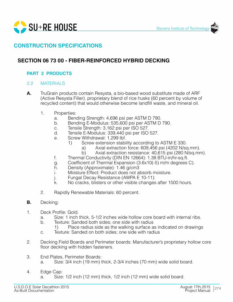
274
Stevens Institute of Technology
August 17th,2015U.S.D.O.E Solar Decathlon 2015As-Built Documentation Project Manual
PART 2 PRODUCTS
2.2 MATERIALS
A. TruGrain products contain Resysta, a bio-based wood substitute made of ARF (Active Resysta Filler). proprietary blend of rice husks (60 percent by volume of recycled content) that would otherwise become landfill waste, and mineral oil.
1. Properties: a. Bending Strength: 4,696 psi per ASTM D 790. b. Bending E-Modulus: 535,600 psi per ASTM D 790. c. Tensile Strength: 3,162 psi per ISO 527. d. Tensile E-Modulus: 339,440 psi per ISO 527. e. Screw Withdrawal: 1,299 lbf. 1) Screw extension stability according to ASTM E 330. a) Axial extraction force: 609,456 psi (4202 N/sq.mm). b) Axial extraction resistance: 40,615 psi (280 N/sq.mm). f. Thermal Conductivity (DIN EN 12664): 1.38 BTU-in/hr-sq.ft. g. Coefficient of Thermal Expansion (3.6x10(-5) m/m degrees C). h. Density (Approximate): 1.46 g/cm3 i. Moisture Effect: Product does not absorb moisture. j. Fungal Decay Resistance (AWPA E 10-11): k. No cracks, blisters or other visible changes after 1500 hours.
2. Rapidly Renewable Materials: 60 percent.
B. Decking:
1. Deck Profile: Gold. a. Size: 1 inch thick, 5-1/2 inches wide hollow core board with internal ribs. b. Texture: Sanded both sides; one side with radius 1) Place radius side as the walking surface as indicated on drawings c. Texture: Sanded on both sides; one side with radius
2. Decking Field Boards and Perimeter boards: Manufacturer’s proprietary hollow core floor decking with hidden fasteners.
3. End Plates, Perimeter Boards: a. Size: 3/4 inch (19 mm) thick, 2-3/4 inches (70 mm) wide solid board.
4. Edge Cap: a. Size: 1/2 inch (12 mm) thick, 1/2 inch (12 mm) wide solid board.
CONSTRUCTION SPECIFICATIONS
SECTION 06 73 00 - FIBER-REINFORCED HYBRID DECKING
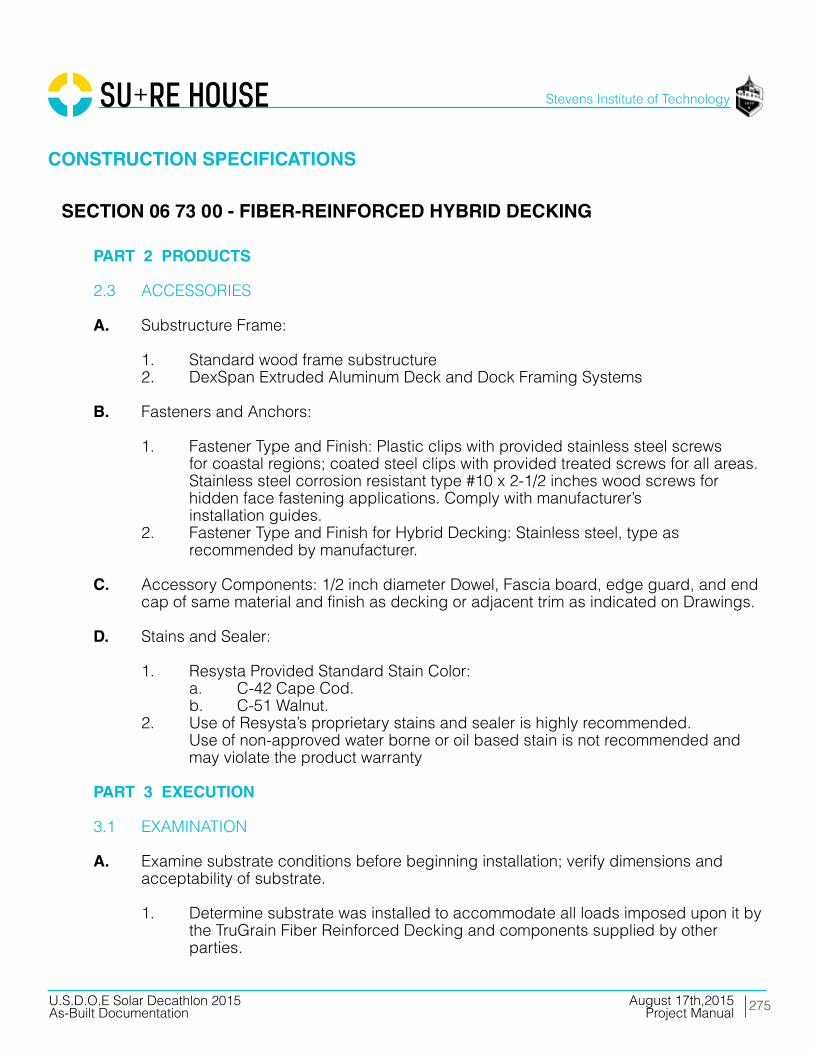
275
Stevens Institute of Technology
August 17th,2015U.S.D.O.E Solar Decathlon 2015As-Built Documentation Project Manual
PART 2 PRODUCTS
2.3 ACCESSORIES
A. Substructure Frame:
1. Standard wood frame substructure 2. DexSpan Extruded Aluminum Deck and Dock Framing Systems
B. Fasteners and Anchors:
1. Fastener Type and Finish: Plastic clips with provided stainless steel screws for coastal regions; coated steel clips with provided treated screws for all areas. Stainless steel corrosion resistant type #10 x 2-1/2 inches wood screws for hidden face fastening applications. Comply with manufacturer’s installation guides. 2. Fastener Type and Finish for Hybrid Decking: Stainless steel, type as recommended by manufacturer.
C. Accessory Components: 1/2 inch diameter Dowel, Fascia board, edge guard, and end cap of same material and finish as decking or adjacent trim as indicated on Drawings.
D. Stains and Sealer:
1. Resysta Provided Standard Stain Color: a. C-42 Cape Cod. b. C-51 Walnut. 2. Use of Resysta’s proprietary stains and sealer is highly recommended. Use of non-approved water borne or oil based stain is not recommended and may violate the product warranty PART 3 EXECUTION
3.1 EXAMINATION
A. Examine substrate conditions before beginning installation; verify dimensions and acceptability of substrate.
1. Determine substrate was installed to accommodate all loads imposed upon it by the TruGrain Fiber Reinforced Decking and components supplied by other parties.
CONSTRUCTION SPECIFICATIONS
SECTION 06 73 00 - FIBER-REINFORCED HYBRID DECKING

276
Stevens Institute of Technology
August 17th,2015U.S.D.O.E Solar Decathlon 2015As-Built Documentation Project Manual
PART 3 EXECUTION
3.1 EXAMINATION
B. Do not proceed with installation until unacceptable conditions have been corrected.
C. If substrate preparation is the responsibility of another installer, notify Architect of unsatisfactory preparation before proceeding.
D. If the decking is being installed in a location where the air gap below the decking is equal to or less than 6 inches (152 mm) from the underside of the decking substructure to the ground / solid structure the joist spacing shall be reduced to 12 inches (305 mm) center-to-center. Comply with manufacturer’s installation guidelines.
3.2 PREPARATION
A. Coordinate placement of bearing items.
B. Apply one coat of bituminous paint to concealed surfaces that will be in contact with cementitious or dissimilar materials.
C. Do not install materials until site pre-finishing is complete and dry.
3.3 INSTALLATION - BOARD DECKING
A. Install sleepers, decking, trim and accessories per manufacturer’s recommendations.
B. Apply finish stain to individual decking planks and trim prior to installation before or after installation.
C. Install decking perpendicular to framing members, with ends staggered over minimum 1-1/2 inches (38 mm) minimum firm bearing.
D. Always take into account the expansion/contraction of TruGrain material and plan gaps at board abutment joints, termination points, and trim locations accordingly. Comply with manufacturer’s installation guidelines.
CONSTRUCTION SPECIFICATIONS
SECTION 06 73 00 - FIBER-REINFORCED HYBRID DECKING
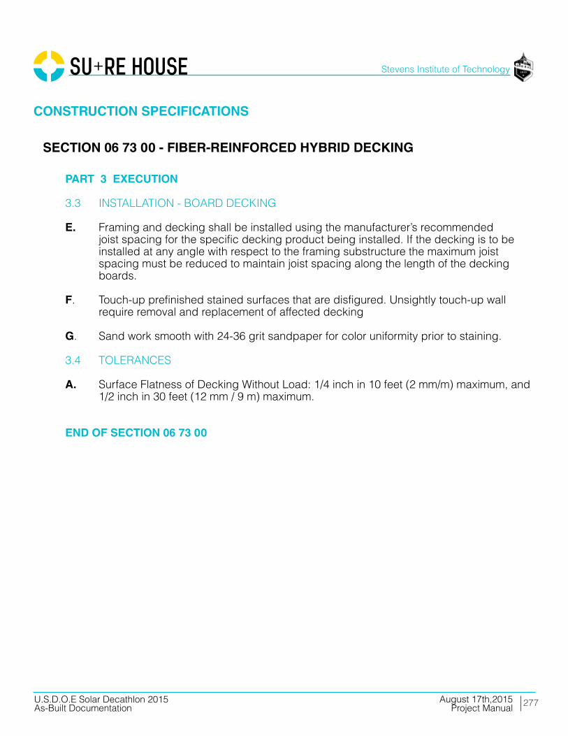
277
Stevens Institute of Technology
August 17th,2015U.S.D.O.E Solar Decathlon 2015As-Built Documentation Project Manual
PART 3 EXECUTION
3.3 INSTALLATION - BOARD DECKING
E. Framing and decking shall be installed using the manufacturer’s recommended joist spacing for the specific decking product being installed. If the decking is to be installed at any angle with respect to the framing substructure the maximum joist spacing must be reduced to maintain joist spacing along the length of the decking boards.
F. Touch-up prefinished stained surfaces that are disfigured. Unsightly touch-up wall require removal and replacement of affected decking
G. Sand work smooth with 24-36 grit sandpaper for color uniformity prior to staining.
3.4 TOLERANCES
A. Surface Flatness of Decking Without Load: 1/4 inch in 10 feet (2 mm/m) maximum, and 1/2 inch in 30 feet (12 mm / 9 m) maximum.
END OF SECTION 06 73 00
CONSTRUCTION SPECIFICATIONS
SECTION 06 73 00 - FIBER-REINFORCED HYBRID DECKING

278
Stevens Institute of Technology
August 17th,2015U.S.D.O.E Solar Decathlon 2015As-Built Documentation Project Manual
PART 1 - GENERAL
1.01 RELATED DOCUMENTS
A. Drawings and general provisions of the Contract, including General and Supplementary Conditions and Division Specification Sections apply to this Section.
1.02 SUMMARY
A. Section Includes: Composite Reinforced Fiberglass Panels and hardware.
1.03 DEFINITION
“Composte Reinforced Fiberglass Panel” means a panel manufactured using glass fibers and polyester resin in a thermoset matrix. Typically water proof / water resistant.
1.04 RELATED SECTIONS
A. Section 05400-Cold Formed Metal Framing
B. Section 07920-Joint Sealants
1.05 REFERENCE STANDARDS
A. ASTM De38: Test Method for Tensile Properties of Plastic.
B. ASTM D695: Test Method for Compressive Strength of Rigid Plastics.
C. ASTM D790: Test Methods for Properties of un-reinforced and Reinforced Plastics and Electrical Insulating Materials.
D. ASTM E84: Test Method for Surface Burning Characteristics of Building Materials.
CONSTRUCTION SPECIFICATIONSCONSTRUCTION SPECIFICATIONSCONSTRUCTION SPECIFICATIONSCONSTRUCTION SPECIFICATIONSCONSTRUCTION SPECIFICATIONS
SECTION 06 83 00 - COMPOSITE PANELING

279
Stevens Institute of Technology
August 17th,2015U.S.D.O.E Solar Decathlon 2015As-Built Documentation Project Manual
PART 1 - GENERAL
1.06 DESIGN REQUIREMENTS
A. Structural Requirements: Engineering calculations shall account for the following loads:
1. Dead Loads: Include the weight of the Composite Reinforced Fiberglass Panels and attached items. 2. Live Loads: As required by applicable code, 3. Wind Loads: As required by applicable code. 4. Snow Loads: As required by applicable codes. 5. Load Combinations: Consider applicable load combinations. 6. Flood Loads: As required by applicable codes.
B. Provisions for Movement
1. Design and detail anchorage, connections, and joints to allow for dimensional changes of theComposite Reinforced Fiberglass Panels due to thermal and similar effects. 2. Where the piece is restrained, allow for effects of restraint in design.
C. Anchorage and Connections
1. Suggested anchorage and connections are shown on the design drawings. Proposed substitutions may be submitted for review. Substitutions shall satisfy the function of the connection as indicated or implied on the drawings and shall not vary to indicated building loading. 2. Anchorage and connection designs shall consider tolerances and eccentricities of load applications. Provide proper edge and end distances for inserts.
1.07 SUBMITTALS
A. Product Data: Submit manufacturer’s data on the Composite Reinforced Fiberglass Panels.
B. Product Samples: Submit minimum of three (3) - 6” x 6” samples in specified color, texture and finish. Architect will select finish, color and texture from manufacturer’s offerings.
CONSTRUCTION SPECIFICATIONSCONSTRUCTION SPECIFICATIONSCONSTRUCTION SPECIFICATIONSCONSTRUCTION SPECIFICATIONSCONSTRUCTION SPECIFICATIONS
SECTION 06 83 00 - COMPOSITE PANELING

280
Stevens Institute of Technology
August 17th,2015U.S.D.O.E Solar Decathlon 2015As-Built Documentation Project Manual
PART 1 - GENERAL
1.07 SUBMITTALS
C. Shop Drawings: Submit drawings indicating:
1. Panel shapes and dimensions; 2. Panel surface finish; 3. Part numbers; 4. Jointing and connection details; 5. Adjacent structure details; 6. Hardware location and details; and 7. Lifting and erection details.
D. Manufacturers Instructions: Submit manufacturer’s instructions and recommendations for:
1. Product delivery, storage and handling. 2. Erection, lifting and connecting of Composite Reinforced Fiberglass Panels.
1.08 DELIVERY, STORAGE AND HANDLING
A. Handle, store and transport panels according to rnanufacturer’s recommendations and in a manner that prevents cosmetic and structural damage.
B. Verify those areas where panels will be unloaded are clear of obstructions and well drained.
C. Do not subject panels to undue stress.
D. Brace and stabilize panels to prevent warping.
E. Damage Responsibility: Except for damage caused by others, the installer is responsible for chipping,cracking, or other damage to composite panels.
CONSTRUCTION SPECIFICATIONSCONSTRUCTION SPECIFICATIONSCONSTRUCTION SPECIFICATIONSCONSTRUCTION SPECIFICATIONSCONSTRUCTION SPECIFICATIONS
SECTION 06 83 00 - COMPOSITE PANELING
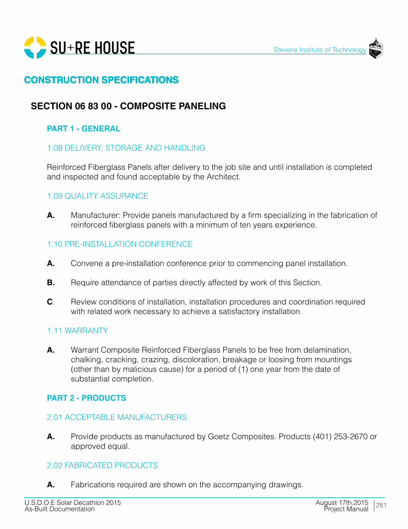
281
Stevens Institute of Technology
August 17th,2015U.S.D.O.E Solar Decathlon 2015As-Built Documentation Project Manual
PART 1 - GENERAL
1.08 DELIVERY, STORAGE AND HANDLING
Reinforced Fiberglass Panels after delivery to the job site and until installation is completed and inspected and found acceptable by the Architect.
1.09 QUALITY ASSURANCE
A. Manufacturer: Provide panels manufactured by a firm specializing in the fabrication of reinforced fiberglass panels with a minimum of ten years experience.
1.10 PRE-INSTALLATION CONFERENCE
A. Convene a pre-installation conference prior to commencing panel installation.
B. Require attendance of parties directly affected by work of this Section.
C. Review conditions of installation, installation procedures and coordination required with related work necessary to achieve a satisfactory installation.
1.11 WARRANTY
A. Warrant Composite Reinforced Fiberglass Panels to be free from delamination, chalking, cracking, crazing, discoloration, breakage or loosing from mountings (other than by malicious cause) for a period of (1) one year from the date of substantial completion.
PART 2 - PRODUCTS
2.01 ACCEPTABLE MANUFACTURERS
A. Provide products as manufactured by Goetz Composites. Products (401) 253-2670 or approved equal.
2.02 FABRICATED PRODUCTS
A. Fabrications required are shown on the accompanying drawings.
CONSTRUCTION SPECIFICATIONSCONSTRUCTION SPECIFICATIONSCONSTRUCTION SPECIFICATIONSCONSTRUCTION SPECIFICATIONSCONSTRUCTION SPECIFICATIONS
SECTION 06 83 00 - COMPOSITE PANELING

282
Stevens Institute of Technology
August 17th,2015U.S.D.O.E Solar Decathlon 2015As-Built Documentation Project Manual
PART 2 - PRODUCTS
2.03 MATERIAL CHARACTERISTICS
A. MOLDED EXTERIOR SURFACE. U-V inhibited, NPG-ISO polyester gel coat, 18 to 22 mils thick.
1. Gel Coat Color: Match sample supplied by Architect.
B. BACK UP LAMINATE:
1. Resin: Fire retardant, isophthalic polyester resin, ASTM E84, Class I (flame spread rating of 25 or less) 2. Fiberglass Reinforcement a. “E” type fiberglass. b. Random Chopped glass fibers. c. Glass content approximately 25% to 30% except, 15% for filled resin systems. 3. Laminate Thickness: a. Nominal thickness 3/16” b. Additional thickness and reinforcement, and sandwich structures as indicated and as required for structural integrity
2.04 FINISH
A. Color and finish shall be as selected by the Architect from the manufacturer’s standard finishes.
2.05 TOLERANCES
A. Gel Coat Thickness: + or - 2.5 mils.
B. Length: + or - 1/8 inch in 10 feet.
C. Overall thickness tolerance: +/- 1/16”.
D. Variation from Square: 1/8 inch in 10 feet.
CONSTRUCTION SPECIFICATIONSCONSTRUCTION SPECIFICATIONSCONSTRUCTION SPECIFICATIONSCONSTRUCTION SPECIFICATIONSCONSTRUCTION SPECIFICATIONS
SECTION 06 83 00 - COMPOSITE PANELING

283
Stevens Institute of Technology
August 17th,2015U.S.D.O.E Solar Decathlon 2015As-Built Documentation Project Manual
PART 2 - PRODUCTS
2.06 IDENTIFICATION
A. Identify each part with a permanent serial number.
B. Number parts to coordinate with shop drawings.
2.07 CURING AND CLEANING
A. Cure and clean components prior to shipment and remove material which may be incompatible with adjacent building materials.
2.08 HARDWARE
A. Metal Anchors and Fasteners: Provide anchors and fasteners as recommended by panel manufacturer and conforming to the following standards of the American Society for Testing and Materials.
1. Stainless steel: ASTM A666, Type 304. 2. Anchor bolts ASTM A307 or ASTM AS25.
PART 3 - EXECUTION
3.01 INSTALLERS PRE-INSTALLATTON INSPECTION
A. Observe field conditions and verify that building lines, centers, and grades will allow proper installation of Composite Reinforced Fiberglass Panels.
B. Verify that bearing surfaces are true and level.
C. Verify that support framing has been constructed to allow accurate placement and alignment of anchor bolts, plates, dowels, or other connections on the structure.
D. Check field dimensions affecting the installation of Composite Reinforced Fiberglass Panels.
CONSTRUCTION SPECIFICATIONSCONSTRUCTION SPECIFICATIONSCONSTRUCTION SPECIFICATIONSCONSTRUCTION SPECIFICATIONSCONSTRUCTION SPECIFICATIONS
SECTION 06 83 00 - COMPOSITE PANELING

284
Stevens Institute of Technology
August 17th,2015U.S.D.O.E Solar Decathlon 2015As-Built Documentation Project Manual
PART 3 - EXECUTION
3.01 INSTALLERS PRE-INSTALLATTON INSPECTION
E. Report discrepancies between design dimensions and field dimensions, which could adversely affect installation, to the Architect.
F. Do not proceed with installation until discrepancies are corrected, or until installation requirements are modified and approved by the Architect.
3.02 ERECTION
A. Install fabrications in accordance with manufacturer’s instructions and approved shop drawings.
B. Unloading: Use equipment that will prevent delays in installation process. Do not block access to panel installation area or other construction areas with equipment and materials.
C. Lifting and Positioning: Lift Composite Reinforced Fiberglass Panels with suitable lifting devices at points as recommended by the manufacturer.
D. Set panels level, plumb, square, and true within the allowable tolerances.
E. Temporarily support and brace panels as required to maintain position, stability and alignment during and until permanent connection.
F. Fastening: Fasten Composite Reinforced Fiberglass Panels as shown on approved shop drawings.
CONSTRUCTION SPECIFICATIONSCONSTRUCTION SPECIFICATIONSCONSTRUCTION SPECIFICATIONSCONSTRUCTION SPECIFICATIONSCONSTRUCTION SPECIFICATIONS
SECTION 06 83 00 - COMPOSITE PANELING

285
Stevens Institute of Technology
August 17th,2015U.S.D.O.E Solar Decathlon 2015As-Built Documentation Project Manual
PART 3 - EXECUTION
3.03 ALLOWABLE TOLERANCES FOR ERECTED PANELS
A. Tolerances for Location of Composite Reinforced Fiberglass Panels: Non-cumulative.
B. Width of Joint: ¼”to ¾” depending upon engineering criteria. C Gap tolerances between joints for panel dimensions of:
1. <l0 ft: +/-3/16” (5mm) 2. l0 ft. - 20ft: +/- 1/4” (7rnrn) 3. >20 ft: +/- 5/16” (9mm)
3.04 CLEANING
A. Clean soiled panels using cleaning methods and materials approved by panel manufacturer.
3.05 PROTECTION OF INSTALLED FABRICATIONS
A. Comply with manufacturer’s recommendations and instructions for protecting installed fabrications during construction activities.
END OF SECTION 06 83 00
CONSTRUCTION SPECIFICATIONSCONSTRUCTION SPECIFICATIONSCONSTRUCTION SPECIFICATIONSCONSTRUCTION SPECIFICATIONSCONSTRUCTION SPECIFICATIONS
SECTION 06 83 00 - COMPOSITE PANELING

286
Stevens Institute of Technology
August 17th,2015U.S.D.O.E Solar Decathlon 2015As-Built Documentation Project Manual
PART 1 - GENERAL
1.01 SUMMARY
A. This Section includes the following :
1. Concealed rubberized-asphalt strip flashing at exterior openings. 2. Concealed rubberized-asphalt strip flashing under roofing.
B. Related Sections include the following: 1. Division 07 Section “Joint Sealing” for joint-sealant materials and installation. 2. SEE DIVISION 07 13 54 PRODUCT CUTSHEETS 1.02 PERFORMANCE REQUIREMENTS
A. Provide waterproofing that prevents the passage of water.
1.03 SUBMITTALS
A. Product Data: Include manufacturer’s written instructions for evaluating, preparing, and treating substrate, technical data, and tested physical and performance properties of waterproofing.
1.04 QUALITY ASSURANCE
A. Installer Qualifications: A qualified installer who is acceptable to waterproofing manufacturer to install manufacturer’s products.
B. Source Limitations: Obtain waterproofing materials through one source from a single manufacturer.
1.05 DELIVERY, STORAGE, AND HANDLING
A. Deliver liquid materials to Project site in original packages with seals unbroken, labeled with manufacturer’s name, product brand name and type, date of manufacture, and directions for storing and mixing with other components.
B. Store liquid materials in their original undamaged packages in a clean, dry, protected location and within temperature range required by waterproofing manufacturer.
CONSTRUCTION SPECIFICATIONSCONSTRUCTION SPECIFICATIONSCONSTRUCTION SPECIFICATIONSCONSTRUCTION SPECIFICATIONSCONSTRUCTION SPECIFICATIONS
SECTION 07 13 26 - SELF-ADHERING SHEET WATERPROOFING

287
Stevens Institute of Technology
August 17th,2015U.S.D.O.E Solar Decathlon 2015As-Built Documentation Project Manual
PART 1 - GENERAL
1.05 DELIVERY, STORAGE, AND HANDLING
C. Remove and replace liquid materials that cannot be applied within their stated shelf life.
D. Store rolls according to manufacturer’s written instructions.
E. Protect stored materials from direct sunlight.
1.06 PROJECT CONDITIONS
A. Environmental Limitations: Apply waterproofing within the range of ambient and substrate temperatures recommended by waterproofing manufacturer. Do not apply waterproofing to a damp or wet substrate. 1. Do not apply waterproofing in snow, rain, fog, or mist.
B. Maintain adequate ventilation during preparation and application of waterproofing materials.
1.07 WARRANTY
A. Special Manufacturer’s Warranty: Written warranty, signed by waterproofing manufacturer agreeing to replace waterproofing material that does not comply with requirements or that does not remain watertight during specified warranty period. 1. Warranty does not include failure of waterproofing due to failure of substrate prepared and treated according to requirements or formation of new joints and cracks in substrate exceeding 1/16 inch (1.6 mm) in width. 2. Warranty Period: Three years after date of Substantial Completion.
B. Special Installer’s Warranty for Roofing Underlayment: Written waterproofing Installer’s warranty, signed by Installer, covering Work of this Section, for warranty period of two years.
CONSTRUCTION SPECIFICATIONSCONSTRUCTION SPECIFICATIONSCONSTRUCTION SPECIFICATIONSCONSTRUCTION SPECIFICATIONSCONSTRUCTION SPECIFICATIONS
SECTION 07 13 26 - SELF-ADHERING SHEET WATERPROOFING
288
Stevens Institute of Technology
August 17th,2015U.S.D.O.E Solar Decathlon 2015As-Built Documentation Project Manual
PART 2 - PRODUCTS
2.01 MATERIALS, GENERAL
2.02 RUBBERIZED-ASPHALT STRIP FLASHING
A. Products: Subject to compliance with requirements, products that may be incorporated into the Work include, but are not limited to, the following:
1. Grace Ice and Water Shield 2. W. R. Grace & Co.; Vycor V40. 3. W. R. Meadows, Inc.; AirShield.
B. Rubberized-Asphalt Strips: 40-mil- (1.02-mm-) thick, self-adhering sheet consisting of 37-mil (0.95-mm) of rubberized asphalt laminated to a 3-mil- (0.07-mm-) thick, polyethylene film with release liner on adhesive side and formulated for application with primer or surface conditioner that complies with VOC limits of authorities having jurisdiction. Provide minimum 9-inch wide strips. 1. Physical Properties: As follows, measured per standard test methods referenced:
a. Tensile Strength: 250 psi (1.7 MPa) minimum; ASTM D 412, Die C, modified. b. Ultimate Elongation: 200 percent minimum; ASTM D 412, Die C, modified. c. Low-Temperature Flexibility: Unaffected at minus 45 deg F (minus 43 deg C); ASTM D 1970. d. Crack Cycling: Unaffected after 100 cycles of 1/8-inch (3-mm) movement; ASTM C 836. e. Vapor Permeance: 0.05 perms (2.9 ng/Pa x s x sq. m); ASTM E 96, Water Method. f. MUST MEET ALL TESTING REQUIREMENT FOR PHIUS.
2.03 RUBBERIZED-ASPHALT STRIP ROOFING UNDERLAYMENT
A. Products: Subject to compliance with requirements, products that may be incorporated into the Work include, but are not limited to, the following:
CONSTRUCTION SPECIFICATIONSCONSTRUCTION SPECIFICATIONSCONSTRUCTION SPECIFICATIONSCONSTRUCTION SPECIFICATIONSCONSTRUCTION SPECIFICATIONS
SECTION 07 13 26 - SELF-ADHERING SHEET WATERPROOFING
289
Stevens Institute of Technology
August 17th,2015U.S.D.O.E Solar Decathlon 2015As-Built Documentation Project Manual
PART 2 - PRODUCTS
2.03 RUBBERIZED-ASPHALT STRIP ROOFING UNDERLAYMENT
1. Carlisle Corporation, Carlisle Coatings & Waterproofing Div.; Window & Door Flashing. 2. W. R. Grace & Co.; Vycor V40. 3. W. R. Meadows, Inc.; AirShield.
B. Rubberized-Asphalt Strips: 40-mil- (1.02-mm-) thick, self-adhering sheet consisting of 37-mil (0.95-mm) of rubberized asphalt laminated to a 3-mil- (0.07-mm-) thick, polyethylene film with release liner on adhesive side and formulated for application with primer or surface conditioner that complies with VOC limits of authorities having jurisdiction. Provide minimum 9-inch wide strips. 1. Physical Properties: As follows, measured per standard test methods referenced:
a. Tensile Strength: 250 psi (1.7 MPa) minimum; ASTM D 412, Die C, modified. b. Ultimate Elongation: 200 percent minimum; ASTM D 412, Die C, modified. c. Low-Temperature Flexibility: Unaffected at minus 45 deg F (minus 43 deg C); ASTM D 1970. d. Crack Cycling: Unaffected after 100 cycles of 1/8-inch (3-mm) movement; ASTM C 836. e. Vapor Permeance: 0.05 perms (2.9 ng/Pa x s x sq. m); ASTM E 96, Water Method. f. MUST MEET ALL TESTING REQUIREMENT FOR PHIUS.
2.04 AUXILIARY MATERIALS
A. General: Furnish auxiliary materials recommended by waterproofing manufacturer for intended use and compatible with sheet waterproofing.
1. Furnish liquid-type auxiliary materials that comply with VOC limits of authorities having jurisdiction.
B. Primer: Liquid primer recommended for substrate by manufacturer of sheet waterproofing material.
CONSTRUCTION SPECIFICATIONSCONSTRUCTION SPECIFICATIONSCONSTRUCTION SPECIFICATIONSCONSTRUCTION SPECIFICATIONSCONSTRUCTION SPECIFICATIONS
SECTION 07 13 26 - SELF-ADHERING SHEET WATERPROOFING
290
Stevens Institute of Technology
August 17th,2015U.S.D.O.E Solar Decathlon 2015As-Built Documentation Project Manual
PART 2 - PRODUCTS
2.04 AUXILIARY MATERIALS
C. Surface Conditioner: Liquid, waterborne surface conditioner recommended for substrate by manufacturer of sheet waterproofing material.
D. Sheet Strips: Self-adhering, rubberized-asphalt composite sheet strips of same material and thickness as sheet waterproofing.
E. Tape: Self-adhering strips of same material and thickness as sheet waterproofing or compatible material as recommended by the membrane manufacturer.
F. Liquid Membrane: Elastomeric, two-component liquid, cold fluid applied, trowel grade or low viscosity.
G. Substrate Patching Membrane: Low-viscosity, two-component, asphalt-modified coating.
H. Mastic, Adhesives, and Tape: Liquid mastic and adhesives, and adhesive tapes recommended by waterproofing manufacturer.
PART 3 - EXECUTION
3.01 EXAMINATION
A. Examine substrates, areas, and conditions, with Installer present, for compliance with requirements and other conditions affecting performance.
1. Verify that concrete has cured and aged for minimum time period recommended by waterproofing manufacturer. 2. Verify that concrete is visibly dry and free of moisture. Test for capillary moisture by plastic sheet method according to ASTM D 4263. 3. Proceed with installation only after unsatisfactory conditions have been corrected.
CONSTRUCTION SPECIFICATIONSCONSTRUCTION SPECIFICATIONSCONSTRUCTION SPECIFICATIONSCONSTRUCTION SPECIFICATIONSCONSTRUCTION SPECIFICATIONS
SECTION 07 13 26 - SELF-ADHERING SHEET WATERPROOFING
291
Stevens Institute of Technology
August 17th,2015U.S.D.O.E Solar Decathlon 2015As-Built Documentation Project Manual
PART 3 - EXECUTION
3.02 SURFACE PREPARATION
A. Clean, prepare, and treat substrates according to manufacturer’s written instructions. Provide clean, dust-free, and dry substrates for waterproofing application.
B. Mask off adjoining surfaces not receiving waterproofing to prevent spillage and overspray affecting other construction.
C. Remove grease, oil, bitumen, form-release agents, paints, curing compounds, and other penetrating contaminants or film-forming coatings from concrete.
D. Remove fins, ridges, mortar, and other projections and fill honeycomb, aggregate pockets, holes, and other voids.
E. Prepare, fill, prime, and treat joints and cracks in substrates. Remove dust and dirt from joints and cracks according to ASTM D 4258.
1. Install sheet strips and center over treated construction and contraction joints and cracks exceeding a width of 1/16 inch (1.6 mm).
F. Bridge and cover isolation joints, expansion joints, and discontinuous deck-to-wall and deck-to-deck joints with overlapping sheet strips.
1. Invert and loosely lay first sheet strip over center of joint. Firmly adhere second sheet strip to first and overlap to substrate.
G. Corners: Prepare, prime, and treat inside and outside corners according to ASTM D 6135.
1. Install membrane strips centered over vertical inside corners. Install 3/4-inch (19-mm) fillets of liquid membrane on horizontal inside corners and as follows: a. At footing-to-wall intersections, extend liquid membrane each direction from corner or install membrane strip centered over corner. b. At plaza deck-to-wall intersections, extend liquid membrane or sheet strips onto deck waterproofing and to finished height of sheet flashing.
H. Prepare, treat, and seal vertical and horizontal surfaces at terminations and penetrations through waterproofing and at drains and protrusions according to ASTM D 6135.
CONSTRUCTION SPECIFICATIONSCONSTRUCTION SPECIFICATIONSCONSTRUCTION SPECIFICATIONSCONSTRUCTION SPECIFICATIONSCONSTRUCTION SPECIFICATIONS
SECTION 07 13 26 - SELF-ADHERING SHEET WATERPROOFING

292
Stevens Institute of Technology
August 17th,2015U.S.D.O.E Solar Decathlon 2015As-Built Documentation Project Manual
PART 3 - EXECUTION
3.03 RUBBERIZED-ASPHALT SHEET AND STRIP APPLICATION
A. Install self-adhering sheets according to waterproofing manufacturer’s written instructions and recommendations in ASTM D 6135.
B. Apply primer to substrates at required rate and allow to dry. Limit priming to areas that will be covered by sheet waterproofing in same day. Reprime areas exposed for more than 24 hours.
C. Apply and firmly adhere sheets over area to receive waterproofing. Accurately align sheets and maintain uniform 2-1/2-inch- (64-mm-) minimum lap widths and end laps. Overlap and seal seams and stagger end laps to ensure watertight installation.
1. When ambient and substrate temperatures range between 25 and 40 deg F (minus4 and plus 5 deg C), install self-adhering, rubberized-asphalt sheets produced for low-temperature application. Do not use low-temperature sheets if ambient or substrate temperature is higher than 60 deg F (16 deg C).
D. Horizontal Application: Apply sheets from low point to high point of decks to ensure that side laps shed water.
E. Application at Openings: Apply strips at sill first, then jambs, and lastly at head of openings. Install over fins and flanges, and install weatherproofing membranes for general wall areas over the strips.
F. Application at Roofs: Apply strips from low point to high point of roofs to ensure that side laps shed water and in accordance with roofing manufacturer’s recommendations.
1. At roof eaves: Install from edge to a height 24-inches away from the roof edge. 2. Valleys: Install from center of valley to 24 inches from the valley in both directions.
G. Apply continuous sheets over sheet strips bridging substrate cracks, construction, and contraction joints.
H. Seal exposed edges of sheets at terminations not concealed by metal counterflashings or ending in reglets with mastic or sealant.
I. Repair tears, voids, and lapped seams in waterproofing not complying with requirements. Slit and flatten fishmouths and blisters. Patch with sheets extending 6 inches (150 mm) beyond repaired areas in all directions.
CONSTRUCTION SPECIFICATIONSCONSTRUCTION SPECIFICATIONSCONSTRUCTION SPECIFICATIONSCONSTRUCTION SPECIFICATIONSCONSTRUCTION SPECIFICATIONS
SECTION 07 13 26 - SELF-ADHERING SHEET WATERPROOFING
293
Stevens Institute of Technology
August 17th,2015U.S.D.O.E Solar Decathlon 2015As-Built Documentation Project Manual
PART 3 - EXECUTION
3.03 RUBBERIZED-ASPHALT SHEET AND STRIP APPLICATION
J. Correct deficiencies in or remove sheet waterproofing that does not comply with requirements, repair substrates, reapply waterproofing, and repair sheet flashings.
3.04 PROTECTION AND CLEANING
A. Do not permit foot or vehicular traffic on unprotected membrane.
B. Protect waterproofing from damage and wear during remainder of construction period.
C. Clean spillage and soiling from adjacent construction using cleaning agents and procedures recommended by manufacturer of affected construction.
END OF SECTION 07 13 26
CONSTRUCTION SPECIFICATIONSCONSTRUCTION SPECIFICATIONSCONSTRUCTION SPECIFICATIONSCONSTRUCTION SPECIFICATIONSCONSTRUCTION SPECIFICATIONS
SECTION 07 13 26 - SELF-ADHERING SHEET WATERPROOFING
294
Stevens Institute of Technology
August 17th,2015U.S.D.O.E Solar Decathlon 2015As-Built Documentation Project Manual
PART 1 - GENERAL
1.01 SUMMARY
A. This Section includes :
1. Mineral wool board insulation. 2. Mineral wool batt insulation. 3. Spray polyurethane foam insulation. 3. Vapor retarders
B. Related Work specified elsewhere includes:
1. SEE DIVISION 07 PRODUCT CUTSHEETS for insulations and sealing tapes.
1.02 SUBMITTALS
A. Product Data: For each type of product indicated.
B. Schedule: Indicate where each type of product is to be applied. Provide drawings ifnecessary to show where insulation is to be installed.
PART 2 - PRODUCTS
2.01 MINERAL WOOL BOARD INSULATION
A. Stone wool insulation product for use in both new residential construction . This semi-rigid batt has a unique flexible edge designed to compress as the batt is inserted into walls, attics, ceilings and floor frames.
1. Manufacturers: Subject to compliance with requirements, provide products by one of the following: a. ROXUL Inc. 2. R-5 at 1.25” thick a. Fire Performance: ASTM E 136 Behaviour of Materials at 750°C (1382°F) Non-Combustible CAN/ULC-S114 Test for Non-Combustibility Non-Combustible ASTM E 84 (UL 723) Surface Burning Characteristics Flame Spread = 0
CONSTRUCTION SPECIFICATIONSCONSTRUCTION SPECIFICATIONSCONSTRUCTION SPECIFICATIONSCONSTRUCTION SPECIFICATIONSCONSTRUCTION SPECIFICATIONS
SECTION 07 21 00 - THERMAL INSULATION

295
Stevens Institute of Technology
August 17th,2015U.S.D.O.E Solar Decathlon 2015As-Built Documentation Project Manual
PART 2 - PRODUCTS
2.01 MINERAL WOOL BOARD INSULATION
A. Stone wool insulation product for use in both new residential construction . This semi-rigid batt has a unique flexible edge designed to compress as the batt is inserted into walls, attics, ceilings and floor frames.
3. Thermal Resistance:
ASTM C 518 (C 177) R-value/inch @ 75°F 4.0 hr.ft².F/Btu RSI value/25.4 mm @ 24°C 0.70 m²K/W
2.02 MINERAL WOOL BATT INSULATION
A. Stone wool insulation productcompensates for normal variations in stud centres caused by distortion or warping. The special flexible characteristic at the insulation edge ensures the expected R-value is achieved.
1. Manufacturers: Subject to compliance with requirements, provide products by one of the following: a. ROXUL Inc.
2. ROXUL COMFORTBATT® R-23 for Wood Studs/Joists on 16” Centers 3. COMFORTBATT® R-15 for Wood Studs/Joists on 16” Centers
B. Fire Performance:
ASTM E 136 Behaviour of Materials at 750°C (1382°F) Non-Combustible CAN/ULC-S114 Test for Non-Combustibility Non-Combustible ASTM E 84 (UL 723) Surface Burning Characteristics Flame Spread = 0
C. Thermal Resistance:
ASTM C 518 (C 177) R-value/inch @ 75°F 4.0 hr.ft².F/Btu RSI value/25.4 mm @ 24°C 0.70 m²K/W
SECTION 07 21 00 - THERMAL INSULATION
CONSTRUCTION SPECIFICATIONS
296
Stevens Institute of Technology
August 17th,2015U.S.D.O.E Solar Decathlon 2015As-Built Documentation Project Manual
PART 2 - PRODUCTS
2.03 SPRAY FOAM INSULATION
A. Closed-Cell Polyurethane Foam Insulation: ASTM C 1029, Type II, with maximum flame-spread and smoke-developed indexes of 75 and 450, respectively, per ASTM E 84.
1. Manufacturers: Subject to compliance with requirements, provide products by one of the following:
a. 3M 78 Polystyrene Foam Spray Adhesive
2.04 VAPOR RETARDERS
A. Reinforced-Polyethylene Vapor Retarders: Two outer layers of polyethylene film laminated to an inner reinforcing layer consisting of either nylon cord or polyester scrim and weighing not less than 25 lb/1000 sq. ft. (12 kg/100 sq. m), with maximum permeance rating of 0.0507 perm (2.9 ng/Pa x s x sq. m).
1. Products: Subject to compliance with requirements, provide one of the following:
a. INTELLO® and INTELLO® PLUS system
B. Vapor-Retarder Tape: Pressure-sensitive tape of type recommended by vapor-retarder manufacturer for sealing joints and penetrations in vapor retarder.
1. Products: Subject to compliance with requirements, provide one of the following:
a. PROCLIMA - Tescon Vana b. PROCLIMA - Tescon Profil c. PROCLIMA - Contega d. PROCLIMA - Extoseal e. GRACE Tape
C. Vapor-Retarder Fasteners: Pancake-head, self-tapping steel drill screws; with fender washers.
CONSTRUCTION SPECIFICATIONSCONSTRUCTION SPECIFICATIONSCONSTRUCTION SPECIFICATIONSCONSTRUCTION SPECIFICATIONSCONSTRUCTION SPECIFICATIONS
SECTION 07 21 00 - THERMAL INSULATION
297
Stevens Institute of Technology
August 17th,2015U.S.D.O.E Solar Decathlon 2015As-Built Documentation Project Manual
PART 3 - EXECUTION
3.01 INSTALLATION, GENERAL
A. Comply with insulation manufacturer’s written instructions applicable to products and applications indicated.
B. Install insulation that is undamaged, dry, and unsoiled and that has not been left exposed to ice, rain, or snow at any time.
C. Extend insulation to envelop entire area to be insulated. Cut and fit tightly around obstructions and fill voids with insulation. Remove projections that interfere with placement.
D. Provide sizes to fit applications indicated and selected from manufacturer’s standard thicknesses, widths, and lengths. Apply single layer of insulation units to produce thickness indicated unless multiple layers are otherwise shown or required to make up total thickness.
3.02 INSTALLATION OF CAVITY-WALL INTERIOR INSULATION
A. Roxul ComfortBatt: Install pads of adhesive spaced approximately 16 inches (610 mm) o.c. both ways on inside face, and as recommended by manufacturer. Fit courses of insulation between wall ties and other obstructions, with edges butted tightly in both directions. Press units firmly against inside substrates.
3.03 INSTALLATION OF EXTERIOR INSULATION
A. Roxul ComfortBoard: Edges butted tightly in both directions. Press units firmly against inside substrates. Friction fit underneath rainscreen system.
CONSTRUCTION SPECIFICATIONSCONSTRUCTION SPECIFICATIONSCONSTRUCTION SPECIFICATIONSCONSTRUCTION SPECIFICATIONSCONSTRUCTION SPECIFICATIONS
SECTION 07 21 00 - THERMAL INSULATION
298
Stevens Institute of Technology
August 17th,2015U.S.D.O.E Solar Decathlon 2015As-Built Documentation Project Manual
PART 3 - EXECUTION
3.04 INSTALLATION OF INSULATION FOR FRAMED CONSTRUCTION
A. Apply insulation units to substrates by method indicated, complying with manufacturer’s written instructions. If no specific method is indicated, bond units to substrate with adhesive or use mechanical anchorage to provide permanent placement and support of units.
B. Mineral Wool Insulation: Seal joints between units by applying adhesive, mastic, or sealant to edges of each unit to form a tight seal as units are shoved into place. Fill voids in completed installation with adhesive, mastic, or sealant as recommended by insulation manufacturer.
C. Spray-Applied Insulation: Apply spray-applied insulation according to manufacturer’s written instructions. Do not apply insulation until installation of pipes, ducts, conduits, wiring, and electrical outlets in walls is completed and windows, electrical boxes, and other items not indicated to receive insulation are masked. After insulation is applied, make flush with face of studs by using method recommended by insulation manufacturer.
D. Miscellaneous Voids: Install insulation in miscellaneous voids and cavity spaces where required to prevent gaps in insulation using the following materials:
1. Loose-Fill Insulation: Compact to approximately 40 percent of normal maximum volume equaling a density of approximately 2.5 lb/cu. ft. (40 kg/cu. m). 2. Spray Polyurethane Insulation: Apply according to manufacturer’s written instructions.
E. Electrical Boxes: Install sheet caulking at each electrical switch and outlet box and at cavity spaces where required to prevent air infiltration through boxes in framed and cavity walls.
CONSTRUCTION SPECIFICATIONSCONSTRUCTION SPECIFICATIONSCONSTRUCTION SPECIFICATIONSCONSTRUCTION SPECIFICATIONSCONSTRUCTION SPECIFICATIONS
SECTION 07 21 00 - THERMAL INSULATION

299
Stevens Institute of Technology
August 17th,2015U.S.D.O.E Solar Decathlon 2015As-Built Documentation Project Manual
PART 3 - EXECUTION
3.05 INSTALLATION OF VAPOR RETARDERS
A. Place vapor retarders on side of construction indicated on Drawings. Extend vapor retarders to extremities of areas to protect from vapor transmission. Secure vapor retarders in place with adhesives or other anchorage system as indicated. Extend vapor retarders to cover miscellaneous voids in insulated substrates, including those filled with loose-fiber insulation.
B. Seal vertical joints in vapor retarders over framing by lapping no fewer than two studs.
1. Fasten vapor retarders to wood framing at top, end, and bottom edges; at perimeter of wall openings; and at lap joints. Space fasteners 16 inches (406 mm) o.c.
C. Seal joints caused by pipes, conduits, electrical boxes, and similar items penetrating vapor retarders with vapor-retarder tape to create an airtight seal between penetrating objects and vapor retarders.
D. Repair tears or punctures in vapor retarders immediately before concealment by other work. Cover with vapor-retarder tape or another layer of vapor retarders.
END OF SECTION 07 21 00
CONSTRUCTION SPECIFICATIONSCONSTRUCTION SPECIFICATIONSCONSTRUCTION SPECIFICATIONSCONSTRUCTION SPECIFICATIONSCONSTRUCTION SPECIFICATIONS
SECTION 07 21 00 - THERMAL INSULATION

300
Stevens Institute of Technology
August 17th,2015U.S.D.O.E Solar Decathlon 2015As-Built Documentation Project Manual
PART 1 - GENERAL
1.01 SECTION INCLUDES
A. Tapered Polyisocyanurate Roof Insulation.
1.02 RELATED INCLUDES
A. Section 07200 - Building Insulation.
B. Section 07540 - Thermoplastic Membrane Roofing.
1.03 REFERENCES
A. ASTM C 209 - Methods of Testing Insulating Board, Structural and Decorative.
B. ASTM C 518 - Standard Test Method for Steady-State Thermal Transmission Properties by Means of the Heat Flow Meter Apparatus
C. ASTM C 1289 - Standard Specification for Faced Rigid Cellular Thermal Insulation Board.
D. UL 1256 - Fire Test of Roof Deck Constructions.
1.04 SYSTEM DESCRIPTION
A. Performance Requirements:
1. UL Assemblies: a. Component of Class A Roof System – UL 790.
1.05 SUBMITTALS
A. Submit under provisions of Section 01300.
B. Product Data: Manufacturer’s data sheets on each product to be used, including:
1. Preparation instructions and recommendations. 2. Storage and handling requirements and recommendations.
CONSTRUCTION SPECIFICATIONSCONSTRUCTION SPECIFICATIONSCONSTRUCTION SPECIFICATIONSCONSTRUCTION SPECIFICATIONSCONSTRUCTION SPECIFICATIONS
SECTION 07 22 22 - POLYISOCYANURATE ROOF INSULATION

301
Stevens Institute of Technology
August 17th,2015U.S.D.O.E Solar Decathlon 2015As-Built Documentation Project Manual
PART 1 - GENERAL
1.06 QUALITY ASSURANCE
A. Manufacturer Qualifications: Manufacturer shall be a company that regularly manufactures polyisocyanurate and fully assembled nailbase insulation panels in- house with no outside fabrication operations.
PART 2 PRODUCTS
2.1 MANUFACTURERS
A. Acceptable Manufacturer: Hunter Panels, 15 Franklin Street, Portland, Maine 04101. ASD. Phone: (207) 761-5678 or (888) 746-1114. Fax: (877) 775-1769. E-mail: [email protected].
B. Substitutions: Not permitted.
C. Requests for substitutions will be considered in accordance with provisions of Section 01600.
2.2 MATERIALS
A. Roof Board Insulation: Provide products that comply with the following:
1. ASTM standards specified. 2. Factory Mutual (FM) approvals specified. 3. Underwriters Laboratories Inc. (UL) classifications specified. 4. Florida Building Code Approval FL#5968. 5. Miami Dade County, Florida Product Control No. 09-0915.15.
B. Flat Foam Roof Insulation with Fiber-Reinforced Facers: H-Shield; closed-cell polyiso cyanurate foam core bonded to fiber-reinforced facers on both sides; conforming to ASTM C 1289, Type II, Class 1 with square edges. 1. Blowing Agent: Zero ODP, 3rd generation.
CONSTRUCTION SPECIFICATIONSCONSTRUCTION SPECIFICATIONSCONSTRUCTION SPECIFICATIONSCONSTRUCTION SPECIFICATIONSCONSTRUCTION SPECIFICATIONS
SECTION 07 22 22 - POLYISOCYANURATE ROOF INSULATION
302
Stevens Institute of Technology
August 17th,2015U.S.D.O.E Solar Decathlon 2015As-Built Documentation Project Manual
PART 2 PRODUCTS
2.3 ACCESSORIES
A. Approved Fasteners: Appropriate for purpose intended and approved by FM Approvals and system manufacturer; length required for thickness of insulation material and penetration of deck substrate, with distribution plates if required.
B. Base Ply: As recommended by membrane manufacturer.
C. Asphalt Bitumen: ASTM D 312, Type III, or Type IV.
1. Use only on approved board insulation types. 2. Provide with labels indicating flash point, softening point, finished blowing temperature and equiviscous temperature.
D. Cant Strip and Tapered Edge Strip: Standard machine cut perlite or wood fiberboard strips in sizes indicated or required.
PART 3 EXECUTION
3.1 EXAMINATION
A. Do not begin installation until substrates have been properly prepared.
B. Examine roof deck for suitability to receive insulation. Verify that substrate is dry, clean, and free of foreign material that will damage insulation installation.
C. Verify that roof drains, scuppers, roof curbs, nailers, equipment supports, vents, and other roof accessories are secured properly and installed in conformance with drawings and submittals.
D. Verify that deck is structurally sound to support installers, materials, and equipment without damaging or deforming work.
E. If substrate preparation is the responsibility of another installer, notify Architect of unsatisfactory preparation before proceeding.
CONSTRUCTION SPECIFICATIONSCONSTRUCTION SPECIFICATIONSCONSTRUCTION SPECIFICATIONSCONSTRUCTION SPECIFICATIONSCONSTRUCTION SPECIFICATIONS
SECTION 07 22 22 - POLYISOCYANURATE ROOF INSULATION

303
Stevens Institute of Technology
August 17th,2015U.S.D.O.E Solar Decathlon 2015As-Built Documentation Project Manual
PART 3 EXECUTION
3.2 PREPARATION
A. Clean surfaces thoroughly prior to installation.
B. Prepare surfaces using the methods recommended by the manufacturer for achieving the best result for the substrate under the project conditions.
C. Apply vapor barrier and or retarder, as specified by the Architect or required by the local building code, to decking prior to installation of insulation.
3.3 INSTALLATION
A. Install specified insulation in accordance with manufacturer’s latest printed instructions and as required by governing codes and Owner’s insurance carrier.
B. Do not leave installed insulation exposed to weather. Cover and waterproof immediately after installation.
C. Seal exposed insulation joints at the end of each day. Remove seal when work resumes.
D. Remove installed insulation that has become wet or damaged and replace with new solid and dry insulation material.
E. Built-Up Systems:
1. Secure each H-Shield panel to the roof deck with Factory Mutual approved fasteners and plates (appropriate to the deck type). 2. Adhere maximum 4 foot by 4 foot (1220 mm by 1220 mm) panels of H-Shield to a prepared concrete deck with a full mopping of hot steep asphalt. 3. Adhere maximum 4 foot by 4 foot (1220 mm by 1220 mm) panels of H-Shield to a prepared concrete deck with FM approved cold adhesive. 4. Butt edges and stagger joints of adjacent panels. 5. Multi-layer systems: Adhere subsequent layers with a full mopping of hot steep asphalt. 6. Multi-layer systems: Adhere subsequent layers with FM approved cold adhesive. 7. In multi-layer installations, stagger joints in top and bottom layers. Do not align joints in insulation. 8. Install the roof covering according to the roof manufacturer’s specifications.
CONSTRUCTION SPECIFICATIONSCONSTRUCTION SPECIFICATIONSCONSTRUCTION SPECIFICATIONSCONSTRUCTION SPECIFICATIONSCONSTRUCTION SPECIFICATIONS
SECTION 07 22 22 - POLYISOCYANURATE ROOF INSULATION

304
Stevens Institute of Technology
August 17th,2015U.S.D.O.E Solar Decathlon 2015As-Built Documentation Project Manual
PART 3 EXECUTION
3.4 CLEANING
A. Remove trash and construction debris from insulation before application of roofing membrane.
3.5 PROTECTION
A. Protect installed products until completion of project.
B. Protect installed insulation traffic by use of protective covering materials during and after installation.
C. Cover the top and edges of unfinished roof panel work to protect it from the weather and to prevent accumulation of water in the cores of the panels. Only apply enough insulation per day that can be covered by the finished roofing system.
D. Do not leave panels exposed to moisture. Wet panels shall be removed or allowed to completely dry prior to application of vapor barrier and/or roof covering.
E. Repair or replace damaged products before Substantial Completion.
END OF SECTION 07 22 22
CONSTRUCTION SPECIFICATIONSCONSTRUCTION SPECIFICATIONSCONSTRUCTION SPECIFICATIONSCONSTRUCTION SPECIFICATIONSCONSTRUCTION SPECIFICATIONS
SECTION 07 22 22 - POLYISOCYANURATE ROOF INSULATION

305
Stevens Institute of Technology
August 17th,2015U.S.D.O.E Solar Decathlon 2015As-Built Documentation Project Manual
PART 1 - GENERAL
1.01 SECTION REQUIREMENTS
A. Submittals: ICC-ES evaluation reports for water-resistive barrier.
PART 2 - PRODUCTS
2.01 WATER-RESISTIVE BARRIERS
A. Building Paper: ASTM D 226, Type 1 (No. 15 asphalt-saturated organic felt), unperforated.
B. ZIP Sheathing System in Section 06 16 53
C. ABS sheet plastic
2.02 ACCESSORIES
A. Flexible Flashing: Adhesive [butyl rubber] [or] [rubberized-asphalt] compound, bonded to plastic film or spunbonded polyolefin, with an overall thickness of 0.030 inch (0.8 mm).
B. Building Wrap Tape: Pressure-sensitive plastic tape recommended by building-wrap manufacturer for sealing joints and penetrations in building wrap.
1. Products: Subject to compliance with requirements, provide one of the following:
a. PROCLIMA - Tescon Vana b. PROCLIMA - Tescon Profil c. PROCLIMA - Contega d. PROCLIMA - Extoseal e. GRACE Tape
C. Silicone Water Repellants:
1. Products: Subject to compliance with requirements, provide one of the following:
a. TOTAL BOAT BOND b. 3M Silicone Adhesive
CONSTRUCTION SPECIFICATIONSCONSTRUCTION SPECIFICATIONSCONSTRUCTION SPECIFICATIONSCONSTRUCTION SPECIFICATIONSCONSTRUCTION SPECIFICATIONS
SECTION 07 25 00 - WEATHER BARRIER

306
Stevens Institute of Technology
August 17th,2015U.S.D.O.E Solar Decathlon 2015As-Built Documentation Project Manual
CONSTRUCTION SPECIFICATIONSCONSTRUCTION SPECIFICATIONSCONSTRUCTION SPECIFICATIONSCONSTRUCTION SPECIFICATIONSCONSTRUCTION SPECIFICATIONS
SECTION 07 25 00 - WEATHER BARRIER
PART 3 - EXECUTION
3.01 INSTALLATION
A. Building Paper Installation:
1. Apply building paper immediately after sheathing is installed. 2. Apply horizontally with a 2-inch (50-mm) overlap and a 6-inch (150-mm) end lap. 3. Seal seams, edges, fasteners, and penetrations with tape. 4. Extend into jambs of openings and seal corners with [flexible flashing] [tape].
B. Building Wrap Installation:
1. Apply building wrap immediately after sheathing is installed. 2. Seal seams, edges, fasteners, and penetrations with building wrap tape. 3. Extend into jambs of openings and seal corners with building wrap tape.
C. Flexible Flashing Installation:
1. Prime substrates as recommended by flashing manufacturer. 2. Lap seams and junctures with other materials at least 3 inches (75 mm), except that at flashing flanges of other construction, laps need not exceed flange width. 3. Lap flashing over water-resistive barrier at bottom and sides of openings. 4. Lap water-resistive barrier over flashing at heads of openings. 5. After flashing has been applied, roll surfaces with a hard rubber or metal roller.
END OF SECTION 07 25 00

307
Stevens Institute of Technology
August 17th,2015U.S.D.O.E Solar Decathlon 2015As-Built Documentation Project Manual
PART 1 - GENERAL
1.01 SECTION REQUIREMENTS
A. Submittals: Product Data[, Samples,] and ICC-ES evaluation reports.
PART 2 - PRODUCTS
2.01 MANUFACTURERS
A. Subject to compliance with requirements, provide products by the following or similar: a. WAKSA CEDAR SHAKES
2.02 PERFORMANCE REQUIREMENTS
A. Fire-Test-Exposure Classification: [Class B] [Class C]; UL 790 or ASTM E 108 with ASTM D 2898, for application and roof slopes indicated.
B. Grading Rules: Cedar Shake & Shingle Bureau’s (CSSB) grading rules for products indicated.
2.03 SHAKES
A. Hand-Split and Resawn Cedar Roof Shakes: [Premium] [No. 1] grade; [18 inches (455 mm) long, 1/2 inch (13 mm)] [18 inches (455 mm) long, 3/4 inch (19 mm)] [24 inches (610 mm) long, 1/2 inch (13 mm)] [24 inches (610 mm) long, 3/4 inch (19 mm)] thick at butt.
2.03 ACCESSORIES
A. Self-Adhering Sheet Underlayment: ASTM D 1970/D 1970M, SBS-modified asphalt; mineral-granule or slip-resisting-polyethylene surfaced; with release backing; cold applied. 1. Manufacturers: Subject to compliance with requirements, provide products by the following: a. CertainTeed Corporation. b. Owens Corning. c. Obdyke, Benjamin Incorporated
CONSTRUCTION SPECIFICATIONSCONSTRUCTION SPECIFICATIONSCONSTRUCTION SPECIFICATIONSCONSTRUCTION SPECIFICATIONSCONSTRUCTION SPECIFICATIONS
SECTION 07 31 29.16 - WOOD SHAKES

308
Stevens Institute of Technology
August 17th,2015U.S.D.O.E Solar Decathlon 2015As-Built Documentation Project Manual
PART 2 - PRODUCTS
2.03 ACCESSORIES
B. Flexible Ridge Vent: Compression-resisting, three-dimensional, open-nylon or polyester-mat filter[ bonded to a nonwoven, nonwicking, geotextile fabric cover].
1. Manufacturers: Subject to compliance with requirements, available manufacturers offering products that may be incorporated into the Work include, but are not limited to the following: a. Coravent
C. Roofing Nails: Stainless-steel or hot-dip galvanized-steel box-type wire nails, of sufficient length to penetrate 3/4 inch (19 mm) into sheathing. 1. Where nails are in contact with metal flashing, use nails made from same metal as flashing.
D. Sheet Metal Flashing and Trim: Comply with requirements in Section 076200 “Sheet Metal Flashing and Trim.”
1. Sheet Metal: [Copper] [Stainless steel] [Zinc-tin alloy-coated stainless steel] [Zinc-tin alloy-coated steel] [Aluminum] <Insert sheet material>. 2. Drip Edge: Formed sheet metal with at least a 2-inch (50-mm) roof deck flange and a 1-1/2-inch (38-mm) fascia flange with a 3/8-inch (9.6-mm) drip at lower edge.
CONSTRUCTION SPECIFICATIONSCONSTRUCTION SPECIFICATIONSCONSTRUCTION SPECIFICATIONSCONSTRUCTION SPECIFICATIONSCONSTRUCTION SPECIFICATIONS
SECTION 07 31 29.16 - WOOD SHAKES
309
Stevens Institute of Technology
August 17th,2015U.S.D.O.E Solar Decathlon 2015As-Built Documentation Project Manual
PART 3 - EXECUTION
3.01 INSTALLATION
A. Install wood wall shingles according to manufacturer’s written instructions and recommendations in CSSB’s “Exterior and Interior Wall Manual.”
B. Apply wall shingles to plywood panels to later be attached to façade, for ease of transport.
C. Apply self-adhering sheet underlayment extending 18 inches (450 mm) on each side of 3/4” plywood.
D. Attach to Rainscreen Z-clips to both the 3/4” Plywood panels, and facade.
END OF SECTION 37 31 29.16
CONSTRUCTION SPECIFICATIONSCONSTRUCTION SPECIFICATIONSCONSTRUCTION SPECIFICATIONSCONSTRUCTION SPECIFICATIONSCONSTRUCTION SPECIFICATIONS
SECTION 07 31 29.16 - WOOD SHAKES
310
Stevens Institute of Technology
August 17th,2015U.S.D.O.E Solar Decathlon 2015As-Built Documentation Project Manual
PART 1 - GENERAL
1.01 SUMMARY
A. Section Includes: Composite panels, wood/composite louvers, and rainscreen system for wall cladding system application.
1. Aluminum clip and sub-girt secondary support system.
B. Related Sections: Section(s) related to this section include:
1. Rough Carpentry: Division 06 Rough Carpentry Section. 2. Air and moisture barriers: Division 07.
1.02 SYSTEM DESCRIPTION
A. Performance Requirements: Provide panels that have been manufactured, fabricated and installed to maintain performance criteria stated by manufacturer without defects, damage or failure.
1.03 SUBMITTALS
A. Product Data: Submit manufacturer’s product data for specified products.
B. Shop Drawings: Submit shop drawings showing layout, profiles and product components, including edge conditions, panel joints, fixture location, anchorage, accessories, finish colors, patterns and textures.
C. Samples: Submit selection and verification samples for finishes, colors and textures.
1.04 QUALITY ASSURANCE
A. Qualifications:
1. Manufacturer Qualifications: Manufacturer producing product in ISO 9001 certified facility, capable of providing field service representation during fabrication and approving application method. a. Obtain from a single manufacturer.
CONSTRUCTION SPECIFICATIONSCONSTRUCTION SPECIFICATIONSCONSTRUCTION SPECIFICATIONSCONSTRUCTION SPECIFICATIONSCONSTRUCTION SPECIFICATIONS
SECTION 07 42 33 - EXTERIOR WALL CLADDING SYSTEM

311
Stevens Institute of Technology
August 17th,2015U.S.D.O.E Solar Decathlon 2015As-Built Documentation Project Manual
PART 1 - GENERAL
1.04 QUALITY ASSURANCE
A. Qualifications:
2. Fabricator/Installer Qualifications: Installer shall be approved by the manufacturer and experienced in performing work of similar type and scope.
1.05 PROJECT CONDITIONS
A. Field Measurements: Verify actual measurements/openings by field measurements before fabrication; show recorded measurements on shop drawings. Coordinate field measurements and fabrication schedule with construction progress to avoid construction delays.
1.06 WARRANTY
A. Manufacturer’s Warranty: Submit, for Owner’s acceptance, manufacturer’s standard warranty document executed by authorized company official. Manufacturer’s warranty is in addition to, and not a limitation of, other rights Owner may have under Contract Documents.
PART 2 - PRODUCTS
2.02 WOOD WALL PANELS
Provide one of the following louver systems :
A. Wood Louvers: Louvers constructed from milled ProTeak boards as specified in Division 06 Section, “Exterior Finish Carpentry” with smooth texture.
1. Louver Profiles: a. Nearly horizontal louvers, evenly spaced, with slight slope to shed water. b. Sloped fixed louvers, evenly spaced.
2. Finish: Clear Sealer and finish.
CONSTRUCTION SPECIFICATIONSCONSTRUCTION SPECIFICATIONSCONSTRUCTION SPECIFICATIONSCONSTRUCTION SPECIFICATIONSCONSTRUCTION SPECIFICATIONS
SECTION 07 42 33 - EXTERIOR WALL CLADDING SYSTEM
312
Stevens Institute of Technology
August 17th,2015U.S.D.O.E Solar Decathlon 2015As-Built Documentation Project Manual
PART 2 - PRODUCTS
2.02 WALL PANELS
B. Tru-Grain Louver constructed from milled from composite as specified in Division 06 Section, “COMPOSITE PANELING” with smooth texture.
1. Louver Profiles:
a. Nearly horizontal louvers, evenly spaced, with slight slope to shed water. b. Sloped fixed louvers, evenly spaced.
2. Finish: Clear Sealer and finish.
C. Panelized Wooden Shakes. constructed from Waska Cedar Shakes as specified in Division 07 Section, “WOOD SHAKES” with smooth texture.
1. Finish: Clear Sealer and finish. 2. Finish: STD light gray. 3. Finish: Bleached with clear sealer.
2.03 ACCESSORIES
A. Supporting system; Fastening method: A complete, pre-engineered aluminum clip and sub-girt system, complying with the following requirements:
1. The panels are through-fastened to aluminum clips. 2. To ensure proper structural performance, the clips should be located at appoint equal to 20% of the length of the tile from the edge of the panel. 3. The aluminum clips must be fastened to horizontal aluminum sub-frame in order to maintain an accurate horizontal gap. 4. Panels must be capable of easy and fast assembly 5. The replacement of damaged panels, particularly in the middle sections, must be possible using simple methods and should not require special tools. 6. Under no circumstances shall it be possible to remove individual panels unless they are first destroyed.
CONSTRUCTION SPECIFICATIONSCONSTRUCTION SPECIFICATIONSCONSTRUCTION SPECIFICATIONSCONSTRUCTION SPECIFICATIONSCONSTRUCTION SPECIFICATIONS
SECTION 07 42 33 - EXTERIOR WALL CLADDING SYSTEM
313
Stevens Institute of Technology
August 17th,2015U.S.D.O.E Solar Decathlon 2015As-Built Documentation Project Manual
PART 2 - PRODUCTS
2.04 FABRICATION
A. Fabricate wall panels and accessory items in accordance with manufacturer’s recommendations and approved submittals.
B. Fabricate panels to profiles indicated.
PART 3 - EXECUTION
3.01 EXAMINATION
A. Site Verification of Conditions: Verify substrate conditions, which have been previously installed under other sections, are acceptable for product installation in accordance with manufacturer’s instructions.
3.02 PREPARATION
A. Surface Preparation: Provide air and moisture barriers, insulation, and primary support structure with sheathing.
3.03 INSTALLATION
A. Comply with manufacturer’s product data, including product technical bulletins, product catalog installation instructions and product carton instructions for installation. B. Install wall panels plumb and level and accurately spaced in accordance with manufacturer’s recommendations and approved submittals. C. Fasten wall panels to supporting substrate with fasteners and adhesive approved for use with adjoining construction.
D. Accessory Items: Install corner profiles, gaskets and trim with fasteners and adhesive appropriate for use with adjoining construction as indicated on drawings and as recommended by manufacturer.
CONSTRUCTION SPECIFICATIONSCONSTRUCTION SPECIFICATIONSCONSTRUCTION SPECIFICATIONSCONSTRUCTION SPECIFICATIONSCONSTRUCTION SPECIFICATIONS
SECTION 07 42 33 - EXTERIOR WALL CLADDING SYSTEM

314
Stevens Institute of Technology
August 17th,2015U.S.D.O.E Solar Decathlon 2015As-Built Documentation Project Manual
PART 3 - EXECUTION
3.04 CLEANING
A. Cleaning: Remove temporary coverings and protection of adjacent work areas. Repair or replace damaged installed products. Clean installed products in accordance with manufacturer’s instructions prior to Owner’s acceptance. Remove construction debris from project site and legally dispose of debris.
3.05 PROTECTION
A. Protection: Protect installed product and finish surfaces from damage during construction.
END OF SECTION 07 42 33
CONSTRUCTION SPECIFICATIONSCONSTRUCTION SPECIFICATIONSCONSTRUCTION SPECIFICATIONSCONSTRUCTION SPECIFICATIONSCONSTRUCTION SPECIFICATIONS
SECTION 07 42 33 - EXTERIOR WALL CLADDING SYSTEM

315
Stevens Institute of Technology
August 17th,2015U.S.D.O.E Solar Decathlon 2015As-Built Documentation Project Manual
PART 1 - GENERAL
1.01 GENERAL PROVISIONS
A. Attention is directed to the CONTRACT AND GENERAL CONDITIONS and all Sections within DIVISION 01 - GENERAL REQUIREMENTS which are hereby made a part of this Section of the Specifications.
1.02 DESCRIPTION OF WORK
A. Work Included: The Work of this Section includes Fibre cement panels of the following types:
1. Through color high density fibre cement EQUITONE [tectiva] panels. a. EQUITONE [tectiva] is a through colored panel with no coating. As the panel has an honest, pure and natural appearance color differences are possible. The surface of the sheet is characterised by fine sanding lines. 2. Fixed with Visible EQUITONE rivets colored to match the panel.
1.3 RELATED WORK SPECIFIED ELSEWHERE
A. Carefully examine Contract Documents for requirements that affect work of this section.
B. Other specifications sections that directly relate to work of this section include, but are not limited to, the following:
1. Section 05 40 00 - Cold-Formed Metal Framing. 2. Section 06 10 00 - Mechanically Graded Lumber. 3. Section 07 21 00 – Thermal Insulation; exterior insulation, if required for NFPA 285 compliance, is not included in the scope of Section 07450. 4. Section 07 27 29 - Air Barriers Coatings: Exterior wall air and moisture barrier
1.4 REFERENCES
A. ASTM International (ASTM):
1. ASTM C 1185 - 08 Standard Test Methods for Sampling and Testing Non-Asbestos Fibre-Cement Flat Sheet, Roofing and Siding Shingles, and Clapboards.
CONSTRUCTION SPECIFICATIONSCONSTRUCTION SPECIFICATIONSCONSTRUCTION SPECIFICATIONSCONSTRUCTION SPECIFICATIONSCONSTRUCTION SPECIFICATIONS
SECTION 07 46 46 - FIBER CEMENT WALL PANELS

316
Stevens Institute of Technology
August 17th,2015U.S.D.O.E Solar Decathlon 2015As-Built Documentation Project Manual
PART 1 - GENERAL
1.4 REFERENCES
A. ASTM International (ASTM):
2. ASTM C 1186 - 08 Standard Specification for Flat Fibre-Cement Sheets. 3. ASTM E 84 - Surface Burning Characteristics of Building Materials. 4. ASTM E 136 - Standard Test Method for Behavior of Materials in a Vertical Tube Furnace at 750 degree C.
B. Materials and Equipment Acceptance (MEA) - New York City Department of Buildings Division.
C. CEN - European Committee For Standardization: EN12467 - Fibre Cement Flat Sheets - Product Specification and Test Methods.
D. CCHD - Coding Center Heidelberg: Performance Test Report.
1.5 SUBMITTALS
A. Products Submittals shall be per Section 01 33 00 – Submittal Procedures.
B. Product Data: Manufacturer’s data sheets on each product to be used, including, but not limited to:
1. Preparation instructions and recommendations for EQUITONE [tectiva]. 2. Storage and handling requirements and recommendations. 3. Installation methods for the supporting framework and the EQUITONE [tectiva] panels.
C. Shop Drawings: Provide detailed drawings of non-standard applications of fibre cement materials which are outside the scope of the standard details and specifications provided by the manufacturer.
CONSTRUCTION SPECIFICATIONSCONSTRUCTION SPECIFICATIONSCONSTRUCTION SPECIFICATIONSCONSTRUCTION SPECIFICATIONSCONSTRUCTION SPECIFICATIONS
SECTION 07 46 46 - FIBER CEMENT WALL PANELS

317
Stevens Institute of Technology
August 17th,2015U.S.D.O.E Solar Decathlon 2015As-Built Documentation Project Manual
PART 1 - GENERAL
1.4 REFERENCES
D. Code Compliance: Documents showing product compliance with local building code shall be submitted prior to the bid. These documents shall include, but not be limited to, appropriate Evaluation Reports and/or test reports supporting the use of the product.
E. Engineering Calculations: Submit engineering calculations as required by the local building code, showing that the installed panels and attachment system meets the wind load requirements for the project.
F. Selection Samples: For each finish product specified, two complete sets of 5 ¼” x 2 1/2” (160x65mm) color chips representing manufacturer’s full range of colors and patterns available in the US shall be provided upon request.
G. Verification Samples: For each finish product specified, two samples, minimum size 12 inches (305 mm) square, representing actual product, color, and patterns.
1.6 QUALITY ASSURANCE
A. Color Evaluation: No change, 2000 hours of accelerated weathering with color evaluation, CCHD Performance Test Report.
PART 2 - PRODUCTS
2.1 MANUFACTURER
A. As a basis of Design, Fibre Cement Panels shall be manufacturerd by Equitone: 1731 Fred Lawson Dr, TN 37801. Tel: (888) 681-0155 Fax: (865) 681-0016. Email: [email protected]. Web: http://www.equitone.com.
B. Substitutions: Not permitted.
C. Requests for substitutions will be considered in accordance with provisions of Section 01 60 00 - Product Requirements.
CONSTRUCTION SPECIFICATIONSCONSTRUCTION SPECIFICATIONSCONSTRUCTION SPECIFICATIONSCONSTRUCTION SPECIFICATIONSCONSTRUCTION SPECIFICATIONS
SECTION 07 46 46 - FIBER CEMENT WALL PANELS

318
Stevens Institute of Technology
August 17th,2015U.S.D.O.E Solar Decathlon 2015As-Built Documentation Project Manual
PART 2 - PRODUCTS
2.2 WALL PANELS
A. Through Color High Density Fibre Cement Panels:
1. Product: EQUITONE [tectiva] Fibre Cement Panel a. Application: Exterior. b. Thickness: 5/16 inch (8 mm). c. Finish: EQUITONE [tectiva] is a through colored panel with no coating. d. Physical Characteristics:ASTM C1185, ASTM C1186,EN 12467 ‘Fibre-cement flat sheets 1. Fire reaction (EN 13501-1) ASTM E-136 - passed. 2. Impermeability test: Ok. 3. Warm water test: Ok. 4. Soak dry test: Ok. 5. Freeze thaw test: Ok.
PART 3- EXECUTION
3.1 EXAMINATION
A. Do not begin installation until substrates have been properly prepared.
B. If substrate preparation is the responsibility of another installer, notify Architect of unsatisfactory preparation before proceeding.
3.2 PREPARATION
A. Clean panel surfaces thoroughly prior to installation. Remove any cutting or drilling dust from the surface of the panel using a micro-soft cloth. [This is especially important when panels are being adhesively fixed]
B. Prepare surfaces using the methods recommended by Equitone for achieving the best result for the substrate under the project conditions.
CONSTRUCTION SPECIFICATIONSCONSTRUCTION SPECIFICATIONSCONSTRUCTION SPECIFICATIONSCONSTRUCTION SPECIFICATIONSCONSTRUCTION SPECIFICATIONS
SECTION 07 46 46 - FIBER CEMENT WALL PANELS

319
Stevens Institute of Technology
August 17th,2015U.S.D.O.E Solar Decathlon 2015As-Built Documentation Project Manual
PART 3- EXECUTION
3.3 INSTALLATION
A. Install in accordance with manufacturer’s instructions and approved submittals.
B. For exterior applications, comply with local codes and structural engineer’s fastening calculations along with manufacturer’s recommendations for fastener spacing.
3.4 EXTERIOR CLADDING FOR RAINSCREEN APPLICATIONS A. Detailing Requirements:
1. Air space inlets and outlets are required at top and bottom of building or wall termination and shall be equivalent to a continuous 1/2 inch to 3/4 inch (12 mm to 18 mm) to facilitate airflow behind the panels. Do not block vertical airflow at windows, doors, eaves, or at the base of the building. Airflow shall be continuous from bottom to top so there is air movement behind each panel. The minimum cavity width should be atleast 25/32” (20mm) for facades up to 33’ (10m) high. For facades between 66’-165’ (20-50 m) the cavity width needs to increase to 1 3/16” (30mm). Air flow behind the fiber cement panels is critical to the performance of the rain screen constructions. 2. Fasteners in profile shall accommodate thermal expansion/contraction of metal and not interfere with panel application. 3. Install panels starting from top of building and work down the facade. 4. For straight walls, start panel installation in center and work outward.
B. Rain Screen Installation: Comply with manufacturer’s installation requirements.
END OF SECTION 07 46 46
CONSTRUCTION SPECIFICATIONSCONSTRUCTION SPECIFICATIONSCONSTRUCTION SPECIFICATIONSCONSTRUCTION SPECIFICATIONSCONSTRUCTION SPECIFICATIONS
SECTION 07 46 46 - FIBER CEMENT WALL PANELS

320
Stevens Institute of Technology
August 17th,2015U.S.D.O.E Solar Decathlon 2015As-Built Documentation Project Manual
PART 1 GENERAL
1.1 SECTION INCLUDES
A. Thermoplastic Polyvinyl Chloride Membrane Roofing.
B. Membrane Flashings.
C. Roof Insulation.
1.2 RELATED SECTIONS
A. Section 06 10 00 - Rough Carpentry.
1.3 REFERENCES
A. American Society of Civil Engineers (ASCE) - ASCE 7 - Minimum Design Loads for Buildings and Other Structures, Current Revision.
B. Factory Mutual (FM Global):
1. Approval Guide. a. Factory Mutual Standard 4470 - Standard for Class 1 Roof Covers. b. Loss Prevention Data Sheets 1-28, 1-29C. International Code Council (ICC):
1. International Building Code (IBC).
D. National Roofing Contractors Association (NRCA) - Slope Roofing and Waterproofing
1.4 SUBMITTALS
A. Detail Drawings:
1. Submit approved plan, section, elevation or isometric drawings which detail the appropriate methods for all flashing conditions found on the project. 2. Coordinate approved drawings with locations found on the Contract Drawings.
CONSTRUCTION SPECIFICATIONSCONSTRUCTION SPECIFICATIONSCONSTRUCTION SPECIFICATIONSCONSTRUCTION SPECIFICATIONSCONSTRUCTION SPECIFICATIONS
SECTION 07 54 23 - THERMOPLASTIC-POLYOLEFIN ROOFING

321
Stevens Institute of Technology
August 17th,2015U.S.D.O.E Solar Decathlon 2015As-Built Documentation Project Manual
PART 1 GENERAL
1.4 SUBMITTALS
B. Selection Samples: For each finish product specified, two complete sets of chips representing manufacturer’s full range of available colors, membranes, and thicknesses.
C. Verification Samples: For each finish product specified, two samples, minimum size 4 inches (100 mm) square representing actual product, color, and patterns.
PART 2 PRODUCTS
2.1 MANUFACTURERS
A. Acceptable Manufacturer: SIKA ROOFING, which is located at:
1. Delta Contracting Services, Inc. 12 Connerty Court East Brunswick, NJ 08816 732-432-4870 http://www.deltaroofnj.com/
B. Substitutions: Not permitted.
C. Requests for substitutions will be considered in accordance with provisions of Section 01 60 00 - Product Requirements.
2.2 SCOPE / APPLICATION
A. Roof System: Provide a waterproof roof system, capable of withstanding uplift forces as specified in this section.
1. Membrane Attachment: Mechanically Attached. 2. Membrane Attachment: Fully Adhered.
B. Base Flashing: Provide a waterproof, fully adhered base flashing system at all penetrations, plane transitions and terminations.
C. Insulation: Provide a roof insulation system beneath the finish membrane.
CONSTRUCTION SPECIFICATIONSCONSTRUCTION SPECIFICATIONSCONSTRUCTION SPECIFICATIONSCONSTRUCTION SPECIFICATIONSCONSTRUCTION SPECIFICATIONS
SECTION 07 54 23 - THERMOPLASTIC-POLYOLEFIN ROOFING

322
Stevens Institute of Technology
August 17th,2015U.S.D.O.E Solar Decathlon 2015As-Built Documentation Project Manual
PART 2 PRODUCTS
2.3 INSULATION
A. Polyisocyanurate MP-H: Rigid board with fiber reinforced facers on both sides, meeting or exceeding the requirements of ASTM C 1289. Hunter Panels MPH
1. Compressive Strength: 20 psi (138 kPa). 2. Density: 2 lb per cubic foot (24 kg/cu m) minimum.
2.4 POLYVINYL CHLORIDE (PVC) MEMBRANE
A. SIKA SARNAFIL Membrane:
1. Color: White. 2. Membrane Thickness: 60 mil nominal. a. Thickness over Scrim (ASTM D 4434): 0.016 inches (0.406mm). b. Breaking Strength (ASTM D 751): 200 lbf/in (35 kN/m) minimum. c. Tearing Strength (ASTM D 751): 45 lbf/in (200 N/m) minimum. d. Elongation (ASTM D 751): 15 percent. e. Field Sheet Width: 81 inches (2057 mm) maximum. f. Length: 80 feet (24.4 m) maximum.
2.5 SEALANTS
A. SIKA PVC Adhesive: Solvent-based contact adhesive that allows bonding of SIKA - SikaSarnafil G410 PVC 60 mil MEMBRANE to various porous and non-porous substrates.
1. Base: Synthetic Rubber. 2. Color: Pale Yellow. 3. Solids: 24.2 percent. 4. VOC: 600 to 700 grams/liter.
B. Aqua Base 120 Bonding Adhesive: Semi-pressure-sensitive water-based adhesive used as a two-sided contact adhesive.
CONSTRUCTION SPECIFICATIONSCONSTRUCTION SPECIFICATIONSCONSTRUCTION SPECIFICATIONSCONSTRUCTION SPECIFICATIONSCONSTRUCTION SPECIFICATIONS
SECTION 07 54 23 - THERMOPLASTIC-POLYOLEFIN ROOFING

323
Stevens Institute of Technology
August 17th,2015U.S.D.O.E Solar Decathlon 2015As-Built Documentation Project Manual
PART 2 PRODUCTS
2.5 SEALANTS
C. PVC Low VOC Bonding Adhesive: Solvent-based contact adhesive to various porous and non-porous substrates. This product meets the requirements of the < 250 gpl VOC content requirements for the OTC Model Rule for Single-Ply Roofing Adhesives.
D. Water Cut-Off Mastic: A one-component, low viscosity, self wetting, Butyl blend mastic used as a compression sealing agent between membrane and applicable substrates.
E. Universal Single-Ply Sealant: A 100% solids, solvent free, one-part polyether sealant that is used as a termination bar sealant. Available in white only.
F. White One-Part Pourable Sealant: Single component, moisture curing, elastomeric polyether sealant that is compatible with SIKA’s Thermoplastic membranes. Provides a flexible, durable and long lasting seal around hard-to-flash penetrations in Thermoplastic Roofing Systems.
G. PVC Membrane Cleaner: Clear, solvent-based cleaner used to loosen and remove contaminants from the surface of exposed membrane.
2.6 EDGINGS AND TERMINATIONS
A. SIKA PARAPET COPING: Anchor bar roof edge fascia system consisting of 0.100 inch (2.5 mm) thick extruded aluminum bar, corrosion resistant stainless steel fasteners and snap-on fascia cover.
PART 3 EXECUTION
3.1 EXAMINATION
A. Do not begin installation until substrates have been properly prepared.
B. If substrate preparation is the responsibility of another installer, notify Architect of unsatisfactory preparation before proceeding.
CONSTRUCTION SPECIFICATIONSCONSTRUCTION SPECIFICATIONSCONSTRUCTION SPECIFICATIONSCONSTRUCTION SPECIFICATIONSCONSTRUCTION SPECIFICATIONS
SECTION 07 54 23 - THERMOPLASTIC-POLYOLEFIN ROOFING
324
Stevens Institute of Technology
August 17th,2015U.S.D.O.E Solar Decathlon 2015As-Built Documentation Project Manual
PART 3 EXECUTION
3.2 SUBSTRATE PREPARATION
A. Wood Deck (ADVANTECH Plywood Deck):
1. ADVANTECH Plywood sheathing shall be OSB grade, minimum 4 ply, and not less than 3/4 inch (12 mm) thick. 2. Install deck over joists spaced 24 inches (610 mm) o.c. or less. Install deck with all sides bearing on and secured to joist and cross blocking.
3.3 INSULATION - SYSTEM DESIGN
A. Tapered System:
1. SEE SECTION 07 22 22 FOR ROOF INSULATION
3.4 INSULATION PLACEMENT
A. Install insulation or membrane underlayment over the substrate with boards butted tightly together with no joints or gaps greater than 1/4 inch (6 mm). Stagger joints both horizontally and vertically if multiple layers are provided.
B. Secure insulation to the substrate with the required mechanical fasteners or insulation adhesive in accordance with the manufacturer’s current application guidelines.
C. Do not install wet, damaged or warped insulation boards.
D. Stagger joints in one direction unless joints are to be taped. Install insulation boards snug. Gaps between board joints shall not exceed 1/4 inch (6 mm). Fill all gaps in excess of 1/4 inch (6 mm) with same insulation material.
E. Wood nailers shall be at least 3 1/2 inches (89 mm) wide or 1 inch (25 mm) wider than adjacent metal flange. Thickness shall equal that of insulation but not less than 1 inch (25 mm) thickness.
CONSTRUCTION SPECIFICATIONSCONSTRUCTION SPECIFICATIONSCONSTRUCTION SPECIFICATIONSCONSTRUCTION SPECIFICATIONSCONSTRUCTION SPECIFICATIONS
SECTION 07 54 23 - THERMOPLASTIC-POLYOLEFIN ROOFING
325
Stevens Institute of Technology
August 17th,2015U.S.D.O.E Solar Decathlon 2015As-Built Documentation Project Manual
PART 3 EXECUTION
3.5 INSULATION ATTACHMENT
A. Securely attach insulation to the roof deck for fully adhered or mechanically attached roofing systems. Attachment shall have been successfully tested to meet or exceed the calculated uplift pressure required by the International Building Code (ASCE-7) or ANSI/SPRI WD-1.
B. Enhance the perimeter and corner areas in accordance with the International Building Code (ASCE-7) or ANSI/SPRI WD-1.
C. Install insulation layers, maximum 4 feet by 4 feet (1220 mm by 1220 mm) board size, in a full and uniform mopping of hot asphalt applied at the rate of 25 lb/square (1.2 kg/sm). Stagger the joints of additional layers in relation to the insulation joints in the layer(s) below by a minimum of 6 inches (152 mm).
D. Install insulation layers applied with adhesive, coverage rate as necessary to achieve the specified attachment and uplift rating. Press each board firmly into place after adhesive develops strings when touched, typically 1 1/2 to 2 minutes after adhesive was applied, and roll with a weighted roller. Add temporary weight and use relief cuts to ensure boards are well adhered. Stagger the joints of additional layers by a minimum of 6 inches (152 mm).
3.6 MEMBRANE PLACEMENT AND ATTACHMENT (Fully Adhered)
A. Position SIKA SARNAFIL membrane over the acceptable substrate. Fold membrane sheet back lengthwise so half the underside of the membrane is exposed.
B. Apply SIKA SARNAFIL Bonding Adhesive in accordance with the manufacturer’s published instructions, to the exposed underside of the membrane and the corresponding substrate area. Do not apply Bonding Adhesive along the splice edge of the membrane to be hot air welded over the adjoining sheet. Allow the adhesive to dry until it is tacky but will not string or stick to a dry finger touch.
CONSTRUCTION SPECIFICATIONSCONSTRUCTION SPECIFICATIONSCONSTRUCTION SPECIFICATIONSCONSTRUCTION SPECIFICATIONSCONSTRUCTION SPECIFICATIONS
SECTION 07 54 23 - THERMOPLASTIC-POLYOLEFIN ROOFING

326
Stevens Institute of Technology
August 17th,2015U.S.D.O.E Solar Decathlon 2015As-Built Documentation Project Manual
PART 3 EXECUTION
3.6 MEMBRANE PLACEMENT AND ATTACHMENT (Fully Adhered)
C. Position adjoining sheets to allow a minimum overlap of 2 inches (51mm).
D. Hot-air weld the SIKA SARNAFIL membrane sheets using the Automatic Hot Air Welding Machine or Hot Air Hand Welder in accordance with the manufacturer’s hot air welding procedures.
E. Continue to install adjoining membrane sheets in the same manner, overlapping edges a minimum of 2 inches (51mm) and complete bonding procedures as stated previously.
3.7 MEMBRANE PLACEMENT AND ATTACHMENT (Mechanically Attached)
A. Provide and secure both perimeter and field membrane sheets in accordance with the manufacturer’s most current specifications and details.
B. Secure the membrane with the required. Fasteners and Plates centered over the pre- printed marks approximately 1 1/2 inches (39mm) from the edge of the membrane sheet.
3.8 SEAM WELDING
A. Hot-air weld membrane using an Automatic Hot Air Welding Machine or Hot Air Hand Welder in accordance with the manufacturer’s current guidelines. At all splice intersections, roll the seam with a roller to ensure a continuous hot air welded seam.
B. Overlay all splice intersections with SIKA SARNAFIL T-Joint Covers.
C. Probe all seams once the hot air welds have thoroughly cooled.
D. Repair all seam deficiencies the same day they are discovered.
E. Apply Cut Edge Sealant on all cut edges of reinforced membrane after seam probing is complete. Cut Edge Sealant is not required on vertical splices.
CONSTRUCTION SPECIFICATIONSCONSTRUCTION SPECIFICATIONSCONSTRUCTION SPECIFICATIONSCONSTRUCTION SPECIFICATIONSCONSTRUCTION SPECIFICATIONS
SECTION 07 54 23 - THERMOPLASTIC-POLYOLEFIN ROOFING

327
Stevens Institute of Technology
August 17th,2015U.S.D.O.E Solar Decathlon 2015As-Built Documentation Project Manual
PART 3 EXECUTION
3.9 MEMBRANE PLACEMENT AND ATTACHMENT (Fully Adhered)
A. Flashing of parapets, curbs, expansion joints and other parts of the roof shall be performed using SIKA SARNAFIL reinforced membrane. SIKA SARNAFIL non- reinforced membrane may be used for flashing pipe penetrations, Sealant Pockets, and scuppers, as well as inside and outside corners, when the use of pre-molded accessories is not feasible.
B. Follow manufacturer’s typical flashing procedures for all wall, curb, and penetration flashing including metal edging/coping and roof drain applications.
C. in accordance with the manufacturer’s current application guidelines.
END OF SECTION 07 54 23
SECTION 07 54 23 - THERMOPLASTIC-POLYOLEFIN ROOFING

328
Stevens Institute of Technology
August 17th,2015U.S.D.O.E Solar Decathlon 2015As-Built Documentation Project Manual
CONSTRUCTION SPECIFICATIONSCONSTRUCTION SPECIFICATIONSCONSTRUCTION SPECIFICATIONSCONSTRUCTION SPECIFICATIONSCONSTRUCTION SPECIFICATIONS
SECTION 07 62 00 - SHEET METAL FLASHING AND TRIM
PART 1 - GENERAL
1.01 SUMMARY
A. This Section includes the following sheet metal flashing and trim:
1. Formed roof drainage system. 2. Formed wall flashing and trim.
B. Related Sections include the following:
1. Division 06 Section “Rough Carpentry” for wood nailers, curbs, and blocking. 2. Division 07 Section “Hot Fluid-Applied Waterproofing” for installing sheet metal flashing and trim integral with roofing membrane.
3. Division 07 Section “Roof Accessories” for set-on-type curbs, equipment supports, roof hatches, vents, and other manufactured roof accessory units.
4. Division 07 Section “Joint Sealing” for field-applied sheet metal flashing and trim sealants.
1.02 PERFORMANCE REQUIREMENTS
A. General: Install sheet metal flashing and trim to withstand wind loads, structural movement, thermally induced movement, and exposure to weather without failing, rattling, leaking, and fastener disengagement.
B. Water Infiltration: Provide sheet metal flashing and trim that do not allow water infiltration to building interior.
1.03 SUBMITTALS
A. Product Data: For each type of product indicated. Include construction details, material descriptions, dimensions of individual components and profiles, and finishes.
329
Stevens Institute of Technology
August 17th,2015U.S.D.O.E Solar Decathlon 2015As-Built Documentation Project Manual
CONSTRUCTION SPECIFICATIONSCONSTRUCTION SPECIFICATIONSCONSTRUCTION SPECIFICATIONSCONSTRUCTION SPECIFICATIONSCONSTRUCTION SPECIFICATIONS
PART 2 - PRODUCTS
2.01 SHEET METALS
A. Aluminum Sheet: ASTM B 209 (ASTM B 209M), Alloy 3003, 3004, 3105, or 5005, Temper suitable for forming and structural performance required, but not less than H14, finished as follows: 1. Mill Finish: One-side bright.
B. Zinc-Coated (Galvanized) Steel Sheet: ASTM A 653/A 653M, G90 (Z275) coating designation; structural quality, mill phosphatized for field painting.
2.02 UNDERLAYMENT MATERIALS
A. Slip Sheet: Rosin-sized paper, minimum 3 lb/100 sq. ft. (0.16 kg/sq. m).
2.03 MISCELLANEOUS MATERIALS
A. General: Provide materials and types of fasteners, solder, welding rods, protective coatings, separators, sealants, and other miscellaneous items as required for complete sheet metal flashing and trim installation.B. Fasteners: Wood screws, annular threaded nails, self-tapping screws, self-locking rivets and bolts, and other suitable fasteners designed to withstand design loads.
1. Nails for Copper Sheet: Copper, hardware bronze, or Series 300 stainless steel, 0.109 inch (2.8 mm) minimum and not less than 7/8 inch (22 mm) long, barbed with large head. 2. Exposed Fasteners: Heads matching color of sheet metal by means of plastic caps or factory-applied coating. 3. Fasteners for Flashing and Trim: Blind fasteners or self-drilling screws, gasketed, with hex washer head. 4. Blind Fasteners: High-strength aluminum or stainless-steel rivets. 5. Spikes and Ferrules: Same material as gutter; with spike with ferrule matching internal gutter width.
C. Sealing Tape: Pressure-sensitive, 100 percent solids, polyisobutylene compound sealing tape with release-paper backing. Provide permanently elastic, nonsag, nontoxic, nonstaining tape.
SECTION 07 62 00 - SHEET METAL FLASHING AND TRIM
330
Stevens Institute of Technology
August 17th,2015U.S.D.O.E Solar Decathlon 2015As-Built Documentation Project Manual
CONSTRUCTION SPECIFICATIONSCONSTRUCTION SPECIFICATIONSCONSTRUCTION SPECIFICATIONSCONSTRUCTION SPECIFICATIONSCONSTRUCTION SPECIFICATIONS
PART 2 - PRODUCTS
2.04 FABRICATION, GENERAL
A. General: Custom fabricate sheet metal flashing and trim to comply with recommendations in SMACNA’s “Architectural Sheet Metal Manual” that apply to design, dimensions, metal, and other characteristics of item indicated. Shop fabricate items where practicable. Obtain field measurements for accurate fit before shop fabrication.
B. Fabricate sheet metal flashing and trim in thickness or weight needed to comply with performance requirements, but not less than that specified for each application and metal.
C. Fabricate sheet metal flashing and trim without excessive oil canning, buckling, and tool marks and true to line and levels indicated, with exposed edges folded back to form hems.
1. Seams for Aluminum: Fabricate nonmoving seams with flat-lock seams. Form seams and seal with epoxy seam sealer. Rivet joints for additional strength. 2. Seams for Other Than Aluminum: Fabricate nonmoving seams in accessories with flat-lock seams. Tin edges to be seamed, form seams, and solder.
D. Sealed Joints: Form non-expansion but movable joints in metal to accommodate elastomeric sealant to comply with SMACNA recommendations.
SECTION 07 62 00 - SHEET METAL FLASHING AND TRIM
331
Stevens Institute of Technology
August 17th,2015U.S.D.O.E Solar Decathlon 2015As-Built Documentation Project Manual
CONSTRUCTION SPECIFICATIONSCONSTRUCTION SPECIFICATIONSCONSTRUCTION SPECIFICATIONSCONSTRUCTION SPECIFICATIONSCONSTRUCTION SPECIFICATIONS
PART 2 - PRODUCTS
2.04 FABRICATION, GENERAL
F. Conceal fasteners and expansion provisions where possible on exposed-to-view sheet metal flashing and trim, unless otherwise indicated.
G. Fabricate cleats and attachment devices from same material as accessory being anchored or from compatible, non-corrosive metal.
1. Thickness: As recommended by SMACNA’s “Architectural Sheet Metal Manual” and FMG Loss Prevention Data Sheet 1-49 for application but not less than thickness of metal being secured.
2.05 ROOF DRAINAGE SHEET METAL FABRICATIONS
B. Downspouts: Fabricate round downspouts complete with mitered elbows. Furnish with metal hangers, from same material as downspouts, and anchors.
1. Manufactured Hanger Style: Concealed straps. 2. Fabricate downspouts from the following material: a. Copper: 16 oz./sq. ft. (0.55 mm thick). b. Galvanized Steel: 0.0217 inch (0.55 mm) thick.
SECTION 07 62 00 - SHEET METAL FLASHING AND TRIM

332
Stevens Institute of Technology
August 17th,2015U.S.D.O.E Solar Decathlon 2015As-Built Documentation Project Manual
CONSTRUCTION SPECIFICATIONSCONSTRUCTION SPECIFICATIONSCONSTRUCTION SPECIFICATIONSCONSTRUCTION SPECIFICATIONSCONSTRUCTION SPECIFICATIONS
PART 2 - PRODUCTS
2.06 STEEP SLOPE ROOF SHEET METAL FABRICATIONS
A. Valley Flashing: Fabricate from the following material: 1. Prepainted, Metallic-Coated Steel: 0.0276 inch (0.7 mm) thick.
B. Drip Edges: Fabricate from the following material: 1. Aluminum: 0.0320 inch (0.8 mm) thick.
C. Eave, Rake, Ridge, and Hip Flashing: Fabricate from the following material: 1. Aluminum: 0.0320 inch (0.8 mm) thick.
D. Roof-Penetration Flashing: Fabricate from the following material: 1. Lead: 4.0 lb/sq. ft. (1.6 mm thick), hard tempered.
2.07 WALL SHEET METAL FABRICATIONS
A. Through-Wall Flashing: Fabricate continuous flashings in minimum 96-inch- (2438- mm-) long, but not exceeding 12 foot (3.6 m) long, sections, under copings, at shelf angles, and where indicated. Fabricate discontinuous lintel, sill, and similar flashings to extend 6 inches (152 mm) beyond each side of wall openings. Form with 2-inch- (51- mm-) high end dams. Fabricate from the following material: 1. Stainless Steel: 0.0156 inch (0.4 mm) thick.
B. Openings Flashing in Frame Construction: Fabricate head, sill, jamb, and similar flashings to extend 4 inches (102 mm) beyond wall openings. Form head and sill flashing with 2-inch- (51-mm-) high end dams. Fabricate from the following material: 1. Aluminum-Zinc Alloy-Coated Steel: 0.0217 inch (0.55 mm) thick.
2.08 FINISHES
A. Comply with NAAMM’s “Metal Finishes Manual for Architectural and Metal Products” for recommendations for applying and designating finishes.
B. Protect mechanical and painted finishes on exposed surfaces from damage by applying a strippable, temporary protective covering before shipping.
SECTION 07 62 00 - SHEET METAL FLASHING AND TRIM
333
Stevens Institute of Technology
August 17th,2015U.S.D.O.E Solar Decathlon 2015As-Built Documentation Project Manual
CONSTRUCTION SPECIFICATIONSCONSTRUCTION SPECIFICATIONSCONSTRUCTION SPECIFICATIONSCONSTRUCTION SPECIFICATIONSCONSTRUCTION SPECIFICATIONS
PART 2 - PRODUCTS
2.08 FINISHES
C. Appearance of Finished Work: Variations in appearance of abutting or adjacent pieces are acceptable if they are within one-half of the range of approved Samples. Noticeable variations in the same piece are not acceptable. Variations in appearance of other components are acceptable if they are within the range of approved Samples and are assembled or installed to minimize contrast.
PART 3 - EXECUTION
3.01 EXAMINATION
A. Examine substrates, areas, and conditions, with Installer present, to verify actual locations, dimensions and other conditions affecting performance of work.
1. Verify that substrate is sound, dry, smooth, clean, sloped for drainage, and securely anchored. 2. Proceed with installation only after unsatisfactory conditions have been corrected.
3.02 INSTALLATION, GENERAL
A. General: Anchor sheet metal flashing and trim and other components of the Work securely in place, with provisions for thermal and structural movement. Use fasteners, solder, welding rods, protective coatings, separators, sealants, and other miscellaneous items as required to complete sheet metal flashing and trim system.
1. Torch cutting of sheet metal flashing and trim is not permitted.
B. Metal Protection: Where dissimilar metals will contact each other or corrosive substrates, protect against galvanic action by painting contact surfaces with bituminous coating or by other permanent separation as recommended by fabricator or manufacturers of dissimilar metals.
SECTION 07 62 00 - SHEET METAL FLASHING AND TRIM

334
Stevens Institute of Technology
August 17th,2015U.S.D.O.E Solar Decathlon 2015As-Built Documentation Project Manual
CONSTRUCTION SPECIFICATIONSCONSTRUCTION SPECIFICATIONSCONSTRUCTION SPECIFICATIONSCONSTRUCTION SPECIFICATIONSCONSTRUCTION SPECIFICATIONS
PART 3 - EXECUTION
3.01 EXAMINATION
1. Coat side of uncoated aluminum, stainless-steel, and lead sheet metal flashing and trim with bituminous coating where flashing and trim will contact wood, ferrous metal, or cementitious construction. 2. Underlayment: Where installing metal flashing directly on cementitious or wood substrates, install a course of felt underlayment and cover with a slip sheet or install a course of polyethylene underlayment. 3. Bed flanges in thick coat of asphalt roofing cement where required for waterproof performance.
C. Install exposed sheet metal flashing and trim without excessive oil canning, buckling, and tool marks.
D. Install sheet metal flashing and trim true to line and levels indicated. Provide uniform, neat seams with minimum exposure of solder, welds, and elastomeric butyl sealant.
E. Install sheet metal flashing and trim to fit substrates and to result in watertight performance. Verify shapes and dimensions of surfaces to be covered before fabricating sheet metal.
1. Space cleats not more than 12 inches (305 mm) apart. Anchor each cleat with two fasteners. Bend tabs over fasteners.
F. Expansion Provisions: Provide for thermal expansion of exposed flashing and trim. Space movement joints at a maximum of 10 feet (3 m) with no joints allowed within 24 inches (610 mm) of corner or intersection. Where lapped or bayonet-type expansion provisions cannot be used or would not be sufficiently watertight, form expansion joints of intermeshing hooked flanges, not less than 1 inch (25.4 mm) deep, filled with elastomeric butyl sealant concealed within joints.
SECTION 07 62 00 - SHEET METAL FLASHING AND TRIM
335
Stevens Institute of Technology
August 17th,2015U.S.D.O.E Solar Decathlon 2015As-Built Documentation Project Manual
CONSTRUCTION SPECIFICATIONSCONSTRUCTION SPECIFICATIONSCONSTRUCTION SPECIFICATIONSCONSTRUCTION SPECIFICATIONSCONSTRUCTION SPECIFICATIONS
PART 3 - EXECUTION
3.01 EXAMINATION
G. Fasteners: Use fasteners of sizes that will penetrate substrate not less than 1-1/4 inches (32 mm) for nails and not less than 3/4 inch (19 mm) for wood screws. 1. Galvanized or Prepainted, Metallic-Coated Steel: Use stainless-steel fasteners. 2. Aluminum: Use aluminum or stainless-steel fasteners. 3. Copper: Use copper, hardware bronze, or stainless-steel fasteners. 4. Stainless Steel: Use stainless-steel fasteners.
H. Seal joints with elastomeric butyl sealant as required for watertight construction. 1. Where sealant-filled joints are used, embed hooked flanges of joint members not less than 1 inch (25.4 mm) into sealant. Form joints to completely conceal sealant. When ambient temperature at time of installation is moderate, between 40 and 70 deg F (4 and 21 deg C), set joint members for 50 percent movement either way. Adjust setting proportionately for installation at higher ambient temperatures. Do not install sealant-type joints at temperatures below 40 deg F (4 deg C). 2. Prepare joints and apply sealants to comply with requirements in Division 07 Section “Joint Sealing”.I. Aluminum Flashing: Rivet or weld joints in uncoated aluminum where necessary for strength.
3.03 ROOF DRAINAGE SYSTEM INSTALLATION
A. General: Install sheet metal roof drainage items to produce complete roof drainage system according to SMACNA recommendations and as indicated. Coordinate installation of roof perimeter flashing with installation of roof drainage system.
B. Hanging Gutters: Join sections with riveted and soldered joints or with lapped joints sealed with elastomeric butyl sealant. Provide for thermal expansion. Attach gutters at eave or fascia to firmly anchored gutter brackets and straps spaced not more than 36 inches (914 mm) apart. Provide end closures and seal watertight with sealant. Slope to downspouts.
SECTION 07 62 00 - SHEET METAL FLASHING AND TRIM

336
Stevens Institute of Technology
August 17th,2015U.S.D.O.E Solar Decathlon 2015As-Built Documentation Project Manual
CONSTRUCTION SPECIFICATIONSCONSTRUCTION SPECIFICATIONSCONSTRUCTION SPECIFICATIONSCONSTRUCTION SPECIFICATIONSCONSTRUCTION SPECIFICATIONS
PART 3 - EXECUTION
3.03 ROOF DRAINAGE SYSTEM INSTALLATION
C. Roof-Penetration Flashing: Coordinate installation of roof-penetration flashing with installation of roofing and other items penetrating roof. Install flashing as follows: 1. Turn lead flashing down inside vent piping, being careful not to block vent piping with flashing. 2. Seal with elastomeric butyl sealant and clamp flashing to pipes penetrating roof except for lead flashing on vent piping.
3.05 WALL FLASHING INSTALLATION
A. General: Install sheet metal wall flashing to intercept and exclude penetrating moisture according to SMACNA recommendations and as indicated. Coordinate installation of wall flashing with installation of wall-opening components such as windows, doors, and louvers.
B. Openings Flashing in Frame Construction: Install continuous head, sill, jamb, and similar flashings to extend 4 inches (102 mm) beyond wall openings.
3.06 CLEANING AND PROTECTION
A. Clean exposed metal surfaces of substances that interfere with uniform oxidation and weathering.
B. Clean and neutralize flux materials. Clean off excess solder and sealants.
C. Remove temporary protective coverings and strippable films as sheet metal flashing and trim are installed. On completion of installation, clean finished surfaces, including removing unused fasteners, metal filings, pop rivet stems, and pieces of flashing. Maintain in a clean condition during construction.
D. Replace sheet metal flashing and trim that have been damaged or that have deteriorated beyond successful repair by finish touchup or similar minor repair procedures.
END OF SECTION 07 62 00
SECTION 07 62 00 - SHEET METAL FLASHING AND TRIM

337
Stevens Institute of Technology
August 17th,2015U.S.D.O.E Solar Decathlon 2015As-Built Documentation Project Manual
CONSTRUCTION SPECIFICATIONSCONSTRUCTION SPECIFICATIONSCONSTRUCTION SPECIFICATIONSCONSTRUCTION SPECIFICATIONSCONSTRUCTION SPECIFICATIONS
PART 1 - GENERAL
1.01 SECTION INCLUDES
A. Siding Vents
1.02 RELATED SECTIONS
A. Section 06 10 00 – ROUGH CARPENTRYB. Section 07 31 29.16 – WOOD SHAKES
1.03 SUBMITTALS
A. Product Data: Manufacturer’s catalog data.
PART 2 - PRODUCTS
2.1 MANUFACTURER
A. Manufacturer: Provide vents fabricated by Cor-A-Vent, Inc.; P.O. Box 428; Mishawaka, IN 46546-0428. ASD. Tel: (800) 837-8368. Fax: (800) 645-6162.
B. Substitutions will not be acceptable.
2.2 MATERIALS
A. Siding Vents: SV-3.
1. Net free area: 5 sq in per lin ft (10585 sq mm/m). 2. Dimensions: 7/16 inches (10.5mm) wide by 48 inches (1220 mm) long by 3 inch (75 mm) high. 3. Color: Black.
SECTION 07 70 00 - RIDGE,SOFFIT AND SIDING VENTS
CONSTRUCTION SPECIFICATIONSCONSTRUCTION SPECIFICATIONSCONSTRUCTION SPECIFICATIONSCONSTRUCTION SPECIFICATIONSCONSTRUCTION SPECIFICATIONS

338
Stevens Institute of Technology
August 17th,2015U.S.D.O.E Solar Decathlon 2015As-Built Documentation Project Manual
CONSTRUCTION SPECIFICATIONSCONSTRUCTION SPECIFICATIONSCONSTRUCTION SPECIFICATIONSCONSTRUCTION SPECIFICATIONSCONSTRUCTION SPECIFICATIONS
PART 3 - EXAMINATION
3.1 EXAMINATION
A. Verify that framing, sheathing, and shingles are secured and ready to receive vents.
B. Verify that there is a 1 inch (25 mm) wide clear air space between sheathing and each side of ridge board or, if trusses are used, a 1-1/2 inches (40 mm) wide continuous clear air space centered on ridge.
3.2 INSTALLATION
A. Cedar Shakes:
1. Select shakes of uniform thickness to provide an even surface for the vent to rest on. 2. Lay a bead of sealant on top of and between edges of shakes to provide weather seal between shakes and vent. 3. Install wet sheet on top of vent and cap with shakes. Use nails of sufficient length to penetrate sheathing.
3.3 SIDING VENTS
A. Nail SV-3 or SV-5 in a continuous band along the wall at the level where the siding will start. A continuous band of SV-3 or SV-5 may also be nailed at the top of the wall where the siding ends if full ventilation behind the siding is desired. SV-3 and SV-5 may also be used above and below windows and above doors to provide drainage/ ventilation in these areas as well.
B. Remove any scrap from the site, and leave in a neat and clean condition.
END OF SECTION 07 70 00
SECTION 07 70 00 - RIDGE,SOFFIT AND SIDING VENTS
CONSTRUCTION SPECIFICATIONSCONSTRUCTION SPECIFICATIONSCONSTRUCTION SPECIFICATIONSCONSTRUCTION SPECIFICATIONSCONSTRUCTION SPECIFICATIONS

339
Stevens Institute of Technology
August 17th,2015U.S.D.O.E Solar Decathlon 2015As-Built Documentation Project Manual
CONSTRUCTION SPECIFICATIONSCONSTRUCTION SPECIFICATIONSCONSTRUCTION SPECIFICATIONSCONSTRUCTION SPECIFICATIONSCONSTRUCTION SPECIFICATIONS
PART 1 - GENERAL
1.01 SECTION REQUIREMENTS
A. Submittals: Product Data and Product Samples.
B. Warranties: Provide manufacturer’s standard written warranty, signed by manufacturer agreeing to promptly repair or replace roof specialties that show evidence of deterioration of factory-applied finishes within 5 years from date of Substantial Completion.
C. SPRI Wind Design Standard: Provide roof-edge flashings tested according to SPRI ES- 1 and capable of resisting the following design pressures:
1. Design Pressure: ANSI/SPRI ES-1 Test Method RE-1 Test for Roof Edge Termination of Single-Ply Roofing Membranes: The fascia system shall be tested to secure the membrane to minimum 100 lbs./ft.
PART 2 - PRODUCTS
2.01 ROOF SPECIALTIES
A. Siding Vents: heat resistant polypropylene
1. Cor-A-Vent SV-3 Siding Vent a. ¾” x 3” x 4’ heat resistant polypropylene siding vent, 8.5 sq. in. NFVA per lineal foot b. http://www.cor-a-vent.com/siding-vent-sv-3.cfm
B. Gutters and Downspouts
1. Guttersupply Aluminum Downspouts a. 2” x 3” Aluminum downspout, .019” gauge, Almond color b. http://guttersupply.com/m-aluminum-downspout-rectangular.gstml 2. Guttersupply Aluminum Elbows a. 2” x 3” A style Aluminum elbow, .019” gauge, Almond color b. http:/guttersupply.com/m-aluminum-elbows-rectangular-A.gstml
SECTION 07 71 00 - ROOF SPECIALTIES
CONSTRUCTION SPECIFICATIONSCONSTRUCTION SPECIFICATIONSCONSTRUCTION SPECIFICATIONSCONSTRUCTION SPECIFICATIONSCONSTRUCTION SPECIFICATIONS
SECTION 07 71 00 - ROOF SPECIALTIES
340
Stevens Institute of Technology
August 17th,2015U.S.D.O.E Solar Decathlon 2015As-Built Documentation Project Manual
CONSTRUCTION SPECIFICATIONSCONSTRUCTION SPECIFICATIONSCONSTRUCTION SPECIFICATIONSCONSTRUCTION SPECIFICATIONSCONSTRUCTION SPECIFICATIONS
PART 2 - PRODUCTS
2.01 ROOF SPECIALTIES
B. Gutters and Downspouts
3. Guttersupply Aluminum Outlets a. Wide flange rectangular Aluminum outlet b. Manufactured to fit 2” x 3” downspout c. http://www.guttersupply.com/p-2x3-Outlet-Wide-Flange.gstml 4. Guttersupply PVC Adapter a. 2” x 3” x 3” Flush Downspout Tile Adapter b. Manufactured to connect a 2” x 3” downspout to a 3” PVC pipe c. http://guttersupply.com/p-tile-adapter-2x3x3-Flush-Downspout-Ad.gstml
2.02 ACCESSORIES
A. Aluminum Extrusions: ASTM B 221 (ASTM B 221M), alloy and temper as recommended by manufacturer for use and finish indicated.
B. Aluminum Finish: Mill finish
C. Fasteners: Manufacturer’s recommended fasteners, suitable for application and designed to meet performance requirements.
1. Exposed Penetrating Fasteners: Gasketed screws with heads matching color of metal. 2. Fasteners for Aluminum: Aluminum or Series 300 stainless steel. 3. Fasteners for Zinc-Coated (Galvanized) Steel Sheet: Series 300 stainless steel or hot-dip zinc-coated steel.D. Butyl Sealant: ASTM C 1311, solvent-release butyl rubber sealant.
E. Bituminous Coating: Cold-applied asphalt emulsion complying with ASTM D 1187.
2.03 FINISHES
A. Finish to be selected by Architect from manufacturer’s full range of standard colors.
SECTION 07 71 00 - ROOF SPECIALTIES

341
Stevens Institute of Technology
August 17th,2015U.S.D.O.E Solar Decathlon 2015As-Built Documentation Project Manual
CONSTRUCTION SPECIFICATIONSCONSTRUCTION SPECIFICATIONSCONSTRUCTION SPECIFICATIONSCONSTRUCTION SPECIFICATIONSCONSTRUCTION SPECIFICATIONS
PART 3 - EXECUTION
3.01 INSTALLATION
A. General: Install roof specialties according to manufacturer’s written instructions. Anchor roof specialties securely in place, with provisions for thermal and structural movement.
B. Coat back side of aluminum and stainless-steel roof specialties with bituminous coating where they will contact wood, ferrous metal, or cementitious construction.
C. Bed flanges in thick coat of asphalt roofing cement where required by manufacturers ofroof specialties for waterproof performance.
D. Space movement joints at a maximum of 12 feet (3.6 m) with no joints within 24 inches (609.6 mm) of corners or intersections unless indicated.
E. Fastener Sizes: Use fasteners of sizes that will penetrate substrate not less than recommended by fastener manufacturer to achieve maximum pull-out resistance.
END OF SECTION 07 71 00
SECTION 07 71 00 - ROOF SPECIALTIES
CONSTRUCTION SPECIFICATIONSCONSTRUCTION SPECIFICATIONSCONSTRUCTION SPECIFICATIONSCONSTRUCTION SPECIFICATIONSCONSTRUCTION SPECIFICATIONS
342
Stevens Institute of Technology
August 17th,2015U.S.D.O.E Solar Decathlon 2015As-Built Documentation Project Manual
CONSTRUCTION SPECIFICATIONSCONSTRUCTION SPECIFICATIONSCONSTRUCTION SPECIFICATIONSCONSTRUCTION SPECIFICATIONSCONSTRUCTION SPECIFICATIONS
PART 1 - GENERAL
1.01 SECTION REQUIREMENTS
A. Section Includes: Underlayment for Wood Shingle & Shake Construction (also Metal Roofing)
B. Related Sections 1. Division 6 Section: Rough Carpentry (06 10 00), Finish Carpentry (06 20 00). 2. Division 7 Section: Roofing and Siding Panels
1.02 REFERENCES
A. ASTM C 165-00: Standard Test Method for Measuring Compressive Properties of Thermal Insulations
B. ASTM D 6818: Standard Test Method for Ultimate Tensile Properties of Rolled Erosion Control Products
C. ASTM E 84: Standard Test Method for Surface Burning Characteristics of Building Materials
1.03 SUBMITTALS
A. General: Submit listed submittals in accordance with Conditions of the Contract and Division 1 Submittal Procedures Section.
B. Product Data: Submit manufacturer’s product data and installation instructions.
C. Samples: Submit selection and verification samples.
D. Closeout Submittals: Submit the following:
1. Warranty documents specified herein.
SECTION 07 72 00 - ROOF ACCESSORIES
CONSTRUCTION SPECIFICATIONSCONSTRUCTION SPECIFICATIONSCONSTRUCTION SPECIFICATIONSCONSTRUCTION SPECIFICATIONS

343
Stevens Institute of Technology
August 17th,2015U.S.D.O.E Solar Decathlon 2015As-Built Documentation Project Manual
CONSTRUCTION SPECIFICATIONSCONSTRUCTION SPECIFICATIONSCONSTRUCTION SPECIFICATIONSCONSTRUCTION SPECIFICATIONSCONSTRUCTION SPECIFICATIONS
PART 1 - GENERAL
1.04 QUALITY ASSURANCE
A. Installer Qualifications: Utilize an installer having demonstrated experience on projects of similar size and complexity.
B. Mock-Ups: [Specify requirements for mock-up.]. 1. Subject to acceptance by owner, mock-up may be retained as part of finish work. 2. If mock-up is not retained, remove and properly dispose of mock-up.
1.05 DELIVERY, STORAGE & HANDLING
A. General: Comply with Division 1 Product Requirement Section.
B. Delivery: Deliver materials in manufacturer’s original, unopened, undamaged containers with identification labels intact.
C. Storage and Protection: Store materials protected from exposure to harmful environmental condition and at temperature and humidity conditions recommended by the manufacturer.
1.06 WARRANTY
A. Project Warranty: Refer to Conditions of the Contract for project warranty provisions.
B. Manufacturer’s Warranty: Submit, for Owner’s acceptance, manufacturer’s standard warranty document executed by authorized company official. Manufacturer’s warranty is in addition to, and not a limitation of, other rights Owner may have under contract documents.
SECTION 07 72 00 - ROOF ACCESSORIES
CONSTRUCTION SPECIFICATIONSCONSTRUCTION SPECIFICATIONSCONSTRUCTION SPECIFICATIONSCONSTRUCTION SPECIFICATIONS

344
Stevens Institute of Technology
August 17th,2015U.S.D.O.E Solar Decathlon 2015As-Built Documentation Project Manual
CONSTRUCTION SPECIFICATIONSCONSTRUCTION SPECIFICATIONSCONSTRUCTION SPECIFICATIONSCONSTRUCTION SPECIFICATIONSCONSTRUCTION SPECIFICATIONS
PART 2 - PRODUCTS
2.01 UNDERLAYMENT
A. Manufacturer: Benjamin Obdyke Incorporated.
1. Contact: 400 Babylon Road, Suite A, Horsham, PA 19044; Telephone: (800) 523-5261; Website: www.benjaminobdyke.com
B. Proprietary Products/Systems: Rainscreen, including the following:
1. Cedar Breather® : a. Description: Three-dimensional matrix in roll form. b. Color: Black c. Material: Nylon d. Width: 39.37 inches (1 m). e. Length: 46 1/2 feet (14.2 m). f. Coverage Area: 200 ft2 g. Thickness: 0.277 inches (7.04 mm). h. Weight: 9.7 lbs/roll i. Fire Rating: A
2.02 PRODUCT SUBSTITUTIONS
A. Substitutions: No substitutions permitted.
PART 3 - EXECUTION
3.01 MANUFACTURER’S INSTRUCTIONS
A. Comply with the instructions and recommendations of the underlayment manufacturer
SECTION 07 72 00 - ROOF ACCESSORIES
CONSTRUCTION SPECIFICATIONSCONSTRUCTION SPECIFICATIONSCONSTRUCTION SPECIFICATIONSCONSTRUCTION SPECIFICATIONS
345
Stevens Institute of Technology
August 17th,2015U.S.D.O.E Solar Decathlon 2015As-Built Documentation Project Manual
CONSTRUCTION SPECIFICATIONSCONSTRUCTION SPECIFICATIONSCONSTRUCTION SPECIFICATIONSCONSTRUCTION SPECIFICATIONSCONSTRUCTION SPECIFICATIONS
PART 3 - EXECUTION
3.02 EXAMINATION
A. Site Verification of Conditions:
1. Verify that site conditions are acceptable for installation of the underlayment. 2. Do not proceed with installation of rainscreen until unacceptable conditions are corrected.
3.03 INSTALLATION
A. Cedar Shake Installation :
a. Install plywood sheathing onto roof framing as specified in related section. b. Install 36” (914mm) of 30lb (14kg) roofing felt for eave protection extending 1/4” beyond edge of roof deck. c. Tack down underlayment with 1 tack (or nail) approximately every 3 square feet. d. Install underlayment with dimples down to present the flat side as the nailing surface. e. Butt each course of underlayment against previous course. Do not lap layers of underlayment. f. Work from fascia to ridge just ahead of shake and felt installation to avoid walking directly on the underlayment. g. Install an 18” (457mm) wide strip of 30lb (14kg) roofing felt over the top portion of the shakes and extend onto the underlayment. Position the bottom edge of the felt above the butt of the shake at a distance equal to twice the weather exposure in compliance with manufacturer’s installation instructions. Use a nail of sufficient length to allow for 3/4” (19.1mm) penetration into the sheathing.
3.04 PROTECTION
A. Protect installed work from damage due to subsequent construction activity on the site.
END OF SECTION 07 72 00
SECTION 07 72 00 - ROOF ACCESSORIES
CONSTRUCTION SPECIFICATIONSCONSTRUCTION SPECIFICATIONSCONSTRUCTION SPECIFICATIONSCONSTRUCTION SPECIFICATIONS

346
Stevens Institute of Technology
August 17th,2015U.S.D.O.E Solar Decathlon 2015As-Built Documentation Project Manual
CONSTRUCTION SPECIFICATIONSCONSTRUCTION SPECIFICATIONSCONSTRUCTION SPECIFICATIONSCONSTRUCTION SPECIFICATIONSCONSTRUCTION SPECIFICATIONS
PART 1 - GENERAL
1.01 SUMMARY
A. This Section includes but is not limited to interior and exterior horizontal and vertical joint sealing.
B. Related Sections
1. Division 08 Section “Hollow Metal Doors and Frames.” 2. Division 08 Section “Glazing.” 3. Division 09 Section “Gypsum Board.” 4. Division 10 Section “Toilet and Bath Accessories.”
1.02 SYSTEM PERFORMANCE REQUIREMENTS
A. Provide joint sealants that have been produced and installed to establish and maintain continuous seals that cause no staining or deterioration of joint substrates.
1.03 SUBMITTALS
A. Product data from manufacturers for each joint sealant product required. 1. Certification by joint sealant manufacturer that sealants plus the primers and cleaners required for sealant installation comply with local regulations controlling use of volatile organic compounds.
B. Samples for verification purposes of each type and color of joint sealant required. Install joint sealant samples in 1/2-inch-wide joints formed between two 6-inch-long strips of material matching the appearance of exposed surfaces adjacent to joint sealants.
1.04 QUALITY ASSURANCE
A. Installer Qualifications: Engage an experienced Installer who has completed joint sealant applications similar in material, design, and extent to that indicated for Project that have resulted in construction with a record of successful in-service performance.
CONSTRUCTION SPECIFICATIONSCONSTRUCTION SPECIFICATIONSCONSTRUCTION SPECIFICATIONSCONSTRUCTION SPECIFICATIONSCONSTRUCTION SPECIFICATIONS
SECTION 07 92 00 - JOINT SEALING

347
Stevens Institute of Technology
August 17th,2015U.S.D.O.E Solar Decathlon 2015As-Built Documentation Project Manual
CONSTRUCTION SPECIFICATIONSCONSTRUCTION SPECIFICATIONSCONSTRUCTION SPECIFICATIONSCONSTRUCTION SPECIFICATIONSCONSTRUCTION SPECIFICATIONS
PART 1 - GENERAL
1.04 QUALITY ASSURANCE
B. Single Source Responsibility for Joint Sealant Materials: Obtain joint sealant materials from a single manufacturer for each different product required.
1.05 DELIVERY, STORAGE AND HANDLING
A. Deliver materials to Project site in original unopened containers or bundles with labels indicating manufacturer, product name and designation, color, expiration period for use, potlife, curing time, and mixing instructions for multi-component materials.
B. Store and handle materials in compliance with manufacturer’s recommendations to prevent their deterioration or damage due to moisture, high or low temperatures, contaminants, or other causes.
1.06 PROJECT CONDITIONS
A. Environmental Conditions: Do not proceed with installation of joint sealants under the following conditions:
1. When ambient and substrate temperature conditions are outside the limits permitted by joint sealant manufacturer or below 40 deg F (4.4 deg C). 2. When joint substrates are wet.
B. Joint Width Conditions: Do not proceed with installation of joint sealants where joint widths are less than allowed by joint sealant manufacturer for application indicated.
C. Joint Substrate Conditions: Do not proceed with installation of joint sealants until contaminants capable of interfering with their adhesion are removed from joint substrates.
1.07 SEQUENCING AND SCHEDULING
A. Sequence installation of joint sealants to occur not less than 21 nor more than 30 days after completion of waterproofing, unless otherwise indicated.
CONSTRUCTION SPECIFICATIONSCONSTRUCTION SPECIFICATIONSCONSTRUCTION SPECIFICATIONSCONSTRUCTION SPECIFICATIONSCONSTRUCTION SPECIFICATIONS
SECTION 07 92 00 - JOINT SEALING

348
Stevens Institute of Technology
August 17th,2015U.S.D.O.E Solar Decathlon 2015As-Built Documentation Project Manual
CONSTRUCTION SPECIFICATIONSCONSTRUCTION SPECIFICATIONSCONSTRUCTION SPECIFICATIONSCONSTRUCTION SPECIFICATIONSCONSTRUCTION SPECIFICATIONS
PART 2 - PRODUCTS
2.01 MATERIALS, GENERAL
A. VOC Content of Interior Sealants: Provide sealants and sealant primers for use inside the weatherproofing system that comply with the following limits for VOC content when calculated according to 40 CFR 59, Part 59, Subpart D (EPA Method 24):
1. Architectural Sealants: 250 g/L. 2. Sealant Primers for Nonporous Substrates: 250 g/L. 3. Sealant Primers for Porous Substrates: 775 g/L.
B. Compatibility: Provide joint sealants, joint fillers, and other related materials that are compatible with one another and with joint substrates under conditions of service and application, as demonstrated by sealant manufacturer based on testing and field experience.
C. Colors: Provide color of exposed joint sealants to comply with the following:
1. Provide selections made by Architect from manufacturer’s full range of standard colors for products of type indicated.
2.02 ELASTOMERIC JOINT SEALANTS
A. Elastomeric Sealant Standard: Provide manufacturer’s standard chemically curing elastomeric sealants that comply with ASTM C 920, including those requirements referencing ASTM C 920 classifications for Type, Grade, Class, and Uses.
B. One-Part Neutral Cure Silicone Sealant: Type S; Grade NS; Class 25; where specifically approved by the Architect.
1. Additional Capability: When tested per ASTM C 719, to withstand 50 percent increase and decrease of joint width as measured at time of application.
CONSTRUCTION SPECIFICATIONSCONSTRUCTION SPECIFICATIONSCONSTRUCTION SPECIFICATIONSCONSTRUCTION SPECIFICATIONSCONSTRUCTION SPECIFICATIONS
SECTION 07 92 00 - JOINT SEALING
349
Stevens Institute of Technology
August 17th,2015U.S.D.O.E Solar Decathlon 2015As-Built Documentation Project Manual
CONSTRUCTION SPECIFICATIONSCONSTRUCTION SPECIFICATIONSCONSTRUCTION SPECIFICATIONSCONSTRUCTION SPECIFICATIONSCONSTRUCTION SPECIFICATIONS
PART 2 - PRODUCTS
2.03 LATEX JOINT SEALANTS
A. General: Provide manufacturer’s standard one-part, nonsag, mildew-resistant, paintable latex sealant of formulation indicated that is recommended for exposed applications on interior and protected exterior locations and that accommodates indicated percentage change in joint width existing at time of installation without failing either adhesively or cohesively.
B. Acrylic-Emulsion Sealant: Provide product complying with ASTM C 834 that accommodates joint movement of not more than 5 percent in both extension and compression for a total of 10 percent.
C. Silicone Emulsion Sealant: Provide product complying with ASTM C 834 and, except for weight loss measured per ASTM C 792, with ASTM C 920 that accommodates joint movement of not more than 25 percent in both extension and compression for a total of 50 percent.
D. Products: Subject to compliance with requirements, latex joint sealants that may be incorporated in the Work include, but are not limited to, the following:
1. Acrylic-Emulsion Sealant: a. “AC-20,” Pecora Corp. b. “Sonolac,” Sonneborn Building Products Div., ChemRex, Inc. c. “Tremco Acrylic Latex 834,” Tremco, Inc. 2. Silicone-Emulsion Sealant: a. “Trade Mate Paintable Glazing Sealant,” Dow Corning Corp.
2.04 ACOUSTICAL JOINT SEALANTS
A. Acoustical Sealant: Manufacturer’s standard nonsag, paintable, nonstaining latex sealant complying with ASTM C 834 and the following requirements:
1. Product is effective in reducing airborne sound transmission through perimeter joints and openings in building construction as demonstrated by testing representative assemblies per ASTM E 90.
CONSTRUCTION SPECIFICATIONSCONSTRUCTION SPECIFICATIONSCONSTRUCTION SPECIFICATIONSCONSTRUCTION SPECIFICATIONSCONSTRUCTION SPECIFICATIONS
SECTION 07 92 00 - JOINT SEALING

350
Stevens Institute of Technology
August 17th,2015U.S.D.O.E Solar Decathlon 2015As-Built Documentation Project Manual
CONSTRUCTION SPECIFICATIONSCONSTRUCTION SPECIFICATIONSCONSTRUCTION SPECIFICATIONSCONSTRUCTION SPECIFICATIONSCONSTRUCTION SPECIFICATIONS
PART 2 - PRODUCTS
2.04 ACOUSTICAL JOINT SEALANTS
B. Acoustical Sealant for Concealed Joints: Manufacturer’s standard, nondrying, nonhardening, nonskinning, nonstaining, gunnable, synthetic rubber sealant recommended for sealing interior concealed joints to reduce transmission of airborne sound.
C. Products: Subject to compliance with requirements, acoustical joint sealants that may be incorporated in the Work include, but are not limited to, the following:
1. Acoustical Sealant: a. “Sheetrock Acoustical Sealant,” United States Gypsum Corp. b. “AC-20 FTR Acoustical and Insulation Sealant,” Pecora Corp. 2. Acoustical Sealant for Concealed Joints: a. “BA-98,” Pecora Corp. b. “Tremco Acoustical Sealant
2.05 MISCELLANEOUS MATERIALS
A. Joint Cleaners: Provide joint cleaning compounds as recommended by sealant manufacturer(s).
B. Joint Prime Sealer: Provide type(s) of joint primers as recommended by sealant manufacturer(s).
PART 3 - EXECUTION
3.01 PRE-INSTALLATION MEETING
A. Prior to all work of this Section, schedule a job site pre-installation meeting to review the procedures and time schedule proposed for installation of all sealant work.
B. Present at meeting shall be Contractor, Architect, Installer, sealant manufacturer’s technical representative and other trades involved in coordination with sealant work.
CONSTRUCTION SPECIFICATIONSCONSTRUCTION SPECIFICATIONSCONSTRUCTION SPECIFICATIONSCONSTRUCTION SPECIFICATIONSCONSTRUCTION SPECIFICATIONS
SECTION 07 92 00 - JOINT SEALING
351
Stevens Institute of Technology
August 17th,2015U.S.D.O.E Solar Decathlon 2015As-Built Documentation Project Manual
CONSTRUCTION SPECIFICATIONSCONSTRUCTION SPECIFICATIONSCONSTRUCTION SPECIFICATIONSCONSTRUCTION SPECIFICATIONSCONSTRUCTION SPECIFICATIONS
PART 3 - EXECUTION
3.02 SURFACE CONDITIONS
A. Prior to work of this Section, carefully inspect the installed work of other trades and verify that such work is complete to point where this installation may properly commence. In the event of discrepancy do not proceed with installation until all such discrepancies have been fully resolved.
3.03 JOINT SURFACE PREPARATION
A. Clean joint surfaces immediately before installation of sealant. Remove dirt, insecure coatings, moisture and other substances which would interfere with bond of sealant.
B. For polyurethane sealants, do not proceed with installation of sealant over joint surfaces which have been painted, lacquered, waterproofed or treated with water repellent or other treatment or coating unless a laboratory test for durability (adhesion), in compliance with Paragraph 4.3.9 of FS TT-S-227 has successfully demonstrated that sealant bond is not impaired by the coating or treatment. If laboratory test has not been performed, or shows bond interference, remove coating or treatment from joint surfaces before installing sealant.
C. Etch concrete surfaces to remove excess alkalinity, unless sealant manufacturer’s printed instructions indicate that alkalinity does not interfere with sealant bond and performance. Etch with 5% solution of muriatic acid; neutralize with dilute ammonia solution, rinse thoroughly with water and allow to dry before sealant installation.
D. Roughen joint surfaces on non-porous materials, wherever sealant manufacturer’s data indicates lower bond strength than for porous surfaces. Rub with fine abrasive cloth or wool to produce a dull sheen.
3.04 INSTALLATION
A. Comply with sealant manufacturer’s printed instructions except where more stringent requirements are shown or specified and except where manufacturer’s technical representative directs otherwise.
CONSTRUCTION SPECIFICATIONSCONSTRUCTION SPECIFICATIONSCONSTRUCTION SPECIFICATIONSCONSTRUCTION SPECIFICATIONSCONSTRUCTION SPECIFICATIONS
SECTION 07 92 00 - JOINT SEALING

352
Stevens Institute of Technology
August 17th,2015U.S.D.O.E Solar Decathlon 2015As-Built Documentation Project Manual
CONSTRUCTION SPECIFICATIONSCONSTRUCTION SPECIFICATIONSCONSTRUCTION SPECIFICATIONSCONSTRUCTION SPECIFICATIONSCONSTRUCTION SPECIFICATIONS
PART 3 - EXECUTION
3.04 INSTALLATION
B. Prime or seal the joint surfaces wherever recommended by the sealant manufacturer. Do not allow primer/sealer to spill or migrate onto adjoining surfaces.
C. Install sealant backer rod for liquid elastomeric sealants, except where shown to be omitted or recommended to be omitted by sealant manufacturer for the application shown.
D. Install bond breaker tape wherever shown and wherever required by manufacturer’s recommendations to ensure that elastomeric sealants will perform properly.
E. Employ only proven installation techniques, which will ensure that sealants will be deposited in uniform, continuous ribbons without gaps or air pockets, with complete “wetting” of the joint bond surfaces equally on opposite sides. Except as otherwise indicated, fill sealant rabbet to a slightly concave surface, slightly below adjoining surfaces. Where horizontal joints are between a horizontal surface and a vertical surface, fill joint to form a slight cove, so that joint will not trap moisture and dirt.
F. Install sealants to depths as shown or, if not shown, as recommended by sealant manufacturer but within the following general limitations, measured at center section of bead.
1. For normal moving joints sealed with one component silicone sealants, but not subject to traffic, fill joints to a depth equal to 50% of joint width, but neither more than 1/2” deep nor less than 1/4” deep. 2. For joints sealed with acrylic-latex sealant, fill joints to a depth in the range of 75% to 125% of joint width.
G. Spillage: Do not allow sealants or compounds to overflow or spill onto adjoining surfaces, or to migrate into the voids of adjoining surfaces. Use masking tape or other precautionary devices to prevent staining of adjoining surfaces, by either the primer/sealer or the sealant compound.
CONSTRUCTION SPECIFICATIONSCONSTRUCTION SPECIFICATIONSCONSTRUCTION SPECIFICATIONSCONSTRUCTION SPECIFICATIONSCONSTRUCTION SPECIFICATIONS
SECTION 07 92 00 - JOINT SEALING

353
Stevens Institute of Technology
August 17th,2015U.S.D.O.E Solar Decathlon 2015As-Built Documentation Project Manual
CONSTRUCTION SPECIFICATIONSCONSTRUCTION SPECIFICATIONSCONSTRUCTION SPECIFICATIONSCONSTRUCTION SPECIFICATIONSCONSTRUCTION SPECIFICATIONS
PART 3 - EXECUTION
3.04 INSTALLATION
H. Remove excess and spillage of compounds promptly as work progresses. Clean adjoining surfaces by whatever means may be necessary to eliminate evidence of spillage, without damage to adjoining surfaces or finishes.
I. Installation of Preformed Foam Sealants: Install each length of sealant immediately after removing protective wrapping, taking care not to pull or stretch material, and complying with sealant manufacturer’s directions for installation methods, materials and tools which produce seal continuity at ends, turns, and intersections of joints. For application at low ambient temperatures where expansion of sealant requires acceleration to produce seal, apply heat to sealant in conformance with sealant manufacturer’s recommendations.
3.05 CURE AND PROTECTION
A. Cure sealant compounds in compliance with manufacturer’s instructions and recommendations, in order to obtain high early bond strength, cohesive strength and surface durability.
B. Adopt procedures as required for the curing and protection of sealants and caulking compounds during construction period, so that they will be without deterioration or dam age (other than normal wear and weathering) at time of Owner’s acceptance.
END OF SECTION 07 92 00
CONSTRUCTION SPECIFICATIONSCONSTRUCTION SPECIFICATIONSCONSTRUCTION SPECIFICATIONSCONSTRUCTION SPECIFICATIONSCONSTRUCTION SPECIFICATIONS
SECTION 07 92 00 - JOINT SEALING

354
Stevens Institute of Technology
August 17th,2015U.S.D.O.E Solar Decathlon 2015As-Built Documentation Project Manual
CONSTRUCTION SPECIFICATIONSCONSTRUCTION SPECIFICATIONSCONSTRUCTION SPECIFICATIONSCONSTRUCTION SPECIFICATIONSCONSTRUCTION SPECIFICATIONS
PART 1 - GENERAL
1.01 SUMMARY
A. This Section includes commercial door hardware for the following:
1. Swinging doors. 2. Sliding doors. 3. Other doors to the extent indicated.
B. Door hardware includes, but is not necessarily limited to, the following:
1. Mechanical door hardware. 2. Cylinders specified for doors in other sections.
C. Related Sections:
1. Division 08 Section “Door Hardware Schedule”. 2. Division 08 Section “Plastic Doors”. 3. Division 08 Section “Flush Wood Doors”.
D. Codes and References: Comply with the version year adopted by the Authority Having Jurisdiction.
1. ANSI A117.1 - Accessible and Usable Buildings and Facilities. 2. ICC/IBC - International Building Code. 3. NFPA 101 - Life Safety Code. 4. State Building Codes, Local Amendments.
E. Standards: All hardware specified shall comply with the following industry standards:
1. ANSI/BHMA Certified Product Standards - A156 Series
1.02 SUBMITTALS
A. Product Data: Manufacturer’s product data sheets including installation details, material descriptions, dimensions of individual components and profiles, operational descriptions and finishes.
CONSTRUCTION SPECIFICATIONSCONSTRUCTION SPECIFICATIONSCONSTRUCTION SPECIFICATIONSCONSTRUCTION SPECIFICATIONSCONSTRUCTION SPECIFICATIONS
SECTION 08 06 71 - DOOR HARDWARE SCHEDULE

355
Stevens Institute of Technology
August 17th,2015U.S.D.O.E Solar Decathlon 2015As-Built Documentation Project Manual
CONSTRUCTION SPECIFICATIONSCONSTRUCTION SPECIFICATIONSCONSTRUCTION SPECIFICATIONSCONSTRUCTION SPECIFICATIONSCONSTRUCTION SPECIFICATIONS
PART 1 - GENERAL
1.02 SUBMITTALS
A. Door Hardware Schedule: Prepared by or under the supervision of supplier, detailing fabrication and assembly of door hardware, as well as procedures and diagrams. Coordinate the final Door Hardware Schedule with doors, frames, and related work to ensure proper size, thickness, hand, function, and finish of door hardware.
1. Format: Comply with scheduling sequence and vertical format in DHI’s “Sequence and Format for the Hardware Schedule.” 2. Organization: Organize the Door Hardware Schedule into door hardware sets indicating complete designations of every item required for each door or opening. Organize door hardware sets in same order as in the Door Hardware Sets at the end of Part 3. Submittals that do not follow the same format and order as the Door Hardware Sets will be rejected and subject to resubmission. 3. Content: Include the following information: a. Type, style, function, size, label, hand, and finish of each door hardware item. b. Manufacturer of each item. c. Fastenings and other pertinent information. d. Location of door hardware set, cross-referenced to Drawings, both on floor plans and in door and frame schedule. e. Explanation of abbreviations, symbols, and codes contained in schedule. f. Mounting locations for door hardware. g. Door and frame sizes and materials. 4. Submittal Sequence: Submit the final Door Hardware Schedule at earliest possible date, particularly where approval of the Door Hardware Schedule must precede fabrication of other work that is critical in the Project construction schedule. Include Product Data, Samples, Shop Drawings of other work affected by door hardware, and other information essential to the coordinated review of the Door Hardware Schedule.
1.03 QUALITY ASSURANCE
A. Engage qualified manufacturers with a minimum 5 years of documented experience in producing hardware and equipment similar to that indicated for this Project and that have a proven record of successful in-service performance.
CONSTRUCTION SPECIFICATIONSCONSTRUCTION SPECIFICATIONSCONSTRUCTION SPECIFICATIONSCONSTRUCTION SPECIFICATIONSCONSTRUCTION SPECIFICATIONS
SECTION 08 06 71 - DOOR HARDWARE SCHEDULE
356
Stevens Institute of Technology
August 17th,2015U.S.D.O.E Solar Decathlon 2015As-Built Documentation Project Manual
CONSTRUCTION SPECIFICATIONSCONSTRUCTION SPECIFICATIONSCONSTRUCTION SPECIFICATIONSCONSTRUCTION SPECIFICATIONSCONSTRUCTION SPECIFICATIONS
PART 1 - GENERAL
1.03 QUALITY ASSURANCE
B. Regulatory Requirements: Comply with NFPA 70, NFPA 80, NFPA 101 and ANSI A117.1 requirements and guidelines as directed in the model building code including, but not limited to, the following:
1. Where indicated to comply with accessibility requirements, comply with Americans with Disabilities Act (ADA), “Accessibility Guidelines for Buildings and Facilities (ADAAG),” ANSI A117.1 as follows: a. Handles, Pulls, Latches, Locks, and other Operating Devices: Shape that is easy to grasp with one hand and does not require tight grasping, tight pinching, or twisting of the wrist. b. Door Closers: Comply with the following maximum opening-force requirements indicated: 1. Interior Hinged Doors: 5 lbf applied perpendicular to door. 2. Fire Doors: Minimum opening force allowable by authorities having jurisdiction. c. Thresholds: Not more than 1/2 inch high. Bevel raised thresholds with a slope of not more than 1:2. 2. NFPA 101: Comply with the following for means of egress doors: a. Latches, Locks, and Exit Devices: Not more than 15 lbf to release the latch. Locks shall not require the use of a key, tool, or special knowledge for operation. b. Thresholds: Not more than 1/2 inch high. 3. Fire-Rated Door Assemblies: Provide door hardware for assemblies complying with NFPA 80 that are listed and labeled by a testing and inspecting agency acceptable to authorities having jurisdiction, for fire ratings indicated, based on testing according to NFPA 252 (neutral pressure at 40” above sill) or UL-10C. a. Test Pressure: Positive pressure labeling.
C. Each unit to bear third party permanent label demonstrating compliance with the referenced standards.
CONSTRUCTION SPECIFICATIONSCONSTRUCTION SPECIFICATIONSCONSTRUCTION SPECIFICATIONSCONSTRUCTION SPECIFICATIONSCONSTRUCTION SPECIFICATIONS
SECTION 08 06 71 - DOOR HARDWARE SCHEDULE
357
Stevens Institute of Technology
August 17th,2015U.S.D.O.E Solar Decathlon 2015As-Built Documentation Project Manual
CONSTRUCTION SPECIFICATIONSCONSTRUCTION SPECIFICATIONSCONSTRUCTION SPECIFICATIONSCONSTRUCTION SPECIFICATIONSCONSTRUCTION SPECIFICATIONS
PART 1 - GENERAL
1.04 MAINTENANCE SERVICE
A. Maintenance Tools and Instructions: Furnish a complete set of specialized tools and maintenance instructions as needed for Owner’s continued adjustment, maintenance, and removal and replacement of door hardware.
B. Continuing Service: Beginning at Substantial Completion, and running concurrent with the specified warranty period, provide continuous (6) months full maintenance including repair and replacement of worn or defective components, lubrication, cleaning, and adjusting as required for proper door opening operation. Provide parts and supplies as used in the manufacture and installation of original products.
PART 2 - PRODUCTS
2.1 SCHEDULED DOOR HARDWARE
A. General: Provide door hardware for each door to comply with requirements in Door Hardware Sets and each referenced section that products are to be supplied under.
1. Designations: Requirements for quantity, item, size, finish or color, grade, function, and other distinctive qualities of each type of door hardware are indicated in the Door Hardware Sets at the end of Part 3. Products are identified by using door hardware designations, as follows: a. Named Manufacturer’s Products: Product designation and manufacturer are listed for each door hardware type required for the purpose of establishing requirements. Manufacturers’ names are abbreviated in the Door Hardware Schedule.
B. Substitutions: Requests for substitution and product approval for inclusive mechanical and electromechanical door hardware in compliance with the specifications must be submitted in writing and in accordance with the procedures and time frames outlined in Division 01, Substitution Procedures. Approval of requests is at the discretion of the architect, owner, and their designated consultants.
CONSTRUCTION SPECIFICATIONSCONSTRUCTION SPECIFICATIONSCONSTRUCTION SPECIFICATIONSCONSTRUCTION SPECIFICATIONSCONSTRUCTION SPECIFICATIONS
SECTION 08 06 71 - DOOR HARDWARE SCHEDULE
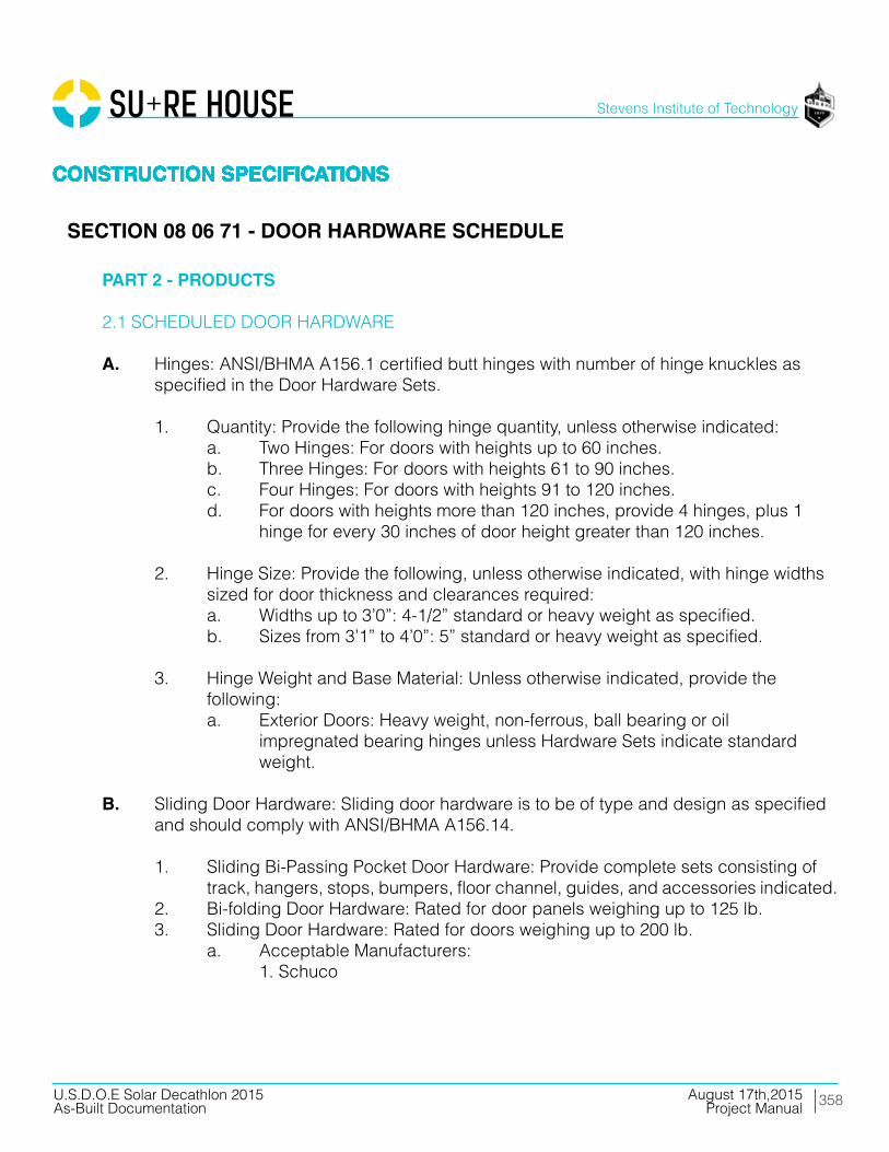
358
Stevens Institute of Technology
August 17th,2015U.S.D.O.E Solar Decathlon 2015As-Built Documentation Project Manual
CONSTRUCTION SPECIFICATIONSCONSTRUCTION SPECIFICATIONSCONSTRUCTION SPECIFICATIONSCONSTRUCTION SPECIFICATIONSCONSTRUCTION SPECIFICATIONS
PART 2 - PRODUCTS
2.1 SCHEDULED DOOR HARDWARE
A. Hinges: ANSI/BHMA A156.1 certified butt hinges with number of hinge knuckles as specified in the Door Hardware Sets.
1. Quantity: Provide the following hinge quantity, unless otherwise indicated: a. Two Hinges: For doors with heights up to 60 inches. b. Three Hinges: For doors with heights 61 to 90 inches. c. Four Hinges: For doors with heights 91 to 120 inches. d. For doors with heights more than 120 inches, provide 4 hinges, plus 1 hinge for every 30 inches of door height greater than 120 inches.
2. Hinge Size: Provide the following, unless otherwise indicated, with hinge widths sized for door thickness and clearances required: a. Widths up to 3’0”: 4-1/2” standard or heavy weight as specified. b. Sizes from 3’1” to 4’0”: 5” standard or heavy weight as specified.
3. Hinge Weight and Base Material: Unless otherwise indicated, provide the following: a. Exterior Doors: Heavy weight, non-ferrous, ball bearing or oil impregnated bearing hinges unless Hardware Sets indicate standard weight.
B. Sliding Door Hardware: Sliding door hardware is to be of type and design as specified and should comply with ANSI/BHMA A156.14.
1. Sliding Bi-Passing Pocket Door Hardware: Provide complete sets consisting of track, hangers, stops, bumpers, floor channel, guides, and accessories indicated. 2. Bi-folding Door Hardware: Rated for door panels weighing up to 125 lb. 3. Sliding Door Hardware: Rated for doors weighing up to 200 lb. a. Acceptable Manufacturers: 1. Schuco
CONSTRUCTION SPECIFICATIONSCONSTRUCTION SPECIFICATIONSCONSTRUCTION SPECIFICATIONSCONSTRUCTION SPECIFICATIONSCONSTRUCTION SPECIFICATIONS
SECTION 08 06 71 - DOOR HARDWARE SCHEDULE
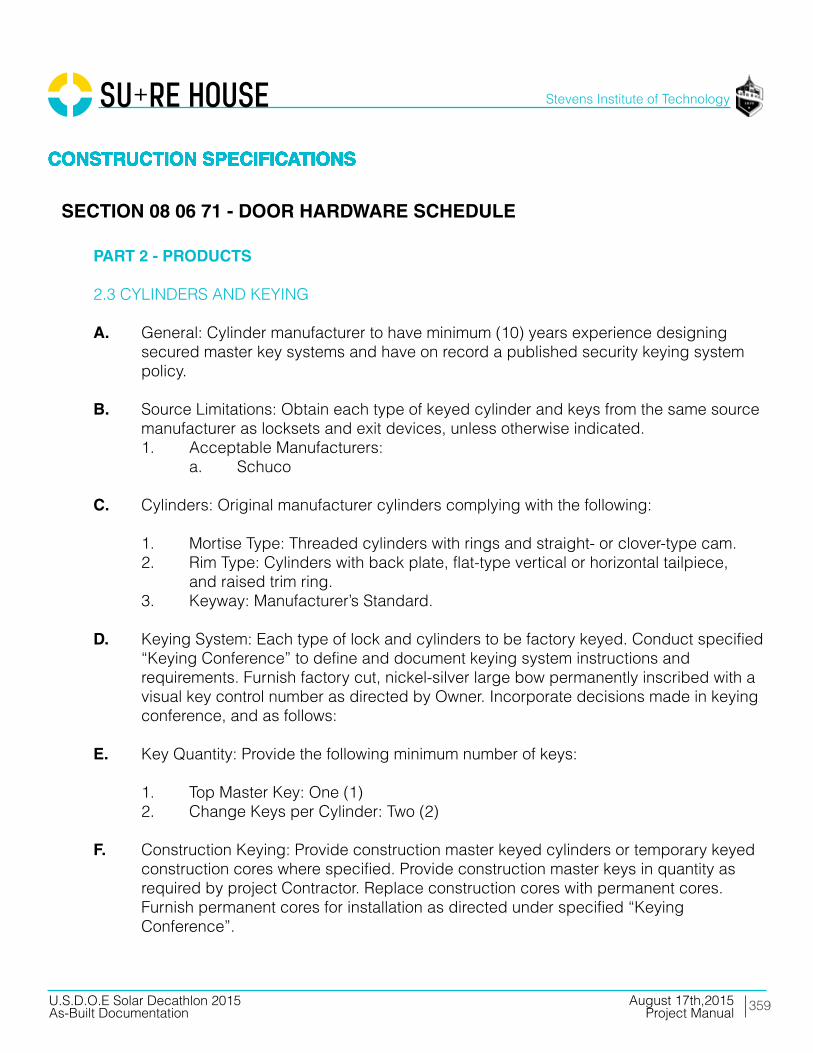
359
Stevens Institute of Technology
August 17th,2015U.S.D.O.E Solar Decathlon 2015As-Built Documentation Project Manual
CONSTRUCTION SPECIFICATIONSCONSTRUCTION SPECIFICATIONSCONSTRUCTION SPECIFICATIONSCONSTRUCTION SPECIFICATIONSCONSTRUCTION SPECIFICATIONS
PART 2 - PRODUCTS
2.3 CYLINDERS AND KEYING
A. General: Cylinder manufacturer to have minimum (10) years experience designing secured master key systems and have on record a published security keying system policy.
B. Source Limitations: Obtain each type of keyed cylinder and keys from the same source manufacturer as locksets and exit devices, unless otherwise indicated. 1. Acceptable Manufacturers: a. Schuco
C. Cylinders: Original manufacturer cylinders complying with the following:
1. Mortise Type: Threaded cylinders with rings and straight- or clover-type cam. 2. Rim Type: Cylinders with back plate, flat-type vertical or horizontal tailpiece, and raised trim ring. 3. Keyway: Manufacturer’s Standard.
D. Keying System: Each type of lock and cylinders to be factory keyed. Conduct specified “Keying Conference” to define and document keying system instructions and requirements. Furnish factory cut, nickel-silver large bow permanently inscribed with a visual key control number as directed by Owner. Incorporate decisions made in keying conference, and as follows:
E. Key Quantity: Provide the following minimum number of keys:
1. Top Master Key: One (1) 2. Change Keys per Cylinder: Two (2)
F. Construction Keying: Provide construction master keyed cylinders or temporary keyed construction cores where specified. Provide construction master keys in quantity as required by project Contractor. Replace construction cores with permanent cores. Furnish permanent cores for installation as directed under specified “Keying Conference”.
CONSTRUCTION SPECIFICATIONSCONSTRUCTION SPECIFICATIONSCONSTRUCTION SPECIFICATIONSCONSTRUCTION SPECIFICATIONSCONSTRUCTION SPECIFICATIONS
SECTION 08 06 71 - DOOR HARDWARE SCHEDULE
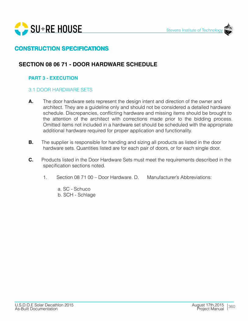
360
Stevens Institute of Technology
August 17th,2015U.S.D.O.E Solar Decathlon 2015As-Built Documentation Project Manual
CONSTRUCTION SPECIFICATIONSCONSTRUCTION SPECIFICATIONSCONSTRUCTION SPECIFICATIONSCONSTRUCTION SPECIFICATIONSCONSTRUCTION SPECIFICATIONS
PART 3 - EXECUTION
3.1 DOOR HARDWARE SETS
A. The door hardware sets represent the design intent and direction of the owner and architect. They are a guideline only and should not be considered a detailed hardware schedule. Discrepancies, conflicting hardware and missing items should be brought to the attention of the architect with corrections made prior to the bidding process. Omitted items not included in a hardware set should be scheduled with the appropriate additional hardware required for proper application and functionality.
B. The supplier is responsible for handing and sizing all products as listed in the door hardware sets. Quantities listed are for each pair of doors, or for each single door.
C. Products listed in the Door Hardware Sets must meet the requirements described in the specification sections noted.
1. Section 08 71 00 – Door Hardware. D. Manufacturer’s Abbreviations:
a. SC - Schuco b. SCH - Schlage
CONSTRUCTION SPECIFICATIONSCONSTRUCTION SPECIFICATIONSCONSTRUCTION SPECIFICATIONSCONSTRUCTION SPECIFICATIONSCONSTRUCTION SPECIFICATIONS
SECTION 08 06 71 - DOOR HARDWARE SCHEDULE

361
Stevens Institute of Technology
August 17th,2015U.S.D.O.E Solar Decathlon 2015As-Built Documentation Project Manual
CONSTRUCTION SPECIFICATIONSCONSTRUCTION SPECIFICATIONSCONSTRUCTION SPECIFICATIONSCONSTRUCTION SPECIFICATIONSCONSTRUCTION SPECIFICATIONS
PART 3 - EXECUTION
3.2 DOOR HARDWARE SCHEDULE
A. SET ONE
1. Doors: 3’ x 8’ x 1 ¾” WDD ( 2 LH, 2 RH) a. Description: Bedroom/Bathroom/Mechanical b. 8 Surface Mounted Invisible Hinge c. 4 Tubular Lock d. 4 Door Stop e. 4 Lever Sets Model 2. Door Manufacturers a. Masonite Max 3. Door Hardware Manufacturers a. Schlage 1. SATIN CHROME
C. SET TWO
1. Doors: 1’ 6” x 8’ x 1 ¾” WDD (French) a. Description: 2-DR Bifold Door Track Laundry Room b. 1 Sliding Door Hardware c. 2 French Pull 2. Door Manufacturers a. Masonite Max 3. Door Hardware Manufacturers a. MC MASTER CARR 1. SILVER
D. SET THREE
1. Doors: 3’ 11” x 8’ x 1” (LH) CT70 a. Description: Front Door b. 2 Surface Mounted Hinge 2. Door and Hardware Manufacturers a. Schuco 1. SILVER
CONSTRUCTION SPECIFICATIONSCONSTRUCTION SPECIFICATIONSCONSTRUCTION SPECIFICATIONSCONSTRUCTION SPECIFICATIONSCONSTRUCTION SPECIFICATIONS
SECTION 08 06 71 - DOOR HARDWARE SCHEDULE
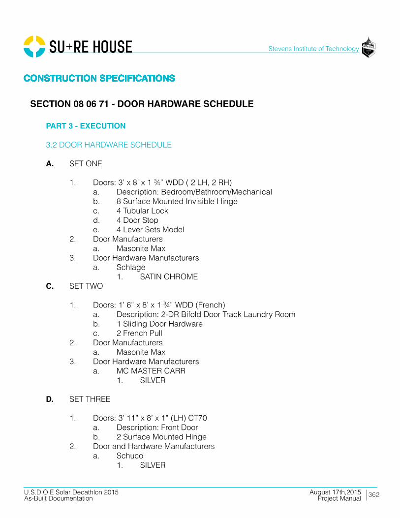
362
Stevens Institute of Technology
August 17th,2015U.S.D.O.E Solar Decathlon 2015As-Built Documentation Project Manual
CONSTRUCTION SPECIFICATIONSCONSTRUCTION SPECIFICATIONSCONSTRUCTION SPECIFICATIONSCONSTRUCTION SPECIFICATIONSCONSTRUCTION SPECIFICATIONS
PART 3 - EXECUTION
3.2 DOOR HARDWARE SCHEDULE
A. SET ONE
1. Doors: 3’ x 8’ x 1 ¾” WDD ( 2 LH, 2 RH) a. Description: Bedroom/Bathroom/Mechanical b. 8 Surface Mounted Invisible Hinge c. 4 Tubular Lock d. 4 Door Stop e. 4 Lever Sets Model 2. Door Manufacturers a. Masonite Max 3. Door Hardware Manufacturers a. Schlage 1. SATIN CHROMEC. SET TWO
1. Doors: 1’ 6” x 8’ x 1 ¾” WDD (French) a. Description: 2-DR Bifold Door Track Laundry Room b. 1 Sliding Door Hardware c. 2 French Pull 2. Door Manufacturers a. Masonite Max 3. Door Hardware Manufacturers a. MC MASTER CARR 1. SILVER
D. SET THREE
1. Doors: 3’ 11” x 8’ x 1” (LH) CT70 a. Description: Front Door b. 2 Surface Mounted Hinge 2. Door and Hardware Manufacturers a. Schuco 1. SILVER
CONSTRUCTION SPECIFICATIONSCONSTRUCTION SPECIFICATIONSCONSTRUCTION SPECIFICATIONSCONSTRUCTION SPECIFICATIONSCONSTRUCTION SPECIFICATIONS
SECTION 08 06 71 - DOOR HARDWARE SCHEDULE

363
Stevens Institute of Technology
August 17th,2015U.S.D.O.E Solar Decathlon 2015As-Built Documentation Project Manual
CONSTRUCTION SPECIFICATIONSCONSTRUCTION SPECIFICATIONSCONSTRUCTION SPECIFICATIONSCONSTRUCTION SPECIFICATIONSCONSTRUCTION SPECIFICATIONS
PART 3 - EXECUTION
3.2 DOOR HARDWARE SCHEDULE
E. SET THREE
1. Doors: 3’ 2.5” x 8’ x 1” (RH) CT70 a. Description: Bathroom Exterior Door b. 2 Surface Mounted Hinge 2. Door and Hardware Manufacturers a. Schuco 1. SILVER
END OF SECTION 08 06 71
CONSTRUCTION SPECIFICATIONSCONSTRUCTION SPECIFICATIONSCONSTRUCTION SPECIFICATIONSCONSTRUCTION SPECIFICATIONSCONSTRUCTION SPECIFICATIONS
SECTION 08 06 71 - DOOR HARDWARE SCHEDULE
364
Stevens Institute of Technology
August 17th,2015U.S.D.O.E Solar Decathlon 2015As-Built Documentation Project Manual
CONSTRUCTION SPECIFICATIONSCONSTRUCTION SPECIFICATIONSCONSTRUCTION SPECIFICATIONSCONSTRUCTION SPECIFICATIONSCONSTRUCTION SPECIFICATIONS
PART 1 - GENERAL
1.01 SUMMARY
A. Section Includes:
1. Solid core doors with wood veneer, hardboard or MDF faces.
B. Related Sections:
1. Section 08 71 00 Section “Door Hardware” for door hardware for flush wood doors and hollow metal frames. 2. Division 09 “Painting”
C. Standards and References: Comply with the version year adopted by the Authority Having Jurisdiction.
1. ANSI A208.1 – Wood Particleboard. 2. Window and Door Manufacturers Association - WDMA I.S.1-A Architectural Wood Flush Doors.
1.02 SUBMITTALS
A. Product Data: For each type of door indicated. Include details of core and edge construction, louvers, trim for openings, and WDMA I.S.1-A or AWS classifications. Include factory finishing specifications.
B. Door hardware supplier is to furnish templates, template reference number and/ or physical hardware to the wood door supplier in order to prepare the doors and frames to receive the finish hardware items.
C. Shop Drawings: Indicate location, size, and hand of each door; elevation of each kind of door; construction details not covered in Product Data; location and extent of hardware blocking; and other pertinent data.
1. Indicate dimensions and locations of mortises and holes for hardware. 2. Indicate dimensions and locations of cutouts. 3. Indicate finish requirements.
CONSTRUCTION SPECIFICATIONSCONSTRUCTION SPECIFICATIONSCONSTRUCTION SPECIFICATIONSCONSTRUCTION SPECIFICATIONSCONSTRUCTION SPECIFICATIONS
365
Stevens Institute of Technology
August 17th,2015U.S.D.O.E Solar Decathlon 2015As-Built Documentation Project Manual
CONSTRUCTION SPECIFICATIONSCONSTRUCTION SPECIFICATIONSCONSTRUCTION SPECIFICATIONSCONSTRUCTION SPECIFICATIONSCONSTRUCTION SPECIFICATIONS
PART 1 - GENERAL
1.03 GENERAL
A. Source Limitations: Obtain flush wood doors through one source from a single manufacturer wherever possible.
B. Quality Standard: In addition to requirements specified, comply with WDMA I.S.1-A, latest edition, “Industry Standard for Architectural Wood Flush Doors’.
C. Pre-Submittal Conference: Conduct conference in compliance with requirements in Division 01 Section “Project Meetings” with attendance by representatives of Supplier, Installer, and Contractor to review proper methods and procedures for receiving, handling, and installing flush wood doors.
1.04 DELIVERY, STORAGE, AND HANDLING
A. Comply with requirements of referenced standard and manufacturer’s written instructions.
B. Package pre-finished doors individually in plastic bags or cardboard cartons and wrap bundles of doors in plastic sheeting.
C. Mark each door on top rail with opening number used on Shop Drawings.
1.05 PROJECT CONDITIONS
A. Environmental Limitations: Do not deliver or install doors until spaces are enclosed and weather tight, wet work in spaces is complete and dry, and HVAC system is operating and maintaining ambient temperature and humidity conditions at occupancy levels during the remainder of the construction period.
CONSTRUCTION SPECIFICATIONSCONSTRUCTION SPECIFICATIONSCONSTRUCTION SPECIFICATIONSCONSTRUCTION SPECIFICATIONSCONSTRUCTION SPECIFICATIONS
SECTION 08 14 16 - FLUSH WOOD DOORS
366
Stevens Institute of Technology
August 17th,2015U.S.D.O.E Solar Decathlon 2015As-Built Documentation Project Manual
CONSTRUCTION SPECIFICATIONSCONSTRUCTION SPECIFICATIONSCONSTRUCTION SPECIFICATIONSCONSTRUCTION SPECIFICATIONSCONSTRUCTION SPECIFICATIONS
PART 1 - GENERAL
1.06 WARRANTY
A. Special Warranty: Manufacturer’s standard form in which manufacturer agrees to repair or replace doors that fail in materials or workmanship within specified warranty period.
1. Failures include, but are not limited to, the following: a. Warping (bow, cup,or twist) more than 1/4 inch in a 42-by-84-inch section. b. Telegraphing of core construction in wood face veneers exceeding 0.01 inch in a 3-inch span. c. Telegraphing of core construction and delaminating of face in decorative laminate-faced doors. 2. Warranty includes installation and finishing that may be required due to repair or replacement of defective doors. 3. Warranty Period for Solid Core Interior Doors: Life of installation according to manufacturer’s written warranty.
PART 2 - PRODUCTS
2.01 MANUFACTURER
A. MASONITE MAX, Home Depot, 180 Twelfth Street Jersey City, NJ 07310 1. Bedroom Doors. 2. Bathroom Door. 3. Mechanical Room Door. 4. Laundry Room Door.
CONSTRUCTION SPECIFICATIONSCONSTRUCTION SPECIFICATIONSCONSTRUCTION SPECIFICATIONSCONSTRUCTION SPECIFICATIONSCONSTRUCTION SPECIFICATIONS
SECTION 08 14 16 - FLUSH WOOD DOORS
367
Stevens Institute of Technology
August 17th,2015U.S.D.O.E Solar Decathlon 2015As-Built Documentation Project Manual
CONSTRUCTION SPECIFICATIONSCONSTRUCTION SPECIFICATIONSCONSTRUCTION SPECIFICATIONSCONSTRUCTION SPECIFICATIONSCONSTRUCTION SPECIFICATIONS
PART 2 - PRODUCTS
2.02 PASSAGE DOORS
A. Core and Frame
1. Solid core with [combination wood/MDF] [all-wood] frame. a. Thickness: 1-3/4 inch with 45-minute fire rating. 2. Solid mineral core with mineral composite frame. a. Thickness: 1-3/4 inch with [45-minute] [60-minute] [90-minute] fire rating. 3. Hollow core with MDF frame. a. Thickness: 1-3/8 inch.3
2.03 DOOR HARDWARE
A. Door Handles
1. To be specified by architect. a. Finish 1. Satin Chrome or Satin Nickel
B. Finish
1. Prefinished Smooth : Based on material samples. Finishes to be chosen by architect. a. Baltic Birch
CONSTRUCTION SPECIFICATIONSCONSTRUCTION SPECIFICATIONSCONSTRUCTION SPECIFICATIONSCONSTRUCTION SPECIFICATIONSCONSTRUCTION SPECIFICATIONS
SECTION 08 14 16 - FLUSH WOOD DOORS

368
Stevens Institute of Technology
August 17th,2015U.S.D.O.E Solar Decathlon 2015As-Built Documentation Project Manual
CONSTRUCTION SPECIFICATIONSCONSTRUCTION SPECIFICATIONSCONSTRUCTION SPECIFICATIONSCONSTRUCTION SPECIFICATIONSCONSTRUCTION SPECIFICATIONS
PART 3 - EXECUTION
3.01 GENERAL
A. Install doors in accordance with manufacturer’s installation guidelines and recommendations.
3.02 EXAMINATION
A. Inspect door prior to installation.
B. Inspect rough opening for compliance with door manufacturer recommendations.
3.03 PREPARATION
A. Prepare door for installation in accordance with manufacturer’s recommendations.
B. Trim bottom of jamb sides to achieve desired distance between door bottom and finished floor height.
3.04 INSTALLATION
A. Place door unit into opening and level hinge side of jamb. Use shims fastened through jamb and stop to level and temporarily secure in place.
B. Use shims fastened through jamb and stop to level and temporarily secure in place.
C. Verify spacing between jamb and door is uniform on all sides. Adjust as necessary.
D. Shim top of jamb in center of opening and fasten with nail.
E. Re-check for square, level and even spacing around door. F. Set nails.
G. Install trim on both sides using nails every 12 to 16 inches.
END OF SECTION 08 14 16
CONSTRUCTION SPECIFICATIONSCONSTRUCTION SPECIFICATIONSCONSTRUCTION SPECIFICATIONSCONSTRUCTION SPECIFICATIONSCONSTRUCTION SPECIFICATIONS
SECTION 08 14 16 - FLUSH WOOD DOORS
369
Stevens Institute of Technology
August 17th,2015U.S.D.O.E Solar Decathlon 2015As-Built Documentation Project Manual
CONSTRUCTION SPECIFICATIONSCONSTRUCTION SPECIFICATIONSCONSTRUCTION SPECIFICATIONSCONSTRUCTION SPECIFICATIONSCONSTRUCTION SPECIFICATIONS
PART 1 - GENERAL
1.01 SECTION INCLUDES
A. Out-swing entry doors.
1.02 PERFORMANCE REQUIREMENTS
A. Doors shall have a certified rating in accordance with WDMA CS2 Hallmark Program Guide for Side-hinged Exterior Door Systems.
B. Door Unit Air Leakage, ASTM E 283, 1.57 psf (25 mph): 0.30 cfm per square foot of frame or less.
C. Door Unit Water Penetration: No water penetration through door unit when tested in accordance with ASTM E 331 with water applied at rate of 5 gallons per hour per square foot. Doors with standard sill shall have water resistance performance level up to 7.5 psf and low profile sill (ADA) shall have water resistance performance level of 0 psf.
D. ALL DOOR PERFORMANCE REQUIREMENTS MUST COMPLY WITH PASSIVE HOUSE CERTIFICATION
1.03 SUBMITTALS
A. Product Data: Submit manufacturer’s product data, including installation instructions.
B. Shop Drawings: Submit manufacturer’s shop drawings, indicating dimensions, construction, component connections and locations, anchorage methods and locations, hardware locations, and installation details.
C. Samples: Submit full-size or partial full-size sample of door illustrating glazing system, quality of construction, and color of finish.
D. Warranty: Submit manufacturer’s standard warranty.
CONSTRUCTION SPECIFICATIONSCONSTRUCTION SPECIFICATIONSCONSTRUCTION SPECIFICATIONSCONSTRUCTION SPECIFICATIONSCONSTRUCTION SPECIFICATIONS
SECTION 08 15 00 - PLASTIC DOORS (EXTERIOR)

370
Stevens Institute of Technology
August 17th,2015U.S.D.O.E Solar Decathlon 2015As-Built Documentation Project Manual
CONSTRUCTION SPECIFICATIONSCONSTRUCTION SPECIFICATIONSCONSTRUCTION SPECIFICATIONSCONSTRUCTION SPECIFICATIONSCONSTRUCTION SPECIFICATIONS
PART 1 - GENERAL
1.04 DELIVERY, STORAGE, AND HANDLING
A. Delivery: Deliver materials to site undamaged in manufacturer’s or sales branch’s original, unopened containers and packaging, with labels clearly identifying manufacturer and product name. Include installation instructions.
B. Storage: Store materials in an upright position, off ground, under cover, and protected from weather, direct sunlight, and construction activities.
C. Handling: Protect materials and finish during handling and installation to prevent damage.
PART 2 - PRODUCTS
2.01 MANUFACTURER
A. Schüco USA L.P. 240 Pane Road CT 06111 Newington United States of America Toll Free: +1 877 472 4826
2.02 OUT-SWING ENTRY DOORS
A. Out-Swing Entry Doors: Factory-assembled doors with outward-swing door panels installed in frames. B. Frames
1. UPVC Door a. Gray
CONSTRUCTION SPECIFICATIONSCONSTRUCTION SPECIFICATIONSCONSTRUCTION SPECIFICATIONSCONSTRUCTION SPECIFICATIONSCONSTRUCTION SPECIFICATIONS
SECTION 08 15 00 - PLASTIC DOORS (EXTERIOR)

371
Stevens Institute of Technology
August 17th,2015U.S.D.O.E Solar Decathlon 2015As-Built Documentation Project Manual
CONSTRUCTION SPECIFICATIONSCONSTRUCTION SPECIFICATIONSCONSTRUCTION SPECIFICATIONSCONSTRUCTION SPECIFICATIONSCONSTRUCTION SPECIFICATIONS
PART 2 - PRODUCTS
2.02 OUT-SWING ENTRY DOORS
C. UPVC Door Panels
1. Hardware Preparation a. Factory prepared Multi-point with lock installed b. 2-3/8-inch backset c. 6 inches on center 2. Door Closer and Panic Hardware Reinforcement: Solid reinforcement positioned to support surface-mounted closer and panic hardware.
D. Weather Strip:
1. Head: Dual-seal weather strip shall contact interior face and side of door panel and extruded leaf rain screen shall cover the exterior face of door panel. 2. Jambs: Dual-seal weather strip shall contact interior face and side of door panel. 3. Sill: Bristle rain screen at exterior face of door panel with bulb weather strip on threshold shall contact interior face of door panel.
2.04 HARDWARE
A. Hinges: Three (3) per door panel on 6’ 8” and 7’ 0” panel heights; four (4) per door panel on 8’ 0” heights for operable units.
1. Type: a. 4-inch by 4-inch by 0.100-inch thick cold-rolled steel with non-removal pin. b. 4-inch by 4-inch by 0.100-inch thick cold-rolled steel with spring and non-removal pin. 2. Finish: US26, polished chrome-plated
B. Frames are prepared for hardware to match door panel boring.
CONSTRUCTION SPECIFICATIONSCONSTRUCTION SPECIFICATIONSCONSTRUCTION SPECIFICATIONSCONSTRUCTION SPECIFICATIONSCONSTRUCTION SPECIFICATIONS
SECTION 08 15 00 - PLASTIC DOORS (EXTERIOR)

372
Stevens Institute of Technology
August 17th,2015U.S.D.O.E Solar Decathlon 2015As-Built Documentation Project Manual
CONSTRUCTION SPECIFICATIONSCONSTRUCTION SPECIFICATIONSCONSTRUCTION SPECIFICATIONSCONSTRUCTION SPECIFICATIONSCONSTRUCTION SPECIFICATIONS
PART 2 - PRODUCTS
2.05 TOLERANCES
C. Doors shall accommodate the following opening tolerances:
1. Vertical Dimensions Between High and Low Points: Plus 1/4 inch, minus 0 inch. 2. Width Dimensions: Plus 1/4 inch, minus 0 inch. 3. Building Columns or Masonry Openings: Plus or minus 1/4 inch from plumb.
2.06 FINISH
A. Door Frame Exterior Finish System: SCHUCO Thermoclad System.
1. Exterior aluminum door frame surfaces shall be finished with the following multi-stage system: a. Clean and etch aluminum surface of oxides. b. Pre-treat with chrome phosphate conversion coating. c. Pre-treat with chromic acid sealer/rinse. d. Prime with baked-on modified polyester primer. e. Top coat with baked-on polyester enamel. 2. Color: White
B. Exterior Finish System Performance Requirements:
1. Exterior UPVC finishes shall meet or exceed the following performance requirements: a. Ozone Deterioration, ASTM D 1149, Modified: 5 ppm ozone, 160 degrees F, 60 percent relative humidity, 100 hours exposure, little or no loss of cure. b. Taber Abrasion Resistance, ASTM D 4060: 500 g weight, CS-10 wheel, 500 cycles, less than 25 g weight loss. c. Cyclic Acidified Salt Fog Test, ASTM G 85, Appendix A-2.
CONSTRUCTION SPECIFICATIONSCONSTRUCTION SPECIFICATIONSCONSTRUCTION SPECIFICATIONSCONSTRUCTION SPECIFICATIONSCONSTRUCTION SPECIFICATIONS
SECTION 08 15 00 - PLASTIC DOORS (EXTERIOR)

373
Stevens Institute of Technology
August 17th,2015U.S.D.O.E Solar Decathlon 2015As-Built Documentation Project Manual
CONSTRUCTION SPECIFICATIONSCONSTRUCTION SPECIFICATIONSCONSTRUCTION SPECIFICATIONSCONSTRUCTION SPECIFICATIONSCONSTRUCTION SPECIFICATIONS
PART 2 - PRODUCTS
2.06 FINISH
C. Door Panel Exterior Finish:
1. UPVC Door Panels: Factory pre-finished, paint; color Gray.
D. Door Frame Interior Finish: Factory pre-finished, paint; Gray.
E. Door Panel Interior Finish:
1. UPVC Door Panels: Factory pre-finished, paint; color Gray.
PART 3 - EXECUTION
3.01 EXAMINATION
A. Examine areas to receive doors. Notify Architect of conditions that would adversely affect installation or subsequent use. Do not proceed with installation until unsatisfactory conditions are corrected.
3.02 INSTALLATION
A. Install doors in accordance with manufacturer’s instructions and approved shop drawings.
B. Install doors to be weather-tight and freely operating.
C. Maintain alignment with adjacent work.
D. Secure assembly to framed openings, plumb and square, without distortion.
E. Integrate door system installation with exterior weather-resistant barrier using flashing/sealant tape. Apply and integrate flashing/sealant tape with weather-resistant barrier using watershed principles in accordance with door manufacturer’s instructions.
CONSTRUCTION SPECIFICATIONSCONSTRUCTION SPECIFICATIONSCONSTRUCTION SPECIFICATIONSCONSTRUCTION SPECIFICATIONSCONSTRUCTION SPECIFICATIONS
SECTION 08 15 00 - PLASTIC DOORS (EXTERIOR)
374
Stevens Institute of Technology
August 17th,2015U.S.D.O.E Solar Decathlon 2015As-Built Documentation Project Manual
CONSTRUCTION SPECIFICATIONSCONSTRUCTION SPECIFICATIONSCONSTRUCTION SPECIFICATIONSCONSTRUCTION SPECIFICATIONSCONSTRUCTION SPECIFICATIONS
PART 3 - EXECUTION
3.02 INSTALLATION
F. Place interior seal around door perimeter to maintain continuity of building thermal and air barrier using insulating-foam sealant.
G. Seal door to exterior wall cladding with sealant and related backing materials at perimeter of assembly.
H. Leave doors closed.
3.03 CLEANING
A. Clean door frames and glass in accordance with Division 1 requirements.
B. Do not use harsh cleaning materials or methods that would damage finish.
C. Remove manufacturer’s proprietary labels and visible markings.
SECTION 08 15 00
CONSTRUCTION SPECIFICATIONSCONSTRUCTION SPECIFICATIONSCONSTRUCTION SPECIFICATIONSCONSTRUCTION SPECIFICATIONSCONSTRUCTION SPECIFICATIONS
SECTION 08 15 00 - PLASTIC DOORS (EXTERIOR)
375
Stevens Institute of Technology
August 17th,2015U.S.D.O.E Solar Decathlon 2015As-Built Documentation Project Manual
CONSTRUCTION SPECIFICATIONSCONSTRUCTION SPECIFICATIONSCONSTRUCTION SPECIFICATIONSCONSTRUCTION SPECIFICATIONSCONSTRUCTION SPECIFICATIONS
PART 1 - GENERAL
1.01 SUMMARY
A. UPVC Lift and Slide Glass Doors.
1.02 RELATED SECTIONS
A. Section 07270 (07 27 00) - Air Barriers: Water-resistant barrier.
B. Section 07920 (07 92 00) - Joint Sealants: Sealants and caulking.
1.02 PERFORMANCE REQUIREMENTS
A. Doors shall have a certified rating in accordance with WDMA CS2 Hallmark Program Guide for Side-hinged Exterior Door Systems.
B. Door Unit Air Leakage, ASTM E 283, 1.57 psf (25 mph): 0.30 cfm per square foot of frame or less.
C. Door Unit Water Penetration: No water penetration through door unit when tested in accordance with ASTM E 331 with water applied at rate of 5 gallons per hour per square foot. Doors with standard sill shall have water resistance performance level up to 7.5 psf and low profile sill (ADA) shall have water resistance performance level of 0 psf.
D. ALL DOOR PERFORMANCE REQUIREMENTS MUST COMPLY WITH PASSIVE HOUSE CERTIFICATION
1.06 QUALITY ASSURANCE
A. Mockup
1. Provide sample installation for field testing door performance requirements and to determine acceptability of door installation methods. 2. Approved mockup shall represent minimum quality required for the Work. 3. Approved mockup shall [not] remain in place within the Work.
CONSTRUCTION SPECIFICATIONSCONSTRUCTION SPECIFICATIONSCONSTRUCTION SPECIFICATIONSCONSTRUCTION SPECIFICATIONSCONSTRUCTION SPECIFICATIONS
SECTION 08 32 00 - SLIDING GLASS DOORS

376
Stevens Institute of Technology
August 17th,2015U.S.D.O.E Solar Decathlon 2015As-Built Documentation Project Manual
PART 2 - PRODUCTS
2.01 MANUFACTURER
A. Schüco USA L.P. 240 Pane Road CT 06111 Newington United States of America Toll Free: +1 877 472 4826
2.02 PERFORMANCE REQUIREMENTS
A. Product Standard: AAMA/WDMA/CSA 101/I.S.2/A440.
1. Product Certification: AAMA certified with label attached to each door.
B. Solar Heat-Gain Coefficient (SHGC): NFRC 200 maximum total fenestration product SHGC of .62
C. Thermal Transmittance: NFRC 100 maximum total fenestration product U-factor of.14 U Value
D. Low - E coating, Argon Gas Triple Pane Glass
E. MUST COMPLY WITH PASSIVE HOUSE CERTIFICATION
2.02 GLASS LIFT AND SLIDE DOOR
A. EAS ThermoSlide
1. SHGC of .62 2. .7 watts per m2 U -Factor 3. Argon Gas Triple Pane Glass 4. Finish : White Specified By Architect 5. UPVC Frame
CONSTRUCTION SPECIFICATIONSCONSTRUCTION SPECIFICATIONSCONSTRUCTION SPECIFICATIONSCONSTRUCTION SPECIFICATIONSCONSTRUCTION SPECIFICATIONSCONSTRUCTION SPECIFICATIONSCONSTRUCTION SPECIFICATIONSCONSTRUCTION SPECIFICATIONSCONSTRUCTION SPECIFICATIONSCONSTRUCTION SPECIFICATIONS
SECTION 08 32 00 - SLIDING GLASS DOORS

377
Stevens Institute of Technology
August 17th,2015U.S.D.O.E Solar Decathlon 2015As-Built Documentation Project Manual
PART 2 - PRODUCTS
2.03 GLAZING AND ACCESSORIES
A. Glaze units with clear, low-e coated,argon-filled,sealed, and insulating glass complying with Section 088000 “Glazing” and with testing requirements in 16 CFR 1201 for Category II materials.
B. Floor Track: Exterior type, low profile, ADA-ABA compliant.
C. Lock: Install manufacturer’s keyed cylinder lock and multipoint locking device on each movable panel, lockable from the inside and outside.
PART 3 - EXECUTION
3.01 INSTALLATION
A. Set doors level, plumb, and true to line, without warp or rack of frames and panels. Provide proper support and anchor securely in place.
B. Set sill members in bed of sealant or with gaskets, as indicated, to provide weathertight construction.
C. Separate aluminum and other corrodible surfaces from sources of corrosion or electrolytic action at points of contact with other materials.
D. Adjust operating panels, screens, and hardware to provide a tight fit at contact points and weather stripping for smooth operation and weathertight closure. Lubricate hardware and moving parts.
E. Clean frame surfaces and glass immediately after installing sliding glass doors. Remove nonpermanent labels from glass surfaces.
END OF SECTION 08 23 00
CONSTRUCTION SPECIFICATIONSCONSTRUCTION SPECIFICATIONSCONSTRUCTION SPECIFICATIONSCONSTRUCTION SPECIFICATIONSCONSTRUCTION SPECIFICATIONSCONSTRUCTION SPECIFICATIONSCONSTRUCTION SPECIFICATIONSCONSTRUCTION SPECIFICATIONSCONSTRUCTION SPECIFICATIONSCONSTRUCTION SPECIFICATIONS
SECTION 08 32 00 - SLIDING GLASS DOORS

378
Stevens Institute of Technology
August 17th,2015U.S.D.O.E Solar Decathlon 2015As-Built Documentation Project Manual
PART 1 - GENERAL
1.01 SUMMARY
A. UPVC Lift and Slide Glass Doors.
1.02 RELATED SECTIONS
A. Section 07270 (07 27 00) - Air Barriers: Water-resistant barrier.
B. Section 07920 (07 92 00) - Joint Sealants: Sealants and caulking.
1.03 PERFORMANCE REQUIREMENTS
A. Window Unit Air Leakage, ASTM E 283, 1.57 psf (25 mph): 0.30 cfm per square foot of frame or less.
B. Window Unit Water Penetration: No water penetration through door unit when tested in accordance with ASTM E 331 with water applied at rate of 5 gallons per hour per square foot. Windows with standard sill shall have water resistance performance level up to 7.5 psf.
C. ALL WINDOW PERFORMANCE REQUIREMENTS MUST COMPLY WITH PASSIVE HOUSE CERTIFICATION.
PART 2 - PRODUCTS
2.01 MANUFACTURER
A. Schüco USA L.P. 240 Pane Road CT 06111 Newington United States of America Toll Free: +1 877 472 4826
CONSTRUCTION SPECIFICATIONSCONSTRUCTION SPECIFICATIONSCONSTRUCTION SPECIFICATIONSCONSTRUCTION SPECIFICATIONSCONSTRUCTION SPECIFICATIONSCONSTRUCTION SPECIFICATIONSCONSTRUCTION SPECIFICATIONSCONSTRUCTION SPECIFICATIONSCONSTRUCTION SPECIFICATIONSCONSTRUCTION SPECIFICATIONS
SECTION 08 53 00 - PLASTIC WINDOWS
379
Stevens Institute of Technology
August 17th,2015U.S.D.O.E Solar Decathlon 2015As-Built Documentation Project Manual
PART 2 - PRODUCTS
2.02 PERFORMANCE REQUIREMENTS
A. Product Standard: AAMA/WDMA/CSA 101/I.S.2/A440.
1. Window Certification: WDMA certified with label attached to each window.
B. Solar Heat-Gain Coefficient (SHGC): NFRC 200 maximum whole-window SHGC of .5.
C. Thermal Transmittance: NFRC 100 maximum whole-window U-factor of .14.
2.03 PLASTIC WINDOWS
A. Window Types - The following types, as indicated on Drawings:
1. Tilt and Turn Window 2. Fixed
B. SCHUCO SL82 UPVC FIXED WINDOW
1. SHGC of .5 2. .14 watts per m2 U -Factor 3. Argon Gas Triple Pane Glass 4. Finish : White or Gray Specified By Architect 5. UPVC Frame
C. SCHUCO SL82 UPVC TILT AND TURN WINDOW
1. SHGC of .5 2. .14 watts per m2 U -Factor 3. Argon Gas Triple Pane Glass 4. Finish : White or Gray Specified By Architect 5. UPVC Frame
CONSTRUCTION SPECIFICATIONSCONSTRUCTION SPECIFICATIONSCONSTRUCTION SPECIFICATIONSCONSTRUCTION SPECIFICATIONSCONSTRUCTION SPECIFICATIONSCONSTRUCTION SPECIFICATIONSCONSTRUCTION SPECIFICATIONSCONSTRUCTION SPECIFICATIONSCONSTRUCTION SPECIFICATIONSCONSTRUCTION SPECIFICATIONS
SECTION 08 53 00 - PLASTIC WINDOWS

380
Stevens Institute of Technology
August 17th,2015U.S.D.O.E Solar Decathlon 2015As-Built Documentation Project Manual
PART 2 - PRODUCTS
2.03 PLASTIC WINDOWS
C. Equip units with removable grilles as indicated; attach to inside face of each lite.
D. Trim: Provide indicated trim, matching material and finish of frame members.
E. Provide prefabricated window units as indicated.
F. Equip units with vinyl-coated, glass-fiber mesh insect screens at operable sashes.
G. Glaze units with clear, low-E-coated, argon-filled, sealed insulating glass, complying with Section 08 80 00 “Glazing.”
2.04 WINDOW HARDWARE
A. Handle and Hardware to be supplied by manufacturer.
B. Schuco Handle 1. Style : Stainless Steel
PART 3 - EXECUTION
3.01 INSTALLATION
A. Set units level, plumb, and true to line, without warp or rack of frames and panels. Provide proper support and anchor securely in place.
B. For installation procedures and requirements not addressed in manufacturer’s written instructions, comply with installation requirements in ASTM E 2112.
C. Set sill members in bed of sealant or with gaskets, as indicated, to provide weather tight construction.
CONSTRUCTION SPECIFICATIONSCONSTRUCTION SPECIFICATIONSCONSTRUCTION SPECIFICATIONSCONSTRUCTION SPECIFICATIONSCONSTRUCTION SPECIFICATIONSCONSTRUCTION SPECIFICATIONSCONSTRUCTION SPECIFICATIONSCONSTRUCTION SPECIFICATIONSCONSTRUCTION SPECIFICATIONSCONSTRUCTION SPECIFICATIONS
SECTION 08 53 00 - PLASTIC WINDOWS

381
Stevens Institute of Technology
August 17th,2015U.S.D.O.E Solar Decathlon 2015As-Built Documentation Project Manual
PART 3 - EXECUTION
3.02 INSTALLATION
D. Adjust operating panels, screens, and hardware to provide a tight fit at contact points and weather stripping for smooth operation and weather tight closure. Lubricate hardware and moving parts.
E. Clean glass and vinyl surfaces immediately after installing windows. Remove non permanent labels from glass surfaces.
SECTION 08 53 00
CONSTRUCTION SPECIFICATIONSCONSTRUCTION SPECIFICATIONSCONSTRUCTION SPECIFICATIONSCONSTRUCTION SPECIFICATIONSCONSTRUCTION SPECIFICATIONSCONSTRUCTION SPECIFICATIONSCONSTRUCTION SPECIFICATIONSCONSTRUCTION SPECIFICATIONSCONSTRUCTION SPECIFICATIONSCONSTRUCTION SPECIFICATIONS
SECTION 08 53 00 - PLASTIC WINDOWS

382
Stevens Institute of Technology
August 17th,2015U.S.D.O.E Solar Decathlon 2015As-Built Documentation Project Manual
PART 1 - GENERAL
1.01 SUMMARY
A. This Section includes commercial door hardware for the following:
1. Swinging doors. 2. Sliding doors. 3. Other doors to the extent indicated.
B. Door hardware includes, but is not necessarily limited to, the following:
1. Mechanical door hardware. 2. Cylinders specified for doors in other sections.
C. Related Sections:
1. Division 08 Section “Flush Wood Doors”.
D. Codes and References: Comply with the version year adopted by the Authority Having Jurisdiction.
1. ANSI A117.1 - Accessible and Usable Buildings and Facilities. 2. ICC/IBC - International Building Code. 3. NFPA 101 - Life Safety Code. 4. State Building Codes, Local Amendments.
E. Standards: All hardware specified here in shall comply with the following industry standards:
1. ANSI/BHMA Certified Product Standards - A156 Series
CONSTRUCTION SPECIFICATIONSCONSTRUCTION SPECIFICATIONSCONSTRUCTION SPECIFICATIONSCONSTRUCTION SPECIFICATIONSCONSTRUCTION SPECIFICATIONSCONSTRUCTION SPECIFICATIONSCONSTRUCTION SPECIFICATIONSCONSTRUCTION SPECIFICATIONSCONSTRUCTION SPECIFICATIONSCONSTRUCTION SPECIFICATIONS
SECTION 08 71 00 - DOOR HARDWARE
383
Stevens Institute of Technology
August 17th,2015U.S.D.O.E Solar Decathlon 2015As-Built Documentation Project Manual
PART 1 - GENERAL
1.02 SUBMITTALS
A. Product Data: Manufacturer’s product data sheets including installation details, material descriptions, dimensions of individual components and profiles, operational descriptions and finishes.
B. Door Hardware Schedule: Prepared by or under the supervision of supplier, detailing fabrication and assembly of door hardware, as well as procedures and diagrams. Coordinate the final Door Hardware Schedule with doors, frames, and related work to ensure proper size, thickness, hand, function, and finish of door hardware.
1. Format: Comply with scheduling sequence and vertical format in DHI’s “Sequence and Format for the Hardware Schedule.”
2. Organization: Organize the Door Hardware Schedule into door hardware sets indicating complete designations of every item required for each door or opening. Organize door hardware sets in same order as in the Door Hardware Sets at the end of Part 3. Submittals that do not follow the same format and order as the Door Hardware Sets will be rejected and subject to resubmission.
3. Content: Include the following information:
a. Type, style, function, size, label, hand, and finish of each door hardware item. b. Manufacturer of each item. c. Fastenings and other pertinent information. d. Location of door hardware set, cross-referenced to Drawings, both on floor plans and in door and frame schedule. e. Explanation of abbreviations, symbols, and codes contained in schedule. f. Mounting locations for door hardware. g. Door and frame sizes and materials.
CONSTRUCTION SPECIFICATIONSCONSTRUCTION SPECIFICATIONSCONSTRUCTION SPECIFICATIONSCONSTRUCTION SPECIFICATIONSCONSTRUCTION SPECIFICATIONSCONSTRUCTION SPECIFICATIONSCONSTRUCTION SPECIFICATIONSCONSTRUCTION SPECIFICATIONSCONSTRUCTION SPECIFICATIONSCONSTRUCTION SPECIFICATIONS
SECTION 08 71 00 - DOOR HARDWARE
384
Stevens Institute of Technology
August 17th,2015U.S.D.O.E Solar Decathlon 2015As-Built Documentation Project Manual
PART 1 - GENERAL
1.02 SUBMITTALS
C. Shop Drawings: Details of electrified access control hardware indicating the following:
1. Wiring Diagrams: Upon receipt of approved schedules, submit detailed system wiring diagrams for power, signaling, monitoring, communication, and control of the access control system electrified hardware. Differentiate between manufacturer-installed and field-installed wiring. Include the following:
a. Elevation diagram of each unique access controlled opening showing location and interconnection of major system components with respect to their placement in the respective door openings. b. Complete (risers, point-to-point) access control system block wiring diagrams.
D. Warranties and Maintenance: Special warranties and maintenance agreements specified in this Section.
1.03 QUALITY ASSURANCE
A. Manufacturers Qualifications: Engage qualified manufacturers with a minimum 5 years of documented experience in producing hardware and equipment similar to that indicated for this Project and that have a proven record of successful in-service performance.
B. Installer Qualifications: Installers, trained by the primary product manufacturers, with a minimum 3 years documented experience installing both standard and electrified builders hardware similar in material, design, and extent to that indicated for this Project and whose work has resulted in construction with a record of successful in- service performance.
CONSTRUCTION SPECIFICATIONSCONSTRUCTION SPECIFICATIONSCONSTRUCTION SPECIFICATIONSCONSTRUCTION SPECIFICATIONSCONSTRUCTION SPECIFICATIONSCONSTRUCTION SPECIFICATIONSCONSTRUCTION SPECIFICATIONSCONSTRUCTION SPECIFICATIONSCONSTRUCTION SPECIFICATIONSCONSTRUCTION SPECIFICATIONS
SECTION 08 71 00 - DOOR HARDWARE

385
Stevens Institute of Technology
August 17th,2015U.S.D.O.E Solar Decathlon 2015As-Built Documentation Project Manual
PART 1 - GENERAL
1.03 QUALITY ASSURANCE
A. Manufacturers Qualifications: Engage qualified manufacturers with a minimum 5 years of documented experience in producing hardware and equipment similar to that indicated for this Project and that have a proven record of successful in-service performance.
B. Installer Qualifications: Installers, trained by the primary product manufacturers, with a minimum 3 years documented experience installing both standard and electrified builders hardware similar in material, design, and extent to that indicated for this Project and whose work has resulted in construction with a record of successful in- service performance.
C. Regulatory Requirements: Comply with NFPA 70, NFPA 80, NFPA 101 and ANSI A117.1 requirements and guidelines as directed in the model building code including, but not limited to, the following:
1. Where indicated to comply with accessibility requirements, comply with Americans with Disabilities Act (ADA), “Accessibility Guidelines for Buildings and Facilities (ADAAG),” ANSI A117.1 as follows: a. Handles, Pulls, Latches, Locks, and other Operating Devices: Shape that is easy to grasp with one hand and does not require tight grasping, tight pinching, or twisting of the wrist. b. Door Closers: Comply with the following maximum opening-force requirements indicated: 1) Interior Hinged Doors: 5 lbf applied perpendicular to door. 2) Fire Doors: Minimum opening force allowable. c. Thresholds: Not more than 1/2 inch high. Bevel raised thresholds with a slope of not more than 1:2. 2. NFPA 101: Comply with the following for means of egress doors: a. Latches, Locks, and Exit Devices: Not more than 15 lbf to release the latch. Locks shall not require the use of a key, tool, or special knowledge for operation. b. Thresholds: Not more than 1/2 inch high.
CONSTRUCTION SPECIFICATIONSCONSTRUCTION SPECIFICATIONSCONSTRUCTION SPECIFICATIONSCONSTRUCTION SPECIFICATIONSCONSTRUCTION SPECIFICATIONSCONSTRUCTION SPECIFICATIONSCONSTRUCTION SPECIFICATIONSCONSTRUCTION SPECIFICATIONSCONSTRUCTION SPECIFICATIONSCONSTRUCTION SPECIFICATIONS
SECTION 08 71 00 - DOOR HARDWARE

386
Stevens Institute of Technology
August 17th,2015U.S.D.O.E Solar Decathlon 2015As-Built Documentation Project Manual
PART 1 - GENERAL
1.06 WARRANTY
A. General Warranty: Reference Division 01, General Requirements. Special warranties specified in this Article shall not deprive Owner of other rights Owner may have under other provisions of the Contract Documents and shall be in addition to, and run concurrent with, other warranties made by Contractor under requirements of the Contract Documents.
B. Warranty Period: Written warranty, executed by manufacturer(s), agreeing to repair or replace components of standard and electrified door hardware that fails in materials or workmanship within specified warranty period after final acceptance by the Owner. Failures include, but are not limited to, the following:
1. Structural failures including excessive deflection, cracking, or breakage. 2. Faulty operation of the hardware. 3. Deterioration of metals, metal finishes, and other materials beyond normal weathering. 4. Electrical component defects and failures within the systems operation. C. Standard Warranty Period: One year from date of Substantial Completion, unless otherwise indicated.
D. Special Warranty Periods:
1. Twenty five years for manual surface door closers.
PART 2 - PRODUCTS
1.06 HANGING DEVICES
A. Hinges: ANSI/BHMA A156.1 certified butt hinges with number of hinge knuckles as specified in the Door Hardware Sets.
CONSTRUCTION SPECIFICATIONSCONSTRUCTION SPECIFICATIONSCONSTRUCTION SPECIFICATIONSCONSTRUCTION SPECIFICATIONSCONSTRUCTION SPECIFICATIONSCONSTRUCTION SPECIFICATIONSCONSTRUCTION SPECIFICATIONSCONSTRUCTION SPECIFICATIONSCONSTRUCTION SPECIFICATIONSCONSTRUCTION SPECIFICATIONS
SECTION 08 71 00 - DOOR HARDWARE

387
Stevens Institute of Technology
August 17th,2015U.S.D.O.E Solar Decathlon 2015As-Built Documentation Project Manual
PART 2 - PRODUCTS
2.02 HANGING DEVICES
1. Quantity: Provide the following hinge quantity, unless otherwise indicated:
a. Two Hinges: For doors with heights up to 60 inches. b. Three Hinges: For doors with heights 61 to 90 inches. c. Four Hinges: For doors with heights 91 to 120 inches. d. For doors with heights more than 120 inches, provide 4 hinges, plus 1 hinge for every 30 inches of door height greater than 120 inches.
2. Hinge Size: Provide the following, unless otherwise indicated, with hinge widths sized for door thickness and clearances required:
a. Widths up to 3’0”: 4-1/2” standard or heavy weight as specified. b. Sizes from 3’1” to 4’0”: 5” standard or heavy weight as specified.
3. Hinge Weight and Base Material: Unless otherwise indicated, provide the following:
a. Exterior Doors: Heavy weight, non-ferrous, ball bearing or oil impregnated bearing hinges unless standard weight.
4. Hinge Options: Comply with the following where indicated in the Hardware Sets or on Drawings:
a. Non-removable Pins: Provide set screw in hinge barrel that, when tightened into a groove in hinge pin, prevents removal of pin while door is closed; for the following applications:
1) Out-swinging exterior doors.
5. Acceptable Manufacturers:
a. Schlage
CONSTRUCTION SPECIFICATIONSCONSTRUCTION SPECIFICATIONSCONSTRUCTION SPECIFICATIONSCONSTRUCTION SPECIFICATIONSCONSTRUCTION SPECIFICATIONSCONSTRUCTION SPECIFICATIONSCONSTRUCTION SPECIFICATIONSCONSTRUCTION SPECIFICATIONSCONSTRUCTION SPECIFICATIONSCONSTRUCTION SPECIFICATIONS
SECTION 08 71 00 - DOOR HARDWARE

388
Stevens Institute of Technology
August 17th,2015U.S.D.O.E Solar Decathlon 2015As-Built Documentation Project Manual
PART 2 - PRODUCTS
2.02 HANGING DEVICES
B. Interior Hinges: Surface mounted invisible hinges
1. Acceptable Manufacturers: a. Schlage
C. Sliding Door Hardware: Sliding door hardware is to be of type and design as specified and should comply with ANSI/BHMA A156.14.
2.03 CYLINDERS AND KEYING
A. General: Cylinder manufacturer to have minimum (10) years experience designing secured master key systems and have on record a published security keying system policy.
B. Source Limitations: Obtain each type of keyed cylinder and keys from the same source manufacturer as locksets and exit devices, unless otherwise indicated.
1. Acceptable Manufacturers: a. Schuco b. Schlage
C. Cylinders: Original manufacturer cylinders complying with the following:
1. Mortise Type: Threaded cylinders with rings and straight- or clover-type cam. 2. Rim Type: Cylinders with back plate, flat-type vertical or horizontal tailpiece, and raised trim ring. 3. Keyway: Manufacturer’s Standard.
CONSTRUCTION SPECIFICATIONSCONSTRUCTION SPECIFICATIONSCONSTRUCTION SPECIFICATIONSCONSTRUCTION SPECIFICATIONSCONSTRUCTION SPECIFICATIONSCONSTRUCTION SPECIFICATIONSCONSTRUCTION SPECIFICATIONSCONSTRUCTION SPECIFICATIONSCONSTRUCTION SPECIFICATIONSCONSTRUCTION SPECIFICATIONS
SECTION 08 71 00 - DOOR HARDWARE
389
Stevens Institute of Technology
August 17th,2015U.S.D.O.E Solar Decathlon 2015As-Built Documentation Project Manual
PART 2 - PRODUCTS
2.02 HANGING DEVICES
D. Keying System: Each type of lock and cylinders to be factory keyed. Conduct specified “Keying Conference” to define and document keying system instructions and requirements. Furnish factory cut, nickel-silver large bow permanently inscribed with a visual key control number as directed by Owner. Incorporate decisions made in keying conference, and as follows:
E. Key Quantity: Provide the following minimum number of keys:
1. Top Master Key: One (1) 2. Change Keys per Cylinder: Two (2)
2.04 LOCK AND LATCH STRIKES
A. Strikes: Provide manufacturer’s standard strike with strike box for each latch or lock bolt, with curved lip extended to protect frame, finished to match door hardware set, unless otherwise indicated, and as follows:
1. Flat-Lip Strikes: For locks with three-piece antifriction latch bolts, as recommended by manufacturer.
B. Standards: Comply with the following:
1. Strikes for Mortise Locks and Latches: BHMA A156.13.
C. All door closers specified herein shall meet or exceed the following criteria:
1. General: Door closers to be from one manufacturer, matching in design and style, with the same type door preparations and templates regardless of application or spring size. Closers to be non- handed with full sized covers including installation and adjusting information on inside of cover.
CONSTRUCTION SPECIFICATIONSCONSTRUCTION SPECIFICATIONSCONSTRUCTION SPECIFICATIONSCONSTRUCTION SPECIFICATIONSCONSTRUCTION SPECIFICATIONSCONSTRUCTION SPECIFICATIONSCONSTRUCTION SPECIFICATIONSCONSTRUCTION SPECIFICATIONSCONSTRUCTION SPECIFICATIONSCONSTRUCTION SPECIFICATIONS
SECTION 08 71 00 - DOOR HARDWARE

390
Stevens Institute of Technology
August 17th,2015U.S.D.O.E Solar Decathlon 2015As-Built Documentation Project Manual
PART 2 - PRODUCTS
2.05 DOOR STOPS AND HOLDERS
A. General: Door stops and holders to be of type and design as specified below or in the Hardware Sets.
B. Door Stops and Bumpers: ANSI/BHMA A156.16, Grade 1 certified door stops and wall bumpers. Provide wall bumpers, either convex or concave types with anchorage as indicated, unless floor or other types of door stops are specified in Hardware Sets. Do not mount floor stops where they will impede traffic. Where floor or wall bumpers are not appropriate, provide overhead type stops and holders.
2.06 ARCHITECTURAL SEALS
A. General: Thresholds, weatherstripping, and gasket seals to be of type and design as specified below or in the Hardware Sets. Provide continuous weatherstrip gasketing on exterior doors and provide smoke, light, or sound gasketing on interior doors where indicated.
B. Smoke Labeled Gasketing: Assemblies complying with NFPA 105 that are listed and labeled by a testing and inspecting agency acceptable to authorities having jurisdiction, for smoke control ratings indicated, based on testing according to UL 784. 1. Provide smoke labeled perimeter gasketing at all smoke labeled openings.
C. Fire Labeled Gasketing: Assemblies complying with NFPA 80 that are listed and labeled by a testing and inspecting agency acceptable to authorities having jurisdiction, for fire ratings indicated, based on testing according to UL-10C. 1. Provide seals as indicated to meet UL10C Standard for Positive Pressure Fire Tests of Door Assemblies, and UBC 7-2, Fire Tests of Door Assemblies.
D. Replaceable Seal Strips: Provide only those units where resilient or flexible seal strips are easily replaceable and readily available from stocks maintained by manufacturer.
SECTION 08 71 00 - DOOR HARDWARE
CONSTRUCTION SPECIFICATIONS
391
Stevens Institute of Technology
August 17th,2015U.S.D.O.E Solar Decathlon 2015As-Built Documentation Project Manual
PART 2 - PRODUCTS
2.08 FINISHES
A. Standard: Designations used in the Hardware Sets and elsewhere indicate hardware finishes complying with ANSI/BHMA A156.18, including coordination with traditional U.S. finishes indicated by certain manufacturers for their products.
a. Provide quality of finish, including thickness of plating or coating (if any), composition, hardness, and other qualities complying with manufacturer’s standards, but in no case less than specified by referenced standards for the applicable units of hardware.
b. Protect mechanical finishes on exposed surfaces from damage by applying a strippable, temporary protective covering before shipping.
PART 3 - EXECUTION
3.01 EXAMINATION
A. Examine scheduled openings, with Installer present, for compliance with requirements for installation tolerances, labeled fire door assembly construction, wall and floor construction, and other conditions affecting performance.
B. Notify architect of any discrepancies or conflicts between the door schedule, door types, drawings and scheduled hardware. Proceed only after such discrepancies or conflicts have been resolved in writing.
3.02 INSTALLATION
A. Install each item of mechanical and electromechanical hardware and access control equipment to comply with manufacturer’s written instructions and according to specifications.
1. Installers are to be trained and certified by the manufacturer on the proper installation and adjustment of fire, life safety, and security products including: hanging devices; locking devices; closing devices; and seals.
SECTION 08 71 00 - DOOR HARDWARE
CONSTRUCTION SPECIFICATIONS

392
Stevens Institute of Technology
August 17th,2015U.S.D.O.E Solar Decathlon 2015As-Built Documentation Project Manual
PART 3 - EXECUTION
3.02 INSTALLATION
D. Thresholds: Set thresholds for exterior and acoustical doors in full bed of sealant complying with requirements specified in Division 7 Section “Joint Sealants.”
3.03 FIELD QUALITY CONTROL
A. Field Inspection: Supplier will perform a final inspection of installed door hardware and state in report whether work complies with or deviates from requirements, including whether door hardware is properly installed, operating and adjusted.
3.04 ADJUSTING
A. Initial Adjustment: Adjust and check each operating item of door hardware and each door to ensure proper operation or function of every unit. Replace units that cannot be adjusted to operate as intended. Adjust door control devices to compensate for final operation of heating and ventilating equipment and to comply with referenced accessibility requirements.
3.05 CLEANING AND PROTECTION
A. Protect all hardware stored on construction site in a covered and dry place. Protect exposed hardware installed on doors during the construction phase. Install any and all hardware at the latest possible time frame.
B. Clean adjacent surfaces soiled by door hardware installation.
C. Clean operating items as necessary to restore proper finish. and provide final protection and maintain conditions that ensure door hardware is without damage or deterioration at time of owner occupancy.
END OF SECTION 08 71 00
SECTION 08 71 00 - DOOR HARDWARE
CONSTRUCTION SPECIFICATIONS

393
Stevens Institute of Technology
August 17th,2015U.S.D.O.E Solar Decathlon 2015As-Built Documentation Project Manual
PART 1 - GENERAL
1.01 RELATED DOCUMENTS
A. Drawings and general provisions of the Contract, including General and Supplementary Conditions and Division 01 Specification Sections, apply to this Section.
PART 2 - PRODUCTS
2.01 MANUFACTURERS
A. Glazing Manufacturers and Fabricators: Subject to compliance with requirements, firms producing glass products which may be incorporated into the work include the following: 1. EAS Schuco
2.02 GLASS, GENERAL
A. Primary Glass Standard: Provide primary glass which complies with ASTM C 1036 requirements for type, class and quality.
B. Heat-Treated Glass Standard: Provide heat-treated glass which complies with ASTM C 1048 requirements. Surface compression of heat strengthened glass shall be in the range of 3500 to 6500 psi. 1. Provide heat treated glass where glass would be vulnerable to thermal breakage and where required for safety of persons. 2. Provide fully tempered or heat strengthened glass where indicated or required by authorities having jurisdiction. 3. Tempered glass shall comply with ANSI Z97.1.
C. Sizes: Fabricate glass to sizes required, with edge clearances and tolerances complying with recommendations of glass manufacturer. Provide thicknesses to comply with Building Code, and as recommended by glass manufacturer, unless greater thickness is indicated.
SECTION 08 80 00 - GLAZING
CONSTRUCTION SPECIFICATIONS
394
Stevens Institute of Technology
August 17th,2015U.S.D.O.E Solar Decathlon 2015As-Built Documentation Project Manual
PART 2 - PRODUCTS
2.05 COATED GLASS
A. Low-Emittance Coated Vision Glass: ASTM C 1376, coated by vacuum deposition (sputter-coating) process, and complying with other requirements specified.
1. Kind: Kind CV (coated vision glass), except that Kind CO (coated overhead glass) may be used where the lower edge of the glass is more than 6 feet (1.8 m) above the adjacent floor level or cannot be approached closer than 10 feet. 2. Glass: Clear float.
2.06 INSULATING GLASS UNITS
A. Insulating-Glass Units, General: Factory-assembled units consisting of sealed lites of glass separated by a dehydrated interspace, and complying with ASTM E 774 for Class CBA units.
1. Provide Low-E vacuum deposition-coated glass with coating on surface 2. 2. Provide Kind HS (heat-strengthened) float glass in place of annealed glass where needed to resist thermal stresses induced by differential shading of individual glass lites and to comply with glass design requirements specified in Part 1 “Performance Requirements” Article. 3. Provide Kind FT (fully tempered) or laminated glass lites where safety glass is indicated. 4. Overall Unit Thickness and Thickness of Each Lite: Dimensions indicated for insulating-glass units are nominal and the overall thicknesses of units are measured perpendicularly from outer surfaces of glass lites at unit’s edge. 5. Sealing System: Dual seal, with manufacturer’s standard primary and secondary sealants. 6. Sealing System: Dual seal, with custom color primary and secondary sealants. 7. Spacer: Manufacturer’s standard spacer material and construction.
B. U-Factor: As indicated. C. Solar Heat-Gain Coefficient (SHGC): Provide aluminum windows with a whole-window SHGC maximum of 0.65, determined according to NFRC 200 procedures.
SECTION 08 80 00 - GLAZING
CONSTRUCTION SPECIFICATIONS

395
Stevens Institute of Technology
August 17th,2015U.S.D.O.E Solar Decathlon 2015As-Built Documentation Project Manual
PART 2 - PRODUCTS
2.07 GLAZING MATERIALS
A. General: Provide standard color of glazing materials as selected by Architect. Comply with manufacturer’s recommendations for applications and conditions at time of installation.
B. Polyurethane Glazing Gasket: Polyurethane gasket or stick tape, color to be selected by Architect, thickness and size as shown on drawings.
C. Cleaners, Primers and Sealers: Type recommended by sealant or gasket manufacturer.
D. Setting Blocks: Neoprene, silicone or EPDM, 70-90 durometer hardness, with proven compatibility with glazing materials used.
E. Spacers: Neoprene, silicone or EPDM, 40-50 durometer hardness with proven compatibility with glazing materials used.
F. Compressible Fillers: Closed-cell or waterproof-jacketed rod stock of synthetic rubber or plastic foam, proven to be compatible with sealants used, flexible and resilient, with 5-10 psi compression strength for 25% deflection.
G. Sealant: Neutral-curing silicone glazing sealant complying with ASTM C 920, Type S, Grade NS, Class 100/50, Use NT.
1. VOC Content: For sealants used inside of the weatherproofing system, not more than 250 g/L when calculated according to 40 CFR 59, Subpart D.
SECTION 08 80 00 - GLAZING
CONSTRUCTION SPECIFICATIONS

396
Stevens Institute of Technology
August 17th,2015U.S.D.O.E Solar Decathlon 2015As-Built Documentation Project Manual
PART 3 - EXECUTION
3.01 GENERAL
A. Each glazing installation must withstand normal temperature changes, and impact loading without failure of glass, failure of sealants or gaskets, deterioration of glazing materials and other defects in the work.
B. Protect glass from damage during handling and installation, and subsequent operation of glazed components of the work. Discard units with edge damage or other imperfections.
C. Glazing channel dimensions are intended to provide for necessary bite on glass, minimum edge clearance, and adequate tape or sealant thicknesses, with reasonable tolerances.
D. Comply with recommendations by manufacturers of glass and glazing products, except where more stringent requirements are indicated, including those of referenced glazing standards.
SECTION 08 80 00 - GLAZING
CONSTRUCTION SPECIFICATIONS

397
Stevens Institute of Technology
August 17th,2015U.S.D.O.E Solar Decathlon 2015As-Built Documentation Project Manual
PART 3 - EXECUTION
3.02 PREPARATION
A. Clean glazing channel and other framing members to receive glass, immediately before glazing. Remove coatings which are not firmly bonded to substrate.
B. Where sealants are used, apply primer or sealant to joint surfaces where recommended by sealant manufacturer.
3.03 GLAZING
A. Where indicated, provide spacers for size and spacing required for glass sizes larger than 50 united inches, except where gaskets or pre-shimmed tapes are used for glazing.
B. Set units of glass in each series with uniformity of pattern, draw, bow and similar characteristics.
C. Where sealants are used at butt joints, apply sealant in thin continuous clear bead. Tool sealant to a uniform, continuous, even profile.
D. Unless otherwise indicated mirrors in exercise and athletic rooms shall extend from top of base to ceiling and from wall to wall, with no horizontal joints and a minimum number of vertical joints. Penetrations of mirrors shall be accomplished solely with drilled holes or with cuts in the edge of the mirror. Splicing of mirror pieces is not permitted.
3.04 PROTECTION AND CLEANING
A. Remove and replace glass which is broken, chipped, cracked, abraded or damaged in other ways during construction period, including natural causes, accidents and vandalism.
B. Wash and polish glass on both faces not more than 4 days prior to date scheduled for inspections intended to establish Date of Substantial Completion in each area of project. Comply with glass manufacturer’s recommendations for final cleaning.
END OF SECTION 08 80 00
SECTION 08 80 00 - GLAZING
CONSTRUCTION SPECIFICATIONS

398
Stevens Institute of Technology
August 17th,2015U.S.D.O.E Solar Decathlon 2015As-Built Documentation Project Manual
PART 1 - GENERAL
1.01 RELATED DOCUMENTS
A. Drawings and general provisions of the Contract, including General and Supplementary Conditions and Division 01 Specification Sections, apply to this Section.
1.02 SUMMARY
A. This Section includes fixed, extruded-aluminum storm-resistant louvers, fixed formed metal acoustic louvers.
1.03 SUBMITTALS
A. Product Data: For each type of product indicated.[ For louvers specified to bear AMCA seal, include printed catalog pages showing AMCA Certified Ratings Seals.]
B. Shop Drawings: Include plans, elevations, sections, details, and attachments to other Work.
1. Verify louver openings by field measurements before fabrication and indicate measurements on Shop Drawings.
PART 2 - PRODUCTS
2.01 MANUFACTURERS
A. Manufacturers: Subject to compliance with requirements, provide products by one of the following: 1. Tuttle and Bailey
2.03 FABRICATION, GENERAL
A. Fabricate frames to fit in openings of sizes indicated, with allowances made for fabrication and installation tolerances, adjoining material tolerances, and perimeter sealant joints.
SECTION 08 90 00 - LOUVERS AND VENTS
CONSTRUCTION SPECIFICATIONS

399
Stevens Institute of Technology
August 17th,2015U.S.D.O.E Solar Decathlon 2015As-Built Documentation Project Manual
PART 2 - PRODUCTS
2.03 FABRICATION, GENERAL
B. Join frame members to each other and to louver blades with fillet welds concealed from view.
C. Join frame members to each other and to louver blades with fillet welds, threaded fasteners, or both, as standard with louver manufacturer, concealed from view.
2.05 LOUVER SCREENS
A. General: Provide screen at interior face of each exterior louver.
B. Louver Screen Frames: Same kind and form of metal as indicated for louver to which screens are attached.
C. Louver Screening:
1. Bird Screening: Aluminum or stainless steel, 1/2-inch- (12.7-mm-) square mesh, 0.063-inch (1.6-mm) wire.
2.06 FINISHES
A. Aluminum, High-Performance Organic Finish: Two-coat thermocured system with fluoropolymer coats containing not less than 70 percent polyvinylidene fluoride resin by weight; complying with AAMA 2605.
1. Color and Gloss: As selected from manufacturer’s full range.
PART 3 - EXECUTION
3.01 INSTALLATION
A. Locate and place louvers and vents level, plumb, and at indicated alignment with adjacent work.
SECTION 08 90 00 - LOUVERS AND VENTS
CONSTRUCTION SPECIFICATIONS
400
Stevens Institute of Technology
August 17th,2015U.S.D.O.E Solar Decathlon 2015As-Built Documentation Project Manual
PART 3 - EXECUTION
3.01 INSTALLATION
B. Use concealed anchorages where possible. Provide brass or lead washers fitted to screws where required to protect metal surfaces and to make a weathertight connection.
C. Provide perimeter reveals and openings of uniform width for sealants and joint fillers, as indicated.
D. Repair damaged finishes so no evidence remains of corrective work. Return items that cannot be refinished in the field to the factory, make required alterations, and refinish entire unit or provide new units.
E. Protect galvanized and nonferrous-metal surfaces from corrosion or galvanic action by applying a heavy coating of bituminous paint on surfaces that will be in contact with concrete, masonry, or dissimilar metals.
END OF SECTION 08 90 00
SECTION 08 90 00 - LOUVERS AND VENTS
CONSTRUCTION SPECIFICATIONS

401
Stevens Institute of Technology
August 17th,2015U.S.D.O.E Solar Decathlon 2015As-Built Documentation Project Manual
CONSTRUCTION SPECIFICATIONSCONSTRUCTION SPECIFICATIONSCONSTRUCTION SPECIFICATIONSCONSTRUCTION SPECIFICATIONSCONSTRUCTION SPECIFICATIONS
PART 1 - GENERAL
1.01 SECTION REQUIREMENTS
A. Submittals: Product Data.
PART 2 - GENERAL
A. Fire-Resistance-Rated Assemblies: Provide materials and construction identical to those tested in assemblies per ASTM E 119 by an independent testing and inspecting agency acceptable to authorities having jurisdiction.
B. STC-Rated Assemblies: Provide materials and construction identical to those tested in assemblies per ASTM E 90 and classified per ASTM E 413 by a qualified independent testing and inspecting agency.
2.02 PANEL PRODUCTS
A. Provide in maximum lengths available to minimize end-to-end butt joints.
B. Interior Gypsum Board: ASTM C 1396/C 1396M, in thickness indicated, with manufacturer’s standard edges. Regular type unless otherwise indicated Sag-resistant type for ceiling surfaces.
1. Core: Regular 2. Surface Paper: 100% recycled content paper on front, back and long edges 3. Long Edges: Square 4. Overall thickness: 5/8 inch 5. Manufacturers: a. American Gypsum. b. CertainTeed Corp. c. Georgia-Pacific Gypsum LLC.
CONSTRUCTION SPECIFICATIONSCONSTRUCTION SPECIFICATIONSCONSTRUCTION SPECIFICATIONSCONSTRUCTION SPECIFICATIONSCONSTRUCTION SPECIFICATIONS
SECTION 09 29 00 - GYPSUM BOARD

402
Stevens Institute of Technology
August 17th,2015U.S.D.O.E Solar Decathlon 2015As-Built Documentation Project Manual
CONSTRUCTION SPECIFICATIONSCONSTRUCTION SPECIFICATIONSCONSTRUCTION SPECIFICATIONSCONSTRUCTION SPECIFICATIONSCONSTRUCTION SPECIFICATIONS
PART 1 - GENERAL
2.02 PANEL PRODUCTS
C. Water-Resistant Gypsum Backing Board: ASTM C 1396/C 1396M, in thickness indicated. Regular type unless otherwise indicated.
1. Core: mold and moisture resistant gypsum core 2. Surface Paper: 100% recycled content moisture/mold/mildew resistant paper on front, back and long edges 3. Long Edges: Square 4. Overall thickness: 5/8 inch 5. Manufacturers: a. American Gypsum. b. CertainTeed Corp. c. Georgia-Pacific Gypsum LLC.
D. Cementitious Backer Units: ANSI A118.9, ASTM C 1288, or ASTM C 1325 compliant.
1. Overall Thickness: ½ inch 2. Install in all locations receiving tile finish material or as indicated in drawings. 3. Retain option in “Products” Subparagraph below to limit products to those listed. 4. Products: a. C-Cure; C-Cure Board 990. b. CertainTeed Corp.; Fiber Cement c. USG Corporation; DUROCK Cement Board.
E. Trim Accessories: ASTM C 1047, formed from galvanized or aluminum-coated steel sheet, rolled zinc, plastic, or paper-faced galvanized-steel sheet.
1. Provide corner bead at outside corners unless otherwise indicated. 2. Provide LC-bead (J-bead) at exposed panel edges. 3. Provide control joints where indicated.
CONSTRUCTION SPECIFICATIONSCONSTRUCTION SPECIFICATIONSCONSTRUCTION SPECIFICATIONSCONSTRUCTION SPECIFICATIONSCONSTRUCTION SPECIFICATIONS
SECTION 09 29 00 - GYPSUM BOARD

403
Stevens Institute of Technology
August 17th,2015U.S.D.O.E Solar Decathlon 2015As-Built Documentation Project Manual
CONSTRUCTION SPECIFICATIONSCONSTRUCTION SPECIFICATIONSCONSTRUCTION SPECIFICATIONSCONSTRUCTION SPECIFICATIONSCONSTRUCTION SPECIFICATIONS
PART 1 - GENERAL
2.02 PANEL PRODUCTS
F. Joint-Treatment Materials: ASTM C 475/C 475M.
1. Joint Tape: Paper unless otherwise recommended by panel manufacturer. 2. Joint Compounds: Drying-type, ready-mixed, all-purpose compounds or Setting type taping compound and drying-type, ready-mixed, compounds for topping. 3. Skim Coat: For final coat of Level 5 finish, use setting-type, sandable topping compound. 4. Cementitious Backer Unit Joint-Treatment Materials: Products recommended by cementitious backer unit manufacturer.
PART 3 - EXECUTION
3.01 INSTALLATION
A. Install gypsum board to comply with ASTM C 840.
1. Isolate gypsum board assemblies from abutting structural and masonry work. Provide edge trim and acoustical sealant. 2. Single-Layer Fastening Methods: Fasten gypsum panels to supports with screws.
B. Install cementitious backer units to comply with ANSI A108.11.
C. Finishing Gypsum Board: ASTM C 840.
1. At concealed areas, unless a higher level of finish is required for fire- resistance rated assemblies, provide Level 1 finish: Embed tape at joints. 2. At substrates for tile, provide Level 2 finish: Embed tape and apply separate first coat of joint compound to tape, fasteners, and trim flanges. 3. Unless otherwise indicated, provide Level 4 finish: Embed tape and apply separate first, fill, and finish coats of joint compound to tape, fasteners, and trim flanges.
D. Cementitious Backer Units: Finish according to manufacturer’s written instructions.
CONSTRUCTION SPECIFICATIONSCONSTRUCTION SPECIFICATIONSCONSTRUCTION SPECIFICATIONSCONSTRUCTION SPECIFICATIONSCONSTRUCTION SPECIFICATIONS
SECTION 09 29 00 - GYPSUM BOARD
END OF SECTION 09 29 00

404
Stevens Institute of Technology
August 17th,2015U.S.D.O.E Solar Decathlon 2015As-Built Documentation Project Manual
CONSTRUCTION SPECIFICATIONSCONSTRUCTION SPECIFICATIONSCONSTRUCTION SPECIFICATIONSCONSTRUCTION SPECIFICATIONSCONSTRUCTION SPECIFICATIONS
PART 1 - GENERAL
1.01 SECTION REQUIREMENTS
A. Submittals: Product Data and Samples.
B. Obtain tile of each type and color or finish from same production run for each contiguous area
C. Deliver and store packaged materials in original containers with seals unbroken and labels intact until time of use.
PART 2 - PRODUCTS
2.01 CERAMIC TILE
A. Ceramic tile that complies with Standard grade requirements in ANSI A137.1, “Specifications for Ceramic Tile.”
B. Tile Type CT-1: Factory-mounted, impervious natural clay or porcelain cushion-edged ceramic mosaic tile.
1. Manufacturers: DALTILE, www.daltile.com 2. Basis-of-Design Product: a. White 1. Module Size 12” x 12” 2. Color : White b. Wood Texture 1. Module Size 6” x 24” 2. Color : Wood Texture
CONSTRUCTION SPECIFICATIONSCONSTRUCTION SPECIFICATIONSCONSTRUCTION SPECIFICATIONSCONSTRUCTION SPECIFICATIONSCONSTRUCTION SPECIFICATIONS
SECTION 09 30 00 - TILING

405
Stevens Institute of Technology
August 17th,2015U.S.D.O.E Solar Decathlon 2015As-Built Documentation Project Manual
CONSTRUCTION SPECIFICATIONSCONSTRUCTION SPECIFICATIONSCONSTRUCTION SPECIFICATIONSCONSTRUCTION SPECIFICATIONSCONSTRUCTION SPECIFICATIONS
PART 2 - PRODUCTS
2.01 CERAMIC TILE
B. Tile Type CT-1: Factory-mounted, impervious natural clay or porcelain cushion-edged ceramic mosaic tile.
4. Surface: Smooth. 5. Finish: As selected. 6. Grout Color: As selected. 7. Trim Units: Coordinated with sizes and coursing of adjoining flat tile.
C. Accessories: Provide vitreous china accessories of type and size indicated, suitable for installing by same method as adjoining wall tile.
1. One soap holder for each shower and tub indicated. 2. Color and Finish: Match adjoining glazed wall tile .
CONSTRUCTION SPECIFICATIONSCONSTRUCTION SPECIFICATIONSCONSTRUCTION SPECIFICATIONSCONSTRUCTION SPECIFICATIONSCONSTRUCTION SPECIFICATIONS
SECTION 09 30 00 - TILING

406
Stevens Institute of Technology
August 17th,2015U.S.D.O.E Solar Decathlon 2015As-Built Documentation Project Manual
CONSTRUCTION SPECIFICATIONSCONSTRUCTION SPECIFICATIONSCONSTRUCTION SPECIFICATIONSCONSTRUCTION SPECIFICATIONSCONSTRUCTION SPECIFICATIONS
PART 2 - PRODUCTS
2.04 INSTALLATION MATERIALS
A. Cementitious Backer Units: ANSI A118.9 or ASTM C 1325, 1/2 inch thick.
1. Products: a. USG Corporation; DUROCK Cement Board. b. Hardie Cement Backer Board c. Kerdi Board d. Kerdi Floor Board
B. Low-Emitting Materials: Adhesives and fluid-applied waterproofing membranes shall have a VOC content of 65 g/L or less.
C. Setting and Grouting Materials: Comply with material standards in ANSI’s “Specifications for the Installation of Ceramic Tile” that apply to materials and methods indicated.
1. Thin-Set Mortar Type: latex-portland cement. 2. Grout Type: Standard cement, unless otherwise indicated. a. Finish 1. White 3. Grout Type: Polymer modified, unless otherwise indicated. a. Finish 1. Earth PART 3 - EXECUTION
3.01 INSTALLATION
A. Comply with TCA’s “Handbook for Ceramic Tile Installation” for TCA installation methods specified in tile installation schedules. Comply with parts of ANSI A108 Series “Specifications for Installation of Ceramic Tile” that are referenced in TCA installation methods, specified in tile installation schedules, and apply to types of setting and grouting materials used.
CONSTRUCTION SPECIFICATIONSCONSTRUCTION SPECIFICATIONSCONSTRUCTION SPECIFICATIONSCONSTRUCTION SPECIFICATIONSCONSTRUCTION SPECIFICATIONS
SECTION 09 30 00 - TILING
407
Stevens Institute of Technology
August 17th,2015U.S.D.O.E Solar Decathlon 2015As-Built Documentation Project Manual
CONSTRUCTION SPECIFICATIONSCONSTRUCTION SPECIFICATIONSCONSTRUCTION SPECIFICATIONSCONSTRUCTION SPECIFICATIONSCONSTRUCTION SPECIFICATIONS
PART 3 - EXECUTION
3.01 INSTALLATION
1. For installations indicated below, follow procedures in ANSI’s “Specifications for the Installation of Ceramic Tile” for providing 95 percent mortar coverage. a. Tile floors + walls in wet areas.
B. Perform cutting and drilling of tile without marring visible surfaces. Carefully grind cut edges of tile abutting trim, finish, or built-in items for straight aligned joints. Fit tile closely to electrical outlets, piping, fixtures, and other penetrations so plates, collars, or covers overlap tile.
C. Lay tile in grid pattern unless otherwise indicated. Align joints where adjoining tiles on floor, base, walls, and trim are the same size.
D. Install cementitious backer units and treat joints according to ANSI A108.11.
E. Install KERDI BOARD ontop of backer units.
F. Install waterproofing to comply with ANSI A108.13.
G. At locations where mortar bed (thickset) would otherwise be exposed above adjacent floor finishes, set thresholds in latex-portland cement mortar (thin set).
H. Interior Floor+ Wall Tile Installation Method(s):
1. Over Wood Subfloors: TCA F144 (thin-set mortar bonded on cementitious backer units or fiber cement underlayment) TCA F150/160 (thin-set mortar on exterior-glue plywood).I. Interior Wall Tile Installation Method(s):
1. Over Wood Studs or Furring: TCA W244 (thin-set mortar on either cementitious backer units or fiber cement underlayment). 2. Bathtub/Shower Wall Installations, Wood Studs or Furring: TCA B412 (thin-set mortar on either cementitious backer units or fiber cement underlayment).
CONSTRUCTION SPECIFICATIONSCONSTRUCTION SPECIFICATIONSCONSTRUCTION SPECIFICATIONSCONSTRUCTION SPECIFICATIONSCONSTRUCTION SPECIFICATIONS
SECTION 09 30 00 - TILING
END OF SECTION 09 30 00

408
Stevens Institute of Technology
August 17th,2015U.S.D.O.E Solar Decathlon 2015As-Built Documentation Project Manual
CONSTRUCTION SPECIFICATIONSCONSTRUCTION SPECIFICATIONSCONSTRUCTION SPECIFICATIONSCONSTRUCTION SPECIFICATIONSCONSTRUCTION SPECIFICATIONS
PART 1 - GENERAL
1.01 SECTION REQUIREMENTS
A. Drawings and general provisions of the Contract, including General and Supplementary Conditions and Division 1 Specification Sections, apply to this Section.
1.02 REFERENCES
A. ASTM C635, Standard Specifications for Metal Suspension Systems
B. ASTM C636, Recommended Practice for Installation of Metal Suspension System
C. ATSM E84, Standard Test Method for Surface Burning Characteristics of Building Materials
D. CISCA Ceiling Systems Installation Handbook.
E. CISCA Wood Ceilings Technical Guidelines
1.03 SUMMARY
A. Section Includes:
1. Acoustical ceilings panels 2. Exposed grid suspension system. 3. Wire hangers, fasteners, main runners, cross tees, and wall angle moldings.
B. Related Sections include the following:
1. Section 01 41 13 (01450) - Codes 2. Section 01 45 33 (01450) - Code-required Special Inspections and Procedures 3. Section 09 20 00 (09250) - Plaster and Gypsum Board 4. Divisions 23 (15) - HVAC 5. Division 26 (16) Sections - Electrical Work
CONSTRUCTION SPECIFICATIONSCONSTRUCTION SPECIFICATIONSCONSTRUCTION SPECIFICATIONSCONSTRUCTION SPECIFICATIONSCONSTRUCTION SPECIFICATIONS
SECTION 09 51 00 - WOOD CEILING PANELS

409
Stevens Institute of Technology
August 17th,2015U.S.D.O.E Solar Decathlon 2015As-Built Documentation Project Manual
CONSTRUCTION SPECIFICATIONSCONSTRUCTION SPECIFICATIONSCONSTRUCTION SPECIFICATIONSCONSTRUCTION SPECIFICATIONSCONSTRUCTION SPECIFICATIONS
PART 1 - GENERAL
1.04 SUBMITTALS
A. Samples: Submit panel finish and suspension system main and cross tees for acceptance.
B. Shop drawings:
1. Reflected ceiling plans: Submit ceiling suspension system layout indicating dimensions, lighting fixture locations, and related mechanical components. 2. Assembly drawings: Indicate installation details, accessory attachments and installation of related lighting fixtures and related mechanical system components. 3. Samples: Minimum 4 inch x 6 inch samples of specified acoustical panel; 8 inch long samples of exposed wall molding and suspension system, including main runner and 4 foot cross tees.
C. Manufacturer’s data:
1. System details: Submit manufacturer’s catalog cuts, literature, or standard drawings showing details of system with project conditions clearly identified and manufacturer’s recommended installation instructions.
1.05 DELIVERY, STORAGE, AND HANDLING
A. Delivery of materials: Deliver materials in original unopened packages, clearly labeled with manufacturer’s name, item description, specification number, type, and class as applicable.
B. Inspection: Promptly inspect delivered materials, file freight claims for damage during shipment, and order replacement materials as required. Any damaged materials shall be promptly removed from the job site.
C. Storage: Store in manner that will prevent warpage, water damage, or damage of any kind. Prevent interference to/by other trades and any other adverse job conditions due to storage locations or methods.
CONSTRUCTION SPECIFICATIONSCONSTRUCTION SPECIFICATIONSCONSTRUCTION SPECIFICATIONSCONSTRUCTION SPECIFICATIONSCONSTRUCTION SPECIFICATIONS
SECTION 09 51 00 - WOOD CEILING PANELS

410
Stevens Institute of Technology
August 17th,2015U.S.D.O.E Solar Decathlon 2015As-Built Documentation Project Manual
CONSTRUCTION SPECIFICATIONSCONSTRUCTION SPECIFICATIONSCONSTRUCTION SPECIFICATIONSCONSTRUCTION SPECIFICATIONSCONSTRUCTION SPECIFICATIONS
PART 1 - GENERAL
1.06 QUALITY ASSURANCE
A. Subcontractor qualifications: Installer shall have not less than three years of successful experience in the installation of ceiling suspension systems on projects with requirements similar to requirements specified.
B. Requirements of regulatory agencies: Codes and regulations of authorities having jurisdiction.
C. Source quality control: Manufacturer will provide test certification for ceiling system as required to meet industry performance standards specified by various agencies.
D. Pre-installation Conference: Conduct conference at Project site to comply with requirements in Division 1 Section “Project Meetings.”
1.07 PROJECT CONDITIONS
A. Building conditions: Building shall be enclosed with all windows and exterior doors in place and glazed, and the roof watertight before installation of suspension system.
B. Interior temperature/humidity in building: Climatic conditions in areas to receive ceiling suspension systems shall range from 60°F (16°C) to 85°F (29°C) and relative humidity of not more than 55% shall be maintained before installation of components.
PART 2 - PRODUCTS
2.01 PRODUCTS AND MANUFACTURERS
Architect shall specify ceiling product between :
A. USG TRUE WOOD ceiling panels
B. 3/4” Finished Baltic Birch Plywood
CONSTRUCTION SPECIFICATIONSCONSTRUCTION SPECIFICATIONSCONSTRUCTION SPECIFICATIONSCONSTRUCTION SPECIFICATIONSCONSTRUCTION SPECIFICATIONS
SECTION 09 51 00 - WOOD CEILING PANELS

411
Stevens Institute of Technology
August 17th,2015U.S.D.O.E Solar Decathlon 2015As-Built Documentation Project Manual
CONSTRUCTION SPECIFICATIONSCONSTRUCTION SPECIFICATIONSCONSTRUCTION SPECIFICATIONSCONSTRUCTION SPECIFICATIONSCONSTRUCTION SPECIFICATIONS
PART 2 - PRODUCTS
2.02 MATERIALS
A. USG TRUE WOOD ceiling panels:
1. PART 1 - USG TRUE WOOD ceiling panels will be made with a [veneer species] face veneer, [veneer cut] [veneer match], applied to a 3/4” thick core material. The edge treatment on the Wood Square panels shall be finished. The standard TRUE WOOD ceiling panel shall be 3/4” thick and [7.5’ x 4’] (nominal). Wood is a natural product that will undergo changes with variations in the environment. Therefore, all dimension tolerances shall be ± 1/8”. 2. Accessories: a. M9 wall molding: 15/16”x9/16”x12’ -long angle shape of prepainted steel.
B. 3/4” Finished Birch Plywood
1. Finished Birch Plywood shall be bough in nominal sheet sized and cut down to 4’ x 7.5’
2.03 METAL SUSPENSION SYSTEMS
A. STEEL STUD CEILING SYSTEM 1. See Section “ COLD-FORMED METAL FRAMING 05 40 00”
CONSTRUCTION SPECIFICATIONSCONSTRUCTION SPECIFICATIONSCONSTRUCTION SPECIFICATIONSCONSTRUCTION SPECIFICATIONSCONSTRUCTION SPECIFICATIONS
SECTION 09 51 00 - WOOD CEILING PANELS

412
Stevens Institute of Technology
August 17th,2015U.S.D.O.E Solar Decathlon 2015As-Built Documentation Project Manual
CONSTRUCTION SPECIFICATIONSCONSTRUCTION SPECIFICATIONSCONSTRUCTION SPECIFICATIONSCONSTRUCTION SPECIFICATIONSCONSTRUCTION SPECIFICATIONS
PART 3 - EXECUTION
3.01 EXAMINATION
A. Examine substrates and structural framing to which ceiling systems attach or abut, with Installer present, for compliance with requirements specified in this and other Sections that affect ceiling installation and anchorage, and other conditions affecting performance of ceiling systems.
B. Proceed with installation only after unsatisfactory conditions have been corrected.
C. Work to be concealed: Verify work above ceiling system is complete and installed in manner that will not affect layout and installation of system components.
3.02 PREPARATION
A. Coordination: Furnish layouts for cast-in-place anchors, clips, and other ceiling anchors whose installation is specified in other Sections.
B. Measure each ceiling area and establish layout of 3-dimensional ceiling systems. Comply with layout shown on reflected ceiling plans.
C. Field dimensions: Installer must verify actual field dimensions prior to installation.
3.03 INSTALLATION
A. Ceiling Framing:
1. Standard reference: Install grid members in accordance with ASTM C636, CISCA installation standards, and other applicable references. 2. Manufacturer’s reference: Install in accordance with manufacturer’s current printed recommendations. 3. Drawing reference: Install in accordance with approved shop drawings and locate ceiling in accordance with main tee dimensions relative to elevations. 4. Hanger Wire Installation: Secure hanger wires to upper structural elements and space hangers so that each hanger wire supports a maximum of 16 sq. ft. 5. Space main tee members a maximum span of 48” on center. Space cross tees to achieve a 2’ x 2’ grid for 2’ x 2’ panels or 4’ x 4’ grid for 4’ x 4’ panels.
CONSTRUCTION SPECIFICATIONSCONSTRUCTION SPECIFICATIONSCONSTRUCTION SPECIFICATIONSCONSTRUCTION SPECIFICATIONSCONSTRUCTION SPECIFICATIONS
SECTION 09 51 00 - WOOD CEILING PANELS

413
Stevens Institute of Technology
August 17th,2015U.S.D.O.E Solar Decathlon 2015As-Built Documentation Project Manual
CONSTRUCTION SPECIFICATIONSCONSTRUCTION SPECIFICATIONSCONSTRUCTION SPECIFICATIONSCONSTRUCTION SPECIFICATIONSCONSTRUCTION SPECIFICATIONS
PART 3 - EXECUTION
3.03 INSTALLATION
B. Ceiling Panels
1. Preparation: Remove dirt and debris from surrounding area. Comply with manufacturer’s written instructions. 2. Install ceiling panels in accordance with approved shop drawings.
3.04 CLEANING
A. Suspension system: Remove infill material and perform any necessary cleaning maintenance with non-solvent based commercial cleaner.
B. Touch up all minor scratches and spots, as acceptable, or replace damaged sections when touch up is not permitted.
C. Painting: Repainting of suspension members shall be with a high-quality solvent base paint and applied as recommended by paint manufacturer.
D. Removal of debris: Remove all debris resulting from work of this section.
E. Clean exposed surfaces of ceiling systems. Comply with manufacturer’s written instructions for cleaning and touchup of minor finish damage. Remove and replace ceiling system components that cannot be successfully cleaned and repaired to permanently eliminate evidence of damage, including dented and deformed members.
END OF SECTION 09 51 00
CONSTRUCTION SPECIFICATIONSCONSTRUCTION SPECIFICATIONSCONSTRUCTION SPECIFICATIONSCONSTRUCTION SPECIFICATIONSCONSTRUCTION SPECIFICATIONS
SECTION 09 51 00 - WOOD CEILING PANELS

414
Stevens Institute of Technology
August 17th,2015U.S.D.O.E Solar Decathlon 2015As-Built Documentation Project Manual
CONSTRUCTION SPECIFICATIONSCONSTRUCTION SPECIFICATIONSCONSTRUCTION SPECIFICATIONSCONSTRUCTION SPECIFICATIONSCONSTRUCTION SPECIFICATIONS
PART 1 - GENERAL
1.01 SUMMARY
A. Section Includes :
1. Field-finished wood BATHROOM flooring. 2. Pre-finished wood LIVING ROOM + BEDROOM flooring.
1.02 ACTION SUBMITTALS
A. Product Data: For each type of product indicated.
B. Shop Drawings: For each type of floor assembly and accessory. Include plans, elevations, sections, details, and attachments to other work. Include expansion provisions and trim details.
1.03 QUALITY ASSURANCE
A. Manufacturer Qualifications: A qualified manufacturer that is certified for chain of custody by an FSC-accredited certification body.
B. Plank Flooring: Comply with NOFMA’s “Official Flooring Grading Rules” for species, grade, and cut. 1. Certification: Provide flooring that carries NOFMA grade stamp on each bundle or piece.
1.04 DELIVERY, STORAGE, AND HANDLING
A. Deliver wood flooring materials in unopened cartons or bundles.
B. Protect wood flooring from exposure to moisture. Do not deliver wood flooring until after concrete, masonry, plaster, ceramic tile, and similar wet work is complete and dry.
C. Store wood flooring materials in a dry, warm, ventilated, weathertight location.
CONSTRUCTION SPECIFICATIONSCONSTRUCTION SPECIFICATIONSCONSTRUCTION SPECIFICATIONSCONSTRUCTION SPECIFICATIONSCONSTRUCTION SPECIFICATIONS
SECTION 09 64 29 - WOOD STRIP AND PLANK FLOORING

415
Stevens Institute of Technology
August 17th,2015U.S.D.O.E Solar Decathlon 2015As-Built Documentation Project Manual
CONSTRUCTION SPECIFICATIONSCONSTRUCTION SPECIFICATIONSCONSTRUCTION SPECIFICATIONSCONSTRUCTION SPECIFICATIONSCONSTRUCTION SPECIFICATIONS
PART 1 - GENERAL
1.05 PROJECT CONDITIONS
A. Conditioning period begins not less than seven days before wood flooring installation, is continuous through installation, and continues not less than seven days after wood flooring installation.
1. Wood Flooring Conditioning: Move wood flooring into spaces where it will be installed, no later than the beginning of the conditioning period.
B. Install factory-finished wood flooring after other finishing operations, including painting, have been completed.
PART 2 - PRODUCTS
2.01 FIELD-FINISHED WOOD FLOORING
A. TRU GRAIN COMPOSITE DECKING: Kiln dried to 6 to 9 percent maximum moisture content, and with backs channeled. SEE SECTION “COMPOSITE DECKING 06 73 00”
1. Species and Grade: Select TRU GRAIN. 2. Cut: Plain sawn. 3. Thickness: 3/4 inch (19 mm). 4. Nominal/Actual Sizes a. 1 x 5 / 7/8“ 5. Lengths: VIF
B. Urethane Finish System: Complete water-based system of compatible components that is recommended by finish manufacturer for application indicated.
1. Manufacturers: Subject to compliance with requirements, available manufacturers offering products that may be incorporated into the Work include, but are not limited to, the following:
CONSTRUCTION SPECIFICATIONSCONSTRUCTION SPECIFICATIONSCONSTRUCTION SPECIFICATIONSCONSTRUCTION SPECIFICATIONSCONSTRUCTION SPECIFICATIONS
SECTION 09 64 29 - WOOD STRIP AND PLANK FLOORING

416
Stevens Institute of Technology
August 17th,2015U.S.D.O.E Solar Decathlon 2015As-Built Documentation Project Manual
CONSTRUCTION SPECIFICATIONSCONSTRUCTION SPECIFICATIONSCONSTRUCTION SPECIFICATIONSCONSTRUCTION SPECIFICATIONSCONSTRUCTION SPECIFICATIONS
PART 2 - PRODUCTS
2.01 FIELD-FINISHED WOOD FLOORING
a. RESYSTA
2. VOC Content: When calculated according to 40 CFR 59, Subpart D (EPA Method 24), as follows: a. Finish Coats and Floor Sealers: Not more than 350 g/L. b. Stains: Not more than 250 g/L. 3. Floor Sealer: Pliable, penetrating type. 4. Finish Coats: Formulated for multicoat application on wood flooring.
C. Wood Filler: Compatible with finish system components and recommended by filler and finish manufacturers for use indicated. If required to match approved Samples, provide pigmented filler.
D. Wood Overlayment : As specified in Section : 1. 22 40 00 “PLUMBING FIXTURES” 2. 22 41 23 “RESIDENTIAL SHOWERS”
2.02 FACTORY-FINISHED WOOD FLOORING
C. BELLAWOOD 3/4” x 5” Natural Maple: Kiln dried to 6 to 9 percent maximum moisture content, tongue and groove and end matched, and with backs channeled.
1. Species and Grade: Natural Maple. 2. Cut: Plain sawn. 3. Thickness: 3/4 inch (19 mm). 4. Nominal/Actual Sizes a. 5” 5. Lengths: Random - Stagger at seams 6. Edge Style: [Square] . 7. Finish: UV urethane system.
CONSTRUCTION SPECIFICATIONSCONSTRUCTION SPECIFICATIONSCONSTRUCTION SPECIFICATIONSCONSTRUCTION SPECIFICATIONSCONSTRUCTION SPECIFICATIONS
SECTION 09 64 29 - WOOD STRIP AND PLANK FLOORING
CONSTRUCTION SPECIFICATIONSCONSTRUCTION SPECIFICATIONSCONSTRUCTION SPECIFICATIONSCONSTRUCTION SPECIFICATIONSCONSTRUCTION SPECIFICATIONSCONSTRUCTION SPECIFICATIONSCONSTRUCTION SPECIFICATIONSCONSTRUCTION SPECIFICATIONSCONSTRUCTION SPECIFICATIONSCONSTRUCTION SPECIFICATIONS
SECTION 09 64 29 - WOOD STRIP AND PLANK FLOORING
417
Stevens Institute of Technology
August 17th,2015U.S.D.O.E Solar Decathlon 2015As-Built Documentation Project Manual
CONSTRUCTION SPECIFICATIONSCONSTRUCTION SPECIFICATIONSCONSTRUCTION SPECIFICATIONSCONSTRUCTION SPECIFICATIONSCONSTRUCTION SPECIFICATIONS
PART 2 - PRODUCTS
2.4 ACCESSORY MATERIALS
A. Vapor Retarder: ASTM D 4397, polyethylene sheet not less than 6.0 mils (0.15 mm) thick.
B. Asphalt-Saturated Felt: ASTM D 4869, Type II.
C. Wood Flooring Adhesive: Mastic recommended by flooring and adhesive manufacturers for application indicated.
1. Low-Emitting Materials: Adhesives shall have a VOC content of 100 g/L or less. 2. Low-Emitting Materials: Adhesives shall comply with Green Seal’s GS-36 and with the testing and product requirements of the California Department of Health Services’ “Standard Practice for the Testing of Volatile Organic Emissions from Various Sources Using Small-Scale Environmental Chambers.”
D. Fasteners: As recommended by manufacturer, but not less than that recommended in NWFA’s “Installation Guidelines: Wood Flooring.”
PART 3 - EXECUTION
3.01 EXAMINATION
A. Examine substrates, areas and conditions, with Installer present, for compliance with requirements for maximum moisture content, installation tolerances, and other conditions affecting performance of wood flooring.
B. Proceed with installation only after unsatisfactory conditions have been corrected.
CONSTRUCTION SPECIFICATIONSCONSTRUCTION SPECIFICATIONSCONSTRUCTION SPECIFICATIONSCONSTRUCTION SPECIFICATIONSCONSTRUCTION SPECIFICATIONS
SECTION 09 64 29 - WOOD STRIP AND PLANK FLOORING
CONSTRUCTION SPECIFICATIONSCONSTRUCTION SPECIFICATIONSCONSTRUCTION SPECIFICATIONSCONSTRUCTION SPECIFICATIONSCONSTRUCTION SPECIFICATIONSCONSTRUCTION SPECIFICATIONSCONSTRUCTION SPECIFICATIONSCONSTRUCTION SPECIFICATIONSCONSTRUCTION SPECIFICATIONSCONSTRUCTION SPECIFICATIONS
SECTION 09 64 29 - WOOD STRIP AND PLANK FLOORING

418
Stevens Institute of Technology
August 17th,2015U.S.D.O.E Solar Decathlon 2015As-Built Documentation Project Manual
CONSTRUCTION SPECIFICATIONSCONSTRUCTION SPECIFICATIONSCONSTRUCTION SPECIFICATIONSCONSTRUCTION SPECIFICATIONSCONSTRUCTION SPECIFICATIONS
PART 3 - EXECUTION
3.02 PREPARATION
A. Broom or vacuum clean substrates to be covered immediately before product installation. After cleaning, examine substrates for moisture, alkaline salts, carbonation, or dust. Proceed with installation only after unsatisfactory conditions have been corrected.
3.03 INSTALLATION
A. Comply with flooring manufacturer’s written installation instructions, but not less than applicable recommendations in NWFA’s “Installation Guidelines: Wood Flooring.”.
B. Provide expansion space at walls and other obstructions and terminations of flooring of not less than 3/4 inch (19 mm).
C. Vapor Retarder: Comply with NOFMA’s “Installing Hardwood Flooring” for vapor retarder installation and the following:
1. Wood Flooring Nailed to Wood Subfloor: Install flooring over a layer of asphalt-saturated felt.
D. Solid-Wood Flooring: Blind nail to perimeter furring in shower stall.
1. For flooring of face width more than 3 inches (75 mm):
a. Install countersunk screws at each end of each piece in addition to blind nailing. Cover screw heads with wood plugs glued flush with flooring.
CONSTRUCTION SPECIFICATIONSCONSTRUCTION SPECIFICATIONSCONSTRUCTION SPECIFICATIONSCONSTRUCTION SPECIFICATIONSCONSTRUCTION SPECIFICATIONS
SECTION 09 64 29 - WOOD STRIP AND PLANK FLOORING
419
Stevens Institute of Technology
August 17th,2015U.S.D.O.E Solar Decathlon 2015As-Built Documentation Project Manual
CONSTRUCTION SPECIFICATIONSCONSTRUCTION SPECIFICATIONSCONSTRUCTION SPECIFICATIONSCONSTRUCTION SPECIFICATIONSCONSTRUCTION SPECIFICATIONS
PART 3 - EXECUTION
3.04 FIELD FINISHING
A. Machine-sand flooring to remove offsets, ridges, cups, and sanding-machine marks that would be noticeable after finishing. Vacuum and tack with a clean cloth immediately before applying finish.
B. Apply floor-finish materials in number of coats recommended by finish manufacturer for application indicated, but not less than one coat of floor sealer and three finish coats.
1. Apply stains to achieve an even color distribution matching approved Samples. 2. For water-based finishes, use finishing methods recommended by finish manufacturer to minimize grain raise.
C. Cover wood flooring before finishing.
D. Do not cover wood flooring after finishing until finish reaches full cure, and not before seven days after applying last finish coat.
END OF SECTION 09 64 29
CONSTRUCTION SPECIFICATIONSCONSTRUCTION SPECIFICATIONSCONSTRUCTION SPECIFICATIONSCONSTRUCTION SPECIFICATIONSCONSTRUCTION SPECIFICATIONS
SECTION 09 64 29 - WOOD STRIP AND PLANK FLOORING
420
Stevens Institute of Technology
August 17th,2015U.S.D.O.E Solar Decathlon 2015As-Built Documentation Project Manual
CONSTRUCTION SPECIFICATIONSCONSTRUCTION SPECIFICATIONSCONSTRUCTION SPECIFICATIONSCONSTRUCTION SPECIFICATIONSCONSTRUCTION SPECIFICATIONS
PART 1 - GENERAL
1.01 SECTION REQUIREMENTS
A. The AQUA-LOK floorcovering needs to be installed by a professional installer. LTA will not be responsible for poor workmanship or problems due to improper installation. Tiles are the most appropriate floor covering for raised floors.
1.02 PERFORMANCE SPECIFICATION
A. Density : ASTM D6111-13AB. Critical Radiant Flux : ASTM-E648-08C. Static Coefficient of Friction : ASTM 1028-07D. Static Load : ASTM F970-07E. Castor Chair : NALFA 3.9
PART 2 - PRODUCTS
2.01 SOLID VINYL TILE
A. Submittals: Product Data and Samples.
B. Extra Materials: Deliver to Team SIT 2 boxes of type and color of resilient floor vinyl tile installed.
C. Manufacturer
APPOLLO Distributing Company 128 Passaic Avenue, Fairfield, NJ 07004 http://www.apollodist.com/
D. Tile Standard: ASTM F 1700; [Type B, embossed surface].
E. Thickness 3.3 mm
CONSTRUCTION SPECIFICATIONSCONSTRUCTION SPECIFICATIONSCONSTRUCTION SPECIFICATIONSCONSTRUCTION SPECIFICATIONSCONSTRUCTION SPECIFICATIONS
SECTION 09 65 19- RESILIENT TILE FLOORING

421
Stevens Institute of Technology
August 17th,2015U.S.D.O.E Solar Decathlon 2015As-Built Documentation Project Manual
CONSTRUCTION SPECIFICATIONSCONSTRUCTION SPECIFICATIONSCONSTRUCTION SPECIFICATIONSCONSTRUCTION SPECIFICATIONSCONSTRUCTION SPECIFICATIONS
PART 2 - PRODUCTS
2.01 SOLID VINYL TILE
F. Hardness: [Not less than 85 as required by ASTM F 1344, measured using Shore, Type A durometer per ASTM D 2240] [Manufacturer’s standard hardness].
G. Wearing Surface: [Textured]
1. Molded-Pattern Figure: WOOD TEXTURE
H. Thickness: 3.3 mm
I. Size19.69” x 19.69”
J. Colors Specified: see product cutsheets
1. Mechanical Room : GRAY WOOD
2.2 INSTALLATION ACCESSORIES
A. Trowel-able Leveling and Patching Compounds: Latex-modified, portland-cement- or blended-hydraulic-cement-based formulation provided or approved by flooring manufacturer for applications indicated.
B. Adhesives: Water-resistant type recommended by manufacturer to suit floor covering and substrate conditions indicated.
1. Low-Emitting Materials: Adhesives shall have a VOC content of [50] [60] g/L or less. 2. Low-Emitting Materials: Adhesives shall comply with Green Seal’s GS-36 and with the testing and product requirements of the California Department of Public Health’s “Standard Method for the Testing and Evaluation of Volatile Organic Chemical Emissions from Indoor Sources Using Environmental Chambers.”
C. Floor Polish: Protective liquid floor polish products as recommended by manufacturer.
CONSTRUCTION SPECIFICATIONSCONSTRUCTION SPECIFICATIONSCONSTRUCTION SPECIFICATIONSCONSTRUCTION SPECIFICATIONSCONSTRUCTION SPECIFICATIONS
SECTION 09 65 19 - RESILIENT TILE FLOORING
422
Stevens Institute of Technology
August 17th,2015U.S.D.O.E Solar Decathlon 2015As-Built Documentation Project Manual
CONSTRUCTION SPECIFICATIONSCONSTRUCTION SPECIFICATIONSCONSTRUCTION SPECIFICATIONSCONSTRUCTION SPECIFICATIONSCONSTRUCTION SPECIFICATIONS
PART 3 - EXECUTION
3.1 NEW CONSTRUCTION
A. Sub-Floor Preparation
1. Treat the surface with a primer. 2. Apply afterwards a self leveling compound, 24 hours prior to installation. This compound is then grinded and vacuum cleaned. Take heed, depending on the construction of the floor, of the allowed residual humidity and possible rising moisture. 3. If necessary, apply a damp screen as a moisture barrier.
3.2 STOCKING THE TILES AND MATERIAL CHECK
A. Before installation, tiles are to be kept in the original packing and original pallet. The boxes should be stored flat, in straight piles of maximum 12 boxes. To avoid damages, 2 pallets should never be piled up. Make sure the reference matches the order and check if you have identical batch numbers.
3.2. ACCLIMATISATION
A. The following indoor climate conditions are to be met: a floor temperature of at least 15°C (60°F}, a room temperature between 18°C (65°F) and 25°C (7rF) and a relative humidity of the air not to exceed 75%. Allow the tiles a period of at least 48 hours to adapt to the temperature in the room before installation.
CONSTRUCTION SPECIFICATIONSCONSTRUCTION SPECIFICATIONSCONSTRUCTION SPECIFICATIONSCONSTRUCTION SPECIFICATIONSCONSTRUCTION SPECIFICATIONS
SECTION 09 65 19 - RESILIENT TILE FLOORING
423
Stevens Institute of Technology
August 17th,2015U.S.D.O.E Solar Decathlon 2015As-Built Documentation Project Manual
CONSTRUCTION SPECIFICATIONSCONSTRUCTION SPECIFICATIONSCONSTRUCTION SPECIFICATIONSCONSTRUCTION SPECIFICATIONSCONSTRUCTION SPECIFICATIONS
PART 3 - EXECUTION
3.4. INSTALLATION
A. PRIOR TO INSTALLATION
1. Check each tile for visual defects prior to installing or cutting. Otherwise notily the manufacturer before proceeding with installation.
B. ADHESIVE APPUCATION
1. Carpet tiles do not require the use of a permanent bond adhesive. These tiles should be installed with a peel up adhesive by Blitzfix from Wulff Gmbh or any comparable product with a permanent low adhesive strength once dried. 80g/m2 (or 0.26oz/sq ft) of adhesive needs to be applied on the surface with a short pile roller. The adhesive should be perfectly dry (transparent colour) before fitting otherwise permanent adhesion may occur. Use a black adhesive when placing Aqua Lok.
END OF SECTION 09 65 19
CONSTRUCTION SPECIFICATIONSCONSTRUCTION SPECIFICATIONSCONSTRUCTION SPECIFICATIONSCONSTRUCTION SPECIFICATIONSCONSTRUCTION SPECIFICATIONS
SECTION 09 65 19 - RESILIENT TILE FLOORING

424
Stevens Institute of Technology
August 17th,2015U.S.D.O.E Solar Decathlon 2015As-Built Documentation Project Manual
CONSTRUCTION SPECIFICATIONSCONSTRUCTION SPECIFICATIONSCONSTRUCTION SPECIFICATIONSCONSTRUCTION SPECIFICATIONSCONSTRUCTION SPECIFICATIONS
PART 1 - GENERAL
1.01 GENERAL
A. Provide wood wallcovering, complete.
B. Related Sections
1. Section 165000 - Lighting: Permanent during installation. 2. Section 092500 - Gypsum Board: Wall Substrates. 3. Section 099000 - Painting: Preparation and priming of substrate
1.02 REFERENCES
A. United States Testing Company, Inc.
1. Testing performed “in accordance with the specification set forth in ASTM E84 “Standard Test Method for Surface Burning Characteristics of Building Materials,” both as to equipment and test procedures. Test procedure is similar to UL-723, ANSI No. 2.5, NFPA No. 255 and UBC in UBC1994 & 1997.
1.03 SUBMITTALS
A. Submit manufacturer’s product data and installation instructions for each type of wood veneer wallcovering, adhesive and accessory required.
1. Include data on physical properties, fire hazard classification and fire detection characteristics of wallcoverings. 2. Include manufacturer’s recommendations for maximum permissible moisture content of substrates.
B. Submit 6” X 9” samples of each type of wood wallcovering specified, inclusive of product name, wood species and cut and/or figure labeled on the back of each sample.
1.04 QUALITY ASSURANCE
A. Provide each type of wood wallcovering required produced by one manufacturer whose published literature clearly indicated compliance of wood wall covering.
CONSTRUCTION SPECIFICATIONSCONSTRUCTION SPECIFICATIONSCONSTRUCTION SPECIFICATIONSCONSTRUCTION SPECIFICATIONSCONSTRUCTION SPECIFICATIONS
SECTION 09 74 13 - WALL COVERINGS
425
Stevens Institute of Technology
August 17th,2015U.S.D.O.E Solar Decathlon 2015As-Built Documentation Project Manual
CONSTRUCTION SPECIFICATIONSCONSTRUCTION SPECIFICATIONSCONSTRUCTION SPECIFICATIONSCONSTRUCTION SPECIFICATIONSCONSTRUCTION SPECIFICATIONS
PART 1 - GENERAL
1.04 QUALITY ASSURANCE
B. Applicator: Installation by skilled commercial wallcovering applicators with no less than three years of documented experience installing wallcovering of the types and extent specified for the project.
C. Composition:
1. A five-ply wood wallcovering consisting of genuine wood veneer, bonded to paper, foil, glue line barrier, and paper. 2. Factory applied protective urethane coating to ensure quality and help maintain the integrity of the wood veneer wallcovering.
D. Fire Hazard Classification: Provide materials that comply with Class A Fire Rating when tested in accordance with ASTM E84
1. Flame Spread: 10 2. Smoke Developed: 25
E. Field Test Panels: Install not less than three (3) full-width sheets of each pattern specified in an area designated by the architect and or designer. Review installation area for conformance to manufacture’s standard installation instructions. Maintain approved test area as part of the finished installation work and as a standard of comparison for the installation throughout the project
1.05 PRODUCT DELIVERY, STORAGE AND HANDLING
A. Deliver all wood wallcovering to the job site in the distributor’s undamaged packaging clearly labeled and properly identified.
B. Store materials in a clean, dry, protected area where temperature and humidity remain stable and within the ranges specified by the distributor.
CONSTRUCTION SPECIFICATIONSCONSTRUCTION SPECIFICATIONSCONSTRUCTION SPECIFICATIONSCONSTRUCTION SPECIFICATIONSCONSTRUCTION SPECIFICATIONS
SECTION 09 74 13 - WALL COVERINGS
426
Stevens Institute of Technology
August 17th,2015U.S.D.O.E Solar Decathlon 2015As-Built Documentation Project Manual
CONSTRUCTION SPECIFICATIONSCONSTRUCTION SPECIFICATIONSCONSTRUCTION SPECIFICATIONSCONSTRUCTION SPECIFICATIONSCONSTRUCTION SPECIFICATIONS
PART 1 - GENERAL
1.06 PROJECT CONDITIONS
A. Maintain a constant temperature range of 65 degrees F to 85 degrees F, with not more than 50% relative humidity and not less than the relative humidity specified for the project area in the AWI Quality Standards Section 1700-T-19, for at least 4 days prior to, throughout the installation period and maintained consistently there after.
B. Surface preparation: Provide hanging surface that is smooth and free of all excess dust, oils or other foreign matter.
C. Select Surface Finish:
1. Provide Gypsum board finish in compliance AWCI Specification, Level 4 2. Finish plaster walls to the manufacturer’s specification and free from undulations and surface defects. 3. Prepare metal surfaces to clean, dry and smooth finish with a rust inhibitor applied as indicated by written wood wallcovering product installations instructions. 4. Prepare wood composite surface Select: [BIRCH Hardwood] as indicated in manufacturer’s written installation instructions. Apply non-woven wall liner to any surface showing cracks or splits.
D. Lighting: Provide permanent lighting during the installation process. If temporary lighting is required, provide not less than an 80 foot candles per square foot lighting level minimum measured mid-height at substrate surfaces.
PART 2 - PRODUCTS
2.01 DISTRIBUTOR
A. Substitutions: Permitted.
B Distributor chosen at the discretion of contractor. 1. Finish must be approved by Architect.
CONSTRUCTION SPECIFICATIONSCONSTRUCTION SPECIFICATIONSCONSTRUCTION SPECIFICATIONSCONSTRUCTION SPECIFICATIONSCONSTRUCTION SPECIFICATIONS
SECTION 09 74 13 - WALL COVERINGS

427
Stevens Institute of Technology
August 17th,2015U.S.D.O.E Solar Decathlon 2015As-Built Documentation Project Manual
CONSTRUCTION SPECIFICATIONSCONSTRUCTION SPECIFICATIONSCONSTRUCTION SPECIFICATIONSCONSTRUCTION SPECIFICATIONSCONSTRUCTION SPECIFICATIONS
PART 2 - PRODUCTS
2.02 MATERIALS
A. Wallcovering: Flexible Wood Veneer Wallcovering 1. Species : Baltic Birch Wood 2. Cut and figure : Flat Cut 3. Sheet Size : 4’x8’ - Dictated by Area of Wall Surface 4. Factory Finish: Select: Ultra 70
2.03 ACCESSORIES
A. Substrate Primer/Sealer: Acrylic/latex base primer specifically formulated for use with flexible wood veneer wallcovering.
PART 3 - EXECUTION
3.01 EXAMINATION
A. Examine substrates and installation conditions.
B. Test substrates with suitable moisture meter and verify that moisture content does not exceed 4%.
C. Verify that substrate surfaces are clean, dry, smooth, structurally sound and free from surface defects and imperfections that would show through the finished surface.
D. Notify the contractor and architect in writing of any conditions detrimental to the proper and timely completion of the installation.
E. Do not proceed with work until conditions have been corrected.
CONSTRUCTION SPECIFICATIONSCONSTRUCTION SPECIFICATIONSCONSTRUCTION SPECIFICATIONSCONSTRUCTION SPECIFICATIONSCONSTRUCTION SPECIFICATIONS
SECTION 09 74 13 - WALL COVERINGS

428
Stevens Institute of Technology
August 17th,2015U.S.D.O.E Solar Decathlon 2015As-Built Documentation Project Manual
CONSTRUCTION SPECIFICATIONSCONSTRUCTION SPECIFICATIONSCONSTRUCTION SPECIFICATIONSCONSTRUCTION SPECIFICATIONSCONSTRUCTION SPECIFICATIONS
PART 3 - EXECUTION
3.02 INSTALLATION
A. Install flexible wood veneer wall coverings in strict accordance with manufacturer’s written installation instructions.
B. Do not use oil based primers when installing Arbor Series Flexible Wood Wallcoverings
C. After the application of three sheets of wood wallcovering, request inspection by Architect/Designer for material quality and proper installation.
D. Notify the contractor and architect in writing of any conditions detrimental to the proper and timely completion of the installation.
E. Install as delivered from the factory with the standard urethane finish applied by the manufacturer.
3.03 CLEAN-UP COMPLETION
A. Upon completion of the work, remove excess materials, debris and rubbish resulting from the installation and leave the area in a clean and orderly condition.
B. Protect the finished wood wallcovering from damage that may occur from other trades until project has been completed.
END OF SECTION 09 72 13
CONSTRUCTION SPECIFICATIONSCONSTRUCTION SPECIFICATIONSCONSTRUCTION SPECIFICATIONSCONSTRUCTION SPECIFICATIONSCONSTRUCTION SPECIFICATIONS
SECTION 09 74 13 - WALL COVERINGS

429
Stevens Institute of Technology
August 17th,2015U.S.D.O.E Solar Decathlon 2015As-Built Documentation Project Manual
CONSTRUCTION SPECIFICATIONSCONSTRUCTION SPECIFICATIONSCONSTRUCTION SPECIFICATIONSCONSTRUCTION SPECIFICATIONSCONSTRUCTION SPECIFICATIONS
PART 1 - GENERAL
1.01 SECTION REQUIREMENTS
A. Submittals:
1. Product Data:[ Include printout of MPI’s “MPI Approved Products List” with product highlighted.] 2. Samples.
B. Mockups: Full-coat finish Sample of each type of coating, color, and substrate, applied where directed.
PART 2 - PRODUCTS
2.1 PAINT A. BENJAMIN MOORE 130 WASHINGTON ST, HOBOKEN, NJ 07030 Telephone: (201) 659-006
B. MPI Standards: Provide materials that comply with MPI standards indicated and listed in its “MPI Approved Products List.”
1. Block Filler, Latex: MPI #4. 2. Primer Sealer, Latex: MPI #50. 3. Primer, Galvanized, Water Based: MPI #134. 4. Latex, Interior, Flat, (Gloss Level 1): MPI #53.
C. Material Compatibility: Provide materials that are compatible with one another and with substrates.
1. For each coat in a paint system, provide products recommended in writing by manufacturers of topcoat for use in paint system and on substrate indicated.
CONSTRUCTION SPECIFICATIONSCONSTRUCTION SPECIFICATIONSCONSTRUCTION SPECIFICATIONSCONSTRUCTION SPECIFICATIONSCONSTRUCTION SPECIFICATIONS
SECTION 09 91 23 - INTERIOR PAINTING

430
Stevens Institute of Technology
August 17th,2015U.S.D.O.E Solar Decathlon 2015As-Built Documentation Project Manual
CONSTRUCTION SPECIFICATIONSCONSTRUCTION SPECIFICATIONSCONSTRUCTION SPECIFICATIONSCONSTRUCTION SPECIFICATIONSCONSTRUCTION SPECIFICATIONS
PART 2 - PRODUCT
2.01 PAINT
D. Paints and coatings shall comply with the following limits for VOC content :
1. Flat Paints and Coatings: 27 g /L. 2. Nonflat Paints, Coatings: 27 g/L. 3. Primers, Sealers, and Undercoaters: 27 g/L. 4. Anticorrosive and Antirust Paints Applied to Ferrous Metals: 90 gr / l 5. Floor Coatings: 90 gr / l 6. Colors: As [selected] [scheduled].
2.02 FINISHES
A. Color Schedule
1. Master Bedroom Wall a. Benjamin Moore “Dune White” 2. Master Bedroom Ceiling a. Benjamin Moore “Pearl White” 3. Second Bedroom Wall a. Benjamin Moore “White” b. Benjamin Moore “Banan-Appeal” c. Benjamin Moore “San Clemente” 4. Second Bedroom Ceiling a. Benjamin Moore “Pearl White” 5. Laundry Room a. Benjamin Moore “White” 6. Bathroom Ceiling a. Benjamin Moore “White”
CONSTRUCTION SPECIFICATIONSCONSTRUCTION SPECIFICATIONSCONSTRUCTION SPECIFICATIONSCONSTRUCTION SPECIFICATIONSCONSTRUCTION SPECIFICATIONS
SECTION 09 91 23 - INTERIOR PAINTING
431
Stevens Institute of Technology
August 17th,2015U.S.D.O.E Solar Decathlon 2015As-Built Documentation Project Manual
CONSTRUCTION SPECIFICATIONSCONSTRUCTION SPECIFICATIONSCONSTRUCTION SPECIFICATIONSCONSTRUCTION SPECIFICATIONSCONSTRUCTION SPECIFICATIONS
PART 3 - EXECUTION
3.1 PREPARATION
A. Comply with recommendations in MPI’s “MPI Architectural Painting Specification Manual” applicable to substrates indicated.
B. Remove hardware, lighting fixtures, and similar items that are not to be painted. Mask items that cannot be removed. Reinstall items in each area after painting is complete.
C. Clean and prepare surfaces in an area before beginning painting in that area. Schedule painting so cleaning operations will not damage newly painted surfaces.
3.2 APPLICATION
A. Comply with recommendations in MPI’s “MPI Architectural Painting Specification Manual” applicable to substrates indicated.
B. Paint exposed surfaces[, new and existing,] unless otherwise indicated.
1. Paint behind movable equipment and furniture same as exposed surfaces. 2. Paint the back side of access panels. 3. Color-code mechanical piping in accessible ceiling spaces. 4. Do not paint prefinished items, items with an integral finish, operating parts, and labels unless otherwise indicated.
PART 3 - EXECUTION
3.2 APPLICATION
C. Apply paints according to manufacturer’s written instructions.
1. Use brushes only where the use of other applicators is not practical. 2. Use rollers for finish coat on interior walls and ceilings.
CONSTRUCTION SPECIFICATIONSCONSTRUCTION SPECIFICATIONSCONSTRUCTION SPECIFICATIONSCONSTRUCTION SPECIFICATIONSCONSTRUCTION SPECIFICATIONS
SECTION 09 91 23 - INTERIOR PAINTING

432
Stevens Institute of Technology
August 17th,2015U.S.D.O.E Solar Decathlon 2015As-Built Documentation Project Manual
CONSTRUCTION SPECIFICATIONSCONSTRUCTION SPECIFICATIONSCONSTRUCTION SPECIFICATIONSCONSTRUCTION SPECIFICATIONSCONSTRUCTION SPECIFICATIONS
PART 3 - EXECUTION
3.2 APPLICATION
D. Apply paints to produce surface films without cloudiness, spotting, holidays, laps, brush marks, roller tracking, runs, sags, ropiness, or other surface imperfections. Cut in sharp lines and color breaks.
1. If undercoats or other conditions show through topcoat, apply additional coats until cured film has a uniform paint finish, color, and appearance.
END OF SECTION 09 91 23
CONSTRUCTION SPECIFICATIONSCONSTRUCTION SPECIFICATIONSCONSTRUCTION SPECIFICATIONSCONSTRUCTION SPECIFICATIONSCONSTRUCTION SPECIFICATIONS
SECTION 09 91 23 - INTERIOR PAINTING

433
Stevens Institute of Technology
August 17th,2015U.S.D.O.E Solar Decathlon 2015As-Built Documentation Project Manual
CONSTRUCTION SPECIFICATIONSCONSTRUCTION SPECIFICATIONSCONSTRUCTION SPECIFICATIONSCONSTRUCTION SPECIFICATIONSCONSTRUCTION SPECIFICATIONS
PART 1 - GENERAL
1.01 SECTION REQUIREMENTS
A. Submittals:
1. Product Data:[ Include printout of MPI’s “MPI Approved Products List” with product highlighted.] 2. Samples.
B. Mockups: Full-coat finish Sample of each type of coating, color, and substrate, applied where directed.
PART 2 - PRODUCTS
2.1 STAINED AND TRANSPARENT FINISHES A. BENJAMIN MOORE 130 WASHINGTON ST, HOBOKEN, NJ 07030 Telephone: (201) 659-0061
B. MPI Standards: Provide materials that comply with MPI standards indicated and listed in its “MPI Approved Products List.”
1. Varnish, Water Based, Clear, Satin (Gloss Level 4): MPI #128. 2. Varnish, Water Based, Clear, Semigloss (Gloss Level 5): MPI #129. 3. Varnish, Water Based, Clear, Gloss (Gloss Level 6): MPI #130. 4. Varnish, Interior, Flat (Gloss Level 1): MPI #73. 5. Varnish, Interior, Semigloss (Gloss Level 5): MPI #74. 6. Varnish, Interior, Gloss (Gloss Level 6): MPI #75. 7. Varnish, Interior, Polyurethane, Oil Modified, Satin (Gloss Level 4): MPI #57. 8. Varnish, Interior, Polyurethane, Oil Modified, Gloss (Gloss Level 6): MPI #56. 9. Varnish, Polyurethane, Moisture Cured, Gloss (Gloss Level 6): MPI #31.
C. Material Compatibility: Provide materials that are compatible with one another and with substrates.
1. For each coat in a paint system, provide products recommended in writing by manufacturers of topcoat for use in paint system and on substrate indicated.
CONSTRUCTION SPECIFICATIONSCONSTRUCTION SPECIFICATIONSCONSTRUCTION SPECIFICATIONSCONSTRUCTION SPECIFICATIONSCONSTRUCTION SPECIFICATIONS
SECTION 09 93 00 - STAINING AND TRANSPARENT FINISHING
434
Stevens Institute of Technology
August 17th,2015U.S.D.O.E Solar Decathlon 2015As-Built Documentation Project Manual
CONSTRUCTION SPECIFICATIONSCONSTRUCTION SPECIFICATIONSCONSTRUCTION SPECIFICATIONSCONSTRUCTION SPECIFICATIONSCONSTRUCTION SPECIFICATIONSCONSTRUCTION SPECIFICATIONSCONSTRUCTION SPECIFICATIONSCONSTRUCTION SPECIFICATIONSCONSTRUCTION SPECIFICATIONSCONSTRUCTION SPECIFICATIONS
SECTION 09 93 00 - STAINING AND TRANSPARENT FINISHING
PART 2 - PRODUCTS
2.1 STAINED AND TRANSPARENT FINISHES D. Interior stains and clear finishes shall comply with the following limits for VOC content:
1. Primers, Sealers, and Undercoaters : 150 g/L. 2. Clear Wood Finishes, Varnishes : 150 g/L. 3. Stains : 150 g/L.
E. Colors: As [selected]
2.2 STAINED AND TRANSPARENT FINISHES
A. Interior Wood Finishes Polyurethane – Low Lustre 1. Benjamin Moore
B. Interior Wood Finishes Polyurethane – High Gloss 1. Benjamin Moore
PART 3 - EXECUTION
3.1 PREPARATION
A. Comply with recommendations in MPI’s “MPI Architectural Painting Specification Manual” applicable to substrates indicated.
B. Remove hardware, lighting fixtures, and similar items that are not to be finished. Mask items that cannot be removed. Reinstall items in each area after finishing is complete.
C. Clean and prepare surfaces in an area before beginning finishing in that area. Schedule finishing so cleaning operations will not damage newly finished surfaces.
435
Stevens Institute of Technology
August 17th,2015U.S.D.O.E Solar Decathlon 2015As-Built Documentation Project Manual
CONSTRUCTION SPECIFICATIONSCONSTRUCTION SPECIFICATIONSCONSTRUCTION SPECIFICATIONSCONSTRUCTION SPECIFICATIONSCONSTRUCTION SPECIFICATIONS
PART 3 - EXECUTION
3.2 APPLICATION
A. Comply with recommendations in MPI’s “MPI Architectural Painting Specification Manual” applicable to substrates indicated.
B. Finish exposed surfaces
C. Apply stains and transparent finishes according to manufacturer’s written instructions.
D. Apply stains and transparent finishes to produce surface films without color irregularity, or other imperfections. Use coats to produce a smooth surface film of even luster.
END OF SECTION 09 93 00
CONSTRUCTION SPECIFICATIONSCONSTRUCTION SPECIFICATIONSCONSTRUCTION SPECIFICATIONSCONSTRUCTION SPECIFICATIONSCONSTRUCTION SPECIFICATIONS
SECTION 09 93 00 - STAINING AND TRANSPARENT FINISHING

436
Stevens Institute of Technology
August 17th,2015U.S.D.O.E Solar Decathlon 2015As-Built Documentation Project Manual
CONSTRUCTION SPECIFICATIONSCONSTRUCTION SPECIFICATIONSCONSTRUCTION SPECIFICATIONSCONSTRUCTION SPECIFICATIONSCONSTRUCTION SPECIFICATIONS
PART 1 - GENERAL
1.01 SECTION INCLUDES
A. Submittal: Product Data, Selection Samples, Verification Samples.
B. Quality Assurance
1. Installer qualifications: A firm or individual experienced in applying paints and coatings similar in material, design, and extent to those indicated for this Project, whose work has resulted in applications with a record of successful in-service performance. 2. Mock-Up: Provide a mock-up for evaluation of surface preparation techniques and application workmanship. Provide samples that designate primer and finish coats.
C. Project Conditions
1. Maintain environmental conditions (temperature, humidity, and ventilation) within limits recommended by manufacturer for optimum results. Do not install products under environmental conditions outside manufacturer’s absolute limits.
D. Extra Materials
1. Furnish one percent of each material and color to the Owner, but not less than 1 gal or 1 case, as appropriate.
1.01 ASSOCIATED SECTIONS
A. “WOOD SHAKES 07 31 29.16”
B. “COMPOSITE DECKING 06 73 00”
CONSTRUCTION SPECIFICATIONSCONSTRUCTION SPECIFICATIONSCONSTRUCTION SPECIFICATIONSCONSTRUCTION SPECIFICATIONSCONSTRUCTION SPECIFICATIONS
SECTION 09 93 13 - EXTERIOR STAINING AND FINISHING

437
Stevens Institute of Technology
August 17th,2015U.S.D.O.E Solar Decathlon 2015As-Built Documentation Project Manual
CONSTRUCTION SPECIFICATIONSCONSTRUCTION SPECIFICATIONSCONSTRUCTION SPECIFICATIONSCONSTRUCTION SPECIFICATIONSCONSTRUCTION SPECIFICATIONS
PART 2 - PRODUCTS
2.01 STAINS AND SEALERS
A. Siding Stain
1. Materials: Wood siding (raw cedar), 2. Manufacturer: Sikkins 3. Stain: Cetol Water based SRD translucent GRAY finish a. Color: GRAY b. Coats: 1 c. Description: contains an optimal amount of translucent iron oxide pigments and UV light stabilizers.
B. Decking Stain
1. Materials: Decking,Deck skirts (Tru - Grain) 2. Manufacturer: WESTECH with Resysta 3. Stain: Cetol Water based SRD translucent Walnut finish a. Color: Walnut b. Coats: 1
4. Sealer: Cetol Water based SRD translucent clear finish a. Color: Clear b. Coats: 1 c. Description: contains an optimal amount of translucent iron oxide pigments and UV light stabilizers.
CONSTRUCTION SPECIFICATIONSCONSTRUCTION SPECIFICATIONSCONSTRUCTION SPECIFICATIONSCONSTRUCTION SPECIFICATIONSCONSTRUCTION SPECIFICATIONS
SECTION 09 93 13 - EXTERIOR STAINING AND FINISHING
438
Stevens Institute of Technology
August 17th,2015U.S.D.O.E Solar Decathlon 2015As-Built Documentation Project Manual
CONSTRUCTION SPECIFICATIONSCONSTRUCTION SPECIFICATIONSCONSTRUCTION SPECIFICATIONSCONSTRUCTION SPECIFICATIONSCONSTRUCTION SPECIFICATIONS
PART 2 - PRODUCTS
2.01 STAINS AND SEALERS
B. Louver Stain
1. Materials: Louver (Tru - Grain) 2. Manufacturer: WESTECH with Resysta 3. Stain: Cetol Water based SRD translucent Cape Cod Gray finish a. Color: Cape Cod Gray b. Coats: 1
4. Sealer: Cetol Water based SRD translucent clear finish a. Color: Clear b. Coats: 1 c. Description: contains an optimal amount of translucent iron oxide pigments and UV light stabilizers.
PART 3 - EXECUTION
3.01 EXAMINATION
A. Do not begin installation until substrates have been properly prepared; notify Architect of unsatisfactory conditions before proceeding. If substrate preparation is the responsibility of another installer, notify Architect of unsatisfactory preparation before proceeding.
B. Proceed with work only after conditions have been corrected and approved by all parties, otherwise application of coatings will be considered as an acceptance of surface conditions.
3.02 SURFACE PREPARATION
A. General: Surfaces shall be dry and in sound condition. Remove oil, dust, dirt, loose rust, peeling paint or other contamination to ensure good adhesion.
CONSTRUCTION SPECIFICATIONSCONSTRUCTION SPECIFICATIONSCONSTRUCTION SPECIFICATIONSCONSTRUCTION SPECIFICATIONSCONSTRUCTION SPECIFICATIONS
SECTION 09 93 13 - EXTERIOR STAINING AND FINISHING

439
Stevens Institute of Technology
August 17th,2015U.S.D.O.E Solar Decathlon 2015As-Built Documentation Project Manual
CONSTRUCTION SPECIFICATIONSCONSTRUCTION SPECIFICATIONSCONSTRUCTION SPECIFICATIONSCONSTRUCTION SPECIFICATIONSCONSTRUCTION SPECIFICATIONS
PART 3 - EXECUTION
3.03 INSTALLATION
A. Apply all coatings and materials with manufacture specifications in mind. Mix and thin coatings according to manufacturer’s recommendations.
B. Do not apply to wet or damp surfaces.
C. Apply coatings using methods recommended by manufacturer.
D. Uniformly apply coatings without runs, drips, or sags, without brush marks, and with consistent sheen.
E. The coated surface must be inspected and approved by the Architect immediately prior to each coat.
3.04 PROTECTION
A. Protect finished coatings from damage until completion of project.
B. Touch-up damaged coatings after substantial completion, following manufacturer’s recommendation for touch up or repair of damaged coatings. Repair any defects that will hinder the performance of the coatings.
END OF SECTION 09 93 13
CONSTRUCTION SPECIFICATIONSCONSTRUCTION SPECIFICATIONSCONSTRUCTION SPECIFICATIONSCONSTRUCTION SPECIFICATIONSCONSTRUCTION SPECIFICATIONS
SECTION 09 93 13 - EXTERIOR STAINING AND FINISHING

440
Stevens Institute of Technology
August 17th,2015U.S.D.O.E Solar Decathlon 2015As-Built Documentation Project Manual
CONSTRUCTION SPECIFICATIONSCONSTRUCTION SPECIFICATIONSCONSTRUCTION SPECIFICATIONSCONSTRUCTION SPECIFICATIONSCONSTRUCTION SPECIFICATIONS
PART 1 - GENERAL
1.01 SUBMITTALS
A. All submittals and finish schedules shall include all exterior and interior items such as siding, doors, frames, trim, base, sills, walls, decks, and railings. Indicate color number and gloss required for each item.
PART 2 - PRODUCTS
2.1 MATERIALS
A. Provide the best quality grade of coating as regularly manufactured by acceptable paint material manufacturers.
B. Materials not displaying the manufacturer’s identification as a standard, best grade product will not be acceptable.
C. All paints and coatings shall be industrial grade as opposed to contractor grade. Listed manufacturers are for traditional paint products. Manufacturers for epoxy and urethane coatings must be pre-approved.
D. Material Safety Data Sheets shall be included for all products used.
2.2 MANUFACTURERS FOR PAINT PRODUCTS
A. Sherwin Williams
B. Benjamin Moore
2.3 FINISHES
A. Marine Gray to be approved by architect.
CONSTRUCTION SPECIFICATIONSCONSTRUCTION SPECIFICATIONSCONSTRUCTION SPECIFICATIONSCONSTRUCTION SPECIFICATIONSCONSTRUCTION SPECIFICATIONS
SECTION 09 97 13 - STEEL COATINGS

441
Stevens Institute of Technology
August 17th,2015U.S.D.O.E Solar Decathlon 2015As-Built Documentation Project Manual
CONSTRUCTION SPECIFICATIONSCONSTRUCTION SPECIFICATIONSCONSTRUCTION SPECIFICATIONSCONSTRUCTION SPECIFICATIONSCONSTRUCTION SPECIFICATIONS
PART 3 - EXECUTION 3.1 PREPARATION
A. Steel Structures Painting Council: All preparation and painting shall be done according to the Steel Structures Painting Council (SSPC). B. Rust Converter: Use of a rust converter in lieu of normal methods of cleaning is not allowed.
C. Surface Preparation Standards:
1. Solvent Cleaning: Remove oil, grease, dirt, soil, salts, and contaminants by cleaning with solvent, vapor, alkali, emulsion, or steam. 2. Hand Tool Cleaning: Remove loose rust, mill scale, and paint to degree specified by hand chipping, scraping, sanding, and wire brushing. 3. Power Tool Cleaning: Remove loose rust, mill scale, and paint to degree specified by power tool chipping, scraping, sanding, and wire brushing.
D. Ferrous Metals: Remove all corrosive deposits down to a bright metal and sound surface. Loose scale and rust found on new or unquoted iron or steel surfaces shall be removed. If surface has been protected with a coating of oil or grease it shall be solvent washed as described in this section. Steel exposed to abnormal conditions such as chemicals, condensation, frosting, and high humidity requires a primer with hard-drying characteristics and moisture resistance.
3.2 APPLICATION
A. Apply paint and coatings within an appropriate timeframe after cleaning when environmental conditions encourage flash rusting, rusting, contamination, or the manufacturer’s specifications require earlier applications. Do not apply finishes that are not sufficiently dry unless manufacturer’s directions state otherwise.
CONSTRUCTION SPECIFICATIONSCONSTRUCTION SPECIFICATIONSCONSTRUCTION SPECIFICATIONSCONSTRUCTION SPECIFICATIONSCONSTRUCTION SPECIFICATIONS
SECTION 09 97 13 - STEEL COATINGS

442
Stevens Institute of Technology
August 17th,2015U.S.D.O.E Solar Decathlon 2015As-Built Documentation Project Manual
CONSTRUCTION SPECIFICATIONSCONSTRUCTION SPECIFICATIONSCONSTRUCTION SPECIFICATIONSCONSTRUCTION SPECIFICATIONSCONSTRUCTION SPECIFICATIONS
PART 3 - EXECUTION 3.3 QUALITY CONTROL
A. All surfaces, preparation and paint application shall be inspected.
B. Painted surfaces shall be considered to lack uniformity and soundness if any of the following defects are apparent to the inspector.
1. Runs, sags, hiding, or shadowing due to inefficient application methods. 2. Evidence of poor coverage at rivet heads, plate edges, lap joints, crevices, pockets, corners, and re-entrant angles.
SECTION 09 97 13
CONSTRUCTION SPECIFICATIONSCONSTRUCTION SPECIFICATIONSCONSTRUCTION SPECIFICATIONSCONSTRUCTION SPECIFICATIONSCONSTRUCTION SPECIFICATIONS
SECTION 09 97 13 - STEEL COATINGS
443
Stevens Institute of Technology
August 17th,2015U.S.D.O.E Solar Decathlon 2015As-Built Documentation Project Manual
CONSTRUCTION SPECIFICATIONSCONSTRUCTION SPECIFICATIONSCONSTRUCTION SPECIFICATIONSCONSTRUCTION SPECIFICATIONSCONSTRUCTION SPECIFICATIONS
PART 1 - GENERAL
1.01 SECTION REQUIREMENTS
A. Submittals : Product Data
PART 2 - PRODUCTS
2.01 TOILET TISSUE DISPENSER
A. IKEA Grundtal 1. Model No. 20047898 2. Type: Single-roll dispenser 3. Mounting: Surface mounted with concealed anchorage 4. Material/Finish: White
2.02 MIRROR UNIT
A. DULLES GLASS AND MIRROR
1. Model No. N1Z-A7-Z1G5 2. Mirror, aluminum 3. Size: Custom , 43” x 32”
2.03 TOWEL BAR
A. IKEA Grundtal
1. Model No. 60047896 2. Model No. 30061247 3. Chrome Plated 4. Mounting: Surface mounted with concealed anchorage
CONSTRUCTION SPECIFICATIONSCONSTRUCTION SPECIFICATIONSCONSTRUCTION SPECIFICATIONSCONSTRUCTION SPECIFICATIONSCONSTRUCTION SPECIFICATIONS
SECTION 10 28 16 - RESIDENTIAL BATH ACCESSORIES
444
Stevens Institute of Technology
August 17th,2015U.S.D.O.E Solar Decathlon 2015As-Built Documentation Project Manual
CONSTRUCTION SPECIFICATIONSCONSTRUCTION SPECIFICATIONSCONSTRUCTION SPECIFICATIONSCONSTRUCTION SPECIFICATIONSCONSTRUCTION SPECIFICATIONS
PART 3 - EXECUTION
3.01 INSTALLATION
A. Install accessories using fasteners appropriate to substrate indicated and recommended by unit manufacturer. Install units level, plumb, and firmly anchored in locations and at heights indicated in drawings.
1. Install grab bars to withstand a downward load of at least 250 lbf (1112 N), when tested according to method in ASTM F 446.
B. Adjust accessories for unencumbered, smooth operation and verify that mechanisms function properly. Replace damaged or defective items. Remove temporary labels and protective coatings.
C. Repair, refinish, or replace finishes damaged during installation or transit, as directed by Architect.
END OF SECTION 10 28 16
CONSTRUCTION SPECIFICATIONSCONSTRUCTION SPECIFICATIONSCONSTRUCTION SPECIFICATIONSCONSTRUCTION SPECIFICATIONSCONSTRUCTION SPECIFICATIONS
SECTION 10 28 16 - RESIDENTIAL BATH ACCESSORIES

445
Stevens Institute of Technology
August 17th,2015U.S.D.O.E Solar Decathlon 2015As-Built Documentation Project Manual
CONSTRUCTION SPECIFICATIONSCONSTRUCTION SPECIFICATIONSCONSTRUCTION SPECIFICATIONSCONSTRUCTION SPECIFICATIONSCONSTRUCTION SPECIFICATIONS
PART 1 - GENERAL
1.01 SECTION INCLUDES
A. Storage shelving.
B. Wall mounted standards.
C. Shelf support brackets.
1.02 RELATED SECTIONS
A. Section 06 10 00 - Rough Carpentry.
B. Section 06 20 00 - Finish Carpentry.
C. Section 06 40 00 - Architectural Woodwork.
D. Section 06 41 13 - Wood-Veneer-Faced Architectural Cabinets.
E. Section 09 29 00 - Gypsum Board.
1.3 REFERENCES
A. AAMA 605.2 - Voluntary Specification for High Performance Organic Coatings on Architectural Extrusions and Panels.
B. AAMA 606.1 - Voluntary Guide Specification and Inspection Methods for Integral Color Anodic Finishes for Architectural Aluminum.
C. AAMA 607.1 - Voluntary Guide Specification and Inspection Methods for Clear Anodic Finishes for Architectural Aluminum.
D. ASTM B 221 - Aluminum-Alloy Extruded Bar, Rod, Wire, Shape, and Tube.
CONSTRUCTION SPECIFICATIONSCONSTRUCTION SPECIFICATIONSCONSTRUCTION SPECIFICATIONSCONSTRUCTION SPECIFICATIONSCONSTRUCTION SPECIFICATIONS
SECTION 10 56 16 - FABRICATED WOOD STORAGE SHELVING

446
Stevens Institute of Technology
August 17th,2015U.S.D.O.E Solar Decathlon 2015As-Built Documentation Project Manual
CONSTRUCTION SPECIFICATIONSCONSTRUCTION SPECIFICATIONSCONSTRUCTION SPECIFICATIONSCONSTRUCTION SPECIFICATIONSCONSTRUCTION SPECIFICATIONS
PART 1 - GENERAL
1.04 SUBMITTALS
A. Product Data: Manufacturer’s data sheets on each product to be used, including installation instructions.
B. Shop Drawings: Submit plan, section, elevation and perspective drawings as necessary to properly depict the design, fabrication and installation of each product specified.
C. Verification Samples: For each finish product specified, two samples representing actual product, color, and patterns.
1.5 QUALITY ASSURANCE
A. Manufacturer Qualifications: All primary products specified in this section will be supplied by a single manufacturer with a minimum of ten years’ experience in designing and fabricating unique aluminum storage systems, support brackets and other architectural specialties.
1.6 PROJECT CONDITIONS
A. Maintain environmental conditions (temperature, humidity, and ventilation) within limits recommended by manufacturer for optimum results. Do not install products under environmental conditions outside manufacturer’s absolute limits.
1.7 WARRANTY
A. At project closeout, provide to Owner or Owners Representative an executed copy of the manufacturer’s standard limited warranty against manufacturing defect, outlining its terms, conditions, and exclusions from coverage.
CONSTRUCTION SPECIFICATIONSCONSTRUCTION SPECIFICATIONSCONSTRUCTION SPECIFICATIONSCONSTRUCTION SPECIFICATIONSCONSTRUCTION SPECIFICATIONS
SECTION 10 56 16 - FABRICATED WOOD STORAGE SHELVING

447
Stevens Institute of Technology
August 17th,2015U.S.D.O.E Solar Decathlon 2015As-Built Documentation Project Manual
CONSTRUCTION SPECIFICATIONSCONSTRUCTION SPECIFICATIONSCONSTRUCTION SPECIFICATIONSCONSTRUCTION SPECIFICATIONSCONSTRUCTION SPECIFICATIONS
PART 2 - PRODUCTS
2.02 SCOPE / APPLICATION
A. Provide complete shelving system as detailed on Drawings consisting of modular components that can be field assembled using simple hand tools. System shall provide: 1. Fully compatible components allowing integration into total system. 2. Total shelf adjustability without slots or visible hardware. 3. Capability to expand. 4. Capability for disassembly, relocation, and reconfiguration.
B. Provide wall mounted, heavy duty, welded aluminum brackets for supporting the following surfaces: 1. Counter tops. 2. Work surfaces. 3. Vanities. 4. Shelves. 5. Displays.
2.03 WALL MOUNTED STANDARDS
A. Type: Channel type, extruded aluminum standard mounted on walls and designed to hold shelf support brackets inserted into channel ends or access slots and slid to desired position; RESOURCE FURNITURE as manufactured by RESOURCE FURNITURE.
1. Mounting: Surface. 2. Mounting: Recessed.
CONSTRUCTION SPECIFICATIONSCONSTRUCTION SPECIFICATIONSCONSTRUCTION SPECIFICATIONSCONSTRUCTION SPECIFICATIONSCONSTRUCTION SPECIFICATIONS
SECTION 10 56 16 - FABRICATED WOOD STORAGE SHELVING

448
Stevens Institute of Technology
August 17th,2015U.S.D.O.E Solar Decathlon 2015As-Built Documentation Project Manual
CONSTRUCTION SPECIFICATIONSCONSTRUCTION SPECIFICATIONSCONSTRUCTION SPECIFICATIONSCONSTRUCTION SPECIFICATIONSCONSTRUCTION SPECIFICATIONS
PART 2 - PRODUCTS
2.03 WALL MOUNTED STANDARDS
B. Spline Connectors: Provide 4 inch (102 mm) long aluminum splines to insert into channels of connecting poles. Secure splines with set screws.
C. Access Slots: Provide poles with slots in channels for insertion and removal of shelf support brackets. Size slots for type of bracket being provided.
D. Threaded Inserts: Where indicated on Drawings or required for screw attachment of cabinets and other components, provide threaded inserts designed to accept 1/4 - #20 screws. Inserts shall slide into pole channel and be secured with set screw.
E. Channel Covers: Model No. CC-096 PVC, snap-in channel covers. 96 inch (2438 mm) lengths.
1. Finish: White 2. Finish: Translucent.
F. Door Hinges: Where indicated on Drawings or scheduled, provide polished aluminum door hinges for attachment to support poles.
G. Grommets: Circular delrin grommets to epoxy into counter tops to receive case work mounted pole supports:
1. For single rectangular support poles: 2-1/2 inch (64 mm) diameter grommets. 2. For double channel square poles: 3-1/2 inch (89 mm) diameter grommets.
H. Pole Corner Adapters: Where scheduled or indicated on Drawings, provide screw applied channel extrusion installed in side recess of support pole to accommodate corner condition.
2.04 SHELF SUPPORT BRACKETS
A. Rectangular Bracket: Fabricated from 1/4 inch (4 mm) thick extruded aluminum bar with steel pin to retain and hold bracket in support channel.
CONSTRUCTION SPECIFICATIONSCONSTRUCTION SPECIFICATIONSCONSTRUCTION SPECIFICATIONSCONSTRUCTION SPECIFICATIONSCONSTRUCTION SPECIFICATIONS
SECTION 10 56 16 - FABRICATED WOOD STORAGE SHELVING
449
Stevens Institute of Technology
August 17th,2015U.S.D.O.E Solar Decathlon 2015As-Built Documentation Project Manual
CONSTRUCTION SPECIFICATIONSCONSTRUCTION SPECIFICATIONSCONSTRUCTION SPECIFICATIONSCONSTRUCTION SPECIFICATIONSCONSTRUCTION SPECIFICATIONS
PART 2 - PRODUCTS
2.04 SHELF SUPPORT BRACKETS
B. T-Style Brackets With Shelf Attachment Plates: 1 inch (25 mm) wide PVC extrusions pinned to top of bracket and pre-drilled to provide means of screw attaching shelves to brackets.
1. Finish: As specified by the architect from the manufacturer’s available options.
C. Retaining Pins: 5/32 inch (4 mm) diameter by 0.3 inch (8 mm) long steel pin to secure shelf from shifting on bracket.
D. Desk Bracket: Where scheduled or indicated on Drawings provide 18 inch (457 mm) long T-shaped brackets with diagonal braces for support of work surface and capable of supporting 120 pounds (54 kilograms) per bracket.
2.05 COUNTER AND SILL SUPPORT BRACKETS
A. General: Support brackets fabricated by welding miter cut extruded aluminum sections, grinding and deburring sharp edges and welds, drilling holes for field attachment, and factory finishing.
B. Flush Mounted Counter Brackets: Fabricated from horizontal aluminum T section and vertical aluminum L section. Vertical leg designed to attach to side of supporting stud and be concealed by gypsum board or other wall finish.
C. Custom EH Bracket: Custom sloped, surface mounted bracket for supporting sloping counter or shelf. Fabricated from aluminum T sections and pre drilled to provided means for anchoring bracket and attaching sloping surface.
D. Vanity Brackets: Surface mounted bracket fabricated from miter cut and welded aluminum sections; with wooden strips on the front faces to provide for the convenient mounting, or removal, of laminated or solid surface panels.
CONSTRUCTION SPECIFICATIONSCONSTRUCTION SPECIFICATIONSCONSTRUCTION SPECIFICATIONSCONSTRUCTION SPECIFICATIONSCONSTRUCTION SPECIFICATIONS
SECTION 10 56 16 - FABRICATED WOOD STORAGE SHELVING

450
Stevens Institute of Technology
August 17th,2015U.S.D.O.E Solar Decathlon 2015As-Built Documentation Project Manual
CONSTRUCTION SPECIFICATIONSCONSTRUCTION SPECIFICATIONSCONSTRUCTION SPECIFICATIONSCONSTRUCTION SPECIFICATIONSCONSTRUCTION SPECIFICATIONS
PART 2 - PRODUCTS
2.05 COUNTER AND SILL SUPPORT BRACKETS
E. Face Plates: EH-FP22, 2.75 inch (70 mm) projection, 2 inch (51 mm) deep slot.
F. Face Plates: EH-FP23, 2.75 inch (70 mm) projection, 3 inch (76 mm) deep slot.
G. Wire Management Grommets: Where indicated in the Contract Documents, provide brackets with holes and rubber grommets with 5/8 inch (16 mm) diameter opening to accommodate RJ-45 connector or wire ties.
H. Length: Provide aluminum shelves in quantities and lengths as scheduled.
I. Aluminum Shelf Accessories:
1. Shelf Lip Brackets: Where scheduled or indicated on Drawings, provide 2 inch (51 mm) aluminum shelf lip bar to be secured in notched brackets and to retain shelf and display material.
2. Shelf-Hold-Down Clip: Where scheduled, provide clips to anchor aluminum shelf to support bracket. Secure clip to both bracket and shelf with set screws.
2.07 FABRlCATlON
A. Material: Fabricate components from extruded aluminum sections complying with ASTM B221, 6063-T5.
B. Fasteners: No. 6 Phillips flat head plated steel screws. Exposed to view fasteners finished to match standards and other components. 1. Length: 1 1/4 inches (32mm) 2. Length: 2 inches (51 mm).
CONSTRUCTION SPECIFICATIONSCONSTRUCTION SPECIFICATIONSCONSTRUCTION SPECIFICATIONSCONSTRUCTION SPECIFICATIONSCONSTRUCTION SPECIFICATIONS
SECTION 10 56 16 - FABRICATED WOOD STORAGE SHELVING

451
Stevens Institute of Technology
August 17th,2015U.S.D.O.E Solar Decathlon 2015As-Built Documentation Project Manual
CONSTRUCTION SPECIFICATIONSCONSTRUCTION SPECIFICATIONSCONSTRUCTION SPECIFICATIONSCONSTRUCTION SPECIFICATIONSCONSTRUCTION SPECIFICATIONS
PART 3 - EXECUTION
3.01 EXAMINATION
A. Do not begin installation until substrates have been properly prepared.
B. If substrate preparation is the responsibility of another installer, notify Architect of unsatisfactory preparation before proceeding.
3.02 PREPARATION
A. Clean surfaces thoroughly prior to installation.
B. Prepare surfaces using the methods recommended by the manufacturer for achieving the best result for the substrate under the project conditions.
3.03 COORDINATION - STORAGE SHELVING
A. Coordinate provision of shelving system with locations of other wall and ceiling mounted components such as visual display boards, casework, structural framing, light fixtures, and air diffusers to eliminate potential conflicts.
B. Coordinate requirements for stud spacing, blocking, and auxiliary structural supports to ensure adequate means for installation of shelving system.
C. Coordinate installation of shelving system with application of wall and ceiling finishes. To the extent possible install shelving components after finishes have been applied.
3.04 INSTALLATION - STORAGE SHELVING
A. Install shelving system and accessories in accordance with approved shop drawings and manufacturer’s installation instructions.
B. Install shelving at locations and heights indicated on Drawings. Verify locations in field with Architect.
CONSTRUCTION SPECIFICATIONSCONSTRUCTION SPECIFICATIONSCONSTRUCTION SPECIFICATIONSCONSTRUCTION SPECIFICATIONSCONSTRUCTION SPECIFICATIONS
SECTION 10 56 16 - FABRICATED WOOD STORAGE SHELVING

452
Stevens Institute of Technology
August 17th,2015U.S.D.O.E Solar Decathlon 2015As-Built Documentation Project Manual
CONSTRUCTION SPECIFICATIONSCONSTRUCTION SPECIFICATIONSCONSTRUCTION SPECIFICATIONSCONSTRUCTION SPECIFICATIONSCONSTRUCTION SPECIFICATIONS
PART 3 - EXECUTION
3.04 INSTALLATION - STORAGE SHELVING
C. Install standards and other support components rigidly to supporting substrate so that components are secure, plumb, and level.
D. Install with fasteners of type, size, and quantity as supplied or recommended by shelving manufacturer for type of application and substrate.
E. Ensure screws used to anchor wall standards are set flush and do not project into channel.
F. Provide double sided foam tape between adjoining sections of aluminum shelving to maintain alignment.
G. Thoroughly clean and polish storage system components and protect from subsequent construction activities. Remove and replace damaged components.
3.05 INSTALLATION - ALUMINUM SUPPORT BRACKETS
A. Install support brackets in accordance with reviewed shop drawings and manufacturer’s installation instructions.
B. Install brackets at locations and heights indicated on Drawings. Verify locations in field with Architect.
C. Install with fasteners of type, size, and quantity as supplied or recommended by bracket manufacturer for type of application and substrate.
3.6 PROTECTION
A. Protect installed products until completion of project.
B. Touch-up, repair or replace damaged products before Substantial Completion.
END OF SECTION 10 56 16
CONSTRUCTION SPECIFICATIONSCONSTRUCTION SPECIFICATIONSCONSTRUCTION SPECIFICATIONSCONSTRUCTION SPECIFICATIONSCONSTRUCTION SPECIFICATIONS
SECTION 10 56 16 - FABRICATED WOOD STORAGE SHELVING

453
Stevens Institute of Technology
August 17th,2015U.S.D.O.E Solar Decathlon 2015As-Built Documentation Project Manual
CONSTRUCTION SPECIFICATIONSCONSTRUCTION SPECIFICATIONSCONSTRUCTION SPECIFICATIONSCONSTRUCTION SPECIFICATIONSCONSTRUCTION SPECIFICATIONS
PART 1 GENERAL
1.01 RELATED DOCUMENTS A. Drawings and general provisions of the Contract, including General Conditions, Division 01 General Requirements, and other applicable specification sections in the Project Manual apply to the work specified in this Section. 1.02 SUMMARY A. Scope: Provide design and engineering, labor, material, equipment, related services, and supervision required, including, but not limited to, manufacturing, fabrication, erection, and installation for exterior sun control devices as required for the complete performance of the work, and as shown on the Drawings and as herein specified. B. Section Includes: The work specified in this Section includes, but shall not be limited to, the following:
C. Related Sections: Related sections include, but shall not be limited to, the following:
1. Section 05 12 00 Structural Steel Framing. 2. Section 06 10 00 Rough Carpentry. 3. Section 07 60 00 Flashing and Sheet Metal. 4. Section 07 92 00 Joint Protection. 5. Section 06 83 00 – Composite Paneling
1.03 SYSTEM DESCRIPTION
A. General: Work shall be designed to perform under conditions specified here in or required by site conditions with no permanent damage to or deforming of the sun control panel/storm shutter or assembly, or permanent damage to fasteners and anchors.
CONSTRUCTION SPECIFICATIONSCONSTRUCTION SPECIFICATIONSCONSTRUCTION SPECIFICATIONSCONSTRUCTION SPECIFICATIONSCONSTRUCTION SPECIFICATIONS
SECTION 10 71 00 - EXTERIOR PROTECTION

454
Stevens Institute of Technology
August 17th,2015U.S.D.O.E Solar Decathlon 2015As-Built Documentation Project Manual
CONSTRUCTION SPECIFICATIONSCONSTRUCTION SPECIFICATIONSCONSTRUCTION SPECIFICATIONSCONSTRUCTION SPECIFICATIONSCONSTRUCTION SPECIFICATIONS
PART 1 GENERAL
1.03 SYSTEM DESCRIPTION
B. Performance Requirements:
1. Sun control panel/storm shutter devices shall be factory engineered to with stand all applicable design loads, including, but not limited to, dead loads, live loads, and snow loads. Minimum design loads shall be calculated to comply with ASCE/SEI 7, or with requirements of authorities having jurisdiction.
2. Sun control panel/storm shutter devices shall be factory engineered to with stand wind loads, acting inwards and outwards. Minimum design loads shall be calculated to comply with ASCE/SEI 7, or with requirements of authorities having jurisdiction.
3. Sun control panel/storm shutter devices shall be factory engineered to withstand seismic loads. Minimum design loads shall be calculated to comply with ASCE/SEI 7, or with requirements of authorities having jurisdiction.
1.04 SUBMITTALS A. Product Data: Submit product data showing material proposed. Submit sufficient information to determine compliance with the Drawings and Specifications. Product data shall include, but shall not be limited to, device components and finishes. B. Shop Drawings: Submit shop drawings for each product and accessory required. Include information not fully detailed in manufacturer’s standard product data, including, but not limited to, layout, dimensions, spacing of components, and anchorage and installation details. C. Samples:
1. Submit samples for initial color selection. Submit samples of each specified finish. Where finishes involve normal color variations, include samples showing the full, range of variations expected.
CONSTRUCTION SPECIFICATIONSCONSTRUCTION SPECIFICATIONSCONSTRUCTION SPECIFICATIONSCONSTRUCTION SPECIFICATIONSCONSTRUCTION SPECIFICATIONS
SECTION 10 71 00 - EXTERIOR PROTECTION

455
Stevens Institute of Technology
August 17th,2015U.S.D.O.E Solar Decathlon 2015As-Built Documentation Project Manual
CONSTRUCTION SPECIFICATIONSCONSTRUCTION SPECIFICATIONSCONSTRUCTION SPECIFICATIONSCONSTRUCTION SPECIFICATIONSCONSTRUCTION SPECIFICATIONS
PART 1 GENERAL
1.04 SUBMITTALS
C. Samples:
2. Submit samples for verification purposes. Submit 10 inch (254 mm) by 10 inch (254 mm) minimum size sample of sun control panel/storm shutter illustrating de sign, fabrication workmanship, and selected color coating. Additional samples may be required to show fabrication techniques and workmanship.
E. Quality Control Submittals:
1. Design Data: For installed products indicated to comply with certain design loadings, include structural analysis data signed and sealed by the professional engineer who was responsible for their preparation. 2. Qualification Data: Submit documentation demonstrating capability and experience in performing installations of the same type and scope as specified by this Section. Include lists of completed projects with project names and addresses, names and addresses of architects and owners, and other information specified.
F. Maintenance Data: Submit maintenance data for exterior sun control devices to include in operation and maintenance manuals specified in Division 01 General Requirements. 1.05 QUALITY ASSURANCE A. Qualifications:
1. Fabricator Qualifications: Fabricator shall be a firm engaged in the fabrication of sun control panel/storm shutter of types and sizes required. 2. Installer Qualifications: Installer shall be a firm that shall have a minimum of five years of successful installation experience with projects utilizing exterior sun control devices similar in type and scope to that required for this Project, and shall be approved by the manufacturer.
CONSTRUCTION SPECIFICATIONSCONSTRUCTION SPECIFICATIONSCONSTRUCTION SPECIFICATIONSCONSTRUCTION SPECIFICATIONSCONSTRUCTION SPECIFICATIONS
SECTION 10 71 00 - EXTERIOR PROTECTION

456
Stevens Institute of Technology
August 17th,2015U.S.D.O.E Solar Decathlon 2015As-Built Documentation Project Manual
CONSTRUCTION SPECIFICATIONSCONSTRUCTION SPECIFICATIONSCONSTRUCTION SPECIFICATIONSCONSTRUCTION SPECIFICATIONSCONSTRUCTION SPECIFICATIONS
PART 1 GENERAL
1.05 QUALITY ASSURANCE B. Regulatory Requirements: Comply with applicable requirements of the laws, codes, ordinances, and regulations of Federal, State, and local authorities having jurisdiction. Obtain necessary approvals from such authorities.
C. Mock Ups: Prior to installation of the work, fabricate and erect mock ups for each type of finish and application required to verify selections made under sample submittals and to demonstrate aesthetic effects as well as qualities of materials and execution. Build mock ups to comply with the following requirements, using materials indicated for final unit of work. Locate mock ups on site in location and of size indicated or, if not indicated, as directed by the Architect. Demonstrate the proposed range of aesthetic effects and workmanship to be expected in the completed work. Obtain the Architect’s acceptance of mock ups before start of final unit of work. Retain and maintain mock ups during construction in undisturbed condition as a standard for judging completed unit of work.
1. When directed, demolish and remove mock ups from the Project site. 2. Accepted mock ups in undisturbed condition at time of Substantial Completion may become part of completed unit of work.
D. Single Source Responsibility: Obtain sun control panel/storm shutter devices from a single source with resources to produce products of consistent quality in appearance and physical properties without delaying the work.
1.06 DELIVERY, STORAGE, AND HANDLING A. Deliver materials to the Project site in supplier’s or manufacturer’s original wrappings and containers, labeled with supplier’s or manufacturer’s name, material or product brand name, and lot number, if any. B. Store materials in their original, undamaged packages and containers, inside a well ventilated area protected from weather, moisture, soiling, extreme temperatures, and humidity.
CONSTRUCTION SPECIFICATIONSCONSTRUCTION SPECIFICATIONSCONSTRUCTION SPECIFICATIONSCONSTRUCTION SPECIFICATIONSCONSTRUCTION SPECIFICATIONS
SECTION 10 71 00 - EXTERIOR PROTECTION
457
Stevens Institute of Technology
August 17th,2015U.S.D.O.E Solar Decathlon 2015As-Built Documentation Project Manual
CONSTRUCTION SPECIFICATIONSCONSTRUCTION SPECIFICATIONSCONSTRUCTION SPECIFICATIONSCONSTRUCTION SPECIFICATIONSCONSTRUCTION SPECIFICATIONS
PART 1 - GENERAL
1.07 PROJECT CONDITIONS A. Field Measurements: Take field measurements prior to fabrication of the work and preparation of shop drawings, to ensure proper fitting of the work. Show recorded measurements on final shop drawings. Notify the Owner and the Architect, in writing, of any dimensions found which are not within specified dimensions and tolerances in the Contract Documents, prior to proceeding with the fabrication. Coordinate fabrication schedule with construction progress to avoid delaying the work. PART 2 - PRODUCTS
2.01 MANUFACTURERS A. Basis of Design: Items specified are to establish a standard of quality for design, function, materials, and appearance. Equivalent products by other manufacturers are acceptable. The Architect will be the sole judge of the basis of what is equivalent. 2.02 MATERIALS
A. See Product Cut Sheets Division 10 – “Specialties”
B. Section 06 83 00 – Composite Panels for Specifications C. Anchors and Inserts: Provide type, size, and material required for loading and installation indicated. Use non ferrous metal or hot dip galvanized anchors and inserts for exterior installations and elsewhere as needed for corrosion resistance. Use toothed steel or expansion bolt devices for drilled in place anchors. Provide types of size and spacing as recommended by manufacturer for specific condition and as de tailed on final shop drawings.
CONSTRUCTION SPECIFICATIONSCONSTRUCTION SPECIFICATIONSCONSTRUCTION SPECIFICATIONSCONSTRUCTION SPECIFICATIONSCONSTRUCTION SPECIFICATIONS
SECTION 10 71 00 - EXTERIOR PROTECTION

458
Stevens Institute of Technology
August 17th,2015U.S.D.O.E Solar Decathlon 2015As-Built Documentation Project Manual
CONSTRUCTION SPECIFICATIONSCONSTRUCTION SPECIFICATIONSCONSTRUCTION SPECIFICATIONSCONSTRUCTION SPECIFICATIONSCONSTRUCTION SPECIFICATIONS
PART 2 - PRODUCTS
2.03 MANUFACTURED UNITS
A. Exterior Sun Control / Stormshutter Device:
1. Type: Provide exterior sun control device consisting of modular framed panels with indicated infill and outriggers for mounting on window framing or exterior wall surfaces, as indicated on the Drawings. a. Material: Fiberglass Composite. b. Infill: Foam Insulation. 2. Panel: Modular bi-fold panel with perimeter flange. a. Panel Size: As indicated on the Drawings. 3. Support System: Provide means for support of exterior sun control / stormshutter devices. System shall be designed to resist applicable dead, live, wind, and seismic loads. Provide type as indicated on the Drawings. Provide welded fabrication as detailed and dimensioned on the Drawings and final shop drawings. Provide size as required to provide sufficient structural support.
2.04 FABRICATION A. Assemble exterior sun control / stormshutter devices in factory to minimize field splicing and assembly. Disassemble units as necessary for shipping and handling limitations. Clearly mark units for reassembly and coordinated installation.
1. Exterior sun control / stormshutter devices shall be assembled entirely by welding. 2. Include supports, anchorages, and accessories required for complete assembly. 3. Join fixed blades, fascia, outriggers, mounting plates, etc., concealed from view, unless size of assembly makes concealed, bolted connections between frame members necessary.
2.05 FINISHES A. General: Comply with NAAMM MFM for recommendations for applying and designating finishes.
1. Variations in appearance of units are acceptable if they are within range of final samples. Noticeable variations in the same unit are not acceptable.
CONSTRUCTION SPECIFICATIONSCONSTRUCTION SPECIFICATIONSCONSTRUCTION SPECIFICATIONSCONSTRUCTION SPECIFICATIONSCONSTRUCTION SPECIFICATIONS
SECTION 10 71 00 - EXTERIOR PROTECTION
459
Stevens Institute of Technology
August 17th,2015U.S.D.O.E Solar Decathlon 2015As-Built Documentation Project Manual
CONSTRUCTION SPECIFICATIONSCONSTRUCTION SPECIFICATIONSCONSTRUCTION SPECIFICATIONSCONSTRUCTION SPECIFICATIONSCONSTRUCTION SPECIFICATIONS
PART 2 - PRODUCTS
2.05 FINISHES B. White Gel Coat Composite – Smooth or Textured
PART 3 - EXECUTION
3.01 EXAMINATION A. Verification of Conditions: Examine areas and conditions under which the work is to be installed, and notify the Contractor in writing, with a copy to the Owner and the Architect, of any conditions detrimental to the proper and timely completion of the work. Do not proceed with the work until unsatisfactory conditions have been corrected.
1. Beginning of the work shall indicate acceptance of the areas and conditions as satisfactory by the Installer. 3.02 PREPARATION A. Coordinate installation of exterior sun control devices with provision of exterior wall system, window framing system, curtain wall system, etc., to ensure proper structural support is provided, attachment of exterior sun control / stormshutter devices is compatible with substrate, and weathertightness of exterior envelope is maintained. 3.03 INSTALLATION A. Install exterior sun control / stormshutter devices in accordance with reviewed product data, final shop drawings, the Drawings, and fabricator’s written instructions.
1. Provide separation as recommended by manufacturer on concealed metal surfaces that will be in contact with grout, concrete, masonry, wood, or dissimilar metals.
CONSTRUCTION SPECIFICATIONSCONSTRUCTION SPECIFICATIONSCONSTRUCTION SPECIFICATIONSCONSTRUCTION SPECIFICATIONSCONSTRUCTION SPECIFICATIONS
SECTION 10 71 00 - EXTERIOR PROTECTION

460
Stevens Institute of Technology
August 17th,2015U.S.D.O.E Solar Decathlon 2015As-Built Documentation Project Manual
CONSTRUCTION SPECIFICATIONSCONSTRUCTION SPECIFICATIONSCONSTRUCTION SPECIFICATIONSCONSTRUCTION SPECIFICATIONSCONSTRUCTION SPECIFICATIONS
PART 3 - EXECUTION
3.03 INSTALLATION 2. Allow for thermal expansion and contraction of metal components. 3. Install exterior sun control / stormshutter devices plumb, level, free from distortion, and aligned with building elements and adjacent construction. 4. Do not install bent, bowed, or otherwise damaged devices. Remove damaged components from site and replace. 5. Attach devices with appropriate fasteners for secure, permanent installation.
3.04 ADJUSTING AND CLEANING A. Touch Up: Immediately after installation, touch up scratched, nicked, abraded, chipped, or otherwise damaged areas of the finish so as to be unnoticeable. Performance of touch up shall be in all ways equal to that of the factory finish. B. Cleaning: Wash to remove any deleterious material from finished surfaces immediately. Cleaning and protective methods shall be carefully selected, applied, and maintained so that finishes shall not become uneven or otherwise impaired as a result of unequal exposure to light and weathering conditions. 3.5 PROTECTION A. Provide final protection and maintain conditions in a manner acceptable to the Installer that shall ensure that the exterior sun control devices shall be without damage at time of Substantial Completion.
END OF SECTION 10 71 00
CONSTRUCTION SPECIFICATIONSCONSTRUCTION SPECIFICATIONSCONSTRUCTION SPECIFICATIONSCONSTRUCTION SPECIFICATIONSCONSTRUCTION SPECIFICATIONS
SECTION 10 71 00 - EXTERIOR PROTECTION

461
Stevens Institute of Technology
August 17th,2015U.S.D.O.E Solar Decathlon 2015As-Built Documentation Project Manual
CONSTRUCTION SPECIFICATIONSCONSTRUCTION SPECIFICATIONSCONSTRUCTION SPECIFICATIONSCONSTRUCTION SPECIFICATIONSCONSTRUCTION SPECIFICATIONSCONSTRUCTION SPECIFICATIONSCONSTRUCTION SPECIFICATIONSCONSTRUCTION SPECIFICATIONSCONSTRUCTION SPECIFICATIONSCONSTRUCTION SPECIFICATIONS
SECTION 10 71 16.13 - DEMOUNTABLE STORM PANELS
PART 1 - GENERAL
1.01 RELATED DOCUMENTS
A. Drawings and general provisions of the Contract, including General and Supplementary Conditions and Division Specification Sections apply to this Section.
1.02 SUMMARY
A. Section Includes: Composite Reinforced Fiberglass Panels and hardware.
1.03 DEFINITION
“Composte Reinforced Fiberglass Panel” means a panel manufactured using glass fibers and polyester resin in a thermoset matrix. Typically water proof / water resistant.
1.04 RELATED SECTIONS
A. Section 05400-Cold Formed Metal Framing
B. Section 07920-Joint Sealants
1.05 REFERENCE STANDARDS
A. ASTM De38: Test Method for Tensile Properties of Plastic.
B. ASTM D695: Test Method for Compressive Strength of Rigid Plastics.
C. ASTM D790: Test Methods for Properties of un-reinforced and Reinforced Plastics and Electrical Insulating Materials.
D. ASTM E84: Test Method for Surface Burning Characteristics of Building Materials.

462
Stevens Institute of Technology
August 17th,2015U.S.D.O.E Solar Decathlon 2015As-Built Documentation Project Manual
PART 1 - GENERAL
1.06 DESIGN REQUIREMENTS
A. Structural Requirements: Engineering calculations shall account for the following loads:
1. Dead Loads: Include the weight of the Composite Reinforced Fiberglass Panels and attached items. 2. Live Loads: As required by applicable code, 3. Wind Loads: As required by applicable code. 4. Snow Loads: As required by applicable codes. 5. Load Combinations: Consider applicable load combinations. 6. Flood Loads: As required by applicable codes.
B. Provisions for Movement
1. Design and detail anchorage, connections, and joints to allow for dimensional changes of theComposite Reinforced Fiberglass Panels due to thermal and similar effects. 2. Where the piece is restrained, allow for effects of restraint in design.
C. Anchorage and Connections
1. Suggested anchorage and connections are shown on the design drawings. Proposed substitutions may be submitted for review. Substitutions shall satisfy the function of the connection as indicated or implied on the drawings and shall not vary to indicated building loading. 2. Anchorage and connection designs shall consider tolerances and eccentricities of load applications. Provide proper edge and end distances for inserts.
1.07 SUBMITTALS
A. Product Data: Submit manufacturer’s data on the Composite Reinforced Fiberglass Panels.
B. Product Samples: Submit minimum of three (3) - 6” x 6” samples in specified color, texture and finish. Architect will select finish, color and texture from manufacturer’s offerings.
CONSTRUCTION SPECIFICATIONS
SECTION 10 71 16.13 - DEMOUNTABLE STORM PANELS

463
Stevens Institute of Technology
August 17th,2015U.S.D.O.E Solar Decathlon 2015As-Built Documentation Project Manual
PART 1 - GENERAL
1.07 SUBMITTALS
C. Shop Drawings: Submit drawings indicating:
1. Panel shapes and dimensions; 2. Panel surface finish; 3. Part numbers; 4. Jointing and connection details; 5. Adjacent structure details; 6. Hardware location and details; and 7. Lifting and erection details.
D. Manufacturers Instructions: Submit manufacturer’s instructions and recommendations for:
1. Product delivery, storage and handling. 2. Erection, lifting and connecting of Composite Reinforced Fiberglass Panels.
1.08 DELIVERY, STORAGE AND HANDLING
A. Handle, store and transport panels according to rnanufacturer’s recommendations and in a manner that prevents cosmetic and structural damage.
B. Verify those areas where panels will be unloaded are clear of obstructions and well drained.
C. Do not subject panels to undue stress.
D. Brace and stabilize panels to prevent warping.
E. Damage Responsibility: Except for damage caused by others, the installer is responsible for chipping,cracking, or other damage to composite panels.
CONSTRUCTION SPECIFICATIONSCONSTRUCTION SPECIFICATIONSCONSTRUCTION SPECIFICATIONSCONSTRUCTION SPECIFICATIONSCONSTRUCTION SPECIFICATIONS
SECTION 10 71 16.13 - DEMOUNTABLE STORM PANELS

464
Stevens Institute of Technology
August 17th,2015U.S.D.O.E Solar Decathlon 2015As-Built Documentation Project Manual
PART 1 - GENERAL
1.08 DELIVERY, STORAGE AND HANDLING
Reinforced Fiberglass Panels after delivery to the job site and until installation is completed and inspected and found acceptable by the Architect.
1.09 QUALITY ASSURANCE
A. Manufacturer: Provide panels manufactured by a firm specializing in the fabrication of reinforced fiberglass panels with a minimum of ten years experience.
1.10 PRE-INSTALLATION CONFERENCE
A. Convene a pre-installation conference prior to commencing panel installation.
B. Require attendance of parties directly affected by work of this Section.
C. Review conditions of installation, installation procedures and coordination required with related work necessary to achieve a satisfactory installation.
1.11 WARRANTY
A. Warrant Composite Reinforced Fiberglass Panels to be free from delamination, chalking, cracking, crazing, discoloration, breakage or loosing from mountings (other than by malicious cause) for a period of (1) one year from the date of substantial completion.
PART 2 - PRODUCTS
2.01 ACCEPTABLE MANUFACTURERS
A. Provide products as manufactured by Goetz Composites. Products (401) 253-2670 or approved equal.
2.02 FABRICATED PRODUCTS
A. Fabrications required are shown on the accompanying drawings.
CONSTRUCTION SPECIFICATIONSCONSTRUCTION SPECIFICATIONSCONSTRUCTION SPECIFICATIONSCONSTRUCTION SPECIFICATIONSCONSTRUCTION SPECIFICATIONS
SECTION 10 71 16.13 - DEMOUNTABLE STORM PANELS

465
Stevens Institute of Technology
August 17th,2015U.S.D.O.E Solar Decathlon 2015As-Built Documentation Project Manual
PART 2 - PRODUCTS
2.03 MATERIAL CHARACTERISTICS
A. MOLDED EXTERIOR SURFACE. U-V inhibited, NPG-ISO polyester gel coat, 18 to 22 mils thick.
1. Gel Coat Color: Match sample supplied by Architect.
B. BACK UP LAMINATE:
1. Resin: Fire retardant, isophthalic polyester resin, ASTM E84, Class I (flame spread rating of 25 or less) 2. Fiberglass Reinforcement a. “E” type fiberglass. b. Random Chopped glass fibers. c. Glass content approximately 25% to 30% except, 15% for filled resin systems. 3. Laminate Thickness: a. Nominal thickness 3/16” b. Additional thickness and reinforcement, and sandwich structures as indicated and as required for structural integrity
2.04 FINISH
A. Color and finish shall be as selected by the Architect from the manufacturer’s standard finishes.
2.05 TOLERANCES
A. Gel Coat Thickness: + or - 2.5 mils.
B. Length: + or - 1/8 inch in 10 feet.
C. Overall thickness tolerance: +/- 1/16”.
D. Variation from Square: 1/8 inch in 10 feet.
CONSTRUCTION SPECIFICATIONSCONSTRUCTION SPECIFICATIONSCONSTRUCTION SPECIFICATIONSCONSTRUCTION SPECIFICATIONSCONSTRUCTION SPECIFICATIONS
SECTION 10 71 16.13 - DEMOUNTABLE STORM PANELS

466
Stevens Institute of Technology
August 17th,2015U.S.D.O.E Solar Decathlon 2015As-Built Documentation Project Manual
PART 2 - PRODUCTS
2.06 IDENTIFICATION
A. Identify each part with a permanent serial number.
B. Number parts to coordinate with shop drawings.
2.07 CURING AND CLEANING
A. Cure and clean components prior to shipment and remove material which may be incompatible with adjacent building materials.
2.08 HARDWARE
A. Metal Anchors and Fasteners: Provide anchors and fasteners as recommended by panel manufacturer and conforming to the following standards of the American Society for Testing and Materials.
1. Stainless steel: ASTM A666, Type 304. 2. Anchor bolts ASTM A307 or ASTM AS25.
PART 3 - EXECUTION
3.01 INSTALLERS PRE-INSTALLATTON INSPECTION
A. Observe field conditions and verify that building lines, centers, and grades will allow proper installation of Composite Reinforced Fiberglass Panels.
B. Verify that bearing surfaces are true and level.
C. Verify that support framing has been constructed to allow accurate placement and alignment of anchor bolts, plates, dowels, or other connections on the structure.
D. Check field dimensions affecting the installation of Composite Reinforced Fiberglass Panels.
CONSTRUCTION SPECIFICATIONSCONSTRUCTION SPECIFICATIONSCONSTRUCTION SPECIFICATIONSCONSTRUCTION SPECIFICATIONSCONSTRUCTION SPECIFICATIONS
SECTION 10 71 16.13 - DEMOUNTABLE STORM PANELS
467
Stevens Institute of Technology
August 17th,2015U.S.D.O.E Solar Decathlon 2015As-Built Documentation Project Manual
PART 3 - EXECUTION
3.01 INSTALLERS PRE-INSTALLATTON INSPECTION
E. Report discrepancies between design dimensions and field dimensions, which could adversely affect installation, to the Architect.
F. Do not proceed with installation until discrepancies are corrected, or until installation requirements are modified and approved by the Architect.
3.02 ERECTION
A. Install fabrications in accordance with manufacturer’s instructions and approved shop drawings.
B. Unloading: Use equipment that will prevent delays in installation process. Do not block access to panel installation area or other construction areas with equipment and materials.
C. Lifting and Positioning: Lift Composite Reinforced Fiberglass Panels with suitable lifting devices at points as recommended by the manufacturer.
D. Set panels level, plumb, square, and true within the allowable tolerances.
E. Temporarily support and brace panels as required to maintain position, stability and alignment during and until permanent connection.
F. Fastening: Fasten Composite Reinforced Fiberglass Panels as shown on approved shop drawings.
CONSTRUCTION SPECIFICATIONSCONSTRUCTION SPECIFICATIONSCONSTRUCTION SPECIFICATIONSCONSTRUCTION SPECIFICATIONSCONSTRUCTION SPECIFICATIONS
SECTION 10 71 16.13 - DEMOUNTABLE STORM PANELS

468
Stevens Institute of Technology
August 17th,2015U.S.D.O.E Solar Decathlon 2015As-Built Documentation Project Manual
PART 3 - EXECUTION
3.03 ALLOWABLE TOLERANCES FOR ERECTED PANELS
A. Tolerances for Location of Composite Reinforced Fiberglass Panels: Non-cumulative.
B. Width of Joint: ¼”to ¾” depending upon engineering criteria. C Gap tolerances between joints for panel dimensions of:
1. <l0 ft: +/-3/16” (5mm) 2. l0 ft. - 20ft: +/- 1/4” (7rnrn) 3. >20 ft: +/- 5/16” (9mm)
3.04 CLEANING
A. Clean soiled panels using cleaning methods and materials approved by panel manufacturer.
3.05 PROTECTION OF INSTALLED FABRICATIONS
A. Comply with manufacturer’s recommendations and instructions for protecting installed fabrications during construction activities.
3.06 DEPLOYMENT OF PANELS
A. Panels will shall be deployed only in times of emergency. Panels will be bolted through potted inserts
END OF SECTION 10 71 16.13
CONSTRUCTION SPECIFICATIONSCONSTRUCTION SPECIFICATIONSCONSTRUCTION SPECIFICATIONSCONSTRUCTION SPECIFICATIONSCONSTRUCTION SPECIFICATIONS
SECTION 10 71 16.13 - DEMOUNTABLE STORM PANELS
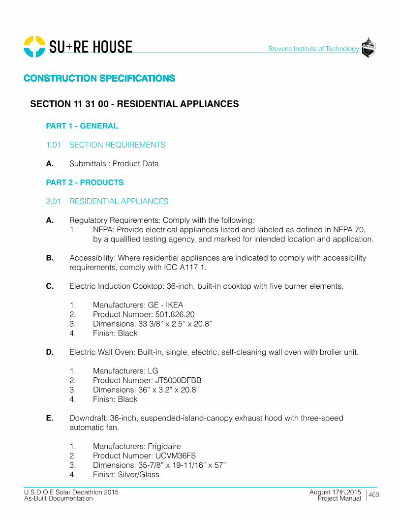
469
Stevens Institute of Technology
August 17th,2015U.S.D.O.E Solar Decathlon 2015As-Built Documentation Project Manual
CONSTRUCTION SPECIFICATIONSCONSTRUCTION SPECIFICATIONSCONSTRUCTION SPECIFICATIONSCONSTRUCTION SPECIFICATIONSCONSTRUCTION SPECIFICATIONS
PART 1 - GENERAL
1.01 SECTION REQUIREMENTS
A. Submittals : Product Data
PART 2 - PRODUCTS
2.01 RESIDENTIAL APPLIANCES
A. Regulatory Requirements: Comply with the following: 1. NFPA: Provide electrical appliances listed and labeled as defined in NFPA 70, by a qualified testing agency, and marked for intended location and application.
B. Accessibility: Where residential appliances are indicated to comply with accessibility requirements, comply with ICC A117.1.
C. Electric Induction Cooktop: 36-inch, built-in cooktop with five burner elements.
1. Manufacturers: GE - IKEA 2. Product Number: 501.826.20 3. Dimensions: 33 3/8” x 2.5” x 20.8” 4. Finish: Black
D. Electric Wall Oven: Built-in, single, electric, self-cleaning wall oven with broiler unit.
1. Manufacturers: LG 2. Product Number: JT5000DFBB 3. Dimensions: 36” x 3.2” x 20.8” 4. Finish: Black
E. Downdraft: 36-inch, suspended-island-canopy exhaust hood with three-speed automatic fan. 1. Manufacturers: Frigidaire 2. Product Number: UCVM36FS 3. Dimensions: 35-7/8” x 19-11/16” x 57” 4. Finish: Silver/Glass
CONSTRUCTION SPECIFICATIONSCONSTRUCTION SPECIFICATIONSCONSTRUCTION SPECIFICATIONSCONSTRUCTION SPECIFICATIONSCONSTRUCTION SPECIFICATIONS
SECTION 11 31 00 - RESIDENTIAL APPLIANCES

470
Stevens Institute of Technology
August 17th,2015U.S.D.O.E Solar Decathlon 2015As-Built Documentation Project Manual
CONSTRUCTION SPECIFICATIONSCONSTRUCTION SPECIFICATIONSCONSTRUCTION SPECIFICATIONSCONSTRUCTION SPECIFICATIONSCONSTRUCTION SPECIFICATIONS
PART 2 - PRODUCTS
2.01 RESIDENTIAL APPLIANCES
F. Refrigerator:Counter-Depth Bottom-Freezer Refrigerator 1. Manufacturers: Liebherr 2. Product Number: HC 1030 / HC 1050B 091014 7086148 3. Dimensions: 78 7/8” x 23 1/2” x 23 7/8” 4. Finish: Stainless Steel
G. Dishwasher: Built-in, under counter, automatic dishwasher, sized to replace 24-inch base cabinet, 7 wash cycles with hot-air and heat-off drying cycles.
1. Manufacturers: Blomberg 2. Product Number: DWT57500FBI 3. Dimensions: 34 1/16’’-36 7/16’’ x 24 ‘’ x 24 ‘’ 4. Finish: Integrated
H. Clothes Washer: Freestanding, Front-loading, automatic clothes washer with 3.6-cu. ft. capacity stainless-steel tub and 9 wash cycles including regular.
1. Manufacturers: LG 2. Product Number: WM4070H_A 3. Color: White 4. Energy Performance: Provide appliances that qualify for the EPA/DOE ENERGY STAR product labeling program.
I. Television: 1080p Smart LED TV 1. Manufacturers: LG 2. Product Number: 719192597044 3. Color: BLACK 4. Energy Performance: Provide appliances that qualify for the EPA/DOE ENERGY STAR product labeling program.
CONSTRUCTION SPECIFICATIONSCONSTRUCTION SPECIFICATIONSCONSTRUCTION SPECIFICATIONSCONSTRUCTION SPECIFICATIONSCONSTRUCTION SPECIFICATIONS
SECTION 11 31 00 - RESIDENTIAL APPLIANCES

471
Stevens Institute of Technology
August 17th,2015U.S.D.O.E Solar Decathlon 2015As-Built Documentation Project Manual
CONSTRUCTION SPECIFICATIONSCONSTRUCTION SPECIFICATIONSCONSTRUCTION SPECIFICATIONSCONSTRUCTION SPECIFICATIONSCONSTRUCTION SPECIFICATIONS
PART 2 - PRODUCTS
2.01 RESIDENTIAL APPLIANCES
J. Dryer 7.3 Cu. Ft. EcoHybrid Heat Pump Front Load Dryer 1. LG 2. Product Number: DLHX4072 3. Dimensions: 27” x 39” x 30” 4. Finish:White
PART 3 - EXECUTION
3.01 INSTALLATION
A. Built-in Appliances: Securely anchor to supporting cabinetry or countertops with concealed fasteners. Verify that clearances are adequate for proper functioning and rough openings are completely concealed.
B. Freestanding Appliances: Place in final locations after finishes have been completed in each area. Verify that clearances are adequate to properly operate equipment.
C. Test each item of residential appliances to verify proper operation. Make necessary adjustments.
D. Verify that accessories required have been furnished and installed.
END OF SECTION 11 31 00
CONSTRUCTION SPECIFICATIONSCONSTRUCTION SPECIFICATIONSCONSTRUCTION SPECIFICATIONSCONSTRUCTION SPECIFICATIONSCONSTRUCTION SPECIFICATIONS
SECTION 11 31 00 - RESIDENTIAL APPLIANCES

472
Stevens Institute of Technology
August 17th,2015U.S.D.O.E Solar Decathlon 2015As-Built Documentation Project Manual
CONSTRUCTION SPECIFICATIONSCONSTRUCTION SPECIFICATIONSCONSTRUCTION SPECIFICATIONSCONSTRUCTION SPECIFICATIONSCONSTRUCTION SPECIFICATIONS
PART 1 - GENERAL
1.01 SECTION REQUIREMENTS
A. Provide manually operated, sunscreen and blackout roller shades as applicable.
1. Division 09 - Gypsum Board Assemblies: Coordination with gypsum board assemblies for blocking, installation of shade pockets, closures and related accessories. 2. Division 09 - Acoustical Ceilings: Coordination with acoustical ceiling systems for blocking, installation of shade pockets, closures and related accessories.
B. Product Data: Manufacturer’s data sheets on each product to be used, including:
1. Preparation instructions and recommendations. 2. Styles, material descriptions, dimensions of individual components, profiles, features, finishes and operating instructions. 3. Storage and handling requirements and recommendations. 4. Mounting details and installation methods.
C. Window Treatment Schedule: For all roller shades. Use same room designations as indicated on the Drawings and include opening sizes and key to typical mounting details.
D. Verification Samples: For each finish product specified, one complete set of shade components, unassembled, demonstrating compliance with specified requirements. Shade cloth samples and aluminum finish sample as selected. Mark face of material to indicate interior faces.
E. Maintenance Data: Methods for maintaining roller shades, precautions regarding cleaning materials and methods, instructions for operating hardware and controls.
F. Warranty: Provide manufacturer’s warranty documents as specified in this Section.
CONSTRUCTION SPECIFICATIONSCONSTRUCTION SPECIFICATIONSCONSTRUCTION SPECIFICATIONSCONSTRUCTION SPECIFICATIONSCONSTRUCTION SPECIFICATIONS
SECTION 12 21 23 - ROLL DOWN BLINDS

473
Stevens Institute of Technology
August 17th,2015U.S.D.O.E Solar Decathlon 2015As-Built Documentation Project Manual
CONSTRUCTION SPECIFICATIONSCONSTRUCTION SPECIFICATIONSCONSTRUCTION SPECIFICATIONSCONSTRUCTION SPECIFICATIONSCONSTRUCTION SPECIFICATIONS
PART 1 - GENERAL
1.02 QUALITY ASSURANCE
A. Manufacturer Qualifications: Obtain roller shades system through one source from a single manufacturer with a minimum of ten years experience and minimum of five projects of similar scope and size in manufacturing products comparable to those specified in this section. This includes but is not limited to all required extrusions, accessories, controls and fabricated roller shades or else all stated and published warranties may be void.
B. Installer Qualifications: Engage an installer, which shall assume responsibility for installation of all system components, with the following qualifications.
1. Installer for roller shade system shall be trained and certified by the manufacturer with a minimum of ten years experience in installing products comparable to those specified in this section.
C. Fire-Test-Response Characteristics: Passes NFPA 701-99 small and large-scale vertical burn. Materials tested shall be identical to products proposed for use.
D. Shadecloth Anti-Microbial Characteristics: ‘No Growth’ per ASTM G 21 results for fungi ATCC9642, ATCC 9644, and ATCC9645.
1.03 DELIVERY, STORAGE, AND HANDLING
A. Deliver components in factory-labeled packages, marked with manufacturer and product name, fire-test-response characteristics, and location of installation using same room designations indicated on Drawings and in the Window Treatment Schedule.
1.04 PROJECT CONDITIONS
A. Environmental Limitations: Install roller shades after finish work including painting is complete and ambient temperature and humidity conditions are maintained at the levels indicated for Project when occupied for its intended use.
CONSTRUCTION SPECIFICATIONSCONSTRUCTION SPECIFICATIONSCONSTRUCTION SPECIFICATIONSCONSTRUCTION SPECIFICATIONSCONSTRUCTION SPECIFICATIONS
SECTION 12 21 23 - ROLL DOWN BLINDS

474
Stevens Institute of Technology
August 17th,2015U.S.D.O.E Solar Decathlon 2015As-Built Documentation Project Manual
CONSTRUCTION SPECIFICATIONSCONSTRUCTION SPECIFICATIONSCONSTRUCTION SPECIFICATIONSCONSTRUCTION SPECIFICATIONSCONSTRUCTION SPECIFICATIONS
PART 1 - GENERAL
1.04 PROJECT CONDITIONS
B. Power and control wiring shall be complete and certified, fully operational with uninterrupted communication on the lines and minimal noise certified by a commissioning agent (engaged by others).
1. 485, ICON, Lonmark and Dry Contract Network: Noise on the line not to exceed shade manufacturer’s limits.
1.5 WARRANTY
A. Warranty: Provide manufacturer’s standard warranties, including the following:
1. Roller Shade Hardware, and Shadecloth: Manufacturer’s standard non- depreciating twenty-five year limited warranty. a. EcoVeil standard non-depreciating 10-year limited warranty.
2. Roller Shade Installation: One year from date of Substantial Completion, not including scaffolding, lifts or other means to access to the work above 12’ Feet AFF, which are the responsibility of others.
PART 2 – PRODUCTS
2.1 MANUFACTURER
A. Hunter Douglas Contract/ 13915 Danielson St., Ste.100/ Poway, CA 92064/ Phone: 800- 727-8953 Fax: 800-205-9819/ Website: www.hunterdouglascontract.com, or architect approved equivalent.
B. Product substitutions must be approved by architect minimum of 30 days prior to close of bid.
CONSTRUCTION SPECIFICATIONSCONSTRUCTION SPECIFICATIONSCONSTRUCTION SPECIFICATIONSCONSTRUCTION SPECIFICATIONSCONSTRUCTION SPECIFICATIONS
SECTION 12 21 23 - ROLL DOWN BLINDS

475
Stevens Institute of Technology
August 17th,2015U.S.D.O.E Solar Decathlon 2015As-Built Documentation Project Manual
CONSTRUCTION SPECIFICATIONSCONSTRUCTION SPECIFICATIONSCONSTRUCTION SPECIFICATIONSCONSTRUCTION SPECIFICATIONSCONSTRUCTION SPECIFICATIONS
2.2 SHADE BANDS
A. Shade Bands: Construction of shade band includes the fabric, the enclosed hem weight, shade roller tube, and the attachment of the shade band to the roller tube. Sewn hems and open hem pockets are not acceptable.
1. Shade Band and Shade Roller Attachment: a. Use extruded aluminum shade roller tube of a diameter and wall thickness required to support shade fabric without excessive deflection. b. Provide for positive mechanical attachment of shade band to roller tube; shade band shall be made removable / replaceable with a “snap-on” snap-off” spline mounting, without having to remove shade roller from shade brackets. c. Mounting Spline shall not require use of adhesives, adhesive tapes, staples, and/or rivets. d. Any method of attaching shade band to roller tube that requires the use of: adhesive, adhesive tapes, staples, and/or rivets, does not meet the performance requirements of this specification and shall not be accepted.
2.03 ROLLER SHADE FABRICATION
A. Fabricate shade cloth to hang flat without buckling or distortion. Fabricate with heat-sealed trimmed edges to hang straight without curling or raveling. Fabricate unguided shadecloth to roll true and straight without shifting sideways more than 1/8 inch (3.18 mm) in either direction per 8 feet (2438 mm) of shade height due to warp distortion or weave design.
B. Provide battens in standard shades as required to assure proper tracking and uniform rolling of the shade bands. Contractor shall be responsible for assuring the width-to-height (W:H) ratios shall not exceed manufacturer’s standards or, in absence of such standards, shall be responsible for establishing appropriate standards to assure proper tracking and rolling of the shadecloth within specified standards. Battens shall be roll-formed stainless steel or tempered steel, as required.
CONSTRUCTION SPECIFICATIONSCONSTRUCTION SPECIFICATIONSCONSTRUCTION SPECIFICATIONSCONSTRUCTION SPECIFICATIONSCONSTRUCTION SPECIFICATIONS
SECTION 12 21 23 - ROLL DOWN BLINDS
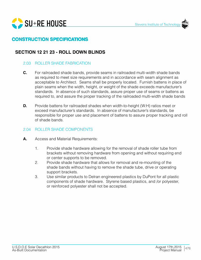
476
Stevens Institute of Technology
August 17th,2015U.S.D.O.E Solar Decathlon 2015As-Built Documentation Project Manual
CONSTRUCTION SPECIFICATIONSCONSTRUCTION SPECIFICATIONSCONSTRUCTION SPECIFICATIONSCONSTRUCTION SPECIFICATIONSCONSTRUCTION SPECIFICATIONS
2.03 ROLLER SHADE FABRICATION
C. For railroaded shade bands, provide seams in railroaded multi-width shade bands as required to meet size requirements and in accordance with seam alignment as acceptable to Architect. Seams shall be properly located. Furnish battens in place of plain seams when the width, height, or weight of the shade exceeds manufacturer’s standards. In absence of such standards, assure proper use of seams or battens as required to, and assure the proper tracking of the railroaded multi-width shade bands
D. Provide battens for railroaded shades when width-to-height (W:H) ratios meet or exceed manufacturer’s standards. In absence of manufacturer’s standards, be responsible for proper use and placement of battens to assure proper tracking and roll of shade bands.
2.04 ROLLER SHADE COMPONENTS
A. Access and Material Requirements:
1. Provide shade hardware allowing for the removal of shade roller tube from brackets without removing hardware from opening and without requiring end or center supports to be removed. 2. Provide shade hardware that allows for removal and re-mounting of the shade bands without having to remove the shade tube, drive or operating support brackets. 3. Use similar products to Delran engineered plastics by DuPont for all plastic components of shade hardware. Styrene based plastics, and /or polyester, or reinforced polyester shall not be accepted.
CONSTRUCTION SPECIFICATIONSCONSTRUCTION SPECIFICATIONSCONSTRUCTION SPECIFICATIONSCONSTRUCTION SPECIFICATIONSCONSTRUCTION SPECIFICATIONS
SECTION 12 21 23 - ROLL DOWN BLINDS

477
Stevens Institute of Technology
August 17th,2015U.S.D.O.E Solar Decathlon 2015As-Built Documentation Project Manual
CONSTRUCTION SPECIFICATIONSCONSTRUCTION SPECIFICATIONSCONSTRUCTION SPECIFICATIONSCONSTRUCTION SPECIFICATIONSCONSTRUCTION SPECIFICATIONS
2.04 ROLLER SHADE COMPONENTS
B. Manual Operated Chain Drive Hardware and Brackets:
1. Provide for universal, regular and offset drive capacity, allowing drive chain to fall at front, rear or non-offset for all shade drive end brackets. Universal offset shall be adjustable for future change. 2. Provide hardware capable for installation of a removable fascia, for both regular and/or reverse roll, which shall be installed without exposed fastening devices of any kind. 3. Provide shade hardware system that allows for removable regular and/or reverse roll fascias to be mounted continuously across two or more shade bands without requiring exposed fasteners of any kind. 4. Provide shade hardware system that allows for operation of multiple shade bands (multi-banded shades) by a single chain operator, subject to manufacturer’s design criteria. Connectors shall be offset to assure alignment from the first to the last shade band. 5. Provide shade hardware system that allows multi-banded manually operated shades to be capable of smooth operation when the axis is offset a maximum of 6 degrees on each side of the plane perpendicular to the radial line of the curve, for a 12 degrees total offset. 6. Provide positive mechanical engagement of drive mechanism to shade roller tube. Friction fit connectors for drive mechanism connection to shade roller tube are not acceptable. 7. Provide shade hardware constructed of minimum 1/8-inch (3.18 mm) thick plated steel or heavier as required to support 150 percent of the full weight of each shade.
2.05 FABRICS
1. FABRICS: Inherently anti-static, flame retardant, fade and stain resistant, light filtering, room darkening, & blackout fabrics providing 0% - 15% openness factors. Fabric weights to range between 6.00 oz/sq.yd. – 20.70 oz/sq.yd. containing fiberglass, PVC, polyester, acrylic, vinyl laminates, cotton, & vinyl coatings. Finish selected by architect from manufacturer’s available contract colors.
CONSTRUCTION SPECIFICATIONSCONSTRUCTION SPECIFICATIONSCONSTRUCTION SPECIFICATIONSCONSTRUCTION SPECIFICATIONSCONSTRUCTION SPECIFICATIONS
SECTION 12 21 23 - ROLL DOWN BLINDS

478
Stevens Institute of Technology
August 17th,2015U.S.D.O.E Solar Decathlon 2015As-Built Documentation Project Manual
CONSTRUCTION SPECIFICATIONSCONSTRUCTION SPECIFICATIONSCONSTRUCTION SPECIFICATIONSCONSTRUCTION SPECIFICATIONSCONSTRUCTION SPECIFICATIONS
2.06 ROLLER SHADE ACCESSORIES
A. Shade Pocket: For recessed mounting in acoustical tile or drywall ceilings as indicated on the drawings.
1. Either extruded aluminum and or formed steel shade pocket, sized to accommodate roller shades, with exposed extruded aluminum closure mount, tile support and removable closure panel to provide access to shades.
PART 3 – EXECUTION
3.01 EXAMINATION
A. Do not begin installation until substrates have been properly prepared. If substrate preparation is the responsibility of another installer, notify Architect of unsatisfactory preparation before proceeding.
3.02 PREPARATION
A. Clean surfaces thoroughly prior to installation. Prepare surfaces using the methods recommended by the manufacturer for achieving the best result for the substrate under the project conditions.
3.02 PREPARATION
A. Contractor Furnish and Install Responsibilities:
1. Window Covering Contractor (WC) shall provide an on site, Project Manager, and shall be present for all related jobsite scheduling meetings. 2. WC shall supervise the roller shade installation.
CONSTRUCTION SPECIFICATIONSCONSTRUCTION SPECIFICATIONSCONSTRUCTION SPECIFICATIONSCONSTRUCTION SPECIFICATIONSCONSTRUCTION SPECIFICATIONS
SECTION 12 21 23 - ROLL DOWN BLINDS

479
Stevens Institute of Technology
August 17th,2015U.S.D.O.E Solar Decathlon 2015As-Built Documentation Project Manual
CONSTRUCTION SPECIFICATIONSCONSTRUCTION SPECIFICATIONSCONSTRUCTION SPECIFICATIONSCONSTRUCTION SPECIFICATIONSCONSTRUCTION SPECIFICATIONS
3.02 PREPARATION
A. Contractor Furnish and Install Responsibilities:
3. WC shall be responsible for field inspection on an area-by- area and floor-by- floor basis during construction to confirm proper mounting conditions per approved shop drawings. 4. Verification of Conditions: examine the areas to receive the work and the conditions under which the work would be performed and notify General Contractor and Owner of conditions detrimental to the proper and timely completion of the work. Do not proceed until unsatisfactory conditions have been corrected. Commencement of installation shall constitute acceptance of substrate conditions by the installer. 5. WC shall provide accurate to 0.0625 inch (1.5875mm); field measurements for custom shade fabrication on the Roller Shades manufacturers input forms. 6. WC Installer shall install roller shades level, plumb, square, and true according to manufacturer’s written instructions, and as specified here in. Blocking for roller shades installed under the contract of the interior General Contractor shall be installed plumb, level, and fitted to window mullion as per interior architect’s de sign documents and in accordance with industry standard tolerances. The horizontal surface of the shade pocket shall not be out-of-level more than 0.625 inch (15.875mm) over 20 linear feet (6.096 meters) 7. Shades shall be located so the shade band is not closer than 2 inches (50 mm) to the interior face of the glass. Allow proper clearances for window operation hardware. 8. Adjust, align and balance roller shades to operate smoothly, easily, safely, and free from binding or malfunction throughout entire operational range. 9. Installer shall set Upper, Lower and up to 3 intermediate stop positions of all motorized shade bands, and assure alignment in accordance with the above requirements. 10. WC shall certify the operation of all motorized shades and turn over each floor for preliminary acceptance. 11. Clean roller shade surfaces after installation, according to manufacturer’s written instructions. 12. WC shall train Owner’s maintenance personnel to adjust, operate and maintain roller shade systems. 13. Protect installed products until completion of project. 14. Touch-up, repair or replace damaged products before Substantial Completion.
CONSTRUCTION SPECIFICATIONSCONSTRUCTION SPECIFICATIONSCONSTRUCTION SPECIFICATIONSCONSTRUCTION SPECIFICATIONSCONSTRUCTION SPECIFICATIONS
SECTION 12 21 23 - ROLL DOWN BLINDS
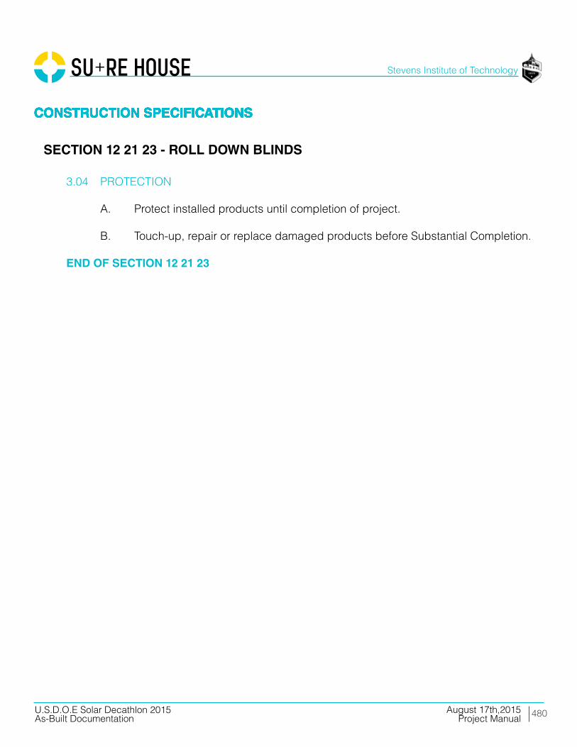
480
Stevens Institute of Technology
August 17th,2015U.S.D.O.E Solar Decathlon 2015As-Built Documentation Project Manual
CONSTRUCTION SPECIFICATIONSCONSTRUCTION SPECIFICATIONSCONSTRUCTION SPECIFICATIONSCONSTRUCTION SPECIFICATIONSCONSTRUCTION SPECIFICATIONS
3.04 PROTECTION
A. Protect installed products until completion of project.
B. Touch-up, repair or replace damaged products before Substantial Completion.
END OF SECTION 12 21 23
CONSTRUCTION SPECIFICATIONSCONSTRUCTION SPECIFICATIONSCONSTRUCTION SPECIFICATIONSCONSTRUCTION SPECIFICATIONSCONSTRUCTION SPECIFICATIONS
SECTION 12 21 23 - ROLL DOWN BLINDS
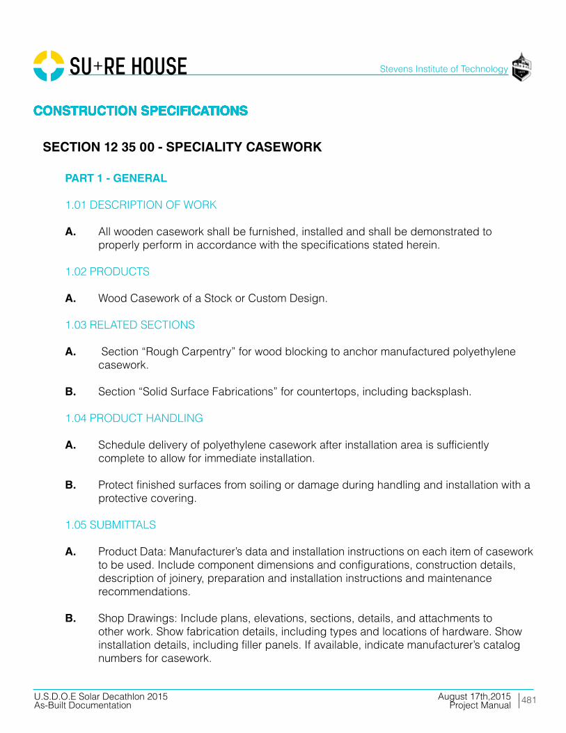
481
Stevens Institute of Technology
August 17th,2015U.S.D.O.E Solar Decathlon 2015As-Built Documentation Project Manual
CONSTRUCTION SPECIFICATIONSCONSTRUCTION SPECIFICATIONSCONSTRUCTION SPECIFICATIONSCONSTRUCTION SPECIFICATIONSCONSTRUCTION SPECIFICATIONS
PART 1 - GENERAL
1.01 DESCRIPTION OF WORK
A. All wooden casework shall be furnished, installed and shall be demonstrated to properly perform in accordance with the specifications stated herein.
1.02 PRODUCTS
A. Wood Casework of a Stock or Custom Design.
1.03 RELATED SECTIONS
A. Section “Rough Carpentry” for wood blocking to anchor manufactured polyethylene casework.
B. Section “Solid Surface Fabrications” for countertops, including backsplash.
1.04 PRODUCT HANDLING
A. Schedule delivery of polyethylene casework after installation area is sufficiently complete to allow for immediate installation.
B. Protect finished surfaces from soiling or damage during handling and installation with a protective covering.
1.05 SUBMITTALS
A. Product Data: Manufacturer’s data and installation instructions on each item of casework to be used. Include component dimensions and configurations, construction details, description of joinery, preparation and installation instructions and maintenance recommendations.
B. Shop Drawings: Include plans, elevations, sections, details, and attachments to other work. Show fabrication details, including types and locations of hardware. Show installation details, including filler panels. If available, indicate manufacturer’s catalog numbers for casework.
CONSTRUCTION SPECIFICATIONSCONSTRUCTION SPECIFICATIONSCONSTRUCTION SPECIFICATIONSCONSTRUCTION SPECIFICATIONSCONSTRUCTION SPECIFICATIONS
SECTION 12 35 00 - SPECIALITY CASEWORK
482
Stevens Institute of Technology
August 17th,2015U.S.D.O.E Solar Decathlon 2015As-Built Documentation Project Manual
CONSTRUCTION SPECIFICATIONSCONSTRUCTION SPECIFICATIONSCONSTRUCTION SPECIFICATIONSCONSTRUCTION SPECIFICATIONSCONSTRUCTION SPECIFICATIONS
PART 1 - GENERAL
1.05 SUBMITTALS
A. Samples: Submit samples of wood variation material and the full range of colors available.
1.06 REFERENCES
A. Comply with all applicable trade standards, ordinances, building codes and regulations and those standards and references listed (where applicable).
B. Approval for Food-Safe Contact from the Food and Drug Administration (FDA).
C. Meet or exceed standards established by American Nat’l Stand. Institute/Business & Institutional Furniture Mfr. Assoc. (ANSI/BIFMA) for casework, X5.9-2004 – Storage Units.
D. Adjustable to ADA Height Requirements of 33-1/2”.
1.07 WARRANTY
A. Casework and hardware shall be warrantied for a period three (3) years, from the date of delivery by Manufacturer, and shall cover only defects in material and/or workmanship.
B. Defects reported to Manufacturer in writing prior to the expiration of the warranty period shall be repaired or replaced at Manufacturer’s option.
PART 2 - PRODUCTS
2.01 MANUFACTURERS
A. All wooden casework shall be the product of one manufacturer and shall be fabricated at one geographic location to ensure product consistency, shipping continuity, and single-source responsibility.
CONSTRUCTION SPECIFICATIONSCONSTRUCTION SPECIFICATIONSCONSTRUCTION SPECIFICATIONSCONSTRUCTION SPECIFICATIONSCONSTRUCTION SPECIFICATIONS
SECTION 12 35 00 - SPECIALITY CASEWORK

483
Stevens Institute of Technology
August 17th,2015U.S.D.O.E Solar Decathlon 2015As-Built Documentation Project Manual
CONSTRUCTION SPECIFICATIONSCONSTRUCTION SPECIFICATIONSCONSTRUCTION SPECIFICATIONSCONSTRUCTION SPECIFICATIONSCONSTRUCTION SPECIFICATIONS
PART 2 - PRODUCTS
2.01 MANUFACTURERS
B. Products of other polyethylene casework manufacturers may be used as an approved equal provided they meet the product characteristics specified herein. No known equal exists.
2.02 MATERIALS, GENERAL
A. Materials:
1. Casework.
a. Casework bodies, drawer heads, drawer bodies, drawer guides, shelves, and door assemblies shall be fabricated from Baltic Birch Plywood. b. Stais shall be chosen by the Architect from the full range of standard colors available from the manufacturer. c. Door and drawer styles shall be chosen by the Architect from the full range of standard door and drawer styles available from the manufacturer.
2. Casework Hardware
a. Doors shall be equipped with 304 stainless steel 110 degree self- closing hinges securely fastened to doors and casework with stainless steel screws. b. Door and drawer pulls shall be made of stainless steel, securely fastened to doors and drawers with screws (if applicable). c. Casework and extendible elements may contain stainless steel screws and or nails for non-support purposes. d. Casework shall be equipped with plastic cabinet legs adjustable from 3 3/4” to 5 ¾” with a load capacity of not less than 250 pounds per leg. e. Shelving height shall be adjustable, but shelf pins shall secure the shelf in place using corrosive resistant pins.
CONSTRUCTION SPECIFICATIONSCONSTRUCTION SPECIFICATIONSCONSTRUCTION SPECIFICATIONSCONSTRUCTION SPECIFICATIONSCONSTRUCTION SPECIFICATIONS
SECTION 12 35 00 - SPECIALITY CASEWORK

484
Stevens Institute of Technology
August 17th,2015U.S.D.O.E Solar Decathlon 2015As-Built Documentation Project Manual
CONSTRUCTION SPECIFICATIONSCONSTRUCTION SPECIFICATIONSCONSTRUCTION SPECIFICATIONSCONSTRUCTION SPECIFICATIONSCONSTRUCTION SPECIFICATIONS
PART 2 - PRODUCTS
2.03 CASEWORK FABRICATION
A. Casework shall be constructed using FINISHED BIRCH PLYWOOD sheets with the following thicknesses:
1. Side panels shall be cut from ¾” solid FINISHED BIRCH PLYWOOD. 2. Floor panel shall be cut from ¾” solid FINISHED BIRCH PLYWOOD. 3. Back panel shall be cut from ½” solid FINISHED BIRCH PLYWOOD. 4. Drawer face shall be cut from ¾” solid FINISHED BIRCH PLYWOOD. 5. Drawer box sides shall be cut from ½” solid FINISHED BIRCH PLYWOOD. 6. Door panels shall be cut from ¾” solid FINISHED BIRCH PLYWOOD. 7. Shelves shall be cut from ¾” solid FINISHED BIRCH PLYWOOD. 8. Top spreaders shall be constructed of ¾” FINISHED BIRCH PLYWOOD. 9. Drawer guides shall be constructed of ½” solid FINISHED BIRCH PLYWOOD.
B. Casework Assembly: Shall be cut and assembled without any supporting metal or hardware.
1. Adjustable shelves shall have a mechanism for securing the shelves from moving, using non-metal corrosive-resistant pins. 2. Drawer faces shall be attached to the face of a drawer box to provide for additional strength to the drawer. 3. Drawer slides shall be made from a non-metal corrosive resistant material. 4. Door panels shall be attached to side panels using not less than three (3) 304 stainless steel 110 degree self-closing hinges. 5. Top spreaders shall be designed to enable use of a countertop adhesive to adhere the countertop to the casework. 6. Casework adjustable leg bases shall be attached from the underside of the bottom panels using four (4) stainless steel screws.
CONSTRUCTION SPECIFICATIONSCONSTRUCTION SPECIFICATIONSCONSTRUCTION SPECIFICATIONSCONSTRUCTION SPECIFICATIONSCONSTRUCTION SPECIFICATIONS
SECTION 12 35 00 - SPECIALITY CASEWORK

485
Stevens Institute of Technology
August 17th,2015U.S.D.O.E Solar Decathlon 2015As-Built Documentation Project Manual
CONSTRUCTION SPECIFICATIONSCONSTRUCTION SPECIFICATIONSCONSTRUCTION SPECIFICATIONSCONSTRUCTION SPECIFICATIONSCONSTRUCTION SPECIFICATIONS
PART 2 - PRODUCTS
2.03 CASEWORK FABRICATION
C. Performance Requirements: All casework shall meet the following MINIMUM standards:
1. Casework body shall be waterproof; 2. Casework shall be UV stabilized for direct sun exposure; 3. Casework shall be manufactured from solid color material; 4. Casework shall be FDA approved for food-safe contact; 5. Casework material shall be rated as not less than a Class C under ASTM E-84
PART 3 - EXECUTION
3.01 INSTALLATION
A. Do not begin installation until substrates have been properly prepared.
B. If substrate preparation is the responsibility of another installer, notify Architect of unsatisfactory preparation before proceeding.
3.02 COORDINATION
A. Coordination with appropriate contractors, who shall furnish plumbing and electrical services which shall be passing through the casework.
3.03 INSTALLATION OF CASEWORK
A. All exterior surface protective covering shall be left in place and removed only when the casework is ready for installation and only on surfaces that will be concealed during installation.
B. Set casework components plumb, square, and straight with no distortion. Adjust leveling legs as needed. Where casework abuts other finished work, apply filler panels and scribe for accurate fit with fasteners concealed where practical.
END OF SECTION 12 35 00
CONSTRUCTION SPECIFICATIONSCONSTRUCTION SPECIFICATIONSCONSTRUCTION SPECIFICATIONSCONSTRUCTION SPECIFICATIONSCONSTRUCTION SPECIFICATIONS
SECTION 12 35 00 - SPECIALITY CASEWORK

486
Stevens Institute of Technology
August 17th,2015U.S.D.O.E Solar Decathlon 2015As-Built Documentation Project Manual
CONSTRUCTION SPECIFICATIONSCONSTRUCTION SPECIFICATIONSCONSTRUCTION SPECIFICATIONSCONSTRUCTION SPECIFICATIONSCONSTRUCTION SPECIFICATIONS
PART 1 - GENERAL
1.01 SUMMARY
A. Section Includes:
1. Acrylic agglomerate countertops.
1.02 SUBMITTALS
A. Product Data: For countertop materials.
B. Shop Drawings: For countertops. Show materials, finishes, edge and backsplash profiles, methods of joining, and cutouts for plumbing fixtures.
1.03 WARRANTY
A. Special Warranty: Manufacturer’s standard form in which manufacturer agrees to repair or replace simulated stone countertops that fail in materials or workmanship within specified warranty period.
1. Warranty shall also include installation and finishing that may be required due to repair or replacement of defective simulated stone countertops. 2. Warranty Period: 10 years from date of Substantial Completion.
PART 2 - PRODUCTS
2.01 ACRYLIC AGGLOMERATE COUNTERTOPS
A. Configuration: Provide countertops with the following front and backsplash style:
1. Front: Straight, slightly eased at top. 2. Backsplash: Straight, slightly eased at corner, Custom CNC Pattern
B. Countertops: 1/2-inch- (12.7-mm-) thick, LG Hi-Macs with front edge built up with same material.
CONSTRUCTION SPECIFICATIONSCONSTRUCTION SPECIFICATIONSCONSTRUCTION SPECIFICATIONSCONSTRUCTION SPECIFICATIONSCONSTRUCTION SPECIFICATIONS
SECTION 12 36 61 - SIMULATED STONE COUNTERTOPS

487
Stevens Institute of Technology
August 17th,2015U.S.D.O.E Solar Decathlon 2015As-Built Documentation Project Manual
CONSTRUCTION SPECIFICATIONSCONSTRUCTION SPECIFICATIONSCONSTRUCTION SPECIFICATIONSCONSTRUCTION SPECIFICATIONSCONSTRUCTION SPECIFICATIONS
PART 2 - PRODUCTS
2.01 QUARTZ AGGLOMERATE COUNTERTOPS
C. Backsplashes: 1/2-inch- (12.7-mm-) thick, quartz agglomerate.
D. Fabrication: Fabricate tops in one piece with shop-applied edges and backsplashes unless otherwise indicated. Comply with quartz agglomerate manufacturer’s written instructions for adhesives, sealers, fabrication, and finishing.
E. Fabricate countertops without joints.
2.02 COUNTERTOP MATERIALS
A. Certified Wood Materials: Fabricate countertops with wood and wood-based products produced from wood obtained from forests certified by an FSC-accredited certification body to comply with FSC STD-01-001, “FSC Principles and Criteria for Forest Stewardship.”
B. Adhesives: Adhesives shall contain no added urea formaldehyde.
1. Stone Adhesive: Manufacturer’s recommended adhesive, formulated specifically for bonding simulated stone to simulated stone with a VOC content of 65 g/L or less.
C. Quartz Agglomerate: Solid sheets consisting of quartz aggregates bound together with a matrix of filled plastic resin and complying with the “Physical Characteristics of Materials” Article of ANSI SS1.
1. Manufacturers: Subject to compliance with requirements, provide products by one of the following : a. LG Hi Macs b. Dupont Corian
2. Color : Arctic White
CONSTRUCTION SPECIFICATIONSCONSTRUCTION SPECIFICATIONSCONSTRUCTION SPECIFICATIONSCONSTRUCTION SPECIFICATIONSCONSTRUCTION SPECIFICATIONS
SECTION 12 36 61 - SIMULATED STONE COUNTERTOPS

488
Stevens Institute of Technology
August 17th,2015U.S.D.O.E Solar Decathlon 2015As-Built Documentation Project Manual
CONSTRUCTION SPECIFICATIONSCONSTRUCTION SPECIFICATIONSCONSTRUCTION SPECIFICATIONSCONSTRUCTION SPECIFICATIONSCONSTRUCTION SPECIFICATIONS
PART 3 - EXECUTION
3.01 PREPARATION
A. Clean surfaces to receive countertops; remove loose and foreign matter that could interfere with adhesion.
3.02 INSTALLATION
A. Install countertops in accordance with manufacturer’s written instructions and approved Shop Drawings.
B. Install countertops level to a tolerance of 1/8 inch in 8 feet (3 mm in 2.4 m) , and with a maximum variation in plane between adjacent pieces at joint of plus or minus 1/16 inch.
C. For quartz agglomerate countertops, fasten by applying continuous bead of adhesive along all base cabinet surfaces, or if underlayment is used, apply continuous bead of adhesive along perimeter and around openings. Align adjacent surfaces and, using adhesive in color to match countertop, form seams to comply with manufacturer’s recommended written instructions. Carefully dress joints smooth; remove excess adhesive and sealant, and clean entire surface.
1. Bond joints with stone adhesive and draw tight as countertops are set. Mask areas of countertops adjacent to joints to prevent adhesive smears. a. Fill joints with stone adhesive level with quartz surfacing. b. Clamp or brace quartz-agglomerate surfacing in position until adhesive sets.
2. Install backsplashes to comply with manufacturer’s written instructions for adhesives, sealers, fabrication, and finishing.
END OF SECTION 12 36 61
CONSTRUCTION SPECIFICATIONSCONSTRUCTION SPECIFICATIONSCONSTRUCTION SPECIFICATIONSCONSTRUCTION SPECIFICATIONSCONSTRUCTION SPECIFICATIONS
SECTION 12 36 61 - SIMULATED STONE COUNTERTOPS

489
Stevens Institute of Technology
August 17th,2015U.S.D.O.E Solar Decathlon 2015As-Built Documentation Project Manual
CONSTRUCTION SPECIFICATIONSCONSTRUCTION SPECIFICATIONSCONSTRUCTION SPECIFICATIONSCONSTRUCTION SPECIFICATIONSCONSTRUCTION SPECIFICATIONS
PART 1 - GENERAL
1.01 SECTION REQUIREMENTS
A. Submittals: Product Data for valves, sprinklers, specialties, and alarms. 1. Submit sprinkler system drawings identified as “working plans” and calculations according to NFPA 13. Submit required number of sets to authorities having jurisdiction for review, comment, and approval. Include system hydraulic calculations. 2. Submit test reports and certificates as described in NFPA 13.
B. Design and Installation Approval: Acceptable to authorities having jurisdiction.
C. Hydraulically design sprinkler systems according to NFPA 13.
D. Comply with NFPA 13D and NFPA 70, and IRC 2009 Section P2904. E. UL listed and labeled and FM-approved pipe and fittings.
E. Verify dimensions in field measurements before fabrication & indicate on shop drawings. SEE “DIVISION 21 FIRE SUPPRESSION CUTSHEETS” for additional specifications.
PART 2 - PRODUCTS
2.01 PIPE AND FITTINGS
A. CPVC Plastic Pipe: ASTM F 442/F 442M, UL 1821, 175-psig rating, made in NPS for sprinkler service. Include “Listed” and “CPVC Sprinkler Pipe” marks on pipe.
B. CPVC Plastic Pipe Fittings: ASTM F 438 for NPS 3/4 to NPS 1-1/2 and ASTM F 439 for NPS 2, UL listed, 175-psig rating, for sprinkler service. Include “Listed” and “CPVC Sprinkler Fitting” marks on fittings.
C. Black steel piping shall be provided in all exposed areas.
D. Provide hangers, supports, and seismic restraints with UL listing and FM approval for fire-protection systems.
CONSTRUCTION SPECIFICATIONSCONSTRUCTION SPECIFICATIONSCONSTRUCTION SPECIFICATIONSCONSTRUCTION SPECIFICATIONSCONSTRUCTION SPECIFICATIONS
SECTION 21 13 13 - WET PIPE SPRINKLER SYSTEM

490
Stevens Institute of Technology
August 17th,2015U.S.D.O.E Solar Decathlon 2015As-Built Documentation Project Manual
CONSTRUCTION SPECIFICATIONSCONSTRUCTION SPECIFICATIONSCONSTRUCTION SPECIFICATIONSCONSTRUCTION SPECIFICATIONSCONSTRUCTION SPECIFICATIONS
PART 2 - PRODUCTS
2.02 VALVES
A. Fire-Protection Service Valves: UL listed and FM approved, with 175-psig non-shock minimum working-pressure rating. Indicating valves shall be butterfly or ball type, bronze body, and integral indicat ing device wi th 115-V ac, elect r ic, singlecircuit supervisory switch indicator.
B. SEE “DIVISION 21 FIRE SUPPRESSION CUTSHEETS” for additional specifications.
2.03 SPRINKLERS
A. Automatic Sprinklers: With heat-responsive element complying with the following:
1. UL 1626, for residential applications.
B. Sprinkler Types and Categories: Nominal 1/2-inch orifice for “Ordinary” temperature classification rating unless otherwise indicated or required by application.
C. Sprinkler types include the following:
1. Pendent Sprinkler: RELIABLE Model F1 Res Sprinklers : Chrome Pendant 2. Pendent Sprinkler: RELIABLE Model RFC30 (SIN RA0611) 3. Pendent Sprinkler: RELIABLE Model F1 Res Sprinklers : White Concealed
D. Sprinkler Escutcheons: steel, one piece, with finish to match sprinklers.
E. Sprinklers shall be low flow residential hidden pendent sprinklers engineered to provide a minimum design density of 0.05 gpm/ft2 over the listed coverage area.
F. Sprinkler frame and deflector shall be of bronze frame construction having a ½” NPT thread.
G. Water seal assembly shall consist of a Teflon-coated Belleville spring washer with top- loaded extruded or cold head cup with 3 mm glass bulb containing no plastic parts, and having a temperature rating of 155°F, 165°F or 175°F.
CONSTRUCTION SPECIFICATIONSCONSTRUCTION SPECIFICATIONSCONSTRUCTION SPECIFICATIONSCONSTRUCTION SPECIFICATIONSCONSTRUCTION SPECIFICATIONS
SECTION 21 13 13 - WET PIPE SPRINKLER SYSTEM

491
Stevens Institute of Technology
August 17th,2015U.S.D.O.E Solar Decathlon 2015As-Built Documentation Project Manual
CONSTRUCTION SPECIFICATIONSCONSTRUCTION SPECIFICATIONSCONSTRUCTION SPECIFICATIONSCONSTRUCTION SPECIFICATIONSCONSTRUCTION SPECIFICATIONS
PART 3 - EXECUTION
3.01 INSTALLATION
A. Fasten securely in place, with provisions for thermal and structural movement. Install with concealed fasteners, unless otherwise indicated.
B. Correct deficiencies in or remove and reinstall sprinkler that does not comply with requirements.
C. Repair, refinish, or replace sprinklers damaged during installation, as directed by Architect.
D. Adjust operating parts and hardware for smooth, quiet operation and weather tight closure. Lubricate hardware and moving parts.
3.02 PIPE AND FITTING APPLICATION
A. Use steel pipe with threaded, press-seal, roll-grooved, or cut-grooved joints; copper tube with wrought-copper fittings and brazed joints; or CPVC plastic pipe and fittings and metal-to-plastic transition fittings with solvent-cemented joints.
B. SEE “DIVISION 21 FIRE SUPPRESSION CUTSHEETS” for additional specifications.
3.03 PIPING INSTALLATION
A. Install “Inspector’s Test Connections” in sprinkler piping, complete with shutoff valve.
3.04 TESTING
A. Flush, test, and inspect sprinkler piping systems according to NFPA 13.
END OF SECTION 21 13 13
CONSTRUCTION SPECIFICATIONSCONSTRUCTION SPECIFICATIONSCONSTRUCTION SPECIFICATIONSCONSTRUCTION SPECIFICATIONSCONSTRUCTION SPECIFICATIONS
SECTION 21 13 13 - WET PIPE SPRINKLER SYSTEM

492
Stevens Institute of Technology
August 17th,2015U.S.D.O.E Solar Decathlon 2015As-Built Documentation Project Manual
CONSTRUCTION SPECIFICATIONSCONSTRUCTION SPECIFICATIONSCONSTRUCTION SPECIFICATIONSCONSTRUCTION SPECIFICATIONSCONSTRUCTION SPECIFICATIONS
PART 1 - GENERAL
1.01 SECTION REQUIREMENTS
A. Comply with NSF 14 for plastic, potable domestic water piping and components.
B. Comply with NSF 61 for potable domestic water piping and components.
PART 2 - PRODUCTS
2.01 PIPE AND FITTINGS
A. Hard Copper Tubing: ASTM B 88, Type L (ASTM B 88M, Types B and C), water tube, drawn temper with wrought-copper, solder-joint fittings and pro-press fittings.
1. Copper Unions: Cast-copper-alloy, hexagonal-stock body, with ball-and-socket, metal-to-metal seating surfaces and solder-joint ends. 2. Joining Materials: Use ASTM B 813, water-flushable, lead-free flux; ASTM B 32, lead-free-alloy solder.B. Watts
1. PEX tubing: ½” type A: Part #: WPTC08 (red) and WPTC08 (blue) 2. PEX tubing: ¾” type A: Part #: WPTC12 3. PEX tubing: ¾” type A: Part #: WPTC12
C. Uponor
1. PEX tubing: 1” type A: Part #: F3061000
D. PVC Pipe: ASTM D 1785, Schedule 40.
1. PVC Fittings: 1 1 / 2 ” , ASTM D 2466, Schedule 40, socket type 2. PVC Fittings: 1 1 / 4 ” , ASTM D 2466, Schedule 40, socket type 3. PVC Fittings: 2 ” , ASTM D 2466, Schedule 40, socket type 4. PVC Fittings: 3 ” , ASTM D 2466, Schedule 40, socket type
E. Transition Fittings: Manufactured piping coupling or specified piping system fitting. Same size as pipes to be joined and pressure rating at least equal to pipes to be joined.
CONSTRUCTION SPECIFICATIONSCONSTRUCTION SPECIFICATIONSCONSTRUCTION SPECIFICATIONSCONSTRUCTION SPECIFICATIONSCONSTRUCTION SPECIFICATIONS
SECTION 22 11 16 - DOMESTIC WATER PIPING

493
Stevens Institute of Technology
August 17th,2015U.S.D.O.E Solar Decathlon 2015As-Built Documentation Project Manual
CONSTRUCTION SPECIFICATIONSCONSTRUCTION SPECIFICATIONSCONSTRUCTION SPECIFICATIONSCONSTRUCTION SPECIFICATIONSCONSTRUCTION SPECIFICATIONS
PART 3 - EXECUTION
3.01 INSTALLATION
A. Comply with requirements in Division 22 Section “Common Work Results for Plumbing” for basic piping installation requirements.
B. Install floor penetration system at each service pipe penetration through foundation floor. Make installation watertight. Comply with requirements in Division 22 Section.
C. “Common Work Results for Plumbing” for wall penetration systems.
D. Install shutoff valve, hose-end drain valve, strainer, pressure gage, and test tee with valve, inside the building at each domestic water service entrance. Comply with requirements in Division 22 Section “Common Work Results for Plumbing” for pressure gages and Division 22 Section “Domestic Water Piping Specialties” for drain valves and strainers.
E. Install domestic water piping without pitch for horizontal piping and plumb for vertical piping.
F. Rough-in domestic water piping for water-meter installation according to utility company’s requirements.
G. Comply with requirements in Division 22 Section “Common Work Results for Plumbing” for basic piping joint construction.
1. Soldered Joints: Comply with procedures in ASTM B 828 unless otherwise indicated.
H. Comply with requirements in Division 22 Section “Common Work Results for Plumbing” for pipe hanger and support devices.
3.02 INSPECTION AND CLEANING
CONSTRUCTION SPECIFICATIONSCONSTRUCTION SPECIFICATIONSCONSTRUCTION SPECIFICATIONSCONSTRUCTION SPECIFICATIONSCONSTRUCTION SPECIFICATIONS
SECTION 22 11 16 - DOMESTIC WATER PIPING
494
Stevens Institute of Technology
August 17th,2015U.S.D.O.E Solar Decathlon 2015As-Built Documentation Project Manual
CONSTRUCTION SPECIFICATIONSCONSTRUCTION SPECIFICATIONSCONSTRUCTION SPECIFICATIONSCONSTRUCTION SPECIFICATIONSCONSTRUCTION SPECIFICATIONS
PART 3 - EXECUTION
3.02 INSPECTION AND CLEANING
A. Inspect and test piping systems as follows:
1. Fill domestic water piping. Check components to determine that they are not air bound and that piping is full of water. 2. Test for leaks and defects in new piping and parts of existing piping that have been altered, extended, or repaired by visual inspection of all joints.
B. Clean and disinfect potable domestic water piping by filling system with water/chlorine solution with at least 50 ppm (50 mg/L) of chlorine. Isolate with valves and allow to stand for 24 hours. Flush system with clean, potable water until no chlorine is in water coming from system after the standing time by flushing out a volume equal to the system volume, then stopping the flow of water for one hour, and then flushing the system.
3.03 PIPING SCHEDULE
A. Aboveground Distribution Piping: PEX piping
B. Mechanical Room Piping: Copper pipe and PEX piping
3.04 VALVE SCHEDULE
A. Drawings indicate valve types to be used.
B. Where specific valve types are not indicated, the following requirements apply:
1. Shutoff Duty: Use bronze ball valve 2. Throttling Duty: Use bronze ball valve 3. Drain Duty: Hose-end drain valves
C. Install ball valves on inlet to each plumbing equipment item, on each supply to each plumbing fixture not having stops on supplies, and elsewhere as indicated.
D. PVC ball, butterfly, and check valves may be used in matching piping materials.
CONSTRUCTION SPECIFICATIONSCONSTRUCTION SPECIFICATIONSCONSTRUCTION SPECIFICATIONSCONSTRUCTION SPECIFICATIONSCONSTRUCTION SPECIFICATIONS
SECTION 22 11 16 - DOMESTIC WATER PIPING

495
Stevens Institute of Technology
August 17th,2015U.S.D.O.E Solar Decathlon 2015As-Built Documentation Project Manual
CONSTRUCTION SPECIFICATIONSCONSTRUCTION SPECIFICATIONSCONSTRUCTION SPECIFICATIONSCONSTRUCTION SPECIFICATIONSCONSTRUCTION SPECIFICATIONS
PART 3 - EXECUTION
3.04 VALVE SCHEDULE
E. Install drain valve at base of each riser, at low points of horizontal runs, and where required to drain water distribution piping system.
F. Install spring check valve on discharge side of each pump and elsewhere as indicated.
G. Install ball valves in each hot-water circulating loop and discharge side of each pump.
END OF SECTION 22 11 16
CONSTRUCTION SPECIFICATIONSCONSTRUCTION SPECIFICATIONSCONSTRUCTION SPECIFICATIONSCONSTRUCTION SPECIFICATIONSCONSTRUCTION SPECIFICATIONS
SECTION 22 11 16 - DOMESTIC WATER PIPING

496
Stevens Institute of Technology
August 17th,2015U.S.D.O.E Solar Decathlon 2015As-Built Documentation Project Manual
CONSTRUCTION SPECIFICATIONSCONSTRUCTION SPECIFICATIONSCONSTRUCTION SPECIFICATIONSCONSTRUCTION SPECIFICATIONSCONSTRUCTION SPECIFICATIONS
PART 1 - GENERAL
1.01 SECTION REQUIREMENTS
A. Submittals: Product Data.
PART 2 - PRODUCTS
2.01 BACKFLOW PREVENTER
A. Watts
1. Brass construction. Temperature Range: -20 degrees F – 100 degrees F. Max pressure: 400 psi. 2.02 BALL VALVES
A. Watts 1. 3/4” and 1” Ball Valve with full-port, Barbed end connectors, Rated to 400WOG, crimped joint rated at 160 psi at 70 degrees F 2.03 WATER CONDITIONER
A. Watts
1. 1” Connections, rated operating pressure 15-1 0 0 ps i PART 3 - EXECUTION
3.01 INSTALLATION
A. Install backflow preventers at each water-supply connection to mechanical equipment and where required by authorities having jurisdiction.
B. Install hose bibs with integral or field-installed vacuum breaker.
END OF SECTION 22 11 19
CONSTRUCTION SPECIFICATIONSCONSTRUCTION SPECIFICATIONSCONSTRUCTION SPECIFICATIONSCONSTRUCTION SPECIFICATIONSCONSTRUCTION SPECIFICATIONS
SECTION 22 11 19 - DOMESTIC WATER PIPING SPECIALTIES
497
Stevens Institute of Technology
August 17th,2015U.S.D.O.E Solar Decathlon 2015As-Built Documentation Project Manual
CONSTRUCTION SPECIFICATIONSCONSTRUCTION SPECIFICATIONSCONSTRUCTION SPECIFICATIONSCONSTRUCTION SPECIFICATIONSCONSTRUCTION SPECIFICATIONS
PART 1 - GENERAL
1.01 SECTION REQUIREMENTS
A. Submittals: Product Data. Include certified performance curves with operating points plotted on curves, operating characteristics, electrical characteristics, and furnished specialties and accessories.
B. Comply with NFPA 70, “National Electrical Code.”
C. Comply with UL 778 for motor-operated water pumps.
PART 2 - PRODUCTS
2.01 MAIN PRESSURIZING DOMESTIC WATER PUMP
A. Use one of the two options listed below:
B. Davey
1. 3/4 Horsepower, 120 Volt 2. Part #: HS18-40HT2
C. Davey
1. 3/4 Horsepower, 120 Volt 2. Part #: BT20-40
2.02 MOTORS
A. NEMA MG 1, “Standard for Motors and Generators.” Include NEMA listing and labeling.
B. Motor Sizes: Minimum size as indicated. If not indicated, large enough so driven load will not require motor to operate in service factor range above 1.0.
C. Controllers, Electrical Devices, and Wiring: Comply with requirements for electrical devices and connections specified in Division 26 Sections.
CONSTRUCTION SPECIFICATIONSCONSTRUCTION SPECIFICATIONSCONSTRUCTION SPECIFICATIONSCONSTRUCTION SPECIFICATIONSCONSTRUCTION SPECIFICATIONS
SECTION 22 11 23 - DOMESTIC WATER PUMP
498
Stevens Institute of Technology
August 17th,2015U.S.D.O.E Solar Decathlon 2015As-Built Documentation Project Manual
CONSTRUCTION SPECIFICATIONSCONSTRUCTION SPECIFICATIONSCONSTRUCTION SPECIFICATIONSCONSTRUCTION SPECIFICATIONSCONSTRUCTION SPECIFICATIONS
PART 2 - PRODUCTS
2.03 CONTROLS
A. Thermostats: Electric; adjustable for control of hot-water circulation pump.
1. Type: Water-immersion temperature sensor, for installation in piping. 2. Settings: Pump turned on and off by remotely
PART 3 - EXECUTION
3.01 INSTALLATION
A. Comply with HI 1.4.
B. Install pumps with access for periodic maintenance, including removal of motors, impellers, couplings, and accessories.
C. Support pumps and piping so weight of piping is not supported by pump volute.
D. Install electrical connections for power, controls, and devices.
E. Connect piping with valves that are same size as piping connecting to pumps.
F. Install suction and discharge pipe sizes equal to or greater than diameter of pump nozzles.
G. Install shutoff valve on suction and discharge side of pumps.
H. Install strainer on suction side of pumps.
I. Install non-slam check valve and throttling valve on discharge side of pumps.
J. Install thermostats in hot-water return piping.
K. Install test plugs on suction and discharge of each pump.
END OF SECTION 22 11 23
CONSTRUCTION SPECIFICATIONSCONSTRUCTION SPECIFICATIONSCONSTRUCTION SPECIFICATIONSCONSTRUCTION SPECIFICATIONSCONSTRUCTION SPECIFICATIONS
SECTION 22 11 23 - DOMESTIC WATER PUMP

499
Stevens Institute of Technology
August 17th,2015U.S.D.O.E Solar Decathlon 2015As-Built Documentation Project Manual
CONSTRUCTION SPECIFICATIONSCONSTRUCTION SPECIFICATIONSCONSTRUCTION SPECIFICATIONSCONSTRUCTION SPECIFICATIONSCONSTRUCTION SPECIFICATIONS
PART 1 - GENERAL
1.01 SECTION REQUIREMENTS
A. Submittals: Product Data.
PART 2 - PRODUCTS
2.01 SUPPLY TANK
A. HUSKY PORTABLE CONTAINMENT - SWT-1 1. Custom collapsable bladder 2. 1,000 gal. capacity 3. Dimension : 8’x8’x2’ 4. Will provide the necessary 250 gallons of water to the fire suppression system.
2.02 WASTE TANK
A. HUSKY PORTABLE CONTAINMENT - WT-1 1. Custom pillow bladder 2. 400 gal. capacity 3. Dimension : 8’x8’x2’
2.03 MOTORS
A. NEMA MG 1, “Standard for Motors and Generators.” Include NEMA listing and labeling.
B. Motor Sizes: Minimum size as indicated. If not indicated, large enough so driven load will not require motor to operate in service factor range above 1.0.
C. Controllers, Electrical Devices, and Wiring: Comply with requirements for electrical devices and connections specified in Division 26 Sections.
CONSTRUCTION SPECIFICATIONSCONSTRUCTION SPECIFICATIONSCONSTRUCTION SPECIFICATIONSCONSTRUCTION SPECIFICATIONSCONSTRUCTION SPECIFICATIONS
SECTION 22 12 19 - FACILITY POTABLE-WATER STORAGE TANKS
CONSTRUCTION SPECIFICATIONS
500
Stevens Institute of Technology
August 17th,2015U.S.D.O.E Solar Decathlon 2015As-Built Documentation Project Manual
CONSTRUCTION SPECIFICATIONSCONSTRUCTION SPECIFICATIONSCONSTRUCTION SPECIFICATIONSCONSTRUCTION SPECIFICATIONSCONSTRUCTION SPECIFICATIONS
PART 3 - EXECUTION
3.01 INSTALLATION
A. Set units level, plumb, and true to line, without warp or rack of frames and panels and anchor securely in place.
B. Fasten securely in place, with provisions for thermal and structural movement. Install with concealed fasteners, unless otherwise indicated.
C. Separate dissimilar metals and metal products from contact with wood or cementitious materials, by painting each metal surface in area of contact with a bituminous coating or by other permanent separation.
D. Correct deficiencies in or remove and reinstall products that do not comply with requirements.
E. Repair, refinish, or replace products damaged during installation, as directed by Architect.
F. Adjust operating parts and hardware for smooth, quiet operation.
END OF SECTION 22 12 19
CONSTRUCTION SPECIFICATIONSCONSTRUCTION SPECIFICATIONSCONSTRUCTION SPECIFICATIONSCONSTRUCTION SPECIFICATIONSCONSTRUCTION SPECIFICATIONS
SECTION 22 12 19 - FACILITY POTABLE-WATER STORAGE TANKS

501
Stevens Institute of Technology
August 17th,2015U.S.D.O.E Solar Decathlon 2015As-Built Documentation Project Manual
CONSTRUCTION SPECIFICATIONSCONSTRUCTION SPECIFICATIONSCONSTRUCTION SPECIFICATIONSCONSTRUCTION SPECIFICATIONSCONSTRUCTION SPECIFICATIONS
PART 1 - GENERAL
1.01 SECTION REQUIREMENTS
A. Minimum Pressure Requirement for Soil, Waste, and Vent: 10-foot head of water (30 kPa).
B. Comply with NSF 14, “Plastic Piping Components and Related Materials,” for plastic piping components.
PART 2 - PRODUCTS
2.01 PIPES AND FITTINGS
A. PVC Pipe
1. 2” pipe, ASTM D 1785, Schedule 40. 2. 1-1/2” pipe, ASTM D 1785, Schedule 40. 3. 3” pipe, ASTM D 1785, Schedule 40.
B. ASTM D 2466, Schedule 40, socket type and npt.
PART 3 - EXECUTION
3.01 PIPING INSTALLATION
A. Install wall penetration system at each pipe penetration through foundation wall. Make installation watertight.
B. Make changes in direction for soil and waste drainage and vent piping using appropriate branches, bends, and long-sweep bends. Sanitary tees and short-sweep 1/4 bends may be used on vertical stacks if change in direction of flow is from horizontal to vertical. Use long-turn, double Y-branch and 1/8-bend fittings if 2 fixtures are installed back to back or side by side with common drain pipe. Straight tees, elbows, and crosses may be used on vent lines. Do not change direction of flow more than 90 degrees. Use proper size of standard increasers and reducers if pipes of different sizes are connected. Reducing size of drainage piping in direction of flow is prohibited.
CONSTRUCTION SPECIFICATIONSCONSTRUCTION SPECIFICATIONSCONSTRUCTION SPECIFICATIONSCONSTRUCTION SPECIFICATIONSCONSTRUCTION SPECIFICATIONS
SECTION 22 13 16 - SANITARY WASTE AND VENT PIPING

502
Stevens Institute of Technology
August 17th,2015U.S.D.O.E Solar Decathlon 2015As-Built Documentation Project Manual
CONSTRUCTION SPECIFICATIONSCONSTRUCTION SPECIFICATIONSCONSTRUCTION SPECIFICATIONSCONSTRUCTION SPECIFICATIONSCONSTRUCTION SPECIFICATIONS
PART 3 - EXECUTION
3.01 PIPING INSTALLATION
C. Install soil and waste drainage and vent piping at the following minimum slopes, unless otherwise indicated:
1. Building Sanitary Drain: 2 percent downward in direction of flow for piping NPS 3 (DN 80) and smaller; 1 percent downward in direction of flow for piping NPS 4 (DN 100) and larger. 2. Horizontal Sanitary Drainage Piping: 2 percent downward in direction of flow. 3. Vent Piping: 1 percent down toward vertical fixture vent or toward vent stack.
D. Install PVC soil and waste drainage and vent piping according to ASTM D 2665.
E. Do not enclose, cover, or put piping into operation until it is inspected and approved by authorities having jurisdiction.
3.02 PIPE SCHEDULE
A. Above ground Applications: PVC plastic, DWV pipe and fittings with solventcemented joints.
END OF SECTION 22 13 16
CONSTRUCTION SPECIFICATIONSCONSTRUCTION SPECIFICATIONSCONSTRUCTION SPECIFICATIONSCONSTRUCTION SPECIFICATIONSCONSTRUCTION SPECIFICATIONS
SECTION 22 13 16 - SANITARY WASTE AND VENT PIPING

503
Stevens Institute of Technology
August 17th,2015U.S.D.O.E Solar Decathlon 2015As-Built Documentation Project Manual
CONSTRUCTION SPECIFICATIONSCONSTRUCTION SPECIFICATIONSCONSTRUCTION SPECIFICATIONSCONSTRUCTION SPECIFICATIONSCONSTRUCTION SPECIFICATIONS
PART 1 GENERAL
1.01 DESCRIPTION
A. Sump pumps. See schedule on Drawings for pump capacity and head.
1.02 RELATED WORK
A. Division 22, PLUMBING.
1.03 SUBMITTALS
A. Submit in accordance with Section 01 33 23, SHOP DRAWINGS, PRODUCT DATA, AND SAMPLES.
B. Manufacturer’s Literature and Data:
1. Pump: a. Manufacturer and model. b. Operating speed. c. Capacity. d. Characteristic performance curves. 2. Motor: a. Manufacturer b. Speed. c. Current Characteristics and W (HP). d. Efficiency.
C. Certified copies of all the factory and construction site test data sheets and reports.
D. Complete operating and maintenance manuals including wiring diagrams, technical data sheets and information for ordering replaceable parts:
1. Include complete list which indicates all components of the system. 2. Include complete diagrams of the internal wiring for each item of equipment. 3. Diagrams shall have their terminals identified to facilitate installation, operation and maintenance.
CONSTRUCTION SPECIFICATIONSCONSTRUCTION SPECIFICATIONSCONSTRUCTION SPECIFICATIONSCONSTRUCTION SPECIFICATIONSCONSTRUCTION SPECIFICATIONS
SECTION 22 14 29 - SUMP PUMP
504
Stevens Institute of Technology
August 17th,2015U.S.D.O.E Solar Decathlon 2015As-Built Documentation Project Manual
CONSTRUCTION SPECIFICATIONSCONSTRUCTION SPECIFICATIONSCONSTRUCTION SPECIFICATIONSCONSTRUCTION SPECIFICATIONSCONSTRUCTION SPECIFICATIONS
PART 1 - GENERAL
1.04 APPLICABLE PUBLICATIONS
A. The publications listed below form a part of this specification to the extent referenced. The publications are referenced in the text by the basic designation only.
B. National Electrical Manufacturers Association (NEMA): ICS6-93 (2006) Industrial Control and Systems Enclosures 250 2008 Enclosures for Electrical Equipment (1000 Volts Maximum)
C. Underwriters’ Laboratories, Inc. (UL): 508-99 (R2008) Standards For Industrial Control Equipment
PART 2 - PRODUCTS
2.01 PUMP OPTION
A. GRUNDFOS 1. MODEL : KP 150 2. DIMENSION 11-1/8” X 13-3/4” 3. MOTOR 1/3 HP. 60HZ
2.02 SUMP PUMP
A. Starting Switch: Manually operated, tumbler type, as specified in Section 26 29 11, LOW-VOLTAGE MOTOR STARTERS.
1. Sensors that detect the level of water in the sump shall be so arranged as to allow the accumulation of enough volume of liquid below the normal on level that the pump will run for a minimum cycle time as recommended by the pump manufacturer. Sensors shall be located to activate the alarm adequately before the water level rises to the inlet pipe.
CONSTRUCTION SPECIFICATIONSCONSTRUCTION SPECIFICATIONSCONSTRUCTION SPECIFICATIONSCONSTRUCTION SPECIFICATIONSCONSTRUCTION SPECIFICATIONS
SECTION 22 14 29 - SUMP PUMP
505
Stevens Institute of Technology
August 17th,2015U.S.D.O.E Solar Decathlon 2015As-Built Documentation Project Manual
CONSTRUCTION SPECIFICATIONSCONSTRUCTION SPECIFICATIONSCONSTRUCTION SPECIFICATIONSCONSTRUCTION SPECIFICATIONSCONSTRUCTION SPECIFICATIONS
PART 2 - PRODUCTS
2.02 SUMP PUMP
2. Provide two separate power supplies to the control panel, one for the control/ alarm circuitry and one for power to the pump motors. Each power supply is to be fed from its own breaker so that if a pump overload trips a breaker, the alarm system will still function. Each power supply is to be wired in its own conduit. 3. Wiring from the sump to the control panel shall have separate conduits for the pump power and for the sensor switches. All conduits are to be sealed at the basin and at the control panel to prevent the intrusion of moisture and of flammable and/or corrosive gases.
B. Sump: Furnish cast iron or fiberglass basin with gas tight covers. Cover shall have 280 mm by 380 mm (11 inch by 15 inch) manhole with bolted cover, vent connection, openings for pumps and controls. Sump shall be sized to allow an adequate volume of water to accumulate for a minimum one minute cycle of pump operation.
2.02 SUMP PUMP BASIN
1. MANFACTURER : JACKEL 2. MODEL : SF 15 PART 3 - EXECUTION
3.01 STARTUP AND TESTING
A. Make tests as recommended by product manufacturer and listed standards and under actual or simulated operating conditions and prove full compliance with design and specified requirements. Tests of the various items of equipment shall be performed simultaneously with the system of which each item is an integral part.
CONSTRUCTION SPECIFICATIONSCONSTRUCTION SPECIFICATIONSCONSTRUCTION SPECIFICATIONSCONSTRUCTION SPECIFICATIONSCONSTRUCTION SPECIFICATIONS
SECTION 22 14 29 - SUMP PUMP

506
Stevens Institute of Technology
August 17th,2015U.S.D.O.E Solar Decathlon 2015As-Built Documentation Project Manual
CONSTRUCTION SPECIFICATIONSCONSTRUCTION SPECIFICATIONSCONSTRUCTION SPECIFICATIONSCONSTRUCTION SPECIFICATIONSCONSTRUCTION SPECIFICATIONS
PART 3 - EXECUTION
B. The tests shall include system capacity and all control and alarm functions.
C. When any defects are detected, correct defects and repeat test.
3.02 COMMISSIONING
A. Provide commissioning documentation accordance with the requirements for all inspection, startup, and contractor testing required above and required by the System Readiness Checklist provided by the Commissioning Agent. 3.02 COMMISSIONING
B. Components provided under this section of the specification will be tested as part of a larger system.
3.02 DEMONSTRATION AND TRAINING
A. Provide services of manufacturer’s technical representative for four hours to instruct VA Personnel in operation and maintenance of units.
B. Submit training plans and instructor qualifications in accordance with the requirements of Section 22 08 00, COMMISSIONING OF PLUMBING SYSTEMS.
END OF SECTION 22 14 29
CONSTRUCTION SPECIFICATIONSCONSTRUCTION SPECIFICATIONSCONSTRUCTION SPECIFICATIONSCONSTRUCTION SPECIFICATIONSCONSTRUCTION SPECIFICATIONS
SECTION 22 14 29 - SUMP PUMP

507
Stevens Institute of Technology
August 17th,2015U.S.D.O.E Solar Decathlon 2015As-Built Documentation Project Manual
CONSTRUCTION SPECIFICATIONSCONSTRUCTION SPECIFICATIONSCONSTRUCTION SPECIFICATIONSCONSTRUCTION SPECIFICATIONSCONSTRUCTION SPECIFICATIONS
PART 1 - GENERAL
1.01 SECTION REQUIREMENTS
A. Submittals: Product Data
1. SEE DIVISION 22 and DIVISION 48 CUTSHEETS
B. Comply with NFPA 70, “National Electrical Code.”
C. Warranty: 6-year limited tank and parts warranty.
CONSTRUCTION SPECIFICATIONSCONSTRUCTION SPECIFICATIONSCONSTRUCTION SPECIFICATIONSCONSTRUCTION SPECIFICATIONSCONSTRUCTION SPECIFICATIONS
SECTION 22 33 01 - DOMESTIC WATER HEATER ELECTRIC RESIDENTIAL
508
Stevens Institute of Technology
August 17th,2015U.S.D.O.E Solar Decathlon 2015As-Built Documentation Project Manual
CONSTRUCTION SPECIFICATIONSCONSTRUCTION SPECIFICATIONSCONSTRUCTION SPECIFICATIONSCONSTRUCTION SPECIFICATIONSCONSTRUCTION SPECIFICATIONS
PART 2 - PRODUCTS
2.01 MANUFACTURER
A. Advanced Energy Industries, Inc. 1625 Sharp Point Drive Fort Collins, CO 80525 USA B. Vaughn Water Heater Controllers 26 Old Elm Street P.O. Box 5431, Salisbury,MA 01952-5431
2.02 PRODUCT
A. Vaughn Water Heater Controllers 1. Part #: S80WHPT3838I
B. AE PV Heater
1. 1,500 W Heating Capacity 2. Reccomended PV power, kWp 1.5..2.7 3. Part #: 401R1K5
2.03 ACCESSORIES - SOLAR ENERGY COLLECTOR
A. Solbian PV Energy Collector
1. SEE DIVISON 48 14 13 SOLAR ENERGY COLLECTORS
B. Amtrol Pressure Tank
1. Part #: WX-202-H
CONSTRUCTION SPECIFICATIONSCONSTRUCTION SPECIFICATIONSCONSTRUCTION SPECIFICATIONSCONSTRUCTION SPECIFICATIONSCONSTRUCTION SPECIFICATIONS
SECTION 22 33 01 - DOMESTIC WATER HEATER ELECTRIC RESIDENTIAL

509
Stevens Institute of Technology
August 17th,2015U.S.D.O.E Solar Decathlon 2015As-Built Documentation Project Manual
CONSTRUCTION SPECIFICATIONSCONSTRUCTION SPECIFICATIONSCONSTRUCTION SPECIFICATIONSCONSTRUCTION SPECIFICATIONSCONSTRUCTION SPECIFICATIONS
PART 3 - EXECUTION
3.01 INSTALLATION
A. Set units level, plumb, and true to line, without warp or rack of frames and panels and anchor securely in place.
B. Fasten securely in place, with provisions for thermal and structural movement. Install with concealed fasteners, unless otherwise indicated.
C. Separate dissimilar metals and metal products from contact with wood or cementations materials, by painting each metal surface in area of contact with a bituminous coating or by other permanent separation.
D. Correct deficiencies in or remove and reinstall products that do not comply with requirements.
E. Repair, refinish, or replace products damaged during installation, as directed by Architect.
F. Adjust operating parts and hardware for smooth, quiet operation.
END OF SECTION 22 33 00
CONSTRUCTION SPECIFICATIONSCONSTRUCTION SPECIFICATIONSCONSTRUCTION SPECIFICATIONSCONSTRUCTION SPECIFICATIONSCONSTRUCTION SPECIFICATIONS
SECTION 22 33 01 - DOMESTIC WATER HEATER ELECTRIC RESIDENTIAL

510
Stevens Institute of Technology
August 17th,2015U.S.D.O.E Solar Decathlon 2015As-Built Documentation Project Manual
CONSTRUCTION SPECIFICATIONSCONSTRUCTION SPECIFICATIONSCONSTRUCTION SPECIFICATIONSCONSTRUCTION SPECIFICATIONSCONSTRUCTION SPECIFICATIONS
PART 1 - GENERAL
1.01 SECTION REQUIREMENTS
A. Submittals : Product Data SEE DIVISION 22 PRODUCT CUT SHEETS
PART 2 - PRODUCTS
2.01 RESIDENTIAL APPLIANCES
A. Bathroom Sink Faucet 1. Manufacturers: KITCHEN SOURCE 2. Product Number: Vigo Olus Antique 3. Finish: Brushed Nickel
B. Bathroom Sink - SEE A-528 FOR FABRICATION DETAIL SPECIFICATIONS 1. Manufacturers: PRECISION CUSTOM COUNTERS 2. Product Number: Custom 3. Finish: White
C. Bathroom Sink Drain 1. Manufacturers: Glacier Bay 2. Product Number: 02545 3. Finish: Stainless Steel
D. Kitchen Sink 1. Manufacturers: Blanco 2. Product Number: 440220 3. Finish: White
E. Kitchen Faucet 1. Manufacturers: Blanco 2. Product Number: 441196 3. Finish: Satin Nickel
CONSTRUCTION SPECIFICATIONSCONSTRUCTION SPECIFICATIONSCONSTRUCTION SPECIFICATIONSCONSTRUCTION SPECIFICATIONSCONSTRUCTION SPECIFICATIONS
SECTION 22 41 00 - RESIDENTIAL PLUMBING FIXTURES

511
Stevens Institute of Technology
August 17th,2015U.S.D.O.E Solar Decathlon 2015As-Built Documentation Project Manual
CONSTRUCTION SPECIFICATIONSCONSTRUCTION SPECIFICATIONSCONSTRUCTION SPECIFICATIONSCONSTRUCTION SPECIFICATIONSCONSTRUCTION SPECIFICATIONS
PART 2 - PRODUCTS
2.01 RESIDENTIAL APPLIANCES
F. Bathroom Toilet 1. Manufacturers: Kohler 2. Product Number: Veil 3. Finish: White
G. Toilet Carrier 1. Manufacturers: Kohler 2. Product Number: K-6284-NA
END OF SECTION 22 41 00
CONSTRUCTION SPECIFICATIONSCONSTRUCTION SPECIFICATIONSCONSTRUCTION SPECIFICATIONSCONSTRUCTION SPECIFICATIONSCONSTRUCTION SPECIFICATIONS
SECTION 22 41 00 - RESIDENTIAL PLUMBING FIXTURES
512
Stevens Institute of Technology
August 17th,2015U.S.D.O.E Solar Decathlon 2015As-Built Documentation Project Manual
CONSTRUCTION SPECIFICATIONSCONSTRUCTION SPECIFICATIONSCONSTRUCTION SPECIFICATIONSCONSTRUCTION SPECIFICATIONSCONSTRUCTION SPECIFICATIONS
PART 1 - GENERAL
1.01 SECTION REQUIREMENTS
A. Submittals : Product Data SEE DIVISION 22 PRODUCT CUT SHEETS
PART 2 - PRODUCTS
2.01 RESIDENTIAL SHOWERS
A. Shower Base 1. Manufacturers: KBRS 2. Product Number: DLT-1136360 3. Finish: White
B. Shower Knobs 1. Manufacturers: HUDSON REED 2. Product Number: UFG-BDL0707 3. Finish : Stainless Steel
C. Shower Hardware + Thermostatic Mixing Valves + Tubspout 1. Manufacturers: HUDSON REED 2. Product Number: UFG-BDL0707 3. Finish : Stainless Steel
D. Shower Head 1. Manufacturers: DELTA 2. Product Number: 75174 3. Finish : Stainless Steel
E. Shower Drain 1. Manufacturers: ZURN 2. Product Number: FD2254
CONSTRUCTION SPECIFICATIONSCONSTRUCTION SPECIFICATIONSCONSTRUCTION SPECIFICATIONSCONSTRUCTION SPECIFICATIONSCONSTRUCTION SPECIFICATIONS
SECTION 22 41 23 - RESIDENTIAL SHOWERS
513
Stevens Institute of Technology
August 17th,2015U.S.D.O.E Solar Decathlon 2015As-Built Documentation Project Manual
CONSTRUCTION SPECIFICATIONSCONSTRUCTION SPECIFICATIONSCONSTRUCTION SPECIFICATIONSCONSTRUCTION SPECIFICATIONSCONSTRUCTION SPECIFICATIONS
PART 2 - PRODUCTS
2.01 RESIDENTIAL SHOWERS
F. Shower Decking 1. Manufacturers: Tru Grain 2. Product Name: 4 Channel Decking 3. Finish: STD Walnut
END OF SECTION 22 41 23
CONSTRUCTION SPECIFICATIONSCONSTRUCTION SPECIFICATIONSCONSTRUCTION SPECIFICATIONSCONSTRUCTION SPECIFICATIONSCONSTRUCTION SPECIFICATIONS
SECTION 22 41 23 - RESIDENTIAL SHOWERS
514
Stevens Institute of Technology
August 17th,2015U.S.D.O.E Solar Decathlon 2015As-Built Documentation Project Manual
CONSTRUCTION SPECIFICATIONSCONSTRUCTION SPECIFICATIONSCONSTRUCTION SPECIFICATIONSCONSTRUCTION SPECIFICATIONSCONSTRUCTION SPECIFICATIONS
PART 1 - GENERAL
1.01 SECTION REQUIREMENTS
A. Submittals : Product Data
B. Quality Assurance: Labeled with maximum flame-spread index of 25 and maximum smoke-developed index of 50 according to ASTM E 84.
PART 2 - PRODUCTS
2.01 INSULATION MATERIALS
A. Refrigerant Insulation
1. Closed-cell, sponge- or expanded-rubber materials. Comply with ASTM C 534, Type I for tubular materials and Type II for sheet materials. 2. K-Flex USA INSUL-TUBE Coil
B. SHURTAPE HVAC Tape
1. Polypropylene Film
C. Duct Insulation
1. Zhender Comfopipe : SEE DIVISION 23 PRODUCT CUTSHEETS
D. FSK Facing Tape
1. Scrim on polyethylene coated kraft paper
CONSTRUCTION SPECIFICATIONSCONSTRUCTION SPECIFICATIONSCONSTRUCTION SPECIFICATIONSCONSTRUCTION SPECIFICATIONSCONSTRUCTION SPECIFICATIONS
SECTION 23 07 00 - HVAC INSULATION

515
Stevens Institute of Technology
August 17th,2015U.S.D.O.E Solar Decathlon 2015As-Built Documentation Project Manual
CONSTRUCTION SPECIFICATIONSCONSTRUCTION SPECIFICATIONSCONSTRUCTION SPECIFICATIONSCONSTRUCTION SPECIFICATIONSCONSTRUCTION SPECIFICATIONS
PART 3 - EXECUTION
3.01 INSULATION INSTALLATION
A. Comply with requirements of the Midwest Insulation Contractors Association’s “National Commercial & Industrial Insulation Standards” for insulation installation on pipes and equipment.
B. Insulation Installation at Interior Wall and Partition Penetrations (That Are Not Fire Rated): Install insulation continuously through walls and partitions.
C. Insulation Installation at Fire-Rated Wall, Partition, and Floor Penetrations: Install insulation continuously through penetrations. Seal penetrations. Comply with requirements in Division 07 Section “Penetration Firestopping.”
D. Plenums and Ducts Not Insulated:
1. Metal ducts with duct liner. 2. Factory-insulated plenums and casings. 3. Flexible connectors. 4. Vibration-control devices. 5. Factory-insulated access panels and doors.
E. Piping Not Insulated: Unless otherwise indicated, do not install insulation on the following:
1. Drainage piping located in crawlspaces. 2. Chrome-plated pipes and fittings unless there is a potential for injury.
END OF SECTION 23 07 00
CONSTRUCTION SPECIFICATIONSCONSTRUCTION SPECIFICATIONSCONSTRUCTION SPECIFICATIONSCONSTRUCTION SPECIFICATIONSCONSTRUCTION SPECIFICATIONS
SECTION 23 07 00 - HVAC INSULATION
516
Stevens Institute of Technology
August 17th,2015U.S.D.O.E Solar Decathlon 2015As-Built Documentation Project Manual
CONSTRUCTION SPECIFICATIONSCONSTRUCTION SPECIFICATIONSCONSTRUCTION SPECIFICATIONSCONSTRUCTION SPECIFICATIONSCONSTRUCTION SPECIFICATIONS
PART 1 - GENERAL
1.01 SECTION REQUIREMENTS
A. Submittals : Product data. Shop Drawings.
B. Comply with NFPA 70, “National Electrical Code.”
PART 2 - PRODUCTS
2.01 PIPING
A. PEX Tube and Fittings
1. Comply with: ASTM F 877, SDR 9 PEX tubing and ASTM F 1807, metal inserttype fittings with copper or stainless-steel crimp rings. 2. Uponor F2060750 PEX-a
B. PEX Tubing
1. 3/4” type A 2. Uponor F1060750
C. Duct Insulation
1. Zhender Comfopipe : SEE DIVISION 23 PRODUCT CUTSHEETS
D. FSK Facing Tape
1. Scrim on polyethylene coated kraft paper
CONSTRUCTION SPECIFICATIONSCONSTRUCTION SPECIFICATIONSCONSTRUCTION SPECIFICATIONSCONSTRUCTION SPECIFICATIONSCONSTRUCTION SPECIFICATIONS
SECTION 23 20 00 - HVAC PIPING AND PUMPS

517
Stevens Institute of Technology
August 17th,2015U.S.D.O.E Solar Decathlon 2015As-Built Documentation Project Manual
CONSTRUCTION SPECIFICATIONSCONSTRUCTION SPECIFICATIONSCONSTRUCTION SPECIFICATIONSCONSTRUCTION SPECIFICATIONSCONSTRUCTION SPECIFICATIONS
PART 3 - GENERAL
3.01 INSTALLATION
A. Comply with requirements for basic piping installation.
B. Install wall penetration system at each service pipe penetration through exterior wall. Make installation watertight.
C. Install shutoff valve, hose-end drain valve, strainer, pressure gage, and test tee with valve, inside the building at each domestic water service entrance.
D. Install domestic water piping with 0.25 percent slope downward toward drain for horizontal piping and plumb for vertical piping.
E. Install flexible connectors in suction and discharge piping connections to each domestic water pump and in suction and discharge manifold connections to each domestic water booster pump.
END OF SECTION 23 20 00
CONSTRUCTION SPECIFICATIONSCONSTRUCTION SPECIFICATIONSCONSTRUCTION SPECIFICATIONSCONSTRUCTION SPECIFICATIONSCONSTRUCTION SPECIFICATIONS
SECTION 23 20 00 - HVAC PIPING AND PUMPS

518
Stevens Institute of Technology
August 17th,2015U.S.D.O.E Solar Decathlon 2015As-Built Documentation Project Manual
CONSTRUCTION SPECIFICATIONSCONSTRUCTION SPECIFICATIONSCONSTRUCTION SPECIFICATIONSCONSTRUCTION SPECIFICATIONSCONSTRUCTION SPECIFICATIONS
PART 1 - GENERAL
1.01 SECTION REQUIREMENTS
A. Comply with ASME B31.5, “Refrigerant Piping,” and with ASHRAE 15, “Safety Code for Mechanical Refrigeration.”
PART 2 - PRODUCTS
2.01 TUBES AND FITTINGS
A. Copper Tube: ASTM B 88, Types K and L (ASTM B 88M, Types A and B) and ASTM B 280, Type ACR.
B. Wrought-Copper Fittings: ASME B16.22.
C. Solder Filler Metals: ASTM B 32. Use 95-5 tin antimony or alloy HB solder to join copper socket fittings on copper pipe.
D. Brazing Filler Metals: AWS A5.8.
2.02 VALVES
A. Thermostatic Expansion Valve: Comply with ARI 750; forged brass or steel body, stainless-steel internal parts, copper tubing filled with refrigerant charge for 46 deg F heating and 71 deg F cooling suction temperature; 102-411 psig working pressure, and 240 deg F operating temperature.
B. Solenoid Valves: Comply with ARI 760; 240 deg F temperature rating, 400-psig (2760-kPa) working pressure, 240 deg F operating temperature; and 24-V normally closed holding coil. C. Reversing Valve: Max operating temp. 250 deg F, 2500 minimum burst pressure.
CONSTRUCTION SPECIFICATIONSCONSTRUCTION SPECIFICATIONSCONSTRUCTION SPECIFICATIONSCONSTRUCTION SPECIFICATIONSCONSTRUCTION SPECIFICATIONS
SECTION 23 23 00 - REFRIGERANT PIPING
519
Stevens Institute of Technology
August 17th,2015U.S.D.O.E Solar Decathlon 2015As-Built Documentation Project Manual
CONSTRUCTION SPECIFICATIONSCONSTRUCTION SPECIFICATIONSCONSTRUCTION SPECIFICATIONSCONSTRUCTION SPECIFICATIONSCONSTRUCTION SPECIFICATIONS
PART 1 - GENERAL
2.03 REFRIGERANT PIPING SPECIALTIES
A. Filter Drier: Comply with ratings in accordance to ARI standard 710-86, 500 psi maximum working pressure
B. Moisture/Liquid Indicators: 500-psig operating pressure, 240 deg F operating temperature; with replaceable, polished, optical viewing window and color-coded moisture indicator
C. Refrigerant: ASHRAE 34; R-410A.
PART 3 - EXECUTION
3.01 INSTALLATION
A. Install wall penetration system at each pipe penetration through foundation wall. Make installation watertight.
B. Install refrigerant piping and charge with refrigerant according to ASHRAE 15.
C. Below ground, install copper tubing in PVC conduit. Vent conduit outdoors.
D. Insulate suction lines to comply with Division 23 Section “HVAC Insulation.”
E. Slope refrigerant piping as follows:
1. Install horizontal hot-gas discharge piping with a uniform slope downward away from compressor. 2. Install horizontal suction lines with a uniform slope downward to compressor. 3. Install traps and double risers to entrain oil in vertical runs. 4. Liquid lines may be installed level.
CONSTRUCTION SPECIFICATIONSCONSTRUCTION SPECIFICATIONSCONSTRUCTION SPECIFICATIONSCONSTRUCTION SPECIFICATIONSCONSTRUCTION SPECIFICATIONS
SECTION 23 23 00 - REFRIGERANT PIPING
520
Stevens Institute of Technology
August 17th,2015U.S.D.O.E Solar Decathlon 2015As-Built Documentation Project Manual
CONSTRUCTION SPECIFICATIONSCONSTRUCTION SPECIFICATIONSCONSTRUCTION SPECIFICATIONSCONSTRUCTION SPECIFICATIONSCONSTRUCTION SPECIFICATIONS
PART 3 - EXECUTION
3.01 INSTALLATION
F. Install solenoid valves upstream from each thermostatic expansion valve. Install solenoid valves in horizontal lines with coil at top.
G. Install thermostatic expansion valves as close as possible to distributors on evaporator coils.
H. Install moisture/liquid indicators in liquid line at the inlet of the thermostatic expansion valve or at the inlet of the evaporator coil capillary tube.
I. Install strainers upstream from and adjacent to solenoid valves, thermostatic expansion valves, and compressors unless they are furnished as an integral assembly for device being protected:
J. Install piping as short and direct as possible, with a minimum number of joints, elbows, and fittings.
3.02 PIPING APPLICATIONS FOR REFRIGERANT R-410A
A. Suction Lines: Copper, Type L (B), annealed- or drawn-temper tubing and wrought copper fittings with soldered joints.
END OF SECTION 23 23 00
CONSTRUCTION SPECIFICATIONSCONSTRUCTION SPECIFICATIONSCONSTRUCTION SPECIFICATIONSCONSTRUCTION SPECIFICATIONSCONSTRUCTION SPECIFICATIONS
SECTION 23 23 00 - REFRIGERANT PIPING
521
Stevens Institute of Technology
August 17th,2015U.S.D.O.E Solar Decathlon 2015As-Built Documentation Project Manual
CONSTRUCTION SPECIFICATIONSCONSTRUCTION SPECIFICATIONSCONSTRUCTION SPECIFICATIONSCONSTRUCTION SPECIFICATIONSCONSTRUCTION SPECIFICATIONS
PART 1 - GENERAL
1.01 SECTION REQUIREMENTS
A. Submittals: Product Data
PART 2 - PRODUCTS
2.01 REFRIGERANT
A. R-410A, ASHRAE 34.
1. Non-ozone depleting refrigerant
PART 3 - EXECUTION
3.01 INSTALLATION
A. Install refrigerant piping and charge with refrigerant according to ASHRAE 15.
END OF SECTION 23 23 23
CONSTRUCTION SPECIFICATIONSCONSTRUCTION SPECIFICATIONSCONSTRUCTION SPECIFICATIONSCONSTRUCTION SPECIFICATIONSCONSTRUCTION SPECIFICATIONS
SECTION 23 23 23 - REFRIGERANTS
CONSTRUCTION SPECIFICATIONSCONSTRUCTION SPECIFICATIONSCONSTRUCTION SPECIFICATIONSCONSTRUCTION SPECIFICATIONSCONSTRUCTION SPECIFICATIONSCONSTRUCTION SPECIFICATIONSCONSTRUCTION SPECIFICATIONSCONSTRUCTION SPECIFICATIONSCONSTRUCTION SPECIFICATIONS
522
Stevens Institute of Technology
August 17th,2015U.S.D.O.E Solar Decathlon 2015As-Built Documentation Project Manual
CONSTRUCTION SPECIFICATIONSCONSTRUCTION SPECIFICATIONSCONSTRUCTION SPECIFICATIONSCONSTRUCTION SPECIFICATIONSCONSTRUCTION SPECIFICATIONS
PART 1 - GENERAL
1.01 SECTION REQUIREMENTS
A. Submittals: Product Data for fire and smoke dampers and Shop Drawings detailing duct layout and including locations and types of duct accessories, duct sizes, transitions, radius and vaned elbows, special supports details, and inlets and outlet types and locations.
B. Comply with NFPA 90A, “Installation of Air Conditioning and Ventilating Systems,” and with NFPA 90B, “Installation of Warm Air Heating and Air Conditioning Systems.”
C. Comply with NFPA 96 for ducts connected to commercial kitchen hoods.
D. Comply with UL 181 for ducts and closures.
PART 2 - PRODUCTS
2.01 DUCTS
A. Duct Insulation - (AC + HEAT)
1. Zhender Comfopipe : SEE DIVISION 23 PRODUCT CUTSHEETS
A. Fresh Air Tube Intake
1. Zhender Comfotube : SEE DIVISION 23 PRODUCT CUTSHEETS
2.02 ACCESSORIES
A. Volume Dampers and Control Dampers: Single-blade and multiple opposed-blade dampers, standard leakage rating, and suitable for horizontal or vertical applications.
CONSTRUCTION SPECIFICATIONSCONSTRUCTION SPECIFICATIONSCONSTRUCTION SPECIFICATIONSCONSTRUCTION SPECIFICATIONSCONSTRUCTION SPECIFICATIONS
SECTION 23 31 00 - HVAC DUCTS AND CASINGS

523
Stevens Institute of Technology
August 17th,2015U.S.D.O.E Solar Decathlon 2015As-Built Documentation Project Manual
CONSTRUCTION SPECIFICATIONSCONSTRUCTION SPECIFICATIONSCONSTRUCTION SPECIFICATIONSCONSTRUCTION SPECIFICATIONSCONSTRUCTION SPECIFICATIONS
PART 3 - EXECUTION
3.01 INSTALLATION
B. Seal ducts to the following seal classes according to SMACNA’s “HVAC Duct Construction Standards - Metal and Flexible”:
1. Outdoor, Supply-Air Ducts: Seal Class A. 2. Outdoor, Exhaust Ducts: Seal Class C. 3. Outdoor, Return-Air Ducts: Seal Class C. 4. Conditioned Space, Supply-Air Ducts in Pressure Classes 2-Inch wg (500 Pa) and Lower: Seal Class C. 5. Conditioned Space, Supply-Air Ducts in Pressure Classes Higher Than 2-Inch wg (500 Pa): Seal Class B. 6. Conditioned Space, Exhaust Ducts: Seal Class B.
C. Conceal ducts from view in finished and occupied spaces.
D. Avoid passing through electrical equipment spaces and enclosures.
E. Support ducts to comply with SMACNA’s “HVAC Duct Construction Standards - Metal and Flexible,” Ch. 4, “Hangers and Supports.”
F. Install duct accessories according to applicable details in SMACNA’s “HVAC Duct Construction Standards - Metal and Flexible” for metal ducts and in NAIMA AH116, “Fibrous Glass Duct Construction Standards,” for fibrous-glass ducts.
H. Clean new duct system(s) before testing, adjusting, and balancing.
3.02 TESTING, ADJUSTING, AND BALANCING
A. Balance airflow within distribution systems, including sub-mains, branches, and terminals to indicated quantities.
END OF SECTION 23 31 13
CONSTRUCTION SPECIFICATIONSCONSTRUCTION SPECIFICATIONSCONSTRUCTION SPECIFICATIONSCONSTRUCTION SPECIFICATIONSCONSTRUCTION SPECIFICATIONS
SECTION 23 31 00 - HVAC DUCTS AND CASINGS

524
Stevens Institute of Technology
August 17th,2015U.S.D.O.E Solar Decathlon 2015As-Built Documentation Project Manual
PART 1 - GENERAL
1.01 SECTION REQUIREMENTS
A. Submittals: Product Data and color charts for factory finishes.
PART 2 - PRODUCTS
2.01 REGISTERS
A. Tuttle and Bailey - SEE DIVISION 10 PRODUCT CUT SHEETS
1. Material: Steel; Finish: Appliance White; Mounting: Flush. 2. Sidewall/Ceiling Register Part #: A52, A62
PART 3 - EXECUTION
3.01 INSTALLATION
A. Install registers.
B. Ceiling-Mounted Outlets and Inlets: Drawings indicate general arrangement of ducts, fittings, and accessories. Make final locations where indicated, as much as practical. For units installed in lay-in ceiling panels, locate units in the center of panel unless otherwise indicated. Where architectural features or other items conflict with installation, notify Architect for a determination of final location.
C. After installation, adjust registers to air patterns indicated, or as directed, before starting air balancing.
END OF SECTION 23 33 00
SECTION 23 33 00 - DIFFUSERS, REGISTERS AND GRILLES
CONSTRUCTION SPECIFICATIONS
525
Stevens Institute of Technology
August 17th,2015U.S.D.O.E Solar Decathlon 2015As-Built Documentation Project Manual
PART 1 - GENERAL
1.01 SECTION REQUIREMENTS
A. Submittals: Product Data and color charts for factory finishes.
PART 2 - PRODUCTS
2.01 REGISTERS
A. Tuttle and Bailey - SEE DIVISION 10 PRODUCT CUT SHEETS
1. Material: Steel; Finish: Appliance White; Mounting: Flush. 2. Sidewall/Ceiling Register Part #: A52, A62
PART 3 - EXECUTION
3.01 INSTALLATION
A. Install registers.
B. Ceiling-Mounted Outlets and Inlets: Drawings indicate general arrangement of ducts, fittings, and accessories. Make final locations where indicated, as much as practical. For units installed in lay-in ceiling panels, locate units in the center of panel unless otherwise indicated. Where architectural features or other items conflict with installation, notify Architect for a determination of final location.
C. After installation, adjust registers to air patterns indicated, or as directed, before starting air balancing.
END OF SECTION 23 33 00
SECTION 23 56 00 - SOLAR ENERGY HEATING EQUIPMENT
CONSTRUCTION SPECIFICATIONS
526
Stevens Institute of Technology
August 17th,2015U.S.D.O.E Solar Decathlon 2015As-Built Documentation Project Manual
PART 1 - GENERAL
1.01 SECTION REQUIREMENTS
A. Submittals: Product Data, Shop Drawings.
B. Comply with NFPA 70, “National Electrical Code.”
C. Warranties: Provide standard manufacturer’s written warranty, without monetary limitation, signed by manufacturer agreeing to promptly repair or replace products that fail in materials or workmanship for the period of 5 years.
PART 2 - PRODUCTS
2.01 ENERGY RECOVERY VENTILATOR
A. Zehnder
1. Model No. : Zehnder Novus 300 2. 177 CFM 3. Variable speed energy recovery ventilator providing filtration and ventilation, removing particles from both incoming and outgoing air.
PART 3 - EXECUTION
3.01 INSTALLATION
A. Install unit per Manufacturer’s instructions under supervision of HVAC contractor.
B. Connect and install ducts as described in Section 23 31 13.
END OF SECTION 23 72 00
SECTION 23 72 00 - AIR-TO-AIR ENERGY RECOVERY EQUIPMENT
CONSTRUCTION SPECIFICATIONS
527
Stevens Institute of Technology
August 17th,2015U.S.D.O.E Solar Decathlon 2015As-Built Documentation Project Manual
PART 1 - GENERAL
1.01 SECTION REQUIREMENTS
A. Submittals: Product Data, Shop Drawings.
B. Comply with NFPA 70, “National Electrical Code.”
C. Warranties: Provide standard manufacturer’s written warranty, without monetary limitation, signed by manufacturer agreeing to promptly repair or replace products that fail in materials or workmanship for the period of 5 years.
PART 2 - PRODUCTS
2.01 OUTDOOR UNIT
A. Daikin 1. Model No. : RZQ24PVJU9 2. 24,000 Btu
2.02 INDOOR VARIABLE SPEED MODULAR COMUNICATING AIR HANDLER
A. Daikin 1. Model No. : FBQ24PVJU 2. Multi-position, variable airflow, independently controlled units
2.03 INSTALLATION MATERIALS
A. Daiken unit comes with wall mount installation plates, remote control holder, hardware, and anti allergen and deodorizing filters.
PART 3 - EXECUTION
3.01 INSTALLATION
A. Installation shall be executed as per installation manuals provided by the Manufacturer.
CONSTRUCTION SPECIFICATIONS
SECTION 23 74 00 - AIR COOLED CONDENSING UNIT
528
Stevens Institute of Technology
August 17th,2015U.S.D.O.E Solar Decathlon 2015As-Built Documentation Project Manual
PART 3 - EXECUTION
3.01 INSTALLATION
B. Set units level, plumb, and true to line, without warp or rack of products and anchor securely in place as described in manufacturer’s specifications.
C. Correct deficiencies in or remove and reinstall units that do not comply with requirements.
D. Repair, refinish, or replace products or finishes damaged during installation or transit, as directed by Architect.
END OF SECTION 23 81 26
SECTION 23 74 00 - AIR COOLED CONDENSING UNIT
CONSTRUCTION SPECIFICATIONS

529
Stevens Institute of Technology
August 17th,2015U.S.D.O.E Solar Decathlon 2015As-Built Documentation Project Manual
PART 1 - GENERAL
1.01 SECTION REQUIREMENTS
A. Submittals:
1. Product Data.
B. Compliance:
1. NFPA 70, “National Electrical Code”
PART 2 - PRODUCTS
2.01 POWER SUPPLY
A. Power supply will be chosen by Electrical Engineer + Architect
2.02 DATABASE COMPUTER
A. Database computer will be chosen by Electrical Engineer + Architect
2.03 ROUTER
A. Internet router will be chosen by Electrical Engineer + Architect
2.04 SENSOR MODULE
A. Microcontroller will be chosen by Electrical Engineer + Architect
B. Wireless communication will be chosen by Electrical Engineer + Architect
C. Sensors will be chosen by Electrical Engineer + Architect
SECTION 25 10 00 - INTEGRATED AUTOMATION NETWORK EQUIPMENT
CONSTRUCTION SPECIFICATIONS

530
Stevens Institute of Technology
August 17th,2015U.S.D.O.E Solar Decathlon 2015As-Built Documentation Project Manual
PART 2 - PRODUCTS
2.05 CURRENT MONITORING
A. Current monitoring will be chosen by Electrical Engineer + Architect
2.06 LIGHTING CONTROL
A. Lighting controls will be chosen by Electrical Engineer + Architect
PART 3 - EXECUTION
3.01 INSTALLATIONS
A. Prepare substrate by cleaning, removing projections, filling voids, sealing joints, and as otherwise recommended in manufacturer’s written instructions.
B. Network equipment to be installed according to manufacturer’s specifications.
C. Set units level, plumb, and true to line and anchor securely in place.
D. Correct deficiencies in or remove and reinstall materials that do not comply with requirements.
E. Repair, refinish, or replace substrate damaged during installation or transit, as directed by Architect.
END OF SECTION 25 10 00
SECTION 25 10 00 - INTEGRATED AUTOMATION NETWORK EQUIPMENT
CONSTRUCTION SPECIFICATIONS

531
Stevens Institute of Technology
August 17th,2015U.S.D.O.E Solar Decathlon 2015As-Built Documentation Project Manual
PART 1 - GENERAL
1.01 REFERENCE STANDARDS
A. Institute of Electrical and Electronic Engineers (IEEE):
1. IEEE C37.90-2005, Standard for Relays and Relay Systems Associated with Electric Power Apparatus 2. IEEE C37.90.1-2002, Standard Surge Withstand Capability (SWC) Tests for Protective Relays and Relay Systems 3. IEEE C37.90.2-2004, Standard for Withstand Capability of Relay Systems to Radiated Electromagnetic Interference from Transceivers 4. IEEE C37.90.3-2001, Standard for Electrostatic Discharge Tests for Protective Relays
1.02 ADMINISTRATIVE REQUIREMENTS
A. Systems and items indicated on Drawings and Specifications are only nominally described and may not be completely specified or noted, however, where additional components are obviously necessary to make a complete working installation; they shall be included as if specified in their entirety.
B. Drawings indicate various electrical devices, particularly wall mounted devices, which take up more space on the Drawings than the device does in the actual installation:
1. This allows the Drawings to provide sufficient detail and a maximum degree of clarity when indicating the intent of work using symbols. 2. Drafting limitations allow only for indication of symbolic locations rather than exact physical locations of the devices. 3. Devices shall be installed with prime regard for convenience of operation and the best usage of wall space for this and other purposes rather than stringing the devices out along a wall so as to coincide with the scaled locations of the symbols. 4. Coordinate and confirm locations of devices and fixtures provided by other Divisions of Work, and confirm location of devices with Consultant before completing installation.
SECTION 26 05 00- COMMON WORK RESULTS FOR ELECTRICAL
CONSTRUCTION SPECIFICATIONS
532
Stevens Institute of Technology
August 17th,2015U.S.D.O.E Solar Decathlon 2015As-Built Documentation Project Manual
PART 1 - GENERAL
1.03 QUALITY ASSURANCE
A. Standards Organizations: Reference is made to the following standards organizations within the text of these specifications:
1. American National Standards Institute (ANSI) 2. Institute of Electrical and Electronic Engineers (IEEE) 3. Insulated Cable Engineers Association (ICEA) 4. National Electrical Manufacturers Association (NEMA)
B. Supply and install materials, and perform the work as though called for to minimum Code standards.PART 2 - PRODUCTS
2.1 MATERIALS
A. Where materials or equipment are specified by the technical description only without reference to manufacturer or trade name,.
B. Where materials are specified by reference to “Acceptable Materials” or similar words, use any one of the materials listed maintaining same source of supply and manufacture where related products are used in a system, as follows:
1. Where equipment or materials are specified by manufacturer or trade name, this is for the purpose of establishing a standard of quality and Subcontractors quoting on materials other than those specified or approved for substitution do so at their own risk. 2. Manufacturers named as acceptable materials are required to comply completely with the intent of the specifications, even if this implies custom made products or standard products modified to comply. 3. Naming an acceptable material does not imply that a standard product of the manufacturer will be accepted. If it deviates from the specifications in any way whatsoever, the standard product will not be approved for use on the project. 4. Any substitute material or equipment installed without acceptance from the Consultant will be removed.
SECTION 26 05 00- COMMON WORK RESULTS FOR ELECTRICAL
CONSTRUCTION SPECIFICATIONS

533
Stevens Institute of Technology
August 17th,2015U.S.D.O.E Solar Decathlon 2015As-Built Documentation Project Manual
PART 2 - PRODUCTS
2.2 FASTENINGS AND SUPPORTS
A. All equipment loads imposed on the building structure must be reviewed by the Consultant.
B. All supports and attachments to the building structure are the Contractor’s responsibility and shall be designed by a professional engineer registered in the Province of the Work.
2.3 ACCESS DOORS
A. Provide access doors for electrical equipment, junction boxes, and controls as required to provide access for servicing and maintenance.
PART 3 - EXECUTION
3.1 PROTECTION
1. Protect all finished and unfinished work of this and other Divisions from damage due to carrying out of this work. 2. Keep equipment dry and clean at all times. 3. Cover openings in equipment and materials. 4. Be responsible for and make good any damage caused directly or indirectly to walls, floors, ceilings, woodwork, finishes, etc. 5. Store switchgear, transformers and sensitive electrical equipment in a dry heated location.
3.2 START UP
A. Instruct operating personnel in operation, care and maintenance of installation, at times arranged with the Team Project Manager, team member or team Crew Member assigned to such duties and the operating personnel.
SECTION 26 05 00- COMMON WORK RESULTS FOR ELECTRICAL
CONSTRUCTION SPECIFICATIONS
534
Stevens Institute of Technology
August 17th,2015U.S.D.O.E Solar Decathlon 2015As-Built Documentation Project Manual
PART 3 - EXECUTION
3.2 START UP
B. Where specified herein and where necessary, arrange and pay for the services of the manufacturer’s factory service engineer to supervise start-up of installation, check, adjust, balance and calibrate components:
1. Provide these services as often as necessary to put installation in working order and to ensure that operating personnel are conversant with all aspects of operation, care and maintenance.
2. Provide these services for such period and for as many visits as necessary to put equipment into operation and to ensure that operating personnel are conversant with its care and operation.
END OF SECTION 26 05 00
SECTION 26 05 00- COMMON WORK RESULTS FOR ELECTRICAL
CONSTRUCTION SPECIFICATIONS

535
Stevens Institute of Technology
August 17th,2015U.S.D.O.E Solar Decathlon 2015As-Built Documentation Project Manual
PART 1 - GENERAL
1.01 SECTION REQUIREMENTS
A. Submittals: Product Data
B. Comply with NFPA 70, “National Electrical Code.”
PART 2 - PRODUCTS
2.01 THHN/THWN COPPER WIRE
A. SEE DIVISION 26 CUTSHEETS FOR ALL COPPER WIRE
2.02 CAT5E SHIELDED CABLE
A. SEE DIVISION 26 CUTSHEETS FOR ALL SHIELDED CABLE
PART 3 - EXECUTION
3.01 INSTALLATION
A. Installation according to manufacturer’s specifications inside flexible ENT. For an explanation of options and Contractor’s product selection procedures, see Section 01 60 00 “Product Requirements.”
END OF SECTION 26 05 19
SECTION 26 05 19 - LOW-VOLTAGE ELECTRICAL POWER CONDUCTORS
CONSTRUCTION SPECIFICATIONS
536
Stevens Institute of Technology
August 17th,2015U.S.D.O.E Solar Decathlon 2015As-Built Documentation Project Manual
PART 1 - GENERAL
1.01 SECTION REQUIREMENTS
A. Submittals:
1. Product Data
B. Comply with NFPA 70, “National Electrical Code”
PART 2 - PRODUCTS
2.01 GROUND ROD
A. Ground Electric System
B. McMaster-Carr
C. http://www.mcmaster.com/#grounding-rods/=lg6ul
PART 3 - EXECUTION
3.01 INSTALLATION
A. Prepare grounding location set by the DOE by clearing debris and other obstructions.
B. Drive grounding rod(s) into pre-selected location(s) at depths set forth by competition organizers
C. Bond Main Service Panel and V circuit bare ground copper wires to grounding rod.
D. Correct deficiencies in or remove and reinstall wires and connectors that do not comply with requirements.
END OF SECTION 26 05 26
SECTION 26 05 26 - GROUNDING FOR ELECTRICAL SYSTEMS
CONSTRUCTION SPECIFICATIONS
537
Stevens Institute of Technology
August 17th,2015U.S.D.O.E Solar Decathlon 2015As-Built Documentation Project Manual
PART 1 - GENERAL
1.01 SECTION REQUIREMENTS
A. Submittals:
1. Product Data
B. Comply with NFPA 70, “National Electrical Code”
PART 2 - PRODUCTS
2.01 RACEWAY AND CONDUIT
A. SEE DIVISION 26 CUTSHEETS FOR ALL RACEWAY AND CONDUIT
2.02 BOXES
A. SEE DIVISION 26 CUTSHEETS FOR ALL BOXES
PART 3 - EXECUTION
3.01 INSTALLATION
A. Set units level. plumb true to lines, without warp of frames and panels and anchor securely in place.
B. Fasten raceway and boxes securely in place, with provisions for thermal and structural movement. Install with concealed fasteners, unless otherwise indicated.
END OF SECTION 26 05 33
SECTION 26 05 33 - RACEWAYS FOR ELECTRICAL SYSTEMS
CONSTRUCTION SPECIFICATIONS

538
Stevens Institute of Technology
August 17th,2015U.S.D.O.E Solar Decathlon 2015As-Built Documentation Project Manual
PART 1 - GENERAL
1.01 RELATED REQUIREMENTS
1. Section 26 08 23 - Electrical Starting and Testing by Team Crew Member
1.02 ADMINISTRATION PROCEDURES
1. Scheduling and Coordinating Facility Start-Up Procedures: A detailed start-up procedure is required for this project, schedule sufficient time to all for testing, adjusting, fine tuning and verification procedures.
2. Coordination: Coordinate starting of electrical equipment and systems with testing, adjusting and balancing, and demonstration and instruction of the following after verifying that equipment of system requiring testing is fully adjusted and balanced prior to starting of electrical equipment and systems: a. Division 21 – Fire Suppression: Coordination of pipes and pipe fittings and other materials. b. Division 22 – Plumbing: Coordination of pipes and pipe fittings and other materials. c. Division 23 – Heating, Ventilation and Air Conditioning: Coordination of ductwork and other materials. d. Division 25 – Integrated Automation: Coordination conduit, wiring, communications cabling, cable trays and other materials. e. Division 26 – Electrical: Coordination conduit, wiring, communications cabling,cable trays and other materials. f. Division 27 – Communications: Coordination conduit, wiring, communications cabling, cable trays and other materials. g. Other equipment and systems specified in other Divisions of the Project Manual.
3. Manufacturer’s Site Services: Arrange and pay for appropriately qualified manufacturer’s representatives to supervise starting of the following electrical equipment and systems: a. Fire Alarm System b. Solar Electricity Generation System c. Data Collection System
SECTION 26 08 13 - STARTING OF EQUIPMENT AND SYSTEMS
CONSTRUCTION SPECIFICATIONS

539
Stevens Institute of Technology
August 17th,2015U.S.D.O.E Solar Decathlon 2015As-Built Documentation Project Manual
PART 2 - NOT USED
PART 3 - EXECUTION
3.1 PROCEDURES
1. Energizing Main Electrical System: Verify the following before energizing main electrical system:
a. Supply authority voltage and phase rotation b. Correct mechanical operation by closing and opening operable devices
2. Energizing Equipment: Verify equipment nameplate data match characteristics of power supply before energizing equipment provided under other Sections and equipment provided by Owner.
END OF SECTION 26 08 13
SECTION 26 08 13 - STARTING OF EQUIPMENT AND SYSTEMS
CONSTRUCTION SPECIFICATIONS
540
Stevens Institute of Technology
August 17th,2015U.S.D.O.E Solar Decathlon 2015As-Built Documentation Project Manual
PART 1 - GENERAL
1.1 INTENT
1. Arrange and pay for testing, adjusting and balancing, and related requirements as specified in this section.
2. Repair, replace, adjust or balance equipment and systems where test results do not conform with applicable requirements.
3. Repeat testing and adjusting until acceptable results are achieved.
1.2 RELATED REQUIREMENTS
1. Section 26 08 13 – Starting of Equipment and Systems 2. Section 26 08 23 – Electrical Starting and Testing by Team Crew Member
1.3 REFERENCE DOCUMENTS
1. Perform tests in accordance with:
a. The Contract Documents. b. Requirements of authorities having jurisdiction. c. Manufacturer’s published instructions. d. Applicable CSA, IEEE, IPCEA, EEMAC and ASTM standards.
2. Notify Consultant before proceeding with test and obtain clarification where requirements of any items listed in 1.3.1 above conflict.
1.4 SEQUENCING AND SCHEDULING
1. Perform testing, adjusting, balancing and related requirements before declaration of Substantial Performance.
2. Perform voltage testing and adjusting after user occupancy or utilization of facility.
SECTION 26 08 19 - TESTING,ADJUSTING AND BALANCING OF ELECTRICAL EQUIPMENT AND SYSTEMS
CONSTRUCTION SPECIFICATIONS

541
Stevens Institute of Technology
August 17th,2015U.S.D.O.E Solar Decathlon 2015As-Built Documentation Project Manual
PART 2 - PRODUCTS
2.1 TEST EQUIPMENT
1. Provide all equipment and tools necessary to perform testing, adjusting and balancing specified herein and as otherwise required.
Part 3 EXECUTION
3.1 STARTING AND TESTING
A. Refer to Section 26 08 23.
END OF SECTION 26 08 19
SECTION 26 08 19 - TESTING,ADJUSTING AND BALANCING OF ELECTRICAL EQUIPMENT AND SYSTEMS
CONSTRUCTION SPECIFICATIONS
542
Stevens Institute of Technology
August 17th,2015U.S.D.O.E Solar Decathlon 2015As-Built Documentation Project Manual
PART 1 - GENERAL
1.1 INTENT
1. Read this Section in conjunction with Section 26 08 19 – Electrical Starting and Testing, and other related starting and test sections.
Part 2 - PRODUCTS - NOT USED
Part 3 - EXECUTION
3.1 BASIC ELECTRICAL START-UP AND TESTING
A. Energizing Main Electrical System: Perform the following operations prior to energizing main electrical system:
1. Verify supply authority voltage and phase rotation. 2. Verify that testing as specified has been completed and deficiencies have been corrected. 3. Megger all feeders and record results on approved test report forms.
B. Testing and Wiring and Wiring Devices:
1. Test conductors at distribution centres and panelboards for insulation resistance to ground (megger test). 2. Test service grounding conductors for ground resistance. 3. Test all wiring devices for correct operation and circuitry.
C. Ground Resistance Testing:
1. Measure ground resistance of ground grids with earth test megger to verify compliance with CSA C22.2 No. 0.4 and Canadian Electrical Code.
D. Load Balance Testing:
1. Perform load tests with as many building loads activated as possible. 2. Test load balance on feeders at distribution centres, motor control centres, and panelboards.
SECTION 26 08 23 - STARTING,TESTING BY QUALIFIED TEAM MEMBER
CONSTRUCTION SPECIFICATIONS

543
Stevens Institute of Technology
August 17th,2015U.S.D.O.E Solar Decathlon 2015As-Built Documentation Project Manual
Part 3 - EXECUTION
3.1 BASIC ELECTRICAL START-UP AND TESTING
E. Voltage Testing and Adjusting:
1. Test voltage at service entry point. 2. Adjust transformer tap settings to compensate for under-voltage or over-voltage conditions, if directed to do so by the Consultant.
3.2 LIGHTING
A. Function test all light switches, luminaries, dimmers, and lighting control equipment such as photo-cells and time clock settings. 1. Function test light dimming systems.
3.3 FIRE SAFETY SYSTEMS
A. Prior to requesting verification of the Fire Alarm system by an Engineer, Division 16 and the system manufacturer’s technical staff shall perform the following operations:
1. Inspect system in conjunction with the Manufacturer and verify that fire alarm system is correctly installed, connected, and fully operational in accordance with requirements of the Contract Documents and Manufacturer’s recommendations with auxiliary equipment connected to the fire alarm system including, but not limited to, the following: a. Sprinklers b. Other devices.
END OF SECTION 26 08 23
SECTION 26 08 23 - STARTING,TESTING BY QUALIFIED TEAM MEMBER
CONSTRUCTION SPECIFICATIONS

544
Stevens Institute of Technology
August 17th,2015U.S.D.O.E Solar Decathlon 2015As-Built Documentation Project Manual
PART 1 - GENERAL
1.01 SECTION REQUIREMENTS
A. Submittals:
1. Product Data
B. Electrical Components, Devices, and Accessories: Listed and labeled as defined in NFPA 70, by a qualified testing agency, and marked for intended location and application.
C. Comply with NEMA PB 1.
PART 2 - PRODUCTS
2.01 GENERAL REQUIREMENTS FOR PANELBOARDS
A. Enclosures: Flush and Surface-mounted cabinets; Type 1.
1. Hinged Front Cover: Entire front trim hinged to box and with standard door within hinged trim cover.
B. Incoming Mains Location: Bottom
C. Phase, Neutral, and Ground Buses: Plated Copper
D. Conductor Connectors: Suitable for use with conductor material and sizes.
1. Material: Tin-plated copper. 2. Main and Neutral Lugs: Mechanical Type.
E. Panelboard Short-Circuit Current Rating: Rated for series-connected system with integral overcurrent protective devices and labeled by UL.
F. Panelboard Short-Circuit Current Rating: Fully rated to interrupt symmetrical short circuit current available at terminals.
SECTION 26 24 16 - PANELBOARDS
CONSTRUCTION SPECIFICATIONS
545
Stevens Institute of Technology
August 17th,2015U.S.D.O.E Solar Decathlon 2015As-Built Documentation Project Manual
PART 2 - PRODUCTS
2.02 GENERAL REQUIREMENTS FOR PANELBOARDS
A. Mains : Circuit Breaker Outside
B. Branch Overcurrent Protective Devices: For Circuit-Breaker Frame Sizes 125 A and Smaller: Plug-in circuit breakers
C. See DIVISION 26 CUTSHEETS FOR LOADCENTERS
D. See DIVISION 26 CUTSHEETS FOR PANELBOARDS
PART 3 - EXECUTION
3.01 INSTALLATION
A. Receive, inspect, handle, store and install panelboards and accessories according to NECA 407 and NEMA PB 1.1.
B. Mount bottom of trim 55 inches above finished floor unless otherwise indicated. C. Arrange conductors into groups; bundle and wrap with wire ties.
C. Create a directory to indicate installed circuit loads and incorporating Owner’s final room designations. Obtain approval before installing. Use a computer or typewriter to create directory.
END OF SECTION 26 24 16
SECTION 26 24 16 - PANELBOARDS
CONSTRUCTION SPECIFICATIONS
546
Stevens Institute of Technology
August 17th,2015U.S.D.O.E Solar Decathlon 2015As-Built Documentation Project Manual
PART 1 - GENERAL
1.01 SECTION REQUIREMENTS
A. Submittals: 1. Product Data
B. Electrical Components, Devices, and Accessories: Listed and labeled as defined in NFPA 70, by a qualified testing agency, and marked for intended location and application.
C. Comply with NFPA 70.
PART 2 - PRODUCTS
2.01 RECEPTACLES
A. DIVISION 26 CUTSHEETS FOR RECEPTACLES
2.02 SWITCHES
A. DIVISION 26 27 00 CUTSHEETS FOR ALL STANDARD & LIGHT SWITCHES
PART 3 - EXECUTION
3.01 INSTALLATION
A. Comply with NECA 1, including the mounting heights listed in that standard, unless otherwise noted.
B. Install devices and assemblies plumb, level, and square with building lines.
C. When mounting into metal boxes, remove the fiber or plastic washers used to hold device mounting screws in yokes, allowing metal-to-metal contact.
SECTION 26 27 26 - WIRING DEVICES
CONSTRUCTION SPECIFICATIONS

547
Stevens Institute of Technology
August 17th,2015U.S.D.O.E Solar Decathlon 2015As-Built Documentation Project Manual
PART 3 - EXECUTION
3.01 INSTALLATION
D. Install unshared neutral conductors on line and load side of dimmers.
E. Mount devices flush, with long dimension vertical, and grounding terminal of receptacles on top unless otherwise indicated. Group adjacent devices under single, multigang wall plates.
END OF SECTION 26 27 26
SECTION 26 27 26 - WIRING DEVICES
CONSTRUCTION SPECIFICATIONS

548
Stevens Institute of Technology
August 17th,2015U.S.D.O.E Solar Decathlon 2015As-Built Documentation Project Manual
PART 1 - GENERAL
1.01 SECTION REQUIREMENTS
A. Submittals:
1. Product Data
B. Comply with NFPA 70, “National Electrical Code.”
C. Related Sections: 481916 Electrical Power Generation Inverters
PART 2 - PRODUCTS
2.01 SOLAR COLLECTORS
A. LG
1. Model No. : 280 S1C-G4 2. Copper Indium Gallium diSelenide with tempered glass
B. Solbian by PVillion
1. Model No. : Custom Panels 2. Storm Shutter Panels
2.02 INVERTER
A. Sunnyboy Inverter
1. Sunny Boy 3800TL - US 2. Usable DC Power 4200 W
2.03 ACCESSORIES
A. DIVISION 26 + 48 CUTSHEETS FOR PV COLLECTORS
SECTION 26 31 00 - PHOTOVOLTAIC COLLECTORS
CONSTRUCTION SPECIFICATIONS

549
Stevens Institute of Technology
August 17th,2015U.S.D.O.E Solar Decathlon 2015As-Built Documentation Project Manual
PART 3 - EXECUTION
3.01 INSTALLATION
A. Prepare substrate by cleaning, removing projections, filling voids, sealing joints, and as otherwise recommended in photovoltaic cell manufacturer’s written instructions. Adjust operating parts and hardware for smooth, quiet operation. Lubricate hardware and moving parts.
B. Set units level, plumb, and true to line, without warp of shingles and anchor securely in place to torque pressures required in manufacturer’s specifications.
C. Make connections between the individual shingles as per manufacturer instructions.
D. Correct deficiencies in or remove and reinstall mountings and modules that do not comply with requirements.
E. Repair, refinish, or replace mountings and modules damaged during installation or transit, as directed by Architect.
F. Wire PV system to the Inverter as per manufacturers instructions.
END OF SECTION 26 32 00
SECTION 26 32 00 - PHOTOVOLTAIC COLLECTORS
CONSTRUCTION SPECIFICATIONS

550
Stevens Institute of Technology
August 17th,2015U.S.D.O.E Solar Decathlon 2015As-Built Documentation Project Manual
PART 1 - GENERAL
1.01 SECTION REQUIREMENTS
A. Submittals: Product Data for each luminaire, including lamps.
B. Fixtures, Emergency Lighting Units, Electrical Components, Devices, and Accessories: Listed and labeled as defined in NFPA 70, by a qualified testing agency, and marked for intended location and application.
C. Comply with IEEE C2, “National Electrical Safety Code.”
D. Coordinate ceiling-mounted luminaires with ceiling construction, mechanical work, and security and fire-prevention features mounted in ceiling space and on ceiling.
PART 2 - PRODUCTS
2.01 LIGHTING FIXTURES AND COMPONENTS, GENERAL REQUIREMENTS
A. Recessed Fixtures: Comply with NEMA LE 4 for ceiling compatibility for recessed fixtures.
B. Fluorescent Fixtures: Comply with UL 1598. Where LER is specified, test according to NEMA Le 5 and NEMA LE 5A as applicable.
C. Exterior Luminaires: Comply with UL 1598 and listed and labeled for installation in wet locations by an NRTL acceptable to authorities having jurisdiction.
D. Comply with IESNA RP-8 for parameters of lateral light distribution patterns indicated for luminaires.
E. Plastic Parts: High resistance to yellowing and other changes due to aging, exposure to heat, and UV radiation.
SECTION 26 50 00 - LIGHTING
CONSTRUCTION SPECIFICATIONS

551
Stevens Institute of Technology
August 17th,2015U.S.D.O.E Solar Decathlon 2015As-Built Documentation Project Manual
PART 2 - PRODUCTS
2.02 REQUIREMENTS FOR INDIVIDUAL LIGHTING FIXTURES
A. Recessed Fixtures: Comply with NEMA LE 4 for ceiling compatibility for recessed fixtures.
B. Fluorescent Fixtures: Comply with UL 1598. Where LER is specified, test according to NEMA Le 5 and NEMA LE 5A as applicable.
C. Exterior Luminaires: Comply with UL 1598 and listed and labeled for installation in wet locations by an NRTL acceptable to authorities having jurisdiction.
D. Comply with IESNA RP-8 for parameters of lateral light distribution patterns indicated for luminaires.
E. Plastic Parts: High resistance to yellowing and other changes due to aging, exposure to heat, and UV radiation.
2.02 REQUIREMENTS FOR INDIVIDUAL LIGHTING FIXTURES
A. Fixture L1A
1. 2 Circuit 120v Track 2. LITELAB BUSRUN 08H 3. Wattage:N/A
B. Fixture L1B
1. 1 Circuit 120v Track 2. JUNO 1 CIRCUIT TRACK 3. Wattage:N/A
SECTION 26 50 00 - LIGHTING
CONSTRUCTION SPECIFICATIONS

552
Stevens Institute of Technology
August 17th,2015U.S.D.O.E Solar Decathlon 2015As-Built Documentation Project Manual
PART 2 - PRODUCTS
2.02 REQUIREMENTS FOR INDIVIDUAL LIGHTING FIXTURES
B. Fixture L2A
1. Track mounted adjustable LED spot 2. LITELAB J19 MR16 3. Wattage : 9W 4. Count : 12 5. Total Wattage : 108W
C. Fixture L2B
1. Track mounted adjustable LED wall wash 2. LITELAB J21 MR16 3. Wattage : 9W 4. Count : 6 5. Total Wattage : 54W
D. Fixture L3A
1. Linear LED graze 2. KETRA G2 Linear LED narrow - 400 Lumen 3. Wattage : 11W 4. Count : 5 5. Total Wattage : 55W
E. Fixture L3Ba
1. Linear LED medium flood 2. KETRA G2 Linear LED medium - 700 Lumen 3. Wattage : 19W 4. Count : 9 5. Total Wattage :171W
SECTION 26 50 00 - LIGHTING
CONSTRUCTION SPECIFICATIONS
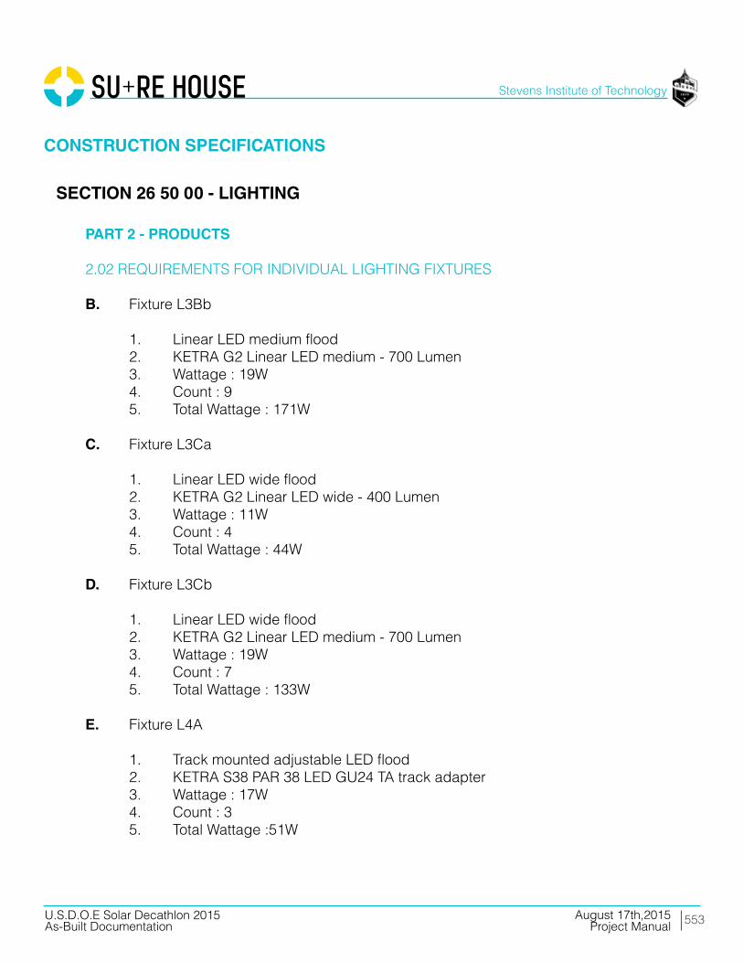
553
Stevens Institute of Technology
August 17th,2015U.S.D.O.E Solar Decathlon 2015As-Built Documentation Project Manual
PART 2 - PRODUCTS
2.02 REQUIREMENTS FOR INDIVIDUAL LIGHTING FIXTURES
B. Fixture L3Bb
1. Linear LED medium flood 2. KETRA G2 Linear LED medium - 700 Lumen 3. Wattage : 19W 4. Count : 9 5. Total Wattage : 171W
C. Fixture L3Ca
1. Linear LED wide flood 2. KETRA G2 Linear LED wide - 400 Lumen 3. Wattage : 11W 4. Count : 4 5. Total Wattage : 44W
D. Fixture L3Cb
1. Linear LED wide flood 2. KETRA G2 Linear LED medium - 700 Lumen 3. Wattage : 19W 4. Count : 7 5. Total Wattage : 133W
E. Fixture L4A
1. Track mounted adjustable LED flood 2. KETRA S38 PAR 38 LED GU24 TA track adapter 3. Wattage : 17W 4. Count : 3 5. Total Wattage :51W
SECTION 26 50 00 - LIGHTING
CONSTRUCTION SPECIFICATIONS
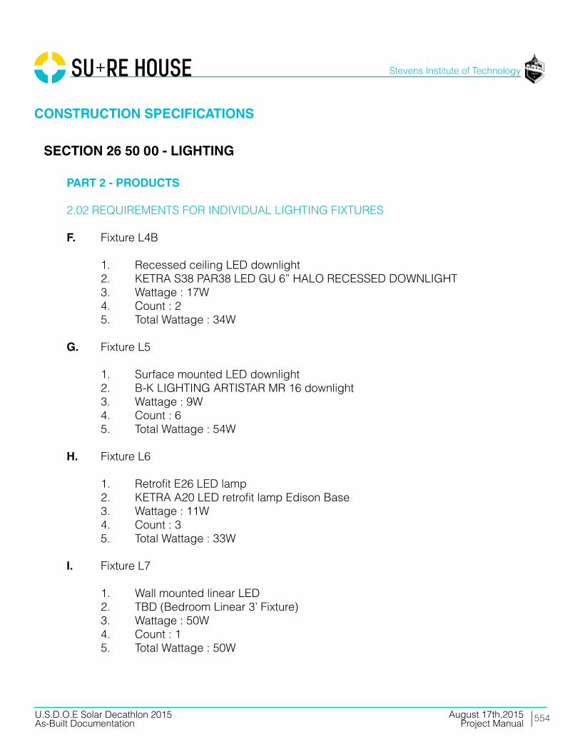
554
Stevens Institute of Technology
August 17th,2015U.S.D.O.E Solar Decathlon 2015As-Built Documentation Project Manual
PART 2 - PRODUCTS
2.02 REQUIREMENTS FOR INDIVIDUAL LIGHTING FIXTURES
F. Fixture L4B
1. Recessed ceiling LED downlight 2. KETRA S38 PAR38 LED GU 6” HALO RECESSED DOWNLIGHT 3. Wattage : 17W 4. Count : 2 5. Total Wattage : 34W
G. Fixture L5
1. Surface mounted LED downlight 2. B-K LIGHTING ARTISTAR MR 16 downlight 3. Wattage : 9W 4. Count : 6 5. Total Wattage : 54W
H. Fixture L6
1. Retrofit E26 LED lamp 2. KETRA A20 LED retrofit lamp Edison Base 3. Wattage : 11W 4. Count : 3 5. Total Wattage : 33W
I. Fixture L7
1. Wall mounted linear LED 2. TBD (Bedroom Linear 3’ Fixture) 3. Wattage : 50W 4. Count : 1 5. Total Wattage : 50W
SECTION 26 50 00 - LIGHTING
CONSTRUCTION SPECIFICATIONS

555
Stevens Institute of Technology
August 17th,2015U.S.D.O.E Solar Decathlon 2015As-Built Documentation Project Manual
PART 2 - PRODUCTS
2.02 REQUIREMENTS FOR INDIVIDUAL LIGHTING FIXTURES
J. Fixture L8
1. Surface mounted ingrade LED uplight 2. BK LIGHTING ARTISTAR recessed in-grade uplight 3. Wattage : 9W 4. Count : 6 5. Total Wattage : 54W
2.03 LIGHTING ACCESSORIES
A. Unit D1
1. Linear LED drive 2. KETRA N3 Satellite 3. Wattage : 5W 4. Count : 2 5. Total Wattage : 10W
B. Unit D2
1. 120V DMX DIMMER 2. DMX DIMMER 3. Wattage : 5W
C. Unit D3
1. 12V ELECTRONIC DRIVER 2. B-K LIGHTING 3. Wattage : 5W 4. Count : 2 5. Total Wattage : 10W
SECTION 26 50 00 - LIGHTING
CONSTRUCTION SPECIFICATIONS

556
Stevens Institute of Technology
August 17th,2015U.S.D.O.E Solar Decathlon 2015As-Built Documentation Project Manual
PART 3 - EXECUTION
2.03 LIGHTING ACCESSORIES
D. Unit R1
1. 120V CONTACT CLOSURE RELAY 2. Functional Devices
3.01 INSTALLATION
A. Set units level, plumb, and square with ceiling and walls, and secure.
B. Terminate appropriate fixtures with corresponding transformer and secure trans former.
C. Wire fixtures to scheduled switch legs.
D. Correct deficiencies in or remove and reinstall mountings and modules that do not comply with requirements.
E. Repair, refinish, or replace mountings and modules damaged during installation or transit, as directed by Architect.
END OF SECTION 26 50 00
SECTION 26 50 00 - LIGHTING
CONSTRUCTION SPECIFICATIONS

557
Stevens Institute of Technology
August 17th,2015U.S.D.O.E Solar Decathlon 2015As-Built Documentation Project Manual
PART 1 - GENERAL
1.01 SECTION REQUIREMENTS
A. Submittals: Product Data and system operating description.
B. Submittals to Authorities Having Jurisdiction: In addition to distribution requirements for submittals, make an identical submittal to authorities having jurisdiction. To facilitate review, include copies of annotated Contract Drawings as needed to depict component locations.
C. Comply with NFPA 72.
D. D. UL listed and labeled.
E. E. Electrical Components, Devices, and Accessories: Listed and labeled as defined in NFPA 70, by a qualified testing agency, and marked for intended location and application.
PART 2 - PRODUCTS
2.01 SMOKE DETECTORS
A. SIMPLEX TrueAlarm Photoelectric Smoke Detector - TrueSense® Smoke/Heat Detection
B. TYCO Riser Manifold
C. TYCO RAPID RESPONSE Series LFII Residential Sprinklers
2.02 WIRE AND CABLE
A. UL listed and labeled as complying with NFPA 70, Article 760.
B. Solid-copper conductors with 600-V rated, 75 deg C, color-coded insulation. No. 12 AWG or larger as required by local codes.
SECTION 28 31 46 - SMOKE DETECTOR SENSORS
CONSTRUCTION SPECIFICATIONS

558
Stevens Institute of Technology
August 17th,2015U.S.D.O.E Solar Decathlon 2015As-Built Documentation Project Manual
PART 3 - EXECUTION
3.01 INSTALLATION
A. Install and test systems according to NFPA 72. Comply with NECA 1.
B. Install wiring “finished” in concealed spaces and exposed on ceilings and walls where indicated.
C. Wire system per manufacturer specifications.
END OF SECTION 28 31 46
SECTION 28 31 46 - SMOKE DETECTOR SENSORS
CONSTRUCTION SPECIFICATIONS
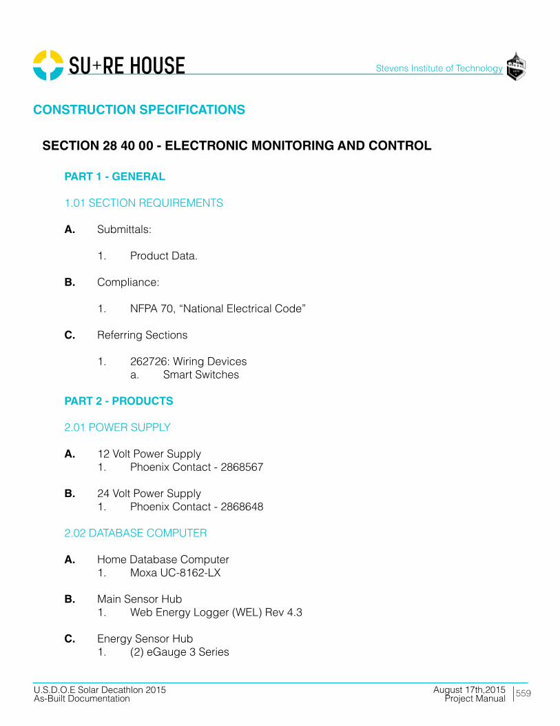
559
Stevens Institute of Technology
August 17th,2015U.S.D.O.E Solar Decathlon 2015As-Built Documentation Project Manual
PART 1 - GENERAL
1.01 SECTION REQUIREMENTS
A. Submittals:
1. Product Data.
B. Compliance:
1. NFPA 70, “National Electrical Code”
C. Referring Sections
1. 262726: Wiring Devices a. Smart Switches
PART 2 - PRODUCTS
2.01 POWER SUPPLY
A. 12 Volt Power Supply 1. Phoenix Contact - 2868567
B. 24 Volt Power Supply 1. Phoenix Contact - 2868648
2.02 DATABASE COMPUTER
A. Home Database Computer 1. Moxa UC-8162-LX
B. Main Sensor Hub 1. Web Energy Logger (WEL) Rev 4.3
C. Energy Sensor Hub 1. (2) eGauge 3 Series
SECTION 28 40 00 - ELECTRONIC MONITORING AND CONTROL
CONSTRUCTION SPECIFICATIONS

560
Stevens Institute of Technology
August 17th,2015U.S.D.O.E Solar Decathlon 2015As-Built Documentation Project Manual
PART 2 - PRODUCTS
2.03 NETWORKING
A. Ethernet Switch 1. Moxa EDS-208
2.04 MONITORING ENCLOSURE
A. Wallmount Enclosure with Window 1. Hammond -EN45D242012WLG
2.05 SENSORS
A. Split-core Current Trsansformer (CT) 1. Magnelab SCT Series
B. High Accuracy Split-core Current Trsansformer (CT) 1. Continental Control Systems ACT Series
C. Environmental 1-Wire Sensor 1. iButtonLink SS-WALL-TH 2. Web Energy Logger Temp Sensor- TSENSE-SS3
2.06 LIGHTING CONTROLS
A. Lighting Nodes :
1. Ketra N3 Satellite a. 11.05” x 5.13” x 2.38”
B. Lighting Switches :
1. Ketra X1 Touchpad 2. Lutron Maestro
SECTION 28 40 00 - ELECTRONIC MONITORING AND CONTROL
CONSTRUCTION SPECIFICATIONS

561
Stevens Institute of Technology
August 17th,2015U.S.D.O.E Solar Decathlon 2015As-Built Documentation Project Manual
PART 3 - EXECUTION
3.01 INSTALLATIONS
A. Prepare substrate by cleaning, removing projections, filling voids, sealing joints, and as otherwise recommended in manufacturer’s written instructions.
B. Network equipment to be installed according to manufacturer’s specifications.
C. Set units level, plumb, and true to line and anchor securely in place.
D. Correct deficiencies in or remove and reinstall materials that do not comply with requirements.
E. Repair, refinish, or replace substrate damaged during installation or transit, as directed by Architect.
END OF SECTION 28 40 00
SECTION 28 40 00 - ELECTRONIC MONITORING AND CONTROL
CONSTRUCTION SPECIFICATIONS

11 PRODUCT CUTSHEETS

563
Stevens Institute of Technology
August 17th,2015U.S.D.O.E Solar Decathlon 2015As-Built Documentation Project Manual
Division 05 Metals

564
Stevens Institute of Technology
August 17th,2015U.S.D.O.E Solar Decathlon 2015As-Built Documentation Project Manual
CSI #: 05 13 00

565
Stevens Institute of Technology
August 17th,2015U.S.D.O.E Solar Decathlon 2015As-Built Documentation Project Manual
CSI #: 05 13 00
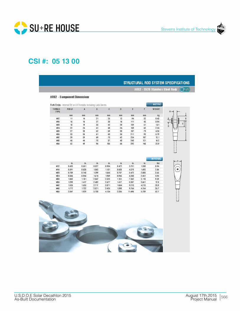
566
Stevens Institute of Technology
August 17th,2015U.S.D.O.E Solar Decathlon 2015As-Built Documentation Project Manual
CSI #: 05 13 00

567
Stevens Institute of Technology
August 17th,2015U.S.D.O.E Solar Decathlon 2015As-Built Documentation Project Manual
CSI #: 05 13 00

568
Stevens Institute of Technology
August 17th,2015U.S.D.O.E Solar Decathlon 2015As-Built Documentation Project Manual
CSI #: 05 45 00
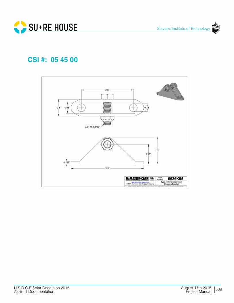
569
Stevens Institute of Technology
August 17th,2015U.S.D.O.E Solar Decathlon 2015As-Built Documentation Project Manual
CSI #: 05 45 00

570
Stevens Institute of Technology
August 17th,2015U.S.D.O.E Solar Decathlon 2015As-Built Documentation Project Manual
CSI #: 05 45 00

571
Stevens Institute of Technology
August 17th,2015U.S.D.O.E Solar Decathlon 2015As-Built Documentation Project Manual
CSI #: 05 45 00

572
Stevens Institute of Technology
August 17th,2015U.S.D.O.E Solar Decathlon 2015As-Built Documentation Project Manual
CSI #: 05 45 00

573
Stevens Institute of Technology
August 17th,2015U.S.D.O.E Solar Decathlon 2015As-Built Documentation Project Manual
CSI #: 05 45 00

574
Stevens Institute of Technology
August 17th,2015U.S.D.O.E Solar Decathlon 2015As-Built Documentation Project Manual
CSI #: 05 45 00
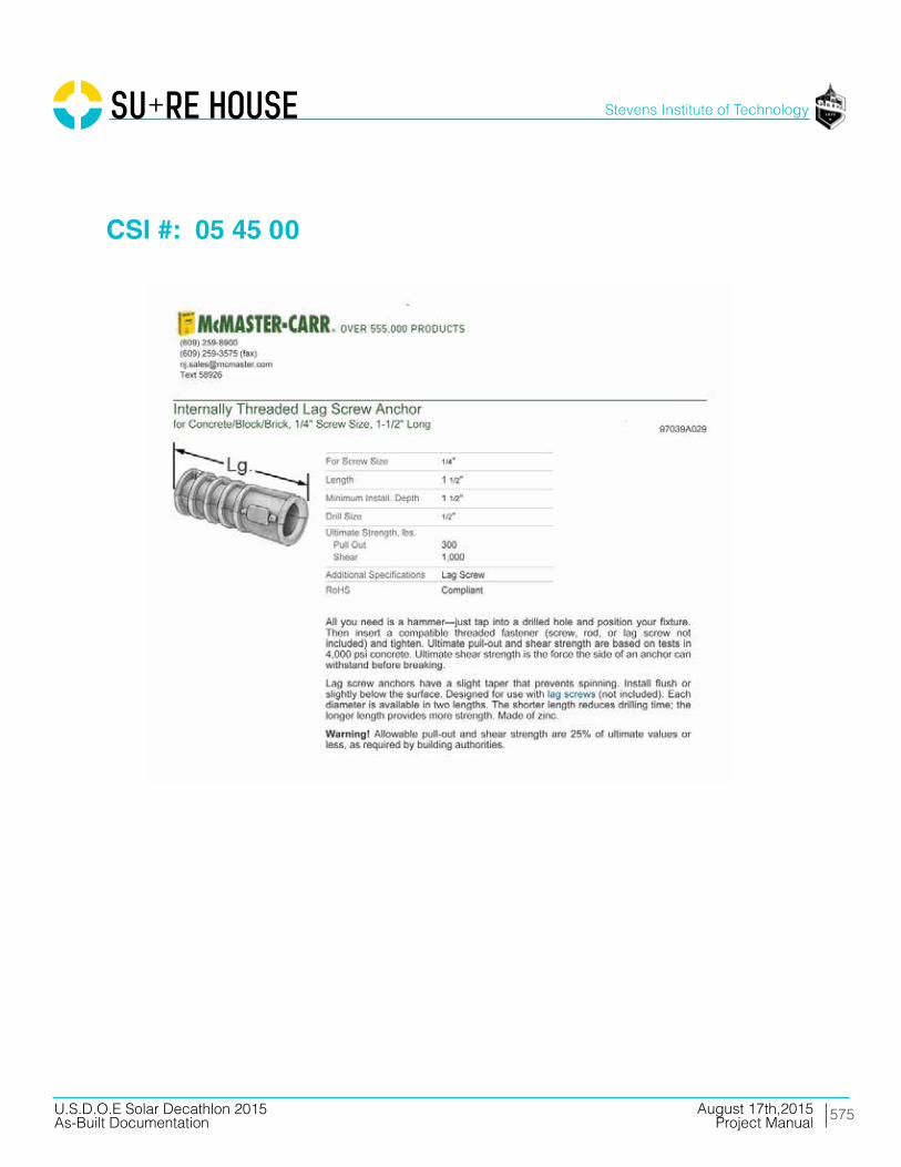
575
Stevens Institute of Technology
August 17th,2015U.S.D.O.E Solar Decathlon 2015As-Built Documentation Project Manual
CSI #: 05 45 00
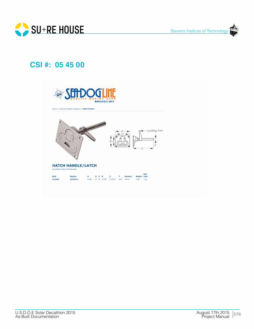
576
Stevens Institute of Technology
August 17th,2015U.S.D.O.E Solar Decathlon 2015As-Built Documentation Project Manual
CSI #: 05 45 00

577
Stevens Institute of Technology
August 17th,2015U.S.D.O.E Solar Decathlon 2015As-Built Documentation Project Manual
CSI #: 05 45 00

578
Stevens Institute of Technology
August 17th,2015U.S.D.O.E Solar Decathlon 2015As-Built Documentation Project Manual
CSI #: 05 45 00

579
Stevens Institute of Technology
August 17th,2015U.S.D.O.E Solar Decathlon 2015As-Built Documentation Project Manual
CSI #: 05 45 00

580
Stevens Institute of Technology
August 17th,2015U.S.D.O.E Solar Decathlon 2015As-Built Documentation Project Manual
CSI #: 05 45 00
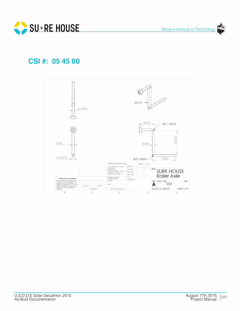
581
Stevens Institute of Technology
August 17th,2015U.S.D.O.E Solar Decathlon 2015As-Built Documentation Project Manual
CSI #: 05 45 00

582
Stevens Institute of Technology
August 17th,2015U.S.D.O.E Solar Decathlon 2015As-Built Documentation Project Manual
CSI #: 05 45 00

583
Stevens Institute of Technology
August 17th,2015U.S.D.O.E Solar Decathlon 2015As-Built Documentation Project Manual
CSI #: 05 45 00

584
Stevens Institute of Technology
August 17th,2015U.S.D.O.E Solar Decathlon 2015As-Built Documentation Project Manual
CSI #: 05 45 00

585
Stevens Institute of Technology
August 17th,2015U.S.D.O.E Solar Decathlon 2015As-Built Documentation Project Manual
CSI #: 05 45 00

586
Stevens Institute of Technology
August 17th,2015U.S.D.O.E Solar Decathlon 2015As-Built Documentation Project Manual
CSI #: 05 45 00
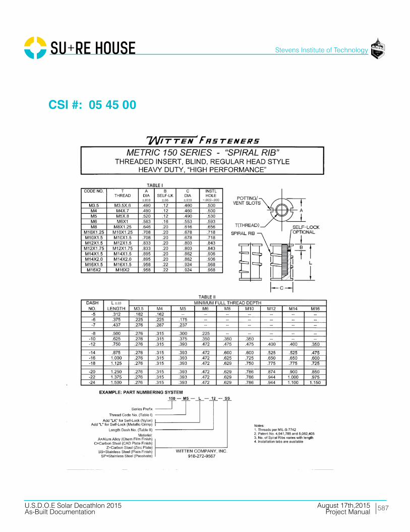
587
Stevens Institute of Technology
August 17th,2015U.S.D.O.E Solar Decathlon 2015As-Built Documentation Project Manual
CSI #: 05 45 00
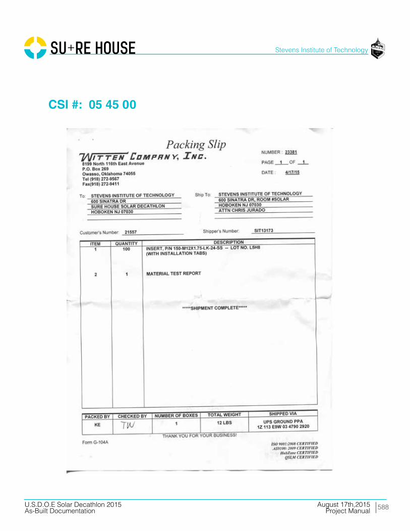
588
Stevens Institute of Technology
August 17th,2015U.S.D.O.E Solar Decathlon 2015As-Built Documentation Project Manual
CSI #: 05 45 00

589
Stevens Institute of Technology
August 17th,2015U.S.D.O.E Solar Decathlon 2015As-Built Documentation Project Manual
CSI #: 05 45 00
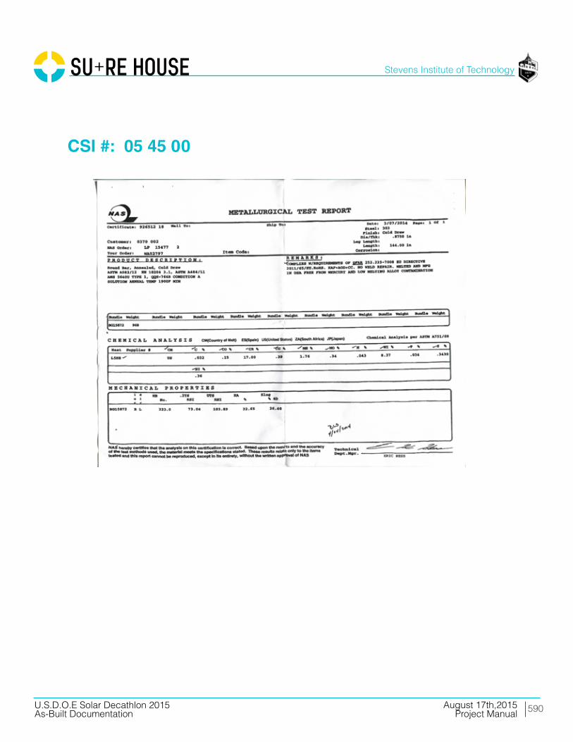
590
Stevens Institute of Technology
August 17th,2015U.S.D.O.E Solar Decathlon 2015As-Built Documentation Project Manual
CSI #: 05 45 00
591
Stevens Institute of Technology
August 17th,2015U.S.D.O.E Solar Decathlon 2015As-Built Documentation Project Manual
Division 06 Woods, Plastics, and Composites

592
Stevens Institute of Technology
August 17th,2015U.S.D.O.E Solar Decathlon 2015As-Built Documentation Project Manual
CSI #: 06 00 00
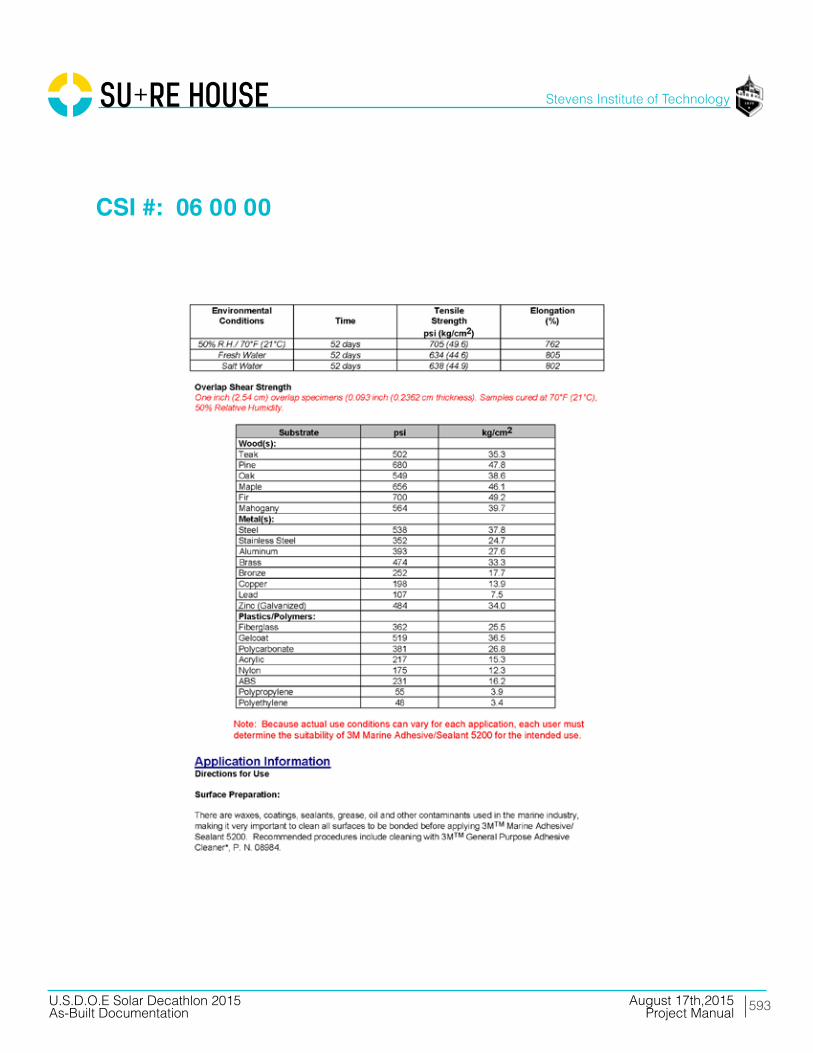
593
Stevens Institute of Technology
August 17th,2015U.S.D.O.E Solar Decathlon 2015As-Built Documentation Project Manual
CSI #: 06 00 00

594
Stevens Institute of Technology
August 17th,2015U.S.D.O.E Solar Decathlon 2015As-Built Documentation Project Manual
CSI #: 06 00 00
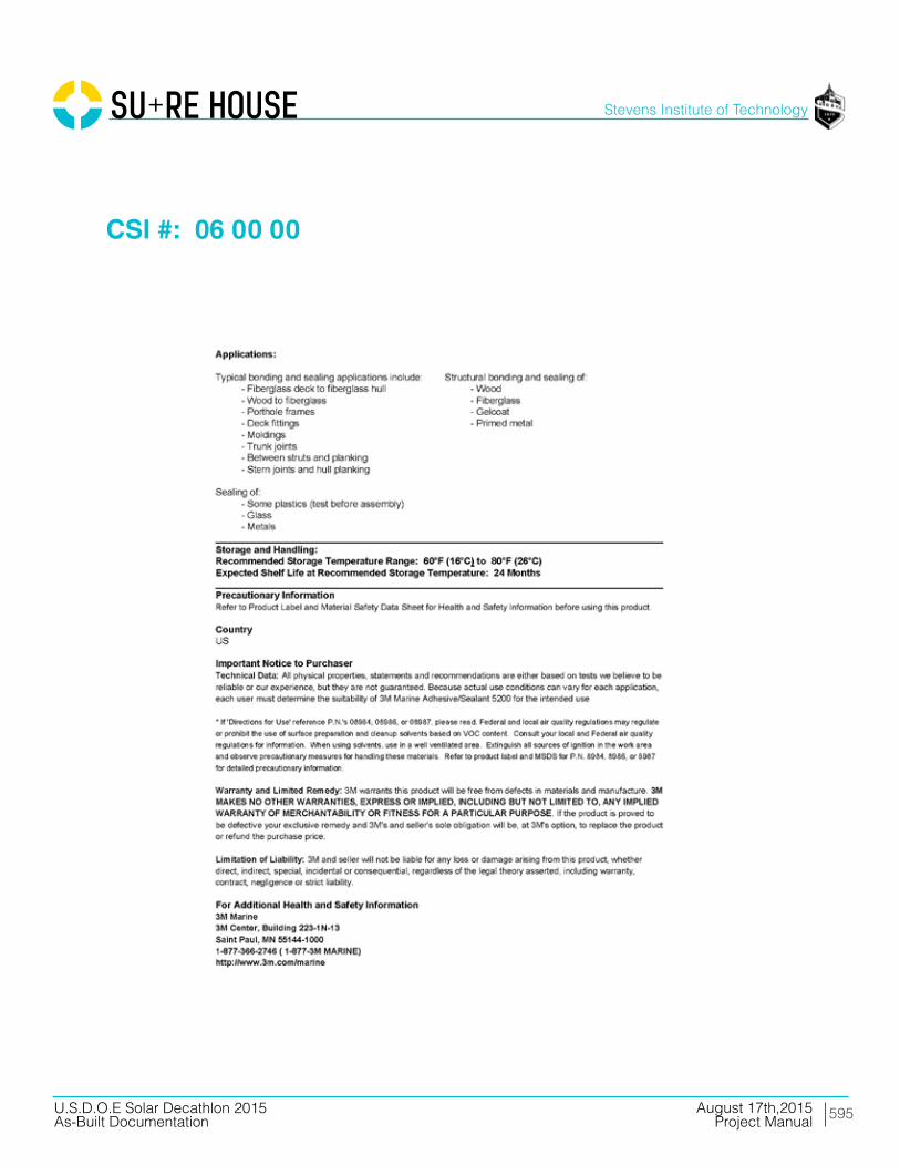
595
Stevens Institute of Technology
August 17th,2015U.S.D.O.E Solar Decathlon 2015As-Built Documentation Project Manual
CSI #: 06 00 00

596
Stevens Institute of Technology
August 17th,2015U.S.D.O.E Solar Decathlon 2015As-Built Documentation Project Manual
CSI #: 06 00 00

597
Stevens Institute of Technology
August 17th,2015U.S.D.O.E Solar Decathlon 2015As-Built Documentation Project Manual
CSI #: 06 00 00

598
Stevens Institute of Technology
August 17th,2015U.S.D.O.E Solar Decathlon 2015As-Built Documentation Project Manual
CSI #: 06 00 00

599
Stevens Institute of Technology
August 17th,2015U.S.D.O.E Solar Decathlon 2015As-Built Documentation Project Manual
CSI #: 06 00 00

600
Stevens Institute of Technology
August 17th,2015U.S.D.O.E Solar Decathlon 2015As-Built Documentation Project Manual
CSI #: 06 00 00

601
Stevens Institute of Technology
August 17th,2015U.S.D.O.E Solar Decathlon 2015As-Built Documentation Project Manual
CSI #: 06 00 00
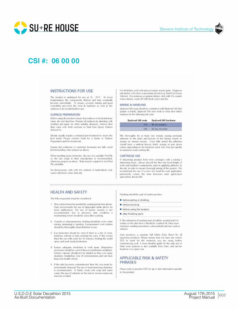
602
Stevens Institute of Technology
August 17th,2015U.S.D.O.E Solar Decathlon 2015As-Built Documentation Project Manual
CSI #: 06 00 00

603
Stevens Institute of Technology
August 17th,2015U.S.D.O.E Solar Decathlon 2015As-Built Documentation Project Manual
CSI #: 06 00 00

604
Stevens Institute of Technology
August 17th,2015U.S.D.O.E Solar Decathlon 2015As-Built Documentation Project Manual
CSI #: 06 00 00

605
Stevens Institute of Technology
August 17th,2015U.S.D.O.E Solar Decathlon 2015As-Built Documentation Project Manual
CSI #: 06 16 53

606
Stevens Institute of Technology
August 17th,2015U.S.D.O.E Solar Decathlon 2015As-Built Documentation Project Manual
CSI #: 06 16 53

607
Stevens Institute of Technology
August 17th,2015U.S.D.O.E Solar Decathlon 2015As-Built Documentation Project Manual
CSI #: 06 16 53

608
Stevens Institute of Technology
August 17th,2015U.S.D.O.E Solar Decathlon 2015As-Built Documentation Project Manual
CSI #: 06 16 53

609
Stevens Institute of Technology
August 17th,2015U.S.D.O.E Solar Decathlon 2015As-Built Documentation Project Manual
CSI #: 06 17 13
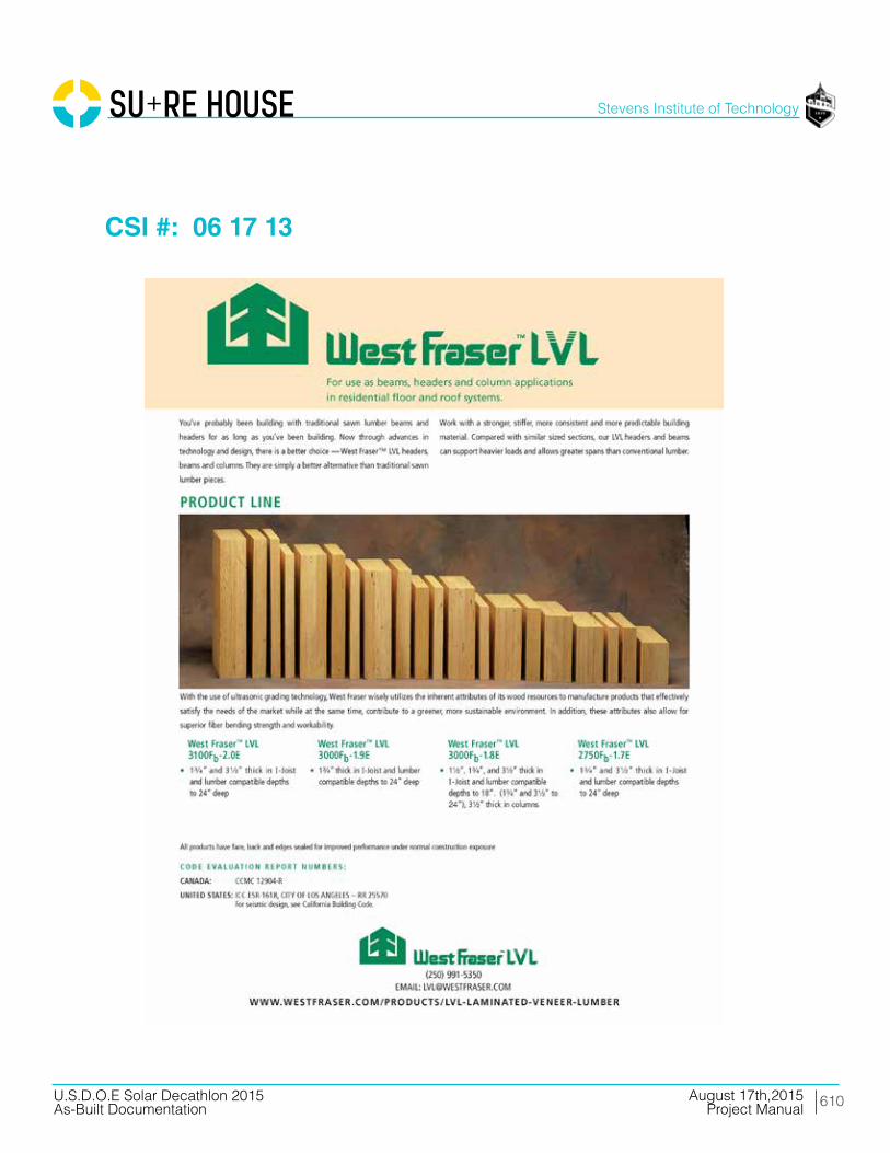
610
Stevens Institute of Technology
August 17th,2015U.S.D.O.E Solar Decathlon 2015As-Built Documentation Project Manual
CSI #: 06 17 13

611
Stevens Institute of Technology
August 17th,2015U.S.D.O.E Solar Decathlon 2015As-Built Documentation Project Manual
CSI #: 06 17 33

612
Stevens Institute of Technology
August 17th,2015U.S.D.O.E Solar Decathlon 2015As-Built Documentation Project Manual
CSI #: 06 17 33
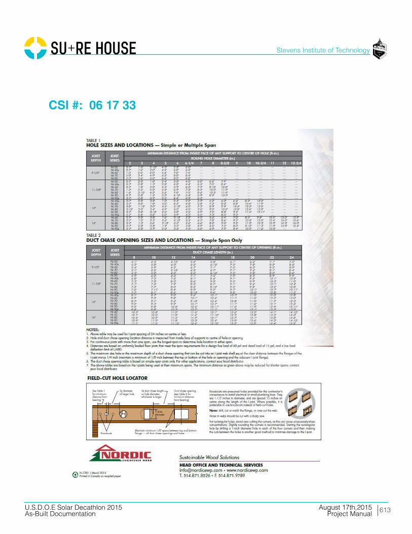
613
Stevens Institute of Technology
August 17th,2015U.S.D.O.E Solar Decathlon 2015As-Built Documentation Project Manual
CSI #: 06 17 33

614
Stevens Institute of Technology
August 17th,2015U.S.D.O.E Solar Decathlon 2015As-Built Documentation Project Manual
CSI #: 06 40 23

615
Stevens Institute of Technology
August 17th,2015U.S.D.O.E Solar Decathlon 2015As-Built Documentation Project Manual
CSI #: 06 40 23

616
Stevens Institute of Technology
August 17th,2015U.S.D.O.E Solar Decathlon 2015As-Built Documentation Project Manual
CSI #: 06 40 23

617
Stevens Institute of Technology
August 17th,2015U.S.D.O.E Solar Decathlon 2015As-Built Documentation Project Manual
CSI #: 06 65 00
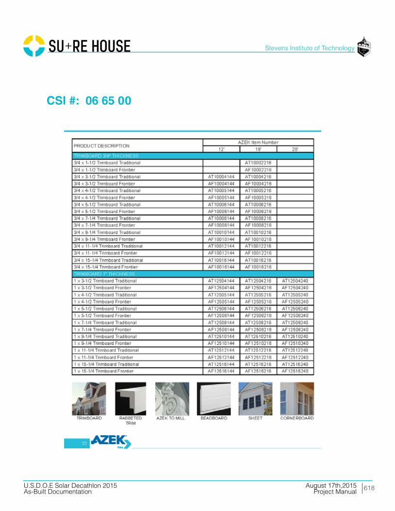
618
Stevens Institute of Technology
August 17th,2015U.S.D.O.E Solar Decathlon 2015As-Built Documentation Project Manual
CSI #: 06 65 00

619
Stevens Institute of Technology
August 17th,2015U.S.D.O.E Solar Decathlon 2015As-Built Documentation Project Manual
CSI #: 06 65 00

620
Stevens Institute of Technology
August 17th,2015U.S.D.O.E Solar Decathlon 2015As-Built Documentation Project Manual
CSI #: 06 65 00

621
Stevens Institute of Technology
August 17th,2015U.S.D.O.E Solar Decathlon 2015As-Built Documentation Project Manual
CSI #: 06 72 00
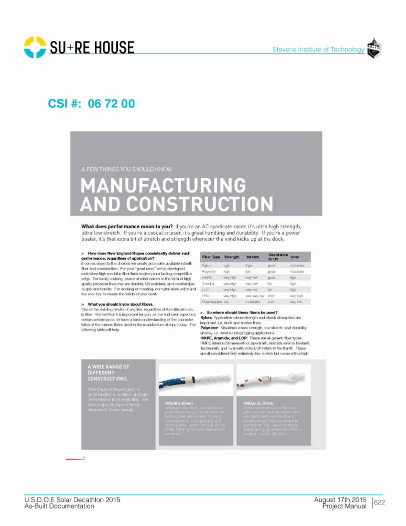
622
Stevens Institute of Technology
August 17th,2015U.S.D.O.E Solar Decathlon 2015As-Built Documentation Project Manual
CSI #: 06 72 00
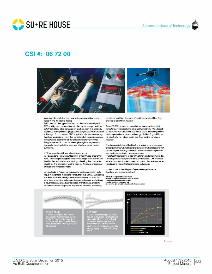
623
Stevens Institute of Technology
August 17th,2015U.S.D.O.E Solar Decathlon 2015As-Built Documentation Project Manual
CSI #: 06 72 00

624
Stevens Institute of Technology
August 17th,2015U.S.D.O.E Solar Decathlon 2015As-Built Documentation Project Manual
CSI #: 06 72 00

625
Stevens Institute of Technology
August 17th,2015U.S.D.O.E Solar Decathlon 2015As-Built Documentation Project Manual
CSI #: 06 73 00

626
Stevens Institute of Technology
August 17th,2015U.S.D.O.E Solar Decathlon 2015As-Built Documentation Project Manual
CSI #: 06 73 00
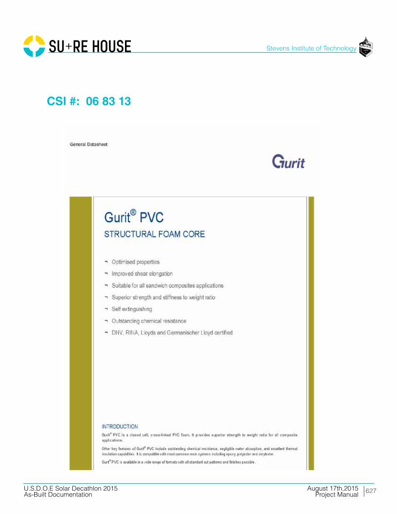
627
Stevens Institute of Technology
August 17th,2015U.S.D.O.E Solar Decathlon 2015As-Built Documentation Project Manual
CSI #: 06 83 13

628
Stevens Institute of Technology
August 17th,2015U.S.D.O.E Solar Decathlon 2015As-Built Documentation Project Manual
CSI #: 06 83 13
629
Stevens Institute of Technology
August 17th,2015U.S.D.O.E Solar Decathlon 2015As-Built Documentation Project Manual
CSI #: 06 83 13

630
Stevens Institute of Technology
August 17th,2015U.S.D.O.E Solar Decathlon 2015As-Built Documentation Project Manual
CSI #: 06 83 13

631
Stevens Institute of Technology
August 17th,2015U.S.D.O.E Solar Decathlon 2015As-Built Documentation Project Manual
CSI #: 06 83 13

632
Stevens Institute of Technology
August 17th,2015U.S.D.O.E Solar Decathlon 2015As-Built Documentation Project Manual
CSI #: 06 83 13

633
Stevens Institute of Technology
August 17th,2015U.S.D.O.E Solar Decathlon 2015As-Built Documentation Project Manual
CSI #: 06 83 13
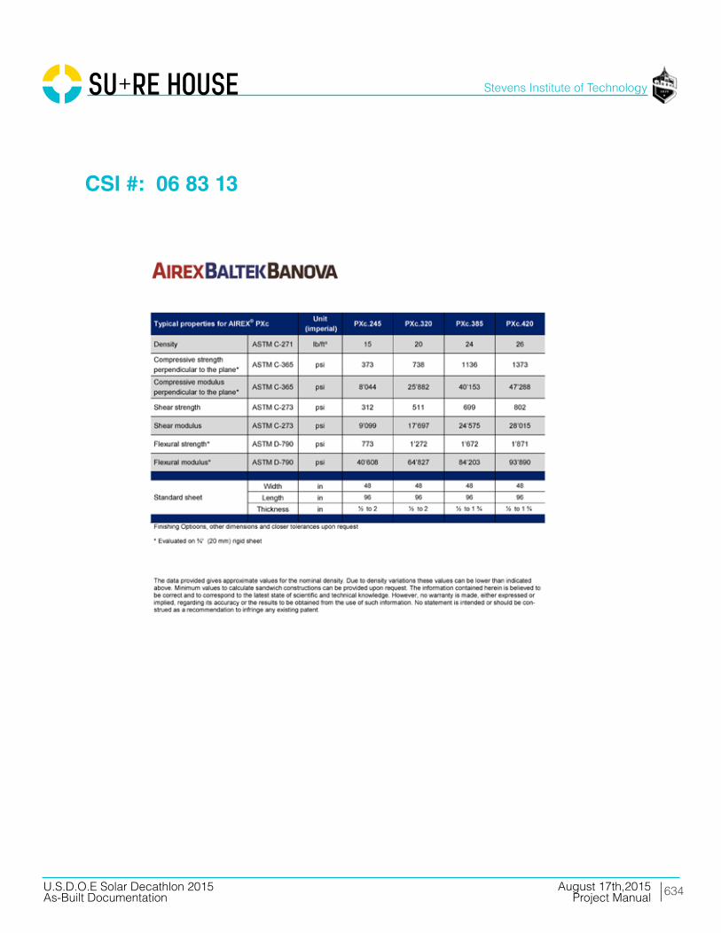
634
Stevens Institute of Technology
August 17th,2015U.S.D.O.E Solar Decathlon 2015As-Built Documentation Project Manual
CSI #: 06 83 13

635
Stevens Institute of Technology
August 17th,2015U.S.D.O.E Solar Decathlon 2015As-Built Documentation Project Manual
CSI #: 06 83 13

636
Stevens Institute of Technology
August 17th,2015U.S.D.O.E Solar Decathlon 2015As-Built Documentation Project Manual
CSI #: 06 83 13

637
Stevens Institute of Technology
August 17th,2015U.S.D.O.E Solar Decathlon 2015As-Built Documentation Project Manual
CSI #: 06 83 13
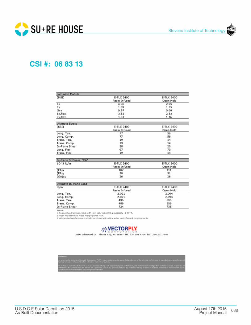
638
Stevens Institute of Technology
August 17th,2015U.S.D.O.E Solar Decathlon 2015As-Built Documentation Project Manual
CSI #: 06 83 13

639
Stevens Institute of Technology
August 17th,2015U.S.D.O.E Solar Decathlon 2015As-Built Documentation Project Manual
Division 07 Thermal and Moisture Protection
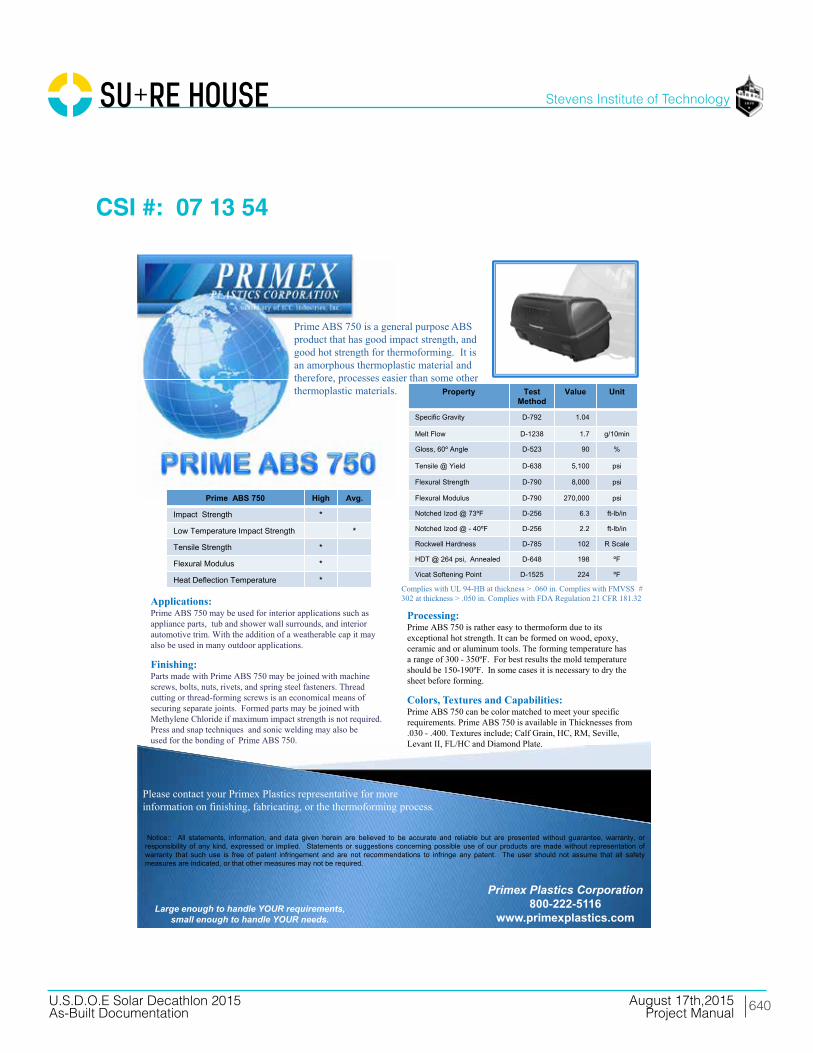
640
Stevens Institute of Technology
August 17th,2015U.S.D.O.E Solar Decathlon 2015As-Built Documentation Project Manual
CSI #: 07 13 54
Applications:Prime ABS 750 may be used for interior applications such as appliance parts, tub and shower wall surrounds, and interior automotive trim. With the addition of a weatherable cap it may also be used in many outdoor applications.
Finishing:Parts made with Prime ABS 750 may be joined with machine screws, bolts, nuts, rivets, and spring steel fasteners. Thread cutting or thread-forming screws is an economical means of securing separate joints. Formed parts may be joined with Methylene Chloride if maximum impact strength is not required. Press and snap techniques and sonic welding may also be used for the bonding of Prime ABS 750.
Primex Plastics Corporation800-222-5116
www.primexplastics.comLarge enough to handle YOUR requirements,
small enough to handle YOUR needs.
Please contact your Primex Plastics representative for more information on finishing, fabricating, or the thermoforming process.
Notice:: All statements, information, and data given herein are believed to be accurate and reliable but are presented without guarantee, warranty, orresponsibility of any kind, expressed or implied. Statements or suggestions concerning possible use of our products are made without representation ofwarranty that such use is free of patent infringement and are not recommendations to infringe any patent. The user should not assume that all safetymeasures are indicated, or that other measures may not be required.
Property Test Method
Value Unit
Specific Gravity D-792 1.04
Melt Flow D-1238 1.7 g/10min
Gloss, 60º Angle D-523 90 %
Tensile @ Yield D-638 5,100 psi
Flexural Strength D-790 8,000 psi
Flexural Modulus D-790 270,000 psi
Notched Izod @ 73ºF D-256 6.3 ft-lb/in
Notched Izod @ - 40ºF D-256 2.2 ft-lb/in
Rockwell Hardness D-785 102 R Scale
HDT @ 264 psi, Annealed D-648 198 ºF
Vicat Softening Point D-1525 224 ºF
Prime ABS 750 High Avg.
Impact Strength *
Low Temperature Impact Strength *
Tensile Strength *
Flexural Modulus *
Heat Deflection Temperature *
Prime ABS 750 is a general purpose ABS product that has good impact strength, and good hot strength for thermoforming. It is an amorphous thermoplastic material and therefore, processes easier than some other thermoplastic materials.
Processing:Prime ABS 750 is rather easy to thermoform due to its exceptional hot strength. It can be formed on wood, epoxy, ceramic and or aluminum tools. The forming temperature has a range of 300 - 350ºF. For best results the mold temperature should be 150-190ºF. In some cases it is necessary to dry the sheet before forming.
Colors, Textures and Capabilities: Prime ABS 750 can be color matched to meet your specific requirements. Prime ABS 750 is available in Thicknesses from .030 - .400. Textures include; Calf Grain, HC, RM, Seville, Levant II, FL/HC and Diamond Plate.
Complies with UL 94-HB at thickness > .060 in. Complies with FMVSS # 302 at thickness > .050 in. Complies with FDA Regulation 21 CFR 181.32
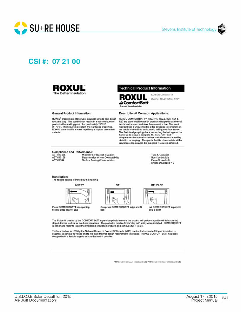
641
Stevens Institute of Technology
August 17th,2015U.S.D.O.E Solar Decathlon 2015As-Built Documentation Project Manual
CSI #: 07 21 00

642
Stevens Institute of Technology
August 17th,2015U.S.D.O.E Solar Decathlon 2015As-Built Documentation Project Manual
CSI #: 07 21 00
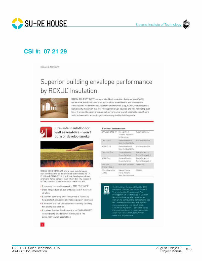
643
Stevens Institute of Technology
August 17th,2015U.S.D.O.E Solar Decathlon 2015As-Built Documentation Project Manual
CSI #: 07 21 29

644
Stevens Institute of Technology
August 17th,2015U.S.D.O.E Solar Decathlon 2015As-Built Documentation Project Manual
CSI #: 07 21 29
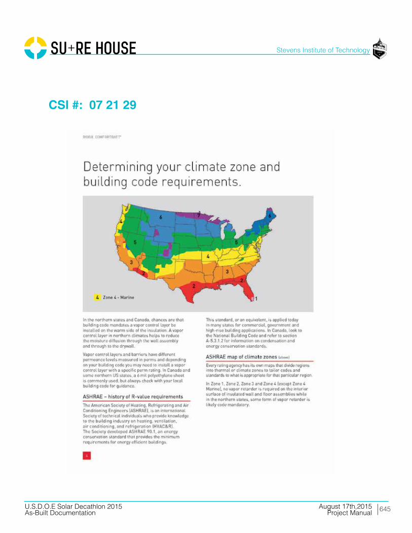
645
Stevens Institute of Technology
August 17th,2015U.S.D.O.E Solar Decathlon 2015As-Built Documentation Project Manual
CSI #: 07 21 29
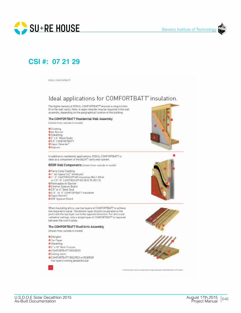
646
Stevens Institute of Technology
August 17th,2015U.S.D.O.E Solar Decathlon 2015As-Built Documentation Project Manual
CSI #: 07 21 29
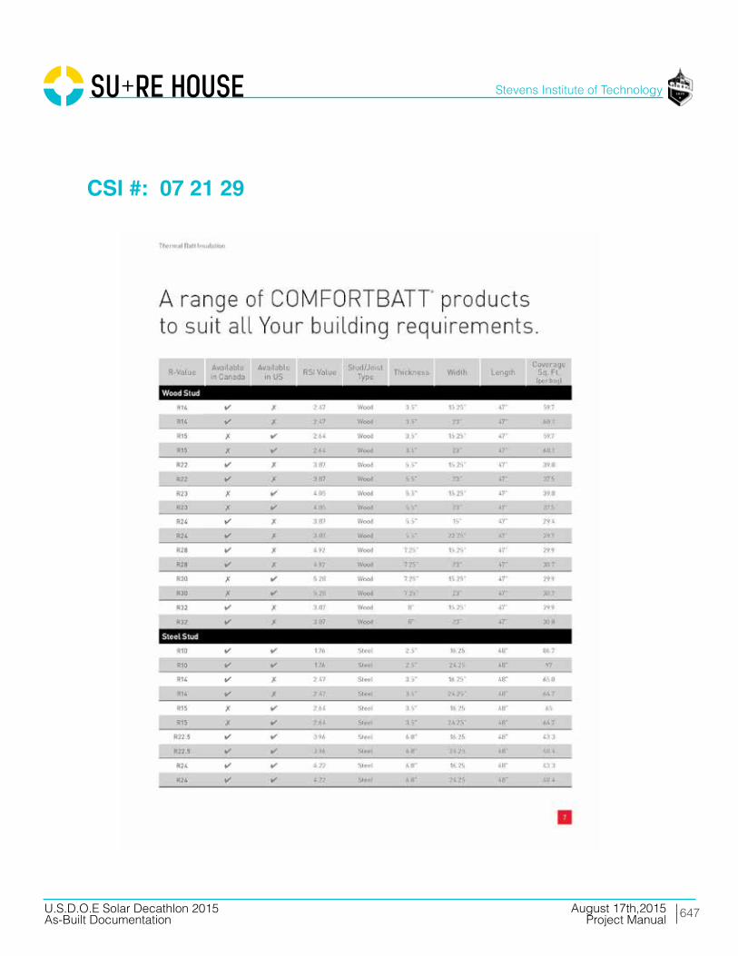
647
Stevens Institute of Technology
August 17th,2015U.S.D.O.E Solar Decathlon 2015As-Built Documentation Project Manual
CSI #: 07 21 29

648
Stevens Institute of Technology
August 17th,2015U.S.D.O.E Solar Decathlon 2015As-Built Documentation Project Manual
CSI #: 07 21 29
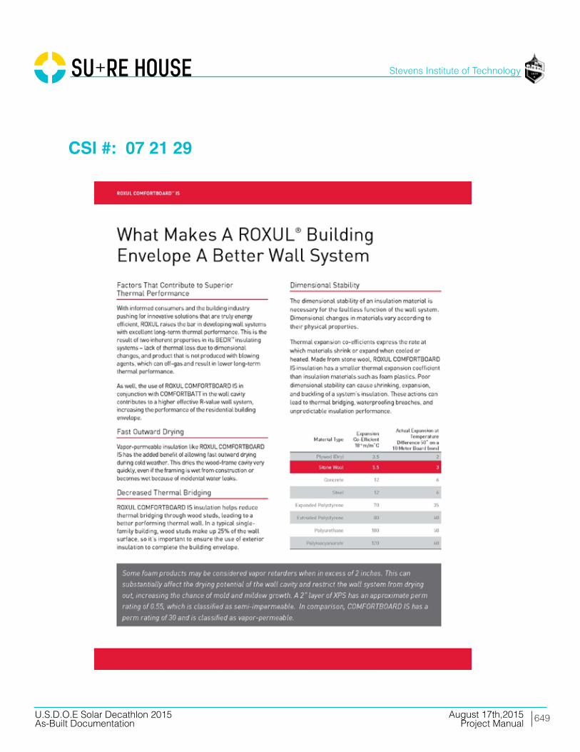
649
Stevens Institute of Technology
August 17th,2015U.S.D.O.E Solar Decathlon 2015As-Built Documentation Project Manual
CSI #: 07 21 29

650
Stevens Institute of Technology
August 17th,2015U.S.D.O.E Solar Decathlon 2015As-Built Documentation Project Manual
CSI #: 07 21 29
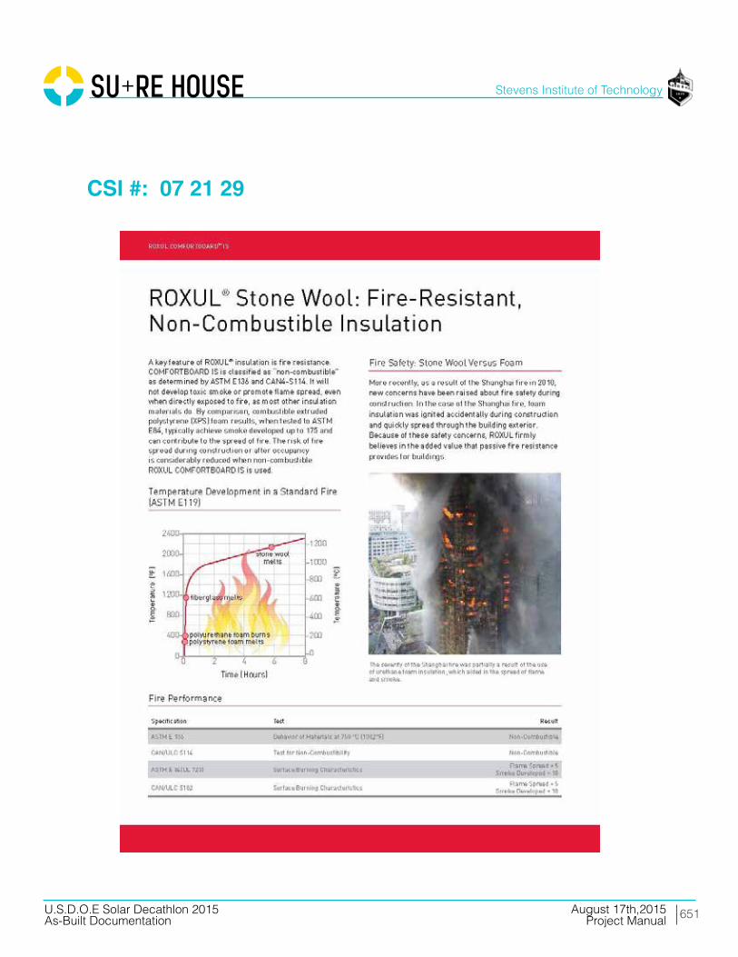
651
Stevens Institute of Technology
August 17th,2015U.S.D.O.E Solar Decathlon 2015As-Built Documentation Project Manual
CSI #: 07 21 29

652
Stevens Institute of Technology
August 17th,2015U.S.D.O.E Solar Decathlon 2015As-Built Documentation Project Manual
CSI #: 07 21 29

653
Stevens Institute of Technology
August 17th,2015U.S.D.O.E Solar Decathlon 2015As-Built Documentation Project Manual
CSI #: 07 21 29

654
Stevens Institute of Technology
August 17th,2015U.S.D.O.E Solar Decathlon 2015As-Built Documentation Project Manual
CSI #: 07 21 29

655
Stevens Institute of Technology
August 17th,2015U.S.D.O.E Solar Decathlon 2015As-Built Documentation Project Manual
CSI #: 07 22 22
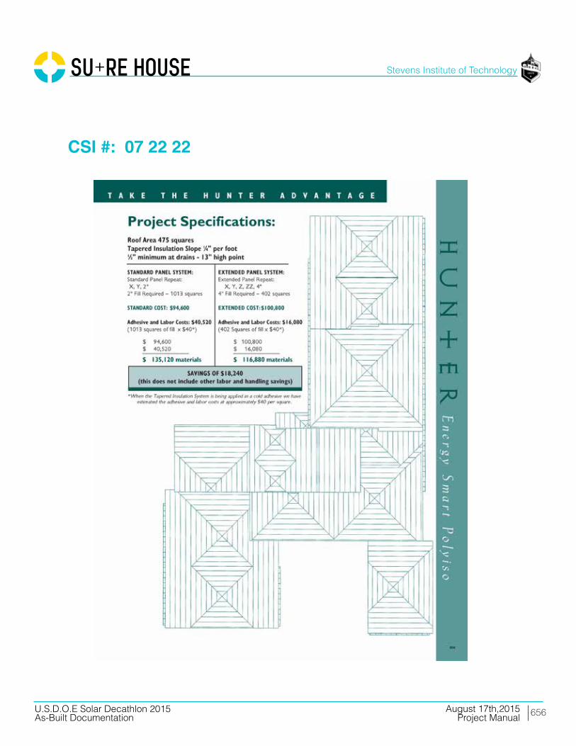
656
Stevens Institute of Technology
August 17th,2015U.S.D.O.E Solar Decathlon 2015As-Built Documentation Project Manual
CSI #: 07 22 22
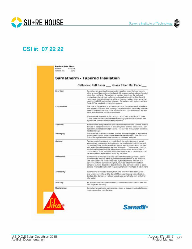
657
Stevens Institute of Technology
August 17th,2015U.S.D.O.E Solar Decathlon 2015As-Built Documentation Project Manual
CSI #: 07 22 22
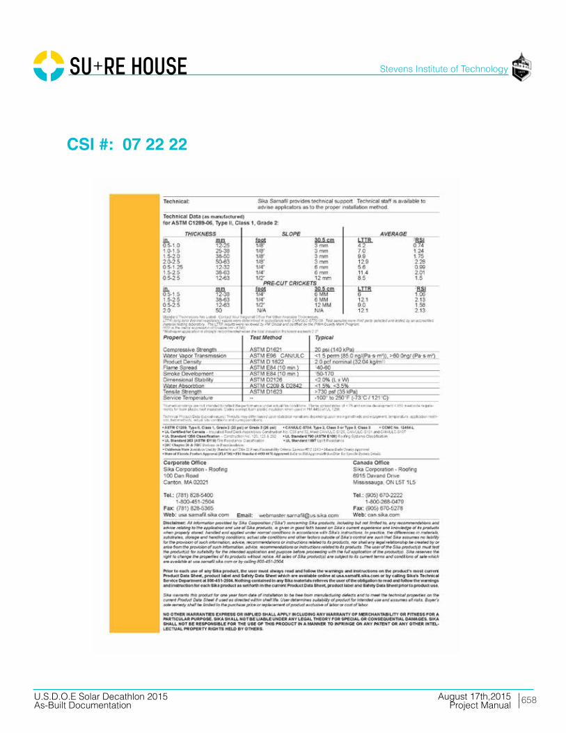
658
Stevens Institute of Technology
August 17th,2015U.S.D.O.E Solar Decathlon 2015As-Built Documentation Project Manual
CSI #: 07 22 22

659
Stevens Institute of Technology
August 17th,2015U.S.D.O.E Solar Decathlon 2015As-Built Documentation Project Manual
CSI #: 07 25 00

660
Stevens Institute of Technology
August 17th,2015U.S.D.O.E Solar Decathlon 2015As-Built Documentation Project Manual
CSI #: 07 25 00
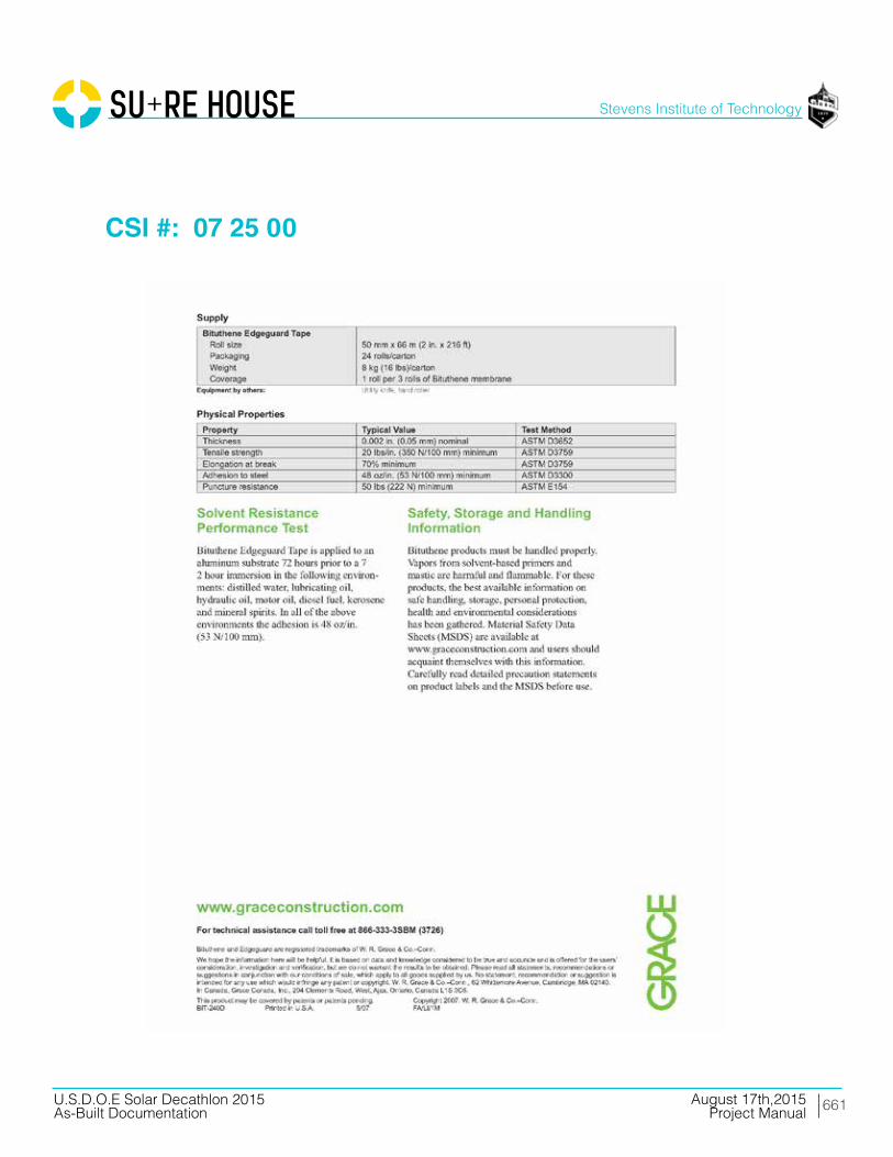
661
Stevens Institute of Technology
August 17th,2015U.S.D.O.E Solar Decathlon 2015As-Built Documentation Project Manual
CSI #: 07 25 00

662
Stevens Institute of Technology
August 17th,2015U.S.D.O.E Solar Decathlon 2015As-Built Documentation Project Manual
CSI #: 07 25 00

663
Stevens Institute of Technology
August 17th,2015U.S.D.O.E Solar Decathlon 2015As-Built Documentation Project Manual
CSI #: 07 25 00

664
Stevens Institute of Technology
August 17th,2015U.S.D.O.E Solar Decathlon 2015As-Built Documentation Project Manual
CSI #: 07 25 00

665
Stevens Institute of Technology
August 17th,2015U.S.D.O.E Solar Decathlon 2015As-Built Documentation Project Manual
CSI #: 07 25 00
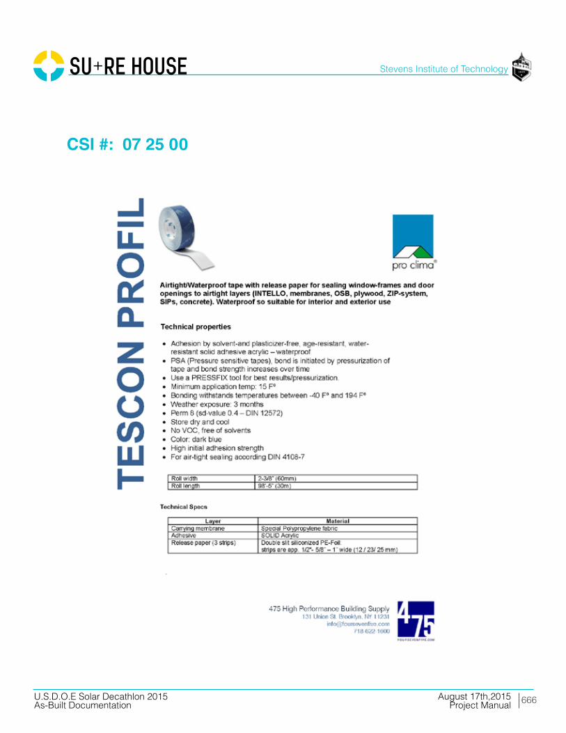
666
Stevens Institute of Technology
August 17th,2015U.S.D.O.E Solar Decathlon 2015As-Built Documentation Project Manual
CSI #: 07 25 00

667
Stevens Institute of Technology
August 17th,2015U.S.D.O.E Solar Decathlon 2015As-Built Documentation Project Manual
CSI #: 07 25 00
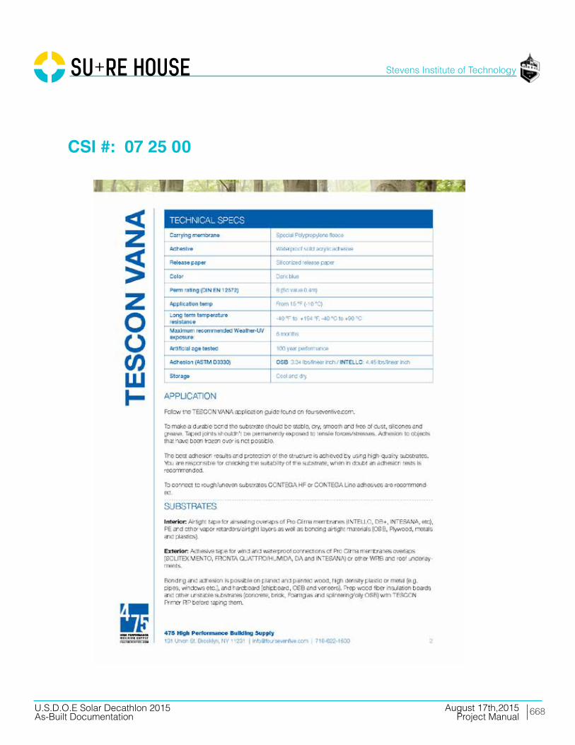
668
Stevens Institute of Technology
August 17th,2015U.S.D.O.E Solar Decathlon 2015As-Built Documentation Project Manual
CSI #: 07 25 00

669
Stevens Institute of Technology
August 17th,2015U.S.D.O.E Solar Decathlon 2015As-Built Documentation Project Manual
CSI #: 07 25 00
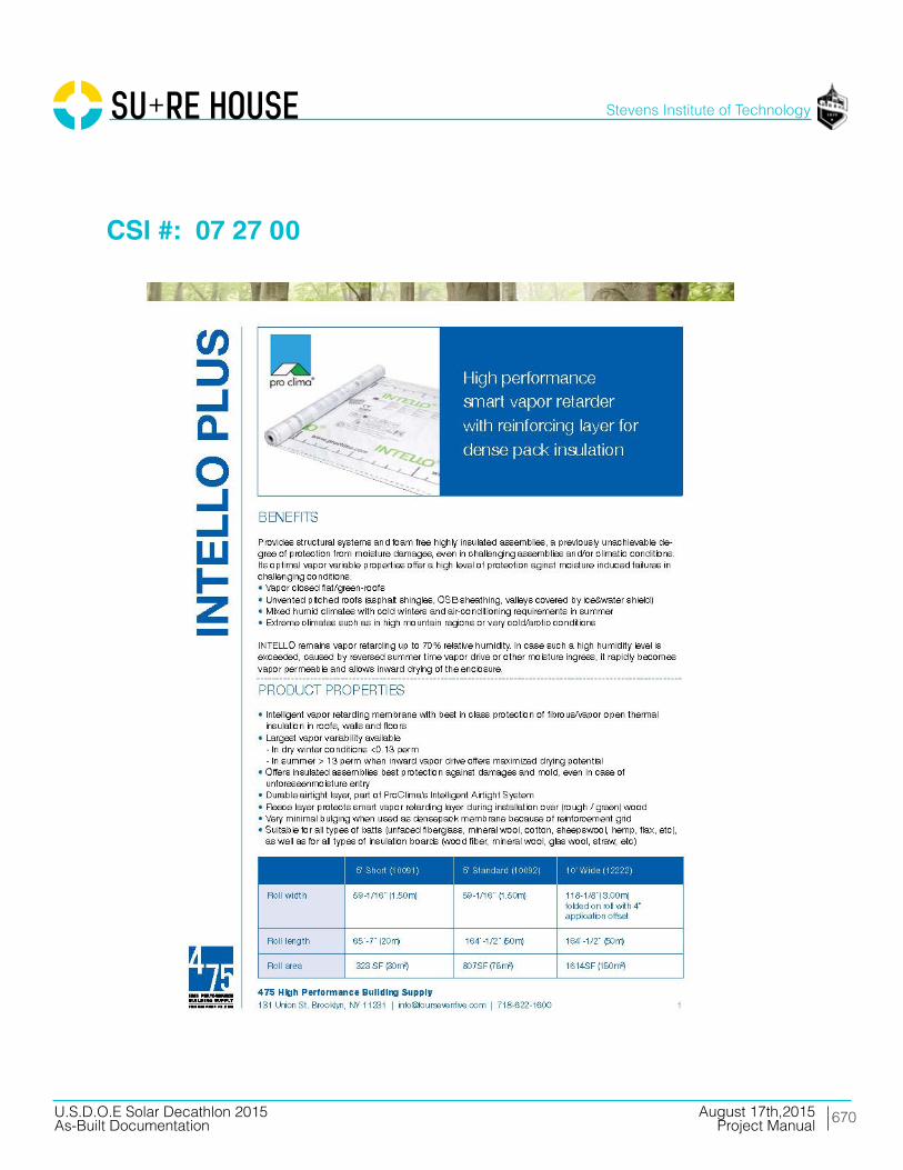
670
Stevens Institute of Technology
August 17th,2015U.S.D.O.E Solar Decathlon 2015As-Built Documentation Project Manual
CSI #: 07 27 00

671
Stevens Institute of Technology
August 17th,2015U.S.D.O.E Solar Decathlon 2015As-Built Documentation Project Manual
CSI #: 07 27 00

672
Stevens Institute of Technology
August 17th,2015U.S.D.O.E Solar Decathlon 2015As-Built Documentation Project Manual
CSI #: 07 27 00
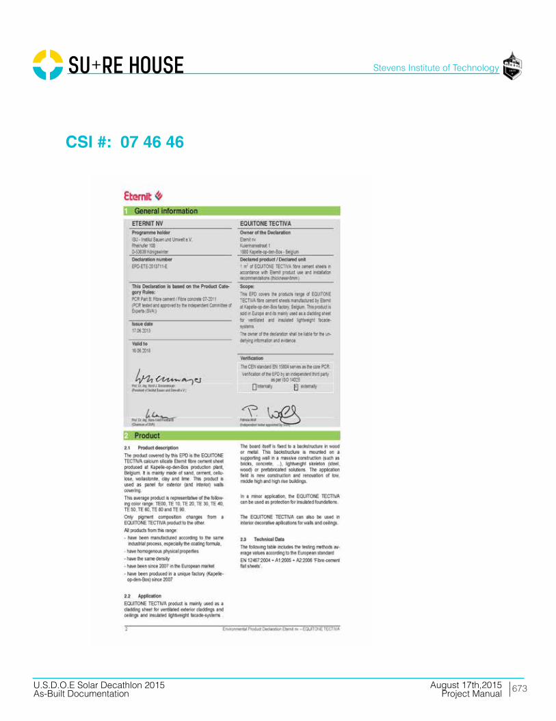
673
Stevens Institute of Technology
August 17th,2015U.S.D.O.E Solar Decathlon 2015As-Built Documentation Project Manual
CSI #: 07 46 46

674
Stevens Institute of Technology
August 17th,2015U.S.D.O.E Solar Decathlon 2015As-Built Documentation Project Manual
CSI #: 07 46 46
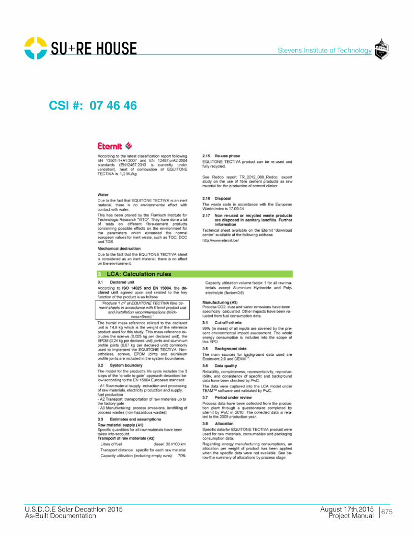
675
Stevens Institute of Technology
August 17th,2015U.S.D.O.E Solar Decathlon 2015As-Built Documentation Project Manual
CSI #: 07 46 46

676
Stevens Institute of Technology
August 17th,2015U.S.D.O.E Solar Decathlon 2015As-Built Documentation Project Manual
CSI #: 07 46 46

677
Stevens Institute of Technology
August 17th,2015U.S.D.O.E Solar Decathlon 2015As-Built Documentation Project Manual
CSI #: 07 46 46

678
Stevens Institute of Technology
August 17th,2015U.S.D.O.E Solar Decathlon 2015As-Built Documentation Project Manual
CSI #: 07 46 46
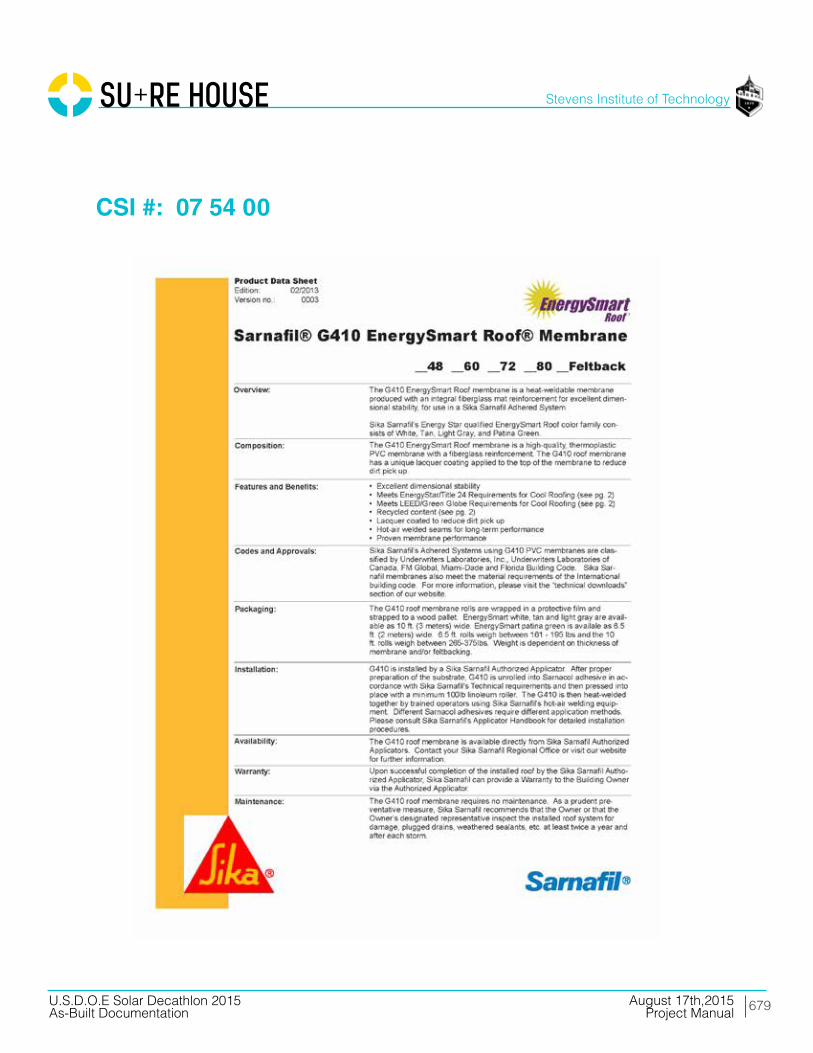
679
Stevens Institute of Technology
August 17th,2015U.S.D.O.E Solar Decathlon 2015As-Built Documentation Project Manual
CSI #: 07 54 00
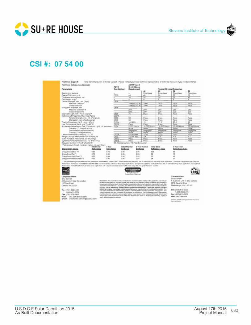
680
Stevens Institute of Technology
August 17th,2015U.S.D.O.E Solar Decathlon 2015As-Built Documentation Project Manual
CSI #: 07 54 00

681
Stevens Institute of Technology
August 17th,2015U.S.D.O.E Solar Decathlon 2015As-Built Documentation Project Manual
CSI #: 07 62 00

682
Stevens Institute of Technology
August 17th,2015U.S.D.O.E Solar Decathlon 2015As-Built Documentation Project Manual
CSI #: 07 62 00

683
Stevens Institute of Technology
August 17th,2015U.S.D.O.E Solar Decathlon 2015As-Built Documentation Project Manual
CSI #: 07 62 00

684
Stevens Institute of Technology
August 17th,2015U.S.D.O.E Solar Decathlon 2015As-Built Documentation Project Manual
CSI #: 07 62 00

685
Stevens Institute of Technology
August 17th,2015U.S.D.O.E Solar Decathlon 2015As-Built Documentation Project Manual
CSI #: 07 70 00

686
Stevens Institute of Technology
August 17th,2015U.S.D.O.E Solar Decathlon 2015As-Built Documentation Project Manual
CSI #: 07 71 00

687
Stevens Institute of Technology
August 17th,2015U.S.D.O.E Solar Decathlon 2015As-Built Documentation Project Manual
CSI #: 07 71 00

688
Stevens Institute of Technology
August 17th,2015U.S.D.O.E Solar Decathlon 2015As-Built Documentation Project Manual
CSI #: 07 71 00

689
Stevens Institute of Technology
August 17th,2015U.S.D.O.E Solar Decathlon 2015As-Built Documentation Project Manual
CSI #: 07 71 00

690
Stevens Institute of Technology
August 17th,2015U.S.D.O.E Solar Decathlon 2015As-Built Documentation Project Manual
CSI #: 07 71 13

691
Stevens Institute of Technology
August 17th,2015U.S.D.O.E Solar Decathlon 2015As-Built Documentation Project Manual
CSI #: 07 71 13

692
Stevens Institute of Technology
August 17th,2015U.S.D.O.E Solar Decathlon 2015As-Built Documentation Project Manual
CSI #: 07 91 00

693
Stevens Institute of Technology
August 17th,2015U.S.D.O.E Solar Decathlon 2015As-Built Documentation Project Manual
Division 08 Openings

694
Stevens Institute of Technology
August 17th,2015U.S.D.O.E Solar Decathlon 2015As-Built Documentation Project Manual
CSI #: 08 14 00

695
Stevens Institute of Technology
August 17th,2015U.S.D.O.E Solar Decathlon 2015As-Built Documentation Project Manual
CSI #: 08 14 00
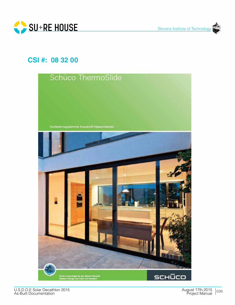
696
Stevens Institute of Technology
August 17th,2015U.S.D.O.E Solar Decathlon 2015As-Built Documentation Project Manual
CSI #: 08 32 00

697
Stevens Institute of Technology
August 17th,2015U.S.D.O.E Solar Decathlon 2015As-Built Documentation Project Manual
CSI #: 08 32 00

698
Stevens Institute of Technology
August 17th,2015U.S.D.O.E Solar Decathlon 2015As-Built Documentation Project Manual
CSI #: 08 32 00

699
Stevens Institute of Technology
August 17th,2015U.S.D.O.E Solar Decathlon 2015As-Built Documentation Project Manual
CSI #: 08 53 00

700
Stevens Institute of Technology
August 17th,2015U.S.D.O.E Solar Decathlon 2015As-Built Documentation Project Manual
CSI #: 08 53 00

701
Stevens Institute of Technology
August 17th,2015U.S.D.O.E Solar Decathlon 2015As-Built Documentation Project Manual
CSI #: 08 53 00

702
Stevens Institute of Technology
August 17th,2015U.S.D.O.E Solar Decathlon 2015As-Built Documentation Project Manual
CSI #: 08 53 00

703
Stevens Institute of Technology
August 17th,2015U.S.D.O.E Solar Decathlon 2015As-Built Documentation Project Manual
CSI #: 08 71 00

704
Stevens Institute of Technology
August 17th,2015U.S.D.O.E Solar Decathlon 2015As-Built Documentation Project Manual
CSI #: 08 71 00

705
Stevens Institute of Technology
August 17th,2015U.S.D.O.E Solar Decathlon 2015As-Built Documentation Project Manual
CSI #: 08 90 00
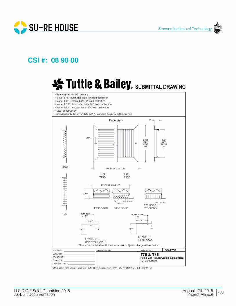
706
Stevens Institute of Technology
August 17th,2015U.S.D.O.E Solar Decathlon 2015As-Built Documentation Project Manual
CSI #: 08 90 00

707
Stevens Institute of Technology
August 17th,2015U.S.D.O.E Solar Decathlon 2015As-Built Documentation Project Manual
Division 09 Finishes
708
Stevens Institute of Technology
August 17th,2015U.S.D.O.E Solar Decathlon 2015As-Built Documentation Project Manual
CSI #: 09 20 00
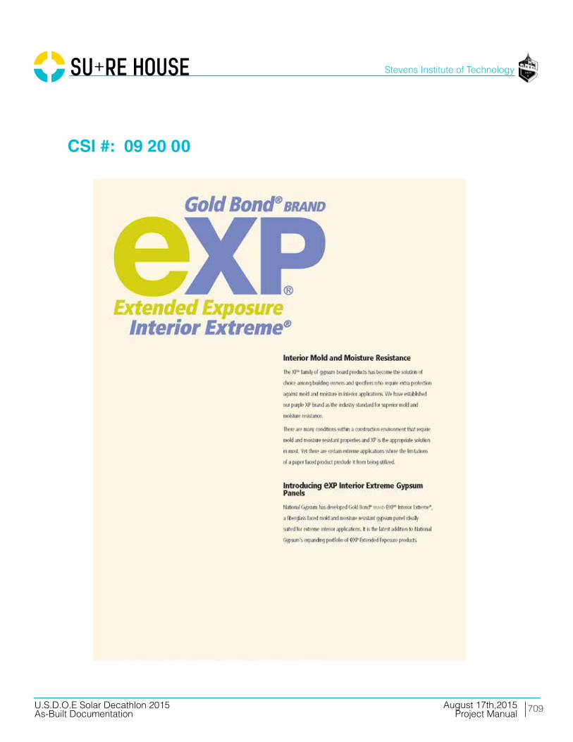
709
Stevens Institute of Technology
August 17th,2015U.S.D.O.E Solar Decathlon 2015As-Built Documentation Project Manual
CSI #: 09 20 00

710
Stevens Institute of Technology
August 17th,2015U.S.D.O.E Solar Decathlon 2015As-Built Documentation Project Manual
CSI #: 09 20 00
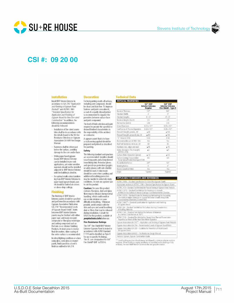
711
Stevens Institute of Technology
August 17th,2015U.S.D.O.E Solar Decathlon 2015As-Built Documentation Project Manual
CSI #: 09 20 00
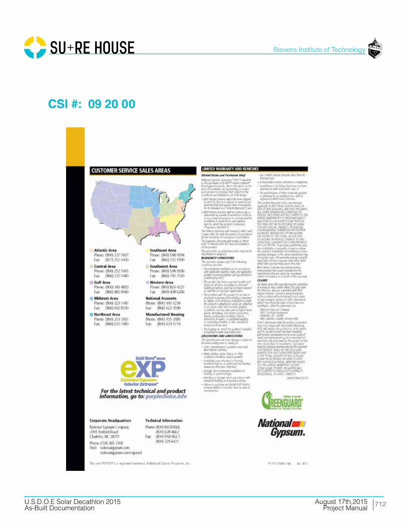
712
Stevens Institute of Technology
August 17th,2015U.S.D.O.E Solar Decathlon 2015As-Built Documentation Project Manual
CSI #: 09 20 00

713
Stevens Institute of Technology
August 17th,2015U.S.D.O.E Solar Decathlon 2015As-Built Documentation Project Manual
CSI #: 09 20 00
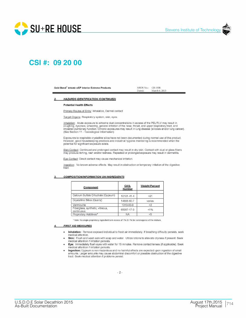
714
Stevens Institute of Technology
August 17th,2015U.S.D.O.E Solar Decathlon 2015As-Built Documentation Project Manual
CSI #: 09 20 00

715
Stevens Institute of Technology
August 17th,2015U.S.D.O.E Solar Decathlon 2015As-Built Documentation Project Manual
CSI #: 09 20 00

716
Stevens Institute of Technology
August 17th,2015U.S.D.O.E Solar Decathlon 2015As-Built Documentation Project Manual
CSI #: 09 20 00

717
Stevens Institute of Technology
August 17th,2015U.S.D.O.E Solar Decathlon 2015As-Built Documentation Project Manual
CSI #: 09 20 00
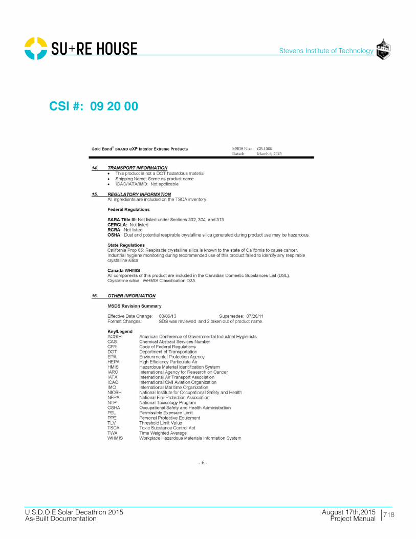
718
Stevens Institute of Technology
August 17th,2015U.S.D.O.E Solar Decathlon 2015As-Built Documentation Project Manual
CSI #: 09 20 00

719
Stevens Institute of Technology
August 17th,2015U.S.D.O.E Solar Decathlon 2015As-Built Documentation Project Manual
CSI #: 09 20 00
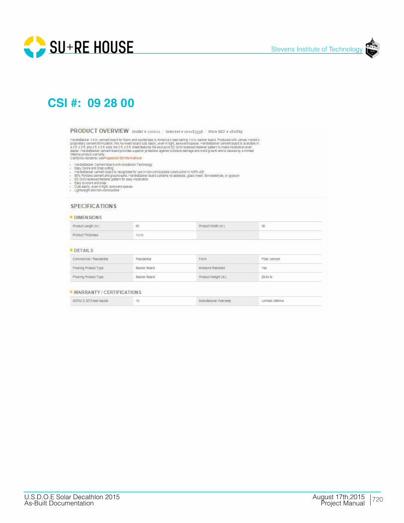
720
Stevens Institute of Technology
August 17th,2015U.S.D.O.E Solar Decathlon 2015As-Built Documentation Project Manual
CSI #: 09 28 00
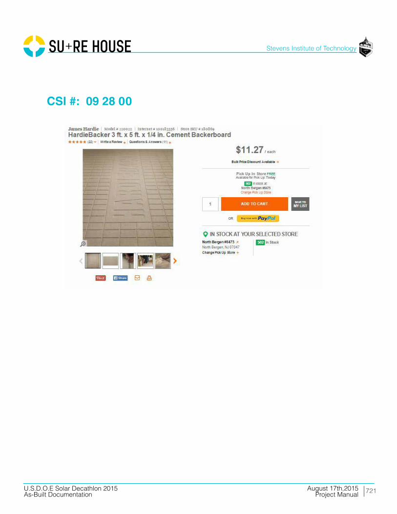
721
Stevens Institute of Technology
August 17th,2015U.S.D.O.E Solar Decathlon 2015As-Built Documentation Project Manual
CSI #: 09 28 00
722
Stevens Institute of Technology
August 17th,2015U.S.D.O.E Solar Decathlon 2015As-Built Documentation Project Manual
CSI #: 09 28 00
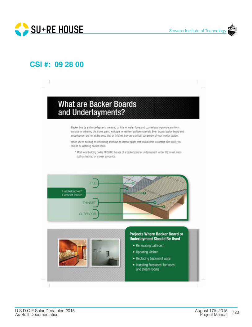
723
Stevens Institute of Technology
August 17th,2015U.S.D.O.E Solar Decathlon 2015As-Built Documentation Project Manual
CSI #: 09 28 00

724
Stevens Institute of Technology
August 17th,2015U.S.D.O.E Solar Decathlon 2015As-Built Documentation Project Manual
CSI #: 09 28 00

725
Stevens Institute of Technology
August 17th,2015U.S.D.O.E Solar Decathlon 2015As-Built Documentation Project Manual
CSI #: 09 28 00

726
Stevens Institute of Technology
August 17th,2015U.S.D.O.E Solar Decathlon 2015As-Built Documentation Project Manual
CSI #: 09 28 00
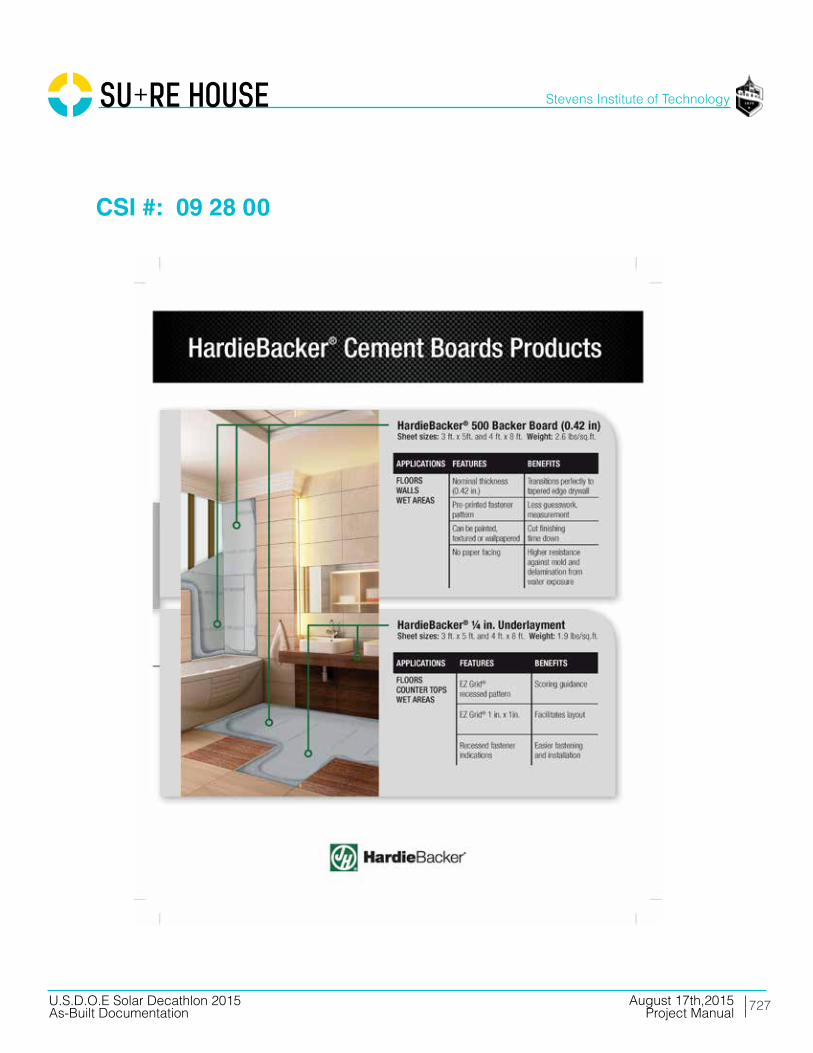
727
Stevens Institute of Technology
August 17th,2015U.S.D.O.E Solar Decathlon 2015As-Built Documentation Project Manual
CSI #: 09 28 00

728
Stevens Institute of Technology
August 17th,2015U.S.D.O.E Solar Decathlon 2015As-Built Documentation Project Manual
CSI #: 09 30 00

729
Stevens Institute of Technology
August 17th,2015U.S.D.O.E Solar Decathlon 2015As-Built Documentation Project Manual
CSI #: 09 30 00
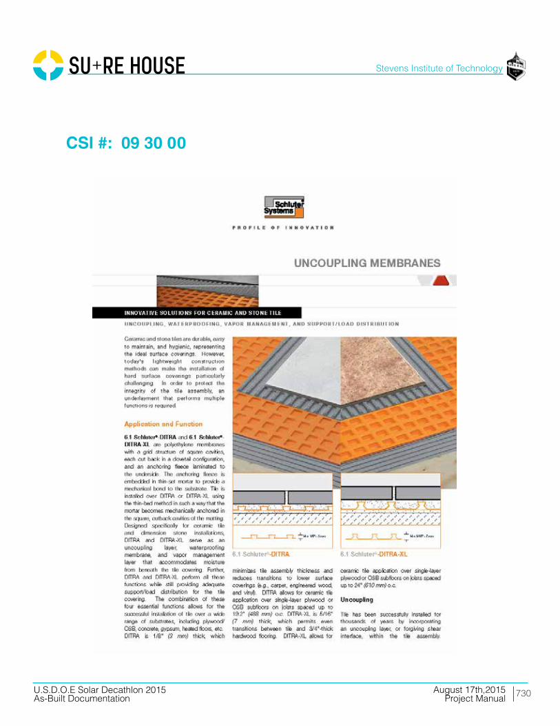
730
Stevens Institute of Technology
August 17th,2015U.S.D.O.E Solar Decathlon 2015As-Built Documentation Project Manual
CSI #: 09 30 00

731
Stevens Institute of Technology
August 17th,2015U.S.D.O.E Solar Decathlon 2015As-Built Documentation Project Manual
CSI #: 09 30 00

732
Stevens Institute of Technology
August 17th,2015U.S.D.O.E Solar Decathlon 2015As-Built Documentation Project Manual
CSI #: 09 30 00
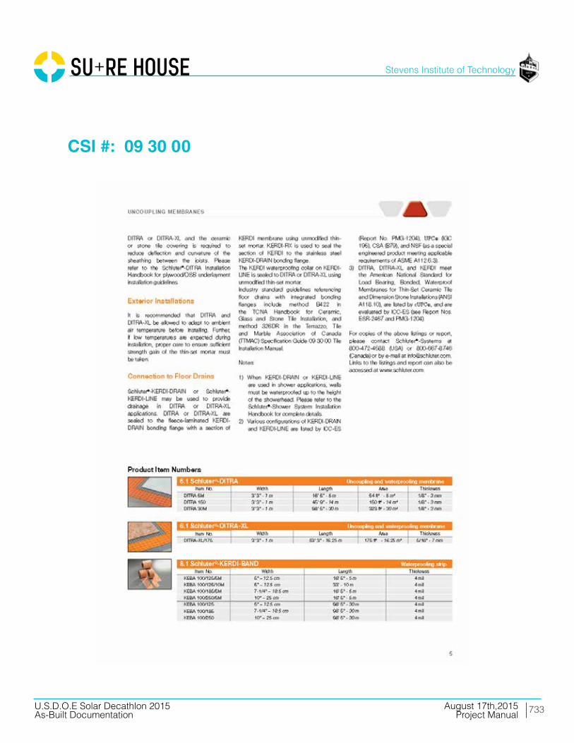
733
Stevens Institute of Technology
August 17th,2015U.S.D.O.E Solar Decathlon 2015As-Built Documentation Project Manual
CSI #: 09 30 00
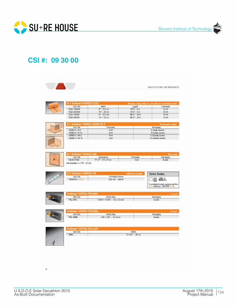
734
Stevens Institute of Technology
August 17th,2015U.S.D.O.E Solar Decathlon 2015As-Built Documentation Project Manual
CSI #: 09 30 00
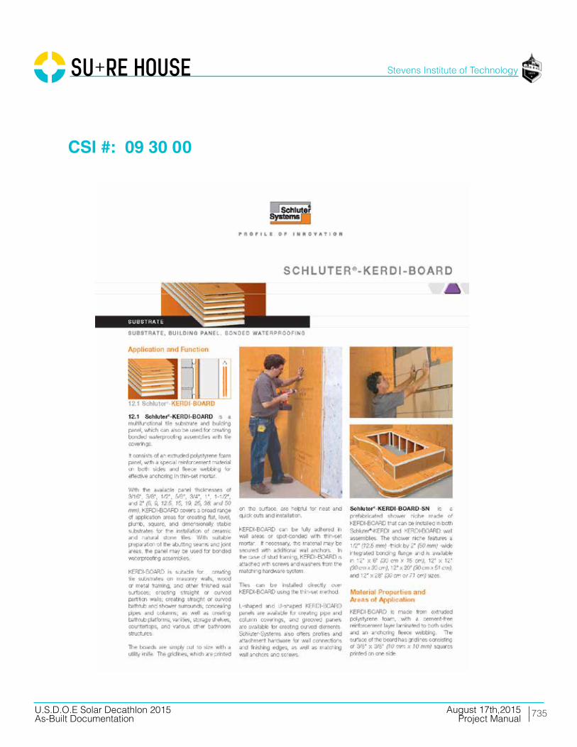
735
Stevens Institute of Technology
August 17th,2015U.S.D.O.E Solar Decathlon 2015As-Built Documentation Project Manual
CSI #: 09 30 00
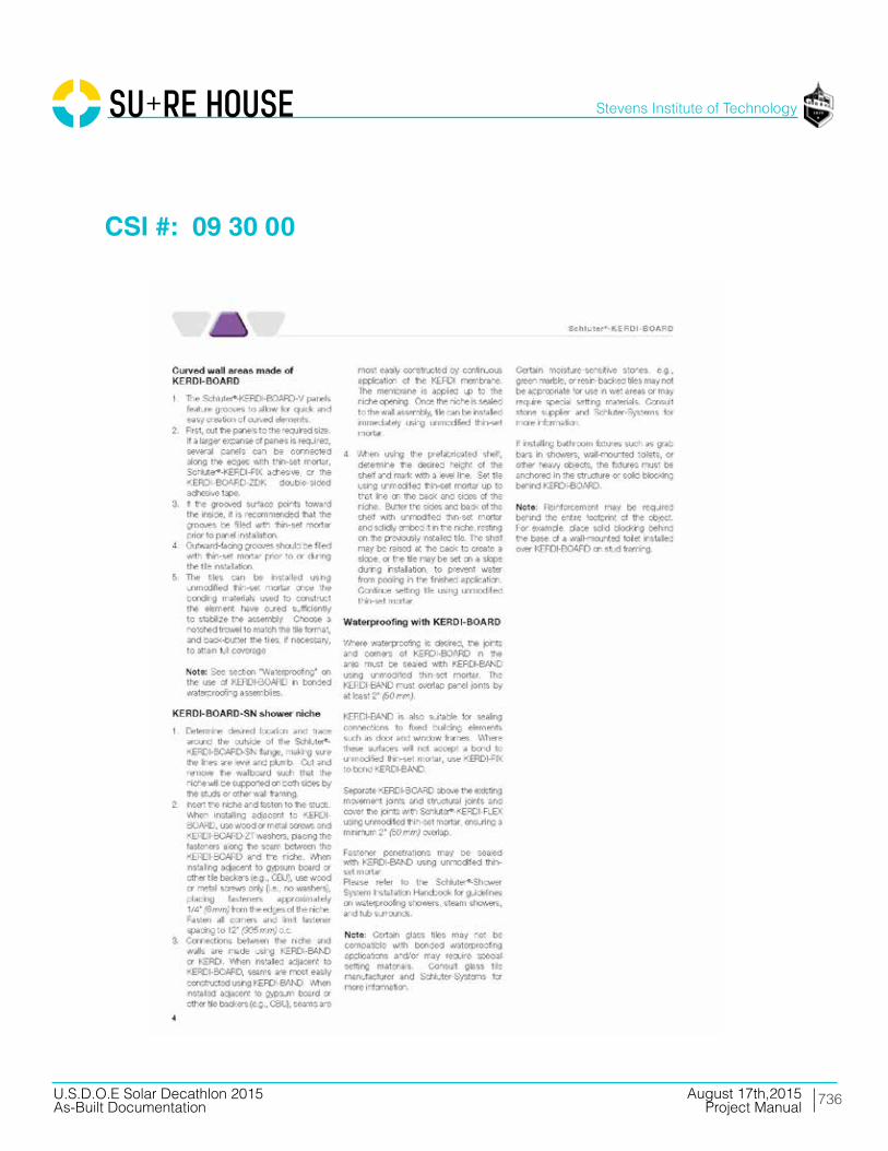
736
Stevens Institute of Technology
August 17th,2015U.S.D.O.E Solar Decathlon 2015As-Built Documentation Project Manual
CSI #: 09 30 00
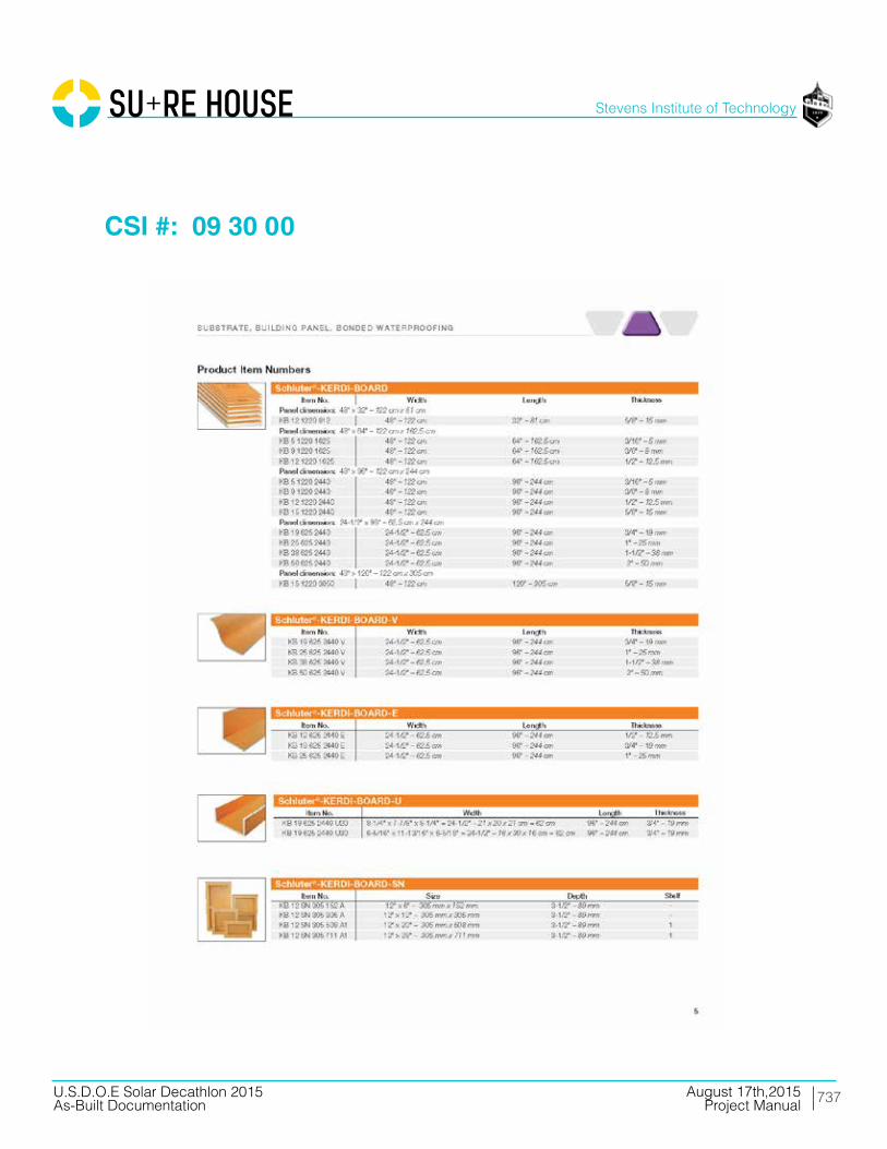
737
Stevens Institute of Technology
August 17th,2015U.S.D.O.E Solar Decathlon 2015As-Built Documentation Project Manual
CSI #: 09 30 00

738
Stevens Institute of Technology
August 17th,2015U.S.D.O.E Solar Decathlon 2015As-Built Documentation Project Manual
CSI #: 09 30 00

739
Stevens Institute of Technology
August 17th,2015U.S.D.O.E Solar Decathlon 2015As-Built Documentation Project Manual
CSI #: 09 30 00
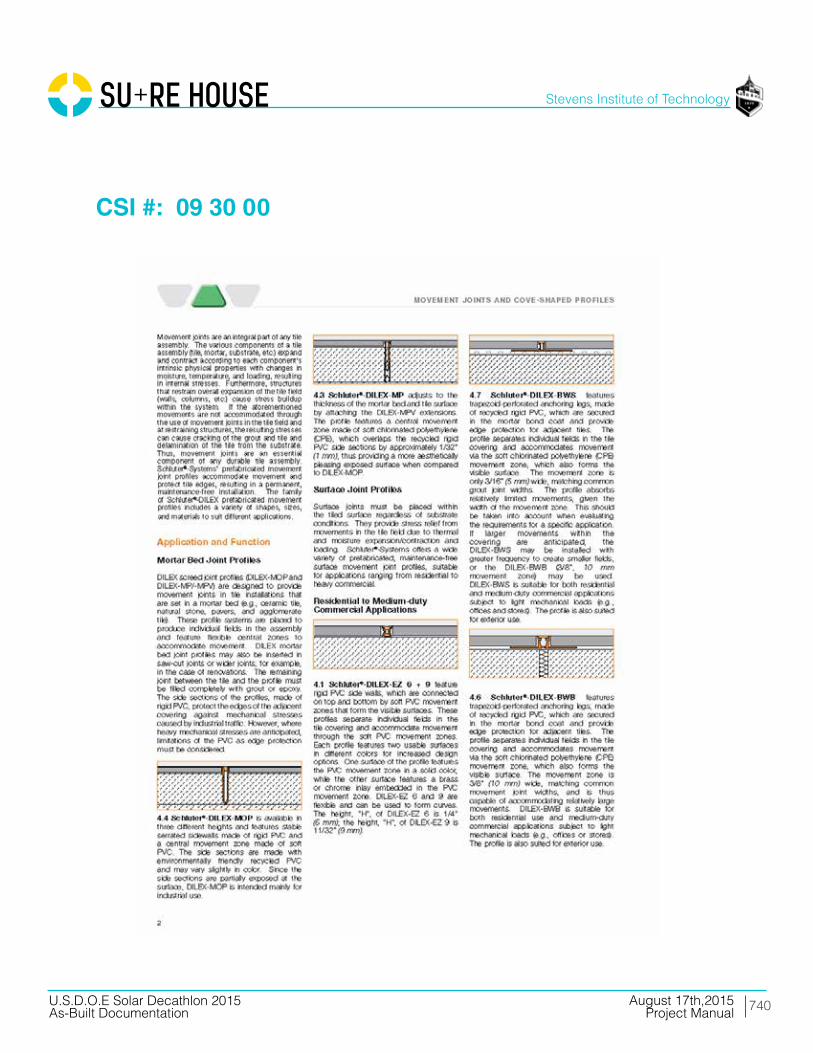
740
Stevens Institute of Technology
August 17th,2015U.S.D.O.E Solar Decathlon 2015As-Built Documentation Project Manual
CSI #: 09 30 00
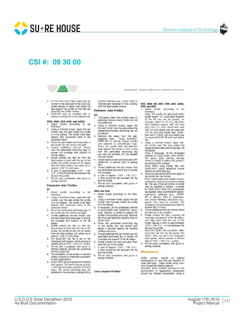
741
Stevens Institute of Technology
August 17th,2015U.S.D.O.E Solar Decathlon 2015As-Built Documentation Project Manual
CSI #: 09 30 00
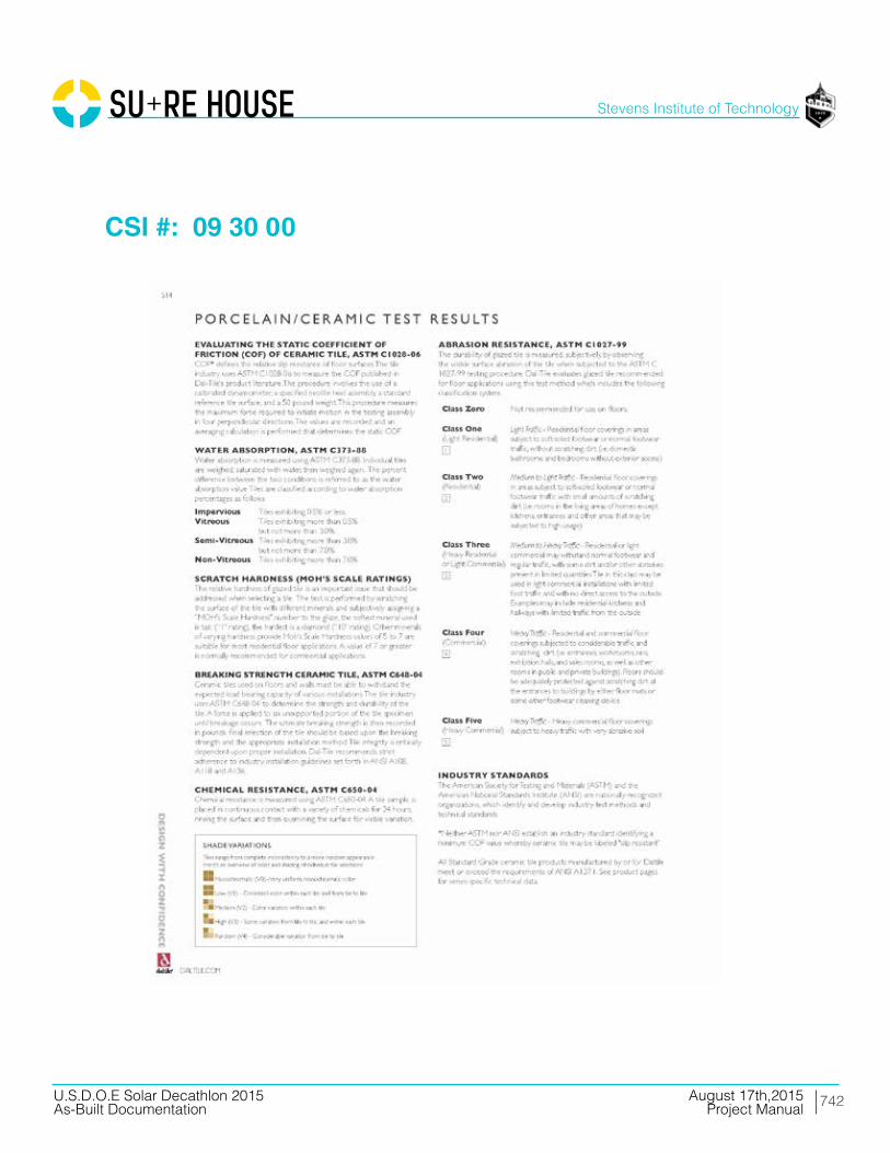
742
Stevens Institute of Technology
August 17th,2015U.S.D.O.E Solar Decathlon 2015As-Built Documentation Project Manual
CSI #: 09 30 00

743
Stevens Institute of Technology
August 17th,2015U.S.D.O.E Solar Decathlon 2015As-Built Documentation Project Manual
CSI #: 09 30 00

744
Stevens Institute of Technology
August 17th,2015U.S.D.O.E Solar Decathlon 2015As-Built Documentation Project Manual
CSI #: 09 30 00

745
Stevens Institute of Technology
August 17th,2015U.S.D.O.E Solar Decathlon 2015As-Built Documentation Project Manual
CSI #: 09 30 00

746
Stevens Institute of Technology
August 17th,2015U.S.D.O.E Solar Decathlon 2015As-Built Documentation Project Manual
CSI #: 09 30 00
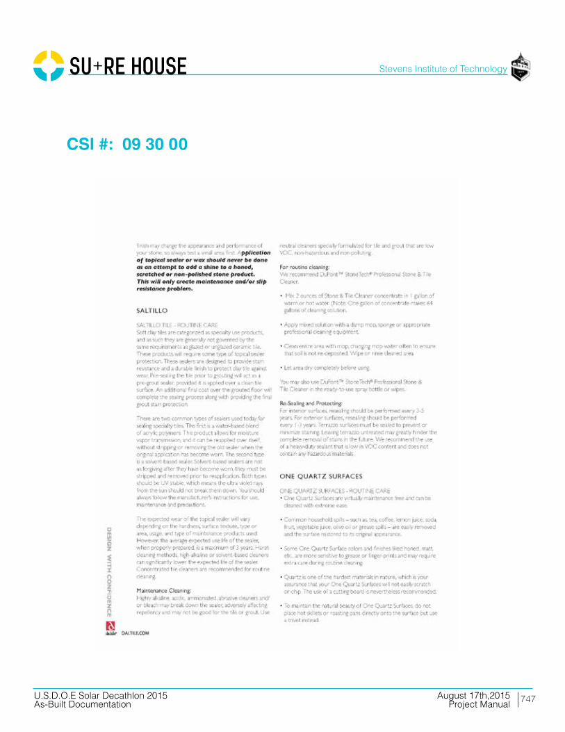
747
Stevens Institute of Technology
August 17th,2015U.S.D.O.E Solar Decathlon 2015As-Built Documentation Project Manual
CSI #: 09 30 00

748
Stevens Institute of Technology
August 17th,2015U.S.D.O.E Solar Decathlon 2015As-Built Documentation Project Manual
CSI #: 09 30 00
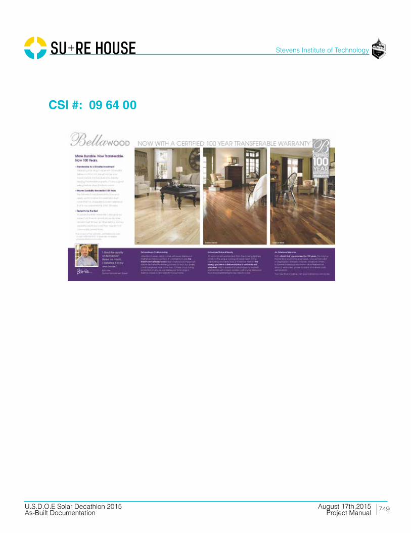
749
Stevens Institute of Technology
August 17th,2015U.S.D.O.E Solar Decathlon 2015As-Built Documentation Project Manual
CSI #: 09 64 00

750
Stevens Institute of Technology
August 17th,2015U.S.D.O.E Solar Decathlon 2015As-Built Documentation Project Manual
CSI #: 09 91 23

751
Stevens Institute of Technology
August 17th,2015U.S.D.O.E Solar Decathlon 2015As-Built Documentation Project Manual
CSI #: 09 91 23
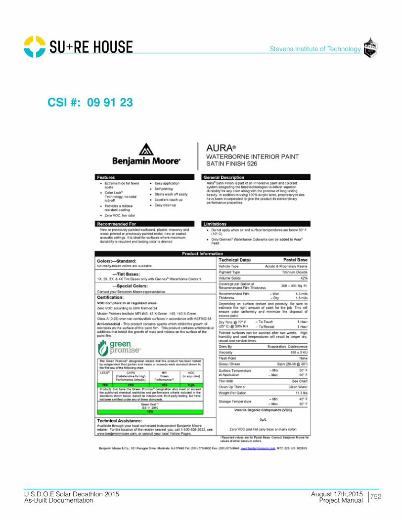
752
Stevens Institute of Technology
August 17th,2015U.S.D.O.E Solar Decathlon 2015As-Built Documentation Project Manual
CSI #: 09 91 23

753
Stevens Institute of Technology
August 17th,2015U.S.D.O.E Solar Decathlon 2015As-Built Documentation Project Manual
CSI #: 09 91 23
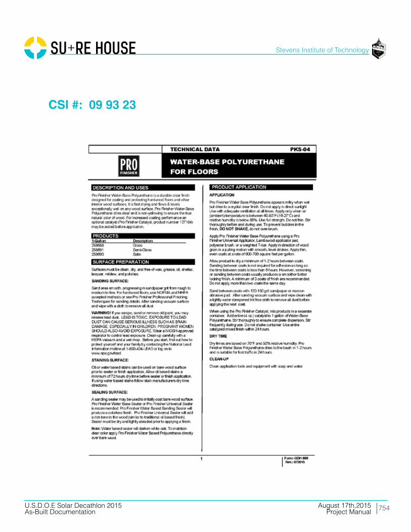
754
Stevens Institute of Technology
August 17th,2015U.S.D.O.E Solar Decathlon 2015As-Built Documentation Project Manual
CSI #: 09 93 23

755
Stevens Institute of Technology
August 17th,2015U.S.D.O.E Solar Decathlon 2015As-Built Documentation Project Manual
CSI #: 09 93 23

756
Stevens Institute of Technology
August 17th,2015U.S.D.O.E Solar Decathlon 2015As-Built Documentation Project Manual
Division 10 Specialties

757
Stevens Institute of Technology
August 17th,2015U.S.D.O.E Solar Decathlon 2015As-Built Documentation Project Manual
CSI #: 10 28 13

758
Stevens Institute of Technology
August 17th,2015U.S.D.O.E Solar Decathlon 2015As-Built Documentation Project Manual
CSI #: 10 28 13
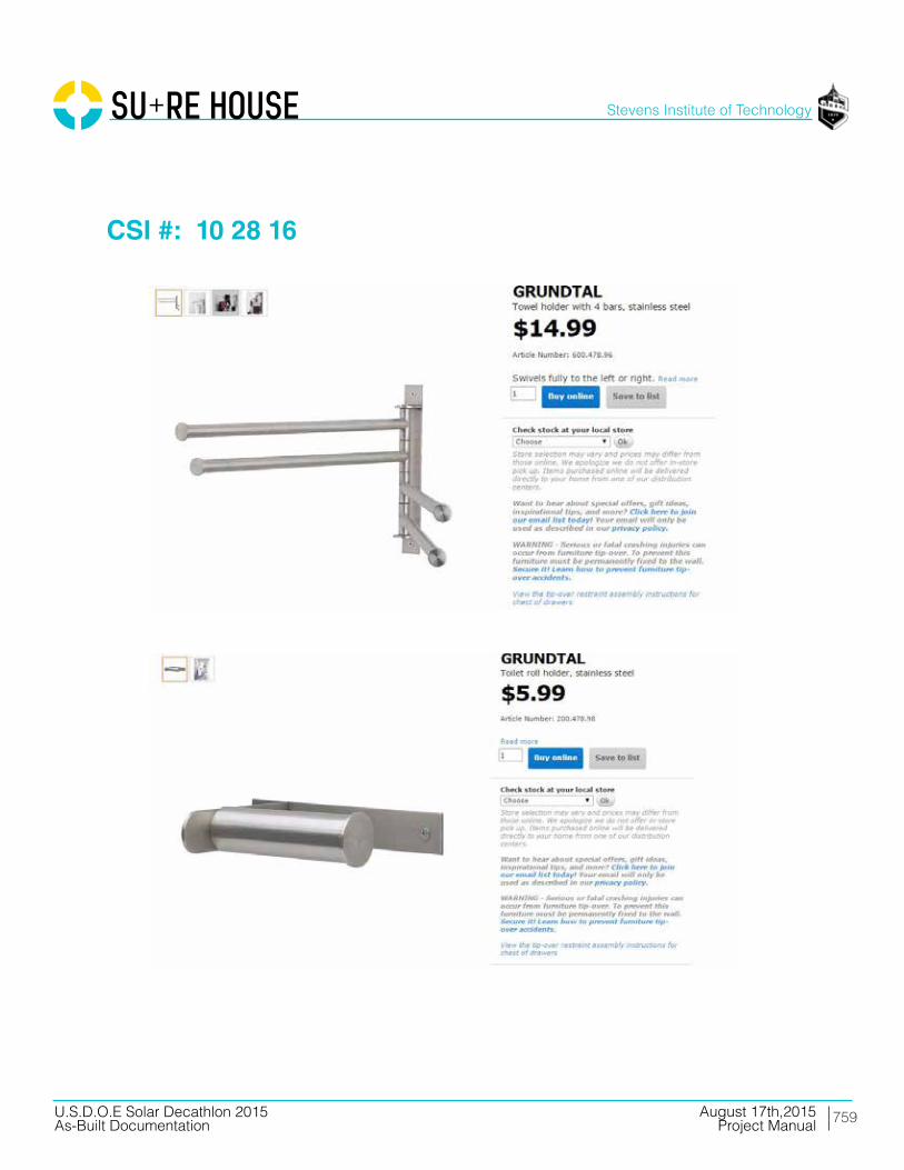
759
Stevens Institute of Technology
August 17th,2015U.S.D.O.E Solar Decathlon 2015As-Built Documentation Project Manual
CSI #: 10 28 16

760
Stevens Institute of Technology
August 17th,2015U.S.D.O.E Solar Decathlon 2015As-Built Documentation Project Manual
CSI #: 10 28 16

761
Stevens Institute of Technology
August 17th,2015U.S.D.O.E Solar Decathlon 2015As-Built Documentation Project Manual
CSI #: 10 35 23

762
Stevens Institute of Technology
August 17th,2015U.S.D.O.E Solar Decathlon 2015As-Built Documentation Project Manual
CSI #: 10 82 23

763
Stevens Institute of Technology
August 17th,2015U.S.D.O.E Solar Decathlon 2015As-Built Documentation Project Manual
CSI #: 10 82 23
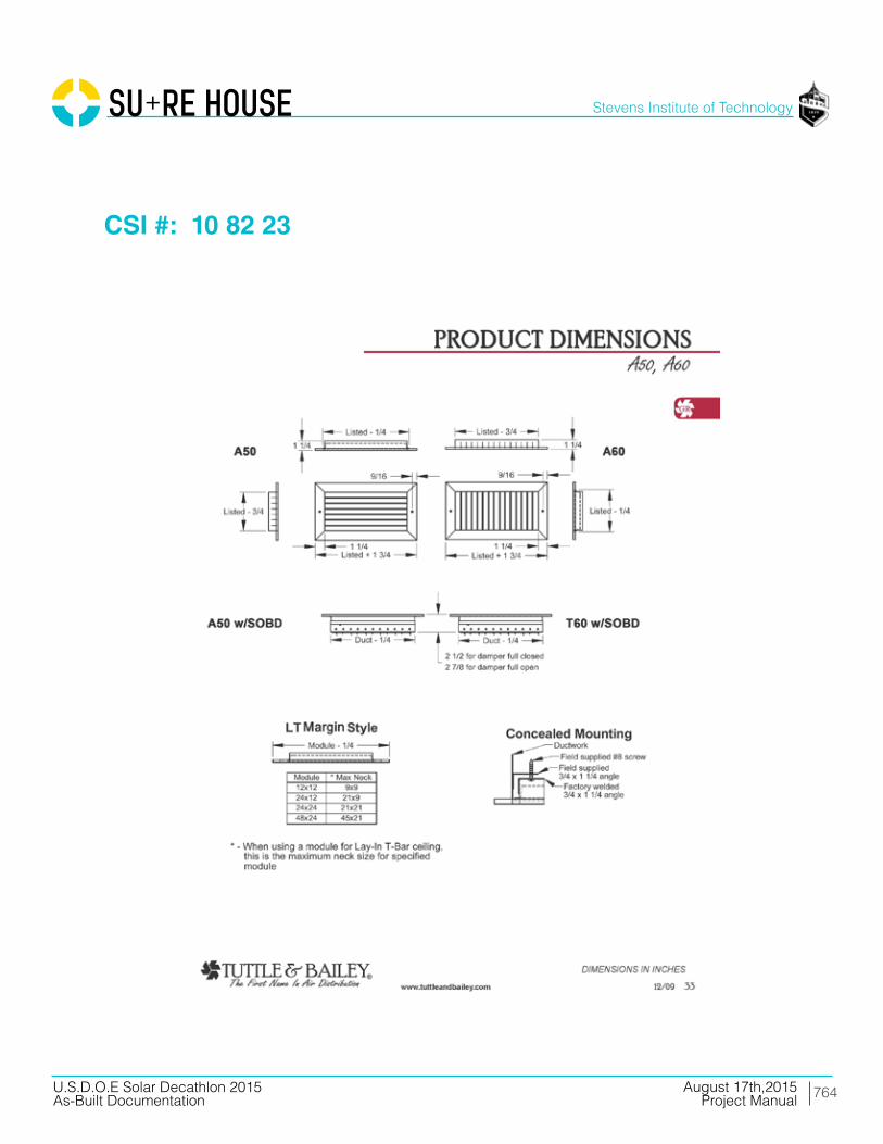
764
Stevens Institute of Technology
August 17th,2015U.S.D.O.E Solar Decathlon 2015As-Built Documentation Project Manual
CSI #: 10 82 23

765
Stevens Institute of Technology
August 17th,2015U.S.D.O.E Solar Decathlon 2015As-Built Documentation Project Manual
CSI #: 10 82 23
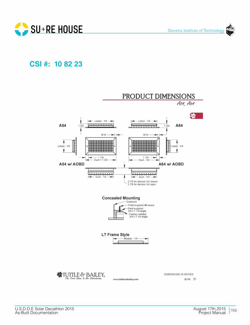
766
Stevens Institute of Technology
August 17th,2015U.S.D.O.E Solar Decathlon 2015As-Built Documentation Project Manual
CSI #: 10 82 23

767
Stevens Institute of Technology
August 17th,2015U.S.D.O.E Solar Decathlon 2015As-Built Documentation Project Manual
Division 11 Equipment

768
Stevens Institute of Technology
August 17th,2015U.S.D.O.E Solar Decathlon 2015As-Built Documentation Project Manual
CSI #: 11 10 00

769
Stevens Institute of Technology
August 17th,2015U.S.D.O.E Solar Decathlon 2015As-Built Documentation Project Manual
CSI #: 11 10 00
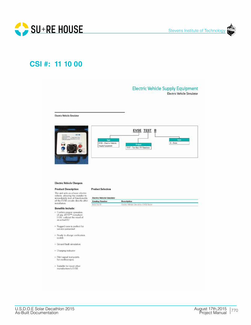
770
Stevens Institute of Technology
August 17th,2015U.S.D.O.E Solar Decathlon 2015As-Built Documentation Project Manual
CSI #: 11 10 00

771
Stevens Institute of Technology
August 17th,2015U.S.D.O.E Solar Decathlon 2015As-Built Documentation Project Manual
CSI #: 11 30 13.13

772
Stevens Institute of Technology
August 17th,2015U.S.D.O.E Solar Decathlon 2015As-Built Documentation Project Manual
CSI #: 11 30 13.13

773
Stevens Institute of Technology
August 17th,2015U.S.D.O.E Solar Decathlon 2015As-Built Documentation Project Manual
CSI #: 11 30 13.13
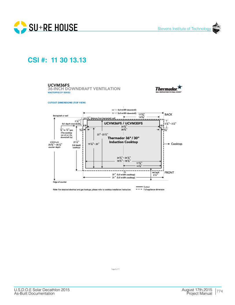
774
Stevens Institute of Technology
August 17th,2015U.S.D.O.E Solar Decathlon 2015As-Built Documentation Project Manual
CSI #: 11 30 13.13

775
Stevens Institute of Technology
August 17th,2015U.S.D.O.E Solar Decathlon 2015As-Built Documentation Project Manual
CSI #: 11 30 13.13
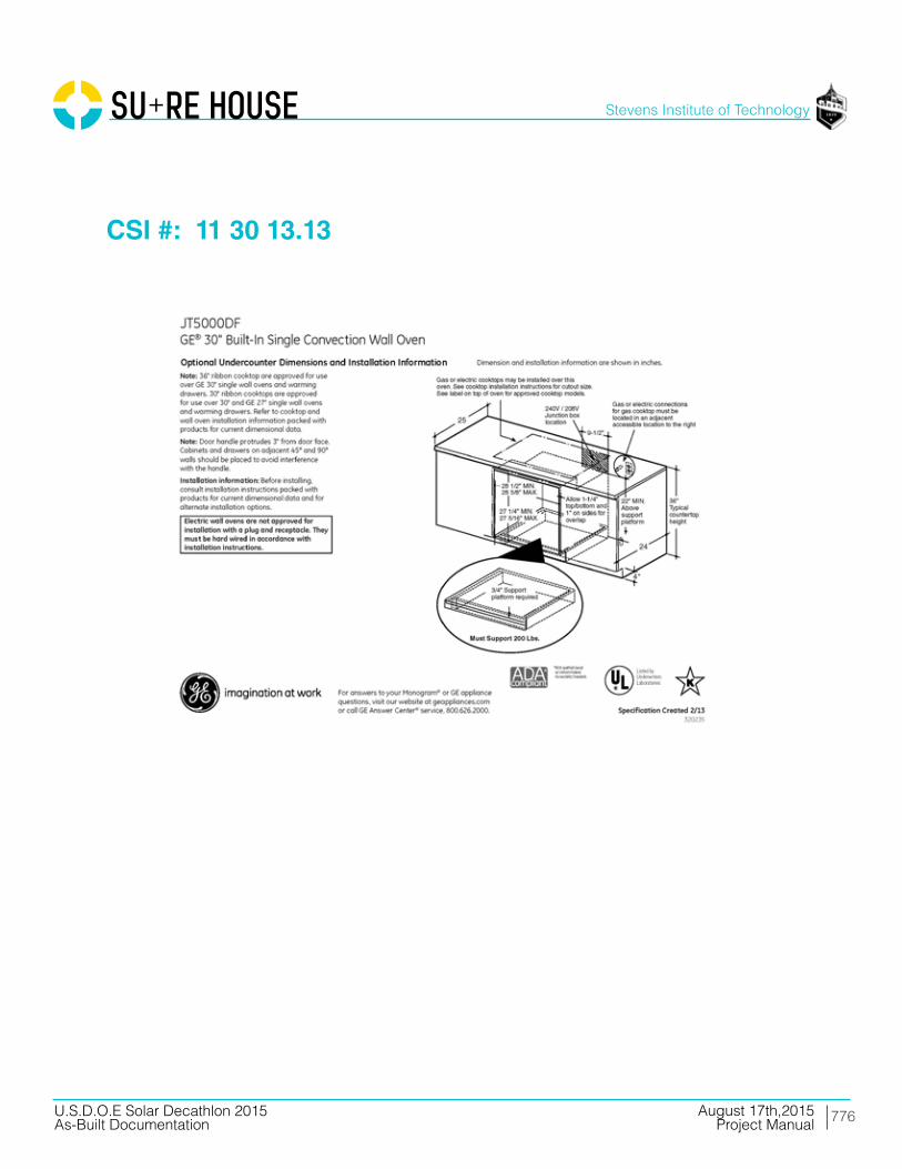
776
Stevens Institute of Technology
August 17th,2015U.S.D.O.E Solar Decathlon 2015As-Built Documentation Project Manual
CSI #: 11 30 13.13

777
Stevens Institute of Technology
August 17th,2015U.S.D.O.E Solar Decathlon 2015As-Built Documentation Project Manual
CSI #: 11 30 13.13

778
Stevens Institute of Technology
August 17th,2015U.S.D.O.E Solar Decathlon 2015As-Built Documentation Project Manual
CSI #: 11 30 13.23
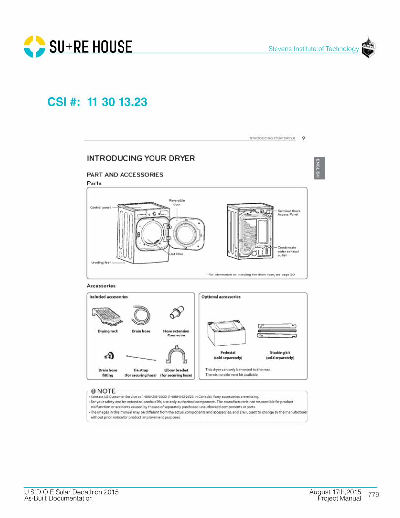
779
Stevens Institute of Technology
August 17th,2015U.S.D.O.E Solar Decathlon 2015As-Built Documentation Project Manual
CSI #: 11 30 13.23

780
Stevens Institute of Technology
August 17th,2015U.S.D.O.E Solar Decathlon 2015As-Built Documentation Project Manual
CSI #: 11 30 13.23
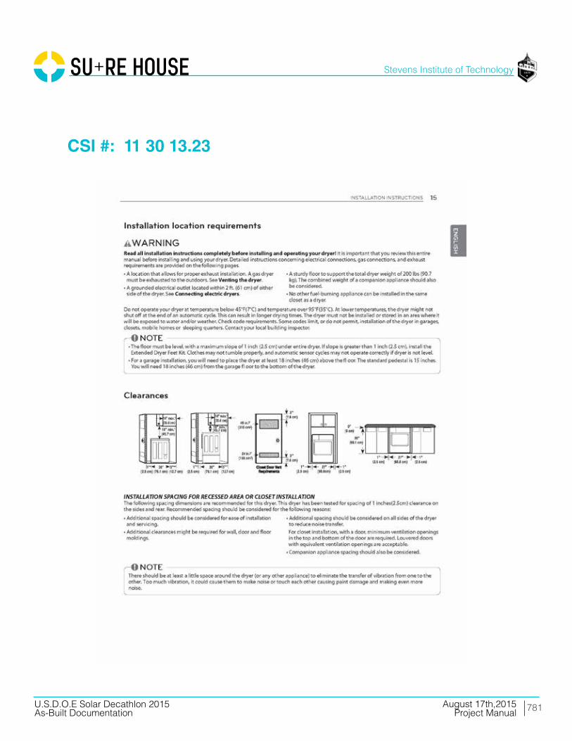
781
Stevens Institute of Technology
August 17th,2015U.S.D.O.E Solar Decathlon 2015As-Built Documentation Project Manual
CSI #: 11 30 13.23

782
Stevens Institute of Technology
August 17th,2015U.S.D.O.E Solar Decathlon 2015As-Built Documentation Project Manual
CSI #: 11 30 13.23
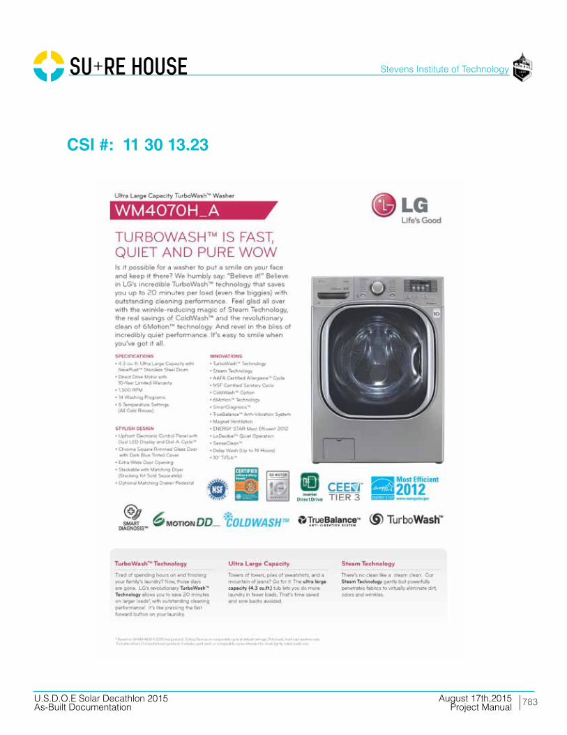
783
Stevens Institute of Technology
August 17th,2015U.S.D.O.E Solar Decathlon 2015As-Built Documentation Project Manual
CSI #: 11 30 13.23
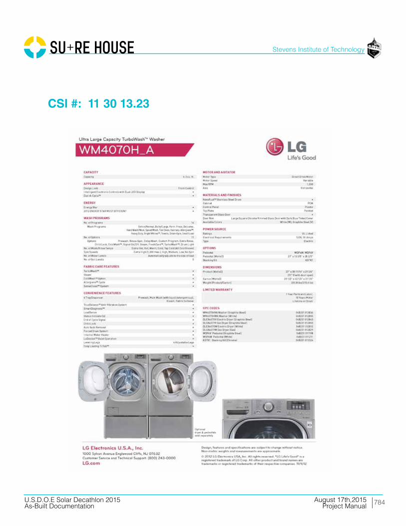
784
Stevens Institute of Technology
August 17th,2015U.S.D.O.E Solar Decathlon 2015As-Built Documentation Project Manual
CSI #: 11 30 13.23

785
Stevens Institute of Technology
August 17th,2015U.S.D.O.E Solar Decathlon 2015As-Built Documentation Project Manual
CSI #: 11 30 13

786
Stevens Institute of Technology
August 17th,2015U.S.D.O.E Solar Decathlon 2015As-Built Documentation Project Manual
CSI #: 11 48 00

787
Stevens Institute of Technology
August 17th,2015U.S.D.O.E Solar Decathlon 2015As-Built Documentation Project Manual
CSI #: 11 48 00

788
Stevens Institute of Technology
August 17th,2015U.S.D.O.E Solar Decathlon 2015As-Built Documentation Project Manual
Division 12 Furnishings
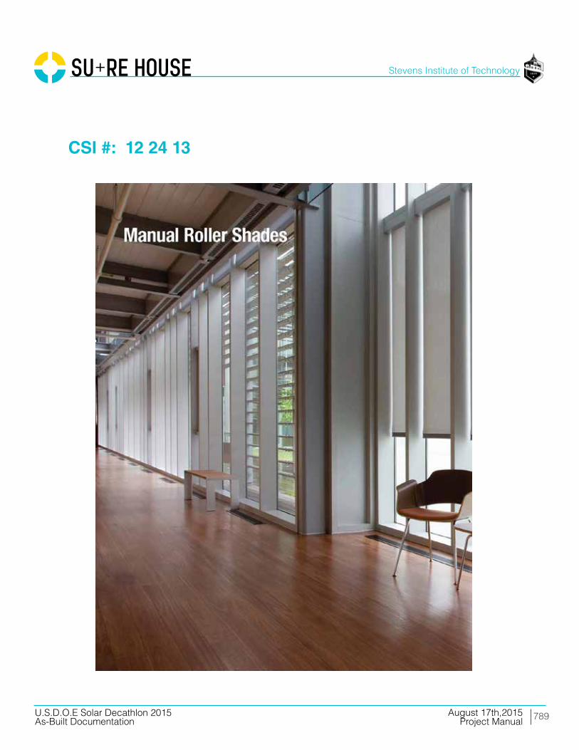
789
Stevens Institute of Technology
August 17th,2015U.S.D.O.E Solar Decathlon 2015As-Built Documentation Project Manual
CSI #: 12 24 13
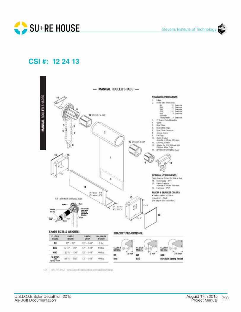
790
Stevens Institute of Technology
August 17th,2015U.S.D.O.E Solar Decathlon 2015As-Built Documentation Project Manual
CSI #: 12 24 13

791
Stevens Institute of Technology
August 17th,2015U.S.D.O.E Solar Decathlon 2015As-Built Documentation Project Manual
CSI #: 12 24 13
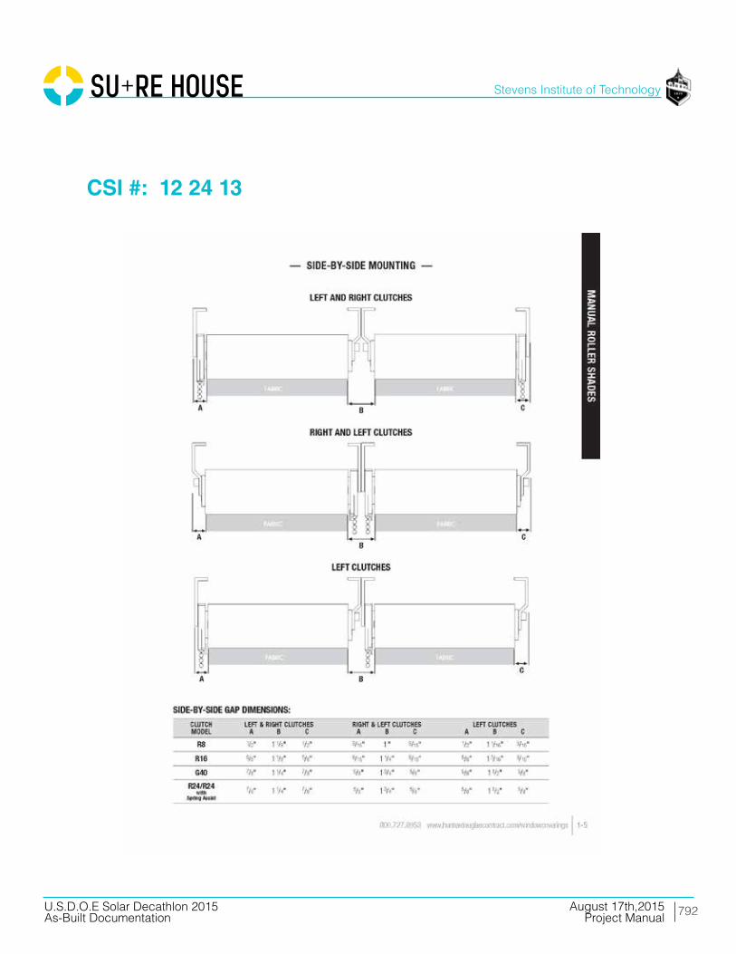
792
Stevens Institute of Technology
August 17th,2015U.S.D.O.E Solar Decathlon 2015As-Built Documentation Project Manual
CSI #: 12 24 13

793
Stevens Institute of Technology
August 17th,2015U.S.D.O.E Solar Decathlon 2015As-Built Documentation Project Manual
CSI #: 12 24 13

794
Stevens Institute of Technology
August 17th,2015U.S.D.O.E Solar Decathlon 2015As-Built Documentation Project Manual
CSI #: 12 24 13
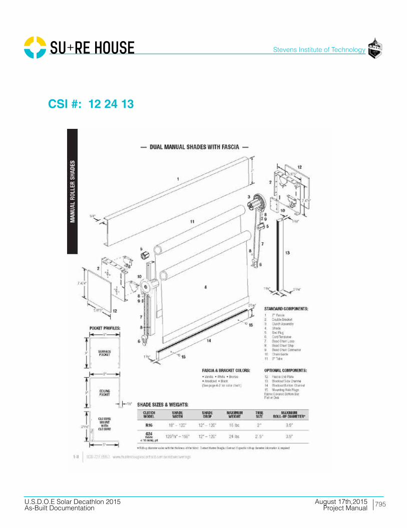
795
Stevens Institute of Technology
August 17th,2015U.S.D.O.E Solar Decathlon 2015As-Built Documentation Project Manual
CSI #: 12 24 13
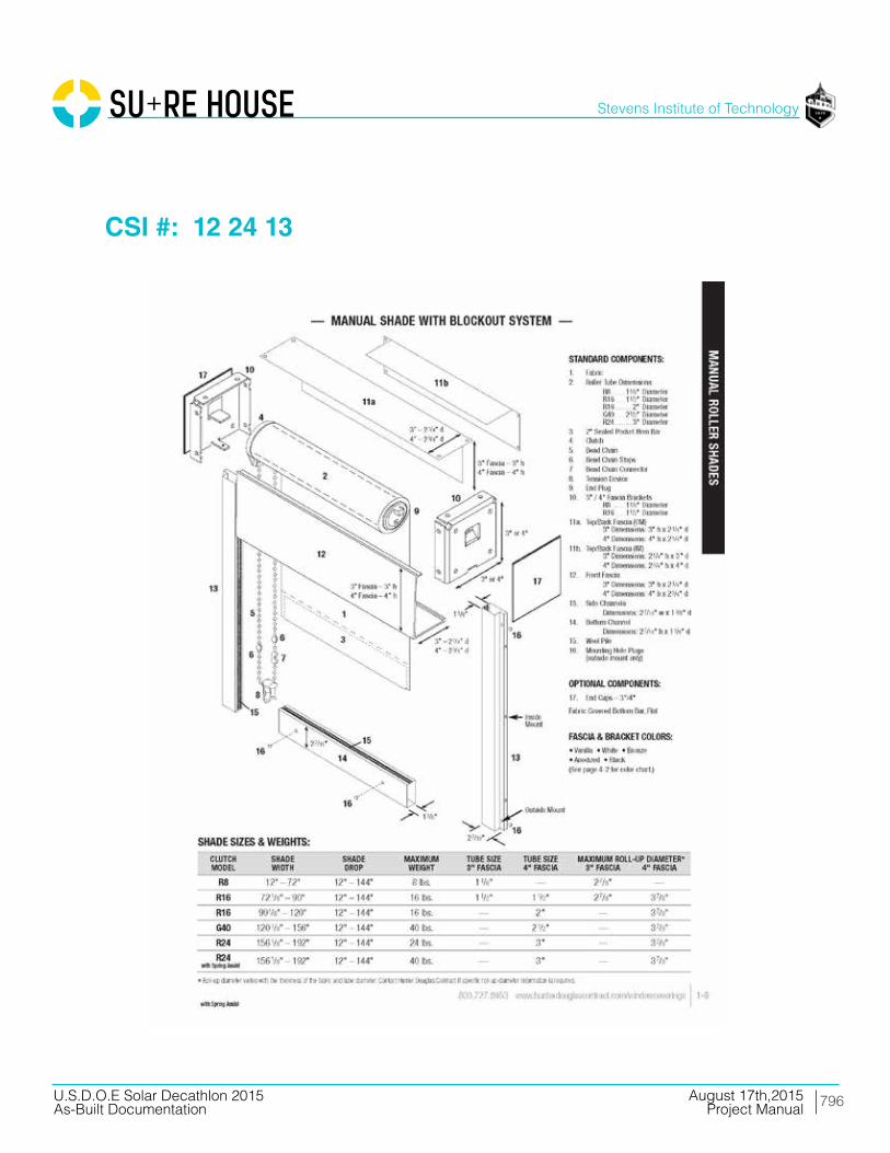
796
Stevens Institute of Technology
August 17th,2015U.S.D.O.E Solar Decathlon 2015As-Built Documentation Project Manual
CSI #: 12 24 13

797
Stevens Institute of Technology
August 17th,2015U.S.D.O.E Solar Decathlon 2015As-Built Documentation Project Manual
CSI #: 12 34 00
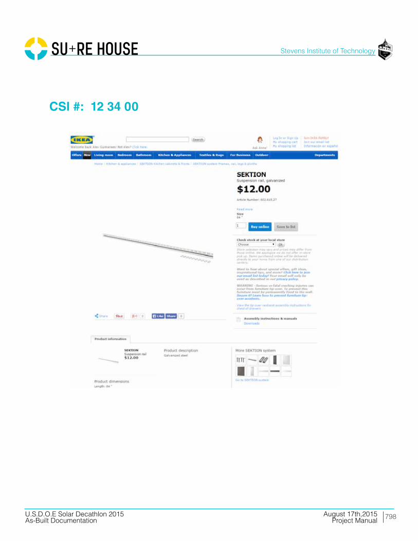
798
Stevens Institute of Technology
August 17th,2015U.S.D.O.E Solar Decathlon 2015As-Built Documentation Project Manual
CSI #: 12 34 00

799
Stevens Institute of Technology
August 17th,2015U.S.D.O.E Solar Decathlon 2015As-Built Documentation Project Manual
CSI #: 12 34 00

800
Stevens Institute of Technology
August 17th,2015U.S.D.O.E Solar Decathlon 2015As-Built Documentation Project Manual
CSI #: 12 34 00

801
Stevens Institute of Technology
August 17th,2015U.S.D.O.E Solar Decathlon 2015As-Built Documentation Project Manual
CSI #: 12 34 00

802
Stevens Institute of Technology
August 17th,2015U.S.D.O.E Solar Decathlon 2015As-Built Documentation Project Manual
CSI #: 12 34 00

803
Stevens Institute of Technology
August 17th,2015U.S.D.O.E Solar Decathlon 2015As-Built Documentation Project Manual
CSI #: 12 34 00
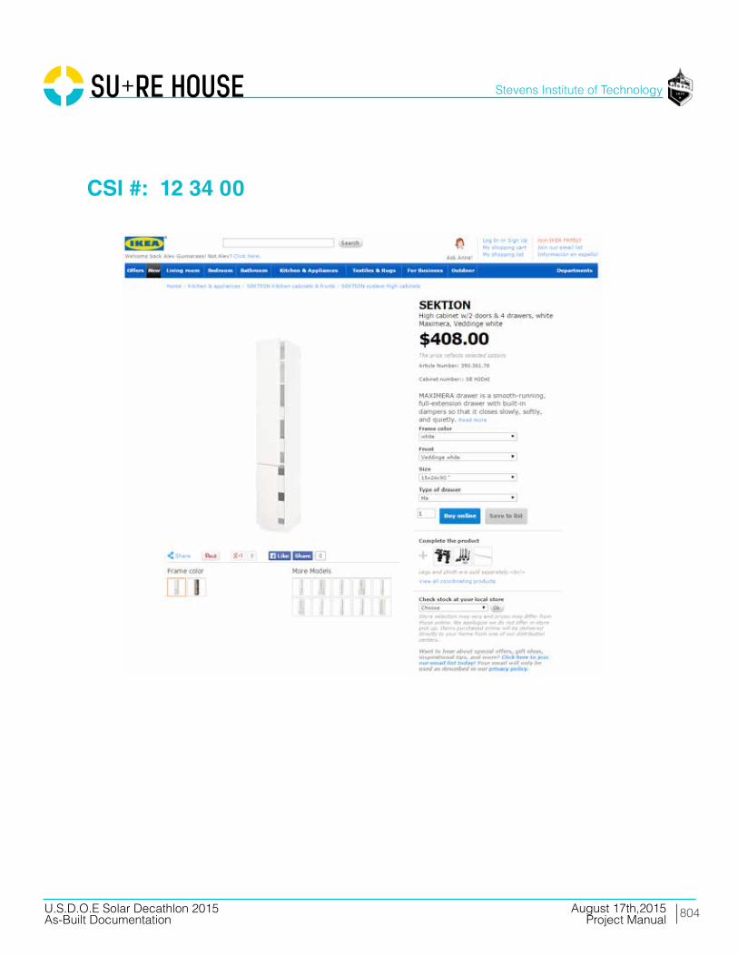
804
Stevens Institute of Technology
August 17th,2015U.S.D.O.E Solar Decathlon 2015As-Built Documentation Project Manual
CSI #: 12 34 00
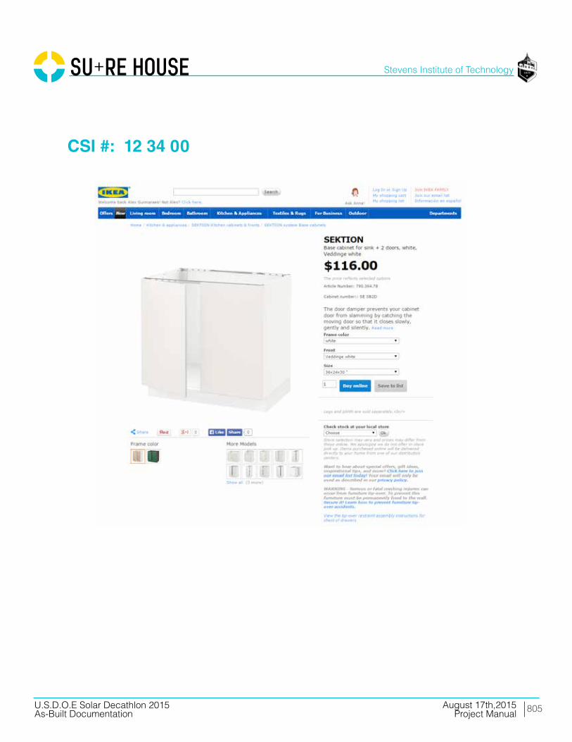
805
Stevens Institute of Technology
August 17th,2015U.S.D.O.E Solar Decathlon 2015As-Built Documentation Project Manual
CSI #: 12 34 00

806
Stevens Institute of Technology
August 17th,2015U.S.D.O.E Solar Decathlon 2015As-Built Documentation Project Manual
CSI #: 12 34 00
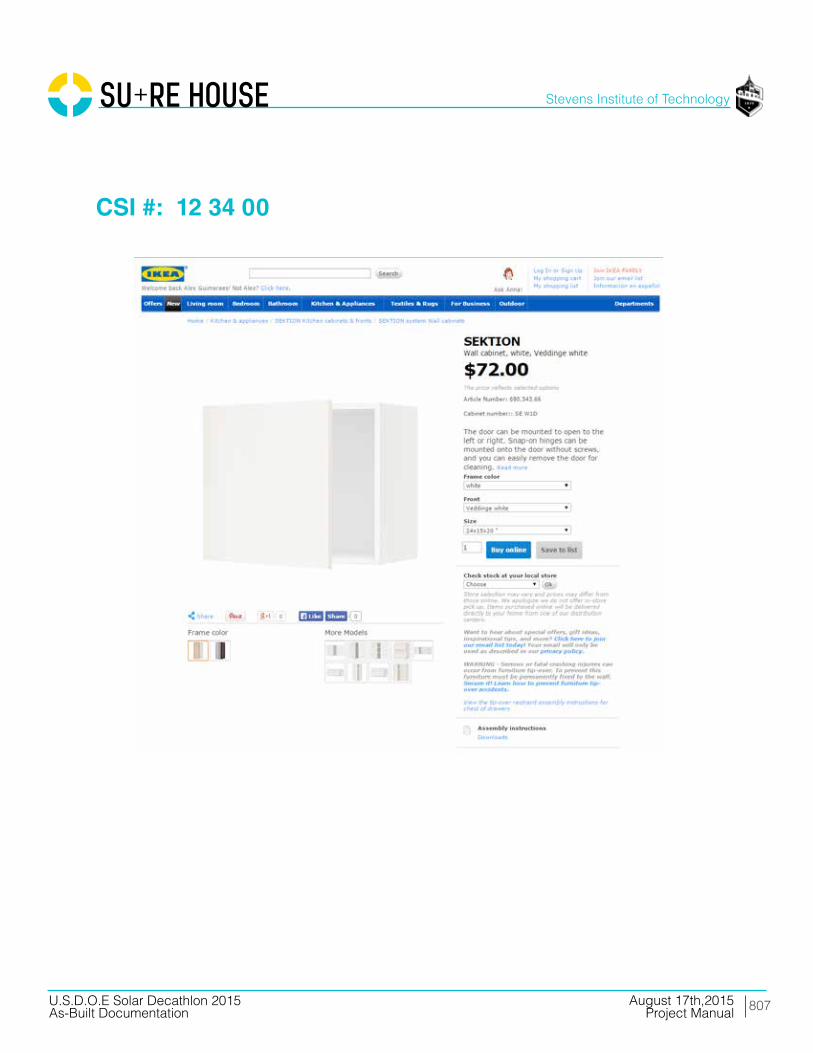
807
Stevens Institute of Technology
August 17th,2015U.S.D.O.E Solar Decathlon 2015As-Built Documentation Project Manual
CSI #: 12 34 00
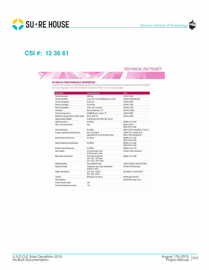
808
Stevens Institute of Technology
August 17th,2015U.S.D.O.E Solar Decathlon 2015As-Built Documentation Project Manual
CSI #: 12 36 61

809
Stevens Institute of Technology
August 17th,2015U.S.D.O.E Solar Decathlon 2015As-Built Documentation Project Manual
CSI #: 12 40 00
810
Stevens Institute of Technology
August 17th,2015U.S.D.O.E Solar Decathlon 2015As-Built Documentation Project Manual
Division 21 Fire Suppression

811
Stevens Institute of Technology
August 17th,2015U.S.D.O.E Solar Decathlon 2015As-Built Documentation Project Manual
CSI #: 21 13 00
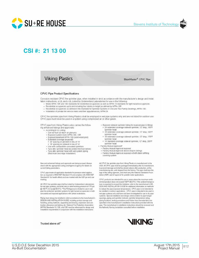
812
Stevens Institute of Technology
August 17th,2015U.S.D.O.E Solar Decathlon 2015As-Built Documentation Project Manual
CSI #: 21 13 00

813
Stevens Institute of Technology
August 17th,2015U.S.D.O.E Solar Decathlon 2015As-Built Documentation Project Manual
CSI #: 21 13 00

814
Stevens Institute of Technology
August 17th,2015U.S.D.O.E Solar Decathlon 2015As-Built Documentation Project Manual
CSI #: 21 13 00

815
Stevens Institute of Technology
August 17th,2015U.S.D.O.E Solar Decathlon 2015As-Built Documentation Project Manual
CSI #: 21 13 00
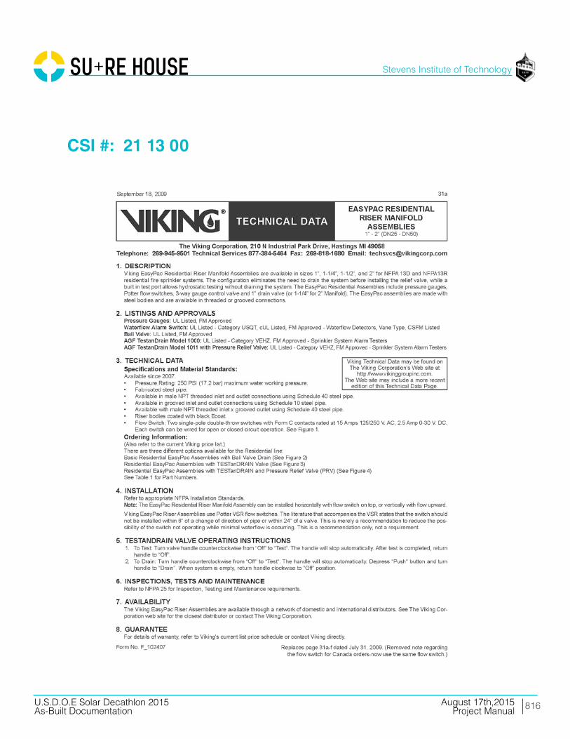
816
Stevens Institute of Technology
August 17th,2015U.S.D.O.E Solar Decathlon 2015As-Built Documentation Project Manual
CSI #: 21 13 00

817
Stevens Institute of Technology
August 17th,2015U.S.D.O.E Solar Decathlon 2015As-Built Documentation Project Manual
CSI #: 21 13 00
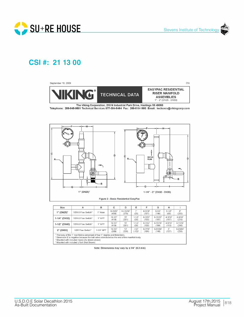
818
Stevens Institute of Technology
August 17th,2015U.S.D.O.E Solar Decathlon 2015As-Built Documentation Project Manual
CSI #: 21 13 00
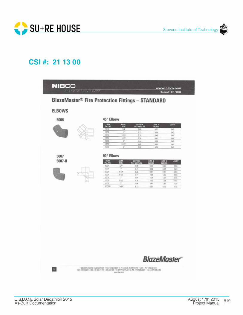
819
Stevens Institute of Technology
August 17th,2015U.S.D.O.E Solar Decathlon 2015As-Built Documentation Project Manual
CSI #: 21 13 00

820
Stevens Institute of Technology
August 17th,2015U.S.D.O.E Solar Decathlon 2015As-Built Documentation Project Manual
CSI #: 21 13 00

821
Stevens Institute of Technology
August 17th,2015U.S.D.O.E Solar Decathlon 2015As-Built Documentation Project Manual
CSI #: 21 13 00

822
Stevens Institute of Technology
August 17th,2015U.S.D.O.E Solar Decathlon 2015As-Built Documentation Project Manual
CSI #: 21 13 00
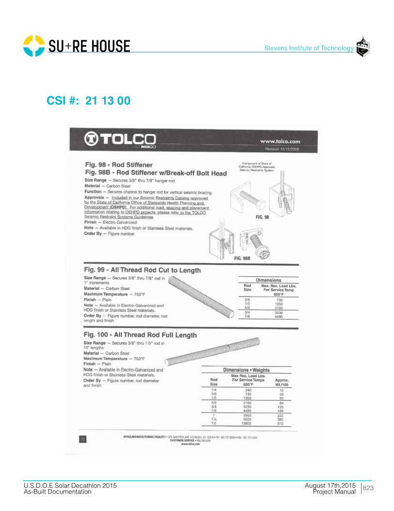
823
Stevens Institute of Technology
August 17th,2015U.S.D.O.E Solar Decathlon 2015As-Built Documentation Project Manual
CSI #: 21 13 00

824
Stevens Institute of Technology
August 17th,2015U.S.D.O.E Solar Decathlon 2015As-Built Documentation Project Manual
CSI #: 21 13 00

825
Stevens Institute of Technology
August 17th,2015U.S.D.O.E Solar Decathlon 2015As-Built Documentation Project Manual
CSI #: 21 13 00

826
Stevens Institute of Technology
August 17th,2015U.S.D.O.E Solar Decathlon 2015As-Built Documentation Project Manual
CSI #: 21 13 00
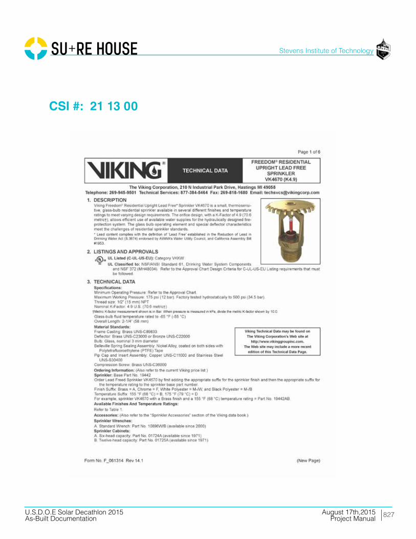
827
Stevens Institute of Technology
August 17th,2015U.S.D.O.E Solar Decathlon 2015As-Built Documentation Project Manual
CSI #: 21 13 00

828
Stevens Institute of Technology
August 17th,2015U.S.D.O.E Solar Decathlon 2015As-Built Documentation Project Manual
CSI #: 21 13 00

829
Stevens Institute of Technology
August 17th,2015U.S.D.O.E Solar Decathlon 2015As-Built Documentation Project Manual
CSI #: 21 13 00

830
Stevens Institute of Technology
August 17th,2015U.S.D.O.E Solar Decathlon 2015As-Built Documentation Project Manual
CSI #: 21 13 00

831
Stevens Institute of Technology
August 17th,2015U.S.D.O.E Solar Decathlon 2015As-Built Documentation Project Manual
CSI #: 21 13 00
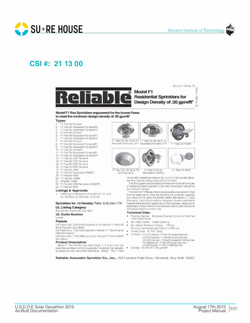
832
Stevens Institute of Technology
August 17th,2015U.S.D.O.E Solar Decathlon 2015As-Built Documentation Project Manual
CSI #: 21 13 00

833
Stevens Institute of Technology
August 17th,2015U.S.D.O.E Solar Decathlon 2015As-Built Documentation Project Manual
CSI #: 21 13 00
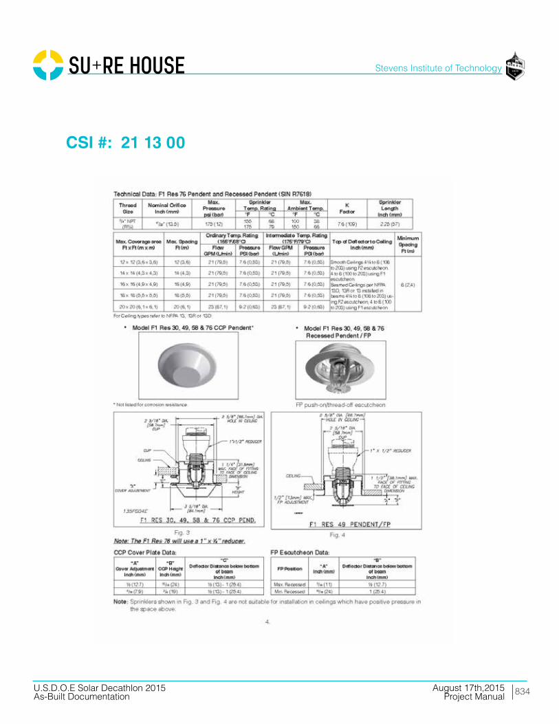
834
Stevens Institute of Technology
August 17th,2015U.S.D.O.E Solar Decathlon 2015As-Built Documentation Project Manual
CSI #: 21 13 00

835
Stevens Institute of Technology
August 17th,2015U.S.D.O.E Solar Decathlon 2015As-Built Documentation Project Manual
CSI #: 21 13 00

836
Stevens Institute of Technology
August 17th,2015U.S.D.O.E Solar Decathlon 2015As-Built Documentation Project Manual
CSI #: 21 13 00
837
Stevens Institute of Technology
August 17th,2015U.S.D.O.E Solar Decathlon 2015As-Built Documentation Project Manual
Division 22 Plumbing

838
Stevens Institute of Technology
August 17th,2015U.S.D.O.E Solar Decathlon 2015As-Built Documentation Project Manual
CSI #: 22 11 13

839
Stevens Institute of Technology
August 17th,2015U.S.D.O.E Solar Decathlon 2015As-Built Documentation Project Manual
CSI #: 22 11 13

840
Stevens Institute of Technology
August 17th,2015U.S.D.O.E Solar Decathlon 2015As-Built Documentation Project Manual
CSI #: 22 11 23

841
Stevens Institute of Technology
August 17th,2015U.S.D.O.E Solar Decathlon 2015As-Built Documentation Project Manual
CSI #: 22 11 23

842
Stevens Institute of Technology
August 17th,2015U.S.D.O.E Solar Decathlon 2015As-Built Documentation Project Manual
CSI #: 22 11 23
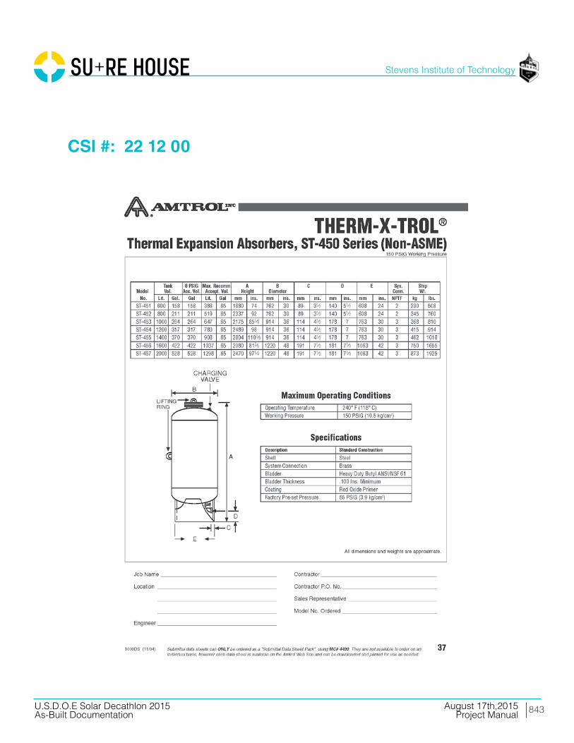
843
Stevens Institute of Technology
August 17th,2015U.S.D.O.E Solar Decathlon 2015As-Built Documentation Project Manual
CSI #: 22 12 00
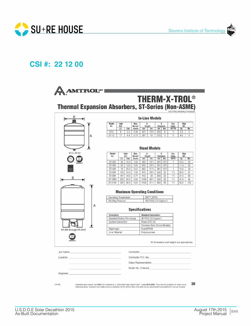
844
Stevens Institute of Technology
August 17th,2015U.S.D.O.E Solar Decathlon 2015As-Built Documentation Project Manual
CSI #: 22 12 00

845
Stevens Institute of Technology
August 17th,2015U.S.D.O.E Solar Decathlon 2015As-Built Documentation Project Manual
CSI #: 22 12 00

846
Stevens Institute of Technology
August 17th,2015U.S.D.O.E Solar Decathlon 2015As-Built Documentation Project Manual
CSI #: 22 12 23.13
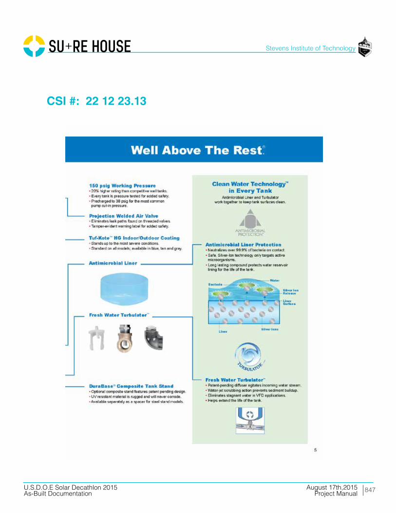
847
Stevens Institute of Technology
August 17th,2015U.S.D.O.E Solar Decathlon 2015As-Built Documentation Project Manual
CSI #: 22 12 23.13
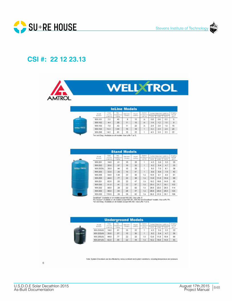
848
Stevens Institute of Technology
August 17th,2015U.S.D.O.E Solar Decathlon 2015As-Built Documentation Project Manual
CSI #: 22 12 23.13

849
Stevens Institute of Technology
August 17th,2015U.S.D.O.E Solar Decathlon 2015As-Built Documentation Project Manual
CSI #: 22 12 23.13
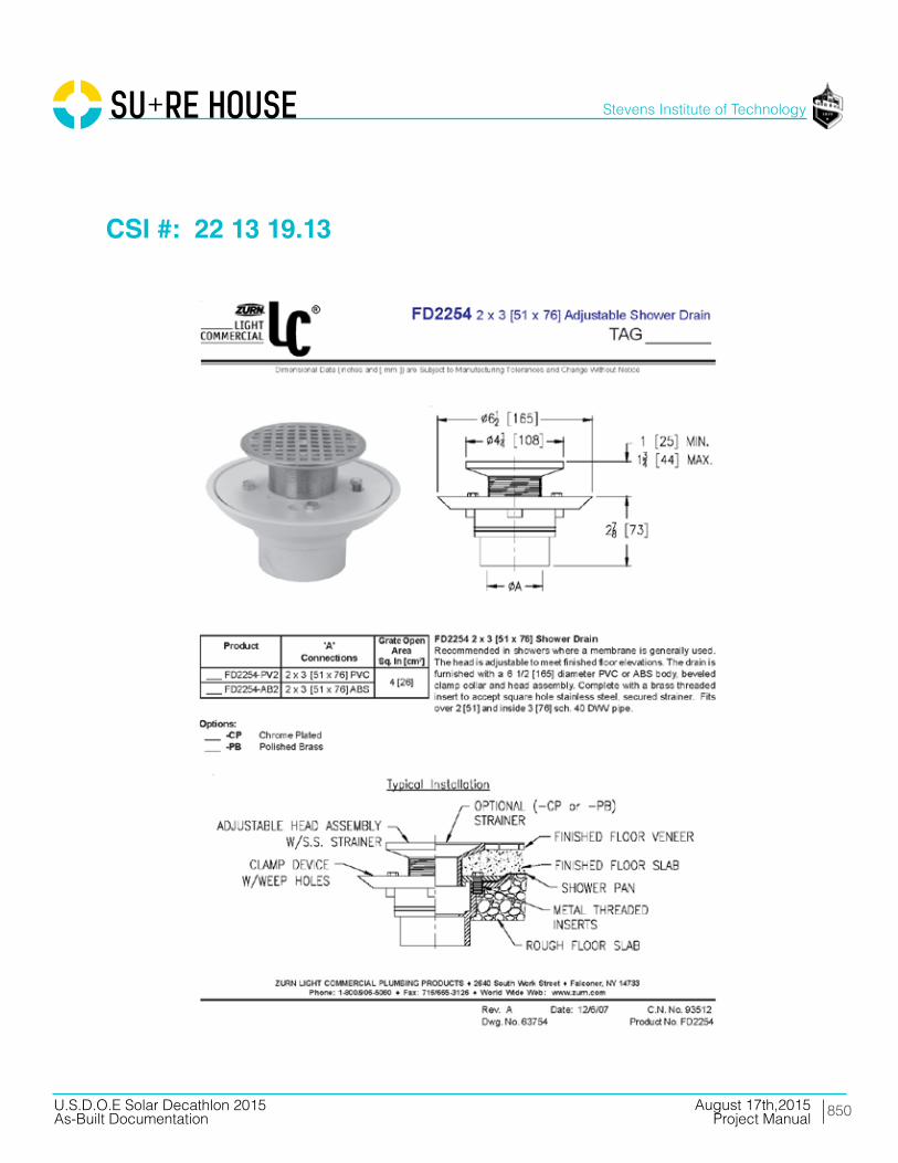
850
Stevens Institute of Technology
August 17th,2015U.S.D.O.E Solar Decathlon 2015As-Built Documentation Project Manual
CSI #: 22 13 19.13

851
Stevens Institute of Technology
August 17th,2015U.S.D.O.E Solar Decathlon 2015As-Built Documentation Project Manual
CSI #: 22 14 29

852
Stevens Institute of Technology
August 17th,2015U.S.D.O.E Solar Decathlon 2015As-Built Documentation Project Manual
CSI #: 22 14 29

853
Stevens Institute of Technology
August 17th,2015U.S.D.O.E Solar Decathlon 2015As-Built Documentation Project Manual
CSI #: 22 14 29

854
Stevens Institute of Technology
August 17th,2015U.S.D.O.E Solar Decathlon 2015As-Built Documentation Project Manual
CSI #: 22 41 00

855
Stevens Institute of Technology
August 17th,2015U.S.D.O.E Solar Decathlon 2015As-Built Documentation Project Manual
CSI #: 22 41 00
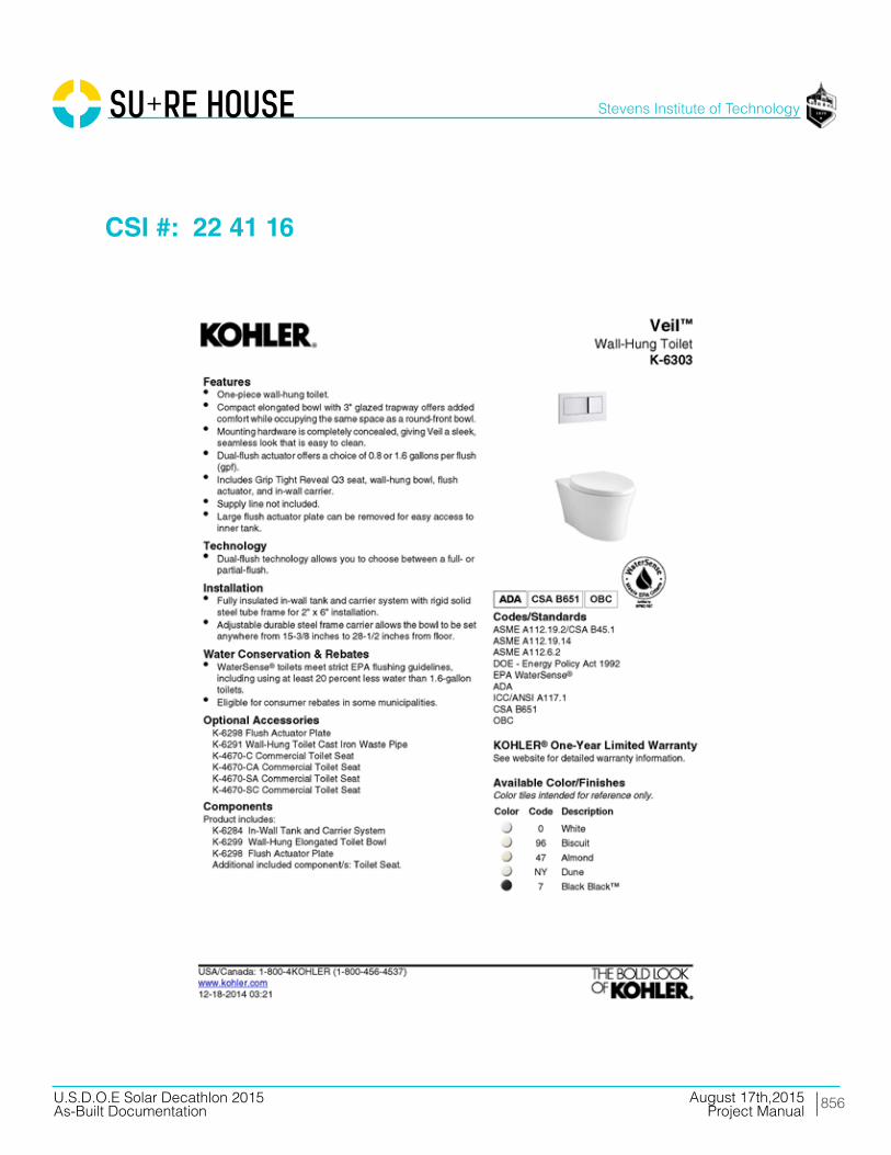
856
Stevens Institute of Technology
August 17th,2015U.S.D.O.E Solar Decathlon 2015As-Built Documentation Project Manual
CSI #: 22 41 16

857
Stevens Institute of Technology
August 17th,2015U.S.D.O.E Solar Decathlon 2015As-Built Documentation Project Manual
CSI #: 22 41 16
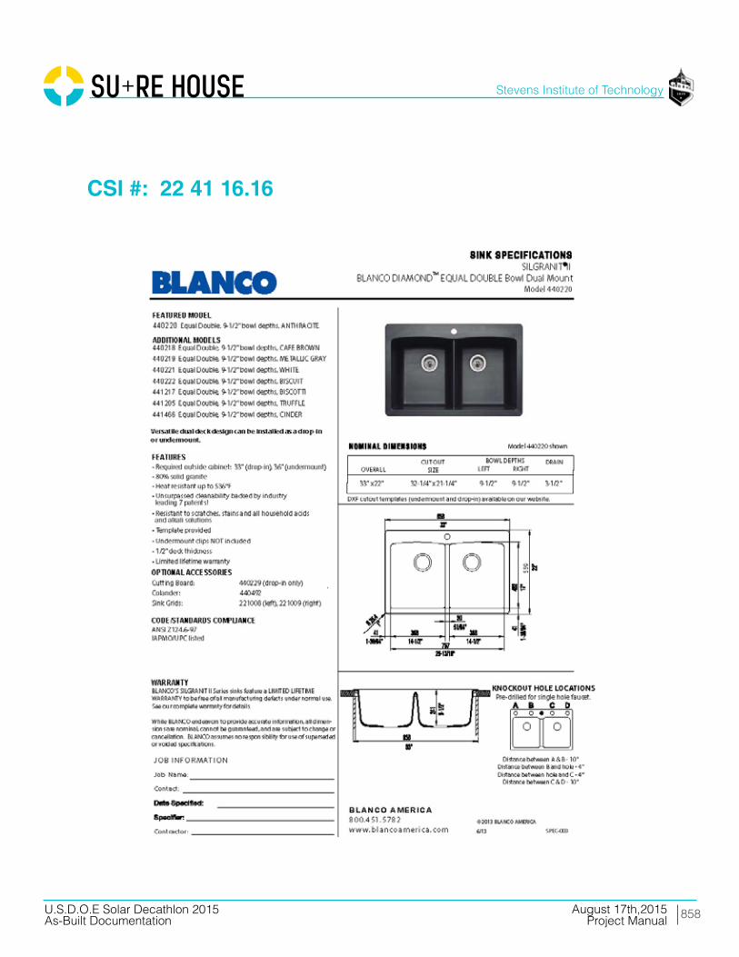
858
Stevens Institute of Technology
August 17th,2015U.S.D.O.E Solar Decathlon 2015As-Built Documentation Project Manual
CSI #: 22 41 16.16
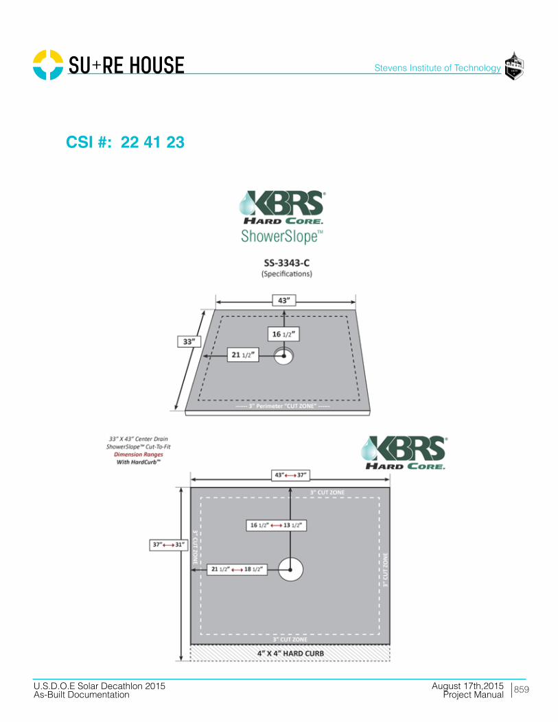
859
Stevens Institute of Technology
August 17th,2015U.S.D.O.E Solar Decathlon 2015As-Built Documentation Project Manual
CSI #: 22 41 23

860
Stevens Institute of Technology
August 17th,2015U.S.D.O.E Solar Decathlon 2015As-Built Documentation Project Manual
CSI #: 22 41 39

861
Stevens Institute of Technology
August 17th,2015U.S.D.O.E Solar Decathlon 2015As-Built Documentation Project Manual
CSI #: 22 41 39

862
Stevens Institute of Technology
August 17th,2015U.S.D.O.E Solar Decathlon 2015As-Built Documentation Project Manual
CSI #: 22 41 39
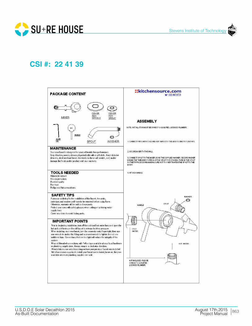
863
Stevens Institute of Technology
August 17th,2015U.S.D.O.E Solar Decathlon 2015As-Built Documentation Project Manual
CSI #: 22 41 39

864
Stevens Institute of Technology
August 17th,2015U.S.D.O.E Solar Decathlon 2015As-Built Documentation Project Manual
CSI #: 22 41 39

865
Stevens Institute of Technology
August 17th,2015U.S.D.O.E Solar Decathlon 2015As-Built Documentation Project Manual
Division 23 Heating,Ventilating, and Air-Conditioning

866
Stevens Institute of Technology
August 17th,2015U.S.D.O.E Solar Decathlon 2015As-Built Documentation Project Manual
CSI #: 23 74 00

867
Stevens Institute of Technology
August 17th,2015U.S.D.O.E Solar Decathlon 2015As-Built Documentation Project Manual
CSI #: 23 74 00

868
Stevens Institute of Technology
August 17th,2015U.S.D.O.E Solar Decathlon 2015As-Built Documentation Project Manual
CSI #: 23 74 00
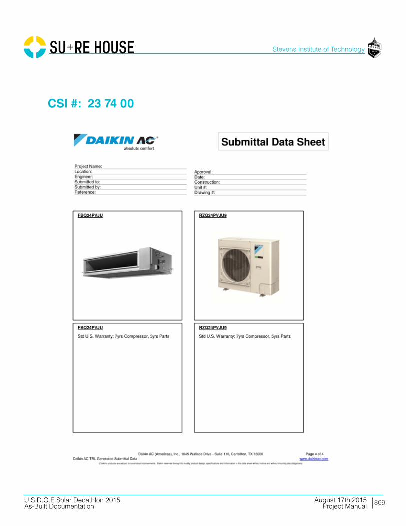
869
Stevens Institute of Technology
August 17th,2015U.S.D.O.E Solar Decathlon 2015As-Built Documentation Project Manual
CSI #: 23 74 00

870
Stevens Institute of Technology
August 17th,2015U.S.D.O.E Solar Decathlon 2015As-Built Documentation Project Manual
CSI #: 23 82 19
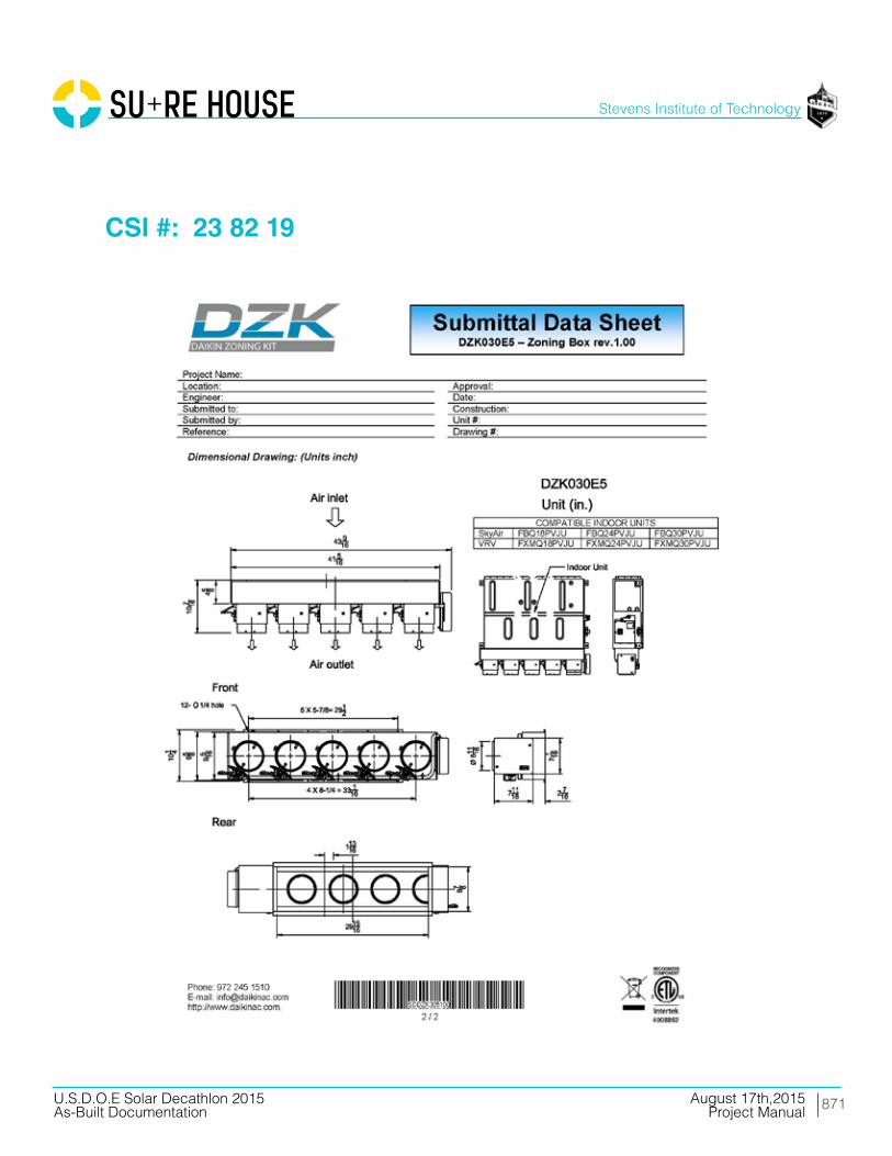
871
Stevens Institute of Technology
August 17th,2015U.S.D.O.E Solar Decathlon 2015As-Built Documentation Project Manual
CSI #: 23 82 19

872
Stevens Institute of Technology
August 17th,2015U.S.D.O.E Solar Decathlon 2015As-Built Documentation Project Manual
Division 26 Electrical
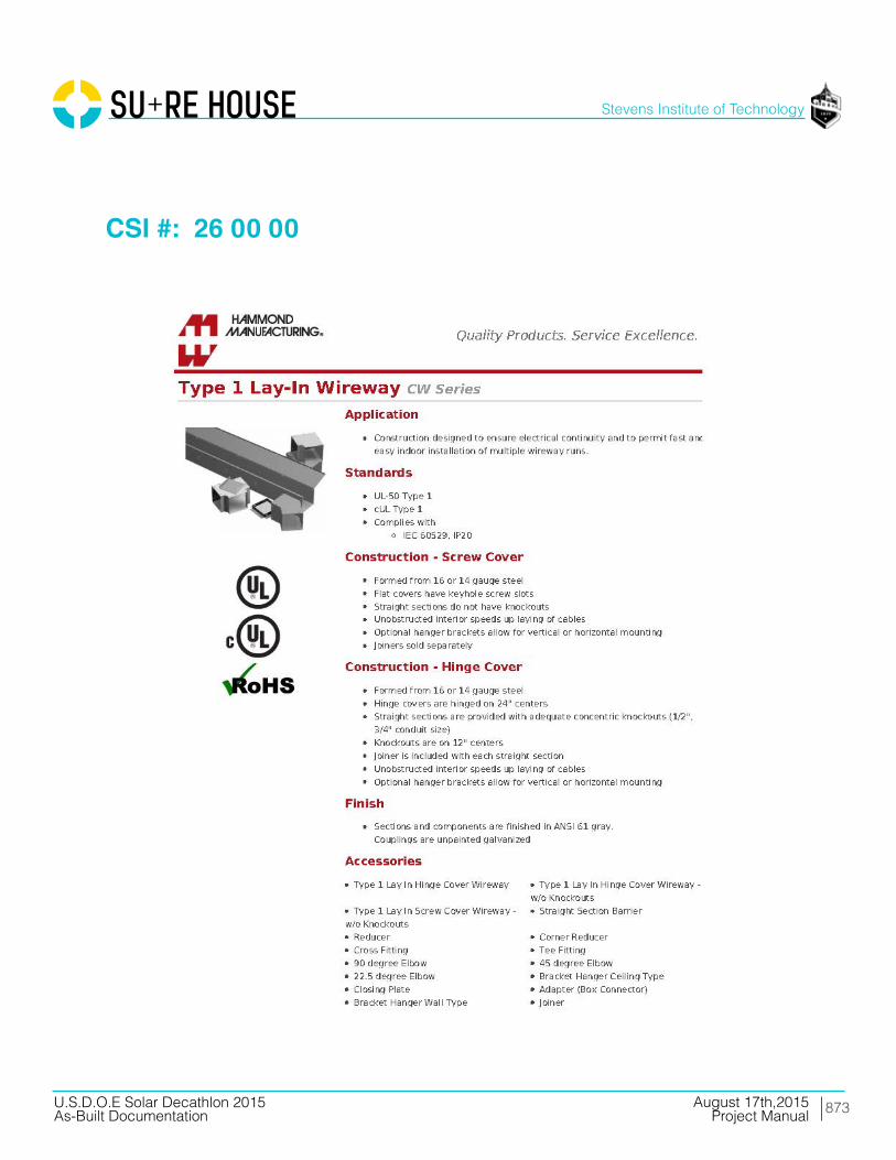
873
Stevens Institute of Technology
August 17th,2015U.S.D.O.E Solar Decathlon 2015As-Built Documentation Project Manual
CSI #: 26 00 00

874
Stevens Institute of Technology
August 17th,2015U.S.D.O.E Solar Decathlon 2015As-Built Documentation Project Manual
CSI #: 26 00 00

875
Stevens Institute of Technology
August 17th,2015U.S.D.O.E Solar Decathlon 2015As-Built Documentation Project Manual
CSI #: 26 00 00

876
Stevens Institute of Technology
August 17th,2015U.S.D.O.E Solar Decathlon 2015As-Built Documentation Project Manual
CSI #: 26 05 33.13
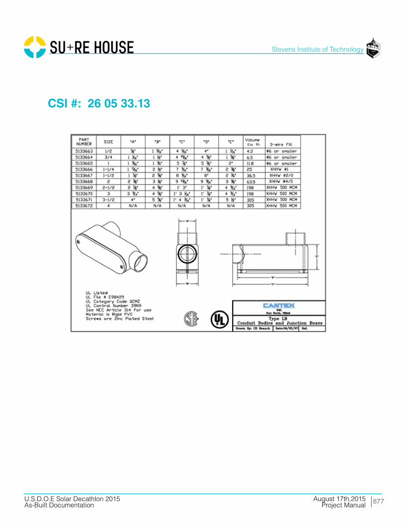
877
Stevens Institute of Technology
August 17th,2015U.S.D.O.E Solar Decathlon 2015As-Built Documentation Project Manual
CSI #: 26 05 33.13
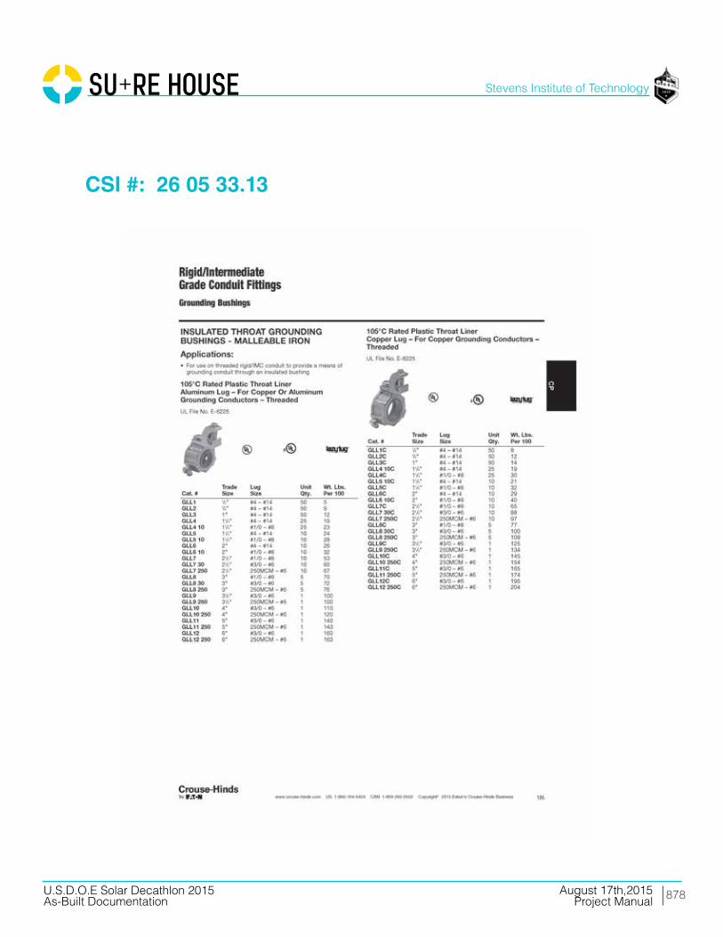
878
Stevens Institute of Technology
August 17th,2015U.S.D.O.E Solar Decathlon 2015As-Built Documentation Project Manual
CSI #: 26 05 33.13

879
Stevens Institute of Technology
August 17th,2015U.S.D.O.E Solar Decathlon 2015As-Built Documentation Project Manual
CSI #: 26 05 33.13

880
Stevens Institute of Technology
August 17th,2015U.S.D.O.E Solar Decathlon 2015As-Built Documentation Project Manual
CSI #: 26 05 33.13
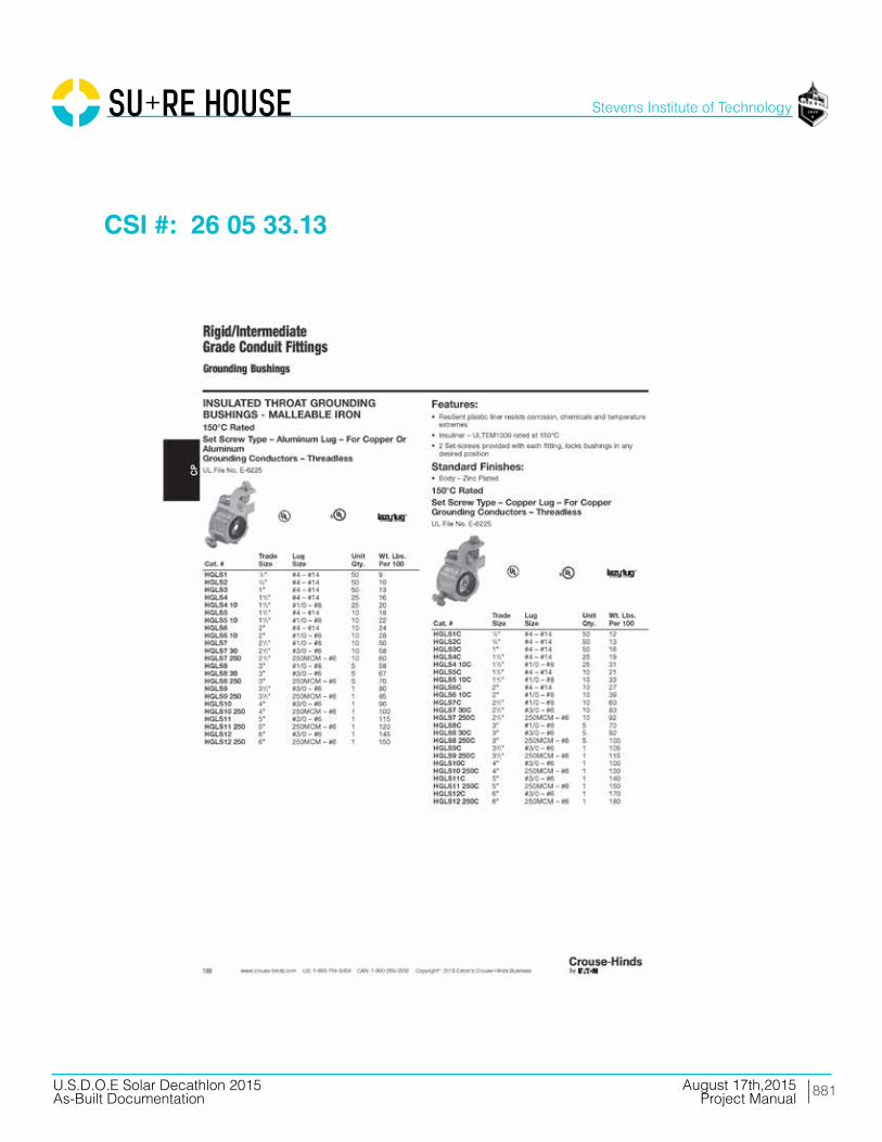
881
Stevens Institute of Technology
August 17th,2015U.S.D.O.E Solar Decathlon 2015As-Built Documentation Project Manual
CSI #: 26 05 33.13

882
Stevens Institute of Technology
August 17th,2015U.S.D.O.E Solar Decathlon 2015As-Built Documentation Project Manual
CSI #: 26 05 33.13
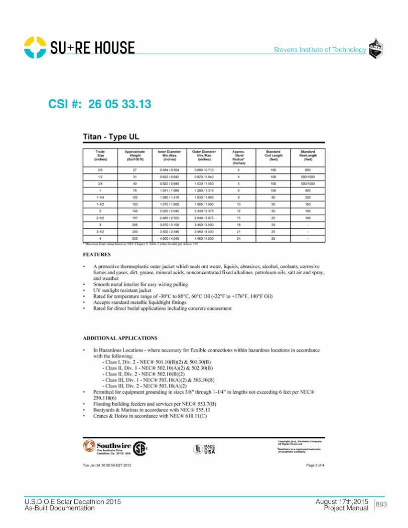
883
Stevens Institute of Technology
August 17th,2015U.S.D.O.E Solar Decathlon 2015As-Built Documentation Project Manual
CSI #: 26 05 33.13
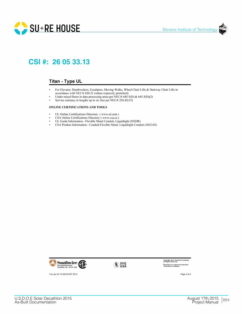
884
Stevens Institute of Technology
August 17th,2015U.S.D.O.E Solar Decathlon 2015As-Built Documentation Project Manual
CSI #: 26 05 33.13

885
Stevens Institute of Technology
August 17th,2015U.S.D.O.E Solar Decathlon 2015As-Built Documentation Project Manual
CSI #: 26 05 33.13

886
Stevens Institute of Technology
August 17th,2015U.S.D.O.E Solar Decathlon 2015As-Built Documentation Project Manual
CSI #: 26 05 33.13
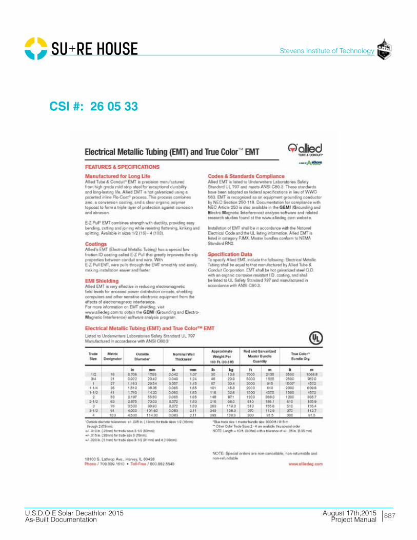
887
Stevens Institute of Technology
August 17th,2015U.S.D.O.E Solar Decathlon 2015As-Built Documentation Project Manual
CSI #: 26 05 33

888
Stevens Institute of Technology
August 17th,2015U.S.D.O.E Solar Decathlon 2015As-Built Documentation Project Manual
CSI #: 26 05 33.13

889
Stevens Institute of Technology
August 17th,2015U.S.D.O.E Solar Decathlon 2015As-Built Documentation Project Manual
CSI #: 26 05 33.13

890
Stevens Institute of Technology
August 17th,2015U.S.D.O.E Solar Decathlon 2015As-Built Documentation Project Manual
CSI #: 26 05 33.13

891
Stevens Institute of Technology
August 17th,2015U.S.D.O.E Solar Decathlon 2015As-Built Documentation Project Manual
CSI #: 26 05 53
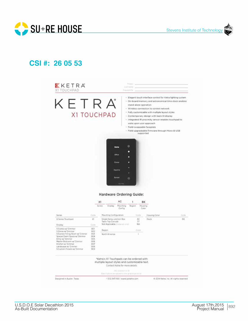
892
Stevens Institute of Technology
August 17th,2015U.S.D.O.E Solar Decathlon 2015As-Built Documentation Project Manual
CSI #: 26 05 53

893
Stevens Institute of Technology
August 17th,2015U.S.D.O.E Solar Decathlon 2015As-Built Documentation Project Manual
CSI #: 26 09 23
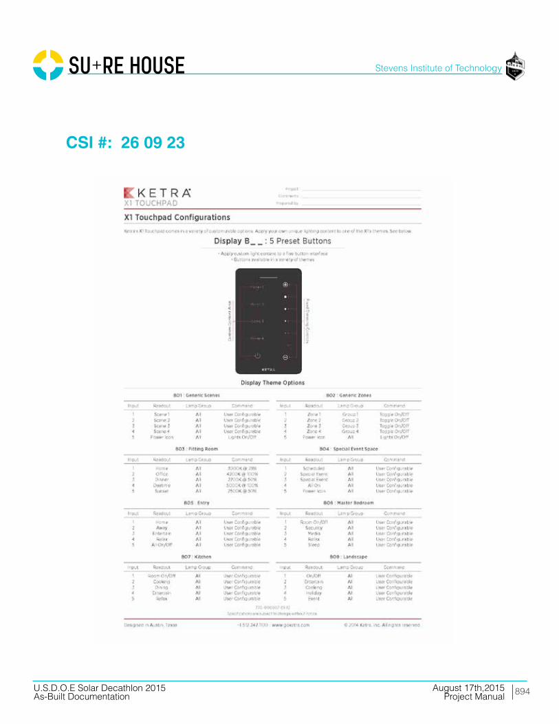
894
Stevens Institute of Technology
August 17th,2015U.S.D.O.E Solar Decathlon 2015As-Built Documentation Project Manual
CSI #: 26 09 23

895
Stevens Institute of Technology
August 17th,2015U.S.D.O.E Solar Decathlon 2015As-Built Documentation Project Manual
CSI #: 26 13 00

896
Stevens Institute of Technology
August 17th,2015U.S.D.O.E Solar Decathlon 2015As-Built Documentation Project Manual
CSI #: 26 13 00
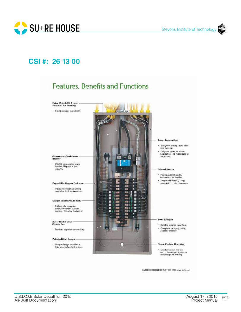
897
Stevens Institute of Technology
August 17th,2015U.S.D.O.E Solar Decathlon 2015As-Built Documentation Project Manual
CSI #: 26 13 00

898
Stevens Institute of Technology
August 17th,2015U.S.D.O.E Solar Decathlon 2015As-Built Documentation Project Manual
CSI #: 26 13 00
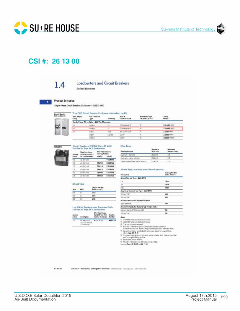
899
Stevens Institute of Technology
August 17th,2015U.S.D.O.E Solar Decathlon 2015As-Built Documentation Project Manual
CSI #: 26 13 00
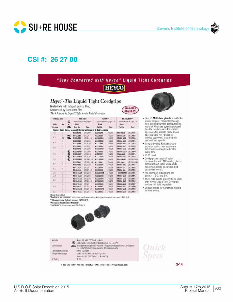
900
Stevens Institute of Technology
August 17th,2015U.S.D.O.E Solar Decathlon 2015As-Built Documentation Project Manual
CSI #: 26 27 00
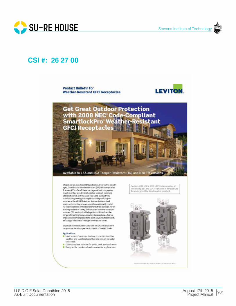
901
Stevens Institute of Technology
August 17th,2015U.S.D.O.E Solar Decathlon 2015As-Built Documentation Project Manual
CSI #: 26 27 00

902
Stevens Institute of Technology
August 17th,2015U.S.D.O.E Solar Decathlon 2015As-Built Documentation Project Manual
CSI #: 26 27 00

903
Stevens Institute of Technology
August 17th,2015U.S.D.O.E Solar Decathlon 2015As-Built Documentation Project Manual
CSI #: 26 27 00

904
Stevens Institute of Technology
August 17th,2015U.S.D.O.E Solar Decathlon 2015As-Built Documentation Project Manual
CSI #: 26 27 00
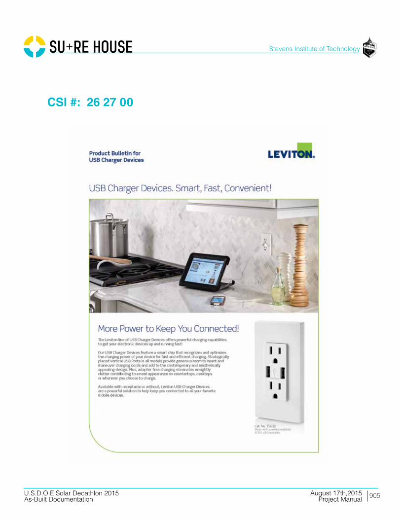
905
Stevens Institute of Technology
August 17th,2015U.S.D.O.E Solar Decathlon 2015As-Built Documentation Project Manual
CSI #: 26 27 00

906
Stevens Institute of Technology
August 17th,2015U.S.D.O.E Solar Decathlon 2015As-Built Documentation Project Manual
CSI #: 26 27 00

907
Stevens Institute of Technology
August 17th,2015U.S.D.O.E Solar Decathlon 2015As-Built Documentation Project Manual
CSI #: 26 27 00
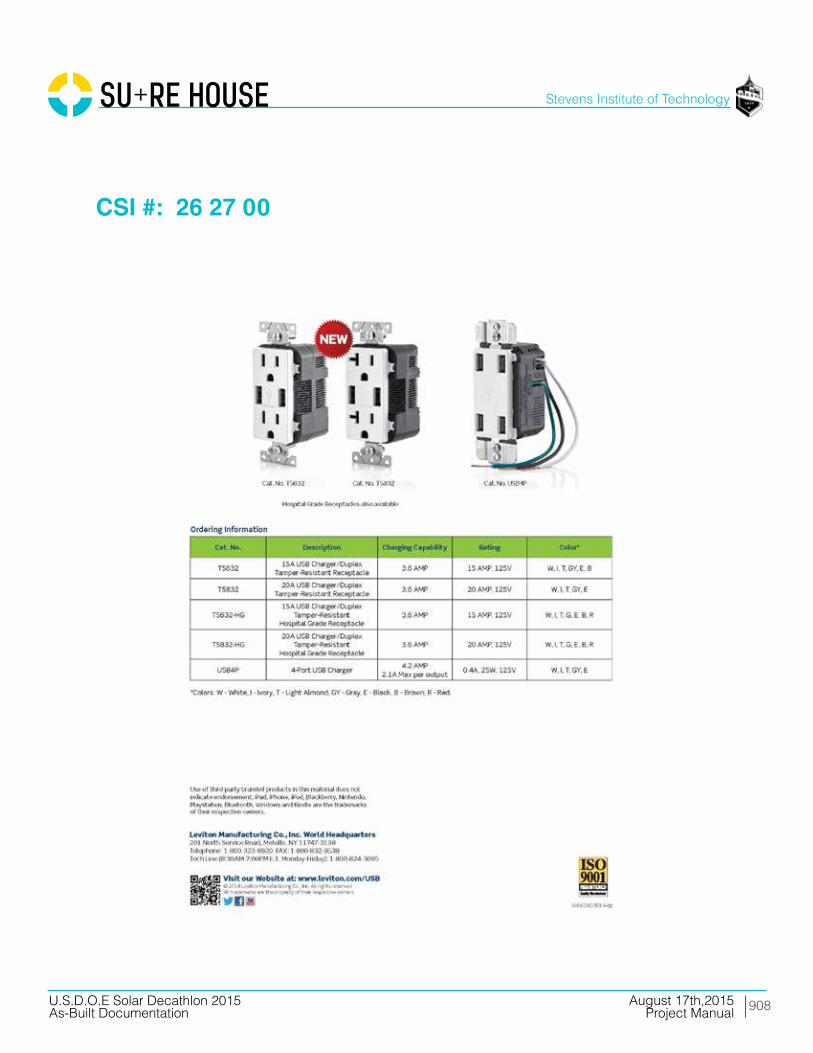
908
Stevens Institute of Technology
August 17th,2015U.S.D.O.E Solar Decathlon 2015As-Built Documentation Project Manual
CSI #: 26 27 00
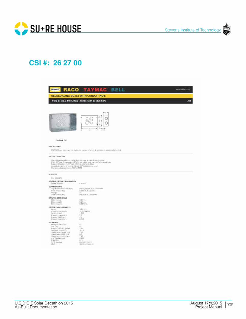
909
Stevens Institute of Technology
August 17th,2015U.S.D.O.E Solar Decathlon 2015As-Built Documentation Project Manual
CSI #: 26 27 00

910
Stevens Institute of Technology
August 17th,2015U.S.D.O.E Solar Decathlon 2015As-Built Documentation Project Manual
CSI #: 26 27 00

911
Stevens Institute of Technology
August 17th,2015U.S.D.O.E Solar Decathlon 2015As-Built Documentation Project Manual
CSI #: 26 27 16
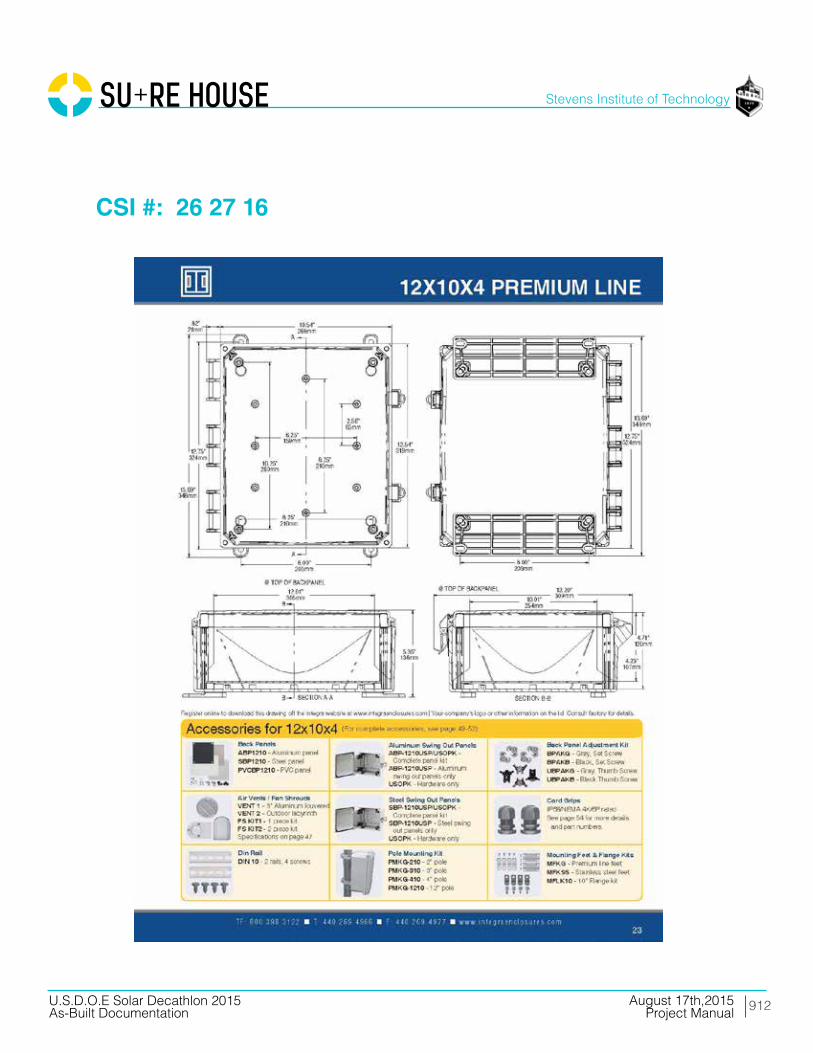
912
Stevens Institute of Technology
August 17th,2015U.S.D.O.E Solar Decathlon 2015As-Built Documentation Project Manual
CSI #: 26 27 16

913
Stevens Institute of Technology
August 17th,2015U.S.D.O.E Solar Decathlon 2015As-Built Documentation Project Manual
CSI #: 26 27 16

914
Stevens Institute of Technology
August 17th,2015U.S.D.O.E Solar Decathlon 2015As-Built Documentation Project Manual
CSI #: 26 27 16
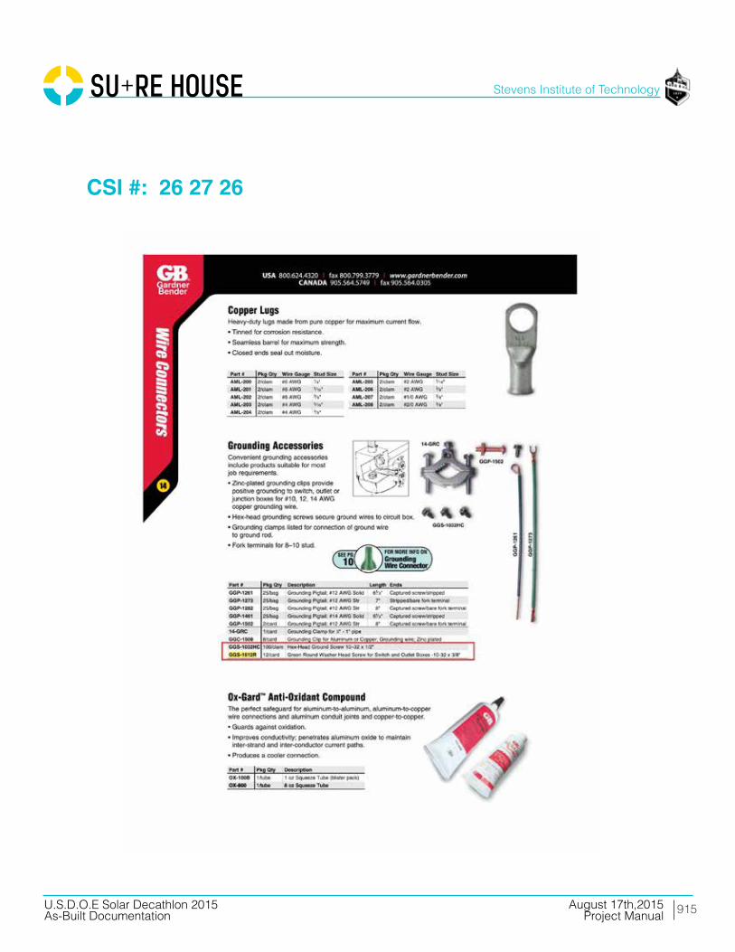
915
Stevens Institute of Technology
August 17th,2015U.S.D.O.E Solar Decathlon 2015As-Built Documentation Project Manual
CSI #: 26 27 26

916
Stevens Institute of Technology
August 17th,2015U.S.D.O.E Solar Decathlon 2015As-Built Documentation Project Manual
CSI #: 26 27 26

917
Stevens Institute of Technology
August 17th,2015U.S.D.O.E Solar Decathlon 2015As-Built Documentation Project Manual
CSI #: 26 27 26

918
Stevens Institute of Technology
August 17th,2015U.S.D.O.E Solar Decathlon 2015As-Built Documentation Project Manual
CSI #: 26 27 26

919
Stevens Institute of Technology
August 17th,2015U.S.D.O.E Solar Decathlon 2015As-Built Documentation Project Manual
CSI #: 26 27 26

920
Stevens Institute of Technology
August 17th,2015U.S.D.O.E Solar Decathlon 2015As-Built Documentation Project Manual
CSI #: 26 27 26

921
Stevens Institute of Technology
August 17th,2015U.S.D.O.E Solar Decathlon 2015As-Built Documentation Project Manual
CSI #: 26 27 26

922
Stevens Institute of Technology
August 17th,2015U.S.D.O.E Solar Decathlon 2015As-Built Documentation Project Manual
CSI #: 26 27 26
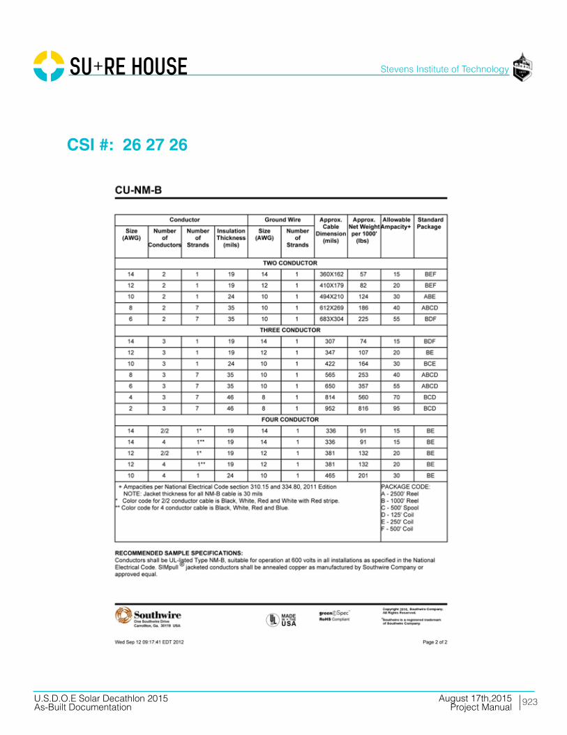
923
Stevens Institute of Technology
August 17th,2015U.S.D.O.E Solar Decathlon 2015As-Built Documentation Project Manual
CSI #: 26 27 26

924
Stevens Institute of Technology
August 17th,2015U.S.D.O.E Solar Decathlon 2015As-Built Documentation Project Manual
CSI #: 26 27 26
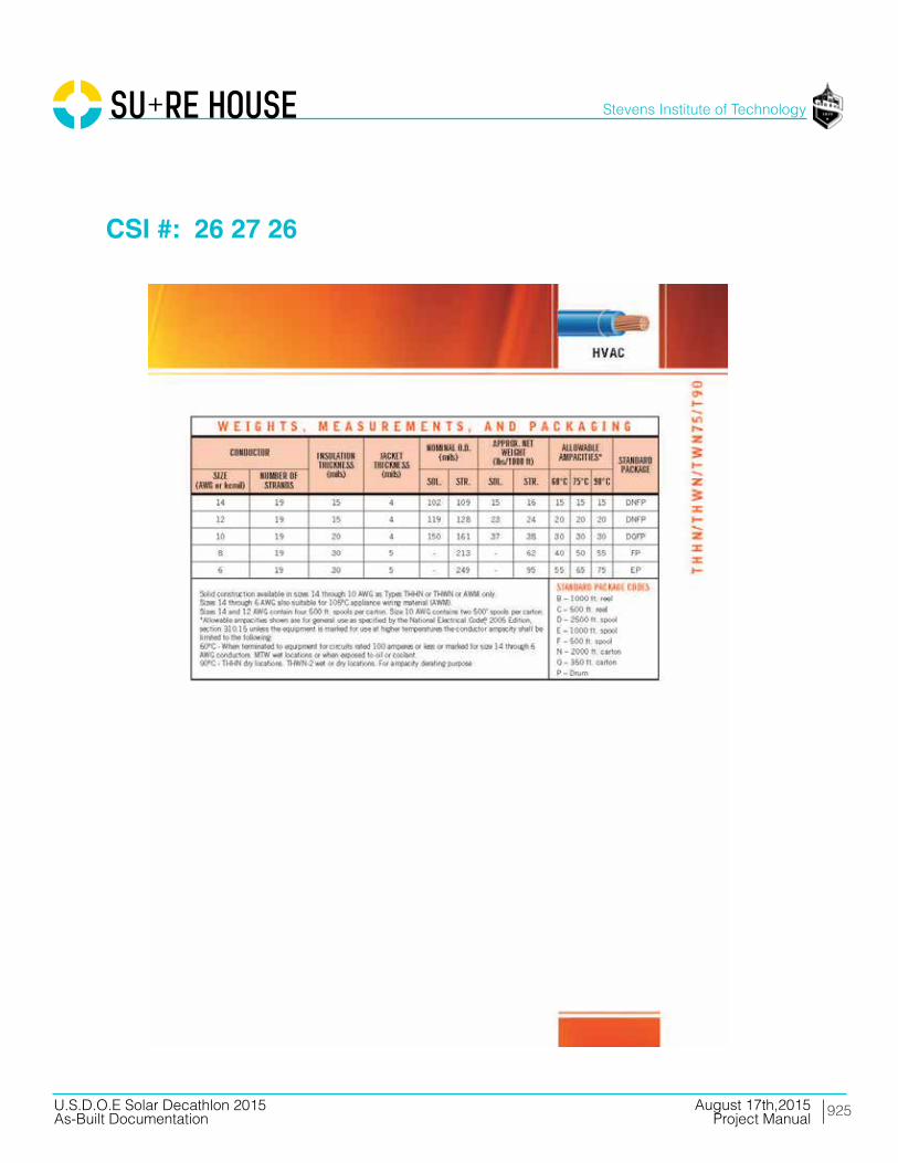
925
Stevens Institute of Technology
August 17th,2015U.S.D.O.E Solar Decathlon 2015As-Built Documentation Project Manual
CSI #: 26 27 26

926
Stevens Institute of Technology
August 17th,2015U.S.D.O.E Solar Decathlon 2015As-Built Documentation Project Manual
CSI #: 26 27 26
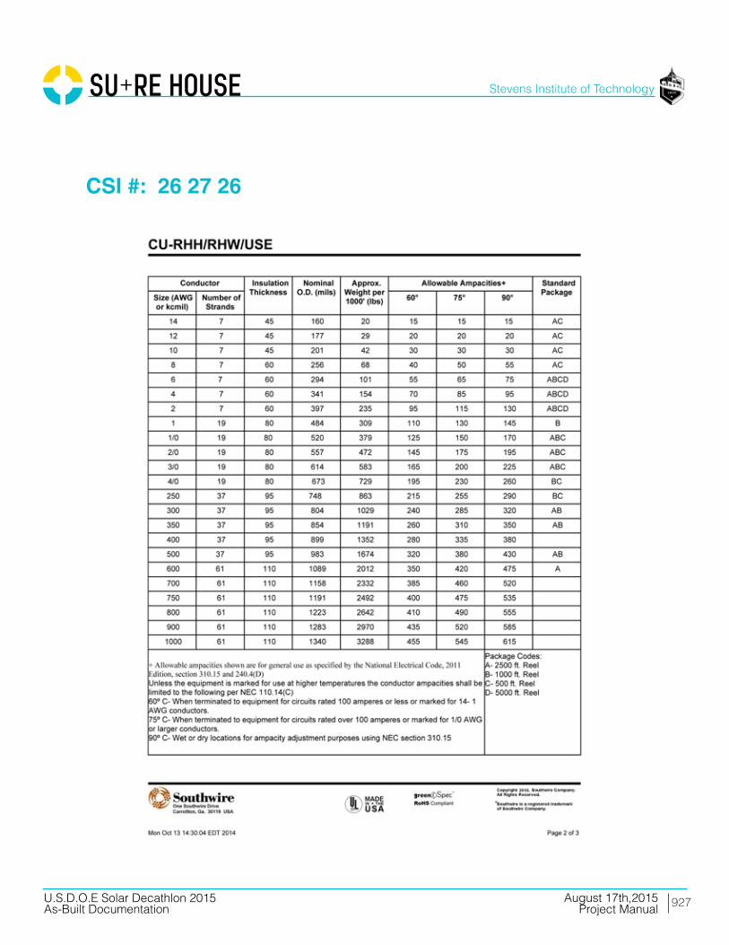
927
Stevens Institute of Technology
August 17th,2015U.S.D.O.E Solar Decathlon 2015As-Built Documentation Project Manual
CSI #: 26 27 26

928
Stevens Institute of Technology
August 17th,2015U.S.D.O.E Solar Decathlon 2015As-Built Documentation Project Manual
CSI #: 26 27 26

929
Stevens Institute of Technology
August 17th,2015U.S.D.O.E Solar Decathlon 2015As-Built Documentation Project Manual
CSI #: 26 27 26

930
Stevens Institute of Technology
August 17th,2015U.S.D.O.E Solar Decathlon 2015As-Built Documentation Project Manual
CSI #: 26 27 26

931
Stevens Institute of Technology
August 17th,2015U.S.D.O.E Solar Decathlon 2015As-Built Documentation Project Manual
CSI #: 26 27 26

932
Stevens Institute of Technology
August 17th,2015U.S.D.O.E Solar Decathlon 2015As-Built Documentation Project Manual
CSI #: 26 27 26
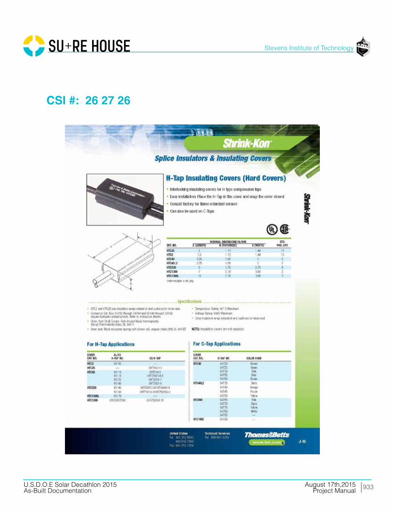
933
Stevens Institute of Technology
August 17th,2015U.S.D.O.E Solar Decathlon 2015As-Built Documentation Project Manual
CSI #: 26 27 26

934
Stevens Institute of Technology
August 17th,2015U.S.D.O.E Solar Decathlon 2015As-Built Documentation Project Manual
CSI #: 26 28 16

935
Stevens Institute of Technology
August 17th,2015U.S.D.O.E Solar Decathlon 2015As-Built Documentation Project Manual
CSI #: 26 28 16
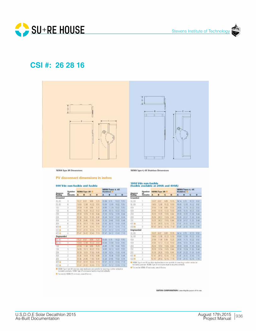
936
Stevens Institute of Technology
August 17th,2015U.S.D.O.E Solar Decathlon 2015As-Built Documentation Project Manual
CSI #: 26 28 16
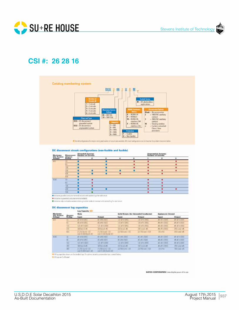
937
Stevens Institute of Technology
August 17th,2015U.S.D.O.E Solar Decathlon 2015As-Built Documentation Project Manual
CSI #: 26 28 16

938
Stevens Institute of Technology
August 17th,2015U.S.D.O.E Solar Decathlon 2015As-Built Documentation Project Manual
CSI #: 26 28 16

939
Stevens Institute of Technology
August 17th,2015U.S.D.O.E Solar Decathlon 2015As-Built Documentation Project Manual
CSI #: 26 28 16

940
Stevens Institute of Technology
August 17th,2015U.S.D.O.E Solar Decathlon 2015As-Built Documentation Project Manual
CSI #: 26 29 00

941
Stevens Institute of Technology
August 17th,2015U.S.D.O.E Solar Decathlon 2015As-Built Documentation Project Manual
CSI #: 26 31 00
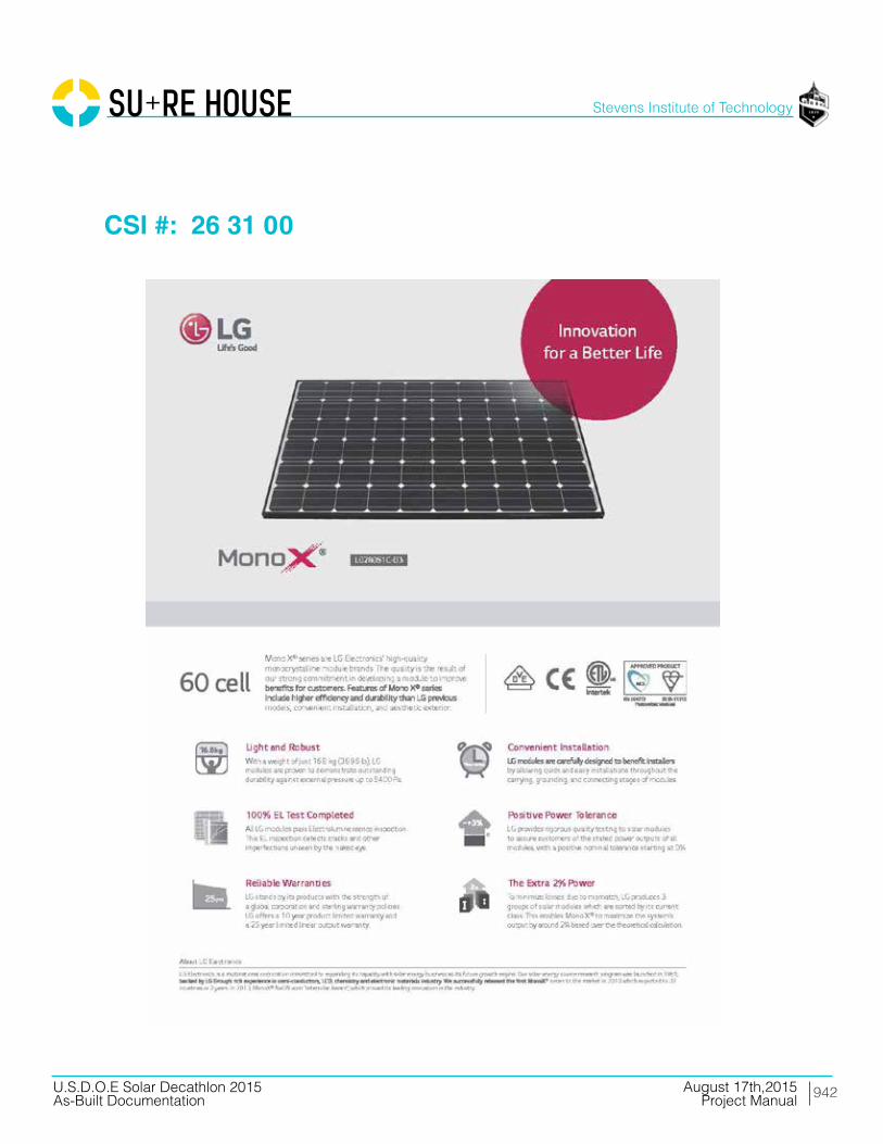
942
Stevens Institute of Technology
August 17th,2015U.S.D.O.E Solar Decathlon 2015As-Built Documentation Project Manual
CSI #: 26 31 00
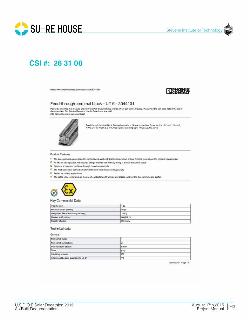
943
Stevens Institute of Technology
August 17th,2015U.S.D.O.E Solar Decathlon 2015As-Built Documentation Project Manual
CSI #: 26 31 00
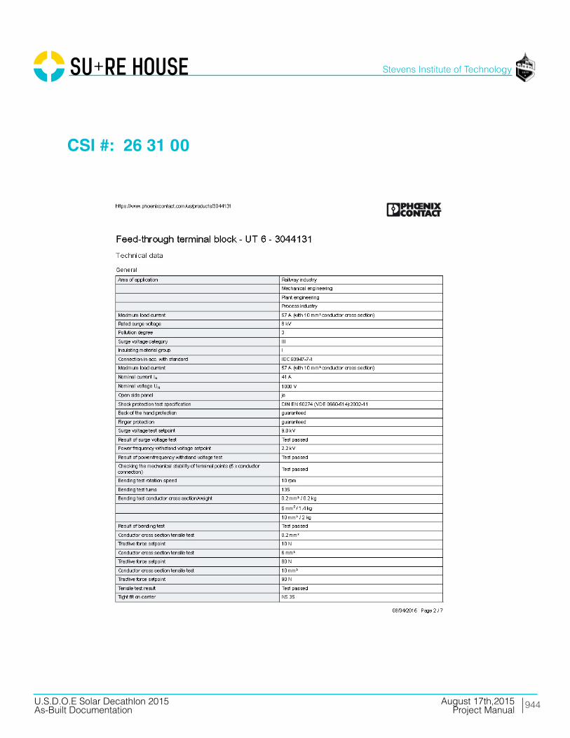
944
Stevens Institute of Technology
August 17th,2015U.S.D.O.E Solar Decathlon 2015As-Built Documentation Project Manual
CSI #: 26 31 00
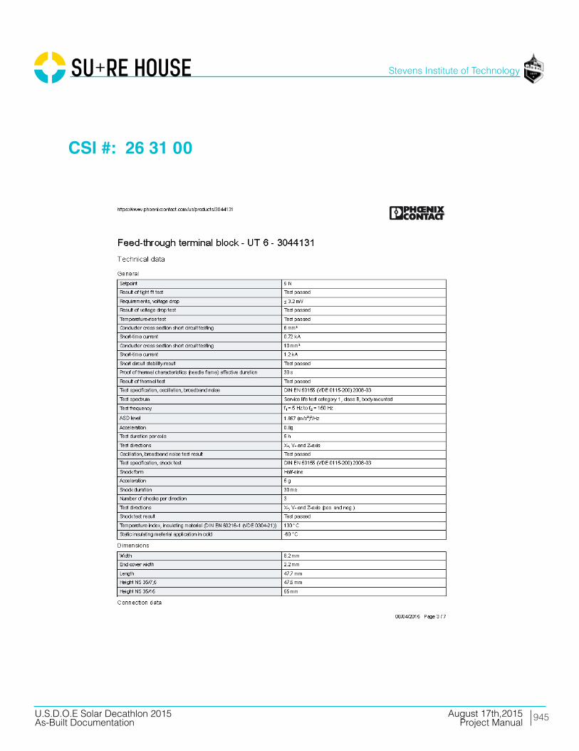
945
Stevens Institute of Technology
August 17th,2015U.S.D.O.E Solar Decathlon 2015As-Built Documentation Project Manual
CSI #: 26 31 00

946
Stevens Institute of Technology
August 17th,2015U.S.D.O.E Solar Decathlon 2015As-Built Documentation Project Manual
CSI #: 26 31 00

947
Stevens Institute of Technology
August 17th,2015U.S.D.O.E Solar Decathlon 2015As-Built Documentation Project Manual
CSI #: 26 50 00

948
Stevens Institute of Technology
August 17th,2015U.S.D.O.E Solar Decathlon 2015As-Built Documentation Project Manual
CSI #: 26 50 00

949
Stevens Institute of Technology
August 17th,2015U.S.D.O.E Solar Decathlon 2015As-Built Documentation Project Manual
CSI #: 26 50 00
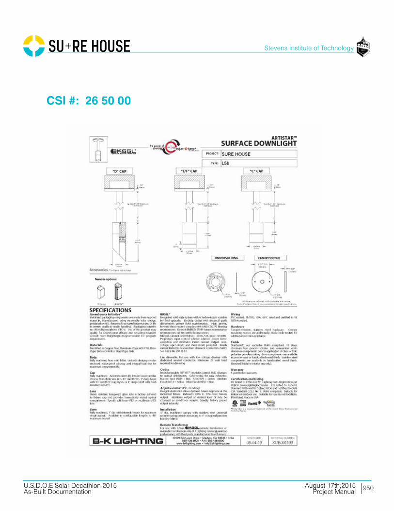
950
Stevens Institute of Technology
August 17th,2015U.S.D.O.E Solar Decathlon 2015As-Built Documentation Project Manual
CSI #: 26 50 00
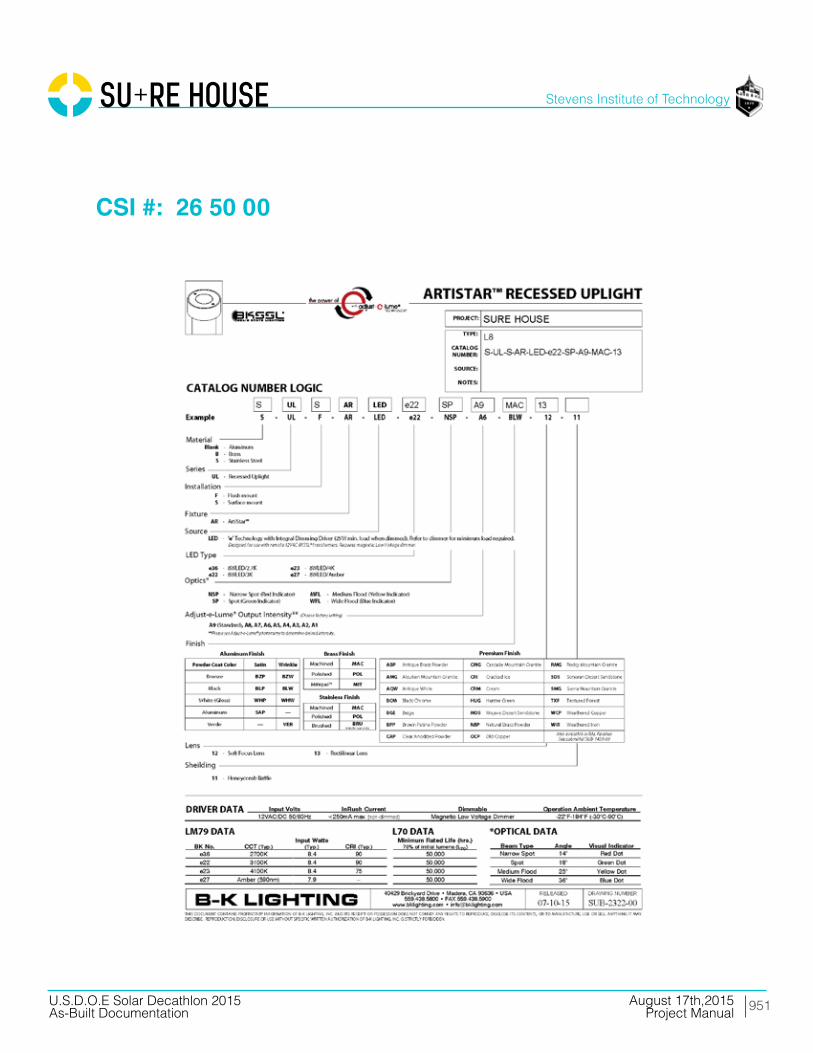
951
Stevens Institute of Technology
August 17th,2015U.S.D.O.E Solar Decathlon 2015As-Built Documentation Project Manual
CSI #: 26 50 00

952
Stevens Institute of Technology
August 17th,2015U.S.D.O.E Solar Decathlon 2015As-Built Documentation Project Manual
CSI #: 26 50 00

953
Stevens Institute of Technology
August 17th,2015U.S.D.O.E Solar Decathlon 2015As-Built Documentation Project Manual
CSI #: 26 50 00
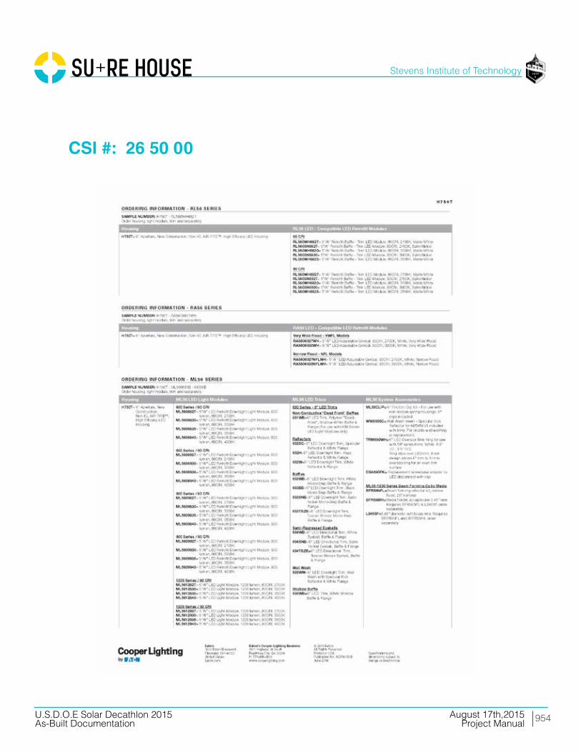
954
Stevens Institute of Technology
August 17th,2015U.S.D.O.E Solar Decathlon 2015As-Built Documentation Project Manual
CSI #: 26 50 00

955
Stevens Institute of Technology
August 17th,2015U.S.D.O.E Solar Decathlon 2015As-Built Documentation Project Manual
CSI #: 26 50 00

956
Stevens Institute of Technology
August 17th,2015U.S.D.O.E Solar Decathlon 2015As-Built Documentation Project Manual
CSI #: 26 50 00
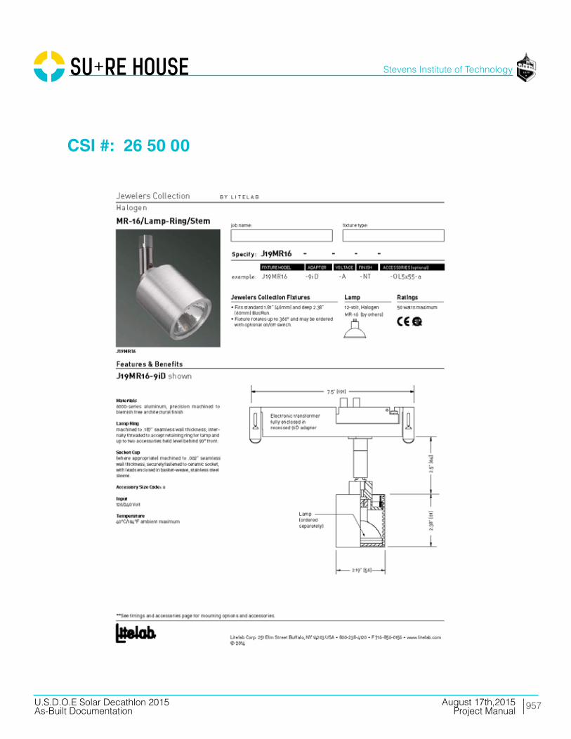
957
Stevens Institute of Technology
August 17th,2015U.S.D.O.E Solar Decathlon 2015As-Built Documentation Project Manual
CSI #: 26 50 00

958
Stevens Institute of Technology
August 17th,2015U.S.D.O.E Solar Decathlon 2015As-Built Documentation Project Manual
CSI #: 26 50 00
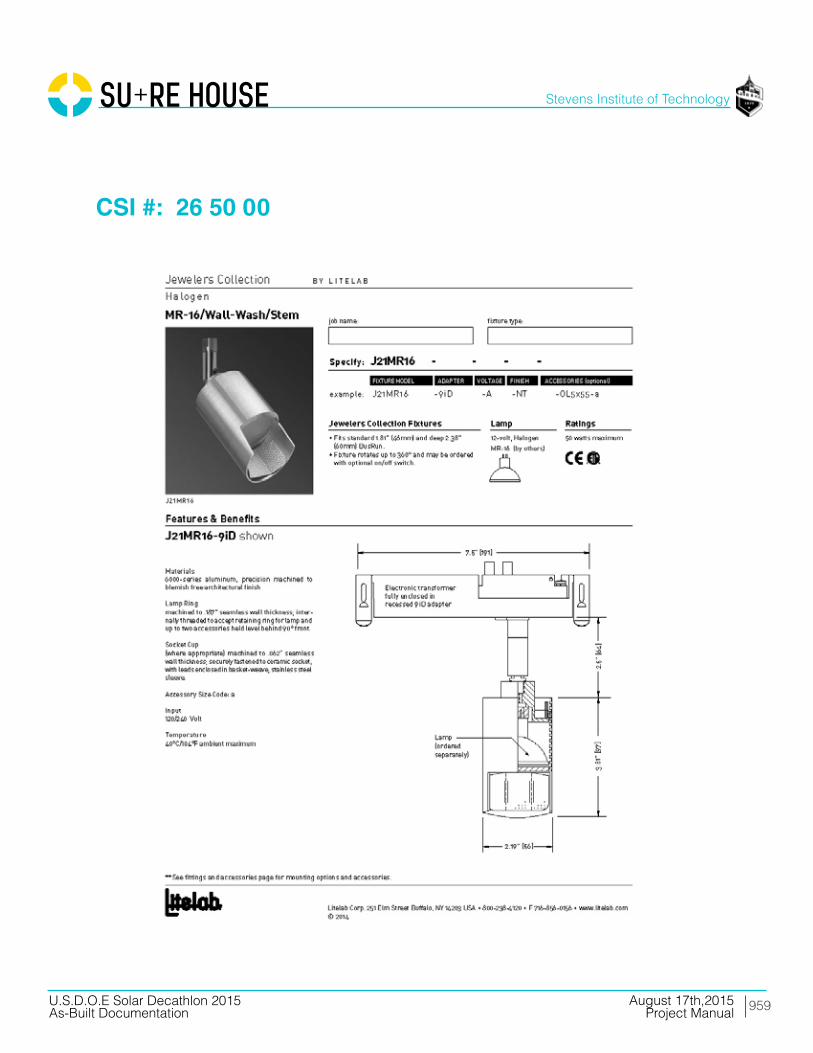
959
Stevens Institute of Technology
August 17th,2015U.S.D.O.E Solar Decathlon 2015As-Built Documentation Project Manual
CSI #: 26 50 00
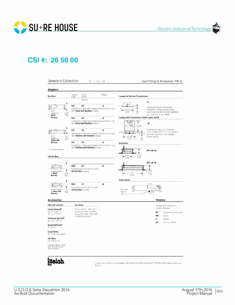
960
Stevens Institute of Technology
August 17th,2015U.S.D.O.E Solar Decathlon 2015As-Built Documentation Project Manual
CSI #: 26 50 00

961
Stevens Institute of Technology
August 17th,2015U.S.D.O.E Solar Decathlon 2015As-Built Documentation Project Manual
CSI #: 26 50 00
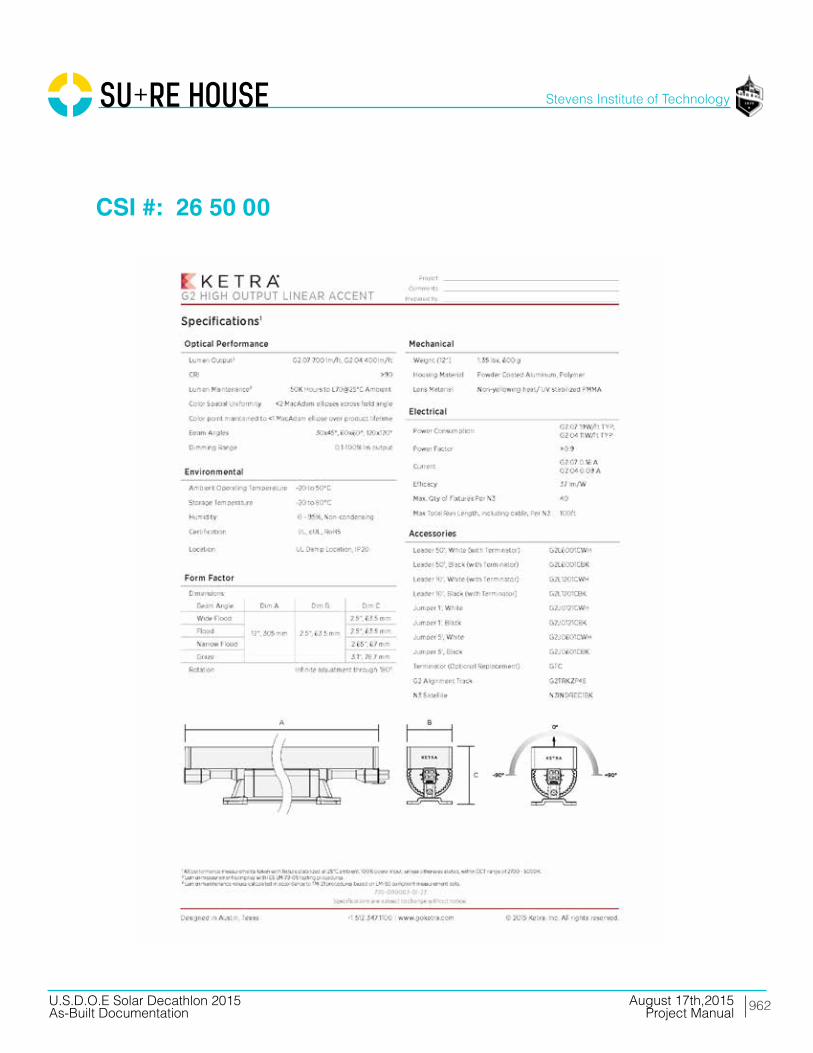
962
Stevens Institute of Technology
August 17th,2015U.S.D.O.E Solar Decathlon 2015As-Built Documentation Project Manual
CSI #: 26 50 00
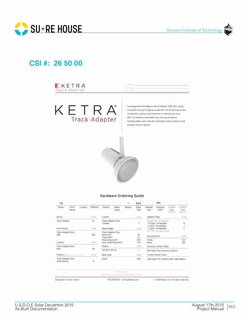
963
Stevens Institute of Technology
August 17th,2015U.S.D.O.E Solar Decathlon 2015As-Built Documentation Project Manual
CSI #: 26 50 00
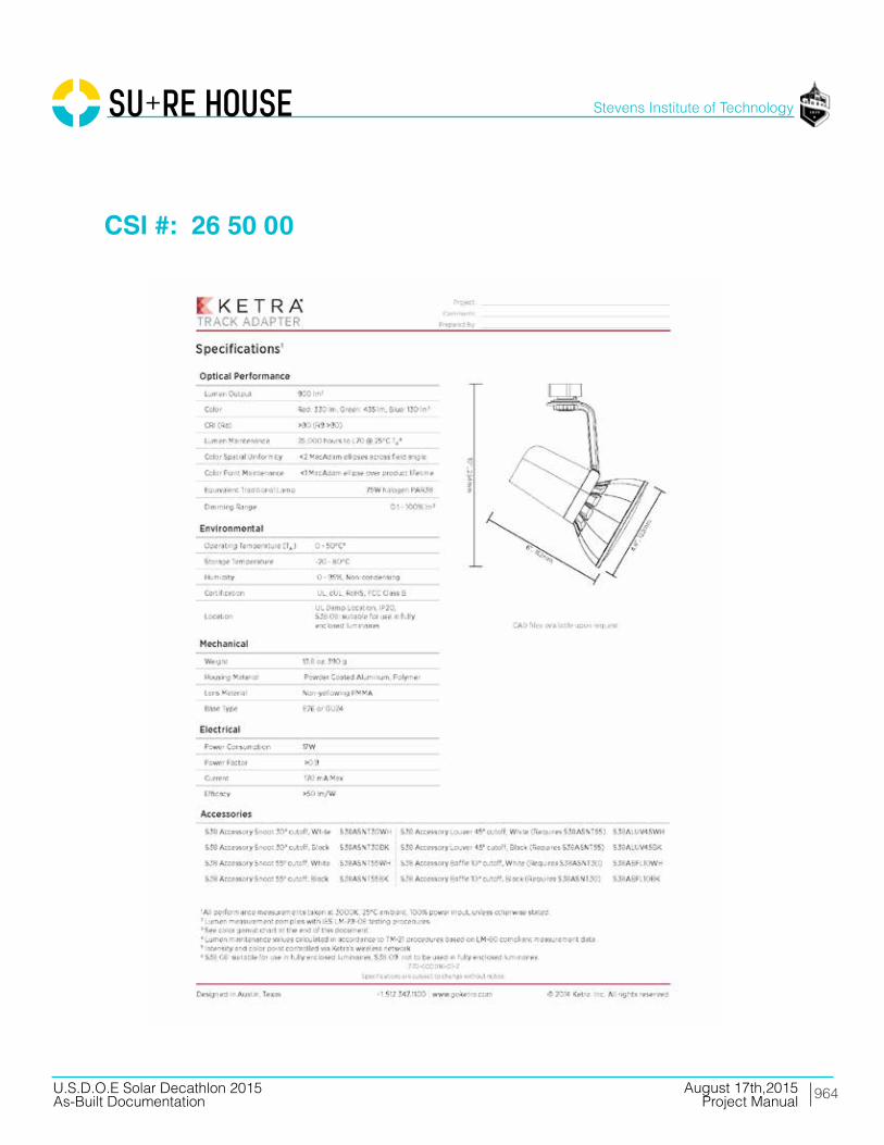
964
Stevens Institute of Technology
August 17th,2015U.S.D.O.E Solar Decathlon 2015As-Built Documentation Project Manual
CSI #: 26 50 00

965
Stevens Institute of Technology
August 17th,2015U.S.D.O.E Solar Decathlon 2015As-Built Documentation Project Manual
CSI #: 26 50 00

966
Stevens Institute of Technology
August 17th,2015U.S.D.O.E Solar Decathlon 2015As-Built Documentation Project Manual
CSI #: 26 50 00

967
Stevens Institute of Technology
August 17th,2015U.S.D.O.E Solar Decathlon 2015As-Built Documentation Project Manual
CSI #: 26 50 00
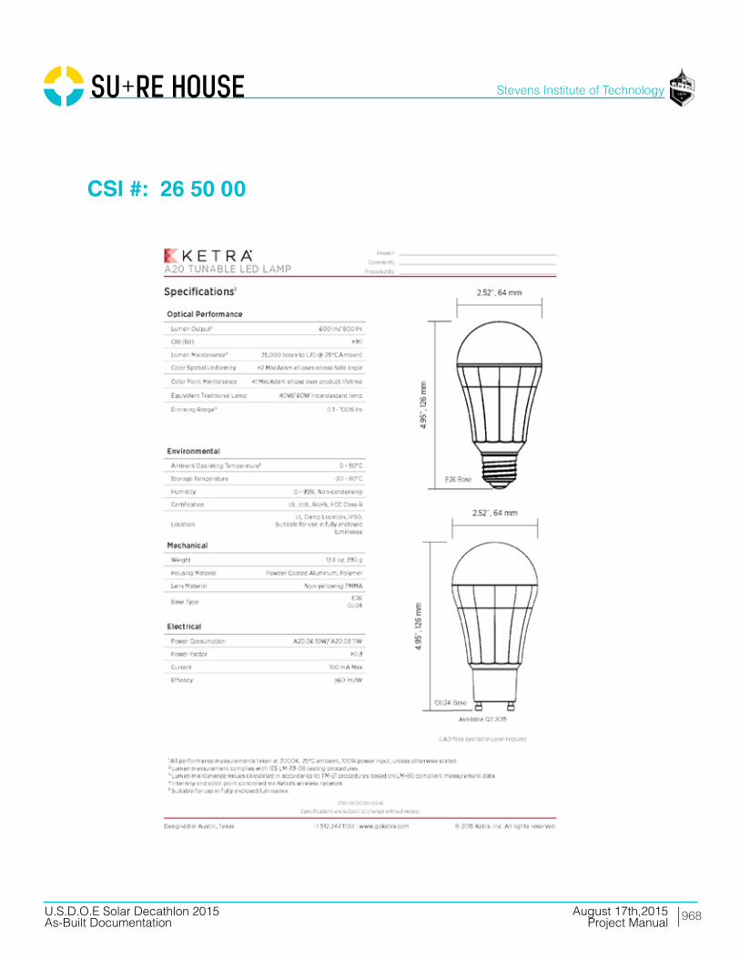
968
Stevens Institute of Technology
August 17th,2015U.S.D.O.E Solar Decathlon 2015As-Built Documentation Project Manual
CSI #: 26 50 00
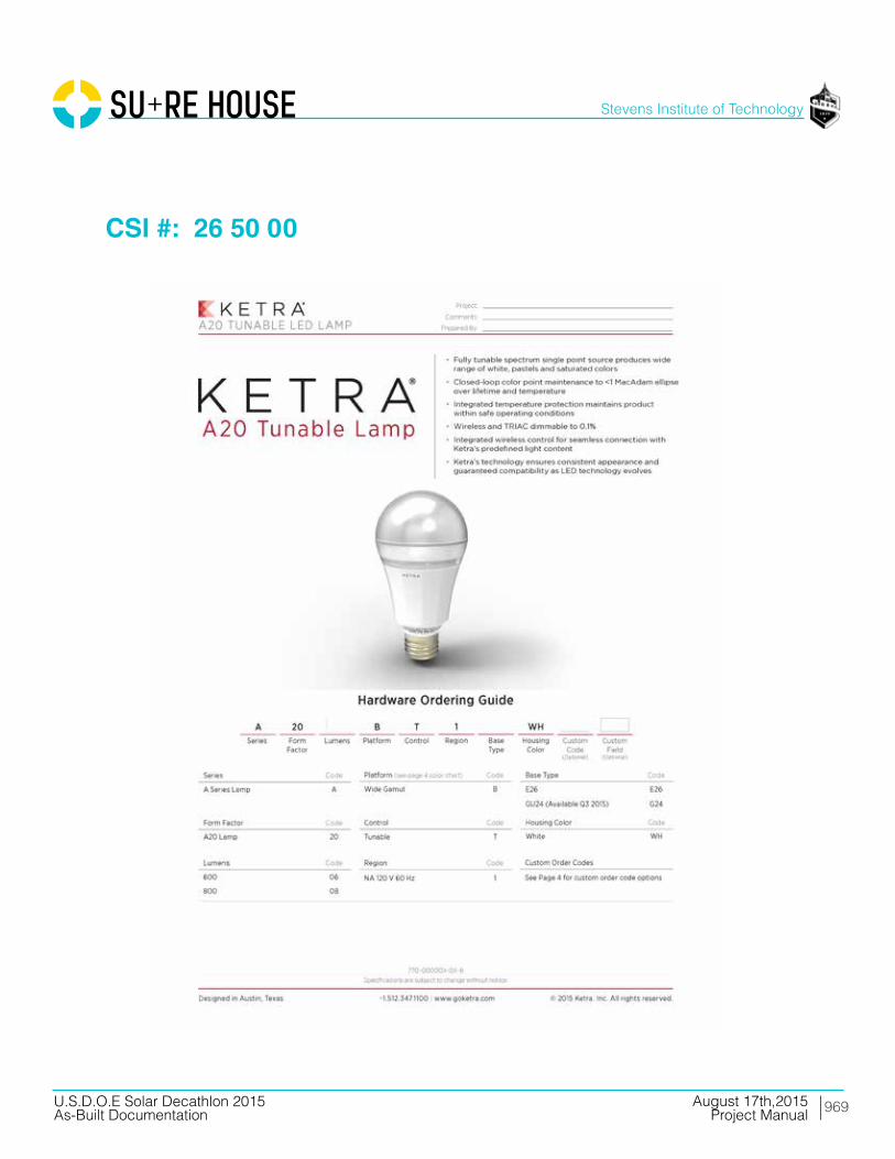
969
Stevens Institute of Technology
August 17th,2015U.S.D.O.E Solar Decathlon 2015As-Built Documentation Project Manual
CSI #: 26 50 00

970
Stevens Institute of Technology
August 17th,2015U.S.D.O.E Solar Decathlon 2015As-Built Documentation Project Manual
CSI #: 26 50 00

971
Stevens Institute of Technology
August 17th,2015U.S.D.O.E Solar Decathlon 2015As-Built Documentation Project Manual
CSI #: 26 50 00
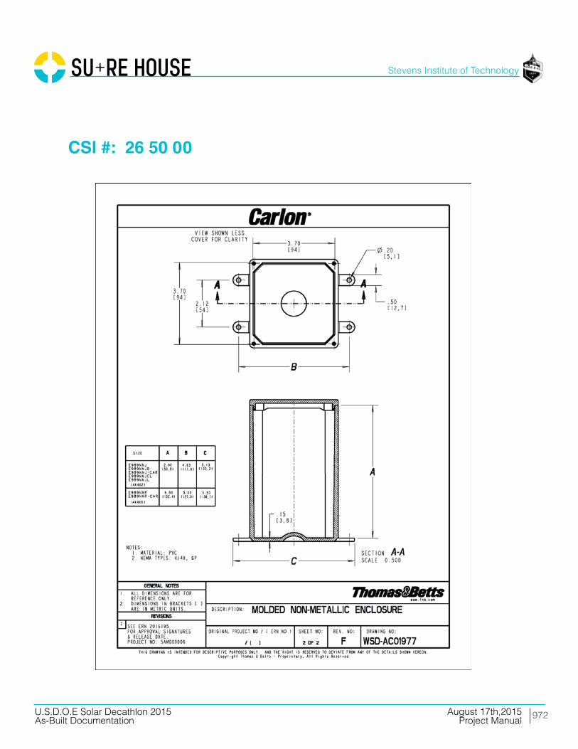
972
Stevens Institute of Technology
August 17th,2015U.S.D.O.E Solar Decathlon 2015As-Built Documentation Project Manual
CSI #: 26 50 00
973
Stevens Institute of Technology
August 17th,2015U.S.D.O.E Solar Decathlon 2015As-Built Documentation Project Manual
Division 28 Electronic Safety and Security

974
Stevens Institute of Technology
August 17th,2015U.S.D.O.E Solar Decathlon 2015As-Built Documentation Project Manual
CSI #: 28 40 00

975
Stevens Institute of Technology
August 17th,2015U.S.D.O.E Solar Decathlon 2015As-Built Documentation Project Manual
CSI #: 28 40 00

976
Stevens Institute of Technology
August 17th,2015U.S.D.O.E Solar Decathlon 2015As-Built Documentation Project Manual
CSI #: 28 40 00
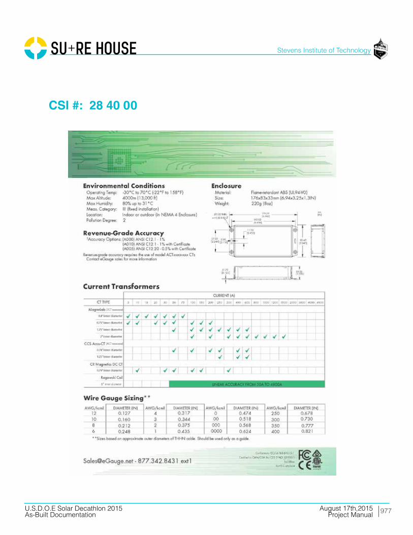
977
Stevens Institute of Technology
August 17th,2015U.S.D.O.E Solar Decathlon 2015As-Built Documentation Project Manual
CSI #: 28 40 00

978
Stevens Institute of Technology
August 17th,2015U.S.D.O.E Solar Decathlon 2015As-Built Documentation Project Manual
CSI #: 28 40 00

979
Stevens Institute of Technology
August 17th,2015U.S.D.O.E Solar Decathlon 2015As-Built Documentation Project Manual
CSI #: 28 40 00

980
Stevens Institute of Technology
August 17th,2015U.S.D.O.E Solar Decathlon 2015As-Built Documentation Project Manual
CSI #: 28 40 00
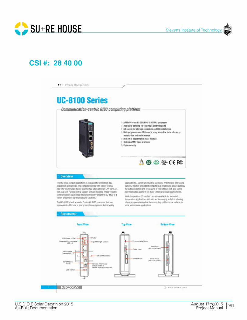
981
Stevens Institute of Technology
August 17th,2015U.S.D.O.E Solar Decathlon 2015As-Built Documentation Project Manual
CSI #: 28 40 00

982
Stevens Institute of Technology
August 17th,2015U.S.D.O.E Solar Decathlon 2015As-Built Documentation Project Manual
CSI #: 28 40 00

983
Stevens Institute of Technology
August 17th,2015U.S.D.O.E Solar Decathlon 2015As-Built Documentation Project Manual
CSI #: 28 40 00

984
Stevens Institute of Technology
August 17th,2015U.S.D.O.E Solar Decathlon 2015As-Built Documentation Project Manual
CSI #: 28 40 00
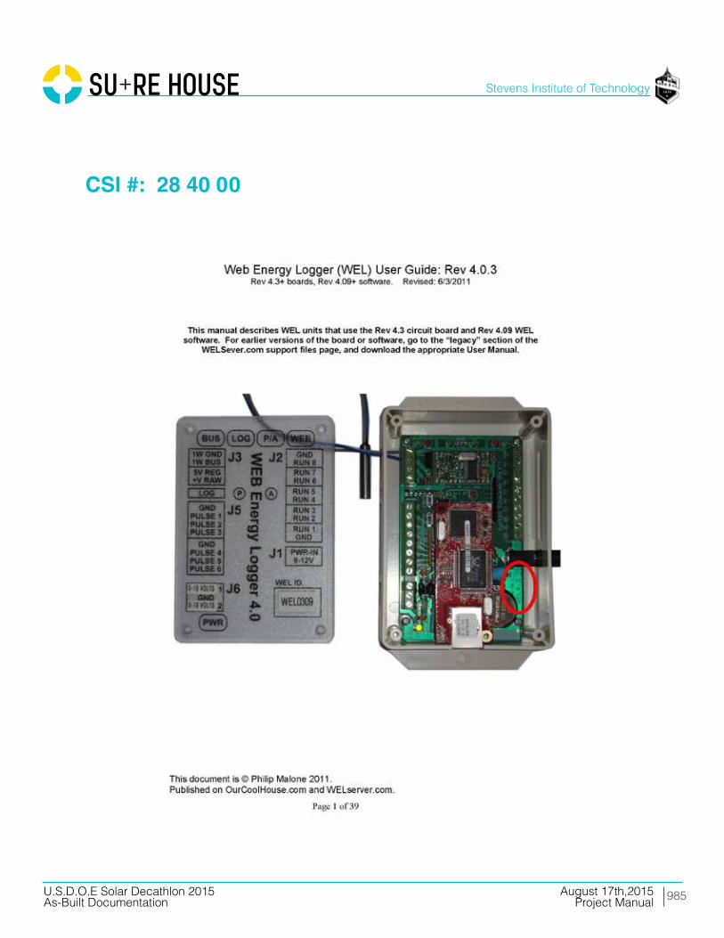
985
Stevens Institute of Technology
August 17th,2015U.S.D.O.E Solar Decathlon 2015As-Built Documentation Project Manual
CSI #: 28 40 00

986
Stevens Institute of Technology
August 17th,2015U.S.D.O.E Solar Decathlon 2015As-Built Documentation Project Manual
Division 31 Earthwork
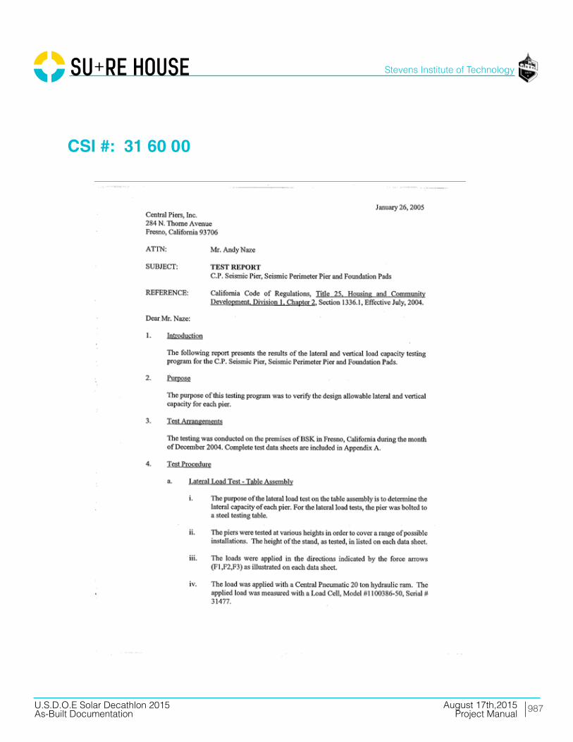
987
Stevens Institute of Technology
August 17th,2015U.S.D.O.E Solar Decathlon 2015As-Built Documentation Project Manual
CSI #: 31 60 00

988
Stevens Institute of Technology
August 17th,2015U.S.D.O.E Solar Decathlon 2015As-Built Documentation Project Manual
CSI #: 31 60 00

989
Stevens Institute of Technology
August 17th,2015U.S.D.O.E Solar Decathlon 2015As-Built Documentation Project Manual
CSI #: 31 60 00
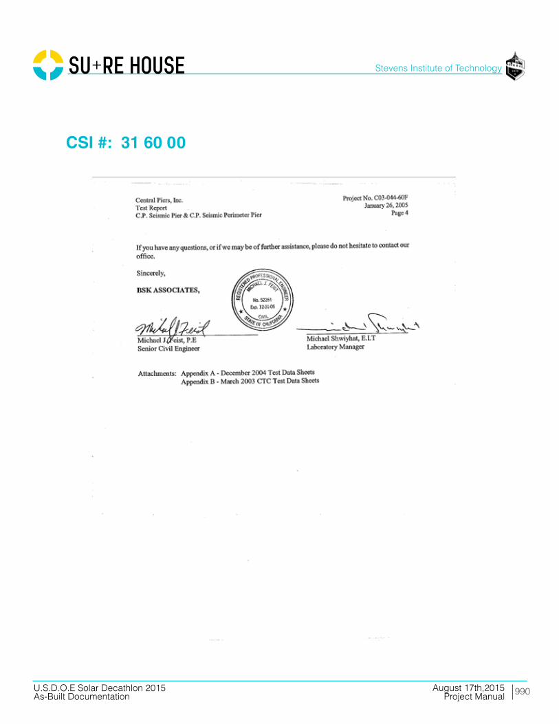
990
Stevens Institute of Technology
August 17th,2015U.S.D.O.E Solar Decathlon 2015As-Built Documentation Project Manual
CSI #: 31 60 00

991
Stevens Institute of Technology
August 17th,2015U.S.D.O.E Solar Decathlon 2015As-Built Documentation Project Manual
CSI #: 31 60 00

992
Stevens Institute of Technology
August 17th,2015U.S.D.O.E Solar Decathlon 2015As-Built Documentation Project Manual
CSI #: 31 60 00

993
Stevens Institute of Technology
August 17th,2015U.S.D.O.E Solar Decathlon 2015As-Built Documentation Project Manual
Division 41 Material Processing and Handling Equipment

994
Stevens Institute of Technology
August 17th,2015U.S.D.O.E Solar Decathlon 2015As-Built Documentation Project Manual
CSI #: 41 00 00

995
Stevens Institute of Technology
August 17th,2015U.S.D.O.E Solar Decathlon 2015As-Built Documentation Project Manual
CSI #: 41 00 00

996
Stevens Institute of Technology
August 17th,2015U.S.D.O.E Solar Decathlon 2015As-Built Documentation Project Manual
CSI #: 41 22 13
Steerable all wheel axles, in conjunction with super single tires, makes the HTT even harder to beat on the job-site. And NO changes to the on-outrigger capacity charts.
• Driveandsteercapabilitiesfortherearaxles
• Foursteeringmodes: - Independentfront - Independentrear - Combination - Crab• Rearaxlesself-centerandlockin
thestraightaheadpositionforhighspeedtravel.
• Turningradiusunder29ft(8.8 m)attheedgeofthetire
• 445/65R22.5tiresfrontandrearthatareinterchangeable
• Onlyonesparerimandtirecombinationisneeded.
• Transverse(cross-axle)differentiallocksthatgreatlyimprovetractiononunimprovedjob-siteconditions.

997
Stevens Institute of Technology
August 17th,2015U.S.D.O.E Solar Decathlon 2015As-Built Documentation Project Manual
CSI #: 41 22 13
Roomier and quieter operator’s cab• Extralargefrontwindowalmostseamlesslymergesintotheroof
window• Slidingleftsidedoor,rightandrearwindows,andswinguptop
windowprovideexcellentventilation• Allgauges,switches,indicators,andcontrolsareplacedinthe
operatorsforwardlineofsightforexcellentergonomics• Allgaugesandswitchesarebacklitforexcellentvisibilitywhen
thecabworkinglightsareswitchedtotheonposition• Available—Integratedairconditioningutilizesthesameventila-
tionoutletsasthestandardheatingsystem
IntegratedMicroguardratedcapacitylimiterwithcolorgraphicdisplay,forexcellentcontrastevenindirectsunlight,aidstheoperatorinsafeandefficientoperationbycontinuouslymonitoringamultitudeofcraneconditions.Optionalexternalandinternallightbarsinformtheoperatorand/orgroundcrewofthepercentageofcapacity.
Multiple counterweight configurations give you capacities for any size job • Standard–Totalof11,500lbs(5 216 kg)ofremovablecounterweights.
Capacitiesforfivedifferentcounterweightconfigurations.• Optional–Upto39,500lbs(17 917.2 kg)ofremovablecounterweights.
Capacitiesforuptothirteendifferentcounterweightconfigurations.• Allconfigurationscanberaisedandloweredbyhydrauliccylindersfrom
thecomfortoftheoperator’scabforeaseofinstallationandremoval.
Access to the engine compartments and the operator’s cab is superb with strategically-located ladders and steps.

998
Stevens Institute of Technology
August 17th,2015U.S.D.O.E Solar Decathlon 2015As-Built Documentation Project Manual
CSI #: 41 22 13
Your crane investment is always protected ... with your Link-Belt distributor.
When you invest in a Link-Belt crane, you invest in a legacy of outstanding customer support dating back to 1874. The ultimate value of a machine begins with state-of-the-art design and quality manufacturing, but it is the excellent Link-Belt distributor product support that determines its long term value. This philosophy has earned Link-Belt cranes the enviable position of traditionally commanding some of the highest resale prices in the industry.
As a member of Link-Belt Cranes user’s group, you will have access to:
• Online access to a comprehensive library of all parts, service and operator manuals for YOUR crane
• Interactive, live groundbearing calculations for YOUR crane
• Plus a vast array of information on new products, services and special offerings
Link-Belt’s investment in the highly acclaimed Master Technician Training Program is further testimony to its commitment to highly trained, experienced service personnel.
Technical schools are specifically designed to establish proficiency in three phases: fundamentals, machine systems, and diagnostics/repair. To further support these highly trained distributor personnel, Link-Belt has dedicated, full time factory technical advisors available with comprehensive machine records, drawings and technical publications to quickly isolate and resolve service issues.
No one knows your Link-Belt crane better than our trained technical specialists and coupled with the energy of our customer parts representatives, no one in the crane industry provides faster, more efficient customer service.
With state of the art computer information systems, distributors order Genuine Link-Belt Parts 24 hours a day, 7 days a week.
Our dedicated 72,000 sq. ft. (6 689 m2) Parts Distribution Center is an integral part of our prod-uct support commitment where we invest in an extensive and well planned parts inventory. And all parts in stock ship the same business day.
Link-Belt Construction Equipment Company is a leader in the design, manufacture and sales of telescopic and lattice boom cranes, with headquarters in Lexington, Kentucky.
In the recent decade, a dynamic and highly focused Link-Belt has emerged as a market leader in crane design and product quality standards by focusing on continuous improvement and employee empowerment.
Link-Belt’s core production base and center for worldwide operations is its 500,000 sq. ft. (46 451.5 m2) manufacturing facility in Lexington, Kentucky.
With major expansions over the last ten years, along with continuous improvement philosophies, this facility has emerged as the most modern crane facility in North America.
LINK-BELT CONSTRUCTION EQUIPMENT COMPANY
Lexington, Kentucky | www.linkbelt.com
® Link-Belt is a registered trademark. Copyright 2007. All rights reserved.
We are constantly improving our products and therefore reserve the right to change designs and specifications.
Litho in U.S.A. 11/07 #4344 (supersedes #4331)Link-Belt Parts Distribution Center
Link-Belt headquarters - Lexington, Kentucky
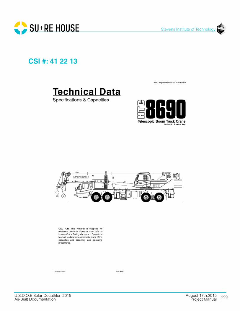
999
Stevens Institute of Technology
August 17th,2015U.S.D.O.E Solar Decathlon 2015As-Built Documentation Project Manual
CSI #: 41 22 13
15460 (supersedes 5424)---0506---N3
HTC-8690Link-Belt Cranes
Technical DataSpecifications & Capacities
Telescopic Boom Truck Crane90 ton (81.6 metric ton)
CAUTION: This material is supplied forreference use only. Operator must refer toin---cab Crane RatingManual andOperator’sManual to determine allowable crane liftingcapacities and assembly and operatingprocedures.
1000
Stevens Institute of Technology
August 17th,2015U.S.D.O.E Solar Decathlon 2015As-Built Documentation Project Manual
Division 48 Electrical Power Generation

1001
Stevens Institute of Technology
August 17th,2015U.S.D.O.E Solar Decathlon 2015As-Built Documentation Project Manual
CSI #: 48 14 00

1002
Stevens Institute of Technology
August 17th,2015U.S.D.O.E Solar Decathlon 2015As-Built Documentation Project Manual
CSI #: 48 14 00

1003
Stevens Institute of Technology
August 17th,2015U.S.D.O.E Solar Decathlon 2015As-Built Documentation Project Manual
CSI #: 48 14 00
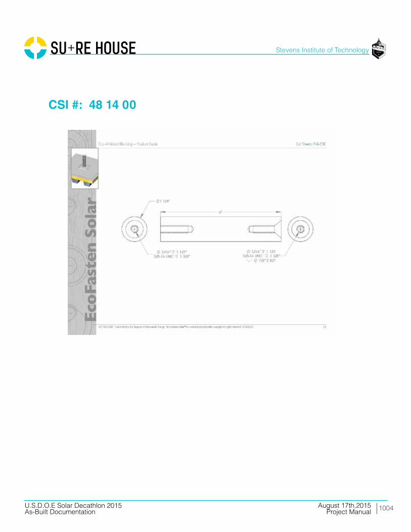
1004
Stevens Institute of Technology
August 17th,2015U.S.D.O.E Solar Decathlon 2015As-Built Documentation Project Manual
CSI #: 48 14 00

1005
Stevens Institute of Technology
August 17th,2015U.S.D.O.E Solar Decathlon 2015As-Built Documentation Project Manual
CSI #: 48 14 00

1006
Stevens Institute of Technology
August 17th,2015U.S.D.O.E Solar Decathlon 2015As-Built Documentation Project Manual
CSI #: 48 14 00

1007
Stevens Institute of Technology
August 17th,2015U.S.D.O.E Solar Decathlon 2015As-Built Documentation Project Manual
CSI #: 48 14 13
SunPower monocrystalline cells, laminated in high strength technopolymers. The back-contact technology results in a superior aesthetic appearance and productivity.These cells allow for flexible panels with the highest efficiency on the market.
by
1008
Stevens Institute of Technology
August 17th,2015U.S.D.O.E Solar Decathlon 2015As-Built Documentation Project Manual
CSI #: 48 14 13

1009
Stevens Institute of Technology
August 17th,2015U.S.D.O.E Solar Decathlon 2015As-Built Documentation Project Manual
CSI #: 48 14 13

1010
Stevens Institute of Technology
August 17th,2015U.S.D.O.E Solar Decathlon 2015As-Built Documentation Project Manual
CSI #: 48 14 13

1011
Stevens Institute of Technology
August 17th,2015U.S.D.O.E Solar Decathlon 2015As-Built Documentation Project Manual
CSI #: 48 14 13
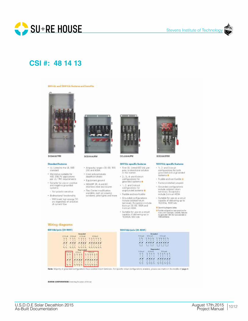
1012
Stevens Institute of Technology
August 17th,2015U.S.D.O.E Solar Decathlon 2015As-Built Documentation Project Manual
CSI #: 48 14 13

1013
Stevens Institute of Technology
August 17th,2015U.S.D.O.E Solar Decathlon 2015As-Built Documentation Project Manual
CSI #: 48 14 13

1014
Stevens Institute of Technology
August 17th,2015U.S.D.O.E Solar Decathlon 2015As-Built Documentation Project Manual
CSI #: 48 19 00
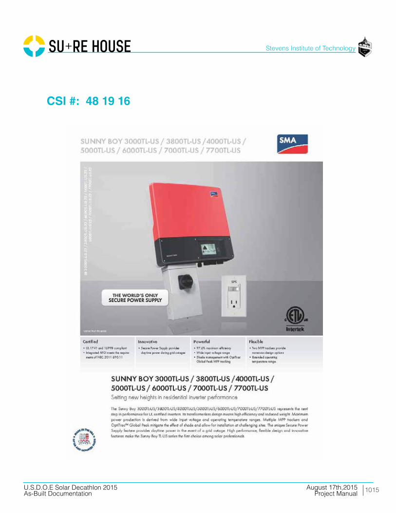
1015
Stevens Institute of Technology
August 17th,2015U.S.D.O.E Solar Decathlon 2015As-Built Documentation Project Manual
CSI #: 48 19 16

1016
Stevens Institute of Technology
August 17th,2015U.S.D.O.E Solar Decathlon 2015As-Built Documentation Project Manual
CSI #: 48 19 16
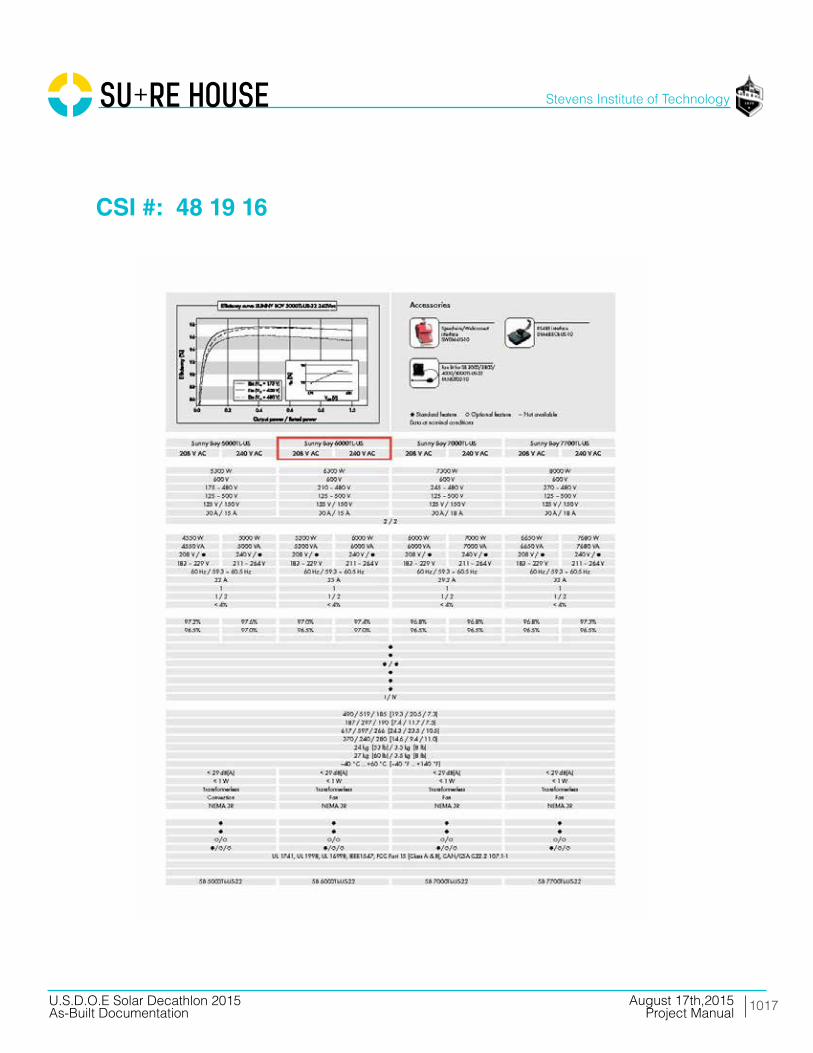
1017
Stevens Institute of Technology
August 17th,2015U.S.D.O.E Solar Decathlon 2015As-Built Documentation Project Manual
CSI #: 48 19 16
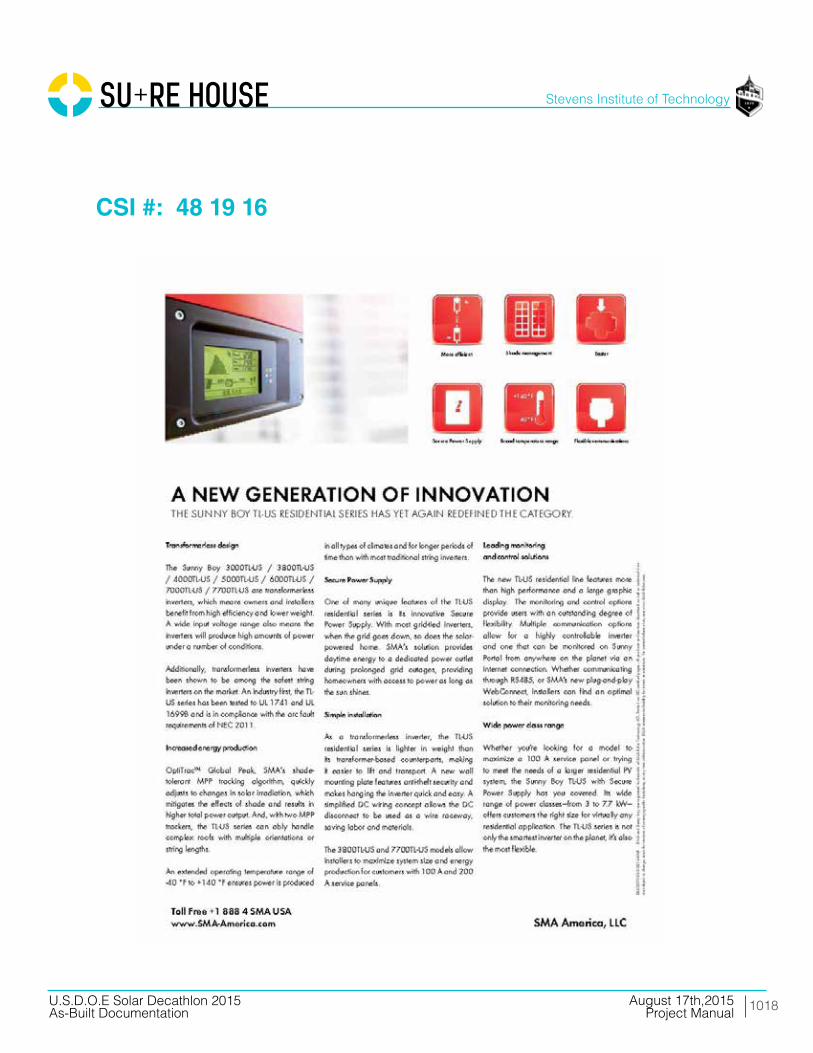
1018
Stevens Institute of Technology
August 17th,2015U.S.D.O.E Solar Decathlon 2015As-Built Documentation Project Manual
CSI #: 48 19 16

1019
Stevens Institute of Technology
August 17th,2015U.S.D.O.E Solar Decathlon 2015As-Built Documentation Project Manual
CP
438 www.crouse-hinds.com US: 1-866-764-5454 CAN: 1-800-265-0502 Copyright© 2013 Eaton’s Crouse-Hinds Business
Solar Accessories
Cable Tie and Cable Clip Applications:Eaton's Crouse-Hinds Solar Cable Clips and Ties provide cablemanagement options for bundling and harnessing PV solar wireanywhere between the panels to the inverter.
Cable Tie Features:• Equipped with a UV protected vinyl jacket which prevents damage
to installation cable insulation and ensures durability• Tin plated with a copper crimp sleeve which allows for easy field
installation • Constructed from commercial aircraft grade stainless wire for long,
dependable service
Standard Materials and Finishes:• UV resistant vinyl jacketing, tin plated copper crimp sleeve,
commercial aircraft grade stainless wire
Cable Tie Ordering Information:
Cable Clip Features:• Manufactured out of corrosion-resistant 304 stainless steel• Double compression design which can accommodate (2) 12 gauge
USE-2 wire or (2) 10 gauge PV-1000 wires• Smooth clip edges which prevent damage to cable insulation• Screwdriver designed slot which allows for easy removal or
movement of the clip when necessary
Standard Materials:• Corrosion-resistant 304 stainless steel
Cable Clip Ordering Information:
Panel Thickness Clamping Range
Minimum Maximum Wire Dia. Range Foot PrintOverallHeight
Cat. # Description in. in. Max. (2) Wires in. in.UnitQty
Wt. Lbs.Per 100
SCLP1Solar PV CableClip 0.06 0.125
.20" (5.0 mm) -
.30" (7.6 mm) each cable 1 0.39 100 1
Solar Combiner Solutions
Part Specification Part Dimensions
Min. Tensile Strength Max. Bundle Dia. Length Cable Dia.
Cat. # Description Lbs. N in. in. in. Unit QtyWt. Lbs.Per 100
SCBLTIE8 Solar Cable Tie 8"
100 440
2.3 8
0.06
100 1SCBLTIE10 Solar Cable Tie 10" 2.92 10 100 1SCBLTIE12 Solar Cable Tie 12" 3.88 12 100 1SCBLTIE14 Solar Cable Tie 14" 4.2 14 100 1
CSI #: 48 19 19

1020
Stevens Institute of Technology
August 17th,2015U.S.D.O.E Solar Decathlon 2015As-Built Documentation Project Manual
CP
437www.crouse-hinds.com US: 1-866-764-5454 CAN: 1-800-265-0502 Copyright© 2013 Eaton’s Crouse-Hinds Business
Solar Pass Through Boxes
Applications:Eaton's Crouse-Hinds Solar Pass Through Boxes (sometimesreferred to as “transition boxes”) are used in residential applicationsto provide a low profile, cost-effective way to group inputwires/circuits from several arrays and/or solar panels and transitionfrom solar (PV) cable to regular building wire. The Pass Through Boxwas designed for PV applications where overcurrent protection is notnecessary due to the low power rating of the PV string.
Features:• Rated 600 VDC continuous duty• Constructed in accordance with UL1741 standards, providing
spacious wiring room for quick, easy wire termination• Factory installed multi-hole solar cord grip provides dependable,
secure wire termination to enclosure and saves field installation –eliminating the need for enclosure drilling – saving time and labor
• Fiberglass enclosures with captive stainless steel screws andformed-in-place polyurethane seamless gasket provided asstandard
• Available in N3R sheet steel enclosures – consult factory• Lightweight design offers easy mounting capabilities; optional
mounting feet are available for increased customer flexibility• Rated for continuous operation at 60°C
Standard Materials and Finishes:• Hot compression molded fiberglass-reinforced thermoset
polyester• Non-conductive, impact-resistant, UV-resistant, flame retardant• Poured polyurethane seamless gasket provides water-tight,
dust-tight environmental seal• Stainless steel used on all external hardware
Ordering Information:Cat. # Description
CPBF03 3 Circuit Pass Through BoxCPBF04 4 Circuit Pass Through BoxCPBF05 5 Circuit Pass Through BoxCPBF06 6 Circuit Pass Through BoxCPBF07 7 Circuit Pass Through BoxCPBF08 8 Circuit Pass Through BoxCPBF09 9 Circuit Pass Through BoxCPBF10 10 Circuit Pass Through BoxCPBF11 11 Circuit Pass Through BoxCPBF12 12 Circuit Pass Through BoxCPBF13 13 Circuit Pass Through BoxCPBF14 14 Circuit Pass Through BoxCPBF15 15 Circuit Pass Through BoxCPBF16 16 Circuit Pass Through BoxCPBF17 17 Circuit Pass Through BoxCPBF18 18 Circuit Pass Through BoxCPBF19 19 Circuit Pass Through Box
CPBF20 20 Circuit Pass Through BoxCPBF21 21 Circuit Pass Through BoxCPBF22 22 Circuit Pass Through BoxCPBF23 23 Circuit Pass Through BoxCPBF24 24 Circuit Pass Through BoxCPBF25 25 Circuit Pass Through BoxCPBF26 26 Circuit Pass Through BoxCPBF27 27 Circuit Pass Through BoxCPBF28 28 Circuit Pass Through BoxCPBF29 29 Circuit Pass Through BoxCPBF30 30 Circuit Pass Through BoxCPBF31 31 Circuit Pass Through BoxCPBF32 32 Circuit Pass Through BoxCPBF33 33 Circuit Pass Through BoxCPBF34 34 Circuit Pass Through BoxCPBF35 35 Circuit Pass Through BoxCPBF36 36 Circuit Pass Through Box
Certifications and Compliances:• cETLus 1741 Listed• cETLus 1741 Listed to CSA Standard C22.2 No. 31 & No. 107.1• NEMA 4X
Cat. # Description
CSI #: 48 19 19
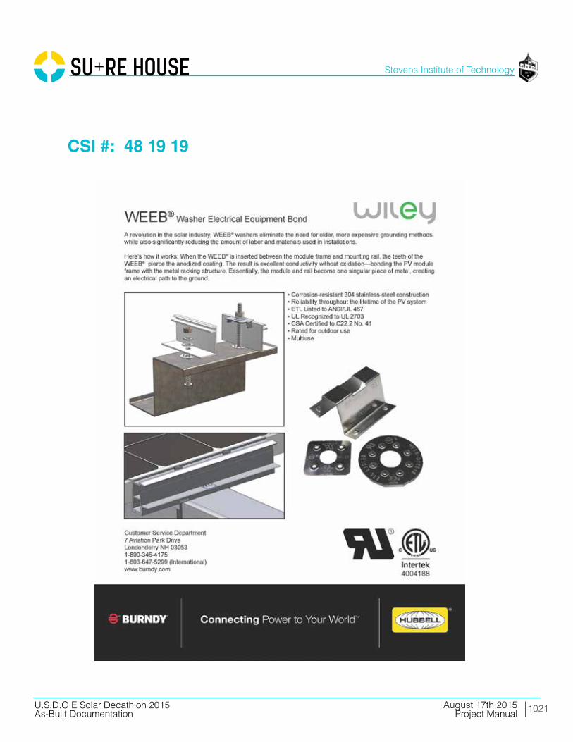
1021
Stevens Institute of Technology
August 17th,2015U.S.D.O.E Solar Decathlon 2015As-Built Documentation Project Manual
CSI #: 48 19 19

1022
Stevens Institute of Technology
August 17th,2015U.S.D.O.E Solar Decathlon 2015As-Built Documentation Project Manual
CSI #: 48 19 19
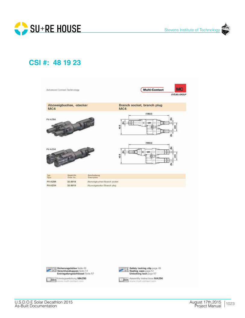
1023
Stevens Institute of Technology
August 17th,2015U.S.D.O.E Solar Decathlon 2015As-Built Documentation Project Manual
CSI #: 48 19 23
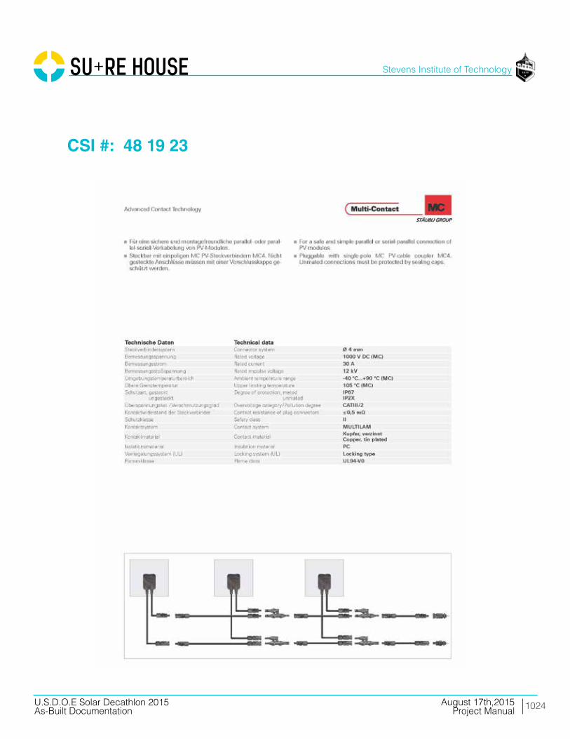
1024
Stevens Institute of Technology
August 17th,2015U.S.D.O.E Solar Decathlon 2015As-Built Documentation Project Manual
CSI #: 48 19 23
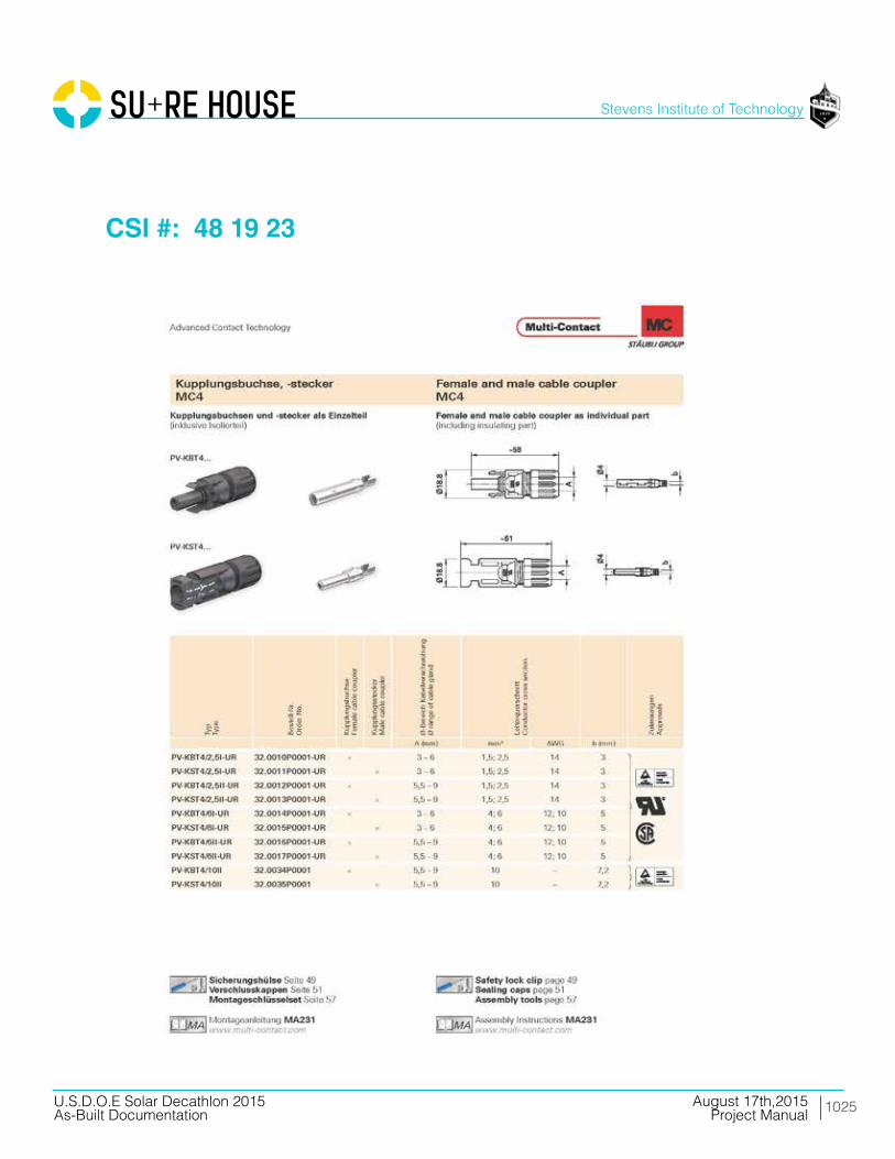
1025
Stevens Institute of Technology
August 17th,2015U.S.D.O.E Solar Decathlon 2015As-Built Documentation Project Manual
CSI #: 48 19 23

1026
Stevens Institute of Technology
August 17th,2015U.S.D.O.E Solar Decathlon 2015As-Built Documentation Project Manual
CSI #: 48 19 23

SU+RE HOUSEProject Manual
As-Built DocumentationAugust 2015
Related Documents