Steven Bellamy and Ronnie Jones Raleigh Durham International Airport

Welcome message from author
This document is posted to help you gain knowledge. Please leave a comment to let me know what you think about it! Share it to your friends and learn new things together.
Transcript

Steven Bellamy and Ronnie Jones
Raleigh Durham International Airport

The Purpose of this Presentation
1. To introduce airfield lighting maintenance.
2. To collaborate and exchange information.

The Classroom TrainingWill Cover the Following
1. SAFETY
2. Series Circuit
3. Constant Current Regulators (CCR)
4. Trouble Shooting
5. Airfield cable splicing

Airfield Lighting Maintenance
1. Can be defined as maintaining the airfield lights!
2. Maintaining the airfield lights means that each component
should perform as designed or be ready to perform when
requested.
a. Make sure the lights are not only on, but serviceable
(not to dim/not to bright.)
b. The CCRs are doing what they are assigned to do.


They said it couldn’t be done!

Lunch break

Just hanging out

1 TO MANY BRICKS!

FELLAS,, HOW DO I GET TO WALMART?

Joe’s onsite muffler repair


NOT “UL” APPROVED!

I got your back partner.

Taking it to the next level

DON’T GET IN OVER YOUR HEAD!!!

CLEAN YOUR EQUIPMENT DAILY
Airfield Lighting Maintenance SAFETY Tips
1. Wear proper Personal Protective Equipment.
a. High voltage class 2 gloves and protectors
b. SAFETY eye wear
c. Ear plugs
d. Working gloves
e. Proper reflective clothing
f. SAFETY shoes
Airfield Lighting Maintenance SAFETY Tips
2. Never
Never,
NEVER……..
perform work on electrical energized
equipment or wiring except when measuring voltage and current.
Never, never, never break a live circuit or attempt to replace a
airfield fixture with the circuit still energized.

Airfield Lighting Maintenance SAFETY Tips
3. Common causes of Accidents
a. Working on equipment without adequate
coordination with equipment users.
b. Working on equipment without sufficient
experience on that equipment.
c. Failure to follow instructions in equipment manuals.
d. Using unsafe equipment, SAFETY devices, and working
at unsafe speeds.

Airfield Lighting Maintenance SAFETY Tips
4. Coordinate work with Operations and tower personnel
5. Inspect and test all meters before using
6. Never assume anything. Check it out first
7. Radios working
8. SAFETY will be mentioned throughout this presentation
Questions before we move into Series Circuits


LOCKOUT TAG OUT KIT

Series Circuit
Laws of series circuits important to our discussion:
Rule 1- The total current (amps) in a series circuit is equal to the
current in any other part of the circuit.
Rule 2- The total voltage is equal to the sum of the voltages
across all parts of the circuit.
As you will see in the next slide the series circuit is a continuous
loop from one transformer to the next. Since the amperage
remains the same throughout the circuit each load or light fixture
will have 6.6 amps available.
* Parallel Circuits are used on helipads and short runways if any!

VAULT FIELD


Series Circuits Consists of 5/6 Basic Components For Airfield
Lighting
1. Constant Current Regulator. (CCR)
2. 5000 KV Cable.
3. S-1 Cutout.
4. Isolation Transformer.
5. Connector Kits.
6. Lighting Device- fixtures, signs, windsock, etc.

Series Circuit
QUESTIONS?

CONSTANT CURRENT REGULATOR
(CCR)
CONSTANT CURRENT REGULATOR
(CCR)
1. Power source for airfield lighting.
2. Provides regulated (constant) current to airfield lights.
3. Output current controls lighting intensity.
4. Located in the airfield Vault (Substation)

CCR TYPES
1. Dry type, air cooled. These have vented
enclosures.
2. Oil type (wet type), oil cooled. These have
cabinets with leak proof tanks.
3. Rated Sizes: 4 KW, 7.5 KW, 10 KW, 15 KW, 20 KW,
25 KW, 30 KW, 50 KW, & 70 KW.
(1 Kilowatt = 1000 Watts)
4. Primary Supply (Input) rated in volts, 60 HZ
208, 240, 480, and some 2400V.

CCR TYPES
5. There are 2 styles by output steps. Style 1 is 3 step
brightness (3 step output current.)
a. Mostly 4 KW to 15 KW ratings used on medium
intensity lamps 60W or less, taxiways and some
runways.
b. B10/B30/B100 represents 10%, 30%, or 100%
intensity.
c. 10% = 4.8A
d. 30% = 5.5A
e. 100% = 6.6A

CCR TYPES
6. Style 2 is 5 step brightness (5 step output
current.)
a. B1 = 0.15% @ 2.8A
b. B2 = 1.2% @ 3.4A
c. B3 = 5% @ 4.1A
d. B4 = 25% @ 5.2A
e. B5 = 100% @ 6.6A
7. Realize a potential hazard exist whenever work is
performed on or around energized electrical equipment.

CCR TYPES
1. A 3 Step CCR is usually used on a Taxiway
2. A 5 Step CCR is usually on the Runway Lighting (because
light intensities are higher).
3. A 6.6 Amp maximum CCR output is the most common
type used.
4. The 20 Amp maximum CCR output is primarily used at
Military Airports.
5. The advantage of the 20A CCR is that for the same load, it
has a lower output voltage than the equivalent 6.6A CCR.
6. The 20A CCR is the only type available in the 50KW and
70KW CCR.

CCR DISPLAY

CCR DISPLAY


CCR TYPES
It’s a good idea to obtain manuals for your equipment if you do
not have them. Please follow the suggested periodic maintenance
for each piece of equipment at you facility. When sizing CCRs
please refer to the previous slide, and know what type of CCR
works best for your application. Please allow me to explain the
difference between a SCR CCR and a Ferroresonant CCR.
1. SCR CCRs are smaller in size, less expensive, very noisy
harmonics, produce a poor sine wave which is worst
when the CCR is over sized and should not be used on
circuits that have flashing lights.
2. Ferroresonant CCRs are larger in size, more expensive,
very low harmonics, produce a good sine wave, there is
no effect on circuits with flashing lights, and there is no
effect if the CCR is over sized for the actual load.

COLLABORATION AT IT’S
FINEST!


YOU WANT TO GO
HOME THE SAME
WAY YOU CAME TO
WORK!!

ENJOYING ME TIME!

Airfield all nice and illuminated

Storms start to roll in……..
Phone call…….Airfield down TROUBLE!

Troubleshooting Airfield Lighting Systems
We will go over some basic troubleshooting techniques. First you
want to verify if the problem is in the Vault or the field. There are
numerous problems you may encounter which normally are
created from two types; an open circuit or a short circuit.
1. Safety
a. Coordinate and communicate with co-workers
as to what’s what.
b. Know your circuit. (Find drawings, or someone
who knows how it’s laid out. This will help you stay
safe and out of other circuits.)

Troubleshooting Airfield Lighting Systems
c. Wear your SAFETY equipment. SAFETY gloves, ear
plugs, SAFETY glasses, and use a true RMS meter.
d. Always treat your circuit like it’s hot. Again
even though commonly done at some airports.
It is not recommended to change lamps with
the circuit on.
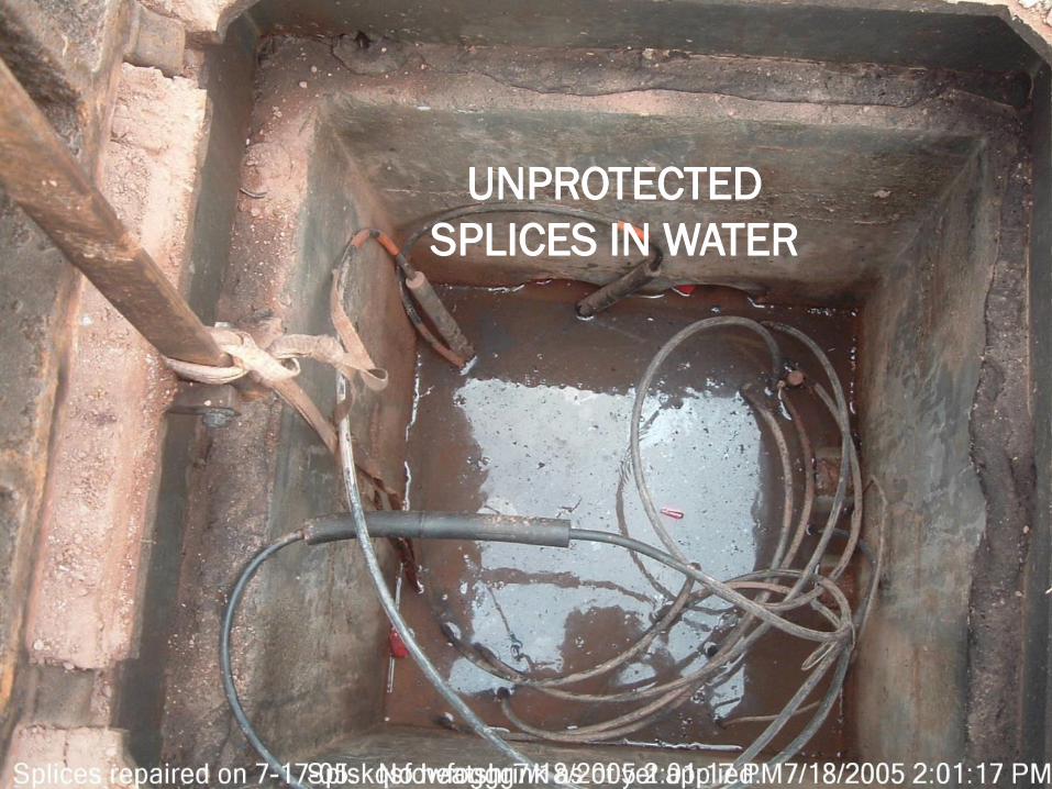
UNPROTECTED
SPLICES IN WATER

RICHARD SAYS….
NEVER, NEVER,
NEVER ASSUME IT’S
OFF!!!

Troubleshooting Airfield Lighting Systems
2. There are some basic troubleshooting techniques
we can use and you don’t have to be an
expert.
a. Sense of smell
b. Sense of sight
c. Sense of listening
d. YOU need to know if someone else has worked on the
circuit
e. DO NOT TOUCH!
Troubleshooting Airfield Lighting Systems
3. Recent weather?
a. Thunder storm
b. Rain
c. Extremely hot or cold
4. Any recent digging?

Troubleshooting Airfield Lighting Systems
5. The Open circuit is a common problem found in
airfield circuitry. An open circuit; is defined as a
circuit, which does not have a complete path for
current to return to the source.
a. Open circuit can be in the field wiring
b. Open circuit can be in the isolation transformer
c. Open circuit can be in the light unit
d. Open circuit can be in the CCR

Troubleshooting Airfield Lighting Systems
6. The short circuit will be the opposite of the open
circuit, there is a shorter path for current to
to return to it’s source. Also referred to as a
ground.
a. Short circuit can be in the field wiring
b. Short circuit can be in the isolation transformer
c. Short circuit can be in the lighting device
d. Short circuit can be in the CCR
If you find yourself in over your head seek help from a supervisor.

Troubleshooting Airfield Lighting Systems
Can plazas used to separate circuits

Troubleshooting Airfield Lighting Systems
COVERS ENGRAVED WITH CIRCUITS

Quick Reference to Troubleshooting
1. Don’t panic! Accidents usually occur doing things we are most familiar with.
2. Communicate……….. what is actually out on the field.
3. Distinguish if the problem is in the Vault or the field.
4. If no lights, I’m checking the CCR first. Is it on? Did it trip out? If so check the display to see what did it trip out on? Is the switch on the CCR in the correct position? Has the circuit breaker tripped? Will the CCR reset or does it reset but trips out again? At the same time I’m using my senses, any unusual noises in the Vault? Do I smell anything burnt? Do I see smoke? (hope not) Anyone recently been working on the circuit that day? If the CCR still will not stay on, my next step will be to (loop) the CCR out. This takes the field section of the fault out of the equation. Now if the CCR stays on with the field part of the circuit not connected, then I know my problem is in the field. If it does not stay on, then I know the problem is in the CCR.

Quick Reference to Troubleshooting
5. Problem in the field……. Depending on the fault, in this
case (no lights) then before I leave the Vault I’m going to
lockout tag out the circuit, ensure any S-1 cut out devices
are removed then check continuity on the field circuit.
Meanwhile I’m communicating with tower or the power to
be, and ensuring some qualified help is on the way.

When you are in over your head
Call for your team members!

NOW THAT THE TEAM HAS SHOWN UP!

ONE PERSON NEEDS TO BE IN CHARGE!

AVOID DAMAGING FIXTURES
WITH SNOW PILES


Meters & MeggersUsed at RDU
CRANK STYLE

PUSH BUTTON STYLE

FLUKE 1507 INSULATION
TESTER

CLAMP METERS AND MUTI METERS TRUE-RMS

Airfield Cable Splicing Demonstration by Mr. Ronnie Jones
The Primary Connector Kit
The primary cable connector kit is designed to provide a
separable connection between:
1. a non-screened primary airfield cable(5 kV or less) and
an FAA L-830 isolation transformer.
2. in a non-screened primary series circuit cable. One kit
is required for each cable splice or transformer
installation. Each kit conforms to FAA L-823 Style 3
plug and Style 10 receptacle with crimp-on pin and
socket contacts.

Airfield Cable Splicing
Preparing the Cable
1. Ensure the cable is clean. The cable needs to be cleaned off from dirt and grease. It also needs to be dry. Do this on both ends of the splice, twelve inches from the end.
2. Ensure cable is smooth. The first five inches of the cable should be smoothed out with sand paper to ensure a good seal with the housing and heat shrink. This will help with any possible chance of air pockets forming.
3. Stripping the jacket off the conductor. You now are ready to strip the jacket off the conductor. You need to strip back about one inch. Once you strip it back ensure that you didn’t nick the conductor. Make sure there is no jacketing left on the conductor where it was stripped. You should slide the crimp on the conductor to ensure proper length exposed.
Airfield Cable Splicing
4. Pencil the jacket. Now it is time to pencil, or cut the jacket
at an angle all the way around the cable, so that it looks
like a sharpened pencil. There are a couple of ways to do
this, first, use a penciling tool. Second, use a knife and cut
the jacket at a 20-30 degree angle. Once the penciling is
complete inspect the conductor for any nicks that you
might have made.

Airfield Cable Splicing
Crimping
1. Check the length of the conductor. Try the crimp on the conductor for a proper fit. Ensure that it is the right size crimp for the conductor. Next, while the crimp is on the conductor check to make sure there is not excess conductor exposed or that the crimp does not go on all the way. You may need to cut off some of the conductor or strip more of the jacket off.
2. Inspect the crimping tool. Ensure the crimping tool is in good working condition. Make sure the proper die is in place for the size crimp you have.
3. Crimping the crimp. Slide the crimp on the conductor. Double-check everything again before you actually crimp. Each manufacture tells you how many times to crimp their crimp. For the type that we use it is twice.

Airfield Cable Splicing
Housing
1. Ensure the cable and crimp is clean. Before you put the housing on, ensure that the jacket and crimp are clean from shaving and dirt.
2. Ensure you match up the proper housing with the proper crimp. Before sliding the housing over the crimp, make sure you have the right house according to the manufacture.
3. Push the housing on. This is why you penciled to jacket. Push the housing on a little bit then pull back off, you should see some silicone on the jacket. Smear the silicone around the conductor, this will help to push the housing on all the way. The male crimp should come out about one inch. The female should stay in about one inch. Check with the manufacture specs thou.

Airfield Cable SplicingHeat Shrinking
1. Installing the heat shrink. Before you plug the two ends together, you need to slide a heat shrink tube over one end. Then you can plug the ends together.
2. Note: Look out for air pockets!
3. Properly placing the heat shrink. Once the ends are together slide the heat shrink over the splice. You want the heat shrink to be even on both sides of the splice.
4. Time to heat. You can use either a torch or heat gun to heat the heat shrink. You want to start in the middle working outward ensuring that you go all the way around the cable. While heating keep an even slow motion to ensure that no air is trapped under the heat shrink. Make sure you don’t get to close or touch the heat shrink with the torch or heat gun or you will burn the heat shrink. Once heat shrink is complete, you are done!

SO WHY DO WE DO ALL OF THIS?

IT’S MY AIRFIELD I
CAN RUN IT HOWEVER I
WANT!!!


THAT IS OUR TIME
AND WE THANK YOU FOR YOURS
RDU AIRPORT AUTHORITY
Related Documents