STERIDOSE SALES Head Office Himmelsbodavägen 7 · P.O.Box 120 · SE-147 22 TUMBA · SWEDEN Phone: +46-8 449 99 00 · Fax: +46-8 449 99 90 [email protected] · www.steridose.com Regional Office 5020 World Dairy Drive · Madison, WI 53718 · USA Phone: +1-608 229 5225 · Fax: +1-608 227 9599 [email protected] · www.steridose.com STERIMIXER ® Installation and operation manual (including welding guideline) This user manual shall be read carefully before unpacking Sterimixer ® ! Customer Order No: Roplan Order No: 60/75 AC 85/100 Motec 85/140 DC 120/150 Air 120/190 SMA 120H/220 SMO 210/275 Sign: TC SiC

Welcome message from author
This document is posted to help you gain knowledge. Please leave a comment to let me know what you think about it! Share it to your friends and learn new things together.
Transcript

STERIDOSE SALES Head Office Himmelsbodavägen 7 · P.O.Box 120 · SE-147 22 TUMBA · SWEDEN Phone: +46-8 449 99 00 · Fax: +46-8 449 99 90 [email protected] · www.steridose.com Regional Office 5020 World Dairy Drive · Madison, WI 53718 · USA Phone: +1-608 229 5225 · Fax: +1-608 227 9599 [email protected] · www.steridose.com
STERIMIXER®
Installation and operation manual (including welding guideline)
This user manual shall be read carefully before unpacking Sterimixer®!
Customer Order No:
Roplan Order No:
60/75 AC
85/100
Motec
85/140 DC 120/150 Air 120/190 SMA 120H/220 SMO 210/275
Sign: TC
SiC

STERIDOSE SALES Head Office Himmelsbodavägen 7 · P.O.Box 120 · SE-147 22 TUMBA · SWEDEN Phone: +46-8 449 99 00 · Fax: +46-8 449 99 90 [email protected] · www.steridose.com Regional Office 5020 World Dairy Drive · Madison, WI 53718 · USA Phone: +1-608 229 5225 · Fax: +1-608 227 9599 [email protected] · www.steridose.com
Table of Contents
1 Safety Information
2 General description of the Sterimixer®
3 Handling
4 Installation and mounting
5. Technical data
6. Operation
7 Maintenance and service
8 Troubleshooting
Steridose Sales AB reserves the right to alter instructions and/or specifications without prior notice.
STERIDOSE SALES Head Office Himmelsbodavägen 7 · P.O.Box 120 · SE-147 22 TUMBA · SWEDEN Phone: +46-8 449 99 00 · Fax: +46-8 449 99 90 [email protected] · www.steridose.com Regional Office 5020 World Dairy Drive · Madison, WI 53718 · USA Phone: +1-608 229 5225 · Fax: +1-608 227 9599 [email protected] · www.steridose.com
NOTE! For bespoke designs to customer specifications, the supplied Sterimixer® can differ
from the descriptions within this user manual. Roplan AB/Steridose® does not give any warranty for products that has not been
approved by Roplan AB/Steridose® including but not limited to similar products and/or copies of original Roplan AB/Steridose® products. All Steridose® products are validated to work in cooperation with Steridose® products and Steridose® validated products only.

STERIDOSE SALES Head Office Himmelsbodavägen 7 · P.O.Box 120 · SE-147 22 TUMBA · SWEDEN Phone: +46-8 449 99 00 · Fax: +46-8 449 99 90 [email protected] · www.steridose.com Regional Office 5020 World Dairy Drive · Madison, WI 53718 · USA Phone: +1-608 229 5225 · Fax: +1-608 227 9599 [email protected] · www.steridose.com
1 Safety Information
1.1 Introduction
Read the safety information chapter very carefully as it concerns your own and others safety as well
as the safe function of the Sterimixer®. This introduction describes how the safety information is
presented in this manual and it gives general information about which safety precautions to take
when you work with the Sterimixer®.
Always read the user manual before installing or using the Sterimixer®!
Special instructions for use in ATEX complying environments is included in section 6, `Operation´.
1.2 Important information
Unsafe practices and other important information are emphasized in this manual by means of special signs.
WARNING! Indicates that there is a great risk of personal injury as well as serious damage to the Sterimixer® if
the warning text is ignored.
CAUTION! Indicates that minor personal injury as well as damage to the Sterimixer® or major operating faults
can occur if the caution text is ignored. NOTE! Draws attention to important information, which facilitates the reading of the instructions.

STERIDOSE SALES Head Office Himmelsbodavägen 7 · P.O.Box 120 · SE-147 22 TUMBA · SWEDEN Phone: +46-8 449 99 00 · Fax: +46-8 449 99 90 [email protected] · www.steridose.com Regional Office 5020 World Dairy Drive · Madison, WI 53718 · USA Phone: +1-608 229 5225 · Fax: +1-608 227 9599 [email protected] · www.steridose.com
1.3 Signs
Following warning signs are used within the user manual to further emphasize important information.
General warning
Dangerous electrical voltage
Corrosive agents
Strong magnetic fields
No cardiac pacemakers allowed

STERIDOSE SALES Head Office Himmelsbodavägen 7 · P.O.Box 120 · SE-147 22 TUMBA · SWEDEN Phone: +46-8 449 99 00 · Fax: +46-8 449 99 90 [email protected] · www.steridose.com Regional Office 5020 World Dairy Drive · Madison, WI 53718 · USA Phone: +1-608 229 5225 · Fax: +1-608 227 9599 [email protected] · www.steridose.com
1.4 General statement
Undertaking any work envisaged by this manual may either directly or indirectly create risks to the
safety and health of the person undertaking the work or the Sterimixer® and/or its components
whilst the work is being undertaken. It is the responsibility of the user to ensure that appropriate controls and precautions are identified and applied in relation to the work envisaged by this document in accordance with relevant statutory, legal and industry requirements to protect the health and safety of the persons undertaking the work. Neither this document, nor its use, in any way absolves the user from their responsibility to ensure that the controls and precautions referred to in this chapter are implemented. If, whilst undertaking any work envisaged by this document, you become aware of any Roplan product design related feature which could create risk to a person undertaking work or to the
Sterimixer® and/or its components please contact Roplan immediately.
1.5 Safety precautions
Find below all warnings in this installation and operation manual summarised. Pay special attention
to the instructions to ensure severe personal injury or damage to the Sterimixer® are avoided.
1.5.1 Installation
Always observe the technical data (refer to section 5 `Sterimixer® Main Parts´).
Never start in the wrong direction of rotation.
Never put your fingers inside the vessel or anywhere close to rotating shaft.
The Sterimixer® must be electrically connected by authorised personnel.

STERIDOSE SALES Head Office Himmelsbodavägen 7 · P.O.Box 120 · SE-147 22 TUMBA · SWEDEN Phone: +46-8 449 99 00 · Fax: +46-8 449 99 90 [email protected] · www.steridose.com Regional Office 5020 World Dairy Drive · Madison, WI 53718 · USA Phone: +1-608 229 5225 · Fax: +1-608 227 9599 [email protected] · www.steridose.com
1.5.2 Operation
Always observe the technical data (refer to section 5 ”Sterimixer® Main Parts”).
Never touch the Sterimixer® when processing hot media.
Never step on the Sterimixer®.
Only handle hazardous media as per their supplier instructions.
Applicable health and safety regulations with regards to processed media must be considered.
1.5.3 Maintenance
Always observe the technical data (refer to section 5 “Sterimixer® Main Parts”).
The Sterimixer® must never be serviced when hot.
The Sterimixer® must be electrically disconnected when being serviced.

STERIDOSE SALES Head Office Himmelsbodavägen 7 · P.O.Box 120 · SE-147 22 TUMBA · SWEDEN Phone: +46-8 449 99 00 · Fax: +46-8 449 99 90 [email protected] · www.steridose.com Regional Office 5020 World Dairy Drive · Madison, WI 53718 · USA Phone: +1-608 229 5225 · Fax: +1-608 227 9599 [email protected] · www.steridose.com
2 General description of the Sterimixer®
The Sterimixer® is a magnetically driven highly aseptic mixer for pharmaceutical, food and other
relevant applications where cleaniness is a requirement. The Sterimixer® may be supplied as separate
components or a complete unit (see picture). The picture below specifies the different components
of the Sterimixer®.
The Sterimixer® has a mixing capacity for vessels with volumes ranging from 5 to 15000 litres and
for other applications such as stirring up to 30000 litres. The Sterimixer® is available with a wide
range of different options providing flexibility for different applications. The impeller “aseptic type”, SMA, is ideal for critical applications due to the creation of a minimum of shear forces. For efficient CIP and/or SIP performance the SMA impeller uses a patented feature involving horizontal flow-channels. The differential pressure created during rotation, ensures continuous purging of liquid through the bearing from beneath the impeller.
Impeller Bearing unit Weld plate Magnetic rotor
Drive unit
Control box
STERIDOSE SALES Head Office Himmelsbodavägen 7 · P.O.Box 120 · SE-147 22 TUMBA · SWEDEN Phone: +46-8 449 99 00 · Fax: +46-8 449 99 90 [email protected] · www.steridose.com Regional Office 5020 World Dairy Drive · Madison, WI 53718 · USA Phone: +1-608 229 5225 · Fax: +1-608 227 9599 [email protected] · www.steridose.com
The impeller `open type´, SMO, is used within applications where the requirement for low shear forces and high CIP and/or SIP performance are not critical.
For more information on the different components of the Sterimixer®, refer to section 5
“Sterimixer® Main Parts”.
3 Handling
Upon receipt always:
Check the delivery note against the goods received.
If drive unit is included, check that the drive instructions are available.
Inspect the packaging for signs of damage in transit.
Carefully remove the packaging.
Inspect the Sterimixer® for any visible signs of damage.
Clean away the packaging from cavities.
Report any damage to the carrier.

STERIDOSE SALES Head Office Himmelsbodavägen 7 · P.O.Box 120 · SE-147 22 TUMBA · SWEDEN Phone: +46-8 449 99 00 · Fax: +46-8 449 99 90 [email protected] · www.steridose.com Regional Office 5020 World Dairy Drive · Madison, WI 53718 · USA Phone: +1-608 229 5225 · Fax: +1-608 227 9599 [email protected] · www.steridose.com
Weight of the different components of the Sterimixer® is specified within section 5 “Sterimixer® Main Parts”. WARNING! The Sterimixer® impeller and magnetic rotor includes strong
magnets thus personnel equipped with pacemaker shall not handle these components.
NOTE! The Sterimixer® impeller and magnetic rotor includes strong magnets
thus magnetic cards, e.g. credit cards, can be permanently damaged if being close to the components specified.
CAUTION! Ensure that lifting equipment chosen is suitable and properly used. CAUTION! If the Sterimixer® is not to be installed immediately, the Sterimixer®
should be repacked in the original package and stored in a suitable storage after receipt and inspection. The following should be considered with regards to storage:
The storage shall be a clean, dry location free from vibration. If a moist or dusty
atmosphere is used for storage, further protect the Sterimixer® with a suitable cover.

STERIDOSE SALES Head Office Himmelsbodavägen 7 · P.O.Box 120 · SE-147 22 TUMBA · SWEDEN Phone: +46-8 449 99 00 · Fax: +46-8 449 99 90 [email protected] · www.steridose.com Regional Office 5020 World Dairy Drive · Madison, WI 53718 · USA Phone: +1-608 229 5225 · Fax: +1-608 227 9599 [email protected] · www.steridose.com
4 Installation and mounting
4.1 Welding guide
4.1.1 About the welding guide
The welding procedure described in this guide has been used for welding the weld plates into Steridose vessels. The guidelines refer only to the technical aspects of welding operations. Do note that welding currents, time frames etc are approximate and may vary in practice. NOTE! Ensure that the vessel is compliant with relevant standards for pressure vessels. The most common fault occurring for the weld plate, is deformation introduced when welding the weld plate into the dished end of the vessel. To minimise the risk of faults occurring after delivery from Roplan AB, it is therefore essential that the welding guide is thoroughly studied and that only properly trained, experienced and qualified personnel are employed in the welding operations.
4.1.2 General
A weld plate may be welded into the lower dished end, before or after the dished end is welded to the jacket. For purely practical reasons, it is usually easier to weld the weld plate to the dished end before the jacket and the dished end are welded together. All other welding on the lower dished end must however be completed before making a hole for the weld plate.

STERIDOSE SALES Head Office Himmelsbodavägen 7 · P.O.Box 120 · SE-147 22 TUMBA · SWEDEN Phone: +46-8 449 99 00 · Fax: +46-8 449 99 90 [email protected] · www.steridose.com Regional Office 5020 World Dairy Drive · Madison, WI 53718 · USA Phone: +1-608 229 5225 · Fax: +1-608 227 9599 [email protected] · www.steridose.com
4.1.3 Positioning and orientation of Weld Plate
4.1.3.1 Information for design and orientation of Weld Plate
The normal position for the drive unit is 270° as shown in figure.
The lock nuts on the weld plate shall then be positioned in direction 0° - 180° as shown in figure.
For drive unit 120H/220 and 210/275 there are four lock nuts. For these drive units the position has to be 0° - 180° and 90° - 270°.
If the drive unit will have another direction, the weld plate has to be positioned in accordance to that direction.
NOTE! For best performance, the weld plate has to be mounted as close as possible to the
centre of the tank.
60/75 120/150 - 190 120H/220 210/275
85/100 - 140

STERIDOSE SALES Head Office Himmelsbodavägen 7 · P.O.Box 120 · SE-147 22 TUMBA · SWEDEN Phone: +46-8 449 99 00 · Fax: +46-8 449 99 90 [email protected] · www.steridose.com Regional Office 5020 World Dairy Drive · Madison, WI 53718 · USA Phone: +1-608 229 5225 · Fax: +1-608 227 9599 [email protected] · www.steridose.com
4.1.3.2 Distance between welds Ensure the distance in between the weld-in components are in accordance to relevant pressure vessel regulation. NOTE! For best performance, the weld plate has to be mounted as close as possible to the centre of the tank.
4.1.3.3 Distance from outer edge
Ensure that the weld plate is positioned in accordance to relevant pressure vessel regulation. Normally, these specify that the weld plate shall be positioned in such way that no part of it’s weld is outside the large radius R2 (refer to figure below).
4.1.4 Optimum alignment of Sterimixer
impeller axis
The weld plate should be positioned in the lower dished end allowing the impeller axis to be aligned as close as possible to a diagonal through the centre of the vessel. This ensures maximum mixing effect and minimum risk of creating a vortex and subsequently the intake of air into the product. For best mixing result the dimension L shall be equal at the top and bottom. Bottom dished end Bottom conical end
min, distance
L
L
L
L

STERIDOSE SALES Head Office Himmelsbodavägen 7 · P.O.Box 120 · SE-147 22 TUMBA · SWEDEN Phone: +46-8 449 99 00 · Fax: +46-8 449 99 90 [email protected] · www.steridose.com Regional Office 5020 World Dairy Drive · Madison, WI 53718 · USA Phone: +1-608 229 5225 · Fax: +1-608 227 9599 [email protected] · www.steridose.com
NOTE! For best performance, the weld plate has to be mounted as close as possible to the centre of the tank.
As a guide the following formula Vessel Diameter Ø L
can be used, for location of <1000 mm Ø *0,5 * 0,5 Weld Plate. >1000 mm Ø *0,5 *0,3 - 0,5
Limitation described under 4.1.3.2 will overrule any conflicts in these calculations. 4.1.5 Making and Preparation of Hole in the Dished End
1. Mark the hole diameter on the outside of the lower dished end. Refer to table for proper hole diameter.
2. Cut a hole with appropriate equipment along the mark on the dished end.
3. Prepare a suitable weld gap between the dished end and the weld plate by grinding the edge of the cut hole. This weld groove should be kept as small as possible. The weld plate can be used as a template.
4. Prepare the hole for welding by grinding
a 45 angle, sloping outwards (see figure).
A straight edge about 1 to 2 mm should be left towards the inside of the vessel.
Weld plate Diameter Hole diameter
60/75 Ø60 Diameter of the weld plate +1 mm (maximum) for the weld joint.
85/100-140 Ø90
120/150-190 Ø149
120H/220 Ø150
210/275 Ø280
STERIDOSE SALES Head Office Himmelsbodavägen 7 · P.O.Box 120 · SE-147 22 TUMBA · SWEDEN Phone: +46-8 449 99 00 · Fax: +46-8 449 99 90 [email protected] · www.steridose.com Regional Office 5020 World Dairy Drive · Madison, WI 53718 · USA Phone: +1-608 229 5225 · Fax: +1-608 227 9599 [email protected] · www.steridose.com
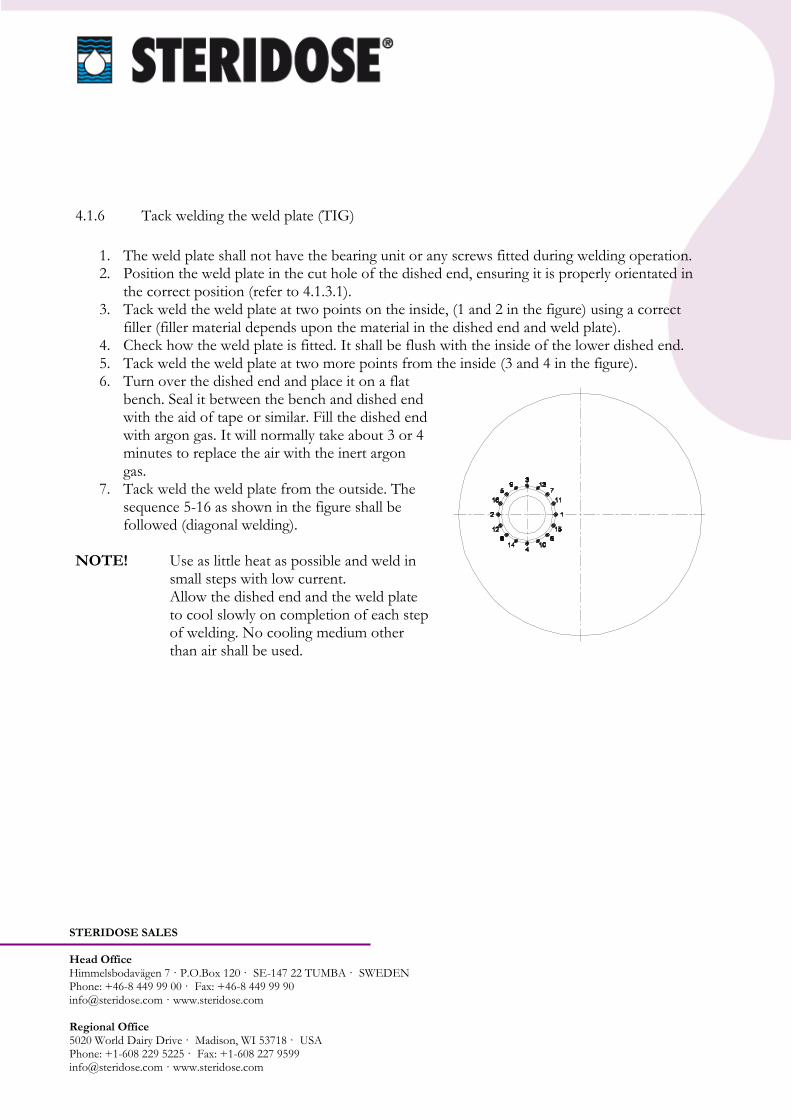
4.1.6 Tack welding the weld plate (TIG)
1. The weld plate shall not have the bearing unit or any screws fitted during welding operation. 2. Position the weld plate in the cut hole of the dished end, ensuring it is properly orientated in
the correct position (refer to 4.1.3.1). 3. Tack weld the weld plate at two points on the inside, (1 and 2 in the figure) using a correct
filler (filler material depends upon the material in the dished end and weld plate). 4. Check how the weld plate is fitted. It shall be flush with the inside of the lower dished end. 5. Tack weld the weld plate at two more points from the inside (3 and 4 in the figure). 6. Turn over the dished end and place it on a flat
bench. Seal it between the bench and dished end with the aid of tape or similar. Fill the dished end with argon gas. It will normally take about 3 or 4 minutes to replace the air with the inert argon gas.
7. Tack weld the weld plate from the outside. The sequence 5-16 as shown in the figure shall be followed (diagonal welding).
NOTE! Use as little heat as possible and weld in small steps with low current.
Allow the dished end and the weld plate to cool slowly on completion of each step of welding. No cooling medium other than air shall be used.

STERIDOSE SALES Head Office Himmelsbodavägen 7 · P.O.Box 120 · SE-147 22 TUMBA · SWEDEN Phone: +46-8 449 99 00 · Fax: +46-8 449 99 90 [email protected] · www.steridose.com Regional Office 5020 World Dairy Drive · Madison, WI 53718 · USA Phone: +1-608 229 5225 · Fax: +1-608 227 9599 [email protected] · www.steridose.com
4.1.7 Final Welding The final welding shall start closest to the centre of the dished end. The filler material should be the same as used previously. Weld continuously from point 1 to point 2 alternating in between path A and B (refer to figure) until the weld groove is filled. The dished end should be inverted again and welded from the inside to even out the weld joint. NOTE! Use as little heat as possible and weld in
small steps with low current. Allow the dished end and the weld plate to cool slowly on completion of each step of welding. No cooling medium other than air shall be used.
4.1.8 After Welding
1. Allow the dished end and the weld plate to cool slowly on completion of welding. No cooling
medium other than air shall be used. 2. Grind and polish the inside and outside of the weld to the required finish. 3. Re-assemble the screws for the bayonet connection. Tighten and secure the screws to the weld
plate with appropriate thread locking, e.g. Loctite 243. 4. Fit the bearing unit to the weld plate. Tighten the
bearing unit with a torque as per the table. 5. Fit the impeller on the bearing unit and turn a few
revolutions by hand to ensure adequate clearance to the weld plate and the vessel. If interference is present, necessary corrections have to be performed.
6. Fit the drive unit to the vessel as per instructions (refer to section 4.4) to ensure adequate clearance to the weld plate and the vessel. If interference is present, necessary corrections have to be performed.
Weld plate / Bearing unit
Max torque
60/75 85/100-140
6 Nm
120/150-190 120H/220 210/275
20 Nm
STERIDOSE SALES Head Office Himmelsbodavägen 7 · P.O.Box 120 · SE-147 22 TUMBA · SWEDEN Phone: +46-8 449 99 00 · Fax: +46-8 449 99 90 [email protected] · www.steridose.com Regional Office 5020 World Dairy Drive · Madison, WI 53718 · USA Phone: +1-608 229 5225 · Fax: +1-608 227 9599 [email protected] · www.steridose.com
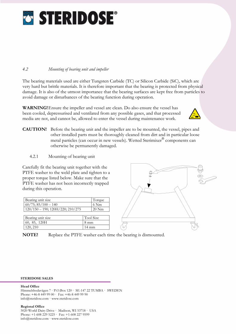
4.2 Mounting of bearing unit and impeller
The bearing materials used are either Tungsten Carbide (TC) or Silicon Carbide (SiC), which are very hard but brittle materials. It is therefore important that the bearing is protected from physical damage. It is also of the utmost importance that the bearing surfaces are kept free from particles to avoid damage or disturbances of the bearing function during operation. WARNING! Ensure the impeller and vessel are clean. Do also ensure the vessel has been cooled, depressurised and ventilated from any possible gases, and that processed media are not, and cannot be, allowed to enter the vessel during maintenance work. CAUTION! Before the bearing unit and the impeller are to be mounted, the vessel, pipes and
other installed parts must be thoroughly cleaned from dirt and in particular loose
metal particles (can occur in new vessels). Wetted Sterimixer® components can
otherwise be permanently damaged.
4.2.1 Mounting of bearing unit Carefully fit the bearing unit together with the PTFE washer to the weld plate and tighten to a proper torque listed below. Make sure that the PTFE washer has not been incorrectly trapped during this operation.
NOTE! Replace the PTFE washer each time the bearing is dismounted.
Bearing unit size Torque
60/75; 85/100 – 140 6 Nm
120/150 – 190; 120H/220; 210/275 20 Nm
Bearing unit size Tool Size
60, 85, 120H 8 mm
120, 210 14 mm
STERIDOSE SALES Head Office Himmelsbodavägen 7 · P.O.Box 120 · SE-147 22 TUMBA · SWEDEN Phone: +46-8 449 99 00 · Fax: +46-8 449 99 90 [email protected] · www.steridose.com Regional Office 5020 World Dairy Drive · Madison, WI 53718 · USA Phone: +1-608 229 5225 · Fax: +1-608 227 9599 [email protected] · www.steridose.com
4.2.2 Mounting of impeller Before mounting the impeller, be sure of that the drive unit is NOT mounted to the vessel. The impeller is to be mounted before the drive unit, thus avoiding any damage caused by crushing, and making sure that the bearing is not damaged by the magnetic charges arising from the drive unit magnets. Carefully position the impeller onto the bearing unit and spin by hand to ensure that the impeller runs freely.
WARNING! The Sterimixer® impeller includes strong magnets thus personnel
equipped with pacemaker shall not handle these components.
CAUTION! Due to the strong magnetic forces generated by the magnets, the impeller
must be mounted before the drive unit to avoid any damage on the bearings. NOTE! Extreme care should be taken to prevent damages to the bearings when mounting
the impeller. NOTE! The Sterimixer® impeller and magnetic rotor includes strong magnets thus
magnetic cards, e.g. credit cards, can be permanently damaged if being close to the components specified.

STERIDOSE SALES Head Office Himmelsbodavägen 7 · P.O.Box 120 · SE-147 22 TUMBA · SWEDEN Phone: +46-8 449 99 00 · Fax: +46-8 449 99 90 [email protected] · www.steridose.com Regional Office 5020 World Dairy Drive · Madison, WI 53718 · USA Phone: +1-608 229 5225 · Fax: +1-608 227 9599 [email protected] · www.steridose.com
4.3 Bearing and impeller mount tool (optional) To change impeller and male bearing in applications when it is difficult to enter the tank, a special `Bearing and impeller mount tool´ can be used. It consists of the following parts:
Handle
Bearing mount tool
Impeller mount tool
“Hair pin” To allow easy mounting of the male bearing it is recommended to apply a small amount of suitable grease onto the PTFE washer. This prevents the PTFE washer from loosening from the bearing unit during mounting. The “Bearing and impeller mount tool” is to be ordered separately.
Handle “Hair pin” Bearing mount tool Impeller mount tool
STERIDOSE SALES Head Office Himmelsbodavägen 7 · P.O.Box 120 · SE-147 22 TUMBA · SWEDEN Phone: +46-8 449 99 00 · Fax: +46-8 449 99 90 [email protected] · www.steridose.com Regional Office 5020 World Dairy Drive · Madison, WI 53718 · USA Phone: +1-608 229 5225 · Fax: +1-608 227 9599 [email protected] · www.steridose.com
4.4 Mounting and dismounting of drive unit The drive unit consist of a motor (either a AC, MOTEC, DC or Air driven), gearbox, flange and rotor (some differences occurs depending on type of drive and size).
4.4.1 Mounting of drive unit There is two different ways of attaching the drive unit to the flange of the vessel, depending on Sterimixer® size, by a bayonet coupling or by a threaded joint. Ensure the magnetic rotor is not damaged and properly aligned preventing physical contact with the weld plate upon installation and operation. Be certain that you can handle the weight of the drive unit. Take a firm grip of the gearbox to balance the weight of the drive unit and to minimise the risk of damage caused by crushing when dismounting. Use appropriate lifting device for the larger models, SM 120/190 and larger. 60/75; 85/100 & 85/140
1. Lift the drive unit up and let the welding plate’s screws pass through the slots in the drive unit flange.
2. Turn the drive unit counter clockwise into position. 3. Lock the drive unit in position by tightening the locking nuts.
120/150 & 120/190
1. Lift the drive unit up and let the welding plate’s screws pass through the slots in the drive plate.
2. Turn the drive unit counter clockwise into position. 3. Lock the drive unit in position by tightening the locking nuts.
120H/220 & 210/275
1. Lift the drive unit up and let the flange screws pass through the holes in the drive unit flange.
2. Lock the drive unit by tightening the locking nuts.

STERIDOSE SALES Head Office Himmelsbodavägen 7 · P.O.Box 120 · SE-147 22 TUMBA · SWEDEN Phone: +46-8 449 99 00 · Fax: +46-8 449 99 90 [email protected] · www.steridose.com Regional Office 5020 World Dairy Drive · Madison, WI 53718 · USA Phone: +1-608 229 5225 · Fax: +1-608 227 9599 [email protected] · www.steridose.com
CAUTION! Due to the strong magnetic forces generated by the magnets, the impeller
must be mounted before the drive unit to avoid any damage on the bearings.
WARNING! The Sterimixer® magnetic rotor includes strong magnets thus
personnel equipped with pacemaker shall not handle these components.
NOTE! The Sterimixer® impeller and magnetic rotor includes strong magnets thus
magnetic cards, e.g. credit cards, can be permanently damaged if being close to the components specified.
WARNING! Ensure the power supply is disconnected and not possible to accidentally be connected.
CAUTION! The drive unit can be heavy, refer to section 5 “Sterimixer® Main Parts”.

STERIDOSE SALES Head Office Himmelsbodavägen 7 · P.O.Box 120 · SE-147 22 TUMBA · SWEDEN Phone: +46-8 449 99 00 · Fax: +46-8 449 99 90 [email protected] · www.steridose.com Regional Office 5020 World Dairy Drive · Madison, WI 53718 · USA Phone: +1-608 229 5225 · Fax: +1-608 227 9599 [email protected] · www.steridose.com
4.4.2 Dismounting of drive unit Dismount the drive unit by following the mounting instructions in reverse order. Be certain that you can handle the weight of the drive unit. Take a firm grip of the gearbox to balance the weight of the drive unit and to minimise the risk of damage caused by crushing when dismounting. Use appropriate lifting device for the larger models, SM 120/190 and larger. WARNING! The Sterimixer® magnetic rotor includes strong magnets thus
personnel equipped with pacemaker shall not handle these components.
CAUTION! Due to the strong magnetic forces generated by the magnets, the drive unit
must be dismounted before the impeller to avoid any damage on the bearings.
NOTE! The Sterimixer® impeller and magnetic rotor includes strong magnets thus
magnetic cards, e.g. credit cards, can be permanently damaged if being close to the components specified.
WARNING! Ensure the power supply is disconnected and not possible to accidentally be connected.
CAUTION! The drive unit can be heavy, refer to section 5 “Sterimixer® Main Parts”.
4.5 Power Installation
The motor applied to the Sterimixer® could be either a AC, MOTEC, DC or Air driven type.
Any electrical connections shall be carried out by an authorised electrician in accordance with applicable regulations, standards and directives.
If a control box is used, the drive unit is connected to the control box, which in turn is connected to the external power supply.

STERIDOSE SALES Head Office Himmelsbodavägen 7 · P.O.Box 120 · SE-147 22 TUMBA · SWEDEN Phone: +46-8 449 99 00 · Fax: +46-8 449 99 90 [email protected] · www.steridose.com Regional Office 5020 World Dairy Drive · Madison, WI 53718 · USA Phone: +1-608 229 5225 · Fax: +1-608 227 9599 [email protected] · www.steridose.com
An electrical drawing/wiring diagram is supplied with the motor (drive unit) and control box upon delivery when applicable. Technical information for the motor (drive unit) and the control box is found within the documentation enclosed with the equipment. Compressed air driven motor: The air intake to the control box is to be dry, free from particles (<5µm), and the pressure should be between 6 and 7 bar. The total length of the air supply hoses from the control box to the motor is not to exceed 10 metres (6 mm inner diameter for SM 60/75 - 85/140 and 10 mm inner diameter for SM 120/150 - 120/190). The oil mist lubricator for the compressed air is located in the control box. The amount added to the air should be 2-3 drops per minute.
4.6 Installation check and calibration
4.6.1 Verify the direction of rotation for the impeller
1. Make sure that there is a film of fluid between impeller and bearing unit by filling the vessel with water having the impeller fully immersed.
2. Set the speed potentiometer/regulator to zero.
3. For DC applications - Start the Sterimixer® and
carefully increase to a low speed (max 50 rpm).
4. For AC applications – The Sterimixer® starts at
low speed. 5. Visually check the direction of rotation for the impeller, which should be clockwise when
looking from above. If the Sterimixer rotates counter clockwise, refer to section 8 `Troubleshooting´.
6. Stop the Sterimixer® immediately after completed verification.
WARNING! Dry operation of the Sterimixer® will damage the bearings.

STERIDOSE SALES Head Office Himmelsbodavägen 7 · P.O.Box 120 · SE-147 22 TUMBA · SWEDEN Phone: +46-8 449 99 00 · Fax: +46-8 449 99 90 [email protected] · www.steridose.com Regional Office 5020 World Dairy Drive · Madison, WI 53718 · USA Phone: +1-608 229 5225 · Fax: +1-608 227 9599 [email protected] · www.steridose.com
4.6.2 Calibration of the Sterimixer®
The most important parameters in maintaining proper operation and thereby a long operational life
for the Sterimixer® are pre-set on delivery. The pre-set parameters include acceleration time,
deceleration time, max speed, and min speed. Acceleration time and max speed will depend very much upon the application. Max speed must not be set to low, as a cleaning process usually requires a relatively high speed (approximately 300 rpm) to achieve best performance. The max speed shall not exceed the specified max speed for each Sterimixer® size, refer to section 5 `Technical data´.
For verification of the speed of the Sterimixer®, use a hand tachometer and the recess provided on
the gearbox shaft.
WARNING! Dry operation of the Sterimixer® will damage the bearings.

STERIDOSE SALES Head Office Himmelsbodavägen 7 · P.O.Box 120 · SE-147 22 TUMBA · SWEDEN Phone: +46-8 449 99 00 · Fax: +46-8 449 99 90 [email protected] · www.steridose.com Regional Office 5020 World Dairy Drive · Madison, WI 53718 · USA Phone: +1-608 229 5225 · Fax: +1-608 227 9599 [email protected] · www.steridose.com
Drive plate(Size 120/150
and 120/190)
Control box
Drive unit
Above
Drive unit
Weld plate
Bearing
PTFE washer
Impeller
5. Technical data
Type SMA Type SMO
5.1 Sterimixer® main parts
The Sterimixer® consists of the Following components.
Each component is described in technical data.
SMA (Sterimixer Aseptic) and
SMO (Sterimixer Open).
STERIDOSE SALES Head Office Himmelsbodavägen 7 · P.O.Box 120 · SE-147 22 TUMBA · SWEDEN Phone: +46-8 449 99 00 · Fax: +46-8 449 99 90 [email protected] · www.steridose.com Regional Office 5020 World Dairy Drive · Madison, WI 53718 · USA Phone: +1-608 229 5225 · Fax: +1-608 227 9599 [email protected] · www.steridose.com
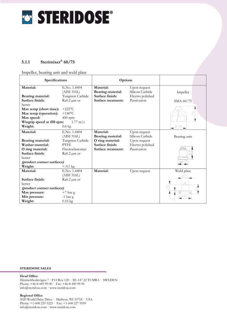
5.1.1 Sterimixer® 60/75 Impeller, bearing unit and weld plate
Specifications Options
Material: E.No. 1.4404 (AISI 316L) Bearing material: Tungsten Carbide Surface finish: Ra0.2 µm or better Max temp (short time): +225°C Max temp (operation): +140°C Max speed: 450 rpm Wingtip speed at 450 rpm: 1.77 m/s Weight: 0.6 kg
Material: Upon request Bearing material: Silicon Carbide Surface finish: Electro polished Surface treatment: Passivation
Impeller
SMA 60/75
Material: E.No. 1.4404 (AISI 316L) Bearing material: Tungsten Carbide Washer material: PTFE O ring material: Fluoroelastomer Surface finish: Ra0.2 µm or better (product contact surfaces) Weight: < 0.1 kg
Material: Upon request Bearing material: Silicon Carbide O ring material: Upon request Surface finish: Electro polished Surface treatment: Passivation
Bearing unit
Material: E.No. 1.4404 (AISI 316L) Surface finish: Ra0.2 µm or better (product contact surfaces) Max pressure: +7 bar g Min pressure: -1 bar g Weight: 0.16 kg
Material: Upon request
Weld plate

STERIDOSE SALES Head Office Himmelsbodavägen 7 · P.O.Box 120 · SE-147 22 TUMBA · SWEDEN Phone: +46-8 449 99 00 · Fax: +46-8 449 99 90 [email protected] · www.steridose.com Regional Office 5020 World Dairy Drive · Madison, WI 53718 · USA Phone: +1-608 229 5225 · Fax: +1-608 227 9599 [email protected] · www.steridose.com
5.1.1.1 Sterimixer® 60/75 AC Drive unit and Control box
Specifications Options
Power: 75 W Speed: 2700 rpm (50 Hz) Voltage: 230 VAC Current: 0.40 A VAC Protection: IP54 Operating temperature: -25°C to +40°C Weight: 3.3 kg Gearbox ratio: 5:1 Gearbox type: Worm gearbox Extension (E=0): A = 29 mm Conforms to: CE / UL
Protection: IP65 Extension (E=27): A=56 mm Thermal contact Thermistor Impeller monitor Sensor Connector 10 pin male harting Motor cable (length): 5 m
Drive unit (principal drawing)
Frequency inverter: 0.75 kW Main voltage: 230 VAC Current: 16 A Frequency input: 50/60 Hz Speed setting impeller potentiometer = 0: 50 rpm = 5 Hz Speed setting impeller potentiometer = max: 450 rpm = 60 Hz Material cabinet: E.No. 1.4301 (AISI 304) Protection: IP65 Weight: 10.5 kg Connector: 10 pin female
harting Conforms to: CE / UL
Impeller monitor display Timer Main voltage: 120VAC
Control box
Min impeller speed: 50 rpm Max impeller speed: 450 rpm Sound level: <70 dBa Weight (approx): 4.2 kg Torque magnet coupling: 0.75 Nm
Sterimixer®
excluding control box (principal drawing)

STERIDOSE SALES Head Office Himmelsbodavägen 7 · P.O.Box 120 · SE-147 22 TUMBA · SWEDEN Phone: +46-8 449 99 00 · Fax: +46-8 449 99 90 [email protected] · www.steridose.com Regional Office 5020 World Dairy Drive · Madison, WI 53718 · USA Phone: +1-608 229 5225 · Fax: +1-608 227 9599 [email protected] · www.steridose.com
5.1.1.2 Sterimixer® 60/75 DC Drive unit and Control box
Specifications Options
Power: 55 W Speed: 3000 rpm Voltage: 180 VDC Current: 0.46 A at 180 VDC Protection: IP55 Operating temperature: -25°C to +40°C Weight: 3.3 kg Gearbox ratio: 5:1 Gearbox type: Worm gearbox Extension (E=0): A = 29 mm Conforms to: CE
Extension (E=27): A=56 mm Impeller monitor Sensor Connector 10 pin male harting Motor cable (length): 5 m
Drive unit (principal drawing)
Speed controller: 360 W Main voltage: 230 VAC Current: 6.3 A Frequency Input: 50/60 Hz Speed setting impeller potentiometer = 0: 0 rpm Speed setting impeller potentiometer = max: 450 rpm Material cabinet: E.No. 1.4301 (AISI 304) Protection: IP65 Weight: 6.5 kg Connector: 10 pin female
harting Conforms to: CE
Impeller monitor display Timer
Main voltage: 120VAC
Control box
Min impeller speed: 0 rpm Max impeller speed: 450 rpm Sound level: <70 dBa Weight (approx): 7.4 kg Torque magnet coupling: 0.75 Nm
Sterimixer®
excluding control box (principal drawing)
STERIDOSE SALES Head Office Himmelsbodavägen 7 · P.O.Box 120 · SE-147 22 TUMBA · SWEDEN Phone: +46-8 449 99 00 · Fax: +46-8 449 99 90 [email protected] · www.steridose.com Regional Office 5020 World Dairy Drive · Madison, WI 53718 · USA Phone: +1-608 229 5225 · Fax: +1-608 227 9599 [email protected] · www.steridose.com
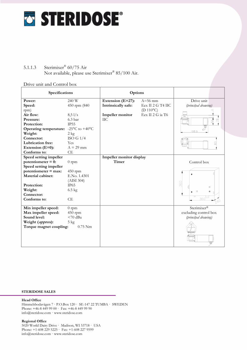
5.1.1.3 Sterimixer® 60/75 Air Not available, please use Sterimixer® 85/100 Air. Drive unit and Control box
Specifications Options
Power: 240 W Speed: 450 rpm (840 rpm) Air flow: 8,5 l/s Pressure: 6.3 bar Protection: IP55 Operating temperature: -25°C to +40°C Weight: 2 kg Connector: ISO G 1/4 Lubrication free: Yes Extension (E=0): A = 29 mm Conforms to: CE
Extension (E=27): A=56 mm Intrinsically safe: Eex II 2 G T4 IIC (D 110°C) Impeller monitor Eex II 2 G ia T6 IIC
Drive unit (principal drawing)
Speed setting impeller potentiometer = 0: 0 rpm Speed setting impeller potentiometer = max: 450 rpm Material cabinet: E.No. 1.4301 (AISI 304) Protection: IP65 Weight: 6.5 kg Connector: Conforms to: CE
Impeller monitor display Timer Control box
Min impeller speed: 0 rpm Max impeller speed: 450 rpm Sound level: <70 dBa Weight (approx): 5 kg Torque magnet coupling: 0.75 Nm
Sterimixer®
excluding control box (principal drawing)
STERIDOSE SALES Head Office Himmelsbodavägen 7 · P.O.Box 120 · SE-147 22 TUMBA · SWEDEN Phone: +46-8 449 99 00 · Fax: +46-8 449 99 90 [email protected] · www.steridose.com Regional Office 5020 World Dairy Drive · Madison, WI 53718 · USA Phone: +1-608 229 5225 · Fax: +1-608 227 9599 [email protected] · www.steridose.com
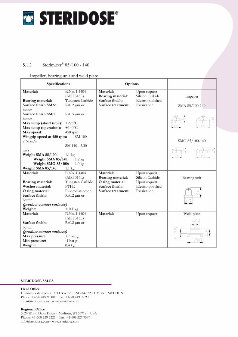
5.1.2 Sterimixer® 85/100 - 140
Impeller, bearing unit and weld plate
Specifications Options
Material: E.No. 1.4404 (AISI 316L) Bearing material: Tungsten Carbide Surface finish SMA: Ra0.2 µm or better Surface finish SMO: Ra0.5 µm or better Max temp (short time): +225°C Max temp (operation): +140°C Max speed: 450 rpm Wingtip speed at 450 rpm: SM 100 - 2.36 m/s SM 140 - 3.30 m/s Weight SMA 85/100: 1.1 kg
Weight SMA 85/140: 1.2 kg Weight SMO 85/100: 1.0 kg
Weight SMA 85/140: 1.1 kg
Material: Upon request Bearing material: Silicon Carbide Surface finish: Electro polished Surface treatment: Passivation
Impeller
SMA 85/100-140
SMO 85/100-140
Material: E.No. 1.4404 (AISI 316L) Bearing material: Tungsten Carbide Washer material: PTFE O ring material: Fluoroelastomer Surface finish: Ra0.2 µm or better (product contact surfaces) Weight: < 0.1 kg
Material: Upon request Bearing material: Silicon Carbide O ring material: Upon request Surface finish: Electro polished Surface treatment: Passivation
Bearing unit
Material: E.No. 1.4404 (AISI 316L) Surface finish: Ra0.2 µm or better (product contact surfaces) Max pressure: +7 bar g Min pressure: -1 bar g Weight: 0.4 kg
Material: Upon request
Weld plate
STERIDOSE SALES Head Office Himmelsbodavägen 7 · P.O.Box 120 · SE-147 22 TUMBA · SWEDEN Phone: +46-8 449 99 00 · Fax: +46-8 449 99 90 [email protected] · www.steridose.com Regional Office 5020 World Dairy Drive · Madison, WI 53718 · USA Phone: +1-608 229 5225 · Fax: +1-608 227 9599 [email protected] · www.steridose.com
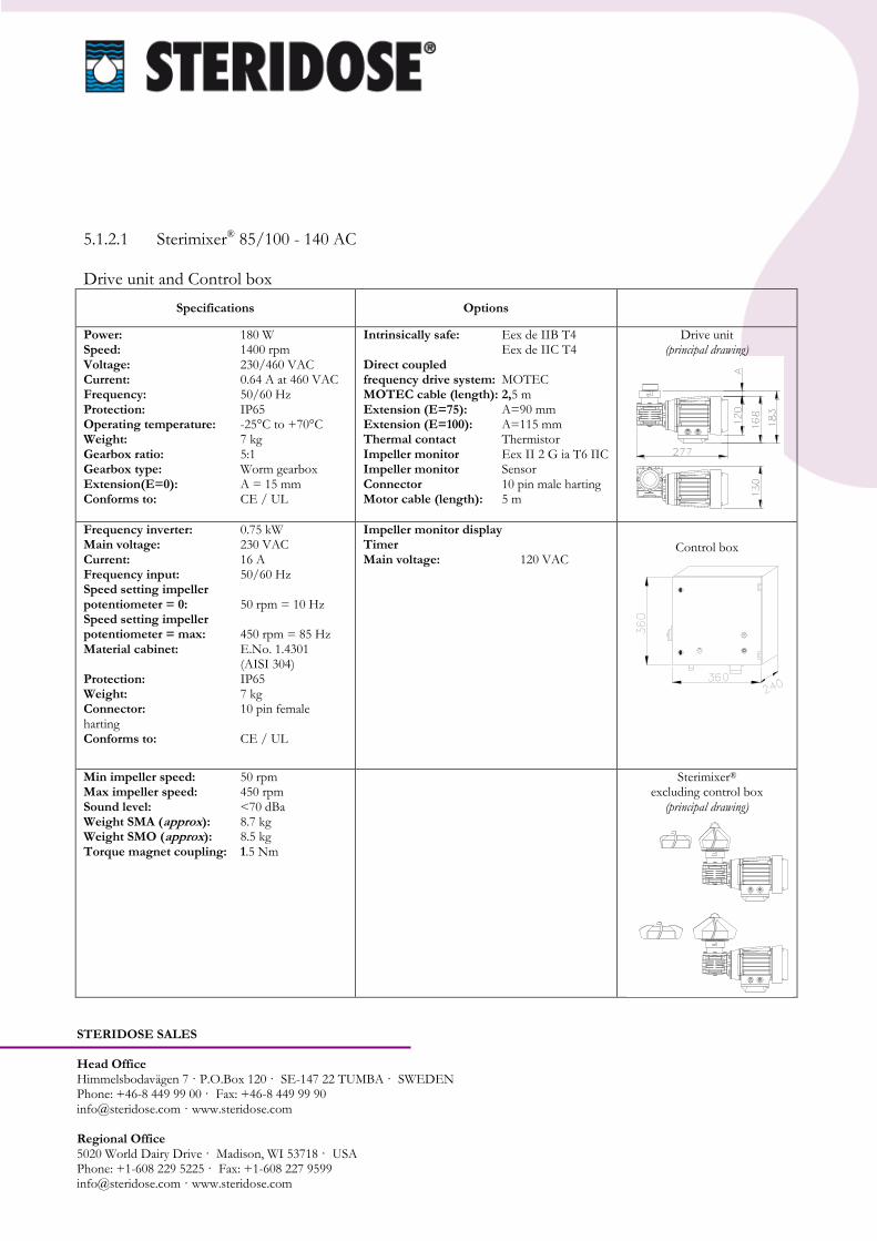
5.1.2.1 Sterimixer® 85/100 - 140 AC Drive unit and Control box
Specifications Options
Power: 180 W Speed: 1400 rpm Voltage: 230/460 VAC Current: 0.64 A at 460 VAC Frequency: 50/60 Hz Protection: IP65 Operating temperature: -25°C to +70°C Weight: 7 kg Gearbox ratio: 5:1 Gearbox type: Worm gearbox Extension(E=0): A = 15 mm Conforms to: CE / UL
Intrinsically safe: Eex de IIB T4 Eex de IIC T4 Direct coupled frequency drive system: MOTEC MOTEC cable (length): 2,5 m Extension (E=75): A=90 mm Extension (E=100): A=115 mm Thermal contact Thermistor Impeller monitor Eex II 2 G ia T6 IIC Impeller monitor Sensor Connector 10 pin male harting Motor cable (length): 5 m
Drive unit (principal drawing)
Frequency inverter: 0.75 kW Main voltage: 230 VAC Current: 16 A Frequency input: 50/60 Hz Speed setting impeller potentiometer = 0: 50 rpm = 10 Hz Speed setting impeller potentiometer = max: 450 rpm = 85 Hz Material cabinet: E.No. 1.4301 (AISI 304) Protection: IP65 Weight: 7 kg Connector: 10 pin female harting Conforms to: CE / UL
Impeller monitor display Timer Main voltage: 120 VAC
Control box
Min impeller speed: 50 rpm Max impeller speed: 450 rpm Sound level: <70 dBa Weight SMA (approx): 8.7 kg Weight SMO (approx): 8.5 kg Torque magnet coupling: 1.5 Nm
Sterimixer®
excluding control box (principal drawing)
STERIDOSE SALES Head Office Himmelsbodavägen 7 · P.O.Box 120 · SE-147 22 TUMBA · SWEDEN Phone: +46-8 449 99 00 · Fax: +46-8 449 99 90 [email protected] · www.steridose.com Regional Office 5020 World Dairy Drive · Madison, WI 53718 · USA Phone: +1-608 229 5225 · Fax: +1-608 227 9599 [email protected] · www.steridose.com
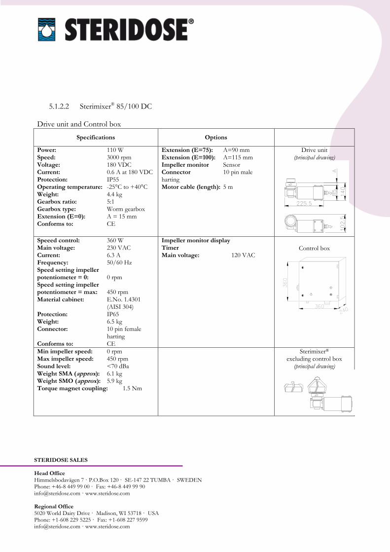
5.1.2.2 Sterimixer® 85/100 DC Drive unit and Control box
Specifications Options
Power: 110 W Speed: 3000 rpm Voltage: 180 VDC Current: 0.6 A at 180 VDC Protection: IP55 Operating temperature: -25°C to +40°C Weight: 4.4 kg Gearbox ratio: 5:1 Gearbox type: Worm gearbox Extension (E=0): A = 15 mm Conforms to: CE
Extension (E=75): A=90 mm Extension (E=100): A=115 mm Impeller monitor Sensor Connector 10 pin male harting Motor cable (length): 5 m
Drive unit (principal drawing)
Speeed control: 360 W Main voltage: 230 VAC Current: 6.3 A Frequency: 50/60 Hz Speed setting impeller potentiometer = 0: 0 rpm Speed setting impeller potentiometer = max: 450 rpm Material cabinet: E.No. 1.4301 (AISI 304) Protection: IP65 Weight: 6.5 kg Connector: 10 pin female
harting Conforms to: CE
Impeller monitor display Timer Main voltage: 120 VAC
Control box
Min impeller speed: 0 rpm Max impeller speed: 450 rpm Sound level: <70 dBa Weight SMA (approx): 6.1 kg Weight SMO (approx): 5.9 kg Torque magnet coupling: 1.5 Nm
Sterimixer®
excluding control box (principal drawing)

STERIDOSE SALES Head Office Himmelsbodavägen 7 · P.O.Box 120 · SE-147 22 TUMBA · SWEDEN Phone: +46-8 449 99 00 · Fax: +46-8 449 99 90 [email protected] · www.steridose.com Regional Office 5020 World Dairy Drive · Madison, WI 53718 · USA Phone: +1-608 229 5225 · Fax: +1-608 227 9599 [email protected] · www.steridose.com
5.1.2.3 Sterimixer® 85/140 DC Drive unit and Control box
Specifications Options
Power: 200 W Speed: 3000 rpm Voltage: 180 VDC Current: 0.23 A at 180 VDC Protection: IP55 Operating temperature: -25°C to +40°C Weight: 4.4 kg Gearbox ratio: 5:1 Gearbox type: Worm gearbox Extension (E=0): A = 15 mm Conforms to: CE
Extension (E=75): A=90 mm Extension (E=100): A=115 mm Impeller monitor Sensor Connector 10 pin male harting Motor cable (length): 5 m
Drive unit (principal drawing)
Speed control: 360 W Main voltage: 230 VAC Current: 6.3 A Frequency: 50/60 Hz Speed setting impeller potentiometer = 0: 0 rpm Speed setting impeller potentiometer = max: 450 rpm Material cabinet: E.No. 1.4301 (AISI 304) Protection: IP65 Weight: 6.5 kg Connector: 10 pin female
harting Conforms to: CE
Impeller monitor display Timer Main voltage: 120 VAC
Control box
Min impeller speed: 0 rpm Max impeller speed: 450 rpm Sound level: <70 dBa Weight SMA (approx): 6.1 kg Weight SMO (approx): 5.9 kg Torque magnet coupling: 1.5 Nm
Sterimixer®
excluding control box (principal drawing)

STERIDOSE SALES Head Office Himmelsbodavägen 7 · P.O.Box 120 · SE-147 22 TUMBA · SWEDEN Phone: +46-8 449 99 00 · Fax: +46-8 449 99 90 [email protected] · www.steridose.com Regional Office 5020 World Dairy Drive · Madison, WI 53718 · USA Phone: +1-608 229 5225 · Fax: +1-608 227 9599 [email protected] · www.steridose.com
5.1.2.4 Sterimixer® 85/100 - 140 Air Drive unit and Control box
Specifications Options
Power: 380 W Speed: 450 rpm (840 rpm) Air flow: 8.3 l/s Pressure: 6.3 bar Protection: IP65 Operating temperature: -25°C to +40°C Weight: 1.0 kg + växel Connector: ISO G 1/4 Lubrication free: Yes Extension (E=0): A = 15 mm Conforms to: CE
Extension (E=75): A=90 mm Extension (E=100): A=115 mm Intrinsically safe: Eex II 2 G T5 IIC (D 85°C) Impeller monitor Eex II 2 G ia T6 IIC
Drive unit (principal drawing)
Speed setting impeller potentiometer = 0: 0 rpm Speed setting impeller potentiometer = max: 450 rpm Material cabinet: E.No. 1.4301 (AISI 304) Protection: IP65 Weight: kg Connector:
Impeller monitor display Timer Control box
Min impeller speed: 0 rpm Max impeller speed: 450 rpm Sound level: <70 dBa Weight (approx): 4.2 kg Torque magnet coupling: 1.5 Nm
Sterimixer®
excluding control box (principal drawing)

STERIDOSE SALES Head Office Himmelsbodavägen 7 · P.O.Box 120 · SE-147 22 TUMBA · SWEDEN Phone: +46-8 449 99 00 · Fax: +46-8 449 99 90 [email protected] · www.steridose.com Regional Office 5020 World Dairy Drive · Madison, WI 53718 · USA Phone: +1-608 229 5225 · Fax: +1-608 227 9599 [email protected] · www.steridose.com
5.1.3 Sterimixer® 120/150 - 190
Impeller, bearing unit and weld plate
Specifications Options
Material: E.No. 1.4404 (AISI 316L) Bearing material: Tungsten Carbide Surface finish SMA: Ra0.2 µm or better Surface finish SMO: Ra0.5 µm or better Max temp (short time): +225°C Max temp (operation): +140°C Max speed SM 150: 450 rpm Max speed SM 190: 350 rpm Wingtip speed at 450 rpm: SM 150 - 3.53 m/s Wingtip speed at 350 rpm: SM 190 - 3.48 m/s Weight SMA 120/150: 2.9 kg Weight SMA 120/190: 3.0 kg
Weight SMO 120/150: 2.6 kg Weight SMO 120/190: 2.7 kg
Material: Upon request Bearing material: Silicon Carbide Surface finish: Electro polished Surface treatment: Passivation
Impeller
SMA 120/150-190
SMO 120/150-190
Material: E.No. 1.4404 (AISI 316L) Bearing material: Tungsten Carbide Washer material: PTFE O ring material: Fluoroelastomer Surface finish: Ra0.2 µm or better (product contact surfaces) Weight: 0.2 kg
Material: Upon request Bearing material: Silicon Carbide O ring material: Upon request Surface finish: Electro polished Surface treatment: Passivation
Bearing unit
Material: E.No. 1.4404 (AISI 316L) Surface finish: Ra0.2 µm or better (product contact surfaces) Max pressure: +7 bar g Min pressure: -1 bar g Weight: 1.9 kg
Material: Upon request
Weld plate

STERIDOSE SALES Head Office Himmelsbodavägen 7 · P.O.Box 120 · SE-147 22 TUMBA · SWEDEN Phone: +46-8 449 99 00 · Fax: +46-8 449 99 90 [email protected] · www.steridose.com Regional Office 5020 World Dairy Drive · Madison, WI 53718 · USA Phone: +1-608 229 5225 · Fax: +1-608 227 9599 [email protected] · www.steridose.com
5.1.3.1 Sterimixer® 120/150 AC Drive unit and Control box
Specifications Options
Power: 750 W Speed: 1400 rpm Voltage: 230/460 VAC Current: 1.9 A at 460 VAC Frequency: 50/60 Hz Protection: IP65 Operating temperature: -25°C to +70°C Weight: 15 kg Gearbox ratio: 5:1 Gearbox type: Worm gearbox Extension (E=0): A = 18 mm Conforms to: CE / UL
Intrinsically safe: Eex de IIB T4 Eex de IIC T4 Direct coupled frequency drive system: MOTEC MOTEC cable (length): 2,5 m Extension (E=100): A=118 mm Thermal contact Thermistor Impeller monitor Eex II 2 G ia T6 IIC Impeller monitor Sensor Connector 10 pin male harting Motor cable (length): 5 m
Drive unit (principal drawing)
Material: E.No. 1.4401 (AISI 316L)
Drive plate
Frequency inverter: 0.75 kW Main voltage: 230 VAC Current: 16 A Frequency input: 50/60 Hz Speed setting impeller potentiometer = 0: 50 rpm = 10 Hz Speed setting impeller potentiometer = max: 450 rpm = 85 Hz Material cabinet: E.No. 1.4301 (AISI 304) Protection: IP65 Weight: 10.5 kg Connector: 10 pin female harting Conforms to: CE / UL
Impeller monitor display Timer Main voltage: 120 VAC
Control box
Min impeller speed: 50 rpm Max impeller speed: 450 rpm Sound level: <70 dBa Weight SMA (approx): 20.1 kg Weight SMO (approx): 19.8 kg Torque magnet coupling: 14 Nm
Sterimixer®
excluding control box (principal drawing)
STERIDOSE SALES Head Office Himmelsbodavägen 7 · P.O.Box 120 · SE-147 22 TUMBA · SWEDEN Phone: +46-8 449 99 00 · Fax: +46-8 449 99 90 [email protected] · www.steridose.com Regional Office 5020 World Dairy Drive · Madison, WI 53718 · USA Phone: +1-608 229 5225 · Fax: +1-608 227 9599 [email protected] · www.steridose.com
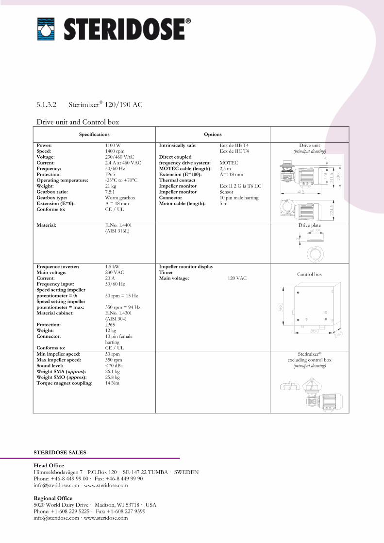
5.1.3.2 Sterimixer® 120/190 AC Drive unit and Control box
Specifications Options
Power: 1100 W Speed: 1400 rpm Voltage: 230/460 VAC Current: 2.4 A at 460 VAC Frequency: 50/60 Hz Protection: IP65 Operating temperature: -25°C to +70°C Weight: 21 kg Gearbox ratio: 7.5:1 Gearbox type: Worm gearbox Extension (E=0): A = 18 mm Conforms to: CE / UL
Intrinsically safe: Eex de IIB T4 Eex de IIC T4 Direct coupled frequency drive system: MOTEC MOTEC cable (length): 2,5 m Extension (E=100): A=118 mm Thermal contact Impeller monitor Eex II 2 G ia T6 IIC Impeller monitor Sensor Connector 10 pin male harting Motor cable (length): 5 m
Drive unit (principal drawing)
Material: E.No. 1.4401 (AISI 316L)
Drive plate
Frequence inverter: 1.5 kW Main voltage: 230 VAC Current: 20 A Frequency input: 50/60 Hz Speed setting impeller potentiometer = 0: 50 rpm = 15 Hz Speed setting impeller potentiometer = max: 350 rpm = 94 Hz Material cabinet: E.No. 1.4301 (AISI 304) Protection: IP65 Weight: 12 kg Connector: 10 pin female harting Conforms to: CE / UL
Impeller monitor display Timer Main voltage: 120 VAC
Control box
Min impeller speed: 50 rpm Max impeller speed: 350 rpm Sound level: <70 dBa Weight SMA (approx): 26.1 kg Weight SMO (approx): 25.8 kg Torque magnet coupling: 14 Nm
Sterimixer®
excluding control box (principal drawing)

STERIDOSE SALES Head Office Himmelsbodavägen 7 · P.O.Box 120 · SE-147 22 TUMBA · SWEDEN Phone: +46-8 449 99 00 · Fax: +46-8 449 99 90 [email protected] · www.steridose.com Regional Office 5020 World Dairy Drive · Madison, WI 53718 · USA Phone: +1-608 229 5225 · Fax: +1-608 227 9599 [email protected] · www.steridose.com
5.1.4 Sterimixer® 120H/220 Impeller, bearing unit and weld plate
Specifications Options
Material: E.No. 1.4404 (AISI 316L) Bearing material: Tungsten Carbide Surface finish SMA: Ra0.5 µm or better Surface finish SMO: Ra0.5 µm or better Max temp (short time): +225°C Max temp (operation): +140°C Max speed: 350 rpm Wingtip speed at 350 rpm: 4.03 m/s Weight SMA: 4.1 kg Weight SMO: 4,1 kg
Material: Upon request Bearing material: Silicon Carbide Surface finish: Electro polished Surface treatment: Passivation
Impeller
SMA 120H/200 SMS 120H/220
SMO 120H/220
Material: E.No. 1.4404 (AISI 316L) Bearing material: Tungsten Carbide Washer material: PTFE O ring material: Fluoroelastomer Surface finish: Ra0.5 µm or better (product contact surfaces) Weight: 0.1 kg
Material: Upon request Bearing material: Silicon Carbide O ring material: Upon request Surface finish: Electro polished Surface treatment: Passivation
Bearing unit
Material: E.No. 1.4404 (AISI 316L) Surface finish: Ra0.5 µm or better (product contact surfaces) Max pressure: +7 bar g Min pressure: -1 bar g Weight: 2.0 kg
Material: Upon request
Weld plate

STERIDOSE SALES Head Office Himmelsbodavägen 7 · P.O.Box 120 · SE-147 22 TUMBA · SWEDEN Phone: +46-8 449 99 00 · Fax: +46-8 449 99 90 [email protected] · www.steridose.com Regional Office 5020 World Dairy Drive · Madison, WI 53718 · USA Phone: +1-608 229 5225 · Fax: +1-608 227 9599 [email protected] · www.steridose.com
5.1.4.1 Sterimixer® 120H/220 AC Drive unit and Control box
Specifications Options
Power: 1500 W Speed: 1400 rpm Voltage: 230/460 VAC Current: 3.2 A at 460 VAC Frequency: 50/60 Hz Protection: IP65 Operating temperature: -25°C to +70°C Weight: 24 kg Gearbox ratio: 7.5:1 Gearbox type: Worm gearbox Extension(E=0): A = 19 mm Conforms to: CE / UL
Intrinsically safe: Eex de IIB T4 Eex de IIC T4 Direct coupled frequency drive system: MOTEC MOTEC cable (length): 2,5 m Extension (E=100): A = 119 mm Thermal contact Impeller monitor Eex II 2 G ia T6 IIC Impeller monitor Sensor Connector 10 pin male harting Motor cable (length): 5 m
Drive unit (principal drawing)
Frequency inverter: 1.5 kW Main voltage: 230 VAC Current: 20 A Frequency input: 50/60 Hz Speed setting impeller potentiometer = 0: 50 rpm = 15 Hz Speed setting impeller potentiometer = max: 350 rpm = 94Hz Material cabinet: E.No. 1.4301 (AISI 304) Protection: IP65 Weight: 12 kg Connector: 10 pin female harting Conforms to: CE / UL
Impeller monitor display Timer Main voltage: 120 VAC
Control box
Min impeller speed: 50 rpm Max impeller speed: 350 rpm Sound level: <70 dBa Weight (approx): 30.2 kg Torque magnet coupling: 26 Nm
Sterimixer®
excluding control box (principal drawing)

STERIDOSE SALES Head Office Himmelsbodavägen 7 · P.O.Box 120 · SE-147 22 TUMBA · SWEDEN Phone: +46-8 449 99 00 · Fax: +46-8 449 99 90 [email protected] · www.steridose.com Regional Office 5020 World Dairy Drive · Madison, WI 53718 · USA Phone: +1-608 229 5225 · Fax: +1-608 227 9599 [email protected] · www.steridose.com
5.1.5 Sterimixer® 210/275 Impeller, bearing unit and weld plate
Specifications Options
Material: E.No. 1.4404 (AISI 316L) Bearing material: Tungsten Carbide Surface finish SMA/SMO: Ra0.5 µm or better Max temp (short time): +225°C Max temp (operation): +140°C Max speed: 350 rpm Wingtip speed at 350 rpm: 5.04 m/s Weight SMA: 10.0 kg Weight SMO: 12.0 kg
Material: Upon request Bearing material: Silicon Carbide Surface finish: Electro polished Surface treatment: Passivation
Impeller
SMA 210/275
SMO210/275
Material: E.No. 1.4404 (AISI 316L) Bearing material: Tungsten Carbide Washer material: PTFE O ring material: Fluoroelastomer Surface finish: Ra0.5 µm or better (product contact surfaces) Weight: 0.1 kg
Material: Upon request Bearing material: Silicon Carbide O ring material: Upon request Surface finish: Electro polished Surface treatment: Passivation
Bearing unit
Material: E.No. 1.4404 (AISI 316L) Surface finish: Ra0.5 µm or better (product contact surfaces) Max pressure: +7 bar g Min pressure: -1 bar g Weight: 6.5 kg
Material: Upon request
Weld plate

STERIDOSE SALES Head Office Himmelsbodavägen 7 · P.O.Box 120 · SE-147 22 TUMBA · SWEDEN Phone: +46-8 449 99 00 · Fax: +46-8 449 99 90 [email protected] · www.steridose.com Regional Office 5020 World Dairy Drive · Madison, WI 53718 · USA Phone: +1-608 229 5225 · Fax: +1-608 227 9599 [email protected] · www.steridose.com
5.1.5.1 Sterimixer® 210/275 AC Drive unit and Control box
Specifications Options
Power: 2200 W Speed: 1400 rpm Voltage: 230/460 VAC Current: 4.8 A at 460 VAC Frequency: 50/60 Hz Protection: IP65 Operating temperature: -25°C to +70°C Weight: 32 kg Gearbox ratio: 7.5:1 Gearbox type: Worm gearbox Extension (E=0): A = 16 mm Conforms to: CE / UL
Intrinsically safe: Eex de IIB T4 Eex de IIC T4 Direct coupled frequency drive system: MOTEC MOTEC cable (length): 2,5 m Extension (E=100): A = 116 mm Thermal contact Impeller monitor Eex II 2 G ia T6 IIC Impeller monitor Sensor Connector 10 pin male harting Motor cable (length): 5 m
Drive unit (principal drawing)
Frequency inverter: 2.2 kW Main voltage: 230 VAC Current: 20 A Frequency input: 50/60 Hz Speed setting impeller potentiometer = 0: 50 rpm = 15 Hz Speed setting impeller potentiometer = max: 350 rpm = 92 Hz Material cabinet: E.No. 1.4301 (AISI 304) Protection: IP65 Weight: 12 kg Connector: 10 pin female harting Conforms to: CE / UL
Impeller monitor display Timer
Main voltage: 120 VAC
Control box
Min impeller speed: 50 rpm Max impeller speed: 350 rpm Sound level: <70 dBa Weight (approx): 47.4 kg Torque magnet coupling: 38 Nm
Sterimixer®
excluding control box (principal drawing)

STERIDOSE SALES Head Office Himmelsbodavägen 7 · P.O.Box 120 · SE-147 22 TUMBA · SWEDEN Phone: +46-8 449 99 00 · Fax: +46-8 449 99 90 [email protected] · www.steridose.com Regional Office 5020 World Dairy Drive · Madison, WI 53718 · USA Phone: +1-608 229 5225 · Fax: +1-608 227 9599 [email protected] · www.steridose.com
5.2 Guideline mixer size Find below a simple guideline to estimate a nominal tank size matching the Sterimixer® capacity. Do note that to get the accurate mixing performance, tests in a real system is required. Some basic parameters are:
Volume
Shape of the tank
Viscosity
Mixing time
Type of mixing, gentle, stirring, dissolving Contact Roplan for further technical assistance.
STERIDOSE SALES Head Office Himmelsbodavägen 7 · P.O.Box 120 · SE-147 22 TUMBA · SWEDEN Phone: +46-8 449 99 00 · Fax: +46-8 449 99 90 [email protected] · www.steridose.com Regional Office 5020 World Dairy Drive · Madison, WI 53718 · USA Phone: +1-608 229 5225 · Fax: +1-608 227 9599 [email protected] · www.steridose.com
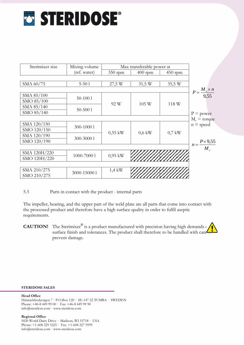
Sterimixer size Mixing volume (ref. water)
Max transferable power at
55,9
nMP v
P = power Mv = torque n = speed
vM
Pn
55,9
350 rpm 400 rpm 450 rpm
SMA 60/75 5-50 l 27,5 W 31,5 W 35,5 W
SMA 85/100 50-100 l
92 W 105 W 118 W SMO 85/100
SMA 85/140 50-500 l
SMO 85/140
SMA 120/150 300-1000 l
0,55 kW 0,6 kW 0,7 kW SMO 120/150
SMA 120/190 300-3000 l
SMO 120/190
SMA 120H/220 1000-7000 l 0,95 kW
SMO 120H/220
SMA 210/275 SMO 210/275
3000-15000 l 1,4 kW
5.3 Parts in contact with the product - internal parts
The impeller, bearing, and the upper part of the weld plate are all parts that come into contact with the processed product and therefore have a high surface quality in order to fulfil aseptic requirements.
CAUTION! The Sterimixer® is a product manufactured with precision having high demands on
surface finish and tolerances. The product shall therefore to be handled with care to prevent damage.

STERIDOSE SALES Head Office Himmelsbodavägen 7 · P.O.Box 120 · SE-147 22 TUMBA · SWEDEN Phone: +46-8 449 99 00 · Fax: +46-8 449 99 90 [email protected] · www.steridose.com Regional Office 5020 World Dairy Drive · Madison, WI 53718 · USA Phone: +1-608 229 5225 · Fax: +1-608 227 9599 [email protected] · www.steridose.com
5.3.1 Impeller
The impeller - the heart of the Sterimixer® - generates in comparison to other mixers such as
propellers and the Rushton turbine, a minimum of shear forces during operation, and thereby a low risk of damage to sensitive products.
The drive is transmitted to the impeller through a magnetic coupling, thus avoiding the problems presented by through-going shafts. WARNING! The Sterimixer® impeller includes strong magnets thus personnel
equipped with pacemaker shall not handle these components.
The unique Sterimixer® design allows cleaning and sterilisation in place (CIP/SIP), without the need
for disassembly of the unit. The especially designed flow channels and wings in the impeller provide a continuous flow of fluid through the impeller during rotation. This fluid flow ensures an effective cleaning of the inside of the impeller including the bearings. For more information on cleaning and
sterilisation of the Sterimixer®, refer to section 6 `Operation´.
5.3.2 Bearing Unit
The standard bearing material used for bearings is Tungsten Carbide (TC) having Silicon Carbide (SiC) as an option. As both materials are by nature brittle it is important keeping the bearing protected from accidentally being hit. It is also vital that the bearing surfaces are kept free from particles to avoid damage or disturbances in the bearing function. The male bearing and the female bearing must be of the same material, TC or SiC. Do also ensure both male and female bearings are replaced upon refurbishment of the impeller.

STERIDOSE SALES Head Office Himmelsbodavägen 7 · P.O.Box 120 · SE-147 22 TUMBA · SWEDEN Phone: +46-8 449 99 00 · Fax: +46-8 449 99 90 [email protected] · www.steridose.com Regional Office 5020 World Dairy Drive · Madison, WI 53718 · USA Phone: +1-608 229 5225 · Fax: +1-608 227 9599 [email protected] · www.steridose.com
5.3.3 Weld Plate
After the weld plate has been welded into the vessel it becomes an integral part of the vessel, allowing fitment of the bearing and drive unit. The outside of the weld plate has a threaded joint or bayonet coupling for the attachment of the drive unit. The threaded joint will differ depending upon the size of the mounting flange. The function, however, is the same allowing the drive unit to be easily mounted and dismounted.
5.4 External parts
5.4.1 Drive Unit
The drive unit consists of a drive (AC; MOTEC; DC; Air) together with the gearbox, flange and drive rotor. On Sterimixer® 120/150 and 120/190 there are also a drive plate as an interface between the gearbox and the weld plate. The drive plate can be ordered separately. WARNING! The Sterimixer® magnetic rotor includes strong magnets thus personnel
equipped with pacemaker shall not handle these components.
5.4.1.1 Gearbox
All gearboxes are permanently lubricated. Find below the technical data for each motor size. Sterimixer®: 60/75AC, 60/75DC, 85/100DC Size 311.25- 311.31 gear reducers come pre-filled with Shell Alvania GL00, a grease suitable for permanent lubrication. The grease is applicable to temperatures from -20°C up to +100°C. The units are supplied plugged, as the lubrication is permanent, i.e. any service is not required.
Sterimixer® Gearbox
Quantity of grease [ml]
Supplier Grease
60/75 AC, 60/75 DC
311.25 30 SHELL ALVANIA GL00
85/100 DC 311.31 50 KLÜBERSYNTH
GH-680

STERIDOSE SALES Head Office Himmelsbodavägen 7 · P.O.Box 120 · SE-147 22 TUMBA · SWEDEN Phone: +46-8 449 99 00 · Fax: +46-8 449 99 90 [email protected] · www.steridose.com Regional Office 5020 World Dairy Drive · Madison, WI 53718 · USA Phone: +1-608 229 5225 · Fax: +1-608 227 9599 [email protected] · www.steridose.com
Sterimixer®: 85/140 AC, 85/140 DC, 120/150 AC, 120/190 AC, 12OH/220 AC and 210/275 AC Size 030- 050- 063- 075- gear reducers come pre-filled with IP TELIUM VSF, a synthetic gear oil suitable for permanent lubrication. The synthetic oil is applicable to temperatures from -25°C up to +50°C. The units are supplied plugged, as the lubrication is permanent, i.e. any service is not required.
Sterimixer® Gearbox Quantity of oil [ml]
Supplier Synthetic oil Mineral oil
85/140 AC, 85/140 DC
030 40 IP TELIUM VSF MELLANA OIL 220
120/150 AC
050 150 SHELL TIVELA OIL SC320
OMALA OIL 220
120/190 AC
063 300 AGIP BLASIA S320 BLASIA 220
120H/220 063 300 MOBIL GLYCOYLE 30 MOBILGEAR 220
210/275 075 550 CASTOL ALPHASYN PG320
ALPHA MAX 220
5.4.1.2 Motor
Refer to motor cable installation instruction for each motor size and type, enclosed with the motor.
5.4.2 Control Box
The control box has a main power switch, start and stop buttons as well as equipment for speed setting with either a frequency converter (AC) or a thyristor (DC), depending upon model used.
Where the Sterimixer® is part of a process system or similar, the control box functions are built into
the process system’s control box.
The Sterimixer® can also be supplied and used without control box.
STERIDOSE SALES Head Office Himmelsbodavägen 7 · P.O.Box 120 · SE-147 22 TUMBA · SWEDEN Phone: +46-8 449 99 00 · Fax: +46-8 449 99 90 [email protected] · www.steridose.com Regional Office 5020 World Dairy Drive · Madison, WI 53718 · USA Phone: +1-608 229 5225 · Fax: +1-608 227 9599 [email protected] · www.steridose.com
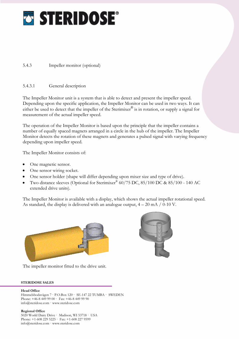
5.4.3 Impeller monitor (optional)
5.4.3.1 General description
The Impeller Monitor unit is a system that is able to detect and present the impeller speed. Depending upon the specific application, the Impeller Monitor can be used in two ways. It can
either be used to detect that the impeller of the Sterimixer® is in rotation, or supply a signal for
measurement of the actual impeller speed. The operation of the Impeller Monitor is based upon the principle that the impeller contains a number of equally spaced magnets arranged in a circle in the hub of the impeller. The Impeller Monitor detects the rotation of these magnets and generates a pulsed signal with varying frequency depending upon impeller speed. The Impeller Monitor consists of:
One magnetic sensor.
One sensor wiring socket.
One sensor holder (shape will differ depending upon mixer size and type of drive).
Two distance sleeves (Optional for Sterimixer® 60/75 DC, 85/100 DC & 85/100 - 140 AC extended drive units).
The Impeller Monitor is available with a display, which shows the actual impeller rotational speed. As standard, the display is delivered with an analogue output, 4 – 20 mA / 0-10 V.
The impeller monitor fitted to the drive unit.
STERIDOSE SALES Head Office Himmelsbodavägen 7 · P.O.Box 120 · SE-147 22 TUMBA · SWEDEN Phone: +46-8 449 99 00 · Fax: +46-8 449 99 90 [email protected] · www.steridose.com Regional Office 5020 World Dairy Drive · Madison, WI 53718 · USA Phone: +1-608 229 5225 · Fax: +1-608 227 9599 [email protected] · www.steridose.com
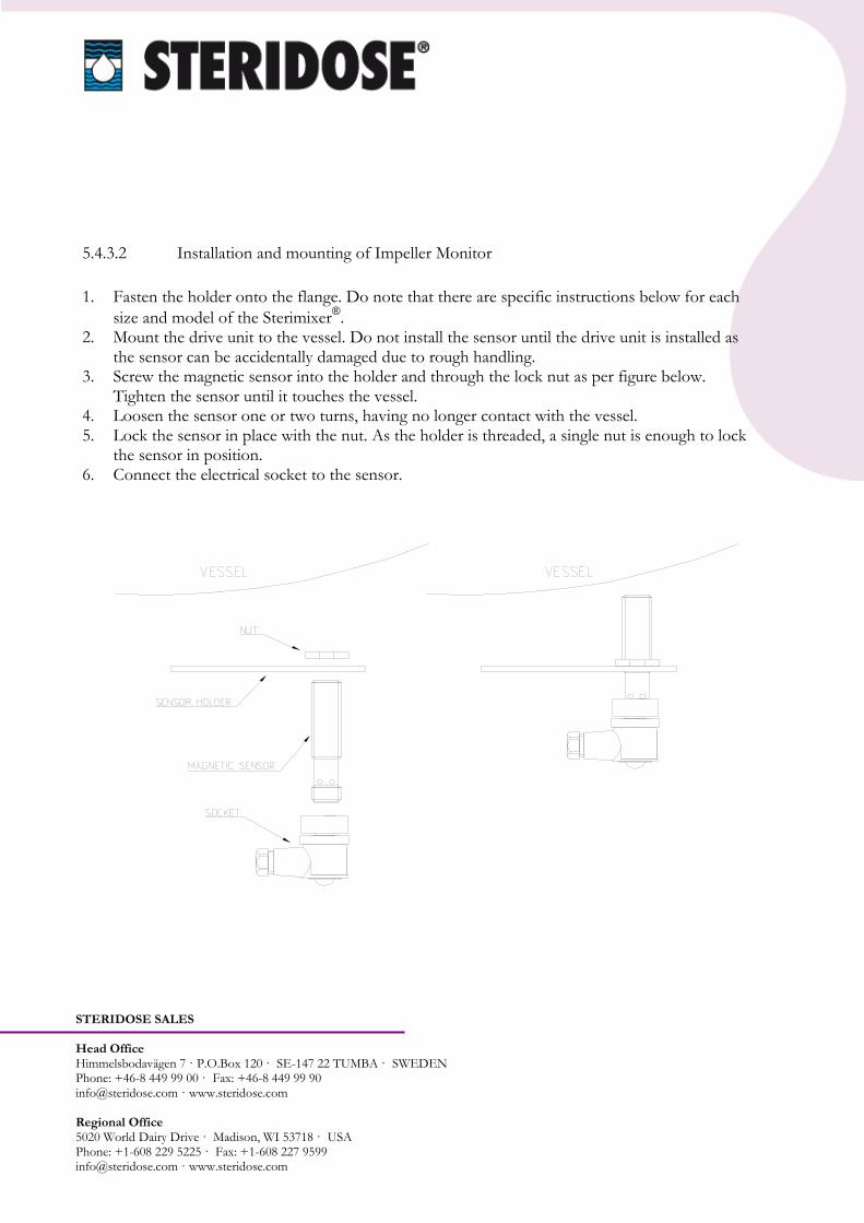
5.4.3.2 Installation and mounting of Impeller Monitor
1. Fasten the holder onto the flange. Do note that there are specific instructions below for each
size and model of the Sterimixer®.
2. Mount the drive unit to the vessel. Do not install the sensor until the drive unit is installed as the sensor can be accidentally damaged due to rough handling.
3. Screw the magnetic sensor into the holder and through the lock nut as per figure below. Tighten the sensor until it touches the vessel.
4. Loosen the sensor one or two turns, having no longer contact with the vessel. 5. Lock the sensor in place with the nut. As the holder is threaded, a single nut is enough to lock
the sensor in position. 6. Connect the electrical socket to the sensor.

STERIDOSE SALES Head Office Himmelsbodavägen 7 · P.O.Box 120 · SE-147 22 TUMBA · SWEDEN Phone: +46-8 449 99 00 · Fax: +46-8 449 99 90 [email protected] · www.steridose.com Regional Office 5020 World Dairy Drive · Madison, WI 53718 · USA Phone: +1-608 229 5225 · Fax: +1-608 227 9599 [email protected] · www.steridose.com
5.4.3.3 Sensor holder 60/75, 85/100 - 140
The sensor holders for Sterimixer® 60/75 DC, 85/100 DC and 85/100-140 AC are mounted in the
same way. The holder is installed on the lower part of the flange, as shown in the three figures below. The holder is fixed to the flange with two of the screws that are used to fix the flange to the gearbox. When the drive unit has an extension, longer screws and distance sleeves are required.
60/75 DC
85/100 DC
85/100-140 AC 85/140 DC
85/100-140 AC
85/140 DC with extension
Positioning of the sensor holder, see the figure of the drive unit above.
5.4.3.4 Sensor holder 120/150 - 190
The holder for the Sterimixer® 120/150-190 is
assembled on the upper part of the flange, as the figure shows. The holder is fixed to the flange with the screws that are used to fix the drive plate against the flange. Since the holder is installed on the upper flange, the mounting instructions are identical for units with extended drive units.
5.4.3.5 Sensor holder 120H/220 and 210/275
120/150 AC
STERIDOSE SALES Head Office Himmelsbodavägen 7 · P.O.Box 120 · SE-147 22 TUMBA · SWEDEN Phone: +46-8 449 99 00 · Fax: +46-8 449 99 90 [email protected] · www.steridose.com Regional Office 5020 World Dairy Drive · Madison, WI 53718 · USA Phone: +1-608 229 5225 · Fax: +1-608 227 9599 [email protected] · www.steridose.com
The holder for the Sterimixer® 120H/220 is assembled on the upper part of the flange, similar to
the 120/150-190. But as the 120H/220 do not have a separate drive plate, the screws that fix the flange to the vessel are used.
The sensor for the Sterimixer® 210/275 is screwed into a threaded hole in the weld plate.
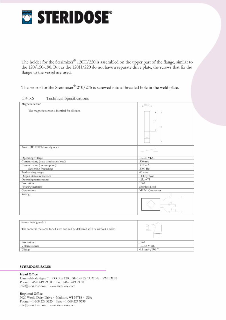
5.4.3.6 Technical Specifications
Magnetic sensor
The magnetic sensor is identical for all sizes.
3-wire DC PNP Normally open
Operating voltage: 10...30 VDC
Current rating (max continuous load): 300 mA
Current rating (consumption): <10 mA
Switching frequency: 5000 Hz
Real sensing range: 60 mm
Output status indication: LED yellow
Operating temperature: -25...+75
Protection: IP67
Housing material: Stainless Steel
Connection: M12x1 Connector
Wiring:
Sensor wiring socket The socket is the same for all sizes and can be delivered with or without a cable.
Protection: IP67
Voltage rating: 10...55 V DC
Wiring: 0.5 mm2 / PG 7
STERIDOSE SALES Head Office Himmelsbodavägen 7 · P.O.Box 120 · SE-147 22 TUMBA · SWEDEN Phone: +46-8 449 99 00 · Fax: +46-8 449 99 90 [email protected] · www.steridose.com Regional Office 5020 World Dairy Drive · Madison, WI 53718 · USA Phone: +1-608 229 5225 · Fax: +1-608 227 9599 [email protected] · www.steridose.com
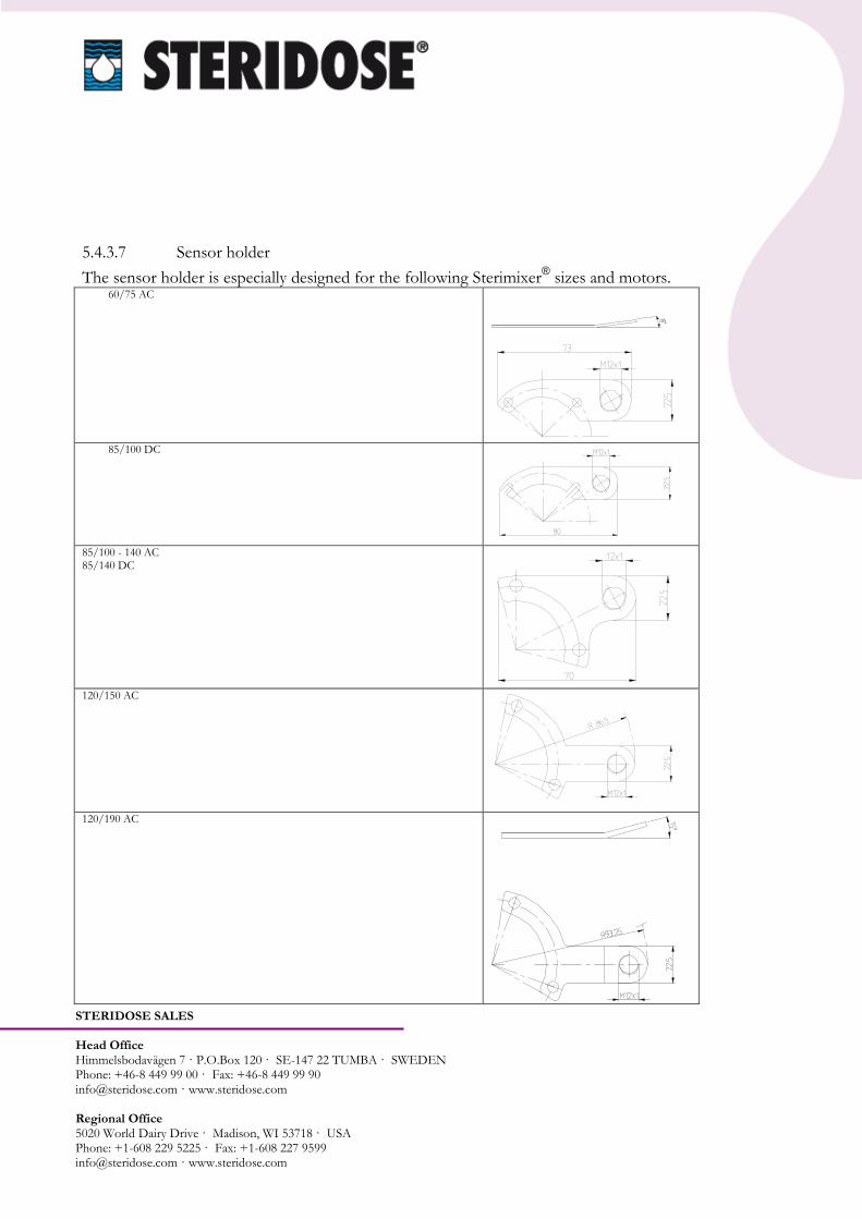
5.4.3.7 Sensor holder
The sensor holder is especially designed for the following Sterimixer® sizes and motors.
60/75 AC
85/100 DC
85/100 - 140 AC 85/140 DC
120/150 AC
120/190 AC

STERIDOSE SALES Head Office Himmelsbodavägen 7 · P.O.Box 120 · SE-147 22 TUMBA · SWEDEN Phone: +46-8 449 99 00 · Fax: +46-8 449 99 90 [email protected] · www.steridose.com Regional Office 5020 World Dairy Drive · Madison, WI 53718 · USA Phone: +1-608 229 5225 · Fax: +1-608 227 9599 [email protected] · www.steridose.com
120H/220 AC
210/275 AC
Weld plate

STERIDOSE SALES Head Office Himmelsbodavägen 7 · P.O.Box 120 · SE-147 22 TUMBA · SWEDEN Phone: +46-8 449 99 00 · Fax: +46-8 449 99 90 [email protected] · www.steridose.com Regional Office 5020 World Dairy Drive · Madison, WI 53718 · USA Phone: +1-608 229 5225 · Fax: +1-608 227 9599 [email protected] · www.steridose.com
5.4.3.8 Display for Impeller Monitor, Wiring Diagram
Input voltage Display: art no.
85-265 V AC (47 - 63 Hz)
OPTSM-10452
Display Sensor wiring
socket Magnetic sensor

STERIDOSE SALES Head Office Himmelsbodavägen 7 · P.O.Box 120 · SE-147 22 TUMBA · SWEDEN Phone: +46-8 449 99 00 · Fax: +46-8 449 99 90 [email protected] · www.steridose.com Regional Office 5020 World Dairy Drive · Madison, WI 53718 · USA Phone: +1-608 229 5225 · Fax: +1-608 227 9599 [email protected] · www.steridose.com
5.4.3.9 Programming NOTE! This is factory set at delivery of a complete unit. 1. Entering the program mode. NOTE: If the optional
analogue output board is installed, entering the program mode will cause the analogue output to go to its minimum value regardless of the input signal. Connect program enable input terminal to Ground. Press and hold the front panel
program key, ( ), until the display presents `run´.
2. Navigate through the parameter list by using the program key ( ) and the up ( ) and down (
) arrow keys.
While holding the program key ( ), the unit scrolls down one parameter each time the down
arrow ( ) key is pressed, and scrolls up one parameter each time the up arrow ( ) key is
pressed. When the program key ( ) is released, the display shows the value of the selected parameter.
3. Change the value of the selected parameter by using the right ( ), up ( ) and down ( ) arrow keys. For parameter that have a selection lists such as display, display decimal point and scaler decimal
point, the value will descent one selection through the list each time the right arrow ( ) key is pressed. For numeric values such as scaler, display update time, display zero time, analogue output offset
value and analogue output full scale value, press the right arrow ( ) key to select which digit to
change (flash). Then use the up ( ) and down ( ) arrow keys, to change the value of the flashing digit.
Press the program key ( ) to go back to the parameter list. 4. When the programming is done, navigate back
through the parameter list to the parameter named run and then release the program key (
). 5. To lock the program mode, disconnect the program enable input terminal from Ground
PGM
PGM
PGM
PGM
PGM
PGM
PGM PGM
PGM PGM
PGM PGM
PGM PGM
PGM
PGM
PGM
PGM
PGM PGM
PGM
PGM
PGM
PGM
PGM PGM
PGM PGM
PGM PGM
PGM PGM
PGM
PGM
PGM
PGM
PGM PGM
PGM
PGM
PGM
PGM
STERIDOSE SALES Head Office Himmelsbodavägen 7 · P.O.Box 120 · SE-147 22 TUMBA · SWEDEN Phone: +46-8 449 99 00 · Fax: +46-8 449 99 90 [email protected] · www.steridose.com Regional Office 5020 World Dairy Drive · Madison, WI 53718 · USA Phone: +1-608 229 5225 · Fax: +1-608 227 9599 [email protected] · www.steridose.com
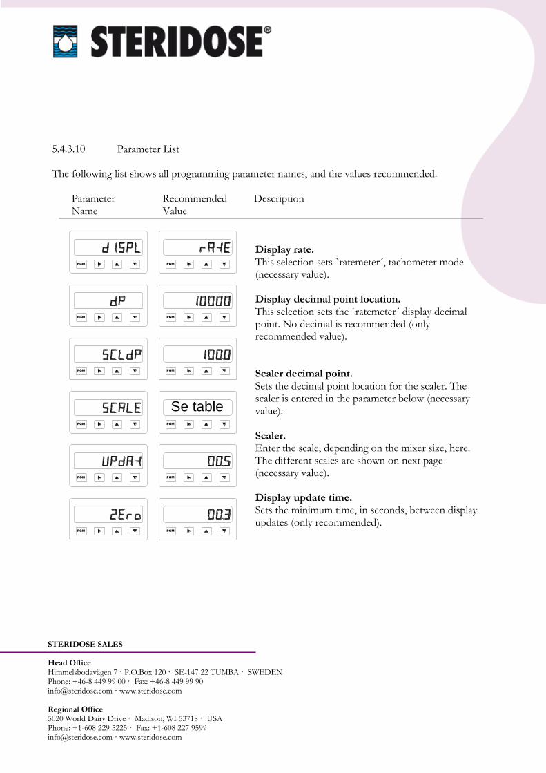
5.4.3.10 Parameter List The following list shows all programming parameter names, and the values recommended. Parameter Recommended Description
Name Value
Display rate. This selection sets `ratemeter´, tachometer mode (necessary value). Display decimal point location. This selection sets the `ratemeter´ display decimal point. No decimal is recommended (only recommended value). Scaler decimal point. Sets the decimal point location for the scaler. The scaler is entered in the parameter below (necessary value). Scaler. Enter the scale, depending on the mixer size, here. The different scales are shown on next page (necessary value). Display update time. Sets the minimum time, in seconds, between display updates (only recommended).
PGM PGM
PGM PGM
PGM PGM
PGM
PGM
PGM
PGM
PGM PGM
Se table
STERIDOSE SALES Head Office Himmelsbodavägen 7 · P.O.Box 120 · SE-147 22 TUMBA · SWEDEN Phone: +46-8 449 99 00 · Fax: +46-8 449 99 90 [email protected] · www.steridose.com Regional Office 5020 World Dairy Drive · Madison, WI 53718 · USA Phone: +1-608 229 5225 · Fax: +1-608 227 9599 [email protected] · www.steridose.com
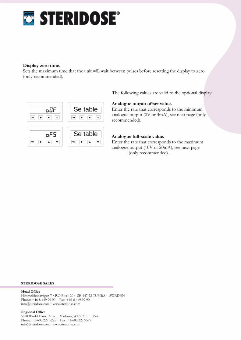
Display zero time. Sets the maximum time that the unit will wait between pulses before resetting the display to zero (only recommended). The following values are valid to the optional display:
Analogue output offset value. Enter the rate that corresponds to the minimum analogue output (0V or 4mA), see next page (only recommended). Analogue full-scale value. Enter the rate that corresponds to the maximum analogue output (10V or 20mA), see next page
(only recommended).
PGM PGM
PGM PGM
Se table
Se table

STERIDOSE SALES Head Office Himmelsbodavägen 7 · P.O.Box 120 · SE-147 22 TUMBA · SWEDEN Phone: +46-8 449 99 00 · Fax: +46-8 449 99 90 [email protected] · www.steridose.com Regional Office 5020 World Dairy Drive · Madison, WI 53718 · USA Phone: +1-608 229 5225 · Fax: +1-608 227 9599 [email protected] · www.steridose.com
5.4.3.11 Mixer depending values Scaler: The parameter scaler, are calculated out of NOS and PPI. Scaler = NOS / PPI NOS = Numbers of seconds in one time unit,
rotation. (Rpm NOS = 60) PPI = Pulses per rotation, number of magnets. The following values are valid to the optional display. Analogue output offset value: Enter the rate that corresponds to the minimum analogue output (0V or 4mA). This value is equal to the minimum speed of the impeller. The minimum speed differs between drive units, such as AC or DC motors. Analogue full-scale value: Enter the rate that corresponds to the maximum analogue output (10V or 20mA). This value is equal to the maximum speed of the impeller. The maximum speed varies between different Sterimixer® sizes.
STERIMIXER® PPI SCALER
VALUE
SIZE =60/PPI
(RPM)
60/75 4 15
85/100-140 8 7.5
120/150-190 12 5
120H/220 12 5
210/275 24 2.5
STERIMIXER®
DRIVE UNIT
Analogue output offset value
DC 0
AC 50
STERIMIXER®
SIZE
Analogue output offset value
60/75 85/100-140 120/150
450
120/190 120H/220 210/275
350
STERIDOSE SALES Head Office Himmelsbodavägen 7 · P.O.Box 120 · SE-147 22 TUMBA · SWEDEN Phone: +46-8 449 99 00 · Fax: +46-8 449 99 90 [email protected] · www.steridose.com Regional Office 5020 World Dairy Drive · Madison, WI 53718 · USA Phone: +1-608 229 5225 · Fax: +1-608 227 9599 [email protected] · www.steridose.com
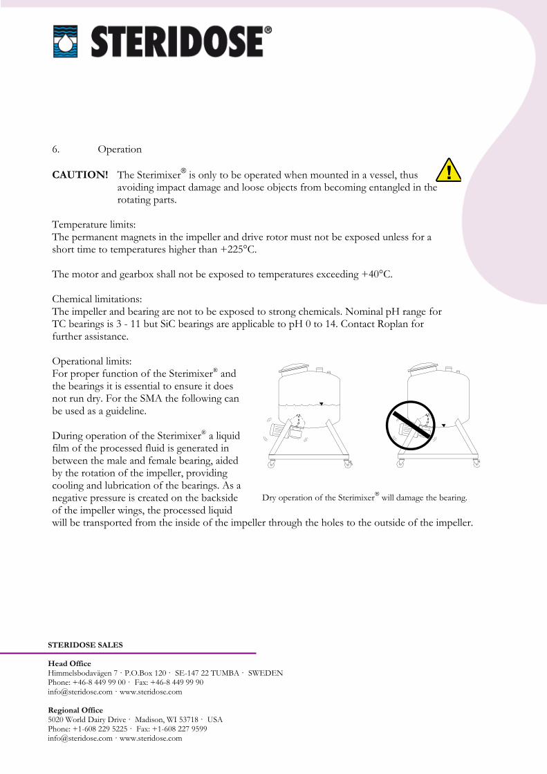
6. Operation
CAUTION! The Sterimixer® is only to be operated when mounted in a vessel, thus
avoiding impact damage and loose objects from becoming entangled in the rotating parts.
Temperature limits: The permanent magnets in the impeller and drive rotor must not be exposed unless for a short time to temperatures higher than +225°C. The motor and gearbox shall not be exposed to temperatures exceeding +40°C. Chemical limitations: The impeller and bearing are not to be exposed to strong chemicals. Nominal pH range for TC bearings is 3 - 11 but SiC bearings are applicable to pH 0 to 14. Contact Roplan for further assistance. Operational limits: For proper function of the Sterimixer® and the bearings it is essential to ensure it does not run dry. For the SMA the following can be used as a guideline. During operation of the Sterimixer® a liquid film of the processed fluid is generated in between the male and female bearing, aided by the rotation of the impeller, providing cooling and lubrication of the bearings. As a negative pressure is created on the backside of the impeller wings, the processed liquid will be transported from the inside of the impeller through the holes to the outside of the impeller.
Dry operation of the Sterimixer® will damage the bearing.

STERIDOSE SALES Head Office Himmelsbodavägen 7 · P.O.Box 120 · SE-147 22 TUMBA · SWEDEN Phone: +46-8 449 99 00 · Fax: +46-8 449 99 90 [email protected] · www.steridose.com Regional Office 5020 World Dairy Drive · Madison, WI 53718 · USA Phone: +1-608 229 5225 · Fax: +1-608 227 9599 [email protected] · www.steridose.com
Fluid 200mm above impeller If the impeller is fully covered by process fluid, there will be enough to fulfil this. However, when the impeller starts to rotate, the processed fluid will centrifuge from the impeller and when the speed is high enough, the impeller is rotating in a “dry” hole. As there is no flow of processed fluid through the impeller, the bearing will lack both lubrication and cooling and subsequently run dry. To avoid dry running the speed has to be adjusted in accordance to the level in the tank. This will depend upon the following:
The diameter of the tank
The shape of the bottom of the tank
The viscosity, as higher the viscosity is the less is the flow through the impeller. Due to these parameters it is not possible to give any exact data for the maximum speed.
WARNING! Dry operation of the Sterimixer® will damage the bearings.
NOTE! For the SMO the function of the flow through of the impeller is different, but the
level above the impeller is as important as for the SMA. NOTE! During SIP there is a risk that the bearing will run dry. Please find further
information in section 6.3, “Guide for sterilizing the Sterimixer®”.

STERIDOSE SALES Head Office Himmelsbodavägen 7 · P.O.Box 120 · SE-147 22 TUMBA · SWEDEN Phone: +46-8 449 99 00 · Fax: +46-8 449 99 90 [email protected] · www.steridose.com Regional Office 5020 World Dairy Drive · Madison, WI 53718 · USA Phone: +1-608 229 5225 · Fax: +1-608 227 9599 [email protected] · www.steridose.com
6.1 Guide for operation of the Sterimixer®
The impeller is factory cleaned prior to delivery. However, before it is put into service it must be cleaned in an appropriate manner i.e. in a dishwasher or high pressure cleaning, as per the requirements of the application. The operational parameters are pre-set in the control box. In extreme working conditions, disconnection of the magnetic coupling can occur, i.e. the motor rotates, but not the impeller. To avoid any disconnection of the magnetic coupling, the acceleration time and the max rpm should be adjusted to conform to the specific application.
For a Sterimixer® supplied without a control box, soft
manual start of the motor is required to prevent the magnetic coupling being disconnected. A suitable acceleration time up to the max rpm can be anything from ten seconds to a couple of minutes depending upon the application. CAUTION! Never insert foreign objects in the vessel
when the mixer is rotating.
No foreign objects in the vessel!
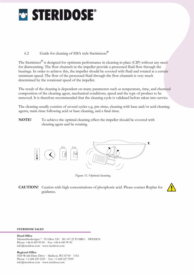
STERIDOSE SALES Head Office Himmelsbodavägen 7 · P.O.Box 120 · SE-147 22 TUMBA · SWEDEN Phone: +46-8 449 99 00 · Fax: +46-8 449 99 90 [email protected] · www.steridose.com Regional Office 5020 World Dairy Drive · Madison, WI 53718 · USA Phone: +1-608 229 5225 · Fax: +1-608 227 9599 [email protected] · www.steridose.com
6.2 Guide for cleaning of SMA style Sterimixers®
The Sterimixer® is designed for optimum performance in cleaning in place (CIP) without any need
for dismounting. The flow channels in the impeller provide a processed fluid flow through the bearings. In order to achieve this, the impeller should be covered with fluid and rotated at a certain minimum speed. The flow of the processed fluid through the flow channels is very much determined by the rotational speed of the impeller. The result of the cleaning is dependent on many parameters such as temperature, time, and chemical composition of the cleaning agent, mechanical conditions, speed and the type of product to be removed. It is therefore recommended that the cleaning cycle is validated before taken into service. The cleaning usually consists of several cycles e.g. pre-rinse, cleaning with base and/or acid cleaning agents, main rinse following acid or base cleaning, and a final rinse. NOTE! To achieve the optimal cleaning effect the impeller should be covered with
cleaning agent and be rotating.
CAUTION! Caution with high concentrations of phosphoric acid. Please contact Roplan for
guidance.
Figure 11. Optimal cleaning

STERIDOSE SALES Head Office Himmelsbodavägen 7 · P.O.Box 120 · SE-147 22 TUMBA · SWEDEN Phone: +46-8 449 99 00 · Fax: +46-8 449 99 90 [email protected] · www.steridose.com Regional Office 5020 World Dairy Drive · Madison, WI 53718 · USA Phone: +1-608 229 5225 · Fax: +1-608 227 9599 [email protected] · www.steridose.com
Example of CIP Procedure: 1. Drain the vessel from processed media. 2. Close the outlet and fill with cleaning agent having the fluid level above the impeller with at least 150 - 200 mm. 3. A suitable speed is approximately 300 rpm with filled vessel (depending on the size). 4. Normal cycle time is 5 - 20 minutes.
NOTE! The exact operational conditions for CIP must be validated for each individual
application. NOTE! The above cleaning method does not remove any magnetic particles. Due to the
strong magnets inside the impeller all magnetic particles will be stuck inside the impeller. To have these removed, the impeller must be removed and cleaned separately.
CAUTION! The impeller must be covered with fluid to avoid damage to the bearings.
WARNING! Dry operation of the Sterimixer® will damage the bearings.
CIP GUIDELINES FOR SMO STYLE STERIMIXERS
The following document provides general guidelines for CIP procedures for Sterimixers with SMO style impellers. Principle of Operation during CIP: The bearing assembly on a SMO impeller head is exposed. When directing flow from a spray ball to the impeller head, the bearing surface will get in contact with the CIP fluid. The openings on top of the SMO impeller head also allow the CIP fluid to hit the weld-plate under the impeller. In order to hit all surfaces, the impeller head needs to rotate at low speed during the CIP cycle. Please refer to Figure 12. Typical mixer speed during the CIP cycle is 100 rpm.

STERIDOSE SALES Head Office Himmelsbodavägen 7 · P.O.Box 120 · SE-147 22 TUMBA · SWEDEN Phone: +46-8 449 99 00 · Fax: +46-8 449 99 90 [email protected] · www.steridose.com Regional Office 5020 World Dairy Drive · Madison, WI 53718 · USA Phone: +1-608 229 5225 · Fax: +1-608 227 9599 [email protected] · www.steridose.com
Figure 12. SMO IMPELLER
Typical cleaning procedure for SMO style impellers: The cleaning procedure can be divided in two steps: Step 1:CIP solution cleaning Start CIP solution flow through the sprayball at the recommended flow rate. Open the tank outlet valve completely to allow full drainage. Operate mixer at low speed (around 50-100 rpm). Avoid running the mixer at high speed. This may cause the bearing to run dry.

STERIDOSE SALES Head Office Himmelsbodavägen 7 · P.O.Box 120 · SE-147 22 TUMBA · SWEDEN Phone: +46-8 449 99 00 · Fax: +46-8 449 99 90 [email protected] · www.steridose.com Regional Office 5020 World Dairy Drive · Madison, WI 53718 · USA Phone: +1-608 229 5225 · Fax: +1-608 227 9599 [email protected] · www.steridose.com
Ensure that the sprayball flow is hitting the impeller head. Typically, coverage test with riboflavin (usually performed during FAT) will provide evidence that the impeller head is fully wetted by the cleaning solution. The duration of the cycle depends on the application and requires to be validated by swabbing vessel and mixer surfaces. Step 2: WFI flushing Repeat step 1 using WFI through the sprayball.
6.3 Guide for sterilising the Sterimixer®
The Sterimixer® is designed for optimum performance in sterilisation in place (SIP) without any
need for dismounting. The selection of method from those listed below depends on the individual conditions. NOTE! The permanent magnets in the impeller and the rotor are heat stable up to
+225°C. Never expose these parts to higher temperatures. The drive unit and gearbox shall not be exposed to ambient temperatures above +40°C.
A certain delay in the rise of temperature between the inside of the impeller and the vessel is caused by the mass of the impeller head. This delay is influenced by:
- Sterimixer® size: The larger the Sterimixer
® is, the longer the delay.
- Sterilisation method: Steam sterilisation gives the shortest delay. Hot air sterilisation gives the longest delay. When evaluating sterilisation temperature you should focus on the area inside the impeller. A thermal element should be used if the system is sterilised in a hot air oven or autoclave. For applications with SIP/SHW where the impeller rotates, the validation should be carried out by biological tests.
STERIDOSE SALES Head Office Himmelsbodavägen 7 · P.O.Box 120 · SE-147 22 TUMBA · SWEDEN Phone: +46-8 449 99 00 · Fax: +46-8 449 99 90 [email protected] · www.steridose.com Regional Office 5020 World Dairy Drive · Madison, WI 53718 · USA Phone: +1-608 229 5225 · Fax: +1-608 227 9599 [email protected] · www.steridose.com
CAUTION! The impeller must be covered with fluid to avoid damage to the bearings.
WARNING! Dry operation of the Sterimixer® will damage the bearings.
6.3.1 Steam Sterilisation in Place (SIP)
The vessel with the impeller and the mounted drive unit is steam sterilised. Example of SIP procedure:
To remove any condensation inside the impeller during sterilisation, rotate the Sterimixer® at
a low speed i.e. 50 rpm a few seconds, approx. every five minutes. NB! This is a critical phase for dry running.
When the sterilisation temperature in the vessel has been achieved, the rotation of the
Sterimixer® shall be stopped.
WARNING! Dry operation of the Sterimixer® will damage the bearings.
6.3.2 Super Heated Water Sterilisation in Place (SHW)
The vessel and the mounted drive unit are sterilised with super heated water. Example of SHW procedure:
The vessel is filled with WFI (Water For Injection) to a suitable level.
During heating, sterilisation and cooling the Sterimixer® should rotate.
Vortexes (suction whirlpools) must not arise. The water level and speed controls this.
During the emptying phase the Sterimixer® must not rotate.
CAUTION! The impeller must be covered with fluid to avoid damage to the bearings.
WARNING! Dry operation of the Sterimixer® will damage the bearings.
6.3.3 Sterilisation in Autoclave or Hot Air Oven

STERIDOSE SALES Head Office Himmelsbodavägen 7 · P.O.Box 120 · SE-147 22 TUMBA · SWEDEN Phone: +46-8 449 99 00 · Fax: +46-8 449 99 90 [email protected] · www.steridose.com Regional Office 5020 World Dairy Drive · Madison, WI 53718 · USA Phone: +1-608 229 5225 · Fax: +1-608 227 9599 [email protected] · www.steridose.com
Dismount the drive unit as per section 4.4.2 “Dismounting of the drive unit”.
CAUTION! The vessel and the impeller (without the drive unit) must be sterilised in an upright
position in an autoclave or hot air oven to prevent the impeller sliding off the bearing. To prevent this, a magnetic drive dummy can be installed to avoid any risk of damage and hold the impeller in place.
Example of autoclave procedure:
Dismount the drive unit.
Install the eventual magnetic drive dummy.
At least one pre-vacuum period must be used to eliminate air pockets on the inside of the impeller.
The vessel, with the impeller in place, is sterilised at a maximum temperature of +140°C in the autoclave.
Example of hot air oven procedure:
Dismount the drive unit.
Install the eventual magnetic drive dummy.
The vessel and the impeller are sterilised in the hot air oven at a maximum temperature of +225°C.

STERIDOSE SALES Head Office Himmelsbodavägen 7 · P.O.Box 120 · SE-147 22 TUMBA · SWEDEN Phone: +46-8 449 99 00 · Fax: +46-8 449 99 90 [email protected] · www.steridose.com Regional Office 5020 World Dairy Drive · Madison, WI 53718 · USA Phone: +1-608 229 5225 · Fax: +1-608 227 9599 [email protected] · www.steridose.com
6.4 Additional instructions when using the Sterimixer® in ATEX applications
Only original part from the supplier must be used to achieve the level of protection stated. 6.4.1 General Manufacturer: Roplan AB/Steridose® Tel: +46-8-449 99 00 Skyttbrinksvägen 20 Fax: +46-8-449 99 90 SE-147 39 Tumba mail: [email protected] Sweden www.steridose.com
Type denomination: Sterimixer®
General: This incorporation manual applies to the Sterimixer® fitted into applications
covered by the ATEX directive 94/9/EC.
Do note that applicable health and safety regulations with regards to processed media and eventual buffer or barrier fluid shall be considered by the end-user.
The electrical motor, gear-box and impeller monitor (optional) shall be installed and
operated as per the manufacturers instructions supplied with the Sterimixer®.
Protection class: II 2 G c Tx Type of protection: EN 13463-1:2001 `c´ `k´ Safety zones applicable: Zone 1 & 2
Maximum surface The maximum surface temperature of the Sterimixer® are very much
temperature: dependant upon the temperature of the media processed by the pump. In the table below the maximum temperature of the processed fluid within the pump is specified to ensure that the maximum surface temperature of the mechanical seal components does not exceed the corresponding temperature class.
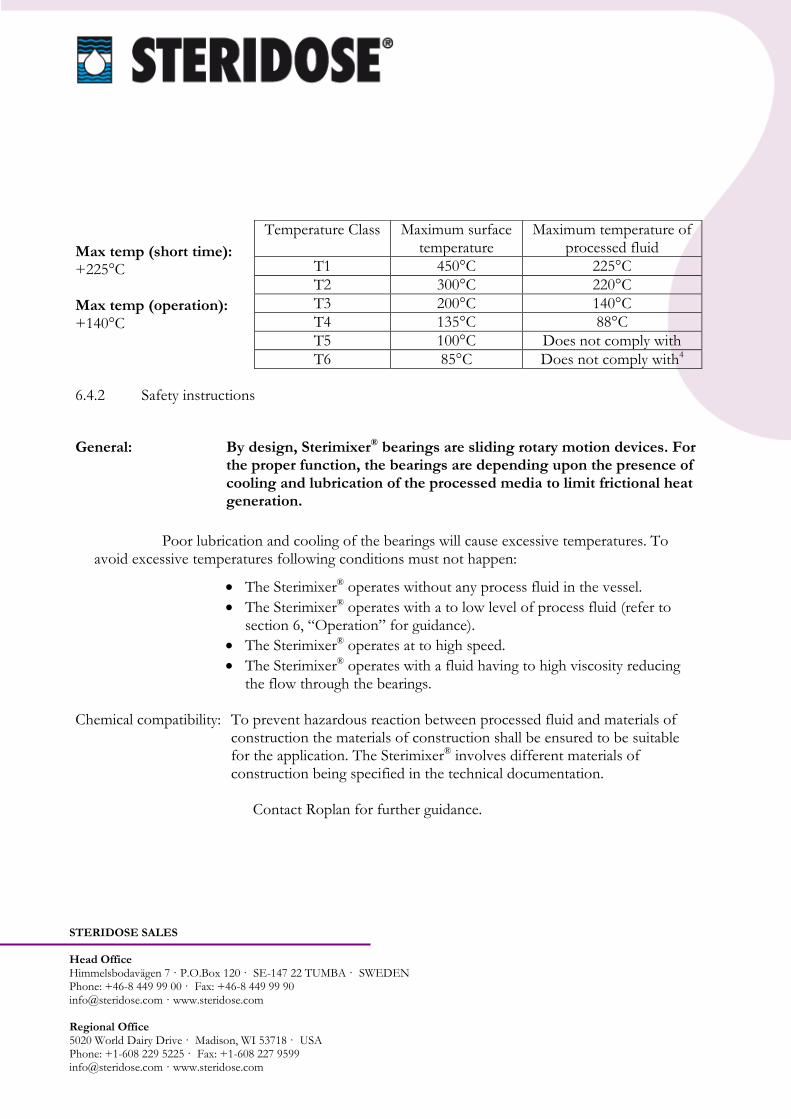
STERIDOSE SALES Head Office Himmelsbodavägen 7 · P.O.Box 120 · SE-147 22 TUMBA · SWEDEN Phone: +46-8 449 99 00 · Fax: +46-8 449 99 90 [email protected] · www.steridose.com Regional Office 5020 World Dairy Drive · Madison, WI 53718 · USA Phone: +1-608 229 5225 · Fax: +1-608 227 9599 [email protected] · www.steridose.com
Max temp (short time): +225°C Max temp (operation): +140°C 6.4.2 Safety instructions
General: By design, Sterimixer® bearings are sliding rotary motion devices. For the proper function, the bearings are depending upon the presence of cooling and lubrication of the processed media to limit frictional heat generation.
Poor lubrication and cooling of the bearings will cause excessive temperatures. To avoid excessive temperatures following conditions must not happen:
The Sterimixer® operates without any process fluid in the vessel.
The Sterimixer® operates with a to low level of process fluid (refer to section 6, “Operation” for guidance).
The Sterimixer® operates at to high speed.
The Sterimixer® operates with a fluid having to high viscosity reducing the flow through the bearings.
Chemical compatibility: To prevent hazardous reaction between processed fluid and materials of
construction the materials of construction shall be ensured to be suitable for the application. The Sterimixer® involves different materials of construction being specified in the technical documentation.
Contact Roplan for further guidance.
Temperature Class Maximum surface temperature
Maximum temperature of processed fluid
T1 450°C 225°C
T2 300°C 220°C
T3 200°C 140°C
T4 135°C 88°C
T5 100°C Does not comply with
T6 85°C Does not comply with4

STERIDOSE SALES Head Office Himmelsbodavägen 7 · P.O.Box 120 · SE-147 22 TUMBA · SWEDEN Phone: +46-8 449 99 00 · Fax: +46-8 449 99 90 [email protected] · www.steridose.com Regional Office 5020 World Dairy Drive · Madison, WI 53718 · USA Phone: +1-608 229 5225 · Fax: +1-608 227 9599 [email protected] · www.steridose.com
Start-up: Before start-up of the Sterimixer® the following shall be controlled and verified:
- The Sterimixer® being correctly installed as per section 4, “Installation and mounting”.
- Materials of construction chosen are suitable for the application.
- The application is within operating parameters originally specified.
Operation: The Sterimixer® shall not operate beyond the operating limits specified in section 5, “Technical specifications”.
Assembly: The Sterimixer® shall be installed as per section 4, “Installation and
mounting”. Disassembly: The Sterimixer® shall be disassembled as per section 4, “Installation and
mounting”. Maintenance: Refer to section 7, “Maintenance”. To this, the following is added; Zone 1 Daily; Zone 2 Weekly Verify the function of any alarms applied.
Every two years or 9000 hrs of operation whichever comes first:
Replace the Sterimixer® with a new or a professionally refurbished Sterimixer®. Do note that the used Sterimixer® usually can be refurbished thus it is essential to handle this with care to prevent unnecessary damages.
Do note that the life time of the Sterimixer® depends upon the application thus shorter service life might apply.
Installation: The Sterimixer® shall be installed as per section 4, “Installation and mounting”.
Set-up: The set-up of the Sterimixer® shall be performed as per section 4, “Installation and mounting”.
STERIDOSE SALES Head Office Himmelsbodavägen 7 · P.O.Box 120 · SE-147 22 TUMBA · SWEDEN Phone: +46-8 449 99 00 · Fax: +46-8 449 99 90 [email protected] · www.steridose.com Regional Office 5020 World Dairy Drive · Madison, WI 53718 · USA Phone: +1-608 229 5225 · Fax: +1-608 227 9599 [email protected] · www.steridose.com
Education: Operator must have necessary knowledge about the Sterimixer® before handling the Sterimixer®. Necessary knowledge includes the understanding of the;
- function of the Sterimixer®.
- installation of the Sterimixer®. - safety instructions within this incorporation and operation manual. - operational limits for the Sterimixer®.
Operational limits: The Sterimixer® shall not operate beyond the operating limits specified in section 5, “Technical specifications”.
Special conditions - If the Sterimixer® is to be used within another application than originally which by experience intended there will be a risk of chemical incompatibility in between proved likely to occur the processed fluid and the materials of construction creating a possible
hazard. Each and every application shall be handled individually to ensure the safety conditions are maintained.
- If the Sterimixer® is subjected to poor lubrication this will create excessive wear and heat and subsequently premature failure. - If the Sterimixer® is exposed to rough handling permanent damages can occur. It is therefore essential that personnel involved receive the specified education above.
- If the Sterimixer® is incorrectly installed conditions could very likely be similar to poor lubrication creating excessive wear and heat and subsequently premature failure. It is therefore important that the operator has received the specified education above. - If the Sterimixer® is operated beyond it’s operating limits severe damage might occur subsequently creating a failure. It is essential that the operator has received the specified education above together with the full understanding of the Sterimixer® and the education related thereto.
- If the weld plate has been incorrectly fitted to the vessel deformation can cause contact with the impeller and/or magnetic rotor.
- Worn out bearings will cause physical contact in between the impeller and the weld plate. Specified maintenance shall be performed.

STERIDOSE SALES Head Office Himmelsbodavägen 7 · P.O.Box 120 · SE-147 22 TUMBA · SWEDEN Phone: +46-8 449 99 00 · Fax: +46-8 449 99 90 [email protected] · www.steridose.com Regional Office 5020 World Dairy Drive · Madison, WI 53718 · USA Phone: +1-608 229 5225 · Fax: +1-608 227 9599 [email protected] · www.steridose.com
- Through poor handling the magnetic rotor can be misaligned causing physical contact in between magnetic rotor and weld plate. Do always upon installation ensure the magnetic rotor to be correctly aligned.
- If the impeller is subjected to excessive torque it might loosen from the magnetic coupling. Do ensure compliance with operational limits and set-up specification.
- Media with tacky properties and/or particles can possibly clog the flow channels within the impeller reducing the cooling and lubricating flow. The applications shall therefore be validated to ensure proper function.
- Incorrect direction of rotation can cause the impeller to loosen from the magnetic coupling. Do ensure proper direction of rotation as per description in installation section is complied with.
Important There are no additional important accessories required for the use of accessories: Sterimixer® apart from being presented in this installation and operation
manual. Drawings and No special drawings or diagrams are required for the safe operation diagrams: of the Sterimixer® apart from being presented in this installation and
operation manual.7 Maintenance and service
The Sterimixer® requires a minimum of maintenance. Regular inspection of all parts, and any
consequent action is usually sufficient.
WARNING! Ensure the Sterimixer® is in a safe state before performing any service.
Before performing maintenance and service ensure;
the impeller and vessel are fully cleaned from any processed media and that any processed media cannot enter the vessel during maintenance.
the vessel is fully vented from any possible gases.
the vessel is depressurised.
the main power is switched-off and cannot be accidentally switched on during maintenance.
the vessel has been cooled to a temperature below 50°C (or a limit set by local regulations).
STERIDOSE SALES Head Office Himmelsbodavägen 7 · P.O.Box 120 · SE-147 22 TUMBA · SWEDEN Phone: +46-8 449 99 00 · Fax: +46-8 449 99 90 [email protected] · www.steridose.com Regional Office 5020 World Dairy Drive · Madison, WI 53718 · USA Phone: +1-608 229 5225 · Fax: +1-608 227 9599 [email protected] · www.steridose.com
Dismount the drive unit as per section 4.4.2 “Dismounting of the drive unit”.
Mount the drive unit as per section 4.4.1 “Mounting of the drive unit”.
7.1 Routine maintenance during start up/running in Following maintenance schedule should be performed at start up and/or running in of the
Sterimixer®.
Remove and check the impeller.
If particles are stuck to the impeller they have to be removed.
Due to the strong magnets inside the impeller all magnetic particles will get stuck inside the impeller. Therefore, check the inside of the impeller in particular.
The impeller must not be scratched or in any way damaged. If it has been damaged, the impeller and bearing must be replaced. The impeller can be sent to Roplan for refurbishment.
If a refurbished impeller is to be installed the bearing unit shall be replaced with a new. WARNING! The Sterimixer® impeller includes strong magnets thus personnel
equipped with pacemaker shall not handle these components. 7.2 At least once a year - interval dependent upon application Following maintenance schedule should be performed at least once a year. Do note that the interval will be highly dependant upon the application.
Remove and check the bearing and the impeller for signs of surface damage and general wear of the bearings.
Change the bearing and the impeller if the surface is coarse or uneven, scratched or if fragments have been knocked out from the bearing. The impeller can be sent to Roplan for refurbishment.
Change the PTFE washer when dismounting the bearing.
Make a general inspection of the motor, gearbox and other Sterimixer® parts. Make sure the
gearbox is not leaking oil.
STERIDOSE SALES Head Office Himmelsbodavägen 7 · P.O.Box 120 · SE-147 22 TUMBA · SWEDEN Phone: +46-8 449 99 00 · Fax: +46-8 449 99 90 [email protected] · www.steridose.com Regional Office 5020 World Dairy Drive · Madison, WI 53718 · USA Phone: +1-608 229 5225 · Fax: +1-608 227 9599 [email protected] · www.steridose.com
WARNING! The Sterimixer® impeller includes strong magnets thus personnel
equipped with pacemaker shall not handle these components. NOTE! The male bearing and the female bearing must be of same material, TC or SiC. If a
refurbished impeller is installed, a new bearing unit shall be mounted as well.

STERIDOSE SALES Head Office Himmelsbodavägen 7 · P.O.Box 120 · SE-147 22 TUMBA · SWEDEN Phone: +46-8 449 99 00 · Fax: +46-8 449 99 90 [email protected] · www.steridose.com Regional Office 5020 World Dairy Drive · Madison, WI 53718 · USA Phone: +1-608 229 5225 · Fax: +1-608 227 9599 [email protected] · www.steridose.com
8 Troubleshooting
Fault Possible cause Action
1. The Sterimixer® does not
start.
Fault in power supply. Check power supply.
2. The impeller does not rotate. Male bearing or magnetic drive not mounted.
Dismount the drive unit, detach the impeller, and mount the male bearing, impeller and magnetic drive.
3. Poor motor effect. Motor incorrectly connected. Check wiring diagram.
4. Poor mixing.
Impeller rotating in wrong direction.
Check the drive installation. AC: Phase reverse power cables. DC: Pole reversed power cables. AIR: Swap the air supply and the outlet
hoses. Verify the impeller rotates clockwise as
seen from above.
5. The Sterimixer® does not
reach the required maximum rpm.
Incorrectly set parameters in the VFD (Variable Frequency Drive).
Adjust and calibrate the VFD.
6. Slow and inefficient compressed air driven motor.
Clogged motor housing. Flush with paraffin as per maintenance instructions.
7. Noise from the Sterimixer®. a) Impeller has rotated
without fluid between the male and female bearing.
b) Worn out bearings. c) Missing male bearing.
a) Stop the Sterimixer®. Do not restart until
the fluid level covers the impeller. b) Replace the bearing and the impeller. c) See point 2.
8 Noise from the drive unit. Gearbox problems. Running dry from oil.
Refer to gearbox manual for maintenance.
9. Magnetic coupling disconnected.
a) Acceleration too rapid. b) Speed too high for the
application.
a) Check start up and adjust ramp up time. b) Reduce speed and adjust setting of max.
speed.
10. Many particles in the impeller.
Magnetic particles from associated media.
Check and take action with regard to the presence of particles/contents of associated media and raw materials. Magnetic particles are not re-moved during normal cleaning. The impeller must be removed and cleaned separately.
11. Insufficient cleaning of the impeller.
Poor fluid flow in the impeller; a) due to low fluid level. b) due to low speed. c) due to high speed.
a) Increase fluid level. b) Increase speed. c) Reduce speed (to prevent vortexes).
Related Documents