STEP 7 – MICRO/WIN TUTORIAL Step7 – Micro/WIN makes programming of S7-200 easier. Programming of S7-200 by using Step 7 – Micro/WIN will be introduced in a simple example. Inputs will be defined as IX.X, outputs will be defined as QX.X and flags will be defined as MX.X for programming Siemens PLCs. For example I0.1 defines the first module’s 1 st input and Q0.1 defines first module’s first output. Step-1: How to open Step 7 – Micro/WIN You can open Step 7 – Micro/WIN from following path for Windows. After opening the program you will see the window in Figure 1.1. In Figure 1.2 steps of writing and running a program on PLC is demonstrated. Start All Programs Simatic Step 7 Micro/WIN V4 XX Step 7 Micro/WIN Figure 1.1: Step 7 Micro/WIN Start Window Figure 1.2: Steps of Running Your Code on PLC Open Step 7 Micro/WIN Write a Simple Code in Ladder Networks Compile Your Code Download Your Code to PLC Run PLC to Perform Code

Welcome message from author
This document is posted to help you gain knowledge. Please leave a comment to let me know what you think about it! Share it to your friends and learn new things together.
Transcript
STEP 7 – MICRO/WIN TUTORIAL
Step7 – Micro/WIN makes programming of S7-200 easier. Programming of S7-200 by using Step 7 –
Micro/WIN will be introduced in a simple example. Inputs will be defined as IX.X, outputs will be
defined as QX.X and flags will be defined as MX.X for programming Siemens PLCs. For example
I0.1 defines the first module’s 1st input and Q0.1 defines first module’s first output.
Step-1: How to open Step 7 – Micro/WIN
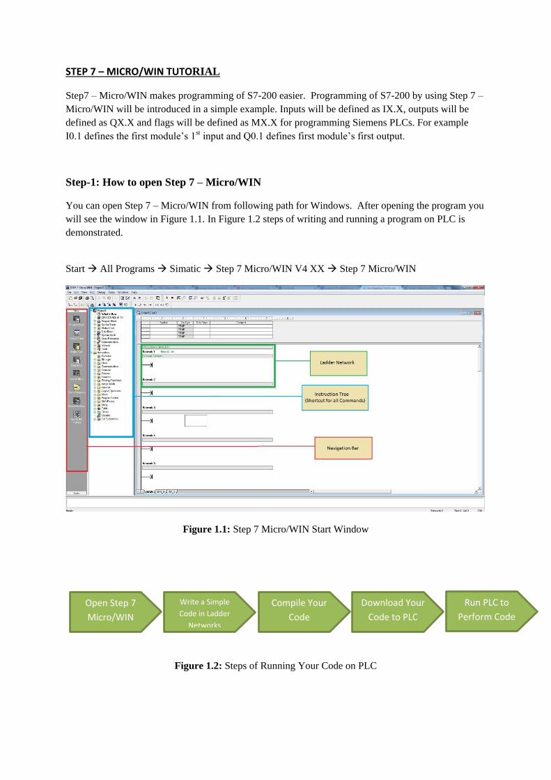
You can open Step 7 – Micro/WIN from following path for Windows. After opening the program you
will see the window in Figure 1.1. In Figure 1.2 steps of writing and running a program on PLC is
demonstrated.
Start All Programs Simatic Step 7 Micro/WIN V4 XX Step 7 Micro/WIN
Figure 1.1: Step 7 Micro/WIN Start Window
Figure 1.2: Steps of Running Your Code on PLC
Open Step 7
Micro/WIN
Write a Simple
Code in Ladder
Networks
Compile Your
Code
Download Your
Code to PLC
Run PLC to
Perform Code
Step-2: How to write a simple program and use a timer in Step 7 – Micro/WIN
(NETWORK 1)
You can check the timer types and properties from Table 1.1 and Table 1.2. Procedure of
using timer is as follow;
Click on Bit Logic icon to open bit logic commands.
Choose normally close contact.
Drag and drop the contact to network 1.
Write the M0.0 instead of the question marks (???) over the contact. M0.0 is flag
contact.
Press the enter button to finish contact definition.
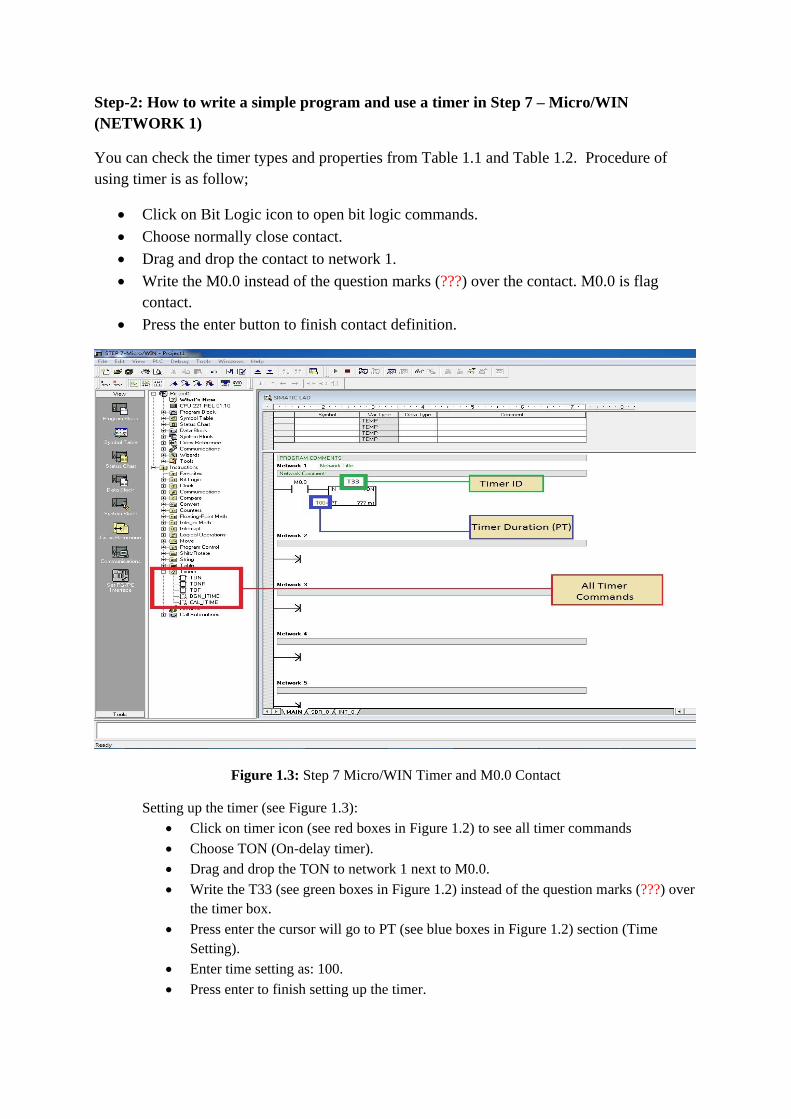
Figure 1.3: Step 7 Micro/WIN Timer and M0.0 Contact
Setting up the timer (see Figure 1.3):
Click on timer icon (see red boxes in Figure 1.2) to see all timer commands
Choose TON (On-delay timer).
Drag and drop the TON to network 1 next to M0.0.
Write the T33 (see green boxes in Figure 1.2) instead of the question marks (???) over
the timer box.
Press enter the cursor will go to PT (see blue boxes in Figure 1.2) section (Time
Setting).
Enter time setting as: 100.
Press enter to finish setting up the timer.
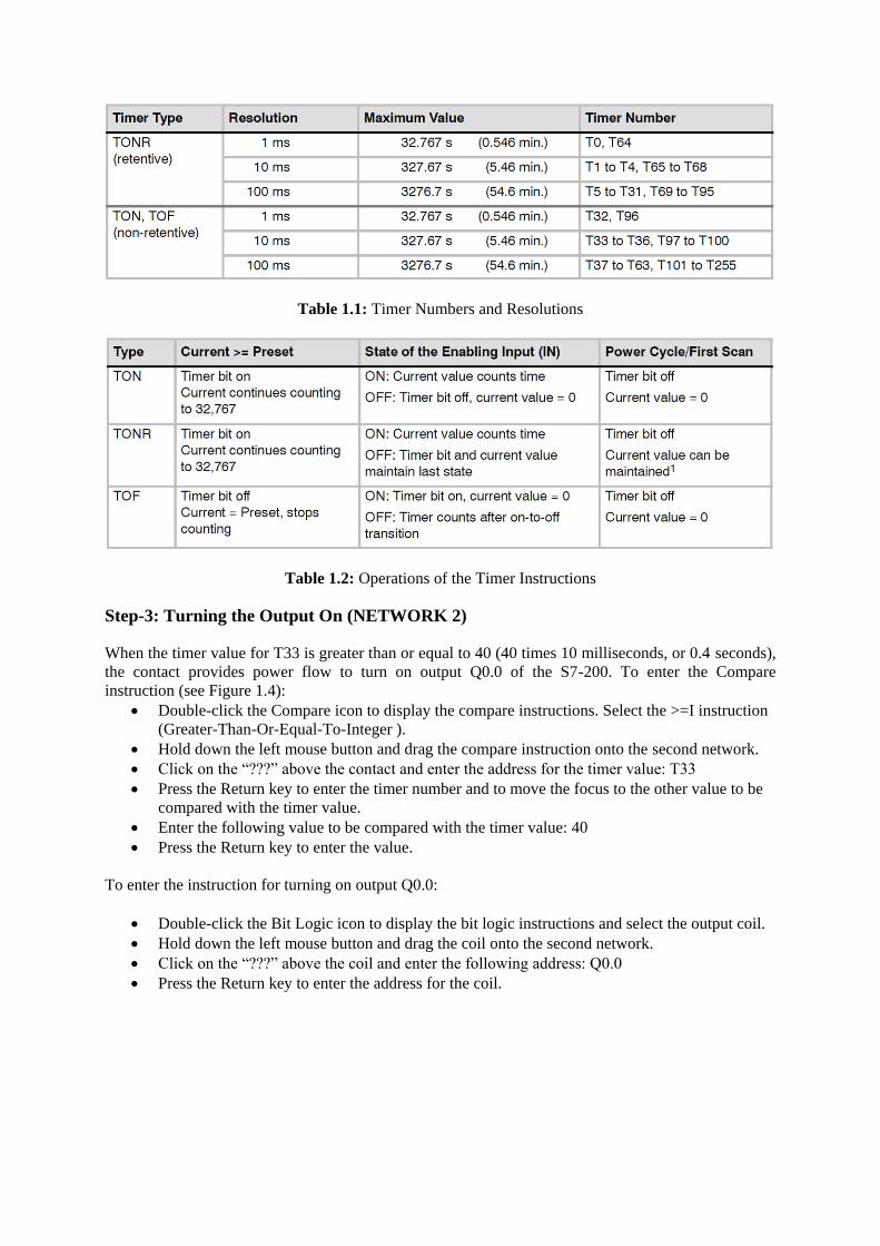
Table 1.1: Timer Numbers and Resolutions
Table 1.2: Operations of the Timer Instructions
Step-3: Turning the Output On (NETWORK 2)
When the timer value for T33 is greater than or equal to 40 (40 times 10 milliseconds, or 0.4 seconds),
the contact provides power flow to turn on output Q0.0 of the S7-200. To enter the Compare
instruction (see Figure 1.4):
Double-click the Compare icon to display the compare instructions. Select the >=I instruction
(Greater-Than-Or-Equal-To-Integer ).
Hold down the left mouse button and drag the compare instruction onto the second network.
Click on the “???” above the contact and enter the address for the timer value: T33
Press the Return key to enter the timer number and to move the focus to the other value to be
compared with the timer value.
Enter the following value to be compared with the timer value: 40
Press the Return key to enter the value.
To enter the instruction for turning on output Q0.0:
Double-click the Bit Logic icon to display the bit logic instructions and select the output coil.
Hold down the left mouse button and drag the coil onto the second network.
Click on the “???” above the coil and enter the following address: Q0.0
Press the Return key to enter the address for the coil.
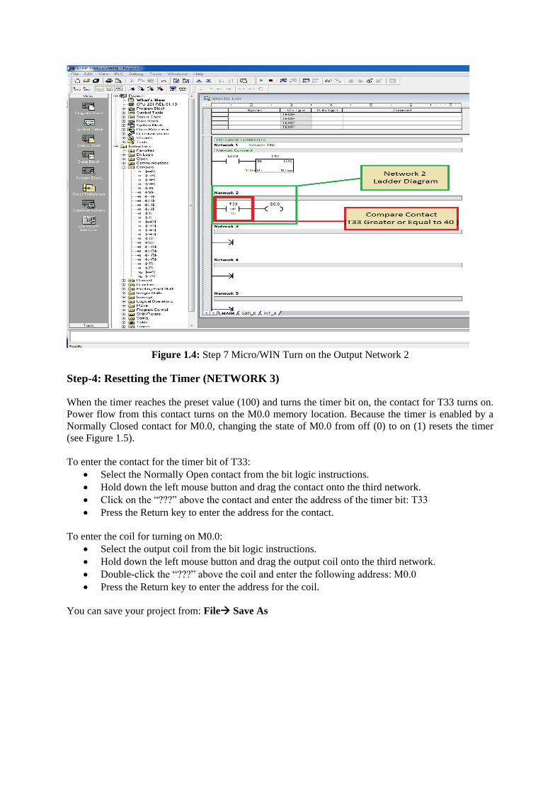
Figure 1.4: Step 7 Micro/WIN Turn on the Output Network 2
Step-4: Resetting the Timer (NETWORK 3)
When the timer reaches the preset value (100) and turns the timer bit on, the contact for T33 turns on.
Power flow from this contact turns on the M0.0 memory location. Because the timer is enabled by a
Normally Closed contact for M0.0, changing the state of M0.0 from off (0) to on (1) resets the timer
(see Figure 1.5).
To enter the contact for the timer bit of T33:
Select the Normally Open contact from the bit logic instructions.
Hold down the left mouse button and drag the contact onto the third network.
Click on the “???” above the contact and enter the address of the timer bit: T33
Press the Return key to enter the address for the contact.
To enter the coil for turning on M0.0:
Select the output coil from the bit logic instructions.
Hold down the left mouse button and drag the output coil onto the third network.
Double-click the “???” above the coil and enter the following address: M0.0
Press the Return key to enter the address for the coil.
You can save your project from: File Save As
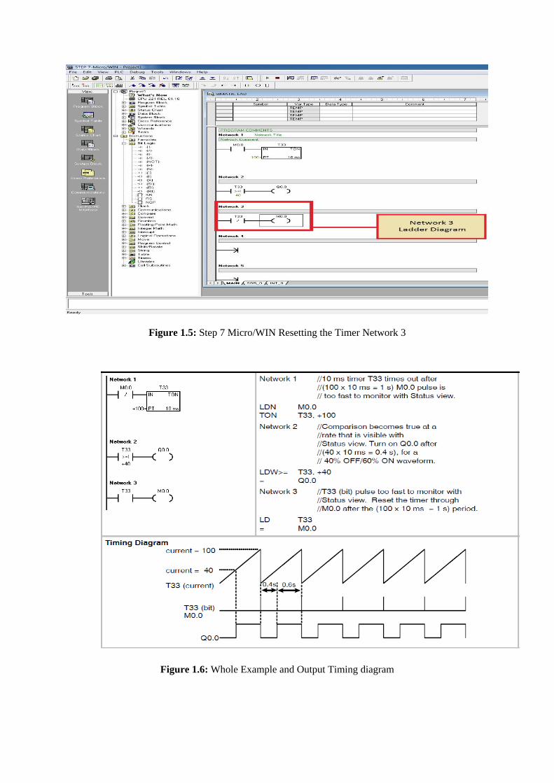
Figure 1.5: Step 7 Micro/WIN Resetting the Timer Network 3
Figure 1.6: Whole Example and Output Timing diagram
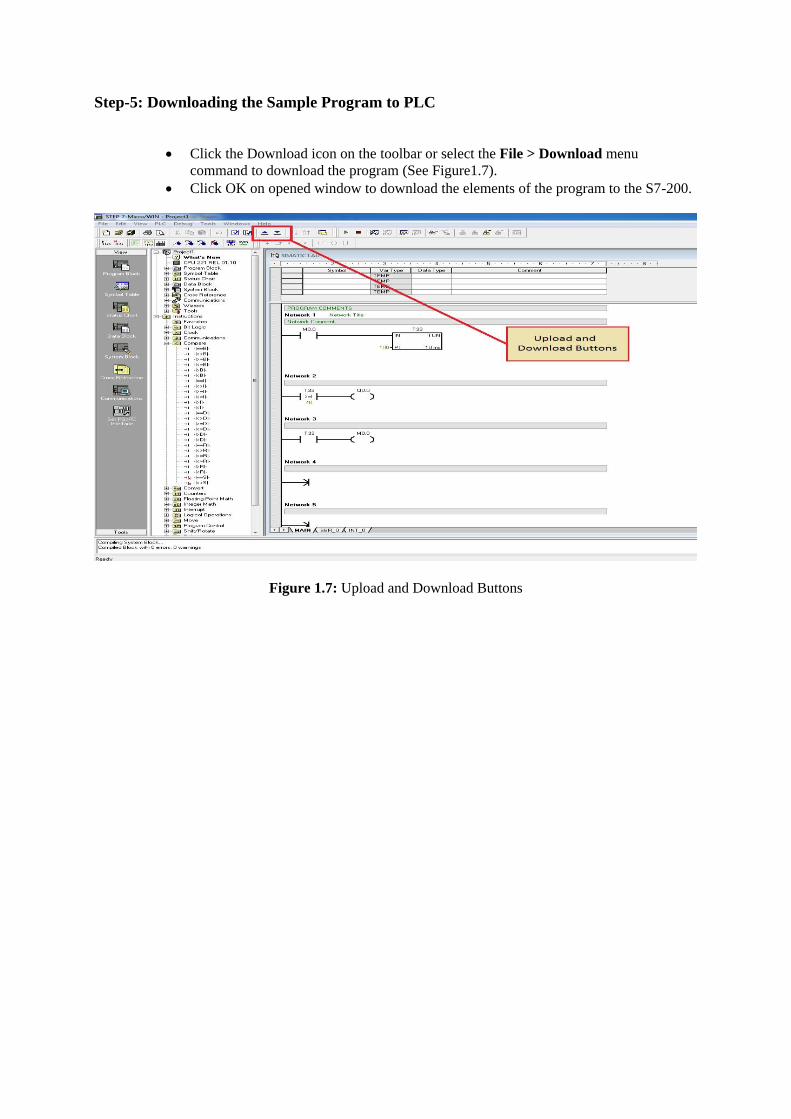
Step-5: Downloading the Sample Program to PLC
Click the Download icon on the toolbar or select the File > Download menu
command to download the program (See Figure1.7).
Click OK on opened window to download the elements of the program to the S7-200.
Figure 1.7: Upload and Download Buttons

Step-6: Running the PLC
For STEP 7--Micro/WIN to place the S7-200 CPU in RUN mode, the mode switch of the S7-200
must be set to TERM or RUN. When you place the S7-200 in RUN mode, the S7-200 executes
the program:
Click the RUN icon on the toolbar or select the PLC > RUN menu command (See Figure1.8).
Click OK to change the operating mode of the S7-200.
Figure 1.8: Run and Stop Buttons

Counters
Figure 2.1: Up-Down Counter Definitions
The Count Up instruction (CTU) counts up from the current value each time the count up (CU) input makes the transition from off to on. When the current value Cxx is greater than or equal to the preset value PV, the counter bit Cxx turns on. The counter is reset when the Reset (R) input turns on, or when the Reset instruction is executed. The counter stops counting when it reaches the maximum value (32,767).
The Count Down instruction (CTD) counts down from the current value of that counter each time the count down (CD) input makes the transition from off to on. When the current value Cxx is equal to 0, the counter bit Cxx turns on. The counter resets the counter bit Cxx and loads the current value with the preset value PV when the load input LD turns on. The counter stops upon reaching zero, and the counter bit Cxx turns on.
R input for CTU and LD input for CTD are reset inputs of counters (see Figure 2.1). You can reset counters by using this inputs.
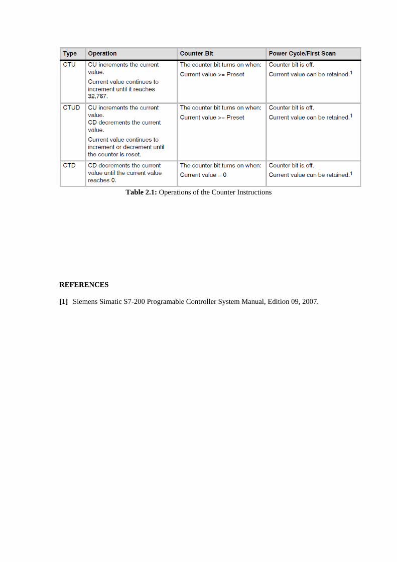
Table 2.1: Operations of the Counter Instructions
REFERENCES
[1] Siemens Simatic S7-200 Programable Controller System Manual, Edition 09, 2007.
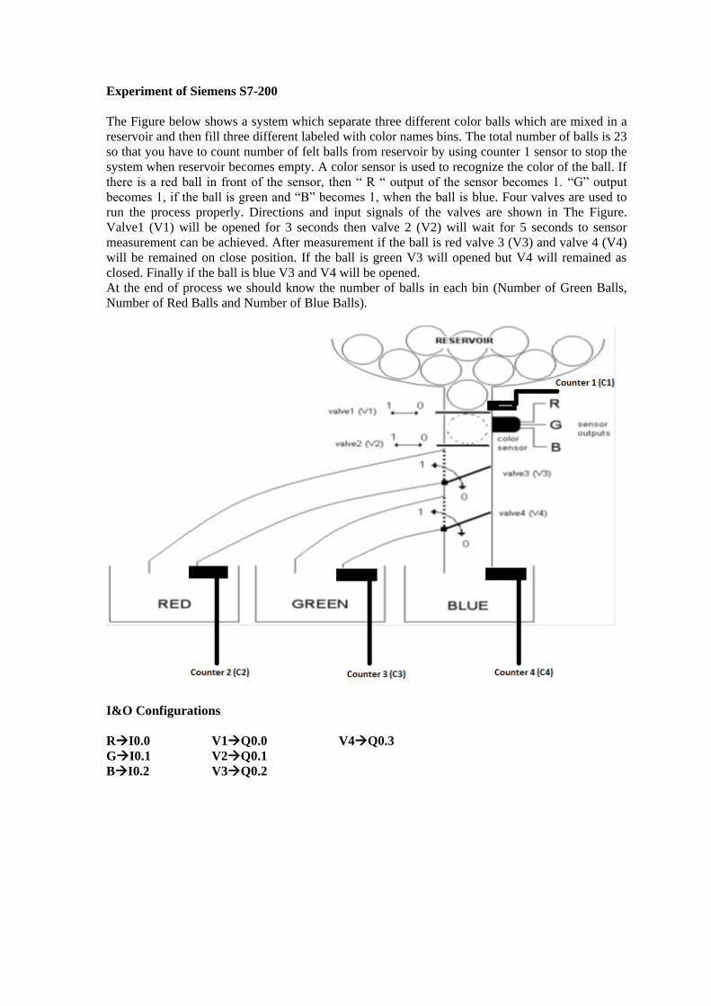
Experiment of Siemens S7-200
The Figure below shows a system which separate three different color balls which are mixed in a
reservoir and then fill three different labeled with color names bins. The total number of balls is 23
so that you have to count number of felt balls from reservoir by using counter 1 sensor to stop the
system when reservoir becomes empty. A color sensor is used to recognize the color of the ball. If
there is a red ball in front of the sensor, then “ R “ output of the sensor becomes 1. “G” output
becomes 1, if the ball is green and “B” becomes 1, when the ball is blue. Four valves are used to
run the process properly. Directions and input signals of the valves are shown in The Figure.
Valve1 (V1) will be opened for 3 seconds then valve 2 (V2) will wait for 5 seconds to sensor
measurement can be achieved. After measurement if the ball is red valve 3 (V3) and valve 4 (V4)
will be remained on close position. If the ball is green V3 will opened but V4 will remained as
closed. Finally if the ball is blue V3 and V4 will be opened.
At the end of process we should know the number of balls in each bin (Number of Green Balls,
Number of Red Balls and Number of Blue Balls).
I&O Configurations
RI0.0 V1Q0.0 V4Q0.3
GI0.1 V2Q0.1
BI0.2 V3Q0.2
Related Documents