9/14 Instructions Continued On Back Side Product Parts 1 - Left Frame Assembly 2 - Right Frame Assembly 3 - Top Horizontal Pole 4 - Bottom Horizontal Pole 5 - Graphic 6 - Carrying Case Bravo Kit Item #: 254150, 254151 Graphic Item #: 254154, 254155 Display Set-Up Step 1 Remove the parts from the bag and place on a clean, flat surface, along with your banner. Lay the Left Frame Assembly (1) on its side and unfold. First, open the levers on each of the two poles. Push the poles down into the joints as shown. Repeat step for Right Frame Assembly (2). Step 2 Stand the Left Frame Assembly (1) upright and fold open and push the Vertical poles down into the joints as shown. Repeat step for Right Frame Assembly (2). Step 4 Slide the Graphic (5) on the Top and Bottom Horizontal Poles (3 & 4) as shown. Continue to slide the graphic until the Horizontal Poles are exposed on the opposite end. Step 3 Insert Top Horizontal Pole (3) into the Left Frame Assembly (1) by matching up the labels on the hardware. Push in the push- button and insert as shown. Repeat step for Bottom Pole (4). Step 5 Connect the Right Frame Assembly (2) to the Top Horizontal Pole (3) as shown. Repeat step for Bottom Horizontal Pole (4). Step 6 To adjust the height, open the telescoping clamp as shown. 1 3 5 2 4 6 PUSH IN PIN OPEN LEVERS

Welcome message from author
This document is posted to help you gain knowledge. Please leave a comment to let me know what you think about it! Share it to your friends and learn new things together.
Transcript

9/14Instructions Continued On Back Side
Product Parts
1 - Left Frame Assembly2 - Right Frame Assembly3 - Top Horizontal Pole4 - Bottom Horizontal Pole5 - Graphic6 - Carrying Case
Bravo Kit Item #: 254150, 254151Graphic Item #: 254154, 254155
Display Set-UpStep 1 Remove the parts from the bag and place on a clean, flat surface, along with your banner. Lay the Left Frame Assembly (1) on its side and unfold. First, open the levers on each of the two poles. Push the poles down into the joints as shown. Repeat step for Right Frame Assembly (2).
Step 2 Stand the Left Frame Assembly (1) upright and fold open and push the Vertical poles down into the joints as shown. Repeat step for Right Frame Assembly (2).
Step 4Slide the Graphic (5) on the Top and Bottom Horizontal Poles (3 & 4) as shown. Continue to slide the graphic until the Horizontal Poles are exposed on the opposite end.
Step 3Insert Top Horizontal Pole (3) into the Left Frame Assembly (1) by matching up the labels on the hardware. Push in the push- button and insert as shown. Repeat step for Bottom Pole (4).
Step 5Connect the Right Frame Assembly (2) to the Top Horizontal Pole (3) as shown. Repeat step for Bottom Horizontal Pole (4).
Step 6To adjust the height, open the telescoping clamp as shown.
1
3
5
2
4
6
PUSH IN PIN
OPEN LEVERS
9/14
Warranty Information: All products are designed to provide the user with a cost-effective and durable product. Standard warranty is a ‘one year parts and labor’ warranty which warrants product against defects in material and workmanship. It does not cover damage due to accidents, abuse, or normal wear and tear. Products found to be defective will be replaced or repaired at factory’s discretion.
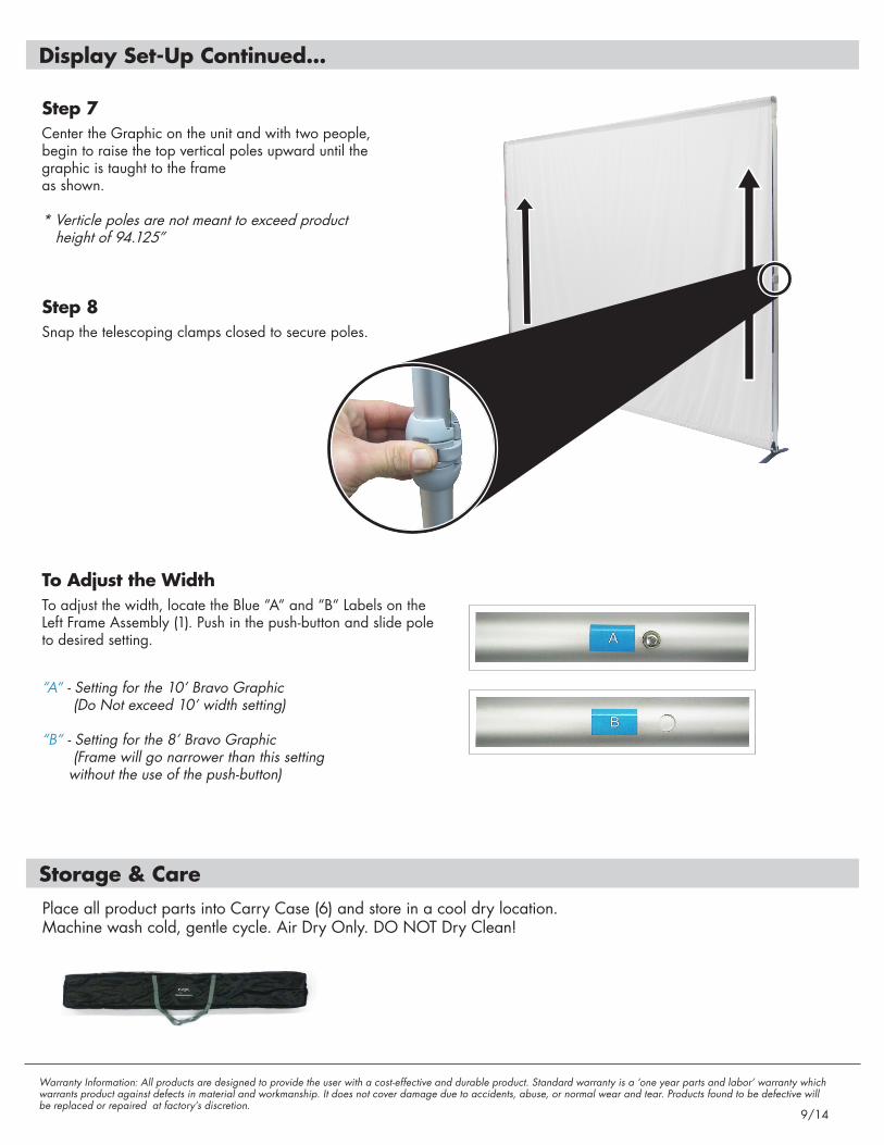
Step 7Center the Graphic on the unit and with two people, begin to raise the top vertical poles upward until the graphic is taught to the frame as shown. * Verticle poles are not meant to exceed product height of 94.125”
Step 8Snap the telescoping clamps closed to secure poles.
To Adjust the WidthTo adjust the width, locate the Blue “A“ and “B“ Labels on the Left Frame Assembly (1). Push in the push-button and slide pole to desired setting.
“A“ - Setting for the 10’ Bravo Graphic (Do Not exceed 10’ width setting) “B“ - Setting for the 8’ Bravo Graphic (Frame will go narrower than this setting without the use of the push-button)
Display Set-Up Continued...
Storage & CarePlace all product parts into Carry Case (6) and store in a cool dry location. Machine wash cold, gentle cycle. Air Dry Only. DO NOT Dry Clean!
Related Documents


