Wednesday, September 14, 2011 6:56 The Dublin based, Irish free energy company Steorn, has allowed PESN to view and report on four documents written by third party scientists and engineers that appear to validate the Orbo overunity technology. by Hank Mills for Pure Energy Systems News PESN has been given the opportunity by Sean McCarthy, the CEO of Steorn, to review four documents that provide confirmation of their overunity magnetic technology, named Orbo. The first three documents cover tests performed on permanent magnet based systems, and the final document discusses a test of a solid state Orbo in a calorimeter. The significance of these documents is that they seem to validate Steorn's technology, and prove the Orbo technology works as Steorn has claimed. Orbo's Back Story Steorn is the Irish based company that in August of 2006 announced -- via a full page advertisement in The Economist -- they had developed a technology that offered free, clean, and constant energy. Around this same time, they opened a public forum (now closed) on their website, on which the CEO of the company, Sean McCarthy, frequently posted and contributed to discussions. This public forum evolved, and lead to the creation of a private forum for those willing to sign non-disclosure agreements. This private forum eventually became what is today called the "Steorn Knowledge Development Base" or SKDB. Between 2006 and present day, Steorn has been rapidly developing their technology, which is all based on magnetism. Originally, in 2006, their t echnology utilized only permanent magnets interacting with other magnets in very specific ways. These original configurations ut ilized

Welcome message from author
This document is posted to help you gain knowledge. Please leave a comment to let me know what you think about it! Share it to your friends and learn new things together.
Transcript
7/30/2019 Steorn Drops Four Bombshell Documents Validating Orbo
http://slidepdf.com/reader/full/steorn-drops-four-bombshell-documents-validating-orbo 1/307
Wednesday, September 14, 2011 6:56
The Dublin based, Irish free energy company Steorn, has allowed PESN to view and
report on four documents written by third party scientists and engineers that appear to
validate the Orbo overunity technology.
by Hank Mills
for Pure Energy Systems News
PESN has been given the opportunity by Sean
McCarthy, the CEO of Steorn, to review four
documents that provide confirmation of their
overunity magnetic technology, named Orbo.
The first three documents cover tests
performed on permanent magnet based
systems, and the final document discusses a
test of a solid state Orbo in a calorimeter. The
significance of these documents is that they
seem to validate Steorn's technology, and
prove the Orbo technology works as Steorn has
claimed.
Orbo's Back Story
Steorn is the Irish based company that in August of 2006 announced -- via a full page
advertisement in The Economist -- they had developed a technology that offered free, clean,
and constant energy. Around this same time, they opened a public forum (now closed) on
their website, on which the CEO of the company, Sean McCarthy, frequently posted and
contributed to discussions. This public forum evolved, and lead to the creation of a private
forum for those willing to sign non-disclosure agreements. This private forum eventually
became what is today called the "Steorn Knowledge Development Base" or SKDB.
Between 2006 and present day, Steorn has been rapidly developing their technology, which is
all based on magnetism. Originally, in 2006, their technology utilized only permanent magnets
interacting with other magnets in very specific ways. These original configurations utilized

7/30/2019 Steorn Drops Four Bombshell Documents Validating Orbo
http://slidepdf.com/reader/full/steorn-drops-four-bombshell-documents-validating-orbo 2/307
the concept of magnetic viscosity (the delay of a magnetic material to move on the BH curve
or respond magnetically, when exposed to the field of another magnet) to produce gains or
losses of energy. In a rotary system utilizing such a setup, if the rotor moved in one direction
there would be a loss of energy, and if it moved in the other direction there would be a gain
of energy. Over the course of time, Steorn enhanced their permanent-magnet-only
configurations to include the use of "soft" (not having a permanent magnetic field of their
own) magnetic materials -- such as ferrite -- and geometric relationships that allowed for
greater amounts of OU. As their configurations evolved, so did their understanding of what
was taking place to produce the gains/losses of energy. They came to the realization that the
manipulation of the BH curve was at the heart of all their configurations.
At some point Steorn developed a design for an electric pulse motor -- named E-Orbo - that
did not produce back EMF (also known as counter EMF), and hence produced overunity gains
of energy. Back EMF is the enemy of free energy in electric motors, because it is the
signature of energy transfer between the circuit that powers the electromagnets (input) thatare pulsed, and the rotor (output). If you can avoid producing back EMF, you simply will not
be transferring energy from the input to the output. The concept is that the torque gained by
the rotor will be thermodynamically free. Hence, the efficiency of such a setup will be
infinite, since none of the input is actually consumed.
During late 2009 and early 2010, Steorn held a series of demonstrations of the E-Orbo at the
Waterways Center in Dublin, Ireland. These demonstrations were streamed live onto the
internet, and were posted to YouTube www.youtube.com/user/SteornOfficial . With high end
oscilloscopes, current probes, inductance meters, and other equipment, Steorn was able to
clearly show the E-Orbo systems present were producing overunity, and not producing backEMF (within the measurement capability of the equipment present). In fact, in addition to
producing a gain of energy in the form of torque on the rotor, the coils being pulsed
experienced an "induction gain." Many individuals replicated the E-Orbo, and posted videos of
their systems on the internet. In the recent past, the patent for E-Orbo has been published. It
documents the system down to the smallest detail.
Steorn is first and foremost an intellectual property company that desires to accumulate a
stock of patented, novel technologies they can license to developers. Their primary goal is
not to develop products themselves, but to allow their licensees to do so. This drive to
accumulate as much intellectual property as possible, is probably what drove them to pursuea solid state (no moving parts) version of their Orbo technology. The following description of
their solid state technology was provided on a previous version of their website.
Solid State Orbo is the latest physical implementation of the Orbo technology platform.Solid State has numerous advantages over previous implementations. The fact that theSolid State version has no moving parts lowers the costs and reduces the time-frame for

7/30/2019 Steorn Drops Four Bombshell Documents Validating Orbo
http://slidepdf.com/reader/full/steorn-drops-four-bombshell-documents-validating-orbo 3/307
developers wishing to replicate the core effect. Testing is greatly simplified too. The onlytest equipment required is a simple digital oscilloscope.
Solid State Orbo gains energy via control of a material's inductance and domain rotation. As with all previous implementations of Orbo, these material permeability effects are
fundamental to the production of an energy gain.
Although Solid State Orbo is in the early stages of development, rapid progress is beingmade with regards to optimisation. For this reason, it forms the basis of the SteornKnowledge Development Base.
The development of the solid state Orbo technology seems to be their current focus. A solid
state technology that can produce overunity gains of energy would be a huge achievement.
Once hitting the marketplace, such a technology would have the potential to advance as
rapidly as integrated circuit chips did in the 1990's.
Awesome Scoop for PESN
After hearing very little from Steorn for quite a while, an email was sent to Sean McCarthy
requesting an update on the status of their company. He very promptly (hours later) replied
to the email, and offered PESN a great opportunity to review four papers -- written by third
party scientists and engineers -- about the Orbo technology. The condition that came with the
offer was that the papers themselves could not be posted, and the authors names could not
be revealed. Also, Steorn would have right to review the article before it was published,
which is a common courtesy we offer to many of the inventors and companies we compose
feature articles about. Very quickly, we took him up on the offer!
Shortly after reviewing the four papers, their significance became obvious. They are all
written by third parties outside of Steorn, who indicate that Steorn's claims are valid. To be
specific, three of the papers address permanent magnet configurations, and the final paper
covers a solid state configuration tested in a calorimeter. It should be noted that Steorn has
previously tested the E-Orbo in a calorimeter of their own design, and published the positive
results on their website.
The remaining portion of this article will be divided into four parts, each part covering one of
the four papers. In each part, we will share as much information as we can from the specific
paper -- while carefully avoiding content that could be considered too proprietary.
MORE...

7/30/2019 Steorn Drops Four Bombshell Documents Validating Orbo
http://slidepdf.com/reader/full/steorn-drops-four-bombshell-documents-validating-orbo 4/307
This story is continued at PESN .
What You Can Do
1. Pass this on to your friends and favorite news sources.
2. Get involved in the replication process.
3. We at PES Network are in a pinch right now. Donations would be greatly appreciated.
4. Subscribe to our newsletter to stay abreast of the latest, greatest developments in the
free energy sector.
5. Let professionals in the renewable energy sector know about the promise of this
technology.
See also
Resources from PESWiki.com
• Directory:Steorn_Free_Energy - feature page• News:Steorn • Directory:Solid_State_Generators • Directory:Electromagnetic • News:Electromagnetic • Directory:Toroidal_Power • Directory:Magnet Motors• News:Magnet Motors• More Stories by Hank Mills
Steorn Drops Four Bombshell Documents
Validating Orbo
The Dublin based, Irish free energy company Steorn, has allowed PESN to view and report on
four documents written by third party scientists and engineers that appear to validate the Orbo
overunity technology.
by Hank Mills
for Pure Energy Systems News

7/30/2019 Steorn Drops Four Bombshell Documents Validating Orbo
http://slidepdf.com/reader/full/steorn-drops-four-bombshell-documents-validating-orbo 5/307

7/30/2019 Steorn Drops Four Bombshell Documents Validating Orbo
http://slidepdf.com/reader/full/steorn-drops-four-bombshell-documents-validating-orbo 6/307
energy from the input to the output. The concept is that the torque gained by the rotor will be
thermodynamically free. Hence, the efficiency of such a setup will be infinite, since none of the
input is actually consumed.
During late 2009 and early 2010, Steorn held a series of demonstrations of the E-Orbo at the
Waterways Center in Dublin, Ireland. These demonstrations were streamed live onto the internet,and were posted to YouTube http://www.youtube.com/user/SteornOfficial . With high end
oscilloscopes, current probes, inductance meters, and other equipment, Steorn was able to clearly
show the E-Orbo systems present were producing overunity, and not producing back EMF(within the measurement capability of the equipment present). In fact, in addition to producing a
gain of energy in the form of torque on the rotor, the coils being pulsed experienced an
"induction gain." Many individuals replicated the E-Orbo, and posted videos of their systems on
the internet. In the recent past, the patent for E-Orbo has been published. It documents thesystem down to the smallest detail.
Steorn is first and foremost an intellectual property company that desires to accumulate a stock
of patented, novel technologies they can license to developers. Their primary goal is not todevelop products themselves, but to allow their licensees to do so. This drive to accumulate as
much intellectual property as possible, is probably what drove them to pursue a solid state (nomoving parts) version of their Orbo technology. The following description of their solid state
technology was provided on a previous version of their website.
Solid State Orbo is the latest physical implementation of the Orbo technology
platform. Solid State has numerous advantages over previous implementations. The
fact that the Solid State version has no moving parts lowers the costs and reduces
the time-frame for developers wishing to replicate the core effect. Testing is greatly
simplified too. The only test equipment required is a simple digital oscilloscope.
Solid State Orbo gains energy via control of a material's inductance and domain
rotation. As with all previous implementations of Orbo, these material permeability
effects are fundamental to the production of an energy gain.
Although Solid State Orbo is in the early stages of development, rapid progress is
being made with regards to optimisation. For this reason, it forms the basis of the
Steorn Knowledge Development Base.
The development of the solid state Orbo technology seems to be their current focus. A solid state
technology that can produce overunity gains of energy would be a huge achievement. Oncehitting the marketplace, such a technology would have the potential to advance as rapidly as
integrated circuit chips did in the 1990's.
Awesome Scoop for PESN

7/30/2019 Steorn Drops Four Bombshell Documents Validating Orbo
http://slidepdf.com/reader/full/steorn-drops-four-bombshell-documents-validating-orbo 7/307
After hearing very little from Steorn for quite a while, an email was sent to Sean McCarthy
requesting an update on the status of their company. He very promptly (hours later) replied to theemail, and offered PESN a great opportunity to review four papers -- written by third party
scientists and engineers -- about the Orbo technology. The condition that came with the offer was
that the papers themselves could not be posted, and the authors names could not be revealed.Also, Steorn would have right to review the article before it was published, which is a common
courtesy we offer to many of the inventors and companies we compose feature articles about.
Very quickly, we took him up on the offer!
Shortly after reviewing the four papers, their significance became obvious. They are all written
by third parties outside of Steorn, who indicate that Steorn's claims are valid. To be specific,
three of the papers address permanent magnet configurations, and the final paper covers a solidstate configuration tested in a calorimeter. It should be noted that Steorn has previously tested the
E-Orbo in a calorimeter of their own design, and published the positive results on their website.
The remaining portion of this article will be divided into four parts, each part covering one of thefour papers. In each part, we will share as much information as we can from the specific paper --
while carefully avoiding content that could be considered too proprietary.
Paper #1 - Overunity Only Gets Better With Age
This fairly short paper is the oldest of the four (written in 2006), but verifies that early on, Steorn
had third parties replicating, and hence validating, their technology. The author is a highly
credible engineer and scientist who holds multiple advanced degrees. With degrees in physicsand engineering, R&D (research and development) experience, and expertise in magnetism, he
would seem like an ideal individual to test and validate Steorn's claims about the Orbo
technology.
The topic of the paper is a test of an early configuration that was performed at Steorn's offices.
The setup seems to be composed of a "main" wheel with a magnet attached to it, and asecondary, smaller wheel that also holds a magnet. One of the magnets would be set at an angle
to the opposite magnet, on the other wheel. During each test, either the main wheel or the small
wheel would rotate (the other being in a fixed or stationary position), and the magnets attached to
each wheel would interact with each other. The torque of the wheel in motion would bemeasured with a torque meter, and the data would be analyzed. From this analysis, any
anomalous torque in the system would be apparent.
To prepare for the test, the torque meter for each wheel was properly calibrated, and the friction
and the electronic offset of each torque meter were determined. This information was used to
correct the raw data that would come from each torque meter.
Multiple tests were performed in which one wheel (either the main wheel or small wheel) was
fixed and the other was allowed to rotate. Also, the angle of the magnets were changed and then
tested. After the data was corrected and analyzed, the conclusion was a gain of energy of .99

7/30/2019 Steorn Drops Four Bombshell Documents Validating Orbo
http://slidepdf.com/reader/full/steorn-drops-four-bombshell-documents-validating-orbo 8/307
mill-joules or 6.2% of the total energy could be obtained in the experiment.
The author of the report states,
"The background friction cannot explain such a large unbalance. The calibration of the torque
meter also rules out any experimental error associated with the readings. It is not clear what thesource of this net energy [is], and further investigation is required to find a physical explanation
for this phenomenon."
This document clearly indicates that even Steorn's earliest permanent magnetic configurations
could produce gains of energy (in this case torque on a wheel), that could be detected by
professionals with high quality, testing equipment. The fact a scientist and engineer of the caliber that wrote this paper would report such an anomalous gain of energy is a boost for Steorn's
credibility.
Document #2 - Real Men Love Torque Curves
(Editors Note: We have discovered this document is actually posted on Steorn's website. It is theonly one of the four documents that appears to be publicly available.)
This long and very detailed document, composed in 2008, was written by a consulting engineer,John A.M. Rice, who went to Steorn's offices to perform a test of a permanent magnet
configuration. In the document, the engineer specifically states his role, which was three fold.
- From an engineering and technical perspective, to formally observe a series of tests which aimto support the above-mentioned claim.
- To examine the test methods, equipment and procedures, with particular respect to their suitability, accuracy, and performance.
- To observe, verify, and report on specific tests carried out in support of the claim in theundersigned's presence.
In the paper, the engineer specifically details the setup, all the components used, the testingequipment used, and the experiment to be performed. He goes on to describe how the equipment
was calibrated, and all possible variables (such as bend in the rotor shaft, friction in the system,
ovality of the wheel, the linearity of the data from torque meters, and possible interference from
the Earth's magnetic field) were measured and accounted for. All of this setup and preliminarywork was vital to ensure the raw data could be appropriately corrected as necessary, so the
results of the testing would be valid. The results of the testing in the form of many torque curves
(graphs of the torque on the rotor over a 360 degree rotation) are included in the document.
The basic setup was a rotor (connected to a torque meter), with a stator. The rotor could be
"stepped" (moved a tiny fraction of a degree at a time) repeatedly for "static" testing, or allowedto rotate continually for 360 degrees or more, never stopping during the range of degrees tested,

7/30/2019 Steorn Drops Four Bombshell Documents Validating Orbo
http://slidepdf.com/reader/full/steorn-drops-four-bombshell-documents-validating-orbo 9/307
for "dynamic" testing. Both the rotor and stationary stator could be fitted with magnets
(neodymium in this case) and/or rods of soft ferrite. Multiple tests were performed (both static
and dynamic) of various magnetic configurations. As an example, in one test the rotor held a rodof soft ferrite, with a neodymium magnet backing it in a configuration that "biased" the ferrite (as
explained in a paper previously available on Steorn's public website). The permanent magnet and
biased ferrite interacted with a permanent magnet attached to the stator.
Over a 360 degree rotation there was a gain of energy, which the author reported with the
following statement...
"In the test context distance involves a 360 degree rotation of the rig rotor. By integrating, i.e.
summation, of the torque profile through a full revolution of the rotor, the associated energy can
be calculated. This facility was setup in the test IE equipment.
"A zero energy gain applied to 4.2.10.5 (b) i.e. ferrite removed, but neo magnet only in rotor.
Conversely, a net energy GAIN (through a 360 degree rotation) is evident for 4.2.10.5 (b) i.e.
ferrite included in rotor. This latter result is the key outcome of the tests."
This report also offered a very upbeat discussion of the test results.
DISCUSSION OF TEST RESULTS V. OBJECTIVE:
Recapping on this short program of tests, the fundamental questions were:
(i) Is the test equipment appropriate and suitable for the purpose -- YES.
(ii) Is the particular test rig, and its component parts, controls and IT systems utilizedin a manner which delivers accurate, consistent and repeatable test results -- YES.
(iii) Are the applied methods and procedures, as observed during the tests, objective
and pertinent -- YES.
(iv) Do the test results provide clear and explicit support of the claim? - YES.
So in short, when it comes to Steorn's permanent magnet based Orbo technology, this author's
answer was, "Yes! Yes! Yes! Yes!"
It sounds like a pretty good endorsement to me!
Document #3 - I'll Do It Better The Second Time Around
The author of this third paper -- from 2009 -- starts off by stating that he thinks Steorn may have

7/30/2019 Steorn Drops Four Bombshell Documents Validating Orbo
http://slidepdf.com/reader/full/steorn-drops-four-bombshell-documents-validating-orbo 10/307
"really stumbled across an experimental magnetic anomaly", because Steorn's test data (he
references various test data provided by Steorn) seems to confirm a theoretical anomaly he has
discovered, through his own calculations.
In the paper he elaborates on his theoretical anomaly that would be produced by a specific
arrangement of a neodymium magnet on a rotor (or a soft ferrite biased by a neodymium magnet)interacting with a stator magnet, at a certain angle to the rotor. He states that the gain of energy
in the setup would be, according to Steorn, due to specific conditions of "asymmetry and
nonlinearity." However, he adds that according to his theoretical anomaly, it is due to a change inanisotropic asymmetry that can apparently produce a gain of energy.&^&
He makes it clear in the paper that his analysis of Steorn's data and his calculations do not prove
that the theory of conservation of energy is being violated. However, he also states there is thechance that additional research may explain why it is not possible to produce energy from the
magnetic effects, or it could indicate "unknown physics might reveal the impossible."
A few additional bits of information he offers are as follows.
- The variables in the system (airgap, amount of biasing, and stator angle) must all be optimizedto produce an obviously detectable gain of energy. For example, a change in the strength of the
biasing of the soft ferrite or the angle of the neodymium stator magnet requires the other
parameter to be altered. This is why it can be so difficult to detect the effect.
"There exists an optimized bias value for a fixed stator angle and also an optimized angle for a
fixed bias value for which the effect has maxima. This together with the general smallness
explains why it is so difficult to demonstrate the experimental anomaly!"
- The test data the author was given was not obtained in such a way to maximize the gain of
energy, but to show the "importance of conditions."
- The author details in a chart how both asymmetry and nonlinearity must be present for the
Steorn effect to appear. For example, in a setup with an unbiased rotor magnet and a symmetricmagnetic field produced by the stator magnet, there is no gain of energy. With a biased rotor
magnet and an asymmetric magnetic field produced by the stator magnet, there is a gain of
energy.
This report was not an absolute confirmation of the Steorn technology (the author makes this
clear), but shows that highly credible scientists and engineers can see how the Orbo technology
may work to produce gains of energy.
Document #4 - "It's getting hot in here, turn off that Orbo!"
The fourth report that we were allowed to examine is unique from the others in that it is about a
solid state version of Steorn's technology. It is also the most recent of the documents, being
written in March, 2011.

7/30/2019 Steorn Drops Four Bombshell Documents Validating Orbo
http://slidepdf.com/reader/full/steorn-drops-four-bombshell-documents-validating-orbo 11/307
A solid state Orbo offers the potential of having no moving parts, having no need for bearings (as
in permanent manget (PM) or E-Orbo configurations), being simpler to build, and potentially being simpler to test. Other advantages of solid state Orbo include fewer parts to wear out, and
perhaps more potential to evolve quickly -- in a similar manner to the way computers evolved
during the past twenty years.
In this paper the author describes a very simple configuration that involves a coil wrapped
around a nickel core (that is both magnetic and conductive) acting as an inductor. The coil andcore is placed in a calorimeter composed of a vacuum chamber. Two thermocouples measure the
temperature of the coil itself, and the temperature of the air in the room. A metered power supply
provides the input power to the coil, and an oscilloscope monitors the current, voltage, and can
also calculate total input power by using a math function of the scope.
The purpose of the test is to determine if the coil fed with a quantity of AC power, can produce
more heat than the same coil fed with the same quantity of DC power. In the paper, the formula
needed to calculate the total AC power is presented. The AC input and DC input is configured to be as identical as possible. Actually, the power input during the AC run was .9 (point nine) watts,
and in the DC run it was 1 (one) watt. The fact that the input power during the AC run wasslightly less than in the DC run actually biases the test against the AC run. This makes the results
of the test even more significant.
In the first test, 1 watt of DC power is fed into the coil wound around the nickel core. The
temperature of the coil increases until it reaches an equilibrium point of 36.1 degrees. This is the
point at which the power lost by the coil via heat dissipation matches the electrical input power.
Even if the input power stayed on for hours longer, the temperature of the coil would notincrease above this temperature.
In the second test, .9 watts is fed into the same coil wound around the same exact nickel core.Obviously, this test took place a period of time after the first one, after the temperature of the coil
has dropped back to its original value. The result of AC being fed into the coil is that it rises to
an equilibrium temperature of 41.1 degrees. This means that in the AC test, the temperature of the coil reached a temperature five degrees higher than in the DC test.
The higher equilibrium temperature obtained when the coil was powered with AC, indicates an
anomalous gain of energy. The gain of energy is unexplainable, because the input power in bothtests were almost identical -- actually slightly less when AC was utilized. As the paper continues,
the author indicates that resistive heating cannot be the case for the increased temperature in the
AC test run.
Here is the conclusion found at the end of the paper.
"The extra heating effect under the application of an AC signal is not explained simply by the
transfer of input power to the coil. Consideration of the energy input to the system does not
account for the energy output -- as evidenced by the steady state temperature; there is an extra
effect which needs to be isolated and identified.

7/30/2019 Steorn Drops Four Bombshell Documents Validating Orbo
http://slidepdf.com/reader/full/steorn-drops-four-bombshell-documents-validating-orbo 12/307

7/30/2019 Steorn Drops Four Bombshell Documents Validating Orbo
http://slidepdf.com/reader/full/steorn-drops-four-bombshell-documents-validating-orbo 13/307
PESN would like to thank Sean McCarthy for providing us
with the four documents to review, and allow us to report onthem.
# # #
This story is also published at BeforeItsNews.
What You Can Do
1. Pass this on to your friends and favorite newssources.
2. Get involved in the replication process.3. We at PES Network are in a pinch right now.
Donations would be greatly appreciated.4. Subscribe to our newsletter to stay abreast of the latest, greatest
developments in the free energy sector.5. Let professionals in the renewable energy sector know about the promise of
this technology.
See also
Resources from PESWiki.com
• Directory:Steorn_Free_Energy - feature page• News:Steorn •
Directory:Solid_State_Generators • Directory:Electromagnetic • News:Electromagnetic • Directory:Toroidal_Power • Directory:Magnet Motors • News:Magnet Motors • More Stories by Hank Mills
Steorn Free Energy Directory

7/30/2019 Steorn Drops Four Bombshell Documents Validating Orbo
http://slidepdf.com/reader/full/steorn-drops-four-bombshell-documents-validating-orbo 14/307
Steorn CEO, Sean McCarthy, demonstrates the e-Orbo technology during their historic
"Proving Over-Unity" demonstration at the Waterways Centre in Dublin, Ireland on Jan. 30,
2010.
Steorn, of Dublin Ireland, claims to have discovered a technology that produces"free energy" that could transform the renewable energy sector, providing clean,continuous, reliable, safe, affordable energy for the world. They have essentially twoiterations of the effect: an all-magnet motor technology as well as an elecromagnetic overunity technology.
As of Feb. 1, 2010, they have presented their evidence and are now turning thetechnology over to developers under license through the Steorn KnowledgeDatabase (SKDB) to prepare the technology for the myriad of applications.
Contents
[hide]
1 About
1.1 Official Websites
1.2 Brief History of Steorn's Free Energy Pursuit
1.3 Videos
1.3.1 Test Results of the Orbo Solid State Development Unit
1.3.2 Proving Overunity: Part 1 of 2
1.3.3 Proving Overunity: Part 2 of 2
1.3.4 Steorn Talk Dec. 12, 2009
1.3.5 Steorn Orbo Technology Launch 2009
1.3.6 Engineers' View

7/30/2019 Steorn Drops Four Bombshell Documents Validating Orbo
http://slidepdf.com/reader/full/steorn-drops-four-bombshell-documents-validating-orbo 15/307

7/30/2019 Steorn Drops Four Bombshell Documents Validating Orbo
http://slidepdf.com/reader/full/steorn-drops-four-bombshell-documents-validating-orbo 16/307
2 See also
About
Official Websites
http://www.steorn.com
SKDB – Steorn Knowledge Database – for developers
ZeroF: Passive Magnetic Bearings - product
Steorn Lab
Demo page
About Steorn
Press Releases
News Coverage
Orbo Technology
Forum
http://www.youtube.com/user/Steornofficial
Brief History of Steorn's Free Energy Pursuit
Device built to characterize the Steorn magnet motor concept, which proves more energy
output than is put into the system. (K-Toy Video; Aug. 30, 2007)
For many years Steorn has developed technology to help combat counterfeiting andfraud in the plastic card and optical disc industries.

7/30/2019 Steorn Drops Four Bombshell Documents Validating Orbo
http://slidepdf.com/reader/full/steorn-drops-four-bombshell-documents-validating-orbo 17/307

7/30/2019 Steorn Drops Four Bombshell Documents Validating Orbo
http://slidepdf.com/reader/full/steorn-drops-four-bombshell-documents-validating-orbo 18/307
Electromagnetic > Solid State > Steorn >
Test Results of the Orbo Solid State Development Unit - On Sept. 25, two
electronics engineers and a physicist tested Steorn's solid state (no moving
parts) electromagnetic devices, and attest to observing over 200% efficiency.
"Orbo uses time-variant magnetic interactions to produce non-conservative
energy results." (YouTube / SteornOfficial ; Sept. 29, 2010)
Proving Overunity: Part 1 of 2
"Steorn's final pre-launch demonstration of its Orbo technology, Proving
Overunity. Join the SKDB to develop your own Orbo technology applications."
(YouTube by SteornOfficial ; Feb. 1, 2010)
- - - -
Proving Overunity: Part 2 of 2
(YouTube by SteornOfficial ; Feb. 1, 2010)
- - - -
Steorn Talk Dec. 12, 2009
The first of a series of talks explaining Orbo technology. (YouTube; by
SteornOfficial ; December 19, 2009)
- - - -
The first part of this one overlaps some with the above video.
19/12/2009 Steorn first Live Broadcast or part of it LOL. Tried to capture this,
but had big problems due to delays and visitors grrrrrrrr. This is most of it though.
(YouTube; by Seacrhing ; December 19, 2009) (Thanks CLaNZeR)

7/30/2019 Steorn Drops Four Bombshell Documents Validating Orbo
http://slidepdf.com/reader/full/steorn-drops-four-bombshell-documents-validating-orbo 19/307
- - - -
Steorn Orbo Technology Launch 2009
Posted Dec. 15, 2009.
"Steorn launch Orbo technology at the Waterways Ireland Visitor Centre"
(YouTube; December 15, 2009)
- - - -
Engineers' View
This is the first video published by Steorn at YouTube.
"http://www.steorn.com/orbo/ Three independent engineers discuss the
potential of Orbo technology. Sean McCarthy, CEO of Steorn, on the plans to
release Orbo technology to developers this year. Originally published at
Steorn.com in February 2009." (YouTube; December 10, 2009)
- - - -
McCarthy on PrimeTime
(11.33 Minutes)
Sean McCarthy, CoE of Steorn on TV Excerpts from PrimeTime, Google
video, 11.33 minutes, Jan. 15, 2009. (YouTube; January 16, 2009)
- - - -
K-Toy Video
This video features Thieu Knapen, founder of Kinetron, referring to a gizmo he built
to characterize Steorn's invention concept, to document whether or not it producedmore energy out than was put in; and his surprize that it does work -- something hedid not think was possible. He now is apparently involved in developing thetechnology to market. See his website: http://www.kinetron.nl/
Audio and parts of the video have been available since the beginning of this year,but this is the first time non-insiders get to see the full video.

7/30/2019 Steorn Drops Four Bombshell Documents Validating Orbo
http://slidepdf.com/reader/full/steorn-drops-four-bombshell-documents-validating-orbo 20/307
On Sept. 1, 2007, an anonymous source wrote:
"The cat is out of the bag now, so I can freely point to the firm Kinetron as a
partner of Steorn. It is K that makes the devices - S only designs them. In the
video Knapen of K says he already, in the rig he constructed at Kinetron, wasgetting 25% and it was just the beginning - that was nearly a year ago. The
problem was then it was the stop-start machine as seen in the video. It was
found that continuous motion could also give a gain and would be simpler to
build and maintain. They are seeking to perfect continuous motion as they
want to run with that. After all - Kinetron is a supplier to Swatch and other
giants. It is well known in the industry."
See K-Toy Video Discovered - Background and comments.(FreeEnergyTracker ; August 30, 2007)
- - - -
How Free Energy Works
(6:55 minutes)
How Free Energy Works - Steorn has developed all-magnet motor
technology which produces free energy. The company's CEO, Sean
McCarthy, has explained his theory and how it works. (YouTube; September 13, 2006)
- - - -
Steorn Orbo music video
Shows various jigs for testing the phenomena.
A short music video made up from youtube clips of Steorn (YouTube
by Eltimple; January 17, 2009)
Other Videos
http://www.nextenergynews.com/freeenergy/freeenergy1.html
http://www.nextenergynews.com/freeenergy/freeenergy6.html

7/30/2019 Steorn Drops Four Bombshell Documents Validating Orbo
http://slidepdf.com/reader/full/steorn-drops-four-bombshell-documents-validating-orbo 21/307
Steorn videos linked from PESwiki Video-page
MAY 9TH 2007 - portions of Steorn lecture at university college of dublin, may4th 2007!
Steorn Part 1 - michaeldoyle - 9 min - May 8, 2007 - Lecture onSteorn's perpetual motion machine.
http://www.youtube.com/watch?v=z9nYyypgNWc
Steorn Part 2 - michaeldoyle - 9 min - May 8, 2007 - Lecture on
Steorn's perpetual motion machine.
http://www.youtube.com/watch?v=y7kKuSHjBbY
Steorn Part 3 - michaeldoyle - 9 min - May 8, 2007 - Academic
response to Steorn's perpetual motion machine claims.
http://www.youtube.com/watch?v=9Vwj0A0TWr4
Steorn Part 4 - michaeldoyle - 3 min - May 8, 2007 - Academic
response to Steorn's perpetual motion machine claims
http://www.youtube.com/watch?v=OJ7JhlEoL-w
Steorn Part 5 - michaeldoyle - 8 min - May 8, 2007 - Q&A session with
Steorn CEO Sean McCarthy
http://www.youtube.com/watch?v=EhMc3Xr6htM
Independent Verification
Electromagnetic > Solid State > Steorn >
Test Results of the Orbo Solid State Development Unit - On Sept. 25,
two electronics engineers and a physicist tested Steorn's solid state (no

7/30/2019 Steorn Drops Four Bombshell Documents Validating Orbo
http://slidepdf.com/reader/full/steorn-drops-four-bombshell-documents-validating-orbo 22/307
moving parts) electromagnetic devices, and attest to observing over 200%
efficiency. "Orbo uses time-variant magnetic interactions to produce non-
conservative energy results." (YouTube / SteornOfficial ; Sept. 29, 2010)
Replications
Featured: Electromagnetic > Steorn >
What goes on in the Steorn SKDB; views from Dublin demo - One of the
foremost replicators, Sean CLaNZeR, has posted four videos and a few
photos from his work with the Steorn Knowledge Database (SKDB) group.
Also, Esa Ruoho took a bunch of photos and videos from his visit to the Orbo
demonstration in Dublin. (PESN ; Dec. 31, 2009) (Comments)
Featured: Electromagnetic > Steorn > Naudin replica >
Steorn engineers give thumbs down on Naudin replication; Next demo
announced - "We have to advise that this is in no way a valid replication of
Orbo. It is very clear to us that the arrangement that he has set up has a
significant amount of [Counter]EMF in the system. While not quite a normal
pulse motor, it certainly is not Orbo and is almost certainly not [overunity]."
(PESN ; Jan. 4, 2009)

7/30/2019 Steorn Drops Four Bombshell Documents Validating Orbo
http://slidepdf.com/reader/full/steorn-drops-four-bombshell-documents-validating-orbo 23/307
Featured / DIY: Electromagnetic > Steorn >
JLN Labs replicates Steorn's free energy motor - French replicator, Jean-
Louis Naudin, says he has confirmed that there is no counter electromotive
force (back EMF) in the toroidal coils -- a key to converting magnetic power
into kinetic (motion) power. Provides clear instructions and report of data.
(PESN ; Dec. 28, 2009) (Comments)
Understanding the Orbo principle: 3 KEY EXPERIMENTS
By J L Naudin (not approved by Steorn)
"You will find in this video, three very simple experiments which can
help you to understand the hidden principles of the Orbo motor from Steorn.
The experiments proposed here and their explanations are based on my
personnal interpretation only of the Orbo working principle and may be differ from the official Steorn explanations. These experiments presented here are
the tests results of all my researches about the Orbo device. These
experiments are very simple to do and you can check these facts by yourself
with few equipement. So, these key experiments are intend to demonstrate
the main effect in the Orbo device which can produce free energy from
moving magnets. More info at : http://jnaudin.free.fr "(YouTube; February 08,
2010)
Steorn Jury
See Directory:Steorn Free Energy:Validation Recommendations - A pagedevoted to coming up with a listing of recommended testing procedures for useby the Steorn jury.
The Steorn website says:
7/30/2019 Steorn Drops Four Bombshell Documents Validating Orbo
http://slidepdf.com/reader/full/steorn-drops-four-bombshell-documents-validating-orbo 24/307
During 2005 Steorn embarked on a process of independent validation andapproached a wide selection of academic institutions. The vast majority of theseinstitutions refused to even look at the technology; however, several did. Thosewho completed the testing have all confirmed our claims but none will publiclygo on record.
On Aug 25, 2006, The Guardian Unlimited reports (from facility visit by SteveBoggan):
There have been no fewer than eight independent validations of their workconducted by electrical engineers and academics `with multiple PhDs' fromworld-class universities. But none of them will talk to me, even off the record. Iam promised a diagram explaining how the system works, but then Steorn holdsit back, saying its lawyers are concerned about intellectual property rights. Andthat European partner, the one with the moving, almost perpetual, prototypes? It
won't talk to me either and Steorn has undertaken not to name it.
On October 11th, 2006, a page was opened on the Steorn website whose titleis:
'Test methods applied to Steorn technology and results' . Here, one may scrollthrough slides, some of them movies, of ways to test the magnets in part of their device. More details are to be made available soon, according to Steorn.
On March 7, 2007, the Steorn website states:
Orbo produces free, clean and constant energy - that is our claim. By free wemean that the energy produced is done so without recourse to external source.By clean we mean that during operation the technology produces no emissions.By constant we mean that with the exception of mechanical failure thetechnology will continue to operate indefinitely.
The sum of these claims for our Orbo technology is a violation of the principle of conservation of energy, perhaps the most fundamental of scientific principles.The principle of the conservation of energy states that energy can neither becreated or destroyed, it can only change form.
Because of the revolutionary nature of our claim, not only to the world of sciencebut to the world in general, Steorn issued a challenge to the scientificcommunity in August 2006 to test our technology and report their findings. Theprocess of validation that has resulted from this challenge is currently underway,with results expected by the end of 2007.

7/30/2019 Steorn Drops Four Bombshell Documents Validating Orbo
http://slidepdf.com/reader/full/steorn-drops-four-bombshell-documents-validating-orbo 25/307
Patents
Figs. 4-6 of Low Energy Magnet Actuator Patent application by Steorn. April 6, 2006.
Low Energy Magnet Actuator (patent application) - arrangement of
magnets and a magnetic shield on a linear slide; the operative principle
seems to be low-energy switching of the magnetic fields.
US2006066428A1 (pdf) U.S. patent application.
Abstract
A low energy magnet actuator allows magnetic fields to be turned on and off
using a small amount of energy. The magnetic actuator according to the
invention generally includes a base suitable for the support of a plurality of magnets. An actuatable shield is positioned in relation to the plurality of
magnets so that it effectively blocks the magnetic field when it is positioned
over at least one of the magnets. The magnetic fields of the plurality of
magnets interact in a manner that allows low energy actuation of the shield.
Company Statement

7/30/2019 Steorn Drops Four Bombshell Documents Validating Orbo
http://slidepdf.com/reader/full/steorn-drops-four-bombshell-documents-validating-orbo 26/307
The patent ... is not a patent on the core steorn technology. Due to the fact
that the US patent office does not allow patents with this claim we have filed a
sequence of patents wich describe various aspects of the technology.
This is 'patently untrue': a keyword search of American patentapplications returns dozens (the latest filed on the 21st December 2006) of them which claim 'perpetual motion'. What grounds would theUSPO have therefore for rejecting the Steorn claim? There are far sillier ones (including the 'classic' overbalancing wheel) on file. ArtDent.
The patent ... is at the PCT stage and hence is available to the public. Our
other patents are currently pre-PCT and will move to the PCT phase (and
hence be available to the public) in the near future. [7]
The Challenge As published at http://www.steorn.net/en/technology.aspx?p=5
Steorn’s technology produces free, clean and constant energy.This provides a significant range of benefits, from the convenienceof never having to refuel your car or recharge your mobile phone,to a genuine solution to the need for zero emission energyproduction. It also provides a secure supply of energy, since thecomponents of the technology are readily available.
The technology is in a constant state of development. Thecompany has focused for the past three years on increasing power output and the development of test systems that allow detailedanalysis to be performed.
Steorn’s technology appears to violate the ‘Principle of theConservation of Energy’, considered by many to be the mostfundamental principle in our current understanding of the universe.This principle is stated simply as ‘energy can neither be creatednor destroyed, it can only change form’.
Steorn is making three claims for its technology:
1. The technology has a coefficient of performance
greater than 100%.

7/30/2019 Steorn Drops Four Bombshell Documents Validating Orbo
http://slidepdf.com/reader/full/steorn-drops-four-bombshell-documents-validating-orbo 27/307
2. The operation of the technology (i.e. the creation of
energy) is not derived from the degradation of its
component parts.
3. There is no identifiable environmental source of the
energy (as might be witnessed by a cooling of ambient air temperature).
The sum of these claims is that our technology creates freeenergy.
This represents a significant challenge to our currentunderstanding of the universe and clearly such claims requireindependent validation from credible third parties. During 2005Steorn embarked on a process of independent validation and
approached a wide selection of academic institutions. The vastmajority of these institutions refused to even look at thetechnology; however, several did. Those who completed thetesting have all confirmed our claims but none will publicly go onrecord .
In early 2006 Steorn decided to seek validation from the scientificcommunity in a more public forum, and as a result have publishedthe challenge in The Economist . The company is seeking a jury of twelve qualified experimental physicists to define the testsrequired, the test centres to be used, monitor the analysis and
then publish the results.
Steorn has decided to publish its challenge in The Economistbecause of the breadth of its readership. "We chose it over apurely scientific magazine simply because we want to make thegeneral public aware that this process is about to commence andto generate public support, awareness, interest etc for what we aredoing."
Register
Registration Deadline Passed
The registration deadline passed on Sep 8th, 2006. At that stagenearly 5000 had registered to become jury members, but initialsorting showed that only roughly 1000 of these had validcredentials. As of Sept 9th, 2006 Steorn has therefore entered thepre-phase-1 stage, where they "Analyze list of scientists, contact

7/30/2019 Steorn Drops Four Bombshell Documents Validating Orbo
http://slidepdf.com/reader/full/steorn-drops-four-bombshell-documents-validating-orbo 28/307
and verify interest, choose twelve and negotiate terms." When thisphase is over, Phase 1 proper begins, when they will "Confirm thatthe Steorn technology has a coefficient of performance greater than 100%."
On Sept 13th, e-mails went out to (at least some of) the scientistswho had applied to go on the jury, asking for details of their academic careers.
On Sept 27th, e-mails went out to (at least some of) the scientistswho had applied to go on the jury, saying that midnight, 5thOctober 2006, had been set as the deadline for receipt of synopses. A shortlist should be generated from all the synopsesreceived by the deadline, accorning to Steorn. From the 9thOctober 2006, Steorn intends to take about two weeks to contactapplicants on the shortlist to judge their availability as potential jury
members. From near the end of October 2006 Steorn should thenstart on the jury selection process.
NEC Involvement
On Aug. 19, 2006, the New Energy Congress was made aware of this challenge and phoned the company to offer its services in thevalidation process.
Licence to be made generally available and
Jury process underway
On the 11th of January 2007 Steorn announced that they wouldmake the licence for their device available to all interested parties,from individual enthusiasts to larger research organisations, for a'nominal fee' after the validation process had been completed [8].They also revealed that the jury process was now underway, butthat no further news on the process would be forthcoming until theend of the first financial quarter of 2007 [9].
April 13, 2007 update on progress
update on progress - posted April friday 13th, 2007.
Steorn/Orbo Core Technology update:

7/30/2019 Steorn Drops Four Bombshell Documents Validating Orbo
http://slidepdf.com/reader/full/steorn-drops-four-bombshell-documents-validating-orbo 29/307
Orbo is based upon the principle of time variant
magneto-mechanical interactions. The core output from
our Orbo technology is mechanical. This mechanical
energy can be converted into electrical energy using
standard generator technology either by integrating suchtechnology directly with Orbo or by connecting the
mechanical output from Orbo to the generation
technology. The efficiency of such mechanical/electrical
conversions is highly dependent on the components
used and is also a function of size.
Orbo technology is subject to continuous
development. This development is focused on improving
the manufacturability of the technology, production costsand power density. Orbo was initially developed as using
stop-start mechanisms (with a power density of 0.5 Watts
per cm3), Steorn is currently finalizing the development
of constant motion systems and a significant
improvement in power density is anticipated.
July 4, 2007; 10-day demonstration pending
Sean McCarthy preparing for major demo
(compiled from a couple of sources)[If you can attend this event, and would be willing to report for PESN, please contact Sterling D. Allan.]
A demo will take place indoors at a single location in London,
possibly the Kinetica Museum, and will last 10 days. Sean hasstated that it will begin in the first week of July, and that it isintended to coincide with (and ride the wave of environment-friendly media attention generated by) Al Gore’s Live Earth concerton July 7th.

7/30/2019 Steorn Drops Four Bombshell Documents Validating Orbo
http://slidepdf.com/reader/full/steorn-drops-four-bombshell-documents-validating-orbo 30/307

7/30/2019 Steorn Drops Four Bombshell Documents Validating Orbo
http://slidepdf.com/reader/full/steorn-drops-four-bombshell-documents-validating-orbo 31/307
video now shows the device not running. (PESN ; July 5, 2007)
July 6, 2007: demostration cancelled
Further to Steorn’s announcement yesterday (5th July) regardingthe technical difficulties experienced during the installation of its“Orbo?? technology at the Kinentica Museum in London, Steornhas decided to postpone the demonstration until further notice.Over the next few weeks the company will explore alternativedates for the public demonstration (read more on Steorn site).
July 10, 2007; Orbo drawings
User "Axle" posted on the Steorn forum his best estimation basedon the Orbo photos.
The "stator" is shown in green and blue, and contains a circular arrangement of eight magnets fit into slots around the periphery of
a central cavity. In that cavity spins the "rotor", with four magnetsaround its circumference. The stator and rotor are connected bytwo bearings, seen in orange -- the weak links that, according toSean, put an end to the demo.
Feb. 18, 2008
Sean McCarthy wrote:
Things are going very well, however we will not be preannouncinganything - when we launch everyone will know at the same time.
June 22, 2009 Jury Unaninmously FindsAgainst Steorn
Penny Gruber's comment moved to the discussion page - OnJune 21, 2009 Steorn's 22 member jury unanimously found that
7/30/2019 Steorn Drops Four Bombshell Documents Validating Orbo
http://slidepdf.com/reader/full/steorn-drops-four-bombshell-documents-validating-orbo 32/307
Steorn had failed to show any energy production from their devices. …
Theoretical Physics
Theoretical Physics for Steorn's Free Energy
Challenge - Tom Bearden presents some theoretical physics
explanations that could support the recent revolutionary
announcement of a free energy device by the Irish company
Steorn, who claim to have an all-magnet motor. (PESWiki ; Aug.
25, 2006)
Software Modeling
Question
Does their invention match the known models of magnetism, or contradict
them. In other words, could they simulate their invention in a simulator? --
Nathan Allan (April 28, 2007)
Answer
Yes, we use an FEA package called Flux3D from Cedrat
(http://www.cedrat.com). I should point out that the system does require some
code changes in order to demonstrate the effect which is based around
Magnetic Viscosity. -- Sean McCarthy, Steorn (Apr. 29, 2007)
In the News
See News:Steorn – moved to a separate index page Feb.
1, 2010.
Here are a few recent news stories:

7/30/2019 Steorn Drops Four Bombshell Documents Validating Orbo
http://slidepdf.com/reader/full/steorn-drops-four-bombshell-documents-validating-orbo 33/307

7/30/2019 Steorn Drops Four Bombshell Documents Validating Orbo
http://slidepdf.com/reader/full/steorn-drops-four-bombshell-documents-validating-orbo 34/307
Featured: Electromagnetic > Solid State > Steorn >
Steorn's Orbo -- From Permanent Magnets to
Solid State Systems - Steorn is a small company
based in Dublin, Ireland. For most of the past decade
they have been working on ways of producing energyvia the interaction of magnetic fields. They have been
ridiculed and attacked, but it seems Steorn is moving
forward with their Orbo technology. (PESN and
BeforeItsNews; February 12, 2011)
Featured / Best Exotic FE: Trends >
Gerald Celente looks to 2011 free energy
breakthroughs as the beginning of a new
revolution - World-revered trends research expert
says: "We're going to see ... an energy revolution.
...We're going to be releasing more information inTrends Journal about breakthroughs in new energy
that could shift the whole game. It may be as big as the
discovery of fire or the invention of the wheel". They
will cite PESWiki as a recommended resource. (PESN ;
January 8, 2011)
MORE – on separate index page.
Steorn Blogs
http://freeenergytruth.blogspot.com
http://freeenergytracker.blogspot.com
http://www.dispatchesfromthefuture.com

7/30/2019 Steorn Drops Four Bombshell Documents Validating Orbo
http://slidepdf.com/reader/full/steorn-drops-four-bombshell-documents-validating-orbo 35/307
Discussions
See Talk:Directory:Steorn Free Energy - many comments,skeptic views, rebuttals, theories, etc.
Forums
Steorn website forum
http://groups.yahoo.com/group/steorn_test - The
purpose of this discussion list, overseen by the New
Energy Congress, is to come up with
recommendations for consideration by the Steorn jury,
that they might use in analyzing the Steorn free energy
device. (Aug. 30, 2006) Irish Company Claims Free Energy (Slashdot ;
August 21, 2006)
http://groups.yahoo.com/group/steorn/ [dormant
and spam infested] - Discuss the revolutionary energy
claims made by Steorn
http://freeenergytalk.com/ - Free Energy Discussion
Forum
http://fizzx.com/ - The (independent) SteornReplications Board
Steorn Ltd.
Steorn is a privately-owned technology researchcompany, with 30 shareholders. Over thr last three years,

7/30/2019 Steorn Drops Four Bombshell Documents Validating Orbo
http://slidepdf.com/reader/full/steorn-drops-four-bombshell-documents-validating-orbo 36/307
the company has spent GBP2.7m developing their "freeenergy" technology. The advertisement in the Economist cost GBP75,000. [10]
In fact, there are 2 companies registered at the stated
address: Steorn Ltd, registered on the 25th July 2000 andSteorn Nominees Ltd, registered on the 16th August 2005.The last Annual Returns deadline for the first companywas the 30th September 2004, but the latest accountswere supplied on the 31st December 2003. The latest
Annual Returns deadline for the second company was the16th July 2006 and the latest accounts were declared onthe 31st December 2006. The status of both companies isdescribed as being 'normal'. With which company iseverybody dealing? Art Dent
Related Links
Wikipedia:Steorn
http://crasexmachina.blogspot.com/ - covers Steorn
Related Technologies
Featured: Electromagnetic > Bedini / Steorn >
Is Steorn's e-Orbo a copy of Bedini's monopole? -
Bedini associate, Rick Friedrich, says he wishes
people would give due credit when they consult and
then copy John Bedini's technology. "Steorn not only
copied my 3 pole monopole kit, ...with a few different
unessential parts configurations, but they even had the
nerve to call it the classic!" Says Steorn's
demonstrations are not very convincing. (PESN ; Jan.
13, 2010)

7/30/2019 Steorn Drops Four Bombshell Documents Validating Orbo
http://slidepdf.com/reader/full/steorn-drops-four-bombshell-documents-validating-orbo 37/307
Contact
Steorn Ltd.Docklands Innovation Park
East Wall Road, Dublin 3Ireland
Tel: +353-1-4871000 / Fax: +353-1-4871001E-mail: [email protected]
Sponsor
Detailed reviews of merchant account providers along withvoip companies along with good coverage of web design
service providers.
See also
Directory:Magnet Motors
Directory:Electromagnetic
BEST
Directory:Best Exotic Clean Energy Technologies News:Best Exotic Free Energy Technologies
Top free energy stories of 2010 and beyond
Template:Tesla footer
ENERGY TYPES
Directory:Galactic Sea of Energy
Directory:Aether | PowerPedia:Aether
Directory:Atmospheric Electrostatic Energy Directory:Dark Energy
Directory:Radiant Energy |
PowerPedia:Radiant Energy
Directory:Vacuum
Directory:Zero Point Energy

7/30/2019 Steorn Drops Four Bombshell Documents Validating Orbo
http://slidepdf.com/reader/full/steorn-drops-four-bombshell-documents-validating-orbo 38/307
Directory:Grand Unified Theories | Directory:Aether
Physics Model
Directory:Vibrations
Directory:Fractal Antennas as an Energy Source
DEVICE TYPES
Directory:Electromagnetic (overunity)
News:Electromagnetic (latest) | 2009 | 2006-
2008
Directory:Magnet Motors | News:Magnet Motors
Directory:Linear Magnet Accelerators
Directory:Pyramid Power
Directory:Solid State
Directory:Solid State Generators |
PowerPedia:Solid State Generator
Directory:Toroidal Power
Directory:Marko Rodin Coil / Torus / Motor
Directory:Vibrations
Directory:Power from Ambient Electromagnetic
Radiation
Directory:Gravity Motors
Directory:Pendulums
- Other Directory listings• Latest• A-I• J-R• S-Z• Tree•News- PESWiki home page
SKDB About
•Orbo
Steorn’s proprietary technology ("Orbo") is a result of many man years of technological developmentusing a "Victorian Science" approach. It is a technology that has been derived phenomenologically,through test, implementation and retest.

7/30/2019 Steorn Drops Four Bombshell Documents Validating Orbo
http://slidepdf.com/reader/full/steorn-drops-four-bombshell-documents-validating-orbo 39/307

7/30/2019 Steorn Drops Four Bombshell Documents Validating Orbo
http://slidepdf.com/reader/full/steorn-drops-four-bombshell-documents-validating-orbo 40/307
ratio can be considered as a constant and this constant is known as μo, the permeability of free space, (μo
= 4.π.10-7 H/m). By plotting values of flux density, (B) against the field strength, (H) we can produce a set
of curves called Magnetisation Curves, Magnetic Hysteresis Curves or more commonly B-H Curves
for each type of core material used as shown below.
Magnetisation or B-H Curve
The set of magnetisation curves, M above represents an example of the relationship between B and H for
soft-iron and steel cores but every type of core material will have its own set of magnetic hysteresis
curves. You may notice that the flux density increases in proportion to the field strength until it reaches a
certain value were it can not increase any more becoming almost level and constant as the field strength
continues to increase. This is because there is a limit to the amount of flux density that can be generated
by the core as all the domains in the iron are perfectly aligned. Any further increase will have no effect on
the value of M, and the point on the graph where the flux density reaches its limit is called Magnetic
Saturation also known as Saturation of the Core and in our simple example above the saturation point of
the steel curve begins at about 3000 ampere-turns per metre.
Saturation occurs because as we remember from the previous Magnetism tutorial which included
Weber's theory, the random haphazard arrangement of the molecule structure within the core material
changes as the tiny molecular magnets within the material become "lined-up". As the magnetic field

7/30/2019 Steorn Drops Four Bombshell Documents Validating Orbo
http://slidepdf.com/reader/full/steorn-drops-four-bombshell-documents-validating-orbo 41/307

7/30/2019 Steorn Drops Four Bombshell Documents Validating Orbo
http://slidepdf.com/reader/full/steorn-drops-four-bombshell-documents-validating-orbo 42/307
The Magnetic Hysteresis loop above, shows the behavior of a ferromagnetic core graphically as the
relationship between B and H is non-linear. Starting with an unmagnetised core both B and H will be at
zero, point 0 on the magnetisation curve. If the magnetisation current, i is increased in a positive direction
to some value the magnetic field strength H increases linearly with i and the flux density B will also
increase as shown by the curve from point 0 to point a as it heads towards saturation. Now if the
magnetising current in the coil is reduced to zero the magnetic field around the core reduces to zero but
the magnetic flux does not reach zero due to the residual magnetism present within the core and this is
shown on the curve from point a to point b.
To reduce the flux density at point b to zero we need to reverse the current flowing through the coil. The
magnetising force which must be applied to null the residual flux density is called a Coercive Force. This
coercive force reverses the magnetic field re-arranging the molecular magnets until the core becomes
unmagnetised at point c. An increase in the reverse current causes the core to be magnetised in the
opposite direction and increasing this magnetisation current will cause the core to reach saturation but inthe opposite direction, point d on the cure which is symmetrical to point b. If the magnetising current is
reduced again to zero the residual magnetism present in the core will be equal to the previous value but in
reverse at point e.
Again reversing the magnetising current flowing through the coil this time into a positive direction will
cause the magnetic flux to reach zero, point f on the curve and as before increasing the magnetisation

7/30/2019 Steorn Drops Four Bombshell Documents Validating Orbo
http://slidepdf.com/reader/full/steorn-drops-four-bombshell-documents-validating-orbo 43/307
current further in a positive direction will cause the core to reach saturation at point a. Then the B-H curve
follows the path of a-b-c-d-e-f-a as the magnetising current flowing through the coil alternates
between a positive and negative value such as the cycle of an AC voltage. This path is called a Magnetic
Hysteresis Loop.
The effect of magnetic hysteresis shows that the magnetisation process of a ferromagnetic core and
therefore the flux density depends on which part of the curve the ferromagnetic core is magnetised on as
this depends upon the circuits past history giving the core a form of "memory". Then ferromagnetic
materials have memory because they remain magnetised after the external magnetic field has been
removed. However, soft ferromagnetic materials such as iron or silicon steel have very narrow magnetic
hysteresis loops resulting in very small amounts of residual magnetism making them ideal for use in
relays, solenoids and transformers as they can be easily magnetised and demagnetised.
Since a coercive force must be applied to overcome this residual magnetism, work must be done in closing
the hysteresis loop with the energy being used being dissipated as heat in the magnetic material. This heat
is known as hysteresis loss, the amount of loss depends on the material's value of coercive force. By
adding addictive's to the iron metal such as silicon, materials with a very small coercive force can be made
that have a very narrow hysteresis loop. Materials with narrow hysteresis loops are easily magnetised and
demagnetised and known as soft magnetic materials.
Magnetic Hysteresis Loops for Soft and Hard Materials
Magnetic Hysteresis results in the dissipation of wasted energy in the form of heat with the energy
wasted being in proportion to the area of the magnetic hysteresis loop. Hysteresis losses will always be a

7/30/2019 Steorn Drops Four Bombshell Documents Validating Orbo
http://slidepdf.com/reader/full/steorn-drops-four-bombshell-documents-validating-orbo 44/307
problem in AC transformers where the current is constantly changing direction and thus the magnetic
poles in the core will cause losses because they constantly reverse direction. Rotating coils in DC
machines will also incur hysteresis losses as they are alternately passing north the south magnetic poles.
As said previously, the shape of the hysteresis loop depends upon the nature of the iron or steel used andin the case of iron which is subjected to massive reversals of magnetism, for example transformer cores, it
is important that the B-H hysteresis loop is as small as possible.
In the next tutorial about Electromagnetism, we will look at Faraday's Law of Electromagnetic
Induction and see that by moving a wire conductor within a stationary magnetic field it is possible to
induce an electric current in the conductor producing a simple generator.
Electronics Tutorial about Electromagnets
Electromagnet
The Electromagnet
We now know that a straight current carrying conductor produces a circular magnetic field around itself at
all points along its length and that the direction of rotation of this magnetic field depends upon the direction
of current flow through the conductor, the Left Hand Rule. In the last tutorial about Electromagnetism
we saw that if we bend the conductor into a single loop the current will flow in opposite directions through
the loop producing a clockwise field and an anticlockwise field next to each other. The Electromagnet
uses this principal by having several individual loops magnetically joined together to produce a single coil.
Electromagnets are basically coils of wire which behave like bar magnets with a distinct north and south
pole when current passes through them. The static magnetic field produced by each individual coil loop is
summed with its neighbour with the combined magnetic field concentrated like the single wire loop we
looked at in the last tutorial in the centre of the coil. The resultant static magnetic field with a north pole at
one end and a south pole at the other is uniform and a lot more stronger in the centre of the coil than
around the exterior.
Lines of Force around Electromagnets

7/30/2019 Steorn Drops Four Bombshell Documents Validating Orbo
http://slidepdf.com/reader/full/steorn-drops-four-bombshell-documents-validating-orbo 45/307

7/30/2019 Steorn Drops Four Bombshell Documents Validating Orbo
http://slidepdf.com/reader/full/steorn-drops-four-bombshell-documents-validating-orbo 46/307

7/30/2019 Steorn Drops Four Bombshell Documents Validating Orbo
http://slidepdf.com/reader/full/steorn-drops-four-bombshell-documents-validating-orbo 47/307
density around the coil will be observed.
Electromagnet using a nail
Ferromagnetic materials are those which can be magnetised and are usually made from soft iron, steel or
various nickel alloys. The introduction of this type of material into a magnetic circuit has the effect of
concentrating the magnetic flux making it more concentrated and dense and amplifies the magnetic field
created by the current in the coil.
We can prove this by wrapping a coil of wire around a large soft-iron nail and connecting it to a battery as
shown. This simple classroom experiment allows us to pick-up a large quantity of clips or pins and we can
make the electromagnet stronger by adding more turns to the coil. This degree of intensity of the magneticfield either by a hollow air core or by introducing ferromagnetic materials into the core is called Magnetic
Permeability.
Permeability of Electromagnets
If cores of different materials with the same physical dimensions are used in the electromagnet, the
strength of the magnet will vary in relation to the core material being used. This variation in the magnetic
strength is due to the number of flux lines passing through the central core. if the magnetic material has a
high permeability then the flux lines can easily be created and pass through the central core and
permeability (μ) and it is a measure of the ease by which the core can be magnetised.
The numerical constant given for the permeability of a vacuum is given as: μo = 4.π.10-7 H/m with the
relative permeability of free space (a vacuum) generally given a value of one. It is this value that is used as
a reference in all calculations dealing with permeability and all materials have their own specific values of
permeability. The problem with using just the permeability of different iron, steel or alloy cores is that the

7/30/2019 Steorn Drops Four Bombshell Documents Validating Orbo
http://slidepdf.com/reader/full/steorn-drops-four-bombshell-documents-validating-orbo 48/307
calculations involved can become very large so it is more convenient to define the materials by their
relative permeability.
Relative Permeability, symbol μr is the product of μ (absolute permeability) and μo the permeability of free space and is given as.
Relative Permeability
Materials that have a permeability slightly less than that of free space (a vacuum) and have a weak,
negative susceptibility to magnetic fields are said to be Diamagnetic in nature such as: water, copper,silver and gold. Those materials with a permeability slightly greater than that of free space and themselves
are only slightly attracted by a magnetic field are said to be Paramagnetic in nature such as: gases,
magnesium, and tantalum.
Example No1
The absolute permeability of a soft iron core is given as 80 milli-henries/m (80.10 -3). Calculate the
equivalent relative permeability value.
When ferromagnetic materials are used in the core the use of relative permeability to define the field
strength gives a better idea of the strength of the magnetic field for the different types of materials used.
For example, a vacuum and air have a relative permeability of one and for an iron core it is around 500, so
we can say that the field strength of an iron core is 500 times stronger than an equivalent hollow air coil
and this relationship is much easier to understand than 0.628x10⁻³ H/m, (500.4.π.10-7).
While, air may have a permeability of just one, some ferrite and permalloy materials can have a
permeability of 10,000 or more. However, there are limits to the amount of magnetic field strength that can
be obtained from a single coil as the core becomes heavily saturated as the magnetic flux increases and
this is looked at in the next tutorial about B-H curves and Hysteresis.

7/30/2019 Steorn Drops Four Bombshell Documents Validating Orbo
http://slidepdf.com/reader/full/steorn-drops-four-bombshell-documents-validating-orbo 49/307

7/30/2019 Steorn Drops Four Bombshell Documents Validating Orbo
http://slidepdf.com/reader/full/steorn-drops-four-bombshell-documents-validating-orbo 50/307
A simple way to determine the direction of the magnetic field around the conductor is to consider screwing
an ordinary wood screw into a sheet of paper. As the screw enters the paper the rotational action is
CLOCKWISE and the only part of the screw that is visible above the paper is the screw head. If the wood
screw is of the pozidriv or philips type head design,the cross on the head will be visible and it is this cross
that is used to indicate current flowing "into" the paper and away from the observer.
Likewise, the action of removing the screw is the reverse, anti-clockwise. As the current enters from the
top it therefore leaves the underside of the paper and the only part of the wood screw that is visible from
below is the tip or point of the screw and it is this point which is used to indicate current flowing "out of" the
paper and towards the observer. Then the physical action of screwing into and out of the paper indicates
the direction of the current in the conductor and therefore, the direction of rotation of the electromagnetic
field around it as shown below. This concept is known generally as the Right Hand Screw Action.
The Right Hand Screw Action

7/30/2019 Steorn Drops Four Bombshell Documents Validating Orbo
http://slidepdf.com/reader/full/steorn-drops-four-bombshell-documents-validating-orbo 51/307
A magnetic field implies the existence of poles and the polarity of a current carrying conductor can beestablished by drawing the capital letters S and N and then adding arrow heads to the free end of the
letters as shown above giving a visual representation of the magnetic field direction.
Another more familiar concept which determines both the direction of current flow and the resulting
direction of the magnetic flux around the conductor is called the "Left Hand Rule".
Left Hand Rule of Electromagnetism
The direction of the magnetic field is from north pole to south pole and can be deduced by holding the
current carrying conductor in your left hand with the thumb extended it will be pointing in the direction of
the electron flow from negative to positive. The position of the fingers laid across the conductor will now
point in the direction of the magnetic lines of force as shown.
If the direction of the electron flowing through the conductor is reversed, the left hand will need to be
placed onto the other side of the conductor with the thumb pointing in the new direction of the electron
current flow. Also as the current is reversed the direction of the magnetic field produced around the
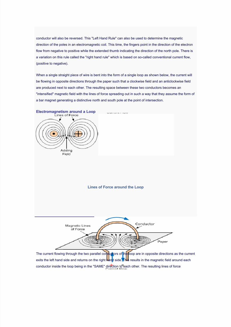
7/30/2019 Steorn Drops Four Bombshell Documents Validating Orbo
http://slidepdf.com/reader/full/steorn-drops-four-bombshell-documents-validating-orbo 52/307
conductor will also be reversed. This "Left Hand Rule" can also be used to determine the magnetic
direction of the poles in an electromagnetic coil. This time, the fingers point in the direction of the electron
flow from negative to positive while the extended thumb indicating the direction of the north pole. There is
a variation on this rule called the "right hand rule" which is based on so-called conventional current flow,(positive to negative).
When a single straight piece of wire is bent into the form of a single loop as shown below, the current will
be flowing in opposite directions through the paper such that a clockwise field and an anticlockwise field
are produced next to each other. The resulting space between these two conductors becomes an
"intensified" magnetic field with the lines of force spreading out in such a way that they assume the form of
a bar magnet generating a distinctive north and south pole at the point of intersection.
Electromagnetism around a Loop
Lines of Force around the Loop
The current flowing through the two parallel conductors of the loop are in opposite directions as the current
exits the left hand side and returns on the right hand side. This results in the magnetic field around each
conductor inside the loop being in the "SAME" direction to each other. The resulting lines of force

7/30/2019 Steorn Drops Four Bombshell Documents Validating Orbo
http://slidepdf.com/reader/full/steorn-drops-four-bombshell-documents-validating-orbo 53/307
generated by the current flowing through the loop oppose each other in the space between the two
conductors where the two like poles meet thereby deforming the lines of force around each conductor as
shown.
However, the distortion of the magnetic flux in between the two conductors results in an intensity of the
magnetic field at the middle junction were the lines of force become closer together. The resulting
interaction between the two like fields produces a mechanical force between the two conductors as they
try to repel away from each other producing motion. However, as the conductors cannot move, the two
magnetic fields therefore help each other by generating a north and a south pole along this line of
interaction. This results in the magnetic field being strongest in the middle between the two conductors.
The intensity of the magnetic field around the conductor is proportional to the distance from the conductor
and by the amount of current flowing through it.
The magnetic field generated by a straight length of current-carrying wire is very weak even with a high
current passing through it. However, if several loops of wire are wound together along the same axis
producing a coil, the resultant magnetic field will become even more stronger than the single loop
producing an electromagnetic coil more commonly called a Solenoid. Then every coil of wire uses the
effect of electromagnetism when an electrical current flows through it and we will look at this effect in
more detail in the next tutorial.
Electronics Tutorial about Magnetism
Magnetism
Magnetism
Electromagnetism is produced when an electrical current flows through a simple conductor such as a
piece of wire or cable. A small magnetic field is created around the conductor with the direction of this
magnetic field with regards to its "North" and "South" poles being determined by the direction of the current
flowing through the conductor. Magnetism plays an important role in Electrical and Electronic Engineering
because without it components such as relays, solenoids, inductors, chokes, coils, loudspeakers, motors,generators, transformers, and electricity meters etc, would not work if magnetism did not exist. Then every
coil of wire uses the effect of electromagnetism when an electrical current flows through it. But before we
can look at Magnetism and especially Electromagnetism in more detail we need to remember back to
our physics classes of how magnets and magnetism works.
The Nature of Magnetism

7/30/2019 Steorn Drops Four Bombshell Documents Validating Orbo
http://slidepdf.com/reader/full/steorn-drops-four-bombshell-documents-validating-orbo 54/307
Magnets can be found in a natural state in the form of a magnetic ore, with the two main types being
Magnetite also called "iron oxide", ( FE3O4 ) and Lodestone, also called "leading stone". If these two
natural magnets are suspended from a piece of string, they will take up a position inline with the earths
magnetic field always pointing north. A good example of this effect is the needle of a compass. For mostpractical applications these natural occurring magnets can be disregarded as their magnetism is very low
and because nowadays, man-made artificial magnets can be produced in many different shapes, sizes
and magnetic strengths.
There are basically two forms of magnetism, "Permanent Magnets" and "Temporary Magnets", with the
type being used dependant upon its application. There are many different types of materials available to
make magnets such as iron, nickel, nickel alloys, chromium and cobalt and in their natural state some of
these elements such as nickel and cobalt show very poor magnetic quantities on their own. However,
when mixed or "alloyed" together with other materials such as iron or aluminium peroxide they becomevery strong magnets producing unusual names such as "alcomax", "hycomax", "alni" and "alnico".
Magnetic material in the non-magnetic state has its molecular structure in the form of loose magnetic
chains or individual tiny magnets loosely arranged in a random pattern. The overall effect of this type of
arrangement results in zero or very weak magnetism as this haphazard arrangement of each molecular
magnet tends to neutralise its neighbour. When the material is Magnetised this random arrangement of
the molecules changes and the tiny unaligned and random molecular magnets become "lined-up" in such
a way that they produce a series magnetic arrangement. This idea of the molecular alignment of
ferromagnetic materials is known as Weber's Theory and is illustrated below.
Magnetic Molecule Alignment of a Piece of Iron and a Magnet
Weber's theory is based on the fact that all atoms have magnetic properties due to the spinning action of
the atoms electrons. Groups of atoms join together so that their magnetic fields are all rotating in the same
direction. Magnetic materials are composed of groups of tiny magnets at a molecular level around the
atoms, and a magnetised material will have most of its tiny magnets lined up in one direction only to
produce a north pole in one direction and a south pole in the other direction. Likewise, a material that has
its tiny molecular magnets pointing in all directions will have its molecular magnets neutralised by its
neighbouring magnet, thereby neutralising any magnetic effect. These areas of molecular magnets are

7/30/2019 Steorn Drops Four Bombshell Documents Validating Orbo
http://slidepdf.com/reader/full/steorn-drops-four-bombshell-documents-validating-orbo 55/307

7/30/2019 Steorn Drops Four Bombshell Documents Validating Orbo
http://slidepdf.com/reader/full/steorn-drops-four-bombshell-documents-validating-orbo 56/307
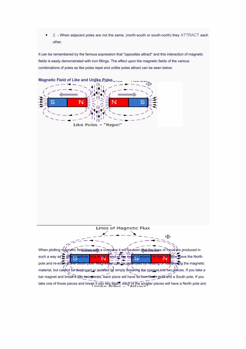
7/30/2019 Steorn Drops Four Bombshell Documents Validating Orbo
http://slidepdf.com/reader/full/steorn-drops-four-bombshell-documents-validating-orbo 57/307
• 2. - When adjacent poles are not the same, (north-south or south-north) they ATTRACT each
other.
It can be remembered by the famous expression that "opposites attract" and this interaction of magnetic
fields is easily demonstrated with iron fillings. The effect upon the magnetic fields of the variouscombinations of poles as like poles repel and unlike poles attract can be seen below.
Magnetic Field of Like and Unlike Poles
When plotting magnetic field lines with a compass it will be seen that the lines of force are produced in
such a way as to give a definite pole at each end of the magnet where the lines of force leave the North
pole and re-enter at the South pole. Magnetism can be destroyed by heating or hammering the magnetic
material, but cannot be destroyed or isolated by simply breaking the magnet into two pieces. If you take a
bar magnet and break it into two pieces, each piece will have its own North pole and a South pole. If you
take one of those pieces and break it into two again, each of the smaller pieces will have a North pole and

7/30/2019 Steorn Drops Four Bombshell Documents Validating Orbo
http://slidepdf.com/reader/full/steorn-drops-four-bombshell-documents-validating-orbo 58/307
a South pole. No matter how small the pieces of the magnet become, each piece will have a North pole
and a South pole. In order to make use of magnetism in electrical or electronic calculations, it is necessary
to define the various aspects of magnetism.
The Magnitude of Magnetism
We now know that the lines of force or more commonly the magnetic flux around a magnetic material is
given the Greek symbol, Phi, ( Φ ) with the unit of flux being the Weber , ( Wb ) after Wilhelm Eduard
Weber. But the number of lines of force within a given unit area is called the "Flux Density" and since flux (
Φ ) is measured in ( Wb ) and area ( A ) in metres squared, ( m2 ), flux density is therefore measured in
Webers/Metre2 or ( Wb/m2 ) and is given the symbol B.
However, when referring to flux density in magnetism, flux density is given the unit of the Teslaafter Nikola
Tesla so therefore one Wb/m2 is equal to one Tesla, 1Wb/m2 = 1T. Flux density is proportional to the
lines of force and inversely proportional to area so we can define Flux Density as:
Magnetic Flux Density
The symbol for magnetic flux density is B and the unit of magnetic flux density is the Tesla, T.
It is important to remember that all calculations for flux density are done in the same units, e.g., flux in
webers, area in m2 and flux density in Teslas.
Example No1
The amount of flux present in a round magnetic bar was measured at 0.013 webers. If the material has a
diameter of 12cm, calculate the flux density.
The cross sectional area of the magnetic material in m2 is given as:

7/30/2019 Steorn Drops Four Bombshell Documents Validating Orbo
http://slidepdf.com/reader/full/steorn-drops-four-bombshell-documents-validating-orbo 59/307
The magnetic flux is given as 0.013 webers, therefore the flux density can be calculated as:
So the flux density is calculated as 1.15 Teslas.
When dealing with magnetism in electrical circuits it must be remembered that one Tesla is the density of
a magnetic field such that a conductor carrying 1 ampere at right angles to the magnetic field experiences
a force of one newton-metre length on it and this will be demonstrated in the next tutorial about
Electromagnetism.
Electronics Tutorial about Electromagnetic Induction
Electromagnetic
Induction
Electromagnetic Induction
Air-core Hollow Coil
We have seen previously that when a DC current pass through a long straight conductor a magnetising

7/30/2019 Steorn Drops Four Bombshell Documents Validating Orbo
http://slidepdf.com/reader/full/steorn-drops-four-bombshell-documents-validating-orbo 60/307

7/30/2019 Steorn Drops Four Bombshell Documents Validating Orbo
http://slidepdf.com/reader/full/steorn-drops-four-bombshell-documents-validating-orbo 61/307
Likewise, if the magnet is now held stationary and ONLY the coil is moved towards or away from the
magnet the needle of the galvanometer will also deflect in either direction. Then the action of moving a coil
or loop of wire through a magnetic field induces a voltage in the coil with the magnitude of this induced
voltage being proportional to the speed or velocity of the movement. In other words the faster the
movement of the magnetic field the greater will be the induced emf or voltage in the coil, so for Faraday's
law to hold true there must be "relative motion" or movement between the coil and the magnetic field and
either the magnetic field, the coil or both can move.
Faraday's Law of Induction
From the above description we can say that a relationship exists between an electrical voltage and a
changing magnetic field to which Michael Faraday's famous law of electromagnetic induction states "that
a voltage is induced in a circuit whenever relative motion exists between a conductor and a
magnetic field and that the magnitude of this voltage is proportional to the rate of change of the
flux". In other words, Electromagnetic Induction is the process of using magnetic fields to produce
voltage, and in a closed circuit, a current.
So how much voltage (emf) can be induced into the coil using just magnetism. Well this is determined by
the following 3 different factors.
•
1). Increasing the number of turns of wire in the coil. - By increasing the amount of individual conductors cutting through the magnetic field, the amount of induced emf produced will
be the sum of all the individual loops of the coil, so if there are 20 turns in the coil there will be 20
times more induced emf than in one piece of wire.
•
• 2). Increasing the speed of the relative motion between the coil and the magnet. - If the
same coil of wire passed through the same magnetic field but its speed or velocity is increased,

7/30/2019 Steorn Drops Four Bombshell Documents Validating Orbo
http://slidepdf.com/reader/full/steorn-drops-four-bombshell-documents-validating-orbo 62/307

7/30/2019 Steorn Drops Four Bombshell Documents Validating Orbo
http://slidepdf.com/reader/full/steorn-drops-four-bombshell-documents-validating-orbo 63/307
If the conductor does not move at right angles (90°) to the magnetic field then the angle θ° will be added tothe above expression giving a reduced output as the angle increases:
Lenz's Law of Electromagnetic Induction
Faraday's Law tells us that inducing a voltage into a conductor can be done by either passing it through a
magnetic field, or by moving the magnetic field past the conductor and that if this conductor is part of a
closed circuit, an electric current will flow. This voltage is called an induced emf as it has been induced
into the conductor by a changing magnetic field due to electromagnetic induction with the negative sign in
Faraday's law telling us the direction of the induced current (or polarity of the induced emf).
But a changing magnetic flux produces a varying current through the coil which itself will produce its own
magnetic field as we saw in the Electromagnets tutorial. This self-induced emf opposes the change that
is causing it and the faster the rate of change of current the greater is the opposing emf. This self-induced
emf will, by Lenz’s law oppose the change in current in the coil and because of its direction this self-
induced emf is generally called a back-emf .
Lenz's Law states that: "the direction of an induced emf is such that it will always opposes the
change that is causing it". In other words, an induced current will always OPPOSE the motion or change
which started the induced current in the first place and this idea is found in the analysis of Inductance.
Likewise, if the magnetic flux is decreased then the induced emf will oppose this decrease by generating
and induced magnetic flux that adds to the original flux.
Lenz's law is one of the basic laws in electromagnetic induction for determining the direction of flow of
induced currents and is related to the law of conservation of energy. According to the law of conservation
of energy which states that the total amount of energy in the universe will always remain constant asenergy can not be created nor destroyed. Lenz's law is derived from Michael Faraday's law of induction.
One final comment about Lenz's Law regarding electromagnetic induction. We now know that when a
relative motion exists between a conductor and a magnetic field, an emf is induced within the conductor.
But the conductor may not actually be part of the coils electrical circuit, but may be the coils iron core or
some other metallic part of the system, for example, a transformer. The induced emf within this metallic

7/30/2019 Steorn Drops Four Bombshell Documents Validating Orbo
http://slidepdf.com/reader/full/steorn-drops-four-bombshell-documents-validating-orbo 64/307
part of the system causes a circulating current to flow around it and this type of core current is known as
an Eddy Current.
Eddy currents generated by electromagnetic induction circulate around the coils core or any connectingmetallic components inside the magnetic field because for the magnetic flux they are acting like a single
loop of wire. Eddy currents do not contribute anything towards the usefulness of the system but instead
they oppose the flow of the induced current by acting like a negative force generating resistive heating and
power loss within the core. However, there are electromagnetic induction furnace applications in which
only eddy currents are used to heat and melt ferromagnetic metals.
Eddy Currents Circulating in a Transformer
The changing magnetic flux in the iron core of a transformer above will induce an emf, not only in the
primary and secondary windings, but also in the iron core. The iron core is a good conductor, so the
currents induced in a solid iron core will be large. Furthermore, the eddy currents flow in a direction which,
by Lenz's law, acts to weaken the flux created by the primary coil. Consequently, the current in the primary
coil required to produce a given B field is increased, so the hysteresis curves are fatter along the H axis.
Laminating the Iron Core
Eddy current and hysteresis losses can not be eliminated completely, but they can be greatly reduced.

7/30/2019 Steorn Drops Four Bombshell Documents Validating Orbo
http://slidepdf.com/reader/full/steorn-drops-four-bombshell-documents-validating-orbo 65/307

7/30/2019 Steorn Drops Four Bombshell Documents Validating Orbo
http://slidepdf.com/reader/full/steorn-drops-four-bombshell-documents-validating-orbo 66/307
Hall Effect Sensors consist basically of a thin piece of rectangular p-type semiconductor material such as
gallium arsenide (GaAs), indium antimonide (InSb) or indium arsenide (InAs) passing a continuous current
through itself. When the device is placed within a magnetic field, the magnetic flux lines exert a force on
the semiconductor material which deflects the charge carriers, electrons and holes, to either side of the
semiconductor slab. This movement of charge carriers is a result of the magnetic force they experiencepassing through the semiconductor material. As these electrons and holes move side wards a potential
difference is produced between the two sides of the semiconductor material by the build-up of these
charge carriers. Then the movement of electrons through the semiconductor material is affected by the
presence of an external magnetic field which is at right angles to it and this effect is greater in a flat
rectangular shaped material.
The effect of generating a measurable voltage by using a magnetic field is called the Hall Effectafter
Edwin Hall who discovered it back in the 1870's with the basic physical principle underlying the Hall effect
being Lorentz force. To generate a potential difference across the device the magnetic flux lines must be
perpendicular, (90o) to the flow of current and be of the correct polarity, generally a south pole. The Hall
effect provides information regarding the type of magnetic pole and magnitude of the magnetic field. For
example, a south pole would cause the device to produce a voltage output while a north pole would have
no effect. Generally, Hall Effect sensors and switches are designed to be in the "OFF", (open circuit
condition) when there is no magnetic field present. They only turn "ON", (closed circuit condition) when

7/30/2019 Steorn Drops Four Bombshell Documents Validating Orbo
http://slidepdf.com/reader/full/steorn-drops-four-bombshell-documents-validating-orbo 67/307
subjected to a magnetic field of sufficient strength and polarity.
Hall Effect Magnetic Sensor
The output voltage, called the Hall voltage, (VH) of the basic Hall Element is directly proportional to the
strength of the magnetic field passing through the semiconductor material (output∝ H). This output
voltage can be quite small, only a few microvolts even when subjected to strong magnetic fields so most
commercially available Hall effect devices are manufactured with built-in DC amplifiers, logic switching
circuits and voltage regulators to improve the sensors sensitivity, hysteresis and output voltage. This also
allows the Hall effect sensor to operate over a wider range of power supplies and magnetic field
conditions.
Hall Effect Sensor
Hall Effect Sensors are available with either linear or digital outputs. The output signal for linear
(analogue) sensors is taken directly from the output of the operational amplifier with the output voltage
being directly proportional to the magnetic field passing through the Hall sensor. This output Hall voltage is
given as:
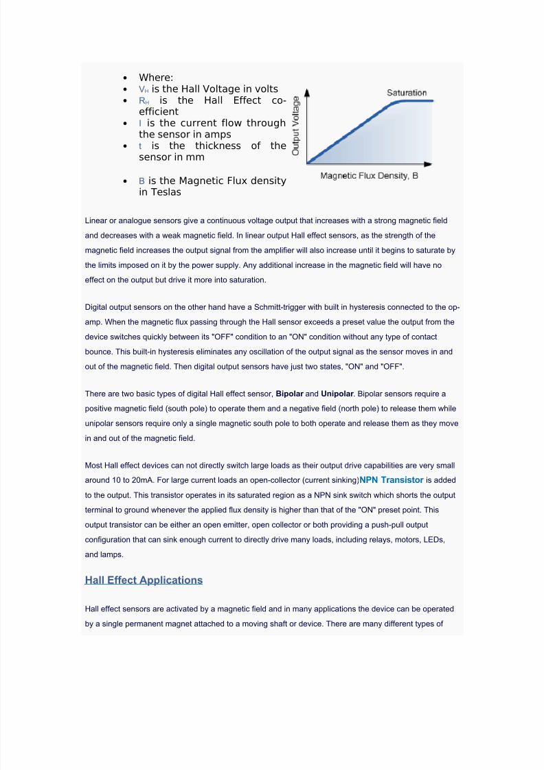
7/30/2019 Steorn Drops Four Bombshell Documents Validating Orbo
http://slidepdf.com/reader/full/steorn-drops-four-bombshell-documents-validating-orbo 68/307

7/30/2019 Steorn Drops Four Bombshell Documents Validating Orbo
http://slidepdf.com/reader/full/steorn-drops-four-bombshell-documents-validating-orbo 69/307
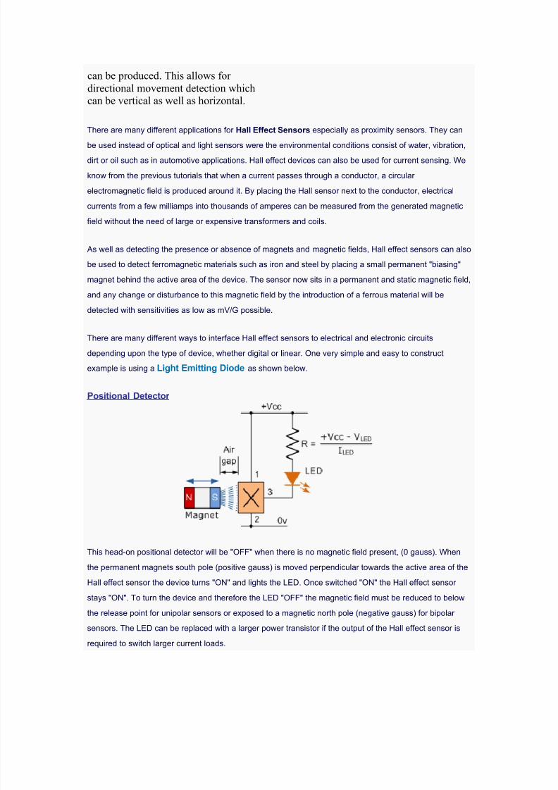
7/30/2019 Steorn Drops Four Bombshell Documents Validating Orbo
http://slidepdf.com/reader/full/steorn-drops-four-bombshell-documents-validating-orbo 70/307
can be produced. This allows for
directional movement detection whichcan be vertical as well as horizontal.
There are many different applications for Hall Effect Sensors especially as proximity sensors. They can
be used instead of optical and light sensors were the environmental conditions consist of water, vibration,
dirt or oil such as in automotive applications. Hall effect devices can also be used for current sensing. We
know from the previous tutorials that when a current passes through a conductor, a circular
electromagnetic field is produced around it. By placing the Hall sensor next to the conductor, electrical
currents from a few milliamps into thousands of amperes can be measured from the generated magnetic
field without the need of large or expensive transformers and coils.
As well as detecting the presence or absence of magnets and magnetic fields, Hall effect sensors can also
be used to detect ferromagnetic materials such as iron and steel by placing a small permanent "biasing"
magnet behind the active area of the device. The sensor now sits in a permanent and static magnetic field,
and any change or disturbance to this magnetic field by the introduction of a ferrous material will be
detected with sensitivities as low as mV/G possible.
There are many different ways to interface Hall effect sensors to electrical and electronic circuits
depending upon the type of device, whether digital or linear. One very simple and easy to construct
example is using a Light Emitting Diode as shown below.
Positional Detector
This head-on positional detector will be "OFF" when there is no magnetic field present, (0 gauss). Whenthe permanent magnets south pole (positive gauss) is moved perpendicular towards the active area of the
Hall effect sensor the device turns "ON" and lights the LED. Once switched "ON" the Hall effect sensor
stays "ON". To turn the device and therefore the LED "OFF" the magnetic field must be reduced to below
the release point for unipolar sensors or exposed to a magnetic north pole (negative gauss) for bipolar
sensors. The LED can be replaced with a larger power transistor if the output of the Hall effect sensor is
required to switch larger current loads.

7/30/2019 Steorn Drops Four Bombshell Documents Validating Orbo
http://slidepdf.com/reader/full/steorn-drops-four-bombshell-documents-validating-orbo 71/307
Coil Inductance Calculator
Choose Type
Wire
Parallel Wires
Coax
Wire over Plane
Loop
Rectangle Loop
Coil
Broadside Traces
Edge Coupled Traces
Coil Inductance Calculator

7/30/2019 Steorn Drops Four Bombshell Documents Validating Orbo
http://slidepdf.com/reader/full/steorn-drops-four-bombshell-documents-validating-orbo 72/307
Inputs
Number of Turns
N
Loop Diameter
D
Wire Diameter
d
Relative Permeability
μR
[H/m]
Outputs
Inductance:
2.99e-8 H
Introduction
A coil inductance formula is based upon the basic loop inductance. Inductance is the ability to storeenergy in a magnetic field, and coils are a very common way to create inductance. Many magnetic fieldcoupling circuits, like chokes and transformers take advantage of a coil’s magnetic storage properties.

7/30/2019 Steorn Drops Four Bombshell Documents Validating Orbo
http://slidepdf.com/reader/full/steorn-drops-four-bombshell-documents-validating-orbo 73/307
Wire Loop Inductance Description
The inductance of a wire loop is a common example of a circuit with inductance. The variables used inthis tool are the diameter of the wire conductor and the diameter of the wire loop, number of turns, andthe relative permeability. Coil inductance is related to individual loop inductance by the square of thenumber of turns.
Coil Inductance Model.
The inductance of the wire a coil is:
Wire Self Inductance Calculator
Inputs
Diameter of Wire
D
Length of Wire
L
Outputs
Wire Self Inductance:
0.0637 uH
Introduction

7/30/2019 Steorn Drops Four Bombshell Documents Validating Orbo
http://slidepdf.com/reader/full/steorn-drops-four-bombshell-documents-validating-orbo 74/307
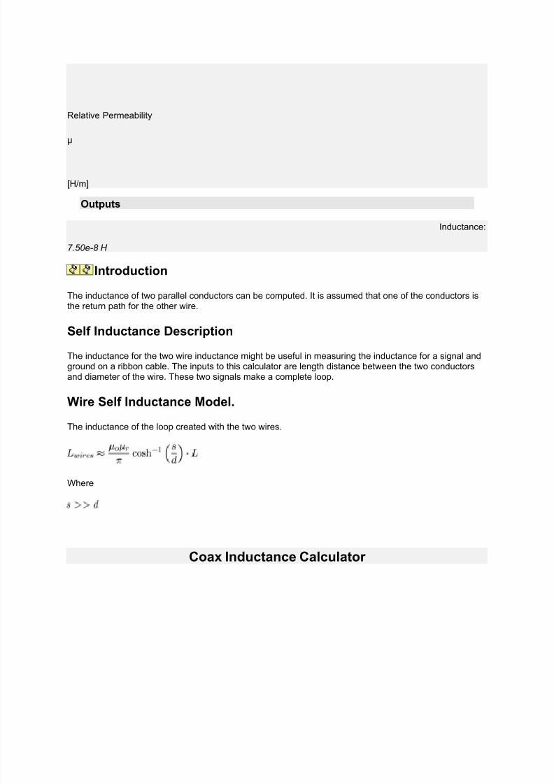
7/30/2019 Steorn Drops Four Bombshell Documents Validating Orbo
http://slidepdf.com/reader/full/steorn-drops-four-bombshell-documents-validating-orbo 75/307

7/30/2019 Steorn Drops Four Bombshell Documents Validating Orbo
http://slidepdf.com/reader/full/steorn-drops-four-bombshell-documents-validating-orbo 76/307
Inputs
Outer Diameter
D
Inner Diameter
d
Length of Wire
L
Relative Permeability
μR
[H/m]
Outputs
Inductance:
2.41e-8 H
Introduction

7/30/2019 Steorn Drops Four Bombshell Documents Validating Orbo
http://slidepdf.com/reader/full/steorn-drops-four-bombshell-documents-validating-orbo 77/307
A coax is a common transmission line construction and most rf cables are coax. The impedance of thecoax is a relationship of the capacitance per unit length and the inductance per unit length. This tool willhelp you find the inductance for a given length of coax cable.
Coax Inductance Description
The inductance of a coax cable can be useful to know. The variables needed in calculating thisinductance are center conductor diameter, distance to outer shield, and length. You might notice that thediameter of the outer shield is not required. It is assumed that this shield is sufficiently thick. Thiscalculation is for a loop inductance where the outer shield is the return path for the center conductor.
Coax Inductance Model.
The inductance of the loop created with the center conductor and outer shield.
Wire Over Plane Inductance Calculator
Inputs
Wire Diameter
D
Height Above Plane
H
Length of Wire
L
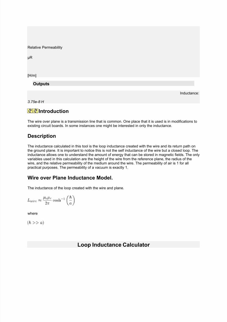
7/30/2019 Steorn Drops Four Bombshell Documents Validating Orbo
http://slidepdf.com/reader/full/steorn-drops-four-bombshell-documents-validating-orbo 78/307

7/30/2019 Steorn Drops Four Bombshell Documents Validating Orbo
http://slidepdf.com/reader/full/steorn-drops-four-bombshell-documents-validating-orbo 79/307
Inputs
Loop Diameter
D
Wire Diameter
d
Relative Permeability
μR
[H/m]
Outputs
Inductance:
2.99e-8 H
Introduction
A wire loop creates inductance. Inductance is the ability to store energy in a magnetic field.
Wire Loop Inductance Description
The inductance of a wire loop is a common textbook example of a circuit with inductance. The variablesused in this tool are the diameter of the wire conductor and the diameter of the wire loop. This calculationis for loop and self inductance they are the same for this example.
Loop Inductance Model.

7/30/2019 Steorn Drops Four Bombshell Documents Validating Orbo
http://slidepdf.com/reader/full/steorn-drops-four-bombshell-documents-validating-orbo 80/307
The inductance of the wire loop.
Rectangle Loop Inductance Calculator
Inputs
Number of Turns
N
Loop Width
W
Loop Height
H
Wire Diameter
d
Relative Permeability

7/30/2019 Steorn Drops Four Bombshell Documents Validating Orbo
http://slidepdf.com/reader/full/steorn-drops-four-bombshell-documents-validating-orbo 81/307
μR
[H/m]
Outputs
Inductance:
3.55e-8 H
Introduction
The rectangle loop is often found in windings for transformers or ferrite cores.
Rectangle Inductance Description
The inductance of a rectangle loop has three geometric variables:
• W – rectangle long side• h – rectangle short side• d – wire diameter
Rectangle Loop Inductance Model.
The inductance for a rectangle loop is:
where
Broadside Coupled Trace Inductance Calculator

7/30/2019 Steorn Drops Four Bombshell Documents Validating Orbo
http://slidepdf.com/reader/full/steorn-drops-four-bombshell-documents-validating-orbo 82/307
Inputs
Trace Width
W
Trace Seperation
H
Trace Length
L
Relative Permeability
μr
[H/m]
Outputs
Inductance:
6.38e-10 H
Introduction
The broadside coupled trace is a common technique for routing differential pair signals.
Broadside Trace Inductance Description

7/30/2019 Steorn Drops Four Bombshell Documents Validating Orbo
http://slidepdf.com/reader/full/steorn-drops-four-bombshell-documents-validating-orbo 83/307

7/30/2019 Steorn Drops Four Bombshell Documents Validating Orbo
http://slidepdf.com/reader/full/steorn-drops-four-bombshell-documents-validating-orbo 84/307

7/30/2019 Steorn Drops Four Bombshell Documents Validating Orbo
http://slidepdf.com/reader/full/steorn-drops-four-bombshell-documents-validating-orbo 85/307

7/30/2019 Steorn Drops Four Bombshell Documents Validating Orbo
http://slidepdf.com/reader/full/steorn-drops-four-bombshell-documents-validating-orbo 86/307
Directory:Solar
Electromagnetic Directory
See Directory:Electromagnetic | News:Electromagnetic
Featured: Electromagnetic / Solid State >
ERR Fluxgenerator by Noah's Ark Research Foundation - Inventor,
James B. Schwartz of the Philippines, has come up with a device that
allegedly puts out six kilowatts of electricity from the surroundings, using a
solid state arrangement in a panel made from "left-handed material" --
Aluminum and Bismuth interwoven with coils -- tying into the Earth's
frequencies. (PESWiki ; Aug. 15, 2009)
Featured / Best Exotic: Suppression / Solid State Generators > ERR Fluxgenerator >
ERR Fluxgenerators that almost made it to market - Alexander
Frolov sent me a couple of old sales brochures of the ERR Fluxgenerator
from 2002 when the 250W - 6KVA product line was approaching the market
in Japan. There were around 20,000 units manufactured. But before they hitthe market, the Japanese government issued a shut-down order due to
some alleged "safety concerns", and confiscated all the units. (PESWiki ;
December 8, 2010)

7/30/2019 Steorn Drops Four Bombshell Documents Validating Orbo
http://slidepdf.com/reader/full/steorn-drops-four-bombshell-documents-validating-orbo 87/307
Featured / Best Exotic FE: Radiant Energy / Solid State > Electrostatic > Aviso EV >
Aviso Solid State Generator Makes Hundreds of Watts - Philippine
inventor, Ismael Aviso, presents his Motionless Electric Generator (MEG),
reporting that it has been powering around 800 Watts of resistive light bulbs
while the battery voltage drops very little, which powers the circuit involved in
harnessing this radiant energy from the surroundings. (PESN and
BeforeItsNews; March 2, 2011)
Featured / Best Exotic FE: Electromagnetic > Solid State > Magnacoaster >
Magnacoaster Eyes July for Multi-kW Solid State Generator
Release -- Finally- The Canadian company Magnecoaster claims to offer
solid state electrical generators that produce many kilowatts of output, but
not a single unit has shipped in the near 3 years they've been selling. With
units claimed to be going to customers later in July, can Magnecoaster stop
coasting and deliver a working product? (PESN and BeforeItsNews; June 11,
2011)
Featured: Lighting > CFL / Electromagnetic > Solid State >
Free Energy for the Downcast -- "One Man's Trash..." Revolution

7/30/2019 Steorn Drops Four Bombshell Documents Validating Orbo
http://slidepdf.com/reader/full/steorn-drops-four-bombshell-documents-validating-orbo 88/307
Commencing - Dallas inventor, Donald Bell, has three technologies he's
rolling out to make energy more affordable; and he's using discarded items
as his building material to give away to Dallas County residents a free CFL
lamp with 75-W incandescent output equivalent that runs for 5 days
continuous. He also has a home lighting package and a self-charging cellphone that harness power radio waves. (PESN and BeforeItsNews; October
3, 2011)
Featured / OS: Electromagnetic > Solid State >
Dr. Steven E. Jones' circuit gives evidence for 8x overunity -
Professor Jones has developed a variation of the 'Joule Thief' circuit and has
shown evidence that its output is eight times greater than the input as
measured by a state-of-the-art oscilloscope. He is open sourcing his solid
state design to help speed its development and implementation, as well as to
answer the scientific question of where the energy is coming from. (PESN
and BeforeItsNews; May 27, 2011)
Featured / OS: Wireless Transmission / Electromagnetic > Scalar > Solid State > Tesla > Coils > Jackson >
Tesla Coils: Unleash the Aether - Nikola Tesla's most significantcontribution was not AC power, radio, or the induction motor, but what we
call the Tesla Coil - a tool which allows for the power of the aether to be
unleashed and harnessed. Now being launched through an open source
project. (PESN and BeforeItsNews; April 19, 2011)
7/30/2019 Steorn Drops Four Bombshell Documents Validating Orbo
http://slidepdf.com/reader/full/steorn-drops-four-bombshell-documents-validating-orbo 89/307
Featured / OS: Wireless Transmission / Electromagnetic > Scalar > Solid State > Tesla > Coils > Jackson >
Jackson's Wireless Aetheric Power Transmission Open Source
Project - To facilitate the replication of these plans, as well as to
characterize, optimize, improve, and come up with the zillion applications
that can come from it, including: 1) harnessing aetheric energy, 2)
superluminal communication, 3) wireless transmission of power through any
barrier, 4) anti-gravity capabilities, and 5) creating defensive shields to make
conventional war obsolete. (PESWiki ; April 21, 2011)
Featured: Electromagnetic > Solid State >
Two Toroid Over-Unity Gabriel Device -- Part 1- David Klingelhoefer
has designed and tested a variation of Thane Heins' Bi-Toroid Transformer
that outputs more power than is consumed. He has been able to get the
primary circuit consumption down to 60 watts, while outputting 480 watts --
8x overunity. (PESN and BeforeItsNews; March 20, 2011)
Feature / Best Exotic: EVs > Motors / Solid State / Electromagnetic > NEW: TurXator >
Free energy TurXator ready for license from Alperen Group - A Turkish
inventor, Attila Alperen, and his group who have been developing an

7/30/2019 Steorn Drops Four Bombshell Documents Validating Orbo
http://slidepdf.com/reader/full/steorn-drops-four-bombshell-documents-validating-orbo 90/307
overunity motor/generator technology for over a decade, having built some
100 prototypes, are now saying they are ready to license the technology for
production. Electric output ranges from several watts to megawatts. Motor
output targeted for EV market. (PESN ; June 12, 2010) (Comment)
Featured: Electromagnetic > Solid State Generators > Steorn >
Steorn opens development base with emphasis on new solid state
design - Irish company says they have a solid state (no moving parts)version of their "overunity" electromagnetic technology that is showing great
promise and which is in process of being optimized by the Steorn Knowledge
Development Base (SKDB), now open for general membership as of the
beginning of April. (PESN ; April 12, 2010) (Comment)
Electromagnetic > Solid State > Steorn >
Test Results of the Orbo Solid State Development Unit - On Sept. 25,
two electronics engineers and a physicist tested Steorn's solid state (no
moving parts) electromagnetic devices, and attest to observing over
200% efficiency. "Orbo uses time-variant magnetic interactions to
produce non-conservative energy results." (YouTube / SteornOfficial ;Sept. 29, 2010)

7/30/2019 Steorn Drops Four Bombshell Documents Validating Orbo
http://slidepdf.com/reader/full/steorn-drops-four-bombshell-documents-validating-orbo 91/307
Featured: EV / Electrolysis > Boyce / Electromagnetic > NEW: Boyce Hex Controller >
Child Rides EV Toy on Boyce Free Energy! - A South African
experimenter has modified an electrolysis circuit developed by Bob Boyce so
that now it recharges his daughter's electric vehicle riding toy. What makes
this remarkable is that the energy is not drawn from the wall but from the
environment somehow. He's done this around 35 times now and knows of
three replications by others. (PESN ; Nov. 12, 2009) (Comment)
World Improvement Through the Spirit Ministries - Timothy
Thrapp's organization claims to have many technologies for sale, including
electromagnetic motors that produce more energy than they consume to run;
both mechanical and solid state.
Tom Bearden's MEG - Electromagnetic Generator (MEG) - Solid state
technology for tapping into the "oceans of free energy" all around us. Claimsthree previously working prototypes of a device that extracts energy from the
vacuum of space.

7/30/2019 Steorn Drops Four Bombshell Documents Validating Orbo
http://slidepdf.com/reader/full/steorn-drops-four-bombshell-documents-validating-orbo 92/307
7/30/2019 Steorn Drops Four Bombshell Documents Validating Orbo
http://slidepdf.com/reader/full/steorn-drops-four-bombshell-documents-validating-orbo 93/307
7/30/2019 Steorn Drops Four Bombshell Documents Validating Orbo
http://slidepdf.com/reader/full/steorn-drops-four-bombshell-documents-validating-orbo 94/307

7/30/2019 Steorn Drops Four Bombshell Documents Validating Orbo
http://slidepdf.com/reader/full/steorn-drops-four-bombshell-documents-validating-orbo 95/307

7/30/2019 Steorn Drops Four Bombshell Documents Validating Orbo
http://slidepdf.com/reader/full/steorn-drops-four-bombshell-documents-validating-orbo 96/307
been pointed out which argue that the system is not over unity.
Environmental Vibrations
Vibrations / Solid State >
Cell Phones Powered by Conversations - Just as speakers transform
electric signals into sound, the opposite process -- of turning sound into a
source of electrical power -- is possible, according to Scientists from Korea
who have turned the main ingredient of calamine lotion into a tiny material
that converts sound waves into electricity. Other noise sources such as
traffic could also be harnesses for the power grid. (Discovery ; Sept. 13,
2010)
Tiny Generator Runs Off Vibrations - Researchers at the University
of Southampton, UK, have developed an efficient, sugar-cube-sized electric
generator that feeds on environmental vibrations, via the wobbling of several
magnets attached to a millimeter-sized cantilever. The device could power
small, low-power devices such as wireless sensors or medical implants.
Piezoelectric
See Directory:Piezoelectric
Petravoltaic

7/30/2019 Steorn Drops Four Bombshell Documents Validating Orbo
http://slidepdf.com/reader/full/steorn-drops-four-bombshell-documents-validating-orbo 97/307

7/30/2019 Steorn Drops Four Bombshell Documents Validating Orbo
http://slidepdf.com/reader/full/steorn-drops-four-bombshell-documents-validating-orbo 98/307
Bedini SG - Full plans posted; many replications, a few claim over
unity in their variant designs. Solid state region exists. (PESWiki.com)
John Bedini's Website - Bedini Technology shares core technologies
openly. US Patent#6392370
Research Jay Garrett Technologies - Zero Point Energy device brainstorming;
open research & development.
Genesis EMT Systems open for licensing - Peter x says he was
employed in 1978/79 by NASA/JPL to derive a non-solar energy device that
could provide power for space craft, and that the electromagnetic technology
developed has been in continuous operation since that time . . . , and is now
being offered for licensing for lay application. (PESWiki ; Feb. 17, 2006)
Cal Physics - Zero Point Energy
ForumsSee Discussion page
Comments by or about "Solid State"

7/30/2019 Steorn Drops Four Bombshell Documents Validating Orbo
http://slidepdf.com/reader/full/steorn-drops-four-bombshell-documents-validating-orbo 99/307
- Free_Energy discussion group- JLNlabs discussion group (registered users)- KeeleyNet
See Also
BEST
Directory:Best Exotic Clean Energy Technologies
News:Best Exotic Free Energy Technologies
Top free energy stories of 2010 and beyond
Template:Tesla footer
ENERGY TYPES
Directory:Galactic Sea of Energy
Directory:Aether | PowerPedia:Aether
Directory:Atmospheric Electrostatic Energy
Directory:Dark Energy
Directory:Radiant Energy | PowerPedia:Radiant Energy
Directory:Vacuum
Directory:Zero Point Energy
Directory:Grand Unified Theories | Directory:Aether Physics Model Directory:Vibrations
Directory:Fractal Antennas as an Energy Source
DEVICE TYPES
Directory:Electromagnetic (overunity)
News:Electromagnetic (latest) | 2009 | 2006-2008
Directory:Magnet Motors | News:Magnet Motors
Directory:Linear Magnet Accelerators
Directory:Pyramid Power
Directory:Solid State
Directory:Solid State Generators | PowerPedia:Solid State Generator
Directory:Toroidal Power
Directory:Marko Rodin Coil / Torus / Motor

7/30/2019 Steorn Drops Four Bombshell Documents Validating Orbo
http://slidepdf.com/reader/full/steorn-drops-four-bombshell-documents-validating-orbo 100/307

7/30/2019 Steorn Drops Four Bombshell Documents Validating Orbo
http://slidepdf.com/reader/full/steorn-drops-four-bombshell-documents-validating-orbo 101/307

7/30/2019 Steorn Drops Four Bombshell Documents Validating Orbo
http://slidepdf.com/reader/full/steorn-drops-four-bombshell-documents-validating-orbo 102/307
In this paper the author describes a very simple configuration that involves a coil
wrapped around a nickel core (that is both magnetic and conductive) acting as an
inductor. The coil and core is placed in a calorimeter composed of a vacuum
chamber. Two thermocouples measure the temperature of the coil itself, and the
temperature of the air in the room. A metered power supply provides the input
power to the coil, and an oscilloscope monitors the current, voltage, and can also
calculate total input power by using a math function of the scope.
The purpose of the test is to determine if the coil fed with a quantity of AC power,
can produce more heat than the same coil fed with the same quantity of DC power.
In the paper, the formula needed to calculate the total AC power is presented. The
AC input and DC input is configured to be as identical as possible. Actually, the
power input during the AC run was .9 (point nine) watts, and in the DC run it was 1
(one) watt. The fact that the input power during the AC run was slightly less than in
the DC run actually biases the test against the AC run. This makes the results of thetest even more significant.
In the first test, 1 watt of DC power is fed into the coil wound around the nickel core.
The temperature of the coil increases until it reaches an equilibrium point of 36.1
degrees. This is the point at which the power lost by the coil via heat dissipation
matches the electrical input power. Even if the input power stayed on for hours
longer, the temperature of the coil would not increase above this temperature.
In the second test, .9 watts is fed into the same coil wound around the same exact
nickel core. Obviously, this test took place a period of time after the first one, afterthe temperature of the coil has dropped back to its original value. The result of AC
being fed into the coil is that it rises to an equilibrium temperature of 41.1 degrees.
This means that in the AC test, the temperature of the coil reached a temperature
five degrees higher than in the DC test.
The higher equilibrium temperature obtained when the coil was powered with AC,
indicates an anomalous gain of energy. The gain of energy is unexplainable, because
the input power in both tests were almost identical -- actually slightly less when AC
was utilized. As the paper continues, the author indicates that resistive heating
cannot be the case for the increased temperature in the AC test run.
Here is the conclusion found at the end of the paper.
"The extra heating effect under the application of an AC signal is not explained
simply by the transfer of input power to the coil. Consideration of the energy input to
the system does not account for the energy output -- as evidenced by the steady
state temperature; there is an extra effect which needs to be isolated and identified.

7/30/2019 Steorn Drops Four Bombshell Documents Validating Orbo
http://slidepdf.com/reader/full/steorn-drops-four-bombshell-documents-validating-orbo 103/307

7/30/2019 Steorn Drops Four Bombshell Documents Validating Orbo
http://slidepdf.com/reader/full/steorn-drops-four-bombshell-documents-validating-orbo 104/307
Comments
Feel free to post your comments down below.
40x Overunity?
MrVibrating wrote:
Eek well I did the math and got 40kW out for that 1kW in.
Have I made some mistake?
The specific heat of water is 1 calorie per gram °C.
1 calorie = 4.184 Joules, and 1 litre of water weighs 1kg.
Round that down to 4J/g/c and, taking the most conservative flow rate estimate of 8 litres / minand a 25° input temp (so a 75° rise to steam) we get: 4kJ per litre per degree, x 75 = 300kJ per
litre, x 8L per minute = 2400,000J per minute.
1W = 1J/s, so 2400kJ / 60 = 40kJ/s or 40kW...
40X OU!?
* * * *
What You Can Do
1. Pass this on to your friends and favorite news sources.2. Subscribe to our newsletter to stay abreast of the latest,
greatest developments in the free energy sector.
3. Let professionals in the renewable energy sector know
about the promise of this technology.

7/30/2019 Steorn Drops Four Bombshell Documents Validating Orbo
http://slidepdf.com/reader/full/steorn-drops-four-bombshell-documents-validating-orbo 105/307
See also
Resources from PESWiki.com
•
Directory:Steorn_Free_Energy - feature page• News:Steorn • Directory:Thermal_Electric • Directory:Solid_State_Generators • Directory:Electromagnetic • News:Electromagnetic • Directory:Toroidal_Power • Directory:Magnet Motors • News:Magnet Motors • More Stories by Hank Mills
Steorn to Push Tipping Point for Magnet
Motor Technology
To solidify the credentials of a radical, new energy approach, Irish Company intents to select
jury of 12 hard-core skeptics with high academic qualifications to review existing data, then
design testing procedure, test, and publish the results.
PESN Interview with Sean McCarthy, Steorn CEO, Aug. 21, 2006
by Sterling D. Allan
Pure Energy Systems News (PESN)
Copyright © 2006
DUBLIN, IRELAND -- Irish high-technology firm, Steorn, has stirred the imagination of theworld's scientific community with their recent posting of an advertisement in The Economist on
Aug. 18 announcing that they have a working free-energy technology. The full-page ad stated
that their independently-tested technology is capable of providing the world with "an infinitesupply of pure energy," so that the need to recharge a phone or refuel a car becomes obsolete.
The brief announcement stated that they are seeking a jury of twelve scientists who are "the most
qualified and the most cynical" to test the technology and publish their findings.

7/30/2019 Steorn Drops Four Bombshell Documents Validating Orbo
http://slidepdf.com/reader/full/steorn-drops-four-bombshell-documents-validating-orbo 106/307
Compressed version of ad posted in The Economist ; Aug. 18,2006.
Discovering and Refining a Magnet Motor
The mystery technology turns out to be an all-magnet motor, with no electromagnetic component
involved. Current-day Physics says such a thing is impossible.
"We thought it was impossible too," said Sean McCarthy, CEO of Steorn, in an interview with
Sterling D. Allan, Executive Director of PES Network, which over the last four and a half yearshas been apprised of some twenty different claims to operational magnet motor systems, none of
which have been validated.
Specializing for many years in technology to help combat counterfeiting and fraud in the plasticcard and optical disc industries, the group at Steorn accidentally stumbled onto this free energy
phenomenon three years ago in the course of developing another project. "It wasn't so much a
Eureka moment as a get-back-in-there-and-check-your-instruments moment," said McCarthy.(Ref .)

7/30/2019 Steorn Drops Four Bombshell Documents Validating Orbo
http://slidepdf.com/reader/full/steorn-drops-four-bombshell-documents-validating-orbo 107/307

7/30/2019 Steorn Drops Four Bombshell Documents Validating Orbo
http://slidepdf.com/reader/full/steorn-drops-four-bombshell-documents-validating-orbo 108/307

7/30/2019 Steorn Drops Four Bombshell Documents Validating Orbo
http://slidepdf.com/reader/full/steorn-drops-four-bombshell-documents-validating-orbo 109/307
various applications.
"We've come up with the transistor; other people can build the microchips", McCarthy said,drawing an analogy.
The Review Process
McCarthy itemized three primary facets that will need to be addressed in any validation of thetechnology. The first thing to prove will be that there is indeed mechanical work being done. The
second thing to prove will be that the amount of energy coming from the system is not a function
of the amount of energy that went into creating the magnets in the first place. Finally, the last
thing to prove will be that the energy is not coming from some unseen environmental source thatcan be depleted, such as ambient heat in a room or nearby transmission lines.
"We're a technology company, not Physicists. We've shown that it can work. It will be up to the
the Physicists to tell us how it works." That answer may be years, if not decades in coming.
But the core question of whether or not it works, and whether or not it is feasible for implementation as an energy-generating technology is the pressing question that will be
presented to the international cross-section of scientists, who will make up the jury of twelve.
But the core question of whether or not it works, and whether or not it is feasible for
implementation as an energy generating technology is the pressing question that will be
presented to the jury of twelve scientists, drawn from an international cross section.
Each jury member will sign a contract that states that Steorn will provide all funding for the
review, and that the results will be published, including disclosure of each jury member's name
and credentials. Once convened in Dublin, the jury will be presented with the information thatSteorn has about the technology.
The scientists will then decide how to proceed with testing. Inasmuch as adequate testing mighttake several months, the jury is likely to select an independent testing firm to do the actual
testing, which they will oversee. This is likely to take several months. Then, when the testing is
complete, the jury will reconvene to analyze the results and render their decision.
"We're not going to rush the process," said McCarthy. "Having solid academic validation of the
technology is too valuable." The results will be published regardless of the outcome, he added.
When asked if he or his company has been impacted by the threat or fear of possible suppression of the technology, as has allegedly been the case in many other similar revolutionary energy
technology situations, McCarthy responded: "Not in the slightest." "We don't live in the
conspiracy-theory world." He said his company has worked extensively as a vendor for law
enforcement, and has confronted some "pretty scary people," and has good security in place."Furthermore, it's not a person, but a company that has produced this technology."

7/30/2019 Steorn Drops Four Bombshell Documents Validating Orbo
http://slidepdf.com/reader/full/steorn-drops-four-bombshell-documents-validating-orbo 110/307
# # #
SOURCES:
•
Phone Interview with Sean McCarthy, CEO of Steorn, Aug. 21, 2006.• http://www.steorn.net - Official website• Irish Energy miracle 'a joke' (The Age; Australia; Aug. 20)
ACKNOWLEDGEMENT:
• Editing input provided by Mary-Sue Haliburton, PES Network Inc Editor.
Feedback
Seek Honest Skeptics, Avoid Review Sabotage
On Aug. 21, 2006, Mary-Sue Haliburton wrote:
I don’t think it goes without saying that it will be essential to make sure that these are honest
cynics. Dishonest cynics and professional skeptics or groups thereof could very well fudge the
experimental design or manipulate the readings to ensure failure of the device, or so that they can publicly proclaim failure of the device even if it did work.
I suggest that in addition to not being believers in new energy, these skeptics must not be
employees or shareholders in any competing traditional-energy technologies or any businessrelated to these technologies (advertising, sub-contractors, industry publishing, etc.), and should
not have relatives who have such ties either. Also, if they are associated with a university, they
must disclose the sources of their research funding. This information must be part of the publicreporting of the study.
Dishonest or biased testing has been alleged and often directly observed to occur many times,especially when hardcore skeptics are involved. I have seen examples of testing by such skeptics
in other fields including health and agriculture, that were explicitly designed to discredit rather
than to analyze honestly the alternative approach or phenomenon.
Therefore, I recommend that when Steorn chooses its jury of twelve, you should also select a
larger scientific review panel to look over the shoulders of the skeptics . This group should
include a range of opinion, rather than only hard skeptics, to ensure that every argument is fullyheard and fairly reported. This second-level review group will be responsible for confirming that
the jury-scientists’ plan is balanced enough to allow for success of the technology should it be
possible, and that procedures, equipment and data recording are honestly done while the testingis in progress.
Otherwise, you run an extreme risk that this skeptic test will be trumpeted around the world as"disproving" your technology, and further that it may be used to smear the reputation of your

7/30/2019 Steorn Drops Four Bombshell Documents Validating Orbo
http://slidepdf.com/reader/full/steorn-drops-four-bombshell-documents-validating-orbo 111/307

7/30/2019 Steorn Drops Four Bombshell Documents Validating Orbo
http://slidepdf.com/reader/full/steorn-drops-four-bombshell-documents-validating-orbo 112/307

7/30/2019 Steorn Drops Four Bombshell Documents Validating Orbo
http://slidepdf.com/reader/full/steorn-drops-four-bombshell-documents-validating-orbo 113/307

7/30/2019 Steorn Drops Four Bombshell Documents Validating Orbo
http://slidepdf.com/reader/full/steorn-drops-four-bombshell-documents-validating-orbo 114/307

7/30/2019 Steorn Drops Four Bombshell Documents Validating Orbo
http://slidepdf.com/reader/full/steorn-drops-four-bombshell-documents-validating-orbo 115/307
See also
Resources from PESWiki.com
•
Directory:Steorn_Free_Energy - feature page• News:Steorn • Directory:Solid_State_Generators • Directory:Electromagnetic • News:Electromagnetic • Directory:Toroidal_Power • Directory:Magnet Motors • News:Magnet Motors • More Stories by Hank Mills
ElectromagneticSee also News:Electromagnetic
Directory of electromagnetic energy generation modalities, in which moreenergy emerges than was put into the system (over unity), harvesting energyfrom some external source, usually unseen. Also covering super efficientmethods.
Contents
[hide]
1 Overviews
2 Events
3 Technologies
3.1 Commercial
3.2 Companies
3.3 Research & Development
3.3.1 Solid State
3.3.2 Joseph Flynn's Parallel Path Magnet Technology
3.3.3 Rodin Coils
3.3.4 Tools
3.3.5 Plans

7/30/2019 Steorn Drops Four Bombshell Documents Validating Orbo
http://slidepdf.com/reader/full/steorn-drops-four-bombshell-documents-validating-orbo 116/307
3.4 Other PES Network Coverage
3.5 Disappeared in History
3.6 For Communications
3.7 Other
3.8 Theory
3.9 Videos
3.9.1 Why Batteries Work and Capacitor's Don't
3.10 Cautions
4 Resources
4.1 Forums
4.2 Testing
4.3 Volunteers
4.4 Humor
4.5 In the News
4.6 Comments
5 See also
Overviews
Feature: Electrolysis > Hydrogen / Electromagnetic >
Hydroxy Gen and OU Replications - Michael Couch writes about the many
self charging battery system videos of various origins; Bedini, Tesla Switch,
SEC, and others showing up all over Youtube. 100% 'Looped' Hydroxy
Genset, Kapanadze OU and Self Charging Battery Systems Demoed!(PESN ; July 13, 2010)

7/30/2019 Steorn Drops Four Bombshell Documents Validating Orbo
http://slidepdf.com/reader/full/steorn-drops-four-bombshell-documents-validating-orbo 117/307
Featured: Orgone / Aetherometry / Weather Control / Bio-Energetics >
Report on Reich Research from Group in Greece - An introductory
paper giving a Reichian perspective on zero point energy, global weather
phenomena, free energy, modern science and non-science, misconceptions
and associated dangers; as a contribution to discussions involving climate
changes, disasters, and the quest for new energies. (PESN and
BeforeItsNews; May 15, 2011)
Featured: Wireless Transmission > Scalar > Tesla >
Eric Dollard's Talk on Longitudinal Wave Energy - In 1996 Eric
Dollard gave a talk about Tesla's Longitudinal Wave Energy at a gathering of HAM radio operators. A video recording of the event has been posted on
Youtube. As one of the most knowledgeable experts in the world on the
topic, such a rare talk is something to pay attention to! (PESN ; May 9, 2011)
Events
Featured: Jobs / Electromagnetic > Tesla > Events > Tesla Extravaganza >
Vegas Tesla Holographic Expo Extravaganza Coming this
Summer - James Turner is pulling together an expo and new show genre to

7/30/2019 Steorn Drops Four Bombshell Documents Validating Orbo
http://slidepdf.com/reader/full/steorn-drops-four-bombshell-documents-validating-orbo 118/307
7/30/2019 Steorn Drops Four Bombshell Documents Validating Orbo
http://slidepdf.com/reader/full/steorn-drops-four-bombshell-documents-validating-orbo 119/307
Featured / Best Exotic FE: Electromagnetic / Events > 2011 > NEW: Bedini Conferences >
Early Registration Promotion of Upcoming July 2011 Bedini
Conference - Rick Friedrich is offering several incentives for early
registration to the July 29-31, 2011 conference to be held in Idaho, USA. The
unspoken promise in this series of Bedini conferences is that eventually,
working, commercial overunity devices of increasing quality and capability
will emerge from this process. (PESWiki ; December 24, 2010)
TechnologiesCommercial
Featured: Lighting > CFL / Electromagnetic > Solid State >
Free Energy for the Downcast -- "One Man's Trash..." Revolution
Commencing - Dallas inventor, Donald Bell, has three technologies he's
rolling out to make energy more affordable; and he's using discarded items
as his building material to give away to Dallas County residents a free CFL
lamp with 75-W incandescent output equivalent that runs for 5 days
continuous. He also has a home lighting package and a self-charging cell
phone that harness power radio waves. (PESN and BeforeItsNews; October
3, 2011)

7/30/2019 Steorn Drops Four Bombshell Documents Validating Orbo
http://slidepdf.com/reader/full/steorn-drops-four-bombshell-documents-validating-orbo 120/307

7/30/2019 Steorn Drops Four Bombshell Documents Validating Orbo
http://slidepdf.com/reader/full/steorn-drops-four-bombshell-documents-validating-orbo 121/307

7/30/2019 Steorn Drops Four Bombshell Documents Validating Orbo
http://slidepdf.com/reader/full/steorn-drops-four-bombshell-documents-validating-orbo 122/307
Professor Ph. M. Kanarev presents what he calls "the world's first self-
rotating electric generator," saying it has been tested by a scientist from the
Russian Academy of Science. The device was built to demonstrate
Kanarev's theory of the mocrocosm. (PESN ; Oct. 13, 2010)
Featured: Electromagnetic > MagnaCoaster >
Magnacoaster Vorktex nearing commercial rollout (Interview) - Canadian
inventor, Richard Willis, claims to have a solid state device that amplifiesinput power, such as from a solar panel, to produce many more times output
-- enough to power a home, for under 20,000 USD. The technology involves
pulsing (kHZ) the input power through a coil next to large, permanent
magnets. (PESN ; July 10, 2009) (Comment at Examiner.com)
Magnacoaster Motor Co - Magnetic motor and generator produces
electric power without using fuel. A home unit is planned for production in fall
of 2008. Several demonstration videos have been posted.
Featured: Electromagnetic / Propulsion >
EmDrive - Chinese Say They're Building 'Impossible' Space Drive -

7/30/2019 Steorn Drops Four Bombshell Documents Validating Orbo
http://slidepdf.com/reader/full/steorn-drops-four-bombshell-documents-validating-orbo 123/307

7/30/2019 Steorn Drops Four Bombshell Documents Validating Orbo
http://slidepdf.com/reader/full/steorn-drops-four-bombshell-documents-validating-orbo 124/307

7/30/2019 Steorn Drops Four Bombshell Documents Validating Orbo
http://slidepdf.com/reader/full/steorn-drops-four-bombshell-documents-validating-orbo 125/307

7/30/2019 Steorn Drops Four Bombshell Documents Validating Orbo
http://slidepdf.com/reader/full/steorn-drops-four-bombshell-documents-validating-orbo 126/307

7/30/2019 Steorn Drops Four Bombshell Documents Validating Orbo
http://slidepdf.com/reader/full/steorn-drops-four-bombshell-documents-validating-orbo 127/307

7/30/2019 Steorn Drops Four Bombshell Documents Validating Orbo
http://slidepdf.com/reader/full/steorn-drops-four-bombshell-documents-validating-orbo 128/307

7/30/2019 Steorn Drops Four Bombshell Documents Validating Orbo
http://slidepdf.com/reader/full/steorn-drops-four-bombshell-documents-validating-orbo 129/307

7/30/2019 Steorn Drops Four Bombshell Documents Validating Orbo
http://slidepdf.com/reader/full/steorn-drops-four-bombshell-documents-validating-orbo 130/307
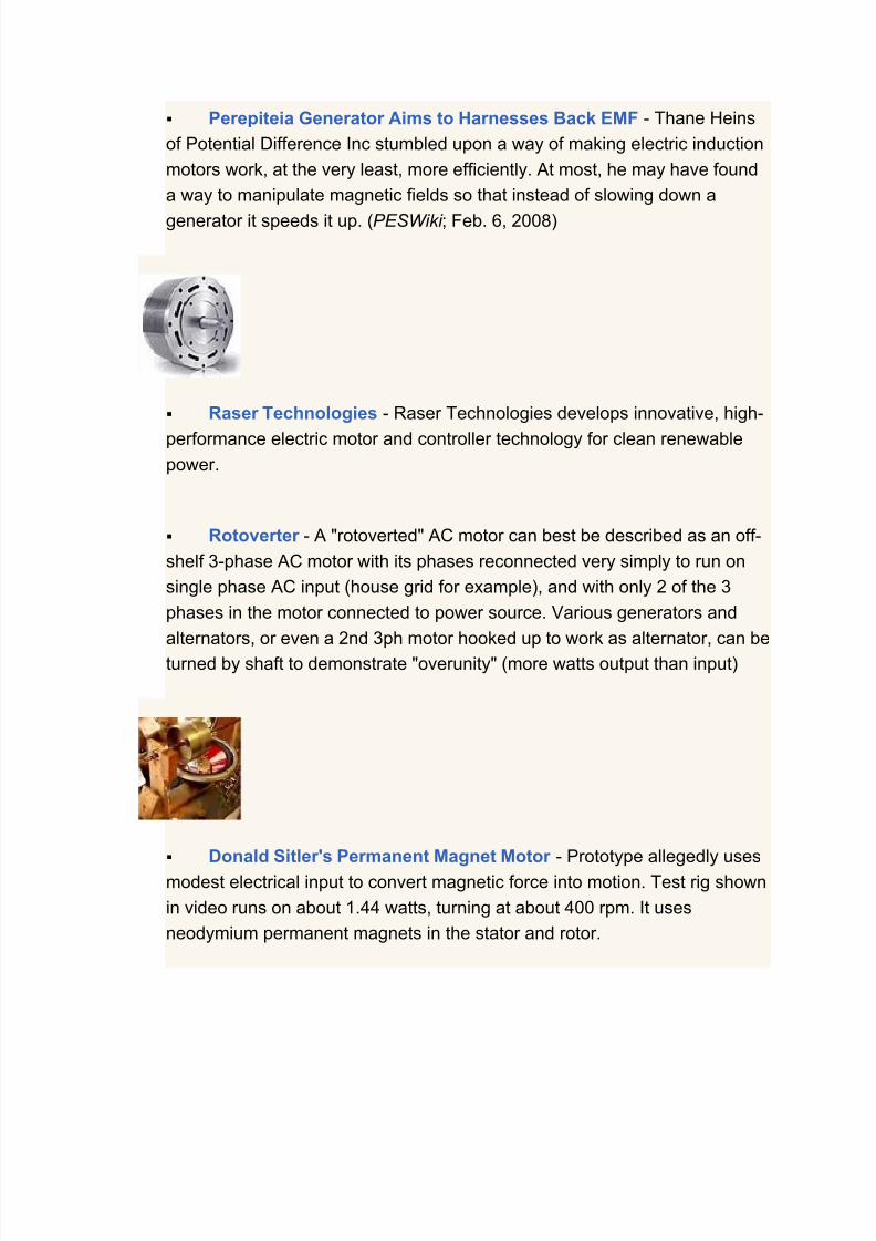
7/30/2019 Steorn Drops Four Bombshell Documents Validating Orbo
http://slidepdf.com/reader/full/steorn-drops-four-bombshell-documents-validating-orbo 131/307

7/30/2019 Steorn Drops Four Bombshell Documents Validating Orbo
http://slidepdf.com/reader/full/steorn-drops-four-bombshell-documents-validating-orbo 132/307
Can the SuperMag Engine/Generator Solve the World's Clean
Energy Needs? - Enigma G.C.'s "SuperMag", being marketed by
Supervision Entertainment, allegedly uses manipulated magnetic fields to
generate electricity sufficient to power the needs of a home or office building
and provides clean electrical power for free to the consumer after the initialcost of the purchase and installation of the system.
Testatika Electromagnetic Generator - Includes an inductancecircuit, a capacitance circuit, and a thermionic rectification valve. Alleged free
energy machine harnesses energy from the aether. Also known as the Swiss
M-L converter or Thesta-Distatica.
Vallee Synergetic Generator (VSG)
Research & Development
Featured: Electromagnetic > Potential Differences, Inc >
Thane Heins' Regenerative Acceleration Generator Goes Insteadof Stopping - Thane Heins, a native of Ottawa, Canada, has made
progress developing his Regenerative Acceleration Generator Technology.
With the use of a special coil design, the technology allows for
complimentary torque and electricity to be created in an electric vehicle with
no extra power required by the prime mover. He says that a researcher was

7/30/2019 Steorn Drops Four Bombshell Documents Validating Orbo
http://slidepdf.com/reader/full/steorn-drops-four-bombshell-documents-validating-orbo 133/307

7/30/2019 Steorn Drops Four Bombshell Documents Validating Orbo
http://slidepdf.com/reader/full/steorn-drops-four-bombshell-documents-validating-orbo 134/307
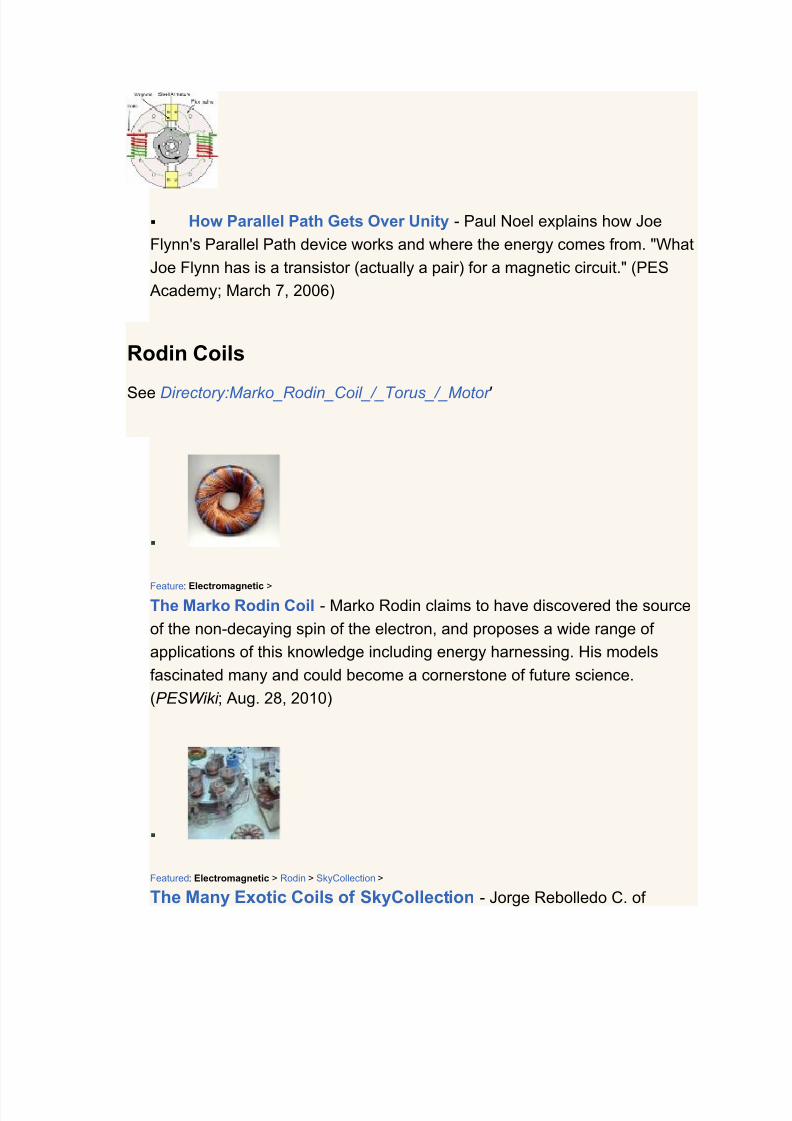
7/30/2019 Steorn Drops Four Bombshell Documents Validating Orbo
http://slidepdf.com/reader/full/steorn-drops-four-bombshell-documents-validating-orbo 135/307

7/30/2019 Steorn Drops Four Bombshell Documents Validating Orbo
http://slidepdf.com/reader/full/steorn-drops-four-bombshell-documents-validating-orbo 136/307

7/30/2019 Steorn Drops Four Bombshell Documents Validating Orbo
http://slidepdf.com/reader/full/steorn-drops-four-bombshell-documents-validating-orbo 137/307

7/30/2019 Steorn Drops Four Bombshell Documents Validating Orbo
http://slidepdf.com/reader/full/steorn-drops-four-bombshell-documents-validating-orbo 138/307

7/30/2019 Steorn Drops Four Bombshell Documents Validating Orbo
http://slidepdf.com/reader/full/steorn-drops-four-bombshell-documents-validating-orbo 139/307

7/30/2019 Steorn Drops Four Bombshell Documents Validating Orbo
http://slidepdf.com/reader/full/steorn-drops-four-bombshell-documents-validating-orbo 140/307
Adams Motor - The CD motor instructions posted are compiled by Tim
Harwood and originated by Robert Adams.
Lindemann Rotary Attraction Motor - Peter Lindemann has been
coaching a forum in replicating a modified off-the-shelf motor, adding a
Bedini-like circuit for improved efficiency, smoother running, and possible
over-unity performance.
Ross Motor - Theoretical overunity motor design presented by Jim
Ross, based on theories put forth by Tom Bearden.
Free Energy Generator: The Mini Romag Electromagnetic Motor -
The Mini Romag free energy generator from Magnetic Energy uses the
principle of moving magnetic flow named “the magnetic current” for

7/30/2019 Steorn Drops Four Bombshell Documents Validating Orbo
http://slidepdf.com/reader/full/steorn-drops-four-bombshell-documents-validating-orbo 141/307

7/30/2019 Steorn Drops Four Bombshell Documents Validating Orbo
http://slidepdf.com/reader/full/steorn-drops-four-bombshell-documents-validating-orbo 142/307

7/30/2019 Steorn Drops Four Bombshell Documents Validating Orbo
http://slidepdf.com/reader/full/steorn-drops-four-bombshell-documents-validating-orbo 143/307

7/30/2019 Steorn Drops Four Bombshell Documents Validating Orbo
http://slidepdf.com/reader/full/steorn-drops-four-bombshell-documents-validating-orbo 144/307

7/30/2019 Steorn Drops Four Bombshell Documents Validating Orbo
http://slidepdf.com/reader/full/steorn-drops-four-bombshell-documents-validating-orbo 145/307
7/30/2019 Steorn Drops Four Bombshell Documents Validating Orbo
http://slidepdf.com/reader/full/steorn-drops-four-bombshell-documents-validating-orbo 146/307

7/30/2019 Steorn Drops Four Bombshell Documents Validating Orbo
http://slidepdf.com/reader/full/steorn-drops-four-bombshell-documents-validating-orbo 147/307
The Orion Project >
Update on Pulsed Motor Generator by the Orion Project - Greer's group
reports: "In one test, the Pulsed Motor Generator successfully powered an
18 pound metal rotor at a steady speed of 1500 rpm with as little as 25 watts
of input power." (Orion Project ; August 12, 2008)
Featured: Electromagnetic >
Daniel Quale's Lenzless Generator - Inventor claims to have come up with
an electric generator that is unaffected by Lenz's Law. According to the site,
this type of generator should be capable of overunity. (PESWiki ; March 9,
2009)
Featured: Electromagnetic >
Alan Francoeur Interference Disc Generator - Alan L. Francoeur describes his generator as a multi-phase, interchangeable, ac/dc, variable,
frequency dynamo machine of high efficiency. Due to some "prior art"
controversy, in the interest of history, we resurrect this information.
(PESWiki ; March 9, 2009)

7/30/2019 Steorn Drops Four Bombshell Documents Validating Orbo
http://slidepdf.com/reader/full/steorn-drops-four-bombshell-documents-validating-orbo 148/307

7/30/2019 Steorn Drops Four Bombshell Documents Validating Orbo
http://slidepdf.com/reader/full/steorn-drops-four-bombshell-documents-validating-orbo 149/307
Using a Clock Pendulum to Generate Electricity - Bill Mehess has
invented a system in which a clock pendulum mechanism swings magnets
into coils, allegedly generating enough electricity to recharge the clock spring
as well as power other devices. (PESN; Mar. 24, 2007)
James D. Hardy's Self-Looped Water Pump and Electricity
Generator - Massachusetts inventor demonstrates a patent pending
technology in which a 165 gallon/minute water pump powers a water wheel,which is connected through belts to a one horse power generator, which
powers the water pump as well as an incandescent bulb. (PESWiki ; July 16,
2008)
Disappeared in History
Suppression / Videos > Energy from the Vacuum series >
Cold Heat from Canada (Trailer ) - In 1968, Designex Inc. in Toronto,
Canada, was powering the refrigerator, lights, radio and other appliances in
their offices with a device of their own design that was self powered by cold
negative radiant energy. Toronto Hydro, the local power company, sent acrew out, who removed all Toronto Hydro power meters, fuse boxes, and
wiring in an attempt to shut the power off, but to no avail. (Energy from the
Vacuum; Disc. 19; July, 2010)
For Communications

7/30/2019 Steorn Drops Four Bombshell Documents Validating Orbo
http://slidepdf.com/reader/full/steorn-drops-four-bombshell-documents-validating-orbo 150/307
Electromagnetism > Nikola Tesla >
Tapping Tesla to Save Trapped Miners - The noted pioneer in electricity
and radio showed over a century ago that a magnetic wave generator could
be used for wireless communications. Basically, the generator works like an
electromagnet. Powered by standard alternating current or battery, it runs
electricity through a wire that is coiled around a metal cylinder, creating a
harmless, low-energy magnetic field that extends for hundreds of meters.
(ScienceMag ; Aug. 20, 2010)
Other
Electric Motor Design Cuts Energy Use in Half - Thor Power is
commercializing a new electric motor design that generates twice the power
at half the weight and double the efficiency of existing electric motors. This
cuts the consumers' operating costs by 50%, for applications like
refrigerators and air conditioners. (Ben Franklin Technology Partners)
Brushless Doubly-Fed Generator (BDFG) improves the reliability
of wind turbines - A research team from the University of Cambridge have
developed a new generator technology for the wind turbine industry to the
point of commercial exploitation, for application in a wide spectrum of wind

7/30/2019 Steorn Drops Four Bombshell Documents Validating Orbo
http://slidepdf.com/reader/full/steorn-drops-four-bombshell-documents-validating-orbo 151/307

7/30/2019 Steorn Drops Four Bombshell Documents Validating Orbo
http://slidepdf.com/reader/full/steorn-drops-four-bombshell-documents-validating-orbo 152/307

7/30/2019 Steorn Drops Four Bombshell Documents Validating Orbo
http://slidepdf.com/reader/full/steorn-drops-four-bombshell-documents-validating-orbo 153/307
Variable Torque Motors - Axial field weakening yields higher
efficiency over the rpm range, creating a "built-in" transmission that
mechanically enables an operating range up to 10x the motor base speed for
electric vehicles. VTM offers hybrid retrofit packages installed on the drive
shaft of rear wheel drive vehicles using Maxwell BoostCap™ ultracapacitorsfor energy storage.
ExRo - The Variable Input Electrical Generator has been designed tomore efficiently convert variable energy sources such as wind into electricity,
producing 30% higher output. The VIEG is a permanent magnet brushless
system, so maintenance costs are minimal, and since it is a direct drive
system, the cost, weight and inefficiency of the gearbox is also eliminated.
Best Electric Machine - The Advanced Brushless Wound-Rotor
Synchronous Doubly-Fed Electric Machine System improves the cost-
performance envelope in electric motor and generator systems. It shows
nearly 50% reduction in cost and nearly 50% improvement in power density.
It has high reliability and low maintenance with no brushes or slip rings.

7/30/2019 Steorn Drops Four Bombshell Documents Validating Orbo
http://slidepdf.com/reader/full/steorn-drops-four-bombshell-documents-validating-orbo 154/307
InMotion Technologies - The IMT motor is a single sided axial flux
permanent magnet (PM) brushless motor with a slotted iron stator. New
power electronics and magnetically strong materials allow dramatic
improvements in efficiency of small machines and variable speed drives.
Suitable for electric bicycles, air conditioners, fans and electrical appliances.
Featured: Electromagnetic / Magnet Motors >
The Magnevex Research Project - Based on the research and writings of Ernest L. Norman, the Magnevex magnet motor / generator uses neodymium
magnets passing coils of wire to generate electricity. The goal is to do away
with the battery that is presently used to run the motor side of the magnetic
vortex. (PESWiki ; Feb. 1, 2009)
Ultra Motor Company - Permanent magnet DC Hub motors have only
five major components, are simple in design, easy to manufacture and suited
for narrow, wheel-mounted motor applications such as electric bikes and
scooters. Ultra motors offer significant space-saving while delivering higher
torque and efficiency - without the need for gears, belts or chains.
Direct Drive Systems - High speed permanent magnet motors &
generators above 1.5MW are able to operate at speeds of turbo-machines
which are up to 12 times faster. DDS electric machines are smaller (20% the
size and weight of conventional electric motors), more reliable, more efficient
7/30/2019 Steorn Drops Four Bombshell Documents Validating Orbo
http://slidepdf.com/reader/full/steorn-drops-four-bombshell-documents-validating-orbo 155/307
and more economical in capital and operating costs.
UQM Technologies - Permanent magnet electric motor system
achieves a 10 to 1 constant power speed ratio (CPSR), providing both hightorque and high speed capability in the same machine at levels greater than
that of other motor technology. Peak power is increased by 33 percent and
continuous power output by nearly 100 percent, and system efficiency from 2
to 8 percent. Suitable for electric vehicles and distributed power generation.
WaveCrest Laboratories - WaveCrest motors enhance dynamic
performance and control of vehicles by providing high levels of both positive
and negative torque at the wheel. They independently power the wheels onone or more of a vehicle’s axles, and occupy less interior space. The low-
speed torque and fast response time replaces costly systems such as anti-
lock braking and traction control. Regenerative braking reduces brake wear
and extends electric range.
Bodine Electric - Extremely high torque, energy efficiency, and
extraordinary precision make e-TORQ motors the practical direct drive
solution in applications which traditionally required a speed reducer. North
Dakota State University used one of these motors to finish first in a field of
30 teams in the American Solar Challenge in July of 2003.
Multi Products Company, Inc. - Manufacturer of custom gearmotors
and gearboxs which can be designed to meet extreme torque applications.
Gearmotors can be custom designed, built, and manufactured for both AC
and DC applications. All gearmotors are custom made in the USA.
NovaTorque - Produces small diameter fractional horsepower motors
for the appliance industry with coils wound parallel to the axis of rotation,
resulting in much higher efficiency and lower waste heat production.

7/30/2019 Steorn Drops Four Bombshell Documents Validating Orbo
http://slidepdf.com/reader/full/steorn-drops-four-bombshell-documents-validating-orbo 156/307
Synchro Pulse - High efficiency brushless motor technology utilising
an innovative approach to the magnetic engineering inside the motors,
delivering more load for less electricity without requiring exotic materials or
unusual production techniques. The motors use much less electricity for a
given load and the speed controller ensures you never deliver more power than needed.
Batteryless Bicycle Flashing Light System - video A Non-FrictionBicycle Dynamo (Generator). No friction on any parts of the bicycle; no drag;
very bright. Get the energy almost free (at least on bicycle). Uses a tumbling
magnet electrical generating system. Exterior magnet can be in any
orientation.
Theory
Featured: ZPE > Electromagnetic >
Nuclear Catastrophe: How the lack of fundamental research on
alternative energy led to a wrong energy policy - In an open letter to
the scientific and government communities, a group of eminent scientistspoint out the shortcomings of nuclear energy as it has been implemented,
and ask: "Is there a safer replacement for nuclear energy? The correct
answer is Yes! It comes from the revised concept of space – the physical
vacuum." (PESN ; May 10, 2011)

7/30/2019 Steorn Drops Four Bombshell Documents Validating Orbo
http://slidepdf.com/reader/full/steorn-drops-four-bombshell-documents-validating-orbo 157/307
Feature: Grand Unified Theories > Galactic Sea of Energy >
The role of the plasma with heterodyne resonance mechanism in
overunity devices - "In my recent book, Field Propulsion by Control of
Gravity - Theory and Experiments, I describe a unique physical mechanism
at the quantum mechanical level. Investigating many experiments that
apparently succeeded in obtaining overunity, I am sure that the same
mechanism is involved. It always involves EM activated plasma that in some
cases may not be visually observed." (PESWiki ; Sept. 17, 2010)
Featured: Electromagnetic Overunity > Bearden >
Bearden writes to New Scientist about fundamental flaws in EE model -Tom Bearden urges the scientific community to reexamine their core
electrical models to account for asymmetric systems that physics
acknowledges, thus providing explanation and support for the many
inventors discovering overunity electromagnetic effects. (PESN ; March 7,
2010)
Electromagnetic >
Basic Principles of Over Unity Electro Machines (pdf) - In this work
7/30/2019 Steorn Drops Four Bombshell Documents Validating Orbo
http://slidepdf.com/reader/full/steorn-drops-four-bombshell-documents-validating-orbo 158/307

7/30/2019 Steorn Drops Four Bombshell Documents Validating Orbo
http://slidepdf.com/reader/full/steorn-drops-four-bombshell-documents-validating-orbo 159/307

7/30/2019 Steorn Drops Four Bombshell Documents Validating Orbo
http://slidepdf.com/reader/full/steorn-drops-four-bombshell-documents-validating-orbo 160/307
gated. The original Tesla coil was energized by pulsed DC, quenched with amagnetic arc blowout. Pulsed AC does not do the same thing.
Cautions
Featured: Electromagnetic > Bedini SG >
Magniwork free energy plans = bogus claim; say they'll remedy that -
Magniwork has been selling a set of plans for a free energy device they say
could be scaled to power an entire house. However, it turns out that thedevice is nothing more than the Bedini SG circuit, which, though interesting,
has never been embodied in a self-looped system with energy left over for
practical use. They've apologized and removed the Bedini stuff. (PESWiki ;
June 2, 2009)
Featured / Polls: Electromagnetic > Magniwork >
Poll regarding the Magniwork power generator - We've been calling it a
scam, but is it? What's your experience? Haven't bought the plans. • Won't
get plans; a scam. • Got the plans; looks bogus. • Got the plans; haven't tried
building. • Plans not clear enough. • Built it; doesn't tap free energy. • It's
powering stuff, but not house. • It's powering my house completely. (PESNetwork ; Aug. 16, 2009)

7/30/2019 Steorn Drops Four Bombshell Documents Validating Orbo
http://slidepdf.com/reader/full/steorn-drops-four-bombshell-documents-validating-orbo 161/307

7/30/2019 Steorn Drops Four Bombshell Documents Validating Orbo
http://slidepdf.com/reader/full/steorn-drops-four-bombshell-documents-validating-orbo 162/307

7/30/2019 Steorn Drops Four Bombshell Documents Validating Orbo
http://slidepdf.com/reader/full/steorn-drops-four-bombshell-documents-validating-orbo 163/307

7/30/2019 Steorn Drops Four Bombshell Documents Validating Orbo
http://slidepdf.com/reader/full/steorn-drops-four-bombshell-documents-validating-orbo 164/307

7/30/2019 Steorn Drops Four Bombshell Documents Validating Orbo
http://slidepdf.com/reader/full/steorn-drops-four-bombshell-documents-validating-orbo 165/307

7/30/2019 Steorn Drops Four Bombshell Documents Validating Orbo
http://slidepdf.com/reader/full/steorn-drops-four-bombshell-documents-validating-orbo 166/307
Electromagnetic News
Electromagnetic (Overunity) in the News
Feature commenced January, 2010
News relating to Electromagnetic overunity systems which apparently or allegedlyput out more electrical charge than when is put in, somehow harness energy fromthe environment in the process.
2011
Vibrations >
Green sidewalk makes electricity -- one footstep at a time - The recycled
rubber "PaveGen" paving slabs harvest kinetic energy from the impact of people
stepping on them and instantly deliver tiny bursts of electricity to nearby
appliances. (CNN ; October 3, 2011)
Featured / Best Exotic FE: Electrostatic > Aviso >
Aviso Requests Expert Help for Equation - Ismael Aviso is an inventor
from the Philippines, who has developed multiple technologies that apparentlywork by collecting free energy from the ambient environment. He is now
requesting help from experts to produce an equation, derived from his test
results. (PESN ; October 13, 2011)

7/30/2019 Steorn Drops Four Bombshell Documents Validating Orbo
http://slidepdf.com/reader/full/steorn-drops-four-bombshell-documents-validating-orbo 167/307

7/30/2019 Steorn Drops Four Bombshell Documents Validating Orbo
http://slidepdf.com/reader/full/steorn-drops-four-bombshell-documents-validating-orbo 168/307

7/30/2019 Steorn Drops Four Bombshell Documents Validating Orbo
http://slidepdf.com/reader/full/steorn-drops-four-bombshell-documents-validating-orbo 169/307
Featured / Best Exotic FE: Electromagnetic > Solid State > Magnacoaster >
Magnacoaster Delays Continue - Richard Willis, of the Canadian company
Magnacoaster, has been promising to ship solid state, overunity generators for
three years, but has failed so far to do so. All these years later, though no units
have been shipped to customers. He still talks like this will happen very soon.(PESN and BeforeItsNews; October 2, 2011)
Featured / Best Exotic FE: Electrostatic > Aviso >
Aviso's Long- and Short-Term Goals - Between two devastating typhoons,
Ismael Aviso shares: "My Alt energy R&D ultimate goal is to achieve a self-
sustaining Electric car & Power generator system." In the near term, "We decided
to focus on building a Fuel saving device based from Hydrogen technology &
Highest efficiency E. Car." (PESN ; September 30, 2011)
Featured / Best Exotic FE: Electrostatic > Aviso >
Typhoon Floods Free Energy Inventor's Workshop - Ismael Aviso, an
alternative energy pioneer from the Philippines, has experienced a weather-
related disaster. A recent tropical system has flooded his home and workshop,
and has set back his research and development work by a few weeks. (PESN and BeforeItsNews; September 30, 2011)

7/30/2019 Steorn Drops Four Bombshell Documents Validating Orbo
http://slidepdf.com/reader/full/steorn-drops-four-bombshell-documents-validating-orbo 170/307

7/30/2019 Steorn Drops Four Bombshell Documents Validating Orbo
http://slidepdf.com/reader/full/steorn-drops-four-bombshell-documents-validating-orbo 171/307
with hardware and scope shots what is going on in the Transverter and Plasma
Globe ZPE converters designed by Hector Perez Torres. (PESN ; September 2,
2011)
Featured: Electromagnetic > Newman >
Solar Powered Perpetual Motion Machine - The user Magnetflipper on
YouTube has posted a video of a machine that is powered by a solar panel but
which then appears to augment that energy from yet another source, usingelectromagnetic overunity from a Joseph Newman motor. (PESN and
BeforeItsNews; August 31, 2011)
Featured: Electromagnetic / Weather Control > David Wells > Hurricane control >
Hurricane Irene Mitigation Efforts by Alberto and Dave - Alberto was up
visiting David recently on the mainland, and didn't get back down to an area
where he could effect the Irene, so it got away from him. David think Alberto's
belated efforts diminished the force of the storm, but Alberto said his battery was
not yet property conditioned, but is hopeful to hold off remaining hurricanes this
season. (PESN and -->BeforeItsNews; August 29, 2011)

7/30/2019 Steorn Drops Four Bombshell Documents Validating Orbo
http://slidepdf.com/reader/full/steorn-drops-four-bombshell-documents-validating-orbo 172/307

7/30/2019 Steorn Drops Four Bombshell Documents Validating Orbo
http://slidepdf.com/reader/full/steorn-drops-four-bombshell-documents-validating-orbo 173/307

7/30/2019 Steorn Drops Four Bombshell Documents Validating Orbo
http://slidepdf.com/reader/full/steorn-drops-four-bombshell-documents-validating-orbo 174/307

7/30/2019 Steorn Drops Four Bombshell Documents Validating Orbo
http://slidepdf.com/reader/full/steorn-drops-four-bombshell-documents-validating-orbo 175/307

7/30/2019 Steorn Drops Four Bombshell Documents Validating Orbo
http://slidepdf.com/reader/full/steorn-drops-four-bombshell-documents-validating-orbo 176/307

7/30/2019 Steorn Drops Four Bombshell Documents Validating Orbo
http://slidepdf.com/reader/full/steorn-drops-four-bombshell-documents-validating-orbo 177/307

7/30/2019 Steorn Drops Four Bombshell Documents Validating Orbo
http://slidepdf.com/reader/full/steorn-drops-four-bombshell-documents-validating-orbo 178/307

7/30/2019 Steorn Drops Four Bombshell Documents Validating Orbo
http://slidepdf.com/reader/full/steorn-drops-four-bombshell-documents-validating-orbo 179/307
Featured: Grand Unified Theories > Electric Universe Model >
NASA captures giant comet hitting sun - NASA has caught an astonishing
image of a comet smashing into the sun, followed by an immediate coronal mass
ejection that goes streaming out as if instigated by the comet, in a cause-effect
relationship. Is this additional evidence of the Electric Universe model? (PESN
and BeforeItsNews; May 18, 2011)
Featured: Orgone / Aetherometry / Weather Control / Bio-Energetics >
Report on Reich Research from Group in Greece - An introductory paper
giving a Reichian perspective on zero point energy, global weather phenomena,
free energy, modern science and non-science, misconceptions and associateddangers; as a contribution to discussions involving climate changes, disasters,
and the quest for new energies. (PESN and BeforeItsNews; May 15, 2011)
Featured / OS: Suppression > Electromagnetic > Muller Dynamo >
Romero's Self-Sustaining Dynamo Drama - An overunity.com forum
member going by the handle "romerouk" claims to have produced a self
sustaining "Muller Dynamo." He has posted instructions, specifications, pictures,
and videos of the device. Then yesterday, after receiving an unsettling visit, he

7/30/2019 Steorn Drops Four Bombshell Documents Validating Orbo
http://slidepdf.com/reader/full/steorn-drops-four-bombshell-documents-validating-orbo 180/307

7/30/2019 Steorn Drops Four Bombshell Documents Validating Orbo
http://slidepdf.com/reader/full/steorn-drops-four-bombshell-documents-validating-orbo 181/307
7/30/2019 Steorn Drops Four Bombshell Documents Validating Orbo
http://slidepdf.com/reader/full/steorn-drops-four-bombshell-documents-validating-orbo 182/307

7/30/2019 Steorn Drops Four Bombshell Documents Validating Orbo
http://slidepdf.com/reader/full/steorn-drops-four-bombshell-documents-validating-orbo 183/307

7/30/2019 Steorn Drops Four Bombshell Documents Validating Orbo
http://slidepdf.com/reader/full/steorn-drops-four-bombshell-documents-validating-orbo 184/307
Featured / Best Exotic FE: EVs > Electrostatic > Aviso EV >
Aviso Runs AC Motor on DC and Aether - Philippine Inventor Ismael Aviso
is breaking down barriers as he continues to develop his ambient energy
technology. He is now powering AC motors with DC current and in doing so has
solved the issue of overheating in his system. It just takes 0.8 amps at 240 Volts
(~200 Watts) to run an 18.5 kW motor during start-up and under load. (PESN and
BeforeItsNews; April 10, 2011)
Featured: Free Energy >
Twenty-first Century Technologies: The Road to Reindustrialization --
From the Ground Up- Artificial Intelligence expert explains the lag between
scientific discovery and explanation; specifies a few promising technologies of
note, including Brown's gas or hydroxy, Rossi's cold fusion, Turtur's zero point
energy, Aviso's self-running electric car. (PESN ; March 29, 2011)
Electromagnetic >
Ken Shoulders on Exotic Vacuum Objects (EVOs) - Electronics pioneer, Ken
Shoulders' new paper “Primordial Substance” refers to EVOs — Exotic Vacuum
Objects: yet another name for a new electronic effect that’s also been calledElectromagnetic Vortex or Electrum Validum and “charge cluster”. EVOs are
considered by the author to be composed of myriad electromagnetic wavelets
instead of conventional particles such as electrons. (Changing Power ; March 26,
2011)

7/30/2019 Steorn Drops Four Bombshell Documents Validating Orbo
http://slidepdf.com/reader/full/steorn-drops-four-bombshell-documents-validating-orbo 185/307
Featured / Best Exotic FE: Nuclear > Cold Fusion > Rossi >
Andrea Rossi with Sterling Allan on Coast to Coast AM (Transcript) - On
the evening of March 23rd, Andrea Rossi, the inventor of the Energy Catalyzer (a
10 kW cold fusion reactor going commercial), joined Sterling Allan on Coast to
Coast AM with host George Noory. Coincidentally, it took place on the twenty
second anniversary of Pons and Fleishman's legendary announcement! (PESN
and BeforeItsNews; March 24, 2011)
Featured / Best Exotic FE: EVs > Electrostatic > Aviso >
Aviso's Ambient Energy Technologies: Frequently Asked Questions -
Hank Mills has compiled a FAQ page about Ismael Aviso's technology thatincludes 1) being able to keep an electric vehicle battery charged while driving
down the road, 2) a motionless electric generator, and 3) a repelling force motor;
which all use the same "FYMEGM" effect. (PESWiki ; March 23, 2011)
Featured: Electromagnetic > Magratten PEMM >
PEMM Motor Harnesses Anti-matter and Electron-Avalanche - Gary
Magrattan's PEMM Electric motor is said to harness the phenomenon of electron
avalanche across a spark gap to boost current, voltage, and power. A unique

7/30/2019 Steorn Drops Four Bombshell Documents Validating Orbo
http://slidepdf.com/reader/full/steorn-drops-four-bombshell-documents-validating-orbo 186/307
7/30/2019 Steorn Drops Four Bombshell Documents Validating Orbo
http://slidepdf.com/reader/full/steorn-drops-four-bombshell-documents-validating-orbo 187/307

7/30/2019 Steorn Drops Four Bombshell Documents Validating Orbo
http://slidepdf.com/reader/full/steorn-drops-four-bombshell-documents-validating-orbo 188/307

7/30/2019 Steorn Drops Four Bombshell Documents Validating Orbo
http://slidepdf.com/reader/full/steorn-drops-four-bombshell-documents-validating-orbo 189/307

7/30/2019 Steorn Drops Four Bombshell Documents Validating Orbo
http://slidepdf.com/reader/full/steorn-drops-four-bombshell-documents-validating-orbo 190/307
Players to Change Sides. (PESN and BeforeItsNews; March 1, 2011)
Featured / OS / Best Exotic FE: EVs > Electrostatic > Aviso EV >
Aviso Ponders Open Sourcing his Self-Running Electric Car
Technology - Ismael Aviso is considering open sourcing his technology that
harvests energy from the environment on the fly to keep a 11-kW DC motor
running. He said he'll give it three months to decide whether to continue the
investor route, or pursue the open source route. Both involve common pre-requisite steps including plans preparation, replication.... (PESN and
BeforeItsNews; February 27, 2011)
Best Exotic FE: EVs > Electrostatic > Aviso >
Overview of Aviso Free Energy Technology (video) - Ashtweth of Panacea-
BOCAF has compiled recent video footage, adding a voice-over description,
talking about the antenna system that harvests ambient energy from the
surroundings, the repelling force, the recent coverage on Philippines Channel 7,
and the recent collaborative testing by the Department of Energy. He encourages
donation support of this breakthrough team. (YouTube / andrewg85 ; February
25, 2011)

7/30/2019 Steorn Drops Four Bombshell Documents Validating Orbo
http://slidepdf.com/reader/full/steorn-drops-four-bombshell-documents-validating-orbo 191/307

7/30/2019 Steorn Drops Four Bombshell Documents Validating Orbo
http://slidepdf.com/reader/full/steorn-drops-four-bombshell-documents-validating-orbo 192/307

7/30/2019 Steorn Drops Four Bombshell Documents Validating Orbo
http://slidepdf.com/reader/full/steorn-drops-four-bombshell-documents-validating-orbo 193/307

7/30/2019 Steorn Drops Four Bombshell Documents Validating Orbo
http://slidepdf.com/reader/full/steorn-drops-four-bombshell-documents-validating-orbo 194/307
information in Trends Journal about breakthroughs in new energy that could shift
the whole game. It may be as big as the discovery of fire or the invention of the
wheel". They will cite PESWiki as a recommended resource. (PESN ; January 8,
2011)
Featured / Best Exotic FE: Zeitgeist > Trends >
Top free energy stories of 2010 and beyond - My prediction that 2010
would be known as "the year of crowning", to use a childbirth analogy, hasproven true. Several free energy technologies began popping out, getting ready
for market. Join us as we take a look at some of the most exciting developments.
(PESN ; January 6, 2011)
2010
News:2010:Electromagnetic - going back in time
2009
News:2009:Electromagnetic - going back in time
2006 - 2008
News:2006-2008:Electromagnetic - going back in time
See also Directory:Electromagnetic (overunity)
BEST
Directory:Best Exotic Clean Energy Technologies

7/30/2019 Steorn Drops Four Bombshell Documents Validating Orbo
http://slidepdf.com/reader/full/steorn-drops-four-bombshell-documents-validating-orbo 195/307

7/30/2019 Steorn Drops Four Bombshell Documents Validating Orbo
http://slidepdf.com/reader/full/steorn-drops-four-bombshell-documents-validating-orbo 196/307
NEWS BY TOPIC --> Alternative Fuels | Batteries | Best Exotic FE | Cold
Fusion | Conspiracy | Electric Vehicles | Electromagnetic OU | Fuel Efficiency |
Geothermal | Gravity Motors | Hydro | Hydrogen | Hydroxy / HHO | Magnet
Motors | Nanotech | Open Source | Rossi Cold Fusion | Solar | Storage | Tesla |
Top 100 | Waste to Energy | Water | Wind | Zero Point Energy PESN - Stories by PES Network, Inc.
PESWiki News Archive index
This Week in Free Energy - 10-minute weekly wrap-up radio
Free Energy Now - radio show featuring specific technologies
Toroidal Power DirectoryDirectory technologies and resources relating to toroids.
Contents
[hide]
1 Overview
2 Featured at
PESWiki
3 In the News
4 See also
Overview
April 10, 2006RE: Toroidal Power
The toroid, as a magnetic core, serves as a quite efficient AC transformer,depending upon the ratio of the input to output turns. As with any magnetic device,there is a small bit of resident hysteresis, which consumes power, producing heatingof the toroid. Such heating invariably reduces the amount of output energy relative tothe amount of input energy.

7/30/2019 Steorn Drops Four Bombshell Documents Validating Orbo
http://slidepdf.com/reader/full/steorn-drops-four-bombshell-documents-validating-orbo 197/307

7/30/2019 Steorn Drops Four Bombshell Documents Validating Orbo
http://slidepdf.com/reader/full/steorn-drops-four-bombshell-documents-validating-orbo 198/307
7/30/2019 Steorn Drops Four Bombshell Documents Validating Orbo
http://slidepdf.com/reader/full/steorn-drops-four-bombshell-documents-validating-orbo 199/307
Said to harness the power of the Earth's electromagnetic field.
In the News
Featured: Electromagnetic > Toroid > Steorn >
Orbo and magnetic flux-gating - While the author (Kavee) doesn't know of any
bona fide "free energy" proof springing from the Orbo technology, he does think
there are several fascinating effects that are worth exploring, which could lead to
greater efficiency. Preface rebuttal by Steorn CEO. (PESN ; May 12, 2010)
Overview of the TPU (Toroidal Power Unit) of Steven Mark - In the inventors
words; "There has been a concerted effort to eliminate anything I may have to
say and to discount the validity of the technology. This is done by attacking me
rather than the demonstration as viewed in the video tapes. That is because
most of the demonstrations I gave were to engineers and scientists whoconfirmed the validity of the power generated by my technology. Lay people do
not understand just how difficult if not impossible it would be to fake what is
shown in the video tapes of the demonstrations."
1997 Demo Video Shows Solid State Energy Coils - Toroid coils put out 183
Volts DC and 875 Volts DC. Device also exhibits anti-moving gyro effect. Patent
Application available. (PESWiki ; Oct. 23, 2005)
See alsoBEST
Directory:Best Exotic Clean Energy Technologies
News:Best Exotic Free Energy Technologies

7/30/2019 Steorn Drops Four Bombshell Documents Validating Orbo
http://slidepdf.com/reader/full/steorn-drops-four-bombshell-documents-validating-orbo 200/307
Top free energy stories of 2010 and beyond
Template:Tesla footer
ENERGY TYPES
Directory:Galactic Sea of Energy
Directory:Aether | PowerPedia:Aether
Directory:Atmospheric Electrostatic Energy
Directory:Dark Energy
Directory:Radiant Energy | PowerPedia:Radiant Energy
Directory:Vacuum
Directory:Zero Point Energy
Directory:Grand Unified Theories | Directory:Aether Physics Model
Directory:Vibrations
Directory:Fractal Antennas as an Energy Source
DEVICE TYPES
Directory:Electromagnetic (overunity)
News:Electromagnetic (latest) | 2009 | 2006-2008
Directory:Magnet Motors | News:Magnet Motors
Directory:Linear Magnet Accelerators Directory:Pyramid Power
Directory:Solid State
Directory:Solid State Generators | PowerPedia:Solid State Generator
Directory:Toroidal Power
Directory:Marko Rodin Coil / Torus / Motor
Directory:Vibrations
Directory:Power from Ambient Electromagnetic Radiation
Directory:Gravity Motors Directory:Pendulums
- Other Directory listings• Latest• A-I• J-R• S-Z• Tree• News- PESWiki home page
7/30/2019 Steorn Drops Four Bombshell Documents Validating Orbo
http://slidepdf.com/reader/full/steorn-drops-four-bombshell-documents-validating-orbo 201/307

7/30/2019 Steorn Drops Four Bombshell Documents Validating Orbo
http://slidepdf.com/reader/full/steorn-drops-four-bombshell-documents-validating-orbo 202/307
3.8 Historical
3.9 Theoretical
3.10 Spoofs
3.11 Beware
3.12 Conventional Systems
4 Resources
4.1 Overviews
4.2 Ads
4.3 Directories
5 Coverage
5.1 Events
5.2 In the News
5.3 Discussion
6 See also
Overview
Updated August 2, 2011
As of today, there still are no plans that I know of that surely result in a magnet
motor. However, that could change in the next few weeks, as someone has comeforward with a design that they are talking about open sourcing. I'm in process of getting those, having a few built to confirm the design, and then publishing the plans.
Also, the number of people I have met who adamantly claim to have built a workingall-magnet motor has increased; though I myself still have never seen one myself.
I've also met a person who is an extremely gifted inventor who told me that some 30years ago he was told that at some point he would invent an all-magnet motor thatwould substantially help the planet. He seems to have been pushed closer to maybefinally getting around to that.
There is one alleged working design that I am confident is real, that has beenpowering a house for 1.5 years with only a 5% drop in magnetism over a 1 year period. The inventor doesn't want to take it forward himself, but he is willing to sell itoutright to someone who will take it forward, for many million dollars. If you knowsomeone who might be interested, let me know.
-- Sterling D. Allan

7/30/2019 Steorn Drops Four Bombshell Documents Validating Orbo
http://slidepdf.com/reader/full/steorn-drops-four-bombshell-documents-validating-orbo 203/307
Witnesses
Conventional physics says that it is "impossible" for magnets to provide a primaryenergy source. Yet thousands of researchers worldwide have been pursuing the
task of building a working magnet motor. Many claim to have achieved thisobjective. None has reached the marketplace yet.
Poll
Featured: Magnet Motors >
Poll: Do you think an all-magnet motor (no electrical input) is possible? -
We've posted a poll to get your input on this question, with the following answer
options: - Impossible - Maybe - Quite sure - Someone I trust says they've
built/seen one - I've personally built or seen one. Comment as you like. (PES
Network via 99Polls.com; May 30, 2009)
New Energy Congress Members Witness MagnetMotors
Running Magnet Motors Witnessed - Four of twenty New Energy Congress
members who responded to a week-long poll said they had personally witnesseda magnet motor in operation in which magnets were the only motive force. A
follow-up poll presented to the general public shows a similar ratio. (PESN ; Sept.
28, 2007)

7/30/2019 Steorn Drops Four Bombshell Documents Validating Orbo
http://slidepdf.com/reader/full/steorn-drops-four-bombshell-documents-validating-orbo 204/307

7/30/2019 Steorn Drops Four Bombshell Documents Validating Orbo
http://slidepdf.com/reader/full/steorn-drops-four-bombshell-documents-validating-orbo 205/307

7/30/2019 Steorn Drops Four Bombshell Documents Validating Orbo
http://slidepdf.com/reader/full/steorn-drops-four-bombshell-documents-validating-orbo 206/307

7/30/2019 Steorn Drops Four Bombshell Documents Validating Orbo
http://slidepdf.com/reader/full/steorn-drops-four-bombshell-documents-validating-orbo 207/307

7/30/2019 Steorn Drops Four Bombshell Documents Validating Orbo
http://slidepdf.com/reader/full/steorn-drops-four-bombshell-documents-validating-orbo 208/307

7/30/2019 Steorn Drops Four Bombshell Documents Validating Orbo
http://slidepdf.com/reader/full/steorn-drops-four-bombshell-documents-validating-orbo 209/307

7/30/2019 Steorn Drops Four Bombshell Documents Validating Orbo
http://slidepdf.com/reader/full/steorn-drops-four-bombshell-documents-validating-orbo 210/307
Magnetic Power Inc - CEO, Mark Goldes, expected to have a 1 kW module
ready for production toward the end of 2006... 2007... now 2008...
Directory:Syncopetra Motor
Open Source Projects
Featured: Magnet Motors > V-Gates >
Mechanical Opener for V-Gate Magnet Motor - A video originally posed by
Roobert33 shows a V-gate magnet motor that supposedly is made functional
(rotation maintained) by means of a mechanical method for moving the stator
magnets in and out of the way of the gate ("re-gauging") so that the gate doesn't
become a lock-up point that otherwise would stop the motion of the magnet
motor. (PESWiki ; November 18 2010)
Feature / OS: Magnet Motors >
Hatem Magnetic Cogging Device Open Source Project - Several people
are claiming that they have achieved more energy out than in with a system in
which a motor drives one magnet disc that propels a second, non-touching
magnet disc that drives an alternator, introducing nearly twice as much power as

7/30/2019 Steorn Drops Four Bombshell Documents Validating Orbo
http://slidepdf.com/reader/full/steorn-drops-four-bombshell-documents-validating-orbo 211/307

7/30/2019 Steorn Drops Four Bombshell Documents Validating Orbo
http://slidepdf.com/reader/full/steorn-drops-four-bombshell-documents-validating-orbo 212/307

7/30/2019 Steorn Drops Four Bombshell Documents Validating Orbo
http://slidepdf.com/reader/full/steorn-drops-four-bombshell-documents-validating-orbo 213/307

7/30/2019 Steorn Drops Four Bombshell Documents Validating Orbo
http://slidepdf.com/reader/full/steorn-drops-four-bombshell-documents-validating-orbo 214/307

7/30/2019 Steorn Drops Four Bombshell Documents Validating Orbo
http://slidepdf.com/reader/full/steorn-drops-four-bombshell-documents-validating-orbo 215/307

7/30/2019 Steorn Drops Four Bombshell Documents Validating Orbo
http://slidepdf.com/reader/full/steorn-drops-four-bombshell-documents-validating-orbo 216/307
Gravity Motor with Permanent Magnet Assist - Open-sourced design
combines the principles of gravity and magnetism to create a rotating device,
whose torque can be harnessed for energy. Working prototype destroyed.
Gravity Test Motor Might Work as Magnet Motor Platform - Replication
variant of Tom Ferko's gravity motor with magnet assist design turns out to not
self-rotate. However, the dynamics of motion near the fulcrum point provide
interesting possibilities for a possible magnet motor application. (PESN ; May 12,
2006)
Peterman Magnet Motor - Brad Peterman seeks donations to build high-precision permanent magnet motor prototype based on a rough prototype he said
ran for 5 1/2 minutes. If prototype is successful, he said he will open source the
design. Howard Johnson design.
Telesis Magnetic Motor with Superconductor Shielding - prototype built, but
not working; says that materials were not adequate.

7/30/2019 Steorn Drops Four Bombshell Documents Validating Orbo
http://slidepdf.com/reader/full/steorn-drops-four-bombshell-documents-validating-orbo 217/307

7/30/2019 Steorn Drops Four Bombshell Documents Validating Orbo
http://slidepdf.com/reader/full/steorn-drops-four-bombshell-documents-validating-orbo 218/307

7/30/2019 Steorn Drops Four Bombshell Documents Validating Orbo
http://slidepdf.com/reader/full/steorn-drops-four-bombshell-documents-validating-orbo 219/307

7/30/2019 Steorn Drops Four Bombshell Documents Validating Orbo
http://slidepdf.com/reader/full/steorn-drops-four-bombshell-documents-validating-orbo 220/307

7/30/2019 Steorn Drops Four Bombshell Documents Validating Orbo
http://slidepdf.com/reader/full/steorn-drops-four-bombshell-documents-validating-orbo 221/307

7/30/2019 Steorn Drops Four Bombshell Documents Validating Orbo
http://slidepdf.com/reader/full/steorn-drops-four-bombshell-documents-validating-orbo 222/307

7/30/2019 Steorn Drops Four Bombshell Documents Validating Orbo
http://slidepdf.com/reader/full/steorn-drops-four-bombshell-documents-validating-orbo 223/307

7/30/2019 Steorn Drops Four Bombshell Documents Validating Orbo
http://slidepdf.com/reader/full/steorn-drops-four-bombshell-documents-validating-orbo 224/307

7/30/2019 Steorn Drops Four Bombshell Documents Validating Orbo
http://slidepdf.com/reader/full/steorn-drops-four-bombshell-documents-validating-orbo 225/307

7/30/2019 Steorn Drops Four Bombshell Documents Validating Orbo
http://slidepdf.com/reader/full/steorn-drops-four-bombshell-documents-validating-orbo 226/307

7/30/2019 Steorn Drops Four Bombshell Documents Validating Orbo
http://slidepdf.com/reader/full/steorn-drops-four-bombshell-documents-validating-orbo 227/307
Muller Power - Official Web Site for information pertaining to Canadian
inventor Bill Muller and his Motor / Generator design.
Vyacheslav Strushchenko motor - Claims to have working model, but says
that for five years the Russian government has refused to grant official
recognition or patent. (Pravda; July 23, 2005)
Magnet Motor Design - Explanation, photos, commentary. "The only problem
is, that he used the wrong permanent magnets and the motor came to a standstill
after a few minutes due to eddy currents inside the magnets (Neo magnets
conduct themselves!) discharged the magnets themselves. Now he will try it withferrite magnets!"
Featured: Electromagnetic / Magnet Motors >
The Magnevex Research Project - Based on the research and writings of
Ernest L. Norman, the Magnevex magnet motor / generator uses neodymium
magnets passing coils of wire to generate electricity. The goal is to do away with
the battery that is presently used to run the motor side of the magnetic vortex.

7/30/2019 Steorn Drops Four Bombshell Documents Validating Orbo
http://slidepdf.com/reader/full/steorn-drops-four-bombshell-documents-validating-orbo 228/307

7/30/2019 Steorn Drops Four Bombshell Documents Validating Orbo
http://slidepdf.com/reader/full/steorn-drops-four-bombshell-documents-validating-orbo 229/307

7/30/2019 Steorn Drops Four Bombshell Documents Validating Orbo
http://slidepdf.com/reader/full/steorn-drops-four-bombshell-documents-validating-orbo 230/307

7/30/2019 Steorn Drops Four Bombshell Documents Validating Orbo
http://slidepdf.com/reader/full/steorn-drops-four-bombshell-documents-validating-orbo 231/307

7/30/2019 Steorn Drops Four Bombshell Documents Validating Orbo
http://slidepdf.com/reader/full/steorn-drops-four-bombshell-documents-validating-orbo 232/307

7/30/2019 Steorn Drops Four Bombshell Documents Validating Orbo
http://slidepdf.com/reader/full/steorn-drops-four-bombshell-documents-validating-orbo 233/307
Zwick13 - Universal and planetary gears driven by magnetic repulsion,
hypercube magnet box.
Perpetually Rotating Bar Magnet Arrangement Using magnets in a pattern
where symmetry is slightly disjointed. Magnets naturally find a place to rest
somewhere where the system is in balance. This system/arrangement
deliberately has no balance point..
The Astronaut's Magnetic Boots - Astronaut training boots had permanent
magnets with "memory". The boots and references thereto disappeared from the
literature for reasons suspected to do with the magnet motor application which
"the powers that be" did not want released. Researcher John Reed uncovers the
original Radus magnet boots from Radus' sister. (Chiniere.org; circa 2001-2005)

7/30/2019 Steorn Drops Four Bombshell Documents Validating Orbo
http://slidepdf.com/reader/full/steorn-drops-four-bombshell-documents-validating-orbo 234/307

7/30/2019 Steorn Drops Four Bombshell Documents Validating Orbo
http://slidepdf.com/reader/full/steorn-drops-four-bombshell-documents-validating-orbo 235/307

7/30/2019 Steorn Drops Four Bombshell Documents Validating Orbo
http://slidepdf.com/reader/full/steorn-drops-four-bombshell-documents-validating-orbo 236/307

7/30/2019 Steorn Drops Four Bombshell Documents Validating Orbo
http://slidepdf.com/reader/full/steorn-drops-four-bombshell-documents-validating-orbo 237/307

7/30/2019 Steorn Drops Four Bombshell Documents Validating Orbo
http://slidepdf.com/reader/full/steorn-drops-four-bombshell-documents-validating-orbo 238/307
7/30/2019 Steorn Drops Four Bombshell Documents Validating Orbo
http://slidepdf.com/reader/full/steorn-drops-four-bombshell-documents-validating-orbo 239/307
Magnetizer.com -- The Science of Applied Magnetics - "With
decades of extensive research, Magnetizer has developed the most powerful
and effective magnetic technology in the world."
Resources
Forcefield - The world's most powerful magnets in dozens of shapes
and sizes. Magnet and magnetism FAQs, safety information, science
experiments with magnets, amazing demonstration images, very active
magnet science discussion board! Diamagnetic levitation, superconductors,
magnetic water treatment, unusual uses for strong magnets.
Magswitch - Switchable on/off permanent magnets control magnetic
fields without the electric power required by electromagnets. It affords the
ability to manufacture a low cost, switchable permanent magnetic device,
replacing existing electromagnets to develop ecological sustainability andimproved performance.
Overviews
See PowerPedia:Magnetic motor
Magnetism > Magnet Motors >
Sources of Small Magnet Motors - "A magnetic motor spins by its own

7/30/2019 Steorn Drops Four Bombshell Documents Validating Orbo
http://slidepdf.com/reader/full/steorn-drops-four-bombshell-documents-validating-orbo 240/307
7/30/2019 Steorn Drops Four Bombshell Documents Validating Orbo
http://slidepdf.com/reader/full/steorn-drops-four-bombshell-documents-validating-orbo 241/307

7/30/2019 Steorn Drops Four Bombshell Documents Validating Orbo
http://slidepdf.com/reader/full/steorn-drops-four-bombshell-documents-validating-orbo 242/307
Directory:Best Exotic Clean Energy Technologies
News:Best Exotic Free Energy Technologies
Top free energy stories of 2010 and beyond
Template:Tesla footer
ENERGY TYPES
Directory:Galactic Sea of Energy
Directory:Aether | PowerPedia:Aether
Directory:Atmospheric Electrostatic Energy
Directory:Dark Energy
Directory:Radiant Energy | PowerPedia:Radiant Energy
Directory:Vacuum
Directory:Zero Point Energy
Directory:Grand Unified Theories | Directory:Aether Physics Model
Directory:Vibrations
Directory:Fractal Antennas as an Energy Source
DEVICE TYPES
Directory:Electromagnetic (overunity)
News:Electromagnetic (latest) | 2009 | 2006-2008 Directory:Magnet Motors | News:Magnet Motors
Directory:Linear Magnet Accelerators
Directory:Pyramid Power
Directory:Solid State
Directory:Solid State Generators | PowerPedia:Solid State Generator
Directory:Toroidal Power
Directory:Marko Rodin Coil / Torus / Motor
Directory:Vibrations Directory:Power from Ambient Electromagnetic Radiation
Directory:Gravity Motors
Directory:Pendulums
- Other Directory listings• Latest• A-I• J-R• S-Z• Tree• News- PESWiki home page

7/30/2019 Steorn Drops Four Bombshell Documents Validating Orbo
http://slidepdf.com/reader/full/steorn-drops-four-bombshell-documents-validating-orbo 243/307

7/30/2019 Steorn Drops Four Bombshell Documents Validating Orbo
http://slidepdf.com/reader/full/steorn-drops-four-bombshell-documents-validating-orbo 244/307

7/30/2019 Steorn Drops Four Bombshell Documents Validating Orbo
http://slidepdf.com/reader/full/steorn-drops-four-bombshell-documents-validating-orbo 245/307

7/30/2019 Steorn Drops Four Bombshell Documents Validating Orbo
http://slidepdf.com/reader/full/steorn-drops-four-bombshell-documents-validating-orbo 246/307

7/30/2019 Steorn Drops Four Bombshell Documents Validating Orbo
http://slidepdf.com/reader/full/steorn-drops-four-bombshell-documents-validating-orbo 247/307
Featured: Prizes > Contests >
Create the Future and Win Twenty Grand! - The 2011 Create the Future
contest by NASA Tech Briefs magazine is now accepting entries. By submitting
your innovative technology you could attract attention to your idea and win twenty
thousand dollars! Previous winners have include the MYT Engine and
Litrospheres. (PES and BeforeItsNews; April 25, 2011)
FYI Solar / Magnetism >
Solar power without solar cells: A hidden magnetic effect of light could
make it possible - A dramatic and surprising magnetic effect of light discovered
by University of Michigan researchers could lead to solar power without
traditional semiconductor-based solar cells. At the right intensity, when light is
traveling through a material that does not conduct electricity, the light field can
generate magnetic effects that are 100 million times stronger than previously
expected. (PhysOrg ; Apr. 14, 2011)
Magnetism > Magnet Motors >
Sources of Small Magnet Motors - "A magnetic motor spins by its own internal
magnetism; magnets are strategically placed so that a shaft is turned by
attraction and repulsion forces." Brief review covers Wesley Gary from the 1870s,Howard Johnson's 1979 patent, Kohei Minato's 1997 patent. (eHow ; March 9,
2011)

7/30/2019 Steorn Drops Four Bombshell Documents Validating Orbo
http://slidepdf.com/reader/full/steorn-drops-four-bombshell-documents-validating-orbo 248/307
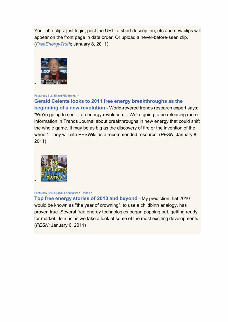
7/30/2019 Steorn Drops Four Bombshell Documents Validating Orbo
http://slidepdf.com/reader/full/steorn-drops-four-bombshell-documents-validating-orbo 249/307

7/30/2019 Steorn Drops Four Bombshell Documents Validating Orbo
http://slidepdf.com/reader/full/steorn-drops-four-bombshell-documents-validating-orbo 250/307

7/30/2019 Steorn Drops Four Bombshell Documents Validating Orbo
http://slidepdf.com/reader/full/steorn-drops-four-bombshell-documents-validating-orbo 251/307

7/30/2019 Steorn Drops Four Bombshell Documents Validating Orbo
http://slidepdf.com/reader/full/steorn-drops-four-bombshell-documents-validating-orbo 252/307

7/30/2019 Steorn Drops Four Bombshell Documents Validating Orbo
http://slidepdf.com/reader/full/steorn-drops-four-bombshell-documents-validating-orbo 253/307
7/30/2019 Steorn Drops Four Bombshell Documents Validating Orbo
http://slidepdf.com/reader/full/steorn-drops-four-bombshell-documents-validating-orbo 254/307
magnets in and out of the way of the gate ("re-gauging") so that the gate doesn't
become a lock-up point that otherwise would stop the motion of the magnet
motor. (PESWiki ; November 18 2010)
Magnets > Vulnerabilities >
EU, U.S. Grapple With Crunch In Rare Earth Supplies - The European Union
and the United States said on Tuesday they were pressing for solutions to
concerns China may be exploiting its stranglehold on rare earth metals, crucial inthe making of everything from portable phones to wind turbines. (PlanetArk ; Oct.
27, 2010)
Featured / DIY: Magnet Motors >
Plans available for Luis Tonos (LT) Magnet Motor alleged working
design - Luis has been posting comments on any magnet motor videos he can
find at YouTube saying that plans for a "REAL free energy machine" are
available, urging: "Join the free energy revolution!!" (PESWiki ; Oct. 26, 2010)
Magnets > Vulnerabilities >
China Lowers the Boom on Rare Earths - Monday, China embargoed exports
of rare earth elements to the United States. Rare earths are integral to most all
cutting edge technologies including renewable energy systems (e.g. magnet
motors), and China controls 93-97% of the world supply. "Whenever you have a

7/30/2019 Steorn Drops Four Bombshell Documents Validating Orbo
http://slidepdf.com/reader/full/steorn-drops-four-bombshell-documents-validating-orbo 255/307

7/30/2019 Steorn Drops Four Bombshell Documents Validating Orbo
http://slidepdf.com/reader/full/steorn-drops-four-bombshell-documents-validating-orbo 256/307
come up with a device that combines forces of gravity and magnets with a
flywheel to produce power. External power is required to get it rotating, but once
it comes up to speed, it allegedly produces excess energy. A local newspaper, as
well as 14 UK Engineers and the patent office have all allegedly witnessed it in
operation. (PESWiki ; Sept. 18, 2010)
Feature: Grand Unified Theories > Galactic Sea of Energy >
The role of the plasma with heterodyne resonance mechanism in
overunity devices - "In my recent book, Field Propulsion by Control of Gravity
- Theory and Experiments, I describe a unique physical mechanism at the
quantum mechanical level. Investigating many experiments that apparently
succeeded in obtaining overunity, I am sure that the same mechanism is
involved. It always involves EM activated plasma that in some cases may not be
visually observed." (PESWiki ; Sept. 17, 2010)
Magnet Motors / Electromagnetic > Perendev >
He runs and runs and runs (Brady's Perendev) - On Sept. 8, when Mike Brady
appeared in court, a local news report said he "vehemently cursed" when
charged with fraud according to 70 witnesses, who said he accepted pre-
payment for his motor but did not receive delivery, nor refund when requested.
(Merkur via PESWiki ; Sept. 9, 2010)
Feature / OS: Magnet Motors > Perendev >
Revealing what I know about building the Perendev magnet motor - Having

7/30/2019 Steorn Drops Four Bombshell Documents Validating Orbo
http://slidepdf.com/reader/full/steorn-drops-four-bombshell-documents-validating-orbo 257/307

7/30/2019 Steorn Drops Four Bombshell Documents Validating Orbo
http://slidepdf.com/reader/full/steorn-drops-four-bombshell-documents-validating-orbo 258/307
Featured: Magnet Motors > Yildiz >
Magnet motor demonstrated at Delft University - Turkish inventor, Muammer
Yildiz, recently demonstrated his magnet motor that he alleged runs on the power
of magnets alone at a University in the Netherlands. The motor is shown turning
a fan at a high speed, and no wires can be seen going to the device; then thedevice is disassembled in front of the group. (PESN ; April 21, 2010) (Comments)
Featured: Magnet Motors > Perendev >
Perendev closes its doors - Over the years, the term "Perendev" has become
nearly synonymous with the idea of all-magnet motors. Citing the need for sole
director, Michael Brady, to take care of severe legal proceedings abroad against
his person, Perendev Power Holding AG is saying that he will not be able to
attend to Perendev tasks, which may lead to its insolvency. Their website is
gone. (PESN ; April 14, 2010) (Comment )
Featured: Magnet Motors >
Muammer Yildiz Magnet Motor - A Turkish inventor who several years ago had
a homopolar overunity motor design claim, now appears to have an all-magnet
motor. A news report says he plans to give a public demonstration of it in May.(PESWiki ; March 20, 2010)

7/30/2019 Steorn Drops Four Bombshell Documents Validating Orbo
http://slidepdf.com/reader/full/steorn-drops-four-bombshell-documents-validating-orbo 259/307
Magnets > Vulnerabilities >
U.S. Sitting on Mother Lode of Rare Tech-Crucial Minerals - An Idaho
company called U.S. Rare Earths holds the only known U.S. deposit of heavy
rare earths with a concentration worth mining, according to a recent report by the
U.S. Geological Survey (USGS). If developed, such deposits could help the U.S.
avoid a possibly crippling rare earth shortage in the next decade. (LiveScience;
March 8, 2010)
Featured: Magnet Motors > Commercial >
Jose Zapata's Magnet Motor - Last November, Mr. Zapata posted a video of his
magnet motor system that received an Argentine patent in 2001 and is open for licensing. A starter motor gets it turning, after which the permanent magnet
interactions are said to keep it running, which turns an alternator. (PESWiki ; Mar.
8, 2010)
Featured / Events: Tesla >
Tesla Technologies Symposium in Vienna - Look at this line-up of topics and
speakers coming March 12-14, including The Secret of Water and Vortex
Phenomena • Interaction of solar and cosmic Neutrinos • Demo of Tesla

7/30/2019 Steorn Drops Four Bombshell Documents Validating Orbo
http://slidepdf.com/reader/full/steorn-drops-four-bombshell-documents-validating-orbo 260/307

7/30/2019 Steorn Drops Four Bombshell Documents Validating Orbo
http://slidepdf.com/reader/full/steorn-drops-four-bombshell-documents-validating-orbo 261/307
Featured / OS: Magnet Motors > Perendev > Replications >
Perendev all-magnet motor replica appears to hold constant speed - In a
YouTube video, user ubozkurt1 gives the rotor on his Perendev replica a push by
hand to get close to what appears to be a resonant speed which then appears to
be maintained by the magnetic interactions alone. Visual and audio analysisconclude "constant speed". (PESWiki ; Jan. 30, 2010) (Comments)
OS: Magnet Motors > Dreieck >
Simulation error noted in Dreieck Magnet Motor concept - "Hohl's and many
other's mistake is to take a limited 'snapshot' of a complete cycle. This limited
zone or region of force, integrated (averaged) over the incomplete cycle path,
then shows an apparent 'gain' or non-zero result!" 3D simulations suggest net
zero gain. (PESWiki ; Jan. 26, 2010)
Featured / OS: Magnet Motors >
Dreieck Magnet Motor concept - No prototypes have been built yet for this
design developed in Austria, which they are open sourcing. Their 2D computer
modeling predicts a three-fold gain. They're hoping for help with 3D modeling.
(PESWiki ; Jan. 21, 2010)

7/30/2019 Steorn Drops Four Bombshell Documents Validating Orbo
http://slidepdf.com/reader/full/steorn-drops-four-bombshell-documents-validating-orbo 262/307
Pendulums > Magnet Motors > Delk Magnetic Pendulum >
Aadhar's replication of Delk's magnetic pendulum - Anand Aadhar has done
a fairly close replication of George Delk's magnetic pendulum that Delk claims
has been running continuously for three years. Aadhar shows how the video
could have been faked. But is his replication close enough to conclude that the
device doesn't actually work? (PESWiki ; Jan. 16, 2010)
Featured / OS: Magnet Motors >
McNutt Magnet Motor open source project - This design built by David McNutt
and witnessed by two friends nearly a decade ago and now being made public
has to be the simplest iteration one could conceive: Styrofoam, pencil, and a fewmagnets. An invitation is extended to replicators to give it a whirl. It's the ideal
open source design if it works. (PESWiki ; Jan. 6, 2010) (Comments)
Featured: Zeitgeist / Top 10 Exotic FE >
Top 10 Free Energy Stories of 2009 and Beyond - In 2009 we encountered
plenty of amazing free energy claims, some of which still look very promising for
bringing practical devices to market soon; while others turned out to be bogus, or
worse yet, fraudulent. New info and insights reflecting on the past year. (PESN ;

7/30/2019 Steorn Drops Four Bombshell Documents Validating Orbo
http://slidepdf.com/reader/full/steorn-drops-four-bombshell-documents-validating-orbo 263/307
Jan. 3, 2010) (Comment)
Featured / OS: Magnet Motors >
Mecsdgp Magnet Motor - A new video has been posted showing a small rotor
with square magnets around the perimeter. It starts to turn and then accelerates
(supposedly up to 6000 rpm) as a "reactor bar" is brought closer to it. Most likely
just an air nozzle making it turn. (PESWiki ; Dec. 18, 2009)
Featured: Electromagnetic / Magnet Motors > Steorn >
Steorn's e-Orbo self-looped electromagnetic motor demonstration
underway - The long-awaited, public demo of electromagnetic overunity that is
self-looped to keep itself running continuously, is now under way, with Steorn's e-
Orbo being shown at Dublin's Waterways Centre. A D-cell battery powers the
motor and is supposedly recharged by it continuously. (PESN ; Dec. 15, 2009)
(Comment)
Magnet Motors > Steorn >
Steorn sets up for second bite at perpetual cherry - "Perpetual motion isback. Or it will be when Steorn, the Emerald Isle's leading proponents of the art,
shows off working machines and opens the tech up to anyone who wants a
licence. This exciting event is due to happen sometime in the next week at the
Waterways Building in Dublin." (ZDNet ; Dec. 14 2009)

7/30/2019 Steorn Drops Four Bombshell Documents Validating Orbo
http://slidepdf.com/reader/full/steorn-drops-four-bombshell-documents-validating-orbo 264/307
Magnet Motors > Steorn >
Engineers' View on Steorn's Orbo Technology - Steorn produced this
professional segment ten months ago (Feb. '09), featuring three independent
engineers who have become convinced of the overunity aspects of the Steorn
magnetic motor concept; and the challenge hence presented to engineers to
develop a practical embodiment. (YouTube; by Steornofficial ; Dec. 10, 2009)
Classifieds: Magnet Motors >
Detroit Magnet Motor Inventor Seeks Gauss Meter - An inventor in Detroit
said that on Dec. 1 an all-magnet motor he's been working on began rapidly
spinning by the power of magnetism alone. He is looking for someone in the
Detroit area who has a gauss meter he could use to test the magnets to see if
they are diminishing in strength. (PESWiki ; Dec. 4, 2009)
Featured: Best Exotics > Magnet Motors > Steorn >
Steorn free energy storm brewing? - An insider from the "Steorn 300"
speculates that the secretive company is preparing for a major disclosure this
month -- the long awaited, jaw-dropping, irrefutable demonstration with plenty of
witnesses. But that is speculation. (PESN ; Nov. 29, 2009)
Steorn >
Steorn renews perpetual promise to show free energy machine - A skeptical
commentary by a major tech news source, covering the development we covered

7/30/2019 Steorn Drops Four Bombshell Documents Validating Orbo
http://slidepdf.com/reader/full/steorn-drops-four-bombshell-documents-validating-orbo 265/307
two weeks ago. (ZDNet ; Oct. 12, 2009)
Featured: Magnet Motors / Steorn >
Steorn plans Orbo free energy demo in 2009 - Having solved a problem with
bearings, coming up with a magnetic bearing system that can handle the
stresses that would destroy regular bearings, Steorn is nearing readiness to give
a public display of various Orbo systems via a live video-stream from location.
(PESN ; Sept. 27, 2009) (Comment )
Magnet Motors > Linear Magnet Accelerators >
Linear V-Track Nothing More than Spring Action? - At first, this V-track video
would seem to illustrate the ability of stationary magnets to perform net gain; but
on further testing the system is shown to have a strong gate that is only
overcome by a significant gravity-powered drop. (PESWiki ; Aug. 30, 2009)
Cycclone >
Supreme Court issues final orders on Cycclone Magnetic Engines (ruling) -
The Supreme Court of Queensland has made final orders in relation to unlawful
conduct by Cycclone Magnetic Engines Inc (CME) and its chairman Micheal (sic)
Peter Nugent of the Gold Coast. US-based CME claimed it had developed an
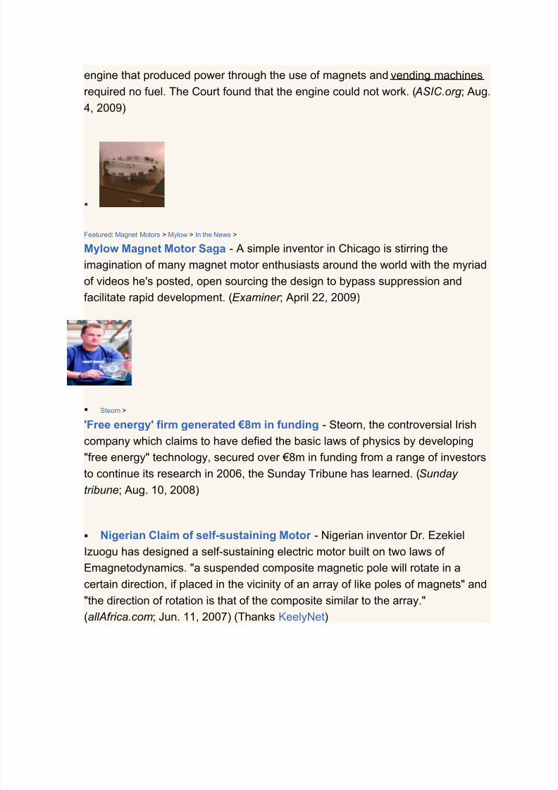
7/30/2019 Steorn Drops Four Bombshell Documents Validating Orbo
http://slidepdf.com/reader/full/steorn-drops-four-bombshell-documents-validating-orbo 266/307
engine that produced power through the use of magnets and vending machines
required no fuel. The Court found that the engine could not work. ( ASIC.org ; Aug.
4, 2009)
Featured: Magnet Motors > Mylow > In the News >
Mylow Magnet Motor Saga - A simple inventor in Chicago is stirring the
imagination of many magnet motor enthusiasts around the world with the myriad
of videos he's posted, open sourcing the design to bypass suppression andfacilitate rapid development. (Examiner ; April 22, 2009)
Steorn >
'Free energy' firm generated €8m in funding - Steorn, the controversial Irish
company which claims to have defied the basic laws of physics by developing
"free energy" technology, secured over €8m in funding from a range of investors
to continue its research in 2006, the Sunday Tribune has learned. (Sunday
tribune; Aug. 10, 2008)
Nigerian Claim of self-sustaining Motor - Nigerian inventor Dr. Ezekiel
Izuogu has designed a self-sustaining electric motor built on two laws of Emagnetodynamics. "a suspended composite magnetic pole will rotate in a
certain direction, if placed in the vicinity of an array of like poles of magnets" and
"the direction of rotation is that of the composite similar to the array."
(allAfrica.com; Jun. 11, 2007) (Thanks KeelyNet)

7/30/2019 Steorn Drops Four Bombshell Documents Validating Orbo
http://slidepdf.com/reader/full/steorn-drops-four-bombshell-documents-validating-orbo 267/307
Comment: Sure does sound like nonsense, especially with the caveat
of having to obtain magnetic shielding. It is like saying he has a nuclear power
solution, but he has to overcome radiation problems. (Ken Rauen)
Comment: This is nonsense...I am suprised it wasn't attached with one
of those letters stating that they have $40 million in the bank and they needyour help to release the funds. (Mark Dansie)
A scooter that runs on magnetic power - A man in India has developed a
scooter that runs on magnetic power and doesn't require recharging. A battery
starts the scooter and the rest is done by the inbuilt magnetic mechanism, whichenables the scooter to run at a speed of 25 to 45 km/hr. The magnetic power
reduces if the scooter is used for a long period, but it can be retrieved in no time.
(DailyIndia; May 8, 2007)
Deal Announced for "SuperMag" Engine/Generator - Supervision
Entertainment has entered into an agreement with Enigma G.C. of the UK to
acquire the marketing rights for the Company's "SuperMag" electrical generation
system in the United Kingdom. It uses manipulated magnetic fields to generate
electricity sufficient to power the needs of a home or office building and provides
clean electrical power for free to the consumer after the initial cost of the
purchase and installation of the system. (Market Wire; December 12, 2006)
See also
Directory:Magnet Motors
BEST

7/30/2019 Steorn Drops Four Bombshell Documents Validating Orbo
http://slidepdf.com/reader/full/steorn-drops-four-bombshell-documents-validating-orbo 268/307
Directory:Best Exotic Clean Energy Technologies
News:Best Exotic Free Energy Technologies
Top free energy stories of 2010 and beyond
Template:Tesla footer
ENERGY TYPES
Directory:Galactic Sea of Energy
Directory:Aether | PowerPedia:Aether
Directory:Atmospheric Electrostatic Energy
Directory:Dark Energy
Directory:Radiant Energy | PowerPedia:Radiant Energy
Directory:Vacuum
Directory:Zero Point Energy
Directory:Grand Unified Theories | Directory:Aether Physics Model
Directory:Vibrations
Directory:Fractal Antennas as an Energy Source
DEVICE TYPES
Directory:Electromagnetic (overunity)
News:Electromagnetic (latest) | 2009 | 2006-2008 Directory:Magnet Motors | News:Magnet Motors
Directory:Linear Magnet Accelerators
Directory:Pyramid Power
Directory:Solid State
Directory:Solid State Generators | PowerPedia:Solid State Generator
Directory:Toroidal Power
Directory:Marko Rodin Coil / Torus / Motor
Directory:Vibrations Directory:Power from Ambient Electromagnetic Radiation
Directory:Gravity Motors
Directory:Pendulums
NEWS FOOTER

7/30/2019 Steorn Drops Four Bombshell Documents Validating Orbo
http://slidepdf.com/reader/full/steorn-drops-four-bombshell-documents-validating-orbo 269/307
Free Energy News (PESWiki) - daily, from around the world
NEWS BY TOPIC --> Alternative Fuels | Batteries | Best Exotic FE | Cold
Fusion | Conspiracy | Electric Vehicles | Electromagnetic OU | Fuel Efficiency |
Geothermal | Gravity Motors | Hydro | Hydrogen | Hydroxy / HHO | Magnet
Motors | Nanotech | Open Source | Rossi Cold Fusion | Solar | Storage | Tesla |Top 100 | Waste to Energy | Water | Wind | Zero Point Energy
PESN - Stories by PES Network, Inc.
PESWiki News Archive index
This Week in Free Energy - 10-minute weekly wrap-up radio
Free Energy Now - radio show featuring specific technologies
- PESWiki main page
Categories: Galactic | News | Archive | Magnet Motors
Thermal Electric Directory
This page presents a directory of thermal electric environmental heat enginedesigns and theories, which in some cases appear to violate the second law of thermodynamics for the purpose of practical energy generation. Index of systems
that utilize temperature gradients to generate usable energy or electricity (known asthermal electricity).
Contents
[hide]
1 Overviews
2 Technologies
2.1 Features
2.2 Mechanical Thermal Electric Systems
2.3 Solid State
2.3.1 Thin-Film Thermoelectrics
2.4 Thermal-Chemical
2.5 Research and Development

7/30/2019 Steorn Drops Four Bombshell Documents Validating Orbo
http://slidepdf.com/reader/full/steorn-drops-four-bombshell-documents-validating-orbo 270/307
2.6 Data
3 Resources
3.1 Blogs
3.2 Discussion
3.3 Directories
3.4 Dig Deeper
3.5 Related
3.6 See also
Overviews
There are many large scale thermal to electric systems operating today, many withlow delta-T's (temperature change) like the Ener-G-Rotor system that takes thewaste heat from steam turbines and produces 50 KW. -- (NEC Advisor, Jim Dunn;Sept. 6, 2007)
Such devices fall into one of two categories:
solid state (no moving parts)
mechanical (e.g. Wikipedia:Rankine_cycle)
TechnologiesFeatures
Featured: Electromagnetic / Thermal Electric > Steorn >
Steorn's CEO Posts Overunity Heater Video - The CEO of Steorn, Sean
McCarthy, has posted two videos to Facebook that show a test of an Orbo heater
that is designed to produce sixty degree water for a shower. In the test, the
device consumes one kilowatt of power, with an output in the form of steam.

7/30/2019 Steorn Drops Four Bombshell Documents Validating Orbo
http://slidepdf.com/reader/full/steorn-drops-four-bombshell-documents-validating-orbo 271/307
(PESN and BeforeItsNews; October 5, 2011)
Featured / Best Exotic FE: Turbines > Thermal Electric > Air Engines > Zorzi >
Part I: Overunity Heat Pump Turbine -- Context - Inventor, Kim Zorzi
provides some background information about his Recirculating Air Turbine (RAT)
system that apparently is able to harvest energy latent in air to provide 235
kilowatts of power in his present prototype that is now in production, with many
improvements envisioned for next versions. (PES; August 19, 2011)
Featured / Best Exotic FE: Turbines > Thermal Electric > Air Engines > Zorzi >
Part II: Recirculating Air Turbine Generator -- Air Engine of the Future
- Texas inventor, Kim Zorzi explains how his Recirculating Air Turbine system
works to harness energy latent in air by combining several expired patent
technologies including supercharger compression, expanded diameter generator,
water injection, axial flux generator, etc. (PES; August 19, 2011)
Thermopower Waves: MIT’s Invention That Could Change Batteries and
Devices Forever - Thermopower waves are a phenomenon that happens when
powerful waves of energy shoot through carbon nanotube wires, creating

7/30/2019 Steorn Drops Four Bombshell Documents Validating Orbo
http://slidepdf.com/reader/full/steorn-drops-four-bombshell-documents-validating-orbo 272/307
electricity. The researchers from MIT are responsible for this discovery, thus
opening a new area of rare energy research. (The Green Optimistic ; March 9,
2010)
Matteran Energy produces electricity and refrigeration from near
ambient heat - An experimental small scale power plant is producing electricity
and refrigeration temperatures fueled simply by the heat in warm water - typically
150 degrees Fahrenheit. ("PESWiki"; July 10, 2006)
Fellows' Thermoacoustic Cycle (TAC) Generator - Texas inventor's
technology uses heat to amplify acoustic waves (sound waves) in a highpressure gas, which drive a linear generator and produce electric power. The
system can allegedly be built at a very low cost. (PESWiki )
Far Infrared Radiation (FIR) energy extraction methods at room
temperature - Basic introduction on the science of how all matter radiates
electromagnetic waves in the far infrared region; e.g., 450+ watts per square
meter -- aka T-rays (THz rays). Includes very basic experiment to verify this well

7/30/2019 Steorn Drops Four Bombshell Documents Validating Orbo
http://slidepdf.com/reader/full/steorn-drops-four-bombshell-documents-validating-orbo 273/307
known and understood science.
ENECO Chip Converts Heat to Electricity - Utah company claims to have
invented and patented a "solid state energy conversion/generation chip" that will
convert heat directly into electricity or alternatively refrigerate down to -200
degrees Celsius when electricity is applied.
Rauen Environmental Heat Engine - The Superclassical heat engine of Ken
Rauen is designed to be able to tap the heat of the environment for energy
generation. It is based upon the experimental evidence of the Proell effect, a
macroscopic Maxwell’s Demon. ("PESWiki"; April 1, 2006)
Nansulate Paint Creates Efficient Thermal Barrier - Industrial Nanotech,
Inc has a line of non-toxic paint products that integrate nanotechnology toprovide insulative properties, corrosion resistance, mold resistance. They are
also engineering a method to generate electricity from the thermal gradient to
which the coating is exposed.

7/30/2019 Steorn Drops Four Bombshell Documents Validating Orbo
http://slidepdf.com/reader/full/steorn-drops-four-bombshell-documents-validating-orbo 274/307
Mechanical Thermal Electric Systems
Thermal Electic > Ocean Thermal Energy Conversion >
First robotic underwater vehicle to be powered entirely by natural,
renewable, ocean thermal energy - The Sounding Oceanographic Lagrangrian
Observer Thermal RECharging (SOLO-TREC) autonomous underwater vehicle
uses a novel thermal recharging engine powered by the natural temperature
differences found at different ocean depths, via phase change materials. So the
vehicle can be powered indefinitely just by moving up and down in the water.
(GizMag ; April 8, 2010)
Piezoelectric / Thermal Electric >
Physicists Shrink Heat Engines by Seven Orders of Magnitude - A 0.5 cubic
micrometer heat engine being developed by NXP Semiconductors in the
Netherlands is essentially a bar of piezoelectric material which expands and
contracts when an alternating current is applied, which changes the resistance of
the bar, so passing a DC current through the bar at the same time causes the bar
to heat up and cool down... (MIT Technology Review ; Jan. 22, 2010) (Thanks
Jim Dunn)

7/30/2019 Steorn Drops Four Bombshell Documents Validating Orbo
http://slidepdf.com/reader/full/steorn-drops-four-bombshell-documents-validating-orbo 275/307
Transpacific Energy - Advanced Organic Rankine Cycle TransPacifc Energy
has developed a heat recovery and energy conversion system that produces
electricity from waste heat (or other low temperature heat sources such as solar).
The process uses an advanced Organic Rankine Cycle (ORC) with a proprietary,
environmentally sound multiple refrigerant mixture that can easily be adapted tolow and medium heat sources and used where ammonia, propane, butane and
other CFCs cannot be used. (PR ; June 22, 2008)
Evaporation Heat Engines - Sunoba has developed a heat engine that
operates by evaporative cooling of hot air at reduced pressure. The engine has
natural advantages when waste heat is available (such as gas turbine exhaust)
or can be produced cheaply (such as by passive solar collection). Air is the heat
transfer medium and working gas, so there is no need for heat exchangers. The
efficiency is comparable to that of simple Rankine turbines operating at the same
maximum temperature, but there is no need for boiler or condenser. Evaporative
coolers can actually generate power.
IAUS solar design includes super-efficient, bladeless turbine-International Automated Systems, Inc. (IAUS.OB) ["IAS"] has developed a new
breakthrough bladeless turbine technology. It is a patented propulsion turbine,
which some believe may revolutionize electrical power generation and low-cost
hydrogen fuel production.Thermal solar panels will produce electricity at 3-5
cents per kilowatt-hour. Highly-efficient bladeless turbine has wide range of

7/30/2019 Steorn Drops Four Bombshell Documents Validating Orbo
http://slidepdf.com/reader/full/steorn-drops-four-bombshell-documents-validating-orbo 276/307
waste-heat-harnessing applications. ("PESN"; Aug. 2, 2005)
Thermator - VarmaRaf makes thermoelectric generators that use the
Seebeck effect to induce voltage in solid state devices as heat flows through
them. With a constant excess heat source, such as geothermal water or ambient
air, Varmaraf's generators are considerably more economical than photovoltaicgenerators, based on the number of watthours produced annually.
Shockwave Power Reactor - Hydro Dynamics makes the ShockWavePower™ Reactor (SPR) to create heat. The moving rotor inside the Reactor
produces cavitation in the liquid. The cavitation, in turn, creates millions of
microscopic bubbles inside the liquid that release heat when they collapse. Used
in heating food products, chemical and polymeric streams, and industrial brines
using controlled cavitation technology.
StarDrive Engineering - Electrodynamic field generator (US Patent
6,404,089) "could actually now be used for electric power generation on a

7/30/2019 Steorn Drops Four Bombshell Documents Validating Orbo
http://slidepdf.com/reader/full/steorn-drops-four-bombshell-documents-validating-orbo 277/307
commercial scale far more efficiently and economically than any other method
known."
Acoustic Stove, Fridge, Generator Could Aid Third World - The "Stove for
Cooking, Refrigeration and Electricity," or SCORE, could help improve the health
and quality of life for the two billion or so people in the world who cook over open
fires. The SCORE thermoacoustics technology promoted by a multi-institutional
project converts heated gas into sound waves which can be used to cook, cool,and/or generate electricity.
Thermal Acoustic Resonator - Uses sound waves to convert waste heatdirectly into useable electricity. Working prototype; video; patent. Can be printed
on microchip. Seeking licensees, developer partners, venture partners.
(Contributed by Chris Horianopoulos)
Deluge Inc's Thermal Hydraulic Engine Generates from Low Heat Input -
Utilizing low level heat energy, 180°F (82°C), the Natural Energy Engine™ is
suitable for solar, geothermal, or any other heat source, including waste heat
from existing processes. The engine requires no combustion, operates virtually

7/30/2019 Steorn Drops Four Bombshell Documents Validating Orbo
http://slidepdf.com/reader/full/steorn-drops-four-bombshell-documents-validating-orbo 278/307
silently, and generates no emissions. Now ready for commercialization.
Honda patents exhaust-heat-to-energy process - Honda has received a
patent on an exhaust heat exchanger that harnesses the heat energy from the
exhaust through a thermal exchange, which can then be converted into electrical
energy through a thermal electric process or to drive a turbine/generator.
Ergenics - Developing a metal hydride heat engine that converts solar hot
water into electricity for an estimated cost of less than 1¢ per kilowatt hour. The
solar panels produce hot water which is pumped to a hydrogen compressor, that
compresses a gas that is then expanded in a hydraulic motor-generator set thatproduces electricity.
Michaud Atmospheric Vortex Engine - Louis Michaud's atmosphere vortexengine would harness waste heat from power plants and other heat sources,
creating a stationary tornado and capturing the rotational force.

7/30/2019 Steorn Drops Four Bombshell Documents Validating Orbo
http://slidepdf.com/reader/full/steorn-drops-four-bombshell-documents-validating-orbo 279/307
Ghosh Energy from Atmospheric Heat - Pranab Jyoti Ghosh seeks
assistance for building a working prototype of a technology that would produce
electricity from atmospheric heat, based on combining a number of well-proven
concepts. Uses a mechanical arrangement similar to a heat pump.
US 7019412 -- Power generation methods and systems - A closed loop
system for generating mechanical energy at high efficiencies. The system can
have a heating source, a superheater, an expander, a receiver, an absorber, a
desorber, and regenerator with pumps and controls. The superheater heats a
working fluid (a refrigerant or steam). A positive liquid/vapor expander expands a
low temperature refrigerant, or steam vapor to the saturated state (having both
liquid and vapor parts) utilizing a low-pressure sub-atmospheric exhaust sink. An
absorber, generates a low-pressure sub-atmospheric sink using chemosorption
which involves the exothermic reaction/absorption of ammonia refrigerant in
water. The desorber is used to reconstitute inlet vapor (for reuse) and the
regenerator recovers heat generated by chemosorption. The system can meet
electrical power needs for residences, businesses or office buildings. The system
can supply electrical energy to power grids, and can be an alternative power
generation plants. (Issued Mar. 28, 2006)

7/30/2019 Steorn Drops Four Bombshell Documents Validating Orbo
http://slidepdf.com/reader/full/steorn-drops-four-bombshell-documents-validating-orbo 280/307
Ocean Thermal Energy Conversion (OTEC) - seeks to harness the
temperature difference between surface and deep sea water. An MIT Technology
Review article estimated that "massive ocean thermal energy conversion plants
may be turning this heat to usable electricity by 1985." This vision has not yet
been fulfilled, though progress is being made toward 6-8 cents/kW-h electricity bythis method. ("MIT Technology Review"; July 21, 2006)
Thermal-Gradient Cold: Free Power or Planetary Suicide? - Advocates of tapping ocean depths for stored cold promise a clean future. But is it really
environmentally friendly, or a slippery slope into unrecoverable catastrophe?
("PESN"; June 3, 2005)
EIC Solutions manufactures thermoelectric air conditioners designed to
protect PC's and other types of industrial control equipment from harsh
environments.
ThermoElectric Generator (TEG) converts the engine's waste exhaust heat
into electricity to replace the alternator. Power to the driveshaft increases, which
increases fuel efficiency.
ReGen Power Systems - Developing a 1 megawatt low temperature Stirling
engine to convert excess process heat and steam energy at industrial plants into
electricity. It has an efficiency of 13% for steam and 20% for industrial heat, with

7/30/2019 Steorn Drops Four Bombshell Documents Validating Orbo
http://slidepdf.com/reader/full/steorn-drops-four-bombshell-documents-validating-orbo 281/307
O&M costs projected at $0.006/kWh and a payback period from 2-3 years.
JX Crystals ThermoPhotoVoltaics - Midnight Sun Stove® was the very first
commercial TPV product, demonstrating the basic TPV concept - generating
electricity from heat energy.
ElectraTherm - Waste Heat Generators capture waste heat (190 F+) to
generate fuel-free emission-free electricity. If used on a wide scale, recycled
energy could generate the equivalent of ninety-two 500 MW gas-fired combined-
cycle plants without any fuel consumption.
Ormat Technologies - The Ormat Energy Converter (OEC) is a power
generation unit which converts low and medium temperature heat into electrical
energy using the Organic Rankine Cycle. Ormat has manufactured more than750 MW of geothermal power plants, and also uses the OEC to generate power
from exhaust heat recovery in energy-intensive industrial processes.

7/30/2019 Steorn Drops Four Bombshell Documents Validating Orbo
http://slidepdf.com/reader/full/steorn-drops-four-bombshell-documents-validating-orbo 282/307
Amerigon - Developing products based on thermoelectric (TE) technologies
for conversion of electrical current to thermal energy (Peltier effect) or heat
differentials to electric current (Seebeck effect). The initial product is the Climate
Control Seat™ (CCS™) cooled/heated car seat, which provides all-season
heating and cooling comfort.
Custom Thermoelectric - Power generation modules utilize the Seebeck
effect to generate electrical energy from waste heat sources such as wood
stoves, gas and fuel exhausts, boilers and solar collectors and concentrators.
Each face of the device must be exposed to different temperatures; a "hot" side
and a "cold" side. The greater the temperature difference, the more power
generated.
CUBE Technology - The Personal Power Generator combines fuel and air
inside a ceramic Micro-Furnace that produces a flameless heat source using any
fuel such as Hydrogen, Propane, Butane, or Alcohols. An efficient Thermoelectric
Module then converts this fuel energy into electricity with no moving parts to wear
out or maintain.

7/30/2019 Steorn Drops Four Bombshell Documents Validating Orbo
http://slidepdf.com/reader/full/steorn-drops-four-bombshell-documents-validating-orbo 283/307

7/30/2019 Steorn Drops Four Bombshell Documents Validating Orbo
http://slidepdf.com/reader/full/steorn-drops-four-bombshell-documents-validating-orbo 284/307
Solid State
Featured: Batteries > Thermal Electric > Solid State Generators >
Karpen's Pile -- A Battery That Has Produced Energy Continuously
Since 1950s - A battery designed in 1908 by Nicolae Vasilescu-Karpen,
patented in 1922, and called "the uniform-temperature thermoelectric pile," has
allegedly been producing energy continuously in a Romanian museum since the
1950s. (PESWiki ; January 4, 2011)
Top 100: Solar > Thermal / Thermal Electric > Johnson Electro Mechanical Systems >
Super Soaker Inventor Doubles Solar Power Efficiency - Lonnie Johnson'slatest JTEC prototype, which looks like a desktop model for a next-generation
moonshine still, features two fuel-cell-like stacks filled with hydrogen gas and
connected by steel tubes with round pressure gauges. The JTEC uses heat (from
the sun, for instance) to expand hydrogen atoms in one stack.... (Inhabitat ; Oct.
19, 2010)
Nanotech / Waste to Energy > Waste Heat > Thermal Electric > Solid State >
Turning Waste Heat Into Power via Nanotech Molecules - Using a theoretical

7/30/2019 Steorn Drops Four Bombshell Documents Validating Orbo
http://slidepdf.com/reader/full/steorn-drops-four-bombshell-documents-validating-orbo 285/307
model of a so-called molecular thermoelectric device, a technology being
developed at the University of Arizona harvests waste heat and cleanly converts
it directly into electrical power, and requires no moving parts. A rubber-like
polymer sandwiched between two metals acting as electrodes can do the trick,
taking advantage of the laws of quantum physics. (Univ. of AZ News; Sept. 23,2010)
Featured: Thermal_Electric > Eneco_power_chip >
Eneco thermal-electric converter technology re-emerging - MicroPower
Global of Texas has purchased the IP from the bankrupt Eneco, and has secured
relationships with Texas State University to test and perfect the technology so it
can be brought to market in order to harvest waste heat energy via a solid state
chip. (PESN ; May 11, 2010) (Comment)
Waste to Energy > Waste Heat Generators / Thermal Electric >
Harnessing waste heat to produce electricity - In experiments involving a new
technology, thermal diodes, an MIT research team has been able to demonstrate
efficiency as high as 40 percent of the Carnot Limit, with calculations showing
that this new system could ultimately reach as much as 90 percent of that ceiling.See the team's paper, "Quantum-coupled single-electron thermal to electric
conversion scheme". (GizMag ; November 19, 2009)

7/30/2019 Steorn Drops Four Bombshell Documents Validating Orbo
http://slidepdf.com/reader/full/steorn-drops-four-bombshell-documents-validating-orbo 286/307
New Technology Can Turn Heat Waste Into Electricity - Researchers at
Ohio State University in Columbus and Caltech in Pasadena, California, think
they can recycle some of that lost energy with a new highly toxic thermoelectric
material (sodium-doped lead telluride with thallium) that is twice as effective as
current materials within 5-10 years at around $10. (Clean Technica; July 25,
2008)
Beakon Technologies - Developing next generation thermoelectric (TE)
device with efficiencies 10-15 times that of today’s Peltier-elements and 30%
higher than compressors. The Beakon chip can provide a cooling solution for
applications like computers, cell phones, lasers but also replace traditional
cooling systems like the compressor in a refrigerator. (Beakon Technologies; July
6, 2008)
Cheap, Efficient Thermoelectrics via Nanomaterials - Researchers at MIT
and Boston College have developed an inexpensive, simple technique for
achieving a 40 percent increase in the efficiency of a common thermoelectric
material, bringing the technology closer to becoming economically feasible for a
wide range of waste heat recovery. (MIT Technology Review ; March. 20, 2008)

7/30/2019 Steorn Drops Four Bombshell Documents Validating Orbo
http://slidepdf.com/reader/full/steorn-drops-four-bombshell-documents-validating-orbo 287/307
(MIT EI )
TEG 5000 - The Cordless-Electric Company has developed the TEG 5000,
thermoelectric generator that is solid-state, makes no noise, and has no moving
parts. Corroboration
Thermoelectric battery and power plant - US Patent #6,130,377 issued
Oct. 2000 to Carlos Avila Rivera now posted with images. Device is two patents
in one. (1) Thermoelectric battery generates electricity from temperature
gradient. (2) Pendulum with sphere containing ions generates current from
Foucault principle.
Advanced Diamond Solutions amorphous nanostructures -
Semiconductor industry company serendipitously developed thermionic solar
cells using amorphous diamond nanostructures that offer potential efficiencies of
50% at half the cost of silicon solar cells. Also has good promise as a thermal
electric generator.

7/30/2019 Steorn Drops Four Bombshell Documents Validating Orbo
http://slidepdf.com/reader/full/steorn-drops-four-bombshell-documents-validating-orbo 288/307
Johnson Electro Mechanical Systems - Thermal energy system invented
by the person who came up with the Super Soaker can achieve a conversion
efficiency rate that tops 60 percent with a new solid-state heat engine. It uses
temperature differences to create pressure gradients that are used to force ions
through a membrane, instead of moving an axle or wheel. Inventor has also
come up with an ambient energy conversion system as well as an electric heat
pump.
Nova Thermal Electric Chips - Salt Lake company is in late R&D stage in
bringing forward an efficient, low-heat conversion to electricity method.
A Sound Way to Turn Heat into Electricity - University of Utah physicists
developed small devices that turn heat into sound and then into electricity via
piezoelectric conversion. The technology holds promise for changing waste heat
into electricity, harnessing solar energy and cooling computers and radars.
(PESN ; May 5, 2007)
New nanostructured thin film shows promise for efficient solar energy
conversion - Researchers at Berkeley have demonstrated highly efficient
thermoelectric behavior from arrays of silicon nanowires grown onto a silicon
wafer. The technology is compatible with fabrication processes used in the large-
scale silicon processing industry. A low-cost thermoelectric system could be used
to generate electricity from heat lost from fossil-fuel based energy generation.

7/30/2019 Steorn Drops Four Bombshell Documents Validating Orbo
http://slidepdf.com/reader/full/steorn-drops-four-bombshell-documents-validating-orbo 289/307
(EnergyTech Today ; Jan. 8, 2008)
An Alternative to your Alternator - Researchers at MIT are developing new
technology for converting heat into light and then into electricity that could
eventually save fuel in vehicles by replacing less-efficient alternators and
allowing electrical systems to run without the engine idling. (MIT Technology
Review ; June 1, 2006)
Active Building Envelope system provides heating and cooling - The
ABE system being developed by Rensselaer Polytechnic Institute accomplishes
the jobs of both cooling and heating, yet operates silently with no moving parts,using a thin-film technology that adheres both solar cells and heat pumps onto
surfaces.
Far Infrared Radiation (FIR) energy extraction methods at room
temperature - Basic introduction on the science of how all matter radiates
electromagnetic waves in the far infrared region; e.g., 450+ watts per square
meter -- aka T-rays (THz rays). Includes very basic experiment to verify this well

7/30/2019 Steorn Drops Four Bombshell Documents Validating Orbo
http://slidepdf.com/reader/full/steorn-drops-four-bombshell-documents-validating-orbo 290/307
known and understood science.
Power Chips™ Convert Heat to Electricity - Chips use thermionics to
convert heat directly into electricity with a Carnot heat pump efficiency of up to
70-80%. This will be one of the first industrial applications of nanotechnology.
Solar technology that works at night - INL and MicroContinuum are
developing cheap solar technology that could absorb energy from both sunlight
and the earth's heat, with 80% efficiency compared to 20% for conventional solar
cells. Tiny square metal spirals, or “nanoantennas?, are stamped onto a sheet of
plastic and can be made of a number of different conducting metals. (GizMag ;Jan. 4, 2008)
Reincarnated material turns waste heat into power - A major boost in the
effectiveness of a material that transforms waste heat into electricity could
significantly boost energy efficiency in anything from air conditioners to car
engines. It is the first major improvement in such "thermoelectric" materials in 50
years, say researchers. (New Scientist ; Mar. 20, 2008)

7/30/2019 Steorn Drops Four Bombshell Documents Validating Orbo
http://slidepdf.com/reader/full/steorn-drops-four-bombshell-documents-validating-orbo 291/307

7/30/2019 Steorn Drops Four Bombshell Documents Validating Orbo
http://slidepdf.com/reader/full/steorn-drops-four-bombshell-documents-validating-orbo 292/307
Organic Thermoelectric Material from UC Berkeley - Researchers have
generated electricity from heat by trapping organic molecules between metal
nanoparticles to create an organic thermoelectric material. The discovery could
lead to the development of more cost-effective thermoelectric converters that
could be applied to waste heat recovery—including in vehicles. (Green Car
Congress; Feb. 15, 2007)
Air Conditioning via the Peltier Effect - When a temperature difference is
applied to certain dissimilar metals, an electric current results. This is called theSeebeck effect. The reverse of this -- applying current to effect a temperature
difference -- is called the Peltier Effect.
Creating power out of thin air - Syrdec is working on generating electricity
from ambient room heat by combining the Seebeck effect and the product of
nuclear fusion. Two substances are combined, one with its natural energy state
artificially altered inside the molecular structure to produce an excited state at
room temperatures. (CNET News; Oct. 26, 2007)
High-Performance Thermoelectric Capability in Silicon Nanowires -
Researchers have shown that the thermoelectric properties of silicon—a material
that can be processed on a large scale but has poor thermoelectric properties—

7/30/2019 Steorn Drops Four Bombshell Documents Validating Orbo
http://slidepdf.com/reader/full/steorn-drops-four-bombshell-documents-validating-orbo 293/307
can be vastly improved by structuring it into arrays of nanowires and carefully
controlling nanowire morphology and doping. (Green Car Congress; Jan. 11,
2008)
Belleza Thermoelectric Generator - Paul Bellezza wants to be able to mass
produce his "Highly Efficient Thermoelectric Generator," an invention that would
produce electricity more efficiently than anything now on the market. He knows
the invention works. He hasn’t yet been able come up with a way to reliablyreproduce it. (PESWiki ; Feb. 13, 2008)
High Merit Thermoelectrics - Thermoelectric device manufacturing company
that offers devices that include an innovative material called YMS, that out-
performs competing materials, nearly quadrupling device efficiency. The devices
are long-lasting, compact, environmentally benign power sources that directly
convert heat into electrical energy.
Thin-Film Thermoelectrics
Micropelt - Solid state thin film Peltier cooler and thermogenerator devices
build on a scalable semiconductor platform technology. Heating and coolingenergy density of > 100 W per cm2.
Nanocoolers - These are ideal for use in a range of applications that require
cooling, heating and/or temperature stabilization, including: Electronics Cooling /
Thermal Management, Lasers and Optical Communications, Aerospace / Military
7/30/2019 Steorn Drops Four Bombshell Documents Validating Orbo
http://slidepdf.com/reader/full/steorn-drops-four-bombshell-documents-validating-orbo 294/307
/ Defense, Micro-refrigeration, Medical / Bio-medical, Refrigeration, and Air
Conditioning.
RTI International - Thin-Film Superlattice Technology- A thermoelectric
module with just one square centimeter of RTI's new material can provide 700watts of cooling under a nominal temperature gradient.
Thermal-Chemical
Solar / Storage / Thermal >
Thermo-Chemical Solar Energy could be efficient and indefinitely storable -
Researchers at MIT are working on a new process in thermo-chemical solar
energy that uses a molecular structure reconfiguration to capture energy from the
sun, potentially storing it forever. A molecule of fulvalene diruthenium changes its
configuration when it absorbs heat, and later releases heat when it snaps back to
its original shape. (MIT News; Oct. 26, 2010)
Research and Development
Nanotech / Thermal Electric >
Carbon nanotubes offer new way to produce electricity - MIT scientists havediscovered that moving pulse of heat traveling along the miniscule wires known
as carbon nanotubes can cause powerful waves of energy. These "thermopower
waves" can drive electrons along like a collection of flotsam propelled along the
surface of ocean waves, creating an electrical current. The previously unknown

7/30/2019 Steorn Drops Four Bombshell Documents Validating Orbo
http://slidepdf.com/reader/full/steorn-drops-four-bombshell-documents-validating-orbo 295/307
phenomenon opens up a new area of energy research. (GizMag ; March 8, 2010)
Cold Fusion / Thermal Electric / Magazines > Infinite Energy >
Infinite Energy: Issue 90: Metamaterials and the Search for New Energy -
Metamaterial Shaped LANR-Cathodes Produce Deuteron Flux • Rock Oil’s Dark
Sesquicentennial • Carbon Arc Under Vacuum • The Earth-Centered Non-
Rotating Inertial Frame and the Michelson-Morley Experiment • The Fine
Structure Constant • Theoretical Analysis of Heat Engines: ConstructionOptimization and High Efficiency • At 21, Cold Fusion Is Still in Its Infancy
(Mar/Apr 2010)
Material May Help Autos Turn Heat into Electricity - Researchers have
invented a new material that could potentially make cars more efficient, by
converting heat wasted through engine exhaust into electricity. The researchers
say that the material has twice the efficiency of anything currently on the market.
(Renewable Energy Worldwide; July 25, 2008)
Thermal Electric / Human-Powered >
Human heat can power electronics - New energy-scavenging systems under

7/30/2019 Steorn Drops Four Bombshell Documents Validating Orbo
http://slidepdf.com/reader/full/steorn-drops-four-bombshell-documents-validating-orbo 296/307
development at MIT could generate electricity just from differences in
temperature between the body (or other warm object) and the surrounding air,
harnessing differences of just one or two degrees, producing tiny (~100
microwatts) but nevertheless useful amounts of electricity. (GizMag ; Feb. 17,
2010)
Data
Thermal Electric / Zero Point Energy >
First Observation of the Dynamical Casimir Effect - A rapidly moving mirror
that turns virtual photons into real ones is the first experimental evidence of the
dynamical Casimir effect. "One of the most surprising predictions of modern
quantum theory is that the vacuum of space is not empty. In fact, quantum theory
predicts that it teems with virtual particles flitting in and out of existence." (MIT
Technology Review ; May 26, 2011)
ResourcesBlogs
http://thermoenergetics.blogspot.com/ - To create a worldwide conscience for
innovative and serious debate about the Laws of Physics and new propositions.
Energetics and the Maximum Power Principals, the Onsager reciprocal relations
and Thermoeconomics are propositions that should be discussed.
Was Carnot misunderstood? Compression only, heat engines
Discussion
See Discussion page

7/30/2019 Steorn Drops Four Bombshell Documents Validating Orbo
http://slidepdf.com/reader/full/steorn-drops-four-bombshell-documents-validating-orbo 297/307
Environmental Heat Engine - Yahoo!Groups discussion list surrounding the
environmental heat engine concept. Encouraging replications, refinement of
theory, and ultimately getting a feasible product to market.
Directories Thermoelectric Waste Heat Recovery Project at Green Car Congress
Dig Deeper
Thermogenerators
Seebeck, Peltier and Thomson Effects
Related
Stirling Engine - Generates Energy from Small External TemperatureGradients - Index of resources regarding this technology that enables the tapping
of waste heat or cold. Displacer piston moves enclosed air back and forth
between cold and hot reservoirs.
Traveling-Wave Engine- Adaptation of Stirling engine uses heat differential
and acoustics.

7/30/2019 Steorn Drops Four Bombshell Documents Validating Orbo
http://slidepdf.com/reader/full/steorn-drops-four-bombshell-documents-validating-orbo 298/307
Directory:Cavitation Heaters
Tapping Thermal-Gradient Cold: Free Power or Planetary Suicide? -
Advocates of tapping ocean depths for stored cold promise a clean future. But is
it really environmentally friendly, or a slippery slope into unrecoverable
catastrophe? ("PESN"; June 3, 2005)
Refrigeration Unplugged - A prototype metal cylinder with a liquid coolant
has converted the heat from fire into an inexpensive chilling agent. Cylindrical
device, called a "Coolth", 10 cm x 20 cm long, could be built for as little as $18
per unit. ("MIT Technology Review"; Dec.2006/Jan.2006) (See Google)
See also
Directory:Acoustic
Directory:Ambient Air Engines
Directory:Cavitation Heaters
Directory:Engines
PowerPedia:Heat engine
Directory:Heat Pumps

7/30/2019 Steorn Drops Four Bombshell Documents Validating Orbo
http://slidepdf.com/reader/full/steorn-drops-four-bombshell-documents-validating-orbo 299/307
Directory:Ocean Thermal Energy Conversion
PowerPedia:Thermodynamics
Directory:Stirling Engines
PowerPedia:Stirling Engine
Directory:Traveling-wave Engine - Adaptation of Stirling engine uses heat
differential and thermoacoustics
Directory:Waste to Energy
GEOTHERMAL
Directory:Geothermal
News:Geothermal
Videos:Geothermal
TYPES OF GEOTHERMAL
Ground Source Heat Pumps | OS:Ground Source Heat Pump
Directory:Geothermal Oil Wells
Hydrothermal Vents
GEOTHERMAL-RELATED
Directory:Thermal Electric Directory:Ocean Thermal Energy Conversion
- Other Directory listings• Latest• A-I• J-R• S-Z• Tree• News- PESWiki home page
Hank Mills Directory
Hank Mills has contributed a large number of stories to PES.
Contents
[hide]
1 Bio

7/30/2019 Steorn Drops Four Bombshell Documents Validating Orbo
http://slidepdf.com/reader/full/steorn-drops-four-bombshell-documents-validating-orbo 300/307
2
Stories
3
Archive
s
4 See
also
Bio
list here
Stories
Featured / Best Exotic FE: Nuclear > Cold Fusion > Rossi > Defkalion Controversy >
Stremmenos Accuses Defkalion of Lies and Megalomania; Defkalion
Responds - Christos Stremmenos, a member of the board of Defkalion GreenTechnologies Inc., has posted a bold statement slamming his company for lying,
making false accusations, and for being afflicted with the mental pathology of
Megalomania. Defkalion gives a magnanimous response. (PESN ; October 12,
2011)
Featured / Best Exotic FE: Nuclear > Cold Fusion > Rossi >
Cold Fusion E-Cat Case Design Competition - Andrea Rossi, the inventor
of the E-Cat (Energy Catalyzer) has asked for the help of the alternative energy

7/30/2019 Steorn Drops Four Bombshell Documents Validating Orbo
http://slidepdf.com/reader/full/steorn-drops-four-bombshell-documents-validating-orbo 301/307
community, in designing the case for his home heating product. He has asked for
the community to submit concepts, so he can purchase the best idea from the
individual who submitted it! (PESWiki and BeforeItsNews; October 10, 2011)
Featured / Best Exotic FE: Cold Fusion > Rossi > Validations > Oct. 6 Test >
E-Cat Test Validates Cold Fusion Despite Challenges - The test of the E-
Cat (Energy Catalyzer) that took place on October 6, 2011 in Italy has validated
Andrea Rossi's claim that the device produces excess energy via a novel ColdFusion nuclear reaction. Despite its success, the test was flawed, and could have
been done in a way that produced more spectacular results -- as if confirmation
of cold fusion is not already stunning enough. (PESN and BeforeItsNews;
October 8, 2011)
Featured / Best Exotic FE: Nuclear > Cold Fusion > Rossi > Validations >
Real-Time Updates on the October 6, 2011 E-Cat Test - For the next few
days, PES will be scanning the net to bring you the latest and most up-to-date
information about the important October 6 test of the E-Cat (Energy Catalyzer),
taking place in Bologna, Italy. Keep checking this page for the latest news and
updates! (PESWiki and BeforeItsNews; October 5, 2011)

7/30/2019 Steorn Drops Four Bombshell Documents Validating Orbo
http://slidepdf.com/reader/full/steorn-drops-four-bombshell-documents-validating-orbo 302/307
Featured: Electromagnetic / Thermal Electric > Steorn >
Steorn's CEO Posts Overunity Heater Video - The CEO of Steorn, Sean
McCarthy, has posted two videos to Facebook that show a test of an Orbo heater
that is designed to produce sixty degree water for a shower. In the test, the
device consumes one kilowatt of power, with an output in the form of steam.
(PESN and BeforeItsNews; October 5, 2011)
Featured: Buyer Beware / Magnet Motors > Howard Johnson >
Letter to Hojo Motor Plan Scammers - Hank Mills has composed a letter to
the company and individuals selling bogus plans for a claimed free energy motor,
based on Howard Johnson's technology. He addresses the fact they are lying,and bamboozling people. (PESN and BeforeItsNews; October 4, 2011)
Featured / Best Exotic FE: Electromagnetic > Solid State > Magnacoaster >
Magnacoaster Delays Continue - Richard Willis, of the Canadian company
Magnacoaster, has been promising to ship solid state, overunity generators for
three years, but has failed so far to do so. All these years later, though no units
have been shipped to customers. He still talks like this will happen very soon.

7/30/2019 Steorn Drops Four Bombshell Documents Validating Orbo
http://slidepdf.com/reader/full/steorn-drops-four-bombshell-documents-validating-orbo 303/307
(PESN and BeforeItsNews; October 2, 2011)
Featured / Best Exotic FE: Electrostatic > Aviso >
Typhoon Floods Free Energy Inventor's Workshop - Ismael Aviso, an
alternative energy pioneer from the Philippines, has experienced a weather-
related disaster. A recent tropical system has flooded his home and workshop,
and has set back his research and development work by a few weeks. (PESN
and BeforeItsNews; September 30, 2011)
Featured: Magnet Motors > Cycclone >
Cycclone Magnetic Engines Inc. Acquired by Lodestone Motor
Corporation - A company claiming to have an overunity magnetic technology,
Cycclone Magnetic Engines Inc., has been acquired by Lodestone Motor
Corporation. This company, based in Australia, plans to continue developing the
technology. (PESN and BeforeItsNews; September 29, 2011)
Featured / Best Exotic FE: Nuclear > Cold Fusion > Rossi > Validations >
Scientists to Test Cold Fusion E-Cat - Italian Inventor, Andrea Rossi, has
invited scientists from around the world to perform an important test on his E-Cat

7/30/2019 Steorn Drops Four Bombshell Documents Validating Orbo
http://slidepdf.com/reader/full/steorn-drops-four-bombshell-documents-validating-orbo 304/307
cold fusion reactor on October 6th. This test will be held at the University of
Uppsala in Sweden and should hopefully erase all doubt about the validity of the
Energy Catalyzer technology. (PESN and BeforeItsNews; September 26, 2011)
Featured / Proceedings: Nuclear > Cold Fusion >
The 2011 Cold Fusion Colloquium Report Published - This June 11th
and 12th, the 2011 "Cold Fusion - Lattice Assisted Nuclear Reactions
Colloquium" was held at the Massachusetts Institute of Technology. At themeeting twenty three presentations were made, and a report has been issued
detailing what took place. (PESN and BeforeItsNews; September 25, 2011)
Featured / Best Exotic FE: Nuclear > Cold Fusion > Rossi >
Rossi's Home Sacrificed for Cold Fusion E-Cat Launch - Only several
days ago, Andrea Rossi stated on his blog that he had big financial problems.
Now he has revealed that these problems are resolved. To acquire the funds to
insure the demo of the one megawatt plant takes place as planned, he has sold
his house. The personal sacrifices he has made to bring the E-Cat (Energy
Catalyzer) to the market are becoming heart wrenching. (PESN and
BeforeItsNews; September 21, 2011)
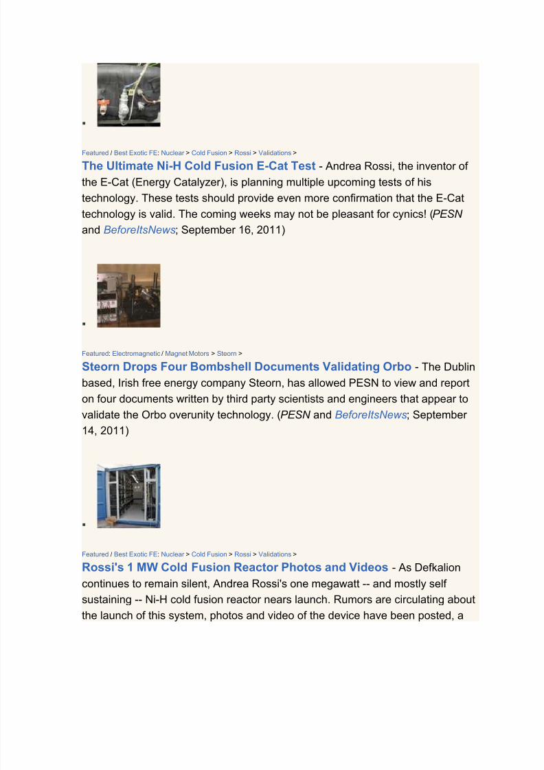
7/30/2019 Steorn Drops Four Bombshell Documents Validating Orbo
http://slidepdf.com/reader/full/steorn-drops-four-bombshell-documents-validating-orbo 305/307
Featured / Best Exotic FE: Nuclear > Cold Fusion > Rossi > Validations >
The Ultimate Ni-H Cold Fusion E-Cat Test - Andrea Rossi, the inventor of
the E-Cat (Energy Catalyzer), is planning multiple upcoming tests of his
technology. These tests should provide even more confirmation that the E-Cat
technology is valid. The coming weeks may not be pleasant for cynics! (PESN
and BeforeItsNews; September 16, 2011)
Featured: Electromagnetic / Magnet Motors > Steorn >
Steorn Drops Four Bombshell Documents Validating Orbo - The Dublin
based, Irish free energy company Steorn, has allowed PESN to view and report
on four documents written by third party scientists and engineers that appear tovalidate the Orbo overunity technology. (PESN and BeforeItsNews; September
14, 2011)
Featured / Best Exotic FE: Nuclear > Cold Fusion > Rossi > Validations >
Rossi's 1 MW Cold Fusion Reactor Photos and Videos - As Defkalion
continues to remain silent, Andrea Rossi's one megawatt -- and mostly self
sustaining -- Ni-H cold fusion reactor nears launch. Rumors are circulating about
the launch of this system, photos and video of the device have been posted, a

7/30/2019 Steorn Drops Four Bombshell Documents Validating Orbo
http://slidepdf.com/reader/full/steorn-drops-four-bombshell-documents-validating-orbo 306/307

7/30/2019 Steorn Drops Four Bombshell Documents Validating Orbo
http://slidepdf.com/reader/full/steorn-drops-four-bombshell-documents-validating-orbo 307/307
Related Documents