Steganography: Reversible Data Hiding Methods for Digital Media Andrew Tilley BSc (Hons) Computing (2002/2003) The candidate confirms that the work submitted is their own and the appropriate credit has been given where reference has been made to the work of others. I understand that failure to attribute material which is obtained from another source may be considered as plagiarism. (Signature of student)________________________________

Welcome message from author
This document is posted to help you gain knowledge. Please leave a comment to let me know what you think about it! Share it to your friends and learn new things together.
Transcript
Steganography: Reversible Data Hiding
Methods for Digital Media
Andrew Tilley
BSc (Hons) Computing
(2002/2003)
The candidate confirms that the work submitted is their own and the appropriate credit has been given
where reference has been made to the work of others.
I understand that failure to attribute material which is obtained from another source may be
considered as plagiarism.
(Signature of student)________________________________
I
Summary
This project is an investigation into the methods used for the undetectable and reversible hiding of
data in digital media, known as steganography.
"Proof of concept" software has been implemented as a deliverable in order to demonstrate the
practical use of the theories described.
II
Acknowledgements
Many thanks to Nick Efford, for his help pointing me in the right direction during the project, and Kia
Ng, for his feedback in the progress meeting.
Special thanks to Yoko Kanno, Randers, A Ali, PKK, Miss Alias, Ash Tilley, Craig Anderson and
Dune Tails, for their help and entertainment.
III
TABLE OF CONTENTS
Summary.....................................................................................................................................I
Acknowledgements .................................................................................................................... II
TABLE OF CONTENTS..........................................................................................................III
1. Introduction............................................................................................................................ 1
1.1 Project Aim ........................................................................................................................ 1
1.2 Objectives .......................................................................................................................... 2
1.2.1 Minimum Requirements ................................................................................................ 2
1.2.2 Possible Enhancements ................................................................................................. 2
1.2.3 Deliverables ................................................................................................................. 2
1.3 Initial Project Schedule ........................................................................................................ 3
2. Researching the Problem - Steganography in Digital Media................................................... 4 2.1 Steganography In Image Files .............................................................................................. 4
2.1.1 Format Of A Digital Image ............................................................................................ 4
2.1.2 Least Significant Bit (LSB) ........................................................................................... 5
2.1.3 JPEG and JSTEG.......................................................................................................... 9
2.2 Steganography In Audio Files .............................................................................................11
2.2.1 Psychoacoustics And Low Bit Encoding........................................................................11
2.2.2 Phase Coding...............................................................................................................11
2.2.3 Echo Hiding ................................................................................................................12
2.3 Potential and Current Applications ......................................................................................12
2.3.1 Watermarking in Images ..............................................................................................12
2.3.2 Watermarking in Audio ................................................................................................15
2.3.3 WEDELMUSIC ..........................................................................................................17
2.3.4 Concealograms and Three Dimensional Barcodes..........................................................17
2.3.5 Conclusion ..................................................................................................................18
3. Design................................................................................................................................... 20 3.1 Software Methodology .......................................................................................................20
3.1.1 Rational Unified Process and the Unified Modelling Language ..........................................21

IV
3.1.2 Chosen Methodology ...................................................................................................22
3.2 Authoring Tools and Development Language ......................................................................23
3.3 Requirements and Functionality ..........................................................................................24
3.4 Summary...........................................................................................................................25
4. Implementation.................................................................................................................... 26
4.1 What was achieved? ...........................................................................................................26
4.2 Problems during Implementation.........................................................................................26
4.2.1 24-bit Images and Headers ...........................................................................................26
4.2.2 Insertion and extraction problems .................................................................................28
4.2.3 The “No Information Embedded” Problem....................................................................28
4.2.4 The Security System....................................................................................................29
4.2.5 Insertion and Extraction Algorithms ..............................................................................30
4.2.6 Errors and Exceptions ..................................................................................................31
4.3 Basic Operations of Datahide ..............................................................................................31
4.3.1 Insertion ......................................................................................................................31
4.3.2 Extraction....................................................................................................................32
4.4 Remaining Problems ..........................................................................................................32
4.5 Following the Schedule and Further Developments ..............................................................33
4.6 Summary...........................................................................................................................35
5. Testing and Evaluation......................................................................................................... 36 5.1 The Code-and-Fix Model....................................................................................................36
5.1.1 Flags and Arguments ...................................................................................................36
5.1.2 Insertion ......................................................................................................................36
5.1.3 Extraction....................................................................................................................37
5.1.4 Security System...........................................................................................................38
5.2 Difference Imaging ............................................................................................................38
5.3 User Evaluation Forms .......................................................................................................39
5.3.1 User Evaluation Form Results.......................................................................................40
5.4 Evaluation of the Software..................................................................................................41
5.4.1 Criteria ........................................................................................................................41
5.4.2 Minimum Requirements ...............................................................................................41
5.4.3 Steganographic Requirements.......................................................................................42
5.4.4 Assessment Of Functionality ........................................................................................43
5.5 Evaluation Of Project.........................................................................................................44
5.5.1 Criteria ........................................................................................................................44
V
5.5.2 Objectives And Minimum Requirements .......................................................................44
5.5.3 Choice Of Methodology ...............................................................................................45
5.5.4 Language ....................................................................................................................45
5.5.5 Development Tools ......................................................................................................45
5.5.6 Background Research...................................................................................................46
5.5.7 Project Management ....................................................................................................46
5.6 Summary .......................................................................................................................47
6. Conclusion and Future Enhancement................................................................................... 48
6.1 Project Achievements.........................................................................................................48
6.2 Future Enhancements .........................................................................................................48
Bibliography............................................................................................................................. 50
Appendix A- Reflections on the Project Experience.................................................................. 52
Appendix B- Datahide Manual ................................................................................................. 53
Appendix C- User Evaluation Form ......................................................................................... 55
Appendix D- 24-bit Bitmap Header Structure .......................................................................... 56
Appendix E- Use Case UML Diagram and Description Forms ................................................. 57
Appendix F- Activity Diagrams ................................................................................................ 59
1
1. Introduction
While cryptography is preoccupied with the protection of the contents of a message or information,
steganography concentrates on concealing the very existence of such messages from detection.
The term steganography is adapted from the Greek word steganographia, meaning “covered writing”,
and is taken in its modern form to mean the hiding of information inside other information [1].
Naturally these techniques date back throughout history, the main applications being in couriering
information during times of war.
The Greek writer Herodotus gave a famous anecdotal account of this around 440 B.C. His tale was of
a Demeratus, a Greek in the Persian court who warned Sparta of an invasion by Xerxes, the King of
Persia. He did this by removing the wax from a writing tablet, scoring his message in the wood
underneath, and then covering it with wax again before sending it to Sparta [1].
With the invention of digital audio and images files this has taken on a whole new meaning; creating
new methods for performing “reversible data hiding” as it is often dubbed. This has many possible
applications including the copyright watermarking of audio, video and still image data.
In digital media, steganography is mainly oriented around the undetectable transmission of one form
of information within another. In order for a data hiding technique to be successful it must adhere to
two rules:
• The embedded data must be undetectable within its carrier medium (the audio or image file
used). The carrier should display no properties that flag it as suspicious, whether it be to the
human visual/auditory system or in increased file size for the carrier file.
• The embedded data must maintain its integrity within the carrier and should be easily
removable, under the right circumstances, by the receiving party.
1.1 Project Aim
The aim of this project is firstly to look at reversible data hiding methods used in both audio and
image files and their potential uses.
2
Secondly, one of the methods researched is to be implemented as “proof-of-concept” software that
allows the user to see the practical use of steganography first hand.
It is hoped that other students can use the information provided to further develop this project in the
future.
1.2 Objectives
• Research current reversible data hiding methods in image and sound files
• Implement a piece of demonstration software using one of the steganographic techniques
described.
1.2.1 Minimum Requirements
• Analysis of reversible data hiding methods.
• Produce a piece of software that shows how to encode information in to a simple image or
sound file.
• Produce documentation for the program.
1.2.2 Possible Enhancements
• Research into Steganalysis and the methods used in the detection of hidden data.
• Implement a solution to encode information into a complex image such as a 24-bit bitmap.
• Implement a solution for both image and sound files.
• Produce code that can be compiled for both a Windows and Linux platform.
• Development of a front-end GUI.
• Creation of a security measure to prevent the removal of data without a correct password.
• Research into the potential applications of steganography.
1.2.3 Deliverables
• Software implementation.
• Documentation for the program.
3
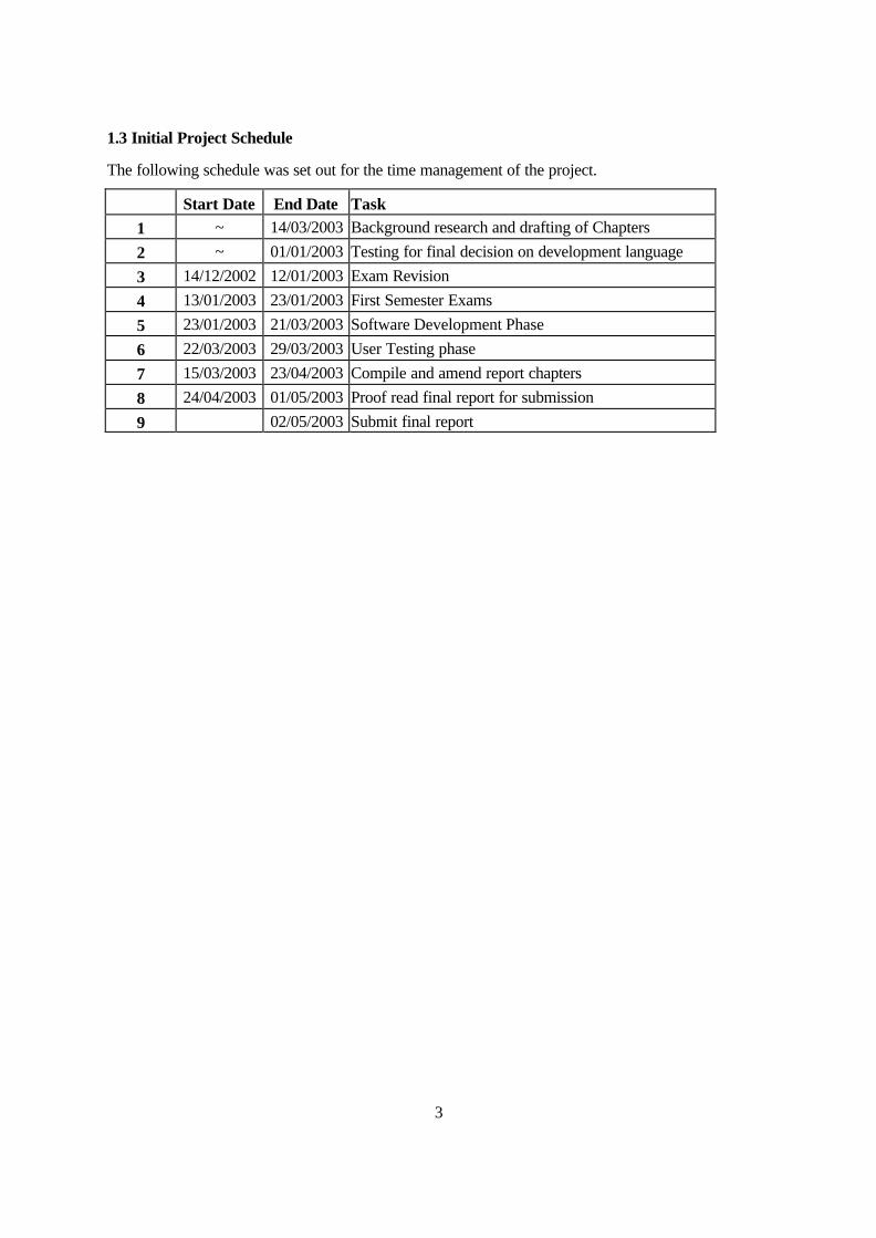
1.3 Initial Project Schedule
The following schedule was set out for the time management of the project.
Start Date End Date Task 1 ~ 14/03/2003 Background research and drafting of Chapters
2 ~ 01/01/2003 Testing for final decision on development language
3 14/12/2002 12/01/2003 Exam Revision
4 13/01/2003 23/01/2003 First Semester Exams
5 23/01/2003 21/03/2003 Software Development Phase
6 22/03/2003 29/03/2003 User Testing phase
7 15/03/2003 23/04/2003 Compile and amend report chapters
8 24/04/2003 01/05/2003 Proof read final report for submission
9 02/05/2003 Submit final report

4
2. Researching the Problem - Steganography in Digital Media
This chapter is concerned with three main goals:
• To look at the different methods used for data hiding in both image and audio formats.
• To cover briefly some of the potential uses for data hiding as a means of highlighting its
importance in today’s computing industry.
• To justify the method chosen for implementation and the reasons behind the decision.
2.1 Steganography In Image Files
2.1.1 Format Of A Digital Image
Before going into the methods used to hide information in digital images it is important to understand
how such images are represented and stored.
A digital image is represented by a one-dimensional array of numbers that represent the different light
intensities of each pixel. The dimensions of a 640 x 480 pixel image can literally be multiplied out to
find the total amount of pixels in the image, in this case 307,200 pixels. In digital photography this is
known as the resolution of an image; a digital camera that takes pictures of 640 x 480 is known as a
0.3 Mega Pixel resolution camera for this reason.
Digital images usually use either 24-bits (standard bitmap) or 8-bits (standard GIF image, colour or
grey scale) for the storage of intensity information per pixel. This means that in a bitmap image
(BMP) there are a potential 16.8 Million colours (224) per pixel and in a GIF, 256 different colour
combinations.
In a typical 24-bit image, each pixel has three colour components, red, green and blue, each
component using 8-bits to represent a value from 0 to 255. An 8-bit image on the other hand can
either have a colour palette of 256 different grey levels or colour va lues. Naturally this results in the
8-bit colour image having to perform a “best fit” in order to match a real world colour to it’s limited
palette.

5
The number of pixels in an uncompressed BMP image contribute directly to file size, for instance, a
640 x 480 image has 307,200 pixels in total, each of these is represented by 24-bits which equals a
total of 900 Kilobytes.
Due to this size overhead images are often compressed using either lossy or lossless compression.
Lossy compression as the name suggests, reduces the files size but at the expense of the image’s
integrity, JPEG (Joint Photographic Experts Group) format is a prime example of this, trading quality
of image for level of compression.
Lossless compression is sometimes used to save space while maintaining the images integrity as it
always reconstructs the image exactly as it was before compression. In bitmap images this is usually
Run Length Encoding (RLE), [19] succinctly describes it as method consisting of the process of
searching for repeated runs of a single symbol in an input stream, and replacing them by a single
instance of the symbol and a run count. In the case of a bitmap image the symbols it hopes to find
runs of are the concurrent 1s or 0s that represent colour values.
2.1.2 Least Significant Bit (LSB)
In a digital image, information can be inserted straight into every bit of image information or the more
busy areas of an image can be calculated so as to hide such messages in less perceptible or “busy”
parts of an image.
An example of the former is Least Significant Bit insertion. The following section explains how this
works for a 24-bit colour image and the possible effects of altering such an image. The principle of
embedding is fairly simple and effective. If we use a true colour bitmap image, which is 24- bit, we
would need to read in the file and then add data to the least significant bits of each colour component,
in every 24-bit pixel.
In a true colour image each pixel is represented by 3 bytes, each byte is 8-bits long (hence the reason
it is called a 24-bit image). Each of these 3 bytes in the pixel represents the value of either the red,
green or blue colour component. Because one byte can represent 256 different values, one pixel can
have approximately 17 million different colour values.
As an example, the bit-data of one black pixel would be:

6
red byte green byte blue byte
0 0 0 0 0 0 0 0 0 0 0 0 0 0 0 0 0 0 0 0 0 0 0 0
A white pixel would be:
red byte green byte blue byte
1 1 1 1 1 1 1 1 1 1 1 1 1 1 1 1 1 1 1 1 1 1 1 1
The principle of encoding uses the Least Significant Bit of each of these bytes, the bit on the far right
hand side. It is possible to use more of these bits to encode your data but there becomes a trade off as
the more bits used, the more the colour values of the image become altered in a way that becomes
perceptible to the human eye. This is quite dependent on what is in the image, but in general, the last
four least significant bits of any one colour component are the largest number of bits that can be used
before the noise created becomes obvious to the observer.
If data is encoded to only the last two significant bits of each colour component it is most likely not
going to be detectable; the human retina becomes the limiting factor in viewing 24-bit pictures. The
smallest difference between two pixels in the 24-bit palette isn't noticeable to humans, hence the name
true colour.
For the sake of this example only the least significant bit of each colour component will be used for
embedding information. Once converted to binary, the data we wish to embed consists of bits
whatever data type it is, text, executables, images etc. Every byte (8 bits) of our data-file will be
spread over 3 pixels (9 bytes, of which the last byte will be used to encode the start of our next byte of
hidden file).
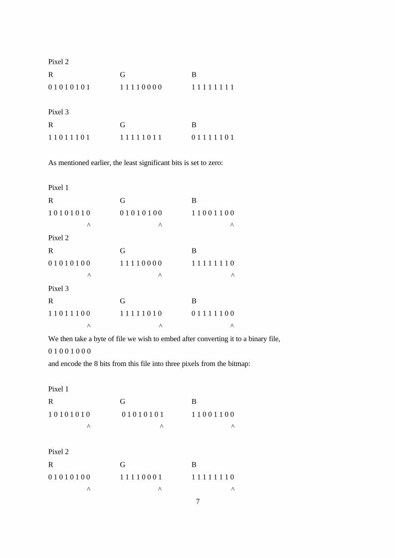
Every bit of our data-file will be put onto the next least significant bit in our bitmap like so:
Taking three pixels from a bitmap we would see:
Pixel 1
R G B
1 0 1 0 1 0 1 0 0 1 0 1 0 1 0 1 1 1 0 0 1 1 0 0
7
Pixel 2
R G B
0 1 0 1 0 1 0 1 1 1 1 1 0 0 0 0 1 1 1 1 1 1 1 1
Pixel 3
R G B
1 1 0 1 1 1 0 1 1 1 1 1 1 0 1 1 0 1 1 1 1 1 0 1
As mentioned earlier, the least significant bits is set to zero:
Pixel 1
R G B
1 0 1 0 1 0 1 0 0 1 0 1 0 1 0 0 1 1 0 0 1 1 0 0
Pixel 2
R G B
0 1 0 1 0 1 0 0 1 1 1 1 0 0 0 0 1 1 1 1 1 1 1 0
^
Pixel 3
R G B
1 1 0 1 1 1 0 0 1 1 1 1 1 0 1 0 0 1 1 1 1 1 0 0
We then take a byte of file we wish to embed after converting it to a binary file,
0 1 0 0 1 0 0 0
and encode the 8 bits from this file into three pixels from the bitmap:
Pixel 1
R G B
1 0 1 0 1 0 1 0 0 1 0 1 0 1 0 1 1 1 0 0 1 1 0 0
Pixel 2
R G B
0 1 0 1 0 1 0 0 1 1 1 1 0 0 0 1 1 1 1 1 1 1 1 0

8
Pixel 3
R G B
1 1 0 1 1 1 0 0 1 1 1 1 1 0 1 0 This byte remains unchanged
^
The final byte, part of the blue component of pixel 3, would be used for the start of the next byte of
hidden information.
This is the underlying principle of the Least Significant Bit method. Now that we have seen how the
information is recorded it becomes apparent that it has certain inherent weaknesses. Any image
manipulation that alters the pixel values of the image permanently will result in the loss of our hidden
data. Therefore the image cannot use any kind of lossy compression such as JPEG for instance as this
would result in an approximation of the image rather than a full reconstruction of the data within. The
same can be said of cropping the image or scaling it. It is possible to do operations such as rotations,
reflections or negative images however, the reason being that once the process is reversed again the
original bit values are restored.
Another weakness that is more specific to bitmap images is the file size. 24-bit bitmaps can become
very large files, which in themselves would seem suspicious during transmission over e-mail for
instance. Although this method of data hiding has a high capacity for storage, 12.5% of the cover
image’s size in the least (3 bits per pixel), the only people who could potentially get away with
transmitting these sizes of image in an uncompressed format such as BMP are digital photographers
and artists who wish to retain quality in their high resolution images.
The LSB method works in exactly the same manner for 8-bit images, such as GIF and greyscale
bitmaps, however the differences are in the amount of data that can be hidden and the visibility of
noise generated by the insertion of data.
In the case of colour GIF images each pixel can only show 256 different colours. Because of this
limited palette the colours can only be a “best representation” from the colour table of the original
colours present in an image. Changing the least significant bit has a much larger effect on changes in
colour than in a 24-bit image. In this limited palette a change of one bit might alter a navy blue pixel
to an indigo, altering an image drastically. The advantage of 8-bit images though is their
inconspicuous size making them ideal for e-mailing or display on websites.
9
2.1.3 JPEG and JSTEG
According to [3], despite the use of JPEG on an LSB inserted bitmap being damaging to the
information hidden inside, JPEG compression on its own can also be used for the reversible hiding of
information in an image file.
Until recently it was not thought possible for information to be encoded in this way until Derek
Upham created the JSTEG method explained in [20].
As briefly mentioned at the start of this chapter, it is possible to calculate the “busiest” parts of an
image in order to find sections that would hide data most imperceptibly. In essence, the JPEG
algorithm has always performed this operation during its processing and compression of images.
This led to Upham altering the way the algorithm works in order for JPEG itself, rather than the image
data, to hide the embedded information. This is known as file format dependence i.e. the method
hides data through the manipulation of coefficients in the JPEG compression scheme rather than in the
actual image data so as to survive the compression process.
Data hidden in a JPEG image is difficult to detect by the naked eye due to questions over whether any
inconsistencies in the image are down to suspected hidden information or simply lower-quality
quantisation.
JSTEG is distributed by Upham as a free code module in C that can be used in other freeware
applications. The following information was gleaned from [3] and Derek Upham's JSTEG
documentation in [20].
The JPEG algorithm encodes in both a lossy and lossless stage, the lossy stage using Discrete Cosine
Transform (DCT) and a quantisation step in order to compress the image data; the lossless stage then
uses Huffman coding to compress this even further.
As explained, information therefore cannot be inserted into the image data without suffering damage
to it's integrity, JSTEG, however, inserts data in between these two processes in order to avoid
corruption, saving the image to the JFIF format.
10
The JPEG compression algorithm divides images into 8x8 blocks of pixels that are run through the
DCT. The resulting frequency coefficients are scaled to remove the ones undetectable to the human
eye.
It is directly after this stage that the steganographic information is inserted, the least significant bit of
all the non-zero coefficients are replaced with concurrent bits from the hidden data, much like in the
LSB method except this time not directly into the image data.
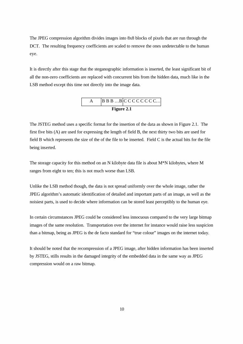
A B B B …B C C C C C C C C…
Figure 2.1
The JSTEG method uses a specific format for the insertion of the data as shown in Figure 2.1. The
first five bits (A) are used for expressing the length of field B, the next thirty two bits are used for
field B which represents the size of the of the file to be inserted. Field C is the actual bits for the file
being inserted.
The storage capacity for this method on an N kilobyte data file is about M*N kilobytes, where M
ranges from eight to ten; this is not much worse than LSB.
Unlike the LSB method though, the data is not spread uniformly over the whole image, rather the
JPEG algorithm’s automatic identification of detailed and important parts of an image, as well as the
noisiest parts, is used to decide where information can be stored least perceptibly to the human eye.
In certain circumstances JPEG could be considered less innocuous compared to the very large bitmap
images of the same resolution. Transportation over the internet for instance would raise less suspicion
than a bitmap, being as JPEG is the de facto standard for “true colour” images on the internet today.
It should be noted that the recompression of a JPEG image, after hidden information has been inserted
by JSTEG, stills results in the damaged integrity of the embedded data in the same way as JPEG
compression would on a raw bitmap.
11
2.2 Steganography In Audio Files
2.2.1 Psychoacoustics And Low Bit Encoding
Before going into the popular methods for data hiding in audio files it is important to gain a basic
understanding of the principles of Psychoacoustics. Embedding information into sound files is
generally considered more difficult than images; according to [2] the human ear is extremely sensitive
to perturbations in sound and can in fact detect such turbulence as low as one part in 10 million.
According to [21], the human ear has a dynamic range of 96dB making it capable of hearing low
energy noise such as a pin dropping or very loud noises like a gunshot, however it is not capable of
detecting a low energy sound at the same time as a high energy sound due to the auditory system’s
adaptation to dynamic variations in sound which mask the lower energy sound. These theories are
widely used in the noise reduction on analog tape recordings for instance, and as you can image, have
implications on the insertion of data as “noise” in audio files.
Much like the already Least Significant Bit method of embedding for images, it is possible to insert
data into WAV (one of the standard sound formats for Microsoft Windows) files using similar
methods. Sivathsan [9] in his research stated that the optimum channel capacity for this is 1kb per
second per kilohertz; his example being 44kbps in a 44kHz sampled sound sequence.
Nonetheless, this added noise is usually just outside the masking range of most high-energy sounds in
an audio file, making the data distributed in the noise audible. Low Bit Encoding is therefore an
undesirable method, mainly due to its failure to meet the steganographic requirement of being
undetectable.
2.2.2 Phase Coding
One technique that the human auditory system isn’t so sensitive to is phase coding. The phase coding
method in [1] and [22] breaks down the sound file into a series of N segments. A Discrete Fourier
Transform (DFT) is applied to each segment to create a matrix of the phase and magnitude. The
phase difference between each segment is calculated, the first segment (s0) has an artificial absolute
phase of p0 created, all other segments have newly created phase frames. The new phase and original
magnitude are combined to get the new segment, Sn. These new segments are then concatenated to
create the encoded output and the frequency remains preserved.
12
In order to decode the hidden information the receiver must know the length of the segments and the
data interval used. The first segment is detected as a 0 or a 1 and this indicates where the message
starts.
This method has many advantages over Low Bit Encoding, the most important being that it is
undetectable to the human ear. Like all of the techniques described so far though, its weakness is still
in its lack of robustness to changes in the audio data. Any single sound operation or change to the
data would distort the information and prevent its retrieval.
2.2.3 Echo Hiding
Echo hiding embeds its data by creating an echo to the source audio. Three parameters of this
artificial echo are used to hide the embedded data, the delay, the decay rate and the initial amplitude.
As the delay between the original source audio and the echo decrease it becomes harder for the human
ear to distinguish between the two signals until eventually a created carrier sound’s echo is just heard
as extra resonance.
Much like phase encoding this has considerably better results than Low Bit Encoding and makes good
use of research done so far in psychoacoustics. As with all sound file encoding, we find that working
in audio formats such as WAV is very costly, more so than with bitmap images in terms of the “file
size to storage capacity” ratio. The transmission of audio files via e-mail or over the web is much less
prolific than image files and so is much more suspicious in comparison.
2.3 Potential and Current Applications
The potential for reversible data hiding is staggering, new methods for its application are being found
that could revolutionise many current industries. The following are a few of the foremost examples of
this technology and highlight the importance of the subject as a whole.
2.3.1 Watermarking in Images
Although digital watermarking employs steganographic techniques there is one main factor that
differentiates the two. Both techniques employ methods to imperceptibly embed information into
cover data, however, as defined in [1], Steganography is usually more interested in “covert point-to-
point communication between two parties”.
13
Watermarking, on the other hand, requires a higher degree of robustness than is usually shown in
steganographic transmission of data. It needs to protect the embedded information from the usual
modifications to the file format that can occur. Everyday operations such as transmission, format
conversion and compression must all be overcome if the watermark is to remain. Deliberate attempts
to remove the watermarking data must also be taken into account.
Watermarking’s main application is in the copyrighting of digital media to give proof of ownership.
This is usually achieved by inserting copyright statements. There are, however, quite a few other
possible uses of digital watermarking that will be explored in more detail later on.
Visible watermarking is usually applied by the use of visible symbols overlaid onto an image or
possibly a video file, making it plain to see who the copyright owner is, and secondly to prevent the
use of such images without it being plainly obvious who it belongs to. For this chapter we will only
be concerned with invis ible watermarking and the benefits gained from imperceptibility.
Some of the possible uses of imperceptible watermarks are given below:
• Fingerprinting- This technique allows the copyrighter to embed a code specific to the legal
recipient of the data file . These characteristics distinguish each copy of the original data from
another and allows the owner to trace authorised recipients that are illegally distributing
copies of the data, or at least to trace back to the original recipient of leaked data.
• Fragile watermarks and image authentication – Using fragile watermarks for image
authentication relies on the detection of modifications through the use of fragile watermarks
that “break” under image manipulation. These watermarks deliberately employ low
robustness as a damaged watermark is a good indicator that the cover image has been altered
in some manner.
• Copy protection- Watermarking for copy protection is used as a mechanism to prevent the
unauthorised copying of media. This can mainly be seen in DVD technology where the data
contains copy information as a watermark. The copy information is used to define how many
times a DVD will allow itself to be copied.
• Labelling- The use of the watermark to insert extra data pertaining to an image has many
possible applications. One of the recently suggested ideas was adding a patient’s medical
notes to an X-ray image. This technique allows doctors to use a computer to scan the X-ray
14
and see whatever extra patient information needed. At the same time the photo would be
“backwardly compatible” with traditional systems.
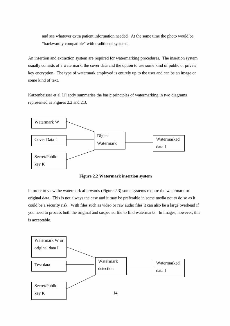
An insertion and extraction system are required for watermarking procedures. The insertion system
usually consists of a watermark, the cover data and the option to use some kind of public or private
key encryption. The type of watermark employed is entirely up to the user and can be an image or
some kind of text.
Katzenbeisser et al [1] aptly summarise the basic principles of watermarking in two diagrams
represented as Figures 2.2 and 2.3.
Figure 2.2 Watermark insertion system
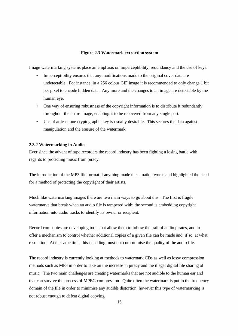
In order to view the watermark afterwards (Figure 2.3) some systems require the watermark or
original data. This is not always the case and it may be preferable in some media not to do so as it
could be a security risk. With files such as video or raw audio files it can also be a large overhead if
you need to process both the original and suspected file to find watermarks. In images, however, this
is acceptable.
Digital
Watermark
Watermark W
Cover Data I
Secret/Public
key K
Watermarked
data I
Watermark
detection
Watermark W or
original data I
Test data
Secret/Public
key K
Watermarked
data I
15
Figure 2.3 Watermark extraction system
Image watermarking systems place an emphasis on imperceptibility, redundancy and the use of keys:
• Imperceptibility ensures that any modifications made to the original cover data are
undetectable. For instance, in a 256 colour GIF image it is recommended to only change 1 bit
per pixel to encode hidden data. Any more and the changes to an image are detectable by the
human eye.
• One way of ensuring robustness of the copyright information is to distribute it redundantly
throughout the entire image, enabling it to be recovered from any single part.
• Use of at least one cryptographic key is usually desirable. This secures the data against
manipulation and the erasure of the watermark.
2.3.2 Watermarking in Audio
Ever since the advent of tape recorders the record industry has been fighting a losing battle with
regards to protecting music from piracy.
The introduction of the MP3 file format if anything made the situation worse and highlighted the need
for a method of protecting the copyright of their artists.
Much like watermarking images there are two main ways to go about this. The first is fragile
watermarks that break when an audio file is tampered with; the second is embedding copyright
information into audio tracks to identify its owner or recipient.
Record companies are developing tools that allow them to follow the trail of audio pirates, and to
offer a mechanism to control whether additional copies of a given file can be made and, if so, at what
resolution. At the same time, this encoding must not compromise the quality of the audio file.
The record industry is currently looking at methods to watermark CDs as well as lossy compression
methods such as MP3 in order to take on the increase in piracy and the illegal digital file sharing of
music. The two main challenges are creating watermarks that are not audible to the human ear and
that can survive the process of MPEG compression. Quite often the watermark is put in the frequency
domain of the file in order to minimise any audible distortion, however this type of watermarking is
not robust enough to defeat digital copying.

16
The most popular method for watermarking sound files is to embed it in the raw PCM audio data.
The main downside of this is the fact that PCM is uncompressed and so not only takes up a lot of
space (as well as being time consuming to encode in) but is often compressed into other formats by
users (such as MP3) hence breaking non robust watermarks.
A paper a few years ago by Koukopoulos et al [18] suggested a method for watermarking the MP3
file format. One added benefit of this particular method was that it didn’t require the use of the
original audio signal in order to detect the hidden watermark.
The algorithm encodes the watermark in the scale factors domain and not in the digitized audio data.
This enables the file to be recompressed by a user and still maintain the watermark.
Another novel approach in [18] is the fact that the authentication and copyright of the audio file relies
on the owner being able to prove a difficult to compute property of the watermark rather than from
finding the bit pattern of the watermark outright (as shown in the previous watermarking methods).
Much like in watermarking images there are criteria that audio watermarking must meet in order to be
effective.
Once again, as well as the robustness of the method, imperceptibility or inaudibility is important as
the cover data must not display noticeable or statistical loss in quality.
Koukopoulos et al [18] used encoding in the scale factor of the compression domain rather than the
spatial, time or frequency domain of the actual audio file in order to improve robustness and avoid the
pitfalls of operating on PCM data. At the same time it didn’t require the use of the original data in
order to extract the hidden information
The paper successfully demonstrated that watermarking MP3 files is viable; however the creators did
note that there was an audible distortion in low amplitude musical pieces or those without instruments
such as poetry reading.
17
2.3.3 WEDELMUSIC
WEDELMUSIC [26], or Web Delivering of Music is a European project being coordinated by the
University of Florence Computer Department for the distribution of musical scores in a digital format,
while ensuring their protection against copyright violation.
The website describes it as allowing “…publishers, archives and consumers (theatres, orchestras,
music schools, libraries, music shops, musicians) to manage interactive music; that is, music that can
be manipulated: arranged, transposed, modified, reformatted, printed, etc., respecting copyright.” [26]
It is the perfect demonstration of the techniques discussed so far, combining image score and audio
watermarking as well as printed music sheets.
WEDELMUSIC uses watermarking as both an active protection of the transmitted digital objects and
a passive security mechanism for tracing the source of illegally distributed copies.
The hidden watermarks contain publisher identification codes, an identification code for the musical
piece itself and a final code for the identification of the local distributor. Despite all this information,
WEDELMUSIC uses the psycho acoustic model to guarantee such watermarks are non-audible in
WAV and MP3 files.
It comes with its own watermark reader for the demonstration of ownership and copyright
infringement. The watermark apparently remains readable after reprints, scanning of the printed
sheets or even imperfect photocopies. In fact they claim that by the time the image was
modified/deformed so as to make the watermark non-extractable, the sheet music itself would be
unreadable. The cost of removing the watermarks is said to be more expensive than buying the actual
sheet music itself.
2.3.4 Concealograms and Three Dimensional Barcodes
The concealogram [23] is a new steganography-based technique for hiding barcodes inside pictures,
with many possible applications.
Some of the most recent suggestions for its use are in the creation of forgery-proof identity documents
such as corporate ID cards or passports. In fact, they’ve already been approved for use in passports
by the International Civil Aviation Authority. Their hope is that this will bring forward developments
in machine-readable identification documents while making it much harder to manufacture fraudulent
passports.
18
Concealograms rely on a two dimensional barcode being inserted into a halftone image. This
however can still be read by conventional scanner technologies.
The two dimensional barcode is not too dissimilar from the one-dimensional version found on the
goods bought in all stores currently. Two-dimensional barcodes contain all the information needed to
read them inside their 2D binary dot array. One-dimensional barcodes on the other hand hold only
twelve characters providing a reference number. The reference number then has to be looked up in a
database.
Although the barcodes can be created and embedded in an image using computer software, the makers
claim that it isn't digital steganography due to the fact that the information is contained in the final
hard copy (the physically printed image) and decoded using a scan of that hard copy.
Software developed for this purpose by Datastrip [24] can store around 3 kilobytes of information
leading to suggestions that future identification documents might use this technology to embed a
colour photo or fingerprint.
The United States Postal Service (USPS) is looking into using this information storage method in so-
called “Smart Stamps”. They hope to embed the sender's identity as well as the date, time and place
the postage was paid for all packages.
One of the main advantages of the concealogram is that each section of image-barcode contains the
information that the barcode held on its own. This allows the information to be picked up from a
scanner even if part of the picture is obscured or missing.
2.3.5 Conclusion
For the ”proof-of-concept” software to demonstrate steganography first hand, the final decision was
made to use the Least Significant Bit (LSB) method for data hiding in images, as described earlier.
This method would allowed reasonably large amounts of data to be hidden without betraying it’s
existence to human observation, while at the same time, not requiring overly complex mathematical
understanding to implement.
Implementation of a JPEG based scheme would have been ideal considering its potential for the size
of embedded data being similar to LSB, however, with the source code for JSTEG being widely
19
available it was considered not sufficient enough of a challenge to implement the C code in an
application.
Embedding into an image rather than audio file was considered a more attainable target in the time
frame available. Not only do audio files require a complex understanding of the underlying
mathematics, but even the simpler methods such Low Bit Encoding were not suitable for an effective
demonstration of steganography. Any mistakes made in audio embedding would result in a noticeable
difference by the human auditory system therefore failing to meet the undetectability requirement.
Even if one of the more complex methods such as phase encoding were implemented, its evaluation
would have to be entirely subjective. Unlike in image embedding where we can evaluate whether a
pixel’s intensity change is detectable to the human eye mathematically, such measurements cannot be
made on audio files so easily.
The psychoacoustic masking ability of an audio file would no doubt vary over miniscule time frames
meaning that some parts may embed very well while others not so well, even with phase encoding.
The theories may be sound but in order to judge the overall success of any final implementation, short
of using a large group of test listeners to grade the final software (which as mentioned is entirely
subjective), there is no easy way to evaluate effectiveness using software available in the School of
Computing, nor given the time constraints of this project.

20
3. Design
3.1 Software Methodology
It is widely accepted that for software projects to succeed a methodology of some kind must be
applied to create specific, measurable attainment targets and evaluation criteria for the end product.
Software engineers use such methodologies to fulfil four main goals:
• To accurately record a system’s requirements.
• To create a systematic approach to development.
• To provide a solution within a finite time limit and for a finite cost.
• To allow changes to the project during development.
Traditional methods such as Functional Decomposition, Structured Systems Analysis and Design
Methodology (SSADM) and System Development Life Cycle (SDLC) have in recent years been
acknowledged to lead to failure the majority of the time on large projects. Moreover, it has been
shown that the probability of failure is proportional to the size of the project. Complex applications of
around 100,000 function points (equivalent to Microsoft Office for instance) were shown to have an
80% chance of termination, as explained in [15].
With traditional methodologies being dubbed “heavy weight”, mainly due to the amount of
bureaucracy surrounding them, the last five years especially have shown a shift of focus to
“lightweight” or more agile methodologies.
For a small software project such as this one, these methods are much better suited than a traditional
approach like SSADM for instance. At the same time they have a proven scalability that allows
incredibly large projects a better change at succeeding.
The term “lightweight” generally refers to the changed mentality of these approaches. Bureaucracy,
the amount of paperwork required, and the steps in the lifecycle that need to be applied have all been
cut down to the bare minimum needed. There is an emphasis on using only the diagrams and

21
planning that you need to do and removing anything that isn’t necessary. This simplifies the process
of creating large projects that in the past have generated mountains of paperwork; there is no longer a
need to follow through on paperwork merely because the guidelines say you must include it.
Another facet of these methods is their people orientation, the use of the end user in the design,
analysis and final evaluation of the system. Fowler [14] describes them as being agile methods that
are adaptive rather than predictive, referring to the general trait of an iterative development cycle that
refines the software through repeating of the life cycle.
3.1.1 Rational Unified Process and the Unified Modelling Language
The Rational Unified Process (RUP) is an object-oriented methodology created in 1998 that utilises
the Unified Modelling Language (UML).
Ivar Jacobson, one of the so called “Three Amigos” that created UML along with Grady Booch and
James Rumbaugh, suggested that UML be used for the basis of an agile process able to support the
entire software development life cycle, as Jacobson himself described it in [13].
He goes on to call the RUP a use case driven, architecture centric, iterative and incremental process in
[13]. The reason for this iterative approach to the design and analysis of a system is down to the
belief that a system cannot have its requirements defined initially in one go, but rather these will
evolve as the project progresses.
The advantage of RUP and UML is that it is an agile and Object Oriented approach to project
management. Because it encourages the creation of only enough UML diagrams to get by, and the
“throwing away” of any UML not serving a purpose; this is perfect for a small project such as this
where there is no benefit in being held back in an unnecessarily restrictive analysis and design phase.
Being fast and easy to model means the software engineer can get to the actual programming quicker
and yet still have enough documentation to gauge progress and assess the final product.
UML uses a standard syntax that allows others to easily read and understand the methods employed.
Having a set of diagrams that show the full details of the application, activity flows, classes and the
user requirements, is very valuable when it comes to documenting the software upon completion.
22
UML and the RUP streamline the process of creating the coded software, and the development
process as a whole, making the project a lot more efficient.
3.1.2 Chosen Methodology
Due to the fact that the software being implemented was quite small, a unique approach was chosen
that involved elements from the RUP, mainly the use of UML, combined with the well known “Code
and Fix” methodology described by Fowler in [14] and prevalent in the School of Computing’s SO11
and SO12 programming modules.
The “Code and Fix” methodology is lacking in terms of “underlying plan and the design“ (Fowler
[14]) but it is acknowledged to work well on small projects such as this one. After the design phase,
each feature is implemented and tested one by one and fixed if necessary. This iteration of design,
implementation and testing of every component of the application before moving to the next allows
the programmer to incrementally deal with potential problems and focus on smaller goals in order to
complete the overall target of a completed application.
RUP revolves around an Object Oriented approach and in general is aimed at larger applications than
will be provided by this project. The use of UML and some of the stages in the design phase however
were invaluable in the improvement of the “Code and Fix” methodology’s weakness, that being a lack
of planning and design. Another key element of the Rational Process that was employed was the idea
of continual iteration of each phase of development in order to properly evolve the requirements of
the application.
One of the advantages of using an approach like this is that the system can be tailored to meet explicit
requirements. This saves a lot of time for projects with one-off needs like this one. By developing
the system along these lines, and specifically dealing with each small-scale problem as it occurs, it
becomes easier to handle all possible error states that might crop up. The use of UML diagrams at the
design stage, such as Activity Diagrams, is an added advantage at pre-empting these problems before
even reaching the implementation stage.
It should be noted that Jacobson[13], Owen[12] and Avison et al[11] are all advocates of using UML
even in non-Object Oriented development. UML is a valuable tool for describing any system, not just
computing related ones, as shown by its use in Business Modelling.
23
Combined with elements of the RUP and UML, a structured design phase with proper requirements
and planning can be created before implementation is undertaken. This creates measurable goals that
can be used to evaluate the software upon completion as well as reduce the amount of testing required
through proper planning at the design stage.
3.2 Authoring Tools and Development Language
In order to gain a larger potential user base for the application, as well as provide an opportunity for
future development, the authoring tool was best not to be an Operating System specific. Although the
development of a GUI was one of the potential further developments, it was decided that the main
program would be a command line application so as to separate it entirely from any potential front
ends and allowing the code to be easily ported over both Windows and Linux.
With this early requirement in consideration, the use of Visual Basic was eliminated, along with many
HCI issues as the application would have to utilise command line arguments for it’s input and output
parameters. This left two main choices of development language, namely Java and C++.
Java is an Object Oriented programming language that runs on a virtual machine. As a result this can
be used to develop cross platform applications. At the same time, this left the option of developing a
front end in Java if time permitted. One advantage of Java over C++ is the automatic “garbage
collection” used for restoring system resources without specific code being written for the de-
allocation of pointers for instance.
While the virtual machine is an advantage in terms of cross platform compatibility, in this case it was
an unnecessary overhead. To install the software would have required the installation of the virtual
machine as well, rather than just the single executable file that is produced by C++.
C++ is also an object-oriented language. Being very popular in the IT industry and not requiring any
virtual machine software to run the application, it was the primary candidates for development. The
decision was made to use Microsoft Visual C++. The reasons for this were two fold. Firstly, Visual
C++ has an advanced debugging suite that is highly intuitive; secondly, it is possible to develop C++
code as a command line application that could be ported easily, with a minimum of changes, to be
compiled under Linux. In addition, if there were enough time, it would be possible to use these tools
to create a GUI that relied on the compiled command line application.
24
3.3 Requirements and Functionality
Since in Chapter 2 it was decided that the method being implemented was going to be the Least
Significant Bit method, and a suitable methodology was chosen, it was now possible to formalise
requirements through the use of UML diagrams during the design phase. Firstly a Use Case diagram
(Appendix E) was used to complete Use Case Description forms (also Appendix E) based on those
provided by Owen in [12].
The Use Case approach is equivalent to the traditional requirements list yet in a much more flexible
and understandable format. Once the Use Case Description forms were complete it became easy to
identify the essential and desirable functionality for the application based on the functional and non-
functional requirements.
Essential Functionality:
• The insertion of the chosen data into a simple image file (i.e. GIF or PNG).
• The extraction of a hidden file from a carrier image.
• Calculation of the maximum available space in the carrier image before insertion.
Desirable Functionality:
• Display the maximum available space in the carrier image.
• Display the size of the file the user intends to hide.
• Built in “quick manual” if the incorrect number of arguments are used
In terms of further features to enhance the application past the minimum requirements, the following
additions were planned if time permitted:
• Encoding of the hidden data into a complex 24-bit Bitmap image rather than GIF or PNG.
• Development of a front-end GUI.
• A security measure involving the need for a password upon extraction.
The Use Case descriptions paved the way for the Activity Diagrams. The Activity Diagram is a
variation on the State Diagram focusing on the flow of activity driven by internal processing. By
utilising the Activity Diagrams in Appendix F it was possible to plan the course of events as the user
operated the application, including what should occur upon reaching an exception state or during an
alternative action.

25
As you can see in Appendix F, the use of the Activity Diagram is simply to represent graphically the
basic, alternative and exception paths already filled out in the Use Case Description forms of
Appendix E.
3.4 Summary
This chapters has provided an overview and justification of the methodologies, tools and languages
considered for the project as well as displaying some of the techniques used during the actual design
phase that led into the implementation phase.
26
4. Implementation
4.1 What was achieved?
As shown in Chapter 1, the minimum requirements for the software implementation were:
• Produce a piece of software that shows how to encode information in to a simple image or
sound file.
• Produce documentation for the program.
The project managed to fulfil both of these minimum requirements, the deliverable was demonstrated
in the progress meeting and the software manual for the program can be found in Appendix B.
The possible enhancements suggested at the start of the project were:
• Implement a solution to encode information into a complex image such as a 24-bit bitmap.
• Implement a solution for both image and sound files.
• Produce code that can be compiled for both a Windows and Linux platform.
• Development of a front-end GUI.
• A security measure to prevent the removal of data without the inputting of a password.
Of these, three out of the five were completed within the time available for implementation. The final
application was capable of encoding any file type into a 24-bit uncompressed bitmap; it also compiled
on both Windows and Linux systems easily with no alterations in the code due to the use of only
standard libraries. A four-digit security code was implemented so that the user who inserts the hidden
file can prevent the extraction of the data without the insertion code. Also, a front-end GUI for the
command line application was started but not completed; this is discussed later in the chapter.
4.2 Problems during Implementation
4.2.1 24-bit Images and Headers
It was decided at the initial stages of the implementation, after research was completed, to base the
application around 24-bit bitmap images instead of a simple GIF or PNG image. The reason for this
27
was to gain a better lead-time during the development part of the project schedule (see Chapter 1 for
the initial schedule) and to surpass the minimum requirements by encoding into a complex image. By
doing this, the development was not as incremental in goals as originally hoped. The original plan
was to start off on simple images; once these were mastered they would be replaced with the 24-bit
method. Getting the program to encode into a 24-bit image naturally took longer to get working than
a GIF would have, however it was felt afterward that the struggle had been worth it as the incremental
approach would have taken too long to surpass minimum requirements. In terms of what could be
inserted into a 24-bit image, the results were much more impressive. Rather than just encoding a
short text file message it was now possible to embed any file desired.
In order to guarantee that the program would compile under both Windows and Linux it was decided
from the offset that only standard libraries would be used. In particular, the most important libraries
used were the string operation libraries. Once the file to be hidden and the bitmap file were converted
to binary it was simply a case of string manipulations such as reading in bytes, writing to single bits
and writing out all the altered information to a new image file.
The actual implementation was a lot more complex to think through at the time. As shown in Chapter
2, the 24-bit bitmap represents the red green and blue component of each pixel with 8-bits, hence the
reason for it being called a 24-bit image, in total each pixel uses a 24-bit representation. In order to
encode large amounts of information, yet at the same time make this information undetectable, only
the least significant bit of each red, green and blue component was used.
In doing this the range of colours that any one pixel can change within, due to data insertion, is a mere
eight values out of a possible 16.8 million colours, a difference that is not detectable to the human
eye.
The first problem encountered with using 24-bit images was dealing with the bitmap header files. For
this the format and size of such headers, and the point at which the actual image data started, was
required. [16] provided the information on the structure of the header. The data held within produced
variables that solved smaller problems, namely image size, whether the image was a bitmap at all, its
bit quality and if it was compressed. If the image was not a bitmap, or it was compressed, then the
process would not work as the data cannot be stored within a compressed bitmap.
The file header turned out to be 54 bits in total, 14 for the file header and another 40 for the info
header, after this, the image data itself was stored in a 1D array of unsigned characters, where each
28
value is a pixel stored in (b, g, r) format and written from the bottom right corner of the image
upward. The tables in Appendix D were taken from [16] and describe the full details contained in
these file headers.
4.2.2 Insertion and extraction problems
The next challenge was storing information about the insertion process in the image. The first
problem to be overcome was when to stop attempting to extract the bits of a stored file. There were
two possible solutions to this problem, either a termination character of some kind, upon which when
the extraction algorithm found it, it stops writing out the hidden file; the second option was to store
the message size at the start of the file in some sort of header specific to the application.
As it was impossible to create an appropriate termination character (remember that we could be
embedding any file type and hence everything used binary copies of both files), an embedding header
was invented. This resolved another problem, that of extracting the embedded file without knowing
its file extension.
The embedding header created is the first thing inserted in a carrier file after the bitmap file’s own
header. The header stores both message size (the size of the embedded file) and the three-letter file
extension of the embedded file. This meant that the user could output to a file name of their choice
during extraction and Datahide (as the program was dubbed) would append the correct file extension
upon completion.
4.2.3 The “No Information Embedded” Problem
After the base application was complete, a new problem was stumbled upon while testing the
extraction method. Although the application was capable of inserting information into a bitmap
perfectly, and extracting it perfectly, when extraction of information from a bitmap that had no
information encoded to it was attempted, Datahide still attempted to extract the non-existent
information. A temporary file was created containing random data from the least significant bit of
every pixel component. After this the application would stall.
To resolve this, the information in Datahide’s header was used once again. When a file was extracted,
Datahide now had to check the file extension as one of the first things it did before extracting actual
embedded file data. By testing whether all three characters in the space that should be occupied by
the extension were alphanumeric, it could tell if a real file was embedded or not.
29
Every file embedded had to have its extension inserted to the header, the chances of random data
being pulled out of a carrier bitmap that contained no information, and actually creating a readable
alphanumeric character in all three of the file extension characters, is incalculably low. As a result,
Datahide now gives out an error message saying that no file is encoded to a bitmap if it finds no valid
file extension.
4.2.4 The Security System
One of the further enhancements made to Datahide was the inclusion of a security system. This
required the user to enter a four-digit number as a command line argument. This code is needed by
the receiver of the carrier bitmap in order to remove the information; otherwise Datahide reports that
no information is stored in the file.
The problem of implementing a password system was a tricky one, plans were drawn up that would
use a character based system but it was found that there was no easy way to get it working. Any
system would have to be based on an offset basis. The password would have to be converted into a
number of bits that Datahide would skip after the header before encoding the embedded file to the
new carrier.
As a result, the simplest method was to use a four-digit number as this was the easiest way of
producing a unique number. The code is taken by Datahide as an offset from the start of the image
data (after the Datahide header), so if the code is 1234, Datahide will write out the bitmap headers, its
own header, and then it skips the first 1234 bits of the image data. When the receiver gets the carrier
they will naturally need this information to tell Datahide where it needs to start reading the embedded
data from in the carrier image.
This, however, caused problems of its own during encoding. When testing on very small image files
of only 9k or so, it was found that the image file would become noticeably larger, by a few more K
than it was before insertion of data. It became apparent that the data was becoming shifted along with
larger four-digit keys because there was so little space available in the cover image in the first place.
The key potentially removed 10,000 bits from every image encoded and this had not been taken into
account in terms of the holding size of each image. To solve the problem a minor change was made
to the output of Datahide; instead of displaying the size of the file that was to be hidden, it now
displayed the space required to hide it. This new value represented the size of the file to be hidden
30
plus space for the message size, the file extension and the 10,000 bits of the security key that were
essentially lost and could not be written to.
From tests and calculations it was shown that with this security measure in place it was now only
possible to encode hidden files of a maximum size of 12.4% of the bitmap file.
e.g. To encode just 1 byte of hidden information Datahide will inform you that the file requires 1,258
bytes and hence a 10,145 byte bitmap image. Essentially, a minimum bitmap file size has been
created of approximately 10k for just 1 byte.
The advantage of the security key is that if someone attempted to remove data from an image encoded
by Datahide they could not know, without looking at the source code, how the header was encoded or
how the security measure works. Even if they did guess that it was an offset value, or they looked at
the code and knew the format of the header, they would still have to use a brute force method to
check, 10,000 different start positions (worst case) that the data could be written from.
4.2.5 Insertion and Extraction Algorithms
Undoubtedly the most complex and challenging parts of the implementation were the algorithms for
the insertion and extraction. While not too difficult to code in the end, as they were string
manipulations of binary data, a lot of time was spent roughing out pseudo code to keep track of what
needed inserting, at what point, while at the same time making it easy to extract that data.
A major obstacle was that the only way to test the insertion or the extraction was to have both of these
operations being programmed and altered almost in parallel. There was no way to check that data was
embedded into an image correctly unless it could be extracted to see if it was in one piece. This took
a lot of planning and many rough notes were made in the code as both algorithms were changed so
that a corresponding change could be written for the other.
In fact, during the early phases of development both of these were in separate source code files and
were compiled to create separate executables. This allowed two windows to be open at any one time
with insertion code in one and extraction code in the other to make it easier when comparing their
alterations. Only once both were completed, and all errors and exception states handled, were they
united into one single source file and executable.
31
4.2.6 Errors and Exceptions
One of the original reasons why an Object Oriented approach was not used for the design and
implementation was not only the lack of credible classes that needed to be created, but also the need
to be able to predict all the possible error states that the application might end up in.
It is widely known that in safety critical systems it is sometimes preferred to use functional processing
methods to tailor applications specifically to the needs of the requirements. In doing so, rather than
using objects that can be re-arranged to create different program paths and behaviours, you admittedly
limit the behaviour of an application. This is not always a bad thing, and as with this application, it
was felt an Object Oriented approach would have increased the already large problem of error states.
The code in Datahide makes many checks all the way through and has to catch exceptions for the non
existence of files, the size of files, the failure to generate or insert binary data, the minimum amount
of pixels that are in a bitmap and so on and so forth. By coding it specifically to meet these needs,
although a tiresome job, it was possible to make sure that the application was able to deal with all
possible outcomes. This was partially a benefit of the planning in UML for the Activity Diagram and
the exception states brought up during the writing of the Use Case Description forms.
4.3 Basic Operations of Datahide
4.3.1 Insertion
The program first reads in the bitmap file as binary and checks that it is the correct format, it then
reads in the file to be embedded as binary also.
After comparing the file sizes and making sure that the file to be inserted doesn’t exceed 12.4% the
size of the cover bitmap, Datahide will output the space required for that file, the size cover bitmap
needed to store it and the capacity of the current chosen bitmap.
Datahide then copies the bits corresponding to the bitmap header to the output carrier file, and creates
its own header. This includes the size of the size of the file being inserted and it’s three-letter file
extension. The application then skips a set amount of bits decided by the four digit key inputted by
the user (this could be any number between 1 and 10,000) before encoding the chosen file into the
least significant bit of the red, green and blue components of each pixel. Once the insertion is
complete Datahide outputs the time taken for the operation. Naturally, the time taken for insertion is
32
wholly dependent on the processor of the machine and the size of the bitmap image used, as no matter
how large the size of the hidden data, the whole of the source bitmap still has to be copied to the
carrier bitmap.
4.3.2 Extraction
Datahide reads in the carrier bitmap as binary and skips past the first bitmap headers straight to the
Datahide header. It takes the hidden files size and the file extension and immediately checks whether
the three letters in the file extension are valid alphanumeric values. If not it assumes there is no file
hidden inside the bitmap and stops the extraction.
If the letters are valid it uses the key the user entered at the prompt and skips however many bits are
denoted by the security key to get to the start of the embedded file. Datahide then extracts the number
of bits denoted by the hidden file’s size from the header.
Once again the time for the operation to complete is given, this time however it is mainly dependent
on the size of the hidden file. As soon as this has been written out there is no need to process the rest
of the image, unlike insertion there is obviously no need to write out the whole image twice as it only
writes out the embedded file.
4.4 Remaining Problems
At the end of the development phase there was only one remaining problem that went unsolved. It
was found that upon the insertion of data into a bitmap the new carrier bitmap was mysteriously one
bit larger than the original source no matter what was embedded.
Due to constraints, there was not any time left to investigate this. The reason it went uncovered for so
long was that a difference of 1 bit almost never leads to a change in the displayed file size shown in
graphical interfaces for operating systems like Linux or Windows. During development, when the file
size was checked, the size in Kilobytes remained the same, only by closely looking at the properties
and the size in bytes was it realised that there was a minor problem.
This is more than likely a result of the method used to write out the carrier bitmap, it can only be
concluded, on the small evidence given and the experiences gained in programming from this project,
that this is some unexpected result of writing the carrier out to file using the standard string libraries
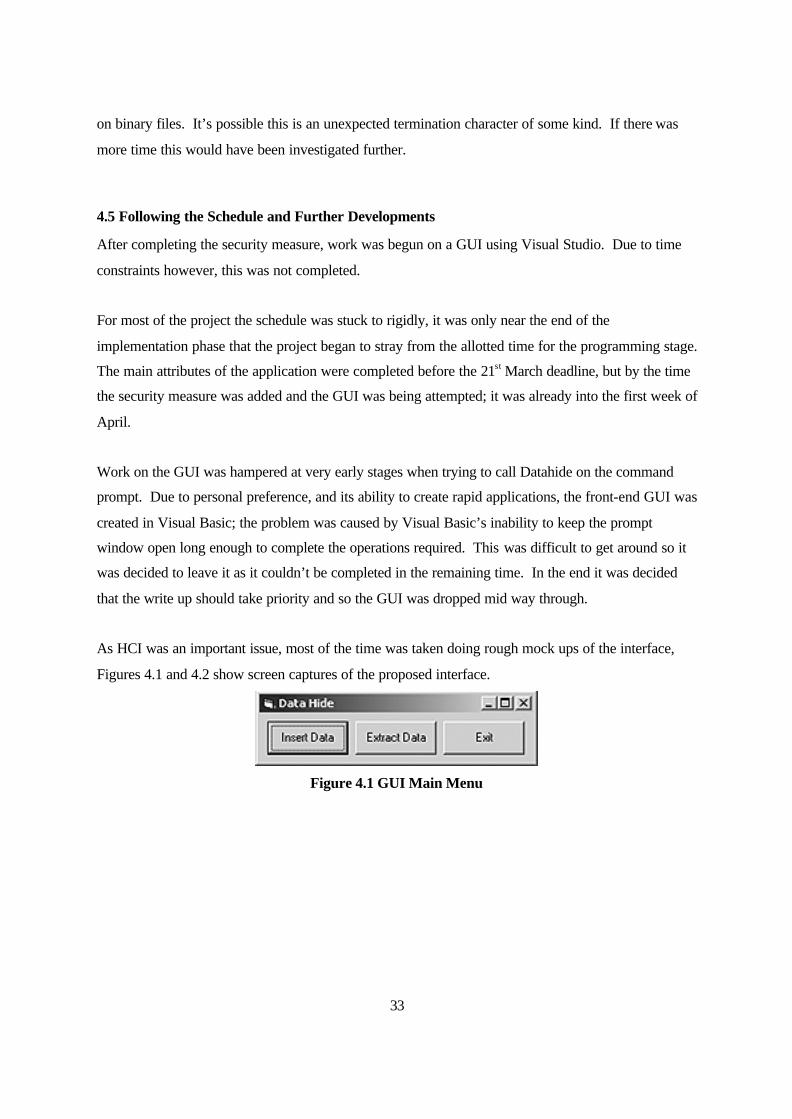
33
on binary files. It’s possible this is an unexpected termination character of some kind. If there was
more time this would have been investigated further.
4.5 Following the Schedule and Further Developments
After completing the security measure, work was begun on a GUI using Visual Studio. Due to time
constraints however, this was not completed.
For most of the project the schedule was stuck to rigidly, it was only near the end of the
implementation phase that the project began to stray from the allotted time for the programming stage.
The main attributes of the application were completed before the 21st March deadline, but by the time
the security measure was added and the GUI was being attempted; it was already into the first week of
April.
Work on the GUI was hampered at very early stages when trying to call Datahide on the command
prompt. Due to personal preference, and its ability to create rapid applications, the front-end GUI was
created in Visual Basic; the problem was caused by Visual Basic’s inability to keep the prompt
window open long enough to complete the operations required. This was difficult to get around so it
was decided to leave it as it couldn’t be completed in the remaining time. In the end it was decided
that the write up should take priority and so the GUI was dropped mid way through.
As HCI was an important issue, most of the time was taken doing rough mock ups of the interface,
Figures 4.1 and 4.2 show screen captures of the proposed interface.
Figure 4.1 GUI Main Menu

34
Figure 4.2 GUI Insertion Menu
As the front-end GUI and back-end applications were totally separated it was planned that the
interface would take in the arguments required to call the command line program and insert them to
perform the operations, however, there were problems firstly returning error messages from the
command line to Visual Studio and also in the actual execution of the command line application itself.
Due to the development phase in general stretching a little further than originally intended, the testing
phases were conducted at the same time as the writing up and compilation of the report. Other than
these oversights the schedule was kept to fairly well, especially at the research stage.
It did prove to a certain extent the solidarity of the theory that the back-end was best developed as a
separate entity to any front-end. By developing in Visual Studio yet keeping these two elements
separate it made it easier to manage the project and to fulfil the minimum requirements before
attempting the further developments.
If the GUI and back-end application had both been attempted at the same time it is unlikely, given my
adherence to the schedule, that the whole application could have been completed to a working
demonstration standard. By breaking it down into manageable steps using the “Code-and-Fix”
methodology, a lot more progress was made.
35
4.6 Summary
This chapter has described the code behavior of Datahide and the problems that came up during its
implementation. Further details can be found in the actual implementation code, datahide.cc.
All of the minimum requirements were met for the implementation and three of the five goals to
surpass these were also met.
The one further development started but not completed, the user interface, was described briefly with
screen captures of its intended appearance and the underlying calling of the command line Datahide
explained. The GUI was not far from completion, however, unfortunately it did not function to a
satisfactory stage by the projects conclusion. The GUI can also be found on the provided disk of
deliverables.
36
5. Testing and Evaluation
5.1 The Code -and-Fix Model
Due to the choice of methodology, every part of the implementation described went through its own
design, coding and testing phase. This meant that the program was tested thoroughly at every stage,
removing the vast majority of programming and logical errors and allowing the designing of functions
to catch exceptions as and when they were found.
There were four main development areas that required their own design, implementation and testing
phases, the following subsections will describe the test carried out for each.
5.1.1 Flags and Arguments
The -I and -X flags, for insertion and extraction respectively, were tested by trying incorrect input
flags. There were also tests performed using incorrect arguments or numbers of arguments as inputs
for Datahide. Upon all incorrect inputs Datahide was programmed to output a “quick manual”
describing its use or more specific exception messages for the many potential error states. The “quick
manual” gave brief instructions on the applications use based on the more detailed ones given in the
User Manual
5.1.2 Insertion
It should be noted that the insertion and extraction were tested almost in parallel due to the fact that
they had to be implemented in parallel. As such, neither could be completely tested without the other
so it was decided that this was the only plausible option.
A variety of source file types were tested, these included non-image files and non-bitmap to make
sure that Datahide did not attempt to embed in incorrect formats. Bitmaps of 8 and 16-bits were
tested as well as RLE compressed bitmaps. All of these were correctly recognised as incorrect source
images and Datahide provided an appropriate message.

37
A test was performed using an output carrier name that was the same as the cover bitmap as this
cannot be allowed. Datahide cannot read from a cover file and at the same time write to the very
same file for obvious reasons.
Files of all types were tested for insertion including other images, compressed files and executables.
All were embedded into carrier images with no problems. The executable was possibly the most
important file type tested as if it is improperly embedded it could not be run upon reconstruction.
Performance tests were done using 50Mb image files to get estimate times for insertion and
extraction, naturally these rely heavily on the computers processing power but it was confirmed that
Datahide takes longer to insert a file than to extract it simply because there is more data to write
during an insertion.
Insertions were tested on files too large for their supposed cover bitmaps; the recommended cover file
size given by Datahide in the resulting error message was then used to check accuracy of calculations.
5.1.3 Extraction
Bitmaps containing no hidden files were passed into Datahide to check that it did not attempt to
extract non-existent files from them. Since the changes that made extension checks possible, no files
were now extracted under these circumstances.
The program was also tested to make sure it appended the correct file extensions for each hidden file
and that the properties and integrity of each file had not been altered by either the insertion or
extraction process. The extracted files were checked for changes in size, and in the case of
executables, were actually run to make sure that they still maintained their integrity through the
process.
The user adding the file extension to their chosen output filename, despite the application explicitly
instructing not to, caused no major error, the correct extension is still appended and the file can still be
run or viewed normally. The only resulting action is that the file will have two extensions i.e.
embedded.zip.zip
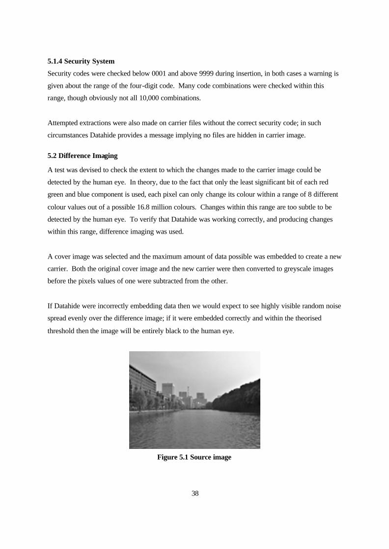
38
5.1.4 Security System
Security codes were checked below 0001 and above 9999 during insertion, in both cases a warning is
given about the range of the four-digit code. Many code combinations were checked within this
range, though obviously not all 10,000 combinations.
Attempted extractions were also made on carrier files without the correct security code; in such
circumstances Datahide provides a message implying no files are hidden in carrier image.
5.2 Difference Imaging
A test was devised to check the extent to which the changes made to the carrier image could be
detected by the human eye. In theory, due to the fact that only the least significant bit of each red
green and blue component is used, each pixel can only change its colour within a range of 8 different
colour values out of a possible 16.8 million colours. Changes within this range are too subtle to be
detected by the human eye. To verify that Datahide was working correctly, and producing changes
within this range, difference imaging was used.
A cover image was selected and the maximum amount of data possible was embedded to create a new
carrier. Both the original cover image and the new carrier were then converted to greyscale images
before the pixels values of one were subtracted from the other.
If Datahide were incorrectly embedding data then we would expect to see highly visible random noise
spread evenly over the difference image; if it were embedded correctly and within the theorised
threshold then the image will be entirely black to the human eye.
Figure 5.1 Source image
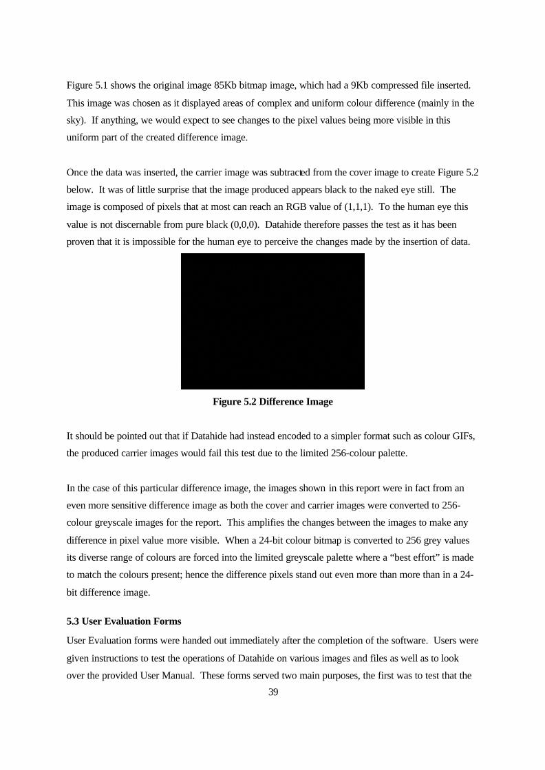
39
Figure 5.1 shows the original image 85Kb bitmap image, which had a 9Kb compressed file inserted.
This image was chosen as it displayed areas of complex and uniform colour difference (mainly in the
sky). If anything, we would expect to see changes to the pixel values being more visible in this
uniform part of the created difference image.
Once the data was inserted, the carrier image was subtracted from the cover image to create Figure 5.2
below. It was of little surprise that the image produced appears black to the naked eye still. The
image is composed of pixels that at most can reach an RGB value of (1,1,1). To the human eye this
value is not discernable from pure black (0,0,0). Datahide therefore passes the test as it has been
proven that it is impossible for the human eye to perceive the changes made by the insertion of data.
Figure 5.2 Difference Image
It should be pointed out that if Datahide had instead encoded to a simpler format such as colour GIFs,
the produced carrier images would fail this test due to the limited 256-colour palette.
In the case of this particular difference image, the images shown in this report were in fact from an
even more sensitive difference image as both the cover and carrier images were converted to 256-
colour greyscale images for the report. This amplifies the changes between the images to make any
difference in pixel value more visible. When a 24-bit colour bitmap is converted to 256 grey values
its diverse range of colours are forced into the limited greyscale palette where a “best effort” is made
to match the colours present; hence the difference pixels stand out even more than more than in a 24-
bit difference image.
5.3 User Evaluation Forms
User Evaluation forms were handed out immediately after the completion of the software. Users were
given instructions to test the operations of Datahide on various images and files as well as to look
over the provided User Manual. These forms served two main purposes, the first was to test that the
40
application worked as it should and the second was to get a users evaluation of how successful the
programs goals were in terms of usability.
Five users were asked to take part, three experts and two novice users. The aim of the form (which
can be found in Appendix C) was to make sure the program was accessible to as many users as
possible, and secondly, to use the feedback given to improve the program. The feedback from these
users was also used to refine the software manual and the programs own “quick manual” to remove
ambiguity and to better identify any parts that were missing.
The feedback from the novice users was mainly used to improve the accuracy and clarity of the user
manuals. The experienced users, all students of the computing department, were asked to run extra
tests for robustness, checking for logical errors or uncaught exceptions and analysing the quality of
carrier images and the integrity of the data contained within them.
5.3.1 User Evaluation Form Results
The results from the user evaluation forms were gathered early enough to take the suggestions into
account and make minor improvements to the program and it’s User Manual.
From the scores given, and the user comments, it became clear that the novice users were having
problems understanding how to use the input parameters of the program. There was particular
confusion over which filenames did not require their file extension to be added during extraction. To
solve this there were changes made to "quick manual" and User Manual for clarity. One such change
was calling the "cover image" the "source image" as novice users also found they became confused
over the difference between the two.
Both novice and expert users agreed that the error messages for incorrect arguments were sufficient,
and once the clarification between carrier and cover image were made they both found insertion and
extraction to be extremely simple processes. The expert users were incredibly thorough when
attempting to bring the program into an uncaught exception, however, only minor errors were found
and they were unable to bring the program into an unacceptable state. The program obviously
benefited from the coding methodology used in terms of robustness.
Both user types liked the idea of the security key as an extra measure against third party interception
of carrier files. The instructions for its use were fairly simple although one of the novice users once

41
again felt that it might be an unnecessary overhead in terms of the byte space it took up in the final
carrier image.
Some changes were also made to the functionality, specifically the outputs given by the program. A
display of the minimum sized bitmap required for a file’s insertion was added after one of the
novice’s suggestions and the expert users requested that the time taken for each operation was given.
These were superficial changes to the program at best; the users didn’t suggest any major changes nor
find any considerable errors that required fixing.
5.4 Evaluation of the Software
5.4.1 Criteria
Three facets were chosen for the thorough evaluation of the software produced for this project:
Minimum Requirements- The final software was compared to the original minimum requirements to
see whether they had all been met or surpassed.
Steganographic requirements- Criteria were devised to decide whether the software held up against
the rules of steganography. These were:
• That the altered carrier images do not betray the fact they contain hidden information through
either distortion of the image or excessive noise.
• That the embedded data is easily recoverable under the correct circumstances (i.e. with the
correct key code only).
• That the embedded data maintains its integrity.
• That the carrier file’s size has not been changed by the embedded data.
Assessment of functionality- The application’s functionality was compared to the essential, desirable
and further functionality provided during the design phase’s Use Case Descriptions as well as the
suggestions made by the users in the User Evaluation Forms.
5.4.2 Minimum Requirements
The minimum requirements for the software solution were:
• To produce a piece of software that shows how to encode information in to a simple image or
sound file.
42
• To produce documentation for the program.
The software met both of these and surpassed them through the following further developments:
• The application allowed the insertion of any file type into a complex 24-bit bitmap instead of
a simple 8-bit image file such as a GIF.
• The code produced compiles under both a Windows and Linux platforms with no problems
and operates in exactly the same manner.
• A four-digit security code was implemented to prevent the removal of data by a third party,
producing 10,000 possible offset combinations.
5.4.3 Steganographic Requirements
As defined in [1], Steganography is usually more centred on the covert point-to-point communications
of two parties.
In order to be successful in this endeavour Datahide had to meet four main criteria. The first is the
visually undetectable element. This was proven objectively during testing through the use of
difference imaging that showed there is no detectable difference to the human eye between the
original cover bitmap and the newly created carrier bitmaps.
Secondly it has been proven through testing that the data hidden, no matter what the file type, can be
removed form the carrier whilst, thirdly, maintaining its integrity; even for executable files, a type that
would be most sensitive to missing bits upon extraction this can be said to be true.
Finally, the file sizes of the cover bitmap and the altered carrier bitmap were compared. This is the
only requirement that Datahide partially failed as it was found that there is a 1-bit increase in the
carrier file’s size. This is not normally visible during a casual glance in Windows systems as the file
size is given in Kilobytes; as a result the size is unlikely to change due to one bit difference.
It is believed that this is some side effect of the binary repackaging that creates the carrier rather than
as a result of the algorithms used; nonetheless this is the major weakness in Datahide under these
criteria.
43
5.4.4 Assessment Of Functionality
When the final application is compared to the essential functionality of the design phase every target
was reached, or surpassed in terms of the image type that can be encoded to, where a 24-bit image
was in fact part of the further features.
• The insertion of the chosen data into a simple image file (i.e. GIF or PNG).
• The extraction of a hidden file from a carrier image.
• Calculation of the maximum available space in the carrier image before insertion.
All of the desirable pieces of functionality were also implemented as listed below.
• Display the maximum available space in the carrier image.
• Display the size of the file the user intends to hide.
• Built in “quick manual” if the incorrect number of arguments are used
• Display the time taken for the insertion to complete
There were, in addition, functionality changes made due to user feedback from the User Acceptance
Testing. This was found to be highly useful in making minor changes to the software and it’s
documentation. The changes are given below:
• Changes to the wording of the “quick manual” for clarity and brevity
• Display of the minimum sized bitmap required for a hidden files insertion
• Displaying of the time taken for operations.
In terms of the original further features that were intended to enhance the application past the
minimum requirements, only two of the three were implemented:
• Encoding of the hidden data into a complex 24-bit Bitmap image rather than GIF or PNG.
• The four-digit security code.
Given the time restraints it was always unlikely that any GUI front end for the underlying application
would be finished, hence its inclusion as a further requirement; a start was made on this but it was not
completed. Two screen shots can be found in Chapter 4.
44
5.5 Evaluation Of Project
5.5.1 Criteria
The criteria for the evaluation of the project as a whole are:
Objectives and minimum requirements - A comparison of the minimum requirements, aims and
objectives of the project against the final outcome.
Choice of methodology- An analysis of whether the development methodology used was an
appropriate choice for a project of this type.
Language- Looking at whether the chosen language was appropriate.
Development tools- Evaluating whether the chosen development tool was appropriate.
Background research- A look at whether sufficient background research was carried out in order to
accomplish the project and meet the objectives.
Project management- A look at how well the initial project schedule shown in Chapter 1 was kept
to.
5.5.2 Objectives And Minimum Requirements
The project met its original aims and objects as originally set out. Reversible data hiding methods in
both audio and image file formats were looked at in detail, as well as their potential uses. This
information was successfully implemented in demonstration software to show the practical use of the
theories described. Both of these main aims were met through the background research in Chapter 2
of this project and in the creation of the software deliverable and its manual.
If there was more time and space available it would have been better to include more background
material on areas such as steganalysis, the methods used to detecting hidden information, however
this was not considered essential in order to understand the underlying principles of steganography.
Within the page limit given everything needed to understand and realise the aims of the project was
covered in sufficient detail.
45
5.5.3 Choice Of Methodology
The benefits of fusing the “Code and Fix” methodology, the RUP and UML were mainly felt during
the testing phase of development when the need for an iterative development process and a
lightweight methodology became most prevalent.
This fusion meant that the design phase was quick and concise allowing the completion of the further
enhancements with a minimum of change to the design. As expected, the RUP would have been too
heavyweight for a project of this size; with only around 500 lines of code required to implement a
solution, rapid development was the main priority and this iterative approach to the design,
implementation and testing phases did not hamper work in any way.
“Code and Fix” alone would not been enough to complete the project due to the usually weak design
phase. A structured design phase, using UML, was found to aid the testing phase greatly as many of
the potential exception states had already been foreseen at the early stages.
5.5.4 Language
As mentioned, for a project that was completed in 500 lines of code, the use of c++ was definitely the
better choice over java. A virtual machine was an unnecessary overhead merely to make sure that the
application compiled and worked under both Windows and Linux.
By using the standard libraries it was possible to guarantee this without any such overhead and it
resulted in fewer files needing to be distributed to run the application.
5.5.5 Development Tools
The choice of Visual Studio for development proved to be more of a private choice by the end of the
project than a matter of practicality.
A GUI was attempted once minimum requirements were met but this only got into the very early
implementation stages meaning that essentially, given the fact only standard libraries were used and a
command line application created, the program could have been developed under any c++
development tool. The code compiles under g++ and could have been written in any text editor.
The only real benefit that can be attributed to Visual Studio was the integrated debugger that became
heavily utilised in the testing phase and at the end of the project to track down logical errors. Despite

46
this being the only noticeable benefit it was still a priceless advantage and saved much time tracking
down unwanted errors.
For this reason alone, if the project were redone, Visual Studio would probably still be the tool of
choice. Having said that, pretty much any text editor and compiler would have sufficed; if the cost of
development tools was not covered by the School of Computing then it could just as easily been built
using alternate tools.
5.5.6 Background Research
As will be mentioned in project management, background research was the part of the final write-up
that caused the most problem. During the initial phases of the project schedule a lot of information
was gathered on the subject of data hiding and by the end of the project much of this had to be left out
for brevity.
Only the essential material needed for the understanding of the project was left in and although this
meets the needs for the aims and objectives, being that the methods used were explained in some
detail, there is much more on the subject that could have been included given a larger page count.
This can probably be said of any project, but the scope of the material available makes what is
contained in this project the tip of the iceberg.
5.5.7 Project Management
The original schedule for the project (see Chapter 1) proved to be more than realistic timescale wise.
The background research phase was in fact begun well in advance of the timetabled start time and the
only phase that overran its allotted period was the actual implementation of the program and the
write-up to a certain extent. This, however, was because of the inclusion of further functionality in
order to exceed minimum requirements.
The minimum requirements had already been met during the allotted time and it was only the security
feature that extended the deadline for completion of development by a further three days; two days for
programming the feature and an extra day for the testing.
The write up on the other hand took two weeks longer than expected, this was handled by a re-
arrangement of the schedule making sure that it was started earlier to compensate and guarantee that it
was in on time. Due to this there was an overlap between development and write-up.
47
The cause for the change of schedule to accommodate write-up was in part caused by the need to
remove some of the background research in order to make sure the correct weighting was given to
each section of the project in line with the mark scheme.
In general the project was managed well and the problems with the schedule were solved by starting
work earlier than originally planned despite this resulting in small amounts of overlap. Being as the
schedule was fairly flexible from the beginning this wasn’t a major problem.
5.6 Summary
Overall, the project as a whole met and surpassed the objectives set out. It was well executed and
with the only main shortfall being in the planning of the write-up phase as this was underestimated to
a certain extent. The research was thorough and detailed while the deliverable application aptly met
the objectives, showing the benefits of an iterative and lightweight development process.

48
6. Conclusion and Future Enhancement
6.1 Project Achievements
This project has looked in detail at the major techniques used for reversible data hiding in both image
and audio files. There was an overview of the potential applications of steganography and “proof-of-
concept” software was created demonstrating a practical implementation of Least Significant Bit
embedding.
This application itself demonstrates how the theories described in Chapter 2 could be applied to
produce software capable of hiding large quantities of information inside the imperceptible noise of
any 24-bit bitmap image without noticeably increasing file size. It was proven through image
differencing that the embedded information was undetectable by the human eye, and incredibly
difficult to detect even with image manipulation software.
Like all of the techniques described, LSB relies up its imperceptibility to remain undetected, but in
addition, any third party attempting to remove the embedded data would find it difficult without
knowing both the format it was stored in the carrier file and the specific point at which this embedded
data started and finished. In any techniques implementation, without seeing the source code, a third
party intercepting the carrier cannot know the format or starting point of the embedded data.
In summary, if implemented correctly and in conjunction with cryptographic methods to secure the
embedded data before insertion to a cover medium, many of the data hiding methods described could
become powerful tools for the transmission of undetectable and secure communications. This is by
no means the only potential application for steganography and over the next few years we are likely to
see this area of research used in everyday industries and in as widely differing uses as enforcing music
copyrights to verifying the authenticity of passports.
6.2 Future Enhancements
Steganography has been shown to be an important area of research with many implications and
beneficial uses. The methods described for embedding data have been shown not to be outside the
49
ability of the average computing student, many of the concepts being closely tied to the understanding
of de facto file formats whose transmission between users would not raise suspicion.
There are still many potential areas for future projects to look into. Other areas of research that would
be appropriate include steganography in text files, the history of steganography and steganalysis and
its use by government agencies to monitor Internet.
There are more practical areas that if researched could lead to other software implementations like the
one created for this project. Background work in psychoacoustics and audio formats such as WAV of
MP3 are potentially large subjects that could provide more fertile grounds for research due to their
relative infancy when compared to the work already done with image formats.
To conclude, the subject of Steganography is wide reaching, this project has covered some of the
basic techniques involved in transmitting embedded information within audio and image cover data
while providing much scope for the enhancement and implementation of the methods described
within.

50
Bibliography [1] Stefan Katzenbeisser, Fabien A.P. Petitcolas, (2000), Information Hiding, Techniques for Steganography and Digital Watermarking, Kluwer Academic Publishers [2] Neil F. Johnson, Zoran Duric, Sushil Jajodia , (2001), Information Hiding- Attacks and Countermeasures, Artech House [3] Peter Wayner, (1996), Disappearing Cryptography, AP Professional [4] Deitel & Deitel, (1998), C++ How to Program, Prentice Hall (Programming help) [5] (2003) Introduction to C programming, http://www.hull.ac.uk/Hull/CC_Web/docs/cnotes/contents.html (Programming help) [6] (2003), C Plus Plus Resources, http://www.cplusplus.com/ (C basic functions help) [7] (2003), Steganography & Digital Watermarking - Information Hiding http://www.jjtc.com/Steganography/ (General Steganography information) [8] (2003), Microsoft MSDN http://msdn.microsoft.com/default.asp (Visual Basic Help) [9] Peter Milton Sivathasan, (2002) , Steganography - An Urban Myth Or A Brutal Reality [10] Bennett S, McRobb S & Farmer R, (2002), Object Oriented Systems Analysis and Design using UML [11] David Avison, Guy Fitzgerald, (2003), Information Systems Development, McGraw Hill Education [12] Owen Johnson, (2003), IN21- Object Oriented Analysis and Design, School of Computing, Leeds University [13] I. Jacobson, G. Booch, J. Rumbaugh, (1999), The Unified Software Development Process, Addison-Wesley Pub Co [14] Martin Fowler, (2003), The New Methodology http://www.martinfowler.com/articles/newMethodology.html [15] Capers Jones, (1997), Applied Software Measurement: Assuring Productivity and Quality, McGraw Hill Text
51
[16] Greg Slabaugh, (2003), Writing out bitmap files to disk, in C http://users.ece.gatech.edu/~slabaugh/personal/c/bmpwrite.html [17] Tania Hershman, (2001), Steganography, Next Generation, Wired News http://www.wired.com/news/conflict/0,2100,49213,00.html [18] D. K. Koukopoulos and Y.C. Stamatiou, (2001), A Compressed-Domain Watermarking Algorithm for Mpeg Audio Layer 3- Computer Technology Institute (CTI) and Patras University [19] Mark Nelson, (2003), Run Length Encoding/RLE http://datacompression.info/RLE.shtml [20] Derek Upham, (2003), JSTEG Documentation http://www.theargon.com/archives/steganography/DOS/jsteg.txt [21] System for Copyright Protection, (2003) http://syscop.igd.fhg.de/glossary.html. [22] Tracey Jarvis, (2003), Steganography in Different mediums http://students.washington.edu/tjarvis2/steganography/tracys.steganography.in.different.mediums.html [23] Tania Hershman, (2001), Steganography, Next Generation, Wired News http://www.wired.com/news/conflict/0,2100,49213,00.html [24] Datastrip, (2003), http://www1.btwebworld.com/datastrip/ (Corporate Website) [25] Julia Scheeres, (2001), A Pitch for Smart Postal Stamps http://www.wired.com/news/conflict/0,2100,49186,00.html
[26] The official WEDELMUSIC website, (2003) http://www.wedelmusic.org/

52
Appendix A- Reflections on the Project Experience This is the most ambitious solo software project I have attempted, despite spending a year in industry
on a Developer Support Unit. Despite this, the lessons learned in my year in industry helped
immeasurably in terms of systematic approach and time management.
Although a daunting prospect at first, the actual implementation turned out to be easier than I
originally expected. There were no revolutionary coding techniques needed to accomplish it, it was
mainly a case of binary string manipulations; finding and fitting together existing methods for reading
and writing data as binary and altering the required bits. The concepts of reversible data hiding were
surprisingly simple once researched; the hard part was taking the time to think through how my
algorithms should work.
The research chapter in particular was one part that, although started early on, I wish I had written up
completely in the first semester. My initial project plan was essential to the smooth running of the
report writing and programming; time management is possibly the one most important lesson that
students will learn from Final Year Projects as a whole. Only a few minor changes were made to my
project schedule but I would stress to future final year students to make the schedule as flexible as
possible and with buffer zones for over running time limits.
I found the subject area as a whole very interesting, if anything, I spent too much time researching the
applications of data hiding when I should have been concentrating on other areas. The lesson learned
here was to look closely at the mark scheme when setting out the chapters you intend to include in
your report, and to do this as early as possible. The advice and feedback given during my
demonstration to my supervisor and assessor were valuable in the redefining of chapters.
My advice to future final year project students is to start as early as possible, preferably, write up at
least your background research chapters during the first semester so as to leave more time to write up
the information pertaining to any software you create.
Generally, this project was a great learning experience, especially in terms of the subject matter and
time management, and I hope to apply these in other future work.
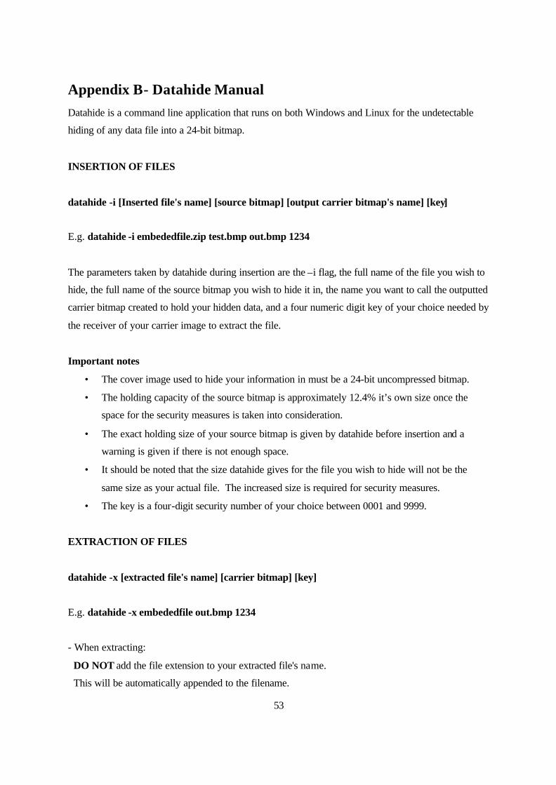
53
Appendix B- Datahide Manual Datahide is a command line application that runs on both Windows and Linux for the undetectable
hiding of any data file into a 24-bit bitmap.
INSERTION OF FILES
datahide -i [Inserted file's name] [source bitmap] [output carrier bitmap's name] [key]
E.g. datahide -i embededfile.zip test.bmp out.bmp 1234
The parameters taken by datahide during insertion are the –i flag, the full name of the file you wish to
hide, the full name of the source bitmap you wish to hide it in, the name you want to call the outputted
carrier bitmap created to hold your hidden data, and a four numeric digit key of your choice needed by
the receiver of your carrier image to extract the file.
Important notes
• The cover image used to hide your information in must be a 24-bit uncompressed bitmap.
• The holding capacity of the source bitmap is approximately 12.4% it’s own size once the
space for the security measures is taken into consideration.
• The exact holding size of your source bitmap is given by datahide before insertion and a
warning is given if there is not enough space.
• It should be noted that the size datahide gives for the file you wish to hide will not be the
same size as your actual file. The increased size is required for security measures.
• The key is a four-digit security number of your choice between 0001 and 9999.
EXTRACTION OF FILES
datahide -x [extracted file's name] [carrier bitmap] [key]
E.g. datahide -x embededfile out.bmp 1234
- When extracting:
DO NOT add the file extension to your extracted file's name.
This will be automatically appended to the filename.
54
The parameters taken by datahide during extraction are the –x flag, your chosen name for the
outputted file (without it’s file extension), the full name of the bitmap that carries it and the four digit
key that was used to insert it into that bitmap.
You do not need to know the extension of the file hidden in the bitmap as this is stored and
automatically appended. This is the only time while using datahide that you should omit the file
extension of a filename.
Important notes
• Without the key used for insertion it is not possible to extract the hidden file and datahide will
report the file as containing no hidden data if attempts are made to extract it without the
correct key.
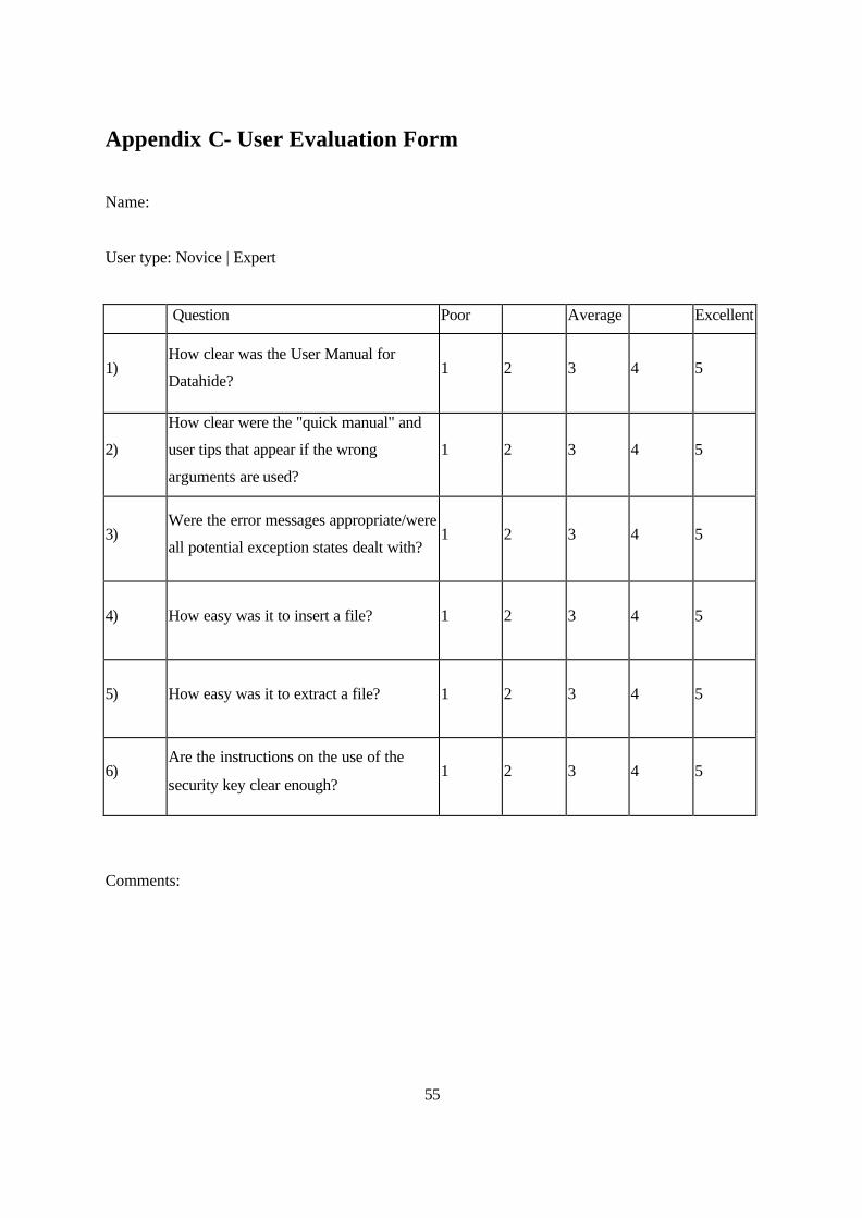
55
Appendix C- User Evaluation Form
Name:
User type: Novice | Expert
Question Poor Average Excellent
1) How clear was the User Manual for
Datahide? 1 2 3 4 5
2)
How clear were the "quick manual" and
user tips that appear if the wrong
arguments are used?
1 2 3 4 5
3) Were the error messages appropriate/were
all potential exception states dealt with? 1 2 3 4 5
4) How easy was it to insert a file? 1 2 3 4 5
5) How easy was it to extract a file? 1 2 3 4 5
6) Are the instructions on the use of the
security key clear enough? 1 2 3 4 5
Comments:

56
Appendix D- 24-bit Bitmap Header Structure
BMP File Header (BMPFILEHEADER)
BMP Info Header (BMPINFOHEADER)
Image Data
Basic structure of a 24-bit bitmap image
Field Bytes Description
bfType 2 Bitmap identifier. Must be 'BM'.
bfSize 4 Can be set to 0 for uncompressed bitmaps, which is the kind we have.
bfReserved 2 Set to 0.
bfReserved 2 Set to 0. bfOffbits 4 Specifies the location (in bytes) in the file of the image data.
BMP File Header
Field Bytes Description biSize 4 This is the size of the BMPINFOHEADER structure.
biWidth 4 The width of the bitmap, in pixels. biHeight 4 The height of the bitmap, in pixels.
biPlanes 2 Set to 1.
biBitCount 2 The bit depth of the bitmap. For 24-bit bitmaps, this is 24.
biCompression 4 Our bitmaps are uncompressed, so this field is set to 0.
biSizeImage 4 The size of the padded image, in bytes.
biXPelsPerMeter 4 Horizontal resolution, in pixels per meter, of device displaying bitmap. This number is not significant for us, and will be set to 0.
biYPelsPerMeter 4 Vertical resolution, in pixels per meter, of device displaying bitmap. This number is not significant for us, and will be set to 0.
biClrUsed 4 This number does not apply to 24-bit bitmaps. Set to zero.
biClrImportant 4 This number does not apply to 24-bit bitmaps. Set to zero.
BMP Info Header
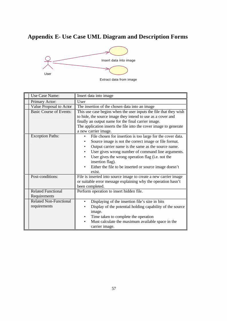
57
Appendix E- Use Case UML Diagram and Description Forms
Insert data into image
User
Extract data from image
Use Case Name: Insert data into image Primary Actor: User Value Proposal to Actor The insertion of the chosen data into an image Basic Course of Events:
This use case begins when the user inputs the file that they wish to hide, the source image they intend to use as a cover and finally an output name for the final carrier image. The application inserts the file into the cover image to generate a new carrier image.
Exception Paths:
• File chosen for insertion is too large for the cover data. • Source image is not the correct image or file format. • Output carrier name is the same as the source name. • User gives wrong number of command line arguments. • User gives the wrong operation flag (i.e. not the
insertion flag). • Either the file to be inserted or source image doesn’t
exist. Post-conditions: File is inserted into source image to create a new carrier image
or suitable error message explaining why the operation hasn’t been completed.
Related Functional Requirements
Perform operation to insert hidden file.
Related Non-Functional requirements
• Displaying of the insertion file’s size in bits • Display of the potential holding capability of the source
image. • Time taken to complete the operation • Must calculate the maximum available space in the
carrier image.
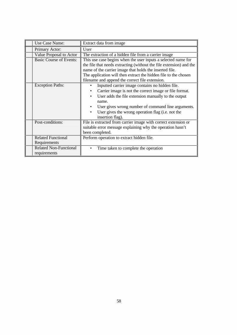
58
Use Case Name: Extract data from image Primary Actor: User Value Proposal to Actor The extraction of a hidden file from a carrier image Basic Course of Events:
This use case begins when the user inputs a selected name for the file that needs extracting (without the file extension) and the name of the carrier image that holds the inserted file. The application will then extract the hidden file to the chosen filename and append the correct file extension.
Exception Paths:
• Inputted carrier image contains no hidden file. • Carrier image is not the correct image or file format. • User adds the file extension manually to the output
name. • User gives wrong number of command line arguments. • User gives the wrong operation flag (i.e. not the
insertion flag). Post-conditions: File is extracted from carrier image with correct extension or
suitable error message explaining why the operation hasn’t been completed.
Related Functional Requirements
Perform operation to extract hidden file.
Related Non-Functional requirements
• Time taken to complete the operation
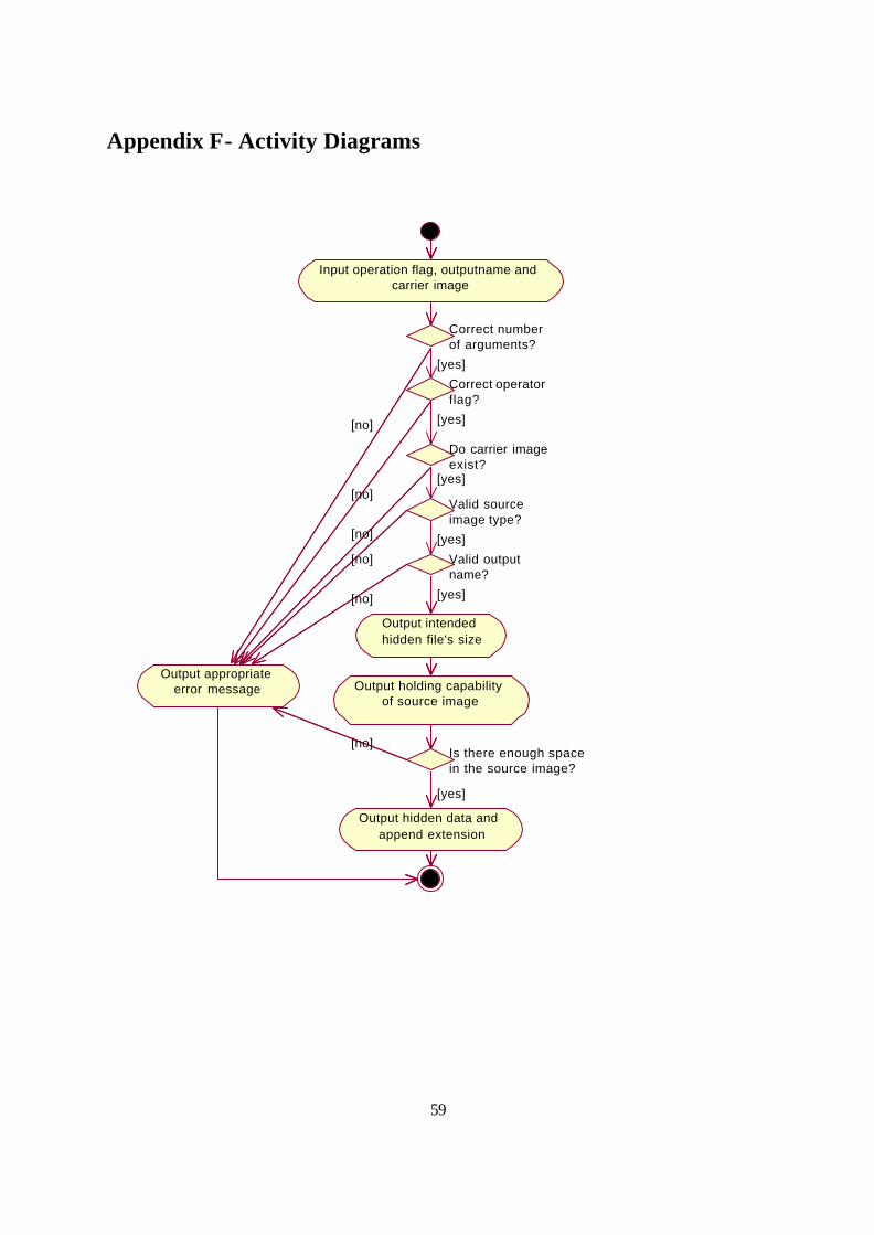
59
Appendix F- Activity Diagrams
Input operation flag, outputname and carrier image
Correct number of arguments?
Correct operator flag?
Do carrier image exist?
Valid source image type?
Valid output name?
Output intended hidden file's size
Output holding capability of source image
Is there enough space in the source image?
Output hidden data and append extension
Output appropriate error message
[no]
[no]
[no]
[no]
[no]
[no]
[yes]
[yes]
[yes]
[yes]
[yes]
[yes]
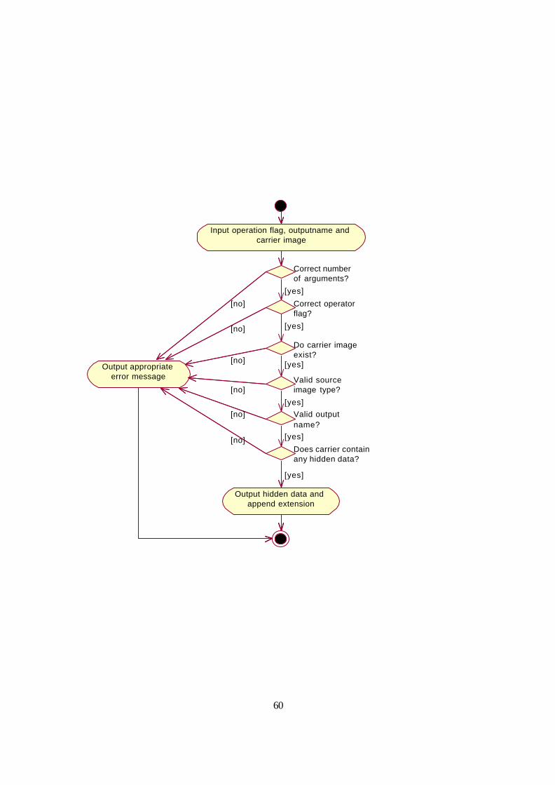
60
Input operation flag, outputname and carrier image
Correct number of arguments?
Correct operator flag?
Do carrier image exist?
Valid source image type?
Valid output name?
Output hidden data and append extension
Output appropriate error message
[no]
[no]
[no]
[no]
[no]
[yes]
[yes]
[yes]
[yes]
[yes]
[yes]
Does carrier contain any hidden data?
[no]

61
Related Documents