Fault tolerant real time control system for steer-by-wire electro-hydraulic systems Salem Haggag, Aristoteles Rosa, Kevin Huang 1 , Sabri Cetinkunt * Department of Mechanical and Industrial Engineering, University of Illinois at Chicago, Chicago, IL 60607, USA Received 8 September 2005; accepted 4 August 2006 Abstract A steer-by-wire (SBW) control system is presented with emphasis on safety issues. The applications are in articulated vehicles such as the wheel type loaders, articulated trucks, and others. The electro-hydraulic (EH) power circuit is controlled by two embedded electronic control modules (ECM), the primary ECM and backup ECM. The two ECMs monitor each others condition. If one detects fault in the other, it takes over the control functions. There are two main control algorithms that run in the ECMs in real-time: the steering valve control algorithm and the failure detection algorithm. The valve control algorithm basically generates command signal to the steering valve based on operator steering column signal as well as other machine condition sensors. The failure detection algorithm implements a fault detection logic for both input sensors and output drivers, and flags the correspond- ing warning for to the operator, and take a predefined action depending on the type of the failure detected. A unique fault strategy orga- nization is implemented by inspecting the failure behavior on both the component and the system levels. The failure detection algorithm also determines the most likely ‘‘good’’ sensor signal from a set of redundant sensors for each critical measurement. Based on these good sensors data, the steering control algorithm sends two output signals: the control signal to the steering EH circuit valve and the control signal to the steering wheel force feedback device (i.e. a brake or a motor) to give operator feedback about the steering conditions. Finite state machine (FSM) concept is used to design the fault handling algorithms for both the component level and the system level failure. The probability of the system being at normal steering state or at any other steering failure state is determined. Failure mode probabilities of steering system components are also determined. Ó 2006 Elsevier Ltd. All rights reserved. 1. Introduction The next generation of steering systems in the automo- tive and construction equipment industry, following the power assist steering system and the electric power assist steering system, is the SBW system. In SBW system con- cept, there is no mechanical or hydraulic connection between the steering wheel and the steering power hydrau- lic system. The traditional hydro-mechanical linkage between the steering wheel and steering valve (which con- trols the hydraulic power) of an off-road vehicle is replaced by an electrical wire linkage. SBW is a special case of the more general X-by-wire control systems used in many com- puter controlled mechanical systems. X-by-wire systems help convert vehicular systems, once the domain of mechanical or hydraulic system, to distributed fault toler- ant Mechatronic system. In X-by-wire systems, the connec- tion between the command control device and the actuation device is an electrical connection as opposed to a mechan- ical connection. The SBW control system offers advantages such as intelligent steering, modular construction, and lower cost [1]. By-wire systems are designed to achieve high level of reliability, frequently employ high level of dynamic redun- dancy, such as stand by spares. Dynamic redundancy tech- niques employed by-wire system can realize complex fault and error diagnosis, recovery and reconfiguration. In by- wire systems the internal element redundancy management 0957-4158/$ - see front matter Ó 2006 Elsevier Ltd. All rights reserved. doi:10.1016/j.mechatronics.2006.08.003 * Corresponding author. Tel.: +1 312 996 9611; fax: +1 312 996 0708. E-mail address: [email protected] (S. Cetinkunt). 1 Currently with Caterpillar Inc. Mechatronics 17 (2007) 129–142

Steer by Wire Elctro-hydraulics
Oct 08, 2014
Welcome message from author
This document is posted to help you gain knowledge. Please leave a comment to let me know what you think about it! Share it to your friends and learn new things together.
Transcript
Mechatronics 17 (2007) 129–142
Fault tolerant real time control system for steer-by-wireelectro-hydraulic systems
Salem Haggag, Aristoteles Rosa, Kevin Huang 1, Sabri Cetinkunt *
Department of Mechanical and Industrial Engineering, University of Illinois at Chicago, Chicago, IL 60607, USA
Received 8 September 2005; accepted 4 August 2006
Abstract
A steer-by-wire (SBW) control system is presented with emphasis on safety issues. The applications are in articulated vehicles such asthe wheel type loaders, articulated trucks, and others. The electro-hydraulic (EH) power circuit is controlled by two embedded electroniccontrol modules (ECM), the primary ECM and backup ECM. The two ECMs monitor each others condition. If one detects fault in theother, it takes over the control functions. There are two main control algorithms that run in the ECMs in real-time: the steering valvecontrol algorithm and the failure detection algorithm. The valve control algorithm basically generates command signal to the steeringvalve based on operator steering column signal as well as other machine condition sensors.
The failure detection algorithm implements a fault detection logic for both input sensors and output drivers, and flags the correspond-ing warning for to the operator, and take a predefined action depending on the type of the failure detected. A unique fault strategy orga-nization is implemented by inspecting the failure behavior on both the component and the system levels. The failure detection algorithmalso determines the most likely ‘‘good’’ sensor signal from a set of redundant sensors for each critical measurement. Based on these goodsensors data, the steering control algorithm sends two output signals: the control signal to the steering EH circuit valve and the controlsignal to the steering wheel force feedback device (i.e. a brake or a motor) to give operator feedback about the steering conditions.
Finite state machine (FSM) concept is used to design the fault handling algorithms for both the component level and the system levelfailure. The probability of the system being at normal steering state or at any other steering failure state is determined. Failure modeprobabilities of steering system components are also determined.� 2006 Elsevier Ltd. All rights reserved.
1. Introduction
The next generation of steering systems in the automo-tive and construction equipment industry, following thepower assist steering system and the electric power assiststeering system, is the SBW system. In SBW system con-cept, there is no mechanical or hydraulic connectionbetween the steering wheel and the steering power hydrau-lic system. The traditional hydro-mechanical linkagebetween the steering wheel and steering valve (which con-trols the hydraulic power) of an off-road vehicle is replacedby an electrical wire linkage. SBW is a special case of the
0957-4158/$ - see front matter � 2006 Elsevier Ltd. All rights reserved.
doi:10.1016/j.mechatronics.2006.08.003
* Corresponding author. Tel.: +1 312 996 9611; fax: +1 312 996 0708.E-mail address: [email protected] (S. Cetinkunt).
1 Currently with Caterpillar Inc.
more general X-by-wire control systems used in many com-puter controlled mechanical systems. X-by-wire systemshelp convert vehicular systems, once the domain ofmechanical or hydraulic system, to distributed fault toler-ant Mechatronic system. In X-by-wire systems, the connec-tion between the command control device and the actuation
device is an electrical connection as opposed to a mechan-ical connection. The SBW control system offers advantagessuch as intelligent steering, modular construction, andlower cost [1].
By-wire systems are designed to achieve high level ofreliability, frequently employ high level of dynamic redun-dancy, such as stand by spares. Dynamic redundancy tech-niques employed by-wire system can realize complex faultand error diagnosis, recovery and reconfiguration. In by-wire systems the internal element redundancy management
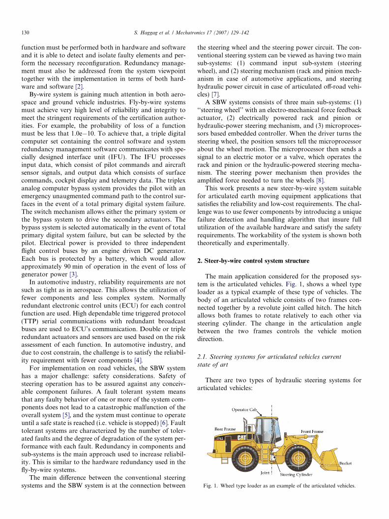
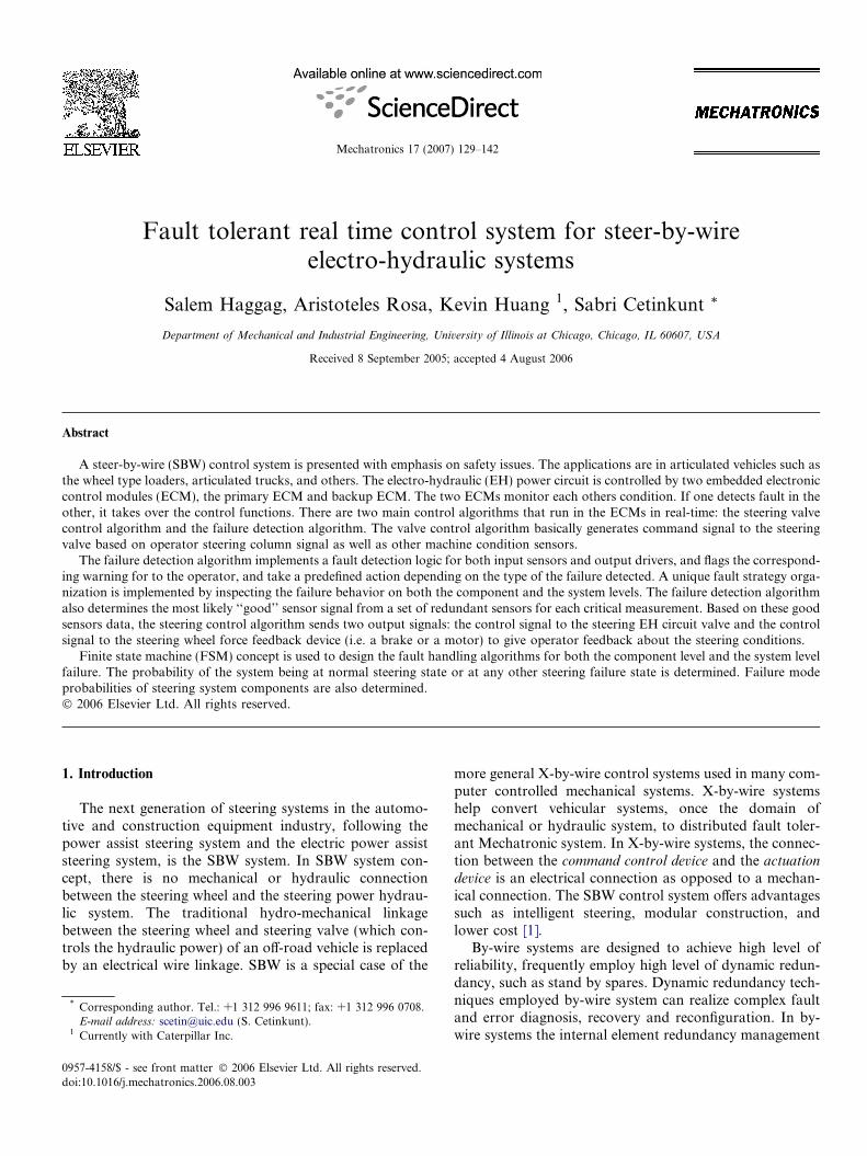
Fig. 1. Wheel type loader as an example of the articulated vehicles.
130 S. Haggag et al. / Mechatronics 17 (2007) 129–142
function must be performed both in hardware and softwareand it is able to detect and isolate faulty elements and per-form the necessary reconfiguration. Redundancy manage-ment must also be addressed from the system viewpointtogether with the implementation in terms of both hard-ware and software [2].
By-wire system is gaining much attention in both aero-space and ground vehicle industries. Fly-by-wire systemsmust achieve very high level of reliability and integrity tomeet the stringent requirements of the certification author-ities. For example, the probability of loss of a functionmust be less that 1.0e�10. To achieve that, a triple digitalcomputer set containing the control software and systemredundancy management software communicates with spe-cially designed interface unit (IFU). The IFU processesinput data, which consist of pilot commands and aircraftsensor signals, and output data which consists of surfacecommands, cockpit display and telemetry data. The triplexanalog computer bypass system provides the pilot with anemergency unaugmented command path to the control sur-faces in the event of a total primary digital system failure.The switch mechanism allows either the primary system orthe bypass system to drive the secondary actuators. Thebypass system is selected automatically in the event of totalprimary digital system failure, but can be selected by thepilot. Electrical power is provided to three independentflight control buses by an engine driven DC generator.Each bus is protected by a battery, which would allowapproximately 90 min of operation in the event of loss ofgenerator power [3].
In automotive industry, reliability requirements are notsuch as tight as in aerospace. This allows the utilization offewer components and less complex system. Normallyredundant electronic control units (ECU) for each controlfunction are used. High dependable time triggered protocol(TTP) serial communications with redundant broadcastbuses are used to ECU’s communication. Double or tripleredundant actuators and sensors are used based on the riskassessment of each function. In automotive industry, anddue to cost constrain, the challenge is to satisfy the reliabil-ity requirement with fewer components [4].
For implementation on road vehicles, the SBW systemhas a major challenge: safety considerations. Safety ofsteering operation has to be assured against any conceiv-able component failures. A fault tolerant system meansthat any faulty behavior of one or more of the system com-ponents does not lead to a catastrophic malfunction of theoverall system [5], and the system must continue to operateuntil a safe state is reached (i.e. vehicle is stopped) [6]. Faulttolerant systems are characterized by the number of toler-ated faults and the degree of degradation of the system per-formance with each fault. Redundancy in components andsub-systems is the main approach used to increase reliabil-ity. This is similar to the hardware redundancy used in thefly-by-wire systems.
The main difference between the conventional steeringsystems and the SBW system is at the connection between
the steering wheel and the steering power circuit. The con-ventional steering system can be viewed as having two mainsub-systems: (1) command input sub-system (steeringwheel), and (2) steering mechanism (rack and pinion mech-anism in case of automotive applications, and steeringhydraulic power circuit in case of articulated off-road vehi-cles) [7].
A SBW systems consists of three main sub-systems: (1)‘‘steering wheel’’ with an electro-mechanical force feedbackactuator, (2) electrically powered rack and pinion orhydraulic-power steering mechanism, and (3) microproces-sors based embedded controller. When the driver turns thesteering wheel, the position sensors tell the microprocessorabout the wheel motion. The microprocessor then sends asignal to an electric motor or a valve, which operates therack and pinion or the hydraulic-powered steering mecha-nism. The steering power mechanism then provides theamplified force needed to turn the wheels [8].
This work presents a new steer-by-wire system suitablefor articulated earth moving equipment applications thatsatisfies the reliability and low-cost requirements. The chal-lenge was to use fewer components by introducing a uniquefailure detection and handling algorithm that insure fullutilization of the available hardware and satisfy the safetyrequirements. The workability of the system is shown boththeoretically and experimentally.
2. Steer-by-wire control system structure
The main application considered for the proposed sys-tem is the articulated vehicles. Fig. 1, shows a wheel typeloader as a typical example of these type of vehicles. Thebody of an articulated vehicle consists of two frames con-nected together by a revolute joint called hitch. The hitchallows both frames to rotate relatively to each other viasteering cylinder. The change in the articulation anglebetween the two frames controls the vehicle motiondirection.
2.1. Steering systems for articulated vehicles current
state of art
There are two types of hydraulic steering systems forarticulated vehicles:
S. Haggag et al. / Mechatronics 17 (2007) 129–142 131
(1) hand metering unit (HMU) type,(2) command control steering (CCS) type.
In CCS system, the articulation angle of the machine isapproximately proportional to the rotational position ofthe steering wheel in relation to the front frame. In theHMU system, the articulation speed of the machine is pro-portional to the speed of the steering wheel. The proposedSBW system is more similar to the CCS system. Therefore,the operation and basic circuit of the CCS system will bediscussed. CCS steering is based on a hydro-mechanicalcontrol system. There are no embedded digital computersinvolved in the control of the steering pump or valves(Fig. 2). The operator command generated by the steeringwheel is transmitted and amplified to the steering valvemotion through hydro-mechanical connections.
When the steering wheel is turned either to the left or theright the pilot command valve (1) will supply pilot oil flowto the main valve (11) that will control the flow to the steer-ing cylinders that will articulate the vehicle. The articula-tion of the vehicle will then turn the control valvetowards a neutral position and slow down the commandas the valve approaches the neutral position before finallyclosing it completely. The pilot system also includes a quadcheck valve (5) for the purpose of reducing the risk of cav-
Fig. 2. Command control steering system sche
itation in the pilot circuit. A shuttle valve (2) makes surethat pilot pressure is always present by supplying pilotpressure from the main circuit in the case of a pilot pumpfailure. This system has neutralizer valves (7), (3) to shut-off the steering command before the machine hits themechanical stops of the frames. The main circuit includesa pressure crossover relief valve (9) to prevent dangeroussystem pressure in case of the vehicle hitting an obstacle.
2.2. Proposed electro-hydraulic steering system description
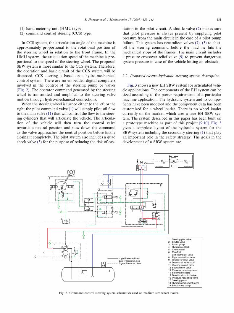
Fig. 3 shows a new EH SBW system for articulated vehi-cle applications. The components of the EH system can besized according to the power requirements of a particularmachine application. The hydraulic system and its compo-nents have been modeled and the component data has beencustomized for a wheel loader. There is no wheel loadercurrently on the market, which uses a true EH SBW sys-tem. The system described in this paper has been built ona prototype machine as part of this project [9,10]. Fig. 3gives a complete layout of the hydraulic system for theSBW system including the secondary steering (1) that playan important role in the safety strategy. The goals in thedevelopment of a SBW system are
matics used on medium size wheel loader.
Make-upCheck
SteeringPilot Supply
Pilot Return
Steering ReturnLoad Sence
CCS Steering Valve(with Hydracs)
Back-upRelief Valve
Pressure ReducingValve
Pressure ReducingValve for MainPilot Pressure
Hydrac
2
3
5
M
Secondary SteeringSystem
Solenoid CurrentCommand
6
4
Shuttle Valve
CrossoverRelief Valve
1
Steering ValveGroup
Back Frame Front Frame- Articulation angle sensor- Travel speed- Engine speed
Inputs & Real Time Controllers
Steering WheelSensors
Brake
Primary & SecondaryControllers
Fig. 3. Steer-by-wire electrohydraulic (EH) system schematics for articulated vehicle.
132 S. Haggag et al. / Mechatronics 17 (2007) 129–142
(1) new functionality (intelligent steering software asfunction sensors feedback, i.e. operator can be pre-vented from commanding dangerous steering inputwhen bucket is loaded and the machine is on a slopedsurface which would result in tip-over of themachine),
(2) modularity of steering wheel system,(3) lower cost manufacturing due to reduced hydraulic
component count.
It can be seen that SBW has less hydraulic componentscompared to the CCS system. The logic functions of theeliminated hardware are now implemented in software.The steering input is given via a steering wheel that is trans-lated to input command as electric current via a sensor andcontroller rather than supplying pilot flow to the mainvalve of the system (Fig. 3). The system still needs pilotsupply (3) but it is only used as internal actuating powerin the main valve (2), which is actuated via electric currentto solenoids. This system also has make-up check valves (4)and crossover relief valves (5). Load sensing signal is fedback from a shuttle valve between the steering cylinders(6) to the pump control circuit. The system also includesan independent secondary steering system for backupsafety considerations which consists of a battery drivenelectric motor, a fixed displacement pump and a valve (sec-ondary steering valve).
2.3. Proposed system modeling
A mathematical model is developed which is used intesting the steering control algorithm before the real imple-mentation on the test vehicle. The goal for the modeling isto obtain a reasonably good correlation between the simu-lation and the experimental results so that the model simu-lation can be used as a good indication of how the controlsystem will perform. The following shows the mathematicalmodel for the two stage proportional valve and the hydrau-lic cylinder actuator. Modeling for the variable displace-ment pump as well as the articulated vehicle is presentedin an earlier paper [10].
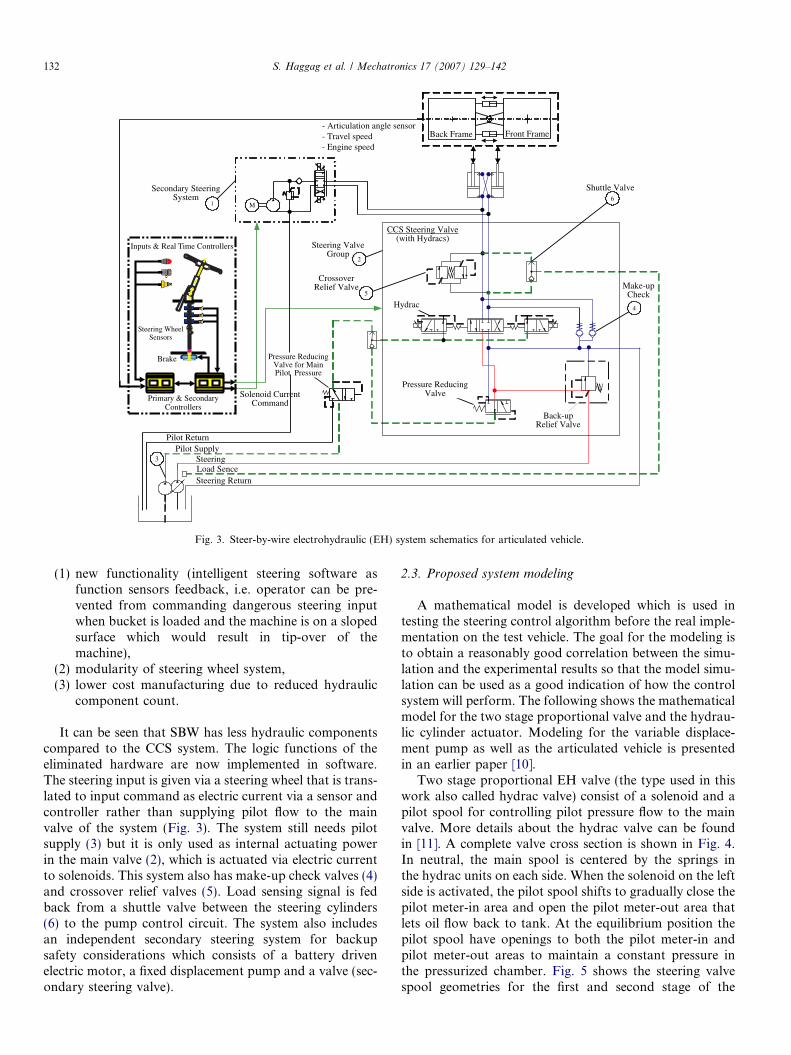
Two stage proportional EH valve (the type used in thiswork also called hydrac valve) consist of a solenoid and apilot spool for controlling pilot pressure flow to the mainvalve. More details about the hydrac valve can be foundin [11]. A complete valve cross section is shown in Fig. 4.In neutral, the main spool is centered by the springs inthe hydrac units on each side. When the solenoid on the leftside is activated, the pilot spool shifts to gradually close thepilot meter-in area and open the pilot meter-out area thatlets oil flow back to tank. At the equilibrium position thepilot spool have openings to both the pilot meter-in andpilot meter-out areas to maintain a constant pressure inthe pressurized chamber. Fig. 5 shows the steering valvespool geometries for the first and second stage of the
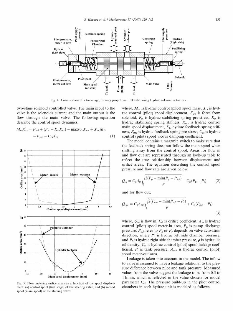
Fig. 4. Cross section of a two-stage, for-way proprtional EH valve using Hydrac solenoid actuators.
S. Haggag et al. / Mechatronics 17 (2007) 129–142 133
two-stage solenoid controlled valve. The main input to thevalve is the solenoids current and the main output is theflow through the main valve. The following equationdescribe the control spool dynamics,
M cs€X cs ¼ F sol þ ðF st � KstX csÞ �maxð0;X ms þ X csÞK fs
� F pre � Ccs_X cs ð1Þ
0 0.5 1 1.5 2 2.5 3 3.50
2
4
6
8
10
12
14
16
18
20
Control spool displacement [mm]
Ori
fice
are
a[m
m2 ]
Meter - inarea Meter - outarea
-15 -10 -5 0 5 10 150
10
20
30
40
50
60
Pump to Cylinder
Cylinder to Tank
Main spool displacement [mm]
Ori
fice
are
a[m
m2 ]
Fig. 5. Flow metering orifice areas as a function of the spool displace-ment: (a) control spool (first stage) of the steering valve, and (b) secondspool (main spool) of the steering valve.
where, Mcs is hydrac control (pilot) spool mass, Xcs is hyd-rac control (pilot) spool displacement, Fsol is force fromsolenoid, Fst is hydrac stabilizing spring pre-stress, Kst ishydrac stabilizing spring stiffness, Xms is hydrac controlmain spool displacement, Kfs hydrac feedback spring stiff-ness, Fpre is hydrac feedback spring pre-stress, Ccs is hydraccontrol (pilot) spool vicous damping coefficient.
The model contains a max/min switch to make sure thatthe feedback spring does not follow the main spool whenshifting away from the control spool. Areas for flow inand flow out are represented through an look-up table toreflect the true relationship between displacement andorifice areas. The equation describing the control spoolpressure and flow rate are given below,
Qin ¼ CdAin
ffiffiffiffiffiffiffiffiffiffiffiffiffiffiffiffiffiffiffiffiffiffiffiffiffiffiffiffiffiffiffiffiffiffiffiffiffiffiffiffiffiffiffiffiffi2ðP p �minðP p � P a;bÞ
q
s� CclðP p � P tÞ ð2Þ
and for flow out,
Qout ¼ CdAout
ffiffiffiffiffiffiffiffiffiffiffiffiffiffiffiffiffiffiffiffiffiffiffiffiffiffiffiffiffiffiffiffiffiffiffiffiffiffiffiffiffiffiffiffiffiffiffi2ðP a;b �minðP a;b � P tÞ
q
sþ CclðP a;b � P tÞ
ð3Þ
where, Qin is flow in, Cd is orifice coefficient, Ain is hydraccontrol (pilot) spool meter-in area, Pp is pump dischargepressure, Pa,b refer to Pa or Pb depends on valve activationdirection, where Pa is hydrac left side chamber pressure,and Pb is hydrac right side chamber pressure, q is hydraulicoil density, Ccl is hydrac control (pilot) spool leakage coef-ficient, Pt is tank pressure, Aout is hydrac control (pilot)spool meter-out area.
Leakage is taken into account in the model. The inflowto valve is assumed to have a leakage relational to the pres-sure difference between pilot and tank pressure. Measuredvalues from the valve suggest the leakage to be from 0.5 to1 l/min, which is reflected in the value chosen for modelparameter Ccl. The pressure build-up in the pilot controlchambers in each hydrac unit is modeled as follows,

Fig. 6. Comparison of simulation and experimental result.
134 S. Haggag et al. / Mechatronics 17 (2007) 129–142
P a ¼Z
_P a ¼Z
b
ðV 0 þ AmsX msÞðQin � Qout � _X msAmsÞ ð4Þ
where, V0 is hydrac chamber volume at null position, Ams ishydrac main spool cross section pressure area, Xms is hyd-rac control main spool displacement. The main spool equa-tions of motion in both directions (Xms > 0 and Xms < 0respectively) are given by,
Mms€X ms ¼ AmsðP a � P bÞ � KmsX ms � F ms � F fs � Cms
_X ms
ð5ÞMms
€X ms ¼ AmsðP a � P bÞ � KmsX ms � F ms þ F fs � Cms_X ms
ð6Þ
where, Mms is hydrac main spool mass, Xms is hydrac con-trol main spool displacement, Ams is hydrac main spoolcross section pressure area, Pa is hydrac left side chamberpressure, Pb is hydrac right side chamber pressure, Kms ismain spool centering spring stiffness, Fms is main spoolcentering spring pre-stress, Ffs is feedback spring pre-stress,Cms is main spool damping coefficient. Using Eqs. (1)–(6)and Fsol as input, the output Xms could be determined.
Nonlinear dynamic model of the cylinder, including thefluid compressibility, is considered next. Let us consider themotion of the piston-rod-load assuming they are rigidlyconnected to each other. Using Newton’s second law forthe force-motion relationships of the cylinder and the load.The equations below are for the extension motion, thesame approach could be used for the retraction motion.
M cyl � €Y cyl ¼ P h � Ah � P r � Ar � F ext 0 6 Y cyl 6 Lcyl ð7Þ
and the pressure transients in the control volumes on bothsides of the cylinder,
_P h ¼b
Y cyl � Ah
ðQph � _Y cyl � AhÞ ð8Þ
_P r ¼b
ðLcyl � Y cylÞ � Ar
ð�Qrt þ _Y cyl � ArÞ ð9Þ
_P p ¼b
V hose
ðQp � Qph � QptÞ ð10Þ
and
Qp ¼ wp � DpðhÞ ð11Þ
Qpt ¼ CdAptðX msÞffiffiffiffiffiffiffiffiffiffiffiffiffiffiffiffiffiffiffiffiffiffiffiffiffiffiffiffiffiffiffiffiffiffið2=qÞ � ðP p � P tÞ
qð12Þ
Qph ¼ CdAphðX msÞffiffiffiffiffiffiffiffiffiffiffiffiffiffiffiffiffiffiffiffiffiffiffiffiffiffiffiffiffiffiffiffiffiffiffið2=qÞ � ðP p � P hÞ
qð13Þ
Qrt ¼ CdArtðX msÞffiffiffiffiffiffiffiffiffiffiffiffiffiffiffiffiffiffiffiffiffiffiffiffiffiffiffiffiffiffiffiffiffið2=qÞ � ðP r � P tÞ
pð14Þ
where, Mcyl is steering cylinder moving mass, Ycyl is vehiclesteering cylinder displacement, Ph is cylinder head-endpressure, Ah is cylinder head-end cross sectional area, Pr
is cylinder rod-end pressure, Ar is cylinder rod-end crosssectional area, Fext is steering cylinder external force, Lcyl
is cylinder travel range, Qph is flow rate from pump to cyl-inder head-end, Qrt is flow rate from cylinder rod-end to
tank, Qp is flow rate from pump, Qpt is flow rate frompump to tank, wp is pump speed, Dp is pump displacement(volume/revolution), h is pump swash plate angle, Apt isflow area from pump to tank, q is hydraulic oil density,Xms is hydra control main spool displacement, Pp is pumpdischarge pressure, Pt is tank pressure, Ph is cylinder head-end pressure, Pr is cylinder rod-end pressure.
Fig. 6 shows a comparison between the experimentaland the simulation result of the proposed model. As itcan be seen that the simulation and experimental resultsshow good level of agreement.
2.4. Real time steering control algorithm
Fig. 7 shows the overall steering control algorithm blockdiagram. ANSI C programming language is used for thereal time implementation that is suitable for the embeddedcontrollers used in this work. As shown in Fig. 7 systeminputs are:
(1) steering wheel sensor, gives the steering wheel anglevelocity,
(2) articulation angle sensor, gives the articulation anglebetween the front-frame and the back frame over thejoint linkage,
(3) machine ground speed,(4) engine speed.
The control system is divided into three major parts, thesteering planner, steering valve control and the fault detec-tion algorithm. The steering planner controls the output tothe force feedback brake and the steering valve control thatgives the desired output to the steering solenoids. The mainfunction of the fault detection algorithm is to inspect allsensors signals and send qualified signals to the steeringcontrol algorithm under different types of failure catego-ries. The failure detection algorithm also sends a warringsignal for the operator through cab warning system (con-sists of a lamp and buzzer) and use the force feedbackdevise as another method of safety assurance by increasing
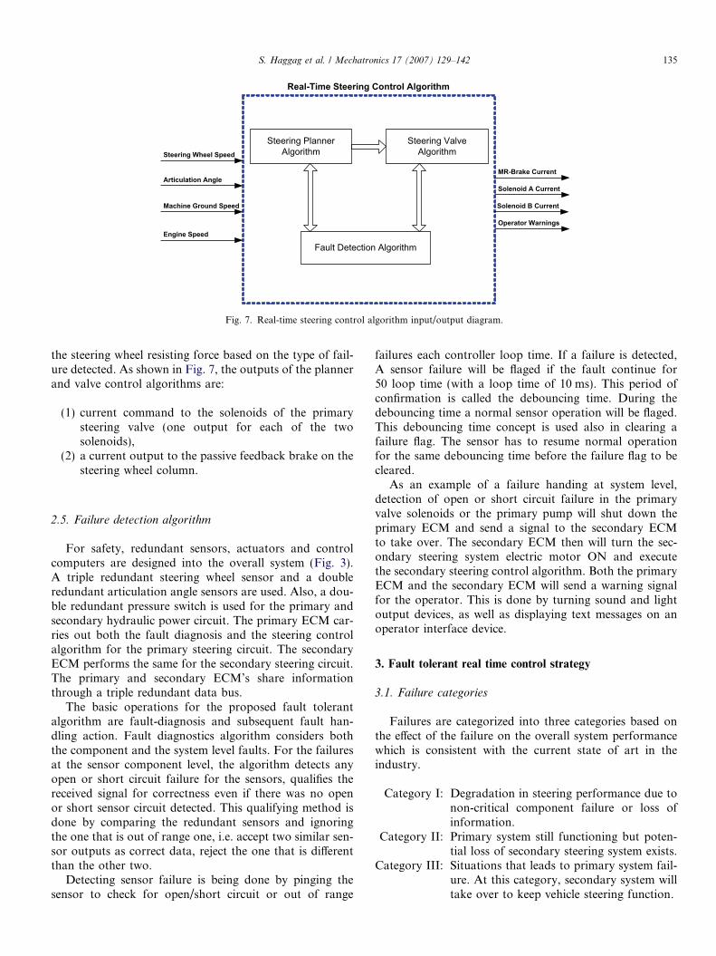
Fig. 7. Real-time steering control algorithm input/output diagram.
S. Haggag et al. / Mechatronics 17 (2007) 129–142 135
the steering wheel resisting force based on the type of fail-ure detected. As shown in Fig. 7, the outputs of the plannerand valve control algorithms are:
(1) current command to the solenoids of the primarysteering valve (one output for each of the twosolenoids),
(2) a current output to the passive feedback brake on thesteering wheel column.
2.5. Failure detection algorithm
For safety, redundant sensors, actuators and controlcomputers are designed into the overall system (Fig. 3).A triple redundant steering wheel sensor and a doubleredundant articulation angle sensors are used. Also, a dou-ble redundant pressure switch is used for the primary andsecondary hydraulic power circuit. The primary ECM car-ries out both the fault diagnosis and the steering controlalgorithm for the primary steering circuit. The secondaryECM performs the same for the secondary steering circuit.The primary and secondary ECM’s share informationthrough a triple redundant data bus.
The basic operations for the proposed fault tolerantalgorithm are fault-diagnosis and subsequent fault han-dling action. Fault diagnostics algorithm considers boththe component and the system level faults. For the failuresat the sensor component level, the algorithm detects anyopen or short circuit failure for the sensors, qualifies thereceived signal for correctness even if there was no openor short sensor circuit detected. This qualifying method isdone by comparing the redundant sensors and ignoringthe one that is out of range one, i.e. accept two similar sen-sor outputs as correct data, reject the one that is differentthan the other two.
Detecting sensor failure is being done by pinging thesensor to check for open/short circuit or out of range
failures each controller loop time. If a failure is detected,A sensor failure will be flaged if the fault continue for50 loop time (with a loop time of 10 ms). This period ofconfirmation is called the debouncing time. During thedebouncing time a normal sensor operation will be flaged.This debouncing time concept is used also in clearing afailure flag. The sensor has to resume normal operationfor the same debouncing time before the failure flag to becleared.
As an example of a failure handing at system level,detection of open or short circuit failure in the primaryvalve solenoids or the primary pump will shut down theprimary ECM and send a signal to the secondary ECMto take over. The secondary ECM then will turn the sec-ondary steering system electric motor ON and executethe secondary steering control algorithm. Both the primaryECM and the secondary ECM will send a warning signalfor the operator. This is done by turning sound and lightoutput devices, as well as displaying text messages on anoperator interface device.
3. Fault tolerant real time control strategy
3.1. Failure categories
Failures are categorized into three categories based onthe effect of the failure on the overall system performancewhich is consistent with the current state of art in theindustry.
Category I: Degradation in steering performance due tonon-critical component failure or loss ofinformation.
Category II: Primary system still functioning but poten-tial loss of secondary steering system exists.
Category III: Situations that leads to primary system fail-ure. At this category, secondary system willtake over to keep vehicle steering function.

Table 1Failure types and handling routines
Failed component Component failure
action
Warning by Category Category action Warning
Articulation sensor #1 Use default value Primary ECM 1 Use primary steeri control using the component
failure action
Lamp on
Articulation sensor #2 Use default value
MR brake None
Steering wheel sensor #1 Use steering wheel
sensor
Primary ECM II Use primary steeri control using the component
failure action
Buzzer on
Steering wheel sensor #2 Use steering wheel
sensor
Steering wheel sensor #3 Use steering wheel
sensor
Key switch failure Key switch override
while
CAN network Use CDL
CDL network Use CAN
Secondary ECM failure None
Battery charge level low None Secondary ECM
Secondary solenoid
driver #1
None
Secondary solenoid
driver #2
None
Secondary motor relay None
Primary solenoid
driver #1
Primary solenoid
drivers
Primary ECM III Use secondary steer control Lamp & Buzzer
on
Primary solenoid
driver #2
Primary solenoid
drivers
Primary ECM failure None Secondary ECM
136S
.H
ag
ga
get
al.
/M
echa
tron
ics1
7(
20
07
)1
29
–1
42
S. Haggag et al. / Mechatronics 17 (2007) 129–142 137
Table 1 shows the failure category and handing routinesfor each system components.
Fig. 9. Finite state machine concept: (a) finite state machine of a sensor,two possible states: OK and failure, and (b) generic finite state machinemodel.
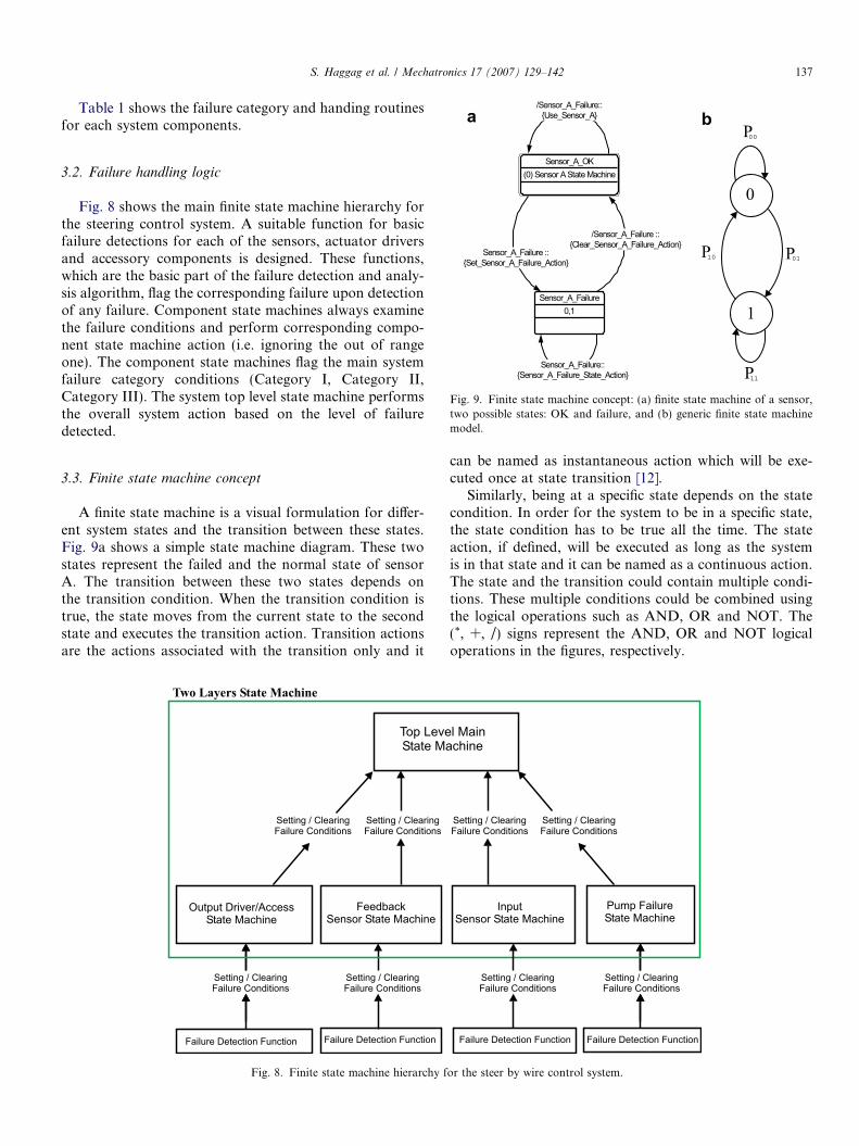
3.2. Failure handling logic
Fig. 8 shows the main finite state machine hierarchy forthe steering control system. A suitable function for basicfailure detections for each of the sensors, actuator driversand accessory components is designed. These functions,which are the basic part of the failure detection and analy-sis algorithm, flag the corresponding failure upon detectionof any failure. Component state machines always examinethe failure conditions and perform corresponding compo-nent state machine action (i.e. ignoring the out of rangeone). The component state machines flag the main systemfailure category conditions (Category I, Category II,Category III). The system top level state machine performsthe overall system action based on the level of failuredetected.
3.3. Finite state machine concept
A finite state machine is a visual formulation for differ-ent system states and the transition between these states.Fig. 9a shows a simple state machine diagram. These twostates represent the failed and the normal state of sensorA. The transition between these two states depends onthe transition condition. When the transition condition istrue, the state moves from the current state to the secondstate and executes the transition action. Transition actionsare the actions associated with the transition only and it
Fig. 8. Finite state machine hierarchy f
can be named as instantaneous action which will be exe-cuted once at state transition [12].
Similarly, being at a specific state depends on the statecondition. In order for the system to be in a specific state,the state condition has to be true all the time. The stateaction, if defined, will be executed as long as the systemis in that state and it can be named as a continuous action.The state and the transition could contain multiple condi-tions. These multiple conditions could be combined usingthe logical operations such as AND, OR and NOT. The(*, +, /) signs represent the AND, OR and NOT logicaloperations in the figures, respectively.
or the steer by wire control system.
138 S. Haggag et al. / Mechatronics 17 (2007) 129–142
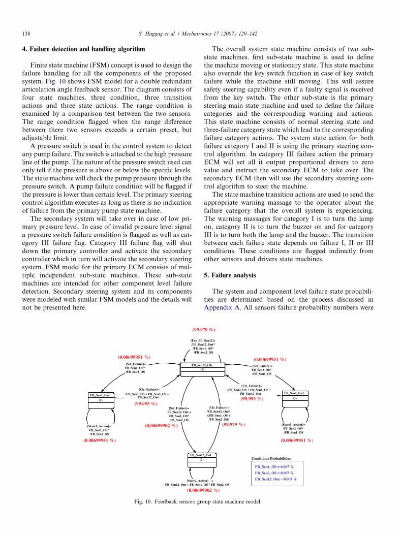
4. Failure detection and handling algorithm
Finite state machine (FSM) concept is used to design thefailure handling for all the components of the proposedsystem. Fig. 10 shows FSM model for a double redundantarticulation angle feedback sensor. The diagram consists offour state machines, three condition, three transitionactions and three state actions. The range condition isexamined by a comparison test between the two sensors.The range condition flagged when the range differencebetween there two sensors exceeds a certain preset, butadjustable limit.
A pressure switch is used in the control system to detectany pump failure. The switch is attached to the high pressureline of the pump. The nature of the pressure switch used canonly tell if the pressure is above or below the specific levels.The state machine will check the pump pressure through thepressure switch. A pump failure condition will be flagged ifthe pressure is lower than certain level. The primary steeringcontrol algorithm executes as long as there is no indicationof failure from the primary pump state machine.
The secondary system will take over in case of low pri-mary pressure level. In case of invalid pressure level signala pressure switch failure condition is flagged as well as cat-egory III failure flag. Category III failure flag will shutdown the primary controller and activate the secondarycontroller which in turn will activate the secondary steeringsystem. FSM model for the primary ECM consists of mul-tiple independent sub-state machines. These sub-statemachines are intended for other component level failuredetection. Secondary steering system and its componentswere modeled with similar FSM models and the details willnot be presented here.
FB_Sen(0
FB_Sen1(2
{Set_Failure}=FB_Sen12_Out +
FB_Sen1_OS* FB_Sen2_OS
{State2_ActFB_Sen12_Out + FB_Sen1_
{Use_FB/FB_Sen/FB_Se/FB_S
FB_Sen1_Fail
(1)
{Set_Failure}=FB_Sen1_OS* /FB_Sen2_OS
{Clr_Failure}=/FB_Sen1_OS + FB_Sen2_OS +
FB_Sen12_Out
{State1_Action}=FB_Sen1_OS* /FB_Sen2_OS
(99.9
(99.993 %)
(0.00699951 %)
(0.00699951 %)
(0.00699
(0.00699902 %)
Fig. 10. Feedback sensors gro
The overall system state machine consists of two sub-state machines. first sub-state machine is used to definethe machine moving or stationary state. This state machinealso override the key switch function in case of key switchfailure while the machine still moving. This will assuresafety steering capability even if a faulty signal is receivedfrom the key switch. The other sub-state is the primarysteering main state machine and used to define the failurecategories and the corresponding warning and actions.This state machine consists of normal steering state andthree-failure category state which lead to the correspondingfailure category actions. The system state action for bothfailure category I and II is using the primary steering con-trol algorithm. In category III failure action the primaryECM will set all it output proportional drivers to zerovalue and instruct the secondary ECM to take over. Thesecondary ECM then will use the secondary steering con-trol algorithm to steer the machine.
The state machine transition actions are used to send theappropriate warning massage to the operator about thefailure category that the overall system is experiencing.The warning massages for category I is to turn the lampon, category II is to turn the buzzer on and for categoryIII is to turn both the lamp and the buzzer. The transitionbetween each failure state depends on failure I, II or IIIconditions. These conditions are flagged indirectly fromother sensors and drivers state machines.
5. Failure analysis
The system and component level failure state probabili-ties are determined based on the process discussed inAppendix A. All sensors failure probability numbers were
12_OK)
2_Fail)
{Clr_Failure}=/FB_Sen12_Out* (/FB_Sen1_OS + /FB_Sen2_OS)
ion} =OS * FB_Sen2_OS
_Sen12}=12_Out* n1_OS*en2_OS
FB_Sen2_Fail
(3)
{Set_Failure}=FB_Sen2_OS* /FB_Sen1_OS
{Clr_Failure}=/FB_Sen2_OS + FB_Sen1_OS +
FB_Sen12_Out
{State3_Action}=FB_Sen2_OS* /FB_Sen1_OS
(0.00699951 %)
(99.993 %)
(0.00699951 %)
79 %)
902 %)
(99.979 %)
FB_Sen1_OS = 0.007 %
FB_Sen2_OS = 0.007 %
FB_Sen12_Out = 0.007 %
Conditions Probabilities
up state machine model.
S. Haggag et al. / Mechatronics 17 (2007) 129–142 139
provided by this industrial partner during project time. Forinstance, given the condition occurrence probability of thedouble redundant articulation feedback sensors group asfollows (Fig. 10),
0 2 4 6 8 10 12 140
500
1000
1500
2000
Bra
ke C
ur (
mA
)
0
200
400
600
Sec
Sol #
2 C
ur (
mA
)
0
200
400
600
Sec
Sol #
1 C
ur (
mA
)
-40
-20
0
20
40
Art
ic S
peed
(de
g/s)
-400
-200
0
200
400
Category III Failure
Stee
ring
Spe
ed (
deg/
s)
0
500
1000
1500
2000
Pri
Sol
#2
(mA
)
0
500
1000
1500
2000
Pri
Sol
#1
(mA
)
Primary ECM shutdown(Zero current commands)
Secondary ECM active
Primary system failure P
Continues and smoothsteering operation
Fig. 11. Experimental results of the steer by wire system implemented on an articuidle engine speed.
p(FB_Sen1_OS) = 0.0007p(FB_Sen2_OS) = 0.0007p(FB_Sen12_Out) = 0.0007
16 18 20 22 24 26 28 30
Time (Sec)
rimary system OK
A
B
C
D
E
F
G
lated vehicle at high idle engine speed. Similar results obtained at low
140 S. Haggag et al. / Mechatronics 17 (2007) 129–142
where FB stand for Feedback, Sen stand for sensor, OSstand for open or shot failure and Out stand for out ofrange failure. The transition conditional probabilities couldbe determined using the previous values and talking intoaccount, the definition of the logical operators (AND,OR, NOT) as follows:
(Condition A) AND (Condition B) = (Condition A) ·(Condition B)(Condition A) OR (Condition B) = Maximum [(Condi-tion A), (Condition B)]NOT (Condition A) = 1 � (Condition A)
Fig. 10 shows the feedback sensors group state machineand the transition condition probabilities. Also the stateprobability matrix (S) could be determined as:
S ¼ s0 s1 s2 s3½ �¼ 0:99979 6:99951e� 5 0:00007 6:99951e� 5½ �
ð15Þ
This tells us that the probability of this feedback sensorsgroup to operate in normal or no-fault mode is 99.979%.Category I failure condition probability caused by the feed-back sensors group is 0.007%. Similarly, the same analysisis done for different state machines and composed togetherto form the final probability of occurrence of category I, II,or III conditions. These values are then used in the overallsystem state machine to determine the overall system fail-ure probability characteristics. The normal steering proba-bility for the proposed system is 99.49%, while theprobability of category III failure and hence activation ofthe secondary steering is 0.25%.
6. Test results
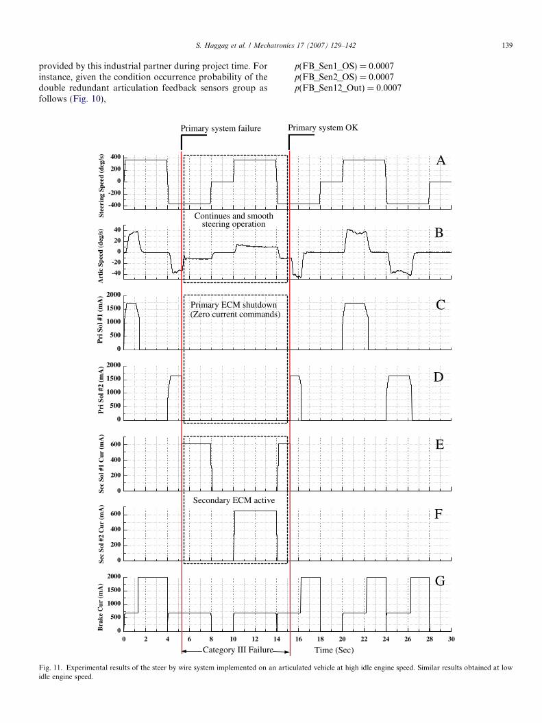
The main purpose of these tests is to investigate the reli-ability of the proposed control system and examine howmuch it satisfies the fault tolerance requirements. Fig. 11shows an experimental test result which was conductedon an articulated type vehicle (wheel type loader). In orderto assure identical steering wheel command, the tests aredone without a real movement of the steering wheel, butsteering commands are generated by the real time software.Fault signals are forced in purpose through the test periodthat causes category I, II or III failures. As an example ofcategory III failure (Fig. 11), when a category III failure isdetected, the primary system shuts down all its currentcommands as shown in graphs C and D. The secondarysystem takes over and starts sending current commandsto the secondary system solenoid valve (graphs E and F).During this most critical failure the secondary system keepsvehicle steering function as shown in graphs A and B ofFig. 11. When the failure is cleared, the control againswitches back to the primary system. As shown in this sam-ple test, the vehicle keep the steering function even at theworst failure category which represent a complete loss of
the primary steering system. Similarly, Different type ofcomponents failures are tested and the reliability of thecontrol system was verified.
7. Conclusion
A new EH SBW system hardware and software config-urations for articulated vehicles applications are presented.Finite state machine (FSM) concept is used to design thefault event handling algorithms for both the componentand system level failures in the proposed system. The sen-sor level fault detection sate machine is used to providean approved sensors and drivers signal for the control sys-tem under different type and failure category. Failure anal-ysis of the proposed system shows a good level ofreliability. The proposed system keeps functioning at thenormal steering state up to 99.49% of the overall operatingtime. The proposed system with its configuration isbelieved to offer a reliable and durable steering perfor-mance over different type of failure categories. This keepssystem functionality and satisfies the fault tolerancerequirements which is essential for the SBW system.
Appendix A. Proposed system state machine analysis
Markov chains are used in the analysis of proposed sys-tem. It should be pointed out that the analysis of Markovchains provides a rich framework for studying many typesof discrete event system (DES) ranging from gambling andthe stock market to the design of computer systems andcommunication networks [10]. The main characteristic ofMarkov chains is that their stochastic behavior is describedby transition probabilities of the form
pijðkÞ ¼ P ½X ðtkþ1Þ ¼ jjX ðtkÞ ¼ i�for the state value i; j and tk 6 t
ðA:1Þ
where tk is the time step, pij(k) is the state i to state j tran-sition probability, X(tk+1) is the state value at time tk+1,X(tk) is the state value at time tk, j is set condition operatorand it means ‘‘such that’’, P is the state transition probabil-ity set. Given these transition probabilities and initialstates, it is possible to determine the probability of beingat any state at any time instant.
Finite state machine (FSM) of the proposed systemcomponent or system level could be described by a five-tuple [10].
FSM ¼X
Q; P ; q0;Qf
� �ðA:2Þ
whereP
is the event set, Q is the state set, P :P�Q! Q
is the visible state transition probability set (· is the crossproduct), q0 the initial state probability, and Qf is the finalstates.
We can define parallel composition of several FSMsrunning in parallel to form a composite finite state machine(CFSM)
S. Haggag et al. / Mechatronics 17 (2007) 129–142 141
CFSM ¼ FSM1kFSM2k . . . kFSMn
¼X
1;Q1; P 1; q01;Qf
� �k . . . k
Xn;Qn; P n; q0n;Qfn
� �¼
X1[ . . . [
Xn;Q1 � . . .� Qn; P 1 � . . .� P n;
�� q01; . . . ; q0nÞ;Qf1 � . . .� Qfnð
�ðA:3Þ
where k means parallel composition , [ means set union, ·means set intersection. Shown in Fig. 9b is a simple exam-ple of a finite state machine model. The model consists oftwo states and four transitions. The system parameterscould be described as followsX¼ fp00; p01; p10; p11g Q ¼ f0; 1g ðA:4Þ
P ¼p00 p01
p10 p11
� �q0 ¼ ½0� Qf ¼ f0; 1g ðA:5Þ
There are two possible states, Q = 0,1, and four transitionswith probabilities of {p00,p01,p10,p11} as shown in Fig. 9b.We provide several state definitions in order to classify thestates of a Markov chain in a way that is meaningful in areal system as follows.
Reachable state: a state j is said to be reachable fromstate i if pij > 0.Closed state: a state is said to be closed if the transitionprobability between this state and all other states isequal to zero.Absorbing state: a state j is said to be absorbing if pij = 1.
Whenever the transition probability pij(k) is independentof k for all i, j 2 Q, we obtain a homogeneous system. Inthis case we can write,
pij ¼ P ½X kþ1 ¼ j j X k ¼ i� ðA:6Þ
where, pij is independent of k. In simple terms, a state tran-sition from i to j always occurs with the same probabilityindependent of time. The proposed system is consideredhomogeneous during this analysis.
A.1. Transition probability matrix
The transition probability information for each compo-nent or system state diagram is conveniently summarized ina matrix form. We define the transition probability matrixP as follows:
P � ½pij� ¼
p00 p01 p02 � � � p0j
p10 p11 p12 � � � p1j
p30 p31 p33 � � � p3j
..
. ... ..
. ... ..
.
pi0 pi1 pi2 � � � pij
26666666664
37777777775
i; j ¼ 0; 1; 2; . . .
ðA:7Þ
since probabilities are non-negative and since the processmust make a transition into some state, the following rela-tionships hold,
pij P 0; i; j P 0; ðA:8ÞX1j¼0
pij ¼ 1; i ¼ 0; 1; 2; . . . ðA:9Þ
In other words, the sum of each row of the transition prob-ability matrix must be equal to one.
A.2. State probability matrix
One of the main objectives of this analysis is the deter-mination of the probability of finding the system at variousstates. We define state probability as follows
sjðkÞ ¼ P ½X k ¼ j� ðA:10Þwhere sj is the probability of state j, P is the probability set,Xk is the state value at time k. Accordingly, we define thestate probability vector
SðkÞ ¼ ½s0ðkÞ; s1ðkÞ; . . . ; snðkÞ� ðA:11Þwhere n is the number of states of the finite state machine.For the homogeneous system the pervious equation couldbe written as follows
sj ¼ p½X k ¼ j� ðA:12Þ
S ¼ ½s0; s1; . . . ; sn� ðA:13Þ
the state probability vector could be easily obtained bysolving the following system of linear algebraic equation:
S ¼ SP ðA:14Þor explicitly as:
½s0ðkÞ; s1ðkÞ; . . . ; snðkÞ� ¼ ½s0ðkÞ; s1ðkÞ; . . . ; snðkÞ�
�
p00 p01 p02 � � � p0n
p10 p11 p12 � � � p1n
p30 p31 p33 � � � p3n
..
. ... ..
. ... ..
.
pn0 pn1 pn2 � � � pnn
2666666664
3777777775
ðA:15Þ
where n is total system number of states. By Solving thissystem of equations, the state probability vector could beobtained and the probability of the system being at anyspecific state will be determined.
References
[1] Peter D, Gehrad R. Electric power steering — The first step on theway to steer by wire, SAE 1999-01-0401, 1999.
[2] Dennis RW, Hills AD. A fault tolerant fly by wire system formaintenance free applications. In: Proceedings of IEEE/AIAA/NASA 9th Digital Avionics Systems Conference, 1990, pp. 11–20.
[3] Megna VA, Szalai KJ. Multi-flight computer redundancy manage-ment for digital fly-by-wire aircraft control. IEEE Comput Soc IntConf 1977:378–84.
142 S. Haggag et al. / Mechatronics 17 (2007) 129–142
[4] Bannatyne R. Future development in electronically controlled steer-ing and suspension systems, Electric Steering and SuspensionSystems. SAE Automot Electron Ser 1999:539–57.
[5] Fuhrer T, Schedl A. The steer-by-wire prototype implementation:realizing time triggered system design, fail silence behavior and activereplication with fault tolerance support, SAE paper 1999-01-0400,1999.
[6] Bannatyne R. Time triggered protocol-fault tolerant serial commu-nications for real-time embedded systems. IEEE Catalog Number98CH36265, pp. 86–91, 1998.
[7] Hayama R, Nishizaki K, Nakano S, Katou K. The vehicle stabilitycontrol responsibility improvement using steer-by-wire. IEEE IntellVehicle Sympos 2000(October):596–601.
[8] Joseph D. Automakers prepare for by-wire revolution. Design News2001:S9–S16.
[9] Haggag S. Development of Fault Tolerant Steer-by-Wire System forEarth Moving Equipment, Ph.D. Thesis, University of Illinois atChicago, Chicago, 2002.
[10] Haggag S, Alstrom D, Cetinkunt S, Egelja A. Modeling, control andvalidation of an electro-hydraulic steer-by-wire system for articulatedvehicle applications. IEEE/ASME Transact Mechatron 2005;10(6).
[11] Cetinkunt S. Mechatronics. John Wiley and Sons Inc.; 2006.[12] Harel D. Statecharts: a visual formalism for complex systems. Sci
Comput Program 1987:231–74.
Related Documents


